2004 Kia Amanti V6-3.5L Vehicle > ALL Diagnostic Trouble ...
7
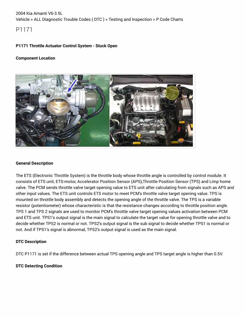
2004 Kia Amanti V6-3.5L Vehicle > ALL Diagnostic Trouble Codes ( DTC ) > Testing and Inspection > P Code Charts P1171 P1171 Throttle Actuator Control System - Stuck Open Component Location General Description The ETS (Electronic Throttle System) is the throttle body whose throttle angle is controlled by control module. It consists of ETS unit, ETS-motor, Accelerator Position Sensor (APS),Throttle Position Sensor (TPS) and Limp home valve. The PCM sends throttle valve target opening value to ETS unit after calculating from signals such as APS and other input values. The ETS unit controls ETS motor to meet PCM's throttle valve target opening value. TPS is mounted on throttle body assembly and detects the opening angle of the throttle valve. The TPS is a variable resistor (potentiometer) whose characteristic is that the resistance changes according to throttle position angle. TPS 1 and TPS 2 signals are used to monitor PCM's throttle valve target opening values activation between PCM and ETS unit. TPS1's output signal is the main signal to calculate the target value for opening throttle valve and to decide whether TPS2 is normal or not. TPS2's output signal is the sub signal to decide whether TPS1 is normal or not. And if TPS1's signal is abnormal, TPS2's output signal is used as the main signal. DTC Description DTC P1171 is set if the difference between actual TPS opening angle and TPS target angle is higher than 0.5V. DTC Detecting Condition
-
Upload
khangminh22 -
Category
Documents
-
view
0 -
download
0
Transcript of 2004 Kia Amanti V6-3.5L Vehicle > ALL Diagnostic Trouble ...
2004 Kia Amanti V6-3.5LVehicle > ALL Diagnostic Trouble Codes ( DTC ) > Testing and Inspection > P Code Charts
P1171
P1171 Throttle Actuator Control System - Stuck Open
Component Location
General Description
The ETS (Electronic Throttle System) is the throttle body whose throttle angle is controlled by control module. Itconsists of ETS unit, ETS-motor, Accelerator Position Sensor (APS),Throttle Position Sensor (TPS) and Limp homevalve. The PCM sends throttle valve target opening value to ETS unit after calculating from signals such as APS andother input values. The ETS unit controls ETS motor to meet PCM's throttle valve target opening value. TPS ismounted on throttle body assembly and detects the opening angle of the throttle valve. The TPS is a variableresistor (potentiometer) whose characteristic is that the resistance changes according to throttle position angle.TPS 1 and TPS 2 signals are used to monitor PCM's throttle valve target opening values activation between PCMand ETS unit. TPS1's output signal is the main signal to calculate the target value for opening throttle valve and todecide whether TPS2 is normal or not. TPS2's output signal is the sub signal to decide whether TPS1 is normal ornot. And if TPS1's signal is abnormal, TPS2's output signal is used as the main signal.
DTC Description
DTC P1171 is set if the difference between actual TPS opening angle and TPS target angle is higher than 0.5V.
DTC Detecting Condition

Specification
Schematic Diagram
Signal Waveform

1. Connect scantool to Data Link Connector (DLC). 2. Warm up the engine to normal operating temperature. 3. Monitor the "TPS (EMS)" and "TPS (ETS)" parameter on the scantool. A. Specification : 1) Approx. 0.3~1.0V at idle & No load (TPS1 or TPS ETS) 2) Approx. 4.2~4.8V at idle & No load (TPS2 or TPS EMS)
4. Is parameter displayed within specifications? YES
Monitor Scantool Data

1) Fault is intermittent caused by poor contact in the related sensors and/or ETS units connector or was repairedand PCM memory was not cleared. Thoroughly check connectors for looseness, poor connection, bending,corrosion, contamination, deterioration, or damage. Repair or replace as necessary and then go to "Verification ofVehicle Repair" procedure. NO 1) Go to "Component Inspection" procedure.
1. Ignition "OFF". 2. Remove the air hose between MAF and Throttle body. 3. Visually check the overall ETS (Throttle valve, ETS motor, APS and TPS). (Especially check the throttle valve for open stuck) 4. Has a problem been found? YES 1) Repair as necessary and go to "Verification of Vehicle Repair" procedure. NO 1) Go to " Check ETS Motor " as below.
1. Ignition "OFF". 2. Disconnect ETS motor connector 3. Measure resistance between terminals "1" and "2" of the ETS motor connector. (Component side) 4. Measure resistance between terminals "1" and "3" of the ETS motor connector. (Component side) 5. Measure resistance between terminals "2" and "3" of the ETS motor connector. (Component side) A. Specification 1) Approx. 0.6 ~ 1.5O ("1" to "2")
Component Inspection
Visually Check ETS
Check ETS Motor

2) Approx. 0.6 ~ 1.5O ("1" to "3")
3) Approx. 0.6 ~ 1.5O ("2" to "3")

- Difference between each resistance should be less than 0.5 ohm 6. Is the ETS motor resistance within specifications? YES 1) Substitute with a known-good ETS unit and check for proper operation. If the problem is corrected, replace ETSunit and then go to "Verification of Vehicle Repair" procedure. If ETS unit needs to be replaced, do initialization afterit is replaced. NO 1) Check ETS motor for contamination,deterioration, or damage. Substitute with a known-good ETS motor andcheck for proper operation. If the problem is corrected, replace ETS motor and then do initialization. And go to"Verification of Vehicle Repair" procedure. 1. Erase the trouble codes on PCM 2. Turn the ignition key on less than 1second and turn it off (Do not start the engine) 3. Turn the ignition key off and keep this condition until the main relay is turned off. (It will takes 10 second) 4. Turn ignition key on more than 1 second to record the throttle motor position on the EEPROM.
After a repair, it is essential to verify that the fault has been corrected.
Verification of Vehicle Repair

1. Monitor and record the Freeze Frame Data for the Diagnostic Trouble Code (DTC) which has been diagnosed 2. Using a Scantool, Clear DTC. 3. Operate the vehicle within conditions noted in the freeze frame data or enable conditions 4. Monitor that all readiness test have been verified as "Complete" 5. Are any DTCs present ? YES 1) Go to the applicable troubleshooting procedure. NO 1) System is performing to specification at this time.