Diagnostic - Trouble Godes
832
Diagnostic Trouble Godes Fault locations and probable causes tr Flash, MIL andEOBD codes tr Engine management systems tr Transmissions tr lmmobilizers E Data link connector locations Petrol and Diesel Gars, MPVs, 4x4s and LGVs igg4-2004
-
Upload
khangminh22 -
Category
Documents
-
view
0 -
download
0
Transcript of Diagnostic - Trouble Godes

DiagnosticTrouble GodesFault locations and probable causes
tr Flash, MIL and EOBD codestr Engine management systemstr Transmissionstr lmmobilizersE Data link connector locations
Petrol and Diesel Gars, MPVs, 4x4s and LGVs igg4-2004

Diagnostic Trouble Codes Fault locations and probable causes
Flash, MIL and EOBD codes
Engine management systems
Transmissions
Immobilizers
Data link connector locations
Petrol and Diesel Cars, MPVs, 4x4s and LCVs 1994-2004
Caution: The information used to compile this manual has been sourced from the vehicle manufacturers information and is believed to be the latest available in May 2004. Manufacturers' information is liable to change at any time and there may have been updates or revisions which applied to the content of this manual but were not available at the time of compilation. Later revisions published by the manufacturers may contain revisions which would be applied retrospectively to the information contained in this manual.
The information contained in this manual applies only to standard models and does not apply to vehicles fitted with equipment other than the standard production options.

Contents
This manual is a comprehensive single source of information on diagnostic trouble codes for engine management, transmission and immobilizer systems for cars and light commercials introduced or revised during the period 1994-2004.
The manual is part of a series from Autodata and has been written and presented in a way to enable any professional automotive technician, with appropriate skills and competence, to make accurate tests and diagnoses, on the engine management, transmission and immobilizer systems.
Detailed knowledge of self-diagnosis systems is not required to make full use of this publication. With a basic understanding of fuel and electrical systems, successful trouble shooting and fault repair should be possible.
Using this manual, in conjunction with the Autodata CD2, or the Pin Data, Engine Management and Wiring Diagrams manuals, time and expense can be saved by quickly tracing and rectifying the cause of obscure and/or intermittent faults.
Where possible, procedures for accessing trouble codes without special diagnostic equipment are given, but increasingly some form of 'scan tool' is required to successfully read the fault memories of control modules.
Each chapter covers a range of models sharing the same trouble code table and lists the codes in numerical or alphabetical order with their fault locations and probable causes.
The probable causes column identifies the various different areas of the system that should be investigated in addition to the primary component in the fault location column.
If a trouble code has been logged, the fault location can be looked up in the trouble code table. This will give suggested probable causes, which should be the primary areas for checking. Most of these probable causes will suggest checking the wiring as well as the primary component in the circuit. The multi-plugs, wiring continuity, insulation and resistance should all be verified before replacing components.
Index Engine management Transmission Immobilizer
How to use this manual Abbreviations Terminology Fault location Probable causes
Safety precautions 36
Tools & equipment Code readers and scan tools Fault diagnosis and testing methods
--
Oscilloscope testing Oscillosopes and wave forms Component testing
-
Trouble codes Engine management systems Electronically controlled transmissions Immobilizers Trouble code format Basic requirements of EOBD
EOBD trouble code table 59
Alfa Romeo - Volvo 91
/Autodata Contents 3

Index Engine management
Model Year System
1451146 1,411,611,812,O 1996-00 Bosch Motronic M 1.5.5lM 2.10.314 91 1451146 1,7 1994-97 Bosch Motronic M 1.5.5lM 2.10.314 91 156 1.611.812.0 (MTI 1997-00 Bosch Motronic M 1.5.5lM 2.10.314 91 . . . . , 166 2,O 1998-00 Bosch Motronic M 1.5.5lM 2.10.314 9 1 SpiderlGTV 1,8 1998-00 Bosch Motronic M 1.5.5lM 2.10.314 9 1 SpiderlGTV 2,O 1996-00 Bosch Motronic M 1.5.5lM 2.10.314 9 1
1993-95 VAG MPI
1991 -07192 Bosch Mono-Motron~c MA1.2.1
80 1,612,O 08/92-95 Bosch Mono-Motronic MA1.2.3 133 80 1,9 TDI 1991 -06193 Bosch EDC 1.2.3141619 135 80 1,9 TDI 07/93-96 Bosch EDC 1.3.213 94 80 2,O 1991-96 VAG Digifant ML5.7 94 80 2,O 16V 1991-96 Bosch KE Motronic 1.211.2.111.2.2 139 80 2.612.8 1991 -96 VAG MPI 94 100 2,O 1991 -92 Bosch KE Motronic 1.211.2.111.2.2 139 100 2,O 1991 -07192 Bosch Mono-Motronic MA1.2.1 130 100 2,O 08/92-94 Bosch Mono-Motronic MA1.2.3 133 100 2.0 1992-94 VAG Diaifant ML5.7 94 "
100 2,O 16V 1992-94 Bosch KE Motronic 1.211.2.111.2.2 139 100 2,5 TDI 1990-94 Bosch EDC 1.2.3/4/6/9 135 100 2,612.8 1991-94 VAG MPI 94 100 4.2 1991 -94 Bosch Motronic M2.4.1 94 A2 2000-04 All systems 94 A3 1996-03 All systems 94 A4lS4 1994-04 All svstems 94 A6 1.8 1995-97 Bosch Motronic M3.2.1 94 A6 2,O 1994-97 VAG Digifant ML5.7 94 A6 2,O 1994-97 Bosch Mono-Motronic MA1.2.3 133 A6 2.0 16V 1994-97 Bosch KE Motronic 1.211.2.111.2.2 139 A6 2,5 TDI 1994-04 All systems 94 A6 2,612,8 1994-97 VAG MPI 94 A6IAllroad 1997-04 All systems 94 A8 1994-02 All svstems 94 Cabriolet 1,8 1997-00 Bosch Motronic M3.8.2 94
Cabriolet 1,9 TDI 1995-00 Bosch EDC 1.3.311.4 94
Cabriolet 2.0 1991 -96 VAG Diaifant ML5.7 94 Cabriolet 2.612.8 1991 -00 VAG MPI 94
-- -
Coupe 2,O
Coupe 2,O 16V
1991 -96 VAG Digifant ML5.7 94 1991 -96 Bosch KE Motronic 1.211.2.111.2.2 139
Coupe 2,612.8 1991 -96 VAG MPI 94 S3 1999-03 All systems 94 S6 2,2 1994-96 Bosch Motronic M2.31.2 142

Engine management I Model Year System Paw
S6 4,2 1994-04 All systems 94 S8 1999-03 All systems 94 TT 1998-04 All systems 94
316lCompact (E36) 1991-00 Motronic M I .7/1.7.2/1.7.3 156 31 8lCoupelCompact (E36) 1991-99 Motronic M I .3/1.7/1.7.2/1.7.3 156 3201325 (E36) 199 1-00 Motronic M3.1 156 325tdltds (E36) 1991 -99 Bosch EDC 1.2.3 (DDE 2) 164 3 SerieslCompact (E36)
Trouble codes: BMW type 1992-00 Siemens MS40141
3 SerieslCompact (E36) Trouble codes: EOBD t v ~ e
1992-01 Siemens MS41
3 Series (E46) Trouble codes: BMW tvDe
1998-00 Siemens MS42
3 Series (E46) 1998-04 Siemens MS42 177 Trouble codes: EOBD type
3 Series (E46) 1998-04 Bosch BMS46 177 518 (E34) 1991-96 Motronic M I .3 156 5201525 (E34) 1991 -96 Motronic M3.1 156 525tdltds IE34) 1991-99 Bosch EDC 1.2.3 (DDE 2) 164
- -
520 IE34) 1991 -96 Siemens MS40 167 . , ~ -~
5 Series (E39) 1996-00 Siemens MS41142 167 Trouble codes: BMW type
5 Series (E39) Trouble codes: EOBD type
1996-03 Siemens MS41142
750 (E32) 1987-94 Motronic M I .2 156 7 Series (E38) 1994-00 Siemens MS41142 167
Trouble codes: BMW type
7 Series (E38) Trouble codes: EOBD type
1994-02 Siemens MS41142
7 Series (E38) 1994-02 Bosch Motronic M5.2 177 8501CSI (E31) 1990-97 Motronic M I .2/1.7 156 8 Series (E31) 1994-99 Bosch Motronic M5.2 177 23 1996-99 Motronic M I .7.3 156 23 1996-00 Siemens MS41142 167
Trouble codes: BMW type
23 1996-03 Siemens MS41142 177 Trouble codes: EOBD type
X5 4,4 (E53) 1999-04 Bosch ME7.2 177
Cherokee 2,514,O 1996-97 JTEC 203 Cherokee 2,514.0 1998 JTEC 21 0 Cherokee 2.514.0 1999-0 1 JTEC 21 6 Grand Cherokee 4.014.7
-
1999-02 JTEC 21 6 Grand Cherokee 4,015,2 1996-97 JTEC 203 Grand Cherokee 4,015,2/5,9 1998 JTEC 21 0 Grand Voyager 2,413,313,8 1996-97 SBEC Ill 189 Grand Voyager 2,413,313,8 1998 SBEC Ill 195 Grand Vovaaer 2.413.313.8 1999-02 SBEC Ill
4
/Autodata 1 Engine management 5

I Engine management
Model
Neon 2.0
Year System
1999-02 SBEC Ill
Page
185 Voyager 2,413,313,8 1996-97 S B ~ ~ I I 189 Voyager 2,413,313,8 1998 SBEC Ill 195 Voyager 2,413,313,8 1999-02 SBEC Ill 200 Wrangler 2,514,O 1996-97 JTEC 203 Wrangler 2,514,O 1998 JTEC 21 0 Wrangler 2,514,O 1999-02 JTEC 21 6
--
AX 1,011,4 1992-97 Bosch Mono-Motronic MA3.0 21 9 AX 1,l 1991 -97 Bosch Mono-Jetronic A2.2 21 9 AX 1,l 1992-97 Magneti Marelli Monopoint G6.11 21 9 Berlingo 1,111,4 1997-98 Bosch Mono-Motronic MA3.1 223 Berlingo 1,111,4 1998-00 Bosch Motronic MA3.1 225 Berlingo 1,4 2002-04 Sagern S2000 PMI 236 Berlingo 1,411,8 1997-98 Magneti Marelli lAPllAP20 227 Berlingo 1,411,8 1998-00 Magneti Marelli lAPllAP20 229 Berlingo 2,O HDi 1999-04 Bosch EDC 15C2 245 C3 1,4 2002-04 Sagern S2000 PMI 236 C5 1,8 2002-04 Sagern S2000 PMI 236 C5 2,O 2002-04 Magneti Marelli 6LP1 242 C8 2,012,2 2002-04 Magneti Marelli 4MP216LP1 242 C15 1,111,4 1992-98 Bosch Mono-Jetronic A2.2 21 9 DispatchlJumpy 1996-99 Lucas EPIC 252 DispatchlJumpy 2,O HDi 1999-04 Bosch EDC 15C2 245 Picasso 1,6 1999-00 Bosch Motronic MP7.2 234 Picasso 1,8 1999-00 Sagern S2000 229 Picasso 1,8 2002-04 Sagern S2000 PMI 236 Picasso 2,O 2002-04 Magneti Marelli 6LP1 242 Picasso 2,O HDi 1999-04 Bosch EDC 15C2 245 RelaylJumper 2,O 1994-00 Magneti Marelli 8P.11 21 9 Saxo 1,011 ,I 1996-98 Bosch Mono-Motronic MA3.1 223 Saxo 1,011 ,I 1998-00 Bosch Motronic MA3.1 225 Saxo 1,411,6 1996-98 Magneti Marelli lAPllAP41 227 Saxo 1,411,6 1998-00 Magneti Marelli lAPllAP41 229 Saxo 1,6 1996-98 Bosch Motronic MP5.115.2 231 Saxo 1,6 1998-00 Bosch MP5.115.2 233 Saxo 1,6 MT 1998-00 Bosch Motronic MP7.2 234 SynergielEvasion 1,9D Turbo 1997-98 Bosch AS3 250 SynergielEvasion 2,O 1993-00 Magneti Marelli 8P.22 247 SynergielEvasion 2,O HDi 1999-02 Bosch EDC 15C2 245 SynergielEvasion 2,O Turbo -
1993-00 Bosch Motronic MP3.2 247 SynergielEvasion 2,l TD 1996-00 Lucas EPIC 252 Xantia 1,6 1993-00 Magneti Marelli 8P.13 247 Xantia 1,8 1997-00 Magneti Marelli 1AP20 229 Xantia 1,812,O 1993-00 Bosch Motronic MP5.115.1 . I 247 Xantia 1,812,O 1993-98 Magneti Marelli 8P.10120 247 Xantia 1,9D Turbo 1995-98 Bosch AS3 250 Xantia 2.0 HDi 1 998-01 Bosch EDC 15 CPllC2 245

Index 1 '. 4$ Engine management \&&
Model Year System Page
Xantia 2,OITurbo 1993-00 Bosch Motronic MP3.2 247 Xantia 2,l D Turbo 1996-98 Lucas EPIC 252 XM 2,O 1989-94 Bosch Motronic MP3.113.2 21 9 XM 2,O 1994-98 Bosch Motronic MP3.2 247 XM 2,O 1994-98 Bosch Motronic MP5.1.1 247 XM 2,lD Turbo 1995-00 Lucas EPIC 252 XM 3.0 1989-94 Fenix 3814 21 9 XM 3.0 1994-98 Fenix 3814 247 - ~
Xsara 1,4 1997-00 Magneti Marelli 1AP40 ' 229 Xsara 1,4 2000 Sagem S2000 229
--
Xsara I ,6 1997-00 Bosch MP5.115.2 233 Xsara 1,6 1998-00 Bosch Motronic MP7.2 234 Xsara 1,8 1997-00 Magneti Marelli 08PlN8PI 0 238 Xsara 1,8 1997-00 Magneti Marelli 1AP20 229 Xsara 1,8 1997-00 Sagem SL96 229 Xsara 2,O 1997-00 Bosch MP5.2 233 Xsara 2.0 1997-00 Mameti Marelli 1AP10 240 Xsara 2.0 2002-04 Maaneti Marelli 4MP216LPl 242 - Xsara 2,O HDi 1999-04 Bosch EDC 15C2 245 ZX 1,l 1991 -95 Bosch Mono-Jetronic A2.2 219 h 1,4 1991 -97 ~ o & h Mono-Jetronic A2.2 21 9 ZX 1,4 1992-98 Bosch Mono-Jetronic MA3.0 21 9 ZX 1,6 1991-97 Magneti Marelli G618P.13 21 9 ZX 1,8 1991 -98 Bosch Motronic MP5.115.1 . I 21 9 ZX 1.812.0 1993-97 Mameti Marelli 8P.10120 21 9 ZX 2.0 1991 -97 Bosch Motronic MP3.2 21 9
Barchetta 1995-00 Hitachi MPI 258 BravalBravo 1,2 1998-02 Bosch Motronic 1.5.5 258 BravalBravo 1,4 1995-98 Bosch Mono-Motronic MA1.7.3 258 BravalBravo 1,6 1995-00 Weber-Marelli 255 BravalBravo 1,8 1995-99 Hitachi MPI 258 BravalBravo 1,9 JTD 1995-02 Bosch EDC 15C 263 Bravo 2,O 1995-98 Bosch Motronic M2.10.4 258 Bravo 2.0 1 998-0 1 Bosch Motronic ME3.1 258 Cinauecento 90011 .I 1991 -98 Weber-Marelli 255 coupe 1,8 16V 1996-01 Hitach1 MPI 258 Coupe 2,O 16VITurbo 1994-97 Weber-Marel11 255 Coupe 2,O 20V 1 998-0 1 Bosch Motron~c ME3.1 258 Coupe 2,O 2OVITurbo 1 996-0 1 Bosch Motronic M2.10.4 258 Fiorino 1.4 1994-02 Bosch Mono-Jetronic A2.2 258 Fiorino 1.5 1991 -93 Bosch Mono-Jetronic A2.2 258 Fiorino 1.6 1994-99 Bosch Mono-Jetronic A2.2 258 MarealMarea Weekend 1.2 1998-03 Bosch Motronic 1.5.5 258 MarealMarea Weekend 1.4 1996-00 Bosch Mono-Motronic MA1.7.3 258 MarealMarea Weekend 1,6 1996-98 Weber-Marelli 255 MarealMarea Weekend 1,8 1996-99 Hitachi MPI 258 MarealMarea Weekend 1,912,4 JTD 1996-03 Bosch EDC 15C 263
/Autodata I Eng~ne management 7

Model Year System Page
MarealMarea Weekend 2,O 1996-99 Hitachi MPI 258 Panda 1.011 ,I 1994-03 Weber-Marelli 1AW 06F 258 Panda 1, l 1991-94 Bosch Mono-Jetronic A2.2 258 Panda 90011 ,I 1992-03 Weber-Marelli 255 Punto 1,111,2116V 1993-99 Weber-Marelli 255 Punto 1,4 GT 1993-99 Bosch Motronic M2.7 258 Punto 1,6 1994-97 GM ACG ~ u l t e c 258 Seicento 90011 , I 1998-00 Weber-Marelli 255 Stilo 1,9 JTD 200 1 -04 Bosch EDC 15C7 264 Tempra 1,4 1991 -97 Bosch Mono-Jetronic A2.2 2 58 Tempra 1,4 1994-97 Bosch Mono-Motronic MA1.7 258 Tempra 1.6 1991 -97 Bosch Mono-Jetronic A2.2 258 Tempra 1,6 1993-97 Bosch Mono-Motronic MA1.7 258 Tempra 1,6 1994-97 GM ACG Multec 258 Tempra 1,812,O 1990-97 Weber-Marelli 255 Tipo 1,4 1988-95 Bosch Mono-Jetronic A2.2 258 Tipo 1,4 1994-95 Bosch Mono-Motronic MA1.7 258 Tipo 1.6 1990-95 Bosch Mono-Jetronic A2.2 258 T i ~ o 1.6 1993-95 Bosch Mono-Motronic MA1.7 258 Tipo 1,812,O 1989-97 Weber-Marelli 255 Uno 1,011,1/1,4/1,5 1989-95 Bosch Mono-Jetronic A2.2 2 58
Cougar 2,012,5 1998-01 Ford EEC V 265 EscorVOrion 1,311,4 1987-94 Ford CFiIEEC-IV 289 EscorVOrion 1,3/1,6/1,8 1 994-0 1 Ford EEC V 265 EscorVOrion 1.4 1994-95 Ford EEC-IV 2 89 EscorVOrion 1.6 1990-93 Ford EEC IV 289 EscorVOrion 1,611,8 16V 1992-95 Ford EEC IV 299 Escort 1,311,4 1995-96 Ford CFiIEEC IV 293 Escort 1,4 1996-99 Ford EEC IV 296 Escort 1,6/1,8 16V 1995-97 Ford EEC IV 306 Escort Cosworth 1995-96 Ford EEC IV 31 2 Escort RS 2000 1995-96 Ford EEC IV 31 2 Explorer 4.0 1996-02 Ford EEC V 265 Fiesta 1,111,3/1,4
-
Fiesta 1,3/1,4
1989-95 Ford CFiIEEC IV
1995-96 Ford CFiIEEC IV
Fiesta 1,4 1994-95 Ford EEC IV 289 Fiesta 1,4 1995-96 Ford EEC IV 296 Fiesta 1,6 1989-93 Ford EEC IV 289 Fiesta 1,611,8 16V 1 991 -94 Ford EEC IV 299 Fiesta 1,611,8 16V 1995 Ford EEC IV 306 FiestalCourier 1,25 2000-02 SIM 19 265 FiestalCourier 1,25/1,3/1,4 1995-02 Ford EEC V 265 FiestalCourier 1,6 2000-02 Ford EEC V 265 FiestalCourier 1,8 DITD 1996-02 Bosch EDC 265 Focus 1,411,611,812,O 1998-04 Ford EEC V 265 Focus 1.8 TD 1998-04 Bosch EDC 265 Focus 1.8 TDCi 200 1 -04 Del~hilEEC V 265

Index Engine management
Year System
2003-04 SIM 28lESU 121
FocusC-MAX 1,612,O TDCi 2003-04 EUDCI6lSID 803 265 Fusion 1,2511,411,6 2002-04 SIM 22 265 Galaxy 1,9 TDI 1995-00 Bosch EDC 265 Galaxy 1,9 TDI PD 1999-04 Bosch EDC 15P 265 Galaxy 2,012,3 1995-04 Ford EEC V 265 Galaxy 2.8 1995-04 Bosch Motronic M3.8.1lME7.1 265 GranadalScorpio 2,O 1989-94 Ford EEC IV 31 6 GranadalScorpio 2,4 V6 R-Cat 1986-94 Ford EEC IV 320 GranadalScorpio 2,9 V6 1986-94 Ford EEC IV 31 6 GranadalScorpio 2,9 V6 24V 1991-94 Ford EEC IV 299 GranadalScorpio 2,9 V6 R-Cat 1986-94 Ford EEC IV 320 Ka 1,3 1996-04 Ford EEC V 265 Maverick 2,4 1993-98 Nissan ECCS 324 Maverick 2,7 D Turbo 1996-98 EDC 326 Mondeo 1.611 -812.0 16V 1993-95 Ford EEC IV 299 Mondeo 1,611.812.0 16V 1995-96 Ford EEC IV 306 . . . . -.
Mondeo 1,611,812,012,5 1996-00 Ford EEC V 265 Mondeo 1,812,O TD 1996-04 Bosch EDC 265 Mondeo 1,812,012,513,O 2000-04 Ford Black Oak 265 Mondeo 2,O TDCi
Mondeo 2,5 V6 1994-95 Ford EEC IV 299 Mondeo 2,5 V6 1995-96 Ford EEC IV 306 Puma 1.411.611.7 1997-02 Ford EEC V 265 Scorpio 2,012,312,9 1994-98 Ford EEC V 265 Scorpio 2,5 TD 1994-98 Bosch EDC 265 Sierra 1.6 1989-93 Ford CFiIEEC IV 31 6 Sierra 1.8 R-Cat 1992-93 Ford CFiIEEC IV 320 Sierra 2,O 1987-93 Ford EEC IV 31 6 Sierra 2,8 1987-89 Ford EEC IV 31 6 Sierra 2,9 V6 R-Cat 1989-93 Ford EEC IV 320 StreetkalSportka 1,6 2003-04 Ford EEC V 265 Transit 2,O 1986-95 Ford CFilEEC IV 31 6 Transit 2,012,3 1994-04 Ford EEC V 265 Transit 2,012,4 TD 2000-04 Bosch EDC 265 Transit 2,5 D Turbo 1994-00 Lucas EPIC 328 Transit 2,9 V6 1989-95 Ford EEC IV 31 6 Transit 2,9 V6 R-Cat 1991 -95 Ford EEC IV 320 TransitITourneo Connect 1,8 2002-04 Ford EEC V 265 Windstar 3,O 1994-03 Ford EEC V 265
Accord 1.6 1998-03 PGM-FI 336 Accord 1.8 1998-03 PGM-FI 336 Accord 1.812.012.212.3 1993-98 PGM-FI 34 1 Accord 2,O
Accord 2,O TD
1998-03 PGM-FI
1996-98 B O S C ~ MSA 11
Accord 2,2 1998-03 PGM-FI 336 Accord 2,3 2000-03 PGM-FI 336
/Autodata Engine management 9

Model Year System Page
d' .@
7.. ,
*
Accord AerodecklCoupe 2,012,2 1993-97 PGM-FI 341 Accord Coupe 2,O 1998-03 PGM-FI 336
index Engine management
Accord Coupe 3.0 1998-03 PGM-FI 336 Civic 1,4 200 1 -04 PGM-FI 336 Civic 1,4/1,511,611,8 1991-00 PGM-FI 333 Civic 1,6 200 1 -04 PGM-FI 336 Civic 2,O Type R 2002-04 PGM-FI 336 Civic Aerodeck 1,411,511,6/1,8 1997-00 PGM-FI 333 Civic Coupe 1,511,6 1994-00 PGM-FI
- 333
Civic Coupe 1,7 200 1-04 PGM-FI 336 CR-V 2,O 2002-04 PGM-FI 347 CR-V 2,4 2002-04 PGM-FI 347
Accent 1,3/1,5 2000-04 MFI (ECFI) 353 Accent 1,511,6 16V 2000-04 MFI (ECFI) 353 Elantra 1,611,812,O 200 1-04 MFI (ECFI) 353 Getz 1.111.3 2002-04 MFI (ECFI) 353 Getz 1,511,6 DOHC 2002-04 MFI (ECFI) 353 Matrix 1,611,8 2001 -04 MFI (ECFI) 353 Santa Fe 2.012.412.7 200 1 -04 MFI (ECFI) 353 Sonata 2,012,512,7 1998-04 MFI (ECFI) 353
Trooper 3,5 1998-03 MFI 356
Sovereign 3,214,O ppp.-p-
1994-97 -
Nippon Denso 360 XJ6 3,214,O 1994-97 Nippon Denso
-- 360
XJ12 6,O 1994-97 Nippon Denso 360 XJR 4.0 1994-97 N i ~ ~ o n Denso 360
Discovery 2,5 TD5 1998-04 Lucas 364 Discoverv 3.5 1991-94 Lucas 14 CUX 372 . , Discovery 3,9 1993-98 Lucas 14 CUX 372 Discoverv 4.0 1998-04 Bosch Motronic M5.2.1 364 Freelander 1,8 2000-04 MEMSI .913 364 Freelander 2,O D Turbo 1997-00 Bosch EDCIMSA 11 364 Freelander 2.0 TD4 2000-04 Bosch CP1 364 Freelander 2,5 2000-04 Siemens EMS 2000 364 Ranae Rover 2.5D Turbo 1994-02 Bosch MSA 11 374 Range Rover 3,O TD6
Range Rover 3,9
Bosch CP113
Lucas 14 CUX
Range Rover 4,O 1994-02 Bosch Motronic M5.2.1 364 Ranae Rover 4.4 2002-04 Bosch Motronic ME7.2 364
Range Rover 4.6 1994-99 Lucas GEMS 8.2 364 Range Rover 4,6 1999-02 Bosch Motronic M5.2.1 364

Index Engine management
Model Year System
1989-91 Mazda EGI
323 1.3 16V (BG) 1991 -94 Mazda EGI 402 323 1.311.511.8 IBJ) 1998-00 Mazda EGI 402 323 1.311,611.8/2.0 (BJ) 2000-03 Mazda EGI 409 . . . . . , -
- - -
323 1,6 8V (BG) 1989-91 Mazda EGI 402 323 1,6 16V (BG) 1991 -94 Mazda EGI 402 323 1,8 16V (BG) 1989-94 Mazda EGI 402 323 2,O D (BA) 1997-98 Mazda EDC 402 323 2,O DITD (BJ) 1998-03 Mazda EDC 402 323 2,O V6 (BA) 1994-98 Mazda EGI 402 323 Estate 1,614~4 (BW) 1989-94 Mazda EGI 402 626 2,O D (GE) 1992-97 Mazda EDC 402 6261Estate 1,812,O (GFIGW) 1997-99 Mazda EGI 41 3 6261Estate 1,812.0 (GFIGW) 1999-00 Mazda EGI 402 6261Estate 1.812.0 IGFIGW) 2000-02 Mazda EGI 409 6261Estate 2.0 TD IGFIGW) 1998-02 Mazda EDC 402 6261MX-6 1,812,O (GE) 1992-97 Mazda EGI 402 6261MX-6 2,5 V6 (GE) 1992-98 Mazda EGI 402 Mazda2 1,2511,411,4 TDCill,6 2002-04 All systems 381 Mazda6 1,812,012,O TD12,3 2002-04 All systems 381 MX-3 1,6 (EC) 1991 -99 Mazda EGI 402 MX-3 1,8 V6 (EC) 1991-99 Mazda EGI 402 MX-5 1,6 (NA) 1989-98 Mazda EGI 402 MX-5 1,611.8 (NB) 1998-00 Mazda EGI 402 MX-5 1,611,8 (NB) 2000-04 Mazda EGI 409 MX-5 1.8 (NA) 1993-98 Mazda EGI 402 Tribute 2.013.0 200 1-04 Ford EEC V 381 Xedos 6 1.6 1992-99 Mazda EGI 402 Xedos 6 2,O V6 1992-00 Mazda EGI 402 Xedos 9 2,012,5 V6 1994-00 Mazda EGI 402 Xedos 9 2,3 V6 1995-00 Mazda EGI 402
1998-04 B O S C ~ MSM
A1601170 CDI (168) 1998-04 Bosch EDC 15C 41 8 C180 (203) 2000-04 Bosch ME SIM4 433 Cl8Ol2OO (202)
Trouble codes: Two-digit flash type 1993-98 Siemens PMSIBosch HFM-SF1 42 1
C1801200 (202) 1993-98 Siemens PMSlBosch HFM-SF1 425 Trouble codes: Three-digit
C1801200 (202) 1998-00 Bosch ME 2.1 433 C200 (203) 2000-04 Bosch ME SIM4 433 C2001220 CDI (202) 1998-00 Bosch EDC 15C 41 8

lndex Engine management
Model
C200K (202) Trouble codes: Two-diqit flash type
Year System
1996-00 Bosch HFM-SF1
Page
42 1 - . .
C200K (202) 1996-00 Bosch HFM-SF1 425 Trouble codes: Three-digit
C200K (202) 1996-00 Bosch ME 2.1lSIM4 433 C200K (203) 2000-04 Bosch ME SIM4 433 C2201230 (202) 1993-98 Bosch HFMIHFM-SF1 42 1
Trouble codes: Two-digit flash type
C2201230 (202) 1993-98 B O S C ~ HFMIHFM-SF1 425 Trouble codes: Three-digit
C230 (202) 1996-00 B O S C ~ ME 2.1 433 C230K (202) estate 1995-97 Bosch HFM-SF1 42 1
Trouble codes: Two-digit flash type
C230K (202) estate 1995-97 Bosch HFM-SF1 42 5 Trouble codes: Three-digit
C230K (202) estate 1997-00 Bosch ME 2.1 433 C230K (202) saloon 1995-96 Bosch HFM-SF1 42 1
Trouble codes: Two-digit flash type
C230K (202) saloon 1995-96 Bosch HFM-SF1 42 5 Trouble codes: Three-digit
C230K (202) saloon 1996-00 Bosch ME 2.1 433 C240 (202) 1998-00 Bosch ME 2.0 433 C240 (203) 2000-04 Bosch ME 2.8 433 C250 1993-94 B O S C ~ EDC 437 C250 DITD 1994-96 B O S C ~ EDC 439
Flash type trouble codes
C250 DITD 1994-96 B O S C ~ EDC 44 I P type trouble codes
C250 TD 1996-99 Bosch EDC 443 C280 (202) 1993-96 Bosch HFM 421
Trouble codes: Two-digit flash type
C280 (202) 1993-96 Bosch HFM 425 Trouble codes: Three-digit
C280 (202) 1996-00 B O S C ~ ME 2.012.1 433 C320 (203) 2000-04 Bosch ME 2.8 433 CL420 (140) 1995-98 Bosch ME 1.0 433 CL500 (140) 1995-99 B O S C ~ ME 1.0 433 CL600 (140) 1995-99 B O S C ~ ME 1.0 433 CLK2OO (208) 1998-03 Bosch ME 2.1 433 CLK2OOK (208) 1996-03 Bosch ME 2.1lSIM4 433 CLK230K (208) 1997-03 Bosch ME 2.1 433 CLK320 (208) 1997-03 Bosch ME 2.0 433 CLK430 (208) 1998-03 Bosch ME 2.8 433 E200 (1 24/21 0) 1993-98 Siemens PMSlBosch HFM 42 1
Trouble codes: Two-digit flash type
E200 (1 24/21 0) 1993-98 Siemens PMSIBosch HFM 425 Trouble codes: Three-digit
E200 (210) 1998-03 Bosch ME 2.1lSIM4 433 E200/220/270/320 CDI (21 0) 1998-03 Bosch EDC 15C 41 8 E200K (210) 1997-03 Bosch ME 2.1 433 E22012801320 (1 24) 1993-95 Bosch HFM 421
Trouble codes: Two-digit flash type
I '2 I,,,,,,,,,,,,., /Autodata

Index Engine management
Model Year System
1993-95 Bosch HFM E22012801320 (1 24) Trouble codes: Three-digit
E23012801320 (21 0) Trouble codes: Two-digit flash type
1995-97 Bosch HFM
E23012801320 (21 0) Trouble codes: Three-digit
1995-97 Bosch HFM
E240 (21 0) 1998-03 B O S C ~ ME 2.0 433 E280 (21 0) 1995-03 B O S C ~ ME 2.0 433 E320 (21 01 1995-03 Bosch ME 2.0 433 E420 (210) 1995-03 B O S C ~ ME 1.0 433 E430 (210) 1998-03 Bosch ME 2.012.8 433 S280 (140) 1996-98 Bosch ME 2.1 433 S2801320 (1 40)
Trouble codes: Two-digit flash type 1993-96 Bosch HFM
S2801320 (1 40) Trouble codes: Three-digit
1993-96 Bosch HFM
S320 (140) 1996-98 Bosch ME 2.1 433 S420 (140) 1995-98 B O S C ~ ME 1.0 433 S500 (140) 1995-99 Bosch ME 1.0 433 S600 (140) 1995-99 B O S C ~ ME 1.0 433 SL280 (129) 1996-02 B O S C ~ ME 2.1 433 SL2801320 (1 29)
Trouble codes: Two-digit flash type 1993-96 Bosch HFM
SL2801320 (129) Trouble codes: Three-digit
1993-96 Bosch HFM
SL320 (129) 1996-02 Bosch ME 2.1 433 SL500 (129) 1995-02 Bosch ME 1.012.0 433 SL500 (230) 2002-04 Bosch ME 2.8 433 SL600 (129) 1995-02 Bosch ME 1.0 433 SLK200 (1 70)
Trouble codes: Two-digit flash type 1996-98 B O S C ~ HFM-SF1
SLK200 (1 70) Trouble codes: Three-digit
1996-98 B O S C ~ HFM-SF1
SLKZOO (170) 1998-04 Bosch ME 2.1 433 SLK200W230K (170) 1996-04 Bosch ME 2.1 433 SLK320 (1701 2000-04 Bosch ME 2.8 433 Sprinter CDI (90112131415) 1999-04 Bosch EDC 15C 41 8 V2001220 CDlNito (638) 1999-03 Bosch EDC 15C 41 8 Vaneo CDI (4141 2002-04 Bosch EDC 15C
Cooper 2001 -04 Siemens EMS 2000 450 One 2001 -04 Siemens EMS 2000 450 One D 2002-04 DDE4 454
Challenger 3,O V6 1999-00 Mitsubishi ECI-Multi 456 Galant 1,8/2,0/2,5 1993-00 Mitsubishi ECI-Multi 456 ShogunlPajero 3,O V6 1994-00 Mitsubishi ECI-Multi 456 ShogunlPajero 3,5 V6 1994-00 Mitsubishi ECI-Multi 456
/Autodata- Ena~ne manaaement 13

index Engine management
Model Year System Page
1 OONX 1,612,O 1990-95 Nissan ECCS 467 200SX 2,O 1994-00 Nissan ECCS 467 Alrnera 1,4/1,6/2,0 1995-00 Nissan ECCS 467 Alrnera 1,511.8 2000-02 Nissan ECCS 469 Alrnera 1,5/1,8 2002-04 Nissan ECCS
-- 472
Almera 2,OD 1996-00 Bosch EDC 48 1 Alrnera Tino 1,812,O 2000-02 Nissan ECCS 469 Alrnera Tino 1,8 2002-04 Nissan ECCS 472 Micra 1,011.3 1992-98 Nissan ECCS 463 Micra 1.011.4 1999-02 Nissan ECCS 465 . . ~ . -
Navara Pick-up 2,4 2001 -04 Nissan ECCS 472 Patrol 4,2 1992-98 Nissan ECCS 467 Pick-uplNavara 2,4 1999-00 Nissan ECCS 467 Prirnera 1,612,O 1990-00 Nissan ECCS 467 Prirnera 1.6/1.8/2,0 1999-02 Nissan ECCS 469 . . . - -
Prirnera 1,611,812,O 2002-04 Nissan ECCS 472 Prirnera 2,OTD 1996-00 Bosch EDC 48 1 Serena 1,612,O 1992-00 Nissan ECCS 467 Sunny 1,4/1,6/2,0 1990-95 Nissan ECCS 467 Sunnv EstateNan 1992-95 Nissan ECCS 467 Terrano 11 2,4 1993-00 Nissan ECCS 467 Terrano 11 2,7 TD 1996-00 Bosch EDC 48 1 X-Trail 2,012,5 2001 -04 Nissan ECCS 472
106 1,011,l - 1996-03 Bosch Mono-Motronic MA3.1 490 106 1,011,4 1993-96 Bosch Mono-Motronic MA3.0 486 106 1,l 1993-96 Magnet1 Marelli Monopoint G6 486 106 1,l 2000-03 Bosch Motronic M7.4.4 490 106 1,111,4 1991 -97 Bosch Mono-Jetronic A2.2 486 106 1.311.6 1994-96 Maaneti Marelli 8P 48 6 106 1,3/1,6 1996-97 Magneti Marelli 8P 493 106 1,4 1991 -96 Bosch Motronic MP3.1 486 106 1,4 1998-03 Bosch Motronic MP7.3 490 106 1,4/1,6 1996-03 Maqneti Marelli IAP 490 106 1.6 1996-03 Maaneti Marelli 8P 490
1996-03 Bosch Motronic MP5.1.115.2
2000-03 Magneti Marelli 4.8P
205 1.111,4 1989-96 Bosch Mono-Jetronic A2.2 48 6 205 1,111.6 1989-96 Maqneti Marelli Monopoint G5lG6 48 6 206 1.1 2000-04 Bosch Motronic M7.4.4 490 206 1,111,4 1998-04 Magneti Marelli 1AP 490 206 1,4 1998-04 Bosch Motronic MP7.3 490
206 1.4 HDi 2001 -04 Bosch EDC 16 498
/ '4 I,,,,,,,,,,., IAutodata

Index '4 '". ,#
Engine management I No.
Model
206 1.6
Year System
1998-02 Bosch Motronic MP7.2
Page
490 206 1,6 2000-04 Bosch Motronic M7.4.4 490 206 2,O 1998-04 Magneti Marelli 4.8P 490 206 2,O HDi 1999-04 Bosch EDC 15C2 498 306 1,111,4 1993-97 Magneti Marelli Monopoint G6 486 306 1,4 1993-97 Bosch Mono-Motronic MA3.0 486 306 1,4 1997-02 Maqneti Marelli IAP 490 306 1.4 1998-02 Bosch Motronic MP7.217.3 490 306 1.4 1998-02 Saaern SL96lS2000 490
- --
306 1,6/1,8 1993-97 Bosch Motron~c MP5.1 486 306 1,6 1 997-0 1 Bosch Motronic MP5.2 490 306 1,6 2000-02 Bosch Motronic M7.4.4 490 306 1,812,O 1993-97 Magneti Marelli 8P 486 306 1,8 1997-01 Magneti Marelli 8P1A 490 306 1,8 1997-02 Sagem SL96 490 306 2,O 1993-97 Bosch Motronic MP3.2 486 306 2,O 1 997-0 1 Bosch Motronic MP5.2 490 306 2.0 1997-01 Maqneti Marelli IAP 490 306 2.0 HDi 1999-02 Bosch EDC 15C2 498 307 2,O 2002-04 Magneti Marelli 4MP216LP1 500 405 1,6 1992-97 Magneti Marelli Monopoint G6 486 405 1,8 1992-97 Bosch Motronic MP5.1 486 405 1,812,O 1992-97 Magneti Marelli 8P 486 405 2,O 1993-95 Bosch Motronic MP3.2 486 405 2,O Turbo 1993-95 Maqneti Marelli AP 486 406 1,6 1995-99 Magneti Marelli 8P 490
406 1.8 1997-02 Motronic MP5.1 .I 490 406 1,8 1997-02 Magneti Marelli 1AP20 490 406 1,8 2002-04 Sagern S2000 PMI 496 406 1,812,O 1995-97 Bosch Motronic MP5.1.115.2 493 406 2,O 1997-02 Motronic MP5.1.115.2 490 406 2,O 1999-04 Magneti Marelli 4.8P14.8P2 490 406 2,O Turbo 1997-00 Motronic MP3.2 490 406 2,012.2 2002-04 Maqneti Marelli 4MP216LPl 500 406 2.012.2 HDi 1998-04 Bosch EDC 15C2 498 406 2.1 D Turbo 1995-00 Lucas EPIC 503 406 C o u ~ e 2.0 1997-02 Motronic MP5.1.115.2 490 406 Coupe 2,O 1999-04 Magneti Marelli 4.8P14.8P2 490 406 Coupe 2,012,2 2002-04 Magneti Marelli 4MP216LPl 500 406 Coupe 2,2 HDi 2000-04 Bosch EDC 15C2 498 605 2,O 1992-94 Bosch Motronic MP3.115.1 486 605 2,O 1994-00 Bosch Motronic MP5.1/5.1.1/5.2 493 605 2,O Turbo 1992-94 Bosch Motronic MP3.2 486 605 2,O Turbo 1994-00 Bosch Motronic MP3.2 493 605 2.1 D Turbo 1994-00 Lucas EPIC 503 607 2,012,2 2002-04 Magneti Marelli 4MP216LPl 50 0 806 1,812,O 1994-97 Magneti Marelli 8P 493
4

index Engine management
Model Year System page
806 1,812,O 1997-01 Maqneti Marelli 8P 490 806 1,9D Turbo 1995-00 Bosch AS3 506 806 2.0 1998-01 Bosch Motronic MP7.3 490 806 2.0 2000-02 Maaneti Marelli 4.8P 490
-
806 2,O HDi 1999-02 Bosch EDC 15C2 498 806 2,O Turbo 1994-97 Bosch Motron~c MP3 2 493 806 2,O Turbo 1997-01 Bosch Motron~c MP3 2 490 806 2,lD Turbo 1996-00 Lucas EPIC 503 807 2,012,2 2002-04 Maqneti Marelli 4MP216LP1 500 Boxer 2.0 1994-00 Maqneti Marelli 8P.11 486 Partner 1.4 2002-04 Saaem S2000 PMI 496 Partner 1,4/1,8 1996-03 Magneti Marelli lAPllAP20 490 Partner 2.0 HDi 1999-04 Bosch EDC 15C2 498
Alpine 3,O 1992-97 Bendix MPI 508 Clio 1,2 1990-96 Bosch/Delco TBI 508 Clio 1,2 1995-04 Saqem Safir 512 Clio 1.4 1994-98 Siemens Mono~oint 508 Clio 1,4 1996-01 Bosch/Delco TBI 508 Clio 1,4 1998-04 Siemens Fenix 5 508 Clio 1,4 16V 1999-04 Siemens Sirius 508 Clio 1,5D Turbo 2000-04 Lucas common rail 51 5 Clio 1,6 1998-03 Siemens Fenix 5 508 Clio 1,6 16V 1999-04 Siemens Sirius 508 Clio 1.8 16V 1991 -97 Siemens MPI 508 Clio 1.8IRsi 1990-98 Siemens MPI 508 Clio 2,O 1999-04 Siemens Sirius 508 Clio Williams 1993-95 Siemens MPI 508 Espace 1,9D Turbo 1999-02 Bosch MSA 15.5 528 Espace 2,O 1991-97 Bendix MPI 508 Espace 2,O 1996-99 Siemens Fenix 5 508 Espace 2,O 16V 1998-02 Siemens Sirius 32 526 E s ~ a c e 2.2 1991-97 Siemens MPI 508 Espace 2,2D Turbo 2000-02 Bosch common rail 523 Espace 2,2D Turbo 1997-00 Bosch MSA 15.5lAS3 52 1 Espace 2,8 1991 -97 Siemens MPI 508 Espace 3,O V6 1996-99 Siemens MPI 508 ExtralRapidlExpress 1,211,4 1990-02 RenixIMaqneti Marelli TBI 508 Kanaoo 1.2 1998-04 Saaem Safir 51 2 Kangoo 1,411,6 1998-04 Siemens Fenix 51Sirius 508 Kangoo 1,5D Turbo 2000-02 Lucas common rail 51 5 Laguna 1,6 16V 1 998-0 1 Siemens Sirius 32 526 Laguna 1,8 1994-98 BoschIFenix TBI 508 Laguna 1,8 16V 1998-01 Siemens Sirius 32 526 Laguna 1,9D Turbo 1999-01 Bosch common rail 523 Laauna 2.0 1994-96 Siemens MPllFenix 3B 508 ~ a ~ u n a 2,0 1 996-01 S~emens Fen~x 5 508 Laguna 2,O 16V 1996-99 S~emens Fenix 5 508
1 '6 I,,,,,,,,,,,,,,, /Autodata

Model Year System page
Laguna 2.0 16V 1 999-01 Siemens Sirius 32 526 Laguna 3,O V6 1994-98 Siemens MPI 508 Laguna 3,O V6 24V 1997-01 Bosch Motronic MP7.0 508 Master 2,2D Turbo 2000-03 Bosch common rail 523 Master 2,8D Turbo 1998-02 Sagem 528 Megane 1,4 1999-02 Siemens Sirius 508 Menane 1,411,6 16V 1999-02 Siemens Sirius 32 508 Megane 1,411,612,O 2002-04 Sagem 3000 51 8 Megane 1,9D 1999-02 Lucas EPIC 519 Megane 1,9D Turbo 1999-02 Bosch common rail 523 Megane 1,9D Turbo 1999-02 Bosch MSA 15.5lAS3 52 1 Megane 2,O 16V 1996-99 Siemens Fenix 5 508 Megane 2,O 16V 1999-02 Siemens Sirius 32 508 Megane 2,O 16V IDE 1999-02 Siemens Sirius 3H 51 2 MenanelMenane Scenic 1,4 1995-99 Siemens Fenix 3 508 MenanelMenane Scenic 1.6 1995-99 Siemens Fenix 5 508 MenanelMenane Scenic 2.0 1995-99 Siemens Fenix 5 508
- -
MeganelMegane Scenic 1,9 D Turbo 1997-99 Bosch MSA 15.5lAS3 52 1 R19 1,l 1993-95 B O S C ~ TBI 508 R19 1,4 1991 -96 Bosch/Siemens/Delco TBI 508 R19 1,7 1988-96 Renix R MPI 508 R19 1,8 1992-96 SiemensIBosch TBI 508 R19 1,8 16V 1989-96 Siemens MPI 508 R19 1.81s 1992-96 Maaneti Marelli TBI 508 R19 1,81S 1992-96 Siemens MPI 508 R21 1,7 1987-93 Renix TBI 508 R21 2,0112VTTurbo 1986-94 Renix R MPI 508 R5Nan 1,4 1986-95 Renix TBI 508 R5Nan 1,7 1987-93 Renix TBI 508 Safrane 2,O 16V 1996-01 Siemens Fenix 5 508 Safrane 2,011 2V 1992-97 Siemens MPI 508 Safrane 2.211 2V 1992-01 Siemens MPI 508 Safrane 2.5 20V 1 996-01 Bosch Motronic M4.4 508 Safrane 3,O V6IQuadra 1992-98 Siemens MPI 508 Scenic 1,411,6 16V 1999-03 Siemens Sirius 32 508 Scenic 1,411,612,O 2003-04 Sagem 3000 51 8 Scenic 1,9D Turbo 1999-02 Bosch common rail 523 Scenic 1,9D Turbo 1999-03 Bosch MSA 15.51AS3 52 1 Scenic 2.0 16V 1999-03 Siemens Sirius 32 508 Scenic RX4 1.9D Turbo 2000-02 Bosch common rail 523 Scenic RX4 2,O 16V 2000-03 Siemens Sirius 32 508 Trafic T N 2,2 1989-00 Siemens MPI 508
25 1,1/1,411,6 1999-04 MEMS 3 543 25 1,811,8 W C 1999-04 MEMS 3 543 45 1,411,611,8 1999-04 MEMS 3 543 45 2.0 1999-04 Siemens EMS 2000 543 75 1,811,8 Turbo 1999-04 MEMS 3 543
4

Engine management
Year System
1999-04 Siemens EMS 2000
Page
543 100 1,111,4 1995-98 Rover MEMS 540 200 1.111.4 1989-99 Rover MEMS 540 200 1.411.611.8 16V 1989-99 Rover MEMS 540 200 1,8 Vi 1995-99 Rover MEMS 540 200 CabriolCoupe 1,611,812,O 1991-99 Rover MEMS 540 20014001600 2,O TD 1995-99 Bosch MSA 11 548 2001CabriolCoupe 1,6 1989-96 Honda PGM-FI 546 400 1,411,612.0 1995-99 Rover MEMS 540 400/Tourer 1.4 16V 1989-95 Rover MEMS 540 400/Tourer 1,6 1989-96 Honda PGM-FI 546 400/Tourer 1,6 16V 1996-99 Rover MEMS 540 400/Tourer 2,OIlurbo 1992-99 Rover MEMS 540 600 1.812,012.3 1993-99 Honda PGM-FI 551 6201820 Turbo 1992-99 Rover MEMS 540 820 1991 -99 Rover MEMS 540 825 1996-99 Rover MEMS 540 Metro 1,111,4 1990-95 Rover MEMS 540 MG TF 1,611.8 2002-04 MEMS 3 543 MG ZR 1.4 200 1-04 MEMS 3 543 MG ZR 1,811,8 W C 200 1-04 MEMS 3 543 MG ZS 1,611,8 200 1-04 MEMS 3 543 MG ZS 2,5 200 1-04 Siemens EMS 2000 543 MG ZTIZT-T 1.8 2002-04 MEMS 3 543 MG ZTIZT-T 2.5 200 1 -04 Siemens EMS 2000 543 MGF 1,811,8 W C 1995-02 Rover MEMS 540 Mini 1,3 1991 -01 Rover MEMS 540 Montego 2,O 1989-93 Rover MEMS 540
900 2.0 Turbo 1993-98 Trionic 560 900 2,012,3
Trouble codes: Flash type 1993-98 Bosch Motronic 2.1 0.2 556
900 2,012,3 Trouble codes: EOBD type
1993-98 Bosch Motronic 2.1 0.2 558
900 2,5 Trouble codes: Flash type
1993-98 Bosch Motronic 2.8.1 556 - .
900 2,5 1993-98 Bosch Motronic 2.8.1 Trouble codes: EOBD type
9000 2,OIlurbo 1994-98 Trionic 560 9000 2,3 Aero 1994-98 Trionic 560 9000 2.3Ilurbo 1994-98 Trionic 560 9000 3,O V6
Trouble codes: EOBD type 1995-97 Bosch Motronic 2.8.1 571
9-3 2.0 Turbo 1998-03 Trionic T5/T7 562 9-3 2,012,3
Trouble codes: Flash type 1998-00 Bosch Motronic 2.10.3 556
9-3 2,012,3 Trouble codes: EOBD type
1998-00 Bosch Motronic 2.10.3 558 . .
9-3 2,2 D Turbo 1998-02 Bosch EDC 15/PSG 16 567

Engine management I 0;.6Q )
Model
9-3 2,3 Viggen
Year System
1 999-0 1 Trionic T7
Page
562 9-5 2,012,3 Turbo 1997-04 Trionic T7 562 9-5 2,3 Aero 1999-04 Trionic T7 562 9-5 3,O 1998-03 Trionic T7 562
Alhambra 1995-04 All systems --
576 Arosa 1997-04 All systems 576 IbizalCordoba 1999-02 All systems 576
--
IbizalCordoba 1,011,4 1996-99 Bosch Motronic MP9.0 576 IbizalCordoba 1,05 1993-97 Bosch Mono-Motronic MA1.2.2 578 IbizalCordoba 1,05 1993-97 Bosch Mono-Motronic MA1.2.3 581 IbizalCordoba 1.3 1993-94 Bosch Mono-Motronic MA1.2.2 57 8 lbizalcordoba 1.3 1993-94 Bosch Mono-Motronic MA1.2.3 581 m-p
- - ~
IbizalCordoba 1,411,6 1996-99 Magneti Marelli 1AV 576 --
IbizalCordoba 1,411,6 1993-99 Bosch Mono-Motronic MA1.2.3 --
583 IbizalCordoba 1,6 1996-99 Siemens Simos 576 IbizalCordoba 1,711,9 SDI 1996-99 Bosch EDC 1.3.311 5V 576 IbizalCordoba 1,8 1993-94 Bosch Mono-Motronic MA1.2.2 578 IbizalCordoba 1.8 1993-94 Bosch Mono-Motronic MA1.2.3 58 1 lbizalcordoba 1.8 1994-99 Bosch Mono-Motronic MA1.2.3 583 IbizalCordoba 1.812.0 16V 1994-99 VAG Diaifant MP4.4 576
-- -
IbizalCordoba 1,9 DITD 1993-99 Bosch EDC --
576 IbizalCordoba 1,9 TDI 1996-99 Bosch EDC 1.3.3/15V 576 IbizalCordoba 2,O 1993-96 VAG Digifant ML5.9 576 IbizalCordoba 2,O 1995-99 Siemens Simos 576 Inca 1.4 1995-00 Bosch Motronic MP9.0 576 Inca 1.4 2000-04 Bosch Motronic ME7.5.10 576 Inca 1,4 2000-04 Magneti-Marelli 4LV 576
Inca 1,6 1995-00 Bosch Mono-Motronic MA1.2.3 583 --
Inca 1,6 1998-00 Magneti-Marelli 4LV 576 Inca 1,9 D 1996-04 Bosch EDC 576 Inca 1,9 SDI 1996-04 Bosch EDC 1.3.3115V 576 Toledo 1,611,8 1994-97 Bosch Mono-Motronic MA1.2.3 583 Toledo 1.612.0 1996-99 Siemens Simos 576 Toledo 1,9 DITD --
1994-99 B O S C ~ EDC 576 Toledo 1,9 TDI 1994-99 Bosch EDC 1.3.3115V 576 Toledo 2,O 1994-98 VAG Digifant ML5.5 576 Toledo 2,O 16V 1994-99 VAG Digifant MP4.4 576 ToledolLeon 1999-04 All systems 576
Fabia 1999-04 All svstems
~ a v o r i t 1.3 +07/93 Bosch Mono-Motronic MA1.2.2 59 1 Favorit 1,3 08/93-96 Bosch Mono-Motronic MA1.2.3 589 Favorit VanlForman Pick-up 1,3 +07/93 Bosch Mono-Motronic MA1.2.2 59 1 Favorit VanlForman Pick-up 1,3 --
08/93-94 Bosch Mono-Motronic MA1 2.3 589 Felicia 1,3 1994-96 Bosch Mono-Motronic MA1.2.3
-- 589
FeliciaNanlPick-up 1,3 1 996-01 Siemens Simos 594 --
4

Engine management
Model
FeliciaNanlPick-up 1,6
Year system
1995-01 Maqneti Marelli 1AV
FeliciaNanlPick-up 1,9 D 1995-01 Bosch EDC 594 Octavia 1996-04 All svstems 594
Avensis 1.611.812.0 1998-07100 TCCS 61 2 . . . - - -
Avensis 2,0D Turbo 1998-07100 TCCS 61 2 Carina E 1,6/1,812,0 1992-98 TCCS 609 --
Carina E 2,0D 1992-96 TCCS 609 Carina E 2,OD Turbo 1996-98 TCCS 609 Carina II 1,6 1988-90 TCCS 606 Carina 11 2,O
With VAF sensor 1988-92 TCCS
Celica 1,6 1985-94 TCCS 61 9 Celica 1.8 1994-99 TCCS 61 9 Celica 2.0 1986-99 TCCS 619 Corolla 1.3 1990-01 100 TCCS 600 - - -
Corolla 1,6 1988-01100 TCCS 600 Corolla 1,6 GT 1984-87 TCCS 600 Corolla 1,8 1993-95 TCCS 600 Corolla 2,OD 1993-01100 TCCS 600 MR2 1,6 1985-90 TCCS 61 5 MR2 2.0 1990-00 TCCS 61 5 Picnic 2,O 1996-00 TCCS 627 Picnic 2,2 D Turbo 1998-00 TCCS 627 Previa 2,4 1 990-04100 TCCS 630 RAV4 1994-00 TCCS 633 Starlet 1,3 1990-99 TCCS 597 Supra 3,0/Turbo 1993-97 TCCS 624
2000-04 Bosch Motronic ME1.5.5 Aaila 1.011.2
Astra 2.0116V 1986-91 Bosch Motronic 682 Astra-F 1,411,6/1,8
Trouble codes: Flash type 1991-98 Multec
Astra-F 1,411,611,812,0 Trouble codes: EOBD type
1994-98 MultecISimtec 56,5170 675
Astra-F 1,812,O 16V Trouble codes: Flash type
1993-98 Simtec 56.0156.1156.5 687
Astra-F 2.011 6V 1991-98 Bosch Motronic 682 Astra-G 1,2 2000-04 Bosch Motronic ME1.5.5 666 Astra-G 1,2/1,4/1,6/1,8 1998-04 Multec S(F)lMotronic/Simtec 71lGMPT-El5 672 Astra-G 1,4/1,6/1,8/2,0 1998-00 MulteclSimtec 56,5170 675 Astra-G 1,7 TD 1999-04 Denso HDRC 679 Astra-G 1,7 TD 2002-04 Bosch EDC 15C7 693 Astra-G 1,7 TD12.0 TDl2,2 TD 1998-04 Bosch EDC 15M 690 Astra-G 2.0 Turbo 2000-04 Bosch Motronic ME1.5.5 666 Astra-G 2,2 2000-04 GMPT-El5 697 Calibra 2,O 1996-98 Simtec 56.5 703 Calibra 2,O 16V 1994-98 Simtec 56.0156.1156.5 687
I 20 I,,,,,,,,,,,,,, IAufodafa

Engine management
Model Year System Page
CarltonlOmega-B 2,012,512,613,O 24V 1986-00 Bosch Motronic 682 CavalierNectra 1,611,8 1988-95 Multec 669 CavalierNectra 2,O 16V 1993-95 Simtec 56.0156.1156.5 687 CavalierNectra 2,O & 4x4 1988-95 Bosch Motronic 682 CavalierNectralCalibra 2,O 16VlTurbo & 4x412,5 1990-98 Bosch Motronic 682 Combo-C 1,6 2001-04 Multec S(F)lMotronic/Simtec 71lGMPT-El5 672 Combo-C 1,7 TD 2001 -04 Denso HDRC 679 Corsa-BICombo 1,011,2 1997-00 Multec S(F)lMotroniclSimtec 71lGMPT-El5 672 Corsa-BICombo 1,211,4/1,6 1993-98 Multec 669
Trouble codes: Flash type
Corsa-BICombo 1,411,6 1994-00 MulteclSimtec 56.5170 675 Trouble codes: EOBD type
Corsa-C 1,011,211,411.611.8 2000-04 Multec S~F~IMotroniclSimtec 71lGMPT-El5 672 -
Corsa-C 1,7 TD 2000-04 Denso HDRC 679 Frontera-A 2.012.212.4 1991 -98 Bosch Motronic 682
- ~ - ~ -
Frontera-A 2.5 TD 1995-98 Bosch EDC 679 Frontera-B 2,213,2 1998-03 Multec S(F)lMotroniclSimtec 71lGMPT-El5 672
Trouble codes: Y22XE/Y32SE (6VD1) engines
Frontera-B 2,2 Trouble codes: Y22SE enaines
2000-03 Multec SlS(F) -
Frontera-B 2,2 TD 1998-02 Bosch EDC 15M 690 Frontera-B 2,2 TD 2003-04 Bosch PSG 16 693 NovalCorsa 1,2/1,411,6 1990-93 Multec 669 Omega-B 2,O 1995-00 MulteclSimtec 56.5170 675 Omega-B 2,O 16V 1994-95 Simtec 56.0156.1156.5 687 Omega-B 2,O TD12,2 TD 1998-03 Bosch EDC 15M 690 Omega-B 2,012,512,613,O 24V
Trouble codes: Flash type 1986-00 Bosch Motronic
- . Omega-B 2,212,613,013,2 1999-03 Multec S(F)lMotronic/Simtec 71lGMPT-El5 672
Trouble codes: EOBD type
Omeaa-B 2.5 TD 1994-00 Bosch EDCIMSA 11 700 Omeaa-B 2.5 TD 2001-03 Bosch EDC 15C4 693 Senator-B 2.613.013.0 24V 1987-93 Bosch Motronic 682 Sintra 2.2 1996-99 Bosch Motronic 682 Sintra 2.2 TD 1998-99 Bosch EDC 15M 690 Sintra 3.0 1996-99 Multec S(FVMotronic1Simtec 71lGMPT-El5 672 Tigra l,4ll,6
Trouble codes: Flash type 1995-00 Multec
Tigra 1,411,6 Trouble codes: EOBD type
1995-00 MultecISimtec 56.5170 675
Vectra-B 1,611,812,O 1995-00 MulteclSimtec 56.5170 675 Vectra-B 1,611,812,212,512,6 1995-02 Multec S(F)lMotronic/Simtec 71lGMPT-El5 672 Vectra-B 2.0 TD12,2 TD 1997-02 Bosch EDC 15M 690 Vectra-C 1.6 2002-04 Multec SlS(F) 705 Vectra-C 1.8 2002-04 Siemens Simtec 71.5 666 Vectra-C 2.0 TD 2002-04 Bosch PSG 16 693 Vectra-C 2,O Turbo 2002-04 Trionic 8 697
Vectra-C 2.2 TD 2002-04 Bosch PSG 16 693 Vectra-C 3.2 2002-04 Bosch Motronic M3.11 666 ~ ~ 2 2 0 2 . 0 Turbo 2003-04 Bosch Motronic ME1.5.5 666

index Engine management
Year System
2003-04 Bosch Motronic ME1.5.5
Model
VX220 2,O Turbo
Page
666 Zafira 1,6/1,8 1999-00 MultecISimtec 56.5170
-- 675
Zafira 1,6/1,8/2,012,2 2000-04 Multec S(F)/Motronic/Simtec 71lGMPT-El5 672 Zafira 1,7 TD 2000-04
Zafira 2,O TD12,2 TD 1999-04
Denso HDRC
Bosch EDC 15M
Beetle 1999-04 All svstems 722 CaddylPickup 1995-04 All systems except: Bosch Mono-Motronic 722 CaddvlPicku~ 1.6 1996-00 Bosch Mono-Motronic MA1.2.3IMAl .3 7 64 Corrado (08192-95) 1992-95 All systems except: Bosch KE-Motronic 722 Corrado 2,O 16V 1992-95 Bosch KE-Motronic 1.2/1.2.1/1.2.2 769 GolfNento 1.4 ( 407192) 199 1-92 Bosch Mono-Motronic MA1 2 .2 766 GolfNento 1,4 (07192 4 ) 1992-97 Bosch Mono-Motronic MA1.2.3lMAI .3 764 GolfNento 1.6 1992-95 Bosch Mono-Motronic MA1.2.3lMAI .3 764 GolfNento 1,8 (407193) 1991 -93 Bosch Mono-Motronic MA1.2.2 766
1991-04 All systems except: Bosch Mono-Jetronicl 722 Mono-Motronic
GolfNentolCabrio 1,8 (07193 4 ) 1993-02 Bosch Mono-Motronic MA1.2.3IMAl .3 764 Jetta 2,O 16V 1989-92 Bosch KE-Motronic 1.2/1.2.1/1.2.2 769 LT 2,3 1996-04 Bosch Motronic 772 LT 2,5 SDllTDl 1996-04 Bosch EDC 722 LT14x4 2,4 03/95-96 Bosch Digifant MP4.0 775
Lupo 1998-04 All systems 722 Passat 1991-04 All systems except: Bosch Mono-Jetronicl 722
Mono-MotronidKE-Motronic
Passat 1,6 Without MIL
1988-90 Bosch Mono-Jetronic A2.2 759
Passat 1,8 (408190) Without MIL
1988-90 Bosch Mono-Jetronic A2.2 759
Passat 1,8 (AAM 407194) 06/92-94 Bosch Mono-Motronic MA1.2.2 766 Passat 1,8 (AAM, ADZ 07/94 4 ) 1994-96 Bosch Mono-Motronic MA1.2.3IMAl .3 764 Passat 1,8 (ABS 410193) 06/92-93 Bosch Mono-Motronic MA1.2.2 766
Passat 1.8 (ABS 10193 4 ) 1993-95 Bosch Mono-Motronic MA1.2.3lMAl .3 764 Passat 1,8 (RP 08/90 4 ) 1990-91 Bosch Mono-Motronic MA1.2lMAl .2.1 761
Passat 1,8 (AAM)
Passat 1,8 (ABS)
1990-06192 Bosch Mono-Motronic MA1.2IMAl .2.1 761 1991-06192 Bosch Mono-Motronic MA1.2lMAl .2.1 761
Passat 2,O 16V
Polo 1,05 Without MIL
Bosch KE-Motronic 1.2/1.2.1/1.2.2
Bosch Mono-Jetronic A2.2
Polo 1,0511,3 ( 408193) 1990-93 Bosch Mono-Motronic MA1.2lMAl .2.1 761 Polo 1,05/1,3 (08193 4 ) 1993-97 Bosch Mono-Motronic MA1.2.3lMAI .3 764 Polo 1.3 1990-94 All svstems exce~t : Bosch Mono-Motronic 722 Polo ClassiclEstate 1,6/1,8 1995-02 Bosch Mono-Motronic MA1.2.3lMAI .3 764
1994-04 All systems except: Bosch Mono-Jetronicl 722 Mono-Motronic
Sharan 1995-04 All systems 722 TransporterlCaravelle 1990-03 All svstems 722

Engine management Y- ii f
Model Year System
1989-95 Bosch LH-Jetronic 2.413.2
44014601480 1,6/1,711,812,0 1990-97 Fenix 38 792
740 2,012,3 1989-92 Bosch LH-Jetronic 2.413.2 --
806 7401760 2,012,3 Turbo 1989-92 Bosch LH-Jetronic 2.413.2 806
850 2,O 1995 Siemens Fenix 5.21Bosch Motronic 1.814.3 81 0 Without 16-pin DLC
850 2,O 1995-97 Siemens Fenix 5.2lBosch Motronic 1.814.3 81 5 With 16-pin DLC
850 2,012,312,5lTurbo 1995-97 Bosch Motronic 4.4 794 850 2,012,5 1991-95 Bosch LH-Jetronic 2.413.2 806
850 2,012,5 1995-97 Bosch LH-Jetronic 2.413.2 820
850 2,312,5 1993-95 Siemens Fenix 5.21Bosch Motronic 1.814.3 81 0 Without 16-pin DLC
850 2,312,5 1995-97 Siemens Fenix 5.21Bosch Motronic 1.814.3 81 5 With 16-pin DLC
850 2,5 20V 1995 Siemens Fenix 5.21Bosch Motronic 1.814.3 810 Without 16-pin DLC
850 2,5 20V 1995-97 Siemens Fenix 5.21Bosch Motronic 1.814.3 81 5 With 16-pin DLC
- -
8501SN70 2,5 TDI (408198) 1996-98 Bosch MSA 15.7 794 940 2,OlTurbo 1990-95 Bosch LH-Jetronic 2.413 2 806
940 2.3 LPT 1995 Bosch LH-Jetronic 2.413.2 806
940 2.3 LPT 1995-98 Bosch LH-Jetronic 2.413.2 820
9401960 2.012.3lTurbo 1990-95 Bosch LH-Jetronic 2.413.2 806 -
9401960 2,012.3lTurbo 1995-98 Bosch LH-Jetronic 2.413.2 820
960 2,5 20V With 16- in DLC
1996 Siemens Fenix 5.21Bosch ~ot ron ic 1.814.3 815
960 2,513,O 1990-95 Siemens Fenix 5.21Bosch Motronic 1.814.3 810 Without 16-pin DLC
960 2,513,O --
1995-97 Bosch Motronic 4.4 794
C70 2.0 TXO 2000-04 DensoIBosch Motronic ME 7.0 800 - --
C70 2.3 Turbo 2000-02 DensoIBosch ~ o t r o n i c ME f i 800 C70 2.4lTurbo 2000-01 DensoIBosch Motronic ME 7.0 800
S60 2.012.3 Turbo 2000-04 DensoIBosch Motronic ME 7.0 800
S60 2.4lTurbo 2000-04 DensoIBosch Motronic ME 7.0 800
S70N70 2.5 20V 1997-98 Bosch LH-Jetronic 2.413.2 820
S80 2.012.3 Turbo 2000-04 DensoIBosch Motronic ME 7.0 800
S80 2.4lTurbo 2000-04 DensoIBosch Motronic ME 7.0 800 S80 2.8 Turbo 2000-01 DensoIBosch Motronic ME 7.0 800 S80 2.9 2000-04 DensoIBosch Motronic ME 7.0 800
SN40 1.611.811,912,0 1996-99 Siemens Fenix 5.1 /EMS 20001Melco1Lucas 794
SN40 1.9 TD 1996-99 Siemens Fenix 5.11EMS 20001MelcolLucas 794
SN70 2.012.5 20V 1997-99 Siemens Fenix 5.21Bosch Motronic 1.814.3 815 SNl90 2.9 1997-98 Bosch Motronic 4.4 794 SNIC70 2,012,312,5lTurbo 1997-98 Bosch Motronic 4.4 794
V70 2.012.3 Turbo 2000-04 DensoIBosch Motronic ME 7.0 800 V70 2.4lTurbo 2000-04 DensolBosch Motronic ME 7.0 800
XC70 2,312.5 Turbo 2002-04 DensoIBosch Motronic ME 7.0 800
XC90 2.5 Turbo 2002-04 DensoIBosch Motronic ME 7.0 800
a
[Autodata a Engine management 23
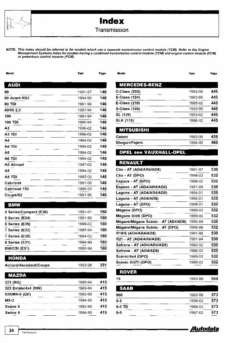
Index Transmission
NOTE: This index should be referred to for models which use a separate transmission control module (TCM). Refer to the Engine Management Systems index for models having a combined transmission control module (TCM) and engine control module (ECM) or powertrain control module (PCM).
Model Year Page Model Year Page
80 Avant RS2 1994-95 146
80 TDI 1991-96 146
100 1991-94 146 100 TDI 1990-94 146
A3 TDI 1996-02 146
A4 1994-02 146 ShogunlPajero 1994-00 460
A4 TDI 1994-02 146
A6 TDI 1994-02 146 A6 Allroad 1997-02 146
Clio - AT (AD41AR41AD8) 1991-97 530 Clio - AT (DPO) 1998-02 532 A8 TDI 1997-02 146
Cabriolet 1991-00 146 Espace - AT (DPO) 1998-02 532 Espace - AT (AD41AR41AD81 1991-99 530 Cabriolet TDI 1995-00 146 Laguna - AT (AD4lAR41AD8) 1994-01 530 Laguna - AT (AD4lAD8) 1995-01 535 Laguna - AT (DPO) 1998-01 532 Megane (DPO) 1999-02 532 Megane Dldti (DPO) 1999-02 532 5 Series (E34) 1991-96 180 MeganelMeaane Scenic - AT (AD41AD81 1995-99 535
5 Series (E391 1996-02 180 MdganelMBgane Scenic - AT ( ~ 6 ) 1995-99 532 - -
7 Series (E32)
7 Series (E38) 1994-02 180
8 Series (E31) 1994-99 180 Safrane - AT (AD4IAR4lAD8) 1992-02 530 Safrane - AT (AD4lAD81 1996-02 535 Scenicl4x4 (DPO) 1999-02 532 Scenic DldTl (DPO) 1999-02 532
323 (BG) 1989-94 415
323 Estatel4x4 (BW) 1989-94 415 626lMX-6 (GE) 1992-95 415
Xedos 6 1992-95 415

Index l :, A Transmission '
Model Year Page Model Year Page
Sintra TD 1998-99 709 Tigra -- 1995 709 Vectra-B 1995-01 714 Vectra-B TD 1997-01 714
Alharnbra 1995-02 585
Alhambra TDI
Arosa --
1997-02 585
Arosa SDlITDl 1997-02 585
Beetle 1998-02 776 Beetle TDI 1998-02 776
Toledo 1991-99 585 Corrado 1992-95 776 Toledo D/TD/TDI 1994-99 585 Golf Cabrio 1993-02 776 ToledolLeon 1999-02 585 Golf Cabrio D/TD/TDI 1994-02 776
GolflBora 1997-02 776 ToledolLeon SDIITDI 1999-02 585 GolflBora TDI 1997-02 776 GolfNento 1991-01 776 GolfNento DITDITDI 1991-98 776 Fabia
Fabia SDIITDI 1999-02 595 Lupo 1998-02 776
Lupo SDllTDl 1998-02 776 Passat 1988-02 776
Octavia 1996-02 595
Octavia SDIITDI 1996-02 595 Passat 1,812,O 16V 1989-07190 785
Passat DITDITDI 1991-02 776 Polo 1993-02 776 Avensis
-- 1998-00 638
Avensis D 1998-00 638 Polo ClassiclEstate 1995-02 776
Polo ClassiclEstate DlSDllTDl 1995-02 776 Polo DISDIITDI 1995-02 776
Carina E 1992-98 636
Carina E D Sharan 1995-02 776 Celica 1985-99 640
Picnic 1996-00 642 Sharan TDI 1995-02 776 TransporterlCaravelle 1990-02 776
Previa 1990-00 644 TransporterlCaravelle TDI 1995-02 776
850 TDI 1996-97 827
960 1990-95 824
SN70 TDI 1997-98 827 Sintra 1996-99 709

Index Immobilizer
Model Year Page Model Year Page
626lEstate IGFlGWl 1997-00 417
626lEstate TD IGFlGWl 1998-00 417
626lMX-6 (GE) 1995-97 417
A2 TDI 2000-02 154 A3 A3 TDI Xedos 6 1995-00 417
Xedos 9 1995-00 417 A4 1994-02 154 A4 TDI 1994-02 154
A6 TDI 1994-02 154 A6 Allroad 1999-02 154 A8 A8 TDI
Almera 1996-02 484 Cabriolet 1994-00 154
Almera D 1996-02 484 Cabriolet TDI 1994-00 154 C O U D ~ / ~ ~ 1994-96 154 Almera Tino 2000-02 484
Micra 1996-02 484
Primera 1996-02 484
Primera TD 1996-02 484
Serena 1996-01 484
Terrano II
Terrano II TD
Cougar 1997-02 330 EscorVOrion 1993-02 330 Escort 16V 1995-97 330 Escort Cosworth 1993-96 330 Clio 1994-02 537
Clio D Turbo 2000-01 537 Escort RS 2000 1993-96 330 Fiesta 1993-02 330 Fiesta DlTD 1996-02 330
Clio Williams 1994-95 537
FOCUS 1998-02 330 FOCUS TD 1998-02 330 E s ~ a c e D Turbo 1997-02 537
Galaxy 1995-02 330 Galaxy TDlTDl 1995-02 330 Ka 1996-02 330
Kangoo 1998-02 537
Kangoo D Turbo 2000-02 537 MavericWD 1996-02 330 Laguna 1994-01 537 Mondeo 1994-02 330 Mondeo TD 1996-02 330
Laguna D Turbo 1999-01 537
Megane 1999-02 537 Meaane DlTurbo 1999-02 537 Puma 1997-02 330
S c o r ~ i o 1994-98 330 Meaane dTI 1999-02 537
MeaanelMeaane Scenic 1995-99 537 Transit 1994-01 330 Transit TD 1994-01 330
MeganelMegane Scenic D Turbo 1997-99 537
R19 1994-96 537
Safrane 1996-02 537 323 (BJ) 1998-00 417 323 DlTD (BJ) 1998-00 417 Scenic 1999-02 537
Scenic D Turbol4x4 1999-02 537
Scenic dTI 1999-02 537
626 D (GE) 1995-97 417 Trafic 1996-02 537

Index 1, / Immobilizer
Model Year Page
Omega-B 1994-99 718 Omega-B TD 1994-99 718 Omega-B 1999-02 720 Omega-B TD 1999-02 720 Sintra 1996-99 718 Sintra TD 1998-99 718
--
Tiara 1994-01 718 Alhambra 1996-02 587 Alhambra TDI 1996-02 587 Arosa 1997-02 587 Arosa SDlITDl 1997-02 587
Zaf ira 1999-02 720 Zafira TD --
1999-02 720 Toledo 1995-99 587 Toledo DITDITDI 1995-99 587
Beetle 1999-02 788 ToledotLeon 1999-02 587 ToledolLeon SDlITDl 1999-02 587 Beetle TDI 1999-02 788
Caddv 1996-02 788 Caddy DlSDllTDl 1996-02 788
Fabia 1999-02 596 Caddy Pickup Caddv Pickup D Fabia SDlITDl 1999-02 596 Corrado 1994-95 788 Golf Cabrio 1994-02 788
Felicia 1995-96 596 FeliciaNanlPick-up 1996-02 596
Golf Cabrio DITDITDI 1994-02 788 GolflBora 1997-02 788 Octavia 1996-02 596
Octavia SDlITDl 1996-02 596 GolfIBora TDI 1997-02 788 GolfNento 1994-01 788 GolfNento DITDITDI 1994-98 788 LT 1996-02 788 LT SDlITDl 1996-02 788
Avensis --- Avensis D Turbo 1998-00 654 Carina E 1995-98 652 Lupo 1998-02 788
LUDO SDlITDl 1998-02 788 Carina E DITurbo 1995-98 652 Celica 1995-99 658 Passat 1994-02 788
Passat DITDITDI 1994-02 788 Corolla 1995-00 650 Corolla D 1995-00 650 Polo 1994-02 788
Polo DlSDlITDl 1995-02 788 Polo ClassiclEstate 1995-02 788 Picnic
Picnic D Turbo Polo ClassiclEstate DlSDlITDl 1995-02 788 Sharan 1995-02 788 Previa 1996-00 662
RAV4 Starlet
Sharan TDI 1995-02 788 TransporterlCaravelle 1995-02 788 TransporterlCaravelle TDI 1995-02 788
850 1995-97 830 850 TDI 1996-97 830
Calibra --- 1994-98 718
Corsa-B 1994-01 718 Corsa-C 2000-02 720 ---- Corsa-C TD 2000-02 720 Frontera 1994-98 718
SN70 TDI --
1997-98 830 SNIC70 1997-00 830

How to use this manual
A AV Auxiliary air valve ECT Engine coolant temperature (sensor)
ABDC After bottom dead centre ECU Electronic control unit
ABS Anti-lock brake system EDC Electronic diesel control
EDlS Electronic distributorless Ignition system ABV Air bypass valve
ac Alternating current EDL Electronic differential lock
AC Air conditioning EDU Electronic drivina unit - EEPROM Electronically erasable programmable APP Accelerator pedal position (sensor/switch)
read only memory Approx. Approximately
AR F Exhaust gas recirculation
ASC Automatic stability control
EFi Electronic fuel injection
EFP Electronic accelerator pedal
EGR Exhaust gas recirculation
EOBD European on-board diagnostics ASM Auto shift manual (transmission)
ASR Anti-skid requlation (same as TCS) EPC Electronic power control (same as ETS) AT Automatic transmiss&
ATC Automatic temperature control (AC) EPIC Electronic proarammed iniection control -
EPROM Electronically programmable read only memory ATDC After top dead centre EPT Exhaust pressure transducer AWD All wheel drive
BAR0 Barometric pressure
BAS Brake assist system
ERS Electronic restraint system
ESP Electronic stability programme
ETC Electronic traction control BBDC Before bottom dead centre ETS Electronic throttle system BDC Bottom dead centre ETV Electronic throttle valve
EVAP Evaporative emission BFP Brake fluid pressure
BPP Brake pedal position (switch) FL Fuse link BTDC Before top dead centre FR P Fuel rail pressure (sensor) CAN Controller area network (data bus) FT Fuel trim
FWD Front wheel drive Cat Catalytic converter
C Dl Capacitor discharge ignition GPS Global positioning system CFi Central fuel injection HDC Hill descent control CHT Cylinder head temperature (sensor) HDI High pressure direct injection
HEGO Heated exhaust gas oxygen (sensor) CKP Crankshaft position (sensor)
CMP Camshaft position (sensor)
CO Carbon monoxide HFM Hot film management
HI High pressure
H02S Heated oxygen sensor C02 Carbon dioxide
CPP Clutch pedal position (switch)
CPU Central processing unit
CVT Continuously variable transmission
HT High tension
Hz Hertz (cycles per second)
110 Input-output unit
IAC Idle air control
DAS Drive authorisation system
DDE Digital diesel electronics
DLC Data link connector
DM E Digital motor electronics
I AT Intake air temperature
IC lntearated circuit
DOHC Double overhead camshaft ICM Ignition control module
DSA Dynamic stability assistance I FS Inertia fuel shut-off (switch)
DTC Diagnostic trouble code
DVM Digital volt meter
I FZ Infra-red remote control for central locking
IMA Idling mixture adjustment sensor
ISC Idle speed control EBD Electronic brake pressure distribution
ECi Electronicallv controlled iniection J1930 Standard terminology for automotive applications
KAM Keep alive memory ECM ~ n g i n e control module

How to use this manual
kmlh Kilometres per hour RHD Right-hand drive
LCD Liquid crystal display ROM Read only memory
R PM Revolutions per minute LED Light emitting diode
LH Left-hand RWD Rear-wheel drive
LH D Left-hand drive
LO Low pressure
secs. seconds
SEFl Sequential electronic fuel iniection
LOS Limited operating strategy
LPG Liquefied petroleum gas
SF1 Sequential fuel injection
Single zone Common temperature control for all areas of vehicle mA Milli-amps
MAF Mass air flow (sensor)
-
SPI Single point injection
SPS Speed sensitive power steering MAP Manifold absolute pressure (sensor)
Max. Maximum SRS Supplementary restraint system
ST0 Self test output MFI Multi-port fuel iniection TBI Throttle body injection
TC Turbocharger MIL Malfunction indicator lamp
Min. Minimum TCCS Toyota computer control system
TCM Transmission control module m ~ h Miles ~ e r hour
MPI Multi-point iniection TCS Traction control system ms Milli-second
MT Manual transmission TD Turbo diesel
TDC TOP dead centre MTC Manual tem~erature control (AC) TDI ~ u r b o direct injection
TFP Transmission fluid pressure MY Model year (usually starts AugISept before calendar year)
N Neutral position, automatic transmission
TFT Transmission fluid temperature
TP Throttle position
N ATS Nissan anti-theft system
nda No data available
TPM Tempomat cruise control
TPS Throttle position switch/sensor
NOx Nitrogen oxides
N P Neutral position (switch)
TR Transmission range (sensor/switch)
TRAC Traction control
NTC Negative temperature coefficient
0 2 s Oxygen sensor
TRC Traction control
TWC Three-way catalytic converter
OBD On-board diagnostics
OHC Overhead camshaft
VAF Volume air flow (sensor)
VAG Volkswagen Aktiengesellschaft (Volkswagen group Ltd.) P Park position, automatic transmission
VlCS Variable intake control system PAIR Pulsed secondary air injection VIS Variable intake system PAS Power assisted steering V P Diesel iniection pump (axial type) PATS Passive anti-theft system VR Diesel injection pump (radial type) PCM Powertrain control module
(ECM + o~t ional TCM function) VRlS Variable resonance intake system
PCV Positive crankcase ventilation VSS Vehicle speed sensor
VSV Vacuum switching valve PGM-FI Programmed fuel injection
PMS Pressure management system WOT Wide o ~ e n throttle
PNP Parklneutral position (switch) 8V Eight valve
PS Power steering 1 OV Ten valve
PSP Power steering pressure (switch) 16V Sixteen valve
PTC Positive temperature coefficient
quattro All wheel drive
20V Twenty valve
24V Twenty four valve
R-Cat Regulated catalytic converter
RAM Random access memory
2WD Two-wheel drive
4WD All-wheel drive
4x4 Four-wheel drive
[Autodata How to use th~s manual 29

How to use this manual
Find the model related chapter from vehicle manufacturer, model name, engine code, year of manufacture and system.
Observe the following relevant test conditions: All auxiliary equipment, including air conditioning, switched OFF. Ensure battery voltage above 11 volts. Ensure earth wires in good condition. If vehicle fitted with engine malfunction indicator lamp (MIL): Check MIL operation - if MIL does not flash or illuminate, replace bulb or repair circuit.
NOTE: If MIL remains illuminated or flashes, this indicates a fault, but if it goes out there could still be trouble codes logged in the ECM. Scan tool may not respond if MIL is not working.
Engine at normal operating temperature. Carry out road test. Ensure overrun cut-off function operates several times. Operate accelerator pedal several times over complete travel range. Allow engine to idle. If engine does not start: Briefly crank engine and leave ignition switched ON. Observe any model specific information. Find the location of the data link connector (DLC). Bridge DLC terminals, connect an LED tester or scan tool, as appropriate and observe any special conditions. If a scan tool is used, follow the manufacturer's operating instructions. Follow procedure for accessing trouble codes and note any codes displayed.
NOTE: The trouble code may not identify the exact cause of any problem, but serves as a guide to the component or system to be investigated.
Refer to probable causes and carry out systematic check of components and circuits until cause of problem is identified and rectified. Refer to Autodata CD or engine management and pin data manuals, for further test and diagnosis information.
NOTE: Where the probable cause is a non-specific engine fault, fuel system or ignition system fault, refer to General Trouble Shooter section.
Check for further trouble codes. Follow procedure for erasing trouble codes.
NOTE: If the battery is disconnected to erase trouble codes, data stored, such as radio security codes and ECM adaptive memory may be lost.
Road test vehicle and recheck for any logged trouble codes. If a trouble code is output, but not listed in the appropriate code table, suspect a control module fault.
NOTE: In the case of signal or component malfunction, the ECM will substitute a fixed value from its internal limited operating strategy (LOS) software. This enables the vehicle to be driven in limp-home mode until the fault can be rectified. Depending on the component or circuit in question, it may not be obvious to the driver that the engine management system is operating in limp-home mode.
Quick reference icon
Engine management Transmission Immobilizer
1 Quick reference icon I
I Engine identification code
I Manufacturer's I system name I
] Year 198695 I I Ename code. ARD. BRD. BRE. BRF. BRT. BRV. B4B, B4C. R6A
Sy~tm. Ford CFllEEC IV 1 Engine rnanagemenVtmnsrnission
I
I
P
Data link connector (DLC) iocation(s)
I system I

How to use this manual
1 number 1
I Identification of trouble 1 code access method@) conditions
trouble codes
NOTE: Engine control module (ECM) incorporates transrnissio! control function.
Refer lo genera test cond~tlons dl tne front of Ins maria Tro.be wdes are osoaye~ l ~y s n g an -FD connrcled II
1 the -r 0 The ECM fault memory can also be accessed and erased
uslng d~agnost~c equipment connected to the data llnk connector (DLC)
d n g Engine at normal operating temperature. Ensure ignition swltched OFF. Br~dge data link connector (DLC) termmals 2 Connect LED test lamp negative connection terminal 2 0. Connect LED test lamp pos~tive connection to 1 0. Swltch lanition ON Check that LED illuminates. Trouble d e s are di-layed after 10-25 s e c o n d & $ Note trouble codes. Compare wlth trouble code table. Trouble wdes are displayed by lllumlnated LED switching OFF for appmxlmately 1 second fl In1 Each troubie code co&ts of two LED illuminates for approximately 2 seconds between each group fl ICI. . , . .
NOTE: Trouble codes ending in '0' are displayed with only f UroUD.
Trouble code(s) are displayed twlce.
I
L Illustration by number ] I
trouble code Pvw
I TrouMe code number
Primary fault location and associated fault{s)
I Probable causw of fault I I

I How to use this manual
Terminology Throughout this manual the following standard descriptions and terminology have been used, together with J1930 component descriptions. Left-hand (LH) and right-hand (RH) - As seen from the driver's seat facing forward Bank 1 - Cylinder bank or group including No.1 cylinder (e.g. cylinders 1, 2 & 3 of a six cylinder engine) Bank 2 - Cylinder bank or group not including No.1 cylinder (e.g. cylinders 4, 5 & 6 of a six cylinder engine) H02S 1 - Heated oxygen sensor (H02S) single or nearest to engine (in front of catalytic converter) H02S 2 - Heated oxygen sensor (H02S) after catalytic converter KS 1 - Knock sensor (KS) single or nearest No.1 cylinder
Typical sensor locations and descriptions:
Fig. 1
4 cylinder in-lne
1 Heated oxygen sensor (H02S) 1 2 Heated oxygen sensor (H02S) 2 3 Knock sensor (KS) 1 4 Knock sensor (KS) 2 5 Catalytic converter
Fig. 2 - 6 cylinder In-line
1 Heated oxygen sensor (H02S) 1, bank 2 2 Heated oxygen sensor (H02S) 1, bank 1 3 Heated oxygen sensor (H02S) 2, bank 2 4 Heated oxygen sensor (H02S) 2, bank 1 5 Heated oxygen sensor (H02S) 2
(if only single heated oxygen sensor (H02S) after cat)
6 Catalytic converter C

How to use this manual
Fig. 3
1 Heated oxygen sensor (H02S) 1, bank 1 2 Heated oxygen sensor (HOZS) 2, bank 1 3 Heated oxygen sensor (H02S) 1, bank 2 4 Heated oxygen sensor (H02S) 2, bank 2 5 Knock sensor (KS) 1 6 Knock sensor (KS) 2 7 Catalytic converter
Fig. 4 -
Heated oxygen sensor (H02S) 1, bank 2 Heated oxygen sensor (H02S) 1, bank 1 Heated oxygen sensor (H02S) 2 Knock sensor (KS) 1, bank 2 Knock sensor (KS) 2, bank 2 Knock sensor (KS) 1, bank 1 Knock sensor (KS) 2, bank 1 Catalytic converter
4
[Autodata How to use thls manual 33

How to use this manual
Fault location
Fuel trim - F I ~ . 5 - Short and long term fuel trim refers to the strategy used to reduce exhaust emissions after the basic computation of injection period, using engine load as the major parameter. Both front and rear oxygen sensor signals are used to fine tune the fuellair mixture by increasing or decreasing the injection period +I-25% above or below the basic level. Any fault requiring a correction beyond this level will result in a trouble code being logged. When the engine is new and running satisfactorily a level of fuel trim will be established - represented by 100°/o.
Fig. 5 -
RICHER
The fuel trim will oscillate the injection period +I-5% above and below the mean level [A].
Manufacturing and in-service tolerances of load sensors (MAP, MAF or VAF) and injectors in particular and faults such as intake air leaks will affect the fuellair mixture and cause the fuel trim to quickly compensate. An intake air leak for instance would result in the injection period increasing, for example to 115-125%. This level will also oscillate +I-5% as before [B]. This new short term fuel trim (STFT) level will be stored in the ECM if it is established as a new basic mixture level. It will then become a long term fuel trim (LTFT) correction and results in the correct mixture level immediately after starting, even when the H02S has had insufficient time to heat up. Long term fuel trim (LTFT) values can be erased by disconnecting the ECM power supply for a suitable length of time. If the memory is not erased after repairs the ECM will eventually learn the new LTFT values, but this will take some time and probably cause high emissions and some driveability problems. For example if an intake air leak causes the engine to run lean this will be compensated by a change in the LTFT value, which will be stored in the ECM memory. After the leak has been repaired this memorised LTFT value will still be used to compute the injection period, resulting in excessively rich running, until new LTFT values have been learned.
Probable causes
Wiring
Wiring - refers not only to the wiring harness, but also to any associated component multi-plugs, relay plates, welded, crimped or soldered joints and bulkhead connectors. Short to earth - refers to wiring that has a 'leak' to earth somewhere along its length e.g. if the insulation has chaffed through and the wiring is in contact with the body or engine. Short to positive - refers to wiring that would normally not be carrying 12 volts, but is shorted to the 12 volt supply e.g. a sensor wire that would normally be fed with approx. 5 volts from the ECM, shorted to a 12 volt battery positive supply. Open circuit - refers to wiring that is either disconnected or broken, but is not shorted to either earth or a positive supply. Poor connection - refers to a loose, intermittent or high resistance connection.
General faults
Despite the sophistication of modern electronic management systems, basic mechanical faults can still cause unsatisfactory starting, running and driveability. Before assuming that a problem is an electronic one, it should be established that the engine/transmission/immobilizer is in good mechanical condition and that the basic fuel and electrical circuits are OK.

HOW to use this manual
Check the following:
Engine
Mechanical
Compression pressure Manifold vacuum Valve clearances Valve timing Oil filler cap sealing Not burning excess oil No excessive crankcase fumes
Electrical
Battery fully charged and 11-14 volts available Plug leads connected correctly Ignition coil(s) Ignition timing HT leads (where applicable) Spark at plugs Engine ground connections Engine control module (ECM) ground connections
Fuel system
Air filter for blockage Fuel filter for blockage Fuel delivery rate Fuel system pressure Fuel regulated pressure Fuel injector spray pattern Vacuum hoses not split or collapsed Catalytic converter and exhaust for blockage
Transmission 0 Fluid level correct
Fluid in good condition No foreign matter in transmission fluid No restricted fluid passages in valve block
0 Vacuum hoses not disconnected, split, blocked or collapsed No engine related faults Selector lever cablellinkage adjusted correctly Multi-plugs connected securely Wiring undamaged
Immobilizer (engine won't start) Correct key is being used Key is not damaged
0 Does the key need reprogramming No spurious signals from external source No engine related faults Gear selector in P or N

Safety precautions
Airbags (Supplementary Restraint System - SRS)
Many of the models covered by this manual are fitted with airbags as standard equipment. When working on a vehicle fitted with such a system, extreme caution must be taken to avoid accidental firing of the airbag, which could result in personal injury. Unauthorised repairs to the system could render it inoperative, or cause it to inflate accidentally.
NOTE: All related wiring is encased in a yellow outer covering.
When the engine is started the AIRBAG warning lamp should go out after approximately 5-10 seconds, if not this indicates a fault in the system. The system should be checked and the fault corrected by a competent technician before any other work is undertaken.
NEVER attempt to test the system using a multi-meter.
NEVER tamper with or disconnect the airbag wiring harness.
NEVER make extra connections to any part of the system wiring harness or terminals.
ALWAYS ensure that the airbag wiring harness has not been trapped or damaged in any way when working on adjacent components or systems.
Electrical
ALWAYS ensure that the battery is properly connected before attempting to start the engine.
DO NOT attempt to start the engine using a source in excess of 12 volts, such as a fast charger (1 6 volts) or by connecting two batteries in series (24 volts). ALWAYS disconnect the battery before charging it.
DO NOT disconnect the battery while the engine is running.
DO NOT connect the battery with reverse polarity.
DO NOT disconnect or touch the HT leads when the engine is being cranked or when it is running.
DO NOT connect or disconnect the electronic control module (ECM), or any other component of the fuel injection system while the ignition is switched ON.
DO NOT disconnect ECM multi-plug within 30 seconds of switching ignition OFF.
DO NOT connect or disconnect multi-meters, voltmeters, ammeters or ohmmeters with the ignition switched ON.
ALWAYS ensure that all electrical connections are in good condition and making good contact, PARTICULARLY the ECM connector.
ALWAYS disconnect the ignition coil, ECM, fuel pump relaylfuse before carrying out a compression test.
DO NOT flash a wire or circuit to ground to check that continuity exists.
Modern ignition systems operate at very high voltages and these high voltages can severely damage transistorised components such as a wrist-watch if electrical contact is made. Wearers of heart pacemaker devices, therefore, should not at any time carry out work involving ignition systems. In addition to the danger from electric shock, further hazards can arise through sudden uncontrolled body movement causing involuntary contact with moving parts of the engine, i.e. fan blades, pulleys and drive belts.
ALWAYS ensure that any replacement fuel or ignition system parts are correct for the application in question. Manv units share common external features, but differ
DO NOT reverse the polarity of the fuel pump. internally.
Mechanical
ALWAYS disconnect the distributor before carrying out a fuel pump pressure or delivery check.
AVOID the risk of fire - ALWAYS disconnect the ignition coil supply and ground the coil HT lead, so that NO HT spark can be emitted, before checking the fuel injector valves, or any other component of the fuel injection system likely to result in the presence of fuel in or around the engine bay.
AVOID the risk of fire - NEVER work on the fuel injection system when SMOKING or close to a NAKED FLAME.
ALWAYS keep a fire extinguisher close at hand when working on the fuel injection system.
ALWAYS ensure that test equipment, leads, tools and especially items of clothing, are clear of moving parts and are not liable to fall into the engine bay, due to vibration, when the engine is running.
4

Tools & equipment
The method of fault code output varies considerably from manufacturer to manufacturer. The simplest to access are flash type codes displayed with the malfunction indicator lamp (MIL) on the instrument panel Fig. 1 or an LED display on the - control module Fig. 2 - these do not require any special equipment. Systems r e q u i r i ~ p e c i a l tools or equipment may output fault memory data as numerical codes or as plain text messages. Many different types of diagnostic equipment are available for reading self-diagnosis fault memories. These vary from simple LED based testers, for reading flash type codes, to software based scan tools fully compatible with EOBD requirements and incorporating many additional features, including the facility to be connected to a PC and printer. Some flash type codes are very complex, with up to ten flashes per group and four or five groups of digits, so that reading them accurately with an LED tester is difficult and the possibility of miscounting is quite likely. Some code readers can only display numerical codes, which means that they are unsuitable for use on certain makes and models (such as Renault, Rover, Fiat etc.). These require equipment capable of displaying fault descriptions in plain text. Most scanner tools will enable fault codes to be erased without disconnecting the battery, therefore avoiding the loss of radio codes and control module learnt values. Any software based equipment will need to be updated periodically by replacement 'pods' or CDs provided by the equipment manufacturers. Additional features accessible with the more sophisticated testers include:
Activation and functional testing of specific actuators and sensors. a Multi-meter ranges.
Recording and displaying oscilloscope patterns. n Links to menu based fault diagnosis procedures, with wiring diagrams, technical data and fault finding flow charts.
Fig. 1
Instrument panel malfunction indicator lamp (MIL)
Fig. 2
- \
Control module with LED indicator
General recommendations Electronic control modules such as the engine control module (ECM), transmission control module (TCM) and immobilizer control module need special care during fault diagnosis. They are easily damaged by excess voltage or reversed polarity. Whenever possible disconnect them before testing wiring continuity. Some ECMs have an adaptive memory which may have to re-learn its basic dynamic values (during driving) if the power supply is interrupted, for instance to erase fault codes. Electrical wiring can be repaired where practicable but ensure that all repairs are properly insulated, preferably with heat shrink tubing and protected by a fuse of the correct amperage.
NOTE: Many electronic control modules have fault memories which may be erased if the power supply is interrupted.
Check condition of ALL fuses in the system prior to circuit testing.
4

Tools & equipment
Test equipment
Multi-meter types The majority of electrical faults identified in this manual can be successfully diagnosed using an ohmmeter or voltmeter. Normally these functions will be combined in a multi-meter. A high impedance (1 0 K ohmslvolt minimum) multi-meter that includes a 0-20 V voltage scale and a low (0-200) and high (0-20 K) range ohm scale is recommended for measuring the voltage and resistance of the system components. Analogue meters (with a needle sweeping across a numerical scale),-due to their continuous readout are useful for certain applications, such as counting needle deflections to identify fault codes on certain models and the identification of intermittent faults, but for general workshop use a digital meter is easier to use and is more resistant to rough handling and less likely to be damaged by incorrect use. Digital meters (with an LED or LCD display), are available in many different types. In addition to the basic, general purpose meters with voltage (DCIAC), resistance and amperage scales additional features such as temperature, duty cycle and engine RPM etc. are often incorporated in dedicated test meters for automobile applications.
Using multi-meters Voltage checking - Fig. 3, Fig. 4, Fig. 5 81 Fig. 6 --- -
Set the meter to VOLTAGE. If applicable, set the meter to the correct scale e.g. ACIDC, VImV etc. (most modern meters are self- ranging). Connect the black test lead to the negative terminal being tested. Observe the conditions of the test, e.g. ignition ON etc. Connect the red test lead to the positive terminal being tested. Read and record the value displayed.
Measurement of voltage drop through cables and components can be a useful diagnostic tool, as any abnormal condition will have an effect on the operation of the circuit(s) and components involved. The multi-meter should be set to measure milli-volts and the circuit should be in its normal operating mode e.g. all multi-plugs connected and current flowing. Maximum voltage drop should not exceed the following values:
Control module harness wire - 200 mV Switch - 300 mV Earth connection - 100 mV Sensor connection - 50 mV
Fig. 4
Checking supply voltage - harness multi-plug disconnected
Fig. 3
Checking voltage with multi-meter
Fig. 5
Checking signal voltage between wires - harness multi-plug connected

Tools & equipment
Resistance and continuity checking - Fig. 7, Fig. 8, Fig. 9 & Fig. 10 --- - High resistance in earth connections can cause unusual (and apparently illogical) symptoms that are seemingly unconnected with the components involved. Earth connections should be thoroughly cleaned and treated with a proprietary contact cleaner before assembly. Connections in the vicinity of the battery are particularly vulnerable to corrosion. Earth wires should be checked along their whole length for chafing, corrosion and mechanical damage. A typical earth wire may have 20-30 strands and although there will still be a connection if only a few of these are intact, the resulting high resistance will cause problems. Suspect multi-plugs should be 'dismantled' (if possible) and the terminals thoroughly inspected and cleaned.
Set the meter to RESISTANCE. If applicable, set the meter to the correct scale (most modern meters are self-ranging). Connect the black test lead to the red test lead and check that the meter displays ZERO R.
Fig. 6 -
Checking signal voltage between wire and earth - component multi-plug connected
NOTE: If ZERO R is not displayed, refer to the meter operating instructions.
Disconnect the component from any wiring. Connect the black test lead to one terminal being tested. Connect the red test lead to the other terminal being tested. Read and record the value displayed. If the meter displays ZERO, Fig. 7 this indicates continuity. - If the meter displays a (infinity) Fig. 8, this indicates NO continuity (open circuit). -
Fig. 7 -
Circuit continuity
Fig. 9 -
AD52755
Checking component resistance
Fig. 8
Open circuit
Fig. 10
Checking earth connection at harness multi-plug
[Autodata f Tools & equ~prnent 39

Tools & equipment
Diode checking - Fig. 11 & Fig. 12 - - Set the meter to RESISTANCE or DIODE. Connect the red test lead to positive terminal of the diode. Connect the black test lead to the neqative terminal of the diode The meter should display continuity fig. 11 . Reverse the test leads, the meter should display NO continuity Fig. 12 .
NOTE: If the meter displays continuity in both tests the diode is faulty.
Fig. 11
Continuity through diode
Fig. 13
Checking sensor signal wlth LED tester - multi-plug connected
Fig. 12
No continuity through diode
Signal checking with LED tester - ~ l g . 13
CAUTION: Circuit testers incorporating a bulb should not be used on electronic circuits as the high current involved could damage sensitive components.
LED testers can be used safely on electronic circuits as their low current consumption cannot damage electronic components. They are particularly useful where a pulse or intermittent signal is being checked. Most LED testers are in the form of a probe attached to the tester body, with a test lead and clip for the other terminal. The more sophisticated testers have different coloured LEDs to indicate polarity.

Tools & equipment
Breakout box - F I ~ . 14
Whenever possible a breakout box should be used for circuit testing at the control module multi-plug and when checking pin data. A breakout box [ I ] is a means of connecting test equipment to the control module harness without the need to probe into the back of the harness multi-plug. For checking pin data it is connected by an adaptor lead [2], between the ECM [3] and the car's wiring harness [4]. For circuit testing the harness multi-plug is disconnected from the control module and connected to the breakout box. The pin connections are laid out in rows in numerical order and have large connecting sockets, enabling test leads to be securely plugged into a circuit, and avoiding the possibility of connecting to the incorrect pin, due to miscounting. The possibility of damaging components or wiring, due to shorting live pins to ground or to other components, is also much reduced.
Fia. 14
v ~ ~ 4 2 7 2 0
Breakout box connectlonr
The limiting factor is the range of adaptor leads. Several equipment manufacturers produce breakout boxes, but none are able to supply a complete range of leads to cover all the models included in this manual.
Fig. 15
Testing at wire 5-Me ot harness multi-plug
Fig. 16
Testing at harness multi-plug
ECM harness multi-plug testing - ~ i g . 15
If a breakout box and suitable adaptor leads are not available, testing must be carried out at the wire side of the ECM harness multi-plug Fig. 15. To access the terminals the protective cover must be removed from the plug. Many different types of plug are used for engine management wiring harnesses and two examples are shown in Fig. 16 and Fig. 17. - Use the appropriate ECM harness multi-plug -wire side diagram and identify the pin(s) to be tested - refer to Autodata CD2 or Pin Data manual. Use only very fine test probes to access the connections and measure the signal between the pin and earth Fig. 15 [A], or between two ECM pins Fig. 15 [2].-
Fig. 17
Terting at hcrmesrr multi-plug
/Zlutodata Tools 8 eauioment
41

Oscilloscopes Digital multi-meters are entirely satisfactory for checking circuits in a static condition and for instances where any change in reading is a gradual one, but for dynamic checking and the diagnosis of intermittent faults, the oscilloscope is a very powerful workshop tool. Unlike older analogue oscilloscopes dedicated to HT ignition testing, a modern digital oscilloscope has a variable voltage scale, enabling low voltages (typically 0-5 V or 0-12 V) to be displayed and also an adjustable time scale, enabling any wave form to be displayed in the ideal manner. Most oscilloscopes designed for automotive use can be hand-held and are therefore ideal fcr use in the workshop. They can also be used inside the car, while the vehicle is driven, to capture dynamic data. Usually it is possible to store wave forms and associated data in an internal memory and then print out or download the information onto a PC, enabling the scope patterns to be studied in detail. The oscilloscope display can show the amplitude, frequency, pulse width, shape and pattern of the signal received, by effectively drawing a graph of voltage (vertically) and time (horizontally). It is easy to connect (normally just two leads) and the speed of sampling can be far in excess of even the best of digital multi-meters. This fast response time enables diagnosis of intermittent problems and also enables the effect of disturbing parts of the system to be observed. When necessary, the response time can be slow enough to display signals such as the throttle position sensor. Once the cause of a problem has been diagnosed and rectified, the repair can be verified by retesting with the oscilloscope. The oscilloscope can also be used to check the overall condition of an engine management system equipped with a catalytic converter, by monitoring the activity of the oxygen sensor. The complex electronic engine management systems fitted to catalyst equipped vehicles are designed to maintain the mixture level between quite close tolerances so that the oxygen sensor is able react to small changes in the exhaust oxygen level and feed this information back to the ECM in the form of a voltage signal. By watching the oxygen sensor signal with an oscilloscope any irregularity in the overall system performance can be detected. If the wave form displayed is satisfactory this is a reliable indication that the whole system is operating correctly. Currently available oscilloscopes are easy to connect and use, enabling a trace to be displayed on the screen without any specialist knowledge or experience. The interpretation of this trace can be greatly assisted by reference to the typical wave forms illustrated in this chapter.
Wave forms - ~ i g . 1 - Each oscilloscope wave form has one or more of the following parameters: Amplitude - voltage (V)
The signal voltage at a certain moment in time Frequency - cycles per second (Hz)
The time between points of the signal Pulse width - duty cycle (%)
The period during which the signal is ON - expressed as a percentage (%) of the total
Shape - spike, curve, saw-tooth etc. The overall 'picture' of the signal
Pattern - repeated shapes The pattern of repetition of the overall shape of the signal
The oscilloscope will show all these parameters in one display and by comparing the scope traces from the vehicle under test with those illustrated, a judgement can be made about the condition of each circuit and its components. The scope trace for a faulty circuit or component will usually appear very different to that for a satisfactory one, thus simplifying fault identification. The five parameters listed above can be categorised as follows:
Fig. 1
- Time - AD42264
Wave

Direct current (DC) voltage signals - amplitude only Analogue signal voltages from components such as:
Fig. 2 Fig. 3
Fig. 4 Fig. 5

Oscilloscope testing
Fig. 6
T AD42435 F
Volume air flow (VAF) sensor
Fig. 7 -
* T D AD42205
Mass air flow (MAF) sensor
Alternating current (AC) voltage signals - amplitude, frequency and shape AC voltage signals are generated by components such as:
Fig. 8 Fig. 9 -
- I AD42120 -
Knock sensor (KS) Engine speed (RPM) sensor - Inductive type
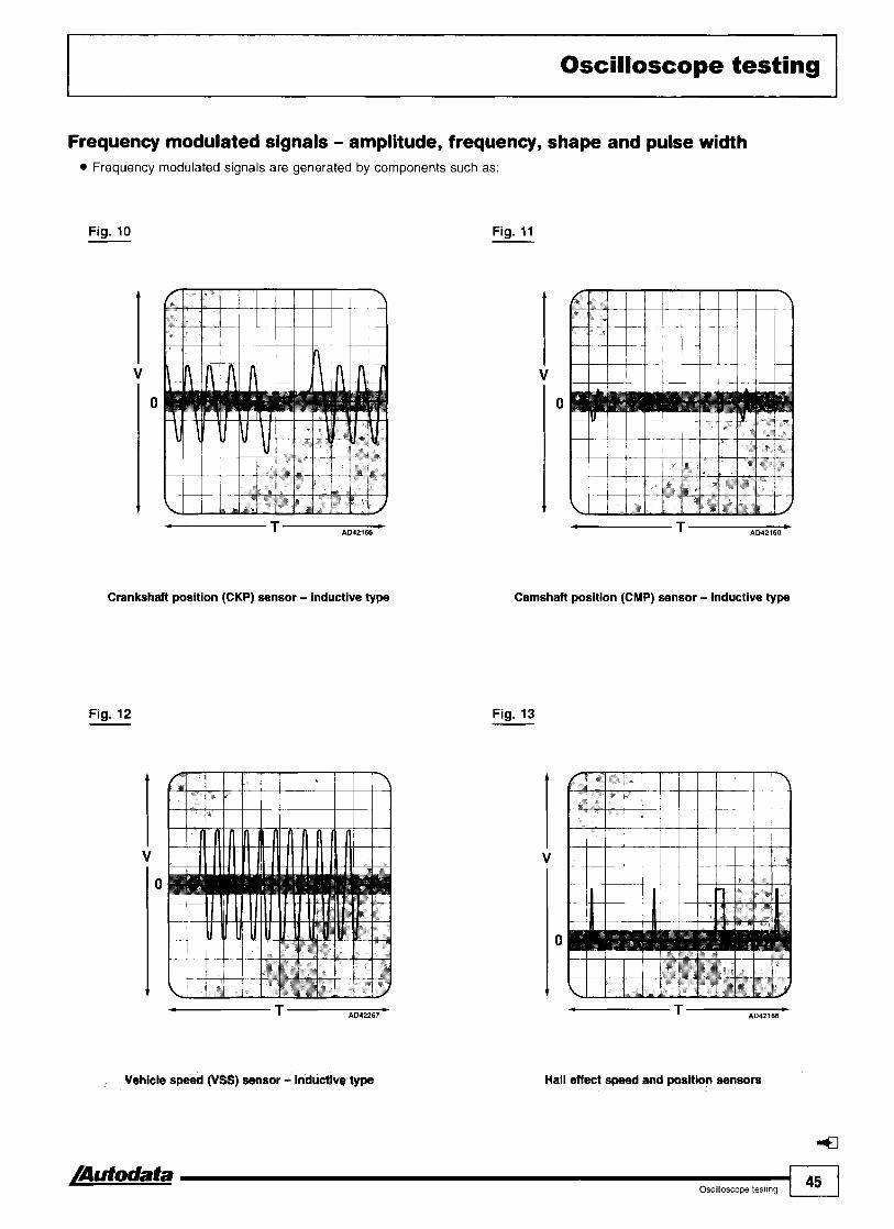
Oscilloscope testing
Frequency modulated signals - amplitude, frequency, shape and pulse width Frequency modulated signals are generated by components such as:
Fig. 10 Fig. 11
Crankshaft position (CKP) sensor - inductive type
Fig. 12
4 T b AD42267
Vehicle speed (VSS) sensor - inductive type
Camshaft position (CMP) sensor - inductive type
Fig. 13
Hall effect speed and posltlon sensors

Fig. 14 Fig. 15
Mass air flow (MAF) and manltold absolute pressure (MAP) sensors - digital type
Pulse width modulated signals - amplitude, frequency, shape, pulse width Pulse width modulated signals from components such as:
Fig. 16 Fig. 17
In- fdie ak control (IAC) devices

Oscilloscope testing I
Fig. 18
Fig. 20
Fig. 19
EvapMstive ~mlsslon (EVAP) can- purge valve
Fig. 21
Serial data - amplitude, frequency, shape, pulse width and pattern Serial data signals will be generated by the engine control module (ECM), if it has a self-diagnosis facility - Fig. 21. By noting the pulse width, pattern and frequency, the short pulses can be counted in groups and interpreted a s o u b l e code, in this case 1223. The amplitude and shape remain constant and the pattern will be repeated until the trouble code has been erased.

Oscilloscope testing -
Interpreting wave forms
Typical wave forms - F I ~ . 22 81 F I ~ . 23 -- Oscilloscope wave form patterns can vary greatly and are dependent on many factors. Therefore prior to making a diagnosis or changing components the following points should be considered when the wave form obtained does not appear to be correct when compared with the 'typical' wave form.
Fig. 22
Mgital wave t o m
Fig. 23
Voltage
Typical wave forms indicate the approximate position of the wave form in relationship to the 'zero grid', but this may vary Fig. 22 [I], dependent on the system being tested and may be positioned anywhere within the approximate 'zero range' Fig. 22 [2] & Fig. 23 [I]. T h e m p l i t u ~ v e r a l l height of the pattern (the voltage) Fig. 22 [3] & Fig. 23 [2], will depend on the circuit's operating voltage. For direct current (DC) circuits this will depend on the voltage being switched, for example, idle speed control device voltage will be constant and will not vary with engine speed. For alternating current (AC) circuits this will depend on the speed of the signal generator, for example, an inductive crankshaft position (CKP) sensor's output voltage will increase with engine speed. Therefore if the oscilloscope pattern is too high (or the upper part is missing) increase the voltage scale to obtain the view required. If the pattern is too low decrease the voltage scale. Some circuits operating solenoid components, for example idle speed control devices, may display voltage spikes Fig. 22 [4], when the circuit is switched off. This voltage is generated by the component and can normally be ignored.
- Some circuits that have a square wave type of typical wave form may display the voltage decaying at the end of the switching period Fig. 22 [5]. This is a characteristic of some systems and can normally be ignored, as it does not by itself indicate a fault. -
Frequency
The overall width of the pattern (the frequency), will depend on the circuit's operating speed. The typical wave forms illustrated show the wave form viewed with the oscilloscope's time scale set to enable detailed observation. In direct current (DC) circuits the time scale will be dependant on the speed at which the circuit is switched Fig. 22 [6], for example, the frequency of an idle speed control device will vary with engine load.
1 48 I.,,,,,,,,, /Autodata

Oscilloscope testing
In alternating current (AC) circuits the time scale will depend on the speed of the signal generator Fig. 23 [3], for example, an inductive crankshaft position (CKP) sensor's frequency will increase with engine speed.
- If the oscilloscope pattern is too compressed, decrease the time scale to obtain the view required. If the pattern is too expanded, increase the time scale. If the pattern is reversed Fig. 23 [4], this indicates that the system being tested has its component connected in the opposite polarity to the typical wave form shown and can normally be ignored as it does not by itself indicate a fault.
Component testing Wave forms for a variety of components can be displayed. A few of the more common examples are described below. Most modern oscilloscopes have just two test leads, used with a variety of interchangeable test probes. The red lead is the positive and is normally connected to the ECM pin. The black lead is the negative and is normally connected to a good earth. If the leads are inadvertently connected with the wrong polarity, usually the only consequence is that the wave form will be displayed upside down.
Injectors
Fig. 24
All electronically controlled intermittent injection systems operate by varying the opening time of the injectors to match the quantity of fuel supplied with the engine operating conditions. The duration of the electrical impulses from the control module is measured in m~lliseconds (ms) and typically ranges from 1 to 14. The oscilloscope on most engine testers can be used to display the injector pulse, enabling the duration to be measured.
4 T w AD42127
Injector wave farm
A typical oscilloscope trace is shown in Fig. 24.
A series of smaller pulses, which hold the injector open after the initial negative pulse and a sharp positive voltage spike may be displayed as the injector closes. It is therefore possible to check that the control module is operating correctly by observing the changes in injector opening times during various engine operating conditions. Pulse duration during cranking and at idle speed will be higher than at low engine speeds, but will increase as the engine speed rises, up to a maximum at full throttle. This effect will be particularly evident if the throttle is 'blipped'.
Injector pulse Using a thin probe, connect the oscilloscope test probe to the ECM injector terminal and the second test probe to earth. Crank the engine and check the wave form. Start engine and observe the wave form at idle speed. Open the throttle rapidly to increase engine speed to around 3000 rpm. The measured pulse duration should increase during acceleration and then stabilise at a reading equal to or slightly below the idle speed value. Close the throttle rapidly and the trace should become a straight line with no pulse indicating that injection has been cut-off (for systems fitted with overrun injection cut-off). When the engine is started from cold the quantity of fuel required is increased and therefore the pulse duration or dwell will be greater. During warm-up the injection period should progressively decrease until the engine reaches normal operating temperature. Systems without a cold start injector usually give additional injector pulses during the cold start, which may be seen as long and short pulses on the scope.
Typical injector duration periods
CONDITION DURATION
Idle SIJeed 1.5-5 ms
2000-3000 rpm 1 .I-3,5 ms
Full throttle 8,2-8,4 ms

Oscilloscope testing
Inductive sensors - Flg. 25
The general procedure is as follows: Select sensor pin from pin data list with wave form reference. Connect oscilloscope probe to ECM pin and second probe to earth. Start engine and observe test conditions. Compare scope trace with wave form reference. Raise the engine speed and watch for the voltage (amplitude) display to increase.
ldle air control (IAC) vaive ldle air control (IAC) valves come in many different types, each with a different wave form. In each case the duty cycle (or ON time) of the valve should increase when any additional engine load starts to reduce the idle speed. If the duty cycle varies but the idle speed is not maintained under load, this indicates a faulty valve. If the wave form shows a straight line around the zero mark, or the line is constant at the 5 V or 12 V level, this indicates a fault in the IAC valve circuit or ECM signal output. The commonly used 4 pin stepper motor type is described below. Two and three pin IAC valves can be tested in a similar way, but will of course generate very different wave forms. The stepper motor responds to an oscillating signal from the ECM, enabling small adjustments to be made to the engine idle speed, in reaction to variations of operating temperature and load. This voltage signal can be checked by connecting the oscilloscope test probe to each of the four stepper motor ECM pins in turn. Ensure engine is at normal operating temperature. Start the engine and allow idle speed to stabilise. Increase the load on the engine by switching on the headlights, air conditioning or by turning the steering (power steering only). The idle speed should momentarily drop, but then be stabilised by the action of the IAC valve. Compare scope trace with wave form reference Fig. 26.
Fig. 25 Fig. 26

Oxygen sensor (02s)
NOTE: The following voltage figures refer to the almost universally usedzirconium type O2S, without a 0,5 V control reference. A few recent models are fitted with a Titanium sensor which has an operating range of 0-5 volts and shows a high voltage signal with a weak mixture and a low voltage signal with a rich mixture.
Connect oscilloscope test probes between oxygen sensor ECM pin and earth. Ensure engine is at normal operating temperature. Compare scope trace with wave form reference Fig. 27.
If the trace shows no wave form but instead is a straight line, this usually indicates a weak mixture if the voltage is approximately 0-0,15, or a rich mixture if the voltage is approximately 0,6-1 - refer to Autodata fuel injectiontengine management manuals or CD for possible causes of this condition. If the wave form is satisfactory at idle, open the throttle briefly several times in succession. The wave form should show the signal voltage 'cycling' between approximately 0-1 Volt. The increasing voltage corresponds to the engine speed rising and the decreasing voltage corresponds to the engine speed falling.
Knock sensor (KS)
Connect oscilloscope test probes between knock sensor ECM pin and earth. Ensure engine is at normal operating temperature. Briefly snap throttle open. Wave form should display an AC signal showing a considerable increase in amplitude Fig. 28. If this signal is not distinctly displayed, tap the cylinder block lightly in the region of thesensor. If the signal is still not satisfactory this indicates a faulty sensor or associated circuit.
Fig. 27 Fig. 28

Oscilloscope testing
Ignition amplifier
Connect oscilloscope test probes between ignition amplifier ECM pin and earth. Ensure engine is at normal operating temperature. Start the engine and allow to idle. The signal should show a digital DC voltage pulse. Compare scope trace with wave form reference Fig. 29. If the signal is satisfactory the amplitude, f r e q u e n i d shape of each pulse should be closely matched. Increase the engine speed and check that the signal frequency increases in proportion to the engine rpm.
Ignition coil - primary Connect oscilloscope test probes between ignition coil ECM pin and earth. Ensure engine is at normal operating temperature. Start the engine and allow to idle. Compare scope trace with wave form reference Fig. 30.
Positive voltage spikes should be of even amplitude. Major differences of amplitude could indicate either a high resistance in the secondary circuit or a faulty spark plug or HT lead (where applicable).
Electronic control modules
Without specialist equipment and data no testing of control modules is possible, except by self-diagnosis (if applicable) or substitution. Several companies operate a repair or exchange service for control modules and some offer a diagnosis service via a modem link to an appointed agent. However it is possible to check: 0 The signal inputs. 0 The signal outputs.
The wiring.
NOTE: Refer to Autodata Pin Data manual or CDZ for engine management system signal values.
NOTE: For information regarding control module self-diagnosis refer to model-specific chapter in this manual.
Fig. 29
1 T AM2133 )
IgnMon arnplsfler wave form
Fig. 30
T L AD42123
Ignition coil wave form

Trouble codes
All the systems covered by this manual are controlled by a module which incorporates a self-diagnosis function. These control modules are capable of detecting certain faulty signals and storing them for access later. In many cases the detection of a faulty signal will cause the control module to invoke the limp-home mode, which adopts a mean signal value (programmed into the control module memory), to enable the vehicle to be driven until the fault can be diagnosed and rectified. In many early models faults are signalled by numerical trouble codes comprising two, three or four digits, which can be interpreted by reference to the code tables in this manual. Later models have EOBD codes which are mandatory on new vehicles produced after January 2000. Trouble codes on early models may be displayed by an LED on the control module, or on the fascia mounted malfunction indicator lamp (MIL). If this is not possible then an LED tester can sometimes be used at the data link connector (DLC). If access to trouble codes is possible in this manner it is described along with the relevant code table. Many later models and those that comply with EOBD regulations may require a scan tool to enable the trouble code information to be displayed. Self-diagnosis for fuel injection, mapped ignition and integrated engine management systems has been used for many years, but with the more recently introduced electronically controlled transmissions and immobilizer systems, the scope for trouble code based fault diagnosis has expanded considerably and the adoption of European On-Board Diagnostics (EOBD) has brought a degree of standardisation.
Engine management The engine control module (ECM) processes the load and temperature signals received from the system sensors and controls the fuellair ratio, idle speed, ignition timing and other functions through outputs to the actuators, such as injectors, idle speed control (1%) valve, evaporative emission (EVAP) canister purge valve etc. As emission regulations have become more stringent, more systems, such as throttle control, cruise control, transmissions and immobilizers have been linked to the ECM. The ECM self-diagnosis fault memory will log trouble codes if certain inputs or outputs are outside the programmed parameters and may invoke 'limp home' substitute values for any out-of range signals, to enable the vehicle to continue to be driven until repairs can be carried out.
Fig. 1 -
Air
n Engine control module M+ -TIl Mter
air flow
Intake-air temperature
sensor I I I I I \
Throttle Throttle- Idle speed position valve control
switch or sensor t-
valve . I
I Engine intake manifold I AD84398
Typical engine management system 4
[Autodata L Trouble codes 53

Electronically controlled transmissions Most electronically controlled transmission systems have sensors monitoring load, selector lever position, gear change strategy program, transmission output shaft speed, engine crankshaft speed, and speed of brake and throttle operation. Signals from these are sent to a combined engine and transmission (powertrain) control module or a separate transmission control module (TCM). These inputs are processed by the transmission control module (TCM) and appropriate control outputs are sent to the transmission. Where a separate engine control module (ECM) and transmission control module (TCM) are used, these are linked and data is shared between the two. The self-diagnosis fault memory will log trouble codes when certain control module inputs or outputs are outside the programmed parameters and may invoke 'limp home' substitute values for any out-of range signals. There are several types of transmission that can have electronic control with self-diagnosis trouble code output:
Automatic Semi-automatic 4 wheel drive
Automatic transmission: usually comprise a torque converter driven by the engine crankshaft and an epicyclic gearbox with four or five forward ratios. The mechanical operation of the transmission is actuated hydraulically, but with electronic controls, enabling several different change patterns to be selected by the driver (e.g. sport, economy etc.). Smoother gear changes (using torque reduction by retarding the ignition timing) and better matching of gear ratios to available torque, are also advantages. Lower powered (and often front-wheel drive) cars may be fitted with a continuously variable transmission. This may be driven via a torque converter, multi-plate clutch or magnetic coupling. In this form of transmission a steel band is driven by a variable diameter drum and the output is from a similarly variable diameter drum. It has no fixed ratios and finds its own 'ideal' ratio from the inputs of speed and load sensors. Semi-automatic transmission: these are a comparatively recent innovation and use a conventional gearbox (helical spur gears) with hydraulically operated clutch. Electronics are used to ensure smooth gear changes, prevent excessive engine speeds and to 'blip' the throttle during down changes. 4 wheel drive: vehicles with a Haldex coupling between the front and rear wheels have electronic control of the centre differential. Sensor inputs from the wheel speed sensors, stop lamp switch and other control modules (via a CAN data bus) are used to govern the power distribution between the front and rear wheels. The transmission systems covered by this manual have associated trouble codes which will be logged under certain fault conditions. These codes may be part of the engine management trouble code output (in the case of powertrain control modules) or they may be accessed separately - refer to model-specific chapters.
Fig. 2
1 Selector lever 2 Selector position switch 3 3 Mode selection switch 4 Kickdown switch 8 15 1 3 5 Throttle position (TP) sensor 6 Engine torque signal 7 Engine speed (RPM) signal 8 Output shaft speed (OSS) sensor 9 Solenoid valves
10 Transmission control module (TCM) 1 1 Engine control module (ECM) 12 Data link connector (DLC) 13 Torque converter 14 Ignition coils 15 Epicyclic gearbox

Immobilizers The immobilizer may be self-contained or integrated with the alarm system and remote control central locking, all activated from the key. The central locking will be operated separately by either an infrared or radio frequency signal and requires a self-contained battery supply. The immobilizer may also be controlled by the infraredlradio frequency signal or separately by a transponder. The transponder [I] is embedded in the ignition key [2] , and is activated by a read coil [3] in the ignition switch [4]. The read coil is connected to the immobilizer control module [5] which is linked to the engine control module (ECM) [6]. The transponder uses induced power from the read solenoid and therefore does not require a battery supply. When the ignition is switched on, the read solenoid induces a response from the transponder, which then transmits its unique security code to the immobilizer control module. The key code is compared with the stored code in the immobilizer control module and then matched with the 'rolling' code in the ECM. If all the criteria match, the engine will run normally. If the immobilizer control module does not recognise the key code the engine will either not start or only run for a few seconds. The immobilizer is automatically reset when the key is withdrawn from the ignition switch. Many immobilizer systems feature fault memories which can be accessed in various ways e.g. by counting the immobilizer warning lamp flashes, bridging data link connector (DLC) terminals with a voltmeter or LED tester, or using suitable diagnostic equipment - refer to model-specific chapters.
Fig. 3
1 Transponder 2 Key 3 Read coil 4 Ignition switch 5 Immobilizer control module 6 Engine control module (ECM) 7 Data link connector (DLC)
Trouble code format Prior to 2000 there was no uniformity in the display, format or method of retrieval of diagnostic trouble codes, each vehicle manufacturer developing a dedicated system with special diagnostic equipment and varying amounts of data logging. Some systems having just a few one or two digit codes while others had more comprehensive three and four digit coding systems. In many cases the codes for these early systems could be displayed by connecting an LED tester between the appropriate terminals of the data link connector (DLC) and counting the flashes or groups of flashes. For example Fig. shows a diagrammatic representation of three LED (or MIL) flashes. The vertical scale represents voltage and the horizontal scale represents time, therefore the shaded areas represent the 'on' time and the gaps in between represent the 'off' time. The three short flashes, with a short pause separating each flash, display trouble code 3. If more than one code has been logged, a long pause would be used to separate each code.
Fig. 4
Trouble codes &I

Trouble codes
If the trouble code is greater than 9, long flashes are used for the tens and short flashes for the units. For example Fig. 5 shows one long flash, and two short flashes - Fig. 5 separated by a short pause, indicating trouble code 12. In 1988 the California Air Resources Board (CARB) introduced legislation covering all new cars sold in California. These new laws governed on-board diagnostic 1 2 requirements for emissions related faults and began the -- process of standardization in the US and eventually Europe. These regulations were known as onboard diagnostic systems - phase I (OBD-I) and were subsequently adopted by the vehicle manufacturers, for states other than California. The basic requirements of OBD-l were as follows: A043243
A malfunction indicator lamp (MIL), to provide a visible warning that an emissions related fault had been logged by the engine control module (ECM). Provision for the logging and storage, for subsequent retrieval, of diagnostic trouble codes (DTC)/flash codes for emissions related faults. The location of the diagnostic socket, the method of access to the trouble codes and the configuration and scope of the self-diagnosis was left to individual vehicle manufacturers. This resulted in an almost complete lack of standardization, requiring the technician to adopt different procedures and to use different equipment for each vehicle. In 1995 the California Air Resources Board (CARB), after consultation with the Society of Automotive Engineers (SAE), introduced further legislation covering all new cars sold in California. These regulations are known as OBD-ll and have been adopted for all states. They closely define trouble code logging and retrieval. More significantly they require monitoring of the operation of the system and components, in addition to detecting component failures. OBD-ll also covers systems other than engine management. Basically the US OBD-II regulations have been adopted for European vehicles and are known as EOBD - European On Board Diagnostics. These EOBD regulations became mandatory for most new petrol engined vehicles produced after January 1 st 2000 (diesel and LPG engined cars were not required to comply until 2003). Most petrol engined vehicles already in production before January 1 st 2000 were granted exemption until January 1 st 2001.
EOBD codes
Basic requirements
Malfunction indicator lamp (MIL) located on the instrument panel, which either flashes or illuminates continuously, when a fault is detected. If no fault is present the MIL
Fig. 6 - should illuminate when the ignition is switched on and extinguish when the engine starts. Standard configuration of 16 pin data link connector (DLC) The 16 pins of the DLC are arranged in two parallel rows, 1 - 1 - 1 1 1 1
with certain pin connections defined by the EOBD regulations and the rest allocated by the vehicle 10
manufacturer - A081444
Standard location for the DLC
The standard location for the DLC is defined as being between the driver's end of the instrument panel and 300 mm beyond the vehicle centre line, accessible from the driver's seat. The recommended location is between the steering column and the vehicle centre line.
1 56 1 Trouble codes /nutodata

Trouble codes I Format of EOBD codes Standard, 5 element alpha-numeric format, trouble codes, made up as follows:
Letter prefix defines system designation
B
C
First digit defines code type
Body
Chassis
P
U
I 0 ( Standard EOBD I
Powertrain
Network communications systems
( 1 I Defined by vehicle manufacturer I
Second digit defines system identification
2
3
/ 0 1 Standard code (refer to PO code list) I
Standard EOBD
Standard EOBDIdefined by vehicle manufacturer
/ 1 1 Fuel or air I ( 2 1 Fuel or air I 1 3 1 Ignition I 1 4 1 Emission control I 1 5 1 Speed control (idle, vehicle etc.) 1 1 6 1 Trip computer 1
1 9 1 Transmission I
7
8
Third and fourth digits define specific fault
Transmission
Transmission
These digits define general malfunction, range or performance of component or system, low or high input
Example code POl08 This code is logged when a high input is detected in the pressure circuit of the manifold absolute pressure (MAP) sensor or barometric pressure (BARO) sensor
I P 1 System - Powertrain I Code type - EOBD
System identification (fuel or air) - manifold absolute pressure (MAP) sensorlbarometric pressure (BARO) sensor
Pressure circuit
NOTE: Emissions related problems have a IS0 defined list of codes and definitions starting with P0001.
8 High input I

Trouble codes
Standard areas monitored:
The following areas are monitored continuously: Misfire detection Fuel system performance Component performance
The following areas are monitored once per 'trip'
NOTE: The definition of a 'trip' varies, but is basically - key ON, vehicle driven, key OFF.
Catalytic converter Evaporative emission system Secondary air (AIR) system Air conditioning system Heated oxygen sensor (H02S) Oxygen sensor (02s) heater Exhaust gas recirculation (EGR) system In cases where flash codes and EOBD codes are listed for the same model range, only one flash code will be generated for a particular component, but there may be a list of many EOBD codes related to this component. Alternatively there may be some EOBD codes with no equivalent flash code(s). These EOBD codes will provide more specific details about the fault location, wiring, voltage signals and other information relative to the circuit or system.
Logging faults with EOBD
Fault logging is based on inputs received during each 'trip' which may comprise a number of 'drive cycles'. Each 'drive cycle' is initiated when the engine is started and is terminated when the engine is switched off. For a complete 'trip' to be completed the following, complex, conditions need to be met (and may take several 'drive cycles' to complete):
Before starting the engine, coolant temperature should be below 50°C and +/-6°C of ambient temperature.
This ensures that the ECM logs a cold start. n Allow engine to idle for 2-3 minutes with an
electrical load switched on (such as headlamps or heated rear window).
This will ensure that the misfire monitoring and fuel trim monitoring programmes run.
Drive vehicle up to at least 50 mph and maintain this speed for at least 3 minutes.
Misfire and fuel trim monitoring will run. Allow the speed to reduce to around 20 mph without changing gear, using the brakes or the clutch.
Fuel trim monitoring will run. Accelerate to at least 50 mph and maintain for at least 5 minutes.
Misfire and fuel trim monitoring will run. n Allow the speed to reduce to around 20 mph
without changing gear, using the brakes or the clutch.
Fuel trim monitoring will run.
Each 'trip' starts when the engine is started and continues through a number of 'drive cycles' until all the EOBD monitors have completed a self-test. The EOBD monitoring programme provides operating tolerance checks on all emissions related sensors and actuators. Some components/circuits are continuously monitored and some are only activated under predetermined operating conditions. Misfire monitoring detects irregularities in the crankshaft position (CKP) sensor signal pattern and identifies which cylinder misfired and if the misfire is frequent enough to cause catalytic converter damage due to excess internal temperatures. If this is the case the MIL will flash. If the misfire is likely to increase emissions above the EOBD limits and occurs on each of two consecutive 'trips' the MIL will flash. If the misfire is absent during the next three 'trips' the MIL will be extinguished. When a fault code is logged a number of data parameters are stored with it, to assist in accurate fault diagnosis. These are: n Vehicle speed
Engine coolant temperature Engine rpm
cj Engine load Oxygen sensor system status - open/closed loop Distance since fault first logged Long term fuel trim (LTFT) level
Most EOBD scan tools are capable of capturing this 'snapshot' of data and displaying (or printing) it for analysis to aid the fault diagnosis process.
After rectification EOBD monitoring is very sensitive and replacement components may still be identified as faulty if their specifications do not exactly match the originals. The trouble code memory must be completely erased and a 'trip' completed. The trouble code memory should be accessed to establish that no further codes have been logged.

All EOBD codes starting with P zero have standard meanings irrespective of vehicle make or model. For EOBD codes, other than those starting P zero, refer to model-specific chapters. The following list covers all PO codes allocated at the time of publication.
code
PO000
PO001
PO002
PO003
I I
PO005 ( Fuel shut-off valve - circuit open 1 Wiring open circuit, fuel shut-off valve
I
Faun location
No fault found
Fuel volume regulator control - circuit open
Fuel volume regulator control - circuit rangelperforrnance
Fuel volume regulator control - circuit low
PO004
I I
PO008 I Engine position system, bank 1 - engine performance I Mechanical fault
Probable cause
-
Wiring, regulator control solenoid
Wiring, regulator control solenoid
Wiring short to earth, regulator control solenoid
PO006
PO007
Fuel volume regulator control - circuit high Wiring open circuitlshort to positive, regulator control solenoid
Fuel shut-off vatve - circuit low
Fuel shut-off valve - circuit high
PO009
PO010
PO01 1
Wiring short to earth, fuel shut-off valve
Wiring short to positive, fuel shut-off valve
- 1
I Crankshaft positionlcamshaft position, bank 1 sensor B - Wiring, CKP sensor, CMP sensor, mechanical fault correlation
Engine position system, bank 2 - engine performance
Camshaft position (CMP) actuator, intakelleftlfront, bank 1 - circuit malfunction Camshaft position (CMP), intakelleftlfront, bank 1 - timing over-advancedlsystem performance
PO012
PO013
PO014
PO015
PO016
I Crankshaft positionlcarnshaft position, bank 2 sensor A - Wiring, CKP sensor, CMP sensor, mechanical fault correlation I
Mechanical fault
Wiring, CMP actuator, ECM
Valve timing, engine mechanical fault, CMP actuator
Camshaft position (CMP), intakelleftlfront, bank 1 - timing over-retarded
Camshaft position (CMP) actuator, intakelleftlfront, bank 1 - circuit malfunction
Camshaft position (CMP) actuator, exhaustlrighurear, bank 1 - timing over-advancedlsystem performance Camshaft position (CMP) actuator, exhaustlrightlrear, bank 1 - timing over-retarded
Crankshaft position/camshaft position, bank 1 sensor A - correlation
Valve timing, engine mechanical fault, CMP actuator
Wiring, CMP actuator, ECM
Valve timing, engine mechanical fault, CMP actuator
Valve timing, engine mechanical fault, CMP actuator
Wiring, CKP sensor, CMP sensor, mechanical fault
PO019
PO020
PO021
PO022
PO023
I " I
PO025 ) Camshaft position (CMP), exhaustlrightlrear, bank 2 - I Valve timing, engine mechanical fault, CMP actuator
Crankshaft positionlcamshaft position, bank 2 sensor B - corretation
Camshaft position (CMP) actuator, intakelleftffront, bank 2 - circuit malfunction
Camshaft position (CMP), intakeIlefVfront, bank 2 - timing over-advancedlsystem performance Camshaft position (CMP), intakelleftlfront, bank 2 - timing over-retarded
I 1
Wiring, CKP sensor, CMP sensor, mechanical fault
Wiring, CMP actuator, ECM
Valve timing, engine mechanical fault, CMP actuator
Valve timing, engine mechanical fault, CMP actuator
Camshaft position (CMP) actuator, exhaustlrightlrear, bank 2 - circuit malfunction
PO024
Wiring, CMP actuator, ECM
PO026
PO027
Camshaft position (CMP), exhaustlrightlrear, bank 2 - timina over-advancedlsvstem wrformance
Valve timing, engine mechanical fault, CMP actuator
timing over-retarded tntake valve controt solenoid circuit, bank 1 - rangelperformance
Exhaust vatve control solenoid circuit, bank 1 - range/performance
Wiring, intake valve control solenoid
Wiring, exhaust valve control solenoid

EOBD trouble code table
TrOUbIe / FauR kcation code Probable cause
I Intake valve control solenoid circuit, bank 2 - ranae/performance
Wiring, intake valve control solenoid
I Exhaust valve control solenoid circuit, bank 2 - ranael~erformance
Wiring, exhaust valve control solenoid
Heated oxygen sensor (H02S) 1, bank 1, heater control - circuit malfunction
Heated oxygen sensor (H02S) 1, bank 1, heater control - circuit low
Heated oxygen sensor (H02S) 1, bank 1, heater control - circuit high
Wiring, H02S, ECM
Wiring short to earth, H02S, ECM
Wiring short to positive, H02S, ECM
Turbocharger (TC) wastegate regulating valve - circuit malfunction I Turbocharger (TC) wastegate regulating valve - circuit low
circuit low
PO038 Heated oxygen sensor (H02S) 2, bank 1, heater control - circuit hiah
sensor 1
sensor 2
PO042 Heated oxygen sensor (H02S) 3, bank 1, heater control - circuit malfunction
Wiring, TC wastegate regulating valve, ECM
Wiring short to earth, TC wastegate regulating valve, ECM
Wiring short to positive, TC wastegate regulating valve, ECM
Wiring, H02S, ECM
Wiring short to earth, H02S, ECM
Wiring short to positive, H02S, ECM
Wiring, bypass valve
Wiring
Wiring
Wiring, H02S, ECM
I Heated oxygen sensor (H02S) 3, bank 1, heater control - circuit low
Wiring short to earth, H02S, ECM
PO044 Heated oxygen sensor (H02S) 3, bank 1, heater control - circuit high
PO045 Turbolsuper charger boost control solenoid - circuit open
Wiring short to positive, H02S, ECM
Wiring, boost control solenoid
I Turbolsuper charger boost control solenoid - circuit ranael~erformance
Wiring, boost control solenoid, mechanical fault
PO047 I Turbolsuper charger boost control solenoid - circuit low Wiring short to earth, boost control solenoid
PO048 I Turbolsuper charger boost control solenoid - circuit high
PO049 Turbolsuper charger turbine - over-speed
PO050 Heated oxygen sensor (H02S) I , bank 2, heater control - circuit malfunction
PO051 Heated oxygen sensor (H02S) 1, bank 2, heater control - circuit low
PO052 Heated oxygen sensor (H02S) 1, bank 2, heater control - circuit hiah
Wiring short to positive, boost control solenoid
Mechanical fault
Wiring, H02S, ECM
Wiring short to earth, H02S, ECM
Wiring short to positive, H02S, ECM
PO053 Heated oxygen sensor (H02S), bank 1, sensor 1 - heater resistance
PO054 Heated oxygen sensor (H02S), bank 1, sensor 2 - heater resistance
PO055 Heated oxygen sensor (H02S), bank 1, sensor 3 - heater resistance
PO056 Heated oxygen sensor (H02S) 2, bank 2, heater control - c~rcuit malfunction
Wiring, H02S
Wiring, H02S
Wiring, H02S
Wiring, H02S, ECM

EOBD trouble code table
PO057
PO058
PO059
PO061 Heated oxygen sensor (H02S), bank 2, sensor 3 -heater Wiring, H02S I resistance
PO060
Fault location
Heated oxygen sensor (H02S) 2, bank 2, heater control - heater circuit low
Heated oxygen sensor (H02S) 2, bank 2, heater control - circuit high
Heated oxygen sensor (H02S), bank 2, sensor 1 - heater resistance
Probable cause
Wiring short to earth, H02S, ECM
Wiring short to positive, H02S, ECM
Wiring, H02S
Heated oxygen sensor (H02S), bank 2, sensor 2 - heater resistance
PO062
PO063
PO064
PO065
PO066
Wiring, H02S
PO067
PO068
PO070 I Outside air temperature sensor - circuit malfunction I Wiring, outside air temperature sensor, ECM
Heated oxygen sensor (H02S) 3, bank 2, heater control - circuit malfunction
Heated oxygen sensor (H02S) 3, bank 2, heater control - circuit low
Heated oxygen sensor (H02S) 3, bank 2, heater control - circuit high
Air assisted injector - rangelperformance problem
Air assisted injector - circuit malfunction/circuit low
PO069
-
Wiring, H02S, ECM
Wiring short to earth, H02S, ECM
Wiring short to positive, H02S, ECM
Air assisted injector
Wiring short to earth, air assisted injector, ECM
Air assisted injector - circuit high
Manifold absolute pressure (MAP) sensorlmass air flow (MAF) sensorlthrottle position correlation
I Outside air temperature sensor - low input
Wiring short to positive, air assisted injector, ECM
Wiring, MAP sensor, MAF sensor, mechanical fault
Manifold absolute pressure (MAP) sensor1barometric pressure (BARO) sensor correlation
PO071
Wiring short to earth, outside air temperature sensor, 1 ECM
MAP sensor, mechanical fault
Outside air temperature sensor - rangelperformance problem
I Intake valve control solenoid, bank 1 - circuit low Wiring short to earth, intake valve control solenoid, 1 ECM
Outside air temperature sensor
PO073
PO074
PO075
I lntake valve control solenoid, bank 1 - circuit high
Outside air temperature sensor - high input
Outside air temperature sensor - circuit intermittent
lntake valve control solenoid, bank 1 - circuit malfunction
Wiring short to positive, intake valve control solenoid, ECM Wiring, exhaust valve control solenoid, ECM
Wiring short to positive, outside air temperature sensor, ECM Wiring, poor connection, outside air temperature sensor, ECM
Wiring, intake valve control solenoid, ECM
PO078
PO079 Wiring short to earth, exhaust valve control solenoid, ECM
Exhaust valve control solenoid, bank 1 - circuit malfunction
Exhaust valve control solenoid, bank 1 - circuit low
I Intake valve control solenoid, bank 2 - circuit high Wiring short to positive, intake valve control solenoid, 1 ECM
Wiring short to positive, exhaust valve control solenoid, ECM
PO080
PO081
PO082
1 Exhaust valve control solenoid, bank 2 - circuit I Wiring, exhaust valve control solenoid, ECM malfunction
Exhaust valve control solenoid, bank 1 - circuit high
I
Wiring short to earth, exhaust valve control solenoid, ECM
Wiring short to positive, exhaust valve control solenoid, ECM
lntake valve control solenoid, bank 2 - circuit malfunction
Intake valve control solenoid, bank 2 - circuit low
PO085
PO086
Wiring, intake valve control solenoid, ECM
Wiring short to earth, intake valve control solenoid, ECM
Exhaust valve control solenoid, bank 2 - circuit low
Exhaust valve control solenoid, bank 2 - circuit high

Trouble code
PO087
Probable cause
Fuel pressure regulator - performance problem Fuel pressure regulator, mechanical fault
Fuel metering sdenoid - open circuit Wiring open circuit, fuel metering solenoid, ECM
Fuel metering solenoid - short to earth Wiring short to earth, fuel metering solenoid, ECM
Fuel metering solenoid - short to positive I Wirina short to positive, fuel meterina solenoid, ECM Fuel system leak - large leak detected Wiring, fuel pressure sensor, mechanical fault
Fuel system leak - small leak detected Wiring, fuel pressure sensor, mechanical fault
Intake air temperature (IAT) sensor 2 - circuit malfunction Wiring, poor connection, IAT sensor, ECM
Intake air temperature (IAT) sensor 2 - Wiring, poor connection, IAT sensor, ECM circuit rangelperformance Intake air temperature (IAT) sensor 2 - circuit low input Wiring short to earth, IAT sensor, ECM
Intake air temperature (1AT) sensor 2 - circuit high input Wiring short to positive, IAT sensor, ECM
Intake air temperature (IAT) sensor 2 - Wiring, poor connection, IAT sensor, ECM circuit intermittederratic Mass air flow (MAF) sensorfvolume air flow (VAF) Wiring, MAFNAF sensor, ECM sensor - circuit malfunction
Mass air flow (MAF) sensorlvolume air flow (VAF) Intake leaklblockage, MAFNAF sensor sensor - rangelperformance problem Mass air flow (MAF) sensorlvolume air flow (VAF) Wiring short to earth, MAFNAF sensor, ECM sensor - low input Mass air flow (MAF) sensorlvolume air flow (VAF) Wiring short to positive, MAFNAF sensor, ECM sensor - high input Mass air flow (MAF) sensorlvolume air flow (VAF) Wiring, poor connection, MAFNAF sensor, ECM sensor - circuit intermittent Manifold absolute pressure (MAP) sensorlbarometric Wiring, MAP sensor, BAR0 sensor, ECM pressure (BARO) sensor - circuit malfunction Manifold absolute pressure (MAP) sensor/barometric lntakelexhaust leak, wiring, MAP sensor, pressure (BARO) sensor - range/performance problem BAR0 sensor - Manifold absolute pressure (MAP) sensor/barometric Wiring short to earth, MAP sensor, BAR0 sensor, pressure (BARO) sensor - low input ECM
I
Manifold absolute pressure (MAP) sensor/barometric Wiring short to positive, MAP sensor, BAR0 sensor, pressure (BARO) sensor - hiah input ECM Manifold absolute pressure (MAP) sensorlbarometric Wiring, poor connection, MAP sensor, BAR0 sensor, pressure (BARO) sensor - circuit intermittent ECM Intake air temperature (IAT) sensor - circuit malfunction Wiring, IAT sensor, ECM
Intake air temperature (IAT) sensor - rangelperformance IAT sensor problem Intake air temperature (IAT) sensor - low input Wiring short to earth, IAT sensor, ECM
1
Intake air temperature (IAT) sensor - high input Wiring open circuitlshort to positive, earth wire defective, IAT sensor, ECM
lntake air temperature (IAT) sensor - circuit intermittent 1 Wiring, poor connection, IAT sensor, ECM I
Engine coolant temperature (ECT) sensor - Wiring, ECT sensor, ECM circuit malfunction Engine coolant temperature (ECT) sensor - Coolant thermostat, poor connection, wiring, ranaelperformance problem ECT sensor Engine coolant temperature (ECT) sensor - low input Coolant thermostat, wiring short to earth, ECT sensor
Engine coolant temperature (ECT) sensor - high input Coolant thermostat, wiring open circuitlshort to positive, earth wire defective, ECT sensor

EOBD trouble code table
Trouble code Fault location Probable cause
Wiring, poor connection, ECT sensor, ECM Engine coolant temperature (ECT) sensor - circuit intermittent
I
PO1 20 Throttle position (TP) sensor Akxcelerator pedal position (APP) sensor A - circuit malfunction
Wiring, TPIAPP sensor, ECM . ,
I Throttle msition (TP) switch Naccelerator pedal msition Wiring, TPIAPP switch, ECM
Accelerator cable adjustment, TPIAPP sensor
I IAPP) switch A -circuit malfunction . ,
PO121 I Throttle position (TP) sensor Naccelerator pedal position (APP) sensor A - rangelperformance problem Throttle position (TP) switch Nacceferator pedal position (APP) switch A - rangelperformance problem
Accelerator cable adjustment, TPIAPP switch
I Throttle position (TP) sensor Naccelerator pedal position Wiring short to earth, TPIAPP sensor, ECM I (APP) sensor A - low input Throttle position (TP) switch Naccelerator pedal position Wiring short to earth, TPIAPP switch, ECM (APP) switch A - low input
Insufficient coolant temperature for closed loop fuet control Wiring, cooling system, coolant thermostat, I ECT sensor
Throttle position (TP) sensor Naccelerator pedal position (APP) sensor A - high input Throttle position (TP) switch Naccelerator pedal position (APP) switch A - high input
Throttle position (TP) sensor Naccelerator pedal position (APP) sensor A - circuit intermittent
Throttle position (TP) switch Naccelerator pedal position (APP) switch A - circuit intermittent
Insufficient coolant temperature for stable operation Wiring, cooling system, coolant thermostat, ECT sensor
Wiring short to positive, TP/APP sensor, ECM
Wiring short to positive, TPIAPP switch, ECM
Wiring, poor connection, TPIAPP sensor, ECM
Wiring, poor connection, TPIAPP switch, ECM
Intake air temperature too high
Coolant thermostat - coolant temperature below thermostat regulating temperature
Barometric pressure too low
Wiring short to earth, IAT sensor 2, mechanical fault, ECM Mechanical fault
Wiring, BAR0 sensor, mechanical fault
Heated oxygen sensor (H02S) 1, bank 1 - circuit malfunction
Oxygen sensor (02s) 1, bank 1 - circuit malfunction
PO132 I Heated oxygen sensor (H02S) 1, bank 1 - high voltage I Wiring short to positive, H02S, ECM
Heating inoperative, poor connection, wiring, H02S
Wiring, 02S, ECM
PO131
Heated oxygen sensor (H02S) 1, bank 1 - no activity Wiring open circuit, heating inoperative, H02S detected
Heated oxygen sensor (H02S) 1, bank 1 - low voltage
Oxygen sensor (02s) 1, bank 1 - low voltage
PO133
Exhaust leak, wiring short to earth, H02S, ECM
Exhaust leak, wiring short to earth, 02S, ECM
Heated oxygen sensor (H02S) 2, bank 1 - circuit malfunction
Oxygen sensor (02s) 1, bank 1 - high voltage
Heated oxygen sensor (H02S) 1, bank 1 -slow response
Oxygen sensor (02s) 1, bank 1 - slow response
PO135
Heating inoperative, wiring, H02S, ECM
Wiring short to positive, 02S, ECM
Heating inoperative, wiring, H02S
Wiring, 0 2 s
Oxygen sensor (02s) 1, bank 1 - no activity detected
Heated oxygen sensor (H02S) 1, bank 1, heater control - circuit malfunction
Wiring, 0 2 s
Fuse, wiring, H02S, ECM
PO137
PO138
Oxygen sensor (02s) 2, bank 1 - circuit malfunction
Heated oxygen sensor (H02S) 2, bank 1 - low voltage
Oxygen sensor (02s) 2, bank 1 - low voltage
Wiring, 02S, ECM
Exhaust leak, wiring short to earth, H02S, ECM
Exhaust leak, wiring short to earth, 02S, ECM
Heated oxygen sensor (H02S) 2, bank 1 - high voltage
Oxygen sensor (02s) 2, bank 1 - high voltage
Wiring short to positive, H02S, ECM
Wiring short to positive, 02S, ECM

EOBD trouble code table J
Trouble I code I Probable cause
PO144 ( Heated oxywn sensor (HO2S) 3, bank 1 -hi& voltaw I Wiring short to positive, H02S, ECM
PO145
PO146
Oxygen sensor (02s) 3, bank 1 - high voltage
Heated oxygen sensor (H02S) 3, bank 1 -slow response
PO1 47
Wiring short to positive, 02S, ECM
Heating inoperative, wiring, H02S
Oxygan sensor (02s) 3, bank 1 - slow response
Heated oxygen sensor (H02S) 3, bank 1 - no activity detected
PO1 48
PO149
Wiring, 02s
Wiring, H02S, ECM
Oxygen sensor (025) 3, bank 1 - no activity detected
Heated oxygen sensor (H02S) 3, bank 1, heater control - circuit malfunction
PO1 50
I Oxygen sensor (02s) 1, bank 2 - high voltage I Wiring short to positive, 02S, ECM
Wiring, 02S, ECM
Wiring, H02S, ECM
Fuel delivery error
Fuel timing error
PO151
PO152
Fuel pumplfuel injection pump
Fuel pumplfuel injection pump
Heated oxygen sensor (H02S) 1, bank 2 - circuit malunction Oxygen sensor (02s) 1, bank 2 - circuit malfunction
Wiring, H02S, ECM
Wiring, 02S, ECM
Heated oxygen sensor (H02S) 1, bank 2 - low voltage
Oxygen sensor (02s) 1, bank 2 - low voltage
Heated oxygen sensor (H02S) 1, bank 2 - high voltage
PO153
I Oxygen sensor (02s) 1, bank 2 - no activity detected I Wiring, 02S, ECM
Exhaust leak, wiring short to earth, H02S, ECM
Exhaust leak, wiring short to earth, 02S, ECM
Wiring short to positive, H02S, ECM
I I
Heated oxygen sensor (H02S) 1, bank 2 - slow response
Oxygen sensor (02s) 1, bank 2 - slow response
PO154
Heating inoperative, wiring, H02S
Wiring, 0 2 s
I
Oxygen sensor (02s) 2, bank 2 -circuit malfunction I Wiring, 02S, ECM
Heated oxygen sensor (H02S) 1, bank 2 - no activity detected
Wiring, H02S, ECM PO155
I I
Wiring, H02S, ECM
Heated oxygen sensor (H02S) 1, bank 2, heater control - circuit malfunction
PO156
Heated oxygen sensor (H02S) 2, bank 2 - low voltage
Oxygen sensor (025) 2, bank 2 - low voltage
Heated oxygen sensor (hQ2S) 2, bank 2 - high voftage
Heated oxygen sensor (H02S) 2, bank 2 - circuit malfunction
Exhaust leak, wiring short to earth, H02S, ECM
Exhaust leak, wiring short to earth, 02S, ECM
Wiring short to positive, H02S, ECM
Oxygen sensor (02s) 2, bank 2 - high voltage
Heated oxygen sensor (H02S) 2, bank 2 -slow response
Oxygen sensor (02s) 2, bank 2 - slow response
Heating inoperative, wiring, H02S, ECM
Wiring short to positive, 02S, ECM
Heating inoperative, wiring, H02S
Wiring, 0 2 s
Heated oxygen sensor (H02S) 2, bank 2 - no activity detected Oxygen sensor (02s) 2, bank 2 - no activity detected
Wiring, H02S, ECM
Wiring, 02S, ECM

EOBD trouble code table I :;:Ie 1 Fautt Iocatiom
PO161 Heated oxygen sensor (H02S) 2, bank 2, heater control - circuit malfunction
PO162 Heated oxygen sensor (H02S) 3, bank 2 - circuit malfunction
Probable cause
Wiring, H02S, ECM
Wiring, H02S, ECM
Oxygen sensor (02s) 3, bank 2 - circuit malfunction
PO163 Heated oxygen sensor (H02S) 3, bank 2 - low voltage
Oxygen sensor (02s) 3, bank 2 - low voltage
Wiring, 02S, ECM
Exhaust leak, wiring short to earth, H02S, ECM
Exhaust leak, wiring short to earth, 02S, ECM
PO164 I Heated oxygen sensor (H02S) 3, bank 2 - high voltage Wiring short to positive, H02S, ECM
Oxygen sensor (02s) 3, bank 2 - high voltage
PO165 Heated oxygen sensor (H02S) 3, bank 2 - slow response
Wiring short to positive, 02S, ECM
Heating inoperative, wiring, H02S
Oxygen sensor (02s) 3, bank 2 - slow response
PO166 Heated oxygen sensor (H02S) 3, bank 2 - no activity detected
Wiring, 0 2 s
Wiring, H02S, ECM
Oxygen sensor (02s) 3, bank 2 - no activity detected
PO167 Heated oxygen sensor (H02S) 3, bank 2, heater control - circuit malfunction
Wiring, 02S, ECM
Wiring, H02S, ECM
PO168 Fuel temperature too high
PO1 69 Incorrect fuel composition I
PO170 Fuel trim (FT), bank 1 - malfunction
PO171 System too lean, bank 1
I
PO172 System too rich, bank 1
PO173 Fuel trim (FT), bank 2 - malfunction
Wiring, fuel temperature sensor, mechanical fault
Wiring, fuel composition sensor, mechanical fault
lntake leak, AIR system, fuel pressurelpump, iniectorlsl. EVAP canister Durae valve. H02S . ,, . - Intakelexhaust leak. AIR svstem. MAFNAF sensor. fuel pressure/pum~, injectbr(s), H O ~ S
lntake blocked, EVAP canister purge valve, fuel pressure, EGR system, injector(s), H02S
lntake leak, AIR system, fuel pressurelpump, iniector(s), EVAP canister purge valve, H02S
I System too lean, bank 2 Intakelexhaust leak, fuel pressurelpump, injector(s), AIR svstem, hose connection(s~
PO175 I System too rich, bank 2
PO176 I Fuel composition sensor - circuit malfunction
lntake blocked, EVAP canister purge valve, fuel Dressure. EGR svstem, iniectortsl. H02S . . , .. Wiring, fuel composition sensor, ECM
PO177 Fuel composition sensor - rangelperformance problem
PO178 Fuel composition sensor - low input
PO179 Fuel composition sensor - high input
PO180 Fuel temperature sensor A - circuit malfunction
PO181 Fuel temperature sensor A - rangelperformance problem
PO182 Fuel temperature sensor A - low input
PO183 Fuel temperature sensor A - high input
PO184 Fuel temperature sensor A - circuit intermittent
PO185 Fuel temperature sensor B - circuit malfunction
PO186 Fuel temperature sensor B - rangelperformance problem
Fuel composition sensor
Wiring short to earth, fuel composition sensor, ECM
Wiring short topositive, fuel composition sensor, ECM
Wiring, fuel temperature sensor, ECM
Fuel temperature sensor
Wiring short to earth, fuel temperature sensor, ECM
Wiring short to positive, fuel temperature sensor, ECM
wiring, poor connection: fuel temperature sensor, ECM
Wiring, fuel temperature sensor, ECM
Fuel temperature sensor
PO187 Fuel temperature sensor B - low input
PO188 Fuel temperature sensor B - high input
Wiring short to earth, fuel temperature sensor, ECM
Wiring short to positive, fuel temperature sensor, ECM
I Fuel temperature sensor B - circuit intermittent
I
PO190 I Fuel rail pressure (FRP) sensor - circuit malfunction
Wiring, poor connection, fuel temperature sensor, ECM
Wiring, fuel rail pressure sensor, ECM
PO191 Fuel rail pressure (FRP) sensor - rangelperformance problem
Wiring, FRP sensor
[Autodata EOBD trouble code table 1 65 1

EOBD trouble code table
Trouble code Fault location Probable cause
Fuel rail pressure (FRP) sensor - low input
Fuel rail pressure (FRP) sensor - high input
Wiring short to earth, FRP sensor
Wiring short to positive, FRP sensor
Wiring, poor connection, FRP sensor Fuel rail pressure (FRP) sensor - circuit intermittent
Engine oil temperature (EOT) sensor - circuit malfunction Wiring, EOT sensor, ECM
EOT sensor Engine oil temperature (EOT) sensor - rangelperformance problem
Engine oil temperature (EOT) sensor - low input Wiring short to earth, EOT sensor
Wiring short to positive, EOT sensor Engine oil temperature (EOT) sensor - high input
Engine oil temperature (EOT) sensor - circuit intermittent Wiring, poor connection, EOT sensor, ECM
lnjector - circuit malfunction
lnjector 1 - circuit malfunction
Wiring, injector, ECM - ~
Wiring, injector, ECM
Wiring, injector, ECM lnjector 2 - circuit malfunction
lnjector 3 - circuit malfunction
lnjector 4 - circuit malfunction
Wiring, injector, ECM
Wiring, injector, ECM
lnjector 5 - circuit malfunction Wiring, injector, ECM
lnjector 6 - circuit malfunction Wiring, injector, ECM
Wiring, injector, ECM
Wiring, injector, ECM
lnjector 7 - circuit malfunction
lnjector 8 - circuit malfunction
lnjector 9 - circuit malfunction Wiring, injector, ECM
Wiring, injector, ECM
Wiring, injector, ECM
lnjector 10 - circuit malfunction
lnjector 11 - circuit malfunction
lnjector 12 - circuit malfunction Wiring, injector, ECM
Cold start injector 1 - circuit malfunction
Cold start injector 2 - circuit malfunction
Wiring, cold start injector, ECM
Wiring, cold start injector, ECM
Fuel shut-off solenoid - circuit malfunction Wiring, fuel shut-off solenoid, ECM
Fuel injection timing control - circuit malfunction
Engine over temperature condition
Transmission over temperature condition
Wiring, fuel injection timing control solenoid, ECM
Wiring, cooling system, coolant thermostat, ECT sensor
Wiring, TFT sensor, ECM
Engine over speed condition
Throttle position (TP) sensor Btaccelerator pedal position (APP) sensor B - circuit malfunction
Throttle position (TP) switch Btaccelerator pedal position (APP) switch B - circuit malfunction
Incorrect gear change
Wiring, TPIAPP sensor, ECM
Wiring, TPIAPP switch, ECM
Throttle position (TP) sensor Btaccelerator pedal position (APP) sensor B - ranaet~erformance Droblem
Accelerator cable adjustment, TPIAPP sensor
Accelerator cable adjustment, TPIAPP switch
Wiring short to earth, TPIAPP sensor, ECM
Wiring short to earth, TPIAPP switch, ECM
, , - " . Throttle Dosition (TP) switch Blaccelerator Dedal Dosition (APP) switch B rangetperformance '
Throttle position (TP) sensor Btaccelerator pedal position (APP) sensor B - low input
Throttle position (TP) switch Btaccelerator pedal position (APP) switch B - low input
Throttle position (TP) sensor Blaccelerator pedal position (APP) sensor B - high inout
Wiring short to positive, TPIAPP sensor, ECM
Throttle position (TP) switch Blaccelerator pedal position (APP) switch B - high input
Throttle position (TP) sensor Btaccelerator pedal position (APP) sensor B - circuit intermittent
Wiring short to positive, TPIAPP switch, ECM
Wiring, poor connection, TPIAPP sensor, ECM
Wiring, poor connection, TPIAPP switch, ECM Throttle position (TP) switch Btaccelerator pedal position (APP) switch B - circuit mtermittent

I
EOBD trouble code table -
Trouble code Fault location Probable cause
Throttle position (TP) sensor Claccelerator pedal position (APP) sensor C - circuit malfunction
Throttle position (TP) switch Claccelerator pedal position (APP) switch C - circuit malfunction
Throttle position (TP) sensor Claccelerator pedal position (APP) sensor C - rangelperformance problem
Throttle position (TP) switch Claccelerator pedal position (APP) switch C - rangelperformance problem
Throttle position (TP) switch Claccelerator pedal position (APP) switch C - low input
Wiring, TPIAPP sensor, ECM
Wiring, TPIAPP switch, ECM
Accelerator cable adjustment, TPIAPP sensor
Accelerator cable adjustment, TPIAPP switch - . I
Wiring short to earth, TPIAPP switch, ECM
Throttle position (TP) sensor Claccelerator pedal position (APP) sensor C - low input
Throttle position (TP) sensor Claccelerator pedal position (APP) sensor C - high input
Throttle position (TP) switch Claccelerator pedal position (APP) switch C - high input
Throttle position (TP) sensor Claccelerator pedal position (APP) sensor C - circuit intermittent
Wiring short to earth, TPIAPP sensor, ECM
Wiring short to positive, TPIAPP sensor, ECM
Wiring short to positive, TPIAPP switch, ECM
Wiring, poor connection, TPIAPP sensor, ECM
Throttle position (TP) switch Claccelerator pedal position (APP) switch C - circuit intermittent
Wiring, poor connection, TPIAPP switch, ECM
Fuel pump relay - circuit malfunction I Wiring, fuel pump relay, ECM
Fuel pump relay - circuit intermittent I Wiring, poor connection, fuel pump relay, ECM
Fuel pump relay - circuit low
Fuel pump relay - circuit high
Wiring short to earth, fuel pump relay, ECM
Wiring short to positive, fuel pump relay, ECM
Engine boost condition - limit not reached
Engine boost condition - limit exceeded
Hose connection(s), wiring, TC wastegate regulating valve. TC wasteaate. TC
Hose connection(s), wiring, TC wastegate regulating valve, TC wasteaate
Manifold absolute pressure (MAP) sensor A, TC system - rangelperformance problem
Manifold absolute pressure (MAP) sensor A, TC system - low input
Manifold absolute pressure (MAP) sensor A, TC system - high input
- -
lntakelexhaust leak, hose connection(s), MAP sensor
Wiring short to earth, MAP sensor, ECM
Wiring short to positive, MAP sensor, ECM - .
Manifold absolute pressure (MAP) sensor 8, TC system - circuit malfunction
Manifold absolute pressure (MAP) sensor B, TC system - rangelperformance problem
Manifold absolute pressure (MAP) sensor 8, TC system - low input
Manifold absolute pressure (MAP) sensor B, TC system - high input
Turbocharger (TC) wastegate regulating valve A - circuit malfunction
- --
Turbocharger (TC) wastegate regulatingvalve A - circuit low
Turbocharger (TC) wastegate regulating valve A - circuit high
Turbocharger (TC) wastegate regulating valve B - circuit malfunction
Wiring, MAP sensor, ECM
lntakelexhaust leak, hose connection(s), MAP sensor
Wiring short to earth, MAP sensor, ECM
Wiring short to positive, MAP sensor, ECM
Wiring, TC wastegate regulating valve, ECM
Turbocharger (TC) wastegate regulating valve A - ranqelperformance problem
Wiring short to earth, TC wastegate regulating valve, ECM
TC wastegate regulating valve
Wiring short to positive, TC wastegate regulating valve. ECM
Wiring, TC wastegate regulating valve, ECM

I EOBD trouble code table
code Fault location I I Probable cause
PO251 I Injection pump A, rotorlcam - circuit malfunction I Wiring, injection pump, ECM
PO248
PO249
PO250
Turbocharger (TC) wastegate regulating valve B - rangelperformance problem
Turbocharger (TC) wastegate regulating valve B - circuit low
Turbocharger (TC) wastegate regulating valve B - circuit high
PO252
PO253
PO257 1 lnjection pump B, rotorlcam - rangelperformance problem 1 lnjection pump
TC wastegate regulating valve
Wiring short to earth, TC wastegate regulating valve, ECM Wiring short to positive, TC wastegate regulating valve, ECM
PO254
PO255
PO256
lnjection pump A, rotorlcam - rangelperformance problem
Injection pump A, rotorlcam - circuit low
PO260 I Injection pump B, rotorlcam - circuit intermittent I Wiring, poor connection, injection pump, ECM
lnjection pump
Wiring short to earth, injection pump, ECM
Injection pump A, rotorlcam - circuit high
Injection pump A, rotorlcam - circuit intermittent
Injection pump B, rotorlcam - circuit malfunction
PO258
PO259
Wiring short to positive, injection pump, ECM
Wiring, poor connection, injection pump, ECM
Wiring, injection pump, ECM
Injection pump B, rotorlcam - circuit low
Injection pump B, rotorlcam - circuit high
PO261
PO262
PO263
PO267 1 Injector 3 - circuit low I Wiring short to earth, injector, ECM
Wiring short to earth, injection pump, ECM
Wiring short to positive, injection pump, ECM
PO264
PO265
PO266
Injector 1 - circuit low
Injector 1 - circuit high
Cylinder 1 - contributionlbalance fault
PO270 I Injector 4 - circuit low I Wiring short to earth, injector, ECM
Wiring short to earth, injector, ECM
Wiring short to positive, injector, ECM
Wiring, fuel system, ECM
Injector 2 - circuit low
Injector 2 - circuit high
Cylinder 2 - contribution/balance fault
PO268
PO269
Wiring short to earth, injector, ECM
Wiring short to positive, injector, ECM
Wiring, fuel system, ECM
Injector 3 - circuit high
Cylinder 3 - contributionlbalance fault
PO271
PO272
PO273
PO277 1 Injector 6 - circuit high I Wiring short to positive, injector, ECM
Wiring short to positive, injector, ECM
Wiring, fuel system, ECM
PO274
PO275
PO276
Injector 4 - circuit high
Cylinder 4 - contributionlbalance fault
Injector 5 - circuit low
PO280 I Injector 7 - circuit high I Wiring short to positive, injector, ECM
Wiring short to positive, injector, ECM
Wiring, fuel system, ECM
Wiring short to earth, injector, ECM
Injector 5 - circuit high
Cylinder 5 - contributionlbalance fault
Injector 6 - circuit low
PO278
PO279
Wiring short to positive, injector, ECM
Wiring, fuel system, ECM
Wiring short to earth, injector, ECM
PO284 1 Cylinder 8 - contributionlbalance fault I Wiring, fuel system, ECM
Cylinder 6 - contributionlbalance fault
Injector 7 - circuit low
PO281
PO282
PO283
Wiring, fuel system, ECM
Wiring short to earth, injector, ECM
PO287 1 Cylinder 9 - contribution/balance fault I Wiring, fuel system, ECM
Cylinder 7 - contributionlbalance fault
Injector 8 - circuit low
Injector 8 - circuit high
PO285
PO286
Wiring, fuel system, ECM
Wiring short to earth, injector, ECM
Wiring short to positive, injector, ECM
Injector 9 - circuit low
Injector 9 - circuit high
PO288
PO289
Wiring short to earth, injector, ECM
Wiring short to positive, injector, ECM
Injector 10 - circuit low
Injector 10 - circuit high
Wiring short to earth, injector, ECM
Wiring short to positive, injector, ECM

EOBD trouble code table
I I
PO291 I Injector 11 - circuit low I Wiring short to earth, injector, ECM
code
PO290
PO294 1 Injector 12 - circuit low I Wiring short to earth, injector, ECM
FBUN location
Cylinder 10 - contribution/balance fault
PO292
PO293
Probable cause
Wiring, fuel system, ECM
I I
PO297 1 Vehicle over-speed condition I Wiring, VSS, mechanical fault
Injector 11 - circuit high
Cylinder 11 - contribut~onlbalance fault
PO295
PO296
Wiring short to positive, injector, ECM
Wiring, fuel system, ECM
Injector 12 - circuit high
Cylinder 12 - contributionlbalance fault
I Cylinder 4 - misfire detected
Wiring short to positive, injector, ECM
Wiring, fuel system, ECM
Wiring, EOT sensor, mechanical fault
Mechanical fault
PO298
PO299
PO300
PO301
PO302
PO303
Engine mechanical fault, wiring, ignitionlfuel system, iniector, ECTIMAF sensor. ECM
Engine oil temperature too high
Turbolsuper charger - low boost
Cylinder 5 - misfire detected
Randomlmultiple cylinder(s) - misfire detected
Cylinder 1 - misfire detected
Cylinder 2 - misfire detected
Cylinder 3 - misfire detected
Spark plug(s), HT lead@), injector(s), ignition coil(+ low compression, wiring
Engine mechanical fault, wiring, ignitionlfuel system, injector, ECTIMAF sensor, ECM
Engine mechanical fault, wiring, ignitionlfuel system, injector, ECTIMAF sensor, ECM
Engine mechanical fault, wiring, ignitionlfuel system, injector, ECTIMAF sensor, ECM
I
PO306
PO307
Engine mechanical fault, wiring, ignitionlfuel system, injector, ECTIMAF sensor, ECM
Engine mechanical fault, wiring, ignitionlfuel system, injector, ECTIMAF sensor, ECM
Engine mechanical fault, wiring, ignitionlfuel system, injector, ECTIMAF sensor, ECM
Cylinder 6 - misfire detected
Cylinder 7 - misfire detected
PO308 Engine mechanical fault, wiring, ignitionlfuel system, injector, ECTIMAF sensor, ECM
Cylinder 8 - misfire detected
Cylinder 10 - misfire detected
PO309
Engine mechanical fault, wiring, ignitionlfuel system, iniector. ECTIMAF sensor. ECM
Cylinder 9 - misfire detected Engine mechanical fault, wiring, ignitionlfuel system, iniector, ECTIMAF sensor, ECM
PO31 1
PO312
PO313
PO314
PO315
PO318 ( Rough road sensor signal A - circuit malfunction I Wiring, rough road sensor A, mechanical fault
Misfire detected during start-up - first 1000 revolutions
Rough road hardware not present
Cylinder 11 - misfire detected
Cylinder 12 - misfire detected
Misfire detected - low fuel level
Single cylinder misfire - cylinder not specified
Crankshaft position system - variation not learned
Engine mechanical fault, wiring, ignitionlfuel system, injector
Wiring, ECM
Engine mechanical fault, wiring, ignitionlfuel system, injector, ECTIMAF sensor, ECM
Engine mechanical fault, wiring, ignitionlfuel system, injector, ECTIMAF sensor, ECM
Fuel system, mechanical fault
Engine mechanical fault, wiring, ignitionlfuel system, injector Engine mechanical fault, wiring
Rough road sensor signal B - circuit malfunction
Crankshaft position (CKP) sensorlengine speed (RPM) sensor - circuit malfunction
Crankshaft position (CKP) sensorlengine speed (RPM) sensor - rangelperformance problem
Crankshaft position (CKP) sensorlengine speed (RPM) sensor - no siqnal
Wiring, rough road sensor 6, mechanical fault
Wiring, CKPIRPM sensor, ECM
Air gap, metal particle contamination, insecure sensorlrotor, wiring, CKPIRPM sensor
Wiring, CKPIRPM sensor, ECM

EOBD trouble code table
1 Crankshaft position (CKP) sensortengine speed (RPM) Wiring, poor connection, CKPIRPM sensor, ECM sensor - circuit intermittent
:ztle I ~ a u l t location
PO324 1 Knock control system error I Wiring, poor connection, KS, ECM
Probable cause
Wiring, poor connection, KS
Wiring, KS incorrectly tightened, KS
PO325
PO326
PO327
Knock sensor (KS) 1 , bank 1 - circuit malfunction
Knock sensor (KS) 1, bank 1 - rangelperformance problem
PO328
Knock sensor (KS) 1, bank 1 - low input
PO329
PO330
PO331
Insecure KS, poor connection, wiring short to earth, incorrectly tightened, KS, ECM
Knock sensor (KS) 1, bank 1 - high input
PO332
PO334 1 Knock sensor (KS) 2, bank 2 - circuit intermittent I Wiring, poor connection, KS, ECM
- - Wiring short to positive, KS incorrectly tightened, KS, ECM
Knock sensor (KS) 1, bank 1 - circuit intermittent
Knock sensor (KS) 2, bank 2 - circuit malfunction
Knock sensor (KS) 2, bank 2 - rangelperformance problem
PO333
Wiring, poor connection, KS, ECM
Wiring, KS, ECM
Wiring, KS incorrectly tightened, KS
Knock sensor (KS) 2, bank 2 - low input
I Camshaft position (CMP) sensor A, bank 1 - circuit malfunction
Insecure KS, poor connection, wiring short to earth, KS incorrectly tightened, KS, ECM
Knock sensor (KS) 2, bank 2 - high input
PO335
PO336
PO337
PO338
PO339
/ Wiring, CMP sensor, ECM
- - Wiring short to positive, KS incorrectly tightened, KS, ECM
Crankshaft position (CKP) sensor - circuit malfunction
Crankshaft position (CKP) sensor - rangelperformance problem
Crankshaft position (CKP) sensor - low input
Crankshaft position (CKP) sensor - high input
Crankshaft position (CKP) sensor - circuit intermittent
Wiring, CKP sensor, ECM
lnsecure sensorlrotor, air gap, wiring, CKP sensor
Wiring short to earth, CKP sensor, ECM
Wiring short to positive, CKP sensor, ECM
Wiring, poor connection, CKP sensor, ECM
PO341
PO342
PO343
PO344
Camshaft position (CMP) sensor A, bank 1 - rangelperformance problem
Camshaft position (CMP) sensor A, bank 1 - low input
I
Insecure sensorlrotor, air gap, wiring, CMP sensor
Wiring short to earth, CMP sensor, ECM
Camshaft position (CMP) sensor A, bank 1 - high input
Camshaft position (CMP) sensor A, bank 1 - circuit intermittent
PO345
PO346
PO347
PO348
PO350 I lgnition coil, primary/secondary - circuit malfunction I Wiring, ignition coil, ECM
Wiring short to positive, CMP sensor, ECM
Wiring, poor connection, CMP sensor, ECM
PO349
PO351 I lgnition coil A, primarylsecondary - circuit malfunction I Wiring, ignition coil, ECM
Camshaft position (CMP) sensor A, bank 2 - circuit malfunction
Camshaft position (CMP) sensor A, bank 2 - rangelperformance problem
Camshaft position (CMP) sensor A, bank 2 - low input
Camshaft position (CMP) sensor A, bank 2 - high input
Wiring, CMP sensor, ECM
Insecure sensorlrotor, air gap, wiring, CMP sensor
Wiring short to earth, CMP sensor, ECM
Wiring short to positive, CMP sensor, ECM
Camshaft position (CMP) sensor A, bank 2 - circuit intermittent
Wiring, poor connection, CMP sensor, ECM
PO352
PO353
PO356 1 lgnition coil F, primary/secondary - circuit malfunction I Wiring, ignition coil, ECM
PO354
PO355
PO357 1 lgnition coil G, primarylsecondary - circuit malfunction I Wiring, ignition coil, ECM
-
lgnition coil B, primary/secondary - circuit malfunction
lgnition coil C, primary/secondary - circuit malfunction
PO358 1 Ignition coil H, primary/secondary - circuit malfunction I Wiring, ignition coil, ECM
Wiring, ignition coil, ECM
Wiring, ignition coil, ECM
lgnition coil D, primary/secondary - circuit matfunction
lgnition coil E, primarylsecondary - circuit malfunction
Wiring, ignition coil, ECM
Wiring, ignition coil, ECM

EOBD trouble code table
Trouble code
PO359
PO360
Fault location I Probable cause
Ignition coil I, primarylsecondary - circuit malfunction Wiring, ignition coil, ECM
Ignition coil J, primarylsecondary - circuit malfunction Wiring, ignition coil, ECM
lgnition coil K, prirnarylsecondary - circuit malfunction 1 Wiring, ignition coil, ECM
Ignition coil L, primarylsecondary - circuit malfunction Wiring, ignition coil, ECM
Misfire detected - fuelling disabled Fuel system, mechanical fault
Camshaft position (CMP) sensor B, bank 1 - circuit malfunction
Wiring, poor connection, CMP sensor, ECM
Wiring, poor connection, CMP sensor - --
Camshaft position (CMP) sensor B, bank 1 - circuit rangelperformance
Camshaft posit~on (CMP) sensor B, bank 1 - circuit low input
Camshaft position (CMP) sensor B, bank 1 - circuit high input
Camshaft position (CMP) sensor B, bank 1 - circuit intermittent
Wiring short to earth, CMP sensor, ECM
Wiring short to positive, CMP sensor, ECM
Wiring, poor connection, ECM
Timing reference, high resolution signal A - malfunction
Timing reference, high resolution signal A - too many pulses
Wiring, CKPIRPMICMP sensor, ECM
Wiring, CKPIRPMICMP sensor, ECM
Wiring, CKPIRPMICMP sensor, ECM Timing reference, high resolution signal A -too few pulses
Timing reference, high resolution signal A - intermittent erratic pulses
Wiring, poor connection, CKPIRPMICMP sensor, ECM
Wiring, CKPIRPMICMP sensor, ECM Timing reference, high resolution signal A - no pulses
Timing reference, high resolution signal B - malfunction I Wiring, CKPIRPMICMP sensor, ECM I
Timing reference, high resolution signal B - too many Wiring, CKPIRPMICMP sensor, ECM pulses
Timing reference, high resolution signal B -too few pulses Wiring, CKPIRPMICMP sensor, ECM
Timing reference, high resolution signal B - intermittent Wiring, poor connection, CKPIRPMICMP sensor, ECM erratic pulses
Timing reference, high resolution signal B - no pulses I Wiring, CKPIRPMICMP sensor, ECM
Glow plugs, circuit A - malfunction Wiring, glow plug relay, fuse, glow plugs, ECM
Glow plug warning lamp - circuit malfunction Wiring, glow plug warning lamp, ECM
Glow plugs, circuit B - malfunction I Wiring, glow plug relay, glow plugs, ECM
Glow plug control module - circuit low Wiring short to earth, glow plug control module
Glow plug control module - circuit high Wiring short to positive, glow plug control module
Crankshaft position (CKP) sensor B - circuit malfunction I Wiring, CKP sensor, ECM
Crankshaft position (CKP) sensor B - rangelperformance Insecure sensorlrotor, air gap, wiring, CKP sensor problem Crankshaft position (CKP) sensor B - low input Wiring short to earth, CKP sensor, ECM
Crankshaft position (CKP) sensor B - high input Wiring short to positive, CKP sensor, ECM
Crankshaft position (CKP) sensor B - circuit intermittent I Wiring, poor connection, CKP sensor, ECM I
Camshaft position (CMP) sensor B, bank 2 - Wiring, poor connection, CMP sensor, ECM circuit malfunction
Camshaft position (CMP) sensor B, bank 2 - Wiring, poor connection, CMP sensor circuit rangelperformance Camshaft position (CMP) sensor B, bank 2 - Wiring short to earth, CMP sensor, ECM circuit low input
Camshaft position (CMP) sensor B, bank 2 - Wiring short to positive, CMP sensor, ECM circuit high input
.
Camshaft position (CMP) sensor B, bank 2 - Wiring, poor connection, ECM circuit intermittent
/Autodata EOBII trouble code lable
71

EOBO trouble code table
Exhaust gas recirculation (EGR) system - flow malfunction
:;:* I h u l t location
Hose leaklblockage, basic setting not carried out (if applicable), wirina, EGR valve. EGR solenoid, ECM
Probable cause
Exhaust gas recirculation (EGR) system - insufficient flow detected
Exhaust gas recirculation (EGR) system - excessive flow detected
Exhaust gas recirculation (EGR) - circuit malfunction
Exhaust gas recirculation (EGR) valve position sensor B - Wiring short to positive, EGR valve position sensor, high input 1 ECM
Hose leaklblockage, basic setting not carried out (if applicable), wiring, EGR valve, EGR solenoid, ECM
Wiring, EGR solenoid, ECM
Exhaust gas recirculation (EGR) system - rangelperformance problem
Exhaust gas recirculation (EGR) valve position sensor A - low input
Exhaust gas recirculation (EGR) valve position sensor A - high input
Exhaust gas recirculation (EGR) valve position sensor B - low input
Hose leaklblockage, wiring, EGR valve/solenoid
Wiring short to earth, EGR valve position sensor, ECM
Wiring short to positive, EGR valve position sensor, ECM
Wiring short to earth, EGR valve position sensor, ECM
Secondary air injection (AIR) system - incorrect flow I AIR pump, AIR valve. AIR hose(s) detected
PO409
PO410
Exhaust gas recirculation (EGR) sensor A - circuit malfunction
Secondary air injection (AIR) system - malfunction
PO412
PO413
Wiring, poor connection, EGR sensor, ECM
Wiring, AIR valve, AIR solenoid, ECM
PO414
PO415
Secondary air injection (AIR) solenoid A - circuit malfunction
Secondary air injection (AIR) solenoid A - open circuit
PO416
PO417
PO418
PO419
PO420
Wiring, AIR solenoid, ECM
Wiring open circuit, AIR solenoid, ECM
Secondary air injection (AIR) solenoid A - short circuit
Secondary air injection (AIR) solenoid B - circuit malfunction
PO421
Catalytic converter temperature sensor, bank 1
Wiring short circuit, AIR solenoid, ECM
Wiring, AIR solenoid, ECM
Secondary air injection (AIR) solenoid B - open circuit
Secondary air injection (AIR) solenoid B - short circuit
Secondary air injection (AIR) pump relay A - circuit malfunction
Secondary air injection (AIR) pump relay B - circuit malfunction
Catalytic converter system, bank 1 - efficiency below threshold
PO422
PO423
PO424
Wiring, poor connection, catalytic converter temperature sensor, ECM
Wiring open circuit, AIR solenoid, ECM
Wiring short circuit, AIR solenoid, ECM
Wiring, AIR pump relay, ECM
Wiring, AIR pump relay, ECM
Catalytic converter, wiring, H02S 2
Warm up catalytic converter, bank 1 - efficiency below threshold
Catalytic converter temperature sensor, bank 1 - Wiring, poor connection, catalytic converter ranael~erformance temperature sensor
Catalytic converter, wiring, H02S 2
Main catalytic converter, bank 1 - efficiency below threshold
Heated catalytic converter, bank 1 - efficiency below threshold
Heated catalytic converter, bank 1 - temperature below threshold
Catalytic converter temperature sensor, bank 1 - low input Wiring short to earth, catalytic converter temperature I sensor. ECM
Catalytic converter, wiring, H02S 2
Catalytic converter, wiring, H02S 2
Catalytic converter, wiring, H02S 2
Catalytic converter temperature sensor, bank 1 - high input
Catalytic converter heater, bank 1 - control circuit malfunction
Wiring short to positive, catalytic converter temperature sensor, ECM
Wiring, relay, ECM

EOBD trouble code table
PO433 Heated catalytic converter, bank 2 - efficiency below I Catalytic converter, wiring, H02S 2 1 threshold
code
PO430
PO431
PO432
1 Heated catalytic converter, bank 2 - temperature below Catalytic converter, wiring, H02S 2 threshold
I Catalytic converter temperature sensor, bank 2
Fault location
Catalytic converter system, bank 2 - efficiency below threshold
Warm up catalytic converter, bank 2 - efficiency below threshold
Main catalytic converter, bank 2 - efficiency below threshold
Probable cause
Catalytic converter, wiring, H02S 2
Catalytic converter, wiring, H02S 2
Catalytic converter, wiring, H02S 2
Wiring, poor connection, catalytic converter temperature sensor, ECM
Wiring, poor connection, catalytic converter temperature sensor
PO436
PO437 Wiring short to earth, catalytic converter temperature sensor, ECM
Catalytic converter temperature sensor, bank 2 - rangelperformance
Catalytic converter temperature sensor, bank 2 - low input
PO438
1 Evaporative emission (EVAP) canister purge valve - open circuit
PO439
PO440
PO441
PO442
PO443
Wiring open circuit, EVAP canister purge valve, ECM
Catalytic converter temperature sensor, bank 2 - high input
Wiring short to positive, catalytic converter temperature sensor, ECM
Catalytic converter heater, bank 2 - control circuit malfunction
Evaporative emission (EVAP) system - malfunction
Evaporative emission (EVAP) system - incorrect flow detected
Evaporative emission (EVAP) system - small leak detected
Evaporative emission (EVAP) canister purge valve - circuit malfunction
Wiring short circuit, EVAP canister purge valve, ECM
Wiring, relay, ECM
Hose connection(s), intake leak, EVAP canister purge valve
Hose connection(s), intake leak, EVAP canister purge valve
Hose connection(s), intake leak, EVAP canister, EVAP canister purge valve
Wiring, EVAP canister purge valve, ECM
PO445
PO446
PO447
PO448
Wiring, EVAP canister purge valve, ECM
Evaporative emission (EVAP) canister purge valve - short circuit
Evaporative emission (EVAP) system, vent control - circuit malfunction
Evaporative emission (EVAP) system, vent control - open circuit
Evaporative emission (EVAP) system, vent control - short circuit
Wiring open circuit, EVAP canister purge valve, ECM
Wiring short circuit, EVAP canister purge valve, ECM
Evaporative emission (EVAP) system, vent valve - circuit malfunction
Wiring, EVAP canister purge valve, ECM
Evaporative emission (EVAP) pressure sensor - circuit malfunction
Evaporative emission (EVAP) pressure sensor - rangelperformance problem
Evaporative em~ssion (EVAP) pressure sensor - low input
Evaporative emission (EVAP) pressure sensor - high input
Evaporative emission (EVAP) pressure sensor - circuit intermittent Evaporative emission (EVAP) system - large leak detected
Wiring, EVAP pressure sensor, ECM
EVAP pressure sensor
Wiring short to earth, EVAP pressure sensor, ECM
Wiring short to positive, EVAP pressure sensor, ECM
Wiring, poor connection, EVAP pressure sensor, ECM
Hose connection(s), intake leak, EVAP canister, EVAP canister purge valve
Evaporative emission (EVAP) system - leak detected Mechanical fault, hose connection(s), EVAP pressure (filler cao loose/offl 1 sensor
I ~ -
Mechanical fault, hose connection(s), EVAP pressure sensor
PO456 Evaporative emission (EVAP) system - very small teak detected

1 EOBD trouble code table
zIpd","le PO458
PO459
PO460
PO461
PO462
Fault location
Evaporative emission (EVAP) system, EVAP valve - circuit low
Evaporative emission (EVAP) system, EVAP valve - circuit hlgh
PO463
PO464
PO465
PO466
PO467
-
Probable cause
Wiring short to earth, EVAP valve
Wiring short to positive, EVAP valve
Fuel tank level sensor - circuit malfunction
Fuel tank level sensor - rangelperformance problem
Fuel tank level sensor - low input
PO468
PO471 Exhaust gas pressure sensoi' - rangelperformance I Exhaust gas pressure sensor 1 problem
Wiring, fuel tank level sensor, ECM
Wiring, fuel tank level sensor
Wiring short to earth, fuel tank level sensor, ECM
Fuel tank level sensor - high input
Fuel tank level sensor - circuit intermittent
Evaporative emission (EVAP) canister purge flow sensor - circuit malfunction
Evaporative emission (EVAP) canister purge flow sensor - rangelperformance problem
Evaporative emission (EVAP) canister purge flow sensor - low input
PO469
PO470
Wiring short to positive, fuel tank level sensor, ECM
Wiring, poor connection, fuel tank level sensor, ECM
Wiring, EVAP canister purge flow sensor, ECM
EVAP canister purge flow sensor
Wiring short to earth, EVAP canister purge flow sensor, ECM
Evaporative emission (EVAP) canister purge flow sensor - high input
Wiring short to positive, EVAP canister purge flow sensor, ECM
Evaporative emission (EVAP) canister purge flow sensor - circuit intermittent
Exhaust gas pressure sensor - circuit malfunction
PO472
PO473
Wiring, poor connection, EVAP canister purge flow sensor, ECM
Wiring, exhaust gas pressure sensor, ECM
PO474
Exhaust gas pressure sensor - low input
Exhaust gas pressure sensor - high input
PO475
PO476
1 Exhaust gas pressure control valve - high input Wiring short to positive, exhaust gas pressure control valve, ECM
Wiring short to earth, exhaust gas pressure sensor, ECM
Wiring short to positive, exhaust gas pressure sensor, ECM
Exhaust gas pressure sensor - circuit intermittent Wiring, poor connection, exhaust gas pressure sensor, ECM
Exhaust gas pressure control valve - circuit malfunction
Exhaust gas pressure control valve - rangelperformance problem
Wiring short to earth, exhaust gas pressure control valve, ECM
PO477
PO481 I Engine coolant blower motor 2 - circuit malfunction I Wiring, engine coolant blower motor, ECM
Wiring, exhaust gas pressure control valve, ECM
Exhaust gas pressure control valve
Exhaust gas pressure control valve - low input
PO479
PO480
Exhaust gas pressure control valve - circuit intermittent
Engine coolant blower motor 1 - circuit malfunction
PO482
PO483
PO484
PO485
Wiring, poor connection, exhaust gas pressure control valve, ECM
Wiring, engine coolant blower motor, ECM
I
Engine coolant blower motor 3 - circuit malfunction
Engine coolant blower motor, rationality check - malfunction
Engine coolant blower motor - circuit over current
Engine coolant blower motor, powerlearth - circuit malfunction
PO486
PO487
Wiring, engine coolant blower motor, ECM
Wiring, engine coolant blower motor, ECM
Wiring, engine coolant blower motor, ECM
Wiring, engine coolant blower motor, ECM
PO488
PO489
Exhaust gas recirculation (EGR) valve position sensor B - circuit malfunction
Exhaust gas recirculation (EGR) system, throttle position control - circuit malfunction
Wiring, poor connection, EGR valve position sensor, ECM Wiring, poor connection, ECM
Exhaust gas recirculation (EGR) system, throttle position control - rangelperformance
Exhaust gas recirculation (EGR) system - circuit low
Wiring, poor connection, ECM
Wiring short to earth, EGR valve

EOBD trouble code table I
lrouble code
PO490
1 Secondary air injection (AIR) system, bank 2 - Wiring, AIR solenoid, hose connections, mechanical malfunction 1 fault
I I
PO493 1 Engine coolant blower motor over-speed (clutch locked) I Blower motor clutch, mechanical fault
Fault location
Exhaust gas recirculation (EGR) system - circuit high
PO491
PO494 1 Engine coolant blower motor speed - low I Wiring, relay, blower motor, mechanical fault
Probable cause
Wiring short to positive, EGR valve
Secondary air injection (AIR) system, bank 1 - malfunction
Wiring, AIR solenoid, hose connections, mechanical fault
PO495 1 Engine coolant blower motor speed - high
PO496 1 Evaporative emission (EVAP) system - high purge flow
Wiring, relay, blower motor, mechanical fault
Wiring, EVAP valve, mechanical fault
PO497
PO498
PO499
Evaporative emission (EVAP) system - low purge flow
Evaporative emission (EVAP) system, vent control - circuit low
PO500
PO501
Wiring, EVAP valve, hoses blocked, mechanical fault
Wiring short to earth, EVAP valve
Evaporative emission (EVAP) system, vent control - circuit high
PO502
PO503
I ldle speed control (ISC) system - rpm higher than expected
Wiring short to positive, EVAP valve
Vehicle speed sensor (VSS) - circuit malfunction
Vehicle speed sensor (VSS) - rangelperformance problem
PO504
PO505
PO506
Wiring, ISC actuator1lAC valve, throttle motor, throttle valve tiahtlstickina. ECM
Wiring, VSS, ECM
Wiring, speedometer, VSS, CAN data bus
Vehicle speed sensor (VSS) - low input
Vehicle speed sensor (VSS) - intermittentlerraticlhigh input
Wiring short to earth, VSS, ECM
Wiring, poor connection, other connected system, instrument panel, VSS
Brake switch - A/B correlation
Idle speed control (ISC) system - malfunction
Idle speed control (ISC) system - rpm lower than expected
PO524 1 Engine oil pressure too low I Mechanical fault
Wiring, mechanical fault
Wiring, ISC actuator1lAC valve, throttle motor, throttle valve tightlsticking, ECM
Wiring, ISC actuator1lAC valve, throttle motor, throttle valve tiphtlstickinp, ECM
PO508
PO509
PO510
PO51 1
PO512
PO51 3
PO514
PO51 5
PO516
PO517
PO518
PO519
PO520
PO521
PO522
PO523
Idle air control (IAC) - circuit low
Idle air control (IAC) - circuit high
Closed throttle position (CTP) switch - circuit malfunction
Idle air control (IAC) - circuit malfunction
Starter request circuit - malfunction
Incorrect immobilizer key
Battery temperature sensor - clrcuit rangelperformance
Battery temperature sensor - circuit malfunction
Battery temperature sensor - circuit low
Battery temperature sensor - circuit high
Idle air control (IAC) - circuit intermittent
Idle air control (IAC) - circuit performance
Engine oil pressure sensor/switch - circuit malfunction
Engine oil pressure sensorlswitch - rangelperformance problem Engine oil pressure sensor/switch - low voltage
Engme oil pressure sensor/switch - high voltage
Wiring short to earth, IAC valve, ECM
Wiring short to positive, IAC valve, ECM
Wiring, CTP switch, ECM
Wiring, poor connection, IAC valve, ECM
Wiring, immobilizer system, relay
Immobilizer system
Wiring, poor connection, battery temperature sensor
Wiring, poor connection, battery temperature sensor
Wiring short to earth, battery temperature sensor, ECM Wiring short to positive, battery temperature sensor, ECM
Wiring, poor connection, IAC valve, ECM
Wiring, poor connection, IAC valve, ECM
Wiring, engine oil pressure sensorlswitch, ECM
Engine oil pressure sensorlswitch
Wiring short to earth, engine oil pressure sensorlswitch, ECM
Wiring short to positive, engine oil pressure sensor1 switch, ECM

EOBD trouble code table
Trouble code Fault location Probable cause
Cruise control system, actuator control - Wiring, poor connection, cruise control actuator circuit range/performance
Engine coolant blower motor speed sensor - circuit malfunction
Wiring, poor connection, blower motor speed sensor, ECM
Engine coolant blower motor speed sensor - circuit rangelperformance
Wiring, poor connection, blower motor speed sensor
Engine coolant blower motor speed sensor - no signal Wiring, poor connection, blower motor speed sensor, ECM
Wiring, poor connection, ECM Engine coolant blower motor speed sensor - circuit intermittent
AC refrigerant pressure sensor - circuit malfunction Wiring, AC refrigerant pressure sensor, ECM
AC refrigerant pressure sensor - rangelperformance problem
AC refrigerant pressure sensor - low input
AC refrigerant pressure sensor
AC refrigerant pressure too low (incorrectly charged), wiring, AC refrigerant pressure sensor, ECM
AC refrigerant pressure sensor - high input AC refrigerant pressure too high (cooling fault/incorrectly charged), wiring, AC refrigerant pressure sensor, ECM
AC refrigerant charge loss AC leak, wiring, AC refrigerant pressure sensor
AC evaporator temperature sensor - circuit malfunction Wiring, poor connection, AC evaporator temperature sensor, ECM
AC evaporator temperature sensor - circuit ran~elperformance
Wiring, poor connection, AC evaporator temperature sensor, ECM
AC evaporator temperature sensor - circuit low Wiring short to earth, AC evaporator temperature sensor. ECM
AC evaporator temperature sensor - circuit high Wiring short to positive, AC evaporator temperature sensor, ECM
AC evaporator temperature sensor - circuit intermittent Wiring, poor connection, AC evaporator temperature sensor, ECM
lntake air heater A - circuit malfunction
lntake air heater A - circuit low
lntake air heater A - circuit high
Wiring, relay, intake air heater
Wiring short to earth, intake air heater
Wiring short to positive, intake air heater
lntake air heater A - circuit open
Exhaust gas recirculation temperature (EGRT) sensor, bank 1 - circuit malfunction
Wiring, intake air heater
Wiring, EGRT sensor, ECM
Wiring short to earth, EGRT sensor, ECM Exhaust gas recirculation temperature (EGRT) sensor, bank 1 -low input
Exhaust gas recirculation temperature (EGRT) sensor, bank 1 - high input
Exhaust gas temperature sensor, bank 2 sensor 1 - circuit malfunction
Wiring short to positive, EGRT sensor, ECM
Wiring, poor connection, exhaust gas temperature sensor, ECM Wiring short to earth, exhaust gas temperature sensor, ECM
Wiring short to positive, exhaust gas temperature sensor, ECM
Exhaust gas temperature sensor, bank 2 sensor 1 - circuit low
Exhaust gas temperature sensor, bank 2 sensor 1 - circuit high
Power steering pressure (PSP) sensorlswitch - circuit malfunction
Power steering pressure (PSP) sensorlswitch - rangelperformance problem
Power steering pressure (PSP) sensorlswitch - low input
Wiring, PSP sensor/switch, ECM
PAS system, PSP sensor/switch
Wiring short to earth, PSP sensor/switch, ECM
Power steering pressure (PSP) sensorlswitch - high inpul Wiring short to positive, PSP sensor/switch, ECM
Wiring, poor connection, PSP sensor/switch, ECM Power steering pressure (PSP) sensorlswitch - circuit intermittent

EOBD trouble code table
TrOub'e / RUN location code I Probable taus. PO555
Brake servo pressure sensor - circuit low input Wiring short to earth, brake servo pressure sensor, 1 ECM
PO556
Brake servo pressure sensor - circuit malfunction
I I
PO561 I System voltage - unstable I Wiring, poor connection, battery, alternator
Wiring, poor connection, brake servo pressure sensor, ECM
Brake servo pressure sensor - circuit rangelperformance
Brake servo pressure sensor - circuit high input
Brake servo pressure sensor - circuit intermittent
System voltage - malfunction
PO562 1 System voltage - low I Wiring, poor connection, battery, alternator
Wiring, poor connection, brake servo pressure sensor, ECM
Wiring short to positivebrake servo p r e s s u ~ e n s o r , ECM
Wiring, poor connection, brake servo pressure sensor, ECM
Wiring, poor connection, battery, alternator
System voltage - high
Cruise control system, multi-function switch input A - circuit malfunction
Cruise control master switch, ON signal - malfunction
Alternator
Wiring, poor connection, multi-function switch, mechanical fault
Wiring, cruise control master switch, ECM
PO566 1 Cruise control master switch, OFF signal - malfunction 1 Wiring, cruise control master switch, ECM I I
PO570 I Cruise control system, APP sensor siynal - malfunction I Wiring, APP sensor, ECM
PO567
PO568
PO569
PO573 1 Cruiselbrake switch A - circuit high I Wiring short to positive, cruiselbrake switch, ECM
Cruise control selector switch, RESUME signal - malfunction
Cruise control master switch, SET signal - malfunction
Cruise control selector switch, COAST signal - malfunction
PO571
PO572
Wiring, cruise control selector switch, ECM
Wiring, cruise control master switch, ECM
Wiring, cruise control selector switch, ECM
PO576 ( Cruise control system - input circuit low I Wiring short to earth
Cruiselbrake switch A - circuit malfunction
Cruiselbrake switch A - circuit low
PO574
PO575
Wiring, cruiselbrake switch, ECM
Wiring short to earth, cruiselbrake switch, ECM
Cruise control system - vehicle speed too high
Cruise control system - input circuit malfunction
PO577
PO578
PO579
PO583 ( Cruise control system, vacuum control - circuit low
Mechanical fault
Wiring, poor connection, mechanical fault, ECM
PO580
PO581
PO582
Cruise control system - input circuit high
Cruise control system, multi-function switch input A - circuit stuck
Cruise control system, multi-function switch input A - circuit rangelperformance
Wiring short to earth, vacuum control solenoid
Wiring short to positive
Wiring, poor connection, multi-function switch, mechanical fault
Wiring, poor connection, multi-function switch, mechanical fault
Cruise control system, multi-function switch input A - circuit low
Cruise control system, multi-function switch input A - circuit high
Cruise control system, vacuum control - circuit open
PO584
PO585
Wiring short to positive, vacuum control solenoid
Mechanical fault
Wiring short to earth, multi-function switch, mechanical fault
Wiring short to positive, multi-function switch, mechanical fault
Wiring, vacuum control solenoid
Cruise control system, vacuum control - circuit high
Cruise control system, multi-function switch input AIB - correlation
PO586
PO587
PO588
PO589
Cruise control system, vent control - circuit open
Cruise control system, vent control - circuit low
Wiring, vent control solenoid
Wiring short to earth, vent control solenoid
Cruise control system, vent control - circuit high
Cruise control system, multi-function switch input B - circuit malfunction
Wiring short to positive, vent control solenoid
Wiring, poor connection, multi-function switch, mechanical fault

EOBD trouble code table
:zzFble I Fault location I Probable cause
PO591 Cruise control system, multi-function switch input B - Wiring, poor connection, multi-function switch, I circuit ranqel~erformance I mechanical fault
PO590 Cruise control system, multi-function switch input B - circuit stuck
PO592
PO593
PO596 1 Cruise control system, actuator control - circuit high I Wiring short to positive, actuator
Wiring, poor connection, multi-function switch, mechanical fault
PO594
PO595
Cruise control system, multi-function switch input B - circuit low
Cruise control system, multi-function switch input B - circuit high
PO599 1 Thermostat heater control system - circuit high I Wiring short to positive, relay, thermostat heater
Wiring short to earth, multi-function switch, mechanical fault
Wiring short to positive, multi-function switch, mechanical fault
Cruise control system, actuator control - circuit open
Cruise control system, actuator control - circuit low
PO597
PO598
Wiring, actuator
Wiring short to earth, actuator
PO602 I Engine control module (ECM) - programming error I ECM
Thermostat heater control system - circuit open
Thermostat heater control system - circuit low
PO600
PO601
Wiring, relay, thermostat heater
Wiring short to earth, relay, thermostat heater
CAN data bus - malfunction
Engine control module (ECM) - memory check sum error
PO603
PO604
PO605
Wiring, connected system, ECM
ECM
PO606
PO607
PO612 I Fuel injector control module - control relay circuit I Wiring, relay, fuel injector control module
Engine control module (ECM) - KAM error
Engine control module (ECM) - RAM error
Engine control module (ECM) - ROM error
PO608
PO609
PO610
PO611
ECM
ECM
ECM
Engine control module (ECM)/powertrain control module (PCM) - processor fault
Control module - performance problem
I I
PO616 I Starter motor relay - circuit low I Wiring short to earth, starter motor relay, ECM
ECMIPCM
Control module
Engine control module (ECM), VSS output A - malfunction
Engine control module (ECM), VSS output B - malfunction
Control module - vehicle options error
Fuel injector control module - performance problem
PO613
PO614
PO615
PO617 I Starter motor relay - circuit high I Wiring short to positive, starter motor relay, ECM
ECM
ECM
Control module
Fuel injector control module
Transmission control module (TCM) - processor error
Engine control module (ECM)ltransmission control module (TCM) - mismatch
Starter motor relay - circuit malfunction
PO621 I Alternator warning lamp - circuit malfunction I Wiring, alternator warning lamp, ECM
TCM
ECMKCM
Wiring, poor connection, starter motor relay, ECM
PO618
PO619
PO620
PO622 1 Alternator, field control - circuit malfunction ] Wiring, alternator, battery, ECM
Alternative fuel control module - KAM error
Alternative fuel control module - RAMIROM error
Alternator, control - circuit malfunction
Alternative fuel control module
Alternative fuel control module
Wiring, alternator, battery, ECM
PO623
PO624
PO627 1 Fuel pump control - circuit open I Wiring, relay, fuel pump
PO625
PO626
Generator control lamp - circuit malfunction
Filler cap control lamp - circuit malfunction
Wiring, poor connection, bulb, ECM
Wiring, poor connection, bulb, ECM
Generator field terminal - circuit low
Generator field terminal - circuit high
PO628
PO629
Wiring short to earth, generator
Wiring short to positive, generator
Fuel pump control - circuit low
Fuel pump control - circuit high
Wiring short to earth, relay, fuel pump
Wiring short to positive, relay, fuel pump

EOBD trouble code table
code Fault location I I Probable cause
PO634 1 PCMIECMTTCM - internal temperature too high I Mechanical fault, PCMIECMTTCM
PO630
PO631
PO632
PO633
I Power steering control - circuit malfunction Wiring, poor connection, power steering pressure (PSPI switch, ECM
1 Power steering control - circuit low
VIN not programmed or mismatch - ECMIPCM
VIN not programmed or mismatch - TCM
Odometer not programmed - ECMIPCM
Immobilizer key not programmed - ECMIPCM
Wiring short to earth, power steering pressure (PSP) switch. ECM
ECMIPCM
TCM
ECMIPCM
ECMIPCM
PO640 ( Intake air heater control - circuit malfunction I Wiring, relay, intake air heater
PO637
PO638
PO639
PO644 1 Driver display, serial communication - circuit malfunction I Wiring, CAN data bus, ECM
Power steering control - circuit high
Throttle actuator control, bank 1 - rangelperformance problem
Throttle actuator control, bank 2 - rangelperformance
PO641
PO642
PO643
Wiring short to positive, power %ring (PSP) switch, ECM
Basic setting not carried out (if applicable), ISC actuatorlthrottle motor, APP sensor
Wiring, throttle control unit
PO647 ( AC compressor clutch relay - circuit high ( Wiring short to positive, AC compressor clutch relay
Sensor reference voltage A - circuit open
Engine control module (ECM), knock control - defective
Sensor reference voltage A - circuit high
PO645
PO646
Wiring short to positive -
ECM
Wiring short to positive
PO650 I Malfunction indicator lamp (MIL) - circuit malfunction I Wiring, MIL, ECM
Air conditioning (AC)
AC compressor clutch relay - circuit low
PO648
PO649
Wiring, AC system
Wiring short to earth, AC compressor clutch relay
PO653 1 Sensor reference voltage B - circuit high I Wiring short to positive
Immobilizer control lamp - circuit malfunction
Cruise control lamp - circuit
PO651
PO652
Wiring, poor connection, bulb, ECM
Wiring, poor connection, bulb, ECM
PO656 1 Fuel level output - circuit malfunction I Wiring, ECM
Sensor reference voltage B - circuit open
Sensor reference voltage B - circuit low
PO654
PO655
Wiring short to positive
Wiring short to earth
Engine rpm, output - circuit malfunction
Engine hot lamp output - circuit malfunction
PO657
PO658
PO659
Wiring, ECM
Wiring, engine hot lamp, ECM
PO660
PO661
PO663 1 lntake manifold air control solenoid, bank 2 - circuit open I Wiring, intake manifold air control solenoid
Actuator supply voltage - circuit open
Actuator supply voltage - circuit low
Actuator supply voltage - circuit high
PO662
Wiring
Wiring short to earth, actuator
Wiring short to positive, actuator
lntake manifold air control solenoid, bank 1 - circuit open
lntake manifold air control solenoid, bank 1 - circuit low
Wiring, intake manifold air control solenoid
Wiring short to earth, intake manifold air control solenoid
lntake manifold air control solenoid, bank 1 - circuit high Wiring short to positive, intake manifold air control solenoid
Wiring short to earth, intake manifold air control solenoid
PO664
PO665
PO666
lntake manifold air control solenoid, bank 2 - circuit low
lntake manifold air control solenoid, bank 2 - circuit high
PCMIECMTTCM internal temperature sensor - circuit malfunction
Wiring, poor connection, internal temperature sensor, ECM
PO667
Wiring short to positive, intake manifold
Wiring, poor connection, internal temperature sensor, ECM
PCMIECMTTCM internal temperature sensor - ranaelperformance

EOBD trouble code table
Trouble code
PO668
I k u H location I Probable cause
I Glow plug control module - circuit malfunction Wiring, poor connection, glow plug control module, alow plua, ECM
1
PCM/ECM/TCM internal temperature sensor - circuit low
PCM/ECM/TCM internal temperature sensor - circuit high
Wiring short to earth, internal temperature sensor, ECM Wiring short to positive, internal temperature sensor, ECM
PO671
PO672
PO673
PO674
PO675
PO676
PO677
PO678
PO679
PO680
PO681
PO682
PO683
PO686 1 ECMIPCM power relay - circuit low I Wiring short to earth, ECMIPCM power relay, ECM
Glow plug, cylinder 1 - circuit malfunction
Glow plug, cylinder 2 - circuit malfunction
Glow plug, cylinder 3 - circuit malfunction
PO684
PO685
Wiring, poor connection, relay, glow plug control module, glow plug, ECM
Wiring, poor connection, relay, glow plug control module, glow plug, ECM
Wiring, poor connection, relay, glow plug control module, glow plug, ECM
Glow plug, cylinder 4 - circuit malfunction
Glow plug, cylinder 5 - circuit malfunction
Glow plug, cylinder 6 - circuit malfunction
Glow plug, cylinder 7 - circuit malfunction
Glow plug, cylinder 8 - circuit malfunction
Glow plug, cylinder 9 - circuit malfunction
Glow plug, cylinder 10 - circuit malfunction
Glow plug, cylinder 11 - circuit malfunction
Glow plug, cylinder 12 - circuit malfunction
Glow plug control module/ECM/PCM communication - malfunction
PO689 1 ECMIPCM power relay - sense circuit low I Wiring short to earth, ECMIPCM power relay, ECM
Wiring, poor connection, relay, glow plug control module, glow plug, ECM
Wiring, poor connection, relay, glow plug control module, glow plug, ECM Wiring, poor connection, relay, glow plug control module, glow plug, ECM
Wiring, poor connection, relay, glow plug control module, glow plug, ECM
Wiring, poor connection, relay, glow plug control module, glow plug, ECM
Wiring, poor connection, relay, glow plug control module, glow plug, ECM
Wiring, poor connection, relay, glow plug control module, glow plug, ECM
Wiring, poor connection, relay, glow plug control module, glow plug, ECM Wiring, poor connection, relay, glow plug control module, glow plug, ECM
Wiring, poor connection, glow plug control module, ECMIPCM
Glow plug control modulelECM1PCM communication - rangelperformance
ECMJPCM power relay - circuit open
PO687
PO688
PO690 I ECMIPCM power relay -sense circuit high I Wiring short to positive, ECMIPCM power relay, ECM
Wiring, poor connection, glow plug control module, ECMIPCM Wiring, ECMIPCM power relay
Engine control relay - short to earth
Engine control relay - short to positive
Wiring short to earth, engine control relay, ECM
Wiring short to positive, engine control relay, ECM
PO691
1 Engine coolant blower motor 2 - short to earth
PO692
Wiring short to earth, engine coolant blower motor, 1 ECM
Engine coolant blower motor 1 - short to earth Wiring short to earth, engine coolant blower motor, ECM
Engine coolant blower motor 1 - short to positive
PO697 1 Sensor reference voltage C - circuit open I Wiring short to positive
Wiring short to positive, engine coolant blower motor, ECM
PO694
PO695
PO696
Engine coolant blower motor 2 - short to positive
Engine coolant blower motor 3 - control circuit low
Engine coolant blower motor 3 - control circuit high
Wiring short to positive, engine coolant blower motor, ECM Wiring short to earth, blower motor
Wiring short to positive, blower motor
Wiring short to earth
Wiring short to positive
PO698
PO699
Sensor reference voltage C - circuit low
Sensor reference voltage C - circuit high

EOBD trouble code table
I
PO700 I Transmission control system - malfunction
PO701 Transmission control system - rangelperformance problem
PO702 Transmission control system - electrical
Probable cause
Wiring, ECMIPCMKCM
Wiring, ECMIPCMLrCM
Wiring, ECMIPCMKCM
PO703 Torque converterlbrake switch B - circuit malfunction
PO704 Clutch pedal position (CPP) switch - circuit malfunction I
PO705 I Transmission range (TR) sensorlswitch, PRNDL input - I circuit malfunction I
PO706 I Transmission range (TR) sensorlswitch - rangelperformance problem
PO707 Transmission range (TR) sensor/switch - low input
PO708 Transmission range (TR) sensorlswitch - high input
I
PO709 Transmission range (TR) sensor/switch - circuit intermittent
Wiring, torque converterlbrake switch, ECMIPCMKCM
Wiring, CPP switch, ECMIPCMLrCM
Wiring, TR sensorlswitch, ECMIPCMLrCM
Wiring, TR sensorlswitch
Wiring short to earth, TR sensorlswitch, ECMIPCMLrCM
Wiring short to positive, TR sensorlswitch, ECMIPCMKCM
Wiring, poor connection, TR sensorlswitch, ECMIPCMLrCM
rangelperformance problem
Wiring, TFT sensor, ECM, ECMIPCMLrCM
Wiring, TFT sensor
Wiring short to earth, TFT sensor, ECMIPCMLrCM
PO713 Transmission fluid temperature (TFT) sensor- high G u t
PO714 Transmission fluid temperature (TFT) sensor - circuit intermittent
Wiring short to positive, TFT sensor, ECMIPCM~CM
Wiring, poor connection, TFT sensor, ECMIPCMKCM
PO715 Turbine shaft speed (TSS) sensor - circuit malfunction
PO71 6 Turbine shaft speed (TSS) sensor - rangelperformance problem
PO717 Turbine shaft speed (TSS) sensor - no signal
PO718 Turbine shaft speed (TSS) sensor - circuit intermittent I
PO719 Torque converterlbrake switch 6 - circuit low
I
PO720 I Output shaft speed (OSS) sensor - circuit malfunction
PO721 Output shaft speed (OSS) sensor - rangelperformance problem
PO722 Output shaft speed (OSS) sensor - no signal
PO723 Output shaft speed (OSS) sensor - circuit intermittent
PO724 Torque converter/brake switch 6 - circuit high
Wiring, TSS sensor, ECMIPCMLrCM
Wiring, TSS sensor
Wiring, TSS sensor, ECMIPCMLrCM
Wiring, poor connection, TSS sensor, ECMIPCMLrCM
Wiring short to earth, torque converterlbrake switch, ECMIPCMLrCM
Wiring, VSS, ECMIPCMLrCM
Wiring, VSS
Wiring, VSS, ECMIPCMKCM
Wiring, poor connection, VSS, ECMIPCMLrCM
Wiring short to positive, torque converterlbrake switch, ECMIPCMKCM
PO725 Engine RPM input - circuit malfunction
PO726 Engine RPM input - rangelperformance problem
Wiring, CKPIRPM sensor, ECMIPCMKCM
Wiring, CKPIRPM sensor
PO727 1 Engine RPM input - no signal Wiring, CKPIRPM sensor, ECMIPCMKCM
I Engine RPM input - circuit intermittent
1
PO729 Gear 6 - incorrect ratio
I
PO730 Incorrect gear ratio
I
PO731 Gear 1 - incorrect ratio
I
PO732 Gear 2 - incorrect ratio
Wiring, poor connection, CKPIRPM sensor, ECMIPCMLrCM
Wiring, TR sensorlswitch, shift solenoids, transmission mechanical fault
Wirina. TR sensorlswitch, shift solenoids, trans;;;ission mechanical'fault
Wiring, TR sensorlswitch, shift solenoids, transmission mechanical fault
Wiring, TR sensorlswitch, shift solenoids, transmission mechanical fault
/Autodata EOBD trouble code table 81

I EOBD trouble code table
Probable cause
1 Reverse - incorrect ratio
PO733
PO734
PO735
Wiring, TR sensor/switch, shift solenoids, transmission mechanical fault
Gear 3 - incorrect ratio
Gear 4 - incorrect ratio
Gear 5 - incorrect ratio
stuck off
Wiring, TR sensorlswitch, shift solenoids, transmission mechanical fault
Wiring, TR sensorlswitch, shift solenoids, transmission mechanical fault
Wiring, TR sensorlswitch, shift solenoids, transmission mechanical fault
PO737
PO738
PO739
Wiring, TCC solenoid, ECMIPCMTTCM
Wiring, TCC solenoid
TCM engine speed - output circuit
TCM engine speed - output circuit low
TCM engine speed - output circuit high
Wiring, TCC solenoid
Wiring, TCM
Wiring, TCM
Wiring, TCM
PO743 1 Torque converter clutch (TCC) solenoid - electrical 1 Wiring, TCC solenoid, ECM/PCM/TCM
1 Torque converter clutch (TCC) solenoid - circuit intermittent
Wiring, poor connection, TCC solenoid, ECM/PCM/TCM
1 Transmission fluid pressure (TFP) solenoid - circuit intermittent
PO745
PO746
PO747
PO748
Wiring, poor connection, TFP solenoid, ECMIPCMITCM
PO750 I Shift solenoid (SS) A - circuit malfunction I Wiring, shift solenoid, ECM/PCM/TCM
Transmission fluid pressure (TFP) solenoid - circuit malfunction
Transmission fluid pressure (TFP) solenoid - performance or stuck off
Transmission fluid pressure (TFP) solenoid - stuck on
Transmission fluid pressure (TFP) solenoid - electrical
Wiring, TFP solenoid, ECMIPCMTTCM
Wiring, TFP solenoid
Wiring, TFP solenoid
Wiring, TFP solenoid, ECM/PCM/TCM
I Shift solenoid (SS) A - circuit intermittent
PO751
PO752
PO753
Wiring, poor connection, shift solenoid, ECM/PCM/TCM
PO755 1 Shift solenoid (SS) B - circuit malfunction 1 Wiring, shift solenoid, ECM/PCM/TCM
Shift solenoid (SS) A - performance or stuck off
Shift solenoid (SS) A - stuck on
Shift solenoid (SS) A - electrical
Wiring, shift solenoid
Wiring, shift solenoid
Wiring, shift solenoid, ECM/PCM/TCM
Wiring, shift solenoid
Wiring, shift solenoid
Wiring, shift solenoid, ECM/PCM/TCM
PO756
PO757
PO758
Shift solenoid (SS) B - performance or stuck off
Shift solenoid (SS) B - stuck on
Shift solenoid (SS) B - electrical
PO759
PO760
PO761
PO762
PO763
PO764
PO765
Shift solenoid (SS) B - circuit intermittent
Shift solenoid (SS) C - circuit malfunction
PO766
PO767
PO768
Wiring, poor connection, shift solenoid, ECM/PCM/TCM Wiring, shift solenoid, ECM/PCM/TCM
Shift solenoid (SS) C - performance or stuck off
Shift solenoid (SS) C - stuck on
Shift solenoid (SS) C - electrical
Shift solenoid (SS) C - circuit intermittent
Shift solenoid (SS) D - circuit malfunction
Wiring, shift solenoid
Wiring, shift solenoid
Wiring, shift solenoid, ECM/PCM/TCM
Wiring, poor connection, shift solenoid, ECM/PCM/TCM Wiring, shift solenoid, ECMIPCM/TCM
Shift solenoid (SS) D - performance or stuck off
Shift solenoid (SS) D - stuck on
Shift solenoid (SS) D - electrical
Wiring, shift solenoid
Wiring, shift solenoid
Wiring, shift solenoid, ECMIPCMTTCM

EOBD trouble code table
Trouble code Fault location I Probable cause
Shift solenoid (SS) D - circuit intermittent
Shift solenoid (SS) E - circuit malfunction
Shift solenoid (SS) E - performance or stuck off
Pressure control solenoid B - malfunction I Pressure control solenoid
Pressure control solenoid B - performance or stuck off I Wiring, pressure control solenoid
Wiring, poor connection, shift solenoid, ECMIPCMTTCM
Wiring, shift solenoid, ECMIPCMTTCM
Wiring, shift solenoid
Shift solenoid (SS) E - stuck on
Shift solenoid (SS) E - electrical
Shift solenoid (SS) E - circuit intermittent
Wiring, shift solenoid
Wiring, shift solenoid, ECMIPCMTTCM
Wiring, poor connection, shift solenoid, ECMIPCMnCM
Gear selection - shift malfunction
Pressure control solenoid B - stuck on
Pressure control solenoid B - electrical malfunction
Pressure control solenoid B - circuit intermittent
Wiring, TR sensor, shift solenoids, transmission mechanical fault
Wiring, pressure control solenoid
Wiring, pressure control solenoid
Wiring, poor connection, pressure control solenoid
Gear selection, 1-2 - shift malfunction
Gear selection, 2-3 - shift malfunction
Gear selection, 3-4 - shift malfunction
Shiftltiming solenoid - circuit malfunction I Wiring, shifthiming solenoid, ECMIPCMTTCM
Wiring, TR sensor, shift solenoids, transmission mechanical fault
Wiring, TR sensor, shift solenoids, transmission mechanical fault
Wiring, TR sensor, shift solenoids, transmission mechanical fault
Gear selection, 4-5 - shift malfunction Wiring, TR sensor, shift solenoids, transmission mechanical fault
Intermediate shaft speed sensor - no signal Wiring, poor connection, short to earth, intermediate shaft speed sensor, ECMIPCMTTCM
Shiftltiming solenoid - rangelperformance problem
Shiftltiming solenoid - low
Shiftltiming solenoid - high
Shiftltiming solenoid - intermittent
Transmission mode selection switch -circuit malfunction
Intermediate shaft speed sensor - circuit malfunction
Intermediate shaft speed sensor - rangelperformance ~roblem
Wiring, shiftltiming solenoid
Wiring short to earth, shiftltiming solei~oid, ECMIPCMTTCM
Wiring short to positive, shiftltiming solenoid, ECMIPCMTTCM
Wiring, poor connection, shiftttiming solenoid, ECMIPCMTTCM
Wiring, transmission mode selection switch, ECMIPCMTTCM
Wiring, poor connection, intermediate shaft speed sensor, ECMIPCMTTCM
Wiring, poor connection, intermediate shaft speed sensor. ECMIPCMTTCM
Transmission fluid pressure (TFP) solenoid C - Wiring, poor connection, TFP solenoid, circuit malfunction ECMIPCMTTCM
I
Intermediate shaft speed sensor - intermittent circuit malfunction
Transfer box control system, MIL request - malfunction I Wiring, mechanical fault
Wiring, poor connection, intermediate shaft speed sensor, ECMIPCMTTCM
~ransm~ssion fluid pressure (TFP) s o ~ e n o i d ~ - -
performance or stuck off
Transmission fluid pressure (TFP) solenoid C - stuck on
Transmission fluid pressure (TFP) solenoid C - electrical malfunction
Transmission fluid pressure (TFP) solenoid C - intermittent circuit malfunction
[Autodata a EOBD trouble code table 83
Wiring, poor connection, TFP solenoid, ECMIPCMTTCM
Wiring, poor connection, TFP solenoid, ECMIPCMTTCM
Wiring, poor connection, TFP solenoid, ECMIPCMTTCM
Wiring, poor connection, ECMIPCMTTCM

EOBD trouble code table
Probable cause
PO801 I Reverse inhibit circuit - malfunction Wiring, poor connection
PO802 I Transmission control system, MIL request - circuit open Wiring, mechanical fault I
PO803 1 1-4 Upshift (Skip shift) solenoid - circuit malfunction Wiring, poor connection, upshift solenoid
Wiring, poor connection PO804
PO805 Wiring, poor connection, clutch position sensor, ECMIPCMTTCM
1-4 Upshift (Skip shift) warning lamp - circuit malfunction
Clutch position sensor - circuit malfunction
PO806 Clutch position sensor - rangelperformance problem I Wiring, poor connection, clutch position sensor, ECMIPCMTTCM
Wiring, short to earth, clutch position sensor, ECMIPCMTTCM
Wiring, short to positive, clutch position sensor, ECMIPCMTTCM
PO807 Clutch position sensor - low input
PO808
Wiring, poor connection, clutch position sensor, ECMIPCMTTCM
Clutsh position sensor - high input
PO809 Clutch position sensor - intermittent circuit malfunction
Wiring, poor connection, ECMIPCMTTCM PO810
PO81 1 Wiring, poor connection, mechanical fault, ECMIPCMTTCM
Clutch position control error
Excessive clutch slip
Wiring, poor connection, ECM/PCM/TCM
Wiring, poor connection, ECMIPCMTTCM
PO812
PO813
PO814 Wiring, poor connection, TR sensor, ECMIPCMTTCM
Reverse gear - input circuit maifunction
Reverse gear - output circuit malfunction
Transmission range (TR) display - circuit malfunction
I Upshift switch - circuit malfunction Wiring, poor connection, upshift switch, ECMIPCMTTCM
Wiring, poor connection, downshift switch, ECMIPCMTTCM
Wiring, poor connection, ECMIPCMTTCM
Wiring, poor connection, upshift switch, ECMIPCMTTCM
Wiring, poor connection, TR sensor, ECMIPCMTTCM
PO816 I Downshift switch - circuit malfunction
I
PO819 I Upldown shift switch to transmission range correlation
PO817
PO818
I Gear lever X-Y position sensor - circuit malfunction
Starter disable circuit - malfunction
Driveline disconnect switch - circuit malfunction
Wiring, poor connection, gear lever position sensor, ECMIPCMTTCM
Wiring, poor connection, gear lever position sensor, ECMIPCMTTCM
PO822 1 Gear lever Y position sensor - circuit malfunction
I
Wiring, poor connection, gear lever position sensor, ECMIPCMTTCM
PO821
PO823 1 Gear lever X position sensor - circuit intermittent
Gear lever X position sensor - circuit malfunction
Wiring, poor connection, gear lever position sensor, ECMIPCMTTCM
PO824 Gear lever Y position sensor - circuit intermittent Wiring, poor connection, gear lever position sensor, ECMIPCMTTCM
Wiring, poor connection, gear lever push-pull switch, ECMIPCMTTCM
PO825 Gear lever push-pull switch - circuit malfunction
Wiring, upldown shift switch
Wiring short to earth, upldown shift switch
PO826
PO827
PO828 1 Upldown shift switch - input circuit high
Upldown shift switch - input circuit
Upldown shift switch - input circuit low
Wiring short to positive, upldown shift switch
Mechanical fault
Wiring, poor connection, CPP switch, ECMIPCMTTCM
PO829
PO830
PO831 Wiring, short to earth, CPP switch, ECMIPCMTTCM
Wiring, short to positive, CPP switch, ECMIPCMTTCM
5-6 Upshift
Clutch pedal position (CPP) switch A -circuit malfunction
Clutch pedal position (CPP) switch A - low input
Wiring, poor connection, CPP switch, ECMIPCMTTCM
PO832
PO833
PO834
PO835
Wiring, short to earth, CPP switch, ECMIPCMTTCM
Clutch pedal position (CPP) switch A - high input
Clutch pedal position (CPP) switch B - circuit malfunction
Clutch pedal position (CPP) switch B - low input
Clutch pedal position (CPP) switch B - high input Wiring, short to positive, CPP switch, ECMIPCMTTCM
1 84 1 EOBD trouble code table /dutodata

EOBD trouble code table
1 Fault location
I Four wheel drive switch - circuit malfunction
I Four wheel drive switch - rangelperformance problem
I
PO838 Four wheel drive switch - low input
I
PO839 Four wheel drive switch - high input
range/performance problem
Probable cause
Wiring, poor connection, four wheel drive switch, E C M I P C M K C M Wiring, poor connection, four wheel drive switch, E C M I P C M K C M Wiring, short to earth, four wheel drive switch, E C M I P C M K C M
Wiring, short to positive, four wheel drive switch, E C M I P C M K C M Wiring, poor connection, T F P sensor, E C M I P C M K C M
Wiring, poor connection, T F P switch, E C M I P C M K C M
Wiring, poor connection, T F P sensor, E C M I P C M K C M
PO841 Transmission fluid pressure (TFP) switch A - I ranaeiperformance problem Wiring, poor connection, T F P switc~h, E C M I P C M K C M
PO842 Transmission fluid pressure (TFP) sensor A - low input
PO842 Transmission fluid pressure (TFP) switch A - low input
PO843 Transmission fluid pressure (TFP) sensor A - high input
PO843 Transmission fluid pressure (TFP) switch A - high input
PO844 Transmission fluid pressure (TFP) sensor A - intermittent circuit malfunction
I
PO844 Transmission fluid pressure (TFP) switch A - intermittent circuit malfunction
Wiring, short to earth, %P sensor, ECMIPCMTTCM Wiring, short to earth, T F P switch, E C M I P C M K C M
Wiring, short to positive, T F P sensor, E C M I P C M K C M
Wiring, short to positive, T F P switch, E C M I P C M K C M
Wiring, poor connection, T F P sensor, E C M I P C M K C M
Wiring, poor connection, T F P switch, E C M I P C M K C M
PO845 Transmission fluid pressure (TFP) sensor B - circuit malfunction
PO845 Transmission fluid pressure (TFP) switch B - circuit malfunction
PO846 Transmission fluid pressure (TFP) sensor B - range/ performance problem
PO846 Transmission fluid pressure (TFP) switch B - range/ performance problem
PO847 Transmission fluid pressure (TFP) sensor B - low input
PO847 Transmission fluid pressure (TFP) switch B - low input
Wiring, poor connection, T F P S ~ ~ S O ~ , E C M / P C M T T C M
Wiring, poor connection, T F P switch, E C M I P C M K C M
Wiring, poor connection, T F P sensor, E C M I P C M K C M
Wiring, poor connection, T F P switch, E C M I P C M K C M
Wiring, short to earth, T F P sensor , E C M / P C M K C M
Wiring, short to earth, T F P switch, E C M I P C M K C M
PO848 Transmission fluid pressure (TFP) sensor B - high input
PO848 Transmission fluid pressure (TFP) switch B - high input
PO849 Transmission fluid pressure (TFP) sensor B - intermittent circuit malfunction
PO849 Transmission fluid pressure (TFP) switch B - intermittent circuit malfunction
PO850 ParWneutral position (PNP) switch - input circuit malfunction
Wiring, short to positive, T F P sensor, E C M I P C M K C M
Wiring, short to positive, T F P switch, E C M I P C M K C M
Wiring, poor connection, T F P sensor, E C M I P C M K C M
Wiring, poor connection, T F P switch, E C M I P C M K C M
Wiring, PNP switch, E C M I P C M K C M
PO851 ParWneutral position (PNP) switch - input circuit low
PO852 ParWneutral position (PNP) switch - input circuit high
PO853 Drive switch - input circuit malfunction
Wiring, short to earth, PNP switch, E C M I P C M K C M -
Wiring, short to positive, PNP switch, E C M I P C M K C M
Wiring, drive switch, E C M I P C M K C M
PO854 Drive switch - input circuit low
PO855 Drive switch - input circuit high
Wiring, short to earth, drive switch, E C M I P C M K C M
Wiring, short to positive, drive switch, E C M I P C M K C M
PO856 1 Traction control input signal - malfunction
PO857 Traction control input signal - range/perforrnance problem
PO858 Traction control input signal - low
PO859 Traction control input signal - high
Wiring, poor connection, E C M I P C M K C M
Wiring, poor connection, E C M I P C M K C M
Wiring, short to earth, E C M I P C M K C M
Wiring, short to positive, E C M I P C M K C M
/Autodata EOBD trouble code table 85

I EOBD trouble code table
Probable cause
PO860
PO861
1 Transmission control module (TCM) communication circuit - malfunction
Gear shift module communication circuit - malfunction
I
I
PO864 1 Transmission control module (TCM) communication
Wiring, poor connection, gear shift module, ECM/PCM/TCM
Gear shift module communication circuit - low input
PO862
I circuit - ranael~erforrnance D;obler;l
Wiring, short to earth, gear shift module, ECM/PCM/TCM
I u ,
PO865 1 Transmission control module (TCM) communication
Gear shift module communication circuit - high input Wiring, short to positive, gear shift module, ECMIPCMTTCM
Wiring, poor connection, TCM
PO866
Wiring, poor connection, TCM
circuit - low input
Transmission control module (TCM) communication circuit - high input
Wiring, short to earth, TCM
Wiring, short to positive, TCM
PO867
PO868
PO869
PO870
Wiring, poor connection, TFP switch, ECM/PCM/TCM
Transmission fluid pressure (TFP) sensor
Transmission fluid pressure (TFP) sensor - low
PO870
PO871
PO871
PO872
PO872
Wiring, poor connection, TFP sensor, ECM/PCM/TCM
Wiring, poor connection, TFP sensor, ECM/PCM/TCM
Wiring, short to earth, TFP sensor, ECM/PCM/TCM
Transmission fluid pressure (TFP) sensor - high
Transmission fluid pressure (TFP) sensor C - circuit malfunction
Transmission fluid pressure (TFP) switch C - circuit malfunction
Transmission fluid pressure (TFP) sensor C - rangelperformance
Transmission fluid pressure (TFP) switch C - range/performance
Transmission fluid pressure (TFP) sensor C -circuit low
Transmission fluid pressure (TFP) switch C - circuit low
Wiring, poor connection, TFP switch, ECM/PCM/TCM
Wiring, short to earth, TFP sensor, ECM/PCM/TCM
Wiring, short to earth, TFP switch, ECM/PCM/TCM
Wiring, short to positive, TFP sensor, ECM/PCM/TCM
Wiring, poor connection, TFP sensor, ECM/PCM/TCM
PO873
PO873
PO874
PO874
PO875
PO875
Transmission fluid pressure (TFP) sensor D - rangelperformance
Transmission fluid pressure (TFP) switch D - rangelperformance
Transmiss~on fluid pressure (TFP) sensor D - circuit low
Transmission fluid pressure (TFP) switch D - circuit low
Transmission fluid pressure (TFP) sensor C - circuit high
Transmission fluid pressure (TFP) switch C - circuit high
Transmission fluid pressure (TFP) sensor C - intermittent circuit malfunction
Transmission fluid pressure (TFP) switch C - intermittent circuit malfunction
Transmission fluid pressure (TFP) sensor D - circuit malfunction
Transmission fluid pressure (TFP) switch D - circuit malfunction
Wiring, poor connection, TFP sensor, ECM/PCM/TCM
Wiring, poor connection, TFP switch, ECM/PCM/TCM
Wiring, short to earth, TFP sensor, ECMlPCM/TCM
Wiring, short to earth, TFP switch, ECM/PCM/TCM
PO878
PO878
PO879
PO879
Wiring, short to positive, TFP sensor, ECM/PCM/TCM
Wiring, short to positive, TFP switch, ECM/PCM/TCM
Wiring, poor connection, TFP sensor, ECM/PCM/TCM
Wiring, poor connection, TFP switch, ECMlPCM/TCM
Wiring, poor connection, TFP sensor, ECM/PCM/TCM
Wiring, poor connection, TFP switch, ECM/PCM/TCM
Transmission fluid pressure (TFP) sensor D -circuit high
Transmission fluid pressure (TFP) switch D - circuit high
Transmission fluid pressure (TFP) sensor D - intermittent circuit malfunction
Transmission fluid pressure (TFP) switch D - intermittent circu~t malfunction
Wiring, poor connection, TCM PO880
PO881
Wiring, short to positive, TFP sensor, ECM/PCM/TCM
Wiring, short to positive, TFP switch, ECM/PCM/TCM
Wiring, poor connection, TFP sensor, ECM/PCM/TCM
Wiring, poor connection, TFP switch, ECM/PCM/TCM
Transmission control module (TCM) - power input signal malfunction
Transmission control module (TCM) - power input signal rangelperformance
Wiring, poor connection, TCM

EOBD trouble code table
PO882 Transmission control module (TCM) - power input signal Wiring, short to earth, TCM l low
TrOub* ( F ~ U H location code
PO883 Transmission control module (TCM) - power input signal Wiring, short to positive, TCM 1 hiah
Probable cause
1 Transmission control module (TCM) power relay - sense circuit rangelperformance
PO884
PO885
PO886
PO887
PO888
I Wiring, poor connection, TCM power relay, TCM
I Transmission control module (TCM) power relay - sense circuit low
Transmission control module (TCM) - power input signal intermittent malfunction
Transmission control module (TCM) power relay - control circuit open
Transmission control module (TCM) power relay - control circuit low
Transmission control module (TCM) power relay - control circuit high
Transmission control module (TCM) power relay - sense circuit malfunction
/ Wiring, short to earth, TCM power relay, TCM
Wiring, poor connection, TCM
Wiring, poor connection, TCM power relay, TCM
Wiring, short to earth, TCM power relay, TCM
Wiring, short to positive, TCM power relay, TCM
Wiring, poor connection, TCM power relay, TCM
PO894 1 Transmission component slipping 1 Mechanical fault
PO891
PO892
PO893
PO897 1 Transmission fluid deteriorated I Mechanical fault
Transmission control module (TCM) power relay - sense circuit high
Transmission control module (TCM) power relay - sense circuit intermittent malfunction
Multiple gears engaged
PO895
PO896
Wiring, short to positive, TCM power relay, TCM
Wiring, poor connection, TCM power relay, TCM
Mechanical fault
PO900 I Clutch actuator - circuit open ( Wiring, clutch actuator, ECMIPCMITCM
Shift time too short
Shift time too long
PO898
PO899
Mechanical fault
Mechanical fault
Transmission control system - MIL request - circuit low
Transmission control system - MIL request - circuit high
PO901
PO902
PO903
PO904
Wiring, poor connection, short to earth
Wiring, poor connection, short to positive
~ 0 9 0 5
PO906
PO909 I Transmission gate select control error I Mechanical fault
Clutch actuator - circuit rangelperformance
Clutch actuator - circuit low
Clutch actuator - circuit high
Transmission gate select position circuit - malfunction
PO907
PO908
Wiring, poor connection, clutch actuator, ECMIPCMrrCM
Wiring, short to earth, clutch actuator, ECMIPCMITCM
Wiring, short to positive, clutch actuator, ECMIPCMITCM
Wiring, poor connection, ECMIPCMITCM
~ransmission gate select position circuit - rangelperformance
Transmission gate select position circuit - low
PO91 1 Transmission gate select actuator - circuit range1 I performance
Wiring, poor connection, ECMIPCMITCM
Wiring, short to earth, ECMIPCMITCM
Transmission gate select position circuit - high
Transmission gate select position circuit - intermittent circuit malfunction
PO91 0
Wiring, poor connection, transmission gate select actuator, ECMIPCMITCM
Wiring, short to positive, ECMIPCMITCM
Wiring, poor connection, ECMIPCMITCM
-
Transmission gate select actuator - circuit open Wiring, transmission gate select actuator, ECMIPCMrrCM
4 .
/Autodata- EoBD trouble code table 87
PO913
PO914
Wiring, short to earth, transmission gate select actuator, ECMIPCMITCM
PO912 Transmission gate select actuator - circuit low
Transmission gate select actuator - circuit high
Gear shift position circuit - malfunction
Wiring, short to positive, transmission gate select actuator, ECMIPCMITCM
Wiring, poor connection, ECMIPCMITCM

I EOBD trouble code table
code Fault location I I Probable cause
PO91 5
PO916
PO919 I Gear shift position control - error 1 Wiring, poor connection, ECMIPCMTTCM
PO917
PO918
Gear shift position circuit - rangelperformance
Gear shift position circuit - low
Wiring, poor connection, ECMIPCMTTCM
Wiring, short to earth, ECMIPCMTTCM
Gear shift position circuit - high
Gear shift position circuit - intermittent malfunction
PO920
PO921
PO922
PO924 1 Gear shift reverse actuator - circuit open I Wiring, gear shift reverse actuator, ECMIPCMTTCM
Wiring, short to positive, ECMIPCMTTCM
Wiring, poor connection, ECMIPCMTTCM
PO923
Gear shift forward actuator - circuit open
Gear shlft forward actuator - circuit rangelperformance
Gear shift forward actuator - circuit low
Wiring, gear shift forward actuator, ECMIPCMTTCM
Wiring, poor connection, gear shift forward actuator, ECMIPCMTTCM
Wiring, short to earth, gear shift forward actuator, ECMIPCMTTCM
Gear shift forward actuator - circuit high Wiring, short to positive, gear shift forward actuator, ECMIPCMTTCM
- - Wiring, poor connection, gear shift reverse actuator, ECMIPCMTTCM
I
PO926
PO925
PO927
PO928
PO929
PO930
I Hydraulic pressure sensor - circuit malfunction
Gear shift reverse actuator - circuit rangelperforrnance
Gear shift reverse actuator - circuit low
PO931
Wiring, poor connection, hydraulic pressure sensor, ECMIPCMTTCM
Wiring, short to earth, gear shift reverse actuator, ECM/PCM/TCM
Gear shift reverse actuator - circuit high
Gear shift lock solenoid - circuit open
Gear shift lock solenoid - circuit rangelperformance
Gear shift lock solenoid - circuit low
PO933 1 Hydraulic pressure sensor - rangelperformance I Wiring, hydraulic pressure sensor, ECMIPCMTTCM
Wiring, short to positive, gear shift reverse actuator, ECMIPCMTTCM
Wiring, gear shift lock solenoid, ECMIPCMTTCM
Wiring, gear shift lock solenoid, ECMIPCMTTCM
Wiring, short to earth, gear shift lock solenoid, ECMIPCMTTCM
Gear shift lock solenoid - circuit high Wiring, short to positive, gear shift lock solenoid, ECMIPCMTTCM
1 Hydraulic pressure sensor - circuit high input Wiring, short to positive, hydraulic pressure sensor, ECMIPCMTTCM
Wiring, short to earth, hydraulic pressure sensor, ECMIPCMTTCM
PO934
I Hydraulic pressure sensor - circuit intermittent
Hydraulic pressure sensor - circuit low input
Wiring, poor connection, hydraulic pressure sensor, ECMIPCMTTCM
Wiring, poor connection, hydraulic oil temperature sensor, ECMIPCMTTCM
Wiring, hydraulic oil temperature sensor, ECMIPCMTTCM
PO937
PO938
Hydraulic oil temperature sensor - circuit malfunction
Hydraulic oil temperature sensor - rangelperformance
Wiring, short to earth, hydraulic oil temperature sensor, ECMIPCMTTCM
PO939
1
PO943 1 Hydraulic pressure unit - cycling period too short I Mechanical fault
Hydraulic oil temperature sensor - circuit low input
PO940
PO941
PO942
PO944 1 Hydraulic pressure unit - loss of pressure I Mechanical fault I I
PO945 ( Hydraulic pump relay - circuit open I Wiring, hydraulic pump relay, ECMIPCMKCM
Hydraulic oil temperature sensor - circuit high input
Hydraulic oil temperature sensor - circuit intermittent
Hydraulic pressure unit
I
PO946 1 Hydraulic pump relay - circuit rangelperformance I Wiring, hydraulic pump relay, ECMIPCMKCM
Wiring, short to positive, hydraulic oil temperature sensor, ECMIPCMTTCM
Wiring, poor connection, hydraulic oil temperature sensor, ECMIPCMTTCM
Mechanical fault
PO947 Hydraulic pump relay - circuit low Wiring, short to earth, hydraulic pump relay, ECMIPCMKCM
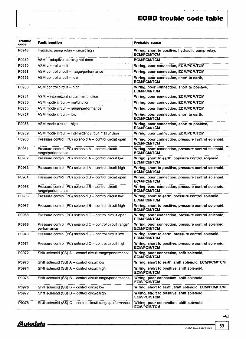
EOBD trouble code table
PO948
PO949
PO950
PO951
PO952
PO953
PO954
PO955
Hydraulic pump relay - circuit high
ASM - adaptive learning not done
PO956
PO957
Wiring, short to positive, hydraulic pump relay, ECMIPCMKCM ECMIPCMKCM
ASM control circuit
ASM control circuit - rangelperformance
ASM control circuit - low
ASM control circuit - h~gh
ASM - intermittent circuit malfunction
ASM mode circuit - malfunction
PO958
PO959
PO960
Wiring, poor connection, ECMIPCMTTCM
Wiring, poor connection, ECMIPCMKCM
Wiring, poor connection, short to earth, ECMIPCMKCM Wiring, poor connection, short to positive, ECMIPCMITCM Wiring, poor connection, ECMIPCMKCM
Wiring, poor connection, ECMIPCMKCM
ASM mode circuit - rangelperformance
ASM mode circuit - low
PO961
Wiring, poor connection, ECMIPCMKCM
Wiring, poor connection, short to earth, ECMIPCMKCM
ASM mode circuit - high
ASM mode circuit - intermittent circuit malfunction
Pressure control (PC) solenoid A - control circuit open
- .
Wiring, poor connection, short to positive, ECMIPCMKCM
Wiring, poor connection, ECMIPCMKCM
Wiring, poor connection, pressure control solenoid, ECMIPCMKCM
Pressure control (PC) solenoid A - control circuit rangelperformance
PO962
PO963
PO964
PO965
PO966
PO967
Wiring, poor connection, pressure control solenoid, ECMIPCMKCM
PO968
Pressure control (PC) solenoid A - control circuit low
Pressure control (PC) solenoid A - control circuit high
Pressure control (PC) solenoid B - control circuit open
Pressure control (PC) solenoid B - control circuit rangelperformance
Pressure control (PC) solenoid B - control circuit low
Pressure control (PC) solenoid B - control circuit high
I
Wiring, short to earth, pressure control solenoid, ECMIPCMKCM Wiring, short to positive, pressure control solenoid, ECMIPCMITCM
Wiring, poor connection, pressure control solenoid, ECMIPCMKCM Wiring, poor connection, pressure control solenoid, ECMIPCMKCM Wiring, short to earth, pressure control solenoid, ECMIPCMKCM Wiring, short to positive, pressure control solenoid, ECMIPCMITCM
Pressure control (PC) solenoid C - control circuit open
Pressure control (PC) solenoid C - control circuit low
Pressure control (PC) solenoid C - control c~rcuit high
Shift solenoid (SS) A - control circuit rangelperformance
Shift solenoid (SS) A - control circuit low
Wiring, poor connection, pressure control solenoid, ECMIPCMITCM Wiring, poor connection, pressure control solenoid, ECMIPCMKCM
PO969
Wiring, short to earth, pressure control solenoid, ECMIPCMKCM Wiring, short to positive, pressure control solenoid, ECMIPCMKCM Wiring, poor connection, shift solenoid, ECMIPCMKCM Wiring, short to earth, shift solenoid, ECMIPCMKCM
PO974
PO975
PO976
4
/Autodata I
EOBD trouble code table 1 89
Pressure control (PC) solenoid C - control circuit range1 performance
PO977
PO978
Shift solenoid (SS) A - control circuit high
Shift solenoid (SS) B - control circuit rangelperformance
Shift solenoid (SS) B - control circuit low
Wiring, short to positive, shift solenoid, ECMIPCMKCM Wiring, poor connection, shift solenoid, ECMIPCMKCM Wiring, short to earth, shift solenoid, ECMIPCMKCM
Shift solenoid (SS) B - control circuit high
Shift solenoid (SS) C - control circuit rangelperformance
Wiring, short to positive, shift solenoid, ECMIPCMKCM Wiring, poor connection, shift solenoid, ECMIPCMKCM

EOBD trouble code table
I Shift solenoid (SS) C - control circuit high
:s:le PO979
Wiring, short to positive, shift solenoid, ECMIPCMITCM
Fault location
Shift solenoid (SS) C - control circuit low
I Shift solenoid (SS) D - control circuit high
Probable cause
Wiring, short to earth, shift solenoid, ECMIPCMITCM
PO981
PO982
Wiring, short to positive, shift solenoid, ECMIPCMITCM
Shift solenoid (SS) D - control circuit rangelperformance
Shift solenoid (SS) D - control circuit low
--
Wiring, poor connection, shift solenoid, ECMIPCMITCM
Wiring, short to earth, shift solenoid, ECMIPCMITCM
Wiring, poor connection, shift solenoid, ECMIPCMITCM
Wiring, short to earth, shift solenoid, ECMIPCMITCM
PO984
PO985
I Shift solenoid (SS) E - control circuit high
Shift solenoid (SS) E - control circuit rangdperformance
Shift solenoid (SS) E - control circuit low
Wiring, short to positive, shift solenoid, ECMIPCMITCM
PO987
PO987
PO988
PO988
PO990 ( Transmission fluid pressure (TFP) sensor E - circuit high I Wiring, short to positive, TFP sensor, ECMIPCMITCM
PO989
PO989
circuit intermittent
circuit intermittent
Transmission fluid pressure (TFP) sensor E - circuit malfunction
Transmission fluid pressure (TFP) switch E - circuit malfunction
Transmission fluid pressure (TFP) sensor E - circuit rangelperformance
Transmission fluid pressure (TFP) switch E - circuit rangelperformance
Wiring, short to positive, TFP switch, ECMIPCMITCM
Wiring, poor connection, TFP sensor, ECMIPCMITCM
Wiring, poor connection, TFP switch, ECMIPCMITCM
Wiring, poor connection, TFP sensor, ECMIPCMITCM
Wiring, poor connection, TFP switch, ECMIPCMITCM
Transmission fluid pressure (TFP) sensor E - circuit low
Transmission fluid pressure (TFP) switch E - circuit low
Wiring, poor connection, TFP sensor, ECMIPCMITCM
Wiring, short to earth, TFP sensor, ECMIPCMITCM
Wiring, short to earth, TFP switch, ECMIPCMITCM
Wiring, poor connection, TFP switch, ECMIPCMITCM
Transmission fluid pressure (TFP) sensor F - circuit malfunction
Wiring, poor connection, TFP sensor, ECMIPCMITCM
I " ,
PO993 1 Transmission fluid Pressure (TFP) switch F -
PO992
PO993
Transmission fluid pressure (TFP) switch F - circuit malfunction
Transmission fluid pressure (TFP) sensor F - circuit ranael~erformance
Wiring, poor connection, TFP switch, ECMIPCMITCM
Wiring, poor connection, TFP sensor, ECMIPCMITCM
PO994
PO994
Wiring, poor connection, TFP switch, ECMIPCMITCM . , circuit rangelperformance
Transmission fluid pressure (TFP) sensor F - circuit low
Transmission fluid pressure (TFP) switch F - circuit low
Wiring, short to earth, TFP sensor, ECMIPCMITCM
Wiring, short to earth, TFP switch, ECMlPCMITCM
I Shift solenoid (SS) F - control circuit range/performance
PO995
PO995
PO996
PO996
Wiring, poor connection, shift solenoid, ECMIPCMITCM
Transmission fluid pressure (TFP) sensor F - circuit high
Transmission fluid pressure (TFP) switch F - circuit high
Transmission fluid pressure (TFP) sensor F - circuit intermittent
Transmission fluid pressure (TFP) switch F - circuit intermittent
Wiring, short to positive, TFP sensor, ECMIPCMITCM
Wiring, short to positive, TFP switch, ECMIPCMITCM
Wiring, poor connection, TFP sensor, ECMIPCMITCM
Wiring, poor connection, TFP switch, ECMIPCMITCM
(SS) F - control circuit low
(SS) F - control circuit high
Wiring short to earth, shift solenoid, ECMIPCMITCM
Wiring short to positive, shift solenoid, ECMIPCMITCM

Model: 14511 46 1,411,611,812,O 14511 46 1,7 I56 I,6/1,8/2,O (MT) 166 2,O SpiderlGTV 1,8 SpiderlGTV 2,O
Year: 1994-00
Engine code: l6Z.Oll32, 322.01, 323.01, 334.01, 335.03, 341 .O3, 671.06, 672.04, 676.01
System: Bosch Motronic M 1.5.5 Bosch Motronic M 2.10.314
ALFA ROMEO 1
Engine management I
I
1451146 type 1, 3-pin - LH engine bay
1451146 type 3, 16-pin - under fascia, driver's side
1561166 - under fascia, driver's side
I
1451146 type 2, 3-pin - LH footwell, under cover
SpiderlGlV 4 9 9 7 - under centre console, passengel's side
- - - - -
SpiderlGlV 1998-r - under fascia, driver's side

I Engine management
General information Refer to the front of this manual for general test conditions, terminology, detailed descriptions of wiring faults and a general trouble shooter for electrical and mechanical faults.
0 No digital trouble codes available from vehicle manufacturer.
Accessing and erasing The engine control module (ECM) fault memory can only be accessed and erased using diagnostic equipment able to display fault locations as a text description.
Trouble code identification
Fault location Probable cause
AC signal
Air conditioning relay - circuit malfunction
Crankshaft position (CKP) sensorlengine speed (RPM) sensor - malfunction
Wiring, AC system, AC control module
Wiring, supply voltage, AC system
Camshaft position (CMP) actuator - circuit malfunction
Camshaft position (CMP) sensor - circuit malfunction 1 Wiring, air gap, CKPIRPM sensor, mechanical fault, ECM
Wiring, CMP actuator relay, CMP actuator, ECM
Wiring, CMP sensor, ECM
Engine control module (ECM) - defective I ECM
Evaporative emission (EVAP) canister purge valve - circuit Wiring, supply voltage, EVAP canister purge valve, ECM malfunction
Engine control relay
Engine coolant temperature (ECT) sensor - openlshort circuit
Wiring, supply voltage, engine control relay
Wiring, ECT sensor, ECM
Heated oxygen sensor (H02S) 1 Wiring, H02S, air leak, ECM
Exhaust gas recirculation (EGR) solenoid
Fuel pump relay
Idle air control (IAC) valve [ Wiring, IAC valve, ECM
Wiring, supply voltage, EGR solenoid, ECM
Wiring, supply voltage, fuel pump relay
Idle speed control (ISC) actuatorlthrottle motor
Idle control - outside specification
Immobilizer circuit - malfunction I Wiring, immobilizer defective, ECM
Wiring, ISC actuatorlthrottle motor, mechanical fault, ECM
Intake leaklblockage, throttle valve tightlsticking, IAC valve or ISC actuator, ECM
Ignition coils
Ignition switch - circuit malfunction
Injector 1 1 Wiring, fuse, engine control relay, injector
Wiring, supply voltage, ignition coil, ECM
Wiring, supply voltage, ignition switch
lnjector 2 I Wiring, fuse, engine control relay, injector
Injector 3 I Wiring, fuse, engine control relay, injector
Injector 4
E l Intake air temperature (IAT) sensor - openlshort circuit
Wiring, fuse, engine control relay, injector
Wiring, IAT sensor, ECM
Intake manifold air control solenoid - circuit malfunction
Knock sensor (KS)
Wiring, intake manifold air control solenoid, ECM
Wiring, KS, KS incorrectly tightened, ECM

I Engine management I
Fault location Probable cause
Malfunction indicator lamp (MIL) - circuit malfunction I Wiring, supply voltage, MIL lamp
Mass air flow (MAF) sensor - - - -
1 Wiring, intake leak, air filter blocked, MAF sensor, ECM
Mixture control (MC) Fuel level low, fuel pressurelpump, intakelexhaust leak, misfire, MAPlMAF sensor, H02S, EVAP canister purge valve, injector(s), excessive fuel in engine oil
Mixture control (MC) - rich 1 Wiring, injector, fuel pressure, MAF sensor, ECM
Mixture control (MC) - weak Wiring, air leak, fuel pressure, ignition system, injector, MAF sensor, H02S, ECM
Supply voltage I Wiring, fuses, battery, alternator, ignition switch
M 1.5.5: Located in mass air flow (MAF) sensor. rn M 1.5.5: Located in idle speed control (ISC) actuatorlthrottle motor
rn Throttle position (TP) sensor
Vehicle speed signal
Wiring, TP sensor, ECM
Wiring, VSS, ECM

Model: A2 A31S3 80 1,612,012,612,8 80 1,9 TDI (07193 -+) A41S4 100lA6 1,812,012,612,814,2 A6 2,5 TDI A6IS6IAllroad A81S8 CoupelCabriolet 1,812,012,612,8 Cabriolet 1,9 TDI TT
Year: 1 991 -04 Engine IZ, AAH, AAT, ABC, ABK, ABZ, ACK, ACZ, ADA, ADP, ADR, AEB, AEC, AEH, AEL, AEW, AFB, AFF, AFN, 'Ode: AFY, AGA, AGB, AGN, AGR, AGU, AHC, AHF, AHH, AHK, AHL, AHU, AJG, AJK, AJL, AJM, AJP, AJQ, AKC,
AKE, AKG, AKF, AKH, AKJ, AKL, AKN, ALF, ALG, ALH, ALT, ALW, ALZ, AMF, AMK, AML, AMM, AMU, AMX, ANA, ANB, ANK, ANP, ANY, APB, APF, APG, APP, APR, APS, APT, APU, APX, APY, APZ, AQA, AQD, AQE, AQF, AQG, AQH, AQJ, ARE, ARG, ARH, ARJ, ARM, ARS, ARU, ARX, ARY, ARZ, ASG, ASJ, ASM, ASN, ASV, ATD, ATJ, AUA, AUM, AUQ, AVB, AVF, AVG, AVJ, AVN, AVU, AW, AWN, AWT, AWX, AXR, AYM, AZA, AZC, AZR, BAD, BAM, BAU, BBD, BBJ, BBY, BCZ, BDG, BDH, BDV, BFC, BFQ, BHE
System: Bosch EDC11.3.1121311.4 Bosch EDC 15MIPN Bosch Motronic Bosch Motronic M2.4.1 Bosch Motronic M3.213.2.1 Bosch Motronic M3.8.21314 Bosch Motronic M5.41.1 Bosch Motronic ME7.017.1/7.517.5.10 Bosch MSA 12115.5 Siemens Simos VAG Digifant ML5.7 VAG MPI
Engine management
1 I
A2, A4/S4 2000+, AG/SG/Allroad 1997- - fascia, driver's side A3/S3 - centre console
I I
80, Coup6, Cabriolet - in underbonnet fuseboxlrelay plate A41S4 1994-00 - centre console, rear

Model. A2 A31S3 80 1,612,012,612,8 80 1,9 TDI (07193+) A41S4 1001A6 1,812,012,612,814,2 A6 2,s TDI A6IS6IAllroad A81S8
AUDI CoupelCabriolet 1,812,012,612,8 Cabriolet 1,9 TDI lT
Engine management
1001A61S6 4 9 9 7 - in underbonnet relay plate
A81S8 - under front ashtray
General information r ~ : Refer to the front of this manual for general test conditions.
terminology, detailed descriptions of wiring faults and a general trouble shooter for electrical and mechanical faults.
[; Carry out road test for at least 10 minutes. :? Automatic transmiss~on in 'P' or 'N'. n If engine does not start. Crank engine for 6 seconds. Leave
ignition sw~tched ON.
Accessing and erasing The engine control module (ECM) fault memory can only be accessed and erased using diagnostic equipment connected to the data link connector (DLC).
NOTE: Self-diagnosis output using 4-digit trouble codes may not display al l available diagnostic information (early models).
TT - fascia, driver's side

AUDl Model A2 A363 80 1,6/2,012,612,8 80 1,9 TDI (07193 +) A 4 6 4 1001A6 1,812,012,6/2,8/4,2 A6 2,s TDI A6IS6IAllroad A81S8 CoupelCabriolet 1,812,0/2,6/2,8 Cabriolet 1,9 TDI lT
Engine management
Trouble code identification
VAG type 4-digit Fault location Probable cause
Vehicle speed sensor (VSS) I Wiring, speedometer, VSS
Engine control module (ECM) - defective
ECM
Camshaft position (CMP) sensor Air gap, insecure sensorlrotor, wiring, poor connection, fuse, I distributorlcamshaft alignment, CMP sensor
ldle speed control (ISC) actuator
Crankshaft position (CKP) sensor
Closed throttle position (CTP) Accelerator cable adjustment, CTP switch adjustment, Gring, CTP switch switch
Throttle valve tightlsticking, wiring, multi-plug incorrectly wired, ISC actuator
Air gap, metal particles, insecure sensorlrotor, wiring, CKP sensor
Knock control - control limit exceeded I ECM
Knock sensor (KS) 1 1 Wiring, KS, ECM
Maximum engine RPM exceeded
Knock sensor (KS) 2
Throttle position (TP) sensor I Incorrect gear shift, CKPIRPM sensor
-
Wiring, KS, ECM
Wiring, poor connection, TP sensor
Engine control module (ECM) - Fuse, alternator, battery, current draw with ignition OFF, engine control supply voltage relay, wiring
Manifold absolute pressure (MAP) sensor
Idle speed control (tSC)
TC wastegate regulating valve, hose connection(s), oil contamination, valve timing, poor connection, wiring, MAP sensor, ECM
Intake leaklblockage, throttle valve tightlsticking, IAC valve or ISC actuatorlposition sensor
Engine coolant temperature Wiring, poor connection, ECT sensor (ECT) sensor
Mixture adjustment resistor
Instrument panel, fuel consumption signal
Enginelgearbox electrical connection
-
Wiring, mixture adjustment resistor
Wiring short to positive, instrument panel
Wiring, transmission fault
Intake air temperature (IAT) Wiring, poor connection, IAT sensor sensor
Volume air flow (VAF) sensor
Mass air flow (MAF) sensor
Heated oxygen sensor (H02S) - lambda control
Intake air temperature (IAT) Wiring, poor connection, IAT sensor sensor
lntake leak, wiring, VAF sensor
Intake leak, wiring, MAF sensor
Heating inoperative, intakelexhaust leak, misfire, fuel level low, fuel pressurelpu~np, injector(s), EVAP canister purge valve, MAF sensor filament burn-off, wiring, H02S
Heated oxygen sensor (H02S)
Exhaust gas recirculation temperature (EGRT) sensor
Mixture control (MC)
Wiring, H02S, heating inoperative, fuel level low
Wiring, EGRT sensor
Fuel level low, fuel pressurelpump, intakelexhaust leak, misfire, MAF sensor filament burn-off, H02S, EVAP canister purge valve, injector(s), excessive fuel in engine oil
Oxygen sensor heater relay I Wiring, oxygen sensor heater relay

Model: A2 A 3 6 3 80 1,612,012,612,8 80 1,9 TDI (07193 +) A41S4 1001A6 1,812,0/2,6/2,814,2 A6 2,s TDI A6IS6IAllroad A81S8 CoupelCabriolet 1,8/2,012,6/2,8 Cabriolet 1,9 TDI lT
'IG type ( Fault location 4-digit Probable cause
4332 1 Engine control module (ECM) - Wiring, ECM controlled components output stages
4312
441 2 ( Injector 2 I Wiring, fuse, injector
Exhaust gas recirculation (EGR) solenoid
4343
441 1
441 3 I Injector 3 I Wiring, fuse, injector
Wiring, EGR solenoid
4414 I Injector 4 ( Wiring, fuse, injector
Evaporative emission (EVAP) canister purge valve
Injector 1
Wiring, fuse, EVAP canister purge valve
Wiring, fuse, injector
4431 I Idle air control (IAC) valve 1 Wiring, IAC valve
442 1
4422
4433 I Fuel pump relay / Wiring, fuse, fuel pump relay
Injector 5
Injector 6
Trouble code may be displayed if engine is not idling during self-diagnosis due to missing CKP sensor signal. Ignore trouble code if engine starts.
- - - -- -- -
Wiring, injector
Wiring, injector
4444 No fault found
'IG type 5-digit
-
00268 1 - I Idle speed control (ISC) actuator I Wiring, ISC actuator
-
00000
00263
EOBD type
PO
-
-
00281
00282
I Crankshaft position (CKP) sensor
Fault location
Refer to EOBD trouble code table
00305
00513
Air gap, insecure sensorlrotor, wiring, poor connection, CKP sensor
Probable cause
-
No fault found
Transmission control module (TCM) - incorrect signal
-
-
-
Wiring short to earth, TCM trouble code(s) stored, ECM
-
-
Vehicle speedsensor ( V S S ) ~
Idle speed control (ISC) actuatorlthrottle motor
0051 5
0051 6
0051 8
00519
00520
w i r i n g , speedometer, VSS
Throttle valve tighffsticking, wiring, multi-plug incorrectly wired, ISC actuatorlthrottle motor
Instrument panel, fuel consumption signal
Crankshaft position (CKP) sensor
Wiring, instrument panel
Air gap, metal particles, insecure sensorlrotor, wiring, CKP sensor
-
-
-
-
-
Camshaft position (CMP) sensor
Closed throttle position (CTP) switch
Throttle position (TP) sensor
Manifold absolute pressure (MAP) sensor
Mass air flow (MAF) sensor
Air gap, insecure sensorlrotor, wiring, poor connection, fuse, distributorlcamshaft alignment, CMP sensor
Accelerator cable adjustment, CTP switch adjustment, throttle valve tightlsticking, wiring, CTP switch
Wiring, poor connection, TP sensor
TC wastegate regulating valve, hose connection(s), oil contamination, valve timing, poor connection, wiring, MAP sensor, ECM
Wiring, MAF sensor

FEngine management
Model: A2 A3lS3 80 1,6/2,012,6/2,8 80 1,9 TDI (07193+) A4lS4 100lA6 1,8/2,012,6/2,814,2 A6 2,s TDI A6lS61Allroad A8lS8 CoupelCabriolet 1,812,012,6/2,8 Cabriolet 1,9 TDI TT
vAG 1 EOBD type I F ~ U N location 5-digit Probable cause
00521 I - I Mixture adjustment resistor I Wiring, mixture adjustment resistor
00522 1 - I Engine coolant temperature (ECT) sensor I Wiring, poor connection, ECT sensor
00525 I - Heated oxygen sensor (H02S) 1 - I Wiring. H025, heating inoperative, fuel level low implausible signal
00523
00524
00526 1 - I Stop lamp switch I Wiring, stop lamp switch
- -
00527
00528
- -
Intake air temperature (IAT) sensor
Knock sensor (KS) 1
00529
00530
- - -
Wiring, poor connection, IAT sensor
Wiring, KS, ECM
- -
00532
00533
00536 I - Engine control module (ECM) - I Wiring, KS, ECM knock control 2
-
-
00534
00535
Heated oxygen sensor (H02S) - lambda control
Intake air temperature (IAT) sensor
Barometric pressure (BARO) sensor
-
-
CO adjustment, heating inoperative, intakelexhaust leak, misfire, fuel level low, fuel pressurelpump, injector(s), EVAP canister purge valve, MAP sensor, MAF sensor filament burn-off, wiring, H02S
Wiring, poor connection, IAT sensor
Wiring, BAR0 sensor
Crankshaft position (CKP) sensor
Idle speed control (ISC) actuatorlposition sensor
- -
Wiring, CKP sensor
Wiring, poor connection, multi-plug incorrectly wired, ISC actuatorlposition sensor
Engine control module (ECM) - supply voltage
Idle speed control (ISC)
00542 I - I Injector needle lift sensor
Fuse, alternator, battery, current draw with ignition OFF, engine control relay, wiring
Intake leaklblockage, throttle valve tightlsticking, IAC valve or ISC actuatorlposition sensor
Engine oil temperature (EOT) sensor
Engine control module (ECM) - knock control 1
00539
00540
Air in fuel system, fuel level low, wiring, injector needle lift sensor
Wiring, EOT sensor
Wiring, KS, ECM
Maximum engine RPM exceeded ----- Incorrect gear shift, CKPIRPM sensor, AT fault, I ECM
- -
Maximum boost pressure exceeded Hoses interchangedlnot connected, hoses blockedlleaking, TC wastegate actuator1 regulating valve, MAP sensor
Fuel temperature sensor
Knock sensor (KS) 2
Wiring, fuel temperature sensor
Wiring, KS, ECM
00545
00546
00549
00550
[ 98 I,,,,,,,,,,,.,
-
-
00552
00553
-
-
ECMrTCM electrical connection
Data link connector (DLC) - defective
-
-
TCM trouble code(s) stored, wiring, transmission fault
Wiring
Instrument panel, fuel consumption signal
Start of injection - control
Wiring short to positive, instrument panel
Wiring, fuel injection timing solenoid, injector needle lift sensor, air in fuel system, fuel level low, pump timing
Volume air flow (VAF) sensor
Mass air flow (MAF) sensor
Intake leak, wiring, VAF sensor
Intake leak, wiring, MAF sensor

Model: A2 A31S3 80 1,612,0/2,612,8 80 1,9 TDI (07193 -+) A41S4 1001A6 1,8/2,0/2,6/2,8/4,2 A6 2,s TDI A6/S6/Allroad A81S8 CoupeICabriolet 1,8/2,0/2,612,8 Cabriolet 1,9 TDI lT
AUDI
Engine management 1 --
VAG type 5-digit EOBD type
- Heated oxygen sensor (H02S) 2 - Wiring, H02S, heating inoperative, fuel level low implausible signal
Fault location
-
Probable cause
Heated oxygen sensor (H02S) - lambda control
-
-
Trouble codes 00525100533 stored, fuel level low, fuel pressurelpump, intakelexhaust leak, misfire, MAP sensor, MAF sensor filament burn-off, H02S, EVAP canister purge valve, injector(s), excessive fuel in engine oil
CO adjustment, heating inoperative, intakelexhaust leak, misfire, fuel level low, fuel pressurelpump, injector(s), EVAP canister purge valve, MAP sensor, MAF sensor filament burn-off, wiring, H02S
-
- I Intake manifold pressure
Power steering pressure (PSP) switch - short to earth
Exhaust gas recirculation (EGR) - control difference
Mixture control (MC)
lntake leaklblockage, MAF sensor, MAP sensor, TC wastegate actuatorlregulating valve, hoses interchangedlnot connected, wiring
Wiring short to earth, PSP switch
Intake leak, EGR valveisolenoid
-
-
-
-
Knock control, cylinder 1 - control limit exceeded
Knock control, cylinder 2 - control limit exceeded
-
-
- I Exhaust gas recirculation (EGR) system - EGR solenoid control I
Fuel pressure, misfire, intake leak, injector(s)
Fuel pressure, misfire, intake leak, injector(s)
Knock control, cylinder 3 - control limit exceeded
Knock control, cylinder 4 - control limit exceeded
-
-- -
- I Ignition amplifier,primary%cuit 1- W~ring, ignition amplifier 1 ;
Fuel pressure, misfire, intake leak, injector(s)
Fuel pressure, misfire, intake leak, injector(s)
Knock control, cylinder 5 - control limit exceeded
Knock control, cylinder 6 - control limit exceeded
- I Ignition amplifier, primary circuit 2 I Wiring, ignition amplifier
Fuel pressure, misfire, intake leak, injector(s)
Fuel pressure, misfire, intake leak, injector(s)
I
Exhaust gas recirculation temperature (EGRT) sensor
Wiring, EGRT sensor
-
- -
- Fuel injection pump control module - I Wiring, fuel injection pump engine stop malfunction
- -
Ignition amplifier, primary circuit 3
AC signal - compressor cut-in
Vehicle speed signal
- ECMITCM electrical connection Wiring, transmission fault
Wiring, ignition amplifier
Wiring, AC system
Wiring, speedometer, VSS
Glow plug warning lamp
Fuel filter water level sensor
-
- I Oxygen sensor heater relay I Wiring, oxygen sensor heater relay
Wiring, glow plug warning lamp
Water in filter, wiring, fuel filter water level sensor
Heated oxygen sensor (H02S) 1, bank 1 - heater circuit malfunction
Wiring, H02S

IEngine management
Model: A2 A363 80 1,612,012,612,8 80 1,9 TDI (07193 +) A4lS4 1001A6 1,8/2,012,6/2,814,2 A6 2,s TDI A6lS61Allroad A8lS8 CoupelCabriolet 1,812,012,612,8 Cabriolet 1,9 TDI lT
type 5-digit
00650
00653
00667
EOBD type
-
00668
00670
-
-
00671
00740
Fault location
Clutch pedal position (CPP) switch - short to positive
-
-
00741
00750
00777 1 - I Accelerator pedal position (APP) sensor I Incorrectly adjusted, wiring, APP sensor
Probable cause
Wiring short to positive, CPP switch
Transmission control module (TCM)ITR sensor - implausible TR signal
Outside air temperature signal
- -
00758
00765
Wiring, transmission fault, poor connection
Wiring, instrument panel, AC system, outside air temperature sensor
Engine control module (ECM) - supply voltage low
Idle speed control (1%) actuator position sensor
-
-
Battery, wiring, engine control relay
Wiring, throttle valve, ISC actuator position sensor
Cruise control master switch
Camshaft position (CMP) sensor
- -
00792
01013
Wiring, cruise control master switch
Wiring, CMP sensor
Stop lamp switchlbrake pedal position (BPP) switch - implausible ratio
Malfunction indicator lamp (MIL) - circuit malfunction
01025
01 028
01 044
Wiring, both switch positions not synchronised, stop lamp switch, BPP switch
ECM incorrectly coded, wiring, MIL
Secondary air injection (AIR) system
Fuel quantity adjuster position sensor
- -
01050
01052
AIR solenoidlrelay, wiring
Wiring, fuel injection pump
- - -
01087
01088
AC pressure switch
AC compressor clutch, load signal
- -
01117
01119
Wiring, AC pressure switch
Wiring, AC system
Malfunction indicator lamp (MIL)
Engine coolant blower motor relay
Engine control module (ECM) - coding
-
-
01 120
01121
Wiring, MIL
Wiring, engine coolant blower motor relay
Incorrectly coded
Glow plug monitoring
Fuel lever position sensor
-
-
01126
01 163
01 168 I - I ldle speed boost solenoid
Fuse, wiring, glow plug relay, glow plugs
Wiring, fuel lever position sensor
Engine control module (ECM) - basic setting
Mixture control (MC)
-
-
01165
01 167
Wiring, full throttle stop valve, idle speed boost solenoid
Basic setting not completed, throttle valve tightlsticking
Fuel level low, fuel pressurelpump, MAP sensor, MAF sensor, intakelexhaust leak, EVAP canister purge valve, excessive fuel in engine oil, injector(s)
Alternator load signal
Gear recognition signal - AT
- -
1 loo 1 Engine management /mutodata
Wiring, alternator
Wiring
Camshaft position (CMP) control, bank 1 - mechanical fault
Camshaft position (CMP) control, bank 2 - mechanical fault
-
-
Wiring, fuse, CMP actuator
Wiring, fuse, CMP actuator
Engine RPM signal
Backfire
Wiring, CKPIRPM sensor, instrument panel
Intake leak, wiring, ignition amplifier, injector(s)
Idle speed control (1%) actuatorlthrottle motor
Full throttle stop solenoid
Accelerator cable adjustment, throttle valve, wiring, ISC actuatorlthrottle motor, basic setting not carried out
Wiring, full throttle stop valve

Model: A2 A31S3 80 1,612,012,6/2,8 80 1,9 TDI (07193 -+) A41S4 1001A6 1,812,012,612,8/4,2 A6 2,5 TDI A6IS6IAllroad A8lS8 CoupelCabriolet 1,8/2,012,6/2,8 Cabriolet 1,9 TDI lT
Engine management 1 type
5-digit
01169
01170
01177
EOBD type
01180
01182
Wiring
Throttle valve sticking, ISC actuatorlthrottle motor sticking/mechanically damaged, incorrect throttle control unit, intake leak between MAF sensor and throttle valve, air filter blocked
ECM incorrectly coded, wiring, MIL I
-
-
-
01183
01193 I - ( Engine coolant heater relay 1, low output I Wiring, engine coolant heater relay
Fault location
-
-
Probable cause
Door contact switch, driver's
Fuel injection timing sensor
Engine control module (ECM) - defective
EnginelAC electrical connection
Mass air flow (MAF) sensor/throttle position (TP) sensor - signal incompatibility
-
Wiring, door contact switch
Wiring, fuel injection timing sensor
ECM
Malfunction indicator lamp (MIL) - circuit malfunction
01 194
01196
01209 1 - 1 Alternator speed signal I Wiring, alternator
01204
01208
- - -
-
01235
01237
- - -
Engine coolant heater relay 2, high output
CAN data bus, TCM - incorrect signal
01242
01 243
01249 I - I lniector 1 I Wiring, fuse, injector
- - - - --
Wiring, engine coolant heater relay
Wiring
Engine coolant temperature (ECT) sensor
Engine control module (ECM) - data changed
- -
01247
01250 1 - I Injector 2 I Wiring, fuse, injector
Wiring, ECT sensor
ECM
-
-
Secondary air injection (AIR) solenoid
Fuel shut-off solenoid
-
01252 1 - I lniector 4 I Wiring, fuse, injector
-- -
Wiring, AIR solenoid
Wiring, fuel shut-off solenoid
Engine control module (ECM) - output stages
Intake manifold air control solenoid
01251
01253 1 - I Injector 5 I Wiring, injector
Wiring, ECM controlled components
Wiring, intake manifold air control solenoid
Evaporative emission (EVAP) canister purge valve
Wiring, fuse, EVAP canister purge valve
-
01254
01257
01265 1 - I Exhaust gas recirculation (EGR) solenoid I Wiring, EGR solenoid
Injector 3
01259
01262
Wiring, fuse, injector
- -
01269 1 - I Fuel injection timing solenoid I Wiring, fuel injection timing solenoid
-
-
01266
01 268
Injector 6
Idle air control (IAC) valve
01312 1 - I CAN data bus - defective I Trouble code(s) stored in other system(s), wiring
Wiring, injector
Wiring, IAC valve
Fuel pump relay
Turbocharger (TC) wastegate regulating valve
- -
-
01282
01 283
Wiring, fuse, fuel pump relay
Wiring, fuse, TC wastegate regulating valve
Glow plug relay
Fuel quantity adjuster
-
-
Wiring, glow plug relay
Incorrectly set, wiring, fuel injection pump
Intake manifold air control solenoid
Intake manifold air control actuator
Wiring, intake manifold air control solenoid
Wiring, intake manifold flap, intake manifold air control actuator

AUDI Model: A2 A31S3 80 1,6/2,0/2,612,8 80 1,9 TDI (07193+) A41S4 1001A6 1,8/2,0/2,6/2,8/4,2 A6 2,s TDI A6IS6IAllroad A81S8 CoupelCabriolet 1,8/2,0/2,6/2,8 Cabriolet 1,9 TDI TT
Engine management
type 5-digit
01314
01315
01316
EOBD type
-
01317
01318
-
-
01321
01375
Fault location
Engine control module (ECM), cruise control system - defective
-
-
01376
01437
01442 1 - I Engine misfire - fuel pump housing empty I Fuel level low, fuel transfer pump
Probable cause
ECM
CAN data bus, TCM - no signal
CAN data bus, ABS - defective
-
-
01440
01441
TCM trouble code(s) stored, wiring, matching resistor in ECM
ABS control module incorrectly coded, wiring
CAN data bus, instrumentation
Fuel injection pump control module
-
-
01686 1 - I Engine coolant blower motor run-on relay I Wiring, engine coolant blower motor run-on relay
Trouble code(s) stored in other system(s), wiring, instrumentation control module
Data bus wiring, fuel injection pump
CAN data bus, SRS
Engine mounting control solenoid, bank 1 & 2
- -
01 575
01 61 3
01 656
SRS control module trouble code@) stored, wiring
Wiring, engine mounting control solenoid
Fuel injection pump position sensor
Throttle control unit - basic setting
16396 I - Camshaft position (CMP), intakelleftlfront, Valve timing, camshaft position (CMP) actuator bank 1 - timing over retarded
Wiring, fuel injection pump position sensor
Basic setting not carried out, CTP switch, ISC actuatorlposition sensor, TP sensor
Fuel level signal
Fuel low level sensor
-
-
-
01 695
16394
16395
Wiring, instrument panel, fuel gauge tank sensor
Wiring, fuel transfer pump, fuel level sensor
Auxiliary drive - switched OFF
Fuel cooling pump relay - circuit malfunction
SRS control module - crash signal
-
-
-
I - I Camshaft position (CMP) actuator, exhaustl rightlrear, bank 1 - timing over advanced1 system performance
-- - - -
Auxiliary drive overloaded
Wiring, fuel cooling pump relay
Wiring
Valve timing, camshaft position (CMP) actuator
16399
1641 4
Fuel temperature sensor - circuit malfunction
Camshaft position (CMP) actuator, intake1 leftlfront, bank 1 - circuit malfunction
Camshaft position (CMP), intakelleftlfront, bank 1 - timing over advancedlsystem performance
16415
1 641 6
16475 1 - I Fuel metering solenoid - short to earth I Wiring short to earth, fuel metering solenoid
Wiring, fuel temperature sensor
Wiring, CMP actuator
Valve timing, camshaft position (CMP) actuator
-
-
16474
-
-
Camshaft position (CMP) actuator, exhaustl rightlrear, bank 1 - timing over retarded
Heated oxygen sensor (H02S) 1, bank 1, heater control - circuit malfunction
-
16476
Valve timing, camshaft position (CMP) actuator
Wiring open circuit, H02S
Heated oxygen sensor (H02S) 1, bank 1, heater control - circuit low
Heated oxygen sensor (H02S) 1, bank 1, heater control - circuit high
Wiring short to earth, H02S
Wiring short to positive, H02S
Fuel metering solenoid - open circuit
-
Wiring open circuit, fuel metering solenoid
Fuel metering solenoid - short to positive Wiring short to positive, fuel metering solenoid

Model: A2 A 3 6 3 80 1,612,012,612,8 80 1,9 TDI (07193+) A41S4 1001A6 1,812,012,612,814,2 A6 2,s TDI A6IS6IAllroad A81S8 CoupelCabriolet 1,8/2,012,612,8 Cabriolet 1,9 TDI lT
AUDI
Engine management I
VAG type 5-digit EOBD type Fault location
-
-
Probable cause
-
- Intake air temperature (IAT) sensor - low Wiring short to earth, IAT sensor input
Mass air flow (MAF) sensor, bank 1 - rangelperformance problem
Mass air flow (MAF) sensor, bank 1 - low input
-
-
-
Intake leak, wiring, MAF sensor
Intake leak, air filter blocked, wiring short to earth, fuse, MAF sensor
Mass air flow (MAF) sensor, bank 1 - high input
Wiring short to positive, earth wire defective, MAF sensor
Manifold absolute pressure (MAP) sensor1 barometric pressure (BARO) sensor - rangelperformance problem
Manifold absolute pressure (MAP) sensor1 barometric pressure (BARO) sensor - low input
Manifold absolute pressure (MAP) sensor1 barometric pressure (BARO) sensor - high input
-
-
- Throttle position (TP) sensor - circuit Poor connection, wiring, TP sensor malfunction
lntakelexhaust leak, wiring, MAP sensor, BAR0 sensor
Wiring short to earth, MAP sensor, BARO sensor
Wiring short to positive, MAP sensor, BARO sensor
-
-
Intake air temperature (IAT) sensor - high input
Engine coolant temperature (ECT) sensor - rangelperformance problem
Wiring open circuitlshort to positive, earth wire defective, IAT sensor
Coolant thermostat, poor connection, wiring, ECT sensor
Engine coolant temperature (ECT) sensor - low input
Engine coolant temperature (ECT) sensor - high input
-
-
- Heated oxygen sensor (H02S) 1, I Wiring short to earth, HO2S bank 1 - voltage low
Coolant thermostat, wiring short to earth, ECT sensor
Coolant thermostat, wiring open circuitlshort to positive, earth wire defective, ECT sensor
-
-
Throttle position (TP) sensor - range1 performance problem
Throttle position (TP) sensor - low input
Poor connection, TP sensor
Signal wire short to earth, supply wire defective, TP sensor
Throttle position (TP) sensor - high input
Heated oxygen sensor (H02S) 1, bank 1 - circuit malfunction
-
-
Signal wire open circuitlshort to positive, earth wire defective, TP sensor
Heating inoperative, poor connection, wiring, H02S
-
-
a a Eng~ne management 103
Heated oxygen sensor (H02S) 1, bank 1 - voltage high
Heated oxygen sensor (H02S) 1, bank 1 - slow response
-
-
Wiring short to positive, H02S
Heating inoperative, wiring, H02S
Heated oxygen sensor (H02S) 1, bank 1 - no activity detected
Heated oxygen sensor (H02S) 1, bank 1 - heater circuit malfunction
Wiring open circuit, heating inoperative, H02S
Fuse, wiring, H02S
4
Heated oxygen sensor (H02S) 2, bank 1 - circuit malfunction
Heated oxygen sensor (H02S) 2, bank 1 - low voltage
Heating inoperative, wiring, H02S
Wiring short to earth, exhaust leak, H02S

I
Engine management
Model: A2 A 3 6 3 80 1,612,012,6/2,8 80 1,9 TDI (07193 -+) A4lS4 100lA6 1,8/2,012,612,8/4,2 A6 2,5 TDI A6lS61Allroad A8lS8 CoupelCabriolet 1,8/2,0/2,6/2,8 Cabriolet 1,9 TDI TT
vAG type I EOBD type 1 Fault location 5-digit Probable cause
Heated oxygen sensor (H02S) 2, bank 1 - no activity detected
16522
16523
I Wiring, H02S
-
-
16535 I - Heated oxygen sensor (H02S) 1, I Wiring short to earth, HO2S bank 2 - low voltage
16525
16534
Heated oxygen sensor (H02S) 2, bank 1 - high voltage
Heated oxygen sensor (H02S) 2, bank 1 - slow response
I6538 I - Heated oxygen sensor (H02S) 1, I Wiring, H02S bank 2 - no activity detected
Wiring short to positive, H02S
Heating inoperative, wiring, H02S
-
-
16536
16537
16540 I - Heated oxygen sensor (H02S) 2, Heating inoperative, wiring, H02S bank 2 - circuit malfunction
Heated oxygen sensor (H02S) 2, bank 2 - low voltage
Heated oxygen sensor (H02S) 2, bank 1 - heater circuit malfunction
Heated oxygen sensor (H02S) 1, bank 2 - circuit malfunction
-
-
Wiring short to earth, exhaust leak, H02S
Wiring, H02S
Wiring, H02S
Heated oxygen sensor (H02S) 1, bank 2 - high voltage
Heated oxygen sensor (H02S) 1, bank 2 - slow response
I - Heated oxygen sensor (H02S) 2, bank 2 - no activity detected
Wiring short to positive, H02S
Heating inoperative, wiring, H02S
1 6542
16543
I Wiring, HO2S
-
-
System too lean, bank 1
16545
16554
lntakelexhaust leak, AIR system, MAP sensor, MAF sensor, fuel pressurelpump, injector(s), EVAP canister purge valve, H02S
Heated oxygen sensor (H02S) 2, bank 2 - high voltage
Heated oxygen sensor (H02S) 2, bank 2 - slow response
Wiring short to positive, H02S
Heating inoperative, wiring, H02S
-
-
/ System too lean. bank 2
16556
16557
Fuel pressurelpump, injector(s), intakelexhaust leak, AIR system, hose connection(s)
Heated oxygen sensor (H02S) 2, bank 2 - heater circuit malfunction
Fuel trim (FT), bank 1 - malfunction
Wiring, H02S
Intake leak, AIR system, fuel pressurelpump, injector(s), EVAP canister purge valve, H02S
-
-
16559
16575
1 '04 1 Eng~ne management /Autodata
System too rich, bank 1
Fuel trim (FT), bank 2 - malfunction
16576
16577
EVAP canister purge valve, fuel pressure, injector(s), H02S
Fuel pressurelpump, injector(s), AIR system, hose connection(s), intake leak
-
-
- -
System too rich, bank 2
Fuel rail pressure (FRP) sensor - range1 performance problem
Fuel pressure, injector(s), EVAP canister purge valve
Wiring, FRP sensor
Fuel rail pressure (FRP) sensor - low input
Fuel rail pressure (FRP) sensor - high input
Wiring short to earth, FRP sensor
Wiring short to positive, FRP sensor

Model: A2 A363 80 1,6/2,012,6/2,8 80 1,9 TDI (07193 +) A464 100lA6 1,8/2,0/2,6/2,8/4,2 A6 2,s TDI A6lS61Allroad A8lS8 CoupelCabriolet 1,8/2,012,6/2,8 Cabriolet 1,9 TDI TT
Engine management 7
16581 I - / Engine oil temperature (EOT) sensor - low Wiring short to earth, EOT sensor
input
type 5-digit
16578
16586 1 - I Injector 2 - circuit malfunction I Wiring, injector
EOBD type
-
16582
16585
16589 1 - I Injector 5 - circuit malfunction I Wiring, injector
Fault location
Fuel rail pressure (FRP) sensor - circuit intermittent
-
-
16587
16588
Probable cause
Wiring open circuit, FRP sensor
Engine oil temperature (EOT) sensor - high input
Injector 1 - circuit malfunction
- -
16590
16603
16607 1 - I Throttle position (TP) sensor B - high input I Wiring short to positive, TP sensor
Wiring short to positive, EOT sensor
Wiring, injector
16605
16606
Accelerator pedal position (APP) Wiring, APP sensor sensor A/B - rangelperformance problem
Injector 3 - circuit malfunction
Injector 4 - circuit malfunction
-
-
Wiring, injector
Wiring, injector
-
-
Injector 6 - circuit malfunction
Engine over speed condition
1661 1
1661 2
Wiring, injector
Incorrect gear change
Throttle position (TP) sensor B - range1 performance problem
Throttle position (TP) sensor B - low input
16614
1 661 8
I -
Manifold absolute pressure (MAP) sensor A, Wiring short to earth, MAP sensor TC system - low input
Wiring, TP sensor
Wiring short to earth, TP sensor
-
-
16619
16620
- -
16629 I - Turbocharger (TC) wastegate regulating Wiring short to earth, TC wastegate regulating valve A - circuit low valve
Accelerator pedal position (APP) sensor A - low input
Accelerator pedal position (APP) sensor A - high input
-
-
16622
16627
Wiring short to earth, APP sensor
Wiring short to positive, APP sensor
Fuel pump relay - circuit malfunction
Engine boost condition - limit exceeded
Wiring, fuel pump relay
Hose connection(s), wiring, TC wastegate regulating valve, TC wastegate
Engine boost condition - limit not reached
Manifold absolute pressure (MAP) sensor A, TC system - rangelperformance problem
-
-
16630
16645
16646
Hose connection(s), wiring, TC wastegate regulating valve, TC wastegate
lntakelexhaust leak, hose connection(s), MAP sensor
16648
16649
-a- Eng~ne management 105
Manifold absolute pressure (MAP) sensor A, TC system - high input
Turbocharger (TC) wastegate regulating valve A - circuit malfunction
-
-
-
16651
Wiring short to positive, MAP sensor
Wiring, TC wastegate regulating valve
- -
Turbocharger (TC) wastegate regulating valve A - circuit high
Injector 1 - circuit low
Injector 1 - circuit high
110
-
Wiring short to positive, TC wastegate regulating valve
Wiring short to earth, injector
Wiring short to positive, injector
Injector 2 - circuit low
Injector 2 - circuit high
Wiring short to earth, injector
Wiring short to positive, injector
Injector 3 - circuit low Wiring short to earth, injector

AUDI Model: A2 A3lS3 80 1,6/2,012,6/2,8 80 1,9 TDI (07193 -) A41S4 100lA6 1,8/2,012,6/2,8/4,2 A6 2,s TDI A6lS61Allroad A81S8 CoupelCabriolet 1,8/2,012,6/2,8 Cabriolet 1,9 TDI TT
Engine management
VAG type 1 EOBD type I Fault location 5-digit Probable cause
16652 1 - I Injector 3 - circuit high I Wiring short to positive, injector
16654
16655
16661 I - I Injector 6 - circuit high I Wiring short to positive, injector
16657
16658
16660
- -
- -
-
16684
16687 I - I Cylinder 3 - misfire detected Spark plug, HT lead(s), injector, ignition coil, low
compression, wiring
Injector 4 - circuit low
Injector 4 - circuit high
16685
16686
-
Wiring short to earth, injector
Wiring short to positive, injector
Injector 5 - circuit low
Injector 5 - circuit high
Injector 6 - circuit low
-
16690 I - I Cylinder 6 - misfire detected Spark plug, HT lead(s), injector, ignition coil, low
compression, wiring
Wiring short to earth, injector
Wiring short to positive, injector
Wiring short to earth, injector
-
-
16688
16689
Randomlmultiple cylinder(s) - misfire detected
Spark plug(s), HT lead(s), injector(s), ignition coil(s), low compression, wiring
Cylinder 1 - misfire detected
Cylinder 2 - misfire detected
-
-
16691
16692
Spark plug, HT lead(s), injector, ignition coil, low compression, wiring
Spark plug, HT lead(s), injector, ignition coil, low compression, wiring
Crankshaft position (CKP) sensorlengine speed (RPM) sensor - rangelperformance problem
1671 0 1 - Knock sensor (KS) 1, bank I - range/ I Wiring, KS incorrectly tightened, KS performance problem
Cylinder 4 - misfire detected
Cylinder 5 - misfire detected
-
-
Air gap, metal particles, insecure sensorlrotor, wiring, CKPIRPM sensor
16706
16709
1671 1 I - Knock sensor (KS) 1, bank 1 - low input lnsecure KS, poor connection, wiring short to
earth, incorrectly tightened, KS
Spark plug, HT lead(s), injector, ignition coil, low compression, wiring
Spark plug, HT lead(s), injector, ignition coil, low compression, wiring
1671 2 I - / Knock sensor (KS) 1, bank 1 - high input Wiring short to positive, KS incorrectly tightened, / KS
Cylinder 7 - misfire detected
Cylinder 8 - misfire detected
-
-
Spark plug, HT lead(s), injector, ignition coil, low compression, wiring
Spark plug, HT lead(s), injector, ignition coil, low compression, wiring
Crankshaft position (CKP) sensorlengine speed (RPM) sensor - no signal
Knock sensor (KS) 1, bank I - circuit malfunction
16716
16717
Wiring, CKPIRPM sensor
Wiring, poor connection, KS
16719
16721
-
-
-
-
Knock sensor (KS) 2, bank 2 - low input
Knock sensor (KS) 2, bank 2 - high input
Insecure KS, poor connection, wiring short to earth, KS incorrectly tightened, KS
Wiring short to positive, KS incorrectly tightened, KS
Crankshaft position (CKP) sensor - circuit malfunction
Crankshaft position (CKP) sensor - low input
Wiring, CKPIRPM sensor
Insecure sensor, air gap, wiring short to earth, CKP/RPM sensor

Model: A2 A3lS3 80 1,6/2,012,6/2,8 80 1,9 TDI (07193 -+) A4lS4 1001A6 1,8/2,012,6/2,8/4,2 A6 2,5 TDI A6lS61Allroad A8lS8 CoupelCabriolet 1,8/2,012,6/2,8 Cabriolet 1,9 TDI TT
Engine management I VAG type I EOBD type I Fault location 5-digit Probable cause
16724
16725
16726
16727
-
-
16730
16731
16732
-
-
16735
16736
Camshaft position (CMP) sensor A, bank 1 - circuit malfunction
Camshaft position (CMP) sensor A, bank 1 - rangelperformance problem
-
-
-
16737
16738
16785 I - Exhaust gas recirculation (EGR) system - Hose leaklblockage, basic setting not carried out, insufficient flow detected I EGR valvelsolenoid
Wiring, CMP sensor
Insecure sensorlrotor, air gap, wiring, CMP sensor
Camshaft position (CMP) sensor A, bank 1 - low input
Camshaft position (CMP) sensor A, bank 1 - high input
-
-
16764
16784
Wiring short to earth, CMP sensor
Wiring short to positive, CMP sensor
Camshaft position (CMP) sensor A, bank 2 - rangelperformance problem
Camshaft position (CMP) sensor A, bank 2 - low input
Camshaft position (CMP) sensor A, bank 2 - high input
-
-
Insecure sensorlrotor, air gap, wiring, CMP sensor
Wiring short to earth, CMP sensor
Wiring short to positive, CMP sensor
Ignition coil, cylinder 1, primary1 secondary - circuit malfunction
Ignition coil, cylinder 2, primary1 secondary - circuit malfunction
- -
16786
16787
Wiring, ignition amplifier, ignition coil
Wiring, ignition amplifier, ignition coil
Ignition coil, cylinder 3, primary1 secondary - circuit malfunction
Ignition coil, cylinder 4, primary1 secondary - circuit malfunction
16788
16791
16795 I - Secondary air injection (AIR) system - I AIR pump, AIR valve, AIR hose@) incorrect flow detected
Wiring, ignition amplifier, ignition coil
Wiring, ignition amplifier, ignition coil
Glow plugs - clrcuit A malfunction
Exhaust gas recirculation (EGR) system - flow malfunction
-
-
16792
16796 I - air injection (AIR) 1 Gring, AIR solenoid
solenoid A - circuit malfunction
Wiring, glow plug relay, fuse, glow plugs
Basic setting not carried out, EGR valvelsolenoid
-
-
Exhaust gas recirculation (EGR) system - excessive flow detected
Exhaust gas recirculation (EGR) system - circuit malfunction
-
16806 I - Main catalytic converter, bank 1 - Catalytic converter efficiency below threshold
EGR valvelsolenoid, basic setting not carried out
Wiring, EGR valvelsolenoid
Exhaust gas recirculation (EGR) system - rangelperformance problem
Exhaust gas recirculation (EGR) valve position sensor - low input
16802
16804
+I
/Autodata I Eng~ne management 107
Hose connection(s), wiring, EGR valvelsolenoid
Wiring short to earth, EGR valve position sensor
Exhaust gas recirculation (EGR) valve position sensor - high input
Wiring short to positive, EGR valve position sensor
-
-
Secondary air injection (AIR) pump relay A - circuit malfunction
Catalytic converter system, bank 1 - efficiency below threshold
Wiring, AIR pump relay
Catalytic converter

lndu! M O ~ - 1 yueq '~osuas ( 1 ~ 3 3 ) Josuas 1 8 9 3 ' q ~ e a o j ~ o q s ~U!J!M a~nle~adlual uo!leln3~pa~ se6 lsneqx3
433!MS dSd '~u!J!M
Josuas 1 8 9 3 'a~!j!sod o j ~ o q s 6u!~!M
uo!punjlelu l!n3~!3 - 1 yueq '~osuas (1833)
ualqo~d a3uelu~oyadla6ue~ - 43l!MS /JOSUaS (&d) aJnssaJd 6~!Jaals JaMOd
lndu! 46!4 - 1 yueq 'JOSUaS ( 1 ~ 3 3 ) a~nle~adlual uo!leln3~pa~ se6 lsneqx3
j!un lo~juo:, a l j j o ~ q l
j y n lo~juo3 a l j j o ~ q l
-
-
SSA 'Wed juaurn~pu! 'luajsAs papauuo3 ~ a q j o '~u!J!M
snq ejep N V ~ 'SSA 'Ja~awopaads '~u!J!M
I yn3Jp uado - ahleh aA(eA a6~nd JajS!Ue3 dvA3 'j!n3~!3 uado ~U!J!M a6~nd Ja)S!Ue3 ( d v ~ 3 ) uo!ss!lua ah!leJodeh3
SE69 1
OE69 1
papadxa ueql ~a46!q w d ~ - ualsAs (39 ) lo~luo3 paads alp1
papadxa ueql JaMo( l u d ~ - lualsAs (39 ) lo~luo:, paads alp1
JOJOlu JaMOlq jUelOO3 au!6ua '~u!J!M
~osuas l a ~ a l yuej lanj '~u!J!M
~ndu! 46!4/3!leJJa ~uau!u~alu! - (SSA) ~osuas paads a p y a ~
lualq0Jd ameuoyad la6ueJ - (SSA) ~osuas paads ap !ga~
-
-
uo!punjlelu l!n3J!3 - 1 JOlOlu JaMOlq lUel003 au!6u3
lualq0Jd a3~eluJoyad la6~eJ - ~osuas laha1 yuel land
aye^ a6~nd ~als!ue3 d v ~ 3 'yea1 ayeju! '(s)uo!j3auuo3 a s o ~
~apa~uo:, 3!gAleje3
H C689C
H 0689C
-
-
L889 C
E889 1
-
-
uo!punj(elu - uapAs ( d v ~ 3 ) uo!ss!lua ah!le~odehq
pfoqsaJq1 Molaq Rauapga - z yueq 'lualds Jayahuo3 3!flle)e3
9989 1
SP89 1
-
-
PZ89 1
PC89C
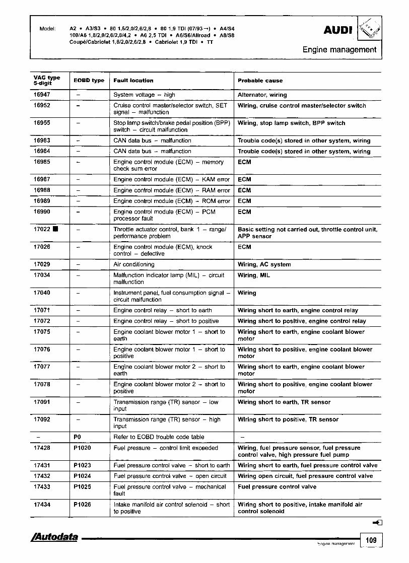
Model: A2 A3lS3 80 1,612,012,612,8 80 1,9 TDI (07/93+) A4lS4 1001A6 1,8/2,012,6/2,814,2 A6 2,5 TDI A6IS6IAllroad A81S8 CoupelCabriolet 1,812,012,6/2,8 Cabriolet 1,9 TDI lT
Engine management I
type EOBD type Fauk bocation 5-digit Probable cause
16955 I - Stop lamp switchlbrake pedal position (BPP) Wiring, stop lamp switch, BPP switch switch - circuit malfunction
16947
16952
16983 1 - I CAN data bus - malfunction ( Trouble code(s) stored in other system, wiring
- -
16984
16985
16989 1 - I Engine control module (ECM) - ROM error I ECM
System voltage - high
Cruise control masterlselector switch, SET signal - malfunction
16987
16988
Alternator, wiring
Wiring, cruise control masterlselector switch
-
-
17029 1 - I Air conditioning I Wiring, AC system
-
-
16990
17022
17026
17034 I - Malfunction indicator tamp (MIL) - circuit Wiring, MIL malfunction
CAN data bus - malfunction
Engine control module (ECM) - memory check sum error
Trouble code(s) stored in other system, wiring
ECM
Engine control module (ECM) - KAM error
Engine control module (ECM) - RAM error
-
-
-
17072 1 - 1 Engine control relay - short to positive I Wiring short to positive, engine control relay
ECM
ECM
17040
17071
Engine control module (ECM) - PCM processor fault
Throttle actuator control, bank 1 - range1 performance problem
Engine control module (ECM), knock control - defective
ECM
Basic setting not carried out, throttle control unit, APP sensor
ECM
-
-
17075
17076
17077
17078
17091
Instrument panel, fuel consumption signal - circuit malfunction
Engine control relay - short to earth
-
-
17092
-
17432 1 Pi024 I Fuel pressure control valve - open circuit I Wiring open circuit, fuel pressure control valve
Wiring
Wiring short to earth, engine control relay
-
-
-
17428
17431
17433 I Fuel pressure control valve - mechanical Fuel pressure control valve / fault
Engine coolant blower motor 1 - short to earth
Engine coolant blower motor 1 - short to positive
-
PO
Wiring short to earth, engine coolant blower motor
Wiring short to positive, engine coolant blower motor
Engine coolant blower motor 2 - short to earth
Engine coolant blower motor 2 - short to positive
Transmission range (TR) sensor - low input
PI020
P l 023
/Autodata Eng~ne management 109
Wiring short to earth, engine coolant blower motor
Wiring short to positive, engine coolant blower motor
Wiring short to earth, TR sensor
Transmission range (TR) sensor - high input
Refer to EOBD trouble code table
17434
Wiring short to positive, TR sensor
-
Fuel pressure - control limit exceeded
Fuel pressure control valve - short to earth
Wiring, fuel pressure sensor, fuel pressure control valve, high pressure fuel pump
Wiring short to earth, fuel pressure control valve
4
P I 026 Intake manifold air control solenoid - short to positive
Wiring short to positive, intake manifold air control solenoid

Probable cause
t.'
type EOBD type Fault location 5-digit
AUDl Model: A2 A3lS3 80 1,612,012,6/2,8 80 1,9 TDI (07193 -.) A4lS4 1001A6 1,812,012,6/2,814,2 A6 2,s TDI A6lS61Allroad A8IS8 CoupelCabriolet 1,8/2,012,612,8 Cabriolet 1,9 TDI TT
Engine management -
Wiring short to earth, intake manifold air control solenoid
Wiring open circuit, intake manifold air control solenoid
17435
17436
I lntake manifold air control valve position sensor - upper limit not reached
Air control flap tightlsticking, hose connection(s), intake manifold air control actuator
P I 027
PI028
17438 I lntake manifold air control valve position sensor - lower limit not reached
Intake manifold air control solenoid - short to earth
Intake manifold air control solenoid - open circuit
Air control flap tightlsticking, hose connection(s), intake manifold air control actuator
17439 i I lntake manifold air control valve position sensor - specification not attained
Air control flap tightlsticking, hose connection(s), intake manifold air control actuator, intake manifold air control solenoid
Catalytic converter, wiring short to positive, NOx sensor
17440
17441
17442
Exhaust leak, wiring short to earth, NOx sensor
Catalytic converter, exhaust leak, wiring, NOx sensor
PI032
PI033
PI034
Nitrogen oxides (NOx) sensor - signal too high
Nitrogen oxides (NOx) sensor - signal too low
Nitrogen oxides (NOx) sensor - signal outside tolerance
Wiring, heating inoperative, NOx sensor 17443
17444 Wiring short to positive, NOx sensor
7445 Ia I Nitrogen oxides (NOx) heater sensor - short to earth
PI035
PI036
Wiring short to earth, NOx sensor
Nitrogen oxides (NOx) sensor - range1 performance problem
Nitrogen oxides (NOx) heater sensor - short to positive
Wiring open circuit, NOx sensor 17446
17447 Wiring, injector
PI038
PI039
Wiring, injector
Nitrogen oxides (NOx) heater sensor - open circuit
lniector 1, supply voltage - short circuit
17448
17449 Wiring, injector
PI040
PI041
Wiring, injector
Injector 1, supply voltage - circuit malfunction
Injector 2, supply voltage - short circuit
17450
17451
17452
17453
Wiring, injector
Wiring, injector
P I 042
P I 043
P I 044
PI045 Wiring, injector
Injector 2, supply voltage - circuit malfunction
Injector 3, supply voltage - short circuit
Injector 3, supply voltage - circuit malfunction
Injector 4, supply voltage - short circuit
Wiring, injector 17454
17455 Wiring, camshaft position (CMP) actuator
17456 I Camshaft position (CMP) actuator, exhaust/ righthear, bank 1 - short to positive
P I 046
P I 047
Wiring short to positive, camshaft position (CMP) actuator
Injector 4, supply voltage - circuit malfunction
Camshaft position (CMP) actuator, exhaust/ righthear, bank 1 - circuit malfunction
Wiring short to earth, camshaft position (CMP) actuator
17457
17458 Wiring open circuit, camshaft position (CMP) actuator
Fuel pressure - control limit not reached
PI049
PI050
Air in fuel system, fuel leak, fuel lift pump, fuel bypass valve, fuel pressure control valve, high pressure fuel pump
Camshaft position (CMP) actuator, exhaust/ righthear, bank 1 - short to earth
Camshaft position (CMP) actuator, exhaust/ righthear, bank 1 - open circuit

Model: A2 A 3 6 3 80 1,612,0/2,6/2,8 80 1,9 TDI (07193 -) A41S4 1001A6 1,812,012,612,814,2 A6 2,s TDI A6IS6IAllroad A8lS8 CoupelCabriolet 1,8/2,012,6/2,8 Cabriolet 1,9 TDI TT
VAG type I EOBD type 5-digit Fault location Probable cause
Air in fuel system, fuel leak, fuel lift pump, fuel bypass valve, fuel pressure control valve, high pressure fuel pump
Fuel pressure - mechanical fault
Air in fuel system, fuel leak, fuel lift pump, fuel bypass valve, fuel pressure control valve, high pressure fuel pump
Fuel pressure - system deviation
lntake manifold air control solenoid - short to positive
Intake manifold air control solenoid - short to earth
Wiring short to positive, intake manifold air control solenoid
Wiring short to earth, intake manifold air control solenoid
lntake manifold air control solenoid - open circuit
Wiring open circuit, intake manifold air control solenoid
Nitrogen oxides (NOx) sensor - heater control - short to earth
Nitrogen oxides (NOx) sensor - heater control - short to positive
Wiring short to earth, NOx sensor
Wiring short to positive, NOx sensor
Nitrogen oxides (NOx) sensor - heater control - incorrect signal
Nitrogen oxides (NOx) sensor - heater control - circuit malfunction
Wiring, NOx sensor
Wiring, NOx sensor
Mixture control (MC), bank 1 - malfunction
Heated oxygen sensor (H02S) I, bank 1 - low voltagelair leak
Fuel pressurelpump, injector(s) intake leak
lntakelexhaust leak, fuel pressurelpump, wiring short to earth, H02S
Heated oxygen sensor (H02S) 1, bank 1 - heater short to positive
Heated oxygen sensor (H02S) I, bank 1 - heater output too low
Heated oxygen sensor (H02S) 2, bank I - heater short to positive
Wiring short to positive, H02S
Wiring, H02S
Wiring short to positive, H02S
Heated oxygen sensor (H02S) 1, bank 2 - low voltagelair leak
Heated oxygen sensor (H02S) 1, bank 2 - heater short to positive
lntakelexhaust leak, fuel pressurelpump, wiring short to earth, H02S
Heated oxygen sensor (H02S) 2, bank 2 - heater short to positive
Heated oxygen sensor (H02S) control, bank 1 - system too lean
Wiring short to positive, H02S
lntakelexhaust leak, injector blocked, MAP sensor, MAF sensor, fuel pressurelpump, H02S
Heated oxygen sensor (H02S) control, bank 1 - system too rich
Excessive fuel in engine oil, injector leaking, fuel pressure, EVAP canister purge valve, MAP sensor, MAF sensor, H02S
Heated oxygen sensor (H02S) 1, bank 1 - heater resistance too high
Heated oxygen sensor (H02S) 2, bank 1 - heater resistance too high
Wiring, H02S
Wiring, H02S
Heated oxygen sensor (H02S) 1, bank 1 - heater short to earth
Heated oxygen sensor (H02S) 1, bank 1 - heater open circuit
Wiring short to earth, H02S
Wiring open circuit, H02S
/Autodata- Engine management 111 1

Model: A2 A3lS3 80 1,6/2,012,612,8 80 1,9 TDI (07193 +) A 4 6 4 1001A6 1,812,012,612,814,2 A6 2,5 TDI A6IS6lAllroad A8lS8 CoupUCabriolet 1,8/2,012,6/2,8 Cabriolet 1,9 TDI TT
VAG type 5-digit I EOBD type I Fault location Probable cause
17526 I Heated oxygen sensor (H02S) 2, / Wiring open circuit, H02S bank 1 - heater open circuit
17525 Pl117
17527
17530 I P1122 Heated oxygen sensor (H02S) 2, I Wiring open circuit, HO2S bank 2 - heater open circuit
17528
17529
17535 I P1127 Long term fuel trim, entire speednoad range, Excessive fuel in engine oil, fuel pressure, EVAP bank 1 - system too rich canister purge valve, injector@)
Heated oxygen sensor (H02S) 2, bank 1 - heater short to earth
P i l l 9
17536 I P1128
Long term fuel trim, entire speedlload range, Fuel pressurelpump, injector(s), intakelexhaust bank 1 - system too lean leak, AIR system, hose leak
Wiring short to earth, H02S
P1120
Pi121
Heated oxygen sensor (H02S) 1, bank 2 - heater short to earth
Wiring short to earth, H02S
Heated oxygen sensor (H02S) 1, bank 2 - heater open circuit
Heated oxygen sensor (H02S) 2, bank 2 - heater short to earth
17537
17538
Wiring open circuit, H02S
Wiring short to earth, H02S
17539
17540
17541
P1129
Pi130
17544
17545
17548 I P1140
Heated oxygen sensor (H02S) 2, I Wiring, HO2S bank 2 - heater resistance too high
PI131
Pi132
P1133
17546
17547
17549 1P1141 I Load calculation - implausible value I Wiring, MAP sensor, MAF sensor
Long term fuel trim, entire speedlload range, bank 2 - system too rich
Long term fuel trim, entire speednoad range, bank 2 - system too lean
Pi136
Pi137
Load calculation - too low Throttle control unit, MAP sensor, MAF sensor, APP sensor
Excessive fuel in engine oil, fuel pressure, EVAP canister purge valve, injector@)
Fuel pressurelpump, injector(s), intakelexhaust leak, AIR system, hose leak
Heated oxygen sensor (H02S) 1, bank 1 - heater resistance too high
Heated oxygen sensor (H02S) 1, bank 1 & 2 - heater control - circuit high
Heated oxygen sensor (H02S) 1, bank 1 & 2 - heater control - circuit low
P1138
Pi139
Wiring, H02S
Wiring short to positive, H02S
Wiring open circuiffshort to earth, H02S
Long term fuel trim, idling, bank 1 - system too lean
Long term fuel trim, idling, bank 1 - system too rich
Fuel pressurelpump, injector@), intakelexhaust leak, AIR system, hose leak
Fuel pressure, injector(s), EVAP canister purge valve
Long term fuel trim, idling, bank 2 - system too lean
Long term fuel trim, idling, bank 2 - system too rich
17551 El
17552
Fuel pressurelpump, injector@), intakelexhaust leak, AIR system, hose leak
Fuel pressure, injector(s), EVAP canister purge valve
17553
17554
Pi143
P1144
Pi145
Pi146
Load calculation - too high
Mass air flow (MAF) sensor, bank 1 - open circuit/short to earth
Throttle control unit, MAP sensor, MAF sensor, APP sensor
Wiring open circuiffshort to earth, MAF sensor
Mass air flow (MAF) sensor, bank 1 - short to positive
Mass air flow (MAF) sensor, bank 1 - supply voltage
Wiring short to positive, MAF sensor
Operating voltage too highllow, wiring

Model: A2 A363 80 1,6/2,012,6/2,8 80 1,9 TDI (07193 +) A41S4 1001A6 1,812,012,612,8/4,2 A6 2,s TDI A6lS61Allroad A81S8 CoupelCabriolet 1,812,012,612,8 Cabriolet 1,9 TDI T T
Engine management
VAG type 5-digit EOBD type Fault location I Probable cause
17558 Heated oxygen sensor (H02S) 1, I Exhaust leak, wiring, H02S bank 2 - implausible lambda control value
17555
17556
17557
Pi147
Pi148
Pi149
17559
17560
17561
17563
17564
17567 I P1159 Mass air flow (MAF) sensor, bank 1 & 2 - EGR system, intake leak, wiring, MAF sensor 112 implausible ratio
Heated oxygen sensor (H02S) 1, bank 2 - lambda regulation, system too lean
Heated oxygen sensor (H02S) 1, bank 2 - lambda regulation, system too rich
Heated oxygen sensor (H02S) 1, bank 1 - implausible lambda control value
Pl151
P l l 52
17565
17566
17568 I P1160 lntake air temperature (IAT) sensor - short Wiring short to earth, IAT sensor to earth
Intake leak, wiring, H02S
Exhaust leak, wiring, H02S
Exhaust leak, wiring, H02S
Pi153
P l l 55
Pi156
Long term fuel trim 1, bank 1 - below lean limit
Long term fuel trim 2, bank 1 - below lean limit
Pi157
Pi158
Fuel pressurelpump, injectors, intakelexhaust leak, H02S
Fuel pressurelpump, injectors, intakelexhaust leak, AIR system, H02S
Heated oxygen sensor (H02S) 2, bank 1 & 2 - interchanged
Manifold absolute pressure (MAP) sensor - short to positive
Manifold absolute pressure (MAP) sensor - open circuiffshort to earth
17569
H02S 2 on bank 1 8 2 incorrectly installed
Wiring short to positive, MAP sensor
Wiring open circuiffshort to earth, MAP sensor
Manifold absolute pressure (MAP) sensor - supply voltage
Manifold absolute pressure (MAP) sensor - rangelperformance problem
17570
17571
Wiring, MAP sensor
Wiring, hose connection(s), MAP sensor
Pi161
17572
17573
17574
17575
17578 I Mass air flow (MAF) sensor, bank 2 - Wiring, fuse, engine control relay, injector supply voltage
Pi162
Pi163
17576
17577
110
/Autodata- Engine management 113
Intake air temperature (IAT) sensor - open circuiffshort to positive
Pi164
Pi165
P1166
P1167
Wiring open circuiffshort to positive, IAT sensor
Fuel temperature sensor - short to earth
Fuel temperature sensor - open circuiff short to positive
Pi168
Pi169
Wiring short to earth, fuel temperature sensor
Wiring open circuitlshort to positive, fuel temperature sensor
Fuel temperature sensor - range1 performance problem
Long term fuel trim 1, bank 1 - above rich limit
Long term fuel trim 2, bank 1 - above rich limit
Mass air flow (MAF) sensor, bank 2 - rangelperformance problem
Wiring, fuel temperature sensor
Fuel pressurelpump, injectors, EVAP canister purge valve, EGR system, H02S, intakelexhaust system
Fuel pressurelpump, injectors, EVAP canister purge valve, EGR system, H02S, intakelexhaust system
Intake leak, wiring, MAF sensor
Mass air flow (MAF) sensor, bank 2 - low input
Mass air flow (MAF) sensor, bank 2 - high input
Intake leak, air filter blocked, wiring short to earth, fuse, MAF sensor
Wiring short to positive, earth wire defective, MAF sensor

Model: A2 A3lS3 80 1,6/2,0/2,6/2,8 80 1,9 TDI (07193-) A4lS4 100lA6 1,8/2,012,612,814,2 A6 2,5 TDI A6lS61Allroad A81S8 CoupelCabriolet 1,812,012,6/2,8 Cabriolet 1,9 TDI lT
type 5-digit
17579
EOBD type
17580
17581
PI171
17582
~ault laoation
PI172
PI173
17584
17585
Probable cause
Throttle motor position sensor 2 - range1 performance problem
P I 174
17586
17587
Wiring, throttle valve tightlsticking, throttle motor position sensor
Throttte motor position sensor 2 - low input
Throffle motor position sensor 2 - high input
PI176
PI177
17588
Wiring short to earth, throttle motor position sensor
Wiring short to positive, throttle motor position sensor
Fuel measurement system, bank 1 - injection timing incorrect
PI178
P I 179
17589
Fuel pressurelpump, injector(s), intakelexhaust leak, EGR system, EVAP canister purge valve, H02S
Lambda correction after catalyst, bank 1 - control limit reached
Lambda correction after catalyst, bank 2 - control limit reached
PI180
17590
17595 I Heated oxygen sensor (H02S) 1, 1 Wiring, H02S bank 1 or 2 - circuit malfunction
Intake leak, H02S
Intake leak, H02S
Heated oxygen sensor (H02S) 1, bank 1, pump current - open circuit
Heated oxygen sensor (H02S) 1, bank 1, pump current - short to earth
P I 181
17591
Wiring open circuit, H02S
Wiring short to earth, H02S
Heated oxygen sensor (H02S) 1, bank 1, pump current - short to mi t i ve
PI182
Wiring short to positive, H02S
Heated oxygen sensor (H02S) 1, bank 1, reference voltage - open circuit
P I 183
17598
17601 I Fuel pressure sensor - open circuit/short to Wiring open circuitlshort to positive I positive
Wiring open circuit, H02S, HT leads, spark plugs, misfire detection
Heated oxygen sensor (H02S) 1, bank 1, reference voltage - short to earth
17599
I7600
Wiring short to earth, H02S, HT leads, spark plugs, misfire detection
I
P I 190
Heated oxygen sensor (H02S) 1, bank 1, reference vottage - short to positive
PI191
PI192
17602
17603
Wiring short to positive, H02S, HT leads, spark plugs, misfire detection
I
17604
17605
17606
Heated oxygen sensor (H02S) 1, bank 1, reference voltage - range/performance ~r0blem
Heated oxygen sensor (H02S) 1, bank 1 8 2 - interchanged
Fuel pressure sensor - supply voltage
PI194
PI195
17607
17609
Wiring, H02S, HT leads, spark plugs, misfire detection
H02S 1 on banks 1 & 2 incorrectly installed
Wiring, fuel pressure sensor
P I 196
P I 197
P I 198
Fuel pressure control valve - short to positive
Fuel pressure control valve - open circuit/ short to earth
PI199
P I 201
Wiring short to positive, fuel pressure control valve
Wiring open circuitlshort to earth, fuel pressure control valve
Heated oxygen sensor (H02S) 1, bank 1, heater circuit malfunction
Heated oxygen sensor (H02S) 1, bank 2, heater circuit malfunction
Heated oxygen sensor (H02S) 2, bank 1, heater circuit malfunction
Wiring, H02S
Wiring, H02S
Wiring, H02S
Heated oxygen sensor (H02S) 2, bank 2, heater circuit malfunction
Injector 1 - circuit malfunction
Wiring, H02S
Wiring, injector
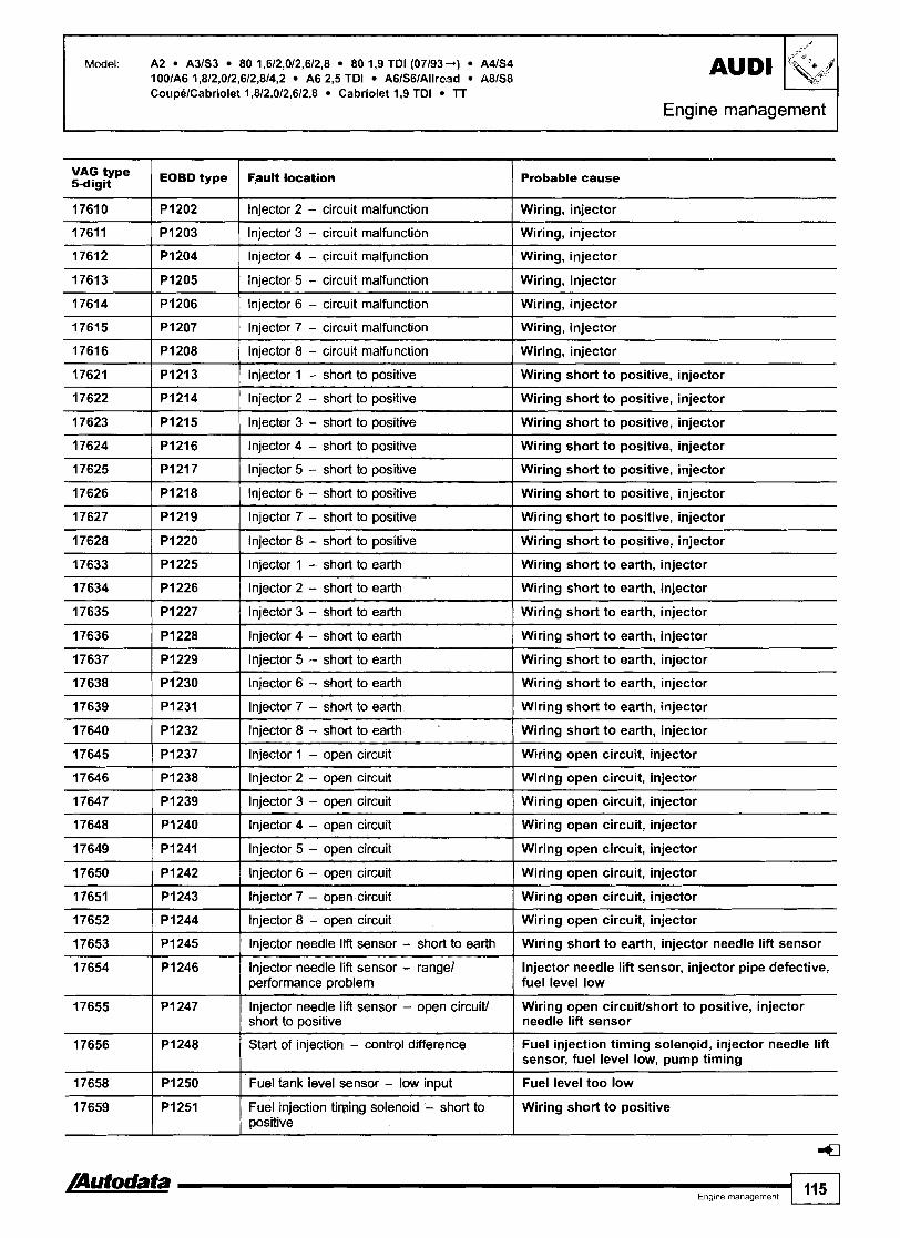
Model: A2 A3lS3 80 1,6/2,012,612,8 80 1,9 TDI (07193+) A 4 6 4 AUDI 100lA6 1,812,012,6/2,814,2 A6 2,s TDI A6/S6/Allrc.~d M I S 8
17611 ( PI203 ( Injector 3 - circuit malfunction 1 Wiring, injector
-4 -'Y+
VAG type 5-digit
1761 0
CoupelCabriolet 1,812,012,612,8 Cabriolet 1,9 TDI lT
Engine management
17614 1 PI206 I Injector 6 - circuit malfunction I Wiring, injector
EOBD type
PI202
17612
1761 3
17621 I PI21 3 I Injector 1 - short to positive I Wiring short to positive, injector
Fault location
Injector 2 - circuit malfunction
P I 204
PI205
17615
1761 6
Probable cause
Wiring, injector
17624 1 PI216 I Injector 4 - short to positive I Wiring short to positive, injector
Injector 4 - circuit malfunction
Injector 5 - circuit malfunction
PI207
PI208
17622
17623
Wiring, injector
Wiring, injector
- - - -
Injector 7 - circuit malfunction
Injector 8 - circuit malfunction
PI214
PI215
17625
17626
17633 1 PI225 1 Injector 1 - short to earth I Wiring short to earth, injector
- - -- --
Wiring, injector
Wiring, injector
17627
17628
17634 1 PI226 1 Injector 2 - short to earth I Wiring short to earth, injector
Injector 2 - short to positive
Injector 3 - short to positive
PI217
PI218
-- - --
17635 [ PI227 1 Injector 3 - short to earth
Wiring short to positive, injector
Wiring short to positive, injector
P I 21 9
PI220
17636 1 PI228 1 Injector 4 - short to earth ] Wiring short to earth, injector
Injector 5 - short to positive
Injector 6 - short to positive
Wiring short to positive, injector
Wiring short to positive, injector
Injector 7 - short to positive
Injector 8 - short to positive
17639 1 PI231 I Injector 7 - short to earth I Wiring short to earth, injector
Wiring short to positive, injector
Wiring short to positive, injector
17637
17638
17646 1 PI238 1 Injector 2 - open circuit I Wiring open circuit, injector
P I 229
PI230
17640
17645
17649 1 PI241 I Injector 5 - open circuit I Wiring open circuit, injector
Injector 5 - short to earth
Injector 6 - short to earth
PI232
PI237
17647
17648
Wiring short to earth, injector
Wiring short to earth, injector
17652 1 PI244 1 Injector 8 - open circuit ( Wiring open circuit, injector
Injector 8 - short to earth
Injector I - open circuit
PI239
P I 240
17650
17651
Wiring short to earth, injector
Wiring open circuit, injector
Injector 3 - open circuit
Injector 4 - open circuit
P I 242
P I 243
17653
17654
17656 1 Start of injection - control difference
Wiring open circuit, injector
Wiring open circuit, injector
17655
Fuel injection timing solenoid, injector needle lift sensor, fuel level low, pump timing
Injector 6 - open circuit
Injector 7 - open circuit
P I 245
P I 246
Wiring open circuit, injector
Wiring open circuit, injector
P I 247
Injector needle lift sensor - short to earth
Injector needle lift sensor - range1 performance problem
17658
17659
Wiring short to earth, injector needle lift sensor
Injector needle lift sensor, injector pipe defective, fuel level low
Injector needle lift sensor - open circuit1 short to positive
Wiring open circuivshort to positive, injector needle lift sensor
4
P I 250
PI251
Fuel tank level sensor - low input
Fuel injection timing solenoid - short to positive
Fuel level too low
Wiring short to positive

Engine management
Model: A2 A3lS3 80 1,6/2,012,6/2,8 80 1,9 TDI (07193 -+) A4lS4 1001A6 1,8/2,012,6/2,8/4,2 A6 2,s TDI AGISGlAllroad A81S8 CoupeICabriolet 1,8/2,012,6/2,8 Cabriolet 1,9 TDI lT
Probable cause
17660
17661
17662
17663
17669 1 PI261 I Injector 1 - control limit exceeded I Control period too long, wiring, injector
PI252
17664
17668
PI253
PI254
PI255
Fuel injection timing solenoid - open circuitlshort to earth
P I 256
PI260
17670
17671
Wiring open circuitlshort to earth, fuel injection timing solenoid
Instrument panel, fuel consumption signal - short to earth
Instrument panel, fuel consumption signal - short to positive
Engine coolant temperature (ECT) sensor - short to earth
17672
17673
Wiring short to earth, instrument panel
Wiring short to positive, instrument panel
Wiring short to earth, ECT sensor
Engine coolant temperature (ECT) sensor - open circuitfshort to positive
Injector 1 - implausible signal
PI262
PI263
17674
17675
17678 / PI270 I Injector 4 - control limit exceeded I Control period too long, wiring, injector
Wiring open circuitlshort to positive, ECT sensor
No control
PI264
PI265
17676
17677
17679 I lnjector 4 - control limit not reached
Injector I - control limit not reached
Injector 2 - implausible signal
PI266
P I 267
Control period too short, fuel level low, air in fuel system
Control period too short, fuel level low, air in fuel system
No control
Injector 2 - control limit exceeded
Injector 2 - control limit not reached
PI268
PI269
17686 1 PI278 1 Fuel metering solenoid - short to positive I Wiring short to positive, fuel metering solenoid
Control period too long, wiring, injector
Control period too short, fuel level low, air in fuel system
Injector 3 - implausible signal
Injector 3 - control limit exceeded
No control
Control period too long, wiring, injector
Injector 3 - control limit not reached
Injector 4 - implausible signal
17689 1 PI281 ( Fuel metering solenoid - short to earth I Wiring short to earth, fuel metering solenoid
Control period too short, fuel level low, air in fuel system
No control
17687 P I 279
17690
17695
17696
Fuel metering solenoid - open circuitfshort to earth
PI282
PI287
17697
17698
Wiring open circuitlshort to earth, fuel metering solenoid
PI288
17699
17700
Fuel metering solenoid - open circuit
Turbocharger (TC) bypass valve - open circuit
PI289
PI290
I7701
17702
Wiring open circuit, fuel metering solenoid
Wiring open circuit, TC bypass valve
Turbocharger (TC) bypass valve - short to positive
PI291
P I 292
Wiring short to positive, TC bypass valve
Turbocharger (TC) bypass valve - short to earth
Engine coolant temperature (ECT) sensor, ECM controlled cooling system - high input
PI293
PI294
Wiring short to earth, TC bypass valve
Wiring, ECT sensor
Engine coolant temperature (ECT) sensor, ECM controlled cooling system - high input
Engine coolant thermostat - open circuit
Wiring, ECT sensor
Wiring open circuit, engine coolant thermostat
Engine coolant thermostat - short to positive
Engine coolant thermostat - short to earth
Wiring short to positive, engine coolant thermostat
Wiring short to earth, engine coolant thermostat

Model: A2 A3lS3 80 1,6/2,012,6/2,8 80 1,9 TDI (07/93-+) A4lS4 1001A6 1,812,012,6/2,8/4,2 A6 2,5 TDI A6lS61Allroad A8IS8 CoupelCabriolet 1,812,012,6/2,8 Cabriolet 1,9 TDI TT
Engine management
VAG type 5-digit 1 EOBD type / Fault location I Probable cause
17703
17704
17705
17707
17708
17733
17734
Pi295
Pi296
Pi297
PI299
Knock control, cylinder 3 - control limit reached
P l 300
P1325
P l 326
Poor quality fuel, incorrect fuel, insecure engine component, KS incorrectly tightenedldefective, shield wiring open circuit, poor connection
Knock control, cylinder 4 - control limit reached
Knock control, cylinder 6 - control limit reached
Turbocharger (TC), bypass - flow malfunction
Engine cooling system - malfunction
Turbocharger (TC)lthrottle valve, hose connection - pressure loss
Fuel metering solenoid - circuit malfunction
Poor quality fuel, incorrect fuel, insecure engine component, KS incorrectly tightenedldefective, shield wiring open circuit, poor connection
Knock control, cylinder 5 - control limit reached
TC wastegate regulating valve, hose connection(s), injector
ECT sensor, coolant thermostat
Hose connection
Wiring, fuel metering solenoid
Randomlmultiple cylinder(s) - misfire detected
Knock control, cylinder 1 - control limit reached
Knock control, cylinder 2 - control limit reached
Poor quality fuel, incorrect fuel, insecure engine component, KS incorrectly tightenedldefective, shield wiring open circuit, poor connection
Poor quality fuel, incorrect fuel, insecure engine component, KS incorrectly tightenedldefective, shield wiring open circuit, poor connection
Poor quality fuel, incorrect fuel, insecure engine component, KS incorrectly tightenedldefective, shield wiring open circuit, poor connection
Fuel level low, fuel gauge tank sensor
Poor quality fuel, incorrect fuel, insecure engine component, KS incorrectly tightenedldefective, shield wiring open circuit, poor connection
Poor quality fuel, incorrect fuel, insecure engine component, KS incorrectly tightenedldefective, shield wiring open circuit, poor connection
17739
-- --
Knock control, cylinder 8 - control limit Poor quality fuel, incorrect fuel, insecure engine reached component, KS incorrectly tightenedldefective,
shield wiring open circuit, poor connection
P1331
17746 I Camshaft position (CMP) sensor, I Wiring open circuiffshort to positive, CMP sensor bank 1 - open circuitkhort to positive
Knock control, cylinder 7 - control limit reached
17743
17744 El
17745
Crankshaft position (CKP) sensorlengine speed (RPM) sensor - interchanged
Camshaft position (CMP) sensor I1 Valve timing, CKPICMP sensor installation, bank llcrankshaft position (CKP) sensor - out of sequence
17749 Ignition amplifier, primary circuit 1 - short to Wiring short to earth, ignition amplifier, 1 earth I CMP sensor, HT leads, spark plugs
P1335
PI336
P1337
Engine torque control - limit reached
Engine torque monitoring - control limit exceeded
Camshaft position (CMP) sensor, bank 1 - short to earth
Throttle control unit, hose(s), TC system, MAP sensor, IAT sensor, MAF sensor, ECT sensor
Hose(s), TC system, throttle control unit, IAT sensor, MAP sensor, MAF sensor, ECT sensor, APP sensor
Wiring short to earth, CMP sensor

b e management
Model: A2 A31S3 80 1,612,012,612,8 80 1,9 TDI (07193 -+) A41S4 1001A6 1,812,012,612,8/4,2 A6 2,5 TDI A6IS6IAllroad A8IS8 CoupelCabriolet 1,8/2,012,6/2,8 Cabriolet 1,9 TDI lT
VAG type I EOBD type 1 Fault location 5-digit , Probable cause
17750
17751
17752
17753
P I 342
17754
17755
17756
PI343
PI344
PI345
17757
17758
17759
Ignition amplifier, primary circuit 1 - short to positive
PI346
PI347
P I 348
17762
17763
Ignition coillamplifier, cylinder 2 - open Wiring open circuit, ignition coillamplifier circuit
Wiring short to positive, ignition amplifier, CMP sensor, HT leads, spark plugs
Ignition amplifier, primary circuit 2 - short to earth
Ignition amplifier, primary circuit 2 - short to positive
Ignition amplifier, primary circuit 3 - short to earth
P I 349
P I 350
P I 351
17764
17765
Wiring short to earth, ignition amplifier, CMP sensor, HT leads, spark plugs
Wiring short to positive, ignition amplifier, CMP sensor, HT leads, spark plugs
Wiring short to earth, ignition amplifier, CMP sensor, HT leads, spark plugs
Ignition amplifier, primary circuit 3 - short to positive
Camshaft position (CMP) sensor 21 bank 2lcrankshaft position (CKP) sensor - out of sequence
Ignition amplifier, primary circuit 1 - open circuit
PI354
PI355
17769 Ignition millamplifier, cylinder 3 - open Wiring open circuit, ignition coillamplifier I circuit
Wiring short to positive, ignition amplifier, CMP sensor, HT leads, spark plugs
Valve timing, CKPICMP sensor installation, CKP sensor rotor
Wiring short to earth, ignition amplifier, CMP sensor, HT leads, spark plugs
Ignition amplifier, primary circuit 2 - open circuit
Ignition amplifier, primary circuit 3 - open circuit
Camshaft position (CMP) sensor, bank 1 - rangelperformance problem
PI356
PI357
17767 Id
17768 Id
17770 1 lgnition coillamplifier, cylinder 3 - short to Wiring short to positive, ignition coillamplifier positive
Wiring short to positive, ignition amplifier, CMP sensor, HT leads, spark plugs
Wiring short to positive, ignition amplifier, CMP sensor, HT leads, spark plugs
Ignore trouble code, erase fault memory
Fuel quantity adjuster position sensor
Ignition coillamplifier, cylinder 1 - open circuit
17771 I lgnition coillamplifier, cylinder 3 - short to Wiring short to earth, ignition coillamplifier 1 earth
Wiring, fuel injection pump
Wiring open circuit, ignition coillamplifier
Ignition coillamplifier, cylinder 1 - short to positive
Ignition coillamplifier, cylinder 1 - short to earth
PI359
PI360
17772 1 Ignition coillamplifier, cylinder 4 - open Wiring open circuit, ignition coillamplifier circuit
Wiring short to positive, ignition coillamplifier
Wiring short to earth, ignition coillamplifier
17773 I lgnition coillamplifier, cylinder 4 - short to Wiring short to positive, ignition coillamplifier positive
Ignition coillamplifier, cylinder 2 - short to positive
Ignition coillamplifier, cylinder 2 - short to earth
17774 I lgnition coillamplifier, cylinder 4 - short to Wiring short to earth, ignition coillamplifier I earth
Wiring short to positive, ignition coillamplifier
Wiring short to earth, ignition coillamplifier
1 118 1 Engne management [Autodata
17775 P I 367 Ignition coillamplifier, cylinder 5 - open circuit
Wiring open circuit, ignition coillamplifier

Model: A2 A31S3 80 1,612,012,612,8 80 1,9 TDI (07193 -+) A41S4 100lA6 1,8/2,0/2,6/2,8/4,2 A6 2,5 TDI A6lS61Allroad A8lS8 CoupelCabriolet 1,8/2,012,6/2,8 Cabriolet 1,9 TDI lT
type 5-digit
17776
17777
17778
EOBD type
17779
17780
P I 368
P I 369
PI370
17781
17782
Fault location
PI371
PI372
17783
17784
Probable cause
Ignition coillamplifier, cylinder 5 - short to positive
Ignition coillamplifier, cylinder 5 - short to earth
Ignition coillamplifier, cylinder 6 - open circuit
P I 373
P I 374
17785
-
Wiring short to positive, ignition coillamplifier
Wiring short to earth, ignition coillamplifier
Wiring open circuit, ignition coillamplifier
Ignition coillamplifier, cylinder 6 - short to positive
Ignition coillamplifier, cylinder 6 - short to earth
P I 375
P I 376
17786
17793
Wiring short to positive, ignition coillamplifier
Wiring short to earth, ignition coillamplifier
Ignition coillamplifier, cylinder 7 - open circuit
Ignition coillamplifier, cylinder 7 - short to positive
P I 377
17794
17795
Wiring open circuit, ignition coillamplifier
Wiring short to positive, ignition coillamplifier
Ignition coillamplifier, cylinder 7 - short to earth
Ignition coillamplifier, cylinder 8 - open circuit
P I 378
P I 385
17796
17797
17799
Wiring short to earth, ignition coillamplifier
Wiring open circuit, ignition coillamplifier
Ignition coil/amplifier, cylinder 8 - short to positive
PI386
P I 387
I7800
Wiring short to positive, ignition coillamplifier
Ignition coillamplifier, cylinder 8 - short to earth
Engine control module (ECM) - defective
PI388
P I 389
PI391
17801
17802
Wiring short to earth, ignition coillamplifier
ECM
Engine control module (ECM), knock control - defective
Engine control module (ECM), BAR0 sensor - defective
P I 392
17803
17805
ECM
ECM
Engine control module (ECM), ETS - defective
Engine control module (ECM) 2 - defective
Camshaft position (CMP) sensor 21 bank 2 - short to earth
P I 393
P I 394
17806
17807
ECM
ECM
Wiring short to earth, CMP sensor
Camshaft position (CMP) sensor 21 bank 2 - open circuitlshort to positive
P I 395
PI397
17808
Wiring open circuitlshort to positive, CMP sensor
Ignition amplifier, primary circuit 1 - circuit malfunction
Ignition amplifier, primary circuit 2 - circuit malfunction
P I 398
P I 399
Wiring, ignition amplifier, HT leads, spark plugs
Wiring, ignition amplifier, HT leads, spark plugs
Ignition amplifier, primary circuit 3 - circuit malfunction
Crankshaft position (CKP) sensorlengine speed (RPM) sensor - control limit reached
P I 400
Wiring, ignition amplifier, HT leads, spark plugs
lnsecureldamaged rotor, CKPIRPM sensor
Crankshaft position (CKP) sensortengine speed (RPM) sensor - short to earth
Crankshaft position (CKP) sensorlengine speed (RPM) sensor - short to positive
Wiring short to earth, CKPIRPM sensor
Wiring short to positive, CKPIRPM sensor
Exhaust gas recirculation (EGR) valve1 solenoid, bank 1 - circuit malfunction
Wiring, EGR valve

Engine management r Model: A2 A3lS3 80 1,6/2,012,612,8 80 1,9 TDI (07193 -+) A4lS4
100lA6 1,8/2,012,6/2,8/4,2 A6 2,5 TDI A6lS61Allroad A81S8 CoupelCabriolet 1,8/2,0/2,6/2,8 Cabriolet 1,9 TDI TT
VAG type I EOBD type I Fault location 5-digit Probable cause
17809
1781 0
17811
1781 2
PI401
PI402
17815
17816
1781 7
PI403
PI404
17818
1781 9
Exhaust gas recirculation (EGR) valve1 solenoid, bank 1 - short to earth
Exhaust gas recirculation (EGR) valve1 solenoid, bank 1 - short to positive
PI407
PI408
PI409
17822
17823
17824
17830 1 PI422 Secondary air injection (AIR) valve1 Wiring short to positive, AIR valvelsolenoid solenoid - short to positive
Wiring short to earth, EGR valve
Wiring short to positive, EGR valvelsolenoid
Exhaust gas recirculation (EGR) system - control difference
Exhaust gas recirculation (EGR) system - basic setting
PI410
PI411
17828
17829
17831 I Secondary air injection (AIR) system, Hose connection(s), AIR valvelsolenoid bank 1 - insufficient flow detected
Basic setting not carried out, EGR system
Basic setting not carried out, EGR system
Exhaust gas recirculation temperature (EGRT) sensor - low input
Exhaust gas recirculation temperature (EGRT) sensor - high input
Evaporative emission (EVAP) canister purge valve - circuit malfunction
PI414
PI415
PI416
I Secondary air injection (AIR) system, bank 1 - leak detected
Wiring short to earth, EGRT sensor
Wiring short to positive, earth wire defective, EGRT sensor
Wiring, EVAP canister purge valve
Evaporative emission (EVAP) canister purge valve - short to positive
Secondary air injection (AIR) system, bank 2 - insufficient flow detected
PI420
PI421
AIR valve, exhaust leak
Wiring short to positive, EVAP canister purge valve
Intake leak, hose@) blockedlleaking, AIR valvelsolenoid
Secondary air injection (AIR) system, bank 2 - leak detected
Exhaust gas recirculation (EGR) valve position sensor - lower limit exceeded
Exhaust gas recirculation (EGR) valve position sensor - upper limit exceeded
Intake leak, hose(s) leaking, AIR valvelsolenoid
Basic setting not carried out
Basic setting not carried out
Secondary air injection (AIR) valve1 solenoid - circuit malfunction
Secondary air injection (AIR) valve1 solenoid - short to earth
Wiring, AIR solenoid
Wiring short to earth, AIR valvelsolenoid
17833
17834
17835
17836
PI425
PI426
17837
17838
PI427
PI428
17839
17840
Evaporative emission (EVAP) canister purge valve - short to earth
Evaporative emission (EVAP) canister purge valve - open circuit
PI429
PI430
Wiring short to earth, EVAP canister purge valve
Wiring open circuit, EVAP canister purge valve
Vacuum pump, brakes - short to positive
Vacuum pump, brakes - short to earth
PI431
PI432
Wiring short to positive, vacuum pump
Wiring short to earth, vacuum pump
Vacuum pump, brakes - open circuit
Vacuum pump, brakes - open circuitlshort to positive
Wiring open circuit, vacuum pump
Wiring open circuitlshort to positive, vacuum pump
Vacuum pump, brakes - open circuitlshort to earth
Secondary air injection (AIR) valve1 solenoid - open circuit
Wiring open circuitlshort to earth, vacuum pump
Wiring open circuit, fuse, AIR valvelsolenoid

Model: A2 A3lS3 80 1,6/2,012,612,8 80 1,9 TDI (07/93+) A4lS4 1001A6 1,812,012,612,8/4,2 A6 2,s TDI A6lS61Allroad A8lS8 CoupelCabriolet 1,8/2,0/2,612,8 Cabriolet 1,9 TDI lT
Engine management I VAG type I EOBD type 1 Fault location 5-digit Probable cause
17841
17842
17843
17844
PI433
PI434
17845
17846
17847
PI435
PI436
17848
17849
17850
Secondary air injection (AIR) pump relay - open circuit
Secondary air injection (AIR) pump relay - short to positive
PI437
PI438
P 1439
17851
17852
17858
Wiring open circuit, fuse, AIR pump relay
Wiring short to positive, AIR pump relay
Secondary air injection (AIR) pump relay - short to earth
Secondary air injection (AIR) pump relay - circuit malfunction
PI440
PI441
PI442
17859
17860
Wiring short to earth, AIR pump relay
Wiring, AIR pump relay
Exhaust gas recirculation (EGR) valve1 solenoid, bank 2 - short to positive
Exhaust gas recirculation (EGR) valve1 solenoid, bank 2 - open circuitlshort to earth
Exhaust gas recirculation (EGR) valve position sensor - basic setting
PI443
PI444
PI450
Exhaust gas recirculation temperature (EGRT) sensor llbank 1 - open circuitl short to positive
Wiring short to positive, EGR valvelsolenoid
Wiring open circuitlshort to earth, EGR valvelsolenoid
Basic setting not carried out, EGR system
Exhaust gas recirculation (EGR) valve - open circuit
Exhaust gas recirculation (EGR) valve1 solenoid, bank 1 - open circuitlshort to earth
Exhaust gas recirculation (EGR) valve position sensor - high input
PI451
PI452
Wiring open circuitlshort to positive, EGRT sensor
PI454
PI455
Wiring open circuit, EGR valve
Wiring open circuitlshort to earth, EGR solenoid
Wiring short to positive, EGR valve position sensor
Exhaust gas recirculation (EGR) valve position sensor - low input
Exhaust gas recirculation (EGR) valve position sensor - rangelperformance problem
Secondary air injection (AIR) system - short to positive
-
Exhaust gas recirculation temperature (EGRT) control, bank 1 - control limit reached
Wiring short to earth, EGR valve position sensor
Wiring, EGR valve position sensor
Wiring short to positive, AIR relay
Secondary air injection (AIR) system - short to earth
Secondary air injection (AIR) system - open circuit
Exhaust gas recirculation temperature (EGRT) sensor llbank 1 - short to earth
Exhaust gas recirculation temperature (EGRT) sensor llbank 1 - range1 performance problem
EGRT sensor
Exhaust gas recirculation temperature (EGRT) sensor 2lbank 2 - open circuitl short to positive
Wiring short to earth, AIR relay
Wiring open circuit, AIR relay
Wiring short to earth, EGRT sensor
Exhaust leak, wiring, EGRT sensor
Wiring open circuitlshort to positive, EGRT sensor
17866 PI458 Exhaust gas recirculation temperature (EGRT) sensor 2lbank 2 - short to earth
Wiring short to earth, EGRT sensor

Model: A2 A31S3 80 1,612,012,6/2,8 80 1,9 TDI (07193 +) A41S4 1001A6 1,812,012,6/2,8/4,2 A6 2,s TDI A6IS6IAllroad A868 CoupelCabriolet 1,8/2,012,6/2,8 Cabriolet 1,9 TDI TT
VAG lype I EOBD type 5-digit Fault location Probable cause
Exhaust gas recirculation temperature (EGRT) sensor 2lbank 2 - range1 performance problem
Exhaust leak, wiring, EGRT sensor
Exhaust gas recirculation temperature (EGRT) control, bank 2 - control limit reached
EGRT sensor
Exhaust gas recirculation temperature (EGRT) control, bank 1 - range1 performance problem
Vacuum system, brakes - mechanical fault I Vacuum pump
Exhaust leaklblockage, EGRT sensor
Exhaust gas recirculation temperature (EGRT) control, bank 2 - range1 performance problem
Exhaust leaklblockage, EGRT sensor
Fuel pump relay - circuit malfunction
Fuel pump relay - short to earth
Wiring, fuel pump relay
Wiring short to earth, fuel pump relay
Fuel pump relay - short to positive
Alternator load signal
Wiring short to positive, fuel pump relay
Wiring, alternator
Intake system - leak detected
Closed throttle position (CTP) switch - does not close
Idle speed control (ISC) - upper limit Throttle control unitlbasic setting, intakelexhaust reached leak, mechanical fault, AC signals
Intake leak, EGR system, EVAP system, hose connection(s), throttle control unit
Throttle cablelvalve, wiring open circuitlshort to positive, CTP switch adjustmentldefective, ECM
Closed throttle position (CTP) switch - does not open
Idle speed control (KC) - lower limit reached
Moisture ingress, wiring short to earth, CTP switch adjustmentldefective, ECM
Throttle control unitl basic setting, intakelexhaust leak, mechanical fault, AC signals
Idle air control (IAC) valve - circuit malfunction
Idle air control (IAC) valve - short to positive
Wiring, IAC valve
Wiring open circuitlshort to positive, IAC valve
Intake manifold air control solenoid 1 - current circuit
Intake manifold air control solenoid 1 - short to positive
Intake manifold air control solenoid 2 - short to positive
Intake manifold air control solenoid 1 - Wiring open circuit, intake manifold air control open circuit solenoid
Wiring, intake manifold air control solenoid
Wiring short to positive, intake manifold air control solenoid
Wiring short to positive, intake manifold air control solenoid
Intake manifold air control solenoid 2 - short to earth
Intake manifold air control solenoid 1 - short to earth
Engine control relay - circuit malfunction I Wiring, engine control relay
Wiring short to earth, intake manifold air control solenoid
Wiring short to earth, intake manifold air control solenoid
Engine control relay - short to positive
Camshaft position (CMP) control, bank 1 - malfunction
Wiring short to positive, engine control relay
Cylinder head oil pressure too low, CMP actuator stickingldefective

Model: A2 A31S3 80 1,612,012,612,8 80 1,9 TDI (07193 -+) A41S4 1001A6 1,812,012,612,814,2 A6 2,s TDI A6lS61Allroad A81S8 CoupelCabriolet 1,8/2,012,6/2,8 Cabriolet 1,9 TDI TT
Engine management I type
5-digit
17928
17930
EOBD type
17931
17932
P I 520
P I 522
17933
17934
Fault location
P1523
PI524
17935
17936
Probable cause
Intake manifold air control solenoid 2 - open circuit
Camshaft position (CMP) control, bank 2 - malfunction
P1525
P1526
17937
17938
Wiring open circuit, intake manifold air control solenoid
Cylinder head oil pressure too low, CMP actuator stickingldefective
SRS crash signal received
Fuel pump relay - open circuiffshort to earth
P i 527
PI528
17939
17940
17943 1 Camshaft position (CMP) actuator, / Wiring short to earth, CMP actuator bank 2 - short to earth
Airbag triggered
Wiring open circuitlshort to earth, fuel pump relay
Camshaft position (CMP) actuator, bank 1 - circuit malfunction
Camshaft position (CMP) actuator, bank 1 - short to positive
P i 529
P1530
17941
17942
17944 I Camshaft position (CMP) actuator, / Wiring open circuit, CMP actuator bank 2 - open circuit
Wiring, CMP actuator
Wiring short to positive, CMP actuator
Camshaft position (CMP) actuator, bank 1 - short to earth
Camshaft position (CMP) actuator, bank 1 - open circuit
P I 531
P1532
Wiring short to earth, CMP actuator
Wiring open circuit, CMP actuator
Camshaft position (CMP) actuator - short to positive
Camshaft position (CMP) actuator - short to earth
P1533
P1534
-
17947 i p1539 I Clutch pedal position (CPP) Wiring, CPP switch switch - rangelperformance problem
Wiring short to positive, CMP actuator
Wiring short to earth, CMP actuator
Camshaft position (CMP) actuator - open circuit
Idle control - lean running speed below specification
17945
17946
17948 I P1540 Vehicle speed signal - high input Excessive vehicle speed, instrument panel
defective
Wiring open circuit, CMP actuator
Throttle control unit
Camshaft position (CMP) actuator, bank 2 - circuit malfunction
Camshaft position (CMP) actuator, bank 2 - short to positive
- - -
Wiring, CMP actuator
Wiring short to positive, CMP actuator
P1537
PI538
-
17949
17950
17951
17952
Fuel shut& solenoid - malfunction
Fuel shut-off solenoid - open circuiffshort to earth
17953
Fuel shut-off solenoid (leakinglsticking)
Wiring open circuitlshort to earth, fuel shut-off solenoid
P1541
P1542
P1543
P1544
P1545
Fuel pump relay - open circuit
Throttle motor position sensor 1 - range1 performance problem
Throttle motor position sensor 1 - low input
Throttle motor position sensor 1 - high input
Wiring open circuit, fuel pump relay
Throttle valve requires cleaning, wiring, throttle motor position sensor
Wiring short to earth, throttle motor position sensor
Wiring short to positive, throttle motor position sensor
I
Throttle valve control - malfunction Throttle valve tightlsticking, wiring, throttle control unit

I'kk4f1 AUDl
Engine management r Model: A2 A31S3 80 1,612,012,612,8 80 1,9 TDI (07193 -+) A4lS4
1001A6 1,8/2,012,612,814,2 A6 2,5 TDI A6IS6IAllroad A81S8 CoupelCabriolet 1,812,012,6/2,8 Cabriolet 1,9 TDI lT
17955 1 Turbocharger (TC) wastegate regulating Wiring short to earth, TC wastegate regulating valve - short to earth valve
type 5-digit
17954
EOBD type
P I 546
17956 1 PI548
Turbocharger (TC) pressure - control difference
Fault location
Turbocharger (TC) wastegate regulating valve - short to positive
Turbocharger (TC) wastegate regulating valve - open circuit
Turbocharger (TC) wastegate regulating vatve - open circuitlshort to earth
17957
lntakelexhaust leak, hoses interchangedlnot connected, MAP sensor, TC wastegate regulating valve, turbocharger (TC) wastegate actuator, TC
P I 553
P I 554
Probable cause
Wiring short to positive, TC wastegate regulating valve
Wiring open circuit, TC wastegate regulating valve
Wiring open circuitlshort to earth, TC wastegate regulating valve
P I 549
Turbocharger (TC) pressure - upper limit exceeded
I7966 i Idle speed control (ISC) actuatorlthrottle Wiring, ISC actuatorlthrottle motor motor - circuit malfunction
Manifold absolute pressure (MAP) sensor1 barometric pressure (BARO) sensor - rangelperformance problem
Throttle control unit - basic setting conditions
Hoses interchangedlnot connected, TC wastegate regulating valve, turbocharger (TC) wastegate actuator, TC
P I 556
P I 557
Throttle control unit - basic setting Accelerator pedal or starter motor operated malfunction during basic setting
lntakelexhaust leak, EGR system, EVAP canister purge valve, throttle control unit, wiring, MAP sensor, BAR0 sensor
Basic setting conditions not met
I7968 I I Maximum engine RPM exceeded Incorrect gear shift, wiring open circuit, CKPIRPM sensor
Turbocharger (TC) pressure - control limit not reached
Turbocharger (TC) pressure - control limit exceeded
17969 / PI561 I Fuel quantity adjuster - control difference I Wiring, fuel injection pump
TC wastegate regulating valve, intake leak, TC defective
Hose connection interchangedlnot connected
17970
17971
17972
P I 562
P I 563
17973
17974
PI564
17976
17977
I -- --
P I 572 Engme mounting control solenoid, bank 2 - short to earth
Fuel quantity adjuster - upper stop value
Fuel quantity adjuster - lower stop value
PI565
P I 566
17978
- --
Wiring short to earth, engine mounting control solenoid
Fuel quantity adjuster blockedldefective, stop value reached
Fuel quantity adjuster blockedldefective, lower stop value reached
Throttle control unit - voltage low during basic setting
PI568
P I 569
Battery, wiring
Throttle control unit - lower stop not reached
AC compressor, load signal - implausible signal
P I 570
Throttle valve tightlsticking, ISC actuator
Wiring, AC system
Throttle control unit - mechanical fault
Cruise control master switch
17979 I
Throttle valve tightlsticking
Wiring, cruise control master switch
Engine control module (ECM) - immobilizer active
lncorrectldamaged key, incorrectly coded, ECMlimmobilizer replacement without coding, wiring, immobilizer defective
Engine mounting control solenoid, bank 2 - short to positive
Wiring short to positive, engine mounting control solenoid

Model: A2 A 3 6 3 80 1,6/2,0/2,6/2,8 80 1,9 TDI (07193 -) A 4 6 4 1001A6 1,8/2,0/2,6/2,8/4,2 A6 2,5 TDI A6IS6lAllroad A 8 6 8 CoupelCabriolet 1,8/2,0/2,612,8 Cabriolet 1,9 TDI TT
vAG type 1 EOBD type / Fault location 5-digit Probable cause
17981
17983
17984
17988 1 PI580 I Throttle motor, bank 1 - circuit malfunction I Wiring, throttle motor
PI573
17985
17987
PI575
P I 576
Engine mounting control solenoid, bank 2 - open circuit
P I 577
PI579
17989
17990
Wiring open circuit, engine mounting control solenoid
Engine mounting control solenoid, bank 1 - short to positive
Engine mounting control solenoid, bank 1 - short to earth
17993
17994
17997
I I I
18001 El 1 PI593 I Altitude adaption - signal outside tolerance I Intake leak, MAF sensor, throttle control unit
Wiring short to positive, engine mounting control solenoid
Wiring short to earth, engine mounting control solenoid
Engine mounting control solenoid, bank 1 - open circuit
Throttle control unit - basic settinq
PI581
P I 582
17998
18000
Wiring open circuit, engine mounting control solenoid
Basic setting not carried out
PI585
P I 586
PI589
Throttle control unit - basic setting
Idle speed adaptation - limit reached
P I 590
PI592
18007
1801 0 I Engine control module (ECM) - supply voltage low from battery
Basic setting not carried out
lntakelexhaust leak, AIR system, fuel pressure1 pump, injector(s), EVAP canister purge valve
Throttle control unit - lower stop not reached
Engine mounting control solenoid, bank 1 8 2 - short to positive
AClheater air temperature control switch - short to earth
18008
18009
Battery was disconnected, battery discharged, alternator, wiring open circuit, fuse
Throttle motor, throttle control unit
Wiring short to positive, engine mounting control solenoid
Wiring short to earth, AClheater air temperature control switch
AClheater air temperature control switch - open circuit
Barometric pressure (BARO) sensor1 manifold absolute pressure (MAP) sensor - implausible ratio
P I 599
18011 I PI603 I Engine control module (ECM) - defective I ECM
Wiring open circuit, AClheater air temperature control switch
TC system, MAP sensor
PI600
P I 601
Idle control - lean running speed above specification
18016 / P I 6 0 8 Power steering pressure (PSP) switch - Wiring, PSP switch I circuit malfunction
IAC valve
Engine control module (ECM) - supply voltage low from ignition switch
Engine control module (ECM) - supply voltage
-
18012
18014
Battery, alternator, wiring open circuit
Wiring, engine control relay
18018 / PI610 / Engine control module (ECM) - defective ECM
P I 604
PI606
1801 7
1801 9 Malfunction indicator lamp (MIL) - short to Wiring short to earth I earth
- -
~ G n e cont~module E M ) - defective
Rough road signal - circuit malfunction
PI609
- - - --
ECM
ABS control module trouble code@) stored, CAN data bus
18020
18021
Engine control module (ECM) - crash switch-off triggered
Airbag triggered
4
PI612
PI613
Engine control module (ECM) - coding
Malfunction indicator lamp (MIL) - open circuitlshort to positive
Incorrectly coded
Wiring open circuitlshort to positive

)Engine management
Model: A2 A31S3 80 1,6/2,0/2,6/2,8 80 1,9 TDI (07193+) A464 1001A6 1,812,012,612,8/4,2 A6 2,s TDI A6IS6IAllroad A81S8 CoupelCabriolet 1,8/2,012,612,8 Cabriolet 1,9 TDI l 7
18024 1 PI616 ( Glow plug warning lamp - short to positive I Wiring short to positive
type 5-digit
18023
I Glow plug warning lamp - open circuit/ Bulb, wiring open circuiffshort to earth short to earth
18026 1 PI618 I Glow plug relay - short to positive 1 Wiring short to positive, glow plug relay
EOBD type
PI615
18029 I lnstrument panel, ECT signal - short to Wiring short to earth, instrument panel 1 earth
Fault location
Engine oil temperature (EOT) sensor - rangelperformance problem
18027
18028
18030 1 lnstrument panel, ECT signal - implausible Wiring, instrument panel, ECT sensor signal
Probable cause
Engine oil level, wiring, EOT sensor
P I 61 9
P I 620
18031
18034 1 PI626 1 CAN data bus, TCM - no signal I TCM trouble code(s) stored, TCM incorrectly
Glow plug relay - open circuit/short to earth
Instrument panel, ECT signal - open circuit/short to positive
18032
18033
I I I coded, wiring, matching resistor in ECM
--
Wiring open circuiffshort to earth, glow plug relay
Wiring open circuiffshort to positive, instrument panel
PI623
P I 624
PI625
I
18037
18038
CAN data bus - no signal
Malfunction indicator lamp (MIL) - request signal active
CAN data bus, TCM - incorrect signal
18039
18040
- I - -
CAN data bus, AC - no signal AC control module trouble code(s) stored, wiring, matching resistor in ECM
Trouble code(s) stored in other system(s), wiring, matching resistor in ECM
Trouble code(s) stored in other system(s)
TCM trouble code@) stored, TCM incorrectly coded, wiring, matching resistor in ECM
PI629
P I 630
18041
18042
PI631
PI632
18045 / CAN data bus, electronic CE - no signal code@) stored, wiring, matching resistor
CAN data bus, cruise control - no signal
Accelerator pedal position (APP) sensor 1 - low input
P I 633
PI634
18044
1 Accelerator pedal position (APP) Wiring, APP sensor sensor 112 - rangelperformance problem
Cruise control trouble code@) stored, wiring, matching resistor in ECM
Wiring short to earth, APP sensor
Accelerator pedal position (APP) sensor 1 - high input
Accelerator pedal position (APP) sensor - supply voltage
18048 1 PI640 I Engine control module (ECM) - defective I ECM
Wiring short to positive, APP sensor
Operating voltage too highllow, wiring
Accelerator pedal position (APP) sensor 2 - low input
Accelerator pedal position (APP) sensor 2 - high input
PI636
Wiring short to earth, APP sensor
Wiring short to positive, APP sensor
CAN data bus, SRS - no signal
I8050
18053
1 '26 1 Engne management [Autodata
SRS control module trouble code@) stored, wiring, matching resistor in ECM
18056
PI642
P I 645
PI648
SRS control module - system malfunction
CAN data bus, 4WD - no signal
Trouble code@) stored
4WD trouble code(s) stored, wiring, matching resistor in ECM
CAN data bus - defective Wiring, matching resistor in ECM

Model: A2 A3lS3 80 1,6/2,012,6/2,8 80 1,9 TDI (07193 -+) A4lS4 100lA6 1,8/2,012,6/2,8/4,2 A6 2,5 TDI A6lS61Allroad A8lS8
AUDI CoupelCabriolet 1,8/2,0/2,6/2,8 Cabriolet 1,9 TDI TT
Engine management
VAG 'ype I EOBD type I ~ a u m loution 5-digit Probable cause I I I
18057 1 PI649 I CAN data bus, ABS - no signal ( ABS control module trouble code(s) stored, . . I wirinq, matchinq resistor in ECM
18058
18060
18064 ( PI656 1 AC signal - short to earth I Wiring short to earth
18061
18062
PI650
PI652
PI653
P I 654
18065
18066
CAN data bus, instrumentation - no signal
Transmission control module (TCM) - system malfunction
18067
18068
18071 / PI663 ( Injector, activation - short to positive ( Wiring short to positive, ECM
Instrumentation control module trouble code@) stored, wiring, matching resistor in ECM
Trouble code@) stored
ABS control module - system malfunction
Instrumentation control module - system malfunction
PI657
P I 658
18069
18070
18072 1 PI664 I Iniector, activation - current circuit I Wiring open circuitkhort to earth
Trouble code(s) stored
Trouble code stored for engine oil levell temperature sensor
P i 659
PI660
18073 ( PI665 ( Injector - mechanical fault / Injector
AC signal - short to positive
CAN data bus, cruise control - incorrect signal
PI661
PI662
Wiring
Cruise control trouble code@) stored, wiring, matching resistor in ECM
Engine coolant blower motor, speed 1 - short to positive
Engine coolant blower motor, s ~ e e d I - short to earth
18076 1 PI668 1 Injector 3 - current circuit ( Wiring open circuitkhort to earth
Wiring short to positive, engine coolant blower motor
Wiring short to earth, engine coolant blower motor
Engine coolant blower motor, speed 2 - short to positive
Engine coolant blower motor, speed 2 - short to earth
18074
18075
Wiring short to positive, engine coolant blower motor
Wiring short to earth, engine coolant blower motor
PI666
P I 667
18077
18080
18082
18084
18086 PI678 ( ETS warning lamp - short to earth Instrumentation control module trouble code@) stored, wiring short to earth, matching resistor in
Injector 1 - current circuit
Injector 2 - current circuit
PI669
PI672
ETS warning lamp - short to positive
18087 PI679 1 ETS warning lamp - open circuit
Wiring open circuitlshort to earth
Wiring open circuitkhort to earth
PI674
PI676
Instrumentation control module trouble code(s) stored, wiring short to positive, matching resistor in ECM
lnstrumentation control module trouble code@) stored, wiring open circuit, matching resistor in 1 ECM
Injector 4 - current circuit
Engine coolant blower motor, speed I - open circuitlshort to earth
Wiring open circuitlshort to earth
Wiring open circuitkhort to earth
CAN data bus, instrumentation - incorrect signal
ETS warning lamp - circuit malfunction
[Autodata Englne management 127
Wiring, instrumentation control module trouble code(s) stored, matching resistor in ECM
Instrumentation control module trouble code(s) stored, wiring, matching resistor in ECM
18088
18089
PI680
P I 681
Limp-home mode - active
Engine control module (ECM) - programming incomplete
Throttle control unit, APP sensor
ECM

Model: A2 A363 80 1,612,012,6/2,8 80 1,9 TDI (07193 +) A464 1001A6 1,8/2,012,612,814,2 A6 2,s TDI A6IS6IAllroad A81S8 CoupelCabriolet 1,8/2,012,612,8 Cabriolet 1,9 TDI TT
nglne management
VAG type 5-digit
18090
Probable cause
PI682 / CAN data bus. ABS - implausible signal ABS control module trouble code@) stored, wiring, matching resistor in ECM
PI683 I CAN data bus. SRS - implausible signal SRS control module trouble code@) stored, wiring, matching resistor in ECM
Malfunction indicator lamp (MIL) - circuit lnstrumentation control module trouble code@) malfunction stored, wiring, matching resistor in ECM
PI692 Malfunction indicator lamp (MIL) - short to control module trouble code(s) 1 earth stored, wiring short to earth, matching resistor in
PI691
lnstrumentation control module trouble code(s) stored, wiring short to positive, matching resistor in ECM
Wiring, matching resistor in ECM
Malfunction indicator lamp (MIL) - open circuit
P I 693
Instrumentation control module trouble code(s) stored, wiring open circuit, matching resistor in ECM
Malfunction indicator lamp (MIL) - short to positive
PI851 I CAN data bus, ABS - incorrect signal ABS trouble code(s) stored, wiring, matching resistor in ECM
PI696
PI853 I CAN data bus, ABS - incorrect signal ABS trouble code@) stored, wiring, matching resistor in ECM
CAN data bus, steering column electronics - incorrect signal
P I 854 I CAN data bus, ABS - defective ABS trouble code(s) stored, wiring, matching resistor in ECM
PI900
PI901
PI902
PI903
PI906 Charge air coolant pump relay - open Wiring open circuitlshort to earth, charge air circuitlshort to earth coolant pump relay
Engine coolant blower motor, speed 2 - open circuitlshort to earth
Engine coolant blower motor run-on relay - short to positive
PI904
PI905
PI907 I Data bus, ECM 112 - defective 1 Wiring
Wiring open circuitlshort to earth, engine coolant blower motor
Wiring short to positive, engine coolant blower motor run-on relay
Engine coolant blower motor run-on relay - open circuitlshort to earth
Engine coolant hydraulic blower motor solenoid - short to positive
Wiring open circuitlshort to earth, engine coolant blower motor run-on relay
Wiring short to positive, engine coolant hydraulic blower motor solenoid
Engine coolant hydraulic blower motor solenoid - open circuitlshort to earth
Charge air coolant pump relay - short to positive
Wiring open circuitlshort to earth, engine coolant hydraulic blower motor solenoid
Wiring short to positive, charge air coolant pump relay
PI908
PI909
PI913 Brake servo pressure sensor - short to Wiring short to earth, brake servo pressure I earth sensor
PI910
PI911
PI912
Data bus, ECM 112 - software version monitoring
Data bus, ECM 112 - no signal from ECM 1
Data in ECM I & ECM 2 does not match
Wiring, ECM 1
Data bus, ECM 112 - no signal from ECM 2
Data bus, ECM 112 - circuit malfunction
Brake servo pressure sensor - open circuitlshort to positive
Wiring, ECM 2
Wiring, ECM 112
Wiring open circuitlshort to positive, brake servo pressure sensor

Model: A2 A3lS3 80 1,612,012,612,8 80 1,9 TDI (07193-) A41S4 1001A6 1,812,012,6/2,814,2 A6 2,5 TDI A6IS6IAllroad A 8 6 8 CoupelCabriolet 1,8/2,012,6/2,8 Cabriolet 1,9 TDI TT
AUDI
Engine management 1
VAG type 5-digit 1 EOBD type 1 Fault location Probable cause
18331 ( P1923 1 Engine control module (ECM) 2 - malfunction I Trouble code(s) stored
18322
18328
-
19456 I P3000 CAN data bus, instrumentation - glow plug Wiring, matching resistor in ECM warning lamp
19458 I P3002 Accelerator pedal position (APP) sensor - APP sensor transmission kick-down switch
Pi914
P1920
Brake servo pressure sensor - range1 performance problem
Engine mounting control solenoid, bank 1 & 2 - open circuiffshort to earth
19459
19461
Vacuum leak, wiring, brake servo pressure sensor
Wiring open circuitlshort to earth, engine mounting control solenoid
19463
19464
P3003
P3005
19465
19466
P3007
P3008
19467
19468
19471 I P3015 I Fuel bypass valve - short to positive I Wiring short to positive, fuel bypass valve
Engine coolant heater relay 1, low output
Engine coolant heater relay 2, high output
P3009
P3010
19469
19470
-- -
Wiring, engine coolant heater relay
Wiring, engine coolant heater relay
Camshaft position (CMP) sensor - no signal
Camshaft position (CMP) sensor - signal limit exceeded
P3011
P3012
Air gap, insecure sensorlrotor, wiring, CMP sensor
Insecure rotor, camshaft alignment
Fuel cooling pump relay - short to positive
Fuel cooling pump relay - open circuiff short to earth
P3013
P3014
19472
19496
19561 I P3105 Intake manifold air control solenoid - open Wiring open circuitlshort to earth, intake manifold circuit/short to earth air control solenoid
Wiring short to positive, fuel cooling pump relay
Wiring open circuitlshort to earth, fuel cooling pump relay
Fuel pump relay - short to positive
Fuel pump relay - open circuiffshort to earth
19497
19560
Wiring short to positive, fuel pump relay
Wiring open circuitlshort to earth, fuel pump relay
Turbocharger (TC) wastegate regulating valve B - short to positive
Turbocharger (TC) wastegate regulating valve B - open circuiffshort to earth
P3016
P3040
Trouble code may be displayed if engine is not idling during self-diagnosis due to missing CKP sensor signal. Ignore trouble code if engine starts. Located at rear of exhaust camshaft. Throttle control unit incorporates the following components: TP sensor, CTP switch (if fitted), ISC actuatorlposition sensor or throttle motorlposition sensor. May also produce HT voltage for cylinder 4.
H May also produce HT voltage for cylinder 3. Incorporates heated oxygen sensor (H02S) 2.
4
Wiring short to positive, TC wastegate regulating valve
Wiring open circuitlshort to earth, TC wastegate regulating valve
P3041
P3104
19717
65280
65535
Fuel bypass valve - open c~rcuiffshort to earth
Gear ratio - imptausible
Wiring open circuitlshort to earth, fuel bypass valve
Transmission fault
CAN data bus, instrumentation - implausible ECT signal
Intake manifold air control solenoid - short to msitive
P3262
-
-
Wiring, matching resistor in ECM
Wiring short to positive, intake manifold air control solenoid
Heated oxygen sensor (H02S) 2, bank 1 & 2 - interchanged
CAN data bus, ABS - defective
Engine control module (ECM) - defective
H02S 2 on bank 1 8 2 incorrectly installed
ABS trouble code@) stored, wiring, matching resistor in ECM
ECM

Engine management
Model: 80 1,612,O 1001A6 2,O
Year: 1991 -07192
Engine code: M E , ABM, ABT
System: Bosch Mono-Motronic MA1.2.1
80 - in underbonnet fuseboxlrelay plate
NOTE: 35 pin ECM multi-plug.
General information Refer to the front of this manual for general test conditions, terminology, detailed descriptions of wiring faults and a general trouble shooter for electrical and mechanical faults. Trouble codes are displayed by using an LED connected to the data link connector (DLC).
n The ECM fault memory can also be checked and erased using diagnostic equipment connected to the data link connector (DLC). Self-diagnosis using flash type trouble codes may not display all available diagnostic information. Carry out road test for 10 minutes.
Accessing Ensure ignition switched OFF. Bridge black data link connector (DLC) terminal 1 H [A] and brown or white data link connector (DLC) terminal 1 H [B] with a switched lead - contacts normally open. Connect LED test lamp between black data link connector (DLC) terminal 2 [A] and ECM terminal 33. 80: ECM located behind passenger's glovebox. 100: ECM located in plenum chamber.
NOTE: DO NOT disconnect ECM multi-plug as this will erase fault memory.
Start engine. Allow to idle. NOTE: If engine does not start: Crank engine for 6 seconds.
Leave ignition switched ON.
Operate switch for 4 seconds. Release switch. Check that LED flashes. Count LED flashes. Note trouble code. Each trouble code consists of four groups of one to four flashes. A 2,5 second pause separates each trouble code group [A].
100lA6 - in underbonnet relay plate
Repeat switch operation. Note trouble codes. Compare with trouble code table. End of test sequence indicated by trouble code 0000 (long flashes). Switch ignition OFF. Rectify faults as necessary.

Model. 80 1,612,O 1001A6 2,O
Engine management
Erasing
Method 1
Ensure ignition switched OFF. Bridge black data link connector (DLC) terminal 1 [A] and brown or white data link connector (DLC) terminal 1 [B] with a switched lead - contacts normally open. Operate switch and hold. Switch ignition ON. Release switch after 5 seconds. Repeat checking procedure to ensure no data remains in ECM fault memory.
Trouble code identification
Method 2
Ensure ignition switched OFF. Disconnect ECM multi-plug or battery earth lead.
NOTE: ECM adaptive memory may be erased causing erratic running faults. Carry out road test to allow ECM to re-learn basic values.
WARNING: Disconnecting the battery may erase memory from electronic units (e.g. radio, clock).
1111 ( Engine control module (ECM) I ECM
type 4-digit
0000
1231 I Vehicle speed sensor (VSS) ( Wiring, speedometer, VSS
Fault location
End of test sequence
I Closed throttle position (CTP) switch
Probable cause
-
1232
2113
Accelerator cable adjustment, CTP switch adjustment, wiring, CTP switch
221 2 I Throttle position (TP) sensor I Wiring, poor connection, TP sensor
Idle speed control (ISC) actuator
Crankshaft position (CKP) sensor
Wiring, multi-plug incorrectly wired, ISC actuator
Insecure rotor, wiring, CKP sensor
2322 I Intake air temperature (IAT) sensor I Wiring, IAT sensor
2234
2312
2341 rn 1 Heated oxygen sensor (H02S) - lambda control Heating inoperative, exhaust leak, misfire, fuel pressurelpump, EVAP canister purge valve
Engine control module (ECM) - supply voltage
Engine coolant temperature (ECT) sensor
Battery, wiring
Wiring, poor connection, ECT sensor
2342
2413 fl
rn Trouble code may be displayed if engine is not idling during self-diagnosis due to missing CKP sensor signal. Ignore trouble code if engine starts. After repairs, erase learnt lambda control values: Wait 30 seconds. Disconnect battery or ECM multi-plug for at least 30 seconds. Carry out road test to allow ECM to re-learn basic values.
4444
Heated oxygen sensor (H02S)
Mixture control (MC)
Wiring, H02S, heating inoperative, fuel level low
Fuel level low, fuel pressurelpump, intakelexhaust leak, misfire, HOZS, EVAP canister purge valve, injector, excessive fuel in engine oil
No fault found -

Model: 80 1,612,O 1001A6 2,O
I Engine management
VAG type 5-digit
00000
Fault location 1 Probable cause
Vehicle speed sensor (VSS) I Wiring, speedometer, VSS
I
Idle speed control (ISC) actuator I Wiring, multi-plug incorrectly wired, ISC actuator
No fault found -
Throttle position (TP) sensor I Wiring, poor connection, TP sensor
Crankshaft position (CKP) sensor
Closed throttle position (CTP) switch
Engine coolant temperature (ECT) sensor I Wiring, poor connection, ECT sensor
Insecure rotor, wiring, CKP sensor
Accelerator cable adjustment, CTP switch adjustment, wiring, CTP switch
Heated oxygen sensor (H02S) I Wiring, H02S, heating inoperative, fuel level low
Intake air temperature (IAT) sensor
Knock sensor (KS)
Engine control module (ECM) - supply voltage I Battery, wiring
Wiring, IAT sensor
Wiring, KS
Heated oxygen sensor (H02S) - lambda control
Heated oxygen sensor (H02S)
rn Trouble code may be displayed if engine is not idling during self-diagnosis due to missing CKP sensor signal. Ignore trouble code if engine starts.
rn After repairs, erase learnt lambda control values: Wait 30 seconds. Disconnect battery or ECM multi-plug for at least 30 seconds. Carry out road test to allow ECM to re-learn basic values. 4
Heating inoperative, exhaust leak, misfire, fuel pressurelpump, EVAP canister purge valve
Wiring, H02S, heating inoperative, fuel level low
Mixture control (MC)
Idle speed control (ISC) actuator position sensor
Engine control module (ECM) immobilizer active
Engine control module (ECM)
Fuel level low, fuel pressurelpump, intakelexhaust leak, misfire, H02S, EVAP canister purge valve, injector, excessive fuel in engine oil
Wiring, throttle valve, ISC actuator position sensor
lncorrectldamaged key, incorrectly coded, ECMlimmobilizer replacement without coding, wiring, immobilizer defective
ECM

Model:
Year:
Engine code: AAE, ABM, ABT
System: Bosch Mono-Motronic MA1.2.3
AUDI
80 - in underbonnet fuseboxlrelay plate 100lA6 - in underbonnet relay ptate
NOTE: 45 pin ECM multi-plug.
General information Refer to the front of this manual for general test conditions, terminology, detailed descriptions of wiring faults and a general trouble shooter for electrical and mechanical faults.
0 Carry out road test for at least 10 minutes. o If engine does not start: Crank engine for 6 seconds. Leave
ignition switched ON.
Erasing Ensure ignition switched OFF. Disconnect ECM multi-plug or battery earth lead.
NOTE: ECM adaptive memory may be erased causing erratic running faults. Carry out road test to allow ECM to re-learn basic values.
Diagnostic equipment can also be used to erase data from ECM fault memory.
WARNING: Disconnecting the battery may erase memory from electronic units (e.g. radio, clock).
Accessing The engine control module (ECM) fault memory can only be accessed using diagnostic equipment connected to the data link connector (DLC).
NOTE: Brown or white data link connector (DLC) terminal 1 is not connected to ECM terminal 11.
Trouble code identification
I I
0000 I End of test sequence -
type 4-digit
1232 I Idle speed control (ISC) actuator I Wiring, multi-plug incorrectly wired, ISC actuator
Fault location
1111
1231
2113 I Crankshaft position (CKP) sensor I Insecure rotor, wiring, CKP sensor
Probable cause
2121 1 Closed throttle position (CTP) switch
Engine control module (ECM)
Vehicle speed sensor (VSS)
Accelerator cable adjustment, CTP switch adjustment, wiring, CTP switch
ECM
Wiring, speedometer, VSS
2312 I Engine coolant temperature (ECT) sensor I Wiring, poor connection, ECT sensor
2212
2234
Throttle position (TP) sensor
Engine control module (ECM) - supply voltage
Wiring, poor connection, TP sensor
Battery, wiring

AUDI Model: 80 1,612,O 1001A6 2,O
Engine management
type Fault location 4-digit Probable cause I
2322 I Intake air temperature (IAT) sensor I Wiring, IAT sensor
2341 0 Heated oxygen sensor (H02S) - lambda control Heating inoperative, exhaust leak, misfire, fuel pressurelpump, EVAP canister purge valve
2342 I Heated oxygen sensor (H02S) 1 Wiring, H02S, heating inoperative, fuel level low
Fuel level low, fuel pressurelpump, intakelexhaust leak, misfire, H02S, EVAP canister purge valve, injector, excessive fuel in engine oil
2413 Mixture control (MC)
Trouble code may be displayed if engine is not idling during self-diagnosis due to missing CKP sensor signal. Ignore trouble code if engine starts.
H After repairs, erase learnt lambda control values: Wait 30 seconds. Disconnect battery or ECM multi-plug for at least 30 seconds. Carry out road test to allow ECM to re-learn basic values.
4444
00000 I No fault found 1 -
No fault found
00281 I Vehicle speed sensor (VSS) I Wiring, speedometer, VSS
-
Probable cause type 5-digit
00282 1 Idle speed control (ISC) actuator I Wiring, multi-plug incorrectly wired, ISC actuator
Fault location
00515 rn I Crankshaft position (CKP) sensor I Insecure rotor, wiring, CKP sensor
0051 6 / Closed throttle position (CTP) switch Accelerator cable adjustment, CTP switch adjustment, wiring, CTP switch
00523 1 Intake air temperature (IAT) sensor 1 Wiring, IAT sensor
00518
00522
00524 1 Knock sensor (KS) I Wiring, KS
00525 ( Heated oxygen sensor (H02S) I Wiring, H02S, heating inoperative, fuel level low
Throttle position (TP) sensor
Engine coolant temperature (ECT) sensor
00532 1 Engine control module (ECM) - supply voltage 1 Battery, wiring
Wiring, poor connection, TP sensor
Wiring, poor connection, ECT sensor
00537 I Heated oxygen sensor (H02S) - lambda control Heating inoperative, exhaust leak, misfire, fuel pressurelpump, EVAP canister purge valve
00525 1 Heated oxygen sensor (H02S) I Wiring, H02S, heating inoperative, fuel level low
I I
65535 I Engine control module (ECM) I ECM
Mixture control (MC)
Idle speed control (ISC) actuator position sensor
Engine control module (ECM) immobilizer active
rn Trouble code may be displayed if engine is not idling during self-diagnosis due to missing CKP sensor signal. Ignore trouble code if englne starts. After repairs, erase learnt lambda control values: Wait 30 seconds. Disconnect battery or ECM multi-plug for at least 30 seconds. Carry out road test to allow ECM to re-learn basic values. a
Fuel level low, fuel pressurelpump, intakelexhaust leak, misfire, H02S, EVAP canister purge valve, injector, excessive fuel in engine oil
Wiring, throttle valve, ISC actuator position sensor
lncorrectldamaged key, incorrectly coded, ECMlimmobilizer replacement without coding, wiring, immobilizer defective

Model: 80 1,9 TDI (-06193) 100 2,5 TDI
Year: 1990-94
Engine code: IT, 12, AAT, ABP
System: Bosch EDC 1.2.3 Bosch EDC 1.2.4 Bosch EDC 1.2.6 Bosch EDC 1.2.9
I Engine management
80 - in underbonnet fuseboxlrelay plate 100 1991 * - in underbonnet relay plate
100 4 9 9 1 - under fascia, driver's side
General information Refer to the front of this manual for general test conditions, terminology, detailed descriptions of wiring faults and a general trouble shooter for electrical and mechanical faults. Trouble codes are displayed by the malfunction indicator lamp (MIL). The ECM fault memory can also be checked and erased using diagnostic equipment connected to the data link connector (DLC). Self-diagnosis using flash type trouble codes may not display all available diagnostic information.
Accessing Ensure ignition switched OFF. Bridge black data link connector (DLC) terminal 1 rn [A] and brown data link connector (DLC) terminal 1 rn [B] with a switched lead - contacts normally open.
Start engine. Allow to idle. NOTE: If engine does not start: Crank engine for 6 seconds.
Leave ignition switched ON.
Operate switch for 4 seconds minimum. Release switch. Check that MIL flashes. Count MIL flashes. Note trouble code. Each trouble code consists of four groups of one to four flashes. A 2,5 second pause separates each trouble code group [A]. Repeat switch operation. Note trouble codes. Compare with trouble code table.
NOTE: Maximum of 5 trouble codes can be stored by memory at one time.
End of test sequence indicated by trouble code 0000 (long flashes). Switch ignition OFF. Rectify faults as necessary.
-a- Enq~ne rnanaqemenl 135

1 Engine management I
Trouble code identification
Erasing Ensure ignition switched OFF. Bridge black data link connector (DLC) terminal 1 [A] and brown data link connector (DLC) terminal 1 [B] with a switched lead - contacts normally open. Access trouble codes until flash code 4444 displayed. Operate switch for 4 seconds minimum. Release switch. Switch ignition OFF. Operate switch and hold. Switch ignition ON. Release switch after 4 seconds minimum to display flash code 4444. Operate switch for 4 seconds minimum. Fault memory erased. Repeat checking procedure to ensure no data remains in ECM fault memory.
Flash type Fault location 4-digit Probable cause
Ill1 I Engine control module (ECM) - defective I ECM
1231 ( Vehicle speed sensor (VSS) I Wiring, speedometer, VSS
in fuel system, fuel level low, wiring, CKP sensor, injector needle
2111
2131
Crankshaft position (CKP) sensor
Stop lamp switchlbrake pedal position (BPPI switch - imolausible ratio
Air gap, metal particles, insecure sensorlrotor, wiring, CKP sensor
Wiring, both switch positions not synchronised, stop lamp switch, BPP switch

Engine management I
2311 1 Fuel temperature sensor Fuel filter pre-heater, fuel filter non-return valve, wiring, fuel temperature sensor
Wiring, poor connection, ECT sensor
Probable cause type 4-digit Fault location
2322 I Intake air temperature (IAT) sensor I Wiring, poor connection, IAT sensor
2312 Engine coolant temperature (ECT) sensor
Exhaust gas recirculation (EGR) solenoid
3131
4113
Wiring, EGR solenoid
Accelerator pedal position (APP) sensor
Fuel quantity adjuster
-
Incorrectly adjusted, wiring, APP sensor
Incorrectly set, wiring, fuel injection pump
4321
4332
Probable cause
4444
type Fauit location 5-digit
Fuel shut-off solenoid
Engine control module (ECM) - output stages
00281 I Vehicle speed sensor (VSS)
Wiring, fuel shut-off solenoid
Wiring, ECM controlled components
No fault found
Wiring, speedometer, VSS
-
Air gap, metal particles, insecure sensorlrotor, wiring, CKP sensor
TC wastegate regulating valve, hose connection(s), poor connection, wiring, MAP sensor, ECM
00513
00519
00522 Engine coolant temperature (ECT)
00523
(BPP) switch - implausible ratio
Crankshaft position (CKP) sensor
Manifold absolute pressure (MAP) sensor
Wiring, poor connection, ECT sensor
Wiring, poor connection, IAT sensor
Wiring, both switch positions not synchronised, stop lamp switch, BPP switch
00527 1 lntake air temperature (IAT) sensor Wiring, poor connection, IAT sensor
Fuse, alternator, battery, current draw with ignition OFF, engine control relay, wiring
00532
00539 Fuel temperature sensor
Engine control module (ECM) - supply voltage
Fuel filter pre-heater, fuel filter non-return valve, wiring, fuel temperature sensor
Wiring, fuel quantity adjuster position sensor
Air in fuel system, fuel level low, wiring, CKP sensor, injector needle lift sensor
00541
00542
00550 Start of injection - control
Fuel quantity adjuster position sensor
Injector needle lift sensor
Wiring, fuel injection timing solenoid, injector needle lift sensor, air in fuel system, fuel level low, pump timing
lntake leak, EGR system hose connections interchanged, wiring, VAF sensor
00552
00560 Exhaust gas recirculation (EGR)
00575 Intake manifold pressure
Volume air flow (VAF) sensor
Hose connection(s), wiring, EGR solenoidlvalve
lntake leaklblockage, MAP sensor, MAF sensor, TC wastegate actuatorlregulating valve, hoses interchangedlnot connected, wiring
Wiring, speedometer, VSS 00625
00627 Water in filter, wiring, fuel filter water level sensor
Vehicle speed signal
Fuel filter water level sensor
-I Engine management 137

Model: 80 1,9 TDI (+06/93) 100 2,5 TDI
Engine management
00671 I Cruise control master switch
00668
00741 Stop lamp switchlbrake pedal position
00765
Engine control module (ECM) - supply voltage low
Engine control module (ECM) - supply voltage
Engine control module (ECM) - supply voltage
01117 I Alternator load signal
01 242 Engine control module (ECM) -
solenoid
01268 1 Fuel quantity adjuster
65535 Engine control module (ECM) - defective
Probable cause
Battery, wiring, engine control relay
Wiring, cruise control master switch
Wiring, both switch positions not synchronised, stop lamp switch, BPP switch
Wiring, fuel injection pump
Incorrectly adjusted, wiring, APP sensor
Wiring, engine control relay
Wiring, engine control relay
Wiring, alternator
Wiring, fuel shut-off solenoid
Wiring, ECM controlled components
Wiring, EGR solenoid
Incorrectly set, wiring, fuel injection pump
ECM

Year: 1991-97
Engine code: 6A, AAD, ACE
System: Bosch KE Motronic 1.211.2.111.2.2
Engine management
80, Coupe - in underbonnet fuseboxhelay plate
r
100, A6 - in underbonnet relay plate
Model: 80 2,O 16V 100 2,0 1001A6 2,O 16V AUDl Coupe 2,O 16V
General information Refer to the front of this manual for general test conditions, terminology, detailed descriptions of wiring faults and a general trouble shooter for electrical and mechanical faults. Trouble codes are displayed by using an LED connected to the data link connector (DLC). The ECM fault memory can also be checked and erased using diagnostic equipment connected to the data link connector (DLC). Self-diagnosis using flash type trouble codes may not display all available diagnostic information. Carry out road test for at least 5 minutes.
0 Briefly fully depress throttle pedal to increase engine speed over 3000 rpm. Allow to idle for 2 minutes. If engine does not start: Crank engine for 6 seconds.
*kf
Accessing Ensure ignition switched OFF. Connect LED test lamp between black data link connector (DLC) terminal 2 [A] and blue data link connector (DLC) terminal 2 [C]. Bridge black data link connector (DLC) terminal 1 [A] and brownlwhite data link connector (DLC) terminal 1 [B] with a switched lead - contacts normally open. Switch ignition ON. Operate switch for 4-6 seconds. Release switch. Check that LED flashes. Count LED flashes. Note trouble code. Each trouble code consists of four groups of one to four flashes. A 2,5 second pause separates each trouble code group [A]. Repeat switch operation. Note trouble codes. Compare with trouble code table.
-
End of test sequence indicated by trouble code 0000 (long flashes). Switch ignition OFF. Rectify faults as necessary.
[Autodata Eng~ne management 139
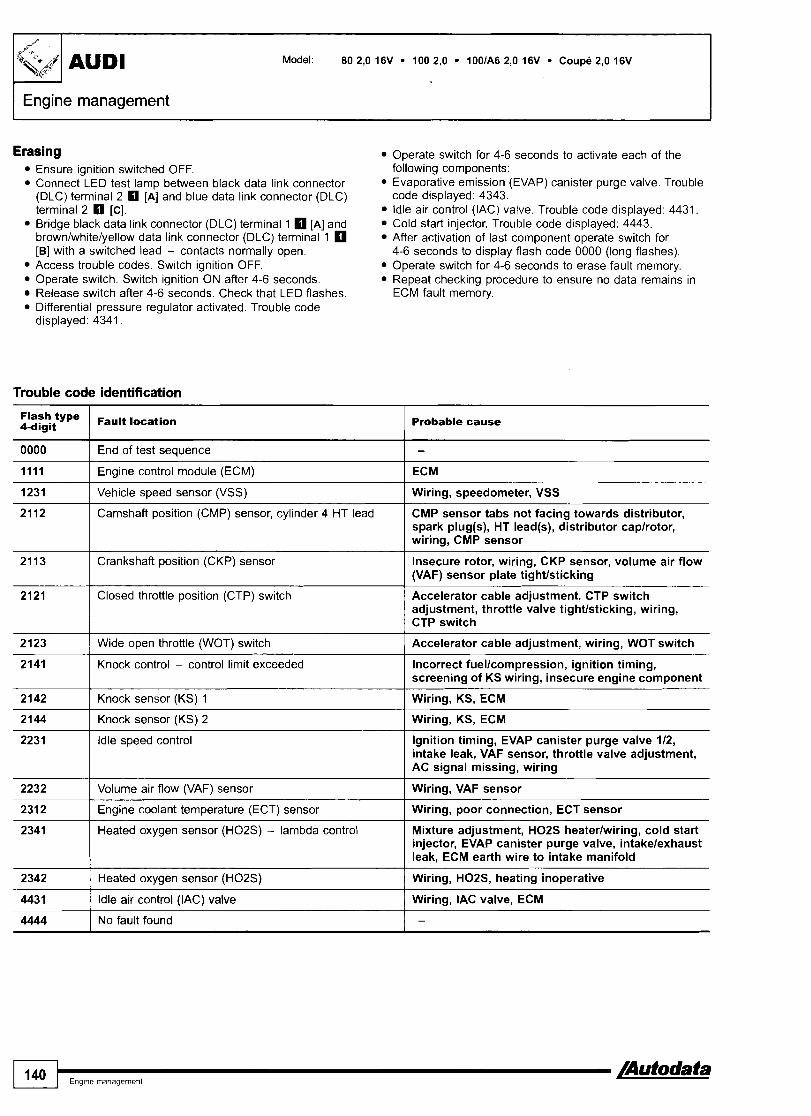
1 Engine management
Erasing Operate switch for 4-6 seconds to activate each of the following components: Evaporative emission (EVAP) canister purge valve. Trouble code displayed: 4343. ldle air control (IAC) valve. Trouble code displayed: 4431. Cold start injector. Trouble code displayed: 4443. After activation of last component operate switch for 4-6 seconds to display flash code 0000 (long flashes). Operate switch for 4-6 seconds to erase fault memory. Repeat checking procedure to ensure no data remains in ECM fault memory.
Ensure ignition switched OFF. Connect LED test lamp between black data link connector (DLC) terminal 2 rn [A] and blue data link connector (DLC) terminal 2 0 [C]. Bridge black data link connector (DLC) terminal 1 [A] and brownlwhitelyellow data link connector (DLC) terminal 1 [B] with a switched lead - contacts normally open. Access trouble codes. Switch ignition OFF. Operate switch. Switch ignition ON after 4-6 seconds. Release switch after 4-6 seconds. Check that LED flashes. Differential pressure regulator activated. Trouble code displayed: 4341.
Trouble code identification
Flash type 4-digit
0000
Fault location 1 Probable cause I
Closed throttle position (CTP) switch
End of test sequence
Engine control module (ECM)
Vehicle speed sensor (VSS)
Camshaft position (CMP) sensor, cylinder 4 HT lead
Crankshaft position (CKP) sensor
Accelerator cable adjustment, CTP switch adjustment, throttle valve tighffsticking, wiring, CTP switch
-
ECM
Wiring, speedometer, VSS
CMP sensor tabs not facing towards distributor, spark plug(s), HT lead@), distributor caplrotor, wiring, CMP sensor
Insecure rotor, wiring, CKP sensor, volume air flow (VAF) sensor plate tighffsticking
Knock sensor (KS) 1 I Wiring, KS, ECM
Wide open throttle (WOT) switch
Knock control - control limit exceeded
Knock sensor (KS) 2 I Wiring, KS, ECM
Accelerator cable adjustment, wiring, WOT switch
Incorrect fuellcompression, ignition timing, screening of KS wiring, insecure engine component
ldle speed control Ignition timing, EVAP canister purge valve 112, intake leak, VAF sensor, throttle valve adjustment, AC signal missing, wiring
Volume air flow (VAF) sensor
Engine coolant temperature (ECT) sensor
Heated oxygen sensor (H02S) - lambda control
No fault found I -
Wiring, VAF sensor
Wiring, poor connection, ECT sensor
Mixture adjustment, HO2S heaterlwiring, cold start injector, EVAP canister purge valve, intakelexhaust leak, ECM earth wire to intake manifold
Heated oxygen sensor (H02S)
Idle air control (IAC) valve
1 140 I,,,,,,,,,,,, IAutodata
Wiring, HOZS, heating inoperative
Wiring, IAC valve, ECM

I Engine management I Model 80 2,0 16V 100 2,0 1001A6 2,0 16V Coupe 2,0 16V AUDI
/+-'
$$/
00281 1 Vehicle speed sensor (VSS) I Wiring, speedometer, VSS
type 5-digit
00000
0051 5 I Crankshaft position (CKP) sensor
Fa"# location
No fault found
00514
Insecure rotor, wiring, CKP sensor, volume air flow (VAF) sensor plate tightlsticking
Probable cause
-
0051 6 I Closed throttle position (CTP) switch
Camshaft position (CMP) sensor, cylinder 4 HT lead
Accelerator cable adjustment, CTP switch adjustment, throttle valve tightlsticking, wiring, CTP switch
CMP sensor tabs not facing towards distributor, spark plug(s), HT lead(s), distributor caplrotor, wiring, CMP sensor
00517 1 Wide open throttle (WOT) switch I Accelerator cable adjustment, wiring, WOT switch
00520 1 Volume air flow (VAF) sensor I Wiring, VAF sensor
00522 1 Engine coolant temperature (ECT) sensor I Wiring, poor connection, ECT sensor
00524
00525
00533
00535
Mixture adjustment, H02S heaterlwiring, cold start injector, EVAP canister purge valve, intakelexhaust leak, ECM earth wire to intake manifold
-
Knock sensor (KS) 1
Heated oxygen sensor (H02S)
00537
00540 1 Knock sensor (KS) 2 I Wiring, KS, ECM
-
Wiring, KS, ECM
Wiring, HOZS, heating inoperative
Idle speed control
Knock control - control limit exceeded
Heated oxygen sensor (H02S) - lambda control
00558 Mixture control (MC) - mixture lean
Ignition timing, EVAP canister purge valve 112, intake leak, VAF sensor, throttle valve adjustment, AC signal missing, wiring
Incorrect fuellcompression, ignition timing, screening of KS wiring, insecure engine component
ECM earth wire to intake manifold, intake leak, idle speed adjustment
--
00559 [ Mixture control (MC) - mixturerich 1 Injector(s), cold start injector, idle speed adjustment
Mixture control (MC) ECM earth wire to intake manifold, intake leak, idle speed adjustment, injector(s), cold start injector, EVAP canister purge valve
65535 1 Engine control module (ECM) I ECM
01257
17978
/Autodata I Engme management 141
Idle air control (IAC) valve
Engine control module (ECM) - immobilizer active
Wiring, IAC valve, ECM
Incorrectldamaged key, incorrectly coded, ECMlimmobilizer replacement without coding, wiring, immobilizer defective

AUDl Model: S6 2,2
Year: 1994-96
Engine code: AAN
System: Bosch Motronic M2.3 Bosch Motronic M2.3.2
Engine management
In underbonnet relay plate
Erasing Ensure ignition switched OFF.
General information Disconnect ECM multi-plug or battery earth lead. . - Refer to the front of this manual for general test conditions, NOTE: ECM adapt;ve memory may be erased causing terminology, detailed descriptions of wiring faults and a running faults. Carry out road test to allow ECM to general trouble shooter for electrical and mechanical faults. re-learn basic values.
Accessing Diagnostic equipment can also be used to erase data from ECM fault memory.
The engine control module (ECM) fault memory can be WARNING: Disconnecting the battery may erase memory from accessed using diagnostic equipment connected to the data electronic units (e.g. radio, clock).
link connector (DLC).
Trouble code identification
Flash type / Fault location 4-digit
Engine speed (RPM) sensor
0000
1111
1231
Air gap, metal particles, insecure sensor, flywheel ring gear damaged, wiring, CKPIRPM sensor multi-plugs interchanged, RPM sensor
Crankshaft position (CKP) sensor
End of test sequence
Engine control module (ECM) - defective
Vehicle speed sensor (VSS)
Air gap, metal particles, insecure sensor, flywheel pin bentlmissing, wiring, CKPIRPM sensor multi-plugs interchanged, CKP sensor
-
ECM
Wiring, speedometer, VSS
camshaft position (CMP) sensor Valve timing, distributor alignment, wiring, CMP sensor, CKP sensor flywheel pin bent/ missing, CMP sensor
Closed throttle position (CTP) switch Accelerator cable adjustment, CTP switch adjustment, throttle valve tightlsticking, wiring, CTP switch

Engine management
type Fault location 4-digit Probable cause
Poor quality fuel, CKPIRPM sensor wiring, insecure engine component, KS shield wiring
2141 1 Knock control - control limit exceeded
I
2142 1 Knock sensor (KS) 1 Wiring, KS looseldefective, ECM
2144 I Knock sensor (KS) 2 Wiring, KS looseldefective, ECM
221 2 I Throttle position (TP) sensor Wiring, poor connection, TP sensor
Incorrect gear shift, AT fault
Hose leaklblockage, hose fluid collector full, TC wastegate regulating valve, MAP sensor (in ECM)
2223 I Barometric pressure (BARO) sensor
2214
2222
Wiring, BARO sensor
-
Maximum engine RPM exceeded
Manifold absolute pressure (MAP) sensor
Maximum boost pressure exceeded Hoses interchangedlnot connected, hoses blockedlleaking, TC wastegate actuatorlregulating valve, MAP sensor (in ECM)
lntake leaklblockage, wiring, IAC valve, MAF sensor, throttle valve tightlsticking
2231
2234 Alternator, battery, current d r a w z h i g n i t i o n F ~ , wiring
Idle speed control (ISC)
Engine control module (ECM) - supply voltage
231 2 ( Engine coolant temperature (ECT) sensor Wiring, poor connection, ECT sensor
2314 1 ECMtlCM electrical connection TCM trouble code(s) stored, wiring, transmission fault
Wiring, poor connection, IAT sensor
lntake leak, wiring, MAF sensor
2322
2324
2341 I Heated oxygen sensor (H02S) - lambda control
Intake air temperature (IAT) sensor
Mass air flow (MAF) sensor
Fuel level low, fuel pressurelpump, misfire, intakelexhaust leak, wiring, H02S I Heated oxygen sensor (H02S) lntakelexhaust leak, wiring, H02S, heating inoperative, fuel level low, misfire
Fuel pressurelpump, misfire, intakelexhaust leak, MAF sensor
241 3
4343 I Evaporative emission (EVAP) canister purge valve
Mixture control (MC)
Wiring, fuse, EVAP canister purge valve
Wiring, fuse, injector
Wiring, fuse, injector
Wiring, fuse, injector
441 1
441 2
441 3
441 4 I Injector 4
Injector 1
Injector 2
Injector 3
Wiring, fuse, injector
lnjector 5
ldle air control (IAC) valve
Turbocharger (TC) wastegate regulating valve
No fault found
Wiring, fuse, injector
wiring, fuse, l ~ E a l v e
Wiring, fuse, TC wastegate regulating valve

Model: S6 2,2
)Engine management
00281 / Vehicle speed sensor (VSS) I Wiring, speedometer, VSS
type 5-digit
00000
Engine speed (RPM) sensor Air gap, metal particles, insecure sensor, flywheel ring gear damaged, wiring, CKPIRPM sensor multi-plugs interchanged, RPM sensor
Fault location
No fault found
Crankshaft position (CKP) sensor
Probable cause
-
Air gap, metal particles, insecure sensor, flywheel pin bentlmissing, wiring, CKPIRPM sensor multi-plugs interchanged, CKP sensor
Camshaft position (CMP) sensor Valve timing, distributor alignment, wiring, CMP sensor, CKP sensor flywheel pin bentl missing, CMP sensor
Accelerator cable adjustment, CTP switch adjustment, throttle valve tightlsticking, wiring, CTP switch
Closed throttle position (CTP) switch
Manifold absolute pressure (MAP) sensor
0051 8
Hose leaklblockage, hose fluid collector full, TC wastegate regulating valve, MAP sensor (in ECM)
I Throttle position (TP) sensor I Wiring, poor connection, TP sensor
00522 1 Engine coolant temperature (ECT) sensor 1 Wiring, poor connection, ECT sensor
00523 1 Intake air temperature (IAT) sensor I Wiring, poor connection, IAT sensor
00528 I Barometric pressure (BARO) sensor I Wiring, BAR0 sensor
00524
00525
Heated oxygen sensor (H02S) - lambda control Fuel level low, fuel pressurelpump, misfire, intakelexhaust leak, wiring, H02S
Knock sensor (KS) 1
Heated oxygen sensor (H02S)
00532
00533
Wiring, KS looseldefective, ECM
lntakelexhaust leak, wiring, H02S, heating inoperative, fuel level low, misfire
Maximum boost pressure exceeded
Engine control module (ECM) - supply voltage
Idle speed control (ISC)
00540
00543
Hoses interchangedlnot connected, hoses blockedlleaking, TC wastegate actuatorlregulating valve, MAP sensor (in ECM)
Alternator, battery, current draw with ignition OFF, wiring
Intake leaklblockage, wiring, IAC valve, MAF sensor, throttle valve tightlsticking
ECMlTCM electrical connection
Knock sensor (KS) 2
Maximum engine RPM exceeded
I TCM trouble code(s) stored, wiring, transmission fault
Wiring, KS looseldefective, ECM
Incorrect gear shift, AT fault
00553 I Mass air flow (MAF) sensor I Intake leak, wiring, MAF sensor
Mixture control (MC) Fuel pressurelpump, misfire, intakelexhaust leak, MAF sensor
Poor quality fuel, CKPIRPM sensor wiring, insecure engine component, KS shield wiring
Knock control, cylinder 1 - control limit exceeded
Knock control, cylinder 2 - control limit exceeded I Poor quality fuel, CKPIRPM sensor wiring,
insecure engine component, KS shield wiring
Knock control, cylinder 3 - control limit exceeded
Poor quality fuel, CKPIRPM sensor wiring, insecure engine component, KS shield wiring

Engine management
type Fault location 5-digit Probable cause
01247 1 Evaporative emission (EVAP) canister purge valve 1 Wiring, fuse, EVAP canister purge valve
Knock control, cylinder 4 - control limit exceeded
Knock control, cylinder 5 - control limit exceeded
01 249 I Injector 1 I Wiring, fuse, injector
Poor quality fuel, CKPIRPM sensor wiring, insecure engine component, KS shield wiring
Poor quality fuel, CKPIRPM sensor wiring, insecure engine component, KS shield wiring
01251 I Injector 3 I Wiring, fuse, injector
01 250
01 252 I Injector 4 I Wiring, fuse, injector
01253 1 Injector 5 I Wiring, fuse, injector
Injector 2
01257 / Idle air control (IAC) valve I Wiring, fuse, IAC valve
--
Wiring, fuse, injector
01 262 I Turbocharger (TC) wastegate regulating valve I Wiring, fuse, TC wastegate regulating valve
17978
a
Engine control module (ECM) - immobilizer active lncorrectldamaged key, incorrectly coded, ECMlimmobilizer replacement without coding, wiring, immobilizer defective

Model: A3 80 A4 1001A6 A6IAllroad A8 Coupe Cabriolet
Year: 1991-02
Transmission
A3 - centre console
A4 +2000 - centre console, rear
A4 2000 -+, AWAllroad 1997 + - fascia, driver's side
80, Coup&, Cabriolet - in underbonnet fuseboxlreiay plate
1001A6 -1997 - in underbonnet relay plate
A8 - under front ashtray

Model: A3 80 A4 100lA6 A61Allroad A8 Coupe Cabriolet
Transmission I
4motion - manual 516 speed 4WD NOTE: Vehicle equipped with an electronically controlled Haldex
coupling.
General information n Refer to the front of this manual for general test conditions,
terminology, detailed descriptions of wiring faults and a general trouble shooter for electrical and mechanical faults.
Accessing and erasing The four wheel drive control module fault memory can only be accessed and erased using diagnostic equipment connected to the data link connector (DLC).
Trouble code identification I I
VAG type Fault location I I probable cause I I
00000 ( No fault found
00453
00526
01155 I Haldex coupling - mechanical fault I Mechanical fault
-
00532
01043
01312 1 CAN data bus - defective I Trouble code(s) stored in other system(s), wiring
Haldex coupling - overheating
Stop lamp switch
Mechanical fault
Wiring, stop lamp switch
Four wheel drive control module - supply voltage
Four wheel drive control module - programming
65535 I Four wheel drive control module - defective I Four wheel drive control module
Alternator, battery, wiring
Incorrect four wheel drive control module
01314
01316
AutomaticKiptronic
General information
CAN data bus, ECM
CAN data bus, ABS
0 Refer to the front of this manual for general test conditions, terminology, detailed descriptions of wiring faults and a general trouble shooter for electrical and mechanical faults. Automatic transmission in 'P'.
0 Data link connector (DLC) - 2-pin: (A) black, (B) brownlwhite.
Wiring, ECM trouble code(s) stored, ECM incorrectly coded, wiring
ABS control module trouble code(s) stored, wiring
Accessing and erasing The transmission control module (TCM) fault memory can only be accessed and erased using diagnostic equipment connected to the data link connector (DLC).

Model: A3 80 A4 1001A6 A6IAllroad A8 Coupe Cabriolet
I
Transmission
Trouble code identification
VAG type Fault location Probable cause
PO
-
- / Solenoid valve 3
-
-
Wiring, poor connection, transmission internal wiring, solenoid valve
Refer to EOBD trouble code table
No fault found
- I Transmission
- -
Solenoid valve 1
Solenoid valve 2
- -
rwirin; hydraulic fault, clutchlvalve body
Wiring, poor connection, transmission internal wiring, solenoid valve
Wiring, poor connection, transmission internal wiring, solenoid valve
-
-
- I Vehicle speed sensor (VSS) I Wiring, speedometer, insecure rotor, VSS
-
-
Solenoid valve 4
Solenoid valve 5
Wiring, poor connection, transmission internal wiring, solenoid valve
Wiring, poor connection, transmission internal wiring, solenoid valve
Solenoid valve 6
Solenoid valve 7
-
Wiring, poor connection, transmission internal wiring, solenoid valve
Wiring, poor connection, transmission internal wiring, solenoid valve
-
output shift speed (OSS) sensor - -
Wiring, transmission speed sensor, multi-plugs for no signal VSS and transmission speed sensor interchanged
ABS control module, LH front wheel speed signal - rangelperformance problem
-
-
-
-
- I Transmission mode selection switch I Wiring, transmission mode selection switch
Wiring, ABS trouble code(s) stored, incorrect ABS control module
ABS control module, RH front wheel speed signal - rangelperformance problem
- Transmission fluid temperature (TFT) Wiring, poor connection, TFT sensor sensor
Wiring, ABS trouble code(s) stored, incorrect ABS control module
ABS control module, RH rear wheel speed signal - rangelperformance problem
ABS control module, LH rear wheel speed signal - rangelperformance problem
Transmission range (TR) switch
Transmission kick-down switch
Wiring, ABS trouble code(s) stored, incorrect ABS control module
Wiring, ABS trouble code(s) stored, incorrect ABS control module
Wiring, poor connection, TR switch
Wiring, accelerator cable adjustment, transmission kick-down switch, TP sensor
- / Solenoid valve 10
-
-
Wiring, poor connection, transmission internal wiring, solenoid valve
~arthreturn wire, modulation valve [ Wiring open circuit, TCM
Solenoid valve 8
Solenoid valve 9
- Transmission intermediate shaft speed Wiring open circuit, transmission intermediate shaft sensor - no signal speed sensor
Wiring, poor connection, transmission internal wiring, solenoid valve
Wiring, poor connection, transmission internal wiring, solenoid valve

Model: A3 80 A4 1001A6 A6IAllroad A8 Coupe Cabriolet
Transmission
VAG type I P type I Fault location I Probable cause
00526 1 - I Stop lamp switch I Wiring, stop lamp switch
I 00518 - I Throttle position (TP) sensor I Wiring, signal from TP sensor or ECM, TP sensor
1 I I
00529
00532
- I Engine RPM input - no signal 1 Wiring, ECM
00543
00545
00549 1 - ECM/TCM electrical connection - I Wiring, ECM, TCM fuel consumption signal
-
00548
-
-
Transmission control module (TCM) - supply voltage
-
00596
00597
00641 I - Transmission fluid temperature (TFT) ATF level incorrect, towing weight limit exceeded, sensor - high input transmission internal wiring, TFT sensor
Alternator, battery, wiring
Maximum engine RPM exceeded
ECM/TCM electrical connection - torque reduction signal
00638
Incorrect gear shift, CKPIRPM sensor, valve body, ECM
Wiring, ECM, TCM
Transmission control module (TCM), fault memory - supply voltage, from battery
- -
Fuse, supply voltage wiring, earth wiring
-
00652
00660
Solenoid valves - short circuit
ABS control module, wheel speed signals - speed difference too great
00668
00789 1 - I Reverse gear position switch I Wiring, reverse gear position switch, TR switch
Poor connection, transmission internal wiring
Wiring, ABS trouble code(s) stored, incorrect ABS control module
ECM/TCM electrical connection - TP sensor signal
- -
00753
00777
Transmission control module (TCM) - Incorrectly coded coding
Wiring, ECM, TCM
-
Gear monitoring - implausible signal
Transmission kick-down switchlthrottle position (TP) sensor - implausible signal
-
-
Wiring, hydraulic fault, clutchlvalve body
Wiring, accelerator cable adjustment, kick-down switch, TP sensor
Transmission control module (TCM) - supply voltage, from battery
01 045
01166
01236 1 - I Selector lever lock solenoid I Wiring, selector lever lock solenoid
Wiring, fuse
ABS control module, wheel speed signals - implausible
CAN data bus, APP sensor - incorrect signal
01192
01196
Wiring, ABS trouble code@) stored, incorrect ABS control module
Wiring, APP sensor signal from ECM, ECM trouble code(s) stored
-
-
-
-
- -
01312
01314
Tiptronic gear selection switch - incorrect signal
Engine torque signal
01316
Wiring, tiptronic gear selection switch
Trouble codes 01312101314 stored, ECM incorrectly coded, faulty enginelcomponent(s), ECM
Torque converter clutch (TCC) solenoid - mechanical fault
CAN data bus, ECM/TCM
-
- -
ATF level, clutch slipping, TCC solenoid, valve body defective
Ignition switched ON with TCM disconnected, wiring, ECM, TCM
- I CAN data bus. ABS
-
CAN d& bus-- defective
CAN data bus, ECM
ABS control module trouble code@) stored, wiring
Trouble code(s) stored in other system@), wiring
Wiring, ECM trouble code(s) stored, ECM incorrectly coded, wiring

I " I - / AUDI Model: A3 80 A4 100lA6 A61Allroad A8 Coupe Cabriolet
I Transmission I VAG type Fault location I Probable cause
Transmission control module (TCM) - TCM KAM error
Stop lamp switch - rangelperformance problem
Wiring, stop lamp switch
Stop lamp switch - circuit malfunction I Wiring, stop lamp switch, ECM, TCM
Transmission control module (TCM) - ROM error
Transmission control module (TCM) - defective
Transmission range (TR) switch - rangelperformance problem
TCM
TCM
Wiring, TR switch
Transmission fluid temperature (TFT) sensor - circuit malfunction
Transmission fluid temperature (TFT) sensor - rangelperformance problem
lnput shaft speed (ISS) sensorlturbine shaft speed (TSS) sensor - range1 performance problem
Wiring, TFT sensor
Wiring, TFT sensor
Transmission fluid temperature (TFT) sensor - low input
Transmission fluid temperature (TFT) sensor - high input
Wiring, shield wiring, transmission input shaft speed sensor, engine RPM signal, TR switch, ATF level, torque converter, clutches or brakes slipping, sticking solenoid valve
Wiring, shield wiring, transmission input shaft speed sensor, engine RPM signal, TR switch, ATF level, transmission speed sensor, torque converter, clutches or brakes slipping, sticking solenoid valve
Wiring, TFT sensor
Wiring, TFT sensor
lnput shaft speed (ISS) sensorlturbine shaft speed (TSS) sensor - no signal
Output shaft speed (OSS) sensor - rangelperformance problem
Wiring, shield wiring, OSS sensor, ECM/TCM input signals incorrectly transmitted, ATF level, torque converter, clutches or brakes slipping, sticking solenoid valve
Incorrect gear ratio
Output shaft speed (OSS) sensor - no signal
Engine RPM input - rangelperformance problem
ATF level, torque converter, clutches or brakes slipping, sticking solenoid valve, wiring, transmission speed sensor, transmission input shaft speed sensor, TCM
Wiring, shield wiring, ECM/TCM input signals incorrectly transmitted, OSS sensor, ATF level, torque converter, clutches or brakes slipping, sticking solenoid valve
Wiring, CKPIRPM sensor, ECM, TCM
Gear 1 - incorrect ratio
Gear 2 - incorrect ratio
Clutch slipping, solenoid valve, transmission speed sensor, transmission input shaft speed sensor, TCM
Clutch slipping, solenoid valve, transmission speed sensor, transmission input shaft speed sensor, TCM
Gear 3 - incorrect ratio
Gear 4 - incorrect ratio
Clutch slipping, solenoid valve, transmission speed sensor, transmission input shaft speed sensor, TCM
Clutch slipping, solenoid valve, transmission speed sensor, transmission input shaft speed sensor, TCM

Model: A3 80 A4 1001A6 A6IAllroad A8 Coupe Cabriolet
Transmission 7 VAG type / P type ( h u i t location I Probable cause
17119
17125
17135
-
17136
17137
-
-
17140
17141
17142
17147 1 - I Shift solenoid (SS) C - electrical I Wiring, poor connection, solenoid valve
Gear 5 - incorrect ratio
- -
17145
17146
Clutch slipping, solenoid valve, transmission speed sensor, transmission input shaft speed sensor, TCM
Torque converter clutch (TCC) solenoid - performance or stuck off
Shift solenoid (SS) A - performance or stuck off
-
- -
ATF level, torque converter, wiring, TCC solenoid, torque converter pressure valve
Wiring open circuitlshort to earth, poor connection, shift solenoid
Shift solenoid (SS) A - stuck on
Shift solenoid (SS) A - electrical
-
-
- 17968
Wiring, poor connection, shift solenoid
Wiring, poor connection, solenoid valve
Shift solenoid (SS) B - performance or stuck off
Shift solenoid (SS) 0 - stuck on
Shift solenoid (SS) B - electrical
-
18112
181 41
18147
18152
Wiring open circuitlshort to earth, poor connection, shift solenoid
Wiring, poor connection, shift solenoid
Wiring, poor connection, solenoid valve
Shift solenoid (SS) C - performance or stuck off
Shift solenoid (SS) C - stuck on
PO
PI560
18153
-
Wiring open circuitlshort to earth, poor connection, shift solenoid
Wiring, poor connection, shift solenoid
PI625
PI704
PI733
P I 739
PI744
18155
18156
-
Refer to EOBD trouble code table
Maximum engine RPM exceeded
PI745
P I 746
18157
18158
1 I I
- I PI760 I Selector lever lock solenoid I Wiring, selector lever lock solenoid
- - - - --
-
Incorrect gear shift, wiring open circuit, CKPlRPM sensor
CAN data bus, ECMITCM
Transmission kick-down switch - short to earth
Tiptronic gear selection switch, down shift - short to earth
Tiptronic gear selection switch, up shift - short to earth
Tiptronic gear selection switch, recognition - short to earth
P I 747
PI748
18159
18160
Ignition switched ON with TCM disconnected, wiring, ECM, TCM
Wiring open circuitlshort to earth, transmission kick-down switch
Wiring short to earth, tiptronic gear selection switch
Wiring short to earth, tiptronic gear selection switch
Wiring short to earth, tiptronic gear selection switch
Solenoid valves, supply voltage - short to positive
Transmission control module (TCM) - supply voltaqe
P I 749
P I 750
Wiring open circuitlshort to positive, poor connection, TCM
Alternator, battery, wiring
Solenoid valves, supply voltage - open circuitlshort to earth
Transmission control module (TCM) - defective
P I 751
PI752
Battery, wiring open circuitlshort to earth, poor connection, TCM
TCM
Transmission control module (TCM) - coding
Transmission control module (TCM) - supply voltage low
Incorrectly coded, ECM incorrectly coded, TCM
Fuse, wiring, TCM
Transmission control module (TCM) - supply voltage high
Transmission control module (TCM) - supply voltage
Alternator, second battery incorrectly connected
Wiring, alternator

Model: A3 80 A4 1001A6 A61Allroad A8 Coupe Cabriolet
I Transmission
VAGtype
18169
181 70
Ptype
18171
-
- I ECM/TCM electrical connection, torque Wiring short to positive, ECM, TCM reduction signal - short to positive
PI761
P I 762
18179
18180
-
18192 1 Engine control module (ECM), upldown Wiring open circuiffshort to earth, ECM shift signal - open circuitkhort to earth
Fault location
PI763
PI767
I81 93 1 Engine control module (ECM), upldown Wiring open circuiffshort to positive, ECM shift signal - short to positive
Probable cause
Selector lever lock solenoid - short to earth
Selector lever lock solenoid - short to positive
PI771
PI772
PI781
18108 I - I Brake pressure switch - incorrect signal I Wiring, brake pressure switch
Wiring short to earth, selector lever lock solenoid, tiptronic gear selection switch, TCM
Wiring short to positive, selector lever lock solenoid, tiptronic gear selection switch, TCM
Selector lever lock solenoid - open circuit
ECM/TCM electrical connection - TP sensor s~gnal
- I Solenoid valve 4
Wiring open circuit, selector lever lock solenoid, TCM
Wiring, ECM, TCM
Engine control module (ECM), load s~gnal - open circuitkhort to positive
Engine control module (ECM), load signal - short to earth
ECM/TCM electrical connection, torque reduction signal - open c~rcuit/short to earth
Wiring, poor connection, transmission internal wiring, solenoid valve
Wiring open circuiffshort to positive, ECM
Wiring short to earth, ECM
Wiring open circuiffshort to earth, ECM, TCM
18222
18223
-
18227
PI814
PI815
18228
-
18232
PI818
PI819
18233
-
18242 1 Pressure control (PC) solenoid 5 - Wiring open circuitlshort to earth, PC solenoid open circuitkhort to earth
Pressure control (PC) solenoid 1 - open circuitlshort to earth
Pressure control (PC) solenoid 1 - short to positive
P I 820
PI823
P I 824
18237
18238
Wiring open circuiffshort to earth, PC solenoid
Wiring short to positive, PC solenoid
Solenoid valve 5
Pressure control (PC) solenoid 2 - open circuitkhort to earth
PI825
PI828
Wiring, poor connection, transmission internal wiring, solenoid valve
Wiring open circuiffshort to earth, PC solenoid
Pressure control (PC) solenoid 2 - short to positive
Sotenoid valve 6
Pressure control (PC) solenoid 3 - open circuitkhort to earth
PI829
PI830
Wiring short to positive, PC solenoid
Wiring, poor connection, transmission internal wiring, solenoid valve
Wiring open circuiffshort to earth, PC solenoid
Pressure control (PC) solenoid 3 - I Wiring short to positive, PC solenoid short to positive
Solenoid valve 7
Pressure control (PC) solenoid 4 - open circuitkhort to earth
Pressure control (PC) solenoid 4 - short to positive
Wiring, poor connection, transmission internal wiring, solenoid valve
Wiring open circuiffshort to earth, PC solenoid
Wiring short to positive, PC solenoid

Model: A3 80 A4 100lA6 AGIAllroad A8 Coupe Cabriolet
Transmission 7 type I P type Fault locatlon Probable cause
18243 I Pressure control (PC) solenoid 5 - Wiring short to positive, PC solenoid short to positive
Engine control module (ECM)ltransmission control module (TCM) - incorrectly matched
Incorrect ECMlTCM
18258
18258
18262
18263
I8266 I Engine control module (ECM) - Wiring, CKPIRPM sensor, ECM, TCM RPM signal
PI850
PI851
18264
18265
I8269 1 Engine control module (ECM) - I Wiring, APP sensor, ECM, TCM APP sensor signal
PI854
P I 855
CAN data bus, ECM - missing information
CAN data bus, ABS - missing information
PI856
P I 857
defective I component, wiring, TCM
Ignition switched ON with TCM disconnected, wiring, TCM
Ignition switched ON with TCM disconnected, wiring, TCM, ABS control module, ECM
CAN data bus - defective
CAN data bus - software
I I I
Wiring, ECM, TCM
Ignition switched ON with TCM disconnected, ECM, TCM
Engine control module (ECM) - TP sensor signal
Engine control module (ECM) - load s~gnal
65535
Wiring, ECM, TCM
ECM, TCM
- I Transmission control module (TCM) - 1 Mechanicallhydraulic fault, electricallelectronic

*- AUDI P I Immobilizer
Model: A2 A31S3 80 (081944) A4lS4 A61S6 (07194 4 ) A6IS6IAllroad A81S8 CoupelS2 (071944) Cabriolet (071944) TT
Year: 1994-02
I
A2, A41S4 2000 +, AG/SG/Allroad 1997 + - fascia, driver's slde A4/S4 1994-00 - centre console, rear
ASIS3 - centre console A61S6 1994-97 - in underbonnet relay plate
80, Coupe, Cabriolet, S2 - in underbonnet fuseboxlrelay plate A81S8 - under front ashtray
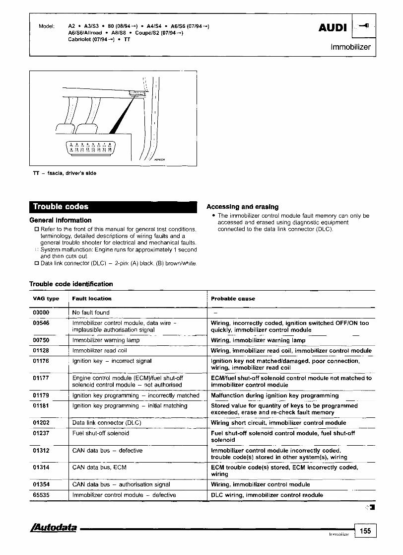
lT - fascia, driver's side
Model: A2 A363 80 (08194 +) A41S4 A666 (07194 +) AGIS6IAllroad A81S8 CoupelS2 (07194 4)
AUDI
Accessing and erasing The immobilizer control module fault memory can only be
General information accessed and erased us in^ diaanostic eaui~ment
41
- - Refer to the front of this manual for general test conditions. connected to the data link connector (DLC): terminology, detailed descriptions of wiring faults and a general trouble shooter for electrical and mechanical faults.
c System malfunction: Engine runs for approximately 1 second and then cuts out. Data link connector (DLC) - 2-pin: (A) black, (B) brownlwhite.
Cabriolet (071944) TT
lmmobilizer
Trouble code identification
VAG type Fault location Probable cause
00546 Immobilizer control module, data wire - implausible authorisation signal
I I
Wiring, incorrectly coded, ignition switched OFFION too quickly, immobilizer control module
00000 I No fault found -
01176 Ignition key - incorrect signal
00750
01128
lgnition key not matchedldamaged, poor connection, wiring, immobilizer read coil
-
Immobilizer warning lamp
Immobilizer read coil
01181 Ignition key programming - initial matching Stored value for quantity of keys to be programmed exceeded, erase and re-check fault memory
- - -
Wiring, immobilizer warning lamp
Wiring, immobilizer read coil, immobilizer control module
Engine control module (ECM)lfuel shut-off solenoid control module - not authorised
lgnition key programming - incorrectly matched
ECMlfuel shut-off solenoid control module not matched to immobilizer control module
Malfunction during ignition key programming
01312 I CAN data bus - defective
01 202
01237
lmmobilizer control module incorrectly coded, trouble code(s) stored in other system(s), wiring
Data link connector (DLC)
Fuel shut-off solenoid
Wiring short circuit, immobilizer control module
Fuel shut-off solenoid control module, fuel shut-off solenoid
01314
01 354
a a Immobilizer 155
65535
CAN data bus, ECM
CAN data bus - authorisation signal
ECM trouble code@) stored, ECM incorrectly coded, wiring
Wiring, immobilizer control module
4
Immobilizer control module - defective DLC wiring, immobilizer control module

Model: 316ilCompact, 318iliSICoupelCornpact, 320i, 3251 (E36) 23 1,8i 518i, 520i, 525iliX (E34) 750i (E32) 850ilCSI (E31)
Year: 1987-00
Enginecode: 164E1,164E2,184E1,184S1,184E2,206S2, 25 6s 2, 50 12 A, 56 12 1
System: Motronic M I .211.311.711.7.211.7.313.1 I Engine management I
I I
23, 3 Series (M1.2/1.7/3.1), 5 Series, 8 Series - engine bay RH side 3 Series (M1.7.211.7.3), 7 Series - engine bay LH side
General information Refer to the front of this manual for general test conditions, terminology, detailed descriptions of wiring faults and a general trouble shooter for electrical and mechanical faults. Trouble codes are displayed by using an LED connected to one of the ECM terminals. The ECM fault memory can also be checked using diagnostic equipment connected to the data link connector (DLC).
Accessing - flash type NOTE: Flash type cannot be accessed from some engine control
modules (ECM).
Ensure ignition switched OFF. Connect breakout box between ECM and harness multi- plug. ECM located in plenum chamber. Motronic M1.713.1: Connect LED tester between breakout box terminal 8 and battery (12 volt) positive m. Motronic M1.2: Connect LED tester between breakout box terminal 15 and battery (12 volt) positive m. Switch ignition ON. Depress accelerator pedal fully 5 times within 5 seconds. V12: To access trouble codes from ECM LH bank, depress accelerator pedal fully 6 times within 5 seconds.
NOTE: V12 engine is controlled by two ECMs, RH bank and LH bank.
Count LED flashes. Note trouble codes. Compare with trouble code table. Long flash indicates start of trouble code display [A]. Each trouble code consists of four groups of flashes [B].
For example: Trouble code 1211 displayed: Engine control module (ECM) [B]. LED flashes code 0000 m, 1000 or 2000 H at end of trouble code output. Switch ignition OFF. Disconnect LED.

Model: 316ilCompact, 318iliSICoupelCompact, 320i, 3251 (E36) 23 1,8i 518i, 520i, 525iliX (E34) 750i (E32) 850ilCSI (E31)
Engine management I
(gq-% LED
Erasing - flash type Depress accelerator pedal fully for 10 seconds minimum when trouble code 0000, 1000 or 2000 (end of output) is flashed. Switch ignition OFF.

Model: 316ilCompact, 318iliSICoupelCompact, 320i, 3251 (E36) 23 1,8i 518i, 520i, 525iliX (E34) 750i (E32) 850ilCSI (E31)
I Engine management
Probable cause
Trouble code identification NOTE: V12: Nash types lxxx for RH bank, 2xxx LH bank.
0000 I End of trouble code output
Flash type
1000 I End of trouble code output
Fault location
I Engine mntrol module (ECM) - defective Disconnect ECM multi-plug for at least 10 min. - check if trouble code reappears before replacing ECM
Mass air flow (MAF) sensorlvolume air flow (VAF) sensor - incorrect signal
Wiring, connector(s), MAF sensorNAF sensor
1216 I Throttle position (TP) sensor - defective Wiring, connector(s), TP sensor
1218 I Engine control module (ECM) - output stage Wiring, ECM controlled components
Heated oxygen sensor (H02S) - circuit malfunction
Wiring, connector(s), H02S
Heated oxygen sensor (H02S) - range1 performance problem
Wiring, intakelexhaust leak, fuel level low, fuel pressure, EVAP canister purge valve, injector(s), HOZS, ECM
Engine coolant temperature (ECT) sensor - malfunction
Wiring, connector(s), ECT sensor
1224 I Intake air temperature (IAT) sensor - malfunction Wiring, connector(s), IAT sensor
1225 I Knock sensor (KS) 1 - defective Wiring, connector, KS incorrectly tightened
1226 I Knock sensor (KS) 2 - defective Wiring, connector, KS incorrectly tightened
1231 I Battery voltage - too lowlhigh Wiring, alternator, battery
1232 I Closed throttle position (CTP) switch - malfunction Wiring, connector, CTP switch, ECM
1233 I Throttle position (TP) sensor - malfunction Wiring, TP sensor, ECM
1234 I Vehicle speed sensor (VSS) - incorrectlno signal Wiring, instrument panel, VSS
1235 I Torque converter clutch (TCC) solenoid - defective Wiring, TCC solenoid
Throttle control, traction control system (TCS) - defective
Wiring, connector(s), throttle control system
1236 Engine control module (ECM)IABS control module communication, ASR system
Wiring, ABS trouble code(s) stored, ECM
1237 I AC compressor clutch relay - malfunction Wiring, AC compressor clutch relay
Intake manifold air control solenoid - circuit malfunction
Wiring, connector, intake manifold air control solenoid
1238 / Engine control module (ECM) - unused output stage
Wiring short to earthlpositive, ignore flash code if terminal 18 not connected
1241 I Engine control module (ECM) - no supply voltage Wiring, fuse(s), battery
1241 Engine control module (ECM)IABS control module communication, traction control system (TCS)
Wiring, ABS trouble code(s) stored, ECM
1241 Engine control module (ECM), electronic throttle system (ETS) - overmn torque control
Wiring short to positive, ECM
Wiring, AC control module 1242
1243 Wiring, CKP sensorlRPM sensor
AC control modulelengine control module (ECM) communication - malfunction
Crankshaft position (CKP) sensorlengine speed (RPM) sensor - incorrectlno signal
Camshaft position (CMP) sensor - rangelperformance problem
Wiring, CMP sensor
Wiring, ECM, TCM 1245
1247 Wiring, ignition coil(s)
Engine control module (ECM)ltransmission control module (TCM) communication - short to earth
Ignition circuit - primary circuit

-
Model: 316ilCompact, 318iliSICoupelCompact, 320i, 3251 (E36) 23 1,8i 518i, 520i, 525iliX (E34) 750i (E32) 850ilCSI (E31)
Engine management 7
I I
1256 I Injector, cyl. 4 - circuit matfunction I Wiring, injector
Flash type
1251
1251 8 1252
1252 8 1253
1254
1255
1261 I Fuel pump relay - malfunction I Wiring, connector(s), fuel pump relay
Idle speed control (ISC) actuatorlidle air control Wiring, connector(s), ISC actuatorllAC valve (IACl valve - malfunction 1
Fault location
Injector(s), group 1 - circuit malfunction
Injector, cyl. 1 - circuit malfunction
Injector(s), group 2 - circuit malfunction
Injector, cyl. 5 - circuit malfunction
Injector, cyl. 3 - circuit malfunction
Injector, cyl. 6 - circuit malfunction
Injector, cyl. 2 - circuit malfunction
Evaporative emission (EVAP) canister purge valve - malfunction
Probable cause
Wiring, injector(s)
Wiring, injector
Wiring, injector(s)
Wiring, injector
Wiring, injector
Wiring, injector
Wiring, injector
( Wiring, connector(s), EVAP canister purge valve
1264 I Oxygen sensor heater relay - malfunction 1 Wiring, connector, oxygen sensor heater relay
I Malfunction indicator lamp (MIL) - I Wiring short to earthlpositive, MIL short to earthlpositive
1268 I Mixture adjustment resistor - signal too lowlhigh I Wiring, mass air flow (MAF) sensor
1271 I Ignition circuit - defective I Wiring, connector, ignition coil, ECM
1271 8 I Ignition circuit, cyl. 1 - defective I Wiring, connector, ignition coil, ECM
1272 I Ignition circuit, cyl. 5 - defective I Wiring, connector, ignition coil, ECM
1273 I Ignition circuit, cyl. 3 - defective I Wiring, connector, ignition coil, ECM
1274 I Ignition circuit, cyl. 6 - defective I Wiring, connector, ignition coil, ECM
1275 I Ignition circuit, cyl. 2 - defective 1 Wiring, connector, ignition coil, ECM
1276 I Ignition circuit, cyl. 4 - defective I Wiring, connector, ignition coil, ECM
1278 I Transmission control module (TCM) - signal 1 Wiring, TCM
1281 I Battery voltage - too low I Wiring, alternator, battery
1 Engine control module (ECM) - internal fault Disconnect ECM multi-plug for at least 10 min. - check if trouble code reappears before replacing ECM
1283 I Injector(s) - circuit malfunction ( Wiring, injector(s)
1 Engine control module (ECM)lalarm system control Wiring short to positive, alarm system control module module communication - alarm system active
1286 I Knock control circuit - defective Wiring, connector, KS incorrectly tightened, knock sensor (KS), ECM
1 Engine control module (ECM) - electronic throttle Wiring short to positive, ignore flash code if terminal 62 system (ETSI sianal I not connected
1288 I Engine control module (ECMI - internal fault I ECM
1288 8 Engine control module (ECM) - automatic stability Wiring, ETS, ABS trouble code(s) stored control (ASR)loverrun torque control defectwe
151 3 Engine control module (ECM) - unused output Wiring short to earthlpositive, ignore flash code if I staae I terminal 18 not connected
I
2000 I End of trouble code output I -
1444 1 No fault found
2211 1 Engine control module (ECM) - defective
-
Disconnect ECM multi-plug for at least 10 rnin. - check if trouble code reappears before replacing ECM
-a- Ena~ne rnanaaement 159

I Engine management
Model: 316ilCompact, 318iliSICoupelCompact, 320i, 3251 (E36) 23 1,8i 518i, 520i, 525iliX (E34) 750i (E32) 850ilCSI (E31)
Motronic M I .7 (VIZ), M3.1 Motronic M3.1
fl Motronic M I .7 (V12)
Flash type
221 5
2218
2221
2222
2223
2224
2231
2232
2233
2234
2235
2236
2237
2241
2244
2245
2444
2251
2252
2261
2263
2264
2265
2268
2278
251 3
4444
Fault location
Mass air flow (MAF) sensorlvolume air Row (VAF) sensor - incorrect signal
Engine control module (ECM) - output stage
Heated oxygen sensor (H02S) - circuit malfunction
Heated oxygen sensor (H02S) - rangelperformance problem
Engine coolant temperature (ECT) sensor - malfunction
Intake air temperature (IAT) sensor - malfunction
Battery voltage - too lowlhigh
Closed throttle position (CTP) switch - malfunction
Throttle position (TP) sensor - malfunction
Vehicle speed sensor (VSS) - incorrecffno signal
Torque converter clutch ( K C ) solenoid - defective
Engine control module (ECM)IABS control module communication, automat~c stability control (ASR) system
AC compressor clutch relay - malfunction
Engine control module (ECM)IABS control module communication, traction control system (TCS)
Camshaft position (CMP) sensor - rangelperformance problem
Engine control module (ECM)ltransmission control module (TCM) communication - short to earth
No fault found
Injector(s), group 1 - circuit malfunction
Injector(s), group 2 - circuit malfunction
Fuel pump relay - malfunction
Evaporative emission (EVAP) canister purge valve - malfunction
Oxygen sensor heater relay - malfunction
Malfunction indicator lamp (MIL) - short to earth1 positive
Mixture adjustment resistor - signal too Iowlhigh
Transmission control module (TCM) - signal
Engine control module (ECM) - unused output stage
No fault found
Probable cause
Wiring, connector(s), MAF sensorNAF sensor
Wiring, ECM controlled components
Wiring, connector(s), H02S
Wiring, intakelexhaust leak, fuel level low, fuel pressure, evaporative emission (EVAP) canister purge valve, injector(s), HOZS, ECM
Wiring, connector(s), ECT sensor
Wiring, connector(s), IAT sensor
Wiring, alternator, battery
Wiring, connector, CTP switch, ECM
Wiring, TP sensor, ECM
Wiring, instrument panel, VSS
Wiring, TCC solenoid
Wiring, ABS trouble code(s) stored, ECM
Wiring, AC compressor clutch relay
Wiring, ABS trouble code(s) stored, ECM
Wiring, CMP sensor
Wiring, ECM, TCM
-
Wiring, injector(s)
Wiring, injector(s)
Wiring, connector(s), fuel pump relay
Wiring, connector(s), EVAP canister purge valve
Wiring, connector, oxygen sensor heater relay
Wiring short to earthlpositive, MIL
Wiring, mass air flow (MAF) sensor
Wiring, TCM
Wiring short to earthlpositive - ignore flash code if terminal 18 not connected
-

Model: 316ilCompact, 318iliSICoupelCompact, 320i, 3251 (E36) 23 1,8i 518i, 520i, 525iliX (E34) 750i (E32) 850ilCSI (E31)
I Engine management I Accessing and erasing - scanner type
The engine control module (ECM) fault memory can also be checked using diagnostic equipment connected to the data link connector (DLC).
Trouble code identification
I I
0 I Engine control module (ECM) - undefined fault I -
Scanner I Fault location type I I
I I
1 I Engine control module (ECM) - defective I ECM
Probable cause
- I No fault found
1 0 I Fuel pump relay - malfunction I Wiring, connector(s), fuel pump relay
-
I I
3 I Fuel pump relay - malfunction I Wiring, connector(s), fuel pump relay
2 Idle speed control (ISC) actuatorlidle air control (IAC) valve - malfunction
3
3 El 3
4
5
5
6
7
10
12
15
16
16
17
23 I Oxygen sensor heater relav - malfunction I Wiring, connector, oxyqen sensor heater relay
Wiring, connector(s), ISC actuatorllAC valve
18
18
19
Injector(s), cyl. 1 & 3 or cyl. 2, 4, 6 & 8, 10, 12 - circuit malfunction
Injector(s), cyl. 2 & 4 - circuit malfunction
Injector(s), cyl. 1 - circuit malfunction
Injector(s), cyl. 3 - circuit malfunction
Evaporative emission (EVAP) canister purge valve - malfunction
Injector(s), cyl. 2 - circuit malfunction
Injector(s) - circuit malfunction
Mass air flow (MAF) sensorlvolume air flow (VAF) sensor - incorrect signal
Heated oxygen sensor (H02S) - rangelperformance problem
Throttle position (TP) sensor - defective
Knock sensor (KS) 1 - defective
Injector(s), cyl. I, 3, 5 & 7, 9, 11 - circuit malfunction
Camshaft position (CMP) sensor - rangelperformance problem
Injector(s), cyl. 2, 4, 6 & 8, 10, 12 - circuit malfunction
25 ( Ignition circuit, cyl. 1 - defective I Wiring, connector, ignition coil, ECM
-
Wiring, injector(s)
Wiring, injector(s)
Wiring, injector
Wiring, injector
Wiring, connector(s), EVAP canister purge valve
Wiring, injector
Wiring, injector(s)
Wiring, connector(s), MAF sensorNAF sensor
Wiring, intakelexhaust leak, fuel level low, fuel pressure, evaporative emission (EVAP) canister purge valve, injector@), ECM
Wiring, connector(s), TP sensor
Wiring, connector, KS incorrectly tightened, KS
Wiring, injector@)
Wiring, CMP sensor
Wiring, injector(s)
Engine control module (ECM) - unused output stage
Intake manifold air control solenoid - circuit malfunction
Engine control module (ECM) - unused output stage
23
24
24
Wiring short to earthlpositive, ignore flash code if terminal 18 not connected
Wiring, connector, intake manifold air control solenoid
Wiring short to earthlpositive, ignore flash code if terminal 18 not connected
Ignition circuit, cyl. 2 - defective
Engine control module (ECM)/transmasion control module (TCM) communication
Ignition crcuit, cyl. 3 - defective
Wiring, connector, ignition coil, ECM
Wiring short to earth, TCM trouble code@) stored
Wiring, connector, ignition coil, ECM

I Engine management
Model: 316ilCompact, 318iliSICoupelCompact, 320i, 3251 (E36) 23 1,8i 518i, 520i, 525iliX (E34) 750i (E32) 850ilCSI (E31)
26 I Battery voltage - too low I Wiring, alternator, battery
Scanner type
28 Heated oxygen sensor (H02S) - circuit I Wiring, connector(s), H02S malfunction
29 Idle speed control (ISC) actuatorlidle air control Wiring, connector(s), ISC actuatorllAC valve (IAC) valve - malfunction
Fault location
3 1 I Injector, cyl. 5 - circuit malfunction 1 Wiring, injector
Probable cause
32 I Injector(s), cyl. 2 & 4 - circuit malfunction I Wiring, injector(s)
32 Injector(s), cyl. 1, 3, 5 & 7, 9, 11 - circuit I Wiring, injector(.) malfunction
32 I Injector(s), cyl. 1 & 3 - circuit malfunction I Wiring, injector(s)
32 I Injector, cyl. 6 - circuit malfunction I Wiring, injector
33 I Injector, cyl. 4 - circuit malfunction I Wiring, injector
36 Evaporative emission (EVAP) canister purge Wiring, connector(s), EVAP canister purge valve valve - malfunction
37 I Battery voltage - too lowlhigh 1 Wiring, alternator, battery
I Oxygen sensor heater relay - malfunction 1 Wiring, connector, oxygen sensor heater relay
Engine control module (ECM)IABS control module communication, acceleration skid control (ASR) system
Wiring, ABS trouble code(s) stored, ECM
41
42
44
45
46
46
48
50
51
51 rn 52
54 0 I Battery voltage - too lowlhigh I Wiring, alternator, battery
53
54
55 I Ignition circuit - defective I Wiring, connector, ignition coil, ECM
52 I Ignition circuit, cyl. 5 - defective I Wiring, connector, ignition coil, ECM
Mass air flow (MAF) sensorlvolume air flow (VAF) sensor - incorrect signal
Knock sensor (KS) 2 - defective
Intake air temperature (IAT) sensor - matfunction
Engine coolant temperature (ECT) sensor - malfunction
AC condenser blower motor relay - short to positive
Engine control module (ECM) - output stage
AC compressor clutch relay - malfunction
Ignition circuit, cyl. 4 - defective
Transmission control module (TCM) - signal
Ignition circuit, cyl. 6 - defective
Closed throttle position (CTP) switch - malfunction
Wiring, connector(s), MAF sensorNAF sensor
Wiring, connector, KS incorrectly tightened, KS
Wiring, connector(s), IAT sensor
Wiring, connector(s), ECT sensor
Wiring short to positive, AC condenser blower motor relay, ECM
Wiring, ECM controlled components
Wiring, AC compressor clutch relay
Wiring, connector, ignition coil, ECM
Wiring, TCM
Wiring, connector, ignition coil, ECM
Wiring, connector, CTP switch, ECM
Throttle position (TP) sensorlwide open throttle (WOT) switch - malfunction
Engine control module (ECM)ltransmission control module (TCM) communication
64 Engine control module (ECM)ltransmission control Wiring, TCM trouble code(s) stored, ECM, TCM module (TCM) communication - short to earth
Wiring, TP sensor, ECM
Wiring short to earth, TCM trouble code(s) stored
62
63
Engine control module (ECM) - electronic throttle system (ETS) signal
Torque converter clutch (TCC) solenoid - defective
Wiring short to positive, ignore flash code if terminal 62 not connected
Wiring, TCC solenoid
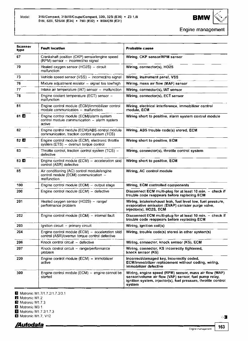
Scanner type
67
70
73
76
77
78
BMW Model 316ilCornpact, 318iliSICoupelCornpact, 320i, 3251 (E36) 23 1,8i 518i, 520i, 525iliX (E34) 750i (E32) 850ilCSI (E31)
Fault location
P
Crankshaft position (CKP) sensorlengine speed (RPM) sensor - incorrectho signal
Heated oxygen sensor (H02S) - circuit malfunction
Vehicle speed sensor (VSS) - incorrectho signal
Mixture adjustment resistor - signal too lowlhigh
Intake air temperature (IAT) sensor - malfunction
Engine coolant temperature (ECT) sensor - malfunction
Engine control module (ECM)limmobilizer control module communication - malfunction
Engine control module (ECM)lalarm system control module communication - alarm system active
Engine control module (ECM)IABS control module communication, traction control system (TCS)
Engine control module (ECM), electronic throttle system (ETS) - overrun torque control
Throttle control, traction control system (TCS) - defective
Engine control module (ECM) - acceleration skid control (ASR) defective
Air conditioning (AC) control modulelengine control module (ECM) communication - malfunction
Engine management
Engine control module (ECM) - output stage
Engine control module (ECM) - defective
Heated oxygen sensor (H02S) - range1 performance problem
Engine control module (ECM) - internal fault
Ignition circuit - primary circuit
Engine control module (ECM) - acceleration skid control (ASR)loverrun torque control defective
Knock control circuit - defective
Knock control circuit - rangelperformance problem
Engine control module (ECM) - immobilizer active
Engine control module (ECM) - engine cannot be started
Probable cause
Wiring, CKP sensorlRPM sensor
Wiring, connector(s), H02S
Wiring, instrument panel, VSS
Wiring, mass air flow (MAF) sensor
Wiring, connector(s), IAT sensor
Wiring, connector(s), ECT sensor
Wiring, electrical interference, immobilizer control module, ECM
Wiring short to positive, alarm system control module
Wiring, ABS trouble code(s) stored, ECM
Wiring short to positive, ECM
Wiring, connector(s), throttle control system
Wiring short to positive, ECM
Wiring, AC control module
Wiring, ECM controlled components
Disconnect ECM multi-plug for at least 10 min. - check if trouble code reappears before replacing ECM
Wiring, intakelexhaust leak, fuel level low, fuel pressure, evaporative emission (EVAP) canister purge valve, injector(s), H02S, ECM
Disconnect ECM multi-plug for at least 10 min. - check if trouble code reappears before replacing ECM
Wiring, ignition coil(s)
Wiring, trouble code(s) stored in other system(s)
Wiring, connector, knock sensor (KS), ECM
Wiring, connector, KS incorrectly tightened, knock sensor (KS)
lncorrecffdamaged key, incorrectly coded, ECMlimmobilizer replacement without coding, wiring, immobilizer defective
Wiring, engine speed (RPM) sensor, mass air flow (MAF) sensorlvolume air flow (VAF) sensor, fuel pump relay, ignition system, injector(s), fuel pressure, throttle control system
Motronic M I .711.7.2/1.7.3/3.1 Motronic M I .2 Motronic M I .7.3
rn Motronic M3.1 Motronic M I .7.2/1.7.3 Motronic M I .7, V12
/Autodata I Eng~ne management 163

Model: 325tdltds (E36) 525tdltds (E34)
Year: 1 991 -99
Engine code: 25 6T 11-L
System: Bosch EDC 1.2.3 (DDE 2) I Engine management
Underbonnet, RH
General information Refer to the front of this manual for general test conditions, terminology, detailed descriptions of wiring faults and a general trouble shooter for electrical and mechanical faults.
Accessing and erasing The engine control module (ECM) fault memory can only be accessed and erased using diagnostic equipment connected to the data link connector (DLC).
Trouble code identification
1
3
3
5
6
9
10 0
10
Probable cause Scanner type
Fault location
Fuel quantity adjuster, in fuel injection pump - mechanicallelectricaI fault
Fuel shut-off solenoid, in fuel injection pump - electrical fault
Engine coolant temperature (ECT) sensor - malfunction
Injector needle lift sensor - malfunction
Glow plug(s) - circuit malfunction
Vehicle speed sensor (VSS) - signal
Fuel injection timing solenoid, in fuel injection pump - malfunction
Cruise control module - malfunction
Wiring, connector, fuel quantity adjuster
Wiring, connector, fuel shut-off solenoid, ECM
Wiring, connector, ECT sensor
Wiring, connector, air in fuel system, fuel leak, fuel level low, RPM sensor, injector needle lift sensor, shield wiring, ECM
Wiring, connector, glow plug@), glow plug timer relay, ECM
Wiring, connector, VSS, instrument panel
Fuel filter, fuel pump, air in fuel system, fuel injection timing solenoid
Wiring, connectors, cruise control module

Model: 325tdltds (E36) 525tdltds (E34) BMW
Engine management I
Probable cause Scanner type
Fault location
Engine control module (ECM) - internal fault ECM
Intake air temperature (IAT) sensor - malfunction
Engine control module (ECM) - supply voltage
Exhaust gas recirculation (EGR) solenoid - defective
Wiring, connector, IAT sensor
Wiring, connectors, battery
Wiring, EGR solenoid
Cruise control module - malfunction Wiring, connectors, cruise control module
Fuel quantity adjuster position sensor, in fuel injection pump - malfunction
Battery voltage - too low
Wiring, connector, fuel quantity adjuster position sensor
Wiring, alternator, battery
Glow plug timer relay - defective Wiring, glow plug timer relay, ECM
Alarm system control moduke - circuit malfunction
Clutch pedal position (CPP) switch - malfunction
Vehicle speed sensor (VSS) - signal
Wiring, alarm system control module
Wiring, connector, CPP switch
Wiring, connector, VSS, instrument panel
Brake pedal position (BPP) switch - malfunction Wiring, connector, BPP switch
Fuel temperature sensor, in fuel injection pump - circuit malfunction
Fuel filter warning lamp switch - water detected
Accelerator pedal position (APP) sensor - malfunction
Wiring, connector, fuel injection pump
Drain fuel filter
Wiring, connector, APP sensor
Alarm system control module - circuit malfunction
Engine speed (RPM) sensor - circuit malfunction
Wiring, alarm system control module
Wiring, connectors, flywheel ring gear damaged, air gap, RPM sensor
Intake air temperature (IAT) sensor - malfunction Wiring, connector, IAT sensor
Engine coolant temperature (ECT) sensor - malfunction
Wiring, connector, ECT sensor
Manifold absolute pressure (MAP) sensor, TC system - malfunction
Wiring, connector, intake leak, MAP sensor
Engine control module (ECM) - internal fault ECM
Engine control module (ECM) - output stages
Turbocharger (TC) boost pressure - lowlhiqh
Wiring, ECM controlled components, ECM
Wiring, MAP sensor, hose(s), TC bypass valve, TC
Engine speed (RPM) sensor - circuit malfunction
Wiring, connectors, flywheel ring gear damaged, air gap, RPM sensor
Fuel temperature sensor, in fuel injection pump - circuit malfunction
Accelerator pedal position (APP) sensor - malfunction
Wiring, connector, fuel injection pump
Wiring, connector, APP sensor
Manifold absolute pressure (MAP) sensor, TC system - malfunction
Fuel quantity adjuster position sensor, in fuel ~njection pumplinjector needle lift sensor - malfunction
Wiring, connector, intake leak, MAP sensor
Wiring, connector, fuel quantity adjuster position sensor, injector needle lift sensor, shield wiring
Turbocharger (TC) system - malfunction Wiring, connectors, hoses, TC, TC bypass valve, MAP sensor, ECM
/Autodata Engine management 165

Model: 325tdltds (E36) 525tdltds (E34)
Engine management r Scanner type
I36
Fault location Probable cause
Fuel quantity adjuster, in fuel injection pump - malfunction
Wiring, fuel quantity adjuster
Injector needle lift sensor - malfunction Wiring, connector, air in fuel system, fuel leak, fuel level low, RPM sensor, injector needle lift sensor, shield wiring, ECM
Start of injection - malfunction Wiring, fuel injection timing solenoid, fuel pressure, fuel filter
Brake pedal position (BPP) switch - malfunction
Barometric pressure (BARO) sensor, incorporated in ECM - malfunction
Wiring, connector, BPP switch
ECM
Fuel shut-off solenoid, in fuel injection pump - defective
Engine control module (ECM) - output stages
Fuel filter warning lamp switch - water detected
Clutch pedal position (CPP) switch - malfunction
Wiring, connector, fuel shut-off solenoid
Wiring, ECM controlled components
Wiring, drain fuel filter
Wiring, connector, CPP switch
Engine operation not possible Wiring, connectors, mechanical fault, fuel system, pre-heating system, starting system
Injector(s), fuel injection pump, fuel shut-off solenoid, air in fuel system, vehicle speed signal, accelerator pedal jammed
Irregular engine speed
Engine performance, loss of power Injector(s), air filter blocked, turbocharger (TC) boost pressure
Wiring, engine control relay, fuel shut-off solenoid, vehicle speed sensor (VSS), fuel quantity adjuster position sensor
Engine cuts out

Model: 3 SerieslCompact (E36) 3 Series (E46) 520i (E34) 5 Series (E39) 7 Series (E38) 23
Year: 1992-00
Engine code: 19 4EIS 1, 20 6s 21314, 25 6s 314, 28 6s 2, 35 8 s 112, 35 8 s 2, 44 8 s 112, 54 12 112
System: Siemens MS40141142
Trouble codes: Scanner type
BMW I
Engine management
23,3 Series, 5 Series, 7 Series - engine bay RH side
3 Series (E46), 23, 5 Series (E39) - 2000 +
General information Refer to the front of this manual for general test conditions, terminology, detailed descriptions of wiring faults and a general trouble shooter for electrical and mechanical faults.
Accessing and erasing The engine control module (ECM) fault memory can only be accessed and erased using diagnostic equipment connected to the data link connector (DLC).
NOTE: Some models may have both DLCs fitted. DO NOT open 20-pin DLC while using 16-pin DLC.
3 Series Compact - engine bay LH side
-a, Eng~ne management 167
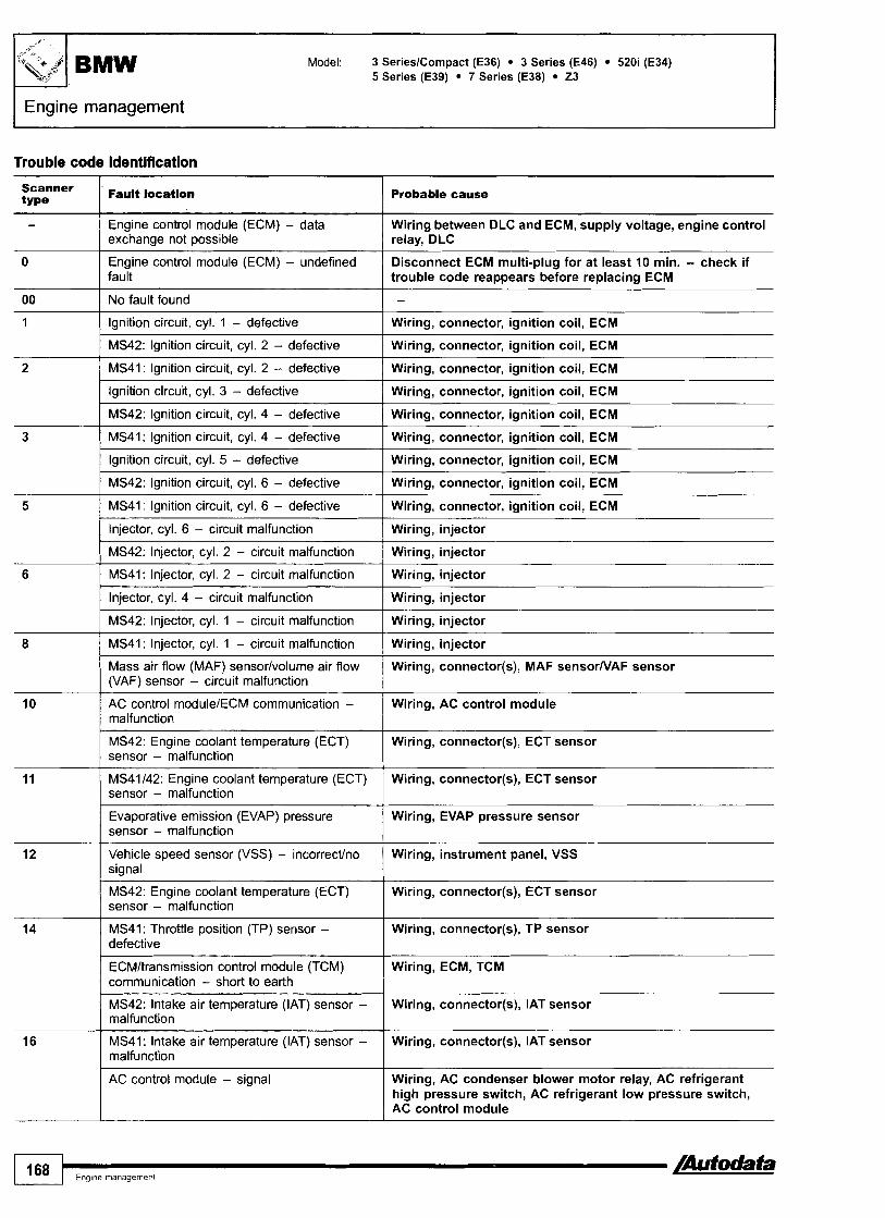
Model: 3 SerieslCompact (E36) 3 Series (E46) 520i (E34) 5 Series (E39) 7 Series (E38) 23
FEngine management
Trouble code identification
scanner 1 Fault location type Probable cause
Engine control module (ECM) - undefined Disconnect ECM multi-plug for at least 10 min. - check if fault trouble code reappears before replacing ECM
-
00 I No fault found I - 1 ( Ignition circuit, cyl. 1 - defective I Wiring, connector, ignition coil, ECM
Engine control module (ECM) - data exchange not possible
I MS42: Ignition circuit, cyl. 2 - defective ( Wiring, connector, ignition coil, ECM
Wiring between DLC and ECM, supply voltage, engine control relay, DLC
Ignition circuit, cyl. 3 - defective I Wiring, connector, ignition coil, ECM
MS41: Ignition circuit, cyl. 2 - defective
I MS42: lgnition circuit, cyl. 4 - defective I Wiring, connector, ignition coil, ECM
Wiring, connector, ignition coil, ECM
3 ( MS41: Ignition circuit, cyl. 4 - defective I Wiring, connector, ignition coil, ECM
1 Ignition circuit, cyl. 5 - defective I Wiring, connector, ignition coil, ECM
I Injector, cyl. 6 - circuit malfunction I Wiring, injector
5
( MS42: Injector, cyl. 2 - circuit malfunction I Wiring, injector
MS42: Ignition circuit, cyl. 6 - defective
MS41: Ignition circuit, cyl. 6 - defective
I MS42: Injector, cyl. 1 - circuit malfunction I Wiring, injector
-
Wiring, connector, ignition coil, ECM
Wiring, connector, ignition coil, ECM
MS41: Injector, cyl. 2 - circuit malfunction
Injector, cyl. 4 - circuit malfunction
8 I MS41: Injector, cyl. 1 - circuit malfunction I Wiring, injector
Wiring, injector
Wiring, injector
10
11
MS42: Engine coolant temperature (ECT) Wiring, connector(s), ECT sensor sensor - malfunction
Mass air flow (MAF) sensorlvolume air flow (VAF) sensor - circuit malfunction
AC control modulelECM communication - malfunction
12
14 MS41: Throttle position (TP) sensor - defective
Wiring, connector(s), MAF sensorNAF sensor
Wiring, AC control module
MS42: Engine coolant temperature (ECT) sensor - malfunction
MS41142: Engine coolant temperature (ECT) sensor - malfunction
I Wiring, connector(s), TP sensor
Wiring, connector(s), ECT sensor
Wiring, connector(s), ECT sensor
Evaporative emission (EVAP) pressure sensor - malfunction
Vehicle speed sensor (VSS) - incorrectho signal
Wiring, EVAP pressure sensor
Wiring, instrument panel, VSS
Wiring, AC condenser blower motor relay, AC refrigerant high pressure switch, AC refrigerant low pressure switch, AC control module
16
ECMltransmission control module (TCM) communication - short to earth
MS42: Intake air temperature (IAT) sensor - malfunction
MS41: intake air temperature (IAT) sensor - malfunction
Wiring, ECM, TCM
Wiring, connector(s), IAT sensor
Wiring, connector(s), IAT sensor

Model: 3 SerieslCompact (E36) - 3 Series (E46) 520i (E34) 5 Series (E39) 7 Series (E38) 23
Engine management I Scanner Fault location type I I -
- - -
Probable cause
18 ECMlimmobilizer control module Wiring, immobilizer control module communication - signal
19
MS42: Camshaft position (CMP) actuator 1 - Wiring, connector, CMP actuator circuit malfunction
20
2 1
MS42: Camshaft position (CMP) sensor 2 - circuit malfunction
MS42: Camshaft position (CMP) actuator 2 - circuit malfunction
-
Wiring, connector, CMP sensor
Wiring, connector, CMP actuator
Malfunction indicator lamp (MIL) - circuit malfunction
Camshaft position (CMP) actuator - malfunction
22
23
Wiring, bulb, ECM
Wiring, connector, CMP actuator
24
25
30 I MS41: Ignition circuit, cyl. 1 - defective I Wiring, connector, ignition coil, ECM
Injector, cyl. 3 - circuit malfunction
Injector, cyl. 1 - circuit malfunction
MS42: Injector, cyl. 6 - circuit matfunction
27
29
- - - - - -
Wiring, injector
Wiring, injector
Wiring, injector
MS41: Injector, cyl. 6 - circuit malfunction
AC compressor clutch relay - malfunction
MS42: Injector, cyl. 4 - circuit malfunction
MS41: Injector, cyl. 4 - circuit malfunction
MS40142: Oxygen sensor heater 1, bank 1 - circuit malfunction
Wiring, injector
Wiring, AC compressor clutch relay
Wiring, injector
Wiring, injector
Wiring, connector, engine control relay, H02S, ECM
Idle speed control (ISC) actuatorlidle air control (IAC) valve - malfunction
Ignition circuit, cyl. 2 - defective
MS42: Ignition circuit, cyl. 1 - defective
Ignition circuit, cyl. 4 - defective
MS42: Ignition circuit, cyl. 3 - defective
33 I MS41: Ignition circuit, cyl. 5 - defective I Wiring, connector, ignition coil, ECM
Wiring, connector(s), ISC actuatorllAC valve, ECM
Wiring, connector, ignition coil, ECM
Wiring, connector, ignition coil, ECM
Wiring, connector, ignition coil, ECM
Wiring, connector, ignition coil, ECM
31
I MS40142: Injector, cyl. 5 - circuit malfunction 1 Wiring, injector
MS41: Ignition circuit, cyl. 3 - defective
Ignition circuit, cyl. 6 - defective
MS42: Ignition circuit, cyl. 5 - defective
38 I Clutch pedal position (CPP) switch - I Wiring, connector, CPP switch malfunction
Wiring, connector, ignition coil, ECM
Wiring, connector, ignition coil, ECM
Wiring, connector, ignition coil, ECM
35
39 Brake pedal position (BPP) switch - circuit Wiring, connector, BPP switch malfunction I
40 Brake pedal position (BPP) switchlthrottle Wiring, connector, BPP switch, TP sensor(s), ECM position (TP) sensor(s) - incorrect signal
Secondary air injection (AIR) pump relay - malfunction
Steering wheel multifunction switch - Wiring, connector, steering wheel multifunction switch incorrectly coded
Wiring, connector, AIR pump relay
/Autodata -I Eng~ne management 169
I
Steering wheel multifunction switch - malfunction
Wiring, spiral cable, steering wheel multifunction switch, ECM

BMW Model: 3 SerieslCompact (E36) 3 Series (E46) 520i (E34) 5 Series (E39) 7 Series (E38) 23
I Engine management I
Scanner Fault location type
Probable cause
Wiring, spiral cable, steering wheel multifunction switch, ECM
45
46 I Fuel level signal
Steering wheel multifunction switch - incorrect signal
Fuel level low, wiring, fuel gauge tank sensor
Wiring, alternator, battery 49 I Battery voltage - too low
Injector, cyl. 2 - circuit malfunction
MS42: Evaporative emission (EVAP) canister purge valve - malfunction
Wiring, injector
Wiring, connector(s), EVAP canister purge valve
51 MS41: Evaporative emission (EVAP) canister purge valve - malfunction
Wiring, connector(s), EVAP canister purge valve
Evaporative emission (EVAP) canister purge valve - malfunction
Wiring, connector(s), EVAP canister purge valve
52 1 Fuel pump relay - malfunction Wiring, connector(s), fuel pump relay
MS42: Exhaust gas control solenoid - malfunction
Wiring, connector, exhaust gas control solenoid
MS41: Exhaust gas control solenoid - malfunction
Wiring, connector, exhaust gas control solenoid
( Oxygen sensor heater - circuit malfunction Wiring, connector, H02S
Wiring, connector, IAC valve
55 --
Wiring, connector(~), l~~?&.tuatorl l~~ valve, ECM
MS42: Idle air control (IAC) valve - circuit malfunction
MS41: Idle speed control (ISC) actuatortidle air control (IAC) valve - malfunction
I Oxygen sensor heater 2 - circuit malfunction Wiring, connector, engine control relay, H02S, ECM
MS42: Oxygen sensor heater 1, bank 2 - circuit malfunction
Ignition signal resistor - defective
Knock sensor (KS) 1 - defective
Wiring, connector, engine control relay, HOZS, ECM
Wiring, ignition signal resistor
Wiring, connector, KS incorrectly tightened, KS
59 I Knock sensor (KS) 2 - defective Wiring, connector, KS incorrectly tightened, KS
MS42: Oxygen sensor heater 2, bank 2 - circuit malfunction
Ignition circuit - secondary circuit
MS42: Secondary air injection (AIR) solenoid - defective
Wiring, connector, engine control relay, H02S, ECM
Wiring, ignition coil(s)
Wiring, connector, AIR solenoid
MS41: Secondary air injection (AIR) solenoid - defective
Wiring, connector, AIR solenoid
I Knock sensor (KS) 2 - defective Wiring, connector, KS incorrectly tightened, KS
64 1 Knock sensor (KS) 1 - defective Wiring, connector, KS incorrectly tightened, KS
Camshaft position (CMP) sensor - circuit
MS42: Camshaft position (CMP) sensor 1 - circuit malfunction
Wiring, connector, CMP sensor
Wiring, connector, CMP sensor
Mass air flow (MAF) sensor/volume air flow (VAF) sensor - incorrect signal
Wiring, connector(s), MAF sensorNAF sensor
MS42: Evaporative emission (EVAP) canister purge valve - electrical fault
Wiring, connector, EVAP canister purge valve
I I P I
Model: 3 SerieslCompact (E36) 3 Series (E46) 520i (E34) 5 Series (E39) 7 Series (E38) 23
I Engine management
Scanner type
Fault location Probable cause
Throttle position (TP) sensor - defective I Wiring, connector(s), TP sensor
MS41: Evaporative emission (EVAP) canister purge valve - electrical fault
MS40142: Fuel pump relay - malfunction
AC compressor clutch relay - malfunction
Heated oxygen sensor (H02S) - circuit malfunction
MS41: Heated oxygen sensor (H02S) 1 - circuit malfunction
Heated oxygen sensor (H02S) 2 - circuit malfunction
Crankshaft position (CKP) sensodengine I Wiring, CKP s e n i o r / ~ ~ ~ < e n s s speed (RPM) sensor - incorrectho signal
Wiring, connector, EVAP canister purge valve
Wiring, connector(s), fuel pump relay
Wiring, AC compressor clutch relay
Wiring, connector(s), H02S
Wiring, connector(s), H02S, ECM
Wiring, connector(s), H02S, ECM
MS42: Oxygen sensor heater 2, bank 1 - circuit malfunction
Wiring, connector, engine control relay, H02S, ECM
Engine control module (ECM)/ABS control module communication, ASR system
Engine coolant temperature (ECT) sensor - matfunction
Crankshaft position (CKP) sensorlengine Wiring, connector, CKP sensor/RPM sensor speed (RPM) sensor - circuit malfunction
Wiring, electrical interference, ABS trouble code(s) stored, ECM
Wiring, connector(s), ECT sensor
MS41: Engine control module (ECM)/ABS control module communication, ASR system
Engine control module (ECM)/ABS control module communication, ASR system
Camshafl position (CMP) sensor - range/ Wiring, CMP sensor performance problem
Wiring, electrical interference, ABS trouble code(s) stored, ECM
Wiring, electrical interference, ABS trouble code(s) stored, ECM
Intake air temperature (IAT) sensor - Wiring, connector(s), IAT sensor malfunction
Evaporative emission (EVAP) canister purge valve - mechanical fault
Idle speed control (ISC) actuatorlidte air control (IAC) valve - mechanical fault
Engine control module (ECM) - defective Disconnect ECM multi-plug for at least 10 min. - check if trouble code reappears before replacing ECM
EVAP canister purge valve
ISC actuatorllAC valve
Heated oxygen sensor (H02S) - range/ performance problem
Wiring, intakelexhaust leak, fuel level low, fuel pressure, evaporative emission (EVAP) canister purge valve, injector(s), H02S, ECM
Camshaft position (CMP) actuator 1 - Wiring, connector(s), mechanical fault, engine control relay, malfunction CMP actuator, ECM
Camshaft position (CMP) actuator 1 - malfunction
Camshafl position (CMP) actuator 2 - malfunction
Camshaft position (CMP) actuator 2 - Wiring, connector(s), mechanical fault, engine control relay, malfunction CMP actuator, ECM
Wiring, connector(s), mechanical fault, engine control relay, CMP actuator, ECM
Wiring, connector(s), mechanical fault, engine control relay, CMP actuator, ECM
Throttle control unit - rangelperformance I Wiring, connector(s), throttle control unit, ECM problem
/Autodata Eng~ne management 171

I Engine management
Model: 3 SerieslCompact (E36) 3 Series (E46) 520i (E34) 5 Series (E39) 7 Series (E38) 23
Scanner type
110
111
114 Throttle control unitlthrottle position Wiring, connector(s), throttle control unit, ECM motor - circuit malfunction
Fault location
Throttle control unitlthrottle position (TP) sensor 1 - rangelperformance problem
Throttle control unitlthrottle position (TP) sensor 2 - rangelperformance problem
115 Throttle control unitlAPP sensor I1 I Wiring, connector(s), throttle control unit, ECM TP sensor 1 - supply voltage
Probable cause
Throttle control unitlaccelerator pedal position (APP) sensor 1 - rangelperformance problem
Throttle control unitlaccelerator pedal position (APP) sensor 2 - rangelperformance problem
Wiring, connector(s), throttle control unit, ECM
Wiring, connector(s), throttle control unit, ECM
116 Throttle control unitlAPP sensor I 1 TP sensor 1 - supply voltage
Wiring, connector(s), throttle control unit, ECM
Wiring, connector(s), throttle control unit, ECM
1 Wiring, connector(s), throttle control unit, ECM
Throttle control unitlAPP sensor 112 - malfunction
Throttle control unit1TP sensor 112 - malfunction
122 I Engine oil temperature sensor - malfunction I Wiring, connector(s), engine oil temperature sensor, ECM
Wiring, connector(s), throttle control unit, ECM
Wiring, connector(s), throttle control unit, ECM
119
120
Throttle control unitlthrottle valve - mechanical fault
Throttle control unit - malfunction
Engine cooling system - circuit malfunction
Intake manifold air control solenoid - circuit malfunction
Throttle valve, throttle control unit
Wiring, connector(s), throttle control unit, ECM
Wiring, connector(s), engine coolant thermostat, ECT sensor, engine coolant blower motor temperature sensor, engine coolant blower motor, ECM
Wiring, connector(s), intake manifold air control solenoid, ECM
125
131 I CAN data bus, instrumentation - defective I Wiring, connector(s), instrument panel
128
130
132 I CAN data bus, instrumentation - defective I Wiring, connector(s), instrument panel
Engine coolant blower motor - circuit malfunction
133 1 CAN data bus, ABSIASR - defective Wiring, connector(s), ABS control moduleltraction control module
Wiring, connector(s), engine coolant blower motor, ECM
Immobilizer control module - malfunction
CAN data bus, ABSIASR - defective
Wiring, connector(s), immobilizer control module, ECM
Wiring, connector(s), ABS control moduleltraction control module
140
141
144 Fuel system leak detection pump motor - leak Hose(s), fuel system leak detection pump motor detected
142
143
Fuel system leak detection pump motor - malfunction
Fuel system leak detection pump motor - malfunction
Wiring, connector(s), fuel system leak detection pump motor, ECM
Wiring, connector(s), fuel system leak detection pump motor, ECM
Fuel system leak detection pump motor - malfunction
Fuel system leak detection pump motor - hose(s) blocked
145
Wiring, connector(s), fuel system leak detection pump motor, ECM
Hose(s), fuel system leak detection pump motor
Fuel system leak detection pump motor - leak detected
Hose(s), fuel system leak detection pump motor

Model: 3 SerieslCompact (E36) 3 Series (E46) 520i (E34) 5 Series (E39) 7 Series (E38) 23
Engine management
Probable cause Scanner Fault location type
Fuel system leak detection pump motor - leak detected
Mass air flow (MAF) sensorlthrottle valve - plausibility t
- -
Hose(s), fuel system leak detection pump motor
Wiring, connector(s), MAF sensor, throttle control unit1 throttle valve, ECM
Wiring, connector(s), H02S 150
151 Wiring, connector(s), H02S
Heated oxygen sensor (H02S) 1, bank 1 - high voltage
Heated oxygen sensor (H02S) 1, bank 1 - low voltage
Heated oxygen sensor (H02S) 1, bank 1 - no signal
Wiring, connector(s), H02S
Heated oxygen sensor (H02S) 1, bank 2 - high voltage
Wiring, connector(s), H02S
Heated oxygen sensor (H02S) 1, bank 2 - low voltage
Wiring, connector(s), H02S
Wiring, connector(s), H02S 155
156 Wiring, connector(s), H02S
Heated oxygen sensor (H02S) 1, bank 2 - no signal
Heated oxygen sensor (H02S) 2, bank 1 - high voltage
Wiring, connector(s), H02S 157
159 Wiring, connector(s), H02S
Heated oxygen sensor (H02S) 2, bank 1 - low voltage
Heated oxygen sensor (H02S) 2, bank 2 - high voltage
Heated oxygen sensor (H02S) 2, bank 2 - low voltage
Engine coolant thermostat - mechanical fault
Throttle control unit - malfunction
Wiring, connector(s), H02S
Engine coolant thermostat
Wiring, connector(s), mechanical fault, throttle control unit, ECM
Wiring, connector(s), mechanical fault, throttle control unit, ECM
Wiring, connector(s), throttle control unit, ECM
170
171
Throttle control unitlaccelerator pedal position (APP) sensor 112 - circuit malfunction
Engine control module (ECM)lthrottle control unit - plausibility
Throttle control unit - plausibility
Wiring short to earthlpositive, connector(s), throttle control unit, ECM
Wiring short to earthlpositive, connector(s), throttle control unit, ECM
Wiring short to earthlpositive, connector(s), throttle control unit, ECM
Wiring, connector(s), throttle control unit, ECM
172
173
Throttle control unitlthrottle position (TP) sensor 112 - circuit malfunction
Throttle control unitlthrottle position (TP) sensor 112 - circuit malfunction
Wiring, connectorjs), throttle control unit, ECM
174
175
Throttle control unitlaccelerator pedal position (APP) sensor 2 - malfunction
Throttle control unitlthrottle position (TP) sensor 112 - malfunction
Throttle control unit - malfunction
Wiring, connector(s), throttle control unit, ECM
Wiring, connector(s), H02S 186
187 Wiring, connector(s), H02S
Heated oxygen sensor (H02S) 1, bank 1 - malfunction
Heated oxygen sensor (H02S) 1, bank 2 - malfunction
Heated oxygen sensor (H02S) 1, bank 1 - rangelperformance problem
Wiring, connector(s), H02S
/Autodata Engine management 173

Model: 3 SerieslCompact (E36) 3 Series (E46) 520i (E34) 5 Series (E39) 7 Series (E38) 23
I Engine management
Probable cause Scanner type
189 Wiring, connector(s), H02S
Fault location
Heated oxygen sensor (H02S) 1, bank 2 - rangelperformance problem
Wiring, connector(s), H02S 190
191 Wiring, connector(s), H02S
Heated oxygen sensor (H02S) 2, bank 1 - rangelperformance problem
Heated oxygen sensor (H02S) 2, bank 2 - rangelperformance problem
200 / Engine control module (ECM) - defective Disconnect ECM multi-plug for at least 5 min. - check if trouble code reappears before replacing ECM
Wiring, connector(s), H02S MS41: Heated oxygen sensor (H02S) 1 - circuit malfunction
Heated oxygen sensor (H02S) 2 - circuit malfunction
Wiring, connector(s), H02S
Heated oxygen sensor (H02S), cyl. 1-3 - rangelperformance problem
Wiring, intakelexhaust leak, fuel level low, fuel pressure, evaporative emission (EVAP) canister purge valve, injector(s), H02S, ECM
Heated oxygen sensor (H02S), cyl. 4-6 - rangelperformance problem
Wiring, intakelexhaust leak, fuel level low, fuel pressure, evaporative emission (EVAP) canister purge valve, injector(s), H02S, ECM
204 I Idle speed control (ISC) actuatorlidle air control (IAC) valve - idle speed incorrect
Intake leak, ISC actuator1lAC valve, TP sensor, throttle valve
Immobilizer control modulelengine control module (ECM) - plausibility
Immobilizer control module - incorrect signal
Wiring, immobilizer control module, ECM
Wiring, incorrectly coded, immobilizer control module
210 I Misfire detected - more than 2 cylinders Wiring, ignition coils, spark plugs, ignition signal resistor, ECM
Idle speed control (ISC) actuatorlidle air control (IAC) valve - mechanical fault
ISC actuatorllAC valve
212 1 Camshaft position (CMP) actuator - mechanical fault
Camshaft timing mechanism, CMP actuator
214 1 Vehicle speed sensor (VSS) - signal Wiring, ECMIABS control module communication, electrical interference, ABS trouble code(s) stored, ECM
215 1 Engine control module (ECM)lABS control module communication - plausibility
Wiring, electrical interference, ABS trouble code(s) stored, ECM
MS42: Heated oxygen sensor (H02S) 2, bank 1 - no signal
Wiring, connector(s), H02S
I CAN data bus. TCM - signal Wiring, transmission range (TR) switch, electrical interference, TCM, ECM
MS42: Heated oxygen sensor (H02S) 2, bank 2 - no signal
CAN data bus, TCM - no data transmission
Wiring, connector(s), H02S
Wiring, electrical interference, TCM
218 ( CAN data bus, ECM Wiring
Wiring
Wiring, connector(s), H02S
21 9
220
Heated oxygen sensor (H02S) 2, bank 2 - malfunction
CAN data bus, ECM
Heated oxygen sensor (H02S) 2, bank 1 - malfunction
Wiring, connector(s), H02S

Model: 3 SerieslCompact (E36) 3 Series (E46) 520i (E34) 5 Series (E39) 7 Series (E38) 23
Engine management I
Scanner type
222
Fault location I Probable cause
Lambda regulation - defective
Heated oxygen sensor (H02S) 2, bank 1 - Wiring, connector(s), H02S malfunction
Engine coolant temperature (ECT) sensor, oxygen sensor heater circuit. H02S. ECM
MS42: CAN data bus, instrument panellengine coolant temperature - plausibility
Heated oxygen sensor (H02S) 2, bank 1 - malfunction
Wiring, instrument panel, engine coolant temperature (ECT) sensor, instrument panel
Wiring, connector(s), H02S
Mixture control (MC), cyl. 1-3 - range1 performance problem
Heated oxygen sensor (H02S) control, bank 1 - plausibility
Heated oxygen sensor (H02S) control, bank 2 - plausibility
Wiring, fuel level low, fuel pressure, intakelexhaust leak, MAF sensorNAF sensor, injector@), H02S, EVAP canister purge valve, ECT sensor, ECM
Wiring, connector(s), intakelexhaust leak, ~ a t a ~ ~ t i ~ c o n v e ~ r , H02S, ECM
Wiring, connector(s), intakelexhaust leak, catalytic converter, H02S, ECM
Mixture control (MC), cyl. 4-6 - range1 performance problem
Wiring, fuel level low, fuel pressure, intakelexhaust leak, MAF sensorNAF sensor, injector(s), H02S, EVAP canister purge valve, ECT sensor, ECM
Wiring, intakelexhaust leak, fuel level low, fuel pressure, EVAP canister purge valve, injector@), H02S, ECM
Heated oxygen sensor (H02S) 1 - range1 performance problem
MS42: Heated oxygen sensor (H02S) 1, I Wiring, connector(s), intakelexhaust leak, fuel level low, fuel bank 1 - rangelperformance problem pressure, EVAP canister purge valve, injector@), H02S, ECM
Heated oxygen sensor (H02S) 2 - range1 Wiring, intakelexhaust leak, fuel level low, fuel pressure, performance problem EVAP canister purge valve, injector@), H02S, ECM
MS42: Heated oxygen sensor (H02S) 1, Wiring, connector(s), intakelexhaust leak, fuel level low, fuel bank 2 - rangelperformance problem pressure, EVAP canister purge valve, injector@), H02S, ECM
Heated oxygen sensor (H02S) 2 - I Wiring, H02S malfunction
Heated oxygen sensor (H02S) 1 - malfunction
MS42: Heated oxygen sensor (H02S) 1, bank 1 - malfunction
MS42: Heated oxygen sensor (H02S) 1, I Wiring, connector(s), HO2S bank 2 - malfunction
Wiring, connector(s), H02S
Wiring, connector(s), H02S
Catalytic converter system, bank 1 - efficiency I Wiring, H02S, ECM
Catalytic converter system, bank 2 - efficiency I Wiring, H02S, ECM
Combustion failure - cyl. 1 I Wiring, ignitionlfuel system, ECM
Heated oxygen sensor (H02S) control, bank 1 - malfunction
Heated oxygen sensor (H02S) control, bank 2 - malfunction
Wiring, connector(s), intakelexhaust leak, catalytic converter, H02S, ECM
Wiring, connector(s), intakelexhaust leak, catalytic converter, H02S, ECM
Combustion failure - cyl. 6 I Wiring, ignitionlfuel system, ECM
Combustion failure - cyl. 2
Combustion failure - cyl. 3
Combustion failure - cyl. 4
Combustion failure - cyl. 5
Wiring, ignitionlfuel system, ECM
Wiring, ignitionlfuel system, ECM
Wiring, ignitionlfuel system, ECM
Wiring, ignitionlfuel system, ECM
Engine speed (RPM) sensorlcrankshaft position (CKP) sensor - circuit malfunction
Wiring, connector, mechanical fault, RPM sensor1 CKP sensor, ECM
+I
Model: 3 SerieslCompact (E36) 3 Series (E46) 520i (E34) 5 Series (E39) 7 Series (E38) 23
Engine management
Scanner Fault location type Probable cause
I I
245 I Secondary air injection (AIR) system - bank 1 I Wiring, connector(s), AIR pump relay, AIR solenoid
246 I Secondary air injection (AIR) system - bank 2 ( Wiring, connector(s), AIR pump relay, AIR solenoid
Heated oxygen sensor (H02S) 2, bank 2 - Wiring, connector(s), H02S malfunction I
247
248
252 I Fuel tank vent system - malfunction I Wiring, hoses, fuel tank vent valve
Secondary air injection (AIR) solenoid - mechanical fault
Heated oxygen sensor (H02S) 2, bank 1 - malfunction
250
251
Evaporative emission (EVAP) canister purge EVAP canister purge valve valve - mechanical fault
AIR solenoid
Wiring, connector(s), H02S
Fuel tank vent valve - malfunction
Fuel tank vent system - malfunction
1 '76 1 Engine management flutodata
Wiring, connector(s), fuel tank vent valve, ECM
Wiring, hoses, fuel tank vent valve
254
255
Fuel tank vent system - leak detected
Evaporative emiss~on (EVAP) canister purge valve - mechanical fault
Hose(s), fuel tank vent valve
EVAP canister purge valve

Model: 3 SerieslCompact (E36) 3 Series (E46) 5 Series (E39) 7 Series (E38) 23 8 Series (E31) X5 4,4 (E53)
Year: 1991 -04
Engine code: 16 4E3,19 4EIS 1,20 6S 21314,25 6S 314,28 6S 2, 35 8s 112, 35 8s 2, 44 8s 112, 54 12 112
System: Siemens MS41142 Bosch Motronic M5.2 Bosch BMS46 Bosch ME7.2
Trouble codes: EOBD type
BMW
Engine management
23, 3 Series, 5 Series, 7 Series, 8 Series - 4 9 9 9 - engine bay RH side
3 Series (E46), 23,5 Series (E39), X5 - 2000-.,
General information 0 Refer to the front of thls manual for general test cond~t~ons,
terminology, detailed descr~pt~ons of wiring faults and a general trouble shooter for electrical and mechanical faults
Accessing and erasing The engine control module (ECM) fault memory can only be accessed and erased using diagnostic equipment connected to the data link connector (DLC).
NOTE: Some models may have both DLCs fitted. DO NOT open 20-pin DLC while using 16-pin DLC.
3 Series Compact, X5 - engine bay LH side
7 Series - 2000 4
+I
[Aufodafa I Eng~ne management 177

Model: 3 SerieslCompact (E36) 3 Series (E46) 5 Series (E39) 7 Series (E38) 23 8 Series (E31) X5 4,4i (E53)
Trouble code identification
EOBD type Pauft locatlon Probable cause
Refer to EOBD trouble code table
Mass air flow (MAF) sensorlthrottle position (TP) sensor communication - plausibility
Heated oxygen sensor (H02S) 1, bank 1 - I Wiring, H02S slow response
-
Wiring, MAF sensorlTP sensor, ECM
Engine oil temperature (EOT) sensor - range1 performance problem
Fuel trim (FT), bank 1 - rangelperformance problem
Heated oxygen sensor (H02S) 2, bank 2 - Wiring, connector, fuel pump relay, H02S heater circuit malfunction
Wiring, connector, EOT sensor, ECM
Wiring, connectors, intakelfuel system, injectors, H02S, MAF sensor, ECT sensor, EVAP canister purge valve, ECM
Fuel trim (FT), bank 1 - rangelperformance Wiring, connectors, intakelfuel system, injectors, H02S, problem I MAF sensor, ECT sensor, EVAP canister purge valve, ECM
Knock sensor(s) (KS) - circuit malfunction I Wiring, connector, KS incorrectly tightened, KS
Engine torque difference bank I to 2 - malfunction
Ignition circuit - malfunction
Trouble code@) stored, intake leak, mechanical fault, electronic throttle system (ETS)
Wiring, connectors, spark plug(s), ignition coil@)
Crankshaft position (CKP) sensorlengine speed (RPM) sensor 1 & 2 - faulty signal
Secondary air injection (AIR) system, bank 1 - insufficient flow detected
CKPIRPM sensor(s), excessive crankshaft clearance, flywheel ring gear damaged
Hose connection(s), AIR valve, AIR pump
Secondary air injection (AIR) system, bank 1 - electrical fault
Evaporative emission (EVAP) canister purge valve - ECM output stage
MS40141142/46lM5.2: lnlet camshaft control system, end position - plausibility
ME7.2: lnlet camshaft control system, bank 1 - plausibility
Wiring, connectors, AIR pump relay, AIR pump
Wiring, EVAP canister purge valve, ECM
Evaporative emission (EVAP) system - malfunction
Idle speed control (ISC) actuator - malfunction
Intake manifold air control solenoid - circuit malfunction
Wiring, connector, camshaft position (CMP) sensor, crankshaft position (CKP) sensor, ECM
Wiring, connector, mechanical fault, camshaft position (CMP) actuator, camshaft position (CMP) sensor(s), crankshaft position (CKP) sensor, ECM
Wiring, connector, EVAP canister purge valve relay, EVAP canister purge valve, ECM
Wiring, ISC actuator
Wiring, connector, intake manifold air control solenoid
Inlet camshaft control system, camshaft 1 Wiring. connector, camshaft position (CMP) actuator, ECM position - plausibility
Exhaust camshaft control system, end position - plausibility
ME7.2: lnlet camshaft control system, bank 2 - plausibility
Wiring, connector, camshaft position (CMP) sensor, crankshaft position (CKP) sensor, ECM
Wiring, connector, mechanical fault, camshaft position (CMP) actuator, camshaft position (CMP) sensor(s), crankshaft position (CKP) sensor, ECM
Exhaust camshaft control system, camshaft position - plausibility
Camshaft position (CMP) actuator, inlet camshaft - ECM output stage
Wiring, connector, camshaft position (CMP) actuator, ECM
Wiring, connector, CMP actuator, ECM
ME7.2: Inlet camshaft control system, bank 1 - ECM output stage
Wiring, connectors, CMP actuator, ECM
Model: 3 SerieslCompact (E36) 3 Series (E46) 5 Series (E39) 7 Series (E38) 23 8 Series (E31) X5 4,4i (E53)
Engine management
EOBD type
PI526
P I 529
PI589 1 Knock sensor(s) (KS) - circuit malfunction I Wiring, connector, KS incorrectly tightened, KS
Fault location
P I 550
P I 585
P I 593 Intake manifold air control solenoid - ECM I Wiring, intake manifold air control solenoid, ECM output stage
Probable cause
Inlet camshaft control system, bank 2 - ECM output stage
Camshaft position (CMP) actuator, exhaust camshaft - ECM output stage
Engine coolant temperature (ECT) sensor, ECM Wiring, ECT sensor, ECM controlled cooling system - ECM output stage 1
Wiring, connectors, CMP actuator, ECM
Wiring, connector, CMP actuator, ECM
Idle speed control (ISC) actuator - malfunction
Randomlmultiple cylinder(s) - misfire detected
Wiring, ISC actuator
Fuel level low, ignitionlfuel system, injector(s), intake leak, mechanical fault
PI690
4
Malfunction indicator lamp (MIL) - circuit malfunction
Wiring, MIL

Model: 3 Series (E36) 5 Series (E34) 5 Series (E39) 7 Series (E321E38) 8 Series (E31)
Year: 1987-02
System: GS 1.2121122126127 (4 HP-22/24) GS 4.14115116119121 (A4S 310R) GS 7.1 (A5S 31 02) GS 9.2 (A5S 5602)
Transmission
3 Series, 5 Series - 42000, 7 Series (E38) - 42000, 8 Series - engine bay RH side
5 Series (E39) - 2000 4
7 Series (E32), Compact - engine bay LH side 7 Series (E38) - 2000 4
General information Refer to the front of this manual for general test conditions, terminology, detailed descriptions of wiring faults and a general trouble shooter for electrical and mechanical faults.
Accessing and erasing The transmission control module (TCM) fault memory can only be accessed and erased using diagnostic equipment connected to the data link connector (DLC).

Model: 3 Series (E36) 5 Series (E34) 5 Series (E39) 7 Series (E32lE38) 8 Series (E31)
I Transmission I
Trouble code identification
Scanner Fault location type
Probable cause I I
1 I Transmission control module (TCM) - internal fault I TCM
1 0 I Transmission park position interlock solenoid - electrical fault I Wiring, solenoid valve
1 0 2
3 I Transmission kick-down switch - defective I Wiring, transmission kick-down switch
2 0
2 El
2 0
Pressure control (PC) solenoid 2 - electrical fault
Transmission control module (TCM) - EPROM error
-
Wiring, solenoid valve
TCM
Transmission mode selection switch - defective
Transmission park position interlock solenoid - electrical fault
Transmission park position interlock solenoid - electrical fault
3 El 4
4 0 ( Pressure control (PC) solenoid 4 - electrical fault I Wiring, solenoid valve
Wiring, transmission mode selection switch
Wiring, solenoid valve
Wiring, solenoid valve
4 0
4 El
5 I ETS control module/TCM communication, APP sensor - signal I Wiring, APP sensor, TP sensor
- -
Solenoid valve 5 - electrical fault
Transmission mode selection switch - defective
- - - --
Wiring, solenoid valve
Wiring, transmission mode selection switch
ECM/TCM communication - ignition timing adjustmentltorque reduction
Torque converter clutch (TCC) lock-up solenoid - electrical fault
6 I Solenoid valve 1 - electrical fault I Wiring, solenoid valve
Wiring, ECM
Wiring, solenoid valve
5 El
5
8 I Transmission range (TR) switch - malfunction I Wiring, TR switch
Pressure control (PC) solenoid - electrical fault
Pressure control (PC) solenoid 1 - electrical fault
7
8 rn
- --
Wiring, solenoid valve
Wiring, solenoid valve
9 I Transmission range (TR) switch - malfunction ( Wiring, TR switch
Solenoid valve 2 - electrical fault
Solenoid valve 1 & 2 - electrical fault
9 El
9 0
-- -
Wiring, solenoid valve
Wiring, solenoid valves
Transmission park position interlock solenoid - electrical fault
ECM/TCM communication - injection signal
10
11
Transmission mode selection switch - defective
Wiring, solenoid valve
Wiring, ECM
11 0 12
Wiring, transmission mode selection / switch
Solenoid valve lltransmission park position interlock solenoid - electrical fault
Solenoid valve 2ltransmission park position interlock solenoid - electrical fault
13 I Torque converter clutch (TCC) lock-up solenoid - electrical fault I Wiring, solenoid valve
Wiring, solenoid valves
Wiring, solenoid valves
ECM/TCM communication - no RPM signal
Solenoid valve 1 & 2ltransmission park position interlock solenoid - electrical fault
Wiring
Wiring, solenoid valves
Solenoid valve 1 & 2ltorque converter clutch (TCC) lock-up solenoid - Wiring, solenoid valve@) electrical fault
14
15
Solenoid valve lltorque converter clutch (TCC) lock-up solenoid - electrical fault
Solenoid valve 2ltorque converter clutch (TCC) lock-up solenoid - electrical fault
16 €I
Wiring, solenoid valve@)
Wiring, solenoid valve(s)
4
Output shaft speed (0SS)lengine speed signal - plausibility Wiring, output shaft speed (OSS) sensor, RPM sensor

I Transmission
Model: 3 Series (E36) 5 Series (E34) 5 Series (E39) 7 Series (E32lE38) 8 Series (E31)
Scanner Fault location type
Probable cause
16 H I Turbine shaft speed (TSS) sensor - no signal I Wiring, TSS sensor
17 Transmission park position interlock solenoidltorque converter clutch Wiring, solenoid valve(s) (TCC) lock-up solenoid - electrical fault
lgrn I Solenoid valve 2ltransmission park position interlock solenoidltorque Wiring, solenoid valve@) converter clutch (TCC) lock-up solenoid - electrical fault
18 rn
18
ECMKCM communication - ASR function Wiring, trouble code@) stored in other system(s)
Solenoid valve lltransmission park position interlock solenoidltorque converter clutch (TCC) lock-up solenoid - electrical fault
Transmission kick-down switch - defective
20 I Solenoid valveslpressure control (PC) solenoid - supply voltage I Wiring, solenoid valves
Wiring, solenoid valve@)
Wiring, transmission kick-down switch
20 ECMnCM communication - no VSSIRPM signal above approximately Wiring 2700 rpm
2 1 I ECMKCM communication - no RPM signal I Wiring
22 0 I Pressure control (PC) solenoid - electrical fault I Wiring, solenoid valve
Transmission fluid temperature (TFT) sensor - defective Wiring, TFT sensor, transmission overloaded
23 I ECMnCM communication - ignition timing adjustment I Wiring
23
24
26 I Battery - supply voltage I Wiring, battery, alternator
25
26 0
Transmission range (TR) switch - malfunction
ECMKCM communication, no VSSIRPM signal - downshift protection
28 I Battery - supply voltage I Wiring, battery, alternator
-- -- -
Wiring, TR switch
Wiring
ECMKCM communication - maximum RPM exceeded
ECMnCM communication - injection signal
27
28
29 I Transmission control module (TCM) - internal fault I TCM
Wiring, ECM
Wiring, ECM
Output shaft speed (OSS) sensor - no signal
Transmission warning lamp - circuit malfunction
Wiring to VSS, RPM sensor, TCC lock-up solenoid
Wiring, connector, instrument panel
29
30
31 I Transmission range (TR) switch - malfunction I Wiring, TR switch
30
30
31 I Solenoid valve 4 - electrical fault I Wiring, solenoid valve
Pressure control (PC) solenoid 3 - electrical fault
Battery - supply voltage
Wiring, solenoid valve
Wiring, battery, alternator
Transmission kick-down switch - defective
Solenoid valve 1 - electrical fault
Wiring, transmission kick-down switch
Wiring, solenoid valve
32
33
36 H I Transmission range (TR) switch - open circuitlshort to earth I Wiring, TR switch
35
36
Solenoid valve 3 - electrical fault
Solenoid valve 2 - electrical fault
40 I Pressure control (PC) solenoid - electrical fault I Wiring, solenoid valve
Wiring, solenoid valve
Wiring, solenoid valve
ECMnCM communication - TP signal
Transmission range (TR) switch - malfunction
37
38
Wiring between ECM/TCM or TP sensor1ECM
Wiring, TR switch
Battery - supply voltage lowlhigh
Tomue converter clutch (TCCI lock-up solenoid - electrical fault
Wiring, battery
Wiring, solenoid valve

Model: 3 Series (E36) 5 Series (E34) 5 Series (E39) 7 Series (E32lE38) 8 Series (E31)
Transmission I
Scanner Fault tocation hw I I Probable cause
41 I ECMKCM communication - injection signal I Wiring, ECM
40 0
42 ECMKCM communication - no VSSIRPM signal above approximately Wiring 2700 rpm
ECMKCM communication - ignition timing adjustmentltorque reduction
45 I Solenoid valve, brake band - electrical fault I Wiring, solenoid valve
Wiring, ECM trouble code(s) stored
42 H
43
43 0
52 I Solenoid valveslpressure control (PC) solenoid - supply voltage I Wiring, solenoid valve(s)
Output shafl speed (OSS) sensor - malfunction
Solenoid valve 2 - electrical fault
ECMKCM communication - no RPM signal
48
5 1
Wiring, electrical interference, OSS sensor
Wiring, solenoid valve
Wiring
54 / Battery - supply voltage lowlhigh I Wiring, battery
Solenoid valve 1 - electrical fault
Pressure control (PC) solenoid 5 - electrical fault
53
54 0
-
Wiring, solenoid valve
Wiring, solenoid valve
Solenoid valves - supply voltage
Solenoid valves - electrical fault
55
100
102 I ECMKCM communication - maximum RPM exceeded I Wiring, ECM
Wiring
Earth wire
101 0
101
ECMKCM communication - TP signal
Output shafl speed (OSS)/engine speed signal - plausibility
103 1 Transmission system relay - defective I Wiring, transmission system relay
Wiring between ECM/TCM or TP sensorlECM
Solenoid valves, valve body, OSS sensor
ECMKCM communication, RPM signal - downshift protection
Transmission control module (TCM) - EPROM error
102
103
103 H I Solenoid valves - supply voltage I Wiring, transmission system relay
Wiring, TCM
TCM
Transmission control module (TCM) - EPROM error
Transmission control module (TCM) - EPROM error
105 1 ECMKCM communication, TP sensor - malfunction I Wiring, TP sensor
TCM
TCM
104
104
152 I CAN data bus, TCM I Wiring, TCM
ECMITCM communication, ECT sensor - malfunction
ECMKCM communication - maximum RPM exceeded
150
151
152 H I CAN data bus - malfunction 1 Wiring, TCM
Wiring, ECT sensor
Wiring, ECM
CAN data bus - malfunction
CAN data bus - malfunction
Wiring, TCM
Wiring, TCM
153
153
ECMKCM communication, engine load signal - malfunction
ECMKCM communication, engine toque signal - malfunction
CAN data bus, test - malfunction
CAN data bus, TCM
Wiring, MAF sensor, trouble code(s) stored in other system(s), ECM
Wiring, trouble code(s) stored in other system(s), ECM, TCM
157
200
Wiring
Wiring, TCM
ECMKCM communication, ECT sensor - malfunction
ETS control moduleKCM communication - no kick-down function
Wiring, ECT sensor, ECM
Wiring, APP sensor, transmission kick-down switch

Model: 3 Series (E36) 5 Series (E34) 5 Series (E39) 7 Series (E32lE38) 8 Series (€31)
I Transmission
Scanner type
200
Fault location Probable cause I
Transmission kick-down switch - defective
ETS control module/lCM communication - kick-down malfunction
Transmission mode selection switch, S-program - malfunction
Transmission mode selection switch - malfunction
Wiring, transmission kick-down switch
Wiring, APP sensor, transmission kick-down switch
Wiring, transmission mode selection switch
Transmission mode selection switch, S-program - malfunction
Transmission mode selection switch, M-program - malfunction
Wiring, transmission mode selection I switch
Wiring, transmission mode selection switch
Wiring, transmission mode selection switch
Transmission mode selection switch, M-program - malfunction Wiring, transmission mode selection switch
Transmission control module (TCM), pin 10 - display indicates wrong wiring,=nnector(s), instrument transmission program I panel
Transmission control module (TCM), pin 12 - display indicates wrong Wiring, connector(s), instrument transmission program panel
Transmission mode selection switch - malfunction
Transmission mode selection switch - malfunction
ECMRCM communication - ignition timing adjustmenthorque reduction I Wiring, ECM
Wiring, transmission mode selection switch
Wiring, transmission mode selection switch
Brake pedal position (BPP) switch - defective I Wiring, BPP switch
ECMDCM communication - ignition timing adjustment/torque reduction
Transmission mode selection switch - malfunction
Wiring, ECM
Wiring, transmission mode selection switch
Transmission control module (TCM) - TP signal I Wiring, TP switchlsensor
Transmission warning lamp - wiring
ECMRCM communication - ignition timing adjustmenthorque reduction
Wiring open circuitlshort to positive
Wiring, ECM
Transmission warning lamp - wiring I Wiring open circuitlshort to positive
AC control module/lCM communication, AC activated - gearshift malfunction
Brake pedal position (BPP) switch - defective
Wiring
Wiring, BPP switch
- - .- - - --
Data link connec t~ (DLC) - no commurMation Wiring
Transmission control module (TCM) - supply voR*
Transmission range (TR) switch - rangelperformance proMem
GS 4.14/15/16119/21 (A4S 310R) GS 9.2 (A5S 5602) GS 7.1" (A5S 3102)
8 GS 1.2/21/22/26/27 (4 HP-22/24) GS 1.21/22/26/27 (4 HP-22/24) GS 7.1* (A5S 3102) & GS 9.2 (A5S 560Z) GS 1.2/21/22/26/27 (4 HP-22/24) without ETS
Wiring
TR switch incorrectly adjusted I
Transmission range (TR) switch - circuit malfunction Wiring, fuse, supply voltage, TR switch

Model: Neon 2,O Stratus 2,O Stratus 2,5
Year: 1999-02
Engine code: ECB, ECC, EEB
System: SBEC Ill
Engine management
Neon
Stratus -+ZOO0
General information 0 Refer to the front of this manual for general test conditions,
terminology, detailed descriptions of wiring faults and a general trouble shooter for electrical and mechanical faults.
Accessing - -2001 The engine control module (ECM) fault memory can only be accessed using diagnostic equipment connected to the data link connector (DLC).
Stratus 2001 -+
Accessing - 2001 - Within 5 seconds switch ignition ON-OFF-ON-OFF-ON. Odometer will display trouble codes. If no trouble codes a;e stored in ECM, odometer will display 'P1684' and 'done' or only 'done'. The engine control module (ECM) fault memory can also be accessed using diagnostic equipment connected to the data link connector (DLC).
Erasing The engine control module (ECM) fault memory can only be erased using diagnostic equipment connected to the data link connector (DLC).

1 CHRYSLER Model: Neon 2,O Stratus 2,O Stratus 2,5
Engine management J Trouble code identification
EOBD type
PI192 I lntake air temperature (IAT) sensor - voltage low I Wiring, IAT sensor
I I
PI193 I lntake air temperature (IAT) sensor - voltage high I Wiring, IAT sensor
Fault location
PO I Refer to EOBD trouble code table
PI195 Heated oxygen sensor (H02S) 1, bank 1 - slow Wiring, heating inoperative, H02S response
Probable cause
-
PI196 Heated oxygen sensor (H02S) 1, bank 2 - slow Wiring, heating inoperative, H02S response
PI197
PI281
P I 289 Intake manifold air control solenoid
PI282
PI288
Wiring open circuitlshort circuit, intake manifold air control solenoid
Heated oxygen sensor (H02S) 2, bank 1 - slow response
Engine temperature low for long period
PI294 Idle speed control (ISC) system - rpm lowerlhigher Wiring, air leak, throttle valve tightlsticking, IAC valve than expected
Wiring, heating inoperative, H02S
Wiring, engine cooling system, coolant thermostat, ECT sensor
Fuel pump relay
Intake manifold air control solenoid (short intake manifold runner)
PI295 1 Throttle position (TP) sensor - no 5 volt supply I Wiring, TP sensor, ECM
Wiring open circuitlshort circuit, fuel pump relay
Wiring open circuitlshort circuit, intake manifold air control solenoid (short intake manifold runner)
PI296 Manifold absolute pressure (MAP) sensor - no 5 volt Wiring, MAP sensor, ECM
PI297 ( Manifold absolute pressure (MAP) sensor I Wiring, hose connection(s), MAP sensor
P I 298 System too lean at prolonged wide open throttle lntakelexhaust leak, MAP sensor, fuel pressurelpump, injector(s), H02S
PI389 1 Engine control relay I Wiring open circuit, engine control relay
PI299
P I 388
PI390 Crankshaft position (CKP) sensorlcamshaft position Timing belt looseljumped position, CKP sensor, sensor - signal synchronisation CMP sensor
Manifold absolute pressure (MAP) sensorlthrottle position (TP) sensor
Engine control relay
PI478 1 Battery ambient temperature sensor 1 Wiring, battery ambient temperature sensor
Intake leak, hose connection(s), MAP sensor, TP sensor
Wiring open circuitlshort circuit, engine control relay
PI391
P I 398
P I 403
PI486 Evaporative emission (EVAP) system - blockage Hose connection(s), hose blockedltrapped, detected I EVAP canister
PI488 Engine control module (ECM) - auxiliary 5 volt Wiring, ECM output low
Crankshaft position (CKP) sensorlcamshaft position (CMP) sensor - intermittent signal
Engine control module (ECM) - misfire detection limit reached
Exhaust gas recirculation (EGR) valve position sensor - no 5 volt supply
Wiring, poor connection, air gap, CKP sensor, CMP sensor
Wiring, poor connection, CKP sensor
Wiring, ECM
PI489 Engine coolant blower motor relay - high speed Wiring open circuitlshort circuit, engine coolant blower motor relay - high speed

Engine management I
*
CHRYSLER Model Neon 2,O Stratus 2,O Stratus 2,5
EOBD , , , / h u i t location
H
y ;
Probable cause
PI490 Engine coolant blower motor relay - low speed Wiring open circuitlshort circuit, engine coolant blower motor relay - low speed
- -- -
PI493 ( Battery ambient temperature sensor - voltage low 1 Wiring, battery ambient temperature sensor
PI491
PI492
PI494 Evaporative emission (EVAP) leak detection pump - Wiring, hose IeaWblockage, EVAP leak detection pump pressure switch
Engine coolant blower motor relay - circuit malfunction
Battery ambient temperature sensor - voltage high
PI594 I Alternator - voltage high 1 Wiring, battery, alternator
- - - --
Wiring open circuitlshort circuit, engine coolant blower motor relay
Wiring, battery ambient temperature sensor
PI495
PI496
Cruise control Wiring open circuiVshort circuit, hoses, cruise control master switch, cruise control vacuum switching valve
Evaporative emission (EVAP) leak detection pump solenoid
Engine control module (ECM) - 5 volt output low
P I 596 1 Cruise control master switch - high voltage I Wiring, cruise control master switch
Wiring open circuivshort circuit, hose leaklblockage, EVAP leak detection pump solenoid
ECM
AC refrigerant pressure sensor - low input
P I 597
P I 598
Wiring, AC refrigerant pressure too low (incorrectly charged), AC refrigerant pressure sensor
PI602 Engine control module (ECM) not programmed New ECM not programmed, incorrectly programmed, I ECM
Cruise control master switch - low voltage
AC refrigerant pressure sensor - high input
PI603 I Engine control module (ECM) - RAM link error / ECM
Wiring, cruise control master switch
Wiring, AC refrigerant pressure too high (cooling faultl incorrectly charged), AC refrigerant pressure sensor
PI604 Engine control module (ECM) - RAM readlwrite error I ECM
PI682 I Alternator - voltage low I Wiring, battery, alternator drive belt, alternator
PI607
P I 681
PI683 ( Cruise control I Wiring, cruise control vacuum switching valve
Engine control module (ECM) - shut down timer error
CAN data bus, instrumentation - no signal
ECM
Wiring, instrumentation control module
PI684
PI685
P I 686
PI687
PI695
4
-a- Eng~ne management 187
Engine control module (ECM) - supply voltage disconnected within last 50 ignition switch ON-OFF cycles
Key not programmed into immobilizer control module
CAN data bus, immobilizer control module - no signal
PI696
P I 697
Wiring, battery
Wiring, ignition key not matchedldamaged, immobilizer control module
Wiring, immobilizer control module
CAN data bus, instrumentation - no signal
CAN data bus, body control module (BCM) - no signal
Wiring, instrumentation control module (mechanical)
Wiring, BCM
Engine control module (ECM) - EEPROM error
Engine control module (ECM) - EEPROM error
ECM
ECM

Model: Neon 2,O Stratus 2,O Stratus 2,5
I Engine management
EOBD type
Fault location Probable cause
Pi698 CAN data bus, transmission control module (TCM) - Wiring, TCM no signal
Intake manifold air control solenoid (short intake Wiring open circuiffshort circuit, intake manifold air manifold runner) control solenoid (short intake manifold runner)
P1765
P1899
P2302 1 Ignition coil I, secondary - circuit malfunction I Wiring, ignition coil
Transmission system relay
Parkheutral position (PNP) switch - input circuit malfunction
P2311 I lgnition coil 4, secondary - circuit malfunction I Wiring, ignition coil
Wiring open circuiffshort circuit, transmission system relay, ECM/TCM
Wiring, PNP switch, ECM/TCM
P2305
P2308
P2314 1 lgnition coil 5, secondary - circuit malfunction I Wiring, ignition coil
Ignition coil 2, secondary - circuit malfunction
Ignition coil 3, secondary - circuit malfunction
Wiring, ignition coil
Wiring, ignition coil
P2317
P2503
4
Ignition coil 6, secondary - circuit malfunction
Charging system - voltage low
Wiring, ignition coil
Wiring, poor connection, battery, alternator

Model: Voyager 2,413,3/3,8 Grand Voyager 2,413,3/3,8
Year: 1996-97
Engine code: EDZ, EGA, EGM, EGH
System: SBEC Ill
CHRYSLER I
Engine management I
a - * @ - Accessing - EOBDlHex type Trouble codes can only be displayed by using diagnostic
General information equipment connected to the data link connector (DLC). 0 Refer to the front of this manual for general test conditions,
terminology, detailed descriptions of wiring faults and a Erasing general trouble shooter for electrical and mechanical faults. The engine control module (ECM) fault memory can only be Trouble codes can be displayed by the MIL or by using erased using diagnostic equipment connected to the data diagnostic equipment connected to the data link connector link connector (DLC). (DLC).
Accessing - flash type Within 5 seconds switch ignition ON-OFF-ON-OFF-ON. Count MIL flashes. Note trouble codes. Each trouble code consists of two groups 8 [A]. The first group of flashes indicate the 'tens' of the trouble code. The second group of flashes indicate the 'units' of the trouble code. A short pause separates 'tens' and 'units' 8 [B]. A long pause separates each trouble code 8 [C]. For example: Trouble code 21 displayed 8. End of test sequence indicated by trouble code 55.

Model: Voyager 2,4/3,3/3,8 Grand Voyager 2,4/3,3/3,8
I Engine management
Trouble code identification - EOBD type
PO I Refer to EOBD trouble code table I -
EOBD type
Pi391 Crankshaft position (CKP) sensorlcamshaft position Wiring, poor connection, air gap, CKP sensor, (CMP) sensor - intermittent signal I CMP sensor
Fault location
Compressed natural gas pressure sensor - pressure high
Idle speed control (ISC) system - rpm lowerlhigher than expected
Manifold absolute pressure (MAP) sensor
Probable cause
Compressed natural gas system, wiring, compressed natural gas pressure sensor
Wiring, air leak, throttle valve tightlsticking, IAC valve
Wiring, hose connection(s), MAP sensor
PI492 1 Battery ambient temperature sensor - voltage high I Wiring, battery ambient temperature sensor
P I 398
P I 486
PI491
PI493 1 Battery ambient temperature sensor - voltage low I Wiring, battery ambient temperature sensor
P I 494 Evaporative emission (EVAP) leak detection pump - Wiring, hose leaklblockage, EVAP leak detection pump pressure switch
Engine control module (ECM) - misfire detection limit reached
Evaporative emission (EVAP) system - blockage detected
Engine coolant blower motor relay - lowlhigh speed
Wiring, poor connection, CKP sensor
Hose connection(s), hose blockedltrapped, EVAP canister
Wiring open circuitlshort circuit, engine coolant blower motor relay - lowlhigh speed
PI496 1 Engine control module (ECM) - 5 volt output low I ECM
Pi495
PI696 1 Engine control module (ECM) - EEPROM error I ECM
PI697 1 Engine control module (ECM) - EEPROM error I ECM
Evaporative emission (EVAP) leak detection pump solenoid
Wiring open circuitlshort circuit, hose leaklblockage, EVAP leak detection pump solenoid
Trouble code identification - flashlHex type
P I 698
P I 899
Flash type Hex type Fault location Probable cause
CAN data bus, transmission control module (TCM) - no signal
ParWneutral position (PNP) switch - input circuit malfunction
I BA Engine control module (ECM) - misfire Wiring, poor connection, CKP sensor detection limit reached
Wiring, TCM
Wiring, PNP switch, ECMfrCM
11
13 1 27 I Manifold absolute pressure (MAP) sensor I Wiring, hose connection(s), MAP sensor
9D
28
Engine control module (ECM) - supply voltage disconnected within last 50 ignition switch ON-OFF cycles
Wiring, battery
Crankshaft position (CKP) sensor1 camshaft position (CMP) sensor
Crankshaft position (CKP) sensor1 camshaft position (CMP) sensor - intermittent signal
Crankshaft position (CKP) sensor - no signal
24
Wiring, poor connection, air gap, CKP sensor, CMP sensor
Wiring, poor connection, air gap, CKP sensor, CMP sensor
Wiring, air gap, CKP sensor
25
Manifold absolute pressure (MAP) sensor - input lowlhigh
Manifold absolute pressure (MAP) sensor - low input
Wiring, MAP sensor
Wiring short circuit to earth, MAP sensor
Manifold absolute pressure (MAP) sensor - high input
Wiring short circuit to positive, MAP sensor
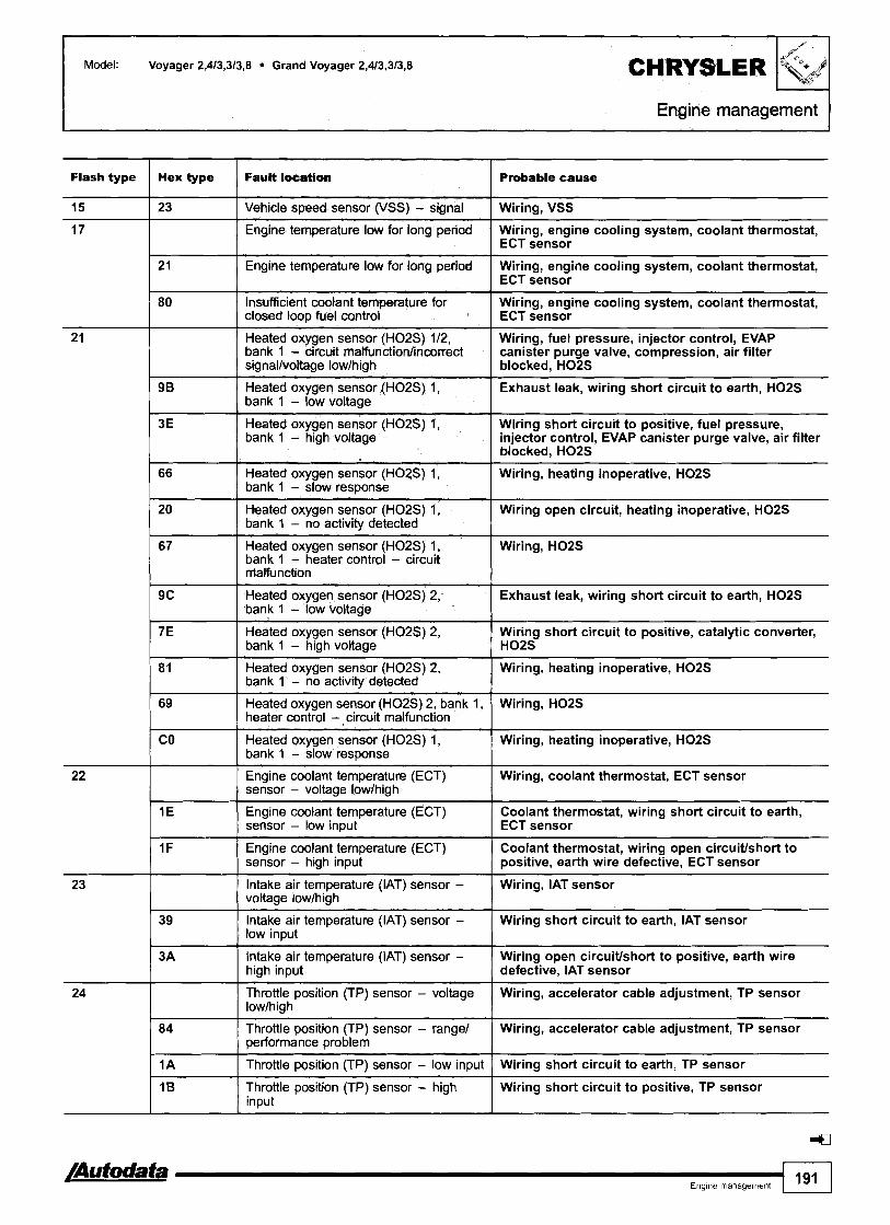
Engine management
Hex type Fault loeation Probable cause Flash type
Wiring, VSS
Wiring, engine cooling system, coolant thermostat, ECT sensor
23
21 I Engine temperature low for long period
Vehicle speed sensor (VSS) - signal
Engine temperature low for long period
Wiring, engine cooling system, coolant thermostat, ECT sensor
80 Insufficient coolant temperature for closed loop fuel control
Wiring, engine cooling system, coolant thermostat, ECT sensor
Heated oxygen sensor (H02S) 112, bank 1 - circuit malfunctionhncorrect signallvoltage lowlhigh
Wiring, fuel pressure, injector control, EVAP canister purge valve, compression, air filter blocked, H02S
Exhaust leak, wiring short circuit to earth, H02S 1
9 B I Heated oxygen sensor (H02S) 1,
Wiring short circuit to positive, fuel pressure, injector control, EVAP canister purge valve, air filter blocked, H02S
3E
bank 1 - low voltage
Heated oxygen sensor (H02S) 1, bank 1 - high voltage
Wiring, heating inoperative, H02S 66
20
67
Wiring open circuit, heating inoperative, H02S
Heated oxygen sensor (H02S) 1, bank 1 - slow response
Heated oxygen sensor (H02S) 1, bank 1 - no activity detected
Heated oxygen sensor (H02S) 1, bank 1 - heater control - circuit malfunction
Wiring, H02S
Heated oxygen sensor (H02S) 2, / bank 1 - low voltaae Exhaust leak, wiring short circuit to earth, H02S
Heated oxygen sensor (H02S) 2, bank 1 - high voltage
Wiring short circuit to positive, catalytic converter, H02S
Wiring, heating inoperative, H02S 81
69
CO
Wiring, H02S
Heated oxygen sensor (H02S) 2, bank 1 - no activity detected
Heated oxygen sensor (H02S) 2, bank 1, heater control - circuit malfunction
Heated oxygen sensor (H02S) 1, bank 1 - slow response
Engine coolant temperature (ECT) sensor - voltage lowlhigh
Wiring, heating inoperative, H02S
-
Wiring, coolant thermostat, ECT sensor
Engine coolant temperature (ECT) sensor - low input
Coolant thermostat, wiring short circuit to earth, ECT sensor
Engine coolant temperature (ECT) sensor - high input
Coolant thermostat, wiring open circuitlshort to positive, earth wire defective, ECT sensor
Wiring, IAT sensor
39
3A
Wiring short circuit to earth, IAT sensor
lntake air temperature (IAT) sensor - voltage lowlhigh
Intake air temperature (IAT) sensor - low input
Intake air temperature (IAT) sensor - high input
Throttle position (TP) sensor - voltage lowlhigh
Wiring open circuitlshort to positive, earth wire defective, IAT sensor
Wiring, accelerator cable adjustment, TP sensor
Throttle position (TP) sensor - range1 oerformance oroblem
Wiring, accelerator cable adjustment, TP sensor
1 A I Throttle position (TP) sensor - low input Wiring short circuit to earth, TP sensor
Throttle position (TP) sensor - high I input Wiring short circuit to positive, TP sensor
Engme management 191

1 CHRYSLER
I Engine management
Model: Voyager 2,4/3,3/3,8 Grand Voyager 2,4/3,3/3,8
Flash type Hex type Fault location Probable cause
25 1 I Idle air control (IAC) valve I Wiring open circuiffshort circuit, IAC valve
1 14 I Injector 2 - circuit malfunction 1 wiring, injector
27
/ 13 I Injector 3 - circuit malfunction 1 Wiring, injector
1 3D I Injector 4 - circuit malfunction ] Wiring, injector
19
8A
15
1 45 ( Injector 5 - circuit malfunction I Wiring, injector
1 46 I Injector 6 - circuit malfunction I Wiring, injector
Idle speed control (ISC) system - malfunction
Idle speed control (ISC) system - rpm lowerlhigher than expected
Injector(s) - circuit malfunction
Injector 1 - circuit malfunction
31 I Evaporative emission (EVAP) canister Wiring, EVAP canister purge valve purge valve - openlshort circuit
Wiring open circuitlshort circuit, IAC valve
Wiring, air leak, throttle valve tightlsticking, IAC valve
Wiring, injector
Wiring, injector
Evaporative emission (EVAP) system - Hose connection(s), intake leak, EVAP canister incorrect flow detected purge valve
Evaporative emission (EVAP) system - Hose connection(s), intake leak, EVAP canister, small leak detected 1 EVAP canister purge valve
1 B8 Evaporative emission (EVAP) leak Wiring, hose leaklblockage, EVAP leak detection detection pump - pressure switch
12
A1
B B
I B7 Evaporative emission (EVAP) leak Wiring open circuitlshort circuit, hose leak1 detection pump solenoid blockage, EVAP leak detection pump solenoid
Evaporative emission (EVAP) canister purge valve - circuit malfunction
Evaporative emission (EVAP) system - large leak detected
Evaporative emission (EVAP) system - blockage detected
Exhaust gas recirculation (EGR) - Wiring open circuitlshort circuit, EGR solenoid circuit malfunction
Wiring open circuitlshort circuit, EVAP canister purge valve
Hose connection(s), intake leak, EVAP canister, EVAP canister purge valve
Hose connection(s), hose blockedltrapped, EVAP canister
2 E
Cruise control
Exhaust gas recirculation (EGR) solenoid1 EGR system - circuit malfunction
Exhaust gas recirculation (EGR) system - insufficient flow detected
Wiring open circuitlshort circuit, hoses, voltage low1 high, cruise control master switch, cruise control vacuum switching valve
Wiring, hoses, EGR solenoid
Hose leaklblockage, wiring, EGR valve, EGR solenoid
- -
33 lk compressor clutch relay/ AC refrigerant pressure sensor - voltage lowlhigh
AC compressor clutch relay
AC refrigerant pressure sensor - high input
AC refrigerant pressure sensor - low input
- -
10
5A
5 8
AC refrigerant pressure too lowlhigh (cooling faulff incorrectly charged), wiring open circuitlshort circuit, AC compressor clutch relay, AC refrigerant pressure sensor
Wiring open circuitlshort circuit, AC compressor clutch relay
AC refrigerant pressure too high (cooling faultl incorrectly charged), wiring, AC refrigerant pressure sensor
AC refrigerant pressure too low (incorrectly charged), wiring, AC refrigerant pressure sensor
35 OE Engine coolant blower motor relay - lowlhigh speed
Wiring open circuitlshort circuit, engine coolant blower motor relay - lowlhigh speed

Model: Voyager 2,4/3,3/3,8 Grand Voyager 2,4/3,3/3,8
Engine management
Flash type Hex type Fault location I Probable cause
1 72 ParWneutral position (PNP) switch - I Wiring, PNP switch, ECMlTCM input circuit malfunction
37
I 94 Torque converter clutch (TCC) solenoid - Wiring, TCC solenoid circuit malfunction
Torque converter clutch (TCC) solenoid1 parkheutral position (PNP) switch - circuit malfunction
I Engine control relay
Wiring, TCC solenoid
41
42
I Wiring open circuitlshort circuit, engine control relay
I 2c I Engine control relay I Wiring open circuit, engine control relay
OC
OB
65
Randomlmultiple cylinder(s) - misfire Wiring, spark plug(s), HT lead(s), injector(s), ignition detected coil(s), low compression
Torque converter clutch (TCC) solenoid - electrical
Alternator, field control - circuit malfunction
Fuel pump relaylengine control relaylfuel level sensor - circuit malfunction
Fuel pump relay
95
96
97
1 6A Randomlmultiple cylinder(s) - misfire Wiring, spark plug(s), HT lead(s), injector(s), ignition detected coil(s), low compression
Wiring open circuitlshort circuit, TCC solenoid
Wiring open circuitlshort circuit, alternator, battery
Wiring open circuitlshort circuit, fuel pump relay, engine control relay, fuel level sensor
Wiring open circuitlshort circuit, fuel pump relay
1 6B Cylinder 1 - misfire detected Wiring, engine mechanical fault, ignitionlfuel
system, injector
Fuel level sensor - low input
Fuel level sensor - high input
Fuel level sensor - malfunction
/ Cylinder 2 - misfire detected Wiring, engine mechanical fault, ignitionlfuel system, injector
Wiring open circuit, fuel level sensor
Wiring short circuit to positive, fuel level sensor
Wiring, fuel level sensor
I 2A Ignition coil B, primarylsecondary - Wiring, ignition coil circuit malfunction
6D
6E
AE
AF
2 B
I 29 Ignition coil C, primarylsecondary - / Wiring, ignition coil circuit malfunction
44 I Battery temperature sensor - voltage Wiring, battery temperature sensor lowlhiclh
Cylinder 3 - misfire detected
Cylinder 4 - misfire detected
Cylinder 5 - misfire detected
Cylinder 6 - misfire detected
Ignition coil A, primarylsecondary - circuit malfunction
Wiring, engine mechanical fault, ignitionlfuel system, injector
Wiring, engine mechanical fault, ignitionlfuel system, injector
Wiring, engine mechanical fault, ignitionlfuel system, injector
Wiring, engine mechanical fault, ignitionlfuel system, injector
Wiring, ignition coil
45
/Autodata Engme management
9A
99
89
193
Battery ambient temperature sensor - voltage high
Battery ambient temperature sensor - voltage low
Transmission control system - malfunction
Wiring, battery ambient temperature sensor
Wiring, battery ambient temperature sensor
Wiring, ECMlTCM

CHRYSLER Model: Voyager 2,4/3,3/3,8 Grand Voyager 2,4/3,3/3,8
Engine management
46 1 06 I Alternator - voltage high I Wiring, battery, alternator
Flash type
47 1 O5 I Alternator - voltage low I Wiring, battery, alternator drive belt, alternator
Hex type
System too rich
51
Wiring, intake blocked, EVAP canister purge valve, fuel pressure, EGR system, injector(s), air filter
Fault location
blocked, ignition sysiem, heated oxygen sensor I (HO2S)
Probable cause
77
I O2 Engine control module (ECM) - internal ECM
System too lean
53
Engine control module (ECM) - intemat I fault I ECM
Wiring, intakelexhaust leak, MAP sensor, fuel pressurelpump, EVAP canister purge valve, injector(s), heated oxygen sensor (H02S)
54 Camshaft position (CMP) sensor - no Wiring, CMP sensor I siqnal
Engine control module (ECM) - internal fault
55 I I End of MIL code outuut 1 -
ECM
65 1 98 Brake pedal position (BPP) switch - I Wiring, BPP switch circuit malfunction
63
64
Manifold absolute pressure (MAP) sensor - barometric pressure range1 performance problem
Engine control module (ECM) - EEPROM error
Engine control module (ECM) - EEPROM error
Compressed natural gas pressure sensor - pressure high
31
BE
66 I I CAN data bus, transmission control rnodule (TCMybody control module (BCM) - no siqnal
lntakelexhaust leak, wiring, MAP sensor
ECM
ECM
Compressed natural gas system, wiring, compressed natural gas pressure sensor
Wiring, TCM, BCM
7 1
72
77
60
61
92
70
52
CAN data bus, transmission control module (TCM) - no signal
CAN data bus, body control module (BCM) - no signal
Engine control module (ECM) - 5 volt output low
Catalytic converter system, bank 1 - efficiency below threshold
Cruise control
Wiring, TCM
Wiring, BCM
ECM
Catalytic converter, wiring, heated oxygen sensor (H02S) 2
Wiring, cruise control vacuum switching valve

Model:
Year:
Voyager 2,413,313,8 Grand Voyager 2,413,313,8
1998
Engine code: EDZ, EGA, EGM, EGH
System: SBEC Ill
Engine management
General information Refer to the front of this manual for general test conditions, terminology, detailed descriptions of wiring faults and a general trouble shooter for electrical and mechanical faults.
Accessing and erasing The engine control module (ECM) fault memory can only be accessed and erased using diagnostic equipment connected to the data link connector (DLC).
Trouble code identification - EOBD type
EOBD type
I Fault location I Probable cause I I
P I 398 Engine control module (ECM) - misfire detection limit Wiring, poor connection, CKP sensor reached
PO I Refer to EOBD trouble code table
P1290
PI294
P1391
Pi486 Evaporative emission (EVAP) system - blockage Hose connection(s), hose blockedltrapped, detected EVAP canister
-
Compressed natural gas pressure sensor -pressure high
Idle speed control (ISC) system - rpm lowerlhigher than expected
Crankshaft position (CKP) sensorlcamshaft position (CMP) sensor - intermittent signal
P1493 1 Battery ambient temperature sensor - voltage low I Wiring, battery ambient temperature sensor
Compressed natural gas system, wiring, compressed natural gas pressure sensor
Wiring, air leak, throttle valve tightlsticking, IAC valve
Wiring, poor connection, air gap, CKP sensor, CMP sensor
P1491
P1492
Engine coolant blower motor relay - lowlhigh speed
Battery ambient temperature sensor - voltage high
Wiring open circuitlshort circuit, engine coolant blower motor relay - lowlhigh speed
Wiring, battery ambient temperature sensor

Model: Voyager 2,413,313,8 Grand Voyager 2,413,3/3,8
F e management
EOBD type
PI494
Fault location Probable cause
Evaporative emission (EVAP) leak detection pump - pressure switch
Wiring, hose leaklblockage, EVAP leak detection Pl"'-'P
Evaporative emission (EVAP) leak detection pump solenoid
Wiring open circuitlshort circuit, hose leak/ blockage, EVAP leak detection pump solenoid
ECM Engine control module (ECM) - 5 volt output low
Cruise control Wiring open circuitlshort circuit, hoses, cruise control master switch, cruise control vacuum switching valve
Engine control module (ECM) - EEPROM error
CAN data bus, transmission control module (TCM) - no signal
ECM
Wiring, TCM
Parklneutral position (PNP) switch - input circuit malfunction -
Wiring, PNP switch, ECMITCM
Trouble code identification - Hex type
Hex type Fault location Probable cause
Camshaft position (CMP) sensor - no signal Wiring, CMP sensor
Engine control module (ECM) - internal fault ECM
Alternator - voltage low
Alternator - voltage high
Wiring, battery, alternator drive belt, alternator
Wiring, battery, alternator
Engine control relay Wiring open circuitlshort circuit, engine control relay
Wiring open circuitlshort circuit, alternator, battery
Wiring open circuitlshort circuit, TCC solenoid
Alternator, field control - circuit malfunction
Torque converter clutch (TCC) solenoid - electrical
Engine coolant blower motor relay - lowlhigh speed Wiring open circuitlshort circuit, engine coolant blower motor relay - lowlhigh speed
Cruise control Wiring open circuitlshort circuit, hoses, cruise control master switch, cruise control vacuum switching valve
AC compressor clutch relay Wiring open circuitlshort circuit, AC compressor clutch relay
Exhaust gas recirculation (EGR) - circuit malfunction Wiring open circuitlshort circuit, EGR solenoid
Evaporative emission (EVAP) canister purge valve - circuit malfunction
Wiring open circuitlshort circuit, EVAP canister purge valve
lnjector 3 - circuit malfunction Wiring, injector
Injector 2 - circuit malfunction Wiring, injector
Wiring, injector Injector 1 - circuit malfunction
Idle speed control (ISC) system - malfunction Wiring open circuitlshort circuit, IAC valve
Throttle position (TP) sensor - low input
Throttle position (TP) sensor - high input
Engine coolant temperature (ECT) sensor - low input
Wiring short circuit to earth, TP sensor
Wiring short circuit to positive, TP sensor
Coolant thermostat, wiring short circuit to earth, ECT sensor
Engine coolant temperature (ECT) sensor - high input Coolant thermostat, wiring open circuitlshort to positive, earth wire defective, ECT sensor

Engine management I
Model: Voyager 2,4/3,3/3,8 Grand Voyager 2,4/3,3/3,8 CHRYSLER
Hex type
/
'k,"
Fault location Probable cause
Heated oxygen sensor (H02S) 1, bank 1 - no activity detected
Wiring open circuit, heating inoperative, H02S
Engine temperature low for long period Wiring, engine cooling system, coolant thermostat, ECT sensor
23 1 Vehicle speed sensor (VSS) - signal Wiring, VSS
24 I Manifold absolute pressure (MAP) sensor - low input Wiring short circuit to earth, MAP sensor
25 / Manifold absolute pressure (MAP) sensor - high input Wiring short circuit to positive, MAP sensor
Wiring, hose connection(s), MAP sensor
Wiring, air gap, CKP sensor
27
28
29 I Ignition coil C, pflmarylsecondary - circuit malfunction
- --
Manifold absolute pressure (MAP) sensor
Crankshaft position (CKP) sensor - no signal
Wiring, ignition coil
2A I Ignition coil B, primarylsecondary - circuit malfunction Wiring, ignition coil
Wiring, ignition coil
Wiring open circuit, engine control relay
2 B
2C
2 E Hose leaklblockage, wiring, EGR valve, EGR solenoid
Ignition coil A, primarylsecondary - circuit malfunction
Engine control relay
Exhaust gas recirculation (EGR) system - insufficient flow detected
ECM
ECM
30
3 1
39 Wiring short circuit to earth, IAT sensor
Engine control module (ECM) - EEPROM error
Engine control module (ECM) - EEPROM error
Intake air temperature (IAT) sensor - low input
Intake air temperature (IAT) sensor - high input
Manifold absolute pressure (MAP) sensor - barometric pressure rangelperformance problem
Wiring open circuiffshort to positive, earth wire defective, IAT sensor
lntakelexhaust leak, wiring, MAP sensor
3 D I Injector 4 - circuit malfunction Wiring, injector
3 E I Heated oxygen sensor (H02S) 1, bank 1 - high voltage Wiring short circuit to positive, fuel pressure, injector control, EVAP canister purge valve, air filter blocked, H02S
ECM 44
45 Wiring, injector
Engine control module (ECM) - internal fault
Injector 5 - circuit malfunction
46 I Injector 6 - circuit malfunction Wiring, injector
Wiring, cruise control vacuum switching valve
AC refrigerant pressure too high (cooling faulff incorrectly charged), wiring, AC refrigerant pressure sensor
AC refrigerant pressure too low (incorrectly charged), wiring, AC refrigerant pressure sensor
52
5A
Cruise control
AC refrigerant pressure sensor - high input
CAN data bus, transmission control module (TCM) - no signal
I
Wiring, TCM
5 B AC refrigerant pressure sensor - low input
Wiring, BCM
Wiring open circuitlshort circuit, fuel pump relay
6 1
65
66 I Heated oxygen sensor (H02S) 1, bank 1 - slow response
CAN data bus, body control module (BCM) - no signal
Fuel pump relay
Wiring, heating inoperative, H02S
Heated oxygen sensor (H02S) 1, bank 1 - heater control - circuit malfunction
Wiring, H02S
Heated oxygen sensor (H02S) 2, bank 1, heater control - circuit malfunction
Wiring, H02S
/Autodata Eno~ne rnanaaernent 1197 1

Model: Voyager 2,413,313,8 Grand Voyager 2,4/3,3/3,8
I Engine management
Hex type Fault location
Randomlmultiple cylinder(s) - misfire detected
Probable cause
Wiring, spark plug(s), HT lead(s), injector(s), ignition coil(s), low compression
Cylinder 2 - misfire detected
Cylinder 1 - misfire detected
Wiring, engine mechanical fault, ignitionlfuel system, injector
Wiring, engine mechanical fault, ignitionlfuel system, injector
Cylinder 3 - misfire detected
Cylinder 4 - misfire detected
Parklneutral position (PNP) switch - input circuit malfunction
- - -- - - -- . - - - - System too rich
Wiring, engine mechanical fault, ignitionlfuel system, injector
Wiring, engine mechanical fault, ignitionlfuel system, injector
Catalytic converter system, bank 1 - efficiency below threshold
Evaporative emission (EVAP) system - incorrect flow detected
Wiring, PNP switch, ECMKCM
Catalytic converter, wiring, heated oxygen sensor (HO2S) 2
Hose connection(s), intake leak, EVAP canister purge valve
Wiring, intake blocked, EVAP canister purge valve, fuel pressure, EGR system, injector(s), air filter blocked, ignition system, heated oxygen sensor (H02S)
Wiring, intakelexhaust leak, MAP sensor, fuel pressurelpump, EVAP canister purge valve, injector (s), heated oxygen sensor (H02S)
System too lean t Heated oxygen sensor (H02S) 2, bank 1 - high voltage Wiring short circuit to positive, catalytic converter, 1 HO2S
Insufficient coolant temperature for closed loop fuel control Wiring, engine cooling system, coolant thermostat, I ECT sensor
Transmission control system - malfunction ] Wiring, ECMKCM
Heated oxygen sensor (H02S) 2, bank 1 - no activity detected
Throttle position (TP) sensor - rangelperformance problem
Wiring, heating inoperative, H02S
Wiring, accelerator cable adjustment, TP sensor
Torque converter clutch (TCC) solenoid - circuit malfunction
Idle speed control (ISC) system - rpm lowerlhigher than expected
Engine control module (ECM) - 5 volt output low
Wiring, TCC solenoid
Wiring, air leak, throttle valve tightlsticking, IAC valve
ECM
Brake pedal position (BPP) switch - circuit malfunction I Wiring, BPP switch
--
Fuel level sensor - low input
Fuel level sensor - high input
Fuel level sensor - malfunction
- --
Wiring open circuit, fuel level sensor
Wiring short circuit to positive, fuel level sensor
Wiring, fuel level sensor
Heated oxygen sensor (H02S) 2, bank 1 - low voltage I Exhaust leak, wiring short circuit to earth, H02S
Battery ambient temperature sensor - voltage low
Battery ambient temperature sensor - voltage high
Heated oxygen sensor (H02S) 1, bank 1 - low voltage
Wiring, battery ambient temperature sensor
Wiring, battery ambient temperature sensor
Exhaust leak, wiring short circuit to earth, H02S
Crankshaft position (CKP) sensor/camshaft position (CMP) sensor - intermittent signal
Wiring, poor connection, air gap, CKP sensor, CMP sensor

Engine management1
Hex type Fault location / Probable cause
A0
/ Cylinder 6 - misfire detected
Evaporative emission (EVAP) system - large leak detected
Cylinder 5 - misfire detected
Wiring, engine mechanical fault, ignitionlfuel system, injector
Evaporative emission (EVAP) system - small leak detected
Hose connection(s), intake leak, EVAP canister, EVAP canister purge valve
Wiring, engine mechanical fault, ignitionlfuel system, injector
Evaporative emission (EVAP) leak detection pump solenoid
Hose connection(s), intake leak, EVAP canister, EVAP canister purge valve
Wiring open circuit/short circuit, hose leak1 blockage, EVAP leak detection pump solenoid
B8 1 Evaporative emission (EVAP) leak detection pump - Wiring, hose leaklblockage, EVAP leak detection pressure switch
BE 1 Compressed natural gas pressure sensor - pressure high Compressed natural gas system, wiring, compressed natural gas pressure sensor
B A
B B
CO I Heated oxygen sensor (H02S) 1, bank 1 -slow response ] Wiring, heating inoperative, H02S
-a, Engme management 199
Engine control module (ECM) - misfire detection limit reached
Evaporative emission (EVAP) system - blockage detected
Wiring, poor connection, CKP sensor
Hose connection(s), hose blockedltrapped, EVAP canister

Engine management
Model: Voyager 2,4/3,3/3,8 Grand Voyager 2,4/3,3/3,8
Year: 1999-02
Engine code: EDZ, EGA, EGM, EGH
System: SBEC Ill
General information Refer to the front of this manual for general test conditions, terminology, detailed descriptions of wiring faults and a general trouble shooter for electrical and mechanical faults.
Accessing - +2001 The engine control module (ECM) fault memory can only be accessed using diagnostic equipment connected to the data link connector (DLC).
Accessing - 2001 +
Within 5 seconds switch ignition ON-OFF-ON-OFF-ON. Odometer will display trouble codes. If no trouble codes are stored in ECM, odometer will display 'P1684' and 'done' or only 'done'. The engine control module (ECM) fault memory can also be accessed using diagnostic equipment connected to the data link connector (DLC).
Erasing The engine control module (ECM) fault memory can only be erased using diagnostic equipment connected to the data link connector (DLC).
Trouble code identification
EOBD type
PO
PI192
P I 193
PI281 Engine temperature low for long period Wiring, engine cooling system, coolant thermostat, ECT sensor
P I 195
PI196
PI282 [ Fuel pump relay I Wiring open circuitlshort circuit, fuel pump relay
Fault location
Refer to EOBD trouble code table
Intake air temperature (IAT) sensor - voltage low
Intake air temperature (IAT) sensor - voltage high
Compressed natural gas pressure sensor - pressure high
Probable cause
-
Wiring, IAT sensor
Wiring, IAT sensor
Heated oxygen sensor (H02S) 1, bank 1 - slow response
Heated oxygen sensor (H02S) 2, bank 1 - slow response
Compressed natural gas system, wiring, compressed natural gas pressure sensor
Heating inoperative, wiring, H02S
Heating inoperative, wiring, H02S

Model: Voyager 2,4/3,3/3,8 Grand Voyager 2,4/3,3/3,8
Engine management
EOBD t~ pe
Compressed natural gas pressure sensor - voltage high
Compressed natural gas pressure sensor - voltage low
PI297 I Manifold absolute pressure (MAP) sensor I Wiring, hose connection(s), MAP sensor
Fault location
Wiring, compressed natural gas pressure sensor
Wiring, compressed natural gas pressure sensor
PI294
P I 295
Pi296
PI298 1 System too lean at prolonged wide open throttle lntakelexhaust leak, MAP sensor, fuel pressurelpump, injector(s), H02S
Probable cause
P I 299 Manifold absolute pressure (MAP) sensorlthrottle Intake leak, hose connection(s), MAP sensor, position (TP) sensor TP sensor
Idle speed control (ISC) system - rpm lowerlhigher than expected
Throttle position (TP) sensor - supply voltage
Manifold absolute pressure (MAP) sensor - supply voltage
PI388 1 Engine control relay I Wiring open circuitlshort circuit, engine control relay
Wiring, air leak, throttle valve tightlsticking, IAC valve
Wiring, TP sensor, ECM
Wiring, MAP sensor, ECM
Engine control relay
Crankshaft position (CKP) sensorlcamshaft position (CMP) sensor - signal synchronisation
- --
Wiring open circuit, engine control relay
Timing belt looseljumped position, CKP sensor, CMP sensor
PI391
P I 398
Engine coolant blower motor relay
PI486
PI488
Wiring open circuitlshort circuit, engine coolant blower motor relay - high speed
Crankshaft position (CKP) sensorlcamshaft position (CMP) sensor - intermittent signal
Engine control module (ECM) - misfire detection limit reached
Wiring, poor connection, air gap, CKP sensor, CMP sensor
Wiring, poor connection, CKP sensor
Evaporative emission (EVAP) system - blockage detected
Engine control module (ECM) - auxiliary 5 volt output low
Hose connection(s), hose blockedltrapped, EVAP canister
Wiring, ECM
PI490
Pi491
Evaporative emission (EVAP) leak detection pump - Wiring, hose leaklblockage, EVAP leak detection pump pressure switch
Battery ambient temperature sensor - high input
Battery ambient temperature sensor - voltage low
Engine coolant blower motor relay
Engine coolant blower motor relay - circuit malfunction
Wiring short circuit to positive, battery ambient temperature sensor, ECM
Wiring, battery ambient temperature sensor
PI594 1 Alternator - voltage high 1 Wiring, battery, alternator
Wiring open circuitlshort circuit, engine coolant blower motor relay - low speed
Wiring open circuitlshort circuit, engine coolant blower motor relay
Evaporative emission (EVAP) leak detection pump solenoid
Engine control module (ECM) - 5 volt output low
Wiring open circuitlshort circuit, hose leaklblockage, EVAP leak detection pump solenoid
ECM
PI597 ( Cruise control master switch - low voltage I Wiring, cruise control master switch
P I 595
P I 596
Cruise control
Cruise control master switch - high voltage
P I 598
Wiring open circuitlshort circuit, hoses, cruise control master switch, cruise control vacuum switching valve
Wiring, cruise control master switch
/Autodata Engme management
4
AC refrigerant pressure sensor - high input
201
Wiring, AC refrigerant pressure too high (cooling fault/ incorrectly charged), AC refrigerant pressure sensor

I Engine management
EOBD type
Fault location I Probable cause
AC refrigerant pressure sensor - low input Wiring, AC refrigerant pressure too low (incorrectly charged), AC refrigerant pressure sensor
PI603 I Engine control module (ECM) - RAM link error I ECM
Engine control module (ECM) not programmed New ECM not programmed, incorrectly programmed, ECM
PI681 I CAN data bus, instrumentation - no signal I Wiring, instrumentation control module
Engine control module (ECM) - RAM readlwrite error
Engine control module (ECM) - shut down timer error
ECM
ECM
Key not programmed into immobilizer control module Wiring, ignition key not matchedldamaged, immobilizer control module
Alternator - voltage low
Cruise control
Engine control module (ECM) - supply voltage disconnected within last 50 ignition switch ON-OFF cycles
CAN data bus, immobilizer control module - no signal
Wiring, battery, alternator drive belt, alternator
Wiring, cruise control vacuum switching valve
Wiring, battery
Wiring, immobilizer control module
PI696 1 Engine control module (ECM) - EEPROM error I ECM
P i 687
PI695
Transmission system relay I Wiring open circuitlshort circuit, transmission system relay, ECMITCM
CAN data bus, instrumentation - no signal
CAN data bus, body control module (BCM) - no siqnal
P I 697
P I 698
Wiring, instrumentation control module (mechanical)
Wiring, BCM
Engine control module (ECM) - EEPROM error
CAN data bus, transmission control module (TCM) - no signal
ECM
Wiring, TCM
Wiring, PNP switch, ECMITCM
Wiring, poor connection, battery, alternator
I
P I 899
P2503
Parkheutral position (PNP) switch - input circuit malfunction
Charging system - voltage low

Model: Cherokee 2,514,O Grand Cherokee 4,015,2 Wrangler 2,514,O
Year: 1996-97
Engine code: VIN position 8 = P, S, Y
System: JTEC
CHRYSLER Ixii;9@l
Engine managementltransmission I
General information Refer to the front of this manual for general test I ;I
' - terminology, detailed descr~pt~ons of wmng faults dlld J
general trouble shooter for electrical and mechanical faults Engine control module (ECM) incorporates transmission control module (TCM) function. Trouble codes can be displayed by the MIL, d~gital odometer or by using diagnostic equipment connected to the data link connector (DLC).
Accessing - flash type Within 5 seconds switch ignition ON-OFF-ON-OFF-ON. Count MIL flashes. Note trouble codes. Each trouble code consists of two groups [A]. The first group of flashes indicate the 'tens' of the trouble code. The second group of flashes indicate the 'units' of the trouble code. A short pause separates 'tens' and 'units' rn [B]. A long pause separates each trouble code rn [C]. For example: Trouble code 21 displayed rn. End of test sequence indicated by trouble code 55. Trouble codes can also be displayed by the digital odometer using the same key cycling procedure as above. After code 55 is displayed the odometer will return to its normal mode.
Grand Cherokee
Accessing - EOBDlHex type Trouble codes can only be displayed by usmg diagnostic equipment connected to the data link connector (DLC).
Erasing The engine control module (ECM) fault memory can only be erased using diagnostic equipment connected to the data link connector (DLC).

Engine managementttransmission
Trouble code identification - EOBD type
EOBD type
PO
PI294
Fault location Probable cause
Engine control module (ECM) - misfire Wiring, poor connection, engine mechanical fault, ignitionlfuel detection limit reached system, CKP sensor, ECM
Refer to EOBD trouble code table
Idle speed control (ISC) system - rpm lowerlhigher than expected
Manifold absolute pressure (MAP) sensor - supply voltage
Manifold absolute pressure (MAP) sensor
Crankshaft position (CKP) sensorlcamshaft position (CMP) sensor - intermittent signal
Evaporative emission (EVAP) system - Hose connection(s), hose blockedltrapped, EVAP canister blockage detected
-
Wiring, air leak, throttle valve tightlsticking, IAC valve
Wiring, MAP sensor, ECM
Wiring, hose connection(s), MAP sensor
Wiring, poor connection, air gap, CKP sensor, CMP sensor
Battery ambient temperature sensor - Wiring, battery ambient temperature sensor, ECM voltage high
Battery ambient temperature sensor - Wiring, battery ambient temperature sensor, ECM voltage low
Evaporative emission (EVAP) leak detection Wiring, hose leaklblockage, EVAP leak detection pump pump - pressure switch
Evaporative emission (EVAP) leak detection Wiring open circuitlshort circuit, hose leaklblockage, EVAP pump solenoid leak detection pump solenoid
Engine control module (ECM) - EEPROM ECM error
Governor pressure not equal to target (1 5-20 PSI) - mid pressure malfunction
Signal wire open circuitlshort circuit, valve body, sensor supply wire open circuit, transmission fluid level, governor pressure solenoid, transmission mechanical fault, ECM - no 5 volt supply
Governor pressure not equal to target - low pressure malfunction
Signal wire open circuitlshort circuit, valve body, sensor supply wire open circuit, transmission fluid level, governor pressure solenoid, transmission mechanical fault, ECM - no 5 volt supply
Governor pressure sensor - incorrect signal Signal wire short circuit to earthlpositive, supply wire open circuitlshort circuit, transmission fluid level, governor pressure solenoid, governor pressure sensor, ECM
Governor pressure sensor - signal high
Governor pressure sensor - signal low
Transmission system relay
Signal wire short circuit to positive, supply wire open circuit, transmission fluid level, governor pressure sensor, ECM
Signal wire short circuit to earth, supply wire open circuit, transmission fluid level, governor pressure sensor, ECM
Wiring open circuitlshort circuit, transmission system relay, ECM
Parklneutral position (PNP) switch - input circuit malfunction
Wiring, PNP switch, ECM

Model: Cherokee 2,5/4,0 Grand Cherokee 4,0/5,2 Wrangler 2,5/4,0 CHRYSLER
Engine management/transmission
Trouble code identification - flashlHex type
Flash type Hex type Fault location Probable cause
I 9D Crankshaft position (CKP) sensorlcamshaft Wiring, poor connection, air gap, CKP sensor, position (CMP) sensor - intermittent signal CMP sensor
11
I BA Engine control module (ECM) - misfire Wiring, poor connection, engine mechanical fault, detection limit reached ignitionlfuel system, CKP sensor, ECM
28
13 1 27 I Manifold absolute pressure (MAP) sensor I Wiring, hose connection(s), MAP sensor
Engine control module (ECM) - supply voltage disconnected within last 50 ignition switch ON-OFF cycles
14 I Manifold absolute pressure (MAP) sensor - Wiring, MAP sensor input lowlhigh
Crankshaft position (CKP) sensorlcamshaft position (CMP) sensor
Crankshaft position (CKP) sensor - no signal
Wiring, battery
I 24 Manifold absolute pressure (MAP) sensor - Wiring short circuit to earth, MAP sensor low input
Wiring, poor connection, air gap, CKP sensor, CMP sensor
Wiring, air gap, CKP sensor
17 1 I Engine temperature low for long period Wiring, engine cooling system, coolant thermostat, ECT sensor
15
/ Engine temperature low for long period Wiring, engine cooling system, coolant thermostat, ECT sensor
Insufficient coolant temperature for closed Wiring, engine cooling system, coolant loop fuel control I thermostat, ECT sensor
25
87
23
A6
Heated oxygen sensor (H02S) 112, bank 1 - circuitlsignal malfunction
Wiring, fuel pressure, injector control, EVAP canister purge valve, compression, air filter blocked, catalytic converter, H02S
Manifold absolute pressure (MAP) sensor - high input
Manifold absolute pressure (MAP) sensor - supply voltage
Vehicle speed sensor (VSS) - signal
Vehicle speed sensor (VSS) - no signal
Vehicle speed sensor (VSS) - circuit malfunction
I 3E Heated oxygen sensor (H02S) 1, bank 1 - Wiring short circuit to positive, H02S high voltage
Wiring short circuit to positive, MAP sensor
Wiring, MAP sensor, ECM
Wiring, VSS, ECM
Wiring, VSS, ECM
Wiring, VSS, ECM
I Heated oxygen sensor (H02S) 1, bank 1 - Heating inoperative, wiring, H02S slow response
1 67 Heated oxygen sensor (H02S) 1, bank 1 - Wiring, H02S heater control - circuit malfunction
1 69 Heated oxygen sensor (H02S) 2, bank 1, Wiring, H02S heater control - circuit malfunction
7E
98
9C
CO
Heated oxygLn sensor (H02S) 2, bank 1 - high voltage
Heated oxygen sensor (H02S) 1, bank 1 - low voltage
Heated oxygen sensor (H02S) 2, bank 1 - low voltage
Heated oxygen sensor (H02S) 1, bank 1 - slow response
Wiring short circuit to positive, catalytic converter, H02S
Exhaust leak, wiring short circuit to earth, H02S
Exhaust leak, wiring short circuit to earth, H02S
Heating inoperative, wiring, H02S

$1 CHRYSLER Model: Cherokee 2,514,O Grand Cherokee 4,015,2 Wrangler 2,514,O
1 I I -- 5 .I Engine managemenVtransmission
Engine coolant temperature (ECT) sensor - Wiring, coolant thermostat, ECT sensor voltage lowlhigh
Flash type
Engine coolant temperature (ECT) sensor - Coolant thermostat, wiring short circuit to earth, low input I ECT sensor
Engine coolant temperature (ECT) sensor - Coolant thermostat, wiring open circuitlshort to high input positive, earth wire defective, ECT sensor
Hex type
Intake air temperature (IAT) sensor - I Wiring, IAT sensor voltage lowlhigh
Intake air temperature (IAT) sensor - low input
Fault location
Wiring short circuit to earth, IAT sensor
Probable cause
Intake air temperature (IAT) sensor - high input
. Throttle position (TP) sensor - voltage lowlhigh
27 I ( Injector(s) - circuit malfunction I Wiring, injector
Wiring open circuitlshort to positive, earth wire defective, IAT sensor
Wiring, accelerator cable adjustment, TP sensor
25
/ I 3 I Injector 3 - circuit malfunction I Wiring, injector
1 3D I Injector 4 - circuit malfunction I Wiring, injector
Wiring short circuit to earth, TP sensor
Wiring short circuit to positive, TP sensor
Wiring, accckrmm cable adjustment, TP sensor
- -- - - Wiring open circu~tlshort circuit, IAC valve
Wiring open circuitlshort circuit, IAC valve
Wiring, air leak, throttle valve tightlsticking, IAC valve
'I A I Throttle position (TP) sensor - low input
i 4 1- ,;-
1 45 ( Injector 5 - circuit malfunction I Wiring, injector
1 B
84
a9
r1&
1 46 I Injector 6 - circuit malfunction I Wiring, injector
Throttle pos~t~on (TP) sensor - high input
r Throttle position (TP) sensor - rangelperformance problem
Idle air control (IAC) valve
Idle speed control (ISC) system - malfunction
Idle speed control (ISC) system -
Injector 2 - circuit malfunction
Injector 1 - circuit malfunction
I rpm lowerlh~qher than expected
Wiring, injector
Wiring, injector
Evaporative emission (EVAP) system - Hose connection(s), intake leak, EVAP canister, large leak detected EVAP canister purge valve
Evaporative emission (EVAP) system - Hose connection(s), hose blockedltrapped, blockaqe detected / EVAP canister
Wiring, injector
Wiring, injector
Wiring, EVAP canister, EVAP canister purge valve
- - - . - . -
Wiring open circuitlshort circuit, EVAP canister purge valve
Hose connection(s), intake leak, EVAP canister purge valve
Hose connection(s), intake leak, EVAP canister, EVAP canister purge valve
1 a ' - , ,rljector 7 - circuit malfunction
Evaporative emission (EVAP) leak Wiring, hose leaklblockage, EVAP leak detection detection pump - pressure switch
Evaporative emission (EVAP) leak I Wiring open circuitlshort circuit, hose leak/ detection pump solenoid blockage, EVAP leak detection pump solenoid
Injector 8 - circuit malfunction
Evaporative emission (EVAP) canister purge valvelEVAP system
Evaporatwe emission (EVAP) canister purge valve - circuit malfunction
Evaporative emission (EVAP) system - incorrect flow detected
3 1
P, 3 Evaporative emission (EVAP) system - I small leak detected
50
12
71

Model. Cherokee 2,5/4,0 Grand Cherokee 4,015,2 Wrangler 2,5/4,0 CHRYSLER
Engine managementltransmission
Flash type
33
34
35
37
Hex type
10
OF
56
57
OE
1 32 I Shift solenoid (SS) 3 4 - electrical I Wiring, shift solenoid, ECM
Transmission control system - malfunction
Torque converter clutch (TCC) solenoid - electrical
1 72 Parklneutrat position (PNP) switch - I Wiring, PNP switch, ECM input circuit malfunction
Fault locatlon
AC compressor clutch relay
Cruise control
Cruise control
Cruise control master switch - high voltage
Cruise control master switch - low voltage
Engine coolant blower motor relay
Wiring, transmission fluid level, transmission mechanical fault, PNP switch, TCC solenoid, TFT sensor, TFP solenoid, shift solenoid, governor pressure solenoid, transmission system relay, ECM
Wiring open circuitlshort circuit, TCC solenoid
Probable cause
Wiring open circuitlshort circuit, AC compressor clutch relay
Wiring open circuitlshort circuit, hoses, voltage lowlhigh, cruise control master switch, cruise control vacuum switching valve
Wiring open circuitlshort circuit, hoses, voltage lowlhigh, cruise control vacuum switching valve
Wiring, cruise control master switch
Wiring, cruise control master switch
Wiring open circuitlshort circuit, engine coolant blower motor relay - lowlhigh speed
Governor pressure not equal to target (15-20 PSI) - mid pressure malfunction
1 94 Torque converter clutch (TCC) solenoid - Wiring, TCC solenoid circuit malfunction
Signal wire open circuitlshort circuit, valve body, sensor supply wire open circuit, transmission fluid level, governor pressure solenoid, transmission mechanical fault. ECM - no 5 volt supply
8E
Transmission fluid pressure (TFP) / Wiring, TFP solenoid, ECM solenoid - electrical
Governor pressure not equal to target - low pressure malfunction
A4
A5
Signal wire open circuitlshort circuit, valve body, sensor supply wire open circuit, transmission fluid level, governor pressure solenoid, transmission mechanical fault, ECM - no 5 volt supply
Transmission fluid temperature (TFT) sensor - range/performance problem
Gear selection, 3 4 - shift malfunction
AD
4A
4 6
06
Wiring, TFT sensor
Wiring, TR sensor, shift solenoids, transmission mechanical fault
Transmission system relay
Transmission fluid temperature (TFT) sensor - low input
Transmission fluid temperature (TFT) sensor - high input
Afternator, field control - circuit malfunction
Wiring open circuitlshort circuit, transmission system relay, ECM
Wiring short circuit to earth, TFT sensor, ECM
Wiring short circuit to positive, TFT sensor, ECM
Wiring open circuitlshort circuit, alternator, battery

Model: Cherokee 2,514,O Grand Cherokee 4,0/5,2 Wrangler 2,514,O
] a Engine managementltransmission
Flash type
1 6A Randomlmultiple cylinder(s) - misfire Wiring, spark plug(s), HT lead(s), injector(s), detected ignition coil(s), low compression
Hex type
0 A
2C
65
95
96
97
Cylinder 1 - misfire detected Wiring, engine mechanical fault, ignitionlfuel system, injector / Cylinder 2 - misfire detected Wiring, engine mechanical fault, ignitionlfuel system, injector
Fault location
Fuel pump relaylengine control relaylfuel level sensor - circuit malfunction
Engine control relay
Engine control relay
Fuel pump relay
Fuel level sensor - low input
Fuel level sensor - high input
Fuel level sensor - malfunction
Randomlmultiple cylinder(s) - misfire detected
I Cylinder 3 - misfire detected Wiring, engine mechanical fault, ignitionlfuel system, injector
Probable cause
Wiring open circuitlshort circuit, fuel pump relay, engine control relay, fuel level sensor
Wiring open circuitlshort circuit, engine control relay
Wiring open circuit, engine control relay
Wiring open circuitlshort circuit, fuel pump relay
Wiring open circuit, fuel level sensor
Wiring short circuit to positive, fuel level sensor
Wiring, fuel level sensor
Wiring, spark plug(s), HT lead@), injector(s), ignition coil(s), low compression
I Cylinder 4 - misfire detected Wiring, engine mechanical fault, ignitionlfuel system, injector
AE
AF
BO
B 1
2 6
9A
99
1 32 I Shift solenoid (SS) 3-4 - electrical I Wiring, shift solenoid, ECM
Transmission control system - malfunction
1 4A Transmission fluid temperature (TFT) I Wiring short circuit to earth, TFT sensor, ECM sensor - low input
Cylinder 5 - misfire detected
Cylinder 6 - misfire detected
Cylinder 7 - misfire detected
Cylinder 8 - misfire detected
Ignition coil A, primary -circuit malfunction
Battery ambient temperature sensor - voltage lowlhigh
Battery ambient temperature sensor - voltage high
Battery ambient temperature sensor - voltage low
Wiring, transmission fluid level, transmission mechanical fault, PNP switch, TCC solenoid, TFT sensor, TFP solenoid, shift solenoid, overdrive solenoidlswitch, governor pressure solenoid, transmission system relay, ECM
1 4B Transmission fluid temperature (TFT) Wiring short circuit to positive, TFT sensor, ECM sensor - high input
Wiring, engine mechanical fault, ignitionlfuel system, injector
Wiring, engine mechanical fault, ignitionlfuel system, injector
Wiring, engine mechanical fault, ignitionlfuel system, injector
Wiring, engine mechanical fault, ignitionlfuel system, injector
Wiring, ignition coil
Wiring, battery ambient temperature sensor, ECM
Wiring, battery ambient temperature sensor, ECM
Wiring, battery ambient temperature sensor, ECM
Governor pressure not equal to target (15-20 PSI) - mid pressure malfunction
Signal wire open circuitlshort circuit, valve body, sensor supply wire open circuit, transmission fluid level, governor pressure solenoid, transmission mechanical fault, ECM - no 5 volt supply

Model: Cherokee 2,514,O Grand Cherokee 4,0/5,2 Wrangler 2,5/4,0 CHRYSLER lG41 Engine rnanagernentltransrnission I iFl-5, -- .I
Flash type / Her type ( Fault location Probable cause
Signal wire open circuitlshort circuit, valve body, sensor supply wire open circuit, transmission fluid level, governor pressure solenoid, transmission mechanical fault, ECM - no 5 volt supply
45
Wiring, TFT sensor
8E
A4
I Gear selection. 3-4 - shift malfunction
Governor pressure not equal to target - low pressure malfunction
Transmission fluid temperature (TFT) sensor - rangelperformance problem
Wiring, TR sensor, shift solenoids, transmission mechanical fault
l A 7 I Governor pressure sensor - signal low Signal wire short circuit to earth, supply wire open circuit, transmission fluid level, governor pressure sensor, ECM
I A8
Governor pressure sensor - signal high Signal wire short circuit to positive, supply wire open circuit, transmission fluid level, governor pressure sensor, ECM
Governor pressure sensor - incorrect signal
Signal wire short circuit to earthlpositive, supply wire open circuitlshort circuit, transmission fluid level, governor pressure solenoid, governor pressure sensor, ECM
AB Transmission fluid pressure (TFP) solenoid - electrical
Wiring, TFP solenoid, ECM
AD Transmission system relay Wiring open circuitlshort circuit, transmission system relay, ECM
I BC Overdrive solenoid/switch - performance problem
Wiring, overdrive solenoidlswitch, transmission mechanical fault, ECM
Wiring, battery, alternator
Wiring, battery, alternator drive belt, alternator
Wiring, intakelexhaust leak, MAP sensor, fuel pressurelpump, EVAP canister purge valve, injector(s), H02S
Wiring, intake blocked, EVAP canister purge valve, fuel pressure, EGR system, injector(s), air filter blocked, ignition system, H02S
ECM
46
47
5 1
06
05
77
52
ECM
Alternator - voltage high
Alternator - voltage low
System too lean
53
ECM
76
Camshaft position (CMP) sensor - no sianal
System too rich
02
44
Wiring, CMP sensor
Engine control module (ECM) - internal fault
Engine control module (ECM) - internal fault
Engine control module (ECM) - internal fault
55 I I End of MIL code output
63 1 31 I Engine control module (ECM) - EEPROM
error ECM
Catalytic converter, wiring, H02S 2 72
77 Wiring, cruise control vacuum switching valve
70
52
Catalytic converter system, bank 1 - efficiency below threshold
Cruise control

CHRYSLER Model: Cherokee 2,514,0 Grand Cherokee 4,015,215,9 Wrangler 2,514,O
Year: 1998
Engine code: VIN position 8 = P, S, Y, Z
System: JTEC
Engine managementltransmission
I
Cherokm, Wrangler
I
Grand Chemkm
General information Refer to the front of this manual for general test conditions, terminology, detailed descriptions of wiring faults and a general trouble shooter for electrical and mechanical faults.
Accessing and erasing The engine control module (ECM) fault memory can only be accessed and erased using diagnostic equipment connected to the data link connector (DLC).
Trouble code identification - EOBD type
EOBD type
PO
Probable cause I
Refer to EOBD trouble code table -
Heated oxygen sensor (HO2S) 1, bank 1 - slow Wiring, heating inoperative, H02S response
Heated oxygen sensor (W02S) 2, bank Wiring, heating inoperative, H02S
- - -. coolant thermostat,
I
Fuel pump relay I Wiring open circuiffshort circuit, fuel pump relay
Idle speed control (1SC) sy Wiring, air leak, throttle valve tighffsticking, IAC valve expected
Manifold absolute pressure (MAP) sensor - no 5 vott Wiring, ECM suppty
Manifold absolute pressure (MAP) sensor Wiring, hose connection(s), MAP sensor
Engine control relay I Wiring open circuiffshort circuit, engine control relay

Model: Cherokee 2,5/4,0 Grand Cherokee 4,015,2/5,9 Wrangler 2,5/4,0 CHRYSLER
EOBD type
P < ?<!
Engine management/transmission
Fault location
r;, '
Probable cause
Wiring open circuit, engine control relay
Wiring, poor connection, air gap, CKP sensor, CMP sensor
Engine control relay
Crankshaft position (CKP) sensor/camshaft position (CMP) sensor - intermittent signal
Engine control module (ECM) - misfire detection limit reached
Evaporative emission (EVAP) system - blockage detected
Wiring, poor connection, CKP sensor
Hose connection(s), hose blockedltrapped, EVAP canister
Battery ambient temperature sensor - voltage high Wiring, battery ambient temperature sensor
Battery ambient temperature sensor - voltage low Wiring, battery ambient temperature sensor
Evaporative emission (EVAP) leak detection pump - pressure switch
Wiring, hose leaklblockage, EVAP leak detection Pump
Evaporative emission (EVAP) leak detection pump solenoid
Wiring open circuitlshort circuit, hose leaklblockage, EVAP leak detection pump solenoid
Alternator - voltage high Wiring, battery, alternator
Cruise control Wiring open circuitlshort circuit, hoses, cruise control master switch, cruise control vacuum switching valve
Cruise control master switch - high voltage Wiring, cruise control master switch
Cruise control master switch - low voltage Wiring, cruise control master switch - --
Cruise control
Engine control module (ECM) - EEPROM error
- - - --
Wiring, cruise control vacuum switching valve
ECM
Governor pressure sensor - incorrect signal Signal wire short circuit to earthlpositive, supply wire open circuitlshort circuit, transmission fluid level, governor pressure solenoid, governor pressure sensor, ECM
Governor pressure sensor - signal high Signal wire short circuit to positive, supply wire open circuit, transmission fluid level, governor pressure sensor, ECM
Signal wire short circuit to earth, supply wire open circuit, transmission fluid level, governor pressure sensor, ECM
Governor pressure sensor - signal low
Transmission system relay Wiring open circuitlshort circuit, transmission system relay, ECM
Signal wire open circuitlshort circuit, valve body, sensor supply wire open circuit, transmission fluid level, governor pressure solenoid, transmission mechanical fault, ECM - no 5 volt supply
Signal wire open circuitlshort circuit, valve body, sensor supply wire open circuit, transmission fluid level, governor pressure solenoid, transmission mechanical fault, ECM - no 5 volt supply
Governor pressure not equal to target (15-20 PSI) - mid pressure malfunction
Governor pressure not equal to target - low pressure malfunction
Parklneutral position (PNP) switch - input circuit matfunction
--
Wiring, PNP switch, ECMITCM

Model: Cherokee 2,514,O Grand Cherokee 4,0/5,2/5,9 Wrangler 2,5/4,0
1 Engine management/transmission
Trouble code identification - Hex type
Hex type Fault location Probable cause
00 I DTC error
01 I Camshaft position (CMP) sensor - no signal Wiring, CMP sensor
ECM 02
05 Wiring, battery, alternator drive belt, alternator
Engine control module (ECM) - internal fault
Alternator - voltage low
06 I Alternator - voltage high Wiring, battery, alternator
0 A I Engine control relay Wiring open circuitlshort circuit, engine control relay
Wiring open circuitlshort circuit, alternator, battery
Wiring open circuitlshort circuit, TCC solenoid
0 6
OC
Cruise control
Alternator, field control - circuit malfunction
Torque converter clutch (TCC) solenoid - electrical
Wiring open circuitlshort circuit, hoses, cruise control master switch, cruise control vacuum switching valve
Wiring open circuitlshort circuit, AC compressor clutch relay
AC compressor clutch relay
Wiring open circuitlshort circuit, EVAP canister purge valve
Wiring, injector
12
13
14 Wiring, injector
Evaporative emission (EVAP) canister purge valve - circuit malfunction
Injector 3 - circuit malfunction
Injector 2 - circuit malfunction
15 I Injector 1 - circuit malfunction Wiring, injector
19 I Idle speed control (ISC) system - malfunction Wiring open circuitlshort circuit, IAC vaive
Wiring short circuit to earth, TP sensor 1 A I Throttle position (TP) sensor - low input
1 6 I Throttle position (TP) sensor - high input Wiring short circuit to positive, TP sensor
1 Engine coolant temperature (ECT) sensor - low input Wiring short circuit to earth, coolant thermostat, ECT sensor
/ Engine coolant temperature (ECT) sensor - high input Wiring open circuitlshort to positive, coolant thermostat, earth wire defective, ECT sensor
Engine temperature low for long period Wiring, engine cooling system, coolant thermostat, ECT sensor
23 I Vehicle speed sensor (VSS) - signal Wiring, VSS
Wiring short circuit to earth, MAP sensor
Wiring short circuit to positive, MAP sensor
24
25
27 I Manifold absolute pressure (MAP) sensor
Manifold absolute pressure (MAP) sensor - low input
Manifold absolute pressure (MAP) sensor - high input
Wiring, hose connection(s), MAP sensor
28 I Crankshaft position (CKP) sensor - no signal Wiring, air gap, CKP sensor
Wiring, ignition coil
Wiring open circuit, engine control relay
2 6
2C
3 1 I Engine control module (ECM) - EEPROM error
- --
Ignition coil A, primarylsecondary - circuit malfunction
Enqine control relay
ECM
Wiring, shift solenoid, ECM/TCM 32
39
3A
Wiring short circuit to earth, IAT sensor
Wiring open circuitlshort to positive, earth wire defective, IAT sensor
Shift solenoid (SS) A - electrical
Intake air temperature (IAT) sensor - low input
Intake air temperature (IAT) sensor - high input

Model: Cherokee 2,514,O Grand Cherokee 4,015,215,9 Wrangler 2,514,O
Engine management/transmission 1-1 Hex type Probable cause Fault location
Wiring, injector
Wiring short circuit to positive, fuel pressure, injector control, EVAP canister purge valve, air filter blocked, H02S
lnjector 4 - circuit malfunction
Heated oxygen sensor (H02S) 1, bank 1 - high voltage
Engine control module (ECM) - internal fault ECM
Wiring, injector
Wiring, injector
--
Injector 5 - circuit malfunction
lnjector 6 - circuit malfunction
Transmission fluid temperature (TFT) sensor - low input Wiring short circuit to earth, TFT sensor, ECM
Transmission fluid temperature (TFT) sensor - high input
Wiring short circuit to positive, TFT sensor, ECM
lnjector 7 - circuit malfunction
lnjector 8 - circuit malfunction
Cruise control
Wiring, injector
Wiring, injector
Wiring, cruise control vacuum switching valve
Cruise control master switch - high voltage Wiring, cruise control master switch
Cruise control master switch - low voltage Wiring, cruise control master switch
Fuel pump relay
Heated oxygen sensor (H02S) 1, bank 1 - slow response
- -- - --
Wiring open circuitlshort circuit, fuel pump relay
Wiring, heating inoperative, H02S
Heated oxygen sensor (H02S) 1, bank 1 - heater control - circuit malfunction
Heated oxygen sensor (H02S) 2, bank 1, heater control - circuit malfunction
Wiring, H02S
Wiring, H02S
Random/multiple cylinder(s) - misfire detected Wiring, spark plug(s), HT lead(s), injector(s), ignition coil(s), low compression
Cylinder 1 - misfire detected Wiring, engine mechanical fault, ignitionlfuel system, injector
Cylinder 2 - misfire detected Wiring, engine mechanical fault, ignitionlfuel system, injector
Cylinder 3 - misfire detected Wiring, engine mechanical fault, ignitionlfuel system, injector
Cylinder 4 - misfire detected Wiring, engine mechanical fault, ignitionlfuel system, injector
Catalytic converter system, bank 1 - efficiency below threshold
Evaporative emission (EVAP) system - incorrect flow detected
Parklneutral position (PNP) switch - input circuit malfunction
Wiring, H02S 2, catalytic converter
Hose connection(s), intake leak, EVAP canister purge valve
Wiring, PNP switch, ECMITCM
System too rich Wiring, intake blocked, EVAP canister purge valve, fuel pressure, EGR system, injector(s), air filter blocked, ignition system, H02S
System too lean Wiring, intakelexhaust leak, MAP sensor, fuel pressurelpump, EVAP canister purge valve, injector(s), H02S
Heated oxygen sensor (H02S) 2, bank 1 - high voltage Wiring short circuit to positive, catalytic converter, H02S

$ 1 CHRYSLER Model: Cherokee 2,5/4,0 Grand Cherokee 4,0/5,2/5,9 Wrangler 2,5/4,0
I bl ' *I Engine managemen t / t ransmiss ion
Hex type Fault location Probable cause
Insufficient coolant temperature for closed loop fuel control
Wiring, engine cooling system, coolant thermostat, ECT sensor
Throttle position (TP) sensor - rangelperformance problem
Manifold absolute pressure (MAP) sensor - no 5 volt supply
Wiring, accelerator cable adjustment, TP sensor
Wiring, ECM
Idle speed control (ISC) system - rpm lowerlhigher than expected
Governor pressure not equal to target (1 5-20 PSI) - mid pressure malfunction
Wiring, air leak, throttle valve tighffsticking, IAC valve
Signal wire open circuiffshort circuit, valve body, sensor supply wire open circuit, transmission fluid level, governor pressure solenoid, transmission mechanical fault, ECM - no 5 volt supply
Governor pressure not equal to target - low pressure malfunction
Signal wire open circuiffshort circuit, valve body, sensor supply wire open circuit, transmission fluid level, governor pressure solenoid, transmission mechanical fault, ECM - no 5 volt supply
Wiring, TCC solenoid Torque converter clutch (TCC) solenoid - circuit malfunction
Fuel level sensor - low input Wiring open circuit, fuel level sensor
Fuel level sensor - high input
Fuel level sensor - malfunction
Wiring short circuit to positive, fuel level sensor
Wiring, fuel level sensor
Battery ambient temperature sensor - voltage low Wiring, battery ambient temperature sensor
Wiring, battery ambient temperature sensor Battery ambient temperature sensor - voltage high
Heated oxygen sensor (H02S) 1, bank 1 - low voltage
Heated oxygen sensor (H02S) 2, bank 1 - low voltage
Wiring short circuit to earth, exhaust leak, HO2S
Wiring short circuit to earth, exhaust leak, HO2S
Wiring, poor connection, air gap, CKP sensor, CMP sensor
Crankshaft position (CKP) sensorlcamshaft position (CMP) sensor - intermittent signal
Evaporative emission (EVAP) system - small leak detected
Evaporative emission (EVAP) system - large leak detected
Hose connection(s), intake leak, EVAP canister, EVAP canister purge valve
Hose connection(s), intake leak, EVAP canister, EVAP canister purge valve
Transmission fluid temperature (TFT) sensor - rangelperformance problem
Gear selection, 3-4 - shift malfunction
Wiring, TFT sensor
Wiring, TR sensor, shift solenoids, transmission mechanical fault
Output shaft speed (OSS) sensor - circuit malfunction Wiring, OSS sensor, ECM
Governor pressure sensor - signal low Signal wire short circuit to earth, supply wire open circuit, transmission fluid level, governor pressure sensor, ECM
Governor pressure sensor - signal high Signal wire short circuit to positive, supply wire open circuit, transmission fluid level, governor pressure sensor, ECM
Governor pressure sensor - incorrect signal Signal wire short circuit to earthlpositive, supply wire open circuiffshort circuit, transmission fluid level, governor pressure solenoid, governor pressure sensor, ECM
Wiring, TFP solenoid, ECM Transmission fluid pressure (TFP) solenoid - electrical
Transmission system relay Wiring open circuiffshort circuit, transmission system relay, ECM

Engine management/transmission
AE
I Cylinder 8 - misfire detected
Cylinder 5 - misfire detected
AF
BO
Cylinder 6 - misfire detected
Cylinder 7 - misfire detected
Engine control module (ECM) - misfire detection limit reached
Evaporative emission (EVAP) system - blockage detected
87
88
I Overdrive solenoid/switch - performance problem
Evaporative emission (EVAP) leak detection pump solenoid
Evaporative emission (EVAP) leak detection pump - pressure switch
Heated oxygen sensor (H02S) 1, bank 1 - slow response
Probable cause
C2
Wiring, engine mechanical fault, ignitionlfuel system, injector
Heated oxygen sensor (H02S) 2, bank 1 - slow response
Wiring, engine mechanical fault, ignitionlfuel system, injector
Wiring, engine mechanical fault, ignitionlfuel system, injector
Wiring, engine mechanical fault, ignitionlfuel system, injector
Wiring open circuiffshort circuit, hose leaklblockage, EVAP leak detection pump solenoid
Wiring, hose leaklblockage, EVAP leak detection Pump
Wiring, poor connection, CKP sensor
Hose connection(s), hose blockedltrapped, EVAP canister
Wiring, overdrive solenoidlswitch, transmission mechanical fault, ECM
Wiring, heating inoperative, H02S
Wiring, heating inoperative, exhaust leak, H02S

CHRYSLER Model: Cherokee 2,5/4,0 Grand Cherokee 4,014,7 Wrangler 2,5/4,0
Year: 1999-02
Engine code: VIN position 8 = N, P, S
System: JTEC
Engine management/transmission
Grand Cherokee
General information Refer to the front of this manual for general test conditions, terminology, detailed descriptions of wiring faults and a general trouble shooter for electrical and mechanical faults. Malfunction indicator lamp (MIL) will illuminate or flash if certain faults are recorded. ECM operates in emergency mode if sensors fail, to enable vehicle to be driven to workshop.
Accessing and erasing The engine control module (ECM) fault memory can only be accessed and erased using diagnostic equipment connected to the data link connector (DLC).
Trouble code identification
EOBD type
Fault location Probable cause
PI194 Heated oxygen sensor (HOZS), heater 1 Wiring, HOZS, ECM control - circuit malfunction
Refer to EOBD trouble code table
Decreased engine performance - high intake air temperature
Intake air temperature (IAT) sensor - voltage low
Intake air temperature (IAT) sensor - voltage high
-
Wiring open circuitlshort to positive, earth wire defective, IAT sensor, ECT sensor, engine cooling system, high engine bay temperature, ECM
Wiring, IAT sensor, ECM
Wiring, IAT sensor, ECM
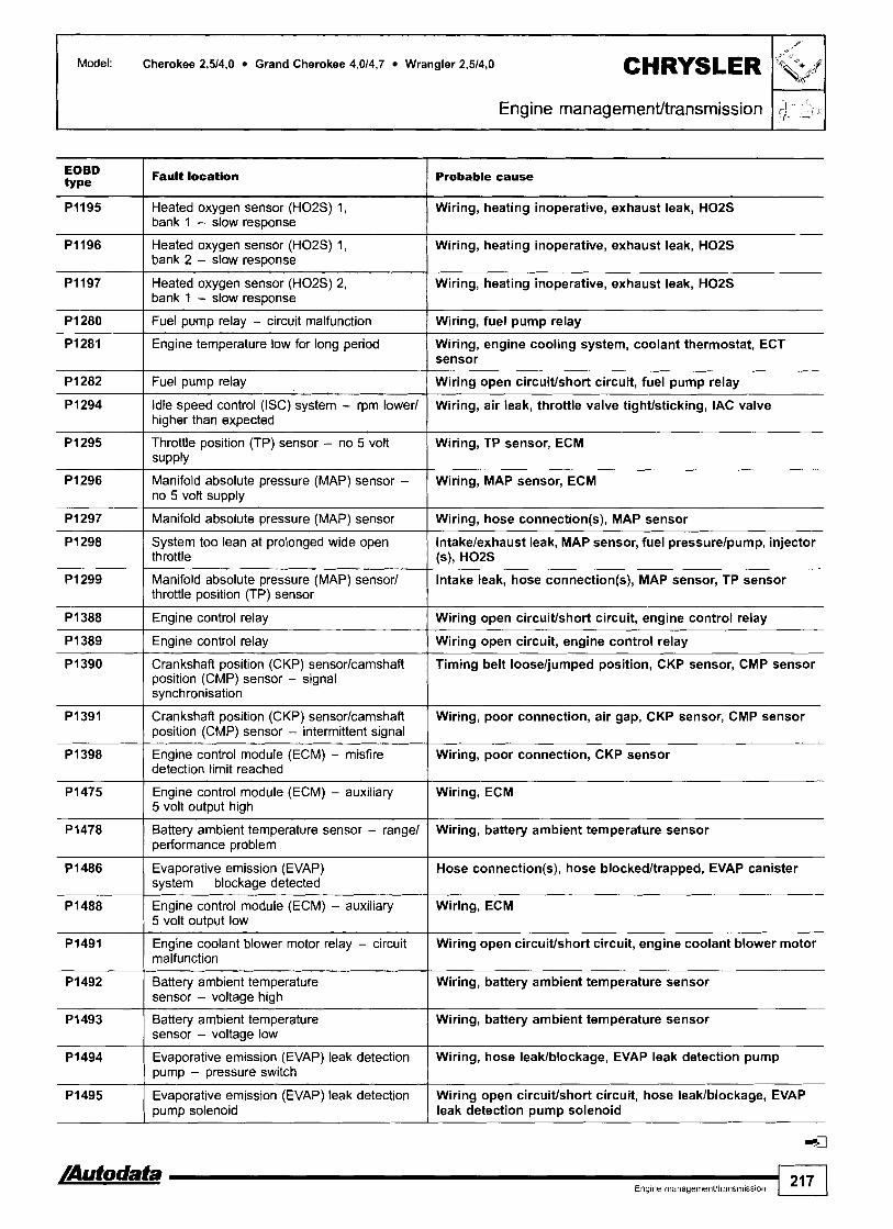
Model: Cherokee 2,514.0 Grand Cherokee 4,014,7 Wrangler 2,5/4,0
Engine management/transrnission I $ 5
EOBD type
Pi197 Heated oxygen sensor (H02S) 2, I Wiring, heating inoperative, exhaust leak, H02S bank 1 - slow response
Pi195
Pi196
Pi280 I Fuel pump relay - circuit malfunction / Wiring, fuel pump relay
Fault location Probable cause
Heated oxygen sensor (H02S) 1, bank 1 - slow response
Heated oxygen sensor (H02S) 1, bank 2 - slow response
Pi282 1 Fuel pump relay I Wiring open circuitlshort circuit, fuel pump relay
Wiring, heating inoperative, exhaust leak, H02S
Wiring, heating inoperative, exhaust leak, H02S
Pi281
Pi296 Manifold absolute pressure (MAP) sensor - Wiring, MAP sensor, ECM no 5 volt supply
Engine temperature low for long period
P 1294
Pi295
Wiring, engine cooling system, coolant thermostat, ECT sensor
P i 299 Manifold absolute pressure (MAP) sensor1 Intake leak, hose connection(s), MAP sensor, TP sensor throttle position (TP) sensor
Idle speed control (ISC) system - rpm tower1 higher than expected
Throttle position (TP) sensor - no 5 volt supply
Pi297
Pi298
Wiring, air leak, throttle valve tightlsticking, IAC valve
Wiring, TP sensor, ECM
Manifold absolute pressure (MAP) sensor
System too lean at prolonged wide open throttle
Pi388
Wiring, hose connection(s), MAP sensor
lntakelexhaust leak, MAP sensor, fuel pressurelpump, injector (s), H02S
P i 389
Pi391 Crankshaft position (CKP) sensorlcamshaft Wiring, poor connection, air gap, CKP sensor, CMP sensor position (CMP) sensor - intermittent signal
Engine control relay
Engine control relay 1 Wiring open circuit, engine control relay
Pi390
P i 398 Engine control module (ECM) - misfire Wiring, poor connection, CKP sensor detection limit reached
Wiring open circuitlshort circuit, engine control relay
Pi475 Engine control module (ECM) - auxiliary 5 volt output high I ECM
Crankshaft position (CKP) sensorlcamshaft position (CMP) sensor - signal synchronisation
P 1478 Battery ambient temperature sensor - range1 Wiring, battery ambient temperature sensor performance problem
Timing belt looseljumped position, CKP sensor, CMP sensor
Pi486 Evaporative emission (EVAP) system - blockage detected
I Hose connection(s), hose blockedltrapped, EVAP canister
Pi488
Pi491
Pi492
Pi493
Engine control module (ECM) - auxiliary 5 volt output low
Engine coolant blower motor relay - circuit malfunction
Pi494
Pi495
Wiring, ECM
Wiring open circuitlshort circuit, engine coolant blower motor
Battery ambient temperature sensor - voltage high
Battery ambient temperature sensor - voltage low
Wiring, battery ambient temperature sensor
Wiring, battery ambient temperature sensor
Evaporative emission (EVAP) leak detection pump - pressure switch
Evaporative emission (EVAP) leak detection pump solenoid
Wiring, hose leaklblockage, EVAP leak detection pump
Wiring open circuitlshort circuit, hose leaklblockage, EVAP leak detection pump solenoid

CHRYSLER Model: Cherokee 2,5/4,0 Grand Cherokee 4,014,7 Wrangler 2,5/4,0
EOBD type
Fault location
bl - - 2 . Probable cause
Engine managemenVtransmission
ECM PI496
PI594 1 Alternator - voltage high
Engine control module (ECM) - 5 volt output low
Wiring, battery, alternator
PI595 I Cruise control Wiring open circuiffshort circuit, hoses, cruise control master switch, cruise control vacuum switching valve
P1596 1 Cruise control master switch - high voltage Wiring, cruise control master switch
PI597 ( Cruise control master switch - low voltage Wiring, cruise control master switch
PI 598 AC refrigerant pressure sensor - high input Wiring, AC refrigerant pressure too high (cooling faulff incorrectly charged), AC refrigerant pressure sensor
Wiring, AC refrigerant pressure too low (incorrectly charged), AC refrigerant pressure sensor
PI602 I Engine control module (ECM) not programmed
P I 599
New ECM not programmed, incorrectly programmed, ECM
AC refrigerant pressure sensor - low input
Pi682 I Alternator - voltage low Wiring, battery, alternator drive belt, alternator
Wiring, cruise control vacuum switching valve
Wiring, battery
P i 683
P I 684
Cruise control
Engine control module (ECM) - supply voltage disconnected within last 50 ignition switch ON-OFF cycles
Wiring, ignition key not matchedldamaged, immobilizer control module
P I 685
P I 686 CAN data bus, immobilizer control module - no signal
Key not programmed into immobilizer control module
Wiring, immobilizer control module
I
P I 696 I Engine control module (ECM) - EEPROM ECM
Signal wire open circuiffshort circuit, valve body, sensor supply wire open circuit, transmission fluid level, governor pressure solenoid, transmission mechanical fault, ECM - no 5 volt supply
Signal wire open circuiffshort circuit, valve body, sensor supply wire open circuit, transmission fluid level, governor pressure solenoid, transmission mechanical fault, ECM - no 5 volt supply
Signal wire short circuit to earthlpositive, supply wire open circuiffshort circuit, transmission fluid level, governor pressure solenoid, governor pressure sensor, ECM
P I 756
error
Governor pressure not equal to target (15-20 PSI) - mid pressure malfunction
P I 757
P I 763 / Governor pressure Sensor - signal high
Governor pressure not equal to target (1 5-20 PSI) - zero pressure malfunction
P1762
Signal wire short circuit to positive, supply wire open circuit, transmission fluid level, governor pressure sensor, ECM
Governor pressure sensor - incorrect signal
PI764 I Governor pressure sensor - signal low Signal wire short circuit to earth, supply wire open circuit, transmission fluid level, governor pressure sensor, ECM
Wiring open circuiffshort circuit, transmission system relay, ECM
Wiring, PNP switch, ECM
P I 765
P I 899
Transmission system relay
PaMneutral position (PNP) switch - input circuit malfunction

Model: AX 1,011,111,4 C15 1,1/1,4 ZX 1,1/1,4/1,6/1,812,0 XM 2,013,O JumperlRelay 2,O
Year: 1989-00
Engine BDY, BFZ, CDY, CDZ, HDY, HDZ, K6B, KDX, KDY, KDZ, KFZ, KFY, LFZ, RFT, RFV, RFW, RFX, RFY, RFZ, 'Ode: RGY, SFZ, SKZ
System: Bosch Mono-Jetronic A2.2 Bosch Mono-Motronic MA3.0 Bosch Motronic MP3.113.215.115.1.1 Magneti Marelli G6 Magneti Marelli Monopoint G6.11 Magneti Marelli 8P.10111113120 Fenix 3B14
Engine management
AX, C15 - RH engine bay ZX - LH engine bay
JurnperlRekiy - LH engine bay XM - RH engine bay
General information 0 Refer to the front of this manual for general test conditions,
terminology, detailed descriptions of wiring faults and a general trouble shooter for electrical and mechanical faults. Trouble codes are displayed by the malfunction indicator lamp (MIL) or LED.
@ The ECM fault memory can also be checked and erased using diagnostic equipment connected to the data link connector (DLC).
o Vehicles fitted with a coded keypad: When switching on ignition or entering start code ensure diagnostic equipment is disconnected from the data link connector (DLC).
Accessing Switch ignition ON. Check that MIL illuminates. Connect LED test lamp between green data link connector (DLC) terminal 2 and battery positive O. Bridge data link connector (DLC) terminal 2 and earth with a switched lead - contacts normally open O. Operate switch for 2,5-5 seconds. LED or MIL will now flash trouble code 12. Each trouble code consists of two groups of one or more flashes a. Long flashes indicate the 'tens' of the trouble code [A]. Short flashes indicate the 'units' of the trouble code [C]. A short pause separates each flash [B]. A long pause separates each trouble code [Dl.
/Autodata- Engme management 21 9

Model: AX 1,011,111,4 CIS 1,111,4 ZX 1,111,411,6/1.812,0 XM 2,013,O JumperlRelay 2,O
Engine management
For example: Trouble code 12 displayed 0. Repeat operation. Count LED or MIL flashes. Note trouble codes. Compare with trouble code table.
Trouble code identification
Erasing
Method 1 Switch ignition ON. Connect LED test lamp between data link connector (DLC) terminal 2 and battery positive O. Bridge data link connector (DLC) terminal 2 and earth with a switched lead - contacts normally open O. Operate switch for 2,5-5 seconds. LED or MIL will now flash trouble code 12. Repeat switch operation until code 11 is displayed. Operate switch for 10-20 seconds. Switch ignition OFF.
Method 2 Ensure ignition switched OFF. Disconnect battery earth lead for 10 seconds.
WARNING: Disconnecting the battery may erase memory from electronic units (e.g. radio, clock).
Flash type Fault location Probable cause
12 I Start of sequence I -
I 1
11 I End of sequence
15 I Relay modulelfuel pump relay I Wiring, fuel pump relay, relay module - fuel pump contacts, ECM
-
13
14
21 I Closed throttle position (CTP) switch I Wiring, CTP switch, accelerator cable adjustment, ECM
Intake air temperature (IAT) sensor
Engine coolant temperature (ECT) sensor
ldle air control (IAC) valvelidle speed Wiring, IAC valve/lSC actuator, ECM control (ISC) actuator
Wiring, IAT sensor, ECM
Wiring, ECT sensor, ECM
21 0 22 El
26 I Intake manifold air control solenoid 2 1 Wiring, intake manifold air control solenoid, ECM
Throttle position (TP) sensor
Closed throttle position (CTP) switch
23
25
Wiring, TP sensor, accelerator cable adjustment, ECM
Wiring, CTP switch, accelerator cable adjustment, ECM
Idle air control (IAC) valve - idle speed incorrect
Intake manifold air control solenoid 1
Wiring, accelerator cable adjustment, hoses blockedlleaking, fuel pump relay, IAC valve, ECM
Wiring, intake manifold air control solenoid, ECM

Model: AX 1,011,111,4 C15 1,111,4 ZX 1,111,411,6/1,8/2,0 XM 2,013,O JumperlRelay 2,O
Engine management I
Flash type Fautt location Probable cause I I
27 I Vehicle speed sensor (VSS) I Wiring, VSS, ECM
32 rn I Mixture control (MC), bank 2
31
31
Wiring, incorrect fuel, heated oxygen sensor (H02S), exhaust leak, fuel pressure, injector control, EVAP canister purge valve,
Wiring, incorrect fuel, heated oxygen sensor (H02S), exhaust leak, fuel pressure, injector control, EVAP canister purge valve, compression, air filter blocked, ignition system, ECM
Mixture control (MC), bank 1
Mixture control (MC)
32
Wiring, incorrect fuel, heated oxygen sensor (H02S), exhaust leak, fuel pressure, injector control, EVAP canister purge valve, compression, air filter blocked, ignition system, ECM
Wiring, incorrect fuel, heated oxygen sensor (H02S), exhaust leak, fuel pressure, injector control, EVAP canister purge valve, compression, air filter blocked, ignition system, ECM
Mixture control (MC)
33
33
42 0 I Injector(s) I Wiring, relay module, injector(s), ECM
34
36
41
Throttle position (TP) sensor
Manifold absolute pressure (MAP) sensor
45 I Ignition coil 1 - cylinder 1 & 4 ( Wiring, ignition coil, ECM
-- - -- -
Wiring, TP sensor, accelerator cable adjustment, ECM
Wiring, MAP sensor, hoses blockedlleaking, ECM
Evaporative emission (EVAP) canister purge valve
Oxygen sensor heater relay
Crankshaft position (CKP) sensor1 engine speed (RPM) sensor
42
43
44
Wiring, EVAP canister purge valve, ECM
Wiring, oxygen sensor heater relay, ECM
Wiring, CKPIRPM sensor, air gap, ECM
51 / Heated oxygen sensor (H02S) 1 Wiring, H02S, exhaust leak, relay module, oxygen sensor heater relay, ECM
lnjectorlfuel pump
Knock control
Knock sensor (KS) 1
46
47
Mixture control (MC), bank 1
Wiring, injector, fuel pump, relay module, ECM
Wiring, KS, mechanical fault, incorrect fuel, ignition system, ECM
Wiring, KS, ECM
Wiring, incorrect fuel, heated oxygen sensor (H02S), exhaust leak, fuel pressure, injector control, EVAP canister purge valve, compression, air filter blocked, ignition system, ECM
Turbocharger (TC) wastegate regulating valve
Turbocharger (TC) wastegate regulation
Mixture control (MC)
Wiring, hoses blockedlleaking, TC wastegate regulating valve, ECM
TC wastegate regulating valve, MAP sensor, TP sensor, exhaust leak, intake leak
Wiring, incorrect fuel, heated oxygen sensor (H02S), exhaust leak, fuel pressure, injector control, EVAP canister purge valve, compression, air filter blocked, ignition system, ECM
56 I Coded keypad I Wiring, coded keypad, ECM
53
54
57 I Ignition coil 2 - cylinders 2 & 3 1 Wiring, ignition coil, ECM
62 I Knock sensor (KS) 2 I Wiring, KS, ECM
Battery voltage
Engine control module (ECM)
Heated oxygen sensor (H02S) 2 Wiring, H02S, exhaust leak, relay module, oxygen sensor heater relay, ECM
Wiring, battery discharged, alternator
Wiring, battery, ECM
64
/Autodata Engine management
4
Mixture control (MC), bank 2
221
Wiring, incorrect fuel, heated oxygen sensor (H02S), exhaust leak, fuel pressure, injector control, EVAP canister purge valve, compression, air filter blocked, ignition system, ECM

Model: AX 1,011,111,4 CIS 1,1/1,4 ZX 1,111,411,611,812,0 XM 2,013,O JumperlRelay 2,O
Engine management
Flash type Fault location I Probable cause I 1
73 I Injector 3 I Wiring, relay module, injector, ECM
65
7 1
72
Bosch Mono-Jetronic A2.2 Except Bosch Mono-Jetronic A2.2 Bosch Mono-Motronic MA3.0 All systems Fenix 4 Except Fenix 4
fl Except Bosch MP3.21Fenix 3814
Camshaft position (CMP) sensor
Injector 1
Injector 2
74
75
76
Wiring, CMP sensor, ECM
Wiring, relay module, injector, ECM
Wiring, relay module, injector, ECM
Injector 4
Injector 5
lniector 6
Wiring, relay module, injector, ECM
Wiring, relay module, injector, ECM
Wiring, relay module, injector, ECM

Model: Saxo 1,011 ,I Berlingo 1,111,4
Year: 1996-98
Engine code: CDY, CDZ, HDY, HDZ, KFX
System: Bosch Mono-Motronic MA3.1
ClTROEN
Engine management I
Saxo - under fascia, passenger's side Berlingo - under fascia, drlvefs side
General information Refer to the front of this manual for general test conditions, terminology, detailed descriptions of wiring faults and a general trouble shooter for electrical and mechanical faults. Trouble codes are displayed by the malfunction indicator lamp (MIL) or LED. The ECM fault memory can also be checked and erased using diagnostic equipment connected to the data link connector (DLC).
D Vehicles fitted with a coded keypad: When switching on ignition or entering start code ensure diagnostic equipment is disconnected from the data link connector (DLC).
Accessing Switch ignition ON. Check that MIL illuminates. Connect LED test lamp between data link connector (DLC) terminal C3 and battery positive O. Bridge data link connector (DLC) terminal C2 and earth with a switched lead - contacts normally open O. Operate switch for 2 5 5 seconds. LED or MIL will now flash trouble code 12. Each trouble code consists of one or two groups of one or more flashes a. Long flashes indicate the 'tens' of the trouble code [A]. Short flashes indicate the 'units' of the trouble code [C]. A short pause separates each flash [B]. A long pause separates each trouble code rn [Dl. For example: Trouble code 12 displayed rn. Repeat operation. Note trouble codes. Compare with trouble code table. Rectify faults as necessary.

I Engine management
Erasing
Method 1 Switch ignition ON. Connect LED test lamp between data link connector (DLC) terminal C3 and battery positive D. Bridge data link connector (DLC) terminal C2 and earth with a switched lead - contacts normally open m. Operate switch for 2,523 seconds. LED or MIL will now flash trouble code 12. Repeat switch operation until code 11 is displayed. Operate switch for 10-20 seconds. Switch ignition OFF.
Method 2
Ensure ignition switched OFF. Disconnect battery earth lead for 10 seconds.
WARNING: Disconnecting the battery may erase memory from electronic units (e.g. radio, clock).
Trouble code identification
Flash type Fault location Probable cause I
Intake air temperature (IAT) sensor I Wiring, IAT sensor, ECM
Engine coolant temperature (ECT) Wiring, ECT sensor, ECM sensor
Idle speed control (ISC) actuator ( Wiring, ISC actuator, ECM
Throttle pos~tion (TP) sensor
Closed throttle position (CTP) switch
Crankshaft position (CKP) sensor1 Wiring, CKPlRPM sensor, air gap, ECM engine speed (RPM) sensor
-
Wiring, TP sensor, accelerator cable adjustment, ECM
Wiring, CTP switch, accelerator cable adjustment, ECM
Mixture control (MC) - mixture rich
~ e a t e d oxygen sensor (H02S) I Wiring, HOZS, exhaust leak, relay module, ECM
Wiring, incorrect fuel, heated oxygen sensor (H02S) - heater circuit, exhaust blockage, fuel pressure, injector control, EVAP canister purge valve, compression, air filter blocked, ignition system, ECM
Mixture control (MC) - mixture lean
Relay module ( Wiring, relay module - fuel pump contacts, ECM
Wiring, incorrect fuel, heated oxygen sensor (H02S) - heater circuit, exhaust leak, fuel pressure, injector control, EVAP canister purge valve, compression, ignition system, ECM
Evaporative emission (EVAP) canister purge valve
I Wiring. EVAP canister purge valve, ECM
Injector I Wiring, relay module, injector, ECM
Battery voltage I Wiring, battery discharged, alternator
Ignition coil 1 - cylinders 1 8 4
Ignition coil 2 - cylinders 2 8 3
Engine control module (ECM) ( Wiring, battery, ECM
Wiring, ignition coil, ECM
Wiring, ignition coil, ECM
1 224 I,.,,,,,,,,,,,
Vehicle speed sensor (VSS) Wiring, VSS, ECM
4

Model: Saxo 1,011,l Berlingo 1,111,4
Year: 1998-00
Engine code: CDY, CDZ, HDY, HDZ, KFX
System: Bosch Motronic MA3.1
Engine management
Saxo - under fascia, passenger's side
--
Berlingo - under fascia, driver's slde
General information Refer to the front of this manual for general test conditions, terminology, detailed descriptions of wiring faults and a general trouble shooter for electrical and mechanical faults.
Accessing and erasing The engine control module (ECM) fault memory can only be accessed and erased using diagnostic equipment connected to the data link connector (DLC).
Trouble code identification
Scanner type
Fault location
Intake air temperature (IAT) sensor
Engine codant temperature (ECT) sensor
Throttle position (TP) sensor
Closed throttle position (CTP) switch
Idle soeed control (ISC) actuator
Crankshaft position (CKP) sensor1 engine speed (RPM) sensor
Mixture control (MC) - mixture rich
Mixture control (MC) - mixture lean
Probable cause
Wiring, IAT sensor, ECM
Wiring, ECT sensor, ECM
Wiring, TP sensor, accelerator cable adjustment, ECM
Wiring, CTP switch, accelerator cable adjustment, ECM
Wiring, ISC actuator, ECM
Wiring, CKPIRPM sensor, air gap, ECM
Wiring, incorrect fuel, heated oxygen sensor (H02S) - heater circuit, exhaust blockage, fuel pressure, injector control, EVAP canister purge valve, compression, air filter blocked, ignition system, ECM
Wiring, incorrect fuel, heated oxygen sensor (H02S) - heater circuit, exhaust leak, fuel pressure, injector control, EVAP canister purge valve, compression, ignition system, ECM
A t a t a a Engme management 225

I Engine management
Scanner Fault location type
Probable cause
9
10
11
12
13
14
15
16
17
4
Heated oxygen sensor (H02S)
Relay module
Evaporative emission (EVAP) canister purge valve
Injector
Ignition coil 1 - cylinders 1 & 4
Ignition coil 2 - cylinders 2 & 3
Battery voltage
Engine control module (ECM)
Vehicle speed sensor (VSS)
Wiring, H02S, exhaust leak, relay module, ECM
Wiring, relay module - fuel pump contacts, ECM
Wiring, EVAP canister purge valve, ECM
Wiring, relay module, injector, ECM
Wiring, ignition coil, ECM
Wiring, ignition coil, ECM
Wiring, battery discharged, alternator
Wiring, battery, ECM
Wiring, VSS, ECM

Model: Saxo 1,411,6 Berlingo 1,411,8
Year: 1996-98
Engine code: KFX, LFX, NFX
System: Magneti Marelli 1API1AP2011AP41
Saxo - under fascia, passenger's side
General information Refer to the front of this manual for general test conditions, terminology, detailed descriptions of wiring faults and a general trouble shooter for electrical and mechanical faults.
0 Trouble codes are displayed by the malfunction indicator lamp (MIL) or LED. The ECM fault memory can also be checked and erased using diagnostic equipment connected to the data link connector (DLC).
0 Vehicles fitted with a coded keypad: When switching on ignition or entering start code ensure diagnostic equipment is disconnected from the data link connector (DLC).
Accessing Switch ignition ON. Check that MIL illuminates. Connect LED test lamp between data link connector (DLC) terminal C3 and battery positive D. Bridge data link connector (DLC) terminal C2 and earth with a switched lead - contacts normally open D. Operate switch for 2,551 seconds. LED or MIL will now flash trouble code 12. Each trouble code consists of one or two groups of one or more flashes O. Long flashes indicate the 'tens' of the trouble code [A]. Short flashes indicate the 'units' of the trouble code [C]. A short pause separates each flash [B]. A long pause separates each trouble code [Dl. For example: Trouble code 12 displayed O. Repeat operation. Note trouble codes. Compare with trouble code table. Rectify faults as necessary.
Berlingo - under fascia, driver's side
/Autodata Engme management 227

Model: Saxo l,4/l,6 Berlingo l,4/1,8
I
Engine management
Erasing Method 2 Ensure ignition switched OFF.
Method 1 Disconnect battery earth lead for 10 seconds. Switch ignition ON. WARNING: Disconnecting the battery may erase memory from Connect LED test lamp between data link connector (DLC) electronic units (e.g. radio, clock). terminal C3 and battery positive O. Bridge data link connector (DLC) terminal C2 and earth with a switched lead - contacts normally open O. Operate switch for 2,5-5 seconds. LED or MIL will now flash trouble code 12. Repeat switch operation until code 11 is displayed. Operate switch for 10-20 seconds. Switch ignition OFF.
Trouble code Identification
I Probable cause
1 1 Intake air temperature (IAT) sensor I Wiring, IAT sensor, ECM
Engine coolant temperature (ECT) Wiring, ECT sensor, ECM sensor I
3 I Relay module I Wiring, relay module - fuel pump contacts, ECM
4 I Throttle position (TP) sensor I Wiring, TP sensor, accelerator cable adjustment, ECM
5 I Idle air control (IAC) valve I Wiring, IAC valve, ECM
6
7
Crankshaft position (CKP) sensor1 Wiring, CKPIRPM sensor, air gap, ECM engine speed (RPM) sensor
8
9
Vehicle speed sensor (VSS)
Mixture control (MC)
13 I Ignition coil 2 - cylinders 2 & 3 1 Wiring, ignition coil, ECM
Wiring, VSS, ECM
Wiring, incorrect fuel, heated oxygen sensor (HOZS) - heater circuit, exhaust leak, fuel pressure, injector control, EVAP canister purge valve, ECM
Manifold absolute pressure (MAP) sensor
Evaporative emission (EVAP) canister purge valve
1 1
12
Mixture control (MC)
Wiring, MAP sensor, hoses blockedlleaking, ECM
Wiring, EVAP canister purge valve, ECM
Wiring, incorrect fuel, heated oxygen sensor (HOZS), intakelexhaust leak, fuel pressure, injector control, EVAP canister purge valve, ignition system, ECM
-- - -
Injectors
Ignition coil 1 - cylinders 1 & 4
15 ( Battery voltage 1 Wiring, battery discharged, alternator
--
Wiring, relay module, injectors, ECM
Wiring, ignition coil, ECM
16 I Engine control module (ECM) I Wiring, battery, ECM
17 I Heated oxygen sensor (H02S) I Wiring, HOZS, exhaust leak, relay module, ECM
18 I Knock control I Wiring, KS, mechanical fault, incorrect fuel, ignition system, ECM
19 I Knock sensor (KS) I Wiring, KS, ECM
20
4
Power steering pressure (PSP) sensorlswitch
Wiring, PSP switchlsensor, power steering pump, power steering system pressure, ECM

Model: Saxo 1,4/1,6 Xsara 1 ,411,8 Xantia 1,8 Picasso 1,8 Berlingo l,4ll,8
Year: 1997-00
Engine code: 6FZ, KFX, KFW, LFX, LFY, NFX
System: Magneti Marelli lAP120l40141 Sagem SL961S2000
Engine management I
Saxo - under fascia, passenger's side
Berlingo - under fascia, driver's side
Xsara, Xantb, Picasso - in fascia fusebax
General information Refer to the front of this manual for general test conditions, terminology, detailed descriptions of wiring faults and a general trouble shooter for electrical and mechanical faults.
Accessing and erasing The engine control module (ECM) fault memory can only be accessed and erased using diagnostic equipment connected to the data link connector (DLC).

I Engine management
Model: Saxo 1,411,6 Xsara 1,411,8 Xantia 1,8 Picasso 1,8 Berlingo 1,411,8
1 I Intake air temperature (IAT) sensor I Wiring, IAT sensor, ECM
Trouble code identification
Engine coolant temperature (ECT) Wiring, ECT sensor, ECM sensor
Scanner type
3 I Relay module I Wiring, relay module - fuel pump contacts, ECM
4 I Throttle position (TP) sensor I Wiring, TP sensor, accelerator cable adjustment, ECM
Fault location
5 I Idle air control (IAC) valve I Wiring, IAC valve, ECM
Probable cause
6
7
Evaporative emission (EVAP) Wiring, EVAP canister purge valve, ECM canister purge valve
8
Crankshaft position (CKP) sensor1 Wiring, CKPIRPM sensor, air gap, ECM engine speed (RPM) sensor
Vehicle speed sensor (VSS)
Mixture control (MC)
11 I Injectors I Wiring, relay module, injector(s), ECM
-
Wiring, VSS, ECM
Wiring, incorrect fuel, heated oxygen sensor (H02S) - heater circuit, exhaust leak, fuel pressure, injector control, EVAP canister purge valve, ECM
Manifold absolute pressure (MAP) sensor
12 I Ignition coil 1 - cylinders 1 8 4 1 Wiring, ignition coil, ECM
Wiring, MAP sensor, hoses blockedlleaking, ECM
I Ignition coil 2 - cylinders 2 8 3 1 Wiring, ignition coil, ECM
15 I Battery voltage I Wiring, battery discharged, alternator
Mixture control (MC) Wiring, incorrect fuel, heated oxygen sensor (H02S), intakelexhaust leak, fuel pressure, injector control, EVAP canister purge valve, ignition system, ECM
18 I Knock control I Wiring, KS, mechanical fault, incorrect fuel, ignition system, ECM
16
17
19 I Knock sensor (KS) I Wiring, KS, ECM
Engine control module (ECM)
Heated oxygen sensor (H02S)
Wiring, battery, ECM
Wiring, H02S, exhaust leak, relay module, ECM
20
4
Power steering pressure (PSP) sensorlswitch
Wiring, PSP switchlsensor, power steering pump, power steering system pressure, ECM

Model: Saxo 1,6
Year: 1996-98
Engine code: N F Z
System: Bosch Motronic MPS.115.2
Engine management I
Under fascia, passengefs side
General information Refer to the front of this manual for general test conditions, terminology, detailed descriptions of wiring faults and a general trouble shooter for electrical and mechanical faults.
0 Trouble codes are displayed by the malfunction indicator lamp (MIL) or LED.
0 The ECM fault memory can also be checked and erased using diagnostic equipment connected to the data link connector (DLC). Vehicles fitted with a coded keypad: When switching on ignition or entering start code ensure diagnostic equipment is disconnected from the data link connector (DLC).
Accessing Switch ignition ON. Check that MIL illuminates. Connect LED test lamp between data link connector (DLC) terminal C3 and battery positive m. Bridge data link connector (DLC) terminal C2 and earth with a switched lead - contacts normally open m. Operate switch for 2,5-5 seconds. LED or MIL will now flash trouble code 12. Each trouble code consists of one or two groups of one or more flashes H. Long flashes indicate the 'tens' of the trouble code [A]. Short flashes indicate the 'units' of the trouble code H [C]. A short pause separates each flash H [B]. A long pause separates each trouble code H [Dl. For example: Trouble code 12 displayed H. Repeat operation. Note trouble codes. Compare with trouble code table. Rectify faults as necessary.

Model. Saxo 1,6
ngtne management
Eraslng Method 2 Ensure ignition switched OFF.
Method 1 Disconnect battery earth lead for 10 seconds. Switch ignition ON. WARNING: Disconnecting the battery may erase memory from Connect LED test lamp between data link connector (DLC) electronic units (e.g. radio, clock). terminal C3 and battery positive m. Bridge data link connector (DLC) terminal C2 and earth with a switched lead - contacts normally open a. Operate switch for 23-5 seconds. LED or MIL will now flash trouble code 12. Repeat switch operation until code 11 is displayed. Operate switch for 10-20 seconds. Switch ignition OFF.
Trouble code identification I I
Flash type Fa- loc-n I I Probable cause
3 I Throttle position (TP) sensor I Wiring, TP sensor, accelerator cable adjustment, ECM
1
2
Manifold absolute pressure (MAP) sensor
l njectars
Mixture control (MC)
Intake air temperature (IAT) sensor
Engine &ant temperature (ECT) sensor
4
5
Wiring, MAP sensor, hoses blockedlleaking, ECM
Wiring, IAT sensor, ECM
Wiring, ECT sensor, ECM
Wiring, relay module, injectors, ECM
Wiring, incorrect fuel, heated oxygen sensor (H02S) - heater circuit, exhaust leak, fuel pressure, injector control, EVAP canister purge valve, ECM
Idle air control (IAC) valve
Crankshaft position (CKP) senswl engine speed (RPM) sensor
Wiring, IAC valve, ECM
Wiring, CKPIRPM sensor, air gap, ECM
I I I B a r n vd- I Wiring, battery discharged, alternator
9
10
--- -- - -
Heated oxygen sensor (H02S)
Evaporative emission (EVAP) canister purse valve
12
13
Wiring, H02S, exhaust leak, relay module, ECM
Wiring, EVAP canister purge valve, ECM
Engine control module (ECM)
Vehicle speed sensor (VSS)
Wiring, battery, ECM
Wiring, VSS, ECM
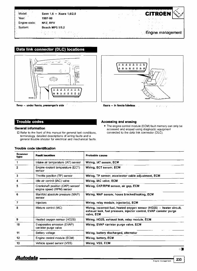
Model: Saxo 1,6 Xsara 1,612,O
Year: 1997-00
I Engine code: NFZ, RFV
System: Bosch MP5.115.2
Engine management
Saxo - under fascia, passenger's side Xsara - in fascia fkmbox
General information The engine control module (ECM) fault memory can only be accessed and erased usina diaanostic eaui~ment - -
Refer to the front of this manual for general test conditions, connected to the data link connector (DLC).' terminology, detailed descriptions of wiring faults and a general trouble shooter for electrical and mechanical faults.
Trouble code identification
3 I Throttle position (TP) sensor I Wiring, TP sensor, accelerator cable adjustment, ECM
Scanner type
1
2
4 I Idle air control (IAC) valve I Wiring, IAC valve, ECM
Crankshaft position (CKP) sensor1 Wiring, CKPIRPM sensor, air gap, ECM engine speed (RPM) sensor
Fault location
Intake air temperature (IAT) sensor
Engine coolant temperature (ECT) sensor
Manifold absolute pressure (MAP) Wiring, MAP sensor, hoses blockedlleaking, ECM sensor
Probable cause
Wiring, IAT sensor, ECM
Wiring, ECT sensor, ECM
7
8
11 I Battery voltage / Wiring, battery discharged, alternator
9
10
12 I Engine control module (ECM) I Wiring, battery, ECM
Injectors
Mixture control (MC)
13 I Vehicle speed sensor (VSS) I Wiring, VSS, ECM
Wiring, relay module, injector(s), ECM
Wiring, incorrect fuel, heated oxygen sensor (H02S) - heater circuit, exhaust leak, fuel pressure, injector control, EVAP canister purge valve, ECM
Heated oxygen sensor (H02S)
Evaporative emission (EVAP) canister purge valve
Wiring, HOZS, exhaust leak, relay module, ECM
Wiring, EVAP canister purge valve, ECM

CITROEN Model: Saxo 1,6 MT Xsara 1,6 Picasso 1,6
Year: 1998-00
Engine code: NFZ
System: Bosch Motronic MP7.2
Engine management
Saxe - under fascia, p m n g e f s side Xsam, Picasso - sn fascia fusebox
Winga - undet fascia, driver% side
General information 0 Refer to the front of this manual for general test conditions,
termmology, deta~led descr~pt~ons of wring faults and a general trouble shooter for electrical and mechanical faults
Accessing and erasing The engine control module (ECM) fault memory can only be accessed and erased using diagnostic equipment connected to the data link connector (DLC).

Model: Saxo 1,6 MT Xsara 1,6 Picasso 1,6
Engine management I Trouble code identification
Scanner type
Fault location
Battery voltage I Wiring, battery discharged, alternator
Probable cause
Crankshaft position (CKP) sensor1 Wiring, CKPIRPM sensor, air gap, ECM engine speed (RPM) sensor
Vehicle speed sensor (VSS) I Wiring, VSS, ECM
Manifold absolute pressure (MAP) Wiring, MAP sensor, hoses blockedlleaking, ECM sensor
Engine coolant temperature (ECT) Wiring, ECT sensor, ECM sensor
Throttle position (TP) sensor
Knock sensor (KS)
Heated oxygen sensor (H02S)
Wiring, TP sensor, accelerator cable adjustment, ECM
Wiring, KS, ECM
Wiring, H02S, exhaust leak, relay module, ECM
Malfunction indicator lamp (MIL) 1 Wiring, MIL, ECM
Intake air temperature (IAT) sensor
Relay module
Oxygen sensor heater I Wiring, oxygen sensor heater, relay module, ECM
- --
Wiring, IAT sensor, ECM
Wiring, relay module - fuel pump contacts, ECM
Idle air control (IAC) valve I Wiring, IAC valve, ECM
Injectors
Ignition coil 1 - cylinders 1 & 4
Ignition coil 2 - cylinders 2 & 3
Wiring, relay module, injector(s), ECM
Wiring, ignition coil, ECM
Wiring, ignition coil, ECM
ldle air control (IAC) valve - idle Wiring, accelerator cable adjustment, hoses blockedlleaking, speed incorrect I intake leak. IAC valve, ECM
Evaporative emission (EVAP) canister purge valve
Mixture control (MC)
Engine control module (ECM) 1 Wiring, battery, ECM
Wiring, EVAP canister purge valve, ECM
Wiring, incorrect fuel, heated oxygen sensor (H02S), exhaust leak, fuel pressure, injector control, EVAP canister purge valve, compression, ignition system, ECM
Engine control module Wiring, ignition coil, relay module, ECM (ECM) - ignition coif control
/Autodata Eng~ne management 235
Engine control module (ECM) - programming
Incorrect programming, ECM
4

Engine management
Model: C3 1,4 Berlingo 1,4 Picasso 1,8 C5 1,8
Year: 2002-04
Engine code: KFV, KFW, 6FZ
System: Sagem S2000 PMI
Picasso - in fascia fuse box
Accessing and erasing The engine control module (ECM) fault memory can only be
General information accessed and erased using diagnostic equipment - - Refer to the front of this manual for general test conditions, connected to the data link connector (DLC).' terminology, detailed descriptions of wiring faults and a general trouble shooter for electrical and mechanical faults.
Trouble code identification
EOBD type
Fault location I Probable cause
PI109 Manifold absolute pressure (MAP) sensor - circuit Wiring, poor connection, MAP sensor, ECM intermittent
PO
PI108
PI110 Manifold absolute pressure (MAP) sensor - circuit Wiring, poor connection, MAP sensor, ECM intermittent
1 23' 1 ,ng,ne management /Autodata
Refer to EOBD trouble code table
Manifold absolute pressure (MAP) sensor - circuit intermittent
-
Wiring, poor connection, MAP sensor, ECM

Engine management 7 EOBD type
Fault location Probable cause
Wiring, EGR valvelsolenoid, hose leaklblockage PI100
PI111 I Exhaust gas recirculation (EGR) - circuit malfunction
Exhaust gas recirculation (EGR) system - range1 performance problem
Wiring, EGR valvelsolenoid
ECM PI121
P I 1 52 Wiring, throttle motor position sensor 112, accelerator pedal position (APP) sensor
Engine control module (ECM) - processor fault
Throttle motor position sensor 112 - correlation
PI157 I Throttle motor position sensor 2 - signal Wiring, throttle motor position sensor 2, throttle motor, mechanical fault
Wiring, throttle motor position sensor 2, throttle motor, mechanical fault
PI158
Wiring, incorrect fuel, heated oxygen sensor (H02S), exhaust leak, fuel pressure, injector control, EVAP canister purge valve, compression, air filter blocked, ignition system, ECM
Throttle motor position sensor 2 - signal
P I 186 Mixture control (MC)
Wiring, throttle motor position sensor 112, throttle motor
P1280
P I 327 Ignition coil, camshaft position (CMP) sensor - control circuit
Throttle motor position sensor 112 - position check
Wiring, ignition coil, CMP sensor, ECM
Wiring, alternator, battery discharged, multifunction control module
P I 526 Alternator - circuit Wiring, alternator, battery discharged, multifunction control module
Wiring, BPP switch, multifunction control module, mechanical fault
PI536
PI543 Air conditioning (AC) - request signal
Brake pedal position (BPP) switch - plausibility
Wiring, multifunction control module, AC refrigerant pressure sensor, AC control module
Wiring, relay module, multifunction control module PI601 I Relay module - control circuit
PI608 I Engine hot lamp output - circuit malfunction Wiring, engine hot lamp, ECM
PI621 I Engine control module (ECM) - internal fault ECM
P I 626 Transmission control system - implausible signal Wiring, transmission control module (TCM), multifunction control module, mechanical fault
ECM
Wiring, electronic stability program (ESP) control module, ABS control module, multifunction control module
PI631
P I 794
UlOOO Controller area network (CAN) data bus, ECM - no communication
Engine control module (ECM) - processor fault
Electronic stability programme (ESP), ABS control system - no communication
Wiring, CAN data bus
Wiring, CAN data bus U1003
U1109 - --
Wiring, CAN data bus, transmission control module (TCM), multifunction control module
Controller area network (CAN) data bus - no communication
Controller area network (CAN) data bus, transmission control system - no communication
Wiring, electronic stability program (ESP) control module, CAN data bus
U1117
U1118 Wiring, multifunction control module, CAN data bus
Controller area network (CAN) data bus, suspension - no communication
Controller area network (CAN) data bus, multifunction control module - no communication

Model: Xsara 1,8
Year: 1997-00
Engine code: LFZ
System: Magneti Marelli 08PlN8P10
Engine management d
In fascia fusebox
General information 0 Refer to the front of this manual for general test conditions,
terminology, detailed descriptions of wiring faults and a general trouble shooter for electrical and mechanical faults.
Accessing and erasing The engine control module (ECM) fault memory can only be accessed and erased using diagnostic equipment connected to the data link connector (DLC).
1 23' ) E g m e management /Autodata
Trouble code identification
Scanner type
11
12
13
14
15
21
22
31
33
34
~ a u ~ t Watlon
End of sequence
Start of sequence
Intake air temperature (IAT) sensor
Engine c d a n t temper8tufe (ECT) sensor
Relay modufe
Throttle position IfP) sensor Idle air con2rol {IAC) \ t a b
Mixture control (MC)
Probable cause
-
-
Wiring, IAT sensor, ECM
Wiring, ECT sensor, ECM
Wiring, relay module - fuel pump contacts, ECM
Wiring, TP sensor, accelerator cable adjustment, ECM
Wiring, IAC valve, ECM
Wiring, incorrect fuel, heated oxygen sensor (H02S), exhaust leak, fuel pressure, injector control, EVAP canister purge valve, compression, air filter blocked, ignition system, ECM
Manifold absolute pressure (MAP) sensor Evaporative emission (EVAP) canister purge valve
Wiring, MAP sensor, hoses blockedlleaking, ECM
Wiring, EVAP canister purge valve, ECM

Model: Xsara 1,8
Engine management
Scanner type
42 I Injectors
41
-
] Wiring, relay module, injector(s), ECM
Fault location
Mixture control (MC)
Probable cause
Crankshaft position (CKP) sensorlengine speed (RPM) sensor
Wiring, ignition coil, ECM
Wiring, incorrect fuel, heated oxygen sensor (H02S), exhaust leak, fuel pressure, injector control, EVAP canister purge valve, compression, air filter blocked, ignition system, ECM
Wiring, CKPIRPM sensor, air gap, ECM
57 I Ignition coil 2 - cylinders 2 & 3 I Wiring, ignition coil, ECM
53 -
54
Battery voltage
Engine control module (ECM)
Wiring, battery discharged, alternator
Wiring, battery, ECM

Engine code: RFS
System: Magneti Marelli 1APlO
Engine management
In fascia fusebox
General information Refer to the front of this manual for general test conditions, terminology, detailed descriptions of wiring faults and a general trouble shooter for electrical and mechanical faults.
Accessing and erasing The engine control module (ECM) fault memory can only be accessed and erased using diagnostic equipment connected to the data link connector (DLC).
Trouble code identification
Probable cause I I
1 I Intake air temperature (IAT) sensor I Wiring, IAT sensor, ECM
2 I Engine coolant temperature (ECT) sensor I Wiring, ECT sensor, ECM
3 I Relay module I Wiring, relay module - fuel pump contacts, ECM
4 I Throttle position (TP) sensor Wiring, TP sensor, accelerator cable adjustment, I ECM
5 I Idle air control (IAC) valve I Wiring, IAC valve, ECM
Vehicle speed sensor (VSS)
Mixture control (MC)
Wiring, VSS, ECM
Wiring, incorrect fuel, heated oxygen sensor (H02S) - heater circuit, exhaust leak, fuel pressure, injector control, EVAP canister purge valve, ECM
8
9
Manifold absolute pressure (MAP) sensor
Evaporative emission (EVAP) canister purge valve
Wiring, MAP sensor, hoses blockedlleaking, ECM
Wiring, EVAP canister purge valve, ECM

Scanner type
10
11
12
13
14
15
16
17
18
-a- Ena~ne manaaement 241
19
20
FdI
Crankshail position (W) sensorl(sngine speed (RPM) sensor
Camshaft position (CMPf sensor
injectors
Ignition coils
Mixture control (MC)
Battery vottage
Engine contrd module (ECM)
Heated o x y w sensor (W02S)
Knock control
Probable cause
Wiring, CKPIRPM sensor, air gap, ECM
Wiring, CMP sensor, ECM
Wiring, relay module, injector(s), ECM
Wiring, ignition coil(s), ECM
Wiring, incorrect fuel, heated oxygen sensor (HOZS), intakelexhaust leak, fuel pressure, injector control, EVAP canister purge valve, ignition system, ECM
Wiring, battery discharged, alternator
Wiring, battery, ECM
Wiring, HOZS, exhaust leak, relay module, ECM
Wiring, KS, mechanical fault, incorrect fuel, ignition system, ECM
Knock sensor (KS)
Power st-ng pressure (PSP) sensorIsw;ltch
Wiring, KS, ECM
Wiring, PSP switchlsensor, power steering pump, power steering system pressure, ECM

Model: Xsara 2,O Picasso 2,O C5 2,012,2 C8 2,012,2
Year: 2002-04
Engine code: RFN, RFM, 3FZ I I System: Magneti Marelli 6LP1.03/1.04/1.05/1.06/1.08/1.23/3.07
Magneti Marelli 4MP2.03/2.04/2.05/2.18
Engine management
Xsara, Picasso - in fascla fuse C8 - fasch, driver's s W
General information Refer to the front of this manual for general test conditions, termmology, detailed descr~pt~ons of wiring faults and a general trouble shooter for electrical and mechanical faults.
Accessing and erasing The engine control module (ECM) fault memory can only be accessed and erased using diagnostic equipment connected to the data link connector (DLC).

P
Model: Xsara 2,O Picasso 2,O C5 2,012,2 C8 2,012,2
Engine management 7 Trouble code identification
EOBD type
PO
PI110
Fault location I Probable cause
Air conditioning (AC) - request signal
Refer to EOBD trouble code table
Wiring, multifunction control module, AC refrigerant pressure sensor
-
Throttle motor position sensor 112 - position check I Wiring, throttle motor position sensor 112, throttle motor
Throttle motor position sensor 1, rnanifold absolute Wiring, throttle motor position sensor 1, MAP sensor, pressure (MAP) sensor - correlation throttle motor, mechanical fault
Camshaft position (CMP) actuator
Throttle motor position sensor 2, manifold absolute pressure (MAP) sensor - correlation
Intake manifold
Camshaft position (CMP) actuator
Wiring, camshaft position (CMP) actuator, mechanical I fault
Wiring, throttle motor position sensor 2, throttle motor, mechanical fault
-
Wiring, camshaft position (CMP) actuator, mechanical fault
Throttle motor - control
Camshaft position (CMP) actuator
Throttle motor - control
Wiring, throttle motor, throttle motor position sensor 112, accelerator pedal Dosition IAPP) sensor
Wiring, camshaft position (CMP) actuator, mechanical fault
Wiring, throttle motor, throttle motor position sensor 112, accelerator pedal position IAPP) sensor
Throttle motor position sensor 112 - correlation Wiring, throttle motor position sensor 112, accelerator pedal position (APP) sensor
Throw motor position sansor I - signal Wiring, throttle motor position sensor 1, throttle motor, mechanical fault
Throttle motor position sensor 112 -initialization of butterfly stops
Throttle motor - control
Throttle motor - control
Wiring, throttle motor position sensor 112, mechanical fault, throttle motor
Wiring, throttle motor, throttle motor position sensor 112, accelerator pedal position (APP) sensor
Wiring, throttle motor, throttle motor position sensor 112, accelerator pedal position (APP) sensor
Throttle motor position sensor 1 - signal
Throttle motor position sensor 1 - signal
Intake manifold
Wiring, throttle motor position sensor 1, throttle motor, mechanical fault
Wiring, throttle motor position sensor 1, throttle motor, mechanical fault
-
Exhaust gas recirculation (EGR) system - rangel ~edotmance ~r0blWn
Wiring, hose leaklblockage, EGR valvelsolenoid
Exhaust gas recircugation (EGR) valve position sensor - initiatidion
Exhaust gas recirculation (EGR) valve position sensor - initiakation
Wiring, EGR valve position sensor, mechanical fault
Wiring, EGR valve position sensor, mechanical fault
Engine coolant btowes motor, rationality check - malfunct'bn
Wiring, engine coolant blower motor, ECM
Immobilizer - programming
Engine oo~lant blower motor, powrIearth - circuit malfunction
Air condining (AG) - request signal
Incorrect programming, immobilizer transponder, multifunction control module, combination switch
Wiring, engine coolant blower motor, ECM
Wiring, multifunction control module, AC refrigerant pressure sensor

I Engine management
Probable cause
P I 555 Exhaust gas recirculation (EGR) system - range1 performance probtem
Wiring, hose leaklblockage, EGR valvelsolenoid
Engine coolant temperature (ECT) sensor - range/ performance problem
Wiring, ECT sensor, multifunction control module
Wiring, engine hot lamp, ECM PI608
PI610 Wiring, trip computer, ECM
Engine hot lamp output - circuit malfunction
Fuel consumption signal
PI612 Immobilizer - memorization Incorrect programming, immobilizer transponder, multifunction control module
PI614 I Engine control module (ECM) - sensor supply Wiring, ECM
PI617 I Engine control module (ECM - processor fault ECM
PI621 1 Engine control module (ECM) - internal fault ECM
P I 622 Throttle motor position sensorlmanifold absolute
P I 623
signal
--
Wiring, throttle motor position sensor I , MAP sensor, throttle motor, mechanical fault
-
Wiring, electronic stability program (ESP) control module, multifunction control module
PI625 / Electronic stability programme (ESP) - incorrect signal
Wiring, electronic stability program (ESP) control module, multifunction control module
PI626 1 Transmission control system - implausible signal Wiring, transmission control module (TCM), multifunction control module, mechanical fault
- PI627 I Non respect of torque demanded by driver
P I 628 Brake pedal position (BPP) switch, accelerator pedal position (APP) sensor - correlation
Wiring, BPP switch, APP sensor, multifunction control module, mechanical fault
P I 629 Calculated mechanical frictionlactual friction - correlation
PI630 1 Cruise control system - implausible signal Wiring, combination switch, multifunction control module 1
PI631 f Engine control module (ECM) - processor fault ECM
Wiring, CAN data bus
U1003 Controller area network (CAN) data bus - no communication
UlOOO
Wiring, CAN data bus
-
Controller area network (CAN) data bus, ECM - no cornrnunication
U1109 Controller area network (CAN) data bus, transmission control module (TCM) - no communication
Wiring, CAN data bus
Wiring, CAN data bus U1113
U1117 Controller area network (CAN) data bus, suspension - no cornrnunication
Controller area network (CAN) data bus, ECMIESP - no communication
Wiring, CAN data bus
U1118 Controller area network (CAN) data bus, multifunction control module - no communication
Wiring, CAN data bus
Wiring, CAN data bus U1209
U1213
U1217
U1218
Wiring, CAN data bus
Controller area network (CAN) data bus, transmission control module (TCM) - no communication
Controller area network (CAN) data bus, ECMIESP - no communication
Controller area network (CAN) data bus, suspension - no cornmunication
Controller area network (CAN) data bus, multifunction control modute - no communication
Wiring, CAN data bus
Wiring, CAN data bus

Model: Xsara 2,O HDi Xantia 2,O HDi Picasso 2,O HDi SynergielEvasion 2,O HDi Berlingo 2,O HDi JumpylDispatch 2,O HDi
Year: 1998-04
Engine code: DWIOTDIDWIOATD (RHY), DWIOATED (RHZ), DWl OBTEDIW (RHX)
System: Bosch EDC 15C2 Bosch EDC 15 CPllC2
Engine management
Xsara, Xantia, Picasso - in fascia fusebox
General information 0 Refer to the front of this manual for general test conditions,
terminology, detailed descriptions of wring faults and a general trouble shooter for electrical and mechanical faults.
Accessing and erasing The engine control module (ECM) fault memory can only be accessed and erased using diagnostic equipment connected to the data link connector (DLC).
Trouble code identification
SynergielEvasion, Berllngo - under fascia, driver's side
EOBD type
Fault location Probable cause
PI101 I Barometric pressure (BARO) sensor 1 Incorrectly programmed ECM, EEPROM error, ECM
I I
Pi108 I Engine coolant blower motor relay 1 - operation I Wiring, blower motor relay 1
PO I Refer to EOBD trouble code table -
PI109
PI110
PI112
PI135
P I 138
Engine coolant blower motor relay 2 - operation
Air conditioning
Pi169
-
Wiring, blower motor relay 2
Wiring, AC temperature sensors control module, AC control module, multifunction control module, ECM
Fuel pressure - control
3rd piston cut-off solenoid
Fuel pressure control solenoid
Wiring, fuel system pressure sensor, fuel pressure control solenoid, fuel system, ECM
Wiring, 3rd piston cut-off solenoid, ECM
Wiring, fuel pressure control solenoid, ECM
110
/Autodata- Engme management 245
Engine control module (ECM) - injector control - capacitor 1
Wiring, ECM

Model: Xsara 2,O HDi Xantia 2,O HDi Picasso 2,O HDi Synergiel Evasion 2,O HDi Berlingo 2,O HDi JumpylDispatch 2,O HDi
Engine management
EOBD type
Engine control module (ECM) - extended engine Wiring, relay module, ECM l st00
P1170
Fault location
Engine control module (ECM) - glow plug control Wiring, glow plug control module, engine coolant heater modutelengine coolant heater relay - control I relay, ECM
Probable cause
Engine control module (ECM) - injector control - capacitor 2
P1402
P1403
Wiring, ECM
P1517 Alarm systemlcentral locking control module - Wiring, incorrectly programmed programming
Exhaust gas recirculation (EGR) solenoid
Engine coolant heater
P1408
PI511
P1519 Engine control module (ECM) - engine coolant Wiring, engine coolant blower motor relay, ECM blower motor control
Wiring, EGR solenoid, ECM
Wiring, engine coolant heater relay, ECM
Engine coolant heater - control
Engine control module (ECM) - supply voltage
Wiring, incorrectly programmed ECM, battery, EEPROM error
Wiring, battery, ignition switch, ECM
P1521
PI606
P I 61 4
PI614
Clutch pedal position (CPP) switch
Malfunction indicator tamp (MIL)
Wiring, CPP switch, VSS, ECM
Wiring, MIL, ECM
4
Engine control module (ECM) - sensor reference voltage incorrect
Engine control module (ECM) - CMP sensor reference voltage incorrect
Wiring, ECM
Wiring, ECM

Model: Xantia 1,6/1,8 Xantia 2,0/Turbo XM 2,013,O SynergielEvasion 2,0/Turbo
Year: 1993-00
Engine code: BFZ, LFY, LFZ, RFT, RFU, RFV, RFX, RFY, RGX, UFY, UFZ, UKZ
System: Magneti Marelli 8P.10113120122 Bosch Motronic MP3.215.115.1.1 Fenix 3Bl4
General information Refer to the front of this manual for general test conditions, terminology, detailed descriptions of wiring faults and a general trouble shooter for electrical and mechanical faults. Trouble codes are displayed by the malfunction indicator lamp (MIL) or LED.
0 The ECM fault memory can also be checked and erased using diagnostic equipment connected to the data link connector (DLC). Vehicles fitted with a coded keypad: When switching on ignition or entering start code ensure diagnostic equipment is disconnected from the data link connector (DLC).
Accessing Switch ignition ON. Check that MIL illuminates. Connect LED test lamp between data link connector (DLC) terminal C3 and battery positive 8. Bridge data link connector (DLC) terminal C2 and earth with a switched lead - contacts normally open 8. Operate switch for 2,5-5 seconds. LED or MIL will now flash trouble code 12. Each trouble code consists of lwo groups of one or more flashes H. Long flashes indicate the 'tens' of the trouble code H [A]. Short flashes indicate the 'units' of the trouble code [C]. A short pause separates each flash H [B]. A long pause separates each trouble code H [Dl. For example: Trouble code 12 displayed H.
SynergieiEvasion - under fascia, drhrsrs rids
Repeat operation. Note trouble codes. Compare with trouble code table. Rectify faults as necessary.
/Autodata al Engme management 247 1

Erasing Method 2 Ensure ignition switched OFF.
Method 1 Disconnect battery earth lead for 10 seconds. Switch ignition ON. WARNING: Disconnecting the battery may erase memory from Connect LED test lamp between data link connector (DLC) electronic units (e.g. radio, clock). terminal C3 and battery positive O. Bridge data link connector (DLC) terminal C2 and earth with a switched lead - contacts normally open O. Operate switch for 2,5-5 seconds. LED or MIL will now flash trouble code 12. Repeat switch operation until code 11 is displayed. Operate switch for 10-20 seconds. Switch ignition OFF.
$2
Trouble code Identification
C!?ROEN Model: Xantia 1,6/1,8 Xantia 2,OKurbo XM 2,013,O SynergielEvasion 2,OKurbo
Flash type
Engine management
PwDt lacation
Engine W a n t temperature (ECT) sensor I Wiring, ECT sensor, ECM
Probable cause
End of sequence
Start of sequence
Intake air temperature (IAT) sensor
-
-
Wiring, IAT sensor, ECM
Relay modulelfuel pump relay
Throttle position (TP) sensor
Wiring, fuel pump relay, relay module - fuel pump contacts, ECM
Wiring, TP sensor, accelerator cable adjustment, ECM
Idle air central (IAC) va lvd i le speed control (ISC) actuator
Idle air control (1AC) valve - idte speed incorrect
Intake manifold air mtrd sofenoid 1
Intake manifold air control &noid 2
Wiring, IAC valvellSC actuator, ECM
Wiring, accelerator cable adjustment, hoses blocked1 leaking, fuel pump relay, IAC valve, ECM
Wiring, intake manifold air control solenoid, ECM
Wiring, intake manifold air control solenoid, ECM
Vehicle speed sensor (VSS)
Mixture control (MC), bank 1
Wiring, VSS, ECM
Wiring, incorrect fuel, heated oxygen sensor (H02S), exhaust leak, fuel pressure, injector control, EVAP canister purge valve, compression, air filter blocked, ignition system, ECM
Mixture control (MC)
Manifold absolute pressure (MAP) sensor I Wiring, MAP sensor, hoses blockedlleaking, ECM
Wiring, incorrect fuel, heated oxygen sensor (H02S), exhaust leak, fuel pressure, injector control, EVAP canister purge valve, compression, air filter blocked, ignition system, ECM
Mixture control (MC), bank 2
Evaporative emission (EVAP) canister purge valve I Wiring, EVAP canister purge valve, ECM
Wiring, incorrect fuel, heated oxygen sensor (H02S), exhaust leak, fuel pressure, injector control, EVAP canister purge valve, compression, air filter blocked, ignition system, ECM
Oxygen sensor heater relay
Crankshaft position (CKP) sensadengine speed (RPM) sensor
Wiring, oxygen sensor heater relay, ECM
Wiring, CKPIRPM sensor, air gap, ECM

Engine management 7
44 I Knock sensor (KS) 1 I Wiring, KS, ECM
Flash type
42
43
47 I Turbocharger (TC) wastegate regulation TC wastegate regulating valve, MAP sensor, TP sensor. exhaust leak. intake leak
FaW locgtlon
Injectors
Knock wntrd
45
46
Probable cause
Wiring, relay module, injectors, ECM
Wiring, KS, mechanical fault, incorrect fuel, ianition svstem, ECM
Wiring, H02S, exhaust leak, relay module, oxygen sensor heater relay, ECM
Ignition coil 1 - cylinders 1 8 4
Turbocharger (TC) wastegate regulating valve
5 1
52
52
Wiring, incorrect fuel, heated oxygen sensor (H02S) , exhaust leak, fuel pressure, injector control, EVAP canister purge valve, compression, air filter blocked, ignition system, ECM
Wiring, incorrect fuel, heated oxygen sensor (H02S) , exhaust leak, fuel pressure, injector control, EVAP canister purge valve, compression, air filter blocked, ignition system, ECM
Wiring, ignition coil, ECM
Wiring, hoses blockedlleaking, TC wastegate regulating valve, ECM
Heated oxygen sensor (H02S) 1
Mixture control (MC), bank 1
Mixture control (MC)
57 I Ignition coil 2 - cylinders 2 & 3 I Wiring, ignition coil, ECM
53
54
56
-
Battery voltage
Engine control module (ECM)
Coded keypad
62
63
72 I Injector 2 1 Wiring, relay module, injector, ECM
- - -- - --
Wiring, battery discharged, alternator
Wiring, battery, ECM
Wiring, coded keypad, ECM
Mixture control (MC), bank 2
Camshaft position (CMP) sensor
Injector 1
Knock sensor (KS) 2
Heated oxygen sensor (H02S) 2
Wiring, incorrect fuel, H02S, exhaust leak, fuel pressure, injector control, EVAP canister purge valve, compression, air filter blocked, ignition system, ECM
Wiring, CMP sensor, ECM
Wiring, relay module, injector, ECM
Fenix 4 Fenix 38
Wiring, KS, ECM
Wiring, H02S, exhaust leak, relay module, oxygen sensor heater relay, ECM
73
74
75
76
Injector 3
Injector 4
Injector 5
tniedor 6
Wiring, relay module, injector, ECM
Wiring, relay module, injector, ECM
Wiring, relay module, injector, ECM
Wiring, relay module, iniector, ECM
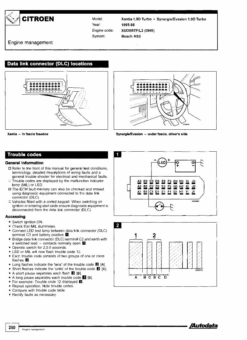
Year: 1995-98
Engine code: XUD9BTFIL3 (DHX)
System: Bosch AS3
Engine management
I I
Xantii - in fascia fusebox SynergieEvasion - under fascia, driver's side
General information Refer to the front of this manual for general test conditions, terminology, detailed descriptions of wiring faults and a general trouble shooter for electrical and mechanical faults.
G Trouble codes are displayed by the malfunction indicator lamp (MIL) or LED. The ECM fault memory can also be checked and erased using diagnostic equipment connected to the data link connector (DLC).
0 Vehicles fitted with a coded keypad: When switching on ignition or entering start code ensure diagnostic equipment is disconnected from the data link connector (DLC).
Accessing Switch ignition ON. Check that MIL illuminates. Connect LED test lamp between data link connector (DLC) terminal C3 and battery positive m. Bridge data link connector (DLC) terminal C2 and earth with a switched lead - contacts normally open O. Operate switch for 2,551 seconds. LED or MIL will now flash trouble code 12. Each trouble code consists of two groups of one or more flashes H. Long flashes indicate the 'tens' of the trouble code H [A]. Short flashes indicate the 'units' of the trouble code rn [C]. A short pause separates each flash rn [B]. A long pause separates each trouble code [Dl. For example: Trouble code 12 displayed H. Repeat operation. Note trouble codes. Compare with trouble code table. Rectify faults as necessary.

I Engine management I Erasing Method 2
Ensure ignition switched OFF. Method 1 Disconnect battery earth lead for 10 seconds.
Switch ignition ON. WARNING: Disconnecting the battery may erase memory from Connect LED test lamp between data link connector (DLC) electronic units (e.g. radio, clock). terminal C3 and battew ~ositive a. Bridge data link connect& (DLC) terminal C2 and earth with a switched lead - contacts normally open a. Operate switch for 2,5-5 seconds. LED or MIL will now flash trouble code 12. Repeat switch operation until code 11 is displayed. Operate switch for 10-20 seconds. Switch ignition OFF.
Trouble code identification
Flash type Fault location Probable cause I I
14 I Engine coolant temperature (ECT) sensor I Wiring, ECT sensor, ECM
16 I Exhaust gas recirculation (EGR) soienoid I Wiring, relay module, EGR solenoid
46 I Fuel injection pump - timing control I Fuel injection pump timing
21
39
41
57 I Barometric pressure (BARO) sensor I ECM
Fuel lever position sensor
Malfunction indicator lamp (MIL)
Crankshaft position (CKP) sensorlengine speed (RPM) sensor
49
53
54
58 I Glow plug control module - pre-heat I Wiring, glow plug(s), glow plug control module
Wiring, fuel lever position sensor
Wiring, MIL, ECM
Wiring, CKPlRPM sensor, air gap, ECM
Fuel injection timing solenoid
Battery voltage
Engine control module (ECM)
Wiring, fuel injection timing solenoid
Wiring, battery discharged, alternator
Wiring, battery, ECM
65
66
67
/Autodata I Eng~ne management 251
68
Injector needle lift sensor
Glow plug control module - pre-lpost-heat
Glow plug warning lamp
Wiring, fuel system, injector, injector needle lift sensor
Wiring, glow plug control module
Wiring, glow plug warning lamp, ECM
4
Idle speed control (ISC) actuator Wiring, hoses blockedlleaking, ISC actuator

I CDTROEN
Engine management
Xantia 2, lD Turbo XM 2,lD Turbo SynergieIEvasion 2, l TD DispatchlJumpy
Year: 199500
Engine code: P8C
System: Lucas EPIC
XM, Xantia -7998 - in fascia fusebox
XM, Xantia 7998 + - in fascia fusebox
General information n Refer to the front of this manual for general test conditions,
terminology, detailed descriptions of wiring faults and a general trouble shooter for electrical and mechanical faults. Vehicles fitted with a coded keypad: When switching on ignition or entering start code ensure diagnostic equipment is disconnected from the data link connector (DLC).
Accessing and erasing The engine control module (ECM) fault memory can only be accessed and erased using diagnostic equipment connected to the data link connector (DLC). The following scanner codes are applicable to the fuel system manufacturer's test equipment, similar and more detailed fault diagnosis information can be obtained using the vehicle manufacturer's or equivalent test equipment.
- -
SynergieEvasion, DispatchlJumpy 1498-*

Engine management 1 Model: Xantia 2,lD Turbo XM 2,lD Turbo SynergielEvasion 2,l TD
DispatchlJumpy C1TROEN P
150 1 Battery voltage
Trouble code identification
Wiring, IFS switch, relay module, battery, alternator, I ECM
Scanner type
100
101
102
104
105
130
151 1 Battery voltage Wiring, IFS switch, relay module, battery discharged, alternator
fauit M i o n
Engine control module (ECM) - memoty
Engine control module (ECM) - low voltage during starting
Engine control modute (ECM) - non-volatile memory fault
Engine control module (ECM) - analogueldigital converter
Engine control module (ECM) - sensor reference voltage incorrect
Engine control module (ECM) - memory locked
Probable cause
ECM
Battery, relay module, wiring, ECM
ECM
Wiring, ECM
Wiring, ECM
Coded keypad, ECM
152
200
220 1 Fuel temperature sensor
21 0
21 1
I Wiring, fuel temperaturesensor;~c~
Relay module
Engine coolant temperature (ECT) sensor
Wiring, relay module, ECM
Wiring, ECT sensor, ECM
Intake air temperature (IAT) sensor
Manifold absolute pressure (MAP) sensor
290 I Accelerator pedal position (APP) sensor I Wiring, APP sensor, ECM
Wiring, IAT sensor, ECM
Wiring, MAP sensor, ECM
240
250
Vehicle speed sensor (VSS)
Crankshaft position (CKP) sensor
Acceterator pedal position (APP) sensorlbrake pedal position (BPP) switch - signal conflict
329 ( Transmission range (TR) switch I Wiring, TR switch
Wiring, VSS, ECM
Wiring, CKP sensor, air gap, ECM
Wiring, APP sensor, BPP switch, brake pedal applied whilst throttle fully depressed, accelerator pedal tighffsticking, ECM
300
320
340 1 Air conditioning Wiring, AC compressor clutch relay, AC control module, ECM
Brake pedal position (BPP) switch
Cruise control
350 I Glow plug control module - pre-lpost-heat control I Wiring, glow plug control module, ECM
Wiring, BPP switch, ECM
Wiring, cruise control master switch, ECM
361 ( Tachometer signal I Wiring, tachometer, ECM
603 I Fuel injection pump - rotor minimum calibration I Fuel injection pump
363
600
601
602
Fuel consumption signal
Fuel injection pump - rotor position monitoring
Fuel injection pump - rotor position
Fuel injection pump - rotor calibration
604
Wiring, trip computer, ECM
Wiring, fuel system, fuel quantity adjuster, fuel injection pump, relay module, ECM
Wiring, shield wiring, injection pump cam ring position sensor, injection pump rotor position sensor, fuel injection pump, ECM
Wiring, fuel injection pump, ECM
Fuel detiverylneedle lift signal Wiring, fuel injection pump, ECM
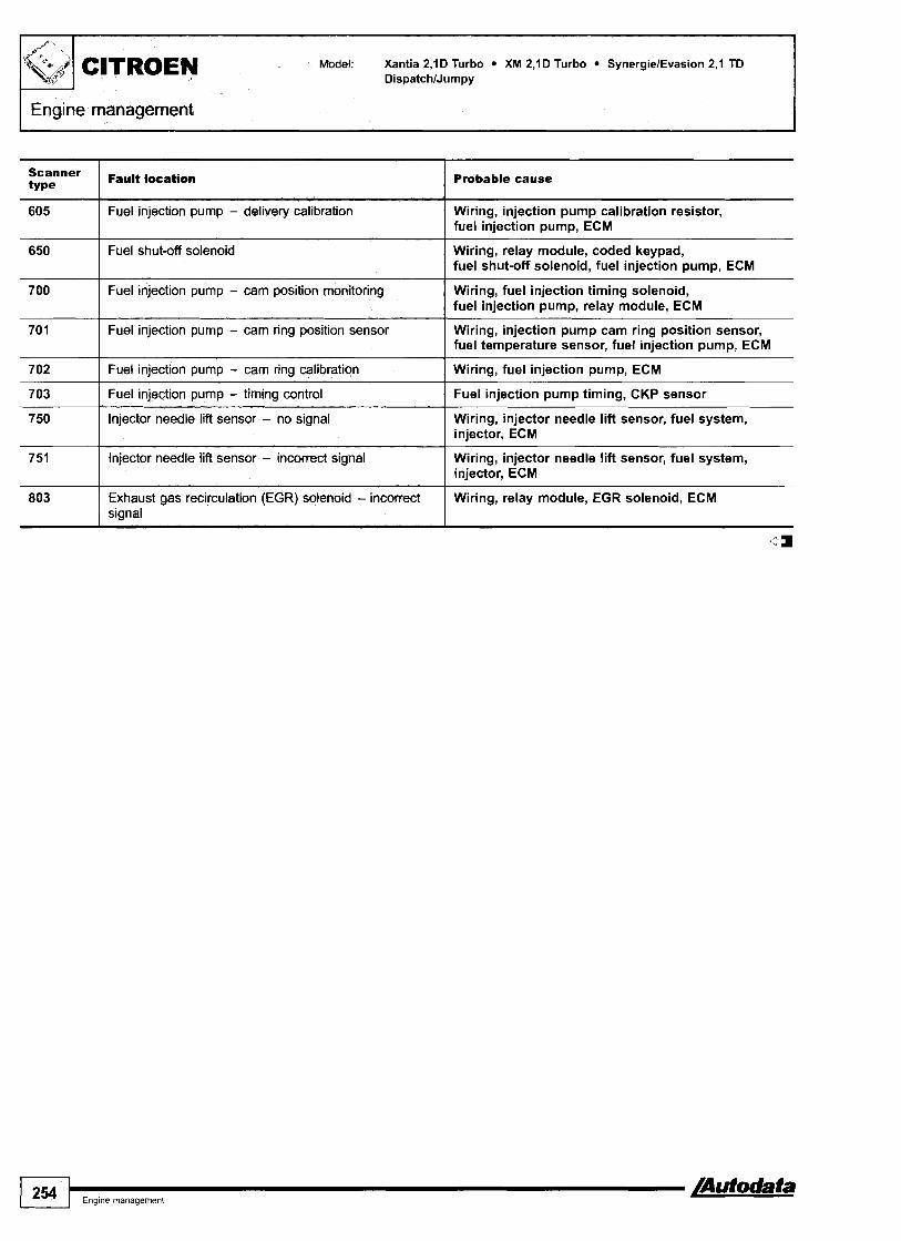
I Engine management
Model: Xantia 2,lD Turbo XM 2, lD Turbo SynergielEvasion 2, l TD DispatchlJumpy
Probable cause
650 I Fuel shut-ofl solenoid
605
Wiring, relay module, coded keypad, fuel shut-off solenoid, fuel injection pump, ECM
700 1 Fuel injection pump - cam position monitoring
Fuel injection pump - delivery calibration
I Wiring, fuel injection timing solenoid, fuel injection pump, relay module, ECM
Wiring, injection pump calibration resistor, fuel injection pump, ECM
701 1 Fuel injection pump - cam ring position sensor Wiring, injection pump cam ring position sensor, fuel temperature sensor, fuel injection pump, ECM
702 I Fuel injection pump - cam ring calibration I Wiring, fuel injection pump, ECM
751 1 lnjector needle lift sensor - incorrect signal
703
750
1 - -
Wiring, injector needle lift sensor, fuel system, injector, ECM
Fuel injection pump - timing control
Injector needle lift sensor - no signal
Fuel injection pump timing, CKP sensor
Wiring, injector needle lift sensor, fuel system, injector, ECM
803
a
Exhaust gas recirculation (EGR) solenoid - incorrect signal
Wiring, relay module, EGR solenoid, ECM

Model: Cinquecento 90011 ,I Seicento 90011 ,I Panda 90011,l Punto 1,111,2116V Tiporrernpra 1,812,O BravalBravo 1,6 MarealMarea Weekend 1,6 Coupe 2,O 16VKurbo
Year: 1989-03
Engine 11 7OAl .O46, 11 7OAlO46, l56C.046, l59A4.000, l59A4.046, l59A5.046, l59A6.046, l6OA5.000, l6OA8.046, 'Ode: l7OAl.OOO, l7OAl .O46, 175A114.000, l76A6.000, l76A7.000, l76A8.000, l76Bl.000, 17682.000, 17684.000,
17689.000, 182A4.000, 182A6.000, 835C2.000, 835C4.000, 836A3.000, 836A5.000
System: Weber-Marelli
I Engine management
FIAT
CinquecentdSeicento - LH engine bay
I
Panda - under fascia, passenger's side
I
Coupe 2,O 16VIPunto - RH engine bay
10212W
Tiporrempra - engine bay, rear
BravdBravolMareatMarea Weekend 1,6 41998 - engine hay rear
Brava/Bravo/MarealMarea Weekend 1,6 19984 - LH engine bay
/Autodata a Eng~ne management 255 /

inquecento 90011,l Seicento 90011,l Panda 9OO11,l nto 1,111,2116V Tiporrernpra 1,812,O BravalBravo 1,6
arealMarea Weekend 1,6 Coupe 2,O 16V1Turbo
ngme management
I
Coupe 2,O 1BV Turbo - LH engine bay
General information Refer to the front of this manual for general test conditions, terminology, detailed descriptions of wiring faults and a general trouble shooter for electrical and mechanical faults. No digital trouble codes available from vehicle manufacturer.
Accessing and erasing The engine control module (ECM) fault memory can only be accessed and erased using diagnostic equipment able to display fault locations as a text description, connected to the data link connector (DLC).
Trouble code identification
PauPt locstlon I Probable cause
AC signal I Wiring, AC system, AC control module
Air conditioning relay - circuit malfunction I Wiring, supply voltage, AC system
Engine control module (ECM) - adaptive tolerance reached I Mechanical fault
Camshaft position (CMP) sensor - circuit mafunction
Crmkshaft position (CKP) sensortengine speed (RPM) sensor - malfunction
I
Engine control module (ECM) - defective I ECM
Wiring, air gap, CMP sensor, insecure sensorlrotor, ECM
Wiring, CKPIRPM sensor, air gap, damaged sensorlrotor, ECM
Engine control module (ECM) - immobilizer active
I
Engine control module (ECM) - ROM m 1 ECM
lncorrectldamaged key, incorrectly coded, wiring, immobilizer defective
Engine control modute (ECM) - UAM error
Engine control d u k e (ECM) - RAM error
Engine c0"trol module (E&) - sensor supply 5V 1 ECM
ECM
ECM
Engine control relay
Engine coolant temperabre (ECT) sensor - openlshort circuit
Wiring, supply voltage, engine control relay
Wiring, ECT sensor, ECM

,1 Seicento 90011,l Panda 9OOI1,l TipoiTernpra 1,812,O BravalBravo 1,6
kend 1,6 Coupe 2,O 16ViTurbo
Fa Probable cause
Fuel pu ] Wiring, supply voltage, fuel pump relay
Evaporative emission (EVAP) canister purge valve - circuit malfunction
Wiring, supply voltage, EVAP canister purge valve, ECM
Heated oxygen sensor (H02S)
Idle air control (IAC) valve
Idle speed control (ISC) actuator
Idle control - outside specification
Ignition coif - malfunction I Wiring, ignition coil, ECM
Wiring, H02S, air leak, ECM
Wiring, IAC valve, ECM
Wiring, ISC actuator, mechanical fault, ECM
Intake leaklblockage, throttle valve tightkticking, IAC valve or ISC actuator. ECM
Ignition amplifier I, cylinders I & 4 - malfunction
Ignition amplifier 2, cylinders 2 & 3 - malfunction
Wiring, supply voltage, ignition coil, ignition amplifier, ECM
Wiring, supply voltage, ignition coil, ignition amplifier, ECM
Ignition coil 1, cylinders I & 4 - malfunction
Ignition coil 2, cylinders 2 & 3 - malfunction
Immobilizer circuit - malfunction
Injector 3 I Wiring, fuse, engine control relaylrelay module, injector
Wiring, ignition coil, ECM
Wiring, ignition coil, ECM
Wiring, incorrectldamaged key, immobilizer defective, ECM
Injector(5) - malfunction
Injector I
Injector 2
Injector 4 I Wiring, fuse, engine control relaylrelay module, injector
Wiring, supply voltage, injector
Wiring, fuse, engine control relaylrelay module, injector
Wiring, fuse, engine control relavlrelav module, injector
Instrument panel, engine speed signal - circuit malfunction
Manifold absolute pressure (MAP) sensor - malfunction I Intakelexhaust leak, wiring, MAP sensor, ECM
--
Wiring, ECM
Knock sensor (KS)
Malfunction indicator lamp (MIL) - circuit malfunction
Intake air temperature (IAT) sensor - openlshort circuit I Wiring, IAT sensor, ECM
Wiring, KS, KS incorrectly tightened, ECM
Wiring, supply voltage, MIL lamp
Mixture control (MC) - weak I Wiring, air leak, fuel pressure, ignition system, injector, MAP sensor, H02S, ECM
Mixture control (MC)
Mixture control (MC) - rich
Fuel level low, fuel pressurelpump, intakelexhaust leak, misfire, MAP sensor, H02S, EVAP canister purge valve, injector(s), excessive fuel in engine oil
Wiring, injector, fuel pressure, MAP sensor, ECM
Transmission control module (TCM) - incorrect signal 1 Wiring, ECM
Relay module
Supply voltage
Throttle position (TP) sensor
Wiring, supply voltage, relay module
Wiring, fuses, battery, alternator, ignition switch
Wiring, TP sensor, ECM
-I Eng~ne managemenl 257
Turbocharger (TC) wastegate regulating valve
Vehicle speed signal
Wiring, supply voltage, TC wastegate regulating valve, ECM
Wiring, VSS, ECM
Some models: Located in man~fold absolute pressure (MAP) sensor. 4

Model: Panda 1,011 ,I/Uno 1,011,1/1,4/1,5 Punto 1,4 GTll ,6ITipoITernpra l,4ll,6 BravalBravo 1,211,411,812,0 MarealMarea Weekend 1,2/1,4/1,812,0 Barchetta Coupe I,8/2,O 2OVITurbo Fiorino l,4ll,5/l,6
Year: 1988-03
System: Bosch Mono-Jetronic A2.2 Bosch Mono-Motronic MA1.711.7.3 Bosch Motronic 1.5.5 Bosch Motronic ME3.1 Bosch Motronic M2.7lM2.10.4 GM ACG Multec Hitachi MPI Weber-Marelli 1AW 06F
Engine management
PandaIUno, type 2 - under fascia, passengefs side
Uno, type 1 - RH engine bay
Punto GT - engine bay rear
Punto 1,6 - engine bay rear
-
Fiorino - RH engine bay
-
Tempra, GM ACG Multec - kick panel, passengefs side

BravdBravo 1,2/1,4/1,8/2,0 MarealMarea Weekend 1,2/1,4/1,8/2,0 Barchetta Coupe l,8/2,O 2OVfrurbo Fiorino l,4/1,5/1,6
Barchetta -1998 - kick panel, passenger's side
Tiponempra, Mono-Jetronic A2.2 - engine bay rear
BravalBravolMareatMarea Weekend 1.2 - LH engine bay
BravaIBravolMarealMarea Weekend 1,4 - engine bay rear
Tiponempra, Mono-Motronic MA1.7 - RH engine bay BravalBravoIMaredMarea Weekend 1,812,O -1998lCoupe 2,O 20V 4 9 9 8 - RH engine bay

BravalBravo 1,2/1,411,812,0 MarealMare Barchetta Coupe 1,812,O 2OVfrurbo
BravalBravofMarealMarea Weekend 1,812,O 1999 -+ - LH engine bay
Coupe 1,8 1998 -+ - engine bay rear
Barchetta 1998 -+ - engine bay rear Coupe 2,O 20V TurbolCoupe 2,O 20V I998 + - RH engine bay
L
Coupe 1,8 4 9 9 8 - RH engine bay

OV/Turbo Fiorino 1,4/1,5/1,6
General information Refer to the front of this manual for general test conditions, terminology, detailed descriptions of wiring faults and a general trouble shooter for electrical and mechanical faults. No digital trouble codes available from vehicle manufacturer.
Accessing and erasing The engine control module (ECM) fault memory can only be accessed and erased using diagnostic equipment able to display fault locations as a text description.
Trouble code identification I
Fault location I Probable cause
Accelerator pedal position (APP) sensor - implausible signal I Wiring, APP sensor, ECM
AC signal
Air conditioning relay - circuit malfunction
Wiring, AC system, AC control module
Wiring, supply voltage, AC system
Barometric pressure (BARO) sensor
Camshaft position (CMP) actuator - circuit malfunction
Crankshaft position (CKP) sensorlengine speed (RPM) sensor - malfunction
Wiring, BAR0 sensor, ECM
Wiring, CMP actuator relay, CMP actuator, ECM
Camshaft position (CMP) sensor - circuit malfunction
Closed throttle position (CTP) switch - malfunction / Wiring, air gap, CKPIRPM sensor, mechanical fault, ECM
Wiring, CMP sensor, ECM
Wiring, mechanical fault, ISC actuator, ECM
Engine control module (ECM) - defective I ECM
Engine control relay / Wiring, supply voltage, engine control relay
Engine coolant temperature (ECT) sensor - openlshort circuit 1 Wiring, ECT sensor, ECM
Evaporative emisslon (EVAP) canister purge valve - circuit / Wiring, supply voltage, EVAP canister purge valve, ECM malfunction
Fuel pump relay I Wiring, supply voltage, fuel pump relay
Heated oxygen sensor (H02S) I Wiring, H02S, air leak, ECM
Idle air control (IAC) valve I Wiring, IAC valve, ECM
ldle speed control (ISC) actuatorlthrottle motor I Wiring, ISC actuatorlthrottle motor, mechanical fault, ECM
ldle control - outside specification Intake leaklblockage, throttle valve tightlsticking, IAC valve or ISC actuator, ECM
Immobilizer circuit - malfunction I Wiring, immobilizer defective, ECM
Ignition amplifier - malfunction
Ignition switch - circuit malfunction
Injector(s) - malfunction I Wiring, supply voltage, injector
Wiring, supply voltage, ignition coil, ignition amplifier, ECM
Wiring, supply voltage, ignition switch
Injector 4 I Wiring, fuse, engine control relaylrelay module, injector
Injector 1
Injector 2
Injector 3
Wiring, fuse, engine control relaylrelay module, injector
Wiring, fuse, engine control relaylrelay module, injector
Wiring, fuse, engine control relaylrelay module, injector
Atodata I Eng~ne management 261
Injector 5 Wiring, fuse, engine control relaylrelay module, injector
lr]

Model: Panda 1,011 ,llUno 1,011,1/1,411,5 Punto 1,4 GTII ,6TTipoTTempra 1,4/1,6 BravalBravo 1,2/1,4/1,8/2,0 MarealMarea Weekend 1,2/1,4/1,812,0 Barchetta Come 1.812.0 2OVTTurbo Fiorino 1 Al l .5/l.6
Engine management
Fault location Probable cause
Intake air temperature (IAT) sensor - openlshort circuit
Intake manifold air control solenoid - circuit malfunction
Wiring, IAT sensor, ECM
Wiring, intake manifold air control solenoid, ECM
Knock sensor(s) (KS) Wiring, KS, KS incorrectly tightened, ECM
Malfunction indicator lamp (MIL) - circuit malfunction Wiring, supply voltage, MIL
El Manifold absolute pressure (MAP) sensor - malfunction lntakelexhaust leak, wiring, MAP sensor, ECM
Mass air flow (MAF) sensor Wiring, intake leak, air filter blocked, MAF sensor, ECM
Mixture control (MC) Fuel level low, fuel pressurelpump, intakelexhaust leak, misfire, MAPIMAF sensor, H02S, EVAP canister purge valve, injector@), excessive fuel in engine oil
Mixture control (MC) - rich Wiring, injector, fuel pressure, MAF sensor, ECM
Mixture control (MC) - weak Wiring, air leak, fuel pressure, ignition system, injector, MAF sensor, H02S, ECM
Wiring, supply voltage, relay module Relay module
Supply voltage Wiring, fuses, battery, alternator, ignition switch
rn Throttle position (TP) sensor Wiring, TP sensor, ECM
Transmission control module (TCM) - incorrect signal Wiring, ECM
Turbocharger (TC) pressure - control difference lntakelexhaust leak, hoses interchangedlnot connected, MAP sensor, TC wastegate regulating valve, turbocharger (TC) wastegate actuator, TC
Wiring, supply voltage, TC wastegate regulating valve, ECM
Turbocharger (TC) wastegate regulating valve
Vehicle speed signal Wiring, VSS, ECM
Located in idle s ~ e e d control (ISC) actuator. ~,
Some models: Located in manifold absolute pressure (MAP) sensor. Punto GT: Located in engine control module (ECM).
rn Some models: Located in idle speed control (ISC) actuator.

Model: BravalBravo 1,9 JTD MarealMarea Weekend 1,912,4 JTD
Year: 1995-03
Engine code: 182~7.000, l82B4.000, l85A2.000, l85A6.000, 189B9.000, l86A6.000
System: Bosch EDC 15C
FIAT
Engine management
RH engine bay
General information Refer to the front of this manual for general test conditions, terminology, detailed descriptions of wiring faults and a general trouble shooter for electrical and mechanical faults.
Accessing and erasing The engine control module (ECM) fault memory can only be accessed and erased using diagnostic equipment connected to the data link connector (DLC).
Trouble code identification
EOBD type
Fault location I Probable cause
P I 320 Crankshaft position (CKP) sensorlcamshaft position Wiring, CKP sensor, CMP sensor, ECM (CMP) sensor - signal variation
I I
PO I Refer to EOBD trouble code table
-a- Enq~ne rnanaqement 263
-
P I 503
4
Fuel pressure control solenoid Wiring, fuel system pressure sensor, fuel pressure control solenoid, fuel system, ECM

192 A1.OOO, 192 A3.000
Bosch EDC 1
Under fascia, driver's side
General information Refer to the front of this manual for general test conditions, terminology, detailed descriptions of wiring faults and a general trouble shooter for electrical and mechanical faults.
Accessing and erasing The engine control module (ECM) fault memory can be accessed and erased using diagnostic equipment connected to the data link connector (DLC).
Trouble code identification
EOBD type
I Probable cause
No vehicle specific 'PI ' codes currently available from manufacturer. ca
PO 0 Refer to EOBD trouble code table -

Ka 1,3 Fiesta l,25ll,3ll,4ll,8DlTD EscortlOrion l,3ll,6ll,8 Fusion l ,2~l l ,4/ l ,6l l ,8 Focus l,4/l,6/l,8/2,O/l,8 TD11,8 TDCi FocusC-MAX l,6Il,8/2,O TDCi Puma l,4Il,6/1,7 StreetkalSportka 1,6 MondeolCougar 1,611,812,012,511,812,O TDI2,O TDCi12,5 Scorpio 2,012,312,912,5 TD Galaxy 2,012,312,811,9 TDlTDl ExplorerMlindstar 3,014,O Transitfrourneo Connect 1,s Transit 2,012,312,O TDl2,4 TD
Year: 1994-04 Engine 12, AAA, ABFA, AFN, AHU, ALDA, AMY, ANU, AUY, AVG, AYL, BHDAIB, BOB, CSDA, CSDAIB, 'Ode: CSDC, CDBB, CDBIC, CDDA, CGBAIB, CHBAIB, CJBAIB, DHA, DHB, DHC, DHD, DHE, DHF, DHG,
DZFA, D3FA, D4FA, DSBA, DGBA, E, EDBAIC, EDBB, EDBD, EDDB, EDDC, EDDD, EDDF, EYDB, EYDC, EYDF, EYDG, EYDI, EYDJ, EYDDIE, E5FA, E5SA, E5SB, FFDA, FHA, FHD, FHE, FHF, FMBA, FMBAIB, FXDAIC, FXDBID, FYDAIC, FYDBID, FYDH, F3FA, MFA, FSDAIB, HJBAIB, HMDA, JJA, JJB, JJC, JJD, JJE, JJF, JJG, JJH, JJJ, JJK, JJL, JJM, J4B, J4C, J4D, J4J, J4K, J4L, J4M, J4N, J4P, J4Q, J4R, J4S, J4T, LCBAIC, LCBB, LCBD, LCBE, LIJ, LIK, LIL, LINIQ, LIT, LIV, LIW, MABA, MABB, MEBA, MHA, MHB, NGA, NGB, NGC, NGD, NSDIE, NSF, NSG, NSH, N3A, RFN, RFS, RKB, RKC, RKF, RKH, RKJ, RKK, RTJ, RTK, RTN, RTP, RTQ, RVA, SCC, SCD, SEA, SEB, SEC, SGA, V6, Y5A, Y5B, ZVSA
System: Ford EEC VlSlM 19 Ford Black Oak Bosch Motronic Bosch EDC Delphi Siemens
Focus
-
Monded

FORD Model: Ka Fiesta EscorVOrion Fusion Focus FocusC-MAX Puma StreetkalSportka MondeolCougar Scorpio Galaxy ExplorerMlindstar Transitrrourneo Connect
Scorpio
11~5
Galaxy -*05/00 - under ashtray
Engine managementltransmission
Transit
Galaxy 06/00-* - fascia, driver's side All models - 2001 -*
Accessing and erasing The ECM fault memory can only be accessed and erased
NOTE: Engine control module (ECM) incorporates transmission using diagnostic equipment connected to the data link control function. connector (DLC).
General information Refer to the front of this manual for general test conditions, terminology, detailed descriptions of wiring faults and a general trouble shooter for electrical and mechanical faults.

I Model: Ka Fiesta EscorUOrion Fusion Focus FocusC-MAX Puma StreetkalSportka MondeolCougar Scorpio Galaxy ExplorerMlindstar Transitrrourneo Connect
FORD
I Engine management/transmission I b ~ 1 . :
Trouble code identification
EOBD Fault location Probable cause I I
PO 1 Refer to EOBD trouble code table -
PI001 ( System diagnosis incomplete I -
Fuel timing error (Diesel engines only)
System readiness test not complete
PI100 I Mass air flow (MAF) sensor - circuit intermittent I Wiring, MAF sensor
Wiring, CKP sensor, injector needle lift sensor, fuel injection pump, fuel injection pump, fuel injection pump control module, ECM
-
P I 106 I Dual alternator lower fault I -
P I I 0 1
P I 105
P I 107 I Dual alternator lower circuit I - PI108 ( Dual alternator battery lamp circuit 1 -
Mass air flow (MAF) sensor - out of self-test range
Dual alternator upper fault
P I 1 09 Intake air temperature (IAT) sensor 2 - circuit intermittent
Wiring, MAF sensor
-
I Wiring, IAT sensor
PI111 I System pass I - PI112 Intake air temperature (IAT) sensor -
circuit intermittent I Wiring, IAT sensor
PI114 Intake air temperature (IAT) sensor 2 - circuit - low - superchargedlturbocharged engines
PI115 Intake air temperature (IAT) sensor 2 - circuit Wiring, IAT sensor high - superchargedlturbocharged engines
PI118 Manifold air temperature (MAT) sensor - I Wiring, MAT sensor, ECM circuit low
PI116
PI117
PI119 Manifold air temperature (MAT) sensor - I Wiring, MAT sensor, ECM circuit high
PI120 I Throttle position (TP) sensor -out of range, low I Wiring, TP sensor
Engine coolant temperature (ECT) sensor - out of self-test range
Engine coolant temperature (ECT) sensor - circuit intermittent
Wiring, ECT sensor
Wiring, ECT sensor
PI123 Accelerator pedal position (APP) sensor A - Wiring, APP sensor, ECM circuit high
PI121
P I 122
PI124 Throttle position (TP) sensor - out of self-test Wiring, TP sensor range
PI125 Throttle position (TP) sensor - circuit I Wiring, TP sensor intermittent
Throttle position (TP) sensor - inconsistent with MAFIMAP sensor signal
Accelerator pedal position (APP) sensor A - circuit tow
Wiring, MAF/MAP/TP sensor
Wiring, APP sensor, ECM
PI129 1 Heated oxygen sensor (H02S) 2 - transposed I Wiring
P I 127
PI128
Exhaust temperature, out of range - 0 2 s tests not complete
Heated oxygen sensor (H02S) 1 - transposed
Exhaust leak, mechanical fault
Wiring

FORD Model: Ka Fiesta EscortlOrion Fusion Focus FocusC-MAX Puma StreetkalSportka MondeolCougar Scorpio Galaxy ExplorerMlindstar Transitrrourneo Connect
I $'L?PI Engine management/transrnission
EOBD type
Fault location I Probable same
Heated oxygen sensor (H02S) - lntakelfuel system, injectors, H02S, MAF sensor, not switching, fuel trim (FT) weak mixture ECT sensor
Heated oxygen sensor (H02S) -fuel trim (FT) at limit
Heated oxygen sensor (H02S) - not switching, fuel trim (FT) rich mixture
lntakelfuel system, injectors, H02S, MAF sensor, ECT sensor
lntakelfuel system, injectors, H02S, MAF sensor, ECT sensor
Fuel control shifted lean, bank 1 I Fuel ~ressure. iniectors. MAFIMAP sensor. intake leak
Fuel control shifted rich, bank 1 I Fuel pressure, injectors, MAFIMAP sensor, EVAP system
Accelerator pedal position (APP) sensor A - circuit intermittent
Heated oxygen sensor (H02S) 1, bank 2 - no activity detected, lean mixture
Water in fuel I Water in fuel
Wiring, APP sensor, ECM
lntakelfuel system, injectors, H02S, MAF sensor, ECT sensor
Heated oxygen sensor (H02S) 1, bank 2 - no activity detected, rich mixture
Water in fuel warning lamp - circuit malfunction
lntakelfuel system, injectors, H02S, MAF sensor, ECT sensor
Wiring, water in fuel warning lamp
Calculated torque error I -
Fuel restriction warning lamp - circuit malfunction
Fuel restriction
Wiring, fuel restriction warning lamp
Blocked fuel filter
Alternator 2 - monitor - voltage high I Wiring, alternator
Manifold air temperature (MAT) sensorlintake air temperature (IAT) sensor - correlation
Alternator 2 - control circuit
Wiring, MAT sensor, IAT
Wiring, alternator
Heated oxygen sensor (H02S) - lntakelfuel system, injectors, H02S, MAF sensor, not switching, sensor indicates rich mixture ECT sensor
Heated oxygen sensor (H02S) - not switching, fuel trim (FT) at limit
Heated oxygen sensor (H02S) - not switching, sensor indicates weak mixture
lntakelfuel system, injectors, H02S, MAF sensor, ECT sensor
lntakelfuel system, injectors, H02S, MAF sensor, ECT sensor
Fuel control shifted lean, bank 2
Fuel control shifted rich, bank 2
Heated oxygen sensor (H02S) 2, bank 2 - lntakelfuel system, injectors, H02S, MAF sensor, no activity detected, rich mixture I ECT sensor
Fuel pressure, injectors, MAFIMAP sensor, intake leak
Fuel pressure, injectors, MAFIMAP sensor, EVAP system
Alternative fuel control module has activated the MIL
Heated oxygen sensor (H02S) 2, bank 2 - no activity detected, lean mixture
-
lntakelfuel system, injectors, H02S, MAF sensor, ECT sensor
Rotor control I -
Fuel shut-off solenoid
Rotor sensor
Rotor calibration I -
Wiring, fuel shut-off solenoid
-
Cam calibration I -
Cam sensor
Cam control
I 268 I,,,, -a
- -
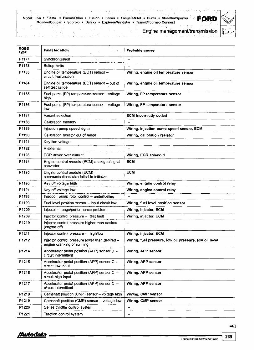
Model: Ka Fiesta EscorUOrion Fusion Focus FocusC-MAX Puma StreetkalSportka FORD MondeolCougar Scorpio Galaxy ExplorerMlindstar TransitlTourneo Connect
EOBD type
PI177
Fault location I Probabie cause
Boltup limits 1 -
I
Svnchronization -
Engine oil temperature (EOT) sensor - circuit malfunction
Engine oil temperature (EOT) sensor - out of self test range
Variant selection I ECM incorrectly coded
Wiring, engine oil temperature sensor
Wiring, engine oil temperature sensor
Fuel pump (FP) temperature sensor - voltage high
Fuel pump (FP) temperature sensor - voltage low
Calibration memory I -
Wiring, FP temperature sensor
Wiring, FP temperature sensor
Injection pump speed signal I Wiring, injection pump speed sensor, ECM
V external I -
-
Calibration resistor out of range
Key line voltage
EGR driver over current 1 Wiring, EGR solenoid
- - - -
Wiring, calibration resistor
-
Engine control module (ECM) analogueldigital ECM converter I Engine control module (ECM) - communications chip failed to initialize
I ECM
Fuel level position sensor - input circuit low I Wiring, fuel level position sensor
Key off voltage high
Key off voltage low
Injection pump rotor control - underfueling
Injector - rangelperformance problem 1 Wiring, injector, ECM
Wiring, engine control relay
Wiring, engine control relay
-
Injector control pressure - highllow I Wiring, injector, ECM
Injector control pressure - test fault
lnjector control pressure higher than desired (engine off)
lnjector control pressure lower than desired - Wiring, fuel pressure, low oil pressure, low oil level engine cranking or running
Wiring, injector, ECM
-
Accelerator pedal position (APP) sensor B - Wiring, APP sensor circuit intermittent
Accelerator pedal position (APP) sensor C - Wiring, APP sensor circuit intermittent
Accelerator pedal position (APP) sensor C - circuit low input
Acceterator pedal position (APP) sensor C - circuit high input
Camshaft position sensor - vGage high Wiring, CMP sensor
Camshaft position (CMP) sensor - voltage low Wiring, CMP sensor
Wiring, APP sensor
Wiring, APP sensor
Series throttle control system I - Traction control system I -

FORD Model: Ka Fiesta EscortlOrion Fusion Focus FocusC-MAX Puma StreetkalSportka MondeolCougar Scorpio Galaxy ExplorerMlindstar Transitrrourneo Connect
Engine managementltransmission
Fault locatSon
Redundant emergency stop I -
Probable cause
Accelerator pedal position (APP) sensor B - circuit low
Accelerator pedal position (APP) sensor B - circuit high
Wiring, APP sensor
Wiring, APP sensor
Fuel quantity adjuster position sensor - circuit Wiring, fuel quantity adjuster position sensor malfunction
Throttle position (TP) sensor B - out of self test range
Injector needle lift sensor
Fuel injection timing solenoid I Wiring, dirty fuel, air in fuel, fuel injection timing solenoid
Wiring, TP sensor
Wiring, dirty fuel, air in fuel, injector needle lift sensor
Vehicle speed governor I Wiring, vehicle speed governor
Fuel injection timing solenoid I Wiring, dirty fuel, air i n fuel, fuel injection timing solenoid
Fuel pump (FP) - low speed malfunction ( Wiring, fuel pump (FP)
Fuel pump (FP) - secondary circuit low, high Wiring, fuel pump (FP) speed
Fuel pump (FP) speed - primary circuit, two Wiring, fuel pump (FP) speed fuel pump (FP)
Fuel pump (FP) - control module disabled or off Wiring, fuel pump (FP), ECM line
Fuel pump (FP) -control module disabled or off Wiring, fuel pump (FP), ECM line
Fuel pump (FP) -secondary circuit malfunction I Wiring, FP control module
Fuel pump (FP) control - out of range
Fuel pump (FP) control - out of range
Fuel pump (FP) - secondary circuit malfunction I Wiring, FP, FP control module
Wiring, FP control module
Wiring, FP control module
Alternator - high input I Wiring, alternator
Speed fuel pump (FP) positive feed
Sensor power supply
Second fuel pump (FP) - malfunction, earth fault
-
Wiring, ECM
Wiring, fuel pump (FP)
Turbocharger boost pressure low I Wiring, turbocharger (TC) wastegate actuator, turbocharger
Alternator - low input
Alternator
Turbocharger boost pressure not detected I Wiring, turbocharger
Wiring, alternator
Wiring, alternator
Wastegate control valve - performance
Accelerator pedal position (APP) sensor - signal correlation, high
Turbocharger
Wiring, APP sensor
Accelerator pedal position (APP) sensor - signal correlation, low
Accelerator pedal position (APP) sensor - signal correlation, high
Wiring, APP sensor
Wiring, APP sensor
Accelerator pedal position (APP) sensor - signal correlation, low
Wiring, APP sensor

Model: Ka Fiesta EscortlOrion Fusion Focus FocusC-MAX Puma StreetkalSportka FORD MondeolCougar Scorpio Galaxy ExplorerlWindstar Transitrrourneo Connect
Engine managementltransrnission
PI256 Accelerator pedal position (APP) sensor - signal correlation
EOBD type I Wiring, APP sensor
Wiring, APP sensor
Fault location
PI257 Accelerator pedal position (APP) sensor -
PI258 Accelerator pedal position (APP) sensor - signal correlation
Probable cause
I Wiring, APP sensor
PI259 1 Immobilizer to ECM signal error ( Wiring, immobilizer control module
PI263 ( Injector 3 - short circuit I Wiring, injector, ECM
PI260
PI261
PI262
PI264 1 Injector 4 - short circuit 1 Wiring, injector, ECM
PI265 1 Injector 5 - short circuit ( Wiring, injector, ECM
Theft detected - vehicle immobilized
Injector 1 - short circuit
Injector 2 - short circuit
-
Wiring, injector, ECM
Wiring, injector, ECM
PI268 1 Injector 8 - short circuit I Wiring, injector, ECM
PI266
PI267
PI270 Maximum engine RPM or vehicle speed limit - reached
Injector 6 - short circuit
Injector 7 - short circuit
PI273 ( Injector 3 - short circuit I Wiring, injector, ECM
Wiring, injector, ECM
Wiring, injector, ECM
PI271
P I 272
PI274 ( Injector 4 - short circuit ( Wiring, injector, ECM
P I 275 1 Injector 5 - short circuit I Wiring, injector, ECM
Injector 1 - short circuit
Injector 2 - short circuit
PI276 ( Injector 6 - short circuit I Wiring, injector, ECM
Wiring, injector, ECM
Wiring, injector, ECM
PI280 1 lnjector control pressure sensor - voltage low I Wiring, injector control pressure sensor, ECM
PI277
P I 278
PI281 I lnjector control pressure sensor - voltage high 1 Wiring, injector control pressure sensor, ECM
Injector 7 - short circuit
Injector 8 - short circuit
PI284 ( Injector control pressure failure I Wiring, injector, injector control pressure sensor, ECM
Wiring, injector, ECM
Wiring, injector, ECM
PI282
PI283
PI285 Cylinder head temperature (CHT) sensor - Wiring, cooling system fault, CHT sensor over-temperature condition
Injector control pressure higher than desired - engine running
Injector pressure regulator - control circuit
Wiring, injector control pressure sensor, ECM
Wiring, injector, ECM
PI286
PI287
PI290 Cylinder head temperature (CHT) sensor - low Wiring, cooling system fault, CHT sensor / input
PI288
PI289
Fuel pulse width in range but lower than expected
Fuel pulse width in range but higher than expected
-
-
Cylinder head temperature (CHT) sensor - out of self-test range
Cylinder head temperature (CHT) sensor - high input
Wiring, cooling system fault, CHT sensor
Wiring, cooling system fault, CHT sensor

EOBD type
PI291
PI292
P I 293
P I 294
P I 295
P I 296
P I 297
P I 298
P I 299
P I 300
P I 301
P I 302
P I 303
P I 304
PI305
P I 306
PI307
PI308
P I 309
PI310
PI311
PI316
P I 31 7
P I 321
P I 322
P I 323
PI324
P I 325
PI326
P I 327
PI328
P I 329
P I 330
Fault location
Injector, bank 1 - short circuit to positivetearth
Injector, bank 2 - short circuit to positivelearth
Injector, bank 1 - open circuit
Injector, bank 2 - open circuit
Injector, bank 1 - multiple faults
Injector, bank 2 - multiple faults
Injectors - shorted together
Injector control module
Cylinder head temperature (CHT) sensor - over-temperature protection system activated
Boost calibration fault
Boost calibration - high
Boost calibration - low
Exhaust gas recirculation (EGR) system - calibration fault
Exhaust gas recirculation (EGR) system - calibration high
Exhaust gas recirculation (EGR) system - calibration low
Transmission kick-down relay - pull in circuit malfunction
Transmission kick-down relay - hold circuit malfunction
Probable cause
Wiring, injector, ECM
Wiring, injector, ECM
Wiring, injector, ECM
Wiring, injector, ECM
Wiring
Wiring
Wiring, ECM
Injector control module
Wiring, cooling system fault, CHT sensor
- - - -
-
-
Wiring, transmission kick-down relay
Wiring, transmission kick-down relay
AC compressor clutch - circuit malfunction
Misfire monitor hardware - CMP misaligned. CKPICMP noise, ECM internal fault
Ionization misfire detection module
Ionization misfire detection module - communication fault
lnjector driver module - trouble codes stored
Injector circuit/injector driver module - codes not retrieved
Injector 9 - short circuit
Injector 10 - short circuit
Injector 11 - short circuit
Injector 12 - short circuit
Injector 9 - open circuit
Injector 10 - open circuit
Injector 11 - open circuit
Cylinder 12 - open circuit
Injector control pressure - higher than desired, engine running
Injector control pressure - lower than desired, engine running
Wiring, AC compressor clutch
CKP sensor, CMP sensor, mechanical fault, ECM
Ionization misfire detection module
Wring, ionization misfire detection module
Check trouble codes
-
Wiring, injector
Wiring, injector
Wiring, injector
Wiring, injector
Wiring, injector
Wiring, injector
Wiring, injector
Wiring, injector
-
-

MondeolCougar urneo Connect
gine managementltransmi
EOBD type
PI331
P I 332
P I 333
P I 334
Fault lotatfon
P I 335
P I 336
Probable cause I
P I 337
P I 340
P I 341
PI342
PI343
PI344
PI351
P I 352
P I 353
Turbochargerlsupercharger boost, high side - control open circuit
Exhaust gas recirculation (EGR) valve position sensor - minimum/maximum stop performance
Crankshaftlcamshaft sensor - range1 performance problem
1 I
Wiring, turbocharger (TC) wastegate actuator, supercharger (SC) bypass valve
Wiring, EGR valve position sensor
Wiring, CMP sensor, mechanical fault
Throttle position - output circuit
Camshaft position (CMP) sensor, circuit B - circuit malfunction
Camshaft position (CMP) sensor, circuit B - rangelperformance problem
Accelerator pedal position (APP) sensor, A - rangelperformance problem
Accelerator pedal position (APP) sensor, B - rangelperformance problem
Accelerator pedal position (APP) sensor, C rangelperformance problem
Ignition system diagnostic monitor - input circuit malfunction
Ignition coil A - primary circuit malfunction
Ignition coil E3 - primary circuit malfunction
P I 354
P I 355 1 Ignition coil D - primary circuit malfunction
Wiring, TP sensor
Wiring, CMP sensor
Wiring, CMP sensor
Wiring, APP sensor, ECM
Wiring, APP sensor, ECM
Wiring, APP sensor, ECM
Wiring, ignition control module, ECM
Wiring, ignition coil
Wiring, ignition coil
Wiring, ignition coil
P I 356
P I 357
PI358
PI359
PI360
P I 361
P I 362
P I 363
P I 364
P I 365
Turbocharger/supercharger boost, high side - contra voltage low
Turbochargerlsupercharger boost, high side - control voltage high
Exhaust gas recirculation (EGR) throttle position sensor - minimum/maximum stop performance
Ignition coil C - primary circuit malfunction
Wiring, turbocharger (TC) wastegate actuator, supercharger (SC) bypass valve
Wiring, turbocharger (TC) wastegate actuator, supercharger (SC) bypass valve
Wiring, EGR throttle posiiion sensor
Wiring, ignition coil
Ignition system diagnostic monitor indicates engine not turning
Ignition system diagnostic monitor pulse width not defined
Ignition system diagnostic monitor - signal out of self-test range
Ignition system - spark output (SPOUT) signal - circuit malfunction
Ignition coil A - secondary circuit malfunction
ignition coil B - secondary circuit malfunction
Ignition coil C - secondary circuit malfunction
Ignition coil D - secondary circuit malfunction
Ignition coil - primary circuit malfunction
-
-
Wiring, ignition control module, ECM
Wiring, ignition control module, ECM
Wiring, ignition coil
Wiring, ignition coil
Wiring, ignition coil
Wiring, ignition coil
Wiring, ignition coil
- -
PI366
Ignition coil - s m d a r y circuit malfunction
Ignition spare
Wiring, HT leads, spark plugs, distributor, ignition coil
PI367 Ignition spare

FORD Model: Ka Fiesta EscortlOrion Fusion Focus FocusC-MAX Puma StreetkalSportka MondeolCougar Scorpio Galaxy ExplorerMlindstar Transitrrourneo Connect
EOBD type
P I 368
Probable cause
- Ignition spare
Engine temperature warning lamp - circuit malfunction
Wiring, fuses, instruments assembly
Injector - over voltage shutdown
Fuel injector control module - system voltage low
Wiring, alternator
Wiring, alternator, battery
Fuel injector control module - system voltage high
Wiring, alternator, battery
Camshaft position (CMP) actuator - circuit malfunction
Camshaft position (CMP) actuator -timing over advanced
Wiring, CMP actuator
Wiring, timing beltlchain, CMP actuator
Camshaft position (CMP) actuator -timing over retarded
Camshaft position (CMP) actuator, bank 2 circuit malfunction
Wiring, timing beltlchain, CMP actuator
Wiring, CMP actuator
Camshaft position timing, bank 2 - over advanced
Camshaft position timing, bank 2 - over retarded
Glow plug - circuit malfunction Wiring, glow plug
Octane coding plug - in uselopen circuit
Glow plug, bank 1 - circuit rnalfunction
Glow pluq, bank 1 - circuit malfunction
Wiring
Wiring, glow plug
Wiring, glow plug
Glow pluq, bank 2 - circuit malfunction Wiring, glow plug
Glow plug, bank 2 - circuit malfunction Wiring, glow plug
Glow plug monitor fault, bank 1
Glow plug monitor fault, bank 2
System voltam out of self test range
Wiring - -- - --
Wiring
Wiring, battery, alternator
Glow plug - circuit malfunction Wiring, glow plug
Exhaust gas recirculation (EGR) pressure sensor - circuit malfunction, low input
Exhaust gas recirculation (EGR) pressure sensor - circuit malfunction, high input
Wiring, EGR pressure sensor
Wiring, EGR pressure sensor
Exhaust gas recirculation (EGR) system - metering orifice restricted
Metering orifice
Differential pressure feedback sensor, EGR system - hoses transposed
Hoses transposed
Exhaust gas recirculation (EGR) temperature sensor - circuit malfunction
Exhaust gas recirculation (EGR) system - upstream hose off or plugged
Exhaust gas recirculation (EGR) system - downstream hose off or blocked
Wiring, EGR temperature sensor
EGR hoses
EGR hoses
Exhaust gas recirculation (EGR) - no flow detected
Hoses blockedlleaking, EGR valve

Model: Ka Fiesta EscortlOrion Fusion Focus FocusC-MAX Puma StreetkalSportka FORD MondeolCougar Scorpio Galaxy ExplorerMlindstar Transitrrourneo Connect
Engine rnanagement/transmission
I Probable cause
PI408
Secondary air injection (AIR) incorrect downstream flow detected
PI409
PI410
I Wiring, AIR relay, mechanical fault
I
I I
PI412 I Exhaust gas recirculation (EGR) valve - seized I EGR valve
Exhaust gas recirculation (EGR) - flow out of self-test ranae
Exhaust gas recirculation (EGR) solenoid - circuit malfunction
Air filter inlet control solenoid - circuit malfunction
Wiring, EGR solenoid, EGR valve
Wiring, EGR solenoid
Wiring, air filter inlet control solenoid
PI413
PI420 I Catalytic converter temperature sensor I Wiring, catalytic converter temperature sensor
P I 41 4
PI421 I Catalytic converter - damage condition limit I Wiring, catalytic converter temperature sensor
Secondary air injection (AIR) monitor circuit - low input
PI422 1 Exhaust gas ignition - temperature sensor I Wiring, exhaust gas temperature sensor
Wiring, AIR solenoid
Secondary air injection (AIR) monitor circuit - high input
Wiring, AIR solenoid
PI423
PI425 1 Exhaust gas ignition - secondary plug I - PI424 I Exhaust gas ignition - primary plug
Exhaust gas ignition - functional test
-
PI428 I Exhaust gas ignition - MAF sensor signal, open Wiring. MAF sensor, ECM circuit I
-
PI426
PI427
PI431 Misfire monitor disabled, unable to learn wheel - 1 profile
Exhaust gas ignition - MAF sensor signal, out of range
Exhaust gas ignition - MAF sensor signal, short circuit
PI429
PI430
Wiring, MAF sensor, ECM
Wiring, MAF sensor, ECM
PI437 AC evaporator temperature sensor - voltage Wiring, AC evaporator temperature sensor I high
Electric air pump - primary
Electric air pump - secondary
PI432
P I 436
P I 442 Evaporative emission (EVAP) system - control Hose connection(s), fuel tank filler cap leak, EVAP canister leak detected purge valve
Wiring, electric air pump
Wiring, electric air pump
Engine thermostat heater - circuit malfunction
AC evaporator temperature sensor - voltage low
Wiring, engine thermostat heater
Wiring, AC evaporator temperature sensor
PI443
PI444
PI451 Evaporative emission (EVAP) vent control I Wiring, EVAP vent control valve valve - circuit malfunction
PI445
PI450
Evaporative emission (EVAP) control valve - lowlno flow
Evaporative emission (EVAP) purge flow sensor - voltage low
Hose connection(s), EVAP canister purge valve
Wiring, EVAP purge flow sensor
Evaporative emission (EVAP) purge flow sensor - voltage high
Evaporative emission (EVAP) system - unable to vacuum fuel tank
Wiring, EVAP purge flow sensor
Hoses blockedlleaking, EVAP vacuum valve
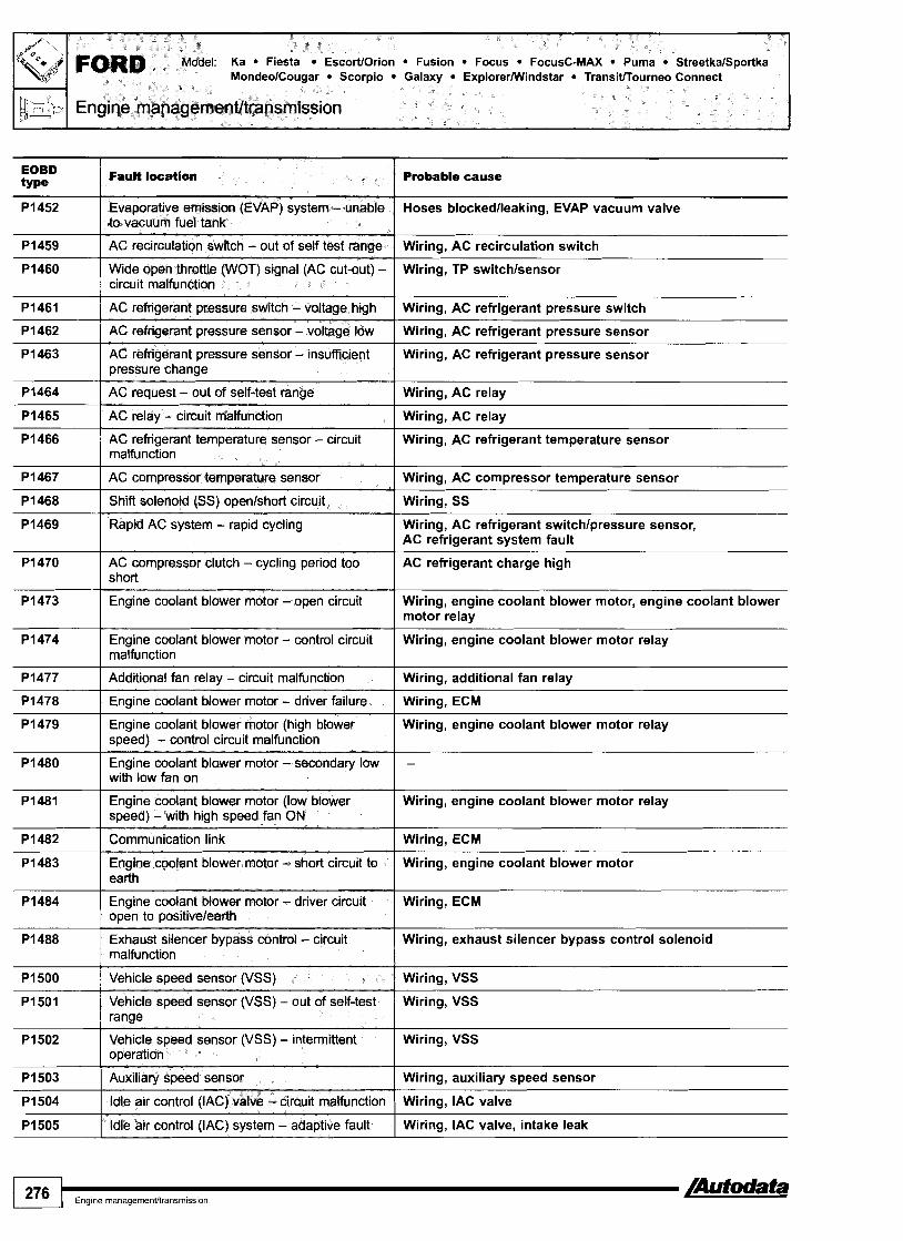
Probable cause EOBD ty Pe
Fault location
Evaporative emission (EVAP) system - unable Hoses blockedlleaking, EVAP vacuum valve to vacuum fuel tank
AC recirculation switch - out of setf test range Wiring, AC recirculation switch
Wide open throttle P O T ) signal (AC cut-out) - circuit malfunction
AC refrigerant pressure switch - voltage high
AC refrigerant pressure sensor - voltage low
AC refrigerant pressure sensor - insufficient pressure change
Wiring, TP switchlsensor
Wiring, AC refrigerant pressure switch
Wiring, AC refrigerant pressure sensor
Wiring, AC refrigerant pressure sensor
AC request - out of self-test range
AC relay - circuit malfunction
Wiring, AC relay
Wiring, AC relay
AC refrigerant temperature sensor - circuit malfunction
Wiring, AC refrigerant temperature sensor
AC compressor temperature sensor Wiring, AC compressor temperature sensor
Wiring, SS Shift solenoid (SS) openlshort circuit
Rapid AC system - rapid cycling Wiring, AC refrigerant switchlpressure sensor, AC refrigerant system fault
AC compressor clutch - cycling period too short
Engine coolant blower motor - open circuit
AC refrigerant charge high
Wiring, engine coolant blower motor, engine coolant blower motor relay
Engine coolant blower motor - control circuit malfunction
Additional fan relay - circuit malfunction
Wiring, engine coolant blower motor relay
Wiring, additional fan relay
Engine coolant blower motor - driver failure Wiring, ECM
Engine coolant blower motor (high blower speed) - control circuit malfunction
Engine coolant blower motor - secondary low with low fan on
Wiring, engine coolant blower motor relay
Engine coolant blower motor (low blower speed) - with high speed fan ON
Communication link
Engine coolant blower motor - short circuit to earth
Wiring, engine coolant blower motor relay
Wiring, ECM
Wiring, engine coolant blower motor
Engine coolant blower motor - driver circuit open to positivelearth
Exhaust silencer bypass control - circuit malfunction
Wiring, ECM
Wiring, exhaust silencer bypass control solenoid
Vehicle speed sensor (VSS)
Vehicle speed sensor (VSS) - out of self-test ranae
Wiring, VSS
Wiring, VSS
Vehicle speed sensor (VSS) - intermittent operation
Wiring, VSS
Auxiliary speed sensor
ldle air control (IAC) valve - circuit malfunction
Wiring, auxiliary speed sensor
Wiring, IAC valve
ldle air control (IAC) system - adaptive fault Wiring, IAC valve, intake leak

scortlOrion Fusion Focus FocusC-MAX Puma StreetkalSportka Scorpio Galaxy ExplorerMlindstar Transitfrourneo Connect
Probable cause
Wiring, air leak, TP sensor, IAC valve
Wiring, TP sensor, IAC valve
Wiring, idle up solenoid
P I 506
P I 507
PI508
Idle air control (IAC) valve - over-speed error
Idle air control (IAC) valve - under-speed error
Idle up solenoid 1 - circuit malfunction
lntake manifold air control solenoid, mechanical fault PI512
P I 51 3
P I 51 6
lntake manifold air control solenoid, mechanical fault
Intake manifold air control solenoid, bank 1 - stuck closed
Intake manifold air control solenoid, bank 2 - stuck closed
Intake manifold air control solenoid, bank 1 - input error
Wiring, intake manifold air control solenoid, ECM
lntake manifold air control solenoid, mechanical fault PI517
PI518 lntake manifold air control solenoid, mechanical fault
Intake manifold air control solenoid, bank 2 - input error
Intake manifold air control solenoid, bank 1 - stuck o w n
lntake manifold air control solenoid, mechanical fault PI519
P I 520 Wiring, intake manifold air control solenoid, ECM
Intake manifold air control solenoid, bank 1 - stuck closed
Intake manifold air control solenoid - circuit malfunction
PI530 I AC compressor clutch - open circuit Wiring, AC compressor clutch
Accelerator pedal movement during test PI531
PI532 Wiring, ECM
Invalid test - accelerator pedal movement during test
Intake manifold communication, bank 2 - control circuit malfunction
Wiring
Wiring
P I 533
P I 534
PI536 Handbrake warning lamp switch - circuit malfunction
Air assisted injector - circuit malfunction
Restraint deployment indicator - circuit malfunction
Wiring, handbrake warning lamp switch
lntake manifold air control solenoid, mechanical fault PI537
PI538 lntake manifold air control solenoid, mechanical fault
Intake manifold air control solenoid, bank 1 - stuck open
Intake manifold air control solenoid, bank 2 - stuck open
Wiring, AC compressor clutch P I 539
P I 538 Wiring, intake manifold air control solenoid, mechanical fault
AC compressor clutch - over currenffshort circuit
Intake manifold air control solenoid - range1 performance
PI542 1 Primary ECM ID circuit (dual ECM application) Wiring
Wiring, engine coolant heater relay, ECM PI543
PI544 Wiring, engine coolant heater relay, ECM
Engine coolant heater, A - control circuit malfunction
Engine coolant heater, B - control circuit malfunction
Wiring, EGR solenoid, ECM PI545
PI546 Wiring, EGR solenoid, ECM
Exhaust gas recirculation (EGR) control - open circuit
Exhaust gas recirculation (EGR) control - voltage low
Wiring, EGR solenoid, ECM P I 547
P I 549 Wiring, mechanical fault, ECM
Exhaust gas recirculation (EGR) control - voltage high
Intake manifold air control solenoid, bank 1 - control circuit malfunction

FORD Model: Ka Fiesta EscortIOrion Fusion Focus FocusC-MAX Puma StreetkalSportka MondeolCougar Scorpio Galaxy ExplorerMlindstar Transitfrourneo Connect
El Engine management/transmission
Probable cause EOBD Fault location
P I 550 Power steering pressure (PSP) sensor - out of self test range
Wiring, PSP sensor
PI551 I lnjector 1 - rangelperformance problem Wiring, injector, ECM
Wiring, injector, ECM
Wiring, injector, ECM
P I 552
P I 553
PI554 1 lnjector 4 - rangelperformance problem
- -
Injector 2 - rangelperformance problem
Injector 3 - rangelperformance problem
Wiring, injector, ECM
PI555 1 lnjector 5 - rangelperformance problem Wiring, injector, ECM
PI556 1 lnjector 6 - rangelperformance problem Wiring, injector, ECM
Wiring, injector, ECM
Wiring, injector, ECM
P I 557
P I 558
PI563 1 Fuel injection pump - engine stop request
Injector 7 - rangelperformance problem
Injector 8 - rangelperformance problem
Wiring, fuel injection pump, ECM
P I 564 Fuel injection pump - reduced fuel mode request
Wiring, fuel injection pump, ECM
Wiring, cruise control master switch, ECM P I 565
P I 566 Wiring, cruise control master switch, ECM
Cruise control master switch - out of range, voltage high
Cruise control master switch - out of range, voltage low
PI567 1 Cruise control -output driver circuit malfunction Wiring, cruise control actuator, ECM
P I 568 Cruise control - unable to hold speed Wiring, cruise control actuator, cruise control actuator control cable
Wiring, BPP switch P I 572
PI573 1 Throttle position (TP) not available
Brake pedal position (BPP) switch - circuit malfunction
PI574 ( Throttle position (TP) sensor - outputs disagree Wiring, TP sensor
P I 575 Accelerator pedal position (APP) sensor - out of self test range
Wiring, APP sensor, ECM
P I 576 Accelerator pedal position (APP) sensor - not available
Wiring, APP sensor, ECM
Wiring, APP sensor, ECM P I 577
P I 578 Wiring, throttle body, ECM
Accelerator pedal position (APP) sensor - outputs disagree
Throttle actuator control (TAC) monitor - power less than demand
Wiring, throttle body, ECM P I 579
P I 580 Wiring, throttle body, ECM
Throttle actuator control (TAC) monitor - power limiting mode
Throttle actuator control (TAC) monitor - ECM override
Throttle actuator control (TAC) monitor - malfunction
Wiring, throttle body, ECM
Wiring, throttle body, ECM P I 582
P I 583 Wiring, throttle body, ECM
Throttle actuator control (TAC) monitor - data available
Throttle actuator control (TAC) monitor - cruise disablement
Throttle body P I 584
P I 585 Wiring, throttle body, ECM
Throttle actuator control (TAC) monitor -throttle body malfunction
Throttle actuator control (TAG) monitor - malfunction

Model: Ka Fiesta EscorVOrion Fusion Focus FocusC-MAX Puma StreetkalSportka MondeolCougar Scorpio Galaxy ExplorerMlindstar Transitrrourneo Connect
FORD
Engine management/transmission
EOBD type
PI586
Fault location Probable cause
Wiring, ECM Throttle actuator control (TAC) monitor - communication error
Throttle actuator control (TAC) monitor - modulated command malfunction
Wiring, throttle body, ECM
Throttle actuator control (TAC) monitor - detected loss of return surinq
Throttle body
Throttle actuator control (TAC) monitor - unable to control to desired throttle angle
Wiring, throttle body, ECM
Loss of keep alive power supply Wiring, fuses, battery
Keep alive memory - test failure
Signal monitoring malfunction
-- - -
Wiring, ECM
Wiring, injection pump control module, ECM
Malfunction indicator lamp (MIL) - driver failure Wiring, ECM
lnteractive reprogramming code - replace module
ECM
lnteractive reprogramming code - diagnose further
lnteractive reprogramming code - repeat test, engine is cranking
lnteractive reprogramming code - TBD --
Interactive reprogramming code - TBD
lnteractive reprogramming code - erase error
lnteractive reprogramming code - erase error, low voltage
lnteractive reprogramming code - block program error
lnteractive reprogramming code - block program error, low voltage
lnteractive reprogramming code - total checksum error
lnteractive reprogramming code - overlay checksum error
Engine coolant blower motor, driver - open circuit to positive
AC system - open circuit
Engine control module (ECM) - supply voltage out of range
Wiring, ECM
Wiring
Battery, alternator
Engine control module (ECM) - supply voltage out of range
Engine control module (ECM) - supply voltage
Wiring, fuses, battery, engine control relay
Wiring, fuses, battery, engine control relay
Engine control module (ECM) - internal voltage regulator
Earth points, ECM
Engine control module (ECM) - internal reference voltage
Engine control relay
Earth points, ECM
- -- - -
Wiring, engine control relay
Alternator fault sensor Alternator fault sensor - circuit malfunction
Keep alive power supply - voltage too low Wiring, battery, alternator
/Autodata Engine rnanagernentltransrn~ssion 279

Ka Fiesta EscorUOrion Fusion Focus FocusC-MAX Puma StreetkalSportka MondeolCougar Scorpio Galaxy ExplorerMlindstar Transitrrourneo Connect I
I I
Pi658 I Fuel injection pump - supply voltage out of I Wiring, engine control relay, ECM
P i 643
P i 644
Pi650
Pi651
P i 656
Pi657
Pi665 I Fuel injection pump - communication I Wiring, fuel injection pump control module, ECM
malfunction
Controller area network (CAN) - module network circuit error
Fuel pump (FP) speed control - circuit malfunction
Power steering pressure (PSP) switch - out of self-test range
Power steering pressure (PSP) switch - input
Controller area network (CAN) - circuit malfunction
Controller area network (CAN) - malfunction
P i 659
P i 660
Pi661
P i 662
P i 663
P i 664
Wiring
Wiring, FP control module, ECM
Wiring, PSP switch
Wiring, PSP switch
Wiring
Wiring, ECM
range
Fuel injection pump - supply voltage
Engine control module (ECM) - output check circuit - voltage high
Engine control module (ECM) - output check circuit - voltage high
ECM EN output - circuit malfunction
Fuel demand - command signal output circuit malfunction
Fuel injection pump - malfunction
P i 666
Pi667
Wiring, engine control relay, ECM
System voltage high, ECM
System voltage low, ECM
Wiring, fuses, engine control relay
Wiring, ECM
Wiring, fuel injection pump, ECM
P i 668
P i 669
P i 670
Pi673
P i 674
Fuel injection pump -crankshaft position (CKP) sensor synchronisation
Camshaft position (CMP) sensor - circuit malfunction
P i 690
Wiring, CKP sensor, injector needle lift sensor, fuel injection pump control module, ECM
Wiring, CMP sensor
Fuel injection pump - communication signal lost
Fuel injection pump - monitor, mechanical fault
Electronic feedback signal not detected
ABS warning lamp - control circuit malfunction
Engine control module (ECM) - software corrupted
Wiring, fuel injection pump control module, ECM
Wiring, fuel injection pump, ECM
-
Wiring, ABS control unit, ECM
ECM
Turbocharger (TC) wastegate regulating valve - circuit malfunction
Wiring, TC wastegate regulating valve

EOBD type -.
PI695
PI700
PI701
P I 702
I - I
PI706 I High vehicle speed observed in park 1 Wiring, TR sensor, ECM
Fault location
P I 703
P I 704
PI705
Probable cause
Controller area network {CAN) data bus - fuel injection pump data
Transmission - neutral position fault
Reverse gear engagement error
Transmission range (TR) sensor - circuit intermittent
Wiring, fuel injection pump control module, ECM
Wiring, transmission
-
Wiring, TR sensor
Brake pedal position (BPP) switch - out of self- test range
Transmission range (TR) sensor - circuit not indicating paMneutral during self test
Transmission range (TR) switch - not in PIN durina self-test
P I 707
P I 709
Wiring, BPP switch
Wiring, TR sensor, ECM
Wiring, TR switch, ECM
P I 71 0
P I 71 1
PI714 I Shift solenoid (SS) A - inductive fault I Wiring, SS, ECM
Transfer case neutral warning tamp - circuit malfunction
PaMneutral position (PNP) switch/clutch pedal position (CPP) switch - out of self-test range
P I 71 2
PI713
P I 71 5 I Shift solenoid (SS) B - inductive fault 1 Wiring, SS, ECM
Wiring, neutral position switch, instruments
Wiring, PNP switch, CPP switch, ECM
Transmission control module - solenoid1 internal earth circuit malfunction
Transmission fluid temperature {TFT) sensor - out of self test ranae
Wiring, SS solenoid
Wiring, TFT sensor
Transmission torque reduction system - request signal error
Transmission fluid temperature (TFT) sensor - rannelperformance
Wiring, TP sensor, ECM
Wiring, TFT sensor
PI716
PI717
P I 71 8
P I 727 Coast clutch solenoid {CCS) solenoid - ( Wiring, CCS solenoid, ECM inductive fault
PI725
PI726
Shift solenoid (SS) C - inductive fault
Shift solenoid (SS) D - inductive fault
Transmission fluid temperature (TFT) sensor - ranaelwrforrnance
PI732 1 Transmission shift malfunction, 2-3 I Transmission mechanical fault
Wiring, SS, ECM
Wiring, SS, ECM
Wiring, TFT sensor
Insufficient engine speed increase during self test
Insufficient engine speed decrease during self test
PI728
PI729
PI733 1 Transmission shift malfunction, 3-4 Transmission mechanical fault
Insufficient engine speed increase during self test
Insufficient engine speed decrease during self test
Transmission slip
Transmission range (TR) switch (4x4) - circuit malfunction
Transmission mechanical fault
Wiring, TR switch
PI734
PI740
PI741
Transmission shift malfunction, 4-5
Torque converter clutch (TCC) solenoid - inductive fault
Transmission mechanical fault
Wiring, TCC solenoid, ECM
110
Torque converter clutch (TCC) solenoid - control error
Wiring, TCC solenoid, ECM

FORD Model: Ka Fiesta EscorUOrion Fusion Focus FocusC-MAX Puma StreetkalSportka MondeolCougar Scorpio Galaxy ExplorerMlindstar Transitrrourneo Connect
k d U 1 Engine managernent/transmission
EOBD type
Fault location Probable cause
Wiring, TCC solenoid, ECM PI742 Torque converter clutch (TCC) solenoid - circuit malfunction
Wiring, TCC solenoid, ECM P I 743
PI744 Wiring, TCC solenoid, ECM
Toque converter clutch (TCC) solenoid - circuit malfunction
Torque converter clutch (TCC) solenoid -circuit performance
P I 746 Transmission fluid pressure (TFP) control solenoid A - open circuit
Wiring, TFP control solenoid
Transmission Ruid pressure (TFP) control
Transmission fluid pressure (TFP) control solenoid A
Wiring, TFP control solenoid
Wiring, TFP control solenoid
Wiring, TFP control solenoid P I 749
P I 750
PI754 Coast clutch solenoid (CCS) valve - circuit malfunction
Transmission fluid pressure (TFP) control solenoid A failed low
Clutch - adaptive learning not completed
Wiring, CCS valve
P I 760 Transmission fluid pressure (TFP) control solenoid A - intermittent short circuit
Wiring, TFP control solenoid
PI761 I Shift solenoid (SS) C - perfomance Wiring, SS
P I 762 I Transmission overdrive band - failed Off
Wiring, fuel injection timing solenoid PI765
P I 766 Wiring, SS
Fuel injection timing solenoid - circuit malfunction
Shift solenoid (SS) D - performance
P I 767 Torque converter clutch (TCC) solenoid - circuit malfunction
Wiring, TCC solenoid
Wiring, transmission mode selection switch P I 768
P I 769
P I 770 I Clutch solenoid - circuit malfunction
Performancelnormallwinter mode input
Transmission torque modulation fault (AG4 transmission)
Wiring, clutch solenoid
PI771 I Shift solenoid (SS) E - perfomance Wiring, SS
Wiring, fuel fired heater
Wiring, transmission warning lamp
PI773
P I 779
CAN data bus - fuel fired heater malfunction
Transmission warning lamp - circuit malfunction
Wiring, transmission mode selection switch P I 780
P I 781 Wiring, TR switch
Transmission mode selection switch, 010 Cancel - circuit out of self test range
Transmission range (TR) switch (4x4L) - out of self test range
Wiring, transmission mode selection switch PI782
P I 783 Transmission mechanical fault
Transmission mode selection switch, perforrnanceleconomy - out of self test range
Transmission over temperature condition
P I 784 Transmission mechanical failure - first and reverse
Transmission mechanical fault
Transmission mechanical fault PI785
P I 786
PI787 ( Transmission downshiff error, 2-1
Transmission mechanical failure - first and second
Transmission downshift error, 3-2

Model: Ka Fiesta EscortlOrion Fusion Focus FocusC-MAX Puma StreetkalSportka MondeolCougar Scorpio Galaxy ExplorerMlindstar Transitffourneo Connect FORD
Engine managernentltransmission
Probable cause EOBD type
PI788 I Transmission fluid pressure (TFP) control solenoid B open circuit
Wiring, TFP control solenoid
Wiring, TFP control solenoid PI789
P I 792 Wiring, BARO sensor
Transmission fluid pressure (TFP) control solenoid B short circuit
Barometric pressure (BARO) sensor - circuit malfunction
PI794 1 Engine control module (ECM) - supply voltage Fuses, wiring, battery, alternator
PI795 1 CAN data bus - level inconsistent Wiring, ECM
Wiring, transmission clutch interlock safety switch, mechanical fault
- -
PI800 I Transmission clutch intertock safety switch -
Wiring, transmission clutch interlock safety switch PI801
circuit malfunction
Transmission clutch intertock safety switch - open circuit
Wiring PI802
PI803 Wiring
Transmission clutch interlock safety switch - short circuit to positive
Transmission clutch intertock safety switch - short circuit to earth
Wiring, selection lamp, instruments, ECM PI804
PI805 Wiring, selection lamp, instruments, ECM
Transmission mode selection lamp, 4x4 high - circuit malfunction
Transmission mode selection lamp, 4x4 high - open circuit
PI806 Transmission mode selection lamp, 4x4 high - short circuit to positive
Wiring, selection lamp, instruments, ECM
Wiring, selection lamp, instruments, ECM PI807
PI808 Wiring, selection lamp, instruments, ECM
Transmission mode selection lamp, 4x4 high - short circuit to earth
Transmission mode selection lamp, 4x4 low - circuit malfunction
Transmission mode selection lamp, 4x4 low - open circuit
Wiring, selection lamp, instruments, ECM
Wiring, selection lamp, instruments, ZM PI810
PI811 Wiring, selection lamp, instruments, ECM
Transmission mode selection lamp, 4x4 low - short circuit to positive
Transmission mode selection lamp, 4x4 low - indicator short circuit to earth
Wiring, transmission mode selection switch, ECM PI812
PI813 Wiring, transmission mode selection switch, ECM
Transmission mode selection switch, 4x4 - circuit malfunction
Transmission mode selection switch, 4x4 - ooen circuit
Transmission mode selection switch, 4x4 - short circuit to positive
Wiring, transmission mode selection switch, ECM
Wiring, transmission mode selection switch, ECM PI815
PI816 Wiring, NP switch
Transmission mode selection switch, 4x4 - short circuit to earth
Neutral position (NP) switch - circuit malfunction
PI817 I Neutral position (NP) switch - open circuit Wiring, NP switch
Neutral position (NP) switch - short circuit to
Neutral position (NP) switch - short circuit to
Wiring
Wiring
Wiring, shift relay PI820 Transmission system relay, transfer case clockwise shifl - circuit malfunction

EOBD type
Fault focatlon
--
Probable cause
PI821 Transmission system relay, transfer case clockwise shift - open circuit
Wiring, shift relay
Wiring, shift relay
Wiring, shift relay
Wiring, transmission system relay
P I 825 Transmission system relay, 4x4 clutch - open I circuit Wiring, transmission system relay
Wiring, transmission system relay PI826
P I 827 Wiring, transmission system relay
Transmission system relay, 4x4 clutch - short circuit to battery
Transmission system relay, 4x4 low clutch - short circuit to earth
P I 828 Transmission system relay, transfer case anticlockwise shift - circuit malfunction
Wiring, transmission system relay
P I 829 Transmission system relay, transfer case anticlockwise shift - oDen circuit
-- -- - -
Wiring, transmission system relay
P I 830 I Transmission system relay, transfer case anticlockwise shift - short circuit to positive
Wiring, transmission system relay
Wiring, transmission system relay PI831
P I 832 Wiring, differential lock actuator
Transmission system relay, transfer case anticlockwise shift - short circuit to earth
Differential lock actuator, transfer case - circuit malfunction
Wiring, differential lock actuator P I 833
P I 834 Wiring, differential lock actuator
Differential lock actuator, transfer case - open circuit
Differential lock actuator, transfer case - short circuit to positive
Wiring, differential lock actuator P I 835
PI836 - -
Wiring, speed sensor
Differential lock actuator, transfer case - short circuit to earth
Transfer case front shaft speed sensor - circuit malfunction
P I 837 Transfer case rear shaft speed sensor - circuit malfunction
Wiring, speed sensor
Wiring, transfer case shift motor
Wiring, transfer case shift motor
P I 838
P I 839
P I 840 Transfer case shifl motor - short circuit to I positive
Transfer case shift motor - circuit malfunction
Transfer case shift motor - open circuit
Wiring, transfer case shift motor
PI841 I Transfer case shift motor - short circuit to earth Wiring, transfer case shift motor
P I 842 Differential lock switch, feedback - transfer case - circuit malfunction
Wiring, differential lock switch
P I 843 Differential lock switch, feedback - transfer case - open circuit
Wiring, differential lock switch
Wiring, differential lock switch P I 844
P I 845 Wiring, differential lock switch
Differential lock switch, feedback - transfer case - short circuit to positive
Differential lock switch, feedback - transfer case - short circuit to earth
Wiring, transfer case contact plate P I 846 Transfer case contact plate A circuit malfunction

EOBD type
Probable cause
PI847
P I 848
PI853 Transfer case contact plate B short circuit to Wiring, transfer case contact plate I earth
PI849
PI850
PI851
PI852
I
PI855 1 Transfer case contact plate C open circuit I Wiring, transfer case contact plate
Transfer case contact plate A open circuit
Transfer case contact plate A short circuit to wsiiive
Transfer case contact plate A short circuit to earth
Transfer case contact plate B circuit malfunction
Transfer case contact plate B open circuit
Transfer case contact plate B short circuit to wsitive
PI854
Wiring, transfer case contact plate
Wiring, transfer case contact plate
Wiring, transfer case contact plate
Wiring, transfer case contact plate
Wiring, transfer case contact plate
Wiring, transfer case contact plate
PI858 Transfer case contact plate D circuit I Wiring, transfer case contact plate malfunction
Transfer case contact plate C circuit malfunction
P I 856
P I 857
Wiring, transfer case contact plate
PI861 Transfer case contact plate D short circuit to Wiring, transfer case contact plate
Transfer case contact plate C short circuit to positive
Transfer case contact plate C short circuit to earth
PI859
P I 860
PI862 1 Transfer case contact plate -circuit malfunction I Wiring, transfer case contact plate
Wiring, transfer case contact plate
Wiring, transfer case contact plate
Transfer case contact plate D open circuit
Transfer case contact plate D short circuit to positive
PI865 Transfer case contact plate - short circuit to Wiring, transfer case contact plate / earth
Wiring, transfer case contact plate
Wiring, transfer case contact plate
PI863
P I 864
PI866 Transfer case system concern - servicing required 1 -
PI867 1 Transfer case contact plate -circuit malfunction I Wiring, transfer case contact plate
- -
Transfer case contact plate - open circ~~it
Transfer case contact plate - short circuit to battery
- - -
Wiring, transfer case contact plate
Wiring, transfer case contact plate
P I 870 Transmission mode selection switch, mechanical transfer case 4x4 - circuit
P i 871 Transmission mode selection switch, mechanical transfer case 4x4 - short circuit to positive
P I 868
PI869
Wiring, transmission mode selection switch
Wiring, transmission mode selection switch
Transmission mode selection lamp, 4x4 - circuit malfunction
Transmission mode selection lamp, 4x4 - short circuit to positive
Wiring, selection lamp, instruments, ECM
Wiring, selection lamp, instruments, ECM
P I 872
PI873
+I
Transmission mode selection lamp, axle lock - mechanical 4x4 - circuit malfunction
Transmission mode selection lamp, axle lock - mechanical 4x4 - short circuit to positive
Wiring, transmission mode selection lamp
Wiring, transmission mode selection lamp

FORD Model: Ka Fiesta EscortlOrion Fusion Focus FocusC-MAX Puma StreetkalSportka MondeolCougar Scorpio Galaxy ExplorerMlindstar Transitrrourneo Connect
I Probable cause I 1
P I 874 I Transfer case hall effect sensor - circuit 1 Wiring, hall effect sensor
PI875
PI876
PI877
PI880 Transmission mode control solenoid, transfer Wiring, transmission mode control solenoid case disengaged - short circuit to positive
malfunction
Transfer case hall effect sensor -short circuit to wsitive
Pi878
PI879
-
Wiring, hall effect sensor
Transmission mode contrd solenoid, transfer case 2x4 - circuit malfunction
Transmission mode control solenoid, transfer case 2x4 - short circuit to positive
Wiring, transmission mode control solenoid
Wiring, transmission mode control solenoid
Transmission mode control solenoid, transfer case disengaged - circuit malfunction
Transmission mode control solenoid, transfer case disengaged - open circuit
PI881
Pi882
Wiring, transmission mode control solenoid
Wiring, transmission mode control solenoid
P I 883
P I 884
P I 890 I Transmission 4x4 mode select, return - circuit - malfunction
Engine coolant low' warning lamp switch - circuit malfunction
Engine coolant 'low' warning lamp switch - short circuit to earth
PI885
P I 886
P I 889
Wiring, engine coolant 'low' warning lamp switch
Wiring, engine coolant 'low' warning lamp switch
Engine coolant 'low' warning lamp switch - circuit malfunction
Engine coolant 'low' warning lamp switch - short circuit to earth
P I 893 Axle disconnect engagement solenoid - Wiring, axle disconnect engagement solenoid voltage low
Wiring, engine coolant 'low' warning lamp switch
Wiring, engine coolant 'low' warning lamp switch
Transmission mode control solenoid, transfer case disengaged - short circuit to earth
Transmission - 4x4 initialization failure
Oil pressure pump - performance
PI891
PI892
PI894 1 Axle disconnect disengagement solenoid - I Wiring, axle disconnect disengagement solenoid
Wiring, transmission mode control solenoid
- -
I voltage high I
Transfer case contact plate - open circuit
Axle disconnect engagement solenoid -
Pi895 I Axle disconnect disengagement solenoid - I Wiring, axle disconnect disengagement solenoid
Wiring, transfer case contact plate
Wiring, axle disconnect engagement solenoid
I voltage low I
PI898 I Transmission mode selection lamp, axle Wiring, selection lamp disconnect - voltage high
P I 896
Pi897
I I
P I 899 I Transmission mode setection lamp, axle I Wiring, selection lamp
Axle disconnect engagement position sensor - voltage high
Axle disconnect engagement position sensor - voltage low
Wiring, axle disconnect engagement position sensor
Wiring, axle disconnect engagement position sensor
P I 900
-
PI901
disconnect - voltage low
Transmission output shaft speed sensor - circuit intermittent
Wiring, transmission output shaft speed sensor
~ransmission turbine shaft speed (TSS) sensor - circuit intermittent
Wiring, TSS sensor

Model: Ka Fiesta Escort/Orion Fusion Focus FocusC-MAX Puma StreetkalSportka MondeolCougar Scorpio Galaxy ExplorerMlindstar Transitrrourneo Connect
FORD
Engine managernentltransrnission
I Probable cause
PI903 1 Transmission kick-down relay - voltage low 1 Wiring, transmission kick-down relay
PI902
PI904 ( Transmission kick-down relay - voltage high ] Wiring, transmission kick-down relay I I
PI905 I Control module configured for end of line test I -
Transmission kick-down relay - control circuit malfunction
Wiring, transmission kick-down relay
PI907 Kick-down relay (A4LD transmission) - hold, Wiring, kick-down relay openlshort circuit
PI906
PI910 ( Reversing lamp, control - open circuit I Wiring, reversing lamp switch
mode
Kick-down relay (A4LD transmission) - pull on, openlshort circuit
PI908
PI909
Wiring, kick-down relay
PI915 ( Sensor earth, A - voltage high ] Wiring, ECM
Transmission fluid pressure (TFP) solenoid (A4LD transmission) - openlshort circuit
Transmission fluid temperature (TFT) sensor (A4LD transmission) - openlshort circuit
PI911
PI912
P I 91 3
PI914
PI916 I Sensor earth, B - open circuit I Wiring, ECM
Wiring, TFP solenoid
Wiring, TFT sensor
PI917 I Sensor earth, B - voltage low I Wiring, ECM
Reversing lamp, control - voltage low
Reversing lamp, control - voltage high
Sensor earth, A - open circuit
Sensor earth, A - voltage low
Wiring, reversing lamp switch
Wiring, reversing lamp switch
Wiring, ECM
Wiring, ECM
PI921 I Transmission range (TR) signal I Wiring, TR sensorlswitch
PI918
PI919
PI920
PI933 1 Fuel level signal I Wiring, fuel gauge tank sensor
PI934 1 Vehicle speed signal 1 Wiring, VSS
Sensor earth, B - voltage high
Engine coolant temperature signal, TCM
Engine speed signal, TCM
PI935 1 Brake switchlsensor signal ( Wiring, BPP switchlsensor
- - - - - - -
Wiring, ECM
Wiring, ECT sensor
Wiring
PI938 1 Fuel fired heater, control - voltage low 1 Wiring
P I 936
P I 937
PI939 1 Fuel fired heater, control - voltage high ( Wiring
Clutch switchlsensor signal
Fuel fired heater, control - open circuit
UlO4l I Communication link - invalidlrnissing for vehicle speed
- -
Wiring, CPP switchlsensor
Wiring
U1021
U1039
U1075 Communication link - invalidlmissing for engine - oil temperature (EOT)
Communication link - invalidlmissing for AC clutch input
Communication link - invalidlmissing for vehicle speed
U1051
U1073
-
-
Communication link - invalidlmissing for brake input
Communication link - invalidlmissing for engine coolant fan status
-
-

Escort/Orion Fusion Focus FocusC-MAX Puma StreetkalSportka
EOBD type
U1089
U 1098
U1130
U1131
U1135
U1147
U1243
U1262
U1341
U1451
U1900
U2023
U2050
U2051
U2064
U2195
Fault location
Communication link - invaiidlmissing for suspension
Communication link - invalidlmissing for cruise control
Communication link - invalidlmissing for fuel system
Communication link - invalidlmissing for fuel pump (FP) status
Communication link - invalidlmissing for ignition switchktarter
Communication link - invalidlmissing for vehicle security
Communication link - invalidlmissing for exterior environment
Communication link - bus fault
Communication link - invalidlmissing for function read vehicle speed
Communication link - invalidlmissing data from immobilizer control module, vehicle immobilized
Controller area network (CAN) - bus fautt
Fault received from external node
No application present
One or more calibration files missinglcompt
Warning lamp requested by another control module
Communication link - invalid data from steering column switches
Probable cause
-
-
-
-
-
-
-
- -
Wiring, immobilizer control module
Wiring
- - - -
Wiring, steering column switches
cj

Fiesta 1,111,311, EscorVOrion 1,311,41
Engine code: F4A, F4B, F6A, F6B, F6C, F6D, F6E, F6F, F6G, G6A, LHA, LJA, LJB, LJC, LJD, LJE, LJF, J6A, J6B
Ford CFi Ford EEC IV
I Engine managemenfftransmission I
l,111,3/1,41RS Turbo
NOTE: Engine control module (ECM) incorporates transmission control function.
General information Refer to the front of this manual for general test conditions, terminology, detailed descriptions of wiring faults and a general trouble shooter for electrical and mechanical faults. Trouble codes are displayed by using an LED connected to the data link connector (DLC). The EChl fault memory can also be checked and erased using diagnostic equipment connected to the data link connector (DLC).
Accessing Engine at normal operating temperature. Ensure ignition switched OFF. Bridge data link connector (DLC) terminals 2 and 3 0.
EscorUOrion CVH
Connect LED test lamp negative connection to DLC terminal 2 0. Connect LED test lamp positive connection to DLC terminal 1 0. Switch ignition ON. Check that LED illuminates. Trouble codes are displayed after 10-25 seconds rn [A]. Note trouble codes. Compare with trouble code table. Trouble codes are displayed by illuminated LED switching OFF for approximately 1 second rn [B]. Each trouble code consists of two groups. LED illuminates for approximately 2 seconds between each group rn [C].
NOTE: Trouble codes ending in '0' are displayed with only 1 group.
LED illuminates for approximately 5 seconds between each trouble code rn [Dl. For example: Trouble code 24 displayed. Trouble code(s) are displayed twice.

(bpi I- Engine managementltransmission
ON
OFF
b-b~ ' 4 I- A B C D
Erasing Ensure ignition switched OFF. Disconnect engine control module (ECM) harness multi-plug. The engine control module (ECM) fault memory can also be erased using diagnostic equipment connected to the data link connector (DLC).
Trouble code identification
Flash type
12 I Volume air flow (VAF) sensor 1 I Wiring, VAF sensor, air leak, air restriction, ECM
Command code
System pass
13 I Engine coolant temperature (ECT) sensor I Wiring, ECT sensor, ECM
Fault location --
-
-
Probable cause
17 I Manifold absolute pressure (MAP) sensor I Wiring, MAP sensor, ECM
14
15
18 I Battery voltage - low I Wiring, battery
19 I Keep Alive Memory (KAM) failure I ECM
Intake air temperature (IAT) sensor
Throttle position (TP) sensor
Wiring, IAT sensor, ECM
Wiring, TP sensor, ECM
22 ( Volume air flow (VAF) sensor 1 - voltage high / Wiring, VAF sensor, ECM
20
21
Engine coolant temperature (ECT) sensor - voltage high
I Wiring, ECT sensor, ECM
Separation code
Ignition signal - erratic
-
Wiring, CKP sensor, alternator
24
25
Intake air temperature (IAT) sensor
Throttle position (TP) sensor - voltage high
Wiring, IAT sensor, ECM
Wiring, TP sensor, ECM

Model. Fiesta 1,111,311,411,6 EscorUOrion l,3/1,4/1,6
Flash type Fault location I Probable cause
Engine managemenVtransmission a)Lr kl-5 2
28 I Heated oxygen sensor (H02S) - mixture rich I Wiring, fuel supply, injector control, HOZS, ECM
27
3 1 I Memory failure I ECM
Manifold absolute pressure (MAP) sensor - voltage high
34 I Intake air temperature (IAT) sensor 1 Wiring, IAT sensor, ECM
Wiring, MAP sensor, ECM
32
33
3 5 I Throttle position (TP) sensor - voltage low I Wiring, TP sensor, ECM
Volume air flow (VAF) sensor 1 - voltage low
Engine coolant temperature (ECT) sensor - voltaae low
38 I Heated oxygen sensor (H02S) - mixture weak I Wiring, fuel supply, injector control, HOZS, ECM
-
Wiring, VAF sensor, ECM
Wiring, ECT sensor, ECM
36
37
42 I Manifold absolute pressure (MAP) sensor - signal I Wiring, MAP sensor, ECM
Volume air Row (VAF) sensor 2 - voltage low
Manifold absolute pressure (MAP) sensor - voltaae low
41
43 I Throttle position (TP) sensor - signal I Wiring, TP sensor, ECM
- -
Wiring, VAF sensor, ECM
Wiring, MAP sensor, ECM
44 I Blip test (throttle open) not performed I -
Volume air flow (VAF) sensor 1 - signal Wiring, VAF sensor, ECM
45
46
49 I Exhaust gas recirculation (EGR) valve I Wiring, restrictedlleaking EGR pipes, EGR valve, ECM
47
48
48
Vehicle speed sensor (VSS)
Idle air control (IAC) valve - maximum engine speed
53 ( Octane plug 1 - short circuit 1 -
Wiring, VSS, ECM
Wiring, IAC valve, ECM
Idle air control (IAC) valve - minimum engine speed
Closed throttle position (CTP) switch (CFi)
Idle air control (IAC) valve (except CFi)
50
51
52
Wiring, IAC valve, ECM
Wiring, CTP switch, ECM
Wiring, IAC valve, ECM
57 I Throttle opened too early during test I -
Identification code for engine control module (ECM)
AC 'ON' during test
AT in 'D' during test
54
55
56
58 I Phasing of ignition pick-uplspark output signals I Wiring, CKP sensor, ignition control module (ICM), ECM
-
-
-
Mixture adjustment resistor
Octane plug 2 - short circuit
Idle speed adjust - short circuit
Knock sensor (KS)
Wiring, air leaks, vacuum leaks, MAP sensor, mixture adjustment resistor, injectors, spark plugs
- -
Wiring, fuel quality, ignition timing, KS, ECM
60 I Start of service set mode I -
61 I Power loss - cylinder 1 I Compression, spark plugs
62 I Power loss - cylinder 2 I Compression, spark plugs
63
64
Power loss - cylinder 3
Power loss - cylinder 4
Compression, spark plugs
Compression, spark plugs

Flash type I Probable cause
69 I Turbocharger (TC) wastegate reguiating valve I Wiring, valve, turbocharger, ECM
70 I End of service set mode I -
7 1
72
76 I Brake pedal position (BPP) switch - AT I Wiring, BPP switch, brake pedal, ECM
72
73
74
7 5
Secondary air injection (AIR) solenoid
Exhaust gas recirculation (EGR) solenoid - E F
8 1 I Exhaust gas recirculation (EGR) solenoid I Wiring, blockedlleaking pipes, EGR solenoid, ECM
Wiring, AIR solenoid, blockedlleaking pipes, ECM
Wiring, blockedlleaking pipes, EGR solenoid, ECM
Turbocharger (TC) wastegate regulating valve
Evaporative emission (EVAP) canister purge valve
Fuel pump
Toroue converter clutch (TCC) lock-uo solenoid
77
78
82 Exhaust gas recirculation (EGR) backpressure Wiring, blockedlleaking pipes, EGR backpressure transducer - voltage below minimum I transducer, ECM
Wiring, TC wastegate regulating valve, blockedlleaking pipes, ECM
Wiring, EVAP canister purge valve, ECM
Wiring, fuel pump relay, fuel pump, ECM
Wiring, lock-up solenoid, transmission fault, ECM
83 Exhaust gas recirculation (EGR) backpressure Wiring, blockedlleaking pipes, EGR backpressure transducer - voltage high I transducer, ECM
Kickdown actuated
Power steering pressure (PSP) switch - not activated
-
Wiring, PSP switch, power steering pump, power steering system pressure, ECM
84
91
4
Exhaust gas recirculation (EGR) backpressure transducer - voltage tow
Heated oxygen sensors (H02S) - multi-plugs interchanged
Wiring, blockedlleaking pipes, EGR backpressure transducer, ECM
Wiring, multi-plugs

Model: Escort 1,311,4
Year: 1995-96
Engine code: F6B, F6D, F6E, F6F, F6G, G6A, J6A, J6B
System: Ford CFi
CFi
NOTE: Engine control module (ECM) incorporates transmission control function.
General information Refer to the front of this manual for general test conditions, terminology, detailed descriptions of wiring faults and a general trouble shooter for electrical and mechanical faults. Trouble codes are displayed by using an LED connected to the data link connector (DLC). The ECM fault memory can also be checked and erased using diagnostic equipment connected to the data link connector (DLC).
Accessing Engine at normal operating temperature. Ensure ignition switched OFF. Bridge data link connector (DLC) terminals 4 and 11 0. Connect LED test lamp negative connection to DLC terminal 4 0. Connect LED test lamp positive connection to DLC terminal 3 0. Switch ignition ON. Check that LED illuminates. Trouble codes are displayed after 10-25 seconds H [A]. Note trouble codes. Compare with trouble code table. Trouble codes are displayed by illuminated LED switching OFF for approximately 1 second H [B]. Each trouble code consists of two groups. LED illuminates for approximately 2 seconds between each group [C].
NOTE: Trouble codes ending in '0' are displayed with only 1 group.
LED illuminates for approximately 5 seconds between each trouble code H [Dl. Trouble code(s) are displayed twice.
ON
OFF
- -- - -
Erasing Ensure ignition switched OFF. Disconnect engine control module (ECM) harness multi-plug. The engine control module (ECM) fault memory can also be erased using diagnostic equipment connected to the data link connector (DLC).

Model: Fiesta 1,311,4 Escort 1,311,4
Trouble code identification I I
Flash type Fault location I I Probable cause
13 1 Engine coolant temperature (ECT) sensor I Wiring, ECT sensor, ECM
10
11
12
14 I Intake air temperature (IAT) sensor I Wiring, IAT sensor, ECM
Command code
System pass
Volume air flow (VAF) sensor 1
19 / Keep Alive Memory (KAM) failure I ECM
-
-
Wiring, VAF sensor, air leak, air restriction, ECM
15
17
18
20 1 Separation code I -
Throttle position (TP) sensor
Manifold absolute pressure (MAP) sensor
Battery voltage - low
Wiring, TP sensor, ECM
Wiring, MAP sensor, ECM
Wiring, battery
21
22
23
24
25
27
32 I Volume air flow (VAF) sensor 1 - voltage low 1 Wiring, VAF sensor, ECM
Ignition signal - erratic
Volume air flow (VAF) sensor 1 - voltage high
28
3 1
Engine coolant temperature (ECT) sensor - I Wiring, ECT sensor, ECM voltage low
-
Wiring, CKP sensor, alternator
Wiring, VAF sensor, ECM
Engine coolant temperature (ECT) sensor - voltage high
Intake air temperature (IAT) sensor
Throffle position (TP) sensor - voltage high
Manifold absolute pressure (MAP) sensor - voltage high
Wiring, ECT sensor, ECM
Wiring, IAT sensor, ECM
Wiring, TP sensor, ECM
Wiring, MAP sensor, ECM
Heated oxygen sensor (H02S) - mixture rich
Memory failure
36 I Volume air flow (VAF) sensor 2 - voltage low I Wiring, VAF sensor, ECM
Wiring, fuel supply, injector control, H02S, ECM
ECM
34
35
Manifold absolute pressure (MAP) sensor - voltage tow
I Wiring, MAP sensor, ECM
Intake air temperature (IAT) sensor
Throttle position (TP) sensor - voltage low
- -- - -
I Heated oxygen sensor (H02S) - mixture weak I Wiring, fuel supply, injector control, H O ~ S , ECM
Wiring, IAT sensor, ECM
Wiring, TP sensor, ECM
41 I Volume air flow (VAF) sensor I - signal I Wiring, VAF sensor, ECM
42 I Manifold absolute pressure (MAP) sensor - signal 1 Wiring, MAP sensor, ECM
43 1 Throttle position (TP) sensor - signal I Wiring, TP sensor, ECM
46 I Idle air control (IAC) valve - maximum engine speed I Wiring, IAC valve, ECM
44
45
47 I Idle air control (IAC) valve - minimum engine speed I Wiring, IAC valve, ECM
48 I Closed throttle position (CTP) switch I Wiring, CTP switch, ECM
Blip test (throttle open) not performed
Vehicle speed sensor (VSS)
I I
49 I Exhaust gas recirculation (EGR) valve I Wiring, restrictedlleaking EGR pipes, EGR valve, ECM
-
Wiring, VSS, ECM
I - I -
50 I Identification code for engine control module (ECM) I -
5 1 I AC 'ON' during test 1 -
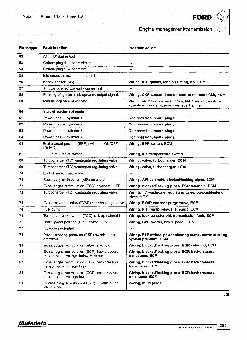
Engine management/transmission lEl Flash type Faun location Probable cause
52 I AT in 'D' during test 1 - 53 I Octane plug 1 - short circuit I - 54 I Octane plug 2 - short circuit I -
57 I Throttle opened too early during test I -
55
56
58 I Phasing of ignition pick-uplspark output signals ( Wiring, CKP sensor, ignition control module (ICM), ECM
Idle speed adjust - short circuit
Knock sensor (KS)
61 I Power loss - cylinder 1 I Compression, spark plugs
--
-
Wiring, fuel quality, ignition timing, KS, ECM
59
60
62 I Power loss - cylinder 2 I Compression, spark plugs
Mixture adjustment resistor
Start of service set mode
67 I Fuel temperature switch 1 Wiring, fuel temperature switch
Wiring, air leaks, vacuum leaks, MAP sensor, mixture adjustment resistor, injectors, spark plugs
-
63
64
65
70 I End of service set mode I -
Power loss - cylinder 3
Power loss - cylinder 4
Brake pedal position (BPP) switch - ONIOFF (DOHC)
68
69
7 1 I Secondary air injection (AIR) solenoid I Wiring, AIR solenoid, blockedlleaking pipes, ECM
Compression, spark plugs
Compression, spark plugs
Wiring, BPP switch, ECM
72 I Exhaust gas recirculation (EGR) solenoid - EFi I Wiring, blockedlleaking pipes, EGR solenoid, ECM
Turbocharger (TC) wastegate regulating valve
Turbocharger (TC) wastegate regulating valve
72 Turbocharger (TC) wastegate regulating valve Wiring, TC wastegate regulating valve, blockedlleaking pipes, ECM
Wiring, valve, turbocharger, ECM
Wiring, valve, turbocharger, ECM
73 ( Evaporative emission (EVAP) canister purge valve ( Wiring, EVAP canister purge valve, ECM
74 I Fuel pump I Wiring, fuel pump relay, fuel pump, ECM
75 I Torque converter clutch (TCC) lock-up solenoid I Wiring, lock-up solenoid, transmission fault, ECM
76
77
78
81
82
Brake pedal position (BPP) switch - AT
Kickdown actuated
83
84
Wiring, BPP switch, brake pedal, ECM
-
Power steering pressure (PSP) switch - not activated
Exhaust gas recirculation (EGR) solenoid
Exhaust gas recirculation (EGR) backpressure transducer - voltage below minimum
91
Wiring, PSP switch, power steering pump, power steering system pressure, ECM
Wiring, blockedlleaking pipes, EGR solenoid, ECM
Wiring, blockedlleaking pipes, EGR backpressure transducer, ECM
Exhaust gas recirculation (EGR) backpressure transducer - voltage high
Exhaust gas recirculation (EGR) backpressure transducer - voltage low
Wiring, blockedlleaking pipes, EGR backpressure transducer, ECM
Wiring, blockedlleaking pipes, EGR backpressure transducer, ECM
4
Heated oxygen sensors (H02S) - multi-plugs interchanged
Wiring, multi-plugs

Year: 1995-99
Engine code: F4A, F4B
System: Ford EEC IV
I Engine managementltransmission I
NOTE: Engine control module (ECM) incorporates transmission control function.
General information Refer to the front of this manual for general test conditions, terminology, detailed descriptions of wiring faults and a general trouble shooter for electrical and mechanical faults.
0 The ECM fault memory can only be accessed and erased using diagnostic equipment connected to the data link connector (DLC).
Accessing and erasing The engine control module (ECM) fault memory can only be accessed and erased using diagnostic equipment connected to the data link connector (DLC).
Trouble code identification I I
Flash type Fault location I Probable cause
10
11
12
13
14
15
17
18
Command code
System pass
- -
Volume air flow (VAF) sensor 1
Engine coolant temperature (ECT) sensor
Intake air temperature (IAT) sensor
Throttle position (TP) sensor
Manifold absolute pressure (MAP) sensor
Battery voltage - low
Wiring, VAF sensor, air leak, air restriction, ECM
Wiring, ECT sensor, ECM
Wiring, IAT sensor, ECM
Wiring, TP sensor, ECM
Wiring, MAP sensor, ECM
Wiring, battery

Flash type I Fault location Probable cause
19 I Keep Alive Memory (KAM) failure I ECM t I
24 [ Intake air temperature (IAT) sensor I Wiring, IAT sensor, ECM
20 I Separation code
2 1
22
23
-
28 I Heated oxygen sensor (H02S) - mixture rich I Wiring, fuel supply, injector control, HOZS, ECM
Ignition signal - erratic
Volume air Row (VAF) sensor 1 - voltage high
Engine coolant temperature (ECT) sensor - voltage high
25
27
31 I Memory failure I ECM
Wiring, CKP sensor, alternator
Wiring, VAF sensor, ECM
Wiring, ECT sensor, ECM
Throttle position (TP) sensor - voltage high
Manifdd absolute pressure (MAP) sensor - voltape hiqh
34 I Intake air temperature (IAT) sensor I Wiring, IAT sensor, ECM
Wiring, TP sensor, ECM
Wiring, MAP sensor, ECM
32
33
Volume air flow (VAF) sensor 1 - voltage low
Engine coolant temperature (ECT) sensor - voltaae low
35
36
37
43 ( Throttle position (TP) sensor - signal I Wiring, TP sensor, ECM
Wiring, VAF sensor, ECM
Wiring, ECT sensor, ECM
38
41
42
Throttle position (TP) sensor - voltage low
Vofume air flow (VAF) sensor 2 - vottage low
Manifold absolute pressure (MAP) sensor - voltacte low
Wiring, TP sensor, ECM
Wiring, VAF sensor, ECM
Wiring, MAP sensor, ECM
Heated oxygen sensor (H02S) - mixture weak
Volume air flow (VAF) sensor I - signal
Manifold absolute pressure (MAP) sensor - siqnal
44
45
46
47
Identification code for engine control module I (ECW I -
Wiring, fuel supply, injector control, H02S, ECM
Wiring, VAF sensor, ECM
Wiring, MAP sensor, ECM
48
49
Blip test (throttle open) not performed
Vehicle speed sensor (VSS)
Idle air control (IAC) valve - maximum engine s p a
Idle air control (IAC) valve - minimum engine speed
53 I Octane plug 1 - short circuit I -
- Wiring, VSS, ECM
Wiring, IAC valve, ECM
Wiring, IAC valve, ECM
Idle air control (IAC) valve
Exhaust gas recirculation (EGR) valve
51
52
54 [ Octane plug 2 - short circuit I -
Wiring, IAC valve, ECM
Wiring, restrictedlleaking EGR pipes, EGR valve, ECM
AC 'ON' during test
AT in 'D' during test
-
-
I I
58 I Phasing of ignition pick-uplspark output signals I Wiring, CKP sensor, ignition control module (ICM), ECM
55 I ldte speed adjust - short circuit
56
57
-
Knock sensor (KS)
Throttle opened too early durinq test
Wiring, fuel quality, ignition timing, KS, ECM
-

Fl IG? Engine managementltransmission
Mixture adjustment resistor
Flash type
Wiring, air leaks, vacuum leaks, MAP sensor, mixture adjustment resistor, injectors, spark plugs
Fault location
62 I Power loss - cylinder 2 I Compression, spark plugs
Probable cause
60
6 1
63 I Power loss - cylinder 3 I Compression, spark plugs
64 ( Power loss - cylinder 4 I Compression, spark plugs
Start of service set mode
Power loss - cylinder 1
- ~~~~~
-
Compression, spark plugs
68 I Turbocharger (TC) wastegate regulating valve I Wiring, valve, turbocharger, ECM
65
67
69 I Turbocharger (TC) wastegate regulating valve I Wiring, valve, turbocharger, ECM
70 I End of service set mode I -
Brake pedal position (BPP) switch - ONIOFF (DOHC)
Fuel temperature switch
Wiring, BPP switch, ECM
Wiring, fuel temperature switch
72 I Turbocharger (TC) wastegate regulating valve Wiring, TC wastegate regulating valve, blockedlleaking pipes, ECM
7 1
72
7 3 I Evaporative emission (EVAP) canister purge valve I Wiring, EVAP canister purge valve, ECM
Secondary air injection (AIR) solenoid
Exhaust gas recirculation (EGR) solenoid - EFi
76 I Brake pedal position (BPP) switch - AT 1 Wiring, BPP switch, brake pedal, ECM
Wiring, AIR solenoid, blockedlleaking pipes, ECM
Wiring, blockedlleaking pipes, EGR solenoid, ECM
74
75
77 I Kickdown actuated I - 78 Power steering pressure (PSP) switch - not Wiring, PSP switch, power steering pump, power steering
activated system pressure, ECM
Fuel pump
Torque converter clutch (TCC) lock-up solenoid
1 1
81 I Exhaust gas recirculation (EGR) solenoid I Wiring, blockedlleaking pipes, EGR solenoid, ECM
Wiring, fuel pump relay, fuel pump, ECM
Wiring, lock-up solenoid, transmission fault, ECM
83 Exhaust gas recirculation (EGR) backpressure Wiring, blockedlleaking pipes, EGR backpressure transducer - voltage high I transducer, ECM
82
84 Exhaust gas recirculation (EGR) backpressure Wiring, blockedlleaking pipes, EGR backpressure transducer - voltage low I transducer, ECM
Exhaust gas recirculation (EGR) backpressure transducer - voltage below minimum
-
Wiring, blockedlleaking pipes, EGR backpressure transducer, ECM
91
a
Heated oxygen sensors (H02S) - multi-plugs interchanged
Wiring, multi-plugs

Model: Fiesta 1,611,8 16V EscortlOrion 1,611,8 16V Mondeo l,6Il,8/2,O 16V Mondeo 2,5 V6
FORD GranadalScorpio 2,9 V6 24V
Year: 1991 -95
Engine code: BOA, LIE, LIF, LIG, LIH, LIJ, NGA, RDA, RDB, RKA, RKB, RQB, RQC, SEA
System: Ford EEC IV
Engine rnanagernent/transmission
I
Fiesta
NOTE: Engine control module (ECM) incorporates transmission control function.
General information Refer to the front of this manual for general test conditions, terminology, detailed descriptions of wiring faults and a general trouble shooter for electrical and mechanical faults.
3 Trouble codes are displayed by using an LED connected to the data link connector (DLC).
n The ECM fault memory can also be checked and erased using diagnostic equipment connected to the data link connector (DLC).
Mondeo
I
I
GranadalScorpio
Accessing Engine at normal operating temperature. Ensure ignition switched OFF. Bridge data link connector (DLC) terminals 2 and 3 0. Connect LED test lamp negative connection to DLC terminal 2 0. Connect LED test lamp positive connection to DLC terminal 1 0. Switch ignition ON. Check that LED illuminates. Note trouble codes. Compare with trouble code table. Trouble codes are displayed by illuminated LED switching OFF for approximately 0,5 second [A].

Model: Fiesta l ,6/ l ,8 16V EscorVOrion l,6/1,8 16V Mondeo 1,6/1,8/2,O 16V Mondeo 2,5 V6 GranadalScorpio 2,9 V6 24V
El Engine managementltransmission
Each trouble code consists of three groups. LED illuminates for approximately 1,5 seconds between each group H [B]. LED illuminates for approximately 3 seconds between each trouble code H [C].
NOTE: Trouble codes ending in '0' are displayed with only one group.
Engine control module (ECM) is equipped with two fault memories. Each fault memory output is separated by the following: LED illuminates for approximately 7 seconds H [Dl. LED extinguishes for 0,5 seconds (separation code) H [El. LED illuminates for approximately 4,5 seconds H [F]. Start of next fault memory trouble code output.
NOTE: Trouble code output of first fault memory is displayed twice. Then trouble code output of second fault memory is displayed twice.
Erasing Ensure ignition switched OFF. Disconnect engine control module (ECM) harness multi-plug.
Trouble code identification I I
System code I code meaning I Action
010
020
Flash type Fault location Probable cause
030
Separatorlcommand code
Command code
Briefly depress accelerator pedal fully
Briefly depress brake pedal fully
Command code
10
20
30
Briefly depress brake pedal fully
40
50
Cylinder 1, low
Cylinder 2, low
Cylinder 3, low
Cylinder compression, ignition components, injector
Cylinder compression, ignition components, injector
Cylinder compression, ignition components, injector
Cylinder 4, low
Cylinder 5, low
Cylinder compression, ignition components, injector
Cylinder compression, ignition components, injector

Model: Fiesta l ,6/ l ,8 16V EscorUOrion l ,6/ l ,8 16V Mondeo l,6/l,8/Z,O 16V Mondeo 2,5 V6 . GranadaIScorpio 2,9 V6 24V
Engine managementltransmission ,I[*-) =
Fault location Flash type I Probable cause
Cylinder balance test OK 1 -
Cylinder 6, low Cylinder compression, ignition components, iniector
Intake air temperature OAT) sensor - ranqe I IAT sensor
Systems OK
Intake air temperature (IAT) sensor - voltage low
Intake air temperature (IAT) sensor - voltage high
Engine coolant temperature (ECT) sensor - range ( ECT sensor
-
Wiring, IAT sensor, ECM
Wi r in~ , IAT sensor, ECM
Throttle position (TP) switchlsensor - voltage low ( Wiring, TP switchlsensor, ECM
Engine coolant temperature (ECT) sensor - voltage low
Engine coolant temperature (ECT) sensor - voltage high
Throttle position (TP) switchlsensor - ranqe
Throttle position (TP) switchlsensor - voltage high I Wiring, TP switchlsensor, ECM
Wiring, ECT sensor, ECM
Wiring, ECT sensor, ECM
TP switchlsensor
Mass air flow (MAF) sensorlmanifold absolute pressure (MAP) Mass air flow (MAF) sensorlmanifold sensor - no signal change during throttle 'blip' absolute pressure (MAP) sensor
Throttle position (TP) switchlsensor - voltage high
Throttle position (TP) switchlsensor - voltage low
Heated oxygen sensor (H02S) 2, bank 2 - weak mixture I Wiring, H02S, ECM
Wiring, TP switchlsensor, ECM
Wiring, TP switchlsensor, ECM
Heated oxygen sensor (H02S) 1, bank 1 - weaklrich mixture I Wiring, H02S, ECM
Heated oxygen sensor (H02S) 2, bank 2 - rich mixture
Heated oxygen sensor (H02S) 2, bank 2 - weaklrich mixture
Mass air flow (MAF) sensor - voltage low I Wiring, MAF sensor, ECM
Wiring, H02S, ECM
Wiring, H02S, ECM
Throttle position (TP) switchlsensor - no signal change during TP switchlsensor throttle 'blip'
Mass air flow (MAF) sensor - voltage high
Mass air flow (MAF) sensor - range
Wiring, MAF sensor, ECM
Wiring, MAF sensor, ECM
Heated oxygen sensor (H02S) 1, bank 1 - rich mixture I Wiring, H02S, ECM
Heated oxygen sensor (H02S) 1, bank 1 - adaptive limit reached
Heated oxygen sensor (H02S) 1, bank 1 - weak mixture
Fuel pressure, wiring, air leaks, injectors, ECM
Wiring, HOZS, ECM
Heated oxygen sensor (H02S) 2, bank 2 - weak mixture I Wiring, H02S, ECM
Heated oxygen sensor (H02S)
Heated oxygen sensor (H02S) 2, bank 2 - adaptive limit reached
Heated oxygen sensor (H02S) 2, bank 2 - rich mixture I Wiring, H02S, ECM
Wiring, H02S, ECM
Fuel pressure, wiring, air leaks, injectors, ECM
Heated oxygen sensor (H02S)
Fuel trim (part throttle) - weak mixture
Wiring, H02S, ECM
Fuel pressure, air leaks, injectors, ignition system
Fuel trim (part throttle) - rich mixture
Fuel trim (idle) - weak mixture
Fuel pressure, air leaks, injectors, ignition system
Fuel pressure, air leaks, injectors, ignition system
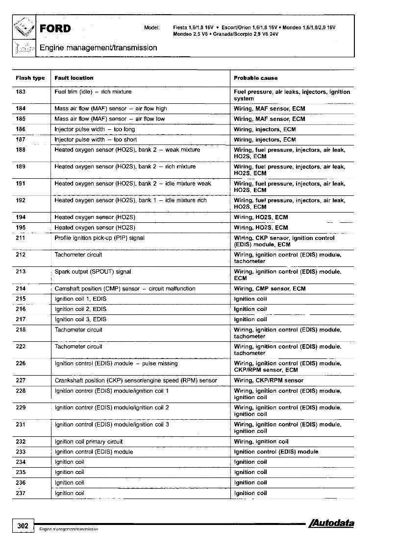
Model: Fiesta 1,611,8 16V EscorWOrion 1,611,8 16V Mondeo 1,611,812,O 16V Mondeo 2,5 V6 GranadalScorpio 2,9 V6 24V
; J Engine managementltransmission I D _ " I Flash type Fault locatlon I Probable cause
184 I Mass air flow (MAF) sensor - air flow high I Wiring, MAF sensor, ECM
183
185 I Mass air flow (MAF) sensor - air flow low I Wiring, MAF sensor, ECM
Fuel trim (idle) - rich mixture
Heated oxygen sensor (H02S), bank 2 - weak mixture Wiring, fuel pressure, injectors, air leak, H02S, ECM
Fuel pressure, air leaks, injectors, ignition system
186
187
Heated oxygen sensor (H02S), bank 2 - idle mixture weak Wiring, fuel pressure, injectors, air leak, H02S, ECM
Injector pulse width - too long
Injector pulse width - too short
189
Wiring, injectors, ECM
Wiring, injectors, ECM
195 I Heated oxygen sensor (H02S) I Wiring, H02S, ECM
Heated oxygen sensor (H02S), bank 2 - rich mixture
192
194
Wiring, fuel pressure, injectors, air leak, H02S, ECM
Spark output (SPOUT) signal
Heated oxygen sensor (H02S), bank 1 - idle mixture rich
Heated oxygen sensor (H02S)
211
212
Wiring, ignition control (EDIS) module, I ECM
Wiring, fuel pressure, injectors, air leak, H02S, ECM
Wiring, H02S, ECM
214 I Camshaft position (CMP) sensor - circuit malfunction I Wiring, CMP sensor, ECM
Profile ignition pick-up (PIP) signal
Tachometer circuit
215 I Ignition coil 1, EDlS I Ignition coil
Wiring, CKP sensor, ignition control (EDIS) module, ECM
Wiring, ignition control (EDIS) module, tachometer
216 I Ignition coil 2, EDlS I Ignition coil I - I
217 I Ignition coil 3, EDlS I Ignition coil
Tachometer circuit Wiring, ignition control (EDIS) module, tachometer
222
226
lgnition control (EDIS) modulelignition coil 2
227
228
Wiring, ignition control (EDIS) module, ignition coil
Tachometer circuit
Ignition control (EDIS) module - pulse missing
Wiring, ignition control (EDIS) module, tachometer
Wiring, ignition control (EDIS) module, CKPlRPM sensor, ECM
Crankshaft position (CKP) sensorlengine speed (RPM) sensor
Ignition control (EDIS) modulelignition coil 1
232 I Ignition coil primary circuit I Wiring, ignition coil
Wiring, CKPIRPM sensor
Wiring, ignition control (EDIS) module, ignition coil
231
236 I Ignition coil I Ignition coil
Ignition control (EDIS) modulelignition coil 3
Ignition control (EDIS) module
Ignition coil
Ignition coil
Wiring, ignition control (EDIS) module, ignition coil
Ignition control (EDIS) module
Ignition coil
Ignition coil
1 302 ....................
237 Ignition coil Ignition coil

Model: Fiesta l,6/l,8 16V EscorVOrion l,6/l,8 16V Mondeo 1,6/1,8/2,O 16V Mondeo 2,5 V6 GranadalScorpio 2,9 V6 24V
Engine management/transmission I bl' 5) .I
Flash type I Fault location I ~mbable cause
239 1 Profile ignition pick-up (PIP) signal - PIP signal occurs when I Wiring, CKPIRPM sensor, ignition control engine cranking (EDIS) module, ECM
238
311 I Pulsed secondary air injection (PAIR) system
Ignition control (EDIS) modulelignition coil
241
243
Wiring, PAlR solenoid, MAPIMAFNAF sensor, ECM
Wiring, ignition control (EDIS) module, ianition coil
Engine control module (ECM)/ignition control (EDIS) module - false data
Ignition coil
-
Engine control module (ECM), ignition control (EDIS) module
Ianition coil
Pulsed secondary air injection (PAIR) system
Pulsed secondary air injection (PAIR) system
316 1 Pulsed secondary air injection (PAIR) system
Wiring, PAIR solenoid, MAPIMAFNAF sensor, ECM
Wiring, PAIR solenoid, MAPIMAFNAF sensor, ECM
314
31 5
Wiring, PAlR solenoid, MAPIMAFNAF sensor, ECM
I I
326 I Exhaust pressure (EP) sensor I Wiring, EP sensor, ECM
Pulsed secondary air injection (PAIR) system
Pulsed secondary air injection (PAIR) system
Wiring, PAIR solenoid, MAPIMAFNAF sensor, ECM
Wiring, PAIR solenoid, MAPIMAFNAF sensor, ECM
328 ( Exhaust gas recirculation (EGR) solenoid I Wiring, EGR solenoid, ECM
327
336 I Exhaust pressure (EP) - high 1 EP sensor
Exhaust pressure (EP) sensorlexhaust gas recirculation (EGR) solenoid
332
334
335
337 Exhaust pressure (EP) sensorlexhaust gas recirculation (EGR) Wiring, EP sensor, EGR solenoid, ECM solenoid
Wiring, EP sensor, EGR solenoid, ECM
Exhaust gas recirculation (EGR) solenoid
Exhaust gas recirculation (EGR) solenoid
Exhaust pressure (EP) sensor
341 I Octane plug - connected to earth I Octane plug
Wiring, EGR solenoid, ECM
Wiring, EGR solenoid, ECM
Wiring, EP sensor, ECM
338
339
41 2 I Engine rpm too high during self-test
Engine coolant temperature (ECT) sensor --temperature l o r
Engine coolant temperature (ECT) sensor - temperature high
41 1
Wiring, compression, ignition, IAC valve, I ECM
- - --
Wiring, ECT sensor, ECM
Wiring, ECT sensor, ECM
41 3 I Idle air control (IAC) valve I Wiring, IAC valve, ECM
Engine rpm too low during self-test
41 4 I Idle air control (IAC) valve I Wiring, IAC valve, ECM
Wiring, compression, ignition, IAC valve, ECM
I I
41 5 I Idle air control (IAC) valve I Wiring, IAC valve, ECM
41 6 1 Idle air control (LAC) valve I Wiring, IAC valve, ECM
512 I Engine control module (ECM) - KAM error I ECM
452
51 1
51 3 I Engine control module (ECM) - internal reference voltage I ECM
Vehicle speed sensor (VSS)
Engine control module (ECM) - ROM error
Wiring, VSS, ECM
ECM

Model: Fiesta 1,611,8 16V Escort/Orion 1,611,8 16V Mondeo 1,611,812,O 16V Mondeo 2,5 V6 GranadalScorpio 2,9 V6 24V I 1 ~ 1 Engine managementltransrnission I
Flash type
51 9
Fault locatkn I Probable cause
Power steering pressure (PSP) switch - not activated during Wiring, PSP switch self-test
Power steering pressure (PSP) switch - not activated ] Wiring, PSP switch
Parkheutral position (PRIP) switch - circuit malfunction Wiring, PNP switch, ECM
Parkheutral position (PNP) switch - circuit malfunction Wiring, PNP switch, ECM
Clutch pedal position (CPP) switch - circuit malfunction Wiring, CPP switch, ECM
Brake pedal position (BPP) switch - not activated during self-test I Wiring, BPP switch, ECM
Owrator error durina self-test 1 - AC switched ON during self-test Wiring, AC switch
Fuel pump - circuit malfunction Wiring, fuel pump relay, IFS switch
Fuel pump - circuit malfunction Wiring, fuel pump relay, IFS switch
Idle air control (IAC) valve - circuit malfunction Wiring, IAC valve, ECM
Pulsed secondary air injection (PAIR) system - circuit malfunction I Wiring, PAIR solenoid
Fuel pump - circuit malfun I Wiring, fuel pump relay
Exhaust gas recirculation (EGR) solenoid - circuit malfunction Wiring, EGR solenoid, ECM
Engine coolant blower motor relay - circuit malfunction Wiring, engine coolant blower motor relay
Engine coolant blower motor relay - circuit malfunction Wiring, engine coolant blower motor relay
Evaporative emission (EVAP) canister puqe valve - circuit Wiring, EVAP canister purge valve, ECM malfunction
3rdJ4th gear shift solenoid Wiring, 3rd14th gear shift solenoid
Engine coolant blower motor relay - circuit malfunction Wiring, engine coolant blower motor relay, ECM
Engine coolant blower motor relay - circuit malfunction Wiring, engine coolant blower motor relay, ECM
Fuel pumplinertia fuel shut-off (IFS) switch - circuit Wiring, fuel pump relay, IFS switch
Kick-down switch Wiring, kick-down switch
Kick-down switch - not activated during self-test Wiring, kick-down switch
Transmission range frRj switch, 4th13rd gear switch Wiring, TR switch contacts - ooen circuit
Transmission range (TR) switch, 4th13rd gear circuit - open circuit Wiring, TR switch
Transmission range (TR) switch, 3rdiZnd gear circuit - short circuit Wiring, TR switch
Transmission range (TR) switch, 3rd/2nd gear switch contacts - Wiring, TR switch open circuit I
AT electronic pressure control solenoid - circuit malfunction Wiring, AT electronic pressure control solenoid, ECM
Modulated torque converter clutch (TCC) solenoid Wiring, TCC solenoid
Torque converter clutch (TCC) solenoid Wiring, TCC solenoid
Parklneutral position (PNP) switch Wiring, PNP switch
Transmission fluid temperature (TIT) switch - circuit malfunction I Wiring, TFT switch, ECM
Transmission fluid temperature (TFT) switch - circuit &lfunc&n I Wiring, TFT switch, ECM

Flash type
637
646 I 2nd aear failure - incorrect ratio I Wirina. transmission fault
638
639
645
647 I 3rd gear failure - incorrect ratio I Wiring, transmission fault
Fault tocation
Transmission fluid temperature (TFT) switch - circuit malfunction
Probable cause
Wiring, TFT switch, ECM
Transmission fluid temperature (TFT) switch - circuit malfunction
Turbine shaft speed (TSS) sensor - signal low
1st gear failure - incorrect ratio
998 ECT sensorllAT sensorlMAF sensor/TP sensor - circuit I Wiring, ECT sensorllAT sensorlMAF malfunction sensorlTP sensor, ECM
Wiring, TFT switch, ECM
Wiring, TSS sensor
Wiring, transmission fault
648
649
651
4th gear failure - incorrect ratio
Electronic throttle valve - failure
Electronic throttle valve - intermittent failure
Wiring, transmission fault
Wiring, electronic throttle valve, ECM
Wiring, electronic throttle valve. ECM

FORD Model: Fiesta 1,6/1,8 16V Escort 1,6/1,8 16V Mondeo 1,6/1,8/2,0 16V Mondeo 2,5 V6
Year: 1995-97
Engine code: LIE, LIF, LIG, LIH, LIJ, NGA, RDA, RDB, RKA, RKB, RQB, RQC, SEA
I System: Ford EEC IV I 1 Engine managementltransmission I
Mondeo
NOTE: Engine control module (ECM) incorporates transmission control function.
General information o Refer to the front of this manual for general test conditions,
terminology, detailed descriptions of wiring faults and a general trouble shooter for electrical and mechanical faults.
Accessing and erasing The ECM fault memory can only be accessed and erased using diagnostic equipment connected to the data link connector (DLC).
Trouble code identification I I
System code I Code meaning I Action
010 I Separator/cornmand code I Briefly depress accelerator pedal fully
020 I Command code I Briefly depress brake pedal fully
030 I Command code I Briefly depress brake pedal fully
I Engine managemenUtransrnission I $Iz4 .)
I Probable cause
10
I Cylinder 4, low
20
30
Cylinder compression, ignition components, injector
Cylinder 1, low Cylinder compression, ignition components, injector
Cylinder 2, low
Cylinder 3, low
Cylinder compression, ignition components, injector
Cylinder compression, ignition components, injector
50
11 3 I Intake air temperature (IAT) sensor - voltage high I Wiring, IAT sensor, ECM
60
90
Ill
112
Cylinder 5, low
117 I Engine coolant temperature (ECT) sensor - voltage low I Wiring, ECT sensor, ECM
Cylinder compression, ignition components, injector
Cylinder 6, low
Cylinder balance test OK
Systems OK
Intake air temperature (IAT) sensor - voltage low
114
116
118 I Engine coolant temperature (ECT) sensor - voltage high I Wiring, ECT sensor, ECM
Cylinder compression, ignition components, injector
-
-
Wiring, IAT sensor, ECM
Intake air temperature (IAT) sensor - range
Engine coolant temperature (ECT) sensor - range
123 I Throttle position (TP) switchlsensor - voltage high I Wiring, TP switchlsensor, ECM
IAT sensor
ECT sensor
121
122
124 I Throttle position (TP) switchlsensor - voltage high I Wiring, TP switchlsensor, ECM
125 I Throttle position (TP) switchlsensor - voltage low 1 Wiring, TP switchlsensor, ECM
Throttle position (TP) switchlsensor - range
Throttle position (TP) switchlsensor - voltage low
Mass air flow (MAF) sensorlmanifold absolute pressure (MAP) Mass air flow (MAF) sensorlmanifold sensor - no signal change during throttle 'blip' absolute pressure (MAP) sensor
TP switchlsensor
Wiring, TP switchlsensor, ECM
136 I Heated oxygen sensor (H02S) 2, bank 2 - weak mixture I Wiring, H02S, ECM
137 I Heated oxygen sensor (H02S) 2, bank 2 - rich mixture I Wiring, H02S, ECM
157 I Mass air flow (MAF) sensor - voltage low ( Wiring, MAF sensor, ECM
139
144
158 I Mass air flow (MAF) sensor - voltage high I Wiring, MAF sensor, ECM
Heated oxygen sensor (H02S) 2, bank 2 - weak/rich mixture
Heated oxygen sensor (H02S) 1, bank 1 - weak/rich mixture
Heated oxygen sensor (H02S) 1, bank 1 - adaptive limit reached Fuel pressure, wiring, air leaks, injectors, I ECM
Wiring, H02S, ECM
Wiring, H02S, ECM
159
167
172 I Heated oxyqen sensor (H02S) 1, bank 1 - weak mixture I Wiring, H02S, ECM
173 I Heated oxygen sensor (H02S) 1, bank 1 - rich mixture I Wiring, H02S, ECM
Mass air flow (MAF) sensor - range
Throttle position (TP) switchlsensor - no signal change during throttle 'blip'
174 I Heated oxygen sensor (H02S) I Wiring, H02S, ECM
Wiring, MAF sensor, ECM
TP switchlsensor
Heated oxygen sensor (H02S) 2, bank 2 - adaptive limit reached Fuel pressure, wiring, air leaks, injectors, I ECM
176 I Heated oxygen sensor (H02S) 2, bank 2 - weak mixture I Wiring, H02S, ECM

Scanner type
177
Heated oxvaen sensor (H02SI 1 Wirina. H02S. ECM
Fault location
Heated oxyqen sensor (H02SI 2, bank 2 - rich mixture
Fuel trim (part throttle) - weak mixture Fuel pressure, air leaks, injectors, ignition system
Probable cause
Wiring, H02S. ECM
Fuel trim (part throttle) - rich mixture Fuel pressure, air leaks, injectors, ignition system
Fuel trim (idle) - weak mixture
Fuel trim (idle) - rich mixture
Fuel pressure, air leaks, injectors, ignition system
Fuel pressure, air leaks, injectors, ignition svstem
Mass air flow (MAF) sensor - air flow high
Mass air flow (MAF) sensor - air flow low
Injector pulse width - too long
Injector pulse width - too short
Wiring, MAF sensor, ECM
Wiring, MAF sensor, ECM
Wiring, injectors, ECM
Wiring, injectors, ECM
Heated oxygen sensor (H02S), bank 2 - weak mixture
Heated oxygen sensor (H02S), bank 2 - rich mixture
Wiring, fuel pressure, injectors, air leak, H02S, ECM
Wiring, fuel pressure, injectors, air leak, H02S. ECM
Heated oxygen sensor (H02S), bank 2 - idle mixture weak
Heated oxygen sensor (H02S), bank 1 - idle mixture rich
Wiring, fuel pressure, injectors, air leak, H02S, ECM
Wiring, fuel pressure, injectors, air leak, H02S, ECM
Heated oxygen sensor (H02S)
Heated oxygen sensor (H02S)
Profile ignition pick-up (PIP) signal
Camshaft position (CMP) sensor - circuit malfunction ] Wiring, CMP sensor, ECM
Wiring, H02S, ECM
Wiring, H02S, ECM
Wiring, CKP sensor, ignition control (EDIS) module, ECM
Tachometer circuit
Spark output (SPOUT) signal
Wiring, ignition control (EDIS) module, tachometer
Wiring, ignition control (EDIS) module, ECM
Ignition coil 3, EDlS I Ignition coil
Ignition coil I, EDlS
lclnition coil 2, EDlS
Ignition coil
Ignition coil
Tachometer circuit
Tachometer circuit
Ignition control (EDIS) moduleflgnition mil 2 Wiring, ignition control (EDIS) module, ignition coil
Wiring, ignition control (EDIS) module, tachometer
Wiring, ignition control (EDIS) module, tachometer
Ignition control (EDIS) module - pulse missing
Crankshaft position (CKP) sensorlengine speed (RPM) sensor
Ignition control (EDIS) moduletignition coil I
Wiring, ignition control (EDIS) module, CKPIRPM sensor, ECM
Wiring, CKPIRPM sensor
Wiring, ignition control (EDIS) module, ianition coil

Model: Fiesta l,6/1,8 16V Escort l,6/1,8 16V Mondeo I,6/1,8/2,O 16V Mondeo 2,s V6
Engine managementftransmission
Scanner 1 Faun ~ocatlon type
Probable cause
I lgnition control (EDIS) modulelignition coil 3 I Wiring, ignition control (EDIS) module, ignition coil
235 I Ignition coil I Ignition coil
232
233
234
236 I Ignition coil I Ignition coil
Ignition coil primary circuit
Ignition control (EDIS) module
Ignition coil
Profile ignition pick-up (PIP) signal - PIP signal occurs when I Wiring, CKPIRPM sensor, ignition control engine cranking (EDIS) module, ECM
Wiring, ignition coil
Ignition control (EDIS) module
Ignition coil
237
238
Engine control module (ECM)lignition control (EDIS) module - Engine control module (ECM), ignition false data I control (EDIS) module
243 I Ignition coil I Ignition coil
Ignition coil
Ignition control (EDIS) modulelignition coil
Ignition coil
Wiring, ignition control (EDIS) module, ianition coil
31 1
31 2
I Pulsed secondary air injection (PAIR) system
31 3
314
Wiring, PAlR solenoid, MAPIMAFNAF sensor. ECM
Pulsed secondary air injection (PAIR) system
Pulsed secondary air injection (PAIR) system
I Pulsed secondary air injection (PAIR) system
Wiring, PAIR solenoid, MAPIMAFNAF sensor, ECM
Wiring, PAIR solenoid, MAPIMAFNAF sensor, ECM
Pulsed secondary air injection (PAIR) system
Pulsed secondary air injection (PAIR) system
Wiring, PAlR solenoid, MAPIMAFNAF sensor, ECM
Wiring, PAIR solenoid, MAPIMAFNAF sensor, ECM
Wiring, PAIR solenoid, MAPIMAFNAF sensor, ECM
326 I Exhaust pressure (EP) sensor I Wiring, EP sensor, ECM
Exhaust pressure (EP) sensorlexhaust gas recirculation (EGR) Wiring, EP sensor, EGR solenoid, ECM solenoid
334 I Exhaust gas recirculation (EGR) solenoid ( Wiring, EGR solenoid, ECM
328
332
335 I Exhaust pressure (EP) sensor ( Wiring, EP sensor, ECM
Exhaust gas recirculation (EGR) solenoid
Exhaust gas recirculation (EGR) solenoid
338 I Engine coolant temperature (ECT) sensor - temperature low I Wiring, ECT sensor, ECM
Wiring, EGR solenoid, ECM
Wiring, EGR solenoid, ECM
336
337
Exhaust pressure (EP) - high
Exhaust pressure (EP) sensorlexhaust gas recirculation (EGR) solenoid
339
341
41 1
EP sensor
Wiring, EP sensor, EGR solenoid, ECM
41 2
41 3
Engine coolant temperature (ECT) sensor - temperature high
Octane plug - connected to earth
Engine rpm too low during self-test
Wiring, ECT sensor, ECM
Octane plug
Wiring, compression, ignition, IAC valve, ECM
Engine rpm too high during self-test
Idle air control (IAC) valve
Wiring, compression, ignition, IAC valve, ECM
Wiring, IAC valve, ECM

Model: Fiesta l,6/1,8 16V Escort l,6/1,8 16V Mondeo I,6/1,8/2,O 16V Mondeo 2,5 V6
Engine management/transmission
Scanner Fault tocation type
Probable cause
41 6 I Idle air control (IAC) valve I Wiring, IAC valve, ECM
414
41 5
452 I Vehicle speed sensor (VSS) I Wiring, VSS, ECM
Idle air control (IAC) valve
Idle air control (IAC) valve
Power steering pressure (PSP) switch - not activated during self- Wiring, PSP switch 519 1 test
Wiring, IAC valve, ECM
Wiring, IAC valve, ECM
51 1
51 2
51 3
523 I Parkfneutral position (PNP) switch - circuit malfunction I Wiring, PNP switch, ECM
Engine control module (ECM) - ROM error
Engine control module (ECM) - KAM error
Engine control module (ECM) - internal reference voltaqe
52 1
522
528 I Clutch pedal position (CPP) switch - circuit malfunction I Wiring, CPP switch, ECM
ECM
ECM
ECM
536 ( Brake pedal position (BPP) switch - not activated during self-test I Wiring, BPP switch, ECM
Power steering pressure (PSP) switch - not activated
Parkfneutral position (PNP) switch - circuit malfunction
Wiring, PSP switch
Wiring, PNP switch, ECM
542 I Fuel pump - circuit malfunction I Wiring, fuel pump relay, IFS switch
538
539
543 I Fuel pump - circuit malfunction I Wiring, fuel pump relay, IFS switch
Operator error during self-test
AC switched ON during self-test
556 I Fuel pump - circuit malfunction I Wiring, fuel pump relay
-
Wiring, AC switch
551
552
558 I Exhaust gas recirculation (EGR) solenoid - circuit malfunction I Wiring, EGR solenoid, ECM
563 I Engine coolant blower motor relay - circuit malfunction I Wiring, engine coolant blower motor relay
Idle air control (IAC) valve - circuit malfunction
Pulsed secondary air injection (PAIR) system - circuit malfunction
Wiring, IAC valve, ECM
Wiring, PAIR solenoid
566 I 3rdl4th gear shift solenoid I Wiring, 3rd14th gear shift solenoid
564
565
Engine coolant blower motor relay - circuit malfunction
Engine coolant blower motor relay - circuit malfunction
Evaporative emission (EVAP) canister purge valve - circuit malfunction
Engine coolant blower motor relay - circuit malfunction
Wiring, engine coolant blower motor relay, I ECM
Wiring, engine coolant blower motor relay
Wiring, EVAP canister purge valve, ECM
Wiring, engine coolant blower motor relay, ECM
575 I Fuel pumplinertia fuel shut-off (IFS) switch - circuit I Wiring, fuel pump relay, IFS switch
576 I Kickdown switch I Wiring, kick-down switch
577
61 2
62 1 I Shift solenoid (SS) 1 - circuit malfunction I Wiring, shift solenoid, ECM
61 3
61 4
61 5
Kick-down switch - not activated during self-test
Transmission range (TR) switch, 4thl3rd gear switch contacts - open circuit
Wiring, kick-down switch
Wiring, TR switch
Transmission range (TR) switch, 4th13rd gear circuit - open circuit
Transmission range (TR) switch, 3rdl2nd gear circuit - short circuit
Transmission range (TR) switch, 3rdl2nd gear switch contacts - oDen circuit
622
Wiring, TR switch
Wiring, TR switch
Wiring, TR switch
Shift solenoid (SS) 2 - circuit malfunction Wiring, shift solenoid, ECM

I Model: Fiesta 1,611,8 16V Escort 1,611,8 16V Mondeo 1,611,812,O 16V Mondeo 2,s V 6
I Engine rnanagement/transmission ( b' --': 31
Scanner type
628 I Modulated torque converter clutch (TCC) solenoid 1 Wiring, TCC solenoid
624
625
629 I Torque converter clutch (TCC) solenoid I Wiring, TCC solenoid
Fault location
634 I Parklneutral position (PNP) switch I Wiring, PNP switch
Probable cause
AT electronic pressure control solenoid
AT electronic pressure control solenoid - circuit malfunction
AT electronic pressure control solenoid
Wiring, AT electronic pressure control solenoid, ECM
638 I Transmission fluid temperature (TFT) switch - circuit malfunction ] Wiring, TFT switch, ECM
635
636
637
639 I Turbine shaft speed (TSS) sensor - signal low I Wiring, TSS sensor
Transmission fluid temperature (TFT) switch - circuit malfunction
Transmission fluid temperature (TFT) switch - circuit malfunction
Transmission fluid temperature (TFT) switch - circuit malfunction
648 I 4th gear failure - incorrect ratio ( Wiring, transmission fault
Wiring, TFT switch, EG Wiring, TFT switch, ECM
Wiring, TFT switch, ECM
645
646
647
649 I Electronic throttle valve - failure 1 Wiring, electronic throttle valve, ECM
1st gear failure - incorrect ratio
2nd gear failure - incorrect ratio
3rd gear failure - incorrect ratio
653 I Transmission control switch - not activated during self-test I Wiring, transmission control switch, ECM
Wiring, transmission fault
Wiring, transmission fault
Wiring, transmission fault
651
652
Electronic throttle valve - intermittent failure
Modulated torque converter clutch (TCC) solenoid - circuit malfunction
658
998
Wiring, electronic throttle valve, ECM
Wiring, TCC solenoid, ECM
Performanceleconomy switch - not activated during self-test
ECT sensorllAT sensorlMAF sensorfrp sensor - circuit malfunction
Wiring, performanceleconomy switch, ECM
Wiring, ECT sensorllAT sensorlMAF sensor/TP sensor, ECM

Engine code: N7A, N5E
System: Ford EEC IV
e managementltransmission
NOTE: Engine control module (ECM) incorporates transmission control function.
General information Refer to the front of this manual for general test conditions, terminology, detailed descriptions of wiring faults and a general trouble shooter for electrical and mechanical faults. Trouble codes are displayed by using an LED connected to the data link connector (DLC). The ECM fault memory can also be checked and erased using diagnostic equipment connected to the data link connector (DLC).
Accessing Engine at normal operating temperature. Ensure ignition switched OFF. Bridge data link connector (DLC) terminals 4 and 11 0. Connect LED test lamp negative connection to DLC terminal 4 0. Connect LED test lamp positive connection to DLC terminal 3 0.
Switch ignition ON. Check that LED illuminates. Trouble codes are displayed after 10-25 seconds rn [A]. Note trouble codes. Compare with trouble code table. Trouble codes are displayed by illuminated LED switching OFF for approximately 1 second [B]. Each trouble code consists of two groups. LED illuminates for approximately 2 seconds between each group rn [C].
NOTE: Trouble codes ending in '0' are displayed with only 1 group.
LED illuminates for approximately 5 seconds between each trouble code rn [Dl. Trouble code(s) are displayed twice.
ON
OFF
Erasing Ensure ignition switched OFF. Disconnect engine control module (ECM) harness multi-plug.

Model: Escort RS 2000 Escort Cosworth
Engine management~transmission
Trouble code identification I I
Flash type 1 Fault Iocatlon I Probable cause
13 I Engine cootant temperature (ECT) sensor I Wiring, ECT sensor, ECM
10
11
12
14 I Intake air temperature (IAT) sensor ( Wiring, IAT sensor, ECM
Command code
System pass
Volume air flow (VAF) sensor 1
19 I Keep Alive Memory (KAM) failure I ECM
- -
Wiring, VAF sensor, air leak, air restriction, ECM
15
16
17
18
20 I Separation code I -
Throttle position (TP) sensor
Volume air flow (VAF) sensor 2
Manifold absolute pressure (MAP) sensor
Battery voltage - low
Engine coolant temperature (ECT) sensor - I Wiring, ECT sensor, ECM voltage high
Wiring, TP sensor, ECM
Wiring, VAF sensor, ECM
Wiring, MAP sensor, ECM
Wiring, battery
21
22
Ignition signal - erratic
Volume air flow (VAF) sensor 1 - voltage high
24
25
26
- -- --
Wiring, CKP sensor, alternator
Wiring, VAF sensor, ECM
27
28
28
29
32 I Volume air flow (VAF) sensor 1 - voltage low I Wiring, VAF sensor, ECM
Intake air temperature (IAT) sensor
Throttle position (TP) sensw - voltage high
Volume air flow (VAF) sensor 2 - voltage high
31
Engine coolant temperature (ECT) sensor - I Wiring, ECT sensor, ECM voltage low
Wiring, IAT sensor, ECM
Wiring, TP sensor, ECM
Wiring, VAF sensor, ECM
Manifold absolute pressure (MAP) sensor - voltage high
Heated oxygen sensor (H02S) - mixture rich
Heated oxygen sensor (H02S) 1 - mixture rich
Heated oxygen sensor (H02S) 2 - mixture rich
34 1 Intake air temperature (IAT) sensor I Wiring, IAT sensor, ECM
Wiring, MAP sensor, ECM
Wiring, fuel supply, injector control, H02S, ECM
Wiring, fuel supply, injector control, H02S, ECM
Fuel supply, injector control, wiring, H02S, ECM
Memory failure
35 I Throttle position (TP) sensor - voltage low I Wiring, TP sensor, ECM
ECM
38 I Heated oxygen sensor (H02S) - mixture weak I Wiring, fuel supply, injector control, H02S, ECM
36
37
38 I Heated oxygen sensor (H02S) 1 - mixture weak 1 Wiring, fuel supply, injector control, H02S, ECM
Volume air flow (VAF) sensor 2 - voltage low
Manifold absolute pressure (MAP) sensor - voltage low
42 I Volume air flow (VAF) sensor 2 - signal I Wiring, VAF sensor, ECM
Wiring, VAF sensor, ECM
Wiring, MAP sensor, ECM
39
41
42 I Manifold absolute pressure (MAP) sensor - signal I Wiring, MAP sensor, ECM
43 I Throttle position (TP) sensor - signal I Wiring, TP sensor, ECM
Heated oxygen sensor (H02S) 2 - mixture weak
Volume air flow WAF) sensor 1 - siqnal
Wiring, fuel supply, injector control, H02S, ECM
Wiring, VAF sensor, ECM
44 Blip test (throttle open) not performed -

Model: Escort RS 2000 Escort Cosworth
I bLr'ial - Engine management/transmission
Flash type Fault location
Vehicle speed sensor (VSS) 1 Wiring, VSS, ECM
Probable cause
Idle air control (IAC) valve I Wiring, IAC valve, ECM
Idle air control (IAC) valve - maximum engine speed
Idle air control (IAC) valve - minimum engine speed
I
Exhaust gas recirculation (EGR) valve I Wiring, restrictedlleaking EGR pipes, EGR valve, ECM
Wiring, IAC valve, ECM
Wiring, IAC valve, ECM
AC 'ON' during test I -
Identification code for engine control module (ECW
-
-
Idle speed adjust - short circuit 1 -
AT in 'D' during test
Octane plug 1 - short circuit
Octane plug 2 - short circuit
Knock sensor (KS) I Wiring, fuel quality, ignition timing, KS, ECM
-
- -
Mixture adjustment resistor
Throttle opened too earty during test
Phasing of ignition pick-uplspark output signals
Wiring, air leaks, vacuum leaks, MAP sensor, mixture adjustment resistor, injectors, spark plugs
-
Wiring, CKP sensor, ignition control module (ICM), ECM
Power loss - cylinder 2 I Compression, spark plugs
Start of service set mode
Power loss - cylinder 1
Power loss - cylinder 3 I Compression, spark plugs
-
Compression, spark plugs
Power loss - cylinder 4 I Compression, spark plugs
Fuel temperature switch I Wiring, fuel temperature switch
Brake pedal position (BPP) switch - ONIOFF
Kick-down switch (DOHC)
Turbocharger (TC) wastegate regulating valve I Wiring, valve, turbocharger, ECM
Wiring, BPP switch, ECM
Wiring, kick-down switch, ECM
Turbocharger (TC) wastegate regulating valve I Wiring, valve, turbocharger, ECM
Exhaust gas recirculation (EGR) solenoid 1 Wiring, blockedlleaking pipes, EGR solenoid, ECM
End of service set mode
Secondary air injection (AIR) solenoid
-
Wiring, AIR solenoid, blockedlleaking pipes, ECM
Fuel pump I Wiring, fuel pump relay, fuel pump, ECM
Turbocharger (TC) wastegate regulating valve
Evaporative emission (EVAP) canister purge valve
3rdl4th gear shift solenoid I Wiring, shift solenoid, transmission fault, ECM
Wiring, wastegate regulating valve, blockedlleaking pipes, ECM
Wiring, EVAP canister purge valve, ECM
Torque converter clutch (TCC) lock-up solenoid I Wiring, lock-up solenoid, transmission fault, ECM
Brake pedal position (BPP) switch - AT
Kickdown actuated
Wiring, BPP switch, brake pedal, ECM
-
Power steering pressure (PSP) switch - not activated
Wiring, PSP switch, power steering pump, power steering system pressure, ECM

Flash type 1 Fault location I Probable cause
Engine management/transmission h 7 L ~ + ~
83 Exhaust gas recirculation (EGR) backpressure Wiring, blockedlteaking pipes, EGR backpressure transducer - voltage high I transducer, ECM
81
82
I I
84 1 Exhaust gas recirculation (EGR) backpressure I Wiring, blockedlleaking pipes, EGR backpressure
Exhaust gas recirculation (EGR) solenoid
Exhaust gas recirculation (EGR) backpressure transducer - voltaqe below minimum
Wiring, blockedlteaking pipes, EGR solenoid, ECM
Wiring, blockedlleaking pipes, EGR backpressure transducer, ECM
91
4
transducer - voltage low
Heated oxygen sensors (H02S) - multi-plugs interchanged
transducer, ECM
Wiring, multi-plugs

Transit 2,012,9 V6
, BRT, B4T, L6B, NCA, N4A, N4B, N6T, N6S, , N9B, N9C, N9D, N9E, N9F, PR7, PR8
Ford CFilEEC IV
NOTE: Engine control module (ECM) incorporates transmission control function.
General information Refer to the front of this manual for general test conditions, terminology, detailed descriptions of wiring faults and a general trouble shooter for electrical and mechanical faults. Trouble codes are displayed by using an LED connected to the data link connector (DLC). The ECM fault memory can also be checked and erased using diagnostic equipment connected to the data link connector (DLC).
Accessing Ensure ignition switched OFF. Engine at normal operating temperature. Connect LED test lamp positive connection to battery positive rn +I 989 or rn 1990 +.
C Connect LED test lamp negative connection to DLC terminal 1 -1989 or rn 1990+. Switch ignition ON.
NOTE: LED will illuminate a few seconds affer ignition is switched ON.
Before LED illuminates: Bridge data link connector (DLC) terminals 2 and 3 rn -1 989 or rn 1990 +.
Check that LED illuminates. Trouble codes are displayed after 10-30 seconds Q [A]. Note trouble codes. Compare with trouble code table. Trouble codes are displayed by illuminated LED switching OFF for approximately 1 second Q [B]. Each trouble code consists of two groups. LED illuminates for approximately 2 seconds between each group rn [C].
NOTE: Trouble codes ending in '0' are displayed with only I group.
Transit
LED illuminates for approximately 5 seconds between each trouble code rn [Dl. For example: Trouble code 24 displayed. Trouble code(s) are displayed twice.

OFF
Trouble code identification
Erasing Ensure ignition switched OFF. Disconnect engine control module (ECM) harness multi-plug.
Flash type I Fault loution Probable cause
11 I Svstern ass I - 10
12 ( Volume air flow (VAF) sensor 1 I Wiring, VAF sensor, air leak, air restriction, ECM
Command code
15 I Throttle position (TP) sensor 1 Wiring, TP sensor, ECM
-
13
14
16 I Volume air flow (VAF) sensor 2 ( Wiring, VAF sensor, ECM
17 I Manifold absolute pressure (MAP) sensor I Wiring, MAP sensor, ECM
Engine coolant temperature (ECT) sensor
Intake air temperature (IAT) sensor
Wiring, ECT sensor, ECM
Wiring, IAT sensor, ECM
2 1 I Ignition signal - erratic I Wiring, CKP sensor, alternator
18
19
20
22 I Volume air flow (VAF) sensor 1 - voltage high I Wiring, VAF sensor, ECM
Battery voltage - low
Keep Alive Memory (KAM) failure
Separation code
Wiring, battery
ECM
-
23
24
25
26
Engine coolant temperature (ECT) sensor - voltage high
Intake air temperature (IAT) sensor
27
28
Wiring, ECT sensor, ECM
Wiring, IAT sensor, ECM
Throttle position (TP) sensor - voltage high
Volume air flow (VAF) sensor 2 - voltage high
Wiring, TP sensor, ECM
Wiring, VAF sensor, ECM
Manifold absolute pressure (MAP) sensor - voltage high
Heated oxygen sensor (H02S) - mixture rich
Wiring, fuel supply, injector control, HOZS, ECM 28
29
30
Wiring, MAP sensor, ECM
Wiring, fuel supply, injector control, HOZS, ECM
Heated oxygen sensor (H02S) 1 (2,O DOHC I6V) - mixture rich
3 1
32
Heated oxygen sensor (H02S) 2 (2,O DOHC 16V) - mixture rich
identification code for 6 cylinder engines
Fuel supply, injector control, wiring, HOZS, ECM
-
Memory failure
Volume air flow (VAF) sensor 1 - voltage tow
ECM
Wiring, VAF sensor, ECM

Model: Sierra l,6/2,Ol2,8 GranadalScorpio 2,012,9 V6 Transit 2,012,9 V6
33
' 36 ( Volume air flow (VAF) sensor 2 - voltage tow I Wiring, VAF sensor, ECM
34
35
37 Manifold absolute pressure (MAP) sensor - I Wiring, MAP sensor, ECM voltage low
Engine coolant temperature (ECT) sensor - voltage low
Wiring, ECT sensor, ECM
Intake air temperature (IAT) sensor
Throttle position (TP) sensor - voltage low
- - - - - - - --
Wiring, IAT sensor, ECM
Wiring, TP sensor, ECM
38
38
39
41
42
44 I Blip test (throttle open) not performed I -
Heated oxygen sensor (H02S) - mixture weak
Heated oxygen sensor (H02S) 1 (2,O DOHC 16V) - mixture weak
42
43
45 I Vehicle speed sensor (VSS) I Wiring, VSS, ECM
Wiring, fuel supply, injector control, H02S, ECM
Wiring, fuel supply, injector control, H02S, ECM
Heated oxygen sensor (H02S) 2 (2,O DOHC 16V) - mixture weak
Volume air Row (VAF) sensor 1 - signal
Volume air Row (VAF) sensor 2 - signal
46 I Idle air control (IAC) valve - maximum engine ( Wiring, IAC valve, ECM
Wiring, fuel supply, injector control, H02S, ECM
Wiring, VAF sensor, ECM
Wiring, VAF sensor, ECM
Manifold absolute pressure (MAP) sensor - signal
Throffle position (TP) sensor - signal
Wiring, MAP sensor, ECM
Wiring, TP sensor, ECM
48 1 Closed throttle position (CTP) switch (CFi) ] Wiring, CTP switch, ECM
47
50 Identification code for engine control module I -
speed
Idle air control (IAC) valve - minimum engine meed
48
49
51 I AC 'ON' during test I -
Wiring, 1AC valve, ECM
Idle air control (IAC) valve (except CFi)
Exhaust gas recirculation (EGR) valve
54 I Octane plug 2 - short circuit 1 -
Wiring, IAC valve, ECM
Wiring, restrictedlleaking EGR pipes, EGR valve, ECM
52
53
55 I Idle speed adjust - short circuit I -
AT in 'D' during test
Octane plug 1 - short circuit
- -
56
57
58
61 I Power loss - cylinder 1 I Compression, spark plugs
59
60
62 I Power loss - cylinder 2 I Compression, spark plugs
Knock sensor (KS)
Throffle opened too early during test
Phasing of ignition pick-uplspark output signals
63 ( Power loss - cylinder 3 I Compression, spark plugs
Wiring, fuel quality, ignition timing, KS, ECM
-
Wiring, CKP sensor, ignition control module (ICM), ECM
Mixture adjustment resistor
Start of service set mode
Wiring, air leaks, vacuum leaks, MAP sensor, mixture adjustment resistor, injectors, spark plugs
-
64 Power loss - cylinder 4 Compression, spark plugs

Model: Sierra 1,612,012,8 GranadalScorpio 2,0/2,9 V6 Transit 2,012,9 V6
Flash type I Fault locatlon 1 Probable cause
Engine management/transmission Pj T--T zLl .
66 I Power loss - cylinder 6 1 Compression, spark plugs
65
65
66 I Kick-down switch (DOHC) I Wiring, kick-down switch, ECM
Power loss - cylinder 5
Brake pedal position (BPP) switch - ONIOFF (DOHC)
7 1 I Secondary air injection (AIR) solenoid I Wiring, AIR solenoid, blockedlleaking pipes, ECM
Compression, spark plugs
Wiring, BPP switch, ECM
67
68
69
70
72 I Exhaust gas recirculation (EGR) solenoid I Wiring, blockedileaking pipes, EGR solenoid, ECM
73 I Evaporative emission (EVAP) canister purge valve / Wiring, EVAP canister purge valve, ECM
Fuel temperature switch
Turbocharger (TC) wastegate regulating valve
Turbocharger (TC) wastegate regulating valve
End of service set mode
- -
Wiring, fuel temperature switch
Wiring, valve, turbocharger, ECM
Wiring, valve, turbocharger, ECM
-
7 5 I Torque converter clutch (TCC) lock-up solenoid I Wiring, lock-up solenoid, transmission fault, ECM
74
74
76 I Brake pedal position (BPP) switch - AT I Wiring, BPP switch, brake pedal, ECM
77 ( Kickdown actuated 1 -
Fuel pump
3rdt4th gear shift solenoid (DOHC)
78 Power steering pressure (PSP) switch - not Wiring, PSP switch, power steering pump, power steering activated system pressure, ECM
- - -
Wiring, fuel pump relay, fuel pump, ECM
Wiring, shift solenoid, transmission fault, ECM
81 I Exhaust gas recirculation (EGR) solenoid ( Wiring, blockedlleaking pipes, EGR solenoid, ECM
82 Exhaust gas recirculation (EGR) backpressure Wiring, blockedlleaking pipes, EGR backpressure transducer - voltage below minimum I transducer, ECM
8 3
84
9 1 ! Heated oxygen sensors (H02S) - multi-plugs interchanged
Exhaust gas recirculation (EGR) backpressure transducer - voltage high
Exhaust gas recirculation (EGR) backpressure transducer - voltage low
Wiring, multi-plugs
Wiring, blockedlleaking pipes, EGR backpressure transducer, ECM
Wiring, blockedlleaking pipes, EGR backpressure transducer, ECM
4

GranadalScorpio 2,412,9 V6 Transit 2,9 V6
Engine management/transmission
1986-95
ARD, BRD, BRE, BRF, BRT, BRV, B4B, B4C, R6A
Ford CFilEEC IV
J I
SienalGranadafScorpio - -1989 Transtt - -1989
I I
SierralGanadalScorpio - 1090 - Transtt - 1990-
NOTE: Engine control module (ECM) incorporates transmission control function.
General information 0 Refer to the front of this manual for general test conditions,
terminology, detailed descriptions of wiring faults and a general trouble shooter for electrical and mechanical faults.
0 Trouble codes are displayed by using an LED connected to the data link connector (DLC). The ECM fault memory can also be checked and erased using diagnostic equipment connected to the data link connector (DLC).
Accessing Ensure ignition switched OFF. Engine at normal operating temperature. Connect LED test lamp positive connection to battery positive -1989 or rn 1990-+.
Connect LED test lamp negative connection to DLC terminal 1 -1989 or rn 1990-+. Switch ignition ON.
NOTE: LED will illuminate a few seconds after ignition is switched ON.
Before LED illuminates: Bridge data link connector (DLC) terminals 2 and 3 1 -1 989 or 1990 -+. Check that LED illuminates. Trouble codes are displayed after 10-30 seconds rn [A]. Note trouble codes. Compare with trouble code table. Trouble codes are displayed by illuminated LED switching OFF for approximately 1 second rn [B]. Each trouble code consists of two groups. LED illuminates for approximately 2 seconds between each group rn [C].
NOTE: Trouble codes ending in '0' are displayed with only 1 group.
LED illuminates for approximately 5 seconds between each trouble code rn [Dl. Trouble code(s) are displayed twice.

Engine management/transrnission ---
ON
OFF
Erasing Ensure ignition switched OFF. Disconnect engine control module (ECM) harness multi-plug.
10 I Command code I -
Trouble code identification
Flash type
12 I Idle speed control (ISC) actuator - CFi I Wiring, ISC actuator, ECM
11
12
13 I Idle air control (1AC) valve I Wiring, IAC valve, ECM
Fault location Probable cause
System pass
Idle air control (IAC) valve
16 I Low idle speed during test I -
-
Wiring, IAC valve, ECM
13
14
15
2 1 1 Engine coolant temperature (ECT) sensor 1 Wiring, ECT sensor, ECM
Idle speed control (ISC) actuator - CFi
Ignition signal
Engine control module (ECM) - KAMIROM error
17
18
19
20
Wiring, ISC actuator, ECM
Wiring, CKP sensor, alternator
ECM
Idle speed control (ISC) actuator - CFi
Ignition amplifier
Ignition amplifier - supply
4 cylinder identification code
22
Wiring, ISC actuator, ECM
Wiring, ignition amplifier, CKPlRPM sensor, ECM
Wiring
-
+I
Manifold absolute pressure (MAP) sensor Wiring, MAP sensor, ECM

Model: Sierra 1,8 Sierra 2,9 V6 GranadalScorpio 2,4/2,9 V6 Transit 2,9 V6
bMia Engine rnanagernenfftransmission
Flash type I Fault locrtlon Probable cause
23 I Throttle position (TP) sensor I Wiring, TP sensor, ECM
24 I Intake air temperature (IAT) sensor I Wiring, IAT sensor, ECM
25
26
27
Knock sensor (KS)
Idle speed control (ISC) actuator - CFi
28
29
30
Wiring, fuel quality, ignition timing, KS, ECM
Wiring, ISC actuator, ECM
Cruise control - too slow
31
32
35 Exhaust gas recirculation (EGR) backpressure Wiring, blockedlleaking pipes, EGR transducer - voltage high backpressure transducer, ECM
Vacuum pipes blockedlleaking, throttle valve sticking
Cruise control - too fast
Vehicle speed sensor (VSS)
6 cylinder identification code
33
34
Vacuum pipes blockedlleaking, throttle valve sticking
Wiring, VSS, ECM
-
Exhaust gas recirculation (EGR) backpressure transducer - voltage low
Exhaust gas recirculation (EGR) backpressure transducer - outside specification
37 1 Closed throttle position (CTP) switch - CFi / Wiring, CTP switch, ECM
Wiring, blockedlleaking pipes, EGR backpressure transducer, ECM
Wiring, blockedlleaking pipes, EGR backpressure transducer, ECM
Exhaust gas recirculation (EGR) solenoid - no gas recirculation
Exhaust gas recirculation (EGR) backpressure transducer - outside specification
36
37
38 I Closed throttle position (CTP) switch - CFi I Wiring, CTP switch, ECM
Wiring, blockedlleaking pipes, EGR backpressure transducer, ECM
Wiring, blockedlleaking pipes, EGR backpressure transducer. ECM
39 I AT lock-up solenoid fault I Wiring, AT lock-up solenoid
No RPM increase during test
No RPM decrease durina test
-
-
Heated oxygen sensor (H02S) 1, cylinders 1-3 - mixture Wiring, air leak, exhaust leak, H02S, ECM I k h I 41 Heated oxygen sensor (H02S) 1, cylinders 1-3 - mixture
weak
43
45 I Closed throttle position (CTP) switch - CFi I Wiring, CTP switch, ECM
Wiring, air leak, exhaust leak, H02S, ECM
44 Throttle position (TP) sensor
47 1 Cruise control switch I Wiring, cruise control switch
Idle speed control (ISC) actuator - CFI
Wiring, TP sensor, ECM
Wiring, ISC actuator, ECM
48
49
51
52
54 I Intake air temperature (IAT) sensor - voltage high I Wiring, IAT sensor, ECM
53
57 I Octane adjuster - short circuit I Octane adjuster wiring
Cruise control switch
Cruise control signal
Engine coolant temperature (ECT) sensor - voltage high
Power steering pressure (PSP) switch - not activated durinq test
Wiring, cruise control switch
Wiring, cruise control switch, cruise control actuator, ECM
Wiring, ECT sensor, ECM
Wiring, PSP switch, ECM
Throffle position (TPf sensor - voltage high Wiring, TP sensor, ECM
58
59
Ignition timing delayed
Idle adjuster - short circuit
Octane adjuster wiring
Octane adjuster wiring

Model: Sierra 1,8 Sierra 2,9 V6 GranadalScorpio 2,4/2,9 V6 Transit 2,9 V6
Engine managementltransmission - +-, 3
Flash type
64 I Intake air temperature (IAT) sensor - voltage low I Wiring, IAT sensor, ECM
6 1
62
63
Fault location
72 I Manifold absolute pressure (MAP) sensor ( Wiring, MAP sensor, ECM
Probable cause --
Engine coolant temperature ( E T ) sensor -voltage low
AT shift valve closed
Throttle position (TP) sensor - voltage low
AC ON or AT in D
Closed throttle position (CTP) switch - CFi
Closed throttle position (CTP) switch - CFi
73 I Throttle position (TP) sensor - no change during test I Wiring, TP sensor
--
Wiring, EC? sensor, ECM
Transmission mechanical fault
Wiring, TP sensor, ECM
Wiring, AC switch, transmission range (TR) switch
Wiring, CTP switch, ECM
Wiring, CTP switch, ECM
8 1 I Manifold absolute pressure (MAP) sensor - Transit Wiring, vacuum pipe, manifold vacuum, MAP sensor
74
75
77
85 I Evaporative emission (EVAP) canister purge valve I Wiring, EVAP solenoid
Brake pedal position (BPP) switch - circuit malfunction
Brake pedal position (BPP) switch - short circuit
Throttle not operated or operated too late
82
83
84
Wiring, BPP switch
Wiring, BPP switch
Wiring, TP switchlsensor
9 1 Heated oxygen sensor (H02S) 2, cylinders 4-6 - mixture Wiring, air leak, exhaust leak, H02S, ECM I weak I
Secondary air injection (AIR) solenoid
Heavy duty fan switch
Exhaust gas recirculation (EGR) solenoid
87
88
89
92 I Heated oxygen sensor (H02S) 2, cylinders 4-6 - mixture I Wiring, air leak, exhaust leak, H02S, ECM
- -
Wiring, AIR solenoid
Wiring, heavy duty fan switch
Wiring. EGR solenoid
Fuel pump
Electric cooling fan
AT lock-up solenoid
Wiring, fuel pump relay, fuel pump, ECM
Wiring, cooling fan motor
Wiring, lock-up solenoid

FORD Model: Maverick 2,4
Year: 1993-98
Engine code: KA24, KA24E
System: Nissan ECCS I Engine management
General information Refer to the front of this manual for general test conditions, terminology, detailed descriptions of wiring faults and a general trouble shooter for electrical and mechanical faults. Trouble codes are displayed by the malfunction indicator lamp (MIL). The ECM fault memory can also be checked and erased using diagnostic equipment connected to the data link connector (DLC).
Accessing Ensure ignition switched OFF. Switch ignition ON. Bridge data link connector (DLC) terminals IGN and CHK m. Wait 2 seconds minimum. Disconnect bridge wire from data link connector (DLC). Count MIL flashes. Compare with trouble code table. Each trouble code consists of two groups of flashes rn. Long flashes indicate the 'tens' rn [A]. Short flashes indicate the 'units' rn [C]. A short pause separates each flash 1 [B]. A long pause separates each trouble code rn [Dl. For example: 1 long flash followed by 2 short flashes indicates trouble code 12 - mass air flow (MAF) sensor. Switch ignition OFF.
CHK I IGN

Model: Maverick 2,4 FORD
Engine management I
Erasing Ensure ignition switched OFF. Switch ignition ON. Bridge data link connector (DLC) terminals IGN and CHK a. Wait 2 seconds minimum. Disconnect bridge wire from data link connector (DLC). Bridge data link connector (DLC) terminals IGN and CHK a. Wait 2 seconds minimum. Disconnect bridge wire from data link connector (DLC). Switch ignition OFF.
NOTE: Trouble codes can also be erased by disconnecting battery earth lead for 24 hours.
WARNING: Disconnecting the battery may erase memory from electronic units (e.g. radio, clock).
Trouble code identification
Flash type I Fault location I Probable cause
12 I Mass air flow (MAF) sensor - voltage lowlhigh I Wiring, MAF sensor, ECM
11
13 I Engine coolant temperature (ECT) sensor - voltage lowlhigh I Wiring, ECT sensor, ECM
21 ( Ignition signal I Wiring, ignition amplifier, ECM
CrankshafI position (CKP) sensorlengine speed (RPM) sensor1 camshaft position (CMP) sensor - incorrect signal
Wiring, CKPlRPMlCMP sensor, ECM
55 I No fault found 1 -
4 1
43
/Autodata I Engme management 325
-
Intake air temperature (1~~);ensor -voltage%wlhigh
Throttle position (TP) sensor - voltage lowlhigh - circuit
-
wiring, l ~ ~ y e n s o r , ~ ~
Wiring, TP sensor, ECM

I Engine management
Model: Maverick 2,7 D Turbo
Year: 1996-98
Engine code: TD27E
System: EDC
General information Refer to the front of this manual for general test conditions, terminology, detailed descriptions of wiring faults and a general trouble shooter for electrical and mechanical faults. Trouble codes are displayed by the malfunction indicator lamp (MIL). The ECM fault memory can also be checked and erased using diagnostic equipment connected to the data link connector (DLC).
Accessing Ensure ignition switched OFF. Switch ignition ON. Bridge data link connector (DLC) terminals IGN and CHK m. Wait 2 seconds minimum. Disconnect bridge wire from data link connector (DLC). Count MIL flashes. Compare with trouble code table. Each trouble code consists of two groups of flashes H. Long flashes indicate the 'tens' rn [A]. Short flashes indicate the 'units' rn [C]. A short pause separates each flash [B]. A long pause separates each trouble code [Dl. For example: 1 long flash followed by 2 short flashes indicates trouble code 12 - mass air flow (MAF) sensor. Switch ignition OFF.
CHK I IGN

Engine management
Erasing Wait 2 seconds minimum. Ensure ignition switched OFF. Disconnect bridge wire from data link connector (DLC). Switch ignition ON. Switch ignition OFF. Bridge data link connector (DLC) terminals IGN and CHK O. NOTE: Trouble codes can also be erased by disconnecting Wait 2 seconds minimum. battery earth lead for 24 hours. Disconnect bridge wire from data link connector (DLC). WARNING: Disconnecting the battery may erase memory from Bridge data link connector (DLC) terminals IGN and CHK e. electronic units (e.g. radio, clock).
Trouble code identification
I Probable u u s e
I I
17 I Module coding plug - voltage lowlhigh I Wiring, module coding plug, ECM
11
12
13
14
15
Camshaft positlon (CMP) sensor - incorrect signal
Mass air flow (MAF) sensor - voltage lowlhigh
Engine coolant temperature (ECT) sensor - voltage lowlhigh
Vehicle speed sensor (VSS) - incorrect signal
Fuel quantity position sensor - voltage lowlhigh
18
22 Fuel quantity adjuster position sensor - circuit Wiring, fuel quantity adjuster position sensor, malfunction fuel quantity adjuster, ECM
Wiring, CMP sensor, ECM
Wiring, MAF sensor, ECM
Wiring, ECT sensor, ECM
Wiring, VSS, ECM
Wiring, fuel quantity position sensor, ECM
2 1
23 Accelerator pedal position (APP) switch - circuit ( Wiring, APP switch, ECM malfunction
Fuel quantity adjuster position sensor - circuit malfunction
25 I Fuel quantity adjuster - circuit malfunction I Wiring, fuel quantity adjuster, ECM
Wiring, fuel quantity adjuster position sensor, fuel quantity adjuster, ECM
Fuel quantity adjuster position sensor - circuit malfunction
27 ( Engine control module (ECM) - internal malfunction I ECM
Wiring, fuel quantity adjuster position sensor, fuel quantity adjuster, injector needle lift sensor, fuel injection timing solenoid, ECM
3 1 I Engine control module (ECM) - internal malfunction I ECM
34
36
37
38
48 I Fuel quantity adjuster - malfunction 1 Wiring, APP switch, CMP sensor, ECM
42
43
47
Injector needle lift sensor - incorrect signal
Fuel shut-off solenoid - short circuit
Fuel shut-off solenoid - open circuit/malfunction
Fuel shut-off solenoid - open circuit/maffunction
Wiring, air in fuel line, injector 1 blocked, injector needle lift sensor, ECM
Wiring, fuel shut-off solenoid, ECM
Wiring, fuel shut-off solenoid, ECM
Wiring, fuel shut-off solenoid, ECM
~ u e ~ e m ~ e r a t u r ~ s e n s o r -voltage lowlhigh
Accelerator pedal position (APP) switch - voltage low1 high
Crankshaft position (CKP) sensor - incorrect signal
I I
wiring, fuel temperature sensor, ECM
Wiring, APP switch, ECM
Wiring, CKP sensor, ECM
55
'4
No fault found -

FORD Model: Year:
Transit 2,5 D Turbo
1994-00
I Engine management
Engine code: 4EB, 4EC, 4ED, 4GAIGBIGCIGD, 4GEIGF, 4HA, 4H D
System: Lucas EPIC
Accessing and erasing The engine control module (ECM) fault memory can only be
General information accessed and erased usinq diaqnostic eclui~ment - - Refer to the front of this manual for general test conditions, connected to the data link connector (DLC): terminology, detailed descriptions of wiring faults and a general trouble shooter for electrical and mechanical faults.
Trouble code identification
I Probable cause
PO I Refer to EOBD trouble code table 1 -
Pi108 I Manifold absolute pressure (MAP) sensor - signal high / Wiring, MAP sensor, ECM
PI170 1 Fuel shut-off solenoid ] Wiring, fuses, fuel shut-off solenoid
PI109
PI1 71 I Injection pump rotor position sensor I Wiring, injection pump rotor position sensor, ECM
I lnjection pump rotor position sensorffuel quantity adjuster - excess fuel
Manifold absolute pressure (MAP) sensor - signal low
Wiring, injection pump rotor position sensor, fuel quantity adjuster, ECM
Wiring, vacuum pipes, manifold leak, MAP sensor, ECM
PI173 I Injection pump rotor position sensor I Wiring, injection pump rotor position sensor, ECM
PI174 I Injection pump cam ring position sensor I Wiring, injection pump rotor position sensor, ECM
I Fuel injection timing solenoid Wiring, restricted fuel supply, dirty fuel, fuel injection timing solenoid, ECM
PI176 I Injection pump cam ring position sensor I Wiring, injection pump cam ring position sensor, ECM
PI177 I Injection pump position sensor I Wiring, injection pump position sensor, ECM
P1178 I lnjection pump position sensor Wiring, injection pump fitted incorrectly, injection pump position sensor, ECM
PI180
PI181
Accelerator pedal position (APP) sensor
Accelerator pedal position (APP) sensor
Wiring, APP sensor, ECM
Wiring, APP sensor, ECM

Model: Transit 2,s D Turbo
Engine management I
EOBD type
PI185 I Fuel temperature sensor - signal high I Wiring, fuel temperature sensor, ECM
P I 182
P I 183
PI184
PI186 I Fuel temperature sensor - signal low I Wiring, fuel temperature sensor, ECM
Fauft locatlan Probable cause
Accelerator pedal position (APP) sensor
Accelerator pedal position (APP) sensor
Accelerator pedal position (APP) sensor
PI190 I Fuel injection pump - calibration I Wiring, calibration resistor, ECM
Wiring, APP sensor, ECM
Wiring, APP sensor, ECM
Wiring, APP sensor, ECM
PI187
PI189
PI191 I Engine control relay I Wiring, engine control relay
Engine control module (ECM) - incorrect programming
Fuel injection pump - pump speed
PI196 I Supply voltage - high 1 Wiring, alternator
ECM
Wiring, injection pump position sensor, fuel injection pump, ECM
PI192
PI193
PI195
P I 252 1 Accelerator pedal position (APP) sensor I Wiring, APP sensor, ECM
Engine control relay
Exhaust gas recirculation (EGR) solenoid
Data transmission fault
PI197
PI198
--
Wiring, engine control relay
Wiring, EGR solenoid, ECM
ECM
PI255 1 Accelerator pedal position (APP) sensor I Wiring, APP sensor, ECM
Supply voltage - low
Injection pump rotor position sensorlfuel quantity adjuster - insufficient fuel
PI253
PI254
PI256 1 Accelerator pedal position (APP) sensor I Wiring, APP sensor, ECM
Wiring, fuses, alternator, engine control relay
Wiring, dirty fuel, fuel filter blocked, fuel pipes restricted, injection pump rotor position sensor, fuel quantity adjuster, ECM
Accelerator pedal position (APP) sensor
Accelerator M a 1 position (APP) sensor
PI301 I Manifold absolute pressure (MAP) sensor I Wiring, MAP sensor, ECM
Wiring, APP sensor, ECM
Wiring, APP sensor, ECM
PI257
PI258
P I 300
P I 302 1 Manifold absolute pressure (MAP) sensor I Wiring, MAP sensor, ECM
Accelerator pedal position (APP) sensor
Accelerator pedal position (APP) sensor
Manifold absolute pressure (MAP) sensor
I Transmission kick-down relay 2 - no kick-down
Wiring, APP sensor, ECM
Wiring, APP sensor, ECM
Wiring, MAP sensor, ECM
PI306
Wiring, kick-down switch, kick-down relay
PI308 I AC compressor clutch relay I Wiring, AC compressor clutch relay
Transmission kickdown relay 1 - no kickdown
Wiring, kick-down switch, kick-down relay
--
PI402
P I 605
PI606
PI608
P9317 1 Battety voltage - high ] Wiring, alternator, battery
Exhaust gas recirculation (EGR) valve position sensor
Engine control module (ECM)
P I 644
P9318 1 Battety voltage - low ] Wiring, alternator, battery
Wiring, EGR valve, EGR valve position sensor, ECM
ECM
Engine control module (ECM)
Engine control module (ECM)
P9671 1 Battety voltage I Wiring, alternator, battery
ECM
ECM
Injection pump position sensor Wiring, injection pump fitted incorrectly, injection pump position sensor

Model: Ka FiestalEscortlOrion Focus Puma Mondeo Scorpio Galaxy CougarlMaverick Transit
Year: 1993-02
System: Ford PATS
Immobilizer
Ka - LH kick panel
Focus Galaxy + O W 0 - under ashtray

Galaxy 06/00 -r - fascia, driver's side
Model: Ka FiestalEscorVOrion Focus Puma Mondeo Scorpio Galaxy CougarlMaverick Transit
FORD
Maverick 2,7 TD
d
Maverick 2,4
Immobilizer
Transit - fascia fusebox
General information 0 Refer to the front of this manual for general test conditions,
terminology, detailed descriptions of wiring faults and a general trouble shooter for electrical and mechanical faults.
0 Trouble codes are displayed by the immobilizer warning lamp.
Accessing Switch ignition ON. Immobilizer warning lamp illuminates.
NOTE: Warning lamp location: In or adjacent to clock.
Warning lamp illuminates for approximately 3 seconds under normal conditions. If warning lamp flashes rapidly for approximately 1 minute: Vehicle is immobilized. If warning lamp illuminates for approximately 1 minute: Wait until warning lamp flashes. Count immobilizer warning lamp flashes. Note trouble codes. Compare with trouble code table. Each trouble code consists of two groups of flashes Trouble codes are repeated 10 times
For example: Trouble code 21 displayed m. After trouble code output, warning lamp will extinguish. Switch ignition OFF. More detailed fault diagnosis information is available by using diagnostic equipment connected to the data link connector (DLC) - 16-pin.
NOTE: Trouble codes cannot be accessed using 3-pin data link connector (DLC).

Model: Ka FiestalEscortlOrion Focus Puma Mondeo Scorpio Galaxy CougarlMaverick Transit
I Immobilizer
Trouble code identification
Flash type I EOBD type I Fault l o c a t l a Probable cause
11 B1681
12 I B2103
13
14
Immobilizer control module - not working correctly
Key code not received 13
15
16
Immobilizer control module - not connected
Immobilizer control module
Key partially obscured by other keys, key damaged or faulty
B1 600
82431
B1602
21
22
Wiring, reader coil connections, immobilizer control module connections
B1601
U1900
23
31
Ignition key programming failed
Partial key code received
B1213
B2141
32
33
Ignition key
Key partially obscured by other keys, key damaged or faulty
Key not programmed into immobilizer control module
Faulty link between immobilizer control module and ECM
B2139
-
Re-programme key, use different key
Wiring
Less than three keys programmed
ROM error (no ECM identificat~on stored)
-
-
Programme one or two more keys
ECM
ECM identification mismatch
Code transmission error between immobilizer control module and ECM
ECM
Wiring, ECM programming
ECM/immobilizer control module communication - no response from ECM
Communication error
Wiring, immobilizer control module
Wiring, ECM, immobilizer control module

Model: Civic 1,4/1,5/1,611,8 Civic Coupe 1,5/1,6 Civic Aerodeck 1,4/1,511,6/1,8
Year: 1991 -00
Engine code: B18C4, B16A2, D14A2, D14A3, D14A4, D14A5, D14A7, D14A8, D14Z1, D14Z2, D14Z3, D14Z4, D15B2, D15B7, D15Z1, D15Z3, D15Z6, D15Z8, B16A2, D16B2, D16Y2, D16Y3, D16Y5, D16Y7, D16Y8, D16W3, D16W4, D16Z6, D16Z7, D16Z9
System: Honda PGM-FI
Engine managementltransmission
Type 4 - fpin Type 1 - 2-pin
Type 2 - 2-pin Type 5 - fpin

Engine rnanagement/transrnission IH- I I &# %+
NOTE: Engine control module (ECM) incorporates transmission control function.
General information 0 Refer to the front of this manual for general test conditions,
terminology, detailed descriptions of wiring faults and a general trouble shooter for electrical and mechanical faults. Trouble codes are displayed by the malfunction indicator lamp (MIL).
n Switch ignition ON. If MIL illuminates to indicate a fault but no trouble codes are stored, suspect DLCIMIL wiring, MIL or ECM.
0 Some models 1997-*: The ECM fault memory can also be checked using diagnostic equipment connected to the sp in data link connector (DLC), type 3. All models 1999 -*: The ECM fault memory can also be checked using diagnostic equipment connected to the 5-pin data link connector (DLC), type 3, or 3-pin data link connector (DLC), type 4 or 5.
Accessing
HONDA Model, Civic 1,411,511,611,8 Civic Coupe 1,511,6 Civic Aerodeck l,4/l,5/l,6/l,8
Ensure ignition switched OFF. Bridge 2-pin data link connector (DLC) terminals - type 1 & 2 0.
NOTE: DO NOT bridge 3 or 5-pin data link connector (DLC) terminals.
Switch ignition ON. Count MIL flashes. Note trouble codes. Compare with trouble code table.
NOTE: No trouble codes stored if MIL illuminates continuously.
Trouble codes 1-9 are indicated as follows: Individual short flashes display trouble code [A].
0 A short pause separates each flash rn [B]. 0 A long pause separates each trouble code H [C]. 0 For example: Trouble code 3 displayed H.
Trouble codes greater than 9 are indicated as follows: Long flashes indicate the 'tens' of the trouble code [A]. Short flashes indicate the 'units' of the trouble code El [C]. A short pause separates each flash El [B].
0 A long pause separates each trouble code El [Dl. 0 For example: Trouble code 12 displayed El.
Switch ignition OFF. Rectify faults as necessary.
NOTE: If a trouble code is displayed but not listed in the trouble code table, suspect engiie control module (ECM) fault.
0
c 4 A B A B A C A B A B A
Erasing Switch ignition OFF. Remove bridge wire. Remove BACK UP (RADIO) fuse (7,5A) from underbonnet fusebox for 10 seconds minimum: D14A2, D14A5, D14A7, D14A8, D15B2, D15B7, D15Z1, D15Z3, D15Z8, B16A2 -*1995, D16B2, D16Y2, D16Y3, D16Y7, D16Y8, D16Z6, D16Z7, D16Z9, B18C4 - 0. D14A3, D14A4, D15Z6, B16A2 1995-*, D16Y5 - 0. Refit fuse. Trouble codes may also be erased by disconnecting battery lead.
WARNING: Disconnecting BACK UP fuse or battery may erase memory from electronic units (e.g. radio, clock).
Repeat checking procedure to ensure no data remains in ECM fault memory.

Civic Aerodeck 1,411,511,611,
Trouble code identification
Flash type FeuR location Probable cause
Heated oxygen sensor (HOZS)/oxygen sensor Fuel pressurelpump, wiring short to earthlopen circuitlshort @2s) to positive, H02S102S, ECM
Wiring, supply voltage, MAP sensor, ECM
Engine codant temperature (ECT) sensor I Wiring short to earthlopen circuit, ECT sensor, ECM
Throttle pasition (TP) sensor I Wiring short to earthlopen circuit, TP sensor, ECM I
Crankshaft position (CKP) sensor I CKP sensor, wiring short to earthlopen circuit, ECM
Camshaft position (CMP) sensor CMP sensor, wiring short to earthlopen circuit, ECM
Intake air temperature (IAT) sensor Wiring short to earthlopen circuit, IAT sensor, ECM
Exhaust gas recirculation (EGR) system - controt
Wiring, vacuum hose(s), EGR solenoid, EGR valve position sensor, EGR valve, ECM
Idle air control (IAC) valve - circuit I Wiring, supply voltage, IAC valve, ECM -- - - - - --
Ignition am@ifier - control circuit -
Wiring, supply voltage, ignition amplifier, ECM
Injectors Wiring, supply voltage, injector, ECM
Vehicle speed sensor (VSS) I Wiring, VSS, ECM
Transmission lock-up solenoid ' 1 Wiring, solenoid, ECM
Electrical load sensor Wiring, electrical load sensor, ECM
Camshat? position (CMP) actuator Wiring, CMP actuator, ECM
Camshaft position (CMP) actuator oil pressure Wiring, CMP actuator oil pressure switch, ECM switch
Knock sensor (KS) I Wiring, KS, ECM
Oxygen sensor heater - circuit malfunction
Heated oxygen sensor (H02S)tfuel supply system - circuit malfunction
Wiring short to earthlopen circuitlshort to positive, H02S, ECM
Wiring, fuel pressurelpumplfilter, injector, H02S, ECM
Heated oxygen sensor (H02S) - circuit malfunction
/ Wiring. HO2S. ECM
Engine speed fluctuation sensor Wiring, engine speed fluctuation sensor, ECM
4

HONDA Model: Civic 1,4 Civic 1,6 Civic 2,O Type R Civic Coupe 1,7 Accord 1,6 Accord 1,8 Accord 2,O Accord 2,2 Accord 2,3 Accord Coupe 2,O Accord Coupe 3,O
Year: 1998-04
Engine code: Dl4251Z6, D16B617, DIGVI, D16W7, Dl7A21819, Fl8B21314, F20B51617, F2325, H22A7, J30A1, K20A213
System: PGM-FI
Engine managementltransmission
Civic
Accord
General information Refer to the front of this manual for general test conditions, terminology, detailed descriptions of wiring faults and a general trouble shooter for electrical and mechanical faults. Engine control module (ECM) incorporates transmission control function. Accord 1,6/1,8 -1999: Data link connector (DLC) 2 not fitted. EOBD trouble codes not displayed.
0 Flash type trouble codes can be displayed by the malfunction indicator lamp (MIL) with data link connector (DLC) 1 bridged.
o EOBD trouble codes can only be displayed by using diagnostic equipment connected to data link connector (DLC) 2.
Accord Coupe
Accessing Ensure ignition switched OFF. Bridge terminals of data link connector (DLC) 1 0. Switch ignition ON. Count MIL flashes. Note trouble codes. Compare with trouble code table.
NOTE: No trouble codes stored if MIL illuminates continuously.
Trouble codes 1-9 are indicated as follows: Individual short flashes display trouble code [A]. A short pause separates each flash [B]. A long pause separates each trouble code [C].
u For example: Trouble code 3 displayed a.

Model: Civic 1,4 Civic 1,6 Civic 2,O Type R Civic Coupe 1,7 Accord 1.6 Accord 1,8 Accord 2,O Accord 2,2 Accord 2,3 Accord Coupe 2,O Accord Coupe 3,O
Trouble codes greater than 9 are indicated as follows: Long flashes indicate the 'tens' of the trouble code [A]. Short flashes indicate the 'units' of the trouble code El [C]. A short pause separates each flash [B].
0 A long pause separates each trouble code El [Dl. For example: Trouble code 12 displayed El. Switch ignition OFF. Rectify faults as necessary.
NOTE: If a trouble code is displayed but not listed in the trouble code table, suspect engine control module (ECM) fault.
I A B A B A C A B A B A
Erasing Switch ignition OFF. Remove bridge wire. Civic:
0 Remove No.6 ECM fuse (15A) from underbonnet fuse box for 10 seconds minimum m. Accord 1,6: Remove No.6 ECM fuse (7.5A) from Dassenaer s side fascia fuse box for 10 seconds k in ikum a. "
Accord/Accord Coupe (except 1,6): Remove No.13 RADIO BACK UP fuse (7,5A) from passenger s side fascia fuse box for 10 seconds minimum El. Refit fuse. Trouble codes may also be erased by disconnecting battery lead.
WARNING: Disconnecting BACK UP fuse or battery may erase memory from electronic units (e.g. radio, clock).
Repeat checking procedure to ensure no data remains in ECM fault memory. The engine control module (ECM) fault memory can also be erased using diagnostic equipment connected to the data link connector (DLC).

ivic 1,6 Civic 2,O Type R Civic Coupe 1,7 Accord 1 Accord 2,2 Accord 2,3 Accord Coupe 2,O Accord
Trouble code identification
7
8
8 1 PI 362 1 Crankshaft position (CKP) sensor - no signal I Wiring, CKP sensor, ECM
8
Camshatl position (CMP) se Wiring short to earthlpositive, CMP sensor, I bank 1 - lowlhigh input ECM
-
P I 359
P I 361
9 1 PI382 I Camshaft position (CMP) sensor - no signal I Wiring, CMP sensor, ECM
Throttle position (TP) sensor - circuiMtage lowhigh
Crankshaft position (CKP) sensor - connector disconnection
9
Wiring, TP sensor, ECM
Wiring, ECM
Crankshaft position (CKP) sensor - intermittent signal
Wiring, CKP sensor, ECM
- ,
PI381
10
12
12
13
1 338 .................... Autodata
13
Camshaft position (CMP) sensor - intsmlttent signal
-
PI491
PI498
PI107
Wiring, CMP sensor, ECM
P I 108
Intake air temperature ((AT) sensor - circuit/ voltage lwfhigh
Exhaust gas recirculation (EGR) system - vahts tiff insufficient
Exhaust gas recirculation (ECR] valve position sensor - vdtage high
Barometric pressure (BARO) sensor - circuit/
Wiring shortlopen circuit, IAT sensor, ECM
Wiring, EGR valvelposition sensor, ECM
Wiring, EGR valvelposition sensor, ECM
ECM voltage law
Barometric pressure (BARO) sensor - circuit/ voltage high
ECM

.-
Model: Civic 1,4 Civic 1,6 Civic 2,O Type R Civic Coupe 1,7 Accord 1.6 Accord 1,8 Accord 2,O Accord 2,2 Accord 2,3 Accord Coupe 2,O Accord Coupe 3,O
Engine managemen
Flash type I EOBD type / Fault location / Probable cause 1 I I
14 0 1 1515 I Idle control (IAC) valve - short circuit 1 Wiring, IAC valve. ECM
14 0 1 1516 I Idle control (IAC) valve - short circuit I Wiring, IAC valve, ECM
14 0 14
20 1 PI298 1 Electrical load sensor - circuiffvoltage high I Wiring open circuit, electrical load sensor, ECM
17
20
1517
PI519
23 1 PI324 1 Knock sensor (KS) - circuit malfunction I Wiring, US, ECM
-
PI297
22
23
Idle control (IAC) valve - open circuit
Idle air control (IAC) valve - circuit malhndion
-
Wiring, IAC v a l v e z ~
Wirina, IAC valve. ECM
Vehide speed sensor (VSS) - circuit matfunctionlrangelperformance problem
Electrical load sensor - circuitlvolta~e low
PI259
-
34
39
41 0 I Air fuel (NF) ratio sensor - heater circuit I Wiring, N F ratio sensor, ECM I problem
Wiring, speedometer, VSS, ECM
Wiring short circuit, electrical load sensor, ECM
41 0
41
VTEC system malfunction
Knock sensor (KS) - circuit malfunction
- -
-
Wiring, VTEC solenoidlpressure switch, ECM
Wiring, US, ECM
-
PI166
41
41
System voltage - malfu"ction
CAN data bus - mahnction
45
48
48 rn 48
--
Wiring, poor connection, battery, alternator
Wiring, connected system, ECM
Heated oxygen sensor (H02S) 1, bank 1, heater control - circuit malfunction
Heated oxygen sensor (H02S) 1, bank 1, heater control - circuit malfunction
PI167
PI167
48 rn
Fuse, wiring, H02S, ECM
Fuse, wiring, H02S, ECM
-
PI162
PI157
PI158
56
57
61 0
61 El
61 El
Heated oxygen sensor (H02S) 1, bank 1, heater control - system malfunction
Air fuel (NF) ratio sensor - heater circuit malfunction
PI159
61 El
Fuse, wiring, H02S, ECM
Wiring, N F ratio sensor
System too leanlrich
Heated oxygen sensor (H02S) 1, bank I - circuit malfunction
Air fuel (NF) ratio sensor - circuit malfunction
Air fuel (NF) ratio sensor - low voltage negative terminal
-
-
-
PI149
PI163
Fuel system, H02S, MAP sensor, contaminated fuel, valve clearance, exhaust leak
Wiring, H02S, ECM
Wiring, N F ratio sensor, ECM
Wiring, N F ratio sensor, ECM
Air f ud (NF) ratio sensor - low voltage positive terminal
PI164
Wiring, N F ratio sensor, ECM
Camshaft position (CMP) actuator, intake1leW front, bank 1 - circuit malfunctionhiming over- advancedlsystem performance
Camshaft position (CMP) sensor A, bank I - circuit malfunction/range/ performance problem
Heated oxygen sensor (H02S) 1, bank I - slow response
Heated oxygen sensor (H02S) 1, bank 1 - rangelperformance problem
Heated oxygen sensor (H02S) 1, bank 1 - circuWslow resDonse
Wiring, CMP actuator, ECM
Insecure
Heating inoperative, wiring, H02S
H02S
H02S, exhaust system
Heated oxygen sensor (H02S) 1, bank 1 - range/performance problem
H02S
Model: Civic 1,4 Civic 1,6 Civic 2,O Type R Civic Coupe 1,7 Accord 1,6 Accord 1,8 Accord 2,O Accord 2,2 Accord 2,3 Accord Coupe 2,O Accord Coupe 3,O
~~3.1 Engine managementltransmission
Flash type EOBD type Fault location Probable cause
61 H
63
65
67
PI165
-
AT - lock-up clutch not engaginglno gear shift
-
-
Wiring, mainshaft speed sensor, countershaft speed sensor, lock-up control system, shift solenoid (SS) AIBIC, ECM, TCM
70
70
-
Heated oxygen sensor (H02S) I, bank I - rangelperformance problem
Heated oxygen sensor (H02S) 2, bank 1 - slow responselcircuit/voltage lowlhigh
70
70
H02S
Wiring, H02S, ECM
Heated oxygen sensor (H02S) 2, bank 1, heater control - circuit malfunction
Catalytic converter system, bank 1 - efficiency below threshold
P I 705
PI706
PI709
70
70
Wiring, H02S, ECM
Catalytic converter, wiring, H02S 2
PI738
70
70
AT - gear shift malfunction
Automatic transmission
AT - manual mode selection malfunction
PI753
PI768
70
70
71
Wiring, range position switch, ECM
Wiring, range position switch, ECM
Wiring, range position switch, ECM
Automatic transmission
PI768
PI773
72
Wiring, clutch pressure switch 2, ECM
PI739 I Automatic transmission
AT - lock-up clutch not engagingldisengaging
AT - no gear shift
PI773
PI791
-
73
74
80
86
I Engine control module (ECM) - internal circuit ECM failure A
Wiring, clutch pressure switch 3, ECM
Wiring, lock-up control solenoid, ECM
Wiring, clutch pressure control solenoid A, ECM
AT - lock-up clutch not engaging
AT - no gear shift
-
92
Civic, Accord H22A7 & D16B6 2001 +
Accord F20B6 Accord D l 6B6 2001 +
Civic 5dr 2003 +
Except Civic 5dr 2003 +
Wiring, clutch pressure control solenoid A, ECM
clutch pressure control solenoid B, ECM
AT - lock-up clutch not engaging
Automatic transmission - malfunction
Cylinder No.1 - misfire
-
-
-
-
1 340 I,,,,,,,,,,,,,.,,, /Autodata
clutch pressure control solenoid B, ECM
-
FuellignitionMEC system, injector, wiring, mechanical fault
Cylinder No.2 - misfire
-
FuellignitionMEC system, injector, wiring, mechanical fault
Cylinder No.3 - misfire
Cylinder No.4 - misfire
Exhaust gas recirculation (EGR) system - insufficient flow
Engine coolant temperature (ECT) sensor - rangelperformance problem
FuellignitionMEC system, injector, wiring, mechanical fault
FuellignitionMEC system, injector, wiring, mechanical fault
EGR valve, EGR solenoid, hose IeaWblockage
ECT sensor, cooling system
Evaporative emission (EVAP) canister purge valve - circuit malfunction
Wiring, EVAP valve, ECM

Model: Accord 1,812,012,2/2,3 Accord AerodecklCoupe 2,012,2
Year: 1993-98
Engine code: F18A3, F20B3, F20B5, F20Z1, F20Z2, F20Z3, F22B5, F22Z2, H23A3
System: Honda PGM-FI
I Engine management I
General information Refer to the front of this manual for general test conditions, terminology, detailed descriptions of wiring faults and a general trouble shooter for electrical and mechanical faults. Trouble codes are displayed by the malfunction indicator lamp (MIL). Switch ignition ON. If MIL illuminates to indicate a fault but no trouble codes are stored, suspect DLClMlL wiring, MIL or ECM.
Accessing Ensure ignition switched OFF. Bridge data link connector (DLC) terminals m. Switch ignition ON. Count MIL flashes. Note trouble codes. Compare with trouble code table.
NOTE: No trouble codes stored if MIL illuminates continuously.
Trouble codes 1-9 are indicated as follows: 0 Individual short flashes display trouble code [A].
A short pause separates each flash [B]. A long pause separates each trouble code [C].
0 For example: Trouble code 3 displayed O. Trouble codes greater than 9 are indicated as follows: Long flashes indicate the 'tens' of the trouble code El [A].
o Short flashes indicate the 'units' of the trouble code El [C]. 0 A short pause separates each flash El [B].
A long pause separates each trouble code El [Dl. For example: Trouble code 12 displayed El. Switch ignition OFF. Rectify faults as necessary.
NOTE: If a trouble code is displayed but not listed in the trouble code table, suspect engine control module (ECM) fault.
c A B A B A C A B A B A
110
A t a t a a Eng~ne management 341

I Engine management
I
Erasing Switch ignition OFF. Remove bridge wire. Remove BACK UP fuse (7,5A) from underbonnet fusebox for 10 seconds minimum: F18A3, F20Z1, F20Z2, F22Z2, H23A3 - 0.
0 F20B3, F22B5 - 0. Refit fuse. Trouble codes may also be erased by disconnecting battery lead.
WARNING: Disconnecting BACK UP fuse or battery may erase memory from electronic units (e.g. radio, clock).
Repeat checking procedure to ensure no data remains in ECM fault memory.
Trouble code identification
Flash type Fault locatlon Probable cause
Manifold absolute pressure (MAP) sensor - circuit I Wiring, supply voltage, MAP sensor, ECM
Heated oxygen sensor (H02S)loxygen sensor (02s) Fuel pressurelpump, wiring short to earthlopen circuiffshort to positive, H02S102S, ECM
Engine coolant temperature (ECT) sensor I Wiring short to earthlopen circuit, ECTsensor, ECM
Engine speed (RPM) sensor
Manifold absolute pressure (MAP) sensor - signal
Wiring, RPM sensor, ECM
Intake leak, vacuum hose blocked, wiring, MAP sensor. ECM
Camshaft position (CMP) sensor I CMP sensor, wiring short to earthlopen circuit, ECM
Throttle position (TP) sensor
Crankshaft position (CKP) sensor
Intake air temperature (IAT) sensor I Wiring short to earthlopen circuit, IAT sensor, ECM
Wiring short to earthlopen circuit, TP sensor, ECM
CKP sensor, wiring short to earthlopen circuit, ECM
Ignition amplifier - control circuit I Wiring, supply voltage, ignition amplifier, ECM
Exhaust gas recirculation (EGR) system - control
Barometric pressure (BARO) sensor
Idle air control (IAC) valve - circuit
Wiring, vacuum hose(s), EGR solenoid, EGR valve position sensor, EGR valve, ECM
ECM
Wiring, supply voltage, IAC valve, ECM
Vehicle speed sensor (VSS) Wiring, VSS, ECM

Model: Accord 1,8/2,012,212,3 Accord AerodecWCoupe 2,012,2
1 I 2 1 I Camshaft position (CMP) actuator ( Wiring, CMP actuator, ECM
Flash type F a d locatSon
30
31
41
43
Probable cause
Transmission control module (TCM) to engine control module (ECM) signal A - circuit malfunction
Transmission control module (TCM) to engine control moduie (ECM) signal 6 - circuit malfunction
Oxygen sensor heater - circuit malfunction
Heated oxygen sensor (HO2S)lfuel supply system - circuit malfunction
Wiring, TCM, ECM
Wiring, TCM, ECM
Wiring short to earthlopen circuitlshort to positive, HOZS, ECM
Wiring, fuel pressurelpumplfilter, injector, H02S, ECM

HONDA Model: Accord 2,0 TD Year: 1996-98
Engine code: 20T2N
System: Bosch MSA 11
Engine management
General information Refer to the front of this manual for general test conditions, terminology, detailed descriptions of wiring faults and a general trouble shooter for electrical and mechanical faults. Trouble codes are displayed by the malfunction indicator lamp (MIL). The ECM fault memorv can also be checked usincl diagnostic equipment connected to the data link connector (DLC).
NOTE: If a trouble code is displayed but not listed in the trouble code table, suspect engine control module (ECM) fault.
Accessing Ensure ignition switched OFF. Bridge data link connector (DLC) terminals 1 and 3 0. Switch ignition ON. DO NOT start engine. Count MIL flashes. Note trouble codes. Compare with trouble code table. Trouble codes are indicated as follows: Long flashes indicate the 'tens' of the trouble code rn [A]. Short flashes indicate the 'units' of the trouble code rn [C]. A short pause separates each flash rn [B]. A long pause separates each trouble code rn [Dl. For example: Trouble code 12 displayed rn. Switch ignition OFF. Remove bridge wire.
Erasing Switch ignition ON. Switch ignition OFF. Repeat approximately 50 times. Repeat checking procedure to ensure no data remains in ECM fault memory.

I Engine management I
Trouble code identification
Flash type Fault location Probable cause
Engine coolant temperature (ECT) sensor - Wiring short to earth, supply voltage, ECT sensor, low voltage I EcM
I
Engine coolant temperature (ECT) sensor - Wiring open circuitlshort to positive, ECT sensor, high voltage I ECM
Start of diagnosis
Fuel temperature sensor - low voltage
-
Wiring short to earth, supply voltage, fuel temperature sensor, ECM
Accelerator pedal position (APP) sensor -high voltage Wiring short to earthlopen circuitlshort to positive, I APP sensor, ECM
Fuel temperature sensor - high voltage
Crankshaft position (CKP) sensor - implausible signal
Wiring open circuitlshort to positive, fuel temperature sensor, ECM
Wiring short to earthlopen circuit, CKP sensor, ECM
Vehicle speed sensor (VSS) - implausible signal Wiring short to earthlopen circuitlshort to positive, supply voltage, VSS, ECM
Accelerator pedal position (APP) sensor - low voltage
Accelerator pedal position (APP) sensor - implausible signal
Mass air flow (MAF) sensor - low voltage Wiring short to earthlopen circuit, supply voltage, earth connection, MAF sensor, ECM
Wiring short to earthlopen circuit, APP sensor, ECM
Wiring short to earthlopen circuitlshort to positive, APP sensor, ECM
Mass air flow (MAF) sensor - high voltage Wiring short to earthlopen circuitlshort to positive, earth connection, MAF sensor, ECM
Crankshaft position (CKP) sensor - no signal Wiring short to earthlopen circuit, CKP sensor, / ECM
Mass air flow (MAF) sensor - implausible signal
Exhaust gas recirculation (EGR) system
Wiring short to earthlopen circuitlshort to positive, supply voltage, earth connection, MAF sensor, intake leak, ECM
Hoses blockedlleaking, wiring short to earthlopen circuit, EGR solenoid, EGR valve, vacuum pump, MAF sensorlwiring, ECM
Fuel injection timing solenoid Wiring open circuit, supply voltage, fuel injection timing solenoid, ECM
Manifold absolute pressure (MAP) sensor - low voltage
Brake pedal position (BPP) switch - implausible signal
Alarm system
Wiring short to earthlopen circuit, MAP sensor, I ECM
Fuse, wiring open circuitlshort to positive, supply voltage, BPP switch, ECM
Alarm system defective
Battery - low voltage I Earth connection, battery, alternator
Manifold absolute pressure (MAP) sensor - high voltage
Manifold absolute pressure (MAP) sensor - implausible signal
Fuel shut-off solenoid - defective I Wiring short to positive, fuel shut-off solenoid
Wiring open circuitlshort to positive, MAP sensor, ECM
Wiring short to earthlopen circuitlshort to positive, supply voltage, MAP sensor, ECM
Engine control module (ECM)
Fuel quantity adjuster position sensor - high1 low voltage
Wiring, supply voltage, earth connection, ECM
Wiring short to earthlopen circuitlshort to positive, fuel quantity adjuster position sensor, ECM

Model: Accord 2,O TD
-
I
Engine management
Flash type Fault location I Probable cause
64 1 Fuel quantity adjuster
62
Wiring short to earthlopen circuit, fuel quantity adjuster, ECM
Fuel quantity adjuster position sensor - implausible sianal
Wiring open circuit, fuel quantity adjuster position sensor. ECM
7 1
72
Intake air temperature (IAT) sensor - low voltage
8 1
82
Wiring short to earthlopen circuit, IAT sensor, ECM
Intake air temperature (IAT) sensor - high voltage Wiring open circuitlshort to positive, IAT sensor, ECM
Injector needle l i sensor - no signal
Injector needle lift sensor - implausible signal
Wiring short to earthlopen circuitlshort to positive, injector needle lift sensor, ECM
Wiring short to earthlopen circuitlshort to positive, injector needle lift sensor, CKP sensor, ECM

Model: CR-V 2,O CR-V 2,4
Year: 2002-04
Engine code: K20A4, K20A5, K24A1
System: PGM-FI
Engine managementltransmission
General information 0 Refer to the front of this manual for general test conditions,
terminology, detailed descriptions of wiring faults and a general trouble shooter for electrical and mechanical faults.
0 Engine management trouble codes can be displayed by the malfunction indicator lamp (MIL) with the data link connector (DLC) terminals bridged. Automatic transmission (AT) trouble codes can be displayed by the transmission selector lamp 'D' with the data link connector (DLC) terminals bridged.
0 Trouble codes can also be displayed by using diagnostic equipment connected to the data link connector (DLC).
Accessing Ensure ignition switched OFF. Bridge data link connector (DLC) terminals 4 and 9 0. Switch ignition ON. Check that MIL flashes. AT Transmission selector lamp 'D' may also flash.
NOTE: No trouble codes stored if MIL illuminates continuously.
Trouble codes 1-9 are indicated as follows: 0 Individual short flashes display trouble code rn [A]. 0 A short pause separates each flash rn [B]. 0 A long pause separates each trouble code [C]. 0 For example: Trouble code 3 displayed rn.
Trouble codes greater than 9 are indicated as follows: 0 Long flashes indicate the 'tens' of the trouble code rn [A].
Short flashes indicate the 'units' of the trouble code rn [C]. 0 A short pause separates each flash rn [B]. 0 A long pause separates each trouble code rn [Dl. 0 For example: Trouble code 12 displayed El.
Count lamp flashes. Compare with trouble code table. Switch ignition OFF. Remove bridge wire.
NOTE: More detailed fault diagnosis information is obtained when using diagnostic equipment.

Model: CR-V 2,O CR-V 2,4
I [.I"; .I Engine management/transmission
Erasing Switch ignition OFF. Remove No.6 ECM fuse (15A) from underbonnet fusebox for 10 seconds minimum m. Refit fuse. Repeat checking procedure to ensure no data remains in ECM fault memory. The engine control module (ECM) fault memory can also be erased using diagnostic equipment connected to the data link connector (DLC).
Trouble code identification - EOBD type
EOBD type
Fault location Probable cause
PO / Refer to EOBD trouble code table I - PI107 1 Barometric pressure (BARO) sensor - voltage low I ECM
PI214 I Mixture adjustment resistor - voltage high I Wiring shortlopen circuit, IAT sensor, ECM
PI108
PI213
PI253 1 VTEC system - malfunction I Wiring, VTEC solenoid, VTEC pressure switch, ECM
PI259 1 VTEC system - malfunction I Wiring, VTEC solenoid, VTEC pressure switch, ECM
Barometric pressure (BARO) sensor - voltage high
Mixture adjustment resistor - voltage low
PI297 1 Electrical load sensor - voltage low I Wiring short circuit, electrical load sensor, ECM
ECM
Wiring shortlopen circuit, IAT sensor, ECM
PI298 1 Electrical load sensor - voltage high I Wiring open circuit, electrical load sensor, ECM
PI361 I Crankshaft position (CKP) sensor - intermittent signal I Wiring, CKP sensor, ECM
PI362 1 Crankshaft position (CKP) sensor - no signal I Wiring, CKP sensor, ECM
PI705 I Transmission range (TR) switch - short circuit I Wiring, TR switch, ECM
PI519
PI607
Pi706 I Transmission range (TR) switch - open circuit I Wiring, TR switch, ECM
Idle air control (IAC) valve - circuit malfunction
Engine control module (ECM) - internal malfunction
Wiring, IAC valve, ECM
ECM
PI717 Transmission range (TR) switch - incorrect signal Wiring, TR switch, ECM

Trouble code identification - flash type I I
Engine management/transmission 1 Ih-p 5;
Flash type
Crankshaft position (CKP) sensor - intermittentlno signal
Transmission range (TR) switch - short circuit
Engine coolant temperature (ECT) sensor - voltage lowlhiqh
1
3
Wiring, CKP sensor, valve timing, ECM
Fault location
Wiring, TR switch, ECM
Probable cause
Heated oxygen sensor (H02S) 1 - voltage lowlhigh
Manifold absolute pressure (MAP) sensor - voltage lowlhigh
Wiring shortlopen circuit, ECT sensor, ECM I
Wiring open/short circuit, H02S, fuel system, ECM
Wiring, MAP sensor, ECM
6 I AT: Transmission range (TR) switch - open circuit I Wiring, TR switch, ECM
8 I AT Shift solenoid (SS) B - electrical I Wiring, SS, ECM
7
7
8
11 I Mixture adjustment resistor - voltage lowhigh I Wiring shortlopen circuit, IAT sensor, ECM
Throttle position (TP) sensor - voltage lowthigh
AT: Shift solenoid (SS) A - electrical
Crankshaft position (CKP) sensor - intermittent1 no signal
9
10
13 Barometric pressure (BARO) sensor - voltage low/ ECM I high
Wiring, TP sensor, ECM
Wiring, SS, ECM
Wiring, CKP sensor, ECM
14 I Idle air control (IAC) valve - circuit malfunction I Wiring, IAC valve, ECM
Vehicle speed sensor (VSS) - circuit malfunction
Intake air temperature (IAT) sensor - voltage low1 high
15 Turbine shaft speed (TSS) sensor - circuit I Wiring, TSS sensor, ECM malfunction
Wiring, VSS, ECM
Wiring shortlopen circuit, IAT sensor, ECM
20 I Electrical load sensor - voltage lowlhigh I Wiring short circuit, electrical load sensor, ECM
16
17
21 I VTEC system - malfunction I Wiring, VTEC solenoid, VTEC pressure switch, ECM
22 I VTEC system - malfunction I Wiring, VTEC solenoid, VTEC pressure switch, ECM
Transmission fluid pressure (TFP) solenoid - electrical
Vehicle weed sensor (VSS) - circuit malfunction
Wiring, TFP solenoid, ECM
Wirina, vehicle speedometer. VSS, ECM
22
23
23
25
--
AT Shift solenoid (SS) C - eledrical
Knock sensor (KS) - circuit malfunction
26
28
29
-
Wiring, SS, ECM
Wiring, KS, ECM
AT Pressure control solenoid B - electrical malfunction
Transmission fluid pressure (TFP) switch, 2nd clutch - circuit malfunction
34
41
Wiring, pressure control solenoid, ECM
Wiring, poor connection, TFP switch, ECM
Transmission fluid pressure (TFP) switch, 3rd clutch - circuit malfunction
Transmission fluid temperature (TFT) sensor - circuit malfunction
Transmission fluid pressure (TFP) solenoid C - electrical malfunction
Wiring, poor connection, TFP switch, ECM
Wiring, TFT sensor, ECM
Wiring, poor connection, TFP solenoid, ECM
Engine control module (ECM) supply voltage
Heated oxygen sensor (H02S) 1 - heater circuit malfunction
Wiring, poor connection, battery, alternator
Fuse, wiring, H02S, ECM

HONDA Model: CR-v 2,o CR-v 2,4
I Probable cause
45
45
56
62 ( Transmission range (TR) switch - incorrect signal 1 Wiring, TR switch, ECM
Mixture too leanlrich
57
61
61
63 I Heated oxygen sensor (H02S) 2 - voltage lowhigh I Wiring, H02S, ECM
Fuel system, front H02S, injectors, MAP sensor, wiring, mechanical fault
AT: Gear selection - shift matfunction
Camshaft position (CMP) actuator - circuit/system malfunction
Wiring, TR sensor, shift solenoids, transmission mechanical fault
Wiring, valve timing, engine mechanical fault, CMP actuator. ECM
Camshaft position (CMP) sensor - intermittenvno signal
Heated oxygen sensor (H02S) 1 - slow response
AT: Shift solenoid (SS) E - electrical
70 I Shift solenoid (SS) A - circuit malfunction I Wiring, SS, ECM
Insecure sensorlrotor, air gap, wiring, poor connection, CMP sensor, ECM
H02S, exhaust system
Wiring, SS, ECM
65
67
Heated oxygen sensor (H02S) 2 - heater circuit malfunction
Catalytic converter - efficiency below threshold
71
72
I Transmission fluid pressu Wiring, TFP solenoid, ECM malfunction
Wiring, H02S, ECM
Catalytic converter, H02S 2
73
74
77 I Pressure control solenoid B - maffunction 1 Pressure control solenoid
Cylinder 1 - misfire
Cylinder 2 - misfire
lgnitionlfuel systemMEC system, injector, wiring, mechanical fault
lgnitionlfuel systemNTEC system, injector, wiring, mechanical fault
Cylinder 3 - misfire
Cylinder 4 - misfire
Ignitionlfuel systemMEC system, injector, wiring, mechanical fault
lgnitionlfuel systemNTEC system, injector, wiring, mechanical fault

Engine code: F18A3, F2063, F20Z1, F2OZ2, F20Z3, F2265, H23A3
Honda PGM-FI
I
Kick panel, paseengefs sside
General information 0 Refer to the front of this manual for general test conditions,
terminology, detailed descriptions of wiring faults and a general trouble shooter for electrical and mechanical faults. F18A3, F20Z1, F20Z2, H23A3 -1995: Trouble codes are displayed by the 'S' (sport) indicator lamp.
0 Except F18A3, F20Z1, F20Z2, H23A3 -1995: Trouble codes are displayed by the 'D4' indicator lamp.
NOTE: If a trouble code is displayed but not listed in the trouble code table, suspect transmission control module (TCM) fault.
Accessing Ensure ignition switched OFF. Bridge data link connector (DLC) terminals m. Switch ignition ON. Count transmission indicator lamp flashes. Note trouble codes. Compare with trouble code table. Trouble codes 1-9 are indicated as follows:
0 Individual short flashes display trouble code rn [A]. o A short pause separates each flash rn [a]. n A long pause separates each trouble code [C].
For example: Trouble code 3 displayed a. Trouble codes greater than 9 are indicated as follows:
u Long flashes indicate the 'tens' of the trouble code El [A]. 0 Short flashes indicate the 'units' of the trouble code El [C]. o A short pause separates each flash El [a]. o A long pause separates each trouble code El [Dl.
For example: Trouble code 14 displayed El. Switch ignition OFF. Remove bridge wire.
c A B A B A C A B A B A

HoNDA Model: Accord 1,8/2,012,2/2,3 Accord AerodecklCoupe 2,012,2
Erasing Switch ignition OFF. Remove bridge wire. Remove BACK UP (RADIO) fuse (7,5A) from underbonnet fusebox for 10 seconds minimum: F18A3, F20Z1, F20Z2, F22Z2, H23A3 0. F20B3, F22B5 0. Refit fuse. Trouble codes may also be erased by disconnecting battery leads.
WARNING: Disconnecting BACK UP fuse or battery may erase memory from electronic units (e.g. radio, clock).
Repeat checking procedure to ensure no data remains in TCM fault memory.
Trouble code identification
1 I Torque converter clutch (TCC) lock-up solenoid A I Wiring, TCC lock-up solenoid, TCM
Flash type
5 I Transmission range (TR) switch - short circuit I Wiring, TR switch, TCM
Fault location
2
3
4
6 ( Transmission range (TR) switch - open circuit I Wiring open circuit, TR switch, TCM
Probable cause
Toque converter clutch (TCC) lock-up solenoid B
Throttle position (TP) sensor
Vehicle speed sensor (VSS)
10 1 Engine coolant temperature (ECT) sensor I Wiring, ECT sensor, TCM
Wiring, TCC lock-up solenoid, TCM
Wiring, TP sensor, TCM
Wiring, VSS, TCM
7
8
9
15 I Input shaft speed (ISS) sensor 1 Wiring short circuitlopen circuit, ISS sensor
Shift solenoid A
Shift solenoid B
Transmission intermediate shaft speed sensor
11
14
- -
Wiring, solenoid, TCM
Wiring, solenoid, TCM
Wiring, transmission intermediate shaft speed sensor, TCM
- - - - -
Ignition coil
Engine control module (ECM)/transmission control module (TCM) - communication
Wiring, ignition coil
Wiring, TCM, ECM

Model: Getz 1,111,3 Getz 1,511,6 DOHC Accent l,3l l,5 Accent 1,511,6 16V
HYUNDAI Elantra 1,611,812,O Sonata 2,012,512,7 Matrix l,6/1,8 Santa Fe 2,012,412,7
Year: 1998-04
Engine code: G4EA, G4E6, G4ED, G4EH, G4EK, G4FK, G4G6, G4GC, G4HD, G4JP, G4JS, G6BA, G6BV
System: MFI (ECFI)
Engine management
Getz, Accent, Elantra, Matrix
General information fl Refer to the front of this manual for general test conditions,
terminology, detailed descriptions of wiring faults and a general trouble shooter for electrical and mechanical faults.
n Engine control module (ECM) incorporates self-diagnosis function.
Accessing The engine control module (ECM) fault memory can only be accessed using diagnostic equipment connected to the data link connector (DLC).
Sonata, Santa Fe
Erasing Ensure ignition switched OFF. Disconnect battery earth lead for 15 seconds minimum. Reconnect battery earth lead. Repeat checking procedure to ensure no data remains in ECM fault memory.
NOTE: Disconnecting battery may erase memory from electronic units (e.g. radio, clock).
The engine control module (ECM) fault memory can also be erased using diagnostic equipment connected to the data link connector (DLC).
Trouble code identification
P I 102 Manifold absolute pressure (MAP) sensor, EGR system Wiring, hoses blockedlleaking, EGR valve, mode 3 I MAP sensor
EOBD type
PO
PI100
P l l l l
Fault location
Refer to EOBD trouble code table
Manifold absolute pressure (MAP) sensor, EGR system - circuit malfunction
Probable cause
-
Wiring, MAP sensor
Manifold absolute pressure (MAP) sensor, EGR system mode 2
Heated oxygen sensor (H02S) 1, bank 1 - no activity detected
Wiring, hoses blockedlleaking, EGR valve, MAP sensor
Heating inoperative, poor connection, wiring, H02S, ECM
/Autodata Engine management 353

Model: Getz 1,111,3 Getz 1,5/1,6 DOHC Accent 1,3/1,5 Accent l,5/1,6 16V Elantra 1,6/1,8/2,O Sonata 2,012,5/2,7 Matrix l ,6 / l ,8 Santa Fe 2,012,4/2,7
ng term fuel trim - multiplicative - system too ressure, fuel system, mechanical
EOBD type
P I 123
P I 124
Fault location
Long term fuel trim - additive - mixture too rich
Long term fuel trim - additive - mixture too lean
P I 134
PI166 Heated oxygen sensor (H02S) 1, bank 1 - control limit Wiring open circuit, fuel pressure, exhaust reached I system leak, EVAP system. HO2S
Probable cause
H02S, fuel pressure, fuel system, mechanical fault, ECM
H02S, fuel pressure, fuel system, mechanical fault, ECM
PI140
PI1 54
Heated oxygen sensor (H02S) 1, bank 1 - slow response Heating inoperative, H02S
Engine load monitoring (MAF sensorrrP sensor) - implausible signals
Heated oxygen sensor (H02S) 1, bank 2 - slow response
PI167
P I 168
Wiring, MAF sensor, TP sensor, mechanical fault
Heating inoperative, H02S
P I 169
P I 184
P I 372 Vehicle speed sensor (VSS) - rangelperformance I Wiring, wheel speed sensor, mechanical fault ~roblem
Heated oxygen sensor (H02S) 1, bank 2 - control limit reached
Heated oxygen sensor (H02S) 2, bank 1, heater control - circuit malfunction
P I 307
P I 308
P I 309
PI400 Exhaust gas recirculation (EGR) system - monitor Wiring, EGR solenoid, EGR valve, mechanical malfunction fault, ECM
Wiring open circuit, fuel pressure, exhaust system leak, EVAP system, H02S
Wiring, H02S
Heated oxygen sensor (H02S) 2, bank 2, heater control - circuit malfunction
Heated oxygen sensor (H02S) 1, bank 1 - no activity detected
PI401 Fuel tank leakage diagnostic module - system I Fuel tank leakage diagnostic module malfunction
Wiring, H02S
Wiring open circuit, heating inoperative, H02S
Rough road sensor - malfunction
Rough road sensor - voltage low
Rough road sensor - voltage high
PI402 I Fuel tank leakage diagnostic module - motor malfunction I Fuel tank leakage diagnostic module motor
Wiring, rough road sensor, ECM
Wiring, rough road sensor, ECM
Wiring, rough road sensor, ECM
P I 440 Evaporative emission (EVAP) system, EVAP vent valve - Wiring, EVAP canister purge valve, ECM circuit malfunction
P I 403
P I 404
P I 506 I Idle air control (IAC) valve opening coil - short circuit I Wiring, IAC valve
Fuel tank leakage diagnostic module - valve malfunction
Fuel tank leakage diagnostic module - heater malfunction
P I 502
P I 505
Fuel tank leakage diagnostic module valve
Fuel tank leakage diagnostic module
Wheel speed sensor - open circuit
Idle air control (IAC) valve opening coil - open circuit
P I 507
P I 508
P I 51 0
[ 354 I,,,,,,,,,,, Autodata
Wiring, wheel speed sensor
Wiring, IAC valve
PI511
PI513
Idle air control (IAC) valve closing coil - open circuit
Idle air control (IAC) valve closing coil - short circuit
Idle air control (IAC) valve - circuit malfunction - wiring openlshort circuit
Wiring, IAC valve
Wiring, IAC valve
Wiring, IAC valve, mechanical fault
Idle air control (IAC) valve - circuit malfunction - wiring openlshort circuit
Idle air control (IAC) valve opening coil - short circuit
Wiring, IAC valve, mechanical fault
Wiring, IAC valve, mechanical fault

Model: Getz 1,1/1,3 Getz 1,5/1,6 DOHC Accent 1,311,5 Accent l ,5 / l ,6 16V Elantra l,6/l,8/2,O Sonata 2,012,5/2,7 Matrix 1,6/1,8 Santa Fe 2,012,412,7
Engine rnanagementI
Probable cause I I
P I 51 5 I Idle air control (IAC) valve - coil 1 - signal malfunction I Wiring, IAC valve
PI516 I ldle air control (IAC) valve - coil 2 - signal malfunction I Wiring, IAC valve
PI520 I Alternator - FR terminal malfunction I Wiring
Power steering pressure (PSP) switch - circuit malfunction
I Wiring, PSP switch
PI529 1 Transmission control module (TCM) - communication I Wiring, TCM, ECM
PI552 1 ldle air control (IAC) valve closing coil - short circuit I Wiring, IAC valve, mechanical fault
PI553 1 ldle air control (IAC) valve closing coil - open circuit I Wiring, IAC valve, mechanical fault
PI605 I G-force sensor - circuit malfunction I Wiring, G-force sensor, ECM
P I 586
PI602
PI606 I G-force sensor - implausible signal I Wiring, G-force sensor, ECM
AT coding - implausible signal
Transmission control module (TCM) - serial communication error
PI614 I MIL request signal - circuit malfunctionlvoltage high I Wiring, ECM
Wiring, mechanical fault
Wiring, TCM, ECM
P I 61 1
PI613
PI616 / Engine control relay - circuit malfunction I Wiring, fuse, engine control relay
PI623 1 Malfunction indicator lamp (MiL) - circuit malfunction I Wiring, MIL
MIL request signal - circuit malfunctionlvoltage low
MIL request signal - circuit malfunctionlvoltage high
PI624 Engine coolant blower motor relay - low blower speed Wiring, engine coolant blower motor relay circuit malfunction - except Accent
Wiring, ECM
Wiring, ECM
Transmission control module (TCM) - system malfunction - Accent
/ Wiring, trouble code(.) stored in other system(.)
PI670 I Ignition power stage B - circuit malfunction I Wiring, ignition control module
P I 625
P I 665
P I 693 Transmission control module (TCM) MIL request circuit - circuit malfunction
I Wiring, TCM, ECM
Engine coolant blower motor relay - high blower speed circuit malfunction
Ignition power stage A - circuit malfunction
Wiring, engine coolant blower motor relay
Wiring, ignition control module
-
PI715
PI750
P I 765
- -
AT pulse generators - open circuit
AT - shift solenoids
Wiring, mechanical fault
Wiring, mechanical fault
4
Transmission control module (TCM) - torque reduction malfunction
Wiring, TCM, ECM

Year: 1998-03 I Engine code: 6VE1
System: MFI
I Engine management
Erasing Ensure ignition switched OFF.
General information Disconnect battery earth lead for 30 seconds minimum. Refer to the front of this manual for general test conditions, Reconnect ba t te j earth lead. terminology, detailed descriptions of wiring faults and a Repeat checking procedure to ensure no data remains in general trouble shooter for electrical and mechanical faults. ECM fault memory. Engine control module (ECM) incorporates self-diagnosis NOTE: Disconnecting battery may erase memory from electronic function. units (e.g. radio, clock).
Accessing The engine control module (ECM) fault memory can also be erased using diagnostic equipment connected to the data
The engine control module (ECM) fault mernory can only be link connector (DLC). accessed using diagnostic equipment connected to the data link connector (DLC).
Trouble code identification
P I 107 Manifold absolute pressure (MAP) sensor - Wiring, MAP sensor, mechanical fault, ECM circuit malfunctionlintermittent voltage low
EOBD type
PO
PI106
P l l l l Intake air temperature (IAT) sensor - circuit Wiring, IAT sensor, ECM malfunctionlintermittent voltage high
PI112 Intake air temperature (IAT) sensor - circuit Wiring, IAT sensor, ECM malfunctionfintermittent voltage low
Fault locatlon
Refer to EOBD trouble code table
Manifold absolute pressure (MAP) sensor - circuit malfunctionlintermittent voltaqe high
Probable cause
-
Wiring, MAP sensor, mechanical fault, ECM
PI114
PI115
P I 120
PI121
Engine coolant temperature (ECT) sensor - circuit malfunctionlintemittent voltage high
Engine coolant temperature (ECT) sensor - circuit malfunctionlintermittent voltage low
Wiring, ECT sensor, ECM
Wiring, ECT sensor, ECM
Throttle motor position sensor ? - circuit malfunction
Throttle position (TP) sensor - circuit malfunctionlintermrttent voltaae hiah
Wiring open circuitlshort circuit to earthlshort circuit to positive, throttle control unit, ECM
Wiring, TP sensor, mechanical fault, ECM

Model: Trooper 3,5
PI122 Throttle position (TP) sensor - circuit / Wiring, TP sensor, mechanical fault, ECM malfunctionlintermittent voltage low
EOBD type
PI125 I Throttle motor - fail safe mode I Wiring, TP sensor, throttle motor, mechanical fault, ECM
Fault location
P I 154 Heated oxygen sensor (H02S) - Wiring, H02S, fuel system, fuel pressure, mechanical fault, LH front - slow response I ECM
Probable cause
PI133
PI133
PI134
PI153
PI167 Fuel trim, bank 1 - mixture too rich during Injectors, fuel pump, fuel pressure, ECM deceleration
Heated oxygen sensor (H02S) - RH front (6 cyl.) - insufficient switching
Oxygen sensor (025) - front (4 cyl.) - insufficient switching
Heated oxygen sensor (H02S) - RH front - slow response
Heated oxygen sensor (H02S) - LH front - insufficient switching
Wiring, H02S, fuel system, fuel pressure, mechanical fault, ECM
Wiring, 02S, fuel system, fuel pressure, mechanical fault, ECM
Wiring, H02S, fuel system, fuel pressure, mechanical fault, ECM
Wiring, H02S, fuel system, fuel pressure, mechanical fault, ECM
P i 169
P I 272 Accelerator pedal position (APP) sensor 213 - Wiring, APP sensor, ECM signal variation
Fuel trim - mixture too lean during acceleration
Throttle motor position sensor 2 - circuit malfunction
Throttle motor position sensor 112 - signal variation
Accelerator pedat position (APP) sensor 112 - signal variation
P I 273 Accelerator pedal position (APP) sensor 113 - Wiring, APP sensor, ECM sianal variation
Fuel trim, bank 2 - mixture too rich during deceleration
Wiring, 02SIH02S, mechanical fault, fuel system, fuel pressure, ECM
Wiring open circuiffshort circuit to earthlshort circuit to positive, throttle control unit, ECM
Wiring, throttle control unit, ECM
Wiring, APP sensor, ECM
PI275 Accelerator pedal position (APP) sensor 1 - Wiring open circuitkhort circuit to earthlshort circuit to circuit malfunction I ~ositive. APP sensor, ECM
Injectors, fuel pump, fuel pressure, ECM
P1280 Accelerator pedal position (APP) sensor 2 - Wiring open circuitlshort circuit to earthlshort circuit to circuit malfunction I ~ s i t i v e . APP sensor. ECM
P I 285 Accelerator pedal position (APP) sensor 3 - Wiring, APP sensor, ECM circuit matfunction I
P I 290
P I 295
PI299
P I 31 0
PI311
PI312
PI326
P I 336
Throttle motor - forced idle mode
Throttle motor - power management mode
Throttle motor - forced engine shut down mode
Ignition control module (ICM) - diagnosis
Ignition control module (ICM) - ignition coil, secondary coil signal, circuit 'l
Ignition control module (ICM) - ignition coil, secondary coil signal, circuit 2
Ignition control module (ICM) - combustion quality input signal
Crankshaft position (CKP) sensor - signal variation
Wiring, APP sensor, throttle motor, mechanical fault, ECM
Wiring, TP sensor, throttle motor, MAP sensor, MAF sensor, ECM
Wiring, TP sensor, throttle motor, MAP sensor, MAF sensor, ECM
Wiring, ignition coil(s), ICM, ECM
Wiring, ignition coil@), ICM, ECM
Wiring, ignition coil@), ICM, ECM
Wiring, ignition coil(s), ICM, ECM
Wiring, CKP sensor, mechanical fault, ECM

Model: Trooper 3,5
EOBD type
Fault location I Probable cause
Crankshaft position (CKP) sensor - variation Learning procedure not performed not learned
Ignition control module (ICM) - I Wiring, ignition coil(s), ICM, ECM cylinder identificationlsynchronization
ECM to ABS control module I Wiring, mechanical fault communication - misfire detected
CKP sensorlCMP sensor - signal malfunction
lgn~tion control module (ICM) - signal voltage high
Ignition control module (ICM) - signal not switchmg
ECM to ABS control module communication - invalid siqnal
G-force sensor - intermittent voltage low I Wiring, G-force sensor, mechanical fault, ECM
Wiring, CKPICMP sensor, mechanical fault
Wiring, ignition control module, ignition system, mechanical fault, ECM
Wiring, ignition control module, ignition system, mechanical fault, ECM
Wiring, mechanical fault
G-force sensor - performance problem I Wiring, G-force sensor, mechanical fault, ECM
G-force sensor - voltage low I Wiring, G-force sensor, mechanical fault, ECM
G-force sensor - voltage high I Wiring, G-force sensor, mechanical fault, ECM
G-force sensor - intermittent voltage high I Wiring, G-force sensor, mechanical fault, ECM
Exhaust gas recirculation (EGR) system - Wiring, EGR valve, EGR solenoid, EGR valve position sensor, circuit malfunction I mechanical fault. ECM
Exhaust gas recirculation (EGR) solenoid - valve closed
Exhaust gas recirculation (EGR) valve - valve stuck open
Secondary air injection (AIR) system, bank 1 ( Wiring, hoses blockedlleaking, AIR valve
Wiring, EGR valve, EGR solenoid, EGR valve position sensor, mechanical fault, ECM
Wiring open circuitlshort circuit to positive, exhaust gas recirculation (EGR) valve position sensor, EGR solenoid
Secondary air injection (AIR) system, bank 2 1 Wiring, hoses blockedlleaking, AIR valve
Evaporative emission (EVAP) system - leak Wiring, EVAP valve, EVAP solenoid, hoses, mechanical fault detected
Evaporative emission (EVAP) canister purge Wiring, EVAP valve, EVAP solenoid, hoses, mechanical fault switch - voltage high
ldle a r control (IAC) system - low rpm I Wiring, IAC valve, mechanical fault, ECM
ldle air control (IAC) system - high rpm I Wiring, IAC valve, mechanical fault, ECM
Throttle position motor - closed throttle Throttle valve tightlsticking, TP sensor, wiring open circuitl position (CTP) performance problem short circuit to earth, throttle control unit, ECM
Throttle position (TP) sensor/mass air flow (MAF) sensor - signal variation
Throttle valve command/actual valve throttle position - signal variation
Throttle position motor - throttle position performance problem
Parktneutral position (PNP) switch - circuit malfunction
AC compressor ctutch relay - circuit Wiring open circuitlshort circuit to earthlshort circuit to malfunction positive, AC compressor clutch relay, ECM
Wiring, TP sensor, MAF sensor, ECM
Wiring, throttle valve sticking, throttle control unit, ECM
Throttle valve tightlsticking, TP sensor, wiring, throttle control unit, ECM
Wiring, PNP switch, mechanical fault
Brake pedal position (BPP) switch - no / Wiring, BPP switch operation

Model: Trooper 3,s IsUzU Engine management
Probable cause
PI574 Brake pedal position (BPP) switch - circuit malfunction
Wiring, BPP switch
PI600 I Serial communication - malfunction ECM
PI601 ( Serial communication - malfunction ECM
ECM
ECM
P I 602
PI618
PI621
P I 625
ECM
ECM to ABS control module communication - circuit malfunction
Engine control module (ECM) - internal fault
Engine control module (ECM) - internal memory fault
Engine control module (ECM) - unexpected reset
Interference from non standard electronics, erase trouble code and re-test
PI626 Immobilizer system - ECM to body control module (BCM) communication error
Wiring, ECM, body control module
PI627 Engine control module (ECM) - analogue1 digital converter
Sensor supply wire open circuiffshort circuit, ECM
P I 631 I Immobilizer system - passwordlcode incorrect lmmobilizer control module, incorrect key, mechanical fault, ECM
PI632 1 lmmobilizer system - fuelling disabled lmmobilizer control module, incorrect key, mechanical fault, ECM
P I 635 Sensor supply voltage - circuit A malfunction
Wiring short circuit to positivelearth, earth wiring open circuit, ECM
PI636 I Engine control module (ECM) - RAM stack Interference from non standard electronics, erase trouble code and re-test
Wiring short circuit to positivelearth, earth wiring open circuit, throttle position (TP) sensor, ECM
Wiring, instruments, EVAP canister purge valve, AC compressor relay
Wiring short circuit to positivelearth, earth wiring open circuit, accelerator pedal position (APP) sensor, ECM
P I 639
P I 640
PI646
P I 650 Wiring, evaporative emission (EVAP) canister purge valve, intake manifold air control solenoid, ECM
Sensor supply voltage - circuit B malfunction
Engine control module (ECM), output driver 1 - supply voltage high
Sensor supply voltage - circuit C malfunction
Engine control module (ECM) - quad driver1 output driver
P I 790 Engine control module (ECM) - AT ROM checksum error
ECM
PI792 I AT - EEPROM checksum error ECM
PI835 1 AT - kick-down switch Wiring, kick-down switch, mechanical fault
P I 860 I AT - torque converter clutch (TCC) solenoid circuit
Wiring, TCC solenoid
PI870 I AT - transmission component slipping Mechanical fault
UlOOO / Class 2 communication ID not learned ECM
Wiring, 4WD AT control module, ECM U1026
U1041 Wiring, ABS control module, ECM
Wiring, BCM, ECM
4
4WD ATcontrol module communication - no signal
ECM to ABS control module communication - no signal
U1064 ECM to body control module (BCM) communication - no signal
/Autodata Eng~ne management 359

JAGUAR Model: XJ6 3,2/4,0 Sovereign 3,214,O XJR 4,O XJ12 6,O
Year: 1994-97
Engine code: AJ16, V12
System: Nippon Denso
Engine management
General information 0 Refer to the front of this manual for general test conditions,
terminology, detailed descriptions of wiring faults and a general trouble shooter for electrical and mechanical faults.
0 Engine control module (ECM) incorporates self-diagnosis function.
Accessing and erasing The engine control module (ECM) fault memory can only be accessed and erased using diagnostic equipment connected to the data link connector (DLC).
Trouble code identification
EOBD t~ pe
P l l l l
Fault tocation
Refer to EOBD trouble code table
Engine control module (ECM) - internal error
Engine control module (ECM) - internal error
Manifold absolute pressure (MAP) sensor - rangelperformance
Manifold absolute pressure (MAP) sensor - circuit low input
Manifold absolute pressure (MAP) sensor - circuit high input
Crankshaft position (CKP) sensor
Crankshaft position (CKP) sensor
Probable cause
-
ECM
ECM
Wiring, MAP sensor
Wiring short to earth, MAP sensor, ECM
Wiring short to positive, MAP sensor, ECM
Wiring, CKP sensor
Wiring, CKP sensor
1 360 I,,,.,,,.,,,,,., IAutodata

Model: XJ6 3,2/4,0 Sovereign 3,2/4,0 XJR 4,O XJ12 6,O
Engine management
EOBD type
Fault location I Probable cause
Heated oxygen sensor (H02S) 2 - 1 Wiring, HO2S cylinders 1,2,3 - rich mixture
Heated oxygen sensor (H02S) 2 - cylinders 1,2,3 - lean mixture
Heated oxygen sensor (H02S) 2 - / Wiring, HO2S cylinders 4,5,6 - lean mixture
Wiring, H02S
Heated oxygen sensor (H02S) 2 - I Wiring, H02S cvlinders 4-56 - rich mixture
Weak mixture - cylinders 1,2,3,4,5,6 1 Wiring, fuel level, fuel pump, fuel pump relay, injector(s)
Rich mixture - cylinders 1,2,3,4,5,6
Weak mixture - long term fuel trim
Weak mixture - long term fuel trim I Air leak, trouble code(s) stored in other system(s)
Fuel line blocked, injector@), trouble code@) stored in other system(s)
Wiring, fuel pump, fuel filter blocked, injector(s), trouble code(s) stored in other svstem(s1
Rich mixture - long term fuel trim
Rich mixture - long term fuel trim I Exhaust leak, trouble code@) stored in other system(s)
Fuel pressure, fuel line blocked, injector(s), trouble code(s) stored in other system@)
Oxygen sensor heater 1 - I Wiring, HO2S cylinders 1,2,3,4,5,6
Oxygen sensor heater I - cylinders 1,2,3,4,5,6
Wiring, H02S
Oxygen sensor heater 1 - cylinders 1,2,3,4,5,6 - circuit malfunction
Wiring, H02S
Oxygen sensor heater 1 - cylinders 1,2,3,4,5,6 - heater resistance
Oxygen sensor heater 1 - cylinders 1,2,3,4,5,6 - heater resistance low
Oxygen sensor heater 1 - cylinders 1,2,3,4,5,6 - heater resistance low
Oxygen sensor heater 2 - cylinders 1,2,3,4,5,6
Oxygen sensor heater 2 - cylinders 1,2,3,4,5,6
Oxygen sensor heater 2 - cylinders 1,2,3,4,5,6 - circuit malfunction
Oxygen sensor heater 2 - cylinders 1,2,3,4,5,6 - heater resistance
Oxygen sensor heater 2 - cylinders 1,2,3,4,5,6 - heater resistance law
Oxygen sensor heater 2 - cylinders 1,2,3,4,5,6 - heater resistance low
Fuel level sensor
Fuel level sensor
Injector - cylinder 1 - short circuitlopen circuit
Wiring, H02S
Wiring, H02S
Wiring, H02S
Wiring, H02S
Wiring, H02S
Wiring, H02S
Wiring, H02S
Wiring, H02S
Wiring, H02S
Wiring, fuel level sensor
Wiring, fuel level sensor
Wiring, injector I I
lnjector - cylinder 2 - short circuithpen circuit
Wiring, injector

Model: XJ6 3,2/4,0 Sovereign 3,2/4,0 XJR 4,O XJ12 6,O
Probable cause EOBD type
PI203
PI206 injector - cylinder 6 - short circuitlopen Wiring, injector I circuit
Fault location
PI204
PI205
PI240 ( Sensor power supply - malfunction I Wiring, MAP sensor, TP sensor
Injector - cylinder 3 - short circuiffopen circuit
Wiring, injector
Injector - cylinder 4 - short circuitlopen circuit
Injector - cylinder 5 - short circuiffopen circuit
Wiring, injector
Wiring, injector
PI241
PI313 / Misfirelcatalyst damage - bank I Engine mechanical fault, wiring, ignitionlfuel system, injector(s), MAP sensor/TP sensorlECTllAT sensor, EVAP system, ECM
PI242
PI244
P I 245
P 1246
Sensor power supply - low input Wiring, MAP sensor, TP sensor
Sensor power supply - high input
Barometric pressure (BARO) sensor, incorporated in ECM - rangelperformance
No cranking signal - signal too low
No cranking signal - signal too high
PI314
PI315
PI336 Crankshaft position (CKP) I Insecure sensorlrotor, air gap, wiring, CKP sensor sensor - rangelperformance
Wiring, MAP sensor, TP sensor
Wiring, ECM
Wiring, CKP sensor
Wiring, CKP sensor
PI316
PI335
I I
PI361 I Ignition coil, cylinder 1 - no activation ] Wiring, ignition coil, engine control relay, ECM
Misfirelcatalyst damage - bank 2
Persistent misfire
Engine mechanical fault, wiring, ignitionlfuel system, injector(s), MAP sensor/TP sensorlECTllAT sensor, EVAP system, ECM
Trouble code(s) stored in other system(s) (P0301-P0306)
Misfire
Crankshaft position (CKP) sensor - circuit malfunction
PI363 1 lgnition coil, cylinder 3 - no activation I Wiring, ignition coil, engine control relay, ECM
Wiring, trouble code@) stored in other system(s), ignitionlfuel system, MAP sensor/TP sensorlECTllAT sensor, injector@), ECM
Wiring, CKP sensor, ECM
P I 362
PI364 1 lgnition coil, cylinder 4 - no activation I Wiring, ignition coil, engine control relay, ECM
Ignition coil, cylinder 2 - no activation
PI367 1 lgnition amplifier - ECM signal - bank 1 1 Wiring, ignition coil relay, ignition amplifier, ECM
Wiring, ignition coil, engine control relay, ECM
PI365
PI366
PI368 1 lgnition amplifier - ECM signal - bank 2 1 Wiring, ignition coil relay, ignition amplifier, ECM
PI371 I lgnition coil, cylinder 1 - early activation ] Wiring, ignition coil, engine control relay, ECM
Ignition coil, cylinder 5 - no activation
Ignition coil, cylinder 6 - no activation
Wiring, ignition coil, engine control relay, ECM
Wiring, ignition coil, engine control relay, ECM
PI374 1 lgnition coil, cylinder 4 - early activation I Wiring, ignition coil, engine control relay, ECM
PI375 1 Ignition coil, cylinder 5 - early activation ] Wiring, ignition coil, engine control relay, ECM
Wiring, ignition coil, engine control relay, ECM
Wiring, ignition coil, engine control relay, ECM
PI372
PI373
Ignition coil, cylinder 2 - early activation
Ignition coil, cylinder 3 - early activation
PI376
PI400
PI401
PI408
--
Ignition coil, cylinder 6 - early activation
Exhaust gas recirculation (EGR) solenoid - valve position control
Wiring, ignition coil, engine control relay, ECM
Wiring, EGR valve position sensor, EGR solenoid
Exhaust gas recirculation (EGR) solenoid - valve position control
Exhaust gas recirculation (EGR) solenoid
Wiring, EGR valve position sensor, EGR solenoid
Wiring, EGR solenoid, EGR temperature sensor, EGR solenoid

Model: XJ6 3,214,O Sovereign 3,214,O XJR 4,O XJ12 6,O
I Engine management
EOBD type
Fault location Probable cause
Exhaust gas recirculation (EGR) solenoid
Evaporative emission (EVAP) canister purge valve - open
Evaporative emission (EVAP) canister Wiring, EVAP canister purge valve, hose connection(s) purge valve
--
wiring, EGR solenoid, EGR temperaturesensor, EGR solenoid
Wiring, EVAP canister purge valve, ECM
P1441
P 1443
Evaporative emission (EVAP) canister purge valve
Evaporative emission (EVAP) canister purge valve - circuit malfunction
P1506
P1507
Closed throttle position (CTP) switch - Wiring, CTP switch, ECM low input
Wiring, EVAP canister purge valve, hose connection(s)
Wiring, EVAP canister purge valve, ECM
Idle air control (IAC) valve - circuit malfunction
Idle air control (IAC) valve - circuit malfunction
Idle air control (IAC) valve - rpm lower than expected
Idle air control (IAC) valve - rpm higher than ex~ected
Wiring open circuit, IAC valve, ECM
Wiring short circuit, IAC valve, ECM
Wiring, intake blocked, MAP sensor, IAC valve, fuel pressure, ECM
Wiring, intake air leak, throttle valve sticking, MAP sensor, ECM
Closed throttle position (CTP) switch - high input
ParWneutral position (PNP) switch - high load neutralldrive
Wiring, CTP switch, ECM
Wiring, PNP switch
ParWneutral position (PNP) switch - gear change neutralldrive
ParWneutral position (PNP) switch - cranking neutralldr~ve
P1622 1 Engine control module (ECM) I ECM
Wiring, PNP switch
Wiring, PNP switch
Engine control module (ECM) - MIL circuit
Engine control module (ECM)
Enqine control module (ECM)
P l 641 I Fuel pump relay f - malfunction ( Wiring, fuel pump relay
Wiring, MIL, ECM
ECM
ECM
Engine control module (ECM) - TCM retard signal
P1646
P1775
Engine control module (ECM) - TCM retard signal
Wiring, ECM
Fuel pump relay 2 - malfunction
Engine control module (ECM) - TCM signal
Wiring, fuel pump relay
Wiring, ECM

1 LAND ROVER
3@ Freelander 1.8 Freelander 2,0D Turbo Freelander 2.0 TD4 Freelander 2.5 Discovery 2,5 TD5 Discovery 4,O Range Rover 3,O TD6 Range Rover 4,O Range Rover 4,4 Range Rover 4,6
Year: 1994-04 Engine IOP, 15P, 18K16, 20T, 36D, 42D, 44 8s 2, 460, 560, 580, 600, 940, K18, KV6, TD4, TD6 code:
System: Bosch CP113 Bosch Motronic M5.2.1 Bosch Motronic ME7.2 Bosch EDCIMSA 11 Lucas MEMS1.913 SagemlLucas GEMS 8.2 Siemens EMS 2000
Engine management/transrnission
Range Rover +2001 - fascia, passengefs side
Range Rover 2001 + - fascia, driver's side
General information 0 Refer to the front of this manual for general test conditions,
terminology, detailed descriptions of wiring faults and a general trouble shooter for electrical and mechanical faults.
Accessing and erasing The engine control module (ECM) fault memory can only be accessed and erased using diagnostic equipment connected to the data link connector (DLC).
Discovery - under fascia, driver's side
Freelander - under fascia, passenger's side

I Model: Freelander 1,8 Freelander 2,OD Turbo Freelander 2,O TD4 Freelander 2,5 Discovery 2,5 TD5 Discovery 4,O Range Rover 3,O TD6 Range Rover 4,0/4,414,6 LAND ROVER I
Engine managernentltransmission 1-1
PO I Refer to EOBD trouble code table 1 -
Trouble code identification
P i 000 Engine control module (ECM) memory / Memory erased, ECM erased - no codes stored
EOBD type
PI100 Mass air flow (MAF) sensorlvolume air flow Wiring, supply voltage, earth connection, MAF sensor, ECM (VAF) sensor - circuit malfunction
Fault location Probable cause
Mass air flow (MAF) sensorlvolume air Row (VAF) sensor - rangelperformance problem
Mass air flow (MAF) sensorlvotume air flow (VAF) sensor - voltage low
I Radiator outlet engine coolant temperature Wiring, ECT sensor, ECM (ECT) - low in~u t
Wiring, supply voltage, earth connection, intake leak, MAF sensor, ECM
Wiring short to earth, supply voltage, earth connection, MAF sensor, ECM
lntake air temperature (IAT) sensor - circuit intermittent
Engine coolant temperature (ECT) sensor - rangelperformance problem
I Engine coolant temperature (ECT) sensor - Wiring, ECT sensor, ECM circuit intermittent I
Wiring, poor connection, IAT sensor, ECM
Wiring, ECT sensor, ECM
PI118 Radiator outlet engine coolant temperature Wiring, ECT sensor, ECM (ECT) - high input 1
PI120
P I 121
PI124 ( Throttle position (TP) sensor - vottage high ( Wiring open circuitlshort to positive, TP sensor, ECM
PI122
PI123
Throttle position (TP) sensor - range1 performance problem
Throttle position (TP) sensor - rangel performance problem
Wiring, supply voltage, TP sensor, ECM
Wiring, supply voltage, TP sensor, ECM
Throttte position (TP) sensor - circuit malfunction
Throttle position (TP) sensor - voltage low
PI125
PI128
P I 131 I Heated oxygen sensor (H02S) upstream, lntake leak, fuel pressure low, injector(s) blocked, H02S, ECM bank I - lean
Wiring, supply voltage, TP sensor, ECM
Wiring short to earth, supply voltage, earth connection, TP sensor, ECM
PI129
PI1 30
PI132 Heated oxygen sensor (H02S) upstream, Intake blockage, fuel pressure high, injector(s) leaking, H02S, bank 1 - rich I ECM
Throttle position (TP) sensor - circuit intermittent
Heated oxygen sensor (H02S) upstream - transposed
Pi150 Heated oxygen sensor (H025) upstream, Wiring, heater supply voltage, earth connection, H02S, ECM bank 2 - rangelperformance
Wiring, TP sensor, ECM
Wiring transposed
Heated oxygen sensors (H02S) 1 - sensors transposed
Heated oxygen sensor (H02S) upstream, bank 1 - ran~e/perfonnance
PI151 Heated oxygen sensor (H02S) upstream, Intake leak, fuel pressure low, injector@) blocked, H02S, ECM bank 2 - lean
Wiring
Wiring, heater supply voltage, earth connection, H02S, ECM
P I 152
PI170
Heated oxygen sensor (H02S) upstream, bank 2 - rich
Intake blockage, fuel pressure high, injector(s) leaking, H02S, ECM
4
[Autodata I Eng~ne rnanagement'transm~sslon 365
Downstream fuel trim (FT), bank 1 - malfunction
Wiring, H02S

LAND ROVER Model: Freelander 1,8 Freelander 2,OD Turbo Freelander 2,O TD4 Freelander 2,5 Discovery 2,5 TD5 Discovery 4,O Range Rover 3,O TD6 Range Rover 4,014,414,6
EOBD t~ pe
Fault location
hkT'
Probable cause
Engine managementltransmission
PI172 1 System too rich, bank 1 & 2 lntakelfuel system, injectors, H02S, MAFNAF sensor, ECT sensor
lntakelfuel system, injectors, H02S, MAFNAF sensor, ECT sensor
1
PI173 Downstream fuel trim (FT), bank 2 - lntakelfuel system, injectors, H02S, MAFNAF sensor, ECT malfunction sensor
PI171
PI174 / System too lean, bank 2
System too lean, bank 1
lntakelfuel system, injectors, H02S, MAFNAF sensor, ECT sensor
PI230 I Fuel pump relay - open circuit I Wiring, relay
PI188
PI189
PI231 I Fuel pump relay - short circuit to positive 1 Wiring, relay
Fuel trim (FT), bank 1 - adaptation
Fuel trim (FT), bank 2 - adaptation
PI232 El I Fuel pump - circuit malfunction I Wiring, supply voltage, earth connection, fuel pump, ECM
lntakelfuel system, injectors, H02S, MAFNAF sensor, ECT sensor
lntakelfuel system, injectors, H02S, MAFNAF sensor, ECT sensor
PI231
PI232
PI235 1 Fuel pump - rangelperformance problem I Wiring, fuel pump, ECM
PI244 1 Alternator, load input - voltage low I Wiring short to earth, alternator, ECM
Fuel pump - high speed
Fuel pump relay - short circuit to earth
Wiring, supply voltage, earth connection, fuel pump, ECM
Wiring, relay
PI260 1 Engine disabled by PATS I lncorrectldamaged key,wiring, immobilizer defective, ECM
P I 245
P I 246
PI288 Cylinder head temperature - range1 I Wiring, cooling system fault, ECM performance problem
Alternator, load input - voltage high
Alternator, load input - circuit malfunction
PI270
P I 287
PI289 1 Cylinder head temperature -voltage high 1 Wiring, cooling system fault, ECM
Wiring short to earth, battery was disconnected, alternator, ECM
Wiring, earth connection, alternator, ECM
PI290 I Cylinder head temperature -voltage low I Wiring, cooling system fault, ECM
Engine speed (RPM) - rangelperformance problem
Engine fuel demand - range/performance problem
PI299 1 Cylinder head temperature - protection active I Wiring, cooling system fault, ECM
Engine over revved in neutral, wheel slippage
lntakelexhaust leak, intake blocked, MAFNAF sensor, fuel pressurelpump, injector@), EGR system, EVAP canister purge valve. H02S
P I 300 Randomlmultiple cylinder@) - misfire detected
Engine mechanical fault, wiring, ignitionlfuel system, injector, ECTIMAF sensor, ECM
P I 301 I Cylinder 1 - misfire detected Engine mechanical fault, wiring, ignitionlfuel system, injector, ECTIMAF sensor, ECM
P I 302
P I 303
Cylinder 2 - misfire detected
P I 304
Engine mechanical fault, wiring, ignitionlfuel system, injector, ECTIMAF sensor, ECM
Cylinder 3 - misfire detected
P I 305
Engine mechanical fault, wiring, ignitionlfuel system, injector, ECTIMAF sensor, ECM
Cylinder 4 - misfire detected Engine mechanical fault, wiring, ignitionlfuel system, injector, ECTIMAF sensor, ECM
Cylinder 5 - misfire detected
Engine mechanical fault, wiring, ignitionlfuel system, injector, ECTIMAF sensor, ECM
I
Engine mechanical fault, wiring, ignitionlfuel system, injector, ECTIMAF sensor, ECM
P I 306 Cylinder 6 - misfire detected


LAND ROVER Model. Freelander 1,8 Freelander 2,OD Turbo Freelander 2,O TD4 Freelander 2,5 Discovery 2,5 TD5 Discovery 4,O Range Rover 3,O TD6 Range Rover 4,014,414,6
I ~e.1 Engine management/transmission
EOBD type
Fault location Probable cause
PI416 I Secondary air injection (AIR) system, Wiring, control valve, ECM bank 2 - control valve open
PI417
PI442
P I 443
PI450
PI453 Evaporative emission (EVAP) pressure I Wiring, pressure pump, ECM pump - high current
PI451
P I 452
Secondary air injection (AIR) system, bank 2 - low flow
Evaporative emission (EVAP) system - leak detected
Evaporative emission (EVAP) system - circuit malfunction
Evaporative emission (EVAP) pressure pump - circuit plausibilitv
PI462 AC refigerant pressure sensor - hgh input AC refrigerant pressure too high (cooling faultlincorrectly charged), wiring, AC refrigerant pressure sensor, ECM
Wiring, control valve, air pump, ECM
Hose connection(s), intake leak, EVAP canister, EVAP canister purge valve
Wiring, EVAP canister purge valve, ECM
Wiring, pressure pump, ECM
Evaporative emission (EVAP) pressure pump - circuit high
Evaporative emission (EVAP) pressure pump - low current
PI461
Wiring, pressure pump, ECM
Wiring, pressure pump, ECM
AC refigerant pressure sensor - low input
PI463
PI465
P I 500 I Vehicle speed sensor (VSS) I Wiring, VSS, ECM
AC refrigerant pressure too low (incorrectly charged), wiring, AC refriaerant pressure sensor, ECM
P I 469
PI504 I Idle air control (IAC) I Wiring, IAC valve, ECM
AC refigerant pressure sensor
Air conditioning - relay
I 1
PI505 I Idle air control (IAC) I Wiring, IAC valve, ECM
Wiring, AC refrigerant pressure sensor, ECM
Wiring, AC relay
Air conditioning - low cycling period Wiring, AC system
I I -
P I 506
P I 507
P I 509
P I 51 0
P I 51 2
PI513
Idle air control QAC) - value high
Idle air control (IAC) - value low
idle air control (IAC) valve opening coil - malfunction
Idle air control (IAC) valve opening coil - circuit malfunction
PI513
Wiring short to positive, IAC valve, ECM
Wiring short to earth, IAC valve, ECM
Wiring, IAC valve
Wiring, IAC valve
Intake manifold air control bank 1 - stuck closed
Idle air control (1AC) valve opening coil -
PI514
PI519 I lntake manifold air control - stuck closed I Wiring, intake manifold air control, mechanical fault
Wiring, intake manifold air control, mechanical fault
Wiring short circuit to earth, IAC valve -
circuit low
lntake manifold air control bank 2 - stuck
PI516
PI518
-
Wiring, intake manifold air control, mechanical fault closed
Idle air control (IAC) valve opening coil - circuit high
PI535 [ AC compressor request - malfunction 1 Wiring, AC master switch, AC control module
Wiring short circuit to positive, IAC valve
Intake manifold air control
Intake manifold air control - stuck open
P I 520
Wiring, intake manifold air control, mechanical fault
Wiring, intake manifold air control, mechanical fault
Intake manifold air control - circuit malfunction
Wiring, intake manifold air control
Discovery 2,s TD5 Discovery 4,O Range Rover 3,O TD6 Range Rover 4,014,4/4,6
EOBD type
I Fault Iocatiom I Probable cause
P I 536
P I 537
PI537 H
PI538
P I 550 H I Power steering pressure (PSP) switch I Wiring, PAS system, PSP switch, ECM
AC compressor request - compressor relay open circuit
AC compressor request - compressor relay short circuit to earth
PI538 H
PI550
Wiring, compressor relay
Wiring, compressor relay
intake manifold air control bank 1 - stuck open
AC compressor request - compressor relay short circuit to positive
Wiring, intake manifold air control, mechanical fault
Wiring, compressor relay
Intake manifold air control bank 2 - stuck open
Idle air control (IAC) valve closing coil - malfunction
P I 551
P I 552
P I 591 Antiiock brake system (ABS) rough road I Wiring, ABS system signal - short circuit to earthlopen circuit
Wiring, intake manifold air control, mechanical fault
Wiring, IAC valve
P I 553
P I 590
Idle air control (IAC) valve closing coil - circuit malfunction
Idle air control (IAC) valve closing coil - circuit low
P I 605 I Power interuption in KAM Wiring, battery terminal corrosion, loose battery connection, I ECM
Wiring, IAC valve
Wiring open circuitlshort circuit to earth, IAC valve
Idle air control (IAC) valve closing coil - circuit high
Antilock brake system (ABS) rough road signal - error message from ABS control unit
Wiring open circuitlshort circuit to positive, IAC valve,
Wiring, ABS system
Wiring, ABS system 1
PI644 I Fuef wrno - speed con I -
P I 592
PI641
P I 642
P I 643
Antilock brake system (ABS) rough road signal - short circuit to positiie
Fuel pump - failure
Fuel pump - voltage high
Fuel pump - voltage low
P I 645
P I 650
PI651
Fuel pump, fuel pipe blockage, mechanical fault
Wiring short to positive, relay, fuel pump
Wiring short to earth, relay, fuel pump
PI667 1 Immobilizer signal - CAN data bus I Wiring short circuit to earth
Fuel pump
Power steering pressure (PSP) switch
Power steering pressure (PSP) switch - circuit malfunction
Wiring, ABS system, HDC system
Wiring, ABS system, HDC system
I
P I 665
P I 666
Fuel pump, fuel pressure regulator, fuel pipe blockage, mechanical fault
Wiring, PSP switch, ECM
Wiring, PSP switch, ECM
PI663
P I 664
Throttle angleltorque signal - ABSlHDC wiring open circuit
Throttle angleltorque signal - ABSlHDC wiring short to earth
Throttle angleltorque signal - ABSlHDC wiring short to positive
Immobilizer signal - CAN data bus
PI668
Wiring, ABS system, HDC system
Wiring, immobilizer control module
Immobilizer signal - CAN data bus Wiring open circuit
Wiring, cooling fan relay, cooling fan motor PI669 Engine control module (ECM) cooling fan - circuit malfunction

M N D ROVER Model: Freelander 1,8 Freelander 2,OD Turbo Freelander 2,O TD4 Freelander 2,s
Engine managementltransmission
EOBD type
/ Probable cause
PI701 I Transfer box - fault signal I Wiring, transfer box
PI670
PI671
PI672
PI673
PI674
PI675
PI700
Wiring, digital transmission selectorltransmission range (TR) switchlPNP switch, shift solenoids, transmission mechanical fault, ECMITCM
PI702 I Transfer box signal tine - communication I Wiring, ECM
Engine control module (ECM) cooling fan - circuit low
Engine control module (ECM) cooling fan - circuit high
Immobilizer signal - incorrect code
Immobitizer signal
Immobilizer signal - no valid code received
Condenser fan - circuit malfunction
Transfer box - low range signal implausible
Wiring short circuit to earth, cooling fan motor
Wiring open circuit, cooling fan motor
Incorrect key, immobilizer control module
ECM not configured
Incorrect key, wiring, immobilizer control module
Wiring openlshort circuit, condenser fan relay
Wiring, transmission mode selector switch, transfer box
PI703
PI704 I Digital transmission selector I Wiring, digital transmission selector, ECMITCM
PI703 rn
PI705 / High vehicle speed obseved in park Wiring, digital transmission selectorltransmission range (TR) switchlPNP switch, VSS, ECMITCM
emr
Transfer box link - signal line
P I 708 I Transfer box link - signal line I Wiring short circuit to earth
Wiring open circuitlshort circuit to positive
Brake pedal position (BPP) switch - range/ ~erformance ~roblem
-
Wiring, BPP switch, ECM
P I 71 5 I Shift solenoid (SS) 2 - defective I Wiring, shift solenoid, ECMITCM
PI711
P I 71 3
PI714
PI716 I Shift solenoid (SS) 3 - defective I Wiring, shift solenoid, ECMITCM
Transmission fluid temperature - range/ performance problem
Transmission fluid temperature - value low
Shift solenoid (SS) 1 - defective
P I 728 I Transmission slip fault I Toraue converter clutch ITCC)
Wiring, TFT sensor, ECMITCM
Wiring short to earth, TFT sensor, ECMITCM
Wiring, shift solenoid, ECMITCM
PI717
PI718
Coast clutch solenoid - defective
Transmission fluid temperature - value high
Transmission mode selection switch 4x4L - circuit malfunction
Torque converter clutch (TCC)
Wiring, coast clutch solenoid, ECMITCM
Wiring short to positive, TFT sensor, ECMITCM
Wiring, transmission mode selection switch, ECMITCM
Wiring, TCC solenoid, ECMITCM
PI741
PI742
PI746 Transmission fluid pressure (TFP) solenoid - Wiring, TFP solenoid, ECMITCM solenoid open
PI744
PI745
Torque converter clutch (TCC)
Torque converter clutch (TCC)
Wiring, TCC solenoid, ECMITCM
Wiring, TCC solenoid, ECMITCM
Torque converter clutch (TCC)
Transmission fluid pressure (TFP) solenoid
P I 747
P I 749
Wiring, TCC solenoid, ECMITCM
Wiring, TFP solenoid, ECMITCM
Transmission fluid pressure (TFP) solenoid - solenoid closed
Transmission fluid pressure (TFP) solenoid - tow pressure
Wiring, TFP solenoid, ECMITCM
Wiring, TFP solenoid, ECMITCM

I Model. Freelander 1,8 Freelander 2,0D Turbo Freelander 2,O TD4 Freelander 2,5 Discovery 2,5 TD5 Discovery 4,O Range Rover 3,O TD6 Range Rover 4,0/4,414,6
LAND ROVER I I Engine managementMansrnission 1 ~ 1
EOBD type
P i 750
P I 751
PI755 Transmission fluid pressure (TFP), I Wiring. TFP solenoid, transmission, ECMITCM 3rd gear - maximum control limit reached
Fault location
PI752
P i 753
P I 754
Probable cause
Transmission fluid pressure (TFP), REV - maximum control limit reached
Shift solenoid (SS) 1 - defective
Pi758 Transmission fluid pressure (TFP), forward Wiring, TFP solenoid, transmission, ECMITCM stall - maximum control limit reached
Wiring, TFP solenoid, transmission, ECMITCM
Wiring, shift solenoid, ECMITCM
Transmission fluid pressure (TFP), 1st gear - maximum control limit reached
Transmission fluid pressure (TFP), 2nd gear - maximum control limit reached
Coast clutch solenoid - circuit malfunction
P I 756
P i 757
Wiring, TFP solenoid, transmission, ECMITCM
Wiring, TFP solenoid, transmission, ECMITCM
Wiring, coast clutch solenoid, ECMITCM
PI760 Transmission Ruid pressure (TFP) solenoid - Wiring, TFP solenoid, ECMITCM short circuit
Shift solenoid (SS) 2 - defective
Transmission fluid pressure (TFP), 4th gear - maximum control limit reached
Pi761 I Shift solenoid (SS) 3 - defective 1 Wiring, shift solenoid, ECMITCM
Wiring, shift solenoid, ECMITCM
Wiring, TFP solenoid, transmission, ECMITCM
Wiring, TFP solenoid, transmission, ECMITCM I
Pi759
PI766 1 Coast clutch solenoid - defective I Wiring, coast clutch solenoid, ECMITCM
Transmission fluid pressure (TFP), reverse stall - maximum control limit reached
I I
PI767 1 Torque converter clutch (TCC) I Wiring, TCC, TCM
Pi765 [ fNJ TIM
PI768 1 Economylsport switch,winter weather 1 Wiring, economylsport switch, TCM
-
Pi779 I Transmission warning lamp I Wiring, poor connection, transmission warning lamp, ECMITCM
PI769
P i 776
Torque modulation circuit
Transmission control system - torque interface malfunction
P I 780
PI781
P I 785 I Transmission - mechical fault I Transmission mechanical fault
-
Wiring, transmission control module ECMITCM
P I 783
Transmission mode selection switch overdrive cancel
Transmission mode selection switch 4x4 - circuit out of self-test ranqe
I circuit
Wiring, digital transmission selectorltransmission mode selection switchlPNP switch, ECMITCM
Wiring, operator error, digital transmission selector1 transmission mode selection switchlPNP switch, ECMITCM
Transmission over temperature
P I 788
PI789
Transmission fluid level low, transmission mechanical fault, TFT sensor, TCM
Except SagemlLucas GEMS 8.2. SagemlLucas GEMS 8.2.
Transmission mechanical fault P i 784
Torque converter clutch (TCC) - open circuit
Toque converter clutch (TCC) - closed
Transmission - mechical fault
Wiring, TCC solenoid, ECMITCM
Wiring, TCC solenoid, ECMITCM
Wiring, BAR0 sensor, ECM
Wiring, poor connection, battery, alternator
P I 792 1 Barometric pressure (BARO) sensor
P i 795 Battery voltage

Model: Discovery 3,5 Discovery 3,9 Range Rover 3,9
Year: 1989-98
Engine code: 22D, 35D, 36D
System: Lucas 14 CUX
Engine management
RH kick panel
General information 0 Refer to the front of this manual for general test conditions,
terminology, detailed descriptions of wiring faults and a general trouble shooter for electrical and mechanical faults.
Accessing and erasing The engine control module (ECM) fault memory can only be accessed and erased using diagnostic equipment connected to the data link connector (DLC).
Trouble code identification
Scanner t v ~ e 1 h a l t locatton I Probable cause - - I I 12 I Mass air flow (MAF) sensor I Wiring, MAF sensor, air leak
14 I Engine coolant temperature (ECT) sensor I Wiring, ECT sensor
15 I Fuel temperature sensor I Wiring, fuel temperature sensor
17 I Throttle position (TP) sensor I Wiring, TP sensor
2 1 / Module coding plug I Wiring, coding plug
18
18
28 ( Air leak I Air leak, mechanical fault
TP sensor - signal highlMAF sensor - signal low
TP sensor - signal IowlMAF sensor - signal hiah
23
25
Wiring, TP sensor, MAF sensor, air leak
Wiring, TP sensor, MAF sensor, air restriction
Fuel supply
lanition misfire
29
Fuel supply, air leak, mixture adjustment resistor - without cat
Ignition system
Engine control module (ECM) - memory fault ECM

Model: Discovery 3 3 Discovery 3,9 Range Rover 3,9 LAND ROVER
I Engine management I
34 ( Injector - bank A I Wiring, injector, air leak
Scanner type
Fault location
36
40
44
50 ( Misfire - bank B 1 Ignition system
Probable cause
45
48
Injector - bank B
Misfire - bank A
Heated oxygen sensor (H02S) - A
69 ( ParkJneutral position (PNP) switch - AT 1 Wiring, PNP switch
Wiring, injector, air leak
Ignition system, mechanical fault
Wiring, H02S
Heated oxygen sensor (H02S) - B
Idle air control (IAC) valve
59
68
69 I Component supplement resistor - MT 1 Wiring, resistor
Wiring, H02S
Wiring, IAC valve
- -
Fuel supplylair leak
Vehicle speed sensor (VSSI
- - -- -
Fuel supply, air leak, mechanical fault
Wiring, VSS
88
a
Evaporative emission (EVAP) canister purge valve
Wiring, EVAP canister purge valve

LAND ROVER Model: Range Rover 2,5D Turbo Year: 1994-02
Engine code: 256T
System: Bosch MSA 11
Engine management
Under fascia, passengets side
General information Refer to the front of this manual for general test conditions, terminology, detailed descriptions of wiring faults and a general trouble shooter for electrical and mechanical faults.
0 Trouble codes are displayed by the malfunction indicator lamp (MIL).
o The ECM fault memory can also be checked using diagnostic equipment connected to the data link connector (DLC).
Accessing Ensure ignition switched OFF. Bridge data link connector (DLC) terminals 4 and 15 0. Switch ignition ON. Trouble codes will be displayed after a short flash H [A] and a long pause H [B]. Count MIL flashes. Note trouble codes. Compare with trouble code table. Each trouble code consists of two groups of one or more flashes. The first group of flashes indicate the 'tens' of the trouble code H [c]. The second group of flashes indicate the 'units' of the trouble code H [Dl. A short pause separates each trouble code group H [El. A long pause separates each trouble code H [F]. For example: Trouble code 12 displayed H. Each trouble code including 12 displayed three times.
Erasing The engine control module (ECM) fault memory can only be erased using diagnostic equipment connected to the data link connector (DLC). Repeat checking procedure to ensure no data remains in ECM fault memory.
1 374 I.,,,,,,,,,,,, Autodata

Model: Range Rover 2,5D Turbo LAND ROVER
Trouble code identification
Flashlscanner Fault location type I Probable cause
-
Wiring short to earth, ECT sensor, ECM
I
15
16
17
12
14
19
2 1
24 I Vehicle speed sensor (VSS) - no signal I Wiring, VSS, ECM
Start and end of diagnosis - some models
Engine coolant temperature (ECT) sensor - voltage low
Engine coolant temperature (ECT) sensor - voltage high
Fuel temperature sensor - voltage low
Fuel temperature sensor - voltage high
23
3 1 I Engine speed (RPM) sensor - no signal ( Wiring, RPM sensor
Wiring short to positivelopen circuit, ECT sensor, ECM
Wiring short to earth, ECT sensor, ECM
Wiring short to positivelopen circuit, ECT sensor, ECM
Engine speed (RPM) sensor - incorrect signal
Accelerator pedal position (APP) sensor - voltage high
Wiring, RPM sensor, reluctor ring, ECM
Wiring short to positivelopen circuit, APP
Accelerator pedal position (APP) sensor - incorrect idle speed signal
39 I Immobilizer - activated 1 Wirina, incorrect kev, ECM
sensor, ECM
Wiring, APP sensor, ECM
34
37
43 Manifold absolute pressure (MAP) sensor, TC boost I Wiring, MAP sensor, TC pressure - invalid signal
Injection timing control - out of range
Brake pedal position (BPP) switch - incorrect siqnal
41
42
-
Wiring, fuel injection pump, ECM
Wiring. BPP switch
48 I Batte~y supply voltage - low I Wiring, battery, ECM relay, ECM
Manifold absolute pressure (MAP) sensor, TC boost pressure - voltage low
Manifold absolute pressure (MAP) sensor, TC boost pressure - voltage high
44
49 I Glow plug control - circuit malfunction
Wiring short to earth, MAP sensor
Wiring short to positivelopen circuit, MAP sensor
Wiring, glow plugs, glow plug control module
Manifold absolute pressure (MAP) sensor, TC boost pressure - incorrect signal
54 I Fuel shut-off solenoid - circuit malfunction I Wiring short to earth, fuel shut-off solenoid
Wiring, MAP sensor, TC
55
61
73 I Intake air temperature (IAT) sensor - voltage low I Wiring short to earth, IAT sensor, ECM
Fuel quantity adjustment control - malfunction
Engine control module (ECM) - overheating
74 / Intake air temperature (IAT) sensor - voltage high Wiring short to positivelopen circuit, IAT sensor, ECM
Engine control module (ECM) - defective
Fuel quantity adjuster position sensor - incorrect signal
Wiring, fuel quantity adjusterlposition sensor, ECM
Wiring, module temperature switch, ambient temperature
8 1 I lniector needle lift sensor - circuit malfunction I Wiring, injector needle lift sensor
-- -
ECM
Wiring, fuel quantity adjuster position sensor
82 I Injector needle lift sensor - incorrect signal I Injector needle lift sensor, ECM
-a- Eng~ne management 375
83
84
Immobilizer control module - programming
Immobilizer control module - no siqnal
Immobilizer control module incorrectlylnot programmed
Immobilizer control module

LAND ROVER Model: Range Rover 2,SD Turbo
Engine management -
Flashlscanner Fault location type
Probable cause
85 ( Immobilizer control module - incorrect signal I Immobilizer control module
87 I Mass air flow (MAF) sensor - voltage high Wiring short to positivelopen circuit, MAF sensor. ECM
9 1 I Cruise control - signal low I Wiring short to earth
88
89
92 I Cruise control - signal high I Wiring short to positivelopen circuit
Mass air flow (MAF) sensor - voltage low
Mass air flow (MAF) sensor - signal out of range
Wiring short to earth, MAF sensor, ECM
Wiring, MAF sensor, MAP sensor, ECM
95
96
1 376 I.,,,,,,,,,,,,,, /Autodata
97
Engine control module (ECM) - malfunction
Exhaust gas recirculation (EGR) solenoid - voltage low
ECM
Wiring short to earthlopen circuit, EGR solenoid
4
Fuel injection pump - adaptation failure Incorrect adjustment

Model: IS200 2,O IS300 3,O GS300 3,O
Year: 1997-04 LEXUS
Engine code: 1G-FE, 2JZ-GE
System: SF1
Engine management I
General information Refer to the front of this manual for general test conditions, terminology, detailed descriptions of wiring faults and a general trouble shooter for electrical and mechanical faults. -06100: Trouble codes can be displayed by the MIL or by using diagnostic equipment connected to the data link connector (DLC). -06100: More detailed fault diagnosis information can be obtained using diagnostic equipment connected to the data link connector (DLC). 07100-: Trouble codes can only be displayed by using diagnostic equipment connected to the data link connector (DLC).
Accessing - flash type +06100 Switch ignition ON. Bridge data link connector (DLC) terminals 4 and 13 0. If no trouble codes are stored, the lamp wiii flash twice per second a. Each trouble code consists of two groups of one or more flashes rn [A]. Warning lamp flash duration: 0,5 second [B]. A 0,5 second pause separates each flash rn [C]. A 1,5 second pause separates each trouble code group rn [Dl. A 2,5 second pause separates each trouble code rn [El. For example: Two 0,5 second flashes - 1,5 second pause - one 0,5 second flash. Trouble code 21 displayed rn - heated oxygen sensor (H02S). Trouble codes are repeated 4,5 seconds after last trouble code. Count MIL flashes. Note trouble codes. Compare with trouble code table. Remove bridge wire. Switch ignition OFF. Rectify faults as necessary.
The engine control module (ECM) fault memory can also be accessed using diagnostic equipment connected to the data link connector (DLC). More detailed fault diagnosis information can be obtained using diagnostic equipment connected to the data link connector (DLC).
[Autodata Eng~ne management
ON - - - - - - - -
OFF '
i ; AD79095

Model: IS200 2,O IS300 $0 GS300 3,o
ngrne management
Accessing - EOBD type Trouble codes can only be displayed by using diagnostic equipment connected to the data link connector (DLC).
Erasing Ensure ignition switched OFF. Disconnect battery earth lead for 30 seconds minimum. Reconnect battery earth lead.
NOTE: Disconnecting battery may erase memory from electronic units (e.g. radio, clock).
The engine control module (ECM) fault memory can also be erased using diagnostic equipment connected to the data link connector (DLC).
Trouble code identification
Flash type I Prob=ble cause
PO I Refer to EOBD trouble code table I - -
- I Ignition control 113141516 - circuit malfunction I Wiring, ignition control module, ECM
-
- I Ignition control 2 - circuit malfunction 1 Wiring, ignition control module, ECM
Crankshaft position (CKP) sensorlcamshaft position (CMP) sensor - circuit malfunction
Wiring, CKP sensor, CMP sensor, starter motor, ECM
Crankshaft position (CKP) sensor - circuit malfunction
Wiring, CKP sensor, starter motor, ECM
-
P I 120
PI121
- Intake air temperature (IAT) sensor - circuit Wiring, IAT sensor, ECM malfunction I
Camshaft position (CMP) sensor - range1 performance problem
-
-
1 System too lean. bank 112
Timing belt, valve timing, ECM
Accelerator pedal position (APP) sensor - c~rcuit malfunction
Accelerator pedal position (APP) sensor - rangelperformance problem
lntakelexhaust leak, AIR system, MAF sensor, fuel pressurelpump, injector(s), H02S
Wiring, APP sensor, ECM
APP sensor, ECM
Heated oxygen sensor (H02S) 1, bank 1 - circuit malfunction
Engine coolant temperature (ECT) sensor - circuit malfunction
- I System too rich, bank I
Heating inoperative, poor connection, wiring, H02S
Wiring, ECT sensor, ECM
Intake blocked, EVAP canister purge valve, fuel pressure, EGR system, injector(s), H02S
-
-
Idle speed control (ISC) system - malfunction Wiring, ISC actuatorllAC valve, throttle motor, throttle valve tightlsticking, ECM
-
-
Heated oxygen sensor (H02S) 2, bank 1 - circuit malfunction
Heated oxygen sensor (H02S) 1, bank 2 - circuit malfunction
Heating inoperative, poor connection, wiring, H02S
Heating inoperative, wiring, H02S, ECM
Heated oxygen sensor (H02S) 2, bank 2 - circuit malfunction
Mass air flow (MAF) sensorlmanifold absolute pressure (MAP) sensor - circuit malfunction
Heating inoperative, wiring, H02S, ECM
Wiring, MAF sensor, MAP sensor, ECM

Model: IS200 2,O IS300 3,O GS300 3,O
Engine management 1
Flash type 1 EOBD type / Fault location Probable cause I I I
39
4 1
42
75 I - Power steering pressure (PSP) sensor - I Wiring, PSP sensor, ECM circuit malfunction
- I Oil control valve - malfunction I Wiring, oil control valve. ECM
52
55
59
78 I - Fuel pump (FP) relaylfuel pump (FP) control Wiring, FP relay, FP control module, ECM module - circuit malfunction
-
-
-
- -
Throttle pos~tion (TP) sensor - circuit malfunction
Vehicle speed sensor (VSS) - circuit malfunction
82
89
89 I Throttle actuator control (TAC) lock - 1 TAC motor, throttle body, ECM malfunction
Wiring, TP sensor, ECM
Wiring, VSS, ECM
Knock sensor (KS) 1 - circuit malfunction
Knock sensor (KS) 2 - circuit malfunction
Variable valve timing control - circuit malfunction
89
89
89 I Throttle actuator control (TAC) system - I TAC system, ECM malfunction
Wiring, poor connection, KS
Wiring, KS, ECM
Valve timing, oil control valve, valve timing control module, ECM
-
PI125
PI126
PI127
Body control module (BCM) - malfunction
Throttle actuator control (TAC) motor - circuit malfunction
- I PI320 / Ignition control 5 - circuit malfunction 1 Wiring, ignition control module, ECM
Wiring, BCM, AC control module
Wiring, TAC motor, ECM
Throttle actuator control (TAC) clutch - circuit malfunction
Throttle actuator control (TAC) power source - circuit malfunction
Wiring, FP relay, FP control module, ECM
Wiring, ignition control module, ECM
1 I
-
- -
Wiring, magnetic clutch, ECM
Wiring, ECM
-
-
P I 305
PI310
P I 31 5
-
-
I Throttle position (TP) sensor 2 - circuit I Wiring, TP sensor, ECM malfunction
PI200
PI300
-
-
- I Throttle position (TP) sensor 2 - range/ TP sensor performance problem
Fuel pump (FP) relay/fuel pump (FP) control module - circuit malfunction
Ignition control 1 - circuit malfunction
Ignition control 2 - circuit matfunction
Ignition control 3 - circuit malfunction
lqnition control 4 - circuit malfunction
P I 325
P I 335
Wiring, ignition control module, ECM
Wiring, ignition control module, ECM
Wiring, ignition control module, ECM
P I 346
P I 349
Ignition control 6 - circuit malfunction
Crankshaft position (CKP) sensor - no signal
- -
Wiring, ignition control module, ECM
Wiring, CKP sensor, starter motor, ECM
Camshaft position (CMP) sensor - range1 performance problem
Variable valve timing control - circu~t malfunction
-
Timing belt, valve timing, ECM
Valve timing, oil control valve, valve timing control module, ECM
P I 500
P I 520
4
P I 565
Starter signal - circuit malfunction
Brake pedal position (BPP) switch - signal malfunction
Wiring, ignition switch, starter relay, ECM
Wiring, BPP switch, ECM
Cruise control masterlselector switch - circuit malfunction
Wiring, cruise control masterlselector switch, ECM

LEXUS Model: IS200 2,O IS300 3,O GS300 3,O
I I Engine management I
FIash type I EOBD type I Fault location Probable cause
-
-
89
- ( PI656 1 Oil control valve - malfunction 1 Wiring, oil control valve, ECM
P I 600
- -
91 I - Insufficient coolant temperature for closed loop Wiring, engine cooling system, coolant fuel control / thermostat. ECT sensor
P I 605
P I 633
93 I - Randomlmultiple cylinder(s) - misfire Spark plug(s), HT lead@), injector(s), ignition detected coil(s), low compression, wiring
Engine controt module (ECM) - supply voltage
P I 645
P I 651
Wiring, fuse, ECM
Knock control - malfunction
Engine control module (ECNI), TAC system - malfunction
ECM
ECM
Body control module (BCM) - malfunction
Intake manifold air control solenoid - malfunction
93
96 1 - 1 Engine control module (ECM) - ] Wiring, fuse, ECM
BCM, AC control module, wiring
Wiring, intake manifold air control solenoid, ECM
94
94
( supply voltage
-
-
-
- 1 B2785 1 Ignition switch ON - malfunction ] Ignition switch, EC relay, wiring
Cylinder 1-6 - misfire detected
96
97
- 1 B2786 1 Ignition switch OFF - malfunction I Ignition switch, EC relay, wiring
Engine mechanical fault, wiring, ignitionlfuel system, injector. ECT sensor, MAF sensor, ECM
Catalytic converter system, bank 112 - efficiency below threshold
Evaporative emission (EVAP) canister purge valve - circuit malfunction
I I 1
- 1 B2791 1 Key unlock warning switch - malfunction I Wiring, key unlock warning switch, EC relay
Catalytic converter, wiring, HO2S 2
Wiring, EVAP canister purge valve, ECM
-
P I 780
99 1 B2795 1 Unrecognized key code I lncorrectldamaged key
- 1 82796 1 Immobilizer system - no communication ] Key, transponder, wiring, ECM
Intake manifold air control solenoid - malfunction
Parklneutral position (PNP) switch
Wiring, intake manifold air control solenoid, ECM
Wiring, PNP switch, ECM
[ 380 Engme management /Autodata
-
-
-
Incorrect key has been used, wiring, ICM, ECM
Key, transponder, ICM, wiring, ECM
~ 2 7 9 7
B2798
Communication error 1 - interference
Communication error 2

Model: Mazda2 Mazda6 Tribute
Year: 2001 -04 MAZDA
Engine code: AJ, FGJA, FBJA, FIJB, FUJA, FXJA, FXJB, FYJA, L8, L3, LF, MZR-CD (RF-Turbo), YF
System: EDC Ford EECV Mazda EGI Siemens SF1
Engine management/transmission
General information
I
Mazda6, Tribute
Accessing and erasing The engine control module (ECM) fault memory can only be accessed and erased usina diaanostic eaui~ment - -
Refer to the front of this manual for general test conditions, connected to the data link connector (DLC).' terminology, detailed descriptions of wiring faults and a general trouble shooter for electrical and mechanical faults. Engine control module (ECM) incorporates immobilizer control module function. Engine control module (ECM) incorporates transmission control module (TCM) function.
Trouble code identification
EOBD type
B1213
81600
B1601
81602
B1681
82103
B2139
B2141
B243 1
PO
4
fault tocation
Immobilizer - number of programmed keys below minimum limit
Immobilizer - transponder signal not received
Immobilizer - incorrect transponder signal
Immobilizer - incorrect transponder signal
Immobilizer read coil - signal not received
Immobilizer read coif - not connected
Immobilizer - challenge response does not match
Immobilizer - no ECM-ID transferred
Immobilizer - transponder programming malfunction
Refer to EOBD trouble code table
Probable cause
Program additional key(s)
lncorrectldamaged key, wiring, immobilizer read coil
lncorrectldamaged key, incorrectly programmed, wiring, immobilizer read coil
lncorrectldamaged key, incorrectly programmed, wiring, immobilizer read coil
Wiring, immobilizer read coil
Multi-plug disconnected, poor connection, wiring, immobilizer read coil
-
Incorrectly programmed
Incorrectly programmed
-

EOBD type
P I 000
5 A -
fault location Probable cause
Engine managementltransmission
System diagnosis incomplete 1 -
I
Mass air flow (MAF) sensor - circuit intermittent I Wiring, MAF sensor
System readiness test not complete
Mass air flow (MAF) sensor - out of self-test range I Wiring, MAF sensor
-
Dual alternator battery lamp circuit I -
Dual alternator upper fault
Dual alternator lower fault
Duaf alternator lower circuit
-
- -
P l l l l
Intake air temperature (IAT) sensor 2 - circuit intermittent
System pass
lntake air tem~erature (IAT) sensor - circuit intermittent I Wiring, IAT sensor
Wiring, IAT sensor
-
lntake air temperature (IAT) sensor 2 - circuit low - - superchargedlturbocharged engines
lntake air temperature (IAT) sensor 2 - circuit high - Wiring, IAT sensor superchargedlturbocharged engines
Engine coolant temperature (ECT) sensor - out of I Wiring. ECT sensor self-test range
Engine coolant temperature (ECT) sensor - circuit / Wiring. ECT sensor intermittent
Manifold air temperature (MAT) sensor - circuit low I Wiring, MAT sensor, ECM
Manifold air temperature (MAT) sensor - circuit high I Wiring, MAT sensor, ECM
Throttle position (TP) sensor - out of range, low I Wiring, TP sensor
Accelerator pedal position (APP) sensor A - circuit low I Wiring, APP sensor, ECM
Throttle position (TP) sensor - inconsistent with MAFl MAP sensor signal
Accelerator pedal position (APP) sensor A -circuit high I Wiring, APP sensor, ECM
Wiring, MAFIMAPITP sensor
Throffle position (TP) sensor - out of self-test range I Wiring, TP sensor
Heated oxygen sensor (H02S) 1 - transposed ] Wiring
Throttle position (TP) sensor - circuit intermittent
Exhaust temperature, out of range - 0 2 s tests not complete
Wiring, TP sensor
Exhaust leak, mechanical fault
Heated oxygen sensor (H02S) 2 - transposed
Heated oxygen sensor (H02S) - fuel trim (FT) at limit
Fuel control shifted lean, bank 1 Fuel pressure, injectors, MAFIMAP sensor, intake leak
Wiring
lntakelfuel system, injectors, H02S, MAF sensor, ECT sensor
Heated oxygen sensor (H02S) - not switching, fuel trim (FT) weak mixture
Heated oxygen sensor (H02S) -not switching, fuel trim (FT) rich mixture
lntakelfuel system, injectors, H02S, MAF sensor, ECT sensor
lntakelfuel system, injectors, H02S, MAF sensor, ECT sensor
Fuel controt shifted rich, bank 1
Accelerator pedal position (APP) sensor A - circuit intermittent
Fuel pressure, injectors, MAFIMAP sensor, EVAP system
Wiring, APP sensor, ECM

Model: Mazda2 Mazda6 Tribute
I -
EOBD type
fault location Probable cause
P1139 I Water in fuel warning lamp - circuit malfunction I Wiring, water in fuel warning lamp
P1137
P1138
P1140 I Water in fuel I Water in fuel
Heated oxygen sensor (H02S) 1, bank 2 - no activity detected, lean mixture
Heated oxygen sensor (H02S) 1, bank 2 - no activity detected, rich mixture
lntakelfuel system, injectors, H02S, MAF sensor, ECT sensor
lntakelfuel system, injectors, H02S, MAF sensor, ECT sensor
I I
PI141
P1142
P1145
P I 147
I I
Fuel restriction warning lamp - circuit malfunction
Fuel restriction
Calculated toque error
Manifold air temperature (MAT) sensortintake air temperature (IAT) sensor - correlation
Pi148
P1149
P1150
Wiring, fuel restriction warning lamp
Blocked fuel filter
- Wiring, MAT sensor, IAT
P l l 5 l
Alternator 2 - control circuit
Alternator 2 - monitor - voltage high
Heated oxygen sensor (H02S) - not switching, fuel trim (Ff) at limit
P1152
P1155 1 Alternative fuel control module has activated the MIL I -
Wiring, alternator
Wiring, alternator
lntakelfuel system, injectors, H02S, MAF sensor, ECT sensor
Heated oxygen sensor (H02S) - not switching, sensor indicates weak mixture
Fuel control shifted lean, bank 2
Fuel control shifted rich, bank 2
lntakelfuel system, injectors, H02S, MAF sensor, ECT sensor
Heated oxygen sensor (H02S) - not switching, sensor indicates rich mixture
Fuel pressure, injectors, MAFIMAP sensor, intake leak
Fuel pressure, injectors, MAFIMAP sensor, EVAP svstem
P1170 [ Fuel shut-off solenoid ( Wiring, fuel shut-off solenoid
tntakelfuel system, injectors, H02S, MAF sensor, ECT sensor
P1157
P1158
P1171 / Rotor sensor I -
Heated oxygen sensor fH02S) 2, bank 2 - no activity detected, lean mixture
Heated oxygen sensor fH02S) 2, bank 2 - no activity detected, rich mixture
lntakelfuel system, injectors, H02S, MAF sensor, ECT sensor
Intakelfuel system, injectors, H02S, MAF sensor, ECT sensor
I I
Pi175 1 Cam control 1 -
P1172 1 Rotor control
P i 173
P1174
-
Rotor calibration
Cam sensor
I I
-
-
P1176 I Cam calibration I I
P1184 Engine oil temperature (EOT) sensor - out of self test Wiring, engine oil temperature sensor range
-
P1177 / Synchronization
PI178
P1183
PI185 I Fuel pump (FP) temperature sensor - voltage high I Wiring, FP temperature sensor
- Boltup limits
Engine oil temperature (EOT) sensor - circuit malfunction
-
Wiring, engine oil temperature sensor
P1186
P1187
Fuel pump (FP) temperature sensor - voltage low
Variant selection
Wiring, FP temperature sensor
ECM incorrectly coded

EOBD type
PI188
fault location ( Probable cause
Injection pump speed signal 1 Wiring, injection pump speed sensor, ECM
1
Calibration resistor out of range ( Wiring, calibration resistor
Calibration memory -
V external 1 - Key line voltage
EGR driver over current 1 Wiring, EGR solenoid
-
Engine control module (ECM) analogueldigital converter 1 ECM
lniection pump rotor control - under fuel in^ 1 -
Engine control module (ECM) - communications chip failed to initialize
Key off voltage high
Key off voltage low
Fuel level position sensor - input circuit low I Wiring, fuel level position sensor
ECM
Wiring, engine control relay
Wiring, ennine control relay
Injector - range/perforrnance problem I Wiring, injector, ECM
Fuel pressure control - test fault -
Wiring, fuel pressure sensor, fuel pressure control solenoid, ECM
Fuel pressure, engine OFF - higher than expected 1 - Fuel pressure - highllow Wiring, fuel pressure sensor, fuel pressure control
solenoid, fuel pump, ECM - - - - -
I --
Fuel pressure, engine crankinglrunning - lower than Wiring, fuel pressure sensor, fuel pressure control expected solenoid, fuel pump, ECM
Accelerator pedal position (APP) sensor 6 - circuit I Wiring, APP sensor intermittent
Accelerator pedal position (APP) sensor C - circuit I Wiring, APP sensor intermittent
Accelerator pedal position (APP) sensor C - circuit low input
Accelerator pedal position (APP) sensor C -circuit high i n ~ u t
Wiring, APP sensor
Wiring, APP sensor
Series throttle control system 1 -
Camshaft position (CMP) sensor - voltage high
Camshaft position (CMP) sensor - voltage low
Traction control system (TCS) I -
Wiring, CMP sensor
Wiring, CMP sensor
Accelerator pedal position (APP) sensor 6 - circuit low 1 Wiring, APP sensor
Accelerator pedal position (APP) sensor 6 - circuit high I Wiring, APP sensor
Injector needle liff sensor
--- - -- - -
Redundant emergency stop
Throttle position (TP) sensor B - out of self test range
Wiring, dirty fuel, air in fuel, injector needle lift sensor
-
Wiring, TP sensor
Vehicle speed governor I Wiring, vehicle speed governor
Fuel quantity adjuster position sensor - circuit malfunction
Fc~el injection timing solenoid
Wiring, fuel quantity adjuster position sensor
Wiring, dirty fuel, air in fuel, fuel injection timing solenoid

Model: Mazda2 Mazda6 Tribute
1-1 Engine managemenfftransmission 1:' --
EOBD t~ pe
fault location Probable cause
Pi230 I Fuel pump (FP) - low speed malfunction 1 Wiring, fuel pump
Pi229
Pi233 1 Fuel pump (FP) - control module disabled or off line I Wiring, fuel pump, ECM
Fuel injection timing solenoid
Pi231
Pi232
Pi234 1 Fuel pump (FP) - control module disabled or off line I Wiring, fuel pump, ECM
Wiring, dirty fuel, air in fuel, fuel injection timing solenoid
Fuel pump (FP) - secondary circuit low, high speed
Fuel pump ( f P) speed - primary circuit, two speed fuel Pump
Pi238 ( Fuel pump (FP) - secondary circuit malfunction I Wiring, FP, FP control module
Wiring, fuel pump
Wiring, fuel pump
P i 235
P i 236
Pi237
Pi239 ( Speed fuel pump (FP) positive feed I -
Fuel pump (FP) control - out of range
Fuel pump ( fP) control - out of range
Fuel pump (FP) - secondary circuit malfunction
Pi244 I Alternator - high input I Wiring, alternator
Wiring, FP control module
Wiring, FP control module
Wiring, FP control module
Pi240
P i 243
Pi245 I Alternator - low input I Wiring, alternator
Pi246 I Alternator I Wiring, alternator
Sensor power supply
Second fuel pump (FP) - malfunction, earth fault
Pi247 Turbocharger boost pressure low
Wiring, ECM
Wiring, fuel pump (FP)
Wiring, turbocharger (TC) wastegate actuator, turbocharger
Pi248 I Turbocharger boost pressure not detected I Wiring, turbocharger
Pi249 I Wastegate control valve - performance I Turbocharger
Pi252 Accelerator pedal position (APP) sensor - signal correlation, high
Wiring, APP sensor
Pi253 Accelerator pedal position (APP) sensor - signal correlation, low
I Wiring, APP sensor
Pi254
P i 255
Accelerator pedal position (APP) sensor - signal correlation
P i 256
Pi257
I Wiring, APP sensor
Accelerator pedal position (APP) sensor - signal correlation, high
Accelerator pedal position (APP) sensor - signal correlation, low
Wiring, APP sensor
Wiring, APP sensor
Accelerator pedal position (APP) sensor - signal correlation
Accelerator pedal position (APP) sensor - signal correlation
Pi262 I Injector 2 - short circuit ( Wiring, injector, ECM
Wiring, APP sensor
Wiring, APP sensor
P i 260
Pi261
Pi263 I Injector 3 - short circuit I Wiring, injector, ECM
Pi264 I Injector 4 - short circuit I Wiring, injector, ECM
Theft detected - vehicle immobilized
Injector 1 - short circuit
---
Pi265 1 Injector 5 - short circuit
-
Wiring, injector, ECM
I Wiring, injector, ECM
Pi266 ( Injector 6 - short circuit I Wiring, injector, ECM
Pi270 I Maximum engine RPM or vehicle speed limit reached I -

Fl Engine managementltransmission
EOBD type
PI271
fault location Probable cause
Injector 1 - short circuit I Wiring, injector, ECM
Injector 2 - short circuit I Wiring, injector, ECM
Injector 5 - short circuit I Wiring, injector, ECM
Injector 3 - short circuit
Injector 4 - short circuit
Injector 6 - short circuit I Wiring, injector, ECM
Wiring, injector, ECM
Wiring, injector, ECM
Injector control pressure sensor - voltage low I Wiring, injector control pressure sensor, ECM
Injector pressure regulator -control circuit I Wiring, injector, ECM
Injector control pressure sensor - voltage high
lnjector control pressure higher than desired - engine running
Wiring, injector control pressure sensor, ECM
Wiring, injector control pressure sensor, ECM
Injector control pressure failure
Cylinder head temperature (CHT) sensor - over- temperature condition
Cylinder head temperature (CHT) sensor - high input I Wiring, cooling system fault, CHT sensor
Wiring, injector, injector control pressure sensor, ECM
Wiring, cooling system fault, CHT sensor
Fuel pulse width in range but lower than expected
Fuel pulse width in range but higher than expected
Cylinder head temperature (CHT) sensor - out of self-test range
- -
Wiring, cooling system fault, CHT sensor
Injector, bank 2 - short circuit to positivelearth I Wiring, injector, ECM
Cylinder head temperature (CHT) sensor - low input
Injector, bank 1 - short circuit to positivelearth
Injector, bank 1 - open circuit I Wiring, injector, ECM
Wiring, cooling system fault, CHT sensor
Wiring, injector, ECM
Injector, bank 2 - multiple faults I Wiring
Injector, bank 2 - open circuit
Injector, bank 1 - multiple faults
Injectors - shorted together I Wiring, ECM
Wiring, injector, ECM
Wiring
Injector control module I Injector control module
Cylinder head temperature (CHT) sensor - over- Wiring, cooling system fault, CHT sensor temperature protection system activated
Boost calibration fault I - Boost calibration - high I - Boost calibration - low
Exhaust gas recirculation (EGR) system - calibration fault
- -
Exhaust gas recirculation (EGR) system - calibration high
Exhaust gas recirculation (EGR) system - calibration low
-
-
Transmission kick-down relay - pull in circuit malfunction
Transmission kick-down relay - hold circuit malfunction
Wiring, transmission kick-down relay
Wiring, transmission kick-down relay

Model: Mazda2 Mazda6 Tribute
Engine management/transrnission I EOBD type
fault location Probable cause
AC compressor clutch - circuit malfunction Wiring, AC compressor clutch
Misfire monitor hardware - CMP misaligned, CKPICMP noise, ECM internal fault
Ionization misfire detection module
CKP sensor, CMP sensor, mechanical fault, ECM
lonization misfire detection module
lonization misfire detection module - communication fault
Wring, ionization misfire detection module
lnjector driver module - trouble codes stored Check trouble codes
lnjector circuithnjector driver module - codes not retrieved
lnjector control pressure - higher than desired, engine running
lnjector control pressure - lower than desired, engine running
- - -
Turbocharger/supercharger boost, high side - control open circuit
Wiring, turbocharger (TC) wastegate actuator, supercharger (SC) bypass valve
Turbochargerlsupercharger boost, high side - control voltage low
Turbocharger/supercharger boost, high side - control voltage high
Wiring, turbocharger (TC) wastegate actuator, supercharger (SC) bypass valve
Wiring, turbocharger (TC) wastegate actuator, supercharger (SC) bypass valve
Exhaust gas recirculation (EGR) throttle position sensor - minimum/maximum stop performance
Wiring, EGR throttle position sensor
Exhaust gas recirculation (EGR) valve position sensor - minimumlmaximum stop performance
Wiring, EGR valve position sensor
Crankshaftlcamshaft sensor - rangelperformance problem
Wiring, CMP sensor, mechanical fault
Throttle position - output circuit Wiring, TP sensor
Camshaft position (CMP) sensor, circuit B - circuit malfunction
Wiring, CMP sensor
Camshaft position (CMP) sensor, circuit B - range/ performance problem
Wiring, CMP sensor
Accelerator pedal position (APP) sensor, A - range1 performance problem
Accelerator pedal position (APP) sensor, B - range/ performance problem
Wiring, APP sensor, ECM
--
Wiring, APP sensor, ECM
Accelerator pedal position (APP) sensor, C range/ performance problem
Wiring, APP sensor, ECM
- - -
lgnition system diagnostic monitor - input circuit malfunction
Wiring, ignition control module, ECM
lgnition coil A - primary circuit malfunction Wiring, ignition coil
lgnition coil B - primary circuit malfunction Wiring, ignition coil
lgnition coil C - primary circuit malfunction
lgnition coil D - primary circuit malfunction
lgnition system diagnostic monitor indicates engine not turning
Wiring, ignition coil
Wiring, ignition coil
lgnition system diagnostic monitor pulse width not defined
/Autodata Engine managemenUtransm~ssion 1 387 1
Model: Mazda2 Mazda6 Tribute
r i 11[:3 Engine managementltransmission
PI358 Ignition system diagnostic monitor - signal out of I Wiring, ignition control module, ECM self-test range
EOBD type
PI359 Ignition system - spark output (SPOUT) signal - circuit Wiring, ignition control module, ECM malfunction
fault location
PI363 1 Ignition coil D - secondary circuit malfunction I Wiring, ignition coil
Probable cause
P I 360
P I 361
P I 362
PI364 1 Ignition coil - primary circuit malfunction I Wiring, ignition coil
P I 365 Ignition coil - secondary circuit malfunction Wiring, HT leads, spark plugs, distributor, ignition coil
Ignition coil A - secondary circuit malfunction
Ignition coil B - secondary circuit malfunction
Ignition coil C - secondary circuit malfunction
PI366 1 Ignition spare I -
Wiring, ignition coil
Wiring, ignition coil
Wiring, ignition coil
PI367 1 Ignition spare I - PI368 1 Ignition spare I -
PI378 1 Fuel injector control module - system voltage low I Wiring, alternator, battery
PI369
PI377
PI379 1 Fuel injector control module - system voltage high I Wiring, alternator, battery
Engine temperature warning lamp - circult malfunction
Injector - over voltage shut-down
P I 383 Camshaft position (CMP) actuator - timing over 1 Wiring, timing beltlchain, CMP actuator retarded
Wiring, fuses, instruments assembly
Wiring, alternator
P I 380
P I 381
PI386 1 Camshaft position timing, bank 2 - over advanced I -
Camshaft position (CMP) actuator - circuit malfunction
Camshaft position (CMP) actuator - timing over advanced
P I 385
PI388 1 Camshaft position timing, bank 2 - over retarded I -
Wiring, CMP actuator
Wiring, timing beltlchain, CMP actuator
Camshaft position (CMP) actuator, bank 2 circuit malfunction
1 Glow plug. bank 1 - high input
Wiring, CMP actuator
P I 389
PI390
PI391
Wiring short to positive, glow plug relay, glow plug, I ECM
Glow plug - circuit malfunction
Octane coding plug - in uselopen circuit
Glow plug, bank 1 - low input
P I 394 I Glow plug, bank 2 - high input
Wiring, glow plug
Wiring
Wiring open circuitlshort to earth, fuse, poor connection, glow plug relay, glow plug, ECM
Glow plug, bank 2 - low input
Wiring short to positive, glow plug relay, glow plug, I ECM
Wiring open circuitlshort to earth, fuse, poor connection, glow plug relay, glow plug, ECM
PI395 ( Glow plug monitor fault, bank 1 I Wiring
PI396 1 Glow plug monitor fault, bank 2 I Wiring
PI397 1 System voltage out of seff test range I Wiring, battery, alternator
PI399
PI400
PI401
Glow plug - circuit malfunction
Exhaust gas recirculation (EGR) pressure sensor - circuit malfunction, low input
Wiring, glow plug
Wiring, EGR pressure sensor
Exhaust gas recirculation (EGR) pressure sensor - circuit malfunction, high input
Wiring, EGR pressure sensor

Model: Mazda2 Mazda6 Tribute
EOBD tY Pe
Engine management/transmission
1 hult location
kl--l
Exhaust gas recirculation (EGR) system - metering orifice restricted
Differential pressure feedback sensor, EGR system - hoses transposed
P1406 Exhaust gas recirculation (EGR) system - downstream EGR hoses hose off or blocked
- -
Metering orifice
Hoses transposed
PI404
P1405
Pi409 Exhaust gas recirculation (EGR) solenoid - circuit I Wiring, EGR solenoid malfunction
Exhaust gas recirculation (EGR) temperature sensor - circuit malfunction
Exhaust gas recirculation (EGR) system - upstream hose off or plugqed
P1407
P1408
Wiring, EGR temperature sensor
EGR hoses
PI412 I Exhaust gas recirculation (EGR) valve - seized ( EGR valve
Exhaust gas recirculation (EGR) - no flow detected
Exhaust gas recirculation (EGR) - flow out of self-test range
P1410
P1411
P1413 I Secondary air injection (AIR) monitor circuit - low input I Wiring, AIR solenoid
Hoses blockedlleaking, EGR valve
Wiring, EGR solenoid, EGR valve
Air filter inlet control solenoid - circuit malfunction
Secondary air injection (AIR) incorrect downstream flow detected
P1420 I Catalytic converter temperature sensor I Wiring, catalytic converter temperature sensor
Wiring, air filter inlet control solenoid
Wiring, AIR relay, mechanical fault
Pi414
P1421 ( Catalytic converter - damage condition limit I Wiring, catalytic converter temperature sensor
P1422 1 Exhaust gas ignition - temperature sensor I Wiring, exhaust gas temperature sensor
Secondary air injection (AIR) monitor circuit - high input
P1423 1 Exhaust gas ignition - functional test I -
Wiring, AIR solenoid
P1427 1 Exhaust gas ignition - MAF sensor signal, short circuit 1 Wiring, MAF sensor, ECM
P1424
P1425
Pi426
P1428 ( Exhaust gas ignition - MAF sensor signal, open circuit I Wiring, MAF sensor, ECM
Pi429 I Electric air pump - primary I Wiring, electric air pump
Exhaust gas ignition - primary plug
Exhaust gas ignition - secondary plug
Exhaust gas ignition - MAF sensor signal, out of range
- -
Wiring, MAF sensor, ECM
P1432 1 Engine thermostat heater - circuit malfunction I Wiring, engine thermostat heater
P1430
PI431
PI436 1 AC evaporator temperature sensor - voltage low 1 Wiring, AC evaporator temperature sensor
P1437 1 AC evaporator temperature sensor - voltage high / Wiring, AC evaporator temperature sensor
Electric air pump - secondary
Misfire monitor disabled, unable to learn wheel profile
P1442 Evaporative emission (EVAP) system - control leak Hose connection(s), fuel tank filler cap leak, EVAP detected canister purge valve
Wiring, electric air pump
-
Evaporative emission (EVAP) contmt valve - lowho Hose connection(s), EVAP canister purge valve I flow
Evaporative emission (EVAP) purge flow sensor - voltage low
Evaporative emission (EVAP) purge flow sensor - voltage high
Wiring, EVAP purge flow sensor
Wiring, EVAP purge flow sensor

I/!'.,) , r- Engine managementltransmission
EOBD type
fault location Probable cause
Evaporative emission (EVAP) system - unable to vacuum fuel tank
Evaporative emission (EVAP) vent control valve -circuit malfunction
Hoses blockedlleaking, EVAP vacuum valve
Wiring, EVAP vent control valve
Evaporative emission (EVAP) system - unable to vacuum fuel tank
Hoses blockedlleaking, EVAP vacuum valve
AC recirculation switch - out of self test range
Wide open throttle (WOT) signal (AC cut-out) - circuit malfunction
AC refrigerant pressure sensor - insufficient pressure Wiring, AC refrigerant pressure sensor change
Wiring, AC recirculation switch
Wiring, TP switchlsensor
AC refrigerant pressure switch - voltage high
AC refrigerant pressure sensor - voltage low
AC request - out of self-test range I Wiring, AC relay
Wiring, AC refrigerant pressure switch
Wiring, AC refrigerant pressure sensor
AC compressor temperature sensor I Wiring, AC compressor temperature sensor
AC relay - circuit malfunction
AC refrigerant temperature sensor - circuit malfunction
Shift solenoid (SS) openlshort circuit I Wiring, SS
Wiring, AC relay
Wiring, AC refrigerant temperature sensor
Engine coolant blower motor - open circuit
Rapid AC system - rapid cycling
AC compressor clutch - cycling period too short
Wiring, engine coolant blower motor, engine coolant blower motor relay
Wiring, AC refrigerant switchlpressure sensor, AC refrigerant system fault
AC refrigerant charge high
Engine coolant blower motor - control circuit malfunction
Wiring, engine coolant blower motor relay
Additional fan relay - circuit malfunction I Wiring, additional fan relay
Engine coolant blower motor - driver failure I Wiring, ECM
Engine coolant blower motor (low blower speed) - with Wiring, engine coolant blower motor relay high speed fan ON
Engine coolant blower motor (high blower speed) - control circuit malfunction
Engine coolant blower motor - secondary low with low fan on
Communication link I Wiring, ECM
Wiring, engine coolant blower motor relay
-
Engine coolant blower motor - short circuit to earth I Wiring, engine coolant blower motor
Vehicle speed sensor (VSS) I Wiring, VSS
Engine coolant blower motor - driver circuit open to positivelearth
Exhaust silencer bypass control - circuit malfunction
Vehicle speed sensor (VSS) - out of self-test range I Wiring, VSS
Wiring, ECM
Wiring, exhaust silencer bypass control solenoid
Vehicle speed sensor (VSS) - intermittent operation / Wiring, VSS -- -
Auxiliary speed sensor
Idle air control (IAC) valve - circuit malfunction
Wiring, auxiliary speed sensor
Wiring, IAC valve
Idle air control (IAC) system - adaptive fault
Idle air control (IAC) valve - over-speed error
Wiring, IAC valve, intake leak
Wiring, air leak, TP sensor, IAC valve

Model: Mazda2 Mazda6 Tribute MAZDA
Engine managementltransmission
EOBD t~ pe
fault location Probable cause
Intake manifold air control solenoid, bank 1 - stuck Intake manifold air control solenoid, mechanical closed ( fault
P I 507
P I 508
- - - --
PI513 Intake manifold air control solenoid, bank 2 - stuck Intake manifold air control solenoid, mechanical I closed I fault
Pi516 I lntake manifold air control solenoid, bank 1 - input error 1 Wiring, intake manifold air control solenoid, ECM
Idle air control (IAC) valve - under-speed error
Idle up solenoid 1 - circuit malfunction
PI517 Intake manifold air control solenoid, bank 2 - input error Intake manifold air control solenoid, mechanical I fault
Wiring, TP sensor, IAC valve
Wiring, idle up solenoid
PI518 Intake manifold air control solenoid, bank 1 -stuck open manifold air control solenoid, mechanical
PI519 Intake manifold air control solenoid, bank 1 - stuck Intake manifold air control solenoid, mechanical I closed I fault
P I 520 I lntake manifold air control solenoid - circuit malfunction I Wiring, intake manifold air control solenoid, ECM
P1532 Intake manifold communication, bank 2 - control circuit Wiring, ECM malfunction
PI530
P I 531
Pi533 I Air assisted injector - circuit malfunction I Wiring
AC compressor clutch - open circuit
Invalid test - accelerator pedal movement during test
P1537 1 Intake manifold air control solenoid, bank 1 -stuck open Intake manifold air control solenoid, mechanical I fault
Wiring, AC compressor clutch
Accelerator pedal movement during test
P1534
PI536
lntake manifold air control solenoid - range1 performance
Restraint deployment indicator - circuit malfunction
Handbrake warning lamp switch - circuit malfunction
P I 538
P1539
Wiring, intake manifold air control solenoid, mechanical fault
Wiring
Wiring, handbrake warning lamp switch
PI542 1 Primary ECM ID circuit (dual ECM application) I Wiring
Intake manifold air control solenoid, bank 2 -stuck open
AC compressor clutch - over currentlshort circuit
Intake manifold air control solenoid, mechanical fault
Wiring, AC compressor clutch
PI545 1 Exhaust gas recirculation (EGR) control - open circuit 1 Wiring, EGR solenoid, ECM
P1543
P I 544
PI546 1 Exhaust gas recirculation (EGR) control - voltage low I Wiring, EGR solenoid, ECM
Pi547 I Exhaust gas recirculation (EGR) control - voltage high 1 Wiring, EGR solenoid, ECM
Engine coolant heater, A - control circuit malfunction
Engine coolant heater, B - control circuit malfunction
Wiring, engine coolant heater relay, ECM -
Wiring, engine coolant heater relay, ECM
PI550 / Power steering pressure (PSP) sensor - out of self test Wiring, PSP sensor range
P l 549
P1554 1 Injector 4 - rangelperformance problem I Wiring, injector, ECM
Intake manifold air control solenoid, bank 1 - control circuit malfunction
P I 551
P1552
P1553
PI555 1 Injector 5 - rangelperformance problem I Wiring, injector, ECM
Wiring, mechanical fault, ECM
Injector 1 - rangelperformance problem
Injector 2 - rangelperformance problem
lniector 3 - rangelperformance problem
Wiring, injector, ECM
Wiring, injector, ECM
Wiring, injector, ECM
PI556
IC7
Injector 6 - rangelperformance problem Wiring, injector, ECM

Model: Mazda2 Mazda6 Tribute
EOBD type
fault location
1
Probable cause
Engine managementltransmission
PI564 1 Fuel injection pump - reduced fuel mode request 1 Wiring, fuel injection pump, ECM
P i 562
P i 563
PI565 1 Cruise control master switch -out of range, voltage high I Wiring, cruise control master switch, ECM
Engine control module (ECM) - supply voltage low
Fuel injection pump - engine stop request
PI572 1 Brake pedal position (BPP) switch - circuit malfunction I Wiring, BPP switch
Battery, alternator, wiring, ECM
Wiring, fuel injection pump, ECM
P I 566
PI567
PI568
P I 575 Accelerator pedal position (APP) sensor - out of self Wiring, APP sensor, ECM test range
Cruise control master switch - out of range, voltage low
Cruise control - output driver circuit malfunction
Cruise control - unable to hold speed
P I 573
P I 574
Wiring, cruise control master switch, ECM
Wiring, cruise control actuator, ECM
Wiring, cruise control actuator, cruise control actuator control cable
Pi578 Throttle actuator control (TAC) monitor - power less Wiring, throttle body, ECM than demand
Throttle position (TP) not available
Throttle position (TP) sensor - outputs disagree
P I 576
PI577
P I 579 Throttle actuator control (TAC) monitor - Wiring, throttle body, ECM I mode
-
Wiring, TP sensor
PI580 I Throttle actuator control (TAC) monitor - ECM override I Wiring, throttle body, ECM
Accelerator pedal position (APP) sensor - not available
Accelerator pedal position (APP) sensor - outputs disagree
Wiring, APP sensor, ECM
Wiring, APP sensor, ECM
P i 581
PI582
P I 583
P I 586 Throttle actuator control (TAC) monitor - communication Wiring, ECM error
PI584
PI585
PI587 Throttle actuator control (TAC) monitor - modulated I Wiring, throttle body, ECM command malfunction
Throttle actuator control (TAC) monitor - malfunction
Throttle actuator control (TAC) monitor - data available
Throttle actuator control (TAC) monitor - cruise disablement
P I 588 Throttle actuator control (TAC) monitor - detected loss Throttle body of return spring
Wiring, throttle body, ECM
Wiring, throttle body, ECM
Wiring, throttle body, ECM
Throttle actuator control (TAC) monitor - throttle body malfunction
Throttle actuator control (TAC) monitor - malfunction
Throttle body
Wiring, throttle body, ECM
PI605 I Keep alive memory - test failure I Wiring, ECM
P I 589
PI600
Throttle actuator control (TAC) monitor - unable to control to desired throttle angle
Loss of keep alive power supply
P I 608
P i 609
Pi610
PI611
Wiring, throttle body, ECM
Wiring, fuses, battery
PI612
PI613
Signal monitoring malfunction
Malfunction indicator lamp (MIL) - driver failure
Interactive reprogramming code - replace module
Interactive reprogramming code - diagnose further
Wiring, injection pump control module, ECM
Wiring, ECM
ECM
-
Interactive reprogramming code - repeat test, engine is cranking
Interactive reprogramming code - TBD
-
-

Model: Mazda2 Mazda6 Tribute MAZDA
Engine managementltransmission
EOBD type
PI614
fault location Probable cause
Interactive reprogramming code - erase error I -
I
Interactive reprogramming code - TBD
lnteractive reprogramming code - block program error, - low voltage
-
Interactive reprogramming code - erase error, low voltage
lnteractive reprogramming code - block program error
lnteractive reprogramming code - total checksum error I -
-
-
AC system - open circuit I Wiring
lnteractive reprogramming code - overlay checksum error
Engine coolant blower motor, driver - open circuit to positive
Engine control module (ECM) - supply voltage out of Battery, alternator range
-
Wiring, ECM
Engine control module (ECM) - supply voltage out of Wiring, fuses, battery, engine control relay range
Engine control module (ECM) - supply voltage I Wiring, fuses, battery, engine control relay
Engine control module (ECM) - internal voltage regulator
I Earth points. ECM
Engine control module (ECM) - internal reference voltage
I Earth points, ECM
Engine control relay I Wiring, engine control relay
Tyretaxle out of acceptable range Incorrect tyre size, incorrect axle ratio, ECM not programmed
Engine control module (ECM) - inductive signature chip error
Engine control module (ECM) not programmed
Controller area network (CAN) - module network circuit error I Wiring
ECM
-
Powertrain trouble codes available in another control module
Fuel pump - circuit malfunction
Controller area network (CAN) - circuit malfunction
-
Wiring, fuel pump relay, fuel pump, ECM
Wiring
Power steering pressure (PSP) switch - input ( Wiring, PSP switch
Fuel pump (FP) speed control - circuit malfunction
Power steering pressure (PSP) switch - out of self-test range
Controller area network (CAN) - circuit malfunction I Wiring
Wiring, FP control module, ECM
Wiring, PSP switch
Fuel injection pump - supply voltage I Wiring, engine control relay, ECM
Controller area network (CAN) - malfunction
Fuel injection pump - supply voltage out of range
Putodata I Engine managementitransmission 393
Wiring, ECM
Wiring, engine control relay, ECM

Model: Mazda2 Mazda6 Tribute
I m"t-a Engine managementftransmission I EOBD type
fault location Probable cause
P I 660
Fuel demand - command signal output circuit malfunction
P I 661
PI662
Engine control module (ECM) - output check circuit - voltage high
PI667 1 Camshaft position (CMP) sensor - circuit malfunction I Wiring, CMP sensor
System voltage high, ECM
Engine control module (ECM) - output check circuit - voltage high
ECM EN output - circuit malfunction
P I 664
P I 665
P I 666
System voltage low, ECM
Wiring, fuses, engine control relay
P I 670 I Electronic feedback signal not detected I -
Fuel injection pump - malfunction
Fuel injection pump - communication
Fuel injection pump - crankshaft position (CKP) sensor synchronisation
P I 668
P I 669
PI673 1 ABS warning lamp - control circuit malfunction I Wiring, ABS control unit, ECM
Wiring, fuel injection pump, ECM
Wiring, fuel injection pump control module, ECM
Wiring, CKP sensor, injector needle lift sensor, fuel injection pump control module, ECM
Fuel injection pump - communication signal lost
Fuel injection pump - monitor, mechanical fault
Wiring, fuel injection pump control module, ECM
Wiring, fuel injection pump, ECM
P I 674
P I 690
PI702 I Transmission range (TR) sensor - circuit intermittent I Wiring, TR sensor
P I 695
P I 700
PI701
Engine control module (ECM) - software corrupted
Turbocharger (TC) wastegate regulating valve - circuit malfunction
PI705 Transmission range (TR) switch - not in PIN during I Wiring, TR switch, ECM self-test
ECM
Wiring, TC wastegate regulating valve
Controller area network (CAN) data bus - fuel injection pump data
Transmission - neutral position fault
Reverse gear engagement error
P I 703
PI704
Wiring, fuel injection pump control module, ECM
Wiring, transmission
-
PI709 Parklneutral position (PNP) switchlclutch pedal position Wiring, PNP switch, CPP switch, ECM (CPP) switch - out of self-test range
Brake pedal position (BPP) switch - out of self-test range
Transmission range (TR) sensor - circuit not indicating parklneutral during self test
PI706
P I 707
PI710 Transmission control module - solenoidlinternal earth Wiring, SS solenoid circuit malfunction
Wiring, BPP switch
Wiring, TR sensor, ECM
High vehicle speed observed in park
Transfer case neutral warning lamp -circuit malfunction
PI713 Transmission fluid temperature (TFT) sensor - range1 Wiring, TFT sensor performance
Wiring, TR sensor, ECM
Wiring, neutral position switch, instruments
PI711
PI712
PI714 I Shift solenoid (SS) A - inductive fault I Wiring, SS, ECM
PI715 I Shift solenoid (SS) B - inductive fault I Wiring, SS, ECM
Transmission fluid temperature (TFT) sensor - out of self test range
Transmission torque reduction system - request signal error
P I 71 6 I Shift solenoid (SS) C - inductive fault I Wiring, SS, ECM
Wiring, TFT sensor
Wiring, TP sensor, ECM
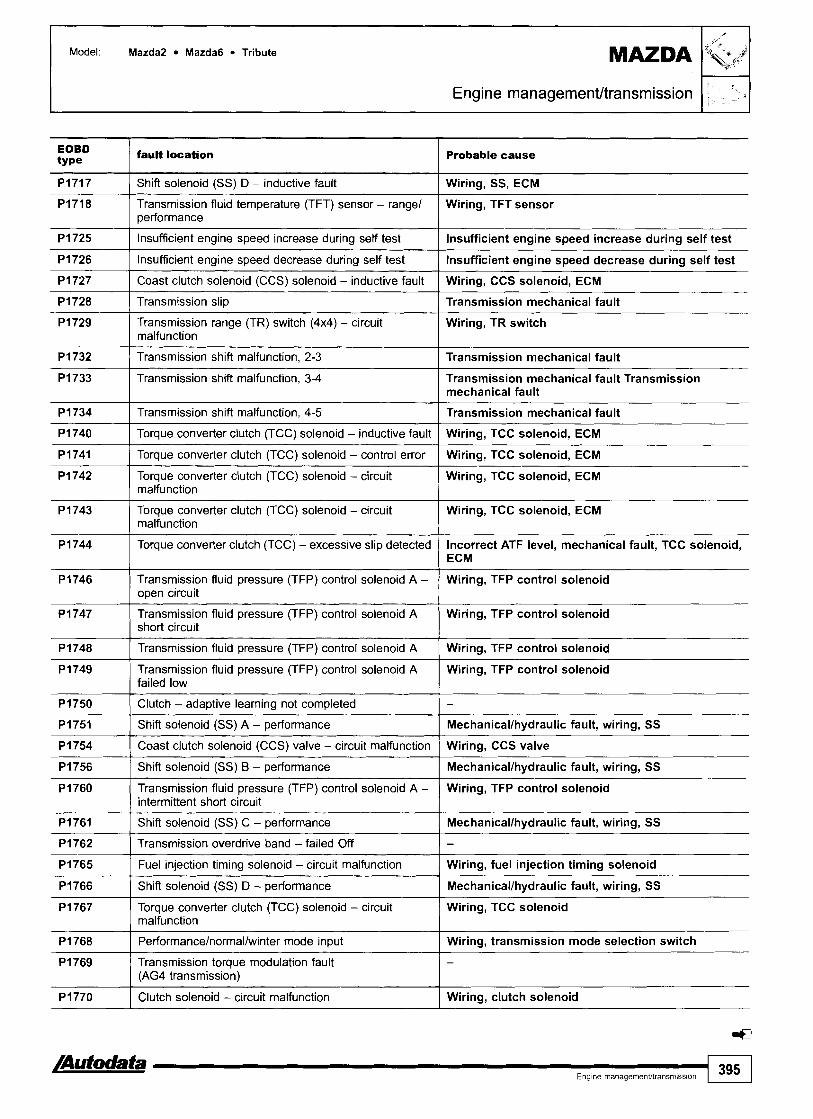
Model: Mazda2 Mazda6 Tribute
Engine managementltransrnission El EOBD type / fault location Probable cause
PI717 I Shift solenoid (SS) D - inductive fault I Wiring, SS, ECM
PI718 Transmission fluid temperature (TFT) sensor - range1 Wiring, TFT sensor performance
PI726 I Insufficient engine speed decrease during self test I Insufficient engine speed decrease during self test
P I 725
PI727 1 Coast clutch solenoid (CCS) solenoid - inductive fault I Wiring, CCS solenoid, ECM
PI728 1 Transmission slip ( Transmission mechanical fault
Insufficient engine speed increase during self test
PI729 Transmission range (TR) switch (4x4) - circuit malfunction
Insufficient engine speed increase during self test
I Wiring, TR switch
PI734 1 Transmission shift malfunction, 4-5 I Transmission mechanical fault
P I 732
P I 733
PI740 I Torque converter clutch (TCC) solenoid - inductive fault I Wiring, TCC solenoid, ECM
Transmission shift malfunction, 2-3
Transmission shift malfunction, 3-4
- - -- -- -
Transmission mechanical fault
Transmission mechanical fault Transmission mechanical fault
PI741
P I 742
PI746 Transmission fluid pressure (TFP) control solenoid A - Wiring, TFP control solenoid open circuit
PI743
P I 744
Torque converter clutch (TCC) solenoid - control error
Torque converter clutch (TCC) solenoid - circuit malfunction
PI749 Transmission fluid pressure (TFP) control solenoid A Wiring, TFP control solenoid failed low
-- -
Wiring, TCC solenoid, ECM -
Wiring, TCC solenoid, ECM
Torque converter clutch (TCC) solenoid - circuit malfunction
Torque converter clutch (TCC) - excessive slip detected
P I 747
PI748
PI750 ( Clutch - adaptive learning not completed 1 -
Wiring, TCC solenoid, ECM
Incorrect ATF level, mechanical fault, TCC solenoid, ECM
Transmission fluid pressure (TFP) control solenoid A short circuit
Transmission fluid pressure (TFP) control solenoid A
PI756 1 Shift solenoid (SS) B - performance I Mechanicallhydraulic fault, wiring, SS
Wiring, TFP control solenoid
Wiring, TFP control solenoid
PI751
PI754
PI765 1 Fuel injection timing solenoid - circuit malfunction I Wiring, fuel injection timing solenoid
Shift solenoid (SS) A - performance
Coast clutch solenoid (CCS) valve - circuit malfunction
PI760
P I 761
PI762
PI766 / Shift solenoid (SS) D - performance I Mechanicallhydraulic fault, wiring, SS
Mechanicallhydraulic fault, wiring, SS
Wiring, CCS valve
Transmission fluid pressure (TFP) control solenoid A - intermittent short circuit
Shift solenoid (SS) C - performance
Transmission overdrive band - failed Off
PI769 Transmission torque modulation fault (AG4 transmission)
Wiring, TFP control solenoid
Mechanicallhydraulic fault, wiring, SS
-
P I 767
P I 768
Torque converter clutch (TCC) solenoid - circuit malfunction
Performancelnormallwinter mode input
PI770
Wiring, TCC solenoid
Wiring, transmission mode selection switch
Clutch solenoid - circuit malfunction Wiring, clutch solenoid

Model: Mazda2 Mazda6 Tribute
1 31 Engine managementltransmission I EOBD type
fault location Probable cause I I
PI771 I Shift solenoid (SS) E - performance I Wiring, SS
PI773 1 CAN data bus - fuel fired heater malfunction I Wiring, fuel fired heater
PI779 1 Transmission warning lamp - circuit malfunction I Wiring, transmission warning lamp
P I 780 Transmission mode selection switch, OID Cancel - Wiring, transmission mode selection switch circuit out of self test range 1 Transmission range (TR) switch (4x4L) - out of self test Wiring, TR switch range
PI784 1 Transmission mechanical failure - first and reverse I Transmission mechanical fault
PI782
P I 783
PI785 1 Transmission mechanical failure - first and second I Transmission mechanical fault
PI786 1 Transmission downshift error, 3-2 I -
Transmission mode selection switch, performance1 economy - out of self test range
Transmission over temperature condition
Wiring, transmission mode selection switch
Transmission mechanical fault
P I 787
P I 788
PI794 1 Engine control module - supply voltage I Fuses, wiring, battery, alternator
P I 789
-
P I 792
Transmission downshift error, 2-1
Transmission fluid pressure (TFP) control solenoid B open circuit
Transmission clutch interlock safety switch - open Wiring, transmission clutch interlock safety switch circuit
-
Wiring, TFP control solenoid
Transmission fluid pressure (TFP) control solenoid B short circuit
Barometric pressure (BARO) sensor - circuit malfunction
P I 795
P I 800
P I 802 Transmission clutch interlock safety switch - short Wiring circuit to positive
Wiring, TFP control solenoid
Wiring, BAR0 sensor
P I 803 Transmission clutch interlock safety switch - short circuit to earth I Wiring
CAN data bus - level inconsistent
Transmission clutch interlock safety switch - circuit malfunction
Wiring, ECM
Wiring, transmission clutch interlock safety switch, mechanical fault
P I 804
P I 805
PI806 Transmission mode selection lamp, 4x4 high - short circuit to positive
PI807 Transmission mode selection lamp, 4x4 high - short circuit to earth t Transmission mode selection lamp, 4x4 low - short Wiring, selection lamp, instruments, ECM circuit to positive
Transmission mode selection lamp, 4x4 high - circuit malfunction
Transmission mode selection lamp, 4x4 high - open circuit
Wiring, selection lamp, instruments, ECM
Wiring, selection lamp, instruments, ECM
PI808
PI809
Transmission mode selection lamp, 4x4 low - indicator Wiring, selection lamp, instruments, ECM short circuit to earth
Wiring, selection lamp, instruments, ECM
Wiring, selection lamp, instruments, ECM
Transmission mode selection lamp, 4x4 low - circuit malfunction
Transmission mode selection lamp, 4x4 low - open circuit
Wiring, selection lamp, instruments, ECM
Wiring, selection lamp, instruments, ECM

Model: Mazda2 Mazda6 Tribute
Engine management/transmission 1 4 1 ' -
EOBD type
Pi814 Transmission mode selection switch, 4x4 - short circuit Wiring, transmission mode selection switch, ECM to positive
fault location
Wiring, transmission mode selection switch, ECM
Wiring, transmission mode selection switch, ECM
1
P l 817 I Neutral position (NP) switch - open circuit I Wiring, NP switch
Probable cause
Pi812
PI813
PI815
PI816
PI818 I Neutral position (NP) switch - short circuit to positive I Wiring
Transmission mode selection switch, 4x4 - circuit malfunction
Transmission mode selection switch, 4x4 - open circuit
Pi819 I Neutral position (NP) switch - short circuit to earth I Wiring
Transmission mode selection switch, 4x4 - short circuit to earth
Neutral position (NP) switch - circuit malfunction
Wiring, transmission mode selection switch, ECM
Wiring, NP switch
Pi820
PI821
P l 824 Transmission system relay, 4x4 clutch - circuit malfunction
PI822 Transmission system relay, transfer case clockwise
P l 823 Transmission system relay, transfer case clockwise shift - short circuit to earth
1 Wiring, transmission system relay
Transmission system relay, transfer case clockwise shift - circuit malfunction
Transmission system relay, transfer case clockwise shift - open circuit
Wiring, shift relay
Wiring, shift relay
Wiring, shift relay
Wiring, shift relay
P l 827 Transmission system relay, 4x4 low clutch - short circuit Wiring, transmission system relay to earth
P l 825
Pi826
P l 828 Transmission system relay, transfer case anticlockwise Wiring, transmission system relay shift - circuit malfunction
PI829 Transmission system relay, transfer case anticlockwise Wiring, transmission system relay shift - open circuit
Transmission system relay, 4x4 clutch - open circuit
Transmission system relay, 4x4 clutch - short circuit to battery
Wiring, transmission system relay
Wiring, transmission system relay
P l 832 Differential lock actuator, transfer case - circuit malfunction
Pi830
P l 831
/ Wiring, differential lock actuator
Transmission system relay, transfer case anticlockwise shift - short circuit to positive
Transmission system relay, transfer case anticlockwise shift - short circuit to earth
Wiring, transmission system relay
Wiring, transmission system relay
PI833
P l 834
Pi838 ( Transfer case shift motor - circuit malfunction I Wiring, transfer case shift motor
PI835
PI836
P l 837
- - - -- --
~ 1 8 3 9 - 1 Transfer case shift motor - open circuit
Differential lock actuator, transfer case - open circuit
Differential lock actuator, transfer case - short circuit to positive
1 Wiring, transfer case shift motor
Wiring, differential lock actuator
Wiring, differential lock actuator
Differential lock actuator, transfer case - short circuit to earth
Transfer case front shaft speed sensor - circuit malfunction
Transfer case rear shaft speed sensor - circuit malfunction
Wiring, differential lock actuator
Wiring, speed sensor
Wiring, speed sensor

Model: Mazda2 Mazda6 Tribute
1 b- i' .I Engine management/transmission
EOBD type
PI840
fault location Probable cause 1
Transfer case shift motor - short circuit to positive I Wiring, transfer case shift motor
Transfer case shift motor - short circuit to earth I Wiring, transfer case shift motor
Differential lock switch, feedback - transfer case -short Wiring, differential lock switch circuit to positive
Differential lock switch, feedback - transfer case - circuit malfunction
Differential lock switch, feedback - transfer case -open circuit
Wiring, differential lock switch
Wiring, differential lock switch
Transfer case contact plate A open circuit I Wiring, transfer case contact plate
Differential lock switch, feedback -transfer case -short circuit to earth
Transfer case contact plate A circuit malfunction
Transfer case contact plate A short circuit to positive I Wiring, transfer case contact plate
Wiring, differential lock switch
Wiring, transfer case contact plate
Transfer case contact plate B open circuit I Wiring, transfer case contact plate
Transfer case contact plate A short circuit to earth
Transfer case contact plate B circuit malfunction
Transfer case contact plate B short circuit to positive I Wiring, transfer case contact plate
Wiring, transfer case contact plate
Wiring, transfer case contact plate
Transfer case contact plate B short circuit to earth I Wiring, transfer case contact plate
Transfer case contact plate C short circuit to positive ( Wiring, transfer case contact plate
Transfer case contact plate C circuit malfunction
Transfer case contact plate C open circuit
Transfer case contact plate C short circuit to earth I Wiring, transfer case contact plate
Wiring, transfer case contact plate
Wiring, transfer case contact plate
Transfer case contact plate D circuit malfunction I Wiring, transfer case contact plate
Transfer case contact plate D short circuit to earth I Wiring, transfer case contact plate
Transfer case contact plate D open circuit
Transfer case contact plate D short circuit to positive
Transfer case contact plate - circuit malfunction 1 Wiring, transfer case contact plate
Wiring, transfer case contact plate
Wiring, transfer case contact plate
Transfer case contact plate - open circuit I Wiring, transfer case contact plate
Transfer case system concern - servicing required I -
Transfer case contact plate - short circuit to battery
Transfer case contact plate - short circuit to earth
Transfer case contact plate - circuit malfunction I Wiring, transfer case contact plate
Wiring, transfer case contact plate
Wiring, transfer case contact plate
Transmission mode selection lamp, 4x4 - circuit malfunction
Transmission mode selection lamp, 4x4 - short circuit to positive
Wiring, selection lamp, instruments, ECM
Wiring, selection lamp, instruments, ECM
Transmission mode selection switch, mechanical transfer case 4x4 - circuit malfunction
Transmission mode selection switch, mechanical transfer case 4x4 - short circuit to positive
Wiring, transmission mode selection switch
Wiring, transmission mode selection switch
Transmission mode selection lamp, axle lock - mechanical 4x4 - circuit malfunction
Transmission mode selection lamp, axle lock - mechanical 4x4 - short circuit to positive
Wiring, transmission mode selection lamp
Wiring, transmission mode selection lamp

Model: Mazda2 Mazda6 Tribute
EOBD type
fault location
Engine management/transmission
Probable cause
i -> a
P I 876 Transmission mode control solenoid, transfer case 2x4 - circuit malfunction
Wiring, hall effect sensor
Wiring, hall effect sensor
Wiring, transmission mode control solenoid
P I 877 Transmission mode control solenoid, transfer case 2x4 - short circuit to positive
P I 878 Transmission mode control solenoid, transfer case disengaged - circuit malfunction
PI879 Transmission mode control solenoid, transfer case disengaged - open circuit
Wiring, transmission mode control solenoid
Wiring, transmission mode control solenoid
Wiring, transmission mode control solenoid
PI880 Transmission mode control solenoid, transfer case disengaged - short circuit to positive
PI881 Engine coolant 'low' warning lamp switch - circuit malfunction
Wiring, transmission mode control solenoid
Wiring, engine coolant 'low' warning lamp switch
P I 882 Engine coolant 'low' warning lamp switch - short circuit to earth
Wiring, engine coolant 'low' warning lamp switch
PI883 Engine coolant 'low' warning lamp switch - circuit malfunction
P I 884 Engine coolant 'low' warning lamp switch - short circuit to earth
Wiring, engine coolant 'low' warning lamp switch
Wiring, engine coolant 'low' warning lamp switch
P I 885 Transmission mode control solenoid, transfer case disengaged - short circuit to earth
PI886 Transmission - 4x4 initialization failure
P I 889 Oil pressure pump - performance
PI890 Transmission 4x4 mode select, return - circuit malfunction
Wiring, transmission mode control solenoid
PI891 I Transfer case contact plate - open circuit Wiring, transfer case contact plate
PI892 Axle disconnect engagement solenoid - voltage high
P I 893 Axle disconnect engagement solenoid - voltage low
PI894 Axle disconnect disengagement solenoid - voltage high
PI895 Axle disconnect disenqagement solenoid - vottaqe low
Wiring, axle disconnect engagement solenoid
Wiring, axle disconnect engagement solenoid
Wiring, axle disconnect disengagement solenoid
Wiring, axle disconnect disengagement solenoid
P I 896 Axle disconnect engagement position sensor - voltage / high Wiring, axle disconnect engagement position sensor
P I 897 Axle disconnect engagement position sensor - voltage low
P I 898 Transmission mode selection lamp, axle disconnect - voltage high
Wiring, axle disconnect engagement position sensor
Wiring, selection lamp
P I 899 Transmission mode selection lamp, axle disconnect - voltage low
PI900 Transmission output shaft speed sensor - circuit intermittent
Wiring, selection lamp
- - - - - -
Wiring, transmission output shaft speed sensor
PI901 Transmission turbine shaft speed (TSS) sensor - circuit intermittent
Wiring, TSS sensor
PI902 Transmission kick-down relay - control circuit malfunction
PI903 Transmission kickdown relay - voltage low
Wiring, transmission kick-down relay
Wiring, transmission kick-down relay

Model: Mazda2 Mazda6 Tribute
EOBD type
fault location
' L ---
Probable cause
Engine managementltransmission
PI906 Kick-down relay (A4LD transmission) - pull on, open1 Wiring, kick-down relay short circuit
PI904
PI905
Transmission kick-down relay - voltage high
Control module confiqured for end of line test mode
PI907
PI908
PI912 I Reversing lamp, control - voltage high I Wiring, reversing lamp switch
Wiring, transmission kick-down relay
-
PI909
PI910
PI911
PI913 I Sensor earth, A - open circuit I Wiring, ECM
Kick-down relay (A4LD transmission) - hold, openlshort circuit
Transmission fluid pressure (TFP) solenoid (A4LD transmission) - openlshort circuit
Wiring, kick-down relay
Wiring, TFP solenoid
Transmission fluid temperature (TFT) sensor (A4LD transmission) - openlshort circuit
Reversing lamp, control - open circuit
Reversing lamp, control - voltage low
PI916 I Sensor earth, B - open circuit I Wiring, ECM
Wiring, TFT sensor
Wiring, reversing lamp switch
Wiring, reversing lamp switch
PI914
PI915
PI917 ( Sensor earth, B - voltage low I Wiring, ECM
PI918 I Sensor earth, B - voltage high I Wiring, ECM
Sensor earth, A - voltage low
Sensor earth, A - voltage high
Wiring, ECM
Wiring, ECM
PI933 1 Fuel level signal I Wiring, fuel gauge tank sensor
PI919
PI920
PI921
PI934 ( Vehicle speed signal I Wiring, VSS
PI935 1 Brake switchlsensor signal 1 Wiring, BPP switchlsensor
Engine coolant temperature signal, TCM
Engine speed signal, TCM
Transmission range (TR) signal
Wiring, ECT sensor
Wiring
Wiring, TR sensorlswitch
P I 938 I Fuel fired heater, control - voltacle low I Wiring
PI939 ( Fuel fired heater, control - vottage high I Wiring
Wiring, CPP switchlsensor
Wiring
-
P I 936
PI937
- -
~lutchswitch~sensor sign;
Fuel fired heater, control - open circuit
U1021
U1039
U1041
U1051
U1089 I Communication link - invalid/rnissing for suspension I -
Communication link - invalidlmissing for AC clutch input
Communication link - invalidlmissing for vehicle speed
U1073
U1075
U1098 I Communication link - invalidlmissing for cruise control ( -
- -
Communication link - invalidlmissing for vehicle speed
Communication link - invalidlmissing for brake input
- -
Communication link - invalidlmissing for engine coolant fan status
Communication link - invalid/missing for engine oil temperature (EOT)
-
-
U1130
U1131
Communication link - invalidknissing for fuel system
Communication link - invalid/missing for fuel pump (FP) status
- -

Model: Mazda2 Mazda6 Tribute
Engine management/transmission 1-1 11 -
EOBD type
fault location Probable cause
U1147 I Communication link - invalidlrnissing for vehicle security I -
U1135
U1243 Communication link - invalid/missing for exterior environment
U1262 1 Communication link - bus fault I -
Communication link - invalidlmissing for ignition switch1 starter
-
U1900 I Controller area network (CAN) - bus fault I Wiring
U1341
U1451
U2023 1 Fault received from external node I - U2050 I No application present I -
Communication link - invalidlmissing for function read vehicle speed
Communication link - invalidlmissing data from immobilizer control module, vehicle immobilized
-
Wiring, immobilizer control module
U2051
U2064
U2195
U2510
--
One or more calibration files missinglcorrupt
Warning lamp requested by another control module
--
- -
a
Communication link - ~nvalid data from steering column switches
CAN data bus - malfunction
Wiring, steering column switches
Wiring

I MAZDA
~5.1 323 (BG) 323 Estate 1,614~4 (BW) 323 (BA) 323 1,311,511.8 (BJ) 323 2.0 D/TD (BJ) 626lMX-6 (GE) 626lEstate 1,812,O (GFIGW) 626lEstate 2,O TD (GFIGW) Xedos 619 MX-3lMX-5
Year: 1989-03 Engine BP, BP-DOHC, B3, B3E, B6, B6-SOHC, B6-DOHC, B6E, FP, FS, KF, KJ, KL K8, RF, RF-CX, RF-Turbo, code: ZL, 25
System: Mazda EGI Mazda EDC
Engine managementftransmission
323 - engine bay, LH 6261Estate 1998 -+ - engine bay, LH
626 4997lMX-6, Xedos 619, MX-3 - engine bay, LH MX-5 - near brake master cylinder
General information
Except Xedos 9 2,3
0 Refer to the front of this manual for general test conditions, terminology, detailed descriptions of wiring faults and a general trouble shooter for electrical and mechanical faults.
DLC without wiringlterrninals in positions FAT & TAT: Engine control module (ECM) incorporates transmission control function.
0 DLC with wiringlterminals in positions FAT & TAT: Transmission control module (TCM) mounted separately.
0 The ECM fault memory can also be checked and erased using diagnostic equipment connected to the data link connector (DLC).
Trouble codes are displayed by using an LED connected to Xedos 2,3 the data link connector (DLC). Except 323 1998 +, 626lEstatelMX-5 1997 +: Engine Refer to the front of this manual for general test conditions,
control module (ECM) displays all available diagnostic terminology, detailed descriptions of wiring faults and a
information for immobilizer system. general trouble shooter for electrical and mechanical faults. 0 Trouble codes are displayed by using an LED connected to
the data link connector (DLC)..

Model. 323 (BG) 323 Estate 1.614~4 (BW) 323 ( 6 1 ) 323 1,311,Yl.B (BJ) 323 2.0 DirD (BJ) 6261MX-6 (GE) MAZDA 626lEstate 1,812,O (GFIGW) 6261Estate 2,O TD (GFIGW) Xedos 619 MX-31MX-5
Engine management/transmission
Engine control module (ECM) displays all available diagnostic information for immobilizer system.
n Transmission control module (TCM) mounted separately. 0 Data bus connecting ECM to TCM allows faults relating to
both systems to be displayed when accessing ECM fault memory.
il The ECM/TCM fault memory can also be checked and erased using diagnostic equipment connected to the data link connector (DLC).
Accessing Ensure ignition switched OFF. Bridge data link connector (DLC) terminals GND and TEN a. Connect LED test lamp between terminals FEN and B+ O.
NOTE: Connect LED test lamp positive connection to DLC terminal B+.
Switch ignition ON. Count LED flashes. Note trouble codes. Compare with trouble code table. Two digit trouble codes are displayed as follows:
n Long flashes indicate the 'tens' [A]. Short flashes indicate the 'units' rn [C]. For example: Trouble code 12 displayed H. Four digit trouble codes are displayed as follows:
n Each trouble code consists of four groups. A long flash indicates the start of each group [A]. Short flashes indicate the digits of each group [B].
n No short flashes in a group indicate '0'. n For example: Trouble code 0120 displayed El.
Switch ignition OFF. Rectify faults as necessary.
L GND
FEN \ 1 TEN I I /"T
Trouble code identification
Erasing Ensure ignition switched OFF. Disconnect battery earth lead for at least 30 seconds. Depress brake pedal for at least 20 seconds. Reconnect battery earth lead. Repeat checking procedure to ensure no data remains in ECM fault memory.
WARNING: Disconnecting the battery may erase memory from electronic units (e.g. radio, clock).
Flash type Fault location Probable cause I I
0 1 I Ignition pulse missing I Wiring, tachometer, ignition coil, distributor, ECM, TCM
02 I Diesel: Engine speed (RPM) sensor - no signal I Wiring, RPM sensor
02
03
Petrol: Crankshaft position (CKP) sensorlengine speed (RPM) sensor - no signal
Camshaft position (CMP) sensor - no signal
Wiring, sensor supply voltage, CKPIRPM sensor
Wiring, sensor supply voltage, CMP sensor
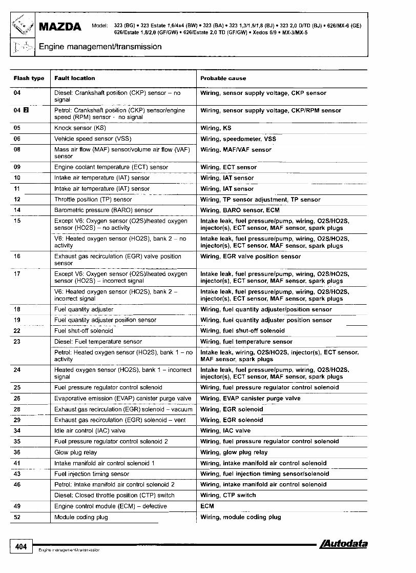
MAZDA Model: 323 (BG) 323 Estate 1,614~4 (BW) 323 (BA) 323 1,311,511,8 (BJ) 323 2,O D/TD (BJ) 6261MX-6 (GE) 626lEstate 1,812,O (GFIGW) 626lEstate 2,O TD (GFIGW) Xedos 619 MX-3lMX-5
1 b--> Engine rnanagernent/transrnission
Flash type Fault location Probable cause
Diesel: Crankshaft position (CKP) sensor - no signal
Wiring, sensor supply voltage, CKP sensor
Petrol: Crankshaft position (CKP) sensorlengine speed (RPM) sensor - no signal
Knock sensor (KS)
Wiring, sensor supply voltage, CKPIRPM sensor
Wiring, KS
Vehicle speed sensor (VSS) Wiring, speedometer, VSS
Mass air flow (MAF) sensor/volume air flow (VAF) sensor
Engine coolant temperature (ECT) sensor
lntake air temperature (IAT) sensor
Wiring, MAFNAF sensor
Wiring, ECT sensor
Wiring, IAT sensor
lntake air temperature (IAT) sensor Wiring, IAT sensor
Throttle position (TP) sensor Wiring, TP sensor adjustment, TP sensor
Barometric pressure (BARO) sensor
Except V6: Oxygen sensor (02S)lheated oxygen sensor (H02S) - no activity
Wiring, BARO sensor, ECM
lntake leak, fuel pressurelpump, wiring, 02SIH02S, injector(s), ECT sensor, MAF sensor, spark plugs
V6: Heated oxygen sensor (H02S), bank 2 - no activity
Exhaust gas recirculation (EGR) valve position sensor
lntake leak, fuel pressurelpump, wiring, 02SIH02S, injector(s), ECT sensor, MAF sensor, spark plugs
Wiring, EGR valve position sensor
Except V6: Oxygen sensor (02S)lheated oxygen sensor (H02S) - incorrect signal
V6: Heated oxygen sensor (HOZS), bank 2 - incorrect signal
lntake leak, fuel pressurelpump, wiring, 02SIH02S, injector(s), ECT sensor, MAF sensor, spark plugs
lntake leak, fuel pressurelpump, wiring, 02SIH02S, injector(s), ECT sensor, MAF sensor, spark plugs
Fuel quantity adjuster Wiring, fuel quantity adjusterlposition sensor
Fuel quantity adjuster position sensor Wiring, fuel quantity adjuster position sensor
Fuel shut-off solenoid
Diesel: Fuel temperature sensor
Wiring, fuel shut-off solenoid
Wiring, fuel temperature sensor
Petrol: Heated oxygen sensor (HOZS), bank 1 - no activity
lntake leak, wiring, 02SIH02S, injector(s), ECT sensor, MAF sensor, spark plugs
Heated oxygen sensor (HOZS), bank 1 - incorrect signal
Fuel pressure regulator control solenoid
lntake leak, fuel pressurelpump, wiring, 02SIH02S, injector(s), ECT sensor, MAF sensor, spark plugs
Wiring, fuel pressure regulator control solenoid
Evaporative emission (EVAP) canister purge valve Wiring, EVAP canister purge valve
Exhaust gas recirculation (EGR) solenoid - vacuum
Exhaust gas recirculation (EGR) solenoid - vent
Idle air control (IAC) valve
Wiring, EGR solenoid
Wiring, EGR solenoid
Wiring, IAC valve
Fuel pressure regulator control solenoid 2 Wiring, fuel pressure regulator control solenoid
Glow plug relay
lntake manifold air control solenoid 1
Wiring, glow plug relay
Wiring, intake manifold air control solenoid
Wiring, fuel injection timing sensorlsolenoid Fuel injection timing sensor
Petrol: lntake manifold air control solenoid 2 Wiring, intake manifold air control solenoid
Diesel: Closed throttle position (CTP) switch Wiring, CTP switch
Engine control module (ECM) - defective
Module coding plug
ECM
Wiring, module coding plug
1 404 ....................
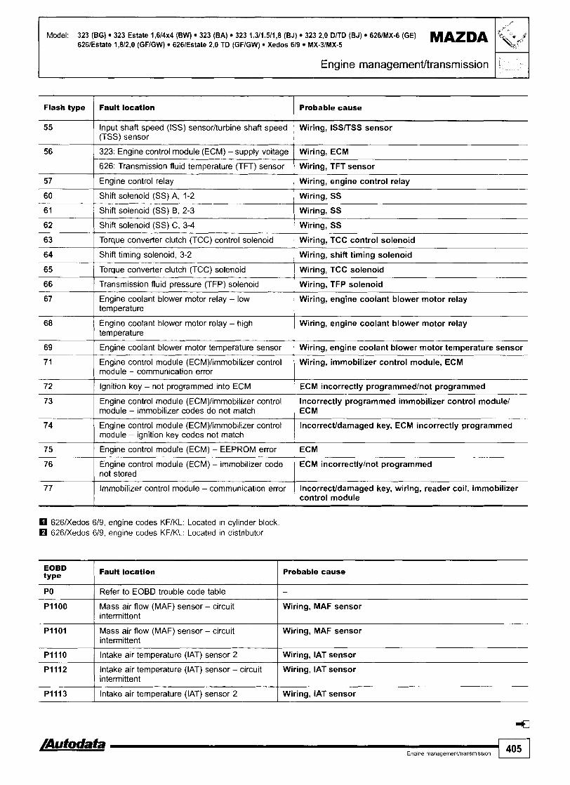
Model: 323 (BG) 323 Estate 1,614~4 (BW) 323 (BA) 323 1,311,511,8 (BJ) 323 2,O DlTD (BJ) 6261MX-6 (GE) MAZDA 6261Estate 1,812,O (GFIGW) 6261Estate 2,O TD (GFIGW) Xedos 619 MX-31MX-5
Engine management~transmission
Flash type
1 626: Transmission fluid temperature (TFT) sensor 1 Wiring, TFT sensor
55
56
57 / Engine control relay I Wiring, engine control relay
Fault location
60 I Shift solenoid (SS) A, 1-2 I Wiring, SS
Probable cause
Input shaft speed (ISS) sensorlturbine shaft speed (TSS) sensor
323: Engine control module (ECM) -supply voltage
Wiring, ISS/TSS sensor
Wiring, ECM
63 I Torque converter clutch (TCC) control solenoid ( Wiring, TCC control solenoid
6 1
62
64 I Shift timing solenoid, 3-2 I Wiring, shift timing solenoid
65 ( Torque converter clutch (TCC) solenoid I Wiring, TCC solenoid
Shift solenoid (SS) B, 2-3
Shift solenoid (SS) C, 3-4
- -
Wiring, SS
Wiring, SS
66
67
72 I Ignition key - not programmed into ECM I ECM incorrectly programmedlnot programmed
68
69
71
Engine control module (ECM)/immobilizer control Incorrectly programmed immobilizer control module1 module - immobilizer codes do not match 1 ECM
Transmission fluid pressure (TFP) solenoid
Engine coolant blower motor relay - low temperature
Engine control module (ECM)/immobilizer control lncorrectldamaged key, ECM incorrectly programmed module - ignition key codes not match
Wiring, TFP solenoid
Wiring, engine coolant blower motor relay
Engine coolant blower motor relay - high temperature
Engine coolant blower motor temperature sensor
Engine control module (ECM)limmobilizer control module - communication error
75 I Engine control module (ECM) - EEPROM error I ECM
Wiring, engine coolant blower motor relay
Wiring, engine coolant blower motor temperature sensor
Wiring, immobilizer control module, ECM
Engine control module (ECM) - immobilizer code ECM incorrectlylnot programmed not stored
626lXedos 619, engine codes KFIKL: Located in cylinder block 626lXedos 619, engine codes KFIKL: Located in distributor.
77
PO I Refer to EOBD trouble code table I -
- Immobilizer control module - communication error
EOBD type
Pi100 Mass air flow (MAF) sensor - circuit intermittent
lncorrectldamaged key, wiring, reader coil, immobilizer control module
I Wiring, MAF sensor
Fault location
Mass air flow (MAF) sensor - circuit intermittent
Probable cause
I Wiring, MAF sensor
P i l l 0 I Intake air temperature (IAT) sensor 2 I Wiring, IAT sensor
P i l l 3 I Intake air temperature (IAT) sensor 2 I Wiring, IAT sensor
P i l l 2 Intake air temperature (IAT) sensor - circuit intermittent
Wiring, IAT sensor

MAZDA Model 323 (BG) 323 Estate 1,614~4 (BW) 323 (BA) 323 1,311,511,8 (BJ) 323 2,O DrrD (BJ) 6261MX-6 (GE) 6261Estate 1,812,O (GFIGW) 6261Estate 2,O TD (GFIGW) Xedos 619 MX-31MX-5
EOBD type
Fault location
, - ' -
Probable cause
Engine rnanagementltransmission
Wiring, ECT sensor Eng~ne coolant temperature (ECT) sensor - circuit intermittent
P1120 I Throttle position (TP) sensor - low input Wiring short to earth, TP sensor
Wiring, TP sensor P1125
P1130 lntakelexhaust leak, fuel pressurelpump, EVAPIEGR system, wiring, H02S
Throttle position (TP) sensor - circuit intermittent
Fuel trim (FT) - control limit exceeded
Heated oxygen sensor (H02S) - low voltage lntakelexhaust leak, fuel pressure low, hose connection, HO2Slwiring short to earth, injector@), MAF sensorlwiring
Heated oxygen sensor (H02S) - high voltage lntakelexhaust blockage, fuel pressure high, EVAPIEGR system, HO2Slwiring short to positive, injector(s), MAF sensor
Oxygen sensor (02S)lheated oxygen sensor (H02S), bank 1 - incorrect signal
Intake leak, fuel pressurelpump, wiring, 02SIH02S, injector(s), ECT sensor, MAF sensor, spark plugs
Intake leak, fuel pressurelpump, wiring, 02SIH02S, injector@), ECT sensor, MAF sensor, spark plugs
P1173 Oxygen sensor (02S)lheated oxygen sensor (HOZS), bank 2 - incorrect signal
Pi182 I Fuel shut-off solenoid Wiring, fuel shut-off solenoid
Pi189 I Fuel injection pump positionlspeed sensor Wiring, fuel injection pump speed sensor
Wiring, module coding plug P1190
Pi195 Wiring, BARO sensor, ECM
Module coding plug
Barometric pressure (BARO) sensor
Pi196 I Ignition switch, start signal -circuit malfunction Wiring, starter motor
PI221 I Traction control system (TCS) - malfunction Wiring, TCS malfunction
Wiring, fuel quantity adjuster position sensor PI226 Fuel quantity adjuster position sensor - circuit malfunction
P1250 I Fuel pressure regulator control solenoid Wiring, fuel pressure regulator control solenoid
P1252 1 Fuel pressure regulator control solenoid 2 Wiring, fuel pressure regulator control solenoid
P1279 Fuel quantity adjuster position sensor - range1 performance problem
Wiring, fuel quantity adjuster position sensor
P1298 Fuel quantity adjuster control module - circuit malfunction
Wiring, fuel quantity adjuster control module
P1312 I Fuel injection timing valve Wiring, fuel injection timing valve
P1318 Fuel injection timing valve position sensor - circuit malfunction
Wiring, fuel injection timing valve position sensor
PI319 Fuel injection timing valve position sensor -
P1345
sensor
Wiring, fuel injection timing valve position sensor
Wiring, sensor supply voltage, CMP sensor
Wiring, EGR valve position sensor
Exhaust gas recirculation (EGR) valve - circuit
Engine coolant blower motor relay - circuit malfunction
Wiring, EGR valve
Wiring, engine coolant blower motor relay
P1485 Exhaust gas recirculation (EGR) solenoid - vacuum
Wiring, EGR solenoid
P1486 Exhaust gas recirculation (EGR) solenoid - I vent Wiring, EGR solenoid
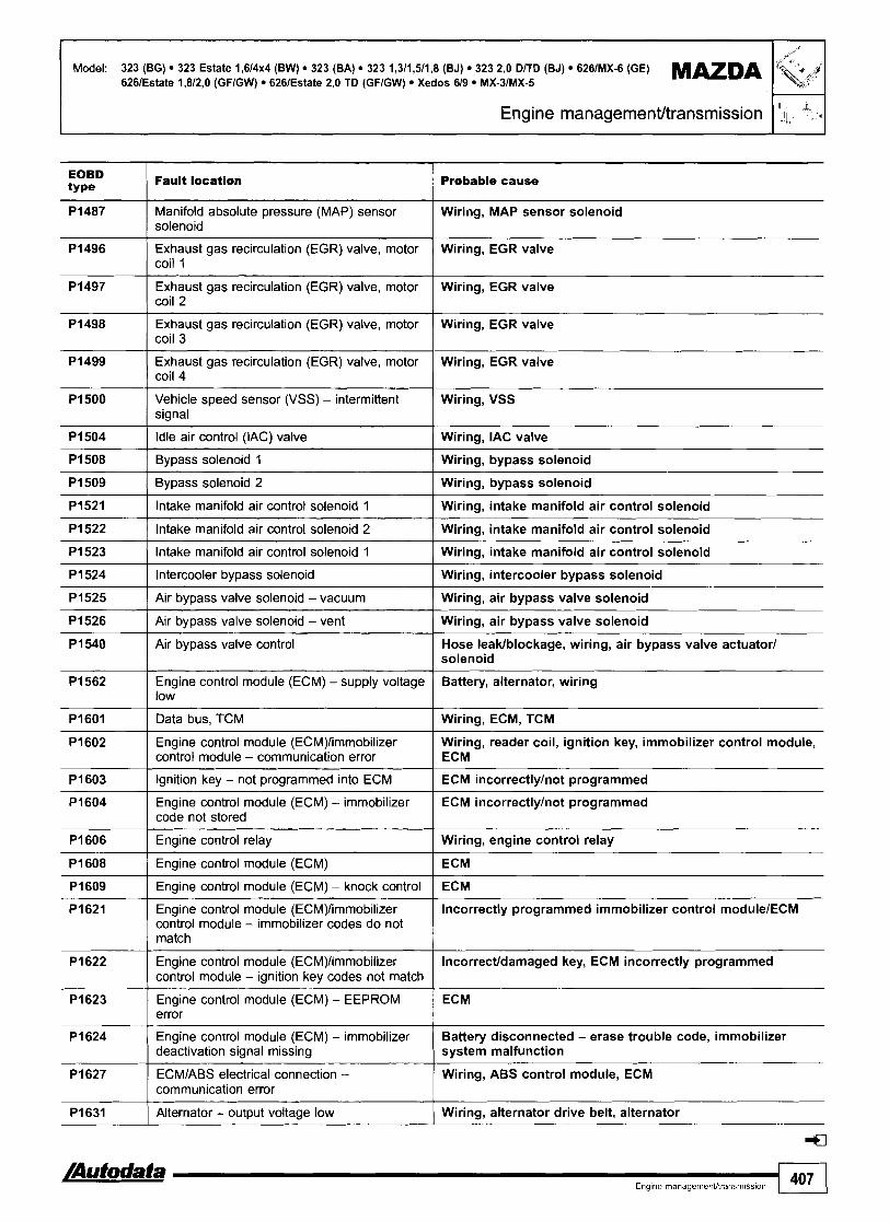
Model: 323 (BG) 323 Estate 1,614.4 (BW) 323 (BA) 323 1,311,511,8 (BJ) 323 2,O DlTD (BJ) 626lMX-6 (GE) M M D A 6261Estate 1,812,O (GFIGW) 6261Estate 2,O TD (GFIGW) Xedos 619 MX-31MX-5
Engine management/transmission 1 lI\- 1 EOBD type
Fault location Probable cause
Manifold absolute (MAP) sensor solenoid
- -- - -
Wiring, MAP sensor solenoid
Exhaust gas recirculation (EGR) valve, motor coil 1
Wiring, EGR valve
Exhaust gas recirculation (EGR) valve, motor coil 2
Exhaust gas recirculation (EGR) valve, motor coil 3
Wiring, EGR valve
Wiring, EGR valve
Exhaust gas recirculation (EGR) valve, motor coil 4
Wiring, EGR valve
Vehicle speed sensor (VSS) - intermittent signal
Wiring, VSS
Idle air control (IAC) valve Wiring, IAC valve
Bypass solenoid 1 Wiring, bypass solenoid
Bypass solenoid 2
lntake manifold air control solenoid 1
Intake manifold air control solenoid 2
Wiring, bypass solenoid
Wiring, intake manifold air control solenoid
Wiring, intake manifold air control solenoid
lntake manifold air control solenoid 1 Wiring, intake manifold air control solenoid
Intercooler bypass solenoid Wiring, intercooler bypass solenoid
Air bypass valve solenoid - vacuum
Air bypass valve solenoid - vent
Air bypass valve control
Wiring, air bypass valve solenoid
Wiring, air bypass valve solenoid
Hose leaklblockage, wiring, air bypass valve actuator1 solenoid
Engine control module (ECM) -supply voltage low
Battery, alternator, wiring
Data bus, TCM
Engine control module (ECM)limmobilizer control module - communication error
Wiring, ECM, TCM
Wiring, reader coil, ignition key, immobilizer control module, ECM
Ignition key - not programmed into ECM ECM incorrectlylnot programmed
Engine control module (ECM) - immobilizer code not stored
Engine control relay
ECM incorrectlylnot programmed
Wiring, engine control relay
Engine control module (ECM) ECM
Engine control module (ECM) - knock control ECM
Engine control module (ECM)limmobilizer control module - immobilizer codes do not match
Incorrectly programmed immobilizer control modulelECM
Engine control module (ECM)limmobilizer control module - ignition key codes not match
Engine control module (ECM) - EEPROM error
Engine control module (ECM) - immobilizer deactivation signal missing
lncorrectldamaged key, ECM incorrectly programmed
ECM
Battery disconnected - erase trouble code, immobilizer system malfunction
ECMlABS electrical connection - communication error
Wiring, ABS control module, ECM
Alternator - output voltage low Wiring, alternator drive belt, alternator
[Autodata a Engine rnanagemenUtransmtssion 407

MAZDA Model: 323 (BG) 323 Estate 1,614~4 (BW) 323 (BA) 323 1,311,511,8 (BJ) 323 2,0 D/TD (BJ) 6261MX-6 (GE) 6261Estate 1,812,O (GFIGW) 6261Estate 2,O TD (GFIGW) Xedos 619 MX-31MX-5
I FJ,;-'; Engine managementltransmission
EOBD ty Pe
P i 633 Engine control module (ECM) -supply voltage Wiring, voltage surge when battery disconnected, alternator I high
P i 632
P i 634 Alternator - output voltage high1 battery voltage low
Fault location
Wiring, alternator, battery
Probable cause
Engine control module (ECM) - supply voltage low
Pi649 I Engine control module (ECM) - defective ( ECM
Wiring, alternator, battery
Pi650 I Power steering pressure (PSP) switch I Wiring, PSP switch
Pi720 I Vehicle speed sensor (VSS) I Wiring, speedometer, VSS
Pi765 1 Shift timing solenoid, 3-2 I Wiring, shift timing solenoid
Pi743
Pi744
Pi770 I Overrunning clutch solenoid I Wiring, overrunning clutch solenoid
Torque converter clutch (TCC) solenoid
Torque converter clutch (TCC) solenoid
--
Wiring, TCC control solenoid
Wiring, TCC solenoid
Pi790
4
Throttle position (TP) sensor Wiring, TP sensor

Model: 323 1,311,611,812,O (BJ) 6261Estate 1,812,O (GFIGW) MX-5 l ,6l l ,8
Year: 2000-04
Engine code: BP, 83, B6, FP, FS, ZM System: Mazda EGI
Engine managementltransmission 1
FAB I=- GND TFA FIP TAB (m)
DLC 1 - 323 - engine bay, LH
I
DLC 1 - MX-5 - near brake master cylinder
DLC 1 - 6261Estate - engine bay, LH DLC 2 - fascia
General information n Refer to the front of this manual for general test conditions,
terminology, detailed descriptions of wiring faults and a general trouble shooter for electrical and mechanical faults.
n 3231626: Engine control module (ECM) incorporates transmission control module (TCM) function.
n MX-5: Transmission control module (TCM) mounted separately.
n MX-5: Data bus connecting ECM to TCM allows faults relating to both systems to be displayed when accessing ECM fault memory.
Accessing and erasing 3231626: The engine control module (ECM) fault memory can only be accessed and erased using diagnostic equipment connected to the data link connector (DLC). MX-5: The ECMITCM fault memory can only be accessed and erased using diagnostic equipment connected to the data link connector (DLC).

Model: 323 l,3/l,6Il,8/2,O (BJ) 6261Estate I,8/2,O (GFIGW) MX-5 1,611,8
1 i, 5: .I Engine managementltransmission
Trouble code identification
Probable cause EOBD type
Fault location I I
-- - -
Mass air flow (MAF) se&or/throttle position (TP) poorconnect=, MAF sensor, TP sensor signal incompatibility, lower than expected
PO I Refer to EOBD trouble code table
PI100
PI101
Mass air flow (MAF) sensorlthrottle position (TP) sensor - Wiring, poor connection, MAF sensor, TP sensor signal incompatibility, higher than expected
-
PI110 I Intake air temperature (IAT) sensor 2 I Wiring, IAT sensor
Mass air flow (MAF) sensor - circuit intermittent
Mass air flow (MAF) sensor - circuit intermittent
Wiring, MAF sensor
Wiring, MAF sensor
Engine coolant temperature (ECT) sensor - circuit intermittent
PI112
PI113
Wiring, ECT sensor
PI120 I Throttle position (TP) sensor - low input I Wiring short to earth, TP sensor
Intake air temperature (IAT) sensor - circuit intermittent
Intake air temperature (IAT) sensor 2
-- - -
Wiring, IAT sensor
Wiring, IAT sensor
PI123 I Throttle position (TP) sensor - signal high I Wiring short to positive, TP sensor, ECM
PI122
PI123 I Throttle position (TP) sensor - stuck open 1 Wiring, TP sensor, ECM
PI125 ( Throttle position (TP) sensor - circuit intermittent I Wiring, TP sensor
Throttle position (TP) sensor - signal low Wiring open circuitlshort to earth, poor connection, TP sensor, ECM
Heated oxygen sensor (H02S) - low voltage
PI130
lntakelexhaust leak, fuel pressure low, hose connection, HO2Siwiring short to earth, injector(s), MAF sensorlwiring
lntakelexhaust blockage, fuel pressure high, EVAPl EGR system, HO2Siwiring short to positive, injector(s), MAF sensor
Heated oxygen sensor (H02S) - high voltage
Fuel trim (FT) - control limit exceeded
Heated oxygen sensor (H02S) - incorrect signal
lntakelexhaust leak, fuel pressurelpump, EVAPIEGR system, wiring, H02S
lntake leak, fuel pressurelpump, wiring, 02SIH02S, injector(s), EVAP canister purge valve, ignition coil, low compression
Oxygen sensor (02S)lheated oxygen sensor (H02S), Intake leak, fuel pressureipump, wiring, 02SIH02S, bank 2 - incorrect signal injector(s), ECT sensor, MAF sensor, spark plugs
PI182 I Fuel shut-off solenoid I Wiring, fuel shut-off solenoid
P I 195 I Barometric pressure (BARO) sensor I Wiring, BAR0 sensor, ECM
- -
PI189
PI190
PI196 ( Ignition switch, start signal - circuit malfunction I Wiring, starter motor
- -- - - -
Fuel injection pump positionispeed sensor
Module coding plug
PI252 1 Fuel pressure regulator control solenoid 2 ( Wiring, fuel pressure regulator control solenoid
Wiring, fuel injection pump speed sensor
Wiring, module coding plug
P I 221
PI226
PI250
Traction control system (TCS) - malfunction
Fuel quantity adjuster position sensor - circuit malfunction
Fuel pressure regulator control solenoid - circuit malfunction
Fuel quantity adjuster position sensor - range1 performance problem
Fuel quantity adjuster control module - circuit malfunction
Wiring, TCS malfunction
Wiring, fuel qantity adjuster position sensor
Wiring, fuel pressure regulator control solenoid
Wiring, fuel qantity adjuster position sensor
Wiring, fuel qantity adjuster control module

Model: 323 1,311,611,812,O (BJ) 6261Estate 1,812,O (GFIGW) MX-5 1,611,8
I Engine rnanagernent/transrnission I 4 , ' I EOBD t Y Pe
Fault location Probable cause
PI318 Fuel injection timing valve position sensor - circuit Wiring, fuel injection timing valve position sensor malfunction
I I
P i 31 2
Pi409 Exhaust gas recirculation (EGR) valve - circuit I Wiring, EGR valve malfunction
Fuel injection timing valve I Wiring, fuel injection timing valve
P I 31 9
P I 345
Pi402
PI496 1 Exhaust gas recirculation (EGR) valve, motor coil 1 I Wiring, EGR valve
Fuel injection timing valve position sensor - range1 performance problem
Camshaft position (CMP) sensor - no signal
Exhaust gas recirculation (EGR) valve position sensor
Pi474
Pi485
PI486
Pi487
Pi497 I Exhaust gas recirculation (EGR) valve, motor coil 2 1 Wiring, EGR valve
Wiring, fuel injection timing valve position sensor
Wiring, sensor supply voltage, CMP sensor
Wiring, EGR valve position sensor
Engine coolant blower motor relay - circuit malfunction
Exhaust gas recirculation (EGR) solenoid - vacuum
Exhaust gas recirculation (EGR) solenoid - vent
Manifold absolute pressure (MAP) sensor solenoid
P i 504 1 Idle air control (IAC) valve - circuit malfunction I Wiring, IAC valve, ECM
Wiring, engine coolant blower motor relay
Wiring, EGR solenoid
Wiring, EGR solenoid
Wiring, MAP sensor solenoid
PI498
Pi499
P I 500
Pi508 ( Bypass solenoid 1 I Wiring, bypass solenoid
Pi509 I Bypass solenoid 2 I Wiring, bypass solenoid
Exhaust gas recirculation (EGR) valve, motor coil 3
Exhaust gas recirculation (EGR) valve, motor coil 4
Vehicle speed sensor (VSS) - intermittent signal
Wiring, EGR valve
Wiring, EGR valve
Wiring, VSS
Wiring short circuit, intake manifold air control solenoid, IAT sensor, BAR0 sensor, CKP sensor, MAF sensor, mechanical fault, ECM
PI512
P I 521 I Intake manifold air control solenoid 1 I Wiring, intake manifold air control solenoid
Intake manifold air control solenoid - stuck closed
Pi522 / Intake manifold air control solenoid 2 I Wiring, intake manifold air control solenoid
Pi523 1 Intake manifold air control solenoid 1 ( Wiring, intake manifold air control solenoid
P i 540 Air bypass valve control
P I 524
P I 525
P I 526
Hose leaklblockage, wiring, air bypass valve actuatorlsolenoid
Intercooler bypass solenoid
Air bypass valve solenoid - vacuum
Air bypass valve solenoid - vent
Wiring, intercooler bypass solenoid
Wiring, air bypass valve solenoid
Wiring, air bypass valve solenoid
P I 562
P I 569
Pi602 Engine control module (ECM)limmobilizer control Wiring, reader coil, ignition key, immobilizer control module - communication error module, ECM
P I 570
Pi601
Engine control module (ECM) - supply voltage low
Intake manifold air control solenoid - low input
Fuse, wiring open circuitlshort to earth, poor connection, battery, alternator
Wiring open circuitlshort to earth, poor connection, intake manifold air control solenoid, ECM
Intake manifold air control solenoid - high input
Data bus, TCM
Pi603
PI604
Wiring open circuitlshort to positive, poor connection, intake manifold air control solenoid, ECM
Wiring, ECM, TCM
Ignition key - not programmed into ECM
Engine control module (ECM) - immobilizer code not stored
ECM incorrectlylnot programmed
ECM incorrectlylnot programmed

Model: 323 l,3ll,6ll,8/2,O (BJ) 6261Estate l,8/2,O (GFIGW) MX-5 1,611,8
11 2 Engine managementltransmission
EOBD type
I Fault location Probable cause
PI606
P I 608
PI609
PI623 1 Engine control module (ECM) - EEPROM error I ECM
PI621
PI622
PI624 Engine control module (ECM) - immobilizer deactivation Battery disconnected - erase trouble code, signal missing immobilizer system malfunction
Engine control relay
Engine control module (ECM)
Engine control module (ECM) - knock control
Wiring, engine control relay
ECM
ECM
Engine control module (ECM)limmobilizer control module - immobilizer codes do not match
Engine control module (ECM)limmobilizer control module - ignition key codes not match
PI633 / Engine control module (ECM) - supply voltage high Wiring, voltage surge when battery disconnected, alternator
Incorrectly programmed immobilizer control modulelECM
lncorrectldamaged key, ECM incorrectly programmed
P I 627
PI631
P I 632
PI649 1 Engine control module (ECM) - defective I ECM
ECMJABS electrical connection - communication error
Alternator - output voltage low
Engine control module (ECM) - supply voltage low
P I 634
PI650 1 Power steering pressure (PSP) switch I Wiring, PSP switch
Wiring, ABS control module, ECM-
Wiring, alternator drive belt, alternator
Wiring, alternator, battery
PI720 I Vehicle speed sensor (VSS) I Wiring, speedometer, VSS
Alternator - output voltage highlbattery voltage low
PI740 Torque converter clutch (TCC) solenoid - open circuit Wiring open circuitlshort to positive, poor / connection, TCC solenoid, ECM
-- -
Wiring, alternator, battery
P I 742 Torque converter clutch (TCC) solenoid - short circuit Wiring short to earth, poor connection, TCC I solenoid, ECM
PI743 I Torque converter clutch (TCC) solenoid I Wiring, TCC control solenoid
PI752 1 Shift solenoid (SS) A - short circuit I Wiring short to earth, poor connection, SS, ECM
P I 744
PI751
PI756 I Shift solenoid (SS) B - open circuit Wiring open circuitlshort to positive, poor connection, SS, ECM
Torque converter clutch (TCC) solenoid
Shift solenoid (SS) A - open circuit
Wiring, TCC solenoid
Wiring open circuitlshort to positive, poor connection, SS, ECM
PI770 I Overrunning clutch solenoid I Wiring, overrunning clutch solenoid
PI757
P I 765
Shift solenoid (SS) B - short circuit
Shift timing solenoid, 3-2
PI771
P I 772
Wiring short to earth, poor connection, SS, ECM
Wiring, shift timing solenoid
P I 790
Throttle position (TP) sensor, AT circuit - open circuit
Throttle position (TP) sensor, AT circuit - short circuit
Wiring open circuit, poor connection, TP sensor, TCM
Wiring short to earth, poor connection, TP sensor, TCM
4
Throttle position (TP) sensor Wiring, TP sensor

Model: 6261Estate 1,812,O (GFIGW)
Year: 1997-99
Engine code: FP, FS
System: Mazda EGI
Engine managementhransmission I
I I
Underbonnet, LH
Accessing and erasing The ennine control module (ECM) fault memorv can onlv be
NOTE: Engine control module (ECM) incorporates transmission accessed and erased using diagnostic equipment control function. connected to the data link connector (DLC).
General information 0 Refer to the front of this manual for general test conditions,
terminology, detailed descriptions of wiring faults and a general trouble shooter for electrical and mechanical faults. Data link connector (DLC) without wiringlterminals in positions FEN & TEN.
Trouble code identification
EOBD type I Fault location Probable cause
P l l 00 ( Mass air flow (MAF) sensor - circuit intermittent I Wiring, MAF sensor
I I
PO I Refer to EOBD trouble code table
PI112 Intake air temperature (IAT) sensor - circuit Wiring, IAT sensor intermittent
-
P l lO l
P l l l O
Engine coolant temperature (ECT) sensor - Wiring, ECT sensor circuit intermittent
Pi120 I Throttle position (TP) sensor - low input I Wiring short to earth, TP sensor
Mass air flow (MAF) sensor - circuit intermittent
Intake air temperature (IAT) sensor - open/ short circuit
Pi125 I Throttle position (TP) sensor - circuit intermittent I Wiring, TP sensor
Wiring, MAF sensor
Wiring, IAT sensor
PI130 / Fuel trim (FT) - control limit exceeded lntakelexhaust leak, fuel pressurelpump, EVAPIEGR system, wiring, H02S
Heated oxygen sensor (H02S) - low voltage lntakelexhaust leak, fuel pressure low, hose connection, HO2Slwiring short to earth, injector(s), MAF sensorlwiring

Model: 6261Estate 1,812,O (GFIGW)
I-.,) Engine management~transrnission
EOBD type
P1182 ( Fuel shut-off solenoid I Wiring, fuel shut-off solenoid
P1132
P1189 I Fuel injection pump positionlspeed sensor I Wiring, fuel injection pump speed sensor
Fault location Probable cause
Heated oxygen sensor (H02S) - high voltage
P1298 Fuel quantity adjuster control module - circuit Wiring, fuel qantity adjuster control module malfunction
--
lntakelexhaust blockage, fuel pressure high, EVAPIEGR system, HO2Slwiring short to positive, injector(s), MAF sensor
Pi196
P i 221
P1250
Ignition switch, start signal - circuit malfunction
Traction control system (TCS) - malfunction
Fuel pressure regulator control solenoid
P1402
P1409
P1504 I Idle air control (IAC) valve - circuit intermittent I Wiring, IAC valve
Wiring, starter motor
Wiring, TCS malfunction
Wiring, fuel pressure regulator control solenoid
P1474
P1500
Exhaust gas recirculation (EGR) valve position sensor - circuit malfunction
Exhaust gas recirculation (EGR) valve - circuit malfunction
PI604 Engine control module (ECM) - immobilizer ECM incorrectly programmedlnot programmed code not stored
Wiring, EGR valve position sensor
Wiring, EGR valve
Engine coolant blower motor relay - circuit malfunction
Vehicle speed sensor (VSS) - intermittent signal
P1602
P1603
Wiring, engine coolant blower motor relay
Wiring, VSS
P1622 Engine control module (ECM)limmobilizer lncorrectldamaged key, ECM incorrectly programmed control module - ignition key codes not match
Engine control module (ECM)limmobilizer control module - communication error
Ignition key - not programmed into ECM
Engine control module (ECM)/immobilizer control module - immobilizer codes do not match
P1623 1 Engine control module (ECM) - EEPROM error / ECM
Wiring, reader coil, ignition key, immobilizer control module, ECM
ECM incorrectly programmedlnot programmed
Incorrectly programmed immobilizer control rnodulelECM
P i 632 Engine control module (ECM) - supply voltage Wiring, alternator, battery I low
P1624
P1631
Engine control module (ECM) - immobilizer deactivation signal missing
Alternator - output voltage low
P1633
Pi634
Battery disconnected - erase trouble code, immobilizer system malfunction
Wiring, alternator drive belt, alternator
P1649
P1650
PI744
PI765
Engine control module (ECM) - supply voltage high
Alternator - output voltage highlbattery voltage low
Wiring, voltage surge when battery disconnected, alternator
Wiring, alternator, battery
Module coding plug
Power steering pressure (PSP) switch
Torque converter clutch (TCC) solenoid
Shift timinq solenoid, 3-2
Wiring, module coding plug
Wiring, PSP switch
Wiring, TCC solenoid
Wiring, shift timing solenoid

Model: 323IEstate 1,6 8VIl6V (BGIBW) 323 1,8 16V (BG) 626IMX-6 2,5 V6 (GE) Xedos 6 Xedos 9 MX-3 1,6
Year: 1989-95
Transmission I
I
323 - engine bay, LH
General information Refer to the front of this manual for general test conditions, terminology, detailed descriptions of wiring faults and a general trouble shooter for electrical and mechanical faults.
o Trouble codes are displayed by using an LED connected to the data link connector (DLC). The TCM fault memory can also be checked and erased using diagnostic equipment connected to the data link connector (DLC).
Accessing Ensure ignition switched OFF. Bridge data link connector (DLC) terminals GND and TAT 0. Connect LED test lamp between terminals FAT and B+ a.
NOTE: Connect LED test lamp positive connection to DLC terminal B+.
Switch ignition ON. Count LED flashes. Note trouble codes. Compare with trouble code table. Long flashes indicate the 'tens' H [A]. Short flashes indicate the 'units' [C]. For example: Trouble code 12 displayed H. Switch ignition OFF. Rectify faults as necessary.
626IMX-6, Xedos 619, MX-3 - engine bay, LH

I Transmission
Model: 3231Estate 1,6 8VIl6V (BGIBW) 323 1,8 16V (BG) 6261MX-6 2,5 V6 (GE) Xedos 6 Xedos 9 MX-3 1,6
Erasing Ensure ignition switched OFF. Disconnect battery earth lead for at least 20 seconds. Depress brake pedal. Reconnect battery earth lead. Repeat checking procedure to ensure no data remains in ECM fault memory.
WARNING: Disconnecting the battery may erase memory from electronic units (e.g. radio, clock).
Trouble code identification I I
Flash type Fault location / Probable cause
06 I Vehicle speed sensor (VSS) 1 Wiring, speedometer, VSS
01
12 I Throttle position (TP) sensor I Wiring, TP sensor adjustment, TP sensor
Ignition pulse missing
56 ( Transmission fluid temperature (TFT) sensor 1 Wiring, TFT sensor
Wiring, tachometer, ignition coil, distributor, ECM, TCM
14
55
59 / Engine control module (ECM) - ECT high. torque reduction Wiring, ECM, TCM signal
Barometric pressure (BARO) sensor
Input shaft speed (ISS) sensorlturbine shaft speed (TSS) sensor
57
58
60 I Shift solenoid (SS) A, 1-2 I Wiring, SS
Wiring, BAR0 sensor, ECM
Wiring, lSS/lSS sensor
Engine control module (ECM) - gear shift, torque reduction signal 1
Engine control module (ECM) - gear shift, torque reduction signal 2
65 I Torque converter clutch (TCC) solenoid 1 Wiring, TCC solenoid
Wiring, ECM, TCM
Wiring, ECM, TCM
6 1
62
63
64
66 1 Transmission fluid pressure (TFP) solenoid I Wiring, TFP solenoid
Shift solenoid (SS) B, 2-3
Shift solenoid (SS) C, 3-4
Torque converter clutch (TCC) control solenoid
Shift timing solenoid, 3-2
Wiring, SS
Wiring, SS
Wiring, TCC control solenoid
Wiring, shift timing solenoid
-
7 1 Closed throttle position (CTP) switch Wiring, CTP switch
:a
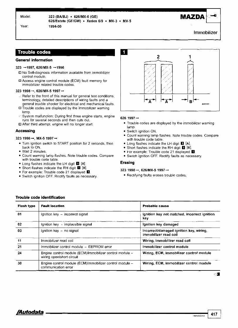
Model: 323 (BAIBJ) 626lMX-6 (GE) 626lEstate (GFIGW) Xedos 619 MX-3 MX-5
Year: 1994-00
lmmobilizer I
General information
323 41997, 626lMX-5 41996
No Self-diagnosis information available from immobilizer control module. Access engine control module (ECM) fault memory for immobilizer related trouble codes.
o Refer to the front of this manual for general test conditions, terminology, detailed descriptions of wiring faults and a general trouble shooter for electrical and mechanical faults. Trouble codes are displayed by the immobilizer warning lamp.
o System malfunction: During first three engine starts, engine runs for several seconds and then cuts out. After third attempt, engine will no longer start.
Accessing
323 1998 4, MX-5 1997 +
Turn ignition switch to START position for 2 seconds, then back to ON. Wait 2 minutes. Count warning lamp flashes. Note trouble codes. Compare with trouble code table. Long flashes indicate the LH digit rn [A]. Short flashes indicate the RH digit rn [B]. For example: Trouble code 21 displayed rn. Switch ignition OFF. Rectify faults as necessary.
Trouble code identification
- - -
626 1997 4
Trouble codes are displayed by the immobilizer warning lamp. Switch ignition ON. Count warning lamp flashes. Note trouble codes. Compare with trouble code table. Long flashes indicate the LH digit rn [A]. Short flashes indicate the RH digit rn [B]. For example: Trouble code 21 displayed rn. Switch ignition OFF. Rectify faults as necessary.
Erasing
323 1998 4, 626lMX-5 1997 -+
Rectifying faults erases trouble codes.
Flash type Fault location Probable cause
01
11 I Immobilizer read coil I Wiring, immobilizer read coil
02
03
2 1 I Immobilizer control module - EEPROM error I Immobilizer control module
Ignition key - incorrect signal
24 Engine control module (ECM)limmobilizer control module - Wiring, ECM, immobilizer control module wiring openlshort circuit
Ignition key not matched, incorrect ignition key
Ignition key - implausible signal
Ignition key - no signal
Ignition key damaged
lncorrectldamaged ignition key, wiring, immobilizer read coil
/Auf odafa 41 7
30
4
Engine control module (ECM)limmobilizer control module - communication error
Wiring, ECM, immobilizer control module

A1 4011 6011 90 (1 68) A1 6011 70 CDI (1 68) C2001220 CDI (202) E200122012701320 CDI (210) Vaneo CDI (414) Sprinter CDI (90112131415) V2001220 CDlNito (638)
Year: 1998-04
Engine code: 166.94019601990, 61 1.9601961198019811987, 612.9611981, 613.961, 668.91419401941/942
System: Bosch EDC 15C Bosch MSM
Engine management
-
C-Class - RH engine bay
I
V-ClassNito - under passenget3 seat
E-Class - LH enghre bay VaneolA-Class - under steering column
I
Sprinter - under fascia, drive6 side

Model. A14011601190 (168) A1601170 CDI (168) C2001220 CDI (202) E200/220/270/320 CDI (210) Vaneo CDI (414)
MERCEDES-BEN2 Sprinter CDI (90112/314/5) V2001220 CDlNito (638)
I Engine management I
Accessing and erasing The encrine control module (ECM) fault memorv can onlv be
General information accessed and erased using diagnostic equipment
0 Refer to the front of this manual for general test conditions, connected to the data link connector (DLC).
terminology, detailed descriptions of wiring faults and a general trouble shooter for electrical and mechanical faults.
Trouble code identification
EOBD type
I Fault l aa t i on Probable cause
P I 105 Barometric pressure (BARO) sensor, in ECM - circuit malfunction
I ECM
I I
PO I Refer to EOBD trouble code table
PI178 I Engine oil sensor module - oil level implausible 1 Wiring, connectors, oil qality, oil level, oil sensor, ECM
-
PI176
PI177
Engine oil sensor module - implausible signal
Engine oil sensor module - oil temperature implausible
PI179
PI180
Wiring, engine coolant temperature sensor, engine coolant blower motorlAC condenser blower motor, engine coolant blower motor control modulelAC condenser blower motor control module, ECM
Wiring, connectors, oil qality, oil level, oil sensor, ECM
Wiring, connectors, oil qality, oil level, oil sensor, ECM
PI181
PI185 I Engine oil sensor module - water in oil I Wiring, connectors, oil qality, oil level, oil sensor, ECM
Engine oil sensor module - oil quality implausible
Engine oil sensor module - oil temperature too high
CAN data bus, engine coolant blower motorlAC condenser blower motor - implausible signal
Wiring, connectors, oil qality, oil level, oil sensor, ECM
Wiring, connectors, oil qality, oil level, oil sensor, ECM
PI189 I Intake manifold air control system - malfunction 1 Wiring, connectors, hoses, intake manifold air control valve
P I 187
PI188
PI190 I Fuel pressure control solenoid - malfunction I Wiring, connectors, fuel pressure control solenoid
PI192 I Engine oil sensor module - malfunction I Wiring, connectors, engine oil qalityllevel
Fuel rail pressure (FRP) sensor - malfunction
3rd piston cut-off solenoid - malfunction
Wiring, poor connection, fuel pressure regulator control solenoid, fuel rail pressure (FRP) sensor, fuel level low, fuel pressure, high-pressure fuel pump, injector(s)
Wiring, connector, 3rd piston cut-off solenoid
PI234 Accelerator pedal position (APP) sensor 2 - Wiring, APP sensor 2, ECM malfunction
PI221
PI222
PI335 / Crankshaft position (CKP)sensor - malfunction I Wiring, connector, CKP sensor, ECM
CAN data bus, TCS - malfunction
Accelerator pedal position (APP) sensor 1 - malfunction
-
PI237
P I 330
Wiring, TCS control module trouble code(s) stored
Wiring, APP sensor 1, ECM
P 1470 Turbocharger (TC) boost pressure - too Wiring, connectors, hoses, turbocharger (TC) wastegate I lowlhigh regulating valve
Traction control system (TCS) - defective
Starter control - malfunction
Crankshaft position (CKP) sensorlcamshaft position (CMP) sensor - implausible signal
Exhaust gas recirculation (EGR) system - malfunction
TCS control module trouble code(s) stored
Wiring, fuse, starter motor, starter motor relay, ECM
Wiring, connector, CKP sensor, CMP sensor
Wiring, connectors, hoses, intake leak, EGR solenoid, MAF sensor
PI481 1 Glow plug(s) - defective I Wiring, connectors, glow plug(s), ECM
PI480 Glow plug warning lamp - malfunction
/Autodata Engine management
Wiring, connectors, bulb, instrument panel
41 9

I MERCEDES-BENZ Model: A14011601190 (168) A1601170 CDI (168) C2001220 CDI (202) E200122012701320 CDI (210) Vaneo CDI (414)
FEngine management Sprinter CDI (901/2/314/5) 0 V2001220 CDIN~~; (638)
I Probable cause
PI482 1 Glow plug control module - output stage I Wiring, connectors, glow plug control module
PI510 Cruise control masterlselector switch - Wiring, connectors, cruise control masterlselector switch, malfunction I ECM
P I 520 Cruise control master switch - malfunction Wiring, connectors, data bus, ignition switch control module, 1 ECM
P I 570 Immobilizer system activated - attempted Erase trouble code, incorrectldamaged key, immobilizer theft detected system malfunction
PI610 I Engine control relay - defective I Wiring, fuse, engine control relay
PI590
P I 592
PI611 I Engine control module (ECM) - internal fault I ECM
PI612 I Engine control module (ECM) - supply voltage I Wiring, connector, ignition switch
Fuel shut-off detected
CAN data bus, automatic clutch system - malfunction
-
Wiring, trouble code(s) stored in other system(s)
P I 61 5 Engine control module (ECM) - I Wiring, connector, ECM supply voltage
PI613
PI614
Engine control module (ECM) - internal fault
Engine control module (ECM) - internal fault
PI617
P I 622
P I 630
PI662 1 Injectors - voltage lowhigh I Wiring, connectors, injectors, ECM
- -
ECM
ECM
PI636
P I 650
PI661
PI663 1 Fuel pressure control solenoid - defective I Wiring, connectors, fuel pressure control solenoid
Engine controt module (ECM) - EPROM error
Fuel shut-off solenoid - defective
Immobilizer control modute - malfunction
ECM
Wiring, fuel shut-off solenoid
Wiring, data bus, ignition switch control module, ECM
Engine coolant blower motor control module - malfunction
Starter motor - short circuit
Injectors - voltage lowlhigh
Engine coolant blower motorlAC condenser Wiring, engine coolant temperature sensor, engine coolant blower motor - short circuit blower motorlAC condenser blower motor, engine coolant
Wiring, connectors, engine coolant blower motor, ECM
Wiring, connectors, ignitionlstarter switch, ECM
Wiring, connectors, injectors, ECM
PI664
P I 666
blower motor control modulelAC condenser blower motor control module, ECM
P I 681 CAN data bus, SRS control module - Wiring, connectors, SRS control module trouble code(s) malfunction stored, SRS control module, ECM
Auxiliary heater control modulelECM - electrical fault
Engine control module (ECM) - engine shut-off control
P I 698 CAN data bus, AClemergency shut-off - I Wiring, connectors, AC control module. ECM malfunction
Wiring, auxiliary heater control module
ECM
P I 705
PI705
PI813
PI822
MT: Clutch pedal position (CPP) switch - malfunction
AT: ParWneutrat position (PNP) switch
Clutch pedal position (CPP) switch - circuit malfunction
Wiring, connector, CPP switch
Wiring, PNP switch, TCM, ECM
Wiring, connector, CPP switch
.=3
Kick-down switch - implausible signal Wiring, connector, kick-down switch

Model: C18012001200W220/230/230W280 (202) E200/220/280/320 (1 24) E200/230/280/320 (21 0)
MERCEDES-BENZ
Year: 1993-98
Engine code: 104.941/942/943/944l94519911992/9941995, 11 1.9201921, 11 1.940/9411942/944/945/946, 111.960/961, 111.970/974/975
System: Bosch HFM Bosch HFM-SF1 Siemens PMS
Trouble codes: Two-digit flash type
Engine management
I
C-Class. S-Class, SLK
General information Refer to the front of this manual for general test conditions, terminology, detailed descriptions of wiring faults and a general trouble shooter for electrical and mechanical faults. Trouble codes are displayed by using an LED connected to the data link connector (DLC). The ECM fault memory can also be checked using diagnostic equipment connected to the data link connector (DLC). Diagnostic equipment can also be used to erase data from ECM fault memory. More detailed fault diagnosis information can be obtained using diagnostic equipment connected to the data link connector (DLC).
Accessing Ensure i~nit ion switched OFF. Bridge data link connector (DLC) terminals 1 and 4 or 1 and 8 with a switched lead - contacts normally open H or m. Connect LED test lamp between terminals 3 and 4 or 8 and 16 or m.
NOTE: Connect LED test lamp positive connection to terminal 3 or 16.
Switch ignition ON. Operate switch for 2-4 seconds. Count LED flashes. Note trouble code. Trouble codes consist of short flashes m. For example: Trouble code 3 displayed El. Repeat operation. Note trouble codes. Compare with trouble code table. Switch ignition OFF. 4
/Autodata Enalne manaaemenl 1 421 (

ME RCED ESIBE NZ Model. Cl801200/200K122012301230K/280 (202) E200122012801320 (1 24) E200123012801320 (210) S2801320 (140) SLK200 (170) SL2801320 (1 29)
Engine management
Trouble code identification
Erasing Ensure ignition switched OFF. Bridge data link connector (DLC) terminals 1 and 4 or 1 and 8 with a switched lead - contacts normally open rn or m. Connect LED test lamp between terminals 3 and 4 or 8 and I 6 rn or m.
NOTE: Connect LED test lamp positive connection to terminal 3 or 16.
Operate switch for 2-4 seconds. Operate switch for 5-6 seconds - Bosch ECM +08193. Allow LED to display trouble code. Operate switch for 6-8 seconds. Operate switch for 8-9 seconds - Bosch ECM +08193. Repeat operation to erase all stored trouble codes. After erasing trouble code 1: Switch ignition OFF. Wait 2 seconds. Switch ignition ON. Wait 10 seconds minimum. Start engine.
1 I No fault found I -
3 I Intake air temperature (IAT) sensor - electrical fault I Wiring, connector, IAT sensor, ECM
2
5 I Idle speed control (ISC) actuator - malfunction I Wiring, connector, ISC actuator
Engine coolant temperature (ECT) sensor - electrical fault
Bosch HFM: Mass air flow (MAF) sensor - rangelperformance problem
Siemens PMS: Manifold absolute pressure (MAP) sensor - vacuum leak
Wiring, connector, ECT sensor, ECM
Wiring, connector, intake leak, MAF sensor, ECM
Hoses, ECM
/ ldle speed control (ISC) - malfunction
6
7
Wiring, connector, intake leak, MAF sensor, throttle valve tighffsticking
1 422 I,,,,,,,,,,,,,,
Throttle position (TP) sensor - rangelperformance problem
Idle speed control (1%) actuator - malfunction
Wiring, connector, TP sensor, ECM
Wiring, connector, ISC actuator, ECM

Engine manage=I
Probable cause
10 I Heated oxygen sensor (H02S) 2 - rangelperformance Wiring, connector, H02S problem
9
Lambda regulation - system too leanlrich Wiring, intakelexhaust leak, MAF sensor, fuel pressure, injector(s), ECM
Heated oxygen sensor (H02S) 1 - rangelperformance problem
Oxygen sensor heater 1 - electrical fault
Oxygen sensor heater 2 - electrical fault
14 I Bosch HFM: Injector 1 - circuit malfunction I Wiring, injector, ECM
Wiring, connector, H02S
Wiring, connector, H02S, ECM
Wiring, connector, H02S, ECM
I Siemens PMS: lnjector 2 & 3 - circuit malfunction I Wiring, injector, ECM
15
16 I Injector 3 - circuit malfunction I Wiring, injector, ECM
17 ( Injector 4 - circuit malfunction I Wiring, injector, ECM
Siemens PMS: Injector 1 & 4 - circuit malfunction
Bosch HFM: Injector 2 - circuit malfunction
Wiring, injector, ECM
Wiring, injector, ECM
20 Bosch HFM: Fuel trim (FT), idle speed - rangelperformance probtem
18
19
Intakelexhaust teak, injector@), fuel pressure, H02S, ECM
Siemens PMS: Fuel trim (FT) - rangelperfomance lntakelexhaust leak, injector@), fuel pressure, I problem H02S, EVAP system, ECM
Injector 5 - circuit malfunction
Injector 6 - circuit malfunction
21 I 111: Ignition amplifierlignition coil, cylinder 1 8 4 - Wiring, ignition amplifier, ignition coil, ECM defective
- - -
Wiring, injector, ECM
Wiring, injector, ECM
22
111: Ignition amplifier 2lignition coil, cylinder 2 8 3 - I Wiring, ignition amplifier, ignition coil, ECM defective
Siemens PMS: Ignition amplifierlignition coil, cylinder 2 & 3 - defective
104: Ignition amplifierlignition coil, cylinder 2 & 5 - defective
104: Ignition amplifierlignition coil, cylinder 1 & 6 - defectwe
Bosch HFM: Ignition amplifier llignition coil, cylinder 1 - defective
Wiring, ignition amplifier, ignition coil, ECM
Wiring, ignition amplifier, ignition coil, ECM
24 I Crankshaft position (CKP) sensor - malfunction Wiring, air gap, flywheel ring gear damaged, CKP sensor
Wiring, ignition amplifier, ignition coil, ECM
Wiring, ignition amplifier, ignition coil, ECM
104: Ignition amplifierlignition coil, cylinder 3 8 4 - defective
Wiring, ignition amplifier, ignition coil, ECM
27 I Engine control module (ECM), RPM signal - output I Wiring, RPM sensor, ECM
25
26
I I
28 I ABS control modulelengine control module (ECM) 1 Wiring, VSS, ABS control module trouble code@)
Camshaft position (CMP) sensor - incorrect signal
Engine control module (ECM) coding plug - electrical fault
30 I Fuel pump relay - defective I Wiring, fuel pump relay
Wiring, CMP sensor
Wiring, ECM
29
communication - signal Intake manifold heater relav - malfunction
31
stored
Wiring, intake manifold heater relay, ECM
Without cat: CO adjustment resistor - malfunction Wiring, CO adjustment resistor, ECM

ME RCE D ES-B E NZ Model: C180/200/200W220/230/230K/280 (202) E200122012801320 (1 24) E200123012801320 (210) S2801320 (140) SLK200 (170) SL2801320 (129) . , I Engine management
1 Probable cause
32 I Knock sensor(s) (KS) - defective ( Wiring, KS
35 I Seconda~y air injection (AIR) pumplrelay - malfunction 1 Wiring, AIR pumplrelay, ECM
33
34
38 I Camshaft position (CMP) actuator - malfunction I Wiring, mechanical fault, CMP actuator, ECM
Ignition timing, knocking - maximum retardation reached
Engine control module (ECM), knock control - internal fault
36
37
39 I Exhaust gas recirculation (EGR) solenoid - malfunction I Wiring, EGR solenoid, hose(s)
Fuel contamination, mechanical fault
ECM
Evaporative emission (EVAP) canister purge valve - electrical fault
Transmission shift control valve - electrical fault
42 1 111: CAN data bus, diagnostic module - malfunction I Wiring
Wiring, EVAP canister purge valve, hose@), ECM
Wiring, transmission shift control valve
40
41
1 104: CAN data bus - malfunction I Wiring
Transmission overload protection switch - malfunction
CAN data bus, ECM - malfunction
46 I Intake manifold air control solenoid - malfunction I Wiring, intake manifold air control solenoid, ECM
Wiring, transmission overload protection switch
Wiring, ECM
43
45
50 I Engine control module (ECM) - internal fault I ECM
Engine control module (ECM), pin 50 - starter signal
With cruise control system: Cruise control, inertia fuel shut-off (IFS) switch - active
48
49
-12192: Code may be displayed although no fault exists E-Class (1 24) -07193
Wiring
Wiring, TP sensor, idle speed control (ISC) actuator
1 424 I,,,.,,,,,,,,., IAutodata
Oxygen sensor heater relay 2 - electrical fault
Engine control module (ECM) - supply voltage
Wiring, oxygen sensor heater relay, ECM
Wiring, ignition switch, overvoltage protection relay

Model: C18012001200K122012301230K/280 (202) E200122012801320 (124) E200123012801320 (21 0)
MERCEDES-BEN2 S2801320 (140) SLK200 (170) SL2801320 (129)
Year: 1993-98
Engine code: 104.9411942194319441945, 104.991199219941995, 11 1.9201921, 11 1.9401941 1942194419451946, 111.9601961, 111.97019741975
System: Bosch HFM Bosch HFM-SF1 Siemens PMS
Trouble codes: Three-digit
Engine management
C-Class, S-Class, SLK
Accessing and erasing The engine control module (ECM) fault memory can only be
General information accessed and erased usina diaanostic eauioment " v
n Refer to the front of this manual for aeneral test conditions, connected to the data link connector (DLC).' terminology, detailed descriptions ofwiring faults and a general trouble shooter for electrical and mechanical faults. Trouble codes are displayed by using an LED connected to the data link connector (DLC). The ECM fault memory can also be checked using diagnostic equipment connected to the data link connector (DLC). Diagnostic equipment can also be used to erase data from ECM fault memory. More detailed fault diagnosis information can be obtained using diagnostic equipment connected to the data link connector (DLC).

. . I Engine management I Trouble code identification
3digit type I Fault location Probable cause
002 I Engine coolant temperature (ECT) sensor - short circuit I Wiring, connector, ECT sensor, ECM
I I
- I No fault found
005 Engine coolant temperature (ECT) sensor - plug I Multi-plug(s) connection(s)
-
003
004
006 ( Intake air temperature (IAT) sensor - short circuit I Wiring, connector, IAT sensor, ECM
Engine coolant temperature (ECT) sensor - open circuit
Engine coolant temperature (ECT) sensor - rangelperformance problem
009 Bosch HFM: Mass air flow (MAF) sensor - range1 I Wiring, connector, intake leak. MAF sensor performance problem
Wiring, connector, ECT sensor, ECM
-
007
008
Siemens PMS: Manifold absolute pressure (MAP) sensor - vacuum leak I ECM
01 0 I Bosch HFM: Mass air flow (MAF) sensor - open circuit I Wiring, connector, MAF sensor, ECM
--
Intake air temperature (IAT) sensor - open circuit
Intake air temperature (IAT) sensor - plug connection(s)
Siemens PMS: Manifold absolute pressure (MAP) sensor - vacuum leak
I "OseS1 ECM
-
Wiring, connector, IAT sensor, ECM
Multi-plug(s)
012 I Idle speed control (ISC) actuator - circuit malfunction I Wiring, connector, ISC actuator
011
014 I Throttle position (TP) sensor - signal high I Wiring, connector, TP sensor, ECM
Idle speed control (ISC) actuator - rangelperformance problem
Bosch HFM: ldle speed control (ISC) actuator - plug connection(s)
Siemens PMS: Throttle position (TP) sensor - range/performance problem
Wiring, connector, ISC actuator
Multi-plug(s)
Wiring, connector, TP sensor, ECM
Siemens PMS: Idle speed control (ISC) actuator - Wiring, connector, ISC actuator, ECM malfunction
01 5
01 6
019 Bosch HFM: Idle speed control (ISC) actuator - plug Multi-plug(s) connection(s)
Throttle position (TP) sensor - signal low
Bosch HFM: Throttle position (TP) sensor - plug connection(s)
01 7
018
Wiring, connector, TP sensor, ECM
Multi-plug(s)
Idle speed control (ISC) actuator - signal high
Idle speed control (ISC) actuator - signal low
020
Wiring, connector, ISC actuator, ECM
Wiring, connector, ISC actuator, ECM
02 1
022
Siemens PMS: ldle speed control (ISC) - malfunction
Idle speed control (ISC) - lower limit reached
022
023
Wiring, connector, intake leak, MAF sensor, throttle valve tightlsticking
Wiring, connector, intake leak, MAF sensor, throttle valve tightlsticking
Idle speed control (ISC) - upper limit reached
Cruise controllidle speed control (ISC) actuator - limp-home mode
Wiring, connector, intake leak, MAF sensor, throttle valve tightlsticking
Wiring, ISC actuator, throttle valve tightlsticking
Siemens PMS: Heated oxygen sensor (H02S) 1 - rangelperformance problem
Heated oxygen sensor (H02S) 1 - voltage high
Wiring, connector, H02S
Wiring, connector, H02S

Model: C18012001200W22012301230W280 (202) E200122012801320 (124) E200123012801320 (210) S2801320 (140) SLK200 (170)
MERCEDES-BENZ SL2801320 (129)
Engine management
024 1 Heated oxygen sensor (H02S) 1 - open circuit I Wiring, connector, H02S
3-digit type
Bosch HFM: Heated oxygen sensor (H02S) 2 - voltage Wiring, connector, H02S 026 ( high
Fault location
025
I Siemens PMS: Oxygen sensor heater 1 -electrical fault ( Wiring, connector, H02S, ECM
Probable cause
Bosch HFM: Heated oxygen sensor (H02S) 1 - rangelperformance problem
Siemens PMS: Oxygen sensor heater 1 - electrical fault
028 Bosch HFM: Heated oxygen sensor (H02S) 2 - I Wiring, connector, H02S rangelperformance problem
Wiring, connector, H02S
Wiring, connector, H02S, ECM
027
Siemens PMS: Lambda regulation - system too rich Wiring, intakelexhaust leak, MAF sensor, fuel pressure, injector(s), ECM
Bosch HFM: Heated oxygen sensor (H02S) 2 - open circuit
Siemens PMS: Oxygen sensor heater 1 - electrical fault
029
Wiring, connector, H02S
Wiring, connector, H02S, ECM
( Siemens PMS: Injector 1 & 4 - circuit malfunction I Wiring, injector, ECM
Siemens PMS: Lambda regulation - system too lean
Bosch HFM: Oxygen sensor heater - current low
030
031
032 I Bosch HFM: Oxygen sensor heater 2 - current low I Wiring, connector, H02S, ECM
Wiring, intakelexhaust leak, MAF sensor, fuel pressure, injector(s), ECM
Wiring, connector, H02S, ECM
Bosch HFM: Oxygen sensor heater - current high
Siemens PMS: Injector 1 & 4 - circuit malfunction
Bosch HFM: Oxygen sensor heater - short circuit
034 I Bosch HFM: Oxygen sensor heater 2 - short circuit I Wiring, connector, H02S, ECM
Wiring, connector, H02S, ECM
Wiring, injector, ECM
Wiring, connector, H02S, ECM
033
Siemens PMS: Fuel trim (FT) - rangelperformance lntakelexhaust leak, injector(s), fuel pressure, I problem H02S, EVAP system, ECM
035 Lambda regulation - system too lean
Siemens PMS: Injector 2 & 3 - circuit malfunction
Bosch HFM: Oxygen sensor heater 2 - current high
Siemens PMS: Injector 2 & 3 - circuit malfunction
Wiring, intakelexhaust leak, MAF sensor, fuel pressure, injector(s), ECM
Wiring, injector, ECM
Wiring, connector, H02S, ECM
Wiring, injector, ECM
036 1 Lambda regulation - system too rich Wiring, intakelexhaust leak, MAF sensor, fuel pressure, injector(s), ECM
039 I Bosch HFM: Injector 2 - short to positive I Wiring short to positive, injector, ECM
037
038
Siemens PMS: lgnition amplifierlignition coil, cylinder 1 & 4 - defective
Wiring, ignition amplifier, ignition coil, ECM
Injector 1 - short to positive
Bosch HFM: Injector 1 - open circuiffshort to earth
Siemens PMS: Ignition amplifierlignition coil, cylinder 1 & 4 - defective
040 I Bosch HFM: Injector 2 - open circuiffshort to earth 1 Wiring open circuitlshort to earth, injector, ECM
Wiring short to positive, injector, ECM
Wiring open circuitlshort to earth, injector, ECM
Wiring, ignition amplifier, ignition coil, ECM
Siemens PMS: Ignition amplifierlignition coil, Wiring, ignition amplifier, ignition coil, ECM cylinder 1 & 4 - defective
041 Bosch HFM: Injector 3 - short to positive
Siemens PMS: Ignition amplifierlignition coil, cylinder 2 & 3 - defective
Wiring short to positive, injector, ECM
Wiring, ignition amplifier, ignition coil, ECM

ME RCEDES-BE NZ Model: C18012001200K/2201230/230K/280 (202) E200/220/280/320 (124) E200123012801320 (210) S2801320 (140) SLK200 (170) SL2801320 (129) . , I Engine management
3-digit type Fault location
Bosch HFM: lnjector 3 - open circuiffshort to earth I Wiring open circuitlshort to earth, injector, ECM
Probable cause
Siemens PMS: Ignition amptifierlignition coil, Wiring, ignition amplifier, ignition coil, ECM cylinder 2 & 3 - defective
Siemens PMS: Ignition amplifierlignition coil, cylinder 2 & 3 - defective
Bosch HFM: Injector 4 - short to positive
Wiring, ignition amplifier, ignition coil, ECM
Wiring short to positive, injector, ECM
111: Crankshaft position (CKP) sensor - malfunction Wiring, air gap, flywheel ring gear damaged, CKP sensor
Bosch HFM: Injector 4 - open circuiffshort to earth
Siemens PMS: Crankshaft position (CKP) sensor - malfunction
Wiring open circuitlshort to earth, injector, ECM
Wiring, air gap, flywheel ring gear damaged, CKP sensor
104: Injector 5 - open circuiffshort to earth I Wiring open circuitlshort to earth, injector, ECM
--
104: Injector 5 - short to positive
11 1 : Crankshaft position (CKP) sensor - malfunction
111: Engine control module (ECM) coding plug - electrical fault
-- --
Wiring short to positive, injector, ECM
Wiring, air gap, flywheel ring gear damaged, CKP sensor
104: Injector 6 - short to positive I Wiring short to positive, injector, ECM
111: Engine control module (ECM) coding plug - electrical fault I ECM
Siemens PMS: Engine control module (ECM), RPM I Wiring short to earth, RPM sensor signal - outpuffshort to earth
104: Injector 6 - open circuiffshort to earth
Bosch HFM: Fuel trim (FT), idle speed - mixture rich
Bosch HFM: Fuel trim (FT), idle speed - mixture lean lntakelexhaust leak, injector(s), fuel pressure, I H02S. ECM
Wiring open circuitlshort to earth, injector, ECM
lntakelexhaust leak, injector(s), fuel pressure, H02S, ECM
Siemens PMS: Engine control module (ECM), RPM I Wiring short to positive, RPM sensor signal - outpuffshort to positive
Bosch HFM: Fuel trim (FT), lower part load - mixture rich
Siemens PMS: ABS control modulelengine control module (ECM) communication - VSS signal
lntakelexhaust leak, injector(s), fuel pressure, HOZS, ECM
Wiring, VSS, ABS control module trouble code(s) stored
Bosch HFM: Fuel trim (FT), lower part load - mixture lean
Siemens PMS: ABS control modulelengine control module (ECM) communication - VSS signal
Fuel trim (FT), upper part load - mixture lean Intakelexhaust leak, injector(s), fuel pressure, H02S, ECM
lntakelexhaust leak, injector(s), fuel pressure, H02S, ECM
Wiring, VSS, ABS control module trouble code(s) stored
Fuel trim (FT), upper part load - mixture rich
Intake manifold heater relay - malfunction
Intake manifold heater relay - malfunction I Wiring, intake manifold heater relay, ECM
lntakelexhaust leak, injector(s), fuel pressure, H02S, ECM
Wiring, intake manifold heater relay, ECM
Bosch HFM: lgnition amplifier llignition coil, cylinder 1 - Wiring, ignition amplifier, ignition coil, ECM misfire
Siemens PMS: Fuel pump relay - defective I Wiring, fuel pump relay
104: Ignition amplifier Ilignition coil, cylinder 2 -misfire / Wiring, ignition amplifier, ignition coil, ECM

Model. C18012001200Kl22012301230Kl280 (202) E200122012801320 (124) ME RC EDES,BENZ E200123012801320 (210) S2801320 (140) SLK200 (170) SL2801320 (129)
Engine management
3-digit type
057 Bosch HFM: Ignition amplifier Ilignition coil, cylinder 1 & 4 - defective
Bosch HFM: lgnition amplifier Ilignition coil, cylinder 4 - misfire
Siemens PMS: Fuel pump relay - defective
104: lgnition amplifier Ilignition coil, cylinder 5 - misfire
Wiring, ignition amplifier, ignition coil, ECM
Fault location
Wiring, ignition amplifier, ignition coil, ECM
Wiring, fuel pump relay
Wiring, ignition amplifier, ignition coil, ECM
I Siemens PMS: CO adjustment resistor - malfunction I Wiring, CO adjustment resistor, ECM
Probable cause
- - - -
104: lgnition amplifier 3lignition coil, cylinder 2 & 5 - Wiring, ignition amplifier, ignition coil, ECM defective
058 Bosch HFM: Ignition amplifier 2lignition coil, cylinder 2 - Wiring, ignition amplifier, ignition coil, ECM I misfire
I Siemens PMS: CO adjustment resistor - malfunction 1 Wiring, CO adjustment resistor, ECM
059
060
061 11 1: Short term fuel trim (FT), idle speedlpart load - Fuel system malfunction
104: lgnition amplifier 2lignition coil, cylinder 3 - misfire
Bosch HFM: Ignition amplifier 2lignition coil, cylinder 3 - misfire
Siemens PMS: Evaporative emission (EVAP) canister purge valve - electrical fault
104: lgnition amplifier 2lignition coil, cylinder 3 & 4 - defective
-
Wiring, ignition amplifier, ignition coil, ECM
Wiring, ignition amplifier, ignition coil, ECM
Siemens PMS: Evaporative emission (EVAP) canister purge valve - electrical fault
104: lgnition amplifier 2lignition coil, cylinder 4 - misfire
Bosch HFM: Ignition amplifier 2lignition coil, cylinder 2 & 3 - defective
Wiring, EVAP canister purge valve, hose(s), ECM
Wiring, ignition amplifier, ignition coil, ECM
063 1 111: Engine control module (ECM) - supply voltage Wiring, connector, fuse, ignition switch, central locking control module, engine control relay
Wiring, EVAP canister purge valve, hose(s), ECM
Wiring, ignition amplifier, ignition coil, ECM
Wiring, ignition amplifier, ignition coil, ECM
062
Siemens PMS: Central locking control module, Wiring, central locking control module, trouble immobilizer signal - open circuitlshort to positive code(s) stored in other system(s)
104: lgnition amplifier 3lignition coil, cylinder 1 - misfire
111: Transmission shift control valve - electrical fault
104: lgnition amplifier 3lignition coil, cylinder 6 - misfire
064
Wiring, ignition amplifier, ignition coil, ECM
Wiring, transmission shift control valve
Wiring, ignition amplifier, ignition coil, ECM
Siemens PMS: Central locking control module, I Wiring, central locking control module, trouble immobilizer signal - open circuitlshort to earth code(s) stored in other system(s)
104: lgnition amplifier 3lignition coil, cylinder 1 & 6 - defective
Bosch HFM: Crankshaft position (CKP) sensor - signal
065
I I
1 Bosch HFM: Crankshaft position (CKP) sensor - I Wiring, air gap, flywheel ring gear damaged,
Wiring, ignition amplifier, ignition coil, ECM
Wiring, air gap, flywheel ring gear damaged, CKP sensor
Bosch HFM: Crankshaft position (CKP) sensor - defective
Eng~ne management 429
Wiring, air gap, flywheel ring gear damaged, CKP sensor
rangelperformance problem
Siemens PMS: Attempt to start engine while central locking still activated
CKP sensor
Erase fault memory, trouble code(s) stored in other system(s)

ME RC ED ESIB E NZ Model: C18012001200K12201230123OK1280 (202) E200122012801320 (1 24) E200123012801320 (210) S2801320 (140) SLK200 (170) SL2801320 1129)
1 , I Engine management
3-digit type
Bosch HFM: Camshaft position (CMP) sensor - incorrect signal
Siemens PMS: Central locking control module, immobilizer signal - plausibility
070 Engine control module (ECM), RPM signal - I Wiring short to earth. RPM sensor outputlshort to earth
Fault location
Wiring, CMP sensor
Wrong central locking control module
068
069
07 1 Engine control module (ECM), RPM signal - Wiring short to positive, RPM sensor output/short to positive
Probable cause
072 ABS control modulelengine control module (ECM) Wiring, VSS, ABS control module trouble code(s) communication, VSS signal - signal not recognised stored
Engine control module (ECM) coding plug - short to earth
Engine control module (ECM) coding plug -open circuit/ short to positive
Wiring short to earth, ECM
Wiring open circuitkhort to positive, ECM
073
074
076 I Fuel pump relay - defective 1 Wiring, fuel pump relay
075
075
ABS control modulelengine control module (ECM) communication, VSS signal - signal high
Intake manifold heater relay - short to positive
079 I Knock sensor(s) (KS) 1 - open circuit I Wiring, KS
Wiring, VSS, ABS control module trouble code(s) stored
Wiring short to positive, intake manifold heater relay, ECM
Intake manifold heater relay - open circuit/short to earth
Engine control module (ECM), ETC signal - not recognisedlshort to positive
077
078
080 ( Knock sensor(s) (KS) 2 - open circuit I Wiring, KS
Wiring open circuitkhort to earth, intake manifold heater relay, ECM
Wiring, electronic traction control (ETC) module
Without cat: CO adjustment resistor - short to positive
Without cat: CO adjustment resistor - malfunction
Wiring short to positive, CO adjustment resistor, ECM
Wiring, connector(s), CO adjustment resistor, ECM
081
082
083
085 I Secondary air injection (AIR) pumplrelay - malfunction I Wiring, AIR pumplrelay, ECM
084
086 Evaporative emission (EVAP) canister purge valve - Wiring, AIR pumplrelay, ECM open circuit/short circuit
Ignition timing, knocking - maximum retardation reached
Ignition timing, knocking -firing angle between cylinders
11 1 : Secondary air injection (AIR) pumplrelay - malfunction
087 Evaporative emission (EVAP) canister purge valve - Wiring short to positive, AIR pumplrelay, ECM short to positive
Fuel contamination, mechanical fault
Fuel contamination, mechanical fault
Wiring, AIR pumplrelay, ECM
104: Engine control module (ECM), knock control - internal fault
Short term fuel trim (FT), max. value - idle speedlpart load
--
088 f i iansmiss ion shift control valve -electrical fault I Wiring, transmission shift control valve
ECM
Fuel system, ECM
I 1
089 I Camshaft position (CMP) actuator - short to positive I Wiring, CMP actuator, ECM
090
091
Camshaft position (CMP) actuator - open circuit/short to earth
Wiring, CMP actuator, ECM
Exhaust gas recirculation (EGR) solenoid -short to positive Wiring short to positive, EGR solenoid, hose(s)

Engine management 7 Probable cause Fault location 3-digit type
Exhaust gas recirculation (EGR) solenoid - open circuit/ short to earth
Transmission overload protection switch - short to earth
Wiring open circuitlshort to earth, EGR solenoid, hose@)
Wiring short to earth, transmission overload protection switch
Transmission overload protection switch - switch closed Wiring, transmission overload protection switch
Transmission overload protection switch - switch open Wiring, transmission overload protection switch
Transmission overload protection switch - plausibility Wiring, transmission overload protection switch
Wiring, ECM
Wiring
- - .-
CAN data bus, ECM - malfunctionp
CAN data bus, ASR system - malfunction
CAN data bus, cruise control system/TP control module - malfunction
Wiring
CAN data bus, diagnostic module - malfunction Wiring
Engine control module (ECM), pin 50 - starter signal
With ATlcruise control system: Cruise control, inertia fuel shut-off (IFS) switch - active
Wiring
Wiring, TP sensor, idle speed control (ISC) actuator
lntake manifold air control solenoid - short to positive Wiring, intake manifold air control solenoid, ECM
lntake manifold air control solenoid -open circuitfshort to earth
Ignition amplifier - malfunction
Oxygen sensor heater relay 2 - short to positive
Wiring, intake manifold air control solenoid, ECM
Wiring, ignition amplifier, ignition coil@), ECM
Wiring short to positive, oxygen sensor heater relay, ECM
Oxygen sensor heater relay 2 - open circuitfshort to earth
Engine control module (ECM) - supply voltage, plausibility
Wiring open circuitlshort to earth, oxygen sensor heater relay, ECM
Wiring, ignition switch, overvoltage protection relay
Engine control module (ECM) - supply voltage low Wiring, ignition switch, overvoltage protection relay
Engine control module (ECM) - internal fault ECM
Engine control module (ECM) - coding
Engine control module (ECM) - identification
Engine control module (ECM) - coding
Not coded
ECM not coded, ECM
Not coded, ECM
CAN data bus, remote central locking - malfunction Wiring
Bosch HFM 06/93 +: Engine control module (ECM) - supply voltage low
Attempt to start engine while central locking still activated
Wiring, connector, fuse, overvoltage protection relay
Erase fault memory, trouble code@) stored in other system(s)
Supercharger (SC) - malfunction Wiring, mechanical fault, hose(s), intake air flap control actuator, ECM
Supercharger (SC) clutch - open circuit/short to earth
Electronic traction control (ETC) - signal
Wiring open circuitlshort to earth, SC clutch, ECM
Wiring short to earth, ETC module
Wiring open circuitlshort to earth, intake air flap control actuator, ECM
lntake air flap control actuator, supercharger (SC) - malfunction
lntake air flap control actuator, supercharger (SC) - malfunction
Wiring short to positive, intake air flap control actuator, ECM
Engine control module (ECM) - internal fault ECM
Engine control module (ECM) - internal fault ECM
/Autodata- Englne management 43 I

lMERCEDESIBE NZ Model: C180/200/200K/220/230/230K/280 (202) E200122012801320 (124) E200123012801320 (210) S2801320 (140) SLK200 (170) SL2801320 (1 29) I Engine management
Probable cause
127 Idle speed control (ISC) actuator1lSC actuator, cruise control system - malfunction
Wiring, ISC actuator, ISC actuator - cruise control system
128 I Engine control module (ECM) - internal fault ECM
129 Engine control module (ECM) - internal fault
130 Throttle position (TP) sensor - malfunction
ECM
Wiring, TP sensor, ECM
131 I Engine control module (ECM) - internal fault ECM
132 I Engine control module (ECM) - internal fault ECM
133 I Idle speed control (ISC) actuator - defective Wiring, ISC actuator
134 Engine control module (ECM) - internal fault
135 Idle speed control (ISC) actuator - supply voltage
136 Idle speed control (ISC) actuator - defective
ECM
Wiring, ECM
Wiring, ISC actuator, ECM
137 I Engine control module (ECM) - internal fault ECM
138 I Idle speed control (ISC) actuator - defective Wiring, ISC actuator
139 Cruise control selector switch - defective
140 Engine control module (ECM) - internal fault
141 Engine control module (ECM) - internal fault
Wiring, cruise control selector switch
ECM
ECM
142 I Engine control module (ECM) - internal fault ECM
143 Brake pedal position (BPP) switch, cruise control system - defective
144 Engine control module (ECM) - internal fault
Wiring, BPP switch
ECM
145 1 CAN data bus, VSS sicmal. rear axle - malfunction Wiring, trouble code(s) stored in other system@)
Wiring, trouble code@) stored in other system@) 146 I CAN data bus, VSS signal, front axle - malfunction
147 I CAN data bus. AC - malfunction Wiring, AC control module trouble code@) stored
148 Starter motor relay - short to positive
149 Starter motor relay - short to earth
1 50 CAN data bus, AT - malfunction
151 CAN data bus. AC - malfunction
Wiring, ignition switch, ECM
Wiring, ignition switch, ECM
Wiring, TCM trouble code@) stored
Wiring, AC control module trouble code@) stored
152 I CAN data bus - malfunction Wiring
Wiring, ECT sensor, AC control module, ECM
Wiring, ECT sensor, AC control module, ECM
Incorrectly coded
Wiring, trouble code@) stored in other system(s)
Wiring, trouble code@) stored in other system@)
Wiring, ABS control module trouble code@) stored
E-Class (124) 407193, Siemens PMS rn E-Class (1 24) -+07/93 rn SLK200 (170)

Model: Cl80/200/200K/2301230W240/280 (202) Cl80/200/200K/240/320 (203) E200/200K/240/280/320/420/430 (21 0) S2801320142015001600 (140) CL42015001600 (140) SLK2001200K/230K/320 (170) CLK2001200K/230K/320/430 (208) SL280132015001600 (129) SL500 (230)
Year: 1995-04 Engine 104.941 1943194419911994, 111 X I , 111.94219431944194519461947, 111 .%I 19521955195619581957, 11 1.97319741975, cDde: 111.983, 11 2.91 0191 1/91 2/91 4, 11 2.92OI921, 11 2.94Ol94lI946l947, 11 3.940194319611963, 11 9.980198119821985,
120.9821983
System: Bosch ME 1.012.012.112.8 Bosch ME SIM4
Engine management
3&pin - C-Class (202), CLK, $-Class, SL-Ciass (1291, SLK (+2000)
16-phr - C-CIam (2031, SLK (2000*)

CL42015001600 (140) SLK2OOl2OOW230W320 (170)
IEngin'e management CLK2001200W230W3201430 (208) SL280132015001600 (129) SL500 (230)
Accessing and erasing The enqine control module (ECM) fault rnemorv can onlv be
General information accessed and erased using' dia&ostic equipment
Refer to the front of this manual for general test conditions, connected to the data link connector (DLC).
terminology, detailed descriptions of wiring faults and a general trouble shooter for electrical and mechanical faults.
Trouble code identification
PO802 I Intake manifold air control solenoid - malfunction I Wirina, intake manifold air control solenoid
EOBD type
PO 0 PO801
PO803 I Supercharger (SC) bypass valve motor - malfunction I Wiring, SC bypass valve motor, ECM
PO805 I Supercharger (SC) pressure - incorrect Supercharger (SC) bypass valve motor sticking, intake leaklblockage, SC, ECM
Fault locatJan
Refer to EOBD trouble code table
Engine coolant blower motorlAC condenser blower motor - malfunction
PO806 I Supercharger (SC) clutch - malfunction I Wiring, SC clutch, ECM
Probable cause
-
Wiring, engine coolant blower motorlAC condenser blower motor
PO809 Crankshaft position (CKP) sensorlcamshaft position Incorrect valve timing (CMP) sensor - signal incompatibility
-
PO81 1 CAN data bus, ignition switch control module - 1 Wiring, ignition switch control module, ECM malfunction
PI031 I Heated oxygen sensor (H02S) 1 - malfunction 1 Wiring, connector, H02S
PI146 I Mass air ffow (MAF) sensor(s) - malfunction 1 Wiring, intake leak, MAF sensor(s)
P I 149 Manifold absolute pressure (MAP) sensor(s) - / Wiring, hose(s), MAP sensor(s), ECM malfunction
PI147
PI148
PI180 I Engine oil sensor, temperature - too high I Wiring, engine oil sensor
Engine coolant temperature (ECT) sensor(s) - malfunction
Intake air temperature (IAT) sensor(s) - malfunction
PI178
PI179
PI181 Engine coolant blower motorIAC condenser blower Wiring, engine coolant blower motor1AC condenser motor - malfunction I blower motor, ECM
Wiring, ECT sensor(s)
Wiring, IAT sensor(s)
Engine oil sensor, level - implausible signal
Engine oil sensor, quality - implausible signal
PI184 I Cylinder cut-out solenoid, bank 2 - defective I Wiring, cylinder cut-out solenoid
Wiring, oil level, engine oil sensor
Wiring, engine oil sensor
PI182
PI183
PI185 I Engine oil sensor, quality - water in oil I Engine oil
Starter motor relay - defective
Cylinder cut-out solenoid, bank 1 - defective
PI233 1 Throttle actuator - mechanical fault I Throttle actuator tightlsticking
Wiring, starter motor relay, ignition switch, ECM
Wiring, cylinder cut-out solenoid
P I 186
PI225
1 434 I,.,,,,,,,,,,, llAutodata
Fuel shut-off - recognised
Intake manifold air control solenoid - malfunction
Wiring, cruise control actuator, mechanical fault, ECM
Wiring, intake manifold air control solenoid, ECM

I Model: C I 80/200/200K/2301230K/240/280 (202) C180/200/2OOKI240/320 (203) ME RCEDES-BE NZ I E200/200K/240/280/320/420/430 (2101 S280/320/420/500/600 (1401
Engine management 7 EOBD type
I ~au. location / ~ r o b a b i e cause
PI236 1 Supercharger (SC) clutch - malfunction 1 Wiring, SC clutch, ECM
Supercharger (SC) bypass valve motor sticking, intake leaklblockage, SC, ECM
I
P1357 Cylinder cut-out system ON, cylinder 2, 3, 5 or 8 - inlet Mechanical fault valve still opening
P1235
P1300
PI355
P1356
Supercharger (SC) pressure - incorrect
Crankshaft position (CKP) sensor(s) - malfunction
Cylinder cut-out solenoid, bank 1 - stuck open
Cylinder cut-out solenoid, bank 2 - stuck open
P1358
P1359
Cylinder cut-out system, throttle switchover valve - Wiring, throttle switchover valve malfunction
Wiring, flywheel ring gear damaged, CKP sensor(s)
Wiring, cylinder cut-out solenoid
Wiring, cylinder cut-out solenoid
PI360
P1361
Cylinder cut-out system OFF, cylinder 5 - exhaust valve not opening
Cylinder cut-out system OFF, cylinder 2 - exhaust valve not opening
Pi385 1 Knock sensor (KS) 2, bank 2 - malfunction I Wiring, KS
Mechanical fault
Mechanical fault
Cylinder cut-out system OFF, cylinder 3 - exhaust valve not opening
Cylinder cut-out system OFF, cylinder 8 - exhaust valve not opening
P1380
PI384
Mechanical fault
Mechanical fault
Fuel contamination, mechanical fault, ECM
Cylinder cut-out system OFF - one inlet valve of a cylinder is not opening
Knock sensor (KS) 1, bank 2 - malfunction
P1386
P1386 Fuel contamination, mechanical fault, ECM
-
Mechanical fault
Wiring, KS
Engine control module (ECM), knock control - defective
Engine control module (ECM), bank 1, knock control - defective
P1397 1 Camshaft position (CMP) sensor(s) - malfunction I Wiring, CMP sensor(s)
PI400 Exhaust gas recirculation (EGR) solenoid - circuit
defective
Wiring, EGR solenoid, hose(s), ECM
Wiring, fuse, AIR valvelsolenoid, ECM
Wiring, catalytic converter temperature sensor, ECM
P1443 Evaporative emission (EVAP) canister purge valve(s) - Wiring, hoses, EVAP canister purge valve(s) defective
Catalytic converter temperature sensor, bank 2 - I Wiring, catalytic converter temperature sensor, ECM defective
P1453 1 Secondary air injection (AIR) pump relay - defective I Wiring, fuse, AIR pump relay, ECM
P1491 ( AC system - pressure too high I AC control module trouble code(s) stored
PI463
P1490
Pi525 1 Camshaft position (CMP) actuator, bank 1 - defective 1 Wiring, CMP actuator, ECM
Secondary air injection (AIR) system - defective
Evaporative emission (EVAP) canister purge valve(s) - defective
P1519
PI522
-a- Eng~ne management 435
Wiring, hoses, AIR pump relay, AIR valvelsolenoid
Wiring, hoses, EVAP canister purge valve(s)
Camshaft position (CMP) control, bank 1 - mechanical fault
Camshaft position (CMP) control, bank 2 - mechanical fault
Camshaft position control system
Camshaft position control system

M E RC E D ESIB E NZ Model C18012001200K/2301230K/2401280 (202) C 180/200/200K/240/320 (203) E200/200K/2401280/320/420/430 (210) S280/320/420/500/600 (140)
Le management
EOBD type
Fault location Probable cause
PI551 I AC compressor clutch shut-off I Wiring, incorrect AC control module, ECM
PI533
PI542
PI584 I Brake pedal position (BPP) switch - malfunction Wiring, BPP switch, trouble code(s) stored in other system(s)
Camshaft position (CMP) actuator, bank 2 - defective
Accelerator pedal position (APP) sensor - signal
PI570
PI580
PI581
PI587 Engine control module (ECM), bank 1 & 2 - Wiring, connectors, ECM supply voltage
Wiring, CMP actuator, ECM
Wiring, APP sensor, ECM
PI588 CAN data bus, central locking control module - malfunction I Wiring
Ignition switch control modulelECM - attempted thew data buslnot compatible
Throttle motor, bank 1, TPMllSC - circuit malfunction
Throttle motor, bank 2, TPMllSC - circuit malfunction
PI589 Engine control module (ECM), bank 2, knock control - Fuel contamination, mechanical fault, ECM defective
Wiring, trouble code(s) stored in other system(s), ignition switch control module, ECM
Wiring, throttle motor, ECM
Wiring, throttle motor, ECM
PI603 CAN data bus, ignition switch control module - malfunction I Wiring
PI641 ( Engine control module (ECM), bank 1 & 2 - TP signal I Wiring, ECM
PI605
PI632
PI644 Transmission control module (TCM) - supply voltage Wiring, TCM trouble code(s) stored I low
Acceleration sensor, ESPIASR system - rough road signal, comparison of wheel speeds
Engine control module (ECM), bank 2 - internal fault
PI642
PI643
Trouble code(s) stored in other system(s)
ECM
Engine control module (ECM) - incorrectly coded
Engine control module (ECM) - incorrectly codedldata bus
P I 666
PI681
Except those listed
ECM coded for MT with AT fitted
ECM coded for AT with MT fitted, wiring
P I 747
Cylinder cut-out solenoid, bank 1 or 2 - does not open
Engine control module (ECM), crash signal - plausibility
Wiring, cylinder cut-out solenoid
Wiring, connectors, SRS control module trouble code(s) stored, ECM
CAN data bus, TCMlinstrument panel - malfunction Wiring, trouble code(s) stored in other system(s)

Model: C250 D
Year: 1993-94
Engine code: 605.91 0
System: Bosch EDC
MERCEDES-BENZ I
Engine management
Engine bay - RH
General information Refer to the front of this manual for general test conditions, terminology, detailed descriptions of wiring faults and a general trouble shooter for electrical and mechanical faults. Trouble codes can be accessed with diagnostic equipment connected to the data link connector (DLC). Flash codes can be displayed by using an LED connected to the data link connector (DLC). Diagnostic equipment can also be used to erase data from ECM fault memory. More detailed fault diagnosis information can be obtained using diagnostic equipment connected to the data link connector (DLC).
Accessing Ensure ignition switched OFF. Bridge data link connector (DLC) terminals 1 and 4 with a switched lead El. Contacts normally open. Connect LED between data link connector (DLC) terminals 3 and 4. Switch ignition ON. Operate switch for 2-4 seconds. LED should illuminate for a few seconds before flashing. Count LED flashes. Note flash code. Individual short flashes display flash code. For example: Flash code 3 displayed O. To display remaining flash codes: Operate switch for 2-4 seconds at the end of each flash code. Note flash code and operate switch again. Switch ignition OFF. Rectify faults as necessary.
Erasing After each flash code is displayed, operate switch for 5-6 seconds. Repeat procedure for each flash code.

MERCEDES-BENZ Mode' C250
I Engine management
Trouble code identification
Trouble / ash type code
003 1 2 I Engine coolant temperature (ECT) sensor I Wiring, ECT sensor, ECM
-
002
004 1 13 I Accelerator pedal position (APP) sensor
~ a u ~ t location
I Wiring, APP sensor, ECM
Probable cause
1
30
005 l 4 I Manifold absolute pressure (MAP) sensor I Wiring, MAP sensor, ECM
No fault found
Fuel temperature sensor
-
Wiring, fuel temperature sensor, ECM
006
008
009
01 0
31
32
011
012
19
18
014
016
01 7
023 I Supply voltagelovervoltage protection relay Wiring, overvoltage protection relay, 1 ECM
Fuel quantity adjuster position sensor
Fuel quantity adjuster
26
3
01 8
021
022
I I I
024 1 26 I Engine control module (ECM) I ECM
Wiring, fuel qantity adjuster position sensor, ECM
Wiring, fuel qantity adjuster, ECM
ABS control module - vehicle speed signal
Cruise control master switch - brake pedal position (BPP) switch
26
6
5
025 1 8 I Engine control module (ECM) I ECM
Wiring, ABS fault, ABS control module, ECM
Wiring, cruise control master switch, BPP switch, ECM
Engine control module (ECM)
Intake air temperature (IAT) sensor
16
20
26
ECM
Wiring, IAT sensor, ECM
Engine control module (ECM)
Engine speed (RPM) sensor
Crankshaft position (CKP) sensor
027 1 27 I Not assigned I -
ECM
Wiring, RPM sensor, ECM
Wiring, CKP sensor, ECM
Brake pedal position (BPP) switch
Malfunction indicator lamp (M1L)lexhaust gas recirculation (EGR) solenoid1AT - cruise control switch-over valves
Engine control module (ECM)
026
026
028 1 Engine control module (ECM) - supply voltage Wiring, relay module, fuse, ignition switch, ECM
Wiring, BPP switch, ECM
Wiring, hose leaklblockage, EGR valve, cruise control switch-over valves, ECM
ECM
15
15
1 438 I,,,,,,,,,,,,., kJAutodata
029
031
Clutch pedal position (CPP) switch
Starter motor relay - AT
Wiring, CPP switch, ECM
Wiring, starter motor relay, ECM
12
29
Supply voltagelholding voltage
Fuel shut-off solenoid
Wiring, alternator, battery, overvoltage protection relay, ECM
Wiring, fuel shut-off solenoid, ECM

Model: C250 D C250 TD
Year: 1994-96
Engine code: 605.910, 605.960
System: Bosch EDC
Trouble codes: Flash type
MERCEDES-BENZ IkudI
Engine management
Engine bay - RH
General information u Refer to the front of this manual for general test conditions,
terminology, detailed descriptions of wiring faults and a general trouble shooter for electrical and mechanical faults. Trouble codes can be displayed by using an LED connected to the data link connector (DLC). The ECM fault memory can also be accessed and erased by using diagnostic equipment connected to the data link connector (DLC).
NOTE: More detailed fault diagnosis information is obtained when using diagnostic equipment.
Accessing Ensure ignition switched OFF. Bridge data link connector (DLC) terminals 1 and 4 with a switched lead (contacts normally open) 0. Connect LED between data link connector (DLC) terminals 3 and 4. Switch ignition ON. Operate switch for 2-4 seconds. LED should illuminate for a few seconds before flashing. Count LED flashes. Note flash code. Individual short flashes display flash code.
0 For example: Flash code 3 displayed m. To display remaining flash codes: Operate switch for 2-4 seconds at the end of each flash code. Note flash code and operate switch again. Switch ignition OFF. Rectify faults as necessary.
- -
/Autodata Engme management 439
Erasing After each flash code is displayed, operate switch for 5-6 seconds. Repeat procedure for each flash code.

Engine management
Trouble code identification
Flash type Fault location Probable cause I I
1 I No fault found
2 I Engine coolant temperature (ECT) sensor ( Wiring, ECT sensor, ECM
3 I Intake air temperature (IAT) sensor I Wiring, IAT sensor, ECM
6 I Engine speed (RPM) sensor I Wiring, RPM sensor, ECM
4
5
7 Supply voltagelovervoltage protection relay Wiring, alternator, battery, overvoltage protection relay, ECM
Manifold absolute pressure (MAP) sensor
Crankshaft position (CKP) sensor
Wiring, MAP sensor, ECM
Wiring, CKP sensor, ECM
13 I Accelerator pedal position (APP) sensor I Wiring, APP sensor, ECM
8
12
16 I Brake pedal position (BPP) switch I Wiring, BPP switch, ECM
Engine control module (ECM)
Supply voltagelholding voltage
15
15
18 Cruise control master switch - brake pedal position (BPP) Wiring, BPP switch, cruise control master I switch switch, ECM
ECM
Wiring, alternator, battery, overvoltage protection relay, ECM
Clutch pedal position (CPP) switch - MT
Starter motor relay - AT
26 I Engine control module (ECM) I ECM
Wiring, CPP switch, ECM
Wiring, starter motor relay, ignition switch
ABS control module - vehicle speed signal
Malfunction indicator lamp (M1L)Iexhaust gas recirculation (EGR) solenoidlAT - cruise control switch-over valves
Wiring, ABS control module, ECM
Wiring, hose leaklblockage, EGR valve, cruise control switch-over valves, ECM
3 1 Fuel quantity adjuster position sensor
27
29
30
Wiring, fuel qantity adjuster position sensor, ECM
Not assigned
Fuel shut-off solenoid
Fuel temperature sensor
Wiring, fuel shut-off solenoid, ECM
Wiring, fuel temperature sensor, ECM
--
32 Fuel quantity adjuster Wiring, fuel qantity adjuster, ECM
4

Model: C250 D C250 TD
Year: 1994-96
Engine code: 605.910, 605.960
System: Bosch EDC
Trouble codes: P type
Engine management
Engine bay - RH
General information 0 Refer to the front of this manual for general test conditions,
terminology, detailed descriptions of wiring faults and a general trouble shooter for electrical and mechanical faults. Trouble codes can also be displayed by using an LED connected to the data link connector (DLC).
NOTE: More detailed fault diagnosis information is obtained when using diagnostic equipment.
Accessing and erasing 0 The ECM fault memory can be accessed and erased using
diagnostic equipment connected to the data link connector (DLC).
Trouble code identification
P type I Fault location I Probable cause
PI220 I Fuel quantity adjuster I Wiring, fuel qantity adjuster
PO
PI105
PI222 1 Accelerator pedal position (APP) sensor I Wiring, APP sensor, ECM
PI223 I Fuel quantity adjuster position sensor 1 Wiring, fuel qantity adjuster, ECM
Refer to EOBD trouble wde table
Barometric pressure (BARO) sensor
-
ECM
PI470 ( Exhaust gas recirculation (EGR) throttle control valve 1 Wiring, EGR throttle control valve, ECM
P I 335
PI465
Crankshaft position (CKP) sensor
Turbocharger (TC) wastegate regulating valve
Wiring, CKP sensor, ECM
Wiring, TC wastegate regulating valve, ECM

I
Engine management
P type I Fault location / Probable cause
PI610 1 Relay module I Wiring, relay module, ECM
1 I
P1611 I Engine control module (ECM) I ECM
P1520
P1612 I Engine control module (ECM) - supply voltage 1 Wiring, relay module, fuse
P1613 I Engine control module (ECM) I ECM
Cruise control master switch Wiring, cruise control master switch, ECM
P1622 1 Fuel shut-off solenoid I Wiring, fuel shut-off solenoid, ECM
P1614
P1615
P1617
P1625 1 Instrument panel - MIL 1 Wiring, bulb, instrument panel, ECM
Pi630 I Immobilizer control module -wiring, communication failure I Wiring, immobilizer control module, ECM
-
Engine control module (ECM), fuel quantity calculation
Engine control module (ECM) - supply voltage
Engine control module (ECM) - not coded
-- - -
ECM
Wiring, alternator, battery, ECM
ECM not coded
P1780 I Cruise control, automatic transmission I Wiring, BPP switch, cruise control master switch
P1631
P1705
-- -
~ r a z o r l control module - wheel spin detection
Clutch pedal positiorl (CPP) switch
PI781
Wiring, ECM, traction control module
Wiring, CPP switch, ECM
4
Cruise control, automatic transmission Wiring, BPP switch, cruise control master switch

Model: C250 TD
Year: 1996-99
Engine code: 605.960
System: Bosch EDC
I
Engine management
Engine bay - RH
General information 0 Refer to the front of this manual for general test conditions,
terminology, detailed descriptions of wiring faults and a general trouble shooter for electrical and mechanical faults.
o The ECM fault memory can only be accessed and erased using diagnostic equipment connected to the data link connector (DLC).
Accessing and erasing The engine control module (ECM) fault memory can only be accessed and erased using diagnostic equipment connected to the data link connector (DLC).
Trouble code identification
P type ( Fault location Probable cause
Pi220 I Fuel quantity adjuster I
PO
Pi105
P I 335 ( Crankshaft position (CKP) sensor I Wiring, CKP sensor, mechanical fault, ECM
Refer to EOBD trouble code table
Barometric pressure (BARO) sensor - in engine control module (ECM)
PI221
PI222
Pi223
Pi330
Pi402 I Exhaust gas recirculation (EGR) solenoid I Wiring, EGR solenoid, ECM
-
ECM
Data bus - acceleration skid control
Accelerator pedal position (APP) sensor
Fuel quantity adjuster position sensor
Starter protection
Wiring, traction control module, ECM
Wiring, APP sensor, ECM
Wiring, fuel qantity adjuster, ECM
Wiring

I Engine management
P type I Fau. location I Probable cause
PI403
PI481 I Glow plugs 1 Wiring, glow plug control module, ECM
PI470
PI480
PI482 1 Glow plug control module 1 Wiring, glow plug control module, ECM
Exhaust gas recirculation (EGR) solenoid/exhaust gas recirculation (EGR) control valve
PI515 I Maximum speed limit I Maximum speed exceeded
Wiring, EGR control valve, hose leaklblockage, mechanical fault, ECM
Turbocharger (TC) wastegate regulating valve
Glow plug warning lamp
P I 520 I Cruise control master switch I Wiring, cruise control master switch, ECM
Wiring, EGR control valve, hose leaklblockage, mechanical fault, ECM
Wiring, glow plugs, warning lamp, ECM
PI612 I Engine control module (ECM) - supply voltage I Wiring, relay module, fuse
PI610
PI611
PI613 I Engine control module (ECM) I ECM
PI614 I Engine control module (ECM), fuel quantity calculation ( ECM
Relay module
Engine control module (ECM)
Wiring, relay module, ECM
ECM
PI617 I Enqine control module (ECM) - not coded 1 ECM not coded
PI615
PI622 1 Fuel shut-off solenoid I Wiring, fuel shut-off solenoid, ECM
PI630 1 Immobilizer control module - communication failure ( Wiring, immobilizer control module, ECM
Engine control module (ECM) - supply voltage Wiring
P I 705 Clutch pedal position (CPP) switch Wiring, CPP switch, ECM

Model: C-Class (202) E-Class (124) E-Class (210) S-Class (140) SL (129) SLK (170)
MERCEDES-BEN2 1 bTrE' blI Year: 1993-02
Transmission
I I
C-Class, E-Class (124), S-Class, SL, SLK - RH engine bay E-Class (210) - LH engine bay
General information Refer to the front of this manual for general test conditions, terminology, detailed descriptions of wiring faults and a general trouble shooter for electrical and mechanical faults. Trouble codes are displayed by using an LED connected to the data link connector (DLC). The TCM fault memory can also be checked using diagnostic equipment connected to the data link connector (DLC). Diagnostic equipment can also be used to erase data from TCM fault memory.
0 More detailed fault diagnosis information can be obtained using diagnostic equipment connected to the data link connector (DLC).
Accessing - flash type Ensure ignition switched OFF. Bridge data link connector (DLC) terminals 1 and 10 or 1 and 13 with a switched lead -contacts normally open or O. Connect LED test lamp between terminals 3 and 10 or 13 and 16 or O.
NOTE: Connect LED test lamp positive connection to terminal 3 or 16.
Switch ign~tion ON. Operate switch for 2-4 seconds. Count LED flashes. Note trouble code. Trouble codes consist of short flashes D. For example: Trouble code 3 displayed a. Repeat operation. Note trouble codes. Compare with trouble code table. Switch ignition OFF.

I bJiil MERCEDES-BENZ Model. C-Class (202) EElass (124) EClass (210) SClass (140) SL (129) SLK (170)
Transmission
- A B A B A C A B A B A
Erasing - flash type Ensure ignition switched OFF. Bridge data link connector (DLC) terminals 1 and 10 or 1 and 13 with a switched lead - contacts normally open 0 or O. Connect LED test lamp between terminals 3 and 10 or 13 and 16 0 or O.
NOTE: Connect LED test lamp positive connection to terminal 3 or 16.
Switch ignition ON. Operate switch for 2-4 seconds. Allow LED to display trouble code. Wait 3 seconds. Operate switch for 6-8 seconds. Repeat operation to erase all stored trouble codes
Trouble code identification I I
Flash type Fault location / Probable cause
Engine control module (ECM)/transmission control module ECM incorrectly coded, ECM trouble code@) (TCM) - incorrectly coded I stored
I I
1 1 No fault found
4 I Accelerator pedal position (APP) sensor - signal I Wiring, APP sensor, TP switchlsensor, TCM
-
3
I CAN data bus. ETS - malfunction Wiring, trouble code@) stored in other system(s), ETS control module
Transmission control module (TCM) - load signallrangel performance problem
Wiring, trouble code@) stored in other system(s), TCM, ECM
5
5 0
7 0 I Shift solenoid (SS) 4 - malfunction I Wiring, SS, TCM
6
6 0 7
Transmission control module (TCM) - RPM signal
CAN data bus, TCMIECM - malfunction
Wiring, ECM control module trouble code@) stored, TCM, ECM
Wiring, trouble code(s) stored in other system(s), TCM, ECM
Transmission control module (TCM) - VSS signal
CAN data bus - malfunction
Transmission control module (TCM) - output stage
8
9
E-Class (124), SL with HFM, S-Class E-Class (124), SL with HFM, S-Class: Trouble code could be indicated due to repair work. Erase code and run engine for approximately 10 seconds with 1000 rpm minimum. If the trouble code is displayed again the fault still exists.
Wiring, VSS, instrument panel, multifunction relay
Wiring, trouble code(s) stored in other system(s)
Wiring, transmission valve block, APP sensor, TP switch/sensor, TCM, ECM
10
Transmission control module (TCM) - internal fault
Transmission valve block - malfunction
TC M
Wiring, transmission valve block, shift solenoid (SS), TCM
Transmission valve block - electrical fault Wiring, connector, transmission valve block, shift solenoid (SS), TCM

Model: C-Class (202) E-Class (124) E-Class (210) SClass (140) MERCEDES-BENZ SL (129) SLK (170)
Transmission I Accessing and erasing - scanner type Trouble code identification
The transmission control module (TCM) fault memory can Trouble code: 002-065 - permanent faults only be accessed and erased using diagnostic equipment Trouble code: 098-155 - intermittent faults connected to the data link connector (DLC).
Scanner type
003 I Shift solenoid (SS) 2 & 3 - defective I Wiring, SS
002
002 0
Fault location
005 I CAN data bus, ECM - malfunction I Wiring, ECM trouble code@) stored
Probable cause
Shift solenoid (SS) 1 & 214 & 5 - defective
Engine control module (ECM)/transmission control module (TCM) - incorrectly coded
003 0
004
004 0
005
006 I Pressure control (PC) solenoid - defective 1 Wiring, TFP solenoid
Wiring, SS
ECM incorrectly coded, ECM trouble code@) stored
Transmission control system - rangelperformance problem
Shift solenoid (SS) 3 & 4 - defective
CAN data bus, ETS - malfunction
Torque converter dutch CFCC) solenoid - defective
007 0 I Shift solenoid (SS) 4 - matfunction I Wiring, SS, TCM
Wiring, trouble code@) stored in other system(s)
Wiring, SS
Wiring, trouble code@) stored in other system(s)
Wiring, TCC solenoid
006 0 007
CAN data bus - malfunction
Pressure control (PC) solenoid, shift pressure - defective
008
008 0 009
009 H
Wiring, trouble code@) stored in other system(s)
Wiring, TFP solenoid
010 ( Transmission valve block - supply voltage
Transmission park position interlock solenoid - defective
Transmission control module (TCM) - internal fault
Starter motor relay - defeciive
Shift solenoid (SS) 4 - defective
Wiring, TCM
010 0 011
01 2
Wiring, transmission park position interlock solenoid
TCM
Starter motor relay
Wiring, SS, TCM
013
Shift solenoid (SS) 4 - short circuit
Transmission speed sensor(s) - supply voltage
Input shaft speed (ISS) sensor/iurbine shaft speed (TSS) sensor 1 - circuit malfunction
01 8
020
02 1
Wiring, SS, TCM
Wiring, TCM
Wiring, connectors, ISS sensor/lSS sensor
Input shaft speed (ISS) sensortturbine shaft speed (TSSI sensor 2 - circuit malfunction
022
023
024
Wiring, connectors, ISS sensornSS sensor
Transmission range (TR) switch - plausibility
Starter motor relay/transmission fluid temperature (TFT) sensor - defective
Transmission control module CFCM) - supply v o l t m
025
026
Wiring, connectors, TR switch
Wiring, connectors, TR switch, starter motor relay, transmission fluid temperature (TFT) sensor
Wiring, connectors
CAN data bus, RH rear wheel speed signal - plausibility
CAN data bus, LH rear wheel speed signal - plausibility
CAN data bus, RH front wheel speed signal - plausibility
Wiring, trouble code(s) stored in other system(s)
Wiring, trouble code(s) stored in other systern(s)
Wiring, trouble code@) stored in other system(s)
CAN data bus, LH front wheel speed signal - plausibility
CAN data bus, APP sensor - plausibility
Wiring, trouble code@) stored in other system(s)
Wiring, APP sensor, trouble code(s) stored in other system(s)

Model: C-Class (202) E-Class (124) E-Class (210) S-Class (140) SL (129) SLK (170)
Transmission
027 I CAN data bus, engine toque - plausibility I Wiring, trouble code(s) stored in other system(s)
Scanner type
031 I CAN data bus, engine torquelspeed - plausibility I Wiring, trouble code(s) stored in other system(s)
FBUI~ location
028
029
030
033 ( CAN data bus, ECM - plausibility I Wiring, ECM trouble code(s) stored
Probable cause
CAN data bus, RPM signal - plausibility
CAN data bus, engine torque - plausibility
CAN data bus, ECM - plausibility
039 ( CAN data bus, ECM - electrical interference I Wiring, ECM trouble code(s) stored
- - - -
Wiring, trouble code(s) stored in other system(s)
Wiring, trouble code(s) stored in other system(s)
Wiring, ECM trouble code(s) stored
036
037
038
040 ( CAN data bus - electrical interference I Wiring, trouble code(s) stored in other system(s)
CAN data bus, ECMIECT - electrical interference1 plausibility
CAN data bus - electrical interference
CAN data bus, ESP - electrical interference
053 I Torque converter clutch (TCC) - defective I Torqe converter
Wiring, ECM trouble code(s) stored
Wiring, trouble code(s) stored in other system(s)
Wiring, trouble code(s) stored in other system(s)
051
052
054 I CAN data bus, TCMlinput signal - malfunction I Wiring
Transmission control system - malfunction
Transmission shift control valve - sticking
056 I Transmission control module (TCM) - internal fault I Wiring, connectors, TCM
Wiring, mechanical fault, shift solenoids, transmission valve block, transmission fluid level, TCM
AT mechanical fault, transmission valve block, transmission shift control valve
055
057 1 Transmission control module (TCM) - internal fault I Wiring, connectors, TCM
058 I Transmission control module (TCM) - internal fault I Wiring, connectors, TCM
Transmission control module (TCM), gear shift - malfunction
Wiring, mechanical fault, shift solenoids, transmission valve block, transmission fluid level, TCM
061 ( Transmission control module (TCM) - internal fault I Wiring, connectors, TCM
059
060
062 I Transmission control module (TCM) - internal fault I Wiring, connectors, TCM
Transmission control module (TCM) - internal fault
Transmission control module (TCM) - internal fault
099 I Shift solenoid (SS) 2 & 3 - defective 1 Wiring, SS
Wiring, connectors, TCM
Wiring, connectors, TCM
063
064
065
098
100 I Shift solenoid (SS) 3 & 4 - defective 1 Wiring, SS
101 I Torque converter clutch (TCC) solenoid - defective I Wiring, TCC solenoid
Transmission control module (TCM) - internal fault
Transmission control module (TCM) - internal fault
Transmission control module (TCM) - internal fault
Shift solenoid (SS) 1 & 214 & 5 - defective
Wiring, connectors, TCM
Wiring, connectors, TCM
Wiring, connectors, TCM
Wiring, SS
Io4 1 Transmission park position interlock solenoid - Wiring, transmission park position interlock solenoid defective
102
103
105 ( Starter motor relay - defective ( Starter motor relay -
106 I ~KnsmiGlon valve bloEk - supply voltage 1 Wiring, TCM
Pressure control (PC) solenoid - defective
Pressure control (PC) solenoid, shift pressure - defective
107 I Transmission speed sensor(s) - supply voltage I Wiring, TCM
Wiring, TFP solenoid
Wiring, TFP solenoid

Scanner $auk t o ~ t m n type I Probable cause
Model: C-Class (202) E-Class (124) E-Class (210) S-Class (140) MEReEDES-BENz SL (129) SLK (170) 1 1
114 I Transmission range (TR) switch - plausibility I Wiring, connectors, TR switch
Transmission
108
109
118 CAN data bus, RH rear wheel speed signat - Wiring, trouble code@) stored in other system(s) plausibility
Input shaft speed (ISS) sensorlturbine shaft speed (TSS) sensor I - circuit malfunction
Input shaft speed (ISS) sensorlturbine shaft speed (TSS) sensor 2 - circuit malfunction
116
117
Wiring, connectors, ISS sensorlTSS sensor
Wiring, connectors, ISS sensorlTSS sensor
Starter motor relayltransmission fluid temperature (TFT) sensor - defective
Transmission control module (TCM) - supply voltage
119
120
124 I CAN data bus, RPM signal - plausibility I Wiring, trouble code(s) stored in other system@)
Wiring, connectors, TR switch, starter motor relay, transmission fluid temperature (TFT) sensor
Wiring, connectors
121
122
CAN data bus, LH rear wheel speed signal - plausibility
CAN data bus, RH front wheel speed signal - plausibility
127 ( CAN data bus, engine torquelspeed - plausibility I Wiring, trouble code(s) stored in other system@)
- -
Wiring, trouble code(s) stored in other system(s)
Wiring, trouble code@) stored in other system(s)
CAN data bus, LH front wheel speed signal - plausibility
CAN data bus, APP sensor - plausibility
125
126
129 I CAN data bus, ECM - plausibility I Wiring, ECM trouble code(s) stored
Wiring, trouble code@) stored in other system(s)
Wiring, APP sensor, trouble code@) stored in other system@)
CAN data bus, engine torque - plausibility
CAN data bus, ECM - plausibility
134 I CAN data bus, ESP - electrical interference I Wiring, trouble code(s) stored in other system(s)
Wiring, trouble code(s) stored in other system@)
Wiring, ECM trouble code(s) stored
132
133
135 ( CAN data bus, ECM - electrical interference I Wiring, ECM trouble code@) stored
CAN data bus, ECMIECT - electrical interference1 plausibility
CAN data bus - electrical interference
Wiring, ECM trouble code(s) stored
Wiring, trouble code(s) stored in other system@)
147
148
152 I Transmission control module (TCM) - internal fault I Wiring, connectors, TCM
149
150
151
Transmission control system - malfunction
Transmission shift control valve - sticking
155 I Transmission control module (TCM) - internal fault I Wiring, connectors, TCM
Wiring, mechanical fault, shift solenoids, transmission valve block, transmission fluid level, TCM
AT mechanical fault, transmission valve block, transmission shift control valve
Torque converter clutch (TCC) - defective
CAN data bus, TCMIinput signal - malfunction
Transmission control module (TCM), gear shift - malfunction
153
154
E-Class (124), SL with HFM, S-Class, E-Class (210) E-Class (124), SL with HFM, S-Class, E-Class (210): Trouble code could be indicated due to repair work. Erase code and run engine for approximately 10 seconds with 1000 rpm minimum. If the trouble code is displayed again the fault still exists. (=3
Torqe converter
Wiring
Wiring, mechanical fault, shift solenoids, transmission valve block, transmission fluid level, TCM
Transmission control module (TCM) - internal fault
Transmission control module (TCM) - internal fault
Wiring, connectors, TCM
Wiring, connectors, TCM

Model: One Cooper
Year: 2001 -04
Engine code: WIOB, W l l B
System: Siemens EMS 2000
Engine management
Under steering column
General information 0 Refer to the front of this manual for general test conditions,
terminology, detailed descriptions of wiring faults and a general trouble shooter for electrical and mechanical faults.
Accessing and erasing The engine control module (ECM) fault memory can only be accessed and erased using diagnostic equipment connected to the data link connector (DLC).
Trouble code identification I I I
EOBD type BMW type Fault kcation I I Probable cause I I I
P I l o8 I 4360 1 Manifold absolute pressure (MAP) sensor - Wiring short to earth, MAP sensor signal too low at full load for low engine speed
PO
PI106
PI107
- I Refer to EOBD trouble code table
4358
4359
P I 109
PI122
-
PI123
PI125
Manifold absolute pressure (MAP) sensor - signal too low at engine stop
Manifold absolute pressure (MAP) sensor - signal too low at idle
4361
4386
Wiring short to earth, poor connection, sensor supply, MAP sensor
Wiring short to earth, poor connection, MAP sensor
4387
4389
Manifold absolute pressure - too high under deceleration
Accelerator pedal position (APP) sensor 1 - low input
Throttle valve sticking, air leak
Wiring short to earth, APP sensor
Acceterator pedal position (APP) sensor 1 - high input
Throttle position (TP) sensor, AIB - small rangelperformance problem
Wiring short to positive, APP sensor
Wiring, TP sensor

Model: One Cooper MINI 1 ; . I Engine management 7
EOBD type / BMW type I FauH 10cation Probable cause
PI126
PI143
PI144
PI222
4390
P I 223
PI224
4419
4420
4642
P I 226
P1229
PI236 1 4662 I Fuel pump (FP) relay, primary circuit - high I Wiring short to positive, fuel pump relay
Throttle position (TP) sensor, NB -large range1 performance problem
4643
4644
PI234
Wiring, TP sensor
Heated oxygen sensor (H02S) 2, bank 1 - signal too high
Heated oxygen sensor (H02S) 2, bank 1 - signal too low
Accelerator pedal position (APP) sensor 2 - low input
4646
4649
Wiring short to positive, catalytic converter, fuel pressure high, H02S
Wiring short to earth, poor connection, exhaust leak, fuel pressure low, H02S
Wiring short to earth, APP sensor
Accelerator pedal position (APP) sensor 2 - high input
Accelerator pedal position (APP) sensor 112 - rangelperformance problem
4660
P1237
P I 238
PI241 I 4673 1 Manifold absolute pressure (MAP) sensor 2 - Wiring short to earth, MAP sensor signal too low at full load for low engine speed
Wiring short to positive, APP sensor
Wiring, APP sensor
Electronic throttle system (ETS) - malfunction
Throttle position (TP) sensor - adaptation failure
PI239
P I 240
Throttle valve tightlsticking, ETS
ETS
Fuel pump (FP) relay, primary circuit - low
4663
4664
Wiring open circuitlshort to earth, fuel pump relay
4665
4672
P I 242
PI320
P1367 1 4967 I Ignition coil B, primarylsecondary circuit - low I Wiring short to earth, ignition coil
Manifold absolute pressure (MAP) sensor 2 - low input
Manifold absolute pressure (MAP) sensor 2 - high input
PI321
PI366
Wiring short to earth, MAP sensor
Wiring short to positive, MAP sensor
Manifold absolute pressure (MAP) sensor 2 - signal too low at engine stop
Manifold absolute pressure (MAP) sensor 2 - signal too low at idle
4674
4896
Wiring short to earth, poor connection, sensor supply, MAP sensor
Wiring short to earth, poor connection, MAP sensor
4897
4966
P I 570
PI571
PI572
Eng~ne management 1 451 1
Manifold absolute pressure (MAP) sensor 2 - too high in deceleration
Flywheel adaptation for misfire detection - range
P I 573
P I 574
Throttle valve sticking, air leak
-
Flywheel adaptation for misfire detection - performance
Ignition coil A, primarylsecondary circuit - low
5488
5489
5490
-
Wiring short to earth, ignition coil
5491
5492
Engine control module (ECM), sensor supply circuit A - low output
Engine control module (ECM), sensor supply circuit A - high output
Engine control module (ECM), sensor supply circuit A - noisy signal
Wiring short to earth, ECM
Wiring short to positive, ECM
Wiring, interference
Engine control module (ECM), sensor supply circuit B - low output
Engine control module (ECM), sensor supply circuit B - high output
Wiring short to earth, ECM
Wiring short to positive, ECM

Probable cause
f a J
Fault locatlon
MINI Model: One Cooper
EOBD type BMW type
Engine management
Engine control module (ECM), sensor supply circuit B - noisy signal
Engine control module (ECM) - external access RAM error
Wiring, interference
CAN data bus version
CAN data bus, instrument an el
Programming
Wiring, instrument panel
CAN data bus, automatic stability control (ASC) system
Engine control module (ECM) processor - SPI-bus failure
Wiring, ASC
ECM
Engine control module (ECM) coding memory - check sum error
ECM
Engine control module (ECM) H bridge controller
Electronic throttle control monitor level 213 - torque loss calculation
ECM
ECM
Electronic throttle control monitor level 213 - ADC processor fault
Electronic throttle control monitor level 213 - engine speed calculation error
ECM
ECM
Electronic throttle control monitor level 213 - idle speed 'a' calculation fault
ECM
Electronic throttle control monitor level 213 - idle speed 'b' calculation fault
Electronic throttle control monitor level 213 - clutch torque min error
ECM
ECM
Electronic throttle control monitor level 213 - clutch torque max error
ECM
Electronic throttle control monitor level 213 - APP sensor diagnostic error
Electronic throttle control monitor level 213 - TP sensor diagnostic error
ECM
ECM
Electronic throttle control monitor level 213 - MAF calculation
Electronic throttle control monitor level 213 - torque calculation error
ECM
ECM
Electronic throttle control monitor level 213 - motorised throttle control engine speed limitation error
ECM
Electronic throttle control monitor level 213 - motorised throttle control and fuel injection switch off A
ECM
Electronic throttle control monitor level 213 - motorised throttle control and fuel injection switch off B
ECM
Engine control (EC) relay, control circuit - low input
Engine control (EC) relay, control circuit - high input
Wiring short to earth, EC relay, ECM
Wiring short to positive, EC relay, ECM

EOBD type
Model: One Cooper MINI
BMW type 1 Fault location Probable cause
i'
'%, ,,'
Engine management
8482
8482
8483
Accelerator pedal position (APP) sensor1 switch D - input low
8483
8487
8488 1 Throttle position (TP) sensorlswitch E circuit - Wiring, TP sensorlswitch input high 1
Wiring, APP sensorlswitch
Throttle position (TP) sensorlswitch D - input low
Accelerator pedal position (APP) sensorlswitch D - input hiqh
Throttle position (TP) sensorlswitch E - input
Accelerator pedal position (APP) sensor/switch E circuit - input high
Wiring, TP sensorlswitch
Wiring, APP sensorlswitch
Throttle position (TP) sensorlswitch D - input high
Accelerator pedal position (APP) sensorlswitch E - input low
Wiring, TP sensorlswitch
Wiring, APP sensorlswitch
Wiring, TP sensorlswitch
Wiring, APP sensorlswitch
8504
8504
881 6
8817
Accelerator pedal position (APP) sensor/switch DIE - voltage correlation
Throttle position (TP) sensor/switch DIE - voltage correlation
8960
8961
/Autodata Enaine manaaement 453
Wiring, APP sensorlswitch
Wiring, TP sensorlswitch
Heated oxygen sensor (H02S) 2, bank 1 - stuck lean
Heated oxygen sensor (H02S) 2, bank 1 - stuck rich
8963
8964
Wiring short to earth, exhaust leak, fuel pressure low, H02S, injectors, intake leak
Wiring short to positve, catalytic converter, HOZS, fuel pressure high, injectors, intake restricted
Ignition coil A - primary circuit -voltage low
Ignition coil A - primary circuit - voltage high
Wiring short to earth, ignition coil
Wiring short to positive, ignition coil
Ignition coil B - primary circuit - voltage low
Ignition coil B - primary circuit - voltage high
Wiring short to earth , ignition coil
Wiring short to positive , ignition coil

I Engine management
Model: One D
Year: 2002-04
Engine code: W17B
System: DDE4
Under steering column
General information Refer to the front of this manual for general test conditions, terminology, detailed descriptions of wiring faults and a general trouble shooter for electrical and mechanical faults.
Accessing and erasing The engine control module (ECM) fault memory can only be accessed and erased using diagnostic equipment connected to the data link connector (DLC).
Trouble code identification I I I
EOBD type BMW type Fault location I I Probable cause
PO 1 - I Refer to EOBD trouble code table I - PI212
-
-
P3000
Fuel rail pressure (FRP), flowlrate controlled - pressure Wiring, FRP control valve too high
17669
17344
P3001
P3002
16480
19996
Exhaust gas recirculation (EGR) valve actuator - circuit high
Exhaust gas recirculation (EGR) throttle control valve - voltage lowlhigh
19996
19993
Wiring short to positive, EGR valve actuator
Wiring, EGR throttle control valve
Barometric pressure (BARO) sensor - voltage lowlhigh
Fuel rail pressure (FRP) sensor - maximum offset exceeded
Wiring, BAR0 sensor
Wiring, FRP sensor, FRP control valve
Fuel rail pressure (FRP) sensor - minimum offset exceeded
Fuel rail pressure (FRP), flowlrate controlled - pressure too low
Wiring, FRP sensor, FRP control valve, fuel pump (FP)
Wiring, FRP control valve, fuel pump (FP)

I
Engine management
Model: One D MINI ,'
( J * "
EOBD type
P3004
BMW type
P3005
P3006
Fuel rail pressure (FRP), pressurelrate controlled - below minimum pressure
P3007
P3090
Wiring, FRP control valve, fuel pump I (FP)
Fault location
Wiring, FRP control valve I
I7760
I7760
Probable cause
19993
17760
19993
[Autodata al Ename manaaement 455
Fuel rail pressure (FRP), flowlrate controlled - maximum pressure exceeded
Fuel rail pressure (FRP), pressurelrate controlled - pressure too low
Fuel rail pressure (FRP), pressurelrate controlled - pressure too high
P3200
P3263
P3264
P3278
Wiring, FRP control valve, fuel pump (FP)
Wiring, FRP control valve
Fuel rail pressure (FRP), pressurelrate controlled - maximum pressure exceeded
Fuel rail pressure (FRP), Rowlrate controlled - below minimum pressure
Wiring, FRP control valve
Wiring, FRP control valve, fuel pump (FP)
18672
16304
16304
17669
Engine control module (ECM) - CAN data bus chip defective
Mass air Row (MAF) sensor - voltage too high
Mass air flow (MAF) sensor - voltage too low
Exhaust gas recirculation (EGR) valve actuator - circuit high
ECM
Wiring short to positive, MAF sensor
Wiring short to earth, intake blocked, MAF sensor
Wiring short to positive, EGR valve actuator

Model: Galant 1,812,012,5 ShogunlPajero 3,O V6 ShogunlPajero 3,5 V6 Challenger 3,O V6
Year: 1993-00
Engine code: 4693, 4663, 6A12, 6672, 6673, 6674
System: Mitsubishi ECI-Multi
Engine management
Galant - under fascia, driver5 side
General information Refer to the front of this manual for general test conditions, terminology, detailed descriptions of wiring faults and a general trouble shooter for electrical and mechanical faults. Trouble codes are displayed by the malfunction indicator lamp (MIL). The ECM fault memory can also be checked using diagnostic equipment connected to the data link connector (DLC).
Accessing Ensure ignition switched OFF. Bridge data link connector (DLC) terminal 1 and earth m. Switch ignition ON. If no trouble codes are stored, MIL will flash at regular intervals. Count MIL flashes. Note trouble codes. Compare with trouble code table. Each trouble code consists of two groups of one or more flashes H. Long flashes indicate the 'tens' of the trouble code H [A]. Short flashes indicate the 'units' of the trouble code H [C]. A short pause separates each flash H [Bl. A long pause separates each trouble code H [Dl. For example: Trouble code 12 displayed H.
I
ShogunlChattenger - under fascia, drive& side

Erasing Ensure ignition switched OFF. Disconnect battery earth lead. Wait 15 seconds. Reconnect battery earth lead. Repeat checking procedure to ensure no data remains in ECM fault memory.
WARNING: Disconnecting the battery may erase memory from electronic units (e.g. radio, clock).
0 I Engine control module (ECM) - malfunction 1 ECM
Trouble code identification
11 I Heated oxygen sensor (H02S)/oxygen sensor (02s) 1 - / Wiring. H02S102S circuit malfunction
Flash type
21 I Engine coolant temperature (ECT) sensor - circuit malfunction I Wiring, ECT sensor, ECM
Fault kcation
12
13
14
22 ( Crankshaft positian (CKP) sensor - circuit malfunction 1 Wiring, CKP sensor, ECM
Probable cause
Mass air flow (MAF) sensor - circuit malfunction
Intake air temperature (IAT) sensor - circuit malfunction
Throttle position (TP) sensor - circuit malfunction
Wiring, MAF sensor, ECM
Wiring, IAT sensor, ECM
Wiring, TP sensor, ECM
23
24
25
31 I Knock sensor (KS) - circuit malfunction
I Ignition coillignitian amplifier - cylinders 1 & 4 Wiring openlshort circuit, ignition coillignition amplifier, ECM
Camshaft position (CMP) sensor - circuit malfunction
Vehicle speed sensor (VSS) - circuit malfunction
Barometric mssure [BARO) sensor - circuit malfunction
Wiring, KS, ECM
36
41
Wiring, CMP sensor, ECM
Wiring, VSS, ECM
Wiring, BAR0 sensor, ECM
Ignition timing, adjustment connector - short circuit
Injectors - circuit malfunction
52
53
Wiring, ignition timing connector short to earth
Wiring, injectors, ECM
54
55
59
Ignition coillignition amplifier - cylinders 2 & 5
Ignition coillignition amplifier - cylinders 3 & 6
61
62
0 MIL continuously illuminated 4
Wiring openlshort circuit, ignition coillignition amplifier, ECM
Wiring openlshort circuit, ignition coillignition amplifier, ECM
Immobilizer control modulekngine control module (ECM) communication - malfunction
Idle speed control (ISC) actuator - malfunction
Heated oxygen sensor (HO2S)loxygen sensor (02s) 2 - circuit malfunction
Wiring, immobilizer control module, ECM
Wiring openlshort circuit, ISC actuator, ECM
Wiring, H02S102S, ECM
Transmission control module (TCM)/engine control module (ECM), torque rtaduction signal
Intake manifold air control actuatorIposition sensor - malfunction
Wiring, alternator, ECM
Wiring, vacuum solenoid, ECM
Wiring, vent solenoid, ECM
64 1 Alternator - circuit malfunction
Wiring, ECM, TCM
Wiring, intake manifold air control actuator1 position sensor, ECM
71
72
Traction control, vacuum solenoid - malfunction
Traction control, vent wlenoid - maffmction

Model: Galant I Year: 1994-00
ITransrnission
Under fascia, drive
General information Refer to the front of this manual for general test conditions, terminology, detailed descriptions of wiring faults and a general trouble shooter for electrical and mechanical faults.
0 Trouble codes are displayed by using the transmission neutral indicator lamp.
0 The transmission control module (TCM) fault memory can also be checked using diagnostic equipment connected to the data link connector (DLC).
0 Trouble codes may not be displayed if battery voltage is low.
Accessing Ensure ignition switched OFF. Bridge data link connector (DLC) terminal 1 and earth m. Switch ignition ON. Count transmission neutral indicator lamp flashes. Note trouble codes. Compare with trouble code table. Each trouble code consists of two groups of one or more indicator lamp flashes H. Long flashes indicate the 'tens' of the trouble code H [A]. Short flashes indicate the 'units' of the trouble code H [Dl. A short pause separates each trouble code group H [Cl. A long pause separates each trouble code [El. For example: Trouble code 22 displayed H.
- - --
Erasing Ensure ignition switched OFF. Disconnect battery earth lead. Wait 15 seconds. Reconnect battery earth lead. Repeat checking procedure to ensure no data remains in TCM fault memory.
WARNING: Disconnecting the battery may erase memory from electronic units (e.g. radio, clock).

MITSUBISHI
Transmission 4 Trouble code identification
I I Flash type Fault location I
I Throttle position (TP) sensorlaccelerator pedal position (APP) I TPIAPP sensor incorrect adjustment sensor - malfunction
11
12
15 I Transmission fluid temperature (TFT) sensor - malfunction I Wiring open circuit, TFT sensor
Throttle position (TP) sensor/accelerator pedal position (APP) sensor - malfunction
Throttle position (TP) sensorlaccelerator pedal position (APP) sensor - malfunction
Transmission output shaft speed sensor - circuit malfunction Wiring openlshort circuit, transmission output shaft speed sensor
Wiring short circuit, TPIAPP sensor
Wiring open circuit, TP sensor
21
22
Transmission reversellow gear selection solenoid - circuit Wiring openlshort circuit, transmission malfunction reversellow gear selection solenoid
-
Crankshaft position (CKP) sensor - circuit malfunction
Transmission input shaft speed sensor - circuit malfunction
25
26
- --- -
Wiring, CKP sensor
Wiring openlshort circuit, transmission input shaft speed sensor
Wide open throttle (WOT) switch - malfunction
Brake pedal position (BPP) switch - circuit malfunction
32
33
I First gear, ratio - out of limits
Wiring short circuit, WOT switch
Wirinq openlshort circuit, BPP switch
34
36
Wiring, transmission inputloutput shaft speed sensors, transmission
Transmission under-drive solenoid - circuit malfunction
Transmission second solenoid - circuit malfunction
Wiring openlshort circuit, transmission under-drive solenoid
Wiring openlshort circuit, transmission second solenoid
Overdrive solenoid - circuit malfunction
Damper dutch system control solenoid - circuit malfunction
I Fourth gear, ratio - out of limits
Wiring openlshort circuit, overdrive solenoid
Wiring openlshort circuit, damper clutch control solenoid, TCM
42
43
Wiring, transmission inputloutput shaft speed sensors, transmission
Reverse gear, ratio - out of limits
Second gear, ratio - out of limits
Third gear, ratio - out of limits
I Wiring, transmission inputloutput shaft speed sensors, transmission
Wiring, transmission inputloutput shaft speed sensors, transmission
Wiring, transmission inputloutput shaft speed sensors, transmission
51 Transmission control module (TCM)/engine control module (ECM)l Wiring, ECM, TCM traction control module - communication malfunction 1 Damper clutch system - defective
Transmission system relay - circuit malfunction
Wiring openlshort circuit, damper clutch system
Wiring open circuitlshort to earth, transmission system relay, TCM
56
71
4
Transmission neutral indicator lamp - circuit malfunction
Transmission control module (TCM) - defective
Wiring short to earth, transmission neutral indicator lamp, TCM
TCM

I ' I. ! '1 MITSUBISHI Model:
w Year: 1994-00 I Transmission
Next to fascia fusebox
General information Refer to the front of this manual for general test conditions, terminology, detailed descriptions of wiring faults and a general trouble shooter for electrical and mechanical faults.
U Trouble codes are displayed by using the ATIfluid temperature warning lamp. The transmission control module (TCM) fault memory can also be checked using diagnostic equipment connected to the data link connector (DLC). Trouble codes may not be displayed if battery voltage is low.
Accessing Ensure ignition switched OFF. Bridge data link connector (DLC) terminal 1 and earth m. Switch ignition ON. Count ATIfluid temperature warning lamp flashes. Note trouble codes. Compare with trouble code table. Each trouble code consists of two groups of one or more warning lamp flashes m. Long flashes indicate the 'tens' of the trouble code [A]. Short flashes indicate the 'units' of the trouble code [Dl. A short pause separates each trouble code group [Cl. A long pause separates each trouble code El [El. For example: Trouble code 22 displayed a.

Erasing Ensure ignition switched OFF. Disconnect battery earth lead. Wait 15 seconds. Reconnect battery earth lead. Repeat checking procedure to ensure no data remains in TCM fault memory.
Model: ShogunlPajero MITSUBISUI
WARNING: Disconnecting the battery may erase memory from electronic units (e.g. radio, clock).
I
Transmission
Trouble code identification
38 I Vehicle speed sensor (VSS) - malfunction I Wiring open circuit, VSS, TCM
Flash type
11
22
32
44 I Shiff solenoid (SS) B - malfunction 1 Wiring short circuit, SS, TCM
Fault hat ian
Throttle position (TP) sensor - malfunction
Wide open throttle (WOT) switch - malfunction
Transmission output shaft speed sensor - malfunction
41
42
43
Probable cause
Wiring openlshort circuit, TP sensor
Wiring short circuit, WOT switch
Wiring open circuit, transmission output shaft speed sensor. TCM
Shift solenoid (SS) A - malfunction
Shift solenoid (SS) A - malfunction
Shift solenoid (SS) B - malfunction
47
48
Wiring open circuit, SS, TCM
Wiring short circuit, SS, TCM
Wiring open circuit, SS, TCM
Transmission lock-up control valve - malfunction
Transmission lock-up control valve - malfunction
Wiring open circuit, transmission lock-up control valve, TCM
Wiring short circuit, transmission lock-up control valve, TCM

MITSUB1SH1 Model: Galant ShogunlPajero Challenger Year: 1996-00
Immobilizer
General information Refer to the front of this manual for general test conditions, terminology, detailed descriptions of wiring faults and a general trouble shooter for electrical and mechanical faults.
Accessing and erasing
The immobilizer control module fault memory can only be accessed and erased using diagnostic equipment connected to the data link connector (DLC).
Trouble code identification
Scanner type
11
3 1 I Immobilizer control module - malfunction I Immobilizer control module
12
2 1
Faun location
Immobilizer read coil - circuit malfunction
Probable cause
Wiring, ignition key, immobilizer read coil, immobilizer control module
Ignition key - incorrect signal
Engine control module (ECMyimrnobilizer control module1 diagnostic equipment communication - malfunction
32
Incorrectly codedlincorrect ignition key, immobilizer control module
Wiring, ECM, immobilizer control module
a
Suppty voltage, ignition switch - circuit malfunction Wiring, ignition switch, immobilizer control module

Model: Micra 1,011,3
Year: 1992-98
Engine ode: CGIODE, CG13DE
System: Nissan ECCS
Engine management
General information 0 Refer to the front of this manual for general test conditions,
terminology, detailed descriptions of wiring faults and a general trouble shooter for electrical and mechanical faults. Vehicles without MIL: Trouble codes are displayed by the red LED in the ECM El.
0 Vehicles with MIL: Trouble codes are displayed by the malfunction indicator lamp (MIL). The ECM fault memory can also be checked using diaanostic equipment connected to the data link connector
Accessing Switch ignition ON. Bridge data link connector (DLC) terminals IGN and CHK m. Wait 2 seconds. Disconnect bridge wire from data link connector (DLC) m. Vehicles without MIL: Count ECM red LED flashes. Compare with trouble code table. Vehicles with MIL: Count MIL flashes. Compare with trouble code table. Long flashes indicate the 'tens' of the trouble code rn [A]. Short flashes indicate the 'units' of the trouble code rn [C]. A short pause separates each flash [B]. A long pause separates each trouble code rn [Dl. For example: Trouble code 12 displayed a. Switch ignition OFF. Rectify faults as necessary.
NOTE: If trouble code 28 is displayed it should be ignored.

Engine management
Erasing Switch ignition ON. Bridge data link connector (DLC) terminals IGN and CHK a. Wait 2 seconds. Disconnect bridge wire from data link connector (DLC) a. Bridge data link connector (DLC) terminals IGN and CHK a. Wait 2 seconds. Disconnect bridge wire from data link connector (DLC) a. Switch ignition OFF. Repeat checking procedure to ensure no data remains in ECM fault memory.
Trouble code identification
1 464 I Egme management /Autodata

General information Refer to the front of this manual for general test conditions, terminology, detailed descriptions of wiring faults and a general trouble shooter for electrical and mechanical faults.
Accessing and erasing The engine control module (ECM) fault memory can only be accessed and erased using diagnostic equipment connected to the data link connector (DLC).
Trouble code identification

Engine manayerrler luirarisrr~~ss~ur I

Model: Sunny 1,4/1,612,0 Sunny EstateNan Almera l,4/l,6/2,O Primera l,6/2,O
L
100NX I,6/2,O 200SX 2,O Serena 1,612,O Terrano 11 2,4 Patrol 4,2 Pick-uplNavara 2,4
Year: 1 990-00
Engine code: GA14DE, GAIGDE, KA24E, SRZODE, SRZODET, SR20D1, TB42E
System: Nissan ECCS
NBSSAN I Y ; , ,
Engine management
I
Except Serena - in fascia fusebox
General information Refer to the front of this manual for general test conditions, terminology, detailed descriptions of wiring faults and a general trouble shooter for electrical and mechanical faults. Trouble codes are displayed by the malfunction indicator lamp (MIL). The ECM fault memory can also be checked using diagnostic equipment connected to the data link connector (DLC).
o Switch ignition ON. Check that MIL illuminates. Start engine. Allow to idle. If MIL extinguishes: No trouble codes have been recorded. If MIL remains illuminated: Access trouble codes.
Accessing NOTE: Some models will also display trouble codes by the red
LED in the ECM m. Switch ignition ON. Bridge data link connector (DLC) terminals IGN and CHK a. Wait 2 seconds. Disconnect bridge wire from data link connector (DLC) m. Count MIL flashes. Compare with trouble code table. Long flashes indicate the 'tens' of the trouble code rn [A]. Short flashes indicate the 'units' of the trouble code rn [Cl. A short pause separates each flash rn [B]. A long pause separates each trouble code rn [Dl. For example: Trouble code 12 displayed a. Switch ignition OFF. Rectify faults as necessary.
-
Serena - under fas~ ia fusebox
CHK I I IGN

NISSAN Model: Sunny l,4/l,6/2,O Sunny EstateNan Almera 1,4/1,6/2,O Primera l,6/2,O 1OONX 1,6/2,0 200SX 2,O Serena l,6/2,O Terrano 11 2,4 Patrol 4,2 Pick-up1Navara 2,4
Engine management
1-4 A B C B C D
Trouble code identification
Erasing Switch ianition ON. Bridge data link connector (DLC) terminals IGN and CHK H. Wait 2 seconds. Disconnect bridge wire from data link connector (DLC) R. Check that MIL flashes. Bridge data link connector (DLC) terminals IGN and CHK H. Wait 2 seconds. Disconnect bridge wire from data link connector (DLC) H. Switch ignition OFF. Repeat checking procedure to ensure no data remains in ECM fault memory.
Flash type I Faun l o u I Probable cause
11
12
13
2 1
28
34
Camshafi position (CMP) sensorlcrankshaft position (CKP) sensor - intermittent signal
Mass air flow (MAF) sensor - circuit malfunction
Engine coolant temperature (ECT) sensor - circuit malfunction
Ignition signal - circuit malfunction
Engine coolant blower motor - malfunction
Knock sensor (KS) - circuit malfunction
Wiring, CMPICKP
Wiring openlshort circuit, MAF sensor
Wiring openlshort circuit, ECT sensor
Wiring openlshort circuit, ignition amplifier
Wiring, engine coolant blower motor, coolant system
Wiring openlshort circuit, KS

Model: Almera 1,511,8 Almera Tino 1,8/2,0 Primera 1,611,812,O
NISSAN 1 Year: 1999-02
Engine code: GAIGDE, QG15DE, QGIGDE, QG18DE, QGA18DE, SR2ODE
System: Nissan ECCS
Engine rnanagemen~transmission
Primera - in fascia fusebox
General information Refer to the front of this manual for general test conditions, terminology, detailed descriptions of wiring faults and a general trouble shooter for electrical and mechanical faults.
0 Trouble codes are displayed by the malfunction indicator lamp (MIL). The ECM fault memory can also be checked using diagnostic equipment connected to the data link connector (DLC). CAN data bus enables the engine control module (ECM) to display diagnostic information relating to immobilizer and transmission systems. Self-diagnosis using the MIL may not display all available trouble codes.
Accessing Switch ignition ON. Bridge data link connector (DLC) terminals IGN and CHK m. Wait 2 seconds. Disconnect bridge wire from data link connector (DLC) m. Count MIL flashes. Compare with trouble code table. Each trouble code consists of four groups of one or more flashes. The first group of flashes indicate the 'thousands' of the trouble code [A]. The second group of flashes indicate the 'hundreds' of the trouble code [El. The third group of flashes indicate the 'tens' of the trouble code [Cl. The fourth group of flashes indicate the 'units' of the trouble code [Dl.
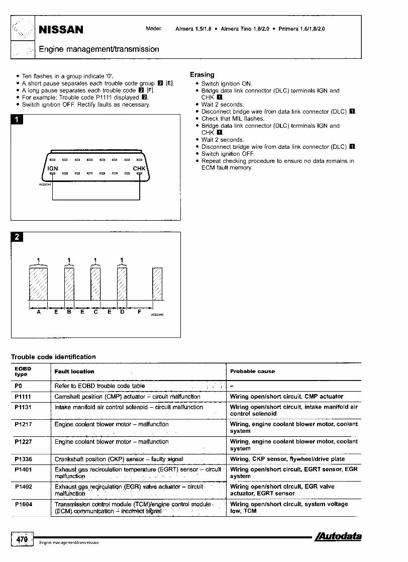
- , I NISSAN Model: Almera l ,5 / l ,8 Almera Tino l,8/2,O Primera l,6/l,8/2,O
Engine management/transmission
Ten flashes in a group indicate '0'. A short pause separates each trouble code group rn [El. A long pause separates each trouble code rn [Fl. For example: Trouble code Pl l l l displayed rn. Switch ignition OFF. Rectify faults as necessary.
Trouble code identification
Erasing Switch ignition ON. Bridge data link connector (DLC) terminals IGN and CHK m. Wait 2 seconds. Disconnect bridge wire from data link connector (DLC) m. Check that MIL flashes. Bridge data link connector (DLC) terminals IGN and CHK m. Wait 2 seconds. Disconnect bridge wire from data link connector (DLC) m. Switch ignition OFF. Repeat checking procedure to ensure no data remains in ECM fault memory.
EOBD type
PO
P l l l l
P I 131
P I 227 I Engine coolant blower motor - malfunction Wiring, engine coolant blower motor, coolant system
Fault location
Refer to EOBD trouble code table
PI217
Probable cause
- Camshaft position (CMP) actuator - circuit malfunction
Intake manifold air control solenoid - circuit malfunction
Wiring openlshort circuit, CMP actuator
Wiring openlshort circuit, intake manifold air
Engine coolant blower motor - malfunction
P I 336 I Crankshaft position (CKP) sensor - faulty signal
control solenoid
Wiring, engine coolant blower motor, coolant system
Wiring, CKP sensor, flywheelldrive plate
PI401
PI402
P I 604
Exhaust gas recirculation temperature (EGRT) sensor - circuit malfunction
Exhaust gas recirculatin (EGR) valve actuator - circuit malfunction
Transmission control module fTCM)lengine control module (ECM) communication - incorrect signal
Wiring openlshort circuit, EGRT sensor, EGR system
Wiring openlshort circuit, EGR valve actuator, EGRT sensor
Wiring openlshort circuit, system voltage low, TCM

EOBD ty Pe
P I 605
PI610
P I 61 1
Fault location
P I 61 2
P I 61 3
Probable cause
Engine control module (ECM)/transmission control module (TCM) communication signal - malfunction
Ignition keylengine control module (ECM) - malfunction
Immobilizer control modulelengine control moduk (ECM) - coding
PI614
PI615
P I 705
1 I
PI756 I Transmission fluid pressure (TFP) solenoid - malfunction I TFP solenoid
Wiring openlshort circuit, system voltage low, TCM
Incorrect ignition key, ECM
lmmobilizer control module/ECM incorrectly coded
Immobilizer control modulelengine control module (ECM) oomrnunication - malfunction
Engine control module (ECM), immobilizer function - internal failure
P I 706
PI751
PI753
I I
PI758 1 Transmission Ruid pressure (TFP) solenoid - circuit malfunction 1 Wiring openlshort circuit, TFP solenoid
Wiring, immobilizer control module, ECM
ECM
Immobilizer axltrd modulelmodule coding plug communication - no signal
ignition keytimmobilizer wntrol module communication - matfunction
Throttle m i t i on (TP) sensor - circuit malfunction
P I 763 Wiring openlshort circuit, transmission clutch pressure control solenoid
Wiring, immobilizer control module, module coding plug
Incorrect ignition key, immobilizer control module
Wiring openlshort circuit, TP switchlsensor
ParWneutral positian (PNP) switch - circuit malfunction
Transmission shift control valve - mlfunctiQn
Transmi~sion sh& wntrol valve - circuit malfunction
control valve
Wiring openlshort circuit, PNP switch
Transmission shift control valve
Wiring openlshort circuit, transmission shift
P I 778 Transmission shift control valve

Year: 2001 -04
Engine code: KA24E, QGISDE, QGIGDE, QGl8DE, QRZODE, QR25DE
Nissan ECCS
Navara Pick-u
General information 0 Refer to the front of this manual for general test conditions,
terminology, detailed descriptions of wiring faults and a general trouble shooter for electrical and mechanical faults.
o Trouble codes can be displayed by using diagnostic equipment connected to the data link connector (DLC) or by the malfunction indicator lamp (MIL).
Accessing NOTE: To access trouble codes, accelerator pedal position (APP)
sensor must be functioning correctly.
Ensure accelerator pedal is fully released. Switch ignition ON. DO NOT start engine. Wait 3 seconds.
Within 5 seconds, repeat the following 5 times: Fully depress accelerator pedal. Fully release accelerator pedal. Wait 7 seconds. Fully depress accelerator pedal. After approximately 10 seconds MIL will start flashing. Fully release accelerator pedal. Trouble codes are now displayed by MIL. Count MIL flashes. Compare with trouble code table. Each trouble code consists of four groups of one or more flashes:
0 The first group of flashes indicate the 'thousands' of the trouble code [A]. The second group of flashes indicate the 'hundreds' of the trouble code [El. The third group of flashes indicate the 'tens' of the trouble code [Cl.

0 The fourth group of flashes indicate the 'units' of the trouble code KI [Dl.
0 Ten flashes in a group indicate '0'. o A short pause separates each trouble code group K I [El. 0 A long pause separates each trouble code [F]. o For example: Trouble code PI130 displayed O.
Switch ignition OFF.
Model: Almera l,S/l,8 Almera Tino 1,8 Primera l,6/l,8/2,O X-Trail 2,012,s Navara Pick-up 2,4 NISSAN
Engine managementltransmission
Trouble code identification
'; i, v
I -
Erasing Ensure accelerator pedal is fully released. Ensure ignition switched OFF for at least 10 seconds. Switch ignition ON. DO NOT start engine. Wait 3 seconds. Within 5 seconds, repeat the following 5 times:
o Fully depress accelerator pedal. 0 Fully release accelerator ~edal .
~ a i i 7 seconds. Fully depress accelerator pedal. After approximately 10 seconds MIL will start flashing. Fully release accelerator pedal. Trouble codes are now displayed by MIL. Fully depress accelerator pedal for more than 10 seconds Fully release accelerator pedal. Trouble code 0000 should be displayed.
Flash type EOBD type Fault location
-
Probable cause
-
0011
0021
0031
PO
-
0032
0037
-
-
0038
0051
Refer to EOBD trouble code tabte
Camshaft position control system - bank 1 - performance problem
-
-
0052
0057
0102 l - Mass air flow (MAF) sensor - voltage Wiring, MAF sensor, air leak, ECM I low
-
Wiring, CMP sensor, CKP sensor, valve timing sensor
Camshaft position control system - bank 2 - performance probtem
Heated oxygen sensor (H02S) 1, bank 1 - heater voltage low
-
-
0058
0101
Wiring, CMP sensor, CKP sensor, valve timing sensor
Wiring, H02S heater, ECM
Heated oxygen sensor (H02S) 1, bank 1 - heater voltage high
Heated oxygen sensor (H02S) 2, bank 1 - heater voltage low
-
-
Wiring, H02S heater, ECM
Wiring, H02S heater, ECM
Heated oxygen sensor (H02S) 2, bank 1 - heater voltage high
Heated oxygen sensor (H02S) 1, bank 2 - heater voltage low
-
-
Wiring, H02S heater, ECM
Wiring, H02S heater, ECM
Heated oxygen sensor (H02S) 1, bank 2 - heater voltage high
Heated oxygen sensor (H02S) 2, bank 2 - heater voltage low
Wiring, H02S heater, ECM
Wiring, H02S heater, ECM
Heated oxygen sensor (H02S) 2, bank 2 - heater voltage high
Mass air flow (MAF) sensor - rangelperformance problem
Wiring, H02S heater, ECM
Wiring, MAF sensor, air leak, ECM

Engine management/transrnission 1,- I
/
6' s
e i NlSSAN Model: Almera l ,5 / l ,8 Almera Tino 1,8 Primera 1,6/1,8/2,O
X-Trail 2,0/2,5 Navara Pick-up 2,4
Flash type
0103
0107
O 1 I 2 l - Intake air temperature (EAT) sensor - I Wiring, IAT sensor, ECM voltage low
Fault location EOBD type
0108
Probable cause
-
-
-
0113
Mass air Row (WAF) sensor - voltage high
Manifold absolute pressure (MAP) sensor - voltage low
0117
0118
Wiring, MAF sensor, ECM
Wiring, MAP sensor, ECM
Manifold absolute pressure (MAP) sensor - voftage high
-
01 21
01 22
0127 I - Intake air temperature (IAT) sensor I Wiring short circuit, IAT sensor, ECM intake air ternoerature too hiah
Wiring, MAP sensor, ECM
-
-
0123
0125
Intake air temperature (IAT) sensor - voltage high
-
-
Wiring, IAT sensor, ECM
Engine coolant temperature (ECT) sensor - voltage low
Engine coolant temperature (ECT) sensor - voltage high
-
-
01 28
01 32
Wiring, ECT sensor, ECM
Wiring, ECT sensor, ECM
Throttle position (TP) sensor - rangelperformance problem
Throttle position (TP) sensor - voltage low
I I I
0138 l - Heated oxygen sensor (H02S) 2, Wiring, H02S, intakelfuel system, injector, ECM bank 1 - voltage high
Wiring, TP sensor, ECM
Wiring, TP sensor, ECM
Throttle position (TP) sensor - voltage high
Engine coolant temperature - insufficient coolant temperature for dosed loop fuel control
-
-
0133
01 34
Wiring, TP sensor, ECM
Wiring, ECT sensor, engine cooling system, ECM
- [ Heated oxygen sensor (H02S) 1, I Wiring, H02S, intakelfuel system, injector, exhaust
Engine coolant temperature too low
Heated oxygen sensor (H02S) 1, bank 1 - voltage high
-
01 39
01 52
Engine coolant thermostat, ECT sensor, engine cooling system, ECM
Wiring, H02S, fuel system, injector, ECM
01 53
01 54
bank 1 - shw response
Heated oxygen sensor (H02S) 1, bank 1 - vottage high
-
-
01 58
01 59
01 71
system, MAF sensor, ECM
Wiring, H02S, ECM
-
-
Heated oxygen sensor (H02S) 2, bank 1 - circuit malfunction
Heated oxygen sensor (H02S) 1, bank 2 - voltage high
-
-
-
Wiring, H02S, intakelfuel system, injector, ECM
Wiring, H02S, fuel system, injector, ECM
Heated oxygen sensor (H02S) 1, bank 2 - slow response
Heated oxygen sensor (H02S) 1, bank 2 - voltage high
Wiring, H02S, intakelfuel system, injector, exhaust system, crankcase vent valve, MAF sensor, ECM
Wiring, H02S, ECM
Heated oxygen sensor (H02S) 2, bank 2 - voltage high
Heated oxygen sensor (H02S) 2, bank 2 - circuit malfunction
Fuel trim - bank 1 - mixture too lean
Wiring, H02S, intakelfuel system, injector, ECM
Wiring, H02S, intakelfuel system, injector, ECM
Wiring, exhaust system, front H02S, fuel system, injector, MAF sensor, ECM

Model: Almera l,S/l,8 Almera Tino 1,8 Primera l,6/1,8/2,O X-Trail 2,012,5 Navara Pick-up 2,4
I Engine managementltransmission
Flash type I EOBD type / R u n location Probable cause
01 72
0174
0175
-
0181
0182
0221 I - Throttle position (TP) sensor 1 & 2 - I Wiring, TP sensor, ECM rangelperformance problem
-
-
0183
021 7
Fuel trim - bank 1 - mixture too rich
-
-
Wiring, intakelexhaust system, front HOZS, fuel system, injector, MAF sensor, ECM
Fuel trim - bank 2 - mixture too lean
Fuel trim - bank 2 - mixture too rich
-
-
0222
0223
Wiring, exhaust system, front H02S, fuel system, injector, MAF sensor, ECM
Wiring, exhaust system, front H02S, fuel system, injector, MAF sensor, ECM
Fuel tank temperature sensor - range1 performance problem
Fuel tank temperature sensor - voltage low
0226
0227
Wiring, fuel tank temperature sensor, ECM
Wiring, fuel tank temperature sensor, ECM
Fuel tank temperature sensor - voltage high
Engine over temperature condition
-
-
0228
0245
Cylinder 3 - misfire
Wiring, fuel tank temperature sensor, ECM
Wiring, engine coolant blower, coolant hoses, engine coolant thermostat, radiator, engine coolant temperature (ECT) switch
-
-
0300
0301
0302
Wiring, mechanical fault, fuel system, EGR valve, injector, intake system, ignition system, CKP sensor, front H02S, ECM
Throttle position (TP) sensor 1 - voltage low
Throttle position (TP) sensor 1 - voltage high
-
-
Wiring, TP sensor, ECM
Wiring, TP sensor, ECM
Accelerator pedal position (APP) sensor 112 - rangelperformance problem
Accelerator pedal position (APP) sensor 1 - voltage low
-
-
-
Cylinder 6 - misfire
Wiring, APP sensor, ECM
Wiring, APP sensor, ECM
Accelerator pedal position (APP) sensor 1 - voltage high
Supercharger (SC) bypass valve - malfunction
-
-
Wiring, mechanical fault, fuel system, EGR valve, injector, intake system, ignition system, CKP sensor, front H02S, ECM
Wiring, APP sensor, ECM
Wiring, SC bypass valve, hose blockedlleaking
Random misfire
Cylinder 1 - misfire
Cylinder 2 - misfire
Wiring, mechanical fault, fuel system, EGR valve, injector, intake system, ignition system, CKP sensor, front H02S, ECM
Wiring, mechanical fault, fuel system, EGR valve, injector, intake system, ignition system, CKP sensor, front H02S, ECM
Wiring, mechanical fault, fuel system, EGR valve, injector, intake system, ignition system, CKP sensor, front H02S, ECM
Cylinder 4 - misfire
Cylinder 5 - misfire
Wiring, mechanical fault, fuel system, EGR valve, injector, intake system, ignition system, CKP sensor, front H02S, ECM
Wiring, mechanical fault, fuel system, EGR valve, injector, intake system, ignition system, CKP sensor, front H02S, ECM
4
/Autodata Engine rnanagementltransmiss~on 475

Engine rnanagernentltransrnission
I r Y'
NISSAN Model: Almera l,5/1,8 Almera Tino 1,s Primera l,6/1,8/2,O X-Trail 2,012,5 Navara Pick-up 2,4
Probable cause Flash type
0327 I - 1 Knock sensor (KS) - voltage low Wiring, KS, ECM
EOBD type Fault location
-
Wiring, KS, ECM
Wiring, CKP sensor, ECM
0328
0335
Wiring, CMP sensor, starter motor, ECM
- -
0340
0400
0402
Wiring, hose blockedlleaking, EGR valve, EGR valve, EVAP valve, ECM
Knock sensor (KS) - voltage high
Crankshaft position (CKP) sensor 1 - circuit malfunction
Wiring, EGR valve, EGR back pressure transducer, hose blockedlleaking, CMP sensor, MAF sensor, EGR valve, EVAP valve, ECM
Wiring, EGRT sensor, ECM
-
-
-
Camshaft position (CMP) sensor - circuit malfunction
Exhaust gas recirculation (EGR) system - insufficienffexcessive flow detected
Exhaust gas recirculation (EGR) system - valve malfunction
0405
Wiring, EGRT sensor, ECM 0406
0420 Catalytic converter, wiring, intakelexhaust system, injector, ECM
- Exhaust gas recirculation temperature (EGRT) sensor - low voltage
-
-
Catalytic converter, wiring, intakelexhaust system, injector, ECM
Wiring, EVAP valve, hose blockedlleaking, EVAP canister, BARO sensor, MAPIBARO switching valve, ECM
Wiring, fuel tank, fuel filler cap, hose blockedl leaking, EVAP valve, EVAP canister, EVAP vent valve, BARO sensor, MAPIBARO switching valve, ECM
Wiring, EVAP control valve, EVAP valvelpressure sensor; hose blockedlleaking, ECM
Exhaust gas recirculation temperature (EGRT) sensor - high voltage
Catalytic converter - bank 1 - efficiency below threshold
0430
0441
-
-
0442
Catalytic converter - bank 2 - efficiency below threshold
Evaporative emission (EVAP) system - flow malfunction
0444
Wiring, EVAP control valve, EVAP valvelpressure sensor, hose blockedlleaking, ECM
Wiring, EVAP vent valve, EVAP breather valve1 pressure sensor, hose blockedlleaking, ECM
-
0445
0447
I - I Evaporative emission (EVAP) system - pressure sensor malfunction
Evaporative emission (EVAP) system - small leak detected
-
Wiring, EVAP pressure sensor, hose blockedl leaking, EVAP ventlcontrol valve, EVAP canister, ECM
Evaporative emission (EVAP) system - control valve malfunction
-
-
Evaporative emission (EVAP) system - pressure sensor malfunction
Evaporative emission (EVAP) system - control valve malfunction
Evaporative emission (EVAP) system - vent valve malfunction
Wiring, EVAP pressure sensor, hose blockedl leaking, EVAP ventlcontrol valve, EVAP canister, ECM
Evaporative emission (EVAP) system - large leak detected
Wiring, fuel tank, fuel filler cap, hose blockedl leaking, EVAP valve, EVAP canister, EVAP vent valve, BARO sensor, MAPIBARO switching valve, ECM
Evaporative emission (EVAP) system - very small leak detected
Wiring, fuel tank, fuel filler cap, hose blockedl leaking, EVAP valve, EVAP canister, EVAP vent valve, BARO sensor, MAPIBARO switching valve, ECM
0460 I - Fuel tank level sensor - signal malfunction
Wiring openlshort circuit, fuel tank level sensor
0461 I - Fuel tank level sensor - rangel performance problem
Wiring, fuel tank level sensor

I Engine rnanagement/transrnission 1 1
Flash type EOBD type Fault location I I I Probable cause
0463 I - I Fuel tank level sensor - voltage hiqh I Wiring, fuel tank level sensor
I I I
0462
0500
0505
0506
- Fuel tank level sensor - voltage low
0507
051 0
0600
0605
Wiring, fuel tank lever sensor
-
- -
0650
0705
Engine speed (RPM) - incorrect signal voltage, ECM to TCM communication
-
-
- -
0710
0720
Wiring, RPM sensor, TCM, ECM
Vehicle speed sensor (VSS) - circuit malfunction
Idle speed control (ISC) - malfunction
Idle speed control (ISC) - engine rpm too low
-
-
0731 I - I AT - first gear selection - malfunction I Transmission valve block
Wiring, VSS, ECM
Wiring, Idle speed control (ISC), ECM
Wiring, Idle speed control (ISC), ECM
Idle speed control (ISC) - engine rpm too high
Closed throttle position (CTP) switch - circuit malfunction
ECMrrCM - communication error
Engine control module (ECM) - malfunction
-
-
Wiring, Idle speed control (ISC), ECM
Wiring, CTP switch, ECM
Wiring, ECM, TCM
ECM
Malfunction indicator lamp (MIL) - circuit malfunction
Parklneutral position (PNP) switch - circuit malfunction
0734 I - I AT - fourth gear selection - malfunction I Transmission valve block
Wiring, ECM
Wiring, PNP switch, ECM
Transmission fluid temperature sensor - voltage too lowthigh
AT - vehicle speed sensor (VSS)
0732
0733
Wiring, temperature sensor, TCM, ECM
Wiring, VSS, TCM
-
-
0740
0750 I - I AT - shift solenoid A - voltage low I Wiring, shift solenoid A, TCM
0744
0745
AT - second gear selection - malfunction
AT - third gear selection - malfunction
I !
I 1 O 2 I P1102 Mass air flow (MAF) sensor - range1 Wiring, MAF sensor, air leak, ECM performance problem
Transmission valve block
Transmission valve block
-
-
0755
1065
Ill1 I P1lll Camshaft position (CMP) actuator - I Wiring, CMP actuator, ECM bank 1 - malfunction
Wiring, torque converter clutch solenoid, TCM - Torque converter clutch solenoid - voltage low
Torque converter lock-up solenoid - circuit malfunction
AT - Line pressure solenoid - voltage low
-
P I 065
Wiring, clutch solenoid, TCM
Wiring, line pressure solenoid, TCM
1121
1122
AT - shift solenoid B - voltage low
Engine control module (ECM) - supply voltage
Wiring, shift solenoid B, TCM
Wiring, ECM
PI121
PI122
Throttle motor - malfunction
Throttle motor - rangelperformance problem
Throttle motor
Wiring, throttle motor
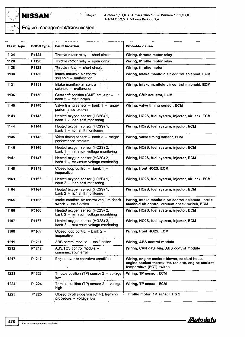
Model: Almera 1,5/1,8 Almera Tino 1,8 Primera 1,611,812,O X-Trail 2,012,s Navara Pick-up 2,4
I . L -- Engine rnanagementltransmission
Flash type
11 24
1126
1128
EOBD type
1130
1131
PI124
PI126
PI128
1136
1140
1143
Fault locatien
PI130
PI131
1144
1145
Probable cause
Throttle motor relay - short circuit
Throttle motor relay - open circuit
Throffle motor - short circuit
P I 136
P I 140
PI143
1146
1147
1148
Wiring, throttle motor relay
Wiring, throttle motor relay
Wirinq, throttle motor
Intake manifold air control solenoid - malfunction
Intake manifold air control solenoid - malfunction
P I 144
PI145
1163
1164
Wiring, intake manifold air control solenoid, ECM
Wiring, intake manifold air control solenoid, ECM
Camshaft position (CMP) actuator - bank 2 - malfunction
Valve timing sensor - bank 1 - range1 performance problem
Heated oxygen sensor (H02S) 1, bank 1 - lean shift monitorinu
PI146
PI147
PI148
1165
1166
Wiring, CMP actuator, ECM
Wiring, valve timing sensor, ECM
Wiring, H02S, fuel system, injector, air leak, ECM
Heated oxygen sensor (H02S) 1, bank 1 - rich shift monitoring
Valve timing sensor - bank 2 - rangel performance problem
P I 163
PI1 64
1167
1168
1211
1212
Wiring, H02S, fuel system, injector, ECM
Wiring, valve timing sensor, ECM
Heated oxygen sensor (H02S) 2, bank 1 - minimum voltage monitoring
Heated oxygen sensor (H02S) 2, bank 1 - maximum voltage monitoring
Closed loop control - bank 1 - inoperative
P I 165
PI166
1217
1223
1224
Wiring, H02S, fuel system, injector, ECM
Wiring, H02S, fuel system, injector, ECM
Wiring, front H02S, ECM
Heated oxygen sensor (H02S) 1, bank 2 - lean shift monitoring
Heated oxygen sensor (H02S) I, bank 2 - rich shift monitorinn
PI167
PI168
P I 21 1
PI212
1225
Wiring, H02S, fuel system, injector, air leak, ECM
Wiring, H02S, fuel system, injector, ECM
Intake manifold air control vacuum check switch - malfunction
Heated oxygen sensor (H02S) 2, bank 2 - minimum voltage monitoring
PI217
PI223
P I 224
Wiring, intake manifold air control solenoid, intake manifold air control vacuum check switch, ECM
Wiring, H02S, fuel system, injector, ECM
Heated oxygen sensor (H02S) 2, bank 2 - maximum vottage monitoring
Closed loop control - bank 2 - inoperative
ABS cor~trol module - malfunction
ABSKCS control module - communication error
P I 225
Wiring, HOZS, fuel system, injector, ECM
Wiring, front H02S, ECM
Wiring, ABS control module
Wiring, CAN data bus, ABS control module
Engine over temperature condition
Throttle position (TP) sensor 2 - voltage low
Throttle position (TP) sensor 2 - voltage high
Wiring, engine coolant blower, coolant hoses, engine coolant thermostat, radiator, engine coolant temperature (ECT) switch
Wiring, TP sensor, ECM
Wiring, TP sensor, ECM
Closed throttle position (CTP), learning procedure - voltage low
Throttle motor, TP sensor 1 8 2

Model: Almera 1,511,8 Almera Tino 1,8 Primera 1,6/1,8/2,0 X - ~ r a i ~ 2,0/2,5 Navara pick-up 2,4 NISSAN
Engine rnanagementltransmission
&
P
%+?f
1 , 7-- M
Flash type
1226
1227
EOBD type
1228
1229
PI226
P I 227
1335
1336
1400
1402
1442
Fault IocaClon
P I 228
P I 229
1444
1446
1448
1464 1 PI464 1 Fuel tank level sensor - voltage high I Wiring, fuel tank level sensor
Probable cause
Closed throttle position (CTP), learning procedure - failed
Accelerator pedal position (APP) sensor 2 - voltage low
P I 335
P I 336
P I 400
PI402
PI442
1456
1490 I Evaporative emission (EVAP) system - Wiring, EVAP bypasslcut valve, hose blockedl bypass vacuum valve malfunction 1 leaking. ECM
Throttle motor, TP sensor 1 8 2
Wiring, APP sensor, ECM
Accelerator pedal position (APP) sensor 2 - voltage high
Sensor supply voltage - short circuit
PI444
PI446
P I 448
Wiring, APP sensor, ECM
Wiring, APP sensor, TP sensor, MAF sensor, EVAP sensor, PS sensor, refrigerant sensor, ECM
Crankshaft position (CKP) sensor 2 - circuit malfunction
Crankshaft posihn (CKP) sensor 1 - rotor teeth damage
Exhaust gas recirculation (EGR) system1 evaporative emission (EVAP) system - valve matfunction
Exhaust gas recirculation (EGR) system - excessive flow detected
Evaporative emksion (EVAP) system - small leak detected
P I 456
Wiring, CKP sensor, ECM
Wiring, CKP sensor, ECM
Wiring, EGR valve, EVAP valve, ECM
Wiring, EGR valve, EVAP valve, EGR valve, EGRT sensor, EGR back pressure transducer, ECM
Wiring, fuel tank, fuel filler cap, hose blocked1 leaking, EVAP valve, EVAP canister, EVAP vent
Evaporative emission (EVW) system - control valve malfunction
Evaporative emission (EVAP) system - vent valve malfunction
Evaporative emission (EVAP) system - vent vake malfunction
1491
1564
valve,^^^^ sensor, MAPIBARO switching valve, ECM
Wiring, EVAP pressure sensor, hose blocked1 leaking, EVAP valve, EVAP canister, ECM
Wiring, EVAP pressure sensor, hose blocked1 leaking, EVAP vent valve, EVAP canister contaminated, ECM
Wiring, EVAP vent valve, EVAP pressure sensor, hose blockedlleaking, EVAP canister contaminated, EVAP vacuum cut valve, ECM
Evaporative emission (EVAP) system - very small leak detected
1572
1574
Wiring, fuel tank, fuel filler cap, hose blocked1 leaking, EVAP valve, EVAP canister, EVAP vent valve, BAR0 sensor, MAPIBARO switching valve, ECM
PI491
P I 564
1605
1610
P I 572
P I 574
Evaporative emission (EVAP) system - bypass vacuum valve malfunction
Cruise control master switch - malfunction
PI605
P I 61 0
Wiring, EVAP vacuum cuffbypass valve, hose blockedlleaking, EVAP pressure sensor, EVAP vent valve, EVAP canister contaminated, ECM
Wiring, cruise control master switch, ECM
Cruise control brake pedal switch -circuit malfunction
Cruise control vehicle speed sensor (VSS) - signal variation between two vehicle speed sensors
Wiring, cruise control brake pedal switch, stop lamp switch, clutch pedal switch, ECM
Wiring, CAN data bus, VSS, instrument panel, ECM
TCM diagnosis communication line - malfunction
Ignition keylengine control module (ECM) - malfunction
Wiring, TCM
Incorrect ignition key, ECM

Flash type 1 EOBD type 1 Fault l m i o n I Probable cause
/
2 "&2"
-" , I - _
NlSSAN Model: Alrnera 1,511,8 Almera Tino 1,s Prirnera 1,611,812,O X-Trail 2,012.5 Navara Pick-up 2,4
Engine management/transrnission
1611
1612
1613
PI611
1614
1615
PI612
P I 61 3
1705
1706
Immobilizer control modulelengine control module (ECM) - coding
PI614
P I 61 5
1760
1800
1805
1000
1001
Immobilizer control modulelECM incorrectly coded
Immobilizer control modulelengine control module (ECM) communication - malfunction
Engine control module (€CAR), immobilizer function - internal failure
P I 705
P I 706
Wiring, immobilizer control module, ECM
ECM
Immobilizer control module/module coding plug communication - no signal
Ignition keylimmobilizer control module communication - malfunction
PI760
PI800
PI805
UIOOO
UlOOl
Wiring, immobilizer control module, module coding plug
Incorrect ignition key, immobilizer control module
AT - throttle position (TP) sensor - voltage too lowthigh
Parklneutral position (PNP) switch - circuit malfunction
Wiring, TP sensor, TCM, ECM
Wiring openlshort circuit, PNP switch
AT - overrun clutch solenoid - voltage low
Intake manifold air control solenoid - malfunction
Brake pedal position (BPP) switch - circuit malfunction
CAN data bus - no communication with other control modules
CAN data bus - no communication with other control modules
Wiring, torque converter clutch solenoid, TCM
Wiring, intake manifold air control solenoid, ECM
Wiring, BPP switch, ECM
Wiring, ECM
Wiring, ECM

Engine code: CDPOE, CDPOT, TD27Ti
Bosch EDC
Engine management
In fascia fusebox
General information 0 Refer to the front of this manual for general test conditions,
terminology, detailed descriptions of wiring faults and a general trouble shooter for electrical and mechanical faults.
0 Trouble codes are displayed by the malfunction indicator lamp (MIL).
n The ECM fault memory can also be checked using diagnostic equipment connected to the data link connector (DLC).
0 Switch ignition ON. 0 Check that MIL illuminates. 0 Start engine. Allow to idle. 0 If MIL extinguishes: No trouble codes have been recorded. 0 If MIL remains illuminated: Access trouble codes.
Accessing NOTE: Some models will also display trouble codes by the red
LED in the ECM m. Switch ignition ON. Bridge data link connector (DLC) terminals IGN and CHK m. Wait 2 seconds. Disconnect bridge wire from data link connector (DLC) m. Count MIL flashes. Compare with trouble code table. Long flashes indicate the 'tens' of the trouble code rn [A]. Short flashes indicate the 'units' of the trouble code [C]. A short pause separates each flash rn [B]. A long pause separates each trouble code rn [Dl. For example: Trouble code 12 displayed O. Switch ignition OFF. Rectify faults as necessary.
CHK I IGN
4
/Autodata rrl Eng~ne management 481

NISSAN
Engine management
Model: Almera 2,OD Primera 2,OTD Terrano II 2,7TD
Erasing Switch ignition ON. Bridge data link connector (DLC) terminals IGN and CHK O. Wait 2 seconds. Disconnect bridge wire from data link connector (DLC) O. Check that MIL flashes. Bridge data link connector (DLC) terminals IGN and CHK O. Wait 2 seconds. Disconnect bridge wire from data link connector (DLC) O. Switch ignition OFF. Repeat checking procedure to ensure no data remains in ECM fault memory.
Trouble code identification
Flash type Fault location Probable cause
Fuel injection pump position sensor - incorrect signal Wiring openlshort circuit, fuel injection pump position sensor
Mass air flow (MAF) sensor - circuit malfunction Wiring openlshort circuit, MAF sensor
Engine coolant temperature (ECT) sensor - circuit malfunction
Wiring openlshort circuit, ECT sensor
Vehicle speed sensor (VSS) - circuit malfunction
Fuel quantity adjuster position sensor - circuit malfunction
Wiring openlshort circuit, VSS
Wiring openlshort circuit, fuel qantity adjuster position sensor
Module coding plug - circuit malfunction Wiring openlshort circuit, module coding plug
Fuel quantity adjusterlposition sensor - malfunction Wiring, supply voltage, fuel qantity adjusterl position sensor, ECM, fuel injection pump
Fuel injection timing solenoidlinjector needle lift sensor - malfunction
Wiring, fuel injection timing solenoid, injector needle lift sensor, CKP sensor, air in fuel
Fuel quantity adjusterlposition sensor - malfunction Wiring, supply voltage, fuel qantity adjusterl position sensor, ECM, fuel injection pump
Wiring openlshort circuit, APP switch Accelerator pedal position (APP) switch - incorrect signal
Fuel quantity adjuster - circuit malfunction Wiring, fuel qantity adjuster
Engine control module (ECM) - defective
Engine coolant blower motor - malfunction
ECM
Wiring, engine coolant blower motor, coolant system
Engine control module (ECM) - defective ECM
Injector needle lift sensor - incorrect signal
Fuel shut-off solenoid 1 - malfunction
Wiring, injector needle lift sensor, air in fuel
Wiring openlshort circuit, fuel shut-off solenoid
Fuel shut-off solenoid 1 - circuit malfunction Wiring short circuit
Fuel shut-off solenoid 2 - malfunction Wiring open circuit, ECM
Fuel temperature sensor - incorrect signal Wiring openlshort circuit, fuel temperature sensor
Accelerator pedal position (APP) sensorlaccelerator pedal position (APP) switch - incorrect signal
Wiring openlshort circuit, APP sensorlswitch
Crankshaft position (CKP) sensor - incorrect signal Wiring openlshort circuit, CKP sensor
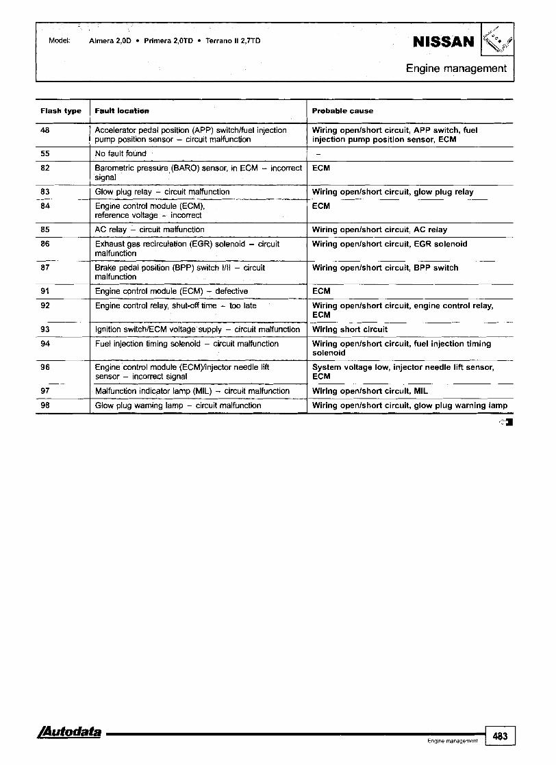
Model: Alrnera 2,OD Prirnera 2,OTD Terrano II 2,7TD
Engine management
Flash type Fault locatlon
Accelerator pedal position (APP) switchlfuel injection I Wiring openlshort circuit, APP switch, fuel pump position sensor - circuit malfunction injection pump position sensor, ECM
Probable cause
No fault found I -
AC relay - circuit malfunction I Wiring openlshort circuit, AC relay
Barometric pressure (BARO) sensor, in ECM - incorrect signal
Glow plug relay - circuit malfunction
Engine control module (ECM), reference voltaae - incorrect
Exhaust gas recircutation (EGR) solenoid - circuit I Wiring openlshort circuit, EGR solenoid malfunction
ECM
Wiring openlshort circuit, glow plug relay
ECM
Brake pedal position (BPP) switch 1/11 - circuit I Wiring openlshort circuit, BPP switch malfunction
Engine control module (ECM) - defective ( ECM
Engine control relay, shut-off time - too late Wiring openlshort circuit, engine control relay, I ECM
Ignition switch/ECM voltage supply - circuit malfunction I Wiring short circuit
Fuel injection timing solenoid - circuit malfunction Wiring openlshort circuit, fuel injection timing solenoid
Engine control module (ECM)/injector needle lift System voltage low, injector needle lift sensor, sensor - incorrect signal I ECM
Malfunction indicator lamp (MIL) - circuit malfunction I Wiring openlshort circuit, MIL
Glow plug warning lamp - circuit malfunction Wiring openlshort circuit, glow plug warning lamp
a

Model: Micra Alrnera Prirnera Serena Terrano II I Year: 1996-00 I
1023235
Serena - under fascia fusebox Alrnera $9984
Except Serena 4999 - in fascia fusebox PrimeMecrano II 1999 -r - in fascia fusebox
Micra 1999-
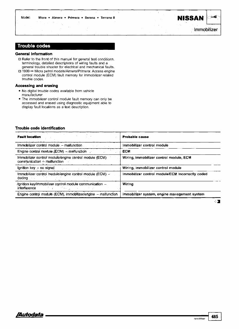
Model: Micra Almera Primera Serena Terrano II NlSSAN
lmmobilizer
General information Refer to the front of this manual for general test conditions, terminology, detailed descriptions of wiring faults and a general trouble shooter for electrical and mechanical faults. 1999 -, Micra petrol models/Almera/Primera: Access engine control module (ECM) fault memory for immobilizer related trouble codes.
Accessing and erasing No digital trouble codes available from vehicle manufacturer. The immobilizer control module fault memory can only be accessed and erased using diagnostic equipment able to display fault locations as a text description.
Trouble code identification
Ennine control module (ECM1 - malfunction I ECM
Fault location
Immobilizer control module - malfunction
Probable cause
Immobilizer control module
Immobilizer control modulelengine control module (ECM) communication - malfunction
Ignition key - no signal
Immobilizer control modulelengine control module (ECM) - codina
Wiring, immobilizer control module, ECM
Wiring, immobilizer control module
Immobilizer control modulelECM incorrectly coded
Ignition keylimmobilizer control module communication - interference
Engine control module (ECM), irnmobilizedengine - malfunction
Wiring
lmmobilizer system, engine management system
4

1 PEUGEOT
Model: I06 1,011,111,311,411,6 205 1,111,4/1,6 306 1,111,411,611,812,0 405 l,6Il,8/2,O 605 2,O Boxer 2,O
Year: 1989-00 Engine BD,KD,KDZ, HDZ, KDX, KD,YKDZ, KFX, K6B, LFZ, MFZ, NFW, NF,\MFZ, RFT, RFW, RFX, RF,VRFZ, 'Ode: RGX, RG,YRGZ System: Bosch Mono-Jetronic A2.2 Bosch Mono-Motronic MA3.0 Bosch Motronic MP3.113.215.1
Magneti Marelli Monopoint G51G6 Magneti Marelli AP18P18P.11
Engine management
205 - position 1
I
I I I 1 I \ A,,,,,,
405 - RH engine bay
205 - position 2

I Engine management I
Boxer
General information n Refer to the front of this manual for general test conditions,
terminology, detailed descriptions of wiring faults and a general trouble shooter for electrical and mechanical faults. Trouble codes are displayed by the malfunction indicator lamp (MIL) or LED.
fl The ECM fault memory can also be checked and erased using diagnostic equipment connected to the data link connector (DLC). Vehicles fitted with a coded keypad: When switching on ignition or entering start code ensure diagnostic equipment is disconnected from the data link connector (DLC).
Accessing Switch ignition ON. Check that MIL illuminates. Connect LED test lamp between green data link connector (DLC) terminal 2 and battery positive O. Bridge data link connector (DLC) terminal 2 and earth with a switched lead - contacts normally open O. Operate switch for 2,5-5 seconds. LED or MIL will now flash trouble code 12. Each trouble code consists of two groups of one or more flashes rn. Long flashes indicate the 'tens' of the trouble code rn [A]. Short flashes indicate the 'units' of the trouble code rn [C]. A short pause separates each flash H [B]. A long pause separates each trouble code rn [Dl. For example: Trouble code 12 displayed rn. Repeat operation. Count LED or MIL flashes. Note trouble codes. Compare with trouble code table.

Erasing Method 2 Ensure ignition switched OFF.
Method 1 Disconnect battery earth lead for 10 seconds. Switch ignition ON. WARNING: Disconnecting the battery may erase memory from Connect LED test lamp between data link connector (DLC) electronic units (e.g. radio, clock). terminal 2 and battery positive 0. Bridge data link connector (DLC) terminal 2 and earth with a switched lead - contacts normally open 0. Operate switch for 2,5-5 seconds. LED or MIL will now flash trouble code 12. Repeat switch operation until code 11 is displayed. Operate switch for 10-20 seconds. Switch ignition OFF.
Trouble code identification
Flash type I Fault location Probable cause
13 I Intake air temperature (IAT) sensor ] Wiring, IAT sensor, ECM
11
12
Engine coolant temperature (ECT) Wiring, ECT sensor, ECM sensor
End of sequence
Start of sequence
21 0 I Closed throttle position (CTP) switch I Wiring, CTP switch, accelerator cable adjustment, ECM
- -
15
18
21 H I Throttle position (TP) sensor 1 Wiring, TP sensor, accelerator cable adjustment, ECM
22 El I Closed throttle position (CTP) switch I Wiring, CTP switch, accelerator cable adjustment, ECM
Relay module
Turbocharger (TC) coolant pump
- --
Wiring, relay module - fuel pump contacts, ECM
Wiring, TC coolant pump, ECM
25 I Intake manifold air control solenoid I Wiring, intake manifold air control solenoid, ECM
22 0
27 I Vehicle speed sensor (VSS) 1 Wiring, VSS, ECM
Idle air control (IAC) valvelidle speed control (ISC) actuator
Wiring, IAC valvellSC actuator, ECM
Mixture control (MC)
34 Evaporative emission (EVAP) I Wiring, EVAP canister purge valve. ECM canister purge valve
Wiring, incorrect fuel, H02S, exhaust leak, fuel pressure, injector control, EVAP canister purge valve, compression, air filter blocked, ignition system, ECM
32
33 0
33 H
41 Crankshafl position (CKP) sensor1 Wiring, CKPIRPM sensor, air gap, ECM engine speed (RPM) sensor
42 I Injector(s) I Wiring, relay module, injector(s), ECM
Mixture control (MC)
Throttle position (TP) sensor
Manifold absolute pressure (MAP) sensor
Wiring, incorrect fuel, H02S, exhaust leak, fuel pressure, injector control, EVAP canister purge valve, compression, air filter blocked, ignition system, ECM
Wiring, TP sensor, accelerator cable adjustment, ECM
Wiring, MAP sensor, hoses blockedlleaking, ECM
43 ( Knock control 1 Wiring, KS, mechanical fault, incorrect fuel, ignition system, ECM
42
44 I Knock sensor (KS) 1 Wiring, KS, ECM
Injectorlfuel pump Wiring, injector, fuel pump, relay module, ECM

Model: 106 1,011,111,311,411,6 205 1,111,411,6 306 1,111,411,611,812,O 405 l,6ll,8/2,O 605 2,O Boxer 2,O
Engine managemen
I I 45 0 I Ignition coil 1 - cylinder 1 I Wiring, ignition coil, ECM
45 0 I Ignition coil 1 - cylinder 1 & 4 1 Wiring, ignition coil, ECM
51 ( Heated oxygen sensor (H02S) ] Wiring, H02S, exhaust leak, relay module, ECM
46
47
53 I Battery voltage I Wiring, battery discharged, alternator
Turbocharger (TC) wastegate regulating valve
Turbocharger (TC) wastegate requlation
52
54 I Engine control module (ECM) 1 Wiring, battery, ECM
Wiring, hoses blockedlleaking, TC wastegate regulating valve, ECM
TC wastegate regulating valve, MAP sensor, TP sensor, exhaust leak, intake leak
56 1 Coded keypad I Wiring, coded keypad
Mixture control (MC)
57 0 I Ignition coil 2 - cylinder 2 I Wiring, ignition coil, ECM
Wiring, incorrect fuel, H02S, exhaust leak, fuel pressure, injector control, EVAP canister purge valve, compression, air filter blocked, ignition system, ECM
61 ( Turbocharger (TC) regulating valve 1 Wiring, hoses blockedlleaking, TC regulating valve. ECM
57 0 58
59 0
65 I Camshaft position (CMP) sensor 1 Wiring, CMP sensor, ECM
Ignition coil 2 - cylinder 2 & 3
Ignition coil 3 - cylinder 3
Ignition coil 4 - cylinder 4
Bosch Mono-Jetronic A2.2 Except Bosch Mono-Jetronic A2.2 Bosch Mono-Motronic MA3.0 All systems Except Magneti Marelli APIBosch MP3.2
fl Magneti Marelli AP Except Magneti Marelli AP Bosch MP3.2 Turbo models
Wiring, ignition coil, ECM
Wiring, ignition coil, ECM
Wiring, ignition coil, ECM
71 0
72 0 El 73 El 74
79 0
Injector 1
Injector 2
Injector 3
Injector 4
Manifold absolute pressure (MAP) sensor
Wiring, relay module, injector, ECM
Wiring, relay module, injector, ECM
Wiring, relay module, injector, ECM
Wiring, relay module, injector, ECM
Wiring, MAP sensor, hoses blockedlleaking, ECM

Model: 106 1,011,1/1,4/1,6 206 1,1/1,4/1,6/2,0 306 1,4/1,6/1,8/2,0 406 1,6/1,8/2,0 406 Coupe 2,O 806 l,8/2,O Partner l,4/l,8
Year: 1995-04
Engine code: BFZ, CD,KDZ, HD,WDZ, HFX, HF,WFZ, KFW, KFX, LFW, LFX, LF,YLFZ, NFT, NFU, NFW, NFX, NFZ, RFN, RFR, RFS, RFU, RFV, RGX, 6FZ
System: Bosch Mono-Motronic MA3.1 Bosch Motronic MP3.2/5.1.1/5.2/7.2/7.3/7.4.4 Magneti Marelli lAPllAP20/4.8P/4.8P2/8P18PlA Sagern 4GISL96/S2000
Engine management
206,806, Partner 1997 +
Partner 4 9 9 7 406 4 9 9 7 - in fascia fusebox

Model: 106 1,011,111,4/1,6 206 1,1/1,4/1,6/2,0 306 l,4/I,6/l,8/2,O 406 1,6/1,8/2,0 406 Coupe 2,O 806 1,8/2,0 Partner l ,4/ l ,8
PEUGEOT I Engine management I
406 1997+ - in fascia fusebox
Accessing and erasing No digital trouble codes available from vehicle
General information manufacturer. Refer to the front of this manual for general test conditions, The engine control module (ECM) fault memory can only be terminology, detailed descriptions of wiring faults and a accessed and erased using diagnostic equipment able to general trouble shooter for electrical and mechanical faults. display fault locations as a text description. Vehicles fitted with a coded keypad: When switching on ignition or entering start code ensure diagnostic equipment is disconnected from the data link connector (DLC).
Trouble code identification
Fault location I Probable cause
G-force sensor (misfire monitor) I Wiring, G-force sensor, insecure sensor, ECM
AC compressor clutch relay 1 Wiring, AC compressor clutch relay, ECM
Catalytic converter I Catalytic converter
AC ON signal to multifunction control module
Battery voltage
Camshaft position (CMP) sensor
Closed throttle position (CTP) switch I Wiring, CTP switch, accelerator cable adjustment, ECM
Wiring, ECM
Wiring, battery discharged, alternator
Wiring, CMP sensor, ECM
Crankshaft position (CKP) sensorlengine speed (RPM) sensor 1 Wiring, CKPIRPM sensor, air gap, ECM
-
Coolant temperature signal to multifunction control module
Coolant temperature warning lamp signal to multifunction control module
- - - - -
Wiring, ECM
Wiring, ECM
Engine coolant temperature (ECT) sensor I Wiring, ECT sensor, ECM
Engine control module (ECM)
Engine control module (ECM) - programming
Engine coolant blower motor relay 1 - operation
Engine coolant blower motor relay 2 - operation
Wiring, battery, ECM
Incorrectly programmed, ECM
Wiring, blower motor relay 1
Wiring, blower motor relay 2
-a- E n m e manaaement 491
Engine speed signal to multifunction control module
Exhaust gas recirculation (EGR) solenoid
Wiring, ECM
Wiring, EGR solenoid, ECM
110
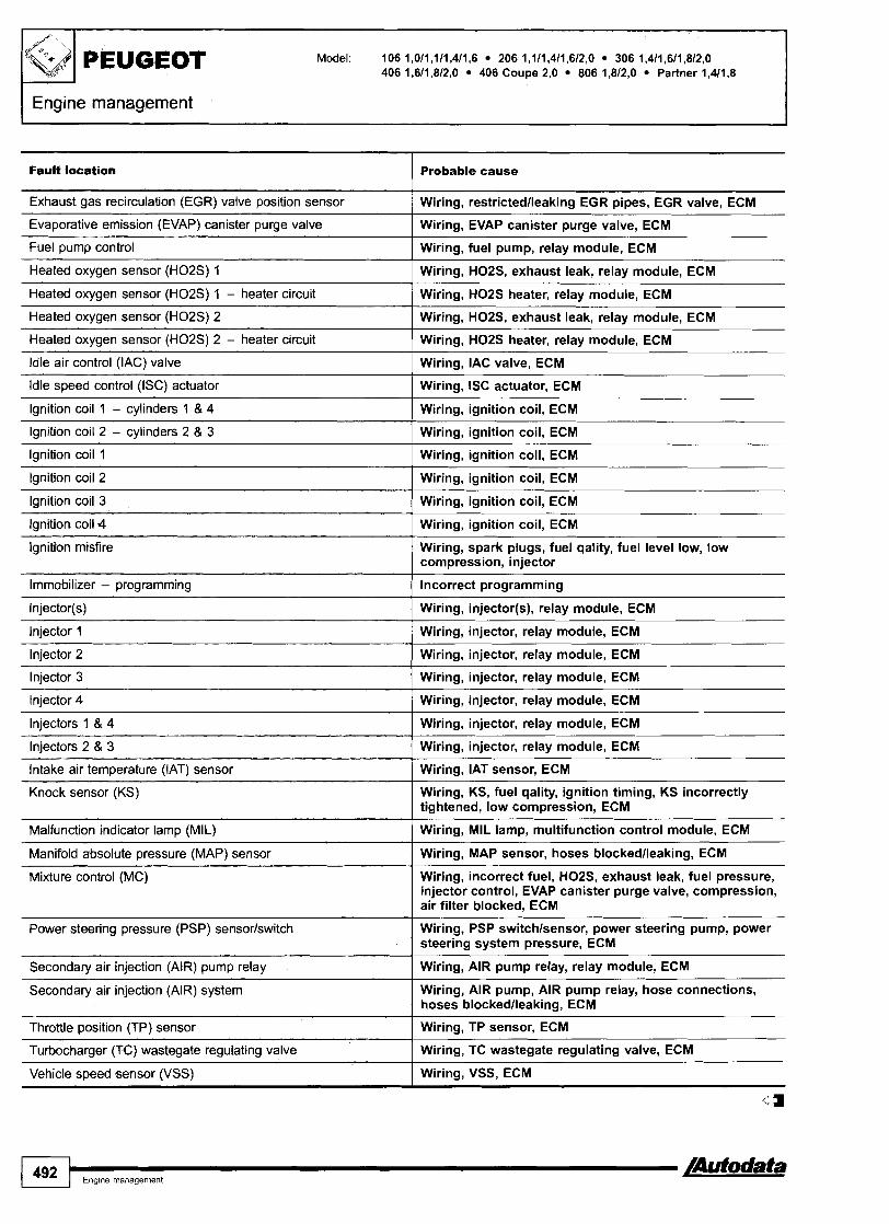
I PEUGEOT Model: 106 1,0/1,1/1,4/1,6 206 1,111,411,612,O 306 l,4/1,6/1,8/2,0 406 l,6/1,8/2,O 406 Coupe 2,O 806 l,8/2,O Partner l,4/1,8
Engine management
Fault location Probable cause
Exhaust gas recirculation (EGR) valve position sensor -- - -
Wiring, restrictedlleaking EGR pipes, EGR valve, ECM
Wiring, EVAP canister purge valve, ECM --
Evaporative emission (EVAP) canister purge valve
Fuel pump control
Heated oxygen sensor (H02S) 1
Wiring, fuel pump, relay module, ECM
Wiring, H02S, exhaust leak, relay module, ECM
Heated oxygen sensor (H02S) 1 - heater circuit Wiring, H02S heater, relay module, ECM
Wiring, H02S, exhaust leak, relay module, ECM
Wiring, H02S heater, relay module, ECM
Heated oxygen sensor (H02S) 2
Heated oxygen sensor (H02S) 2 - heater circuit
ldle air control (IAC) valve Wiring, IAC valve, ECM
ldle speed control (ISC) actuator Wiring, ISC actuator, ECM
lgnition coil 1 - cylinders 1 & 4 Wiring, ignition coil, ECM
lgnition coil 2 - cylinders 2 & 3 Wiring, ignition coil, ECM
Wiring, ignition coil, ECM lgnition coil 1
lgnition coil 2 Wiring, ignition coil, ECM
lgnition coil 3 Wiring, ignition coil, ECM
lgnition coil 4 Wiring, ignition coil, ECM
Wiring, spark plugs, fuel qality, fuel level low, low compression, injector
lgnition misfire
Immobilizer - programming Incorrect programming
Wiring, injector(s), relay module, ECM
lnjector 1
lnjector 2
lnjector 3
Wiring, injector, relay module, ECM
Wiring, injector, relay module, ECM
Wiring, injector, relay module, ECM
lnjector 4 Wiring, injector, relay module, ECM
Injectors 1 & 4
Injectors 2 & 3
Intake air temperature (IAT) sensor
Knock sensor (KS)
Wiring, injector, relay module, ECM
Wiring, injector, relay module, ECM
Wiring, IAT sensor, ECM
Wiring, KS, fuel qality, ignition timing, KS incorrectly tightened, low compression, ECM
Malfunction indicator lamp (MIL)
Manifold absolute pressure (MAP) sensor
Wiring, MIL lamp, multifunction control module, ECM
Wiring, MAP sensor, hoses blockedlleaking, ECM
Mixture control (MC) Wiring, incorrect fuel, H02S, exhaust leak, fuel pressure, injector control, EVAP canister purge valve, compression, air filter blocked, ECM
Power steering pressure (PSP) sensor/switch Wiring, PSP switchlsensor, power steering pump, power steering system pressure, ECM
Secondary air injection (AIR) pump relay Wiring, AIR pump relay, relay module, ECM
Secondary air injection (AIR) system Wiring, AIR pump, AIR pump relay, hose connections, hoses blockedlleaking, ECM
Throttle position (TP) sensor
Turbocharger (TC) wastegate regulating valve
Vehicle speed sensor (VSS)
WGTP sen&, ECM -
Wiring, TC wastegate regulating valve, ECM
Wiring, VSS, ECM
4

Model: 106 1 ,311,6 406 1,812,O 605 2,O 806 1,812,O Year: 1994-00
PEUGEOT
Engine code: LFW, LF,YMFZ, NFW, NF,YRFU, RFV, RFZ, RGX, RGY
System: Magneti Marelli 8P Bosch Motronic MP3.215.115.1.115.2
I Engine management
General information Refer to the front of this manual for general test conditions, terminology, detailed descriptions of wiring faults and a general trouble shooter for electrical and mechanical faults. Trouble codes are displayed by the malfunction indicator lamp (MIL) or LED.
o The ECM fault memory can also be checked and erased using diagnostic equipment connected to the data link connector (DLC). Vehicles fitted with a coded keypad: When switching on ignition or entering start code ensure diagnostic equipment is disconnected from the data link connector (DLC).
406 - in fascia fusebox
Accessing Switch ignition ON. Check that MIL illuminates. Connect LED test lamp between data link connector (DLC) terminal C3 and battery positive m. Bridge data link connector (DLC) terminal C2 and earth with a switched lead - contacts normally open O. Operate switch for 2,5-5 seconds. LED or MIL will now flash trouble code 12. Each trouble code consists of two groups of one or more flashes El. Long flashes indicate the 'tens' of the trouble code H [A]. Short flashes indicate the 'units' of the trouble code H [C]. A short pause separates each flash [B]. A long pause separates each trouble code H [Dl. For example: Trouble code 12 displayed El. Repeat operation. Note trouble codes. Compare with trouble code table. Rectify faults as necessary.

?I PEUGEOT I
Engine management
Model: 106 l,3/l,6 406 1,8/2,0 605 2,O 806 l,8/2,O
Erasing
Method 1 Switch ignition ON. Connect LED test lamp between data link connector (DLC) terminal C3 and battery positive D. Bridge data link connector (DLC) terminal C2 and earth with a switched lead - contacts normally open D. Operate switch for 2,5-5 seconds. LED or MIL will now flash trouble code 12. Repeat switch operation until code 11 is displayed. Operate switch for 10-20 seconds. Switch ignition OFF.
Method 2 Ensure ignition switched OFF. Disconnect battery earth lead for 10 seconds.
WARNING: Disconnecting the battery may erase memory from electronic units (e.g. radio, clock).
Trouble code identification
Flash type
13 I Intake air temperature (IAT) sensor I Wiring, IAT sensor, ECM
11
12
Fault location
15 I Relay module I Wiring, relay module - fuel pump contacts, ECM
Probable cause
End of sequence
Start of sequence
14
21 I Throttle position (TP) sensor I Wiring, TP sensor, accelerator cable adjustment, ECM
--
-
-
22 I Idle air control (IAC) valve I Wiring, IAC valve, ECM
Engine coolant temperature (ECT) sensor
25 I Intake manifold air control solenoid I Wiring, intake manifold air control solenoid, ECM
Wiring, ECT sensor, ECM
Mixture control (MC)
27
31
Wiring, incorrect fuel, H02S, exhaust leak, fuel pressure, injector control, EVAP canister purge valve, compression, air filter blocked, ignition system, ECM
Vehicle speed sensor (VSS)
Mixture control (MC)
Wiring, VSS, ECM
Wiring, incorrect fuel, H02S, exhaust leak, fuel pressure, injector control, EVAP canister purge valve, compression, air filter blocked, ignition system, ECM
33 Manifold absolute pressure (MAP) sensor
Wiring, MAP sensor, hoses blockedlleaking, ECM

Model: 106 1,311,6 406 1,812,O 605 2,O 806 1,812,O
Engine management 1
Flash type Fault location I Probable cause
Crankshaft position (CKP) sensor/ Wiring, CKPIRPM sensor, air gap, ECM engine speed (RPM) sensor
Evaporative emission (EVAP) canister purge valve
Wiring, EVAP canister purge valve, ECM
Knock sensor (KS) 1 Wiring, KS, ECM
Injectors
Knock control
Ignition coil 1 - cylinders 1 & 4 1 Wiring, ignition coil, ECM
Wiring, relay module, injectors, ECM
Wiring, KS, mechanical fault, incorrect fuel, ignition system, ECM
Turbocharger (TC) wastegate regulating valve
/ Wiring, hoses blockedlleaking, TC wastegate regulating valve, ECM
Turbocharger (TC) wastegate regulation
- - - - - - -
TC wastegate regulating valve, MAP sensor, TP sensor, exhaust leak, intake leak
Heated oxygen sensor (H02S) 1 Wiring, H02S, exhaust leak, relay module, ECM
Engine control module (ECM) I Wiring, battery, ECM
Mixture control (MC)
Battery voltage
Coded keypad I Wiring, coded keypad
Wiring, incorrect fuel, H02S, exhaust leak, fuel pressure, injector control, EVAP canister purge valve, compression, air filter blocked, ignition system, ECM
Wiring, battery discharged, alternator
Ignition coil 2 - cylinders 2 & 3 1 Wiring, ignition coil, ECM
Injector 3 1 Wiring, relay module, injector, ECM
Camshaft position (CMP) sensor
Injector 1
lniector 2
Wiring, CMP sensor, ECM
Wiring, relay module, injector, ECM
Wiring, relay module, injector, ECM
rn Except Bosch Motronic MP3.2 Bosch Motronic MP3.2
Injector 4 Wiring, relay module, injector, ECM

Year: 2002-04
Engine code: KFV, KFW, 6FZ
System: Sagern S2OOO PMI
Engine management
- -
206, 406 - in fascia fusebox Partner
General information 0 Refer to the front of this manual for general test conditions,
terminology, detailed descriptions of wiring faults and a general trouble shooter for electrical and mechanical faults.
Accessing and erasing The engine control module (ECM) fault memory can only be accessed and erased using diagnostic equipment connected to the data link connector (DLC).
Trouble code identification
EOBD type
/ Fault location / Probable cause I I
PO I Refer to EOBD trouble code table
PI108
-
PI109
PI110
PI121 Engine control module (ECM) - processor ECM
Manifold absolute pressure (MAP) sensor - circuit intermittent
PI 100
PI111
Wiring, poor connection, MAP sensor, ECM
Manifold absolute pressure (MAP) sensor - circuit intermittent
Manifold absolute pressure (MAP) sensor - circuit intermittent
Wiring, poor connection, MAP sensor, ECM
Wiring, poor connection, MAP sensor, ECM
Exhaust gas recirculation (EGR) system - rangelperformance problem
Exhaust gas recirculation (EGR) - circuit malfunction
Wiring, EGR valve/solenoid, hose leaklblockage
Wiring, EGR valvelsolenoid

EOBD type
PI152
PI157
PI158
PI280 Throttle motor position sensor 112 - I Wiring, throttle motor position sensor 112, throttle motor oosition check
Fault location
PI186
Probable cause
Thmttle motor position sensor 112 - correlation
Throttle motor position sensor 2 - signal
Wiring, throttle motor position sensor 112, accelerator pedal position (APP) sensor
Wiring, throttle motor position sensor 2, throttle motor, mechanical fault
Mixture control (MC)
P I 327
PI511
Throttle motor position sensor 2 - signal 1 Wiring, throttle motor position sensor 2, throttle motor, mechanical fault
Wiring, incorrect fuel, heated oxygen sensor (HOZS), exhaust leak, fuel pressure, injector control, EVAP canister purge valve, compression, air filter blocked, ignition system, ECM
P I 608 Engine hot lamp output - circuit malfunction
Ignition coil, camshaft position (CMP) sensor - control circuit
Supply voltage
Wiring, alternator, battery discharged, multifunction control module
Wiring, BPP switch, multifunction control module, mechanical fault
I
P I 543
PI601
I
PI621 I Engine control module (ECM) - internal
Wiring, ignition coil, CMP sensor, ECM
Wiring, alternator, battery discharged, multifunction control module
P I 526
fault
P I 626 Transmission control svstem - im~lausible
Alternator - circuit
Air conditioning (AC] - request signal
1 signal
Wiring, multifunction control module, AC refrigerant pressure sensor, AC control module
P I 631 Engine control module (ECM) - processor I fault
P I 536
Relay module - control circuit 1 Wiring, relay module, multifunction control module
P I 794 Electronic stability programme (ESP), ABS control system - no communication
U l O O O Controller area network (CAN) data bus, ECM - no communication
Brake pedal position (BPP) switch - plausibility
k
U1003 1 Controller area network (CAN) data bus - no communication
U1109 Contmller area network (CAN) data bus, transmission control system - no communication
Controller area network (CAN) data bus, susoension - no communication
U1118 I Controller area network (CAN) data bus,
Wiring, engine hot lamp, ECM
ECM
Wiring, transmission control module (TCM), multifunction control module, mechanical fault
ECM
Wiring, electronic stability program (ESP) control module, ABS control module, multifunction control module
Wiring, CAN data bus
Wiring, CAN data bus
Wiring, CAN data bus, transmission control module (TCM), multifunction control module
Wiring, electronic stability program (ESP) control module, CAN data bus
Wiring, multifunction control module, CAN data bus multifunction control module - no communication

1 PEUGEOT
Engine management
Model: 206 1,4/2,0 HDi 306 2,O HDi 406 2,012,2 HDi 806 2,O HDi Partner 2,O HDi
Year: 1998-04
Engine code: 4HZ, BHX, RHS, RHW, RH,YRHZ
System: Bosch EDC 15C2 Bosch EDC 16
206, 806, Partner 406 - in fascia fusebox
General information Refer to the front of this manual for general test conditions, terminology, detailed descriptions of wiring faults and a general trouble shooter for electrical and mechanical faults.
Accessing and erasing The engine control module (ECM) fault memory can only be accessed and erased using diagnostic equipment connected to the data link connector (DLC).

Engine management
Trouble code identification
Fault location
PI101
Probable cause
Incorrectly programmed ECM, EEPROM error, ECM
Wiring, blower motor relay 1
PI109 I Engine coolant blower motor relay 2 - operation Wiring, blower motor relay 2
PI110 I Air conditioning Wiring, AC temperature sensors control module, AC control module, multifunction control module, ECM
Wiring, fuel system pressure sensor, fuel pressure control solenoid, fuel system, ECM
I
PI1 35 I 3rd piston cut-off solenoid
PI112
Wiring, 3rd piston cut-off solenoid, ECM
Fuel pressure - control
- --
Wiring, fuel pressure control solenoid, ECM
Wiring, ECM
P I 138
PI169
Engine control module (ECM) - injector control - capacitor 2
Engine control module (ECM) - extended engine
Fuel pressure control sdenoid
Engine control module (ECM) - injector control - capacitor 1
Wiring, ECM
Wiring, relay module, ECM
PI402 I Exhaust gas recirculation (EGR) solenoid Wiring, EGR solenoid, ECM
Wiring, engine coolant heater relay, ECM PI403
PI404 Wiring, glow plug control module, engine coolant heater relay, ECM
Engine coolant heater
Engine control module (ECM) - glow plug control modulelengine coolant heater relay - control
PI408 Engine coolant heater - control Wiring, incorrectly programmed ECM, battery, EEPROM error
PI511 1 Engine control module (ECM) - s u p 5 voltage -- - --
Wiring, battery, ignition switch, ECM
Wiring, incorrectly programmed PI517
Wiring, engine coolant blower motor relay, ECM
~. ~
Alarm systemlcentral locking control module - programming
PI519
P I 521
PI606
Wiring, CPP switch, VSS, ECM
Wiring, MIL, ECM
Engine control module (ECM) - engine coolant blower motor control
Clutch pedal position (CPP) switch
Malfunction indicator lamp (MIL)
Engine control module (ECM) - sensor reference voltage incorrect
Wiring, ECM
-
~ 1 6 1 4 I Engine control module (ECM): CMP sensor Wiring, ECM I reference voltage incorrect .
/Autodata I Engme management 499

1 PEUGEOT
I Engine management
Model:
Year: 2002-04 I Engine code: RFN, RFM, 3FZ
System: Magneti Marelli 4MP2.03104105118 Magneti Marelli 6LP1.0310410510610812316LP3.07
607 - centre console
406 - in fascia fusebox 807 - fascia, driver% side
General information Refer to the front of this manual for general test conditions, terminology, detailed descriptions of wiring faults and a general trouble shooter for electrical and mechanical faults.
Accessing and erasing The engine control module (ECM) fault memory can only be accessed and erased using diagnostic equipment connected to the data link connector (DLC).

Engine management 7 Trouble code identification
Probable cause EOBD type
Fault location
Wiring, multifunction control module, AC refrigerant
PO
PI110 - pressure sensor
Wiring, throttle motor position sensor 112, throttle motor
Refer to EOBD trouble code table
Air conditioning (AC) - request signal
PI112 Throttle motor position sensor 112 - position check
Wiring, throttle motor position sensor I, MAP sensor, throttle motor, mechanical fault
PI133
PI134 Wiring, throttle motor position sensor 2, throttle motor, mechanical fault
-
Throttle motor position sensor 1, manifold absolute pressure (MAP) sensor - correlation
Throttle motor position sensor 2, manifold absolute pressure (MAP) sensor - correlation
PI135 I Intake manifold
PI147 I Camshaft position (CMP) actuator Wiring, camshaft position (CMP) actuator, mechanical fault
PI148 1 Camshaft position (CMP) actuator Wiring, camshaft position (CMP) actuator, mechanical fault
Wiring, camshaft position (CMP) actuator, mechanical fault
PI150 I Throttle motor - control
PI149
Wiring, throttle motor, throttle motor position sensor 112, accelerator pedal position (APP) sensor
Camshaft position (CMP) actuator
PI151 I Throttle motor - control Wiring, throttle motor, throttle motor position sensor 112, accelerator pedal position (APP) sensor
Wiring, throttle motor position sensor 112, accelerator pedal position (APP) sensor
Wiring, throttle motor position sensor 112, mechanical fault, throttle motor
I
PI154 1 Throttle motor - control
P i 152
PI153
Wiring, throttle motor, throttle motor position sensor 112, accelerator pedal position (APP) sensor
Throttle motor position sensor 112 - correlation
Throttle motor position sensor 112 - initialization of butterfly stops
Wiring, throttle motor, throttle motor position sensor 112, accelerator pedal position (APP) sensor
Wiring, throttle motor position sensor I, throttle motor, mechanical fault
PI1 55
I
PI156 I Throttle motor position sensor 1 - signal
Throttle motor - control
PI157 Throttle motor position sensor 1 - signal Wiring, throttle motor position sensor 1, throttle motor, mechanical fault
Wiring, throttle motor position sensor I, throttle motor, mechanical fault
PI454 Exhaust gas recirculation (EGR) system - range1 performance problem
Wiring, hose leaklblockage, EGR valvelsolenoid
Wiring, EGR valve position sensor, mechanical fault PI461
PI462
PI507
P I 51 7
Wiring, EGR valve position sensor, mechanical fault
Exhaust gas recirculation (EGR) valve position sensor - initialization
Exhaust gas recirculation (EGR) valve position sensor - initialization
Engine coolant blower motor, rationality check - malfunction
Immobilizer - programming
Wiring, engine coolant blower motor, ECM
Incorrect programming, immobilizer transponder, multifunction control module, combination switch
Wiring, engine coolant blower motor, ECM PI519
P I 543 Wiring, multifunction control module, AC refrigerant pressure sensor
Engine coolant blower motor, powerlearth - circuit malfunction
Air conditioning (AC) - request signal
Eng~ne management SO 1

Engine management
Probable cause EOBD type
I Fault M i o n
P I 555 Exhaust gas recirculation (EGR) system - rangelperformance problem
Wiring, hose leaklblockage, EGR valvelsolenoid
P I 603 Engine coolant temperature (ECT) sensor -
PI612 Immobilizer - memorization
Wiring, ECT sensor, multifunction control module
Wiring, engine hot lamp, ECM
Wiring, trip computer, ECM
Incorrect programming, immobilizer transponder, multifunction control module
PI614 I Engine control module (ECM) - sensor supply Wiring, ECM
Engine control module (ECM - processor fault
Engine control module (ECM) - internal fault
Throttle motor position sensorlmanifold absolute pressure (MAP) sensor - correlation
ECM
ECM
Wiring, throttle motor position sensor 1, MAP sensor, throttle motor, mechanical fault
Electronic stability programme (ESP) - incorrect signal
PI623
Wiring, electronic stability program (ESP) control module, multifunction control module
1 Engine torque delivered
Wiring, electronic stability program (ESP) control module, multifunction control module
P I 625
P I 626 Wiring, transmission control module (TCM), multifunction control module, mechanical fault
Electronic stability programme (ESP) - incorrect signal
Transmission control system - implausible signal
PI627 1 Non respect of torque demanded by driver
P I 628 Brake pedal position (BPP) switch, accelerator pedal position (APP) sensor - correlation
Wiring, BPP switch, APP sensor, multifunction control module, mechanical fault
Wiring, combination switch, multifunction control
P I 629
PI630 module
Calculated mechanical frictionlactual friction - correlation
Cruise control system - implausible signal
PI631 I Engine control module (ECM) - processor fault ECM
UlOOO Controller area network (CAN) data bus, ECM - no communication
Wiring, CAN data bus
Wiring, CAN data bus U1003
U1109 Wiring, CAN data bus
Controller area network (CAN) data bus - no communication
Controller area network (CAN) data bus, transmission control module (TCM) - no communication
U1113 Controller area network (CAN) data bus, ECMIESP - no communication
Wiring, CAN data bus
U1117 Controller area network (CAN) data bus, suspension - no communication
Wiring, CAN data bus
U1118 Controller area network (CAN) data bus, multifunction control module - no communication
control module (TCM) - no communication
ECMIESP - no communication
Wiring, CAN data bus
Wiring, CAN data bus
Wiring, CAN data bus
U1217 Controller area network (CAN) data bus, suswnsion - no communication
Wiring, CAN data bus
Wiring, CAN data bus U1218
1 502 I,,,,,,,,,,,,,
Controller area network (CAN) data bus, multifunction control module - no communication
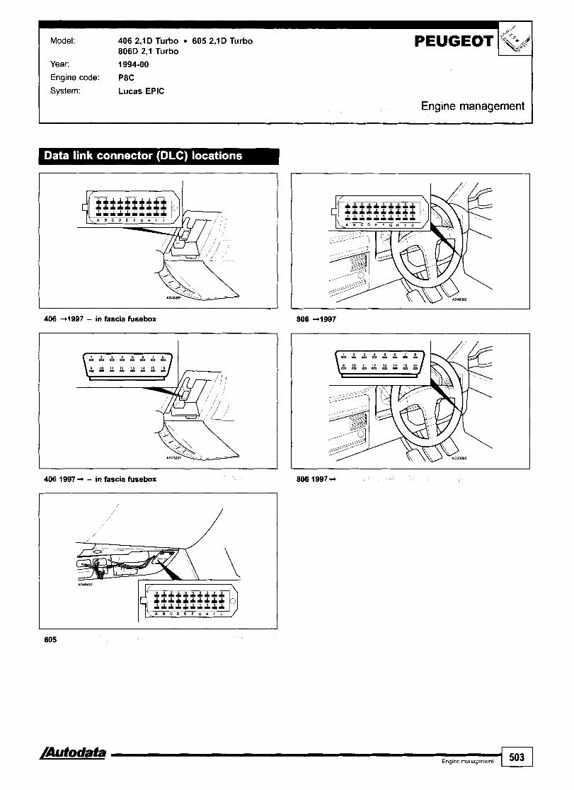
Model: 406 2,lD Turbo 605 2,lD Turbo 806D 2,l Turbo
Year. 1994-00
Engine code: P8C
System: Lucas EPIC
PEUGEOT %& 1 Engine management I
406 +I997 - in fascia fusebox
406 1997 -r - in fascia fwebox
-a- Eng~ne management 503

Model: 406 2,lD Turbo 605 2,lD Turbo 806D 2,l T
General information Refer to the front of this manual for general test conditions, terminology, detailed descriptions of wiring faults and a general trouble shooter for electrical and mechanical faults. Vehicles fitted with a coded keypad: When switching on ignition or entering start code ensure diagnostic equipment is disconnected from the data link connector (DLC).
Accessing and erasing The engine control module (ECM) fault memory can only be accessed and erased using diagnostic equipment connected to the data link connector (DLC). The following scanner codes are applicable to the fuel system manufacturer's test equipment, similar and more detailed fault diagnosis information can be obtained using the vehicle manufacturer's or equivalent test equipment.
Trouble code
Scanner type
100
101
102
104
105
130
1 50
1 51
152
200
210
211
220
240
250
290
291
300
320
329
identification
Fault location
Engine control module (ECM) - memory
Engine control module (ECM) - low voltage during starting
Engine control module (ECM) - non-volatile memory fault
Engine control module (ECM) - analogue1 digital converter
Engine control module {ECM) - sensor reference voltage incorrect
Engine control module (ECM) - memory locked
Battery voltage
Battery voltage
Relay module
Engine coolant temperature (ECT) sensor
Intake air temperature (IAT) sensor
Manifold absolute pressure (MAP) sensor
Fuel temperature sensor
Vehicle speed sensor (VSS)
Crankshaft position (CKP) sensor
Accelerator pedal position (APP) sensor
Accelerator pedal position (APP) sensorlbrake pedal position (BPP) switch - signal conflict
Brake pedal position (BPP) switch
Cruise control
Transmission range (TR) switch
Probable cause
ECM
Battery, relay module, wiring, ECM
ECM
Wiring, ECM
Wiring, ECM
Coded keypad, ECM
Wiring, IFS switch, relay module, battery, alternator, ECM
Wiring, IFS switch, relay module, battery discharged, alternator
Wiring, relay module, ECM
Wiring, ECT sensor, ECM
Wiring, IAT sensor, ECM
Wiring, MAP sensor, ECM
Wiring, fuel temperature sensor, ECM
Wiring, VSS, ECM
Wiring, CKP sensor, air gap, ECM
Wiring, APP sensor, ECM
Wiring, APP sensor, BPP switch, brake pedal applied whilst throttle fully depressed, accelerator pedal tightlsticking, ECM
Wiring, BPP switch, ECM
Wiring, cruise control master switch, ECM
Wiring, TR switch

Probable cause
Model: 406 2,lD Turbo 605 2,lD Turbo 806D 2,l Turbo PEUGEOT
340 I Air conditioning I Wiring, AC compressor clutch relay, AC control module, ECM
Gd Engine management
361 I Tachometer signal 1 Wiring, tachometer, ECM
350
363 I Fuel consumption signal 1 Wiring, trip computer, ECM
Glow plug control module - pre-/post-heat control
t . . 602 1 Fuel injection pump - rotor calibration I Wiring, fuel injection pump, ECM
Wiring, glow plug control module, ECM
600
601
Fuel injection pump - rotor position monitoring
Fuel injection pump - rotor position
603
604
700 Fuel injection pump - cam position Wiring, fuel injection timing solenoid, fuel injection pump, monitorina relav module. ECM
Wiring, fuel system, fuel qantity adjuster, fuel injection pump, relay module, ECM
Wiring, shield wiring, injection pump cam ring position sensor, injection pump rotor position sensor, fuel injection DumD. ECM
605
650
Fuel injection pump - rotor minimum calibration
Fuel deliveryheedle lift signal
703 I Fuel injection pump - timing control I Fuel injection pump timing, CKP sensor
Fuel injection pump
Wiring, fuel injection pump, ECM
Fuel injection pump - delivery calibration
Fuel shut-off solenoid
701
702
750 1 Injector needle lift sensor - no signal I Wiring, injector needle lift sensor, fuel system, injector, ECM
Wiring, injection pump calibration resistor, fuel injection pump, ECM
Wiring, relay module, coded keypad, fuel shut-off solenoid, fuel injection pump, ECM
751 I Injector needle lift sensor - incorrect signal I Wiring, injector needle lift sensor, fuel system, injector, ECM
Fuel injection pump - cam ring position sensor
Fuel injection pump - cam ring calibration
Wiring, injection pump cam ring position sensor, fuel temperature sensor, fuel injection pump, ECM
Wiring, fuel injection pump, ECM
803
[Autodata Ena~ne rnanaaernent
Exhaust gas recirculation (EGR) solenoid - incorrect signal
505
Wiring, relay module, EGR solenoid, ECM

PEUGEOT Model: 806 1,9D Turbo Year: 1995-00
I Engine management
Engine code: DHX
System: Bosch AS3
General information o Refer to the front of this manual for general test conditions,
terminology, detailed descriptions of wiring faults and a general trouble shooter for electrical and mechanical faults. Trouble codes are displayed by the malfunction indicator lamp (MIL) or LED. The ECM fault memory can also be checked and erased using diagnostic equipment connected to the data link connector (DLC).
o Vehicles fitted with a coded keypad: When switching on ignition or entering start code ensure diagnostic equipment is disconnected from the data link connector (DLC).
Accessing Switch ignition ON. Check that MIL illuminates. Connect LED test lamp between data link connector (DLC) terminal C3 and battery positive m. Bridge data link connector (DLC) terminal C2 and earth with a switched lead - contacts normally open m. Operate switch for 2,545 seconds. LED or MIL will now flash trouble code 12. Each trouble code consists of two groups of one or more flashes O. Long flashes indicate the 'tens' of the trouble code rn [A]. Short flashes indicate the 'units' of the trouble code rn [C]. A short pause separates each flash rn [B]. A long pause separates each trouble code rn [Dl. For example: Trouble code 12 displayed rn. Repeat operation. Note trouble codes. Compare with trouble code table. Rectify faults as necessary.

Model: 806 1,9D Turbo
Erasing Method 2 Ensure ignition switched OFF.
Method 1 Disconnect battery earth lead for 10 seconds. Switch ignition ON. WARNING: Disconnecting the battery may erase memory from Connect LED test lamp between data link connector (DLC) electronic units (e.g. radio, clock). terminal C3 and battery positive 0. Bridge data link connector (DLC) terminal C2 and earth with a switched lead - contacts normally open m. Operate switch for 2,5-5 seconds. LED or MIL will now flash trouble code 12. Repeat switch operation until code 11 is displayed. Operate switch for 10-20 seconds. Switch ignition OFF.
Trouble code identification I I
Flash type 1 Fauit loeatton I Probable cause
16 1 Exhaust gas recirculation (EGR) solenoid 1 Wiring, relay module, EGR solenoid
11
12
14
2 1 1 Fuel lever position sensor ( Wiring, fuel lever position sensor
End of sequence
Start of sequence
Engine coolant temperature (ECf) sensor
46 I Fuel iniection pump - timinq control I Fuel injection pump timing
- -
Wiring, ECT sensor, ECM
39
41
49 I Fuel injection timing solenoid 1 Wiring, fuel injection timing solenoid
53 I Battery voltage I Wiring, battery discharged, alternator
Malfunction indicator lamp (MIL)
Crankshaft position (CKP) sensortengine speed (RPM) sensor
Engine control module (ECM)
Barometric pressure (BARO) sensor
Gbw plug control module - pre-heat
65 Injector needle lift sensor
Wiring, MIL, ECM
Wiring, CKPIRPM sensor, air gap, ECM
Wiring, battery, ECM - - --
E C M
Wiring, glow plug(s), glow plug control module
Wiring, fuel system, injector, injector needle lift sensor
66 I Glow plug control module - pre-/post-heat I Wiring, glow plug control module
67
68
4
Glow plug warning lamp
Idle speed control (ISC) actuator
Wiring, glow plug warning lamp, ECM
Wiring, hoses blockedlleaking, ISC actuator

Model: R5Nan ExtralRapidlExpress CliolKangoo R19121 MeganelSceniclRX4 Laguna Safrane Alpine Espace Trafic T N 2,2
Year: 1986-04 Engine C3G 70017101712, C3J 70017601762, C3J 710, E7F 70017041706171117301750, E7J 601, E7J 6241626, E7J 7001706, 'Ode: E7J 71 0171 1/71 6/71 8/71 9, E7J 720172417261728, E7J 74017421745, E7J 754175617571764, E7J 7701771 17731780,
F3N 71 6171 717241726, F3N 740174117431746, F3P 682, F3P 7001704R05170617071708, F3P 71 0171 4171 2175517581 R71Q7, F3P 72017241B6701S724, F3P 76017651782, F3R 71 0, F3R 722ff23lJ7281K7291611, F3R 7501751, F3R JlK17281729, F4R, F4R 7001701171017111730, F4R 74017411744, F5R 740, F7P 700170417201722, F7R 700, F7R D710, J7R 7231732173317341735, J7R 74017461747l7561768, J7T 6001780, J7T 76017611762147661Z766, J7T 772, KAI, K4J 71217131750, K4M, K4M 700l748l750l752l753, K7M, K7M 702l703l7201744l745, L7X, L7X 700/701, N7Q 704171 01711, N7Q A700, N7U 7001701, X7X 744,Z7W 71 2171 3,Z7X 7221723172617531755, Z7X 76017651767,Z7X 775
System: BendixlRenixlFenix MPI BoschlSiemenslDelcolFenixlRenix Monopoint Bosch Motronic M4.4 Bosch Motronic MP7.0 Magneti Marelli TBI Sagem MPllSafir Siemens MPllFenix 313815 Siemens SiriuslSirius 32
Engine management

Trafic T N 2,2
Clio 1998 -,
/Autodata Eng~ne management 509

RENAULT Model: RSNan ExtralRapidlExpress CliolKangoo Rl9121 MeganelSceniclRX4 Laguna Safrane Alpine Espace Trafic T N 2.2
Engine management
Alpine
Safrane Traflc - 12-pin
Espace 4 9 9 5 Traflc - 16-pin
General information 0 Refer to the front of this manual for general test conditions,
terminology, detailed descriptions of wiring faults and a general trouble shooter for electrical and mechanical faults.
Accessing and erasing No digital trouble codes available from vehicle manufacturer. The engine control module (ECM) fault memory can only be accessed and erased using diagnostic equipment able to display fault locations as a text description.

Model: RSNan ExtralRapidlExpress CliolKangcio Rl9121 MeganelSceniclRX4 Laguna Safrane Alpine Espace
RENAULT Trafic T N 2,2
Engine management
Trouble code identification
Fault location I Probable cause I
AC signal 1 Wiring, AC system, AC control module
AC system - malfunction 1 Wiring, supply voltage, MAP sensor
Crankshaft position (CKP) sensor - wiring transposed 1 Wiring
Crankshaft position (CKP) sensor I Wiring, CKP sensor, mechanical fault
Engine control module (ECM) - memory fault
Engine control module (ECM)
Engine coolant temperature (ECT) sensor
Evaporative emission (EVAP) canister purge valve
Heated oxygen sensor (H02S) I Wiring, H02S, air leak
-
Cancel ECM memory 5 times, ECM
ECM
Wiring open circuivshort to positivelshort to earth, ECT sensor
Wiring short to earthlopen circuivshort to positive, supply voltage, EVAP canister purge valve
Exhaust gas recirculation (EGR) solenoid
Fuel pump relay - control circuit
Idle air control (IAC) valve I Wiring, IAC valve
Wiring short to earthlopen circuivshort to positive, supply voltage, EGR solenoid, EGR valve position sensor wiring
Wiring short to earthlopen circuitlshort to positive, supply voltage, fuel pump relay
Idle speed control (ISC) actuator I Wiring, ISC actuator, mechanical fault
Immobilizer circuit I Wiring, immobilizer defective
Ignition coils
Ignition key
Injector - circuit I Wiring short to earthlopen circuivshort to positive, injector
- - - -
Wiring, supply voltage, ignition coil
Ignition key, supply voltage
Injector - control circuit I Wiring short to earthlopen circuivshort to positive, injector
Injector - malfunction I Wiring, supply voltage, injector
Manifold absolute pressure (MAP) sensor I TP sensor signal, wiring, MAP sensor
Intake air temperature (IAT) sensor
Knock sensor (KS)
Malfunction indicator lamp (MIL)
Wiring open circuivshort to positive, IAT sensor
Wiring short to earthlopen circuit, KS, KS incorrectly tightened
Wiring short to earthlopen circuivshort to positive, supply voltage, MIL lamp
Throttle position (TP) sensor I Wiring short to earthlopen circuivshort to positive, TP sensor
Mixture adjustment resistor
Supply voltage
Wiring open circuivshort to earthlshort to positive, mixture adjustment resistor
Wiring, fuses
AT signal I Wiring, AT system defective
Turbocharger (TC) wastegate regulating valve
Vehicle speed sensor (VSS)
Vehicle speed signal
Wiring short to earthlopen circuivshort to positive, supply voltage, earth connection, TC wastegate regulating valve
Wiring, VSS, mechanical fault
Wiring, ABS system defective
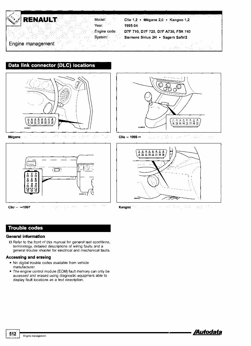
Clio - 4 9 9 7 Kangoo
General information Refer to the front of this manual for general test conditions, terminology, detailed descriptions of wiring faults and a general trouble shooter for electrical and mechanical faults.
Accessing and erasing No digital trouble codes available from vehicle manufacturer. The engine control module (ECM) fault memory can only be accessed and erased using diagnostic equipment able to display fault locations as a text description.

Engine management I Model: Clio 1,2 9 Megane 2,O 9 Kangoo 1,2 RENAULT
Trouble code identification I
J
Tk.,, )/
F auk location 1 Probable cause
Camshaft position (CMP) sensor - F5R 740 I Wiring, earth connection, supply voltage, CMP sensor
AC signal - D7F
AC signal - F5R 740
AC system - malfunction - F5R 740
CAN data bus - F5R 740 I Wiring open circuitlearth connection, supply voltage
Wiring, AC system, AC control module
Wiring, AC system, AC control module
Wiring, supply voltage, MAP sensor
Engine control module (ECM) I Cancel ECM memory 5 times, ECM
Crankshaft position (CKP) sensor - D7F - signal
Crankshaft position (CKP) sensor - F5R 740 - signal
Wiring short to earthlopen circuitltransposed, CKP sensor, flywheel
Wiring, CKP sensor, flywheel
Engine control relay - control circuit - F5R 740
Engine coolant blower motor relay - D7F
Evaporative emission (EVAP) canister purge valve
Wiring short to earthlopen circuitlshort to positive, supply voltage, earth connection, engine control relay
Wiring short to earthlopen circuitlshort to positive, supply voltage, relay
Engine coolant 'hot' warning lamp - F5R 740
Engine coolant temperature (ECT) sensor
Wiring short to earthlopen circuitlshort to positive, supply voltage, EVAP canister purge valve
Wiring short circuitlopen circuitlshort to positive, warning lamplsupply voltage
Wiring short to earthlopen circuitlshort to positive, ECT sensor
Exhaust gas recirculation (EGR) solenoid - F5R 740 Wiring short to earthlopen circuitlshort to positive, supply voltage, EGR solenoid, EGR valve position sensor wiring
Exhaust gas recirculation (EGR) valve position sensor - I Wiring, EGR valve F5R 740
Fuel pressure regulator control solenoid - F5R 740 Wiring short to earthlopen circuitlshort to positive, supply voltage, earth connection, fuel pressurelpump, fuel pressure regulator control solenoid
Fuel pump relay - control circuit
Heated oxygen sensor (H02S) - D7F
Heated oxygen sensor (H02S) - heater circuit - D7F
Heated oxygen sensor (H02S), upstream - F5R 740 1 Wiring, heater supply voltage, intake leak, H02S
Wiring short to earthlopen circuitlshort to positive, supply voltage, fuel pump relay
Wiring, heater supply voltage, intake leak, H02S
Wiring short to earthlopen circuitlshort to positive, supply voltage, H02S, relay
Heated oxygen sensor (H02S), downstream - F5R 740
Heated oxygen sensor (H02S), downstream - heater circuit - F5R 740
Wiring, heater supply voltage, intake leak, H02S
Wiring short to earthlopen circuitlshort to positive, supply voltage, H02S
Idle air control (IAC) valve, AC - D7F 7201710 I Wiring, IAC valve
Heated oxygen sensor (H02S), upstream - heater circuit - F5R 740
Idle air control (IACI valve - D7F A730
Ignition coil - cylinders 1 & 4 - F5R 740 I Wiring, supply voltage, ignition coil
Wiring short to earthlopen circuitlshort to positive, supply voltage, H02S
Wiring, IAC valve
Ignition coil - cylinders 2 & 3 - F5R 740 I Wiring, supply voltage, ignition coil
lgnition coil - D7F Wiring short to earthlopen circuit, supply voltage, ignition coil
Immobilizer - circuit I Wiring, immobilizer defective
4
/Autodata Eng~ne management 51 3

Model: Clio 1,2 Megane 2,O Kangoo 1,2
FEngine management
Fault location Probable cause
Immobilizer - programming - F5R 740 Incorrect programming
lnjector 1 - circuit - F5R 740 Wiring open circuitlshort to positive, injector control module - supply voltagelearth connection, injector
lnjector 1 - control circuit - F5R 740 Wiring short to earthlopen circuitlshort to positive, injector control module - supply voltagelearth connection
lnjector 2 - circuit - F5R 740 Wiring open circuitlshort to positive, injector control module - supply voltagelearth connection, injector
Wiring short to earthlopen circuitlshort to positive, injector control module - supply voltagelearth connection
lnjector 2 - control circuit - F5R 740
lnjector 3 - circuit - F5R 740
lnjector 3 - control circuit - F5R 740
Wiring open circuitlshort to positive, injector control module - supply voltagelearth connection, injector
Wiring short to earthlopen circuitlshort to positive, injector control module - supply voltagelearth connection
lnjector 4 - circuit - F5R 740 - -
Wiring open circuitlshort to positive, injector control module - supply voltagelearth connection, injector
lnjector 4 - control circuit - F5R 740 Wiring short to earthlopen circuitlshort to positive, injector control module - supply voltagelearth connection
Wiring open circuitlsupply voltage, earth connection, injector control module
lnjector control module - F5R 740
Injectors - D7F Wiring open circuitlshort circuitlshort to positive, supply voltage, injector
Wiring short to earthlopen circuitlshort to positive, IAT sensor
Intake air temperature (IAT) sensor
Knock sensor (KS)
Malfunction indicator lamp (MIL) - F5R 7401D7F 710
Wiring short to earthlopen circuit, KS, KS incorrectly tightened
Wiring short to earthlopen circuitlshort to positive, supply voltage, MIL lamp
Manifold absolute pressure (MAP) sensor TP sensor signal, wiring, MAP sensor
Supply voltage - D7F
Supply voltage - F5R 740
Wiring open circuitlearth wire, engine control relay, fuel pump relay
Wiring open circuitlearth wire, engine control relay, injector control module - voltage supplylearth wire
Throttle position (TP) sensor - D7F 7101720
Throttle position (TP) sensor - F5R 7401D7F A730
Wiring short to earthlopen circuitlshort to positive, supply voltage, TP sensor
Wiring short to earthlopen circuitlshort to positive, supply voltage, TP sensor, mechanical fault
Vehicle speed sensor (VSS) - D7F Wiring, supply voltage, earth connection, VSS, mechanical fault
Vehicle speed signal - F5R 740 - --
Wiring, ABS system defective

Model:
Year:
Clio 1,5D Turbo Kangoo 1,5D Turbo
2000-04
Engine code: K9K 700170217041710
System: Lucas common rail
Engine management
I
Clio
General information Refer to the front of this manual for general test conditions, terminology, detailed descriptions of wiring faults and a general trouble shooter for electrical and mechanical faults.
Accessing and erasing No digital trouble codes available from vehicle manufacturer. The engine control module (ECM) fault memory can only be accessed and erased using diagnostic equipment able to display fault locations as a text description.
Trouble code identification I
Fault location I Probable cause
AC control module - control circuit I Wiring short to earthlopen circuitlshort to positive
AC control module Wiring short to earthlopen circuitlshort to positive, AC system, AC control module
Accelerator pedal position (APP) sensor - track 2
Accelerator pedal position (APP) sensor
Accelerator pedal position (APP) sensor - track 1 I Wiring short to earthlopen circuitlshort to positive, supply voltage, APP sensor
Wiring short to earthlopen circuitlshort to positive, supply voltage, APP sensor
Wiring short to earthlopen circuitlshort to positive, supply voltage, APP sensor
Barometric pressure (BARO) sensor
Battery voltage - highllow
Brake pedal position (BPP) switch
IAuf odata 51 5
ECM
Wiring open circuitlearth wire, battery, alternator
Wiring short to earthlopen circuitlsupply voltage, BPP switch
Camshaft position (CMP) sensor Wiring open circuit, earth connection, CMP sensor, valve timing
IC]

Model: Clio 1,SD Tur
Fault lacatlon Probable cause I
Combustion - cylinder 1 I Low compression, valve clearances, injector, EGR system, ECM
Combustion - cylinder 2 I Low compression, valve clearances, injector, EGR system, ECM
Crankshaft position (CKP) sensor - signal I Wiring, CKP sensor
Combustion - cylinder 3
Combustion - cylinder 4
Engine control module (ECM) I Injector wiring short to earthlopen circuit, ECM
Low compression, valve clearances, injector, EGR system, ECM
Low compression, valve clearances, injector, EGR system, ECM
Engine coolant blower motor relay - low Wiring short to earthlopen circuitlshort to positive, supply voltage, relay s~eed
Engine control module (ECM) - RAM error
Engine coolant blower motor relay - high speed
Erase memory - switch ignition ONIOFF and recheck, ECM
Wiring short to earthlopen circuitlshort to positive, supply voltage, relay
Engine coolant heater relay 1 - heater 1
Engine coolant heater relay 2 - heater 2
Engine coolant heater relay 2 - heater 3
Exhaust gas recirculation (EGR) solenoid I Wiring short to earthlopen circuitlshort to positive
Wiring short to earthlopen circuitlshort to positive, relay
Wiring short to earthlopen circuitlshort to positive, relay
Wiring short to earthlopen circuitlshort to positive, relay
Engine coolant 'hot' warning lamp
Engine coolant pressure sensor
Engine coolant temperature (ECT) sensor
Exhaust gas recirculation (EGR) valve Wiring short to earthlopen circuitlshort to positive, supply voltage, mechanical position sensor fault, EGR solenoid
Wiring short to earthlopen circuitlshort to positive, supply voltage, warning lamp, ECM
Wiring short to earthlopen circuit, pressure sensor
Wiring short to earthlopen circuit, ECT sensor
Fuel pressure regulator control solenoid - pressure highllow
Wiring short to earthlopen circuit, fuel level low, air in fuel system, fuel pressure sensor, high pressure pump
Fuel pressure sensor
Fuel shut-off solenoid
Wiring short to earthlopen circuitlshort to positive, supply voltage, fuel pressure sensor
Wiring short to earthlopen circuitlshort to positive, shut-off solenoid
Fuel temperature sensor
Glow plug circuit
Glow plug control module
Injector 2 I Wiring short to earthlopen circuitlshort to positive, supply voltage, injector
Wiring short to earthlopen circuitlshort to positive, fuel temperature sensor
Wiring, supply voltage, glow plugs
Wiring short to earthlopen circuitlshort to positive, earth connection, glow plug control module
Immobilizer - circuit
Injector 1
Injector 3 I Wiring short to earthlopen circuitlshort to positive, supply voltage, injector
Wiring, immobilizer defective
Wiring short to earthlopen circuitlshort to positive, supply voltage, injector
Intake air temperature (IAT) sensor I Wiring short to earthlopen circuitlshort to positive, IAT sensor
Injector 4
Injectors - circuit malfunction
Knock sensor (KS) I Wiring short to earthlopen circuitlshort to positive, KS, ECM
Wiring short to earthlopen circuitlshort to positive, supply voltage, injector
Wiring short to earthlopen circuitlshort to positive, injector, ECM
Manifold absolute pressure (MAP) sensor I Wiring short to earthlopen circuit, MAP sensor
Power assisted steering relay - control Wiring short to earthlopen circuitlshort to positive, relay circuit
1 5'6 1 Eng~ne management /Autodata

Model: Clio 1,5D Turbo Kangoo 1,5D Turbo RENAULT i
tr '
Fault location
Engine management
Probable cause
Sensor supply voltage - APP (track l)/fuel pressure1 EGR valve position1MAPtCMPlcoolant pressure sensor
A t a Eng~ne management 517
Wiring short to earthlshort to positive
Tachometer - signal
Vehicle speed signal
Wiring short to earthlopen circuitlshort to positive, tachometer
Wiring short to earthlopen circuitlshort to positive, ABS system

-;'I RENAULT Model: Megane 1,411,612,O Scenic 1,411,612,O
Year: 2002-04
Engine code: K4J 7301732, K4M 76017611782, F4R 7701771
System: Sagern 3000
Engine management
MBgane - centre console
I
L
Scenic - without sliding centre console, under carpet
Scenic - with sliding centre console, under trim panel
General information The engine control module (ECM) fault memory can only be accessed usina dia~nostic eaui~ment connected to the data . .
0 Refer to the front of this manual for general test conditions, link connector<~~C). terminology, detailed descriptions of wiring faults and a general trouble shooter for electrical and mechanical faults.
Trouble code identification
EOBD type
PO
P i 604
4
Fault location
Refer to EOBD trouble codes
Passenger compartment electric heating element
Probable cause
-
CAN data bus

Model: Megane 1,9D
Year: 1999-02
Engine code: F8Q 622
System: Lucas EPIC
Engine management I
General information Refer to the front of this manual for general test conditions, terminology, detailed descriptions of wiring faults and a general trouble shooter for electrical and mechanical faults.
Access ing and erasing No digital trouble codes available from vehicle manufacturer. The engine control module (ECM) fault memory can only be accessed and erased using diagnostic equipment able to display fault locations as a text description.
Trouble code identif ication I
Fault location I Probable cause
Battery voltage - highllow I Wiring open circuitlearth wire, battery, alternator
AC signal
Accelerator pedal position (APP) sensor
Barometric pressure (BARO) sensor
Wiring, AC system, AC control module
Wiring short to earthlopen circuitlshort to positive, APP sensor
ECM
Engine control relay
Crankshaft position (CKP) sensor - signal
Engine control module (ECM)
I Wiring short to earthlopen circuitlshort to positive, supply voltage, earth connection, engine control relay, ECM
Wiring, CKP sensor, flywheel
ECM
Engine coolant blower motor relay - high speed
Engine coolant blower motor relay - low speed
Wiring short to earthlopen circuitlshort to positive, supply voltage, relay
Wiring short to earthlopen circuitlshort to positive, supply voltage, relay
/Autodata Eng~ne management 519

1:' <-+ ,. ::I RENAULT
I Engine management
Model: Megane 1,9D
Engine coolant temperature (ECT) sensor I Wiring short to earthlopen circuitlshort to positive, ECT sensor
Fault location Probable cause
Exhaust gas recirculation (EGR) solenoid
Fuel injection timing solenoid
Fuel temperature sensor
Wiring short to earthlopen circuitlshort to positive, supply voltage, EGR solenoid, EGR valve position sensorlwiring
Wiring short to earthlopen circuitlshort to positive, supply voltage, timing solenoid
Fuel quantity adjuster 1 & 2
Fuel shut-off solenoid
Wiring short to earthlopen circuitlshort to positive, fuel temperature sensor
Wiring short to earthlopen circuitlshort to positive, supply voltage, earth connection, quantity adjuster
Wiring short to earthlopen circuitlshort to positive, supply voltage, solenoid, ECM
Glow plug warning lamp - circuit I Wiring, warning lamp, supply voltage
Glow plug circuit
Glow plug control module
Immobilizer - circuit I Wiring, immobilizer defective
Wiring, supply voltage, glow plugs, glow plug control module
Wiring short to earthlopen circuitlshort to positive, supply voltage
Intake air temperature (IAT) sensor I Wiring short to earthlopen circuitlshort to positive, IAT sensor
Injection pump assembly memory circuit
Injection pump rotor position sensor
On board diagnostic (OBD) I Rectify other faults recorded
Wiring, injection pump
Wiring, rotor position sensor, ECM
Sensor supply voltage highllow
Power assisted steering control relay
Protective circuit
Wiring, accelerator pedal position (APP) sensor, exhaust gas recirculation (EGR) valve position sensor, injection pump assembly
Wiring short to earthlopen circuitlshort to positive, supply voltage, relay
EC M
Vehicle speed signal Wiring, supply voltage, earth connection, VSS, ABS system, mechanical fault

Model: Megane 1,9D Turbo Megane Scenic 1,9D Turbo Megane 1,9D Turbo rn Scenic 1,9D Turbo Espace 2,2D Turbo
Year: 1997-03
Engine code: F9Q 7301734, F9Q 7301734, F9Q 7311736, F9Q, G8T 7141716
System: Bosch MSA 15.5 Bosch AS3.3
Engine management
Espace
General information Refer to the front of this manual for general test conditions, terminology, detailed descriptions of wiring faults and a general trouble shooter for electrical and mechanical faults.
Accessing and erasing No digital trouble codes available from vehicle manufacturer. The engine control module (ECM) fault memory can only be accessed and erased using diagnostic equipment able to display fault locations as a text description.
Trouble code identification I
Fault locetlon 1 Probable cause
Barometric pressure (BARO) sensor - F9Q I ECM
Accelerator pedal position (APP) sensor - F9Q
Brake pedal position (BPP) switch - F9Q I Wiring short to earthlopen circuit, BPP switch
Wiring short to earthlopen circuitlshort to positive, supply voltage, APP sensor
Clutch pedal position (CPP) switch - F9Q 1 Wiring short to earthlopen circuit, CPP switch
Cold start injection advance solenoid - G8T 716 I Wiring short to earthlopen circuitlshort to positive, solenoid
Crankshaft position (CKP) sensor - signal Wiring, CKP sensor, flywheel, 4 slots at 90" - G8T 7141F9Q, 2 slots at 180" - G8T 716
Engine control module (ECM) I ECM
Engine control relay - F9Q I Wiring open circuit, engine control relay
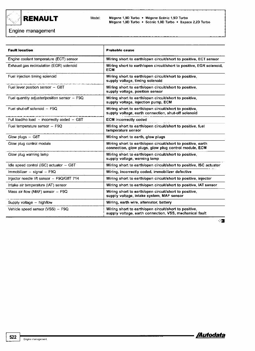
-, 1'. + . RENAULT Model: Megane 1,9D Turbo Megane Scenic 1,9D Turbo Megane 1,9D Turbo Scenic 1,9D Turbo Espace 2,2D Turbo
FEngine management
Probable cause Fault location
Engine coolant temperature (ECT) sensor Wiring short to earthlopen circuitlshort to positive, ECT sensor
Exhaust gas recirculation (EGR) solenoid Wiring short to earthlopen circuitlshort to positive, EGR solenoid, ECM
Fuel injection timing sotenoid Wiring short to earthlopen circuitlshort to positive, supply voltage, timing solenoid
Fuel lever position sensor - G8T Wiring short to earthlopen circuitlshort to positive, supply voltage, position sensor
Fuel quantity adjusterlposition sensor - F9Q Wiring short to earthlopen circuitlshort to positive, supply voltage, injection pump, ECM
Fuel shut-off solenoid - F9Q Wiring short to earthlopen circuitlshort to positive, supply voltage, earth connection, shut-off solenoid
Full loadlno load - incorrectly coded - G8T
Fuel temperature sensor - F9Q
ECM incorrectly coded
Wiring short to earthlopen circuitlshort to positive, fuel temperature sensor
Glow plugs - G8T Wiring short to earth, glow plugs
Glow plug control module Wiring short to earthlopen circuitlshort to positive, earth connection, glow plugs, glow plug control module, ECM
Glow plug warning lamp Wiring short to earthlopen circuitlshort to positive, supply voltage, warning lamp
Idle speed control (ISC) actuator - G8T Wiring short to earthlopen circuitlshort to positive, ISC actuator
Immobilizer - signal - F9Q Wiring, incorrectly coded, immobilizer defective
Wiring short to earthlopen circuitlshort to positive, injector Injector needle lift sensor - F9QIG8T 714
Intake air temperature (IAT) sensor Wiring short to earthlopen circuitlshort to positive, IAT sensor
Mass air flow (MAF) sensor - F9Q Wiring short to earthlopen circuitlshort to positive, supply voltage, intake system, MAF sensor
Wiring, earth wire, alternator, battery Supply voltage - highllow
Vehicle speed sensor (VSS) - F9Q Wiring short to earthlopen circuitlshort to positive, supply voltage, earth connection, VSS, mechanical fault
4

aster 2,2D Turbo
Year: 1999-03
Engine code: F9Q 718, F9Q 732, F9Q 740, G9T 710, G9T 720, G9T 722
System: Bosch common rail
Engine management
J
Model: Megane 1,9D Turbo SceniclRX4 1,9D Turbo RENAWT 'lX4 , /, Laguna 1,9D Turbo Espace 2,2D Turbo
-
Laguna
General information 0 Refer to the front of this manual for general test conditions,
terminology, detailed descriptions of wiring faults and a general trouble shooter for electrical and mechanical faults.
Accessing and erasing No digital trouble codes available from vehicle manufacturer. The engine control module (ECM) fault memory can only be accessed and erased using diagnostic equipment able to display fault locations as a text description.
I
Y aster
Espace

Trouble code identification
FaulQ location
,'
; i+ YJ
Probable cause
RENAULT Model: Megane 1,9D Turbo SceniclRX4 1,9D Turbo Laguna 1,9D Turbo Espace 2,2D Turbo Master 2,2D Turbo
Accelerator pedal position (APP) sensor - track 1
Engine management -
Wiring short to earthlopen circuitlshort to positive, supply voltage, APP sensor
Wiring short to earthlopen circuitlshort to positive, supply voltage, APP sensor
Accelerator pedal position (APP) sensor - track 2
Barometric pressure (BARO) sensor ECM
Battery voltage - highllow Wiring open circuitlearth wire, battery, alternator
Wiring short to earthlopen circuit, BPP switch Brake pedal position (BPP) switch
Camshaft position (CMP) sensor Wiring open circuit, earth connection, CMP sensor, CKP sensor
Clutch pedal position (CPP) switch Wiring short to earthlopen circuit, earth connection, CPP switch
Wiring, CKP sensor Crankshaft position (CKP) sensor - signal
Cruise control Wiring short to earthlopen circuitlshort to positive, supply voltage, earth connection, cruise control master1 selector switch
EC M Engine control module (ECM)
Engine control module (ECM) - ignition key OFF signal Erase memory - switch ignition ONIOFF and recheck, ECM
Engine control module (ECM) - ignition key ON signal Erase memory - switch ignition ONIOFF and recheck, ECM
Engine control module (ECM) - injector control Erase memory - switch ignition ONIOFF and recheck, ECM
Engine control module (ECM) - micro-controller Erase memory - switch ignition ONIOFF and recheck, ECM
Erase memory - switch ignition ONIOFF and recheck, ECM
Engine control module (ECM) - signal converter
Engine control relay Wiring open circuit, supply voltage, battery connections, relay
--
Wiring short to earthlopen circuitlshort to positive, supply voltage, relay
Engine coolant blower motor relay - low speed
Engine coolant heater relay 1 Wiring short to earthlopen circuitlshort to positive, relay
Engine coolant heater relay 2 Wiring short to earthlopen circuitlshort to positive, relay --
Engine coolant heater relay 3 Wiring short to earthlopen circuitlshort to positive, relay
Engine coolant temperature (ECT) sensor Wiring short to earthlopen circuitlshort to positive, ECT sensor
Exhaust gas recirculation (EGR) solenoid Wiring short to earthlopen circuitlshort to positive, supply voltage, EGR solenoid, EGR valve position sensorlwiring
Exhaust gas recirculation (EGR) valve position sensor Wiring short to earthlopen circuitlshort to positive, supply voltage, mechanical fault, EGR solenoid
Wiring short to earthlopen circuitlshort to positive, supply voltage, fuel pressure control solenoid, fuel pressure sensor, injectors
Fuel pressure highllow
Fuel pressure control solenoid Wiring short to earthlopen circuitlshort to positive, supply voltage, solenoid -
Wiring short to earthlopen circuitlshort to positive, supply voltage, fuel pressure sensor
Fuel pressure sensor
1 524 1 ,ng,ne management /Autodata

Engine management 7 Model: Megane 1,QD Turbo SceniclRX4 1,9D Turbo
Laguna 1,QD Turbo Espace 2,2D Turbo Master 2,2D Turbo RENAULT
Fault location
G+i
Fuel pump relay
Fuel temperature sensor
Glow plug control module
Immobilizer - circuit
lnjector 1
lnjector 2
lnjector 3
lnjector 4
Intake air temperature (IAT) sensor
Intake manifold air control solenoid
Malfunction indicator lamp (MIL)
Manifold absolute pressure (MAP) sensor
Mass air flow (MAF) sensor
Sensor supply voltage 1 - APPlfuel pressurelMAFlEGR valve positionlMAP sensor
Sensor supply voltage 2 - APP sensor
Turbocharger (TC) wastegate regulating valve
Vehicle speed signal
Probable cause
Wiring short to earthlopen circuitlshort to positive, fuel pump relay
Wiring short to earthlopen circuitlshort to positive, fuel temperature sensor
Wiring short to earthlopen circuitlshort to positive, earth connection, glow plug control module, glow plugs
Wiring, incorrectly coded, immobilizer defective
Wiring short to earthlopen circuitlshort to positive, supply voltage, injector, ECM
Wiring short to earthlopen circuitlshort to positive, supply voltage, injector, ECM
Wiring short to earthlopen circuitlshort to positive, supply voltage, injector, ECM
Wiring short to earthlopen circuitlshort to positive, supply voltage, injector, ECM
Wiring short to earthlopen circuitlshort to positive, IAT sensor
Wiring short to earthlopen circuitlshort to positive, supply voltage, solenoid
Wiring short to earthlopen circuitlshort to positive, supply voltage, MIL lamp
Wiring short to earthlopen circuitlshort to positive, supply voltage, intake leak, MAP sensor
Wiring short to earthlopen circuitlshort to positive, supply voltage, earth connection, MAF sensor
Wiring short to earthlshort to positive, ECM
Wiring short to earthlshort to positive, ECM
Wiring short to earthlopen circuitlshort to positive, supply voltage, intake leak, TC wastegate regulating valve
Wiring, supply voltage, earth connection, ABS system, mechanical fault
4
/ m u r o c r a f a I Eng~ne management 525

1';: v / I RENAULT
1 Engine management
Model: Laguna 1,611,812,O 16V Espace 2,O 16V
Year: 1998-02
Engine code: F4P 760, F4R 700, F4R 780, K4M 7201724
System: Siemens Sirius 32
I
Laguna Espace
General information 0 Refer to the front of this manual for general test conditions,
terminology, detailed descriptions of wiring faults and a general trouble shooter for electrical and mechanical faults.
Accessing and erasing No digital trouble codes available from vehicle manufacturer. The engine control module (ECM) fault memory can only be accessed using diagnostic equipment able to display fault locations as a text description.
Trouble code identification I
Fault locatian I Probable cause I
ABS wheel speed sensor I Wiring short to earthlopen circuitlshort to positive, sensor
Automatic transmission (AT) - connection to ECM I Wiring
AC signal
AC system - malfunction
Wiring, AC system, AC control module
Wiring, supply voltage, MAP sensor
Camshaft position (CMP) actuator
Catalytic converter failure
Cylinder 2 - misfi re detected I Ignition system, fuel supply, injectors
Wiring, CMP actuator
Air leak, misfire, mechanical fault
Crankshaft position (CKP) sensor - signal
Cylinder 1 - misfire detected
Cylinder 3 - misfire detected I Ignition system, fuel supply, injectors
Wiring, CKP sensor, flywheel
Ignition system, fuel supply, injectors
Cylinder 4 - misfire detected
Engine control module (ECM)
- . . . .
Ignition system, fuel supply, injectors
Cancel ECM memory 5 times, ECM
Engine control relay - control circuit Wiring short to earthlopen circuitlshort to positive, supply voltage, earth connection, engine control relay

Engine management 1 Model: Laguna I,6/1,8/2,O 16V Espace 2,O 16V RENAULT
- - -- p~
Probable cause
'.+ /
Fault location
Wiring short to earthlopen circuitlshort to positive, relay Enaine coolant blower motor - hiah speed - - . Engine coolant blower motor - low speed Wiring short to earthlopen circuitlshort to positive, relay
Engine coolant 'hot' warning lamp Wiring short circuitlopen circuitlshort to positive, warning lamplsupply voltage
Ennine coolant temperature (ECT) sensor Wiring short to earthlopen circuitlshort to positive, ECTsensor - . . Evaporative emission (EVAP) canister purge valve Wiring short to earthlopen circuitlshort to positive,
supply voltage, EVAP canister purge valve
Fuel circuit - operational failure Fuel supply, injectors
Fuel pump relay - control circuit Wiring short to earthlopen circuitlshort to positive, supply voltage, fuel pump relay
Wiring, heater supply voltage, intake leak, H02S Heated oxvaen sensor IH02Si downstream
Heated oxygen sensor (H02S), downstream - heater circuit Wiring short to earthlopen circuitlshort to positive, supply voltage, H02S
Heated oxygen sensor (H02S), upstream
Heated oxygen sensor (HOZS), upstream - heater circuit
Wiring, heater supply voltage, intake leak, H02S - . . - - Wirina short to earthlo~en circuitlshort to ~ositive. supp& voltage, H02S '
Idle air control (IAC) valve Wiring, IAC valve
lgnition coil - cylinders 1 & 4
Ignition coil - cylinders 2 & 3
Wiring, supply voltage, ignition coil
Wiring, supply voltage, ignition coil
Immobilizer - circuit Wiring, immobilizer defective
Immobilizer - programming
lnjector 1 - circuit
Incorrect programming . - - Wirina oDen circuitlshort to ~ositive. iniector control m o d i e 1 supply voltagelea;th conneciion, injector
lnjector 1 - control circuit Wiring short to earthlopen circuitlshort to positive, injector control module - supply voltagelearth connection
lnjector 2 - circuit
lnjector 2 - control circuit
lnjector 3 - circuit
Wiring open circuitlshort to positive, injector control module - supply voltagelearth connection, injector
Wiring short to earthlopen c i rcui t lsho~to injector control module - supply voltagelearth connection
Wiring open circuitlshort to positive, injector control module - supply voltagelearth connection, injector
lnjector 3 - control circuit Wiring short to earthlopen circuitlshort to positive, injector control module - supply voltagelearth connection
lnjector 4 - circuit Wiring open circuitlshort to positive, injector control module - supply voltagelearth connection, iniector
lnjector 4 - control circuit . . - - . -
Wiring short to earthlopen circuitlshort to positive, injector control module - supply voltagelearth connection
Wiring short to earthlopen circuitlshort to positive, IAT sensor
Wiring short to earthlopen circuit, KS, KS incorrectly tightened
Intake air temperature (IAT) sensor
Knock sensor (KS)
Malfunction indicator lamp (MIL) -
Wirina short to earthlo~en circuitlshort to ~ositive. supp$ voltage, MIL lamp
TP sensor signal, wiring, MAP sensor
Wiring
lgnition system, fuel supply, injectors
Wiring open circuitlearth wire, engine control relay, injector control module - voltage supplyiearth wire
Wiring short to earthlopen circuitlshort to positive, supply voltage, TP sensor, mechanical fault
Wiring, ABS system defective
Manifold absolute pressure (MAP) sensor
MIL to TCM - connection
Randomlmultiple cylinder(s) - misfire detected
Supply voltage
Throttle position (TP) sensor
Vehicle speed signal

I Engine code: F9Q 7201722, S9W 700
System: Sagem Bosch MSA 15.5
Engine management
Master
/
j -4',v#
Espace
- REhdAULT Model: Espace 1,9 dTi Master 2,8D Turbo
General information
Year: 1998-02
-
0 Refer to the front of this manual for general test conditions, terminology, detailed descriptions of wiring faults and a general trouble shooter for electrical and mechanical faults.
Accessing and erasing No digital trouble codes available from vehicle manufacturer. The engine control module (ECM) fault memory can only be accessed and erased using diagnostic equipment able to display fault locations as a text description.
Trouble code identification
I 528 I,,,,,,,,,, b'AUwata

Engine coolant temperature (ECT) sensor I Wiring short to earthlopen circuit, ECT sensor
Fault location Probable cause
Fuel lever position sensor - S9W 700 I Wiring short to earthlopen circuitlshort to positive, sensor
Exhaust gas recirculation (EGR) solenoid
Fuel injection timing sotenoid
Wiring short to earthlopen circuitlshort to positive, supply voltage, EGR solenoid
Wiring short to earthlopen circuitlshort to positive, supply voltage, timing solenoid
Fuel quantity adjuster position adjusterlsensor
Fuel shut-off solenoid
Wiring short to earthlopen circuitlshort to positive, supply voltage, injection pump
Wiring short to earthlopen circuitlshort to positive, earth connection, shut-off solenoid
Fuel temperature sensor
Glow plug control module
Ignition switch - start signal I Wiring open circuit
Wiring short to earthlopen circuitlshort to positive, fuel temperature sensor
Wiring short to earthlopen circuitlshort to positive, earth connection, glow plugs, glow plug control module
Glow plug warning lamp
Idle speed control (ISC) actuator
Immobilizer - signal I Wiring, incorrectly coded, immobilizer defective
Wiring short to earthlopen circuitlshort to positive, supply voltage, warning lamp
Wiring short to earthlopen circuitlshort to positive, heated windscreen timer unit. ISC actuator
Injector needle lift sensor
Intake air temperature (IAT) sensor
Wiring short to earthlopen circuitlshort to positive, injector
Wiring short to earthlopen circuitlshort to positive, IATsensor
Mass air flow (MAF) sensor
Supply voltage - highltow
Vehicle speed signal
Wiring short to earthlopen circuitlshort to positive, supply voltage, intake system, MAF sensor
Wiring, earth wire, alternator, battery
Wiring, ABS system, mechanical fault

I '1 RENAULT
I Transmission
Model: Clio R19 R21 Laguna Safrane Espace
Year: 1991 -02
System: AD4-0001002100310041006 AR4 AD8
Clio Laguna -4996
Laguna 1997 +

Espace - dl995
Model: Clio R19 R21 Laguna Safrane Espace RIENAULT
Espace - 1995-
- '"
General information
Transmission
Refer to the front of this manual for general test conditions, terminology, detailed descriptions of wiring faults and a general trouble shooter for electrical and mechanical faults.
Accessing and erasing No digital trouble codes available from vehicle manufacturer. The transmission control module (TCM) fault memory can only be accessed and erased using diagnostic equipment able to display fault locations as a text description.
NOTE: The full load and no load position of the accelerator pedal must be programmed using diagnostic equipment after the TCM fault memory has been erased.
Trouble code identification
Shift solenoid (SS) 3 1 Wiring short to earthlopen circuit, solenoid valve, TCM
Fault location
AC compressor clutch cut-off relay
Shift solenoid (SS) 1
Shift solenoid (SS) 2
Shift solenoid (SS) 4 1 Wiring short to earthlopen circuit, solenoid valve, TCM
Probable cause
Fuse, wiring short to earthlopen circuit, supply voltage, cut-off relay
Wiring short to earthlopen circuit, solenoid valve, TCM
Wiring short to earthlopen circuit, solenoid valve, TCM
Transmission fluid pressure (TFP) sensor
Pressure modulating solenoid
Throttle position (TP) sensor
Transmission fluid temperature (TFT) sensor - circuit malfunction
Wiring short to earthlopen circuit, solenoid valve, TCM
Wiring short to earthlopen circuit, TP sensor
Transmission fluid level low, wiring short to earthlopen circuitlshort to positive, supply voltage, fluid pressure sensor, transmission mechanical fault, TCM
Wiring short to earthlopen circuitlshort to positive, supply voltage, TP sensor, transmission valve block, TCM
Transmission range (TR) switch Wiring short to earthlopen circuit/short to positive, earth connection, starter motor relay, TR switch, TCM
-- -
Vehicle speed sensor (VSS) 1 Wiring short to earthlopen circuit, VSS

Engine code: F3R 611, F3R 791, F4R 7001701, F4R 7401741, F9Q 731, K4M 70011, K7M 745
System: DPO
Transmission
Clio Laguna
General information Refer to the front of this manual for general test conditions, terminology, detailed descriptions of wiring faults and a general trouble shooter for electrical and mechanical faults.
Accessing and erasing No digital trouble codes available from vehicle manufacturer. The transmission control module (TCM) fault memory can only be accessed and erased using diagnostic equipment able to display fault locations as a text description.
NOTE: The full load and no load position of the accelerator pedal must be programmed using diagnostic equipment after the TCM fault memory has been erased.
Espace

I
Transmission
Model: Clio 1,6 MeganelMegane Scenic 2,O MeganelScenic 1,6/2,O Laguna 2,O Scenic 1,9D Turbo Espace 2,O 16V
RENAULT
Trouble code identification
11-t
Fault locatlon Probable cause
AC compressor clutch cut-off
Engine load signal - TP sensor signal
Engine speed (RPM) - signal
--
Wiring short to earthlopen circuitlshort to positive
Wiring short to earthlopen circuit, TP sensor
Wiring short to earthlopen circuitlshort to positive, high voltage interference, TCM, ECM
Engine torque signal
Exchanger flow control solenoid - circuit
Pressure modulating solenoid
Wiring short to earthlopen circuitlshort to
Wiring short to earthlopen circuitlshort to positive, control solenoid, TCM
Wiring short to earthlopen circuitlshort to positive, pressure modulating solenoid
Shift solenoid (SS) 1
Shift solenoid (SS) 2
Shift solenoid (SS) 5
Wiring short to earthlopen circuitlshort to positive, solenoid valve, TCM
Wiring short to earthlopen circuitlshort to positive, solenoid valve. TCM
Shift solenoid (SS) 3
Shift solenoid (SS) 4
Wiring short to earthlopen circuitlshort to positive, solenoid valve, TCM
Wiring short to earthlopen circuitlshort to positive, solenoid valve, TCM
Wiring short to earthlopen circuitlshort to positive, solenoid valve, TCM
Shift solenoid (SS) 6 Wiring short to earthlopen circuitlshort to positive, solenoid valve, TCM
Shift solenoids - supply voltage I Wiring open circuitlshort to positive
TCMIECM connection - ECTItorque information Wiring short to earthlopen circuitlshort to positive, TCM, ECM
TCMlECM connection - load information
Torque converter clutch (TCC) - slipping
Transmission control module (TCM) I TCM
Wiring short to earthlopen circuitlshort to positive, TCM, ECM
TCC solenoid, transmission fluid, torque converter, transmission valve block
Torque converter clutch (TCC) solenoid
Transmission control module (TCM) - full loadlno load position not programmed
Wiring short to earthlopen circuitlshort to positive, TCC solenoid
TCM programming error
Transmission fluid pressure (TFP) - regulation
Transmission fluid
Transmission fluid pressure (TFP) sensor
Transmission fluid pressure (TFP) sensoriTFT sensor - supply voltage
Change fluid, reset TCM fluid age counter
Wiring short to earthlopen circuitlshort to positive, TFP sensor
Pressure modulating solenoid, torque converter clutch (TCC) solenoid, transmission fluid levellquality, TFP sensor - transmission valve block
Wiring short to earthlshort to positive, TFP sensor, TFTsensor
Transmission fluid temperature (TFT) sensor Wiring short to earthlopen circuitlshort to positive, TFT sensor
[Autodata Transmission 533
Transmission range (TR) switch
Transmission range (TR) switch - PNP signal
Wiring short to earthlopen circuit, TR switch
Wiring short to earthlopen circuit, TR switch

1 z: RENAULT Model: Clio 1,6 MeganelMegane Scenic 2,O MeganelScenic 1,6/2,O Laguna 2,O Scenic 1,9D Turbo Espace 2,O 16V
Transmission
Fault location Probable cause
Transmission shift hold solenoid
Transmission speed sensor - no signallsignal variation
Torque reduction signal I Wiring short to earthlopen circuitlshort to positive
Wiring short to earthlopen circuitlshort to positive, shift hold solenoid
Wiring short to earthlopen circuitlshort to positive, high voltage interference, transmission speed sensor
Transmission warning lamp
Turbine shaft speed (TSS) sensor - no signallsignal variation
Wiring short to earthlopen circuitlshort to positive
Wiring short to earthlopen circuitlshort to positive, high voltage interference, TSS sensor

Model: MeganelMegane Scenic Laguna Safrane
Year: 1995-02
System: AD4-01310211025 AD8
Transmission
MeganelMdgane Scenic
I
Laguna 4 9 %
Laguna 1997-
I
Safrane
General information Refer to the front of this manual for general test conditions, terminology, detailed descriptions of wiring faults and a general trouble shooter for electrical and mechanical faults.
Accessing and erasing No digital trouble codes available from vehicle manufacturer. The transmission control module (TCM) fault memory can only be accessed and erased using diagnostic equipment able to display fault locations as a text description.
NOTE: The full load and no load position of the accelerator pedal must be programmed using diagnostic equipment after the TCM fault memory has been erased.

Trouble code identification
, i I I_ I RENAULT Model: MeganelMegane Scenic Laguna Safrane
Engine RPM input - no signal I Wiring short to earthlopen circuit, ECM, TCM
Transmission
Fault tocation
AC control module - compressor clutch cut-off
Probable cause
Wiring short to earthlopen circuitlshort to positive, TCM programming error
Glow plug control module - diesel I Wiring short to earthlopen circuitlshort to positive
Engine torque signal
Fuel lever position sensor - diesel
Pressure modulating solenoid Wiring short to earthlopen circuitlshort to positive, supply voltage, solenoid valve, TCM
Wiring short to earthlopen circuitlshort to positive, torque reduction solenoid - diesel, ECM
Wiring short to earthlopen circuit, TP sensor
Shift solenoid (SS) 2
Shift solenoid (SS) 1
Wiring short to earthlopen circuitlshort to positive, supply voltage, solenoid valve, TCM
Wiring short to earthlopen circuitlshort to positive, supply voltage, solenoid valve, TCM
Shift solenoid (SS) 3 Wiring short to earthlopen circuitlshort to positive, supply voltage, solenoid valve, TCM
Throttle position (TP) sensor - petrol I Wiring short to earthlopen circuit, TP sensor
Shift solenoid (SS) 4 Wiring short to earthlopen circuitlshort to positive, supply voltage, solenoid valve, TCM
Transmission control module (TCM) - overheating 1 TCM mounting, underbonnet temperature too high
Transmission control module (TCM)
Transmission control module (TCM) - full loadlno bad position not programmed
TCM
TCM programming error
Transmission fluid pressure (TFP) sensor - supply voltage Wiring short to earthlopen circuitlshort to positive, TFP sensor
Transmission fluid pressure (TFP) - regulation Transmission fluid level, wiring short to earthlopen circuit/ short to positive, fluid pressure sensor
Transmission fluid pressure (TFP) sensor
Transmission fluid temperature (TIT) sensor
Transmission warning lamp I Wiring short to positive, TCM
Transmission fluid level low, wiring short to earthlopen circuitlshort to positive, supply voltage, TFP sensor, shift solenoid - modulating, TCM
Wiring short to earthlopen circuit, TFT sensor, TCM
Transmission range (TR) switch
Transmission speedlengine speed
Wiring short to earthlopen circuitlshort to positive, starter motor relay, TR switch
Transmission fluid level, vehicle speed sensor (VSS), engine speed (RPM) sensor, mechanical fault
VehiGle speed sensor (VSS) Wiring short to earthlopen circuit, VSS, TCM
d

Model: ExtralRapidlExpress Kangoo Clio R19121 MeganelScenic Laguna Safrane Espacefrrafic
Year: 1994-02
Immobilizer
ExtralRapidlExpress - engine bay
Kangoo
Clio 1998-
I
Clio -1997
110
[Autodata Immobilizer 537

RENAULT
Immobilizer
Model: ExtralRapidlExpress Kangoo Clio R19121 MeganelScenic Laguna Safrane Espacenrafic
Safrane
Laguna -1996 Espace
Laguna 1997 -r Trafic - 12-pin

I Model: ExtralRapidlExpress Kangoo Clio R19121 MeganelScenic Laguna Safrane Espacenrafic RENAULT I I
lmmobilizer I
Trafic - 16-pin
General information 0 Refer to the front of this manual for general test conditions,
terminology, detailed descriptions of wiring faults and a general trouble shooter for electrical and mechanical faults.
Accessing and erasing No digital trouble codes available from vehicle manufacturer. The immobilizer control module fault memory can only be accessed and erased using diagnostic equipment able to display fault locations as a text description.
Trouble code identification
Fuel shut-off solenoid - diesel
Fault location
Central locking master switch
Fuel shut-off solenoid, inertia fuel shut-off (IFS) switch, immobilizer control module
Probable cause
Wiring short to earth, master switch
- -- -
Fuel shut-off solenoidlsignal - diesel / Wiring, fuel shut-off solenoid, i%nobilizer control module
lmmobilizer control modulelengine control module (ECM) - Wiring short to earthlshort to positive, irnrnobilizer control petrol - communication I module, ECM
Immobilizer reader coil
Immobilizer warning lamp
Wiring short to earthlopen circuitlshort to positive, reader coil, ECM
Wiring short to earthlopen circuitlshort to positive, immobilizer control module
/=3

Mini Metro1100 Montego 2001400 200 CabriolCoupe 400ilourer 6201820ilurbo 825 MGF
1989-02
de: I 1 K2D, 12A2DF7516, 12A2EF77, 12A2EK7112, 12A2LK70, 14K16, 14K2AID, 14K4, 14K4CID, 14K4F, 14K8,16K16,18K16,20HE3617,20M4,20T, 20T4, K16-1,4, K16-1,6, K16-1,8, K18, K8-1 , I , K8-1,4, KV6
System: Rover MEMS
I Engine management
Mini 4 9 9 2 engine bay kont - 1993-96 engine bay rear
Mini 1997 -,
Metroll 00 4 995
I
Montego
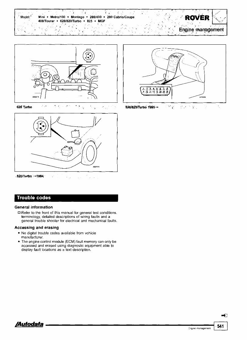
620 Turbo
General information Refer to the front of this manual for general test conditions, terminology, detailed descriptions of wiring faults and a general trouble shooter for electrical and mechanical faults.
Accessing and erasing No digital trouble codes available from vehicle manufacturer. The engine control module (ECM) fault memory can only be accessed and erased using diagnostic equipment able to display fault locations as a text description.
A t --I Eng~ne management 541

ROVER Model: Mini Metro1100 Montego 2001400 200 CabriolCoupe 400lTourer 6201820lTurbo 825 MGF
Engine management
Trouble code identification
Engine coolant Mower motor relay 1 I Fuse, wiring short to earthlopen circuitlshort topositive, supply voltage, engine coolant blower motor relay
Fautt locatlon
AC compressor clutch relay
Alternator load signal
Camshaft position (CMP) actuator
Camshaft position (CMP) sensor
Crankshaft position (CKP) sensor
Engine coolant Mower motor relay 2 Fuse, wiring short to earthlopen circuitlshort to positive, supply voltage, engine coolant blower motor relay
- - -
Probable cause
Wiring short to earthlopen circuit, supply voltage, AC compressor clutch relay
Alternator, battery, wiring open circuitlshort to positive
Wiring short to earthlopen circuit, CMP actuator
Wiring short to earthlopen circuitlshort to positive, supply voltage, CMP sensor, ECM
Wiring short to earthlopen circuitlshort to positive, supply voltage, CKP sensor, ECM
Engine coolant temperature (ECT) gauge I Fuse, wiring short to earthlopen circuitlshort to positive, ECT gauge
Engine coolant temperature (ECT) sensor I Wiring short to earthlopen circuit, ECT sensor
Engine oil temperature gauge Fuse, wiring short to earthlopen circuitlshort to positive, engine oil temperature gauge
Evaporative emission (EVAP) canister purge valve Wiring short to earthlopen circuitlshort to positive, supply voltage, EVAP canister purge valve
Exhaust gas pressure sensor I Exhaust system, catalytic converter, wiring short to earthlopen circuitlshort to positive, exhaust gas pressure sensor
Exhaust gas recirculation (EGR) solenoid Wiring short to earthlopen circuitlshort to positive, supply voltage, EGR solenoid
Intake air temperature (IAT) sensor I Wiring short to earthlopen circuit, IAT sensor
Fuel consumption signal
Fuel pump relay
Fuel temperature sensor
Intake manifold air control solenoid
Wiring short to earthlopen circuitlshort to positive, ECM
Fuse, wiring short to earthlopen circuit, supply voltage, fuel pump relay
Wiring short to earthlopen circuit, fuel temperature sensor
Wiring short to earthlopen circuitlshort to positive, supply voltage, intake manifold air control solenoid
Manifold absotute pressure (MAP) sensor Vacuum hose blockedlleak, wiring short to earthlopen circuit, MAP sensor, ECM
Misfire detected - catalytic converter I Ignition system, injector(s), wiring
Misfire detected I Ignition system, injector(s), wiring
Outside air temperature sensor Wiring short to earthlopen circuitlshort to positive, outside air temperature sensor
Oxygen sensor (02s) Wiring short to earthlopen circuitlshort to positive, heater circuit, earth connection, exhaust leak, 02s
Tachometer
Throttle body heater
Turbocharger (TC) boost pressure gauge
Wiring short to earthlopen circuit, tachometer
Fuse, wiring short to earthlopen circuit, supply voltage, heater relay, throttle body heater
Throttle position (TP) sensor
Throttle position (TP) sensor - supply voltage
Wiring short to earthlopen circuitlshort to positive, TC boost pressure gauge
Wiring short to earthlopen circuitlshort to positive, TP sensor, supply voltage, ECM
Wiring short to earthlopen circuiffshort to positive, TP sensor, ECM
Turbocharger (TC) wastegate regulating valve Wiring short to earthlopen circuitlshort to positive, supply voltage, hoses blockedlleaking, TC wastegate regulating valve

Model: 25 1,111,411,611,811,8 W C 45 1,411,611,812,O 75 1,811,8 Turbo12,0/2,5 MG TF 1,611,8
ROVER 4 MG ZR 1,4 MG ZR l,8ll,8 W C MG ZS l,6/l,8 MG ZS 2,5 MG ZTIZT-T 1,8 MG ZTIZT-T 2,5
Year: 1999-04
Engine code: K8, K16, KV6
System: MEMS 3 Siemens EMS 2000 I Engine managementltransmission 1
Except 751MG TFlMG ZT - under fascia, drlvefs side
I
MG TF - above fascia fuseboxlrelay plate, driver's side
751MG ZT - under fascia, driver's side
General information R Refer to the front of this manual for general test conditions,
terminology, detailed descriptions of wiring faults and a general trouble shooter for electrical and mechanical faults.
Accessing and erasing The engine control module (ECM) fault memory can only be accessed and erased using diagnostic equipment connected to the data link connector (DLC).

Trouble code identification
/ \
< / \ >d ; "L m ) I-_
EOBD type I I Probable cause
ROVER Model: 25 1,111,411,611,811.8 W C 45 1,411.611,BQ.0 75 1,811.8 TurboR.Ol2.5 MG TF 1,611.8 MG ZR 1,4 MG ZR 1,811,8 W C MG ZS 1,611,8 MG ZS 2,5 MG ZTIZT-T 1,8 MG ZTIZT-T 2,5
Engine managernent/transmission
I I
PO I Refer to EOBD trouble code table
P I 185
PI230 I Fuel pump relay - open circuit I Wiring, fuel pump relay, ECM
-
P I 186
P I 191
PI192
Heated oxygen sensor (H02S) 1, bank 1, heater - circuit malfunction
Wiring, H02S, ECM
Heated oxygen sensor (H02S) 1, bank 1, heater - circuit malfunction
Heated oxygen sensor (H02S) 2, bank 1, heater - circuit malfunction
Heated oxygen sensor (H02S) 2, bank 1, heater - circuit malfunction
PI231
P I 232
PI300
P I 321 I Crankshaft position sensor - misfire detection. tooth Engirie mechanical fault, wiring, CKP sensor, ECM error
Wiring, H02S, ECM
Wiring, H02S, ECM
Wiring, H02S, ECM
PI316
PI319
P I 320
Fuel pump relay - circuit malfunction
Fuel pump relay - circuit malfunction
Randomlmultiple cylinder(s) - misfire detected
- - - -- - -
Wiring, fuel pump relay, ECM
Wiring, fuel pump relay, ECM
Spark plug(s), HT lead(s), injector(s), ignition coil(s), low compression, wiring
Random/multiple cylinder(s) - misfire detected
Misfire detected with low fuel level
Crankshaft position sensor - misfire detection, adaption limit
PI470
PI471
Spark plug(s), HT lead(s), injector(s), ignition coil(s), low compression, wiring
Low fuel level
Wiring, CKP sensor, ignition system, mechanical fault. ECM
PI472
PI473
PI474
PI477 Intake air flap control actuator 2 - open circuitkhort Wiring, intake air flap control actuator, ECM circuit to earth 1
Intake air flap control actuator 1 - stuck open
Intake air flap control actuator 1 - stuck closed
PI475
PI476
PI506 ( idle speed control (ISC) system - circuit malfunction I Wiring, IAC valve, ECM
- -
Wiring, intake air flap control actuator, mechanical fault, ECM
Wiring, intake air flap control actuator, mechanical fault, ECM
Intake air flap control actuator 2 - stuck open
Intake air flap control actuator 2 - stuck closed
Intake air flap control actuator 1 - short circuit to positive
Wiring, intake air flap control actuator, mechanical fault, ECM
Wiring, intake air flap control actuator, mechanical fault, ECM
Wiring, intake air flap control actuator, ECM
Intake air flap control actuator 1 - open circuitkhort circuit to earth
Intake air flap control actuator 2 - short circuit to positive
P I 537 / AC compressor clutch - circuit malfunction AC compressor clutch, AC compressor clutch relay, wiring, ECM
Wiring, intake air flap control actuator, ECM
Wiring, intake air flap control actuator, ECM
P I 507
P I 508
Idle speed control (ISC) system - circuit malfunction
Idle speed control (ISC) system - circuit malfunction
PI538
P I 565
Wiring, IAC valve, ECM
Wiring, IAC valve, ECM
AC compressor clutch - circuit malfunction
Cruise control system relay - short circuit to positive
AC compressor clutch, AC compressor clutch relay, wiring, ECM
Wiring, cruise control system relay, ECM

Model: 25 1,111,411,611,811,8 W C 45 l,4ll,6Il,8/2,O 75 l ,8l l ,8 Turbol2,0/2,5 MG TF l ,6/ l ,8 MG ZR 1,4 MG ZR 1,811,8 W C MG ZS 1,611,8 MG ZS 2,5 MG ZTIZT-T 1,8 MG ZTIZT-T 2,5 ROVER 1:
Engine managementltransmission
EOBD type
Fault location I Probable cause
P I 566 Cruise control system relay - open circuitlshort circuit Wiring, cruise control system relay, ECM to earth
PI590 1 Rough road sensor - signal malfunction I Wiring, rough road sensor
PI611 I Engine control relay - circuit malfunction 1 Wiring, engine control relay, ECM
PI610
PI640 I CAN data bus - malfunction 1 Wiring, connected system, ECM
PI641 ( CAN data bus - defective I Trouble code(s) stored in other system(s), wiring
Engine control relay - circuit malfunction
PI646 1 CAN data bus, TCM - communication error I TCM trouble code(s) stored, wiring, ECM
Wiring, engine control relay, ECM
PI775 CAN data bus, TCM - transmission warning lamp I Transmission, wiring, ECM/TCM request
P I 666
P I 672
PI788 1 Transmission ratio control motor - high current I Wiring, transmission ratio control motor, ECM/TCM
Immobilizer signal - CAN data bus
Immobilizer signal - incorrect code
P I 785
P I 787
PI810 I Transmission selector lamp - circuit malfunction I Wiring, transmission selector lamp, TCM
Wiring, immobilizer control module
Incorrect key, immobilizer control module
Transmission ratio control motor - drive over temperature
Transmission ratio control motor - open circuit
Transmission ratio control motor, wiring, ECM/TCM
Wiring, transmission ratio control motor, ECM/TCM
P I 81 5
PI815
PI836 Serial communication, gear shift - circuit malfunction
P I 830
P I 831
1 Wiring, poor connection, ECM/TCM
Transmission gear selection switch, up shift - signal malfunction
Transmission gear selection switch, down shift - signal malfunction
PI837 1 Instrument panel - circuit malfunction 1 Wiring, instrument panel, ECM
Wiring, transmission gear selection switch, TCM
Wiring, transmission gear selection switch, TCM
Transmission control module (TCM) - circuit malfunction
Transmission control module (TCM) - circuit malfunction
Wiring, TCM, ECM
Wiring, TCM, ECM
PI838
a Instrument panel - circuit malfunction Wiring, instrument panel, ECM

9- I , 1 ROVER Model: 2001CoupelCabrio 1,6 400TTourer 1,6
I Engine rnanagernentltransrnission I
NOTE: Engine control module (ECM) incorporates transmission control function.
General information 0 Refer to the front of this manual for general test conditions,
terminology, detailed descriptions of wiring faults and a general trouble shooter for electrical and mechanical faults. Trouble codes are displayed by the LED incorporated in the engine control module (ECM).
0 Switch ignition ON. If MIL illuminates to indicate a fault but no trouble codes are stored, suspect DLCIMIL wiring, MIL or ECM.
0 The ECM fault memory can also be checked using diagnostic equipment connected to the diagnostic socket
Accessing Switch ignition ON. DO NOT start engine. Count ECM LED flashes m. Note trouble codes. Compare with trouble code table.
NOTE: No trouble codes stored if MIL illuminates continuously.
Trouble codes 1-9 are indicated as follows: E Individual short flashes display trouble code [A].
A short pause separates each flash rn [B]. A long pause separates each trouble code [C]. For example: Trouble code 3 displayed rn. Trouble codes greater than 9 are indicated as follows:
o Long flashes indicate the 'tens' of the trouble code El [A]. n Short flashes indicate the 'units' of the trouble code [C]. 0 A short pause separates each flash [B].
A long pause separates each trouble code El [Dl. For example: Trouble code 14 displayed El.
c A B A B A C A B A B A

Model: 200lCoupelCabrio 1,6 400TTourer 1,6 ROVER
Engine management/transmission
Erasing Ensure ignition switched OFF. Remove F4 fuse (10A) from underbonnet fusebox m. Wait 10 seconds. Refit fuse.
Trouble code identification
Flash type Fault location Probable cause
1
Manifold absolute pressure (MAP) I Intake leak, MAP sensor, wiring, ECM sensor - signal
3
4
Heated oxygen sensor (H02S)
8 I Crankshaft position (CKP) sensor 1 CKP sensor, wiring short to earthlopen circuit, ECM
Fuel pressurelpump, wiring short to earthlopen circuiffshort to positive, H02S, ECM
Manifold absolute pressure (MAP) sensor - circuit
Engine speed (RPM) sensor
6
7
9 I Camshaft position (CMP) sensor I CMP sensor, wiring short to earthlopen circuit, ECM
Wiring short to earthlopen circuiffshort to positive, supply voltage, MAP sensor, ECM
RPM sensor, wiring short to earthlopen circuit, ECM
Engine coolant temperature (ECT) sensor
Throttle position (TP) sensor
13 Barometric pressure (BARO) sensor - circuit
Wiring short to earthlopen circuit, ECT sensor, ECM
- Wiring short to earthlopen circuit, TP sensor, ECM
10
11
Wiring short to earthlopen circuiffshort to positive, supply voltage, BARO sensor, ECM
Intake air temperature (IAT) sensor
Mixture adjustment resistor
16 I Injectors
Wiring short to earthlopen circuit, IAT sensor, ECM
Wiring short to earthlopen circuiffshort to positive, mixture adjustment resistor
14
15
Wiring short to earthlopen circuiffshort to positive, supply voltage, injector series resistor, injector, ECM
Idle air control (IAC) valve
Ignition amplifier - control circuit
Wiring short to earthlopen circuiffshort to positive, IAC valve
Wiring short to earthlopen circuiffshort to positive, supply voltage, ignition amplifier, ECM
17
18
19
Vehicle speed sensor (VSS)
Ignition timing adjuster - circuit
Speedometerlcable, wiring short to earthlopen circuit, VSS
Wiring short to earth, ignition timing adjuster
4
Torque converter clutch (TCC) solenoid - circuit malfunction
Fuse, wiring short to earthlopen circuit, supply voltage, TCC solenoid, ECM

Model: 2001400/600 2,O TD
Year: 1995-99 I Engine code: 20T2N
System: Bosch MSA 11
Engine management
200 - under fascia, driver's side
400 - under fascia, driver's side
General information n Refer to the front of this manual for general test conditions,
terminology, detailed descriptions of wiring faults and a general trouble shooter for electrical and mechanical faults.
o Trouble codes are displayed by the malfunction indicator lamp (MIL). The ECM fault memory can also be checked using diagnostic equipment connected to the data link connector (DLC).
EI If a trouble code is displayed but not listed in the trouble code table, suspect engine control module (ECM) fault.
Accessing Ensure ignition switched OFF. Bridge data link connector (DLC) terminals 4 and 15 0. Switch ignition ON. DO NOT start engine. Count MIL flashes. Note trouble codes. Compare with trouble code table.
600 - under fascia, driver's side
Trouble codes are indicated as follows: Long flashes indicate the 'tens' of the trouble code rn [A]. Short flashes indicate the 'units' of the trouble code rn [C]. A short pause separates each flash H [B]. A long pause separates each trouble code rn [Dl. For example: Trouble code 12 displayed a. Switch ignition OFF. Remove bridge wire.
548 Eng~ne management /Autodata

Model: 200/400/600 2,O TD ROVER /I Engine management I
Trouble code identification
Erasing Switch ignition ON. Switch ignition OFF. Repeat approximately 50 times. Repeat checking procedure to ensure no data remains in ECM fault memory.
Flash type I Fault location I Probable cause
14 I Engine coolant temperature (ECT) sensor - low voltage Wiring short to earth, supply voltage, ECT sensor, I ECM
I I
Engine coolant temperature (ECT) sensor - high voltage Wiring open circuitlshort to positive, ECT sensor, I ECM
12 I Start of diagnosis
Fuel temperature sensor - low voltage
-
Wiring short to earth, supply voltage, fuel temperature sensor, ECM
2 1 I Accelerator pedal position (APP) sensor - high voltage Wiring short to earthkpen circuitkhort to positive. / APP sensor, ECM
17
19
27 I Mass air flow (MAF) sensor - low voltage
Fuel temperature sensor - high voltage
Crankshaft position (CKP) sensor - plausibility
22
23
24
Wiring short to earthlopen circuit, supply voltage, earth connection, MAF sensor, ECM
Wiring open circuitlshort to positive, fuel temperature sensor, ECM
Wiring short to earthlopen circuit, CKP sensor, ECM
Accelerator pedal position (APP) sensor - low voltage
Accelerator pedal position (APP) sensor - plausibility
Vehicle speed sensor (VSS) - plausibility
Wiring short to earthlopen circuit, APP sensor, ECM
Wiring short to earthlopen circuitlshort to positive, APP sensor, ECM
Wiring short to earthlopen circuitlshort to positive, supply voltage, VSS, ECM

It>; I; / ) ROVER Model: 20014001600 2,O TD
Engine management
Flash type Fault location I Probable cause
28
29
31
Brake pedal position (BPP) switch - plausibility Fuse, wiring open circuitlshort to positive, supply voltage, BPP switch, ECM
Mass air flow (MAF) sensor - high voltage
Exhaust gas recirculation (EGR) system
Fuel injection timing solenoid
Wiring short to earthlopen circuitlshort to positive, earth connection, MAF sensor, ECM
Mass air flow (MAF) sensor - plausibility
Crankshaft position (CKP) sensor - no signal
Hoses blockedlleaking, wiring short to earthlopen circuit, EGR solenoid, EGR valve, vacuum pump, MAF sensorlwiring, ECM
Wiring open circuit, supply voltage, fuel injection timing solenoid, ECM
Manifold absolute pressure (MAP) sensor - high voltage Wiring open circuitlshort to positive, MAP sensor, I ECM
Wiring short to earthlopen circuitlshort to positive, supply voltage, earth connection, MAF sensor, intake leak, ECM
Wiring short to earthlopen circuit, CKP sensor, ECM
39
41
Manifold absolute pressure (MAP) sensor - plausibility Wiring short to earthlopen circuitlshort to positive, I SUPPIY voltage, MAP sensor, ECM
48 I Battery - low voltage I Earth connection, battery, alternator
Alarm system
Manifotd absolute pressure (MAP) sensor - low voltage
54 I Fuel shut-off solenoid - defective I Wiring short to positive, fuel shut-off solenoid
Alarm system defective
Wiring short to earthlopen circuit, MAP sensor, ECM
Fuel quantity adjuster position sensor - plausibility Wiring open circuit, fuel quantity adjuster position sensor, ECM
55
61
Fuel quantity adjuster Wiring short to earthlopen circuit, fuel quantity adjuster position sensor, ECM
Engine control module (ECM)
Fuel quantity adjuster position sensor - highllow voltage
71 I Intake air temperature (IAT) sensor - low voltage I Wiring short to earthlopen circuit, IAT sensor, ECM
Wiring, supply voltage, earth connection, ECM
Wiring short to earthlopen circuitlshort to positive, fuel quantity adjuster position sensor, ECM
72
81
82
Intake air temperature (IAT) sensor - high voltage
Injector needle lift sensor - no signal
Wiring open circuitlshort to positive, IAT sensor, ECM
Wiring short to earthlopen circuitlshort to positive, injector needle lift sensor, ECM
a
Injector needle lift sensor - plausibility Wiring short to earthlopen circuitlshort to positive, injector needle lift sensor, CKP sensor, ECM

Model: 600 1,8/2,012,3
Year: 1993-99
Engine code: F18A3, F20Z2, F20Z1, H23A3
System: Honda PGM-FI
General information Refer to the front of this manual for general test conditions, terminology, detailed descriptions of wiring faults and a general trouble shooter for electrical and mechanical faults.
U Trouble codes are displayed by the malfunction indicator lamp (MIL).
3 Switch ignition ON. If MIL illuminates to indicate a fault but no trouble codes are stored, suspect DLClMlL wiring, MIL or ECM. If a trouble code is displayed but not listed in the trouble code table, suspect engine control module (ECM) fault.
Accessing Ensure ignition switched OFF. Bridge data link connector (DLC) terminals m. Switch ignition ON. Count MIL flashes. Note trouble codes. Compare with trouble code table.
NOTE: No trouble codes stored if MIL illuminates continuously.
Trouble codes 1-9 are indicated as follows: U Individual short flashes display trouble code rn [A].
A short pause separates each flash [B]. n A long pause separates each trouble code rn [C]. o For example: Trouble code 3 displayed rn.
Trouble codes greater than 9 are indicated as follows: o Long flashes indicate the 'tens' of the trouble code rn [A]. G Short flashes indicate the 'units' of the trouble code rn [C].
A short pause separates each flash rn [B]. A long pause separates each trouble code rn [Dl. For example: Trouble code 12 displayed rn. Switch ignition OFF. Remove bridge wire.
c A B A B A C A B A B A

Engine management
N' i , ' J
q~ - -
Erasing Ensure ignition switched OFF. Remove fuse F7 (7,5A) from underbonnet fusebox (ECM and radio memory) 0. Wait 10 seconds. Refit fuse.
ROVER Model: 600 1,8/2,012,3
Trouble code identification I I
Flash type / Fault location I Probable cause
1 Manifold absolute pressure (MAP) sensor - circuit
1
Wiring short to earthlopen circuitlshort to positive, supply voltage, MAP sensor, ECM
Heated oxygen sensor (H02S)
6 ( Engine coolant temperature (ECT) sensor I Wiring short to earthlopen circuit, ECT sensor, ECM
Fuel pressurelpump, wiring short to earthlopen circuitlshort to positive, H02S, ECM
4
5
7 I Throttle position (TP) sensor I Wiring short to earthlopen circuit, TP sensor, ECM
8 I Crankshaft position (CKP) sensor I CKP sensor, wiring short to earthlopen circuit, ECM
Engine speed (RPM) sensor
Manifold absolute pressure (MAP) sensor - signal
RPM sensor, wiring short to earthlopen circuit, ECM
Intake leak, MAP sensor, wiring, ECM
9
10
I Idle air control (IAC) valve
12
13
Wiring short to earthlopen circuitlshort to positive, IAC valve
Camshaft position (CMP) sensor
Intake air temperature (IAT) sensor
Ignition amplifier - control circuit
--
CMP sensor, wiring short to earthlopen circuit, ECM
Wiring short to earthlopen circuit, IAT sensor, ECM
Exhaust gas recirculation (EGR) solenoid
Barometric pressure (BARO) sensor - circuit
Wiring short to earthlopen circuitlshort to positive, supply voltage, ignition amplifier, ECM
Wiring short to earthlopen circuit, EGR solenoid, ECM
Wiring short to earthlopen circuitlshort to positive, supply voltage, BARO sensor, ECM
I njectors
Vehicle speed sensor (VSS)
Wiring short to earthlopen circuitlshort to positive, supply voltage, injector series resistor, injector, ECM
Speedometerlcable, wiring short to earthlopen circuit, VSS

Model: 600 1,812,0/2,3 ROVER I;.: ,
Engine management 7
30 I ECMItransmission control module (TCM), AT - signal A / Wiring short to earthlopen circuit, ECM
Flash type
/Autodata 1 Eng~ne management 553
Fault location
31
41
43
Probable cause
a
ECMItransmission control module (TCM), AT - signal B
Heated oxygen sensor (H02S) - heater circuit
Fuel system
Wiring short to earthlopen circuit, ECM
Wiring short to earthlopen circuit, H02S, ECM
Fuel pressurelpump, injector@), injector resistor, fuel contamination, engine control relay, H02S, wiring short to earthlopen circuitlshort to positive, supply voltage, ECM

1 ROVER
I Transmission
Model: 600 2,012,3
Year: 1993-99
I / A023255
Under fascia, LH
General information Refer to the front of this manual for general test conditions, terminology, detailed descriptions of wiring faults and a general trouble shooter for electrical and mechanical faults.
0 Trouble codes are displayed by the transmission warning lamp. If a trouble code is displayed but not listed in the trouble code table, suspect transmission control module (TCM) fault. Transmission warning lamp should illuminate for 2 seconds after the ignition is switched ON.
Accessing Ensure ignition switched OFF. Bridge data link connector (DLC) terminals m. Switch ~gnition ON. Count transmission warning lamp flashes. Note trouble codes. Compare with trouble code table. Trouble codes 1-9 are indicated as follows: Individual short flashes display trouble code rn [A]. A short pause separates each flash rn [B]. A long pause separates each trouble code rn [C]. For example Trouble code 3 displayed H. Trouble codes greater than 9 are indicated as follows: Long flashes indicate the 'tens' of the trouble code El [A].
n Short flashes indicate the 'units' of the trouble code El [C]. A short pause separates each flash El [B].
0 A long pause separates each trouble code rn [Dl. o For example: Trouble code 14 displayed O.
Switch ignition OFF. Remove bridge wire.

Transmission
Erasing Ensure ignition switched OFF. Remove fuse F7 (7,5A) from underbonnet fusebox (ECM and radio memory) m. Wait 10 seconds. Refit fuse.
Trouble code identification
Flash type Fault location Probable cause
1
4 I Vehicle speed sensor (VSS) I Wiring short circuitlopen circuit, VSS, TCM
2
3
5 I Transmission range (TR) switch I Wiring short circuitlshort to earth, TR switch, TCM
Torque converter clutch (TCC) lock-up solenoid A Wiring short to earthlopen circuitlshort to positive, TCC lock-up solenoid, TCM
Torque converter clutch (TCC) lock-up solenoid B
Throttle position (TP) sensor
10 I Engine coolant temperature (ECT) sensor I Wiring short circuitlopen circuit, ECT sensor, TCM
Wiring short to earthlopen circuitlshort to positive, TCC lock-up solenoid, TCM
Wiring short circuitlopen circuit, TP sensor, TCM
6
9
Transmission range (TR) switch
Transmission intermediate shaft speed sensor
11
14
Wiring open circuit, TR switch, TCM
Wiring short circuitlopen circuit, transmission intermediate shaft speed sensor, TCM
15
Ignition coil
Engine control module (ECM)ltransmission control module (TCM) - communication
Wiring short to earthlopen circuit, ignition coil
Wiring short to earthlopen circuit, TCM, ECM
a Input shaft speed (ISS) sensor Wiring short circuitlopen circuit, ISS sensor

It<&l SAAB Model: 900 2,012,312,5 9-3 2,012,3
Year: 1993-00
Engine code: B2041, B2061, B2341, B2581
System: Bosch Motronic 2.8.1 Bosch Motronic 2.10.213
Trouble codes: Flash type
I Engine management
Under steering column
General information 0 Refer to the front of this manual for general test conditions,
terminology, detailed descriptions of wiring faults and a general trouble shooter for electrical and mechanical faults. Trouble codes are displayed by the malfunction indicator lamp (MIL). More detailed fault diagnosis information can be obtained using diagnostic equipment connected to the data link connector (DLC).
Accessing Ensure ignition switched OFF. Bridge data link connector (DLC) terminal 6 and earth with a switched lead - contacts normally open 0. Switch ignition ON. Set switch to ON for 4 seconds max. 0. Trouble codes are displayed as a two digit number with a long flash between each separate code. For example: Trouble code 12 displayed - no fault found O. Count MIL flashes. Note trouble codes. Compare with trouble code table.
Erasing Diagnostic equipment required to erase data from ECM fault memory.

Engine management
Model: 900 2,012,312,s 9-3 2,012,3 SAAB
Trouble code identification I I
, - ' ., A ,,
Flash type Fault location Probable cause
12 I No fault found I -
I I
41 I Engine coolant temperature (ECT) sensor 1 Wiring, ECT sensor
Secondary air injection (AIR) pump relay, short to earthlpositive
21
31
51 I Throttle position (TP) sensor I Wiring, TP sensor
Wiring, relay
61 I Heated oxygen sensor (H02S) I Wiring, H02S, intakelfuel leak, fuel pressure
Mass air flow (MAF) sensor, short to earth1 positive
Intake air temperature (IAT) sensor
Wiring, MAF sensor
Wiring, IAT sensor
I Mixture richllean, cylinder 1-3-5 Heated oxygen sensor (H02S), intake leak, injector@), fuel pressure
61
62
/ Mixture richllean, cylinder 2-4-6 Heated oxygen sensor (H02S), intake leak, injector(s), fuel pressure
Mixture richllean - long time
Heated oxygen sensor (H02S) 2
Heated oxygen sensor (H02S) 1
Wiring, heated oxygen sensor (H02S), intake leak, exhaust leak, injector@), fuel pressure
-- -
Wiring, H02S, intakelfuel leak, fuel pressure
Wiring, H02S, intakelfuel leak, fuel pressure
I Mixture richllean - short time Wiring, heated oxygen sensor (H02S), intake leak, exhaust leak, injector(s), fuel pressure
Evaporative emission (EVAP) canister purge Wiring, EVAP canister purge valve I valve
rn Motronic 2.10.3
91
92
/Autodata Engme management 557
Engine control module (ECM) - RAM error
Engine control module (ECM) -- ROM error
ECM
ECM
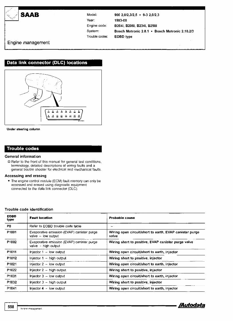
I Engine management
Model: 900 2,012,312,5 9-3 2,012,3
Year: 1993-00
Engine code: 82041, 82061, 82341, 82581
System: Bosch Motronic 2.8.1 Bosch Motronic 2.10.213
Trouble codes: EOBD type
Under steering column
General information Refer to the front of this manual for general test conditions, terminology, detailed descriptions of wiring faults and a general trouble shooter for electrical and mechanical faults.
Accessing and erasing The engine control module (ECM) fault memory can only be accessed and erased using diagnostic equipment connected to the data link connector (DLC).
Trouble code identification
EOBD type
Fault location Probable cause
Evaporative emission (EVAP) canister purge Wiring open circuiffshort to earth, EVAP canister purge valve - low output valve
1 I
PO I Refer to EOBD trouble code table
PI011 I Injector 1 - low output I Wiring open circuiffshort to earth, injector
-
Evaporative emission (EVAP) canister purge valve - high output
Wiring short to positive, EVAP canister purge valve
PI031 I Injector 3 - low output I Wiring open circuiffshort to earth, injector
P I 01 2
PI021
P I 022
1 558 I,,,,,,,,,,,, /Autodata
Injector 1 - high output
Injector 2 - low output
Injector 2 - high output
PI032
PI041
Wiring short to positive, injector
Wiring open circuiffshort to earth, injector
Wiring short to positive, injector
Injector 3 - high output
Injector 4 - low output
Wiring short to positive, injector
Wiring open circuiffshort to earth, injector

Engine management 7 Model: 900 2,0/2,312,5 9-3 2,0/2,3 SAAB
EOBD t~ pe
Fault location
'I , ,
Probable cause I
PI042 I Injector 4 - high output Wiring short to positive, injector
PI051 I lnjector 5 - low output Wiring open circuitlshort to earth, injector
PI052 ( lnjector 5 - high output Wiring short to positive, injector
Wiring open circuitlshort to earth, injector
Wiring short to positive, injector
PI061
PI062
I lntake manifold air control solenoid, outer flap - short to earth
Injector 6 - low output
Injector 6 - high output
Wiring, intake manifold air control solenoid
PI172 I System too lean, during idling lntake leak, battery
Wiring, intake manifold air control solenoid lntake manifold air control solenoid, outer flap - short to positive
PI173 1 System too rich, during idling Fuel pressure, battery, exhaust leak, injector(s)
PI206 Secondary air injection (AIR) pump relay - low output
Wiring open circuitlshort to earth, secondary air injection (AIR) pump, relay
Wiring short to positive, secondary air injection (AIR) pump, relay
PI207 I Secondary air injection (AIR) pump relay - high output
PI211 I Idle air control (tAC) valve - low output Wiring open circuitlshort to earth, IAC valve
PI212 I ldle air control (IAC) valve - high output Wiring short to positive, IAC valve
Wiring short to earth
Wiring short to positive
PI251
P I 252
P I 300 Engine control module (ECM) - AT torque reduction signal
Malfunction indicator lamp (MIL) - low output
Malfunction indicator lamp (MIL) - high output
Wiring, transmission control module (TCM)
Wiring, transmission control module (TCM) PI301
PI455 Wiring open circuitlshort to earth, relay
Engine control module (ECM) - AT torque reduction signal
AC compressor clutch relay - low output
PI456 1 AC compressor clutch relay - high output Wiring short to positive, relay
PI560 Traction control modulelECM communication -
signal high
Wiring, alternator, battery
Wiring open circuitlshort to earth, throttle position (TP) sensor
Wiring short to positive, throttle position (TP) sensor
PI601 I Fuel pump relay - high output Wiring short to positive, relay
PI602 I Fuel pump relay - low output Wiring open circuitlshort to earth, relay
Wiring short to positive, AC compressor clutch relay PI621 I AC compressor clutch relay - high output
PI622 AC compressor clutch relay - low output Wiring open circuitlshort to earth, AC compressor clutch relay
Wiring, alternator, battery
Wiring, connector, fuse
P I 628
PI628 El
PI630 I AC compressor clutch relay - high output
Battery voltage - too lowlhigh
Engine control module (ECM) - supply voltage missing
Wiring short to positive, relay
Wiring open circuitlshort to earth, relay PI631
Motronic 2.10.3
AC compressor clutch relay - low output

Model: 900 2,O Turbo 9000 2,0/2,3/Turbo (94+) 9000 2,3 Aero (94 +)
Year: 1993-98
Engine code: B204E, B2041, B204L, B204S, B234, B234E, B2341, B234L, B234R
System: Trionic
Engine management
I
+f994 black DLCISMIO 4 9 9 5 - under LH front seat
I
16411 - under steering column
General information 0 Refer to the front of this manual for general test conditions,
terminology, detailed descriptions of wiring faults and a general trouble shooter for electrical and mechanical faults. Trouble codes are displayed by the malfunction indicator lamp (MIL).
Accessing - flash type Ensure ignition switched OFF. Switch ignition ON - DO NOT start engine. MIL will illuminate for 3 seconds rn [A]. MIL will extinguish for 3 seconds rn [a]. MIL will illuminate for 3 seconds rn [A] MIL will extinguish for 2 seconds [C]. The last MIL ONlOFF indicates start of trouble code display. Trouble codes are displayed as a single digit number with a 3 second interval between each separate code. Count MIL flashes. Note trouble codes. Compare with trouble code table. For example: Trouble code 2 displayed - manifold absolute pressure (MAP) sensor O. After the last trouble code has been displayed, MIL extinguishes for 3 seconds rn [B]. MIL illuminates for 3 seconds rn [A]. MIL will now repeat all recorded trouble codes. Switch ignition OFF.
A B A C B A C C ADllTBS
Erasing - flash type Ensure ignition switched OFF. is connect ECM multi-plug or battery earth lead for at least 5 minutes.
NOTE: ECM adaptive memory may be erased causing erratic running faults. Carry out road test to allow ECM to re-learn basic values.
Diagnostic equipment can also be used to erase data from ECM fault memory.
WARNING: Disconnecting the battery may erase memory from electronic units (e.g. radio, clock).

t
Model: 900 2,O Turbo 9000 2,0/2,3TTurbo (94 +) 9000 2,3 Aero (94 -) SAAB
2 I Manifold absolute pressure (MAP) sensor I Wiring, MAP sensor
, I
kk f'
Trouble code identification
Engine management
Flash type
5 I Throttle position (TP) sensor I Wiring, TP sensor
3
4
6 I Heated oxygen sensor (H02S) I Wiring, intakelfuel leak, fuel pressure, H02S
Fault location Probable cause
Intake air temperature (IAT) sensor
Engine coolant temperature (ECT) sensor
Accessing and erasing - EOBD type
Wiring, IAT sensor
Wiring, ECT sensor
7
8
9
The engine control module (ECM) fault memory can only be accessed and erased using diagnostic equipment connected to the data link connector (DLC).
Mixture richhean
Evaporative emission (EVAP) canister purge valve
Engine control module (ECM) - internal fault
Heated oxygen sensor (H02S), intake leak, injector (s), fuel pressure, MAP sensor
Wiring, EVAP canister purge valve
ECM
Trouble code identification
P I 500
P I 651
P I 652
input
Battery voltage - too &/high
Engine control module (ECM) - RAM error
Engine control module (ECM) - RONl e m
Wiring, alternator, battery
ECM
ECM

I Engine management
Model: 9-3 2,O Turbo 9-3 2,3 Viggen 9-5 2,0/2,3 Turbo 9-5 2,3 AeroI3,O
Year: 1997-04
Engine code: B204E, B204L, B204R, B205E, B205F, B205L, B205R, B235E, B235R, B308E,
System: Trionic T7 Trionic T5
Under steering column
General information Refer to the front of this manual for general test conditions, terminology, detailed descriptions of wiring faults and a general trouble shooter for electrical and mechanical faults.
Accessing and erasing The engine control module (ECM) fault memory can only be accessed and erased using diagnostic equipment connected to the data link connector (DLC).
Trouble code identification
EOBD type
Fautt location Probable cause
PO I Refer to EOBD trouble code table I - PI105 Manifold absolute pressure (MAP) sensor, TC system - Intake leak, hose(s)
leak detected 1 PI106
PI107
PI131 I Heated oxygen sensor (H02S) 1, bank 1 - malfunction I Wiring, H02S, ECM
PI108
PI110
I I
PI132 I Heated oxygen sensor (H02S) 1, bank 1 - malfunction 1 Wiring, H02S, ECM
Manifold absolute pressure (MAP) sensor, TC system - rangelperformance problem
Manifold absolute pressure (MAP) sensor, TC system - open circuiffshort to earth
MAP sensor - TC system
Wiring open circuiffshort to earth, ECM
Manifold absolute pressure (MAP) sensor, TC system - short to positive
Turbocharger (TC) bypass valve - rangelperformance problem
Wiring short to positive, ECM
Hose(s), TC bypass solenoid, TC bypass valve

Model: 9-3 2,O Turbo 9-3 2,3 Viggen 9-5 2,012,3 Turbo 9-5 2,3 Aerol3,O
Engine "" management L_I PI133 I Heated oxygen sensor (H02S) 1, bank 1 - voltage low I Wiring, H02S
Probable cause EOBD type
Wiring, fuel pump relay, HOZS, ECM
Fault location
PI135
PI136 Wiring, fuel pump relay, H02S, ECM
Heated oxygen sensor (H02S) 1, bank 1 - heater low input
Heated oxygen sensor (H02S) I, bank 1 - heater high input
PI137 I Heated oxygen sensor (H02S) 2, bank 1 - voltage low I Wiring, H02S
PI141
PI142
I Long term fuel trim (FT), max. value - weak mixture
P I 171
P I 172
Fuel pressure, injector@), intake system, mass air flow (MAF) sensor
Heated oxygen sensor (H02S) 2, bank 1 - heater low input
Heated oxygen sensor (H02S) 2, bank 1 - heater high input
PI182 / Long term fuel trim (FT), min. value - rich mixture
Wiring, fuel pump relay, H02S, ECM
Wiring, fuel pump relay, H02S, ECM
Short term fuel trim (FT), max, value - weak mixture
Short term fuel trim (FT), min. value - rich mixture
Fuel pressure, injector(s), evaporative emission (EVAP) canister purge valve
Fuel pressure, injector(s), intake system, mass air flow (MAF) sensor
Fuel pressure, injector(s), evaporative emission (EVAP) canister purge valve
PI230 Throttle position (TP) sensor 1 & 2 - rangel performance problem
Wiring, connectors, throttle control unit, ECM
PI240 ( Throttle position motor - short circuit 1 Wiring, throttle control unit, ECM
PI253 Throttle position motor - fuHy open signal during I cranking
PI251
P I 252
Wiring, mechanical fault, throttle control unit, ECM
PI260 1 Throttle return spring - weak spring force 1 Mechanical fault, throttle control unit
Throttle position motor - fully closed signal
Throttle position motor - fully open signallno current
Wiring, mechanical fault, throttle control unit, ECM
Wiring, throttle control unit, ECM
PI264 / Throttle valve open - accelerator depressed I Throttle control unit, mechanical fault
P I 261
PI263
P I 300 ( Randomlmultiple cylinder(s) - misfire detected Mechanical fault, wiring, ignitionlfuel system, mass air flow (MAF) sensor, fuel pump relay, manifold absolute pressure (MAP) sensor, intake leak
Throttle valve - tightlsticking
Throttle valve - moved manually while en~ine running
Mechanical fault, throttle control unit, ECM
Throttle control unit, mechanical fault
Mechanical fault, ignitionlfuel system, injector P I 301
PI302 I Cylinder 2 - misfire detected I Mechanical fault, ignitionlfuel system, injector
Cylinder 1 - misfire detected
PI303 I Cylinder 3 - misfire detected I Mechanical fault, ignitionlfuel system, injector
P I 304 1 Cylinder 4 - misfire detected I Mechanical fault, ignitionlfuel system, injector
PI320 I Ignition coils, bank 2 - no supply voltage 1 Wiring, ignition coil assembly, ECM
PI310
PI312
I Ignition coil - knock detection, cylinder 3 & 4 Wiring open circuitlshort to positive, ignition coil assembly, ECM
Ignition coils, bank 1 - no supply voltage
Ignition coil - knock detection, cylinder 1 & 2
P I 390 I Misfire detected, random - fuel level low
Wiring, ignition coil assembly, ECM
Wiring open circuitlshort to positive, ignition coil assembly, ECM
Wiring, connectors, injector(s), fuel pump relay, fuel pressure, mass air flow (MAF) sensor, intake leak, fuel level
PI391
110
Cylinder 1, misfire detected - fuel level low Wiring, connectors, injector, fuel level

EOBD type
P I 392
< 'I k4 ;c
Probable cause
SUB Model: 9-3 2,O Turbo 9-3 2,3 Viggen 9-5 2,012,3 Turbo 9-5 2,3 Aerol3,O
Fault location
Engine management
Cvlinder 2, misfire detected - fuel level low Wiring, connectors, injector, fuel level
Cylinder 3, misfire detected - fuel level low Wiring, connectors, injector, fuel level
Cylinder 4, misfire detected - fuel level low
Cylinder 5, misfire detected - fuel level low
Wiring, connectors, injector, fuel level
Wiring, connectors, injector, fuel level
Cylinder 6, misfire detected - fuel level low Wiring, connectors, injector, fuel level
Secondary air injection (AIR) pump relay - open circuit/ short to earth
Wiring open circuiffshort to earth, AIR pump relay
Secondary air injection (AIR) pump relay - short to positive
Wiring short to positive, AIR pump relay
Fuel svstemlmisfire detected - fuel level low lgnitionlfuel system, injector(s), fuel level
Evaporative emission (EVAP) canister purge valvelfuel tank level sensor - malfunction
Evaporative emission (EVAP) systernlfuel tank level sensor - small leak detected/malfunction
Wiring, connectors, EVAP canister purge valve, fuel tank level sensor, ECM
Hose connection(s), intake leak, EVAP canister, EVAP canister purge valve, wiring, fuel tank level sensor
Wiring open circuiffshort to earth, connectors, EVAP canister purge valve
Evaporative emission (EVAP) system - open circuit1 short to earth
Evaporative emission (EVAP) system - open circuit/ short to positive
Wiring open circuiffshort to positive, connectors, EVAP canister purge valve
Evaporative emission (EVAP) pressure sensor, in fuel tank - ranqelperformance problem
Wiring, connectors, EVAP pressure sensor
Evaporative emission (EVAP) pressure sensor, in fuel tank - signal too low when depressurised
Evaporative emission (EVAP) pressure sensor, in fuel tank - siqnal too high when depressurised
Wiring, EVAP canister purge valve, EVAP system leak, EVAP pressure sensor
Wiring, EVAP canister purge valve, hose(s), EVAP pressure sensor
Evaporative emission (EVAP) pressure sensortfuel tank level sensor, in fuel tank - large leak detected1 malfunction
Immobilizer activated - incorrectly programmedlnot programmed
Hose connection(s), wiring, EVAP pressure sensor, fuel tank level sensor
Trouble code(s) stored in other system(s), ECMl instrumentation control modulelignition key not matched to immobilizer control module, immobilizer control module
Wiring, connector(s), EVAP pressure sensor, fuel tank level sensor
Evaporative emission (EVAP) pressure sensorlfuel tank level sensor, in fuel tank - rangelperknmance problem/ malfunction
Evaporative emission (EVAP) pressure sensortfuel tank level sensor, in fuel tank - signal too low when de~ressurised/malfunction
- --
Wiring, connector(~), EVAP pressure sensor, fuel tank level sensor
Evaporative emission (EVAP) pressure sensorlfuet tank level sensor, in fuel tank - signal tao high when depressurisedlmalfunction
Wiring, connector(s), EVAP pressure sensor, fuel tank level sensor
Battery voltage - too lowthigh Wiring, alternator, battery
Accelerator pedal position (APP) sensor 1 & 2 - rangstperformance problem
Accelerator pedal position (APP) sensor 1 & 2 - adapted value out of range
Accelerator pedal position (APP) sensor 1 & 2 - short circuit
Wiring, throttle control unit, ECM
Wiring, throttle control unit, ECM
Wiring, throttle control unit, ECM
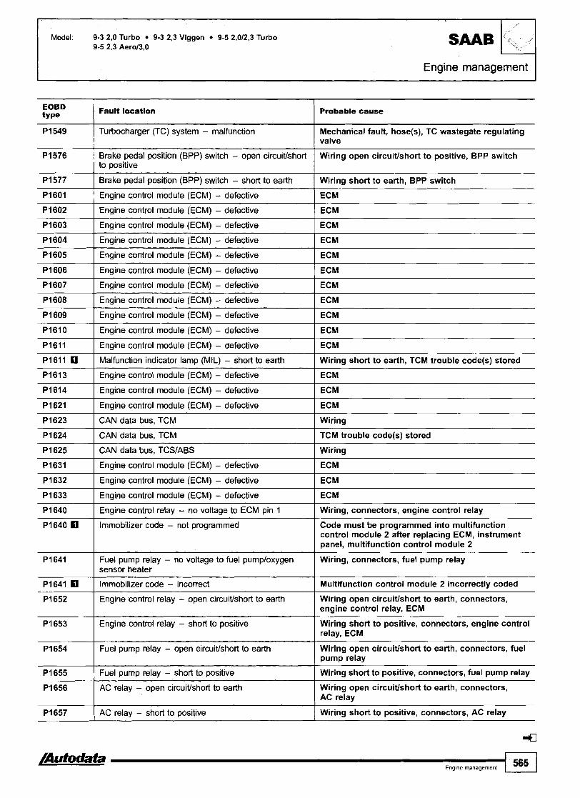
Engine management I Model: 9-3 2,O Turbo 9-3 2,3 Viggen 9-5 2,0/2,3 Turbo
9-5 2,3 Aerol3,O SAAB
EOBD t~ pe
P I 549
'1, /
Fault location Probable cause
Turbocharger (TC) system - malfunction
Engine control modute (ECM) - defective I ECM
Mechanical fault, hose(s), TC wastegate regulating valve
Brake pedal position (BPP) switch - open circuttlshort to positive
Brake pedal position (BPP) switch - short to earth
Engine control module (ECM) - defective 1 ECM
Wiring open circuitlshort to positive, BPP switch
Wiring short to earth, BPP switch
Engine control module (ECM) - defective I ECM
Engine control module (ECM) - defective I ECM
Engine control module (ECM) - defective
Engine control module (ECM) - defective
Engme control module (ECM) - defective
Engine control module (ECM) - defective I ECM
ECM
ECM
ECM
Engine control module (ECM) - defective I ECM
Engine control module (ECM) - defective
Engine control module (ECM) - defective
Malfunction indicator lamp (MIL) - short to earth ( Wiring short to earth, TCM trouble code@) stored
ECM
ECM
Engine control module (ECM) - defective 1 ECM
CAN data bus, TCM I Wiring
Engine control module (ECM) - defective
Engine control module (ECM) - defective
CAN data bus, TCM I TCM trouble code(s) stored
ECM
ECM
CAN data bus, TCSIABS 1 Wiring
Engine control relay - no voltage to ECM pin 1 I Wiring, connectors, engine control relay
Engine control module (ECM) - defective
Engine control module (ECM) - defective
Engine control module (ECM) - defective
Immobilizer
ECM
ECM
ECM
code - not programmed Code must be programmed into multifunction control module 2 after replacing ECM, instrument panel, multifunction control module 2
Wiring, connectors, fuel pump relay Fuel pump relay - no voltage to fuel pumploxygen sensor heater
Immobilizer code - incorrect I Multifunction control module 2 incorrectly coded
Engine control relay - open circuitlshort to earth Wiring open circuitlshort to earth, connectors, engine control relay, ECM
Wiring short to positive, connectors, engine control relay, ECM
Engine control relay - short to positive
Fuel pump relay - open circuitlshort to earth
Fuel pump relay - short to positive
AC relay - open circuitlshort to earth
Wiring open circuiffshort to earth, connectors, fuel pump relay
Wiring short to positive, connectors, fuel pump relay
Wiring open circuiffshort to earth, connectors, AC relay
AC relay - short to positive Wiring short to positive, connectors, AC relay

1"; C jy SAAB Model: 9-3 2,O Turbo 9-3 2,3 Viggen 9-5 2,012,3 Turbo 9-5 2,3 Aerol3,O
I Engine management
EOBD type
Fault location Probable cause
Turbocharger (TC) bypass valve - open circuitlshort to Wiring open circuitlshort to earth, connectors, earth I TC bypass valve
Turbocharger (TC) bypass valve - short to positive
Turbocharger (TC) wastegate regulating valve - open circuitlshort to earth
Wiring short to positive, connectors, TC bypass valve
Wiring open circuitlshort to earth, connectors, TC wastegate regulating valve
Turbocharger (TC) wastegate regulating valve - short to positive
Throttle actuator limp home relay - open circuitlshort to earth
CAN data bus, multifunction control module 2 I Wiring
Wiring short to positive, connectors, TC wastegate regulating valve
Wiring open circuitlshort to earth, connectors, throttle actuator limp home relay
Throttle actuator limp home relay - short to positive
Injector circuits - open circuitlshort to earthlpositive
CAN data bus, muttifunction control module 1
CAN data bus, instrument panel I Wiring
Wiring short to positive, connectors, throttle actuator limp home relay
Wiring, fuse, injector@), ECM
Wiring
Vehicle fitted with TRlONlC T5 rn Multifunction control module 1 controls: headlamps, interior lamps, instrument illumination, intermittent wiper, door mirror heater,
heated rear window Multifunction control module 2 controls: central locking, alarm system, immobilizer, rear seat heater, seat belt warning, electrically adjustable passenger's seat a
CAN data bus, ECM
CAN data bus, TCM
CAN data bus, TCSIABS
Wiring
Wiring
Wiring

Model: 9-3 2,2D Turbo
Year: 1998-02
Engine code: D223L
System: Bosch EDC 15 Bosch PSG 16
Engine management I
Under steering column
General information Refer to the front of this manual for general test conditions, terminology, detailed descriptions of wiring faults and a general trouble shooter for electrical and mechanical faults.
Accessing and erasing The engine control module (ECM) fault memory can only be accessed and erased using diagnostic equipment connected to the data link connector (DLC).
Trouble code identification
Probable cause I 1
POI00 I Mass air flow (MAF) sensor - high input I Wiring, connectors, MAF sensor
POI01 I Mass air flow (MAF) sensor - malfunction I Wiring, connectors, MAF sensor
POI10 Intake air temperature (IAT) sensor - open Wiring open circuitlshort to positive, IAT sensor, ECM circuitkhort to positive
PO104
PO1 06
POI11 Intake air temperature (IAT) sensor - short to Wiring short to earth, IAT sensor, ECM I earth
PO115 Engine coolant temperature (ECT) sensor - Wiring open circuitlshort to positive, connector, ECT sensor open circuitlshort to positive
Mass air flow (MAF) sensor - low input
Mass air flow (MAF) sensor - range1 performance problem
-
Wiring, connectors, MAF sensor
Intake leak, wiring, MAF sensor
Engine coolant temperature (ECT) sensor - short to earth
Engine coolant temperature (ECT) sensor - rangelperformance problem
Wiring short to earth, connector, ECT sensor
Wiring, connector, ECT sensor
Eng~ne management 567

Model: 9-3 2,2D Turbo
(Engine management
PO121 Manifold absolute pressure (MAP) sensor - Wiring open circuitlshort to earth, MAP sensor open circuitlshort to earth
PO120
PO190 I Misfire detected - mechanical fault I Injector(s), fuel leak, pist&&), valve(s)
PO195 Engine oil temperature (EOT) sensor - open Wiring open circuitlshort to positive, EOT sensor circuitlshort to positive
Manifold absolute pressure (MAP) sensor - short to positive
Wiring short to positive, MAP sensor
PO401 Exhaust gas recirculation (EGR) solenoid - Wiring short to positive, EGR solenoid short to positive
PO1 96
PO400
Engine oil temperature (EOT) sensor - short to earth
Exhaust gas recirculation (EGR) solenoid - open circuitlshort to earth
PO402
PO403
ABS trouble code@) stored, wiring, ABS control module1 engine control module (ECM) communication, ABS control module, ECM
Wiring to earth, EOT sensor
Wiring open circuitlshort to earth, EGR solenoid
PO500
PO606 I Engine control module (ECM) - internal fautt I ECM
Exhaust gas recirculation (EGR) system - excessive flow detected
Exhaust gas recirculation (EGR) system - insufficient flow detected
Vehicle speed sensor (VSS) - circuit malfunction
Wiring, EGR valve, EGR solenoid, ECM
Wiring, EGR valve, EGR solenoid, ECM
PO703
PO704
PO726
PO727
Brake pedal position (BPP) switchlcruise control switch - plausibility
Clutch pedal position (CPP) switchlcmise control switch - plausibilitv
PO728
PI110
Wiring, BPP switchlcruise control switch
Wiring, CPP switchlcruise control switch
Crankshaft position (CKP) sensorlengine speed (RPM) sensor - circuit malfunction
Crankshaft position (CKP) sensorlengine speed (RPM) sensor - mechanical fault
P l l l l
P I 125
PI126
Wiring, CKP sensorlRPM sensor
Wiring, CKP sensorlRPM sensor
Engine speed - too high
Intake manifold air control sotenoid - open circuitfshort to earth
P I 127
P I 128
Wiring, throttle control system mechanical fault, fuel system, engine mechanical fault, fuel injection pump control module, ECM
Wiring open circuitlshort to earth, intake manifold air control solenoid
Intake manifold air control solenoid - short to positive
Turbocharger (TC) wastegate regulating valve - open circuiffshorf to earth
Tuhocfiarger (TC) wastegate regulating vatve - short to positive
Engine overheat protection activated - engine oil temperature
Engific3 overheat protection activated - e@ne coolant temperature
Wiring short to positive, intake manifold air control solenoid
Wiring open circuitlshort to earth, connectors, TC wastegate regulating valve
Wiring short to positive, connectors, TC wastegate regulating valve
Twbocharger (TC) boost pressure, too low - mechanical fault
Turbocharger (TC) boost pressure, too high - mechanical fault
Wiring, engine oil temperature (EOT) sensor
Wiring, engine coolant temperature (ECT) sensor, engine cooling system
Wiring, hose(s), TC wastegate regulating valve adjustment, TC wastegate regulating valve, turbocharger (TC)
Wiring, hose(s), TC wastegate regulating valve adjustment, TC wastegate regulating valve, turbocharger (TC)

Model: 9-3 2,2D Turbo
Engine management
Fault location I Probable cause
Fuel temperature sensor, in injection pump - Fuel temperature sensor, fuel injection pump control module malfunction
P1175
Injection pump position sensor - maifunction Wiring, injection pump position sensor, fuel injection pump I control module, ECM
Engine overheat protection activated - fuel injection pump temperature
P I 220
PI335
Wiring, fuel filter heater
. , I malfunction ' I
Injection timing control - malfunction
Fuel injection pump control module - CKP signal missing
Fuel supplylreturn, injection pump, fuel injection pump control module, ECM
Wiring, CKP sensor, fuel injection pump control module, ECM
Wiring, APP sensorlCTP switch 1
Pi515
Accelerator pedal position (APP) sensor1 closed throttle position (CTP) switch - plausibility
AC compressor clutch relay - open circuit1 short to earth
Pi606 I Engine control module (ECM) - internal fault I ECM
Accelerator pedal position (APP) sensor1 closed throttle position (CTP) switch -
Wiring, APP sensorlCTP switch
Wiring open circuitlshort to earth, AC compressor clutch relay
PI531
P1604
P1605
P1607 I Engine control module (ECM) - internal fault I ECM
AC compressor clutch relay - short to positive
Engine control module (ECM) - internal fault
Engine control module (ECM) - internal fault
P1611 I Immobilizer code - incorrect I Multifunction control module 2 incorrectly coded
Wiring short to positive, AC compressor clutch relay
ECM
ECM
Engine control module (EcM) - internal
Immobilizer code - not programmed
--
f a u l t ~ ~ ~
Code must be programmed into multifunction control module 2 after replacing ECM, instrument panel, multifunction control module 2
P1621 I Engine control module (ECM) - internal fault I ECM
Pi613
P1614
P1620
PI629 Fuel quantity adjuster - malfunction Wiring, fuel quantity adjuster, fuel injection pump control module, ECM
- CAN data bus, multifunction controliodule 2
Ignition key - incorrect signal
Engine control module (ECM) - internal fault
PI625
P1626
P I 630 Fuel quantity adjuster - short to positive Wiring short to positive, fuel quantity adjuster, fuel injection pump control module, ECM
--
~ i r i n~ lmu l t i f unc t i on control module 2
Ignition key not matchedldamaged, poor connection, wiring
ECM
P I 631 Fuel injection pump control module - internal Fuel injection pump control module 1 fault
Engine control relay - no voltage to ECM pin 3
Engine control relay - circuit malfunction
P1632 Fuel injection pump control module - internal Fuel injection pump control module I fault
Wiring, connectors, engine control relay
Wiring short to earthlpositive, engine control relay
PI633 Fuel injection pump control module - internal Fuel injection pump control module fault
4 -a E n g ~ n e management 569

1 Engine management
?, 'I vg
Fault location
SAAB Model: 9-3 2,2D Turbo
Probable cause
Fuel injection pump control module - internal Fuel injection pump control module fault
Fuel injection pump controt module - internal fault
Fuel injection pump control module - internal fault
CAN data bus - malfunction I Wiring
Fuel injection pump control module
Fuel injection pump control module
Fuel injection pump control module - internal fault
CAN data bus - malfunction
CAN data bus, fuel injection pump control module I Wiring
Fuel injection pump control module
Wiring
CAN data bus, fuel injection pump control Wiring module
CAN data bus - malfunction I Wiring
CAN data bus - malfunction I Wiring
Fuel shut-off solenoid, in injection pump - Wiring short to positive, fuel shut-off solenoid, fuel injection short to positwe pump control module
CAN data bus - malfunction
CAN data bus - malfunction
CAN data bus - malfunction
Fuel shut-off solenoid, in injection pump - Wiring open circuitlshort to earth, fuel shut& solenoid, fuel open circuitkhort to earth injection pump control module
Wiring
Wiring
Wiring
Fuel shut-off solenoid, in injection pump - Wiring, fuel shut-off solenoid, fuel injection pump control malfunction module
Glow plug control module - open circuitlshort to earth
Glow plug control module - short to positive
Multifunction control module 2 controls: central locking, alarm system, immobilizer, rear seat heater, seat belt warning, electrically adjustable passenger's seat a
Wiring open circuitlshort to earth, glow plug control module
Wiring short to positive, glow plug control module
Glow plug control module - circuit malfunction
1 570 1 Eng(ne management Autodata
Wiring, glow plug@), glow plug control modulelECM communication

Model: 9000 3,O V6
Year: 1995-97
Engine code: B3081
System: Bosch Motronic 2.8.1
Trouble codes: EOBD type
Engine management
1995 - under LH front seat
General information G Refer to the front of this manual for general test conditions,
terminology, detailed descriptions of wiring faults and a general trouble shooter for electrical and mechanical faults.
Accessing and erasing The engine control module (ECM) fault memory can only be accessed and erased using diagnostic equipment connected to the data link connector (DLC).
Trouble code identification
1996- - under fascia, driver's side
EOBD type
Fault location Probable cause
PI001 Evaporative emission (EVAP) canister purge Wiring open circuiffshort to earth, EVAP canister purge valve valve - low output
I I
PO I Refer to EOBD trouble code table
PI012 I Injector 1 - high output I Wiring short to positive, injector
-
PI002
PI011
P I 021 I Injector 2 - low output I Wiring open circuiffshort to earth, injector
PI022 I Injector 2 - high output I Wiring short to positive, injector
Evaporative emission (EVAP) canister purge valve - high output
Injector 1 - low output
Wiring short to positive, EVAP canister purge valve
Wiring open circuiffshort to earth, injector
PI041 I Injector 4 - low output I Wiring open circuiffshort to earth, injector
Wiring open circuiffshort to earth, injector
Wiring short to positive, injector
-
PI031
PI032
-
Injector 3 - low output
Injector 3 - high output

I'I.+. ,>I SAAB
I Engine management
Model: 9000 3,O V6
EOBD type I Probable cause
P1042 I Injector 4 - high output I Wiring short to positive, injector
P1051 I Injector 5 - low output I Wiring open circuitlshort to earth, injector
P1062 ( Injector 6 - high output ] Wiring short to positive, injector
PI052
P1061
P1211 I Idle air control (IAC) valve - low output I Wiring open circuitlshort to earth, IAC valve
Injector 5 - high output
Injector 6 - low output
P1206
P1207
Wiring short to positive, injector
Wiring open circuitlshort to earth, injector
Secondary air injection (AIR) pump relay - low output
Secondary air injection (AIR) pump relay - hi* output
P1212
P1236
P1247 Intake manifold air control solenoid, inner Wiring, intake manifold air control solenoid flap - short to positive
Wiring open circuitlshort to earth, secondary air injection (AIR) pump, relay
Wiring short to positive, secondary air injection (AIR) pump, relay
P1237
P1246
P1251 I Malfunction indicator lamp (MIL) - low I Wiring short to earth output
Idle air control (IAC) valve - high output
Intake manifold air control solenoid, outer flap - open circuitlshort to earth
P1252 I Malfunction indicator lamp (MIL) - high I Wiring short to positive output
Wiring short to positive, IAC valve
Wiring, intake manifold air control solenoid
Intake manifold air control solenoid, outer flap - short to positive
Intake manifold air control solenoid, inner flap - open circuitlshort to earth
Wiring, intake manifold air control solenoid
Wiring, intake manifold air control solenoid
P1601 I Fuel pump relay - high output I Wiring short to positive, relay
P1450
P1451
P1500
P1602 I Fuel pump relay - low output I Wiring open circuitlshort to earth, relay
P1630 Traction control system (TCS) - signal low Wiring open circuitlshort to earth, traction control module1 engine control module (ECM) communication
AC relay - low output
AC relay - high output
Battery voltage - too lowlhigh
Wiring, AC relay
Wiring, AC relay
Wiring, alternator, battery
PI631
4
Traction control system (TCS) - signal high Wiring short to positive, traction control modulelengine control module (ECM) communication

Under steerhg column
General information 0 Refer to the front of this manual for general test conditions,
terminology, detailed descriptions of wiring faults and a general trouble shooter for electrical and mechanical faults.
Accessing and erasing The transmission control module (TCMj fault memory can only be accessed and erased using diagnostic equipment connected to the data link connector (DLC).
Trouble code identification
EOBD ty Pe
Fault location Probable cause
PO I Refer to E08D trouble code table I - P I 500
P I 785
PI786
PI787
PI812 Transmission fluid temperature (TFT) sensor - low input Wiring short to earth, connectors, TFT sensor
Battery voltage - too lowlhigh
Engine control module (ECM)ltransmission control module (TCM) communication, throttle position signal - malfunction
P I 788
P I 789
P I 790
Wiring, alternator, battery
Wiring
Traction control moduleltransmission control module (TCM) communication, throttle position signal - malfunction
Traction control moduleltransmission control module (TCM) communication, throttle position signal - signal low
Wiring
Wiring open circuitkhort to earth
Traction control moduleltransmission control module (TCM) communication, throttle position signal - signal high
Transmission control module (TCM)/engine control module (ECM) communication, transmission range (TR) signal - signal low
Transmission kick-down switch - low input
Wiring short to positive
Wiring open circuitkhort to earth
Wiring short to earth, transmission kick-down switch

Model: 900 9-3 9-5
I
Transmission
EOBD type
P I 81 3
Fault location Probable cause
Transmission fluid temperature (TFT) sensor - high input
Gear selection - shift malfunction
Wiring open circuitlshort to positive, connectors. TFT sensor
Transmission input shaft speed sensor - no signal
Transmission output shaft speed sensor - no signal
Automatic transmission, mechanical I fault
Wiring, connectors, transmission input shaft speed sensor
Wiring, connectors, transmission output shaft speed sensor
Gear selection, down-shift - shift malfunction
Gear selection, shifting-times - shift malfunction
Transmission fluid pressure (TFP) control solenoid - high output I Wiring short to positive, connectors
Automatic transmission, mechanical fault
Automatic transmission, mechanical fault
Transmission control module (TCM)/engine control module (ECM) communication, torque limitation - signal low
Transmission fluid pressure (TFP) control solenoid - low output
Wiring open circuitlshort to earth, connectors
Wiring open circuitlshort to earth, connectors
Gear shift solenoid, 1-213-4 - shift malfunction
Transmission fluid pressure (TFP) control solenoid - circuit malfunction
Gear shift solenoid, 1-213-4 - shift malfunction
Wiring open circuitlshort to positive, connectors, gear shift solenoid
Wiring short to earthlpositive, connectors, TFP control solenoid
Wiring short to earth, connectors, gear shift solenoid
Gear shift solenoid, 2-3 - shift malfunction Wiring short to earth, connectors, gear shift solenoid
Torque converter clutch (TCC) solenoid - high output
Gear shift solenoid, 2-3 - shift malfunction
Torque converter clutch (TCC) solenoid - low output
Wiring open circuitlshort to positive, connectors, TCC solenoid
Wiring open circuitlshort to positive, connectors, gear shift solenoid
Wiring short to earth, connectors, TCC solenoid
CAN data bus, multifunction control module 2 ( Wiring, connectors
Multifunction control module 2 controls: central locking, alarm system, immobilizer, rear seat heater, seat belt warning, electrically adjustable passenger's seat.
da data bus, ECM - no s i g n a l - -
CAN data bus, ECM - incorrect signal
1 574 1 Transmission /Autodata
Wiring
Wiring
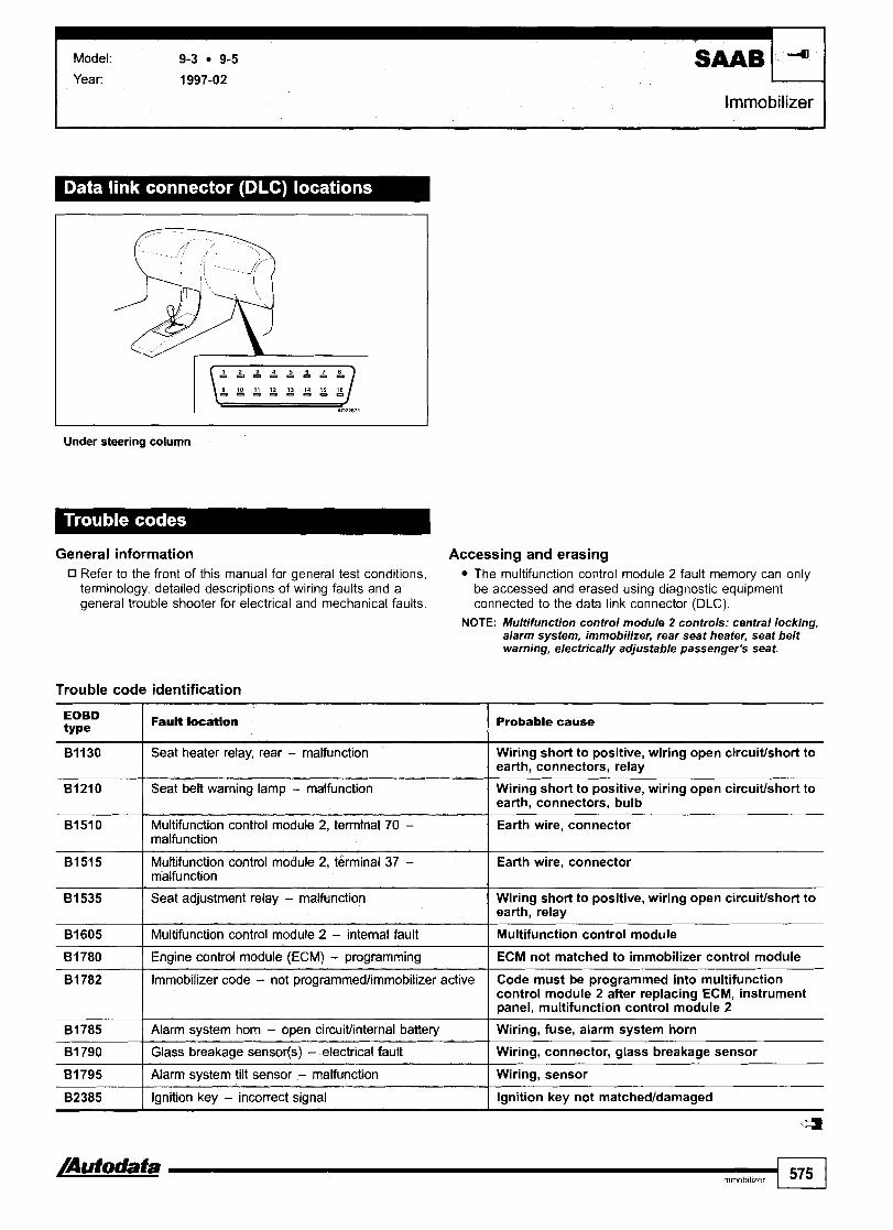
I Model: 9-3 9-5
Year: 1997-02 I
Immobilizer
Under steering column
General information Refer to the front of this manual for general test conditions, terminology, detailed descriptions of wiring faults and a general trouble shooter for electrical and mechanical faults.
Accessing and erasing The multifunction control module 2 fault memory can only be accessed and erased using diagnostic equipment connected to the data link connector (DLC).
NOTE: Multifunction control module 2 controls: central locking, alarm system, immobilizer, rear seat heater, seat belt warning, electrically adjustable passenger's seat.
Trouble code identification
EOBD type
81210 I Seat belt warning lamp - malfunction
81130
Wiring short to positive, wiring open circuiffshort to earth, connectors, bulb
Fault location
81510 Multifunction control module 2, terminal 70 - I Earth wire, connector malfunction
Probable cause
Seat heater relay, rear - malfunction
81515 Multifunction control module 2, terminal 37 - Earth wire, connector malfunction
Wiring short to positive, wiring open circuitlshort to earth, connectors, relay
81535 Seat adjustment relay - malfunction I Wiring short to positive, wiring open circuitlshort to earth, relay
81605 1 Multifunction control module 2 - internal fault I Multifunction control module
81780 1 Engine control module (ECM) - programming I ECM not matched to immobilizer control module
81782
81785
8 1 790
8 1 795
82385
/Autodata Immobilizer
<=I
Immobilizer code - not programmedlimrnobilizer active
Alarm system horn - open circuitlinternal battery
Glass breakage sensorfs) - electrical fault
Alarm system tilt sensor - malfunction
Ignition key - incorrect signal
575
Code must be programmed into multifunction control module 2 after replacing ECM, instrument panel, multifunction control module 2
Wiring, fuse, alarm system horn
Wiring, connector, glass breakage sensor
Wiring, sensor
Ignition key not matchedldamaged

Arosa lbizalcordoba 1,011,411,611,812,0 IbizalCordoba 1,711,9 D/TDlSDl/TDl Toledo 1,612,O Toledo 1,9 D/TD/TDl ToledolLeon Alhambra lnca 1,411,6 lnca 1,9 DlSDl
I year: 1993-04 Engine IY, 12, 2E, AAA, AAZ, ABF, ADL, ADY, AEE, AEH, AER, AEX, AEY, AFH, AFK, AFN, AFR, AFT, AGG, AGN, code: AGP, AGR, AGR, AGZ, AHB, AHF, AHT, AHU, AHW, AJH, AJM, AJQ, AKK, AKL, AKS, AKU, AKV, AKW, ALD,
ALH, ALL, ALM, AMF, AMK, AMY, ANU, ANV, ANW, ANX, APE, APF, APG, APP, APQ, APT, AQM, AQN, AQQ, AQX, ARL, ARY, AST, ASV, ASZ, ATM, ATN, AUA, AUB, AUC, AUD, AUE, AUQ, AUR, AUS, AUY, AVG, AVZ, AWC,AXP,AYL,AYP,AYQ, AZD, BCA, BCB, BDE
System: Bosch EDC11.3.311.4 Bosch EDC I 5 P N Bosch Motronic M3.8.1121315 Bosch Motronic ME7.117.517.5.10 Bosch Motronic MP9.0 Bosch MSA 12115115.5 Magneti-Marelli IAV14CV14LV14MV Siemens Simos VAG Digifant ML5.515.9 VAG Digifant MP4.4
I Engine management
Arosa 408100, lbizalcordoba 1999-2002. lnca 20004 - in fascia fusebox
IbizalCordoba 41999, lnca 42000 - glovebox, driver's side
I
Toledo 403199 - adjacent to steering column
Arosa 091004, Toledo 19994, Leon - centre console

Model: Arosa IbizalCordoba 1,011,4/1,6/1,812,0 l,7ll,9 DTTDlSDllTDl Toledo l,6/2,O DTTDI ToledolLeon Alhambra Inca 1,4/1,6
I
Alhambra +05100 - centre console
General information Refer to the front of this manual for general test conditions, terminology, detailed descriptions of wiring faults and a general trouble shooter for electrical and mechanical faults. Carry out road test for at least 10 minutes.
0 Except 2,8: Ensure accelerator pedal is briefly fully depressed and engine speed exceeds 3500 rpm. 2,8: Ensure accelerator pedal is briefly fully depressed and engine speed exceeds 4600 rpm. Automatic transmission in 'P' or 'N'. If engine does not start: Crank engine for 6 seconds. Leave ignition switched ON.
0 Data link connector (DLC) - 2-pin: (A) black, (B) brownlwhite.
Accessing and erasing The engine control module (ECM) fault memory can only be accessed and erased using diagnostic equipment connected to the data link connector (DLC).
Trouble code identification Refer to Volkswagen GolflBora 1997 -+, see page 722.
4
Alhambra 06N)O-r - fascia, driver's side
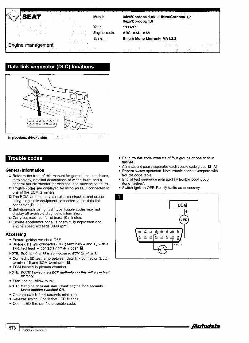
Year: 1993-97
Engine code: ABS, AAU, AAV
System: Bosch Mono-Motronic MA1.2.2
Engine management
I
In glovebox, driver's side
General information 0 Refer to the front of this manual for general test conditions,
terminology, detailed descriptions of wiring faults and a general trouble shooter for electrical and mechanical faults. Trouble codes are displayed by using an LED connected to one of the ECM terminals. The ECM fault memory can also be checked and erased using diagnostic equipment connected to the data link connector (DLC). Self-diagnosis using flash type trouble codes may not display all available diagnostic information. Carry out road test for at least 10 minutes. Ensure accelerator pedal is briefly fully depressed and engine speed exceeds 3000 rpm.
Accessing Ensure ignition switched OFF. Bridge data link connector (DLC) terminals 4 and 15 with a switched lead - contacts normally open O.
NOTE: DLC terminal 15 is connected to ECM terminal 11.
Connect LED test lamp between data link connector (DLC) terminal 16 and ECM terminal 4 0. ECM located in plenum chamber.
NOTE: DO NOT disconnect ECM multi-plug as this will erase fault memory.
Start engine. Allow to idle. NOTE: If engine does not start' Crank engine for 6 seconds.
Leave ignition switched ON.
Operate switch for 4 seconds minimum. Release switch. Check that LED flashes. Count LED flashes. Note trouble code.
Each trouble code consists of four groups of one to four flashes. A 2,5 second pause separates each trouble code group H [A]. ReDeat switch o~eration. Note trouble codes. Com~are with tro"ble code table. End of test sequence indicated by trouble code 0000 (long flashes). Switch ignition OFF. Rectify faults as necessary.
1 578 I,,,,,,,,,,,,,, /Autodata

I
Engine management
Erasing
Method 1
Ensure ignition switched OFF.
Access trouble codes. Switch ignition OFF. Operate switch and hold. Switch ignition ON. Release switch after 5 seconds. Check that LED flashes. ldle speed control (ISC) actuator activated. Trouble code displayed: 1232. Operate switch for 4-6 seconds to activate each of the following components: Intake manifold heater. Trouble code displayed: 4342. Evaporative emission (EVAP) canister purge valve. Trouble code displayed: 4343. After activation of last component operate switch for 4-6 seconds to display flash code 0000 (long flashes). Fault memory automatically erased. Repeat checking procedure to ensure no data remains in ECM fault memory.
Method 2
Ensure ignition switched OFF. Disconnect ECM multi-plug or battery earth lead.
NOTE: ECM adaptive memory may be erased causing erratic Bridge data link connector (DLC) terminals 4 and 15 with a running faults. Carry out road test to allow ECM to switched lead - contacts normally open 8. re-learn basic values.
NOTE: DLC terminal 15 is connected to ECM terminal 11. WARNING: Disconnecting the battery may erase memory from Connect LED test lamp between data link connector (DLC) electronic units (e.g. radio, clock). terminal 16 and ECM terminal 4 8.
0000 I End of test sequence 1 -
Trouble code identification
type 4-digit
2113 8 ( Crankshafl position (CKP) sensor I Insecure rotor, wiring, CKP sensor
1111
1231
1232
2121 I Closed throttle position (CTP) switch Accelerator cable adjustment, CTP switch adjustment, wiring, CTP switch
Fault location Probable cause
Engine control module (ECM)
Vehicle speed sensor (VSS)
Idle speed control (ISC) actuator
231 2 I Engine coolant temperature (ECT) sensor I Wiring, poor connection, ECT sensor
ECM
Wiring, speedometer, VSS
Wiring, multi-plug incorrectly wired, ISC actuator
221 2
2234
2322 I Intake air temperature (IAT) sensor I Wiring, IAT sensor
Throttle position (TP) sensor
Engine control module (ECM) - supply voltage
2342 I Heated oxygen sensor (H02S) 1 Wiring, H02S, heating inoperative, fuel level low
Wiring, poor connection, TP sensor
Battery, wiring
2341
8 Trouble code may be displayed if engine is not idling during self-diagnosis due to missing CKP sensor signal. Ignore trouble code if engine starts. After repairs, erase learnt lambda control values: Wait 30 seconds. Disconnect battery or ECM multi-plug for at least 30 seconds. Carry out road test to allow ECM to re-learn basic values.
Heated oxygen sensor (H02S) - lambda control
2413
4444
Heating inoperative, exhaust leak, misfire, fuel pressurelpump, EVAP canister purge valve
Mixture control (MC)
No fault found
Fuel level low, fuel pressurelpump, intakelexhaust leak, misfire, H02S, EVAP canister purge valve, injector, excessive fuel in engine oil
-

I Engine management
type Fault location 5-digit Probable cause
00000 I No fault found 1 -
Closed throttle position (CTP) switch
00281
00282
00515
Accelerator cable adjustment, CTP switch adjustment, wiring, CTP switch
Vehicle speed sensor (VSS)
Idle speed control (ISC) actuator
Crankshaft position (CKP) sensor
00523 I Intake air temperature (IAT) sensor I Wiring, IAT sensor
Wiring, speedometer, VSS
Wiring, multi-plug incorrectly wired, ISC actuator
Insecure rotor, wiring, CKP sensor
0051 8
00522
00525 I Heated oxygen sensor (H02S) I Wiring, H02S, heating inoperative, fuel level low
00532 1 Engine control module (ECM) - supply voltage I Battery, wiring
Throttle position (TP) sensor
Engine coolant temperature (ECT) sensor
Heated oxygen sensor (H02S) - lambda control Heating inoperative, exhaust leak, misfire, fuel pressurelpump, EVAP canister purge valve
Wiring, poor connection, TP sensor
Wiring, poor connection, ECT sensor
Trouble code may be displayed if engine is not idling during self-diagnosis due to missing CKP sensor signal. Ignore trouble code if engine starts. After repairs, erase learnt lambda control values: Wait 30 seconds. Disconnect battery or ECM multi-plug for at least 30 seconds. Carry out road test to allow ECM to re-learn basic values.
(=3
Mixture control (MC)
Idle speed control (ISC) actuator position sensor
Engine control module (ECM) immobilizer active
Engine control module (ECM)
Fuel level low, fuel pressurelpump, intakelexhaust leak, misfire, HOZS, EVAP canister purge valve, injector, excessive fuel in engine oil
Wiring, throttle valve, ISC actuator position sensor
lncorrecvdamaged key, incorrectly coded, ECMlimmobilizer replacement without coding, wiring, immobilizer defective
ECM

Model: lbizalcordoba 1,05 IbizalCordoba 1,3 IbizalCordoba 1,8
Year: 1993-97
Engine code: ABS, AAU, AAV
System: Bosch Mono-Motronic MA1.2.3
SEAT
Engine management
In glovebox, driver's side
General information Refer to the front of this manual for general test conditions, terminology, detailed descriptions of wiring faults and a general trouble shooter for electrical and mechanical faults. Carry out road test for at least 10 minutes. Ensure accelerator pedal is briefly fully depressed and engine speed exceeds 3000 rpm. If engine does not start: Crank engine for 6 seconds. Leave ignition switched ON.
Accessing The engine control module (ECM) fault memory can only be accessed using diagnostic equipment connected to the data link connector (DLC).
Erasing Ensure ignition switched OFF. Disconnect ECM multi-plug or battery earth lead.
NOTE: ECM adaptive memory may be erased causing erratic running faults. Carry out road test to allow ECM to re-learn basic values.
Diagnostic equipment can also be used to erase data from ECM fault memory.
WARNING: Disconnecting the battery may erase memory from electronic units (e.g. radio, clock).
Trouble code identification
Flash type Fault location 4-digit Probable cause
0000 ( End of test sequence I - 1111 I Engine control module (ECM) I ECM
2113 1 Crankshaft position (CKP) sensor I Insecure rotor, wiring, CKP sensor
1231
1232
2121 1 Closed throttle position (CTP) switch Accelerator cable adjustment, CTP switch adjustment, wiring, CTP switch
-
vehicle Geed sensor (VSS) -
Idle speed control (ISC) actuator
Wiring, speedometer, VSS
Wiring, multi-plug incorrectly wired, ISC actuator
221 2
2234
-
Throttle position (TP) senior
Engine control module (ECM) - supply voltage
Wiring, poor connection, TP sensor
Battery, wiring

Engine management
Probable cause
2341 rn / Heated oxygen sensor (H02S) - lambda control I Heating inoperative, exhaust leak, misfire, fuel pressurelpump, EVAP canister purge valve
2312
2322
Engine coolant temperature (ECT) sensor
Intake air temperature (IAT) sensor
2342
2413
rn Trouble code may be displayed if engine is not idling during self-diagnosis due to missing CKP sensor signal. Ignore trouble code if engine starts.
rn After repairs, erase learnt lambda control values: Wait 30 seconds. Disconnect battery or ECM multi-plug for at least 30 seconds. Carry out road test to allow ECM to re-learn basic values.
- - -- -
Wiring, poor connection, ECT sensor
Wiring, IAT sensor
4444
Heated oxygen sensor (H02S)
Mixture control (MC)
00281 1 Vehicle speed sensor (VSS) ] Wiring, speedometer, VSS
Wiring, H02S, heating inoperative, fuel level low
Fuel level low, fuel pressurelpump, intakelexhaust leak, misfire, H02S, EVAP canister purge valve, injector, excessive fuel in engine oil
No fault found
~ - ~ ~ g ~ ~ p e
00000
00282 1 Idle speed control (ISC) actuator 1 Wiring, multi-plug incorrectly wired, ISC actuator
-
Fauit location
No fault found
00518 1 Throttle position (TP) sensor I Wiring, poor connection, TP sensor
Probable cause
-
00515 rn 00516
00522 ( Engine coolant temperature (ECT) sensor I Wiring, poor connection, ECT sensor
Crankshaft position (CUP) sensor
Closed throttle position (CTP) switch
00532 1 Engine control module (ECM) - supply voltage I Battery, wiring
Insecure rotor, wiring, CKP sensor
Accelerator cable adjustment, CTP switch adjustment, wiring, CTP switch
00523
00525
00537 rn 1 Heated oxygen sensor (H02S) - lambda control Heating inoperative, exhaust leak, misfire, fuel pressurelpump, EVAP canister purge valve
Intake air temperature (IAT) sensor
Heated oxygen sensor (H02S)
Wiring, IAT sensor
Wiring, H02S, heating inoperative, fuel level low
Fuel level low, fuel pressurelpump, intakelexhaust leak, misfire, H02S, EVAP canister purge valve, injector, excessive fuel in engine oil
00561 H
00670 ( Idle speed control (ISC) actuator position sensor I Wiring, throttle valve, ISC actuator position sensor
Mixture control (MC)
lncorrectldamaged key, incorrectly coded, ECMl immobilizer replacement without coding, wiring, immobilizer defective
17978 Engine control module (ECM) immobilizer active
Trouble code may be displayed if engine is not idling during self-diagnosis due to missing CKP sensor signal. Ignore trouble code if engine starts.
rn After repairs, erase learnt lambda control values: Wait 30 seconds. Disconnect battery or ECM multi-plug for at least 30 seconds. Carry out road test to allow ECM to re-learn basic values.
65535 Engine control module (ECM) ECM

Model: IbizalCordoba 1,411,6 IbizalCordoba 1,8 Toledo 1,611,8 Inca 1,6
SEAT Year: 1993-00
Engine code: IF, ABD, ABS, ABU, ACC, ADZ
System: Bosch Mono-Motronic MA1.2.3
Engine management
I I
IbizalCorcbba, Inca - ctrfver's glcrwbox Toledo - Mjaeent to steering
General information Refer to the front of this manual for general test conditions, terminology, detailed descriptions of wiring faults and a general trouble shooter for electrical and mechanical faults. Carry out road test for at least 10 minutes. Ensure accelerator pedal is briefly fully depressed and engine speed exceeds 3000 rpm.
0 If engine does not start: Crank engine for 6 seconds. Leave ignition switched ON.
Accessing The engine control module (ECM) fault memory can only be accessed using diagnostic equipment connected to the data link connector (DLC).
Erasing Ensure ignition switched OFF. Disconnect ECM multi-plug or battery earth lead.
NOTE: ECM adaptive memory may be erased causing erratic running faults. Carry out road test to allow ECM to re-learn basic values.
Diagnostic equipment can also be used to erase data from ECM fault memory.
WARNING: Disconnecting the battery may erase memory from electronic units (e.g. radio, clock).
/Autodata I Engme management 583

I
Engine management
Trouble code identification
00281 I Vehicle speed sensor (VSS) I Wiring, speedometer, VSS
I I
00282 1 Idle speed control (ISC) actuator I Wiring, multi-plug incorrectly wired, ISC actuator
00000 I No fault found -
00522 I Enaine coolant temoerature (ECTI sensor I Wirina, poor connection. ECT sensor
0051 5 rn 0051 6
0051 8
00523 1 Intake air temperature (IAT) sensor I Wiring, IAT sensor
Crankshaft position (CKP) sensor
Closed throttle position (CTP) switch
Throttle position (TP) sensor
Insecure rotor, wiring, CKP sensor
Accelerator cable adjustment, wiring, CTP switch
Wiring, poor connection, TP sensor
00525
00532
00537
00670 1 Idle speed cOntrol (ISC) actuator position sensor I Wiring, throttle valve, ISC actuator position sensor
00561
Heated oxygen sensor (H02S)
Engine control module (ECM) - supply voltage
Heated oxygen sensor (H02S) - lambda control
Wiring, H02S, heating inoperative, fuel level low
Battery, wiring
Heating inoperative, exhaust leak, misfire, fuel pressure1 pump, EVAP canister purae valve
Mixture control (
17978
rn Trouble code may be displayed if engine is not idling during self-diagnosis due to missing CKP sensor signal. Ignore trouble code if engine starts. After repairs, erase learnt lambda control values as follows: Wait 30 seconds. Disconnect battery or ECM multi-plug for at least 30 seconds. Carry out road test to allow ECM to re-learn basic values.
Fuel level low, fuel pressurelpump, intakelexhaust leak, misfire, H02S, EVAP canister purge valve, injector, excessive fuel in engine oil
65535 I Engine control module (ECM)
Engine control module (ECM) immobiiizer active
ECM
lncorrectldamaged key, incorrectly coded, ECMl immobilizer replacement without coding, wiring, immobilizer defective

Model: Arosa IbizalCordoba Toledo ToledolLeon Alhambra
Year: 1991 -02
Transmission
Arosa, lbtzalCordoba 1999-4 - in fascia fusebox
I I
I I
Toledo -r03199 - adjacent to steering column
Toledo 03199 +, Leon - centre console
Ibirat(=ordoba -4999 - driver's glovebox
Ahambra WOO -r - fascia, drivw's side
I
Transmission
M p J
4motion - manual 516 speed 4WD NOTE: Vehicle equipped with an electronically controlled Haldex
coupling.
SEAT Model: Arosa IbizalCordoba Toledo ToledolLeon Alhambra
General information Refer to the front of this manual for general test conditions, terminology, detailed descriptions of wiring faults and a general trouble shooter for electrical and mechanical faults.
Accessing and erasing The four wheel drive control module fault memory can only be accessed and erased using diagnostic equipment connected to the data link connector (DLC).
Trouble code identification Refer to Volkswagen GolflBora 1997 +, see page 776
Automatic
General information Refer to the front of this manual for general test conditions, terminology, detailed descriptions of wiring faults and a general trouble shooter for electrical and mechanical faults. Automatic transmission in 'P'. Data link connector (DLC) - 2-pin: (A) black, (B) brownlwhite.
Accessing and erasing The transmission control module (TCM) fault memory can only be accessed and erased using diagnostic equipment connected to the data link connector (DLC).
Trouble code identification Refer to Volkswagen GolflBora 1997+, see page 776.

Model: Arosa IbizalCordoba Toledo ToledolLeon Alhambra Inca
Year: 1995-02
Immobilizer I
Arosa, IbizalCordoba 1999- - in fascia fusebox
T O W 43/99 - adjacent to stwrlng d u r n
I
Toledo 03/99+, Leon - centre console
Alhambra +05/00 - centre console
I
- -
Alhambra 06100- - faacla, driwsr's sirte

1 / SEAT Model: Arosa IbizalCordoba Toledo ToledolLeon Alhambra Inca
Immobilizer I
General information 0 Refer to the front of this manual for general test conditions,
terminology, detailed descriptions of wiring faults and a general trouble shooter for electrical and mechanical faults. System malfunction: Engine runs for approximately 1 second and then cuts out.
0 Data link connector (DLC) - 2-pin: (A) black, (B) brownlwhite.
Accessing and erasing The immobilizer control module fault memory can only be accessed and erased using diagnostic equipment connected to the data link connector (DLC).
Trouble code identification Refer to Volkswagen GolflBora 1997 +, see page 788.
a

Model: Favorit 1,3 Favorit VanlForman Pick-up 1,3 Felicia 1,3
Year: 08193-96
Engine code: 781 .I 356,781 .l36B
System: Bosch Mono-Motronic MA1.2.3
Engine management
Engine bay, LH rear
Erasing
General information Refer to the front of this manual for general test conditions, terminology, detailed descriptions of wiring faults and a general trouble shooter for electrical and mechanical faults. Carry out road test for at least 10 minutes. If engine does not start: Crank engine for 6 seconds. Leave ignition switched ON.
Accessing The engine control module (ECM) fault memory can only be accessed using diagnostic equipment connected to the data link connector (DLC).
NOTE: DLC terminal 1 is not connected to ECM terminal 11.
Trouble code identification
Ensure ignition switched OFF. Disconnect ECM multi-plug or battery earth lead.
NOTE: ECM adaptive memory may be erased causing erratic running faults. Carry out road test to allow ECM to re-learn basic values.
Diagnostic equipment can also be used to erase data from ECM fault memory.
WARNING: Disconnecting the battery may erase memory from electronic units (e.g. radio, clock).
I Fault location 4-digit Probable cause
1111 I Engine control module (ECM) I Wiring, ECM
I I
0000 I End of test se~uence
221 2 I Throffle position (TP) sensor I Wiring, poor connection, TP sensor
-
1232
2113
2121
/Autodata 1 Engme management 589
Idle speed control (ISC) actuator
Crankshaft position (CKP) sensor
Closed throttle position (CTP) switch
231 2
2322
Wiring, multi-plug incorrectly wired, ISC actuator
Insecure rotor, wiring, CKP sensor
Accelerator cable adjustment, CTP switch adjustment, wiring, CTP switch
Engine coolant temperature (ECT) sensor
Intake air temperature (IAT) sensor
Wiring, poor connection, ECT sensor
Wiring, IAT sensor

I Engine management
Model: Favorit 1,3 Favorit VanlForman Pick-up 1,3 Felicia 1,3
Flash type 4-digit
rn Trouble code may be displayed if engine is not idling during self-diagnosis due to missing CKP sensor signal. lgnore trouble code if engine starts. After repairs, erase learnt lambda control values: Wait 30 seconds. Disconnect battery or ECM multi-plug for at least 30 seconds. Carry out road test to allow ECM to re-learn basic values.
2341
2342
2413
4444
Fault location
00282 I Idle speed control (ISC) actuator I Wiring, multi-plug incorrectly wired, ISC actuator
Probable cause
Heated oxygen sensor (H02S) - lambda control
Heated oxygen sensor (H02S)
Mixture control (MC)
No fault found
type 5-digit
00000
Heating inoperative, exhaust leak, misfire, fuel pressurelpump, EVAP canister purge valve
Wiring, H02S, heating inoperative, fuel level low
Fuel level low, fuel pressurelpump, intakelexhaust leak, misfire, H02S, EVAP canister purge valve, injector, excessive fuel in engine oil
-
0051 8 / Throttle position (TP) sensor 1 Wiring, poor connection, TP sensor
FauH location
No fault found
0051 5
0051 6
Probable cause
-
Crankshaft position (CKP) sensor
Closed throttle position (CTP) switch
00522
00523
00525
Insecure rotor, wiring, CKP sensor
Accelerator cable adjustment, CTP switch adjustment, wiring, CTP switch
00537
00561
rn Trouble code may be displayed if engine is not idling during self-diagnosis due to missing CKP sensor signal. Ignore trouble code if engine starts. After repairs, erase learnt lambda control values as follows: FavoritlForman: Wait 30 seconds. Disconnect battery or ECM multi-plug for at least 30 seconds. Felicia: Erase using diagnostic equipment. Carry out road test to allow ECM to re-learn basic values. 4
Engine coolant temperature (ECT) sensor
Intake air temperature (IAT) sensor
Heated oxygen sensor (H02S)
65535 I Engine mntrol module (ECM)
Wiring, poor connection, ECT sensor
Wiring, IAT sensor
Wiring, H02S, heating inoperative, fuel level low
Heated oxygen sensor (H02S) - lambda control
Mixture control (MC)
Wiring, ECM
Heating inoperative, exhaust leak, misfire, fuel pressurelpump, EVAP canister purge valve
Fuel level low, fuel pressurelpump, intakelexhaust leak, misfire, H02S, EVAP canister purge valve, injector, excessive fuel in enaine oil

Model: Favorit VanlForman Pick
Year: + 07/93
Engine code: 781.1358, 781.1368
System: Bosch Mono-Motronic MA1.2.2
Engine management
Engine b
General information 0 Refer to the front of this manual for general test conditions,
terminology, detailed descriptions of wiring faults and a general trouble shooter for electrical and mechanical faults. Trouble codes are displayed by using an LED connected to the data link connector (DLC).
0 The ECM fault memory can also be checked and erased using diagnostic equipment connected to the data link connector (DLC). Carry out road test for at least 10 minutes.
0 Ensure accelerator pedal is briefly fully depressed and engine speed exceeds 3000 rpm.
Accessing Ensure ignition switched OFF. Bridge data link connector (DLC) terminals 1 and 4 with a switched lead - contacts normally open 8.
NOTE: DLC terminal I is connected to ECM terminal 11.
Connect LED test lamp between data link connector (DLC) terminals 3 and 5 8.
NOTE: DLC terminal 3 is connected to ECM terminal 4.
Start engine. Allow to idle. NOTE: If engine does not start: Crank engine for 6 seconds.
Leave ignition switched ON.
Operate switch for 4 seconds minimum. Release switch. Check that LED flashes. Count LED flashes. Note trouble code. Each trouble code consists of four groups of one to four flashes. A 2,5 second pause separates each trouble code group [A]. Repeat switch operation. Note trouble codes. Compare with trouble code table.
End of test sequence indicated by trouble code 0000 (long flashes). Switch ignition OFF. Rectify faults as necessary.
/Autodata 1 Engme management 501

IEngine management
Erasing
Method 1 Ensure ignition switched OFF. Bridge data link connector (DLC) terminals 1 and 4 with a switched lead - contacts normally open 0. Connect LED test lamp between data link connector (DLC) terminals 3 and 5 0. Access trouble codes. Switch ignition OFF. Operate switch and hold. Switch ignition ON. Release switch after 5 seconds. Check that LED flashes. ldle speed control (ISC) actuator activated. Trouble code displayed: 1232. Operate switch for 4-6 seconds to activate each of the following components: Intake manifold heater. Trouble code displayed: 4342.
Trouble code identification
Evaporative emission (EVAP) canister purge valve. Trouble code displayed: 4343. After activation of last component operate switch for 4-6 seconds to display flash code 0000 (long flashes). Fault memory automatically erased. Repeat checking procedure to ensure no data remains in ECM fault memory.
Method 2 Ensure ignition switched OFF. Disconnect ECM multi-plug or battery earth lead.
NOTE: ECM adaptive memory may be erased causing erratic running faults. Carry out road test to allow ECM to re-learn basic values.
WARNING: Disconnecting the battery may erase memory from electronic units (e.g. radio, clock).
I Probable cause
1232 I Idle speed control (ISC) actuator I Wiring, multi-plug incorrectly wired, ISC actuator
0000
1111
End of test sequenee
Engine control module (ECM)
2113 0 2121
231 2 I Engine codant temperature (ECT) sensor 1 Wiring, poor connection, ECT sensor
-
Wiring, ECM
I 1
Crankshaft position [CKP) sensor
Closed throttle position (CTP) switch
221 2
Insecure rotor, wiring, CKP sensor
Accelerator cable adjustment, CTP switch adjustment, wiring, CTP switch
Throttle position (TP) sensor Wiring, poor connection, TP sensor
2322
2341
2342
Trouble code may be displayed if engine is not idling during self-diagnosis due to missing CKP sensor signal. Ignore trouble code if engine starts.
rn After repairs, erase learnt lambda control values: Wait 30 seconds. Disconnect battery or ECM multi-plug for at least 30 seconds. Carry out road test to allow ECM to re-learn basic values.
I I -
Intake air temperature (IAT) sensor
Heated oxygen sensor (HO2S) - lambda control
Heated oxygen sensor (X02S)
4444
Wiring, IAT sensor
Heating inoperative, exhaust leak, misfire, fuel pressurelpump, EVAP canister purge valve
Wiring, H02S, heating inoperative, fuel level low
No fault found -

Model: Favorit VanlForman Pick
Engine management
00515 I Crankshaft ~osition ICKPf sensor I Insecure rotor. wirina. CKP sensor
type 5-digit
00000
00282
00523 1 Intake air temperature (IAT) sensor I Wiring, IAT sensor
Fa"& lacation
No fault found
Idle speed control (ISC) actuator
0051 6
0051 8
00522
00525 ( Heated oxygen sensor (H02S) I Wiring, H02S, heating inoperative, fuel level low
Probable cause
-
Wiring, multi-plug incorrectly wired, ISC actuator
Closed throttle position (CTP) switch
Throttte position (TP) sensor
Engine coolant temperature (ECT) sensor
Trouble code may be displayed if engine is not idling during self-diagnosis due to missing CKP sensor signal. Ignore trouble code if engine starts. After repairs, erase learnt lambda control values as follows: FavoritlForman: Wait 30 seconds. Disconnect battery or ECM multi-plug for at least 30 seconds. Felicia: Erase using diagnostic equipment. Carry out road test to allow ECM to re-learn basic values.
Accelerator cable adjustment, CTP switch adjustment, wiring, CTP switch
Wiring, poor connection, TP sensor
Wiring, poor connection, ECT sensor
00537 H
00561 H
65535
Heated oxygen sensor (H02S) - lambda control
Mixture control (MC)
Engine control module (ECM)
Heating inoperative, exhaust leak, misfire, fuel pressurelpump, EVAP canister purge valve
Fuel level low, fuel pressurelpump, intakelexhaust leak, misfire, H02S, EVAP canister purge valve, injector, excessive fuel in engine oil
Wiring, ECM

Fabia FeliciaNanlPick-up Octavia
781.135M, 781.136M, AEE, AEF, AEG, AEH, AGN, AGP, AGR, AGU, AHF, AKL, ALH, AMD, AME, AMF, APK, AQM, AQV, AQW, AQY, ARV, ARX, ARZ, ASV, ASY, ATD, ATF, ATY, ATZ, AUA, AUB, AUM,
Cll5PN Bosch Motronic M3.8.21315 Bosch Motronic M5.9.2 Bosch Motronic ME7.5
Accessing and erasing The engine control module (ECM) fault memory can only be
General information accessed and erased using diagnostic equipment Refer to the front of this manual for general test conditions, connected to the data link connector (DLC). terminology, detailed descriptions of wiring faults and a general trouble shooter for electrical and mechanical faults. code Carry out road test for at least 10 minutes. Refer to Volkswagen GolfIBora 1997+, see page 722. ~ns;re accelerator pedal is briefly fully depressed and engine speed exceeds 3000 rpm. Automatic transmission in 'P' or 'N'. If engine does not start: Crank engine for 6 seconds. Leave ignition switched ON.

Year: 1996-02
Transmission
Fabia - In fascia fusebox Octavia - storage compartment, driver's skle
4motion - manual 516 speed 4WD NOTE: Vehicle equipped with an electronically controlled Haldex
coupling.
General information Refer to the front of this manual for general test conditions, terminology, detailed descriptions of wiring faults and a general trouble shooter for electrical and mechanical faults.
Accessing and erasing The four wheel drive control module fault memory can only be accessed and erased using diagnostic equipment connected to the data link connector (DLC).
Trouble code identification Refer to Volkswagen GolfIBora 1997+, see page 776.
Automatic
General information Refer to the front of this manual for general test conditions, terminology, detailed descriptions of wiring faults and a general trouble shooter for electrical and mechanical faults. Automatic transmission in 'P'.
Accessing and erasing The transmission control module (TCM) fault memory can only be accessed and erased using diagnostic equipment connected to the data link connector (DLC).
Trouble code identification Refer to Volkswagen GolfIBora 1997+, see page 776.
4

Model: Fabia FeliciaNanlPick-up Octavia I Immobilizer r Year: 1995-02
Fabia - in fascia fusebox
Felicialvanfp'ick-up - fascia, driver's side
General information Refer to the front of this manual for general test conditions, terminology, detailed descriptions of wiring faults and a general trouble shooter for electrical and mechanical faults. System malfunction: Engine runs for approximately 1 second and then cuts out.
Accessing and erasing The immobilizer control module fault memory can only be accessed and erased using diagnostic equipment connected to the data link connector (DLC).
Trouble code identification Refer to Volkswagen GolfIBora 1 9974, see page 788.
Octavia - storage comparbnent, driver's side

Engine code: 2E-E, 4E-FE
System: TCCS
Engine management
I Model: Starlet 1,3
Year: 1990-99 TOYOTA
-
[I] - SOHC
[2] - DOHC
General information Refer to the front of this manual for general test conditions, terminology, detailed descriptions of wiring faults and a general trouble shooter for electrical and mechanical faults.
LI Trouble codes are displayed by the malfunction indicator lamp (MIL).
0 Late models: The ECM fault memory can also be checked using diagnostic equipment connected to the data link connector (DLC).
Accessing
Normal mode
Switch ignition ON. Bridge data link connector (DLC) terminals E l and TEI. SOHC: O. DOHC: m. If no trouble codes are stored, the lamp will flash twice per second m. Each trouble code consists of two groups of one or more flashes rn [A]. Warning lamp flash duration: 0,5 second rn [B]. A 0,5 second pause separates each flash El [C]. A 1,5 second pause separates each trouble code group rn [Dl. A 2,5 second pause separates each trouble code rn [El. For example: Two 0,5 second flashes - 1,5 second pause - one 0,5 second flash. Trouble code 21 displayed rn - oxygen sensor (02S)lheated oxygen sensor (H02S). Trouble codes are repeated 4 3 seconds after last trouble code. Count MIL flashes. Note trouble codes. Compare with trouble code table. Remove bridge wire. Switch ignition OFF. Rectify faults as necessary.
Englne management 597 1

Engine management I
M ^ M d d B C B D B E
Test mode - DOHC Switch ignition OFF. Bridge data link connector (DLC) terminals E l and TE2 0. Switch ignition ON. Ensure malfunction indicator lamp (MIL) flashes four times per second. Start engine. Drive vehicle at over 6 mph (10 kmlh). Stop vehicle. Do not switch ignition OFF. With data link connector (DLC) terminals E l and TE2 bridged, bridge terminals E l and TEI 0. count MIL flashes. Note trouble codes. Compare with trouble code table. Switch ignition OFF. Remove bridge wires. Rectify faults as necessary.
NOTE: Codes 42 and 43 may be produced if this procedure is NOT carried out correctly. Code 51 will be produced during this procedure and can be ignored.
Erasing NOTE: Fuse removal duration depends on ambient temperature.
The lower the temperature the longer the fuse must be removed.
Switch ignition OFF. Remove EFI fuse (15A) from underbonnet fusebox for 10 seconds minimum. SOHC: Location [1] & [2]. DOHC: Location [3] & [4]. Refit fuse. Trouble codes may also be erased by disconnecting battery leads.
WARNING: Disconnecting the battery may erase memory from electronic units (e.g. radio, clock).
Repeat checking procedure to ensure no data remains in ECM fault memory.

1
Engine management
Trouble code identification
FIash type I Fault location 1 Probable cause
11111 I No fault found
12 I Crankshaft position (CKP) sensorlengine speed Wiring, CKPIRPM sensor, ignition amplifier, (RPM) sensor - no signal ECM
Wiring, injector, 02SIH02S, ECM, fuel pressure,
4

TOYOTA Model: Corolla 1,3 Corolla 1,6 GT Corolla 1,6 Corolla 1,8 Corolla 2,OD
Year: 1984-01 100
Engine code: 2C, 2C-E, 2E-E, 4A-FE, 4A-GE, 4E-FE, 7A-FE
System: TCCS
Engine management
General information Refer to the front of this manual for general test conditions, terminology, detailed descriptions of wiring faults and a general trouble shooter for electrical and mechanical faults.
0 Trouble codes are displayed by the malfunction indicator lamp (MIL). 1997 +: The ECM fault memory can also be checked using diagnostic equipment connected to the data link connector (DLC).
Accessing
1984-87
Switch ignition ON. Bridge diagnostic socket terminals m. If no trouble codes are stored, the lamp will flash once every 3 seconds O. Individual short flashes display trouble code €I. Warning lamp flash duration: 0,3 seconds rn [A].
A 0,7 second pause separates each flash rn [B]. A 3 second pause separates each trouble code rn [C]. For example: Trouble codes 2 and 4 displayed H. Trouble codes are repeated 3 seconds after last trouble code €I [Dl. Count MIL flashes. Note trouble codes. Compare with trouble code table. Switch ignition OFF. Remove bridge wire. Rectify faults as necessary.

Model: Corolla 1,3 Corolla 1,6 GT Corolla 1,6 Corolla 1,8 Corolla 2,0D
Engine management
OFF
4A-GE 1987-89 - with manifold absolute pressure (MAP) sensor
Switch ignition ON. Bridge data link connector (DLC) terminals E l and TEI (T) m. If no trouble codes are stored, the lamp will flash once every 4,5 seconds O. Individual short flashes display trouble code O. Warning lamp flash duration: 0,5 second rn [A]. A 0,5 second pause separates each flash rn [B]. A 2,5 second pause separates each trouble code rn [C]. For example: Trouble codes 2 and 4 displayed rn.
Trouble codes are repeated 4,5 seconds after last trouble code rn [Dl. Count MIL flashes. Note trouble codes. Compare with trouble code table. Switch ignition OFF. Remove bridge wire. Rectify faults as necessary
4
/Autodata Engine management 601

I Engine management I
Except 4A-GE 1987-89 - with manifold absolute pressure (MAP) sensor
Normal mode
Switch ignition ON. Bridge data link connector (DLC) terminals E l and TEI (T). +1992: 0. 1992 +: 0. If no trouble codes are stored, the lamp will flash twice per second O. Each trouble code consists of two groups of one or more flashes rn [A]. Warning lamp flash duration: 0,5 second rn [B]. A 0,5 second pause separates each flash rn [c]. A 1,5 second pause separates each trouble code group rn [Dl. A 2,5 second pause separates each trouble code El [El. For example: Two 0,5 second flashes - 1,5 second pause - one 0,5 second flash. Trouble code 21 displayed rn - heated oxygen sensor (H02S). Trouble codes are repeated 4,5 seconds after last trouble code. Count MIL flashes. Note trouble codes. Compare with trouble code table. Remove bridge wire. Switch ignition OFF. Rectify faults as necessary.
ON
OFF 5
Test mode 1992-01100 Switch ignition OFF. Bridge data link connector (DLC) terminals E l and TE2 0. Switch ignition ON. Ensure malfunction indicator lamp (MIL) flashes four times per second. Start engine. Drive vehicle at over 6 mph (10 kmlh) to meet conditions of customer complaint. Stop vehicle. Do not switch ignition OFF. With data link connector (DLC) terminals E l and TE2 bridged, bridge terminals E l and TEI 0. Count MIL flashes. Note trouble codes. Compare with trouble code table. Switch ignition OFF. Remove bridge wires. Rectify faults as necessary.
NOTE: Codes 42 and 43 may be produced if this procedure is NOT carried out correctly. Code 51 will be produced during this procedure and can be ignored.
Erasing NOTE: Fuse removal duration depends on ambient temperature.
The lower the temperature the longer the fuse must be removed.
Switch ignition OFF. 1984-92: Remove STOP fuse (1 5A) from fascia fusebox for 10 seconds minimum. 1984-87: m. 1987-92: m. 1992-97: Remove EFI fuse (1 5A) from underbonnet fusebox for 10 seconds minimum m. 1997-00: Remove EFIIF-HTR fuse (1 5A) from underbonnet fusebox for 10 seconds minimum m. Refit fuse. Trouble codes may also be erased by disconnecting battery leads.
WARNING: Disconnecting battery may erase memory from electronic units (e.g. radio, clock).
Repeat checking procedure to ensure no data remains in ECM fault memory.
1 602 1 Engme management /Autodata

Model: Corolla 1,3 Corolla 1,6 GT Corolla 1,6 Corolla 1,8 Corolla 2,OD
TOYOTA I _ '%+ I I Engine management I
Trouble code identification - petrol
4A-GE 1984-89 - with manifold absolute pressure (MAP) sensor
1 I No fault found I - Probable cause Flash type
4 I Engine coolant temperature (ECT) sensor - openkhort Wiring. ECT sensor, ECM circuit
Fault location
--
2
3
7 I Throttle position (TP) sensor - openlshort circuit I Wiring, TP sensor, ECM
--
ani if old absolute (MAP) sensor
Ignition amplifier - signal
6
8 I Intake air temperature (IAT) sensor - openlshort circuit I Wiring, IAT sensor, ECM
Wiring, MAP sensor, ECM
Wiring, ignition amplifier, ECM
Crankshaft position (CKP) sensorlengine speed (RPM) sensor - no signal
/ Switch signal - PNP switch not in P or N during diagnosis 1 Wiring, PNP switch, ECM
Wiring, CKPIRPM sensor, ignition amplifier, ECM
9
10
11
-
Vehicle speed sensor (VSS) - signal
Starter signal
Switch signal - AC switch ON during diagnosis
Switch signal - throttle position (TP) sensor, NO closed throttle signal during diagnosis
Wiring, VSS, ECM
Wiring, ignition switch, ECM
Wiring, AC switch, AC control module, ECM
Wiring, TP sensor, ECM
+I
/Autodata 603

Engine management t- Model: Corolla 1,3 Corolla 1,6 GT Corolla 1,6 Corolla 1,8
Corolla 2,OD
Except 4A-GE 1984-89 - with manifold absolute pressure (MAP) sensor I I
Flash type Fault location Probable cause
4A-FE, 4A-GE: Crankshaft position (CKP) sensor1 I Wiring, CKPICMP sensor, ignition amplifier, ECM camshaft position (CMP) sensor - no signal
11111
12
I 1
13 I Crankshaft position (CKP) sensor - no signal over idle I Wiring, CKP sensor, ignition amplifier, ECM
No fault found
2E-E, 4E-FE: Crankshaft position (CKP) sensor - no signal
16 I Transmission control signal I Wiring, ECM
-
Wiring, CKP sensor, ignition amplifier, ECM
I 1 - -
2 1 I Oxygen sensor (02S)lheated oxygen sensor (H02S) I Wiring, 02SIH02S, ECM
14 Ignition signal - no signal I Wiring, ignition amplifier, ECM
22
24
Weak mixture
Rich mixture
33 I Idle air control (IAC) valve I Wiring, IAC valve, ECM
Engine coolant temperature (ECT) sensor - openlshort circuit
Intake air temperature (IAT) sensor - openlshort circuit
Wiring, air leak, ignition system, fuel pressure, injector, VAF sensor, ECT sensor, IAT sensor, 02SIH02S, ECM
Wiring, ignition system, fuel pressure, injector, cold start injector, VAF sensor, ECT sensor, IAT sensor, 02SIH02S, ECM
Manifold absolute pressure (MAP) sensor - circuit
Volume air flow (VAF) sensor - circuit
4 1 I Throttle position (TP) sensor I Wiring, TP sensor, ECM
Wiring, ECT sensor, ECM
Wiring, IAT sensor, ECM
Wiring, MAP sensor, ECM
Wiring, VAF sensor, ECM
43 I Starter signal I Wiring, ignition switch, ECM
42
5 1 I Switch signal - AC switch ON during diagnosis I Wiring, AC switch, AC control module, ECM
I Switch signal - PNP switch not in P or N during diagnosis I Wiring, PNP switch, ECM
Vehicle speed sensor (VSS) Wiring, VSS, ECM
53 I Knock control - malfunction I ECM
52
99 I Immobilizer control system - malfunction Wiring, immobilizer read coil amplifier, immobilizer read coil, immobilizer control module, ECM
Switch signal - throttle position (TP) sensor, NO closed throttle signal during diagnosis
Knock sensor (KS)
Trouble code identification - diesel 1997-01100 I I
Wiring, TP sensor, ECM
Wiring, KS, ECM
Flash type I Fault location I Probable cause
11111 I No fault found I -
14 I Timing control system - malfunction I Wiring, fuel filter, fuel injection timing solenoid, ECM
12
13
17 I Engine control module (ECM) - malfunction I ECM
/I Engne management /Autodata
Crankshaft position (CKP) sensor - no signal
Injection pump position sensor - no signal over 1500 rpm
Wiring, CKP sensor, ECM
Wiring, injection pump position sensor, ECM

Model: Corolla 1,3 Corolla 1,6 GT Corolla 1,6 Corolla 1,8 Corolla 2,0D
Flash type Fault location Probable cause
24 I Intake air temperature (IAT) sensor - openlshort circuit I Wiring, IAT sensor, ECM
22
32 I Module coding plug I Wiring, module coding plug, ECM
Engine coolant temperature (ECT) sensor - openlshort circuit
41 I Throttle position (TP) sensor I Wiring, TP sensor, ECM
Wiring, ECT sensor, ECM
35
39
42 I Vehicle speed sensor (VSS) I Wiring, VSS, instrument panel, ECM
Manifold absolute pressure (MAP) sensor - openlshort circuit
Fuel temperature sensor - openlshort circuit
Wiring, MAP sensor, ECM
Wiring, fuel temperature sensor, ECM
43
51
99
Starter signal
Switch signal - AC switch ON during diagnosis
Switch signal - throttle position (TP) sensor, no closed throttle signal during diagnosis
Wiring, ignition switch, ECM
Wiring, AC switch, AC control module, ECM
Wiring, TP sensor, ECM
c=3
Immobilizer control system - malfunction Wiring, immobilizer read coil amplifier, immobilizer read coil, immobilizer control module, ECM
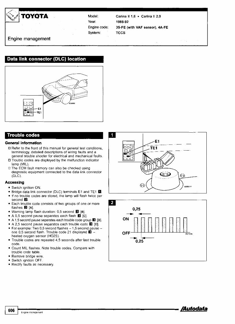
T OYOTA
I Engine management
Model: Carina 11 1,6 Carina 11 2,O
Year: 1988-92
Engine code: 3s-FE (with VAF sensor), 4A-FE
System: TCCS
General information Refer to the front of this manual for general test conditions, terminology, detailed descriptions of wiring faults and a general trouble shooter for electrical and mechanical faults. Trouble codes are displayed by the malfunction indicator lamp (MIL).
o The ECM fault memory can also be checked using diagnostic equipment connected to the data link connector (DLC).
Accessing Switch ignition ON. Bridge data link connector (DLC) terminals E l and TEI m. If no trouble codes are stored, the lamp will flash twice per second B. Each trouble code consists of two groups of one or more flashes Ef [A]. Warning lamp flash duration: 0,5 second Ef [B]. A 0,5 second pause separates each flash Ef [C]. A 1,5 second pause separates each trouble code group Ef [Dl. A 2,5 second pause separates each trouble code Ef [El. For example: Two 0,5 second flashes - 1,5 second pause - one 0,5 second flash. Trouble code 21 displayed Ef - heated oxygen sensor (H02S). Trouble codes are repeated 4,5 seconds after last trouble code. Count MIL flashes. Note trouble codes. Compare with trouble code table. Remove bridge wire. Switch ignition OFF. Rectify faults as necessary.
ON
1 OFF 5
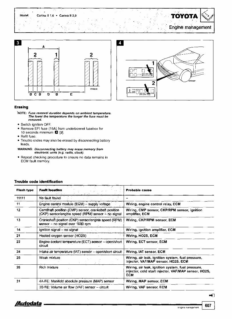
Erasing NOTE: Fuse removal duration depends on ambient temperature.
The lower the temperature the longer the fuse must be removed.
Switch ignition OFF. Remove EFI fuse (15A) from underbonnet fusebox for 10 seconds minimum [2]. Refit fuse. Trouble codes may also be erased by disconnecting battery leads.
WARNING: Disconnecting battery may erase memory from electronic units (e.g. radio, clock).
Repeat checking procedure to ensure no data remains in ECM fault memory.
14 I Ignition signal - no signal ( Wiring, ignition amplifier, ECM
Trouble code identification
Flash type
11111
11
12
13
24 I Intake air temperature (lAT) sensor - openlshort circuit I Wiring, IAT sensor, ECM
2 1
22
Fault locatlan
No fault found
Engine control module (ECM) - supply voltage
Camshaft position (CMP) sensor, crankshaft position (CKP) sensorlengine speed (RPM) sensor - no signal
Crankshaft position (CKP) sensorlengine speed (RPM) sensur - no signal over 1000 rpm
Probable cause
-
Wiring, engine control relay, ECM
Wiring, CMP sensor, CKPIRPM sensor, ignition amplifier, ECM
Wiring, CKPIRPM sensor, ECM
Heated oxygen sensor (H02S)
Engine codant temperature (ECT) sensor - openlshort circuit
Wiring, HOZS, ECM
Wiring, ECT sensor, ECM
Wiring, air leak, ignition system, fuel pressure, injector, VAFlMAP sensor, HOZS, ECM
Wiring, air leak, ignition system, fuel pressure, injector, cold start injector, VAFIMAP sensor, HOZS, ECM
I
31
25
26
Weak mixture
Rich mixture
4A-FE: Manifold absolute pressure (MAP) sensor
3s-FE: Volume air flow (VAF) sensor - circuit
Wiring, MAP sensor, ECM
Wiring, VAF sensor, ECM

TOYOTA Model: Carina 11 1,6 Carina 11 2,O
Engine management
Flash type I Faun loution Probable cause
42 I Vehicle speed sensor (VSS) I Wiring, VSS, ECM
32
41
I ) ,,me management [Autodata
Volume air flow WAF) sensor - circuit
Throttle position (TP) sensor
43
51
Wiring, VAF sensor, ECM
Wiring, TP sensor, ECM
4
Starter signal
Switch signal - AC switch ON during diagnosis
Switch signal - PNP switch not in P or N during diagnosis
Switch signal - throffle position (TP) sensor, NO closed throttle signal during diagnosis
Wiring, ignition switch, ECM
Wiring, AC switch, AC control module, ECM
Wiring, PNP switch, ECM
Wiring, TP sensor, ECM

Model: Carina E 1,611,812,O Carina E 2,0D Carina E 2,0D Turbo
Year: 1992-98
Engine code: 2C, 2C-T, 4A-FE, 7A-FE, 3s-FE, 3s-GE
System: TCCS
TOYOTA lgQ
Engine management
Engine bay, t H
General information Refer to the front of this manual for general test conditions, terminology, detailed descriptions of wiring faults and a general trouble shooter for electrical and mechanical faults. Trouble codes are displayed by the malfunction indicator lamp (MIL).
a Some models: The ECM fault memory can also be checked using diagnostic equipment connected to the data link connector (DLC).
Accessing
Normal mode Switch ignition ON. Bridge data link connector (DLC) terminals E l and TEI m. If no trouble codes are stored, the lamp will flash twice per second H. Each trouble code consists of two groups of one or more flashes El [A]. Warning lamp flash duration: 0,5 second El [B]. A 0,5 second pause separates each flash El [C]. A 1,5 second pause separates each trouble code group El [Dl. A 2,5 second pause separates each trouble code El [El. For example: Two 0,5 second flashes - 1,5 second pause - one 0,5 second flash. Trouble code 21 displayed El - heated oxygen sensor (H02S). Trouble codes are repeated 4,5 seconds after last trouble code. Count MIL flashes. Note trouble codes. Compare with trouble code table.
ON
OFF 5
Remove bridge wire. Switch ignition OFF. Rectify faults as necessary.

Model: Carina E 1,6/1,8/2,0 Carina E 2,O
M ^ M 4 d B C B D B E
Test mode Switch ignition OFF. Bridge data link connector (DLC) terminals E l and TE2 0. Switch ignition ON. Ensure malfunction indicator lamp (MIL) flashes four times per second. Start engine. Drive vehicle at over 6 mph (10 kmlh). Stop vehicle. Do not switch ignition OFF. With data link connector (DLC) terminals E l and TE2 bridged, bridge terminals E l and TEI 0. Count MIL flashes. Note trouble codes. Compare with trouble code table. Switch ignition OFF. Remove bridge wires. Rectify faults as necessary.
NOTE: Codes 42 and 43 may be produced if this procedure is NOT carried out correctly. Code 51 will be produced during this procedure and can be ignored.
Trouble code identification
Erasing NOTE: Fuse removal duration depends on ambient temperature.
The lower the temperature the longer the fuse must be removed.
Switch ignition OFF. Remove EFI fuse (15120A) from underbonnet fusebox for 10 seconds minimum. 1,6/1,8: El [I] . 2,O: El [2]. Refit fuse. Trouble codes may also be erased by disconnecting battery leads.
WARNING: Disconnecting battery may erase memory from electronic units (e.g. radio, clock).
Repeat checking procedure to ensure no data remains in ECM fault memory.
Flash type
11111
11
12
16 I Transmission control signal 1 Wiring, ECM
Fault b c d i n
No fault faund
13
14
18 I Supply voltage low/high I Wiring, battery, alternator, ECM
Probable cause
-
Engine control module (ECM) - defective
Crankshaft position (CKP) sensorlcamshaft position (CMP) sensor - no signal
2 1 I Heated oxygen sensor (H02S) I Wiring, H02S, ECM
ECM
Wiring, CKPfCMP sensor, ECM
Crankshaft position (CKP) sensor - no signal over idle
Ignition signal - no signal
22 Engine coolant temperature (ECT) sensor - I Wiring, ECT sensor, ECM o~enlshort circuit
Wiring, CKP sensor, ECM
Wiring, ignition amplifier, ECM
24 I Intake air temperature (IAT) sensor - openfshort Wiring, IAT sensor, ECM circuit

Model: Carina E 1,611,812,O Carina E 2,OD Carina E 2,0D Turbo
Engine management
Flash type
31 1 Manifold absolute pressure (MAP) sensor I Wiring, MAP sensor, ECM
25
33 I Idle air control (IAC) valve 1 Wiring, IAC valve, ECM
Fault location
41 I Throttle position (TP) sensor I Wiring, TP sensor, ECM
Probable cause
Weak mixture Wiring, air leak, fuel pressure, injector, MAP sensor, H02S, ignition system, ECM
51 I Switch signal - AC switch ON during diagnosis I Wiring, AC switch, AC control module, ECM
42
43
Switch signal - PNP switch not in P or N during Wiring, PNP switch, ECM diagnosis
Switch signal - throttle position (TP) sensor, / Wiring. TP sensor, ECM NO closed throttle signal during diagnosis
Vehicle speed sensor (VSS)
Starter signal
52 I Knock sensor (KS) I Wiring, KS, ECM
Wiring, VSS, ECM
Wiring, ignition switch, ECM
53
99
Knock control - malfunction
Immobilizer control system - malfunction
ECM
Wiring, immobilizer read coil amplifier, immobilizer read coil, immobilizer control module, ECM

Model: Avensis 1,611,8/2,0 Avensis 2,OD Turbo
Fascia
General information Refer to the front of this manual for general test conditions, terminology, detailed descriptions of wiring faults and a general trouble shooter for electrical and mechanical faults.
II Trouble codes are displayed by the malfunction indicator lamp (MIL). More detailed fault diagnosis information can be obtained using diagnostic equipment connected to the data link connector (DLC).
Accessing
Normal mode Switch ignition ON. Bridge data link connector (DLC) terminals 4 and 13 0. If no trouble codes are stored, the lamp will flash twice per second O. Each trouble code consists of two groups of one or more flashes rn [A]. Warning lamp flash duration: 0,5 second [B]. A 0,5 second pause separates each flash rn [C]. A 1,5 second pause separates each trouble code group rn [Dl. A 2,5 second pause separates each trouble code [El. For example: Two 0,5 second flashes - 1,5 second pause - one 0,5 second flash. Trouble code 21 displayed rn - heated oxygen sensor (H02S). Trouble codes are repeated 4,5 seconds after last trouble code. Count MIL flashes. Note trouble codes. Compare with trouble code table. Remove bridge wire. Switch ignition OFF. Rectify faults as necessary.
ON
OFF 5

Model: Avensis I,6/1,8/2,O Avensis 2,OD Turbo
Erasing Ensure ignition switched OFF. Remove EFI fuse (1 5A) from underbonnet fusebox for 10 seconds minimum El. Refit fuse. Diagnostic equipment can also be used to erase data from ECM fault memory.
Trouble code identification
Repeat accessing procedure to ensure trouble codes erased. Trouble codes may also be erased by disconnecting battery leads.
WARNING: Disconnecting the battery may erase memory from electronic units (e.g. radio, clock).
Flash type / BIP type I Fa& I Probable cause
-
11111
I 3 O I - Fuel injection pump position sensor - Wiring, fuel injection pump position sensor, ECM circuit malfunction during idling
12 0
12
12
13 0
PO
-
I 4 O I - Timing control system - matfunction Wiring, fuel filter, fuel injection timing solenoid, fuel injection pump, ECM
-
-
-
PI335
13
14 0
15 0 I PI310 ( Ignition coilfamplifier 2 - malfunction I Wiring, ignition coillamplifier, ECM
Refer to EQBD trouble code table
No fault found
- -
Crankshaft position (CKP) sensorf camshaft position (CMP) sensor - circuit malfunction
Crankshaft position (CKP) sensor - circuit malfunction
Camshaft position (CLIP) sensor - circuit malfunction
Crankshaft position (CKP) sensor - circuit malfunction during idling
-
PI300
18 1 - ( Fuel quantity adjuster - malfunction I Wiring, fuel quantity adjuster, ECM
Wiring, CKP sensor, CMP sensor, ECM
Wiring, CKP sensor, ECM
Wiring, CMP sensor, camshaft sprocket, ECM
Wiring, CKP sensor, starter, ECM
15
16
17
Crankshaft position (CKP) sensor - circuit malfunction
Ignition coilfamplifier 1 - malfunction
Wiring, CKP sensor, crankshaft sprocket, ECM
Wiring, ignition coillamplifier, ECM
-
- -
Throttle motor - circuit malfunction
Transmission control signal
Engine control module (ECM) - malfunction
Wiring, throttle motor, throttle body, ECM
Wiring, ECM
ECM

Model: Avensis 1,611,812,O Avensis 2,OD Turbo
Engine management
Flash type BIP type Fault location Probable cause
2 1 I - Heated oxygen sensor (H02S) 1, I Wiring, H02S. ECM bank 1 - circuit malfunction
19
26 I - I System too rich, bank 1
-
22
24
25
Fuel pressure, wiring, injector, H02S, MAP sensor, ECT sensor. ECM
Accelerator pedal position (APP) sensorlswitch - circuit malfunction
-
-
-
32 rn I - I Module coding plug - malfunction I Wiring, module coding plug, ECM
Wiring, accelerator pedal position (APP) sensor1 switch, ECM
31
31
Engine coolant temperature (ECT) sensor - circuit malfunction
Intake air temperature (IAT) sensor - circuit matfunction
System too lean, bank 1
35 I - I Manifold absolute pressure (MAP) Wiring, MAP sensor, MAP sensor control solenoid, sensor, TC system - circuit hoses blocked/disconnected, ECM malfunction
Wiring, ECT sensor, ECM
Wiring, IAT sensor, ECM
Air leak, fuel pressure, wiring, injector, H02S, MAP sensor. ECT sensor. ECM
-
-
32
33 0
33 rn
42 I - Vehicle speed sensor (WS) - circuit I Wiring, speedometer, VSS, ECM malfunction
Wiring, KS, ECM
s u r e fuel pump control solenoids,
Manifold absolute pressure (MAP) sensor - circuit malfunction
Mass air Row (MAF) sensor - circuit malfunction
- -
-
3s-FEl4A-FEl7A-FE rn 2C-TE H ICD-FTV
Wiring, MAP sensor, ECM
Wiring, MAF sensor, ECM
Injector - matfunction
Idle speed control (ISC) system - malfunction
Intake manifold air control solenoid 2 - malfunction
Wiring, injector, ECM
Wiring, IAC valve, ECM
Wiring, intake manifold air control solenoid 2, ECM

L -
Model: MR2 1,6 MR2 2,O
Year: 1985-00 TOYOTA
Engine code: 3s-FE, 3s-GE, 4A-GE
System: TCCS
Engine management
General information Refer to the front of this manual for general test conditions, terminology, detailed descriptions of wiring faults and a general trouble shooter for electrical and mechanical faults.
0 Trouble codes are displayed by the malfunction indicator lamp (MIL).
Accessing
4A-GE - without airflow meter Switch ignition ON. Bridge data link connector (DLC) terminals E l and TEI (T) a. If no trouble codes are stored, the lamp will flash once every 4,5 seconds O. Individual short flashes display trouble code El. Warning lamp flash duration: 0,5 second El [A]. A 0,5 second pause separates each flash El [B]. A 2,5 second pause separates each trouble code El [C]. For example: Trouble codes 2 and 4 displayed a. Trouble codes are repeated 4,5 seconds after last trouble code El [Dl. Count MIL flashes. Note trouble codes. Compare with trouble code table. Switch ignition OFF. Remove bridge wire. Rectify faults as necessary.
OFF

I Engine management
M - U J A B A C A B A B A B A D
3s-FEI3S-GE
Normal mode
Switch ignition ON. Bridge data link connector (DLC) terminals E l and TEI (T). -+1990: 0. 1990-+: 8. If no trouble codes are stored, the lamp will flash twice per second H. Each trouble code consists of two groups of one or more flashes H [A]. Warning lamp flash duration: 0,5 second H [B]. A 0,5 second pause separates each flash H [C]. A 1,5 second pause separates each trouble code group H [Dl. A 2,5 second pause separates each trouble code H [El. For example: Two 0,5 second flashes - 1 3 second pause - one 0,5 second flash. Trouble code 21 displayed H - heated oxygen sensor (H02S). Trouble codes are repeated 4 3 seconds after last trouble code. Count MIL flashes. Note trouble codes. Compare with trouble code table. Remove bridge wire. Switch ignition OFF. Rectify faults as necessary.
ON
OFF 5
Test mode 1994-+
Switch ignition OFF. Bridge data link connector (DLC) terminals E l and TE2 8. Switch ignition ON. Ensure malfunction indicator lamp (MIL) flashes four times per second. Start engine. Drive vehicle at over 6 mph (10 kmlh) to meet conditions of customer complaint. Stop vehicle. Do not switch ignition OFF. With data link connector (DLC) terminals E l and TE2 bridged, bridge terminals E l and TEI 8. Count MIL flashes. Note trouble codes. Compare with trouble code table. Switch ignition OFF. Remove bridge wires. Rectify faults as necessary.
NOTE: Codes 42 and 43 may be produced if this procedure is NOT carried out correctly. Code 51 will be produced during this procedure and can be ignored.

Model: MR2 1,6 MR2 2,O
Engine management
Erasing NOTE: Fuse removal duration depends on ambient temperature.
The lower the temperature the longer the fuse must be removed.
Switch ignition OFF. +1990: Remove AM2 fuse (7,5A) from underbonnet fusebox for 10 seconds minimum 0. 1990 +: Remove EFI fuse (1 5A) from underbonnet fusebox for 10 seconds minimum m. Refit fuse. Trouble codes may also be erased by disconnecting battery leads.
WARNING: Disconnecting battery may erase memory from electronic units (e.g. radio, clock).
Repeat checking procedure to ensure no data remains in ECM fault memory.
Trouble code identification
4A-GE - with manifold absolute pressure (MAP) sensor
Flash type I Fault location Probable cause
2 ( Manifold absolute pressure (MAP) sensor I Wiring, MAP sensor, ECM
I I
1 I No fault found
Crankshaft position (CKP) sensorlengine speed (RPM) Wiring, CKPIRPM sensor, ignition amplifier, ECM sensor - no signal
-
3
4
9 I Vehicle speed sensor (VSS) - signal I Wiring, VSS, ECM
Ignition amplifier - signal
Engine coolant temperature (ECT) sensor - openlshort circuit
7
8
10 I Starter signal I Wiring, ignition switch, ECM
Wiring, ignition amplifier, ECM
Wiring, ECT sensor, ECM
Throttle position (TP) sensor - open/sh& circuit -
Intake air temperature OAT) sensor - openlshort circuit
Wiring, TP sensor, ECM
Wiring, IAT sensor, ECM
11
Switch signal - throttle position (TP) sensor, NO closed throttle signal during diagnosis
Switch signal - AC switch ON during diagnosis
Switch signal - PNP switch not in P or N during diagnosis
Wiring, TP sensor, ECM
Wiring, AC switch, AC control module, ECM
Wiring, PNP switch, ECM
110

Model: MR2 1,6 MR2 2,O
3s-FE13S-GE and 4A-GE - with volume airflow (VAF) sensor I I
Flash type I FruH k c d o n I Probable cause
l3 I Crankshaft position (CKP) sensor - no signal over idle
11111
12
I Wiring, CKP sensor, ignition amplifier, ECM
I 1
14 I Ignition signal - no signat I Wiring, ignition amplifier, ECM
No fauft found
Crankshaft position (CKP) sensorlcamshaft position (CMP) sensor - no signal
I - 1 - -
16 I Transmission control sigrtal I Wiring, ECM
-
Wiring, CKPICMP sensor, ignition amplifier, ECM
21 Heated oxygen sensor (H02S) Wiring, H02S, ECM

Engine code: 4A-GE, 4A-FE, 7A-FE, 3S-GE, 3S-GTE
System: TCCS
Engine management
Model: Celica 1,6 Celica 1,8 Celica 2,O
Year: 1985-99 TOYOTA
1985-94 - engine bay, LH 1994-99 - engine bay, LH
General information 0 Refer to the front of this manual for general test conditions,
terminology, detailed descriptions of wiring faults and a general trouble shooter for electrical and mechanical faults. Trouble codes are displayed by the malfunction indicator lamp (MIL).
Accessing
4A-GE 1985-90 - with manifold absolute pressure (MAP) sensor
Switch ignition ON. Bridge data link connector (DLC) terminals E l and TEI (T) m. If no trouble codes are stored, the lamp will flash once every 4,5 seconds a. Individual short flashes display trouble code a. Warning lamp flash duration: 0,5 second [A]. A 0,5 second pause separates each flash [B]. A 2,5 second pause separates each trouble code El [C]. For example: Trouble codes 2 and 4 displayed El. Trouble codes are repeated 4,5 seconds after last trouble code El [Dl. Count MIL flashes. Note trouble codes. Compare with trouble code table. Switch ignition OFF. Remove bridge wire. Rectify faults as necessary.
OFF ,

Engine management I
~~~ A B A C A B A B A B A D
Except 4A-GE 1985-90 - with manifold absolute pressure (MAP) sensor
Normal mode
Switch ignition ON. Bridge data link connector (DLC) terminals E l and TEI (T). +1994: 0. 19944: 0. If no trouble codes are stored, the lamp will flash twice per second H. Each trouble code consists of two groups of one or more flashes rn [A]. Warning lamp flash duration: 0,5 second fl [B]. A 0,5 second pause separates each flash rn [C]. A 1,5 second pause separates each trouble code group [Dl. A 2,5 second pause separates each trouble code rn [El. For example: Two 0,5 second flashes - 1,5 second pause - one 0,5 second flash. Trouble code 21 displayed fl - heated oxygen sensor (H02S). Trouble codes are repeated 4,5 seconds after last trouble code. Count MIL flashes. Note trouble codes. Compare with trouble code table. Remove bridge wire. Switch ignition OFF. Rectify faults as necessary.
Test mode 1992 +
Switch ignition OFF. Bridge data link connector (DLC) terminals E l and TE2. +I 994: 0. 1994 +: 0. Switch ignition ON. Ensure malfunction indicator lamp (MIL) flashes four times per second. Start engine. Drive vehicle at over 6 mph (10 kmlh) to meet conditions of customer complaint. Stop vehicle. Do not switch ignition OFF. With data link connector (DLC) terminals E l and TE2 bridged, bridge terminals E l and TEI 0. Count MIL flashes. Note trouble codes. Compare with trouble code table. Switch ignition OFF. Remove bridge wires. Rectify faults as necessary.
NOTE: Codes 42 and 43 may be produced if this procedure is NOT carried out correctly. Code 51 will be produced during this procedure and can be ignored.
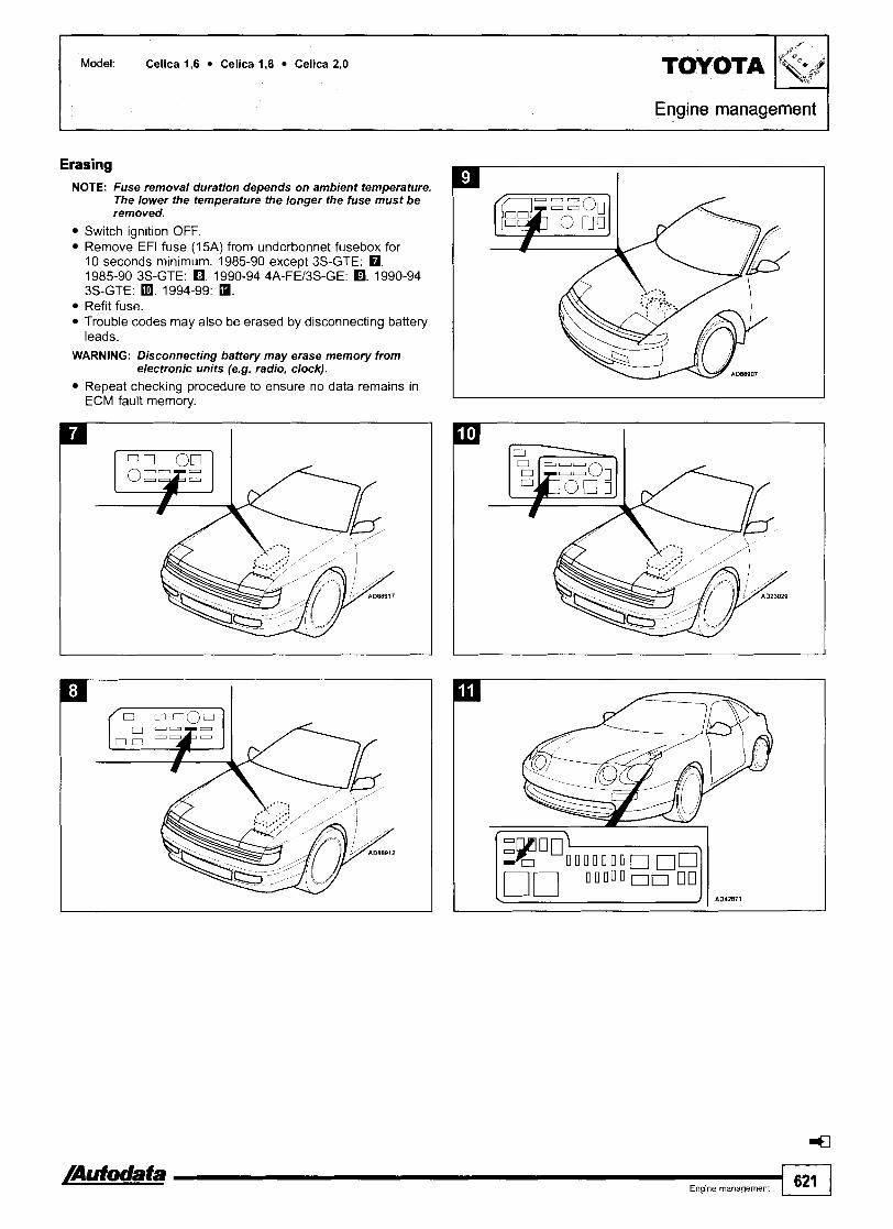
I Model: Celica 1,6 Celica 1,8 Celica 2,O
Engine management 1
Erasing NOTE: Fuse removal duration depends on ambient temperature.
The lower the temperature the longer the fuse must be removed.
Switch ignition OFF. Remove EFI fuse (15A) from underbonnet fusebox for 10 seconds minimum. 1985-90 except 3s-GTE: 0. 1985-90 3s-GTE: 0. 1990-94 4A-FEMS-GE: m. 1990-94 3s-GTE: m. 1994-99: m. Refit fuse. Trouble codes may also be erased by disconnecting battery leads.
WARNING: Disconnecting battery may erase memory from electronic units (e.g. radio, clock).
Repeat checking procedure to ensure no data remains in ECM fault memory.

Model: Celica 1,6 Celica 1,8 Celica 2,O
Engine management
Trouble code identification
4A-GE 1985-90 - with manifold absolute pressure (MAP) sensor
Flash type Fault location Probable cause
1 1 No fault found I - 2 I Manifold absolute pressure (MAP) sensor I Wiring, MAP sensor, ECM
3 1 Ignition amplifier - signal I Wiring, ignition amplifier, ECM
4 Engine coolant temperature (ECT) sensor - openlshort Wiring, ECT sensor, ECM I circuit
6 Crankshaft position (CKP) sensorlengine speed (RPM) Wiring, CKPIRPM sensor, ignition amplifier, ECM sensor - no signal
10 1 Starter signal I Wiring, ignition switch, ECM
7
8
9
Throttle position (TP) sensor - openlshort circuit
Intake air temperature (IAT) sensor - openlshoFt circuit
Vehicle speed sensor (VSS) - signal
I I
Wiring, TP sensor, ECM
Wiring, IAT sensor, ECM
Wiring, VSS, ECM
Except 4A-GE 1985-90 - with manifold absolute pressure (MAP) sensor
l2 1 Crankshaft position (CKP) sensorlcamshaft position I Wiring, CKPlCMP sensor, ignition amplifier, ECM (CMP) sensor - no signal
Switch signal - AC switch ON during diagnosis
Switch signal - PNP switch not in P or N during diagnosis
Switch signal - throffle position (TP) sensor, NO closed throttle signal during diagnosis
11111
11
I I
13 I Crankshaft position (CKP) sensor - no signal over idle I Wiring, CKP sensor, ignition amplifier, ECM
Wiring, AC switch, AC control module, ECM
Wiring, PNP switch, ECM
Wiring, TP sensor, ECM
Probable cause Flash type Fault locatlon
No fault found
Engine control module (ECM) - power suppty
-
Wiring, ignition switch, engine control relay, ECM
14 I Ignition signai - no signal Wiring, ignition amplifier, ECM
16
I circuit
21
22
Transmission control signal Wiring, ECM
Heated oxygen sensor (H02S)
Engine coolant temperature (ECT) sensor - openlshort
24
25
26
31
Wiring, H02S, ECM
Wiring, ECT sensor, ECM
Intake air temperature (IAT) sensor - openlshort circuit
Weak mixture
Rich mixture
Manifold absolute pressure [MAP) sensat- - circuit
Volume air flow (VAF) mmr - circuit
Wiring, IAT sensor, ECM
Wiring, air leak, ignition system, fuel pressure, injector, VAF sensor, ECT sensor, IAT sensor, 02SIH02S, ECM
Wiring, ignition system, fuel pressure, injector, cold start injector, VAF sensor, ECT sensor, IAT sensor, 02SIH02S, ECM
Wiring, MAP sensor, ECM
Wiring, VAF sensor, ECM

Flash type
32 I Volume air flow (VAF) sensor
34 I Turbocharger (TC) pressure - high I Wiring, turbocharger, MAP sensor, ECM
F a i t location
Wiring, VAF sensor, ECM
33 I Idle air conbol (IAC) valve
coolant pump, turbocharger intercooler coolant level sensor, turbocharger intercooler modulelrelay,
read coil immobilizer control module ECM
Probable cause
Wiring, IAC valve, ECM
- a a Englne management 823

1 TOYOTA
Engine management
Model: Supra 3,OlTurbo
Year: 1993-97
Engine code: 2JZ-GTE, 7M-GE, 7M-GTE
System: TCCS
I
Type 1 - engine bay, LH
General information 0 Refer to the front of this manual for general test conditions,
terminology, detailed descriptions of wiring faults and a general trouble shooter for electrical and mechanical faults.
0 Trouble codes are displayed by the malfunction indicator lamp (MIL).
Accessing
Normal mode Switch ignition ON. Bridge data link connector (DLC) terminals E l and TEI LI 111 or PI . If no trouble codes are stored, the lamp will flash twice per second O. Each trouble code consists of two groups of one or more flashes rn [A]. Warning lamp flash duration: 0,5 second El [B]. A 0,5 second pause separates each flash [C]. A 1,5 second pause separates each trouble code group El [Dl. A 2,5 second pause separates each trouble code rn [El. For example: Two 0,5 second flashes - 1,5 second pause - one 0,5 second flash. Trouble code 21 displayed rn - heated oxygen sensor (H02S) 1. Trouble codes are repeated 4,5 seconds after last trouble code. Count MIL flashes. Note trouble codes. Compare with trouble code table. Remove bridge wire. Switch ignition OFF. Rectify faults as necessary.
I
Qpe 2 - under fascia, driver's side
ON
OFF 5

Engine management
Model: Supra 3,Ofrurbo TOYOTA
Test mode Switch ignition OFF. Bridge data link connector (DLC) terminals E l and TE2 PI. Switch ignition ON. Ensure malfunction indicator lamp (MIL) flashes four times per second. Start engine. Drive vehicle to meet conditions of customer complaint. Stop vehicle. Do not switch ignition OFF. With data link connector (DLC) terminals E l and TE2 bridged, bridge terminals E l and TEI H. Count MIL flashes. Note trouble codes. Compare with trouble code table. Switch ignition OFF. Remove bridge wires. Rectify faults as necessary.
NOTE: Code 43 may be produced if this procedure is NOT carried out correctly. Code 51 will be produced during this procedure and can be ignored.
P
Trouble code identification
Erasing NOTE: Fuse removal duration de~ends on ambient tem~erature.
The lower the temperature the longer the fuse nhst be removed.
Switch ignition OFF. Remove EFI no. 1 fuse (30A) from underbonnet fusebox for 10 seconds minimum 8. Refit fuse. Trouble codes may also be erased by disconnecting battery leads.
WARNING: Disconnecting battery may erase memory from electronic units (e.g. radio, clock).
Repeat checking procedure to ensure no data remains in ECM fault memory.
I Probable cause
11111 I No fault found I -
14 I Ignition signal - no signal I Wiring, ignition amplifier, ECM
12
13
24 ( Intake air temperature (IAT) sensor - openlshort circuit I Wiring, IAT sensor, ECM
Crankshaft position (CKP) sensor, camshaft position (CMP) sensor 1 8 2 - no signal
Crankshaft position (CKP) sensor, camshaft position (CMP) sensor 1 8 2 - no sianal over 1000 mm
16
21
22
25 I Weak mixture I Wiring, H02S 1, ignition system, ECM
Wiring, CKP sensor, CMP sensor I & 2, starter motor, ECM
Wiring, valve timing, CKP sensor, CMP sensor I & 2. ECM
Transmission control signal
Heated oxygen sensor (H02S) 1
Engine coolant temperature (ECT) sensor - openlshort circuit
-I Eng~ne management 625
Wiring, ECM
Wiring, H02S 1, ECM
Wiring, ECT sensor, ECM
27
3 1
-
Heated oxygen sensor (H02S) 2
Mass air flow (MAFI sensor - shodopen circuit
Wiring, H02S 2, ECM
Wiring, MAF sensor, ECM

Located on main throttle butterfly Located on sub-throttle butterfly

Model: Picnic 2,O Picnic 2,2D Turbo
Year: 1996-00 TOYOTA
Engine code: 3C-TE, 3S-FE
System: TCCS
Engine management
I
Type 1 - engine bay, LH
General information 0 Refer to the front of this manual for general test conditions,
terminology, detailed descriptions of wiring faults and a general trouble shooter for electrical and mechanical faults. Trouble codes are displayed by the malfunction indicator lamp (MIL).
0 More detailed fault diagnosis information can be obtained using diagnostic equipment connected to the data link connector (DLC).
Accessing
Normal mode Switch ignition ON. Type 1: Bridge data link connector (DLC) terminals E l and TEI m. Type 2: Bridge data link connector (DLC) terminals 4 and 13 0. If no trouble codes are stored, the lamp will flash twice per second Q. Each trouble code consists of two groups of one or more flashes rn [A]. Warning lamp flash duration: 0,5 second rn [B]. A 0,5 second pause separates each flash rn [C]. A 1,5 second pause separates each trouble code group rn [Dl. A 2,5 second pause separates each trouble code rn [El. For example: Two 0,5 second flashes - 1,5 second pause - one 0,5 second flash. Trouble code 21 displayed - heated oxygen sensor (H02S). Trouble codes are repeated 4,5 seconds after last trouble code. Count MIL flashes. Note trouble codes. Compare with trouble code table. Remove bridge wire. Switch ignition OFF. Rectify faults as necessary.
L
Type 2 - under fascia, drfver's side
A t a t a a Engme management 8n ' I -

Model: Picnic 2,O Picnic 2,2D Turbo
Engine management
ON
OFF 95
Test mode - type 1 Switch ignition OFF. Bridge data link connector (DLC) terminals E l and TE2 0. Switch ignition ON. Ensure malfunction indicator lamp (MIL) flashes four times per second. Start engine. Drive vehicle at over 6 mph (10 kmlh) to meet conditions of customer complaint.
Stop vehicle. Do not switch ignition OFF. With data link connector (DLC) terminals E l and TE2 bridged, bridge terminals E l and TEI El. Count MIL flashes. Note trouble codes. Compare with trouble code table. Switch ignition OFF. Remove bridge wires. Rectify faults as necessary.
NOTE: Codes 42 and 43 may be produced if this procedure is NOT carried out correctly. Code 51 will be produced during this procedure and can be ignored.
Erasing Ensure ignition switched OFF. Remove EFI fuse (15A) from underbonnet fusebox for 10 seconds minimum m. Refit fuse. Diagnostic equipment can also be used to erase data from ECM fault memory. Repeat accessing procedure to ensure trouble codes erased. Trouble codes may also be erased by disconnecting battery leads.
WARNING: Disconnecting the battery may erase memory from electronic units (e.g. radio, clock).
Trouble code identification I I
Flash type I Fault location I Probable cause
I l l 1 1
12 El
I 3 O 1 Fuel injection pump position sensor - circuit Wiring, fuel injection pump position sensor, ECM matfunction
12 0
13 0
14 I Ignition millamplifier 1 - malfunction I Wiring, ignition coillamplifier, ECM
No fault found
Crankshaft position (CKP) sensorlcamshaft ~osit ion ICMPl sensor - circuit malfunction
-
Wiring, CKP sensor, CMP sensor, ECM
Crankshaft position (CKP) sensor - circuit malfunction
Crankshaft position (CKP) sensor - no signal over 1000 mm
Wiring, CKP sensor, ECM
Wiring, CKP sensor, ECM

Engine management
Model: Picnic 2,0 Picnic 2,2D Turbo TOYOTA /
9'
Flash type
14 0
15 0 15 0
18 I Fuel quantity adjuster - malfunction I Wiring, fuel quantity adjuster, ECM
Fault loeation
16
17
Accelerator pedal position (APP) sensor1 Wiring, accelerator pedal position (APP) sensor/switch, switch - circuit malfunction 1 ECM
Probable cause
riming control system - malfunction
Ignition coillamplifier 2 - malfunction
Throttle control circuit - malfunction
Wiring, fuel filter, fuel injection timing solenoid, fuel injection pump, ECM
Wiring, ignition coillamplifier, ECM
Wiring, EGR throttle control valve, TP sensor, EGR throttle control actuator, throttle body, vacuum hose blocked1 disconnected, ECM
Transmission control signal
Engine control module (ECM) - malfunction
lntake air temperature (IAT) sensor - openlshort circuit
Wiring, ECM
ECM
2 1
22
I Wiring. IAT sensor, ECM
Heated oxygen sensor (H02S)
Engine coolant temperature (ECT) sensor - openlshort circuit
31 I Manifold absolute pressure (MAP) sensor I Wiring, MAP sensor, ECM
Wiring, H02S, ECM
Wiring, ECT sensor, ECM
25
32 I Module coding plug - malfunction I Wiring, module coding plug, ECM 1 I
33 0 1 Idle air control (IAC) valve I Wiring, IAC valve, ECM
Weak mixture Wiring, air leak, fuel pressure, ignition system, injector, MAP sensor, H02S, ECM
35 Manifold absolute pressure (MAP) sensor, Wiring, MAP sensor, MAP sensor control solenoid, hoses TC system - circuit malfunction blockedldisconnected, ECM
33 0
39 I Fuel temperature sensor - circuit malfunction I Wiring, fuel temperature sensor, ECM
41 I Throttle position (TP) sensor 1 Wiring, TP sensor, ECM
Intake manifold air control solenoid - malfunction
42 Vehicle speed sensor (VSS) - circuit malfunction
-
Wiring, intake manifold air control solenoid, ECM
I Wiring, speedometer, VSS, ECM
43 1 Starter signal I Wiring, ignition switch, ECM
51 I Switch signal - AC switch ON during diagnosis I Wiring, AC switch, AC control module, ECM
47
Switch signal - PNP switch not in P or N during Wiring, PNP switch, ECM diagnosis
Throttle position (TP) sensor
89 I Engine control module (ECM) - malfunction I ECM
Wiring, TP sensor, ECM
52
Switch signal - throffle position (TP) sensor, NO closed throttle signal during diagnosis
Knock sensor (KS)
99
Wiring, TP sensor, ECM
Wiring, KS, ECM
Immobilizer control system - malfunction Wiring, immobilizer read coil amplifier, immobilizer read coil, immobilizer control module, ECM

TOYOTA Model: Previa 2,4 Year: 1990-04100
Engine code: 2TZ-FE
System: TCCS
Engine management
E l TE2 gg@, TEl(T) TSTC
General information Refer to the front of this manual for general test conditions, terminology, detailed descriptions of wiring faults and a general trouble shooter for electrical and mechanical faults. Trouble codes are displayed by the malfunction indicator lamp (MIL). 1996+: The ECM fault memory can also be checked using diagnostic equipment connected to the data link connector (DLC).
Accessing
Normal mode Switch ignition ON. Bridge data link connector (DLC) terminals E l and TEI. +I 996: 0. I996 +: 0. If no trouble codes are stored, the lamp will flash twice per second El. Each trouble code consists of two groups of one or more flashes rn [A]. Warning lamp flash duration: 0,5 second [B]. A 0,5 second pause separates each flash [C]. A 1 3 second pause separates each trouble code group rn [Dl. A 2,5 second pause separates each trouble code rn [El. For example: Two 0,5 second flashes - 1 3 second pause - one 0,5 second flash. Trouble code 21 displayed rn - heated oxygen sensor (H02S). Trouble codes are repeated 4 3 seconds after last trouble code. Count MIL flashes. Note trouble codes. Compare with trouble code table. Remove bridge wire. Switch ignition OFF. Rectify faults as necessary.
630 I Engme management [Autodata

Model: Previa 2,4
ON
OFF 5
Erasing NOTE: Fuse removal duration de~ends on ambient tem~erature.
The lower the temperature the longer the fuse must be removed.
Switch ignition OFF. Remove EFI fuse (15A) from underbonnet fusebox for 30 seconds minimum a. Refit fuse. Trouble codes may also be erased by disconnecting battery leads.
WARNING: Disconnecting battery may erase memory from electronic units (e.g. radio, clock).
Repeat checking procedure to ensure no data remains in ECM fault memory.
Test mode I996 4
Switch ignition OFF. Bridge data link connector (DLC) terminals E l and TE2 0. Switch ignition ON. Ensure malfunction indicator lamp (MIL) flashes four times per second. Start enaine. Drive vehicle at over 6 mph (10 kmlh) to meet conditions of customer complaint. Stop vehicle. Do not switch ignition OFF. With data link connector (DLC) terminals E l and TE2 bridged, bridge terminals E l and TE1 0. Count MIL flashes. Note trouble codes. Compare with trouble code table. Switch ignition OFF. Remove bridge wires. Rectify faults as necessary.
NOTE: Code 42 will be produced when vehicle speed is 6 mph (10 km/h) or less and can be ignored.
/Autodata Engme management 834

I=a management
Trouble code identification
Flash type / Fault locatbn Probable cause
11111 1 No fault found I -
14 I Ignition signal - no signal I Wiring, ignition amplifier, ignition coil, ECM
12
13
Camshafi position (CMP) sensor, crankshaft position (CKP) sensorlengine speed (RPM) sensor - no signal
Crankshaft position (CKP) sensorlengine speed (RPM) sensor - no signal over 1000 rpm
16
21
22
Wiring, CMP sensor, CKPIRPM sensor, ignition amplifier, ECM
Wiring, CKPIRPM sensor, ignition amplifier, ECM
24
25
31 1 -1996: Volume air flow (VAF) sensor - circuit I Wiring, VAF sensor, ECM
Transmission control signal
Heated oxygen sensor (H02S)
Engine coolant temperature (ECT) sensor - openlshort circuit
26
27
Wiring, ECM
Wiring, H02S, ECM
Wiring, ECT sensor, ECM
Intake air temperature (IAT) sensor - openlshort circuit
Weak mixture
41 I Throttle position (TP) sensor I Wiring, TP sensor, ECM
Wiring, IAT sensor, ECM
Wiring, air leak, ECT sensor, IAT sensor, ignition system, fuel pressure, injector, VAFIMAP sensor, H02S102S. ECM
Rich mixture
Oxygen sensor (02s)
32
33
42 I Vehicle speed sensor (VSS) - circuit malfunction I Wiring, speedometer, VSS, ECM
Wiring, ECT sensor, IAT sensor, fuel pressure, injector, cold start injector, VAF sensor, H02S102S, ECM
Wiring, 02S, ECM
1996+: Manifold absolute pressure (MAP) sensor
Volume air flow (VAF) sensor - circuit
Idle air control (IAC) valve
Switch signal - throttle position (TP) sensor, I Wiring, TP sensor, ECM NO closed throttle signal during diagnosis
Wiring, MAP sensor, ECM
Wiring, VAF sensor, ECM
Wiring, IAC valve, ECM
-
43
51
- -
Starter signal
Switch signal - AC switch ON during diagnosis
Switch signal - PNP switch not in P or N during diagnosis
Wiring, ignition switch, ECM
Wiring, AC switch, AC control module, ECM
Wiring, PNP switch, ECM
-
Wiring, KS, ECM
ECM
52
53
99
--
Knock sensor (KS)
Knock control - malfunction
4
Immobilizer control system - malfunction Wiring, immobilizer read coil amplifier, immobilizer read coil, immobilizer control module, ECM

I Model: RAV4
Year: 1994-00
Engine code: 3s-FE
System: TCCS
TOYOTA I
Engine management
Underbonnet, RH
General information 0 Refer to the front of this manual for general test conditions,
terminology, detailed descriptions of wiring faults and a general trouble shooter for electrical and mechanical faults. Trouble codes are displayed by the malfunction indicator lamp (MIL). Some models: The ECM fault memory can also be checked using diagnostic equipment connected to the data link connector (DLC).
Accessing
Normal mode
Switch ignition ON. Bridge data link connector (DLC) terminals E l and TEI n. If no trouble codes are stored, the lamp will flash twice per second m. Each trouble code consists of two groups of one or more flashes El [A]. Warning lamp flash duration: 0,5 second [B]. A 0,5 second pause separates each flash El [C]. A 1,5 second pause separates each trouble code group El [Dl. A 2,5 second pause separates each trouble code [El. For example: Two 0,5 second flashes - 1,5 second pause - one 0,5 second flash. Trouble code 21 displayed El - heated oxygen sensor (H02S). Trouble codes are repeated 4 3 seconds after last trouble code. Count MIL flashes. Note trouble codes. Compare with trouble code table. Remove bridge wire. Switch ignition OFF. Rectify faults as necessary.
ON
OFF 95

Test mode Switch ignition OFF. Bridge data link connector (DLC) terminals E l and TE2 0. Switch ignition ON. Ensure malfunction indicator lamp (MIL) flashes four times per second. Start engine. Drive vehicle at over 6 mph (10 kmlh) to meet conditions of customer complaint. Stop vehicle. Do not switch ignition OFF. With data link connector (DLC) terminals E l and TE2 bridged, bridge terminals E l and TEI m. Count MIL flashes. Note trouble codes. Compare with trouble code table. Switch ignition OFF. Remove bridge wires. Rectify faults as necessary.
NOTE: Codes 42 and 43 may be produced if this procedure is NOT carried out correctly. Code 51 will be produced during this procedure and can be ignored.
Trouble code identification
Flash type
Erasing NOTE: Fuse removal duration depends on ambient temperature.
The lower the temperature the longer the fuse must be removed.
Switch ignition OFF. Remove EFI fuse (15A) from underbonnet fusebox for 10 seconds minimum m. Refit fuse. Trouble codes may also be erased by disconnecting battery leads.
WARNING: Disconnecting battery may erase memory from electronic units (e.g. radio, clock).
Repeat checking procedure to ensure no data remains in ECM fault memory.
Fault location Probable cause
No fault found -
Crankshafl position (CKP) sensor - no signal over 1500 rprn
Crankshafl position (CKP) sensor - no signal over 1000 rmn
Crankshafl position (CKP) sensorlcamshafl position (CMP) sensor - no signal
Crankshaft position (CKP) sensor/carnshafl position (CMP) sensor - no signal
Wiring, CKP sensor, ignition amplifier, ECM
Wiring, CKPlCMP sensor, ignition amplifier, ECM
Wiring, CKPICMP sensor, ECM
Wiring, CKP sensor, ECM
Ignition signal - no signal I Wiring, ignition amplifier, ECM
Heated oxygen sensor (H02S) I Wiring, HOZS, ECM
Ignition coillamplfier 1 - malfunction
Ignition coillamplifier 2 - malfunction
Transmission control signal
Wiring, ignition coillamplifier, ECM
Wiring, ignition coillamplifier, ECM
Wiring, ECM

Engine management
Model: RAV4 TOYOTA
Flash type I Fault losition
<#
I Probable cause
31 1 Manifold absolute pressure (MAP) sensor ( Wiring, MAP sensor, ECM
22
24
25
43 I Starter signal I Wiring, ignition switch, ECM
Engine coolant temperature (ECT) sensor - openlshort circuit
Intake air temperature (IAT) sensor - openlshort circuit
Weak mixture
33
41
42
Wiring, ECT sensor, ECM
Wiring, IAT sensor, ECM
Wiring, air leak, ECT sensor, IAT sensor, ignition system, fuel pressure, injector, MAP sensor, H02S, ECM
Switch signal - throttle position (TP) sensor, Wiring, TP sensor, ECM NO closed throttle signal during diagnosis 1
idle air control (IAC) valve
Throttle position (TP) sensor
Vehicle speed sensor (VSS) - circuit malfunction
Switch signal - AC switch ON during diagnosis
Switch signal - PNP switch not in P or N during diagnosis
Wiring, IAC valve, ECM
Wiring, TP sensor, ECM
Wiring, speedometer, VSS, ECM
Wiring, AC switch, AC control module, ECM
Wiring, PNP switch, ECM
52
99
Knock sensor (KS)
Immobilizer control system - malfunction
Wiring, KS, ECM
Wiring, immobilizer read coil amplifier, immobilizer read coil, immobilizer control module, ECM

Model: Carina E
Transmission r Year: 1992-98
Underbannet, LH
General information 0 Refer to the front of this manual for general test conditions,
terminology, detailed descriptions of wiring faults and a general trouble shooter for electrical and mechanical faults.
0 Trouble codes are displayed by the 'OID OFF' warning lamp.
Accessing Switch ignition ON. Check operation of 'OlD OFF' lamp. Switch the OID switch on the gear lever to ON. Check that 'OID OFF' lamp extinguishes. Bridge data link connector (DLC) terminals E l and TEI n. If no trouble codes are stored, the lamp will flash twice per second Q. Each trouble code consists of two groups of one or more flashes rn [A]. Warning lamp flash duration: 0,5 second rn [B]. A 0,5 second pause separates each flash rn [C]. A 1,5 second pause separates each trouble code group rn [Dl. A 2,5 second pause separates each trouble code [El. For example: Four 0,5 second flashes - 1,5 second pause - two 0,5 second flashes. Trouble code 42 displayed rn - vehicle speed sensor (VSS) 1. Trouble codes are repeated 4,5 seconds after last trouble code. Count warning lamp flashes. Compare with trouble code table. Remove bridge wire. Switch ignition OFF. Rectify faults as necessary.
ON
OFF 5
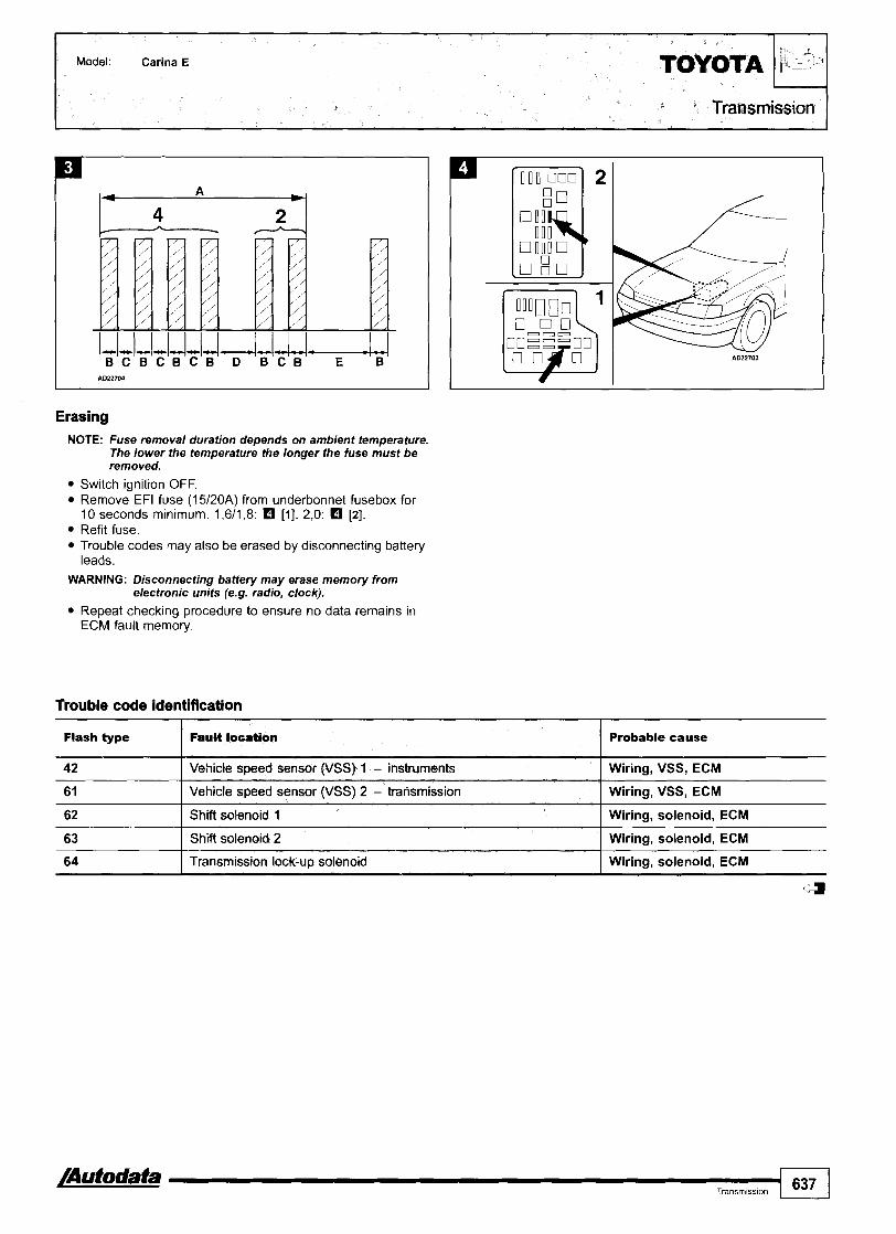
Model: Carina E
Transmission
1 1
u- B C B C B C B D B C B E B
Erasing NOTE: Fuse removal duration depends on ambient temperature.
The lower the temperature the longer the fuse must be removed.
Switch ignition OFF. Remove EFI fuse (15120A) from underbonnet fusebox for 10 seconds minimum. 1,6/1,8: El [I] . 2,O: El [2]. Refit fuse. Trouble codes may also be erased by disconnecting battery leads.
WARNING: Disconnecting battery may erase memory from electronic units (e.g. radio, clock).
Repeat checking procedure to ensure no data remains in ECM fault memory.
Trouble code identification I I
Flash type I F ~ U W location I Probable cause
42 I Vehicle speed sensor (VSS) 1 - instruments I Wiring, VSS, ECM
63 I Shift solenoid 2 I Wiring, solenoid, ECM
61
62
/Autodata --I Transmission 637
Vehicle speed sensor (VSS) 2 - transmission
Shift solenoid 1
64
Wiring, VSS, ECM
Wiring, solenoid, ECM
'Y
Transmission lock-up solenoid Wiring, solenoid, ECM

Model:
I Year:
Transmission
Avensis
Fascia
NOTE: Engine control module (ECM) incorporates transmission control function.
General information Refer to the front of this manual for general test conditions, terminology, detailed descriptions of wiring faults and a general trouble shooter for electrical and mechanical faults.
o Trouble codes are displayed by the 'OID OFF' warning lamp. 0 More detailed fault diagnosis information can be obtained
using diagnostic equipment connected to the data link connector (DLC).
Accessing Switch ignition ON. Check operation of 'OID OFF' lamp. Switch the OID switch on the gear lever to ON. Check that 'OID OFF' lamp extinguishes. Bridge data link connector (DLC) terminals 4 and 13 0. If no trouble codes are stored, the lamp will flash twice per second O. Each trouble code consists of two groups of one or more flashes El [A]. Warning lamp flash duration: 0,5 second El [B]. A 0,5 second pause separates each flash El [C]. A 1,5 second pause separates each trouble code group El [Dl. A 2,5 second pause separates each trouble code El [El. For example: Four 0,5 second flashes - 1,5 second pause - two 0,5 second flashes. Trouble code 42 displayed - vehicle speed sensor (VSS) 1. Trouble codes are repeated 4,5 seconds after last trouble code. Count warning lamp flashes. Compare with trouble code table. Remove bridge wire. Switch ignition OFF. Rectify faults as necessary.
ON
OFF 5

Erasing Ensure ignition switched OFF. Remove EFI fuse (15A) from underbonnet fusebox for 10 seconds minimum D. Refit fuse. Diagnostic equipment can also be used to erase data from ECM fault memory. Repeat accessing procedure to ensure trouble codes erased. Trouble codes may also be erased by disconnecting battery leads.
WARNING: Disconnecting the battery may erase memory from electronic units (e.g. radio, clock).
Trouble code identification

Model: Celica 2,O I Transmission r
1985-94 - underbonnet, LH 19Q4-99 - underbonnet, LH
NOTE: 1990-r: Engine control module (ECM) incorporates transmission control function.
General information Refer to the front of this manual for general test conditions, terminology, detailed descriptions of wiring faults and a general trouble shooter for electrical and mechanical faults. Trouble codes are displayed by the 'OID OFF' warning lamp.
Accessing Switch ignition ON. Check operation of 'OlD OFF' lamp. Switch the OID switch on the gear lever to ON. Check that 'OID OFF' lamp extinguishes. 1985-90: Bridge data link connector (DLC) terminals E l and ECT 0. 1990 +: Bridge data link connector (DLC) terminals E l and TEA. 1990-94: 0. 1994 +: 0. If no trouble codes are stored, the lamp will flash twice per second O. Each trouble code consists of two groups of one or more flashes rn [A]. Warning lamp flash duration: 0,5 second rn [B]. A 0,5 second pause separates each flash rn [C]. A 1,5 second pause separates each trouble code group rn [Dl. A 2,5 second pause separates each trouble code rn [El. For example: Four 0,5 second flashes - 1,5 second pause - two 0,5 second flashes. Trouble code 42 displayed - vehicle speed sensor (VSS) 1. Trouble codes are repeated 4,5 seconds after last trouble code. Count warning lamp flashes. Compare with trouble code table. Remove bridge wire. Switch ignition OFF. Rectify faults as necessary.

ON
OFF A079095
Erasing NOTE: Fuse removal duration depends on ambient temperature.
The lower the temperature the longer the fuse must be removed.
Switch ignition OFF. 1985-90: Remove fuse RADIO no. 1 (15A) from underbonnet fusebox for 10 seconds minimum a. 1990 +: Remove EFI fuse (1 5A) from underbonnet fusebox for 10 seconds minimum. 1990-94: H. 1994-99: 0. Refit fuse. Trouble codes may also be erased by disconnecting battery leads.
WARNING: Disconnecting battery may erase memory from electronic units (e.g. radio, clock).
Repeat checking procedure to ensure no data remains in ECM fault memory.
Trouble code identification
Flash type
42
I Wiring, solenoid, TCM I
6 1
62
63 I Shift solenoid 2 I Wiring, solenoid, TCM
Fault k*cation
Vehicle speed sensor (VSS) 1 - instruments
Vehicle speed sensor ( ,
Shift solenoid 1
Probable cause
Wiring, VSS, TCM
YSS) 2 - transmission Wiring, VSS, TCM
64
64 rn Shift solenoid 3
Transmission lock-up solenoid
Wiring, solenoid, TCM
Wiring, solenoid, TCM

Transmission r Model: Picnic
Year: 1996-00
System: TCCS
Underbonnet, LH
NOTE: Engine control module (ECM) incorporates transmission control function.
General information Refer to the front of this manual for general test conditions, terminology, detailed descriptions of wiring faults and a general trouble shooter for electrical and mechanical faults. Trouble codes are displayed by the 'OID OFF' warning lamp.
Accessing Switch ignition ON. Check operation of 'OlD OFF' lamp. Switch the OID switch on the gear lever to ON. Check that 'OlD OFF' lamp extinguishes. Bridge data link connector (DLC) terminals E l and TEI m. If no trouble codes are stored, the lamp will flash twice per second O. Each trouble code consists of two groups of one or more flashes [A]. Warning lamp flash duration: 0,5 second El [B]. A 0,5 second pause separates each flash El [C]. A 1,5 second pause separates each trouble code group El [Dl. A 2,5 second pause separates each trouble code El [El. For example: Four 0,5 second flashes - 1,5 second pause - four 0,5 second flashes. Trouble code 44 displayed El - vehicle speed sensor (VSS) 1 - malfunction. Trouble codes are repeated 4,5 seconds after last trouble code. Count warning lamp flashes. Compare with trouble code table. Remove bridge wire. Switch ignition OFF. Rectify faults as necessary.
ON
OFF 5
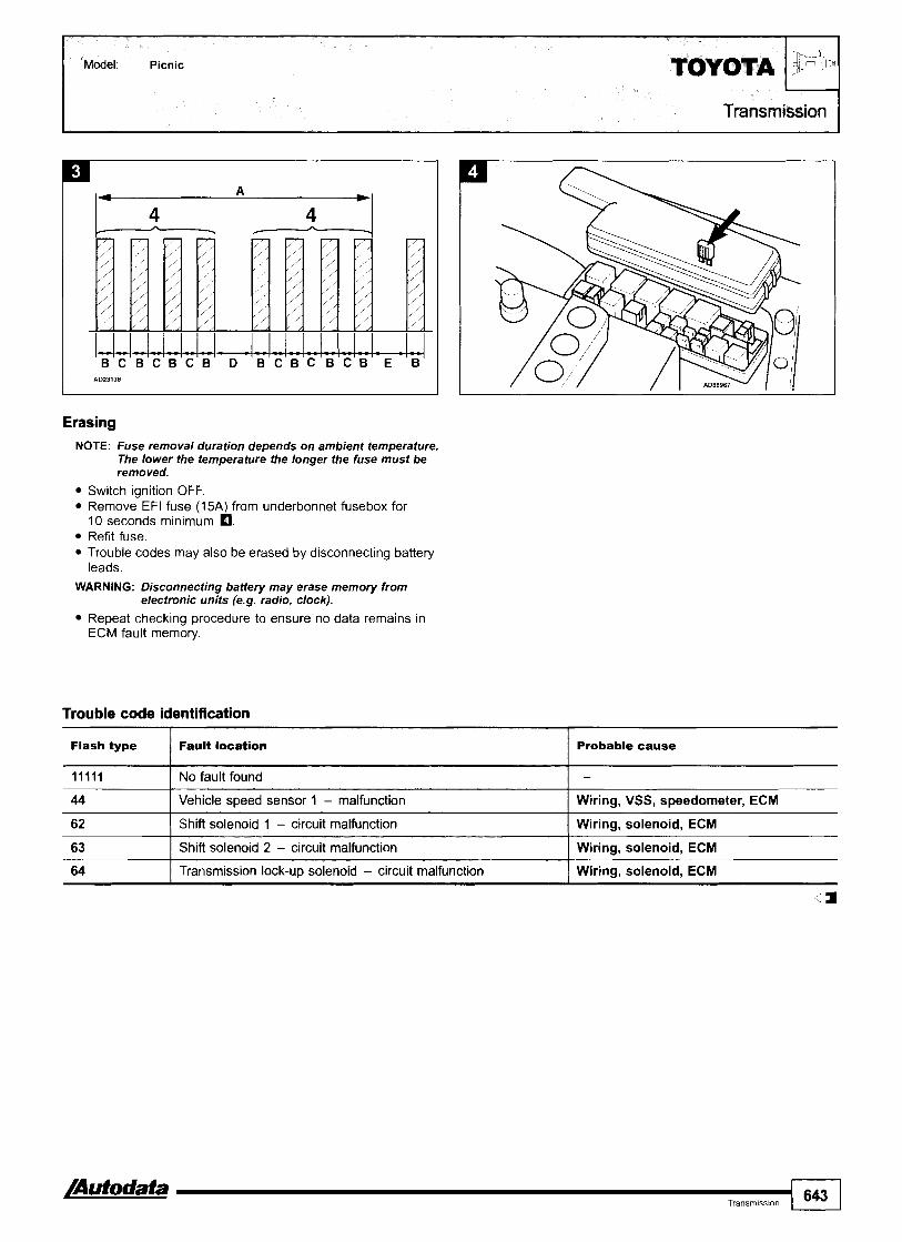
Transmission 7
ulw- B C B C B C B D B C B C B C B E B
Erasing NOTE: Fuse removal duration depends on ambient temperature.
The lower the temperature the longer the fuse must be removed.
Switch ignition OFF. Remove EFI fuse (15A) from underbonnet fusebox for 10 seconds minimum m. Refit fuse. Trouble codes may also be erased by disconnecting battery leads.
WARNING: Disconnecting battery may erase memory from electronic units (e.g. radio, clock).
Repeat checking procedure to ensure no data remains in ECM fault memory.
Trouble code identification
Flash type I Fault loution I Probable cause
44 I Vehicle speed sensor I - malfunction I Wiring, VSS, speedometer, ECM
I I
62 ( Shift solenoid 1 - circuit malfunction I Wiring, solenoid, ECM
11111 I No fault found -
63
64
Shift solenoid 2 - circuit malfunction
Transmission lock-up solenoid - circuit malfunction
Wiring, solenoid, ECM
Wiring, solenoid, ECM

d$i TEl(T) TSTC
NOTE: Engine control module (ECM) incorporates transmission control function.
General information Refer to the front of this manual for general test conditions, terminology, detailed descriptions of wiring faults and a general trouble shooter for electrical and mechanical faults. Trouble codes are displayed by the 'OID OFF' warning lamp.
Accessing Switch ignition ON. Check operation of 'OlD OFF' lamp. Switch the OID switch on the gear lever to ON. Check that 'OID OFF' lamp extinguishes. Bridge data link connector (DLC) terminals E l and TEI. +1996: El. I996 +: 0. If no trouble codes are stored, the lamp will flash twice per second O. Each trouble code consists of two groups of one or more flashes [A]. Warning lamp flash duration: 0,5 second rn [B]. A 0,5 second pause separates each flash rn [C]. A 1,5 second pause separates each trouble code group rn [Dl. A 2,5 second pause separates each trouble code [El. For example: Four 0,5 second flashes - 1,5 second pause - two 0,5 second flashes. Trouble code 42 displayed rn - vehicle speed sensor (VSS) 1. Trouble codes are repeated 4,5 seconds after last trouble code. Count warning lamp flashes. Compare with trouble code table. Remove bridge wire. Switch ignition OFF. Rectify faults as necessary.

Model: Previa
ON
OFF s
1 - B C B C B C B D B C B E B
Trouble code identification
Erasing NOTE: Fuse removal duration depends on ambient temperature.
The lower the temperature the longer the fuse must be removed.
Switch ignition OFF. Remove EFI fuse (15A) from underbonnet fusebox for 10 seconds minimum m. Refit fuse. Trouble codes may also be erased by disconnecting battery leads.
WARNING: Disconnecting battery may erase memory from electronic units (e.g. radio, clock).
Repeat checking procedure to ensure no data remains in ECM fault memory.
Flash type I Ault M i o n Probable cause
42 I Vehicle speed sensor (VSSf I - instruments I Wiring, VSS, ECM
61 ( Vehicle speed sensor (VSS) 2 - transmission I Wiring, VSS, ECM
62
63
64
Shift solenoid I
Shift solenoid 2
Transmission lock-up solenoid
Wiring, solenoid, ECM
Wiring, solenoid, ECM
Wiring, solenoid, ECM

Model: RAV4
Year: 1994-00 I
Transmission
Engine code: 3s-FE System: TCCS
NOTE: Engine control module (ECM) incorporates transmission control function.
General information Refer to the front of this manual for general test conditions, terminology, detailed descriptions of wiring faults and a general trouble shooter for electrical and mechanical faults. Trouble codes are displayed by the 'OID OFF' warning lamp.
Accessing Switch ignition ON. Check operation of 'OlD OFF' lamp. Switch the OID switch on the gear lever to ON. Check that 'OID OFF' lamp extinguishes. Bridge data link connector (DLC) terminals E l and TEI D. If no trouble codes are stored, the lamp will flash twice per second H. Each trouble code consists of two groups of one or more flashes rn [A]. Warning lamp flash duration: 0,5 second rn [B]. A 0,5 second pause separates each flash rn [C]. A 1 3 second pause separates each trouble code group rn [Dl. A 2,5 second pause separates each trouble code rn [El. For example: Four 0,5 second flashes - 1,5 second pause - four 0,5 second flashes. Trouble code 44 displayed rn - transmission output shaft speed sensor 1 - malfunction. Trouble codes are repeated 4 3 seconds after last trouble code. Count warning lamp flashes. Compare with trouble code table. Remove bridge wire. Switch ignition OFF. Rectify faults as necessary.
ON
OFF 95

Model: RAV4
Transmission
Erasing NOTE: Fuse removal duration depends on ambient temperature.
The lower the temperature the longer the fuse must be removed.
Switch ignition OFF. Remove EFI fuse (1 5A) from underbonnet fusebox for 10 seconds minimum m. Refit fuse. Trouble codes may also be erased by disconnecting battery leads.
WARNING: Disconnecting battery may erase memory from electronic units (e.g. radio, clock).
Repeat checking procedure to ensure no data remains in ECM fault memory.
Trouble code identification I I I Probable cause
11111 I No fault found I -
Transmission output shaft speed sensor 1 rear - malfunction
Wiring, transmission output shaft speed sensor, I ECM
Transmission output shaft speed sensor 2 front - malfunction
Wiring, transmission output shaft speed sensor, I ECM
62 I Shift solenoid 1 - circuit malfunction I Wiring, solenoid, ECM
Atodata I Transm~ss~on 647
-
Wiring, solenoid, ECM
Wiring, solenoid, ECM
63
64
73
77
- - - -
Shift solenoid 2 - circuit malfunction
Transmission lock-up solenoid - circuit malfunction
Central differential clutch control solenoid - circuit malfunction
Transmission fluid pressure (TFP) solenoid - circu~t malfunction
Wiring, solenoid, ECM
Wiring, solenoid, ECM

[I] - SOHC - engine bay, LH
[2] - DOHG - engine bay, LH
General information Refer to the front of this manual for general test conditions, terminology, detailed descriptions of wiring faults and a general trouble shooter for electrical and mechanical faults. rouble codes are displayed by using an analogue voltmeter connected to the data link connector (DLC).
Accessing Ensure ignition switched OFF Remove ignition key. Connect analogue voltmeter between data link connector (DLC) terminals as follows: Connect voltmeter negative (-) terminal to DLC terminal E l O. Connect voltmeter positive (+) terminal to DLC terminal OP3 0.
NOTE: An LED with an activation current of 10-20 mA can also be used.
Insert ignition key. Count voltmeter needle deflections. Note trouble codes. Compare with trouble code table. If no trouble codes are output: Check fuses. Each trouble code consists of two groups of one or more needle deflections rn. A 1,5 second pause separates each trouble code group rn [C]. Voltmeter needle deflection duration: 0,5 second rn [A]. A 0,5 second pause separates each deflection rn [B]. A 2,5 second pause separates each trouble code rn [Dl. A 4,5 second pause follows the last trouble code, before they are repeated. Rectify faults as necessary.
- .
l - - u J - U - u ~ ~ ~ ~ ~ A B A B A C A B A D A B A B A C
Erasing Rectifying faults erases trouble codes.

Trouble code identification NOTE: Trouble codes 11-22 DO NOT indicate a fault condition
and should be output if conditions are met.
immobilizer control module
33
34
4
Ignition key - incorrect signal
Immobilizer control module - insufficient memory
Ignition key not matchedldamaged, immobilizer read coil amplifier, immobilizer control module
Immobilizer control module

Model: Corolla
Year: 1995-01100
Underbonnet, LH
General information Refer to the front of this manual for general test conditions, terminology, detailed descriptions of wiring faults and a general trouble shooter for electrical and mechanical faults.
n Trouble codes are displayed by using an analogue voltmeter connected to the data link connector (DLC).
Accessing Ensure ignition switched OFF. Remove ignition key. Connect analogue voltmeter between data link connector (DLC) terminals as follows: Connect voltmeter negative (-) terminal to DLC terminal E l
[I1 and 121. +1997: Connect voltmeter positive (+) terminal to DLC terminal OP3 rn [I]. 1997+: Connect voltmeter positive (+) terminal to DLC terminal OP1 0 121.
NOTE: An LED with an activation current of 10-20 mA can also be used.
Insert ignition key. Count voltmeter needle deflections. Note trouble codes. Compare with trouble code table. If no trouble codes are output: Check fuses. Each trouble code consists of two groups of one or more needle deflections H. A 1 3 second pause separates each trouble code group H [CI. Voltmeter needle deflection duration: 0,5 second H [A]. A 0,5 second pause separates each deflection [B]. A 2,5 second pause separates each trouble code [Dl. A 4 3 second pause follows the last trouble code, before they are repeated. Rectify faults as necessary.
Erasing Rectifying faults erases trouble codes.

Model: Corolla TOYOTA I Immobilizer
Trouble code identification NOTE: Trouble codes 11-22 DO NOT indicate a fault condition
and should be output if conditions are met.
Flash type I h u l location I Probable cause
1 I
2 1 I Master key (black) - inserted 1 Immobilizer deactivated
12
13
lgnition key inserted into ignition switch
lgnition key - no communication
NO code output: Wiring, ignition key warning switch, irnrnobilizer control module
Any door is open
Ignition switched ON
22
31
I Wiring, immobilizer read coil, immobilizer read coil amplifier, irnrnobilizer control module
NO code output: Wiring, door contact switch, irnrnobilizer control module
NO code output: Wiring, IGN fuse, immobilizer control module
lgnition key - incorrect signal
Sub key (grey) - inserted
Ignition key - incorrect programming
I -- -
lgnition key not matchedldamaged, immobilizer read coil amplifier, irnrnobilizer control module
Immobilizer deactivated
Ignition key not matched
34 I Immobilizer control module - insufficient memorv 1 Immobilizer control module

Year: 1995-98 I Immobilizer
General information 0 Refer to the front of this manual for general test conditions,
terminology, detailed descriptions of wiring faults and a general trouble shooter for electrical and mechanical faults. Trouble codes are displayed by using an analogue voltmeter connected to the data link connector (DLC).
Accessing Ensure ignition switched OFF. Remove ignition key. Connect analogue voltmeter between data link connector (DLC) terminals as follows: Connect voltmeter negative (-) terminal to DLC terminal E l 0. Connect voltmeter positive (+) terminal to DLC terminal OP1 0.
NOTE: An LED with an activation current of 10-20 mA can also be used.
Insert ignition key. Count voltmeter needle deflections. Note trouble codes. Compare with trouble code table. If no trouble codes are output: Check fuses. Each trouble code consists of two groups of one or more needle deflections O. A 1 3 second pause separates each trouble code group rn [C]. Voltmeter needle deflection duration: 0,5 second rn [A]. A 0,5 second pause separates each deflection rn [B]. A 2,5 second pause separates each trouble code rn [Dl. A 4 3 second pause follows the last trouble code, before they are repeated. Rectify faults as necessary.
I L - . / L U A d ~ - - U ~ ~ ~ A B A B A C A B A D A B A B A C
Erasing Rectifying faults erases trouble codes.

Trouble code identification NOTE: Trouble codes 11-22 DO NOT indicate a fault condition
and should be output if conditions are met.
Flash type
11
12
13
2 1
22
3 1
34 I Immobilizer control module - insufficient memory Immobilizer control module
Ignition key - no communication
Ignition key - incorrect signal
51 I Fuel shut-off solenoid control module - code learning I Normal code
Fault loeatlon
Ignition key inserted into ignition switch
Any door is open
Ignition switched ON
Master key (black) - inserted
Sub key (grey) - inserted
Ignition key - incorrect programming
Wiring, immobilizer read coil, immobilizer read coil amplifier, immobilizer control module
Ignition key not matchedldamaged, immobilizer read coil amplifier, immobilizer control module
Probable cause
NO code output: Wiring, ignition key warning switch, immobilizer control module
NO code output: Wiring, door contact switch, immobilizer control module
NO code output: Wiring, IGN fuse, immobilizer control module
Immobilizer deactivated
Immobilizer deactivated
Ignition key not matched
52
53
54
55
rn Diesel: The fuel shut-off solenoid control module and the immobilizer control module must be replaced as a set. a
Fuel shut-off solenoid control modute - deactivated
Fuel shut-off solenoid control module - incorrect signal
56
57
58
Normal code
Wiring, immobilizer control module, fuel shut-off solenoid control module rn
Fuel shut-off solenoid control module - incorrect signal
Fuel shut-off solenoid control module - incorrect signal
Wiring, immobilizer control module, fuel shut-off solenoid control module rn Wiring, immobilizer control module, fuel shut-off solenoid control module rn
Fuel shut-off solenoid control module - incorrect signal
Fuel shut-off solenoid control module - defective
Fuel shut-off solenoid control module - not responding
Wiring, immobilizer control module, fuel shut-off solenoid control module rn Wiring, immobilizer control module, fuel shut-off solenoid control module rn Wiring, immobilizer control module, fuel shut-off solenoid control module rn
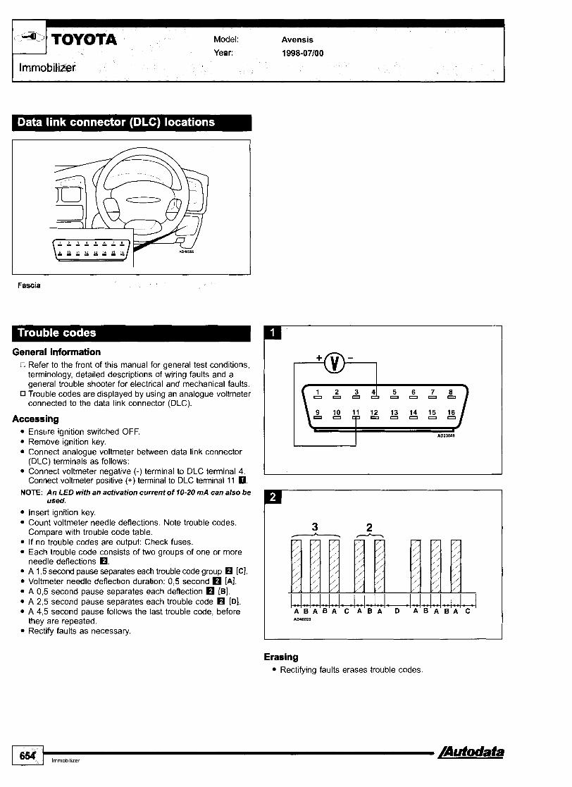
Model: Avensis I Immobilizer r Year:
Fascia
General information o Refer to the front of this manual for general test conditions,
terminology, detailed descriptions of wiring faults and a general trouble shooter for electrical and mechanical faults. Trouble codes are displayed by using an analogue voltmeter connected to the data link connector (DLC).
Accessing Ensure ignition switched OFF. Remove ignition key. Connect analogue voltmeter between data link connector (DLC) terminals as follows: Connect voltmeter negative (-) terminal to DLC terminal 4. Connect voltmeter positive (+) terminal to DLC terminal 11 0.
NOTE: An LED with an activation current of 10-20 mA can also be used.
Insert ignition key. Count voltmeter needle deflections. Note trouble codes. Compare with trouble code table. If no trouble codes are output: Check fuses. Each trouble code consists of two groups of one or more needle deflections O. A 1,5 second pause separates each trouble code group H [Cl. Voltmeter needle deflection duration: 0,5 second [A]. A 0,5 second pause separates each deflection [B]. A 2,5 second pause separates each trouble code H [Dl. A 4,5 second pause follows the last trouble code, before they are repeated. Rectify faults as necessary.
Erasing Rectifying faults erases trouble codes

lmmobilizer I Model: Avensis TOYOTA
Trouble code identification
- NOTE: Trouble codes 11-22 DO NOT indicate a fault condition
and should be output if conditions are met.
Flash type Fault locatson Probable cause
Ignition key inserted into ignition switch
Any door is open
NO code output: Wiring, ignition key warning switch, immobilizer control module
NO code output: Wiring, door contact switch, immobilizer control module
Ignition switched ON
Master key (black) - inserted
Sub key (grey) - inserted
Ignition key - incorrect prwramming
lmmobilizer control module - insufficient memorv I lmmobilizer control module
NO code output: Wiring, IGN fuse, immobilizer control module
Immobilizer deactivated
Immobilizer deactivated
Ignition key not matched
Ignition key - no communication
Ignition key - incorrect signal
Wiring, immobilizer read coil, immobilizer read coil amplifier, immobilizer control module
Ignition key not matchedldamaged, immobilizer read coil amplifier, immobilizer control module

RH engine bay
General information Refer to the front of this manual for general test conditions, terminology, detailed descriptions of wiring faults and a general trouble shooter for electrical and mechanical faults.
n Trouble codes are displayed by using an analogue voltmeter connected to the data link connector (DLC).
Accessing Ensure ignition switched OFF. Remove ignition key. Connect analogue voltmeter between data link connector (DLC) terminals as follows: Connect voltmeter negative (-) terminal to DLC terminal E l . 18-pin: m. 23-pin: 0. Connect voltmeter positive (+) terminal to DLC terminal. 18-pin: OP1 m. 23-pin: OP3 0.
NOTE: An LED with an activation current of 10-20 mA can also be used.
Insert ignition key. Count voltmeter needle deflections. Note trouble codes. Compare with trouble code table. If no trouble codes are output: Check fuses. Each trouble code consists of two groups of one or more needle deflections rn. A 1,5 second pause separates each trouble code group rn [C]. Voltmeter needle deflection duration: 0,5 second rn [A]. A 0,5 second pause separates each deflection rn [B]. A 2,5 second pause separates each trouble code rn [Dl. A 4 3 second pause follows the last trouble code, before they are repeated. Rectify faults as necessary.

- .
1--1-1444J.I..ISM-M A B A B A C A B A D A B A B A C
Erasing Rectifying faults erases trouble codes.
Trouble code identification NOTE: Trouble codes 11-22 DO NOT indicate a fault condition
and should be output if conditions are met.

T OWTA Model: Celica Year: 1995-99
Immobilizer
I
Underbonnet, LH
General information 0 Refer to the front of this manual for general test conditions,
terminology, detailed descriptions of wiring faults and a general trouble shooter for electrical and mechanical faults. Trouble codes are displayed by using an analogue voltmeter connected to the data link connector (DLC).
Accessing Ensure ignition switched OFF. Remove ignition key. Connect analogue voltmeter between data link connector (DLC) terminals as follows: Connect voltmeter negative (-) terminal to DLC terminal E l m. Connect voltmeter positive (+) terminal to DLC terminal OP3 I
NOTE: An LED with an activation current of 10-20 rnA can also be used.
Insert ignition key. Count voltmeter needle deflections. Note trouble codes. Compare with trouble code table. If no trouble codes are output: Check fuses. Each trouble code consists of two groups of one or more needle deflections O. A 1,5 second pause separates each trouble code group rn [C]. Voltmeter needle deflection duration: 0,5 second rn [A]. A 0,5 second pause separates each deflection [Bl. A 2,5 second pause separates each trouble code rn [D]. A 4,5 second pause follows the last trouble code, before they are repeated. Rectify faults as necessary.
Erasing Rectifying faults erases trouble codes.

Trouble code identification
Model: Celica ToYoTA
NOTE: Trouble codes 11-22 DO NOT indicate a fault condition and should be output if conditions are met.
I I
(1 gx;
Flash type I Feuit location I Probable cause
Immobilizer
NO code output: Wiring, door contact switch, immobilizer control module
11 Ignition key inserted into ignition switch
13
NO code output: Wiring, ignition key warning switch, immobilizer control module
2 1 ( Master key (black) - inserted
Ignition switched ON
Immobilizer deactivated
22
31
32
NO code output: Wiring, IGN fuse, immobilizer control module
33
34
Sub key (grey) - inserted
tgnition key - incorrect programming
Ignition key - no communication
Immobilizer deactivated
Ignition key not matched
Wiring, immobilizer read coil, immobilizer read coil amplifier, immobilizer control module
Ignition key - incorrect signal
Immobilizer control module - insufficient mmory
Ignition key not matchedldamaged, immobilizer read coil amplifier, immobilizer control module
Immobilizer control module

General Information 0 Refer to the front of this manual for general test conditions,
terminology, detailed descriptions of wiring faults and a general trouble shooter for electrical and mechanical faults. Trouble codes are displayed by using an analogue voltmeter connected to the data link connector (DLC).
Accessing Ensure ignition switched OFF. Remove ignition key. Connect analogue voltmeter between data link connector (DLC) terminals as follows: Type 1: Connect voltmeter negative (-) terminal to DLC terminal 4. Connect voltmeter positive (+) terminal to DLC terminal 11 0. Type 2: Connect voltmeter negative (-) terminal to DLC terminal E l . Connect voltmeter positive (+) terminal to DLC terminal OP1 m.
NOTE: An LED with an activation current of 10-20 mA can also be used.
Insert ignition key. Count voltmeter needle deflections. Note trouble codes. Compare with trouble code table. If no trouble codes are output: Check fuses. Each trouble code consists of two groups of one or more needle deflections a. A 1,5 second pause separates each trouble code group [C]. Voltmeter needle deflection duration: 0,5 second El [A]. A 0,5 second pause separates each deflection [B]. A 2,5 second pause separates each trouble code [Dl. A 4,5 second pause follows the last trouble code, before they are repeated. Rectify faults as necessary.

Erasing Rectifying faults erases trouble codes.
Trouble code identification NOTE: Trouble codes 11-22 DO NOT indicate a fault condition
and should be output if conditions are met.
Flash type Fault location Probable cause
11
12
13
Ignition key inserted into ignition switch
I I
33 I Ignition key - incorrect signa Ignition key not matchedldamaged, immobilizer read coil amelifier. immobilizer control module
NO code output: Wiring, ignition key warning switch, immobilizer control module
Any door is open
Ignition switched ON
2 1
22
3 1
32
NO code output: Wiring, door contact switch, immobilizer control module
NO code output: Wiring, IGN fuse, immobilizer control module
Master key (black) - inserted
Sub key (grey) - inserted
Ignition key - incorrect programming
Ignition key - no communication
I I
Immobilizer deactivated
Immobilizer deactivated
Ignition key not matched
Wiring, immobilizer read coil, immobilizer read coil amplifier, immobilizer control module
34 Immobilizer mtrol module - insufficient memory Immobilizer control module

Model:
.
Previa 1 Year: 1996-04100
Immobilizer
General information 0 Refer to the front of this manual for general test conditions,
terminology, detailed descriptions of wiring faults and a general trouble shooter for electrical and mechanical faults.
0 Trouble codes are displayed by using an analogue voltmeter connected to the data link connector (DLC).
Accessing Ensure ignition switched OFF. Remove ignition key. Connect analogue voltmeter between data link connector (DLC) terminals as follows: Connect voltmeter negative (-) terminal to DLC terminal E l m. Connect voltmeter positive (+) terminal to DLC terminal OP3 0.
NOTE: An LED with an activation current of 10-20 mA can also be used.
Insert ignition key. Count voltmeter needle deflections. Note trouble codes. Compare with trouble code table. If no trouble codes are output: Check fuses. Each trouble code consists of two groups of one or more needle deflections m. A 1,5 second pause separates each trouble code group [C]. Voltmeter needle deflection duration: 0,5 second [A]. A 0,5 second pause separates each deflection [Bl. A 2,5 second pause separates each trouble code [Dl. For example: Three 0,5 second flashes - 1,5 second pause - two 0,5 second flashes. Trouble code 32 displayed - ignition key - no communication.
3 2 - - W 4 d 4 J U A B A B A C A B A D A B A B A C AD46028
A 4,5 second pause follows the last trouble code, before they are repeated. Erasing Rectify faults as necessary. Rectifying faults erases trouble codes.

Model: Previa TOYOTA [-9 '
Immobilizer 4 Trouble code identification
NOTE: Trouble codes 11-22 DO NOT indicate a fault condition and should be output if conditions are met,
I I Flash type Fault location I I Probable cause
11
12
I lgnition key - no communication
13
21
22
3 1
I Wiring, immobilizer read coil, immobilizer read coil amplifier, immobilizer control module
Ignition key inserted into ignition switch
Any door is open
NO code output: Wiring, ignition key warning switch, immobilizer control module
NO code output: Wiring, door contact switch, immobilizer control module
Ignition switched ON
Master key (black) - inserted
Sub key (grey) - inserted
Ignition key - incorrect programming
NO code output: Wiring, IGN fuse, immobilizer control module
Immobilizer deactivated
Immobilizer deactivated
Ignition key not matched
33
34
Ignition key - incorrect signal
Immobilizer control module - insufficient memory
Ignition key not matchedldamaged, immobilizer read coil amplifier, immobilizer control module
Immobilizer control module

General information Refer to the front of this manual for general test conditions, terminology, detailed descriptions of wiring faults and a general trouble shooter for electrical and mechanical faults. Trouble codes are displayed by using an analogue voltmeter connected to the data link connector (DLC).
Accessing Ensure ignition switched OFF. Remove ignition key. Connect analogue voltmeter between data link connector (DLC) terminals as follows: Connect voltmeter negative (-) terminal to DLC terminal E l 8. Connect voltmeter positive (+) terminal to DLC terminal OP3 0.
NOTE: An LED with an activation current of 10-20 mA can also be used.
Insert ignition key. Count voltmeter needle deflections. Note trouble codes. Compare with trouble code table. If no trouble codes are output: Check fuses. Each trouble code consists of two groups of one or more needle deflections O. A 1,5 second pause separates each trouble code group [C]. Voltmeter needle deflection duration: 0,5 second w [A]. A 0,5 second pause separates each deflection [B]. A 2,5 second pause separates each trouble code w [Dl. For example: Three 0,5 second deflection - 1,5 second pause - two 0,5 second deflections. Trouble code 32 displayed - ignition key - no communication. A 4 3 second pause follows the last trouble code, before they are repeated. Rectify faults as necessary.
I I A I L I A B A B A C A B A D A B A B A C
Erasing Rectifying faults erases trouble codes.
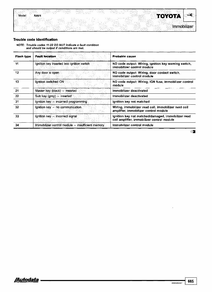
Trouble code identification NOTE: Trouble codes 11-22 DO NOT indicate a fault condition
and should be output if conditions are met.
Flash type
11
12
13
2 1
22
31
32
33
34
4
Fault location
Ignition key inserted into ignition switch
Any door is open
Ignition switched ON
Master key (black) - inserted
Sub key (grey) - inserted
Ignition key - incorrect programming
Ignition key - no communication
Ignition key - incorrect signal
Immobilizer control module - insufficient memory
Probable cause
NO code output: Wiring, ignition key warning switch, immobilizer control module
NO code output: Wiring, door contact switch, immobilizer control module
NO code output: Wiring, IGN fuse, immobilizer control module
Immobilizer deactivated
Immobilizer deactivated
Ignition key not matched
Wiring, immobilizer read coil, immobilizer read coil amplifier, immobilizer control module
Ignition key not matchedldamaged, immobilizer read coil amplifier, immobilizer control module
Immobilizer control module

VAUXHALL-OP E L Model: Agila 1,011,2 ~ s t r a - G 1,2 Astra-G 2,0 Turbo SpeedsterNX220 2,O Turbo Vectra-C 1,813,2
Engine management
Year: 2000-04
Engine code: 21 OXE, Z l 2XE, 21 8XE, Z18XEL, ZPOLET, Z32SE
System: Bosch Motronic ME1.5.51M3.11 Siemens Sirntec 71.5
Agila
General information Refer to the front of this manual for general test conditions, terminology, detailed descriptions of wiring faults and a general trouble shooter for electrical and mechanical faults.
Accessing and erasing The engine control module (ECM) fault memory can only be accessed and erased using diagnostic equipment connected to the data link connector (DLC).

Model: Agila 1,011,2 Astra-G 1,2 Astra-G 2,O Turbo SpeedsterNX220 2,0 Turbo ~ectra-c 1,8/3,2 OPEL-VAUXHALL
Engine management I Trouble code identification
-
Wiring, BARO sensor
Wiring, MAP sensor, ECM
EOBD type
PO
PI105
Refer to EOBD trouble code table
Barometric pressure (BARO) sensor - circuit malfunction
PI110 I Intake manifold air control solenoid 1 - circuit matfunction I Wirina, intake manifold air control solenoid
Fault location
PI106
P l l l l ( tntake manifold air control solenoid 2 - circuit rnaltlmction I Wiring, intake manifold air control solenoid
Probable cause
Manifold absolute pressure (MAP) sensor - circuit malfunction
, I
PI120 ( Accelerator pedal position (APP) sensor A - circuit I Wiring, APP sensor
P I 130 I Heated oxygen sensor (H02S) 1, bank 1 - malfunction 1 Wiring, H02S
PI122
PI300 I Fuel tank empty I Wiring, fuel gauge tank sensor, fuel tank empty
malfunction
Accelerator pedal position (APP) sensor B - circuit malfunction
PI170
PI230
PI243
-
Wiring, APP sensor
Wiring, knock sensor (KS), ECM
Mixture control (PAC), bank 1 - malfunction
Engine control relay - circuit malfunction
Turbocharger (TC) regulating solenoid - circuit malfunction
P I 326
PI327 ( Knock control, cylinder 2 - control limit reached I Wiring, knock sensor (KS), ECM
Fuel system, intake system
Wiring, engine control relay
Wiring, TC regulating solenoid, ECM
Knock control, cylinder 1 - control limit reached
PI328 1 Knock control, cylinder 3 - control limit reached I Wiring, knock sensor (KS), ECM
PI329 1 Knock control, cylinder 4 - control limit reached I Wiring, knock sensor (KS), ECM
PI372 1 Crankshaft position (CKP) sensor - malfunction I Wiring, CKP sensor
PI405 Exhaust gas recirculation (EGR) valve position sensor - Wiring, EGR valve position sensor malfunction
PI481 I Engine coolant blower motor relay 1 - malfunction I Wiring, engine coolant blower motor relay
PI482 1 Engine coolant blower motor relay 2 - malfunction I Wiring, engine coolant blower motor relay
PI483 1 Engine coolant blower motor relay 3 - malfunction I Wiring, engine coolant blower motor relay
PI501 Immobilizer control module - program error I lmmobilizer control module incorrectly programmed
PI490
PI500
PI502 I Immobilizer control module - no signal I Wiring, immobilizer control module
Auxiliary cooling pump relay - circuit malfunction
Electronic throttle system (ETS) - motor malfunction
PI515 ( Idle air control (IAC) valve - circuit malfunction I Wiring, IAC valve
Wiring, auxiliary cooling pump relay, ECM
Throttle motor, ETS, ECM
PI503
PI510
Pi520 I Electronic throttle system (ETS) - supply voltage I Wiring, ECM
PI523 1 Electronic throttle system (ETS) - malfunction I Wiring, ETS
Immobilizer control module - incorrect signal
Closed throttle position (CTP) switch - circuit malfunction
P I 525 Electronic throttle system (ETS), limp home position - Wiring, ETS malfunction
Immobilizer control module, incorrect key
Wiring, CTP switch
PI526 1 Electronic throttle system (ETS), adaptation - malfunction I Wiring, ETS
PI530 I AC cut-off relay - circuit malfunction I Wiring, AC cut-off relay, ECM
PI540 1 AC refrigerant pressure sensor - circuit malfunction I Wiring, AC refrigerant pressure sensor, ECM
P I 550
/Autodata Engine management
4
Electronic throttle system (ETS) - in emergency mode
667
ETS, other trouble codes

EOBD type
Probable cause
P I 571 I Brake pedal position (BPP) switch - circuit matfuncti Wiring, BPP switch
-.
P I 551
P I 555
P I 560
PI606 I Engine control module (ECM) - defective I ECM
Electronic throttle system (ETS), engine toque monitoring - continuously above limit
Throffle position (TP) sensor Almass air flow (MAF) sensor - implausible signal
System voltage, battery - out of limits
P I 600
PI602
PI610 Immobilizer control module - program error Immobilizer control module incorrectly programmed
Wiring, ETS, ECM
Air leak, blocked hose
Wiring, battery, alternator
Engine control module (ECM) - program malfunction
Knock control - RAM malfunction
PI613 I Immobilizer contmi module - incorrectho sianat I lmmobilizer control module
ECM programming
ECM
PI611
PI612
P I 614 I Immobilizer control module - incorrect signal Incorrect key
Immobilizer control module - coding
Immobilizer contrd module - incorrectlno signal
Immobilizer control module incorrect code entered
lmmobilizer control module
PI615
P I 61 6
P I 620
P I 650
P I 690
lmmobilizer control modulelbody control module - incorrect signal
Immobilizer control modulelinstrurnentation control module - incorrect signal
P I 700
PI740
PI813
P I 845
U2103 Engine control module (ECM), CAN data bus - malfunction detected I Wiring
lrnmobilizer control module, body control module
Immobilizer control module, instrumentation control module
Engine control module (ECM), 5 V output voltage - circuit malfunction
Service indicator - circuit malfunction
Malfunction indicator lamp (MIL) - circuit malfunction
PI890
U2100
U2101
U2104 Engine control module (ECM), CAN data bus - malfunction detected I Wiring
Wiring, throttle control unit, APP sensor
Wiring, service indicator
Wiring, MIL
Transmission control module (TCM), MIL request - malfunction
AT torque control, signal - malfunction
AT torque control, signal - malfunction
AT torque control, siqnal - malfunction
U2106 Engine control module (ECM)ltransmission control module Wiring (TCM) communication, CAN data bus - malfunction
ECM, TCM
Wiring, ECM, TCM
Wiring, ECM, TCM
Wiring, ECM, TCM
CAN data bus, ECMRCM communication - malfunction detected
CAN data bus - circuit malfunction
CAN data bus - program malfunction
Wiring, ECM, TCM
Wiring
ECM programming
U2107
U2108
4
Engine control module (ECM)/multifunction control module communication, CAN data bus - malfunction
Engine control module (ECMfIABS control moduleltraction control module communication, CAN data bus - malfunction
Wiring
Wiring

11,6 Astra-F 1,4/1,611,8
14SE, CIZNZ, C14NZ, C14NZ, CI ISE, CIGNZ, C16NZ12, CIGSE, CIGXE, CISNZ, XIZSZ, X14NZ, X14SZ, X I 4XE, X I GSZ, X I GSZR, X I GXE, X I GXEL
System: Multec
Except CavalierNectra
General information 0 Refer to the front of this manual for general test conditions,
terminology, detailed descriptions of wiring faults and a general trouble shooter for electrical and mechanical faults. Trouble codes are displayed by the malfunction indicator lamp (MIL).
0 The ECM fault memory can also be checked using diagnostic equipment connected to the data link connector (DLC).
Accessing Ensure ignition switched OFF. Bridge data link connector (DLC) terminals A and B m. Switch ignition ON. Trouble codes will be displayed after a short flash H [A] and a long pause H [El. Count MIL flashes. Note trouble codes. Compare with trouble code table. Each trouble code consists of two groups of one or more flashes. The first group of flashes indicate the 'tens' of the trouble code H [C]. The second group of flashes indicate the 'units' of the trouble code H [Dl. A short pause separates each trouble code group H [El. A long pause separates each trouble code H [Fl. For example: Trouble code 12 displayed H. Each trouble code including 12 displayed three times.
/Autodata Enq~ne manaqernenl 609 I

Erasing NOTE: Some models 1992 -+ may require diagnostic equipment
to erase trouble codes.
Switch ignition OFF. Disconnect battery earth lead for 60 seconds.
WARNING: Disconnecting battery may erase memory from electronic units (e.g. radio, clock).
Repeat checking procedure to ensure no data remains in ECM fault memory.
Trouble code identification
Flash type
12
16 I Knock sensor (KS) 1 - signal I Wiring, KS
13
14
15
17 I Injector(s) - circuit malfunction I Wiring, injectors, ECM
Fault location
Start and end of diaanosis
Probable cause
-
Heated oxygen sensor (H02S)loxygen sensor (02s) - open circuit
Engine coolant temperature (ECT) sensor - voltage low
Engine coolant temperature (ECT) sensor - voltage high
22 1 Throttle position (TP) sensor - vdtage low 1 Wiring short to earth, TP sensor, ECM
Wiring, H02S102S, ECM
Wiring short to earth, ECT sensor, ECM
Wiring short to positive. ECT sensor, ECM
18
19
21
24 I Vehicle speed sensor (VSS) - no signal I Wiring, VSS, ECM
2 5 I Injector(s) - voltage low I Wiring short to earth, injector, ECM
Engine control module (ECM) - KS control
Engine speed (RPM) sensor - incorrect signal
Throttle position (TP) sensor - voltage high
- - -
Internal KS control failure
Wiring, RPM sensor, reluctor ring, ECM
Wiring short to positive, TP sensor, ECM
32 Fuel pump relay - voltage high
28
29
Wiring short to positive, fuel pump relay, fuel pump, ECM
Fuel pump relay - circuit malfunction
Fuel pump relay - voltage low
Wiring, fuel pump relay, fuel pump, ECM
Wiring short to earth, fuel pump relay, fuel pump, ECM
33
34
35
Engine control module (ECM), ignition signal - except Dl - voltage high
I Wiring
41
42
Manifold absolute pressure (MAP) sensor - voltage high
Manifold absolute pressure (MAP) sensor - voltage low
Engine control module (ECM), idle speed control - idle speed incorrect
Wiring short to positive, MAP sensor, ECM
Wiring short to earth, MAP sensor, ECM
Intake system, fuel system
Engine control module (ECM), ignition signal cyl. 2 & 3 - voltage high
Engine control module (ECM), ignition signal cyl. 1 8 4 - Dl - voltage high
43
44
45
46
Wiring
Wiring
Exhaust gas recirculation (EGR) solenoid - circuit malfunction
Heated oxygen sensor (H02S) - mixture weak
Heated oxygen sensor (H02S) - mixture rich
Engine control module (ECM), ignition signal - voltage high
Wiring, EGR solenoid, ECM
Wiring, H02S, ECM
Wiring, H02S, ECM
Wiring short to positive

Model: CorsalNova 1,211,411,6 Corsa-BICombo 1,211,411,6 Astra-F l ,4/l ,6/l ,8 VectralCavalier l ,6/l ,8 Tigra l,4/1,6 OPEL-VAUXHALL 1
Engine management 7 Flash type I Fault location Probable cause
49 I Battery supply voltage - high ( Alternator, regulator
47
55 I Engine control module (ECM) - defective I ECM
Exhaust gas recirculation (EGR) valve position sensor - circuit malfunction
51
52
53
56 I Secondary air injection (AIR) solenoid - voltage low 1 Wiring short to earth, AIR solenoid, ECM
Wiring, EGR valve position sensor, ECM
Engine control module (ECM) - incorrect programming
Secondary air injection (AIR) pump relay - voltage low
Secondary air injection (AIR) pump relay - voltage high
Wiring, ECM
Wiring short to earth, AIR pump relay, ECM
Wiring short to positive, AIR pump relay, ECM
57
6 1
66 I Manifold absolute pressure (MAP) sensor - incorrect signal I MAP sensor, air leak, ECM
62
63
64
Secondary air injection (AIR) solenoid - voltage high
Evaporative emission (EVAP) canister purge valve - voltage low
71 I Intake air temperature (IAT) sensor - voltage high I Wiring short to positive, IAT sensor, ECM
Wiring short to positive, AIR solenoid, ECM
Wiring short to earth, EVAP canister purge valve, ECM
Evaporative emission (EVAP) canister purge valve - voltage high
Engine control module (ECM), ignition signal cyl. 2 8. 3 - voltage low
Engine control module (ECM), ignition signal cyl. 1 8. 4 - voltage low
67
68
69
72 1 Engine control module (ECM), ignition signal - open circuit I Wiring
Wiring short to positive, EVAP canister purge valve, ECM
Wiring short to earth
Wiring short to earth
75 ( AT toque control, signal - voltage low 1 Wiring open circuit
Mass air flow (MAF) sensor - incorrect signal
Mass air flow (MAF) sensor - voltage low
Intake air temperature (IAT) sensor - voltage low
76 I AT torque control, signal - continuous I Wiring, ECM, TCM
- - - - -- -
Wiring, MAF sensor, ECM
Wiring short to earth, MAF sensor, ECM
Wiring short to earth, IAT sensor, ECM
84 ( Immobilizer control module - no signal I Immobilizer control module
81
83
85 I Immobilizer control module - incorrect signal 1 Immobilizer control module
-
Injector - voltage high
Immobilizer control module - programming
92 I Camshaft position (CMP) sensor - incorrect signal I Wiring, CMP sensor
Wiring short to positive, injector, ECM
Immobilizer control module incorrectly programmed
Wiring short to earth, AC cut-off relay, ECM
Wiring short to positive, AC cut-off relay, ECM
87
88
AC controlsignal-- voltage
AC control signal - voltage high
93
4
Engine control module (ECM), MlLRPMlfuel consumption signal(s) - circuit malfunction
Wiring, ECM

Vectra-B 1,611,8/2,2/2,512,6 Omega-B 2,212,6/3,013,2 Sintra 3,O Zafira 1,6/1,812,012,2 Frontera-B 2,213,2
1995-04
XIOXE, Xl2XE, X22SE, X2 21 GXE, ZIGXEP, ZIGYNG,
Multec S(F) Motronic MI .
General information Refer to the front of this manual for general test conditions, terminology, detailed descriptions of wiring faults and a general trouble shooter for electrical and mechanical faults. Trouble codes are displayed by the malfunction indicator lamp (MIL). The ECM fault memory can also be checked using diagnostic equipment connected to the data link connector (DLC).
Accessing NOTE: Models without a terminal in position 6 of the 16-pin DLC
do not display trouble codes using the MIL. Diagnostic equipment required.
Ensure ignition switched OFF. Bridge data link connector (DLC) terminals 6 and earth u. Switch ignition ON.
Sintra
Trouble codes will be displayed in groups of flashes. Count MIL flashes. Note trouble codes. Compare with trouble code table. Each trouble code consists of four groups of one or more flashes. The first group of flashes indicate the 'thousands' of the trouble code [A]. The second group of flashes indicate the 'hundreds' of the trouble code [Bl. The third group of flashes indicate the 'tens' of the trouble code [Cl. The fourth group of flashes indicate the 'units' of the trouble code rn [Dl. Ten flashes in a group indicate '0'. A short pause separates each trouble code group [El. A long pause separates each trouble code [Fl. For example: Trouble code P l l l l displayed a.

I Model: Corsa-BICombo Corsa-C Combo-C Astra-G Vectra-B Omega-B Sintra 3,O Zafira Frontera-B
I
Trouble code identification
Erasing The engine control module (ECM) fault memory can only be erased using diagnostic equipment connected to the data link connector (DLC). Repeat checking procedure to ensure no data remains in ECM fault memory.
PO
P i l l 0
P l l l l
Pi170 I Mixture control (MC), bank 1 - malfunction I Fuel system, intake system
Pi120
Pi122
P1130
Pi230 I Engine control relay - circuit malfunction I Wiring, engine control relay
Refer to EOBD trouble code table
Intake manifold air control solenoid 1 - circuit malfunction
Intake manifold air control solenoid 2 - circuit malfunction
P1300 I Fuel tank empty I Wiring, fuel gauge tank sensor, fuel tank empty
Pi326 1 Knock control, cylinder 1 - control limit reached I Wiring, knock sensor (KS), ECM
-
- Wiring, intake manifold air control solenoid
Wiring, intake manifold air control solenoid
Accelerator pedal position (APP) sensor A - circuit malfunction
Accelerator pedal position (APP) sensor B - circuit malfunction
Heated oxygen sensor (H02S) 1, bank 1 - malfunction
Wiring, APP sensor
Wiring, APP sensor
Wiring, H02S
P1482 1 Engine coolant blower motor relay 2 - malfunction I Wiring, engine coolant blower motor relay
P1 327
P1328
Pi329
P1372
Pi405
Pi481
P1483 1 Enqine coolant blower motor relay 3 - malfunction I Wiring, engine coolant blower motor relay
Pi500 I Electronic throttle system (ETS) - circuit malfunction I Wiring, ETS, ECM
Knock control, cylinder 2 - control limit reached
Knock control, cylinder 3 - control limit reached
Knock control, cylinder 4 - control limit reached
Crankshaft position (CKP) sensor - malfunction
Exhaust gas recirculation (EGR) valve position sensor - malfunction
Engine coolant blower motor relay 1 - malfunction
Wiring, knock sensor (KS), ECM
Wiring, knock sensor (KS), ECM
Wiring, knock sensor (KS), ECM
Wiring, CKP sensor
Wiring, EGR valve position sensor
Wiring, engine coolant blower motor relay
PI515 I Idle air control (IAC) valve - circuit malfunction I Wiring, IAC valve
-
Pi501
P i 502
P l 503
P1510
-
Immobilizer control module - program error
Immobilizer control module - no signal
Immobilizer control module - incorrect signal
Closed throttie position (CTP) switch - circuit malfunction
Pi520
P1523
Immobilizer control module incorrectly programmed
Wiring, immobilizer control module
Immobilizer control module, incorrect key
Wiring, CTP switch
Electronic throttle system (ETS) - supply voltage
Electronic throttle system (ETS) - malfunction
-- Wiring, ECM
Wiring, ETS

I /i7;e Engine managementltransmission I ,* d
I
EOBD type Fault location
VAU)(HALLIOPEL Model: Corsa-BICombo Corsa-C Combo-C Astra-G Vectra-B Omega-B Sintra 3,O Zafira Frontera-B
Probable cause
Wiring, ETS PI525
PI526 Wiring, ETS
Electronic throttle system (ETS), limp home position - malfunction
Electronic throttle system (ETS), adaptation - malfunction
PI530 I AC cut-off relay - circuit malfunction Wiring, AC cut-off relay, ECM
PI540 I AC refrigerant pressure sensor - circuit malfunction Wiring, AC refrigerant pressure sensor, ECM
PI550 I Electronic throttle system (ETS) - in emergency mode ETS, other trouble codes
Wiring, ETS, ECM PI551 Electronic throttle system (ETS), engine torque monitoring - continuously above limit
Air leak, blocked hose P I 555 Throttle position (TP) sensor Almass air flow (MAF) sensor - implausible signal
PI560 I System voltage, battery - out of limits Wiring, battery, alternator
PI571 I Brake pedal position (BPP) switch - circuit malfunction Wiring, BPP switch
ECM programming
ECM
ECM
PI600
PI602
PI606
PI610 I lmmobilizer control module - program error
Engine control module (ECM) - program malfunction
Knock control - RAM malfunction
Engine control module (ECM) - defective
lmmobilizer control module incorrectly programmed
PI611 I lmmobilizer control module - coding lmmobilizer control module incorrect code entered
PI612 I Immobilizer control module - incorrectho signal lrnrnobilizer control module
PI613 I lmmobilizer control module - incorrectho signal lrnrnobilizer control module
Incorrect key
lmmobilizer control module, body control module
PI614 I lmmobilizer control module - incorrect sianal I -
PI615 I Immobilizer control module/body control module (BCM) - I incorrect sianal I -
PI616 I Immobilizer control modulelinstrumentation control lrnrnobilizer control module, instrumentation control module I module - incorrect signal
PI620 Engine control module (ECM), 5 V output voltage - circuit malfunction
Wiring, throttle control unit, ~ ~ ~ G n s o r
Wiring, service indicator
Wiring, MIL
ECM, TCM
PI650
PI690
PI700
P I 740
PI813
Wiring, ECM, TCM
Service indicator - circuit malfunction
Malfunction indicator lamp (MIL) - circuit malfunction
Transmission control module (TCM), MIL request - malfunction
AT torque control, signal - malfunction
AT toraue control, sianal - malfunction -.
Wiring, ECM, TCM
Wiring, ECM, TCM PI845 1 AT torque control, signal - malfunction
P I 890 CAN data bus, ECMITCM communication - malfunction detected
Wiring, ECM, TCM
U2100 I CAN data bus - circuit malfunction Wiring
U2101 I CAN data bus - program malfunction ECM programming
U2103 Engine control module (ECM), CAN data bus -matfunction detected
Wiring
U2104 Engine control module (ECM), CAN data bus - malfunction detected
Wiring
U2106 Engine control module (ECM)ltransmission control module (TCM) communication, CAN data bus - malfunction
Wiring
Wiring
Wiring
U2107
U2108
Engine control module (ECM)lmultifunction control module communication, CAN data bus - malfunction
Engine control module (ECM)IABS control moduleltraction control module communication, CAN data bus - malfunction

Model: Corsa-BICombo 1,411,6 Tigra 1,411,6 Astra-F 1,411,6/1,812,0 Astra-G 1,4/1,611,812,0
OPEL-VAUXHALL Vectra-B I,G/l,8/2,O Omega-B 2,O Zafira 1,611,8
Year: 1994-00
Engine code: C14SEL, CIGSEL, C18SEL, CZOSEL, X14SZ, X14XE, XIGSEJ, XIGSZR, XIGXE, XIGXEL, X18E1, X18XE, X18XE1, X2OXEV
System: Multec Simtec 56.5170
Engine management/transmission 1
General information 0 Refer to the front of this manual for general test conditions,
terminology, detailed descriptions ofwiring faults and a general trouble shooter for electrical and mechanical faults. Trouble codes are displayed by the malfunction indicator lamp (MIL). The ECM fault memory can also be checked using diagnostic equipment connected to the data link connector (DLC).
Accessing NOTE: Models without a terminal in position 6 of the l6p in DLC
do not display trouble codes using the MIL. Diagnostic equipment required.
Ensure ignition switched OFF. Bridge data link connector (DLC) terminals 6 and earth m. Switch ignition ON. Trouble codes will be displayed in groups of flashes. Count MIL flashes. Note trouble codes. Compare with trouble code table. Each trouble code consists of four groups of one or more flashes. The first group of flashes indicate the 'thousands' of the trouble code H [A]. The second group of flashes indicate the 'hundreds' of the trouble code H [Bl. The third group of flashes indicate the 'tens' of the trouble code H [C]. The fourth group of flashes indicate the 'units' of the trouble code H [Dl.
Ten flashes in a group indicate '0'. A short pause separates each trouble code group H [El. A long pause separates each trouble code H [F]. For example: Trouble code P l l l l displayed H.

Omega-6 Zafira
Erasing The engine control module (ECM) fault memory can only be erased using diagnostic equipment connected to the data link connector (DLC). Repeat checking procedure to ensure no data remains in ECM fault memory.
Trouble code identification
EOBD type
PO
PI110
PI120
PI231 I Fuel pump relay I Wiring, fuel pump relay
Fault location
PI171
P I 229
P I 230
PI326 1 Knock control, cylinder 1 - control limit reached I Wiring, knock sensor (KS), ECM
Probable cause
Refer to EOBD trouble code table
Intake manifold air control solenoid 1 - circuit malfunction
Throttle position (TP) sensorlmanifold absolute pressure (MAP) sensor - implausible signal
-
Wiring, intake manifold air control solenoid
Air leak, MAP sensorlhose
Mixture control (MC), engine under load - mixture lean
Engine control relay - voltage high
Engine control relay - voltage low
PI329 1 Knock control, cylinder 4 - control limit reached I Wiring, knock sensor (KS), ECM
Fuel system, intake system
Wiring, engine control relay
Wiring, engine control relay
P I 327
P I 328
P I 404 Exhaust gas recirculation (EGR) valve - range1 performance problem
I Wiring, EGR valve
Knock control, cylinder 2 - control limit reached
Knock control, cylinder 3 - control limit reached
PI405 Exhaust gas recirculation (EGR) valve position sensor - Wiring, EGR valve position sensor malfunction
Wiring, knock sensor (KS), ECM
Wiring, knock sensor (KS), ECM
PI410 Secondary air injection (AIR) pump relay - circuit malfunction
I Wiring, AIR pump relay
PI483 1 Engine coolant blower motor relay 3 - malfunction I Wiring, engine coolant blower motor relay
PI481
PI482
PI503 I Immobilizer control module - incorrect signal I Immobilizer control module, incorrect key
Engine coolant blower motor relay 1 - malfunction
Engine coolant blower motor relay 2 - malfunction
PI501
P I 502
PI508 I Idle air control (IAC) valve - circuit malfunction I Wiring open circuitlshort to earth, IAC valve
Wiring, engine coolant blower motor relay
Wiring, engine coolant blower motor relay
Immobilizer control module - program error
Immobilizer control module - no signal
PI530 1 AC cut-off relay - circuit malfunction I Wiring, AC cut-off relay, ECM
Immobilizer control module incorrectly programmed
Wiring, immobilizer control module
P I 509
PI510
P I 51 5
Idle air control (IAC) valve - circuit malfunction
Closed throttle position (CTP) switch - circuit malfunction
Idle air control (IAC) valve - circuit malfunction
Wiring short to positive, IAC valve
Wiring, CTP switch
Wiring, IAC valve

Model: Corsa-BICombo Tigra Astra-F Astra-G Vectra-B omega-B Zafira OPEL-VAUXHALL
Engine management.transmission
EOBD type
I Fault iocation I Probable cause I I
PI571 I Brake pedal position (BPP) switch - circuit malfunction I Wiring, BPP switch
P I 540
P I 546
Pi560
PI602 I Knock control - RAM error I ECM
AC refrigerant pressure sensor - circuit malfunction
AC compressor clutch, signal - circuit malfunction
System voltage, battery - out of limits
PI600
PI601
PI604 I Engine control module (ECM) - defective I ECM
Wiring, AC refrigerant pressure sensor, ECM
Wiring
Wiring, battery, alternator
Engine control module (ECM) - program error
Module temperature switch, ECM - temperature high
PI611 Immobilizer control module - incorrect security code Immobilizer control module programming entered
ECM programming
Wiring, module temperature switch, ECM overheating
PI605
PI610
PI612 ( Immobilizer control module - nolincorrect signal I Wiring, immobilizer conti01 module
Engine control module (ECM) - coding
Immobilizer control module - program error
ECM programming
Immobilizer control module incorrectly programmed
PI613
PI614
PI618 I Engine control module (ECM) - malfunction I ECM
PI615
PI616
- - -
Immobilizer control module - nolincorrect signal
Immobilizer control module - incorrect signal
PI625 1 Engine control module (ECM) - malfunction I ECM
- - - - - -
Wiring, immobilizer control module
Incorrect key
Immobilizer control modulelmultifunction control module communication - incorrect code
Immobilizer control modulelinstrumentation control module communication - incorrect code
Pi620
PI622
PI627 ( Engine control module (ECM) - defective I ECM
Immobilizer control module, multifunction control module
Immobilizer control module, instrumentation control module
Pi635 1 Engine control module (ECM) - defective I ECM
Engine control module (ECM), supply voltage - out of limits
Fuel pump relay
PI640 Engine control module (ECM), MIURPMIfuel consumption Wiring, ECM signal(s) - circuit malfunction
Wiring, engine control relay
Wiring, fuel pump relay
PI690 I Malfunction indicator lamp (MIL) - circuit malfunction I Wiring, MIL
P I 700 I Transmission control module (TCM) - service request ECM. TCM signal
P I 743 1 Torque converter clutch - vibration ( Transmission
P I 705
P I 740
PI760 I System voltage, ignition - out of limits ( Wiring, battery, alternator
Parklneutral position (PNP) switch - incorrect signal
AT torque control, signal - malfunction
P I 790 CAN data bus, ECMlTCM communication - malfunction Wiring, ECM, TCM detected
Wiring, PNP switch, TCM
Wiring, ECM, TCM
PI780
PI781
Throttle position (TP) sensor, traction control - circuit malfunction
CAN data bus, ECM actual torque signal - malfunction detected
Wiring, TP sensor, TCM
Wiring, ECM, TCM

VAU)(HALLIOPEL Model: Corsa-BICombo Tigra Astra-F Astra-G Vectra-6 Omega-B Zafira
I k ~ f , .I Engine managementttransmission
EOBD type
Fault location Probable cause
PI800 I System voltage, ignition - out of limits I Wiring, battery, alternator
P I 792
PI842 1 Throffle position (TP) sensor - signal out of range I Wiring, TP sensor, ECM, TCM
CAN data bus, ECMrrCM communication - malfunction detected
PI813
P I 835
Wiring, ECM, TCM
PI845 1 Transmission ratio monitor - circuit malfunction I Wiring, TCM
AT torque control, signal - malfunction
Transmission kick-down switch - circuit malfunction
PI843
P I 844
Wiring, ECM, TCM
Wiring, transmission kick-down switch, TCM
P I 860 I Toque converter clutch (TCC) solenoid - circuit rnalfunction
Engine coolant temperature (ECT) sensor - signal out of range
Engine control module (ECM), torque control - signal out of range
PI847
PI850
I Wiring, TCC solenoid
Wiring, ECT switch, ECM, TCM
Wiring, ECM, TCM
PI870 I Torque converter clutch (TCC) - inoperative I TCC mechanical failure
Transmission control module (TCM), multiplexing - no signal
Shift solenoid (SS) 'C', band apply - circuit malfunction
I 1
PI890 I Throttle position (TP) sensor - circuit malfunction 1 Wiring, TP sensor, TCM
Wiring, TCM
Wiring, SS
PI895 Engine control modute (ECM), actual torque signal - / Wiring, ECM, TCM circuit rnalfunction
I I
U2101 I CAN data bus - program malfunction 1 Wiring, ECM programming
U2103
U2106 Engine control module (ECMYtransmission control module ITCM) communication. CAN data bus - malfunction
I Wiring
U2104
U2105
U2107 Engine control module (ECM)/multiinction control module Wiring cornrnunication, CAN data bus - malfunction
Engine control module (ECM), CAN data bus - malfunction detected
Wiring
Engine control module (ECM), CAN data bus - malfunction detected
Engine control module (ECM)ICAN data bus communication - malfunction
Wiring
Wiring, ECM
U2108
a
Engine control module (ECMflABS control moduleltraction control module communication, CAN data bus
Wiring
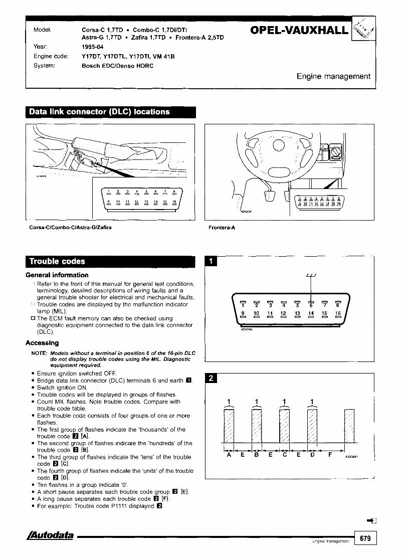
Model. Corsa-C 1,7TD Combo-C 1,7DIIDTI Astra-G 1,7TD Zafira 1,7TD Frontera-A 2,5TD
OPEL-VAUXHALL Year: 1995-04
Engine code: Y17DT, Y17DTL, Y17DT1, VM 41B
System: Bosch EDClDenso HDRC
Engine management
General information n Refer to the front of this manual for general test conditions,
terminology, detailed descriptions of wiring faults and a general trouble shooter for electrical and mechanical faults.
n Trouble codes are displayed by the malfunction indicator lamp (MIL). The ECM fault memorv can also be checked usina diagnostic equipment connected to the data link connector (DLC).
Accessing NOTE: Models without a terminal in position 6 of the 16-pin DLC
do not display trouble codes using the MIL. Diagnostic equipment required.
Ensure ignition switched OFF. Bridge data link connector (DLC) terminals 6 and earth a. Switch ignition ON. Trouble codes will be displayed in groups of flashes. Count MIL flashes. Note trouble codes. Compare with trouble code table. Each trouble code consists of four groups of one or more flashes. The first group of flashes indicate the 'thousands' of the trouble code [A]. The second group of flashes indicate the 'hundreds' of the trouble code rn [B]. The third group of flashes indicate the 'tens' of the trouble code H [Cl. The fourth group of flashes indicate the 'units' of the trouble code rn [Dl. Ten flashes in a group indicate '0'. A short pause separates each trouble code group rn [El. A long pause separates each trouble code rn [F]. For example: Trouble code P l l l l displayed rn.
/Autodata Enq~ne rnanaqernent
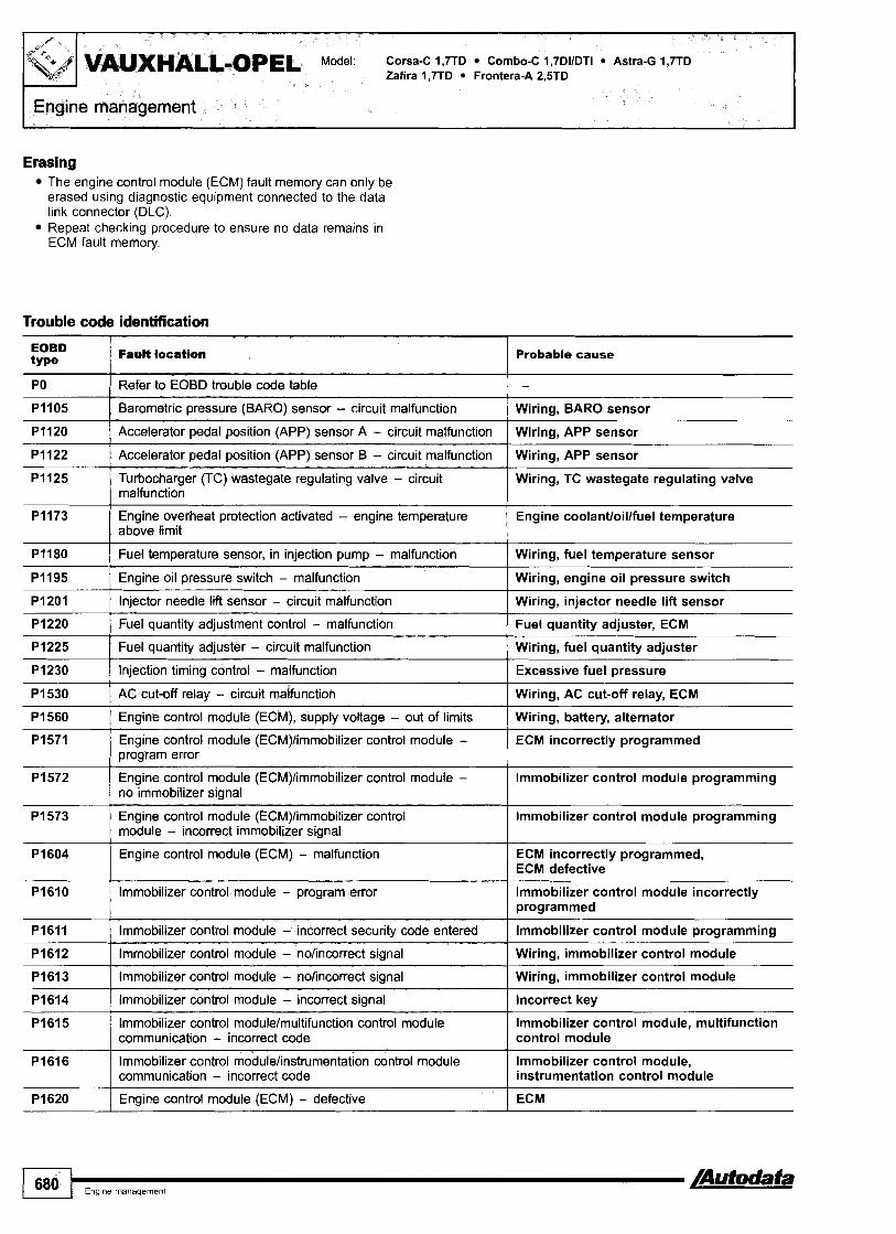
VAuXHALLIOPEL Model: Corsa-C 1,7TD Combo-C 1,7DIIDTI Astra-G 1,7TD Zafira 1,7TD Frontera-A 2,5TD
Erasing The engine control module (ECM) fault memory can only be erased using diagnostic equipment connected to the data link connector (DLC). Repeat checking procedure to ensure no data remains in ECM fault memory.
Trouble code identification
Probable cause I
PO I Refer to EOBD trouble code table
PI105 I Barometric pressure (BARO) sensor - circuit malfunction Wiring, BARO sensor
Wiring, APP sensor
Wiring, APP sensor
PI120
PI122
PI125 Wiring, TC wastegate regulating valve
Accelerator pedal position (APP) sensor A - circuit malfunction
Accelerator pedal position (APP) sensor B - circuit malfunction
Turbocharger (TC) wastegate regulating valve - circuit malfunction
Engine coolant/oillfuel temperature PI173
PI180 Wiring, fuel temperature sensor
Engine overheat protection activated - engine temperature above limit
Fuel temperature sensor, in iniection pump - malfunction
PI195 I Engine oil pressure switch - malfunction Wiring, engine oil pressure switch
PI201 I Injector needle lift sensor - circuit malfunction Wiring, injector needle lift sensor
PI220 I Fuel quantity adjustment control - malfunction Fuel quantity adjuster, ECM - -- --
Wiring, fuel quantity adjuster
Excessive fuel pressure
PI225
PI230
PI530 1 AC cut-off relay - circuit malfunction
Fuel quantity adjuster - circuit malfunction
Injection timing control - malfunction
Wiring, AC cut-off relay, ECM
PI560 I Engine control module (ECM), supply voltage - out of limits Wiring, battery, alternator -
ECM incorrectly programmed PI571
P I 572 lmmobilizer control module programming
Engine control module (ECM)/immobilizer control module - program error
Engine control module (ECM)limmobilizer control module - no immobilizer signal
lmmobilizer control module programming P I 573
PI604 ECM incorrectly programmed, ECM defective
Engine control module (ECM)/immobilizer control module - incorrect immobilizer signal
Engine control module (ECM) - malfunction
PI610 / Immobilizer control module - program error lmmobilizer control module incorrectly programmed
lmmobilizer control module programming I
PI611 I Immobilizer control module - incorrect security code entered
PI612 I lmmobilizer control module - nolincorrect signal Wiring, immobilizer control module
P I 61 3 I Immobilizer control module - nolincorrect signal Wiring, immobilizer control module
Incorrect key
lmmobilizer control module, multifunction control module
PI614
PI615
P I 61 6 Immobilizer control modulelinstrumentation control module communication - incorrect code
Immobilizer control module - incorrect signal
Immobilizer control modulelmultifunction control module communication - incorrect code
lmmobilizer control module, instrumentation control module
ECM P I 620 Engine control module (ECM) - defective

Model: Corsa-C 1,7TD Combo-C 1,7DIIDTI Astra-G 1,7TD Zafira 1,7TD Frontera-A 2,STD
EOBD type
Injection timing control - circuit malfunction I Wiring open circuitlshort to positive
Fault location
Engine control module (ECM), holding voltage - circuit malfunction
Fuel injection pump control module - defective I Wiring open circuitlshort to positive
Probable cause
Wiring, engine control relay
Fuel injection pump control module, CAN data bus - malfunction I Fuel injection pump control module
Glow plug control module, control signal - circuit malfunction
Malfunction indicator lamp (MIL) - circuit malfunction
Fuel shut-off solenoid - circuit malfunction
Wiring short to positivelearth, open circuit, glow plug control module
Wiring, MIL
Wiring open circuitlshort to positive, fuel shut-off solenoid
Engine coolant blower motor - circuit malfunction
Glow plug warning lamp - circuit malfunction
Injector needle lift sensor - incorrect signal
Wiring, engine coolant blower motor, engine coolant blower motor relay
Wiring, glow plug warning lamp
Injector needle lift sensor
CAN data bus - circuit malfunction I Wiring
CAN data bus - program error
Engine control module (ECM), CAN data bus - malfunction detected
ECM programming
Wiring
Engine control module (ECM), CAN data bus - malfunction detected
Engine control module (ECM)/multifunction control module communication, CAN data bus - malfunction
Wiring
Wiring

I VAUXHALL-OPEL
Model: AstraIKadett 2,0116V Astra-F 2,0116V CavalierNectra 2,O 8 4x4 CavalierNectralCalibra 2,O 16VITurbo 8 4x4/2,5 CarltonlOmega-B 2,012,512,613,O 24V Senator-B 2,613,013,O 24V Sintra 2,2 Frontera-A 2,012,2/2,4
Year: 1986-00 Engine 20NE, 20SE, ZOSER, SOSHE, ZOXEJ, CZOLET, CZONE, CZONEF, CZOXE, C24NE, C25XE, C26NE, C30NE, 'Ode: C30SE, C30SEJ, XZOSE, X22XE, X25XE, X30XE
System: Bosch Motronic
Engine management
CavalierNectralCalibra

CarltonlOmega-8 2,012,512,613,O 24V Senator-B 2,613,013,O 24V Sintra 2,2 Frontera-A 2,012,2/2,4 Engine management1
General information 0 Refer to the front of this manual for general test conditions,
terminology, detailed descriptions of wiring faults and a general trouble shooter for electrical and mechanical faults. Trouble codes are displayed by the malfunction indicator lamp (MIL).
0 The ECM fault memory can also be checked using diagnostic equipment connected to the data link connector (DLC).
Accessing Ensure ignition switched OFF. Except Omega-B: Bridge data link connector (DLC) terminals A and B - 10-pin. Omega-B: Bridge data link connector (DLC) terminals 6 and earth - 16-pin.
NOTE: Models without a terminal in position 6 of the 16-pin DLC do not display trouble codes using the MIL.
Switch ignition ON. Trouble codes will be displayed after a short flash El [A] and a long pause El [El. Count MIL flashes. Note trouble codes. Compare with trouble code table. Each trouble code consists of two groups of one or more flashes. The first group of flashes indicate the 'tens' of the trouble code El [Cl. The second group of flashes indicate the 'units' of the trouble code [Dl. A short pause separates each trouble code group fl [El. A long pause separates each trouble code El [F]. For example: Trouble code 12 displayed El. Each trouble code including 12 displayed three times.
NOTE: Some models will display Trouble code 31 with the engine off. Trouble code erased when the engine is running.
Erasing NOTE: Some models 1992+ may require diagnostic equipment
to erase trouble codes.
Switch ignition OFF. Disconnect battery earth lead for 60 seconds.
WARNING: Disconnecting battery may erase memory from electronic units (e.g. radio, clock).
Repeat checking procedure to ensure no data remains in ECM fault memory.
4
- a a Engine management 683

FEngine management CarltonlOmega-B 2,012,512,613,O 24V Senator-B 2,613,013,O 24V Sintra 2,2 Frontera-A 2,012,2/2,4
Trouble code identification
Flash type Fault location Probable cause
12 I Start and end of diagnosis - some models I - I
10 I Engine control module (ECM) - coding I ECM incorrectly programmed
Engine coolant temperature (ECT) sensor - voltage low
13
Wiring short to earth, ECT sensor, ECM
Heated oxygen sensor (H02S)loxygen sensor (02s) - open circuit
15
16
Wiring short to positive, ECT sensor, ECM
Wiring, H02S102S, ECM
Engine coolant temperature (ECT) sensor - voltage high
Knock sensor (KS) 1 - signal Wiring, KS
17 I Knock sensor (KS) 2 - signal I Wiring, KS
18 I Engine control module (ECM) - KS control 1 Internal KS control failure
22 I Throttle position (TP) sensor - voltage low I Wiring short to earth, TP sensor, ECM
19
2 1
23 ( Knock sensor (KS) - KS control I ECM
Engine speed (RPM) sensor - incorrect signal
Throttle position (TP) sensor - voltage high
I Injectors - Motronic M1.5 - voltage high I Wiring short to positive, injectors, ECM
--- -
Wiring, RPM sensor, reluctor ring, ECM
Wiring short to positive, TP sensor, ECM
24
25
26 1 Injector 2 - voltage high I Wiring short to positive, injector, ECM
27 I Injector 3 - voltage high I Wiring short to positive, injector, ECM
Vehicle speed sensor (VSS) - no signal
Injector 1 - except Motronic M1.5 - voltage high
Wiring, VSS, ECM
Wiring short to positive, injector, ECM
31 I Engine speed (RPM) sensor - no signal ( Wiring, RPM sensor, engine not running
28
29
32 I Injector 6 - voltage high I Wiring short to positive, injector, ECM
Injector 4 - voltage high
Injector 5 - voltage high
Wiring short to positive, injector, ECM
Wiring short to positive, injector, ECM
33
34
37
38
Exhaust gas recirculation (EGR) solenoid - voltage low
Exhaust gas recirculation (EGR) solenoid - voltage high
39
41
42
Wiring open circuivshort to earth, EGR solenoid
Wiring short to positive, EGR solenoid
1
44
45
Engine control module (ECM) - MIL control
Heated oxygen sensor (H02S)Ioxygen sensor (02s) - voltage low
Heated oxygen sensor (H02Syoxygen sensor (02s) - voltage high
First gear position switch - voltage low
First gear position switch - voltage high
46
47
Wiring open circuivshort to earth, ECM
Wiring short to earth, ECM
Wiring short to positive, ECM
Wiring short to earth, first gear position switch
Wiring short to positive, first gear position switch
Heated oxygen sensor (H02S)loxygen sensor (02s) - weak mixture
Heated oxygen sensor (H02S)loxygen sensor (02s) - rich mixture
Wiring, ECTllAT sensor, MAFNAF sensor, CTP switch, fuel system, ECM
Wiring, ECTllAT sensor, MAFNAF sensor, CTP switch, fuel system, ECM
Secondary air injection (AIR) pump relay - voltage low
Secondary air injection (AIR) pump relay - voltage high
Wiring open circuivshort to earth, fuse, AIR pump relay, AIR solenoid, AIR pump
Wiring open circuivshort to positive, fuse, AIR pump relay, AIR solenoid, AIR pump

I CarltonlOmega-B 2,012,512,613,O 24V Senator-B 2,613,013,O 24V Sintra 2,2 ~rontera-A 2,012,212,4 Engine management
Flash type Fault location I Probable cause
48 I Battery supply voltage - low I Wiring, battery, ECM relay, ECM
49 I Battery supply voltage - high I Alternator, regulator
54 I Fuel pump relay - voltage high I Wiring short to positive, fuel pump relay, fuel pump, ECM
51
52
53
55 I Engine control module (ECM) - defective 1 ECM
Engine control module (ECM) - incorrect programming
Engine control module (ECM) - MIL control
Fuel pump relay - voltage low
Wiring, ECM
Wiring short to positive, ECM
Wiring short to earth, fuel pump relay, fuel pump, ECM
56
57
6 1
65 I Mixture adjustment resistor - voltage low I Wiring short to earth, ECM
62
63
Idle air control (IAC) valve - voltage high
Idle air control (IAC) valve - voltage low
Evaporative emission (EVAP) canister purge valve - voltage low
69 I Intake air temperature (IAT) sensor - voltage low / Wiring short to earth, IAT sensor, ECM
- -
Wiring short to positive, IAC valve, E C M
Wiring short to earth, IAC valve, ECM
Wiring short to earth, EVAP canister purge valve, ECM
Evaporative emission (EVAP) canister purge valve - voltage high
Intake manifold air control solenoid - voltage high
66
67
7 1 I Intake air temperature (IAT) sensor - voltage high I Wiring short to positive, IAT sensor, ECM
-
Wiring short to positive, EVAP canister purge valve, ECM
Wiring short to positive, intake manifold air control solenoid, ECM
72 I Wide open throttle (WOT) switch - voltage low 1 Wiring short to earth, WOT switch,^^^
Mixture adjustment resistor - voltage high
Closed throttle position (CTP) switch - voltage low
73 Mass air flow (MAF) sensor/volume air flow (VAF) Wiring short to earth, MAFNAF sensor, ECM sensor - voltage low I
Wiring short to positive, ECM
Wiring, CTP switch, ECM
74 Mass air flow (MAF) sensorlvolume air flow (VAF) Wiring short to positive, MAFNAF sensor, ECM sensor - voltage high
79 I Traction control - signal voltage low I Wiring, traction control module
75
76
81 I Injector 1 - except Motronic M1.5 - voltage low I Wiring short to earth, injector, ECM
AT torque control, signal - voltage low
AT torque control, signal - continuous
84 I Injector 4 - voltage low 1 Wiring short to earth, injector, ECM
Wiring open circuit
Wiring, ECM, TCM
82
83
85 I Injector 5 - voltage low I Wiring short to earth, injector, ECM
injectors - Motronic M I .5 - voltage low
Injector 2 - voltage low
Injector 3 - voltage low
88 I AC control signal - voltage high 1 Wiring short to positive, AC cut-off relay, ECM
Wiring short to earth, injectors, ECM
Wiring short to earth, injector, ECM
Wiring short to earth, injector, ECM
86
87
9 1 I Oxygen sensor heater - voltage high I Wiring short to positive, ECM
93 ( Camshaft position (CMP) sensor - voltage low I Wiring short to earth, CMP sensor
Injector 6 - voltage low
AC control signal - voltage low
I I
94 I Camshaft position (CMP) sensor - voltage high 1 Wiring short to positive, CMP sensor
Wiring short to earth, injector, ECM
Wiring short to earth, AC cut-off relay, ECM
/Autodata Engme management 685

VAUXHALL-OpEL Model: AstralKadett 2,0116V Astra-F 2,0116V CavalierNectra 2,O 8 4x4 CavalierNectralCalibra 2.0 16VTTurbo 8 4~412.5
Engine management Sintra 2,2 ~rontera-A 2,012,212,4
Flash type Fault location
Fuel pressure regulator control solenoid - voltage low
Probable cause
Wiring short to earth, fuel pressure regulator control solenoid
Fuel pressure regulator control solenoid - voltage high
Wiring short to positive, fuel pressure regulator control solenoid
Traction control - signal voltage high I Wiring, traction control module
Turbocharger (TC) pressure - idling control limit Wiring, TC wastegate regulating valve, ECM exceeded
Oxygen sensor heater - voltage low
Turbocharger (TC) pressure - out of limits
Wiring short to earth, ECM
Wiring, TC, TC wastegate regulating valve, ECM
Turbocharger (TC) pressure - full load control limit not reached
Turbocharger (TC) pressure - full load control limit exceeded
Turbocharger, ECM
Wiring, TC wastegate regulating valve, ECM
Turbocharger (TC) wastegate regulating valve - voltage low
Turbocharger (TC) wastegate regulating valve - voltage high
Manifold absolute pressure (MAP) sensor, signal - above upper limit
Wiring short to earth, TC wastegate regulating valve, ECM
Wiring short to positive, TC wastegate regulating valve, ECM
Manifold absolute pressure (MAP) sensor - rangelperformance problem
Manifold absolute pressure (MAP) sensor, signal - below lower limit I Wiring, MAP sensor, intake system
Wiring, MAP sensor, air leak, hose blocked
Wiring, MAP sensor, intake system
--
~ x h a u s t ~ a s recirculation (EGR) valve position Wiring open circuiffshort to earth, EGR valve position sensor - voltage low sensor
Engine control module (ECM) - MIL control I Wiring open circuiffshort to earth, ECM
Exhaust gas recirculation (EGR) valve position sensor - voltage high
Exhaust gas recirculation (EGR) valve position sensor - incorrect signal
Wiring short to positive, EGR valve position sensor
Wiring, EGR valve position sensor
Manifold absolute pressure (MAP) sensor - voltage low
Engine control module (ECM) - unknown output error
Engine control module (ECM) - temperature high I Wiring short to earth. MAP sensor
ECM internal short to positive
-
Manifold absolute pressure (MAP) sensor - voltage high
Wiring short to positive, MAP sensor
Immobilizer control module - programming I Immobilizer control module incorrectlylnot programmed
Immobilizer control module - no signal I Immobilizer control module
Immobilizer control module - incorrect signal Immobilizer control module
4

Model: Astra-F 1,812,O 16V VectralCavalier 2,O 16V Omega-B 2,O 16V Calibra 2,O 16V
OPEL-VAUXHALL I Year: 1993-98
Engine code: C18XE, CISXEL, X2OXEV
System: Simtec 56.0156.1156.5
I Engine management 1
General information Refer to the front of this manual for general test conditions, terminology, detailed descriptions of wiring faults and a general trouble shooter for electrical and mechanical faults.
0 Trouble codes are displayed by the malfunction indicator lamp (MIL). The ECM fault memory can also be checked using diagnostic equipment connected to the data link connector (DLC).
Accessing Ensure ignition switched OFF. Bridge data link connector (DLC) terminals A and B
- 10-pin. Bridge data link connector (DLC) terminals 6 and earth
- 16-pin. Switch ignition ON. Trouble codes will be displayed after a short flash H [A] and a long pause [Bl.
Count MIL flashes. Note trouble codes. Compare with trouble code table. Each trouble code consists of two groups of one or more flashes. The first group of flashes indicate the 'tens' of the trouble code H [Cl. The second group of flashes indicate the 'units' of the trouble code H [Dl. A short pause separates each trouble code group H [El. A long pause separates each trouble code H [Fl. For example: Trouble code 12 displayed a. Each trouble code including 12 displayed three times.
4
/Autodata I Eng~ne management 687

VAUXHAf&oPEL Model: Astra-F 1,812,O 16V VectralCavalier 2,O 16V Omega-B 2,O 16V Calibra 2,O 16V
Erasing NOTE: Some models 1992- may require diagnostic equipment
to erase trouble codes.
Switch ignition OFF. Disconnect battery earth lead for 60 seconds.
WARNING: Disconnecting battery may erase memory from electronic units (e.g. radio, clock).
Repeat checking procedure to ensure no data remains in ECM fault memory.
Trouble code identification
Flash type
Heated oxygen sensor (H02S)loxygen sensor (025) - Wiring, H02S102S, ECM open circuit
I I Fault location
12 I Start and end of diaanosis
16 I Knock sensor (KS) 1 - signal I Wiring, KS
Probable cause
-
14
15
Engine coolant temperature (ECT) sensor - voltage low
Engine coolant temperature (ECT) sensor - voltage high
19
21
24 I Vehicle speed sensor (VSS) - no signal 1 Wiring, VSS, ECM
Wiring short to earth, ECT sensor, ECM
Wiring short to positive, ECT sensor, ECM
22
23
Engine speed (RPM) sensor - incorrect signal
Throttle position (TP) sensor - voltage high
Wiring, RPM sensor, reluctor ring, ECM
Wiring short to positive, TP sensor, ECM
Throttle position (TP) sensor - voltage low
Knock sensor (KS) - KS control
25 I Jnjector 1 - vottage high
26 I Injector 2 - voltage high
Wiring short to earth, TP sensor, ECM
ECM
Wiring short to positive, injector, ECM
Wiring short to positive, injector, ECM
27
28
33
34
37
Injector 3 - voltage high
Injector 4 - voltage high
Exhaust gas recircutation (EGR) solenoid - voltage low
Wiring short to positive, injector, ECM
Wiring short to positive, injector, ECM
Wiring open circuitlshort to earth, EGR solenoid
Exhaust gas recirculation (EGR) solenoid -voltage high
Engine control module (ECM) - MIL control
Wiring short to positive, EGR solenoid
Wiring open circuitlshort to earth, ECM

Flash type I Fault losa€bn Probable cause
I - I
39 I Heated oxygen sensor (H02S)Ioxygen sensor (02s) - I Wiring short to positive, ECM
38 Heated oxygen sensor (HQ2S)Ioxygen sensor (02s) - voltaw low
45
46
47
Wiring short to earth, ECM
48
49
52
Heated oxygen sensor (H02S)loxygen sensor (025) - rich mixture
Secondary air injection (AIR) pump relay -voltage low
Secondary air injection (AIR) pump relay - voltage high
53
54
55
59 I Immobilizer control module - programming I Immobilizer control module incorrectlylnot programmed
Wiring, ECTllAT sensor, MAFNAF sensor, CTP switch, fuel system, ECM
Wiring open circuiffshort to earth, fuse, AIR pump relay, AIR solenoid, AIR pump
Wiring open circuiffshort to positive, fuse, AIR pump relay, AIR solenoid, AIR pump
Battery supply voltage - low
Battery supply voltage - high
Engine control module (ECM) - MIL control
56 I Idle air control (IAC) valve - voltage low
57 I Idle air control (IAC) valve - voltage high
Wiring, battery, ECM relay, ECM
Alternator, regulator
Wiring short to positive, ECM
Fuel pump relay - voftage low
Fuef pump relay - voltage high
Engine control module (ECM) - defective
Wiring short to earth, IAC valve, ECM
Wiring short to positive, IAC valve, ECM
Wiring short to earth, fuel pump relay, fuel pump, ECM
Wiring short to positive, fuel pump relay, fuel pump, ECM
ECM
6 1
62
65
69
7 1
75 I AT torque control, signal - voltage low Wiring open circuit
Evaporative emission (EVAP) canister purge valve - voltage low
Evaporative emission (EVAP) canister purge valve - voltage high
73 f Mass air Row ( W F ) sensor - voltage low
74 1 Mass air flow ( M F ) sensor - voltage high
Wiring short to earth, EVAP canister purge valve, ECM
Wiring short to positive, EVAP canister purge valve, ECM
Module temperature switch, ECM - temperature high
Intake air temperature (IAT) sensor - voltage low
Intake air temperature (IAT) sensor - voltage hi ih
Wiring short to earth, MAF sensor, ECM
Wiring short to positive, MAF sensor, ECM
Wiring, module temperature switch, ECM overheating
Wiring short to earth, IAT sensor, ECM
Wiring short to positive, IAT sensor, ECM
76
81
82
83
84
91 I Oxygen sensor heater - volta ] Wiring short to positive, ECM
AT torque control, signal - continuous
Injector 1 - voltage low
87
88
Wiring, ECM, TCM
Wiring short to earth, injector, ECM
Injector 2 - voltage low
Injtxt0r 3 - voltage low
Injector 4 - voltage low
Wiring short to earth, injector, ECM
Wiring short to earth, injector, ECM
Wiring short to earth, injector, ECM
AC control signal - voltage low
AC control signal - voltage high
92
93
Wiring short to earth, AC cut-off relay, ECM
Wiring short to positive, AC cut-off relay, ECM
94
98
Camshaft position (CMP) sensor - incorrect signal
Immobilizer control module - no signal
Wiring, CMP sensor
Immobilizer control module
4
fmmobilizer control module - incorrect signal
Oxygen sensor heater - voltage low
Immobilizer control module
Wiring short to earth, ECM

Zafira 2,OTD12,2TD Sintra Z>TD Frontera-B 2,2TD
Year: 1997-04
Engine code: X17DTL, XZODTH, XZODTL, XZZDTH, YZODTH, YZODTL, YZZDTH, Y22DTR
System: Bosch EDC 15M
Engine management
Sintra
General information Refer to the front of this manual for general test conditions, terminology, detailed descriptions of wiring faults and a general trouble shooter for electrical and mechanical faults. Trouble codes are displayed by the malfunction indicator lamp (MIL). The ECM fault memory can also be checked using diagnostic equipment connected to the data link connector (DLC).
Accessing NOTE: Models without a terminal in position 6 of the 16-pin DLC
do not display trouble codes using the MIL. Diagnostic equipment required.
Ensure ignition switched OFF. Bridge data link connector (DLC) terminals 6 and earth a. Switch ignition ON. Trouble codes will be displayed in groups of flashes. Count MIL flashes. Note trouble codes. Compare with trouble code table. Each trouble code consists of four groups of one or more flashes. The first group of flashes indicate the 'thousands' of the trouble code H [A]. The second group of flashes indicate the 'hundreds' of the trouble code H [B]. The third group of flashes indicate the 'tens' of the trouble code H [Cl. The fourth group of flashes indicate the 'units' of the trouble code H [Dl.

Model: Astra-G 1,7TDI2,OTD/2,2TD Vectra-B 2,OTD12,2TD Omega-B 2,OTDl2,2TD * Zafira 2,OTD/2,2TD Sintra 2,2TD Frontera-B 2,2TD
OPEL-VAUXHALL I I Engine management I
Ten flashes in a group indicate '0'. A short pause separates each trouble code group rn [El. A long pause separates each trouble code rn [Fl. For example: Trouble code P l l l l displayed rn.
Trouble code identification
Erasing The engine control module (ECM) fault memory can only be erased using diagnostic equipment connected to the data link connector (DLC). Repeat checking procedure to ensure no data remains in ECM fault memory.
EOBD type
Fault location - I Probable cause
PO I Refer to EOBD trouble code table I - PI100 Mass air flow (MAF) sensorlmanifotd absolute pressure (MAP) Intake system - air leak, blocked hose
sensor - implausible signal
PI105 I Barometric pressure (BARO) sensor - circuit malfunction I Wiring, BARO sensor
PI110 I Intake manifold air control solenoid - circuit malfunction I Wiring, intake manifold air control solenoid
Turbocharger (TC) wastegate regulating valve - circuit malfunction
Engine overheat protection activated - engine temperature above limit
PI345 1 Injection pump position sensor - malfunction I Wiring, injection pump position sensor
Wiring, TC wastegate regulating valve
Engine coolantloillfuel temperature
PI180
PI220
P I 335
PI501 Immobilizer control module - program error Immobilizer control module incorrectly programmed
Fuel temperature sensor, in injection pump - malfunction
Fuel quantity adjustment control - malfunction
Fuel injection pump control module - CKP signal missing
PI502 I Immobilizer control module - no signal I Wiring, immobilizer control module
Wiring, fuel temperature sensor
Fuel quantity adjuster, ECM
Wiring, ECM, CKP sensor
PI503 ( Immobilizer control module - incorrect signal I Immobilizer control module, incorrect key
PI515 Accelerator pedal position (APP) sensorlclosed throttle position (CTP) switch - malfunction
I Wiring, APP sensor, CTP switch
P I 530 I AC cut-off relay - circuit malfunction I Wiring, AC cut-off relay, ECM
PI560 I Engine control module (ECM), supply voltage - out of limits I Wiring, battery, alternator
PI590 I Ignition switch, supply voltage - out of limits I Wiring, battery, alternator
P I 600 Engine control module (ECM) - defective ECM

Omega-B 2,OTD12,2TD Zafira 2,OTD12,2TD Sintra 2,2TD Frontera-B 2,2TD
EOBD type
Fault location
Engine control module (ECM) - malfunction I ECM incorrectly programmed, ECM defective
Probable cause
Engine control module (ECM) - temperature limit exceeded Ambient temperature too high, ECM malfunction
Immobilizer control module - nolincorrect signal I Wiring, immobilizer control module
Immobilizer control module - program error
Immobilizer control module - incorrect security code entered
Immobilizer control module - noJincorrect signal I Wiring, immobilizer control module
Immobilizer control module incorrectly programmed
lmmobilizer control module programming
- ---
Immobilizer control module - incorrect signal
Engine control module (ECM) - defective
Engine control module (ECM), holding voltage - circuit malfunction
Glow plug control module, control signal - circuit malfunction Wiring short to positivelearth, open circuit, glow plug control module
Incorrect key
ECM
Wiring, engine control relay
Injection timing control - circuit malfunction
Fuel injection pump control module - defective
Fuel injection pump control module, CAN data bus - Fuel injection pump control module malfunction
Wiring open circuitkhort to positive
Wiring open circuitkhort to positive
Malfunction indicator lamp (MIL) - circuit malfunction I Wiring, MIL
Fuel injection pump control module, CAN data bus - rnalfunction
Fuel shut-off solenoid - circuit malfunction
Fuel injection pump control module
Wiring open circuitlshort to positive, fuel shut-off solenoid
Glow plug warning lamp - circuit malfunction Wiring, glow plug warning lamp
4

Model: Astra-G 1,7 TD Frontera-B 2,2 TD Omega-B 2,5 TD Vectra-C 2,0/2,2 TD
Yeac 2001 -04
Engine code: YZODTH, Y22DTH, Y22DTR, Y25DT, Zl7DTL
System: Bosch EDC 15115M115 C4 Bosch PSG 16
I Engine management I
General information Refer to the front of this manual for general test conditions, terminology, detailed descriptions of wiring faults and a general trouble shooter for electrical and mechanical faults.
Accessing and erasing The engine control module (ECM) fault memory can only be accessed and erased using diagnostic equipment connected to the data link connector (DLC).
-a- Enqme management 693

\Engine management
r
Trouble code identification
VAUXHALL-OPEL Model: Astra-G 1.7 TD Frontera-B 2.2 TD Omega-B 2.5 TD Vectra-C 2,012,2 TD
EOBD type
PO
Fault location Probable cause
Refer to EOBD trouble code table
Mass air flow (MAF) sensor/manifold absolute pressure (MAP) sensor - implausible signal
Intake system - air leak, blocked hose
Barometric pressure (BARO) sensor - circuit malfunction
Intake manifold air control solenoid - circuit malfunction
Wiring, BARO sensor
Wiring, intake manifold air control solenoid
Accelerator pedal position (APP) sensor A - circuit malfunction
Accelerator pedal position (APP) sensor B - circuit malfunction
Turbocharger (TC) wastegate regulating valve - circuit malfunction
Wiring, APP sensor
Wiring, APP sensor
Wiring, TC wastegate regulating valve
Engine overheat protection activated - engine temperature above limit
Fuel temperature sensor, in injection pump - malfunction
Fuel rail pressure low while starting - fuel pressure malfunction
Engine coolantloillfuel temperature
Wiring, fuel temperature sensor
Fuel leak, fuel injector(s)
Fuel rail pressure sensor - malfunction
Fuel injector circuit - signal malfunction
Wiring, connectors, pressure sensor, ECM
Wiring, injector(s), ECM
Injector capacitor voltage 1 - circuit malfunction Wiring, connector(s), injector(s), ECM
Injector capacitor voltage 2 - circuit malfunction Wiring, connector(s), injector(s), ECM
Fuel quantity adjustment control - malfunction Fuel quantity adjuster, ECM
Injection pump - malfunction Mechanical fault in high pressure side of injection Pump
Low pressure fuel sensor - malfunction Wiring, connector, fuel supply, low pressure fuel sensor, ECM
Pre-supply pressure under limit for starting - malfunction Wiring, connector, fuel supply, ECM
Wiring, ECM, CKP sensor
Wiring, connector, CMP sensor, ECM
Fuel injection pump control module - CKP signal missing
Camshaft position (CMP) sensor - CMP signal missing
Crankshaft position (CKP) sensor - CKP signal missing Wiring, connector, CKP sensor, ECM
lnjection pump position sensor - malfunction Wiring, injection pump position sensor
Engine control module, supply voltage - circuit malfunction
Wiring, connectors, battery
Swirl level control solenoid - circuit malfunction Wiring, connectors, battery, ECM
Reverse light - circuit malfunction
Engine control module (ECM) - temperature limit exceeded
Wiring, connector, reverse light relay, ECM -
Ambient temperature too high, wiring, connector, relay box temperature sensor
lmmobilizer control module - program error Immobilizer control module incorrectly programmed
lmmobilizer control module - no signal
lmmobilizer control module - incorrect signal
Wiring, immobilizer control module
lmmobilizer control module, incorrect key
Accelerator pedal position (APP) sensorlclosed throttle position (CTP) switch - malfunction
Wiring, APP sensor, CTP switch
Accelerator pedal position (APP) switchlbrake pedal position (BPP)switch - signal error
APP switchlBPP switch operated simultaneously

Model: Astra-G 1,7 TD Frontera-B 2,2 TD Omega-B 2,s TD Vectra-C 2,012,2 TD
OPEL-VAUXHALL
Engine management
-
Probable cause EOBD type
I Fault location
P I 530 I AC cut-off relay - circuit malfunction Wiring, AC cut-off relay, ECM
P I 540 AC control signal - malfunction Wiring, trouble code(s) in AC system control module
Wiring, battery, alternator
P I 590 1 Vacuum solenoid valve - circuit malfunction
PI560
Wiring, Vacuum solenoid valve, ECM
Engine control module (ECM), supply voltage -out of limits
PI600 I Engine control module (ECM) - defective ECM
Ambient temperature too high, ECM malfunction
ECM incorrectly programmed, ECM defective
PI601
P I 603
PI604 Engine control module (ECM) - malfunction
Engine control module (ECM) -t&peratuglimit exceeded
Engine control module (ECM) - malfunction
ECM incorrectly programmed, ECM defective
Wiring, connector(s), injector(s), ECM I
P I 607 I Fuel iniector(s) - malfunction
Pi610 Immobilizer control module - program error lmmobilizer control module incorrectly programmed
lmmobilizer control module programming PI611
PI612 Wiring, immobilizer control module
Immobilizer control module - incorrect security code entered
Immobilizer control module - nolincorrect signal
PI613 ( lmmobilizer control module - nolincorrect signal Wiring, immobilizer control module
PI614 ( lmmobilizer control module - incorrect signal Incorrect key
PI620 H I Engine control module (ECM) - defective ECM
Wiring, APP, MAP, MAF, ECM PI620
PI622 1 Reference voltage - circuit malfunction
Accelerator pedal position (APP) sensorlManifold absolute pressure (MAP) sensorfMass air flow (MAF) sensor - circuit malfunction
ECM
Wiring, engine control relay P I 625
P I 630
PI631
ECM
Engine control module (ECM), holding voltage - circuit malfunction
Fuel injection quantity - circuit malfunction
Fuel injection pump control module - defective Wiring open circuitlshort to positive
PI632 I lnjection pump - malfunction ECM
PI633 1 lnjection pump - malfunction ECM
ECM
Wiring short to positivelearth, open circuit, glow plug control module
PI 6%
PI635
malfunction
--
Injection pump - malfunction
Glow plug control module, control signal - circuit malfunction
Wiring, connector(s), MAP sensor, ECM
ECM
Fuel injection pump control module
Wiring, MIL PI650 H
P I 651 H Wiring, connector, TCM, instrument cluster, ECM
Malfunction indicator lamp (MIL) - circuit malfunction
Service vehicle soon request from transmission control module - circuit malfunction
PI651 I lnjection pump, CAN data bus - malfunction ECM
/Autodata Ename rnanaaernent 695 1
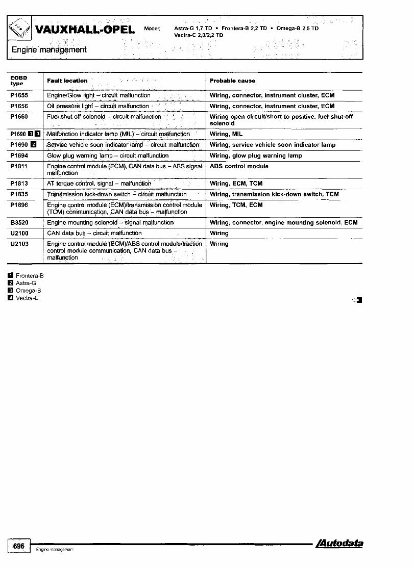
EOBD type
/ Fault hat1011 Probable cause
PI655
PI656
PI660
PI690 fl PI690
PI694
PI811
83520 1 Engine mounting solenoid - signal malfunction I Wiring, connector, engine mounting solenoid, ECM
EnginelGIow light - circuit malfunction
Oil pressure Ibht - circuit malfunction
PI813
P I 835
PI896
U2100 I CAN date bus - circuit malfunction I Wiring
Wiring, connector, instrument cluster, ECM
Wiring, connector, instrument cluster, ECM
Fuel shut-off solenoid - circuit malfunction
Malfunction indicator lamp (MIL) - circuit malfunction
Service vehicle soon indicator lamp - circuit malfunction
Glow plug warning lamp - circuit malfunction
Engine control module (ECM), CAN data bus - ABS signal malfunction
Wiring open circuitlshort to positive, fuel shut-off solenoid
Wiring, MIL
Wiring, service vehicle soon indicator lamp
Wiring, glow plug warning lamp
ABS control module
AT torque controt, signal - malfunction
Transmission kick-down switch - circuit malfunction
Engine control module (ECM)/transmission control module (TCM) communication, CAN data bus - malfunction
Wiring, ECM, TCM
Wiring, transmission kick-down switch, TCM
Wiring, TCM, ECM
U2103 Engine control module (ECM)IABS control moduleltraction control module communication, CAN data bus - malfunction
Wiring

Astra-G 2,2 SpeedsterNX220 2,2 Vectra-C 2,012,2
Engine code: ZZONET, Z22SE
Trionic 8 GMPT-El51El6
Engine management I
General information Refer to the front of this manual for general test conditions, terminology, detailed descriptions of wiring faults and a general trouble shooter for electrical and mechanical faults.
Accessing and erasing The engine control module (ECM) fault memory can only be accessed and erased using diagnostic equipment connected to the data link connector (DLC).

VAUXHALL-OPEL Model Astra-G 2,2 SpeedsterNX220 2,2 Vectra-C 2,012,2
I Engine management
Trouble code identification
EOBD type
Fault location I Probable cause
Refer to EOBD trouble code table I - Throttle position sensor - circuit malfunction I Wiring, throttle valve positioner, ECM
Heated oxygen sensor (H02S) 1, bank 1 - malfunction
Accelerator pedal position (APP) sensor - circuit malfunction
Heated oxygen sensor (H02S) 1, bank 1 - malfunction I Wiring, H02S. ECM
Wiring, APP sensor, ECM
Wiring, H02S, ECM
--
Heated oxygen sensor (H02S) I , bank I - insufficient Wiring, oxygen sensor heater, exhaust system switching 1-leaking, H0;
Heated oxygen sensor (H02S) 2, bank 1 -enrichment Wiring, H02S, ECM lean
I --
Heated oxygen sensor (H02S) 2 - voltage high Wiring short circuit to positive, fuel pressure high, fuel contamination, injector(s) leaking, H02S, ECM
Fuel system - lean during acceleration I Fuel filter, fuel pump relay, fuel pump, H02S, injectors
Throttle ~osition sensor 2 - circuit malfunction Wiring open circuitlshort circuit to groundlshort circuit to positive, throttle valve positioner, ECM
Accelerator pedal position (APP) sensor 1 - circuit Wiring open circuitlshort circuit to ground/short malfunction I circuit to positive, APP sensor, ECM
Throttle position sensor 112 - signal variation
Accelerator pedal position (APP) sensor 112 - signal variation
Accelerator pedal position (APP) sensor 113 - signal Wiring, APP sensor, ECM variation
Wiring, throttle valve positioner, ECM
Wiring, APP sensor, ECM
Accelerator pedal position (APP) sensor 2 - circuit Wiring open circuitlshort circuit to groundlshort malfunction circuit to positive, APP sensor, ECM
Randomlmultiple cylinder(s) - misfire detected Mechanical fault, wiring, ignitionlfuel system, mass air flow (MAF) sensor, fuel pump relay, manifold absolute pressure (MAP) sensor, intake leak
Ignition diagnostic module - malfunction I Wiring, ignition diagnostic module, ECM
Cylinder 1 - misfire detected
Crankshaft position sensor (CKP) - variation not learned
Ignition diagnostic module - malfunction
Spark plug, wiring, ignition coil, ignition diagnostic module
Learning procedure not performed
Wiring, ignition diagnostic module, ECM
Cylinder 2 - misfire detected Spark plug, wiring, ignition coil, ignition diagnostic module
Cylinder 3 - misfire detected Spark plug, wiring, ignition coil, ignition diagnostic module
Rough road signal - signal error / ABS control module trouble code(s) stored
Cylinder 4 - misfire detected
Crankshaft position sensor (CKP)lcamshaft position (CMP) sensor - signal variation
Spark plug, wiring, ignition coil, ignition diagnostic module
CKP sensor, CMP sensor, camshaft alignment, mechanical fault
Exhaust gas recirculation (EGR) solenoid valve
Throttle position adaption - signal variation
Wiring open circuitlshort circuit to ground, supply wire, EGR valve, ECM
Wiring, throttle valve positioner, ECM

I Engine management I Model: Astra-G 2,2 SpeedsterNX220 2,2 Vectra-C 2,012,2 OPEL-VAUXHALL
Probable cause
8"
I
PI514 I Electronic throttle control - malfunction Wiring, MAP sensor, ECM
Wiring, throttle valve sticking, throttle valve positioner, ECM
P I 51 5
PI516
P I 523
Wiring, throttle valve positioner, ECM
Throttle commandlactual throttle position - signal variation
Throttle actuator control position - signal variation
Throttle actuator control position - signal variation Wiring, throttle valve positioner, ECM
I Traction control system (TCS), torque request circuit Wiring open circuitlshort circuit to groundlshort circuit to positive, ABS control module trouble code@) stored, ECM
Wiring, brake light switch, ECM P I 574
P 1 539 ECM
Brake light switch - malfunction
Engine stall detected - malfunction
PI610 I Immobilizer control module - program error lmmobilizer control module incorrectly programmed
lmmobilizer control module incorrect code entered
lmmobilizer control module
PI611
PI612
P I 61 3 lmmobilizer control module
Immobilizer control module - coding
Immobilizer control module - incorrecffno signal
Immobilizer control module - incorrectfno siclnal
P I 614 I lmmobilizer control module - incorrect signal Incorrect key
PI621 I Engine control module (ECM) - memory performance ECM
Fuse, wiring open circuit, ECM
Wiring short circuit to groundlpositive, ground wiring open circuit, APP sensor, ECM
PI633
PI635
P I 639 1 Sensor supply voltage - circuit I malfunction
Engine control module (ECM), ignition supply voltage
Sensor supply voltage - circuit 1 malfunction
Wiring short circuit to groundlpositive, ground wiring open circuit, APP sensor, ECM
P I 680 Accelerator pedal position (APP) sensor - circuit malfunction
Wiring open circuitlshort circuit to groundlshort circuit to positive, APP sensor, ECM
PI681 I Throttle position sensor monitor - malfunction Wiring, throttle valve positioner, ECM
PI682 El I Electronic throttle control - malfunction Wiring, throttle valve positioner, ECM
Relay, wiring, ECM PI682 H P I 700
U2lOl
ECM, TCM
Main relay - contacts stuck open
Transmission control module (TCM), MIL request - malfunction
CAN data bus - program malfunction ECM programming
Wiring U2103
U2104 --
Wiring
Engine control module (ECM), CAN data bus - malfunction detected
Engine control module (ECM), CAN data bus - malfunction detected
U2106 Engine control module (ECM)ltransmission control moduie (TCM) communication, CAN data bus -
Wiring
Wiring
4
U2108
El GMPT-El5lE16 H Trionic 8
mahnction
Engine control module (ECM)IABS control modutel traction control module communication, CAN data bus - malfunction

Year: 1994-00 I
Engine management
Engine code: 25DT, X25DT
System: Bosch EDClMSA 11
General information 0 Refer to the front of this manual for general test conditions,
terminology, detailed descriptions of wiring faults and a general trouble shooter for electrical and mechanical faults.
0 Trouble codes are displayed by the malfunction indicator lamp (MIL). The ECM fault memory can also be checked using diagnostic equipment connected to the data link connector (DLC).
Accessing Ensure ignition switched OFF. Bridge data link connector (DLC) terminals 6 and earth O.
NOTE: Models without a terminal in position 6 of the 16-pin DLC do not display trouble codes using the MIL.
Switch ignition ON. Trouble codes will be displayed after a short flash [A] and a long pause rn [B]. Count MIL flashes. Note trouble codes. Compare with trouble code table. Each trouble code consists of two groups of one or more flashes. The first group of flashes indicate the 'tens' of the trouble code [C]. The second group of flashes indicate the 'units' of the trouble code rn [Dl. A short pause separates each trouble code group rn [E]. A long pause separates each trouble code rn [Fl. For example: Trouble code 12 displayed rn. Each trouble code including 12 displayed three times.
Erasing The engine control module (ECM) fault memory can only be erased using diagnostic equipment connected to the data link connector (DLC). Repeat checking procedure to ensure no data remains in ECM fault memory.

Trouble code identification
Flashlscanner Fault type I Probable cause
15 Engine coolant temperature (ECT) sensor - voltage high I Wiring open circuitlshort to positive, ECT sensor, ECM
12
14
16 1 Fuel temperature sensor - voltage low I Wiring short to earth, ECT sensor, ECM
Start and end of diagnosis - some models
Engine coolant temperature {ECT) sensor - voltage low
-
Wiring short to earth, ECT sensor, ECM
17
19
21
3 1 I Engine speed (RPM) sensor - no signal I Wiring, RPM sensor
23
24
34 I Injection timing control - out of range I Wiring, fuel injection pump, ECM
Fuel temperature sensor - voltage high
Engine speed (RPM) sensor - incorrect signal
Accelerator pedal position (APP) sensor - voltage high
Wiring open circuitlshort to positive, ECT sensor, ECM
Wiring, RPM sensor, reluctor ring, ECM
Wiring open circuitlshort to positive, APP sensor. ECM
Accelerator pedal position (APP) sensor - incorrect idle speed signal
Vehicle speed sensor (VSS) - no siqnal
Wiring, APP sensor, ECM
Wirina, VSS. ECM
37
39
41
44 Manifold absolute pressure (MAP) sensor, TC boost I Wiring. MAP sensor, TC pressure - incorrect signal
42
43
Brake pedal position (BPP) switch - incorrect signal
Immobilizer - act~vated
Man~fold absolute pressure (MAP) sensor, TC boost pressure - voltage low
54 I Fuel shut-off solenoid - circuit malfunction I Wiring short to earth, fuel shut-off solenoid
Wiring, BPP switch
Wiring, incorrect key, ECM
Wiring short to earth, MAP sensor
Manifold absolute pressure (MAP) sensor, TC boost pressure - voltage high
Manifold absolute pressure (MAP) sensor, TC boost pressure - invalid signal
48
49
Wiring open circuitlshort to positive, MAP sensor
Wiring, MAP sensor, TC
64 Fuel quantity adjustment control - malfunction Wiring, fuel quantity adjusterlposition sensor, ECM
Battery supply voltage - low
Glow plug control - circuit malfunction
55
61
Wiring, battery, ECM relay, ECM
Wiring, glow plugs, glow plug control module
74 I Intake air temperature (IAT) sensor - voltage high
Engine control module (ECM) - defective
Fuel quantity adjuster position sensor - incorrect signal
65
73
Wiring open circuitlshort to positive, IAT sensor, ECM
ECM
Wiring, fuel quantity adjuster position sensor
Engine control module (ECM) - overheating
Intake air temperature (IAT) sensor - voltage low
83 Immobilizer control module - programming
Wiring, module temperature switch, ambient temperature
Wiring short to earth, IAT sensor, ECM
8 1
82
Immobilizer control module incorrectlylnot programmed
84 ( Immobilizer control module - no signal 1 Immobilizer control module
Injector needle lift sensor - circuit malfunction
lniector needle lift sensor - incorrect signal
Wiring, injector needle lift sensor
Injector needle lift sensor, ECM
4
/Autodata Engme management 701

Engine management
Flash'scanner type
88 I Mass air flow (MAF) sensor - voltage low I Wiring short to earth, MAF sensor, ECM
85
87
89 I Mass air flow (MAF) sensor - signal out of range I Wiring, MAF sensor, MAP sensor, ECM
Fault location Probable cause
Immobilizer control module - incomt signal
Mass air flow (MAF) sensor - voltage high
95 ( Engine control module (ECM) - malfunction I ECM
Immobilizer control module
Wiring open circuitlshort to positive, MAF sensor, ECM
9 1
92
96 I Exhaust gas recirculation (EGR) solenoid - voltage low Wiring open circuitlshort to earth, EGR solenoid
Cruise control - signal low
Cruise control - siqnal high
Wiring short to earth
Wiring open circuitlshort to positive
97
a Fuel injection pump - adaptation failure Incorrect adjustment

Model: Calibra 2,O
Year: 1996-98
Engine code: X20XEV
System: Simtec 56.5
Engine management
General information n Refer to the front of this manual for general test conditions,
terminology, detailed descriptions of wiring faults and a general trouble shooter for electrical and mechanical faults.
n Trouble codes are displayed by the malfunction indicator lamp (MIL). The ECM fault memory can also be checked using diagnostic equipment connected to the data link connector (DLC).
Accessing Ensure ignition switched OFF. Bridge data link connector (DLC) terminals A and B m. Switch ignition ON. Trouble codes will be displayed in groups of flashes. Count MIL flashes. Note trouble codes. Compare with trouble code table. Each trouble code consists of four groups of one or more flashes. The first group of flashes indicate the 'thousands' of the trouble code rn [A]. The second group of flashes indicate the 'hundreds' of the trouble code rn [B]. The third group of flashes indicate the 'tens' of the trouble code [Cl. The fourth group of flashes indicate the 'units' of the trouble code [Dl. Ten flashes in a group indicate '0'. A short pause separates each trouble code group [El. A long pause separates each trouble code [F]. For example: Trouble code P l l l l displayed m.
Erasing The engine control module (ECM) fault memory can only be erased using diagnostic equipment connected to the data link connector (DLC). Repeat checking procedure to ensure no data remains in ECM fault memory.
/Autodata Engine managemenl 703

Trouble code identification
EOBD type
Fault location I Probable cause I I
PO 1 Refer to EOBD trouble code table
PI110
PI229
-
PI230 ( Engine contml relay - voltage low
PI327 ( Knock control, cylinder 2 - control limit reached I Wiring, knock sensor (KS), ECM
Intake manifold air control solenoid 1 - circuit malfunction
Engine control relay - voltage high
Wiring, engine control relay
P I 326 I Knock control, cylinder 1 - control limit reached
PI328 [ Knock control, cylinder 3 - control limit reached ] Wiring, knock sensor (KS), ECM
Wiring, intake manifold air control solenoid
Wiring, engine control relay
Wiring, knock sensor (KS), ECM
PI502 I Immobilizer control module - no signal 1 Wiring, immobilizer control module
P I 329
PI501
PI503 ( Immobilizer control module - incorrect signal I Immobilizer control module, incorrect key
Knock control, cylinder 4 - control limit reached
Immobilizer control module - program error
I Module temperature switch, ECM - temperature high Wiring, module temperature switch, I ECM overheating
Wiring, knock sensor (KS), ECM-
Immobilizer control module incorrectly programmed
PI530
P I 600
AC cut-off relay - circuit malfunction
Engine control module (ECM) - program error
P I 690
P I 740
-
Wiring, AC cut-off relay, ECM
ECM programming
Malfunction indicator lamp (MIL) - circuit malfunction
AT torque control, signal - malfunction
Wiring, MIL
Wiring, ECM, TCM

Model: Vectra-C 1,6 Frontera-B 2,2
Year: 2000-04
Engine code: YZZSE, Z16XE
System: Multec SIS(F)
General information 17 Refer to the front of this manual for general test conditions,
terminology, detailed descriptions of wiring faults and a general trouble shooter for electrical and mechanical faults.
Accessing and erasing The engine control module (ECM) fault memory can only be accessed and erased using diagnostic equipment connected to the data link connector (DLC).
Trouble code identification
Pi107 Manifold absolute pressure (MAP) sensor - I Wiring, MAP sensor, ECM supply voltage low
EOBD type
PO
Pi106
-
P i l l 0 1 Intake manifold air control solenoid I - circuit malfunction I Wiring, intake manifold air control solenoid
P i l l 1 I Intake air temperature (IAT) sensor - supply voltage high I Wiring, IAT sensor, ECM
Fault location
Refer to EOBD trouble code table
Manifold absolute pressure (MAP) sensor - supply voltage high
Pi112 I Intake air temperature (IAT) sensor - supply voltage low I Wiring, IAT sensor, ECM
Probable cause
-
Wiring, MAP sensor, ECM
Pi114
Pi115
Pi120
PI120
Engine coolant temperature (ECT) sensor - supply voltage low
Engine coolant temperature (ECT) sensor - supply voltage high
Wiring, IAT sensor, ECM
Wiring, IAT sensor, ECM
Throttle position (TP) sensorlmanifold absolute pressure (MAP) sensor - implausible signal
Accelerator pedal position (APP) sensor A - circuit malfunction
Air leak, MAP sensorlhose
Wiring, APP sensor

VAUXHALL-OPEL Model: Vectra-C 1,6 Frontera-B 2,2
FEngine management
EOBD type
Fault location Probable cause I I
PI121 I Throttle position (TP) sensor - supply voltage high I Wiring, TP sensor, ECM
PI122 I Throttle position (TP) sensor - supply voltage low I Wiring, TP sensor, ECM
PI122 H
PI130
PI171 I Mixture control (MC), engine under load - mixture lean I Fuel system, intake system
PI133
PI134
Accelerator pedal position (APP) sensor B - circuit malfunction
Heated oxygen sensor (H02S) 1, bank 1 - low signal variance
Wiring, APP sensor
Wiring, H02S sensor, ECM
Heated oxygen sensor (H02S) 1, bank 1 - insufficient switching
Heated oxygen sensor (H02S) 1, bank 1 - slow response
P I 229
P I 230
PI326 1 Knock control, cylinder 1 - control limit reached I Wiring, knock sensor (KS), ECM
Wiring, exhaust system leaking, H02S
Wiring, exhaust system leaking, H02S
PI231
PI300
PI327 1 Knock control, cylinder 2 - control limit reached I Wiring, knock sensor (KS), ECM
Engine control relay - voltage high
Engine control relay - circuit malfunction
Wiring, engine control relay
Wiring, engine control relay
Fuel pump relay
Fuel tank empty
PI336 1 Crankshaft position sensor (CKP) - variation not learned I Learning procedure not performed
Wiring, fuel pump relay
Wiring, fuel gauge tank sensor, fuel tank empty
P I 328
P I 329
PI380 I Rough road signal - signal error I ABS control module trouble code(s) stored
Knock control, cylinder 3 - control limit reached
Knock control, cylinder 4 - control limit reached
P I 392 1 Deceleration sensor - supply voltage low I Wiring, connector, deceleration sensor, ECM
Wiring, knock sensor (KS), ECM
Wiring, knock sensor (KS), ECM
P I 381
PI391
PI393 1 Deceleration sensor - supply voltage high I Wiring, connector, deceleration sensor, ECM
PI404 Exhaust gas recirculation (EGR) valve - range1 performance problem
Rough road signal - no communication from ABS CAN data bus
Deceleration sensor - supply voltage circuit
I Wiring. EGR valve
Wiring open circuit, ABS system
Wiring, connector, deceleration sensor, ECM
PI405 Exhaust gas recirculation (EGR) valve position sensor - Wiring, EGR valve position sensor malfunction
PI410 Secondary air injection (AIR) pump relay - circuit Wiring, AIR pump relay malfunction
PI441 / Evaporative emission (EVAP) system - leak detected
PI483 1 Engine coolant blower motor relay 3 - malfunction
PI481
PI482
Hose connection(s), EVAP canister, EVAP canister purge valve
Wiring, engine coolant blower motor relay
Wiring, engine coolant blower motor relay
Wiring, engine coolant blower motor relay
Engine coolant blower motor relay 1 - malfunction
Engine coolant blower motor relay 2 - malfunction
PI500 I Electronic throttle system (ETS) - circuit malfunction I Wiring, ETS, ECM
PI503 I Immobilizer control module - incorrect signal I Immobilizer control module, incorrect key
PI501
P I 502
PI508 I Idle air control (IAC) valve - circuit malfunction I Wiring open circuiffshort to earth, IAC valve
Immobilizer control module - program error
Immobilizer control module - no signal
Immobilizer control module incorrectly programmed
Wiring, immobilizer control module
P I 509 Idle air control (IAC) valve - circuit malfunction Wiring short to positive, IAC valve

Model: Vectra-C 1,6 Frontera-B 2,2 OPEL-VAUXHALL
Engine management
Probable cause EOBD t y Pe
Fault location
PI515 Idle air control (IAC) valve - circuit malfunction
Wiring, CTP switch
Wiring, IAC valve
Wiring, AC cut-off relay, ECM
Wiring, AC refrigerant pressure sensor, ECM
P I 546 1 AC compressor clutch, signal - circuit malfunction Wiring
PI550 I Electronic throttle system (ETS) - in emergency mode ETS, other trouble codes
Wiring, battery, alternator P I 560
P I 571
P I 600
Wiring, BPP switch
System voltage, battery - out of limits
Brake pedal position (BPP) switch - circuit malfunction
Engine control module (ECM) - program error ECM programming
PI601 / Module temperature switch. ECM - temperature high Wiring, module temperature switch, ECM overheating
ECM
ECM
PI602
P I 604
PI605 I Engine control module (ECM) - coding
Knock control - RAM error
Engine control module (ECM) - defective
ECM programming
PI610 Immobilizer control module - program error lmmobilizer control module incorrectly programmed
PI611 Immobilizer control module - incorrect security code entered
-
lmmobilizer control module programming
PI612 I lmmobilizer control module - nolincorrect signal Wiring, immobilizer control module
PI613 ( lmmobilizer control module - nolincorrect signal Wiring, immobilizer control module
lncorrect key
lmmobilizer control module, multifunction control module
PI614
P I 61 5
PI616 Immobilizer control modulelinstrumentation control module communication - incorrect code
Immobilizer control module - incorrect signal
Immobilizer control modulelmultifunction control module communication - incorrect code
lmmobilizer control module, instrumentation control module
ECM
Wiring, engine control relay
PI618
PI620
PI622 1 Fuel pump relay
Engine control module (ECM) - malfunction
Engine control module (ECM), supply voltage - out of limits
Wiring, fuel pump relay
ECM PI625
PI626 Wiring, body control module (BCM) trouble code(s) stored
Engine control module (ECM) - malfunction
Data bus, immobilizer
PI627 I Engine control module (ECM) - defective ECM
PI631 Data bus, immobilizer - incorrect signal Wiring, body control module (BCM) trouble code(s) stored
ECM
Wiring, ECM
PI635 1 Engine control module (ECM) - defective
P I 640 Engine control module (ECM), MILIRPMlfuel consumption signal(s) - circuit malfunction
PI648 Immobilizer control module - coding lncorrect code entered, wiring, immobilizer control module, ECM
lncorrect code entered, wiring, immobilizer control module, ECM
PI690 1 Malfunction indicator lamp (MIL) - circuit malfunction
P I 649
Wiring, MIL
Immobilizer control module - coding
ECM, TCM PI700
Englne management 707
Transmission control module (TCM) - service request signal

VAUXHALL-OPEL Model: Vectra-C 1,6 Frontera-B 2,2
Engine management
EOBD ty Pe
Fault location Probable cause
Torque converter clutch - vibration I Transmission
Parklneutral position (PNP) switch - incorrect signal
AT torque control, siqnal - malfunction
System voltage, ignition - out of limits 1 Wiring, battery, alternator
Wiring, PNP switch, TCM
Wiring, ECM, TCM
CAN data bus, ECM/TCM communication - malfunction Wiring, ECM, TCM detected
Throttle position (TP) sensor, traction control - circuit malfunction
CAN data bus, ECM actual torque signal - malfunction detected
CAN data bus, ECMrrCM communication - malfunction Wiring, ECM, TCM detected
Wiring, TP sensor, TCM
Wiring, ECM, TCM
System voltage, ignition - out of limits I Wiring, battery, alternator
AT torque control, signal - malfunction I Wiring, ECM, TCM
AT torque control, signal - malfunction I Wiring, ECM, TCM
Engine coolant temperature (ECT) sensor - signal out of Wiring, ECT switch, ECM, TCM range
Transmission kick-down switch - circuit malfunction
Throttle position (TP) sensor - signal out of range
Engine control module (ECM), torque control - signal out Wiring, ECM, TCM of range I
Wiring, transmission kick-down switch, TCM
Wiring, TP sensor, ECM, TCM
Transmission ratio monitor - circuit malfunction I Wiring, TCM
Transmission control module (TCM), multiplexing - no signal I Wiring, TCM
Torque converter clutch (TCC) - inoperative I TCC mechanical failure
Shift solenoid (SS) 'C', band apply - circuit malfunction
Torque converter clutch (TCC) solenoid - circuit malfunction
Throttle position (TP) sensor - circuit malfunction I Wiring, TP sensor, TCM
Wiring, SS
Wiring, TCC solenoid
Engine control module (ECM), actual torque signal - I Wiring. ECM, TCM circuit malfunction
CAN data bus - program malfunction I Wiring, ECM programming
Engine control module (ECM), CAN data bus - malfunction detected
~n~ inecon t ro l module ( E G ) , CAN data bus 1 malfunction detected
Wiring
Engine control module (ECM)/CAN data bus communication - malfunction
Engine controlmodule ( ~ ~ ~ ) / t r a n z s s i o n control (TCM) communication, CAN data bus - malfunction
Engine control module (ECM)/multifunction control module communication, CAN data bus - malfunction
Engine control module (ECM)IABS control module/traction control module communication, CAN data bus
Wiring
Wiring

Model:
Year:
Corsa-Bnigra Astra-F CavalierNectra CarltonlOmega Senator-B Calibra Sintra
1988-00
OPEL-VAUXHALL 4 Transmission I
10-pin - Sintra

I 1 % I VAUXHALL-OPEL Mode Corsa-Bdigra Astra-1 CavaIierNectra Carltonl0mega Senator-B Calibra Sintra
I Transmission
Automatic
General information n Refer to the front of this manual for general test conditions,
terminology, detailed descriptions of wiring faults and a general trouble shooter for electrical and mechanical faults. Trouble codes are displayed by the transmission sport mode warning lamp.
u The TCM fault memory can also be checked using diagnostic equipment connected to the data link connector (DLC).
Accessing - -07191 Ensure ignition switched OFF. Bridge data link connector (DLC) terminals A and C m. Switch ignition ON. Count transmission sport mode warning lamp flashes. Note trouble codes. Compare with trouble code table. Each trouble code consists of two groups of one or more flashes. The first group of flashes indicate the 'tens' of the trouble code [A]. The second group of flashes indicate the 'units' of the trouble code [Dl. A short pause separates each trouble code group rn [C]. A long pause separates each trouble code rn [El. For example: Trouble code 31 displayed rn. Each trouble code including 12 displayed three times
Trouble code identification - all models
Erasing - +07/91 Switch ignition OFF. Disconnect battery earth lead for 60 seconds.
WARNING: Disconnecting battery may erase memory from electronic units (e.g. radio, clock).
Repeat checking procedure to ensure no data remains in ECM fault memory.
Accessing and erasing - 08/91 +
The transmission control module (TCM) fault memory can only be accessed and erased using diagnostic equipment connected to the data link connector (DLC).
Fault location type 1 Probable cause
12 I Start and end of diagnosis I - Engine coolant temperature (ECT) switch - voltage high Wiring open circuitlshort to positive, / ECT switch, ECM
17 I Shift solenoid (SS) 1, 1st-2nd13rd-4th - voltage low I Wiring short to earth, shift solenoid
21
22
Throttle position (TP) sensor 1 - voltage high
Throttle position (TP) sensor 1 - voltage low
Wiring open circuitlshort to positive, TP sensor, TCM, ECM
Wiring short to earth, TP sensor, TCM, ECM

Model: Corsa-BTTigra Astra-F CavalierNectra CarltonlOmega Senator4 Calibra Sintra
Transmission
Flashlscanner Fault location type
Probable cause
28 I Shift solenoid (SS) 2, 2nd-3rd - voltage high I Wiring open circuit, shift solenoid
23
25
26
29 ( Torque converter clutch (TCC) solenoid - voltage low I Wiring short to earth, TCC solenoid
Engine coolant temperature (ECT) switch - voltage high
Shift solenoid (SS) 1, I st-2ndl3rd-4th - voltage high
Shift solenoid (SS) 2, 2nd-3rd - voltaqe low
34 I Shift solenoid (SS) 3, band apply - voltage high I Wiring short to positive, shift solenoid
Wiring open circuitkhort to positive, ECT switch, ECM
Wiring open circuit, shift solenoid
Wiring short to earth, shift solenoid
3 1
32
33
35 ( Shift solenoid (SS) 3, band apply - voltage low I Wiring short to earth, shift solenoid
Engine speed (RPM) - no signal
Transmission fluid pressure (TFP) solenoid - voltage low
Transmission fluid pressure (TFP) solenoid - voltage high
41 I Gear selection - incorrect I Low fluid level, shift solenoid I , 2 or 3, TCM
Wiring, tachometer, ECM, TCM
Wiring short to earth, TFP solenoid
Wiring short to positive, TFP solenoid
36
38
39
42 I Transmission fluid pressure (TFP) solenoid - short circuit 1 Wiring, TFP solenoid, TCM
Transmission control, earth signals - unauthorised voltage Wiring, TCM change
Torque converter clutch (TCC) solenoid - voltage high
Transmission speed sensor, input - no signal
Transmission speed sensor, output - no signal
Gear selection, incorrect - down shift above maximum I Wiring, RPM sensor, TCM permitted engine speed
Wiring open circuit, TCC solenoid
Wiring, transmission speed sensor, TCM
Wiring, transmission speed sensor, TCM
Down shifting above maximum permitted engine speed - incorrect shift
Wiring, transmission input speed sensor, TCM
48 I Battery supply voltage - low I Wiring, battery, ECM relay, ECM
49 I Battery supply voltage - high I Alternator, regulator
55 I Transmission control module (TCM) - defective I TCM
58 / Throttle position (TP) sensor 2 - voltage high I Wiring, TP sensor, TCM
56
57
59 I Parkheutral position (PNP) switch - incorrect signal I Wiring, PNP switch, TCM
6 1 I Neutral control solenoid - voltage low I Wiring short to earth, neutral control solenoid
Transmission range (TR) switch - incorrect signal
Throttle position (TP) sensor 2 - voltage low
Wiring, TR switch, TCM
Wiring, TP sensor, TCM
65 I Transmission fluid temperature (TFT) sensor - voltage high / Wiring short to positive, TFT sensor, TCM
62
67 I Transmission fluid temperature (TFT) sensor - voltage low I Wiring short to positive, TFT sensor, TCM
Neutral control solenoid - voltage high
Transmission fluid temperature (TFT) sensor - RWD - voltage low
Transmission fluid temperature (TFT) sensor - FWD - voltage high
Wiring open circuitlshort to positive, neutral control solenoid
Wiring short to earth, TFT sensor, TCM
Wiring short to positive, TFT sensor, TCM
75 I Torque control signal - voltage low I Wiring, ECM, TCM
74
76 I Throttle position (TP) sensor 1 - incorrect signal I Wiring, TP sensor, TCM, ECM
77 I Transmission kick-down switch - voltage low I Wiring, kick-down switch
Throttle position (TP) sensor 2 - incorrect signal Wiring, TP sensor, TCM

VAUXHALL-OPEL Model Corsa-BTTigra Astra-F CavalierNectra CarltonlOmega Senator-B Calibra Sintra
Transmission
Fault location type 1 Probable cause
78 I Gear selection - shift time excessive I Wiring, TCM
General information Refer to the front of this manual for general test conditions, terminology, detailed descriptions of wiring faults and a general trouble shooter for electrical and mechanical faults. Trouble codes are displayed by the four wheel drive warning lamp.
D The four wheel drive control module fault memory can also be checked using diagnostic equipment connected to the data link connector (DLC).
82
83
84
Accessing - +07/93 Ensure ignition switched OFF. Bridge data link connector (DLC) terminals A and J El. Switch ignition ON. Count four wheel drive warning lamp flashes. Note trouble codes. Compare with trouble code table.
- -
Transmission range (TR) switch - incorrect signal
Torque control - vottage high
Brake pedal position (BPP) switch - voltage low
Each trouble code consists of two groups of one or more flashes.
Wiring, TR switch, TCM
Wiring short to positive, ECM, TCM
Wiring short to earth, BPP switch, TCM
The first group of flashes indicate the 'tens' of the trouble code [A]. The second group of flashes indicate the 'units' of the trouble code 8 [Dl. A short pause separates each trouble code group 8 [C]. A long pause separates each trouble code 8 [El. For example: Trouble code 31 displayed 8. Each trouble code including 12 displayed three times.
Erasing - +07/93 Switch ignition OFF. Remove bridge wire from data link connector (DLC) terminals A and J 8. Cycle ignition switch ON and OFF 16 times to erase trouble codes. Repeat checking procedure to ensure no data remains in four wheel drive control module fault memory.
Accessing and erasing - 08/93 +
The four wheel drive control module fault memory can only be accessed and erased using diagnostic equipment connected to the data link connector (DLC).

Model: Corsa-Blligra Astra-F CavalierNectra CarltonlOmega Senator-B Calibra Sintra OPEL-VAUXHALL 11 '
Transmission
Trouble code identification
Flash1 scanner type
24 I Vehicle speed sensor (VSS) - no signal I Wiring, VSS, four wheel drive control module
12
15
3 1 I Engine speed (RPM) - no signal I Wiring, ECM, four wheel drive control module
Fault location
Four wheel drive pressure switch - no signal
Probable cause
Start and end of diagnosis
Transmission fluid temperature (TFT) sensor - voltage high
Wiring, pressure switch, four wheel drive control module
-
-
Wiring open circuit, TFT sensor
Four wheel drive control solenoid - voltage high Wiring open circuit, four wheel drive control solenoid, four wheel drive control module
39 I ABS control module - no signal I Wiring open circuit, front wheel speed sensor(s)
34
37
55 I Four wheel drive control module - defective I Four wheel drive control module
7 1 I Brake pedal position (BPP) switch - voltage high I Wiring, fuse, BPP switch
Four wheel drive control solenoid - voltage low
Brake pedal position (BPP) switch - no signal
Wiring short to earth, four wheel drive control solenoid, four wheel drive control module
Wiring, fuse, BPP switch
72
73
74
75
Brake pedal position (BPP) switch - voltage low
Brake pedal position (BPP) switch - vehicle stopped without BPP switch signal
Wiring short to earth;fuse, BPP switch
Wiring, BPP switch
a
Four wheel drive pressure switch - low pressure
Transmission fluid temperature (TFT) sensor - voltage low
Wiring, pressure switch, four wheel drive control module
Wiring, TFT sensor

Transmission r Year: 1995-98
General information Refer to the front of this manual for general test conditions, terminology, detailed descriptions of wiring faults and a general trouble shooter for electrical and mechanical faults.
Accessing and erasing The transmission control module (TCM) fault memory can only be accessed and erased using diagnostic equipment connected to the data link connector (DLC).
Trouble code identification
Scanner Fault location type
Probable cause I I
17 ( Shift solenoid (SS) 1, 1st-2nd13rd4th - voltage low I Wiring short to earth, shift solenoid
25 I Shift solenoid (SS) 1, 1st-2nd13rd4th - voltage high I Wiring open circuit, shift solenoid
28 I Shift solenoid (SS) 2, 2nd-3rd - voltage high I Wiring open circuit, shift solenoid
26
29 I Torque converter clutch (TCC) solenoid - voltage low I Wiring short to earth, TCC solenoid
3 1 I Engine speed (RPM) - no signal I Wiring, tachometer, ECM, TCM
Shift solenoid (SS) 2, 2nd-3rd - voltage low
32 I Transmission fluid pressure (TFP) solenoid - voltage low I Wiring short to earth, TFP solenoid
Wiring short to earth, shift solenoid
33 I ~ransmissionfluid pressure (TFP) solenoid - v o l t a g e Wiring short to positive, TFP solenoid
36 ( Torque converter clutch (TCC) solenoid - voltage high I Wiring open circuit, TCC solenoid
38 I Transmission speed sensor, input - no signal / Wiring, transmission speed sensor, TCM
39 I Transmission speed sensor, output - no signal I Wiring, transmission speed sensor, TCM
Down shifting above maximum permitted engine speed - incorrect shift
41
42
Wiring, transmission input speed sensor, TCM
48 I Supply voltage, ignition - low I Wiring, battery, ECM relay, ECM
Gear selection - incorrect
Transmission fluid pressure (TFP) solenoid - short circuit
Low fluid level, shift solenoid 1, 2 or 3, TCM
Wiring, TFP solenoid, TCM

Model: Vectra-B
Transmission I Scanner Fault location I Probable cause
I I
49 I Supply voltage, ignition - high 1 Alternator, regulator
56 I Transmission range (TR) switch - incorrect signal ( Wiring, TR switch, TCM
57 I Throttle position (TP) sensor 2 - voltage low 1 Wiring, TP sensor, TCM
58 I Throttle position (TP) sensor 2 - voltage high I Wiring, TP sensor, TCM
6 1 I Neutral control solenoid - voltage low I Wiring short to earth, neutral control solenoid
59
Neutral control solenoid - voltage high Wiring open circuitlshort to positive, neutral control solenoid
Parkheutral position (PNP) switch - incorrect signal Wiring, PNP switch, TCM
74 ( Throttle position (TP) sensor 2 - incorrect signal I Wiring, TP sensor, TCM
66
67
78 ( Gear selection - shift time excessive I Wiring, TCM
Transmission fluid temperature (TFT) sensor - voltage high
Transmission fluid temperature (TFT) sensor - voltage low
75
76
77
Wiring short to positive, TFT sensor, TCM
Wiring short to positive, TFT sensor, TCM
Engine control module (ECM), torque control signal - voltage low
Throttle position (TP) sensor 1 - incorrect signal
Transmission kick-down switch - voltage low
8 1
82
Wiring short to earth, ECM, TCM
Wiring, TP sensor, TCM, ECM
Wiring, kick-down switch,
83
84
Transmission clutch C1, neutral control solenoid on - no engagement
Transmission clutch C1, neutral control solenoid on - no release
Wiring, PNP switch, ECM, TCM
Wiring, PNP switch, ECM, TCM
Transmission clutch C1, neutral control solenoid on - slipping
Transmission clutch C1, neutral control solenoid off - slipping
Wiring, ECM, TCM
Wiring, ECM, TCM

I Year: 1994-97
Transmission
General information Refer to the front of th~s manual for general test cond~t~ons, termmology, detaded descr~pt~ons of wlrlng faults and a general trouble shooter for electrical and mechan~cal faults
Accessing and erasing The transmission control module (TCM) fault memory can only be accessed and erased using diagnostic equipment connected to the data link connector (DLC).
Trouble code identification
13 I Torque converter clutch (TCC) solenoid - open circuit ( Wiring, TCC solenoid
Scanner type
10
14 I Transmission fluid pressure (TFP) solenoid - open circuit I Wiring, TFP solenoid
15 I Shift solenoid (SS) 1, I st-2ndl3rd-4th - open circuit I Wiring, shift solenoid
Fault location
Transmission control module (TCM) - coding
16 1 Shift solenoid (SS) 2, 2nd-3rd - open circuit I Wiring, shift solenoid
Probable cause
TCM incorrectly programmed
17 I Shift solenoid (SS) 1, 1st-2ndl3rd-4th - voltage low I Wiring short to earth, shift solenoid
18 I Shift solenoid (SS) 2, 2nd-3rd - voltage low 1 Wiring short to earth, shift solenoid
25 1 Shift solenoid (SS) 1. 1st-2nd13rd4th - voltage high Wiring open circuitlshort to positive, shift solenoid
28 I Shift solenoid (SS) 2, 2nd-3rd - voltage high Wiring open circuitlshort to positive, shift solenoid
29 I Torque converter clutch (TCC) solenoid - voltage low I Wiring short to earth, TCC solenoid
3 1 I Engine speed (RPM) - no signal 1 Wiring, tachometer, ECM, TCM
32 I Transmission fluid pressure (TFP) solenoid - voltage low I Wiring short to earth, TFP solenoid
33 ( Transmission fluid pressure (TFP) solenoid - voltage high I Wiring short to positive, TFP solenoid
34
35
36
39
Shift solenoid (SS) 3, band apply - voltage high
Shift solenoid (SS) 3, band apply - voltage low
Torque converter clutch (TCC) solenoid - voltage high
Transmission speed sensor, output - no signal
Wiring short to positive, shift solenoid
Wiring short to earth, shift solenoid
Wiring open circuitlshort to positive, TCC solenoid
Wiring, transmission speed sensor, TCM

Model: Omega-B OPEL-VAUXHALL 11 - u Transmission
41 I Gear selection - incorrect Low fluid level, shift solenoid 1, 2 or 3, / TCM
Scanner type
44 ( Shift solenoid (SS) 3, band apply - open circuit I Wiring, shift solenoid
45 I Supply voltage, battery - low I Wiring, battery, TCM
Fault location
48 I Supply voltage, ignition - low I Wiring, battery, ECM relay, ECM
Probable cause
49 I Supply voltage, ignition - high I Alternator, regulator
51 I Transmission control module (TCM) - initiation defect I TCM failure
55 I Transmission control module (TCM) - defective I TCM
62 TCM internal control relay, solenoid valve supply voltage - circuit Wiring short to earth, TCM malfunction
56
57
58
59
60
61
65 I Transmission fluid temperature (TFT) sensor - voltage high I Wiring short to positive, TFT sensor, TCM
Transmission range (TR) switch - incorrect signal
Throttle position (TP) sensor 2 - voltage low
Engine control module (ECM), torque reduction signal - voltage low
PaMneutral position (PNP) switch - voltage low
Solenoid valves, supply voltage - circuit malfunction
TCM internal control relay, solenoid valve supply voltage - circuit malfunction
63
64
66 I Transmission fluid temperature (TFT) sensor - voltage low I Wiring short to earth, TFT sensor, TCM
Wiring, TR switch, TCM
Wiring, TP sensor, TCM
Wiring short to earth, ECM, TCM
Wiring short to earth, PNP switch, TCM
Wiring open circuit, TCM
Wiring short to positive, TCM
68 I Transmission fluid temperature (TFT) sensor - signal out of range I Wiring, TFT sensor, TCM
TCM internal control relay, solenoid valve supply voltage - circuit malfunction
TCM internal control relay, solenoid valve supply voltage - malfunction
69 I Parklneutral position (PNP) switch - voltage high I Wiring short to positive, PNP switch, TCM
Wiring open circuit, TCM
TCM
71 I Throttle position (TP) sensor - voltage high I Wiring, TP sensor, TCM
72 ( Throttle position (TP) sensor - signal out of range I Wiring, TP sensor, ECM, TCM
73 I Engine coolant temperature (ECT) sensor - signal out of range I Wiring, ECT switch, ECM, TCM
74 I Throttle position (TP) sensor - voltage low I Wiring short to earth, TP sensor, TCM, ECM
75 I Engine control module (ECM), torque control signal - voltage high I Wiring short to positive, ECM, TCM
-
91 I ~ransmission control module (TCM)IABSltraction control module Wiring short to positive, TCM, communication - voltage high ABSltraction control module
76
77
8 1
82
8 3
84
85
89
Throttle position (TP) sensor - incorrect signal
Transmission kick-down switch - voltage low
Engine control module (ECM), torque reduction signal - voltage high
Transmission range (TR) switch - incorrect signal
Engine control module (ECM), torque control signal - voltage low
Brake pedal position (BPP) switch - voltage low
Engine control module (ECM), torque control - incorrect signal
Engine control module (ECM), torque reduction - incorrect signal
92
Wiring, TP sensor, TCM, ECM
Wiring short to earth, kick-down switch
Wiring open circuitlshort to positive, ECM, TCM
Wiring, TR switch, TCM
Wiring short to earth, ECM, TCM
Wiring short to earth, BPP switch, TCM
Wiring, ECM, TCM
Wiring open circuitlshort to positive, ECM, TCM
4
Transmission control module (TCM)IABSltraction control module communication - voltage low
Wiring short to earth, TCM, ABSltraction control module

I I VAUXHALL-OPEL ~ o d e l :
Year:
Immobilizer
Corsa-B/Tigra Astra-F Vectra-AICavalier Vectra-BICalibra Omega-B Sintra Frontera
1994-00

Model: Corsa-BTTigra Astra-F Vectra-AICavalier Vectra-BICalibra Omega-B Sintra Frontera OPELWAlJXHALL I /
lmmobilizer I
General information Refer to the front of this manual for general test conditions, terminology, detailed descriptions of wiring faults and a general trouble shooter for electrical and mechanical faults.
Accessing and erasing The immobilizer control module fault memory can only be accessed and erased using diagnostic equipment connected to the data link connector (DLC).
Trouble code identification
Probable cause I I
11 ( Ignition key - no signal I Wiring, incorrectldefective ignition key
lgnition key - incorrect signal Incorrect ignition key, ignition key not programmed / Immobilizer control module - coding
-
lmmobilizer control module programming
14 I Immobilizer control module, ignition key(s) - programming ( No ignition keys programmed
15 I Vehicle speed sensor (VSS) - voltage low I Wiring open circuivshort to earth
18 I Malfunction indicator lamp (MIL) - circuit malfunction I Wiring
16
17
21 ( immobilizer relay - voltage low 1 Wiring open circuitlshort to earth
Vehicle speed sensor (VSS) - voltage high
Immobilizer control modulelengine control module (ECM) communication - no ECM siqnal
19
20
22 I Immobilizer relay - voltage high I Wiring short to positive
-
Wiring short to positive
Wiring, ECM
Immobilizer warning lamp - without alarm system - voltage low
Alarm system control module, signal - voltage low
Immobilizer warning lamp - without alarm system - voltage high
Alarm system control module, signal - voltage high
Wiring open circuivshort to earth
Wiring short to earth
Wiring short to positive
Wiring short to positive
52
55
Immobilizer control module - defective
Immobilizer control module - defective
Immobilizer control module
Immobilizer control module

1-41 IVAuXHALL-OPEL Yodel: Zafira Corsa-C Frontera-B Astra-G Vectra-B Omega-B
Year: 1998-02
I Immobilizer
General information Refer to the front of this manual for general test conditions, terminology, detailed descriptions of wiring faults and a general trouble shooter for electrical and mechanical faults.
Accessing and erasing The immobilizer control module fault memory can only be accessed and erased using diagnostic equipment connected to the data link connector (DLC).

Model: Corsa-C Astra-G Vectra-B Omega-B Zafira Frontera-B
OPEL-VAUXHALL u lmmobilizer
Trouble code identification I I
Fault location I Probable cause
Reader coil - circuit malfunction 1 Wiring, reader coil
Immobilizer control module - defective
Immobilizer control module - coding
Ignition key - incorrect signal
Immobilizer control module
Immobilizer control module programming
Incorrect ignition key
lmmobilizer control modulelengine control module (ECM) Wiring, ECM communication - no ECM signal
BOO05
BOO06
BOO10 ( Ignition key, transponder type - incorrect I Incorrect ignition key
Immobilizer control modulelengine control module (ECM) communication - voltage low
Immobilizer control modulelengine control module (ECM) communication - voltaqe hiqh
BOO08
BOO09
B1000 I Immobilizer control module - defective I Immobilizer control module
Wiring short to earth
Wiring short to positive
lmmobilizer control modulelengine control module (ECM) Wiring, immobilizer control module, ECM communication - signal intempted
Ignition key - incorrect signal
Immobilizer control module, ignition key(s) - programming
Immobilizer control modufelengine control module (ECM) Wiring short to earth communication - voltage low
Incorrect ignition key
No ignition keys programmed
lmrnobilizer control modulelengine control module (ECM) communication - voltage high
Immobilizer control module, alarm system signal - voltage low
B3057 1 Immobilizer control module - coding I Immobilizer control module programming
Wiring short to positive
Wiring short to earth
Immobilizer control module, alarm system signal - voltage high
Ignition key - no signal
Immobilizer control module, ignition key@) - programming
Wiring short to positive
Wiring, incorrect ignition key, defective key
No ignition keys programmed
B3060 I Ignition key - incorrect signal I Incorrect ignition key
B3059 Immobilizer control modulelengine control modufe (ECM) communication - no ECM signal received
83061
B3077
Wiring, ECM
Ignition keylengine control module (ECM) coding - no match
Ignition key, transponder type - incorrect
Incorrect ignition key, ECM programming
Incorrect ignition key

VOLKSWAGEN
Model: Lupo Polo 1,3 PololClassiclEstate GolfNentolBoralCabrio Beetle Passat Corrado (08192-95) Sharan CaddylPickup TransporterlCaravelle LT 2,5 SDl/TDl
Year: 1990-04 Engine IY, 12, 2E, 3F, AAA, AAC, AAF, AAZ, ABF, ABV, ACK, ACU, ACV, ADP, ADR, ADY, AEB, AEE, AEF, AEH, AEK, code- AER, AES, AET, AEX, AEY, AFB, AFH, AFK, AFN, AFT, AGD, AGE, AGG, AGK, AGN, AGP, AGR, AGU, AGX, AGZ,
AHB, AHD, AHF, AHG, AHH, AHL, AHT, AHU, AHW, AHY, AJH, AJM, AJT, AJV, AKK, AKL, AKN, AKP, AKQ, AKR, AKS, AKT, AKU, AKV, AKW, ALD, ALE, ALG, ALH, ALL, ALM, ALT, ALZ, AMF, AMV, AMX, AMY, ANA, ANB, ANJ, ANU, ANV, ANW, ANX, ANY, APA, APE, APF, APK, APL, APQ, APR, APT, APU, AQA, AQD, AQM, AQN, AQP, AQQ, AQY, ARC, ARG, ARL, ARM, ARR, ARZ, ASV, ASX, ASY, ASZ, ATA, ATD, ATJ, ATM, ATN, ATU, ATX, AUA, AUB, AUC, AUD, AUE, AUF, AUM, AUQ, AUR, AUS, AUY, AVB, AVC, AVF, AVG, AVT, AVU, AVY, AWC, AWF, AWG, AWH, AWT, AWU, AWY, AWX, AXG, AXL, AXP, AXR, AXU, AYC, AYD, AYL, AYQ, AYZ, AZD, AZH, AZJ, AZM, AZQ, AZX, BAD, BAY, BBE, BBF, BBY, BBZ, BCA, BCB, BDE, BDG, BDN, BFH, BFQ, PG, PY
System: Bosch EDC11.3.311.4 Bosch EDC 15MIPN Bosch Motronic M2.712.912.9.1 Bosch Motronic M3.2 Bosch Motronic M3.8.112131415 Bosch Motronic M5.915.9.2 Bosch Motronic ME7.117.517.5.10 Bosch Motronic MP9.0 Bosch MSA 12115115.5 Magneti Marelli IAV14AV14CV14LV14MV Siemens Simos VAG Digifant 3.013.2 VAG Digifant ML5.415.515.9 VAG Digifant MP4.112131417
Engine management
Lupo +04100 (except 1,2 TDl) - behind storage compartment ~ u p o 05/00 - (& 1,2 TDI), PoldClassidEstate 101'99-02 - under front ashtray
Pdo 4 9 9 4 - driver's glovebox Polo 199447fQ7, ClassicAstate -09199, Caddy - in glovebox, driver's side

CaddylPickup TransporterlCaravelle LT 2,5 SDlfrDl
Model: Lupo Polo 1,3 PololClassiclEstate GolfNentolBoralCabrio Beetle Passat Corrado (08192-95) Sharan
VOLKSWAGEN
Engine management 7 //
yk/
Polo 08197-09199 - in fascia fusebox
-
Golf 08/93-97, Vento 08193 -+, Cabrio - adjacent to ashtray
-
GolfNento -07193 - below heater controls
Passat -,1 993, Corrado 47193 - centre console
Passat 199496 - adjacent to steering column
I
Golf 1997 -,, Bora - centre console
I
Pasgat 199M)9/00 - near handbrake, below rubber mat
Beetle, Passat 10100 --*, Sharan 06/00 -, - fascia, driver's skie
4

Engine management
Model: Lupo Polo 1,3 PololClassiclEstate GolfNentolBoralCabrio Beetle Passat Corrado (08192-95) Sharan CaddylPickup TransporterlCaravelle LT 2,5 SDlllDl
Corrado 08/93 -+ - centre console
Caddy Pickup - fascia, passengefs side
TransporterICaravelle 4 9 9 5 - above fascia fuseboxlrelay plate
Sharan +05100 - centre console
I
TransporterlCaravelle 09/98 + - fascia, driver's side
LT - fascia
TransporterlCaravele 1996-08198 - adjacent to instrument panel

Model: Lupo Polo 1,3 PololClassiclEstate GolfNentolBoralCabrio Beetle Passat Corrado (08192-95) Sharan
Engine management 7 Accessing and erasing
0 The engine control module (ECM) fault memory can only be accessed and erased using diagnostic equipment connected to the data link connector (DLC). Passat, engine code 2E: Self-diagnosis capability only available from 08/92. Engine code PG: Self-diagnosis capability only available from 08/92. Engine code 3F: Self-diagnosis capability only available from 10190. Engine code PY: Self-diagnosis capability only available from 1991. Engine code IYIAAZ: Self-diagnosis capability only available from 10194.
General information Refer to the front of this manual for general test conditions, terminology, detailed descriptions of wiring faults and a general trouble shooter for electrical and mechanical faults.
0 Carry out road test for at least 10 minutes. 0
Except 2,8/2,9: Ensure accelerator pedal is briefly fully depressed and engine speed exceeds 3500 rpm. 0
0 2,8/2,9: Ensure accelerator pedal is briefly fully depressed and engine speed exceeds 4600 rpm.
0 Automatic transmission in 'P' or 'N'. If engine does not start: Crank engine for 6 seconds. Leave
0
ignition switched ON. Data link connector (DLC) - 2-pin: (A) black, (B) brownlwhite.
NOTE: Self-diagnosis output using 4-digit trouble codes may not display all available diagnostic information (early models).
Trouble code identification
VAG type 4-digit Fault location I Probable cause
Engine control module (ECG - defective
Vehicle speed sensor (VSS) I Wiring, speedometer, VSS
Idle speed control (ISC) actuator
Crankshaft position (CKP) sensor
Knock control - control limit exceeded I ECM
Throttle valve tightlsticking, wiring, multi-plug incorrectly wired, ISC actuator
Air gap, metal particles, insecure sensorlrotor, wiring, CKP sensor
Camshaft position (CMP) sensor
Closed throttle position (CTP) switch
Knock sensor (KS) 1 I Wiring, KS, ECM
Air gap, insecure sensorlrotor, wiring, poor connection, fuse, distributorlcamshaft alignment, CMP sensor
Accelerator cable adjustment, CTP switch adjustment, wiring, CTP switch
Maximum engine RPM exceeded I Incorrect gear shift, CKPIRPM sensor
Knock sensor (KS) 2
Throttle position (TP) sensor
Wiring, KS, ECM
Wiring, poor connection, TP sensor
Manifold absolute pressure (MAP) sensor
Idle speed control (ISC)
Instrument panel, fuel consumption signal I Wiring short to positive, instrument panel
TC wastegate regulating valve, hose connection(s), oil contamination, valve timing, poor connection, wiring, MAP sensor, ECM
Intake leaklblockage, throttle valve tightlsticking, IAC valve or ISC actuatorlposition sensor
Engine control module (ECM) - supply voltage
Mixture adjustment resistor
Engine coolant temperature (ECT) sensor I Wiring, poor connection, ECT sensor
Fuse, alternator, battery, current draw with ignition OFF, engine control relay, wiring
Wiring, mixture adjustment resistor
Enginelgearbox electrical connection 1 Wiring, transmission fault
Intake air temperature (IAT) sensor
Volume air flow (VAF) sensor
Wiring, poor connection, IAT sensor
Intake leak, wiring, VAF sensor
/Autodata Eng~ne management 725

Model: Lupo Polo 1,3 PololClassiclEstate GolfNentolBoralCabrio Beetle Passat Corrado (08192-95) Sharan CaddylPickup TransporterlCaravelle LT 2,s SDlllDl
Engine management r :-g:fpe Fault location Probable cause
I
2324 I Mass air flow (MAF) sensor Intake leak, wiring, MAF sensor
2341 1 Heated oxygen sensor (HOZS) - lambda control Heating inoperative, intakelexhaust leak, misfire, fuel level low, fuel pressurelpump, injector(s), EVAP canister purge valve, MAF sensor filament burn-off, wiring, HO2S
Wiring, H02S, heating inoperative, fuel level low 2342
241 1 I Exhaust gas recirculation temperature (EGRT) sensor
Heated oxygen sensor (H02S)
Wiring, EGRT sensor
Mixture control (MC)
Wiring, poor connection, IAT sensor
Fuel level low, fuel pressurelpump, intakelexhaust leak, misfire, MAF sensor filament burn-off, H02S, EVAP canister purge valve, injector@), excessive fuel in engine oil
3434 I Oxygen sensor heater relay Wiring, oxygen sensor heater relay
Wiring, EGR solenoid 4312
4332 Wiring, ECM controlled components
-
Exhaust gas recirculation (EGR) solenoid
Engine control module (ECM) - output stages
4343 I Evaporative emission (EVAP) canister purge valve Wiring, fuse, EVAP canister purge valve
441 1 I Injector 1 Wiring, fuse, injector
Wiring, fuse, injector
Wiring, fuse, injector
441 2
441 3
4414 I Injector 4
Injector 2
lniector 3
Wiring, fuse, injector
4421 I Injector 5 Wiring, injector
4422 ( Injector 6 Wiring, injector
Wiring, IAC valve
Wiring, fuse, fuel pump relay
443 1
4433
Idle air control (IAC) valve
Fuel D U ~ D relay
rn Trouble code may be displayed if engine is not idling during self-diagnosis due to missing CKP sensor signal. Ignore trouble code if engine starts.
4444 No fault found
- I PO I Refer to EOBD trouble code tabte I -
type I EOBD type I FM *cation 5-diait
00000 I - I No fault found I -
Probable cause
O O 5 I 3 I - I Crankshaft position (CKP) sensor
00263
00268
00281
00282
00305
Air gap, metal particles, insecure sensorlrotor, wiring, CKP sensor
I - I Crankshafl position (CKP) sensor
-
-
- -
-
I Air gap, insecure sensorlrotor, wiring, poor connection, CKP sensor
Transmission control module (TCM) - incorrect signal
Idle speed control (ISC) actuator
Vehicle speed sensor (VSS)
idle speed control (ISC) actuatorlthrottle motor
Instrument ane el, fuel consum~tion sianal
Wiring short to earth, TCM trouble code(s) stored, ECM
Wiring, ISC actuator
Wiring, speedometer, VSS
Throttle valve tightlsticking, wiring, multi-plug incorrectly wired, ISC actuatorlthrottle motor
Wiring, instrument panel

Model: Lupo Polo 1,3 PololClassiclEstate GolfNentolBoralCabrio Beetle Passat Corrado (06192-95) Sharan
VOLKSWAGEN CaddylPickup TransporterlCaravelle LT 2,5 SDllTDl
I Engine management I
type 5-digit
0051 5
Closed throttle position (CTP) switch
00515 I - I ACUIADL: Crankshaft position (CKP) sensor
Accelerator cable adjustment, CTP switch adjustment, throttle valve tighffsticking, wiring, CTP switch
EOBD type
-
Air gap, insecure sensorlrotor, wiring, poor connection, fuse, distributorlcamshaft alignment, CKP sensor
00520 1 - 1 Mass air flow (MAF) sensor I Wiring, MAF sensor
Fault location
Except ACUIADL: Camshaft position (CMP) sensor
00518
0051 9
00521 I - I Mixture adjustment resistor 1 Wiring, mixture adjustment resistor
Probable cause
Air gap, insecure sensorlrotor, wiring, poor connection, fuse, distributorlcamshaft alignment, CMP sensor
00522 1 - I Engine coolant temperature (ECT) sensor I Wiring, poor connection, ECT sensor
-
-
00523 1 - I Intake air temperature (IAT) sensor I Wiring, poor connection, IAT sensor
Throttle position (TP) sensor
Manifold absolute pressure (MAP) sensor
00530 1 - ldle speed control (ISC) actuatorlposition Wiring, poor connection, multi-plug incorrectly sensor wired, ISC actuatorlposition sensor
Wiring, poor connection, TP sensor
TC wastegate regulating valve, hose connection (s), oil contamination, valve timing, poor connection, wiring, MAP sensor, ECM
00524
00525
00526
00527
00528
00529
00532 I - Engine control module (ECM) - Fuse, alternator, battery, current draw with supply voltage ignition OFF, engine control relay, wiring
- -
- - - -
00536 I - Engine control module (ECM) - knock I Wiring, KS, ECM control 2
00533
00534
00535
Knock sensor (KS) 1
Heated oxygen sensor (H02S) 1 - implausible signal
Stop lamp switch
Intake air temperature (IAT) sensor
Barometric pressure (BARO) sensor
Crankshaft position (CKP) sensor
00539 1 - I Fuel temperature sensor I Wiring, fuel temperature sensor
Wiring, KS, ECM
Wiring, H02S, heating inoperative, fuel level low
Wiring, stop lamp switch
Wiring, poor connection, IAT sensor
Wiring, BAR0 sensor
Wiring, CKP sensor
-
- -
Heated oxygen sensor (H02S) - lambda control
00540 1 - I Knock sensor (KS) 2 1 Wiring, KS, ECM
CO adjustment, heating inoperative, intake1 exhaust leak, misfire, fuel level low, fuel pressure1 pump, injector(s), EVAP canister purge valve, MAP sensor, MAF sensor filament burn-off, wiring, H02S
00542 I - Injector needle lift sensor
Idle speed control (ISC)
Engine oil temperature (EOT) sensor
Engine control module (ECM) - knock control 1
Air in fuel system, fuel level low, wiring, injector needle lift sensor
Intake leaklblockage, throttle valve tighffsticking, IAC valve or ISC actuatorlposition sensor
Wiring, EOT sensor
Wiring, KS, ECM
I I I
00543
00544
- ( Maximum engine RPM exceeded I Incorrect gear shift, CKPIRPM sensor, AT fault,
- Maximum boost pressure exceeded
ECM
Hoses interchangedlnot connected, hoses blockedlleaking, TC wastegate actuator1 regulating valve, MAP sensor

/ VOLKSWAGEN Model Lupo Polo 1,3 PololClassiclEstate GolfNentolBoralCabrio Beetle Passat Corrado (08192-95) Sharan
Engine management r VAG type 5-digit 1 EOBD type I Fault location I Probable cause
00545
00554 I - I Heated oxygen sensor (H02S) - lambda CO adjustment, heating inoperative, intake/-
control exhaust leak, misfire, fuel level low, fuel pressure1
00546
00549
00550
00552
00553
-
Trouble codes 00525100533 stored, fuel level low, fuel pressurelpump, intakelexhaust leak, misfire, MAP sensor, MAF sensor filament burn-off, H02S, EVAP canister purge valve, injector(s), excessive fuel in engine oil
-
- -
-
-
00555
00557
00560
ECMITCM electrical connection
00578 I - Knock control, cylinder 2 - control limit I Fuel pressure, misfire, intake leak, injector(s) exceeded
TCM trouble code(s) stored, wiring, transmission fault
Data link connector (DLC) - defective
Instrument panel, fuel consumption signal
Start of injection - control
Volume air flow (VAF) sensor
Mass air flow (MAF) sensor
-
-
-
00575
00577
Wiring
Wiring short to positive, instrument panel
Wiring, fuel injection timing solenoid, injector needle lift sensor, air in fuel system, fuel level low, pump timing
Intake leak, wiring, VAF sensor
Intake leak, wiring, MAF sensor
Heated oxygen sensor (H02S) 2 - implausible signal
Power steerlng pressure (PSP) switch - short to earth
Exhaust gas recirculatron (EGR) - control difference
-
-
00579
00580
00581
00609 1 - I Ignition amplifier, primary circuit 1 1 Wiring, ignition amplifier
pump, injector(s), EVAP canister purge valve, MAP sensor, MAF sensor filament burn-off, wiring, H02S
Wiring, H02S, heating inoperative, fuel level low
Wiring short to earth, PSP switch
Intake leak, EGR valvelsolenoid
Knock control, cytinder 6 - control limit exceeded
Exhaust gas recirculation temperature (EGRT) sensor
Exhaust gas recirculation (EGR) system - control
00610 1 - I Ignition amplifier, primary circuit 2 I Wiring, ignition amplifier
Intake manifold pressure
Knock control, cylinder 1 - control limit exceeded
-
-
-
Fuel pressure, misfire, intake leak, injector(s)
Wiring, EGRT sensor
EGR solenoid
0061 1 I - I Ignition amplifier, primary circuit 3 I Wiring, ignition amplifier
Intake leaklblockage, MAF sensor, MAP sensor, TC wastegate actuatorlregulating valve, hoses interchangedlnot connected, wiring
Fuel pressure, misfire, intake leak, injector(s)
Knock control, cylinder 3 - control limit exceeded
Knock control, cylinder 4 - control limit exceeded
Knock control, cylinder 5 - control limit exceeded
Fuel pressure, misfire, intake leak, injector(s)
Fuel pressure, misfire, intake leak, injector(s)
Fuel pressure, misfire, intake leak, injector(s)
00624
00625
- -
AC signal - compressor cut-in
Vehicle speed signal
Wiring, AC system
Wiring, speedometer, VSS

Model: Lupo Polo 1,3 PololClassiclEstate GolfNentolBoralCabrio Beetle Passat Corrado (06192-95) Sharan VOLKSWAGEN CaddylPickup TransporterICaravelle LT 2,5 SDllTDl
I Engine management 1
type EOBD type Fault location 5-digit Probable cause
00635 I - Heated oxygen sensor (H02S) 1, bank 1 - Wiring, HO2S heater circuit malfunction
00626
00627
00628
00638 1 - / ECMITCM electrical connection I Wiring, transmission fault
-
- -
00668 I - Engine control module (ECM) - Battery, wiring, engine control relay supply voltage low
00640
00650
00653
00667
Glow plug warning lamp
Fuel filter water level sensor
Fuel injection pump control module - engine stop malfunction
00740 I - I Camshaft position (CMP) sensor I Wiring, CMP sensor
Wiring, glow plug warning lamp
Water in filter, wiring, fuel filter water level sensor
Wiring, fuel injection pump
- -
-
-
00670
00671
00741 I - Stop lamp switchlbrake pedal position (BPP) Wiring, both switch positions not synchronised, switch - implausible ratio stop lamp switch, BPP switch
00750 1 - Malfunction indicator lamp (MIL) - circuit ECM incorrectly coded, wiring, MIL malfunction
Oxygen sensor heater relay
Clutch pedal position (CPP) switch - short to positive
Transmission control module (TCM)ITR sensor - implausible TR signal
Outside air temperature signal
-
-
Wiring, oxygen sensor heater relay
Wiring short to positive, CPP switch
Wiring, transmission fault, poor connection
Wiring, instrument panel, AC system, outside air temperature sensor
01013 1 - I AC compressor clutch, load signal ( Wiring, AC system
Idle speed control (ISC) actuator position sensor
Cruise control master switch
00758
00765
00777
00792
Wiring, throttle valve, ISC actuator position sensor
Wiring, cruise control master switch
- - - -
01025
01 028
0 1044
01 050
01052
01087
01121 I - Camshaft position (CMP) control, bank 2 - Wiring, fuse, CMP actuator mechanical fault
01 088
01117
01119
01120
/Autodata a Engine management 729
Secondary air injection (AIR) system
Fuel quantity adjuster position sensor
Accelerator pedal position (APP) sensor
AC pressure switch
- -
-
- - -
AIR solenoidlrelay, wiring
Wiring, fuel injection pump
Incorrectly adjusted, wiring, APP sensor
Wiring, AC pressure switch
-
- - -
Malfunct~on ind~cator I ~ ~ ~ - ( M I L )
Engine coolant blower motor relay
Engme control module (ECM) - coding
Glow plug monitoring
Fuel lever pos~t~on sensor
Engine control module (ECM) - basic setting
- -
- ~ i r i n ~ , ~ l ~
Wiring, engine coolant blower motor relay
Incorrectly coded
Fuse, wiring, glow plug relay, glow plugs
Wiring, fuel lever position sensor
Basic setting not completed, throttle valve tig hffsticking
M~xture control (MC)
Alternator load signal
Gear recognition signal - AT
Camshaft position (CMP) control, bank 1 - mechanical fault
Fuel level low, fuel pressurelpump, MAP sensor, MAF sensor, intakelexhaust leak, EVAP canister purge valve, excessive fuel in engine oil, injector@)
Wiring, alternator
Wiring
Wiring, fuse, CMP actuator

VOLKSWAGEN Model: Lupo Polo 1,3 PololClassic/Estate GolfNentolBoralCabrio Beetle Passat Corrado (08192-95) Sharan CaddylPickup TransporterlCaravelle LT 2,5 SDl/lDl
Engine management
type 5-digit
01163 I - I Backfire I Intake leak, wiring, ignition amplifier, injector(s)
I I I
ldle speed control (ISC) actuatorlthrottle motor
EOBD type
01126
Accelerator cable adjustment, throttle valve, wiring, ISC actuatorlthrottle motor, basic setting not carried out
- [ Engine RPM signal / Wiring, CKPlRPM sensor, instrument panel
01167 I - I Full throttle stop solenoid 1 Wiring, full throttle stop valve
Fault location Probable cause
01168
Mass air flow (MAF) sensorlthrottle position (TP) sensor - signal incompatibility
01169
01170
01177
01180
Malfunction indicator lamp (MIL) - circuit
-
malfunction
- - - -
Throttle valve sticking, ISC actuatorlthrottle motor stickinglmechanically damaged, incorrect throttle control unit, intake leak between MAF sensor and throttle valve, air filter blocked
ECM incorrectly coded, wiring, MIL
Idle speed boost solenoid
01193 1 - I Engine coolant heater relay 1, low output I Wiring, engine coolant heater relay
Wiring, full throttle stop valve, idle speed boost solenoid
Door contact switch, driver's
Fuel injection timing sensor
Engine control module (ECM) - defective
EnginelAC electrical connection
01194 1 - I Engine coolant heater relay 2, high output I Wiring, engine coolant heater relay
Wiring, door contact switch
Wiring, fuel injection timing sensor
ECM
Wiring
01196 ( - I CAN data bus, TCM - incorrect signal I Wiring
01204 1 - I Engine coolant temperature (ECT) sensor I Wiring, ECT sensor
01247 I - Evaporative emission (EVAP) canister purge Wiring, fuse, EVAP canister purge valve valve
01208
01209
01 235
01237
01242
01243
01249 1 - I Injector 1 I Wiring, fuse, injector
01250 1 - I Injector 2 I Wiring, fuse, injector
-
-
- - -
-
01251 I - I Injector 3 I Wiring, fuse, injector
Engine control module (ECM) - data changed
Alternator speed signal
Secondary air injection (AIR) solenoid
Fuel shut-off solenoid
Engine control module (ECM) - output stages
Intake manifold air control solenoid
01 265 I - I Exhaust qas recirculation (EGR) solenoid I Wiring. EGR solenoid
ECM
Wiring, alternator
Wiring, AIR solenoid
Wiring, fuel shut-off solenoid
Wiring, ECM controlled components
Wiring, intake manifold air control solenoid
-
01252
01253
01254
01257
01259
01 262
01266 1 - ( Glow plug relay I Wiring, glow plug relay
-
- -
- -
- -
-- - -
Injector 4
Injector 5
Injector 6
Idle air control (IAC) valve
Fuel pump relay
Turbocharger (TC) wastegate regulating valve
Wiring, fuse, injector
Wiring, injector
Wiring, injector
Wiring, IAC valve
Wiring, fuse, fuel pump relay
Wiring, fuse, TC wastegate regulating valve

Model: Lupo Polo 1,3 PololClassiclEstate GolfNentolBoralCabrio Beetle Passat Corrado (08192-95) Sharan
Engine management 7
01268 1 - I Fuel quantity adjuster I Incorrectly set, wiring, fuel injection pump
type 5-digit
01269 1 - I Fuel injection timing solenoid I Wiring, fuel injection timing solenoid
01282 1 - I Intake manifold air control solenoid ( Wiring, intake manifold air control solenoid
EOBD type
01283 I - Intake manifold air control actuator Wiring, intake manifold flap, intake manifold air control actuator
01312 1 - I CAN data bus - defective I Trouble code@) stored in other system(s), wiring
Fault location Probable cause
01318 1 - I Fuel injection pump control module I Data bus wiring, fuel injection pump
01314
01315
01316
01 31 7
01321 1 - I CAN data bus, SRS I SRS control module trouble code(s) stored, wiring
01 375 I - Engine mounting control solenoid, Wiring, engine mounting control solenoid bank 1 & 2
-
-
- -
Engine control module (ECM), cruise control system - defective
CAN data bus, TCM - no signal
CAN data bus, ABS - defective
CAN data bus, instrumentation
01 376
0 1 4 3 7 0
01440
01441
0 1442
01 575
16394 I - Camshaft position (CMP) actuator, intake1 Wiring, CMP actuator leftlfront, bank 1 - circuit malfunction
- - --
ECM
TCM trouble code@) stored, wiring, matching resistor in ECM
ABS control module incorrectly coded, wiring
Trouble code(s) stored in other system(s), wiring, instrumentation control module
01613
01656
01686
01 695
- -
- - - - -
- -
-
16395
16396
1641 5 I - Heated oxygen sensor (H02S) 1, bank 1, Wiring short to earth, H02S heater control - circuit low
Fuel injection pump position sensor
Throttle control unit - basic setting
Fuel level signal
Fuel low level sensor
Engine misfire - fuel pump housing empty
Auxiliary drive - switched OFF
16398
16399
16414
1641 6 I - Heated oxygen sensor (H02S) 1, bank 1, Wiring short to positive, H02S heater control - circuit high
Wiring, fuel injection pump position sensor
Basic setting not carried out, CTP switch, ISC actuatorlposition sensor, TP sensor
Wiring, instrument panel, fuel gauge tank sensor
Wiring, fuel transfer pump, fuel level sensor
Fuel level low, fuel transfer pump
Auxiliary drive overloaded
Fuel cooling pump relay - circuit malfunction
SRS control module - crash signal
Engine coolant blower motor run-on relay
Fuel temperature sensor - circuit malfunction
-
-
/Autodata Eng~ne management 731
Wiring, fuel cooling pump relay
Wiring
Wiring, engine coolant blower motor run-on relay
Wiring, fuel temperature sensor
-
-
-
Camshaft position (CMP), intakelleftlfront, bank 1 - timing over advancedlsystem performance
Camshaft position (CMP), intakelleftlfront, bank 1 - timing over retarded
Valve timing, camshaft position (CMP) actuator
Valve timing, camshaft position (CMP) actuator
Camshaft position (CMP) actuator, exhaust/ righurear, bank 1 - timing over advanced1 system performance
Camshaft position (CMP) actuator, exhaust/ righthear, bank 1 - timing over retarded
Heated oxygen sensor (H02S) 1, bank 1, heater control - circuit malfunction
Valve timing, camshaft position (CMP) actuator
Valve timing, camshaft position (CMP) actuator
Wiring open circuit, H02S

/<:-A' VOLKSWAGEN Model: ~ u p o polo 1,3 PololClassiclEstate GolfNentolBoralCabrio Beetle Passat Corrado (08192-95) Sharan
Engine management r CaddylPickup TransporterlCaravelle LT 2,s SDlfrDl
Probable cause
16486 I - Mass air flow (MAF) sensor, bank 1 - Intake leak, air filter blocked, wiring short to earth, low input fuse, MAF sensor
16474
16475
16476
16485
16487 I - Mass air flow (MAF) sensor, bank 1 - Wiring short to positive, earth wire defective, high input MAF sensor
-
-
- -
16490
Fuel metering solenoid - open circuit
Fuel metering solenoid - short to earth
Fuel metering solenoid - short to positive
Mass air flow (MAF) sensor, bank 1 - range1 performance problem
Manifold absolute pressure (MAP) sensorl barometric pressure (BARO) sensor - low input
Wiring open circuit, fuel metering solenoid
Wiring short to earth, fuel metering solenoid
Wiring short to positive, fuel metering solenoid
Intake leak, wiring, MAF sensor
-
Wiring short to earth, MAP sensor, BARO sensor
16492
16497 I - Intake air temperature (IAT) sensor - Wiring open circuiffshort to positive, earth wire high input defective, IAT sensor
Manifold absolute pressure (MAP) sensor1 barometric pressure (BARO) sensor - rangelperformance problem
-
I
16502 I - Engine coolant temperature (ECT) sensor - Coolant thermostat, wiring open circuiffshort to high input positive, earth wire defective, ECT sensor
lntakelexhaust leak, wiring, MAP sensor, BAR0 sensor
high input
Intake air temperature (IAT) sensor - low input
16496
16500
16501
16504 I - Throttle position (TP) sensor - circuit Poor connection, wiring, TP sensor malfunction
Manifold absolute pressure (MAP) sensor1 barometric pressure (BARO) sensor -
Wiring short to earth, IAT sensor -
Wiring short to positive, MAP sensor, BAR0 sensor
-
-
16507 I - Throttle position (TP) sensor - high input Signal wire open circuiffshort to positive, earth wire defective, TP sensor
16505
16506
Engine coolant temperature (ECT) sensor - rangelperformance problem
Engine coolant temperature (ECT) sensor - low input
1651 6 1 - Heated oxygen sensor (H02S) 1, bank 1 - Wiring short to positive, H02S voltage high
Coolant thermostat, poor connection, wiring, ECT sensor
Coolant thermostat, wiring short to earth, ECT sensor
-
-
16514
1651 5
16517 I - Heated oxygen sensor (H02S) 1, bank 1 - Heating inoperative, wiring, H02S slow response
Throttle position (TP) sensor - range1 performance problem
Throttle position (TP) sensor - low input
-
-
Poor connection, TP sensor
Signal wire short to earth, supply wire defective, TP sensor
76518 -
16519
16520
Heated oxygen sensor (H02S) 1, bank 1 - circuit malfunction
Heated oxygen sensor (H02S) 1, bank 1 - voltage low
Heating inoperative, poor connection, wiring, H02S
Wiring short to earth, H02S
-
-
-
Heated oxygen sensor (H02S) 1, bank 1 - no activity detected
Heated oxygen sensor (H02S) 1, bank 1 - heater circuit malfunction
Heated oxygen sensor (H02S) 2, bank 1 - circuit malfunction
Wiring open circuit, heating inoperative, H02S
Fuse, wiring, H02S
Heating inoperative, wiring, H02S

Model: Lupo Polo 1,3 PololClassiclEstate GolfNentolBoralCabrio Beetle Passat Corrado (08192-95) Sharan CaddylPickup TransporterlCaravelle LT 2,5 SDl/TDl
I Engine management I
type 5-digit
16522 I - I Heated oxygen sensor (H02S) 2, bank 1 - Wiring short to positive, H02S high voltage
16521
EOBD type
16525 I - Heated oxygen sensor (H02S) 2, bank 1 - Wiring, H02S heater circuit malfunction
16523
16524
16534 I - Heated oxygen sensor (H02S) 1, bank 2 - Wiring, H02S circuit malfunction
Fault location
Wiring short to earth, exhaust leak, H02S I
Probable cause
-
-
-
Heated oxygen sensor (H02S) 2, bank 1 - low voltage
16535
16536
16537
16543 I - Heated oxygen sensor (H02S) 2, bank 2 - Heating inoperative, wiring, H02S slow response
Heated oxygen sensor (H02S) 2, bank 1 - slow response
Heated oxygen sensor (H02S) 2, bank 1 - no activity detected
16538
16540
16541
16542
Heating inoperative, wiring, H02S
Wiring, H02S
-
-
-
16554 I - I Fuel trim (FT), bank I - malfunction Intake leak, AIR system, fuel pressurelpump,
injector(s), EVAP canister purge valve, H02S
-
-
-
-
16544
16545
Heated oxygen sensor (H02S) 1, bank 2 - low voltage
Heated oxygen sensor (H02S) 1, bank 2 - high voltage
Heated oxygen sensor (H02S) 1, bank 2 - slow response
16557 I - Fuel trim (FT), bank 2 - malfunction Fuel pressurelpump, injector(s), AIR system, hose connection(s), intake leak
Wiring short to earth, H02S
Wiring short to positive, H02S
Heating inoperative, wiring, H02S
Heated oxygen sensor (H02S) 1, bank 2 - no activity detected
Heated oxygen sensor (H02S) 2, bank 2 - circuit malfunction
Heated oxygen sensor (H02S) 2, bank 2 - low voltage
Heated oxygen sensor (H02S) 2, bank 2 - high voltage
-
-
16555
16556
I6558 I - / System too lean, bank 2
Wiring, H02S
Heating inoperative, wiring, H02S
Wiring short to earth, exhaust leak, H02S
Wiring short to positive, H02S
Fuel pressurelpump, injector(s), intakelexhaust leak, AIR system, hose connection(s)
Heated oxygen sensor (H02S) 2, bank 2 - no activity detected
Heated oxygen sensor (H02S) 2, bank 2 - heater circuit malfunction
-
-
Wiring, H02S
Wiring, H02S
System too lean, bank 1
System too rich, bank 1
I I I
16576 1 - ( Fuel rail pressure (FRP) sensor - low input 1 Wiring short to earth, FRP sensor
lntakelexhaust leak, AIR system, MAP sensor, MAF sensor, fuel pressurelpump, injector(s), EVAP canister purge valve, H02S
EVAP canister purge valve, fuel pressure, injector(s), H02S
16559
16575
16577 1 - ( Fuel rail pressure (FRP) sensor - high input I Wiring short to positive, FRP sensor
- I System too rich, bank 2 I Fuel pressure, injector(s), EVAP canister purge
- Fuel rail pressure (FRP) sensor - range1 performance ~roblem
valve
Wiring, FRP sensor

/ VOLKSWAGEN Model Lupo Polo 1,3 PololClassiclEstate GolfNentolBoralCabrio Beetle Passat Corrado (08192-95) Sharan
FEngine management
type EOBD type Fault location 5-digit Probable cause
16585 1 - ( injector 1 - circuit malfunction I Wiring, injector
16578
16581
16582
16586 1 - I Injector 2 - circuit malfunction I Wiring, injector
16587 1 - I Injector 3 - circuit malfunction I Wiring, injector
-
-
-
16588 I - I lniector 4 - circuit malfunction 1 Wiring, injector
16589 1 - ( Injector 5 - circuit malfunction I Wiring, injector
Fuel rail pressure (FRP) sensor - circuit intermittent
Engine oil temperature (EOT) sensor - low input
Engine oil temperature (EOT) sensor - high input
16590 1 - ( Injector 6 - circuit malfunction I Wiring, injector
Wiring open circuit, FRP sensor
Wiring short to earth, EOT sensor
Wiring short to positive, EOT sensor
16603 1 - I Engine over speed condition 1 Incorrect gear change
I661 1 I - Accelerator pedal position (APP) sensor A - Wiring short to earth, APP sensor low input
16605
16606
16607
16610
16619 I - Engine boost condition - limit not reached Hose connection(s), wiring, TC wastegate
regulating valve, TC wastegate
-
-
- -
1 661 2
16614
1 661 8
Throttle position (TP) sensor B - range1 performance problem
Throttle position (TP) sensor B - tow input
Throttle position (TP) sensor B - high input
Accelerator pedal position (APP) sensor AIB - rangelperformance problem
-
- -
16620
16621
16622
16627
16648 I - 1 lniector 2 - circuit low I Wiring short to earth, injector
Wiring, TP sensor
Wiring short to earth, TP sensor
Wiring short to positive, TP sensor
Wiring, APP sensor
16629
16630
16645
16646
Accelerator pedal position (APP) sensor A - high input
Fuel pump relay - circuit malfunction
Engine boost condition - limit exceeded
-
-
-
-
16652 1 - I Injector 3 - circuit high 1 Wiring short to positive, injector
Wiring short to positive, APP sensor
Wiring, fuel pump relay
Hose connection(s), wiring, TC wastegate regulating valve, TC wastegate
-
-
-
-
16649
16651
1 734 ) Engine management /Autodata
Manifold absolute pressure (MAP) sensor A, TC system - rangelperformance problem
Manifold absolute pressure (MAP) sensor A, TC system - low input
Manifold absolute pressure (MAP) sensor A, TC system - high input
Turbocharger (TC) wastegate regulating valve A - circuit malfunction
lntakelexhaust leak, hose connection(s), MAP sensor
Wiring short to earth, MAP sensor
Wiring short to positive, MAP sensor
Wiring, TC wastegate regulating valve
Turbocharger (TC) wastegate regulating valve A - circuit low
Turbocharger (TC) wastegate regulating valve A - circuit high
Injector 1 - circuit low
lniector 1 - circuit hiqh
-
-
Wiring short to earth, TC wastegate regulating valve
Wiring short to positive, TC wastegate regulating valve
Wiring short to earth, injector
Wiring short to positive, injector
Injector 2 - circuit high
Injector 3 - circuit low
Wiring short to positive, injector
Wiring short to earth, injector

Model: Lupo Polo 1,3 PololClassiclEstate GolfNentolBoralCabrio Beetle Passat Corrado (08192-95) Sharan VOLKSWAGEN /%-;'I CaddylPickup TransporterlCaravelle LT 2,s SDITTDI
Engine management 7
16654 1 - I Injector 4 - circuit low I Wiring short to earth, injector
type 5-digit
16655 1 - I Injector 4 - circuit high ] Wiring short to positive, injector
16657 1 - 1 Injector 5 - circuit low I Wirina short to earth, iniector
EOBD type
16661 I - I Injector 6 - circuit high ] Wiring short to positive, injector
Fault location
16658
16660
16684 I - Randomlmultiple cylinder(s) - misfire I Spark plug(s), HT lead(s), injector(s), detected ignition coil(s), low compression, wiring
Probable cause
16685 I - Cylinder 1 - misfire detected
-
-
I Spark plug, HT lead(s), injector, ignition coil, low compression, wiring
Injector 5 - circuit high
lniector 6 - circuit low
16688 I - I Cylinder 4 - misfire detected
Wiring short to positive, injector
Wirina short to earth. iniector
16686
16687
Spark plug, HT lead(s), injector, ignition coil, low compression. wirina
I6689 I - I Cylinder 5 - misfire detected
-
-
Spark plug, HT lead(s), injector, ignition coil, low compression, wiring
Cylinder 2 - misfire detected
Cylinder 3 - misfire detected
Spark plug, HT lead(s), injector, ignition coil, low compression, wiring
Spark plug, HT lead(s), injector, ignition coil, low compression, wiring
16690
16691
16692
16710 I - Knock sensor (KS) 1, bank 1 - range1 I Wiring, KS incorrectly tightened, KS ~erformance ~roblem
16705
16706
16709
16711 I - Knock sensor (KS) 1, bank 1 - low input lnsecure KS, poor connection, wiring short to I earth, incorrectly tightened, KS
-
-
-
-
-
-
1671 9 I - Crankshaft position (CKP) sensor - circuit Wiring, CKPIRPM sensor malfunction
Cylinder 6 - misfire detected
Cylinder 7 - misfire detected
Cylinder 8 - misfire detected
1671 2
1671 6
16717
Spark plug, HT lead(s), injector, ignition coil, low compression, wiring
Spark plug, HT lead(s), injector, ignition coil, low compression, wiring
Spark plug, HT lead(s), injector, ignition coil, low compression, wiring
Crankshaft position (CKP) sensorlengine speed (RPM) sensor - rangelperformance problem
Crankshaft position (CKP) sensorlengine speed (RPM) sensor - no signal
Knock sensor (KS) 1, bank 1 - circuit malfunction
Air gap, metal particles, insecure sensorlrotor, wiring, CKPlRPM sensor
Wiring, CKPIRPM sensor
Wiring, poor connection, KS
-
-
-
16721
16724
16725
/Autodata Ename rnanaaement
Knock sensor (KS) 1, bank 1 - high input
Knock sensor (KS) 2, bank 2 - low input
Knock sensor (KS) 2, bank 2 - high input
-
-
-
735
Wiring short to positive, KS incorrectly tightened, KS
Insecure KS, poor connection, wiring short to earth, KS incorrectly tightened, KS
Wiring short to positive, KS incorrectly tightened, KS
Crankshaft position (CKP) sensor - low input
Camshaft position (CMP) sensor A, bank 1 - circuit malfunction
Camshaft position (CMP) sensor A, bank 1 - rangelperformance problem
Insecure sensor, air gap, wiring short to earth, CKPIRPM sensor
Wiring, CMP sensor
Insecure sensorlrotor, air gap, wiring, CMP sensor

VOLKSWAGEN Model: Lupo Polo 1,3 PololClassiclEstate GolfNentolBoralCabrio Beetle Passat Corrado (08192-95) Sharan CaddylPickup TransporterlCaravelle LT 2,s SDlrrDl I Engine management
16727 I - Camshaft position (CMP) sensor A, bank 1 - Wiring short to positive, CMP sensor high input
type 5-digit
16726
EOBD type Fault location
I - Camshaft position (CMP) sensor A, bank 2 - Wiring short to positive, CMP sensor hiah input
Probable cause
-
16730
16731
16735 1 - lgnition coil, cylinder 1, primarylsecondary - Wiring, ignition amplifier, ignition coil circuit malfunction
Camshaft position (CMP) sensor A, bank 1 - low input
-
-
16764 1 - I Glow plugs - circuit A malfunction I Wiring, glow plug relay, fuse, glow plugs
Wiring short to earth, CMP sensor
16736
16737
16738
16784 I - Exhaust gas recirculation (EGR) system - Basic setting not carried out, EGR valvelsolenoid flow malfunction
Camshaft position (CMP) sensor A, bank 2 - rangelperformance problem
Camshaft position (CMP) sensor A, bank 2 - low input
Insecure sensorlrotor, air gap, wiring, CMP sensor
Wiring short to earth, CMP sensor
-
-
-
16787 I - Exhaust gas recirculation (EGR) system - Wiring, EGR valvelsolenoid circuit malfunction
16788 I - Exhaust gas recirculation (EGR) system - Hose connection(s), wiring, EGR valvelsolenoid rangelperforrnance problem
Ignition coil, cylinder 2, primarylsecondary - circuit matfunction
Ignition coil, cylinder 3, primarylsecondary - circuit malfunction
Ignition coil, cylinder 4, primarylsecondary - circuit malfunction
16785
16786
Wiring, ignition amplifier, ignition coil
Wiring, ignition amplifier, ignition coil
Wiring, ignition amplifier, ignition coil
Exhaust gas rec!r&lation (EGR) system - insufficient flow detected
Exhaust gas recirculation (EGR) system - excessive flow detected
- -
-
16795 I - Secondary air injection (AIR) system - / AIR pump. AIR valve, AIR hose(s) incorrect flow detected
Hose leaklblockage, basic setting not carried out, EGR valvelsolenoid
EGR valvelsolenoid, basic setting not carried out
16791
16792
16796 I - Secondary air injection (AIR) solenoid A - Wiring, AIR solenoid circuit malfunction
-
-
I6806 I - Main catalytic converter, bank 1 - efficiency Catalytic converter below threshold
- - -
16802
16804
Exhaust gas recirculation (EGR) valve position sensor - low input
Exhaust gas recirculation (EGR) valve position sensor - hiah i n ~ u t
1 736 1 Engme management /Autodata
Wiring short to earth, EGR valve position sensor
Wiring short to positive, EGR valve position sensor
-
-
Catalytic converter system, bank 2 - efficiency below threshold
Evaporative emission (EVAP) system - malfunction
Evaporative emission (EVAP) system - incorrect flow detected
Catalytic converter
Hose connection(s), intake leak, EVAP canister purge valve
Hose connection(s), intake leak, EVAP canister vurae valve
secondary air injection (AIR) pump relay A - circuit malfunction
Catalytic converter system, bank 1 - efficiencv below threshold
Wiring, AIR pump relay
Catalytic converter

Model: Lupo Polo 1,3 PololClassiclEstate GolfNentolBoralCabrio Beetle Passat Corrado (08192-95) Sharan CaddylPickup TransporterlCaravelle LT 2,5 SDlrrDl
VOLKSWAGEN
Engine management
I6826 I - Evaporative emission (EVAP) system - Hose connection(s), intake leak, EVAP canister, small leak detected EVAP canister purge valve
type 5-digit
16827 I - Evaporative emission (EVAP) canister purge Wiring, EVAP canister purge valve valve - circuit malfunction
EOBD type
I6839 I - Evaporative emission (EVAP) system - Hose connection(s), intake leak, EVAP canister, large leak detected EVAP canister purge valve
16828
16829
16845 I - Fuel tank level sensor - rangelperformance Wiring, fuel tank level sensor problem
Fault location Probable cause
-
-
16885 I - I Vehicle speed sensor (VSS) - range1 I Wiring, speedometer, VSS, CAN data bus I performance problem
16864
16865
Evaporative emission (EVAP) canister purge valve - open circuit
Evaporative emission (EVAP) canister purge valve - short circuit
16891El l - ldle speed control (ISC) system - rprn higher Throttle control unit than expected
Wiring open circuit, EVAP canister purge valve
Wiring short circuit, EVAP canister purge valve
-
-
16887
I6890 El
Engine coolant blower motor 1 - circuit malfunction
Engine coolant blower motor 2 - circuit malfunction
-
-
16894
16916
16917
16935 I - Power steering pressure (PSP) sensor1 I Wiring, PSP switch switch - rangelperformance problem
- - -
Wiring, engine coolant blower motor
Wiring, engine coolant blower motor
16928
16929
16930
Vehicle speed sensor (VSS) - intermittent1 erraticlhigh input
Idle speed control (ISC) system - rpm lower than expected
-
-
-
Wiring, other connected system, instrument panel, VSS
Throttle control unit
-
-
-
I I I
Closed throttle position (CTP) switch - circuit malfunction
AC refrigerant pressure sensor - low input
AC refrigerant pressure sensor - high input
16944 I I I
16955 I - I Stop lamp switchlbrake pedal position (BPP) Wiring, stop lamp switch, BPP switch switch - circuit malfunction
Wiring, CTP switch
AC refrigerant pressure too low (incorrectly charged), wiring, AC refrigerant pressure sensor
AC refrigerant pressure too high (cooling fault/ incorrectly charged), wiring, AC refrigerant pressure sensor
Exhaust gas recirculation temperature (EGRT) sensor, bank 1 - circuit malfunction
Exhaust gas recirculation temperature (EGRT) sensor, bank 1 - low input
Exhaust gas recirculation temperature (EGRT) sensor, bank 1 - high input
- I System voltage - malfunction I Fuse(s), battery, wiring, engine control relay
16946
16947
16952
16983 1 - I CAN data bus - malfunction I Trouble code(s) stored in other system, wiring
Wiring, EGRT sensor
Wiring short to earth, EGRT sensor
Wiring short to positive, EGRT sensor
- ( System voltage - low I Fuse(s), battery, wiring, engine control relay
16984 1 - I CAN data bus - malfunction I Trouble code(s) stored in other system, wiring
-
-
System voltage - high
Cruise control masterlselector switch, SET siqnal - malfunction
Alternator, wiring
Wiring, cruise control masterlselector switch

Model. Lupo Polo 1,3 PololClassiclEstate GolfNentolBoralCabrio Beetle Passat Corrado (06192-95) Sharan CaddylPickup TransporterlCaravelle LT 2,5 SDl/TDl
Engine management
Probable cause
16985
16990 I - Engine control module (ECM) - PCM processor fault I ECM
16987
16988
16989
-
17040 I - Instrument panel, fuel consumption signal - Wiring circuit malfunction
- -
-
17022
17026
17029
17034
17071 I - I Engine control relay - short to earth I Wiring short to earth, engine control relay
Engine control module (ECM) - memory check sum error
ECM
Engine control module (ECM) - KAM error
Engine control module (ECM) - RAM error
Engine control module (ECM) - ROM error
-
-
- -
17076 I - Engine coolant blower motor 1 - short to Wiring short to positive, engine coolant blower positive motor
ECM
ECM
ECM
I7072
17075
Throttle actuator control, bank 1 - rangel performance problem
Engine control module (ECM), knock control - defective
Air conditioning
Malfunction indicator lamp (MIL) - circuit malfunction
I7091 I - I Transmission range (TR) sensor - low input I Wiring short to earth, TR sensor
Basic setting not carried out, throttle control unit, APP sensor
ECM
Wiring, AC system
Wiring, MIL
- -
17077
17078
17428 I P1020 Fuel pressure - control limit exceeded Wiring, fuel pressure sensor, fuel pressure
control valve, high pressure fuel pump
Engine control relay: short to positive
Engine coolant blower motor 1 - short to earth
-
-
17092
-
17431 I PI023 ( Fuel pressure control valve - short to earth I Wiring short to earth, fuel pressure control valve
--
Wiring short to positive, engine control relay
Wiring short to earth, engine coolant blower motor
Engine coolant blower motor 2 - short to earth
Engine coolant blower motor 2 - short to positive
-
PO
17435 I lntake manifold air control solenoid - short to Wiring short to earth, intake manifold air control I earth solenoid
Wiring short to earth, engine coolant blower motor
Wiring short to positive, engine coolant blower motor
17432
17433
17434
Transmission range (TR) sensor - high input
17438 I lntake manifold air control valve position Air control flap tightlsticking, hose connection(s), sensor - lower limit not reached intake manifold air control actuator
Wiring short to positive, TR sensor
P I 024
P I 025
PI026
17436
17437
Refer to EOBD trouble code table
Fuel pressure control valve - open circuit
Fuel pressure control valve - mechanical fault
Intake manifold air control solenoid -short to positive
P I 028
PI029
lntake manifold air control valve position sensor - specification not attained
-
Wiring open circuit, fuel pressure control valve
Fuel pressure control valve
Wiring short to positive, intake manifold air control solenoid
Air control flap tightlsticking, hose connection(s), intake manifold air control actuator, intake manifold air control solenoid
Intake manifold air control solenoid - open circuit
Intake manifold air control valve position sensor - upper limit not reached
Wiring open circuit, intake manifold air control solenoid
Air control flap tightlsticking, hose connection(s), intake manifold air control actuator

Model Lupo Polo 1,3 PololClassiclEstate GolfNentolBoralCabrio VOLKSWAGEN Beetle Passat Corrado (08192-95) Sharan CaddylPickup TranspolterlCaravelle LT 2,s SDllTDl
Engine management
17440 Id I Nitrogen oxides (NOx) sensor - signal too Catalytic converter, wiring short to positive, / high 1 NOX sensor
type 5-digit
17441 Id I Nitrogen oxides (NOx) sensor - signal too Exhaust leak, wiring short to earth, NOx sensor I low
EOBD type
17444 Id I Nitrogen oxides (NOx) heater sensor - I Wiring short to positive, NOx sensor short to positive
17442 Id
17443 Id
17445 Id I Nitrogen oxides (NOx) heater sensor - I Wiring short to earth, NOx sensor short to earth
Fault location Probable cause
PI034
PI035
17449 1 PI041 I lnjector 2, supply voltage - short circuit I Wiring, injector
17446 Id
17447
17448
Nitrogen oxides (NOx) sensor - signal outside tolerance
Nitrogen oxides (NOx) sensor - range1 performance problem
17455 I Camshaft position (CMP) actuator, exhaust/ Wiring, camshaft position (CMP) actuator righthear, bank 1 - circuit malfunction
Catalytic converter, exhaust leak, wiring, NOx sensor
Wiring, heating inoperative, NOx sensor
PI038
P I 039
PI040
17450
17451
17452
17453
17454
17458 I Camshaft position (CMP) actuator, exhaust/ Wiring open circuit, camshaft position (CMP) righthear, bank 1 - open circuit actuator
Nitrogen oxides (NOx) heater sensor - open circuit
Injector 1, supply voltage - short circuit
Injector 1, supply voltage - circuit malfunction
P I 042
PI043
P I 044
PI045
P I 046
17456
17457
Wiring open circuit, NOx sensor
Wiring, injector
Wiring, injector
Injector 2, supply voltage - circuit malfunction
Injector 3, supply voltage - short circuit
Injector 3, supply voltage - circuit malfunction
Injector 4, supply voltage - short circuit
Injector 4, supply voltage - circuit malfunction
P I 048
PI049
PI063 Air in fuel system, fuel leak, fuel lift pump, fuel bypass valve, fuel pressure control valve, high pressure fuel pump
Air in fuel system, fuel leak, fuel lift pump, fuel bypass valve, fuel pressure control valve, high pressure fuel pump
Wiring, injector
Wiring, injector
Wiring, injector
Wiring, injector
Wiring, injector
Fuel pressure - control limit not reached
I
Camshaft position (CMP) actuator, exhaust/ rightlrear, bank 1 - short to positive
Camshaft position (CMP) actuator, exhaust/ riqht/rear, bank I - short to earth
P I 064
17475 I lntake manifold air control solenoid -short to Wiring short to earth, intake manifold air control solenoid
Wiring short to positive, camshaft position (CMP) actuator
Wiring short to earth, camshaft position (CMP) actuator
Fuel pressure - mechanical fault
17473
17474
17476 I lntake manifold air control solenoid -open Wiring open circuit, intake manifold air control circuit solenoid
PI065
P I 066
/Autodata Englne management
Fuel pressure - system deviation
Intake manifold air control solenoid -short to msitive
739
Air in fuel system, fuel leak, fuel lift pump, fuel bypass valve, fuel pressure control valve, high pressure fuel pump
Wiring short to positive, intake manifold air control solenoid

I VOLKSWAGEN Model: Lupo Polo 1,3 PololClassiclEstate GolfNentolBoralCabrio Beetle Passat Corrado (08192-95) Sharan
I
Engine management
VAG type 5-digit 1 EOBD type / Fault location I Probable cruse
17477
17478
17479 rn
17511 I Heated oxygen sensor (H02S) 1, bank 1 - Wiring, H02S heater output too low
17480
17501
17509
1751 0
PI069
PI070
PI071
1751 5 I Heated oxygen sensor (H02S) 1, bank 2 - Wiring short to positive, H02S heater short to positive
PI072
P I 093
PI101
PI102
1751 3
17514
17518 1 Heated oxygen sensor (H02S) 2, bank 2 - Wiring short to positive, H02S heater short to positive
Nitrogen oxides (NOx) sensor - heater control - short to earth
Nitrogen oxides (NOx) sensor - heater control - short to positive
Nitrogen ox~des (NOx) sensor - heater control - tncorrect signal
Wiring short to earth, NOx sensor
Wiring short to positive, NOx sensor
Wiring, NOx sensor
Nitrogen oxides (NOx) sensor - heater control - circuit malfunction
Mixture control (MC), bank 1 - matfunction
Heated oxygen sensor (H02S) 1, bank 1 - low voltagelair leak
Heated oxygen sensor (H02S) 1, bank 1 - heater short to positive
PI105
PI106
lntakelexhaust leak, injector blocked, MAP sensor, MAF sensor, fuel pressurelpump, H02S
Excessive fuel in engine oil, injector leaking, fuel pressure, EVAP canister purge valve, MAP sensor, MAF sensor, H02S
Wiring, NOx sensor
Fuel pressurelpump, injector(s) intake leak
lntakelexhaust leak, fuel pressurelpump, wiring short to earth, H02S
Wiring short to positive, H02S
17519
17520
Heated oxygen sensor (H02S) 2, bank 1 - heater short to positive
Heated oxygen sensor (H02S) 1, bank 2 - low voltagelair leak
17524 I Heated oxygen sensor (H02S) 1, bank 1 - Wiring open circuit, H02S heater open circuit
Wiring short to positive, H02S
lntakelexhaust leak, fuel pressurelpump, wiring short to earth, H02S
P l l l l
PI112
17521
17522
17523
Heated oxygen sensor (H02S) control, bank 1 - system too lean
Heated oxygen sensor (H02S) control, bank 1 - system too rich
17527 I Heated oxygen sensor (H02S) 1, bank 2 - Wiring short to earth, H02S heater short to earth
PI113
P i l l 4
PI115
17525
17526
17530 1 Heated oxygen sensor (H02S) 2, bank 2 - Wiring open circuit, H02S heater open circuit
Heated oxygen sensor (H02S) 1, bank 1 - heater resistance too high
Heated oxygen sensor (H02S) 2, bank 1 - heater resistance too high
Heated oxygen sensor (H02S) 1, bank 1 - heater short to earth
PI117
PI118
17528
17529
17535 I Long term fuel trim, entire speedlload range, Excessive fuel in engine oil, fuel pressure, bank 1 - system too rich EVAP canister purge valve, injector(s)
Wiring, H02S
Wiring, H02S
Wiring short to earth, H02S
Heated oxygen sensor (H02S) 2, bank 1 - heater short to earth
Heated oxygen sensor (H02S) 2, bank 1 - heater open circuit
PI120
PI121
Wiring short to earth, H02S
Wiring open circuit, H02S
Heated oxygen sensor (H02S) 1, bank 2 - heater open circuit
Heated oxygen sensor (H02S) 2, bank 2 - heater short to earth
Wiring open circuit, H02S
Wiring short to earth, H02S

Model: Lupo Polo 1,3 PololClassiclEstate GolfNentolBoralCabrio Beetle Passat Corrado (08192-95) Sharan CaddylPickup TransporterlCaravelle LT 2,5 SDIITDI
Engine management 7 'ype I EOBD type 5-digit
17539 I Heated oxygen sensor (H02S) 1, bank 1 - Wiring, H02S heater resistance too high
17536
17537
17538
~ a u ~ t location
I 1 I
17541 I PI133 1 Heated oxygen sensor (H02S) 1, I Wiring open circuitlshort to earth, H02S
Probable cause
PI128
PI129
PI130
17540
17545 I Long term fuel trim, idling, bank 1 - system Fuel pressure, injector(s), EVAP canister purge too rich valve
Long term fuel trim, entire speedlload range, bank 1 - system too lean
Long term fuel trim, entire speedlload range, bank 2 - system too rich
Long term fuel trim, entire speednoad range, bank 2 - system too lean
PI132
1 7544
Fuel pressurelpump, injector(s), intakelexhaust leak, AIR system, hose leak
Excessive fuel in engine oil, fuel pressure, EVAP canister purge valve, injector(s)
Fuel pressurelpump, injector(s), intakelexhaust leak. AIR svstem, hose leak
17548 I Heated oxygen sensor (H02S) 2, bank 2 - Wiring, H02S heater resistance too high
Heated oxygen sensor (H02S) 1, bank 1 & 2 - heater control - circuit high
PI136
17546
17547
17549 1P1141 I Load calculation - implausible value I Wiring, MAP sensor, MAF sensor
Wiring short to positive, H02S
bank 1 & 2 - heater control - circuit low
Long term fuel trim, idling, bank 1 - system too lean
PI138
PI139
17552 I Mass air flow (MAF) sensor, bank 1 - open Wiring open circuitlshort to earth, MAF sensor circuit/short to earth
Fuel pressurelpump, injector(s), intakelexhaust leak, AIR system, hose leak
1 7 5 5 0 0
17551 0
17553 I Mass air flow (MAF) sensor, bank 1 - short Wiring short to positive, MAF sensor to positive
Long term fuel trim, idling, bank 2 - system too lean
Long term fuel trim, idling, bank 2 - system too rich
Fuel pressurelpump, i iector(s), intakelexhaust leak, AIR system, hose leak
Fuel pressure, injector(s), EVAP canister purge valve
PI142
PI143
17556 I Heated oxygen sensor (H02S) 1, bank 2 - Exhaust leak, wiring, H02S lambda regulation, system too rich
17554
17555
Load calculation - too low
Load calculation - too high
17 559 Long term fuel trim 1, bank 1 - below lean Fuel pressurelpump, injectors, intakelexhaust 1 limit I leak, HO2S
Throttle control unit, MAP sensor, MAF sensor, APP sensor
Throttle control unit, MAP sensor, MAF sensor, APP sensor
PI146
PI147
17557
17558
Mass air flow (MAF) sensor, bank 1 - supply voltage
Heated oxygen sensor (H02S) 1, bank 2 - lambda regulation, system too lean
PI149
P I 1 50
17560
17561
17563
Operating voltage too highllow, wiring
Intake leak, wiring, H02S
Heated oxygen sensor (H02S) 1, bank 1 - implausible lambda control value
Heated oxygen sensor (H02S) 1, bank 2 - implausible lambda control value
P I 1 52
PI153
PI155
Exhaust leak, wiring, H02S
Exhaust leak, wiring, H02S
Long term fuel trim 2, bank 1 - below lean limit
Heated oxygen sensor (H02S) 2, bank 1 & 2 - interchanged
Manifold absolute pressure (MAP) sensor - short to positive
Fuel pressurelpump, injectors, intakelexhaust leak, AIR system, H02S
H02S 2 on bank 1 8 2 incorrectly installed
Wiring short to positive, MAP sensor

VOLKSWAGEN Model: Lupo Polo 1,3 PololClassiclEstate GolfNentolBoralCabrio Beetle Passat Corrado (08192-95) Sharan CaddylPickup TransporterlCaravelle LT 2,5 SDlrrDl
Engine management
17564 I Manifold absolute pressure (MAP) sensor - Wiring open circuitlshort to earth, MAP sensor open circuitkhort to earth
type 5-digit
I 1 I
17565 I PI157 I Manifold absolute pressure (MAP) sensor - I Wiring, MAP sensor
EOBD type
17567 I Mass air flow (MAF) sensor, I EGR system, intake leak, wiring, MAF sensor 112 bank 1 8 2 - implausible ratio
17566
Fault location
17571 I Fuel temperature sensor - open circuitkhort Wiring open circuitlshort to positive, fuel to positive temperature sensor
Probable cause
PI158
17568
17569
17570
17572 I Fuel temperature sensor - range1 Wiring, fuel temperature sensor performance problem
supply voltage
Manifold absolute pressure (MAP) sensor - rangelperformance problem
Pi160
PI161
PI162
Wiring, hose connection(s), MAP sensor
Long term fuel trim 1, bank 1 - above rich 1 1 limit
17576 I Mass air flow (MAF) sensor, bank 2 - Intake leak, air filter blocked, wiring short to earth, low input fuse, MAF sensor
Intake air temperature (IAT) sensor - short to earth
Intake air temperature (IAT) sensor - open circuitkhort to positive
Fuel temperature sensor - short to earth
Fuel pressurelpump, injectors, EVAP canister purge valve, EGR system, H02S, intakelexhaust system
17574
17575
Wiring short to earth, IAT sensor
Wiring open circuitlshort to positive, IAT sensor
Wiring short to earth, fuel temperature sensor
PI166
P I 167
17577
17578
17579
17580
17581
17582
17584
17585
Long term fuel trim 2, bank 1 - above rich limit
Mass air flow (MAF) sensor, bank 2 - range1 performance problem
PI169
PI170
PI171
17586
17587
17588
Fuel pressurelpump, injectors, EVAP canister purge valve, EGR system, H02S, intakelexhaust system
Intake leak, wiring, MAF sensor
Pi172
Pi173
PI174
PI176
PI177
Mass air flow (MAF) sensor, bank 2 - high input
Mass air flow (MAF) sensor, bank 2 - supply voltage
Throttle motor position sensor 2 - range1 performance problem
PI178
P I 179
PI180
Wiring short to positive, earth wire defective, MAF sensor
Wiring, fuse, engine control relay, injector
Wiring, throttle valve tightlsticking, throttle motor position sensor
Throttle motor position sensor 2 - low input
Throttle motor position sensor 2 - high input
Fuel measurement system, bank 1 - injection timing incorrect
Lambda correction after catalyst, bank 1 - control limit reached
Lambda correction after catalyst, bank 2 - control limit reached
Wiring short to earth, throttle motor position sensor
Wiring short to positive, throttle motor position sensor
Fuel pressurelpump, injector@), intakelexhaust leak, EGR system, EVAP canister purge valve, HO2S
Intake leak, HO2S
Intake leak, HO2S
Heated oxygen sensor (H02S) 1, bank 1, pump current - open circuit
Heated oxygen sensor (H02S) 1, bank 1, pump current - short to earth
Heated oxygen sensor (H02S) 1, bank 1, pump current - short to positive
Wiring open circuit, HO2S
Wiring short to earth, HO2S
Wiring short to positive, HO2S

Engine manage=I
17589 I P1181 Heated oxygen sensor (H02S) 1, bank 1, Wiring open circuit, H02S, HT leads, spark plugs, reference voltage - open circuit I misfire detection
type 5-digit EOBD type
17590
17591
17595
17602 I I Fuel pressure control valve - short to Wiring short to positive, fuel pressure control positive valve
17598
17599
17600
17601
Fault location
PI182
PI183
PI187
17605 I Heated oxygen sensor (H02S) 1, bank 2, Wiring, H02S heater circuit malfunction
Probable cause
PI190
P I 191
P I 192
PI193
17603
17604
Heated oxygen sensor (H02S) 1, bank 1, reference voltage - short to earth
Heated oxygen sensor (H02S) 1, bank 1, reference voltage - short to positive
Heated oxygen sensor (H02S) 1, bank 1 or 2 - circuit malfunction
17609 1 PI201 I lniector 1 - circuit malfunction I Wiring, injector
Wiring short to earth, H02S, HT leads, spark plugs, misfire detection
Wiring short to positive, H02S, HT leads, spark plugs, misfire detection
Wiring, H02S
Heated oxygen sensor (H02S) 1, bank 1, reference voltage - rangelperfomance problem
Heated oxygen sensor (H02S) 1, bank 1 & 2 - interchanged
Fuel pressure sensor - supply voltage
Fuel pressure sensor - open circuitlshort to positive
PI195
P I 196
17606
17607
1761 0 I PI202 I lniector 2 - circuit malfunction I Wiring, injector
Wiring, H02S, HT leads, spark plugs, misfire detection
H02S 1 on banks 1 8 2 incorrectly installed
Wiring, fuel pressure sensor
Wiring open circuitlshort to positive
1761 1 I PI203 I Injector 3 - circuit malfunction ( Wiring, injector
Fuel pressure control valve - open circuitl short to earth
Heated oxygen sensor (H02S) 1, bank 1, heater circuit malfunction
PI198
PI199
17612 1 PI204 I Injector 4 - circuit malfunction I Wiring, injector
Wiring open circuitlshort to earth, fuel pressure control valve
Wiring, H02S
17613 1 PI205 1 Injector 5 - circuit malfunction I Wiring, injector
Heated oxygen sensor (H02S) 2, bank 1, heater circuit malfunction
Heated oxygen sensor (H02S) 2, bank 2, heater circuit malfunction
17614 1 PI206 I Injector 6 - circuit malfunction 1 Wiring, injector
Wiring, H02S
Wiring, H02S
17615 1 PI207 I Injector 7 - circuit malfunction I Wiring, injector
17616 1 PI208 ( Injector 8 - circuit malfunction 1 Wiring, injector
-- --
1 7 6 2 3 7 ~ 1 2 1 5 1 Injector 3 - short to positwe
17621
17622
I Wiring short to positive, injector
PI213
PI214
17634 ( PI226 ( Injector 2 - short to earth 1 Wiring short to earth, injector
--
17624
17625
17626
17627
17628
17633
/Autodata I Engine management 743
Injector 1 - short to positive
Injector 2 - short to positive
Wiring short to positive, injector
Wiring short to positive, injector
-
PI216
P I 21 7
P I 21 8
PI219
PI220
P I 225
- -
Injector 4 - short to positive
Injector 5 - short to positive
Injector 6 - short to positive
Injector 7 - short to positive
Injector 8 - short to positive
lniector 1 - short to earth
Wiring short to positive, injector
Wiring short to positive, injector
Wiring short to positive, injector
Wiring short to positive, injector
Wiring short to positive, injector
Wiring short to earth, injector

Model: Lupo Polo 1,3 PololClassiclEstate GolfNentolBoralCabrio Beetle Passat Corrado (08192-95) Sharan CaddylPickup TransporterlCaravelle LT 2,5 SDl/TDl
I
Engine management
VAG type 5-digit
17635
EOBD type I Fault location Probable cause I I
PI227 I Injector 3 - short to earth I Wiring short to earth, iniector
PI228 1 lniector 4 - short to earth I Wiring short to earth, iniector
PI231 I Injector 7 - short to earth I Wiring short to earth, injector
PI229
P I 230
PI232 1 Injector 8 - short to earth I Wiring short to earth, injector
PI237 1 Injector 1 - open circuit I Wiring open circuit, injector
Injector 5 - short to earth
lniector 6 - short to earth
PI238 1 Injector 2 - open circuit I Wiring open circuit, injector
Wiring short to earth, injector
Wiring short to earth, injector
PI239 1 Injector 3 - open circuit I Wiring open circuit, injector
PI240 I Injector 4 - open circuit I Wiring open circuit, injector
PI241 1 Injector 5 - open circuit I Wiring open circuit, injector
P I 242
PI245
PI246 Injector needle lift sensor - range1 performance problem
pi243
PI244
PI245
lnjector needle lift sensor, injector pipe defective, fuel level low
Injector 6 - open circuit
Injector needle lift sensor - short to earth
P I 247 Injector needle lift sensor - open circuit/short Wiring open circuitlshort to positive, injector to positive needle lift sensor
- --
Wiring open circuit, injector
Wiring short to earth, injector needle lift sensor -
Injector 7 - open circuit
Injector 8 - open circuit
lniector needle lifl sensor - short to earth
Wiring open circuit, injector
Wiring open circuit, injector
Wiring short to earth, injector needle lift sensor
PI251 Fuel injection timing solenoid - short to I Wiring short to positive positive
P I 248
PI250
PI252 Fuel injection timing solenoid - open circuit/ Wiring open circuitlshort to earth, fuel injection short to earth I timing solenoid
Start of injection - control difference
Fuel tank level sensor - low input
PI255 Engine coolant temperature (ECT) sensor - Wiring short to earth, ECT sensor short to earth
Fuel injection timing solenoid, injector needle lift sensor, fuel level low, pump timing
Fuel level too low
P I 253
P I 254
PI263 1 Injector 2 - implausible signal I NO control
Instrument panel, fuel consumption signal - short to earth
Instrument panel, fuel consumption signal - short to ~ositive
P I 256
P I 260
PI261
PI262
PI264 ( Injector 2 - control limit exceeded I Control period too long, wiring, injector
Wiring short to earth, instrument panel
Wiring short to positive, instrument panel
Engine coolant temperature (ECT) sensor - open circuitlshort to positive
Injector 1 - implausible signal
Injector 1 - control limit exceeded
Injector 1 - control limit not reached
1 744 I,.,,,,,,,,,, /AUfodata
Wiring open circuitlshort to positive, ECT sensor
No control
Control period too long, wiring, injector
Control period too short, fuel level low, air in fuel system
PI265
PI266
P I 267
Injector 2 - control limit not reached
Injector 3 - implausible signal
Injector 3 - control limit exceeded
Control period too short, fuel level low, air in fuel system
No control
Contrd period too long, wiring, injector

Model: Lupo Polo 1,3 PololClassiclEstate GolfNentolBoralCabrio Beetle Passat Corrado (08192-95) Sharan CaddylPickup TransporterlCaravelle LT 2,5 SDl/lDl
Engine management I VAG type 5-digit
17676
EOBD type Fault locatkm I Probable cause
PI268
PI278 1 Fuel metering solenoid - short to positive I Wiring short to positive, fuel metering solenoid
P I 269
PI270
PI271
Injector 3 - control limit not reached Control period too short, fuel level low, air in fuel system
Injector 4 - implausible signal
Injector 4 - control limit exceeded
Injector 4 - control limit not reached
PI279
PI281
Turbocharger (TC) bypass valve - short to Wiring short to positive, TC bypass valve positive
No control
Control period too long, wiring, injector
Control period too short, fuel level low, air in fuel system
PI282
P I 287
Fuel metering solenoid - open circuitlshort to earth
Fuel metering solenoid - short to earth
PI292 1 Engine coolant thermostat - open circuit I Wiring open circuit, engine coolant thermostat
Wiring open circuitlshort to earth, fuel metering solenoid
Wiring short to earth, fuel metering solenoid
Fuel metering solenoid - open circuit
Turbocharger (TC) bypass valve - open circuit
Turbocharger (TC) bypass valve - short to earth
Engine coolant temperature (ECT) sensor, ECM controlled cooling system - high input
Engine coolant temperature (ECT) sensor, ECM controlled cooling system - high input
Wiring open circuit, fuel metering solenoid
Wiring open circuit, TC bypass valve
Wiring short to earth, TC bypass valve
Wiring, ECT sensor
Wiring, ECT sensor
PI299 1 Fuel metering solenoid - circuit malfunction I Wiring, fuel metering solenoid
P I 293
PI294
PI295
PI296
PI297
Randomlmultiple cylinder(s) - misfire Fuel level low, fuel gauge tank sensor detected
Engine coolant thermostat - short to positive
Engine coolant thermostat - short to earth
Turbocharger (TC), bypass - flow malfunction
Engine cooling system - malfunction
Turbocharger (TC)/throttle valve, hose connection - pressure loss
Wiring short to positive, engine coolant thermostat
Wiring short to earth, engine coolant thermostat
TC wastegate regulating valve, hose connection(s), injector
ECT sensor, coolant thermostat
Hose connection
Knock control, cylinder 1 - control limit reached
Poor quality fuel, incorrect fuel, insecure engine component, KS incorrectly tightenedldefective, shield wiring open circuit, poor connection
P I 326
P I 327
Knock control, cylinder 4 - control limit reached
Knock control, cylinder 5 - control limit reached
Knock control, cylinder 2 - control limit reached
Knock control, cylinder 3 - control limit reached
Poor quality fuel, incorrect fuel, insecure engine component, KS incorrectly tightenedldefective, shield wiring open circuit, poor connection
Poor quality fuel, incorrect fuel, insecure engine component, KS incorrectly tightenedldefective, shield wiring open circuit, poor connection
[Autodata Englne management
Poor quality fuel, incorrect fuel, insecure engine component, KS incorrectly tightenedldefective, shield wiring open circuit, poor connection
Poor quality fuel, incorrect fuel, insecure engine component, KS incorrectly tightenedldefective, shield wiring open circuit, poor connection
745

Model: Lupo Polo 1,3 PololClassiclEstate GolfNentolBoralCabrio Beetle Passat Corrado (08192-95) Sharan CaddylPickup TransporterlCaravelle LT 2,s SDl/TDl
Engine management
vAG 1 EOBD type 5-digit Fault location Probable cause
Knock control, cylinder 6 - control limit reached
Poor quality fuel, incorrect fuel, insecure engine component, KS incorrectly tightenedldefective, shield wiring open circuit, poor connection
Knock control, cylinder 7 - control limit reached
Poor quality fuel, incorrect fuel, insecure engine component, KS incorrectly tightenedldefective, shield wiring open circuit, poor connection
Knock control, cylinder 8 - control limit reached
Poor quality fuel, incorrect fuel, insecure engine component, KS incorrectly tightenedldefective, shield wiring open circuit, poor connection
Engine torque control - limit reached Throttle control unit, hose@), TC system, MAP sensor, IAT sensor, MAF sensor, ECT sensor
Engine torque mon~toring - control limit exceeded
Hose@), TC system, throttle control unit, IAT sensor, MAP sensor, MAF sensor, ECT sensor, APP sensor
Wiring short to earth, CMP sensor Camshaft position (CMP) sensor, bank 1 - short to earth
Camshaft position (CMP) sensor, bank 1 - open circuitlshort to positive
Wiring open circuitlshort to positive, CMP sensor
Crankshaft position (CKP) sensorlengine speed (RPM) sensor - interchanged
Camshaft position (CMP) sensor llbank I 1 crankshaft position (CKP) sensor - out of sequence
Multi-plugs incorrectly connected
Valve timing, CKPICMP sensor installation, CKP sensor rotor
lgnition amplifier, primary circuit 1 - short to earth
lgnition amplifier, primary circuit 1 - short to positive
Wiring short to earth, ignition amplifier, CMP sensor, HT leads, spark plugs
Wiring short to positive, ignition amplifier, CMP sensor, HT leads, spark plugs
lgnition amplifier, primary circuit 2 - short to earth
Wiring short to earth, ignition amplifier, CMP sensor, HT leads, spark plugs
lgnition amplifier, primary circuit 2 - short to positive
lgnition amplifier, primary circuit 3 - short to earth
lgnition amplifier, primary circuit 3 - short to positive
Wiring short to positive, ignition amplifier, CMP sensor, HT leads, spark plugs
Wiring short to earth, ignition amplifier, CMP sensor, HT leads, spark plugs
Wiring short to positive, ignition amplifier, CMP sensor, HT leads, spark plugs
Camshaft position (CMP) sensor 2lbank 21 crankshaft position (CKP) sensor - out of sequence
lgnition amplifier, primary circuit 1 - open circuit
Valve timing, CKPICMP sensor installation, CKP sensor rotor
Wiring short to earth, ignition amplifier, CMP sensor, HT leads, spark plugs
lgnition amplifier, primary circuit 2 - open circuit
Wiring short to positive, ignition amplifier, CMP sensor, HT leads, spark plugs
lgnition amplifier, primary circuit 3 - open circuit
Camshaft position (CMP) sensor, bank 1 - rangelperformance problem
Wiring short to positive, ignition amplifier, CMP sensor, HT leads, spark plugs
Ignore trouble code, erase fault memory
Fuel quantity adjuster position sensor Wiring, fuel injection pump
lgnition coillamplifier, cylinder 1 - open circuit
Wiring open circuit, ignition coillamplifier
lgnition coillamplifier, cylinder 1 - short to positive
Wiring short to positive, ignition coillamplifier

Model: Lupo Polo 1,3 PololClassiclEstate GolfNentolBoralCabrio Beetle Passat Corrado (08192-95) Sharan
Engine rnanagimentI
VAG type 5-digit EOBD type Fault location Probable cause
--
Wiring short to earth, ignition coillamplifier 17765
17766
17767
Wiring open circuit, ignition coillamplifier
Wiring short to positive, ignition coillamplifier
PI357
Pi358
P1359
lgnition coillarnplifier, cylinder 2 - short to earth
Ignition coillamplifier, cylinder 1 - short to earth
Ignition coillamplifier, cylinder 2 - open circuit
Ignition coillamplifier, cylinder 2 - short to positive
Wiring short to earth, ignition coillamplifier
Wiring open circuit, ignition coillamplifier 17769
17770 Wiring short to positive, ignition coillamplifier
lgnition coillamplifier, cylinder 3 - short to earth
P1361
Pi362
Wiring short to earth, ignition coillamplifier
Ignition coillamplifier, cylinder 3 - open circuit
Ignition coillamplifier, cylinder 3 - short to positive
lgnition coillarnplifier, cylinder 4 - open circuit
lgnition coillarnplifier, cylinder 4 - short to positive
lgnition coillarnplifier, cylinder 4 - short to earth
Wiring open circuit, ignition coillarnplifier
Wiring short to positive, ignition coillarnplifier
Wiring short to earth, ignition coillamplifier
lgnition coillarnplifier, cylinder 5 - open circuit
lgnition coillarnplifier, cylinder 5 - short to positive
lgnition coillarnplifier, cylinder 5 - short to earth
Wiring open circuit, ignition coillamplifier
- --
Wiring short to positive, ignition coillamplifier
Wiring short to earth, ignition coillarnplifier
lgnition coillarnplifier, cylinder 6 - open circuit
Wiring open circuit, ignition coillamplifier
lgnition coillamplifier, cylinder 6 - short to positive
lgnition coillarnplifier, cylinder 6 - short to earth
Wiring short to positive, ignition coillarnplifier
Wiring short to earth, ignition coillarnplifier
17781 1 P1373 lgnition coillamplifier, cylinder 7 - open circuit
Wiring open circuit, ignition coillamplifier
Wiring short to positive, ignition coillarnplifier 17782
17783 Wiring short to earth, ignition coillarnplifier
17784 I P1376 lgnition coillamplifier, cylinder 8 - open circuit
P1374
P1375
Wiring open circuit, ignition coillamplifier
Ignition coillamplifier, cylinder 7 - short to positive
Ignition coillamplifier, cylinder 7 - short to earth
Wiring short to positive, ignition coillarnplifier 17785
17786 Wiring short to earth, ignition coillarnplifier
17793 1 PI385 1 Engine control module (ECM) - defective
P1377
P1378
ECM
Ignition coillamplifier, cylinder 8 - short to positive
Ignition coillamplifier, cylinder 8 - short to earth
17794 1 Engine control module (ECM), knock control - defective
ECM
ECM
4
17795
/Autodata Engine management 747
P I 387 Engine control module (ECM), BAR0 sensor - defective

Engine management r Model: Lupo Polo 1,3 PololClassiclEstate GolfNentolBoralCabrio
Beetle Passat Corrado (08192-95) Sharan CaddylPickup TransporterlCaravelle LT 2,s SDlfrDl
type I EOBD type I ~ a u ~ t location 5-digit 1 Probable cause
17796 1 Engine control module (ECM), ETS - defective I ECM
I I I
17797 1 PI389 / Engine control module (ECM) 2 - defective I ECM
1 Ignition amplifier, primary circuit 1 - circuit Wiring, ignition amplifier, HT leads, spark plugs malfunction
17799
17800
17802 I Ignition amplifier, primary circuit 2 - circuit Wiring, ignition amplifier, HT leads, spark plugs malfunction
PI391
P I 392
17806 I Crankshaft position (CKP) sensorlengine Wiring short to earth, CKPIRPM sensor speed (RPM) sensor - short to earth
17803
17805
Camshaft position (CMP) sensor 2lbank 2 - short to earth
Camshaft position (CMP) sensor 2lbank 2 - open circuitlshort to positive
17809 I Exhaust gas recirculation (EGR) valve1 I Wiring short to earth. EGR valve solenoid, bank 1 - short to earth
Wiring short to earth, CMP sensor
Wiring open circuitlshort to positive, CMP sensor
PI395
P I 397
17807
17808
17812 I Exhaust gas recirculation (EGR) system - Basic setting not carried out, EGR system basic setting
Ignition amplifier, primary circuit 3 - circuit malfunction
Crankshaft position (CKP) sensorlengine speed (RPM) sensor - control limit reached
P I 399
PI400
17810
1781 1
Wiring, ignition amplifier, HT leads, spark plugs
lnsecureldamaged rotor, CKPIRPM sensor
17817 I Evaporative emission (EVAP) canister purge Wiring, EVAP canister purge valve valve - circuit malfunction
Crankshaft position (CKP) sensorlengine speed (RPM) sensor - short to positive
Exhaust gas recirculation (EGR) valve1 solenoid, bank 1 - circuit malfunction
PI402
PI403
17815
1781 6
Wiring short to positive, CKPIRPM sensor
Wiring, EGR valve
17822 1 Secondary air injection (AIR) system, bank 2 - leak detected
Exhaust gas recirculation (EGR) valve1 solenoid, bank 1 - short to positive
Exhaust gas recirculation (EGR) system - control difference
PI407
PI408
17818
1781 9
I lntake leak, hose(.) leaking, AIR valveholenoid
Wiring short to positive, EGR valvelsolenoid
Basic setting not carried out, EGR system
Exhaust gas recirculation temperature (EGRT) sensor - low input
Exhaust gas recirculation temperature (EGRT) sensor - high input
PI410
PI411
Wiring short to earth, EGRT sensor
Wiring short to positive, earth wire defective, EGRT sensor
17823
17824
Evaporative emission (EVAP) canister purge valve - short to positive
Secondary air injection (AIR) system, bank 2 - insufficient flow detected
Wiring short to positive, EVAP canister purge valve
Intake leak, hose(s) blockedlleaking, AIR valve1 solenoid
PI415
PI416
Exhaust gas recirculation (EGR) valve position sensor - lower limit exceeded
Exhaust gas recirculation (EGR) valve position sensor - upper limit exceeded
Basic setting not carried out
Basic setting not carried out

- --
Model: Lupo Polo 1,3 PololClassiclEstate GolfNentolBoralCabrio VOLKSWAG Beetle Passat Corrado (08192-95) Sharan CaddylPickup TransporterlCaravelle LT 2,5 SDl/TDl
Engine management 7 VAG type 5-digit EOBD type Fault location Probable cause
I I I
17828 I PI420 I Secondary air injection (AIR) 1 Wiring, AIR solenoid
17830 I Secondary air injection (AIR) Wiring short to positive, AIR valvelsolenoid valvelsolenoid - short to positive
17829 PI421
17831
17832
17833
17839 I Vacuum pump, brakes - open circuitlshort to Wiring open circuitlshort to earth, vacuum pump 1 earth
17834
17835
17836
17837
17838
valvelsolenoid - circuit malfunction
Secondary air injection (AIR) valvelsolenoid - short to earth
PI423
PI424
PI425
Wiring open circuit, fuse, AIR valvelsolenoid
Wiring short to earth, AIR valvelsolenoid
PI426
PI427
PI428
PI429
PI430
17840
17841 Wiring open circuit, fuse, AIR pump relay
Secondary air injection (AIR) system, bank 1 - insufficient flow detected
Secondary air injection (AIR) system, bank 1 - leak detected
Evaporative emission (EVAP) canister purge valve - short to earth
17842 1 Secondary air injection (AIR) pump relay - Wiring short to positive, AIR pump relay short to positive
Hose connection(s), AIR valvelsolenoid
AIR valve, exhaust leak
Wiring short to earth, EVAP canister purge valve
Evaporative emission (EVAP) canister purge valve - open circuit
Vacuum pump, brakes - short to positive
Vacuum pump, brakes - short to earth
Vacuum pump, brakes - open circuit
Vacuum pump, brakes -open circuitkhort to positive
PI432
PI433
17843 1 Secondary air injection (AIR) pump relay - Wiring short to earth, AIR pump relay short to earth
Wiring open circuit, EVAP canister purge valve
Wiring short to positive, vacuum pump
Wiring short to earth, vacuum pump
Wiring open circuit, vacuum pump
Wiring open circuitlshort to positive, vacuum Pump
Secondary air injection (AIR) valvelsolenoid - open circuit
Secondary air injection (AIR) pump relay - open circuit
PI436
P 1437
17848 I Exhaust gas recirculation (EGR) valve - Wiring open circuit, EGR valve open circuit
17846
17847
PI441 Exhaust gas recirculation (EGR) valvelsolenoid, bank 1 -open circuitlshort to
PI442 Exhaust gas recirculation (EGR) valve position sensor - high input
Secondary air injection (AIR) pump relay - circuit malfunction
Exhaust gas recirculation (EGR) valvelsolenoid, bank 2 - short to positive
Wiring open circuitlshort to earth, EGR solenoid
Wiring, AIR pump relay
Wiring short to positive, EGR valvelsolenoid
PI438
P 1439
Wiring short to positive, EGR valve position sensor
17851 I Exhaust gas recirculation (EGR) valve I Wiring short to earth, EGR valve position sensor position sensor - low input
Exhaust gas recirculation (EGR) valvelsolenoid, bank 2 - open circuitlshort to earth
Exhaust gas recirculation (EGR) valve position sensor - basic setting
4
/Autodata- Engine management 749
Wiring open circuitlshort to earth, EGR valvelsolenoid
Basic setting not carried out, EGR system

VOLKSWAGEN Model: Lupo Polo 1,3 PololClassiclEstate GolfNentolBoralCabrio Beetle Passat Corrado (08192-95) Sharan CaddylPickup TransporterlCaravelle LT 2,5 SDIRDI I I Engine management I
type 5-digit
17852
17858
17859
17862 1 Exhaust gas recirculation temperature I Wiring short to earth. EGRT sensor (EGRT) sensor llbank 1 - short to earth
EOBD type
Secondary air injection (AIR) system - open circuit
Exhaust gas recirculation temperature (EGRT) sensor llbank 1 - open circuiffshort to positive
Exhaust gas recirculation temperature (EGRT) sensor llbank 1 - range1 performance problem
PI444
PI450
PI451
Wiring open circuit, AIR relay
Wiring open circuiffshort to positive, EGRT sensor
Exhaust leak, wiring, EGRT sensor
Fault location
Exhaust gas recirculation temperature (EGRT) control, bank 1 - control limit reached
Exhaust gas recirculation temperature (EGRT) sensor 2lbank 2 - open circuiffshort to positive
Probable cause
Exhaust gas recirculation (EGR) valve position sensor - rangelperformance problem
Secondary air injection (AIR) system - short to positive
Secondary air injection (AIR) system - short to earth
EGRT sensor
Wiring, EGR valve position sensor
Wiring short to positive, AIR relay
Wiring short to earth, AIR relay
Wiring open circuiffshort to positive, EGRT sensor
17866 1 P1458 Exhaust gas recirculation temperature I Wiring short to earth, EGRT sensor (EGRT) sensor 2lbank 2 - short to earth
Exhaust gas recirculation temperature (EGRT) sensor 2lbank 2 - range1 performance problem
Exhaust leak, wiring, EGRT sensor
Exhaust gas recirculation temperature (EGRT) control, bank 2 - control limit reached
Exhaust gas recirculation temperature (EGRT) control, bank 1 - range1 performance problem
EGRT sensor
Exhaust leaklblockage, EGRT sensor
17909 1 P1501 I Fuel pump relay - short to earth I Wiring short to earth, fuel pump relay
17870
17887
17908
17910 1 PI502 I Fuel pump relay - short to positive I Wiring short to positive, fuel pump relay
17911 I P1503 I Alternator load signal I Wiring, alternator
P1462
P1479
P1500
1791 4 I P1506 Closed throttle position (CTP) switch - Moisture ingress, wiring short to earth, does not open CTP switch adjustmenffdefective, ECM
Exhaust gas recirculation temperature (EGRT) control, bank 2 - range1 performance problem
Vacuum system, brakes - mechanical fault
Fuel pump relay - circuit matfunction
Intake system - leak detected
Closed throttle position (CTP) switch - does not close
Exhaust leaklblockage, EGRT sensor
Vacuum pump
Wiring, fuel pump relay
Intake leak, EGR system, EVAP system, hose connection(s), throttle control unit
Throttle cablelvalve, wiring open circuiffshort to positive, CTP switch adjustmenffdefective, ECM

Model: Lupo Polo 1,3 PololClassiclEstate GolfNentolBoralCabrio Beetle Passat Corrado (08192-95) Sharan VOLKSWAGEN CaddylPickup TransporterlCaravelle LT 2,s SDlfrDl
Engine management
17919 I Intake manifold air control solenoid 1 - 1 Wiring, intake manifold air control solenoid current circuit
type 5-digit
1791 5
1791 6
1791 7
1791 8
17920 I Intake manifold air control solenoid 1 - Wiring short to positive, intake manifold air short to positive control solenoid
EOBD type Fault location Probable cause
P I 507
P I 508
P I 509
PI510
17923 I Intake manifold air control solenoid 1 - Wiring short to earth, intake manifold air control short to earth solenoid
17921
17922
Idle speed control (ISC) - lower limit reached
Idle speed control (ISC) - upper limit reached
Idle air control (IAC) valve - circuit malfunction
Idle air control (IAC) valve - short to positive
17928 I Intake manifold air control solenoid 2 - Wiring open circuit, intake manifold air control open circuit solenoid
Throttle control unitlbasic setting, intakelexhaust leak, mechanical fault, AC signals
Throttle control unitlbasic setting, intakelexhaust leak, mechanical fault, AC signals
Wiring, IAC valve
Wiring open circuitlshort to positive, IAC valve
P I 51 3
PI514
17924
17925
17926
17927
Intake manifold air control solenoid 2 - short to positive
Intake manifold air control solenoid 2 - short to earth
PI516
PI517
P I 51 8
PI519
17930
17931
17932
17933
17937 1 Camshaft position (CMP) actuator - short to Wiring short to positive, CMP actuator I positive
Wiring short to positive, intake manifold air control solenoid
Wiring short to earth, intake manifold air control solenoid
17934
17935
17936
Intake manifold air control solenoid 1 - open circuit
Engine control relay - circuit malfunction
Engine control relay - short to positive
Camshaft position (CMP) control, bank 1 - malfunction
P I 522
P I 523
P I 524
P I 525
17941 I Camshaft position (CMP) actuator, bank 2 - Wiring, CMP actuator circuit malfunction
Wiring open circuit, intake manifold air control solenoid
Wiring, engine control relay
Wiring short to positive, engine control relay
Cylinder head oil pressure too low, CMP actuator stickingldefective
P I 526
P I 527
P I 528
17938
17939
17940
Camshaft position (CMP) control, bank 2 - malfunction
SRS crash signal received
Fuel pump relay -open circuitlshort to earth
Camshaft position (CMP) actuator, bank 1 - circuit malfunction
Cylinder head oil pressure too low, CMP actuator stickingldefective
Airbag triggered
Wiring open circuitlshort to earth, fuel pump relay
Wiring, CMP actuator
Camshaft position (CMP) actuator, bank 1 - short to positive
Camshaft position (CMP) actuator, bank 1 - short to earth
Camshaft position (CMP) actuator, bank 1 - open circuit
PI530
P I 531
PI532
Wiring short to positive, CMP actuator
Wiring short to earth, CMP actuator
Wiring open circuit, CMP actuator
Camshaft position (CMP) actuator - short to earth
Camshaft position (CMP) actuator - open circuit
Idle control - lean running speed below specification
Wiring short to earth, CMP actuator
Wiring open circuit, CMP actuator
Throttle control unit

Model: Lupo Polo 1,3 PololClassiclEstate GolfNentolBoralCabrio Beetle Passat Corrado (08192-95) Sharan CaddyIPickup TransporterlCaravelle LT 2,s SDllTDl
Engine management r VAG type 5-digit
17942
EOBD type
P I 534
PI535 Camshaft position (CMP) actuator, bank 2 - Wiring short to earth, CMP actuator short to earth
P I 536 Camshaft position (CMP) actuator, bank 2 - Wiring open circuit, CMP actuator open circuit
Fault location
Camshaft position (CMP) actuator, bank 2 - short to positive
I I
PI537 I Fuel shut-off solenoid - malfunction I Fuel shut-off solenoid (leakinglsticking)
Probable cause
Wiring short to positive, CMP actuator
P I 539 Clutch pedal position (CPP) switch - range1 Wiring, CPP switch performance problem
P I 538
P I 540 / Vehicle speed signal - high input Excessive vehicle speed, instrument panel defective
Fuel shut-off solenoid - open circuitlshort to earth
PI541 ( Fuel pump relay - open circuit ( Wiring open circuit, fuel pump relay
-
Wiring open circuitlshort to earth, fuel shut-off solenoid
P I 545 Throttle valve control - malfunction
P I 542
P I 543
P I 544
Throttle valve tightlsticking, wiring, throttle control unit
I I
P I 546 ( Turbocharger (TC) wastegate regulating I Wiring short to positive, TC wastegate regulating
Throttle motor position sensor 1 - rangel performance problem
Throttle motor position sensor 1 - low input
Throttle motor position sensor 1 - high input
-
Throttle valve requires cleaning, wiring, throttle motor position sensor
Wiring short to earth, throttle motor position sensor
Wiring short to positive, throttle motor position sensor
P I 548 Turbocharger (TC) wastegate regulating Wiring open circuit, TC wastegate regulating valve - open circuit valve
P 1547
P I 549 Turbocharger (TC) wastegate regulating Wiring open circuitlshort to earth, TC wastegate valve - open circuitlshort to earth regulating valve
valve - short to positive
Turbocharger (TC) wastegate regulating valve - short to earth
lntakelexhaust leak, hoses interchangedlnot connected, MAP sensor, TC wastegate regulating valve, turbocharger (TC) wastegate actuator, TC
valve
Wiring short to earth, TC wastegate regulating valve
PI550 Turbocharger (TC) pressure - control difference
Manifold absolute pressure (MAP) sensor1 barometric pressure (BARO) sensor - rangelperformance problem
lntakelexhaust leak, EGR system, EVAP canister purge valve, throttle control unit, wiring, MAP sensor, BAR0 sensor
PI554
PI555
Throttle control unit - basic setting malfunction
P I 556
P I 557
P I 558
Accelerator pedal or starter motor operated during basic setting
Throttle control unit - basic setting conditions
Turbocharger (TC) pressure - upper limit exceeded
Basic setting conditions not met
Hoses interchangedlnot connected, TC wastegate regulating valve, turbocharger (TC) wastegate actuator, TC
Turbocharger (TC) pressure - control limit not reached
Turbocharger (TC) pressure - control limit exceeded
Idle speed control (ISC) actuatorlthrottle motor - circuit malfunction
TC wastegate regulating valve, intake leak, TC defective
Hose connection interchangedlnot connected
Wiring, ISC actuatorlthrottle motor

Model: Lupo Polo 1,3 PololClassiclEstate GolfNentolBoralCabrio Beetle Passat Corrado (08192-95) Sharan
VOLKSWAGEN CaddyIPickup TransporterlCaravelle LT 2,s SDlITDl
Engine management
type 5-digit
17968
17969
17972 I Throttle control unit - voltage low during Battery, wiring basic setting
EOBD type
17970
17971
17973 E] 1 PI565 1 Throttle control unit - lower stop not reached I Throttle valve tightlsticking, ISC actuator
P I 560
P I 561
Fault location
P I 562
P I 563
Probable cause
Maximum engine RPM exceeded
Fuel quantity adjuster - control difference
17974
17976 E]
17977
17978
17981 Engine mounting control solenoid, bank 2 - Wiring open circuit, engine mounting control open circuit I solenoid
Incorrect gear shift, wiring open circuit, CKPIRPM sensor
Wiring, fuel injection pump
Fuel quantity adjuster - upper stop value
Fuel quantity adjuster - lower stop value
17979
17980
Fuel quantity adjuster blockedldefective, stop value reached
Fuel quantity adjuster blockedldefective, lower stop value reached
P I 566
PI568
P I 569
P I 570
17985 Engine mounting control solenoid, bank 1 - Wiring open circuit, engine mounting control open circuit I solenoid
P I 571
P I 572
17983
17984
17987 E] 1 PI579 1 Throttle control unit - basic setting I Basic setting not carried out
AC compressor, load signal - implausible signal
Throttle control unit - mechanical fault
Cruise control master switch
Engine control module (ECM) - immobilizer active
17988 1 PI580 I Throttle motor, bank 1 - circuit malfunction I Wiring, throttle motor
Wiring, AC system
Throttle valve tightlsticking
Wiring, cruise control master switch
lncorrectldamaged key, incorrectly coded, ECMlimmobilizer replacement without coding, wiring, immobilizer defective
Engine mounting control solenoid, bank 2 - short to positive
Engine mounting control solenoid, bank 2 - short to earth
PI575
P I 576
17989 E] I PI581 I Throttle control unit - basic setting I Basic setting not carried out
Wiring short to positive, engine mounting control solenoid
Wiring short to earth, engine mounting control solenoid
Engine mounting control solenoid, bank 1 - short to positive
Engine mounting control solenoid, bank 1 - short to earth
Wiring short to positive, engine mounting control solenoid
Wiring short to earth, engine mounting control solenoid
17990
17993
17994
17997
17998
18000
18001
18007
-
P I 582
PI585
P I 586
P I 589
PI590
PI592
PI593
P I 599
Idle speed adaptation - limit reached
Throttle control unit - lower stop not reached
Engine mounting control solenoid, bank 1 8 2 - short to positive
lntakelexhaust leak, AIR system, fuel pressure1 pump, injector(s), EVAP canister purge valve
Throttle motor, throttle control unit
Wiring short to positive, engine mounting control solenoid
AClheater air temperature control switch - short to earth
AClheater air temperature control switch - open circuit
Barometric pressure (BARO) sensor1 manifold absolute pressure (MAP) sensor - implausible ratio
Altitude adaption - signal outside tolerance
Idle control - lean running speed above specification
Wiring short to earth, AClheater air temperature control switch
Wiring open circuit, AClheater air temperature control switch
TC system, MAP sensor
Intake leak, MAF sensor, throttle control unit
IAC valve

I VOLKSWAGEN Model: Lupo Polo 1,3 PololClassiclEstate GolfNentolBoralCabrio Beetle Passat Corrado (00192-95) Sharan
I
Engine management
VAG type 5-digit 1 EOBD type I Fault location I Probable cause
18009 I Engine control module (ECM) - Wiring, engine control relay supply voltage
18008
1801 4 I I Rough mad signal - circuit mahbnction I ABS control module trouble code@) stored, CAN data bus
18010
1801 1
1801 2
Battery, alternator, wiring open circuit 1
1801 9 I Malfunction indicator lamp (MIL) - short to Wiring short to earth I earltl
PI600
PI602
PI603
P I 604
18016
18017
1801 8
18020 1 PI612 I Engine control module (ECM) - coding I Incorrectly coded
Engine control module (ECM) - supply voltage low from ignition switch
Engine control module (ECM) - supply vottage low from battery
Engine control module (ECM) - defective
Engine control module (ECM) - defective
PI608
P I 609
PI610
18024 1 PI616 I Glow plug warning lamp -short to positive I Wiring short to positive
Battery was disconnected, battery discharged, alternator, wiring open circuit, fuse
ECM
ECM
18021
18023
18025 I Glow plug warning lamp - open circuitfshort Bulb, wiring open circuitlshort to earth to earth
Power steering pressure (PSP) switch - circuit malfunction
Engine control module (ECM) - crash switch-off trigpred
Engine control module (ECM) - defective
Wiring, PSP switch
Airbag triggered
ECM
PI613
P I 61 5
18030 I I Instrument panel, ECT signal - implausible Wiring, instrument panel, ECT sensor signal
18026
18027
18028
18029
Malfunction indicator lamp (MIL) - open circuitfshort to positive
Engine oil temperature (EOT) sensor - rancref~erformance problem
18033 I I CAN data bus. TCM - incorrect signal TCM trouble code(s) stored, TCM incorrectly coded, wiring, matching resistor in ECM
Wiring open circuitlshort to positive
Engine oil level, wiring, EOT sensor
PI618
PI619
PI620
P I 621
I8031
18032
Glow plug relay - short to positive
Glow plug relay - open circuit/short to earth
Instrument panel, ECTsignal - open circuit/ short to positive
lnsttument panel. ECTsignal - short to earth
P I 623
P I 624
18034
18037
Wiring short to positive, glow plug relay
Wiring open circuitkhort to earth, glow plug relay
Wiring open circuitkhort to positive, instrument panel
Wiring short to earth, instrument panel
18038
18039
18040
CAN data bus - no signal
Malfunction indicator lamp (MIL) - request signal active
P I 626
P I 629
Trouble code@) stored in other system(s), wiring, matching resistor in ECM
Trouble code@) stored in other system(s)
P I 630
PI631
P I 632
CAN data bus, TCM - no signal
CAN data bus, cruise control - no signal
TCM trouble code@) stored, TCM incorrectly coded, wiring, matching resistor in ECM
Cruise control trouble code(s) stored, wiring, matching resistor in ECM
Accelerator pedal position (APP) sensor 1 - low input
Accelerator pedal position (APP) sensor 1 - high input
Acceterator pedal position (APP) sensor - supply voltage
Wiring short to earth, APP sensor
Wiring short to positive, APP sensor
Operating voltage too highflow, wiring
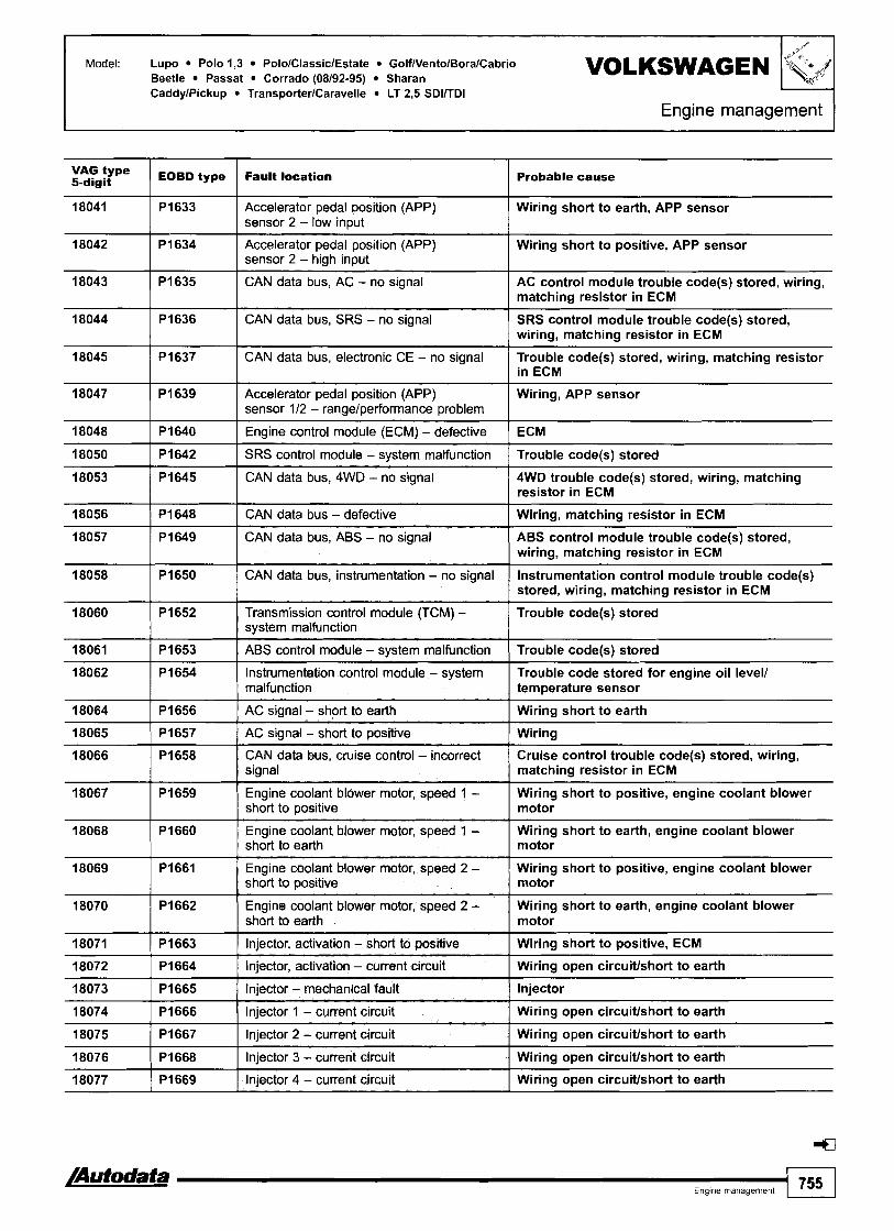
Model: Lupo Polo 1,3 PololClassiclEstate GolfNentolBoralCabrio Beetle Passat Corrado (08192-95) Sharan CaddylPickup TransporterlCaravelle LT 2,5 SDlITDl
Engine management
vAG type 5-digit
18045 1 CAN data bus, electronic CE - no signal code(s) stored, wiring, matching resistor
18041
18042
18043
18044
EOBD type 1 Fault location
18056 1 P I 648 1 CAN data bus - defective I Wiring, matching resistor in ECM
Probable cause
PI633
PI634
P I 635
PI636
18047
18048
18050
18053
18061 1 PI653 I ABS control module - svstem malfunction I Trouble codelsl stored
Accelerator pedal position (APP) sensor 2 - low input
Accelerator pedal position (APP) sensor 2 - high input
CAN data bus, AC - no signal
CAN data bus, SRS - no signal
PI639
PI640
PI642
PI645
18057
18058
18060
Wiring short to earth, APP sensor
Wiring short to positive, APP sensor
AC control module trouble code(s) stored, wiring, matching resistor in ECM
SRS control module trouble code(s) stored, wiring, matching resistor in ECM
Accelerator pedal position (APP) sensor 112 - rangelperformance problem
Engine control module (ECM) - defective
SRS control module - system malfunction
CAN data bus, 4WD - no signal
PI649
PI650
PI652
18062
18064
18065
18066
18067
18071 1 PI663 1 Injector, activation - short to positive I Wiring short to positive, ECM
Wiring, APP sensor
ECM
Trouble code(s) stored
4WD trouble code(s) stored, wiring, matching resistor in ECM
18068
18069
18070
18072 1 PI664 1 Injector, activation - current circuit I Wiring open circuiffshort to earth
CAN data bus, ABS - no signal
CAN data bus, instrumentation - no signal
Transmission control module (TCM) - svstem malfunction
P I 654
P I 656
PI657
PI658
PI659
18073 1 PI665 1 Injector - mechanical fault 1 Injector
ABS control module trouble code(s) stored, wiring, matching resistor in ECM
Instrumentation control module trouble code(s) stored, wiring, matching resistor in ECM
Trouble code(s) stored
P I 660
PI661
P I 662
18074 1 PI666 ( Injector 1 - current circuit 1 Wiring open circuiffshort to earth
Instrumentation control module - system malfunction
AC signal - short to earth
AC signal - short to positive
CAN data bus, cruise control - incorrect signal
Engine cootant blower motor, speed 1 - short to positive
Trouble code stored for engine oil level1 temperature sensor
Wiring short to earth
Wiring
Cruise control trouble code(s) stored, wiring, matching resistor in ECM
Wiring short to positive, engine coolant blower motor
Engine coolant blower motor, speed 1 - short to earth
Engine coolant blower motor, speed 2 - short to positive
Engine coolant blower motor, speed 2 - short to earth
Wiring short to earth, engine coolant blower motor
Wiring short to positive, engine coolant blower motor
Wiring short to earth, engine coolant blower motor
18075
18076
18077
/Autodata Ename manaaement
PI667
PI668
PI669
755
Injector 2 - current circuit
Injector 3 - current circuit
Injector 4 - current circuit
Wiring open circuiffshort to earth
Wiring open circuiffshort to earth
Wiring open circuiffshort to earth

VOLKSWAGEN Model: Lupo Polo 1,3 PololClassiclEstate GolfNentolBoralCabrio Beetle Passat Corrado (08192-95) Sharan CaddylPickup TransporterlCaravelle LT 2,5 SDlfrDl
Engine management
18080 1 Engine coolant blower motor, speed 1 - Wiring open circuitlshort to earth open circuiffshort to earth
type 5-digit
18082 1 CAN data bus, instrumentation - incorrect Wiring, instrumentation control module trouble signal I code(s) stored, matching resistor in ECM
stored, wiring short to positive, matching resistor in ECM
Probable cause EOBD type
18084
18085
Fault location
I -
stored, wiring open circuit, matching resistor. in 1 ECM
PI676
PI677
ETS warning lamp - short to earth
ETS warning lamp - open circuit
18088 El 1 PI680 I Limp-home mode - active I Throttle control unit, APP sensor
Instrumentation control module trouble code(s) stored, wiring short to earth, matching resistor in ECM
Instrumentation control module trouble code(s)
ETS warning lamp - circuit malfunction
ETS warning lamp - short to positive
18091 I CAN data bus. SRS - implausible signal SRS control module trouble code(s) stored, wiring, matching resistor in ECM
Instrumentation control module trouble code(s) stored, wiring, matching resistor in ECM
Instrumentation control module trouble code(s)
18089
I8090
PI681
P I 682
18098
18099
Malfunction indicator lamp (MIL) - short to earth
Malfunction indicator lamp (MIL) - short to positive
Engine control module (ECM) - programming incomplete
CAN data bus, ABS - implausible signal
PI690
PI691
lnstrumentation control module trouble code(s) stored, wiring short to earth, matching resistor in ECM
lnstrumentation control module trouble code(s) stored, wiring short to positive, matching resistor in ECM
18104
18259
18261
1 831 0 1 Engine coolant blower motor run-on relay - Wiring open circuitlshort to earth, engine coolant open circuiffshort to earth blower motor run-on relay
ECM
ABS control module trouble code(s) stored, wiring, matching resistor in ECM
18262
18308
18309
Malfunction indicator lamp (MIL) - circuit malfunction
Malfunction indicator lamp (MIL) - open circuit
P 1696
PI851
PI853
1 756 I,,,.,,,.,,,,,, /Autodata
Instrumentation control module trouble code(s) stored, wiring, matching resistor in ECM
Instrumentation control module trouble code(s) stored, wiring open circuit, matching resistor in ECM
PI854
P I 900
PI901
18311
CAN data bus, steering column electronics - incorrect signal
CAN data bus, ABS - incorrect signal
CAN data bus, ABS - incorrect signal
Wiring, matching resistor in ECM
ABS trouble code(s) stored, wiring, matching resistor in ECM
ABS trouble code(s) stored, wiring, matching resistor in ECM
CAN data bus, ABS - defective
Engine coolant blower motor, speed 2 - open circuiffshort to earth
Engine coolant blower motor run-on relay - short to positive
PI903
ABS trouble code(s) stored, wiring, matching resistor in ECM
Wiring open circuitlshort to earth, engine coolant blower motor
Wiring short to positive, engine coolant blower motor run-on relay
Engine coolant hydraulic blower motor solenoid - short to positive
Wiring short to positive, engine coolant hydraulic blower motor solenoid

Model: Lupo Polo 1,3 PololClassiclEstate GolfNentolBoralCabrio Beetle Passat Corrado (08192-95) Sharan CaddylPickup TransporterlCaravelle LT 2,5 SDlITDl
Engine management 1 VAG type 5-digit
18312
EOBD type Fault location Probable cause
Charge air coolant pump relay - short to positive
Engine coolant hydraulic blower motor solenoid - open circuit/short to earth
Wiring short to positive, charge air coolant pump relay
Wiring open circuiffshort to earth, engine coolant hydraulic blower motor solenoid
Charge air coolant pump relay - open circuit/ short to earth
Data bus, ECM 112 - defective
Data bus, ECM 112 - software version monitoring
Data bus, ECM 112 - circuit malfunction I Wiring, ECM 112
Wiring open circuiffshort to earth, charge air coolant pump relay
Wiring
Data in ECM I 8 ECM 2 does not match
Data bus, ECM 112 - no signal from ECM 1
Data bus, ECM 112 - no signal from ECM 2
Brake servo pressure sensor - open circuit/ short to positive
Wiring, ECM 1
Wiring, ECM 2
Wiring open circuiffshort to positive, brake servo pressure sensor
Engine mounting control solenoid, bank 1 8 2 - open circuit/short to earth
Brake servo pressure sensor - short to earth
Brake servo pressure sensor - range1 performance problem
Wiring open circuiffshort to earth, engine mounting control solenoid
Wiring short to earth, brake servo pressure sensor
Vacuum leak, wiring, brake servo pressure sensor
Engine control module (ECM) 2 - malfunction
CAN data bus, instrumentation - glow plug warning lamp
Accelerator pedal position (APP) sensor - transmission kick-down switch
Trouble code(s) stored
Wiring, matching resistor in ECM
APP sensor
Engine coolant heater relay 1, low output I Wiring, engine coolant heater relay
Engine coolant heater relay 2, high output I Wiring, engine coolant heater relay
Camshaft position (CMP) sensor - no signal Air gap, insecure sensorlrotor, wiring, I CMP sensor
Fuel pump relay - short to positive I Wiring short to positive, fuel pump relay
Camshaft position (CMP) sensor - signal Ilm~t exceeded
Fuel cooling pump relay - short to positive
Fuel cooling pump relay - open circuit/short to earth
Fuel pump relay -open circuit/short to earth 1 Wiring open circuiffshort to earth, fuel pump relay
Insecure rotor, camshaft alignment
Wiring short to positive, fuel cooling pump relay
Wiring open circuiffshort to earth, fuel cooling pump relay
Turbocharger (TC) wastegate regulating Wiring short to positive, TC wastegate regulating valve B - short to positive valve
Fuel bypass valve - open circuit/short to Wiring open circuiffshort to earth, fuel bypass earth valve
- - --
Turbocharger (TC) wastegate regulating - valve B - open circuitlshort to earth
Fuel bypass valve - short to positive
Gear ratio - implausible I Transmission fault
-
Wiring open circuiffshort to earth, TC wastegate regulating valve
Wiring short to positive, fuel bypass valve
/Autodata E n g ~ n e management 757

F e management
Model: Lupo Polo 1,3 PololClassiclEstate GolfNentolBoralCabrio Beetle Passat Corrado (08192-95) Sharan CaddylPickup TransporterlCaravelle LT 2,5 SDllTDl
vAG 1 EOBD type 5-digit Fault location Probable cause
Intake manifold air control solenoid - open Wiring open circuitlshort to earth, intake manifold circuitlshort to earth air control solenoid
CAN data bus, instrumentation - implausible ECT signal
Intake manifold air control solenoid - short to ~osit ive
Wiring, matching resistor in ECM
Wiring short to positive, intake manifold air control solenoid
Engine control module (ECM) - defective I ECM
Heated oxygen sensor (H02S) 2, bank 1 & 2 - interchanged
CAN data bus, ABS - defective
Trouble code may be displayed if engine is not idling during self-diagnosis due to missing CKP sensor signal. Ignore trouble code if engine starts. Located at rear of exhaust camshaft. Throttle control unit incorporates the following components: TP sensor, CTP switch (if fitted), ISC actuator/position sensor or throttle motorlposition sensor. May also produce HT voltage for cylinder 4. May also produce HT voltage for cylinder 3. Incorporates heated oxygen sensor (H02S) 2.
H02S 2 on bank 1 8 2 incorrectly installed
ABS trouble code(s) stored, wiring, matching resistor in ECM
1 758 I,,,,,,,,,,,,, /Autodata

Model: Polo 1,OS Passat 1,G Passat 1,8 (-+08190)
Year: 1988-90 VOLKSWAGEN
Engine code: 1 F, RP, AAK System: Bosch Mono-Jetronic A2.2
Engine management
Polo - fascia, driver's side Passat - centre console (if fitted)
General information Refer to the front of this manual for general test conditions, terminology, detailed descriptions of wiring faults and a general trouble shooter for electrical and mechanical faults.
o Trouble codes are displayed by using an LED connected to the data link connector (DLC).
0 The ECM fault memory can also be checked and erased using diagnostic equipment connected to the data link connector (DLC).
0 Carry out road test for 10 minutes.
Accessing Ensure ignition switched OFF. Connect test wire between black data link connector (DLC) terminal 1 rn [A] and brown data link connector (DLC) terminal 1 0 [El. Connect LED test lamp between black data link connector (DLC) terminal 2 [A] and brown data link connector (DLC) terminal 1 0 [El. Start engine. Allow to idle.
NOTE: If engine does not start: Crank engine for 6 seconds. Leave ignition switched ON.
Bridge test wire terminals 3 and 4 0. Disconnect test wire after 5 seconds. Check that LED flashes. Count LED flashes. Note trouble code.
o Each trouble code consists of four groups of one to four flashes.
n A 2,5 second pause separates each trouble code group H [A]. Repeat operation. Note trouble codes. Compare with trouble code table. End of test sequence indicated by trouble code 0000 (long flashes). Switch ignition OFF. Rectify faults as necessary.
/Autodata Engine rnanagemenl 759

I Engine management
Erasing
Method 1 Ensure ignition switched OFF. Connect test wire between black data link connector (DLC) terminal 1 [A] and brown data link connector (DLC) terminal 1 0 [B]. Bridge test wire terminals 3 and 4 0. Switch ignition ON. Disconnect test wire after 5 seconds. Repeat checking procedure to ensure no data remains in ECM fault memory.
Method 2 Ensure ignition switched OFF. Disconnect ECM multi-plug or battery earth lead.
NOTE: ECM adaptive memory may be erased causing erratic running faults. Carry out road test to allow ECM to re-learn basic values.
WARNING: Disconnecting the battery may erase memory from electronic units (e.g. radio, clock).
Trouble code identification
Flash type Fault location Probable cause
1111 I Engine control module (ECM) ( ECM
I 1
1232 1 Idle speed control (ISC) actuator I Wiring, multi-plug incorrectly wired, ISC actuator
0000 I End of test sequence
1 Closed throttle position (CTP) switch
-
Accelerator cable adjustment, CTP switch adjustment, wiring, CTP switch, ignition timing vacuum control valve, TP sensor
2122 1 Engine RPM signal I Wiring, CKP sensor, ignition amplifier
2212 1 Throttle position (TP) sensor I Wiring, TP sensor
2341 1 Oxygen sensor (02S)lheated oxygen sensor (H02S) - lntakelexhaust leak, low compression, ignition lambda control system, fuel pressurelpump, injector, wiring, 0 2 s
231 2
2322
4431 I Idle speed control (ISC) actuator I Wiring, multi-plug incorrectly wired, ISC actuator
Engine coolant temperature (ECT) sensor
Intake air temperature (IAT) sensor
2342
2343
Wiring, ECT sensor
Wiring, IAT sensor
rn After repairs, erase trouble code and learnt lambda control values by disconnecting battery or ECM multi-plug for at least 30 seconds. Carry out road test to allow ECM to re-learn basic values. 4
Oxygen sensor (02s)
Mixture control (MC)
4444
Wiring, 02s
lntakelexhaust leak, low compression, ignition system, fuel pressurelpump, injector
No fault found -

Model: Polo 1,0511,3 (+08193) Passat 1,8 (RP 08190 4) Passat 1,8 (AAM +06192) Passat 1,8 (ABS -*06/92)
VOLKSWAGEN 'k4f 4 Year: 1990-93
Engine code: AAM, ABD, ABS, AAU, AAV, RP
System: Bosch Mono-Motronic MA1.2 Bosch Mono-Motronic MA1.2.1
Engine management
Polo - under fascia, near glovebox
NOTE: 35 pin ECM multi-plug.
General information 0 Refer to the front of this manual for general test conditions,
terminology, detailed descriptions of wiring faults and a general trouble shooter for electrical and mechanical faults. Trouble codes are displayed by using an LED connected to one of the ECM terminals.
0 The ECM fault memory can also be checked and erased using diagnostic equipment connected to the data link connector (DLC). Self-diagnosis using flash type trouble codes may not display all available diagnostic information.
0 Carry out road test for at least 10 minutes. n Ensure accelerator pedal is briefly fully depressed and
engine speed exceeds 3000 rpm.
Accessing Ensure ignition switched OFF. Bridge black data link connector (DLC) terminal 1 rn [A] and brown or white data link connector (DLC) terminal 1 rn [B] with a switched lead - contacts normally open. Connect LED test lamp between black data link connector (DLC) terminal 2 [A] and ECM terminal 33. ECM located in plenum chamber.
NOTE: DO NOT disconnect ECM multi-plug as this will erase fault memory.
Start engine. Allow to idle. NOTE: If engine does not start: Crank engine for 6 seconds.
Leave ignition switched ON.
Passat - centre console
Release switch. Check that LED flashes. Count LED flashes. Note trouble code. Each trouble code consists of four groups of one to four flashes.
0 A 2,5 second pause separates each trouble code group [A]. Repeat switch operation. Note trouble codes. Compare with trouble code table. End of test sequence indicated by trouble code 0000 (long flashes). Switch ignition OFF. Rectify faults as necessary.
Operate switch for 4 seconds minimum
/Autodata Engine management 761

Engine management
J
Method 1
Ensure ignition switched OFF. Bridge black data link connector (DLC) terminal 1 fl [A] and brown or white data link connector (DLC) terminal 1 [B] with a switched lead - contacts normally open. Operate switch and hold. Switch ignition ON. Release switch after 5 seconds minimum. Repeat checking procedure to ensure no data remains in ECM fault memory.
VOLKSWAGEN Model: Polo l,O5/1,3 (408193) Passat 1,8 (RP 08/90 4 ) Passat 1,8 (AAM +06/92) Passat 1,8 (ABS 406192)
Method 2 Ensure ignition switched OFF. Disconnect ECM multi-plug or battery earth lead.
-
NOTE: ECM adaptive memory may be erased causing erratic running faults. Carry out road test to allow ECM to re-learn basic values.
WARNING: Disconnecting the battery may erase memory from electronic units (e.g. radio, clock).
Trouble code identification
Flash 'ype I Faun location 4-digit I Probable cause
1231 I Vehicle speed sensor (VSS) I Wiring, speedometer, VSS
0000
1111
2121 I Closed throttle position (CTP) switch
End of test sequence
Engine control module (ECM)
1232
2113
Accelerator cable adjustment, CTP switch adjustment, wiring, CTP switch
-
ECM
221 2 I Throttle position (TP) sensor I Wiring, poor connection, TP sensor
Idle speed control (ISC) actuator
Crankshaft position (CKP) sensorlengine speed (RPM) sensor
Wiring, multi-plug incorrectly wired, ISC actuator
Insecure rotor, wiring, CKPIRPM sensor
2322 I Intake air temperature (IAT) sensor I Wiring, IAT sensor
2234
231 2
2341 rn Heated oxygen sensor (H02S) - lambda control Heating inoperative, exhaust leak, misfire, fuel pressurelpump, EVAP canister purge valve
-
2342 I ~ e a t e d oxygen sensor (H02S)
Engine control module (ECM) - supply voltage
Engine coolant temperature (ECT) sensor
-- I wiring,~~~~, heating inoperative, fuel level low
Battery, wiring
Wiring, poor connection, ECT sensor
Fuel level low, fuel pressurelpump, intakelexhaust leak, misfire, HOZS, EVAP canister purge valve, injector, excessive fuel in engine oil
2413 Mixture control (MC)
Trouble code may be displayed if engine is not idling during self-diagnosis due to missing CKPIRPM sensor signal. Ignore trouble code if engine starts.
rn After repairs, erase learnt lambda control values: Wait 30 seconds. Disconnect battery or ECM multi-plug for at least 30 seconds. Carry out road test to allow ECM to re-learn basic values.
4444
1 762 I,,,,,,,,,,,,,,, /Autodata
No fault found -

Model: Polo l,O5/l,3 (-08193) Passat 1,8 (RP 08\90 -+) Passat 1,8 (AAM -06192) Passat 1,8 (ABS -06192)
Engine management
type Fault location 5-digit Probable cause
00282 1 Idle speed control (ISC) actuator I Wiring, multi-plug incorrectly wired, ISC actuator
00000
00281
Crankshaft position (CKP) sensorlengine speed Insecure rotor, wiring, CKPIRPM sensor (RPM) sensor
No fault found
Vehicle speed sensor (VSS)
00522 1 Engine coolant temperature (ECT) sensor I Wiring, poor connection, ECT sensor
-
Wiring, speedometer, VSS
00516
00518
00523 ( Intake air temperature (IAT) sensor I Wiring, IAT sensor
00525 1 Heated oxygen sensor (H02S) I Wiring, H02S, heating inoperative, fuel level low
Closed throttle position (CTP) switch
Throttle position (TP) sensor
Accelerator cable adjustment, CTP switch adjustment, wiring, CTP switch
Wiring, poor connection, TP sensor
00525 1 Heated oxygen sensor (H02S) ( Wiring, H02S, heating inoperative, fuel level low
00532
00537 H
Fuel level low, fuel pressurelpump, intakelexhaust leak, misfire, H02S, EVAP canister purge valve, injector, excessive fuel in engine oil
Engine control module (ECM) - supply voltage
Heated oxygen sensor (H02S) - lambda control
00561
00670 1 ldle speed control (ISC) actuator position sensor I Wiring, throttle valve, ISC actuator position sensor
Battery, wiring
Heating inoperative, exhaust leak, misfire, fuel pressurelpump, EVAP canister purge valve
Mixture control (MC)
Trouble code may be displayed if engine is not idling during self-diagnosis due to missing CKPIRPM sensor signal. Ignore trouble code if engine starts.
H After repairs, erase learnt lambda control values: Wait 30 seconds. Disconnect battery or ECM multi-plug for at least 30 seconds. Carry out road test to allow ECM to re-learn basic values. c=3
17978
65535
Engine control module (ECM) immobilizer active
Engine control module (ECM)
lncorrecffdamaged key, incorrectly coded, ECMlimmobilizer replacement without coding, wiring, immobilizer defective
ECM

1 VOLKSWAGEN
Model: Polo 1 ,O5/l,3 (08193 -+) Polo ClassiclEstate l,6/l,8 GolfNento 1,4 (07192 -+) GolfNento 1,6 GolfNentolCabrio 1,8 (07193 -+) Passat 1,8 (AAM, ADZ 07194-+) Passat 1,8 (ABS 10193 -+) CaddylPickup 1,6
Year: 1992-02 Engine IF, AAM, AAU, AAV, ABD, ABS, ABU, ADX, ADZ, AEA, AEV, ANN, ANP code:
System: Bosch Mono-Motronic MAl.2.3 Bosch Mono-Motronic MA1.3
Engine management
Polo 4 9 9 4 - under fascia, near glovebox Polo 1994-, ClassiclEstate -09199 - driver's glovebox
-- -- - -
ClassiclEstate 10199+ - under front ashtray
J
GolfNento -07193 - below heater controls
GolfNento 08193+, Cabrio - adjacent to ashtray
Passat -1993 - centre console

GolfNentolCabrio 1,8 (07193 +) Passat 1,8 (AAM, ADZ 07/94 -.) Passat 1,8 (ABS 10193 4) CaddylPickup 1,6
Model. Polo 1 ,OSll,3 (08193 +) Polo ClassiclEstate l , 6 / l , 8 GolfNento 1,4 (07192 +) GolfNento 1,6 VOLKSWAGEN
Engine rnanagc--1
/
'kF?
Ensure accelerator pedal is briefly fully depressed and engine speed exceeds 3000 rpm. If engine does not start: Crank engine for 6 seconds. Leave ignition switched ON.
0 Data link connector (DLC) - 2-pin: (A) black, (B) brownlwhite.
Accessing The engine control module (ECM) fault memory can only be accessed and erased using diagnostic equipment connected to the data link connector (DLC).
NOTE: Brown or white data link connector (DLC) terminal 1 is not connected to ECM terminal 11.
Passat 1994+ - adjacent to steering column Erasing Ensure ignition switched OFF. Disconnect ECM multi-plug or battery earth lead.
NOTE: ECM adaptive memory may be erased causing erratic running faults. Carry out road test to allow ECM to re-learn basic values.
Diagnostic equipment can also be used to erase data from ECM fault memory.
--
General information 0 Refer to the front of this manual for general test conditions,
terminology, detailed descriptions of wiring faults and a general trouble shooter for electrical and mechanical faults. Carry out road test for at least 10 minutes.
WARNING: Disconnecting the battery may erase memory from electronic units (e.g. radio, clock).
Trouble code identification
VAG type Fault location Probable cause
No fault found I -
Crankshaft position (CKP) sensorlengine speed I Insecure rotor, wiring, CKPIRPM sensor (RPM) sensor
Vehicle speed sensor (VSS)
Idle speed control (ISC) actuator
Wiring, speedometer, VSS
Wiring, multi-plug incorrectly wired, ISC actuator
Knock sensor (KS) I Wiring, KS
Closed throttle position (CTP) switch
Throttle position (TP) sensor
Engine coolant temperature (ECT) sensor
Intake air temperature (IAT) sensor
Accelerator cable adjustment, wiring, CTP switch
Wiring, poor connection, TP sensor
Wiring, poor connection, ECT sensor
Wiring, IAT sensor
Heated oxygen sensor (H02S) - lambda control Heating inoperative, exhaust leak, misfire, fuel press~?rel pump, EVAP canister purge valve
Heated oxygen sensor (H02S)
Engine control module (ECM) - supply voltage
Mixture control (MC)
Wiring, H02S, heating inoperative, fuel level low
Battery, wiring
Fuel level low, fuel pressurelpump, intakelexhaust leak, misfire, H02S, EVAP canister purge valve, injector, excessive fuel in engine oil
ldle speed control (ISC) actuator position sensor ( Wiring, throttle valve, ISC actuator position sensor
Engine control module (ECM) I ECM
Engine control module (ECM) immobilizer active
Trouble code may be displayed if engine is not idling during self-diagnosis due to missing CKPIRPM sensor signal. Ignore trouble code if engine starts.
rn After repairs, erase learnt lambda control values as follows: Polo -+1994, GolfNento -07193 & Passat: Wait 30 seconds. Disconnect battery or ECM multi-plug for at least 30 seconds. Except Polo -1994. GolfNento -07193 & Passat: Erase using diagnostic equipment. Carry out road test to allow ECM to re-learn basic values. <:a
lncorrectldamaged key, incorrectly coded, ECMlimmobilizer replacement without coding, wiring, immobilizer defective

VOLKSWAGEN Model: GolfNento 1,4 (-07192) GolfNento 1,8 (-07193) Passat 1,8 (AAM -07194) Passat 1,8 (ABS -1 0193)
Engine management
Year: 1991-1994
Engine code: AAM, ABD, ABS, AAU, AAV, RP
System: Bosch Mono-Motronic MA1.2.2
GolfNento - below heater controls Passat - centre console
NOTE: 45 pin ECM multi-plug.
General information
Operate switch for 4 seconds minimum. Release switch. Check that LED flashes Count LED flashes. Note trouble code. Each trouble code consists of four groups of one to four flashes. - -
Refer to the front of this manual for aeneral test conditions. A 215 pause separates each trouble group [A]. terminology, detailed descriptions of\iring faults and a general trouble shooter for electrical and mechanical faults. Trouble codes are displayed by using an LED connected to one of the ECM terminals. The ECM fault memory can also be checked and erased using diagnostic equipment connected to the data link connector (DLC). Self-diagnosis using flash type trouble codes may not display all available diagnostic information. Carry out road test for at least 10 minutes. Ensure accelerator pedal is briefly fully depressed and engine speed exceeds 3000 rpm.
Accessing Ensure ignition switched OFF. Bridge black data link connector (DLC) terminal 1 rn [A] and brown or white data link connector (DLC) terminal 1 rn [B] with a switched lead - contacts normally open.
NOTE: Brown or white data link connector (DLC) terminal 1 is connected to ECM terminal 11.
Connect LED test lamp between black data link connector (DLC) terminal 2 [A] and ECM terminal 4. ECM located in plenum chamber.
NOTE: DO NOT disconnect ECM multi-plug as this will erase fault memory.
Start engine. Allow to idle. NOTE: If engine does not start: Crank engine for 6 seconds.
Leave ignition switched ON.
Repeat switch operation. Note trouble codes. Compare with trouble code table. End of test sequence indicated by trouble code 0000 (long flashes). Switch ignition OFF. Rectify faults as necessary.

Model: GolfNento 1,4 (-07192) GolfNento 1,8 (-07193) Passat 1,8 (AAM -07194) Passat 1,8 (ABS -10193) VOLKSWAGEN
I Engine management I
Erasing
Method 1
Ensure ignition switched OFF. Bridge black data link connector (DLC) terminal 1 rn [A] and brown or white data link connector (DLC) terminal 1 [B] with a switched lead - contacts normally open. Connect LED test lamp between data link connector (DLC) terminal 2 rn [A] and ECM terminal 4.
Trouble code identification
Access trouble codes. Switch ignition OFF. Operate switch and hold. Switch ignition ON. Release switch after 5 seconds. Check that LED flashes. ldle speed control (ISC) actuator activated. Trouble code displayed: 1232. Operate switch for 4-6 seconds to activate each of the following components: Intake manifold heater. Trouble code displayed: 4342.
u Evaporative emission (EVAP) canister purge valve. Trouble code displayed: 4343. After activation of last component operate switch for 4-6 seconds to display flash code 0000 (long flashes). Fault memory automatically erased. Repeat checking procedure to ensure no data remains in ECM fault memory.
Method 2 Ensure ignition switched OFF. Disconnect ECM multi-plug or battery earth lead
NOTE: ECM adaptive memory may be erased causing erratic running faults. Carry out road test to allow ECM to re-learn basic values.
WARNING: Disconnecting the battery may erase memory from electronic units (e.g. radio, clock).
Probable cause I I
0000 I End of test sequence - 1111 I Engine control module (ECM) I ECM
1231 I Vehicle speed sensor (VSS) I Wiring, speedometer, VSS
1232 I Idle speed control (ISC) actuator I Wiring, multi-plug incorrectly wired, ISC actuator
2113 El I Crankshaft position (CKP) sensor I Insecure rotor, wiring, CKP sensor
Closed throttle position (CTP) switch Accelerator cable adjustment, CTP switch adjustment, wiring, CTP switch
2212 I Throttle position (TP) sensor I Wiring, poor connection, TP sensor
2234 I Engine control module (ECM) - supply voltage ( Battery, wiring
2312 I Engine coolant temperature (ECT) sensor I Wiring, poor connection, ECT sensor
2322 / Intake air temperature (IAT) sensor I Wiring, IAT sensor
2341 H Heated oxygen sensor (H02S) - lambda control Heating inoperative, exhaust leak, misfire, fuel pressurelpump, EVAP canister purge valve
I
4444 ] No fault found
2342
2413 H Wiring, H02S, heating inoperative, fuel level low
Fuel level low, fuel pressurelpump, intakelexhaust leak, misfire, H02S, EVAP canister purge valve, injector, excessive fuel in engine oil
-
Heated oxygen sensor (H02S)
Mixture control (MC)
El Trouble code may be displayed if engine is not idling during self-diagnosis due to missing CKP sensor signal. Ignore trouble code if engine starts.
H After repairs, erase learnt lambda control values: Wait 30 seconds. Disconnect battery or ECM multi-plug for at least 30 seconds. Carry out road test to allow ECM to re-learn basic values.

VOLKSWAGEN Model: GolfNento 1,4 (+07192) GolfNento 1,8 (+07193) Passat 1,8 (AAM +07194) Passat 1,8 (ABS 40193)
I Engine management
VAG type I F ~ U M location 5-digit Probable cause I
00000 I No fault found
00281 1 Vehicle speed sensor (VSS) Wiring, speedometer, VSS
00282 1 ldle speed control (ISC) actuator Wiring, multi-plug incorrectly wired, ISC actuator
0051 5 rn [ Crankshaft position (CKP) sensor Insecure rotor, wiring, CKP sensor
00516 I Closed throttle position (CTP) switch Accelerator cable adjustment, CTP switch adjustment, wiring, CTP switch
00518 1 Throttle position (TP) sensor Wiring, poor connection, TP sensor
00522 1 Engine coolant temperature (ECT) sensor Wiring, poor connection, ECT sensor
00523 1 Intake air temperature ([AT) sensor Wiring, IAT sensor
00525 ( Heated oxygen sensor (H02S) Wiring, H02S, heating inoperative, fuel level low
00532 1 Engine control module (ECM) - supply voltage Battery, wiring
00537 rn 1 Heated oxygen sensor (H02S) - lambda control Heating inoperative, exhaust leak, misfire, fuel pressurelpump, EVAP canister purge valve
Wiring, H02S, heating inoperative, fuel level low I
00525 I Heated oxygen sensor (H02S)
00561 rn I Mixture control (MC) Fuel level low, fuel pressurelpump, intakelexhaust leak, misfire, H02S, EVAP canister purge valve, injector, excessive fuel in engine oil
Wiring, throttle valve, ISC actuator position sensor 00670 I Idle speed control (ISC) actuator position sensor
17978 1 Engine control module (ECM) immobilizer active lncorrectldamaged key, incorrectly coded, ECMlimmobilizer replacement without coding, wiring, immobilizer defective
65535 1 Engine control module (ECM) ECM
rn Trouble code may be displayed if engine is not idling during self-diagnosis due to missing CKP sensor signal. Ignore trouble code if engine starts. After repairs, erase learnt lambda control values: Wait 30 seconds. Disconnect battery or ECM multi-plug for at least 30 seconds. Carry out road test to allow ECM to re-learn basic values. 4

Engine code: 9A
Bosch KE-Motronic 1.2/1.2.1/1.2.2
I Engine management I
I
Near gear lever
General information Refer to the front of this manual for general test conditions, terminology, detailed descriptions of wiring faults and a general trouble shooter for electrical and mechanical faults. Trouble codes are displayed by using an LED connected to the data link connector (DLC).
0 The ECM fault memory can also be checked and erased using diagnostic equipment connected to the data link connector (DLC). Self-diagnosis using flash type trouble codes may not display all available diagnostic information. Carry out road test for at least 5 minutes. Briefly fully depress throttle pedal to increase engine speed over 3000 rpm. Allow to idle for 2 minutes. If engine does not start: Crank engine for 6 seconds.
Accessing Ensure ignition switched OFF. Connect LED test lamp between black data link connector (DLC) terminal 2 0 [A] and blue data link connector (DLC) terminal 2 0 [Cl. Bridge black data link connector (DLC) terminal 1 1 [A] and brown/whitelyellow data link connector (DLC) terminal 1 1 [B] with a switched lead - contacts normally open. Switch ignition ON. Operate switch for 4-6 seconds. Release switch. Check that LED flashes. Count LED flashes. Note trouble code. Each trouble code consists of four groups of one to four flashes. A 2,5 second pause separates each trouble code group [A]. Repeat switch operation. Note trouble codes. Compare with trouble code table.
End of test sequence indicated by trouble code 0000 (long flashes). Switch ignition OFF. Rectify faults as necessary.
/Autodata Engme management 769

Erasing Ensure ignition switched OFF. Connect LED test lamp between black data link connector (DLC) terminal 2 LI [A] and blue data link connector (DLC) terminal 2 LI [C]. Bridge black data link connector (DLC) terminal 1 [A] and brown/white/yellow data link connector (DLC) terminal 1 [B] with a switched lead - contacts normally open. Access trouble codes. Switch ignition OFF. Operate switch. Switch ignition ON after 4-6 seconds. Release switch after 4-6 seconds. Check that LED flashes. Differential pressure regulator activated. Trouble code displayed: 4341.
Trouble code identification
Operate switch for 4-6 seconds to activate each of the following components: Evaporative emission (EVAP) canister purge valve. Trouble code displayed: 4343. ldle air control (IAC) valve. Trouble code displayed: 4431. Cold start injector. Trouble code displayed: 4443. After activation of last component operate switch for 4-6 seconds to display flash code 0000 (long flashes). Operate switch for 4-6 seconds to erase fault memory. Repeat checking procedure to ensure no data remains in ECM fault memory.
1111 I Engine control module (ECM) 1 ECM
type 4-digit
0000
Fault location
End of test sequence
1231
2112
Probable cause
-
2113
2121
21 42 I Knock sensor (KS) 1 I Wiring, KS, ECM
Vehicle speed sensor (VSS)
Camshaft position (CMP) sensor, cylinder 4 HT lead
2123
2141
21 44 I Knock sensor (KS) 2 I Wiring, KS, ECM
Wiring, speedometer, VSS
CMP sensor tabs not facing towards distributor, spark plug(s), HT lead(s), distributor caplrotor, wiring, CMP sensor
Crankshaft position (CKP) sensor
Closed throttle position (CTP} switch
ldle speed control
Insecure rotor, wiring, CKP sensor, volume air flow (VAF) sensor plate tightlsticking
Accelerator cable adjustment, CTP switch adjustment, throttle valve tightlsticking, wiring, CTP switch
Wide open throttle (WOT) switch
Knock control - control limit exceeded
Ignition timing, EVAP canister purge valve 112, intake leak, VAF sensor, throttle valve adjustment, AC signal missing, wiring
Accelerator cable adjustment, WOT switch adjustment, wiring, WOT switch
Incorrect fuellcompression, ignition timing, screening of KS wiring, insecure engine component
2232 ( Volume air flow (VAF) sensor I Wiring, VAF sensor
2312 I Engine coolant temperature (ECT) sensor I Wiring, poor connection, ECT sensor
2342 I Heated oxygen sensor (H02S) I Wiring, H02S, heating inoperative
Heated oxygen sensor (H02S) - lambda control Mixture adjustment, H02S heaterlwiring, cold start injector, EVAP canister purge valve, intakelexhaust leak, ECM earth wire to intake manifold
4431
4444
Idle air control (IAC) valve
No fault found
Wiring, IAC valve, ECM
-

Model: Jetta 2.0 16V Passat 2,O 16V Corrado 2,O 16V VOLKSWAGEN
VAG type 5-digit Fault ioestlon
No fault found I -
Probable cause
Vehicle speed sensor (VSS)
Camshaft position (CMP) sensor, cylinder 4 HT lead
Wide open throttte (WOT) switch 1 Accelerator cable adjustment, wiring, WOT switch
- - -
Wiring, speedometer, VSS
CMP sensor tabs not facing towards distributor, spark plug(s), HT lead(s), distributor caplrotor, wiring, CMP sensor
Crankshaft position (CKP) sensor
Closed throttle position (CTP) switch
Volume air flow (VAF) sensor ( Wiring, VAF sensor
Insecure rotor, wiring, CKP sensor, volume air flow (VAF) sensor plate tightlsticking
Accelerator cable adjustment, CTP switch adjustment, throttle valve tightlsticking, wiring, CTP switch
Heated oxygen sensor (H02S) I Wiring, H02S, heating inoperative
Engine coolant temperature (ECT) sensor
Knock sensor (KS) 1
Wiring, poor connection, ECT sensor
Wiring, KS, ECM
Idle speed control
Knock control - control limit exceeded
Mixture control (MC) - mixture lean
Ignition timing, EVAP canister purge valve 112, intake leak, VAF sensor, throttle valve adjustment, AC signal missing, wiring
Incorrect fuellcompression, ignition timing, screening of KS wiring, insecure engine component
Heated oxygen sensor (H02S) - lambda control
Knock sensor (KS) 2
ECM earth wire to intake manifold, intake leak, idle speed adjustment
Mixture adjustment, H02S heaterlwiring, cold start injector, EVAP canister purge valve, intakelexhaust leak, ECM earth wire to intake manifold
Wiring, KS, ECM
Idle air control (IAC) valve ( Wiring, IAC valve, ECM
--
Mixture control (MC) - mixture rich
Mixture control (MC)
Injector(s), cold start injector, idle speed adjustment
ECM earth wire to intake manifold, intake leak, idle speed adjustment, injectorIs), cold start injector
Enqine control module (ECM) I ECM
Engine control module (ECM) - immobilizer active lncorrectldamaged key, incorrectly coded, ECMlimmobilizer replacement without coding, wiring, immobilizer defective

Engine code: AGL
System: Bosch Motronic
Engine management
Fascia
--
General information 2 Refer to the front of this manual for general test conditions,
terminology, detailed descriptions of wiring faults and a general trouble shooter for electrical and mechanical faults.
o Carry out road test for at least 10 minutes. ;1 Ensure accelerator pedal is briefly fully depressed and
engine speed exceeds 3500 rpm. 0 If engine does not start: Crank engine for 6 seconds. Leave
ignition switched ON.
Accessing and erasing The engine control module (ECM) fault memory can only be accessed and erased using diagnostic equipment connected to the data link connector (DLC).
Trouble code identification I I
VAG type 1 Fault location / Probable cause
81 003 Engine coolant temperature (ECT) sensor - broken wire Wiring openlshort circuit, poor connection, I ECT sensor
00000
81002
81 004 Engine coolant temperature (ECT) sensor - range1 I ECT defective. ECM performance problem
No fault found
Engine coolant temperature (ECT) sensor - short circuit
81008 1 Intake air temperature (IAT) sensor - loose connection I Wiring, multi-plug, IAT sensor
-
Wiring short circuit, ECT sensor
81 005
81006
81007
Engine coolant temperature (ECT) sensor - loose connection
Intake air temperature (IAT) sensor - short circuit
Intake air temperature (IAT) sensor - broken wire
Wiring, multi-plug, ECT sensor
Wiring short circuit, IAT sensor
Wiring openlshort circuit, poor connection, IAT sensor

Model: LT 2,3 VOLKSWAGEN
Engine management
-
VAG type Fault location Probable cause
Closed throttle position (CTP) switch - loose connection ( Wiring, multi-plug, CTP switch
Manifold absolute pressure (MAP) sensor - range1 performance problem
Manifold absolute pressure (MAP) sensor - no signal
Closed throttle position (CTP) switch - switch contacts always closed
Hoses blockedlleaking, ECM
Hoses interchangedlnot connected, ECM
Wiring short circuit, CTP switch
Closed throttle position (CTP) switch - switch contacts always open
Throttle position (TP) sensor - high input
ldle speed control (ISC) actuator position sensor - low input
Wiring open circuit, throttle valve tighffsticking, ISC actuator, CTP switch
Wiring short to positive, TP sensor
Throttle position (TP) sensor - low input
Throttle position (TP) sensor - loose connection
Idle speed control (ISC) actuator position sensor - high input I Wiring short to earth, ISC actuator position sensor
- - -
Wiring shortto earth,^^ sensor
Wiring, multi-plug, TP sensor
Wiring short to positive, ISC actuator position sensor
Idling control - upper limit reached I ISC actuatorlposition sensor
ldle speed control (ISC) actuator position sensor - loose connection
Idling control - lower limit reached
Idling control - limp-home mode I ISC actuatorlposition sensor, intake leak
Wiring, multi-plug, ISC actuator position sensor
Intake leak
Heated oxygen sensor (H02S) - high voltage 1 Wiring short to positive, H02S
Heated oxygen sensor (H02S) - broken wire I Wiring open circuit, H02S
Heated oxygen sensor (H02S) - rangelperformance problem I Heated oxygen sensor (H02S) - heater short to earth I Wiring short to earth, H02S
Heated oxygen sensor (H02S) - heater short to positive I Wiring short to positive, H02S
Heated oxygen sensor (H02S) - broken wire I Wiring open circuit, H02S
Lambda regulation - control limit exceeded Fuel pressurelpump, ignition system, intake1 exhaust leak, injector(s), H02S, EVAP canister purge valve
Injectors 1 & 4 - short to positive I Wiring short to positive, injector
Heated oxygen sensor (H02S) - lambda control limit not reached
Fuel pressure, ignition system, intakelexhaust leak, injector(s), HOZSlheating, EVAP canister purge valve
Injectors 2 & 3 - open circuitlshort to earth ( Wiring open circuiffshort to earth, injector
Injectors 1 & 4 - open circuitkhort to earth
lniectors 2 & 3 - short to positive
Mixture control (MC), idling - too rich
Wiring open circuiffshort to earth, injector
Wiring short to positive, injector
Fuel pressure, ignition system, injector(s), H02SI heating, exhaust leak, EVAP canister purge valve
Mixture control (MC), partial load - too lean Fuel pressure, ignition system, intake leak, injector(s), HOZSlheating, exhaust leak
Mixture control (MC), idling - too lean
Mixture control (MC), partial load - too rich
Ignition coillamplifier, cylinders 1 & 4 - short to positive I Wiring, ignition coillamplifier
Fuel pressure, ignition system, intake leak, injector(s), HOZSlheating, exhaust leak
Fuel pressure, ignition system, injector(s), H02SI heating, exhaust leak, EVAP canister purge valve


I Year: 03\95-96
I Engine code: 1E
System: Bosch Digifant MP4.0
Engine management
I
Above fascia relay plate
Trouble code identification
General information Refer to the front of this manual for general test conditions, terminology, detailed descriptions of wiring faults and a general trouble shooter for electrical and mechanical faults.
o Carry out road test for at least 5 minutes. 0 Briefly fully depress throttle pedal to increase engine speed
over 3000 rpm. 0 Allow to idle for 5 minutes.
Accessing and erasing The engine control module (ECM) fault memory can only be accessed and erased using diagnostic equipment connected to the data link connector (DLC).
1111 I Engine control module (ECM) I ECM
Flash type 4-digit
0000
221 2 I Throttle position (TP) sensor I Wiring, poor connection, TP sensor
Fault location
End of test sequence
231 2 I Engine coolant temperature (ECT) sensor I Wiring, poor connection, ECT sensor
Probable cause
-
2222
2242
2322 I Intake air temperature (IAT) sensor I Wiring, IAT sensor
2341 I Heated oxygen sensor (H02S) - lambda control I ECM
Manifold absolute pressure (MAP) sensor
Mixture adjustment resistor
2342 I Heated oxygen sensor (H02S) 1 Wiring, H02S, heating inoperative, fuel level low
Hose connection(s), ECM
Wiring, mixture adjustment resistor
lncorporated in ECM
I I
4444 ( No fault found
00518 1 Throttle position (TP) sensor I Wiring, poor connection, TP sensor
-
type 5-digit
00000
00519 I Manifold absolute pressure (MAP) sensor / Hose connection(s), ECM
Fault location
No fault found
00532 1 Engine control module (ECM) - supply voltage I Alternator, battery, wiring
Probable cause
-
00522
00523
00525
01087 1 Engine control module (ECM) - basic setting I Basic setting not completed
Engine coolant temperature (ECT) sensor
Intake air temperature (IAT) sensor
Heated oxygen sensor (H02S)
Wiring, poor connection, ECT sensor
Wiring, poor connection, IAT sensor
Wiring, H02S, heating inoperative
65535
lncorporated In ECM. 4
Engine control module (ECM) - defective ECM

Model: Lupo PololClassiclEstate GolfNentolBoralCabrio Beetle Passat (08190 4) Corrado Sharan TransporterlCaravelle
Year: 1990-02
Transmission
Lupo -r04/00 - behind storage compartment Lupo 05t00-+, Polo 10l994, Classic & Estate 19@9+ - under front ashtray
Polo 47/97, Classk 81 Estate +I999 - in glovebox, driver's side
I
I
Polo 08197-09199 - in fascia fusebox
Gdfffemto -+07f93 - below heater controls
I
I
Golf 08/93-97, Vento 08/93-98, Cabrio - adjacent to ashtray

Model: Lupo PololClassiclEstate GolfNentolBoralCabrio Beetle Passat ( rrado Sharan TransporterlCaravelle
VOLKSWAGEN Id-' Transmission 4
Gdf 1997+, b r a - centre console
Passat $99446 - adjacent to steering column Beetle, Pasliat 1 W + , Shawn &6100+ - fascia, driver's side
m
Passat 1996-09100 - near handbrake, below rubber mat Corrade 08193 -r - centre corm

Sharan 45 /00 - under fMnt ashtray
B*
TransporterlCaravelle -1995 - above fascia Pus@boxlrelay plate
- VOLKSWAGEN Model: Lupo PololClassiclEstate GolfNentolBoralCabrio Beetle
Passat (08190-) Corrado Sharan TransporterlCaravelle
TransporterICaravelle 199608t9B - adjacent to Instrument panel
Transmission
TransporterlCaravele 09/98 -+ - fascia, drfvefs side
4motion - manual 516 speed 4WD NOTE: Vehicle equipped with an electronically controlled Haldex
coupling.
General information 0 Refer to the front of this manual for general test conditions,
terminology, detailed descriptions of wiring faults and a general trouble shooter for electrical and mechanical faults.
Accessing and erasing The four wheel drive control module fault memory can only be accessed and erased using diagnostic equipment connected to the data link connector (DLC).

Trouble code identification
VAG type I F w H IM lm Probable cause I I
I Four wheel drive control module - I Incorrect four wheel drive control module programming
00000 I No fault found
00453
00526
00532
01155 I Haldex coupling - mechanical fault I Mechanical fault
-
01312 1 CAN data bus - defective I Trouble code(s) stored in other system(s), wiring
Haldex mupiing - owheating
Stop lamp switch
Four wheel drive control module - supply voltage
01314 I CAN data bus. ECM Wiring, ECM trouble code@) stored, ECM incorrectly coded, I wirina
Mechanical fault
Wiring, stop lamp switch
Alternator, battery, wiring
01316 I CAN data bus, ABS I ABS control module trouble code(sl stored. wirina
65535 1 Four heei drive control module - defective I Four wheel drive control module
General information Refer to the front of this manual for general test conditions, terminology, detailed descriptions of wiring faults and a general trouble shooter for electrical and mechanical faults.
0 Automatic transmission in 'P'. o Data link connector (DLC) - 2-pin: (A) black, (B)
brownlwhite.
Accessing and erasing The transmission control module (TCM) fault memory can only be accessed and erased using diagnostic equipment connected to the data link connector (DLC).
Trouble code identification
wiring, solenoid valve
iring, poor connection, transmission lnterna
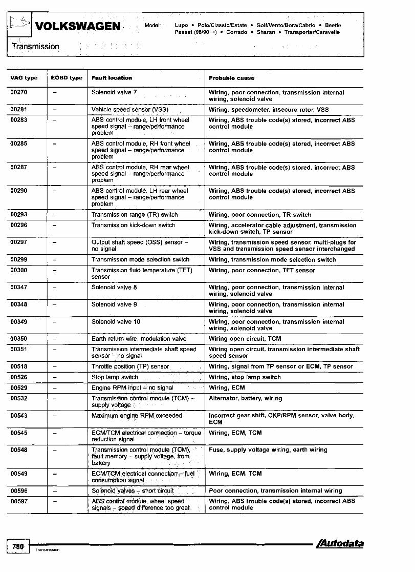
VOLKSWAGEN Model: ~ u p o PololClassiclEstate GolfNentolBoralCabrio Beetle Passat (08190+) Corrado Sharan TransporterlCaravelle
Transmission i
VAG type
00270
00281
EOBD type
00283
00299 1 - I Transmission mode selection switch I Wiring, transmission mode selection switch
-
-
00285
00287
00290
00293
00296
00297
00300 1 - Transmission fluid temperature (TFT) Wiring, poor connection, TFT sensor sensor
Fault location
-
00347 I - I Solenoid valve 8
Probable cause
Solenoid valve 7
Vehicle speed sensor (VSS)
-
-
-
-
-
-
Wiring, poor connection, transmission internal wiring, solenoid valve
Wiring, poor connection, transmission internal wiring, solenoid valve
Wiring, speedometer, insecure rotor, VSS
ABS control module, LH front wheel speed signal - rangelperformance problem
00348 I - I Solenoid valve 9
Wiring, ABS trouble code@) stored, incorrect ABS control module
ABS control module, RH front wheel speed signal - rangelperformance problem
ABS control module, RH rear wheel speed signal - rangelperformance problem
ABS control module, LH rear wheel speed signal - rangelperformance problem
Transmission range (TR) switch
Transmission kick-down switch
Output shaft speed (OSS) sensor - no signal
Wiring, poor connection, transmission internal wiring, solenoid valve
Wiring, ABS trouble code@) stored, incorrect ABS control module
Wiring, ABS trouble code(s) stored, incorrect ABS control module
Wiring, ABS trouble code@) stored, incorrect ABS control module
Wiring, poor connection, TR switch
Wiring, accelerator cable adjustment, transmission kick-down switch, TP sensor
Wiring, transmission speed sensor, multi-plugs for VSS and transmission speed sensor interchanged
00529 I - I Engine RPM input - no signal I Wiring, ECM
00349
00350
00351
0051 8
00526
00543 I - I Maximum engine RPM exceeded Incorrect gear shift, CKPlRPM sensor, valve body, 1 ECM
-
-
-
- -
00532
00545 I - ECMffCMelectricalconnection-torque Wiring, ECM,TCM reduction signal I
Solenoid valve 10-
Earth return wire, modulation valve
Transmission intermediate shaft speed sensor - no signal
Throttle position (TP) sensor
Stop lamp switch
-
Wiring, poor connection, transmission internal wiring, solenoid valve
Wiring open circuit, TCM
Wiring open circuit, transmission intermediate shaft speed sensor
Wiring, signal from TP sensor or ECM, TP sensor
Wiring, stop lamp switch
Transmission control module (TCM), fault memory - supply voltage, from 1 - 1 battery
Transmission contrd module (TCM) - supply voltage
Fuse, supply voltage wiring, earth wiring
00549
00596
00597
Alternator, battery, wiring
-
- -
ECMffCM electrical connection - fuel consumption signal
Solenoid vahres - short circuit
ABS control module, wheel speed signals - speed difference too great
Wiring, ECM, TCM
Poor connection, transmission internal wiring
Wiring, ABS trouble code(s) stored, incorrect ABS control module

Model: Lupo PololClassiclEstate GolfNentolBoralCabrio Beetle Passat (08/90+) Corrado Sharan TransporterICaravelle
VOLKSWAGEN - 2~ ~ J J
VAG type
Transmission
00638
00638
00789 1 - I Reverse gear position switch I Wiring, reverse gear position switch, TR switch
EOBD type
00641
00652
00660
00668
00753
00777
01 044 I - Transmission control module (TChA) - Incorrectly coded
-
-
01 045 I - Tiptronic gear selection switch - Wiring, tiptronic gear selection switch incorrect signal
Fault location
-
- -
-
-
-
Probable cause
Enginelgearbox electrical connection - TP sensor signal
Transmission control module (TChA) - supply voltage
--
Wiring, ECM, TCM
Battery, alternator, wiring, TCM
Transmission fluid temperature (TFT) sensor - high input
Gear monitoring - implausible signal
Transmission kick-down switchlthrottle position (TP) sensor - implausible signal
Transmission control module (TCM) - supply voltage, fmm battery
ABS control module, wheel speed signals - implausible
CAN data bus, APP sensor - incorrect si~nal
01166
01 192
01 196
01 236
01 31 2
01314
01 31 6
ATF level incorrect, towing weight limit exceeded, transmission internal wiring, TFT sensor
Wiring, hydraulic fault, clutchlvalve body
Wiring, accelerator cable adjustment, kick-down switch, TP sensor
Wiring, fuse
Wiring, ABS trouble code@) stored, incorrect ABS control module
Wiring, APP sensor signal from ECM, ECM trouble code(s) stored
16955
-
-
-
- -
-
-
16987
-
16989
Engine toque signal
Torque converter clutch (TCC) solenoid - mechanical fault
CAN data bus, ECMrrCM
Selector lever lock solenoid
CAN data bus - defective
CAN data bus, ECM
CAN data bus, ABS
-
17086
17087
17090
17094
17095
17096
Trouble codes 01 312101 314 stored, ECM incorrectly coded, faulty enginelcomponent(s), ECM
ATF level, clutch slipping, TCC solenoid, valve body defective
Ignition switched ON with TCM disconnected, wiring, ECM, TCM
Wiring, selector lever lock solenoid
Trouble code@) stored in other system@), wiring
Wiring, ECM trouble code(s) stored, ECM incorrectly coded, wiring
ABS control module trouble code(s) stored, wiring
Stop lamp switch - rangelperformance problem
-
-
Wiring, stop lamp switch
Transmission control module (TCM) - KAM error
-
- -
-
-
-
TCM
Transmission control module (TCM) - ROM e m r
TCM
Transmission control module UCM) - defective
Stop lamp switch - circuit malfunction
Transmission range (TR) switch - range1 performance problem
Transmission fluid temperature (TFT) sensor - circuit malfunction
Transmission Ruid temperature VFT) sensor - rangelperformance problem
Transmission fluid temperature (TFT) sensor - low input
TCM
Wiring, stop lamp switch, ECM, TCM
Wiring, TR sensor
Wiring, TFT sensor
Wiring, TFT sensor
Wiring, TFT sensor

I
Transmission
r
= b'. VOLKSWAGEN Model: ~ u p o PololClassiclEstate GolfNentolBoralCabrio Beetle Passat 108190-1 Corrado Sharan Trans~orterlCaravelle
-
VAG type F& l ~ a t l o n EOBD type Probable cause
stickina solenoid valve
ratio
Input shaft s ~ d (ISS) sensorlturbine shaft speed (TSS) sensor - no signal
Output shaft speed (OSS) sensor - rangelperformance problem
Output shafl speed (OSS) sensor - no signal
Engine RPM input - t@ngelpedomance problem
Inwiwci gear ratio
Clutch slipping, solenoid valve, transmission speed sensor, transmission input shaft speed sensor, TCM
Wiring, shield wiring, transmission input shaft speed sensor, engine RPM signal, TR switch, ATF level, transmission speed sensor, torque converter, clutches or brakes slipping, sticking solenoid valve
Wiring, shield wiring, transmission speed sensor, ECMKCM input signals incorrectly transmitted, ATF level, torque converter, clutches or brakes slipping, sticking solenoid valve
Wiring, shield wiring, ECMKCM input signals incorrectly transmitted, transmission speed sensor, ATF level, torque converter, clutches or brakes slipping, sticking solenoid valve
Wiring, CKPlRPM sensor, ECM, TCM
ATF level, torque converter, clutches or brakes slipping, sticking solenoid valve, wiring, transmission speed sensor, transmission input shaft speed sensor, TCM
I Clutch slipping, solenoid valve, transmission speed sensor, transmission input shaft speed sensor, TCM
ratio Clutch slipping, solenoid valve, transmission speed sensor, transmission input shaft speed sensor, TCM
I Clutch slipping, solenoid valve, transmission speed sensor. transmission i n ~ u t shaft s~eed sensor, TCM
G Clutch slipping, solenoid valve, transmission speed sensor, transmission input shaft speed sensor, TCM
I
Shii solenoid @Sf 0 - fxdfmance or I Wiring open circuitlshort to earth, poor connection, . . I shift solenoid
Shift solenaid (SS) B - ~ l c k on 1 Wiring, poor connection, shift solenoid
Shift solenoid (SS) B - electrical 1 Wiring, poor connection, solenoid valve
Shift solenoid (SS) C - pe Wiring open circuitlshort to earth, poor connection, stuck off shift solenoid
Shifl solenoid (SS) C - stuck on Wiring, poor connection, shift solenoid
Shi i solenoid (SS) C - electricat Wiring, poor connection, solenoid valve
Refer to EOBD troubk code Wle -
Maximum engine RPM exce@ded Incorrect gear shift, wiring open circuit, CKPlRPM sensor

Model: Lupo PololClassiclEstate GolfNentolBoralCabrio Beetle VoLK$WAGEN ran TransporterlCaravelle
11;"
-
18147 1 I short to earth I Tiptronic gear selection switch, up shiR - Wiring short to earth, tiptronic gear selection switch
Transmission
18112
18141
18152 I Tiptronic gear selection switch, I Wiring short to earth, tiptronic gear selection switch recognition - short to earth
PI625
18153 1 Solenoid valves, supply voltage - short Wiring open circuitlshort to positive, poor to positive I connection. TCM
P I 704
PI733
- 1 Transmission control module (TCM) - Alternator, battery, wiring supply voltage I
CAN data bus, E C W C M
18155 Solenoid valves, supply voltage - open Battery, wiring open circuitlshort to earth, poor circuitkhort to earth I connection. TCM
Ignition switched ON with TCM disconnected, wiring, ECM, TCM
Transmission kick-down switch - short to earth
Tiptronic gear selection switch, down shift - short to earth
18156 1 I Transmission control module (TCM) - I TCM defective
Wiring open circuitlshort to earth, transmission kick- down switch
Wiring short to earth, tiptronic gear selection switch
1 81 57 1 Transmission control module (TCM) - Incorrectly coded, ECM incorrectly coded, TCM I 18158
18159
181 60
-
18169
18170
181 71
-
181 79
18180
-
PI750
PI751
PI752
PI760
PI761
PI762
PI763
PI 767
PI771
PI772
PI781
Transmission control module (TCM) - supply voltage low
Transmission control module (TCM) - supply voltage high
Transrnissidn control module (TCM) - supply voltage
Selector lever lock sofenoid
Selector lever lock solenoid - short to earth
Selector lever lock solenoid - short to positive
Selector lever lock solenoid - open circuit
ECM/TCM electrical connection - TP sensor signal
Engine control module (ECM), load signal - open circuitlshort to positive
Engine control module (ECM), load signal - short to earth
ECMITCM electrical connection, toque reduction signal - open circuiffshort to earth
Fuse, wiring, TCM
Alternator, second battery incorrectly connected
Wiring, alternator
Wiring, selector lever lock solenoid
Wiring short to earth, selector lever lock solenoid, tiptronic gear selection switch, TCM
Wiring short to positive, selector lever lock solenoid, tiptronic gear selection switch, TCM
Wiring open circuit, selector lever lock solenoid, TCM
Wiring, ECM, TCM
Wiring open circuitlshort to positive, ECM
Wiring short to earth, ECM
Wiring open circuitlshort to earth, ECM, TCM

Except Passat 5 speedI4WD. Passat 5 speed14WD.

Accessing The transmission control module (TCM) fault memory can
General information only be accessed using diagnostic equipment connected to . . Refer to the front of this manual for general test conditions, the-data link connecto; (DLC). terminology, detailed descriptions of wiring faults and a general trouble shooter for electrical and mechanical faults. Erasing Self-diagnosis using flash type trouble codes may not Ensure ignition switched OFF. display all available diagnostic information. Disconnect TCM multi-plug or battery earth lead. Automatic transmission in 'N' Diagnostic equipment can also be used to erase data from
TCM fault memory. WARNING: Disconnecting the battery may erase memory from
electronic units (e.g. radio, clock).
Trouble code identification
I I
1111 1 Transmission control module (TCM) - defective I Electrical interference, mechanicallhydraulic fault,
Flash type 4-digit Faufr betlam Probable cause

1231 I Vehicle speed sensor (VSS) I Wiring, speedometer, insecure rotor, VSS
Flash 4-digit
1143
1332 I Transmission mode selectiin switch I Wiring, transmission mode selection switch
Fauk ho&atm
Shiff control solenoid 2
1314
1323
Probable cause
Wiring, poor connection, transmission internal wiring, shift control solenoid
Transmission range (TR) switch
Transmission kick-down switch
1333
21 22
21 31
221 2
4314 1 Selector lever lock solenoid I Wirina, selector lever lock solenoid
Wiring, poor connection, TR switch
Wiring, accelerator cable adjustment, transmission kick-down switch. TP sensor
2234
2314
Transmission fluid temperature (TFT) sensor
Engine RPM signal missing
Stop lamp switch
Throttle position (TP) sensor
f p e I F ~ U M location I Probable cause
Wiring, poor connection, TFT sensor
Wiring, ECM
Wiring, stop lamp switch
Wiring, TP sensor
Transmission control module (TCM) - supply vottage
Enginelgearbox electrical connection - ignition timing adjustment
4444 I NO fault found
TCC solenoid
shift control solenoid
TFP solenoid
Alternator, battery, wiring
Wiring, ECM, TCM
-
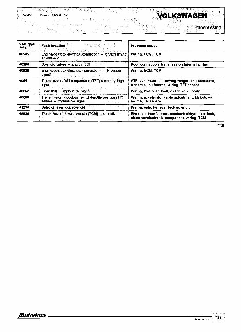
Probable cause
Wiring, ECM, TCM
Poor connection, transmission internal wiring
Wiring, ECM, TCM
ATF level incorrect, towing weight limit exceeded, transmission internal wiring, TFT sensor
Wiring, hydraulic fault, clutchlvalve body
Wiring, accelerator cable adjustment, kick-down switch, TP sensor
Wiring, selector lever lock solenoid
Electrical interference, mechanicallhydraulic fault, electricallelectronic component, wiring, TCM
:-$yp"'
00545
00596
00638
00641
00652
00660
01236
65535
4
FauR 105.110.
Engine/gearbox electWI connection - igniticm timing adjustment
Solenoid valves - short circuit
Enginelgearbox etectrical connection - TP sensor signal
Transmission fluid temperature fTFT) sensor - high input
Gear shifi - implausible signal
Transmission kick-down switchlthrottfe position (TP) sensor - implausible signal
Sdedor lever lock solenoid
Transmission control module (TCM) - defective

entolBoralCabrio (10194 +) Beetle t Corrado (10194-95) Sharan
Lupo -r04/00 (except 1,2 TDI) - behind storage compartment Polo 08197-09199 - In fascia fusebox
Lupo Om+ (& 1,2 m), Polo 10199+, GlassIc & Estate 1999 - under front ashtray
l
Pdo -r07197, Classk 81 Etitets 4999 , Caddy - In glovebox, driver's sede
Oolf 4997 , Vento, Gabrio - adjacent to ashtray
Odf 1997 4, Bora - centre console

Beetle Passat Corrado (10194-95) Sharan
Passat -1996 - adjacent to steering column
Passat 1996-09100 - near handbrake, below rubber mat
Corrado - near gear lever
Sharan +OW00 - centre console
--
Beetle, Passat 10mO -+, Sharan 06/00 + - fascia, driver's side
- -
Caddy Pickup - fascia, passenger's side

TransporterlCawvelb 4 9 6 5 - above fascia fueeboxlrelay plate
1 11 1 am-
General information Refer to the front of this manual for general test condltlons, terminology, detailed descriptions of wiring faults and a general trouble shooter for electrical and mechanical faults. System malfunction: Engine runs for approximately 1 second and then cuts out. Data link connector (DLC) - 2-pin. (A) black, (B) brownlwh~te.
Accessing and erasing The immobilizer control module fault memory can only be accessed and erased using diagnostic equipment connected to the data link connector (DLC).

CaddyIPickup TransporterICaravelle LT
Immobilizer
Trouble code identification
00546 Immobilizer control module, data wire - implausible Wiring, incorrectly coded, ignition switched OFFION authorisation signal too quickly, immobilizer control module
I I 00000 I No fault found
01176 I lgnition key - incorrect signal
-
00750
01128
I lgnition key not matchedldamaged, poor connection, wiring, immobilizer read coil
Immobilizer warning lamp
Immobilizer read coil
01181 I Ignition key programming - initial matching Stored value for quantity of keys to be programmed exceeded, erase and re-check fault memory
Wiring, immobilizer warning lamp
Wiring, immobilizer read coil, immobilizer control module
01177
01179
Engine control module (ECM)/fuel shut-off solenoid control module - not authorised
Ignition key programming - incorrectly matched
01202
01237
01354 1 CAN data bus - authorisation sianal I Wirinq, immobilizer control module
ECMlfuel shut-off solenoid control module not matched to immobilizer control module
Malfunction during ignition key programming
01312
01314
Data link connector (DLC)
Fuel shut-off solenoid
Wiring short circuit, immobilizer control module
Fuel shut-off solenoid control module, fuel shut-off solenoid
CAN data bus - defective
CAN data bus, ECM
65535 I Immobilizer control module - defective
Immobilizer control module incorrectly coded, trouble code@) stored in other system(s), wiring
Wiring, ECM trouble code(s) stored, ECM incorrectly coded, wiring
DLC wiring, immobilizer control module
4

44014601480 1,611,711,812,O
Year: 1990-97
Engine code: B16F, BlBEP, BlBFP, BlBU, B20F
System: Fenix 3 8
Engine management
Engine bay, LH
General information Refer to the front of this manual for general test conditions, terminology, detailed descriptions of wiring faults and a general trouble shooter for electrical and mechanical faults.
0 Trouble codes are displayed by the LED on the data link connector (DLC).
Accessing Open data link connector (DLC) cover. Insert system selector cable in socket 2 rn [ I ] . Switch ignition ON. Press test button for 0,5 to 1 second 121. Count LED flashes rn [3]. Note trouble codes. Compare with trouble code table. Trouble codes consist of a sequence of three groups of flashes H. A 3 second pause separates each group H [A]. For example: Trouble code 223 displayed H.
Erasing NOTE: Trouble codes must be accessed and faults rectified
before codes can be erased.
Open data link connector (DLC) cover. Insert system selector cable in socket 2 rn [ I ] . Switch ignition ON. Press test button for 5 seconds minimum [2]. Release button. Wait until LED illuminates rn [3]. Press test button for 5 seconds minimum. Ensure trouble codes have been erased. The ECM fault memory can also be erased by disconnecting the battery.
WARNING: Disconnecting battery may erase memory from electronic units (e.g. radio, clock).
[ 792 I,,,,,,,.,,,, /Autdata

M e l : 440/460/ VOLVO
Engine management
Trouble code identification
Flash type
No fault found
Engine control module (ECM)
lnjector(s) - faulty sianai
/Autodata a Eng~ne management 793
-
ECM
Wiring open circuit
Manifold absolute pressure (MAP) sensor - signal error
Intake air temperature (IAT) sensor - signal error
Engine coolant temperature (ECT) sensor - signal emr
Battery voltage
Knock sensor (KS) - signal errorlsignal absent
Mixture adjustment resistor - B18EP
Heated oxygen sensor (H02S) - signal emr/signal absent
Crankshaft position (CKP) sensor - early models
Engine control relay - no voltage to ECM pin 20
Idle air control (IAC) valve, MPt - signal em/signal absent
Idle speed control (ISC) actuator, TBI - signal emr/signel absent
Heated oxygen sensor (H02S) - signal emr, part load range
Heated oxygen sensor (H02S) - signal error, idting
Throttle position (TP) sensor - signal error
Knock sensor (KS) - ignition control limit reached
Vehicle speed sensor (VSS)
Throttle position (TP) sensor - signal error
ThroMe position (TP) sensor - signal to multi-function control module
Fault locattbn
Wiring, vacuum hose blockedlsplit, MAP sensor
Wiring, IAT sensor
Wiring, ECT sensor
Wiring, engine control relay, alternator, battery
Wiring, KS
Wiring openlshort circuit, mixture adjustment resistor
Wiring, fuses, oxygen sensor heater, injector(s), fuel pressure
Wiring, CKP sensor
Wiring, engine control relay, ECM
Wiring shotdopen circuit
Wiring shotdopen circuit
Wiring, fuses, oxygen sensor heater, injector(s), fuel pressure
Wiring, fuses, oxygen sensor heater, injectorts), fuel pressure
Wiring, accelerator cable adjustment, TP sensor, ECM
Wiring, KS, fuel quality, combustion fault
Wiring, VSS
Wiring, accelerator cable adjustment, TP sensor, ECM
Wiring, TP sensor, ECM
c a
Probable cause

Model: SN40 1,611,811,912,O SN40 1,9 TD 850 2,012,312,5lTurbo 8501SN70 2,5 TDI (+08198) SNIC70 2,012,312,5~urbo 960 2,513,O SN190 2,9
Year: 1995-99 Engine B4164S, B4184S, B4184SM, B4194T, B4204S, B4204T, B5204TlT2lT3, B5234FS, B5234TlT2lT3lT4lT6lT7, code: B5254S, B5254T, B6254F, B6254S, B6304FIS, B6304S112, D4192T, D5252T
System: Bosch Motronic 4.4 Bosch MSA 15.7 Lucas DPI-N Melco 1 Siemens EMS 2000 Siemens Fenix 5.1
Engine management
850 - near gear lever
1 A023201 \ \ ' 960 - centre console
SN40 - under fascia, driver's side SNIC70 - centre console
General information Refer to the front of this manual for general test conditions, terminology, detailed descriptions of wiring faults and a general trouble shooter for electrical and mechanical faults.
Accessing and erasing The engine control module (ECM) fault memory can only be accessed and erased using diagnostic equipment connected to the data link connector (DLC).

Trouble code identification
Scanner Fault lacattori t~ pe I Probable cause
1 I
EFI-0014 I Throttle position (TP) sensor
EFI-0011
EFI-0012
EFI-0013
Wiring, TP sensor, IAC valve signal exceeded 2 V for 4 seconds
Heated oxygen sensor (H02S)
Mass air Row (MAF) sensor
Intake air temperature (IAT) sensor
Wiring, H02S
Wiring, MAF sensor
Wiring, IAT sensor
EFI-0021
EFI-0022
EFI-0031 I Knock sensor (KS) I Wiring, KS
EFI-0023
EFI-0024
EFI-0025
EFI-0036 I Engine control module (ECM) - ignition adjustment signal I Activation of ignition adjustment incomplete
Engine coolant temperature (ECT) sensor
Crankshaft position (CKP) sensorlengine speed (RPM) sensor
Wiring, ECT sensor
Wiring, poor connection, CKPIRPM sensor
Camshaft position (CMP) sensor
Speedometer
Barometric pressure (BARO) sensor
EFI-0054 I Immobilizer control module - communication error 1 Wirina
Wiring, poor connection, CMP sensor
Wiring, speedometer
Wiring, BAR0 sensor
EFI-0041
EFI-0044
EFI-0056 1 Fuel pressure sensor I Wiring, fuel pressure sensor
EFI-0058 I Fuel trim (FT) - abnormal intake air volume I Wiring, IAC valve, intake air by-pass valve
Injectors
Ignition coil
Wiring, injector(s), injector control module
Spark plug(s), wiring, ignition coil
EFI-0089 / Fuel trim (FT) - highllow
EFI-0064
EFI-0066
lntake leaklblockage, fuel pressurelpump, wiring, IAT sensor, BARO sensor, MAF sensor
EFI-I12 I Engine control module (ECM) I ECM
Alternator
Brake vacuum sensor
- --
Wiring, alternator
Wiring, brake vacuum sensor
EFI-121 Mass air flow (MAF) sensorlmanifotd absolute pressure lntake leaklblockage, hose leak, wiring, I (MAP) sensor I MAFNAP sensor
EFI-115
EFI-116
EFI-122 I Intake air temperature (IAT) sensor 1 Wiring, IAT sensor
Injector 1
Engine control module (ECM) - internal fault
EFI-131 I Motronic 4.4: Crankshaft position (CKP) sensorlengine Wiring, CKPIRPM sensor speed (RPM) sensor - no signal
-
Wiring, injector
ECM
EFI-123
EFI-125
Engine coolant temperature (ECT) sensor
injector 2
EMS 20001diesel: Crankshaft position (CKP) sensorlengine speed (RPM) sensor - nolincorrect signal
Wiring, ECT sensor
Wiring, injector
Wiring, poor connection, flywheelldrive plate damaged, CKPIRPM sensor
EFI-132
EFI-137
EFI-153 I Heated oxygen sensor (H02S) 2 I Exhaust leak, wiring, H02S 112
EFI-135
EFI-143
EFI-145
Engine control module (ECM) - supply voltage
Crankshaft position (CKP) sensorlengine speed (RPM) sensor
Battery, alternator, wiring
Wiring, flywheelldrive plate damaged, CKPIRPM sensor insecureldefective
injector 3
Knock sensor (KS) 1
Injector 4
EFI-155
Wiring, injector
Wiring, KS
Wiring, injector
4
Injector 5 Wiring, injector

Modet: SN40 l,6/l,8/l,9/2,O SN40 1,9 TD 850 2,0/2,3/2,5~urbo 850lSN70 2,5 TDI (-+08/98) SNIC70 2,0/2,3/2,5TTurbo 960 2,513,O SNl90 2,9
Scanner type
EFI-165
FauH location Probable cause
Injector 6 I Wiring, injector
Crankshaft position (CKP) sensorlengine speed (RPM) Poor connection, shield wiring, flywheelldrive plate sensor - incorrect/intermittent signal I damaged, CKPIRPM sensor
Mixture adjustment resistor
Heated oxygen sensor (H02S) 1
Wiring, mixture adjustment resistor incorrectly adjustedldefective
Wiring, H02S 112
AC refrigerant pressure sensor I Wiring, AC refrigerant pressure sensor
Heated oxygen sensor (H02S)
Engine control relay
ldie air control (IAC) valve - opening signal
Wiring, H02S
Wiring, engine control relay
Wiring, IAC valve
Exhaust gas recirculation (EGR) solenoid I Wiring, EGR solenoid
Idle air control (IAC) valve
Idle speed control (ISC) valve
Long term fuel trim, part load
Long term fuel trim, idling
Long term fuel trim, idle air adjustment
Wiring, IAC valve
Wiring, ISC valve
lntakelexhaust leak, fuel pressure, excessive fuel in engine oil, engine oil level too high, injector(s), EVAP canister purge valve, wiring, MAF sensor, ECT sensor, H02S
lntakelexhaust leak, fuel pressure, excessive fuel in engine oil, engine oil level too high, injector(s), EVAP canister purge valve, wiring, MAF sensor, ECT sensor, H02S
Intake leaklblockage, throttle valve adjustment, accelerator cable adjustment, wiring, IAC valve
Engine control relay I Wiring, engine control relay
Turbocharger (TC) wastegate regulating valve
Idle air control (IAC) valve - closing signal
Outside air temperature sensor
Vehicle speed signal 1 Wiring, speedometer
Wiring, TC wastegate regulating valve
Wiring, IAC valve
Wiring, outside air temperature sensor
Camshaft position (CMP) sensor 1 Wiring, poor connection, CMP sensor
Evaporative emission (EVAP) canister purge valve - leak EVAP canister purge valve detected
Malfunction indicator lamp (MIL) I Wiring, MIL
Diesel: CAN data bus, communication error 1 Wiring
Engine control module (ECM) - memory fault
Petrol: Transmission control module (TCM) - MIL ON request
ECM disconnected, battery discharged1 disconnected, wiring
Wiring
Engine control module (ECM) - immobilizer authorisation Immobilizer trouble code IMM-322 stored, wiring signal missing
Transmission control module (TCM) - gear recognition
Transmission control module (TCM)ltraction control module - torque reduction signal
AC relay I Wiring, AC relay
Wiring
Wiring, TCM, traction control module
Fuel pump r e 6 I Wiring, fuel pump relay
Immobilizer control module - communication error Wiring, poor connection, immobilizer control module
1 795 I,,,,,,,,,,, /Aufodata

Probable cause
EFI-355 ( Mass air flaw (MAF) sensor - incorrect signal - --
MAF sensor, TP sensor
Wiring, TP sensor
Hose blocked, TCM wire (TC pressure reduction signal), wiring, MAF sensor, TC wastegate actuator1 regulating valve
EFI-411
EFI-414
Throttle position (TP) sensor
Turbocharger (TC) pressure - control
Wiring, MAP sensor, BARO sensor
Wiring, sensor supply, BARO sensor, AC pressure sensor, fuel tank pressure sensor, G-force sensor
EFI-415
EFI-422
EMS 2000: Barometric Dressure IBARO) sensor
Manifold absolute pressure (MAP) sensor, TC system
Motronic 4.4: Barometric pressure (BARO) sensor
Wiring, BARO sensor
lntakelexhaust leak, uneven compression, fuel pressure, H02S
Engine coolant blower motor, air supply blocked
EFI-425
EFI-432 [ Engine control module (ECM) - overheating
Heated oxygen sensor (H02S) 2
EFI-433 I Knock sensor (KS) 2 Wiring, KS
EFI-435 Heated oxygen sensor (H02S) 1 - slow response lntakelexhaust leak, uneven compression, fuel pressure, MAF sensor, heating inoperative, H02S
EFI-436 I Heated oxygen sensor (HOZS) 2 - compensation -
lntakelexhaust leak, uneven compression, fuel pressure, H02S 112
PAlR valvelsolenoid, exhaust leak EFI-442
EFI-443 lntakelexhaust leak, uneven compression, fuel pressure, catalytic converter
Pulsed secondary air injection (PAIR) system - excessive flow detected
Catalytic converter - efficiency below threshold
Wiring, sensor supply, AC pressure sensor, fuel tank pressure sensor, G-force sensor
EFI-444
flow detected
G-force sensor
Wiring, PAlR pump relay
PAlR valvelsolenoid, exhaust leak
Wiring, PAlR solenoid
PAlR valvelsolenoid, PAlR pumplrelay, hoseslpipes blocked, exhaust leak, PAIR pump wiring
EFI-451 1 Cylinder I - misfire detected Spark plug, HT lead, distributor rotorlcap, moisture ingress, injectorlwiring, air leak, compression, head gasket, low-tension wiring, repeated cold starts (flooding)
Spark plug, HT lead, distributor rotorlcap, moisture ingress, injectorlwiring, air leak, compression, head gasket, low-tension wiring, repeated cold starts (flooding)
EFI-452
EFI-453 I Cylinder 3 - misfire detected
Cylinder 2 - misfire detected
Spark plug, HT lead, distributor rotorlcap, moisture ingress, injectorlwiring, air leak, compression, head gasket, low-tension wiring, repeated cold starts (flooding)
Spark plug, HT lead, distributor rotorlcap, moisture ingress, injectorlwiring, air leak, compression, head gasket, low-tension wiring, repeated cold starts (flooding)
EFI-454 Cylinder 4 - misfire detected
Spark plug, HT lead, distributor rotorlcap, moisture ingress, injectorlwiring, air leak, compression, head gasket, low-tension wiring, repeated cold starts (flooding)
EFI-455
Engine management 797
Cylinder 5 - misfire detected

Fault hxation Scanner type
EFI-456
Probable cause
Spark plug, HT lead, distributor rotorlcap, moisture ingress, injectorlwiring, air leak, compression, head gasket, low-tension wiring, repeated cold starts (flooding)
lntakelexhaust leaklblockage, MAF sensor, fuel pressure
Engine control module (ECM) - overheating Engine coolant blower motor, air supply blocked
Engine coolant blower motor relay, low speed Wiring, engine coolant blower motor relay
Engine coolant blower motor relay, high speed
AC condenser blower motor relay
Heated oxygen sensor (H02S) 1 - heater control
Heated oxygen sensor (H02S) 2 - heater control
Wiring, engine coolant blower motor relay
Wiring, AC condenser blower motor relay
Wiring, H02S
Wiring, HO2S
lgnition coil 1, cylinders 1 & 4 Wiring, ignition coil
Wiring, ignition coil Ignition coil 2, cylinders 2 & 3
Engine control module (ECM) - power stage - group B Wiring, IAC valve, TC wastegate regulating valve, engine coolant blower motor relay, ECM
Engine control module (ECM) - power stage - group C
Engine control module (ECM) - power stage - group D
Wiring short circuit at terminal B19, ECM
Wiring short to positive, MIL, engine coolant blower motor relay, fuel pump, ignition coillamplifier, TCM (load signal), ECM
Engine control module (ECM) - power stage - group E
Evaporative emission (EVAP) canister purge valve - sianal
Wiring short to positive, AC relaylPAlR pump relay, ECM
Wiring, EVAP canister purge valve
Misfire detected, at least 1 cylinder Spark plug, HT lead, distributor rotorlcap, moisture ingress, injectorlwiring, air leak, compression, head gasket, low-tension wiring, repeated cold starts (flooding)
Misfire detected - at least 1 cylinder - TWC damage Spark plug, HT lead, distributor rotorlcap, moisture ingress, injectorlwiring, air leak, compression, head gasket, low-tension wiring, repeated cold starts (flooding)
Cylinder 1, misfire detected - TWC damage Spark plug, HT lead, distributor rotorlcap, moisture ingress, injectorlwiring, air leak, compression, head gasket, low-tension wiring, repeated cold starts (flooding)
Cylinder 2, misfire detected - TWC damage Spark plug, HT lead, distributor rotorlcap, moisture ingress, injectorlwiring, air leak, compression, head gasket, low-tension wiring, repeated cold starts (flooding)
Cylinder 3, misfire detected - TWC damage Spark plug, HT lead, distributor rotorlcap, moisture ingress, injectorlwiring, air leak, compression, head gasket, low-tension wiring, repeated cold starts (flooding)
Cylinder 4, misfire detected - TWC damage Spark plug, HT lead, distributor rotorlcap, moisture ingress, injectorlwiring, air leak, compression, head gasket, low-tension wiring, repeated cold starts (flooding)

Model: SN40 1,6/1,8/1,9/2,0 SN40 1,9 TD 850 2,0/2,3/2,5TTurbo 8501SN70 2,s TDI (+08/98) SNlC7O 2,0/2,3/2,5TTurbo 960 2,5/3,0 SNI90 2,9
Scanner Fawlt location type I I Probable cause
EFI-555
EFI-556
EFI-611
EFI-612
EFI-616 Evaporative emission (EVAP) canister shut-off valve - Wiring, EVAP canister shut-off valve I sional I
EFI-614
Cylinder 5, misfire detected - TWC damage
Cylinder 6, misfire detected - TWC damage
Fuel tank system - large leak detected
Fuel tank system - small leak detected
Spark plug, HT lead, distributor rotorlcap, moisture ingress, injectorlwiring, air leak, compression, head gasket, low-tension wiring, repeated cold starts (flooding)
Spark plug, HT lead, distributor rotorlcap, moisture ingress, injectorlwiring, air leak, compression, head gasket, low-tension wiring, repeated cold starts (flooding)
Fuel tank, filler caplpipe, EVAP system, fuel tank pressure sensor
Fuel tank, filler caplpipe, EVAP system, fuel tank pressure sensor
Evaporative emission (EVAP) canister shut-off vabe - incorrect flow detected
EFI-621
EFI-666
Hose blocked, EVAP canister shut-off valvelfilter, EVAP canister purge valve, fuel tank pressure sensor
EFI-711
EFI-712
EFI-715 I Fuel quantity - incorrect flow detected I Wiring, fuel quantity adjuster
Fuel tank pressure sensor
Transmission control module (TCM) - access fault memory
EFI-713
EFI-714
EFI-716 I Fuel quantity adjuster I Wiring, fuel quantity adjusterlposition sensor
Wiring, sensor supply, G-force sensor, AC pressure sensor, fuel tank pressure sensor
Trouble code(s) stored
Injector needk lift sensor
Fuel temperature sensor
EFI-717 I Fuel quantity adjuster position sensor I Wiring, fuel quantity adjuster position sensor
Wiring, injector needle lift sensor
Wiring, fuel temperature sensor
Fuel injection timing solenoid
Fuel shut-off solenoid
Wiring, fuel injection timing solenoid
Wiring, fuel shut-off solenoid
EFI-724 I Engine coolant heater relay
EFI-718
EFI-719
EFI-721
Wiring, engine coolant heater relay, engine coolant heater wiring
EFI-725 I Engine control relay I Wiring, engine control relay
Injection timing control
Injector needle lift sensor - engine speed signal
Glow plug warning lamp
I 1
EFI-726 1 Engine control module (ECM) - supply voltage 1 Wiring, engine control relay
Fuel injection timing circuit
Engine overheated, injector needle lift sensor
Wiring, glow plug warning lamp
EFI-730 I Brake pedal position (BPP) switch Brake pedal depressed for more than 3 minutes, wiring, BPP switch
EFI-732 ( Accelerator pedal position (APP) sensor - signal I Wiring, APP sensor
EFI-743 I Cruise control masterlselector switch I Wiring, cruise control masterlselector switch
EFI-733
EFI-742
EFI-751 I Glow plug relay 1 I Wiring, glow plug relay
EFI-752 I Glow plug relay 2 I Wiring, glow plug relay
Accelerator pedal position (APP) sensor - supply voltage
Transmission control module (TCM) - communication error
Wiring short to earth, excessive load, ECM
Wiring, TCM, ECM
EFI-761
EFI-762
Glow plugs 1 & 3
Glow plugs 2 & 4
Wiring short to earth, glow plug(s)
Wiring short to earth, glow plug(s)

XC90 2,5 Turbo
B5204T3, B5204T4, B5204T5, B5234T3, B5234T7, B5234T9, B5244S, B5244S2, B5244T, B5244T3, B5244T7, B5254T2, B6284T, B6284T2, B6294S B6294S2
CM - centre mmde
XC90 - behsnd fascia, drkrer's stele
General information Refer to the front of this manual for general test conditions, terminology, detailed descriptions of wiring faults and a general trouble shooter for electrical and mechanical faults.
Accessing and erasing The engine control module (ECM) fault memory can only be accessed and erased using diagnostic equipment connected to the data link connector (DLC).

V70 2,4ITurbo C70 2,O Turbo C70 2,3 Turbo C70 2,4/Turbo S80 2,012,3 Turbo S80 2,4ITurbo S80 2,8 Turbo S80 2,9 XC70 2,312,s Turbo XC90 2,s Turbo
Trouble code identification 1 I I
EOBD type 1 Volvo type I Fault location I Probable cause
PO I - I Refer to EOBD trouble code table I - P I 01 I I 640A I lntake manifold air control solenoid -
rangelperformance problem Wiring, intake manifold air control solenoid
PI112 I - I Intake air temperature (IAT) sensor - signal low Wiring short to earth, poor connection,
IAT sensor
PI014
PI102
PI103
P I 106
PI107
PI108
P l l l l
PI113 I - I Intake air temperature (IAT) sensor - signal high I Wiring short to positive, IAT sensor
PI115 I - Barometric pressure (BARO) sensor - Wiring, poor connection, BAR0 sensor rangelperformance problem
-
150A
150A
140A
1400
1400
-
P I 139 I - Heated oxygen sensor (H02S) 2, bank 1 - Wiring, poor connection, catalytic rangelperformance problem converter, H02S, ECM
Camshaft position (CMP) sensorlcrankshaft position (CKP) sensor - signal incompatibility
Intake manifold air flow adaptation - low limit
Intake manifold air flow adaptation - high limit
Manifold absolute pressure (MAP) sensor - rangelperformance problem
Manifold absolute pressure (MAP) sensor - signal low
Manifold absolute pressure (MAP) sensor - signal high
Intake air temperature (IAT) sensor - rangelperformance problem
PI116
PI117
PI118
PI119
PI129
PI132
PI133
PI152 I - Heated oxygen sensor (H02S) 1, bank 2lheated oxygen Wiring, H02S 112, ECM sensor (H02S) 2, bank 2 - signal incompatibility
Incorrectly fitted timing belt, timing belt jumped 1 tooth or more
Wiring, ECM
Wiring, ECM
Wiring, poor connection, intake leaklblockage, MAP sensor, ECM
Wiring short to earth, poor connection, sensor supply, MAP sensor, ECM
Wiring short to positive, intake leak, MAP sensor, ECM
Wiring, poor connection, IAT sensor
PI153 I - Heated oxygen sensor (H02S) 1, bank 2 - I Wiring, incorrectly connected. H02S heaterlsignal circuits transposed
-
-
-
-
7120
-
-
- a a Eng~ne management 801
Barometric pressure (BARO) sensor - signal low
Barometric pressure (BARO) sensor - signal high
Manifold absolute pressure (MAP) sensorlmass air flow (MAF) sensor, adaptation - rangelperformance problem, lower limit
Manifold absolute pressure (MAP) sensorlmass air flow (MAF) sensor, adaptation - rangelperformance problem, higher limit
Heated oxygen sensor (H02S) - circuit malfunction
Heated oxygen sensor (H02S) 1, bank llheated oxygen sensor (H02S) 2, bank 1 - signal incompatibility
Heated oxygen sensor (H02S) 1, bank 1 - heaterlsignal circuits transposed
PI159
PI169
PI171
PI172
Wiring short to earth, poor connection, BARO sensor
Wiring short to positive, BAR0 sensor
Wiring, intake leak, MAF sensor, MAP sensor
Wiring, intake leak, MAF sensor, MAP sensor
Wiring, ECM
Wiring, H02S 112, ECM
Wiring, incorrectly connected, H02S
4
-
-
-
-
Heated oxygen sensor (H02S) 2, bank 2 - rangelperfomance problem
Heated oxygen sensor (H02S) 1, bank 1 - no signal
System too lean, bank 1 - part load
System too rich, bank 1 - part load
Wiring, poor connection, catalytic converter, H02S, ECM
Wiring, heater inoperative, H02S
Intakelexhaust leak, MAF sensor, MAP sensor, fuel pressure low, fuel pump (FP), injector(s), H02S
Intake blocked, EVAP canister purge valve, fuel pressure high, EGR system, injector(s), H02S

Model: S60 2,012,3 Turbo S60 2,4/Turbo V70 2,012,3 Turbo V70 2,4/Turbo C70 2,O Turbo C70 2.3 Turbo C70 2.41Turbo
I
Engine management S80 2,012,3 Turbo S80 2,4/Turbo S80 2,8 Turbo S80 2,9 XC70 2,3/2,5 Turbo XC90 2,5 Turbo
EQBD type I Volvo type I Fault location I Probable cause
System too lean, bank 1 - full load lntakelexhaust leak, MAF sensor, MAP sensor, fuel pressure low, fuel pump (FP), injector(s1, H02S
System too rich, bank 1 - full load lntake blocked, EVAP canister purge valve, fuel pressure high, EGR system, injector(s), H02S
System too lean, bank 2 - part load lntakelexhaust leak, MAF sensor, MAP sensor, fuel pressure low, fuel pump (FP), iniector(sl, H02S
System too rich, bank 2 - part load lntake blocked, EVAP canister purge valve, fuel pressure high, EGR system, iniector(s), H02S
System too lean, bank 2 - full load lntakelexhaust leak, MAF sensor, MAP sensor, fuel pressure low, fuel pump (FP), injector@), H02S
System too rich, bank 2 - full load lntake blocked, EVAP canister purge valve, fuel pressure high, EGR system, injector@), H02S
PI237 1 - I Turbocharger (TC) boost control deviation I Turbocharger (TC) overboost
Turbocharger (TC) wastegate regulating valve - inlet pressure lower than expected
Other trouble codes stored (limp home mode initiated), TC wastegate regulating valve stuck open
PI325 I - Engine control module (ECM), knock control detection - circuit test pulse
I ECM
PI238
PI273
PI285
P I 286
P I 287
P I 293
P I 326 1 - Engine control module (ECM), knock control detection - circuit offset
I ECM
P I 329 I - Engine control module (ECM), knock control I ECM detection - circuit zero-test
-
-
-
-
-
-
P I 330 I - Camshaft position (CMP) actuator, inlet camshaft - Wiring, timing beltlchain, mechanical valve timing advanced for too long I fault, CMP actuator
P I 332 I - Camshaft position (CMP) actuator, exhaust Wiring, timing beltlchain, mechanical camshaft - valve timing advanced for too long fault, CMP actuator
Turbocharger (TC) boost pressure sensor - boost control malfunction
Electronic throttle system (ETS) - rangelperformance problem
Electronic throttle system (ETS), throttle valve adaptation - rangelperformance problem
Electronic throttle system (ETS), throttle valve adaptation - aborted
Electronic throttle system (ETS), throttle valve adaptation - aborted
Electronic throttle system (ETS), throttle valve adaptation - repeated
TC boost pressure sensor, intake IeaWblockage
ETS
ETS
System voltage below 10 V
Throttle motor position sensor
Throttle motor position sensor
PI354 1 - I Ignition coil, cylinder 3, primary - signal low I Wiring short to earth, ignition coil
P I 336
P I 350
P I 351
P I 352
P I 353
- - - - -
Crankshaft position (CKP) sensor - incorrect signal
Ignition coil, cylinder 1, primary - signal low
Ignition coil, cylinder 1, primary - signal high
Ignition coil, cylinder 2, primary - signal low
Ignition coil, cylinder 2, primary - signal high
-
-
-
- -
Crankshaft position (CKP) sensor, rotor damaged
Wiring short to earth, ignition coil
Wiring short to positive, ignition coil
Wiring short to earth, ignition coil
Wiring short to positive, ignition coil

Model: S60 2,012,3 Turbo S60 2,4lTurbo V70 2,012,3 Turbo V70 2,4lTurbo C70 2,O Turbo C70 2,3 Turbo C70 2,4lTurbo S80 2,012,3 Turbo S80 2,4lTurbo S80 2,8 Turbo S80 2,9 XC70 2,3/2,5 Turbo XC90 2,5 Turbo Engine management I
EOBD type 1 Volvo type ( Fault location I Probable cause
PI359 1 - I Ignition coil, cylinder 5, primary - signal high I Wiring short to positive, ignition coil
PI355
PI356
PI357
P I 358
PI360 I - I Ignition coil, cylinder 6, primary - signal low I Wiring short to earth, ignition coil
PI361 I - I Ignition coil, cylinder 6, primary - signal high I Wiring short to positive, ignition coil
- - -
-
PI440 I - Fuel system leak detection pump - malfunction Fuel system leak detection pump, hose
blockedltrapped
lgn~tion coil, cylinder 3, primary - signal high
Ignition coil, cylinder 4, primary - signal low
Ignition coil, cylinder 4, primary - signal high
Ignition coil, cylinder 5, primary - signal low
PI513 I - Brake pedal position (BPP) sensor - ranqelperforrnance problem
Wiring short to positive, ignition coil
Wiring short to earth, ignition coil
Wiring short to positive, ignition coil
Wiring short to earth, ignition coil
PI446
P 1449
PI460
PI500
P I 501
Wiring, BPP sensor adjustment, BPP sensor
P I 520 1 9 1 7 F I Accelerator pedal position (APP) sensor - I Wiring, APP sensor, ECM implausible signal
-
-
4050
A02B
9818
P I 525 I - Brake pedal position (BPP) switch - Wiring, BPP switch adjustment, rangelperformance problem BPP switch
P I 528 I - Cruise control, plausibility - rangelperformance I Wiring, BPP switch, cruise control master I problem switch
Fuel system leak detection pump - circuit malfunction
Fuel system leak detection pump - signal malfunction
Fuel level sensor B - circuit malfunction
CAN data bus - missing ABS signal
Manifold absolute pressure (MAP) sensor - incorrect signal under deceleration
P I 550 I - ABS wheel speed sensor, LH or RH front - Wiring, wheel speed sensor(s) malfunction
Wiring, fuel system leak detection pump
Wiring, ECM
Wiring, fuel level sensor, ECM
Wiring, ABS control module, ECM
Wiring, intake leak, MAP sensor
PI551 I - ABS wheel speed sensor, LH and RH front - I Wiring, wheel speed sensors malfunction
PI602 I - Electronic throttle system (ETS), throttle return spring - malfunction I ETS
PI603 I - Electronic throttle system (ETS) - rangelperformance problem
-
P I 560
P I 562
PI600
PI601
I Wiring, throttle valve tightlsticking, ETS
- -
-
-
--
Cruise control master switch - circuit malfunction
Cruise control master switch - circuit malfunction
Electronic throttle system (ETS) - malfunction
Electronic throttle system (ETS), throttle motor - circuit malfunction
PI604 I 910E Electronic throttle system (ETS) control module - Wiring, ETS control module malfunction
Wiring, cruise control master switch
Wiring, cruise control master switch
Wiring, throttle valve tightlsticking
Wiring, throttle motor
PI605 I 911A I CAN data bus, ETS - rangelperformance problem I CAN data bus
1 I signals I
PI606
PI607 1 - Electronic throttle system (ETS) - supply voltage Wiring, alternator, battery I lowhigh
Eng~ne management 803
91 2A Engine control module (ECM)lelectronic throttle system (ETS) - no update CAN communication
Wiring, ETS, ECM

VOLVO Model: S60 2,012,3 Turbo S60 2,4nurbo V70 2,012,3 Turbo V70 2,4Kurbo C70 2,O Turbo C70 2,3 Turbo C70 2,4nurbo S80 2,012,3 Turbo 580 2,4nurbo S8O 2,8 Turbo S8O 2,9
Engine management X C ~ O 2,312,s Turbo X C ~ O 2,s Turbo
EOBD type
PI608
Volvo type
PI609
PI615 I 900E I Engine control module (ECM) - malfunction I ECM
903F
PI610
PI611
PI612
PI613
PI614
PI618 I - I Transmission control module (TCM) - MIL request I Automatic transmission malfunction
Fautt location
-
PI619 I - I CAN data bus, digital multifunction display - MIL CAN data bus, digital multifunction
request I display
Probable cause
Engine control module (ECMyelectronic throttle system (ETS) - implausible static communication signals
-
902A
9028
9028
913F
Wiring, interference, ETS
Engine control module (ECMyelectronic throttle system (ETS) - implausible dynamic communication
I -
Electronic throttle system (ETS), ETS warning lamp Wiring short to positive, ETS, ECM output - signal high
Wiring, interference, ETS
signals
Throttle motor position sensor - implausible signal between requested and actual throttle position
Engine control module (ECMyelectronic throttle system (ETS) - no update CAN communication signals
Engine control module (ECM)lelectronic throttle system (ETS) - no communication signal
Engine control module (ECM)lelectronic throttle system (ETS) - communication
Engine control module (ECM), electronic throttle system (ETS) - implausible signals
PI620
PI620
PI621
PI621
PI622
I - Engine control module (ECM), H02S 1 - circuit malfunction I ECM
Wiring, throttle tighffsticking, ETS
Wiring, ETS, ECM
Wiring, ETS
Wiring, ETS
Wiring, ETS
P1623Q I - Electronic throttle system (ETS), ETS warning I Wiring, ETS, ECM lamp - circuit malfunction
532D
-
-
-
-
PI625 1 - I Malfunction indicator lamp (MIL) - signal low I Wiring short to earth, ECM
PI626 I - I Malfunction indicator lamp (MIL) - signal high I Wiring short to positive, ECM
Engine control module (ECM), fuel cut-off - maximum torque exceeded
Electronic throttle system (ETS), ETS warning lamp output - intermittent signal
Digital multifunction display, real time clock - storedlreal time differential out of limits
Electronic throttle system (ETS), ETS warning lamp output - signal low
Engine control module (ECM), knock control - circuit malfunction
P I 627 I - CAN data bus - first communication message not CAN data bus received
Wiring, MAF sensor, MAP sensor, TC regulating valve, ETS, ECM
Wiring, ETS, ECM
Digital multifunction display
Wiring short to earth, ETS, ECM
ECM
communication
P I 632 I - Multifunction control module, real time clock - Multifunction control module storedlreal time differential out of limits

I Model: S60 2,012,3 Turbo S60 2,4/lurbo V70 2,012,3 Turbo V70 2,4/lurbo C70 2,O Turbo C70 2,3 Turbo C70 2,4/lurbo
I S80 2,012,3 Turbo S80 2,4/lurbo S80 2,8 Turbo S80 2,9 XC70 2,3/2,5 Turbo XC90 2,5 Turbo Engine management 7
EOBD type
P i 633
Volvo type
P i 635
P1651 rn 1 - Engine control module (ECM), fuel cut-off - Wiring, MAF sensor, MAP sensor, maximum torque exceeded TC regulating valve, ETS, ECM
-
Pi636
P i 637
P i 638
P i 649
P i 650
Pi651
P i 652 I - Engine control module (ECM), primary fuel cut-off - Wiring, MAF sensor, MAP sensor, implausible signals between sensors I ETS, ECM
Faull localion
-
P i 655 I - Camshaft position (CMP) actuator, exhaust - Wiring short to earth, poor connection, signal low CMP actuator
Probable cause
CAN data bus, ABS control module (VSS signal) - not received in time
-
-
-
-
-
980F
Pi656 I - Camshaft position (CMP) actuator, exhaust - 1 Wiring short to positive, CMP actuator signal high
Wiring, CAN data bus, ABS control module
Engine control module (ECM), internal temperature sensor - signal low
Pi657 I - Electronic throttle system (ETS), MIL request OFF - Wiring, ETS signal low (MIL ON)
ECM, temperature sensor voltage
Engine control module (ECM), internal temperature sensor - signal high
Engine control module (ECM), internal temperature high - stage 1
Engme control module (ECM), internal temperature high - stage 2
Camshaft position (CMP) actuator, inlet camshaft - signal low
Camshaft position (CMP) actuator, inlet camshaft - signal high
Mass air flow (MAF) sensorlmanifold absolute pressure (MAP) sensor - signal incompatible with throttle position
P i 658 I - Electronic throttle system (ETS), MIL request ON - Wiring, ETS signal high (MIL OFF)
- -
ECM, temperature sensor voltage
Wiring, module cooling fan
Wiring, module cooling fan
Wiring short to earth, poor connection, CMP actuator
Wiring short to positive, CMP actuator
Wiring, MAF sensor, MAP sensor, TP sensor
P i 670
P i 671
Pi672
P i 721
Pi740 I - I Leakage module heater - circuit malfunction I Wiring, leakage module heater
Pi722
P i 729
Pi738
Pi741 I - I Leakage module heater - circuit malfunction I Wiring, leakage module heater
-
-
-
71 70
Pi742 1 - I Leakage module heater - circuit malfunction ( Wiring, leakage module heater
71 70
-
-
a a Engme management 805
Immobilizer control module - communication errorltamperinglcode error
Camshaft position (CMP) actuator - rangelperformance problem
Camshaft position (CMP) actuator - rangelperformance problem
Module cooling fan - continuous low signal or no signal
Wiring, immobilizer control module, ECM
Wiring, CMP actuator
Wiring, CMP actuator, incorrect valve timing
Wiring, module cooling fan
Module cooling fan - signal high or continuous signal
Throttle position (TP) sensor - implausible signal between circuit 1 & 2
Heated oxygen sensor (H02S) 2, bank 1 - signal low
Wiring, module cooling fan
Wiring, TP sensor
Wiring short to earth, poor connection, H02S, ECM
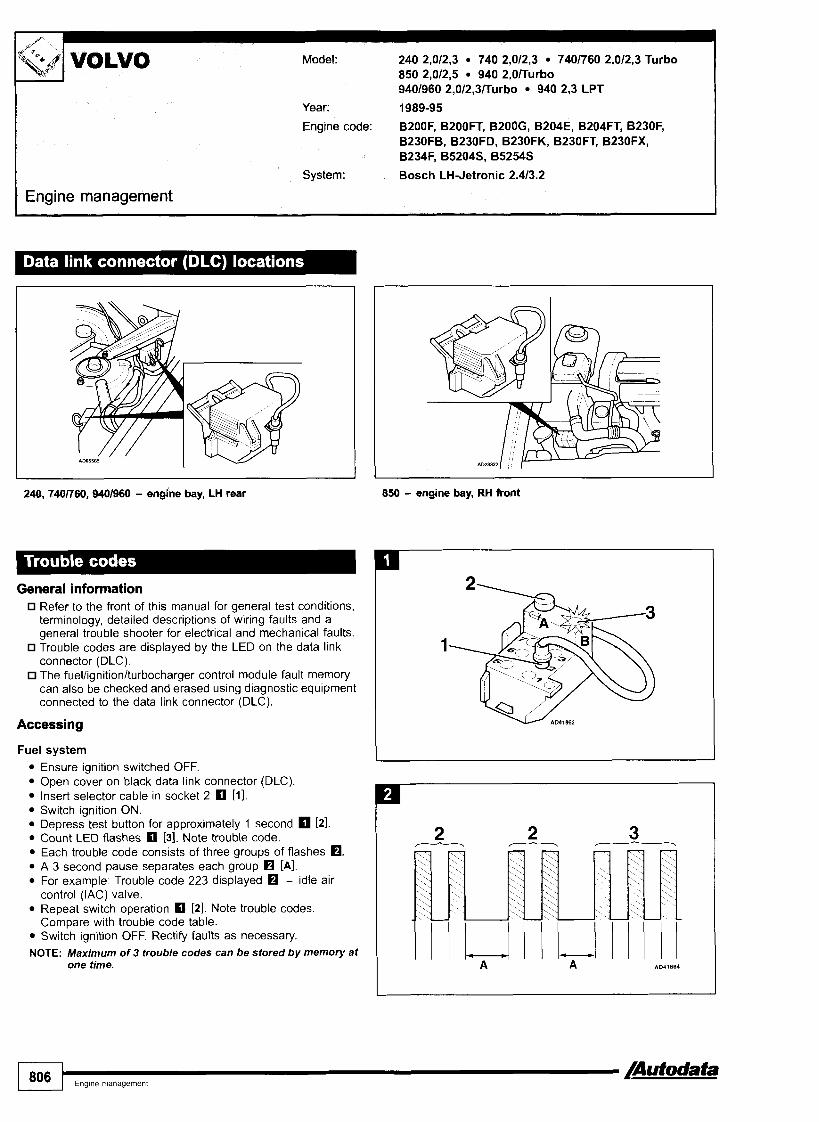
I Engine management
Model: 240 2,012,3 740 2,012,3 7401760 2,012,3 Turbo 850 2,012,s 940 2,OlTurbo 9401960 2,0/2,3lTurbo 940 2,3 LPT
Year: 1989-95
Engine code: B200F, B2OOFT, B200G, B204E, B204FT, B230F, B230F6, B230FD, B230FK, B230FT, B230FX, B234F, B5204S, 85254s
System: Bosch LH-Jetronic 2.413.2
240, 7401760,9401960 - engine bay, LH rear
General information Refer to the front of this manual for general test conditions, terminology, detailed descriptions of wiring faults and a general trouble shooter for electrical and mechanical faults. Trouble codes are displayed by the LED on the data link connector (DLC). The fuellignition/turbocharger control module fault memory can also be checked and erased using diagnostic equipment connected to the data link connector (DLC).
Accessing
850 - engine bay, RH front
1806 Engine management /Autodata
Fuel system Ensure ignition switched OFF. Open cover on black data link connector (DLC). Insert selector cable in socket 2 rn [ I ] . Switch ignition ON. Depress test button for approximately 1 second [2]. Count LED flashes rn [3]. Note trouble code. Each trouble code consists of three groups of flashes rn. A 3 second pause separates each group rn [A]. For example: Trouble code 223 displayed rn - idle air control (IAC) valve. Repeat switch operation rn [2]. Note trouble codes. Compare with trouble code table. Switch ignition OFF. Rectify faults as necessary.
NOTE: Maximum of 3 trouble codes can be stored by memory at one time.
2 ,- y - 2 - 3
A A A041 864

Model: 240 2,012,3 740 2,012,3 7401760 2,012,3 Turbo 850 2,012,5 940 2.0rrurbo 9401960 2 ,0 /2 ,3~urbo 940 2,3 LPT
Engine management
Ignition system
Ensure ignition switched OFF. Open cover on black data link connector (DLC). Insert selector cable in socket 6 [ I ] . Switch ignition ON. Depress test button for approximately 1 second El [2] . Count LED flashes [3]. Note trouble code. Trouble codes are displayed in the same way as those from the fuel system: Each trouble code consists of three groups of flashes m. A 3 second pause separates each group [A]. For example: Trouble code 223 displayed - idle air control (IAC) valve. Repeat switch operation El [2]. Note trouble codes. Compare with trouble code table. Switch ignition OFF. Rectify faults as necessary.
NOTE: Maximum of 3 trouble codes can be stored by memory at one time.
Turbocharger ( T C ) system - BZ04FT
Ensure ignition switched OFF. Open cover on black data link connector (DLC). lnsert selector cable in socket 5 rn 111. Switch ignition ON. Depress test button for approximately 1 second rn [2] Count LED flashes rn [3]. Note trouble code. Trouble codes are displayed in the same way as those from the fuel system:
0 Each trouble code consists of three groups of flashes m. A 3 second pause separates each group [A] .
n For example: Trouble code 223 displayed - idle air control (IAC) valve. Repeat switch operation [2] . Note trouble codes. Compare with trouble code table. Switch ignition OFF. Rectify faults as necessary.
NOTE: Maximum of 7 trouble codes can be stored by memory at one time.
Erasing Ensure ignition switched OFF. lnsert selector cable: Fuel system - in socket 2 [ I ] Ignition system - in socket 6 [' TC system - in socket 5 rn [ I ] . Access trouble codes.
NOTE: Trouble codes must be displayed at least once before they can be erased.
Depress test button for approximately 5 seconds. Release test button. Wait for LED to illuminate. Depress test button for approximately 5 seconds. Release test button. Depress test button for approximately 1 second. Ensure trouble code 111 displayed.
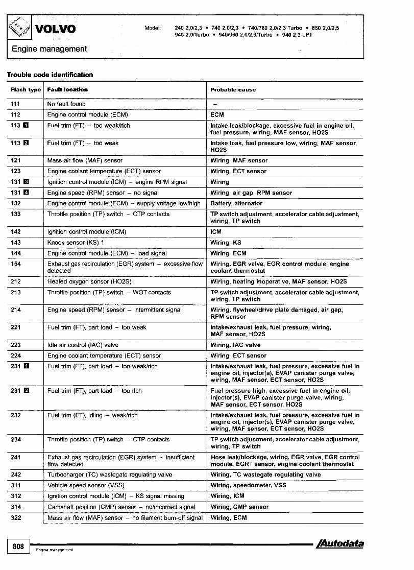
Model: 240 2,012,3 740 2,012,3 7401760 2,012,3 Turbo 850 2,012,5 940 2,OITurbo 9401960 2,012,3ITurbo 940 2,3 LPT
Engine management
Trouble code identification
Probable cause Fault location Flash type
No fault found
Engine control module (ECM)
Fuel trim (FT) - too weaklrich
-
ECM
Intake leaklblockage, excessive fuel in engine oil, fuel pressure, wiring, MAF sensor, H02S
Fuel trim (FT) - too weak Intake leak, fuel pressure low, wiring, MAF sensor, H02S
Wiring, MAF sensor Mass air flow (MAF) sensor
Engine coolant temperature (ECT) sensor Wiring, ECT sensor
Ignition control module (ICM) - engine RPM signal Wiring
Engine speed (RPM) sensor - no signal Wiring, air gap, RPM sensor -
Engine control module (ECM) - supply voltage lowlhigh
Throttle position (TP) switch - CTP contacts
--
Battery, alternator
TP switch adjustment, accelerator cable adjustment, wiring, TP switch
lgnition control module (ICM) ICM
Knock sensor (KS) 1 Wiring, KS
Engine control module (ECM) - load signal Wiring, ECM
Exhaust gas recirculation (EGR) system - excessive flow detected
Wiring, EGR valve, EGR control module, engine coolant thermostat
Heated oxygen sensor (H02S)
Throttle position (TP) switch - WOT contacts
Wiring, heating inoperative, MAF sensor, H02S
TP switch adjustment, accelerator cable adjustment, wiring, TP switch
Engine speed (RPM) sensor - intermittent signal Wiring, flywheelldrive plate damaged, air gap, RPM sensor
Fuel trim (FT), part load - too weak lntakelexhaust leak, fuel pressure, wiring, MAF sensor, H02S
Idle air control (IAC) valve Wiring, IAC valve
Engine coolant temperature (ECT) sensor Wiring, ECT sensor
Fuel trim (FT), part load - too weakkich lntakelexhaust leak, fuel pressure, excessive fuel in engine oil, injector(s), EVAP canister purge valve, wiring, MAF sensor, ECT sensor, H02S
Fuel trim (FT), part load - too rich Fuel pressure high, excessive fuel in engine oil, injector(s), EVAP canister purge valve, wiring, MAF sensor, ECT sensor, H02S
Fuel trim (FT), idling - weak/rich lntakelexhaust leak, fuel pressure, excessive fuel in engine oil, injector(s), EVAP canister purge valve, wiring, MAF sensor, ECT sensor, H02S
Throttle position (TP) switch - CTP contacts TP switch adjustment, accelerator cable adjustment, wiring, TP switch
Exhaust gas recirculation (EGR) system - insufficient flow detected
Turbocharger (TC) wastegate regulating valve
Vehicle speed sensor (VSS)
lgnition control module (ICM) - KS signal missing
Hose leaklblockage, wiring, EGR valve, EGR control module, EGRT sensor, engine coolant thermostat
Wiring, TC wastegate regulating valve
Wiring, speedometer, VSS
Wiring, ICM
Camshaft position (CMP) sensor - nolincorrect signal
Mass air flow (MAF) sensor - no filament burn-off s~gnal
Wiring, CMP sensor
Wiring, ECM

940 2,OITurbo 9401960 2,0/2,3ITurbo 940 2,3 LPT
Flash type
324
41 3 I Exhaust gas recirculation temperature (EGRT) sensor I Wiring, EGRT sensor
342
344
41 1
421 I Manifold absolute pressure (MAP) sensor I Hose leaklblockage, TC, TC control module
Fault location
Camshaft position (CMP) sensor - intermittent signal
422 H I Exhaust gas temperature sensor I Wiring, exhaust gas temperature sensor
Probable cause
Wiring, CMP sensor
AC compressor clutch cut-off relay
Exhaust gas temperature sensor
Throttle position (TP) sensor
Wiring, AC compressor clutch cut-off relay
Wiring, EGRT sensor
Wiring, TP sensor
I Engine coolant blower motor temperature sensor Wiring, engine coolant blower motor temperature sensor
423
424
433 I Knock sensor (KSI 2 I Wiring, KS
Throttle position (TP) sensor
Engine control module (ECM) - load signal
432
-
Wiring, TP sensor
Wiring, ECM if trouble code also stored in ICM
Bosch LH-Jetronic 2.4 Bosch LH-Jetronic 3.2 Engine control module (ECM). Ignition control module (ICM).
H Has no function on early models. Erase trouble code and check fuel system for trouble code 344.
Engine control module (ECM) - overheating
51 2
51 3
Engine coolant blower motor, air supply blocked, module cooling fan
Fuel trim (FT) - too rich
Engine control module (ECM) - overheating
Intake blockage, excessive fuel in engine oil, fuel pressure high, wiring, MAF sensor, H02S
Engine coolant blower motor, air supply blocked, module cooling fan

VOLVO Model: 850 2,O 850 2,3/2,5 850 2,5 20V 960 2,5/3,0
Year: 1990-95
Engine code: B5202S, B5204T, B5234T, B5234T4, B5234T5, B5252S, B5254S, B6254F, B6304F
System: Bosch Motronic 1.8 Bosch Motronic 4.3 Siemens Fenix 5.2
I Engine management I
850 - engine bay, RH front
General information Refer to the front of this manual for general test conditions, terminology, detailed descriptions of wiring faults and a general trouble shooter for electrical and mechanical faults. Trouble codes are displayed by the LED on the data link connector (DLC). The ECM fault memory can also be checked and erased using diagnostic equipment connected to the data link connector (DLC).
Accessing Ensure ignition switched OFF. Open cover on black data link connector (DLC). Insert selector cable in socket 2 [ I ] . Switch ignition ON. Depress test button for approximately 1 second rn [2]. Count LED flashes rn 131. Note trouble code. Each trouble code consists of three groups of flashes m. A 3 second pause separates each group H [A]. For example: Trouble code 223 displayed - idle air control (IAC) valve. Repeat switch operation rn 121. Note trouble codes. Compare with trouble code table. Switch ignition OFF. Rectify faults as necessary.
960 - engine bay, LH rear

I
Engine management
Erasing Ensure ignition switched OFF. Insert selector cable in socket 2 [I]. Access trouble codes.
NOTE: Trouble codes must be displayed at least once before they can be erased.
Depress test button for approximately 5 seconds. Release test button. Wait for LED to illuminate. Depress test button for approximately 5 seconds. Release test button. Depress test button for approximately 1 second. Ensure trouble code 111 displayed.
Trouble code identification
Flash type I Fault location Probable cause I
111 I No fault found
112 I Engine control module (ECM) ECM
113 I Early models: Injector(s) Wiring, fuse, injector(s)
Late models: Injectors 1, 2 & 4
113 1993: Short term fuel trim
Wiring, fuse, injector(s)
No vacuum to MAP sensor, HO2Slsignal short to earth, MAP sensorlearth wire
1994 +: Short term fuel trim - upper limit reached
Injectors 3, 5 & 6
lnjector 1
Mass air flow (MAF) sensor/manifold absolute pressure (MAP) sensor
Wiring, H02S - -- - --
Wiring, fuse, injector(~)
Wiring, injector
Wiring, hose connection, MAFIMAP sensor
Intake air temperature (IAT) sensor
Engine coolant temperature (ECT) sensor
lnjector 2
Engine speed (RPM) sensor - no signal
Wiring, IAT sensor --
w i r i n g , ~ ~ ~ s e n s o r
Wiring, injector
Wiring, RPM sensor
132 I Engine control module (ECM) - supply voltage lowlhigh Battery, alternator
Wiring, injector
Wiring, KS
Wiring, injector
Wiring, AIR solenoid
Wiring, heating inoperative, HO2S
Wiring, EGR valve, EGR control module, engine coolant thermostat
Wiring, injector
135 Injector 3
143 Knock sensor (KS) 1
145 I lniector 4
152 I Secondary air injection (AIR) solenoid
153 I Heated oxygen sensor (H02S) 2
154 1 Exhaust gas recirculation (EGR) system - excessive flow detected
155 I Injector 5
212 I Heated oxygen sensor (H02S) 1 Wiring, heating inoperative, MAF sensor, HO2S
214 1 Engine speed (RPM) sensor - intermittent signal Wiring, flywheelldrive plate damaged, air gap, RPM sensor
lntakelexhaust leak, fuel pressure low, injector(s) blocked, hose connection, wiring, MAFIMAP sensor, ECT sensor, H02S
Wiring, engine control relay
4
221 I Long term fuel trim, part load - upper limit reached
I 222 Engine control relay
/Autodata Engme management f811 1

[Engine management
Probable cause Flash type
Early models: ldle air control (IAC) valve Wiring, IAC valve
Late models: ldle air control (IAC) valve - opening signal Wiring, IAC valve
Wiring, AC refrigerant pressure sensor AC refrigerant pressure sensor
Long term fuel trim, part load - lower limit reached Fuel pressure high, excessive fuel in engine oil, engine oil level high, injector(s) leaking, EVAP canister purge valve, hose connection, wiring, MAFIMAP sensor, ECT sensor, H02S
lntakelexhaust leak, fuel pressure, excessive fuel in engine oil, injector(s), EVAP canister purge valve, wiring, MAF sensor, ECT sensor, H02S
Long term fuel trim, idling
Long term fuel trim, idle air adjustment Intake leaklblockage, throttle valve adjustment, wiring, IAC valve
Exhaust gas recirculation (EGR) solenoid
Exhaust gas recirculation (EGR) system - incorrect flow detected
Throttle position (TP) sensor
Wiring, EGR solenoid
Hose leaklblockage, wiring, EGR valve, EGR control module, engine coolant thermostat
Wiring, TP sensor
ldle air control (IAC) valve - closing siqnal Wiring, IAC valve
Vehicle speed sensor (VSS) Wiring, speedometer, VSS
Camshaft position (CMP) sensor Wiring, CMP sensor
Evaporative emission (EVAP) system EVAP canister, hose leaklblockage, EVAP canister purge valve
Mass air flow (MAF) sensor - no filament bum-off signal Wiring, ECM
Malfunction indicator lamp (MIL) Wiring, MIL
Engine control module (ECM) - supply voltage, battery Battery dischargedldisconnected, wiring, ECM disconnected
Transmission control module (TCM) - MIL ON request Wiring
AC relay Wiring, AC relay
Fuel pump retay
Throttle position (TP) sensor
Exhaust gas recirculation temperature (EGRT) sensor
Wiring, fuel pump relay ---
Wiring, TP sensor
Wiring, EGRT sensor
Turbocharger (TC) pressure - control TC wastegate regulating valve hose leaklblockage, wiring, MAF sensor, TCM wire (TC boost reduction), TC wastegate regulating valve
Transmission control moduje (TCM) - TC boost reduction signal
Wiring short to earth
Engine control module (ECM) - overheating Engine coolant blower motor, air supply blocked, module cooling fan
Wiring, KS Knock sensor (KS) 2
Heated oxygen sensor (H02S) 1 - slow response lntakelexhaust leak, fuel pressure, compression, H02S
lntakelexhaust leak, fuel pressure, compression, H02S 112
Heated oxygen sensor (H02S) 2 - compensation
Secondary air injection (AIR) pump relay Wiring, AIR pump relay
Catalytic converter - elficien~y lntakelexhaust leak, fuel pressure, compression, catalytic converter
Accelerator pedal position (APP) sensor Wiring, APP sensor

Model: 850 2,O 850 2,3/2,5 850 2,5 20V 960 2,5/3,0
Engine management 7 Flash type Fault location
451 Cylinder I - misfire detected
452 Cylinder 2 - misfire detected
I
453
454
Cylinder 3 - misfire detected
Cylinder 4 - misfire detected
455 Cylinder 5 - misfire detected
51 1
513 1 Engine control module (ECM) - overheating
Long term fuel trim, idling
512
512
I
51 4 I Engine coolant blower motor, low speed
Short term fuel trim - lower limit reached
Short term fuel trim
51 5 I Engine coolant blower motor, high speed
52 1 I Heated oxygen sensor (H02S) I - heater control
522 I Heated oxygen sensor (H02S) 2 - heater control
523
524
Module cooling fan
Transmission control module (TCM) - torque reduction signal
53 1
532
534 I Engine control module (ECM) - power stage - group D
Engine control module (ECM) - power stage - group A
Engine control module (ECM) - power stage - group B
533 Engine control module (ECM) - power stage - group C
541 I Evaporative emission (EVAP) canister purge valve
535
Probable cause
Turbocharger (TC) wastegate regulating valve
Spark plug, HT lead, distributor rotorlcap, moisture ingress, injectorlwiring, air leak, compression, head gasket, low-tension wiring, repeated cold starts (flooding), puncture in front tyre
Spark plug, HT lead, distributor rotorlcap, moisture ingress, injectorlwiring, air leak, compression, head gasket, low-tension wiring, repeated cold starts (flooding), puncture in front tyre
Spark plug, HT lead, distributor rotorlcap, moisture ingress, injectorlwiring, air leak, compression, head gasket, low-tension wiring, repeated cold starts (flooding), puncture in front tyre
Spark plug, HT lead, distributor rotorlcap, moisture ingress, injectorlwiring, air leak, compression, head gasket, low-tension wiring, repeated cold starts (flooding), puncture in front tyre
Spark plug, HT lead, distributor rotorlcap, moisture ingress, injectorlwiring, air leak, compression, head gasket, low-tension wiring, repeated cold starts (flooding), puncture in front tyre
lntakelexhaust leak, fuel pressure, excessive fuel in engine oil, injector(s), EVAP canister purge valve, wiring, MAF sensor, ECT sensor, H02S
H02S signal wire short to earth, EGR system leak, MAP sensor, H02S, MAP sensor earth wire open circuitlpoor connection
Fuel pressure, wiring, MAF sensor
Engine coolant blower motor, air supply blocked, module cooling fan
Wiring, engine coolant blower motor relay
Wiring, engine coolant blower motor relay
Wiring, H02S
Wiring, H02S
Wiring, module cooling fan
Wiring
Wiring, injector(s), EVAP canister purge valve, ECM
Wiring, IAC valve, TC wastegate regulating valve, engine coolant blower motor relay, ECM
Wiring short to positive, EGR control module, engine coolant blower motor relay, TCM (load signal), instrument panel (ECTIRPMlfuel consumption signals), ECM
Wiring short to positive, MIL, AC relay, fuel pump, ignition amplifier, ECM
Wiring, TC wastegate regulating valve
Wiring, EVAP canister purge valve

1 VOLVO Model:
Engine management
Flash type
542
FauPt location
Misfire detected, more than 1 cylinder
Misfire detected, at least 1 cylinder
Misfire detected, more than 1 cylinder - TWC damage
Misfire detected - at least 1 cylinder - TWC damage
Cylinder 1, misfire detected - TWC damage
Cylinder 2, misfire detected - TWC damage
Cylinder 3, misfire detected - TWC damage
Cylinder 4, misfire detected - TWC damage
Cylinder 5, misfire detected - TWC damage
Probable cause
Spark plug, HT lead, distributor rotorlcap, moisture ingress, injectorlwiring, air leak, compression, head gasket, low-tension wiring, fuel pressure, fuel pumpl wiring, fuel level low, incorrectlcontaminated fuel, engine oil level high, repeated cold starts (flooding), puncture in front tyre
Spark plug, HT lead, distributor rotorlcap, moisture ingress, injectorlwiring, air leak, compression, head gasket, low-tension wiring, repeated cold starts (flooding), puncture in front tyre
Spark plug, HT lead, distributor rotorlcap, moisture ingress, injectorlwiring, air leak, compression, head gasket, low-tension wiring, fuel pressure, fuel pumpl wiring, fuel level low, incorrectlcontaminated fuel, engine oil level high, repeated cold starts (flooding), puncture in front tyre
-- -
Spark plug, HT lead, distributor rotorlcap, moisture ingress, injectorlwiring, air leak, compression, head gasket, low-tension wiring, repeated cold starts (flooding), puncture in front tyre
Spark plug, HT lead, distributor rotorlcap, moisture ingress, injectorlwiring, air leak, compression, head gasket, low-tension wiring, repeated cold starts (flooding), puncture in front tyre
Spark plug, HT lead, distributor rotorlcap, moisture ingress, injectorlwiring, air leak, compression, head gasket, low-tension wiring, repeated cold starts (flooding), puncture in front tyre
Spark plug, HT lead, distributor rotorlcap, moisture ingress, injectorlwiring, air leak, compression, head gasket, low-tension wiring, repeated cold starts (flooding), puncture in front tyre
Spark plug, HT lead, distributor rotorlcap, moisture ingress, injectorlwiring, air leak, compression, head gasket, low-tension wiring, repeated cold starts (flooding), puncture in front tyre
Spark plug, HT lead, distributor rotorlcap, moisture ingress, injectorlwiring, air leak, compression, head gasket, low-tension wiring, repeated cold starts (flooding), puncture in front tyre
Bosch Motronic 1.8 Siemens Fenix 5.2 Bosch Motronic 4.3

Year: 1995-99
Engine code: 852023, B5202FS, B5204T, B5204T2, B5234FS, B5234T, B5234T2, B5234T4, B5234T5, B5252FS, 852528, 852548, B6254F, B6304F
System: Bosch Motronic 1.8 Bosch Motronic 4.3 Siemens Fenix 5.2
Engine management
Model: 850 2,O 850 2,312,5 850 2,5 20V 960 2,5 20V SN70 2,012,5 20V
VOLVO
850 - near gear lever 960 - centre console
SN70 - centre console
General information Refer to the front of this manual for general test conditions, terminology, detailed descriptions of wiring faults and a general trouble shooter for electrical and mechanical faults.
G Trouble codes are displayed by using an LED connected to the data link connector (DLC). The ECM fault memory can also be checked and erased using diagnostic equipment connected to the data link connector (DLC). Ensure immobilizer disarmed.
Accessing Ensure ignition switched OFF. Bridge data link connector (DLC) terminal 3 and 5 with a switched lead - contacts normally open 0. Connect LED test lamp between data link connector (DLC) terminals 3 and 16 0. Switch ignition ON. Operate switch for approximately 1 second. Count LED flashes. Note trouble code. Each trouble code consists of three groups of flashes m. A 3 second pause separates each group [A]. For example: Trouble code 223 displayed - idle air control (IAC) valve. Repeat switch operation. Note trouble codes. Compare with trouble code table. Switch ignition OFF. Rectify faults as necessary.
/Autodata Ename manaqement 815

I Engine management
Model: 850 2,O 850 2,3/2,5 850 2,5 20V 960 2,5 20V SN70 2,012,5 20V
Erasing Ensure ignition switched OFF. Bridge data link connector (DLC) terminal 3 and 5 with a switched lead - contacts normally open 0 . Connect LED test lamp between data link connector (DLC) terminals 3 and 16 0 . Access trouble codes.
NOTE: Trouble codes must be displayed at least once before they can be erased.
Operate switch for approximately 5 seconds. Release switch. Wait for LED to illuminate. Operate switch for approximately 5 seconds Release switch. Operate switch for approximately 1 second. Ensure trouble code 111 displayed.
Trouble code identication
112 I Engine control module (ECM) I ECM
Flash type
1 1 3 0 IEadymodels:Inpctor(s) I Wiring, fuse, injector(s)
FatlPL ket lon Probable cause
113
115 0 115
121
122
123
125
131
132
135
Late models: Injectors 1, 2 & 4
1993: Short term fuel trim
1994 +: Short term fuel trim - upper limit reached
Injectors 3, 5 & 6
Injector 1
Mass air flow (MAF) sensorlmaniIbM absolute pressure (MAP) sensor
Intake air temperature (EAT) sensor
Engine coolant temperature (ECT) sensor
Injector 2
Engine speed (RPM) sensor - no signal
Engine control module (EW) - supply voltage lowhigh
Injector 3
Wiring, fuse, injector(s)
No vacuum to MAP sensor, HOZSlsignal short to earth, MAP sensorlearth wire
Wiring, H02S
Wiring, fuse, injector(s)
Wiring, injector
Wiring, hose connection, MAFIMAP sensor
Wiring, IAT sensor
Wiring, ECT sensor
Wiring, injector
Wiring, RPM sensor
Battery, alternator
Wiring, injector

Model: 850 2,O 850 2,3/2,5 850 2,5 20V 960 2,s 20V
I I 143 [ Knock sensor (KS) 1 I Wiring, KS
Flash type
--
lant thermostat
Long term fuel trim, part load - upper limit reached lntakelexhaust leak, fuel pressure low, injector@) blocked, hose connection, wiring, MAFIMAP sensor, ECT sensor. H02S
Fa& locathm
I I
41 3 1 Exhaust gas recirculation temperature (EGRT) sensor I Wiring, EGRT sensor
Probable cause
110
/nutodata Engme management 817

Model: 850 2,O 850 2,3/2,5 850 2,5 20V 960 2,5 20V SN70 2,012,5 20V
LEngine management
Flash type Fault location Probable cause
TC wastegate regulating valve hose leaklblockage, wiring, MAF sensor, TCM wire (TC boost reduction), TC wastegate regulating valve
Turbocharger (TC) pressure - control
Transmission control module (TCM) - TC boost reduction signal
Wiring short to earth
Engine control module (ECM) - overheating Engine coolant blower motor, air supply blocked, module cooling fan
Knock sensor (KS) 2 Wiring, KS
Heated oxygen sensor (H02S) 1 - slow response
Heated oxygen sensor (H02S) 2 - compensation
lntakelexhaust leak, fuel pressure, compression, H02S
lntakelexhaust leak, fuel pressure, compression, H02S 112
Wiring, AIR pump relay
lntakelexhaust leak, fuel pressure, compression, catalytic converter
Secondary air injection (AIR) pump relay
Catalytic converter - efficiency
Accelerator pedal position (APP) sensor Wiring, APP sensor
Cytinder 1 - misfire detected Spark plug, HT lead, distributor rotorlcap, moisture ingress, injectorlwiring, air leak, compression, head gasket, low-tension wiring, repeated cold starts (flooding), puncture in front tyre
Cylinder 2 - misfire detected Spark plug, HT lead, distributor rotorlcap, moisture ingress, injectorlwiring, air leak, compression, head gasket, low-tension wiring, repeated cold starts (flooding), puncture in front tyre
Cylinder 3 - misfire detected Spark plug, HT lead, distributor rotorlcap, moisture ingress, injectorlwiring, air leak, compression, head gasket, low-tension wiring, repeated cold starts (flooding), puncture in front tyre
Cylinder 4 - misfire detected Spark plug, HT lead, distributor rotorlcap, moisture ingress, injectorlwiring, air leak, compression, head gasket, low-tension wiring, repeated cold starts (flooding), puncture in front tyre
Cylinder 5 - misfire detected Spark plug, HT lead, distributor rotorlcap, moisture ingress, injectorlwiring, air leak, compression, head gasket, low-tension wiring, repeated cold starts (flooding), puncture in front tyre
lntakelexhaust leak, fuel pressure, excessive fuel in engine oil, injector(s), EVAP canister purge valve, wiring, MAF sensor, ECT sensor, H02S
Long term fuel trim, idling
Short term fuel trim - bwer limit reached H02S signal wire short to earth, EGR system leak, MAP sensor, H02S, MAP sensor earth wire open circuitlpoor connection
Short term fuel trim
Engine control module (ECM) - overheating
Fuel pressure, wiring, MAF sensor
Engine coolant blower motor, air supply blocked, module cooling fan
Wiring, engine coolant blower motor relay
Wiring, engine coolant blower motor relay
Wiring, H02S
Engine coolant blower motor, low speed
Engine coolant blower motor, high speed
Heated oxygen sensor fH02Sf 1 - heater ~ontrol
Heated oxygen sensor (W02S) 2 - heater control Wiring, H02S
Module cooling fa Wiring, module cooling fan
Transmission control module (TCM) - toque reduction signal
Wiring

I Engine control module (ECM) - power stage - group A
Flash type
/ Engine control module (ECM) - power stage - group 8
Fault location
Engine control module (ECM) - power stage - group C
535 I Turbocharger (TC) wastegate regulating valve
534
541 1 Evaporative emission (EVAP) canister purge valve
Engine control module (ECM) - power stage - group D
Misfire detected, at least 1 cylinder
542
Misfire detected, more than 1 cylinder - TWC damage c Misfire detected, more than 1 cylinder
545 I Misfire detected - at least 1 cylinder - TWC damage
552 I Cylinder 2, misfire detected - TWC damage
551 Cylinder 1, misfire detected - TWC damage
553 Cylinder 3, misfire detected - TWC damage
554
Bosch Motronic 1.8 Siemens Fenix 5.2 Bosch Motronic 4.3
Cylinder 4, misfire detected - TWC damage
555
Probable cause
Cylinder 5, misfire detected - TWC damage
Wiring, injector(s), EVAP canister purge valve, ECM
Wiring, IAC valve, TC wastegate regulating valve, engine coolant blower motor relay, ECM
Wiring short to positive, EGR control module, engine coolant blower motor relay, TCM (load signal), instrument panel (ECTIRPMlfuel consumption signals), ECM
Wiring short to positive, MIL, AC relay, fuel pump, ignition amplifier, ECM
Wiring, TC wastegate regulating valve
Wiring, EVAP canister purge valve
Spark plug, HT lead, distributor rotorlcap, moisture ingress, injectorlwiring, air leak, compression, head gasket, low-tension wiring, fuel pressure, fuel pumpl wiring, fuel level low, incorrecffcontaminated fuel, engine oil level high, repeated cold starts (flooding), puncture in front tyre
Spark plug, HT lead, distributor rotorlcap, moisture ingress, injectorlwiring, air leak, compression, head gasket, low-tension wiring, repeated cold starts (flooding), puncture in front tyre
Spark plug, HT lead, distributor rotorlcap, moisture ingress, injectorlwiring, air leak, compression, head gasket, low-tension wiring, repeated cold starts (flooding), puncture in front tyre
Spark plug, HT lead, distributor rotorlcap, moisture ingress, injectorlwiring, air leak, compression, head gasket, low-tension wiring, repeated cold starts (flooding), puncture in front tyre
Spark plug, HT lead, distributor rotorlcap, moisture ingress, injectorlwiring, air leak, compression, head gasket, low-tension wiring, repeated cold starts (flooding), puncture in front tyre
Spark plug, HT lead, distributor rotorlcap, moisture ingress, injectorlwiring, air leak, compression, head gasket, low-tension wiring, repeated cold starts (flooding), puncture in front tyre
Spark plug, HT lead, distributor rotorlcap, moisture ingress, injectorlwiring, air leak, compression, head gasket, low-tension wiring, repeated cold starts (flooding), puncture in front tyre
[Autodata Eng~ne management 819

System: Bosch LH-Jetronic 2.413.2
Engine management
850 - near gear lever W0 - centre cone&
940 - centre console
General information Refer to the front of this manual for general test conditions, terminology, detailed descriptions of wiring faults and a general trouble shooter for electrical and mechanical faults. Without immobilizer: Trouble codes are displayed by using an LED connected to the data link connector (DLC). Without immobilizer: The fuellignition control module fault memory can also be accessed and erased using diagnostic equipment connected to the data link connector (DLC). With immobilizer: The fuellignition control module fault memory can only be accessed and erased using diagnostic equipment connected to the data link connector (DLC).
Accessing - without immobilizer
Fuel system Ensure ignition switched OFF. Bridge data link connector (DLC) terminal 3 and 5 with a switched lead - contacts normally open D. Connect LED test lamp between data link connector (DLC) terminals 3 and 5 0. Switch ignition ON. Operate switch for approximately 1 second. Count LED flashes. Note trouble code. Each trouble code consists of three groups of flashes a. A 3 second pause separates each group [A]. For example: Trouble code 223 displayed - idle air control (IAC) valve. Repeat switch operation. Note trouble codes. Compare with trouble code table. Switch ignition OFF. Rectify faults as necessary.
NOTE: Maximum of 3 trouble codes can be stored by memory at one time.
1 820 _I Engine management /Autodata

Engine management I
Ignition system Ensure ignition switched OFF. Bridge data link connector (DLC) terminal 1 and 5 with a switched lead - contacts normally open m. Connect LED test lamp between data link connector (DLC) terminals 1 and 5 a. Switch ignition ON. Operate switch for approximately 1 second. Count LED flashes. Note trouble code. Trouble codes are displayed in the same way as those from the fuel system: Each trouble code consists of three groups of flashes a. A 3 second pause separates each group [A]. For example: Trouble code 223 displayed - idle air control (IAC) valve. Repeat switch operation. Note trouble codes. Compare with trouble code table. Switch ignition OFF. Rectify faults as necessary.
NOTE: Maximum of 3 trouble codes can be stored by memory at one time.
Accessing - with immobilizer The fuellignition control module fault memory can only be accessed using diagnostic equipment connected to the data link connector (DLC).
Erasing - without immobilizer Ensure ignition switched OFF. Bridge data link connector (DLC) terminal with a switched lead - contacts normally open: Fuel system - terminals 3 & 5 0. lgnition system - terminals 1 & 5 0. Connect LED test lamp between data link connector (DLC) terminals: Fuel system - terminals 3 & 5 0.
fl Ignition system - terminals 1 8 5 a. Access trouble codes.
NOTE: Trouble codes must be displayed at least once before they can be erased.
Operate switch for approximately 5 seconds. Release switch. Wait for LED to illuminate. Operate switch for approximately 5 seconds. Release switch. Operate switch for approximately 1 second. Ensure trouble code 111 displayed.
Eraslng - with immobilizer The fuellignition control module fault memory can only be erased using diagnostic equipment connected to the data link connector (DLC).
4
/Adodata f Eng~ne management 821

IEngine management
Trouble code identification
Probable cause
ECM
I I I
112
113 / Fuel trim (FT) - too weaklrich
No fault found
Enqine control module (ECM)
Intake leaklblockage, excessive fuel in engine oil, fuel pressure, wiring, MAF sensor, H02S
113 0 I Fuel trim (FT) - too weak Intake leak, fuel pressure low, wiring, MAF sensor, H02S
121 I Mass air flow (MAF) sensor Wiring, MAF sensor
123 I Engine coolant temperature (ECT) sensor Wiring, ECT sensor
131 I lgnition control module (ICM) - engine RPM signal Wiring
Wiring, air gap, RPM sensor
Battery, alternator
131
132
133 TP switch adjustment, accelerator cable adjustment, wiring, TP switch
Engine speed (RPM) sensor - no signal
Engine control module (ECM) - supply voltage lowlhigh
Throttle position (TP) switch - CTP contacts
ICM 142
143
144
Wiring, KS
Ignition control module (ICM)
Knock sensor (KS) 1
Engine control module (ECM) - load signal Wiring, ECM
Wiring, EGR valve, EGR control module, engine coolant thermostat
Wiring, heating inoperative, MAF sensor, H02S
1 54
212
Throttle position (TP) switch - WOT contacts
Exhaust gas recirculation (EGR) system - excessive flow detected
Heated oxygen sensor (H02S)
TP switch adjustment, accelerator cable adjustment, wiring, TP switch
214 I Engine speed (RPM) sensor - intermittent signal Wiring, flywheelldrive plate damaged, air gap, RPM sensor
lntakelexhaust leak, fuel pressure, wiring, MAF sensor, H02S
223 I Idle air control (IAC) valve
221
Wiring, IAC valve
Fuel trim (FT), part load - too weak
224 I Engine coolant temperature (ECT) sensor Wiring, ECT sensor
131 I Fuel trim (FT), part load - too weaklrich lntakelexhaust leak, fuel pressure, excessive fuel in engine oil, injector(s), EVAP canister purge valve, wiring, MAF sensor, ECT sensor, H02S
Fuel pressure high, excessive fuel in engine oil, injector(s), EVAP canister purge valve, wiring, MAF sensor, ECT sensor, H02S
lntakelexhaust leak, fuel pressure, excessive fuel in engine oil, injector(s), EVAP canister purge valve, wiring, MAF sensor, ECT sensor, H02S
TP switch adjustment, accelerator cable adjustment, wiring, TP switch
2 3 1 0 1 Fuel trim (FT), part load - too rich
Fuel trim (FT), idling - weaklrich
I
Hose leaklblockage, wiring, EGR valve, EGR control module, EGRT sensor, engine coolant thermostat
Wiring, TC wastegate regulating valve
234
241
242
31 1 ( Vehicle speed sensor (VSS)
Throttle position (TP) switch - CTP contacts
Exhaust gas recirculation (EGR) system - insufficient flow detected
Turbochamer (TC) wastegate regulating valve
Wiring, speedometer, VSS
31 2 1 Ignition control module (ICM) - KS signal missing Wiring, ICM
Wiring, CMP sensor 314 Camshaft position (CMP) sensor - no/incorrect signal

Engine management I Model: 850 2,012,5 9401960 2,0/2,3/Turbo 940 2,3 LPT
S70N70 2.5 20V VOLVO
Flash type I Fault location / Probable cause
<+ +-p r
I I 322 I Mass air flow (MAF) sensor - no filament burn-off signal I Wiring, ECM
324 I Camshaft position (CMP) sensor - intermittent signal I Wiring, CMP sensor
342 I AC compressor clutch cut-off relay 1 Wiring, AC compressor clutch cut-off relay
421 I Manifold absolute pressure (MAP) sensor I Hose leaklblockage, TC, TC control module
344
41 1
41 3
422 H I Exhaust gas temperature sensor I Wiring, exhaust gas temperature sensor
-
Exhaust gas temperature sensor
Throttle position (TP) sensor
Exhaust gas recirculation temperature (EGRT) sensor
-
Wiring, EGRT sensor
Wiring, TP sensor
Wiring, EGRT sensor
Throttle position (TP) sensor
Engine control module (ECM) - load signal
Engine coolant blower motor temperature sensor
Fuel trim (FT) - too rich
-
Wiring, TP sensor
Wiring, ECM if trouble code also stored in ICM
Wiring, engine coolant blower motor temperature sensor
Engine control module (ECM) - overheating
Knock sensor (KS) 2
I Intake blockage, excessive fuel in engine oil, fuel pressure high, wiring, MAF sensor, H02S
Engine coolant blower motor, air supply blocked, module cooling fan
Wiring, KS
Engine control module (ECM) - overheating Engine coolant blower motor, air supply blocked, module cooling fan
Bosch LH-Jetronic 2.4 Bosch LH-Jetronic 3.2 Engine control module (ECM). Ignition control module (ICM). Has no function on early models. Erase trouble code and check fuel system for trouble code 344.

Model: 850 960
Year:
Transmission r
850 - engine bay, UM front 980 - engine bay, LH rear
General information Refer to the front of this manual for general test conditions, terminology, detailed descriptions of wiring faults and a general trouble shooter for electrical and mechanical faults.
o Trouble codes are displayed by the LED on the data link connector (DLC). The transmission control module (TCM) fault memory can also be checked and erased using diagnostic equipment connected to the data link connector (DLC).
Accessing Ensure ignition switched OFF. Open cover on black data link connector (DLC). Insert selector cable in socket 1 [I]. Switch ignition ON. Depress test button for approximately 1 second 121. Count LED flashes rn [3]. Note trouble code. Each trouble code consists of three groups of flashes m. A 3 second pause separates each group [A]. For example: Trouble code 223 displayed - throttle position (TP) sensor. Repeat switch operation rn [2]. Note trouble codes. Compare with trouble code table. Switch ignition OFF. Rectify faults as necessary.

1
Transmission
Erasing Ensure ignition switched OFF. Insert selector cable in socket 1 [ll. Access trouble codes.
NOTE: Trouble codes must be displayed at least once before they can be erased.
Depress test button for approximately 5 seconds. Release test button. Wait for LED to illuminate. Depress test button for approximately 5 seconds. Release test button. Depress test button for approximately 1 second. Ensure trouble code 111 displayed.
Trouble code identification I I
Flash type I Fault location I Probable cause
111
112
113
122 I Shift solenoid (SS) 1 - open circuit ( Wiring open circuit, SS
114
121
I Transmission fluid pressure (TFP) solenoid - short to Wiring short to positive, TFP solenoid positive
No fault found
Shift solenoid (SS) 1 - short to positive
Transmission control module (TCM) - short circuit to SS 2
Transmission mode selection switch - short to earth Wiring short to earth, transmission mode selection switch
-
-
Wiring short to positive, SS
TCM supplylearth wiring, SS signal wire, TCM
Transmission mode selection switch - open circuit
Shift solenoid (SS) 1 - short to earth
Transmission fluid pressure (TFP) solenoid -open circuit1 Wiring openlshort to earth, TFP solenoid short to earth
Wiring open circuit, transmission mode selection switch
Wiring short to earth, SS
Transmission control module (TCM) - supply voltage to Wiring, TCM TFP solenoid defective I
Transmission fluid temperature (TFT) sensor - open circuit
Transmission kick-down switch - short to earth
Transmission control module (TCM) - short circuit to SS 1
134
141
Wiring open circuit, TFT sensor
- - - --
Wiring, transmission kick-down switch
TCM supplylearth wiring, SS signal wire, TCM
Engine control module (ECM) - incorrect load signal
Transmission fluid temperature (TFT) sensor - short circuit
21 2 I Shift solenoid (SS) 2 - short to positive 1 Wiring short to positive, SS
Wiring, ECM, TCM
Wiring short circuit, TFT sensor
222 I Shift solenoid (SS) 2 - open circuit I Wiring open circuit, SS
213
221
Engine control module (ECM), TP sensor signal - high input
Shift solenoid (SS) 2 - short to earth
223
ECM trouble code@) stored, ECMITCM electrical connection, ECMITCM earth wiring
Wiring short to earth, SS
Engine control module (ECM), TP sensor signal - low input
ECM trouble code(s) stored, ECMITCM electrical connection openlshort to earth, ECMITCM earth wiring

Model: 850 960
Transmission
Flash type Fault location I I Probable cause
232 I Vehicle speed sensor (VSS) - no signal I Wiring, speedometer, VSS
23 1
245 I ECMnCM electrical connection -torque reduction signal I Wiring, ECM, TCM
Engine control module (ECM), TP sensor signal - implausible
233
235
31 1 I Input shaft speed (ISS) sensor - no signal I Wiring, ISS sensor
ECM trouble code(s) stored, ECMnCM electrical connection, ECMnCM earth wiring, electrical interference
Vehicle speed sensor (VSS) - implausible signal
Transmission fluid temperature (TFT) sensor - high input
322 I Gear ratio - incorrect I Mechanical transmission fault, TCM program error
Wiring, poor connection, electrical interference, speedometer, VSS
ATF level incorrect, towing weight limit exceeded, wiring, TFT sensor
31 2
31 3
332 I Transmission lock-up solenoid - open circuit I Wiring open circuit, transmission lock-up solenoid
Input shaft speed (ISS) sensor - implausible signal
Transmission range (TR) switch
Transmission lock-up slippinglnot engaged - ISS sensorNSS signals, excessive variation
Transmission lock-up solenoid - short to positive
Wiring, electrical interference, ISS sensor
Incorrect adjustment, wiring, TR switch
Mechanical transmission fault
Wiring short to positive, transmission lock-up solenoid
333
<a Transmission lock-up solenoid - short to earth Wiring short to earth, transmission lock-up solenoid

I Year:
Transmission 'i
850 - near gear lever
1 41023202 \ ' '
960 - centre console
-
SN40 - under fascia, driver's side
SNIC7O - centre console
General information Refer to the front of this manual for general test conditions, terminology, detailed descriptions of wiring faults and a general trouble shooter for electrical and mechanical faults.
Accessing and erasing The transmission control module (TCM) fault memory can only be accessed and erased using diagnostic equipment connected to the data link connector (DLC).

Troubie code identification
I&
Probable cause
VoLVo Model: 850 SNIC7O 960
Scanner type
Fault location
No fault found
Transmission mode selection switch - high input Switch incorrectly operated, wiring open circuitlshort to positive, transmission mode selection switch
Shift solenoid (SS) 1 - short to earth Wiring short to earth, SS
Shift solenoid (SS) 1 - circuit malfunction
Transmission fluid pressure (TFP) solenoid - short to positive
Wiring, SS
Wiring short to positive, TFP solenoid
Transmission mode selection switch - low input Wiring short to earth, transmission mode selection switch, 'W' button pressed for more than 25 seconds
Transmission fluid pressure (TFP) solenoid - open circuit1 short to earth
Wiring openlshort to earth, TFP solenoid
Transmission control module (TCM) - supply voltage to TFP solenoid defective
Engine control module (ECM) - incorrect load signal
TCM
Wiring, ECM, TCM
Transmission fluid temperature (TFT) sensor - low input Wiring short to earth, TFT sensor
Transmission fluid temperature (TFT) sensor - high input Wiring openlshort to positive, TFT sensor
Transmission kick-down switch - low input Wiring short to earth, transmission kick-down switch, TP sensor adaptationlsignal
Engine control module (ECM), TP sensor signal - high input
ECM trouble code@) stored, ECMITCM electrical connection short to positive, ECM/TCM earth wiring
Shift solenoid (SS) 2 - short to earth Wiring short to earth, SS
Shift solenoid (SS) 2 - circuit malfunction Wiring, SS
Engine control module (ECM), TP sensor signal - low input
ECM trouble code@) stored, ECM/TCM electrical connection openlshort to earth, ECM/TCM earth wiring
Vehicle speed sensor (VSS) - no signal Wiring, speedometer, VSS
Transmission fluid temperature (TFT) sensor - high input ATF level incorrect, towing weight limit exceeded, wiring, TFT sensor
ECMRCM electrical connection, torque reduction - signal low
Ignition switched on with ECM disconnected, wiring openlshort to earth, TR switch
ECMRCM electrical connection, torque reduction - signal high
ECMRCM electrical connection - torque reduction signal
Wiring short to positive, TR switch
Wiring, ECM, TCM
lnput shaft speed (ISS) sensor - no signal Wiring, ISS sensor
lnput shaft speed (ISS) sensor - implausible signal
Transmission range (TR) switch
Gear 1 - incorrect ratio
Wiring, electrical interference, ISS sensor
Incorrect adjustment, wiring, TR switch
Electrical interference of ISS sensorNSS signal, ISS sensorNSS signal faulty, TR switch adjustmentldefective, ATF level low, mechanical transmission fault, wiring
Electrical interference of ISS sensorNSS signal, ISS sensorNSS signal faulty, TR switch adjustmentldefective, ATF level low, mechanical transmission fault, wiring
Gear 2 - incorrect ratio

Model: 850 SNIC7O 960
Probable cause Scanner ty Pe
Fault locatlon
Gear 3 - incorrect ratio Electrical interference of ISS sensorNSS signal, ISS sensorNSS signal faulty, TR switch adjustmenudefective, ATF level low, mechanical transmission fault, wiring
Gear 4 - incorrect ratio Electrical interference of ISS sensorNSS signal, ISS sensorNSS signal faulty, TR switch adjustmenudefective, ATF level low, mechanical transmission fault, wiring
Transmission lock-up solenoid - short to positive Wiring short to positive, transmission lock-up solenoid
Transmission lock-up solenoid - open circuit Wiring open circuit, transmission lock-up solenoid
Transmission lock-up solenoid - short to earth
Transmission k k - u p slippinglnot engaged - ISS sensorNSS signal, excessive variation
Wiring short to earth, transmission lock-up solenoid
Mechanical transmission fault, transmission lock-up solenoid wiringldefective
Transmission control module (TCM) - EEPROM error
Transmission control module (TCM) - supply voltage low Battery, fuse, alternator, wiring
Incorrect ECM/TCM Engine control module (ECM)/transmission control module (TCM), communication - ECM not recognised
Engine control module (ECM)/transmission control module (TCM) - communication error
Engine control module (ECM)ltransmission control module (TCM) - communication error
Wiring, ECM, TCM
Wiring, ECM, TCM
Engine control module (ECM)/transmission control module (TCM) - communication error
Wiring, ECM, TCM
Engine control module (ECM)/transmission control module (TCM) - communication error
Engine control module (ECM)ltransmission control module (TCM) - communication error
Wiring, ECM, TCM
Wiring, ECM, TCM
Engine control module (ECM)/transmission control module (TCM) - communication error
Wiring, ECM, TCM
Engine control module (ECM)ltransmission control module (TCM) - communication error
Wiring, ECM, TCM

I 3L )I VoLVo Model: w Year 1995-00 I
850 - near gear lever
I
940 - centre console
960 - centre console
SN40 - under fascia, driver's side
SNIC70 - centre console

Model: SN40 850 SNIC70 9401960
lmmobilizer voLvo
General information o Refer to the front of this manual for general test conditions,
terminology, detailed descriptions of wiring faults and a general trouble shooter for electrical and mechanical faults.
Accessing and erasing The immobilizer control module fault memory can only be accessed and erased using diagnostic equipment connected to the data link connector (DLC).
Trouble code identification
Scanner type
IMM-112
IMM-113
IMM-I21
New immobilizer control module not programmed, incorrectly programmed, immobilizer control module
IMM-122
IMM-132 I lgnition key - none programmed
Fault location
Immobilizer control module - internal fault
Immobilizer control module - EEPROM error
Immobilizer control module - programming error
lmmobilizer control module - not programmed
New immobilizer control module not programmed, incorrectly programmed
Probable cause
Trouble code IMM-121 stored, immobilizer control module
Immobilizer control module
Incorrectly programmed, new immobilizer control module not programmed, immobilizer control module
IMM-212 1 Immobilizer read coil 1 Wiring, immobilizer read coil
IMM-211 Engine control module (ECMyfuel shut-off solenoid control module - communication error
IMM-213
IMM-214
control module - unable to program ignition Wiring, immobilizer read coil, incorrectldamaged I ignition key
Battery voltage low during engine start, electrical interference, wiring, ECM supplylearth wires, fuel shut-off solenoid control module supplylearth wires, immobilizer control module programming
IMM-221
IMM-222
IMM-223
Engine control module (ECM) - communication error
Engine control module (ECM), communication - incorrect ECM model code
IMM-233 I Immobilizer read coil I Wiring, immobilizer read coil
Electrical interference, ECM earth wiring, immobilizer control module earth wiring
lncorrect ECM, immobilizer control module programmed for alternative ECM
Ignition key - no signal
Ignition key - incorrect signal
Ignition key - implausible signal
IMM-225
IMM-232
IMM-234 ( lgnition key - no signal
lncorrectldamaged ignition key, wiring, immobilizer read coil, incorrectly programmed
Incorrect ignition key, transponder defective
Ignition key damaged, wiring
lncorrectldamaged ignition key, immobilizer read coil wiring, electrical interference
Ignition key - programming error
Ignition key - not recognised
lncorrectldamaged ignition key, immobilizer read coil, wiring, electrical interference
Incorrect key
Incorrect ignition key, electrical interference
Wiring short to positive
- --
IMM-235
IMM-311
-- -- - -- -- - - -
lgnitlon key - incorrect signal
Engine control module (ECM), communication - short to positive

Scanner type
Engine control module (ECM), communication - no initialisation signal
Fautt heathbit
Engine control module (ECM), communication - short to earth
Wiring, immobilizer control modulelECM supplyl earth wires, ignition switched on with ECM disconnected, incorrectlfaulty ECM, immobilizer control module, engine restarted within 4 minutes of cutting out (Fenix 5.2)
Probable cause
Wiring short to earth
Engine control module (ECM)lfuel shut-off solenoid control module - communication error
Fuel shut-off solenoid control module - communication error
Engine control module (ECMflfuel shut-off solenoid control module - communication error
Wiring, ECM supplylearth wires, fuel shut-off solenoid control module supplylearth wires, immobilizer control module
lmmobilizer control module programmed for alternative fuel shut-off solenoid control module, wiring, fuel shut-off solenoid control module supplyl earth wires, fuel shut-off solenoid control module, immobilizer control module
Wiring, ECM supplylearth wires, fuel shut-off solenoid control module supplylearth wires, immobilizer control module
Fuel shut-off solenoid control module - communication error
lmmobilizer control module programmed for alternative fuel shut-off solenoid control module, wiring, fuel shut-off solenoid control module, immobilizer control module
Immobilizer warning tamp 1 Wiring short circuit
Immobilizer warning lamp
Starter motor relay
A l a n system control module - communication error
LED - control
Wiring short circuit
Wiring short to positive
Wiring
Wiring
Starter motor relay
Alarm system control module, communication - signal too slow
Wiring short to positive
Wiring short circuit


![[8] self diag and trouble code](https://static.fdokumen.com/doc/165x107/632be615c5a27f694c03170e/8-self-diag-and-trouble-code.jpg)