TROUBLE SHOOTING MANUAL OF PLASSER QUICK ...
45
Page 1 of 41 GOVERNMENT OF INDIA MINISTRY OF RAILWAYS TROUBLE SHOOTING MANUAL OF PLASSER QUICK RELAYING SYSTEM (PQRS) (FOR M/C NO. 231 ONWARDS) REPORT NO. TM - 128 FEBRUARY 2009 RESEARCH DESIGNS AND STANDARDS ORGANISATION LUCKNOW-226011
-
Upload
khangminh22 -
Category
Documents
-
view
0 -
download
0
Transcript of TROUBLE SHOOTING MANUAL OF PLASSER QUICK ...

Page 1 of 41
GOVERNMENT OF INDIA MINISTRY OF RAILWAYS
TROUBLE SHOOTING MANUAL
OF PLASSER QUICK RELAYING SYSTEM
(PQRS)
(FOR M/C NO. 231 ONWARDS)
REPORT NO. TM - 128
FEBRUARY 2009
RESEARCH DESIGNS AND STANDARDS ORGANISATION LUCKNOW-226011

P_R_E_F_A_C_E
A large number of On-Track Machines are presently working on Indian
Railways covering different works related to track maintenance and renewals. To
improve utilization of these machines, it is important to reduce their downtime and repair
them in the shortest possible time. In this context, need was felt to develop Trouble
Shooting Manuals for different On-track Machines. The Trouble Shooting Manuals for
Continuous Tamping Machine (CSM 09-32), Ballast Cleaning Machine (BCM),Ballast
Regulating Machine (BRM Model 66-4), TTM (UNO) & TTM (DUO), Point and Crossing
Tamping Machine (Unimat), Point and Crossing Changing Machine (T-28), Plasser
make work site tamper (08-32) and Provisional Trouble Shooting Manuals for Dynamic
Track Stabilizer (DGS), Shoulder Ballast Cleaning Machine (FRM-80) and PQRS have
already been prepared and issued. This trouble shooting manual of Plasser Quick
Relaying System (PQRS) is also an effort in the same direction.
It is hoped that this manual will be quite useful for field staff attending breakdown
of machines. However, there is always scope for improvement for which suggestions
may be sent to the undersigned.
Vijay Sharma Executive Director/TM Lucknow. RDSO/Lucknow-226011. February 2009
(i)

EXPLANATORY NOTES
While preparing the text of Trouble Shooting Manual of PQRS, the terms used
and their meanings are explained below:
CHECK - Ensure a specific condition does (or does not) exist.
INSPECT - Look for damage and defects including breakage, distortion cracks,
corrosion and wear, check for leaks, security and that all items are
completed.
REPLACE - Remove old parts and substitutes with a new or overhauled or
reconditioned part. Fit reconditioned/overhauled/new part in place
of missing part.
OVERHAUL - Dismantle, examine, recondition or renew parts as necessary against given
specifications, reassemble, inspect and test.
(ii)

INDEX
S. N. DESCRIPTION PAGE NO.
1. Engine 1-7
2. Machine General 8-24
3. Hydraulic Pump 25-29
4. Hydraulic Relief valve 30-31
5. Hydraulic Unloader valve 32
6. Hydraulic Motor 33-35
7. Hose Assembly 36-37
8. General Safety Notes 38
9. Important Items for PQRS 39
10. Annexure 40
11. Acknowledgement 41
(iii)

Page 1 of 41
I. ENGINE:
S. No.
Faults Probable Causes Remedial Actions
1. Engine does not start.
1. Emergency stop switch is operated.
1. Emergency stop switch should be in release position.
2. No fuel in the tank. 2. Fill fuel in the tank.
Bleed air from fuel system as explained below:
i) Loosen the bleed plug on the fuel filter and operate the priming pump until the fuel is free from air bubbles. Tighten the bleed plug.
ii) Then loosen banjo plug on injection pump and operate priming pump until fuel is free from air bubbles. Tighten the Banjo Plug.
3. Shutdown mechanism stuck.
3. Check shut down mechanism i) Release engine shutdown lever
from stop position. ii) Check electrical shutdown circuit for proper functioning.
4. Air in fuel system. 4. Bleed air from fuel system as explained in s. no. 1, item 2 above.
5. Governor is stuck. 5. Replace complete fuel injection pump.
6. Misconnection of starting switch.
6. Check starting switch and if any misconnection is noticed, rectify it.
7. Faulty valve clearance.
7. Adjust the valve clearances as given in engine manual.
8. Wrong grade of engine oil or poor quality of lube oil.
8. Use the lube oil of recommended grade.
9. Weak batteries. 9. Check electrolyte level in the batteries. Terminals should be clean and the charging system should be working. Over-aged batteries should be replaced.
10. Injectors not properly functioning.
10. Remove faulty injectors and get it overhauled/calibrated or alternatively replace it with new one.

Page 2 of 41
S. No.
Faults Probable Causes Remedial Actions
11. Valves not seating properly.
11.i) Check the valve springs and replace the broken spring if any.
6 ii) Lap the valves. iii) Lap the valve seat, if
required. 12. Too much fuel in
engine or flooded engine.
12. i) Clean fuel return pipe. ii) If return pipe is already clean,
calibration of fuel pump may be defective and should be got calibrated.
13. Self starter is inoperative
13. i) If ignition start switch is operated then 24V should come at terminal 206. if it is coming then electrical circuit is ‘OK’. And self starter is faulty. Repair/ Replace it with new one.
ii) If by operating the ignition switch, supply is not coming at terminal 206 then supply may be absent from terminal 205 for that check the circuit breaker 4e1 of 15 AMP. It may be tripped.
iii) If circuit breaker is ‘OK’ but terminal 205 is not getting 24V then check the supply at terminal 202. If it is existing there then wire between terminal 202 and circuit breaker 4e1 may be broken.
iv) If 24V supply is absent from terminal 202, then check it at terminal 200. If it is existing then galvanometer 2g1 may be defective, check and replace it if required.
v) If 24 V is absent from terminal 200 then fuse wire 1e1 of 16 AMP may be broken. Check and replace it.

Page 3 of 41
S. No.
Faults Probable Causes Remedial Actions
vi) If fuse wire 1e1 is ‘OK’ but 24V is absent from terminal 200 then battery key is in “OFF” position. Put “ON” the battery key.
2.
Excessive black smoke at idle.
1. Restricted fuel lines 2. Plugging of injector
spray holes
1. Check the fuel lines. 2. Injectors needs cleaning
3. Cracked injector body
4. Long idle period 5. Gasket blow-bye or
leakage 6. Broken or wrong
piston rings 7. Injectors needs
calibrations
3. Replace the broken one. 4. Do not run the engine at idle speed
for long period 5. Replace the defective gasket
6. Use the piston rings of standard
part no. from engine manufacturer 7. Get the injectors calibrated through
specified agency 3. Excessive
white smoke at idle
1. Poor quality of fuel. 2. Cracked injector
body 3. Long idle periods 4. In correct valve and
injection timing
1. Use proper grade of fuel. It will be better if fuel is tested chemically.
2. Replace the cracked one 3. Do not run the engine at idle speed
for long periods. 4. Get the injector calibrated for setting
of valve and injection timing 4. Excessive
smoke under load
1. Restricted air in take 2. Poor quality of fuel 3. Restricted fuel lines 4. Fuel pump calibration
in correct 5. Injector needs
calibration 6. Engine due for
overhaul
1. Clean the air filter or replace if required
2. Same as 3(1). 3. Check the fuel lines and clean it as
per requirement 4. Get the fuel pump calibrated through
specified agency 5. Get the injector calibrated through
the specified agency. 6. Get the engine overhauled.
Page 4 of 41
S. No.
Faults Probable Causes Remedial Actions
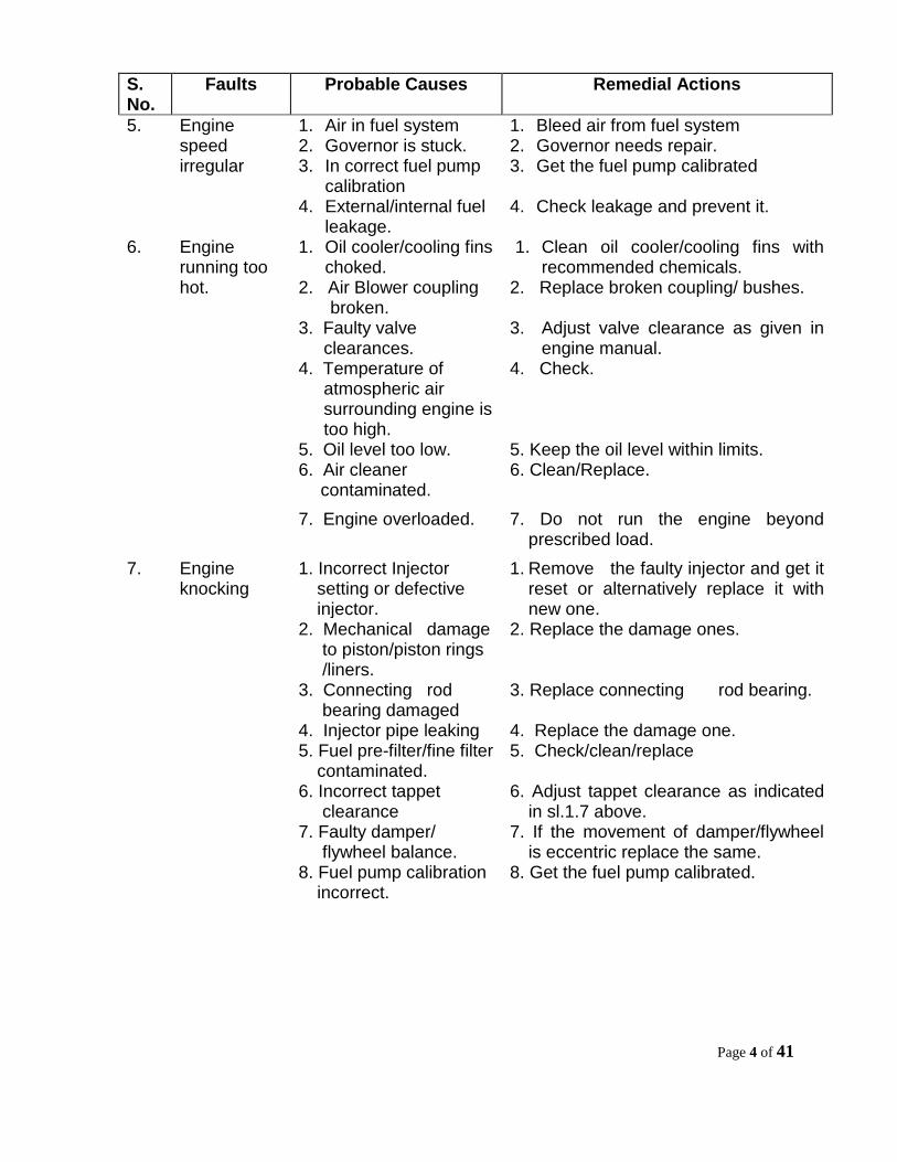
5. Engine speed irregular
1. Air in fuel system 2. Governor is stuck. 3. In correct fuel pump
calibration 4. External/internal fuel
leakage.
1. Bleed air from fuel system 2. Governor needs repair. 3. Get the fuel pump calibrated 4. Check leakage and prevent it.
6. Engine running too hot.
1. Oil cooler/cooling fins choked.
2. Air Blower coupling broken.
1. Clean oil cooler/cooling fins with recommended chemicals.
2. Replace broken coupling/ bushes.
3. Faulty valve clearances.
3. Adjust valve clearance as given in engine manual.
4. Temperature of atmospheric air surrounding engine is too high.
4. Check.
5. Oil level too low. 5. Keep the oil level within limits. 6. Air cleaner
contaminated. 6. Clean/Replace.
7. Engine overloaded. 7. Do not run the engine beyond
prescribed load.
7. Engine knocking
1. Incorrect Injector setting or defective injector.
1. Remove the faulty injector and get it reset or alternatively replace it with new one.
2. Mechanical damage to piston/piston rings /liners.
2. Replace the damage ones.
3. Connecting rod bearing damaged
3. Replace connecting rod bearing.
4. Injector pipe leaking 4. Replace the damage one. 5. Fuel pre-filter/fine filter
contaminated. 5. Check/clean/replace
6. Incorrect tappet clearance
6. Adjust tappet clearance as indicated in sl.1.7 above.
7. Faulty damper/ flywheel balance.
7. If the movement of damper/flywheel is eccentric replace the same.
8. Fuel pump calibration incorrect.
8. Get the fuel pump calibrated.

Page 5 of 41
S. No.
Faults Probable Causes Remedial Actions
8. Output of the engine too low.
1. Dirty fuel filter and fuel line.
1. Replace fuel filter and clean fuel line.
2. Air in fuel system. 2. Bleed air from system as explained, same as 1(2).
3. Faulty Injector. 3. Remove faulty injector and get it overhauled or alternatively replace it with new one.
4. Air filter choked. 4. Clean/Replace air filter element.
5. Improper
compression. 5. Engine needs repairs.
6. Governor sticking. 6. Governor needs repairs.
9. Oil pressure low.
1. Dirty lube oil filter. 1. Replace the lube oil filter element.
2. Improper oil grade. 2. Use proper grade of engine oil.
3. Oil control valve not working.
3. Repair the control valve.
4. Oil level too low 4. Fill the oil up to required level. 5. Excessive inclination
of engine. 5. Check
6. Dirty oil cooler 6. Clean the oil cooler. 7. Excessive wear in
connecting rod/ main bearing.
7. Engine needs to be overhauled in workshop.
8. Mixing of diesel in Engine oil.
7 8. Check
9. Wrong grade of oil. 9. Use the oil of recommended grade. 10. Oil film
present in crank case ventilation.
1. Incorrect compression.
1. Engine needs repairs.
2. Wrong grade of lube oil.
2. Use lube oil of proper grade as recommended by OEM.

Page 6 of 41
S. No.
Faults Probable Causes Remedial Actions
11. Fuel consumption too high.
1. lube oil level too high.
1. Keep the lube oil within limits.
2. Incorrect setting of Injectors.
3 Incorrect valve and injection timing.
2. Replace or overhaul the faulty injectors.
3. Reset the timing.
4. Clogged air filter. 4. Clean air filter/replace.
5. Poor compression. 5. Engine needs repairs in workshop.
12. Lube oil consumption too high.
1. Incorrect lube oil grade.
2. Excessive
inclination of engine.
3. Oil level too high. 4. External and
internal oil leaks. 5. Poor compression. 6. Broken or wrong
piston rings & worn out piston/liners
1. Use proper grade and quality lube oil as recommended by OEM.
2. Check 3. Keep the lube oil level within limits. 4. Prevent the leaks. 5. Replace compression rings or
valve. Valve seat have to be lap. 6. Engine due for top overhauling.
13.
Mixing of diesel in oil.
1. External or internal fuel leakage.
2. Damaged injector O-rings.
1. Prevent the leakage. 2. Replace the defective one.
3. Long idle periods 3. Do not run the engine at idle speed for long periods.

Page 7 of 41
S. No.
Faults Probable Causes Remedial Actions
14. Both the horns are not blowing.
24V supply not coming at horn terminal.
i) Check 24 V at terminal 202 in panel box no B1. If it does not exist there then follow the steps (iii) to (vi) of sl. No.1 item no.13.
ii) If 24 V is existing at terminal 202 then check it at terminal 78. If it is existing there then both the horns are ok and problem is in horn switches 2b2 or 4b10.
iii) Check 24 V at terminal of switches 2b2 and 4b10 and do needful.
15. Alternator is not doing the charging.
Fuse 1e2/1e4 may be blown
i) If by pressing the ignition start switch, charging control lamp 2h1 is not blowing, however, it is ‘OK’, then fuse 1e4 of 2 AMP may be blown. Check it and do needful.
ii) Fuse 1e2 of 16AMP may also be blown. Check it and do needful.
iii) If fuse 1e4 found ‘OK’ then alternator may be defective. Replace it.
16. Instrument & panel box lights are not glowing.
1. Bulb may be fused
1. Check the bulb and do needful.
2. No supply on bulb
terminal
2. If ignition & switch 4b14 both are
‘ON’ but lights are not glowing, then check the supply at terminal 84. If it is not existing there, then black wire may be damaged between terminal 84 and bulb terminal.

Page 8 of 41
II. MACHINE GENERAL
S. No.
Faults Probable Causes Remedial Actions.
1.
Rail clamps are not coming downward.
1) D.C valve part no. HV-IN-151/A-G24NZ4-R1 for rail clamps extra lifting is
In-operative.
1i) Follow the instruction of item no. 2&3 of annexure-I.
ii) Operate the DC Valve manually, if rail clamps does not operates, then DC Valve is defective. Clean it with petrol. If still not working then replace it with new one.If rail clamps operates then D.C Valve is O.K. and problem is in electrical circuit, check it as follows:
a) Check 24V supply at coupler of solenoid coil 1s11 for rail clamps lowering, if it is not coming there, then check it at terminal 76 in P.B. No. B1. If it is existing there then black wire of cable no. 109 between coil 1s11 and terminal 76 in P.B.No. B1 may be broken. Check it and do the needful.
b) If 24 V is not coming at terminal 76, then check it at output contact of relay 2RE9. If it is existing there then black wire of cable no.109 between relay 2RE9 and terminal 76 may be broken. Check it and do the needful.
c) Check 24 V at input contact of relay 2 RE9. If it is existing there but supply is not coming at terminal 76 then relay 2RE9 is defective. Replace it.
d) If input contact of 2RE9 is not showing 24 V, then black wire between relay 2RE9 and switch 4b8 may be damaged in between. Check it and do the needful.
e) If input contact of relay 2RE9 is not showing 24 V but at input terminal of switch 4b8 it is existing, then switch may be defective. Clean it with petrol. If still not working then replace it.

Page 9 of 41
S. No.
Faults Probable Causes Remedial Actions.
(f) If 24 V is not existing at input terminal of switch 4b8 then follow the step 1 of annexure I.
2) Double pump HP-IN3110-D1 may not delivering the oil.
2) If electrical circuit is O.K and DC valve is functioning properly by operating manually but cylinder for rail clamps extra lifting are not functioning then double pump is failed. Replace it.
2. Rail clamps are not going upward.
1) D.C valve part no.HV-IN-151/A-G24NZ4-R1 for rail clamps extra lifting is in operative.
1i) Follow the instructions of item no. 2&3 of annexure-I.
ii) Operate the DC valve manually, if rail clamps does not operates, then DC valve is defective. Clean it with petrol. If it is not working then replace it with new one. If rail clamps operates then D.C Valve is O.K. and problem is in electrical circuit, check it as follows:
a) Check 24V supply at coupler of solenoid coil 1s10 for rail clamps lifting, if it is not coming there, then check it at terminal 75 in P.B. No. B1. If it is existing there then black wire of cable no. 108 between coil 1s10 and terminal 75 in P.B.No. B1 may be broken. Check it and do the needful.
b) If 24 V is not coming at terminal 75, then check it at output contact of relay 2RE10. If it is existing there then black wire of cable no.108 between Relay 2RE10 and terminal 75 may be broken. Check it and do the needful.
c) Check 24 V at input contact of relay 2 RE10. If it is existing there but supply is not coming at terminal 75 then relay 2RE10 is defective. Replace it.
d) If input contact of 2RE10 is not showing 24 V, then black wire between relay 2RE10 and switch 4b8 may be damaged in between. Check it and do needful.

Page 10 of 41
S. No.
Faults Probable Causes Remedial Actions.
e) If input contact of relay 2RE10 is not showing 24 V but at input terminal of switch 4b8 it is existing, then switch may be defective. Clean it with petrol. If still not working then replace it.
f) If 24 V is not existing at input terminal of switch 4b8 then follow the step 1 of annexure I.
2) Double pump HP-IN3110-D1 may not delivering the oil.
2) If electrical circuit is O.K and DC valve is functioning properly by operating manually but cylinder for rail clamps extra lifting are not functioning then double pump is failed. Replace it.
3. Indication of rear rail clamps central position is not coming.
1) Indicator bulb 2h6 for rear rail clamps central position may be fused or missing.
1) Check it and do the needful.
2) 24V is not coming at terminal of limit switch 1ES6.
2i) Check 24V supply at terminal 74. If 24 V is not coming there, then bulb holder may be defective or black wire may be broken. Check it and do needful.
2ii) If 24V is coming at terminal 74 but limit switch is inoperative then black wire in cable 119 from terminal 74 to limit switch may be broken in between. Check it and do the needful.
3) Limit switch 1ES6 may also be defective
3) Check and do the needful.

Page 11 of 41
S. No.
Faults Probable Causes Remedial Actions.
4. Indication of front rail clamps central position is not coming.
1) Indicator bulb for front rail clamps central position 2h5 may be fused or missing.
1) Check it and do the needful.
2) 24V is not coming at terminal of limit switch1ES5.
2i) Check 24V supply at terminal 73. If 24 V is not coming there, then bulb holder may be defective or black wire may be broken. Check it and do needful.
2ii) If 24V is coming at terminal 73 but limit switch is inoperative then black wire in cable 119 from terminal 73 to limit switch may be broken in between. Check it and do needful.
3) Limit switch 1ES6 may also be defective
3) Check and do the needful.
5. Bridge is not coming downward
1) DC valve part no. HV-IN-22J/6A-G24NETZ4-R1 for bridge lifting/ lowering is in operative.
1i) Follow the instructions given in item no. 2&3 of annexure 1.
1ii) Operate the DC valve for bridge lifting/lowering manually. If it does not operate, then problem may be in DC valve. Clean it with petrol, if still not working, replace it with new one.
1iii) If bridge comes downward by operating the DC valve manually then DC valve is O.K. and problem is in electrical circuit.
Check it as follows: a) Check 24 V at coupler of coil 1s9. If
it is not coming there, then check it at terminal 66. If it is existing there, then black wire of cable no.102 between coupler and terminal 66 may be broken Check it and do the needful.

Page 12 of 41
S. No.
Faults Probable Causes Remedial Actions.
b) If 24 V is not coming at terminal 66 then check it at output contact of relay 2RE8. If it is existing there, then black wire between relay 2RE8 and terminal 66 may be damaged in between. Check it and do the needful.
c) If 24 V is not coming at output contact of relay 2RE8, then check it at input contact of relay. If it is existing there then relay 2RE8 is defective. Replace it.
d) If 24 V is not coming at input contact of relay, then check it at terminal 72. If it is existing there, then black wire between terminal 72 and input contact of relay 2RE8 may be damaged in between. Check it and do the needful.
e) If terminal 72 is not showing 24V then check it at input contact of switch 4b7. If it is found there then switch may be defective. Clean the switch if still not working then replace it with new one.
f) If 24 V is not coming at switch 4b7 then follow the instruction of item 1 of annexure I.
2) Check valve part no.HV-IN-20.1.0/OPS-R1 for bridge lifting may be blocked.
2) Clean the check valve with petrol , if still not working then replace it with new one.

Page 13 of 41
S. No.
Faults Probable Causes Remedial Actions.
3) Pilot pressure valve is in operative
3i) If switch 4b7 and relay 2RE8 are found O.K, but pilot pressure valve is still inoperative then operate the valve manually. if it does not operates, Pilot valve is defective. Clean it with petrol. If still not working then replace it with new one.
3ii) If by operating the pilot valve manually, it operates the valve is O.K. and problem is in electrical circuit between relay 2RE8 and coupler of 1s13.
3iii) Check 24 V at coupler of pilot valve, if it does not exist there then check it at terminal 67. If it is found there then black wire of cable no. 104 between coupler and terminal 67 may be damaged. Check it and do needful.
3iv) If 24 V is not found at terminal 67 then check it at output contact of relay 2RE8. If it is existing there, then wire between terminal 67 and relay 2RE8 may be damaged. Check it and do needful.
6. Bridge is not going upward
1) DC valve Pt No. HV-IN-225/6A-G24 NET24-R1 for bridge lifting/ lowering is
in-operative.
1i) Follow the instructions given in item 2&3 of Annexure-I.
1ii) Operate the DC valve for bridge lifting/lowering manually. If it does not operates, then problem is in DC valve. Clean it with petrol. If still not working, then replace it with new one.
1iii) If bridge moves upward by operating the DC valve manually then DC valve is O.K. and problem is in electrical circuit.
Check it as follows: b) If 24 V is not coming at terminal 65
then check it at output contact of relay 2RE7. If it is existing there, then black wire between relay 2RE7 and terminal 65 may be damaged in between. Check it and do the needful.

Page 14 of 41
S. No.
Faults Probable Causes Remedial Actions.
c) If 24 V is not coming at output contact of relay 2RE7, then check it at input contact of relay. If it is existing there then relay 2RE7 is defective. Replace it.
d) If 24 V is not coming at input contact of relay, then check it at terminal 71. If it is existing there, then black wire between terminal 71 and input contact of relay 2RE7 may be damaged in between. Check it and do the needful.
e) If terminal 71 is not showing 24V then check it at input contact of switch 4b7. If it is found there then switch may be defective. Clean the switch and still not working then replace it with new one.
2) Check valve part no. HV-IN-20.1.0/ops R1 for bridge lifting may be blocked.
2) Clean the check valve with petrol. If still not working then replace it with new one.
7. Rear rail
clamps are not going towards right.
1) DC valve part no. HV-IN-151/A-G24NZ4-R1 for rear rail clamps lateral shifting is in operative
1i) Follow the instructions given in item 2&3 of annexure 1.
1ii) Operate the DC valve for rear rail clamps lateral shifting at coil 1s5 manually. If rear rail clamps are not moving towards right, valve may be defective. Clean it with petrol, if still not working then replace it with new one.
1iii) If by manual operation rear rail clamp are moving towards right the valve is O.K. and problem is in electrical circuit.
Check it as follows: a) Check 24 V supply at coupler of DC
valve for rear rail clamps lateral shifting at coil 1s5, if it is not existing there, then check it at terminal 59 in panel box no.B1, if it is found there then black wire of cable 111 between coupler and terminal 59 may be damaged. Check it and do the needful.

Page 15 of 41
S. No.
Faults Probable Causes Remedial Actions.
b) If 24 V is not found at terminal 59 then check it at output terminal of relay 2RE6, if it is existing there then black wire between terminal 59 and relay 2RE6 may be damaged in between. Check it and do the needful.
c) If 24 V not found at output contact of relay 2RE6 check it at input contact. If it is found there then relay 2RE6 is defective. Replace it with new one.
d) If 24 V not found at input contact of relay 2RE6, then check it at output contact of switch 4b6. If it is
existing there then black wire between relay 2RE6 and switch 4b6 may be damaged. Check it and do the needful.
e) If 24 V not found at output contact of switch 4b6, then check it at input contact. If it is found there, then switch 4b6 may be defective. Clean it with petrol, if still not working then replace it.
f) If 24 V not found at input terminal of switch 4b6 then follow the step 1 of annexure I.
2) Double pump HP-IN-3110-D1 may not delivering the oil.
2) If electrical circuit is OK and DC valve is functioning properly by manual operation but cylinder for rail clamp lateral movement is not functioning then double pump is defective, Replace it.
3) Cylinder for rear rail clamp lateral movement may be leaking.
3) Check the leakage from cylinder, if existing then replace the seal.

Page 16 of 41
S. No.
Faults Probable Causes Remedial Actions.
8. Front rail clamps are not going towards right
1) DC valve part no. HV-IN-151/A-G24NZ4-R1 for front rail clamps lateral shifting is in-operative.
1i) Follow the instructions given in item 2&3 of annexure 1.
1ii) Operate the DC valve for front rail clamps lateral shifting at coil 1s4 manually. If front rail clamps are not moving towards right, then valve may be defective. Clean it with petrol, if still not working then replace it with new one
1iii) If by manual operation front rail clamp are moving towards right then valve is O.K. and problem is in electrical circuit.
Check it as follows:
a) Check 24 V supply at coupler of DC valve, if it is not existing there, then check it at terminal 58, if it is found there then black wire of cable 113 between coupler and terminal 58 in P.B. No. B1 may be damaged. Check it and do the needful.
b) If 24 V is not found at terminal 58 then check it at output terminal of relay 2RE5, if it is existing there then black wire between terminal 58 and relay 2RE5 may be damaged in between. Check it and do the needful.
c) If 24 V not found at output contact of relay 2RE5, then check it at input contact. If it is found there then relay 2RE5 is defective. Replace it with new one.
d) If 24 V not found at input contact of relay 2RE5, then check it at output contact of switch 4b5. If it is existing there then black wire between relay 2RE5 and switch 4b5 may be damaged. Check it and do the needful.

Page 17 of 41
S. No.
Faults Probable Causes Remedial Actions.
e) If 24 V not found at output contact of switch 4b5, then check it at input contact. If it is found there, then switch 4b5 may be defective. Clean it with petrol if still not working then replace it.
f) If 24 V not found at input terminal of switch 4b5 then follow the step 1 of annexure I.
2) Double pump HP-IN-3110-D1 may not delivering the oil.
2) If electrical circuit is OK, and spool of DC valve is functioning properly by manual operation but cylinder for rail clamp lateral movement is not functioning, then double pump is defective, Replace it.
3) Cylinder for front rail clamp lateral movement may be leaking.
3) Check the leakage from cylinder, if existing then replace the seal.
9. Rear rail clamps are not going towards left.
1) DC valve part no. HV-IN-151/A-G24NZ4-R1 for rear rail clamps lateral shifting is in operative.
1i) Follow the instructions given in item 2&3 of annexure 1.
1ii) Operate the DC valve for rear rail clamps lateral shifting at coil1s3 manually. If rear rail clamps are not moving towards left, then valve is defective. Clean it with petrol, if still not working then replace it with new one
1iii) If by manual operation rear rail clamp are moving towards left then valve is O.K. and problem is in electrical circuit. Check it as follows:
a) Check 24 V supply at coupler of DC valve, if it is not existing there, then check it at terminal 57, if it is found there then black wire of cable 110 between coupler and terminal 57 may be damaged. Check it and do the needful.
b) If 24 V is not found at terminal 57 then check it at output terminal of relay 2RE4, if it is existing there then black wire between terminal 57 and relay 2RE4 may be damaged. Check it and do the needful.

Page 18 of 41
S. No.
Faults Probable Causes Remedial Actions.
c) If 24 V not found at output contact of relay 2RE4, then check it at input contact. If it is found there then relay 2RE4 is defective. Replace it with new one.
d) If 24 V not found at input contact of relay 2RE4, then check it at output contact of switch 4b4. If it is existing there then black wire between relay 2RE4 and switch 4b4 may be damaged. Check it and do the needful.
e) If 24 V not found at output contact of switch 4b4, then check it at input contact. If it is found there, then switch 4b4 may be defective. Clean it with petrol if still not working then replace it.
f) If 24 V not found at input terminal of switch 4b4 then follow the step 1 of annexure I.
2) Double pump HP-IN-3110-D1 may not delivering the oil.
2) If electrical circuit is OK, and spool of DC valve is functioning properly by manual operation but cylinder for rail clamps lateral movement is not functioning, then double pump is defective, Replace it.
3) Cylinder for rear rail clamp lateral movement may be leaking.
3) Check the leakage from cylinder, if existing then replace the seal.
10. Front rail clamps are not going towards left.
1) DC valve part no. HV-IN-151/A-G24NZ4-R1 for front rail clamps lateral shifting is inoperative.
1i) Follow the instructions given in item 2&3 of annexure 1.
1ii) Operate the DC valve for front rail clamps lateral shifting at coil 1s2 manually. If front rail clamps are not moving towards left, valve is defective. Clean it with petrol, if still not working then replace it with new one
1iii) If by manual operation front rail clamp are moving towards left then valve is O.K. and problem is in electrical circuit.
Check it as follows:

Page 19 of 41
S. No. Faults Probable Causes Remedial Actions.
a) Check 24 V supply at coupler of DC valve, if it is not existing there, then check it at terminal 56, if it is found there then black wire of cable 112 between coupler and terminal 56 may be damaged. Check it and do the needful.
b) If 24 V is not found at terminal 56 then check it at output terminal of relay 2RE3, if it is existing there then black wire between terminal 56 and relay 2RE3 may be damaged in between. Check it and do the needful.
c) If 24 V not found at output contact of relay 2RE3, then check it at input contact. If it is found there then relay 2RE3 is defective. Replace it with new one.
d) If 24V not found at input contact of relay 2RE3, then check it at output contact of switch 4b3. If it is existing there then black wire between relay 2RE3 and switch 4b3 may be damaged. Check it and do the needful.
e) If 24V not found at output contact of switch 4b3, then check it at input contact. If it is found there, then switch 4b3 may be defective. Clean it with petrol if still not working then replace it.
f) If 24V not found at input terminal of switch 4b3 then follow the step 1 of annexure I.
2) Double pump HP-IN-3110-D1 may not delivering the oil.
2) If electrical circuit is OK, and spool of DC valve is functioning properly by manual operation but cylinder for rail clamps lateral movement is not functioning, then double pump is defective, Replace it.
3) Cylinder for front rail clamps lateral
3) Check the leakage from cylinder, if existing then replace the seal.

Page 20 of 41
S. No. Faults Probable Causes Remedial Actions.
movement may be leaking.
11. Rail clamps are not getting open.
1) DC valve HV-IN-10D/LG 24 N-R1 for rail clamps open is not functioning.
1i) Follow the instructions of item 3 of Annexure-I.
1ii) Operate the DC valve manually. If rail clamps does not operates then problem is in DC valve. Clean it with petrol. If still not working then replace it with new one.
1iii) Operate the DC valve manually. If rail clamps operates then valve is O.K. and problem is in electrical circuit. Check it as follows:
a) Check 24 V supply at coupler of DC valve. If it does not exist there then check it at terminal 55 in P.B. No.B1. If it is found there then black wire of cable no. 103 between coupler and terminal 55 may be damaged. Check it and do the needful
b) If 24 V not found at terminal 55, check it at output terminal of switch 4b1. If it is found there then black wire between switch and terminal 55 may be damaged. Check it and do the needful.
c) If 24 V not found at output contact of switch 4b1. Check it at input contact. If it is found there then switch 4b1 may be defective. Clean it with petrol. If still not working then replace it with new one.
d) If input contact of 4b1 is not showing 24 V then follow the step 1 of annexure I.
2. Variable axial piston pump may giving the problem.
2. If so, then some other functions like forward/reverse driving, machine braking may also be hampered. In that case variable pump is to be replaced.
12. Indication for any rail clamp close is not oming.
1) Indication bulb may be fused.
1) Check the respective bulb and do needful.
i) 2h1 for front left ii) 2h2 for rear left

Page 21 of 41
S. No.
Faults Probable Causes Remedial Actions.
iii) 2h3 for front right iv) 2h4 for rear right
2) Limit switches are inoperative
2) 24V may not be coming at respective terminal. Check the wiring between respective terminal and limit switch.
i) Terminal 51 for front left ii) Terminal 52 for rear left iii) Terminal 53 for front right iv) Terminal 54 for rear right.
13 Sleeper gripper is not getting closed.
1) DC valve no. HV-IN-151/A-G24 NZ4-R1 for sleeper gripper closed is inoperative.
1i) Follow the instructions given in item 2&3 of Annexure-I.
1ii) Operate DC valve manually. If it does not operate then it may be defective. Clean it with petrol. If still not working then replace it with new one.
1iii) Operate the DC valve manually. If it operates, then valve is O.K and problem is in electrical circuit. Check it as follows:
a) Check 24 V at coupler of DC valve at coil 1s7, if it is not found there then check it at terminal 64 in P.B. No. B1, if it is existing there then black wire of cable 107 between coupler and terminal 64 may be damaged. Check it and do the needful.
b) If 24 V is not found at terminal 64 then check it at output contact of relay 2RE2. If it is existing there then black wire between terminal 64 and relay 2RE2 may be damaged. Check it and do the needful.
c) If 24 V is not found at output contact of relay then check it at input contact, if it is found there then relay 2RE2 is defective. Replace it with new one.
d) If 24 V not found at input contact of relay 2RE2 then check it at output contact of switch 4b2 for close position.
e) If 24 V not found at output terminal of switch 4b2 in close position, then check it at input terminal, if it is found

Page 22 of 41
S. No. Faults Probable Causes Remedial Actions.
there then switch is defective. Clean it with petrol. If still not working then replace it with new one.
f) If 24 V is not coming at input terminal of switch 4b2 then follow the step 1 of annexure I.
2) Hydraulic problem. 2) If electrical circuit is OK and spool of DC valve is functioning by manual operation, then double pump HP-IN-3110 may not delivering the oil.
i) It shows pump may be defective. But in this case some other operations will also hamper.
ii) Pressure gauge should also show lifting pressure 140-150 bar.
14. Sleeper gripper is not getting open.
1) DC valve no. HV-IN-151/A-G24 NZ4-R1 for sleeper gripper open is inoperative.
1i) Follow the instructions of item 2&3 of Annexure-I
1ii) Operate DC valve manually. If it does not operate then it may be defective. Clean it with petrol. If still not working then replace it with new one.
1iii) Operate the DC valve manually. If it operates, then valve is O.K and problem is in electrical circuit. Check it as follows:
a) Check 24 V at coupler of DC valve at coil 1s6, if it is not found there then check it at terminal 60, if it is existing there then black wire of cable 106 between coupler and terminal 60 may be damaged. Check it and do the needful.
b) If 24 V is not found at terminal 60 then check it at output contact of relay 2RE1. If it is existing there then black wire between terminal 60 and relay 2RE1 may be damaged. Check it and do the needful.
c) If 24 V is not found at output contact of relay then check it at input contact, if it is found there then relay 2RE1 is defective. Replace it with new one.

Page 23 of 41
S. No. Faults Probable Causes Remedial Actions.
d) If 24 V not found at input contact of relay 2RE1 then check it at output contact of switch 4b1 in open position.
e) If 24 V not found at output terminal of switch 4b1 at open position, then check it at input terminal, if it is found there then switch is defective. Clean it with petrol. If still not working then replace it with new one.
f) If 24 V is not coming at input terminal of switch 4b1 then follow the step 1 of annexure I.
2) Hydraulic problem. 2) If electrical circuit is OK and spool of DC valve is functioning by manual operation, then double pump HP-IN-3110 may not delivering the oil.
i) It shows pump may be defective. But in this case some other operations will also hamper.
ii) Pressure gauge should also show lifting pressure 140-150 bar.
15. Portal crane is not getting loaded on BRH.
3) DC valve HV-IN-22J/6A G24 NETZ4-R1 is in operative.
3i) By operating the switches 4b7 for bridge lowering and 4b12 for loading, if crane is not getting loaded, then follow the steps of sl no.5 for bridge lowering.
ii) If fault does not found in bridge lowering circuit then check 24V at terminal of switch 4b12 for loading. If it is found there then switch is faulty. Replace it with new one.
iii) If 24V is absent from input terminal of switch 4b12 for loading then follow the instructions given in item-I of Annexure-I.
16 Machine driving is inoperative
1. No driving pressure
1. Check the driving pressure in pressure gauge by selecting the multi station to point 2 and 3.It should be 150 bar. If not so, then adjust the relief valve of driving circuit.
2. Joystick HY-IN-L06- 1X/1M-R1 may be stuck or defective.
2. Clean the joystick with petrol. If still not working then replace it with new one.

Page 24 of 41
S. No. Faults Probable Causes Remedial Actions.
3. Variable axle piston pump HP-IN-71HD-R1 may be failed.
3 If by adjusting the relief valve, driving motors are still not rotating, then variable pump may be failed. Repair or replace the complete assembly.
4. Brakes are not releasing
4. Problem may be in brake cylinder seal or linkages. Check it and do needful.
17. Duplex/simplex chain failed
1. Spare chain with loose links should be kept with the machine for attending the failure of chains.
18. Bridge is coming down under load without giving command
1. Check Q-meter is not functioning properly
1. If the lowering of bridge is uniform, check the functioning of check Q-meter. If there is defect, repair/replace it
2. There may be internal leakage in bridge lifting cylinder
2. Cut off the hydraulic supply to cylinder and fake it free and lift the bridge with remaining three cylinders. If there is no lowering of the bridge then that particular cylinder is having internal leakage. Replace the seal or do as required.

Page 25 of 41
III. HYDRAULIC PUMP
S. No.
Faults Probable Causes Remedial Action
1.
Pump not delivering oil.
1. Pump driven in wrong direction (at the time of new pump fitment, this problem may occur).
1. Check the pump rotation by hand priming. Pour the hydraulic oil into inlet port and rotate the shaft. See whether the oil is delivering through outlet port or not. If not, change the rotation according to the engine shaft rotation.
2. Oil level too low in the reservoir (if oil level is very low, aeration may take place and pump will not deliver oil).
2. Check oil level in reservoir. It should be above minimum mark. If necessary, recoup the oil.
3. Intake filter/pipe choked.
3. Clean or replace filter for proper flow of oil.
4. Air leaks in pump intake joints.
4. Pour hydraulic oil on intake joint and on observing abnormal sound, tighten the intake joint as required.
5. Broken pump shaft or rotor
5. Replace the broken shaft or rotor. Also align the prime mover shaft.
6. Pump speed too slow. (The delivery rate of discharge is prescribed at a certain rpm of engine. If engine speed becomes less than pressurized speed, it may affect the proper suction of oil).
6. Pump should run at prescribed speed. Engine rpm should be checked.
7. Dirty suction filter. 8. Faulty suction valve. 9. Air in system. 10. Pump drive
inoperative.
7. Replace the filter. 8. Repair or change the valve. 9. Discharge air from the system.
10. i) Replace the broken pump shaft. ii) Replace the sheared spline.
iii) Change defective coupling. 11. Clutch out of
adjustment. 12. Pump is damaged.
11. Adjust clutch. 12. Replace with new one.

Page 26 of 41
S. No.
Faults Probable Causes Remedial Action
2. Pump makes noise
.
Aeration.
1i) Fill the reservoir with the oil up-to required level to prevent aeration.
ii) Check all connections on inlet side of pump and pour hydraulic oil over suspected leak. If noise stops, leakage has been found,. Fill hydraulic tank to the full mark.
iii) Check condition of pump shaft seal. Change, if required.
2. Intake line or suction filter partly clogged.
2. Clean or replace the filter or line.
3. Pump running too fast.
3. Reduce speed up to prescribed limit.
4. Coupling misaligned (Due to this, bearing may get damaged, there will be a play at shaft, abnormal sound will be observed).
4. Realign the pump shaft and prime mover shaft.
5. Reservoir not vented properly.
5. Air breather screening element should be cleaned.
6. Suction Filter too small in size.
6. Replace it by proper size of filter.
7. Air leaks at pump intake pipe joints and air drawn through inlet line.
7. Take action as explained in s.no.1, item no. 4.
8. Oil viscosity too high. (In cold climate, oil viscosity becomes high so no free flow will take place and cavitation will occur).
8. Start the engine for few minutes to warm-up the hydraulic oil used in machine for proper flow. Use only proper grade of oil.
9. Cavitation.
9. i) Check condition of suction filter and return line filters. Clean or change as necessary.
ii) Check clogging of inlet line. Clean or change as necessary.
iii) Check loose fittings on suction lines. Tighten, if required.
iv) Clean hydraulic tank breather. 10. Shaft seal leaks. 10. Replace the seal. 11. Foams in oil. 11. Vent the system.

Page 27 of 41
S. No.
Faults Probable Causes Remedial Action
12. Casing leaks. 13. Vane spring broken. 14. Any part of pump
defective. 15. Pump mounting
bolts are loose. 16. Foreign bodies in
suction line. 17. System dirty. 18. Sharp bends in
suction line. 19. Oil temperature too
high. 20. Boost pump failed. 21. Vibration in system
12. First tighten bolts, then check for cracks and sealing.
13. Change spring. 14. Replace defective parts. 15. Check mounting alignment. Tighten
bolts uniformly. 16. Remove foreign bodies, if need
flush the system. 17. Flush the system 18. Eliminate or reduce the bends in
suction line. 19. Check the hydraulic circuit. Oil cooler
may be ineffective. Rectify the failure 20. Check boost pump and repair if required. 21. Check unusual occurrence in the
system 22. Pump worn or
damaged. 22. Pump should be overhauled or
replaced. 3 Pump overheats 1. Wrong oil grade.
2. Oil speed in system too high.
3. Oil level too low. 4. Pump rotor groove
worn out. 5. Radial or axial loading
too high. 6. Initial speed rises.
7. Inadequate cooling. 8. Cooling system is
dirty. 9. Differential pressure
too low. 10. Pressure too high.
1. Fill oil as recommended. 2. Install pipes of proper size. 3. Fill the oil up to safe level. 4. Change the worn out parts. 5. Loading should be restricted to
prescribed limit to acceptable amount, check alignment limit.
6. Check max, pressure, if needed replace with larger capacity and install pipes of nominal bore.
7. Increase cooling capacity. 8. Clean the cooling system. 9. Increase pressure setting of relief
valve. 10. Reduce pressure setting.
11. Wrong type of pressure valve.
11. Replace by appropriate type of valve.
12. Wrong seal size 12. Replace by suitable size of seals

Page 28 of 41
S. No.
Faults Probable Causes Remedial Action
13. Filter dirty or too small
13. Clean filter or replace by larger type.
14. Pump running speed high.
15. Cavitation. 16. Foams in oil. 17. Venting dirty. 18. System
contaminated. 19. Sharp bends in
suction line. 20. Boost pump failed.
14. Reduce speed. 15. Bleed the system. 16. Vent the system. 17. Clean the vents. 18. Flush the system. 19. Eliminate bends or at least reduce
them. 20.Check boost pump and repair as
required. 4. Pump develops
no pressure 1. Wrong pressure
setting. 2 Pressure valve spool
stuck.
1. Modify the pressure setting. 2. Repair/Replace the valve.
3. Leakage in system. 4. Pump shaft broken. 5. System
contaminated. 6. Improper gaskets and
seal.
3. Replace defective parts. 4. Replace shaft. 5. Flush system completely. 6. Replace seals and gaskets.
5. Speed loss on pump.
1. Inlet pressure too low.
2. Outlet pressure too high.
3. Port plate does not make contact.
4. Oil temperature too high.
1. Increase pressure. 2. Check system pressure. 3. Dismantle the pump and repair as
required. 4. Check circuit.
6. Pump does not work.
1. Pressure too low. 2. 'O' Ring on port plate
defective. 3. Inadequate oil. 4. Too much play in the
shaft.
1. Increase pressure setting. 2. Replace 'O' Ring. 3. Repair pump or change for adequate
delivery. 4. Replace bearing.

Page 29 of 41
S. No.
Faults Probable Causes Remedial Action
7. Hydraulic oil overheated.
1. System pressure is too high.
1. Adjust the pressure to the required limit.
2. Dirty oil 3. Oil level is low.
2. Clean or change filters and strainers. 3. Fill up the oil to the upper mark.
4. Hydraulic oil of incorrect viscosity.
4. Check oil for proper viscosity. If, change of oil is required, flush the entire system and change filter before adding fresh oil.
5. Faulty cooling system.
5. Check oil cooler for trash on out side cooling surfaces. Clean with air pressure, or steam pressure.
6. Hydraulic oil by passing internally due to worn pump, valve, motor and cylinder.
6. Overhaul or replace faulty components.
8. Bearing failure. 1. Chips or other contaminants in bearing.
1. Replace bearings and check intrusion of contaminants.
2. Coupling misaligned.
2. Align prime mover shaft and pump.
3. Inadequate lubrication.
3. Lubricate system properly.
4. Pump running too fast.
4. Adjust speed of prime mover.
5. Excessive or shock loads. (Excessive loads due to operating pressure may damage the bearing).
5. Reduce operating pressure.

Page 30 of 41
IV. HYDRAULIC RELIEF VALVE
S. No.
Faults Probable Causes Remedial Actions
1. Erratic pressure. 1. Foreign material in the oil.
1. Drain the oil, clean the tank and refill with clean oil.
2. Worn poppet valve or seat .
(oil from pilot stage will go to tank due to worn poppet valve or seat and pressure will drop).
2. Replace poppet valve or seat as required.
3. Piston sticking in main body.
3. Clean piston after dismantling. Check free movement after re-assembling.
2. Low pressure or no pressure.
1. Valve improperly adjusted.
2. Vent connection is open (at the time of starting the work, if vent remain open, then oil will go to the tank and no pressure will develop).
3. Balance hole in main piston choked.
4. Poppet in cover not
seating. (So, oil will continuously go to tank line and pressure will drop).
5. Broken or weak spring (oil will push the poppet easily and go to tank. So pressure will drop).
1. Adjust valve by adjusting knob to proper pressure setting.
2. Plug the vent connection. 3. Remove piston and clean the
orifice. Clean the tank and replace hydraulic oil.
4. Check the poppet condition. If required, replace it.
5. Replace the spring and again set
the pressure with adjusting knob.
6. Dirt, chip etc keeps valve partially open.
6. Clean the complete valve.
3.
Excessive noise or chatter.
1. High oil velocity through valve.
1. Check valve flow rating. Replace with larger valve, if necessary.
2. Distorted control
spring.
2. Replace spring.

Page 31 of 41
S. No.
Faults Probable Causes Remedial Actions
3. Worn poppet or seat in cover.
4. Vent line too long. 5. Valve pressure
setting too close to that of another valve in circuit.
3. Replace poppet or seat. 4. Replace restrictions e.g. needle
valve or orifice. Plug in vent line next to the relief valve.
5. Set relief valve pressure atleast 150 PSI higher than other valves in circuit.
4. Valve do not function
1. Spool sticks. 2. Water condensation
in system. 3. Oil temperature too
high. 4. Oil speed too high. 5. Internal leakage. 6. Tank line under high
pressure. 7. Control line dirty.
1. Clean stuck spool. 2. Check condensed water. 3. Check the function of oil cooler
and clean the radiator fins. 4. Check speed of the pump. 5. Prevent leakage. 6. Check pressure in tank line. 7. Clean lines properly.
5. Valve over-heating
1. System pressure too high.
2. Dirt in the system. 3. Spool sticks. 4. Spool defective
1. Adjust the system pressure. 2. Clean the system. 3. Check and clean spool. 4. Check and replace spool, if
defective.

Page 32 of 41
V. HYDRAULIC UNLOADER VALVE
S. No.
Faults Probable Causes Remedial Actions
1.
Low or no pressure.
1. Orifice of main
piston choked. 2. Vent connection
open to tank. 3. Safety valve at zero
setting 4. Broken or weak
spring 5. Worn ball or seat.
1. Clean the orifice. 2. Plug the vent connection. 3. Set the safety valve at proper
pressure. 4. Replace the spring. 5. Replace the ball or seat.
2. Fails to completely unload pump.
1. Valve pressure setting too high.
2. Valve spool binding in body.
3. Incorrect assembly. 4. Nil or low nitrogen
pressure in the accumulator.
5. Punctured bladder.
1. Set valve at proper pressure. 2. Clean the spool and oil in the
tank. 3. Assemble as per proper
drawing. 4. Check pressure and recharge
the accumulator (80 to 85 bar). 5. Change the bladder.

Page 33 of 41
VI. HYDRAULIC MOTOR
S. No.
Faults Probable Causes Remedial Action
1. Motor makes loud Noise.
1. Vane spring broken. 2. Shaft seal leaks. 3. Casing leaks.
4. Oil temperature too high. 5. Motor parts defective.
1. Change the spring. 2. Replace the seal. 3. First tighten bolts, then check
for cracks and sealing. 4. Check cooling circuits. 5. Replace defective parts. Tighten bolts uniformly.
6. Aeration.
6.i) Fill the reservoir with the oil up-to required level to prevent aeration.
ii) Check all connections on inlet side of motor and pour hydraulic oil over suspected leak. If noise stops, leakage has been found,. Fill hydraulic tank to the full mark.
iii) Check condition of motor shaft seal. Change, if required.
7. Intake line or suction filter partly clogged.
7. Clean or replace the filter or line.
8. Motor running too fast. 8. Reduce speed up to prescribed limit.
9. Coupling misaligned (Due to this, bearing may get damaged, there will be a play at shaft, abnormal sound will be observed).
9. Realign the motor shaft.
10. Air leaks at motor intake pipe joints and air drawn through inlet line.
10. Take action as explained in s.no.1, item no. 4.
11. Oil viscosity too high. (In cold climate, oil viscosity becomes high so no free flow will take place and cavitation will occur).
11. Start the engine for few minutes to warm-up the hydraulic oil used in machine for proper flow. Use only proper grade of oil.

Page 34 of 41
S. No.
Faults Probable Causes Remedial Action
12. Cavitation.
12.i) Check condition of suction filter and return line filters. Clean or change as necessary.
ii) Check clogging of inlet line. Clean or change as necessary.
iii) Check loose fittings on suction lines. Tighten, if required.
iv) Clean hydraulic tank breather.
13. Foams in oil. 13. Vent the system. 14. Casing leaks.
15. Motor stressed. 16. Foreign bodies in suction
line. 17. System dirty. 18. Sharp bends in suction
line.
14. First tighten bolts, then check for cracks and sealing.
15. Check mounting alignment.
Tighten bolts uniformly. 16. Remove foreign bodies, if
need flush the system. 17. Flush the system. 18. Eliminate or reduce the
bends in suction line
19. Motor worn or damaged.
19. Motor should be overhauled or replaced.
2. Motor overheats
1. Wrong oil grade. 2. Oil speed in system too
high. 3. Motor rotor groove worn
out. 4. Radial or axial loading too
high.
5. Initial speed rises
1. Fill oil as recommended. 2. Install pipes of proper size.
3. Change motor parts.
4. 4. Limit to acceptable amount, 5. check alignment limit. 6.
5. Check max, pressure, if needed replace with larger capacity and install pipes of nominal bore.
Page 35 of 41
S. No.
Faults Probable Causes Remedial Action
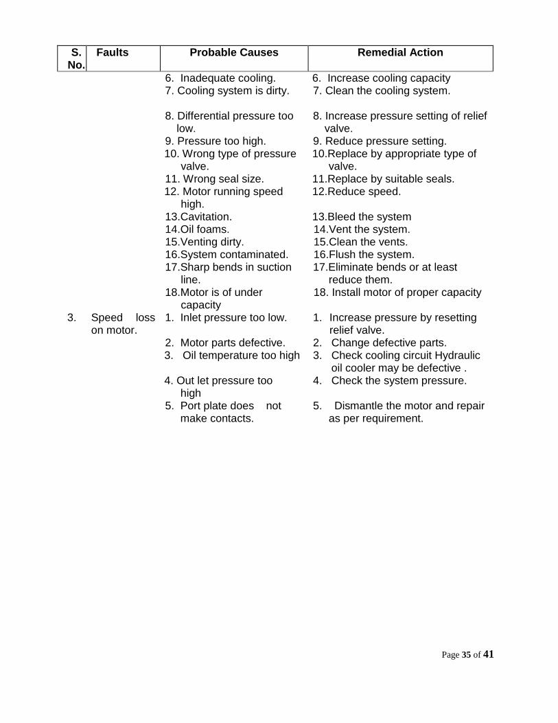
6. Inadequate cooling. 7. Cooling system is dirty.
8. Differential pressure too
low. 9. Pressure too high. 10. Wrong type of pressure
valve. 11. Wrong seal size. 12. Motor running speed
high. 13.Cavitation. 14.Oil foams. 15.Venting dirty. 16.System contaminated. 17.Sharp bends in suction
line. 18.Motor is of under
capacity
6. Increase cooling capacity 7. Clean the cooling system. 8. Increase pressure setting of relief
valve. 9. Reduce pressure setting. 10.Replace by appropriate type of
valve. 11.Replace by suitable seals. 12.Reduce speed.
13.Bleed the system 14.Vent the system. 15.Clean the vents. 16.Flush the system. 17.Eliminate bends or at least
reduce them. 18. Install motor of proper capacity
3.
Speed loss on motor.
1. Inlet pressure too low. 2. Motor parts defective. 3. Oil temperature too high 4. Out let pressure too high 5. Port plate does not make contacts.
1. Increase pressure by resetting relief valve.
2. Change defective parts. 3. Check cooling circuit Hydraulic oil cooler may be defective . 4. Check the system pressure. 5. Dismantle the motor and repair
as per requirement.

Page 36 of 41
VII. HOSE ASSEMBLY
S. No.
Faults Probable Causes Remedial Actions
1.
The hose has burst on examination after stripping back the cover of the wire reinforcement reveals random broken wires in the entire length of the hose.
This indicates high frequency pressure impulse condition. SAE impulse test require-ments are as under: (a) For a double wire braid reinforcement are 2,00,000 cycles of 133% of recommended working pressure. (b)For a four spiral wrapped reinforcement (100R-9) are 3,00,000 cycles at 133% maximum operating pressure at +2000F (930 C).
If the extrapolated impulses in a system amount to over a million in a relatively short time a spiral reinforced hose would be the better choice.
2. The hose has burst, but there is no indication of multiple broken wires in the entire length of the hose. The hose may have burst in more than one place.
This would indicate that the pressure has exceeded the minimum burst strength of the hose.
Either a stronger hose is needed or the hydraulic circuit has a mal-function, which is causing unusually high pressure conditions.
3. Hose has burst. An examination indicates the wire braid is rusted and the cover has been cut, abraded or deteriorated badly.
The primary function of the cover is to protect the reinforcement. Elements that may destroy or remove the hose covers are: 1. Abrasion. 2. Cutting 3. Battery Acid. 4. Chemical Cleaning
Solutions. 5. Heat. 6. Extreme Cold.
Once the cover protection is gone, the wire reinforcement is susceptible to attack from moisture or other corrosive matter. hence take care of item no. 1 to 6 of para 3 mentioned in probable causes.
Page 37 of 41
S. No.
Faults Probable Causes Remedial Actions
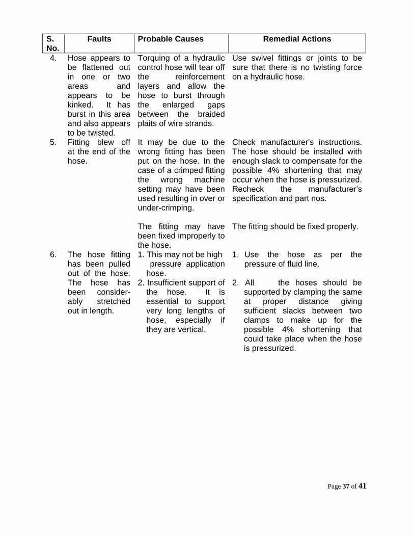
4. Hose appears to be flattened out in one or two areas and appears to be kinked. It has burst in this area and also appears to be twisted.
Torquing of a hydraulic control hose will tear off the reinforcement layers and allow the hose to burst through the enlarged gaps between the braided plaits of wire strands.
Use swivel fittings or joints to be sure that there is no twisting force on a hydraulic hose.
5. Fitting blew off at the end of the hose.
It may be due to the wrong fitting has been put on the hose. In the case of a crimped fitting the wrong machine setting may have been used resulting in over or under-crimping. The fitting may have been fixed improperly to the hose.
Check manufacturer's instructions. The hose should be installed with enough slack to compensate for the possible 4% shortening that may occur when the hose is pressurized. Recheck the manufacturer’s specification and part nos. The fitting should be fixed properly.
6. The hose fitting has been pulled out of the hose. The hose has been consider-ably stretched out in length.
1. This may not be high pressure application
hose. 2. Insufficient support of
the hose. It is essential to support very long lengths of hose, especially if they are vertical.
1. Use the hose as per the pressure of fluid line.
2. All the hoses should be
supported by clamping the same at proper distance giving sufficient slacks between two clamps to make up for the possible 4% shortening that could take place when the hose is pressurized.

Page 38 of 41
General Safety Notes
The machine has to be operated as per existing Indian Railways rules and regulations.
The safety of yourself and other people is a most important consideration in the operation and maintenance of the machine.
Remember, the machine is a working unit, carrying delicate instruments. Therefore the machine should not be driven at excessive speed over bad track or turnouts.
Always keep your eyes open for other men working close to the machine.
Do not forget to look out for signals, switches and track obstructions.
Always keep the machine clean. Excessive oil or grease on the machine can cause you to slip and fall and is also a potential fire hazard.
Always lock the machine before you leave. Make sure that the machine is protected in accordance with railways regulations.
Whenever you have the opportunity while waiting to get out on a job, do some of the smaller maintenance jobs such as tightening loose nuts and bolts and cleaning the machine.
Do not permit unauthorized persons to operate the machine.
It is prohibited to use exposed light or fire on or near the machine.
Do not stand or pass under crane bridge loaded or unloaded unless a proper support is provided under the bridge.

Page 39 of 41
Important Items For PQRS
1. Longer blocks should be stressed for effective working. 2. Track should be surveyed thoroughly for broken sleepers & rail pieces etc. which
may obstruct the working. 3. Signal cables and rods, passing under the track, must be attended by S&T
official at site. 4. Frequent shifting of PQRS from one location to another should be avoided to
achieve good work and adequate progress. 5. Auxiliary track should be 2” higher than main track.

Page 40 of 41
ANNEXURE
GENERAL INSTRUCTIONS FOR RECTIFICATION OF ANY FAILURE
1. If machine is unable to do any operation, 24V supply may not come. For this,
Circuit breaker 4e2 of 15AMP may be tripped.
2. For checking of any failure, firstly do another function. If it is also inoperative then
tank valve may not functioning. For that,
a) Check 24V supply at terminal 80 in panel box no.B1. If it is O.K then check it
at coupler of solenoid coil of tank valve, if it is coming there, then problem is
in tank valve HV-IN-6D50-R1. Clean it with petrol otherwise replace it if still
not working.
If supply is not coming at solenoid coil but up to terminal 80 it is O.K, the
solenoid coil is defective. Replace it.
b) Relay 2RE9 may be defective if supply is not coming at terminal 80 in panel
box no. B1 by operating any switch.
c) Switch 4b8 may also be defective due to which tank valve will be inoperative
d) If relay 2RE9 is found OK but supply is not coming at terminal of tank valve
then black wire of cable 105 from panel box B1 may be broken somewhere.
3. All electrical testing will be done by operating the switch for concerned failure.

Page 41 of 41
ACKNOWLEDGEMENT
Following officers and staff have made their valuable contributions in finalization of the Trouble Shooting Manual of Plasser Quick Relaying System (PQRS).
RAILWAYS 1. Shri P.K. Mishra SE/TMC/NE RLY. 2. ,, Brijesh Shrivastava Sr.Instructor / IRTMTC/ALD 3. ,, A.K.Mourya JE/I/TMC/NE RLY. 4. ,, Ramnath SE/TMC/N. RLY. RDSO 1. S/Shri H. C. Pandey Dy.Director/ Track Machines 2. ,, Mohd. Naeem Siddiqui SE/Engg./TM 3. ,, A.N. Srivastava SRE/TM 4. ,, Prem Kumar SRE/TM