2. Remove surface imperfections such as metal slivers, burrs ...
302
THORNTON WATER PROJECT WELDED STEEL PIPE POLYURETHANE COATING SEGMENT A PHASE II 09 90 05-7 PROJECT NO. 12-777H5 2. Remove surface imperfections such as metal slivers, burrs, weld splatter, gouges, or delaminations in the metal by filing or grinding prior to abrasive surface preparation. 3. In cold weather or when moisture collects on the pipe and the temperature of the pipe is less than 45°F, preheat pipe to a temperature above 50°F and 5°F above dew point. 4. Clean pipe by abrasive blasting with a mixture of steel grit and shot to clean and prepare the surface of the pipe. Clean recycled abrasive of debris and spent abrasive. 5. Protect prepared pipe from humidity, moisture, and rain. Keep pipe clean, dry, and free of flash rust. Remove flash rust, imperfections, or contamination on cleaned pipe surface by re-blasting prior to primer application. 6. Complete priming and coating of pipe the same day as surface preparation. 7. Surface Preparation: SSPC-SP10, Near White Metal blast, 3.0 mil profile, minimum, or as required by the manufacturer, whichever is greater. C. Polyurethane Coating Application: 1. Maintain pipe temperature between 75 and 100°F and 5°F above dew point during coating application. Perform coating application in an environmentally controlled area that meets or exceeds the written environmental application requirements of the coating manufacturer. 2. Thickness: Additional thickness may be required to pass the holiday and coating defects limitations as specified in this section. 3. Test coating adhesion and holiday testing as specified in this section. 4. Complete coating repairs as specified in this Section. D. Holdbacks and Cutbacks: 1. 6 inches, minimum. 2. Make coating cutbacks or holdbacks straight and cut through the full thickness of the coating. Complete cutbacks in a manner that permits field coating of joints in accordance with the manufacturer’s recommendations and as specified herein. 3.04 FIELD COATING OF PIPE JOINTS – EXTERIOR A. Coat exterior pipe joints with heat-shrinkable sleeves in accordance with AWWA C216 and as specified herein. Apply heat shrinkable sleeves to field joints using personnel trained by the heat shrink manufacturer or steel pipe manufacturer. B. Prepare pipe surface as follows: 1. Adhere to OSHA and EPA regulations and coating manufacturer’s recommendations for surface preparation and coating application. 2. Power tool clean in accordance with SSPC-SP3 for shop blasted surfaces that have been coated with storage primer. 3. Hand tool clean areas to be coated in accordance with SSPC-SP2 that cannot be cleaned with power tool cleaning. 4. Solvent clean surfaces to be coated in accordance with SSPC-SP1.
-
Upload
khangminh22 -
Category
Documents
-
view
0 -
download
0
Transcript of 2. Remove surface imperfections such as metal slivers, burrs ...

THORNTON WATER PROJECT WELDED STEEL PIPE POLYURETHANE COATING SEGMENT A PHASE II 09 90 05-7 PROJECT NO. 12-777H5
2. Remove surface imperfections such as metal slivers, burrs, weld splatter, gouges, or delaminations in the metal by filing or grinding prior to abrasive surface preparation.
3. In cold weather or when moisture collects on the pipe and the temperature of the pipe is less than 45°F, preheat pipe to a temperature above 50°F and 5°F above dew point.
4. Clean pipe by abrasive blasting with a mixture of steel grit and shot to clean and prepare the surface of the pipe. Clean recycled abrasive of debris and spent abrasive.
5. Protect prepared pipe from humidity, moisture, and rain. Keep pipe clean, dry, and free of flash rust. Remove flash rust, imperfections, or contamination on cleaned pipe surface by re-blasting prior to primer application.
6. Complete priming and coating of pipe the same day as surface preparation.
7. Surface Preparation: SSPC-SP10, Near White Metal blast, 3.0 mil profile, minimum, or as required by the manufacturer, whichever is greater.
C. Polyurethane Coating Application: 1. Maintain pipe temperature between 75 and 100°F and 5°F above dew
point during coating application. Perform coating application in an environmentally controlled area that meets or exceeds the written environmental application requirements of the coating manufacturer.
2. Thickness: Additional thickness may be required to pass the holiday and coating defects limitations as specified in this section.
3. Test coating adhesion and holiday testing as specified in this section. 4. Complete coating repairs as specified in this Section.
D. Holdbacks and Cutbacks: 1. 6 inches, minimum. 2. Make coating cutbacks or holdbacks straight and cut through the full
thickness of the coating. Complete cutbacks in a manner that permits field coating of joints in accordance with the manufacturer’s recommendations and as specified herein.
3.04 FIELD COATING OF PIPE JOINTS – EXTERIOR A. Coat exterior pipe joints with heat-shrinkable sleeves in accordance with
AWWA C216 and as specified herein. Apply heat shrinkable sleeves to field joints using personnel trained by the heat shrink manufacturer or steel pipe manufacturer.
B. Prepare pipe surface as follows: 1. Adhere to OSHA and EPA regulations and coating manufacturer’s
recommendations for surface preparation and coating application. 2. Power tool clean in accordance with SSPC-SP3 for shop blasted surfaces
that have been coated with storage primer. 3. Hand tool clean areas to be coated in accordance with SSPC-SP2 that
cannot be cleaned with power tool cleaning. 4. Solvent clean surfaces to be coated in accordance with SSPC-SP1.

THORNTON WATER PROJECT WELDED STEEL PIPE POLYURETHANE COATING SEGMENT A PHASE II 09 90 05-8 PROJECT NO. 12-777H5
5. Remove burrs, sharp edges, and weld spatter prior to abrasive blasting. 6. Apply filler tape at lap joints, step downs, and other discontinuities. Lap
joints containing 1:1 sloped fillet welds do not require filler tape. 7. Fit coating material to area as recommended by manufacturer based on
type and recovery of material. 8. Shrink the coating material to tightly conform to pipe joint and overlap
shop coating using manufacturer’s recommended heat sources and methods.
9. Completely remove and replace finish coatings having wrinkles, gaps, holes, or burns until acceptable coverage is achieved.
10. coating application is prohibited when there is water or slurry in bell holes. C. Holiday Testing:
1. Clean and dry the pipe surface when tested. 2. To avoid damage to the coating, the electrode should always be kept in
motion while test voltage is being applied. Always keep the electrode in firm contact with the coated surface. Move the electrode in an even manner over the surface at an approximate rate of 0.5 to 1 foot of travel per second. Do not exceed 1 foot of travel per second as the maximum rate of speed during holiday testing.
3. Mark location of detected holidays for repair. Retest after repair. 3.05 FIELD REPAIR OF COATINGS
A. General: 1. Repair areas where holidays are detected or coating is visually damaged,
such as blisters, tears, rips, bubbles, wrinkles, cuts, or other defects. Repair areas where no holidays are detected, but are visually damaged.
2. Clean area to be repaired for a minimum distance of 6 inches in all directions from the damaged area by solvent wiping.
B. Polyurethane coating Repairs: 1. Complete shop and field coating repairs in accordance with the
manufacturer's written instructions and the Specifications, whichever is more stringent.
2. Unless otherwise accepted by Owner or Designated Representative, do not provide coating repairs on any joint of pipe greater than an average of 2 per 100 square feet of surface area per joint of pipe or an individual defect greater than 6 inches in diameter. Holidays within a 4-inch radius of a holiday shall be counted as a single holiday.
3. Unless otherwise accepted by Owner or Designated Representative, blast pipes exceeding the maximum number or size of coating defects to bare metal and recoat.
4. Unless otherwise accepted by Owner or Designated Representative, pipe arriving in the field with defects or repairs exceeding the maximum number or size of coating defects will be returned to the shop for re coating at no additional cost to the Owner.
5. Repair surface defects, that do not expose the metal substrate by power tool sanding with coarse sandpaper to roughen the coating surface and

THORNTON WATER PROJECT WELDED STEEL PIPE POLYURETHANE COATING SEGMENT A PHASE II 09 90 05-9 PROJECT NO. 12-777H5
feathering the edges of the defect for a minimum of 3 inches around the defect. Apply a single coat of the specified coating material to a properly prepared surface at the specified coating thickness.
6. Prepare deep defects, defined as defects which penetrate to the metal substrate or expose the metal substrate to the metal substrate by power tool sanding to expose the metal and feather the coating edges a minimum of 6 inches. Reblast the metal surface and surrounding coating to equal cleanliness and profile as the original surface preparation. Roughen existing coating to the equivalent of coarse sandpaper by abrasive blasting. Apply one coat of the specified coating material over the repaired surface at the specified thickness.
3.06 SHOP QUALITY CONTROL A. General:
1. Owner’s Designated Representative may conduct additional quality assurance inspection and testing for final acceptance of the pipeline coatings. coating repairs for quality assurance testing shall be repaired by the applicator as specified herein.
B. Adhesion Testing: 1. General:
a. Adhere to the testing protocol required in AWWA C222. b. Repair coating damage from adhesion testing. c. Perform adhesion tests not less than 24 hours after coating
application. d. Pipe joints will be randomly selected for adhesion testing. If any one
of the pipe joints tested fails the adhesion test, two additional tests shall be performed on that pipe joint. If any one of the additional tests fails, that pipe joint shall be rejected. An additional two pipe joints from that day’s production shall be tested for every rejected pipe joint.
C. Polyurethane Adhesion Testing: 1. Polyurethane coatings shall have an adhesion to steel of 1,500 pounds
per square inch, minimum. 2. Test polyurethane coating adhesion to steel substrates using pneumatic
pull off equipment, such as HATE equipment or equal, in accordance with ASTM D4541 and AWWA C222, except as modified in this section.
3. Glue dollies for adhesion testing to the coating surface and allow to cure for a minimum of 12 hours. Score coating around the dolly prior to conducting the adhesion test. Dollies shall be concave or convex to fit the pipe surface on any pipe less than 30 inches in diameter.
4. Failure shall be by adhesive failure only. Adhesive failure is defined as separation of the coating from the steel substrate on over 20 percent of the bonded surface. Glue failures in excess of the minimum required tensile adhesion are acceptable as meeting the specified adhesion requirements.
THORNTON WATER PROJECT WELDED STEEL PIPE POLYURETHANE COATING SEGMENT A PHASE II 09 90 05-10 PROJECT NO. 12-777H5
5. Randomly select repair patches on the polyurethane coating for adhesion testing in a manner as described herein and at the discretion of the person conducting the adhesion tests. Inter coat adhesion of repairs shall be not less than 50 percent of the specified polyurethane coating adhesion requirements to steel.
D. Holiday Testing: 1. Polyurethane coatings:
a. Conduct holiday tests on the completed coating after a minimum of 1 hour cure using a high voltage spark test in accordance with NACE Standard SP0188 or SP0274, and the Specifications.
b. The voltage setting shall be the greater of the coating manufacturer’s recommendation or 100 V/mil.
c. Use the average dry film thickness testing results of the pipe mark being holiday tested to determine the coating thickness used for holiday testing.
E. Dry Film Thickness Testing: Test coatings for dry film thickness in accordance with SSPC PA 2 using a properly calibrated magnetic pull off or eddy current equipment.
3.07 FIELD QUALITY CONTROL A. Provide a visual and field electrical holiday inspection of the pipe coating
immediately before the coated pipe is lowered into the trench. B. Electrical Coating Inspection:
1. Electrically test field applied coatings and coating repairs with a portable high-voltage holiday detector. Test areas as directed by the Owner or Designated Representative. Provide equipment and conduct testing in accordance with NACE Standard SP0188 or SP0274 and the coating manufacturer’s written directions for type and thickness of coating being tested. Furnish one portable high-voltage detector for each pipe laying crew.
2. Set electrical holiday test equipment at voltage as recommended by coating manufacturer but not less than 100 V/mil. Use the average dry film thickness testing results of the pipe mark being holiday tested to determine the coating thickness used for holiday testing.
C. Provide the type of detector with the minimum and maximum voltage setting, inspection speed, and holiday detector electrode type (wire brush or electrically conductive silicone or coil spring) as recommended by the coating manufacturer for the coating type and thickness being tested. Maintain the holiday test equipment in good working condition per detector manufacturer’s recommendations.
D. Adjust the holiday detector during testing to the correct voltage setting and operate in accordance with holiday detector manufacturer recommendations. Recheck voltage setting at start of each day and a minimum of two times during the day and when requested by the Owner or Designated Representative.

THORNTON WATER PROJECT WELDED STEEL PIPE POLYURETHANE COATING SEGMENT A PHASE II 09 90 05-11 PROJECT NO. 12-777H5
E. Provide the holiday detector with an audible signal when electrical contact is made between the pipeline and the electrode at holidays (defects) in the coating. Provide a good ground and a low electrical resistance between the holiday detector and the pipeline. Make only direct connections to uncoated areas or to the pipe ends at the pipe joint cut back areas.
F. Clean and dry the pipe surface when testing. To avoid damage to the coating, the electrode always be kept in motion while test voltage is being applied. Always keep the electrode in firm contact with the coated surface. Move the electrode in an even manner over the surface at an approximate rate of 0.5 to 1 foot of travel per second. Do not exceed 1 foot of travel per second as the maximum rate of speed during holiday testing.
G. Mark location of detected holidays for repair. Retest after repair.
END OF SECTION

THORNTON WATER PROJECT PACKAGED, SUBMERSIBLE, DRAINAGE PUMP UNITS SEGMENT A PHASE II 22 14 36-1 PROJECT NO. 12-777H5
SECTION 22 14 36 PACKAGED, SUBMERSIBLE, DRAINAGE PUMP UNITS
PART 1 GENERAL
1.01 DESCRIPTION A. Includes manufacture, fabrication, furnishing, and installation of packaged
submersible pump unit and related appurtenances. 1.02 GENERAL REQUIREMENTS
A. Standard Products: Material and equipment shall be the standard products of a manufacturer regularly engaged in the manufacture of the products and shall be similar to items that have been in satisfactory use for at least 10 years. Equipment shall be supported by a service organization that can provide timely technical support and local spare parts supply.
B. All submersible sump pumps shall be the product of a single manufacturer. 1.03 SUBMITTALS
A. Contractor shall submit the following for Owner or Designated Representative’s review in accordance with these Specifications and the Drawings. 1 Materials list of items proposed. 2 Certified erection drawings showing sectional views, dimensions and
connection details. 3 Manufacturer's specifications proving compliance with these
specifications, descriptive literature, bulletins and catalog cut sheets. 4 Characteristic, guaranteed performance curves, head, flow, efficiency and
horsepower. 5 List of manufacturer's recommended spare parts.
B. Operations and maintenance manual containing the manufacturer’s operating and maintenance instructions for each piece of equipment.
PART 2 PRODUCTS
2.01 SUBMERSIBLE SUMP PUMPS A. Heavy duty, cast iron, semi open, non-clog impeller type. B. Pump to be listed and marked by an OSHA-approved Nationally-Recognized
Testing Laboratory. C. Provide a pump meeting the following conditions:
1 Capacity – 10 gpm 2 Total discharge head – 25 ft 3 Solids handling capacity – ½” 4 Electrical requirements – 1/3 hp, single-phase, 120V operation, 60 Hz,
capable of operating on Class A personnel protection-type ground fault circuit interrupter without nuisance tripping

THORNTON WATER PROJECT PACKAGED, SUBMERSIBLE, DRAINAGE PUMP UNITS SEGMENT A PHASE II 22 14 36-2 PROJECT NO. 12-777H5
D. Additional pump requirements: 1 Provide cast iron casing. 2 Provide stainless steel shaft. 3 Provide upper and lower heavy-duty ball bearings. 4 Motor shall be oil filled designed for continuous duty. 5 Control pump with float or diaphragm switch, pump mounted. 6 Supply control as an integral unit to the pump and be field adjustable. 7 Provide stainless steel, Series 300, fasteners. 8 Provide a stainless steel nameplate on each pump stating the
manufacturer, address, rated capacity, head, speed, model number, serial number, horsepower and voltage.
9 The motor horsepower shall not be overloaded at any point along the curve.
10 Provide epoxy seal on motor at power cable entrance. 11 Provide with a 10' long, severe duty rated, oil- and water-resistant cord
and three prong male NEMA 5-15P or NEMA 5-20P plug. E. Manufacturers and Models
1 Liberty Pumps; 250-Series cost Iron Sump/Effluent Pump 2 Goulds; GPS-series Cast Iron Sump and Effluent Pumps 3 Zoeller; 130 Series Effluent Pumps 4 Engineer approved equal
PART 3 EXECUTION
3.01 INSTALLATION A. All units shall be installed in strict accordance with the manufacturer's
recommendations and as indicated. B. Units shall be piped with appropriate valves and fittings as shown and as
specified. Locate piping parallel with or at right angles to walls, ceilings, equipment, etc.
C. Field wire in accordance with electrical requirements of Division 26 as they apply to this work.
3.02 TESTING
A. Conduct in the presence of the Owner or Designated Representative an installed test of each pump demonstrating that the pump will perform in accordance with these specifications. Pumps shall demonstrate proper operational sequence.
B. Conduct testing of metallic cases for negligible resistance between the case and the serving equipment grounding conductor.
END OF SECTION

THORNTON WATER PROJECT BASIC ELECTRICAL REQUIREMENTS SEGMENT A PHASE II 26 05 10-1 PROJECT NO. 12-777H5
SECTION 26 05 10 BASIC ELECTRICAL REQUIREMENTS
PART 1 GENERAL
1.01 SUMMARY A. This Section specifies general administrative and procedural requirements for
electrical installations. The following administrative and procedural requirements are included in this Section to expand the requirements specified in the General Conditions with respect to submittals, coordination drawings, record documents, maintenance manuals, and electrical installations.
B. This Contract includes, but is not limited to, the following work components: 1. Provision of electrical and communications conduit, handholes, and
maintenance holes for future fiber optics and electrical installations. 2. Provision of power systems for valve actuators and submersible pumps
within below-grade vaults. 3. Provision of rack-mounted electrical equipment for service connection and
power distribution to utilization equipment. 4. Provision of both power and communication conduits, cables, and
conductors as required to connect to utilization equipment, communications equipment, and electrical equipment.
1.02 RELATED REQUIREMENTS A. Section 09 90 00: Painting and Coating
1.03 REFERENCE STANDARDS A. Comply with the most updated version of the following standards. B. Federal Information Processing Standards Publication (FIPS). C. National Electrical Contractors Association (NECA). D. National Electrical Installation Standards (NEIS): Except where the NEIS
requirements specifically deviate from specific requirements of the NEC, the NEC shall take precedence.
E. National Fire Protection Association (NFPA): 1. NFPA - 70 National Electrical Code (NEC).
F. Institute of Electrical and Electronics Engineers (IEEE): 1. IEEE C2 National Electrical Safety Code (NESC).
G. Underwriters Laboratories (UL). 1.04 SEQUENCING AND SCHEDULING
A. Coordinate electrical equipment installation with other building components. B. Arrange for chases, slots and openings in the building, handhole, vault, and
casing structures during the progress of construction to allow for the electrical installation.

THORNTON WATER PROJECT BASIC ELECTRICAL REQUIREMENTS SEGMENT A PHASE II 26 05 10-2 PROJECT NO. 12-777H5
C. Coordinate installing required supporting devices and set sleeves in poured-in-place concrete and other structural components as they are constructed.
D. Sequence, coordinate and integrate the installation of electrical materials and equipment for efficient flow of the work.
E. Coordinate the installation of large equipment prior to closing in the building. 1.05 QUALITYCONTROL:
A. Provide in accordance with Division 01 and Contract Requirements and as specified.
B. Install electrical work in conformance with latest rules and requirements of National Fire Protection Association Standard No. 70 (National Electrical Code) and in accordance with requirements of State and Local Codes.
C. Provide all equipment bearing the seal of an OSHA-recognized Nationally-Recognized Testing Laboratory, and only use for the uses identified by the manufacturer.
1.06 NAMEPLATES AND LABELING: A. Provide nameplates and labels as specified in Section 26 05 53.
1.07 SUBMITTALS A. Submit as specified in the Contract Documents and these Specifications for
administrative and procedural requirements for submittals. B. Refer to each Section of this Division for specific Submittal requirements. C. Provide Conforming to Construction Records schematic diagrams and wiring
diagrams. D. Provide product data on electrical material and products.
1.01 EQUIPMENT SPECIFIED ELSEWHERE: E. Certain items of control equipment and other equipment are indicated on
electrical drawings for connection, but are specified in other sections pertaining to plumbing, heating, ventilating and air conditioning, mechanical process, etc. Where provision of such items are identified in other sections, these same items not furnished as part of electrical work.
END OF SECTION

THORNTON WATER PROJECT AC MITIGATION FOR UNDERGROUND AND SUBMERGED PIPING SEGMENT A PHASE II 13 47 13.15-1 PROJECT NO. 12-777H5
SECTION 13 47 13.15 AC MITIGATION FOR UNDERGROUND AND SUBMERGED PIPING
PART 1 GENERAL
1.01 SUMMARY A. Section includes materials and requirements to provide AC mitigation
(grounding) and monitoring at above grade appurtenances collocated within High Voltage Alternating Current (HVAC) corridors.
1.02 REFERENCES A. The latest revision of the following minimum standards shall apply to the
materials and installation included in this Specification. In case of conflict, the most stringent requirements shall apply: 1. National Association of Corrosion Engineers International (NACE):
a. Standard Practice SP0169 - Control of External Corrosion on Underground or Submerged Metallic Piping Systems.
b. Standard Practice – SP0286 – Electrical Isolation of Cathodically Protected Pipelines.
c. Standard Practice – SP0177 – Mitigation of Alternating Current and Lightning Effects on Metallic Structures and Corrosion Control Systems
d. Standard Practice – SP21424 – Alternating Current Corrosion on Cathodically Protected Pipelines: Risk Assessment, Mitigation, and Monitoring.
1.03 DEFINITIONS
A. AC: Alternating current generated by distribution or transmission power systems.
B. AC Induction: Alternating voltages and currents induced on a structure because of proximity to overhead AC power system.
C. ‘AC’ Survey: ‘ON’ Survey: Collection of data regarding the AC pipe-to-soil potential measurements along a given pipe span.
D. AC Mitigation Criteria: Conform to NACE SP0177 and SP21424 E. AC Mitigation System (ACM): F. Series of low structure-to-ground electrodes (normally anodes or similar),
solid state decouplers, gradient control mats, and other components used to dissipate AC current accumulating on a structure due to the presence of nearby AC powerlines
G. Bond: A low-impedance connection (usually metallic) provided for electrical continuity.
H. Cathodic Protection: The electrical method of reducing or eliminating corrosion by making previous anodic areas on the structure surface a

THORNTON WATER PROJECT AC MITIGATION FOR UNDERGROUND AND SUBMERGED PIPING SEGMENT A PHASE II 13 47 13.15-2 PROJECT NO. 12-777H5
cathode by creating a DC current flow to the structure by use of an external anodic structure.
I. Dead-Front Construction: A type of construction in which the energized components are recessed or covered to preclude the possibility of accidental contact with elements having electrical potential.
J. Decoupler: An electrical device that permits the passage of AC current but blocks the passage of DC current.
K. Electrical Isolation: The condition of being electrically isolated from other metallic structures and the environment as defined in NACE SP0286.
L. Ferrous or Metallic Pipe: Pipe or structure made of steel or iron alloys and pipe or structure containing steel or iron as a principal structural material (such as steel, ductile iron, and cast iron).
M. Foreign-Owned: Pipe, utility, or structure not specifically owned or operated by the Client.
N. Functional and Performance Testing: Testing that is necessary to demonstrate that the installed equipment and systems function as specified and operate in the manner intended.
O. Functional testing is a prerequisite to performance testing for equipment and systems that are specified to have a performance test.
P. Gradient Control Mat: A system of bare conductors connected to the affected structure and placed on or below the surface of the earth, usually at above grade or exposed appurtenances, arranged and interconnected to provide localized touch-and-step voltage protection.
Q. Ground: An electrical connection to earth, normally comprised of a bare conductor.
R. HVAC: High voltage alternating current (generally 115kVA or larger) S. Lead, Lead Wires, Continuity Bond, and Cable: Insulated copper conductor;
the same as wire. T. Pipe-to-Soil Potential (also Structure-to-Earth Voltage or CP potential): The
difference in voltage (potential) between the subject metallic structure and the electrolyte in which it is buried or submerged, as measured to the standard specified reference electrode placed in contact with the electrolyte.
U. Shock hazard: A condition considered to exist at an accessible part in a circuit between the structure and the earth whereby a steady-state AC voltage of 15 volts or more or a source capacity of 5 milli-amps or more is recognized as a hazardous condition.
1.04 SYSTEM DESCRIPTION A. System Requirements: Materials and equipment shall be new and the
manufacturer’s latest standard design that complies with NACE standards for AC mitigation.
B. Performance Requirements:

THORNTON WATER PROJECT AC MITIGATION FOR UNDERGROUND AND SUBMERGED PIPING SEGMENT A PHASE II 13 47 13.15-3 PROJECT NO. 12-777H5
1. Show evidence of proper AC mitigation to eliminate any shock hazards and AC related corrosion in areas where piping will be collocated within 500 feet of any HVAC (generally 115kVA or greater) overhead powerlines.
2. Show evidence of UL approval where UL standards exist and product listings are available.
3. Conform to the National Electrical Code (NEC) and applicable federal, state, and local laws, codes, and regulations.
4. When requirements of specifications or drawings exceed those of codes or the manufacturer’s instructions, requirements of Specifications or Drawings prevail.
1.05 SUBMITTALS A. Submittals for Review:
1. Product data: e. Manufacturer’s catalog cuts for all materials. f. Include manufacturer’s name and provide sufficient information to
show that materials meet the requirements of the project. 2. Quality Control:
a. NACE certified personnel shall oversee the installation of all AC mitigation including, but not limited to, continuity bonding, electrical isolation, anode installations, test stations, gradient mats, solid state decouplers, etc. and test all components to ensure they are fully operational and providing adequate AC mitigation of each asset.
b. NACE qualifications of Contractor personnel and Cathodic Protection Specialist (CP4).
c. AC Mitigation Testing Plans and Procedures 1) All testing plans and procedures shall be in accordance with
the requirements herein and prepared by the Contractor’s Cathodic Protection Specialist (CP4).
d. Copies of field-collected data, including: 2) Record drawings of installation and construction of each AC
mitigation device; accurate location and type of grounding, wires, conduits, isolation devices, and other components.
3) Field test reports. 4) A Findings and Recommendations report of all captured data
signed and stamped by the Contractor’s Cathodic Protection Specialist (CP4). Report to contain: Summary of design, construction, and testing to include all pertinent information relating to the AC mitigation on this project; summary of the identification and output of any influencing AC power sources, their configuration, and GPS coordinates; summary of location and plots of any dataloggers installed to measure any AC currents; final AC mitigation measurements; analysis
THORNTON WATER PROJECT AC MITIGATION FOR UNDERGROUND AND SUBMERGED PIPING SEGMENT A PHASE II 13 47 13.15-4 PROJECT NO. 12-777H5
and discussion of any deficiencies identified and recommendations to correct such deficiencies.
1.06 QUALITY CONTROL A. Contractor’s Qualifications
1. A minimum of 10 years of experience of AC mitigation and testing of comparable size and complexity.
2. Five comparable projects completed in the last 5 years for review and approval.
B. Cathodic Protection Specialist Qualifications 1. Currently certified by NACE as a Cathodic Protection Specialist (CP4). 2. Perform field observation and oversee testing services during
installation of AC mitigation components associated with the project. 3. Verify proper installation and operation of all AC components. 4. Complete all data analysis and evaluation and provide a final findings
and recommendations report. C. Manufacturer’s Qualifications
1. Regularly engaged on a full-time basis in the manufacture of products in this Section for a minimum of 5 years.
2. Provide certification that all materials and components meet the requirements of Drawings and Specifications; include references for the applicable section of the Specifications and Drawing details.
D. Field Supervision 1. Provide a superintendent or foreman to supervise the construction site.
Visit the site for testing and specification compliance verification a minimum of once every two weeks or more frequent as needed.
2. Currently certified by NACE as a CP 2 or higher. 3. Minimum of 4 years of experience in corrosion control and AC
mitigation. 1.07 DELIVERY, STORAGE, AND HANDLING
A. AC Mitigation Materials 1. Store off the ground. 2. Protect against weather, condensation, and mechanical damage. 3. Handle with care. 4. Do not sharply bend or tightly coil the wire. 5. Replace equipment or materials damaged in shipment or installation.
PART 2 PRODUCTS

THORNTON WATER PROJECT AC MITIGATION FOR UNDERGROUND AND SUBMERGED PIPING SEGMENT A PHASE II 13 47 13.15-5 PROJECT NO. 12-777H5
2.01 MANUFACTURERS A. Use of the manufacturer’s name and model or catalog number is for the
purpose of establishing a standard of quality and the general configuration desired.
B. Substitutions: As approved by Owner or Designated Representative if considered equal.
2.02 SUPPLIERS A. Supplier: Farwest Corrosion, Denver, CO or MESA Products, Denver, CO B. Submit alternate suppliers for approval.
2.03 MATERIALS A. Gradient Control Mats
1. Material: Galvanized steel wire grid, 0.135” diameter 2. Dimensions: 4 feet wide by 8 feet long, to be welded to additional mats,
if required 3. Gradient Mat Lead Wire Connection:
a. Lead Wire: 1) No. 6 AWG black, stranded, copper conductor with RHW
insulation. 2) Length: Sufficient to reach the test station terminal head
without splicing additional wire. Conductor must be kept as short as possible to reduce inductance during a possible fault condition.
4. Cathodic Protection of Gradient Control Mat a. Install high potential magnesium anode referenced below
B. Magnesium Anodes: 1. Composition: High potential magnesium, ASTM B843, Grade M1C. 2. Circuit Potential and Electrochemical Capacity: Open circuit potential of
-1.50 volts or more negative in reference to a copper-copper sulfate reference electrode
3. Dimensions: Minimum bare weight of 32 lbs with an ingot length of 20 ½ inches.
4. Anode Lead Wire Connection: a. Lead Wire:
1) No. 12 AWG solid, copper conductor with RHW insulation. 2) Length: Sufficient to reach the gradient control mat without
splicing additional wire. Recommend minimum 10 foot leads. 5. Anode Backfill:
a. Composition: 75% gypsum, 20% bentonite, and 5% sodium sulfate.
THORNTON WATER PROJECT AC MITIGATION FOR UNDERGROUND AND SUBMERGED PIPING SEGMENT A PHASE II 13 47 13.15-6 PROJECT NO. 12-777H5
b. Thoroughly mix composition and package around anode within a cloth bag by means of adequate vibration.
C. Test Stations: 1. Post style:
a. Test station top: Seven terminal test station with blue tops. Approved manufacturers: Tinker & Rasor T-3 model test stations.
b. Support Post: 3” PVC post c. Labels: Install Panduit label tags on all wires
1) Pipe Diameter and material 2) Wire Function
2. Flush Style: a. Test station body: Model Christy G-5, 7 Terminal Board, by
Oldcastle Precast. b. Labels: Install Panduit label tags on all wires
1) Pipe Diameter and material 2) Wire Function
c. Test station pad: Concrete Pad, 24” W x 24” L x 4” D with Christy G-5 test station body in center
1) Install #4 rebar in all directions, in shape of a square in center of concrete body.
D. Exothermic Welds 1. All electrical cable connections to the underground piping or metallic
fittings shall be made by an exothermic weld. 2. Exothermic type weld materials for pipeline connections shall include
the proper size and type of weld cartridges and welder molds for use on ductile iron or steel pipe as manufactured by Erico Products Inc. CADWELD PLUS model or approved equivalent.
a. Exothermic type weld materials for GCM installation shall include the proper size and type of weld cartridges and welder molds as recommended by the GCM manufacturer such as a Mold-6X and #25 or #15 shots as provided by Dairyland Electrical Industries or similar
3. Weld materials shall be compatible to the pipe material as recommended by the thermite weld manufacturer.
4. Copper sleeves specifically designed for exothermic welding shall be crimped on all bare wire ends of #8 AWG or smaller gauge wires prior to exothermic welding to improve mechanical strength and thermal capacity.
E. Di-Electric Coatings 1. Pre-filled exothermic weld coatings shall consist of Royston Handy Cap
IP or IPXL or approved equivalent. F. Plastic Conduit for Cathodic Protection Sheathing (below grade applications)
1. Diameter: Sized to match application.

THORNTON WATER PROJECT AC MITIGATION FOR UNDERGROUND AND SUBMERGED PIPING SEGMENT A PHASE II 13 47 13.15-7 PROJECT NO. 12-777H5
2. Schedule 40 polyethylene (PE) or polyvinyl chloride (PVC) plastic pipe. G. Wire
1. Insulated stranded or solid copper wire as specified. 2. Wire size, type, and insulation type: As specified in this Section and as
depicted on Drawings: b. Pipe Lead for GCM: #6 AWG, Stranded, RHW c. Anodes: #12 AWG, Solid, RHW d. GCM Lead: #6 AWG, Stranded, RHW
3. Wire insulation color: Indicates the function of each wire as shown on the Drawings.
a. Blue: Project structure b. Black: Gradient control mat
H. In-Line Tap Slices for Cables (use only if approved by ENGINEER): 1. “C” taps made of conductive wrought copper. 2. Sized to fit the wires being spliced. 3. Apply compression connectors the proper crimp tool and die
recommended by the manufacturer for the wire and the tap connector size.
4. “Butt” type wire splice connectors are acceptable for #8 AWG or smaller splices.
5. Electrical splicing tape and coating: a. Sources: Scotch 130C tape, Scotch Super 88 tape, and
Scotchkote Electrical Coating as manufactured by 3M Products. b. 30 mil linerless rubber high voltage splicing tape and 7 mil vinyl
electrical tape suitable for moist or wet environments. c. Electrical Connectors: Tin or nickel plated copper, brass, bronze,
or stainless steel for electrical conductivity and atmospheric corrosion resistance.
I. Wire Terminals: Burndy YAV series J. Wire Marker Tags: Manufactured of permanent weather resistant and UV
light resistant nylon. Marker tag writing surface: 0.75” long x 1.0” wide as manufactured by Panduit Corporation Part No. PLF1MA or approved equivalent.
K. Test Station Shunts: 0.01 ohm, yellow as manufactured by Cott L. CP Warning Tape: 3” plastic, APWA blue, non-detectable, marked “Caution
Cathodic Protection Cable Buried Below”
PART 3 EXECUTION
3.01 GENERAL A. Contractor is responsible for ensuring all equipment, piping, and other
metallic objects are properly grounded to avoid shock hazards to personnel when working in areas of piping that is collocated (within 500 feet) of any HVAC (115 kVA or greater) powerlines. Contractor shall designate a

THORNTON WATER PROJECT AC MITIGATION FOR UNDERGROUND AND SUBMERGED PIPING SEGMENT A PHASE II 13 47 13.15-8 PROJECT NO. 12-777H5
competent person to be in charge of all electrical safety and proper grounding procedures during construction.
B. During construction of metallic structures in areas of AC influence, the following minimum requirements are prescribed: 1. On long metallic structures paralleling AC power systems, temporary
electrical grounds shall be used at intervals not greater than 1,000 feet with the first ground installed at the beginning of the section. Under certain conditions, a ground may be required on each individual pipe segment or sections as it is strung along the ROW.
2. All temporary grounding connections shall be left in place until immediately prior to backfilling. Sufficient temporary grounds shall be maintained on each portion of the structure (i.e. blow-off, ARV, test station, vault, etc.) until adequate permanent grounding connections (i.e. gradient mats) have been installed.
3. All grounding cables shall first be attached to the grounding component and then securely attached to the affected structure. Removal shall be in the reverse order. Properly insulated tools or electrical safety gloves shall also be used to minimize shock hazards.
4. Metallic construction sheds, trailers, equipment, fences, or other temporary structures shall be properly grounded if subject to hazardous AC influence. Rubber tire equipment and trailers shall contain grounding chains while working in areas of hazardous AC influence.
C. Do not work next to power lines during times of high lightning activity. D. Install and work around above grade and underground AC power lines and
oil and gas pipelines with extreme care; follow the minimum separation distances in accordance with foreign company requirements and regulations. Contractor is required to identify and notify all foreign owners of pending construction and schedule of when line crossings will occur.
E. Complete gradient control mat installations, wire connections, splices, placement, and backfill operations during daylight conditions.
F. Install AC mitigation system components, such as splices, bonds, and wire installation when ambient temperature is above 15°F and rising in order to minimize damage to materials and insulation.
G. Bury all wiring, conduits, and other components with a minimum of 24-inches of cover.
H. Do not thermite weld or utilize open flame or torches in areas of flammable vapors or airborne particles where a fire or explosion could result.
I. Changes to the locations of components due to field conditions must be approved in writing by Owner or Designated Representative.
3.02 INSTALLATION
A. Gradient Control Mats

THORNTON WATER PROJECT AC MITIGATION FOR UNDERGROUND AND SUBMERGED PIPING SEGMENT A PHASE II 13 47 13.15-9 PROJECT NO. 12-777H5
1. Install gradient control mats at each cathodic protection test station as depicted on the Drawings.
2. Gradient Mat Anode Installation 3. Anodes should be installed horizontally approximately 3 ft. below the
mat, as indicated in the drawings. a. Install anodes in native soils as shown on Drawings. b. Do not place anode in engineered backfill (pea gravel,
squeegee, concrete, etc.). Install in native soils only. c. Route anode wires along excavation to gradient mat where
applicable. Bury wires a minimum of 24 inches below grade. d. Thermite weld anode lead to gradient mat. e. Thoroughly compact native backfill around each anode to a point
1 foot above anode. Saturate the anode and backfill with approximately 5 gallons of clean water prior to completing remaining backfilling.
4. Gradient Control Mat Installation a. Remove topsoil to a uniform depth of approximately 6” in an area
that extends beyond the lateral mat dimensions. At the anode locations, excavate an additional 36” depth to the lateral dimensions of a horizontally oriented anode as depicted on the Drawings.
b. Locate the position of test station or other structures that will protrude through the mat, and using wire cutters, remove the unneeded portions of the mat so that the mat wires are no closer than 3” to the test station at any point, which will avoid contact and abrasion.
c. Place the mat segments in position around the structure, in the excavated area. When multiple mats are required for a given site, the adjoining mats should be thermite welded together approximately every 18” using the mold and weld charge recommended by the GCM manufacturer.
d. Weld the anode conductors to the mat as illustrated on the Drawings using mold and weld charge recommended by the GCM manufacturer.
e. Install gradient mat and cover the entire gradient control mat with 6” of crushed limestone (alternatively, use clean washed stone, but only if crushed limestone is not available). Extend the covering at least several feet beyond the outer edges of the mat on all sides.
B. Test Stations a. Determine location of test stations based on actual site
conditions and as approved by Owner or Designated Representative.
b. Locate test stations as depicted on Drawings. c. Attach test wires to pipe and wrap wires around pipe for strain
relief.
THORNTON WATER PROJECT AC MITIGATION FOR UNDERGROUND AND SUBMERGED PIPING SEGMENT A PHASE II 13 47 13.15-10 PROJECT NO. 12-777H5
d. Locate all test stations behind curbs, outside of roadways, and in areas that are accessible for personnel.
1) Provide Owner or Designated Representative’s standard pipeline marker a minimum of 1 foot from test station for flush-mounted test stations. Make wire connections to test station terminal boards with crimp-on spade lug terminals.
e. Make wire connections to test station terminal boards with crimp-on spade lug terminals.
f. Wire labels and markings: 1) Label and marking materials should be suitable for
permanent identification. 2) Position markers in boxes so that they do not interfere with
operation and maintenance. 3) Include pipe diameter and type, and wire function, as
applicable. C. Wire Connections
1. Use thermite weld method for electrical connection of copper wire to metallic surfaces. Follow manufacturer’s procedures for installation. Assure that the pipe or fitting wall thickness is of sufficient thickness that thermite weld process will not damage the integrity of the pipe or fitting or protective lining.
2. After cooling, remove all weld slag and visually inspect wire connection. Remove and replace any defective connections.
3. Install pre-fabricated thermite weld cap over each completed connection to the pipeline. Do not coat any thermite weld connections to the GCM.
4. Maintain a minimum of 6 inches of separation between any two wire connections.
3.03 FIELD QUALITY CONTROL A. Preservation, restoration, and cleanup:
1. Keep the site neat and orderly at all times. 2. Remove excess equipment and materials when required by prevailing
conditions. 3. Confine operations to construction easements and work areas. 4. Restore the site to a condition equivalent to the original condition to the
satisfaction of the Owner or Designated Representative and the landowner.
5. Prevent contamination of project area: a. Do not dump or spill oil, fuel, solvents, coatings, rubbish, or
similar materials on the ground or in or near streams or wetland areas.
b. Use caution to prevent stream or groundwater contamination. c. Conform to federal, state, and local regulations.
6. Touch up scratches, scrapes, and chips in the interior and exterior surfaces of devices and equipment with finishes matching as nearly as

THORNTON WATER PROJECT AC MITIGATION FOR UNDERGROUND AND SUBMERGED PIPING SEGMENT A PHASE II 13 47 13.15-11 PROJECT NO. 12-777H5
possible the type, color, consistency, and type of surface of the original finish.
7. If extensive damage is done to equipment paint surfaces, completely refinish to equal or better than factory finish.
8. Repair damage to concrete and asphalt sidewalks, curbs, roads, and driveways.
9. If subsequent trench or undercrossing settlement, cracking, subsidence, or other indication of failure occurs within the warranty period, promptly repair or replace at the Owner or Designated Representative’s sole expense.
3.04 AC MITIGATION COMMISSIONING AND TESTING A. When construction is complete, notify the Owner or Designated
Representative and provide a minimum of 2 weeks’ notice that the installation is ready to be turned on.
B. Contractor’s Cathodic Protection Specialist (CP4) shall develop a test plan and submit to the Owner or Designated Representative for approval prior to completing any testing.
C. Testing to be performed by the Contractor’s Cathodic Protection personnel. D. Energize installation as per the approved testing plan. Removed all
temporary grounding used during construction after permanent grounding systems have been connected.
E. Operating Test: Conduct a series of tests to demonstrate that equipment and material are installed correctly and operating properly for initial approval.
F. Functional testing (to be completed upon completion of pipeline construction): At a minimum, provide the following tests: 1. Commission all AC mitigation devices and measure native and
mitigated AC structure-to-soil potentials of the pipeline at each test station and AC mitigation component using applicable equipment. Include all test stations, isolation devices, bonded segments, above grade appurtenances, surrounding metallic structures, and other identified locations.
2. Follow NACE SP21424 for recommended testing procedures. Obtain both AC and DC potentials at all test stations and appurtenances. Dataloggers should be installed at each AC monitoring test station to record AC conditions for a minimum of seven (7) days.
3. Note any CP deficiencies, changes, or issues from conformed drawings and specifications. Provide a list of deficiencies to the Owner or Designated Representative and correct or repair all items prior to final testing.
G. Final Testing (to be completed 30 days after functional testing and/or connections of all AC mitigation devices) 1. Make adjustments in the output of the system; conduct sufficient testing
throughout the network of protected structures and piping to ensure

THORNTON WATER PROJECT AC MITIGATION FOR UNDERGROUND AND SUBMERGED PIPING SEGMENT A PHASE II 13 47 13.15-12 PROJECT NO. 12-777H5
proper installation and AC grounding levels. a. Locate, correct, and retest system defects or incomplete work
identified. b. Obtain final polarized DC and AC structure-to-soil potentials of
pipeline at each test station and AC mitigation component using applicable equipment. Include all test stations, isolation devices, bonded segments, above grade appurtenances, surrounding metallic structures, and other identified locations.
H. Warranty Testing (to be completed 30 days prior to end of warranty period or approximately 1 year after installation) 1. Make adjustments in the output of the system; conduct sufficient testing
throughout the network of protected structures and piping to ensure proper installation and AC grounding levels.
a. Locate, correct, and retest system defects or incomplete work identified.
2. Obtain final polarized DC and AC structure-to-soil potentials of pipeline at each test station and AC mitigation component using applicable equipment. Include all test stations, isolation devices, bonded segments, above grade appurtenances, surrounding metallic structures, and other identified locations.
I. Locate, correct, and retest system defects or incomplete work identified during functional and final testing or warranty inspections at no additional cost to the Owner or Designated Representative. 1. The Contractor shall assist the Owner or Designated Representative in
the performance of such additional tests by providing electrical contacts and physical access to the pipe. This work, and any subsequent repairs and additional testing shall be performed at no additional cost to the Owner.
J. Data Analysis 1. Contractor’s Cathodic Protection Specialist (CP4) shall analyze and
review all AC data and providing the following minimal items within the analysis:
a. Tabular listing of areas where possible AC induction may be occurring and/or not properly mitigated in regards to shock hazards and personnel safety. Clearly identify any areas with AC voltage greater than 15 volts and AC current density that exceed a time-weighted average of the following:
1) 30 A/m2 if the DC current density exceeds 1 A/m2
2) 100 A/m2 if the DC current density is less than 1 A/m2
b. Possible anomaly areas due to AC coating defects, stray currents, electrical shorts, failing electrical isolation devices, or other issues.
K. As-Builts, Reporting, and Documentation

THORNTON WATER PROJECT AC MITIGATION FOR UNDERGROUND AND SUBMERGED PIPING SEGMENT A PHASE II 13 47 13.15-13 PROJECT NO. 12-777H5
1. Provide a final chronological installation and testing report to include:
a. Record drawings of installation and construction of AC mitigation system. Include accurate location and type of anodes, wires, conduits, pipe connections, test stations, and electrical isolation devices.
b. NACE qualifications of project personnel and Contractor’s Cathodic Protection Specialist (CP4).
c. Changes, modifications, and alterations from plans. d. Comments relative to the Project. e. Tabulated reports of the following:
1) Open-circuit potentials of gradient mats and anodes
2) Native AC potential measurements 3) Energized AC potential measurements 4) Data logging results 5) Summary of location, GPS coordinates
and plots of any dataloggers installed to confirm proper DC and AC potentials.
6) Include 15 volt AC criteria line on all plots. 7) All reports shall contain both permanent
reference electrode readings and portable reference electrode readings.
f. Failures, defects, and any repairs. g. Retesting information. h. Findings and Recommendations. i. Operations and Maintenance manual.
1. Report should be signed and sealed by the Contractor’s NACE certified personnel (Cathodic Protection Specialist CP4) and submitted for approval by the Owner or Designated Representative.
END OF SECTION
THORNTON WATER PROJECT ELECTRIC WIRES AND CABLES SEGMENT A PHASE II 26 05 20-1 PROJECT NO. 12-777H5
SECTION 26 05 20 ELECTRIC WIRES AND CABLES
PART 1 GENERAL
3.05 SUMMARY A. Provide wires and cables for complete electrical systems as indicated and in
compliance with Contract Documents. 3.06 REFERENCES
A. ASTM International (ASTM): 1. B3: Soft or Annealed Copper Wire. 2. B8: Concentric-Lay-Stranded Copper Conductors, Hard, Medium-Hard,
or Soft. 3. B33: Tinned Soft or Annealed Copper Wire for Electrical Purposes.
B. Insulated Cables Engineers Association, Inc. (ICEA)/National Electrical Manufacturers Association (NEMA): 1. S-61-4021/WC 5: Thermoplastic Insulated Wire & Cable. 2. S-66-524/NEMA WC 7: Cross-Linked-Thermosetting-Polyethylene
Insulated Wire and Cable. 3. S-68-516/WC 8: Ethylene-Propylene-Rubber-Insulated Wire & Cable.
C. National Fire Protection Association (NFPA): 1. 70: National Electrical Code (NEC).
D. American National Standards Institute (ANSI)/Telecommunications Industry Association (TIA)/Electronic Industries Association (EIA): 1. ANSI/TIA/EIA-568-B; Commercial Building Telecommunications Cabling
Standards. E. Underwriters Laboratories, Inc. (UL):
1. 44: Thermoset-Insulated Wires and Cables. 2. 83: Thermoplastic-Insulated Wires and Cables. 3. 854: Service Entrance Cables.
3.07 SUBMITTALS A. Submit as specified in the Contract Documents and Section 26 05 10 - Basic
Electrical Requirements for administrative and procedural requirements for submittals.
B. Submittals shall include, but not be limited to, the following: 1. Product Data:
b. Manufacturer's technical product data, including specifications and installation instructions, for each type of product required. Include data substantiating that materials comply with requirements.
THORNTON WATER PROJECT ELECTRIC WIRES AND CABLES SEGMENT A PHASE II 26 05 20-2 PROJECT NO. 12-777H5
3.08 QUALITY ASSURANCE A. Comply with NFPA 70. B. Installations shall follow standard practices of NECA-1.
3.09 COORDINATION A. Coordinate length for actual application with adequate length at each end for
Code compliance and at least three inches more than is required for termination at each end.
3.10 DELIVERY STORAGE AND HANDLING A. Deliver wire and cables in full reels protected against injury. Deliver reels with
factory attached UL approved tags showing the manufacturers name and the type of insulation, size, and length of wire in each coil or reel.
B. Accept wire and cable on site in manufacturer's packaging. Inspect for damage.
C. Store and protect in accordance with manufacturer's instructions. D. Protect from weather. Provide adequate ventilation to prevent condensation.
3.11 DESIGN CRITERIA A. Wire shall be Type XHHW-2. B. Wire for three phase circuits shall be Type XHHW-2. C. Service conductors shall be 600V rated Type XHHW-2. D. Single conductor wire for control, indication and metering shall be Type
XHHW-2 No. 12 or 14 AWG, stranded. E. Wire for process instrumentation shall be twisted shielded pairs No. 16 AWG,
stranded with overall jacket. F. Ground wires shall be Type XHHW-2, green. Bare ground wires shall be soft
drawn copper, 98 percent conductivity, minimum.
PART 2 PRODUCTS
2.01 MANUFACTURERS A. 600V Cable:
1. Okonite. 2. Southwire. 3. American Insulated Wire.
B. Control and Metering Wire: 1. Belden Wire and Cable. 2. Alpha Wire. 3. Coleman Cable.
C. Cable Fireproofing Tape: 1. MAC Products, Inc.

THORNTON WATER PROJECT ELECTRIC WIRES AND CABLES SEGMENT A PHASE II 26 05 20-3 PROJECT NO. 12-777H5
2. 3M Electrical Products. 2.02 MATERIALS AND COMPONENTS
A. Furnish copper conductors. Material and stranding of conductors to conform to ASTM B3, ASTM B33, and to ASTM B8, for the appropriate class.
B. Uncoated, soft or annealed copper wire conforming to ASTM B3. C. Provide insulated and uninsulated conductors listed by an OSHA-approved
Nationally-Recognized Testing Laboratory. D. Wires and Cables for Maximum 600-Volt Power Circuits: For No. 10 AWG
gauge and smaller provide Type XHHW-2 solid conductors. Provide No. 8 AWG gauge and larger as XHHW-2 with Class B stranding.
E. Wires and Cables for Control, Indicating, Metering, or Alarm Circuits: Single and multi-conductor control cable, copper conductors, Class B or C stranding. Insulation; 600-volt polyethylene, polyvinylchloride, or EPR. Continuous rating of 90°C dry and 75°C wet. Colorcoding conforming to Table K-2, ICEA/NEMA S-61-4021/WC 5.
F. Shielded Cable for Instrumentation Wiring: 7-strand copper conductors, size No. 16 AWG. Insulate conductors individually with color coded polyethylene or polyvinylchloride. Twist pairs with varying lay (if more than one pair) and cover with cable tape and copper or aluminum coated Mylar shielding tape and tinned copper drain wire. Jacket: polyvinylchloride. Cables: rated 600 volts and 90°C.
G. Category 6A Cable: Category 6A cable shall consist of 4 twisted pairs of different lay and ground wires, enclosed by an overall conductive mylar backed aluminum foil shield. This shall be enclosed by an overall thermoplastic jacket. The cable shall meet the applicable requirements of ANSI/TIA/IEA-568-B.
PART 3 EXECUTION
3.01 GENERAL A. Perform work in accordance with the National Electrical Code. B. Provide power cable identification as follows:
System Voltage Neutral Phase A Phase B
120/240V White Black Red
C. Use green-pigmented conductor insulation to identify insulated ground conductors.
D. Permanently post means of identification of grounded and ungrounded conductors for each nominal voltage system at each panelboard and motor control center.
E. In power and multiconductor cables manufactured without a grounding conductor identify one of the multiconductors as the equipment grounding
THORNTON WATER PROJECT ELECTRIC WIRES AND CABLES SEGMENT A PHASE II 26 05 20-4 PROJECT NO. 12-777H5
conductor at each cable end and at every point where the conductors are accessible.
3.02 INSTALLATION OF WIRING A. Unless otherwise indicated, use only conductor larger or equal to No. 12 AWG
for power, No. 14 AWG for control, and No. 16 AWG for shielded applications. B. Install conductors continuous from outlet to outlet and make no splices except
within outlet or junction boxes. C. Install cable in underground raceway system without splices. There shall be no
splices between connection points unless otherwise indicated. D. Draw all conductors contained within a single conduit at the same time. E. Apply wire pulling compound to conductors being drawn through conduits
where required to protect conductor insulation. Use only listed pulling compound(s) that are identified for conductor insulation used.
F. Use no cable bend with radius of less than eight times its diameter. Acceptable bends require adequate support or enclosure to ensure the bend will not droop to a tighter radius over the lifespan of the facility.
G. Wires and cables installed without prior submittal review are subject to removal and replacement at no additional expense.
3.03 CONDUCTOR IDENTIFICATION A. Label each wire at both termination points. Carry individual conductor or circuit
identification throughout, with circuit numbers or other identification clearly stamped on terminal boards and printed on directory cards in distribution cabinets and panelboards.
B. Identify each wire in junction boxes, cabinets, and terminal boxes where total number of control, indicating, and metering wires is three or more and no terminal board is provided, including all power wire. Where no termination is made use a plastic-coated, self-adhesive, wire marker and where termination is made use a, plastic, pre-printed sleeve wire marker.
C. In cases similar to above where terminal boards are provided for the control, indicating, and metering wires, identify all wires including motor leads and other power wires too large for connection to terminal boards, by sleeve wire markers as specified above.
D. In manholes and handholes, identify each power wire by laminated plastic tag located so it is easily seen. Control wires to be bundled and marked as listed in conduit and wire schedule.
3.04 CONNECTORS, TERMINAL LUGS AND BOARDS A. For wiring of circuits consisting of No. 10 or No. 12 AWG solid wires, such as
for lighting branch circuits, use self-insulated pressure type connectors for all splices or joints. For 8 AWG and larger use insulated, mechanical type with set screw or follower bearing directly on the wire. Split bolt connectors are not acceptable.

THORNTON WATER PROJECT ELECTRIC WIRES AND CABLES SEGMENT A PHASE II 26 05 20-5 PROJECT NO. 12-777H5
B. Clearly and permanently mark terminal strips with ink or indelible pencil. Mark each wire consistently throughout entire system, using notation of wires given on manufacturer's wiring diagrams wherever possible.
C. Use torque wrench or other torque-setting tool for each connection and provide verification mark in unique color after tightening to final Code or manufacturer-required torque.
3.05 FIELD TESTING A. Test all connections for insulation integrity between conductor and ground, and
test to ensure there are no short-circuits between: 1. Phase-to-phase 2. Phase-to-neutral 3. Phase-to-ground 4. Neutral-to-Ground
B. Provide continuity testing of Phase, Neutral, and Grounded Conductors, as required to assure continuous conductivity to utilization equipment or outlet. Correct any connections that have higher-than anticipated resistances.
C. Upon completion of wiring, temporarily remove system bonding jumper in de-energized condition and rectify any remaining phase-to-ground or neutral-to-ground connections. Restore system bonding jumper upon completion. Provide repeat testing to assure no faults are present prior to utility connection with electric utility, engineer of record, or Owner or Designated Representative witnessing as requested, at no additional cost to the Project.
3.06 CONTRACT CLOSEOUT A. Provide in accordance with Section 01 78 00.
END OF SECTION
THORNTON WATER PROJECT GROUNDING AND BONDING FOR ELECTRICAL SYSTEMS SEGMENT A PHASE II 26 05 26-1 PROJECT NO. 12-777H5
SECTION 26 05 26 GROUNDING AND BONDING FOR ELECTRICAL SYSTEMS
PART 1 GENERAL
1.01 DESCRIPTION A. Provide a single, complete, integrated grounding system, including conductors,
raceways, and connections, as indicated and in compliance with Contract Documents, and in accordance with the National Electrical Code Article 250 and the National Electrical Safety Code.
B. Include grounding of tracing wire, electric equipment enclosures, transformers, ground rings, lightning protection system, and surge protectors with grounding electrodes such as ground rod, and water pipe connections, and structural steel.
C. Include grounding conductors completely inter-connecting ground rods, ground grid, electrical equipment, motor frames, and other groundable equipment, as required to ensure deadfront electrical potential between surfaces is equalized.
1.02 REFERENCES A. American National Standards Institute (ANSI)/Institute of Electrical and
Electronics Engineers (IEEE): 1. ANSI/IEEE C2: National Electrical Safety Code.
B. ASTM International (ASTM): 1. B3: Standard Specification for Soft or Annealed Copper Wire. 2. B8: Standard Specification for Concentric-Lay-Stranded Copper
Conductors, Hard, Medium-Hard, or Soft. 3. B33: Standard Specification for Tinned Soft or Annealed Copper Wire for
Electrical Purposes. C. Institute of Electrical and Electronics Engineers (IEEE):
1. Standard 81: Guide for Measuring Earth Resistivity, Ground Impedance, and Earth Surface Potential of a Ground System.
D. National Fire Protection Association (NFPA): 1. 70: National Electrical Code. 2. 780: Lightning Protection Code.
E. Underwriters Laboratories (UL): 1. 467: Standard for Grounding and Bonding Equipment.
1.03 SUBMITTALS: A. Submit as specified in the Contract Documents and Section 26 05 10 - Basic
Electrical Requirements for administrative and procedural requirements for submittals.

THORNTON WATER PROJECT GROUNDING AND BONDING FOR ELECTRICAL SYSTEMS SEGMENT A PHASE II 26 05 26-2 PROJECT NO. 12-777H5
B. Submit catalog and dimensional data for the following: 1. Ground rods 2. Exothermic welding 3. Connecting hardware
C. Submit grounding system test results.
PART 2 PRODUCTS
2.01 MANUFACTURER'S COMPLIANCE: A. Manufacturer's acceptance contingent upon products' compliance with the
specifications. 2.02 MANUFACTURERS:
A. Ground Rods: 1. ERICO Products Inc. 2. Galvan Electrical Products. 3. Nehring Electrical Works.
B. Exothermic Welding: 1. ERICO Products, Inc. 2. American Brass Mfg. Co. 3. Orgo-Thermit, Inc.
C. Connecting Hardware: 1. American Brass Mfg. Co. 2. Thomas and Betts 3. Anderson Electric Corp.
2.03 MATERIALS AND COMPONENTS: A. Conductors:
1. Provide copper grounding conductors bare or insulated, sized as indicated. When not indicated on the drawing provide in accordance with the CNEC. Provide protection of conductors in locations where physical damage would result from direct exposure.
2. Ground and bond wires shall be annealed bare copper conforming to ASTM B3, stranded, with 98 percent conductivity, with exothermic connection(s) where below-grade.
3. Equipment ground conductors run with circuit conductors and grounding electrode conductor shall be 600 volt with green insulation, unless noted otherwise on the Contract documents.
4. Unless noted otherwise, all conductors No. 8 AWG and larger shall be stranded, Class B in accordance with ASTM B8. a. Uninsulated conductors shall be bare copper in accordance with
ASTM B3, tinned in accordance with ASTM B33. b. Use tinned-coated in corrosive environments including when buried
in earth or embedded in concrete.

THORNTON WATER PROJECT GROUNDING AND BONDING FOR ELECTRICAL SYSTEMS SEGMENT A PHASE II 26 05 26-3 PROJECT NO. 12-777H5
B. Ground Bus: 1. For single-vault applications, provide Intersystem Bonding Termination
(IBT) device, complying with 2020 NEC 250.94, BURNDY BDTIBB, nVent ERICO IBTB, Madison Electric Products MEIBB, or approved equal.
2. For locations with a footprint larger than 200 sq ft or a service larger than 125 amps, provide: a. A 4 by 1/4 inch (100 by 6 mm) copper bar complete with bolted type
connectors as indicated. Bus bar shall have 18 pre-drilled holes, two standoff insulators, two stainless steel mounting brackets and four stainless steel assembly bolts and lock washer.
C. Connectors and Fasteners: 1. Provide ground clamps which are UL listed, and identified for the material
and component to which they are secured. 2. Ensure tightening torque matches terminal manufacturer’s requirements.
If unlabeled, tighten per appropriate Annex in the National Electrical Code. D. Ground Rods:`
1. Ground rods shall conform to the requirements of NFPA 70 and UL Standard 467.
2. Ground rods shall be copper-clad steel rods not less than 3/4 inch (19 mm) in diameter and not less than 10 feet (3 m) long per section.
3. Ground rods shall be clean and smooth with the following characteristics: a. Cone-shaped point on the first section. b. Die-stamped near the top with the name or trademark of the
manufacturer and the length of the rod in millimeters or feet. E. Ground Access Wells:
1 Provide 12”x12”x12” polymer concrete ground access well where indicated on plans.
2 Provide engraved cover with “ground” indicator. 3 Rated for a minimum of 20,000 lbs; HS-20-Rated if within roadway. 4 Provide Harger GAW series or approved equal.
PART 3 EXECUTION
3.01 EXOTHERMIC WELDING A. Welding shall be by the exothermic process, using additive molten material
using a mold. B. Within the welding procedure, include the proper mold and powder charge and
conform to the manufacturer’s recommendations. C. Welding processes shall be the exothermic fusion type that will make a
connection without corroding or loosening. Welding product shall completely envelop the joint between the two components being joined. Where a portion of the joint remains exposed, then remove welding material and re-weld as required for a complete joint.

THORNTON WATER PROJECT GROUNDING AND BONDING FOR ELECTRICAL SYSTEMS SEGMENT A PHASE II 26 05 26-4 PROJECT NO. 12-777H5
D. The welding process shall join all strands and not cause the parts to be damaged or weakened.
E. Completed connection or joint shall be equal or larger in size than the conductors joined and have the same current-carrying capacity as the largest conductor.
F. Paint buried ground connection with a bitumastic paint. 3.02 INSTALLATION OF GROUNDING CONDUCTORS
A. Install grounding conductors so that they will not be exposed to physical damage. Install connections firm and tight. Arrange conductors and connectors so no strain on connections.
B. Run grounding conductors associated with direct burial cables in common trenches above cables except as indicated otherwise.
C. Route buried equipment grounding conductors in conduit with supplying conductors. Bring loops or taps up for connection to equipment or other items to be grounded.
D. Route buried electrode grounding conductors at least 38 inches deep and bring loops or taps up for connection to equipment or other items to be grounded.
E. Where raceways are used to contain and protect grounding conductors, install in accordance with Section 26 05 33 or Section 26 05 43, as applicable.
F. Where bare grounding conductors are contained within metallic raceways, bond ends of raceways to conductors.
G. Install loop type, low impedance, grounding system interconnecting all components so at least two grounding connections are provided for each major item of electrical equipment. Ensure that severing of any single grounding conductor in this system does not remove grounding protection on any major item.
H. Connect Ufer ground, metallic panel rack, and any structural steel to the external perimeter loop of grounding conductors installed around all sides of building foundation, buried at least 38 inches below grade. Connect to each vertical column by loop or tap. Connect two opposite points on external loop to two different points on grounding system.
I. Buried and concealed ground connections shall use exothermic welding. J. Make accessible connections to structural members by exothermic welding
process or by bolted connector. Connections to equipment or ground bus by bolted connectors.
3.03 INSTALLATION OF GROUND RODS A. Install ground rods in handholes, vaults, and maintenance holes in accordance
with requirements specified under the section Underground Distribution Systems. Connect each grounding conductor entering a manhole to ground rod by exothermic weld.

THORNTON WATER PROJECT GROUNDING AND BONDING FOR ELECTRICAL SYSTEMS SEGMENT A PHASE II 26 05 26-5 PROJECT NO. 12-777H5
B. Install ground rods where indicated. Install the top of the rod 12 inch (300 mm) below the ground surface.
C. Make connection to overall grounding system as indicated. D. Ensure that final resistance of interconnected ground system is 5 ohms, or less.
Measure ground resistance in normally dry conditions, and not less than 48 hours after rainfall. Create photographic records of test and submit data to Owner or Designated Representative.
3.04 EQUIPMENT GROUNDING A. Ground each piece of electrical equipment by means of a grounding conductor
installed in raceway feeding that piece of equipment. Grounding conductors installed in conduit with insulated conductors to be furnished with green, 600 volt insulation. Ground conductors are in addition to and not to be considered as the neutral wire of the system. It is unacceptable to intentionally bond a neutral conductor, neutral terminal, or similar to the grounding system, except at the service bonding jumper and system bonding jumpers for separately derived systems.
B. Connect power transformer cases and neutrals to grounding system. Connect neutral ground connection at transformer terminal. Provide two separate, independent, diagonally opposite, connections for power transformers so removal of one connection will not impair continuity of other.
C. Connect two separate ground connections from ground grid to ground bus of switchgear assemblies, motor control centers, switchboards, and all outdoor substation and transformer equipment. Ensure that each connection for item of equipment is from different section of ground grid. Size grounding connections per Contract Drawings, or at least compliant with 2020 NEC Table 250.66, based on the size of the conductors supplying the electrical equipment.
D. Connect a grounding conductor between panelboard and grounding system. Where a grounding bar is furnished with panelboard, connect grounding conductor to bar.
E. Conduits entering metal enclosures shall utilize bonding type locknuts and grounding bushings. Locknuts that gouge into the metal enclosures are not acceptable.
F. Where conduits are not effectively grounded by firm contact with a grounded enclosure, apply grounding bushings on at least one end of conduit run. Conduit connections shall be wrench tight.
G. Install a separate grounding conductor from ground system to frame of motors of 100 horsepower and larger, in addition to raceway system. Ground motor ground connection to motor frame, independent of mounting bolts or sliding base. Ground motor to nearest point on grounding system, unless otherwise indicated.
H. Provide grounding conductor to source of grounding conductors for equipment in area where ground bus is required to ground bus. Connect ground bus to grounding system. Mount ground bus on 600 volt pedestal insulators.

THORNTON WATER PROJECT GROUNDING AND BONDING FOR ELECTRICAL SYSTEMS SEGMENT A PHASE II 26 05 26-6 PROJECT NO. 12-777H5
I. Connect lightning arresters and Surge Protection Devices to ground system by suitable conductors. Where such equipment is furnished with electrical equipment and grounding connections are not inherently provided, ensure that suitable separate grounding conductor connects this equipment with system ground.
J. Ground wire fences when used to enclose electrical equipment or when overhead electrical lines cross fence. Unless otherwise indicated, provide grounding by buried outside peripheral ground loop; connections to each corner fence post and nearby ground rod; flexible connections to each gate; and at least two connections to grounding system from approximately opposite positions on fence.
K. Connect individual ground rods to the ground ring using direct-buried grounding electrode cable.
L. Bond individual cable tray sections with bonding jumpers. 3.05 SIGNAL GROUNDING
A. Ground signal surge protection and shields of twisted, shielded cable using a signal bonding conductor. The signal bonding conductor shall be a continuous path from the instrument surge protection or shield to the grounding electrode conductor. The signal bonding conductor shall be isolated from the equipment grounding conductor for its entire path.
B. Ensure all signal grounds and cable shields are insulated from grounded metal, conductors, racks, and grounds except at end where the control panel, surge protector, or other top-level equipment is located. Test shields, prior to bonding to chassis on one side, to ensure shield is insulated from ground for the entire length, then bond to signal ground. It is noted that unlike Equipment Grounding Conductors, looped grounds are not desired in shielding applications.
C. Signal bonding conductors may be combined, providing that all the following conditions are met: 1. The combined signal bonding conductor shall have the equivalent cross
section of the conductors that it was combined from or three times the cross section of the largest conductor that it was combined from, whichever is less.
2. The combined signal bonding conductor shall be isolated from the Equipment Grounding Conductor(s) and Grounding Electrode Conductor(s).
3. Where two signal bonding conductors are combined use a three port insulated splice.
4. Where three or more signal bonding conductors are combined, use a copper bus mounted on 600 volt insulators. Attach each conductor to the bus using an insulated ring tongue lug and screw terminal.
3.06 FIELD TESTING A. Test grounding systems for ground resistance. Total resistance from any point
on the ground network to the building counterpoise must not exceed 50 milliohms.

THORNTON WATER PROJECT GROUNDING AND BONDING FOR ELECTRICAL SYSTEMS SEGMENT A PHASE II 26 05 26-7 PROJECT NO. 12-777H5
B. Ground resistance and counterpoise tests must be made during dry weather and no sooner than 48 hours after rainfall. Conditions of soil and weather shall be documented on test forms.
C. Conduct tests using the ratio method that measures the ratio of the resistance to earth of an auxiliary test electrode to the series resistance of the electrode under test and a second auxiliary electrode. Perform measurements in accordance with IEEE Standard 81.
D. Indicating instrument must be self-contained and include a direct-current generator, synchronized current and potential reversers, crossed-current and potential coils, direct-reading ohmmeter, series resistors, and range-selector switch. Calibrate direct-reading ohmmeter for ranges of 0 to 20 ohms and 0 to 200 ohms.
E. Place auxiliary grounding electrodes in accordance with instrument manufacturer’s recommendations but not less than 50 feet (15 m) apart, in accordance with IEEE Standard 81.
F. Perform continuity test on all power receptacles to ensure that the ground terminals are properly grounded to the facility ground system.
G. Furnish copies of test reports on ground system. H. Reference requirements for testing isolation of the phase, neutral, and
grounding conductors in Specification 26 05 20. 3.07 CONTRACT CLOSEOUT
A. Provide in accordance with Section 01 78 00.
END OF SECTION

THORNTON WATER PROJECT HANGARS AND SUPPORTS FOR ELECTRICAL SYSTEMS SEGMENT A PHASE II 26 05 29-1 PROJECT NO. 12-777H5
SECTION 26 05 29 HANGERS AND SUPPORTS FOR ELECTRICAL SYSTEMS
PART 1 GENERAL
1.01 DESCRIPTION A. Provide supports from building structure for electrical items by means of
hangers, supports, anchors, sleeves, inserts, seals, and associated fastenings as indicated and in compliance with Contract Documents.
B. It is noted grounding requirements for methods not strictly required by this project are also included, such as cable trays, for locations where such means may be accepted as an alternative.
1.02 REFERENCES A. ASTM International (ASTM):
1. A123/A123M: Standard Specification for Zinc (Hot-Dip Galvanized) Coatings on Iron and Steel Products.
2. A653/A653M: Standard Specification for Steel Sheet, Zinc-Coated (Galvanized) or Zinc-Iron Alloy-Coated (Galvannealed) by the Hot-Dip Process.
3. A924/A924M: Standard Specification for General Requirements for Steel Sheet, Metallic-Coated by the Hot-Dip Process.
4. E84: Standard Test Method for Surface Burning Characteristics of Building Materials.
5. E119: Standard Method for Fire Tests of Building Construction and Materials.
6. E814: Standard Test Method of Fire Tests of Through Penetration Firestops.
B. FM Global (FM): 1. Approval Guide, A Guide to Equipment, Materials & Services Approved
By Factory Mutual Research For Property Conservation. C. National Fire Protection Association (NFPA):
1. 70: National Electrical Code (NEC). D. Underwriters Laboratories, (UL): Applicable listings.
2. FRD: Fire Resistance Directory. 3. 263: Fire Tests of Building Construction and Materials. 4. 723: Test for Surface Burning Characteristics of Building Materials. 5. 1479: Fire Tests of Through-Penetration Firestops.
1.03 SUBMITTALS A. Submit as specified in the Contract Documents and Section 26 05 10 - Basic
Electrical Requirements for administrative and procedural requirements for submittals.
THORNTON WATER PROJECT HANGARS AND SUPPORTS FOR ELECTRICAL SYSTEMS SEGMENT A PHASE II 26 05 29-2 PROJECT NO. 12-777H5
B. Submit shop drawings and manufacturers' product data, using cutsheets that indicate this equipment meets the requirements of these Specifications, including NRTL listing, intended purpose, standards compliance, and ratings.
PART 2 PRODUCTS
2.01 MATERIALS A. Galvanized Steel. (Painted carbon steel is not allowed.) B. Aluminum where indicated. C. Stainless steel where indicated.
2.02 COATINGS A. Protect steel and malleable iron supports, support hardware, and fasteners with
zinc coating. B. Provide products for use outdoors. C. Use PVC coating where indicated on Drawings. D. Paint cut ends of galvanized metal with zinc-rich paint. Repair any finish
damage per Specification 09 90 00. 2.03 MANUFACTURED SUPPORTING DEVICES
A. Raceway Supports: Clevis hangers, riser clamps, conduit straps, threaded C-clamps with retainers, ceiling trapeze hangers, wall brackets, and spring steel clamps.
B. Fasteners: Types, materials, and construction features as follows: 1. Expansion Anchors: Stainless steel wedge or sleeve type. 2. Toggle Bolts: Not for use on this project. 3. Powder-Driven Threaded Studs: Not for use on this project. 4. Nuts, Washers, and Bolts: Stainless steel.
C. Conduit Sealing Bushings: Factory-fabricated watertight conduit sealing bushing assemblies suitable for sealing around conduit passing through concrete floors and walls. Construct seals with steel sleeve, malleable iron body, neoprene sealing grommets or rings, metal pressure rings, pressure clamps, and cap screws.
D. Cable Supports for Vertical Conduit: Factory-fabricated assembly consisting of threaded body and insulating wedging plug for nonarmored electrical cables in riser conduits. Provide plugs with number and size of conductor gripping holes as required to suit individual risers.
E. U-Channel Systems: Channels, with 9/16 inch (14 mm) diameter holes, at minimum of 8 inch (200 mm) on center in top surface. Provide fittings and accessories that mate and match with U-channel and are of same manufacture.
2.04 U-CHANNEL SYSTEMS A. Manufacturers, Stainless Steel/Galvanized Steel Channel.
1. Unistrut Corp.
THORNTON WATER PROJECT HANGARS AND SUPPORTS FOR ELECTRICAL SYSTEMS SEGMENT A PHASE II 26 05 29-3 PROJECT NO. 12-777H5
2. Power-Strut. 3. B-Line Systems, Inc.
B. Manufacturers, Fiberglass Channel. 1. Omnistrut, Champion Fiberglass. 2. Durostrut, Enduro Composite Systems. 3. Struttech, Entrum Industries.
C. Provide Type 316 stainless steel channel or fiberglass channel with corresponding accessories.
D. Channels, with 9/16 inch (14 mm) diameter holes, at minimum of 8 inch (200 mm) on center, in top surface.
E. Provide fittings and accessories that mate and match with U-channel and are of same manufacture.
F. Provide hot-dipped galvanized after fabrication for steel channel and accessories.
G. Provide channel of the proper material to match equipment classifications. 2.05 FABRICATED SUPPORTING DEVICES
A. Shop or field fabricate supports or manufacture supports assembled from U-channel components. – Provide back-to-back U-Channel strut where indicated.
B. Brackets: Factory-fabricated of angles, channels, and other standard structural shapes. Connect with welds and machine bolts to form rigid supports. Install per manufacturer instructions, and as required to preserve manufacturer’s ratings and warranties.
C. Exposed assemblies that are visible to public, including cabinets, supports, conduits and pipes shall be galvanized and painted per City of Thornton Mocha Brown Color or as indicated otherwise.
PART 3 EXECUTION
3.01 INSTALLATION: A. Install supporting devices to fasten electrical components securely and
permanently in accordance with NEC requirements. B. Coordinate with structural system and with other electrical installation. C. Raceway Supports: Comply with NEC and following requirements:
1. Conform to manufacturer’s recommendations for selection and installation of supports.
2. Strength of each support shall be adequate to carry present and future load multiplied by safety factor of at least 4. Where this determination results in safety allowance of less than 300 lbs (1,340 N), provide additional strength until there is minimum of 300 lbs (1,340 N) safety allowance in strength of each support.

THORNTON WATER PROJECT HANGARS AND SUPPORTS FOR ELECTRICAL SYSTEMS SEGMENT A PHASE II 26 05 29-4 PROJECT NO. 12-777H5
3. Install individual and multiple (trapeze) raceway hangers and riser clamps as necessary to support raceways. Provide U-bolts, clamps, attachments, and other hardware necessary for hanger assembly and for securing hanger rods and conduits.
4. Support parallel runs of horizontal raceways together on trapeze-type hangers.
5. Support individual horizontal raceways by separate pipe hangers. Spring steel fasteners are not acceptable.
6. In vertical runs, arrange support so load produced by weight of raceway and enclosed conductors is carried entirely by conduit supports with no weight load on raceway terminals.
D. Vertical Conductor Supports: Install simultaneously with installation of conductors.
E. Sleeves: Install in concrete slabs and walls and other fire-rated floors and walls for raceways and cable installations.
F. Conduit Seals: Install seals, such as link seals, for conduit penetrations of slabs below grade and exterior walls below grade and where indicated. Tighten sleeve seal screws until sealing grommets have expanded to form watertight seal. Where in a ceiling vault, or otherwise exposed to weather, provide grout from top of seal to 1/4-inch, +/- 1/8-inch above top surface.
G. Fastening: Unless otherwise indicated, fasten electrical items and their supporting hardware securely to building/vault structure, including but not limited to conduits, raceways, cables, cable trays, busways, cabinets, panelboards, transformers, boxes, disconnect switches, and control components in accordance with following: 1. Fasten by means of concrete inserts or expansion bolts on concrete or
solid masonry, and machine screws, welded threaded studs, or spring tension clamps on steel. Do not weld conduit, pipe straps, or items other than threaded studs to steel structures.
2. Holes cut in concrete shall not cut main reinforcing bars. Fill holes that are not used.
3. Load applied to any fastener shall not exceed 25 percent of proof test load. Use vibration and shock resistant fasteners for attachments to concrete slabs.
3.02 CHANNELS A. Support electrical components as required to produce same structural safety
factors as specified for raceway supports. B. Install metal U-channel racks for mounting cabinets, panelboards, disconnects,
control enclosures, pull boxes, junction boxes, transformers, and other devices. C. Install Type 316 stainless steel for mounting of electrical equipment in outdoor
and on below grade areas. 3.03 CONTRACT CLOSEOUT
A. Provide in accordance with Section 01 78 00.

THORNTON WATER PROJECT HANGARS AND SUPPORTS FOR ELECTRICAL SYSTEMS SEGMENT A PHASE II 26 05 29-5 PROJECT NO. 12-777H5
END OF SECTION

THORNTON WATER PROJECT RACEWAYS, BOXES, SEALS, AND FITTINGS FOR ELECTRICAL SYSTEMS SEGMENT A PHASE II 26 05 33-1 PROJECT NO. 12-777H5
SECTION 26 05 33 RACEWAYS, BOXES, SEALS, AND FITTINGS FOR ELECTRICAL
SYSTEMS
PART 1 GENERAL
1.01 SUMMARY A. This Section specifies the following:
1. Conduit 2. Conduit wall entrance seals 3. Pull Tape 4. Tracing Wire 5. Tracing Wire Splice Kit 6. Tracing Wire Terminal Boxes 7. Underground Location and Warning Tape 8. Tracer Balls 9. Fiberglass Marker Signs 10. Type 1 Fiber Optics Handholes 11. Fiber Optic Maintenance Holes (MH) 12. Grout for Communications applications 13. Rigid metal conduit 14. Intermediate metal conduit 15. Flexible-metal conduit 16. Polyvinylchloride (PVC) conduit 17. Boxes for copper wiring systems
1.02 REFERENCE STANDARDS A. Publication Dates: Comply with standards in effect as of date of the Contract
Documents unless otherwise indicated. B. American National Standards Institute (ANSI):
1. A780 – “Repair of Damaged and Uncoated Areas of Hot-Dip Galvanized Coatings”
2. E814 – “Test Method for Fire Tests of Penetration Firestop Systems” C. American Welding Society (AWS):
1. AWS D1.1/D1.1M – “Structural Welding Code – Steel” D. ASTM International:
1. F2160 – “Standard Specification for Solid Wall High Density Polyethylene”
2. C1107/C1107M – “Standard Specification for Packaged Dry, Hydraulic- Cement Grout (Nonshrink)”
E. BICSI (Building Industry Consulting Service International) 1. TDMM – “Telecommunications Design Methods Manual” 2. OSPDRM – “Outside Plant Design Reference Manual”

THORNTON WATER PROJECT RACEWAYS, BOXES, SEALS, AND FITTINGS FOR ELECTRICAL SYSTEMS SEGMENT A PHASE II 26 05 33-2 PROJECT NO. 12-777H5
F. Joint Industrial Council (J.I.C.): 1. Comply with standards for Oil and Dust Tight Lay-In Wireway.
G. National Fire Protection Association (NFPA): 1. 70 – “National Electrical Code” (NEC).
H. National Electrical Contractors Association (NECA): 1. NECA-1 – “Standard Practice of Good Workmanship in Electrical
Construction” I. National Electrical Manufacturers Association (NEMA):
1. RN-1: “Polyvinylchloride (PVC) Externally Coated Galvanized Rigid Steel Conduit and Intermediate Metal Conduit”
2. TC-3: “Polyvinyl Chloride (PVC) Fittings for Use with Rigid PVC Conduit and Tubing”
J. Society of Protective Coatings (SSPC): 1. SSPC-PA 1 – “Shop, Field and Maintenance Painting of Steel” 2. SSPC-SP3 – “Power Tool Cleaning”
K. Underwriters' Laboratories, Inc. (UL): 1. 50 – “Standard for Enclosures for Electrical Equipment” 2. 50E – “Standard for Electrical Equipment Environmental
Considerations” 3. 1: “Electrical Flexible Metal Conduit” 4. 6: “Rigid Metal Electrical Conduit” 5. 360: “Electrical Liquid-Tight Flexible Steel” 6. 651: “Schedule 40 and 80 PVC Conduit” 7. 1242: “Intermediate Metal Conduit”
1.03 SUBMITTALS A. Submit as specified in the Contract Documents and Section 26 05 10 - Basic
Electrical Requirements for administrative and procedural requirements for submittals.
B. Submittals shall include, but not be limited to, the following: 1. Product Data:
a. Manufacturer's technical product data, including specifications and installation instructions, for each type of product required. Include data substantiating that materials comply with requirements.
b. Submit manufacturer's data on supporting devices including catalog cuts, specifications, and installation instructions, for each type of support, anchor, sleeve, and seal.
1.04 QUALITY ASSURANCE A. Comply with NFPA 70. B. Installations shall follow standard practices of NECA-1.

THORNTON WATER PROJECT RACEWAYS, BOXES, SEALS, AND FITTINGS FOR ELECTRICAL SYSTEMS SEGMENT A PHASE II 26 05 33-3 PROJECT NO. 12-777H5
1.05 COORDINATION A. Coordinate size and location of concrete bases. Cast anchor-bolt inserts into
bases. B. Concrete, reinforcement, and formwork requirements are specified together
with concrete specifications.
PART 2 PRODUCTS
2.01 GENERAL REQUIREMENTS A. Provide all devices, components, and equipment with UL listing and label. B. Provide all components required for a complete installation of
components in accordance with the Drawings and Specifications even if not explicitly indicated.
2.02 FLEXIBLE HIGH-DENSITY POLYETHYLENE (HDPE) CONDUIT A. Acceptable manufacturers:
1. ARNCO 2. Carlon 3. Dura-Line 4. Oxford Plastics Inc. 5. Performance Pipe 6. Owner or Designated Representative approved equal
B. The flexible HDPE conduit shall be manufactured in accordance with ASTM F2160 requirements.
C. The resin properties for flexible HDPE shall meet or exceed the following: 1. Density: 0.941-0.955 g/cubic cm. 2. Melt Index: 0.05-0.50 g/10 min. 3. Flexural Modulus: 80,000 psi. 4. Tensile Strength: 3,000 psi. 5. Environmental Stress Crack Resistance Condition B: 96 minutes. 6. Brittleness Temperature: -75°C. 7. UV Protection: UV Stabilization additive.
D. All HDPE conduits shall be accompanied with the Letter of Certification from the manufacturer.
E. The HDPE conduit shall be ribbed interior/smooth exterior type with longitudinal ribs.
F. The HDPE conduit shall be coated with an optional silicone based permanent lubricated to maximize pulling and jetting distances and reducing the coefficient of friction.
G. The HDPE conduit shall be homogeneous throughout and uniform in color, opacity, and density. The inside and outside surfaces shall be free of visible cracks, holes, blisters, voids and foreign inclusions or other deleterious defects.
H. The HDPE conduit shall be orange for telecommunications, or as indicated.

THORNTON WATER PROJECT RACEWAYS, BOXES, SEALS, AND FITTINGS FOR ELECTRICAL SYSTEMS SEGMENT A PHASE II 26 05 33-4 PROJECT NO. 12-777H5
I. The HDPE conduit shall be sized SDR 11. J. Couplings and fittings shall be of the same manufacturer as the flexible HDPE
conduit and shall be approved for use with the HDPE conduit. K. Mechanical couplings and fittings, listed and identified for the purpose and
location shall be used, except thermal fusing is acceptable for HDPE conduit within microtunnel casings where performed such that mandrel and fiber optic cables can be routed within the conduit.
L. Minimum conduit size as indicated on the drawings. M. Tracing Wire:
1. Install tracing wire in trench – see Part 3 and applicable Drawing detail(s). 2. Install terminal boxes for pipeline and fiber optic conduit as outlined in
Part 3. 3. Tracing wire for 42-inch raw water shall be solid 12 Ga copper purple
coated. Tracing wire for Fiber Optic systems shall be 12 Ga copper solid wire, orange coated.
N. Pull Tape: 1. Provide HDPE conduit with pull tape; pull tape shall NOT be preinstalled. 2. See additional pull tape requirements withing this Section.
2.03 FIBERGLASS MARKER SIGNS A. Provide Fiberglass Marker Sign at each fenceline crossing, and where
fenceline is not within 10 ft of parcel boundary, at each point where the fiber optic conduits intersect the parcel boundary. This requirement does not apply to parcel crossings where routing is within the road
B. Provide Near-Surface Markers, 3M 1432 or equal, above fiber optic conduits where crossing parcel boundaries iin roadway.
C. Marker attributes – 66-inch 3M PM-301 flat fiberglass marker, with manufacturer-standard Fiber Optic Cable warning, City of Thornton contact phone, and 811 reference, or equal.
2.04 TYPE 1 FIBER OPTICS HANDHOLES A. Acceptable Manufacturers:
1. Hubbell Power Systems 2. Oldcastle 3. Innerduct 4. Owner or Designated Representative -approved equal
B. Design: 1. Boxes and cover shall be made of polymer concrete or fiberglass
reinforced polymer. Provide Disk Marker on interior side of cover, 3M 1411-XR/ID or equal.

THORNTON WATER PROJECT RACEWAYS, BOXES, SEALS, AND FITTINGS FOR ELECTRICAL SYSTEMS SEGMENT A PHASE II 26 05 33-5 PROJECT NO. 12-777H5
2. Enclosures and lid (collectively, the “Handhole”) shall be load rating Tier 22 for off-roadway applications subject to occasional non-deliberate vehicular traffic.
3. Enclosures and lid shall be load-rated for HS-20 loads and identified for roadway applications for driveway, parking lot, and roadway applications where subject to regular vehicular traffic.
4. Provide handhole and cover that is sunlight resistant, chemical resistant, and moisture resistant.
5. The boxes shall be stable type for extra depth. 6. The covers shall be made of non-skid materials. 7. Assembly shall be designed for outdoor in-ground installation. 8. Size shall be as required by the National Electrical Code. Minimum size
shall be 36 inches wide by 40 inches long by 24 inches deep. C. All mounting hardware shall be 316 stainless steel. D. Install where indicated on the Drawings.
2.05 FIBER OPTICS MAINTENANCE HOLES (MH) A. Acceptable manufacturers:
1. Oldcastle 2. Jensen Precast 3. Owner or Designated Representative -approved equal
B. Design: 1. Dimensions as shown in plans and details. 2. Conduit openings as shown in plans and details. 3. Provide HS-20 rated maintenance hole, designed and certified by a
Colorado-licensed Structural Professional Engineer for the loading, conditions, and intended use. 3,500 psi concrete minimum, unless a higher minimum requirement is specified elsewhere in the Contract Documents.
4. To be waterproof, per Specification Section 07 10 00: Waterproofing, so that groundwater and surface water does not enter the maintenance hole by joints, collars, frame/cover, or other openings.
5. Provide, in addition to base features of maintenance hole: a. HS-20-rated cast-iron cover, marked “FIBER OPTIC”. b. Cast Iron Frame/Collar system to secure and support cover; provide
with pre-cast adjustment grade rings with exterior mortar for leveling with final surface.
c. Steps and ladder for entry – locate so as to not compromise conduit routing along walls of manhole.
d. Precast grade rings as required to maintain HS-20 loads and endurance if subject to traffic.
e. Tin-plated Grounding Halo, listed and identified for the purpose, wrapping interior perimeter of the manhole, bonding to each vertical rack mechanically, and using an exothermic weld to bond to the grounding electrodes at opposing sides of the manhole with solid

THORNTON WATER PROJECT RACEWAYS, BOXES, SEALS, AND FITTINGS FOR ELECTRICAL SYSTEMS SEGMENT A PHASE II 26 05 33-6 PROJECT NO. 12-777H5
#4AWG conductor. Ensure halo and bonding conductor are secured from movement.
f. Wall-mounted cable racks around perimeter of manhole, 55-inches tall, 37-hole, conforming to BICSI TDMM recommendations.
g. Link-Seal systems and plugs as a barrier to flow through conduit penetrations and openings, respectively.
h. Pulling irons embedded in manhole wall, generally opposing conduit entry locations, at least 0.875” in diameter.
i. Two (2) 10 ft x ¾-inch (nominal) ground rods. j. Sump at floor of maintenance hole, 13” minimum, or 12” with HDPE
sump insert. C. Coordinate in advance of procurement to ensure maintenance hole layout is as
required to accommodate conduit entries. Reference plans and BICSI OSPDRM for layouts associated with designations identified on plans. (Such as “A”, “J-3”, and “L”.) Provide center windows for conduits entering on the narrow wall, unless otherwise indicated on plans.
2.06 CONDUIT WALL ENTRANCE SEALS A. Provide where required or indicated. B. Provide link seal system around conduits in annular space for maintenance
holes. C. Reference requirements for plugging conduit to protect interior of conduit.
2.07 PULL TAPE A. Design:
1. Woven polyester or aramid fiber tape 2. Prove with a lubricated coating 3. Minimum tensile strength: 2500 lbs
B. Acceptable manufacturers: 1. Dura-Line 2. Primus Cable 3. Owner or Designated Representative-approved equal
2.08 TRACING WIRE A. Design:
1. #12 AWG insulated high-strength solid copper in HDPE or High Molecular Weight Density Ethylene (HMWDE) tape, identified the purpose, including direct burial.
2. Insulation shall be minimum 30 mil. B. Insulation:
1. Wire insulation for raw water pipeline identification shall be purple in color.
2. Wire insulation for fiber optic conduits shall be orange in color. 2.09 TRACING WIRE SPLICE KITS
THORNTON WATER PROJECT RACEWAYS, BOXES, SEALS, AND FITTINGS FOR ELECTRICAL SYSTEMS SEGMENT A PHASE II 26 05 33-7 PROJECT NO. 12-777H5
A. Where connections to existing tracing wire are required or where connections to newly installed tracing wire (tees, end of rolls, etc.) are required, tracing wire shall be spliced with: 1. 3M DBY-6 Low Voltage Direct Bury Splice Kit. 2. Owner or Designated Representative-approved equal.
2.10 TRACER BALLS A. Manufacturers and Products:
1. 3M Ball Marker 1403-XR; or 2. Owner or Designated Representative-approved equal.
2.11 TRACING WIRE TERMINAL BOXES A. Terminal Boxes Flush with Grade:
1. Locations as specified on the Drawings 2. Provide Copperhead Industries “T2-Cobra Access Point” inside top
section of a 6” valve box. Top of valve box shall be flush with finished grade
3. Provide 2-ft x 2-ft x 6-in thick square concrete pad surrounding valve box top
B. Pole-Mounted Terminal Boxes: 1. Locations as specified on the Drawings 2. Provide Copperhead Industries “T2-Cobra Access Point” mounted on
steel pole filled with concrete 3. Top of pole with attached terminal box to extend 5 ft above finished
grade 4. Labels as indicated on the Drawings and as approved by the Owner or
Designated Representative. 2.12 UNDERGROUND LOCATION AND WARNING TAPE
A. Design 1. Size:
a. Minimum three (3) inches in width. b. Minimum overall thickness of five (5) mils. c. Detectable aluminum foil plastic backed tape. d. Preprinted and permanently embedded. e. Message continuous printed. f. Minimum tensile strength: 3500 psi g. Color/Legend:
1) For fiber optics conduit - Orange with black letters
2) For raw water pipeline - Purple with black letters
THORNTON WATER PROJECT RACEWAYS, BOXES, SEALS, AND FITTINGS FOR ELECTRICAL SYSTEMS SEGMENT A PHASE II 26 05 33-8 PROJECT NO. 12-777H5
2. Impervious to all known alkalis, chemical reagents, and solvents found in soil.
3. Color coding shall be in conformance with the APWA/ULCC Color Code. 4. Maximum imprint length of thirty-six inches (36”). 5. Provide for all buried communications conduits. 6. Acceptable Manufacturer:
a. Empire Custom Tape 1) Encore Wire Corporation 2) Magnatec
b. Owner or Designated Representative--approved equal. 2.13 GROUT (COMMUNICATIONS APPLICATIONS ONLY)
A. Description: Nonshrink; recommended for interior and exterior sealing openings in non-fire-rated walls or floors where moisture may be present.
B. Standard: ASTM C1107/C1107M, Grade B, post-hardening and volume- adjusting, dry, hydraulic-cement grout.
C. Design Mix: 5,000-psi (34.5-MPa), 28-day compressive strength. D. Packaging: Premixed and factory packaged.
2.14 RIGID METAL CONDUIT A. Provide galvanized rigid metal conduit, each with a coupling on one end and
thread protector on opposing end. B. Hot-dip galvanize rigid steel conduit over entire length, along interior and
exterior surfaces, including threads. Conduit shall conform to UL 6. C. Exposed assemblies that are visible to public, including cabinets, supports,
conduits and pipes shall be galvanized and painted per City of Thornton Mocha Brown Color or as indicated otherwise.
2.15 INTERMEDIATE METAL CONDUIT A. Provide galvanized intermediate metal conduit, each with a coupling on one
end and a thread protector on the other end. B. Hot-dip galvanize intermediate metal conduit over entire length, along interior
and exterior surfaces, including threads. Conduit shall conform to UL 1242. 2.16 FLEXIBLE-METAL CONDUIT
A. Provide flexible-metal conduit for use in dry areas and match fittings, size, and material to rigid conduit to which it is connected. Flexible-metal conduit shall conform to UL 1
B. Provide liquid-tight flexible-metal conduit for use in damp areas consisting of flexible-metal conduit, with liquid-tight, sunlight-resistant jacket extruded over the conduit. Provide stainless steel, braided flexible conduit in NEMA 4X, corrosive areas. On larger than 1-1/4 inch (30 mm), furnish separate external ground wire. Liquid-Tight flexible-metal conduit shall conform to UL 360.

THORNTON WATER PROJECT RACEWAYS, BOXES, SEALS, AND FITTINGS FOR ELECTRICAL SYSTEMS SEGMENT A PHASE II 26 05 33-9 PROJECT NO. 12-777H5
C. Exposed assemblies that are visible to public, including cabinets, supports, conduits and pipes shall be galvanized and painted per City of Thornton Mocha Brown Color or as indicated otherwise.
2.17 POLYVINYLCHLORIDE (PVC) CONDUIT A. Provide PVC conduit, Schedule 40 and Schedule 80 conforming to NEMA
Standard TC-2 and UL-651. B. Fittings and Conduit Bodies: NEMA TC 3 as recommended by the conduit
manufacturer. 2.18 BOXES FOR COPPER WIRING SYSTEMS
A. In NEMA 1 and NEMA 12 areas, provide standard, sheet-metal, outlet and junction boxes constructed of code-gauge,304 stainless steel. Size each box as required by the NEC. Where below-grade, provide NEMA 6 or 6P-rated boxes as applicable. Where outdoors, provide NEMA 4 boxes, except for specific pieces of equipment identified on contract drawings as NEMA 3R.
B. Provide boxes containing fixture studs for hanging fixtures. Use concrete-tight boxes for installation in concrete. Do not use shallow boxes unless building construction is such that it is impossible to use standard-depth boxes.
C. Provide boxes and covers for polyvinylchloride-coated steel conduit made of either fiberglass reinforced resin or galvanized cast iron, with a polyvinylchloride factory-applied coating over the galvanizing. Provide coating thickness of 40 mil (1.0 mm) minimum. Boxes shall have hubs with extruded sleeves extending beyond the hub in the same manner as specified for conduit couplings. Provide cover screws of stainless steel.
D. Provide polyvinylchloride boxes for use as junction boxes and provide high impact strength fiberglass-reinforced polyester boxes for use as device boxes, pull boxes, and terminal boxes for use with polyvinylchloride conduit. Size each box as required by the NEC.
E. Fittings: 1. Provide cast-iron fittings of malleable iron or a mixture of gray iron and
cast steel. 2. Provide suitable expansion fittings where conduits cross expansion joints.
Equip these fittings with grounding straps, clamps, and copper bonding jumpers.
3. Provide factory-made slip fitting where utility conduit emerges from grade as required to assure mitigation of any forces from soil expansion, settling, and/or frost heave.
PART 3 EXECUTION
3.01 PREPARATION A. Provide suitable protection for conduit risers against damage during
construction.

THORNTON WATER PROJECT RACEWAYS, BOXES, SEALS, AND FITTINGS FOR ELECTRICAL SYSTEMS SEGMENT A PHASE II 26 05 33-10 PROJECT NO. 12-777H5
B. Plug ends of all conduits as soon as practical, for as long as practical, and verify presence of plug before concrete is poured.
C. Plug all conduits after cleaning where conduits are to be left empty or with only a pullstring by this Contract.
D. Carefully ream ends of all conduit lengths after cutting to eliminate sharp burrs. E. Clean out all conduits before pulling wire. F. Clean out all conduits immediately after concrete work is finished. G. Protect conduit from trenchless installation grouting operations, especially from
heat of hydration and pressures associated with grout pumping within casing(s).
H. Coordinate timing and work with Contractor as required for water injection, concrete/grout curing, cleaning, etc.
3.02 FIBER OPTICS HANDHOLES A. Install a rodent-protective-mesh and compacted granular material below pull
box, minimum depth as shown on plans. B. Install top of pull box flush with finished grade. C. Bring conduit up from below box or make conduit penetration in boxes per
manufacturer's recommendations. D. Provide ground rods in floor of handhole, on diagonal corners, and located to
minimize the tripping hazard. Use exothermic welding with #3/0 AWG bare conductor to bond all precast bonding points and the ground rod. Permanently- crimped mechanical connections to wall-mounted pre-cast bonding hardware is acceptable.
E. Test grounding system to assure 5 Ohm impedance or less. Provide additional ground rods and or an Electrolytic Ground Rod as required to achieve impedance of 5 Ohms or less. Bond ground rods to tracer conductor after achieving minimum impedance. Ground plates are an acceptable substitute for ground rods where ground rods would otherwise require excavation of bedrock. Ground plates to be 0.06 inches thick for copper or ¼- inch steel, at least 3-1/2-feet below grade.
3.03 FIBER OPTICS MAINTENANCE HOLES A. Ensure appropriate handhole configuration is used for conduit routing.
Reference plans for maintenance hole format. B. Install using manufacturer-recommended hoist points. C. Provide ground rods in floor of maintenance hole, on diagonal corners, and
located to minimize the tripping hazard. Use exothermic welding with #3/0 AWG bare conductor to bond all precast bonding points and the ground rod. Permanently-crimped mechanical connections to wall-mounted pre-cast bonding hardware is acceptable.
D. Test grounding system to assure 5 Ohm impedance or less. Provide additional ground rods and or an Electrolytic Ground Rod as required to achieve

THORNTON WATER PROJECT RACEWAYS, BOXES, SEALS, AND FITTINGS FOR ELECTRICAL SYSTEMS SEGMENT A PHASE II 26 05 33-11 PROJECT NO. 12-777H5
impedance of 5 Ohms or less. Bond ground rods to tracer conductor after achieving minimum impedance.
E. Install floor of maintenance floor so it is level, and make provisions as required for the hole cover and ring to be flush with finished grade. Adjust collar studs, secure, and grout for flush finish with grade.
3.04 PULL TAPE A. Install pull tape into conduit after installation and backfill of conduit. Verify
conduit is validated with 1-3/4-inch mandrel and cleaned prior to pull tape placement.
B. Provide slack inside conduit at each end. Secure pull tape at each conduit end as required to prevent tape from inadvertently pulling into conduit.
3.05 MANDREL TESTING A. Mandrel testing shall be performed after installation and successful grouting of
conduit in trenchless installations (casings/tunnel lining). B. Mandrel testing is required in all installations and shall be documented and
completed in the presence of the Owner or Designated Representative unless otherwise accepted by the Owner.
C. Backfill of tunnel shafts is not permitted until Mandrel Test is performed and accepted by the Owner or Designated Representative.
D. Mandrels shall be as recommended by conduit manufacturer and submitted to and accepted by the Owner or Designated Representative prior to field test.
3.06 TRACING WIRE AND WARNING TAPE INSTALLATION A. Tracing Wire
1. Provide tracing wire in accordance with Drawings. 2. The tracing wire shall be installed in a continuous run and the ends of the
tracing wire shall be brought into the traceing wire terminal boxes, and bonded to the grounding electrode system.
3. Accomplish wire splices using a mechanical connector as specified in this Section. The use of electrical tape for splicing is prohibited.
4. Tracing Wire Testing a. Provide continuity testing for all tracing wire before and after burial,
including provision of equipment and qualified personnel. Record each test and submit upon completion of project. Advise Owner or Designated Representative of any failed test unless immediately remedied. Repair and restore tracing wires damaged in the backfilling process as required for tracing.
b. All new tracing wire installations shall be located and verified by the Contractor using typical low frequency (512 Hz) line tracing equipment, witnessed by the Owner or Designated Representative prior to acceptance of ownership. This witnessing does not relieve the Contractor of separate written recordkeeping.
c. Re-verify tracing wire upon completion of rough grading and again prior to final acceptance of the project.
THORNTON WATER PROJECT RACEWAYS, BOXES, SEALS, AND FITTINGS FOR ELECTRICAL SYSTEMS SEGMENT A PHASE II 26 05 33-12 PROJECT NO. 12-777H5
d. Continuity testing in lieu of actual line tracing shall not be accepted. B. Warning Tape
1. During the backfilling operation, continuously place pipe locating tape along centerline of raw water pipeline and along centerline of buried conduit bank. Place in accordance with the Drawings, and verify tape is placed with printed side up for visual identification.
3.07 TRACER BALLS A. Provide ball marker 4 inches above wire splice kit B. Program ball with unique ID and record exact coordinates of ball and splice
kits on as-built diagrams. 1. Install ball markers in accordance with manufacturer recommendations. 2. Ball markers shall be installed at all locations with the following
minimum requirements: a. At distances not exceeding 500 feet b. At depths of 3 feet below finished grade c. At all horizontal changes in pipe direction.
3.08 ELECTRICAL AND COPPER COMMUNICATIONS INSTALLATION
A. Perform all work in accordance with the NEC. B. Use no conduit less than 3/4-inch (20 mm) in diameter, unless otherwise
indicated. C. Install raceways, boxes, enclosures, and cabinets as indicated, according to
manufacturer’s printed instructions. 3.09 ELECTRICAL AND COPPER COMMUNICATIONS – INSTALLATION OF FITTINGS
A. Install expansion fittings wherever conduits cross structural expansion joints. Keep the fittings in line with conduit, and install with regard to temperature so that full working range of expansion is available.
B. Terminate ends of all floor conduits installed for future use with couplings and readily removable plugs set flush with finished floor surface. Cap spare wall conduits at wall where they enter building/vault.
C. Equip ends of all conduits with conduit fittings. Fit conduits terminating at motor control center or power distribution equipment, or in box above or below, with grounding type bushings, or solidly ground by locknuts or other acceptable fittings. Connect each grounding bushing to ground bus by a bare or green-covered copper wire. Do not use ground wire smaller than 12 AWG. Install ground wire larger than 12 AWG when required by NEC or when shown in Contract Drawings. Where conduits terminate in unprotected areas or where bonding is required over expansion joint, flexible conduit or equivalent; use ground wires 6 AWG. copper or larger.
D. Terminate conduits entering gasketed sheet-metal boxes or gasketed sheet-metal equipment enclosures with gasketed hubs.

THORNTON WATER PROJECT RACEWAYS, BOXES, SEALS, AND FITTINGS FOR ELECTRICAL SYSTEMS SEGMENT A PHASE II 26 05 33-13 PROJECT NO. 12-777H5
E. Terminate conduits entering non-gasketed sheet-metal boxes or enclosures with double locknuts and insulated bushings, or with acceptable equivalent.
F. Join raceways with fittings listed for the purpose. Make joints tight. Use raceway fittings compatible with raceway and suitable for use and location. For intermediate steel conduit, use threaded rigid steel conduit fittings, except as otherwise indicated. 1. Make raceway terminations tight. Use bonding bushings or wedges at
connections subject to vibration. Use bonding jumpers where joints cannot be made tight.
2. Use insulating bushings to protect conductors. 3. Tighten set screws of threadless fittings with suitable tool.
3.10 INSTALLATION OF ELECTRICAL AND COPPER COMMUNICATIONS RACEWAYS A. General:
1. Use stainless steel sleeve type concrete anchors for installing boxes, and conduit supports. Provide Type 316 stainless steel nut, bolts, and washers, for use with concrete anchors. Epoxy-fix anchors.
2. Do not place conduits within concrete without prior approval from Owner or Designated Representative. Provide any required structural reinforcement at point of penetration at no additional cost to the Project.
3. Stub-Up Connections: Extend conduits through concrete floor or vault ceiling for connection to freestanding equipment with an adjustable top or coupling threaded inside for plugs, and set flush with the finished floor. Extend conductors to equipment with rigid steel conduit. Flexible metal conduit may be used 6 inches (150 mm) above the floor. Where equipment connections are not made under this Contract, terminate ends of floor conduits installed for future use with couplings and readily removable plugs 8 inch (250 mm) above finished floor surface. Cap spare wall conduits at wall entrance to building.
4. Provide sleeves passing through exterior walls and slabs which are wall entrance seals of watertight construction. For new construction, furnish watertight seal between slab and sleeve, and between sleeve and conduit or cable similar to O.Z./Gedney Type "FSK". For existing construction, furnish watertight seal for use in core bit drilled holes that provides seal between concrete and conduit or cable similar to O.Z./Gedney Type "CSM1". Use wall-entrance seals of malleable iron with watertight sealing gland which may be tightened any time after installation.
5. Do not use dissimilar metals in contact with each other. Use an insulation between adjoining surfaces so as to eliminate direct contact and any resultant electrolysis. Maintain electrical continuity of system. Use bituminous impregnated felt, heavy bituminous coatings, nonmetallic separators or washers, or other acceptable materials as insulation. Where providing electrical bonding, omit insulating layer and
THORNTON WATER PROJECT RACEWAYS, BOXES, SEALS, AND FITTINGS FOR ELECTRICAL SYSTEMS SEGMENT A PHASE II 26 05 33-14 PROJECT NO. 12-777H5
provide listed bonding fitting identified for the purpose and associated bonding conductor.
6. Install fittings to match raceway being used. 7. Install expansion fittings wherever conduits cross structural expansion
joints at connections between buildings. Keep fittings in line with conduit, and install with regard to temperature so that full working range of expansion is available.
8. Provide separate raceways for all low voltage instrumentation raceways (50 volts and below) from control and power raceways.
9. Terminations: Where raceways are terminated with locknuts and bushings, align the raceway to enter squarely, and install the locknuts with dished part against the box; use two locknuts, one inside and one outside the box.
10. Where terminating in threaded hubs, screw the raceway or fitting tight into the hub so the end bears against the wire protection shoulder. Where chase nipples are used, align the raceway so the coupling is square to the box, and tighten the chase nipple so no threads are exposed.
11. Keep raceways at least 6 inches (150 mm) away from parallel runs of flues and steam or hot water pipes. Install horizontal raceway runs above water and steam piping.
12. Complete raceway installation before beginning conductor installation. 13. Use temporary closures to prevent foreign matter from entering
raceway. 14. Protect stub-ups from damage where conduits rise through floor slabs.
Arrange so curved portion of bends is not visible above the finished slab.
B. At facilities: 1. Install exposed raceways parallel or at right angles to walls and ceiling
beams. Make all changes in directions with listed bends, elbows, and pull boxes. Space parallel runs uniformly throughout. Secure in place by hangers and fasteners. Ground raceways by connection to properly grounded enclosures, bonding, or other means, to obtain permanent low resistance path to ground throughout installation. Ensure that raceway sections in single run and in parallel runs are of same type and finish.
2. Install raceways level and square and at proper elevations. Provide minimum 7 feet (2 m) headroom.
3. Locate conduits so they will not cause tripping hazards and not obstruct movement of people. Where locating under pipelines, locate near the edges of the pipeline where feasible. Route on ceiling for horizontal runs, and on floor only as required for final connections to equipment.

THORNTON WATER PROJECT RACEWAYS, BOXES, SEALS, AND FITTINGS FOR ELECTRICAL SYSTEMS SEGMENT A PHASE II 26 05 33-15 PROJECT NO. 12-777H5
4. Provide cast-in-place inserts in concrete to support all runs, unless impossible due to pre-cast origin. Where required, secure conduits to vault ceilings using epoxy-fixed stainless steel expansion anchors and listed hardware.
5. Support conduits by hangers or pipe straps spaced according to NEC, but in no case more than 10 feet (3 m) on centers.
6. Provide hot-dipped galvanized supports for galvanized conduit. Paint cut surfaces prior to installation.
7. Where conduits pass through firewalls, grout hole around the conduit to the full depth of the material penetrated.
8. Install pull wires in all empty raceways. Use monofilament plastic line having not less than 200 lb (890 N) tensile strength. Leave not less than 12 inches (300 mm) of slack at each end of the pull wire.
9. Make all field cuts in conduits squarely, file cut ends, ream to remove rough edges and thread in accordance with NEC. No running thread permitted. Make all connections mechanically strong and tight, and with acceptable connectors. Where conduit surface coating is damaged or removed in the cutting, threading or reaming process, restore the surface to its original condition.
10. Where metal conduits rise through floor slabs in wet areas, either: a. Coat conduits for a distance of 6 inches (150 mm) above and
below slab grade with brush coat of waterproof bituminous cement.
b. Provide PVC Coated Rigid conduits for a distance of 6 inches (150 mm) above and below slab grade.
C. Where buried parallel to pipeline: 1. Ensure conduits are continuously secured and supported so runs are
straight between designed bends. Conduit is to bend with pipe, except where bending into a pull-point, or where explicitly noted in Plans or Details. Bending radius of 2-inch conduit shall not be less than 24 inches. Failure to maintain conduit without bending between designed points of inflection, or excessively tight bends, risks damage to cable and/or conduit at time of cable installation. Damage to cable or conduit from such deviations shall require remedy by the Contractor as warranty service.
2. Provide only continuous conduit within casing(s). Couplings and fused joints are unacceptable.
3. Coordinate timing and work with other trades as required for water injection, concrete/grout curing, etc.
4. Install pull tape, as described in Part 2 of this Specification Section, in all empty raceways.
3.11 INSTALLATION OF ELECTRICAL AND COPPER COMMUNICATIONS BOXES

THORNTON WATER PROJECT RACEWAYS, BOXES, SEALS, AND FITTINGS FOR ELECTRICAL SYSTEMS SEGMENT A PHASE II 26 05 33-16 PROJECT NO. 12-777H5
A. Unless otherwise indicated, install sheet metal boxes only in dry, accessible locations. Install cast-metal boxes in exterior concrete or masonry walls, in floor slabs, in basements, all other below grade locations and elsewhere as indicated. Cast metal boxes shall be used (unless otherwise indicated) where vapor-tight fixtures are required, for all surface mounting of wall switches and receptacles and for all outdoor use. Install pull boxes for motor control centers and large ceiling hung boxes where indicated.
B. Assemble cast-metal boxes with threaded conduit hubs in such manner that conduit connections and gasketed covers are watertight. Close all unused threaded openings with pipe plugs and compound.
3.12 FLEXIBLE CONNECTIONS TO MOTORS AND EQUIPMENT A. At all motors and electrically operated equipment to which conduit connections
are made, install with a complete connection between end of conduit and terminal box of motor or other equipment.
B. Install the conduits in locations permitting direct connection to motors. C. Make connections between rigid raceway and motor or equipment subject to
vibration and adjustment using liquidtight flexible conduit. Make each connection with at least one quarter bend so that no vibration can be transmitted beyond flexible connection.
D. Install flexible metal conduit, fittings, and accessories in dry areas in accordance with requirements of NEC.
E. Install liquid-tight flexible metal conduit in damp and corrosive areas. Locate conduit to reduce the possibility of damage to the exterior coating. Use fittings that screw into flexible conduit and provide gaskets.
F. Use maximum of 6 feet (2 m) of flexible conduit for recessed and semi-recessed lighting fixtures for equipment subject to vibration, noise transmission, or movement; and for all motors. Use liquidtight flexible conduit in wet or damp locations. Install liquid-tight flexible metal conduit in areas subject to wetting due to fire protection sprinklers or broken or ruptured water line. Locate conduit to reduce the possibility of damage to the exterior flexible conduit jacket. Use fittings that screw into flexible conduit and provide gaskets. Install separate ground conductor across flexible connections.
3.13 PROTECTION A. Provide protection and install in accordance with manufacturer printed
instructions. The conduit and raceway equipment manufacturers, to ensure that coatings, finishes, and enclosures are without damage or deterioration at completion of project.
B. Repair damage to galvanized finishes with zinc-rich paint recommended by manufacturer.
C. Repair damage to PVC or paint finishes with matching touch-up coating recommended by the manufacturer.
D. Reference Part 3.01 of this Specification Section for additional requirements.

THORNTON WATER PROJECT RACEWAYS, BOXES, SEALS, AND FITTINGS FOR ELECTRICAL SYSTEMS SEGMENT A PHASE II 26 05 33-17 PROJECT NO. 12-777H5
3.14 FINAL SYSTEM ACCEPTANCE A. Upon completion of installation of system, including outlet fittings and devices,
inspect exposed finish. Remove burrs, dirt, and construction debris and repair damaged finish, including chips, scratches, and abrasions and at no additional cost to the Owner.
B. Label all raceways and boxes in accordance with the requirements of Section 26 05 10.
END OF SECTION

THORNTON WATER PROJECT ELECTRICAL IDENTIFICATION SEGMENT A PHASE II 26 05 53-1 PROJECT NO. 12-777H5
SECTION 26 05 53 ELECTRICAL IDENTIFICATION
PART 1 GENERAL
1.01 SUMMARY A. Section Includes:
1. Identification of electrical materials, equipment, and installations as indicated and in compliance with Contract Documents.
1.02 REFERENCES A. American Society of Mechanical Engineers (ASME):
1. A13.1: Scheme for the Identification of Piping Systems B. Institute of Electrical and Electronics Engineers (IEEE):
1. ANSI/IEEE C2: National Electrical Safety Code. C. National Fire Protection Association (NFPA):
1. 70: National Electrical Code (NEC). 1.03 SUBMITTALS:
A. Submit as specified in the Contract Documents and Section 26 05 10 - Basic Electrical Requirements for administrative and procedural requirements for submittals.
B. Submit shop drawings and manufacturers' product data in accordance with the requirements of Section 26 05 10.
C. Submit product data for each type of product specified. 1.04 QUALITY ASSURANCE:
A. Comply with the Contract Documents and Section 26 05 10 - Basic Electrical Requirements.
PART 2 PRODUCTS
2.01 RACEWAY AND CABLE LABELS: A. Manufacturer’s Standard Products: Where more than one type is listed for
specified application, selection is Installer’s option, but provide single type for each application category. Use colors prescribed by ASME A13.1, NFPA 70, or as specified elsewhere.
B. Components and installation shall comply with NFPA 70. C. Conform to ASME A13.1, Table 3, for minimum size of letters for legend and
minimum length of color field for each raceway or cable size. 1. Color: Black legend on orange field. 2. Legend: Indicates voltage.

THORNTON WATER PROJECT ELECTRICAL IDENTIFICATION SEGMENT A PHASE II 26 05 53-2 PROJECT NO. 12-777H5
D. Underground Line Warning Tape – Reference Specification 26 05 33. E. Plasticized Card Stock Tags: Vinyl cloth with preprinted and field printed
legends. Orange background, except as otherwise indicated, with eyelet for fastener.
F. Aluminum Faced Card Stock Tags: Wear resistant, 18 point minimum card stock faced on both sides with embossable aluminum sheet, 0.002 inch (0.05 mm) thick, laminated with moisture resistant acrylic adhesive, and punched for fastener. Preprinted legends suit each application.
G. Brass or Aluminum Tags: Metal tags with stamped legend, punched for fastener. Dimensions: 2 by 2 inch (51 by 51 mm) by 0.05 inch (1.3 mm).
2.02 ENGRAVED NAMEPLATES AND SIGNS A. Manufacturer’s Standard Products: Where more than one type is listed for
specified application, selection is Installer’s option, but provide single type for each application category. Use colors prescribed by ASME A13.1, NFPA 70, or as specified elsewhere.
B. Engraving stock, melamine plastic laminate, 1/16-inch (1.6 mm) minimum thick for signs up to 20 square inches (129 sq cm), 1/8 inch (3.2 mm) thick for larger sizes. 1. Engraved Legend: Black letters on white face. 2. Punched for mechanical fasteners.
C. Exterior and Below-Grade, Metal Backed, Butyrate Signs: Wear resistant, non-fading, preprinted, cellulose acetate butyrate signs with 0.0396 inch (1 mm), galvanized steel backing, with colors, legend, and size appropriate to application. 1/4-inch (6.4 mm) grommets in corners for mounting.
D. Fasteners for Plastic Laminated and Metal Signs: Self tapping stainless steel screws or No. 10/32 stainless steel machine screws with nuts, flat washers and lock washers.
2.03 MISCELLANEOUS IDENTIFICATION PRODUCTS A. Interior - Cable Ties: Fungus-inert, self-extinguishing, 1 piece, self-locking,
Type 6/6 nylon cable ties with following features: 1. Minimum Width: 3/16-inch (5 mm). 2. Tensile Strength: 50 lb (222 N) minimum. 3. Temperature Range: -40 to 185°F (-40 to 85°C). 4. Color: As indicated where used for color coding.
B. Exterior – Stainless steel bands or ties with following features: 1. Minimum Width: 3/16-inch (5 mm). 2. Tensile Strength: 50 lb (222 N) minimum. 3. Color: As indicated where used for color coding.
C. Paint: Alkyd-urethane enamel. Primer as recommended by enamel manufacturer.

THORNTON WATER PROJECT ELECTRICAL IDENTIFICATION SEGMENT A PHASE II 26 05 53-3 PROJECT NO. 12-777H5
PART 3 EXECUTION
3.01 INSTALLATION: A. Install identification devices according to manufacturer’s written instructions. B. Install labels where indicated and at locations for best convenience of viewing
without interference with operation and maintenance of equipment. C. Lettering, Colors, and Graphics: Coordinate names, abbreviations, colors, and
or designations used for electrical identification with corresponding designations used in Contract Documents or required by codes and standards. Use consistent designations throughout Project.
D. Sequence of Work: Where identification is to be applied to surfaces that require finish, install identification after completion of finish work.
E. Self Adhesive Identification Products: Clean surfaces of dust, loose material, and oily films before applying.
F. Install painted identification as follows: 1. Clean surfaces of dust, loose material, and oily films before painting. 2. Prime Surfaces: For galvanized metal, use single component, acrylic
vehicle coating formulated for galvanized surfaces. For concrete masonry units, use heavy duty, acrylic resin block filler. For concrete surfaces, use clear, alkali resistant, alkyd binder type sealer.
3. Apply 1 intermediate and 1 finish coat of silicone alkyd enamel. 4. Apply primer and finish materials according to manufacturer’s instructions.
G. Install Circuit Identification Labels on Boxes: Label externally as follows: 1. Exposed Boxes: Pressure sensitive, self-adhesive plastic label on cover. 2. Concealed Boxes: Plasticized card stock tags. 3. Labeling Legend: Permanent, water proof listing of panel and circuit
number or equivalent. H. Identify Paths of Underground Electrical Lines: During trench backfilling, for
exterior underground power, control, signal, and communications lines, install continuous underground plastic line marker located directly above line at 6 to 8 inch (150 to 200 mm) below finished grade. Where multiple lines installed in common trench or concrete envelope do not exceed an overall width of 16 inch (400 mm), use single line marker. 1. Install line marker for underground wiring, both direct buried and in
raceway. I. ColorCode Conductors: Secondary service, feeder, and branch circuit
conductors throughout secondary electrical system. 1. Field applied, color coding methods may be used in lieu of factory coded
wire for sizes larger than 6 AWG. a. Colored, pressure sensitive plastic tape in half lapped turns for
distance of 6 inch (150 mm) from terminal points and in boxes where splices or taps are made. Apply last 2 turns of tape with no tension to prevent possible unwinding. Use 1 inch (25 mm) wide tape in

THORNTON WATER PROJECT ELECTRICAL IDENTIFICATION SEGMENT A PHASE II 26 05 53-4 PROJECT NO. 12-777H5
colors as specified. Adjust tape bands to avoid obscuring cable identification markings.
b. Colored cable ties applied in groups of 3 ties of specified color to each wire at each terminal or splice point starting 3 inch (76 mm) from terminal and spaced 3 inch (76 mm) apart. Apply with special tool or pliers, tighten to snug fit, and cut off excess length.
2. Pigmentation for voltage systems – Reference Specification 26 05 20. J. Power Circuit Identification: Use metal tags or aluminum wraparound marker
bands for cables, feeders, and power circuits in vaults, pull boxes, junction boxes, manholes, and switchboard rooms. 1. Legend: 1/4-inch (6.4 mm) steel letter and number stamping or
embossing with legend corresponding to indicated circuit designations. 2. Fasten tags with nylon cable ties; fasten bands using integral ears.
K. Apply identification to conductors as follows: 1. Conductors to Be Extended in Future: Indicate source and circuit
numbers. 2. Multiple Power or Lighting Circuits in Same Enclosure: Identify each
conductor with source, voltage, circuit number, and phase. Use color coding for voltage and phase indication of secondary circuit.
3. Multiple Control and Communications Circuits in Same Enclosure: Identify each conductor by its system and circuit designation. Use consistent system of tags, color coding, or cable marking tape.
L. Apply warning, caution, and instruction signs and stencils as follows: 1. Install warning, caution, and instruction signs where indicated or required
to ensure safe operation and maintenance of electrical systems and of items to which they connect. Install engraved, plastic laminated instruction signs with accepted legend where instructions or explanations are needed for system or equipment operation. Install butyrate signs with metal backing for outdoor items.
M. Install identification as follows: 1. Apply equipment identification labels of engraved plastic laminate on each
major unit of equipment, including central or master unit of each system. Except as otherwise indicated, provide single line of text with 1/2-inch (13 mm) high lettering on 1-1/2 inch (38 mm) high label; where 2 lines of text are required, use lettering 2 inch (51 mm) high. Use black lettering on white field. Apply labels for each unit of following categories of equipment. a. Panelboards, electrical cabinets, and enclosures. b. Access doors and panels for concealed electrical items. c. Motor starters. d. Push button stations. e. Contactors. f. Transformers. g. Control panels.
THORNTON WATER PROJECT ELECTRICAL IDENTIFICATION SEGMENT A PHASE II 26 05 53-5 PROJECT NO. 12-777H5
2. Apply designation labels of engraved plastic laminate for disconnect switches, breakers, push buttons, pilot lights, motor control centers, and similar items for power distribution and control components above, except panelboards and alarm/signal components where labeling is specified elsewhere. For panelboards, provide framed, typed circuit schedules with explicit description and identification of items controlled by each individual breaker.
3. For device wall plates, reference Specification 26 27 26 for identification requirements.
END OF SECTION

THORNTON WATER PROJECT PANELBOARDS SEGMENT A PHASE II 26 24 16-1 PROJECT NO. 12-777H5
SECTION 26 24 16 PANELBOARDS
PART 1 GENERAL
1.01 DESCRIPTION A. Provide panelboards rated 600 volts or less and 1200 amperes or less. B. Provide with circuit breakers and cabinets complete, as indicated and in
compliance with Contract Documents. 1.02 REFERENCES
A. Federal Specifications (FS): 1. QQ-S-365B: General Requirements for Silver Plating, Electro Deposited 2. W-C-375B: Automatic Circuit Breakers. 3. W-P-115A: Panel, Power Distribution.
B. National Electrical Manufacturers Association (NEMA): 1. 250: Enclosures for Electrical Equipment (1000 volts maximum) 2. AB 1: Molded Case Circuit Breakers 3. PB 1: Panelboards
C. National Fire Protection Association (NFPA): 1. 70: National Electrical Code (NEC)
D. Underwriter's Laboratories, Inc. (UL): 1. 50: Cabinets and Boxes 2. 67: Panelboards 3. 86A: Wire Connectors and Soldering Lugs for Use with Copper
Conductors 4. 489: Circuit Breakers, Molded Case and Circuit Breaker Enclosures
1.03 SUBMITTALS A. Submit as specified in the Contract Documents and Section 26 05 10 - Basic
Electrical Requirements for administrative and procedural requirements for submittals.
B. Submit shop drawings and manufacturer's product data. 1.04 QUALITY ASSURANCE
A. Provide as specified in the Contract Documents and Section 26 05 10 - Basic Electrical Requirements for administrative and procedural requirements for submittals.
B. All panelboards shall be designed, manufactured and assembled in accordance with the referenced standards.
C. Listing and Labeling: All panelboards shall be listed and labeled by Underwriter’s Laboratories, Inc. (UL), or other nationally-recognized testing laboratory (NRTL).

THORNTON WATER PROJECT PANELBOARDS SEGMENT A PHASE II 26 24 16-2 PROJECT NO. 12-777H5
D. Service Entrance panelboards shall be UL/NRTL-labeled as suitable for that purpose.
E. Single-source Responsibility: Provide panelboards products that are new, and from the same manufacturer for each building or job. Panelboard components shall be from the same manufacturer, or listed as an assembly thereof.
PART 2 PRODUCTS
2.01 PANELBOARD MANUFACTURERS A. Manufacturers acceptable contingent upon products' compliance with the
specifications: 1. Eaton / Cutler-Hammer Products. 2. Siemens Corp. 3. Schneider Electric / Square D.
2.02 PANELBOARDS A. Factory assembled deadfront type panelboards. B. Furnish panelboards complete with branch circuit breakers and a main circuit
breaker or main lugs only as indicated. C. Furnish panelboards with full capacity separate ground bus, separate insulated
neutral bus and furnish panelboards identified for connection to a 3 phase, 4 wire service or single phase, 3-wire service as indicated.
D. Provide panelboards with the voltage, frequency and current ratings as indicated conforming to NEMA Standard PB1, Federal Specification W-P-115A. U.L. 67, and the NEC.
E. Furnish the panelboard main and neutral buses, with minimum 98 percent conductivity rectangular copper bars provided with bolted type lugs as necessary.
F. Drill buses to fit either "A", "B" or "C" Phase connectors, and ensure that connectors are inter-changeable and installed in a distributed phase sequence.
G. Silver plate buses, connectors and terminals to a minimum thickness of 0.005-in., conforming to the requirements of Federal Spec. QQ-S-365B.
H. Prevent terminal lugs from turning per NEMA standard PB 1 and ensure they are suitable for the conductor material and size.
I. Provide main bus-bracing for each panel board adequate for 10,000 amperes symmetrical short circuit at 240 volts and 14,000 amperes symmetrical short circuit at 480600 volts unless otherwise indicated.
J. Where the word “space” occurs on panel schedules, provide all necessary hardware in the space, including connection straps, mounting brackets, and filler plates so that only the addition of a future circuit breaker is required. (And the removal of the blank cover.)
K. Provide integral Surge Protective Device (SPD) in accordance with Section 26 43 13 where indicated on the drawings.

THORNTON WATER PROJECT PANELBOARDS SEGMENT A PHASE II 26 24 16-3 PROJECT NO. 12-777H5
2.03 CIRCUIT BREAKERS A. Each circuit breaker shall be bolted into position in the panelboard, whether by
direct bolted connection to the bus or by being bolted to the panelboard frame. Each circuit breaker shall be replaceable without disturbing adjacent units. Plug-on circuit breakers held in place only by spring force of the bus lug and the pressure of the deadfront are not acceptable.
B. Furnish frame sizes, trip settings and number of poles as indicated. Clearly and visibly mark circuit breakers with ampere trip rating. Furnish breakers meeting the requirements of F.S. W-C-375B and NEMA AB1.
C. Furnish all breakers with quick-make, quick-break, toggle mechanisms and thermal-magnetic, inverse time-limit overload and instantaneous short circuit protection on all poles, unless otherwise indicated. Automatic tripping indicated by the breaker handle assuming a clearly distinctive position from the manual ON and OFF position. Furnish breaker handle that is trip-free on overloads.
D. Do not use single pole breakers with handle ties or bails in lieu of multi-pole breakers.
E. For each panelboard, furnish quantity four handle lock devices for individual breakers to prevent the manual opening of the selected breakers. Turn devices over to Owner or Designated Representative at completion of the project work.
F. Ensure that voltage and interrupting rating of all breakers in a panelboard is not less than voltage and short circuit rating of the panelboard main buses, as indicated. Furnish breakers suitable to operate satisfactorily at the frequency indicated.
G. Furnish ground fault interrupter (GFI) circuit breakers for certain circuits as indicated on the drawings.
H. Furnish single pole breakers with full module size. Do not install two pole breakers in a single module.
I. Furnish time-current characteristic curves and catalog information and data for each size of breaker furnished.
2.04 CABINETS A. Provide cabinets with NEMA enclosure type as indicated and without
knockouts. Drill cabinets only for the exact conduit entrances and mounting bolts.
B. Finish cabinet fronts, trims and surface-mounted boxes in ANSI No. 61 or 49, light-gray enamel over a rust-inhibitive primer. Attach the fronts (exterior trims) to the boxes or interior trims, by quarter-turn, indicating trim clamps. Design cabinets for surface or flush mounting as indicated.
C. Unless otherwise specified, construct panelboard cabinets of code-gauge stainless, sheet steel and equip with gutters of ample size for the risers and outgoing circuits. Ensure that the cabinets do not exceed 78 inch (1980 mm) in height.

THORNTON WATER PROJECT PANELBOARDS SEGMENT A PHASE II 26 24 16-4 PROJECT NO. 12-777H5
D. Trims for branch circuit panelboards shall be supplied with a hinged door over all circuit breaker handles. Doors in panelboard trims shall not uncover any live parts. Doors shall have a semi flush cylinder lock and catch assembly. Door-in-door trim shall be provided. Both hinged trim and trim door shall utilize three point latching. No tools shall be required to install or remove trim. Trim shall be equipped with a door-actuated trim locking tab. Equip locking tab with provision for a screw such that removal of trim requires a tool, at the Owner or Designated Representative’s option. Installation shall be tamper-resistant with no exposed hardware on the panelboard trim.
E. Provide enclosure with the following side gutter dimensions: 1. Left side minimum 4-1/2 inch (114 mm) measured from inside lip of the
box to the installed deadfront. 2. Right side; minimum 4-1/2 inch (114 mm) measured from inside lip of the
box to the installed deadfront. With the door-in-door cover in place; minimum 3-1/4 inch (83 mm) from installed outer door hinge to the installed deadfront.
2.05 FACTORY TESTING A. Standard factory tests shall be performed on the equipment provided under this
section. All tests shall be in accordance with the latest version of NEMA and UL standards.
PART 3 EXECUTION
3.01 INSTALLATION A. Mount panelboards, plumb and rigid without distortion of the box. Mount such
that the height of the top operating handle does not exceed 6 feet 7 inches (2 m) from the floor.
B. Hang each door of the cabinet on semi- or fully-concealed hinges with a combination catch and lock.
C. On cabinets 48 inch (1200 mm) high and over, install a 3-point catch assembly latching at top, bottom and approximate middle.
D. Verify all panelboard locks are keyed alike. E. Provide typed directory card filled-out to clearly indicate the load served. F. Door hinge to be on the side opposite escape route if applicable.
3.02 CONTRACT CLOSEOUT A. Provide in accordance with Section 01 78 00.
END OF SECTION

THORNTON WATER PROJECT WIRING DEVICES SEGMENT A PHASE II 26 27 26-1 PROJECT NO. 12-777H5
SECTION 26 27 26 WIRING DEVICES
PART 1 GENERAL 1.01 DESCRIPTION
A. Provide field test, and place in operating condition, wiring devices as indicated and in compliance with Contract Documents.
1.02 REFERENCES A. Federal Specifications (FS):
1. W-C-596-F: Plug, Electrical Connector, Receptacle, Electrical. 2. W-S-896-F: (1P-2P-3W) Switch, Toggle, Single Unit with wall plates.
B. National Electrical Manufacturers Association (NEMA): 1. WD 1: General Requirements for Wiring Devices 2. WD 6: Wiring Devices – Dimensional Requirements
C. National Fire Protection Association (NFPA): 1. 70: National Electrical Code (NEC).
D. Underwriters' Laboratories, Inc. (UL): 1. 20: General Use Snap Switches.
1.03 SUBMITTAL` A. Submit as specified in the Contract Documents and Section 26 05 10 - Basic
Electrical Requirements for administrative and procedural requirements for submittals.
B. Submit shop drawings and manufacturer's product data.
PART 2 PRODUCTS
2.01 MANUFACTURER'S COMPLIANCE A. Manufacturer’s acceptance contingent upon products compliance with
specifications. B. Provide all devices with UL, or equivalent OSHA Nationally-Recognized Testing
Laboratory label. 2.02 MANUFACTURERS
A. Allen-Bradley Co. B. Appleton Electric Co. C. Cooper Wiring Devices. D. Eaton-Cutler Hammer, Inc. E. Crouse-Hinds Co. F. Hubbell Electrical Products.

THORNTON WATER PROJECT WIRING DEVICES SEGMENT A PHASE II 26 27 26-2 PROJECT NO. 12-777H5
G. Pass & Seymour, Legrand. H. OZ Gedney. I. Nelson Electric.
2.03 MATERIALS AND COMPONENTS: A. Watertight Switches:
1. Provide watertight switches consisting of switches in NEMA Type 4 gasketed cast metal boxes. Switch operable through shaft in matching cast metal cover, twenty-ampere, 120/277-volt switch enclosures: a. Crouse-Hinds Type MC or MCC. b. Appleton Cat. No. WDM 175 and WVG1 c. OZ Gedney Cat. No. WSP and WCT120
B. Receptacles: 1. Provide 20-ampere, 125-volt receptacles constructed in device boxes, and
of grounding type in composition case with insulated mounting yoke, side-wired, binding screw-type terminals. Receptacles to conform to Fed Spec. W-C-596-F.
2. Duplex GFCI Type Receptacles: a. Harvey Hubbell, Inc. Cat. No. CR5352. b. Cooper Wiring Devices Cat. No. GF20. c. Leviton Manufacturing Company Cat. No. 6899.
3. Single receptacles: a. Cooper Wiring Devices Cat No. 5361. b. Hubbell Cat. No. 5361. c. Pass & Seymour Cat. No. 5351.
C. Special Receptacles: 1. Provide weatherproof devices rated 2015 ampere, 125-volt, consisting of
single receptacles with spring-loaded, soft-gasketed hinged covers with stainless steel spring. Covers as follows: a. Hubbell Cat. No. 5206. b. Bryant Electric Cat. No. 4510. c. Crouse-Hinds Cat. No. WLRS-1.
D. Outlet Boxes and Enclosures: 1. Provide outlet boxes and enclosures conforming to Section 26 05 33
unless otherwise indicated. 2. Provide with Weatherproof-while-in-use covers for each outlet box where
located within vault, or outdoors. E. Device Plates:
1. Provide device plates suitable for type of outlet boxes and enclosures used. Plates for flush-mounting by device manufacturer. Plates for surface-mounting boxes by either device manufacturer or box manufacturer.
2. Provide device plates of high corrosion resistant, Type 302 stainless steel.

THORNTON WATER PROJECT WIRING DEVICES SEGMENT A PHASE II 26 27 26-3 PROJECT NO. 12-777H5
3. Provide device plates of material and finish indicated, in certain designated areas.
PART 3 EXECUTION
3.01 GENERAL: A. Perform all work in accordance with the NEC.
3.02 CONNECTION: A. Securely and rigidly attach wiring devices in accordance with regulating
agency, and as indicated, avoiding interference with other equipment. B. Securely fasten nameplates using screws, bolts, or rivets and centered under
or on the device, unless otherwise indicated. 3.03 GROUNDING:
A. Ground all devices in accordance with NEC. B. Ground switches and their metal plates through switch mounting yoke, outlet
box, and raceway system. C. Ground receptacles and their metal plates through positive ground connection
to outlet box and grounding system. Maintain ground to each receptacle by spring-loaded grounding contact to mounting screw, or by grounding jumper, both making positive connection to outlet box and grounding system at all times.
3.04 LABELING A. All wall plates to be engraved with the panelboard alpha-numeric identifier and
circuit breaker number. 1. Characters to be 5/16 inch (8 mm) in size and black in color. 2. All engravings to match panelboard typed circuit breaker directories.
END OF SECTION
THORNTON WATER PROJECT CATHODIC PROTECTION SEGMENT A PHASE II 26 42 13-1 PROJECT NO. 12-777H5
SECTION 26 42 13 CATHODIC PROTECTION
PART 1 GENERAL
1.01 SUMMARY A. Work under this section is subject to all the requirements of the Contract
Documents, including the General Conditions, Special Conditions and all the related sections of the Specifications.
B. Related Work Specified Elsewhere: 1. Painting and Coating: Section 09 90 00 2. Welded Steel Pipe and Fittings: Section 33 05 01.01
1.02 SCOPE OF WORK A. The corrosion control shall consist of monitoring and impressed current
cathodic protection (CP) systems which shall include the furnishing and installation of all wiring, test stations, anodes, AC power, exothermic welding, coating repairs, joint bonding, and all other work and items required for a complete and functioning system for the specified buried piping, metallic fittings, and other appurtenances.
B. The CP systems shall be installed as shown on the Drawings and as specified herein.
C. The installation and testing of each CP system shall be overseen by a National Association of Corrosion Engineers (NACE) certified Cathodic Protection Specialist (CP4) engaged by the Contractor. Approval of the NACE CP Specialist (CP4) shall be subject to the approval of Owner or Designated Representative.
1.03 REFERENCES A. The CP system installations shall comply with applicable requirement codes,
laws and ordinances of Federal, State and Local bodies having jurisdiction; the National Association of Corrosion Engineers (NACE), including applicable supplements, bulletins and special rulings.
B. Where more stringent requirements than code are shown or specified, the more stringent requirements shall apply. All electrical items shall be UL listed or labeled, where such listing or labeling is obtainable.
C. Applicable Standards: 1. National Association of Corrosion Engineers (NACE):
a. Standard Practice SP0169 – Control of External Corrosion on Underground or Submerged Metallic Piping Systems.
b. Standard Practice SP0286 – Electrical Isolation of Catholically Protected Pipelines.
c. Standard Practice SP572 – Design, Installation, Operation, and Maintenance of Impressed Current Deep Groundbed.
2. National Electrical Code (NEC).

THORNTON WATER PROJECT CATHODIC PROTECTION SEGMENT A PHASE II 26 42 13-2 PROJECT NO. 12-777H5
3. Underwriters Laboratory (UL). 1.04 RELATED WORK SPECIFIED ELSEWHERE
A. Dielectric couplings, protective pipe coating, wrapping, and patching will be provided by the Contractor under other sections of the specifications.
B. Backfilling other than specified herein for anodes will be provided by the Contractor under another section of the specifications.
1.05 DEFINITIONS A. Active Column of Anode Groundbed: The portion of the groundbed that
discharges current; consists of anodes and coke breeze. B. Anode Groundbed:
1. Cathodic protection anode(s) that is installed in a drilled or excavated hole at a prescribed depth from the structure being cathodically protected to achieve electrical remoteness.
2. Typically, anodes and coke breeze are installed in the lower portion (active column) and high resistant or sealing material is installed in the top section of the drilled hole (inactive column).
C. Cathodic Protection: The electrical method of reducing or eliminating corrosion by making previous anodic areas on the structure surface a cathode by creating a DC current flow to the structure by use of a cathodic protection system.
D. Cathodic Protection Criteria: Conform to NACE SP0169. E. Cathodic Protection Systems:
1. Galvanic anode system: Galvanic anode material, usually magnesium or zinc, which naturally corrodes or sacrifices itself and does not require an outside power source.
2. Impressed current system: Utilizes an outside power source, usually a rectifier (that converts AC to DC current), and forces (impresses) current from a number of anodes (or ground bed) through the environment to the structure to be protected.
F. Cathodic Protection Station (CPS): An impressed current cathodic protection installation location consisting of rectifier, groundbed, and anode terminal box.
G. Electrically Continuous Pipeline: Linear electrical resistance equal to or less than the sum of the resistance of the pipe plus the maximum allowable bond resistance for each joint as specified in this Section.
H. Electrical Isolation: The condition of being electrically isolated from other metallic structures and the environment as defined in NACE RP0286.
I. Ferrous or Metallic Pipe: Pipe or structure made of steel or iron alloys and pipe or structure containing steel or iron as a principal structural material (such as steel, ductile iron, and cast iron).
J. Foreign-Owned: Buried pipe or cable not specifically owned or operated by the Owner or Designated Representative.

THORNTON WATER PROJECT CATHODIC PROTECTION SEGMENT A PHASE II 26 42 13-3 PROJECT NO. 12-777H5
K. Functional and Performance Testing: 1. Testing that is necessary to demonstrate that the installed equipment and
systems function as specified and operate in the manner intended. 2. Functional testing is a prerequisite to performance testing for equipment
and systems that are specified to have a performance test. L. Inactive Column of Groundbed: The portion of groundbed which does not
discharge current; consists of the gravel fill, casing, and/or bentonite seal which is above the active column.
M. Lead, Lead Wires, Joint Bond, and Cable: Insulated copper conductor; the same as wire.
N. Manufacturer’s Representative: An employee of the manufacturer who is factory trained and knowledgeable in the technical aspects of their products and systems.
O. Raceways: Conduit, plastic or metal pipe, or electrical metallic conduit (EMT) for the casing of electrical or cathodic protection cables.
P. Structure-to-Reference Electrode Potential (also Structure-to-Reference Electrode Voltage): The difference in voltage (potential) between the subject metallic structure and the electrolyte in which it is buried or submerged, as measured to the standard specified reference electrode placed in contact with the electrolyte.
1.06 PERFORMANCE REQUIREMENTS A. Show evidence of UL approval were UL standards exist and product listings are
available. B. Conform to National Electrical Code (NEC) and applicable federal, state, and
local laws, codes, and regulations. C. When requirements of specification or drawings exceed those of codes or the
manufacturer’s instruction, requirements of Specifications or Drawings prevail. 1.07 SUBMITTALS
A. Products and Manufacturers: 1. As soon as practicable and within thirty (30) days after the date of receipt
of notice to proceed, and before any material or equipment is purchased, the Contractor shall submit for approval a complete list of materials and equipment to be incorporated in the work. The list shall include catalog numbers, cuts, diagrams, drawings and other descriptive data as may be necessary. No consideration will be given to partial lists submitted from time to time. Approval will be based on the manufacturer's published ratings. Any materials and equipment listed, which are not in accordance with the specification requirements, will be rejected. Include manufacturer’s name and provide sufficient information to show that materials meet the requirements of the project.
2. As a minimum, submittals for the following items are required: a. Galvanic and impressed current anode alloy, size, and wire type and
length.

THORNTON WATER PROJECT CATHODIC PROTECTION SEGMENT A PHASE II 26 42 13-4 PROJECT NO. 12-777H5
b. Coke breeze and inactive column backfill materials. c. Vent piping and casings. d. Rectifier control units. e. Remote monitoring units. f. Dielectric insulating fittings. g. Test station and junction box enclosures, terminal boards, and shunts. h. Test station wire conductors. i. Reference electrodes and coupons. j. Joint bond wire. k. Exothermic welding equipment. l. Exothermic weld connection coating systems. m. Wire splice kits. n. Wire marker tags and labels. o. Wire terminals. p. Enclosures for impressed current rectifiers, junction boxes, and other
components. B. As soon as practicable and within thirty (30) days after the date of receipt of
notice to proceed, and before any material or equipment is purchased, the Contractor shall submit for approval: 1. Qualifications and certification of the Contractor’s NACE CP Specialist
(CP4). 2. The CP Test Plan as prepared by the Contractor’s NACE CP Specialist
(CP4). C. After completion of the CP installation work, and in compliance with the data
submittal requirements of the contract documents, the Contractor shall submit the following: 1. Record drawings of installation and construction of CPS; accurate location
and type of anodes, wires, conduits, insulators, pipe connections, and junction boxes.
2. Anode groundbed as-built information including, but not limited to: a. Drilling / excavation log. b. Soil resistance testing log. c. Backfilled anode resistance log test results. d. Final anode placement, coke breeze, casing, and seal depths.
3. Field test reports. 4. Cathodic protection system test report and O&M manual.
1.08 QUALITY CONTROL A. Contractor’s CP Specialist (CP4) Qualifications:
1. Currently certified by NACE as a CP Specialist (CP4). 2. Shall have successfully completed a minimum of ten Contracts of similar
nature and scope as that indicated in this Specification. 3. Oversee or perform all installation and testing services during installation
of CP system components associated with the project. 4. Visit the site for testing and specification compliance verification a
minimum of once every two weeks or more frequent as needed.

THORNTON WATER PROJECT CATHODIC PROTECTION SEGMENT A PHASE II 26 42 13-5 PROJECT NO. 12-777H5
5. Ensure the proper installation of the galvanic and impressed current cathodic protection systems indicated on the Contract Drawings, verify electrical continuity of the pipeline, verify the effectiveness of insulating fittings, and obtain test results of the CP system.
B. The Contractor’s NACE CP Specialist (CP4) shall prepare a written test program and shall perform or supervise all testing as the work progresses and for the completed work. The testing program shall include: 1. Procedures for verifying electrical continuity of pipe joints provided with
continuity bond cables after construction. 2. Procedures for measuring the CP potentials and anode currents for the
structure. 3. Methods for determining the effectiveness of dielectric fittings.
C. Manufacturer’s Qualifications: 1. Regularly engaged on a full-time basis in the manufacture of products in
this Section for a minimum of 5 years. 2. Provide certification that all materials and components meet the
requirement of the Drawings and Specifications and applicable standard details.
D. Field Supervision: 1. Provide s Superintendent or Foreman to supervise the construction site. 2. Minimum of 2 years of experience in cathodic protection.
1.09 DELIVERY, STORAGE, AND HANDLING A. Cathodic Protection Materials:
1. Store off the ground. 2. Protect against weather, condensation, and mechanical damage. 3. Handle with care. 4. Do not sharply bend or tightly coil the wire. 5. Replace equipment or materials damaged in shipment or installation.
B. Anodes: 1. Coil the anode wires and secure and package the anode in crates as
required to prevent damage during shipping. 2. Ensure that the wire is not damaged and that the anodes or lead
connection at the anode end are not physically stressed. 3. If anode or wires are damaged, replace the complete anode.
C. Coke Breeze: 1. Bulk or bag shipping. 2. Shipped and stored in a manner to keep it dry in order to minimize it from
freezing solid. 3. If bagged, provide and ship in waterproof bags. 4. Bags shall be UV resistant or protected with tarps to protect from UV
exposure. D. Reference electrodes:

THORNTON WATER PROJECT CATHODIC PROTECTION SEGMENT A PHASE II 26 42 13-6 PROJECT NO. 12-777H5
1. Do not allow to freeze. 2. Store in a protected area.
3. Utilize before shelf life expires.
PART 2 PRODUCTS
2.01 STANDARD PRODUCTS A. Materials and equipment submitted for approval under this specification shall
be product of a manufacturer regularly engaged in the manufacture of the product, shall be of the best quality used for the purpose in commercial service, shall be the respective manufacturers latest standard design and shall meet the requirements of the specifications.
B. Materials and equipment shall be new and the manufacturer’s latest standard design that complies with the specification requirements conforming to NACE Standards.
C. Use of the manufacturer’s name and model or catalog number is for the purpose of establishing a standard quality and the general configuration desired.
D. Substitutions: As approved by Owner or Designated Representative if considered equal.
2.02 MATERIALS AND EQUIPMENT A. Manual Controlled Rectifier:
1. Sources: Advantage Air Cooled Line by Integrated Rectifier Technologies. 2. Mount a permanent means of identification such as an engraved name
plate on the interior of the door: a. List the manufacturer’s name and phone number, model number,
year manufactured, serial number, and AC and DC electrical input and output electrical outlet ratings.
3. Meet the requirements of NEMA MR-20, cathodic protection rectifier units. a. Air-cooled. b. Manually controlled. c. Designed to operate continuously at the full rated output at an
ambient temperature of -58°F to 113°F. d. Single phase, bridge type with silicon diode or selenium stack,
capable of operation at 110% of the rated input/output without damage to the components.
Location / ID Volts Amps Segment A.1 40 35
4. Provide:
a. Hybrid bridge stack or mercury relay for future installation of remote monitoring unit.

THORNTON WATER PROJECT CATHODIC PROTECTION SEGMENT A PHASE II 26 42 13-7 PROJECT NO. 12-777H5
b. Terminal block mounted on front panel for future installation of remote monitoring unit. Include DC volt +/-, DC Amps +/-, 12VDC Interruption, and 115 VAC +/-.
c. Dual AC input of 120/240 volts, single phase, 60Hz and a suitably sized magnetic type circuit breaker on the front of the panel.
d. Suitably sized heat sinks to maintain the rectifying element and the case temperatures below the maximum temperature recommended by the manufacturer.
e. Selenium surge plates and current and voltage limiting devices. f. Lighting protection devices (surge arrestors) on both AC input and
DC output. g. Fine and course secondary taps with output controlled by a minimum
of 30 evenly divided transformer tap settings; arrange in consecutive order.
h. 120-volt convenience outlet. i. Proper sized pedestal or bracket for mounting.
5. Rectifier transformer: a. Separate and secondary type. b. Minimum efficiency: 94%. c. Meet the requirements of NEMA and UL. d. Transformer insulation: Rated for a minimum 130°C with the actual
hottest spot temperature at the rated conditions not to exceed 100°C. 6. Meters:
a. Separate voltage and current meters. b. D’Varsonal movement type. c. Accurate to within 2% of actual voltage and current output. d. Tested and calibrated at the factory. e. Test in the field for accuracy. f. Have inaccurate meters replaced by the manufacturer. g. Able to measure the rectifier output plus 25%.
7. Shunts: a. External panel mounted. b. Holloway type or approved equal. c. In series with ammeter. d. Clearly identify shunt voltage and amperage.
8. Rectifier panel board: a. Mount rectifier meters, shunt, AC circuit breaker, taps, AC and DC
fuses, and DC output terminals. b. Non-metallic. c. Construct of sufficient thickness to withstand shipping and
operational stresses. d. Locate at the front of the rectifier to allow access for testing and
adjustment. 9. Rectifier DC terminals:
a. Solderless lug type of the appropriate size to accommodate the specified size cables on this project.
b. Tap studs, tap bars, nuts, and washers: Suitably sized brass, bronze, nickel, or tin-plated copper.

THORNTON WATER PROJECT CATHODIC PROTECTION SEGMENT A PHASE II 26 42 13-8 PROJECT NO. 12-777H5
c. Clearly engrave or identify the polarity of the rectifier DC terminals, fine and course transformer tap numbering, meters, and fuses with a permanent marking system on the rectifier panel; stick on labels or tape are not acceptable.
10. Provide an enclosure for the transformer, AC circuit breaker, rectifier stacks, lighting arrestors, DC output meters, and wiring connections: a. Material: Minimum 16-gauge steel. b. Finish: Hot-dipped galvanized or baked enamel; color to be
selected. c. Air-cooled. d. Meet the requirements of NEMA 3R. e. Suitable ventilation for adequate cooling of the rectifier by natural air
convection. f. Protect interior components from weather, vandalism, and nest
building insects. 11. Provide:
a. A grounding lug on the outside of the cabinet. b. Hinged and removable doors on the front and on both sides to allow
access. c. Stainless steel latches and a hasp for padlocking.
1) For air cooled standard type rectifiers up to 25 ampere DC output, provide one size larger case size than is standard for the rectifier rating to aid in cooling and access for testing and maintenance.
2) For 26 ampere DC output size rectifiers or larger, provide with a standard size case.
12. Provide spare parts: a. Two complete sets of fuses. b. Two of each type of diode. c. Two AC input lightning arrestors. d. Two DC output lightning arrestors.
13. AC Power Service: To be provided by Contractor at all locations. a. 120 volt or 240 volt circuit with a dedicated negative/ground circuit.
240 volt circuit is preferred for rectifier efficiency. b. Single phase, 60 hertz. c. Include an AC disconnect panel with a minimum 20-amp breaker or
fuse. B. Remote Monitoring Unit:
1. Sources: Watchdog Scout by Elecsys (no substitutions allowed) 2. Satellite or cellular configuration with four (4) circuits to measure rectifier
volts, rectifier amps, structure-to-electrolyte ‘on’ potential, and structure- to-electrolyte ‘off’ potential. a. Confirm anticipated telemetry of location with manufacturer and
provide a satellite or cellular unit as required. b. Include:
1) 100-amp mercury relay 2) AC step-down transformer
3. Remote monitor shall be able to synchronize with other remote units.
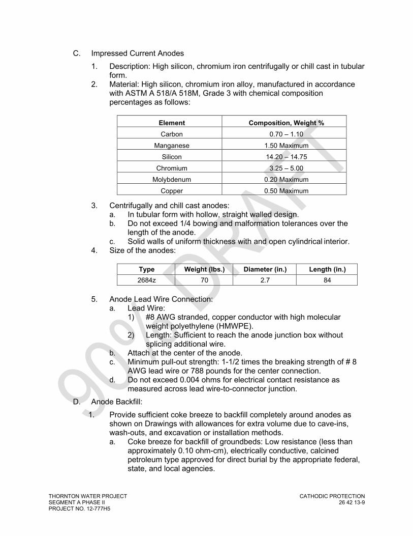
THORNTON WATER PROJECT CATHODIC PROTECTION SEGMENT A PHASE II 26 42 13-9 PROJECT NO. 12-777H5
C. Impressed Current Anodes 1. Description: High silicon, chromium iron centrifugally or chill cast in tubular
form. 2. Material: High silicon, chromium iron alloy, manufactured in accordance
with ASTM A 518/A 518M, Grade 3 with chemical composition percentages as follows:
Element Composition, Weight % Carbon 0.70 – 1.10
Manganese 1.50 Maximum Silicon 14.20 – 14.75
Chromium 3.25 – 5.00 Molybdenum 0.20 Maximum
Copper 0.50 Maximum
3. Centrifugally and chill cast anodes: a. In tubular form with hollow, straight walled design. b. Do not exceed 1/4 bowing and malformation tolerances over the
length of the anode. c. Solid walls of uniform thickness with and open cylindrical interior.
4. Size of the anodes:
Type Weight (lbs.) Diameter (in.) Length (in.) 2684z 70 2.7 84
5. Anode Lead Wire Connection:
a. Lead Wire: 1) #8 AWG stranded, copper conductor with high molecular
weight polyethylene (HMWPE). 2) Length: Sufficient to reach the anode junction box without
splicing additional wire. b. Attach at the center of the anode. c. Minimum pull-out strength: 1-1/2 times the breaking strength of # 8
AWG lead wire or 788 pounds for the center connection. d. Do not exceed 0.004 ohms for electrical contact resistance as
measured across lead wire-to-connector junction. D. Anode Backfill:
1. Provide sufficient coke breeze to backfill completely around anodes as shown on Drawings with allowances for extra volume due to cave-ins, wash-outs, and excavation or installation methods. a. Coke breeze for backfill of groundbeds: Low resistance (less than
approximately 0.10 ohm-cm), electrically conductive, calcined petroleum type approved for direct burial by the appropriate federal, state, and local agencies.

THORNTON WATER PROJECT CATHODIC PROTECTION SEGMENT A PHASE II 26 42 13-10 PROJECT NO. 12-777H5
Element Composition, Weight % Volatile Matter 0.7 to 1.8% maximum
Ash 2.3% maximum Sulfur 5.9% maximum
Actual Carbon 91.0% minimum Particle Size 85% less than 1/4-inch
Bulk Density 55 to 60 pounds per cubic foot minimum
Fixed Carbon (Carbon and Sulfur) 96.0% minimum
b. Coke breeze for deep anode type groundbeds: 1) Sources: LORESCO DW-1, SC-2, or SC-3 or approved equal. 2) Suitable for pumping. 3) Calcined.
E. Downhole Vent Pipe for Deep Anode Groundbeds (vent pipe through active column): 1. Material:
a. Heavy duty Schedule 40 PVC. b. Diameter: Minimum one inch. c. Conforming to ASTM D 1785, Type 1, Grade 1. d. Resistant to chlorine.
2. Extended from the bottom to the top of the drilled hole. 3. Perforated in a continuous manner such that perforated sections are
adjacent to anodes for the entire active anode column length upon installation.
4. Either drilled and provided with geotextile fabric sock or slotted. 5. Seal the bottom of the vent pipe with a plastic end cap or plug. 6. Drilled vent pipe holes:
a. Diameter: 3/8-inch. 1) Penetrate pipe at four quadrants around the circumference at
each drilled location and space equally at 4 inches apart throughout each perforated 2-foot section.
2) Wrap in geotextile fabric sock to prevent intrusion of fine-grained coke breeze into vent pipe. a) Source: Nilex filter sock. b) Description: Non-deteriorating geotextile material of
sufficient durability and attachment to the pipe to resist tearing and damage during installation.
c) Securely fasten to drilled plastic pipe by means of two complete wraps of tape at each end of 20-foot pipe section.
7. Slotted vent pipe: a. Source: All Vent by Loresco. b. Description: Vertical slits approximately 0.006-inch wide and
1-1/2 inches long cut in a parallel pattern to longitudinal centerline of the plastic pipe.

THORNTON WATER PROJECT CATHODIC PROTECTION SEGMENT A PHASE II 26 42 13-11 PROJECT NO. 12-777H5
c. Slot spacing: One-inch form preceding slit at approximately 6-inch centerline separation distance.
F. Well Casing: 1. Use when required due to subsurface conditions or environmental sealing
requirements are necessary. Do not install well casing in active column of deep anode groundbed unless approved by Owner or Designated Representative.
2. Material: a. Standard weight steel or plastic. b. Plastic casing: Meet or exceed ASTM F-480. c. Good condition, durable, and watertight. d. Nontoxic and resistant to water and soil corrosiveness. e. Meet local well drilling standards and withstand installation, grouting,
and operating stresses. f. Nominal wall thickness for 6 inch or larger diameter steel casing:
0.25-inch thick. 3. Sealing Material:
a. Impermeable material, such as bentonite-gelatinous mud or grout or puddling clay as required to meet local and state drilling code requirements. 1) Bentonite Sealer:
a) Sources: PermaPlug by Cathodic Engineering Equipment, Co., Inc., Enviroplug by Mesa or approved equivalent.
b) Description: High swelling, chemically unaltered bentonite clay intended for plugging and sealing drilled holes.
2) Puddling Clay Sealer: a) Mixture of bentonite, other expansive clays, fine-grained
material and water, in a ratio of no less than 7 pounds of bentonite or expansive clay per gallon of water.
b) Composed of a minimum of 50% expansive clay with the maximum size of the remaining portion not exceeding that of coarse sand.
G. Gravel for Deep Anode Groundbed: 1. Use if allowed by state regulation. 2. Description: 3/4-inch thoroughly washed, sound, durable, and well-
rounded gravel. H. Deep Anode Surface Vent Pipe (vent pipe through inactive column and
surface): 1. One-inch diameter PVC pipe with 180º gooseneck. 2. Install cap with ¼” drilled holes or screened fitting on end of gooseneck for
ventilation of the deep anode system. 3. Install and terminated at the top of surface casing as shown on Drawings.
I. Anode Junction Box: 1. Sources: Integrated Rectifier Technologies.

THORNTON WATER PROJECT CATHODIC PROTECTION SEGMENT A PHASE II 26 42 13-12 PROJECT NO. 12-777H5
2. Description: NEMA 3R, vented steel type junction box, standard product of the recognized manufacturer.
3. Material: Minimum 16-gauge steel. 4. Minimum inside box dimensions: 12 inch x 12 inch x 6 inch deep or larger,
if required to provide proper access for the number of anodes specified. 5. Finish: Coating to match rectifier. Galvanized or coated with either baked
enamel or heat-cured 100% solids thermosetting epoxy coating. 6. Provide with:
a. One-piece of oil resistant gasket to be mounted inside the door to form an oil-tight and dust-free seal.
b. A locking lid and a hasp for a padlock. c. Separate panel board:
1) For the attachment of a buss bar with a terminal strip or terminal block with medium-duty solderless compression type terminal connectors.
2) Accommodate the anode wire and the rectifier positive header wire gauge specified with the necessary mounting hardware.
3) Material: A minimum 3/16-inch micarta or cross-laminated phenolic sheet.
d. Sufficient copper shorting bars and/or 0.01 ohm Holloway “Type RS” shunts to electrically bond each anode lead terminal to the rectifier positive lead buss bar as shown on Drawings.
e. A minimum number of shunts and compression type connectors to match the number of anodes provided for each groundbed location.
f. Rugged supports on the enclosure to allow it to be securely wall- mounted if needed.
g. Double hub suitable for thread mounting on two 1-1/4 inch or larger rigid threaded galvanized steel conduit.
J. Negative or Cross Bond Station Junction Box (if required): 1. Sources: Integrated Rectifier Technologies 2. Description: NEMA 3R, vented steel type junction box, standard product
of the recognized manufacturer. 3. Material: Minimum 16-gauge steel. 4. Minimum inside box dimensions: 12” L x 12” W x 6” D or larger, if required
to provide proper access for the number of resistors and structure wires specified.
5. Finish: Coating to match rectifier. Galvanized or coated with either baked enamel or heat-cured 100% solids thermosetting epoxy coating.
6. Provide with: a. One-piece of oil resistant gasket to be mounted inside the door to
form an oil-tight and dust-free seal. b. A locking lid and a hasp for a padlock. c. Separate panel board:
1) For the attachment of a buss bar with a terminal strip or terminal block with medium-duty solderless compression type terminal connectors.
2) Accommodate the resistors and the rectifier negative header wire gauge specified with the necessary mounting hardware.

THORNTON WATER PROJECT CATHODIC PROTECTION SEGMENT A PHASE II 26 42 13-13 PROJECT NO. 12-777H5
3) Material: A minimum 3/16-inch micarta or cross-laminated phenolic sheet.
d. Minimum size and quantity of slide resistors connected to the negative buss bar as shown on Drawings.
e. Sufficient copper shorting bars and/or 0.01 ohm Holloway “Type SW” shunts to electrically bond each structure to the resistor as shown on Drawings.
f. A minimum number of shunts and compression type connectors to match the number of structures provided for each bond location.
g. Rugged supports on the enclosure to allow it to be securely wall- mounted if needed.
h. Double hub suitable for thread mounting on two 1-1/4 inch or larger rigid threaded galvanized steel conduit.
K. Hardware: 1. Flat and lock washer, terminal nuts, and studs: 1/4-inch. 2. Finish: Nickel-plated brass or bronze.
L. Conduit, Locknuts, and Straps: 1. Use intermediate threaded metal conduit, including couplings, elbows,
nipples, and other fittings, hot-dipped galvanized that meet the requirements of UL and the NEC.
2. Heavy wall, rigid, PVC conduit: a. Schedule 40. b. UL listed for concrete encasement, underground direct burial,
concealed, and direct sunlight exposed usage. 3. Flexible non-metal conduit:
a. UL listed. b. Liquid-tight flexible non-metallic conduit consisting of an extruded
PVC jacket and terminated with nylon bushings with steel or malleable iron body and insulated throat and sealing O-ring.
4. Locknuts, two-hole straps, and other miscellaneous hardware: Hot-dipped galvanized in accordance with ASTM A153.
5. Conduit bushings: Threaded plastic or plastic-throated galvanized steel fittings.
M. Enclosures: 1. NEMA 3R, 6’ long x 6’ tall x 4’ wide ,12-gauge carbon steel enclosure with
fully welded seams as manufactured by Bison ProFab Industrial Enclosures.
2. Enclosure shall have 6’ wide, French style, full opening doors on each side for access. Double flanged door openings shall be sealed with neoprene gaskets and contain 3-point stainless steel pad lockable Defeater handles with stainless steel rods and nylon rollers.
3. 12” x 12” door pocket bolted to inside of each door 4. Door shall have hidden hinges with stainless steel hardware spot welded
to each door.

THORNTON WATER PROJECT CATHODIC PROTECTION SEGMENT A PHASE II 26 42 13-14 PROJECT NO. 12-777H5
5. Enclosure shall include four (4) 5/8-11 stainless steel lifting eye bolts installed and sealed to NEMA 3R on roof with channel stiffeners for lifting.
6. Enclosure shall include 12” wide x 18” tall louver panels installed on each side opposite of adjacent doors. Louver panels shall contain a screen mesh permanently secured to the enclosure on the inside of each panel area.
7. Interior and exterior of enclosure shall be painted with Desert Tan coating. Exterior shall have a clear anti-graffiti overcoat applied.
8. Pad locks (either 4-digit combo or keyed) will be provided by the Owner or Designated Representative.
N. Test Stations: 1. Post Mount Type:
a. Gerome Electric, Model 917, 7 Terminal, Threaded 3” Top 1) Terminal board hardware shall consist of stainless steel or
nickel- plated brass and consist of a minimum of seven (7) ½ inch diameter by 1.25 inches long studs with double nuts, flat wasters, and lock washers.
b. Support Post: 3” nominal diameter galvanized rigid steel pipe, threaded one end, at least 6-ft in length to allow for 5-ft protrusion from finished grade.
c. Labels: Install Panduit label tags on all wires 1) Pipe Diameter and material, as applicable 2) Wire Function 3) Posts located at property lines shall include reflective bands
and labels. 2. Flush Mount Type:
a. 12” nominal diameter round enclosure with 3” diameter Cott Big Fink model test head inside, cast iron cover labeled ‘C.P. Test’. 1) Terminal board hardware shall consist of stainless steel
or nickel- plated brass and consist of a minimum of seven (7) ½ inch diameter by 1.25 inches long studs with double nuts, flat wasters, and lock washers.
2) Test station head shall have 3” PVC threaded collar and cover
b. Labels: Install Panduit label tags on all wires with the following: 1) Pipe Diameter and material, as applicable 2) Wire Function
O. Galvanic (Magnesium) Anodes: 1. Magnesium anodes shall be Hi-Potential, ASTM B843, Grade M1C and
conform to the following specifications:
Aluminum (Al) 0.10% maximum Manganese (Mn) 0.50 to 1.30% Zinc (Zn) 0.005% maximum Copper (Cu) 0.02% maximum

THORNTON WATER PROJECT CATHODIC PROTECTION SEGMENT A PHASE II 26 42 13-15 PROJECT NO. 12-777H5
Nickel (Ni) 0.001% maximum Iron (Fe) 0.03% maximum Other Impurities - each 0.05% maximum Total 0.30% maximum Magnesium (Mg) Balance
2. Circuit Potential and Electrochemical Capacity: Open circuit potential of 1.50 volts or more negative in reference to a copper-copper sulfate reference electrode.
3. Anode Backfill: a. Anodes shall be furnished prepackaged in special backfill material
consisting of 75% ground hydrated gypsum, 20% powdered bentonite and 5% anhydrous sodium sulfate.
b. The backfill shall have a grain size such that 100% is capable of passing through a 20-mesh screen and 50% will be retained by a 100- mesh screen. The backfill mixture shall be firmly packaged around the anode within a cotton bag by means of adequate vibration.
4. Anode Lead Wire: a. No. 12 AWG solid copper conductors with RHW/USE-2 insulation. b. Black insulation. c. Lead wires shall be a minimum of 50 feet in length. The lead wires
shall be connected to the galvanized steel core of the anode by silver soldering and sealed with waterproof epoxy or electrical potting compound. 1) Sufficient in length to reach test station without being spliced.
5. Dimensions: Minimum bare weight of 32 lbs with an ingot length of 19 7/8 inches or sized as per detail drawings.
6. Anodes shall be shipped in waterproof bags or wrapping and shall remain dry until installation.
7. Acceptable Manufacturers: a. Farwest Corrosion Control (Denver, CO) or MESA (Denver, CO) b. Engineer or Owner or Designated Representative approved equal.
P. Stationary Reference Electrodes: 1. Copper/copper sulfate reference electrode material designed for minimum
20-year useful life as manufactured by GMC Electrical. 2. Reference electrode to be pre-packaged with a low resistivity backfill
formulated to retain moisture and maintain stability. 3. Reference electrode shall contain one (1) #14 RHW/USE-2 yellow lead
wire for connection. Recommend 50 feet minimum. Q. Metallic Coupons:
1. Suitable sized metallic with a minimum exposed surface area of 1.55 square inches (10 cm2) as manufactured by McMiller Co. Inc.
2. Coupon shall contain two (2) #12 AWG THHN/THWN green cables for connection.
3. Ensure metallic coupon is the same material and composition as the structure under cathodic protection. Recommend 50 feet minimum.

THORNTON WATER PROJECT CATHODIC PROTECTION SEGMENT A PHASE II 26 42 13-16 PROJECT NO. 12-777H5
R. Exothermic Welds: 1. All electrical cable connections to the buried piping shall be made by an
exothermic weld. 2. Exothermic type weld materials including the proper size and type of weld
cartridges and welder molds for use on ductile-iron or steel pipe. 3. Acceptable Manufacturers:
a. Erico Products Inc. "CADWELD PLUS" b. Engineer approved equal.
4. Weld materials shall be compatible to the pipe material as recommended by the manufacturer.
5. Copper sleeves specifically designed for the purpose of exothermic welding shall be crimped on all bare wire ends of #8 AWG or smaller gauge wires prior to exothermic welding to improve mechanical strength and thermal capacity.
S. Di-Electric Coatings: 1. Denso Protal 7125 repair coating or Engineer approved equivalent. 2. All waterline pipe and pipe fittings shall be furnished with a factory applied
coating as specified in other sections. The factory applied coatings shall be inspected prior to installation and shall be installed in accordance with the manufacturer’s recommendations.
3. All bare line pipe, uncoated flange bolts, uncoated mechanical fitting bolts, and other uncoated bolts, nuts, flanges, or fittings with metallic composition shall be protected with wax-tape primer and #1 wax-tape as manufactured by Trenton Corporation or approved equivalent and applied to a thickness of 20 mils.
T. Plastic Conduit for Cathodic Protection Sheathing (below grade applications): 1. Diameter: Sized to match application. 2. Schedule 40 polyethylene (PE) or polyvinyl chloride (PVC) plastic pipe.
U. Wire: 1. Insulated stranded or solid copper wire as specified. 2. Wire size, type, and insulation type: As specified in this Section and as
depicted on the Drawings: a. Structure Connections to Negative Junction Box: #4 AWG, Stranded
HMWPE b. Negative Junction Box to Rectifier: #2 AWG, Stranded, HMWPE c. Anode Junction Box to Rectifier: #2 AWG, Stranded, HMWPE d. Groundbed Anodes to Anode Junction Box: #8 AWG, Stranded,
HMWPE e. Joint/Continuity Bonds: Size per table on Drawings, Stranded,
RHW/USE-2 f. Pipe Test Leads: #8 AWG, Stranded, RHW/USE-2 g. Pipe Test Leads at Isolation Test Station: #4 AWG, Stranded,
RHW/USE-2
h. Galvanic Anode Leads: #12 AWG, Solid, RHW/USE-2

THORNTON WATER PROJECT CATHODIC PROTECTION SEGMENT A PHASE II 26 42 13-17 PROJECT NO. 12-777H5
i. Reference Electrodes: #14 AWG, Stranded, RHW/USE-2 j. Metallic Coupons: #12 AWG, Stranded, THHN/THWN
3. Wire insulation color: Indicate the function of each wire as shown on the Drawings. a. Red: Anode Junction Box to Rectifier b. Blue: Test Leads for Owner or Designated Representative (Project)
Pipe c. White: Test Leads for Future or Foreign Pipelines d. Black: Structure/Negative cables, anode leads, and joint/continuity
bonds e. Yellow: Reference electrode f. Green: Metallic coupon g. Orange: Casing pipe or tunnel lining
4. AC wire to supply power to rectifier: a. Single conductor, soft drawn copper. b. Minimum No. 10 AWG or larger as sized in accordance with (NEC)
to match the maximum rated rectifier power requirement. A. In-Line Tap Slices for Cathodic Protection Cables (use only if approved by
Owner or Designated Representative): 1. “C” taps made of conductive wrought copper. 2. Sized to fit the wires being spliced. 3. Apply compression connectors the proper crimp tool and die
recommended by the manufacturer for the wire and the tap connector size; in-line
4. “Butt” type wire splice connectors are acceptable for #8 AWG or smaller splices.
5. Electrical Splicing Tape and Coating: a. Acceptable manufacturers:
1) Scotch 130C tape 2) Scotch Super 88 tape 3) Scotchkote Electrical Coating as manufactured by 3M Products 4) Engineer-approved equal.
b. 30 mil liner-less rubber high voltage splicing tape and 7 mil vinyl electrical tape suitable for moist or wet environments.
c. Electrical Connectors: Tin or nickel-plated copper, brass, bronze, or stainless steel for electrical conductivity and atmospheric corrosion resistance.
B. Wire Terminals 1. Burndy YAV series.
C. Test Station Shunts 1. 0.01 ohm, yellow 2. Acceptable Manufacturers:
a. Cott. b. Owner or Designated Representative-approved equal.
D. Wax Tape:

THORNTON WATER PROJECT CATHODIC PROTECTION SEGMENT A PHASE II 26 42 13-18 PROJECT NO. 12-777H5
1. Design: a. A blend of microcrystalline waxes, plasticizers and corrosion
inhibitors saturated into a non-woven, non-stitch bonded synthetic fabric, forming a tape wrapper.
b. Shall contain no siliceous mineral fillers. c. Suitable for below ground use d. Nontoxic, nonflammable, non-carcinogenic, free of all VOCs
2. Acceptable manufacturers: a. Trenton, #1 Wax-Tape. b. Owner or Designated Representative-approved equal.
E. Polyethylene Wrap: 1. High density, cross-laminated polyethylene film, 4-mil thickness.
F. Wire Marker Tags and Pens: 1. Design:
a. Marker tags shall be permanent, b. Shall be made of weather resistant/UV light resistant nylon, c. shall be attached to a plastic non-releasing holding device and cable
fastening tail d. The marker tag writing surface shall have minimum dimensions of
0.75" long x 1.0" wide. 2. Acceptable Manufacturers:
a. Panduit Corporation Part No. PLF1MA. b. Engineer or Owner or Designated Representative approved equal.
3. Marker pens shall have a fine point tip with quick-drying, waterproof black ink for use on nylon marker tags and shall be similar to Panduit Corporation Part No. PFX-0.
G. CP Warning Tape: 1. 3” plastic, APWA blue, detectable, marked “Caution Cathodic Protection
Cable Buried Below”. H. Electrical Isolation Devices:
1. Electrical isolation of the buried piping shall be accomplished by flange isolation kits, insulating mechanical couplings, di-electric unions, or a piece of non-metallic piping where specified herein or shown on the Drawings. In the event an insulating coupling is restrained using harness rods, each rod shall be insulated using a properly sized one-piece insulating sleeve and washer with steel backing washer.
2. Flange isolation kits shall be ordered according to pipe size and pressure rating of the flange and shall be installed per the manufacturer’s instructions. Care shall be exercise so as not to damage the insulating bolt sleeves and washers.
3. Required applications of dielectric flange isolation assemblies, couplings, and other devices are not limited to selected locations where new piping is mechanically connect to existing piping. Other such examples include: a. Transfer of Ownership locations. b. Connections between dissimilar metals (i.e. welded steel to ductile).

THORNTON WATER PROJECT CATHODIC PROTECTION SEGMENT A PHASE II 26 42 13-19 PROJECT NO. 12-777H5
c. Cased segments of piping. d. Connections to electrically grounded components such as actuated
valves, meters, pump stations, processing facility, and other structures.
e. Concrete encased segments of piping such building risers and valve vault penetrations.
4. Materials: a. Di-Electric (Insulated) Unions
1) Approved manufacturers: a) Hart Industrial Unions with thermo baked epoxy polymer
coating of 3 to 6 mils on tailpiece. b) Owner or Designated Representative-approved equal.
b. Insulating Mechanical Couplings: 1) Approved manufacturers:
a) Dresser “Style 39” b) Rockwell “416” c) Romac “IC501” d) Baker “Series 216” without pipe stop e) Owner or Designated Representative-approved equal.
c. Insulating Flange Gaskets 1) Provide G-10 Glass Reinforced Epoxy Retainer with
appropriate seal based on type of product, Type ‘E’ full face gasket as manufactured by GPT Industries, or Engineer approved equivalent.
d. Insulating Sleeves and Washers 1) Provide full length G-10 sleeves with G-10 or Diamond Hyde
washers as manufactured by GPT Industries, or Engineer approved equivalent. a) For direct buried applications, install single washer sets
on the existing or uncathodically protected side of the isolation flange or coupling so that the metallic flange bolts, restraining rods, nuts, and washers are electrically continuous with the new or cathodically protected piping.
b) For above grade or vaulted applications, install double washer sets.
5. Coat all bare, buried di-electric components to include nuts, bolts, and washers with wax-tape primer and #1 wax-tape as manufactured by Trenton Corporation or approved equivalent and applied to a thickness of 20 mils.
I. Concrete Encasement for Corrosion Control: 1. Concrete materials:
a. Conform to ASTM C94-90, Option A, and ASTM C 150. b. Concrete shall be Type II with a minimum cement content of
564 pounds per cubic yard. 1) Aggregate size; ¾-inch or smaller
c. Minimum compressive strength of 3,000 psi at 28 days with a maximum water-cement ratio of 0.45.
d. Air Entrainment:
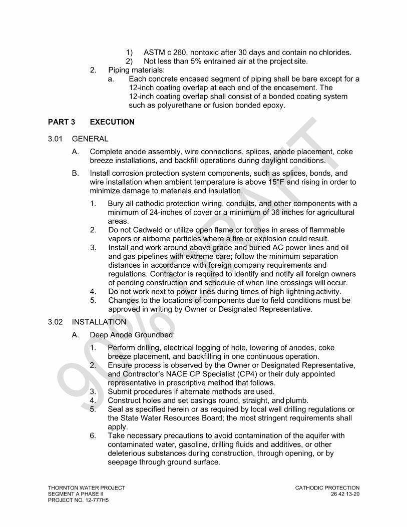
THORNTON WATER PROJECT CATHODIC PROTECTION SEGMENT A PHASE II 26 42 13-20 PROJECT NO. 12-777H5
1) ASTM c 260, nontoxic after 30 days and contain no chlorides. 2) Not less than 5% entrained air at the project site.
2. Piping materials: a. Each concrete encased segment of piping shall be bare except for a
12-inch coating overlap at each end of the encasement. The 12-inch coating overlap shall consist of a bonded coating system such as polyurethane or fusion bonded epoxy.
PART 3 EXECUTION
3.01 GENERAL A. Complete anode assembly, wire connections, splices, anode placement, coke
breeze installations, and backfill operations during daylight conditions. B. Install corrosion protection system components, such as splices, bonds, and
wire installation when ambient temperature is above 15°F and rising in order to minimize damage to materials and insulation. 1. Bury all cathodic protection wiring, conduits, and other components with a
minimum of 24-inches of cover or a minimum of 36 inches for agricultural areas.
2. Do not Cadweld or utilize open flame or torches in areas of flammable vapors or airborne particles where a fire or explosion could result.
3. Install and work around above grade and buried AC power lines and oil and gas pipelines with extreme care; follow the minimum separation distances in accordance with foreign company requirements and regulations. Contractor is required to identify and notify all foreign owners of pending construction and schedule of when line crossings will occur.
4. Do not work next to power lines during times of high lightning activity. 5. Changes to the locations of components due to field conditions must be
approved in writing by Owner or Designated Representative. 3.02 INSTALLATION
A. Deep Anode Groundbed: 1. Perform drilling, electrical logging of hole, lowering of anodes, coke
breeze placement, and backfilling in one continuous operation. 2. Ensure process is observed by the Owner or Designated Representative,
and Contractor’s NACE CP Specialist (CP4) or their duly appointed representative in prescriptive method that follows.
3. Submit procedures if alternate methods are used. 4. Construct holes and set casings round, straight, and plumb. 5. Seal as specified herein or as required by local well drilling regulations or
the State Water Resources Board; the most stringent requirements shall apply.
6. Take necessary precautions to avoid contamination of the aquifer with contaminated water, gasoline, drilling fluids and additives, or other deleterious substances during construction, through opening, or by seepage through ground surface.

THORNTON WATER PROJECT CATHODIC PROTECTION SEGMENT A PHASE II 26 42 13-21 PROJECT NO. 12-777H5
7. For deep anode groundbeds, maintain a log describing depth and type of geological formations encountered during drilling; submit copies of the log to the Owner or Designated Representative and the appropriate authorities.
8. Take precautions to avoid entrance of foreign matter into the hole, movement of soil strata, or collapsing of the hole at all times during progress of Work.
9. Should movement of soil strata or collapse of drilled hole interfere with proper installation occur, recover wire and anode strings and ream or redrill hole as possible. If not possible, consult Owner or Designated Representative.
10. Drilling: a. Drill a minimal nominal depth as shown on the Drawings. b. Over-drill the hole depth as required to compensate for sloughing
during anode installation such that top of the active column is not less than the minimum separation distance below the ground surface as shown on the Drawings.
c. Drill fluid: Non-hazardous, bentonite based, water well type drilling gel or mud.
d. Drilling mud: Certified by National Sanitation Foundation (NSF) as non- hazardous.
e. Locations: 1) Drill at the approximate locations shown on the Drawings. 2) Exact locations will depend on the locations of structures and
utilities encountered in field and must be determined in the field with the approval from the Owner or Designated Representative prior to the start of construction.
f. Over-drill hole and install surface casing as shown on the Drawings: 1) Do not install casing, other than surface casing, unless
necessary for successful completion of hole. 2) Set surface casing prior to completion of the first 50 feet of the
hole. 3) Should steel casing be installed, jack up to point 5 feet,
minimum, above the top of the active column. 4) Complete cutting and jacking operations before or after the
installation of the anode assembly. 5) Plastic casing may be installed in the inactive column area. 6) Install the surface casing such that a minimum of 3 feet
remains above grade. 7) Sealing:
a) Seal annular space around surface casing and soil in accordance with state requirements and local well drilling regulations.
b) Allow sealing material to reach initial set before any additional work on the drilled hole that may disturb the seal will be allowed to continue.
c) Seal hole to prevent downhole movement of surface water and the intermixing of different aquifers.

THORNTON WATER PROJECT CATHODIC PROTECTION SEGMENT A PHASE II 26 42 13-22 PROJECT NO. 12-777H5
d) Where separate aquifers are encountered, install a bentonite seal between the different aquifers as per local well drilling regulations or the State Water Resources Board; the most stringent requirements shall apply.
e) Bentonite seal thickness: Minimum 5 feet or as per local well drilling regulations or the State Water Resources Board; the most stringent requirements shall apply.
f) Increase seal thickness as required to maintain the separation of aquifers under high pressure or artesian conditions.
g) If different aquifers are encountered in active anode area, install separate vent pipes in areas between different aquifers.
g. Contain and dispose of drilling mud and cuttings in a legal manner. h. Field dug mud pits or sumps are acceptable depending on the
location and prior written approval of the Owner or Designated Representative, jurisdiction, and the potential landowner(s).
i. Field mud pits will only be considered, if completely pumped and cleaned out following drilling operations and backfilled and compacted correctly so as to not cause settlement or soft areas in future.
11. Anode Bed Loading Preparation: a. Give the Owner or Designated Representative a minimum of 72
hours’ notice prior to final anode hole preparation and anode and coke breeze placement.
b. Complete the final preparation of the anode hole, electrical logging, lowering of anodes and vent pipe, coke breeze backfill, and placement of seals only during daylight hours and when observed by the Owner or Designated Representative.
c. When holes have been drilled to the specified depth, circulate clean water in the hole to clear of drilling mud and cuttings.
d. Recirculate sufficiently to allow settling of coke breeze without causing danger of anode hole collapse or wall sloughing.
e. Maintain the hole full of water during anode and coke breeze placement.
f. Schedule work of anode bed loading preparations early enough in the day to insure completion during normal working hours.
g. Do not begin flushing and anode loading after 2:00 p.m. without prior written approval.
12. Lowering of Anodes: a. Lower anodes after drilling and the Owner or Designated
Representative’s review of the driller’s log and the electrical logging of the hole are completed.
b. The actual lowering of anodes and backfilling of hole with coke breeze shall be observed by the Owner or Designated Representative.
c. Delay installation of anode assembly and coke breeze until next day if it cannot be completed during daylight of same day as completion of drilling and electrical loggings.

THORNTON WATER PROJECT CATHODIC PROTECTION SEGMENT A PHASE II 26 42 13-23 PROJECT NO. 12-777H5
d. If installation of the anode assembly is delayed more than 4 hours from completion of drilling operations, reinsert drill stem and bit and run back to the bottom of the hole.
e. Maintain sufficient bit rotation and circulation to ensure the drilled hole is adequately prepared for anode and coke breeze installation.
f. Maintain the hole full of water during the installation of the anodes and coke breeze.
g. Lay out anode leads and vent pipe to prevent damage, allow inspection, and to allow ease of downhole installation.
h. The Contractor will be responsible for inspecting anodes and lead wires for damage prior to installation. Damage to anodes or lead wires is cause for rejection of that anode assembly.
i. Measure the anode lead wire length to verify and monitor actual anode depth and spacing in drilled hole by either of the following methods: 1) Measure anode lead length as the individual anode is lowered
down the hole with a wire measurer to confirm actual anode elevation and spacing.
2) Pre-measure the anode length and compare it to other anode lengths for reference; lay out anode leads, measure actual anode wire length, and pre-mark them to demonstrate actual wire lengths and show that difference between ends of wires are equal to specified spacing.
j. If the vent pipe is predrilled, encase in geotextile sock and secure sock with tape on each end of vent pipe.
k. If slotted vent pipe, geotextile sock is not required. l. For deep anode groundbed, attach first, the deepest anode to the
pre- drilled or slotted vent pipe; seal vent pipe with a cap or plug. m. After electrical logging has been completed, carefully lower the
anode and the vent pipe to the bottom of the hole. n. Wipe vent pipe individual ends clean and dry, and glue with solvent
type cement. o. Solvent type cement: Designed to be suitable for similar fast set,
immersion service, and joining of PVC. p. Clean glue, rotate the connection, and allow to sufficiently dry before
the vent pipe is lowered. q. Lower remaining anodes individually. r. Monitor individual anode depth and spacing. s. Maintain sufficient slack in the anode lead cables to prevent damage
during anode installation and backfilling operations. t. When the anode is at the specified depth, suspend in the hole and
securely tie off around the suspension bar or the pipe with a sufficient diameter 2-1/2 inches minimum, to prevent sharp bending of wires.
u. Tie wires off in order. v. Keep anodes securely fastened until the coke breeze backfill has
been placed and has settled. w. Take care to avoid damage to anode assembly and wires from
casing or drill rig.
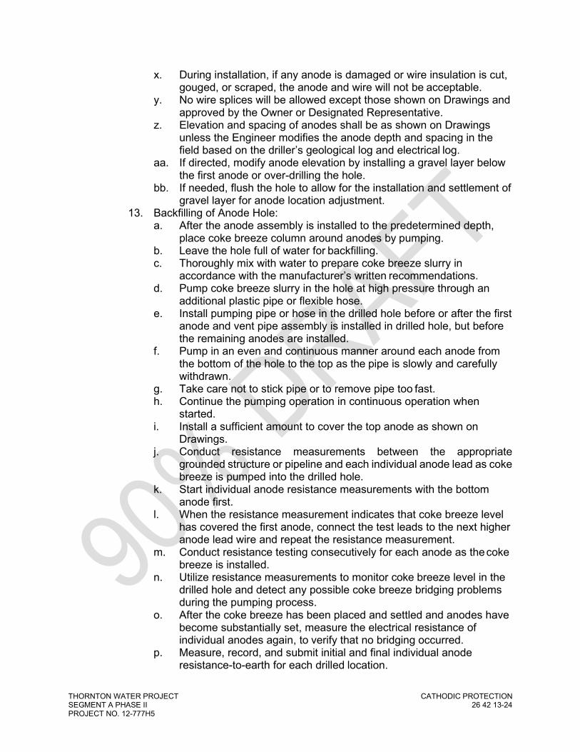
THORNTON WATER PROJECT CATHODIC PROTECTION SEGMENT A PHASE II 26 42 13-24 PROJECT NO. 12-777H5
x. During installation, if any anode is damaged or wire insulation is cut, gouged, or scraped, the anode and wire will not be acceptable.
y. No wire splices will be allowed except those shown on Drawings and approved by the Owner or Designated Representative.
z. Elevation and spacing of anodes shall be as shown on Drawings unless the Engineer modifies the anode depth and spacing in the field based on the driller’s geological log and electrical log.
aa. If directed, modify anode elevation by installing a gravel layer below the first anode or over-drilling the hole.
bb. If needed, flush the hole to allow for the installation and settlement of gravel layer for anode location adjustment.
13. Backfilling of Anode Hole: a. After the anode assembly is installed to the predetermined depth,
place coke breeze column around anodes by pumping. b. Leave the hole full of water for backfilling. c. Thoroughly mix with water to prepare coke breeze slurry in
accordance with the manufacturer’s written recommendations. d. Pump coke breeze slurry in the hole at high pressure through an
additional plastic pipe or flexible hose. e. Install pumping pipe or hose in the drilled hole before or after the first
anode and vent pipe assembly is installed in drilled hole, but before the remaining anodes are installed.
f. Pump in an even and continuous manner around each anode from the bottom of the hole to the top as the pipe is slowly and carefully withdrawn.
g. Take care not to stick pipe or to remove pipe too fast. h. Continue the pumping operation in continuous operation when
started. i. Install a sufficient amount to cover the top anode as shown on
Drawings. j. Conduct resistance measurements between the appropriate
grounded structure or pipeline and each individual anode lead as coke breeze is pumped into the drilled hole.
k. Start individual anode resistance measurements with the bottom anode first.
l. When the resistance measurement indicates that coke breeze level has covered the first anode, connect the test leads to the next higher anode lead wire and repeat the resistance measurement.
m. Conduct resistance testing consecutively for each anode as the coke breeze is installed.
n. Utilize resistance measurements to monitor coke breeze level in the drilled hole and detect any possible coke breeze bridging problems during the pumping process.
o. After the coke breeze has been placed and settled and anodes have become substantially set, measure the electrical resistance of individual anodes again, to verify that no bridging occurred.
p. Measure, record, and submit initial and final individual anode resistance-to-earth for each drilled location.

THORNTON WATER PROJECT CATHODIC PROTECTION SEGMENT A PHASE II 26 42 13-25 PROJECT NO. 12-777H5
q. Take care to not damage the anode assembly and to avoid plugging the vent pipe, bridging of coke breeze, collapsing of the hole, and either over-filling or under-filling the hole.
r. If the hole collapses, coke breeze bridges, vent pipe plugs, anode assembly is damaged, or the hole is under-filled, or over-filled, take necessary steps to resolve and correct the problem at the Contractor’s sole expense.
s. After the coke breeze is installed and has settled for a minimum of 12 hours and anodes are set, measure the depth to the top of coke breeze column to ensure coke breeze is at specified elevation in order to maintain sufficient cover for anodes and electrical isolation from the structure to be protected.
t. If the hole is over-filled by more than 15 feet, remove coke breeze to provide specified elevation.
u. If the hole is under-filled by more than 5 feet, add additional coke breeze to the specified elevation by hand shoveling a saturated mixture of coke breeze and water to bring the coke breeze level up to specified depth.
v. Upon acceptance of the coke breeze installation, either add 3/4-inch diameter of washed gravel, if allowed by state regulations, or drill cuttings or bentonite clay to fill the hole to depth shown on the Drawings
14. Placement of Seal: a. Upon acceptance of washed gravel or top coke breeze elevation,
place sealing material from the top of the gravel backfill or coke breeze to a point either 12 inches below the finished elevation of well seal or hole termination depth shown on the Drawings or as required by local, county, or state well drilling regulations.
b. The method of seal placement shall force the sealing material from the bottom of the space to be sealed to the surface.
c. Place sealing material in a manner that ensures entire the filling of the space in one continuous operation.
d. Complete vent pipe and lead wire termination prior to the placement of the seal inside the casing.
15. Vent Pipe Termination: a. Terminate the vent pipe 3 feet above grade and out the top of the well
casing so that the opening for the vent pipe is facing downward. Other locations may be approved by the Owner or Designated Representative.
b. Install a 180º gooseneck on the vent pipe and cap with predrilled end cap or screened bushing.
B. Rectifier: 1. Provide rectifier, entrance, switch, and electrical hardware. 2. Conform to NEC electrical codes, local utility company requirements,
permitting agencies, and applicable codes and standards. 3. Installation and locations as shown on Drawings. 4. Mounted to allow unobstructed access to and full opening of rectifier
access doors for testing, maintenance, and repair.

THORNTON WATER PROJECT CATHODIC PROTECTION SEGMENT A PHASE II 26 42 13-26 PROJECT NO. 12-777H5
5. Submit location adjustments in writing for review and approval by the Owner.
6. Install level and plumb. 7. Install rectifier cables in rigid galvanized steel conduit or PVC. 8. Terminate conduits with plastic-throated conduit bushings. 9. Identify with a stamped identification tag permanently attached in a visible
location on the inside of the rectifier housing. 10. Install rectifier wire from the rectifier negative terminal directly to the
pipelines or through a junction box as shown on Drawings. 11. Install rectifier wire from the rectifier positive terminal to the anode junction
box or the anode header wire as shown on Drawings. 12. Clearly identify ground bed (anode) and structure leads in the rectifier
case and boxes. C. Remote Monitoring Unit:
1. Conform to NEC electrical codes, local utility company requirements, permitting agencies, and applicable codes and standards.
2. Installation and locations as shown on Drawings. 3. Mounted to allow unobstructed access to and full opening of remote
monitor unit access doors for testing, maintenance, and repair. 4. Submit location adjustments in writing for review and approval by the
Owner or Designated Representative. 5. Install level and plumb. 6. Install remote monitor cables in rigid galvanized steel conduit or PVC. 7. Terminate conduits with plastic-throated conduit bushings. 8. Install a 100-amp mercury relay as per manufacturer’s instructions. 9. If installed within a closed area, orient cellular and/or satellite receiver
outside of building or obstacles and provide a clear, unobstructed view for communication signals.
10. Connect AC power to the remote monitor unit via a step-down transformer as provided by remote monitor manufacturer.
D. Rectifier Conduits and Junction Boxes: 1. Install above-grade conduit, fittings, and wires in rigid hot-dipped
galvanized steel conduit or rigid PVC conduit, as indicated on Drawings. If less than 3 feet long, flexible liquid-tight non-metallic conduit is suitable.
2. Secure with double hole conduit straps with wood screws on wood bolts and expansion shields on concrete or brick, toggle bolts on hollow masonry units, and machine screws or welded, threaded studs on steelwork.
3. Install below grade wires in rigid PVC conduit and fittings. 4. Mount boxes and exposed conduit plumb and level. 5. Install in a secure, substantial manner by attachment to the appropriate
wood post, channel, service pole, building structure, or structural member. 6. Threaded studs driven in by powder charge and provided with lock
washers and nuts are acceptable in lieu of expansion shields. 7. Secure conduits entering cabinets, junction, or terminal boxes with double
galvanized locknuts, one on the inside and one on the outside of the box and with bushings.

THORNTON WATER PROJECT CATHODIC PROTECTION SEGMENT A PHASE II 26 42 13-27 PROJECT NO. 12-777H5
8. Size conduit in accordance with appropriate codes and such that conductors may be drawn in without injury or excessive strain.
9. In outdoor, underground, or buried locations, use watertight couplings, and connections.
10. Open no more knockouts in box than required. Seal unused openings. 11. Install to prevent water from entering the conduit or the box. 12. Install insulated bushings and insulating throat connectors on the ends of
rigid metallic conduit that terminate in test stations, junction or terminal boxes, and rectifier cabinets.
13. Make conduits watertight and free of obstructions. 14. Ream conduits, remove burrs, and clean the conduit interior before
introducing cables or pull wires. 15. For plastic conduits, use factory made elbows for bends 30º or larger. 16. Make no bends in flexible conduit that exceed the allowable bending
radius of the cable to be installed or that significantly restricts conduit flexibility.
17. Solvent weld plastic conduit joints with solvent that is recommended by the conduit manufacturer.
18. Follow the manufacturer’s written instructions and provide watertight joints.
19. Provide expansion joints as required or as recommended by the conduit manufacturer.
20. Use acceptable plastic terminal adapters and female adapters when joining plastic conduit to metallic fittings or conduit.
E. Enclosures: 1. 1. Enclosures to be installed over all impressed current rectifiers and
junction boxes. AC power components, groundbed vent piping, and groundbed surface casing shall be installed outside of any enclosure.
2. 2. Install enclosure on 7’ long x 5’ wide concrete pad with a minimum thickness of 6 inches, centered on the electrical rack and components.
3. Concrete pad: a. Ensure all conduits, posts, and other items are at their proper
location and elevation prior to pouring concrete pad. b. Install a minimum 1” poly foam around all conduit and post
penetrations as a bond breaker from the concrete pad or install flexible connections to all equipment for frost heave and movement.
c. Prep pad area by removing a minimum of 3” of subgrade and compact area with a walk behind or hand compactor. Putting in compaction effort will go a long way toward a long service life.
d. Concrete pad shall consist of #4 or #5 rebar, spaced 12” on center, each way, centered in the slab and minimum 4,000 psi strength for durability.
e. All concrete surfaces shall be flat, broom finish or floated finish with chamfered or round edges.
4. Enclosures shall be secured to the concrete pad with a minimum of four (4) stainless steel wedge anchors.
5. Route remote monitoring antenna using a manufacturer supplied extension to the roof of the enclosure. Install the antenna lead wire

THORNTON WATER PROJECT CATHODIC PROTECTION SEGMENT A PHASE II 26 42 13-28 PROJECT NO. 12-777H5
through a water-proof opening or conduit on the side or top of the enclosure. Do not route antenna lead wire through any doors.
F. Test Stations: 1. Determine location of test stations based on actual site conditions and as
approved by Owner or Designated Representative. 2. Locate test stations as depicted on Drawings and/or CP tables. 3. Locate all test stations in a protected location such as near fences, behind
curbs, outside of roadways, and in areas that are accessible for personnel. a. When routing test stations away from the protected pipe, all test
station, anode, reference electrode, coupons, and other wires shall be installed in a minimum 1” diameter PVC conduit routed from the edge of the pipe trench to the test station location.
4. Make wire connections to test station terminal boards with crimp-on spade lug terminals.
5. Wire labels and markings: a. Label and marking materials should be suitable for permanent
identification. b. Position markers in test stations so that they do not interfere with
operation and maintenance. c. Include pipe diameter and type, and wire function, as applicable. d. Test station wires shall be color coded as shown on the drawings
and specified herein and each wire shall be permanently identified using nylon marker tags and plastic cable ties as shown on the drawings and specified herein. Marker tag identification shall be completed by using a waterproof ink nylon marker marking pen and using block type lettering with the letter size to be a minimum of 1/8-inch high and shall specify test station number, pipe diameter, pipe material, and pipe service or other pertinent information. Test station wiring shall have enough extra wire slack to extend a distance of two feet above the top of the test station box.
Examples:
TS #140 TS #105 TS #160 36”- 45° DI 48” Steel 48 lb. Mag Bend Casing Pipe Anode
G. Galvanic (Magnesium) Anodes: 1. Install anodes as shown on Drawings and/or CP tables. 2. Install anodes equally along each side of pipeline spaced 5 feet on center.
Anodes should be placed a minimum of 2 feet or (1) pipe diameter (whichever is greater) below the invert of the pipe and maintain a minimum of distance of 3 feet from all other buried metallic structures.
3. Anodes should be placed horizontally or vertically at or below the invert of the pipeline.
4. Do not place anode in Engineered backfill (granular pipe embedment, gravel, squeegee, concrete, etc.). Install in native soils only.

THORNTON WATER PROJECT CATHODIC PROTECTION SEGMENT A PHASE II 26 42 13-29 PROJECT NO. 12-777H5
5. Lowering of Anodes: a. The Contractor will be responsible for inspecting anodes and lead
wires for damage prior to installation. Damage to anodes or lead wires is cause for rejection of that anode assembly.
b. Maintain sufficient slack in the anode lead cables to prevent damage during installation and backfilling operations.
c. Lower anodes with rope sling or similar methods and do not lower using the anode lead wire.
d. During installation, if any anode is damaged or wire insulation is cut, gouged, or scraped, the anode and wire will not be acceptable.
e. No wire splices will be allowed except those shown on Drawings and approved by the Owner or Designated Representative.
f. Elevation and spacing of anodes shall be as shown on Drawings unless the Engineer modifies the anode depth and spacing in the field based on the drilling geological log and/or soil resistivity log.
6. Route anode wires along excavation to test station. Bury wires a minimum of 24 inches below grade or a minimum of 36 inches for agricultural areas.
7. Thoroughly compact native backfill a minimum of 1 foot deep above each anode.
8. Saturate the anode and backfill with approximately 5 gallons of clean water prior to completion of backfilling.
9. Obtain anode to soil measurements during backfill to confirm proper anode activation and function. If deficiencies are discovered, replace anode.
10. Install warning tape 12 inches above all anodes and other CP wires. H. Stationary Reference Electrodes:
1. Install reference electrodes as shown on Drawings and/or CP tables. 2. Install reference electrodes a maximum of 6 inches from the structure
under cathodic protection and/or 4 inches from any adjacent metallic coupons. Reference electrodes should be placed according to detail drawings at or below the spring line of the pipeline but must not come into contact with the piping.
3. Lowering of Reference Electrodes: a. The Contractor will be responsible for inspecting reference
electrodes and lead wires for damage prior to installation. Damage to reference electrodes or lead wires is cause for rejection of that reference electrode assembly.
b. Maintain sufficient slack in the reference electrode lead cables to prevent damage during installation and backfilling operations.
c. Lower reference electrodes with rope sling or similar methods and do not lower using the reference electrode lead wire.
d. During installation, if any reference electrode is damaged or wire insulation is cut, gouged, or scraped, the reference electrode and wire will not be acceptable.
e. No wire splices will be allowed except those shown on Drawings and approved by the Owner or Designated Representative.
f. Elevation and spacing of reference electrodes shall be as shown on Drawings unless the Engineer modifies the electrode depth and

THORNTON WATER PROJECT CATHODIC PROTECTION SEGMENT A PHASE II 26 42 13-30 PROJECT NO. 12-777H5
spacing in the field based on the drilling geological log and/or soil resistivity log.
4. Route electrode wires along excavation to test station. Bury wires a minimum of 24 inches below grade or a minimum of 36 inches for agricultural areas.
5. Thoroughly compact native backfill a minimum of 1 foot deep above each electrode.
6. Saturate the electrode and backfill with approximately 5 gallons of clean water prior to completion of backfilling.
7. Obtain reference electrode to structure measurements during backfill to confirm proper electrode activation and function. If deficiencies are discovered, replace electrode.
8. Install warning tape 12 inches above all electrodes and wires. I. Metallic Coupons:
1. Install metallic coupons as shown on Drawings and/or CP tables. 2. Install coupons a maximum of 6 inches from the structure under cathodic
protection and/or 4 inches from any adjacent reference electrodes. Coupons should be placed according to detail drawings at or below the springline of the pipeline but must not come into contact with the piping.
3. Lowering of Metallic Coupons: a. The Contractor will be responsible for inspecting metallic coupons
and lead wires for damage prior to installation. Damage to coupons or lead wires is cause for rejection of that coupon assembly.
b. Maintain sufficient slack in the metallic coupon lead cables to prevent damage during installation and backfilling operations.
c. Lower metallic coupons with rope sling or similar methods and do not lower using the coupon lead wire.
d. During installation, if any metallic coupon is damaged or wire insulation is cut, gouged, or scraped, the metallic coupon and wire will not be acceptable.
e. No wire splices will be allowed except those shown on Drawings and approved by the Owner or Designated Representative.
f. Elevation and spacing of metallic coupons shall be as shown on Drawings unless the Engineer modifies the coupon depth and spacing in the field based on the drilling geological log and/or soil resistivity log.
4. Route coupon wires along excavation to test station. Bury wires a minimum of 24 inches below grade or a minimum of 36 inches for agricultural areas.
5. Thoroughly compact native backfill a minimum of 1 foot deep above each coupon.
6. Saturate the coupon and backfill with approximately 5 gallons of clean water prior to completion of backfilling.
7. Install warning tape 12 inches above all coupons and wires. J. Wire Connections:
1. Use thermite weld method for electrical connection of copper wire to metallic surfaces. Follow manufacturer’s procedures for installation.

THORNTON WATER PROJECT CATHODIC PROTECTION SEGMENT A PHASE II 26 42 13-31 PROJECT NO. 12-777H5
Assure that the pipe or fitting wall thickness is of sufficient thickness that thermite weld process will not damage the integrity of the pipe or fitting or protective lining. Hold back thermite welds from joints and/or flanges where gaskets may be damaged by the thermite weld heat.
2. For #8 AWG or smaller wires, install copper sleeves on wire ends prior to thermite welding.
3. After cooling, remove all weld slag and visually inspect wire connection. Remove and replace any defective connections.
4. Install Denso Protal 7125 repair coating over each completed connection. Repair exposed metal surfaces in accordance with coating manufacturer’s recommendations.
5. Maintain a minimum of 6 inches of separation between any (2) thermite weld connections.
6. Attach test wires to pipe via exothermic weld and wrap wires around pipe for strain relief.
K. Buried Conductors: 1. Install test leads and negative leads to the pipeline and attach by thermite
weld method to pipe. 2. Install negative leads from the pipe and route to the rectifier or negative
junction box (if required) as shown on Drawings. 3. Identify all positive (anode) leads with red insulation or apply red electrical
tape for identification purposes. 4. Bury cathodic protection cables and wires a minimum of 24 inches below
finished grade. 5. Only splices shown on Drawings or approved by the Engineer are
permitted on any wires, cables, or leads. 6. Insulation on wires shall be free of cut or abraded areas. 7. Avoid damage to existing structures, pipelines, and utilities during the
trenching process. 8. Cathodic protection cable trenches:
a. In a general location and route as shown on the Drawings. b. Modify location to minimize possible damage to existing structures;
obtain approval for modification. c. Uniform depth and width, level, smooth, and free of any sharp
objects. d. Hand trenching may be required in some areas to avoid damage to
existing structures. L. Warning Tape:
1. Bury approximately 12 inches above underground cathodic protection cable.
2. Align parallel to and within 2 inches of centerline of conduit or cable run. M. Conductors in Boxes / Test Stations:
1. Do not damage wire, insulation, or conduit during the installation process. 2. Route and maintain sufficient slack in cables to prevent the conductor
from being unduly stressed, damaged, or broken during backfill operations.
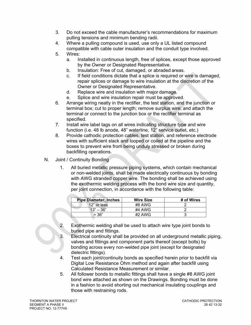
THORNTON WATER PROJECT CATHODIC PROTECTION SEGMENT A PHASE II 26 42 13-32 PROJECT NO. 12-777H5
3. Do not exceed the cable manufacturer’s recommendations for maximum pulling tensions and minimum bending radii.
4. Where a pulling compound is used, use only a UL listed compound compatible with cable outer insulation and the conduit type involved.
5. Wires: a. Installed in continuous length, free of splices, except those approved
by the Owner or Designated Representative. b. Insulation: Free of cut, damaged, or abraded areas. c. If field conditions dictate that a splice is required or wire is damaged,
repair splices or damage to wire insulation at the discretion of the Owner or Designated Representative.
d. Replace wire and insulation with major damage. e. Splice and wire insulation repair must be approved.
6. Arrange wiring neatly in the rectifier, the test station, and the junction or terminal box; cut to proper length; remove surplus wire; and attach the terminal or connect to the junction box or the rectifier terminal as specified.
7. Install wire label tags on all wires indicating structure type and wire function (i.e. 48 lb anode, 48” waterline, 12” service outlet, etc.)
8. Provide cathodic protection cables, test station, and reference electrode wires with sufficient slack and looped or coiled at the pipeline and the boxes to prevent wire from being unduly stressed or broken during backfilling operations.
N. Joint / Continuity Bonding 1. All buried metallic pressure piping systems, which contain mechanical
or non-welded joints, shall be made electrically continuous by bonding with AWG stranded copper wire. The bonding shall be achieved using the exothermic welding process with the bond wire size and quantity, per joint connection, in accordance with the following table:
Pipe Diameter, Inches Wire Size # of Wires
12” or less #8 AWG 2 13” – 36” #4 AWG 2
> 36” #2 AWG 3
2. Exothermic welding shall be used to attach wire type joint bonds to buried pipe and fittings.
3. Electrical continuity shall be provided on all underground metallic piping, valves and fittings and component parts thereof (except bolts) by bonding across every non-welded pipe joint (except for designated dielectric fittings).
4. Test each joint/continuity bonds as specified herein prior to backfill via Digital Low Resistance Ohm method and again after backfill using Calculated Resistance Measurement or similar.
5. All follower bonds to metallic fittings shall have a single #8 AWG joint bond wire attached as shown on the Drawings. Bonding must be done in a fashion to avoid shorting out mechanical insulating couplings and those with restraining rods.

THORNTON WATER PROJECT CATHODIC PROTECTION SEGMENT A PHASE II 26 42 13-33 PROJECT NO. 12-777H5
6. Exothermic welding to narrow surfaces such as MJ follower gland rings shall be accomplished using mold sealing material temporarily placed around the base of the exothermic welder to minimize the leakage of molten weld metal.
7. Any MJ or flexible coupling follower gland rubber seals or any PVC pipe itself damaged by molten weld metal shall be replaced by and at the Contractor’s sole expense.
O. Electrical Isolation 1. Accomplish electrical isolation using flange isolation kits, insulating
mechanical couplings, di-electric fittings, or non-metallic piping where shown on the Drawings. All electrical and instrumentation, pipe supports, and other appurtenances should be configured to maintain proper electrically isolation at each insulating device location.
P. Concrete Encasement for Corrosion Control 1. Position the piping so that movement will not occur during concrete
encasement. 2. Set wooden or earthen forms, stakes, tie-downs, and/or anchors prior to
installation of concrete encasement. 3. Do not use rebar or allow any other metallic structure to come into
contact with the encased metallic piping. Test and inspection each encased pipeline or fittings for electrical isolation prior to pouring concrete.
4. Install the required cathodic protection test leads, joint bons, anodes, and other components as depicted on Drawings prior to pouring of concrete.
5. Pour concrete encasement in a continuous manner along the piping to avoid any seams or joints.
6. Ensure a 3” thick layer of concrete is placed around the piping and no voids, gaps, or un-encased portion of piping exists. The concrete shall be placed to provide direct, intimate contact with the bare embedded piping and fittings.
7. If piping contains insulating flanges or couplings, pour concrete to leading each of insulating device and overlap by 6 inches.
8. Test and inspection each encased pipeline or fittings for electrical isolation again after pouring of concrete
9. Allow concrete to properly cure prior to proceeding with backfilling operations
3.03 QUALITY CONTROL A. Installation is not complete until AC and DC wiring is complete and the rectifier
and remote monitoring unit is capable of operating at the full rated capacity. B. Leave AC to the rectifiers off at all times and all rectifiers turned off at all times
during the installation of cathodic protection groundbeds. C. Keep AC power, entrance switches, and rectifier enclosures secured with
padlocks and safely turned off, until operation tests are performed by the Owner or Designated Representative.

THORNTON WATER PROJECT CATHODIC PROTECTION SEGMENT A PHASE II 26 42 13-34 PROJECT NO. 12-777H5
D. Preservation, restoration, and cleanup: 1. Keep the site neat and orderly at all times. 2. Remove excess equipment and cuttings daily when required by prevailing
conditions. 3. Contain and remove excess materials, mud, waste, products, and tailings. 4. Confine operations to construction easements and work areas. 5. Restore the site to a condition equivalent to the original condition to the
satisfaction of the Owner or Designated Representative, jurisdiction, and the potential landowner(s).
6. Prevent contamination of project area: a. Do not dump or spill oil, fuel, solvents, coatings, rubbish, or similar
materials on the ground or in or near streams or wetland areas. b. Use caution to prevent stream or groundwater contamination. c. Conform to federal, state, and local regulations. d. Provide containment for and remove excess materials, drilling mud,
and waste products from the project site as necessary to meet the local road and highway requirements and the permit and easement conditions.
e. Contain and cleanup contamination to any aquifer, stream, or soil at the Contractor’s sole expense.
7. Upon completion of Work, remove materials, scraps and debris from the premises and from the interior and exterior of devices and equipment.
8. Touch up scratches, scrapes, and chips in the interior and exterior surfaces of devices and equipment with finishes matching as nearly as possible the type, color, consistency, and type of surface of the original finish.
9. If extensive damage is done to equipment paint surfaces, completely refinish to equal or better than factory finish.
10. Promptly correct damage to existing structures or utilities at the Contractor’s sole expense.
11. Repair damage to concrete and asphalt sidewalks, curbs, roads, and driveways.
12. If subsequent trench or undercrossing settlement, cracking, subsidence, or other indication of failure occurs within the warranty period, promptly repair or replace at the Contractor’s sole expense.
3.04 TESTS AND MEASUREMENTS A. Electrical Isolation Testing
1. Piping which is electrically isolated for corrosion control purposes shall be tested prior to and after backfilling to verify electrical isolation from unintended structures. a. Contractor’s NACE CP Specialist (CP4) shall develop a test plan and
submit to the Owner or Designated Representative for approval prior to completing any testing.
b. Acceptable test methods may include but not limited to: 1) Induced current testing

THORNTON WATER PROJECT CATHODIC PROTECTION SEGMENT A PHASE II 26 42 13-35 PROJECT NO. 12-777H5
2) Flange Isolation Tester as per manufacturer’s recommendations
3) IR drop testing 4) Remote ‘Fixed Cell’ testing
c. The pipeline shall be tested for electrical isolation at key elements to include but not limited to the following:
d. Transfer of Ownership locations. e. Connections between dissimilar metals (i.e. welded steel to
aluminum). f. Cased segments of piping. g. Connections to electrically grounded components such as actuated
valves, meters, pump stations, processing facility, and other structures.
h. Concrete encased segments of piping such building risers and valve vault penetrations.
2. Record Tests of each Electrical Isolation Component: a. Description and location of pipeline and electrical isolation
component under test. b. Test method(s) utilized. c. Date of test. d. Summary of findings.
3. The Contractor shall assist the Owner or Designated Representative in the performance of such additional tests by providing electrical contacts and physical access to the pipe. This work, and any subsequent repairs and additional testing shall be performed at no additional cost to the Owner.
B. Joint Bond Electrical Continuity Testing 1. Piping which is electrically bonded for corrosion control purposes shall be
tested prior to and after backfilling to verify electrical continuity. 2. Pressure piping requiring such testing shall be piping which has
mechanical or non-welded joints. 3. Electrical resistance of the pipe shall be measured in sections for
resistance of the pipe shall be measured in sections for which the total length of pipe and the number of mechanical joints is known.
4. The test station wires shall be used as the electrical contact points to the pipe for such measurements to facilitate repeating such measurements subsequent to backfilling.
5. The electrical resistance obtained shall be compared with the calculated resistance for each section of piping. The calculated resistance shall be based on the resistance per unit length of pipe. Such resistance shall be a function of the resistivity and the cross sectional area of the metal conductor in the pipe wall, the length of pipe, the number of pipe joints, the resistance of the bond wires installed across the pipe joints, and the number of bond wires within the pipe length being measured.
6. Measured resistance greater than 120 percent of the corresponding calculated resistance shall be reviewed and additional tests shall be made to determine the reason for the variation and the corrective measures required.

THORNTON WATER PROJECT CATHODIC PROTECTION SEGMENT A PHASE II 26 42 13-36 PROJECT NO. 12-777H5
7. The Contractor shall assist the Owner or Designated Representative in the performance of such additional tests by providing electrical contacts and physical access to the pipe. This work, and any subsequent repairs and additional testing shall be performed at no additional cost to the Owner.
8. The acceptable resistance value obtained prior to backfill shall be used as the standard for comparison for the resistance values subsequent to backfilling.
9. Joint Bond Resistance Test a. General:
1) The Contractor shall test completed joint bonds for electrical continuity using a digital low resistance ohmmeter (DLRO).
2) Joint bond quality control test shall be performed on all bonded joints after the bonds are installed but before backfilling.
3) Furnish all equipment and materials as required for test. b. Digital Low Resistance Ohmmeter Test Method:
1) Required Equipment and Materials: a) One Biddle Model 247001 digital low resistance
ohmmeter (or equal). b) One set of duplex helical current and potential
handspikes, Biddle Model No. 241001, cable length as required.
2) Test Procedure: a) Measure the resistance of joint bonds with the low
resistance ohmmeter in accordance with the manufacturer's written instructions.
b) Use the helical handspikes to contact the pipe on each side of the joint without touching the thermite weld or the bond. The contact area shall be cleaned to bright metal by filing or grinding and without any surface rusting or oxidation.
c) Record the measured joint bond resistance on the test form described herein.
d) Repair any damaged pipe coating in accordance with these specifications.
3) Joint Bond Acceptance a) Joint bond resistance shall be less than or equal to the
maximum allowable bond resistance values shown below.
Bond Wire Length
Bond Wire Size
Maximum Allowable Resistance (µ-ohms) One Bond
Wire Per Joint
Two Bond Wires Per
Joint
Three Bond Wires Per
Joint 12” #8 870 435 290 18” #8 1304 652 435 24” #8 1740 870 580 30” #8 2174 1087 725 36” #8 2610 1305 870 12” #4 518 259 172
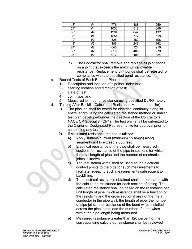
THORNTON WATER PROJECT CATHODIC PROTECTION SEGMENT A PHASE II 26 42 13-37 PROJECT NO. 12-777H5
18” #4 776 388 259 24” #4 1036 518 346 30” #4 1294 647 432 36” #4 1554 777 518 12” #2 325 162 108 18” #2 486 243 162 24” #2 648 324 216 30” #2 810 405 270 36” #2 972 486 324
b) The Contractor shall remove and replace all joint bonds on a joint that exceeds the maximum allowable resistance. Replacement joint bonds shall be retested for compliance with the specified bond resistance.
c. Record Tests of Each Bonded Pipeline: 1) Description and location of pipeline under test; 2) Starting location and direction of test; 3) Date of test; 4) Joint type; and 5) Measured joint bond resistance using specified DLRO meter.
d. Testing After Backfill (Calculated Resistance Method or similar) 1) The pipeline shall be tested for electrical continuity along its
entire length using the calculated resistance method or similar test plan developed under the direction of the Contractor’s NACE CP Specialist (CP4). The test plan shall be submitted to the Owner or Designated Representative for approval prior to completing any testing.
2) If calculated resistance method is utilized: a) Apply suitable current (minimum 15 amps) along
segments not to exceed 2,000 feet. b) Electrical resistance of the pipe shall be measured in
sections for resistance of the pipe in sections for which the total length of pipe and the number of mechanical joints is known.
c) The test station wires shall be used as the electrical contact points to the pipe for such measurements to facilitate repeating such measurements subsequent to backfilling.
d) The electrical resistance obtained shall be compared with the calculated resistance for each section of piping. The calculated resistance shall be based on the resistance per unit length of pipe. Such resistance shall be a function of the resistivity and the cross sectional area of the metal conductor in the pipe wall, the length of pipe, the number of pipe joints, the resistance of the bond wires installed across the pipe joints, and the number of bond wires within the pipe length being measured.
e) Measured resistance greater than 120 percent of the corresponding calculated resistance shall be reviewed

THORNTON WATER PROJECT CATHODIC PROTECTION SEGMENT A PHASE II 26 42 13-38 PROJECT NO. 12-777H5
and additional tests shall be made to determine the reason for the variation and the corrective measures required.
3) Record Tests of Each Bonded Pipeline: a) Utilize the form provided in the CP Testing Plan. b) Description and location of pipeline under test. c) Starting location and direction of test. d) Date of test. e) Joint type and summary of calculated resistances. f) Measured joint bond resistance. g) Results, observations, and comments.
4) The Contractor shall assist the Owner or Designated Representative in the performance of such additional tests by providing electrical contacts and physical access to the pipe. This work, and any subsequent repairs and additional testing shall be performed at no additional cost to the Owner.
C. CP Commissioning and Testing: 1. Prior to Initial Acceptance, notify the Owner or Designated Representative
and provide a minimum of 2 weeks’ notice that the installation is ready to be turned on.
2. Provide a cathodic protection commissioning and testing plan to the Owner or Designated Representative for review and approval.
3. Functional and Final Testing to be overseen or performed by the Contractor’s NACE CP Specialist (CP4).
4. Energize installation as per the approved testing plan. 5. Operating Test: Conduct a series of tests to demonstrate that equipment
and material are installed correctly and operating properly for initial approval. a. Locate, correct, and retest system defects or incomplete work
identified during functional and final testing or warranty inspections at no additional cost to the Owner.
b. Functional testing (to be completed upon completion of pipeline construction): 1) Commission all CP devices and measure native and polarized
structure-to-soil potential of pipeline at each test station and cathodic protection device using applicable equipment. Include all test stations, isolation devices, bonded segments, above grade appurtenances, surrounding metallic structures, and other identified locations.
c. Final Testing (to be completed 30 days after functional testing and/or connections of all CP devices) 1) Make adjustments in the output of the system; conduct
sufficient testing throughout the network of protected structures and piping to ensure proper installation and cathodic protection levels.
2) Locate, correct, and retest system defects or incomplete work identified.
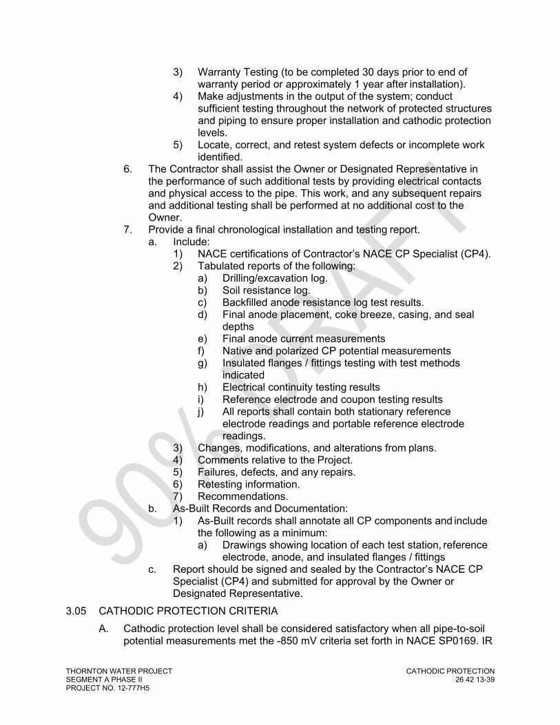
THORNTON WATER PROJECT CATHODIC PROTECTION SEGMENT A PHASE II 26 42 13-39 PROJECT NO. 12-777H5
3) Warranty Testing (to be completed 30 days prior to end of warranty period or approximately 1 year after installation).
4) Make adjustments in the output of the system; conduct sufficient testing throughout the network of protected structures and piping to ensure proper installation and cathodic protection levels.
5) Locate, correct, and retest system defects or incomplete work identified.
6. The Contractor shall assist the Owner or Designated Representative in the performance of such additional tests by providing electrical contacts and physical access to the pipe. This work, and any subsequent repairs and additional testing shall be performed at no additional cost to the Owner.
7. Provide a final chronological installation and testing report. a. Include:
1) NACE certifications of Contractor’s NACE CP Specialist (CP4). 2) Tabulated reports of the following:
a) Drilling/excavation log. b) Soil resistance log. c) Backfilled anode resistance log test results. d) Final anode placement, coke breeze, casing, and seal
depths e) Final anode current measurements f) Native and polarized CP potential measurements g) Insulated flanges / fittings testing with test methods
indicated h) Electrical continuity testing results i) Reference electrode and coupon testing results j) All reports shall contain both stationary reference
electrode readings and portable reference electrode readings.
3) Changes, modifications, and alterations from plans. 4) Comments relative to the Project. 5) Failures, defects, and any repairs. 6) Retesting information. 7) Recommendations.
b. As-Built Records and Documentation: 1) As-Built records shall annotate all CP components and include
the following as a minimum: a) Drawings showing location of each test station, reference
electrode, anode, and insulated flanges / fittings c. Report should be signed and sealed by the Contractor’s NACE CP
Specialist (CP4) and submitted for approval by the Owner or Designated Representative.
3.05 CATHODIC PROTECTION CRITERIA A. Cathodic protection level shall be considered satisfactory when all pipe-to-soil
potential measurements met the -850 mV criteria set forth in NACE SP0169. IR

THORNTON WATER PROJECT CATHODIC PROTECTION SEGMENT A PHASE II 26 42 13-40 PROJECT NO. 12-777H5
drops in the soil, coating, and measurement circuit shall be compensated for in the measurements.
B. All “Native State” anode-to-soil potential measurements must be shall be -1.5 volts or more negative.
C. Piping with native potential measurements of -0.4 volts or more positive shall be investigated for improper electrical isolation and/or interference.
3.06 INADEQUATE PROTECTION A. Inadequate pipe joint continuity and/or cathodic protection levels due to
defective or incorrect installation work shall be corrected by and at the sole expense of the Contractor.
B. Any anode with a “Native State” anode-to-soil potential less than the specified - C. 1.5 volts (CSE) shall be replaced by and at the sole expense of the Contractor,
as required by the Owner or Designated Representative.
3.07 TRACING WIRE TESTING A. See Section 26 05 33: Raceways, Boxes, Seals, and Fittings for Electrical
Systems. 3.08 OPERATION AND MAINTENANCE MANUAL
A. The Contractor’s NACE CP Specialist (CP4) shall prepare and furnish a written Operations and Maintenance (O&M) manual upon completion of the cathodic protection system testing. The O&M manual shall contain the following minimum information: 1. Physical description of the protected pipeline including diameter, pipe
material, type of pipe joint construction, length, and type of external coating system.
2. Cathodic protection system description including anode sizes and locations, test station locations, and locations and type of electrical isolation fittings.
3. Schematic drawing (11” x 17” size) of the pipeline showing locations of cathodic protection system test stations and electrical isolation fittings. The Drawing shall also include the approximate alignment of the pipeline, connections to existing piping, and key topographic information such as roads and ditches. The actual locations of the test stations installed out of the roadways should be shown. The Drawing does not have to be drawn to scale.
4. Final cathodic protection test data. 5. Operations and maintenance procedures and manufacturer manuals or
data outlining the routine steps required to operate and maintain the cathodic protection system and components.
6. Provide two (2) complete training sessions to City of Thornton personnel for the Cathodic Protection systems, operations and maintenance. Provide electronic copies of all manuals in .PDF file format. Provide 5-year license for all required software.
3.09 SPECIAL WARRANTY

THORNTON WATER PROJECT CATHODIC PROTECTION SEGMENT A PHASE II 26 42 13-41 PROJECT NO. 12-777H5
A. The work under this section shall be guaranteed in accordance with the General Conditions and Special Conditions.
END OF SECTION

THORNTON WATER PROJECT CLOSE INTERVAL SURVEY SEGMENT A PHASE II 26 42 16-1 PROJECT NO. 12-777H5
SECTION 26 42 16 CLOSE INTERVAL SURVEY
PART 1 GENERAL
1.01 SUMMARY A. Section Includes:
1. Materials and requirements to perform close interval surveys (CIS) of buried, metallic pipelines.
2. Contractor shall furnish all necessary labor, supervision, equipment, tools, and material to perform each CIS as described herein.
1.02 REFERENCES A. The latest revision of the following minimum standards shall apply to the
materials and installation included in this Specification. In case of conflict, the most stringent requirements shall apply: 1. National Association of Corrosion Engineers International (NACE):
a. Standard Practice SP0169 – Control of External Corrosion on Underground or Submerged Metallic Piping Systems.
b. Standard Practice – SP0286 – Electrical Isolation of Cathodically Protected Pipelines.
c. Standard Practice – SP0207 – Performing Close-Interval Potential Surveys and DC Surface Potential Gradient Surveys on Buried or Submerged Metallic Pipelines.
d. Test Method – TM0497 – Measurement Techniques Related to Criteria for Cathodic Protection on Underground or Submerged Metallic Piping Systems.
1.03 DEFINITIONS A. ‘AC’ Survey: ‘ON’ Survey: Collection of data regarding the AC pipe-to-soil
potential measurements along a given pipe span. B. Cathodic Protection: The electrical method of reducing or eliminating corrosion
by making previous anodic areas on the structure surface a cathode by creating a DC current flow to the structure by use of a cathodic protection system.
C. Cathodic Protection Criteria: Conform to NACE SP0169. D. Cathodic Protection Systems:
1. Galvanic anode system: Galvanic anode material, usually magnesium or zinc, which naturally corrodes or sacrifices itself and does not require an outside power source.
2. Impressed current system: Utilizes an outside power source, usually a rectifier (that converts AC to DC current), and forces (impresses) current from a number of anodes (or groundbed) through the environment to the structure to be protected.

THORNTON WATER PROJECT CLOSE INTERVAL SURVEY SEGMENT A PHASE II 26 42 16-2 PROJECT NO. 12-777H5
E. Cathodic Protection Station (CPS): An impressed current cathodic protection installation location consisting of rectifier, groundbed, and anode terminal box.
F. Current Interrupter: A portable or permanent electrical switching device capable of providing GPS synchronized interruption of cathodic protection rectifiers (Owner and Foreign), bonds, and other sources of current.
G. Deep Borehole Anode Groundbed 1. Cathodic protection impressed current groundbed that is installed in a
drilled hole at a prescribed depth from the structure being cathodic protected to achieve electrical remoteness.
2. Typically, anodes and coke breeze are installed in the lower portion (active column) and high resistant or sealing material is installed in the top section of the drilled hole (inactive column).
H. Electrically Continuous Pipeline: Linear electrical resistance equal to or less than the sum of the resistance of the pipe plus the maximum allowable bond resistance for each joint as specified in this Section.
I. Electrical Isolation: The condition of being electrically isolated from other metallic structures and the environment as defined in NACE SP0286.
J. Ferrous or Metallic Pipe: Pipe or structure made of steel or iron alloys and pipe or structure containing steel or iron as a principal structural material (such as steel, ductile iron, and cast iron).
K. Foreign-Owned: Buried pipe or cable not specifically owned or operated by the Client.
L. Influence Currents: Currents that can cause distortion of the pipe-to-soil potential readings and interpretation which could result in insufficient cathodic protection.
M. Interference Currents: Currents that can initiate or accelerate corrosion and will always include areas of current pick-up and discharge.
N. Lead, Lead Wires, Joint Bond, and Cable: Insulated copper conductor; the same as wire.
O. ‘ON’ Survey: Collection of data without cycling of cathodic protection rectifiers (Owner and Foreign), bonds, or other sources of current.
P. ‘ON/OFF’ Interrupted Survey: Also known as a polarized or instant-off survey. Collection of data involving cycling of cathodic protection rectifiers (Owner and Foreign), bonds, and other sources of current.
Q. ‘ON/OFF’ I&I Survey: Also known as an interference and/or influence (I&I) survey. Collection of data involving cycling of cathodic protection rectifiers (Owner only, Foreign rectifier left on), bonds, and other sources of current.
R. Pipe-to-Soil Potential: Also known as Structure-to-Reference Electrode Potential or Pipe-to-Electrolyte Potential: The difference in voltage (potential) between the subject metallic structure and the electrolyte in which it is buried or submerged, as measured to the standard specified reference electrode placed in contact with the electrolyte.

THORNTON WATER PROJECT CLOSE INTERVAL SURVEY SEGMENT A PHASE II 26 42 16-3 PROJECT NO. 12-777H5
S. ‘STATIC’ Survey: Also known as a native, depolarized, or free-corrosion potential survey. Collection of data involving turning off or de-energizing all sources of cathodic protection current (Owner and Foreign) to record the free-corrosion pipe-to-soil potentials.
1.04 SYSTEM DESCRIPTION A. Survey Requirements: Materials and equipment shall be new and the
manufacturer’s latest certificate of compliance (within 1 year) shall be provided. B. Performance Requirements:
1. Show evidence of proper interruption and de-energization of all sources of current (Owner and Foreign).
2. Obtain quality data by properly saturating the electrolyte and moving at a pace that produces accurate readings.
1.05 SUBMITTALS A. Submittals for Review:
1. Product data: a. Manufacturer’s catalog cuts for all materials. b. Include manufacturer’s name and provide sufficient information to
show that materials meet the requirements of the project. 2. Quality Control:
a. Contractor’s Cathodic Protection Specialist (CP4) shall oversee the survey work including but not limited to, identification of potential sources of current (Owner and Foreign), installation of current interrupters, monitoring of survey crews, review of all captured data, wave forms (plots), interruption cycles, field conditions, foreign crossings, cased segments, electrical isolation device locations to ensure they are accurately assessed and tested.
3. NACE qualifications of Contractor personnel. 4. Testing Plans and Procedures
a. All testing plans and procedures shall be in accordance with the requirements herein and prepared by the Contractor’s Cathodic Protection Specialist (CP4).
5. Final reporting and documentation, including: a. A Findings and Recommendations report of all captured data signed
and stamped by the Contractor’s Cathodic Protection Specialist (CP4).
b. Summary of survey segments to include dates/times, daily weather conditions, start/stop stationing, direction of survey, ROW (ROW) conditions and terrain, confirmation that water was applied to ROW, and any notes/comments such as access or landowner issues.
c. Summary of the identification and output of any influencing rectifiers (Owner and Foreign), bonds, and other sources of current and GPS coordinates.
d. Summary of daily interruption cycles along with start of day, mid-day, and end of day wave forms (plots).

THORNTON WATER PROJECT CLOSE INTERVAL SURVEY SEGMENT A PHASE II 26 42 16-4 PROJECT NO. 12-777H5
e. Summary of location and plots of any dataloggers installed to confirm proper polarization or de-polarization of the piping or to measure any other AC or DC currents.
f. Final, color copies of all pipe-to-soil potential plots. g. Excel spreadsheet of all captured data to include pipeline name,
GPS coordinates, date/time, potential measurements, notes/comments, stationing (both CIS stationing and correlated alignment stationing) of all readings and above grade reference points (roads, valves, streams, test stations, fences, ditches, powerlines, etc.).
1.06 QUALITY ASSURANCE A. Contractor’s Qualifications:
1. A minimum of 10 years of experience of close interval surveys and corrosion control testing of comparable size and complexity.
2. Five comparable projects completed in the last 5 years for review and approval.
B. Cathodic Protection Specialist Qualifications: 1. Currently certified by NACE as a Cathodic Protection Specialist (CP4). 2. Perform field observation and oversee testing services during each survey
associated with the project. 4. Complete all data analysis and evaluation and provide a final findings and
recommendations report. C. Manufacturer’s Qualifications:
1. Regularly engaged on a full-time basis in the manufacture of products in this Section for a minimum of 5 years.
2. Provide certification that all materials and components meet the requirements of Drawings and Specifications; include references for the applicable section of the Specifications and applicable standard details.
D. Field Supervision: 1. Provide a superintendent or foreman to supervise the survey site.
Personnel to remain on-site at all times. 2. Currently certified by NACE as a Cathodic Protection Technician (CP 2) or
higher. 3. Minimum of (3) years of experience in corrosion control.
1.07 DELIVERY, STORAGE AND HANDLING A. Cathodic Protection Materials
1. Store off the ground. 2. Protect against weather, condensation, and mechanical damage. 3. Handle with care. 4. Do not sharply bend or tightly coil the wire. 5. Replace equipment or materials damaged in shipment or installation.

THORNTON WATER PROJECT CLOSE INTERVAL SURVEY SEGMENT A PHASE II 26 42 16-5 PROJECT NO. 12-777H5
B. Reference Electrodes: 1. Do not allow to freeze. 2. Store in a protected area. 3. Calibrate daily.
PART 2 PRODUCTS
2.01 MANUFACTURERS A. Use of the manufacturer’s name and model or catalog number is for the
purpose of establishing a standard of quality and the general configuration desired.
B. Substitutions: As approved by Engineer if considered equal. 2.02 SUPPLIERS
A. Supplier: Farwest Corrosion, Denver, CO or MESA Products, Denver, CO B. Submit alternate suppliers for approval.
2.03 MATERIALS A. Portable Reference Electrodes:
1. Copper / Copper Sulfate. a. List the manufacturer’s name, model number, year manufactured,
serial number, and calibration results. B. CIS Field Computer: American Innovations, MC Miller, or similar models. C. Dataloggers: CorTalk GPS synchronized data logger or similar. D. Current Interrupter:
1. GPS synchronized switching device. a. List the manufacturer’s name, model number, year manufactured,
serial number, and calibration results. E. Wire:
1. MicroMax #30 AWG solid wire with single-build polyurethane/nylon overcoat.
2. Length as required.
PART 3 EXECUTION
3.01 GENERAL A. Complete survey operations during daylight conditions. B. All equipment, instruments, and accessories furnished by the Contractor must
be in satisfactory operating condition and be made available for the Owner or Designated Representative for inspection during the survey.
C. Note weather conditions and ROW conditions on daily survey logs.

THORNTON WATER PROJECT CLOSE INTERVAL SURVEY SEGMENT A PHASE II 26 42 16-6 PROJECT NO. 12-777H5
D. All survey wire must be retrieved daily or immediately after completion of each survey. No wire will be allowed to be left overnight along the ROW.
E. All temporary markings, flagging, and other designations must be removed at the conclusion of each survey or as requested per the landowner.
F. Contractor is responsible for notifying and coordinating access with landowner and/or other stakeholders. This includes scheduling work to minimize crop damages, livestock disturbance, on-going construction activities, and other ROW constraints.
G. Minimize disturbance to each ROW and avoid driving in muddy or snowy conditions. All-terrain and side-by-side quad vehicles may be used but are not permitted on any agricultural tracts or land that are being prepared for planting.
3.02 PREPARATION FOR SURVEYS A. The Owner or Designated Representative CP Specialist has the option of which
survey type, ‘ON/OFF’ I&I, ON/OFF Interrupted, STATIC’, or ‘AC’ to complete. Depending on the results of each individual survey, additional surveys may or may not be required.
B. The Contractor is responsible for notifying the Owner or Designated Representative, all landowner, and/or stakeholders along the project ROW of pending survey activities. Coordination shall include proposed survey dates/times, livestock or crop issues, access issues, and coordination with foreign CP system operators.
C. The Contractor shall canvass the subject pipeline region to determine possible influencing/interfering rectifiers (Owner and Foreign), bonds, or other current sources within a 2-mile radius of the pipeline ROW. Up to a 10-mile radius may be required if a foreign pipeline crosses the subject ROW and is considered a historical interference threat. 1. If possible, obtain the following relevant information:
a. Relationship to project pipeline (parallel, crossing, etc.) b. Operator identification and contact information c. GPS Coordinates d. Rectifier or current source output e. Type of CP system and layout
D. Surveys shall be conducted in such a manner so as to allow data to be overlapped onto single visual plots for comparison of data between the ‘OFF’, ‘ON/OFF’, and ‘AC’ surveys.
E. ‘ON/OFF’ I&I Survey Preparation: 1. Rectifiers and other current sources (Owner and Foreign) shall be
energized to polarize the pipeline. Dataloggers shall be installed at key locations and data analyzed during the polarization period to confirm proper polarization.
2. After a minimum of 30 days of polarization, each rectifier (Owner only), bond, or other identified current source should be synchronously interrupted on a cycle of 80% ‘ON’ and 20% ‘OFF (1.6 seconds on,

THORNTON WATER PROJECT CLOSE INTERVAL SURVEY SEGMENT A PHASE II 26 42 16-7 PROJECT NO. 12-777H5
0.4 second off). All foreign CP system shall be left ‘ON’ during the course of the survey.
3. Extended period dataloggers shall be installed at key locations and data analyzed during the survey to confirm proper interruption synchronization and current variations.
F. ‘ON/OFF’ Interrupted Survey Preparation: 1. Rectifiers and other current sources (Owner and Foreign) shall be
energized to polarize the pipeline. Dataloggers shall be installed at key locations and data analyzed during the polarization period to confirm proper polarization.
2. After a minimum of 30 days of polarization, each rectifier (Owner and Foreign), bond, or other identified current source should be synchronously interrupted on a cycle of 80% ‘ON’ and 20% ‘OFF (1.6 seconds on, 0.4 second off).
3. Extended period dataloggers shall be installed at key locations and data analyzed during the survey to confirm proper interruption synchronization and current variations.
G. ‘OFF’ Survey Preparation: 1. Rectifiers (Owner and Foreign), bonds, and other current sources shall be
de-energized and/or disconnected to allow for de-polarization the pipeline. Dataloggers shall be installed at key locations and data analyzed during the de-polarization period to confirm proper de-polarization.
2. All structures shall be allowed to de-polarize for no less than 5 days before completing any ‘OFF’ survey. Reversal of the rectifier or current source cables to speed up the depolarization process is not allowed.
H. ‘AC’ Survey Preparation: 1. The Contractor shall notify the AC powerline operator to determine the
magnitude and date/times of peak AC loads. Surveys should be coordinated to occur during these peak times.
2. Dataloggers shall be installed at key locations and data analyzed to confirm magnitude and peak AC load times.
I. Watering: 1 Watering of each project ROW may be required depending on current
ROW conditions and weather. To prove watering is not required, in-situ and saturated pipe-to-soil potentials shall be taken prior to the start of the survey day. a. If the in-situ pipe-to-soil potential varies from the saturated pipe-to-
soil potential by more than 5%, watering of the project ROW shall be required before and during surveying.
b. If deviation is less than 5%, watering is not required. c. If watering is not performed, in-situ and saturated pipe-to-soil
potentials must be completed every 2 hours through the survey day and recorded on the daily run summary log.
3.03 SURVEYING

THORNTON WATER PROJECT CLOSE INTERVAL SURVEY SEGMENT A PHASE II 26 42 16-8 PROJECT NO. 12-777H5
A. The survey shall be performed in the direction of flow, from test location to test location. If reverse surveys are required due to ROW constraints, the data shall be properly reversed but the original direction of the survey shall be noted on the final plots and daily run summary logs.
B. The project pipeline shall be properly located, staked, and flagged at 100 foot intervals.
C. Pipeline location, Depth of Cover (DOC), and GPS sub-meter mapping shall be performed in conjunction with each CIS for purposes of aligning data footages to within +/- 5 foot. DOC and GPS measurements shall be recorded at 100 foot intervals.
D. Record all pipeline features and above grade reference points (roads, valves, appurtenances, streams, test stations, fences, ditches, powerlines, etc.). Include GPS coordinates.
E. Reference electrodes shall be calibrated and/or cleaned before the start of each survey day and the readings records on the daily run summary logs. A test reference electrode shall be maintained by each survey crew and calibrations shall be equal to or less than 5mV.
F. Field computers shall be set to collect CIS data in the CPS-sync mode (not a HI/LO or MIN/MAX mode) so as not to misinterpret ‘flipped/inverted’ readings.
G. For interrupted surveys, obtain daily wave forms (plots) at 3 intervals (start of day, mid-day, and end of day) to verify interrupter synchronization, as well as any area of suspected interference or ‘inverted’ potentials.
H. Continuous logging of GPS coordinates (WGS 84) and footages shall be accomplished during each survey.
I. Manual or automatic triggers may be used for recording of pipe-to-soil data. Manual triggering may be required if automatic trigger data is deemed inaccurate by Owner or Designated Representative.
J. All pipe-to-soil potentials shall be taken in 3 to 5 foot intervals unless otherwise approved.
K. Re-connection at every available test location (test station, valve vault, appurtenance, etc.) shall be accomplished.
L. AC pipe-to-soil potential measurements shall be recorded at each re-connect as well as at areas susceptible to AC interference such as physical transitions of the pipeline within 500 feet of any High Voltage AC (HVAC) corridors.
M. At every re-connect, an ON/OFF lateral (left and right) potential measurement shall be recorded as applicable.
N. At every re-connect, an ON/OFF near and far ground potential and an ON/OFF metal IR drop measurement shall be recorded as applicable.
O. The IR drop due to the piping shall be determined for each survey section (from test location to test location) and recorded in the datalogger. Determination of the IR drop shall include both the ‘ON’ and ‘OFF’ readings as applicable. The ‘OFF’ IR reading should be close to zero or no greater than 20mV. If the IR

THORNTON WATER PROJECT CLOSE INTERVAL SURVEY SEGMENT A PHASE II 26 42 16-9 PROJECT NO. 12-777H5
drop is more than 20mV, the rectifiers current interruption cycles may be considered unsynchronized and immediate corrections shall be made and the affected test span re-surveyed at no cost to Owner.
P. ON/OFF potential measurements of both the Owner and Foreign piping shall be obtained at all foreign crossings with available test leads. This includes bond currents (critical, non-critical, and continuity) as well as electrical isolation devices connected to the mainline at each tap, lateral, or other piping connection.
Q. A minimum of 10 ‘OFF’ readings shall be obtained every 100 feet as applicable depending on the survey type.
R. Creek/river/wetland crossings, paved areas, or other sections of piping where contact with soil (electrolyte) is not possible or presences a significant risk to survey personnel may be skipped. The skipped sections should be limited to the fullest extent possible and properly documented on the daily run summary logs.
S. Daily field plots of survey data shall be provided to the Owner or Designated Representative for review within 24 hours. Any unacceptable surveys shall be completed again the following day at no cost to Owner. 1. A daily run summary log listing the pipeline name, date, start/stop times,
type of survey, start/stop CIS stationing, interruption cycles and items, survey direction, weather conditions, ROW conditions, watering requirements and test results, reference electrode calibrations, skipped sections of piping, and other requested information shall be included along with the daily field plots.
3.04 FIELD QUALITY CONTROL A. Record each rectifier, bond, and current source output prior to beginning each
survey. Return each rectifier, bond, and current source to its original, as-found condition upon conclusion of each survey.
B. Notify Owner or Designated Representative, or Owner CP Specialist , and Foreign operators of any modification or temporary installation of current interrupters. Include anticipated dates/times and field point of contact.
C. Maintain security of all rectifiers and current sources at all times during survey. Do not leave rectifier cabinets open and unsecured.
3.05 DATA ANALYSIS AND DOCUMENTATION A. Data Analysis:
1. Contractor’s Cathodic Protection Specialist (CP4) shall analyze and review all survey data and providing the following minimal items within the analysis: a. Tabular listing of areas not meeting the NACE criteria (-850mV
and/or 100 mV) for cathodic protection. b. Possible anomaly areas due to coating defects, stray currents,
electrical shorts, failing electrical isolation devices, or other issues.

THORNTON WATER PROJECT CLOSE INTERVAL SURVEY SEGMENT A PHASE II 26 42 16-10 PROJECT NO. 12-777H5
c. Recommendations for any suspected anomaly or interference mitigation as well as any possible upgrades to the existing CP system(s).
d. Recommendations for any additional or future testing. 2. All findings and recommendations shall be derived from the raw data
collected in the field. No computer ‘smoothing’ or modification of the data will be accepted.
B. Final Report: 1. Equipment calibrations and certifications. 2. NACE qualifications and certifications of all survey personnel and
Contractor’s Cathodic Protection Specialist (CP4). 3. Daily run summary logs that include the following:
a. Pipeline name b. Date of Survey c. Type of Survey d. Direction of Survey e. Start / Stop Times f. Start / Stop CIS Stationing g. Weather Conditions h. ROW Conditions i. Reference Electrode Calibrations j. Watering Requirements and Bi-Hourly Test Results k. Interruption Cycles and Items Interrupted l. Wave forms (plots) for any interrupted surveys m. Start / stop stationing of any skipped areas of piping and reason for
not surveying (wetland, road crossing, etc.). n. Notes/Comments on landowner/access issues, survey issues, etc.
4. Interruption summary with pre-survey current outputs and post-survey outputs of any influencing rectifiers (Owner and Foreign), bonds, and other sources of current. Include GPS coordinates, Owner information, and point of contact.
5. Data logging results a. Summary of location, GPS coordinates and plots of any dataloggers
installed to confirm proper polarization, de-polarization, AC potentials, DC potentials, and/or current synchronization.
6. Final color, copies of all pipe-to-soil potential plots shall be on 8 ½ x 11 paper with separate plots for each pipeline surveyed. a. Surveys may be combined onto single plots (i.e. ON/OFF and
STATIC) as long as data is readable and comprehensible. b. Include the NACE -850mV and/or 100 mV criteria line on all plots as
applicable c. Minimum scales for graphing the data shall be 1” equals 100 feet for
stationing (X-axis) and scale as-needed for the pipe-to-soil potential measurements (Y-axis).
d. Indicate the survey direction of each individual survey on each plot. e. Include skipped sections of piping on each plot. f. Include stationing numbers and applicable notes/comments.

THORNTON WATER PROJECT CLOSE INTERVAL SURVEY SEGMENT A PHASE II 26 42 16-11 PROJECT NO. 12-777H5
7. Google Earth KMZ or KML files of all surveyed pipelines with GPS coordinates and stationing. The Google Earth files shall be delineated as follows: a. Mark all piping sections that meet or exceed the NACE -850mV
criteria as green. b. Mark all piping sections that meet or exceed the NACE 100mV
criteria but not the -850mV criteria as yellow. c. Mark all piping sections that do not meet with the NACE -850mV or
the 100mV criteria as red. d. Include any applicable notes or comments on anomalies, issues,
ROW conditions, field notes, or other items. 8. Excel Spreadsheet of all raw data and analyzed data for each survey. The
following minimum data should be included: a. Pipeline Name b. CIS stationing c. Alignment stationing d. Distance between readings e. Sub-meter GPS coordinates (WGS 84) f. Start and stop stationing of any skips or non-surveyed segments of
piping and reason for not surveying g. AC potential measurements h. Foreign piping measurements and electrical isolation testing
measurements. i. Near and Far Ground measurements j. IR readings for each test span k. ‘ON’, ‘OFF’, and ‘STATIC’ measurements as applicable l. Depth of Cover measurements m. Pipeline features and above grade reference points (roads, valves,
streams, test stations, fences, ditches, powerlines, etc.). 9. Report should be signed and sealed by the Contractor’s Cathodic
Protection Specialist (CP4) and submitted electronically for approval by the Owner or Designated Representative.
END OF SECTION

THORNTON WATER PROJECT GEOTECHNICAL INSTRUMENTATION AND MONITORING SEGMENT A PHASE II 31 09 13-1 PROJECT NO. 12-777H5
SECTION 31 09 13 GEOTECHNICAL INSTRUMENTATION AND MONITORING
PART 1 GENERAL
1.01 WORK INCLUDED A. This section presents requirements for installation, monitoring, and removal of
instrumentation for monitoring of ground movements before, during, and after tunnel construction.
B Requirements in this Section apply to all tunnels on the project. Required submittal information must be provided for each tunnel separately.
1.02 RELATED WORK A. Related Specification Sections include but are not limited to:
1. 31 71 00 – Tunnel Excavation and Initial Support 2. 31 73 00 – Contact Grout 3. 31 74 23 – Carrier Pipe Installation and Backfill 4. 31 75 00 – Construction Shafts 5. Geotechnical Baseline Report (GBR), Lithos Engineering 6. Geotechnical Data Report (GDR), Lithos Engineering
1.03 DEFINITIONS A. GOVERNING Owner: Agency which owns and/or operates the property in
which the tunnel work will be conducted. B. MONITORING POINT ARRAY: A series of Surface Survey Points arranged in a
row to monitor surface movement. C. RESPONSE VALUES: Recorded differential movement at which point a
necessary change to the construction means and methods needs to be implemented to prevent damage to overlying or adjacent existing road surfaces or utilities.
D. SOIL MONITORING POINTS: Monitoring point locations where the ground surface with be monitored for horizontal and vertical movement during tunnel and shaft construction. Also referred to as Surface Survey Point throughout.
E. PAVEMENT OR SIDEWALK SURVEY POINT: Monitoring locations at which the roadway will be monitored for horizontal and vertical movement during tunnel and shaft construction. Also referred to as Surface Survey Point throughout.
F. UTILITY MONITORING POINT: Location at which utilities will be monitored for vertical movement during tunnel and shaft construction.
G. See Section 31 71 00 – Tunnel Excavation and Initial Support for additional definitions.

THORNTON WATER PROJECT GEOTECHNICAL INSTRUMENTATION AND MONITORING SEGMENT A PHASE II 31 09 13-2 PROJECT NO. 12-777H5
1.04 GENERAL A. The Contractor shall monitor, at a minimum, all locations noted on the
Geotechnical Instrumentation and Monitoring sheets of the Contract Drawings for movement during and after tunnel construction.
B. Minimum requirements are presented herein. It is the Contractor’s responsibility to implement the monitoring plan as specified herein or as necessary to ensure the safe completion of the work and prevent damage to existing infrastructure.
1.05 REQUIREMENTS A. Minimum instrumentation and monitoring requirements are presented herein. B. Designate an Instrumentation Specialist to be in charge of installation and
monitoring of instrumentation. Surveys associated with the instrumentation shall be under the direction of and reviewed by the Instrumentation Surveyor.
C. Positively identify all utilities within the project location. D. Obtain applicable permits from Governing Agencies and utility owners to
perform instrumentation and monitoring work. E. Remove or abandon in place all instrumentation in accordance with applicable
laws, regulations and guidelines. F. As a minimum install all instrumentation as shown in the Contract Drawings
and in accordance with this specification. 1.06 QUALIFICATIONS
A. Instrumentation Specialist: The Instrumentation Specialist shall have experience working on tunneling projects where installation, maintenance and monitoring of geotechnical instrumentation similar to those specified herein are required. The Instrumentation Specialist shall have had direct involvement in directing or installing instrumentation and monitoring and working with the Instrumentation Surveyor to monitor and collect survey data. The Instrumentation Specialist shall have served in a similar capacity on a minimum of two (2) tunnel projects in the previous five (5) years.
B. Instrumentation Surveyor: The Instrumentation Surveyor shall be a licensed professional surveyor in the State of Colorado.
1.07 SUBMITTALS A. Preconstruction: Submit to the Owner or Designated Representative the
following a minimum of two (2) weeks before the scheduled start of the applicable activity. 1. Qualification Documentation. Submit Instrumentation Specialist and
Instrumentation Surveyor as stated herein. 2. Survey Equipment. The survey equipment to be used providing the
specified accuracy stated in Section 2.2.B specified herein. 3. Location of any monitoring points or devices to be installed that are not
shown on the Contract Drawings.

THORNTON WATER PROJECT GEOTECHNICAL INSTRUMENTATION AND MONITORING SEGMENT A PHASE II 31 09 13-3 PROJECT NO. 12-777H5
4. Permits. List permits, third party approvals including but not limited to roadway and rail operators, traffic control plans if within roadways, and approval contract submittals required to perform the work.
B. Construction: Submit the following to the Owner or Designated Representative during construction within the specified time restrictions: 1. Installation Records. Within five days of installation of each instrument
and prior to the start of tunnel construction, submit documentation including: a. The installed instrument location, instrument identification number,
instrument type, installation date, initial baseline elevations and coordinates, and offset and stationing to alignment.
b. Furnish details of installed instruments showing all dimensions and materials used, a separate statement describing installation procedures for each instrument, and as-built drawings of each instrument including lengths, elevations, and dimensions.
2. Data. Provide results of initial baseline readings within 2 days of measurement. Provide initial monitoring results to the Owner or Designated Representative verbally immediately following measurement. Monitoring measurements shall then be provided to the Owner or Designated Representative in writing within 1 day of measurement. Submit monitoring data for installations at completion of tunnel and subsequent readings.
PART 2 EQUIPMENT, PRODUCTS AND MATERIALS
2.01 GENERAL A. Surface Survey and Utility Monitoring Points shall be flush with the ground or
roadway surface in areas where the instrument may be damaged or be an impediment to other activities.
2.02 PRODUCTS A. Surface Survey Points: Each Surface Survey Point shall have a tag or marking
indicating the identification number, tunnel station and/or offset from centerline. 1. Surface Survey Points installed in pavement shall be nails that are driven
or drilled and grouted into the pavement. B. Utility Monitoring Points: Each Utility Monitoring Point shall consist of a pipe
casing that exposes the utility and retains the ground to allow for multiple readings throughout the work. A minimum of two (2) datum point shall be set to monitor each site.
C. Survey Equipment: The selected survey equipment shall have an accuracy of 0.01 feet.
PART 3 EXECUTION
3.01 GENERAL

THORNTON WATER PROJECT GEOTECHNICAL INSTRUMENTATION AND MONITORING SEGMENT A PHASE II 31 09 13-4 PROJECT NO. 12-777H5
A. Installation. Instrumentation shall be installed at the locations shown on the Contract Drawings or as directed or approved by the Owner or Designated Representative. All instrumentation shall be installed, and the initial readings recorded a minimum of 48 hours prior to the start of tunnel construction.
B. Access. Provide and facilitate safe access to the instrumentation for the Instrumentation Surveyor and Owner or Designated Representative.
C. Existing Conditions. Locate conduits and underground utilities in all areas where utility monitoring points are to be installed.
D. Identification. All instruments shall be clearly marked, labeled, and protected to avoid being obstructed or otherwise damaged by construction operations or the general public.
E. Instrument Designation. A unique instrument identification number shall be assigned to each survey point. The instrument identification number shall be clearly marked on each instrument.
F. Surveying. Following installation, the location of the top of all survey points shall be surveyed to provide baseline horizontal and vertical coordinates. Data shall be provided to the Owner or Designated Representative. Re-surveying from control points shall be required monthly or more frequently to address potential disturbance or resolve conflicting data as directed by the Owner or Designated Representative.
3.02 QUALITY CONTROL A. Perform all work in accordance with all current applicable regulations and
codes of federal, state, and local agencies. In the event of conflict, comply with the strictest or most restrictive applicable requirements.
B. Installation: 1. Written notice shall be provided to the Owner or Designated
Representative at least 24 hours before installing monitoring instrumentation.
2. Should actual field conditions prevent installation of instruments at the location and elevations shown on the Contract Drawings or specified herein, obtain prior acceptance from the Engineer for new instrument location and elevation.
3.03 SAFETY REQUIREMENTS A. Methods of installing the instrumentation shall be such as to ensure the safety
of the work, project participants, the public, third parties, and adjacent property, whether public or private.
B. Safe access to instrumentation shall be maintained for the Instrumentation Surveyor and Owner or Designated Representative at all times as necessary to satisfy the monitoring requirements specified herein.
3.04 INSTALLATION A. Surface Survey Points: Install surface Survey Points at locations as shown on
the Contract Drawings or as approved or directed by the Owner or Designated

THORNTON WATER PROJECT GEOTECHNICAL INSTRUMENTATION AND MONITORING SEGMENT A PHASE II 31 09 13-5 PROJECT NO. 12-777H5
Representative. Monitor surface survey points for movement in the x, y, and z directions for each reading.
B. Utility Monitoring Points: 1. Utility Monitoring Points shall be installed as shown on the Contract
Drawings. 2. Be responsible for any damage to the utility during installation of the Utility
Monitoring Points and replace or repair as necessary to facilitate monitoring.
3. Use one of two options to measure the elevation of each utility a. A rod shall be lowered into the hole until it rests on the utility. Place
centralizers around the rod to prevent it from moving in the hole. Take survey readings from the top of the rod.
b. Temporarily lower a survey rod down the pipe casing until it rests on the utility. Take survey readings from the rod.
4. Monitor utility monitoring points for movement in the z direction only for each reading.
C. After completion of installation, the as-built location in horizontal position shall be determined to an accuracy of ± 0.1 ft and the elevation to an accuracy of ± 0.01 ft.
3.05 MONITORING A. Initial Readings: The Contractor shall take initial readings of all instruments to
establish a baseline and provide the Owner or Designated Representative with this data a minimum of 48 hours prior to the start of tunnel construction.
B. Frequency: 1. The Contractor shall provide the Owner or Designated Representative
with these data. 2. At a minimum, the Contractor shall maintain the following reading
schedule:
Instrument Type Instrument Reading Schedule After Tunneling
Completion (b) During Shaft Construction
During Tunneling (a)
Pavement/Sidewalk Monitoring Points Twice Weekly Once Daily Weekly
Soil Monitoring Points Twice Weekly Once Daily Weekly Utility Monitoring Points Twice Weekly Once Daily Weekly
Notes: a. Daily readings must be taken a minimum of 4 hours apart. b. Weekly measurements shall occur until movement between
successive measurements is negligible as determined by the Owner or Designated Representative and monthly thereafter until the Initial Acceptance. A minimum of two weekly readings shall be recorded after tunneling completion. A minimum of two months of monitoring shall be conducted after/if no movement is detected.

THORNTON WATER PROJECT GEOTECHNICAL INSTRUMENTATION AND MONITORING SEGMENT A PHASE II 31 09 13-6 PROJECT NO. 12-777H5
3. Perform additional monitoring as necessary to control construction and to ensure safe work completion.
C. Reporting: Provide final data from readings of all monitoring locations to the Owner or Designated Representative within 1 working day of the recorded measurements. Copies of field instrumentation data shall be provided verbally to the Owner or Designated Representative immediately after the data are collected in the field. The data shall include, but are not limited to, the following: 1. A copy of the data sheets containing a cumulative history of readings and
proximity of tunnel excavation to the instrument location at the time of each reading.
2. A copy of the plot of measured values versus time, including a time history of construction activity likely to influence such readings if readings begin to approach Response Values, as determined by the Owner or Designated Representative.
D. Interpretation: The Contractor shall provide interpretations of monitoring data and submit them to the Owner or Designated Representative along with the data. Data or interpretations shall not be published or disclosed to other parties without advance written permission of the Owner or Designated Representative. The Owner or Designated Representative may make his/her interpretations of the data available to the Contractor.
3.06 RESPONSE VALUES A. Abide by the following response values:
Instrument Type Response Values Threshold Value Shutdown Value
Pavement/Sidewalk Monitoring Points 0.04 feet in Z 0.2 feet in any of X or Y
0.08 feet in Z 0.4 feet in any of X or Y
Soil Monitoring Points 0.08 feet in Z 0.2 feet in any of X or Y
0.12 feet in Z 0.4 feet in any of X or Y
Utility Monitoring Points 0.04 feet in Z 0.08 feet in Z
B. When a given response value is reached, respond in accordance with the following:
1. Threshold Value: Notify the Owner or Designated Representative immediately. Meet with the Owner or Designated Representative to: 1) review interpretation of the data and results, 2) review the construction means and methods, and 3) determine what changes, if any, shall be made to better control movement.
2. Shutdown Value: Notify the Owner or Designated Representative immediately. Safely secure the tunnel, completely close all openings at the excavation face, and stop all work inside the tunnel immediately upon closing the face and meet with the Owner or Designated Representative and notify affected parties including Governing Agencies and other property Owner(s) to develop a plan of action before work is resumed. Work inside the tunnel can continue if a plan of action is agreed upon by

THORNTON WATER PROJECT GEOTECHNICAL INSTRUMENTATION AND MONITORING SEGMENT A PHASE II 31 09 13-7 PROJECT NO. 12-777H5
all affected parties and if substantial risk to monitored facilities is determined to not increase with further construction activity.
3.07 MAINTENANCE A. Damaged Instruments: Protect the instruments from damage. Damaged
installations shall be replaced or repaired by the Contractor and approved by the Owner or Designated Representative prior to continuing construction at the Contractor’s expense. Provide new baseline readings if instruments are substantially damaged by Contractor or other public activity as determined by the Owner or Designated Representative.
B. Maintenance: Maintain survey monitoring locations by ensuring survey point identification tags or nomenclature is legible.
3.08 FINAL DISPOSITION A. Surface Survey Points. Remove all Surface Survey Points in accordance with
applicable laws, regulations and guidelines. B. Utility Monitoring Points. Remove all Utility Monitoring Point materials. Utility
Monitoring Point locations shall match the previous conditions prior to Utility Monitoring Point installation.
END OF SECTION

THORNTON WATER PROJECT CLEARING AND GRUBBING SEGMENT A PHASE II 31 11 00-1 PROJECT NO. 12-777H5
SECTION 31 11 00 CLEARING AND GRUBBING
PART 1 GENERAL
1.01 DESCRIPTION A. This Section describes the work included in clearing, stripping, grubbing, and
preparing the project site for construction operations. 1.02 CLEARING
A. Remove and dispose of trees, snags, stumps, shrubs, brush, limbs, sticks, branches, and other vegetative growth, including root balls. Remove rocks, tiles, and lumps of concrete. Remove all evidence of their presence from the surface. Remove and dispose of trash piles. Protect structures and piping above and below ground, trees, shrubs, and vegetative growth which are not designated for removal.
1.03 STRIPPING A. Remove and dispose of organic sod, grass and grass roots, and other organic
or unsuitable material after clearing from the areas designated to be stripped. B. Retain topsoil material onsite for dressing backfill areas before planting.
1.04 GRUBBING A. After clearing and stripping, remove and dispose of wood or root matter,
including stumps, logs, trunks, roots, or root systems greater than 1 inch in diameter or thickness to a depth of 12 inches below the ground surface.
1.05 REPLACEABLE SURFACE MATERIALS A. Remove topsoil, surface gravel, and other replaceable surface materials and
stockpile separately from other excavated materials. Provide additional such surface materials of equal or better quality to replace any surface materials not properly segregated and stockpiled.
B. Retain 3” of topsoil material onsite for dressing backfill areas before planting.
PART 2 PRODUCTS
2.01 TREES AND SHRUBBERY A. Existing trees, shrubbery, and other vegetative material may not be shown on
the Drawings. Inspect the site as to the nature, location, size, and extent of vegetative material to be removed or preserved, as specified herein. Preserve in place trees that are specifically shown in the Drawings and designated to be preserved, as applicable.
2.02 PRESERVATION OF TREES, SHRUBS, AND OTHER PLANT MATERIAL A. Save and protect plant materials (trees, shrubbery, and plants) beyond the
limits of clearing and grubbing from damage resulting from the Work. No filling, excavating, trenching, or stockpiling of materials will be permitted within the

THORNTON WATER PROJECT CLEARING AND GRUBBING SEGMENT A PHASE II 31 11 00-2 PROJECT NO. 12-777H5
drip line of these plant materials. The drip line is defined as a circle drawn by extending a line vertically to the ground from the outermost branches of a plant or group of plants. To prevent soil compaction within the drip line area, no equipment will be permitted within this area.
B. Cut and remove tree branches where necessary for construction. Remove branches other than those required for a balanced appearance of any tree. Treat cuts with a tree sealant.
PART 3 EXECUTION
3.01 CLEARING, STRIPPING, AND GRUBBING AREAS AND LIMITS A. Clear, strip, and grub areas for trenching, structures, and other areas of the
Work. B. Clear and strip stockpile areas. C. Limits of clearing, stripping, and grubbing:
1. Clearing, stripping and grubbing shall be performed in all areas necessary for the work, except stockpile areas.
2. The maximum limit of clearing, stripping and grubbing is to the extents of the Permanent Easement(s) (PE) and Temporary Easement(s) (TE) acquired for the project.
3.02 Disposal of Clearing and Grubbing Debris A. Do not burn combustible materials. Remove cleared and grubbed material from
the worksite and dispose of in accordance with applicable regulations. 3.03 Disposal of Stripped Material
A. Remove stripped material and dispose offsite.
END OF SECTION

THORNTON WATER PROJECT SUBGRADE PREPARATION SEGMENT A PHASE I 31 23 13-1 PROJECT NO. 12-777H5

THORNTON WATER PROJECT EXCAVATION AND BACKFILL FOR UTILITIES SEGMENT A PHASE II 31 23 33.13-1 PROJECT NO. 12-777H5
SECTION 31 23 33.13 EXCAVATION AND BACKFILL FOR UTILITIES
PART 1 GENERAL
1.01 DESCRIPTION A. This section includes clearing, excavation, trenching, sheeting, shoring,
bracing, dewatering, pipe bedding, backfill, clay for backfill and cutoff walls, compacting, and surface restoration for utility pipelines.
B. Refer to Section 31 11 00 – Clearing and Grubbing for additional information. 1.02 REFERENCES
A. American Society for Testing and Materials: 1. ASTM C33 - Standard Specifications for Concrete Aggregates 2. ASTM C136 - Sieve Analysis of Fine and Coarse Aggregates 3. ASTM D421 - Practice for Dry Preparation of Soil Samples for Particle
Size Analysis and Determination of Soil Constants 4. ASTM D422 - Test Method for Particle-Size Analysis of Soils 5. ASTM D1241 - Material for Soil Aggregate Subbase, Base and Surface
Courses 6. ASTM D2940 - Standard Specification for Graded Aggregate Material for
Bases or Subbases for Highways or Airports 7. ASTM D698 - Standard Test Methods for Laboratory Compaction
Characteristics of Soils Using Standard Effort (5.5 lb Rammer and 12-inch Drop)
8. ASTM D1557 - Standard Test Methods for Laboratory Compaction Characteristics of Soil Using Modified Effort (10-lb Rammer and 18- inch drop)
9. ASTM D2487 - Standard Practice for Classification of Soils for Engineering Purposes (Unified Soil Classification System)
10. ASTM D4318 - Test Method for Liquid Limit, Plastic Limit and Plasticity Index of Soils
11. ASTM D6938 - Standard Test Method for In-Place Density and Water Content of Soil and Soil-Aggregate by Nuclear Methods (Shallow Depth)
B. American Water Works Association (AWWA) 1. AWWA C200 - Steel Water Pipe, 6 In. (150 mm) and Larger
C. Occupational Safety and Health Administration (OSHA) Standards – Excavations.
1.03 DEFINITIONS A. Unclassified Excavation: All utility and appurtenant excavations are considered
unclassified and include all materials excavated or removed regardless of material characteristics. Contractor is responsible for determining and estimating the kind and extent of materials which will be encountered in the excavation and to remove unclassified materials to the elevations shown on the

THORNTON WATER PROJECT EXCAVATION AND BACKFILL FOR UTILITIES SEGMENT A PHASE II 31 23 33.13-2 PROJECT NO. 12-777H5
Drawings. An exception to Unclassified Excavation is Rock Excavation, as described in this section.
B. Bedding Material (Pipe Zone Material): Granular material upon which pipes, conduits, cables, or duct banks are embedded within the pipe zone as shown on the Drawings.
C. Backfill Zone: Trench zone from the bottom of the excavation to the bottom of the finished surface.
D. Imported Material: Material obtained from sources offsite. E. Lift: Loose, uncompacted, layer of material. F. Pipe Zone: Backfill zone that includes full trench width and extends from
prepared trench bottom to upper limit 12” above top outside surface of pipe, bank.
G. Prepared Trench Bottom: Graded trench bottom after stabilization, if required. H. Compaction: The field dry density of compacted material, expressed as a
percentage of the maximum dry density. For granular, cohesionless materials, expressed as a percentage of relative density.
I. Maximum Dry Density: Laboratory density as determined by ASTM D1557 (Modified Proctor) and occurring at the optimum moisture content of the material being tested.
J. Relative Density: Laboratory density as determined by ASTOM D 4253 and ASTM D 4254 and occurring at the optimum moisture content of the material being tested.
K. Selected Backfill Material: Material available onsite that Owner or Designated Representative determines to be suitable for specific use.
L. Well-Graded: A mixture of particle sizes that has no specific concentration, or lack thereof, of one or more sizes.
M. Granular Soil: A free draining soil comprised of gravel, sand, silt, and no clay. N. Rock Excavation-Trench or Tunnel Shaft: Removal of solid material which by
actual demonstration cannot, in Owner’s opinion, be reasonably excavated with a minimum 300 horsepower backhoe in good condition and equipped with manufacturer’s standard boom, two rippers, and rock points or similar approved equipment; and which must be systematically drilled and blasted or broken by power-operated hammer, hydraulic rock breaker, expansive compounds, or other similar means prior to removal. Term “rock excavation” indicates removal of solid material, as specified above, and does not necessarily correspond to “rock” as implied by name of geologic formations. Removal of boulders larger than 0.5 cubic yard will be classified as rock excavation, if drilling and blasting or breaking them apart with power-operated hammer, hydraulic rock breaker, expansive compounds, or other similar means is both necessary and actually used for their removal.
1.04 SUBMITTALS

THORNTON WATER PROJECT EXCAVATION AND BACKFILL FOR UTILITIES SEGMENT A PHASE II 31 23 33.13-3 PROJECT NO. 12-777H5
A. Submit the following in accordance with Section 01 33 00: Submittal Procedures.
B. Construction plan for utility earthwork at least fourteen (14) days in advance of the start of each earthwork activity covered in this Section. 1. The plan must be approved by the Owner or Designated Representative
prior to any earthwork activities. Include the following: a. Proposed soil processing, placement, compaction, and moisture
control equipment, including equipment catalog with weight, dimensions, and operating data.
b. Proposed methods of protecting adjacent new and existing utilities. c. Proposed excavation, stockpiling, and staging plan describing
handling and transport of on-site and off-site materials. 2. Gradation analyses. 3. Material sources: Name of source, locations, date of sample, sieve
analysis, and laboratory compaction characteristics. 4. Test and evaluation reports:
a. Field density testing reports: Provide results from field density testing of prepared subgrade and compacted fill.
b. Grain-size analysis. c. Laboratory compaction characteristics of soils. d. Water content.
1.05 QUALITY CONTROL 1.06 QUALITY CONTROL
A. Contractor is responsible for the cost of all testing using an independent testing laboratory in accordance with the General Conditions and Section 01 45 16.13: Contractor Quality Control.
B. Protect excavations by shoring, bracing, sheet piling, underpinning or other methods required to prevent cave-in of loose soil. Protection shall be in accordance with OSHA 29 CFR 1926, Subpart P.
1.07 SEQUENCING AND SCHEDULING A. Give advance notice to the Owner or Designated Representative at least 48
hours prior to sampling materials for potential use in Work. Provide Owner or Designated Representative full access to all sources of material.
B. Give advance notice of at least 48 hours to Owner or Designated Representative when ready for compaction or subgrade testing and inspection.
1.08 TENCH SETTLEMENT REQUIREMENT A. For a period of one (1) year after initiation of the warranty period, the
Contractor shall maintain and repair any trench settlement which may occur and shall make suitable repairs to any pipe, fitting, valve, valve box, pavement, sidewalks, or other structures which may be damaged as a result of backfill settlement. The Contractor is also responsible for material defects.
PART 2 PRODUCTS

THORNTON WATER PROJECT EXCAVATION AND BACKFILL FOR UTILITIES SEGMENT A PHASE II 31 23 33.13-4 PROJECT NO. 12-777H5
2.01 BACKFILL ZONE A. Common Backfill. Native materials excavated free of rocks and stones larger
than 4 inches in greatest dimension and free of organic, brush, wood, debris, other deleterious material and other objectionable materials.
B. CLSM for Backfill. Low strength flowable fill with a 7-day compressive strength not less than 100 psi or more than 200 psi as determined in accordance with ASTM D4832. CLSM shall be removable flow fill per CDOT standard specifications 206.
C. Select Backfill shall be classified as SM, or SC, in accordance with ASTM D2487, free from rock or gravel larger than two-inches (2”) in any dimension, debris, waste, frozen material, organic material, and other deleterious matter. The plasticity index shall be less than 15 and the liquid limit shall be less than 40.
D. Backfilling shall be in 6-inch loose-lift layers. 2.02 BEDDING MATERIAL FOR PIPE ZONE
A. Pipe Bedding for the Pipe Zone: Material shall be a well-graded mineral aggregate mixture which will provide good stability, be unfrozen, friable, and contain no clay balls, roots, or other organic material. Bedding shall conform to the following limits when tested by means of laboratory sieves:
Sieve Size
Total Passing by Sizes (Percent by
Weight) 3/8-inch 100 No. 4 70 to 100 No. 8 36 to 93 No. 16 20 to 80 No. 30 8 to 65 No. 50 2 to 30 No. 100 1 to 10 No. 200 0 to 3
2.03 FOUNDATION STABILIZATION ROCK
A. If the trench bottom is determined to be not stable and determined by the Owner, the trench bottom shall be overexcavated and the overexcavation zone filled with trench stabilization material/Foundation Stabilization Rock as defined below.
B. This material shall be graded within the following limits:
Standard Size of Sieve % By Weight Passing Sieve
2½-inch 100 2-inch 95 - 100

THORNTON WATER PROJECT EXCAVATION AND BACKFILL FOR UTILITIES SEGMENT A PHASE II 31 23 33.13-5 PROJECT NO. 12-777H5
No. 4 30 - 60 No. 200 5 - 15
Liquid Limit 35 (Max) Plasticity Index 6 (Max)
C. Fabric for stabilization material, if necessary, shall be a non-woven
polypropylene geotextile meeting the strength requirements of AASHTO M228 Class 3 and the values in AASHTO M288 Table 3, such as Mirafi 140 N, or equal.
2.04 CLAY FOR CUTOFF WALLS A. Cutoff wall clay shall be proportioned so as to provide a low
permeability as recommended by the supplier. 1. Clay shall include bentonite clay, diatomaceous earth, or other fine
material so as to reduce permeability. 2. Water conductivity of the CLSM mix design (k) shall be a
maximum of 1 x 10⁻⁷ cm/sec as similar to clay. 3. Provide vibratory compaction to verify that CLSM does not contain
any voids. B. Install double wrap of 8-mil thick polyethylene wrap around all metallic
pipe in direct contact with the cutoff wall.
PART 3 EXECUTION
3.01 GENERAL A. Do not place fill or backfill if the material is frozen, or if surface upon which it is
to be placed is frozen. B. Perform all clearing and grubbing in accordance with Section 31 11 00 as
necessary for access, stringing of pipeline materials, and construction of the pipeline and appurtenant structures. Remove and dispose of all surface debris.
C. Remove topsoil, surface gravel, geotextile fabric, and other replaceable surface materials and stockpile separately from other excavated materials. Provide additional such surface materials of equal or better quality to replace any surface materials not properly segregated and stockpiled.
D. Cut existing pavement with a saw, wheel, or pneumatic chisel along straight, clean lines. Remove and keep separate from backfilling materials.
E. Blasting is not permitted for utility or structure excavations. F. Remove unclassified materials to the grades shown on the drawings. G. Immediately notify the Owner or Designated Representative if unexpected
subsurface facilities or suspected hazardous materials are encountered during excavation. Discontinue affected work in area until notified to resume work.

THORNTON WATER PROJECT EXCAVATION AND BACKFILL FOR UTILITIES SEGMENT A PHASE II 31 23 33.13-6 PROJECT NO. 12-777H5
H. Excavate test pits to field verify the locations of existing underground utilities at crossings and at tie-in points before ordering materials or commencing excavation. Immediately notify the Owner or Designated Representative if conflicts are encountered.
I. Follow the most current regulations concerning excavations set forth by OSHA 29 CFR Part 1926.
J. Support and protect from damage – existing pipes, poles, wires, fences, curbs, property line markers, and other features or structures which must be preserved in place to avoid being temporarily or permanently relocated.
3.02 TRENCHING A. If encountered, remove rock to provide a minimum clearance of six (6) inches
under and around the pipe. This is paid for as Rock Excavation. B. Limit the amount of open trench to that necessary to expedite the Work but in no
case more than 100 feet or one day’s laying length, whichever is less, unless approved by the Owner or Designated Representative.
C. Cut trench banks on slopes to reduce earth load and prevent caving only in areas where the increased trench width will not interfere with surface features or encroach on ROW limits.
D. At the end of each work day backfill trenches as specified to within 18 feet from the end of the installed pipeline and properly barricade, cover and otherwise secure against weather.
E. Segregate excavated material to accommodate backfilling and site restoration requirements. Stack excavated material to avoid excessive surcharge on excavation faces. Where stacking material adjacent to excavation is unsafe or impractical, haul and store at an alternate location.
F. Provide and operate mechanical equipment such that: 1. The elevation of the trench bottom is accurately controlled. 2. Uniform trench widths and vertical side walls are formed at a minimum in
the pipe zone. 3. Trench alignment is such that pipe when accurately aligned will be centered
in the trench with proper clearance between the pipe and walls of the trench. G. The maximum permissible trench width, at the bottom of the trench and up to a
point at the crown of the pipe, is shown on the drawings. For trenches exceeding the maximum permissible trench width, provide a higher class of bedding if necessary to prevent overloading of the pipe as determined by the Owner or Designated Representative, and at no additional cost to the Owner.
H. Excavate trenches a sufficient distance below the bottom of the pipe to provide for bedding material as specified or shown.
3.03 SHEETING, SHORING AND BRACING A. Contractor is solely responsible for site safety and complying with all OSHA
regulations for excavations and trenching.

THORNTON WATER PROJECT EXCAVATION AND BACKFILL FOR UTILITIES SEGMENT A PHASE II 31 23 33.13-7 PROJECT NO. 12-777H5
B. Sheet, shore, and brace as necessary all structure and trench excavations to prevent caving or sliding.
C. Leave in place to be embedded in the backfill, any sheeting and bracing which Owner or Designated Representative directs in writing to be left in place to avoid damage to adjacent facilities. Owner or Designated Representative may direct that sheeting and bracing be cut off at a specified elevation. Sheeting left in place at the Owner or Designated Representative’s direction, which could have otherwise been removed, will be paid for by Owner under the provisions of the Contract Documents.
D. Carefully remove all sheeting and bracing not to be left in place, to avoid endangering the Work and adjacent facilities. Immediately fill with sand all voids left or caused by the withdrawal of sheeting, and compact with appropriate tools.
E. Do not withdraw any wooden sheeting driven below mid-diameter of any pipe, and do not cut off any wood sheeting at a level lower than one foot above the top of any pipe.
F. Where trench boxes or other movable sheeting or shoring is used to support trench walls, take care in placing and moving such protection to prevent movement of the pipe or disturbance of the pipe bedding or backfill.
3.04 PIPE FOUNDATIONS A. The term “pipe foundation”, as used in this Section, means the soil upon which
concrete or pipe bedding is placed. Where possible, foundations shall be undisturbed natural soils.
B. The pipe foundation shall be firm, dense, and thoroughly compacted, free from mud and muck, and sufficiently stable to remain firm and intact under the feet of the workers.
C. If Contractor excavates below grade through error, for convenience, through failure to properly dewater, or if subgrade is disturbed before dewatering is complete, replace foundation through one of the following methods, as approved by Owner or Designated Representative: 1. Replace pipe trench foundations with structural backfill as specified in
these Specifications. D. If, in the opinion of the Owner or Designated Representative, the foundation
material found at grade is unsuitable and requires stabilization, Owner or Designated Representative may direct Contractor to remove and replace foundation with trench stabilization material, and possibly nonwoven fabric under the stabilization material.
E. Proper preparation of foundation and placement of foundation material where required, shall precede the installation of all pipe. This shall include the necessary preparation of the native trench bottom and/or the top of the foundation material to a uniform grade so that the entire length of pipe rests firmly on a suitable properly compacted material.

THORNTON WATER PROJECT EXCAVATION AND BACKFILL FOR UTILITIES SEGMENT A PHASE II 31 23 33.13-8 PROJECT NO. 12-777H5
F. Material to be used for foundation purposes shall be of a type and gradation to provide a solid compacted bedding in the trench. Since trench conditions vary, foundation gravel requirements may change.
G. Neither approval nor disapproval of the foundation material proposed by the Contractor shall relieve Contractor of their responsibility to provide an adequate pipe foundation and guarantee their work as elsewhere required by the Contract.
H. Unsuitable material for foundation purposes below the depth required for the specified bedding shall be removed and replaced with suitable foundation gravel.
I. Excavation of unsuitable materials shall be disposed of at an approved waste site and all costs involved in the excavating and wasting of this material shall be considered as part of the bid item for pipe foundation material.
3.05 TRENCH PREPARATION A. Dewater as necessary to conduct the Work. B. Remove foreign material and backfill contaminated with foreign material that
falls into trench. C. Trench Bottom Preparation:
1. Firm Subgrade: a. Grade with hand tools. b. Remove loose and disturbed material. c. Trim off high areas and ridges left by excavating bucket teeth. d. Allow space for bedding material if shown or specified.
2. Soft Subgrade: a. Notify Owner or Designated Representative if subgrade is
encountered that may require removal to prevent pipe settlement. b. Owner or Designated Representative will determine depth of
overexcavation if required. D. Trench Stabilization Material Installation
1. Rebuild trench bottom with trench stabilization material/foundation stabilization rock.
2. Place material over full width of trench in 6-inch lifts to required grade, providing allowance for bedding thickness.
3. Compact each lift to provide firm, unyielding support for bedding material prior to placing succeeding lifts.
3.06 PIPE BEDDING A. Install pipe bedding in the Pipe Zone as shown on the Drawings. B. Spread initial layer smooth and uniform, to the required depth, to provide a
continuous support beneath the pipe between bell holes or joints. After each pipe has been shoved home and is in final position, deposit, and compact bedding material uniformly under the haunches and around each side of the pipe to prevent pipe displacement. Deposit in maximum 4-inch lifts and compact each lift.

THORNTON WATER PROJECT EXCAVATION AND BACKFILL FOR UTILITIES SEGMENT A PHASE II 31 23 33.13-9 PROJECT NO. 12-777H5
2.02 TRENCH BACKFILLING A. Perform no backfilling during freezing weather except by permission of Owner
or Designated Representative. Do not install backfill on frozen surfaces. Do not install backfill material containing frozen materials, snow, or ice.
B. Place in uniform layers not to exceed 6 inches in uncompacted thickness; wet or dry the material and mix as necessary to produce appropriate and uniform moisture content.
C. Where earth fills are required to raise the terrain prior to excavation or trenching, Contractor shall use materials, methods, and compaction as contractor determines to be necessary for the proper completion of work sand safety.
D. Restore and maintain all surfaces as the Work progresses. If settlement occurs, immediately restore the surface to ground level. Unless otherwise specified, return all disturbed surfaces at the construction site to their original condition or better. Make all repairs and replacements made necessary by settlement.
E. Replace stockpiled surface materials to their original locations and conditions. Where original conditions cannot be met, provide and place additional suitable materials as approved by Owner or Designated Representative.
F. Replace sod, seeded areas, shrubs, trees, and irrigation systems as specified in Section 32 92 19: Site Restoration and Seeding.
G. Except as otherwise provided, remove from the site and dispose of all rubble, debris, excess materials and other unneeded items.
H. Installation of pipe bedding to 6 inches over the top of the pipe shall be completed before backfilling operations are started.
I. Contractor shall take all necessary precautions to protect the pipe from any damage, movement or shifting. In general, backfilling shall be performed by pushing the material from the end of the trench into, along and directly over the pipe so that the material will be applied in the form of a rolling slope rather than by side filling which may damage the pipe. Backfilling from the sides of the trench will be permitted after sufficient material has first been carefully placed over the pipe to such a depth as to protect the pipe.
J. Make adequate provisions for the safety of property and persons. K. Temporary cribbing, sheeting, or other timbering shall be removed unless
specifically authorized in writing. L. Dewatering shall be continued until the trench is completely backfilled. M. Where original excavated material is unsuitable for trench backfill, controlled
low-strength material (CLSM) for backfill may be required under roadways as directed by the Owner or Designated Representative. The unsuitable material shall be removed and disposed of. CLSM material shall be used for backfill only where original material is unsuitable or as indicated, and upon approval by the Owner or Designated Representative.
2.03 COMPACTION

THORNTON WATER PROJECT EXCAVATION AND BACKFILL FOR UTILITIES SEGMENT A PHASE II 31 23 33.13-10 PROJECT NO. 12-777H5
A. Trench Compaction 1. Provide the proper size and type of compaction equipment and operate in
a manner to attain the required compaction density. 2. Use compaction methods and equipment appropriate for the material
being compacted and avoid transmitting damaging shocks to the installed and existing structures and pipes.
3. In-place compaction tests shall be made. Unless modified elsewhere in these specifications or on the Drawings, the minimum test frequency for compaction shall be every 200 feet of trench length per lift. Contractor shall remove and recompact material that does not meet specified requirements.
B. Compaction density: Provide densities in the table below. The values listed are minimum percentages, unless noted otherwise. Materials shall be compacted within the specified percent above or below the optimum moisture content as defined by the laboratory testing of materials during construction by the geotechnical engineer.
Area Percentage of Maximum Dry Density
as Defined by ASTM D1557 (Modified Proctor)
Over-excavated subgrade 95 Scarified subgrades 90 Bedding material 95 Backfill above pipe zone, paved areas 95 Open or grassed areas, unpaved areas 85 Topsoil 85 (maximum)
C. Compaction density: Provide densities in the table below for granular cohesionless materials. The values listed are minimum percentages, unless noted otherwise.
Area Percentage of Relative Density as
Defined by ASTM D 4253 and ASTM D 4254
(Relative Density) All areas 75
2.04 FIELD QUALITY CONTROL A. Contractor shall conform to general requirements outlined in Section 01 45
16.13: Contractor Quality Control. B. Perform inspection at least once daily to confirm lift thickness and compaction
effort for entire fill area. C. Perform particle size distribution and gradation analyses using ASTM D422 and
following standard practices in ASTM D421. Perform one test for every source and submit results to Owner or Designated Representative for acceptance. Repeat the moisture density test for every 5,000 cubic yards of material used.
D. Perform field density testing in accordance with ASTM D6938.

THORNTON WATER PROJECT EXCAVATION AND BACKFILL FOR UTILITIES SEGMENT A PHASE II 31 23 33.13-11 PROJECT NO. 12-777H5
E. Evaluate field density test results in relation to maximum dry density as determined by testing material in accordance with ASTM D1557 (Modified Proctor).
F. Perform tests in accordance with ASTM D4318 to determine Liquid Limit, Plastic Limit and Plasticity Index and submit test results to Owner or Designated Representative for acceptance. Perform a minimum of one test per 5,000 cubic yards of soil for use as fill material and whenever classification of material is in doubt as determined by the Owner or Designated Representative.
G. Location of field density tests shall be as recommended by the Owner or Designated Representative.
H. In the event compacted material does not meet specified in-place density, re-compact material and re-test area until specified results are obtained.
I. Frequency of field density tests:
Area Frequency Roadway 1 per lift for each 250 linear feet of fill placed Paved Areas 1 per lift for each 10,000 square feet of fill placed Open Areas 1 per lift for each 25,000 square feet of fill placed Isolated Footing Perimeter 1 per alternate lift for each 25 linear feet
Footing and Wall Backfill 1 per alternate lift for each 50 linear feet (both sides of wall)
Regardless of the minimum testing frequency specified, field density tests shall be performed by the Contractor in sufficient number for the Contractor's quality control purposes to ensure that specified density is obtained.
2.05 TOLERANCES A. Construct finished surfaces to plus or minus 1 inch of the elevations indicated. B. Grade areas of cut and fill to plus or minus 0.20 foot of the grades indicated. C. Complete embankment edges to plus or minus 6 inches of the slope lines
indicated. D. Provide the Owner or Designated Representative with adequate survey
information to verify compliance with above tolerances.
END OF SECTION

THORNTON WATER PROJECT EXCAVATION AND BACKFILL FOR STRUCTURES SEGMENT A PHASE II 31 23 33.16-1 PROJECT NO. 12-777H5
SECTION 31 23 33.16 EXCAVATION AND BACKFILL FOR STRUCTURES
PART 1 GENERAL
1.01 DESCRIPTION A. This section includes clearing, excavation, trenching, sheeting, shoring,
bracing, dewatering, bedding, backfill, compacting, and surface restoration for foundations, structures, and pavement.
B. Refer to Section 31 11 00 – Clearing and Grubbing for additional information. 1.02 REFERENCES
A. American Society for Testing and Materials: 1. ASTM C33 - Standard Specifications for Concrete Aggregates 2. ASTM C136 - Sieve Analysis of Fine and Coarse Aggregates 3. ASTM D421 - Practice for Dry Preparation of Soil Samples for Particle
Size Analysis and Determination of Soil Constants 4. ASTM D422 - Test Method for Particle-Size Analysis of Soils 5. ASTM D1241 - Material for Soil Aggregate Subbase, Base and Surface
Courses 6. ASTM D2940 - Standard Specification for Graded Aggregate Material for
Bases or Subbases for Highways or Airports 7. ASTM D698 - Standard Test Methods for Laboratory Compaction
Characteristics of Soils Using Standard Effort (5.5 lb Rammer and 12-inch Drop)
8. ASTM D1557 - Standard Test Methods for Laboratory Compaction Characteristics of Soil Using Modified Effort (10-lb Rammer and 18-inch drop)
9. ASTM D2487 - Standard Practice for Classification of Soils for Engineering Purposes (Unified Soil Classification System)
10. ASTM D4318 - Test Method for Liquid Limit, Plastic Limit and Plasticity Index of Soils
11. ASTM D1556 -Standard Test Method for Density and Unit Weight of Soil in Place by the Sand-Cone Method
12. ASTM D6938 - Standard Test Method for In-Place Density and Water Content of Soil and Soil-Aggregate by Nuclear Methods (Shallow Depth)
B. Occupational Safety and Health Administration (OSHA) Standards – Excavations.
C. Colorado Department of Transportation, Standard Specifications for Road and Bridge Construction
1.03 DEFINITIONS A. Unclassified Excavation: All utility and appurtenant excavations are considered
unclassified and include all materials excavated or removed regardless of material characteristics. Contractor is responsible for determining and estimating the kind and extent of materials which will be encountered in the

THORNTON WATER PROJECT EXCAVATION AND BACKFILL FOR STRUCTURES SEGMENT A PHASE II 31 23 33.16-2 PROJECT NO. 12-777H5
excavation and to remove unclassified materials to the elevations shown on the Drawings. An exception to Unclassified Excavation is Rock Excavation, as described in this section.
B. Percent Compaction or Compaction Density: The field dry density of compacted material, expressed as a percentage of the maximum dry density.
C. Field Dry Density or Field Density: In-place density as determined by ASTM D6938 (Nuclear Method).
D. Maximum Dry Density: Laboratory density as determined by ASTM D1557 (Modified Proctor) and occurring at the optimum moisture content of the material being tested.
1.04 SUBMITTALS A. Submit the following in accordance with Section 01 33 00: Submittal
Procedures. 1. Construction plan for utility earthwork at least fourteen (14) days in
advance of the start of each earthwork activity covered in this Section. The plan must be approved by the Owner or Designated Representative prior to any earthwork activities. Include the following: a. Proposed soil processing, placement, compaction, and moisture
control equipment, including equipment catalog with weight, dimensions, and operating data.
b. Proposed methods of protecting adjacent new and existing utilities. c. Proposed excavation, stockpiling, and staging plan describing
handling and transport of on-site and off-site materials. 2. Gradation analyses. 3. Material sources: Name of source, locations, date of sample, sieve
analysis, and laboratory compaction characteristics. 4. Test and evaluation reports:
a. Field density testing reports: Provide results from field density testing of prepared subgrade and compacted fill.
b. Grain-size analysis. c. Laboratory compaction characteristics of soils. d. Water content.
1.05 QUALITY CONTROL A. Contractor is responsible for the cost of all testing using an independent testing
laboratory in accordance with the General Conditions and Section 01 45 16.13: Contractor Quality Control.
B. Protect excavations by shoring, bracing, sheet piling, underpinning or other methods required to prevent cave-in of loose soil. Protection shall be in accordance with OSHA 29 CFR 1926, Subpart P.
1.06 SEQUENCING AND SCHEDULING A. Give advance notice to the Owner or Designated Representative at least 48
hours prior to sampling materials for potential use in Work. Provide Owner or Designated Representative full access to all sources of material.

THORNTON WATER PROJECT EXCAVATION AND BACKFILL FOR STRUCTURES SEGMENT A PHASE II 31 23 33.16-3 PROJECT NO. 12-777H5
B. Give advance notice of at least 48 hours to Owner or Designated Representative when ready for compaction or subgrade testing and inspection.
PART 2 PRODUCTS
2.01 FILL MATERIALS A. Suitable material: Material from on-site excavation or permitted off-site sources
that meets all the specified requirements for its intended use and is not unsuitable. Wet subgrade material which meets other requirements for suitable material is suitable.
B. Unsuitable material: Material that fails to meet requirements for suitable materials; or contains any of the following: 1. Organic clay, organic silt, or peat; as defined in ASTM D2487. 2. Vegetation, wood, roots, leaves, and organic, degradable material. 3. Stones or rock fragments over 6 inches in any dimension. 4. Porous biodegradable matter, excavated pavement, construction debris,
rubbish, or refuse. 5. Ice, snow, frost, or frozen soil particles.
C. General fill: Suitable, unclassified material. D. Structural fill: Suitable material that is classified by the Unified Soil
Classification System (USCS) in accordance with ASTM D2487 as GW, GP, GM, GC, SW, SP, SM, SC, CL. Verify that the largest particles in the fill are no greater in dimension than one-half the thickness of the compacted lift thickness.
E. Concrete aggregate: Suitable material that meets the requirements of Coarse Aggregate No. 57 as defined in the Standard Specifications for Road and Bridge Construction as published by the Colorado Department of Transportation.
2.02 Equipment A. Compaction equipment shall be capable of consistently achieving the specified
compaction requirements.
PART 3 EXECUTION
3.01 GENERAL A. Do not place fill or backfill if the material is frozen, or if surface upon which it is
to be placed is frozen. B. Perform all clearing necessary for access, stringing of pipeline materials, and
construction of structures. Remove and dispose of all surface debris. 3.02 EXAMINATION
A. Verify that dewatering support systems are in place before commencing with excavation.

THORNTON WATER PROJECT EXCAVATION AND BACKFILL FOR STRUCTURES SEGMENT A PHASE II 31 23 33.16-4 PROJECT NO. 12-777H5
B. Verify that excavation safety and support systems meeting the requirements of OSHA 29 CFR 1926, Subpart P are in place before commencing with excavation.
C. Verify that fill materials submittals have been accepted by Owner or Designated Representative before commencing with work requiring the use of these materials.
D. Verify that erosion and sediment control measures are in place and functioning properly.
E. Immediately notify the Owner or Designated Representative if unexpected subsurface facilities or suspected hazardous materials are encountered during excavation. Discontinue affected work in area until notified to resume work.
F. Test pits: Excavate test pits to field verify the locations of existing underground utilities at crossings and at tie-in points before ordering materials or commencing excavation. Immediately notify the Owner or Designated Representative if conflicts are encountered.
3.03 PREPARATION A. Underpin adjacent structures that could be damaged by excavation work. B. Cut pavement with saw to prevent damage to remaining pavement. Dispose of
large pieces of demolished pavement before proceeding with excavation. C. Remove subsurface structures and related obstructions. D. Remove boulders within excavation limits. E. Support and protect from damage – existing pipes, poles, wires, fences, curbs,
property line markers, and other features or structures which must be preserved in place to avoid being temporarily or permanently relocated.
F. Excavation near existing structures: 1. Discontinue digging by machinery when excavation approaches pipes,
conduits, or other underground structures. Continue excavation by use of hand tools. Include such manual excavation in work to be done when incidental to normal excavation and under items involving normal excavation.
2. Excavate test pits near, or at intersection with, existing utilities or underground structures to determine the exact location of existing features.
G. Do not use or operate tractors, bulldozers, or other power-operated equipment on paved surfaces. Provide protection on pavement or tracks if construction traffic is unavoidable.
3.04 EXCAVATION A. Excavate to accommodate new structures, 4 feet outside of walls, and
construction operations. B. Excavate to lines and grades necessary to provide finish grades.
THORNTON WATER PROJECT EXCAVATION AND BACKFILL FOR STRUCTURES SEGMENT A PHASE II 31 23 33.16-5 PROJECT NO. 12-777H5
C. Establish limits of excavation to allow adequate working space for installing forms and for safety of personnel.
D. Carry out program of excavation, dewatering, and excavation support systems to eliminate possibility of undermining or disturbing foundations of existing structures or the work.
E. Preserve material below and beyond the lines of excavations. F. Locate stockpiled excavated material at least 3 feet from edge of excavations
to prevent cave-ins or bank slides. G. See Section 31 23 13: Subgrade Preparation for requirements for subgrade
preparation. H. Contractor is responsible for backfilling unauthorized excavations with
structural fill. 3.05 FILL
A. Fill to lines and grades necessary to provide finish grades. B. Use a placement method that does not disturb or damage other work or
existing features. C. Maintain fill materials within 3 percent of optimum moisture, to attain required
compaction density. D. Place and compact material in equal continuous layers. E. General fill may be used in open areas, over lot fill, and areas that are not load
bearing. F. Use structural fill beneath and adjacent to buildings and structures. G. Use roadway subgrade and roadway base course beneath pavements as
shown on the Drawings. H. Use concrete fill where footing bearing surfaces are over-excavated or footing
is otherwise not bearing on undisturbed soil. I. Maximum compacted depth is 6 inches for aggregate materials and 8 inches
for soil materials, unless noted otherwise. J. Deposit material evenly around structure to avoid unequal soil pressure. K. Do not place backfill against or on structures until they have attained sufficient
strength to support the loads (including construction loads) to which they will be subjected, without distortion, cracking, or other damage.
3.06 COMPACTION A. Compact to density specified and indicated for various types of material.
Control moisture content of material being placed as specified. B. Compaction density: Provide densities in the table below. The values listed are
minimum percentages, unless noted otherwise.

THORNTON WATER PROJECT EXCAVATION AND BACKFILL FOR STRUCTURES SEGMENT A PHASE II 31 23 33.16-6 PROJECT NO. 12-777H5
Area Percentage of Maximum Dry Density
as Defined by ASTM D1557 (Modified Proctor)
Over-excavated subgrade 95 Scarified subgrades 90 Under pavement and slabs 95 Under structures, or within 25 feet of structures 95 Under exterior concrete slab and sidewalks 90 Open or grassed areas 85 Topsoil 85 (maximum)
3.07 BACKFILLING AGAINST STRUCTURES A. Backfill shall not be placed against foundation walls until all interior floors have
been placed and the concrete has attained design strength. This includes the floor level at grade or the next level above grade if no floor is within 2 feet of finished grade.
B. Backfill shall not be placed against cantilever walls until the concrete has attained design strength.
3.08 EMBANKMENT FILL AND COMPACTION A. Begin filling in lowest section of work area. Grade surface of fill approximately
horizontal but provide with sufficient longitudinal and transverse slope to allow for runoff of surface water from every point.
B. Install temporary dewatering sumps in low areas during filling operation where excessive amounts of rain runoff collect.
C. Reduce moisture content of fill material, if necessary, in source area by aerating it over during warm and dry atmospheric conditions. A large disc harrow with 2 to 3 foot diameter disks may be required for working soil in a drying operation.
D. Compact uniformly throughout. Keep fill surfaces sufficiently smooth and free from humps and hollows to allow for proper and uniform compaction. Do not permit hauling equipment to follow a single track on the same layer but direct equipment to spread out to prevent over compaction in localized areas. Take care in obtaining thorough compaction at edges of fill.
E. Slightly slope surface of fill to ensure drainage during periods of wet weather. Do not place fill while rain is falling or after a rain-storm until the Owner or Designated Representative considers conditions satisfactory. During such periods and upon suspension of filling operations for periods in excess of 12 hours, roll smooth the surface of fill using a smooth wheel static roller to prevent excessive absorption of rainfall and surface moisture. Prior to resuming compaction operations, remove muddy material off surface to expose firm, compacted material, as determined by the Owner or Designated Representative.
F. When fill is placed against an earlier fill or against in-situ material under and around structures, including around piping beneath structures or embankments, slope junction between two sections of fill at 1.5 to 1 (horizontal to vertical). Bench edge of existing fill 24 inches to form a serrated edge of compact stable

THORNTON WATER PROJECT EXCAVATION AND BACKFILL FOR STRUCTURES SEGMENT A PHASE II 31 23 33.16-7 PROJECT NO. 12-777H5
material against which to place the new fill. Ensure that rolling extends over junction between fills.
G. Clean debris, remove loose material, and proof roll previously placed fill which has had time to become desiccated or littered with debris.
H. After spreading each loose lift to the required thickness and adjusting its moisture content, roll with sufficient number of passes to obtain the required compaction. One pass is defined as the required number of successive trips which by means of sufficient overlap will insure complete coverage and uniform compaction of an entire lift. Do not make additional passes until previous pass has been completed.
I. Fill surface shall be firm and hard when rolled. Reduce moisture content when fill material sinks and weaves under rollers and equipment. Spread out rolling operations over the maximum practicable area to minimize condition of sinking and weaving. Suspend fill operations on portions of embankment where inundations produce surface cracks.
J. Remove material which fails testing requirements and replace Work. 3.09 FIELD QUALITY CONTROL
A. Contractor shall conform to general requirements outlined in Section 01 45 16.13: Contractor Quality Control.
B. Perform inspection at least once daily to confirm lift thickness and compaction effort for entire fill area.
C. Perform particle size distribution and gradation analyses using ASTM D422 and following standard practices in ASTM D421. Perform one test for every source and submit results to Owner or Designated Representative for acceptance. Repeat the moisture density test for every 5,000 cubic yards of material used.
D. Perform field density testing in accordance with ASTM D6938. E. Evaluate field density test results in relation to maximum dry density as
determined by testing material in accordance with ASTM D1557 (Modified Proctor).
F. Perform tests in accordance with ASTM D4318 to determine Liquid Limit, Plastic Limit and Plasticity Index and submit test results to Owner or Designated Representative for acceptance. Perform a minimum of one test per 5,000 cubic yards of soil for use as fill material and whenever classification of material is in doubt as determined by the Owner or Designated Representative.
G. Location of field density tests shall be as recommended by the Owner or Designated Representative.
H. In the event compacted material does not meet specified in-place density, re-compact material and re-test area until specified results are obtained.

THORNTON WATER PROJECT EXCAVATION AND BACKFILL FOR STRUCTURES SEGMENT A PHASE II 31 23 33.16-8 PROJECT NO. 12-777H5
I. Frequency of field density tests: Area Frequency
Roadway 1 per lift for each 250 linear feet of fill placed Paved Areas 1 per lift for each 10,000 square feet of fill placed Open Areas 1 per lift for each 25,000 square feet of fill placed Isolated Footing Perimeter 1 per alternate lift for each 25 linear feet Footing and Wall Backfill 1 per alternate lift for each 50 linear feet (both sides of wall) Regardless of the minimum testing frequency specified, field density tests shall be performed by the Contractor in sufficient number for the Contractor's quality control purposes to ensure that specified density is obtained.
J. Testing of Pipe Embedment: 1. Test granular bedding material, from bottom of pipe to 12 inches above
top of pipe, in accordance with ASTM D1556, ASTM D4253, and ASTM D4254.
3.10 TOLERANCES A. Construct finished surfaces to plus or minus 1 inch of the elevations indicated. B. Grade areas of cut and fill to plus or minus 0.20 foot of the grades indicated. C. Complete embankment edges to plus or minus 6 inches of the slope lines
indicated. D. Provide the Owner or Designated Representative with adequate survey
information to verify compliance with above tolerances.
END OF SECTION

THORNTON WATER PROJECT SOIL-BENTONITE SLURRY WALL REPAIR SEGMENT A PHASE II 31 56 13.13-1 PROJECT NO. 12-777H5
SECTION 31 56 13.13 SOIL-BENTONITE SLURRY WALL REPAIR
PART 1 GENERAL
1.01 SUMMARY
A. This Section specifies the requirements for repair of the existing soil-bentonite slurry wall for WSP Reservoir in locations where pipeline installation crosses the existing wall by open-cut methods.
1.02 REFERENCE STANDARDS 1.03 DEFINITIONS
A. Soil-Bentonite Backfill: A homogeneous mixture of specified soil material, bentonite and water. The terms “soil-bentonite backfill” and “backfill” are used interchangeably in this section.
1.04 SUBMITTALS A. Submit as specified in the Contract Documents. B. Submittals shall include, but not be limited to, the following:
1. Design Mix: a. Laboratory soil-bentonite design mix and trial mix reports, including
proportions, density, bentonite content, moisture content, gradations, Atterberg limits, and hydraulic conductivity on at least four (4) samples of the proposed design mix.
b. Source and properties of all materials proposed for use in the slurry and soil-bentonite including water, bentonite, native soils, borrow soils, and any admixtures.
1.05 QUALITY CONTROL A. Contractor is responsible for the cost of all testing using an independent testing
laboratory in accordance with the General Conditions and Section 01 45 16.13: Contractor Quality Control.
PART 2 PRODUCTS
2.01 GENERAL REQUIREMENTS A. Provide all components required for a complete installation of components in
accordance with the Drawings and Specifications even if not explicitly indicated.
B. Conform to these Specifications for the slurry wall penetration locations as shown on the Drawings.
2.02 SOIL-BENTONITE BACKFILL A. 92% soil to 8% bentonite, by volume.

THORNTON WATER PROJECT SOIL-BENTONITE SLURRY WALL REPAIR SEGMENT A PHASE II 31 56 13.13-2 PROJECT NO. 12-777H5
2.03 BENTONITE A. Bentonite shall be pulverized (powder or granular) premium grade sodium cation
montmorillonite and shall meet the most current API Standard 13A. Peptizing of the bentonite is not acceptable. In particular, the yield of the bentonite shall be 15.76 m3 per metric ton.
2.04 WATER A. Fresh water, free of excessive amounts of deleterious substances that adversely
affect the properties of the slurry shall be used to manufacturer bentonite slurry. It is the responsibility of the Contractor that the slurry resulting from the water shall always meet the standards of this specification.
2.05 ADDITIVES A. Admixtures of the type used in the control of oil-field drilling muds such as
softening agents, dispersants, retarder or plugging or bridging agents may be added to the water or the slurry to permit efficient use of bentonite and proper workability of the slurry. Owner shall be notified in writing of all additives used.
2.06 BACKFILL
A. The material for trench backfilling shall be composed of fresh slurry, trench slurry and selected soils obtained from a designated borrow area and/or trench spoils. Trench slurry may be disallowed if additives are not acceptable to the Owner. The soil shall be friable and free from roots, organic matter, refuse, or other deleterious materials. The backfill shall be thoroughly mixed and reasonably well graded between the following gradation limits:
Screen Size
(U.S. Standard) Percent Passing By Dry Weight
3 inches [100 percent] No. 200 [>15 percent to < 80 percent]
B. The permeability of the backfill shall be less than [1 x 10⁻⁶ or 1x10⁻⁷] cm/sec. The slump of the backfill shall be 3 to 6 inches (75 to 150 mm), and the density of the backfill shall be at least 15 pcf (0.24 gm/cc) greater than the density of the slurry.
2.07 JOINT SEALANT A. Self-sealing, pre-formed joint sealant B. Manufacturers and Products:
1. Henry SF302 Synko-Flex; or 2. Engineer-approved equal
2.08 EQUIPMENT A. Excavation shall be accomplished by use of any suitable earth-moving
equipment. Or combination thereof, such as backhoe, clamshell, chisels, and ripper teeth so the trench can be cut to its final depth of cut continuously along the trench alignment. Special chopping, chiseling or other suitable equipment may be used as necessary to satisfactorily accomplish the required excavation. The width of the excavating tool shall be equal to or greater than the specified minimum width of the slurry trench. Additional equipment such as airlift pumps and slurry desanders shall be used, if required, to clean the trench bottom slurry in accordance with the requirements of the specification. The trench excavation equipment shall be capable of excavating the required key into the designated

THORNTON WATER PROJECT SOIL-BENTONITE SLURRY WALL REPAIR SEGMENT A PHASE II 31 56 13.13-3 PROJECT NO. 12-777H5
stratum.
PART 3 EXECUTION
3.01 PREPARATION
A. Provide all materials, labor, instruments, etc. required to lay out Work. B. Promptly inform Owner or Designated Representative of errors or discrepancies
found, in order that proper corrections may be made. 3.02 SOIL-BENTONITE MIX
A. Mix and hydrate prior to placement at locations shown on the Drawings. 3.03 INSTALLATION
A. The backfill shall be placed continuously from the beginning of the trench, in the direction of the excavation, to the end of the trench. The toe of the slope of the trench excavation shall precede the toe of the backfill slope so that the toe of the backfill shall not be closer than twenty (20) feet to the toe of the excavation slope, or as required to permit proper cleaning of the trench bottom as approved by the Owner or Designated Representative.
B. Excavation must permit inspection and measurement immediately after completion and prior to backfilling. Placing operations shall proceed in such fashion that the surface of the backfill below the slurry shall follow a reasonably smooth grade and shall not have hollows, which may trap pockets of slurry during subsequent backfilling.
C. Free dropping of backfill material through the slurry is not acceptable. Initial backfill shall be placed by lowering it to the bottom with clamshell bucket or backhoe until the surface of the backfill rises above the surface of the slurry or by lead-in slope. Additional backfill may then be placed in such manner that the backfill enters the trench by sliding down the forward face of the previously placed backfill. To accomplish this, sufficient backfill shall be piled behind the crest of the existing backfill slope to cause a mud wave action at the face of the backfill. The backfill shall not be dropped or deposited in any manner that will cause segregation.
D. An acceptable substitute for the initial placing of backfill by the use of a clamshell bucket may be a lead-in trench. The lead-in trench shall begin at a point outside of the limits of work and provide sufficient distance for the backfill face to form, by placing the backfill into the trench, before the toe of the backfill reaches the point where the cut-off is required.
E. After completion of the backfill and capping, all remaining excavated material and slurry shall be removed and the surface shall be cleaned and leveled as directed by the Owner or Designated Representative. Excess slurry shall be disposed by drying, mixing with dry materials or spreading in thin layers on adjacent areas designated by the Owner or Designated Representative. No slurry shall be left in ponds, and all ponds shall be pumped dry and backfilled in a controlled manner.
3.04 DEWATERING/DRAINAGE
A. Drainage and Dewatering shall be implemented to allow the work in the dry. Groundwater shall be controlled to maintain a stable subgrade and working surface.

THORNTON WATER PROJECT SOIL-BENTONITE SLURRY WALL REPAIR SEGMENT A PHASE II 31 56 13.13-4 PROJECT NO. 12-777H5
3.05 FIELD QUALITY CONTROL A. The Contractor shall maintain his own quality control for the slurry trench
construction under the direction of a qualified geotechnical engineer. Testing requirements are specified herein. 1. Trench Continuity and Key: The Contractor shall be responsible for
demonstrating to the satisfaction of the Owner or Designated Representative that the trench is continuous and keyed the minimum specified depth into the designated stratum. The Owner or Designated Representative will be available onsite to verify these measurements. Trench continuity shall be assured by the action of movement of the trench excavation equipment such that the digging tools can be passed vertically from top to bottom of the trench as well as moved horizontally along the axis of the trench without encountering unexcavated material. Penetration of the bottom of the trench into the aquiclude shall be demonstrated at 10-feet centers by observation of the excavation spoils from the trench and by direct measurement of the top of the designated stratum and the final excavated trench depth to the satisfaction of the Owner or Designated Representative.
2. Soundings shall be taken every 10 to 20 feet along the trench centerline using a weighted tape, cable or other device. Soundings shall be recorded to the nearest 0.5 foot. Soundings shall record the following: a. Top of Key Stratum: The top elevation of the key stratum shall be
determined based on an examination of cuttings taken during excavation.
b. Bottom of Excavation: The elevation of the trench shall be determined subject to approval by the Owner or Designated Representative.
c. Bottom of Excavation Prior to Backfilling: Soundings shall be used to monitor for sidewall collapse and accumulation of sediments.
d. Profile of Backfill Slope: The SB backfill slope and trench bottom shall be sounded at the beginning and end of each shift and converted to a record drawing. This drawing shall be reviewed daily as an indication of trench collapse, excessive settlement or sloughing.
B. Quality Control Testing Equipment: 1. The field laboratory shall be equipment with the following equipment, at a
minimum: a. Marsh funnel and cup – 2 sets b. Mud balance – 2 sets c. Sounding cable – 2 sets d. pH tape – 1 set e. Standard Filter Press w/ graduate cylinder – 1 set f. Slump cone and rod – 1 set g. Sand content kit – 1 set h. Standard #200 sieve with hot plate (or microwave oven) and balance
– 1 set i. Modified Filter Press for on-site permeability test – 1 set
2. A qualified off-site laboratory shall be engaged to perform the tests listed below. Samples shall be delivered to the laboratory on an expedited

THORNTON WATER PROJECT SOIL-BENTONITE SLURRY WALL REPAIR SEGMENT A PHASE II 31 56 13.13-5 PROJECT NO. 12-777H5
schedule and test results shall be reported the same week as the samples are received. a. Permeability of SB backfill by ASTM D5084 b. Grain Size of SB backfill by ASTM D422 c. Atterberg Limits of SB backfill by ASTM D4318. d. Permeability Measurements: e. Flexible wall permeability tests shall be conducted on samples of the
backfill to determine compliance with these specifications. Samples of the SB backfill shall be obtained [from the mixing area] and sent to the offsite laboratory for testing. The test parameters shall be as follows: 1) Average Effective Confining Stress = 10 psi.
2) Hydraulic Gradient = <30 3) Permeate = site groundwater
END OF SECTION

THORNTON WATER PROJECT TUNNEL EXCAVATION AND INITIAL SUPPORT SEGMENT A PHASE II 31 71 00-1 PROJECT NO. 12-777H5
SECTION 31 71 00 TUNNEL EXCAVATION AND INITIAL SUPPORT
PART 1 GENERAL
1.01 WORK INCLUDED A. This section presents requirements for tunnel excavation and the installation of
the Initial Support associated with the work, including furnishing all labor, equipment, and materials for tunnels in the Contract.
B. Requirements in this Section apply to all tunnels on the project. Required submittal information must be provided for each tunnel separately.
C. Section 0 and Attachment A herein specifies allowable tunnel construction methods for each tunnel.
1.02 RELATED WORK A. Related documents and Specification Sections include but are not necessarily
limited to: 1. 31 09 13 – Tunnel Instrumentation and Monitoring 2. 31 73 00 – Contact Grout 3. 31 74 23 – Carrier Pipe Installation and Backfill 4. 31 75 00 – Construction Shafts 5. Geotechnical Baseline Report (GBR), Lithos Engineering 6. Geotechnical Data Report (GDR), Lithos Engineering
1.03 DEFINITIONS A. CASING PIPE: Pipe installed along the designed tunnel alignment that also
serves as the Initial Support. B. CARRIER PIPE: Pipe that carries the product fluid. C. CUTTERHEAD: The leading face of a rotary tunnel excavation system that is
responsible for excavation of the ground. D. ERECTED SUPPORT: Initial Support that is constructed in place and stationery
during tunnel construction. Examples include liner plate and ribs and lagging. E. GOVERNING AGENCY: Agency which owns and/or operates the property in
which the tunnel work will be conducted. F. GUIDANCE SYSTEM: A system that is utilized to guide the tunnel excavation
along the design line and grade within specified tolerances. G. GUIDED AUGER BORING: The trenchless installation of a Casing Pipe by Jacking
and rotary excavation using a Cutterhead and attached auger string. Line and grade are maintained through the use of a Guidance System.
H. HAND EXCAVATION: A tunnel excavation technique in which the ground is removed using manual force with hand tools either powered or unpowered.
THORNTON WATER PROJECT TUNNEL EXCAVATION AND INITIAL SUPPORT SEGMENT A PHASE II 31 71 00-2 PROJECT NO. 12-777H5
I. INITIAL SUPPORT: Temporary ground support installed concurrent with tunnel excavation to maintain tunnel stability prior to installation of the Carrier Pipe. Includes Erected Support and Casing Pipe.
J. INTERMEDIATE CASING: An intermediate sized casing that has a smaller diameter than the proposed Casing Pipe and facilitates line and grade control. The intermediate casing is installed between a Pilot Tube and Casing Pipe.
K. INTERMEDIATE JACKING STATION (IJS): A Series of hydraulic jacks temporarily installed between two Casing Pipe segments that provide additional Jacking force.
L. JACKING: The installation of a Casing Pipe into the ground by pushing from one end while cutting and removing muck at the face with mechanized equipment.
M. LAUNCH SEAL: A seal that is fitted on the shaft wall and through which the boring machine and casing pipe passes in order to avoid inflow of groundwater and ground into the tunnel shaft.
N. OBSTRUCTION: Objects or portions of objects located within the cross-sectional area of the tunnel excavation face. An Obstruction shall be defined as: 1. Makes further advancement of the tunnel impossible using techniques
typically used for the current tunnel excavation method; and 2. Has an unconfined compressive strength greater than 15,000 psi, or
consists of steel, concrete, brick, timber, rock, rubble, or other artificial material.
O. OVERCUT: The difference between the radius of the excavation created by the boring machine or cutting shoe as appropriate, and the outside radius of the Initial Support.
P. OVERCUT BAND: A thin band attached to the front of the first Casing Pipe segment used to create an Overcut and lessen skin friction and decrease required forces during installation.
Q. PILOT TUBE: A Guidance System consisting of a small diameter, double-wall pipe jacked into the ground ahead of the Casing Pipe or Intermediate Casing with directional control. The Pilot Tube creates the physical alignment along which the Casing Pipe is installed.
R. SHIELD MINING: A tunnel excavation technique in which the ground is removed using a hydraulic digger or Hand Excavation.
S. SOIL PLUG: Compacted ground materials inside the Casing Pipe that forms a stable excavation face. The length of the soil plug may vary as required by ground conditions and is intended to prevent an uncontrolled loss of material through the Casing Pipe leading to over excavation.
T. TUNNEL BORING MACHINE (TBM): A non-pressurized, rotary method of tunnel excavation operated from inside the tunnel capable of accurate steering in both line and grade directions.
THORNTON WATER PROJECT TUNNEL EXCAVATION AND INITIAL SUPPORT SEGMENT A PHASE II 31 71 00-3 PROJECT NO. 12-777H5
U. TUNNEL SHIELD: A steel cylinder that provides ground support at the tunnel face and the leading edge of the Initial Support and is advanced through the ground either with the Casing Pipe or through the use of jacks thrusting off the Erected Support. Capable of accurate steering in both line and grade directions.
V. TWO-PASS TUNNELING SYSTEM: A method of tunneling in which Initial Support is installed prior to installation of the Carrier Pipe.
1.04 REFERENCE STANDARDS A. ANSI/AWS D1.1 Structural Welding Code B. ASTM A123 – Standard Specification for Zinc (Hot-Dip Galvanized) Coatings on
Iron and Steel Products C. ASTM A252 – Standard Specification for Welded and Seamless Steel Pipe
Piles D. ASTM A1011 – Standard Specification for Steel, Sheet and Strip, Hot-Rolled,
Carbon, Structural, High-Strength Low-Alloy, High-Strength Low-Alloy with Improved Formability, and Ultra-High Strength.
1.05 GENERAL REQUIREMENTS A. Be responsible for design and construction of Initial Support, and performance
of the tunnel excavation. B. Minimum design requirements are presented herein. Be responsible for
developing and implementing the design to fulfill the specified design requirements provided by the Owner or Designated Representative which are necessary for completion of the work.
C. Perform tunnel excavation in accordance with all Governing Agencies, applicable permits and requirements, and all applicable laws and regulations.
D. Construct and install tunnel Initial Support concurrently with the tunnel excavation. Exposed, unsupported ground will not be allowed.
E. Provide means to control the face of the tunnel in the case of loss of ground integrity. Face control can include but is not limited to: slurry, the Cutterhead, competent soil plugs, ground improvement, sand bags, breasting boards/plates, shotcrete or other means subject to approval of the Owner or Designated Representative.
F. Initial Support shall be selected by the Contractor while adhering to requirements specified herein. 1. Safely withstand all installation and long-term loads, and specifically:
ground; highway; rail; surcharge; and construction and machine loads including non- uniform loading, and stress concentrations.
2. Include all loads and stresses caused by fabrication, transportation, and construction operations including handling, erecting, and grouting pressures.
3. Minimum Casing Pipe thickness is specified herein. Increase Casing Pipe thickness as necessary to correspond with Contractor equipment, safely resist applied loads, and to control ground movement.

THORNTON WATER PROJECT TUNNEL EXCAVATION AND INITIAL SUPPORT SEGMENT A PHASE II 31 71 00-4 PROJECT NO. 12-777H5
1.06 ALLOWABLE TUNNELING METHODS A. Allowable tunnel excavation and Initial Support methods are provided on per
tunnel basis in Attachment A of this Specification Section. B. Allowable methods have been selected based on anticipated ground conditions
and ground behavior as described in the GBR and in conjunction with the dimensions of the tunnel. The Contractor may propose to use an alternative system for tunnel excavation and support. Any alternative methods are subject to approval by the Owner or Designated Representative and Governing Agencies. Note that approval of specified methods has been obtained by the Governing Agencies prior to bid and approval of alternative methods may result in substantial time delays and will be the sole responsibility of the Contractor.
1.07 GROUND CONDITIONS A. Information regarding the ground conditions to be anticipated can be found in
the GBR and GDR. 1.08 GASSY CONDITIONS
A. Adhere to OSHA 29 CFR 1926 Subpart S (1926.800) and all other application regulations regarding working where naturally occurring gasses may be present
B. All tunnels are classified as Non-Gassy. 1.09 QUALIFICATIONS
A. Prequalified tunnel contractors shall substantially perform all tunnel construction work. Subcontracting of major aspects of the work will not be allowed. Ancillary work may be subcontracted; for example, trucking and grout supply/mixing.
B. The Contractor directly engaged in tunnel excavation and support work shall have completed at least four (4) tunnel projects during the past two (2) years using similar methods as allowed and selected for use under Section 1.7 and similar scope as proposed for this project. This experience shall cover the full range of tunnel excavation components and work items including but not limited to the excavation of the tunnel, disposal of muck, and control of the encountered conditions.
C. The onsite foreman for tunnel construction shall have: 1. At least five (5) years of construction experience with excavation and
support of tunnels 2. Successfully completed at least two similar jobs within the last three
(3) years using excavation and support methods similar to those proposed by the Contractor.
D. All personnel employed by the Contractor in the work shall be experienced and competent in their respective tasks and shall work only under the direct control of a suitably experienced foreman or superintendent.
E. Design of engineered structures as defined herein shall be signed and sealed by a Registered Professional Engineer in the State of Colorado who has
THORNTON WATER PROJECT TUNNEL EXCAVATION AND INITIAL SUPPORT SEGMENT A PHASE II 31 71 00-5 PROJECT NO. 12-777H5
completed a minimum of two (2) tunnel projects of similar scope in the past five (5) years.
1.10 SUBMITTALS A. Preconstruction: Submit to the Owner or Designated Representative the
following a minimum of two (2) weeks before the scheduled start of the applicable activity. 1. Submit qualifications as stated in 1.9. 2. Tunnel Work Plan. Submit a detailed work plan of all proposed tunnel
construction operations and Initial Support provisions. Include a description and drawings of proposed methods and procedures for: a. Working drawings including the launch and retrieval shaft layouts,
ancillary equipment, thrust block and/or rail system configuration, and limits of construction during tunneling;
b. Tunnel excavation equipment to be used including manufacturer literature, drawings, as-built and modified dimensions, and capacities;
c. Guidance System selection and line and grade control methods; d. Line and grade surveying methods during installation; e. Excavating the tunnel including description of activities involved in a
single cycle of excavation and Initial Support Installation; f. Procedures for measuring excavated muck quantities versus the
installed length or progress during tunneling operations; g. Description and location of IJS’s as required herein. h. Lubrication system and lubricants; i. As necessary, Casing Pipe coupling methods to maintain pipe
segment alignment during installation; j. Hauling and disposal of excavated muck, including disposal site
details and letter of agreement with disposal site indicating their willingness and legal authority to accept the anticipated and described spoil materials; and
k. Detailed contingency plans for the following: 1) Obstructions (as defined herein) encountered during tunnel
construction; 2) Settlement and/or heave; and 3) Loss of line and grade during tunnel construction.
3. For the tunnel installation method selected, submit a plan to maintain stability of the face and prevent ground loss at the beginning of the drive. This may include but is not limited to: ground modification outside the shaft and machine design.
4. Initial Support (not including Casing Pipe) design calculations including loads, methods, assumptions, results, and safety factors. Calculations shall be signed and stamped by a Professional Engineer Registered in the State of Colorado with experience designing underground structures. a. Include as a minimum, evaluation of axial, flexural and shear of the
Initial Support in uniform and non-uniform loading and support conditions as dictated by the proposed installation techniques and

THORNTON WATER PROJECT TUNNEL EXCAVATION AND INITIAL SUPPORT SEGMENT A PHASE II 31 71 00-6 PROJECT NO. 12-777H5
long-term loading. A safety factor appropriate for the level of uncertainty and the nature of the construction shall be applied.
5. The Contractor shall submit dewatering plans for approval in locations where Shaft or Tunnel excavations extend beneath baselined groundwater elevations as indicated in the GBR. The Contractor shall develop and submit groundwater related contingency plans including: a. Contingency plan to handle excess water encountered in the tunnel. b. Contingency plan to address unstable ground encountered in the
tunnel due to incomplete dewatering. 6. Schedule. A critical path schedule of tunneling-related activities and
activities for project components interfacing with the tunnel. The schedule shall include at a minimum: a. Duration for launch and receiving shaft or pit excavation; b. Launch pit set up; and c. Anticipated daily production rate for tunnel excavation and initial
support installation. 7. Submit Manufacturer’s written certifications that Initial Support materials
meet or exceed the specified requirements included in the design calculations and as stated herein.
8. Contractor's safety plan for personnel conducting tunneling operations including, but not necessarily limited to, provisions for ventilation, temperature control, lighting, electrical safeguards, safety of the public, monitoring, and warning systems;
9. Certifications of qualified welders where welding is required. B. Construction: Submit the following to the Owner or Designated Representative
during construction within the specified time restrictions: 1. Provide Written Daily Logs including: a summary of encountered ground
conditions and ground behavior; the length of excavated and supported tunnel; an estimate of estimated muck quantity; and a general summary of daily tunneling activities. Written Daily Logs shall be recorded by the Contractor’s onsite personnel and signed by the Contractor’s Tunneling Superintendent for each shift and shall be submitted to the Owner or Designated Representative within two working days of the date of the log.
2. Instrumentation monitoring results as required herein and in Section 31 09 13, Instrumentation and Monitoring.
C. Provide copies of reports as detailed in this specification and as required by public authorities to the Owner or Designated Representative within 24 hours following preparation and submittal to third party authority. These reports are for record purposes only.
D. Postconstruction Submittals: 1. Record Drawings as detailed in Section 0.
PART 2 EQUIPMENT, PRODUCTS AND MATERIALS
2.01 EQUIPMENT

THORNTON WATER PROJECT TUNNEL EXCAVATION AND INITIAL SUPPORT SEGMENT A PHASE II 31 71 00-7 PROJECT NO. 12-777H5
A. The Contractor shall determine and provide the equipment necessary for excavation and Initial Support of the tunnel and to complete all work associated with this Section within the ground conditions stated in the GBR, without impacts to overlying infrastructure, and without showing evidence of undue stress or failure. Backup equipment shall be required in the event of an equipment breakdown and where the condition of the equipment to be used indicates that routine component replacement or repair will likely be necessary during the work.
B. Tunnel excavation equipment shall have the following minimum attributes: 1. Be capable of controlling the ground during excavation and shutdown. 2. If applicable, have a system to minimize rotation of the boring machine
and Initial Support during installation and/or allow for rotation to correct roll.
3. Be capable of being operated in a manner that will prevent loss of ground during excavation and shall be steerable and capable of controlling the advance of the heading to maintain line and grade within the tolerances specified.
4. Utilize a Guidance System capable of accurately measuring and controlling the excavation equipment and Initial Support position during installation such that the Carrier Pipe can be installed to the line and grade tolerances specified in this Section.
5. The excavation and installation equipment shall be capable of handling and removing all anticipated material documented in the GBR.
2.02 PRODUCTS AND MATERIALS A. Minimum Initial Support diameters are listed on the Drawings. The Contractor
may, at its discretion use a larger Initial Support diameter subject to approval by the Owner or Designated Representative.
B. Casing Pipe: 1. Casing Pipe shall be used for all roadway and/or highway crossings. 2. The minimum casing pipe thickness for the minimum Casing Pipe
diameter stated below shall be 0.625 inches or as required by the Governing Agency granting the utility permit; whichever results in a greater thickness. Casing Pipe thickness may be increased by the Contractor at its discretion.
3. The minimum Casing Pipe outside diameter is 54 inches. The Contractor may upsize the Casing Pipe diameter with the approval of the Owner or Designated Representative. Increased cost associated with the larger diameter and thicker wall thickness shall be borne solely by the Contractor.
4. At a minimum the Casing Pipe shall conform to ASTM A 252 Grade 2 steel and be manufactured specifically for jacking.
5. The pipe shall be in accordance with the pipe manufacturer’s specifications, guidelines for tunnel installation, and recommendations of the equipment manufacturer.
6. The contractor shall adhere to pipe manufacturer’s installation guidelines for:

THORNTON WATER PROJECT TUNNEL EXCAVATION AND INITIAL SUPPORT SEGMENT A PHASE II 31 71 00-8 PROJECT NO. 12-777H5
a. Handling; b. Launch shaft preparations; c. End preparations, mating procedures; and d. Installation.
7. The Casing Pipe shall be round. Casing Pipe shall have a roundness tolerance so that the difference between the major and minor outside diameters shall not exceed the lesser of 1% of the specified nominal outside diameter or 0.25- inches.
C. Pipe Joints: 1. Jacked Casing – Either of:
a. Welded with a full penetration butt weld b. T5 as manufactured by Permalok or equivalent.
2. The joints shall be in accordance with the pipe manufacturer’s specifications and guidelines for jacked or rammed pipe.
D. Steel Ribs 1. For Steel Ribs and Lagging Initial Support, ribs shall be bent to the shape
of the tunnel and shall be expanded after being erected to have continuous contact with tunnel walls.
2. Minimum Section shall be W4x13. 3. Steel ribs shall be galvanized per ASTM A123 except zinc which shall be
applied at the rate of two ounces per square foot total for both sides. 4. Steel ribs shall conform to ASTM A36 as a minimum.
E. Lagging 1. Timber lagging, where permitted, shall be construction grade and shall be
any species that provides a minimum allowable bending stress of 1,100 psi.
2. Steel lagging shall be galvanized per ASTM A123 except zinc which shall be applied at the rate of two ounces per square foot total for both sides.
3. Steel lagging shall conform to ASTM A36 as a minimum. F. Gasketed Liner Plate
1. Liner plates shall be supplied with threaded grout holes and grout verification holes as necessary to achieve the requirements of Section 31 73 00, Contact Grout. Holes shall be supplied with plugs.
2. All liner plate connections shall be bolted. 3. Thickness tolerances shall conform to AASHTO specification for Highway
Bridges, Section 16, or comparable AREMA Manual for Railway Engineering, Chapter 1, Section 4~15.
4. Steel liner plate shall be fabricated from structural quality, hot rolled carbon steel sheets or plates conforming to ASTM A1011.
5. Material shall be galvanized per ASTM A123 except zinc which shall be applied at the rate of two ounces per square foot total for both sides.
6. The steel liner plate shall be flanged on all four sides. Joints shall be such that, when plates are bolted together, no opening large enough to permit inflow of material shall exist.

THORNTON WATER PROJECT TUNNEL EXCAVATION AND INITIAL SUPPORT SEGMENT A PHASE II 31 71 00-9 PROJECT NO. 12-777H5
7. All joints shall be gasketed to prevent muck from piping, running, or filtering between the liner plates.
8. Design and shape of the liner plates shall be such that erection and assembly of the structure can be completely and readily effected from inside the tunnel. Plates shall be accurately curved to suit the tunnel cross section and all dimensions shall be of such size and accuracy that plates of similar curvature will be interchangeable and readily handled in the tunnel.
G. Casing Pipe Grout Ports: Install grout ports as shown on the Contract Drawings and as specified in specification Section 31 73 00 – Contact Grout. Grout Ports shall be installed prior to Initial Support installation if Casing Pipe is used. Grout Ports may be installed prior, during, or after Initial Support installation if Erected Support is used.
H. Lubricant: 1. Lubricant used to reduce friction and control the ground shall be a mixture
of polymer, water, and additives, and shall be designed by the Contractor. 2. Lubricant will be non-toxic, and not release environmental contaminants
into the groundwater either directly or from degradation and shall comply with NSF/ANSI Standard 060.
PART 3 EXECUTION
3.01 TUNNEL REQUIREMENTS - GENERAL A. For each tunnel on the Project do not begin tunneling until:
1. Required preconstruction submittals have been made and the Owner or Designated Representative has reviewed and accepted submittals in writing.
2. All required permits are in place and the Governing Agency has been satisfactorily notified of the schedule and work.
3. Shaft excavations, stabilization and shoring have been satisfactorily completed in accordance with Section 31 75 00 – Construction Shafts.
4. The locations of all monitoring and instrumentation points have been established and initial baseline measurements have been obtained in accordance with Section 31 09 13 – Geotechnical Instrumentation and Monitoring.
5. For each tunnel, a pre-job activity and safety meeting has been conducted with the Contractor and Owner or Designated Representative. Arrange this conference and inform the Owner or Designated Representative of the time and place of the conference at least seven (7) days in advance of tunneling.
6. Existing utilities near the proposed alignment has been identified both horizontally and vertically.
B. Perform tunneling operations in a manner that will minimize loss of ground and minimize settlement or heave of the ground surface, structures, utilities and other facilities above and adjacent to the tunnel.

THORNTON WATER PROJECT TUNNEL EXCAVATION AND INITIAL SUPPORT SEGMENT A PHASE II 31 71 00-10 PROJECT NO. 12-777H5
C. Maintain clean working conditions at all times inside and around the tunnel and shafts. All excavated muck, and any other material not required for tunneling shall be removed from the excavation in a timely manner.
D. Design, install and operate tunneling support utilities as necessary for support of construction and the safety of workers in accordance with project requirements and all Federal, State, and local laws, regulations, and codes. Utilities shall include but not be limited to electrical, lighting, water, and ventilation.
3.02 TUNNEL EXCAVATION - GENERAL A. Maximum Overcut shall be compatible with the subsurface conditions, stiffness
characteristics of selected pipe, and joint system, tunnel diameter, and excavation method at the designed maximum installation loads. Overcut shall not exceed 0.75-inches unless approved otherwise by the Owner or Designated Representative.
B. Monitor and control the volume of muck removed. Compare theoretical and actual volumes of spoil removed as excavation progresses. Investigate potential voids created by over excavation and fill them with grout to avoid surface settlement or structure damage.
C. During shutdowns and other interruptions in tunnel excavation work, provide means to maintain the integrity of the ground at the face of the tunnel.
D. Avoid damage to pipe sections, joints, and overall Initial Support during tunnel construction. In the event of damage to a pipe section or pipe joint during Jacking, the Contractor shall notify the Owner or Designated Representative within the day of observation of the damage. 1. If a damaged Casing Pipe cannot be repaired, the Contractor shall jack all
damaged pipe sections completely through the tunnel following completion of tunnel excavation.
2. If Erected Support is damaged, repair or replace the damaged section in place without exposing the ground to possible failure or settlement.
E. For tunnels greater than 400 feet in length and constructed using jacked Casing Pipe, include at least one IJS at approximately 1/3 the total length of the tunnel behind the boring machine or jacks that are integral to the boring machine. Install additional IJS’s as necessary to maintain jacking loads below the safe working limit of the Casing Pipe.
F. Limit the jacking or ramming force to stay at or below safe working limit of the Initial Support.
G. Continuously monitor and record the jacking loads at the jacking frame or boring machine as applicable.
3.03 Pilot Tube installation A. Use a system to guide the pilot tube by controlling the orientation and
inclination of the steering head. Use a system and the steering head such that if deviations are detected, the operator can modify the direction of advance of
THORNTON WATER PROJECT TUNNEL EXCAVATION AND INITIAL SUPPORT SEGMENT A PHASE II 31 71 00-11 PROJECT NO. 12-777H5
the steering head and pilot tube. Use a steering head with a slanted leading surface or other method of controlling the advance direction.
C. Use a monitoring system that consists of an optical theodolite or laser-based instrument set on design line and grade, target, and camera or monitoring screen which gives the operator continuous information on the location of the steering head.
D. The entry angle of the pilot hole and the boring process shall be straight and have a vertical and horizontal tolerance of plus or minus 1 inch from the specified line and grade.
E. Limit the advancing force to stay at or below the safe working limit of the pilot tube.
F. Carry out steering corrections made to the pilot alignment in such a manner that the joint angle of any two adjacent pipes or segments does not exceed allowable limits.
3.04 GUIDED AUGER BORING A. Requirements presented in Sections 3.1 and 3.2 of this Specification shall apply to
this Section unless specifically noted herein.
B. Guided Auger Boring shall utilize a Guidance System to install the Casing Pipe. The Guidance System shall consist of:
1. A pre-installed Pilot Tube (Section 3.3); or 2. An On-Target Steering System by McLaughlin or approved equivalent.
C. Intermediate Casings
1. If the Contractor elects to use a Pilot Tube Guidance System, install Intermediate Casings as follows: a. Minimum 1 Intermediate Casing 12 to 18-inch diameter installed the full
length of the crossing prior to advancing the final Casing Pipe.
D. In Running or Raveling ground, maintain a minimum Soil Plug length of 2 feet by keeping the auger string retracted from the face of the tunnel.
E. Control the advance, volume of material excavated, and size of the Soil Plug to result in stable ground at the leading edge of the pipe and to prevent the loss of ground and heave.
F. Prevent the soil within the plug from running or flowing and exposing the ground at the leading edge of the pipe.
G. Record, at a minimum, the following data which shall be made available to the Owner or Designated Representative:
1. Maximum jacking load encountered during each Casing Pipe segment advance;
2. Cutter head torque; 3. Steering pressures utilized to maintain or return to design line and grade; 4. Cutter head RPM; and 5. Line and grade.
3.05 TUNNEL BORING MACHINE

THORNTON WATER PROJECT TUNNEL EXCAVATION AND INITIAL SUPPORT SEGMENT A PHASE II 31 71 00-12 PROJECT NO. 12-777H5
A. Requirements presented in Sections 3.1 and Section 3.2 of this Specification shall apply to this Section unless modified herein.
A. The TBM Guidance System shall include an optical theodolite or laser-based system capable of continuously monitoring the location of the TBM head’s position.
B. Employ use of a cradle upon initial setup to properly align the TBM with the design line and grade.
C. Operate the TBM in a manner to minimize movement of the ground in front of and surrounding the tunnel and to minimize loss of ground, surface settlement, and heave of the ground surface. The Contractor shall control the advance rate, volume of material excavated, and pressure applied to the tunnel face to avoid over- excavation, loss of ground, and heave of the ground surface.
D. Maintain cutterhead pressure against the excavation face at all times, including during work shutdown periods.
E. The TBM shall have stabilizers or extendable fins, or a bidirectional cutterhead that allow the equipment to maintain a level orientation and correct a condition in which the shield begins to roll.
F. The TBM may be self-propelling off Erected Support or jacked ahead of a Casing Pipe within the limitations specified in Attachment A.
G. Steering corrections made to the alignment shall be carried out in such a manner that the joint angle of any two adjacent pipes or Initial Support segments does not exceed allowable limits.
H. Record, at a minimum, the following data which shall be made available to the Owner or Designated Representative: 1. Maximum jacking load encountered during each segment advance; 2. Cutter head torque; 3. Steering pressures utilized to maintain or return to design line and grade; 4. Cutter head RPM; and 5. Line and grade.
3.06 SHIELD MINING A. Requirements presented in Sections 3.1 and Section 3.2 of this Specification
shall apply to this Section unless modified herein. B. The Shield guidance system shall include an optical theodolite or laser-based
system as capable of continuously monitoring the location of the Shield line and grade.
C. Support the ground to provide safety, prevent loss of ground, and to keep the perimeter and face of the tunnel excavation stable. Maintain the ability to install breasting boards or other mechanical barriers across the entire the excavation face completely at all times.
D. If the excavation is outside of bedrock as outlined in the project GBR, equip the shield with a minimum of 2 sand shelves or hydraulic louvers for the entire length of the tunnel drive. Sand shelves shall be wide enough to control the

THORNTON WATER PROJECT TUNNEL EXCAVATION AND INITIAL SUPPORT SEGMENT A PHASE II 31 71 00-13 PROJECT NO. 12-777H5
ground at its angle of repose and permit installation of breasting boards. Space sand shelves as necessary suitable for the ground conditions.
E. The shield shall have stabilizers and/or extendable fins that allow the equipment to maintain a level orientation and correct a condition in which the shield begins to roll.
G. The Shield may be self-propelling off Erected Support or jacked ahead of a Casing Pipe within the limitations specified in Attachment A.
H. Each advance of the shield shall not exceed the distance of one ring of Erected Support, if used.
I. Control the advance rate, volume of material excavated, and pressure applied to the tunnel face to keep the tunnel excavation stable.
J. Record, at a minimum, the following data which shall be made available to the Owner or Designated Representative: 1. Maximum jacking load encountered during each segment advance; 2. Shield rotation angle; 3. Steering pressures utilized to maintain or return to design line and grade; 4. Line and grade; and 5. General description of materials encountered at the excavation face.
3.07 LUBRICATION OF CASING PIPE A. For Initial Support methods using Casing Pipe, provide the means to inject
lubrication into the overcut annulus. B. Provide adequate protection for the lubrication system to withstand all
anticipated ground conditions as described in the GBR. 1. Breakage or failure of the lubrication system shall not relieve the
Contractor of its responsibility to install the Casing Pipe as required or for excessive settlement of the ground surface or other underground structures.
C. Maintain the overcut annulus full of lubrication at all times from the start of jacking or ramming until the installation of Casing Pipe is complete.
3.08 ERECTED SUPPORT A. The Contractor shall provide and install Initial Support concurrent with
excavation. Initial Support shall be installed and maintained by the Contractor such that loss of ground is prevented, and voids are not allowed to form outside the Initial Support system.
B. For expandable support types such as ribs and lagging, expand to obtain firm circumferential contact between support and the ground. Expansion shall be immediately after passage of the tail end of the shield. Lock off the support in the expanded position with a rigid member, not compressible materials. Provide support and coverage of the ground exposed after expansion.
C. Contact Grout the Overcut annulus in accordance with requirements detailed in Section 31 73 00 – Contact Grout.

THORNTON WATER PROJECT TUNNEL EXCAVATION AND INITIAL SUPPORT SEGMENT A PHASE II 31 71 00-14 PROJECT NO. 12-777H5
D. Any damaged or displaced Initial Support and any improperly installed Initial Support shall be removed and replaced or repaired immediately in a manner acceptable to the Owner or Designated Representative.
E. Hangers for utilities may be attached to Initial Support elements provided they do not interfere with proper erection or function of the support system.
F. Longitudinal joints in consecutive liner plate rings shall be staggered. 3.09 OBSTRUCTION DURING TUNNELING
A. Remove, clear, or otherwise make it possible for the tunneling equipment and Initial Support to progress past, or through an Obstruction in accordance with the Contractor's submitted contingency plan.
B. Additional payment for Obstruction removal shall be made if the object is found to meet the definition of an Obstruction and subject to the following requirements: 1. Notify the Owner or Designated Representative in writing on the same
calendar day as encountering the Obstruction. 2. Notify and obtain approval from affected Governing Agencies of the intent
to excavate to remove the Obstruction if excavation is necessary within the right- of-way limits of affected Governing Agencies.
3. Submit a complete plan for removal of the Obstruction including estimated time and costs to the Owner or Designated Representative prior to starting Work to remove the Obstruction.
4. Upon written authorization by the Owner or Designated Representative, proceed with removal of the Obstruction by means of the approved removal procedure.
5. No excavation to remove the Obstruction shall be allowed without the Owner or Designated Representative being present.
C. If the Obstruction is such that the tunnel is at risk of endangering life and/or property, the Contractor is directed to work 24-hours/7-days per week as necessary to create a stable and safe condition. Requirements in Section 0.0 shall apply thereafter.
3.10 QUALITY CONTROL A. Perform all Tunnel Excavation and Initial Support work in the presence of the
Owner or Designated Representative, unless the Owner or Designated Representative has granted prior approval in writing to perform such work in their absence.
B. Perform all work in accordance with all current applicable regulations and codes of federal, state, and local agencies. In the event of conflict, comply with the most restrictive applicable requirements.
3.11 TUNNEL LINE AND GRADE TOLERANCES A. The tunnel line and grade shall be sufficiently true and accurate to the design
alignment and profile to allow for accurate placement of the Carrier Pipe. Installed Initial Support not meeting the tolerances indicated shall be reconstructed or replaced.

THORNTON WATER PROJECT TUNNEL EXCAVATION AND INITIAL SUPPORT SEGMENT A PHASE II 31 71 00-15 PROJECT NO. 12-777H5
B. The Initial Support shall allow for a clearance of at least 3 in. between the outside of the Carrier Pipe and the closest point of the Initial Support in all directions.
C. Changes in Initial Support alignment and grade during installation shall be made gradually such that joints are mated within the pipe manufacturer’s specifications, fully functional, and not compromised in any way.
D. If the Initial Support is off line and/or grade by more than the specified tolerances, make adjustments, repairs and changes as necessary to achieve the specified tolerances.
E. If the tunnel is sufficiently far off line and/or grade to require redesign of structures, acquisition of easements, or backfilling and re-excavation, be responsible for doing all necessary additional work as determined by the Owner or Designated Representative and all associated costs. If the Initial Support is off line and/or grade by an amount that requires, in the opinion of the Owner or Designated Representative, re-design of any structure, be responsible for all redesign costs.
F. Be responsible for setting control points and controlling the line and grade of the tunnel as necessary to achieve the specified line, grade and tolerances for the Initial Support.
3.12 SAFETY REQUIREMENTS A. The Contractor shall designate a Safety Officer. The Safety Officer shall
administer an accident prevention program and shall prepare a code of safe practices and an emergency plan. Provide the Owner or Designated Representative with a copy of each prior to starting tunnel excavation. Hold safety meetings and provide safety instruction for new employees and site visitors.
B. Lighting Work Areas: All work areas shall have sufficient lighting to facilitate proper performance and inspection of work, provide safe passage between the installation Shaft and tunnel heading, and be in accordance with applicable federal, state and local laws, safety codes, regulations, and ordinances.
3.13 TUNNEL ACCESS A. Provide safe access for the Owner or Designated Representative during active
tunnel work. Access shall be for, but not be limited to, the following: to inspect and observe the work; to perform independent line and grade surveys; for geologic mapping, for monitoring of instrumentation; and for installation of additional instrumentation.
3.14 EXCAVATED MATERIAL A. Transport and dispose of all excess excavated materials and muck properly
away from the construction site in such a fashion that trucks and other vehicles do not create a dirt nuisance on roads and pathways.
B. Secure the required permits and promptly remove and dispose of any spillage and excess muck as required.
3.15 CLEANUP AND RESTORATION

THORNTON WATER PROJECT TUNNEL EXCAVATION AND INITIAL SUPPORT SEGMENT A PHASE II 31 71 00-16 PROJECT NO. 12-777H5
A. Remove all equipment, unused materials, and debris from the site once the required work has been completed. Restoration shall follow construction as the work progresses and shall be completed as soon as possible. Restore and repair any damage resulting from surface settlement or heave caused by the work immediately. Any property or improvements damaged or destroyed, shall be restored to a condition equal to or better than existing prior to construction at no additional cost to the Owner. Restoration shall be completed immediately if a third party or the Owner or Designated Representative are inconvenienced by the damage, and in no case later than thirty (30) days after the damage is discovered. This provision for restoration shall include all property which was affected by the construction operations.
3.16 CONSTRUCTION RECORDS A. Maintain Written Daily Logs for all components and phases of tunnel
construction. Submit Daily Logs weekly to the Owner or Designated Representative. The Daily Logs shall be signed by the site Superintendent or shift foreman and shall contain the following: 1. Subcontractors onsite with their personnel and equipment, and the work
performed. The reports shall be broken down into work time and down/standby time for each Subcontractor;
2. Work crews and equipment onsite, and the work performed. The reports shall be broken down into work time and down/standby time for each crew and piece of equipment;
3. Progress made for each construction stage; 4. Survey results – line and grade; 5. Problems or unusual conditions encountered and actions taken to address
these situations; 6. Record of safety meetings conducted; and 7. List of visitors to construction site.
B. Maintain records of all surveys. C. Maintain records of the tunnel excavation including but not limited to the
following: 1. The station of the face of the excavation and advance distance; 2. The position of the tunneling face or machine in relation to the design line
and grade; 3. The maximum jacking or ramming load encountered during each Initial
Support segment advancement; 4. The date, starting time, and finish time; 5. Any unusual conditions, breakdowns, and delays; and 6. Excavated muck quantity.
D. Maintain records of all monitoring of the during construction including but not limited to the following: 1. Description and position of complete and partially complete Initial Support
installed; 2. Description of ground type and conditions, and ground behavior; and

THORNTON WATER PROJECT TUNNEL EXCAVATION AND INITIAL SUPPORT SEGMENT A PHASE II 31 71 00-17 PROJECT NO. 12-777H5
3. Inconsistencies such as unusual spacings, deformations, and unusual performance.
E. Construction Record Drawings. Keep and maintain at the construction site a complete set of final design drawings for recording as-built conditions. It shall have marked or noted thereon all field information, properly dated, recording as-built conditions. This set of field drawings shall be kept up-to-date during construction. The record drawings shall be updated at least once every week to current conditions. The record drawings shall contain the following as a minimum: 1. Locations (line and grade) of the installed Initial Support as required
herein. F. As-built drawings shall be submitted and accepted by the Owner or Designated
Representative prior to recommending final payment.
END OF SECTION

THORNTON WATER PROJECT TUNNEL EXCAVATION AND INITIAL SUPPORT SEGMENT A PHASE II 31 71 00-18 PROJECT NO. 12-777H5
Attachment A – Allowable Tunneling And Initial Support Methods
Tunnel
Excavation Method Initial Support Method
Guided Auger Boring
TBM Shield Mining
Casing Pipe
Gasketed Liner Plate
Ribs and Lagging
168th Ave X X X X
160th Ave X X X
Smith Reservoir Floodplain X1 X1 X1 X X X
Todd Creek Drainage X2 X X X
E470 X X
136th Ave X X X X
Horizon Ditch X2 X2 X X X
Brantner Gulch X2 X2 X2 X X X
120th Ave X2 X2 X X” = Allowable method X1= Allowable only with successful pre-excavation dewatering along entire tunnel alignment. Pre-
excavation dewatering shall include wells external to the shaft footprints. X1= Allowable only with successful local dewatering at shaft locations. Local dewatering means and
methods shall be submitted prior to construction and can include wells external to shaft footprints or pumps inside shaft excavations.

THORNTON WATER PROJECT CONTACT GROUT SEGMENT A PHASE II 31 73 00-1 PROJECT NO. 12-777H5
SECTION 31 73 00 CONTACT GROUT
PART 1 GENERAL
1.01 WORK INCLUDED A. Section includes requirements for conducting Contact Grouting of overcut and
voids outside the Initial Support. B. Requirements in this Section apply to all tunnels on the project. Submittals
must be provided for each tunnel separately. 1.02 RELATED WORK
A. 31 09 13 – Geotechnical Instrumentation and Monitoring B. 31 71 00 – Tunnel Excavation and Initial Support C. 31 74 23 – Carrier Pipe Installation and Backfill D. 31 75 00 – Construction Shafts E. Geotechnical Baseline Report (GBR), Lithos Engineering F. Geotechnical Investigation Report (GIR), Lithos Engineering
1.03 DEFINITIONS A. CONTACT GROUT: An approved mixture of Portland cement and water used
to fill the annular overcut space created during tunneling. B. CONTACT GROUTING: The filling of the overcut and voids in the ground or
between the ground and Initial Support. C. GROUT PORTS: Location along the tunnel Initial Support where grout is
injected in the overcut and void space. D. See Section 31 71 00 – Tunnel Excavation and Initial Support for additional
definitions. 1.04 REFERENCE STANDARDS
A. ASTM C150 – Standard Specification for Portland Cement. B. ASTM C827 – Standard Test Method for Change in Height at Early Ages of
Cylindrical Specimens of Cementitious Mixtures C. ASTM C942 – Test Method for Compressive Strength of Grout for Pre-placed
Aggregate Concrete in the Laboratory. 1.05 GENERAL REQUIREMENTS
A. Be responsible for construction and performance of the Contact Grouting on this project. Be responsible for developing and implementing Contact Grouting to fulfill the specified requirements necessary for completion of the work.
B. The Contractor shall provide testing of materials and verification of material properties.

THORNTON WATER PROJECT CONTACT GROUT SEGMENT A PHASE II 31 73 00-2 PROJECT NO. 12-777H5
C. Provide the Owner or Designated Representative with a schedule of Contact Grouting activities at least two (2) weeks before beginning grouting, and update weekly. Notify the Owner or Designated Representative at least one working day in advance of schedule changes.
D. Contact Grouting is required for all Initial Support systems except for Guided Pipe Ramming.
1.06 QUALIFICATIONS A. Be experienced in grouting tunnels and underground projects using methods,
materials, and equipment comparable to this project. Demonstrate successful completion of at least two (2) grouting jobs in the last five (5) years with similar scope to the proposed Contact Grouting plan.
1.07 SUBMITTALS A. Preconstruction: Submit to the Owner or Designated Representative the
following a minimum of two (2) weeks before the scheduled start of the applicable activity. 1. Contractor Contact Grouting qualifications. 2. Descriptions and shop drawings describing and illustrating methods and
equipment proposed for grouting. Include at a minimum the method(s) of transporting/delivery, sequence and stages of Contact Grouting, injection locations, and verification of grouting.
3. Provide the maximum anticipated Contact Grout pressure. This pressure shall be verified in the field and shall not be exceeded without prior approval from the Owner or Designated Representative. The maximum anticipated Contract Grout Pressure shall not cause heave or distress to the ground surrounding the Casing Pipe and shall not damage the Casing Pipe.
4. Mix design for the grout including proportions of all constituents, properties of the wet mix, test results of the wet mix, and test results of the cured backfill. a. Submittal shall fulfill all the QA/QC requirements specified herein. b. Submit test results from samples made using the same materials,
including water and cement that will be used on the Project. 5. Description of equipment and methods proposed to mix Contact Grout
including mixing equipment, quantity controls and instrumentation. a. Description of trial batches, trial batch testing and proof of acceptable
delivery and placement of grout. 6. Injection methods for grout including pumping equipment, mixer, agitator,
hoses, boosters, pumping distances, return flow lines, flow rates, and pressures. a. Include methods and description of instrumentation to monitor and
control placement of the grout, and procedures to be used to verify complete placement and check for voids.
7. Drawings and description of grout ports, plugs and valves for the ports, and materials used to plug and permanently seal the grout ports following Contact Grouting.

THORNTON WATER PROJECT CONTACT GROUT SEGMENT A PHASE II 31 73 00-3 PROJECT NO. 12-777H5
B. Construction: Submit the following to the Owner or Designated Representative during construction within the specified time restrictions: 1. Test results. Include results of all Contact Grout tests specified herein for
the grout including but not limited to field tests and laboratory tests. 2. Instrumentation and monitoring collected data during contact grouting as
specified in Section 31 09 13 – Tunnel Instrumentation and Monitoring. 3. Daily Logs as specified herein. Submit logs daily for the previous day’s
work within 1 day.
PART 2 EQUIPMENT, PRODUCTS, AND MATERIALS
2.01 GROUTING EQUIPMENT A. If Contact Grout is batched onsite, the Contractor’s grouting equipment shall
consist, at a minimum, of: 1. Water meter in gallons; 2. High speed shear mixer; 3. Paddle type agitator; 4. Grout pump; and 5. Grouting header assembly.
B. Provide grouting equipment with the ability to grout to the maximum grout pressure, controllable to within 0.5 pounds per square inch (psi), and controllable to within 0.5 gallons per minute (gpm).
C. Provide controls on the proportioning and mixing of the grout sufficient to assure the designed mix is achieved.
D. Provide a pressure gauge at the injection point with a range suitable for the expected pressures and reading to an accuracy of 0.1 psi or better.
E. Provide a flow meter with a range suitable for the expected grout flows and measuring the rate of flow to an accuracy of 0.2 gpm or better.
F. Provide a total flow indicator capable of measuring the grout injected at each port to an accuracy of 1 gallon or better.
G. Provide piping with a spigot and valve at the injection point for collecting grout samples.
2.02 COMMUNICATIONS EQUIPMENT A. Provide equipment to communicate between workers in the tunnel at the grout
injection points with workers outside the tunnel. 2.03 MATERIALS
A. Cement: per Division 03 00 00: Concrete. B. Contact Grout.
1. A mixture of Portland cement and water. a. Maximum water/cement ratio of 1:1 by volume. b. 28-day strength of at least 500 psi. c. No shrinkage when tested per ASTM C827.

THORNTON WATER PROJECT CONTACT GROUT SEGMENT A PHASE II 31 73 00-4 PROJECT NO. 12-777H5
2. Sand may be added only with approval of the Owner or Designated Representative.
3. Tested for compressive strength per ASTM C942. C. Ports and Port Patches in Initial Support.
1. Ports and Port Patches in the Initial Support as shown on the Contract Drawings. The holes or ports shall be compatible with a minimum 1-inch diameter pipe nipple.
2. Ports shall be pre-fabricated in Casing Pipe.
PART 3 EXECUTION
3.01 CONTACT GROUTING A. Contact Grout using methods and procedures that track the movement of grout
and verify presence of grout throughout the tunnel by injecting grout at one port and using nearby ports to detect the presence of grout. Sequentially close off and move injection points to ensure full grout coverage of voids outside of the casing pipe.
B. The grout pressure shall be sufficient for the grout to fill voids and displace fluids surrounding the pipe. Maximum allowable grouting pressure shall be maintained from the start of grout injection of each hole to refusal of the hole.
C. The maximum grout pressure at all locations shall be less than the pressure that would cause ground surface heave and/or cause hydraulic fracturing and/or cause damage to the Initial Support.
D. Maximum Contact Grout injection port spacing as shown on the Contract Drawings. Contact Grout through any injection port shall be considered complete when the grout take is ¼ of a cubic foot of grout or less for a minimum of 5 minutes at maximum grout injection pressure, or when grout delivery causes rapid increases in the grout injection pressure beyond the maximum grout injection pressure.
E. After completion of Contact Grout, replace plug, and fill or patch in accordance with Initial Support manufacturers’ specifications and recommendations.
3.02 RIBS AND LAGGING INITIAL SUPPORT A. If ribs and lagging is used and stable ground exists as determined by the
Owner or Designated Representative, Contact Grouting may be performed concurrently with Backfill Grouting through grout transmission holes cut in the Initial Support. The maximum size of a single grout transmission hole shall be one rib board spanning between two members of steel ribs.
B. If unstable ground exists as determined by the Owner or Designated Representative, perform Contact Grouting through ports drilled or cut in the lagging. Follow all other requirements specified herein.
C. Regardless of ground type, space ports as shown on the Contract Drawings similar to other Initial Support types.
3.03 LINER PLATE INITIAL SUPPORT

THORNTON WATER PROJECT CONTACT GROUT SEGMENT A PHASE II 31 73 00-5 PROJECT NO. 12-777H5
A. When Liner Plate is used as the tunnel Initial Support, Contact Grout through preinstalled ports in the Initial Support each day that Initial Support is installed.
B. Place Contact Grout as close as possible to the excavation face of the tunnel without damaging or jamming tunneling equipment in place. As a minimum, bring Contact Grout to within four (4) feet of the end of the tail shield of the tunnel excavation equipment before stopping work each day.
3.04 QUALITY CONTROL A. Monitor and record as a minimum all data necessary to complete the required
Submittals. B. Pressure gauges of appropriate diameters and ranges for monitoring the
Contact Grout injection pressures shall be located as close as possible to the point of injection in the line transporting the Contact Grout. Contact Grouting is not permitted without pressure gauges in good working condition.
C. The volume of grout injected shall be measured, recorded, and compared with the anticipated volume per foot of grout expected. The advance of the grout shall be monitored using grout injection ports.
D. Perform all monitoring and testing as specified and as necessary to complete all submittals.
E. Ground Movement 1. The Contractor is solely responsible for damage caused by grouting
operations. The Contractor shall determine the amount of movement allowed and control movements within those limits. The Contractor shall, at his expense repair any damage caused by grouting.
2. Surface survey points as designated in Section 31 09 13 – Tunnel Instrumentation and Monitoring shall be monitored and measured during Contact Grout pumping. If surface heave is measured during Contact Grouting, grouting at that specific Port shall immediately cease and the Contactor shall move on to the next port in series.
3.05 TESTING A. Test the Contact Grout. Obtain samples of Contact Grout at the point of
discharge or alternatively at a simulated point of discharge through the same or greater pumping distance.
B. Compression and Shrinkage Testing of Grout: A minimum of one set of five 3-inch diameter by 6-inch high cylinders shall be made for each 400 LF of contiguous tunnel. At least one set of test samples shall be made from each 75 cubic feet, or major fraction thereof, of Contact Grout placed in any one day. Test grout compressive strength at 7 days and 28 days.
C. Testing results shall be provided to the Owner or Designated Representative as they become available from the Contractor-employed testing agency.
3.06 DAILY LOGS A. Maintain Daily Logs of the work. As a minimum, the Daily Logs shall contain the
following:

THORNTON WATER PROJECT CONTACT GROUT SEGMENT A PHASE II 31 73 00-6 PROJECT NO. 12-777H5
1. Work hours, equipment and crews in use with persons and craft designations;
2. Stations of grouting; 3. Volume and pressures injected at each location and grout sequence with
take at each port and observations of return from nearby holes; 4. Record of holes grouted with locations, quantities, pressures, injection
times, and verifications used; and 5. Problems or unusual conditions encountered, and actions taken to
address these situations.
END OF SECTION

THORNTON WATER PROJECT CARRIER PIPE INSTALLATION AND BACKFILL SEGMENT A PHASE II 31 74 23-1 PROJECT NO. 12-777H5
SECTION 31 74 23 CARRIER PIPE INSTALLATION AND BACKFILL
PART 1 GENERAL
1.01 WORK INCLUDED A. Section covers requirements for installation of the Carrier Pipe in the tunnel and
backfilling the annulus between the Carrier Pipe and Initial Support with Backfill Grout.
B. Requirements in this Section apply to all tunnels on the project. Required submittal information must be provided for each tunnel separately.
1.02 RELATED WORK A. Related Documents and Specification Sections include but are not necessarily
limited to: 1. 31 71 00 – Tunnel Excavation and Initial Support 2. 31 73 00 – Contact Grouting 3. 31 75 00 – Construction Shafts 4. 31 09 13 – Geotechnical Instrumentation and Monitoring 5. Geotechnical Baseline Report (GBR), Lithos Engineering 6. Geotechnical Data Report (GDR), Lithos Engineering
1.03 DEFINITIONS A. BULKHEAD: Material placed between the Carrier Pipe and the Initial Support to
contain Backfill Grout. Bulkheads are typically required at both ends of a tunnel and may also be located at intermediate locations within a tunnel to contain the Backfill Grout in the annular space between the Carrier Pipe and Initial Support.
B. BACKFILL: Filling of the annular space between the Carrier Pipe and Initial Support.
C. BACKFILL GROUT: flowable material to be used in the Backfill operations; can be Cellular Grout or Flyash Grout.
D. CELLULAR GROUT: A low density, lightweight, cementitious material that contains stable air or gas cells as preformed foam uniformly distributed throughout the mixture.
E. CONTACT GROUTING: As defined in Section 31 73 00 – Contact Grouting. F. FLYASH GROUT: A self-leveling and self-compacting, cementitious material
using pozzolanic flyash as the primary cementitious material. G. See Section 31 71 00 – Tunnel Excavation and Initial Support for additional
definitions. 1.04 REFERENCE STANDARDS
A. ASTM International (ASTM): 1. C495 – Standard Test Method for compressive strength of lightweight
insulating concrete.

THORNTON WATER PROJECT CARRIER PIPE INSTALLATION AND BACKFILL SEGMENT A PHASE II 31 74 23-2 PROJECT NO. 12-777H5
2. C618 – Standard Specification for Coal Fly Ash and Raw or Calcined Natural Pozzolan for Use as a Mineral Admixture in Concrete
3. C796 – Standard Test Method for foaming agents for use in producing Cellular Grout using preformed foam.
4. C869 – Standard Specification for foaming agents used in making preformed foam for Cellular Grout.
5. C939 – Standard Test Method for Flow of Grout for Preplaced-Aggregate Concrete (Flow Cone Method)
6. D4832 – Standard Test Method for Preparation and Testing of Controlled Low Strength Material Test Cylinders
7. D5971 – Standard Practice for Sampling Freshly Mixed Controlled Low- Strength Material
8. D6023 – Standard Test Method for Density (Unit Weight), Yield, Cement Content, and Air Content (Gravimetric) of Controlled Low-Strength Material
9. D6103 – Standard Test Method for Flow Consistency of Controlled Low Strength Material
1.05 GENERAL REQUIREMENTS A. Perform design, construction, and execution of the pipe installation and pipe
backfill. B. Minimum design requirements are presented herein. It is the Contractor’s
responsibility to develop and implement the design to fulfill the specified design requirements determined by the Contractor which are necessary for completion of the work.
C. Requirements 1. Install Carrier Pipe without damage and to the grades shown and
specified. 2. Restrain Carrier Pipe from movement due to buoyant and other forces
during Backfill Grouting. 3. Test Carrier Pipe and Initial Support (casing) for electrical isolation as per
Specification 26 42 13 Cathodic Protection. Contractor is fully responsible for all costs associated with repairing or remediating any electrical isolation deficiencies.
4. Backfill annulus outside Carrier Pipe fully with Backfill Grout. 5. Introduce Backfill Grout into the annulus outside the Carrier Pipe using
grout lines (slick lines) secured to the Carrier Pipe or Initial Support or directly from the shafts. Grout ports through the Carrier Pipe are not allowed.
6. Introduce Backfill Grout in tunnels at a spacing of not greater than every 250 feet through the use of slicklines, or other approved method(s).
7. Provide testing of materials and verification of material properties as required herein.
8. Notification. a. Provide the Owner’s Designated Representative with a schedule of
Carrier Pipe installation and Backfill Grouting activities at least three (3) weeks before beginning pipe installation, and update weekly.

THORNTON WATER PROJECT CARRIER PIPE INSTALLATION AND BACKFILL SEGMENT A PHASE II 31 74 23-3 PROJECT NO. 12-777H5
b. Notify the Owner’s Designated Representative at least one working day in advance of schedule changes.
D. Pipe Installation Methods 1. Install Carrier Pipe in the tunnel either incrementally or by jacking or
pulling a pre-assembled pipe string as determined by the Contractor. 2. Utilize casing spacers or other approved blocking method on the Carrier
Pipe to prevent pipe movement. 3. Utilize joint restraint methods or devices to prevent pull-out or over-
assembling of Carrier Pipe joints. 1.06 QUALIFICATIONS
A. The Contractor shall be experienced in the installation of pipe in tunnels and backfilling annular spaces using methods, materials, and equipment comparable to this project.
B. Designate Installation and Backfill Grouting Experts. The Installation and Backfill Grouting Experts may be the same person. The Experts shall: 1. Be thoroughly knowledgeable about the transportation, placement, and
securement of prefabricated pipe in tunnels. 2. Successfully have completed at least two (2) similar projects in which the
pipe was placed in the Initial Support using the same methods as proposed for this project.
3. Successfully have completed at least two (2) similar projects in which the pipe annulus in a tunnel was backfilled with Flyash Grout or Cellular Grout as applicable.
4. Be thoroughly knowledgeable about mixing, pumping and placement of Backfill Grout, including Flyash Grout or Cellular Grout as applicable, in tunnels.
1.07 SUBMITTALS A. Preconstruction: Submit to the Owner or Designated Representative the
following a minimum of two (2) weeks before the scheduled start of the applicable activity. 1. Qualifications of pipe Installation and Backfill Grouting Experts (may be
the same person). 2. Descriptions and shop drawings describing and illustrating methods and
equipment proposed for installation of the Carrier Pipe in the tunnel. The submittal shall address, as a minimum, pipe: a. Transportation, b. Section joining, c. Line and grade surveying, and d. Line and grade control.
3. Methods, procedures, and equipment for monitoring, controlling, and adjusting the alignment of the Carrier Pipe in the tunnel prior to Backfill Grouting.
4. Descriptions, Shop Drawings, and calculations for securing the pipe during Backfill Grouting. Submit calculations which evaluate:
THORNTON WATER PROJECT CARRIER PIPE INSTALLATION AND BACKFILL SEGMENT A PHASE II 31 74 23-4 PROJECT NO. 12-777H5
a. Theoretical annulus volume for actual Initial Support ID and Carrier Pipe OD with adjustments for bells and spacers.
b. Buoyant force(s) generated during backfilling of each stage. c. Loads and deflection of tiedowns, bracing, and spacers. d. Bearing stresses on the pipe and the tunnel walls from the tiedowns
or braces. e. Bending stresses on the pipe between tiedowns or braces. f. Maximum allowable backfill injection and head pressure (if a pump is
used) g. The calculations shall be prepared, stamped, and signed by a
Professional Engineer registered in the State of Colorado. 5. Description of equipment and methods proposed to mix Backfill Grout
including: a. Mix design and results of preconstruction tests for the Backfill Grout.
Results of tests on trial batches conducted as part of grout mix design and pre- grouting verification testing.
b. Mixing equipment c. Quantity controls d. Instrumentation e. Description of trial batches, trial batch testing and proof of
acceptable delivery and placement of Backfill Grout in the tunnel. 6. Description of injection methods for Backfill Grout including:
a. Pumping equipment b. Delivery equipment (hoses, valves) c. Pumping distances and delivery points d. Flow rates e. Pressures f. Bulkhead details g. Proposed orientation of all grout and ventilation pipes. h. Methods and description of instrumentation to monitor and control
placement of the backfill, and procedures to be used to verify backfill volumes.
i. Method and procedures to handle excessive flowing water if criteria in Section 3.7.L herein, are met.
7. Pipe manufacturer certification letter stating that the proposed backfill materials and methods are acceptable for the carrier pipe type.
8. Trial batch results demonstrating the same mix design that includes: a. Date of mix performed and reported b. Mix number c. Materials d. Sources e. Physical properties f. Compressive strength results
B. Construction: Submit the following to the Engineer during construction within the specified time restrictions: 1. Survey results. Surveys shall be conducted and submitted as specified
herein. 2. Daily Field Reports.

THORNTON WATER PROJECT CARRIER PIPE INSTALLATION AND BACKFILL SEGMENT A PHASE II 31 74 23-5 PROJECT NO. 12-777H5
3. Field installation logs having as a minimum, stations and length of Carrier Pipe installed and volume of Backfill Grout delivered; Submit logs daily. Provide copies of reports as required by public authorities to the Owner or Designated Representative within 24 hours following preparation and submittal to third party authority. These reports are for record purposes only.
C. Postconstruction Submittals: 1. Survey of the line and grade of the Carrier Pipe in the tunnel. 2. Compressive strength results of Backfill Grout.
PART 2 EQUIPMENT, PRODUCTS AND MATERIALS
2.01 MATERIALS A. Carrier Pipe: as shown on the Contract Drawings and as specified in the
Contract Documents. B. Backfill Grout shall have the following properties:
1. Flowable through delivery lines and in tunnel annulus 2. Have a heat of hydration that will not weaken or otherwise harm pipe
materials 3. Viscosity shall be low enough to allow grout to completely fill all voids in
the annulus between the Carrier Pipe and the ground. a. Efflux time through a Flow Cone per ASTM C 939 shall be no greater
than 22 seconds. 4. Minimum 28-day compressive strength of 300 psi. Test in accordance with
ASTM C 495. 5. Minimum wet density of 45 pcf unless water is present in the tunnel at
which point a minimum wet density of 65 pcf is required, or per the direction of the Owner or Designated Representative.
6. Additives may be used only with review per approval of the Owner or Designated Representative.
7. Non-shrink mix. 8. Grout shall be a mix of water and cement and/or flyash or foamed Cellular
Grout. No aggregates are allowed. a. Cellular Grout:
1) Cement: Portland Type I/II. 2) Foaming agent for Cellular Grout: in accordance with ASTM
C 869. a) Test in accordance with ASTM C 796. b. Flyash Grout:
1) Flyash Grout shall be composed of: a) Type C Flyash, water, and a set retarder, or b) Type F Flyash, cement, water, and a set retarder. Cement
to Flyash ratio shall not be greater than 0.25:1 by weight. C. Pipe Securement: secure pipe using prefabricated spacers or other approved
bracing. 1. Spacers:

THORNTON WATER PROJECT CARRIER PIPE INSTALLATION AND BACKFILL SEGMENT A PHASE II 31 74 23-6 PROJECT NO. 12-777H5
a. Pre-fabricated units that provide necessary separation between carrier pipe and initial support (casing) while not allowing electrical contact or connection between the two structures. 1) Spacers shall be supplied by a company specializing in
manufacturing of tunnel or casing spacers and specifically designed for placing pipe in tunnels and as skids for the pipe to ride on during installation.
2) Spacers shall be non-conducting material that is rigid under the imposed loads and does not damage the initial support.
3) The spacers shall cathodically isolate the carrier pipe from the casing pipe with resistive material.
2. Bracing: wood, steel, or other system that is rigid under the imposed loads and does not damage the Carrier Pipe.
D. Bulkhead Closure: 1. Provide Bulkheads at the ends of the pipe to prevent spillout of the
Backfill Grout and not damage or degrade the Initial Support or Carrier Pipe during installation or over the life of the structure.
2. Provide venting at the crown of the annulus between Carrier Pipe and Initial Support at the highest elevation to ensure the tunnel is fully evacuated of water/air and filled with grout.
3. Shall be brick and mortar or Engineer approved equivalent.
PART 3 EXECUTION
3.01 GENERAL A. The Carrier Pipe shall have internal bracing, if necessary, to protect the pipe
and control deflections including out-of-round distortions during transportation, handling, and installation.
B. Pipe installation and Backfill Grouting shall be conducted under the direct supervision of the Installation and Backfill Grouting Expert(s).
3.02 PREPARATION A. Do not commence with pipe installation until the tunnel is prepared for pipe
installation in accordance with the following requirements: 1. The tunnel excavation has been stabilized and Contact Grouting has been
completed outside the Initial Support as specified in Section 31 73 00 – Contact Grouting.
2. The alignment of the tunnel has been surveyed and has been verified to allow for installation of the Carrier Pipe to the specified tolerances and clearances.
3. The tunnel has been cleaned as specified herein. 3.03 SURVEYS
A. Surveys shall be at intervals not exceeding 20 ft and shall be for both line and grade to an accuracy of 0.01 ft or better.
B. Conduct the following surveys:

THORNTON WATER PROJECT CARRIER PIPE INSTALLATION AND BACKFILL SEGMENT A PHASE II 31 74 23-7 PROJECT NO. 12-777H5
1. Completed tunnel Initial Support prior to installation of the Carrier Pipe. 2. Carrier Pipe invert prior to Backfill Grouting. 3. Carrier Pipe invert after Backfill Grouting.
3.04 QUALITY CONTROL A. Test methods shall be in accordance with ASTM C 495.
1. Cast the specimens into cylinders at least 3 inches in diameter and 6 inches tall.
2. Separate and remove the specimens for testing by cutting and trimming the forming material surrounding the cylinders.
B. Backfill Grout Mix Design: 1. Two sets of compression test specimens shall be made. 2. Test one set of specimens at an age of 7 days and the other set at an age
of 28 days. 3. Test mix for unit weight at the time of cylinder casting.
C. Index Testing of Backfill Grout: 1. Conduct set of index tests from the first batch of Backfill Grout mixed each
day, after a change in mix design, and from each batch of Backfill Grout from which compression test specimens are made.
2. Conduct index tests a maximum of every two hours from each batch to verify the grout properties.
3. Include as a minimum the following index tests at the time of placement: a. Wet unit weight (wet density) b. Ambient temperature c. Grout temperature d. Efflux time through Flow Cone
D. Compression Testing of Backfill Grout: 1. Make a minimum of one set of 5 specimens each day when up to 25 cubic
yards of Backfill Grout is placed. 2. Make at least one additional set of specimens from each additional 50
cubic yards, or major fraction thereof, placed in any one day, but no more than three sets of specimens for each day.
3. Test two specimens of each set at an age of 7 days and 2 specimens at an age of 28 days. a. Hold one specimen in storage.
3.05 TOLERANCES AND CLEARANCES A. The Carrier Pipe shall be installed to the line and grade specified in the
Technical Specifications and Drawings. B. The Carrier Pipe shall have a clearance of at least 3 inches between the
outside of the pipe and the closest point of the Initial Support system in all directions.
C. Changes in Carrier Pipe alignment and grade shall be made gradually such that pipe joints are mated within the pipe manufacturer’s specifications, fully functional, and not compromised in any way.

THORNTON WATER PROJECT CARRIER PIPE INSTALLATION AND BACKFILL SEGMENT A PHASE II 31 74 23-8 PROJECT NO. 12-777H5
D. Reverse grades will not be allowed. E. If the Carrier Pipe is off line and/or grade by more than the specified tolerances,
the Contractor shall make adjustments, repairs and changes as necessary to achieve the specified tolerances.
F. If the Carrier Pipe is off line and/or grade by an amount that requires, in the opinion of the Owner or Designated Representative, re-design of any structure, the Contractor shall be responsible for all redesign costs.
3.06 INSTALLATION METHODS A. Install the pipe into the tunnels by sliding an assembled pipe string into the
tunnels by jacking or pulling, or both. Alternatively, individual sections of pipe may be carried into the tunnel and mated in place.
B. Complete each joint by mating per the manufacturer’s requirements and the Contract Documents.
C. Adjust the position of the Carrier Pipe within the spacers as necessary to achieve proper line and grade when the pipe is at the final position.
D. Securing: Ensure that the pipe and each pipe segment is firmly secured to prevent flotation, settlement, lateral and axial movement, and pipe deflection during Backfill Grouting.
3.07 BACKFILLING METHODS A. Before placement of Backfill Grout in the tunnel, demonstrate, using trial mixes
of the same design as those proposed for use and the same equipment proposed for placement, the ability to produce Backfill Grout of the required density and strength. Demonstrate the ability to pump the Backfill Grout mix the distances proposed without loss of Backfill Grout quality; may be based on previous projects.
B. Completely backfill the annulus between the Carrier Pipe and the Initial Support with Backfill Grout. Placement methods shall completely fill the spaces below the Carrier Pipe and around the Carrier Pipe support system components.
C. Place Backfill Grout in multiple lifts to prevent pipe flotation unless stiffeners or pipe supports and closely spaced blocking of sufficient structural rigidity are provided to prevent pipe flotation, movement, or damage to the pipe. Lift thickness required to prevent flotation and damage to the pipe shall be determined by the Contractor as represented in the required submittal calculations.
D. Backfill grout shall not be subject to free fall greater than 10 feet. E. The pressure of the backfill against the Carrier Pipe shall not exceed
manufacturer limitations at any time and at any location. F. If the grout is to be pumped, create a pressure break between the pump and
the injection point to prevent grout being pumped directly into the liquid grout pool inside the tunnel annulus.
G. The Contractor may elect to inject Backfill Grout into the tunnel at the shaft(s) or from within the tunnel depending on the pipe installation method. Spacing of

THORNTON WATER PROJECT CARRIER PIPE INSTALLATION AND BACKFILL SEGMENT A PHASE II 31 74 23-9 PROJECT NO. 12-777H5
discharge points shall be as specified in Section 0 to assure continuity between discharge points.
H. Backfill grout shall be injected from the top of the shafts or pumped from the base of the shaft. 1. Vertical drop holes along the tunnel length will not allowed.
I. If the complete filling of the annulus and voids is not verified during backfilling, conduct a secondary grouting program to fill the remaining annulus and voids.
J. Maintain a supply of swabs and compressed air at the tunnel at the location of the backfilling operations or the bulkhead as appropriate to facilitate cleaning of injection lines or outlets as necessary.
K. To prevent contamination of the Backfill Grout, do not introduce water into the tunnel through injection lines.
L. Flowing Water 1. If water is inflowing from the ground into the tunnel at a rate greater than
one gallon per minute at any location, it must be directed to the invert at that location prior to backfill grouting to prevent washout.
2. Develop a plan to direct water using panning, drain pipes, drain rock, etc. prior to grouting.
3. Fill drain pipes, drain rock, etc. with grout once the primary annulus backfill grouting is complete.
3.08 CONSTRUCTION RECORDS A. The Contractor shall maintain Daily Field Reports for pipe installation and
annular sealing. The Field Reports shall be signed by the site superintendent or shift foreman and shall contain the following: 1. Crews and subcontractors onsite with their personnel and equipment, and
the work performed. The reports shall be broken down into work time and down/standby time for each crew and subcontractor;
2. Record of pipe installed; 3. Pipe joining reports; 4. Record of annular sealing materials, and configuration of the seals; 5. Quantity of Backfill installed; 6. Materials testing agency including index testing and specimens; and 7. Problems or unusual conditions encountered and actions taken to
address these situations.
END OF SECTION

THORNTON WATER PROJECT CONSTRUCTION SHAFTS SEGMENT A PHASE II 31 75 00-1 PROJECT NO. 12-777H5
SECTION 31 75 00 CONSTRUCTION SHAFTS
PART 1 GENERAL
1.01 WORK INCLUDED A. Section includes Requirements for construction of shafts, pits, portals and all
excavations to access tunnel work including requirements for excavation, ground support, and abandonment.
B. Requirements in this Section apply to all tunnels on the project. Required submittal information must be provided for each tunnel separately.
1.02 RELATED WORK
A. Related documents and Specification Sections include but are not necessarily limited to: 1. 31 09 13 – Geotechnical Instrumentation and Monitoring 2. 31 71 00 – Tunnel Excavation and Initial Support 3. 31 73 00 – Contact Grout 4. 31 74 23 – Carrier Pipe Installation and Backfill 5. 31 23 33.13 – Excavation and Backfill for Utilities 6. 31 23 33.16 – Excavation and Backfill for Structures 7. Geotechnical Baseline Report (GBR), Lithos Engineering 8. Geotechnical Data Report (GDR), Lithos Engineering
1.03 DEFINITIONS
A. SHAFTS: The launch or retrieval locations of the tunnel installation, typically situated adjacent to the excavation, the Initial Support is installed under or at tie-in locations to the larger pipe system(s). In shallow tunneling scenarios, can also be pits or portals, excavated in a sloped manner up and away from tunneling equipment.
B. SHAFT SUPPORT SYSTEM: Temporary erected support within the excavated Shafts to create a safe location for launch and retrieval of the tunnel installation. Shaft Support Systems commonly include but are not limited to trench boxes, slide rails, sheet piles, ring beams and liner plate or soldier pile and lagging.
C. See Section 31 71 00 – Tunnel Excavation and Initial Support for additional definitions.
1.04 REFERENCE STANDARDS
A. Occupational Safety and Health Administration (OSHA) Regulation 1926 Subpart P, Excavations.
1.05 GENERAL
A. Be fully responsible for the construction pits, shafts, or shaft support systems.

THORNTON WATER PROJECT CONSTRUCTION SHAFTS SEGMENT A PHASE II 31 75 00-2 PROJECT NO. 12-777H5
1.06 REQUIREMENTS
A. Determine the shaft footprint size, methods of excavation, ground control, ground support type, and allowable excavation slopes needed to perform the work and provide access for tunnel construction subject to the limitations specified herein and elsewhere in the Contract Documents. General shaft footprint size is shown on the Drawings for reference only.
B. Ground support for shafts and excavations shall stay within established easements unless the Contractor obtains additional easements, permits and approvals from affected property owners.
C. Where excavations are undertaken near any structure or facility including but not limited to buildings, highways, streets, or utilities; do not alter, damage, impair, or interfere with the operation of the structure or facility.
D. Shaft support shall extend a minimum of 2 feet above the flood plain elevation where applicable and as shown on the Construction Drawings.
1.07 GROUND CONDITIONS
A. Information regarding the ground conditions can be found in the GDR and GBR. 1.08 QUALIFICATIONS
A. The onsite Foreman or Superintendent for shaft construction shall have successfully completed at least two (2) similar jobs within the last five (5) years using excavation and support methods similar to those proposed by the Contractor. These jobs must be completed at the time of bidding to count as relevant experience for this project.
B. The Shaft Support Designer shall have successfully designed at least two (2) similar jobs within the last five (5) years using excavation and support methods similar to those proposed by the Contractor. These jobs must be completed at the time of bidding to count as relevant experience for this project.
C. All personnel employed by the Contractor in the work shall be experienced and competent in their respective tasks and shall work only under the direct control of a suitably experienced supervisor.
1.09 SUBMITTALS
A. Preconstruction: Submit to the Owner or Designated Representative the following a minimum of two (2) weeks before the scheduled start of the applicable activity. 1. Shaft Work Plan including:
a. Description and shop drawings of the shafts, components of the shaft, and shaft excavation.
b. Details of proposed methods and procedures for excavating shafts. c. Proposed shaft size and shape. d. Layout and proposed location(s) of shaft and tunnel support
equipment. 2. Shaft Support including:

THORNTON WATER PROJECT CONSTRUCTION SHAFTS SEGMENT A PHASE II 31 75 00-3 PROJECT NO. 12-777H5
a. Descriptions and shop drawings describing and illustrating the type of Shaft Support System proposed, methods of installation, and equipment proposed to install the support.
3. For Shafts greater than 20 feet in depth, provide Shaft support design calculations including loads, methods, assumptions, results, and safety factors. Shaft support shall consider support around the openings where the tunnel will exit the launch shaft and enter the receiving shaft. Calculations shall be signed and stamped by the Shaft Support Designer. a. Shaft Support Designer shall be a Registered Colorado Professional
Engineer with qualifications as listed under Section 1.8. 4. As necessary, Thrust Block design as part of the shaft to withstand
applied Casing Pipe installation loads. The design shall include loads, methods, assumptions, results, and safety factors. a. Thrust Block designer shall be a Registered Colorado Professional
Engineer with at least five years of experience with the design of tunnels and shafts.
B. Construction: Submit the following to the Owner or Designated Representative during construction within the specified time restrictions: 1. Written Daily Logs. The Daily Logs shall have field logs submitted to the
Owner or Designated Representative. As a minimum, the logs shall include: a. The depth of excavation at each shaft. b. The number of people on the crew.
1) Method of excavation. 2) Shaft support installed.
c. Description of the soils encountered, position of different soils layers, estimated groundwater inflow rates and depths, and description of ground behavior.
d. Any unusual conditions, breakdowns, and delays. C. Postconstruction Submittals:
1. Record of what shaft support elements remain in the ground with location and top elevation.
2. Written Daily Logs shall be provided for Shafts prior to initiating tunnel construction.
PART 2 EQUIPMENT, PRODUCTS, AND MATERIALS
2.01 EQUIPMENT A. Excavation Equipment. Determine the equipment used to excavate the shafts. B. Ancillary Equipment. Determine the equipment used for all ancillary work
including but not limited to spoil removal, materials transfer, and tunneling utilities.
2.02 MATERIALS A. Determine the type and design the shaft temporary support.

THORNTON WATER PROJECT CONSTRUCTION SHAFTS SEGMENT A PHASE II 31 75 00-4 PROJECT NO. 12-777H5
PART 3 EXECUTION
3.01 GENERAL EXECUTION A. Determine the shaft and excavation sizes and shapes subject to easement and
property limitations. B. Perform excavations in a manner that will limit loss of ground and limit
settlement of the ground surface, structures, and utilities above and adjacent to the shafts.
C. Designate an OSHA Competent Person and identify and adhere to all relevant OSHA regulations.
3.02 EXCAVATION SUPPORT SYSTEMS A. Design and construct shafts to withstand all imposed loads, including at a
minimum ground conditions identified in the GBR, dynamic loads from equipment, applicable live loading conditions, and surcharge loads from materials.
B. Grade ground surface in the vicinity of shafts to prevent surface water from entering the excavation.
3.03 RESTORATION A. All structures and utilities modified or moved shall be restored to the original
condition or as determined by the Owner or Designated Representative. 3.04 ABANDONMENT
A. Backfill around pipes and manholes inside shafts to the spring line of the pipe with flowable fill and pipe bedding in accordance with the Construction Drawings. Backfill shafts above spring line in lifts with approved materials in accordance with Section 31 23 33.13: Excavation and Backfill for Utilities or Section 31 23 33.16: Excavation and Backfill for Structures.
B. Backfill shafts and excavations with specified and approved materials and methods in accordance with Project Specifications.
C. Remove all structural elements within five feet of the ground surface that are used for support of shafts and excavations. Any materials left in the ground shall be approved by the Owner or Designated Representative and surveyed and documented on the Record Drawings.
END OF SECTION

THORNTON WATER PROJECT TEMPORARY AND PERMANENT ASPHALT PATCHING AND PAVING SEGMENT A PHASE II 32 12 16-1 PROJECT NO. 12-777H5
SECTION 32 12 16 TEMPORARY AND PERMANENT ASPHALT PATCHING AND PAVING
PART 1 GENERAL
1.01 DESCRIPTION A. This section includes materials, testing, and installation of asphalt cement
pavement for temporary and permanent patching. B. The Work shall meet the requirements within the contract documents and in
conformity with the lines, grades, thickness, and design cross sections as shown on the Drawings or established by the Owner or Designated Representative.
1.02 DEFINITIONS AASHTO American Association of State Highway & Transportation Officials ASTM American Society for Testing & Materials APM Asphalt Paving Material RAP Reclaimed Asphalt Pavement SMA Stone Matrix Asphalt WMA Workability Mixture Additive (formerly known as Warm Mix Asphalt)
1.03 SUBMITTALS A. The Contractor shall submit all mix designs, Certificates of Compliance, and
laboratory data to the Owner or Designated Representative for approval at least 20 calendar days before construction is to begin.
B. Designs shall be developed and performed in a materials laboratory that meets the requirements set forth by AASHTO Materials Reference Laboratory (AMRL) for all testing procedures. The design shall be stamped and signed by a Professional Engineer licensed in the State of Colorado. In addition, the Contractor shall submit, as part of the mixture design, laboratory data documents to verify the following: 1. Gradation, specific gravity, source and description of individual aggregates
and the final blend. 2. Aggregate physical properties. 3. Source and Grade of the Performance Graded Binder. 4. Proposed Design Job Mix: aggregate and additive blending, final gradation,
optimum binder content. 5. Mixing and compaction temperatures used. 6. Mixture properties shall be determined with a minimum of four binder
contents. C. Owner or Designated Representative reserves the right to verify the asphalt
supplier’s mix design for each APM design utilizing materials produced and stockpiled. The asphalt supplier shall provide, at no cost, a sufficient quantity of each aggregate, mineral filler, RAP, and additive for the required laboratory tests, as well as all Certificates of Conformance/Compliance at any time on any

THORNTON WATER PROJECT TEMPORARY AND PERMANENT ASPHALT PATCHING AND PAVING SEGMENT A PHASE II 32 12 16-2 PROJECT NO. 12-777H5
material used. The Asphalt Supplier shall provide copies of quality control testing results during the production of APM used within three business day from the sampling date.
1.04 QUALITY CONTROL A. Contractor shall assume full responsibility for controlling all operations and
processes to meet the Specifications. Contractor shall perform all tests necessary for process control purposes and maintain a log of all process control testing. Owners Acceptance (OA) and/or Process Control (PC) test results will be evaluated to determine acceptability.
B. Prior to use on the project the Contractor shall submit a quality control plan that addresses production, sampling, testing, qualifications of testing personnel, timing, and methods for making adjustments to meet the specifications. Contractor will provide a process or schedule for making corrections for material that was placed but does not meet specifications as well as obtain a follow up sample immediately after corrective actions are taken to assess the adequacy of the corrections. In the event the follow-up process control sample also fails to meet Specification requirements, Contractor shall cease production of the asphalt mixture until the problem is adequately resolved to the Owner or Designated Representative’s satisfaction.
C. Should a change in the source of any material used in the production of APM (aggregate, mineral filler, lime, or performance graded asphalt binder) occur, a one point verification test (at optimum binder content) of the mix must be performed to verify that the applicable criteria shown on Table 20.3A-1 (dense graded APM), Table 20.3A-2 (SMA), and Table 20.3A-3 (VMA), is still met. If this testing shows noncompliance, the Contractor shall establish a new job mix design and obtain approval by the Owner or Designated Representative before the new APM is used.
D. Production verification shall occur prior to the start of the project. Volumetric properties of the mix shall be verified by LabCAT Level C certified Technicians. If the mix was produced for another project within the last 90 days, data from that project can be submitted for verification. Volumetric properties for mix verification testing shall be within the tolerances in Table 20.12B-1. The mix verification test reports shall be submitted to the Owner or Designated Representative prior to mix placement.
E. Verification testing for binder content, gradation and physical properties shall be performed at the frequencies listed in Table 20.14-1.
F. Owner or Designated Representative may require a pre-paving meeting of all parties that are directly involved in the project. Traffic control, transport, sequence of paving and construction plans may be reviewed and discussed.
PART 2 PRODUCTS
2.01 GENERAL

THORNTON WATER PROJECT TEMPORARY AND PERMANENT ASPHALT PATCHING AND PAVING SEGMENT A PHASE II 32 12 16-3 PROJECT NO. 12-777H5
A. Asphalt mixtures may consist of aggregate, filler, anti-strip agent, Recycled Asphalt Pavement (RAP), Workability Mixture Additive (WMA) and asphalt binder.
2.02 MATERIALS A. Aggregate
The Aggregate shall be of uniform quality, composed of clean, hard, durable particles of crushed stone, crushed gravel. The material shall not contain clay balls, vegetable matter, rounded aggregate, or other deleterious substances, and shall meet the following requirements:
TABLE 20.2A-1
Aggregate Properties
Aggregate Test Property Coarse: Retained on #4
Fine: Passing the #4
Fine Aggregate Angularity, CP-L 5113 Method A or AASHTO T 304 (Does not apply to RAP aggregate)
45% Min
Two Fractured Faces, ASTM D 5821 SG Mixtures Top and Middle Lifts Bottom Lifts SMA Mixtures
90% Min. 80% Min. 70% Min. 100% required
Flat and Elongated (Ratio 5:1) %, AASHTO M 283 10% Max.
Sand Equivalent. AASHTO-T 176 45% Min. Micro Deval (for combined samples) AASHTO T 327 18% Max for design
20% Max. for production
TABLE 20.2A-2 Dense Graded Mixture Gradation (AASHTO T 11 & T 27)
ST (3/8” nominal) SX (1/2” nominal) S (3/4” nominal) SG (1” nominal) Leveling,
Maintenance, Bike Path, Sidewalk
Top and Bottom Lifts, Patching
Lower Lifts Lower Lifts
Sieve Size
1.5” 100 1" 100 90-100
3/4" 100 90-100 1/2" 100 90-100 3/8" 90-100 #4 #8 28-58 28-58 23-49 19-45 #16 #30 #50
#200* 2.0-10.0 2.0-8.0 2.0-7.0 1.0-7.0

THORNTON WATER PROJECT TEMPORARY AND PERMANENT ASPHALT PATCHING AND PAVING SEGMENT A PHASE II 32 12 16-4 PROJECT NO. 12-777H5
Note: *Shall include 1% by total weight if lime is used as the anti-strip agent.
TABLE 20.2A-3
SMA Mixture Gradation (AASHTO T 11 & T 27)
Sieve Size ½” ¾” (1") 100 (3/4") 100 90-100 (1/2") 90-100 50-88 (3/8") 50-80 25-60 (#4) 20-35 20-28 (#8) 16-24 16-24
(#16) (#30) 12-18 12-18 (#50)
(#100) (#200) 8-11 8-11
B. Reclaimed Asphalt Pavement (RAP) Allowable percentages of RAP in APM are shown in Table 20.2B-1.
TABLE 20.2B-1
RAP Allowed in APM Mixtures Mix Grading Max % RAP allowed
ST (3/8”) 25% SX (1/2”) 25% S (3/4”) 25% SG (1”) 35%
SMA (1/2” & 3/4”) Not Allowed
1. Quality of RAP a. RAP may be used where allowed and shall be of uniform quality and
gradation with a maximum size no greater than the nominal aggregate size of the mix. RAP shall not contain clay balls, vegetable matter, or other deleterious substances.
b. Asphalt mixtures containing RAP shall meet the same gradation and physical requirements as in Table 20.2A-1.
c. Verification testing for asphalt content and gradation will be performed on RAP at the frequencies listed on Table 20.2B-2, below. The Contractor shall provide testing results on RAP mixtures daily for properties listed in this specification.
d. The aggregate obtained from the processed RAP shall be based on the required gradation limits for the mixture being used. The aggregate and binder obtained from the processed RAP shall meet the tolerances provided in Table 20.2B-2.

THORNTON WATER PROJECT TEMPORARY AND PERMANENT ASPHALT PATCHING AND PAVING SEGMENT A PHASE II 32 12 16-5 PROJECT NO. 12-777H5
Table 20.2B-2 RAP Binder & Aggregate Uniformity Tolerances
Element Standard Deviation Binder Content 0.5 % Passing ¾” 4.0 % Passing ½” 4.0
% Passing 3/8” 4.0 %Passing #4 4.0 % Passing #8 4.0
% Passing #30 3.0 % Passing #200 1.5
2. Process Control (PC) Plan for RAP a. A PC plan detailing how the RAP will be processed and controlled
shall be developed and followed by the Asphalt Producer/ Contractor and shall address the following:
b. A plan that explains the Contractor’s processing techniques for crushing, screening, rejecting, and stockpile operation.
c. RAP shall be tested as shown in Table 20.2B-3. Table 20.2B-3
Test Frequency of Processed RAP
Test Minimum Testing Frequency (minimum 3 tests)
Asphalt Binder Content (AASHTO T-164) 1/1,000 tons Gradation (AASHTO T-30) 1/1,000 tons
d. Process control charts shall be maintained for binder content and
each screen when RAP material is added to the stockpile. Separate control charts for each RAP stockpile shall be maintained. These charts shall be displayed and shall be provided upon request.
C. WMA Technology 1. The Contractor may choose to use a WMA Technology that is included
on the CDOT approved products list (https://www.codot.gov/business/apl/asphalt‐warm‐mix.html).
2. WMA technologies (additive or foaming) used shall be identified on the mix design submitted and approved by the Owner or Designated Representative for use on a project.
3. If a WMA technology is used, the discharge temperatures may be lowered during production at the discretion of the Contractor provided all specifications are achieved.
D. Mineral Filler 1. Mineral filler for use with Stone Matrix Asphalt (SMA) pavement may
consist of limestone dust or any other material filler that will meet the requirements of this subsection and have a maximum Plasticity Index (AASHTO T 90) of less than or equal to 4.0 %.

THORNTON WATER PROJECT TEMPORARY AND PERMANENT ASPHALT PATCHING AND PAVING SEGMENT A PHASE II 32 12 16-6 PROJECT NO. 12-777H5
2. The Contractor shall submit hydrometer analysis (AASHTO T 88) for the gradation of mineral filler used in the SMA mixture.
E. Performance Graded Asphalt Binders 1. The Contractor shall provide to the Owner or Designated Representative
acceptable 'Certifications of Compliance' of each applicable asphalt binder grade from the supplier. Should testing or certificate show non- conformance with the specifications, the asphalt binder may be rejected. When production begins, the Contractor shall, upon request, provide to the Owner or Designated Representative a one quart can of each specified asphalt binder for analysis. Additionally, the Contractor shall provide the refinery test results that pertain to the asphalt binders used during production.
F. Asphalt Binder 1. Asphalt binder shall meet the requirements of the Performance-Graded
Binders (PG) as presented in Table 20.2F-1 and consult www.LTTPbind.com when special circumstances arise.
TABLE 20.2F-1 Properties of Performance Graded Binders
Property of Binder Grade PG 58-28 PG 64-22 PG 76-28 Flash Point Temperature, ºC, AASHTO T 48 230 Min. 230 Min. 230 Min.
Viscosity at 135 ºC, Pas, ASTM D 4402 3 Max. 3 Max. 3 Max.
Dynamic Shear, Temperature ºC, where C/Sin δ @ 10 rad/sec. ≥ 1.00 Kpa, AASHTO TP 5
58 º C 64 º C 76 º C
Rolling Thin Film Oven Residue Properties, AASHTO T 240 Mass Loss, %, AASHTO T 240 1.00 Max. 1.00 Max. 1.00 Max. Dynamic Shear, Temperature ºC, where G/Sin δ @ 10 rad/sec. ≥ 2.20 Kpa, AASHTO TP 5
58 º C 64 º C 76 º C
Elastic Recovery1, 25°C, % Min. N/A N/A 50 Min. Pressure Aging Vessel Residue Properties, Aging Temperature 100 ºC AASHTO R 28 Dynamic Shear, Temperature ºC, where G*/Sin δ @ 10 rad/sec. ≤ 5,000 Kpa, AASHTO TP 5
19 º C 25 º C 28 º C
Creep Stiffness, @ 60 sec. Test Temperature in ºC, AASHTO TP 1
-18 º C -12 º C -18 º C
S, Mpa, AASHTO TP 1 300 Max. 300 Max. 300 Max. m-value, AASHTO TP 1 0.300 Min. 0.300 Min. 0.300 Min.
G. Anti-Strip Additives Anti-Strip shall be added into the APM. Anti-Strip agents may be liquids (added to the binder), lime (added to the aggregates) or other products, and shall be submitted for approval by the Owner or Designated Representative.

THORNTON WATER PROJECT TEMPORARY AND PERMANENT ASPHALT PATCHING AND PAVING SEGMENT A PHASE II 32 12 16-7 PROJECT NO. 12-777H5
The minimum value for Tensile Strength Ratio (TSR) shall be 80% for the mix design and 70% during production. 1. Liquid Anti-Strip
a. There are various types of liquid Anti-Strips. Amine and Organo-silane type liquid Anti-Strip additives are physically mixed with the asphalt binder.
b. Liquid Anti-Strip agents shall be added per the manufactures recommendations. Typical product dosages are provided in Table 20.2F-1.
TABLE 20.2F-1 Liquid Anti-Strip Dosage Rates
Type Typical Dosage Rate
Amine 0.4% to 0.8% Organo-silane 0.05% to 0.15%
c. WMA chemical products which display Anti-Stripping characteristics will be classified as a liquid Anti-Strip additive.
d. When a liquid Anti-Strip additive is used, the Contractor shall include the following information with the mix design submission: 1) Information on the type of liquid Anti-Strip additive to be
supplied, including product name, product manufacturer/supplier
2) Additive rate 3) TSR values for the treated mixes 4) The proposed method for incorporating the additive into the
plant produced mix. 2. Hydrated Lime
a. The hydrated lime for APM shall conform to the requirements of AASHTO M 303, Type I. In addition, the particle size requirements shall conform to AASHTO M 303 when tested in accordance with CP-L 4209 Physical Testing of Quicklime, Hydrated Lime, and Limestone. Hydrated Lime shall be added at the rate of 1% by dry weight of the aggregate and shall be included in the amount of material passing the No. 200 sieve.
2.03 MIX DESIGN AND PRODUCTION REQUIREMENTS A. There shall be no substitutions of materials allowed during production. All
substitutions will require checkpoint verification. If the checkpoint differs from the Job Mix Formula (JMF) a new mix design will be required. Upon request of the Owner or Designated Representative, the binder grade may be changed by one available binder grade level without requiring a new mix design.
B. The Owner or Designated Representative shall indicate on “Mix Design Requirements” Form 20, the criteria concerning mix design method, traffic level, binder type, mixture grading, and percent of RAP allowed.
C. Grading SG (1-inch nominal aggregate) shall only be designed using the 150mm molds. Hveem Stability is not required for Grading SG mixtures.

THORNTON WATER PROJECT TEMPORARY AND PERMANENT ASPHALT PATCHING AND PAVING SEGMENT A PHASE II 32 12 16-8 PROJECT NO. 12-777H5
Lottman test is required for Grading S or SX in-lieu of Lottman for Grading SG. Grading ST, SX, and S shall be designed using 100mm molds.
D. Mixture Design Method 3. A Job Mix Formula (JMF) design shall be submitted for each mixture
required, at least 10 calendar days prior to construction, for review by the Owner or Designated Representative. The JMF design shall be determined using AASHTO T-312 for the Method of Mixture Design.
4. Mixture design and field control testing of dense graded asphalt mixes shall meet the requirements of Table 20.3A-1. For mixes requiring a design gyration of 100 (ESALs greater than 3 million) the Project Special Conditions should be used. This gyration is not recommended for the majority of roads within MGPEC agencies.
5. Mixture design and field control testing of SMA shall meet the requirements of Table 20.3A-2.
TABLE 20.3A-1
Mixture Properties for Dense Graded Asphalt Mixtures
Property Traffic Level (ESALs)
<100,000 ≥100,000 to 3 Million
Design gyrations, N design 50 75 Air Voids (Va) % at N design (AASHTO T-132) 3.0 – 4.0 3.0 – 4.0 Hveem Stability (AASHTO T-246) (Grading ST, SX & S only) 28 Min. 28 Min. Voids Filled with Asphalt (Va), MS-2 70-80 65-80 Accelerated Moisture Susceptibility, tensile strength ratio, (Lottman) (AASHTO T-283 Method B)(for S,SX,SG mixes)
80 Min. 80 Min.
Dry Tensile Strength, psi (AASHTO T-283) 30 Min. 30 Min. Voids in Mineral Aggregates (VMA) % (AASHTO PP-19) Table 20.3A-3
Table 20.3A-2
Mixture Properties for SMA Property Test Method Value
Lab compaction (Gyrations) N Design AASHTO T-312 75 Air Voids (Va) % at N Design AASHTO T-312 3.0 – 4.0 Accelerated Moisture Susceptibility, tensile strength Ratio, (Lottman)
AASHTO T-283, Method B 80 Min.
Dry Split Tensile Strength, psi AASHTO T-283, Method B 30 Min.
Grade of Asphalt Binder N/A PG 76-28 Voids in the Mineral Aggregate (VMA) %, minimum AASHTO PP19 17 Drain Down at Production Temperature AASHTO T-305 0.3 Max.

THORNTON WATER PROJECT TEMPORARY AND PERMANENT ASPHALT PATCHING AND PAVING SEGMENT A PHASE II 32 12 16-9 PROJECT NO. 12-777H5
TABLE 20.3A-3 Minimum Voids in Mineral Aggregate (VMA) Dense Graded & SMA Mixes
Nominal Maximum Particle Size
Minimum VMA (%) 3.0% Va 3.5% Va 4.0% Va
3/8” (ST) 15.5 15.6 15.7 1/2”(SX) 14.5 14.6 14.7 3/4" (S) 13.5 13.6 13.7 1” (SG) 12.5 12.6 12.7
SMA - ½" 17.0 17.0 17.0 SMA - ¾” 17.0 17.0 17.0
2.04 PRODUCTION A. Preparation of Aggregates
Heating and drying of the aggregates shall be accomplished without damaging the aggregate. An Anti-Strip additive shall be added to achieve uniform coating of the aggregate, in accordance with Section 20.2G Anti-Strip Additives.
B Mixing 1 The dried aggregates and asphalt binder shall be combined in the mixer in
the quantities required to meet the design job mix formula. The materials shall be mixed until the aggregate is uniformly coated, and the asphalt binder is uniformly distributed throughout the aggregate. Baghouse fines may be fed back to the mixing plant in a continuous manner to maintain uniformity in the mixture at the discretion of the producer.
2 Discharge temperatures are shown in Table 20.4B-1.
TABLE 20.4B-1 Mixture Discharge Temperatures
Binder Grade
Minimum Discharge Temperature
Maximum Discharge Temperature
PG 58-28 275º F 305º F PG 64-22 290º F 320º F PG 76-28 320º F 330º F
Workability Mixture Additive (WMA)
If a WMA technology (additive or foaming) is used, the discharge temperatures may be lowered during production at the discretion of the Contractor provided all specifications are achieved.
To protect the properties of the binder, APM shall be produced at the lowest temperature within the specified range that produces a workable mix and provides for uniform coating of aggregates, and that allows the Contractor to achieve the required compaction.
C. Transportation Colorado Statutes require that each truck shall be covered. This will also help protect the mix during transport from contamination and weathering. The Owner or Designated Representative may reject any uncovered APM which demonstrates it has been impacted by contamination and/or weather.

THORNTON WATER PROJECT TEMPORARY AND PERMANENT ASPHALT PATCHING AND PAVING SEGMENT A PHASE II 32 12 16-10 PROJECT NO. 12-777H5
2.05 TACK COAT Prior to placement of APM, a tack coat shall be applied to all existing concrete and asphalt surfaces. The tack coat shall meet the specification for emulsified asphalt, consisting of CSS-1h or SS-1h and conform to AASHTO M208 or M140. The tack coat shall be applied at a rate of 0.1 to 0.3 gallons per square yard. The surface receiving the tack coat shall be dry and clean, and dust, debris, and foreign matter shall be removed. Tack coat shall be applied uniformly. The Contractor shall allow the tack coat to cure (dehydrate) prior to the placement of APM. If the tack becomes contaminated during construction, it shall be cleaned, and if necessary, additional tack coat shall be reapplied and allowed to cure before paving resumes.
TABLE 20.5-1 Tack Coat Application Rates
Pavement Condition Application Rate (gal/yd2)
Residual Undiluted Diluted (1:1)
New asphalt 0.03 - 0.04 0.05 – 0.07 0.10 – 0.13 Oxidized asphalt 0.04 – 0.06 0.07 – 0.10 0.13 – 0.20 Milled Surface (asphalt) 0.06 – 0.08 0.10 – 0.13 0.20 – 0.30 Milled Surface (PCC) 0.06 – 0.08 0.10 – 0.13 0.20 – 0.30 Portland Cement Concrete 0.04 – 0.06 0.07 – 0.10 0.13 – 0.20
2.06 EQUIPMENT
A. Transport Equipment Trucks used for transporting APM shall be free of debris, and should be treated with approved release agents. Petroleum distillates such as kerosene or fuel oil will not be permitted as a release agent. The Owner or Designated Representative may reject any APM which demonstrates it has been contaminated from a petroleum distillate release agent.
B. Material Transfer Placement of SMA shall require the use of a Material Transfer Vehicle (MTV) or Material Transfer Device (MTD). The MTV shall be a self-propelled unit with on board storage of material. An MTD is a non-self-propelled unit. Both MTV and MTD are capable of receiving material from trucks or from the ground, transferring the material from the unit to a paver hopper insert via a conveyor system.
C. APM Pavers Self-propelled pavers shall be capable of placing the APM to the desired width, thickness and a satisfactory mat texture. Pavers shall be equipped with automatic screed controls, the sensors may be contact or non- contact type devices. The controls shall be capable of maintaining the screed at the specified transverse slope within ±0.1%.

THORNTON WATER PROJECT TEMPORARY AND PERMANENT ASPHALT PATCHING AND PAVING SEGMENT A PHASE II 32 12 16-11 PROJECT NO. 12-777H5
PART 3 EXECUTION
3.01 GENERAL A. All requirements shall conform to the City of Thornton’s Standards and
Specifications – Section 500. If conflicts between these specifications and the City of Thornton’s Standards and Specifications exist, the more stringent requirements shall apply to the Work.
B. Roadways within CDOT ROW 1. Performance and all construction requirements shall conform to the
requirements of the Colorado Department of Transportation’s “Standard Specifications for Road and Bridge Construction”, current edition.
C. Private roadways 1. Consult local authority
3.02 PLACEMENT APM shall be placed on properly constructed surfaces that are free from debris, frost, snow, or ice. APM shall be placed in accordance with the temperature limitations of Table 20.7A-1. In-place density for APM shall be 94% of maximum theoretical specific gravity (Rice - AASHTO T 209). The allowable variance shall be ± 2%. Test results shall be reported to the nearest whole number. A. Temperature
Surface temperatures shall be used to determine placement of APM. APM produced with documented WMA will be allowed a reduction in minimum surface temperatures for placement as provided in Table 20.7A-1. Ambient temperatures and other weather conditions shall be considered prior to placement.
TABLE 20.7A-1 Minimum Surface Temperatures for placement of APM
Compacted Layer Thickness
(in.)
Minimum Surface Temperature (ºF)
Top Layer Layers Below the
Top Layer Product APM with WMA APM with WMA
<1½ 60 50 50 40 1½ - <3 50 45 40 35
3 or more 45 40 35 35
If the Contractor modifies the placement and compaction processes when ambient temperatures are below minimum surface temperatures in Table 20.7A-1, they shall demonstrate to the Owner or Designated Representative the required in-place density has been achieved. APM cooling software such as PaveCool, or MultiCool can be used to determine placement and compaction times available.

THORNTON WATER PROJECT TEMPORARY AND PERMANENT ASPHALT PATCHING AND PAVING SEGMENT A PHASE II 32 12 16-12 PROJECT NO. 12-777H5
B. SMA Placement 1. The Contractor shall establish and document a roller pattern for the SMA
being placed. The roller pattern shall include, but is not limited to the following: a. Number, size, and type of rollers b. Amplitude, frequency, and speed of rollers c. Temperature of mixture being compacted during each process
(break down, intermediate and finish) d. Number of roller passes for each phase
2. The in-place density shall be determined during placement of the first 1,000 feet with a minimum of 95% of Theoretical Maximum Density (Rice). The allowable variance shall be ± 2%. Test results shall be reported to the nearest whole number.
3. SMA mixture shall be placed with the assistance of a MTV or MTD. The Contractor should minimize flushing and drain down during the transport and placement of SMA. If more than 50 square feet of flushed area is observed, the Contractor shall provide a remedy to address the flushing and/or drain down.
4. In place density may be determined by nuclear gauge measurements in accordance with ASTM D 2950 and AASHTO T 230, or based on cores in accordance with AASHTO T 166, Method B. When cores are used, the Contractor shall provide all labor and equipment for the coring and repair of the holes.
5. When the material being placed is on a structure (bridge deck), nuclear gauge measurements shall be used.
C. WMA Technology 1. WMA technologies (additive or foaming) may be used as a compaction
aid and may allow for workability of the APM at lower temperatures. 2. The addition of WMA additives during production, including foaming, shall
be controlled by a calibrated metering system interlocked with the plant’s controls per the manufacturers’ recommendation.
3. Additives may be added at the asphalt terminal at the dosage rate recommended by the WMA technology provider. The dosage rate and additive name shall be printed on the Bill of Lading for the asphalt binder.
4. The foaming process mixes water and binder to create microscopic steam bubbles. Typical water injection rate is ≤ 2% of binder flow rate or per manufacturers’ recommendation.
3.03 LONGITUDINAL JOINTS A. The Contractor shall submit a joint plan and pavement marking plan showing
the location of and the methods to establish the paving control lines. The plan shall be approved by the Owner or Designated Representative. The Contractor shall use a method to delineate longitudinal joints during paving.
B. Longitudinal joints in all pavement layers shall offset the joint in the layer immediately below by a minimum of six inches. The joint in any pavement layer shall not fall in or between wheel paths. Joints in the top layer of new pavement shall be located on lane lines unless otherwise shown on the

THORNTON WATER PROJECT TEMPORARY AND PERMANENT ASPHALT PATCHING AND PAVING SEGMENT A PHASE II 32 12 16-13 PROJECT NO. 12-777H5
plans. Longitudinal joints shall be minimized with wide paving pulls. Joints shall be parallel to the flow of traffic and shall not cross any centerline, lane line, or edge line.
C. All paving shall be placed parallel to the roadway centerline and as straight as possible. All joints shall receive a coat of tack prior to placement of adjacent paving.
3.04 TRANSVERSE JOINTS A. The Contractor shall submit a joint plan. The plan shall be approved by the
Owner or Designated Representative. The Contractor shall use an approved plan to delineate transverse joints during paving. Transverse joints shall be formed by cutting back on the previous run to expose the full depth of the course. Tack coat material shall be applied to contact surfaces of all joints before additional mixture is placed against the previously compacted material.
B. The surface tolerance at the transverse joint shall be verified by the Contractor with a 10-foot straight edge. If the surface tolerance exceeds 3/16” across the joint, measured in at least three locations, the Contractor shall make corrections to the joint before proceeding.
3.05 SEGREGATION A. Visually segregated areas shall be corrected before the initial compaction
process is applied. Segregated areas may be determined visually or by other acceptable means. The Contractor shall correct segregated areas to the satisfaction of the Owner or Designated Representative.
3.06 COMPACTION A. Equipment used for compaction of the APM will be at the discretion of the
Contractor. The number, weight, and type of rollers furnished shall be sufficient to obtain the required density and surface texture.
B. When the mixture contains unmodified asphalt binder (PG 58-28 or PG 64-22), and the surface temperature falls below 180°F, further compactive effort shall not be applied unless the Contractor can demonstrate that there is no damage to the finished mat.
C. If the mixture contains modified asphalt binder (PG 76-28) and the surface temperature falls below 230°F, further compactive effort shall not be applied unless the Contractor can demonstrate that there is no damage to the finished mat.
D. Use of rollers with the vibrator on will not be permitted on bridge decks covered with waterproofing membrane.
E. In-place density for APM shall be 94% of maximum theoretical specific gravity (Rice - AASHTO T 209). The allowable variance shall be ± 2%. Test results shall be reported to the nearest whole number. Rice values will be based on a three production day’s average. The Contractor shall provide the producer’s Rice value, which shall be used for production until the actual day’s Rice value is determined by the testing firm of record for the project.

THORNTON WATER PROJECT TEMPORARY AND PERMANENT ASPHALT PATCHING AND PAVING SEGMENT A PHASE II 32 12 16-14 PROJECT NO. 12-777H5
F. In place density for SMA shall be determined during placement of the first 1,000 feet with a minimum of 95% of theoretical maximum specific gravity Rice - AASHTO T 209). The allowable variance shall be ± 4%. Test results shall be reported to the nearest whole number.
G. All joints shall be compacted to 92% of Rice, taken six inches offset from the joint, at a minimum of one every 1000 linear feet or fraction thereof. The allowable variance shall be ±2%. Test results shall be reported to the nearest whole number.
H. Cores may be used to verify compaction results. The Contractor shall core the pavement, as required by the Owner or Designated Representative; in accordance with AASHTO T 230, Method B, or for field calibration of nuclear density equipment in accordance with the ASTM D 2950. At a minimum, cores for nuclear density equipment correlation shall be taken at the beginning of placement of each pavement layer or change of mixture materials or gradation.
I. Along forms, curbs, headers, walls, and all other places not accessible to the rollers, the mixture shall meet all project compaction specifications. Any mixture that is defective, shall be corrected to meet the project specifications at the expense of the Contractor.
3.07 PRODUCTION TOLERANCES A. Wearing Course
1. Surface variation shall not exceed 3/16 inch in 10 feet for full lane width paving. For patching, the variation shall not exceed 3/8 inch in 10 feet. The final pavement surface shall not vary from the specified cross section by more than one inch at any point. Transverse measurements for variations shall exclude breaks in the crown sections. Corrections shall be made at the Contractor’s expense.
2. The final surface pavement adjacent to curb and gutter shall be finished from 1/8-inch to 3/8- inches above the lip for catch curb and shall not extend above the lip for spill curb.
3. The Contractor shall adjust all manholes, valve boxes, and survey range boxes 1/8 to 1/2- inch below final grade and adjusted to match the slope of the roadway. Valve boxes and manholes are to be maintained fully accessible at all times for emergency and maintenance operations. The cost of adjusting valve boxes, manholes, and survey range boxes shall be included in the work, unless otherwise specified. The Contractor shall be responsible for any cost incurred by the Owner or Designated Representative to provide access to the covered manholes or valve boxes. Final adjustment of all utility access points shall be completed within seven days of from the time the APM was placed.
B. Job Mix Formula Tolerances for gradation are presented in Table 20.2A-2 and Table 20.2A-3. APM volumetric tolerances are presented in Table 20.12B-1.

THORNTON WATER PROJECT TEMPORARY AND PERMANENT ASPHALT PATCHING AND PAVING SEGMENT A PHASE II 32 12 16-15 PROJECT NO. 12-777H5
TABLE 20.12B-1 Production Mix Tolerances Property Tolerance Air Voids ± 1.2%
VMA ± 1.2% Asphalt Binder Content ± 0.3%
3.08 TESTING A. If any materials furnished or work performed fails to meet the specification
requirements, such deficiencies shall be documented and reported to the Owner or Designated Representative. Field reports shall be delivered to the Owner or Designated Representative within three business days. Test results that cannot be completed within three days shall be provided to the Owner or Designated Representative no later than one week after the sample was obtained.
B. Testing of APM shall be performed in accordance with Table 20.14-1. Laboratories shall be accredited by AASHTO Materials Reference Laboratory (AMRL) for the tests being performed. Technicians obtaining samples and conducting compaction tests must have a LabCAT Level A certification. Technicians conducting tests of asphalt content and gradation must have a LabCAT Level B certification. Technicians performing volumetric testing must have a LabCAT Level C certification. Inspectors on APM projects shall be LabCAT Inspector Certified (Level I).
TABLE 20.14-1 Minimum Materials Sampling and Testing for Process Control and Owners Acceptance
Test Standard Minimum Frequency Sampling AASHTO T168, ASTM D 979 and
ASTM D3665 1/1000 tons or fraction thereof (not less than one test per day)
Density AASHTO T 166, T 238, T 230 One test for each 250 lineal feet per lane
Thickness (Core) ASTM D3549 One test for each 1000 lineal feet per lane
Air Voids & VMA AASHTO T 166 & AASHTO PP 19 1/1000 tons or fraction thereof (not less than one test per day)
Gradation AASHTO T 27, T 11 1/1000 tons or fraction thereof (not less than one test per day)
Hveem/Marshall Stability, As Applicable AASHTO T 245, AASHTO T-246 1/1000 tons or fraction thereof
(not less than one test per day)
Binder Content AASHTO T 164 or other methods agreed upon between Agency and Contractor
1/1000 tons or fraction thereof (not less than one test per day)
Maximum Theoretical Specific Gravity (Rice) AASHTO T 209 1/1000 tons or fraction thereof
(not less than one test per day) Lottman Stripping, TSR & Dry Density AASHTO T 283 One per project per mix used.
THORNTON WATER PROJECT TEMPORARY AND PERMANENT ASPHALT PATCHING AND PAVING SEGMENT A PHASE II 32 12 16-16 PROJECT NO. 12-777H5
H. Materials 1. Materials shall be sampled by and tested by a LabCAT certified
technician(s) in an AMRL accredited testing laboratory in accordance with Section 20.14.
2. Test results that have sampling or testing errors shall not be used. I. Pavement Thickness
1. A minimum of 90% of all the pavement thickness cores must equal or exceed the required thickness shown on plans or pavement design report.
2. If the pavement thickness deficiency is greater than 0.25 inches for individual cores, two additional cores will be taken by the Contractor 50 feet before and after each deficient core. The three core results will be averaged to determine if the results meet the required thickness.
3. When individual core thickness deviates from the target thickness by more than 0.25 inch but not more than 0.50 inch, remedial action will be required. The Contractor shall present proposed remedial measures for consideration by the Owner or Designated Representative. The Owner or Designated Representative will review the proposal within 10 working days to accept or modify the remedial measures. The remedial measures will be performed by the Contractor at no additional cost to the Owner.
4. When individual core thickness deviates from the target thickness by more than 0.50 inch, corrective action shall be required. The deficient area will overlaid with no less than one inch thick lift to meet the design thickness. The Contractor will mill to match existing facilities prior to corrective overlay. The mixture proposed shall be approved by the Owner or Designated Representative. Corrective action will be performed by the Contractor within 15 working days.
5. If the Owner or Designated Representative does not want the top lift cored, they may require the Contractor to use non-destructive survey techniques to determine APM thickness.
J. Smoothness 1. Smoothness criteria is typically not applicable for local agency roads.
Impacts of curb and gutter, utilities, cross streets, and intersections will cause deviation from plane making smoothness measurements inaccurate.
2. However, if the Owner or Designated Representative elects to set smoothness criteria it should only be established for roadways with speed limits 35 mph or greater. When specified, the Contractor shall profile the roadway prior to the work taking place and immediately after the work has ended. The Contractor will be required to maintain or improve the ride quality. If the ride quality decreases, the Contractor will be required to restore the ride to the levels it was prior to the work taking place.

THORNTON WATER PROJECT TEMPORARY AND PERMANENT ASPHALT PATCHING AND PAVING SEGMENT A PHASE II 32 12 16-17 PROJECT NO. 12-777H5
K. Acceptance 1. If the Contractor does not meet the project specifications, but acceptable
work has been produced, the Owner or Designated Representative shall determine the extent of the work to be accepted. If the Owner or Designated Representative determines the work is not acceptable, the Contractor shall correct the work, as approved by the Owner or Designated Representative, at the expense of the Contractor.
END OF SECTION

THORNTON WATER PROJECT TEMPORARY AND PERMANENT ASPHALT PATCHING AND PAVING SEGMENT A PHASE II 32 12 16-18 PROJECT NO. 12-777H5
Form 20 Mix Design Requirements V. 2020
Agency: Date: Project:
Details: APM (tons) (To / From, Length)
Classification □ Arterial □ Collector □ Local □ Other APM Placement □ Wearing course □ Intermediate lift □ Bottom lift □ Patching
Lime Liquid Anti – Strip
Maximum Lift (5x) 2 ¼” 2 ½” 4 ¼” 5 ” 2 ½” 4 ¼”
Minimum Lift (3x) 1 1/8” 1 ½” 2” 3” 1 ½” 3”
(3/8”)
Grading
Binder
<100,000 ESALs ≥100,000 to <3 million ESALs
Ndesign = 50 gyrations Ndesign = 75 gyrations
Design / Traffic
ASPHALT MIX DESIGN
BEST PRACTICES to include in Mix Design
RAP
AGENCY EXCEPTIONS
No RAP in wearing course No RAP allowed in mixture
No WMA allowed in mix

THORNTON WATER PROJECT SITE RESTORATION AND SEEDING SEGMENT A PHASE II 32 92 19-1 PROJECT NO. 12-777H5
SECTION 32 92 19 SITE RESTORATION AND SEEDING
PART 1 GENERAL
1.01 DESCRIPTIONS A. Work includes seeding, sodding, and vegetation reestablishment in all areas
disturbed by construction within the limits of construction as shown on the Drawings.
B. Work includes preparing subsoil, placing topsoil, applying soil amendments, seeding, mulching, replacing existing irrigation systems, and maintaining vegetation establishment through the warranty period.
C. Summary of areas to be seeded and reclaimed: 1. Staging and stockpile areas. 2. Other disturbed areas during construction as directed by the Owner or
Designated Representative. D. Areas that do not require seeding and reclamation:
1. Roads; 2. Concrete structures; and 3. Exposed rock and similar areas as approved by the Owner or Designated
Representative. 1.02 SUBMITTALS
A. Submit in accordance with Section 01 33 00: Submittal Procedures. B. Seeding
1. The proposed seed mix, pounds pure live seed per acre and a note stating that all seeding will be installed in accordance with Section 805 of the City of Thornton’s Standards and Specifications shall be included in the approved construction Drawings and/or Development Permit for the Project.
1.03 QUALITY ASSURANCE A. Seed which has become wet, moldy or damaged in transit or in storage will not
be accepted. No seed will be accepted with a test date of more than 9 months before delivery date to the site.
B. Soil amendments which become caked or damaged will not be accepted. C. Seeded areas shall be reviewed by the Owner or Designated Representative
for bare soils caused by surface or wind erosion. Bare areas caused by surface or gully erosion, blown away mulch, etc. shall be regraded, seeded, and have hydro mulch tackifier applied as necessary.
D. The seeding contractor shall have experience seeding in similar climates and zones on at least five (5) projects of similar size and scope.

THORNTON WATER PROJECT SITE RESTORATION AND SEEDING SEGMENT A PHASE II 32 92 19-2 PROJECT NO. 12-777H5
1.04 DELIVERY STORAGE AND HANDLING A. Seed containers.
1. Sealed: Each type of seed shall be delivered in separate sealed containers and fully tagged unless exception is granted in writing by the Owner or Designated Representative.
2. Labeled: Seed shall be labeled in accordance with the state laws and the U.S. Department of Agriculture rules and regulations under the Federal Seed Act in effect on the date of invitations for bids. Bag tag figures are evidence of purity and germination.
3. Interstate shipping: In accordance with U.S. Department of Agriculture Rules and Regulations under the Federal Seed Act.
PART 2 PRODUCTS
2.01 TOPSOIL A. Native topsoil soil materials removed and stockpiled during stripping of staging
and stockpile areas, and borrow/quarry areas, shall consist of soil material free of subsoil, refuse, stumps, roots greater than ½-inch, large rocks (greater than 6 inches), brush, noxious weed seeds or reproductive vegetative parts, heavy clay, hard clods, toxic substances, or other material which would be detrimental to plant growth.
2.02 SEED A. Seed materials for upland areas shall conform to the requirements outlined in
the City of Thornton’s Standards and Specifications (2012), Paragraph 805.3. B. Seed materials for wetland areas shall conform with the seed mix included in
Table 1 below. Wetland areas within Adams County jurisdiction may require additional approvals, and/or seed mixes.
Table 1 - Wetland Seed Mix Common Name and Variety Scientific Name PLS (pounds/acre)1
Alkali sacaton Sporobolus airoides Baltic rush Juncus balticus 0.10 Canada wildrye Elymus canadensis “Mandan” 3.00 Common threesquare Schoenoplectus pungens 1.00 Creeping spikerush Eleocharis palustris 0.60 Fowl bluegrass Poa palustris 0.15 Marsh muhly Muhlenbergia racemose 0.30 Nebraska sedge Carex nebrascensis 1.00 Prairie cordgrass Spartina pectinate “Red River” 2.50 Streambank wheatgrass Elymus lanceolatus ssp. psammophilus 4.00 Switchgrass Panicum virgatum “Blackwell” 2.50 Torrey’s rush Juncus torreyi 0.05 Western wheatgrass Pascopyrum smithii “Arriba” 4.00 Woolly sedge Carex pellita 2.00 Yellow Indiangrass Sorhastrum nutans “Osage” 2.00 Total 23.20
*Half rate for drill seeding.
2.03 SOD

THORNTON WATER PROJECT SITE RESTORATION AND SEEDING SEGMENT A PHASE II 32 92 19-3 PROJECT NO. 12-777H5
A. Sod materials shall conform to the requirements outlined in the City of Thornton’s Standards and Specifications (2012), Paragraph 806.2.
2.04 FERTILIZER A. Fertilizers shall conform to the requirements outlined in the City of Thornton’s
Standards and Specifications (2012), Paragraph 806.2. 2.05 AMENDMENTS
A. A minimum 4 cubic yards (6 cubic yards for City of Thornton-maintained landscapes and all metropolitan district parks) per 1,000 sf of a Class I or II compost shall be distributed across the soil surface of all landscape areas in a uniform 1⅓” (6 cubic yards = 2 inch layer) and incorporated into the top 8 inches of soil with a rototiller capable of tilling to 8 inches in depth. Shrub beds shall be amended throughout the entire bed prior to planting, not just the planting hole.
B. Native grass seeding: broadcast 1500 lbs/Ac Biosol Forte Mix 7-2-3, or approved equal, before seeding.
2.06 IRRIGATION SYSTEMS A. Existing irrigation systems shall be replaced in kind.
PART 3 EXECUTION
3.01 GENERAL A. Reclaim and restore areas disturbed by construction activities within the limits
of construction as determined by the Owner or Designated Representative. B. In all cases possible, minimize temporary disturbance to and permanent loss of
vegetation. C. In all cases possible, avoid blading and grubbing of woody vegetation in areas
of temporary disturbance. If necessary, prune woody vegetation to ground level without removing the root mass so that it may grow back following construction. Avoid the unnecessary removal of trees or shrubs; for example, prune the aerial portions of trees and shrubs that hang over a project area and interfere with equipment
3.02 EQUIPMENT CLEANING A. Major equipment (e.g., track equipment, rubber tire loaders, and backhoes)
should be cleaned by high-pressure air or water spray before being delivered to the project area to avoid introducing undesirable plants and noxious weeds.
B. If heavy equipment is acquired that was previously working in another stream, river, lake, pond, or wetland, one of the following disinfection practices is necessary prior to bringing on-site to prevent the spread of New Zealand mud snails and other aquatic hitchhikers into this drainageway. These practices are also necessary after project completion, prior to this equipment being used in another stream, river, lake, pond, or wetland, for the same purpose:

THORNTON WATER PROJECT SITE RESTORATION AND SEEDING SEGMENT A PHASE II 32 92 19-4 PROJECT NO. 12-777H5
1. Remove all mud and debris from equipment (tracks, turrets, buckets, drags, teeth, etc.) and pay/soak equipment with a 1:15 solution of disinfection solution containing the following ingredients: a. Dialkyl dimethyl ammonium chloride (5-10% by weight); b. Alkyl diemethyl benzyl ammonium chloride (5-10% by weight); c. Nonyl phenol ethoxylate (5-10% by weight); d. Sodium sesquicarbonate (1-5%) and; e. Tetrasodium ethylene diaminetetraacetate (1-15%)
2. The equipment should be kept moist for at least 10 minutes, and rinsate should be managed as a solid waste in accordance with local, county, state, or federal regulations.
3. Small equipment, hand tools, boots and any other equipment that was previously used in a river, stream, lake, pond, or wetland prior to moving the equipment to another water body may be disinfected using the following methods: a. Spray/soak equipment with water greater than 140 degrees
Fahrenheit for at least 10 minutes. b. Sanitize water suction hoses and water transportation tanks (using
methods described above) and discard rinse water at an appropriately permitted disposal facility.
3.03 EXAMINATION A Verify that prepared soil base is ready to receive the Work of this Section. B. Unless otherwise approved, reclaim upland areas before wetland areas.
Remove erosion control, access, or other temporary construction barriers that would compromise wetlands before wetland reclamation begins.
3.04 TOPSOIL PLACEMENT A. In preparation for seeding, spread stockpiled upland topsoil evenly over upland
areas to be reclaimed. B. Wetland topsoil should be replaced and graded to preconstruction elevations
and contours.
C. Wetland topsoil shall be excavated to a depth of 6- to 12- inches in wetland impact areas.
D. Wetland topsoil shall be stockpiled in an upland location during construction. E. Topsoil shall not remain stockpiled for longer than one month. F. Topsoil shall be applied when seeding is planned to occur within 3 days.
Topsoil shall not be applied if the topsoil is wet. A minimum of 6 inches of wetland topsoil shall be placed evenly over the site. Final soil elevation shall not undulate more than 6 inches. Topsoil should be replaced with a minimum

THORNTON WATER PROJECT SITE RESTORATION AND SEEDING SEGMENT A PHASE II 32 92 19-5 PROJECT NO. 12-777H5
number of machine passes. Relatively rough (less than 6 inches), uneven surfaces are acceptable because they mimic natural systems.
G. Final grades within borrow areas should undulate in topography plus or minus 6 inches to 1 foot from Drawing elevations emulating natural variations in topography. Areas of lower elevations should be graded perpendicular to creeks and other depressional landforms. Final grade within all other disturbed areas with a smooth blade grader, bulldozer, or other approved equipment, to the lines and grades shown on the Drawings, or as directed by the Owner or Designated Representative.
H. In areas where equipment cannot be operated, prepare the seedbed by hand. I. If the topsoil is compacted, use a spring tooth harrow equipped with utility or
seedbed teeth, or similar equipment loosen and smooth the soil surface either after or in conjunction with incorporation of soil amendments.
J. If topsoil is loose, compact with a cultipacker or similar implement to provide a firm seedbed.
K. Before seeding slopes flatter than 2H:1V, till the top 4 inches of the surface into an even and loose seedbed 4 inches deep. Before seeding slopes steeper than 2H:1V, the top 1 inch of surface shall be raked or tilled. Slopes shall be free of clods greater than 4 inches in diameter.
3.05 SEEDBED PREPARATION A. Shall be in conformance with the requirements outlined in the City of Thornton’s
Standards and Specifications (2012), Paragraph 805.4.A. 3.06 SEEDING
A. All seed must be guaranteed for purity and germination, free of noxious weed seeds, and supplied on a Pure Live Seed (PLS) basis.
3.07 The Contractor shall supply the Engineer with all seed bag tags and a certification from the supplier stating that the seed complies with the Federal Seed Act. Using the seed species name listed on the “Certified Seed Blue Tag,” verify that the seed received is the seed specified prior to seeding.
3.08 Seeding will be conducted under favorable weather conditions. Seeding shall take place between October 1 and May 1 except when the ground is frozen. Seeding must occur within 3 days of topsoil placement.
3.09 Seeding equipment used for applying grass seed must be designed, modified, or equipped to regulate the application rate of native grass seed. Seed must be uniformly distributed in the broadcasting device, and seed must be evenly distributed throughout the wetland mitigation sites.
3.10 The applied seed shall not be covered by a soil thickness greater than 0.5 inches in depth.
3.11 The wetland seed mix (Table 1) is based on broadcast seeding and should be cut in half if drill seeded. In wetland areas within Adams County, proposed seed mix(es) are approved through the Adams County Clearing and Grading Permit and the Stormwater Quality Permit. A wetlands biologist, or other professional with experience in wetland creation, shall certify Adams County planting plan(s).

THORNTON WATER PROJECT SITE RESTORATION AND SEEDING SEGMENT A PHASE II 32 92 19-6 PROJECT NO. 12-777H5
A. 3.12 MULCHING
A. Mulch must be applied to seeded areas not more than 24 hours after seeding. Mulch shall not be applied in the presence of free surface water but may be applied upon damp ground. Mulch shall not be applied to snow-covered ground surfaces. Straw mulch shall be applied at a rate of 2,000 lbs/acre. 1. Mulching shall not be done during adverse weather conditions or when
wind prevents uniform distribution. If mulch is applied after seeding, it shall be applied in a manner to not seriously disturb the seedbed surface.
2. The Contractor shall remove any equipment tracks on the seedbed prior to final mulching. The Contractor shall use a rake, small harrow, or other acceptable means to remove the tracks.
3. Remulch any areas from which the original mulch may have been washed or blown away. If the original seedbed and seeding is damaged due to displacement of the mulching material, the seedbed shall be repaired and reseeded before remulching.
3.13 SODDING
A. Shall be in conformance with the requirements outlined in the City of Thornton’s Standards and Specifications (2012), Paragraph 806.3.
3.14 IRRIGATION SYSTEMS A. Existing irrigation systems that are disturbed, damaged, or removed during
construction shall be fully replaced to preconstruction condition or better, including but not limited to system parts and functionality.
B. Replaced irrigation systems shall be tested for leaks and approval from property owner shall be obtained prior to Initial Acceptance.
3.15 MAINTENANCE A. Maintain the reclaimed areas for a period of 2 years after completion of seeding
sodding, and planting. B. Regular monitoring shall include visual inspections to determine if the
seeded areas are germinating and the seed is becoming established; the presence and distribution of bare areas; and the presence and distribution of noxious weeds.
C. Maintenance shall consist of repairing areas where damage is due to the Contractor’s operations, failure to establish a satisfactory stand of permanent grass seed as specified herein, to prevent gullying or other seed and seedbed loss. Areas to be repaired shall be re-amended, reseeded, and resodded, and remulched.

THORNTON WATER PROJECT SITE RESTORATION AND SEEDING SEGMENT A PHASE II 32 92 19-7 PROJECT NO. 12-777H5
D. After Final Acceptance, access to the site will be allowed each year for inspections and maintenance. Coordinate all access for maintenance activities with Owner or Designated Representative.
E. Reseed areas that show bare spots by the end of October of the year following the seeding.
F. Any seeded areas which are not producing a satisfactory stand of permanent grass seed within 2 years of the seeding operations shall be reseeded and remulched at no expense to the Owner.
G. Satisfactory Stand of Seed: A satisfactory stand of permanent grass seed is defined as a uniform coverage of the area to be seeded that prevents the formation of rills or other erosion damage, has a coverage rate equal to or greater than adjacent native grassed areas, and is acceptable to the Owner or Designated Representative.
END OF SECTION

THORNTON WATER PROJECT WELDED STEEL PIPE AND FITTINGS SEGMENT A PHASE II 33 05 01.01-1 PROJECT NO. 12-777H5
SECTION 33 05 01.01 WELDED STEEL PIPE AND FITTINGS
PART 1 GENERAL
1.01 REFERENCES A. The following is a list of standards which may be referenced in this section:
1. American Society of Mechanical Engineers (ASME): a. B16.9, Factory-Made Wrought Buttwelding Fittings. b. B36.10M, Welded and Seamless Wrought Steel Pipe. c. BPVC SEC VIII, Div. 1, Rules for Construction of Pressure Vessels. d. BPVC SEC IX, Welding and Brazing Qualifications.
2. American Society for Nondestructive Testing Inc. (ASNT): a. SNT-TC-1A, Recommended Practice for Personnel Qualification and
Certification in Nondestructive Testing. 3. American Water Works Association (AWWA):
a. C200, Steel Water Pipe - 6 In. (150 mm) and Larger. b. C205, Cement-Mortar Protective Lining and Coating for Steel Water
Pipe - 4 In. (100 mm) and Larger - Shop Applied. c. C206, Field Welding of Steel Water Pipe. d. C207, Steel Pipe Flanges for Waterworks Service - Sizes 4 In.
Through 144 In. (100 mm Through 3,600 mm. e. C208, Dimensions for Fabricated Steel Water Pipe Fittings. f. M11, Steel Pipe - A Guide for Design and Installation.
4. American Welding Society (AWS): a. A2.4, Standard Symbols for Welding, Brazing, and Nondestructive
Examination. b. A3.0M/A3.0, Standard Welding Terms and Definitions Including
Terms for Adhesive Bonding, Brazing, Soldering, Thermal Cutting, and Thermal Spraying.
c. D1.1/D1.1M, Structural Welding Code - Steel. d. QC 1, Standard for AWS Certification of Welding Inspectors.
5. ASTM International (ASTM): a. A20/A20M, Standard Specification for General Requirements for
Steel Plates for Pressure Vessels. b. A53/A53M, Standard Specification for Pipe, Steel, Black and Hot-
Dipped, Zinc-Coated, Welded and Seamless. c. A106/A106M, Standard Specification for Seamless Carbon Steel
Pipe for High-Temperature Service. d. A193, Standard Specification for Alloy-Steel and Stainless Steel
Bolting for High Temperature or High Pressure Service and Other Special Purpose Applications
e. A194, Standard Specification for Carbon Steel, Alloy Steel, and Stainless Steel Nuts for Bolts for High Pressure or High Temperature Service, or Both

THORNTON WATER PROJECT WELDED STEEL PIPE AND FITTINGS SEGMENT A PHASE II 33 05 01.01-2 PROJECT NO. 12-777H5
f. A234/A234M, Standard Specification for Piping Fittings of Wrought Carbon Steel and Alloy Steel for Moderate and High Temperature Service.
g. A370, Standard Test Methods and Definitions for Mechanical Testing of Steel Products.
h. A435/A435M, Standard Specification for Straight-Beam Ultrasonic Examination of Steel Plates.
i. A516/A516M, Standard Specification for Pressure Vessel Plates, Carbon Steel, for Moderate- and Lower-Temperature Service.
j. A770/A770M, Standard Specification for Through-Thickness Tension Testing of Steel Plates for Special Applications.
k. A1018/A1018M, Standard Specification for Steel, Sheet and Strip, Heavy-Thickness Coils, Hot-Rolled, Carbon, Commercial, Drawing, Structural, High-Strength Low-Alloy, High-Strength Low-Alloy with Improved Formability, and Ultra-High Strength.
l. E329, Standard Specification for Agencies Engaged in Construction Inspection, Testing, or Special Inspection.
m. E1255, Standard Practice for Radioscopy. 6. International Organization for Standardization (ISO): 9001:2000, Quality
Management Systems - Requirements. 7. Lloyd’s Registry. 8. NSF International (NSF): 61, Drinking Water System Components -
Health Effects. 9. Steel Pipe Fabricators Association (SFPA).
1.02 DEFINITIONS A. Fittings: Including, but not limited to fittings, closure pieces, bends, reducers,
tees, wyes, bifurcations, crosses, outlets, manifolds, nozzles, wall sleeves, bulkheads, and other piping and appurtenances fabricated from steel plate, sheet, or coils as required to provide the Work, complete. Fittings shall include piping above ground or inside structures.
B. Acronyms: 1. CJP: Complete Joint Penetration. 2. CWI: Certified Welding Inspector. 3. MT: Magnetic Particle Testing. 4. NDE: Nondestructive Examination. 5. NDT: Nondestructive Testing. 6. PJP: Partial Joint Penetration. 7. PQR: Procedure Qualification Record. 8. PT: Liquid Penetrant Testing. 9. RT: Radiographic Testing. 10. UT: Ultrasonic Testing. 11. VT: Visual Testing. 12. WPQ: Welder/Welding Operator Performance Qualification. 13. WPS: Welding Procedure Specification.

THORNTON WATER PROJECT WELDED STEEL PIPE AND FITTINGS SEGMENT A PHASE II 33 05 01.01-3 PROJECT NO. 12-777H5
1.03 DESIGN REQUIREMENTS A. Fittings:
1. Design reinforcement, unless otherwise shown. 2. Design in accordance with AWWA M11, AWWA C200, and AWWA C208
as modified herein, and this specification. B. Pipe Layout
1. Design in accordance with AWWA M11: a. General:
1) Base stationing and elevation convention as shown on Drawings.
2) Maximum Laying Lengths: a) Not limited, unless specifically shown on Drawings. b) Select lengths to accommodate installation operation.
b. Include, as minimum: 1) Specific number, location, and direction of each pipe, joint, and
fitting. Number each pipe in installation sequence. 2) Station and centerline elevation at changes in grade or
horizontal alignment. 3) Station and centerline elevation to which bell end of each pipe
will be laid. 4) Elements of curves and bends, both in horizontal and vertical
alignment. 5) Location of mitered pipe sections, beveled ends for alignment
conformance, butt straps, and deep bell lap joints for temperature stress control.
6) Location of closures, cutoff sections for length adjustment, temporary access manways, vents, and weld lead outlets for construction convenience. a) Provide for adjustment in pipe laying headings and to
conform to indicated stationing. b) Changes in location or number will require Owner or
Designated Representative approval. 7) Location of bulkheads, both those shown and as required, for
hydrostatic testing of pipeline. C. Welding Procedure Specification (WPS):
1. Qualified by testing in accordance with ASME BPVC SEC IX for shop welds and AWS D1.1/D1.1M for field welds.
2. PQRs conducted on unlisted base metal (most coil products are unlisted base metals) to be production welded as required in the referenced welding Code shall be traceable to heat lots.
3. Written WPS required for welds, both shop and field. 4. Notch-tough welding procedures that require heat input control shall be
required: a. WPS used to shop fabricate pipe shall be qualified in accordance
with ASME BPVC SEC IX and shall include Supplementary Essential Variables.

THORNTON WATER PROJECT WELDED STEEL PIPE AND FITTINGS SEGMENT A PHASE II 33 05 01.01-4 PROJECT NO. 12-777H5
b. WPS used to field install pipe shall be qualified for heat input control in accordance with AWS D1.1/D1.1M.
c. PQRs shall be qualified for notch tough welding with consideration for thickness of steel, test temperature, and Charpy V-notch CVN values. Refer to AWS D1.1/D1.1M, Table 4.6 PQR Supplementary Essential Variable Changes for CVN Testing Applications Requiring WPS Requalification for SMAW, SAW, GMAW, FCAW, and GTAW and Section 4, Part D Requirements for CVN Testing, Option A (three specimens). CVN test temperature and acceptance shall be same as pipe base metal specified herein.
D. Stulling (Strutting): Design for pipe and fittings such that over-deflection and damage is avoided during handling, storage, and installation, including backfill and compaction.
1.04 SUBMITTALS A. Action Submittals:
1. Shop Drawings showing pipe layout. 2. Material list and steel reinforcement schedules for materials specified. 3. Fabrication Information:
a. Pipe and fitting details for temporary and permanent facilities indicating: 1) Cylinder thickness. 2) Manufacturing tolerances. 3) Maximum angular deflection limitations of field joints. 4) Closure sections and cutoffs for field length adjustment. 5) Bulkheads, including details for removal of test bulkheads and
repair of lining. 6) Weld lead outlets and plugs. 7) Stulling size, spacing, and layout.
b. Welded joint details including: 1) Butt joints. 2) Miter-cut ends for alignment conformance. 3) Lap joints 4) Special thermal control joints required for control of
temperature stresses. 5) Butt strap joints.
4. Welding Data (Shop and Field Welding): a. Show on a weld map, complete information regarding base metal
specification designation location, type, size, and extent of welds with reference called out for WPS and NDE numbers in tail of welding symbol.
b. Distinguish between shop and field welds. c. Indicate, by welding symbols or sketches, details of welded joints
and preparation of base metal. Provide complete joint welding details showing bevels, groove angles, and root openings for all welds.
d. Welding and NDE symbols shall be in accordance with AWS A2.4. e. Welding terms and definitions shall be in accordance with
AWS A3.0M/A3.0.
THORNTON WATER PROJECT WELDED STEEL PIPE AND FITTINGS SEGMENT A PHASE II 33 05 01.01-5 PROJECT NO. 12-777H5
f. Submit welding data together with Shop Drawings as a complete package.
g. Fittings: Provide a joint weld beveling diagram. Refer to AWS D1.1/D1.1M, Annex P Local Dihedral Angle that can be used to calculate bevels for weld joint details of intersecting pipes.
5. Product data for the following: a. Welded Steel Pipe and Fittings:
1) Material data. 2) Chemical and physical test reports showing data consistent
with specified requirements for each heat of steel proposed for use.
B. Informational Submittals: 1. Certificates:
a. Manufacturer’s Certificate of Compliance. b. Lining Materials: Certificate that lining system satisfies current
applicable governmental health and safety requirements for use in potable water.
2. Pipe Manufacturer’s written Quality Assurance/Control Plan. 3. Statements of Qualification:
a. Pipe manufacturer. b. Fittings fabricator. c. Contractor’s Shop Inspector. d. Contractor’s Field Inspector. e. NDT Quality Control Personnel.
4. Procedures: a. Shop and field welding information; at a minimum include complete
welding code paper trail with linkage to Shop Drawings. b. Welder Qualifications and Welding Procedure Specifications as
specified below: 1) Provide complete joint dimensions and details showing bevels,
groove angles, root face, and root openings for all welds. 2) Notch-tough welding procedures required. For shop welding,
address supplementary essential variables in addition to essential variables as indicated in ASME Section IX, QW-251.2. For field welding, heat- input, control PQR essential variables as indicated in AWS D1.1/D1.1M, Table 4.6 shall be included. For shop and field welding, provide heat-input table on WPSs for welder guidance.
3) PQRs for notch-tough welding shall document heat- input control by monitoring volts, amps, and travel speed or time-rate of change of weld metal volume as calculated by measuring change in electrode length over a period of time. Charpy V- notch tests shall be conducted on weld metal and heat affected zone. Test coupons shall be oriented transverse to final direction of rolling. Full size Charpy specimen test acceptance shall be same as base metal specified herein.
4) Written NDT procedures.

THORNTON WATER PROJECT WELDED STEEL PIPE AND FITTINGS SEGMENT A PHASE II 33 05 01.01-6 PROJECT NO. 12-777H5
5) Written description of proposed sequencing of events or special techniques such as: a) Controlling pipe wall temperature stress during
installation. b) Minimizing distortion of steel. c) Shop-Applied Cement-Mortar Lining: Include description
of machine to be used and list of similar projects where machine was used. Identify pipe size and total footage.
d) Monitoring pipeline temperatures during installation. c. Written weld repair procedures for the Work. d. Field coating application and repair. e. Field lining application and repair.
5. Reports: a. Source Quality Control Test Reports:
1) Nondestructive weld testing. 2) Steel impact testing using Charpy V-notch method. 3) Letter from independent testing agency certifying pipe
furnished meets requirements of this specification. b. Field Quality Control Test Reports:
1) Weld tests, including re-examination of repaired welds, on each weld joint for the following tests, as applicable: a) RT. b) UT.
c. Cement-mortar lining compressive strength tests in accordance with AWWA C205.
6. Field Testing Plan: Submit at least 15 days prior to testing and include following information at a minimum: a. Testing dates. b. Piping system and sections to be tested. c. Method of isolation. d. Method of conveying water from source to system being tested. e. Calculation of maximum allowable leakage for piping sections to be
tested. 7. Design calculations prepared by a licensed professional engineer in the
state of the Work for fittings, including opening reinforcement details of collars, wrappers, crotch plates; and harnessed joint assemblies where such assemblies are used to accommodate differential settlement, with calculations in accordance with AWWA M11 Appendix B and Appendix C.
8. Temperature Stress Control Plan: Submit at least 45 days prior to installing pipe and include at least the following information: a. Step by step installation procedures and sequencing to demonstrate
compliance with temperature control requirements, including: 1) Pipe installation. 2) Joint welding of standard joints and temperature control joints. 3) Pipe bedding and backfill.
b. Methods to ensure compliance with procedures by installation personnel.
c. Equipment to be used to monitor pipe wall temperature.

THORNTON WATER PROJECT WELDED STEEL PIPE AND FITTINGS SEGMENT A PHASE II 33 05 01.01-7 PROJECT NO. 12-777H5
d. Time of day, climatic, or seasonal installation limits to be used to achieve compliance with temperature control requirements.
9. Pipe manufacturer’s certification of training of Contractor’s pipe installation crews.
1.05 QUALITY CONTROL A. Qualifications:
1. Pipe Manufacturer: a. Experienced in fabricating pipe of similar diameters, lengths, and
wall thickness required for the Work. b. Steel Pipe Fabricators Association (SPFA), Lloyd’s Registry
Certification, or ISO 9001:2000 Certification. c. Demonstrate current production capability for volume of work
required for Project. d. Experience shall include successful fabrication to AWWA C200
standards of at least 25,000 linear feet of 36-inch diameter or larger pipe, with wall thickness of 0.2 inch or greater, within past 5-year period.
e. Experience shall be applicable to fabrication plant facilities and personnel, not company or corporation that currently owns fabrication facility or employs personnel.
2. Fittings Fabricator: a. Experienced in fabricating fittings of similar diameters and wall
thickness required for the Work. b. Steel Pipe Fabricators Association (SPFA), Lloyd’s Registry
Certification, or ISO 9001:2000 Certification. c. Demonstrate current production capability for volume of work
required for this Project. d. Experience shall include successful fabrication to AWWA C200 and
AWWA C208 standards of at least 25 fittings of 36-inch or larger pipe, with wall thickness 0.2 inch or greater, within past 5-year period.
e. Experience shall include successful fabrication of at least five crotch plate fittings requiring post weld heat treatment within past 5-year period.
f. Experience shall be applicable to fabrication shop facilities and personnel, not company or corporation that currently owns fabrication facility or employs personnel.
3. Welders and Welding Operators: a. Shop Welders: In accordance with ASME BPVC SEC IX. b. Field Welders: In accordance with AWS D1.1/D1.1M.
4. Contractor’s Inspector for Shop and Field Welding: a. In accordance with AWS QC 1, with knowledge of welding code for
the Work. b. After receiving CWI qualification, at least one Shop CWI and one
Field CWI shall have 5 years’ minimum professional experience related to welding inspection similar to the Work. Other CWI’s may

THORNTON WATER PROJECT WELDED STEEL PIPE AND FITTINGS SEGMENT A PHASE II 33 05 01.01-8 PROJECT NO. 12-777H5
work under the supervision of 5-year CWI, provided they have 1 year of related professional experience after receiving CWI qualification.
5. NDT Quality Control Personnel: a. In accordance with requirements of ASNT SNT-TC-1A, NDT Level II. b. After receiving NDT qualification, at least one NDT person shall have
5 years minimum professional experience related to NDT inspection similar to the Work. Other NDT personnel may work under the supervision of 5-year NDT, provided they have 1 year of related professional experience after receiving NDT qualification.
B. Contractor’s Shop Inspector: 1. In accordance with AWWA C200. 2. Responsibilities:
a. Verify conformance to use of specified materials and their proper storage.
b. Monitor conformance to approved WPS. c. Monitor conformance to approved NDT procedure specifications. d. Monitor conformance of WPQ. e. Provide 100 percent visual inspection before, during, and after shop
welding. f. Coordinate NDT work and review test results. g. Maintain records and prepare report confirming results of inspection
and testing. C. Contractor’s Field Inspector:
1. In accordance with AWWA C206 and AWS D1.1/D1.1M. 2. Responsibilities:
a. Verify conformance to use of specified materials and their proper storage.
b. Monitor conformance to approved WPS. c. Monitor conformance to approved NDT procedure specifications. d. Monitor conformance of WPQ. e. Provide 100 percent VT before, during, and after field welding. f. Coordinate NDT work and review test results. g. Maintain records and prepare report confirming results of inspection
and testing. D. Prefabrication Meeting:
1. Hold prior to fabrication of pipe and fittings between representatives of Thornton, Owner or Designated Representative, Contractor, and pipe fabricator to review following: a. Project scope. b. Submittal requirements. c. Testing. d. Inspection responsibilities. e. Shop welding requirements. f. Field welding requirements. g. Shop and field coating and lining requirements. h. Production and delivery schedule.

THORNTON WATER PROJECT WELDED STEEL PIPE AND FITTINGS SEGMENT A PHASE II 33 05 01.01-9 PROJECT NO. 12-777H5
i. Other issues pertinent to the Work. E. Inspection of Coating and Lining Application
1. Qualified manufacturer’s technical representative shall visit pipe coating and lining shop and Site at beginning of application process to verify proper workmanship associated with coating and lining application and as may be required to resolve shop or field problems. Submit written report of visit to Owner or Designated Representative.
1.06 DELIVERY, HANDLING, AND STORAGE A. Pipe Marking:
1. Legibly mark installation sequence number on pipe and fittings in accordance with piping layout. Standard pipe sections do not need sequence number labeled provided wall thickness is clearly marked.
2. Fittings shall be marked at each end with notation “TOP FIELD CENTERLINE”.
3. The word “TOP” shall be painted or marked on outside top spigot of each fitting.
4. Mark “TOP MATCH POINT” for compound bends per AWWA C208 so end rotations can be easily oriented in field.
B. Delivery: 1. Securely bulkhead or otherwise seal ends of pipe and fittings prior to
loading at manufacturing site. 2. Pipe ends shall remain sealed until installation. 3. Damage to pipe and fittings, including linings and coatings, found upon
delivery to Site shall be repaired to Owner or Designated Representative’s satisfaction or removed from site and replaced.
C. Storage: 1. Support pipe securely to prevent accidental rolling and to avoid contact
with mud, water, or other deleterious materials. 2. Support on sand or earth berms free of rock exceeding 3 inches in
diameter. D. Acceptance at Site: Contractor shall inspect all deliveries for acceptance of
material on site. 1.07 SEQUENCING AND SCHEDULING
A. Notify Owner or Designated Representative in writing of the following: 1. Pipe Manufacturing: Not less than 14 days prior to starting. 2. Not less than 5 days prior to start of each of the following:
a. Welding b. Coating application c. Lining application d. Shop hydrostatic testing

THORNTON WATER PROJECT WELDED STEEL PIPE AND FITTINGS SEGMENT A PHASE II 33 05 01.01-10 PROJECT NO. 12-777H5
PART 2 PRODUCTS
2.01 GENERAL A. Pipe Manufacturer:
1. Pipe and fabricated fittings shall be responsibility of one main Supplier. 2. If pipe and fabricated fittings are manufactured by separate Suppliers, one
main Supplier shall be responsible for formally managing other Supplier. The one main Supplier is responsible for coordination and management of production of all pipe and fittings work of both Suppliers, including, but not limited to: a. Qualifications. b. Submittals. c. Dimensional consistency between pipe and fittings. d. Fabrication. e. Quality assurance. f. Quality control. g. Reporting. h. Shop lining. i. Shop coating. j. Shop testing. k. Field services. l. Delivery schedule. m. Warranties or guarantees.
B. Pipe Size: 1. Unless shown otherwise for pipe over 20 inches in diameter, diameter
shown shall be considered finished inside diameter after lining. 2. For pipe 20 inches in diameter and less, diameter shown shall be per
ASME B36.10M. a. Pipe size shall be nominal outside diameter for 14-inch diameter to
20-inch diameter pipe. b. Pipe size shall be nominal inside diameter for 12-inch diameter pipe
and smaller. C. Steel pipe and fittings shall be manufactured, tested, inspected, and marked to
comply with AWWA C200 and additional requirements of these Contract Documents.
D. In lieu of collar reinforcement, pipe or fittings with outlets may be fabricated in their entirety of steel plate having thickness equal to sum of pipe wall plus required reinforcement.
E. Materials furnished shall be NSF 61 approved for use with potable water. 2.02 PIPE BARREL
A. Steel: Provide steel coils for spiral welded steel pipe or steel plate for straight seam welded steel pipe per AWWA C200 and as follows: 1. Specified Minimum Yield Strength: 42,000 psi, regardless of minimum
yield per ASTM specification.

THORNTON WATER PROJECT WELDED STEEL PIPE AND FITTINGS SEGMENT A PHASE II 33 05 01.01-11 PROJECT NO. 12-777H5
2. Specified Minimum Tensile Strength: 53,000 psi. 3. Minimum Elongation in 2-inch Gauge Length: 21 percent. 4. Steel Quality as follows:
a. Coils: 1) Continuous cast process, fully-killed, fine grained practice
conforming to physical, manufacturing and testing requirements of ASTM A1018/A1018M, SS Grade 36, Type 1.
2) Continuous cast process, fully-killed, fine grained practice conforming to physical, manufacturing and testing requirements of ASTM A1018/A1018M, HSLAS Grade 50, Class 2 (modified). Measured yield strength shall not exceed 85 percent of measured tensile strength.
b. Plate: 1) Fully-killed, conforming to ASTM A20/A20M, fine grained
practice conforming to physical, manufacturing and testing requirements of ASTM A516/A516M, Grade 70.
2) Steel Chemistry: Conform to ASTM A516/A516M, Grade 70. Steel plates that are 3/4-inch thick or greater shall be normalized.
c. Toughness: 1) Charpy V-notch Acceptance Criteria: Transverse specimen
orientation, full size specimens, 25 foot-pounds energy at test temperature of 30°F.
2) Frequency: See Paragraph Steel Toughness Testing for Thickness Equal to or Greater than 7/16 Inches.
5. Steel Cylinder Thickness: a. Cylinder thickness for internal pressure:
1) For resistance to internal pressure, the thickness of the steel cylinder shall be determined using the following formula: t = (PD/2) / (Y/S)
Where: t = Steel Cylinder thickness in inches D = Outside diameter of steel cylinder in inches P = Working pressure in psi (250 psi) Y = Specified minimum yield point of steel in psi S = Safety factor of 2.0
2) The steel shell thickness shall not be less than the minimum thickness shown below nor shall the calculated stress exceed 28,000 psi when the internal pressure is equal to working pressure plus water hammer pressure (water hammer pressure equals 25 psi).

THORNTON WATER PROJECT WELDED STEEL PIPE AND FITTINGS SEGMENT A PHASE II 33 05 01.01-12 PROJECT NO. 12-777H5
Nominal Pipe Diameter (Inches)
Minimum Steel Cylinder Thickness
(Inch) <24 0.135 24 0.165 30 0.165 36 0.188 42 0.207 48 0.250 54 0.271 60 0.280 66 0.312 72 0.375 84 0.406 90 0.438 96 0.468
108 0.500
b. Cylinder thickness for external load: 1) Upon determination of cylinder thickness for internal pressure,
deflection of the pipe shall be checked by the following formula: Dx = (DKWr3) / (EI + 0.0614E'r3)
Where:
Dx = Vertical deflection of pipe in inches, not to exceed the deflection limits recommended in AWWA M11 for the specified lining and coating combination. D = Deflection lag factor = 1.15 K = Bedding constant = 0.1 W(1) = Vertical load on pipe in lb/in, based on soil unit weight of 125 pcf r = Mean radius of pipe shell in inches EI = Flexural rigidity of pipe wall in lb-in E' = Modulus of soil reaction for use of bedding sand in lb/in2 = 1400 Modulus of soil reaction for use of CLSM in lb/in2 = 3000
2) If the calculated deflection Dx exceeds the limit described above, use improved bedding and pipe zone material to increase E' so that the calculated deflection becomes less than allowable.
3) For design earth cover of more than 10 feet, the vertical load on the pipe shall be the weight of the earth directly over the pipe. For pipe design when the design earth cover is 10 feet or less, the vertical load on the pipe shall also include the AASHTO HS-20 design live load. For design earth cover less than 3 feet, impact shall also be included.
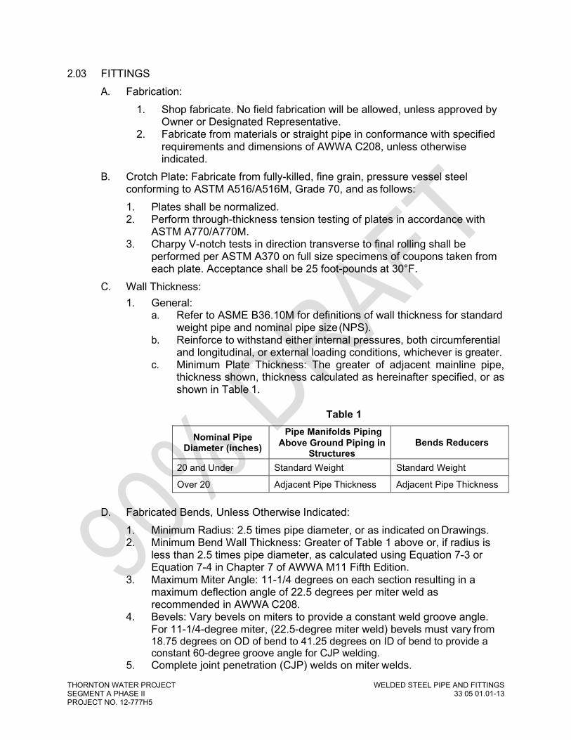
THORNTON WATER PROJECT WELDED STEEL PIPE AND FITTINGS SEGMENT A PHASE II 33 05 01.01-13 PROJECT NO. 12-777H5
2.03 FITTINGS A. Fabrication:
1. Shop fabricate. No field fabrication will be allowed, unless approved by Owner or Designated Representative.
2. Fabricate from materials or straight pipe in conformance with specified requirements and dimensions of AWWA C208, unless otherwise indicated.
B. Crotch Plate: Fabricate from fully-killed, fine grain, pressure vessel steel conforming to ASTM A516/A516M, Grade 70, and as follows: 1. Plates shall be normalized. 2. Perform through-thickness tension testing of plates in accordance with
ASTM A770/A770M. 3. Charpy V-notch tests in direction transverse to final rolling shall be
performed per ASTM A370 on full size specimens of coupons taken from each plate. Acceptance shall be 25 foot-pounds at 30°F.
C. Wall Thickness: 1. General:
a. Refer to ASME B36.10M for definitions of wall thickness for standard weight pipe and nominal pipe size (NPS).
b. Reinforce to withstand either internal pressures, both circumferential and longitudinal, or external loading conditions, whichever is greater.
c. Minimum Plate Thickness: The greater of adjacent mainline pipe, thickness shown, thickness calculated as hereinafter specified, or as shown in Table 1.
Table 1
Nominal Pipe Diameter (inches)
Pipe Manifolds Piping Above Ground Piping in
Structures Bends Reducers
20 and Under Standard Weight Standard Weight
Over 20 Adjacent Pipe Thickness Adjacent Pipe Thickness
D. Fabricated Bends, Unless Otherwise Indicated: 1. Minimum Radius: 2.5 times pipe diameter, or as indicated on Drawings. 2. Minimum Bend Wall Thickness: Greater of Table 1 above or, if radius is
less than 2.5 times pipe diameter, as calculated using Equation 7-3 or Equation 7-4 in Chapter 7 of AWWA M11 Fifth Edition.
3. Maximum Miter Angle: 11-1/4 degrees on each section resulting in a maximum deflection angle of 22.5 degrees per miter weld as recommended in AWWA C208.
4. Bevels: Vary bevels on miters to provide a constant weld groove angle. For 11-1/4-degree miter, (22.5-degree miter weld) bevels must vary from 18.75 degrees on OD of bend to 41.25 degrees on ID of bend to provide a constant 60-degree groove angle for CJP welding.
5. Complete joint penetration (CJP) welds on miter welds.

THORNTON WATER PROJECT WELDED STEEL PIPE AND FITTINGS SEGMENT A PHASE II 33 05 01.01-14 PROJECT NO. 12-777H5
E. Outlets: 1. 20 Inches and Smaller: Fabricate from ASTM A53/A53M, Type E or S,
Grade B, standard weight steel pipe. 2. Larger than 20 Inches: Fabricate from ASTM A106/A106M, Grade B,
standard weight pipe. 3. Fabricate collar or wrapper reinforcement using same steel as specified
for main pipe barrel. F. Steel Butt-Weld Fittings:
1. 20 Inches and Smaller: In accordance with ASME B16.9 conforming to ASTM A234/A234M.
2. Standard weight. 3. Taper pipe wall at welds at 4:1 for connection to pipe of different wall
thickness. 4. Coordinate difference in diameter convention between fittings and
AWWA C200 and AWWA C208 pipe and fittings to provide complete piping system as shown.
2.04 JOINTS A. Shop Welded:
1. Fabricate in accordance with AWWA C200 as modified herein. 2. Complete joint penetration (CJP) butt joints shall be used for longitudinal,
girth, and spiral welds, unless otherwise indicated. 3. Lengths of pipe shall not be shop-joined using lap joints.
B. Preparation of Joints for Field Welding: 1. Butt Joint Welded:
a. Plain ends beveled as required by AWWA C200 and Contractor’s field WPS.
b. Provide protection for factory beveled pipe ends so ends are not damaged during transport.
2. Lap Joint Welded: a. Lap joints in preparation for field welding shall be in accordance with
AWWA C200. b. For pipe 30 inches in diameter and larger, provide one of the
following: 1) Tack weld four metal tabs at equal intervals around inside
circumference of bell ends to indicate location at which spigot end has reached maximum penetration into bell. Remove stops after welding of joint.
2) Paint a 3/4-inch wide white stripe on outside circumference of spigot end of pipe. Side of stripe furthest from pipe end shall indicate location at which spigot end has reached maximum penetration into bell. Side of stripe closest to end of pipe will indicate limit of maximum joint pull.
c. Double welded lap joints and butt-strap joints shall be tapped and drilled for testing in accordance with AWWA C206.

THORNTON WATER PROJECT WELDED STEEL PIPE AND FITTINGS SEGMENT A PHASE II 33 05 01.01-15 PROJECT NO. 12-777H5
C. Miter-End Cuts: 1. Lap Joints:
a. As shown on Drawings. b. Moderate deflections and long radius curves may be made using
miter-end cuts. c. Use only with lap welded joints, unless specifically approved in
writing by Owner or Designated Representative. d. Maximum Total Allowable Angle: 3 degrees per pipe joint. e. Provide miter-cut that is cold expanded square with face of miter-cut
on bell ends only. f. Mitering of spigot ends will not be permitted.
2. Welded Butt Joints: a. Maximum Total Allowable Angle: 2.5 degrees per pipe joint. b. Welded Butt joints shall be CJP.
D. Special Temperature Control Joint: 1. Provide a special longer bell end (Special Temperature Control Joint) at a
maximum spacing as indicated herein to account for movement on installed pipe as a result of temperature changes.
2. Pipe manufacturer shall determine length required for the longer bell. 3. Minimum Special Temperature Control Joint length is: as shown on
Drawings. 2.05 FLANGES
A. In accordance with AWWA C207, class as indicated. Provide ASTM A193 Grade B7 bolts or studs, with ASTM A194 Grade 2H heavy hex nuts.
2.06 STULLING (STRUTTING) A. Materials:
1. Shop-Lined Pipe: Wood stulls and wedges. 2. Unlined Pipe: Steel or wood.
B. Install stulling for pipe and fittings in accordance with approved submittal and as soon as practical after pipe is fabricated or, for shop-lined pipe, after lining has been applied.
C. Install stulling in manner that will not harm lining. 2.07 COATING
A. General: 1. Coating as recommended by the steel pipe manufacturer with the
selected coating system provided. 2. Notify Owner or Designated Representative at least 3 days prior to
application of coating products. 3. Holdback of and coating from field-welded shall be as determined by
designer for coating system specified.
THORNTON WATER PROJECT WELDED STEEL PIPE AND FITTINGS SEGMENT A PHASE II 33 05 01.01-16 PROJECT NO. 12-777H5
4. Unless otherwise indicated, coat exterior surfaces of pipe and fittings passing through structure walls from center of wall or from wall flange to end of underground portion.
B. Shop-Applied: 1. As determined by Owner or Designated Representative for requirements
of coating specified. 2.08 CEMENT-MORTAR LINING
A. General: 1. Notify Owner or Designated Representative at least 3 days prior to
application of lining products. 2. Holdback of lining from field-welded joints shall be as follows:
a. For lap-welded joints and flex couplings, 8 inches. b. For butt-weld and butt-strap joints, 6 inches.
B. Shop-Applied: 1. Applied centrifugally in conformance with AWWA C205. Thickness shall
be in accordance with AWWA C205. 2. Lining machine type that has been used successfully for similar work and
approved by Owner or Designated Representative. 3. Maintain pipe in round condition during lining operation and thereafter by
suitable bracing or strutting. 4. Provide polyethylene or other suitable bulkhead on ends of pipe and on
special openings to prevent drying out of lining. Bulkheads shall be substantial enough to remain intact during shipping and storage until pipe is installed.
5. Pipe shall be left bare where field joints occur. 6. Ends of lining shall be left square and uniform. Feathered or uneven
edges will not be permitted. C. Field-Applied:
1. Materials conforming to AWWA C602. 2. Do not use pozzolanic material in mortar mix. 3. Admixtures shall contain no calcium chloride. 4. Wire mesh conforming to AWWA C205.
2.09 CATHODIC PROTECTION A. Provide as shown and as specified in applicable specification.
2.10 SOURCE QUALITY CONTROL A. Steel Toughness Testing for Thickness Equal to or Greater than 7/16 Inches:
1. Include three impact specimens; conduct test in direction transverse to final direction of the coil rolling.
2. Coils: a. Conduct Charpy Testing per ASTM A370 on an initial coil of each
heat to establish uniformity of steel.
THORNTON WATER PROJECT WELDED STEEL PIPE AND FITTINGS SEGMENT A PHASE II 33 05 01.01-17 PROJECT NO. 12-777H5
b. Take test coupons from an initial coil of each heat at locations of outer and inner wrap of coil.
c. For each coil that fails to meet acceptance criteria, conduct Charpy Testing on next two coils in that heat.
d. Do not use coils that do not qualify in production of pipe. 3. Plate:
a. Conduct Charpy Tests on each plate in accordance with ASTM A20/A20M.
b. Conduct on full-size (10 mm by 10 mm) specimens from each plate in accordance with ASTM A20/A20M.
c. Do not use plates that do not qualify in production of pipe. B. Crotch Plate:
1. Perform through-thickness tension testing with acceptance criteria per Article 5 of ASTM A770/A770M on each plate.
2. Conduct straight-beam ultrasonic examination with acceptance criteria per Article 6 of ASTM A435/A435M on each plate.
3. Plates that do not qualify shall not be used. C. Shop Hydrostatic Pressure Test: In accordance with AWWA C200 Section 5.2,
except as follows: 1. General: Unless specified otherwise, testing of pipe and fittings shall be
performed before lining and coating is applied. 2. Pipe: Maintain test pressure for minimum of 5 minutes. 3. Fittings:
a. Except as otherwise specified herein, no additional shop hydrostatic test will be required on fittings fabricated from successfully tested straight pipe.
b. Test with crotch plates, regardless of whether or not straight pipe sections used were previously tested. 1) Test Pressure: Design Pressure of fitting. 2) Maintain test pressure for a length of time as required to
perform a visual inspection of welds. 3) No leakage is allowed.
D. Joints, Lap-Welded: 1. Fit test minimum of 5 joints, selected by Owner or Designated
Representative, of each pipe size used: a. Join pipe ends with proposed adjacent pipe end. b. Match-mark pipe ends. c. Record Actual Annular Space:
1) Maximum space at a point. 2) Minimum space at a point. 3) Space at 90-degree intervals; top, bottom, and spring line on
both sides. E. Shop Nondestructive Testing:
1. Welds: 100 percent visually examined by Contractor’s Shop Inspector to criteria in ASME BPVC SEC VIII, Division 1.

THORNTON WATER PROJECT WELDED STEEL PIPE AND FITTINGS SEGMENT A PHASE II 33 05 01.01-18 PROJECT NO. 12-777H5
2. CJP Welds: Spot radiographically or radioscopically examine pipe in accordance with ASME BPVC SEC VIII, Div. 1, Paragraph UW-52. Welds that, in opinion of Owner or Designated Representative, cannot readily be radiographed, shall be 100 percent ultrasonically examined in accordance with paragraph UW-53.
3. Fillet Welds: 100 percent examine using magnetic particle inspection method in accordance with ASME BPVC SEC VIII, Division 1, Appendix 6.
4. Air test collars and wrappers in accordance with AWWA C206.
PART 3 EXECUTION
3.01 INSTALLATION A. General:
1. Joints and related work for field assembly of fittings shall conform to requirements for straight pipe, unless otherwise shown.
2. Inspect pipe and fittings before installation. Clean ends thoroughly, remove foreign matter and dirt from inside.
3. Make minor field adjustments by pulling standard joints. a. Maximum Allowable Angle: 75 percent of manufacturer’s
recommended or angle which results from 3/4-inch pull out from normal joint closure, whichever is less.
b. Maximum Allowable Gap: 1/8 inch between bell and spigot at weld location.
4. Horizontal deflections or fabricated angles shall fall on alignment, as shown within tolerances below.
5. Vertical deflections shall fall on alignment, and pipe angle point locations shall match those indicated on Drawings within tolerances below.
6. For field-welded joints, pipe 30 Inches in Diameter and Larger: a. Ensure maximum penetration of spigot end into bell end is achieved
through use of shop-welded tabs on inside circumference of bell end or by use of a paint stripe.
b. If welded metal tabs are used, remove tabs prior to welding inside of joint.
7. Stulling: a. Maintain stulling in place until pipe is completely backfilled and
compacted. b. Reinstall stulls that were temporarily removed to facilitate interior
welding prior to backfilling. 8. Pipeline Alignment Tolerances:
a. Plan: 3 inches. b. Elevation: 3 inches.
B. Control of Temperature Stresses: 1. In accordance with AWWA C206, approved Temperature Stress Control
Plan submittal, and this specification. 2. To control temperature stresses, shade unbackfilled special temperature
control joint area of pipe from direct rays of sun by use of properly supported awnings, umbrellas, tarpaulins or other suitable materials until

THORNTON WATER PROJECT WELDED STEEL PIPE AND FITTINGS SEGMENT A PHASE II 33 05 01.01-19 PROJECT NO. 12-777H5
pipe is backfilled at least 1 foot over top of pipe. The special temperature control joint area is defined as the entire length of pipe left exposed. Shading materials shall not rest directly on pipe, but shall be supported to allow air circulation around pipe. Shading of special temperature control joints is not required when ambient air temperature is below 50°F.
3. Locate special temperature control joints at 300-foot intervals. 4. Install special temperature control joints as indicated on Drawings. 5. Design, furnish and install a pipeline temperature monitoring system
consisting of thermocouple temperature gauges to monitor temperature of steel pipe wall in trench. Gauges shall be located at top inside surface of pipe at intervals not exceeding 50 feet. Hand held portable temperature sensor devices may be used, provided temperature readings are taken at top of pipe at a frequency and spacing that demonstrates compliance with temperature control requirements.
6. Temperature Control Requirements: a. Prior to and during placement of pipe backfill, pipeline steel
temperature shall be at or below 90°F. Monitor specified temperature and control for at least 3 hours after placement of pipe backfill. Provide supplemental cooling as required.
b. Place pipe backfill from a single heading starting at one special temperature control joint and proceed toward next special temperature control joint.
c. During period of pipe backfill placement, pipeline section that is partially backfilled shall be shaded as indicated in above. Temperature of partially backfilled pipe shall not be allowed to exceed 110°F. Provide supplemental cooling as required.
3.02 WELDING Prior to welding special temperature control joints, pipeline extending 300 feet each direction from joint shall be maintained at or below 85°F. Additionally, pipeline extending 300 feet each direction from joint shall be backfilled to at least 1 foot over top of pipe. Weld special temperature control joint at specified temperature of 90°F or below. Begin and complete weld during coolest time interval of the 24-hour day. Use pipeline temperature monitoring system data to demonstrate to Owner or Designated Representative coolest interval of the day. After field welding of special temperature control joint, pipe temperature for 150 feet in each direction shall be maintained below 110°F for a minimum of 24 hours after special temperature control joint area has been backfilled to at least 1 foot over top of pipe. A. Perform welding only in presence of Contractor’s Field Inspector. B. Conform to AWS D1.1/D1.1M, AWWA C206, approved welding procedures,
and referenced welding codes. In case of conflict AWS D1.1/D1.1M shall govern.
C. Preheat and Interpass temperature requirements for unlisted base metals shall be determined according to AWS D1.1/D1.1M, Annex XI Guideline on Alternative Methods for Determining Preheat.
D. Rejectable weld defects shall be repaired or redone, and retested until sound weld metal has been deposited in accordance with appropriate welding codes.

THORNTON WATER PROJECT WELDED STEEL PIPE AND FITTINGS SEGMENT A PHASE II 33 05 01.01-20 PROJECT NO. 12-777H5
3.03 REPAIR OF SHOP-APPLIED COATINGS A. Exterior surfaces of steel pipe and fittings shall be inspected upon delivery to
Site and just prior to backfilling trench. B. Repair of Coating: Field repairs shall be made in accordance with requirements
of coating system specified. 3.04 COATING OF FIELD-WELDED JOINTS
A. As required for coating system specified and as recommended by the steel pipe manufacturer with the selected coating system provided.
B. Weld after backfill using heat shrink sleeves: 1. Welding from the inside of the pipe after backfilling shall only be used
on single-lap welded joints. 2. Apply heat shrink sleeves prior to internal welding of pipe using
approved procedure compatible with coating system. 3. Install heat shrink joint system in accordance with manufacturer’s
recommendation a. Install heat resistant underlay, if required by manufacturer, as
shown in the Drawings 4. Provide services of technical representative or manufacturer available
on site at beginning of pipe laying operations. a. Owner or Designated Representative to advise contractor
regarding installation, repairs, and general construction methods. b. Installations using this method shall be quality controlled by
verification. C. At least three (3) randomly selected joints within the first twenty (20) joints shall
be buried, welded, and then subsequently excavated/exposed to verify that the pipe coating system has performed as specified. This process shall be repeated should the field welding procedure change.
D. The Owner or Designated Representative shall witness excavation to verify that the coating system is performing appropriately. The heat shrink representative shall be coordinated and paid for by the Contractor at no additional cost to the Owner.
3.05 CEMENT-MORTAR LINING APPLICATION AT JOINTS A. Cement-Mortar Lining: For pipe with shop-applied cement-mortar lining, place
lining at joints in accordance with AWWA C205. 3.06 CATHODIC PROTECTION
A. Apply to pipe as shown and as specified in applicable specification. 3.07 FIELD QUALITY CONTROL
A. Field Welding:

THORNTON WATER PROJECT WELDED STEEL PIPE AND FITTINGS SEGMENT A PHASE II 33 05 01.01-21 PROJECT NO. 12-777H5
1. All welds, 100 percent inspection, shall be VT inspected by Contractor’s Field Inspector and marked to indicate acceptance or rejection.
2. Test butt-strap or double-welded lap joint welds by pressurizing connection between the two fillet welds in accordance with AWWA C206. a. Apply air or other Engineer-approved gas into connection between
the two fillet welds. b. Paint welds with soap solution. c. Mark leaks indicated by escaping gas bubbles. d. Close threaded openings with flush pipe plugs or by welding them.
3. CJP Welds: a. Inspect 10 percent of butt joint welds with full circumference RT. b. Inspect 10 percent of other groove welds with UT.
4. Inspect 10 percent of lap joint welds with PT or MT 5. Weld Acceptance:
a. If, in the opinion of Owner or Designated Representative, inspections indicate inadequate quality of welds, percentage of welds inspected shall be increased.
b. Welds to be inspected, if less than 100 percent rate, shall be selected at random by Owner or Designated Representative.
c. VT: Perform VT per AWS D1.1/D1.1M Paragraph 6.9, Visual Inspection, Statically Loaded Nontubular Connections.
d. UT: Perform UT of CJP groove welds in accordance with AWS D1.1/D1.1M, Paragraph 6.13.1.
e. RT: Perform RT of CJP butt joint welds in accordance with AWS D1.1/D1.1M, Paragraph 6.12.1.
f. PT or MT: 1) Perform on fillet and PJP groove welds in accordance with
AWS D1.1/D1.1M, Paragraph 6.10. 2) Acceptance shall be in accordance with VT standards specified
above. g. Remove in manner that permits proper and complete repair by
welding. h. Caulking or peening of defective welds is not permitted. i. Retest unsatisfactory welds.
6. Verification Acceptance: Thornton may conduct random nondestructive inspections of field-welded joints. Inspections will be of an appropriate type for weld being evaluated. Possible types of inspection include, but are not limited to, RT, UT, PT, and VT. Testing will be performed and evaluated per AWS D1.1/D1.1M. Provide Thornton’s Verification Inspector access to the Work.
B. Hydrostatic Testing: 1. Pipeline:
a. General: 1) Notify Owner or Designated Representative in writing 5 days
prior to testing. Perform testing in presence of Owner or Designated Representative.

THORNTON WATER PROJECT WELDED STEEL PIPE AND FITTINGS SEGMENT A PHASE II 33 05 01.01-22 PROJECT NO. 12-777H5
2) Remove construction debris or foreign material and thoroughly broom clean and flush piping systems. Provide temporary connections, equipment and labor for cleaning.
3) Owner or Designated Representative shall inspect water line for cleanliness prior to filling.
4) Test newly installed pipelines. Using water as test medium, pipes shall successfully pass a leakage test prior to acceptance.
5) Furnish testing equipment and perform tests in manner satisfactory to Owner or Designated Representative. Testing equipment shall provide observable and accurate measurements of make-up water under specified conditions.
6) Isolate new pipelines that are connected to existing pipelines. 7) Conduct field hydrostatic test on buried piping after trench has
been completely backfilled. Testing may, as approved by Owner or Designated Representative, be done prior to placement of asphaltic concrete or roadway structural section.
8) Contractor may, if field conditions permit and as determined by Owner or Designated Representative, partially backfill trench and leave joints open for inspection and conduct an initial service leak test. Final field hydrostatic test shall not, however, be conducted until backfilling has been completed as specified above.
9) Supply of temporary water shall be determined by the Contractor.
10) Dispose of water used in testing in accordance with federal, state, and local requirements.
b. Procedure: 1) Maximum filling velocity shall not exceed 0.25 foot per second,
calculated based on the full area of pipe. 2) Expel air from pipe system during filling. Expel air through air
release valve or through corporation stop installed at high points and other strategic points.
3) Test Pressure: 125 percent of system operating pressure based on pressure as measured at low point of pipeline as determined by the HGL on the Drawings.
4) Apply and maintain specified test pressure with hydraulic force pump. Valve off piping system when test pressure is reached.
5) Maintain hydrostatic test pressure continuously for 2 hours minimum, adding additional make-up water only as necessary to restore test pressure.
6) Determine actual make-up water by measuring quantity of water necessary to maintain specified test pressure for duration of test.
7) If measured make-up water exceeds allowable or if leaks are visible, repair defective pipe section and repeat hydrostatic test.
c. Allowable Make-up Water: 1) For pipe with welded joints, no make-up water is allowed.

THORNTON WATER PROJECT WELDED STEEL PIPE AND FITTINGS SEGMENT A PHASE II 33 05 01.01-23 PROJECT NO. 12-777H5
3.08 MANUFACTURER’S SERVICES A. Manufacturer’s representative available at Site for installation assistance and
training of pipe installation crews. 1. Coordinate pipe manufacturer’s representative services. 2. Pipe manufacturer’s representative shall visit Site and instruct, guide, and
provide procedures for pipe handling, laying, and jointing at start of pipe installation by each crew.
END OF SECTION

THORNTON WATER PROJECT MAGNETIC FLOW METERS SEGMENT A PHASE II 40 71 13-1 PROJECT NO. 12-777H5
SECTION 40 27 02 PROCESS VALVES AND OPERATORS
PART 1 GENERAL
1.01 REFERENCES A. The following is a list of standards which may be referenced in this section:
1. American Gas Association (AGA): 3, Orifice Metering of Natural Gas and Other Related Hydrocarbon Fluids.
2. American National Standards Institute (ANSI): Z21.15, Manually Operated Gas Valves for Appliances, Appliance Connector Valves and Hose End Valves.
3. American Society of Mechanical Engineers (ASME): a. B16.1, Gray Iron Pipe Flanges and Flanged Fittings: Classes 25,
125, and 250. b. B16.44, Manually Operated Metallic Gas Valves for Use in Above
Ground Piping Systems up to 5 psi. 4. American Society of Sanitary Engineers (ASSE): 1011, Performance
Requirements for Hose Connection Vacuum Breakers. 5. American Water Works Association (AWWA):
a. C111/A21.11, Rubber-Gasket Joints for Ductile-Iron Pressure Pipe and Fittings.
b. C500, Metal-Seated Gate Valves for Water Supply Service. c. C504, Rubber-Seated Butterfly Valves, 3 In. (75 mm) Through 72 In.
(1,800 mm). d. C508, Swing-Check Valves for Waterworks Service, 2-In. Through
24-In. (50-mm Through 600-mm) NPS. e. C509, Resilient-Seated Gate Valves for Water Supply Service. f. C510, Double Check Valve Backflow Prevention Assembly. g. C511, Reduced-Pressure Principle Backflow Prevention Assembly. h. C512, Air-Release, Air/Vacuum, and Combination Air Valves for
Waterworks Service. i. C515, Reduced-Wall, Resilient-Seated Gate Valves for Water
Supply Service. j. C541, Hydraulic and Pneumatic Cylinder and Vane-Type Actuators
for Valves and Slide Gates. k. C542, Electric Motor Actuators for Valves and Slide Gates. l. C550, Protective Interior Coatings for Valves and Hydrants. m. C606, Grooved and Shouldered Joints. n. C800, Underground Service Line Valves and Fittings.
6. ASTM International (ASTM): a. A276, Standard Specification for Stainless Steel Bars and Shapes. b. A351/A351M, Standard Specification for Castings, Austenitic, for
Pressure-Containing Parts. c. A380, Standard Practice for Cleaning, Descaling, and Passivation of
Stainless Steel Parts, Equipment, and Systems.

THORNTON WATER PROJECT MAGNETIC FLOW METERS SEGMENT A PHASE II 40 71 13-2 PROJECT NO. 12-777H5
d. A564/A564M, Standard Specification for Hot-Rolled and Cold- Finished Age-Hardening Stainless Steel Bars and Shapes.
e. B61, Standard Specification for Steam or Valve Bronze Castings. f. B62, Standard Specification for Composition Bronze or Ounce Metal
Castings. g. B98/B98M, Standard Specification for Copper-Silicon Alloy Rod, Bar,
and Shapes. h. B127, Standard Specification for Nickel-Copper Alloy (UNS N04400)
Plate, Sheet, and Strip. i. B139/B139, Standard Specification for Phosphor Bronze Rod, Bar
and Shapes. j. B164, Standard Specification for Nickel-Copper Alloy Rod, Bar, and
Wire. k. B194, Standard Specification for Copper-Beryllium Alloy Plate,
Sheet, Strip, and Rolled Bar. l. B584, Standard Specification for Copper Alloy Sand Castings for
General Applications. m. D429, Standard Test Methods for Rubber Property-Adhesion to
Rigid Substrates. n. D1784, Standard Specification for Rigid Poly(Vinyl Chloride) (PVC)
Compounds and Chlorinated Poly(Vinyl Chloride) (CPVC) Compounds.
7. Canadian Standards Association, Inc. (CSA): 9.1, Manually Operated Gas Valves for Appliances, Appliance Connector Valves and Hose End Valves.
8. Chlorine Institute (CI): Pamphlet 6, Piping Systems for Dry Chlorine. 9. FM Global (FM). 10. Food and Drug Administration (FDA). 11. International Association of Plumbing and Mechanical Officials (IAPMO). 12. Manufacturers Standardization Society (MSS):
a. SP-80, Bronze Gate, Globe, Angle, and Check Valves. b. SP-81, Stainless Steel, Bonnetless, Flanged Knife Gate Valves. c. SP-85, Gray Iron Globe and Angle Valves, Flanged and Threaded
Ends. d. SP-88, Diaphragm Valves. e. SP-110, Ball Valves Threaded, Socket-Welding, Solder Joint,
Grooved and Flared Ends. 13. National Electrical Manufacturers Association (NEMA): 250, Enclosures
for Electrical Equipment (1000 Volts Maximum). 14. NSF International (NSF):
a. NSF/ANSI 61, Drinking Water System Components - Health Effects. b. NSF/ANSI 372, Drinking Water System Components - Lead Content.
15. Underwriters Laboratories (UL). 16. USC Foundation for Cross-Connection Control and Hydraulic Research.
1.02 REFERENCES A. Action Submittals:
1. Shop Drawings:

THORNTON WATER PROJECT MAGNETIC FLOW METERS SEGMENT A PHASE II 40 71 13-3 PROJECT NO. 12-777H5
a. Product data sheets for each make and model. Indicate valve Type Number, applicable Tag Number, and facility name/number or service where used.
b. Complete catalog information, descriptive literature, specifications, and identification of materials of construction.
c. Power and control wiring diagrams, including terminals and numbers.
d. For each power actuator provided, manufacturer’s standard data sheet, with application specific features and options clearly identified.
e. Sizing calculations for open-close/throttle and modulating valves. f. Anchorage and bracing drawings and cut sheets, as required by
applicable specification. B. Informational Submittals:
1. Anchorage and bracing calculations as required by applicable specification.
2. Manufacturer’s Certificate of Compliance, in accordance with Section, for: a. Electric actuators; full compliance with AWWA C542. b. Butterfly valves; full compliance with AWWA C504.
3. Component and attachment testing seismic certificate of compliance as required by applicable specification.
4. Tests and inspection data. 5. Operation and Maintenance Data as specified in application specification. 6. Manufacturer’s Certificate of Proper Installation, in accordance with
applicable specification. PART 2 PRODUCTS 2.01 GENERAL
A. Valves to include operator, actuator, handwheel, chain wheel, extension stem, floor stand, operating nut, chain, wrench, and accessories to allow a complete operation from the intended operating level.
B. Valve to be suitable for intended service. Renewable parts not to be of a lower quality than specified.
C. Valve same size as adjoining pipe, unless otherwise called out on Drawings or in Supplements.
D. Valve ends to suit adjacent piping. E. Resilient seated valves shall have no leakage (drip-tight) in either direction at
valve rated design pressure. All other valves shall have no leakage (drip-tight) in either direction at valve rated design pressure, unless otherwise allowed for in this section or in stated valve standard.
F. Size operators and actuators to operate valve for full range of pressures and velocities.
G. Valve to open by turning counterclockwise, unless otherwise specified. H. Factory mount operator, actuator, and accessories.

THORNTON WATER PROJECT MAGNETIC FLOW METERS SEGMENT A PHASE II 40 71 13-4 PROJECT NO. 12-777H5
2.02 SCHEDULE A. Additional requirements relative to this section are shown on valve schedule(s)
located at the end of this section. 2.03 MATERIALS
A. Bronze and brass valve components and accessories that have surfaces in contact with water to be alloys containing less than 16 percent zinc and 2 percent aluminum. 1. Approved alloys are of the following ASTM designations: B61, B62,
B98/B98M (Alloy UNS No. C65100, C65500, or C66100), B139/B139M (Alloy UNS No. C51000), B584 (Alloy UNS No. C90300 or C94700), B164, B194, and B127.
2. Stainless steel Alloy 18-8 may be substituted for bronze. 2.04 FACTORY FINISHING
A. General: 1. Interior coatings for valves and hydrants shall be in accordance with
AWWA C550, unless otherwise specified. 2. Exterior coating for valves and hydrants shall be in accordance with
applicable specification. 3. Exposed safety isolation valves and lockout valves with handles,
handwheels, or chain wheels shall be “safety yellow.” B. Where epoxy lining and coating are specified, factory finishing shall be as
follows: 1. In accordance with AWWA C550. 2. Either two-part liquid material or heat-activated (fusion) material except
only heat-activated material if specified as “fusion” or “fusion bonded” epoxy.
3. Minimum 7-mil dry film thickness except where limited by valve operating tolerances.
2.05 VALVES A. Gate Valves:
1. General: a. AWWA gate valves to be in full compliance with stated AWWA
standard and the following requirements: 1) Provide 2-inch operating nut for AWWA gate valves 12 inches
and smaller. 2) Provide totally enclosed spur or bevel gear operator with
indicator where shown on drawings. 3) Provide Affidavit of Compliance per the applicable AWWA
standard for AWWA gate valves. 4) Mark AWWA gate valves with manufacturer’s name or mark,
year of valve casting, valve size, and working water pressure. 5) Repaired AWWA gate valves shall not be submitted or
supplied.

THORNTON WATER PROJECT MAGNETIC FLOW METERS SEGMENT A PHASE II 40 71 13-5 PROJECT NO. 12-777H5
6) Supply AWWA gate valves with stainless steel bolting. 7) AWWA C509 and AWWA C515 valves may be substituted for
each other. 2. Type V135 Resilient Seated Ductile Iron Gate Valve 3 Inches to
36 Inches: a. Ductile iron body, resilient seat, bronze stem and stem nut, flanged
ends, nonrising stem, in accordance with AWWA C515, minimum design working water pressure 250 psig, full port, fusion epoxy coated inside and outside per AWWA C550 NSF/ANSI 61 certified. Flange drilling in accordance with ASME B 16.1.
b. Manufacturers and Products: 1) American Flow Control; Series 2500. 2) M&H; Style 7000 and C515 Large RW Valves.
B. Ball Valves: 1. Type V464 Corporation Stop:
a. In accordance with AWWA C800 type, tapered threaded inlet, except when connecting to tapped fittings which require IPS tapered threads, outlet compression connection, or IPS threads to suit connecting pipe, rated 300 psi.
b. Manufacturers and Products 1) AY McDonald 2) Cambridge Brass 3) The Ford Meter Box Co. 4) Mueller Co.
2. Type V307 Stainless Steel Ball Valve, 2 Inches and Smaller: a. Three-piece, full port, ASTM A276 GR 316 or ASTM A351/A351M
GR CF8M stainless steel body and end pieces, Type 316 stainless steel ball, NPT threaded ends, reinforced PTFE seats, seals, and packing, adjustable packing gland, blowout-proof stainless steel stem, stainless steel lever operator with vinyl grip, rated 800 psig CWP minimum, complies with MSS SP-110.
b. Manufacturers and Products: 1) Conbraco Apollo; 86R-100 2) Nibco; T-595-S6-R-66-LL
C. Butterfly Valves: 1. General:
a. In full compliance with AWWA C504 and following requirements: 1) Suitable for throttling operations and infrequent operation after
periods of inactivity. 2) Elastomer seats which are bonded or vulcanized to the body
shall have adhesive integrity of bond between seat and body assured by testing, with minimum 75-pound pull in accordance with ASTM D429, Method B.
3) Bubble-tight with rated pressure applied from either side. Test valves with pressure applied in both directions.
4) No travel stops for disc on interior of body. 5) Self-adjusting V-type or O-ring shaft seals.
THORNTON WATER PROJECT MAGNETIC FLOW METERS SEGMENT A PHASE II 40 71 13-6 PROJECT NO. 12-777H5
6) Isolate metal-to-metal thrust bearing surfaces from flow stream. 7) Provide traveling nut or worm gear actuator with handwheel.
Valve actuators to meet the requirements of AWWA C504. 8) Buried service operators shall withstand 450 foot-pounds of
input torque at fully open and fully closed positions. 9) Provide linings and coatings per AWWA, unless otherwise
indicated on Drawings or specified herein. 2. Type V506 Butterfly Valve High Pressure Service 4 Inches to 48 Inches:
a. AWWA C504, Class 250B. b. Short body type, Class 250 flanged ends. c. Cast or ductile iron body, cast or ductile iron disc with Type 316
stainless steel disc edge, ASTM A564/A564M Type 630 Condition H-1100/1150 or Type 316 stainless steel shaft, Buna-N rubber seat bonded or molded in body only, self-adjusting V-type multi-ring seals.
d. Provide epoxy lining and coating in compliance with AWWA C550. e. Manufacturers and Products:
1) Pratt; Triton HP-250. 2) DeZurik; AWWA Flanged Class 250. 3) Mueller; Lineseal XP Class 250.
D. Combination Air/Vacuum Release Valves: 1. Type V746 Combination Air Release Valve 1 Inch to 16 Inches:
a. Suitable for water service, combines operating features of air and vacuum valve and air release valve. Air and vacuum portion to automatically exhaust air during filling of system and allow air to re-enter during draining or when vacuum occurs. Air release portion to automatically exhaust entrained air that accumulates in system.
b. Valve single body or dual body, air release valve mounted on air and vacuum valve, isolation valve mounted between the dual valves. 1-inch through 3-inch valves with NPT threaded inlet and outlet, 4-inch and larger valves with ASME B16.1 Class 250 flanged inlet and cover outlet.
c. Rated 300 psi working pressure, cast-iron or ductile iron body and cover, stainless steel float and trim, built and tested to AWWA C512.
d. Manufacturers and Products: 1) RF Valves; Vent-O-Mat, Model 100 RBX 2541 E4, or approved
equal. 2.06 OPERATORS AND ACTUATORS
A. Manual Operators: 1. General:
a. For AWWA valves, operator force not to exceed requirements of applicable valve standard. Provide gear reduction operator when force exceeds requirements.
b. For non-AWWA valves, operator force not to exceed applicable industry standard or 80 pounds, whichever is less, under operating

THORNTON WATER PROJECT MAGNETIC FLOW METERS SEGMENT A PHASE II 40 71 13-7 PROJECT NO. 12-777H5
condition, including initial breakaway. Provide gear reduction operator when force exceeds requirements.
c. Operator self-locking type or equipped with self-locking device. d. Position indicator on quarter-turn valves. e. Worm and gear operators one-piece design, worm-gears of gear
bronze material. Worm of hardened alloy steel with thread ground and polished. Traveling nut type operator’s threaded steel reach rod with internally threaded bronze or ductile iron nut.
2. Exposed Operator: a. Galvanized and painted handwheel. b. Cranks on gear type operator. c. Chain wheel operator with tieback, extension stem, floor stand, and
other accessories to permit operation from normal operation level. d. Valve handles to take a padlock, and wheels a chain and padlock.
3. Buried Operator: a. Buried service operators on valves larger than 2-1/2 inches shall
have a 2-inch AWWA operating nut. Buried operators on valves 2 inches and smaller shall have cross handle for operation by forked key. Enclose moving parts of valve and operator in housing to prevent contact with the soil.
b. Buried service operators to be grease packed and gasketed to withstand submersion in water to 20 feet minimum.
c. Buried valves shall have extension stems, bonnets, and valve boxes. B. Electric Operators, Single-Phase:
1. General: a. Unit shall be low profile to reduce amount of required space and
weigh 15 pounds or less. b. Size to 1-1/2 times required operating torque. Motor stall torque not
to exceed torque capacity of the valve. c. Provide operator mounting bracket to mount operator to valve
providing minimal torque to piping system when operating. 2. Operator Operation, General:
a. Suitable for full 90-degree rotation of quarter-turn valves. b. Provide with manual-override handwheel and manually-actuated
clutch for electric actuator. Provide interruption of actuator power when electric actuator is de-clutched.
c. Combination Electrical and Mechanical valve position indication. Clarification of electrical position requirements are provided in this Section.
3. Electronic Control – for Serial-controlled electronically-actuated valves: a. Incorporate requirements for all electronically-actuated valves, which
also apply. Requirements for Serial-controlled electronically-actuated valves vary as follows: 1) Provide valve with integral microcontroller and integral logic as
required to integrate all instrumentation and control wiring features into the control features of the integral microcontroller.
2) Include analog-to-digital conversion of all measured analog signals into a digital format for serial uplink.

THORNTON WATER PROJECT MAGNETIC FLOW METERS SEGMENT A PHASE II 40 71 13-8 PROJECT NO. 12-777H5
3) Include digital-to-analog conversion of analog output signals, using encoded digital-format data from serial uplink.
4) Include encoding of all measured discrete signals into a digital format for serial uplink.
5) Include switching of discrete commands, using encoded digital-format data from serial uplink.
6) Communicate with Process Control System defined by Owner or Designated Representative using protocol defined by Owner or Designated Representative. Coordinate with Owner or Designated Representative for exact protocol requirements and provide any protocol conversion gateway required for consistency with Owner or Designated Representative protocol. Within this scope, at no additional cost to Project, provide: a) Enclosure at above-grade rack for gateway hardware. b) Cables and conductors as required for a complete
system. c) Circuit breaker and power conduit and wiring as required
to power conversion equipment. 7) Provide display of valve position in terms of percentage open
on local illuminated LCD panel for modulating valves. Provide manufacturer’s standard end-point/in-transition indication on illuminated LCD panel for non-modulating (on/off) (open/close) valves.
b. Actuator manufacturer requirements – Rotork – no substitutes, no exceptions.
c. Provide Rotork IQS-series valve actuator complying with torque requirements, no substitutes, no exceptions, at voltage indicated in Contract Documents, such as on panel schedules.
d. NEMA 6 rating, minimum. e. Valve Actuator weight and dimensional restrictions are waived as
required to accommodate this pre-defined valve actuator configuration. Secure and support actuator per actuator and valve manufacturer instructions.
4. Electronic Control – All electronically-actuated valves: a. Field-Verify with Plans – Where valve actuators with integral
microcontrollers, “digital control”, “network control", or “serial control” are required, reference requirements “for Serial-controlled electronically-actuated valves” and provide additional features accordingly, even if not further elaborated within this Article.
b. Torque Limiting Switches: Two single pole, double throw mechanical switches. Switches operate at any point in valve travel.
c. Jammed-valve detection and protection. d. Motor over-temperature detection and protection. e. Travel limit switches, single pole double throw.
5. Open-Close (O/C) Service: a. Duty cycle for intermittent ON-OFF operation shall be 25 percent,
minimum. b. Operator shall power to OPEN and power to CLOSE. c. Local Indication and Control:

THORNTON WATER PROJECT MAGNETIC FLOW METERS SEGMENT A PHASE II 40 71 13-9 PROJECT NO. 12-777H5
1) Integral mechanical valve POSITION indication, 0 percent to 100 percent OPENED.
2) Integral OPENED and CLOSED indication lights, or display of this status on local illuminated LCD panel.
3) Integral LOCAL-OFF-REMOTE (L-O-R). 4) Integral OPEN maintained switch which causes the valve to
stroke full OPENED, even if OPEN switch is released, while L-O-R switch is in LOCAL.
5) Integral CLOSE maintained switch which causes valve to stroke full CLOSED, even if CLOSED switch is released, while L-O-R switch is in LOCAL.
d. Remote Indication and Control: 1) Relay contact that closes when valve is capable of being
controlled remotely (L-O-R switch in REMOTE) for connection to and monitoring by plant control system.
2) Limit switch that closes when valve is fully OPENED for connection to and monitoring by plant control system.
3) Limit switch that closes when valve is fully CLOSED for connection to and monitoring by plant control system.
e. Modulating (M) Service: 1) Operator rated for continuous duty with servo shall be rated for
100 percent modulating operation. 2) Operator shall modulate based on an externally applied 4 mA
to 20 mA dc signal. 3) Operator shall be equipped with an electronic servo module for
valve modulation. a) Module shall provide serial communications with provided
cable for setup of valve operation. f. Local Indication and Control:
1) Integral mechanical valve POSITION indication, 0 percent to 100 percent OPENED.
2) Integral OPENED and CLOSED indication lights, or display of this status on local illuminated LCD panel.
3) Integral LOCAL-OFF-REMOTE (L-O-R). 4) Integral OPEN momentary switch which causes valve to stroke
towards OPENED, as long as OPEN switch is held, while L-O-R switch is in LOCAL.
5) Integral CLOSE momentary switch which causes valve to stroke towards CLOSED, as long as CLOSED switch is held, while L-O-R switch is in LOCAL.
6) Position valve proportionally 0 to 100 percent OPEN with external 4 mA to 20 mA dc signal while in REMOTE.
g. Remote Indication and Control: 1) Relay contact that closes when valve is capable of being
controlled remotely (L-O-R switch in REMOTE) for connection to and monitoring by plant control system.
2) Limit switch that closes when valve is fully OPENED for connection to and monitoring by plant control system.

THORNTON WATER PROJECT MAGNETIC FLOW METERS SEGMENT A PHASE II 40 71 13-10 PROJECT NO. 12-777H5
3) Limit switch that closes when valve is fully CLOSED for connection to and monitoring by plant control system.
4) Current Position Transmitter, 4 mA to 20 mA dc signal in proportion to 0 percent to 100 percent OPENED, with 0.5 percent accuracy and 0.5 percent repeatability, capable of driving a 750-ohm load, for connection to and monitoring by Plant Control System.
5) Control Features: Electric motor actuators with features as noted above, and as modified/supplemented in Electric Actuated Valve Schedule.
6) Manufacturer: Rotork 2.07 ACCESSORIES
A. Tagging: 1-1/2-inch diameter heavy brass or stainless steel tag attached with No. 16 solid brass or stainless steel jack chain for each valve 6-inch and larger, bearing valve tag number shown on Drawings.
B. T-Handled Operating Wrench: 1. [A: ] each galvanized operating wrenches, 4 feet long. 2. Manufacturers and Products:
a. Mueller; No. A-24610. b. Clow No.; F-2520.
C. Extension Bonnet for Valve Operator: Complete with enclosed stem, extension, support brackets, and accessories for valve and operator.
D. Cast-Iron Valve Box: Designed for traffic loads, sliding type, with minimum of 5-1/4-inch ID shaft. 1. Box: Cast iron with minimum depth of 9 inches. 2. Lid: Cast iron, minimum depth 3 inches, locking type, marked WATER. 3. Extensions: Cast iron. 4. Two-piece box and lid for valves 4 inches through 12 inches, three- piece
box and lid for valves larger than 12 inches with base sized for valve. 5. Valve extension stem for valves with operating nuts 3 feet or greater
below finish grade. 6. Manufacturers and Products:
a. East Jordan Iron Works; Cast-Iron Valve Boxes. b. Bingham & Taylor; Cast-Iron Valve Boxes.
PART 3 EXECUTION
3.01 INSTALLATION A. Flanged valve bolt holes shall straddle vertical centerline of pipe. B. Clean flanged faces, insert gasket and bolts, and tighten nuts progressively
and uniformly. C. Valve Installation and Orientation:
1. General:
THORNTON WATER PROJECT MAGNETIC FLOW METERS SEGMENT A PHASE II 40 71 13-11 PROJECT NO. 12-777H5
a. Install valves so handles operate from fully open to fully closed without encountering obstructions.
b. Install valves in location for easy access for routine operation and maintenance.
c. Install valves per manufacturer’s recommendations. 2. Gate, Globe, and Ball Valves:
a. Install operating stem vertical when valve is installed in horizontal runs of pipe having centerline elevations 4 feet 6 inches or less above finished floor, unless otherwise shown.
b. Install operating stem horizontal in horizontal runs of pipe having centerline elevations greater than 4 feet 6 inches above finish floor, unless otherwise shown.
3. Butterfly Valves: a. Unless otherwise restricted or shown on Drawings, install valve a
minimum of 8 diameters downstream of a horizontal elbow or branch tee with shaft in horizontal position.
b. For vertical elbow or branch tee immediately upstream of valve, install valve with shaft in vertical position.
c. For horizontal elbow or branch tee immediately upstream of valve, install valve with shaft in horizontal position.
d. When installed immediately downstream of swing check, install valve with shaft perpendicular to swing check shaft.
e. For free inlet or discharge into basins and tanks, install valve with shaft in vertical position.
D. Install line size ball valve and union upstream of each solenoid valve, in-line flow switch, or other in-line electrical device, excluding magnetic flowmeters, for isolation during maintenance.
E. Locate valve to provide accessibility for control and maintenance. Install access doors in finished walls and plaster ceilings for valve access.
F. Extension Stem for Operator: Where depth of valve operating nut is 3 feet or greater below finish grade, furnish operating extension stem with 2-inch operating nut to bring operating nut to a point within 6 inches of finish grade.
G. Torque Tube: Where operator for quarter-turn valve is located on floor stand, furnish extension stem torque tube of a type properly sized for maximum torque capacity of valve.
H. Floor Box and Stem: Steel extension stem length shall locate operating nut in floor box.
I. Chain Wheel and Guide: Install chain wheel and guide assemblies or chain lever assemblies on manually operated valves over 6 feet 9 inches above finish floor. Install chain to within 3 feet of finish floor. Where chains hang in normally traveled areas, use appropriate “L” type tie-back anchors. Install chains to within operator horizontal reach of 2 feet 6 inches maximum, measured from normal operator standing location or station.
J. Execution requirements for serial-controlled electronically-actuated valves:

THORNTON WATER PROJECT MAGNETIC FLOW METERS SEGMENT A PHASE II 40 71 13-12 PROJECT NO. 12-777H5
1. Provide programming and calibration at valve as required for system functionality.
2. Coordinate with Owner’s Designated Representative for integration of this valve into their addressable system. Program hardware address, register addresses, designations, protocol, and similar parameters as requested by Owner or Designated Representative.
3. Test valve control features locally prior to release to Owner or Designated Representative.
4. Provide services at local valve as required for Owner or Designated Representative configuration and testing.
5. Collaborate with Owner or Designated Representative and/or third parties providing commissioning services as required to commission valve actuator for service.
3.02 TESTS AND INSPECTION A. Valve may be either tested while testing pipelines, or as a separate step. B. Test that valves open and close smoothly under operating pressure conditions.
Test that two-way valves open and close smoothly under operating pressure conditions from both directions.
C. Inspect air and vacuum valves as pipe is being filled to verify venting and seating is fully functional.
D. Count and record number of turns to open and close valve; account for discrepancies with manufacturer’s data.
E. Set, verify, and record set pressures for relief and regulating valves. F. Automatic valves to be tested in conjunction with control system testing. Set
opening and closing speeds, limit switches, as required or recommended by Owner or Designated Representative.
G. Test hydrostatic relief valve seating; record leakage. Adjust and retest to maximum leakage of 0.1 gpm per foot of seat periphery.
3.03 MANUFACTURER’S SERVICES A. Valve(s) as listed below require manufacturer’s field services:
1. N/A B. Manufacturer’s Representative: Present at Site for minimum person-days listed
below, travel time excluded:
1. Five person-days for installation assistance and inspection. 2. Five person-days for functional and performance testing and completion of
Manufacturer’s Certificate of Proper Installation.
END OF SECTION

Prepared for: City of Thornton AECOM
Appendix G – Neighborhood Meeting Materials


Lovel and
Lak e D it ch
LarinerCounty Canal
Redsto ne Creek
Sout
hSide Ditch
CedarCreek
Lake Ditch
Sprin
gC
reek
New Merc erCanal
Buck
ho rnHig hl ine D
i tch
Culver Ditch
Poudre Va ll eyC
anal
Ho m e Supply Ditc h
Dry Creek
Boulder a nd Larimer CoDitc h
North Poudre
Supp
lyC
LittleThompsonRiver
Geo rg e Rist Ditch
Dixo nCana l
LarimerC
ounty Canal
Old Ish Ditch
Larimer County C
anal
Redston eCreek
La rimer andWeld C anal
Plsnt Vlyan d
L kCana l
Os born and C aywood DitchLittle T hompson River
H a ndy Ditch
Box
elde
r Cre
ek
Bo xelder Ditch
Dry Creek
Dry Creek
New Ish Ditch
Pleasa ntVall ey a n d L ak
eCanal
Cach e laPo udreRive r
BuckhornCreek
Fossil Cree k
Ft Clns Irigt n
Ditch
Jac ks onD
i tch
In dianC ree
k
Number 8
Ou tl e tDitch
F oss i l Creek
L
o veland and Greeley Canal
Dry
Cree
k
C ottonwood Creek
pson Rive r
Lake Canal
Dry Creek
Munroe Gravity Canal
Louden Ditch
Ind i
anC
reek
Buckho rn Creek
North Poud r e Can
al
Mail CreekDi tch
Cowan Lateral
Fa rmers Ditch
Big Thompso n River
Hors
etoot
hSupplyCanal
Big Barnes Ditch
Dry
Cre
ek
Spr ing Creek
SaintVrainSup p ly
Canal
Hom
e SupplyDit ch
Muskrat Ditch
eek
F k Litt le Thompso n R
iver
Fk Little Thompson R iver
Windso r Ditch
Lewst one Creek
Ha nsenCana l
Little Barnes Ditch
North Fo rk FishCreek
Charles Hansen Canal
Charles Hansen
Canal
H
andyDitch
eek
Greeley Num ber2Ca nal
Fish Creek
M ill Creek
Bi
gDryCr e ek
Lone Tree Cr eek
Cache la Poudre R iver
Uni on
Re serv oir
D i tch
Little T
ho
mpsonRiv er
D ryCr
eek
St Vrain
Cr e
ek
Li ttle Dry Cree k
Bo
u lder Cree
k
Big Th
o mpson River
Idah
oCree
k
South Platte River
Coa l Creek
Cache la Poudre Ri ver
Left Hand Creek
Boulder Creek
Sout h Boulde r Creek
Silver Creek
Lit tle Th o mpsonRiver
Left Hand Cr eekBoulder C re
ek
Boulder Creek
Little Dry Creek
St Vrain Creek
Skunk Creek
Dry Cre ek
Bluebe
l lC
reek
Rock Creek
GooseCreek
Gre
g ory
Creek
Coal Creek
Fo urmile Creek
James
C reek
LittleJames Creek
B ear CanyonCreek
Dry C reek
Fourmile
Canyon Cr eek
South St Vr a inCree
k
Anderson Ditch
Whi
pple
Dit ch
Larime r Cou n ty Di tch
Fulto
nDitch
Ro ugh Ready Di tch
Wa r ren Lake Res Feed D
La s t Chance Di
tch
New Cache la Poudre Co D
S Boulder Canon Di tch
Lower Latham Ditch
Mc CartyDitch
Denver-Hudso nC
nl
Sup
plyDitch
LuptonB
o ttom
Di tch
Leyner Cottonw ood Di tch
Nelson Ditch
L a rim
erW
e ldIrr Canal
Bo ulderWhi te
Rock
Ditch
Bar
rLa
ke
Milton Res
SBoul
derB
ear Cr
Ditch
How
ard
Ditc
h
Rice Ditch
Pla t tev ille Di tch
Ho we l
lD
it ch
Dille Tunnel
Lake
Ditc h
Harris Ditch
Jones DonnellyDitch
Bou l der
WeldCty Ditch
R ist Goss Ditch
Hom
eSup
plyDitch
ChaffeeDit ch
Wellma n Ditch
Fulton Ditch
Kinnear Ditch Res
North Poud re SupplyC
nl
John R iceDitch
Clough/True Di tch
JayThom
asDitch
Bo yd Free man Ditch
Un ion Di tch
Mea dow
IslandDi tch
L a keCan al Ditch
Eat on
Mc cle llan Dti ch
HaldiDit ch
Evanstown Ditch
Clo ver Basin Ditch
Pe ck Ditch
Pella Ditch
Smead Ditch
Jim Eglin DitchSupply Lateral Ditch
Eagle Ditch
Lar imerWel d Irr Canal
Mcg innDitch
NBould Farmer Di tch
Whitn
ey Irr Ditch
Union Ditch
Foo
t hillsInlet
YoxallDitc
h
Hand y Ditch
MailCreek Ditch
And r
e ws F
arwe
ll Ditch
Victory IrrC
nl
Brainard
TuckerDitch
Long Lake Dit ch
Goo
sequ
ill
D itch
Schearer Ditch
JohnG
Coy
D itch
Chapman Mccaslin Ditch
Perki ns Ditch
W R B lowerDitch 1
La ri mer
Weld IrrCanal
Eas
t Bou
lde rDi
tch
BonusDi tch
Slate Ditch
B ader Ditch 1 & 2
Bran
tner
Ditch
Smith
Em
mo
ns Dit c
h
Zwe ckTurner Ditch
Boulder White Rock Ditch
Last Chance Ditch
Miner LonganDitch
South Flat Ditch
Larime r We ldIrr
Canal
Low er Bou ld e rD itch
T imna th Reservoi r Outle t
Green Ditch
Will ia mson Ditch
Toll Gate Ditch
StVr
ainS
upply Canal
Patterson Ditch
Fort Co llins IrrCnl
WilliamR Jones Ditch
S tanl
ey
Ditch
Cot tonwo
odD
it ch2
Comm un
ityD
i tch
Cache laPodr R es In Cnl
Davis
D
own ing
Ditch
He wes
Co o
kD
it ch
Uppe
rBald win
Di tch
Johnson
Ditch
Croc ker Di tch
Whipple Ditch
Oligarchy Ditch
Beckwith Ditch
Loude nD
it ch
Hinman Ditch
GrahamSee p
Ditch
Og ilvy Ditch
South Ledge Ditch
No rthPoudre C
anal
BigDr
yC
ree
kDi
t ch
Buckers
Ditc h
Hillsbo rough Di tch
Star Ditch
Denio Taylor Ditch
North
Poud
reSu
pply
Cnl
EvansNo2 Ditch
Plea
sant
Va
lley Lake Cnl
Lupt onM
eadows
LakeC
ana lDit ch
S outhSide Dit ch
B ull C
an
al
B H Ea ton Ditch
Rural
Ditch
Larimer andW
e ld Canal
Fossi lCreek Inlet Pt2
Big Thompson D Mfg
Lea f WasteDitch
Davidson
Ditch
Comm unit y Ditch
Barr Lak e
La r im
erW
eld
IrrC
anal
Farmers Hig hline Cn
l
H i ghland Ditc h
Hill and Brush Ditch
Dry Creek Dav idson Ditch
Goddin
gDa
iley Plu
mbD
Far
mer
sInd
epen
dent
D
Tab le
Mou
nta
inD
itch
En
terp
ri
seDitc
h
Bull Canal
Highla nd Ditch
High land S Sid eD
itch
Farmers Extension Canal
New
Cach el a Poudre C o D
Milton
Res
Dry
Cree
k No2D
it ch
Niwot Ditch
NorthP
o ud re Canal
Clea
r CrPla tte
RiverD
Colo
Agric
ul tura
l D
Holland Ditch
LongmontSupply Ditch
Marshalv i lle
Ditch
Supply Ditch
Loveland Gree ley Canal
German
Ditch
Larimer Coun ty
Ditch
Handy
Ditch
Meadow
Island1
Dit ch
Swed e Ditch
Community
Ditc
h
Ogilvy Ditch
Lar imer County C anal
Goo d hueDit ch
Coal Ridg e Ditch
Silve
r LakeD
itch B
arr L
a ke
Barr
La k e
James Ditch
Erie
Coal
CrDitch
B right onDitch
Larimer Weld Irr Canal
Larimer County No 2 D
Farmers Ditch
Barr Lak
e
L itt
le
Bur lin
gton
Cnl
Davidson Ditch
Oliga rchy Ditch
Supply Ditch
Leggett Ditch
Cana l 3 Ditch
Farmers High line Cnl
Fulto
nDitc
h
Bo ul derLeft
Hand Di tch
Bran tner Ditch
Milt onRes
Churc hDitch
L ove land
and Gree
ley Ca nal
Lower Boulder Ditch
B
arr Lake
Denver-Hudson Cnl
Highla n d Ditch
TIMNATH
WINDSOR
GREELEY
EVANS
LOVELAND
SEVERANCE
WeldCounty
BERTHOUD
MILLIKEN
JOHNSTOWN
MEADPLATTEVILLE
GILCREST
FIRESTONE
LONGMONT
FREDERICK
DACONO
FORT LUPTON
ERIE
BROOMFIELD
NORTHGLENN
LAFAYETTE
BRIGHTON
WESTMINSTER
Boulder County
Weld County
Larimer County
AdamsCounty
BroomfieldCounty
FORT COLLINS
LA SALLE
LOCHBUIE
LOUISVILLE
BOULDER
HUDSON
EATON
AULT
PIERCE
NUNN
ARVADA
THORNTON
COMMERCECITY
DENVER
Wes Brown WTP
LYONS
WATER PIPELINE ROUTE
WATER PIPELINE ROUTE
LCR 56
CR 18
CR
13
CR 50
CR
11
CR 20
TODD AVE
PENA BLVD INBOUND
EASTMAN PARK DR
80TH AVE
BOULDER RD
72ND AVE
WAD
SWO
RTH
BD
14TH
AVE
388
WA
SHIN
GTO
N S
T
TOW
ER R
D
88TH AVE
CR29
1ST
AVE
HU
RO
N S
T
168TH AVE
14TH SW ST
CR 74
CR
33
SHER
IDA
N B
D
1ST
ST
MAI
N S
T
TIM
BER
LIN
E R
D
CR 38
100TH AVE
MOUNTAIN AVE
35TH
AVE
MAGNOLIA DR
CR
31
JAY RD
OL D SH28
120TH AVE
115T
H S
T
128TH AVE
IND
IAN
A S
T
HORSETOOTH RD
13TH ST
9TH AVE
SIM
MS
ST
BROMLEY LN
CR
49
BASELINE RD
57TH ST
120T
H S
T
28TH
AVE
GAY
ST
SHI E
LDS
ST
11TH
AV
E
MA D
ISO
N A
VE
COLLINS ST
104TH AVE
CR 30
SUN
SET
ST
17TH
AV
E
CR 56
DAH
LIA
ST
68TH AVE
63R
D S
T
LOOKOUT RD
IRIS AVE
CR 54
FIRESTONE BD
TAFT
HIL
L R
D
PROSPECT RD
2 1C
59T H
AVE
55TH
ST
MAI
NST
CR
13
CR 22
2E
BRIG
HTON
RD
92ND AVE
9TH
ST
CR
17
LEHIG
H
ST
84TH AVE
3RD AVE
BASELINE RD
100TH AVE
HAR
VAR
DS
T
VALMONT RD
1ST ST
71ST
A VE
136TH AVE
BRO
AD
WAY
ST
HARMONY RD
WESTL A
KE
DR
CR
43
37TH ST
BRIDGE ST
0 ST
CR
9
RIVE
RD
ALE
RD
WILLOX LN
TAFT
AV
E
MULBER RY ST
160TH AVE
NIWOT RD
47TH
AV
E
POMON A DR
75TH
ST
15TH
ST
CR
19.5
38E
19TH
ST
CO
UN
TY L
INE
RD
M
AIN
ST
7TH
ST
PAC
E S
T
16TH ST
5TH ST
CR
13
CR
21
WIL
SO
N A
VE
REM
ING
TON
ST
ALK
IRE
ST
CR 44
CR
23
PEC
OS
ST
ZUN
I ST
OVE
RLA
ND
TR
CR
20
CR 10E
SOUTHERN ST
144TH AVE
TRILBY RD
96TH AVE
KO
HL ST
119T
H S
T
CR 16
CR
37
29TH ST
AIR
PO
RT
RD
BOYD
LAKE
AVE
RIVERSI DE DR
65TH
AVE
CR 64
CR
17
GRE
ENW
OOD
BD
88TH
ST
HO
VER
ST
8TH ST
112TH AVE
LIN
DE N
ME
IER
ST
N T
OW
ER R
D
POZE BD
CR 6
STUAR TST
25 TH ST
OLD SH 287
10TH
AVE
CR 32.50
O ST
11C
124TH AVE
WOODLAND RD
CR
19
108TH AVE
VIAAP
P IA
CR 18
DRAKE RD
HO
LLY
ST
4TH ST
E 75TH AVE
47TH
ST
ELIZABETH ST
VISTA PKWY
7TH
AV
E
95TH
ST
CR 14
CR
29
OAK
ST
NELSON RD
HYGIENE RD
MOUNTAIN VISTA DR
CR 8
CR
5
CR 80
ROCKC
REEKPKWY
43R
DAV
E
L
EEHI LL
DR
CR 64
17TH AVE
22ND ST
CR
7
CR 34
CO
LOR
AD
O B
D
115T
H S
T
8E
SAB
LE R
D
76TH AVE
CR
3
PIC
ADIL
LY R
D
CR
23
CR 10
BI
RC
HDR
LOW
ELL
BD
EPPINGER BD
23R
D A
VE
DILLON RD
NEVA RD
MO
NR
OE
AVE
ISABELLE RD
CHERRY S T
QU
AKER
ST
ARAPAHOE RD
CR 100
104TH AVE
COLLY
E RST
CR
21
CR 394
83R
D S
T
4TH AVE
20TH ST
CR 64
LEM
AYAV
E
ROGE RS RD
96TH
ST
86TH PKWY
CR
35
73R
D S
T
CR 90
QU
EBEC
ST
VINE DR
MON
ACOBD
CR 42
KENOSHA RD
75TH
ST
CR
13
CR
15
ME
LOD
YDR
BRA
INA
RDD
R
CR 90
CR
55
CROSSROADS BD
CR 18
CR
7
CR 8
CR
51
83R
D A
V E
CR
41
YOR
K S
T
CR 48
DOUGLAS RD
CR
31
CR
37
CR
43
CR
41
AGG
REG
ATE
BD/W
CR
7
CR 62
120THEL
DOR ADO B D
3RD
ST
112 T HAVE
GR
ANT
ST
DE ERW
OO
DD
R
144TH AVE
CR 4
52E
44H
CR
5
G APRD
MC
CA
SLIN
BD
CR
2 7
CR 50
CR 4
IMBO
DE
N R
D
CR 60.5C
R 1
9
CO
LI R
D
CR
19
CR
29
CR 32
ERIE PKWY
79TH
ST
143R
D A
VE
CR
19
CR
45
CO
LIN
E R
D
CR 74
152ND AVE
IRM
AD
R
CR
23
SOUTH BOULDER RD
88TH AVE
FEDE
RAL
PKW
Y
CONI FER
RD
29 THST
CRAWFORD G ULCH RD
GR
AN
TDR
SUGARLOAF RD
120TH AVE
OL D
EST
AG
ER
D
CR 60
CR
15
TWIN SPRUCE
RD
CR 24
CR 54
CR
39
FAIR
GR
OU
ND
S A
VE
CR
49
128TH
BUC
KLE
Y R
D
CR
53
112TH
72ND AVE
CR 18
DEVILS
GULCH RD
95TH
ST
CR 30
144TH AVE
CR
31
RIS
T CANYON RD
392
22
121
7
7
170
93
66
56
60
224
5252
52
402
157
470
470
119
1
392 392
60
119
95
72
72 2
46
44
263
128
257
14
42
14 14
14
287
287
287
287
287
85
85
36
36
36
36
85
85
85
6
34
34
34
270
76
76
76
25
25
25
25
25
Burli
ngto
nN
orth
ern
Railr
oad
Union P
acific
Rail
road
C a
nd S
Rai
lroad
Rai
lroad
Cb and Q
Railroa
d
Ridgeline
D and Rgw Railroad
Burlin
gton
North
ern
RRAb
nd
Great Western Railroad
Black HollowReservoir
WindsorReservoir
Lower LathamReservoir
MiltonReservoir
St VrainCreek
CalkinsLake
St VrainCreek
St VrainCreek
Coal Creek
ProspectReservoir
TimnathReservoir
Fossil CreekReservoir
Lake Loveland
TerryLake
Boyd Lake
HorseshoeLake
DouglasReservoir
North PoudreReservoir No 6
CobbLake
Sources: Esri, USGS, NOAA W:\478988_THORNTON_NORTHERN_PROJECT\TASK_ORDER_5\5.1_PERMITTING\GIS\MAPFILES\PUBLIC_MEETINGS\ADAMS_COUNTY_OPEN_HOUSE\2021_AUG\TWP_PA_OVERVIEW_36X48.MXD JQUAN 7/28/2021 2:18:34 PM
CITY OF THORNTONCOLORADO12450 WASHINGTON STTHORNTON, CO 80241-2405
7/28/2021
Legend
Pump Station
County Boundary
Railroad
River/Stream/Canal/Ditch
Lake/Reservoir
Thornton Water Project

Lovel and
Lak e D it ch
LarinerCounty Canal
Redsto ne Creek
Sout
hSide Ditch
CedarCreek
Lake Ditch
Sprin
gC
reek
New Merc erCanal
Buck
ho rnHig hl ine D
i tch
Culver Ditch
Poudre Va ll eyC
anal
Ho m e Supply Ditc h
Dry Creek
Boulder a nd Larimer CoDitc h
North Poudre
Supp
lyC
LittleThompsonRiver
Geo rg e Rist Ditch
Dixo nCana l
LarimerC
ounty Canal
Old Ish Ditch
Larimer County C
anal
Redston eCreek
La rimer andWeld C anal
Plsnt Vlyan d
L kCana l
Os born and C aywood DitchLittle T hompson River
H a ndy Ditch
Box
elde
r Cre
ek
Bo xelder Ditch
Dry Creek
Dry Creek
New Ish Ditch
Pleasa ntVall ey a n d L ak
eCanal
Cach e laPo udreRive r
BuckhornCreek
Fossil Cree k
Ft Clns Irigt n
Ditch
Jac ks onD
i tch
In dianC ree
k
Number 8
Ou tl e tDitch
F oss i l Creek
L
o veland and Greeley Canal
Dry
Cree
k
C ottonwood Creek
pson Rive r
Lake Canal
Dry Creek
Munroe Gravity Canal
Louden Ditch
Ind i
anC
reek
Buckho rn Creek
North Poud r e Can
al
Mail CreekDi tch
Cowan Lateral
Fa rmers Ditch
Big Thompso n River
Hors
etoot
hSupplyCanal
Big Barnes Ditch
Dry
Cre
ek
Spr ing Creek
SaintVrainSup p ly
Canal
Hom
e SupplyDit ch
Muskrat Ditch
eek
F k Litt le Thompso n R
iver
Fk Little Thompson R iver
Windso r Ditch
Lewst one Creek
Ha nsenCana l
Little Barnes Ditch
North Fo rk FishCreek
Charles Hansen Canal
Charles Hansen
Canal
H
andyDitch
eek
Greeley Num ber2Ca nal
Fish Creek
M ill Creek
Bi
gDryCr e ek
Lone Tree Cr eek
Cache la Poudre R iver
Uni on
Re serv oir
D i tch
Little T
ho
mpsonRiv er
D ryCr
eek
St Vrain
Cr e
ek
Li ttle Dry Cree k
Bo
u lder Cree
k
Big Th
o mpson River
Idah
oCree
k
South Platte River
Coa l Creek
Cache la Poudre Ri ver
Left Hand Creek
Boulder Creek
Sout h Boulde r Creek
Silver Creek
Lit tle Th o mpsonRiver
Left Hand Cr eekBoulder C re
ek
Boulder Creek
Little Dry Creek
St Vrain Creek
Skunk Creek
Dry Cre ek
Bluebe
l lC
reek
Rock Creek
GooseCreek
Gre
g ory
Creek
Coal Creek
Fo urmile Creek
James
C reek
LittleJames Creek
B ear CanyonCreek
Dry C reek
Fourmile
Canyon Cr eek
South St Vr a inCree
k
Anderson Ditch
Whi
pple
Dit ch
Larime r Cou n ty Di tch
Fulto
nDitch
Ro ugh Ready Di tch
Wa r ren Lake Res Feed D
La s t Chance Di
tch
New Cache la Poudre Co D
S Boulder Canon Di tch
Lower Latham Ditch
Mc CartyDitch
Denver-Hudso nC
nl
Sup
plyDitch
LuptonB
o ttom
Di tch
Leyner Cottonw ood Di tch
Nelson Ditch
L a rim
erW
e ldIrr Canal
Bo ulderWhi te
Rock
Ditch
Bar
rLa
ke
Milton Res
SBoul
derB
ear Cr
Ditch
How
ard
Ditc
h
Rice Ditch
Pla t tev ille Di tch
Ho we l
lD
it ch
Dille Tunnel
Lake
Ditc h
Harris Ditch
Jones DonnellyDitch
Bou l der
WeldCty Ditch
R ist Goss Ditch
Hom
eSup
plyDitch
ChaffeeDit ch
Wellma n Ditch
Fulton Ditch
Kinnear Ditch Res
North Poud re SupplyC
nl
John R iceDitch
Clough/True Di tch
JayThom
asDitch
Bo yd Free man Ditch
Un ion Di tch
Mea dow
IslandDi tch
L a keCan al Ditch
Eat on
Mc cle llan Dti ch
HaldiDit ch
Evanstown Ditch
Clo ver Basin Ditch
Pe ck Ditch
Pella Ditch
Smead Ditch
Jim Eglin DitchSupply Lateral Ditch
Eagle Ditch
Lar imerWel d Irr Canal
Mcg innDitch
NBould Farmer Di tch
Whitn
ey Irr Ditch
Union Ditch
Foo
t hillsInlet
YoxallDitc
h
Hand y Ditch
MailCreek Ditch
And r
e ws F
arwe
ll Ditch
Victory IrrC
nl
Brainard
TuckerDitch
Long Lake Dit ch
Goo
sequ
ill
D itch
Schearer Ditch
JohnG
Coy
D itch
Chapman Mccaslin Ditch
Perki ns Ditch
W R B lowerDitch 1
La ri mer
Weld IrrCanal
Eas
t Bou
lde rDi
tch
BonusDi tch
Slate Ditch
B ader Ditch 1 & 2
Bran
tner
Ditch
Smith
Em
mo
ns Dit c
h
Zwe ckTurner Ditch
Boulder White Rock Ditch
Last Chance Ditch
Miner LonganDitch
South Flat Ditch
Larime r We ldIrr
Canal
Low er Bou ld e rD itch
T imna th Reservoi r Outle t
Green Ditch
Will ia mson Ditch
Toll Gate Ditch
StVr
ainS
upply Canal
Patterson Ditch
Fort Co llins IrrCnl
WilliamR Jones Ditch
S tanl
ey
Ditch
Cot tonwo
odD
it ch2
Comm un
ityD
i tch
Cache laPodr R es In Cnl
Davis
D
own ing
Ditch
He wes
Co o
kD
it ch
Uppe
rBald win
Di tch
Johnson
Ditch
Croc ker Di tch
Whipple Ditch
Oligarchy Ditch
Beckwith Ditch
Loude nD
it ch
Hinman Ditch
GrahamSee p
Ditch
Og ilvy Ditch
South Ledge Ditch
No rthPoudre C
anal
BigDr
yC
ree
kDi
t ch
Buckers
Ditc h
Hillsbo rough Di tch
Star Ditch
Denio Taylor Ditch
North
Poud
reSu
pply
Cnl
EvansNo2 Ditch
Plea
sant
Va
lley Lake Cnl
Lupt onM
eadows
LakeC
ana lDit ch
S outhSide Dit ch
B ull C
an
al
B H Ea ton Ditch
Rural
Ditch
Larimer andW
e ld Canal
Fossi lCreek Inlet Pt2
Big Thompson D Mfg
Lea f WasteDitch
Davidson
Ditch
Comm unit y Ditch
Barr Lak e
La r im
erW
eld
IrrC
anal
Farmers Hig hline Cn
l
H i ghland Ditc h
Hill and Brush Ditch
Dry Creek Dav idson Ditch
Goddin
gDa
iley Plu
mbD
Far
mer
sInd
epen
dent
D
Tab le
Mou
nta
inD
itch
En
terp
ri
seDitc
h
Bull Canal
Highla nd Ditch
High land S Sid eD
itch
Farmers Extension Canal
New
Cach el a Poudre C o D
Milton
Res
Dry
Cree
k No2D
it ch
Niwot Ditch
NorthP
o ud re Canal
Clea
r CrPla tte
RiverD
Colo
Agric
ul tura
l D
Holland Ditch
LongmontSupply Ditch
Marshalv i lle
Ditch
Supply Ditch
Loveland Gree ley Canal
German
Ditch
Larimer Coun ty
Ditch
Handy
Ditch
Meadow
Island1
Dit ch
Swed e Ditch
Community
Ditc
h
Ogilvy Ditch
Lar imer County C anal
Goo d hueDit ch
Coal Ridg e Ditch
Silve
r LakeD
itch B
arr L
a ke
Barr
La k e
James Ditch
Erie
Coal
CrDitch
B right onDitch
Larimer Weld Irr Canal
Larimer County No 2 D
Farmers Ditch
Barr Lak
e
L itt
le
Bur lin
gton
Cnl
Davidson Ditch
Oliga rchy Ditch
Supply Ditch
Leggett Ditch
Cana l 3 Ditch
Farmers High line Cnl
Fulto
nDitc
h
Bo ul derLeft
Hand Di tch
Bran tner Ditch
Milt onRes
Churc hDitch
L ove land
and Gree
ley Ca nal
Lower Boulder Ditch
B
arr Lake
Denver-Hudson Cnl
Highla n d Ditch
TIMNATH
WINDSOR
GREELEY
EVANS
LOVELAND
SEVERANCE
WeldCounty
BERTHOUD
MILLIKEN
JOHNSTOWN
MEADPLATTEVILLE
GILCREST
FIRESTONE
LONGMONT
FREDERICK
DACONO
FORT LUPTON
ERIE
BROOMFIELD
NORTHGLENN
LAFAYETTE
BRIGHTON
WESTMINSTER
Boulder County
Weld County
Larimer County
AdamsCounty
BroomfieldCounty
FORT COLLINS
LA SALLE
LOCHBUIE
LOUISVILLE
BOULDER
HUDSON
EATON
AULT
PIERCE
NUNN
ARVADA
THORNTON
COMMERCECITY
DENVER
Wes Brown WTP
LYONS
F
E
D
D
C
C
B
A
LCR 56
CR 18
CR
13
CR 50
CR
11
CR 20
TODD AVE
PENA BLVD INBOUND
EASTMAN PARK DR
80TH AVE
BOULDER RD
72ND AVE
WAD
SWO
RTH
BD
14TH
AVE
388
WA
SHIN
GTO
N S
T
TOW
ER R
D
88TH AVE
CR29
1ST
AVE
HU
RO
N S
T
168TH AVE
14TH SW ST
CR 74
CR
33
SHER
IDA
N B
D
1ST
ST
MAI
N S
T
TIM
BER
LIN
E R
D
CR 38
100TH AVE
MOUNTAIN AVE
35TH
AVE
MAGNOLIA DR
CR
31
JAY RD
OL D SH28
120TH AVE
115T
H S
T
128TH AVE
IND
IAN
A S
T
HORSETOOTH RD
13TH ST
9TH AVE
SIM
MS
ST
BROMLEY LN
CR
49
BASELINE RD
57TH ST
120T
H S
T
28TH
AVE
GAY
ST
SHI E
LDS
ST
11TH
AV
E
MA D
ISO
N A
VE
COLLINS ST
104TH AVE
CR 30
SUN
SET
ST
17TH
AV
E
CR 56
DAH
LIA
ST
68TH AVE
63R
D S
T
LOOKOUT RD
IRIS AVE
CR 54
FIRESTONE BD
TAFT
HIL
L R
D
PROSPECT RD
2 1C
59T H
AVE
55TH
ST
MAI
NST
CR
13
CR 22
2E
BRIG
HTO
NRD
92ND AVE
9TH
ST
CR
17
LEHIG
H
ST
84TH AVE
3RD AVE
BASELINE RD
100TH AVE
HAR
VAR
DS
T
VALMONT RD
1ST ST
71ST
A VE
136TH AVE
BRO
AD
WAY
ST
HARMONY RD
WESTL A
KE
DR
CR
43
37TH ST
BRIDGE ST
0 ST
CR
9
RIVE
RD
ALE
RD
WILLOX LN
TAFT
AV
E
MULBER RY ST
160TH AVE
NIWOT RD
47TH
AV
E
POMON A DR
75TH
ST
15TH
ST
CR
19.5
38E
19TH
ST
CO
UN
TY L
INE
RD
M
AIN
ST
7TH
ST
PAC
E S
T
16TH ST
5TH ST
CR
13
CR
21
WIL
SO
N A
VE
REM
ING
TON
ST
ALK
IRE
ST
CR 44
CR
23
PEC
OS
ST
ZUN
I ST
OVE
RLA
ND
TR
CR
20
CR 10E
SOUTHERN ST
144TH AVE
TRILBY RD
96TH AVE
KO
HL ST
119T
H S
T
CR 16
CR
37
29TH ST
AIR
PO
RT
RD
BOYD
LAKE
AVE
RIVERSI DE DR
65TH
AVE
CR 64
CR
17
GRE
ENW
OOD
BD
88TH
ST
HO
VER
ST
8TH ST
112TH AVE
LIN
DE N
ME
IER
ST
N T
OW
ER R
D
POZE BD
CR 6
STUAR TST
25 TH ST
OLD SH 287
10TH
AVE
CR 32.50
O ST
11C
124TH AVE
WOODLAND RD
CR
19
108TH AVE
VIAAP
P IA
CR 18
DRAKE RD
HO
LLY
ST
4TH ST
E 75TH AVE
47TH
ST
ELIZABETH ST
VISTA PKWY
7TH
AV
E
95TH
ST
CR 14
CR
29
OAK
ST
NELSON RD
HYGIENE RD
MOUNTAIN VISTA DR
CR 8
CR
5
CR 80
ROCKC
REEKPKWY
43R
DAV
E
L
EEHI LL
DR
CR 64
17TH AVE
22ND ST
CR
7
CR 34
CO
LOR
AD
O B
D
115T
H S
T
8E
SAB
LE R
D
76TH AVE
CR
3
PIC
ADIL
LY R
D
CR
23
CR 10
BI
RC
HDR
LOW
ELL
BD
EPPINGER BD
23R
D A
VE
DILLON RD
NEVA RD
MO
NR
OE
AVE
ISABELLE RD
CHERRY S T
QU
AKER
ST
ARAPAHOE RD
CR 100
104TH AVE
COLLY
E RST
CR
21
CR 394
83R
D S
T
4TH AVE
20TH ST
CR 64
LEM
AYAV
E
ROGE RS RD
96TH
ST
86TH PKWY
CR
35
73R
D S
T
CR 90
QU
EBEC
ST
VINE DR
MON
ACOBD
CR 42
KENOSHA RD
75TH
ST
CR
13
CR
15
ME
LOD
YDR
BRA
INA
RDD
R
CR 90
CR
55
CROSSROADS BD
CR 18
CR
7
CR 8
CR
51
83R
D A
V E
CR
41
YOR
K S
T
CR 48
DOUGLAS RD
CR
31
CR
37
CR
43
CR
41
AGG
REG
ATE
BD/W
CR
7
CR 62
120THEL
DOR ADO B D
3RD
ST
112 T HAVE
GR
ANT
ST
DE ERW
OO
DD
R
144TH AVE
CR 4
52E
44H
CR
5
G APRD
MC
CA
SLIN
BD
CR
2 7
CR 50
CR 4
IMBO
DE
N R
D
CR 60.5C
R 1
9
CO
LI R
D
CR
19
CR
29
CR 32
ERIE PKWY
79TH
ST
143R
D A
VE
CR
19
CR
45
CO
LIN
E R
D
CR 74
152ND AVE
IRM
AD
R
CR
23
SOUTH BOULDER RD
88TH AVE
FEDE
RAL
PKW
Y
CONI FER
RD
29 THST
CRAWFORD G ULCH RD
GR
AN
TDR
SUGARLOAF RD
120TH AVE
OL D
EST
AG
ER
D
CR 60
CR
15
TWIN SPRUCE
RD
CR 24
CR 54
CR
39
FAIR
GR
OU
ND
S A
VE
CR
49
128TH
BUC
KLE
Y R
D
CR
53
112TH
72ND AVE
CR 18
DEVILS
GULCH RD
95TH
ST
CR 30
144TH AVE
CR
31
RIS
T CANYON RD
392
22
121
7
7
170
93
66
56
60
224
5252
52
402
157
470
470
119
1
392 392
60
119
95
72
72 2
46
44
263
128
257
14
42
14 14
14
287
287
287
287
287
85
85
36
36
36
36
85
85
85
6
34
34
34
270
76
76
76
25
25
25
25
Burli
ngto
nN
orth
ern
Railr
oad
Union P
acific
Rail
road
C a
nd S
Rai
lroad
Rai
lroad
Cb and Q
Railroa
d
Ridgeline
D and Rgw Railroad
Burlin
gton
North
ern
RRAb
nd
Great Western Railroad
Black HollowReservoir
WindsorReservoir
Lower LathamReservoir
MiltonReservoir
St VrainCreek
CalkinsLake
St VrainCreek
St VrainCreek
Coal Creek
ProspectReservoir
TimnathReservoir
Fossil CreekReservoir
Lake Loveland
TerryLake
Boyd Lake
HorseshoeLake
DouglasReservoir
North PoudreReservoir No 6
CobbLake
Sources: Esri, USGS, NOAA
Thornton Water Project Status
W:\478988_THORNTON_NORTHERN_PROJECT\TASK_ORDER_5\5.1_PERMITTING\GIS\MAPFILES\PUBLIC_MEETINGS\ADAMS_COUNTY_OPEN_HOUSE\2021_AUG\TWP_PA_STATUS_36X48.MXD JQUAN 7/29/2021 11:43:19 AM
CITY OF THORNTONCOLORADO12450 WASHINGTON STTHORNTON, CO 80241-2405
7/29/2021
Legend
Pump Station
County Boundary
Railroad
River/Stream/Canal/Ditch
Lake/Reservoir
E - Design - 95%
F - Appeal Pending
C - Design - 55%
B - Design - 75%
A - Design - 65%
D - Construction - 100%

Thornton Water Project Segment A
NORTHGLENN
THORNTON
Wes Brown WTP
WAS
HIN
GTO
N S
T
88TH AVE
HU
RO
N S
T
100TH AVE
168TH AVE
120TH AVE
128TH AVE
112TH AVE
BRIG
HTON
RD
84TH AVE
104TH AVE
RIVE
RDAL
ER
D
160TH AVE
TH ORNTON
PKWY
144TH AVE
POZE BD
124TH AVE
HO
LLY
ST
CO
LOR
ADO
BD
BI RC
HDR
EPPINGER BD
168TH AVE
136TH AVE
QU
EBEC
ST
MO
NACO BD
MELO
D
Y DR
96TH AVE
120TH AVE
YOR
K ST
GR
ANTST
COMMUNIT Y CEN
TER
DR
I RM
ADR
GRA
NTD
R
WELBY RD
22
7
7
128
470
470
470
2
44
85
85
6
25
25
25
76
Burlin
gton N
orthe
rn Rail
road
Union Pacif ic Railroad
ColoAgr
icultu
ral D
Whipple Ditch
Little B urlingtonCnl
Community Ditch
Brant ne r
Ditch
Farmers Highline Cnl
Fulto
nD
itch
Big
Dry
Cre ek
Ditc
h
German
Ditc
h
BullC
anal
Clear Cr Platte River D
Farm
ers
Hig
h lin
eCnl
Farmers Highline Cnl
Brantner Ditch
Farmers Highline Cnl
Brig
hton
Ditch
Farmers Highline Cnl
Bull Canal
Farmers Highline Cnl
ColoAgr
icultu
ral D
Brantner Ditc h
Clea
r Cr Platte River D
Fulton Ditch
German D itch
Sources: Esri, USGS, NOAA W:\478988_THORNTON_NORTHERN_PROJECT\TASK_ORDER_5\5.1_PERMITTING\GIS\MAPFILES\PUBLIC_MEETINGS\ADAMS_COUNTY_OPEN_HOUSE\2021_AUG\TWP_SEGMENT_A_36X48.MXD JQUAN 7/28/2021 3:16:09 PM
CITY OF THORNTONCOLORADO12450 WASHINGTON STTHORNTON, CO 80241-2405
7/28/2021
LegendCounty Boundary
Railroad
River/Stream/Canal/Ditch
Lake/Reservoir
WATER PIPELINE ROUTE

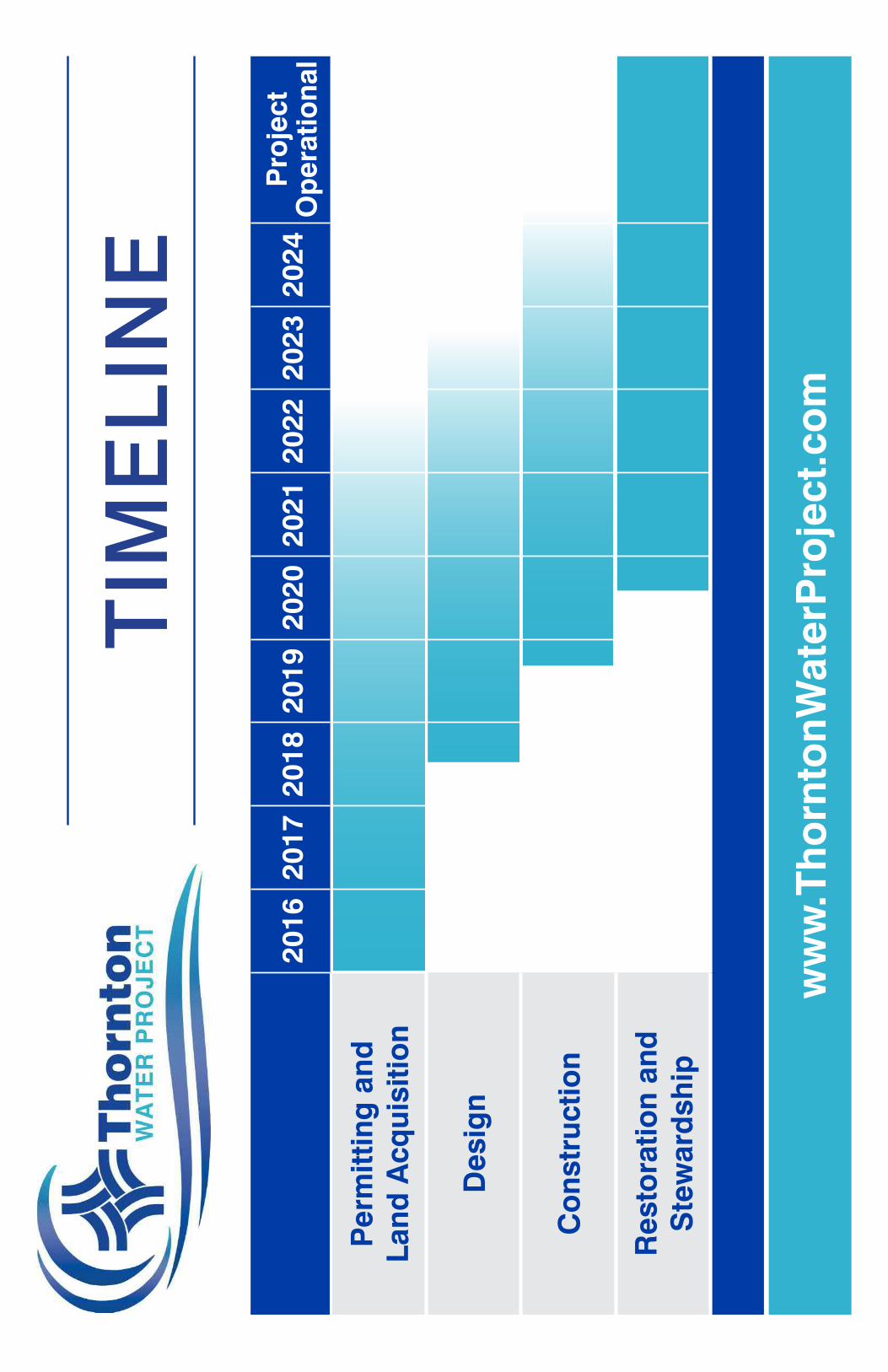

Prepared for: City of Thornton AECOM
Appendix H – Thornton City Council Funding Approval for Project


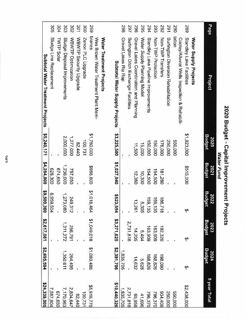


I nil 11 ORD
C. D. No. 2015-150
ORDINANCE NO.: INTRODUCED BY:
3352 Goodman
AN ORDINANCE MAKING APPROPRIATIONS FOR THE CITY OF THORNTON, COLORADO, FOR THE FISCAL YEAR 2016 FOR ALL OPERATING FUNDS AND MAKING APPROPRIATIONS FOR ALL CAPITAL IMPROVEMENT PROJECTS FOR THE CITY OF THORNTON, COLORADO, FOR THE FISCAL YEAR BEGINNING JANUARY 1, 2016 AND ENDING DECEMBER 31, 2016, AND CONTINUING FOR EACH PROJECT UNTIL THAT PROJECT IS COMPLETED OR CANCELLED, AND REGULATING THE PAYMENT OF MONEY OUT OF THE CITY TREASURY.
WHEREAS, the City Council is required to adopt a budget for fiscal year 2016; and t
WHEREAS, the City Council has adopted a budget for fiscal year 2016 and desires to appropriate the funds. i
NOW, THEREFORE, BE IT ORDAINED BY THE CITY COUNCIL OF THE CITY OF THORNTON, COLORADO, AS FOLLOWS: '
I
1. That there is hereby appropriateci for the provision of services and capital projects for the City of Thornton for the fiscal year beginning January 1, 2016 and ending December 31, 2016 the following amounts as follows:
Fund 2016
Expenditures
GENERAL GOVERNMENTAL FUNDS General $110,533,826 Governmental Capital 12,119,752
Subtotal $122,653,578
INTERNAL SERVICE FUNDS Risk Management $3,915,216 Information Technology 6,642,805 Reprographics ' 664,563 Consolidated Service Center • 658.642 Maintenance Services 5.106,813
Subtotal $16,988,039
DEBT SERVICE FUND ; Debt Service $1,806,000
Subtotal $1,806,000

C. D. No. 2015-150
Fund (Continued) 2016
Expenditures SPECIAL REVENUE FUNDS Adams County Road and Bridge $2,412,000 Parks 3,836,596 Open Space 1,139,563 Parks and Open Space 538,852 Adams County Open Space 2,095,923 Conservation Trust 1.859.082
Subtotal $11,882,016
ENTERPRISE FUNDS Water $49,087,709 Sewer 14,435,778 Environmental Services 5.562,727
Subtotal $69,086,214
Grand Total $222,415,847
That appropriations for individual capital projects in the above mentioned funds for fiscal year 2016 shall not lapse at year end but continue until the project is completed or cancelled.
That the City Manager, or designee, shall have the authority to cancel projects and shall have the authority to transfer funds within each fund and project and such transfers shall be entered on the books respective to each affected fund.
That all purchases and disbursements will be made in accordance with the Purchasing Ordinance, Purchasing Manual, and generally accepted purchasing policies and all revenues will be recorded in accordance with generally accepted accounting principles. The City Manager/Utilities Director, or designee, is authorized to enter into and sign all contracts, leases, change orders, and other such documents as may be required to implement the budget. The City Manager/Utilities Director shall have full authority to revise or promulgate policies, procedures, and/or administrative directives to administer the budget.
That the sums appropriated and set forth in the detailed schedule of personnel services shall be paid in accordance with the Pay Plans adopted by City Council for Career Service and Excluded personnel. All positions, position titles, incorporated herein for Career Service and Excluded personnel are authorized and approved. The City Manager is authorized to change positions, position titles, classifications and reclassifications, and reassignments for Career Service and Excluded personnel for all positions authorized in the budget, but no new positions shall be added without the approval of the City Council.

C. D. No. 2015-150
6. That the following Departments, which are under the supervision and control of the City Manager, are established as follows: Economic Development, City Development, City Manager's Office, Community Services, Fire, Infrastructure, Management Services, and Police.
7. That all sums received by the City of Thornton from any source whatsoever, unless by law designated for some special fund or purpose, may be used in meeting the appropriation set out in Section 1 above.
8. That the City Manager is authorized to approve grant applications for projects and to expend funds necessary to meet the terms and obligations of the grant award so long as funds for such projects are within the approved budget.
9. That this ordinance is effective January 1, 2016.
INTRODUCED, READ, PASSED on first reading, ordered posted in full, and title ordered published by the City Council of the City of Thornton, Colorado, on September 22. 2015.
PASSED AND ADOPTED on second and final reading on October 13, 2015.
CITY OF THORNTON, COLORADO
Williams, Mayor ATTEST:
cent. City Clerk
THIS ORDINANCE IS ON FILE IN THE CITY CLERK'S OFFICE FOR PUBLIC INSPECTION.
APPROVED AS TO LEGAL FORM: '
Margaret ^iT^erich, City Attorney
PUBLICATION:
Posted in six (6) public places after first and second readings.
Published in the Northglenn-Thornton Sentinel after first reading on October 1. 2015, and after second and final reading on October 22. 2015.

Ill I III nil 11 III IIIORD
C.D. No. 2016-211
ORDINANCE NO.: INTRODUCED BY:
3413Zvalelbaum
AN ORDINANCE MAKING APPROPRIATIONS FOR THE CITY OF THORNTON, COLORADO. FOR THE FISCAL YEAR 2017 FOR ALL OPERATING FUNDS AND MAKING APPROPRIATIONS FOR ALL CAPITAL IMPROVEMENT PROJECTS FOR THE CITY OF THORNTON, COLORADO, FOR THE FISCAL YEAR BEGINNING JANUARY 1, 2017 AND ENDING DECEMBER 31, 2017, AND CONTINUING FOR EACH PROJECT UNTIL THAT PROJECT IS COMPLETED OR CANCELLED. AND REGULATING THE PAYMENT OF MONEY OUT OF THE CITY TREASURY.
WHEREAS, the City Council Is required to adopt a budget for fiscal year 2017; and
WHEREAS, the City Council has adopted a budget for fiscal year 2017 and desires to appropriate the funds.
NOW, THEREFORE. BE IT ORDAINED BY THE CITY COUNCIL OF THE CITY OF THORNTON, COLORADO, AS FOLLOWS:
1. That there is hereby appropriated for the provision of services and capital projects for the City of Thornton for the fiscal year beginning January 1, 2017 and ending December 31, 2017 the following amounts as follows:
Fund 2017Expenditures
GENERAL GOVERNMENTAL FUNDSGeneralGovernmental Capital
$122,088,66930,342,150
Subtotal $152,430,819
INTERNAL SERVICE FUNDSRisk ManagementInformation TechnologyReprographicsConsolidated Service CenterMaintenance Services
$5,368,3936,920,706
664,252513,791
5,071,317Subtotal $18,538,459
DEBT SERVICE FUNDDebt Service $1,801,800
Subtotal $1,801,800

C.D. No. 2016-211
Fund (Continued) 2017Expenditures
SPECIAL REVENUE FUNDSAdams County Road and Bridge Adams County Open Space Conservation Trust ParksOpen SpaceParks and Open SpaceCash In Lieu
Subtotal
ENTERPRISE FUNDSWaterSewerEnvironmental Services
$7,942,680764,194
1,906,9432,594,2167,240,4332,271,420
188,369$22,908,255
$109,991,57415,060,1215,249,500
Subtotal $130,301,195
Grand Total $325,980,528
That appropriations for individual capital projects in the above mentioned funds for fiscal year 2017 shall not lapse at year end but continue until the project is completed or cancelled.
That the City Manager, or designee, shall have the authority to cancel projects and shall have the authority to transfer funds within each fund and project and such transfers shall be entered on the books respective to each affected fund.
That all purchases and disbursements will be made in accordance with the Purchasing Ordinance, Purchasing Manual, and generally accepted purchasing policies and all revenues will be recorded in accordance with generally accepted accounting principles. The City Manager/Utilities Director, or designee, is authorized to enter into and sign all contracts, leases, change orders, and other such documents as may be required to implement the budget. The City Manager/Utilities Director shall have full authority to revise or promulgate policies, procedures, and/or administrative directives to administer the budget.
That the sums appropriated and set forth in the detailed schedule of personnel services shall be paid in accordance with the Pay Plans adopted by City Council for Career Service and Excluded personnel. All positions, position titles, incorporated herein for Career Service and Excluded personnel are authorized and approved. The City Manager is authorized to change positions, position titles, classifications and reclassifications, and reassignments for Career Service and Excluded personnel for all positions authorized in the budget, but no new positions shall be added without the approval of the City Council.
C.D. No. 2016-211
6. That the following Departments, which are under the supervision and control of the City Manager, are established as follows: Economic Development, City Development, City Manager’s Office, Community Services, Fire, Infrastructure, Management Services, and Police.
7. That all sums received by the City of Thornton from any source whatsoever, unless by law designated for some special fund or purpose, may be used in meeting the appropriation set out in Section 1 above.
8. That the City Manager Is authorized to approve grant applications for projects and to expend funds necessary to meet the terms and obligations of the grant award so long as funds for such projects are within the approved budget.
9. That this ordinance is effective January 1, 2017.
INTRODUCED, READ, PASSED on first reading, ordered posted in full, and title ordered published by the City Council of the City of Thornton, Colorado, on November 10. 2016.
PASSED AND ADOPTED on second and final reading on November 29. 2016.
CITY OF THORNTON, COLORADO
Heidi A Williams, M^r
ATTEST:
Nancy A. Vincent, City Clerk
THIS ORDINANCE IS ON FILE IN THE CITY CLERK’S OFFICE FOR PUBLIC INSPECTION.
APPROVED AS TO LEGAL FORM:
LiMs a. Corchado, City Attorney
PUBLICATION:
Posted in six (6) public places after first and second readings.
Published in the Northglenn-Thornton Sentinel after first reading on November 24. 2016. and after second and final reading on December 8. 2016.

ORD C.D. No. 2017-223
ORDINANCE NO.: INTRODUCED BY:
3450Viqil
AN ORDINANCE MAKING APPROPRIATIONS FOR THE CITY OF THORNTON, COLORADO, FOR THE FISCAL YEAR 2018 FOR ALL OPERATING FUNDS AND MAKING APPROPRIATIONS FOR ALL CAPITAL IMPROVEMENT PROJECTS FOR THE CITY OF THORNTON, COLORADO. FOR THE FISCAL YEAR BEGINNING JANUARY 1, 2018 AND ENDING DECEMBER 31, 2018, AND CONTINUING FOR EACH PROJECT UNTIL THAT PROJECT IS COMPLETED OR CANCELLED. AND REGULATING THE PAYMENT OF MONEY OUT OF THE CITY TREASURY.
WHEREAS, the City Council is required to adopt a budget for fiscal year 2018; and
WHEREAS, the City Council has adopted a budget for fiscal year 2018 and desires to appropriate the funds.
NOW, THEREFORE, BE IT ORDAINED BY THE CITY COUNCIL OF THE CITY OF THORNTON, COLORADO, AS FOLLOWS:
1. That there is hereby appropriated for the provision of services and capital projects for the City of Thornton for the fiscal year beginning January 1, 2018 and ending December 31, 2018 the following amounts as follows:
Fund2018
ExpendituresGENERAL GOVERNMENTAL FUNDSGeneral $129,576,307Governmental Capital 31,500,222
Subtotal $161,076,529
INTERNAL SERVICE FUNDSRisk Management $6,292,404Information Technology 7,538,358Reprographics 663,731Consolidated Service Center 485,769Maintenance Services 6,748,837
Subtotal $21,729,099
DEBT SERVICE FUNDDebt Service $1,800,200
Subtotal $1,800,200
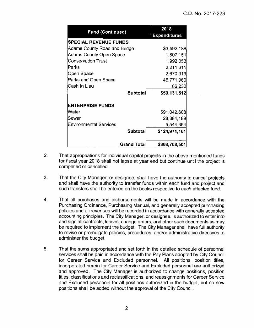
C.D. No. 2017-223
Fund (Continued)
SPECIAL REVENUE FUNDSAdams County Road and Bridge Adams County Open Space Conservation Trust ParksOpen SpaceParks and Open SpaceCash In Lieu
Subtotal
ENTERPRISE FUNDSWaterSewerEnvironmental Services
Subtotal
Grand Total
' Expenditures
$3,592,1881,807,1511,992,0532,211,6112,670,319
46,771,96086,230
$59,131,512
$91,042,60828,384,1895.544,364
$124,971,161
$368,708,5012. That appropriations for individual capital projects in the above mentioned funds
for fiscal year 2018 shall not lapse at year end but continue until the project is completed or cancelled.
3. That the City Manager, or designee, shall have the authority to cancel projects and shall have the authority to transfer funds within each fund and project and such transfers shall be entered on the books respective to each affected fund.
4. That all purchases and disbursements will be made in accordance with the Purchasing Ordinance, Purchasing Manual, and generally accepted purchasing policies and all revenues will be recorded in accordance with generally accepted accounting principles. The City Manager, or designee, is authorized to enter into and sign all contracts, leases, change orders, and other such documents as may be required to implement the budget. The City Manager shall have full authority to revise or promulgate policies, procedures, and/or administrative directives to administer the budget.
5. That the sums appropriated and set forth in the detailed schedule of personnel services shall be paid in accordance with the Pay Plans adopted by City Council for Career Service and Excluded personnel. All positions, position titles, incorporated herein for Career Service and Excluded personnel are authorized and approved. The City Manager is authorized to change positions, position titles, classifications and reclassifications, and reassignments for Career Service and Excluded personnel for all positions authorized in the budget, but no new positions shall be added without the approval of the City Council.

C.D. No. 2017-223
6. That the following Departments, which are under the supervision and control of the City Manager, are established as follows: Economic Development, City Development, City Manager’s Office, Community Services, Fire, Infrastructure, Management Services, and Police.
7. That all sums received by the City of Thornton from any source whatsoever, unless by law designated for some special fund or purpose, may be used in meeting the appropriation set out in Section 1 above.
8. That the City Manager is authorized to approve grant applications for projects and to expend funds necessary to meet the terms and obligations of the grant award so long as funds for such projects are within the approved budget.
9. That this ordinance is effective January 1, 2018.
INTRODUCED, READ, PASSED on first reading, ordered posted in full, and title ordered published by the City Council of the City of Thornton, Colorado, on September 26, 2017.
PASSED AND ADOPTED on second and final reading on October 10. 2017.
CITY OF THORNTON, COLORADO
Eric Montoya, Mayor Pro Tern
ATTEST:
c---Kristen N. Rosenbaum, City Clerk
THIS ORDINANCE IS ON FILE IN THE CITY CLERK’S OFFICE FOR PUBLIC INSPECTION.
APPROVED AS TO LEGAL FORM:
ado, City Attorney

C.D. No. 2017-223
PUBLICATION:
Posted in six (6) public places after first and second readings.
Published in the Northqlenn-Thornton Sentinel after first reading on October 5, 2017. and after second and final reading on October 19. 2017.

ORDC.D, No. 2018-223
ORDINANCE NO.: INTRODUCED BY:
3503Matkowskv
AN ORDINANCE MAKING APPROPRIATIONS FOR THE CITY, FOR THE FISCAL YEAR 2019, FOR ALL OPERATING FUNDS AND MAKING APPROPRIATIONS FOR ALL CAPITAL IMPROVEMENT PROJECTS FOR THE CITY, FOR THE FISCAL YEAR BEGINNING JANUARY 1, 2019 AND ENDING DECEMBER 31, 2019, AND CONTINUING FOR EACH PROJECT UNTIL THAT PROJECT IS COMPLETED OR CANCELLED, AND REGULATING THE PAYMENT OF MONEY OUT OF THE CITY TREASURY.
WHEREAS, the City Council is required to adopt a budget for fiscal year 2019; and
WHEREAS, the City Council has adopted a budget for fiscal year 2019 and desires to appropriate the funds.
NOW, THEREFORE, BE IT ORDAINED BY THE CITY COUNCIL OF THE CITY OF THORNTON, COLORADO, AS FOLLOWS:
1. That there is hereby appropriated for the provision of services and capital projects for the City for the fiscal year beginning January 1,2019 and ending December 31,2019 the following amounts as follows:
^ Fund''^.' 2019Expenditures
GENERAL GOVERNMENTAL FUNDSGeneral $136,044,103Governmental Capital _ 28,609,135
Subtotal $164,653,238
INTERNAL SERVICE FUNDSRisk Management $6,229,133
Subtotal $6,229,133
SPECIAL REVENUE FUNDSAdams County Road and Bridge $3,547,675Adams County Open Space 1,272,400Conservation Trust 1,564,592Parks 450,000Open Space 1,592,270Parks and Open Space 37,890,757Cash In Lieu _ 67,673
Subtotal $46,385,367

C.D. No. 2018-223
Fund (Continued)
ENTERPRISE FUNDSWaterSewerEnvironmental Services
> 2019 i-'.n ■'Expenditures
$77,368,82016,802,5565,649,465
Subtotal $99,820,841
Grand Total $317,088,579
That appropriations for individual capital projects in the above mentioned funds for fiscal year 2019 shall not lapse at year end but continue until the project is completed or cancelled.
That the City Manager, or designee, shall have the authority to cancel projects and shall have the authority to transfer funds within each fund and project and such transfers shall be entered on the books respective to each affected fund.
6.
That all purchases and disbursements will be made in accordance with the Purchasing Ordinance, Purchasing Manual, and generally accepted purchasing policies and all revenues will be recorded in accordance with generally accepted accounting principles. The City Manager, or designee, is authorized to enter into and sign all contracts, leases, change orders, and other such documents as may be required to implement the budget. The City Manager shall have full authority, provided by the City Charter, to revise or promulgate policies, procedures, and/or administrative directives to administer the budget.
That the sums appropriated and set forth in the detailed schedule of personnel services shall be paid in accordance with the Pay Plans adopted by City Council for Career Service and Excluded personnel. All positions, position titles, incorporated herein for Career Service and Excluded personnel are authorized and approved. The City Manager is authorized to change positions, position titles, classifications and reclassifications, and reassignments for Career Service and Excluded personnel for all positions authorized in the Budget, but no new positions shall be added without the approval of the City Council.
That the following Departments, which are under the supervision and control of the City Manager, are established as follows: Economic Development, City Development, City Manager’s Office, Community Services, Fire, Infrastructure, Management Services, Finance, and Police.

C.D. No. 2018-223
7. That all sums received by the City of Thornton from any source v^hatsoever, unless by law designated for some special fund or purpose, may be used in meeting the appropriation set out in Section 1 above and consistent with the City Charter.
8. That the City Manager is authorized to approve grant applications for projects and to expend funds necessary to meet the terms and obligations of the grant award so long as funds for such projects are within the approved Budget.
9. That this ordinance is effective January 1,2019.
INTRODUCED, READ, PASSED on first reading, ordered posted in full, and title ordered published by the City Council of the City of Thornton, Colorado, on November 13. 2018.
PASSED AND ADOPTED on second and final reading on November 27. 2018.
CITYj&FTHORhlTON, COLORADO
!XWrifiams,jyiayor
ATTEST:
Kristen N. Rosenbaum, City Clerk
THIS ORDINANCE IS ON FILE IN THE CITY CLERK’S OFFICE FOR PUBLIC INSPECTION.
API yOVED AS TO LEGAL FORM:
lW a. Corchado, City Attorney
PUBLICATION:
Posted at City Hall, Margaret W. Carpenter Recreation Center, and Thornton Active Adult Center after first and second readings.
Published on the City’s official website after first reading on November 14, 2018, and after second and final reading on November 28. 2018.

Ill I III nil 11 III IIIORD
CD No. 2019-126
ORDINANCE NO.: INTRODUCED BY:
3542Sandaren
AN ORDINANCE MAKING APPROPRIATIONS FOR THE CITY OF THORNTON, COLORADO, FOR THE FISCAL YEAR 2020 FOR ALL OPERATING FUNDS AND MAKING APPROPRIATIONS FOR ALL CAPITAL IMPROVEMENT PROJECTS FOR THE CITY OF THORNTON, COLORADO, FOR THE FISCAL YEAR BEGINNING JANUARY 1, 2020 AND ENDING DECEMBER 31, 2020, AND CONTINUING FOR EACH PROJECT UNTIL THAT PROJECT IS COMPLETED OR CANCELLED, AND REGULATING THE PAYMENT OF MONEY OUT OF THE CITY TREASURY.
andWHEREAS, the City Council is required to adopt a budget for fiscal year 2020;
WHEREAS, the City Council has adopted a budget for fiscal year 2020 and desires to appropriate the funds.
NOW, THEREFORE, BE IT ORDAINED BY THE CITY COUNCIL OF THE CITY OF THORNTON, COLORADO, AS FOLLOWS:
1. That there is hereby appropriated for the provision of services and capital projects for the City of Thornton for the fiscal year beginning January 1, 2020 and ending December 31,2020 the following amounts as follows:
Fund 2020Expenditures
GENERAL GOVERNMENTAL FUNDSGeneral $147,873,460Governmental Capital 36,448,347
Subtotal $184,321,807
INTERNAL SERVICE FUNDSRisk Management $6,181,585
Subtotal $6,181,585
SPECIAL REVENUE FUNDSAdams County Road and Bridge $2,823,710Adams County Open Space 906,000Conservation Trust 1,197,674Parks -Open Space 2,628,869Parks and Open Space 8,369,206Cash In Lieu 559,116
Subtotal $16,484,575
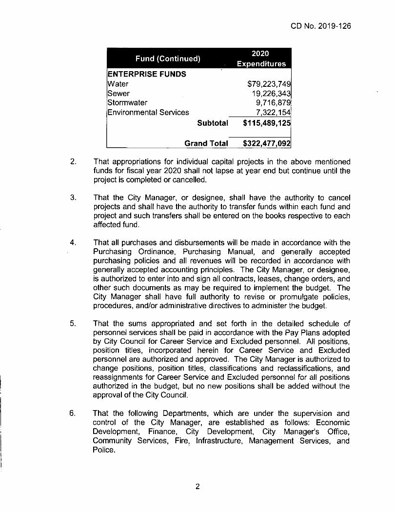
CD No. 2019-126
Fund (Continued) 2020Expenditures
ENTERPRISE FUNDSWater $79,223,749Sewer 19,226,343Stormwater 9,716,879Environmental Services 7,322,154
Subtotal $115,489,125
Grand Total $322,477,092
That appropriations for individual capital projects in the above mentioned funds for fiscal year 2020 shall not lapse at year end but continue until the project is completed or cancelled.
That the City Manager, or designee, shall have the authority to cancel projects and shall have the authority to transfer funds within each fund and project and such transfers shall be entered on the books respective to each affected fund.
That all purchases and disbursements will be made in accordance with the Purchasing Ordinance, Purchasing Manual, and generally accepted purchasing policies and all revenues will be recorded in accordance with generally accepted accounting principles. The City Manager, or designee, is authorized to enter into and sign all contracts, leases, change orders, and other such documents as may be required to implement the budget. The City Manager shall have full authority to revise or promulgate policies, procedures, and/or administrative directives to administer the budget.
That the sums appropriated and set forth in the detailed schedule of personnel services shall be paid in accordance with the Pay Plans adopted by City Council for Career Service and Excluded personnel. All positions, position titles, incorporated herein for Career Service and Excluded personnel are authorized and approved. The City Manager is authorized to change positions, position titles, classifications and reclassifications, and reassignments for Career Service and Excluded personnel for all positions authorized in the budget, but no new positions shall be added without the approval of the City Council.
That the following Departments, which are under the supervision and control of the City Manager, are established as follows: Economic Development, Finance, City Development, City Manager’s Office, Community Services, Fire, Infrastructure, Management Services, and Police.

CD No. 2019-126
7. That all sums received by the City of Thornton from any source whatsoever, unless by law designated for some special fund or purpose, may be used in meeting the appropriation set out in Section 1 above.
8. That the City Manager is authorized to approve grant applications for projects and to expend funds necessary to meet the terms and obligations of the grant award so long as funds for such projects are within the approved budget.
9. That this ordinance is effective January 1,2020.
INTRODUCED, READ, PASSED on first reading, ordered posted in full, and title ordered published by the City Council of the City of Thornton, Colorado, on September 10, 2019.
PASSED AND ADOPTED on second and final reading on September 24, 2019.
CITY OF THORNTON, COLORADO
an Ktilra n A
Jan Ktilmann, Mayor Pro Tern
ATTEST:
Kri^rflC^^senbaum, City Clerk
THIS ORDINANCE IS ON FILE IN THE CITY CLERK’S OFFICE FOR PUBLIC INSPECTION.
APPROVED AS TO LEGAL FORM:
uis A. CorWado, City Attorney