
1980_B2.pdf - ICES
168
I This paper not to be cited witbout prior reference to tbe Council* INTERNATIONAL COUNCIL FOR THE EXPLORATION OF THE SEA C.M. 1980/B : 2 Fish Capture Committee REPORT OF THE WORKING GROUP ON RESEARCH AND ENGINEERING ASPECTS OF FISHING GEAR, VESSELS AND EQUIPMENT • General Secretary, I.C.E.S., Pa1zgade 2- 4,DK 1261 Copenbagen K Denmark
-
Upload
khangminh22 -
Category
Documents
-
view
3 -
download
0
Transcript of 1980_B2.pdf - ICES

I
This paper not to be cited witbout prior reference to tbe Council*
INTERNATIONAL COUNCIL FOR THE EXPLORATION OF THE SEA
C.M. 1980/B : 2 Fish Capture Committee
REPORT OF THE WORKING GROUP ON RESEARCH AND ENGINEERING
ASPECTS OF FISHING GEAR, VESSELS AND EQUIPMENT
• General Secretary, I.C.E.S., Pa1zgade 2- 4,DK 1261 Copenbagen K Denmark
funk-haas
Neuer Stempel

This paper not to be cited without prior reference to the Council*)
International Council for the Exploration of the Sea
C.M.1980/B: 2 Fish Capture Committee
REPORT OF THE WORKING GROUP ON RESEARCH AND ENGINEERING
ASPECTS OF FISHING GEAR, VESSELS AND EQUIPMENT
Convenor and rapporteur E.J. de Boer
Meeting time and place
Terms of reference
Netherlands Institute for Fishery Investigations, IJmuiden - The Netherlands
5 and 6 May, 1980 Reykjavik - Iceland
C. Res. 1979/2:13 (a)The Working Group on Research on
Engineering Aspects of Fishing Gear, Vessels and Equipment, convened by Mr. E.J. de Boer, to evaluate technical aspects of fishing gear, fishing vessels and fishing methods, with special reference to energy consumption of different types of fishing methods and possible ways of energy saving.
This report has not yet been approved by the International Council for the Exploration of the Sea; it has therefore at present the ~tatus of an internal document and does not represent an advice given on behalf of the Council.
The proviso that it shall not be cited without the consent of the Council should be strictly observed.
*) General Secretary, I.C.E.S., Palagade 2-4, DK-1261 Copenhagen K, Denmark.

PARTICIPANTS
!!~!!j~~~ G. van den Broucke
Canada
R.H. McIlwaine
France
G. Kure
J. Prado J.C. Brabant
Fearöes
B. Thomsen
Fisheries Research Station - Ostend
Department of Fisheries and OceansVancouver
Institut Scientifique et Technique des Piches Maritimes - Nantes
11
11 " "
- Lorient - Boulogne sur Mer
Fiskirannsoknarstovan DebessartrpdTorshavn
!~~~~~!_~~E~~!~~_~f_~~~~~~l G. Freytag K. Lange H. Hirschle P. Pfeifer
Finland
M. Tormä
Ieeland
G. Thorsteinsson G. Gurnarsson A. Agustsson
Netherlands
B. van Marlen E.J. de Boer
!:!~~~~~ A. Endal 1. Bjprkum S. Olsen B. Isaksen A. Bredesen
Poland
S.J. Richert
li.S.A.
J.B. Soomala A. Blott
Institut für Fangtechnik-Hamburg 11 " 11
Dornier GmbH-Friedrichshafen Technical University-Aachen
Wärtsilä Turku Shipyards-Turku
Marine Research Institute-Reykjavik Hampibjan H.E.-Reykjavik Fisheries Association of Iceland-Reykjavik
Netherlands Institute for Fishery Investigations-IJmuiden
InsH tute of Fisheries Technology Research " " " Trondheim 11 11 11 Nordnes " " Jl " " " " Tromsp
Sea Fisheries Insti tu te-·Gdynia
C.S. Draper Laboratory-Cambridge, Ha National Marine Fisheries Service Gloucester Laboratory-Gloucester, Mass.
-1~

~!:~!<:~_!S~!:e;~~!!! P. Stewart D.N. MaeT,ennan R.E. Craig C.S. WardIe
Harine Ldbor3..tor:r-Aberdcen " " "
" " "
" 11
11
M. Hatfield D.A. Wileman
White Fish Authority-Hull 11 " 11
U.S.S.R.
E. Postnikov G. Guennadi
Departmbnt of Commercial Fisheries, Ministry of Fisheries of the U.S.S.R.-Moscow
F.A.O.
J. Schärfe Fisheries Department-Rome
AGENDA
1. Progress reports
2. Presentation of papers, films and video-reeordings and verbal contributions
2.1.
2.2.
2·3.
2.4.
2.5.
2.6.
2.7.
2.8.
Estimated fuel saving potential in Norwegian fisheries Anders Endal
Fuel consumption of the Icelandic fishing fleet A. Augustsson and E. Ragnarsso~
Fishing vessel speed and fuel eeonomy Torbjprn Digernes and Anders Endal
Certain problems concerning fuel consumption of small fishing trawlers Jozef Krqpa and Marian Szatybelko
Presentation of films on - Automated long-lining (W.F.A.-U.K.) - Modeltests with rope trawls on scale 1:4 (F.R.G.-Neth.) - Icebreaker operating in Antarctic winter conditions
(Finland)
Report of the expert group meeting in Aberdeen (5-7 February 1980) on the Draft Code of Practice for the Conduct of Fishing Gear Experiments (C.Res 1979/2:14)
Presentation of video-tape recordings on - The behaviour of trawls in action and the reaction
of fish to the approaching gear C.S. Wardie
- Modelexperi·ments wi th a tuna purse-seine Jo;;l Prado
Engineering trials with a conventional and a rope trawl of 2700 meshes circumference David N. MacLennan and Bob van Marlen
2.9. Preliminary report of the blue whiting fishing experiments east/south-east of the Faroe-Islands in JanMarch 1980 Stein Hjalti i Jakobstovu and ~prnur Isaksen
2.10. Problems encountered in the correlation between the results of engineering performance trials of full scale trawls at sea and scal.ed model trawls tested in the White Fish Authority Flume Tank, Hull D.A. Wileman
-2-

2.11.
2.12.
2.13.
2.14.
2.15
An investigation into the towing drag and design of a pelagic net H. Hirschle and H. Pfeifer
Scallop drag tests and development Alan J. Blott and Vernon E. Nulk
A new era for krill catching is dawning Natti T. Törmä
Latest development on gear instrumentation Peter Stewart
Model experiments on rope trawls,scale 1:4 Bob van Marlen
3. Recommendations Progress reports - agenda item 1.
Objective of the progress reports is to inform the participants about recently started and planned activities by member countries in the fields of gear technology, equipment and vessel development.
~~~!!i~~::: A new type of bobbin-groundrope for shrimp trawls was tested. The bobbins are of rubber and connected to a chain. It is expected that this type of bObbin-groundrope will have a better resistance against abrasion.
Comparative fishing experiments wi th beamtrawls '''ere furthered.
Three types of semi-pelagic nets in combination with two sweep systems were tested for the coastal fleet.
The potentials of ovalotterboards (polyvalent-type) were tested for application in coastal fisheries.
Polyamid and Polyethylene yarns were tested on their elongation/ shrinkage characteristics after repeated moistening and drying. It was reported that in Belgium about 65% of the synthetic yarns used in fisheries are of Polyamid. The remainder 35% is Polyethylene. The I.S.O.-standards for yarn, etc are only used by the Fisheries Research Institute.
An on-board flatfish grader of Dutch design was tested.
The development of an underwater, battery powered pulse-generator for shrimp fishing was started. This generator will be put into the operation mode by me ans of apressure switch.
A study into the possibilities of saving energy onboard fishing vessels is planned.
Canada
In Newfoundland a trial with bottom-set long-lines fishing far cod was carried out. The objective was to compare the hooking rate of spun nylon and monofilament gangions.(snoods). The monofilament gangions yielded 47.5 fish per hundred hooks as compared with only 19.1 for the spun nylon gangions.
Trials vii th a rope-,ving midwater trawl in contact wi th the seabed when fishing for cod were not successful. Although the netsounder indicated that the net behaved properly and even though commercial tra\'ilers caught cod wi th bot tom trawls in the area the catch of the rope-wing midwater trawl was almost nil.
-3-
Comparison of ship sounder with netsounder treces indiented that eod was avoiding the trawl.
Squid jigging experiments were conducted in the Halifax region by two 12 metre inshore vessels. For commercial demonstration these vessels were fitted with automated Japanese equipment.
In the New Brunswick area pair bot tom trawling with inshore vessels was demonstrated. The pair trawl was twice as large as the net towed by single boat operation.
The development and promotion of stern drum seining on the eastcoast continued with the outfitting of a 13.5 metre vessel.
Both for eommereial operation and for demonstration a 13 metre Norwegian fibreglass sjark elass vessel has been fitted with a full shelterdeck and a complete 11.000 hook Mustad Autoline-system.
On the west coast a proto-type of a combination midwater/bottom door ,.,as tested. This door has features of both the German Süberkrüband the French Portier-door. The aspect ratio is 1.3 and the tow plates are fully adjustable.
The development of rope trawls was furthered. Tests "ere carried out "ith pressed aluminium eyes and spliceable ropes of 7/8" and 9/16" diameter.
The development of an eseape meehanism for lost traps in the black eod fisheries has started. Practiee has sho"n that the normally used cotton panels last too long.
A projeet has started to eateh rock fish onboard a 25.5 metre combination seiner/long-liner with the Mustad Autoline-system on hard bottom ground in the area of the Queen Charlotte Islands. The latter system is housed in an aluminium container whieh in offseason ean be stored onshore.
Experiments "ith hexagonal meshes in salmon seiner are planned.
Trials and demonstrations "ith very large mesh tra"ls are planned.
Finland
Full seale travlling experiments in iee eondi tions were conducted onboard the Finnish iee-operating tra"ler "Järvsaar". This 30 metre vessel "ith a propulsive po"er of 1000 h.p. can, "hen the iee coverage is less than 80 percent, operate in 30 cm pack ice. The operations in solid ice is restricted to 5 em iee thiekness.
Model tests with tra"ling under the ice in different iee eonditions "ere started. These tests revealed that operation in solid ice up-to 30 em thiekness is feasible. Depending iee coverage ratio, in pack iee of up-to 50 em ean be tra"led.
Model and full seale experiments "ere carried out "ith the "Wärtsilä Air Bubbling System" (WABS) for clearing the aft area of the stern of iee blocks when shooting and hauling the gear.
Model tests were eondueted to loeate the optimum position of the sonar onboard iee operating fishing vessels.
A proto-type of a year-round operating krill faetory trawler was designed. The onboard proeessing lines' "ill deliver peeled krill, krill meal and krill oil.
-4-

France
The very large mesh tl"lo-boat midwater triCul" are fully introdllced in the coastal fleet. 5mall trawlers up-to 600 h.p. use these gesrs sllccessfully.
In 1979 a newtype of rigging permitting bottom trmlling in shallo;[ waters with this type of trawls was developed. In this rigging four doors are used. In addition to the two commonly used otterdoors two small midwater doors of the Süberkrüb-type are positioned at the ends of the upper sv/eeps. The main advantage is that i t is not necessary to change doors when changing over to bottom trawling.
The shrinkage of polyamid webbing is contineously creating problems for especially the fishermen fishing for llephrops. Special attention is given to this problem.
A new type four panel high-headline bot tom trawl is tested in the Mediterranean. The top panel and the upper part of the side panels is constructed of 800 mm meshes. The webbing of the lower panel and the bot tom part of the side panels has a meshsize of 200 rnrn.
In co-operation with the Institut für Fangtechnik (Hamburg) comparative fishing experiments were carried out in the English Channel onboard the German FRV "Solea". Objects of comparison I!ere a German rope tra\ll and a French trawl wi th very large meshes. These comparative experiments will be continued in June 1980 in the Baltic Sea.
The results of tests with a sorting panel for Nephrops rigged inside an ordinary bot tom trawl were encouraging.
In the sardine fishery in the Gulf of Biscay traditionally purseseines 'Iith a floatline length of 200 to 300 metres are used. The theoretical depth of these seines is 60 metres. Measurements under commercial operation revealed an actual depth of 23 metres; the sinking speed was in the order of 10 to 20 metres/minute.
A Nonlegian and a French type of long-line "ere tested.
A distant-water trc"vler made in October/November 1979 an exploratory krill fishing expedition during ,Ihich both bot tom and midwater trawls were tested.
The performance of scale models (1:40) of tuna purse-seines were observed in a basin.
The construction of several 1:20 models of doors has started. These doors '-,ill be tested "hen in operating wi th a model of a trawler.
A sailing vessel for tuna fishing (trolling) is under construction.
~~~~~~~_~~E~~~~=_~~_~~~~~~~ The tests with models of trawls on scale 1:4 in the Mediterranean were in 1979 directed to the performance of rope trawls. Research subjects 'Jere rope trawls and spherical otterboards.
In the Waddensea area experiments to catch grey rnullets wlth gill nets (PA monofilament) were carried out.
The development of an electrified gear "for catching sole l;as finalized. The research and development activities will now be directed to catch plaice with an electrified system.
In co-operation with the l.S.T.P.M. (France) the differences in catching and engineering performance (e.g. resistance) of a rope trawl and very large mesh trawl were studied ..
-5-

In the Baltie Sea experiments were earried out to eateh co,1 ~ith two-boat midwater trawling. One of the main Qbjectives of these experiments was to establish the level of fu~l saving whieh Gan be obtained with this method. '
Gillnet fishing was further introdueed into the eoastal fleet. Adaptation on the loeal hydrographie eonditions was neeessary.
The (further) introduetion of low-energy fishing methods as anehor seining and long-lining (eod) are in the planning stage.
An automation projeet has been earried out in an eel farm uhieh uses the eooling water of a power plant.
During three eruises of the New-Zealand projeet mesh seleetion experiments ware carried out.
The integrated fishfinding system (sonar-eehosounder-netsounder) is installed onboard the FRV "Wal ter Ren/ig".
The re port of the 1978/79 Antaretie Expedition is finalized. One of the interesting observations is that krill eould be detected by standard 30-33 kC sounders.
Windtunnel tests on sheet webbing were earried out by the University of Aaehen and the Dornier Aireraft Company.
Ieeland
Experimental fishing on blue whiting "as carried out with rope trawls and high-headline bot tom trawls. The handling of the rope trawls created problems. The amount of catch was in some cases much less than could be expeeted "hen examing the eehosounder traees. At the various fishing grounds the blue whiting showed different behaviour patterns.
Performance measurements of different types of otterboards were earried out. Among others, the door- and wing-end spread of the gear was measured.
Seleetivi ty experiments ,Ji th four-panel prawn tra"ls were earried out. The seleetion faetor of 40 mm eodend meshes "as determined. It lias observed that only a fe,l prawns eseaped in the 'Iings.
The eatehing of squid by midHater trawls was tested. Due to ineorreet meshsize in the belly part of the gear many squids meshed in that area. The squid, ,;hieh only frequents the area every 5th or 6th year, is mainly used as long-line bait.
Various types of fishing materials, e.g. purse-seine netting, has been tested.
An experiment to eateh blue whiting by high-headline trawls is in the planning stage.
The Netherlands
The research group developing an efficient eleetrieal barrier \;hieh prevents fresh water fish to enter the eooling intake and/or discharge systems of industrial plants studied and analized the behaviour of small fishes (5 and 8 cm -length) in eleetrieal fields. These behaviour studies ,!ere carried out in a small flume tank (6m x 0.8m). Under optimum conditions 95 percent of the fishes did not pass the electrieal barrier.
-6-

The prototype of the flatfish grader was further tested on board a powerful commercial beamtrawler fis hing in an area where the composition of the catch and the condition of the seabed differed from previous tests. In addition to research into the influence of the grader on the survival rate of discarded flatfish also technical and ergonomical research was carried out.
Research wa's carried out into the possibili ties and condi tions of using heavy and blended fuel oils for the propulsive machinery of different types and powerranges of fishing vessels.
In 1979 the activities in relation to catching flatfish species by means of electric stimulation were limited to the development of a new type of pulse-generator and analysis of the results obtained in recent years.
The study into the application of multi-chine hull forms was continued. The parameter study to be used when designing the optimum (beam) trawler was extended with data of 16-27 metre vessels. As a result this study covers vessels in the 16-40 metres range.
The geometry of rigging and net-opening of a rope trawl from the D.D.R. and a large meshed trawl of almost identical dimensions ,.ere studied during a cruise of the FRV "Tridens" in which also staff and instruments of the Marine Laboratory, Aberdeen participated. During this cruise also new developed and converted instruments for gear performance measurements were further tested.
In co-operation with the Institut für Fangtechnik, Hamburg model research on models (scale 1:4) of rope trawls was carried out. Model research on a 1:10 scale model of a Dutch roundfish trawl designed for an area with sandridges was carried out in the flume tank of the Fisheries Training Centre, Hull. In addition the full scale ge ar was tested during instrumented gear trials in said area.
Experiments with Danish pair seines were carried out and this relatively selective and low-ene~gy fishing method was further introduced in the fishing industry.
Technical research in the field of mussel farming was directed to further improve the hydraulic transport of mussels from the seabed into the hold.
In co-operation with the diving team of the Marine Laboratory, Aberdeen observations of a high-headline roundfish trawl for fishing cod in areats with sandridges and a beamtrawl l1ere recorded on video-tape. Also some reactions of fish to the approaching gear and in the net l1ere observed.
~':~::::~;z G·ear research and development and related subjects The study into the parameters of influence, among others hook shape, on the efficiency of long-lines l1as furthered. Experiments l1ith the wide-gap hook, of which the point of the hook is directed to the attachment of the snood, showed a 30 percent increase in catch-rate of ling and tusk.
The influence of hook- and bait size on the selectivity was studied.
The Mustad Autoline system is fully in operation onboard larger vessels. A smaller version, the Mini-line system, is in the prototype stage.
Because of the growing interest in squid trials with squid jigging machines of Norwegian design were carried out.
-7-

In the field of gillnet fishing thc influence bf thc amount of floatation, haging ratio, etc on both the selectivity and the catch rate was studied.
Research to limit the catch of fish by lost gillnets, the 80-
called "ghost-nets", is in the planning stage.
The influence of the netting material on the quality of the catch is subject of a study.
In Nephrops fishing baited pots and hauling systems are introduced.
In the trawling sector of the industry the main effort ,las directed into a joint project of Iceland, Far Oar and Norway in blue whiting fishing. In this project a midwater trawl was used of whict the front part consisted of braided hexagonal ropes.
In co-operation with the Marine Laboratory (Aberdeen) in the summer of 1980 pair trawling experiments in the North Sea will be carried out.
The development work on a shrimp sorting tra\d has been finalized. At the moment tests are conducted to determine the effect of the sweep length on the by-catch of fish during shrimping.
The purse-seine with hexagonal meshes is in use or on order for several commercial vessels. This new type of purse-seine proved. very successful when catching capelin. The main advantages are: the weight of the nylon is reduced by 15.5%; the same sinking speed can be obtained with about 67% of the weight (lead) and the hydrodynamic resistance is less.
The development of mechanized nethandling systems onboard purseseines is extended to l~rger vessels.
Vessel research and develo ment and related sub"ects The activities in this field are directed to A the design of new vessels, (B) the safety and working conditions onboard and (e) the energy efficiency of fishing operations. ad.(A) designing of fishing vessels
deck machinery for gear handling systems catah handling and storage systems
ad.(B) seaworthiness and seakindliness studies safety and lifesaving equipment wheelhouse lay-out and instrumentation noise reduction accident analysis
ad.(e) energy economy resistance and propulsion machinery systems waste heat recovery
Uni ted States of America
Gear research and fish behavior studies in the U.S. are carried on by the National Marine Fisheries ~ervice (N.M.F.S.), state agencies, universities, and individuals. Much of the work is invol ved ",i th conservation gear, sampling gear, gear efficiency and technology transfer. Following are some of the projects underway in various parts of the U.S.
-8-

Massachusetts Institute of Technology is pl~nning comparison studies of the hydrofoil door for this summer. The doors are currently being commercially produced. Aluminum trawl doors for shrimp trawls are being developed, ",nd the developmcnt of a semiautomatic trawl door hookup has been completed.
Studies on large mesh and rope trawls are planned in conjunction "li th Massachusetts Mari time Academy. In addi tion, Hassachuset ts Maritime Academy is testing a modified Boris Goshawk to determine its performance on hard bottom and is working on a towed camera vehicle for observing trawls.
In Virginia, midwater pair trawls have been introduced for the bluefish, mackerel and sea trout fisheries.
A hydraulic oyster dradge is being tested by commercial fishermen.
University of Florida investigators have used their flume tank for the development of shrimp beam trawls now being used commercially and are eurrently testing 1/10 scale doors of their design.
The University of Georgia 1s developing a 3 wing tongue trawl for the shrimp fishery. This will allow shrimpers to use smaller doors to nchieve the same spread with a higher headrope height. The use of the trawl HilI reduce fuel consumption.
Var10us laboratories of the National Harine Fisheries Service have ongoing projects ,,:hieh "ere reported on last year. These include the sea turtle excluder shrimp trawl. Testing of the experimental trawl is completed, and the data is being analyzed.
A satellite transmitter and a radio transmitter were attaehed to a loggerhead turtle ,.hieh \':as released in the Gulf of Hexieo. Bet"een Oetober and December, the turtle was located büce by satellite and several tirnes by airplane-rnounted receivers.
The porpoise tracking programme is also continuing with a second generation system under development, and seine-related porpoise mortality is still being investigated. Current Hork concerns eorrelating different set eonditions with variations in the mortality rate.
A spanish semi-pelagiC trawl i5 being testeu to determine its ability to selectivity eatch shortbelly roekfish on hard bottorn off California.
The NHFSGloueester Laboratory has some continuing projeets which were mentioned last year. They incIude a study of existing seallop drags and the design of a new one, and an investigation of beam trawls for the small boat fleet. A Dutch be am trawl has recently bee·n ordered for this purpose. In addition, we have under study juvenile fish sampiers and a ne" groundfish survey trawl for the assessment biologists.
~~~!~~-~~~~~~~ Scotland Semi-pelagie trawls A range of semi-pelagic trawls has been developed whieh can be used to eatch both pelagie and demersal speeies. The main design feature which eontr1butes to the duel role of the trawl is the smaller mesh size in the belly compared with the top and side panels. Thus the trawls have the large mouth opening and lcw drag charaeteristics of pelagic nets, while the belly mesh size is appropriate for the retention of whitefish.
-9-

This impliHs d;,. larger area cf b~'.ine in the lOHCr' :,anel Gom~,2:red
\"fi th th,; top and eided however" and full 3cale test.::; hU'{e uho':Jn thnt the r~tio cf twine ~rea in the belly to tha other thr02 ;"n818 must be le"," th;ln a critica.l "lTalue ("round 0.]]) tel ~void distortion cf the net. Sev0ral co~mercial fishing ve~G'·lc have been using the 200 and 600 HP "lTDrGion of t:le trawl H:C th con~iderable succe83~
:tape tra~"ls Experiments wi th rope trawls h;1V{~ eon tinued in coll~bora t ~.O:1 with the Netherlancis Institute for Fishery Inv8stigc;tionc, IJmuiden .. A team from the Harine Labora.tory, Abordf~8n, partic:i.lL~.ted in gear trir.:tls on board thc Dutch research veseJel lI'rrid,"::,n;<1! ',,;hen engineering performance tests were done on ra.pe tr"iJ,\,'13 and for cornparison a conventional pelagic trawL. lrhe ad~l,>,nt/'~g'''' 0 ':,' rape panels in reducing drag for the same ~Du,th openinG h~D been quantified by these tests, and mcasurement of th0 tension in individual ropes h~s provided uscful infor~~tio~l for ~hc design of rope pClnel.s ..
Demer:Jal trawls Development "lork haG continued on a range ,Jf '::.h.::'(.'";e-bridIe Lüttorr: trawls whieh "re Guit'cble for use wi.th both 2.iiSht Cl.nd hoa:;] groundropes~ Model tuets have been carried out in the Whi~·; ?is!~
Authority Flume T~nk &nd full Beule tests have ~0en done on 200 HP vercion of the net.
Other work l!"'urther measure1~lenbj ha.ve been mnde on thc 3eometry cf lJt:JJ,~:'.~J,C
trawl while it i8 manoeuvred, using an imp~oved comput~r-~~sed system whieh can truck up to faur acouetic pingcrs ~tt:lchüd to the tr<:ivJl .. The analysiu of results is ~'·;t:Lll in progrC'2s ..
'Ehe theory of stress distribution and meßh geol1lvtry of tr:.,,1t:l ni:tc:. has bt":en investigated 1 ::lnd m[i,them[~tic;3 .. 1 modp.lG of th<; TI ·.t i"re undcr devclopment l-fhich tL\.ke ac count o_~ irnportD.!lt feai::urer,; .,':uch -3.-e Gt;lvedc:;ü joins .. Convergence problems havp been cX}ic-riC':nced with thc complicuted cquation sets involved in ~h~sc ~oGclOt <-<-nd werk is continuing ..
ReGenreh into the effect of trr:wl gC'LT on Q'~{P0(3C{, :Ui':)(:line':::i C'::o..nd vicc versa) has been sponbored by the oi:L :Lncl.ustry .. Th:!.c; :"L ;~n intern2tion:.l project in which Marine Lt,borntory Gt~ff h~vc ~een involved as eonsultc.nts. The rosults sho" th1..t '16 inch dLmeter or larger pipelines, properly reinforcbd, cun sufely witfistand impacts from the heuviest trawl genr. Smr..ller pipelines IbY be dnmnged if 1eft expoaed.
12~~!~~_!S~::g~~:::: ,!hi te Fiah ,iuthority Comparative fishing eX}leriments hith electri.fipd bec.m trc,,,,ü; were furthered .. Four experimental cruises uere f:1[:tdc U.siLZ the American Oceanharvester equipment. In tota: in the order of 400-450 tows leere mi·.de. Ana1yzing the resu~.ts the eateh rates of the electrified geer turned out to be equ[cl or 10;6 above those of standard beam trawls. Pulse rate frequeneies of 4 and 6.25 p.}l.s. were used and the discharge vo1tage of the eleetrodeG ranged from 170 to 220 V. The optimum tra;fling E;peed was 2-2.5 knots. During towing the eleetrified gear ,wes ':;0-40% less fuel than the standard, chuin rigged beamtre'll. Over a eom}llete eruise the fuel saving was 12%.
-10-

For use ao ''1. JU::J.l parpose on- ::lnd off-ba t. to~n tr:1.",,;,l_: a rope trcd,:l w.o designed for 650 HP vessela.
'l'he prototYl1e " rlu toclip" fully r,utomated lonGline bnitinG nnd handling sY,':3cem ha.::; at the moment been used undc':'r commerc_~al eonditions for 13 months. During this neriod li ne shooting was u~ually earried out nt 4.5 knots. The erew of the 15 m commereiul fishing ve3scl eonsisted of 4 men. The eosts of the unit is estimated at , 20.000.-25.000 ineluding u line wit. 10.000 hooks.
E~perimcnts ~re carried out to catch roundfish species, Dainly suithe, by gillnets on untrawlable grounds of N.W.Scotlal1d.
;\ fe::tsibili ty study into the possibili ties of el1ergy savj.ng in fishing was started.
Trials were carried out to definc the initial size of mefihes t"king into aeeount the shrinkage. To determine the shrinkage BDveral eodends of different material was measured after fishing on and off the bottom.
The }'lume Tank haD been used for 75/0 for courses. At :U! "verage two courses per month nre given. Thc r~maining time i8 used far tcsting modHls of tr3.ltls, nets and components f e"g .. floatE .. For dcmonstriltion of the geometry and behaviour of fishing g'2ars ovcr 100 models are Qvaile,ble. The development work includes at the moment a bottom p~ir trawl with flying wings, a small bottom tra"l for cQ~ching Dole and a three bridle bot tom trald for vesselu of 300 HP. The latter tral-Il has "- vertiertl netopening of 12 m"tres.
U .. 3.,S .. tL,
Sxperiments with bottom-sct longlines fiching for cod were carried out in the coastal ilrea of the Barentz Seu.
3,_c'leetivity factors for h'lddoek, eod and red fish were dEterrüned when fü:hing 1fi th bottom trawls in the Barentz Sea.
The Lurviv0..J. rate OJ'~ diGc:\rded small flounder \.;Jas determined ..
c>elGetivi t;, experiments >!hen fishing for shrimp (PandaluE bore;;Li.s) in the B~ren:~ Sen resulted in the npplie~tion of larger meshes .i.n thc codend.,
V,.!.rious typeG of fißhinG material (we bbing ~ ropes, etc) has been tested.
I
J:n thc NorwegiD.n Sec. rape trawls are used all yeGr ,round for c:,tching blue I1hi ting. At ren average the eateh is 30-40 rretric tonnc-c p,-r 24 hours.
-1'he beh"viour end geometry of a midwater trawl wns _observed by !:';f~anB of undeI'I,,,,,,<tcr c[}merafs.
E'"A",O.,
Direetory of Fishing Technology lnstitutiops and Services. This venture has taken mueh longer than even the worst pessimists expected and we are still lacking completed satj.sfactory questionnaires from some institutions of·leES member countries with important fisheries such as the USSR, Poland, the German Democratie Republic, Canada. As you will recall Council Resolution 1977/3:2 requested member countries to cooperate with FAO by providing the neeessary information and I da hope that those mentioned above will comply with the least possible delay. Otherwise they will just have to bIO left out because we cannot waft langer than
-11- ,
•

.Tune 1980 latest. Ae CEll bo Seel' by n";! thc Directory will include smne 50 j.nsti tu tions, uni t8 01' service" from 30 to 35 coun tries, dopending on rsceipt of still outstanding replieG to requests and enquiries Oi Since this cannot go on forcve:c ~re intend to compile and finalize what we can get b,· June 1980, and lwve the first iSDue printed and distributed LC quickly PS possible after", A revised and improved verf:ion, based on constructi,ve criticism, corrections und up-dating information we hope to receive will be prepared thereafter ~s Rppropriate.
Promotion of FishinLTechlloloe;;Y. Services/UniE2. Gonsultaneies provided to developing fisheries included AIgeriR, thc Philippines, KenYD_, Tanznnia and Zambiu. Earlier indcntification consultancies to Sierra Leone und Indonesia are being followed up by implementation consultancies to assist the loca:'. 1tuthorities in the achtal establishment of national fishing technology uni 1;8 and relatod planning, programming -and ini tiar.ion of systematic development work. In Sierra Leone it is hoped to mobilize active cooperation and assistanee for the _new national fishing teehnology unit from a "ubstantial small seale fisheries development project so on to be started by German bilateral aid. A similar eooperation could hopefully develop with Norway bilateral aid in Tanzania. 'rhe consul tant for Indonesia VIill be our Gonvcner. The FAO/Norway project under the GEGAF umbrella for the establishment of a national fishing technology service in Senegal as part of the Direction de l'Oeeanographie et des Peches Maritimes has finslly been started by end '1979. und is prcsently being supported by a consultancy by G. Nedelec. l'Iuclei of national fishing technology services promoted by FAO h;lve been created in Morocco and Tunesia, although the TCP project for Morocco did not materialize. Recent examples for pr01~otion through contributions to meetings and papers include the enlarged Version of 'rh" Role of Fi.shing Technology in the Management and Development of Inland Fisheries in Africa (in English and French), a contribution on request to the magazine Oceanus of the Wo<)ds Hole Oceanographic Institution on Fishing Technology for devedoping countries which are both on display and a contribution on r'_'queat covering fishing technology for the McGraw-Hill Encyclopedia of Scümce and Technology. The TCP project to Brazil providing separate crash courses for the technical upgrading of fisherie<l extension officers in the fields of fishing technology, fiah processing and marine engineering ia prenently being implemented. The intention is to increase the competence for applied technolosy of staff for, inter alia, national fishing technology services. -
Community Fisher;y Centr€> (CFC) Deve~!.t Concept In developing fisheries incr'9asing emphasis 1s being givsn to the artisanal seetor anel to an integrated approach at eommunity level. FAO has developed a concept which involves loeal or regional fisheries technology and extension uni:s (FTEU) servicing clusters of neighbouring fishing communities 1<ith technical backstopping. A paper Community Fishery Centres and the Transfer of Technology to Small-Scale ~'isheries by M. Ben Yami, Hhom many of you know [\s a prolofic fishing technologist, and who is the main initiator of this concept, is on display. Si.nce fishing technology i6 a major component of any fishery development~the coordination of this concept with national fishing technology services/nnits is obviously indicated. Some of yon may ",lso be interested in this paper with regard to relevant bi-laternl technical assistence ventures ..
-12-

Training courses The lecture notes of the ,joint }'rench (ACTIM) and FAO sponsored Training Course in Fishing Technology for francophone African countries, have been revised snd expanded and a copy of this improved version is on display. Also on display is a copy of the preliminary report of the similar Norway funded couse for anglophone countries of the Western Indian Oeean area whieh was sueeessfully implemented with active participation of
· ,
Steiner Olsen and some of his staff in Coehin, India, in November/December 1979. FAO is most grateful to thJ French and Norwegian donars for making these courses possible and for the active assistance and support of our colleagues in the implementation. It is now intended to marry the lecture notes of these two courses to serve as standard background material for similar courses on regional or national level. We hope that we will be able to provide, in due time, English, French and Spanish vers ions of this course material for general use. . Preparations are unde way for a joint French/FAO course on more advanced marine fishing technology to be held again wlth active ISTPM-participation in thelr outpost in Lorient by May 1981. Request to Norway Aid for one cOUrse on fishing technology each for Central American and snglophone African countries are awaiting donor decision. Two Norway funded Training Courses on Fishing Vessel Design have been held for English speaking participants in Thailand and Spanish participants in Ecuador. Lecture notes from these cOUrses are being compiled as a design manual for small fishing boats to be published in both languages. .
FAO Fishing Technology Publications In the se ries of FAO Fishing Manuals, Echo-Sounding and Sonar for Fishing and Tuna Fishing wi th Po:;',o and Line are wi th the copublisher Fishing News Books Ltd o snd should come out soan. There have been deplorable delays with the finalization of Prof. Fridman's manuscript on Calculations for Fishing Gear Designs which 1s still with our colleague John Carrothers. The same applies to the manuscript on Squid Jigging with Small Boats which was found to need much more technical and language editing than had been expected and also to the Fisherman's Pocket Book. We hope to finish these manuscripts latest by Autumn for delivery to the co-publisher Fishing News Books Ltd. There are several more titles in different stages of development. The first title of the FAO Better Fishing Books (IIPOP"series) on Pair Trawling ;lith Small Boats to be pUblished by FAO in English, French and Spanish is still with the printers but will hopefully come out soon. The second title Gillnetting is ready in manuscript
·and awaits printing, also by FAO. More titles of this series which is meant to serve extension workers and semi-literate fishermen are under consideration pending the reaction on the first "test"-issue. The complement of French literature to the English part of the FAO Fisheries Technical Paper No. 184, Bibliography for :Fishermen's Training is on display. The series number is 195. The third and last part containing Spanish literature is with the printers. You may recall that this material was compiled by Prof. A. von Brandt under FAO contract. Your constructive criticism of this collection with suggestions for additional material on fishing technology is invited.
-13-

The English version of the FAO Fisheries Technieal Paper No. 189, Bottom Trawls for Small-Scale Fishing, which had been prepared in Freneh by Nedelee and Brabant has come out and is on display. The Spanish version is under final preparation. The manuseript by Dahm and Lange of the FAO Technical Paper on Monitoring Trawls in Action still requires substantial language editing whieh is under way. Of the publications under the FAO Fisheries Teehnical Paper series prepared by our boat people in the sub-., series Fishing Vessel Design, which are at least'partly relevant, the titles Small Trawlers whieh is being finalized and the further titles Multipurpose Fishing Vessels and:Steel Vessels for Offshore Fishing to come out in 1981 should be ~entioned. The same applies to anothe~ sUb-series, Engineering'Applications, the first title of which Installation and Maintenance of Engines in Small Fishing Vessels is on display. For the preparation of the seeond tentative title Mechanically-Operated Hauling Gear for Small-Seale Fishing, your assistance is requested. This paper is intended to present a good seleetion of devices such as net and line haulers and winehes with installation arrangements and aecessories for small boat trawling, be ach and boat seining, gillnetting, hand- en longlining, trolling, potting, etc of a design suitable for loeal construction. Presentation and instructions will be of a kind and teehnical detail that loeal artisans and workshops ean use them as practieal guide for produetion. FAO would like to have as complete a collection as possible of such simple meehanieal divices as possible which are or have been in commereial operation and urges those of you who are aware of or ean lay their hands on relevant descriptions, sketches', drawings, photos, etc of such auxiliaries to send these to us soonest. Your cooperation in this matter will be highly appreciated. At present we need only mechanieal operated devices. Hydraulically driven auxiliaries will be dealt with in a subsequent issue. The eontract with the Technical College in Hull for the preparation of film strips on fishing gears and methods did not materialize. Another contract has been made with the German-Israely Fund for Rural Development to prepare such film strips on gillnetting and on purse seining with and without light attraction.
Field Aetivities Regarding those relevant to this Meeting, I am sorry to report that no signifieant progress could be made so far in developing the exploitation of meso-pelagics or lantern fish. In view of the impact of escalating fuel prices on trawling, other techniques than midwater trawling would need to be studied and this is certainly achallenging task. Again with regard to the need for fuel saving and also the increasing emphasis on small-scale fisheries already mentioned, the re~ival and further development of sailing fishing boats and of sailingcum-auxiliary engine concepts gain more and more attention. Active development work in this field is being done in the SIDA funded Development of Small Seale Fisheries in the Bay of Bengal Projeet (GCPjRASjo4ojSWE). This project is also concerned with developing beaeh and surf landing craft with better fishing capacity than the traditional boats or catamaran log rafts. One 7.4 simply constructed hull with buoyancy provided by polystyrene and another completely enclosed hull are being tested as replacement for the log raft and better sailing rig for loeal boat trials were started in Sri Lanka where also a double hull eonfiguration for simple beach landing is being considered.
-14-*

Further evaluation of sail propulsion with auxiliary motor is being carried out in the UNDP/FAO Vessel Construction ar.d Bottom Fishing Demonstration Porject (TON/77/002) in Tonga with double and single hull craft. One of the two boats built during the Danish financed regional Training Course in Small Fishing Boat Construction (GCP/RAF/133/DEN) late 1979 in Sierra Leone, a ni ne meter dory, will be used to work out a suitable arrangement for pole engine propulsion using a small stationary diesel motor specifically equipped with a 2:1 reduction gear for improved propeller performance. The Norway financed Development of Extreme Shallow Draft Fishing Vessels Project (GCP/INTj.270/NOR) is finally approaching the testing stage. A 32 ft and 42 ft version of the selected prototype being built in Ghana are expected to be ready so on for practical fishing tests in Nigeria to start around August 1980 •. Last year we had to report unsatisfactory results of tests in Sri Lanka and India. with some prototype units of a novel low cast echo sounder for small scale fisheries in developing countries. The manufacturer has just now indicated his continued interest and will provide some technically improved units for testing by the Development of Small Scale Fisheries in the Bay of Bengal Project (GCP/RAS/040/SWE), probably this autumn in Sri Lanka. In the field of fishing gears and me thods the sal1 ki te revi t,1-lized by my colleague M. Ben-Yami, may be mentioned wlth regard to some initial trials with netsonde monitoring whlch I ~ould
include in test trawling with a high opening bot tom trawl with two research vessels of a joint resource assessment projact in the Bali Strait. The concept worked quite nicely and would deserve further study to conclusively assess 1ts limitations and operational feasibi-li ty for different trawl gear und,n different conditions. Small boat operation of fish-eum-lobster pots and driftnets for swordfish are to be conducted by ehe Fishery Development Porject (ALG/77/001) in Algeria. Att,~mpts to reduce gear costs by substituting ehe aper synthetics ;3uch as polyethylene for polyamide in gillnetting are going on ia several countries in SE Asia. Of general interest for developing tropical fisheries which have resources in small tun& and related speeies and also of dispersed small pelagics is the concept of fish aggregation vith anchored or drifting rafts which is well developed in the Philippine's (payao) and Indenesia (rampon), but not known else1dhere. The success of the installation of such rafts of novel design by the US NMFS for instanee in Hawai and Samoa has promoted inereased interest. Our Regional Fisheries Coordinator Project (RAS/73/025) 1s aetively involved in testing and eventually introducing such fish aggregating rafts in the South Pacific area with starts in Tuva and probably also in Tonga. A TCP Project for testing the feasibility of such devices for the pole and line fishery of the Maldives and similar tests envisaged for Sri Lanka will probably be further expanded to other sui table fisheries,. We are compiling an information paper on this technique fer distribution to interested parties. Coming back finally to the development of latent resources a project idea has been prepared by our WECAF (Western Central Atlantic, INT/77/016) Project to assess eommercial fishing opportunities and techniques for oceanic squid. This, as the develepment of fishing techniques for the latent mesopelagic fish resources, calls for expertise, vessel services and
-'15-

fd.ciliticB which are beyond most developing fish:H'ties o.nd '»'Duld, 'GhaJ:'efo:;."e, be qui te appropriate and sui ta-~)le for a donor package project possibly under sub-·cont:"'act including 3. research vusdel wi th a taarn .cf technical and sc:ientific stalf .. Eoth, ::nHsopul,"!gi es and even more so oc"anoc squid, are qui te achallenge for c";_",hing technology and their development deserves much more attentio:l than has been assigned so far.
ESTHIATED FUEL SAVING POTENTIAL IN NORWEGIAN FISHERIES
by: Anders Endal
SUi'1MARY: This paper, which will be presented at the forthcoming Statutory Heeting as document C.M.1980/B:"14,starts with a :oeview 01' the 8n8rgy input of some of the fishing methods as yet applied in Norway. The energy input is thereby expressed as the kilogrilmmes of fuel oil needed to land one kilogramme of gutted and headed fish. The author next indicates several urea's for fuel saving and gives estimates of the fuel saving potentials. Items discussed in the paper includs, among others, the potentials of speed and po,",er reduction, choice 01' fishing methods, improved propul--sion systems, use of he3.vy fuel oils, waste heat recovery, angine de-rating, alternative energy sources and fish forecasting.
FUEL CONSUMPTION OF THE ICELANDIC FISHING ]'LEET
by: A. Augustsson and E. Ragnarsson
SUMMARY, The paper will be presented at 'ehe forthcoming Statutory Meeting as document C.M.1980/B:5. The main subject of the paper deals ,üth the fuel consumption of different types of vessels. For the period 1972-'78 figures are given for the total fuel consumption of the Icelandic fleet. These figures are related to the total installed pO-Ner and the 'veight of the cateh. Next the fuel consumption of stern trawlers engaged in bottom trawling is analized for the several working conditions of these ves13els. In the same way the operation of purse·-seiners fishircg for capelin and gillnetters is analized. Tha paper ends with a comparison of the fuel- and eateh rates of different methods for catching demersal apeeies (long lining, gillnetting, trawlircgl.
FISHING VESSEL SPEED AND FUEL ECONOMY
by: Torbj~rn Digernes and Anders Endal
SU11NARY: This paper is a shortened version of the report "Fart og drivstoff_
plkonomi i fiskefl~ten" (Speed and fuel economy in the fishing fleet) by Torbj~rn l)ige:~nes and will be presented as document CH.1980/B:15. Paragraphs of the paper have as subject matter: speed and power, speed reduction and fuel saving, the application of fuel saving diagrams, economical speed and the balance between the fuel casts and the "time costs". The main results are that by reducing the free running speed with 10% the fuel consumption will decrease with 30-40% when steaming.
-16-

,
A '1076 r"duction :Ln free runnin,3 "peed of -ehe Norwe"ian fJ.eet ",lI}. resuit in an eatimated fuel saving of 60.000-<30.000 tons of .:uel oil. H01<ever, thc saving in fuel oil is la:cgely ciepended ,;)n -:hc type of fishing method. It i8 e8timat'od that traw~.ers cem "ave 10-'12% of ehe annual fuel consumption 'oy :ceducing their f:ce" running spend ",ith 10%. This figurn is for longlinel's 15-20% and for purse seine.rs 20-25%.
C.B;aJAIN PROBLEMS GONC3RNING FUEL CONSUMPTION OF SMAL::, .FISH~:NG TRAHLERS '~
'oy: Jozef Kr)'pa and Marian Szatybelko
PoliDh fishery mainly operates trawler type vessels which '.re the most universal cruft for waters in the ternpj:~rate zone 1 particularly in the Bal tie region. The sudden increase in p:cices C>f fuei and iubrucants in recent ye:;,rs has nece.ssitated the seareh for reduction of fuel consumption per unit of cateh. Investigations are compiex and include the following pro'olf'ms:
the ndapting of -ehe size of vessels and their p:coporti on to the eonditions existing in the fishing grounds; s"'11'eh for nevJ forms of fleet operation organization; decrease the resistance of towed fishing gear and char.ges in the towing system; changes in fishing technique for loss fuei-consuming.
In the ease of small wct-fish trawlers lower fuel consumpti.on per unit of catch has been observed where the ratio o:f hold eapacity to trawler power is higher (Table 1). The mean diurnal Gatell yield inGreases wi ththe trawler dri ving power. Thc relationship behleen the mean diurnal catGh yield and the driving power has been presented on the basis of operational dat" attained 'oy Bmall Polish trawlers the Baltic (figure 1). AB can be seen from the diagram this is a linear dependenc€ where the increments of the catch yield eorrespond to the ßimilal' inc1'ements of the driving power of the vessel. Basir:,g on these data i t can be coneluded th:ü given 'ohe san,e uni t fuel consumption and similar drive in the 80-420 kW range, the increaae in the driving pOlifer of a small trawler generally has no influence on the annual fuel consumption per unit of catch. The relationship between the hold capacity and the trawle1"s driving pm/er affects the fuel cOl1sumption, as resul'os froni comparis on of uni t fuel consumption by vessels wi th 250 .. 420 kll and 80-250 kli dri ving power (Table 1). The cruise duration may be limited because of the ieed fist; the diurnal catch yield may also show large fluctuations .. Because of these factors, cutters with a higher V/N ratio end a ",naller mean diurnal catch yield make fewer cruises ;;0 the fish:i..ng grouncl~ because of slo\>ler loading .. Such " situation is presented in figure 2. This shm;s the cependence on V/N of the nllm'oer of cruises Hith a fully loaded hold, and also the fuel consumed by these cutters per ton of fist. taken during one year. A. correlation between the num'oer of cruises and fuei consumption per ton fish landed may 'oe deduced ,'rom figure 2. ,ehese data 8hO\'1 tt,at it Hould be desirable to increase the hold capaeity of the small fish trawlers and also their driving pOlifer. Aiternatively a different catch organization (for example: for fish transhipment from fishing ship directly at sea) could be implemented. These changes could decrease the number of eruises during a year and in the consequ.ence cut the fuel consumption per uni t c&tch.
-17-

I -' co I
·rable ::i:.
?uel consumption bf small wet-fish trawlers in tne Baltic
I-----------"":"-----------,-------------"i-----------~---------~-t"-------------rr"'--~------,,--------------., I Type I :tower of . r Shaft horse-l Hold I I~u..'1lber· I Oaten I·V r kG fuel.perj i of ,'essel I main engine I power I~;wl I capacity lof tripsi I. per day I --,r:- . , kfi f f'sh . I i I /,. f .1 / " Cli I ~ i vesoe1 I 1.3 I er 0 . J., I , I "t, I meCl.sure,,- I Im.'1 I - - I Itons/day/ 1 Im /kW/ 1I I I l'r'" I I I'v ·'1 I I I ! I 1 l l.u.H 1 .u.\1 I l I t 1 _, , __________ l. ____________ .J _____________ .J.. _________ ..l,. _____ --____ l.-__________ -J. ___ .. -,.;----_..J-_______ '- ______ ... 1 . I· f I I, ,. r· \. . .. . , I '. 7 I 8~ ~'" I· 7" "0 '3'" 0 1 36 - , 2 0' 1 0 ~q6 I 0 ·16- ··1 \ .:: .. -1 1 1 O,t:.,.; , .. l,V- 1·..It-· I _t' t .:J 4, ,I ,.),., I -,;5 1 1 , ! ! I ·1 I I . I 1 _ _ I .r- 1 _ I 1 1 I .1. I
'
I -,,-2:;:6 I 'G?40 J 1.>5.00 I 80,0 , 26,0 I 3,08 I 0,484 I 0,158 I I I 1 I I1 I I
, I. I I I t I I i
1 3-2510; .. I 257.40 I 175,00 I 80,0: 36,4 I 3,82 I 0,310 I 0,230 I I I 1 I I 1 I I I I ", _ 0 I t. 1 C "0 1 2<;"- N'; I 00 n 1 - L 0 1 5 8 k ' I 0 2' C; , 0 214 I t ·-~-"il I t,-', ..... ' I .... v,Vv I ..I 'v t ?, 1 ,u 1,1...- t '", f" t f I J 1 l I 1 i 1 I I I I I I I I -------------------------------------------------------------------------------------------------------

" 'I , I.~ <
"""'- j
" {on:..~-, .1,
" ,I ,--C'!,,{} j
I ,·1 Q ~'
t .5 ~.
4 ~ i
3 t 2 l'
I 1 "",
1_
./'
t::,;:~0Q Ud ·E{'YiXL. K/ ~<, /
"
, / ""'y
B·25SA ._.- ~~ "---
. , /')1/' [,/ :vt ,:'l . do Joo 3ho· do--?OO--'-;;-C; wt-FIGURE ..1 - Cateh per fishing day of small wet-fish trawlers in the BaI "ie
\tJ ,s;. ~ ..... <:)
a;<:lq~ Cl. V)! '1"Cl ~;;:;: I' I E: ~ "- I .;;! "- <:) , 1<-''::> l::> I I- 50 "'" "'" I I I I
0,300 ~ t40
I I
NLimber oi crips /ve55~'1 ® \ \. /t"\---.-----' .--------
\,( • \
® ® " I 1
I t30 )(~".: '. a~il ® I I ' I ' -'" X i r20 "" ' 7---){ I I " /
1 ~ 1 "'" kG 't I /, ' Q DO l l "'-, or ue!..J.!!.G 01 flsh •
lJl0 ___ .~, __ __ 0,100 0.200 0,]00
.. _~ ~ ... V/. FT/EV J" 'IN L /kW OAOO qsoo
FIGURE 2 - Fuel eonsumption of small wet-fish trawlers in the BalLe -----
-1')-

?recentation of films
The W.F.A.-film on automated lonJ::;.lini~& chowf:d the opera.ion cf the auto-clip system which in rLcent yenru has been developed by the White Fish Authority. As the nome indicCltes the syntem is based on a small plas tic clip ,;i th which the snood can be uutomatically attached to and detached from the main 11ne, This enables the main line to be stored on a reel while tJ,e snoods are stored on racks. A full description cf the sys'em is given in C.M.1979/B:3.
The film on modeltests with rope trawls on scale 1:4 show.d the observations made by thc diving team of the Institut für l'angtechnik (Hamburg) of models designed end constructed by tts Netherlands Institute for Fishery Investigations. In addiiion to the observations during this cooperative research crui<e measurements of thc geometry and resistance of net and ri,ging were carried out. The rope trawls were derived of a 434x8c cm midwater trawl. Two models were tested and observed. One tad a meshed upper squnre and the shape of the headline was a cctenary. The other one had also ropes in the upper panel and the stape of the headline was computer designed.
Because of the growing interest in the exploitation of the Antarctic krill resources the Wärtsilä Shipyard of Turku (Finland) carried out a feasibility and design study on the year-raund operation of a krill factory trawler in thc Antarctic. This means that the vessel also has to operate in that area in winter eonditions and has to cope with pack and/or solid iee. Therefore the vessel must have performance characteristics comparable with an icebreaker. The film showed the performance of an icebreaker special designed and eonstructed for 10he Antaretic. One of the special feat-lres 01' this vessel is the aj.r bubbling system designed by the yar:l to improve the icebreakj.ng performance. This system can also be used for clearing the stern area of iee when shooting and ~auling the gear.
Report of the expert group meeting in Aberdeen (5-7 February 1980) on the Draft Code of Practice for the Conduct of Fishing G,ar Experiments (C.Res.1979/2:14)
The report was preser.:ted by the convenor, Mr. D.N. MacLenn in
(Marine Laboratory, Aberdeen). In introducing the report h, gave a review of the work earried out since 1977 which led to t.le present document. He informed the participants of the meeting tha t the revis·,d Data Index Forms are distributed by the ICES Secretariat. '~he
number of forms as yet received by the Marine Laboratory for the pilot data exchange scheme, which will be received after O;le year (C.Res.1979/4:1), i8 only 7. It was noted that the returne·l forms were mainly dealing with selectivity experiments. Members nf the Fish Capture Commi ttee and the Warking Graups of said Comm;. ttee were therefore urged to fill in and return some forms. In the discussion i t was mentioned that in preparing the f;,nal version of the Code of Practice one can in certain area's :'efer to CoQperative Research Report No. 66 "Report of the Workiag Group on Standardization 01' Scientific Methods for CompariJlg the Catching Performance of F'ishing Gear". Further items discussed were the marking of e.g. trace recrrds, calibration parameters, checking cf key parameters, etc.
-20·,

It was feIt that the draft Code of Pract'ice required further adaptation and editing. Mr. D.N. ,MacLennan was prepared to prepare a second draft in time for the forthcoming Statutory Maating. This draft will include parts of the contributions to the first draft by Prof. Dr. A.L. Fridman and V.P. Karpenko which were receibed at the beginning of the meeting. The titles of these contributions are "Papers relevant to the methods of technical tests of fishing gear models" by Prof.Dr. A.L. Fridman and "A contribution to the development of methods of the planning of fast operational-technical tests of fishing gear and the prediction of the essential operational-technical characteristics thereof" by Prof.Dr. A.L. Fridman and V.P. Karpenko.
Presentation of video-tape recordings
Dr. Clem S. WardIe (Marine Laboratory, Aberdeen) showed the participants video-recordings made by the diving team of several fishing gears in action. Not only the geometry and the performance of gear companents but also the behaviour of the fish in relation to the approaching gear could clearly be observed. Among others, the herding effect of bridles and the influence of exhaustion on the behaviour was demonstrated. Next Dr. WardIe informed the meeting on the application of the remote-controlled towed vehicle, recently developed by the Laboratory for underwater observations.
Mr. Joel Prado (I.S.T.P.M.-Lorient) reported on the recent model tests with a tuna purse-seine. Introducing the video-recordings he gave a review of the observations and measurements in 1977 carried out during c~mmercial operation with a tuna purse-seine. The full scale dimensions of the purse-seine were 1100 x 150 metres; meshsize 100 mm and 110 mm. The model tested in a large basin (50 x 12.5 m) had a floatline of 29 metre length and a (stretched) depth of 4.0 metre. The meshsizes used in the model were 16 mm and 20 mm. To simulate shooting the basin was equipped with a rotating platform. In addition a mini-pursewinch was installed. For observations of especially the behaviour of the seine when sinking and during pursing two underwater video-camera's were used. The main objectives of these modeltests were to observe the behaviour of the gear with different shooting and pursing speed and the influence of the purse-line length on the performance.
-21-

ENGINEERING TRIALS WITR 11 CONVENTIONAL AND A ROPE TRAWL OF 2700 1$3HE0 (= 20 cm) CIRCUMFERENCE
by: Bob van Marlen and David N. MacLennan
Summary
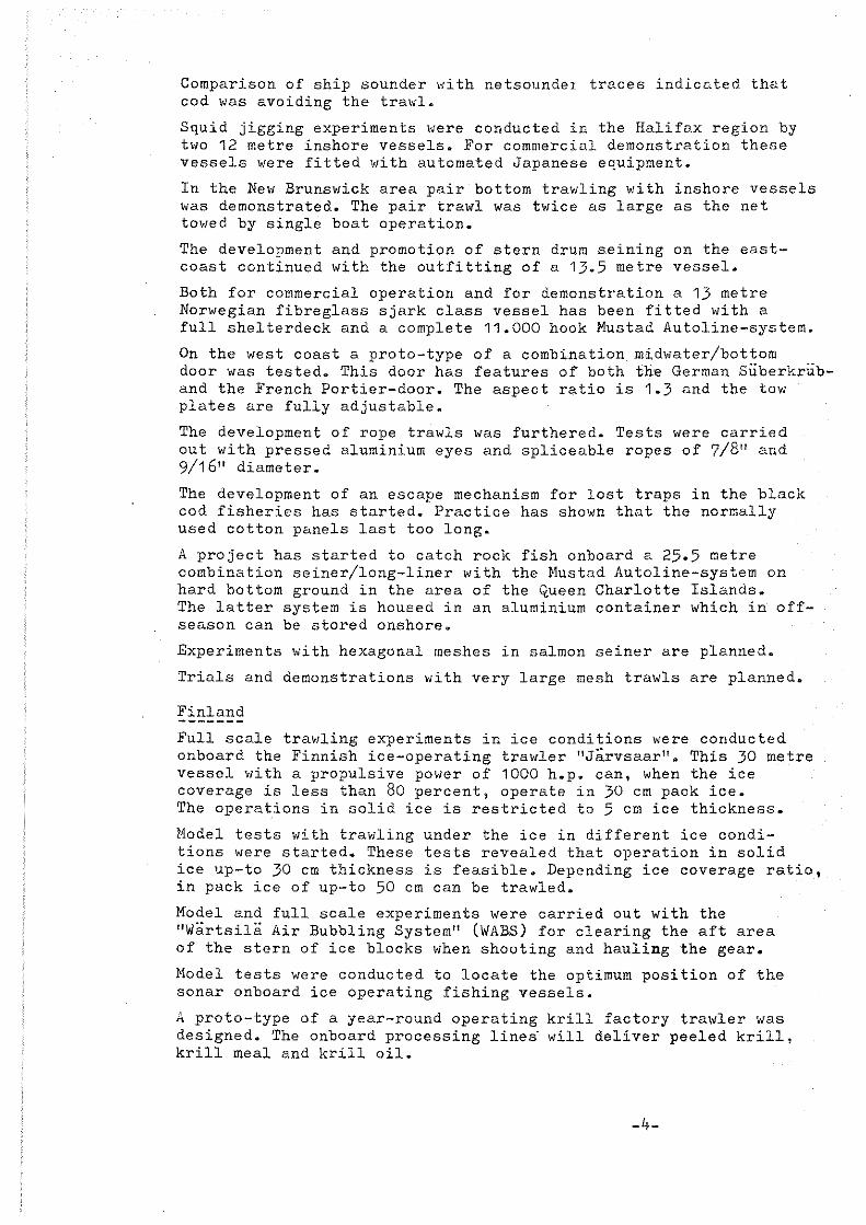
During November 1979 engineering experiments were done on 2700 meshes (equal to 20 cm) circumference pelagic trawls, a size commonly used on Dutch stern trawlers today. The set of tra,üs tested consisted of a conventional net and a rope tra\Vl designed at the "V.E.B.-Fischkombinat" at Rostock. This trawl and the licence to built it was purchased by a Dutch firm called "Jaczon", partly subsidised by the Dutch Government. Like in previous years the tests were done on board of the fishery research vessel "Tridens", involving both the Netherlands Institute for Fishery Investigations in IJmuiden and the Marine Laboratory situated in Aberdeen. Both gears were tested with the same rigging i.e. the same set of SÜberkrübdoors (7 m2) and the same bridles (71 fms (=129,93 m) for the upper one and 70 fms (=128.10 m) for the 10;ler one) and bridle weights varying from 720 kg (7063 N) to 1100 kg (10791 N). The rope trawl was also tested with floats on the headline (230 "Nokalon" floa ts of 2 1 tr. volume each). For most hauls the warplength was kept constant at 600 m, apart from three hauls where a warplength variation up-to 900 m \"as included. The warps were attached to two different points on the doors in order to determine their most efficient angle of attack. Reciprocal courses were sailed to take account of the effect of tide or currents. Basicly the same set of instruments has been used as during the 1978 trials (see reference (1)). In addition new load cells, recording on a cassette tape "ere used enabling longer hauls to be made "ithout having to replace them. There was no ve.riation in the length of the bridle extension. The length of the chain weights had not been altered. Several hauls Vlere done Vlith the mere objective to determine the load distribution among the ropes of the rope trawl. It turned out, that the centre ropes of the top and bottorn panels were heavier loaded than the ropes at the sides. For the side panels it was found, that the tension in the ropes near the toppanel was slightly higher than that in the ropes near the bot tom panel. The load in the top ropes was also more dependent on the speed. At a speed of 4.5 knots the ropes in the top and bottom panels accounted for 56% of the total load, those in the side panels took 31% and the selvedge ropes 13%. The measurements were read from the instrument traces, cslibrations were applied and the results stored in the Marine Laboratory gesr trials data bank. The addition of 480 kg of weight per side caused the net drag to increase some 5% for both the conventional and the rope tra\lls. The addition of 230 flosts to the rope trawl increased its drag by 13%. This traVil and the conventional one had nearly the same drag ,vith 1100 kg bridle weights. The proportion of the shaft horsepower used to tow the gear seemed to be very consistent for all the gears at the same speed (on average 28% st 4 knots snd 32% at 5).
-22-

As could be expected, adding bridle weight introduced more headline height for both trawls; this improvement was greater at higher speeds. The addition of fl,ats with the rope trawl caused the headline height to increase proportionately more at lower speeds. The side line spread of both nets did not vary much. The cross section areas of the conventional net decreased starting from the wing end going to the cod end as would be expected ,Ii th this type of net. The rope trawl behaved differently in this respect, having a cross section area at the beginning of the netting panels greater than the headline centre area, a fact that could be caused by slack netting in the bot tom panel. The rope tension tests seem to indicate in this direction. From these tests it can also be concluded, that the rope trawl was slightly overspread. A smaller set of doors could have been used for this net. The floatation on the headline of the rope trawl did cause this gear to fish higher relative to the doors. A measure to compare the performance of different trawls is the net drag per unit area. Compared with the conventional net and wi th the same weights this quanti ty was 26::06 less at 4 knots and 33% less at 5 knots for the rope trawl without floatation. The floats on the latter trawl increased the net drag per unit area by 10% with 1100 kg bridle weights. The performance of trawls can also be judged from the towing speed multiplied by a cross section area and divided by tlie net drag, i.e. the "swept volume index" and for this parameter it was also found, that the rope trawl was much superior to the pelagic tra\ll, irrespec ti ve of the bridle weight used. The doors showed a consistent performance with much less asymmetry than that reported in previous years. ,Iith the low bridle weights (720 kg) the doors came near the surface at the higher speeds, indicating this weight to be too low for both ge ars with these Süberkrüb doors of 7 m2 • The attachment point of the warp to the door seemed to be of small influence on the behaviour of the doors, vii th the point closest to the door surface slightly in favour, because of the less varying door spread as seen on the echo-sounder traces. The heavier weight lead to smaller heel angles for both doors. A warplength increase from 500 m up-to 900 m did not seem to have a great effect on the horizontal dimensions of the gear. For North Sea conditions the length of the warps paid out will mostly be determined by the depth of the seabed. In addition to tests done in 1978 with a 26 mm diameter warp, this year trials have been conducted with a thinner warp, namely of 16 mm diameter. The pressure drag and skin friction coefficients did not depend significantly on the diameter. There exists a speed dependance however, probably caused by the vibration of the warp, excited by vortex shedding and not by differences in the Reynold's Number. For all warps commonly used in fishery the following empirical formulae could be derived:
Cd = 2.078 - 0.2984 • V
Cf = 0.00625 + 0.02702/V2•465 with V being the speed in rn/s.
These coefficients have been used in the analysis of the data described in this report. Conclusively one can state, that rope trawls can be favoured from an engineering point of view, but problems may arise with tha handling of these nets and the fishing capability.
-23-

Comparative fishing tests will be done in March 1980 on "Tridens" to complete this study.
~~~~~~~-~!_~~~~~~~~~~~-~~~-~~~~~~~~~~!~~~~ A cooperative research programme like this, involving several institutes (The Netherlands Institute for Fishery Investigations and the Marine Laboratory) proves to be benificial for both. The quality and quantity of measurements done is increasing from year to year, leading to a better reliability and less scatter in the graphs of the report of the 1979 experiments. The cooperation also reduces costs of buying or developing instrumentation for each institute involved. As a by-product some very interesting experiments like the warp-shape experiments could be done merely due to the fact that the trials took place in a very suitable physical environment having both a great depth and a calm seastate. It would be wise to continue and extent such cooperative programmes in the near future leaving room for each party involved to fill in their own needs.
For both gears 720 kg bridle weights seemed to be too little. The doors will get at the surface at higher speeds (around 5 knots). The vertical opening of the nets can be improved considerably by adding more weight (1100 kg), although this will cause the gears to fish deeper. In order to oyercome this, floats can be mounted on the headline with the penalty of having more drag.
2·· ., The 7 m Suberkrub doors on these gears shOl,ed a better perfor- 2 mance than found in previous years with the smaller types (4.7 m ). The best attachment point of the warp turned out to be the one closest to the door surface giving a very smooth hydrodynamical performance. At bigger angles of attack the doors will probably show flow separation at the leading edge resulting in an instable run through the water. With 1100 kg the he el angles of the doors are smaller reducing the tendency of the door to reach the surface at high speeds.
The warplength had a minor influence on the geometry of the net mouth. The length needed will depend mostlyon the depth of the seabed in practical applications. The highest values of door spread/w.e.-spread/side line spread will be found at warplengths above 900 m (~ 492 fms), but it does not seem worthwhile to use these length because of the time lass during shooting and hauling.
From the rope tension tests it was found, that the ropes were not equally loaded. The centre ropes of the top and bot tom panels were heavier loaded, indicating the gear to be overspread. For the side panels it was found, that the ropes in the top parts were heavier loaded. These loads were more dependent on speed than those of the lower ropes. At 4.5 knots the total load was distributed as folIows:
top and bot tom panel 56% side panels 31% selvedges 13%
From an engineering point of view the rope trawls seemed to have a superior performance. This is hopeful keeping in mind the main objectives of this research programme i.e. to develop a trawl gear with less drag than that of the conventional types and with the possibility to fish close to or on the seabed without suffering net damage. The first mentioned criterion is related to the fuel consumption of the fishing vessel, This will have an important bearing on the economy of fishing operations.
-24-

The second criterion applies to costs of material and repair also related to the overall economy of fi~,]üng. Both costs aspects need to be cut down in order to survive as '" fishing industry. On the other hand one needs to catch fish to earn money and the fishing efficiency of the gear should be comparable to commonly used types. Only by comparative fishing tests an insight into a gear's fishing capability can be found. That is why such tests are planned with these rope trawls during March 1980 on FRV "Tridens". A delicate balancing of the costs-saving aspects and the fishing efficiency (including size and species selectivity) of these new gears is needed to determine whether this development I-lill be feasible.
In addition to the warp shape tests done in 1978 with a 26 mm warp, experiments were done with a 16 mrn warp this year. A suitable set of formulae could be derived for the prediction of skin friction and pressur~ drag coefficients for trswl warps commonly used in fishery, namely:
Cd = 2.078 - 0.2984 * V with V in m/s
Cf = 0.00625 + 0.02702/v2•465
Fishing tests with smaller (1736 meshes) rope trawls in 1979 casted doubt on the herding effect of ropes at least when fishing close to the bot tom. Direct observations from divers on rope trawls lead to the conclusion that the foreward movement of almost parallel ropes can hardly be spot ted. Small fishes did not seern to react to the ropes at all. It could be worthwhile to develop a gear with the advantages of the rope trawls such as drag reduction and less damage when having bot tom contact and some me ans to have a better herding effect of the rope panel like arranging the ropes in a lattice with transverse connections.
References
(1) van Marlen, B & MacLennan, D.N., 1979 Rope tra>Jl developments-further experiments Report No. 79-03, RIVO-IJmuiden
(2) MacLennan, D.N., 1979 Hydrodynamic Characteristics of tra>Jl 'darps Scot.Fish.Res.Rep. No. 16, 1979
(3) MacLennan, D.N., 1980 Further hydrodynamic force rr.easuremen ts on trawl ,turps Marine Laboratory Working Paper 80/5, t';urch 1980
-25-

PLANNING OF EXPERHIENTS
!!~~?: ___ !'!!:L ___ ~!:~~!!~:! __ !:~~! ____ ~~!:E?:!:!'!~~!! __ !:!E=-:!:~!'!f!i!: __ _____ ~~~!:~ _______ <::~~!:~~_. 01 A 720 4.47 350 0950-1600 II/b 155
0
02 A 720 4.47 600 0905-1570 II/b 205° 03 A 720 4.47 600 0870-1550 II/b 25
0
04 0.:2 06 07
A A
A A
1100 1100
1100 1100
4.47 4.47
4.47 4.47
600 600-900
600 600
0875-1780 0900-1700
0937-1832 1000-1790
II/b II/b
II/a II/a
2050
25° ;~05 0 __ 0
cO::> ===============================================================================: 08 B 1100 4.47 600 0965-1760 lIla 240
0
09 B 1100 4.47 600 0970-1650 lIla 60°
10 B 1100 4.47 600 1000-1700 II/b 260 0
11 B 1100 4.47 600 0973-1740 II/b 400
===============================================================================: 12 13 14 15 16
A A A A A
1100 1100 1100 1100 1100
4.47 4.47 4.47 4.47 4.47
600 600 600 600 600
1276-1810 1300-1840 1300-1838 1385-1843 1344-1825
II/a II/a II/a II/a II/a
2550
2550
2550
2500
2500
===============================================================================: Warp shape exp.
260· 17 C 720 9.82 600 0960-1700 II/a 18 C 720 9.82 600 0910-1560 II/a 80· 19 C 720 2. 82 .:200-200 1260 II/a 2:200
20 C 1100 9.82 600 1135-1770 II/a 2650
21 C 1100 9.82 600-900 1197-1830 II/a 700
22 C 1100 9.82 600 1190-1825 II/a 250· 23 C 720 9.82 600 0970-1625 II/a 70·
TABLE I
-26-

Dridle '.Ieights (kg)
Specd (Imots)
~ing-cnd height (m)
winß-end spread (m)
·.Iing-end area (sq.m)
headline height (m)
ciideline spread (m)
h/l centre area (sq.m)
Gcctlon height (m)
section spread (m)
ciection area (sq.m)
headline depth (m)
I door height above thc heudline (m)'
I I\)
"" I
ROPE THAvlL (A)
720
11,.0 5.0 1+.0
28.0 21.5 32. 1t
64.0 63.9 63.2
1795 1375 201/0 ,
29.7 19.5 ,32 .. 8
49.7 51.6 50.0 1LI72 1019 1631
31.0 22 .. 1 )11.6
50.4 50.8 48.6
1557 1139 1671
1111.6 13.0 '187.')
14.0 17 ~ -,. , 19.0 --_ .. _-------- _ I-- --- ---- ---__ ~_._. __ ~ .. __
ROPE TRAWL (B) PELAGIC TRAWL (C)
1100 1100 720 1100
5.0 L/.O 5.0 ~.O 5.0 4.0 5.0
26.9 35.1 27.7 25.3 21.5 30.3 24.7 66.4 59.9 62.9 53.9 52.6 54.7 55.6 1792 2096 1755 1362 1135 1659 1372
25.3 39.2 28.3 23.5 19.6 28.7 22.5 53.0 48.4 51.6 47.2 45.3 48.2 49.4 1356 1886 1480 1111 889 1383 1110
27.1 39.6 30.0 11.9 9.9 14.2 12.8
52.3 L16.6 50.6 26.2 25.4 26.8 28.2
1432 1839 1537 311 253 380 361
71+.5 150.8 58.8 '121.9 29.6 167.3 60.4
16.1 5.8 7.3 15·5 10.7 16.1 13.0 ----- _~ ... _._ .... _. __ -.--i~_.___________ __ _1--.-_. ___ . _____ ...... _ L..........-______ -
TABLE XIX
COl1PARISON OF TlIE TlIREE TRAWLS - GEAR GEONETRY

I I\) 00 I
Bridl<' "cÜ"hts (kR;)
SEeed (;mots)
Net dra· (tonnes)
Gear dra~ (tonnes)
Sh11ft H.P.
Gear H .. P.
Swept volume index (CV.Il/SEC/TONNE)
Het drag/area (KGF/SQ.l1)
3ridle \':eights (kg)
S"Gced (knots)
Door HEEL angles TILT (De" ) ATTACK
Door depth (m)
Door spread (m)
Door spread force (t)
I/arp att. point
Combined data for
All trawls
TABLE XX
IWPE TRAWL (A) ROPE TRAWL (B) PELAGIC TRAWL (C)
720 1100 1100 720 1100 4.0 5.0 4.0 5.0 4.0 5.0 4.0 5.0 4.0 5.0 9.73 13.89 10.16 F. ':)i, 11.44 15.70 10.97 13.e5 11.42 16.10
11.59 1 'i. 91 12.55 16.91 12.89 17.59 12.96 16.03 12.57 17.73
1132 1659 1236 1764 1278 1827 1246 161,1 1271 ! 1896
319 523 348 562 355 581 356 529 341 586
320 173 338 245 346 233 211 165 251 174
5.60 9.47 5.08 7.72 5.56 8.69 8.24 11.93 I 6.89 I 11.47 ,
TABLE XX
COl1PARISON OF THE THREE TRAWLS - FORCES AND GENERAL PERFORl1ANCE ===============================================================
ROPE TRA~IL (A)
720 1100
4.0 5.0 4.0 5.0 24.6 40.4 17.4 33.9 14.3 20.1 10.5 14.9 35.5 32.4 23.9 23.3
127.6 -0.1 U) 168.9 58.3
11'3.1 140.9 139.9 147.7
1.40 1.85 1.47 2.03 b a + b
Speed (knots) 4.0 5.0 Door drag (tonnes) 0.77 1.00
L. .. ___________ _ _ _____________ ..•.....
TieBLE XXI
ROPE TRAWL (B) PELAGIC TRAWL (C)
1100 720 1100 4.0 5.0 4.0 5.0 4.0 5.0
15.6 29.4 30.3 39.3 20.9 I
34.3 11.7 14.9 17.3 1.8.2 13.0 14.2 21.8 25.4 29.5 26.6 33.0 30.8
145.0 51.5 106.4 18.9 151.2 47.4 134.3 142.2 126.6 120.3 129.1 132.4
1.53 2.13 1.39 1 .61 1.44 2.05 a + b 11 a
TABU XXI
COMPARISON OF DOOR CE.:.RieCTERISTICS-SAME DOOR;) USED WITH DIFFERENT NETS dlD BRIDLE WEIGHTS. COMBINED DATA FOR BOTH \1ARP ATTACHNENT POINTS.

TABLE XXII
COHPARISON OF DOOR CHARACTERISTICS FOR DIFFERENT HARP ATTACm:ENT POIHTS =======================================================================
BRIDLE vlEIGHTS I - 1100 kg
Warp ROPE TRAWL (A) ROPE TM 1'iL (B) att. point
Speed (knots) 4.0 5.0 4.0 5.0
Door HEEL a 15.6 32.7 15.7 31.4 b 19.1 36.4 15.2 25·)
Angles
(DEG) TILT a 10·3 13.8 10.3 13.6 b 11.0 16.8 13.2 16.6
ATTACK a 21.7 23.4 21.8 25.4 b 25.9 24.0 - -
Door spread (m) a _139.1 148.8 133.5 140.9
b 140.2 146.1 135·3 143.6 - _ .. _--
TABLE XXII
-29-

'L~ .: />- I (" .....
IN WlillTE 60VENKRNT _C llPPER 5 I l>E) i Dlm AAZEN (MI + (MN~
I E~~~Ra i
B\, !s: II Eil!'! I IN ilHI
lJl= v·m OPf . ~ 11. Ilfi'-l r:e
2'1
'i 1I !l!l~ I IN BI! IIr 22
!Jl~ ll.'m 3l!
OfF.: 11.37'1 i!
35: lllßkl Dia ll.'lll OFP." 7.S5:'l 112
FIG.: i
/ fJ
IIN ll!
l!l
'i~IIJ:2E lT
I 85
IN 'l6
I
t Il!! ~
4.H n.!lß
y-:,,;',".-. -~ ~' ,. "all ij _..'
11.1:1 i~J:'.ß;
121l!! H , ~.a
I fiCU:fl
I I ,
._---_. 39 <·Il!:'"
.... . ... _~ ... _ .... ~---;f---...,
25: I Illll! !1l u 11. 'iil I !lPP. = i!. lilil '1I:i!
25: I 'lllil 111= I!.'lil IOpp.", 1.235: 112
s:a I :elll! I !Jl" I!.'lil OPF. c l. 35:!'l 112
!im I lllll 1!J1~ H.'lll OFF." I. 75:i! 112
'ililil I 'i5: I iJl '" il. 'lll DPP.c 3.293 112
4l'!l! '1S: iJl= H.'lil OPF." I .1il3>7 1i2
l:2a YS: iJl= Il.YI! [JPP." 11.311 112
IN 3B
!\!> 1111 IN 38
Blil lEiß IN 2B
1--_-41 !Il 225: t112B
12S: :e6B [275]
'IN 36
5l! S:B
1N BI!
!i:il
!t IU!
BENRMING: 2700 MAZEN NET (uACZDN) 'lENGTE BOVENPEES~7.6~ M. (HERvLINE LENGTH)
RIVO RFDELING TECHNISCH ONDERZOEK DATUM: -3:)-
:I!lI! 111 2liU1B j 3.B
L_ ,!!!I 1111 li'um 2.~
</lI! >11 1l!.1!>1 <.B 2 I lI! MI IlUll'l
l!.S
?IRI Si !1l.1!>1 2.3
21 el I! ?~)
I "lID S G3
IIU1B
S:.4ll
NR. : B011! fl
SCHRRL ~-----1
GETEK. :JSvti

ll: i.~f~~~L ! J~~. h'1ZD> LOwER PRNEL. (0 )
j ---
FIG.: 2-ONDERKRNT
----i
43 Ii
, 21llf B
3ii!.411 19 ISBIl IN ilS ßN IH ~.B
UI= IUIlil 11. I llPP." 1l.9Yl!
Ja 2'1 ,
2'i ~_. ~. i 22 'Z\1l3 2l! lT A'2 7.20 1 'i 181m IN BB ilT 31'1 ~.M
Ul" B.4il UP?" I!. 374 ~t. _. .. . --
UI= 1'1. 4l'l 21ilf B 6':l.ilil 3, IBm?! UP?" 7.85:4112
IN 4ll ~.H
39
{' . DI= 1l.411 21ilf H
:2ß.llll 25: B!!!! UPP." 2.11l11 112
IN 38 3.B
S:S:
UI= B.4l'l \ ll llIiI 21ilf H 25: 41'13 IN 38 IB.ilil
UPP.= I .235: 112 BI! 2 .•
UI= 1l.4il \ /, IEill 21llf 2 S:il 2113 I .35:!'I M2
IN 28 2.M Ilum
llflP.= , 111
UI= lL '-!l1\ \ res: 21ilf B llll'l IllB IN 2B IB.llB
DPP.= I .75:il 112 125: :u - 2GB [175'J
4Bß 45: UI= !!.41'l 'lN 3!l 21ilf B IE.llB
OPP.= 3.29] 112 2.1
5:!! S:1l
'lßB YS: UI= ll.'ill IN 1lE! ?IB! M 18.1111
IlPP.= I .IB5: 112 2.3
5:!!
1211 'ls: UI= 1i1.41'l !J m i'lB "~/, . ,.4.3
OPP.= 1'l.311 H2
6ENRMING: 2700 MRZEN PELRGISCH NET (JRCZON) NR.: mm B DNDERKRNT . LEN5TE GRONDPEES: 5B.3B H. (fODT-ROPE LZN5TH
SCHRRL -3h'
RIVO RFDELING TECHNISCH DNDERZOEK DRTUM: ! 7 on 7~ GETEK. :J;vti

. Li...:.C'IL . " .... - [;irit l E[~TR[b IX ~IUJTE (SlDE PRNELS) MR1~ (XX) ZIJKRNTEN (rJl ) , (K)
-FIG.: 3 I
3'J 1 .9 '3'1
lB 2!lI! m :fe .'lB
I !i: lllllil IN 118 ~N IB 21~H ß 27 • BI! UI= 1l.'Il! ~.H
1lP?= H.B91 H2
2Y lil Iß 2Y
'i I ellll IN l!B !IT 22 "Z\~2W 2!lI! B 7.:2E
UID !!.'Il! 311 ~.e
IlPP.· l!. 37'l M:i! 1i8
35: l!llli! UI= il.'iil IN 26 elll! B
!i3. Bi! DP?" 6.3!i3 1'12 U
, TI
\ r 25: Bill! Ul= ll. 'm IN :2E! 21l1! H
2lUB IlPP.= I.EIS: 1'12 3.B
Yll
25: 'lBI! UI= !!.41l \ -; :n iN 2l! 2 I lI! H
111. i!!l UPP.= l.ll99 M2 T2 2.6
5:ß 211il UI= Il.Yll 7 I'lJ 21l!1 a Ill.llll llPP.= 1.267 IU
IN 18 III'J 2.B
U! c 11. 'Il! \ 225: 21l!1 B
lilll lllil IN 2B IIl.ilil DPP.= I .75:1l M2 125: 2.a
~ 2liB [275}
'lIlB 'i5: UI= 11.411 'iN 3fl 21l!1 g
IB.llll OPP.D 3.293 H2 <.3
5:a !i:Il
Yllll 'l5: Ul~ Il.YIl IN 1lE! 2ll!l B IB.BB
UPP.= I .1l3>: l!2 2.3
511
123 'l5: UI= 3.Yll ~ IN llfl l <I.:'~ a L'lll QPP.= 11.311 112 1 9.li OD
BENRMIN5: PELAGISCH 2700 MAZENNET (JACZaN) , LENGTE ZIJPEE5 7~.B0 M (SIDE-RDPE LEN5TH) NR.: mm C
-32- SCHRRl RIVO RFDEllNG TECHNISCH ONDERZDEK DRTUM: 22 DKT. 79 GET EK . :~'3v1l

u; I~::;ZO;
,{i ,L' 1 ( O;r,l ONDER- EN BDVENKRNT FIG.:~ I, ~I,m {r;..~) 0:)
UPPfJL RW) LDWER PANEL
---1 I &iS"'i:li'i L_ i
~ I I --_._- -------~---- _.- --~--------- -... - ---_. __ .-
7,5 I 1,00 TlB~
LENGTEHDVEN I ON~ERPEE5 r, 107.30 ,H_ (HEADLINE liND fDDTROPE LENGTH).
~\ S\ 0\ 0. ..:r = 0 0
IN 'iil
l!l IIBBia ure 12.rn IN 42 PP!'.>< 3.!53'i.Mi!.
1---1-----11---- " ,J
25: flEil UI~ i'J.rn nFP.~ 2.!l61l leI
'iHi! UI= B.rn i DPP • u I .?!fl 1'\:2
25:
!Ce 2EIl UI= 1'l.5Jl I tIPP.e I. 3S:li H:2
11m ! illl UI '" IiL 5Jl I OI'P.m 1.7S:1!l H?
Yllil 40;: Ul '" il. 5Jl llPP.= 3.293 Xc
'illil 'i5: !JI= la.rn DPP.= 1.0351f2
12121 YS: UI= iil,s:g 111'1'.= 1l.31! K2
!i:'2 lilS:
IN '1!l
IN :aß BI!!
loil IN 28
26B [275]
'iN 3!l
!i.'!1\ S:~
IN B8 'l( H !i.'Fl ~ ~ IM 2i!
!3ENRMING: LYNENTRR~L CJRCZON), 27021 MRZEN OMTREK DNTWERP DDR [VEB rI5(HKUXHI~RT RDSTDCK)
I I ____ I
52,12113
'W'~'I ,",J -H- 'i.ruf' ----i
21i!! l! 3'i.21'1 ~.!I!
21i!! 11 :t~ .Illl J.~
21i!! g l!.!i
21i!! m 2.B
<li!! ! l! .B
ill.1lll
II!.ilß
11l.l!ß
,
21i!! 111 .I:ll:l! 2.3 I~~
21i!!-:r-- 11 2.3 J IU~
1.1:)..1 00\ 5:. l f;ij
n .. T1'\-A-L. ! 6<4, ao;!
NR. : SBI R
270~ MESHfB RU PE TRRWL. -:::c:--~-'::----:--___
RIVO RF~ELIN5 TECHNISCH ON~ERZOEK _"_ dSCHRRL
DRTUM :22-'0I(T_. 79 GETEK.~Fr

Li,·,e I· ~il'J;;:T( K~ (Kli) FIG.5 ZIJKRNTEN (5IaEFR~EL5)
LEN5TE ZIJPEE5 = 9~.~0 M. (SlDE-ROPE lEN5TH1
7·S j ~[;llJ ~ I 5:' 'BBll' ~~;.~.~. 717 1'12
I ellfl l!l DI- !l.s:!! OPP." 2.9B7 11:2
2S BII/i! !J/ a i!. s:!! OPP." I.BI!>!!:!
25: 'llll! j VI= !!l.s:!! OPP . • I • Else 1\2
Si! 211!~ I Ul= !l.s:!! OPI'. = I. 2b7 112
lilll 1 BI! j VI= ll. s:!! 01'1' •• I. 7 >:ll 112
'illB 'lS: I UI= Il.s:!! 01'1'.= 3.293 "12
'lilll 'I> Ula !!.!J!I OPP.c I.B)>: 1\2
-+----""I! U I = 1l.!J!I 12B 'iS OFP.= iL 311 112
I1
!J!I SZ
'IN 38
IN llE!
. I !J!I
n ~ IN 1113
. ~ ~~1( I S~~F. i
_.~
52.100
I __ J
--zn- 3.~ '1ß1--::";\~-' um .'HJ---l--
2IIY SI 3'l.1l! q.B
211!! 1I! 2i: .Illl J.1I
21Ll1 li f 12.1lll 2.E _. -
l!IIY ~l I~.l!l! 2.1l
:;liil e~ le.illl 2.m
21~J I 1 19. 1l1l 1
211!!l~ ~::3 . _~. aB I
I .. ~ I !i.'ill
TOTA~ä4:ßo
BENRMING: LIJNENTRRWL (JReZON), DHTREK 2700 MRZEN VRN I"R . 801 B . 20 eH. DNTWERP DDR " .' I (270k1J ME5HES ROPE TRRWl) -34- !SeHRRL
U~ I YQ,BFDEL I Nb TE CHN 15Grllii[)ERZDE~--=-'--TRiuM: 2_i OKT~)l~ITE(~)v}i

fIG.: 6 WA.'R1' ATlF\CHMENT \0 :DOO'RS
13 , , . ,. --, /3\
SKETCH OF 'F..IGGIN<.'i
FIG, : 7
13'
1.2.'3.93
1.:28. 10 "... 6.3'0
I 1 I I
I \ Wi'E TRf'}WL.
']RI1:>LE EXTENSIoN '. 4.47 m.
(12&. \0 + 6.30) - 129.93
129. '33 m.
12.8./0 M
5.'3>1 COt-JvBVTIO NI1l- TRA'~
I
"BRIDLE j;.HE.NSION 9.ß2. h'\
(128,\0+ 6;30.;.5,35)- \2..9.'33
-35-

Ulm IUill
UPFER PRNEL
~ ti ~ f If F
HAUL 178112
IlPI' ." 0 . S85 Mi! I
I
"" 0'\ I
Ul" IUl'l
LO\JER -PANEL
.-<
'J J-
HRUL T79/14
b~
3.0 9A"S "ffl. ~
[;i ~
IlPP ." l1! • SBS \lZ I
IN '"16 IH" a.!il'l
-PORT SIIJE "PANEl
HRUL T '79 ! 13
.... i "" ~, ~, %
DPP.~ l1!.717 M2 , {
. UI" kl.!il'l 01'1'.- S.717 M2
STARBOARD SI1lE· -PANEL
HALJL I 79/15
FIG.: 8 ROPE TENSION TESTS J POSITION OF LOAD CELLS.
IN '2B
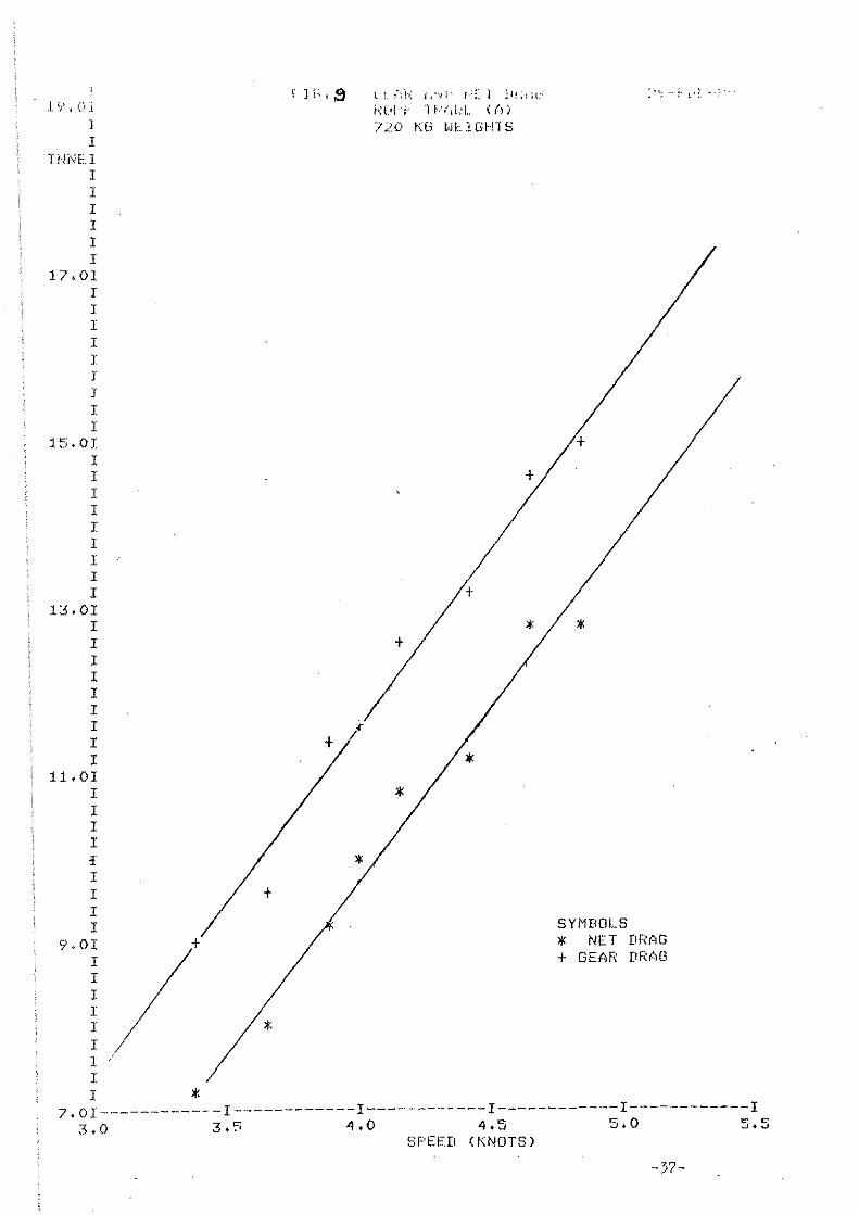
l ~? • <.".i ]
I TNNEl
I 1 I I I I
17.01 I I I I J J J I I
15.0I I I I I I I I I r
13.01 I I I I I I I I I
11.01 I I I I cf I I I I
9.01 I I I I I I I I
+
I *
) f.'; ( 8
+
+
*
"
*
l'~. :';1-'; l;"~i' I':::. I ll!.l;l"
h:l.H -F '11-':/il,.L «(l)
/;.(\ r:(i ~JL1GI··nS
+
+
"< ... i·
+
* / * +
* *
SYMBOLS * NET DRAG + GEAR DRAG
7.01------------1------------I------------l------------I------------I 3.0 3.5 4.0 4.5 5.0 5.5
SPEED (KNOTS)
-37-

j ~" • c<!
J HmEI
1 :I J I I I
17.01 I 1 I I I I I I I
15.01 I I I I I I 1 I I
13.0I I I I I I I I I I
11.01 I I I I + I I I I / + I + I
9.01 I 1 I
/ I * 1 r I
1 /* I
.: {.;, 10 :; ::1" ,:l!\11 !:!") ;1,1.,'·
+ + + /
+
* /* * *
f>:Cd L. "i'!\(Il'.:L ~(':)
ll()O I<b v..'LJGH"i~:.;
+
~
.j
+
:/ +
*' + +
/ +
J. >I<
/ >I< + *' +
*' *' /
>I<
*
/ *
* * /
* *' * /
SYMBOLS *' NET DRAG + GEAR DRAG
, f i
7. 01 -----~------- 1 ------------ I ------------ I ------------ I --.---------- I 3~O 3.5 4.0 4.5 5.0 5.5
SPEED (KNOTS)
-38-

J l() +OJ
1 J
TNNEr I I I I I I
17.01 I I I I I I I I I
15.01 I I I + I , I I I I I
13.0J I I I I I J I I I
11.01 I I I J I I I + I I
9.01, * I * * I I ]
1 I I
. J I
r][;, 11 GEI-li~ (,NIl l'llc·r Jlf'Ai.,' :lA-··1' ",I·,-·UO
+ /
*
RO~E TRAWL WIIH FLUAIS (I') iiOO J<G ,JEJGf-17S
:t' , +
+ *
i *
t
t
+
+ / tU
( ,
** *
/*
t * *
*'
*'
+
* *
SYMBOLS * NET DRAG + GEAR DRAG
7.0!------------1------------1------------1------------1------------1 3+0 3.5 4.0 4.5 5.0 5.5
SF"EED (J<NOTS) -39-
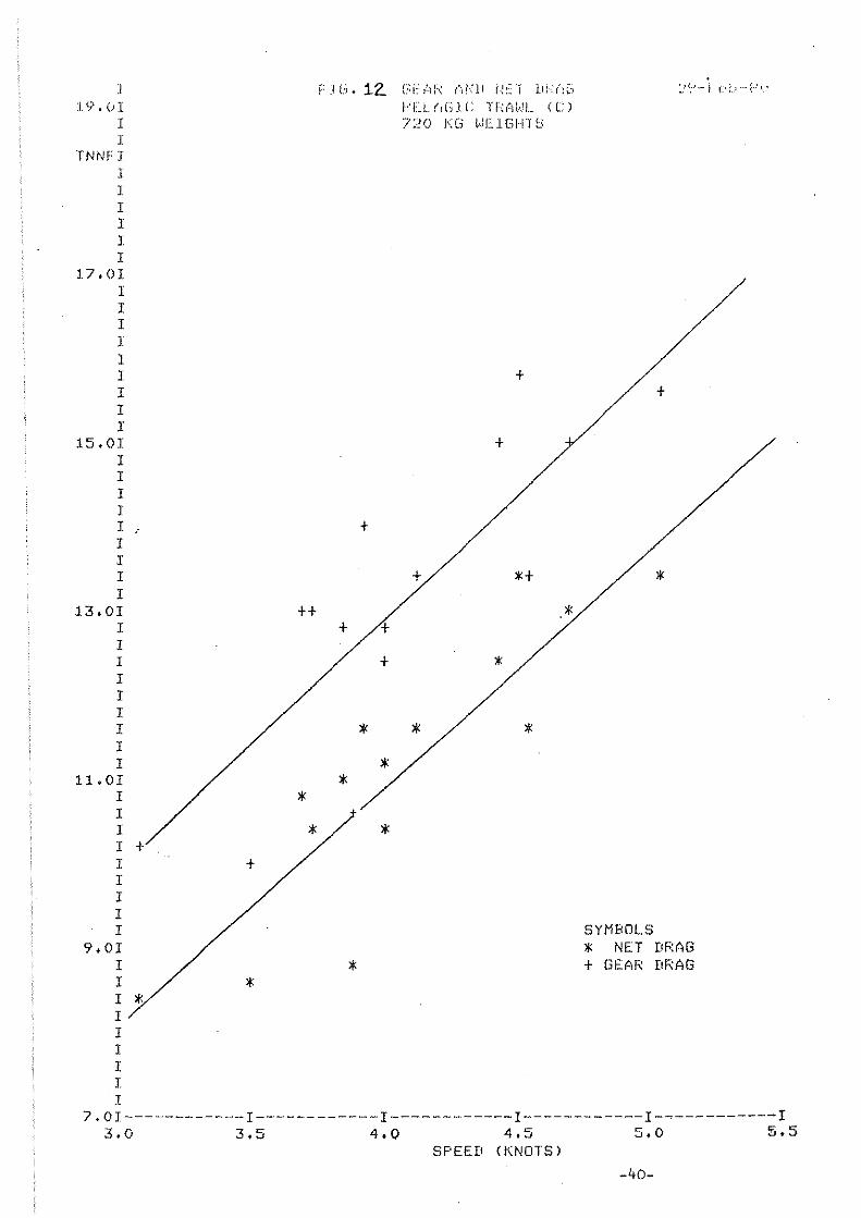
1'7'.(11 I I
TNNEJ I I I I I I
17.01 I I I J 1 I I I I
15.01 I I I I I I I I I
13.01 I I I I I I I I I
11.01 I I I I + I I I I I
9.01 I I
I * I I I I I I
+
*
++
*
F J (3. 12.. E:i:: tlF-: (11<11 i·~:~'1 11).:(;[,
1 .. '[1.. (1(';] C Thtl\ .. .!L (C) 720 I<G ViEHi/·nS
+
+
+
+ H
*' + /+
+ *'
* * * * *
* / *
*
',' (. ." i c' ;,,' -- :; . .' ',_'
+
*'
SYMBOLS * NET DRAG + GEAR DRAG
7.01-----------·-1------------1------------1------------1------------1 3.0 3 .. 5 4.0 4.5 5.0 ~.5
SPEED (KNOTS)
-40-

:! ..:;' + 01 I I
TImE! I I I I I I
17.01 I I I I I I I I I
15.01 I I I I I I
I I
13.0I I I I I I I I I I
11.0T I I I I I I I I I
9.0I I I I I I 1 I 1 1
r: :1.(:'_ 13 C,E(·lF.; (lr~I! NLT l!I«~~'r PElAGIC lR(,WL (C) 1:1.00 t(G (,EIGHT,;
+
* *
*
:.:.~,/N··r c'b-'(:!( I
SYMBOLS * NET DRAG + GEAR DRAG
7.0I------------I------------l------------l------------1------------1 3tO 3 ~
.J 4.0 4.5 SF'EED (KNOTS)
5.0 5.5
-41-

, 14.01
:I J
I\GF /SCl.M
1 1 I I I
12.01 I I I 1 I I I I I
10.01 I I I I I I I I I
8.01 I I I I I I 1 I 1
6.0I I I'i" / ,.. I I I I I I I
4.0I /* I
·I
I * I 1 1 1 I I
t·t
I' l G. 3'4 Nel li/((,('-., / OWSb SFC·llul" (.\1,:1 (, (,I
lH~ HlAliLINE CENlkE WITH 720 KG WEIGH1S
t
*
* ,.,
t ,.. * *
t,
,..
* *
,..
'*
SYMBOLS * ROPE TRAWL (A) + PELAGIC TRAWL (C)
2.0I------------1------------1------------1------r-----1------------1 3.0 3.5 4.0 4.5 5.0 5.5
SPEED (KNOTS) -42-
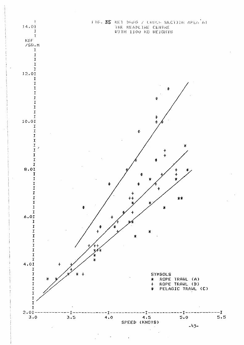
:14.0] I I
t(GF ISCl. M
I I I 1 I
12.01 I I I I I I 1 I I
10.01 I I I r I I ' I 1 I
8.01 I 1 1 1 I 1 1 I 1
6.01 1 1 I 1 1 I 1 1 I
4.01 I I I I I I I 1 I
'"
+
I' "' r;. 35 (lF"} IJi,.:(,C,; ./ C.!<u~",~, S!::.C", J ~.if"'!. (ü:L{: (I I
'IHE HF(.,j'1..1HE CU,JI\[ WJTH 1100 I(G WEJGHfS
* *
* ~I
SYMBOLS * ROPE TRAWL (A) + ROPE TRAWL (B) i PELAG1C TRAWL (C)
2.01------------1------------I------------I------------1------------1 3.0 3.5 4.0 4.5 5.0 5.5
SPEED (KNOTS) -43-

J 1,0(,1 J
I 1
CU. r1. ISE:CDND ITPNNE
I I I I
500 I I I I 1 J I J. I I
400 I I I I I I I" 1 1 1
300 I I 1 1 I I I I 1 1
200 I t 1 r I I 1 I I I 1
100 I I I 1 I I 1 I 1 I
* *
t
1 "r 36 ,"j 11" "l' ." I'" .. , 'II!" -J.i, ,,'tl ... {l,., ._)',-1.1 I ");.: •. ;. L. \.ll ··2..~·r (.'1: ~-Ll."
* t
*
1~'Ek Uhll rJ!~:'f rfJ~AG
WIIH /20 KG liEIGHTS
SYMBOLS * ROPE TRAWL (A) + PELAGIC TRAWL (C)
*
o 1------------1------------1------------1------------1------------1 3.0 3.5 4.0 4.5 5.0. 5.5
SPEED (KNDTS)
_44_

j
t}'-:-!t:' J J I
CI I. M , /SFCUND /TONi'~E
J I I I
500 I I I I I I I I I I
400 I I I I I I I I I I
300 I I I I I I I I I I
200 I I I I I I I I I I
100 I I I I I I I I I I
"
+ + "~*
""'"",
+
;-:;\:1,37 '·./(:l '.d-d ",j i. ", i·,::,;'" I,' ':::~,I!',!!
j:"LJ, Llr<:1 f I-h:. '1 llh/-:t: .. WIIH 1100 KG W[](iH1S
SYMBOLS
", ':"1- . i.,l .... ~'; t .
*' ROPE TRAWL. (A)--+ ' ROPF TfMI,JL (1<) ---~, PELAGIC TRAWL (C) ---
'*', * + *""- '"",
+
*
~~~+ *~ * +
'"
*
o 1------------1------------1------------1------------1----~-------1 3.0 3.5 4.0 4.5
SPEED (KNOTS) 5.0 5.5
-45-
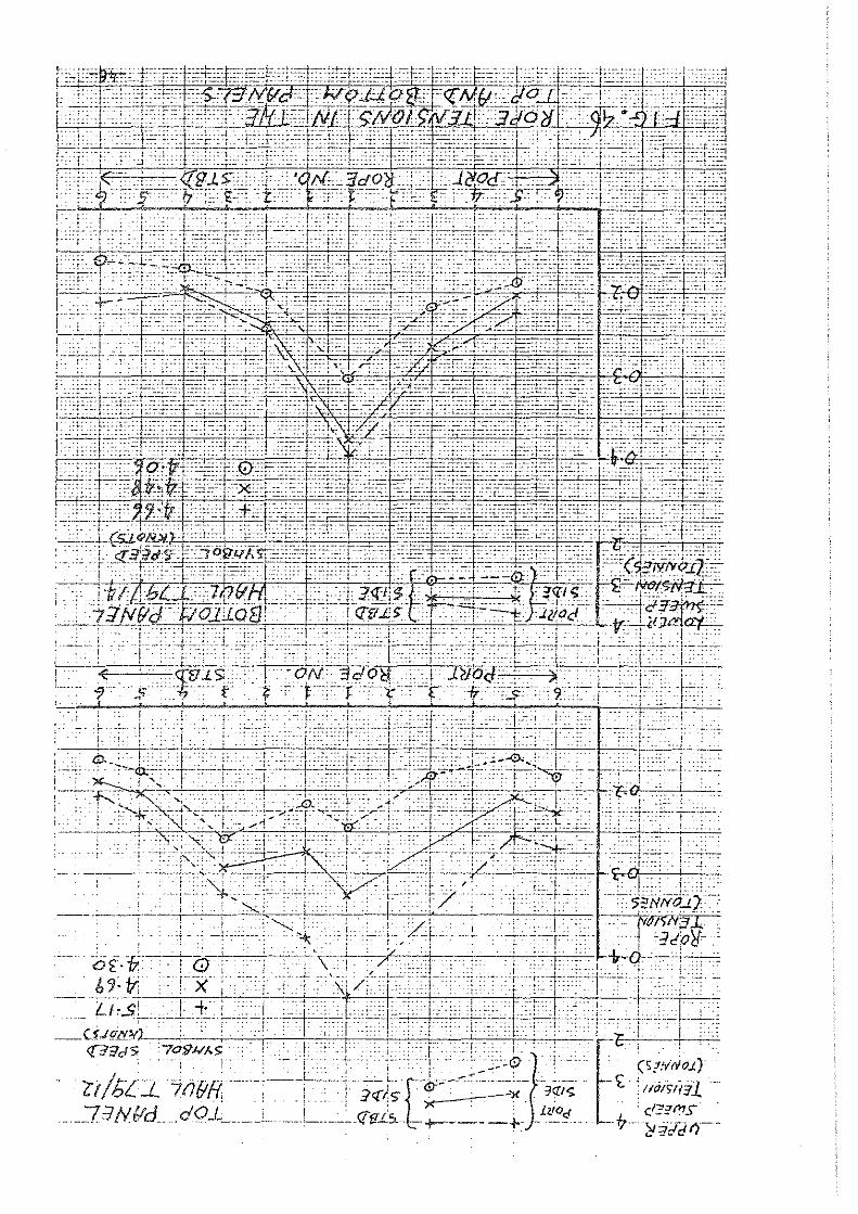
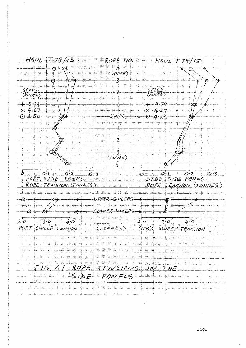
, ,
. . .~ .•.. t •. ·.~±i!_i;s'-:r-~~fu-~!=--=-c_~-=..._ .. _ELG:~ .. :::t.7~j R. oP EcJ-.eL}3, N S Iß 1V5~ A(~~.t1JE_-.e. __ .~_L .. ' _ .... _ ..
. ,
..'.:; .. .iS/.1 E!pij/,>Eis,..i.L ...... ~- . .. . --~----_.- - -.. _----_._._~-- ---~~--- _._ .. --- --~
.L .. 1
-47-

",i" --~-----~-----~--_ -}-Jf)iJ.L T7'1/16 . "::::J'< ,,; "" - - ~ -: - i; ___ ._
~-__;--'-+-ccc-_S--o i ! -.--nO/l..-, --- ----, - ----,----STßI' ., " .. " , I :r j L!.I TENSION ' ',i ~ , -'L
C!~=C~~::~-~_== = -;~-+T~?:;~s ?<
-3- 0 ____ L. __ .~ ____ ..
0--- - - -- _ ':"--8
-,O'S" , : ; - !.. I
+-,--' '-,-----+
-{). 1- ____ • ___ ~. ___ ' •• _,l ____ ~ .. __ . __ _ _ __ . ____ ... l. __ .. ____ " .• ,
• ___ ". _ ____ .1 _________ --;.-__ • _______ • __ •
-- --0-3 ----~-~,-----:..o
---_. __ .. - ---_ .... --- -_ .. - ._. ,-_ ... ---_ ... _--_ .. _--_ .. _ .. _-. __ .
'---------4-0
tlppc:.R ' SFLvEJ)(;f:___ ._
--i!oPEi, -
, TEN~(O!V-- -[ TtlN-NE-:/)
- .-, --" "._--_ ..
+-3-0', ...•• · •• i··.··~·'r;·~·~±-F_!.··.· .• ~.~~!~~=I·------.... -----_._. --------. -- --_ ... ~- --- ._----_. -_ .. -----------_._ ... _-- ------
---,-,~c,-,-------7_0' J_ ,,5PEr-J) I ,," ,... - -_ ..... :J:: .'
_: _ " '" _ I ,', (ICHors) I '
, -------pS-+-,-- -t-:: ":01-
"t ._- ._- .•.•.
---_ .. - ---------,-~_.- ._-,------,. __ ._-~-j_._._---,-~! ------, -_ .. _-- _ .. " , .. ~-'"- ... -______________ , ____ ·~,4~6~J--._ "_" , , ,,' ' ,,' 1 -0 -4 3 i ------,-.. -----------------
:. '
:"'!':.'
---.:-- --c .... --o''I-- - ---------+--
-----~-------i-~,~-' -'- ---,,-------x' .) -
0'3, ,0, "
.. ·"1------·,..·')'-;..OWCI,
SELVEb6-::' --"'--' .~ ., '<' r- _e ---,---
.;·"Ol' 1: ....... \. NO ' ::DIJ 719 ' F 0/(7//[ -PO/(;- - SiJjEY--
1:.jG-.48', ,SEL.VE])-~E----' R,opJ:-rg;:;;sl?)//S-- - -----,---- ----
-48-

FRC:LI;·iINARY REPOHT 0]," THE ßLUS '"iiiITING FISHING EXPERI 'EN'rS LAST! :iOUTH-EAST OF 'IRE F"HOE ISLANDS IN JANUARY!MARCH 1980
ty Stein Hj:-,.l ti i Jakobstovu anel. Bjprnu.r Isaksen
Introduction
On the way to the spawninc :~reJ, the blae ~hiting conireG~t,~ czct nur th-oa:..it 0 [ the F.u·oe::: fürming prf:ßp".::'~mi ns conc~:n tro. tionG ~ \.'hich later ct~rt their migration in thc ~outhwards direction over th0 ~·Iyville Thompson Ridge (Sch.6nc 19'/9)., The blue ~'jhi ting is rocordc·d es ~ more or less continously nl~rro~ layer in this aren. At daytimc blue ulliting is found ~.t 100-220 ftm de~th over rcl~tively deep v~tcr (2?0-650 ftG,).
};·r~.roes fishing experiments in February/H':-:TCh 1978 and 19<19 in the arorL ~etween Fugl~yarbank ~~ci thc south-east' edge cf the Fnroc .Pl,~ter..l.u g.!'l.VC catcheG up-to ~~5 t/h , bLJ.t in gener;ll the catches were much lower, and toD low for sUßcessfull industrinl fishing (Jakobsson 1978, Jukobstovu 1979).
llaterials snd methods
Fishing experiments were conducted by the Foroe M~lrine Rcse~rch
Institute l,'ith t·"co chartered veE.;sPl.s, m ... s .. IISiemundur Brestisson lt
~,d.th 2800 hp and m .. s~ "Krünborgll "li th 270!) hp .. These vessels ',:ere better powered than those that hud been used e~rlier for this kind of fishing experiments$ Both bOflts ~re rel:!tively nel; ~nd built as combined trawlers/purse ~ei~erc~
E .. 8. IISigmundur Brestisson ll used the J?,:.,roes 16 m trU,h'l (JoJ:.obstovu 19T))) \Jhile m .. s .. "Krünborg rt us,~d thc Norw/;!,;i.',\D. H-trt\",,:l (Isaksü!1, Jensen and Olsen ~1979) .. Thic; tr:-;"vl ~.,r:1.S ßiven on lO<\D from the In0tit.ute cf Fishery Technology nCGearch, Bergen, in. nccordance ~ith E~n internordic project on c~tch &nd proc8ssinc technology of blue ,;hi.tine .. 'rhree scienti .. ,)t.; Cl!'.' this institute p2rtici:pated i.n 1.11e F.:·"roes fishinc experimp-ntJ ':lhieh took pl"ce durine t.he periou 15/1 - 11/3 1980, ~ainly in the &ren ~outh-c~st ~nd ei:~t of the F'lroDs (Figura 1). The double netsonde cystem was again used to check
the herding effect of the very big meshes and gave numerous good recor-He;sul ts <':~nd discussion dings.
Th"! 8(:outing an~! fishine exrcri~ent~ ~(rE conducted only d~ring ,.::J.yt.i.mc, duc to vertical r.~.iEr[.~tiorJ uf the bIlle v!hiting .. G·ener,:}.lly the vc,o:sels mL .. Je one haul per d.:.ty, ;,-nd in tee Si.'CO~·:: h<:.lf of the chllrtercd period, two.
:rhe experiGJents stnrtec.i ;; Fuglpy;\rb;'nk {end moved [.';1o"11,y s.:.)~th-,!;;'rd
flccording to the rligr~tion cf the blue whiting~ ~fter the chQrter(!d period, ODe of the J~in~ contin~ed fishing 2bout ~ fortnight on her O\/n ;._ccount~
III thr ;")('conci half cf J[m-,lt~r,y C~:tC:1<'S from 5 "La 26 t/h ·,'(?r·:';" t .. "ro"·'o"j·'n ·'1' "ug' "y'lrb'n'K "l· +h .. W"·n of 02 ~ t 'h (~·'b~' -) " •• \..'.;, ... < •• ' u ..... '-' .1..' ..LjJ' ". ,'" .... 1 ,-" "P..:ct_ "' I,.c:.. I -'-L' <.l.. I ..
The sood fi~hing continued in Febru'try ~ith crltches rates from 2 :0 3;~ t/r: with Q meD.D of 'l~j .. ::; ~/h. In vie'.>: of the hi,;h 0.u~lity of th~ ~re[~p~wning blue ~hiting these cotch rateo are consiciered very gaoJ far n fishery far hUllinn concumption, and for induetrial fi~hin~ thc catch ~3tes are ~lso q~ite promising. In a commarci~l fichAry ,;i th sBveral boats pr~rticini',ting the se.:'Tching :00\-le1' '.vil1 inCre":3e conaiderably, and the cuteh rotes will most pro~~bly incre>,,'t3C ..
Doth 1:: .. :3 .. n'sigr,mndur Brestisson l' c:nd m .. s ... IIKrünborg 1l stored pc,rt cf t~10ir cntches on iee for fileting t the reGt ~as delivered for '":f-:-l !;.rociuction .. On Li. few oec:Jsions thc fish für humnn conc"J.r:1Tl-~io:J ·;erc i-~C'pt in .3.',::~ '.,;1 th S::ttiDfactory resul ts ..
-49-

The total cutehes for the ships in the chartered period were 1200 and 1600 ton respeetively.
On both vessels the crew were weIl satisfied with the good towing and operationsl qualities of these big meshed trawls. To the extont comparative fishing with the two trawls were praeticable, there were no unambigious conelusion with regard to which of the trawlo that were fishing best. The eaptains on the boats at least elaimed that these trawls gave r.lUeh higher csteh rates thnn they liould have expec ted wi th smaller., conven tional mesheq. trnl,'lls .. The double netsonde-system ",ere used on the 16 m tra"l and al together 11 trawl hauls were made with the system working.
The loeations of the second trnnsdueer "ere: fit the ehangss of mesh size from 160 to 80 cm, 80 to 40 Bnd 40 to 20 cm, respectively.
The echo reeordings from the different locations showed thct the distance from the fish to thc panel in the lower belly ehnnged little from for to aft in the trawl. The recordings furthermore confirmed the earlier experience that the fish do swim along with the trawl inside the belly.
Beneath the trawl at the locations of the second netsonde transducer very few fishes \-Iere recorded. This together wi th the very good catch rates clearly suggests that the big meshes in the fore part of the trafl do herd the blue whi ting.
For the time being the impression consequently is that thc big meshed trawls in the blue .hiting fishery are here to stay.
References
lscksen, Jensen and Olsen (1979) Recent developments on blue whiting tru~lG in Norway I.C.E.3. CM.1979/B:24
J"kobsson, J. (1978) A summary report on the I.C.E.3. coordinated blue whiting surveys during the first half of 1978 I.C.ß.3. CN.1978/H:65
JHkobstovu, S.H. (1979) F2.roes experiments I,vi th very bit; meshed trawls for blue l,oJhi ting fishery I.C.E.S. CM.1979/B:16
Sch,6ne, R. (1979) Distribution of blue whiting in the woters around F~roes und west of Gra3t Britain Rnd Ireland in Februery-Mnrch 1979. r.C. E.S. CH.1979/H: 10
-50-

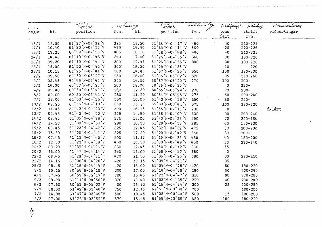
__ ,<7, .... · " : '.11.:-/" 1:(.4f ....... 7
~.
,rt"J~ ~,,,,~ 7 M~~ ';"'d~' T.U~.I. ~JO , ., 'j byrja,~ . / 2nd86 fvn. ? dagu!' kl. position fvn. kl. position tons skrift vi6rnerkingar
{alt fvn.
15/1 12.00 Gl'27'N-04'28'V 285 15.50 61'36 'N-04 '17 'V 460 40 210-225 J7 /1 10.40 Gl'23'N-04'32'V 450 14.40 61' 30 'N-Oll '14 'V 600 20 220-238 1.9/1 12.25 60'58'N-Olj'SS'V 465 16.10 61'OS'N-04'48'Y 4110 40 210-225 24/1 14.48 61"19'N-04'46'Y 340 17.00 61'2S'N-04'3S'V :360 30 180-220 26/1 09.30 61'19 'N-04' 41+ 'V 300 12.45 51' 26 'N-04' 36 'y 300 30 180-220 26/1 15.00 61'23'N-04'43'Y 300' 16.30 61'2ü'N-04'36'Y 10 220 27/1 10.15 61' 25 'N-04 'lll'Y 300 14.45 61'37'N-04'26'V 350 100 180-230
2/2 09.50 60'S3'N-05'27'Y 280 16.00 61'05 'N-OS '02 'y 320 85 210-260 3/2 08.45 ~O'49'N-05'47'V 250 14.00 60'S7'N-OS'20'Y 270 100 200-3/2 16.30 60'S2'N-OS'27'V 260 18.00 60'5S'N-OS'25'V 0 220-4/2 09.40 GO'50'N-05'41'Y 26.0 12,30 60' 55 'N-05 '24'V 270 70 200-5/2 09.00 60'SO'N-05'41'V 260 11.20 60'54 'l!-OS'.26 'y 27S SO 200-240 7/2 13.00 61'33'N-04'26'V 3S0 16,00 61'42'N-04'23'Y 3S0 50 220-
10/2 09.25 61' 56 'N-04 '10 'y 350 15.15 62'03'N-03'41'V 375 100 170-220 12/2 11. 45 51'43'!I-04'23'Y 300 16.15 61'55 'N-t14 'l1"Y 290 0 oklärt J 3/2 09,4S 61'43'11-04'22'Y 325 14.50 61'55'N-04'Og"y 300 90 200-240 14/2 08.45 61"3S'!l-04'38'Y 275 12.00 51"43'N-04'2S'Y 290 70 220-1RC! 14/2 14.20 61' 38 ')1-04 "33 'y 290 16.30 61"29'N-04"39'V 285 60 180-220
\
15/2 08.45 61"23'N-04'42'Y 325 12. lt5 61'32'}!-04'32'y 475 50 200-230 l5/2 15.30 fil'26'N-04'4J.'V 325 17.30 61'20'N-04'42'Y 350 30 200-16/2 07.45 fj1'13'N-04'45'V 500 11.15 61'lS'!I-04"35'Y 460 40 180-230 lfd2 12.50 61"22'N-04'3S'Y 450 16.30 61'09'N-04'49'Y 450 20 220-240 ~J!2 09.20 ·61' 39 'tI-04' 24 'y 380 12.45 61"SO'N-04'12'V 360 15 20/2 15,00 fl'47'N-04"14'V 360 12.00 61'38'N-04'22'Y 380 0 22/2 08.45 bl'28 '1l-04 '31'V 420 11.30 61'36'N-04"2G'Y 380 30 220-250 22/2 14.15 GI' 30 'N-04" 28 'y 420 17.15 61"39'N-Oli'21'V 35 2S/2 08.45 Gl'lS'l!-04"44'y 420 16,00 61'34'N-04'28"V420 50 180-220
3/3 10.15 60'S8'Il-OS'16'Y 300 17.00 6:1.'14 'N-04 'S8'Y 290 60 220-240 4/3 07,45 60'S9'N-OS"17'Y 280 15.45 61"22'N-04"47'Y 310 80 200-260 5/3 09,00 61·11.'N-04"S8'y 320 16.40 61' 33 -N-04" 35 'y 320 40 200-240 l'i/3 07,30 60'Sl'N-05'22'y 400 16.30 61'16 'N-04' 54 'y 300 25 200-250 7/3 ~8"00 O'42'N-03'40'y 750 12,15 61"51'N-03'3S'V 700 180-200 7/3 14,30 61'47'N-03'46'V 500 18,45 61'3S'N-03"44'Y 500 15 180-200 8/3 07.00 61" 28 'N-03" 52 'y 670 15.45 61' 58 'N-03" 39'y 480 100 180-2:i0
I \J! N I

' __ ~~_ __~ ______________ ~,___ -A. _____________ •
h<l.l nr.' ',d.a,gur klo Eosition fvn. klo Eosition fvn. "ttms viömerkinsar 1 24/1 -'1,,*.QO 60'3S'N-OS'35'Y 420 120 min, 270' 0 2 25/1 11. 30 --'Si '-1.3 '!l-04 '54 'V 320 12.45 61' 16 'N-04 '52'y 360 5 vektir Hökt ar 3 26/1 09.30 61'OS'N-Oij:aS''V .410 10.00 61'Ofi'N-04'S7'y 0 kapul sli tnaöur 4 26/1 12.30 61'13'N-04'S8'y 360 16,00 01 "Z1',,-{)4 '46'y 0 10ddini flökt 5 27/1 09.40 61' 20 'N-04' 53'y 290 15.45 61'15'N-04'SS'Y 400 30 6 28/1 09.1S 61'l1'N-04'S9'Y 340 12,25 61'17'N-04'S2'y 340 40 7 29/1 08.50 61'32'N-04'44'y 290 13,05 340 110
30/1 landaö 800 ks. til Bakkafrost 31/1 landaö 182 t til Havsbrün, le~arnir
saman, greiddu restina av degnum B 2/2 08.40 60'SS'N-OS'26'Y 270 15.15 51'08 'N-05 '01'y 320 50 mistu 150 t, posin sakk 9 312 08.40 60'52'N-OS'39'y 260 11.00 60'Sl'N-05'24'y 370 60
10 3/2 13.45 60'S3'N-OS'27'Y 320 16,05 60'S7'N-OS'21'y 2BO 80 4/2 landa6 800 ks. Bakkafrost, 158 t Havsbr
11 5/2 15,00 61'04'N-OS'03'Y 300 16,50 61'07 '1'1-'05 '00 'y 360 0 einki at s:i:ggja, 1 t slept tit aftur :2 6/2 12.40 61' 19 'N-04 '15 'y 620 1S,45 61'29'N-03'SS'y 670 50
,13 7/2 09,15 61:'20 'N-04' 36'y 480 12,25 61' 28 'N-04 ' 27 'y 450 50 8/2 landaö 400 ks, Bakkafrost, 94 t Havsb:
14 11/2 11.00 51' 39 'N-04 '18 'y 410 16,00 61'S2'N-04'04'y 370 50 15 12/2 09.00 51'SO'N-04'27'Y 260 10,30 61'46 'N-04 '19 'y 340 20
13/2 landaö 800 ks, Bakkafrost, 53 t Hil','c:br 16 14/2 09.25 61'43'N-04'2S'Y 310 11.32 61'49 'N-04 '25 'y 280 30 17 14/2 13.50 Gl'4S'N-04'2S'y 280 17,10 61' 35 'N-04' 37 'v 270 30 18 15/2 OB.55 51'lS'N-04'4S'y 400 12.50 61'22 '1'1-04' 33 'y 520 80 19 15/2 15.20 61'18'N-04'33'V 540 17,25 61'24'N-04'35'y 440 40 20 15/2 07.45 61' 13 'N-04: 22 'y 660 11.10 51'21'N-04'34'Y 530 40 21 16/2 13.20 61'19'N-04'36'y 540 ' 16.20 61'OS"N-04'47'y 30 22 17/2 07.20 61'33'!I-04'21'y 520 11.55 61'44'N-04'22'y 330 80 landall 400 ks, llakkafrost 36:1 t Havs 0,1"" 23 22/2 09.00 61'14'N-04'42'y 500 10,55 61'19'N-04'31'y 500 20 24 22/2 13.55 61'2S'N-04'27'Y 540 15.55 61'37'N-04'23'Y 400 70 25 23/2 10.30 61'2S'N-04'41'Y 270 14.05 61' 3S 'N-04 '29 'y 360 10 25 2/3 1S.55 61' 32 'N-04' 04,'y 680 17,10 61'24 'N-04 'Ol'y 680 2 sleptu fiskinum. 1000 kg lodd 27 3/3 14.5S 51'03'N-OS'12'Y 300 17,50 61'09'N-05'02"Y 290 18
4/3 landaö uml. 550 ks, til Bakkafrost I
28 5/3 08.30 61'09'N-OS'03'Y 290 16,20 61'2S'N-04'3S'Y 315 70 500 kg 10dd \J1 29 6/3 07.S5 60' 50 'N-OS '21'y 400 14,45 61'08 'N-OS' 51 'y 460 15 '" 7/3 landa6 450 ks til Bakkafrost I
30 8/3 09.25 61'SO'N-03'37'Y 580 17,10 61'52'N-03'49 'V 420 65 31 9/3 07,30 61'33'N-04'20'Y 520 15.15 51'Sl'N-03'42'Y 520 40
10/3 landaö 1000 ks til Bakkafrast i 1 I"

/.
PROBLEHS ENCOUNTEHED IN THE COHllELATION BBT,IEEN TIm HE3ULTS OF r;NGINEZHING PERFORHANCE TRIAL" OE' FULL SCALE THA\nS AT "EA AND "CALED NODEL TRA,ILS TESTED IN THE WHITE FISH AU'fHOHITY FLUl·1E TANK, HULL
by: D.A. Vlilem::-,n
The Flume Tank of the i{hite Fish Authority, Industrial
Development Unit has been in operation for 4 years during
which time almost 100 scale models of different designs of
trawls have been constructed and tested. This large stock
of models is required for demonstration purposes on the
Fishing Gear Technology Courses that are run at the Fisheries
Training Centre and FlUIDe Tan.~ for the benefit of fishermen
and net makers from manydifferent nations.
The flume tan1{ forms
the centre piece of the training centre. Structually it is a
large
built
re-inforced concrete tank 31m long by 5m wide by 5m deep,
at ground level. It is divided horizontally into two chambers
which are interconnected at each end to enable the water to
circulate. (See Appendix 6)
Demonstration and testing of the model nets takes place in
the centre portion of the tank upper chamber. Th.is area, which
is the tank working section, measures 11m long by 5m wide by 2.5m
deep. The lower chamber of the tank forms a return passage
through which the water recirculates.
For testing model trawls water speed through the tank can
be varied frcm 0 to 1.0m per second (0-2 knots) which, at ascale
of 1/10th,. represents a ma."(imum full-scale water speed of 6.1
knots. The '''ater speed can be increased to a maximum of 105m
per second to permit the full-scale testing cf small components
such as floats, kites and transducer housings.
,.,1'" , '. The basic theory used in the design cf these models is that
'. succe.ssfully employed by the scientists cf the Institute
Scientif'igue et Technique des Peches Maritimes. They had been testing
model trawls in their smaller Flume Tank in Boulogne for several years
p'ricr to the ccnsturction of the I,hi te Fish Authcri ty Tank.. This
theory isbased upon scaling according to Froude number ,.here the
-54-

water speed is scaled by the square root of the length scale
so that gravity and inertial forces are scaled equally. As
it is virtually impossible to obtain sheet netting for the
construction of model trawls which has both the twine diameter
and mesh size reduced exactly by the scale to which the models
overall dimensions are to be reduced further scaling 1aws had
to be deve10ped to ensure that the net drag is correctly
reduced for Froude scaling. This further scaling 1aw states
that the mesh size and twine diameter should be reduced by an
equal ratio (see References ito J for derivation). This
is equivalent to scaling thp. brine surface area correct1y.
In spite of the confidence held in these scaling 1aws it was
decided that i t would be adviseable to ·check the accuracy
of the models used in the Tank by obtaining measurements
at sea of the most important engineering parameters of the
ful1 sca1e tra1~ls·'~ch as headline height, door spread, net-
spread.and warp load. It has also been possible to make a
few general comparisons on the detailed shape of model and
full sca1e trawls using film taken by divers of the Harine
Laboratory, Aberdeen when observing f'-tll scale gear.
It is the purpose of this paper to discuss some of
the problems that have been encountered when attempting to
correlate the model and ful1scale engineering performance
measurements. A specific case history which contained most
of the problems associated "ith such correlation work has been
discussed in detail.
-55-

Chapter 2. A typical case history. Model tests conducted on Stuart Heavy Board Trawls.
2.1 Description of the Gears under test.
Stuarts of Musselburgh, Scotland make a range of bobbin
trawls for inshore boats of 150-500 HP for towing over very
hard ground with doors. These trawls which they call Heavy
Board Trawls are extremely popular with boats fishing the
North Sea and based in South East Scotland and North East
England. The traw'ls are made from polythene netting.
An approximate one tenth size model of the most popular
size of these trawls, the 482B, was constructed by the netmakers
in 1976 from small mesh netting that they had in stock.
In January 1977 full scale trials were conducted aboard
the Ocean Herald II. The 482B trawl was tested together with
two larger nets the 542B and the 602B. Field Report No. 573
which forms Appendix 1 contains the results of the full scale
sea trials together with a comparison of those obtained with
the "rough" model of the 482B.
The 542B trawl has exactly the same headline length of
80ft and footrope length of 100ft as the 482B. This net has
been made larger by simply widening the square and wings and
lengthening the bellies as is shown in the diagram in Appendix 2.
The 602B tested on board the Ocean Herald was the prototype of
a new design for a larger net approximately 120ft on the
footrope.
In June 1979 it was decided by the W.F.A. to make a
1/10th Scale model of the 542B trawl and to provide Stuarts
with special thin model sheet nett~g to enable them to make a more
accurate model of the 482B together with a modified design of
the 602B.
At the chosen scale of 1 : 10 it was possible to model
the whole of the sweep and bridle rig used at sea together
with the last 30 fathoms of warp.
-56-

The re.st of this chapter details the problems encountered
in correlation of the model test results and the results
obtained at sea on the Ocean Herald.
2.2 Problems encountered in the design and construction
of the scale model nets.
There were only two problems encountered in scaling
down the full scale net specification and they both arose
because of the properties of the model sheet netting which is
made in twisted nylon.
Firstly in making the full scale nets the netting in
the wings is stretched past its specified mesh size when it
is mounted to the headline. This is common practice in the
U.K. and Scandinavia. With this particular design of trawl
the amount of stretch is relatively small, the 155mm meshes
are mounted on 158mm of headline and once the net has been
used for a few heuls at sea the mesh size of the netting becomes
permanently stretched to 158mm. The model sheet netting, how
ever, will not stretch permanently with use in the tank and
if the netting is mounted in the same manner as the full scale
net onto the headline, then it has been found that the head
line lies slack and kinked when the model is streamed in the
tank. The problem was solved by effectively constructing
a model of a "used" net and basing the scaling calculations
on a mesh size of 158mm. The model wings are then mounted
length for length with the headline.
Secondly the model netting is made from nylon and is
heavier than water whereas the full scale netting is made
from polythenelQhich is lighter than water. It is to be
expected, ther·efore, that the effective weight in water of
the twine of the model trawl, particularly the netting in
the mouth, may have an adverse effect upon the height of
the headline of the model trawl. To try and quantify this,
the discrepancy between the buoyancy in seawater of the full
scale polythene wings and square and the , .. eight in freshwater
of the equivalent model nylon sections has been calculated
in Appendix 3- It has been presumed that the netting in the
bellies, lying weIl behind the headline floatation, will not
-57-
have a significant effect. It can be seen that in full scale
terms this discrepancy is 6.2 kgms weight which could be
approximately counteracted by adding the buoyancy of 1.7 x 8 in
floats. As there are 38 such floats fitted to the q82B and
542B trawls this is not a very significant discrepancy. Indeed
if this counteracting buoyancy was added to the headline
centre, it would, in. all probability, give a false high head
line height measurement as it would give a distortion to the
net at the point where the height is actually measured. It
can be concluded that nö action is necessary to compensate
for this small mOdelling inaccuracy.
2.3 Problems encountered in obtaining exactly the same
rigging of the model nets as the fullscale nets.
The results of the model tests carried out on the
Stuart Heavy Board Trawls are to be found tabulated in Appendix 5.
For easy comparison, the model measurements obtained are
tabulated alongside the fullscale measurements from the sea
trials on board the Ocean Herald.
The first time the model q82B and 542B nets were tested
in the tank it was immediately noticed that the headline
heights were lower than those obtained at sea, (see Table 1).
On re-examination of the rig drawing contained in the Field
Report: of the sea trials (Appendix 1 Figure 1) i t was noticed
that the trawls had been rigged with 38 x 8 in Nautilus light
pJ.astic floats. The model had been rigged with 38 x 20mm
model floats whose buoyancy scales up to 2.95 kgm fullscale.
This is equivalent to the buoyancy of an 8 in Aluminium floate
As can be seen from Appendix q, however, an 8 in light plastic
float has considerably more buoyancy 3.6 kgm. This meant that
the number of model floats had to be increased to q6.
This modification improved the headline height of the
models by about 2 ft (see Table 2). It was noticed that the
headline height achieved with the q82B trawl was greater than
that achieved with the larger 5q2B trawl. This was contrary
to both the fullscale sea measurements and the netmakers
expectations. A reason for this discrepancy was found when
-58-

it was discovered that both the netmakers and the skippers
had altered the rigging of the trawls at about the time of
the Ocean Herald trials. Originally both the q82B and the 5q2B trawls were designed to have a headline length of 78 ft and
a footrope of 98 ft. The skippers prefered towork 100 ft
of footrope and therefore had to extend the headline by inserting
1 ft of chain extension in each top bridle. The net makers,
at a later date, modified the net by adding 1 ft of bare
extension to each side of the headline and fishing line so that
the trawls became 80 ft on the headline and 100 ft on the
footrope. Many skippers, however, still use the 1 ft extension
to the top bridles with these new nets as it seems to give
slightly better results. It appears that the q82B trawl
used on the Ocean Herald was an old net with the 78 ft head-
line so it was effectively towed with equal bridles. The 5q2B trawl used was an 80 ft headline trawl so it was effectively
towed with a 1 ft extension to the top bridles.
A 1 ft extension was added to the top bridles and the
model 5q2B trawl remeasured. It can be seen from Table J that
this small modification increased the height of the 542B by almost J ft! This made the height achieved with 542B greater than that achieved by the 482B as found at sea. The
results of Table 2 could now be treated with confidence and
they provided the theoretically interesting conclusion that
the height of a net cannot necessarily be improved by keeping
the same headline and footrope frame and simply increasing
the amount of netting round the mouth. Presumably the drag
of the extra netting inserted counteracts the opening effect
of the headline floats and reduces the net height unless the
original net had been so short of netting round the mouth
that this had been restricting the opening.
The model results still did not correlate very weIl with
the full scale measurements. It is noticeable that the door
spreads achieved with the model trawls were considerably less
than those achieved at sea. A final inaccuracy in the rigging
of the models was discovered. The 7 ft Vee doors used on the
-59-

Ocean Herald were unusually high doors - 4 ft 6 in. This
gave the full scale doors an area of 31.5 sq ft. The model
7 ft Vee doors had been modelIed on a different manufacturers
specification and were only equal to 4 ft 1i in high giving
an area of only 28.7 sq ft. The model 7ft 6 in Vee doors
used in the tank are in fact closer in area to the doors used
by the Ocean Herald, they have an area of 32.8 sq, ft. It is
also probably justifiable to use a set of model doors that
are slightly larger than the theoretically correct scaled size
because it has been estimated that as much as 30% of a door's
spreading force can be generated by the ground friction and
it is doubtful whether the friction generated by the smooth
rubber conveyor belt in the tank is as great as that generated
when a full scale door digs into a soft seabed. It is worth
while noting also that different Vee door manufacturers set
the warp and backstrop attachment holes in different positions.
This causes one manufacturer's door to work at a different
angle of attack to another manufacturer's. This can cause
discrepancies in the spreading force generated by different
doors of the same areä. In fact the model 6ft Vee doors
currently in use at the tank generate more spreading force
than the larger 6 ft 6 in long doors.
Accordingly the model 7ft 6 in Vee doors were substituted
and a final set of measurements taken.
2.4 Final Correlation of model and full scale results
It can be seen from Table 4that, once the rigging of
the model trawls had been corrected so that it corresponded
to the rigging of the trawls on the Ocean Herald, the model
and full scalemeasurements for the 482B and 542B trawls
correspond particularly weIl. It can be seen from studying
the field report that at the same towing revolutions of 1550
a speed of 2.6 knots was recorded when towing the 542B trawl,
whilst a higher speed of 3.0 knots was recorded with the larger
602B trawl which had a higher warp load. The towing speed
may weIl have actually been similar to th~ recorded for the
482B trawl - 2.8 knots. Taking this into account the model
measurements are all within a 5% variation of the fullscale
-60-
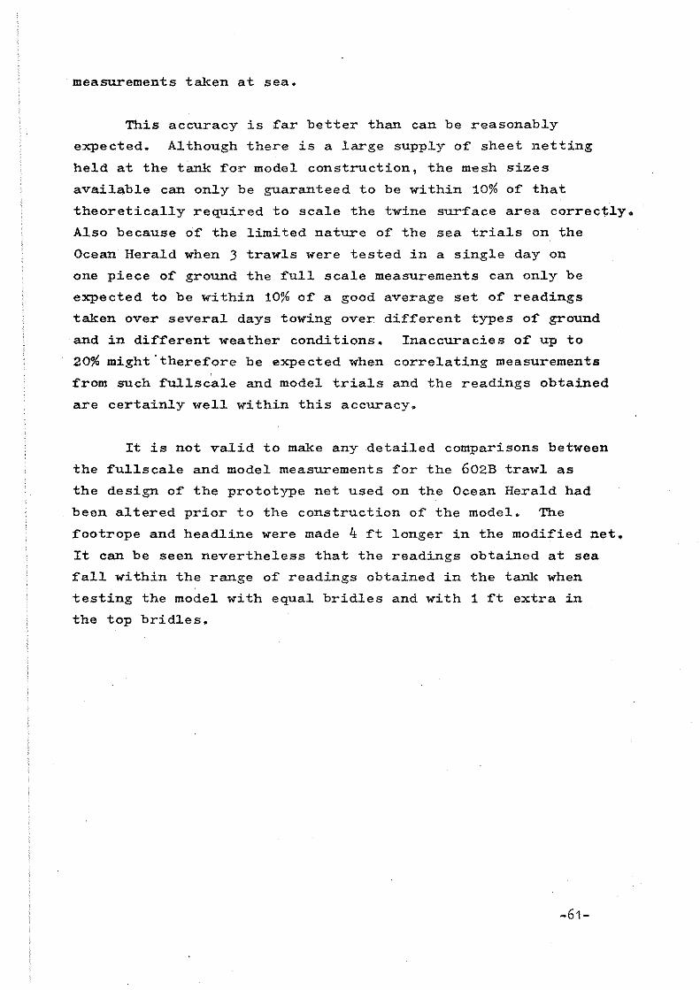
measurements taken at sea.
This accuracy is far better than can be reasonably
expected. Although there is a large supply of sheet netting
held at the tank for model construction, the mesh sizes
available can only be guaranteed to be within 10% of that
theoretically required to scale the twine surface area correctly.
Also because of the limited nature of the sea trials on the
Ocean Herald when 3 trawls were tested in a single day on
one piece of ground the full scale measurements can only be
expected to be within 10% of a good average set of readings
taken over several days towing over different types of ground
and in different weather conditions. Inaccuracies of up to
20% might"therefore be expected when correlating measurements
from such fullscale and model trials and the readings obtained
are certainly weIl within this accuracy.
It is not valid to make any detailed comparisons between
the fullscale and model measurements for the 602B trawl as
the design of the prototype net used on the Ocean Herald had
been altered prior to the construction of the model. The
footrope and headline were made 4 ft longer in the modified net.
It can be seen nevertheless that the readings obtained at sea
fall within the range of readings obtained in the tank when
testing the model with equal bridles and with 1 ft extra in
the top bridles.
-61-

Chapter 3. Problems encountered in the testing of other
model trawls.
Section 3.1 Shortening the length of the wires between the
doors and the net.
When model testing the Stuart Heavy Board trawls it
had been possible to fit the complete bridle and sweep rig
in the tank at the accurate scale of 1 : 10. Because of the
size of the tank this is often not possible when testing model
bot tom trawls which have very long bridle rigs or have a high
angle of attack of the bridles. To fit such complete bridle
rigs in the tank it would be necessary to reduce the scale
of the models substantially to 1:25 or 1:30 and this would
result in a considerable loss of modelling aeeuraey. It is,
therefore, often desirable to reduce the length of the bridle
wires between the doors and the net, but leaving the net as
a 1:10 seale.
The type of rig that has eaused problems is, for example,
a 40 fathom single sweep pl~s two 25 fathom twin split bridles.
Obviously it is not possible to shorten the split bridles as
this will immediately eause a eonsiderable reduction in headline
height. The simple solution often tried in the past was to
miss out the single sweep and attaeh the split bridles into
the baekstrops at the back of the doors. It has been found
that this will also give incorrect headline height measurements
beeause the point at whieh the 2 split bridles separate is
above the seabed by half the height of the door. Tests have
shown that rigging a mOdel net this way ean generate up to
2 ft more height than the full scale situation where the point
of separation of the bridles is on or elose to the seabed.
At least part of the single sweep has to be modelled, therefore,
and if this length is very short, 5 to 10 fathoms for instanee,
it will normally be necessary to artifieially inerease the
weight of the wire-sweep to obtain the correet amount of ground
eontaet. Divers observations at sea or a careful note of
the amount of shine on the bridles and sweeps is ideally
required as it is often found that the tension in the top
bridle is suffieient to pullthe aft end of the single sweep
off the bottom at sea. -62-

3.2 Problems associated with the elasticity and stiffness
of the model materials.
It has already been mentioned in section 2.2 that it
is often impossible when making a model .. net to stretch the
netting past its specified meshsize as is frequently done on
fullscale nets when mounting wings cut on the bar. Presumably
with large nylon midwater trawls in particular·the netting
meshes will also stretch past their specified size when the
net is actually being towed through the water at sea. The
stretch could be in the order of 5-10% and will vary in
different sections of the trawl depending on the local strain
at that point. It is doubtful whether there is sufficient
strain in the model netting when it is being towed to stretch
it at all and this definitely appears to affect the detailed
shape of the net.
It is particularly noticeable that slack
areas of netting in the centre bosom sections of some model
nets are particularly pronounced - slack billows of net with
wide open meshes can be seen oscillating with the water
fluctuations. Divers have often found that the netting in a
bosom is often very slack - they can lift i t up easily .. but
it normally forms a neat smooth shape. Presumably at sea
the tight netting stretches more than the slack sections
and although slack sections of netting have markedly less
strain in them there is still sufficient strain to control
the shape of the netting. It would appear that elasticity
and stiffness do not scale correc'::.:'y in model tral'i"ls where
forces are scaled do~ by the cube of the model scale.
This slackness of netting in the bosom of a trawl associated
with possible incorrectly scaled strain distributions also seems
to have a marked effect upon the relative positions of the
bobbins and fishinglines for bottom trawls. It has been found
on occasion that the fishinlines lie over the top of the bobbins
in the model trawl and sometimes even g.et ",rapped around the
-63-

bobbins particularly at low speeds. Divers observations, however,
normally show the fishinglines hanging behind the bobbins.
Presumably at sea there is sufficient strain in the bosom netting
to overcome any friction or stiffness in the connection chains
to the bobb±ns and pull the fishfugline back behind the bobbins.
It appears that this is often not modelled correc~ly at low
speeds in the tank particularly when using rubber wheel type
bobbins which generate a lot of friction between themse·lves
and the conveyor belt bottom and also the adjacent spacers.
J.J Weight of Codends
Another problem which has arisen, and affects the detailed
shape of the model trawls particularly at low speeds, concerns
the weight of the nylon codends. In particular for heavy blue
whiting type pelagic trawl codends it has been noticed that the
model codends sometimes do not tow straight behindthe trawl but
tend to droop towards the seabed. This has been caused by the
number of meshes in the codend being reduced to obtain the
correctly scaled twine surface area. 1f t for example, al/20th
scale codend has been made in 1/5th the twine diameter and mesh
size but t the number of meshes then the weight of the model
codend will be approximately 4 times too heavy. 1t has been
found, however, that the codend twine surface area has no sign
ificant ef~ect upon the net drag. The codends can be blocked
up without affecting the net dragappreciably. The model
codends should, therefore, be scaled by considering their weight
instead of their drag (t;~ine surface areal. This will save a
considerable amount of labour because if the codends are made
from 2 sheets of netting each of double twine, to date the model
equivalent will have to have been made from 4 sheets of single
twine laced together. Only one sheet of netting would be
required to scale the weight correctly.
3.4 Twine diameter measurements
Obviously the accuracy of the scaling of model nets is
completely dependent on obtaining accurate measurements of the
full scale twine diameters. This measurement is particularly
difficult to obtain as it is not usually specified by the
-64-

manufacturer. Host twines are specified by their runnage
(weight per unit length) apart from braided twines which often
have a diameter quoted. Unfortunately "::hese quo"::ed diameters
for braided twines are extremely "nominal" _ 4m braided polythene
diameter. Xeasurements of braided twines is usually J,5mm in
extremely difficult to make because they are often flattened
in shape rather than round. It is al_so difficul t to try and
determine a formula for diameter for these braids dependent on
the twine runnage because the basic cons;truction differs from
manufacturer to manufacturer, some "t1·,.,-ines have a centre core
some do not, and also the twine shrinks in diameter.as it is
put under strain. It is not even acceptably accurate to
obtain a short sampIe length from the manufacturer and measure
i t aS the extruded filaments from which the twine i s woven
vary in thiclcness from consignment to consignment.
There appears to be no international standard technique
for measuring twine diameter. Most methods using calipers,
micrometers or taking several turns round a rod must result in
either flattening or squashing the sampIe. Using a travelling
are
microscope and measuring large sampIes of knoW'n rUITllage seems
to be the best solution but i t is u:ncertain how much strain the
sampIe should be subjected to. An empirical formula for deter-
mining the twine diameter from its runnage has been developed
from the twine diameter measurements
Diameter mm ~ K Ru=age m/kgm
made to date. It is
where K = 1800 for tW"isted nylon
= 2000 for twisted polythene
A lot more information is required on how accurate such a
formula is and whether the value of the constant shouJ.d alter
dependent on the thickness of the extruded filaments for
t""isted polythene.
-65-

Chapter 4. Conclusions
1. More reliable data on the measurement of twine diameters
is urgently required to improve the accuracy of model net
design.
2. Data is urgently required on the stretch obtained by trawl
netting when it is towed through the water.
J. It is essential that when testing full scale trawls at
sea prior to correlation with model tests that an extremely
detailed record is kept of the exact rigging of the trawl.
Such details as not only the number and size but also the
make and type of trawl floats are essential.
4. One tenth scale models of trawls will generate engineering
performance measurements that will correlate weIl with full
scale measurements at sea provided that the rigging of the
model trawl corresponds exactly to that of the full
scale trawl.
-66-

APPENDIX 1 ~-,~,.~
WH!TE FISH AUTHORITY --", ""
Industrial Davelo~ent Uoit
Field Report No. 573 Januar;;! 1978
Gear Trials on MFV Ooean Herald 11
Intr'oductiofl
These trials were part 0 faseries planned to obtain various paramet.ers
cf full scale trawling gears~ scale mOdels 0,[ which are held in the I.;D .. U ..
Flume Tank. Skipper J. McBain of MFV Oce,s,u Herald II agreed to give the
Anthority the use of his vassal for F'C'iday 16th December, for the purpose
of taking measurements on his Stu,,,,·,t 1±8213 Heavy Board Tra",l; measurements
were also taken on his two Qther Stuart trawlsG
The objccti ves oi the, trials 'were:'-
(i) 1'0 obtai" sufficient full scale data for an evaluation of
results obtained from 1/10 scale gear:; in the Flume Tank
(ii) 1'0 determine the hydrodynamic effeets, If any, of the I.D.U.
headline transducer equipment On gear under test; these effects to be
checked by use cf a headline"manometer",
Vessel Details
Name:
BuH t,
UlA,
Engine:
Deck Gear:
Bridge equipment:
Ocean Herald 11. ~tern trawler KY 197
St. Houans. Fife 1975.
18.Sm ( 60 ft)
Volvo Penta, JOOHP at 1800 RPM Fixed Propeller
w-ith nozzle.
Split net drum, t\<o trawl ",inches, 1 forvard seine net/
discharging winch.
Manual/Automatie steering~ Decca navigator
and track plotter.
cont/ ••
-67-

-2-
Bridge equipment (cant): Kelvin Hughes echo seunder, Radar,
VHF/HF radio telephone.
Crew:
Trials equipment:
Five
1 Furuno netsol1de with cable and I",D",U~
wing end spread transducers, wheelhouse
displaY/lCecorder and cabJ.e ",inch.
1 pair three wheeler warp tension meters
and portable warp tension readout.s~
Trials Personnel:
Trawling .a.ear~
1 Toho Denton to",ed log: w1 th di spl",y
1 Marine Laboratory headline manometer
H. McDiarmid (PFDO), E. Allison (PEE)
A. BIem",n (M.F.) K. Hairsine (MET)
P. MacMul.len C"""t. FDO)
The geers tested were a Stuart 482B Heavy Board Trawl and the Stuart
540 and 600 trawls of similer configuration. !he trawls' designations
refer to the number of meshes areund the mouth. Rigging details
were as in Fig. 1. The same bobbin rig was used on all the geers,
7'0" x 4'6" vee doors locally ",ade were used throughollt with single
backstroPs. picking up irom the middle oi J holes. 100 fatho",.", of lt"
warp were used for all hauls picking up irem the middle towing points.
Trials narrative
Ocean Hera~d IX put out from Pittenween at 0700 on 16th December. and
trials commenced at about 0800 on grounds about J roiles SE of Pittenween.
Th .. water depth in this are ais 20 - JO fathom,,_ Sea condi tions were
very ca~m for the whole period of testir.g~
The first gear ·tested was the 482B and this was fished firstly with
the Marine Laboratory headline manometer... The gear was then hauled and
the manometer replaced with the netsonde package. At this point the
three wheelers were moved from the gallows to the stern towing post
bridles because there was insufficient clearance through the three wheelers
to allow shooting and hauling with them in position~ The warp circumference
(lt") was also slightly small for these instruments whereas the bridle
-68-

-)-
circurnference (J") and position were found to be satisfactory for all
subsequent trials. The gesr was then shot again and spot r"adings
taken frell! the warp tension meters and the towed log. Wa.rp di vergence
~'aS measured over a 6' length as a guide to door spread and engine
HPM ""ted.
Th" 600B trawl was tested next but after the first tow the geal
ca.rne fast a.YJ.d sustained same damage.. Fo!" this reason. the trial was
abandoned.
l"blally the 540B was tested. Four tows 'were made at various
RPM settings and readings taken as before.
Resul:ts
tlill details of the instrument readings are contained on shaets
1,2 and J and discussed below. Although no tidal calculations were made, l~,ns
both with andagainst the tide .. €Ire made for each geer and power setting.
The following figures are'averages of the uncorrected data from each gear~
Gear
\iarp aft (fm)
log sp!'ed (kt)
\iarp load (t/warp)
Daor spread (ft)
Headline height (ftl
\Hngend spread (ft)
RPH
1,82"
482
100
2.8
1.4
100
14.5
38
1500
540 600
100 100
2.6 )",0
1.6 1~ 7
100 100
17 19.5
35 36
1550 1550
----The data obtained from this trial (Shaet 1) show same inconsistencies.
In tows 1 and 4 ",hare headline, height, wing speed and RPH are comparable
tension measurements vary by a factor of 2. On tows 2 and J the same
variation oeeurs and the magnitude af the tensions (4.4t) !jlust be
regarded with Seme suspicion hearing in roind the HP of the vessel and
constant RPM used. In tows 3 and 4 tensions are shownto be very similar
but the tows were in opposite directions. The chart diamond ror the
area 5uggests tidal currents cf about 0.3 kt and in this depth of \o,'ater.,
-69-

-4-
with medium tides a reasonably constant vertical velocity gradient can
expected excepting the bottom boundary layer. The results here indicate
considerable experimental error and difficulty has been found in estimating
a tide correction as shown in Fig~ 24 The possible sources of error are
discussed below~
600B. From the results available (Sheet 2) the deck tension reading~
appear more consistent than previously, though unequally distributed. Tho
headline height varied with no corresponding change in wingend spread.
During this trial the geer came fast and the trial was abandoned.
540B. These test results (Sheet J) also appear to be mare consistent
than in the first trial but again no tide correction can be made (Fig. J). Time was running short in this trial and after same variations in engine
RPH the test series was terminated.
The main source of erroT' in the warp tension readings was
probably oper~tional problems ir using the neW IDU designed tension meters
which were ,:n use for the first tim(?.. Also there was probably seme change
in the zer.o position of :readings between rnoving the instruments from the
gallows to the Samson Post~ These J.atter readings can however be a.ssumed
to be more accurate than the former. rt should be noted that after the first
couple of reading the practice of adjusting wll instrument zeroS prior to asch
observation was instituted. The accuracy of the door spread readings is
limited by the method used which usually gives a value of about 5% less than
the actual spread~
In addition the limited time available for testing each cf the three
trawls resulted in a relatively smal1 number cf observations and a
correspondingly reduced amount of data available for analysis.
-70-

-5-
Fvaluation of model results
As an indication of the relationship between full scale and 1/10 scala
parameters the averaged, uncorrected data from the 4823 is hore presented
w1th some typical 1/10 scale readings scaled up to full size. To date
7' equivalont vee doors are not available at the Flume Tank; data here is
::for 6 ~ 6 n and 7' 6" equi valent calOrs.
Sc"üe 1/1 1/10 1/10
Speed (kt) 2.8 ).0 3.0
Warp aft (im) 100 125 12.5
Doorsiz" (ft) 7'0" 7' 6" 6'6"
a"adline height (ft) 14.5. 11.75 12.0
Wing,ond spread (ft) 38 34 34
door"pread (ft) 100 102 86 • .5
Warp load (tl 1,,1* 1.3 1.3
Conclusions
It can be seen"! ·.from the above figures thnt the net performance
parame~ers are of the same order of magnitude as these predicted by the
1/10 scale within the range of speeds normally used for this gear, although
the head~ine height of the model appears to be about 1~b low.
It is not feIt that valid comparisons can be made between the
re.spective warp tension figures, although they do appear similar ..
No firm conclusions can be drawn regarding interference between the
I.D.U. headline transducer equipment and the gear under test. Bearing in
mind the ideal sea conditions however, and the consistent results obtained
minimal interference could be assumed~
P.H. MACHULLEN
-71-

.- ~ I (p
..J:- (pi N ro - °0 I""
-zl- - , '\10
~ ~§ -I~ -;::j~ S'~ cY - '" ii1
'ii1 :;:\ 'cJx- 0' J> Q;J!. (j'>
~ CI' ~ fi' z: 1l' _
:
I" ::! rz:~1 ,
~~ i!1 ::J -\ -..../'ci -
~ J<:::;r rn 0 ~ ~ z r -.:s ~
~ - '1'0 (-D x..J~ ~ cf;> I -...J ,
--' ~~ b'i .- - 8 - l:':::s:?~ in
8 0 ; : (3 rn 0 i1 1)7.<>--. >
:l: / 1-"---"'
0 0 ~ 0> ""'<:- '!{ ~
..Q , ~ ,,~
\f' ~ ~ 0> ~~ ?::
- ~ - - 'l~ )::" OJ
< /' -s-<>: ':Q es-
~ '-../ /'
~ ~. 'v~ ~ G \ A\'~ t5'~ cf
--"" &: :! '<>.,<.3
~ - N ~ C? 0 ~ ~ . .. -:"7$T;J • ~
. Ci1 0 (jJ - er-. I"
<.f\ 't
- ~ 't;=l . - <> <:O~~2:J Tl . ~
t\- l.J'i . (jJ i'r:J - ..Cl - 0\. U\ \Jl <J ::f
- ~~ "'-!-0, 'v1' tt - 8 11
-...J bß <:)~ ;p.::, (J~ ~ . <:"',&
i '-'~ '0" </ ;.J 'tly,,>
°v rf! C('J ~ Cf f:J .~ & c;-... "- di () -l - eil
- - /(~ <--~ !r 8 Cfl Oi ~ g; U)
8 .,.;)
.. Cl Q) /( 'v<; \i' () 0 0 Cl ~
G - c:;, 1<: '(9+ -
~ 0 15 ~'Y -eh ~'. ..
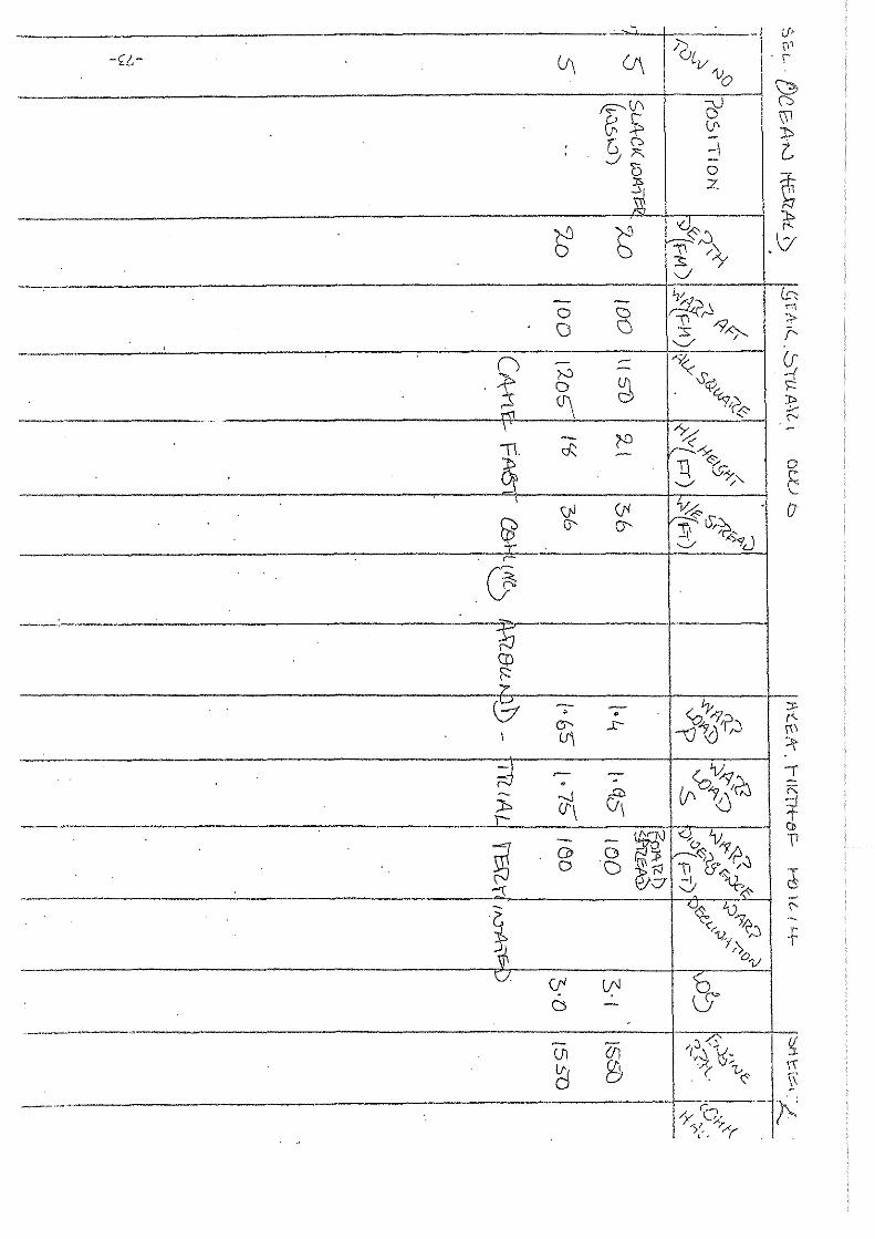
~ -! u·' >. I ~1 /OL -<;6- ~ U\ V v I \
0 ~ r;:::--.<f\ ~ \.:>
~~ \\l V'
t [,0 -\ J'" -
'6 0
~ ~ Z
J;,
S b ~~0 r'
" ' '\ ,\/
3;; /'i v
- - ~ b: 0 8
Ä ~ .."
± "9A>-. ::>
Ci '-./ / r.
n - ~ -x; (j' ~ - Ys -{
'1 0 ~ q:; \:::
~ . ~/0 JO> i-<1 .;.-
._-- '" \ "Y.c:;:' -- (D
~. d:'. ~-< - ~ 1\ 0-1' 0
. '--' ;, C ,
\}J (ti ~L5: . 0
8 Ci' Ü" !! ~~ +- '-../ J <'
(J ---
~ co ; es- , <oly",
:;r. • r'-C3' .r- '\J'tJ'~) n\
\ lf'\ 'r
~ ~ - 'v: I . - 0<01~?,J -J .J:0 r;
~ (J'\ CI\ <J f _. Ci) - - ~-J Y. 'vA \1
~ Cl> G ~<) "1;fl 0 Cl ~:; 11 &. /.J
J -I '\t, -:\ V ~
V~ 'V?, \' t, -~
<> ~~ f 1.}y ,-''>0
1/ CI. er lf'I b~
0 - (J
-----,,, - ((I /:J <15 ~ Vi r., \ -....
~ & -> ".. \"1 ( "<:, )'\
_.-'~-'- -f._) ;< /y CA' ->:_; l',..«

, ,- , ----, ,.---.,'----1----,,-
-l)L- ~ c0 --J C7"- <:J"' /(jiv v ()
----·-G-- ---~
--_._._-----G C; -\2> - (y'='> ::l j:l l!. - ::> (p
-'- r" - -\ 8 :=J g ~ -
tJ 0
\TI rn il1 :z
(-!) N N ~ t;i «)<$' -.J ~ iJ\, '-T\'~
"> <-).-' v
es - - - G I~?~ Cl 8 C)
0 0 0 0 • \\ K? ::r )/~ ~
~ ~ - - CI"' /~ r- .r:- .r:- \1"
S<V, fJ\ (J\ ~ ~ ,s:-
o ""0-- - - - - --Yh' r::I'. () 0\ G' Cl' <'
rJr~ - "8-v /'---(p; l:ft (j'J Ct< ~ \f'J '0, lJ' .J:'- .J:'- Cl' ~ '~0yJ
.
- - - - - <o!-P/X . . • . . ...!'- ct:c Uj .-..J -.J ,/'TJ'GJ
- - - - - (011-'9.2 . ,
ci\ . .
1'- eil. LÄ --Cl Ci' "ri-:J -
ES - - - If0W I <·t,. Lv-'1 8 (1) 0 D N"JJ d~ 1fJ;j CJ 0 Cl ~ü 11 (f'~
\../ "-& - ()~ '0'7, <'/ ~,..)
"!Jy,,> "1/
Nl r:;:> f:'ü ~ fn &-re ...J -. ,-SI .(3) .....:.J
- - - '(~~<ls ~ 0-CO
U\ CI'\ D >-:I ß1 8 .1: /1>~. 0 U\ Cd ._- - 'k '(p~ ~. , 71(-;-/'("

C) i-' "" <::0 D 0 0 i'" ';JJ
~ 7J ()J \:jJ &! -sL- U (I'
-:'"\~ 5 v ;;:. -:> ~,
'ß' <f' c.
~ '" 6 r 'J' cA r
" :::( G :0- m :<= x - -I .--
i<I ;: ;, If'
+ cA
1-" 'V <I' ~
" :t. Z :; n, e:. \J' c-)f1
"'" (;
~ ;y. D 11' 2: 1:.
1: 1;:
\,
er-Cl ;.
CJ -!
" -'" 0::
<.
'" ~ iJ ti'F ~ ~ Q~
.( ;l!o
Q E ~ \ ~ , '.
ö " ;er
p
r~:
" I"
i5 3? .~
~ i ~r ~
'"
7 .... .::-
~ i5 t f ,,~ f;: ;;:
'" d ~
'" H ,;-
1 ~
'" rn ,
ö 0 ~
?' !";
" i' "" '" ~,
~I
;:; , .. Z
7V
~ C-~ 'd m -(
)S.
C

Appendix 2 Comparison of the designs of the
Stuart 482 Band 542 B trawls
Top Sheet Lower Sheet
\
\ Top \ Wings
\ \
Lower Wings /
f<ii:k--
\ I I Outlineof
542 B
\ Square
\ -"'- , I I
,-;;;7"" '" • I J
\ \ \
Bellies (542 e Longer)
I /
I
Outline of 482 B
Fishing Cirde = 540 x 127mm tor 542 B = 468 x 127mm for 482 B
-76-

•
APPENDIX J
COl1U?arison of the Buoyancy or Weight of tl!;~etting in the
Square and Wings for the F~l! Scale and !'~S!'.l Stuart 542B
Trawl.
Weight of twine in air for a net
section
1'1) Full Seale Net
Mesh size = 155mm
Knot faetor - 1.33
Dimensions of square
Meshsize x meshe deep x (meshes 1'101'055
= :!;!?E •• ;~~ottom) xknot factor.
R:llll:fla g e
Twine Rurrnage " 404ml'Kg
230m to 213m in 20 meshes
Dimensions of topwings 2 Je 54m to 92m. :Ln !tO meshes
Dimensions of lower wings 2 Je 88m to 54m in 62 meshes
Dimensions of vees b, Je 53m to i/im in 25 meshes
Total of meshes deep x (meshes aeross top + bottom) '" 4461;8
Weight of Twine in air '" 0.155 x 41;648_~~.33 kg
401;
'" 22.8 kg
Specific gravity of twine (polythene)
Net used in seawater speoific gravity
= 0.95
'" 1.025
Buoyaney of polythene twine = 22.8 x (2,.:°25 - 0.95) kg
0.95
b) Model Net at 1
Mesh size = 25.9mm
Knot faetor = 1.15
Dimensions of square
'" 1.8 kg
10 :O:eale
Twine Runnage = lJ.4 ",/6'11l
141m to 132m in 12 meshes
Dimensions of top wings 2 x 55m to 32m in 24 meshes
Dimensions
Dimensions
of lower wings
of vees
2 x 52m to 32m in 37.5 meshes
4 x 32m to 8m in 15.5 meshes
Total of meshes deep X (meshes aeross tO:0 + bottom) = 16232
Continued 1 ..• -7'1-
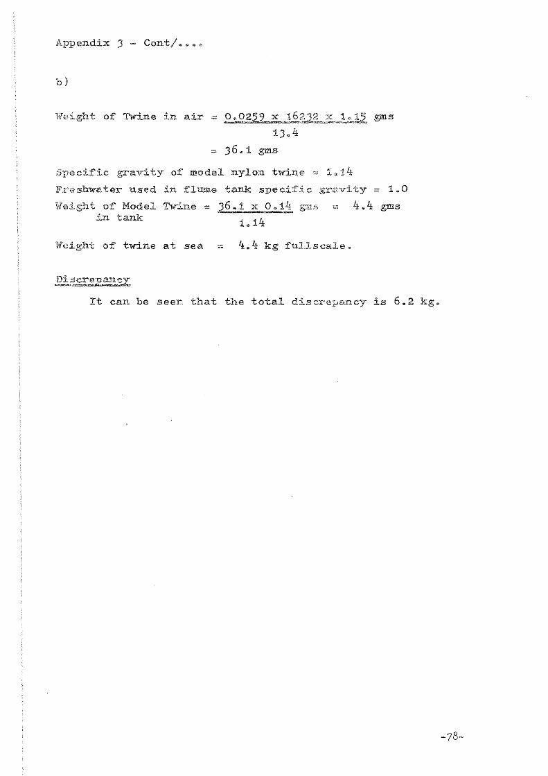
Appendix 3 - Conti ••••
b)
li!eight of Twine in air = 0.0259 x 16~~._~.::.12 gms
13.4
= 36.1 gms
Specific gravity of mOdel nylon twine '" 1.14
Freshwater used in flume tank specific gravity = 1.0
Weight of Model Twine = in tank
36.1 x O. l/f gm".
1.14
Weigh-t of twine at sea = 4.4 kg ful.1.scale.
Discrepancy
4.4 gms
Xt can be seer thai the total discrepllllcy is 6.2 kg.
-78-

I -J 'Ü I i
APPENDIX 4
Buoyaney produeed by di~~erent sizes and makes o~ trawl ~loats
Diameter Make Material Type inches mm
5 127 Phillips Aluminium Twin Lug
5 127 Nokalon Plastie Sideholes
5 127 More Plastic ?
5 127 Nautilus Plastic Sideholes
5 127 North Star Plastic ?
5 127 Permoli~t Plastic Tldn Lug Hinor
6 152 Phillips Aluminium Twin Lug
6 152 Arra Plastie Sideholes
6 152 Noltalon Plastic Sideholes
8 203 Nokalon Plastic CentrehoIe (Yellow) Deep Sea
8 203 Rosendahl Plastic neep sea centrehole
8 203 Phillips Aluminium Twin Lug
8 203 Italian Plastie , Twin Lug (Cosalt) OVhite)
8 203 Noltalon Plastic Sideholes (Blue)
8 203 Nokalon Plastic Sideholes (Orange)
8 203 Arra Plastic Sideholes
10 254 Plastie Twin Lug
11 275 Rosendahl Plastic Side Lugs
'11 280 I Nokalon Plastie I Centrehole i - -J-
Statie Duoyaney Kg
0.7 0.8 0.85 0.85
0.95 1.1
1.3
1.3 1.55 2. lx
2.85 2.95 3.05
3.25
3.6
3.65 11.55 8.8
9.0 I I J

APPENDIX 5
Measurements taken of the scale model Stuart Heavy Board Trawls in
the Flume Tank.
Table 1. First !.:!:x
STUART 482B
Trawl MODEL FULLSCALE
Speed (knots) 2.5 J.O 2.8
Ht. headline centre (ft) 14.9 12.6 14.5
Headline spread (ft) J4 J5.J J8
Door Spread (ft) 88.4 93.6 100
Warp Loads (tons) 1.05t 1.J5t 1.4t
Rig:- Doors 7ft x 4ft 1~ in = 28.7 sq ft
Bridles single 10 fms + 3 x 20 fms
'Floats J8 x 8 in Aluminium.
Table 2. Corrected headline floatation
Trawl
Speed (knots)
Height headline centre (ft)
Headline spread (ft)
Door Spread (ft)
Warp Load (tons)
Rig:- Doors 7ft x 4ft
Bridles single 10
STUART 482B
HODEL FULLSCALE
2.5 3·0 2.8
17.7 15.2 14.5
32.7 34 38
86 91.4 100
1.2t 1.5t 1.4t
1~ in = 28.7 sq ft
fms + 3 x 20 fms
Floats 38 x 8 in light pl.astic
Table 3 Corrected Top Bridle Adjustments
STUART /±82B
Trawl r,!ODEL FULLSCALE
Speed (knots) 2.5 3·0 2.8
Ht. Headline centre (ft) 17.7 15.2 14.5
Headline spread (ft) 32.7 34 38
Doorspread (ft) 86 91.4 100
Warp Load (tons) 1.2t 1.5t 1.4t
Rig :- Doors 7ft x 4ft 1-! in = 28.7 sq. ft
STUART 542B
HODEL FULLSCALE
2.5 J.O 2.6
14.4 12.J 17
32.7 35.3 35
86.8 91.3 100
1.1t 1.4t 1.6t
STUART 542B
HODEL FULLS CA LE
2.5 3.0 2.6
16.1 14.1 17
34 34 35
84.5 87.5 100
1.15t 1.5t lo6t
STUART 542B
MODEL FULLSCALE
2.5 3.0 2.6
19.0 16.7 17
34 34 35
83.5 84.8 100
1.2t t.6t lo6t
~ ,", Cont. / ••
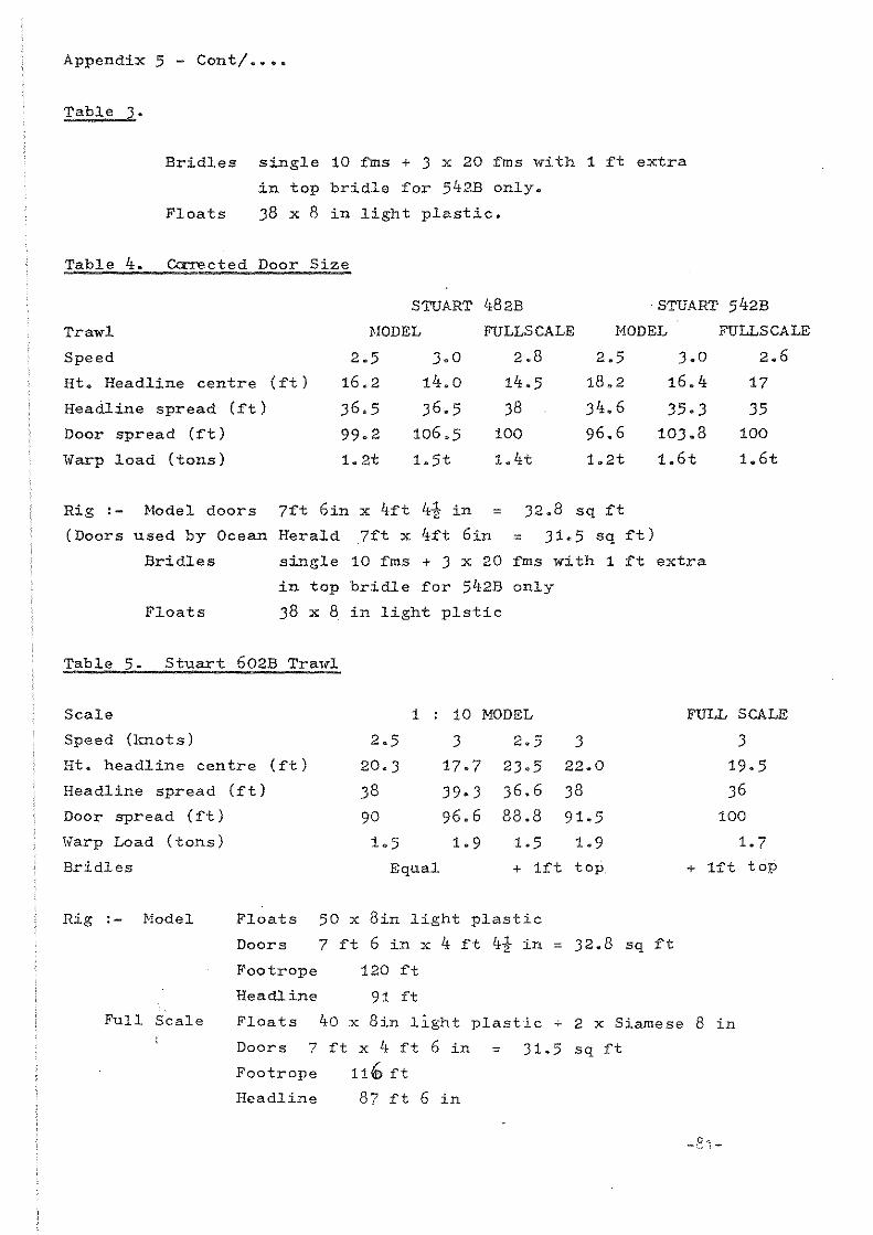
Appendix 5 - conti ••••
Table 3.
Bridles single 10 fms + 3 x 20 fms with 1 ft extra
in top bridle for 542B only.
Floats 38 x 8 in light plastie.
Table 4. ~cted Door Size
STUART 482B ·STUART 542B
Trawl HODEL FULLSCALE NODEL FULLSCA LE
Speed 2.5 3.0 2.8 2.5 3.0 2.6
Ht. Headline centre (ft) 16.2 14.0 14.5 18.2 16.4 17
Headline spread (ft) 36.5 36.5 38 34.6 35.3 35 Door spread (ft) 99.2 106.5 100 96.6 10J.8 100
ivarp load (tons) 1.2t 1.5t 1.4t 1.2t 1.6t 1.6t
Rig ,- Model doors 7ft 6in x 4ft 4t in = 32.8 sq ft
(Doors used by Ocean Herald 7ft x 4ft 6in = 31.5 sq ft)
Bridles single 10 fms + 3 x 20 fms with 1 ft extra
in top bridle for 542B only
Floats 38 x 8 in light plstic
Table 5. Stuart 602B Tra,d
Seale 1 , 10 MODEL
Speed (knots) 2.5 3 2.5 3 Ht. headline centre (ft) 20·3 17.7 23.5 22.0
Headline spread (ft) 38 39.3 36.6 38
Door spread (ft) 90 96.6 88.8 91.5
lvarp Load (tons) 1.5 1.9 1.5 1.9
Bridles Equal + 1ft top
Rig ,- Model Floats 50 x 8in light plastic
Doors 7 ft 6 in x 4 ft 4i in = 32.8 sq ft
Footrope
Headline
120 ft
91 ft
FULL SCALE
3
19.5
36
100
1.7
+ 1ft top
roll Seale Floats 40 x 8in light plastic .;- 2 x Siamese 8 in
Doors 7 ft x 4 ft 6 in = 31.5 sq ft
Footrope 11' ft
Headline 87 ft 6 in
-8"1-

I Co e.' I
APPENDIX 6 WHITE FISH AUTHORITY FLUME TANK DIMENSIONS OF WORKING SECTION
Towing Frame
Safety
Totallength of Curtain ,..::? worklng section I
17·42m )Y
Nowindows' I I
Observation Windows (11) 1 m wide x 1· 5 m high
Nowindows
).E-27m- >k 1106m >I< 366m-->l
Available fortowing warps ete.
Rotating Conveyor Belt 11·06m long by 4·8m wide, All parts of the gear in contact with Ihe sea bed mus! lie in this area.
I Available for
I netting not in contact with
I sea bed.
I I ,
Oepth of
Water 25m
Width of
Tank 5m
Towing Frame for warps
2 Towing Frames can be moved across the tank. Minimum distance apart=097m Maximum distance apart =442 m
---------------Towing bracket can be set /10 any height in the tank
~g Cell Warp

References
1. Nedelec, C, and
Portier, M (1973)
Th~orie et Pratiqu.e des Haqu.ettes • A
d'Eng~ns de Peche. IS TPM No. 227
Juillet - A~ut 1973
2. Dickson ~v. (1959) Model Nets for Experimental ,vork.
In Modern Fishing Gear of the World :1.
3. Dickson W. (1961) Trawl Performance
A study relating Models to Commercial
Trawls D.A.F.S. Marine Research No. 1.
-83-

AN INVESTIGATION INTO THE TOWING DRAG AND DESIGN OF A PELAGIC NBT
by: H. Hirschle and H. Pfeifer
1 • INTRODUCTION
The rapid development of the trawl fishing industry in recent years and the continuously changing conditions has to be reflected in the design of pelagic nets.
Until a few years ago in international fishery, there were no sufficielltly precise design methods or calculatio~ procedures which could enable theory to derive the net's drag, the distribution of the mesh, or its mechanical propsrties, such as the development of the tension in the net and stress points.
The calculation methods for pelagio nets are based on the accurate knowledge of the hydrodynamic drag and lift coefficients of the net fabric.
The angles-of-attack for current pelagic nets are mainly within the small range 0 ~ a ~ 25°. This represents the range of interest for net calculation methods.
However, only very unprecise or insufficient results are available for this angle-of-attacK range.
To obtain a load function for drag end lift, with the highest possible precision, force and moment measurements were carried out with RodLattice models in Oornier's wind tunnel.
For the description of the pelagic net, an analytical design procedure was best suited, since the hydrodynamic force coefficients determined in the wind tunnel with the netlike Rod-Lattice model can be used directly. In addition, this procedure permits a wide variation of the net's parameters.
This project was conducted under contract from the "Institut für Fangtechnik" in Hamburg.
-84-
2. ESTIMATION OF THE ORAG ANO LIFT OF A 0LNJ:: NET FABRIC OF SMALL ANGLES-OF-ATTACK
2.1 Overview of the Present State-of-Art
According to the state-of-art, the hydrodynamic force coefficients of plane net fabries, for a stationary oneoming flow, ean be represented as dependent on the following dimensionless independent parameters. (Notation is defined in the annex):
CW,A = d ( ja' u
1, a, dk/d , Dk/d , Re-d)
Further quantities (elongation, type of material, extended Froude number) are negligible according to SCHARPING (1).
( 1 )
In the last few years, the following principal investigations were carried out for determining the force coefficients of pelagic nets:
The most extensive force coefficients, determined up to now, were by STENGEL/FISCHER [2.2, 2.3]. The drag and lift coefficients of net fabrics in tube frames are subject to extreme error, in particular in the small angle range, due to the follow-up flow and the mutual reaction of the fixing frame and the net fabric.
Recently, a new method was found to determine the coefficients, see [2.4], [2.5], [2.6] and [2.7]. This method excludes the undesirable influence of the frame and the net's deflection. This is achieved by rigid Rod-Lattice models welded together out of welding rods. The investigation 1s conducted in a water channel or a wind tunnel with freely suspended net lattice models. However, only very a few results are available to date.
2.2 Test Procedure
On the basis of the Rod-Lattice model method [2.8J, [2.9], [2.10] and [2.11] an improved model type and test procedure has been developed by Dornier. For these kind of force and moment measurements, a water channel and a wind tunnel are available at Dornier. Due to the simpler test arrangement and the less complex measurement problems, the decision was taken in favour of the wind tunnel.
The eliminate the influences of the finite model, boundary vortices, aspect ratio, length, the model is set up so that the resulting forces and moments are measured only on an inner net s8ction, while the outer area is used to represent the surrounding net. The inner net section is connected to the balance and is separated from the surrounding net by a small gap of 1 mm, see fig. 2.1. The surrounding net is rigidly mounted but always aligned with the inner net. The application of this model arrangement offers the advantage that the measured results are independent of the shape and dimensions of the measured part of the nato
-85-

A 6-component strain gauge balance was used for the force and moment measurements.
The model suspension and the test arrangement are represented in the figures 2.2, 2.3 and 2.4 with various Rod-Lattice mndels.
The forces and moments measured by the balance were determined around 3 axes. The measured signals were stored on magnetic tape as preliminary values and evaluated and plotted by a large computer off line.
ouring the measurements, the Rod-Lattice models were displaced continuous~y wi thin a range between Cl • - 6 and + 90
0 ,,;i th a speed of about 0.5 Is.
This model and measuramant method lad to a very high measurement aocuracy and a continuous and rapid performance of the test.
2.3 Test object - Net Lattice Model
Based on the practical requirements of the present state-of-art and the technieal capability to determine drag and lift coefficients for plane net fabrics in the small angle-of-attacK range, plane net grids manufsctured of cylindrieal rads were selected as test objects.
Compared to net fabrics attaehed to frames, the Rod-Lattice model offer3 the following important advantages in the small angle-of-attaek range:
It is very important that the lettice 18 placed in an undisturbed flow, without the influence of the frame, so that the mutual flow interferenee caused by th8 fixing frame 1s eliminated.
Furthermore, the attachments holding the net fabric on the frame, (eye rings, net cords) which affecting the boundary-layer behaviour of the flow around the frame, are not required.
It is not necessary to taKe the sensHivity of the tube frame with regard to the Reynolds number into account.
Since the mesh geometry can be observed exactly, and no distortions oecur, an accurate mesh arrangement and dia ratio 16 possible,
oue to the use of a rigid lattice, the dGflection due to the flow forees can largely be avoided.
The disadvantage of Rod-Lattice models consists in the fact that it 16 not possible to guarantee exactly a realistic surface and intersection structure, see [2.8J. References [2.5], [2.6) and (2.7J indicate suitable procedures to overcome this disadvantage.
The grids were manufactured from staeI rads with a diameter of 6 mm and welded together at the crossing points with a welding jig. The stesl bar diameter resulted from the rigidity requirements. Ta keep the deflection Of both net parts as lew as possible, a model seale ef 2: 1 was selected •
. The net knots were represented by split "ooden balls with a diameter Of ok • 18 mm (ok • 3 • d).
-86-

Fig. 2.5 shows tl1e basic smooth model without an applied surface struoture, and fig. 2.6 displays a smooth model, this time with knots.
For some Rod-Lattice mcdels, the roughness of the net cords was represented. For thls purposG, the lattice model received at thj.n plastic caating onto which a quartz sand, with a grain of 0.5 + 0.7 mm (approx. 1/10 of the diameter), was applied, see fig. 2.7.
2.4 Test Proa~
In practice, a knowledge of the following parameter dependenoies i8 especially important:
CW,A = (dia, u1
, CL, Re - d) (2)
These were investigated with 12 Rod-lattice models wlth the following parameter values:
o 0 o < '" < 90
0.03 < dia< 0.12
o 0 15 < ß < 45
0.7 • 104 < R - d = 1.52 • 10" - e
(3)
The influence of the relative roughness of the rods dkld was also investigated separately with various Rod-Lattice models. Correc'cion values for the perameters of equation (2) were introduced. Ta determins the effect of the net knots, measurements with and without knote were executed.
To establish the surrounding net size, and the number of rods for the inner net, preliminary tests were carr1ed out in which the number of the meshes of the meBsured element were varied.
2.5 Measured Results
Some of the systematic wind tunnel measurements, performed according to the test procedures laid down in paragraph 2.2 ,are described end dlscusssd below.
Infl.uence of the Mesh Ang~e
In fig. 2.8 to 2.10, the axial force coefficient and normal force cosfficients arB represented as functions of the angle of attack for different dia = 0.03, 0.06 and 0.12. The investigations were made for the mesh angles ß = 150 to 45 0 •
-87~

It c~n be seen from the figurcs that the infllJSrlCS 8f tho ~es~ angle5 on tha force coefficients C and C is ver\ high. x z _.
~urtharmor8 it 18 evident that ~n8 axial forcE coe~~icient ris3E with the mesh angle ß incre8sing.
The figures show that a reduction of t(18 mesh leads tG a smaller axial force coefficient C
x
angle simultaneously für all nets.
In the angle-of-attac~ range a ~ 20°, the normal force coefficient Cz grows as the mesh angle ß increases.
In the angle-of-attack range a > 20° however, the trend is reversad and normal force coefficient can be observed decreasing whi 1e the ITicsh angle increases. The maximu~ normal force coefficient i8 achieved for an angle of attack of about 500
.
InfZuence cf the ['::)1"d Diameter/:;.tesh W'~dth Ratio
Fig,2j1 displays the normal force and a>:ial forCE cGefficlents as funct.io;:s of the angls of attacL for the ;j/e~ 0.03, 0.06 and Ob12, li mes:-: angle had a value of 15°, In principle i~ can be seen th6t tha influence of the dia !"'atio on the force cOBT'ficien-:s C and C lS low for \sry ;:-)-1211 x 0 c angle8 of attack 0.. In the angle-of-attack range> 20u the axial fore" and normal force c8effic:ients rise witii th3 dia ratio incressi!'"!::;.
Inf'luence of the Surl'·QuYl.ding N.3t
To test the quality of the m6asurem8~t3 t~e influenc8 of ths environIT~~t~l nst was investigated.
The me8SUI'ements 07 men~al n8t proved a abeve all for 5mall
the Rod ~5tticc n,~jels with and without~ environgraat influencB on the axial fO~C8 ~o8fficiGnt C, ' angles of attacK. A
Ths axial force increase wi thout the en\/ironment.al nc: t amoLnt,::d U;J tc: 50 %J see fig. 2.12.
Wi th regard to ~he normal force cosf'f icie:lt C the d<:_'''iatj.c-;;s are:: J foT' ths most part, within the range of th2 accura~y Gi ths reprod~c86bility measurements. Ths environmental net cculd be redUGEO -:0 4 b3rs [in flc;.'~
directionJ wittlout a measurable modification of the force coe'Pficients. see fig. 2,'12.
This demonstrats2.:. that ths selected test arrangement E:l8Curat62.y n:::presents the floA force~, actually occur on the net at all angles-of-att3ck anc tha~ ~t eliminates th8 effects of the finite model, bound~~y vortices. aspect retios and length.

Influenoe of the Reyno"lds Number
The influence of the Reynolds number on the axial foroe and normal force coefficients in relation to the cord diameter 15 very low, in the range 0.7 • 104 < R -d < 1.52 • 104, and remains within the limits reproduceability. ~his-statement results from thecinvestigations of STENGEL [3] and KRUSE [10].
Infl-LUmce of the Net Knote
Fig.2.13 illustrates the effect of the modelled smooth net knot balls on the axial force and normal force coefficients on the rod lattlce model (dia· 0.03 and ß • 250
), The measuremant resulted in a reduced axial force coefficient. although the reduction of the aera presented to the flow had already been taken into account in determinating the coeff1cients.
Therefors it can be seen that nets without knots have a considerably lower resistance.
With regard to the normal force coefficient C , however. the knot influence was very small and unimportant. Z
Influence of the RoughneS8
The influence of the roughness 18 represented in fig. 2.14. As can be seen from fig. 2.14 the axial force was increased by the roughness. This 1nfluence 1s taken 1nto account in the practicel celculetion by mean~ of correction valwes.
For the angles-of-attack occuring in pract1ce, the effect on the normal force coeff1c1ent C 19 low and of no 1mportence for prectical appl1cation.
Z
To be able to guarantee reliable statements, on the trensferability of the measurement results obteined with Rod Lattice models to real net clotha with structured cord shapes. further tests are necessary.
2.6 Conclusion~
W1th,the test results briefly presented here regarding the axial force and normal force of plane Rod-Lettice models in the emaIl angle-Qf-etteck range, exact coefficients are aveileblefor the calculation of pelag1c nets. The evaluation showed that the applied test procedure 18 weIl suited for wind tunnel experiments. The force coeffic1ents determined experimentelly in this invest1gation ere very eccurate compered with previgus measurements, perticularly in the emaIl angle-of-attack range a ~ 15 • This reeults especially from the model system which consiete of two Rod-Lettices.
Furthermore, e continuous end rapid test performance wes poss1ble with this measuring and test procedure.
-89-

Vsed Designations
a [ml
d [ml
0 [ml
ß [01
u [-1 1
u [-1 z
q
x .. y, z
x, Z
A C ~-
A q"'''A
C w
w Cl""'A
C = __ x_
x q~.A
C = __ z_
z qCO'A
whereby
mesh side length
rod diameter see Fig. 2.15
knot diameter (3 x d)
mesh angle
horizontal mesh arrangement coefficient (u
1 = sin ß)
vertical mesh arrangement coefficient (uZ = cos ß)
angle-of-attack. angle between the flow direction and the grid plane
C. reference axes given in fig. Z .16 .( if the grid rotates around the y-axis the coordinate system remains body fixed).
forces in the directions of the corresponding axes
Lift coefficient
Orag coefficient
axial force coefficient
normal force coefficient
q~ = pi 'V2 [kp/m2] 2 dynamic pressure of the wind tunnel flow
p [kp p2)
m4 air density
-90-

v ... [m/s]
A • A t x ne
1 8 • u • u
2 1
R _ d • d • v .. e y
y
speed of the wind tunnel flow
degrae of coverage (8) [m2]
whereby,
Anet 19 the totalsurface of the measured net
[dia + (d/a)2 x 0.5]
with 0 • 3 x d
Reynolds number
viecosity of the flow medium air
r ,j -91-

3. MATHEMATICAL OESCRIPTION OF A PELAGIC NET
3.1 Introducti9n
For the eontrol of pelag1c nsts 1t 15 1mportant to know their res1stance and for the calculation of the net thread strength it 15 requ1red to determine the net load on ssch point of ths not surface. Solution possib111t1es are given with the analyt1eal ealculat10n of net patterns (3.11, (3.2), (3.31, (3.41.
In this ease, a distinct10n haB to bo made botween draft and postcaleulat10n (3.51. In the ffrst ease the net pattern in the weter i9 given. Net arrangement, mosh number, and thread tensile forees end net resistanee depending on the oneoming flow ara calculated, In. the eecond ease the mssh number 19 known, end besed on this the other fectors are determined.
In this oese the draft 18 more importent sinDe it ie of higher significanee for the further development of catching tschnique. The most edvanced procedure 1s the one mentioned in 3.4, end the following report 1s pertial1y based on this procedurs.
3.2 Prersquisitss
A model nst 19 sssumed and expressed in cylinder coordinates whose mesh sides run in the direction of the ma:l.n parameters q, • const and x = const. The externe 1 forces thst set upon th1s net ere the seme as the ones exerted on the real net. Forees can only be teken up in the direetion of the parameter eurvs (fig. 3.1). Generally, the mesh sides ara not vertieally erranged on top of each other.
Stretchas in the net cloth are negleetad.
The weight of ths net is neglected agel.nst the force flowB.
The influence and the receding of the sweep line forces whieh are lad in the form of points 1nto the net are essumed to be linear to the eod end:
e (xN
1 ~ 1 J C (x 0) n O.
In the esse of a 4 shae!<.le net the cross section in the sweep li ne point of etteek of the net which 19 eanceived at first without headline 16 eomposed cf e hyperbola "nd an ellipSElJ in the ease of ß 2-shaekel net it 19 sssumsd to be ell1ptieal;
Due to the symmetry of the net the exam:l,nattons can be restricted to ane quadrant.
The undisturbed oneoming flow 1e to Bet on asch net point that 19 exarnined.
The coordinate zero point sterts at the transition from eod end to net.
-92-

3,3 Mathemat:lc~L 1l!!,!,J:n0dc 1"
TMe position vector describ:i.l1g tho ,,0Jt surfac0J (filS. 3.2) ü"
+ + + + r • x • 13 + (n eos<!,) 'Ci + [Il sinqlJ • e
x y z (3.1)
n in this ca se 1s the functicn \"hich descr1bes thB cross 1i.8ction:
Yl " 1 - • coslj>2
[1 + ~(xJ • (e-l)] C;:L2)
for the 4-shackle oet
11 1,\', u (3,3) 1 - Ii: cos~2
for ttle 2'"Bheckle net.
The tEll'm indicatss 'the hyperboli!l part whioh ooours in thti 4-siHlckle net:
~ • [1/oostl) - 1.47273/5 10- 10 • cosh 126'61J (3.4)
~l are tan [(i!l/b) tan~]
a and b ars half the width .~nd heU the he1lj{hc of the rii,t
The longitudinal surface 1.ntBr58ction curve a(xJin the :n.~in 11ne u"' intersect10n <i> - 0 of tha nr,j; 19 es!!umed to be Il 3rd degras pc.lynumiel. It 13 daterm1ned by the fol.lowing valu9!l'
1 • Initial radius of tha n!,j; ,., end end radius
2. Half the width of the nst npening
3, Angle of inclinatinn clf ths Burface intersection curve .jJ ~ 0 ths cod end against the x~axill
4~ Angle OT incl:ination of ths BUx"'"rac@ int8T'S9ct1an curVf: ~ f/;: 0 at the net open1ng against the x-axis
5. Net langth wi t hout ccd end.
H18 s8cond longj.tudinal surt'21C8 int8!'sactian curve is as~uriied i.n such a I.ay that at the end end alb Is 1 and 2lt the net apening 1t Ül 2. It 1s:
b (xJ • a [xl / (1 + c (,d 1 [3.6)
Thus, a eInsed presenteJtion of thl! surf2lce intersecticn cur"" 15 given. This presentation 15 prefelCNld 5inee 11et ring dimensions er" hardly knawn.
-93-
3.4 Differential eguatiün für net forc~s
Based on fig •. 3.3 and by I"OOl!lns of differential geometry /!l differential equation in vector form can be set up for the forcas Bcting upcn ons area element of the net Burface,
.... a (/G'0'1' 611)
ilx ~ ~ ~ + '61)' a [~. 0'2 •
612 + lEG (-Pt10S1+Pt2oe2-Pn 3 + ily
• dx d~ sin w ~ 0 [3.7)
This equation i9 an initial value problem for 0'1 and 0'2' For the oad end these vellu8s ars raletivaly easy tc ealculatsl the squation ean then be solved by mBelns of the Runge-Kutte method (3.7). For this purpese the equation 15 prepared in such ~ waX thet ~t is given in the components cf ths three mein directicns Si' e2 and 9
3,
Tc solve the equ<!ition (3.7l ons marginal condition hall to be ft;.lfilled which was formulated already by Baranov [3.6].rt impl1BS that the forcea 0'1 and 0'2 which arB related to length are linked to each other via the mesh arrangement u
1,
cr " 1 -'U 2 1 1 (3.8)
cr .. u :2 2 1
The 1ndexing of the foroes i5 reisted to the fact that the mesh diagonals sre not vertioal on cne ancther. Acccrding to [3.4] the follow1ng applies to th1s extended oase,
0'1 (0'1 + O2 ein w)
0' 2 (0' 2 + 0 1 ein w)
3 'J [3.9 J
Ttlis marginal oondition implies that the net form to be given should correspond lsrgely to the real form. which oeeurs during the cneoming flow. If this 16 not the oaBe the mathematical formulation has to be changed accordingly.
3.5 Calculst10n of th!-headline and footrope
At first. the net is calculat9d without the headline up to the wing tips. Then. the headline 18 interseotad in the nato FOT this purpose, an initial force T 18 assumed in the middle of the net aurface Cy m w!2) at an
o assumed distance from the wing tips. The headline 16 calculated in the form of segments by means of the forces which are known at Bach point of the net. Tha following force equilibrium exists on point Pi of the headline (fig. 3.4),
-9ltw

-+ -+ 4-'" -+-FMi FMi+1 FNi + Ai = 0 (3.10)
..,. F . are those tensils forees in the headline whieh -,?eeur only in tP,§ headline direction. FNi are the net forces end Ai stands for ths loft wh ich provides that the headline is in the net surface.
In point P a value T is assumed for FM . The aquation (3.10) 15 salved viaoan aUXilia~y plane which 1s vgrtical on the resultant of the farees in the x-y-plane [3.7]. Should the initial farce T be seleeted wrong the wing tip is not hit, and an iteration 18 r~quirod then aceprding to [3.4J.
3.6 Numerical pracedure
The equations (3.7) end (3.10) are solved by means of a computer program which was prepared for the Cybor 175 of the RWTH Aachen. Library sub-programs of the computer center are avaIlable for the algorithm. The force coefficients obtained from wind tunnel tests are put into a table und are then interpolated by means of a Hermite-Spline-function.
The initial value for the integration i8 supplied by aseparate drag calculation for the nat cod end whareby the wind tunnE,l data indicated In paragraph 2 are applied •
The following geometrie data of the net can DU put in for the furt her ealculation:
m and a L as the inclination of the net against the x-axis when • = 00
a~ well as half the width of the net opening. The net form can be varied wsll with these three parameters.
Subsequent to this the mesh ratio dia can either be assumed ta be constant for the total net ar it ean change from net ring to net ring. A further possibility for control consists in the selection of the shacKle number whieh can be either 2 or 4.
Up to the wing Ups the n·st 1s calculated as a closed system, then ths net 18 intsrsected in the headline. The fallowing data can be requ8sted at any arbitrary point of the net surface:
tension in longitudinal and cross dlreetion 01 and 02
angle of mesh arrangement ß
flow angle t<
thread tensile farees in mesh T1 and T2
for the net end (,Jithout headline) or for sach integration section the total resistance end the mesh number can be indicated fram the s1ze
o geometry of the net in form cf a coordinate list far 0/ = 0 and ~ = 90°
geometry and farees of headlines in tabular form.
-95-

3.7 E~ample calculation
3.7.1 ±~12~!_9~!S'
The twin-shackle net with 664 # size made of knotted net fabric in the speed range of 3 kts, 3.5 kts, and 4 kts. is taken as model ease.
The initial valu8 for the solution to the differential equation results from a specific cod end calculation according to (3.9).
When v ; 0 the angle of inclination of ths nst surface intersection o 0 0 curve 1s assumed to be Uo < 5 at $ = 0 and uL = 5 at x ; LN' When
stretched the net has a length of 70.6 m and at v ; 3 kts. LN ; 60 m including wing tips.
Although it 1s possible to vary the dia ratio via the nst lsngth ths sxample 15 calculatsd with a constant dia; 0.018, a value which 1s in the middle of the really procsssed dia data.
3.7.2 Rssults -------The results refer to two nst cross sectlons,
LN 50 m (assumption: bosom centre)
LN ; 60 m (assumption: net end)
At L ; 50 the following date are put out for the three speeds at the three points ~ = 0, $ ; 450 and $ ; 900
,
tensions in axial (01) and peripheral direction (02)
mesh arrangement angle ß
flow angle a
thread tensile forcss in mesh T1
end T2
total resistance up to the length RN50 nst size at this point UN50 mesh number at thls size nM50 •
Ths total drag 1s givsn for LN ; 60 m as a comparison to the head line ealeulation, from which the aetuel nst resistanee results. In addition to this, the net geometry 1s given at v ; 3 kts. (semi-axss a and b of the ellipses as f [x)).
Since no publieation is available of large tests on the pure net resistance (only the wrap drag was measwredJ the drag eoeffieients have to be comparsd which are related to the net opening surfae8. A coeffieient of c = 0.067 for ths empty nst is msntioned in [3.10] for nets with trailing ~quipment. Taking into aceount approximately 5 % for the net trailing squipment Cw = 0.0637. The following Cw va lues are obteined for the three speeds at LN = 50 m (without headline and wing)
-96-

v in kts.
c t,,1
3.0
0.0667
3.5 4.0
0.0644 0.0635
The real nat J:'2sistance at v = 3 kts results from the calculation of the headline fcr LN = 60 m:
R" = , D " "N (half the headline) 4.5534 ~ = 22.136 kN
R ~ 2" ,. N ~" C ,!P
Für this drag coefficient i. c, • 0.0636. Con'form:',,:,' with [3.1 oJ 1s very';good.
3.8 Conclusion
Net length and cod end resistance have comparatively little in-f]usnce on the total resistance. Tne crucial criterium is thE net opening surfacs.
Tns resistance from headline calculation lies weIl between the total net calculations with the given lengths of 50 m and 60 m fron: which a good acquisition of the headline calculations can ce concluded.
The high z-components of the headline force and of the lift at the end of the headline are caused by lateral shearing force which 1s not taken into account. For the calculated example tctal lift until 2 m before the end of the headline is approximately A = 6 kN.
-
4. PROSPECTS FOR FURTHER ACTIVITIES
After the termination of these investigations the following furt her activities can be suggested in the areas of the improvement and securing of the results, the extension of the findings to the design of pelagic nets and the adaptation to the net development:
Further net grid models for other supporting points within and outside the investigated parameter range.
Additional. investigations to ensure a more exact determination of the surface structure by means of rod lettiee models.
Experiments with model nets or large nets are neeessary to obtain information on the aecuracy and to improve the selected mathematical model. These tests should be carried out to determine the aetual shape, mesh arrangement, and net resistance.
This analytie caleulation method should be extended to the calculation of the raps nsts.
-98-

Table 3.1: Input data
v in kn 3,0 3,5 4,0
v in m/s 1,54 1,80 2,06
r o in m 0,37 0,37 0,37
r L in m 13,5 14,5 15,0
LN in m 60 62,5 65
° 10 N/m 879 1201 1573
Table 3.2: Results for LN = 50 m
v in kn 3,0 3,5
'f = O· <r = 4 s" ... = 90" _1f= O· v= 45',/= 90" 01 in N/m 323 340 386 460 464 525
0. in N/m 32 55 69 49 79 98
ß in 0 17,3 22 23 18,2 22,4 23,3
Ct in 0 11 , 1 3,8 2,7 12,4 4,7 3,5
Tl in N 10 13 16 15 19 23
T 2 in N 10 14 16 15 19 23
"N50 in kN 20, 1 41 29,226
UNSO in m 59,7 62,4
I nM50 834 838
origin Quelle •
"
eno .illl~
Steertb!
[ 3.8 J
-~,,,,--,
_cu l,?t 5l2El reCr,rlL i ~t
, , ___ 0_'_, __ "'_
F>S~~
Steertbe rec:'\.:ltr.ng
t~ pO
!' = 00 9~, 45'! r" -~I_-Zf
603 60S-- 6""'f4
67 105 121
1 8,4 22,6 23
13,2 5,4 4, i -
20 25 29
20 26 29 ,-
38,191
62,6 -
835 i
-99-

Taille 3.3: Ne! geometry Table 3.4:' Heoo- am:! footlin!! calculjltion
~ A ß ... ,." ~
0.00 • 170000CO • )1 JOJO 00 1./ 1 ~:"31J·H2;d o;1.3?'t?7Q J~ .. 3 ~744ntl74 *70)'1D70
2M ;.1' • (nd 71200 .):)')0':1126 )(M YM F
Mx FNy F
Nz A Q~ij& t.Z;;ltlilO 1~l2:~4S176 o ~ ) 7 1.5')bC.r,1~7 I.JOltlJbTl in In m N N N· N
1u. Z9 1.Ud~lh51l 1.~0137.Hd.
12.00 2.lJ'/r.,'jl,l'j 1.Hb f )2tl25 50,00 0 6,57 0 3500 16 32 lL n 2,&lbJ0323 2~12y(}5012 50,51 3, 1 5 6,37 1205 3480 463 32 1').':.5 Lul ~d056~ ?.~),)~ H~'1:.l
H.l' )./d.?!5b?; 2~f,td4;t,eb 51,03 4,44 6, 16 1687 3461 655 32 1 iJ. b (, 3-. tH.5H '{t,O ?'.9 /,1.13l07 51,49 5,32 5,98 2008 3446 792 32 20.)7 4.313;7'11,2 3. 2lZ3t/~1.,!)
52,00 6, 16 5,78 2310 3430 931 33 22.llJ '".771r',,-162 3. 4-uDH52 54 .. .24.00 5~2}i 11.::'73') ).74551~54 52,57 6,96 5,55 2595 3414 1074 31 2:>. n 5.721'4J393 t.~OJ50JJ75:
53,05 7,57 5,35 2812 3402 1 1 95 35 27. /.,) n. ~O<'/)5~bJ l,.25'\O:}'~35
2'i.14 t\. uQ Li ~JQ) 4.~OJldl>o 53,55 8, 1 G 5, 13 3020 3391 1322 38 30.Ub 7.l1BJlb05 4.7',)72:7511 54,06 8,73 4,90 3220 3381 1160 40 H.;r 7.06:d4:')l 4~~!J:!2nJ7
Jt.,~2Q ij~ 14tiS I.d.107 5~ 1~54,1 H 55,00 9,67 4,46 3555 336, 1737 48 3-0.00 lJ.bZbZ7l65 5.3ql~?Ofd 55,56 1 0,19 4 , 18 3741 3361 \926 55 31.7L Q.O'l625938 !).!Hi542Z:42
55,97 10,56 3,97 3878 3358 2089 61 j!J. ~ 3 I. :"H,J.?u5tl ). 7o~1I.51a " l ~ 14 10.00C,Z50bO 5.'-13472493 56,5,j 11 ,03 3,66 4058 3356 2346 74 t" 0 co l'J.o!,3]dr.,17,/ 1).0":311.219
57.10 11 ,49 3,32 4237 3:\55 2668 93 " .... )"1 1').d,;~·n1,3b f)~22!:1;:ldOtj
46~21J llo2.:JH~eH b. 352(d tOd 57,52 11 ,82 3,05 4372 3357 2973 114 ~d.O(l l.t .030:;',530 h.r.,:,tt1tl,,{jj 57,96 12 f 1 -1 2,76 ·1508 3360 3262 146 t.~.n 11.;!1lt,7)42d b~55t.l:d5b )1. 4 3 !2.Jll~)tJOl h~63:)J77"O 58,49 12,53 2,33 4691\ 3366 4100 221 ~ 3.1. ... LL {d ~-H 090 b~!:td.:)f,71'f5 59,01 12,90 ! ,85 4890 J ~~ 7 6 5343 390 , :,~~ij& l'.3a62H?O G~ !H;J~l51'
59,49 13 i 2 i pi r 29 5101 3389 C011 926 -' ~b~)J l)~ !Z57'"Jl?b 6~ {Y5-~tt; 83 0 :.r6~1.'-i t 1.1310ß 7 '2 1>. 7?11'57~ 59,98 13,50 0,01 5534 3425 0 I &8.00 I!. ,0000000 u,,75:>OO:;lOO

I <tF=---._._ . ..p

-
(oSl = ~ 00'0= "11') j"[iOlU a:l!Uel-po~;pue uOIsuadsns lapolN
,(, pu. 1:,'0 = e/P)
lapow ao!nel pOl:!' pue uOJsuadsns lapolI\I
1':9 10 llS
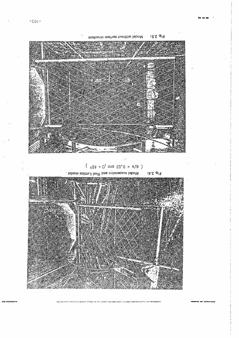
( oSt = d puo SO'Q = E/p )
- lapow aO!'Ilel POl:! pUB uo!suadsns lapolN
-_.-

Fig,.2.6:
Fig.2.7:
'" 01 l) JOO ." ""
---------,~"" "-~
Rod Lattice model with knots ,epresante';
Rod Lattice modal with knots and ,"rface rough nass rapresanted
-10'+-
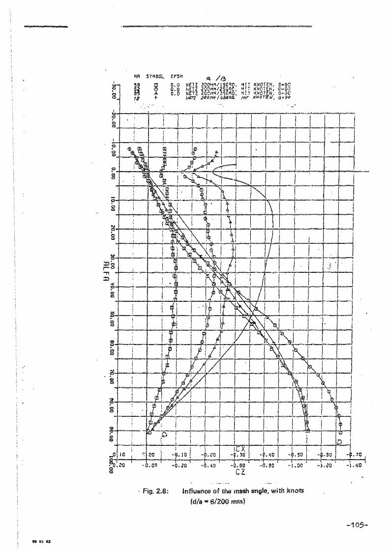
ea 01 Ga
W· ? g
--------,~~-~"".,.-- "" '" --
NR Sr'SOL !PSH <\ /13 S6
;~ 11
2 +
0.0 NETZ 2CC"/ISG~O. 'Ir KNOTEN. 0.90 0.0 NETZ 2COM~/2SG~C, ~!i KNOTEN. Q~a~ 0*0 NETZ GCCM~/35G~O. ~rT KNOTtN. Ow~C
Mff% ,2f)()H/f/t/.56IlA Nil'" X;JOrl!.bJ, rltfgo
~ I .: I I I I 1 1 T I I 'I , r Im' J ~ I I I Q ,
? g m!i!
j
?+-~-+~~~~~.-F~--~~~-+----~+-g +-~-+~~~~~~~--r-~~-+----r-~
?+-~4-~~~~-4-+~+--r~-4----+--r~ '" o ~
~ _. I I ::oe. I I; I r Q .~ ~ I ::0 ' ~ I
; I I
~ 1--+1-4--g I !" ~ I ? I g ,
..I c+-~-+~~~~~-+-4--r-+--r~-+~~~
'g
.0\10 52-, :-o.~o g
, ! f 1 1· I i T,-r -0.00 -Q.zn -O.~O -0.60 -0.60 -1.00 -,.10
CZ
. Fig. 2.8: Influ8nCl! of the mesh IIngle, with kllots
(d/a = 61200 mm)
~ 1 D
l -p.70 ~
-1. qO
-105-

(WW 00 L/9., B/P)
6111uII 1jS&W 1iIj~ !Q e:luGnl~ul :6'Z 'Il!:!
ZJ g ,Oh'l- ,OZ'\- ,OO'!- ,0.'0- os'q- Oh'q- O~'O- ,oo'q- O~'OO
, Ol' - 09 '1- I OS' - f Qh' - ~f~ - 0,' - 0 \' - I 00 0 01 oS
Y~ 1-1 I I <:J ~ I~ ~ I I! i ,,,,
'" '" '" '" ,
1-", 16 '" CL ~ ZS

ZJ
-
0/ ,sr o LL Q S&
'" c OZ'Oo
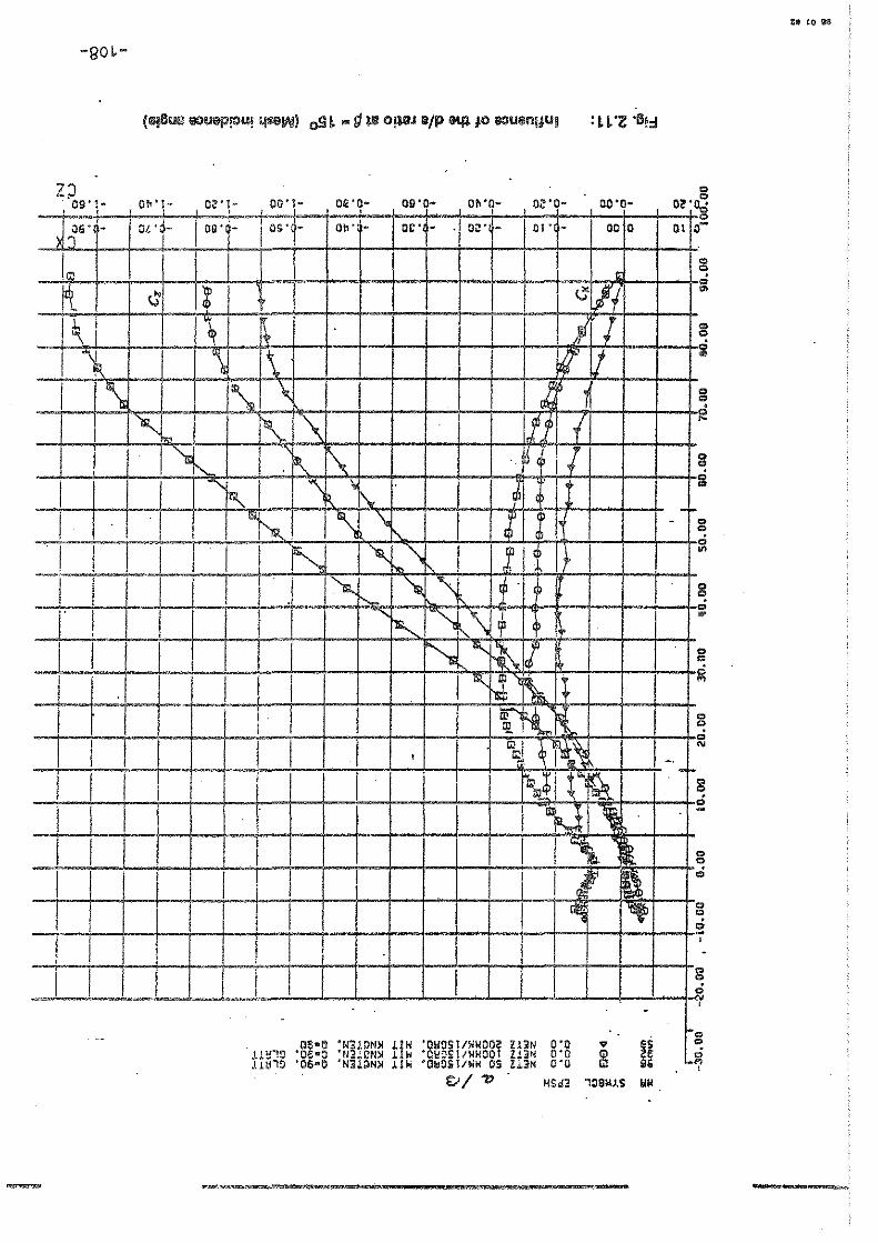
-go~-
2;) OS'I- Oh'!- O~'l- 00'1- oe'o- OS'O- Oh'O- o~'o- 00'0-, , , ,Og'rM , ,
J i G' - Olt OhM I", oe' - . Oi!-- 01' - 00 0
I I I I' G : I (J j I ~ I I
'(
i I;> ~ .,
I "\ \. i j I ,~ \. \ , -]1 i
" "- " I I ~ '"
I ~ "- ,~ \.: ,
I " ",I "\ , I\..
I I '" ,
,~ \, J I ~, I , I I I ~ " ''\ I I qJ I I "" l I I I .I ~ I~ '\ I I , "-
I I I ~ 1 , '" ,,\ I
~ , ~ .. I I
, I 'J,"' ~, I
I 1 I~ J' 1;,.
I tIl l!l..
J I I I III
I b' , c: I ,
I I I I I I !Qoo ' .~
I I I ~FJ l I I ,"-
I I I I 'i ~ I I I , ,
I I I I I - . - --
, - , 00·0 'N3l0N~ LIW 'OWDS1/.NOO? Zl,N 0'0 " i U!{"!;) 'OC--::) '~l3!(m)l J.!~ °C~~Sl/WIoiOOT IBN 0:0 CD • • 111 '" • ~ • L!ö'~ 06 0 N.1QN~ LI. O~D.1/"" OS Z!3N 0 0 m I.
E.:; I"" WS". '09w~s WH
-
ot'~ 01
--
,
-, ..,
Cl
0
-
g co
'" .. " ~
'" '" Ci '"
;..
g Ci
.. ., Ci
'" c
i , -
g Ci ,
·co ., _l'l

(~. 'o9t"' fi 'ww 1:1 .. P 'ww og '" 111)
" -UU! ~1lI.I III.!gpUOOJJIIS
n I
tt~· t ... O~'l- , 00'\- OIl'O- os'o-I ,
, OL '4- I O!i' - os' - Oh' - oc' -'l:"l I
!..i ... I d ~ 8 ~~I-+-+-r,-r~~I-+I-+~1 ~~.~~~+i
rl I~I ' I .1 1'\ I
• <
g -+--+-+--;.-... ·i
Cl:: L&,.
, g~ ~~-~--+-~--~--~g

« (IR" 11· 'ww liI ,. P 'ww 004: '" 1111 ~ $)I!N ~ ~ IIIIIIWWYIIS :i:n: "Ij,j
, ~~ '1- Ol'l- 00'\- el'o- 011'0- O~' . OZ'C· 00-0- 02'
5L' - Sir' - 5S' - S~' -I ~r~ - Sl' - . sr" - SO' - 100
'" ~
~ ~1tL f-
~ !\ . '1
'j f \" .
~ ') "
Ht I U" ,
~ . I .. "'
~ : 1& il'l
I , j \
- .. , •
I • f ~
\.1 -, _. I-~
'" .~ . !-.~ 1-- j..i
. ~ =.~"'~ ~
l ,
.. - I .. • ~- I """'-~ ~
b I
-

I 0~'1- OZ'!- OO'l- OS' 0 OS'O- Ob'O- 0.'0- 00'1)-, , , , , , ,
'OL'r ; 09~t ost Ob' 0 OE' 0 OZ' - 01' - 00 0 , )(:)
d'
~ I I
I l' I ~' I)" " f--m
\ 'lIt !l "- ~
I ~ I'm. . I I I i'1R,~ f'.,
~) , i ~ I P ,
I ~.
I I I ~ ~ I I ~,
I I I I ij
I I ~ ~ I I \ ~ r\ I ~ m '\
I I 1t , I I I I~ ~ I
I I I 1 I I I
I -
unüY '06-0 'N3lgN~ .IW ·OW9S1/W.OOZ !l]N .. Y1$ '06-0 ·N'lgN~ l!W 'OWOSI/W"OaZ llN
0'0 0'0 ~ bS
9$
OZ'O' iS
01 O~
g e .. g e .. '" <> , r-
'" <> e .. e
'" .. '" '" '"
:5 .. .. g , '"
g .. -8 ci
8 e -, •
8 fd , I
er 1.1.. ...J er
"", '" ~
tt- 10 ..
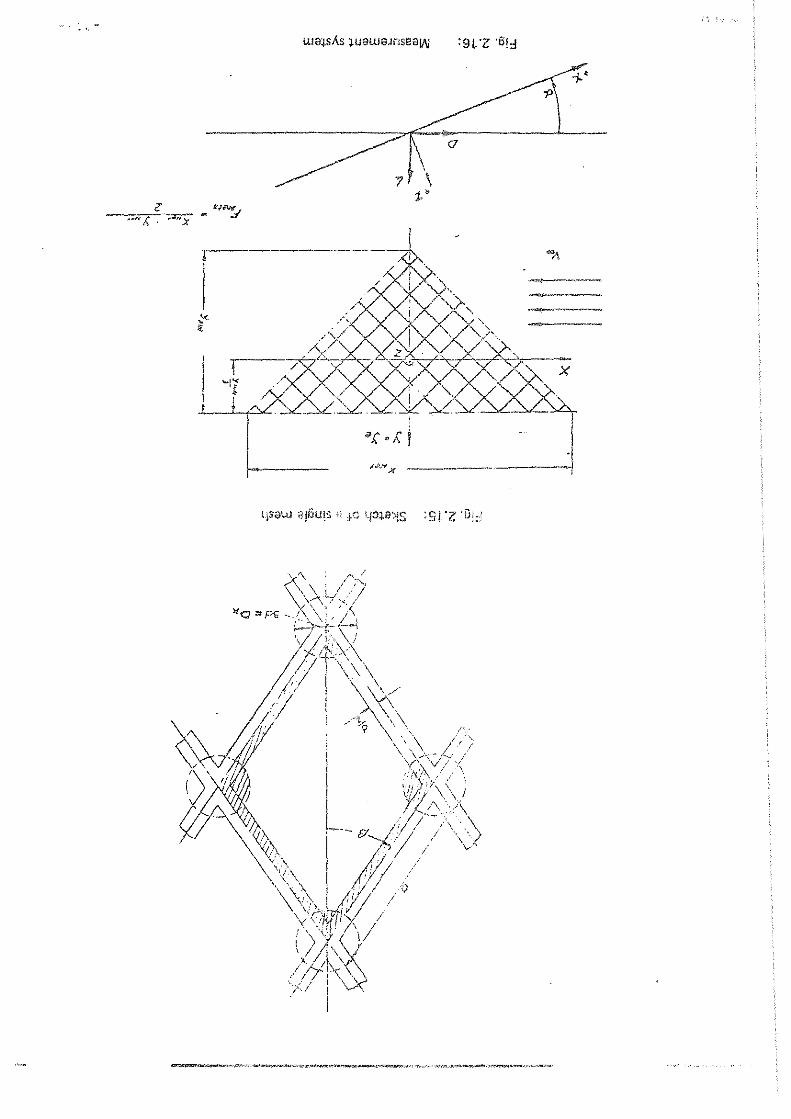
,., ,.
, \
x
/.#N X .-_._~ __ -----!

Fig. 3.1; Substitute model of the !'let accordi!'lg to [3.4]
l
I
'f
/~
",
p
~
'~ ..... '-"-..
<:~
Fig. 3.2: DescriJ:ljion of the !'let part according to(j.4]
/';1
'-/ ----'~~'-':-r \,/ __ -0(" ~;r-
/,1' " /. !! / ,0-0
r
/. ///
/// ://a, b'i.1 / / I Lf ___ _ I / " I __ }
,:<:::/"':' - 7 - - / ,~ / ~ X
/! / /! / /
/ I I / / I I /
/ / / I I / , K______ / ,
Q{xj /
/
/

y> .. ~6"r.
( .I oC'(. c/<4.. / "'1 1" a J(
/ p-----.~'" ~~-, --~ ;' -----------~~ !G. dY'.Ja;'I: .dx. d y'
/;/ I\P. /0" / / " \ /
l(fl _. _lc==-r-/:;_I_ .. - __ :r;
. - '/ 6.__ . e /, '1"
. F ~, ,~ 'l>/
/ ~1 / \ \'1 ", " ~. /
~ .. - /~~L J\; d~---::AAe; --:::~_~ I
~ 1ft 'I'fd~ • C_f.
Fig.3.3: Plilne eiement according to [3.4]
f'.1 I Po
~. A· I
Pj +1
Fig.3.4: Head ;:ne TOI'C01S at Pi
--.. F,,;
-F 1'1;+4 /'
x+dz .. ~tf
_ ; 1'· ...

Je' r-------------------------, ','
...
... '.' ... •• >
.. ' '.'
···r-I ----'.' '.> ',>
'.>
'.' '.'
'.'
Fig.3.5:
lO'
'.' '.' '.' ... <.' ...
Cross section of a 4-shackle net
'.' '.' ~ 10'
"'4~'_ Ib.OI.19tlO
r-------->.>
>.>
'.1
<.' <.' >.>
... '.' '.>
',>
... ' .. . " ' .. '.' ... '.' <.' > •• >.' .. '
.. 10'
. " '. ..~ ... I fp. <q" J 9110
Fig.3.6: Cross section of a 2-shackle net
.- '!" '*


, ,
e" 0>
--
N
" '<
n1 0-ro
" '"
N
w
=J
"'"
N w V130'-N
'<
N
rn , 0-m
" ro

; I .•
0'(
/ /
02

[2.1)
[2.2)
[2.3)
[2.4)
[2.5]
[2.6]
[2.7J
[2.8]
[2.9)
REFERENCES
Scharping, K.D. Beitrag zur Ermittlung des Maßstabseffektes bei der ModelIierung pelagischer Schleppnetze Dissertationsarbeit an der Sektion Schiffstechnik der WPU Rostock, 1973
Stengel, H. und Fischer, H.-J. Ergebnisse von strömungstechnischen Untersuchungen an Netztüchern im Windkanal Schiffbautechnik 14 (1964) H. 7, S. 374-381
Stengel, H. und Fischer A. Ergebnisse von strömungstechnischen Untersuchungen an geknoteten Netztüchern aus gedrehten Polyamidfäden. Fischereiforschung 6 (1968) H 3. S. 49 - 59
Koritzky, H.H. Widerstand und Auftrieb ebener weitmaschiger Netze Fischereiforschung, 12 (1974) 2 S. 51 fL
Koritzky. H.H. Neue Methoden und Ergebnisse zum Bestimmen von Strömungskräften an ebenen rechteckförmigen Netzteilen und Netzfäden Fischereiforschung 15 (1977) 2. 43 ff.
Kruse, W. Beitrag zur Ermittlung von Widerstand und Auftrieb ebener Netztücher im kleinen Anstellwinkelbereich Fischereiforschung. 15 (1977) 2, 31 ff.
Kruse, W. Versuchsmethode und -verfahren zur Ermittlung von Widerstand und Auftrieb ebener Netztücher im kleinen Anstellwinkelbereich Seewirtschaft 9, 8/1977, 471 ff.
Hackeschmidt, M. Grundlagen und Bedeutungen der Modellähnlichkeit in der Strömungsmechanik Maschinenbautechnik 15 (1966), H 12 S. 635 ff.
Kruse, W. Ergebnisse zum Widerstand und Auftrieb ebener Netzgittermodelle im kleinen Anstellwinkelbereich Seewirtschaft 11. 1. 1879
" :-

[ ' ',r, 1 L. I '-'J
[3.1 J
[3.2J
[3.3J
[3.4)
[3.5]
[3.6]
[3.7l
[3.8)
[3.9]
[3.10]
"-rusel 'Wo ;\'eue Msthoden und Ergebnisse zum Bestimmen \Ion StrömungsKräften an 80enen rechteckförmigen Netztsilen und Netzfädef\. I=iccr;srci -Forschung, Wissenschaftliche Sehri ftenreihe 15 ~1977; 2
Pretzsch~ P. Berechnung von pelagischen Schleppnetzen Disse~tation 1970, Universität RostOCK
Ivanov, E.P. Analytische Lösung der Aufgaben der Statik der Fischereinetze Fischerei-Forschung 11 (1973) 2 S. 19-31
S~engel, H. und Fridman. A.L. Fischfanggeräte VEB Verlag Technik, Berlin, 1977
Leitzke, H. Ansatz zum analytischen Entwurf eines pelagischen Vierlaschennetzes Fischerei-Forschung 14 (1976) 1, S. 43-51
Leitzke. H. und Stengel. H. Stand und Perspel<tiven der Erarbeitung einer Me~hodik zur analytischen Berechnung netzartiger Fanggeräte Seewirtschaft 11 (1979) 5, S. 242-244
Baranov, F.I. Selected Works on Fishing Gear, Vol. I, Jerusalem 1976 ISBN 07065 1561 7
Hirschle. H., Pfeifer, P, und Langenbach, E. Untersuchungen zum Schleppwiderstand und Entwurf eines pelagischen Netzes Dornier-System-Bericht, 1980
Lange, K. Schleppwiderstand von Tauwerknetzen Hansa 116 (1979) 4, S. 319
Stopperka. W. und Pretzsch, P. Analytische Entwurfsmethode für pelagische Schleppnetze (Untersuchung von Steerten) Seewirtschaft 3 (1971) 1, S. 65
Dalchow, K. w.a. Bewegungsv9rhalten und dynamische geanspruchung von Schleppnetzen Dornier-System-Ber1cht Nr. 106/74, 1974.

SCALLOP DRAG TESTS AND DEVELOPMENT
by: Alan J. Blott and Vernon E. Nulk
The sea scallop, PlaCope~tin magellanicus, fishery is an important
segment of the fishing industry of the East Coast of the United States.
In 1979, 31.5 million pounds of meats (the adducter muscle only) worth about
$103 million were landed. Over 200 documented vessels are involved in the
fishery. However, studies have shown that commercial scallop gear, called
scallop drags ar dredges, may be only 10 to 20 percent efficient, depending
on scallop size; and gear-related mortality may approach 20 percent. In
addition, present gear with 3 inch rings is nonselective between 3 year ald
and 5 year old scallaps, approximately 62 and 106 mm respectively. Between
the ages of 3 and 5 years aId, the meat weight of scallops quadruples, so
gear which selectively fished for the older scallops might increase yield per
recruit significantly. Investigations have shown that increasing the ring
size does decrease the catch of smaller scallops, but fishermen have argued
that because of the large amount of trash caught, using larger rings would
be ineffective. One Canadian investigator concluded that chan ging to the 4 inch
ring would not make the drag significantly more selective, so he suggested
development of an entirely new piece of gear.
Studies on gear-related mortality have shown that scallops are forced into
mud und er the drag or crushed on hard bottom. Bottom disturbance by drags may
reduce the settlement of spat. Undersized scallops brought up in the gear
-121-

are dumped, culled, shoveled, and exposed to extremes of temperature, thus
reducing their chance of surviving when returned to the water.
In spite of all the investigations conduttedto date, there are many
unanswered questions remaining. 111e Northeast Regional Management Council
realized it would be difficult to manage the scallop resource unless more.
were known about the gear used in the fishery; therefore, a study was funded
to look at the New Bedford scallop drag using divers and color underwater
television.
111e purpose of the initial study in the summer of 1979 was to. develop
the techniques for divers to ride the 8 ft. drag and handle the camera and
lights. Also, it was hoped that methods of determining mortality, selectivity,
and avoidance could be worked out during the initial stage. After the divers
became familiar with riding the dredge, they were able to ride and handle the
camera. One diver aimed the camera and another tended the electrical cable.
111e diver operating the camera was directed by a coordinator watehing a video
monitor on the vessel who was in voice contact with the diver.
Another method was developed where the camera on a two wheel trolley was
lowered down the towing warp after the drag had been set. Using the trolley,
observations can be made without divers. While looking for areas of bottom
suitable for towing or for concentrations of scallops, the camera, with a
pole sticking out in front of the lens, was lowered on a line to the bottom.
As the boat drifted, the line was adjusted so the end of the pole just touched
the bottom. Also, a net and frame were constructed to attach to the top of
the frame of the scallop drag to catch any small scallops which exhibited
the reported avoidance behavior of swimming up over the top of the drag.
-122-

The usc ()f the color und-':l'water television camc:ra and divers fOl
ob.·'crving the operation Oi' thC' dredge at 1 1/2 to 2 knots \Vorh·r! Lv 11.
HOhover, i,,. the 9 days ::.v.iihblc in 1979, thc correet combination of shd lOh
depth, gooe! visibil ity, ,md 'c!dquate conccntrations of sca110p;3 was ,,,.)t
found S0 most of the ohsc'rvations werc 01' dredge performance not sc<:.!lJup
bohav i 01',
It \,;;]s found that the bad of the drag towed at an angJ e so the tow point
was up to 4 ft. off thc' bottom, and the cutting bar--the lower horizontal
member uf thc rigid frnme ." the mouth of the drag--was alwelYs sever:,J inches
off bot tom except in :l ,eas of sand ridgcs where the bar plownl through tbe
tops of thc ridges. Thc ,,,cer chain tendcd bottom wdl, digging into soft sand
and lightly scraping hafel bottom. In areas of sand ridges, it was hccrd to
tell hoVi weIl the swcer W:lS tending because ()f bi 110ws of sand obscuring the
chain. The water flow ",ound the cutting bar "as ind:icatcd by thc flow strCai'iS
of sediment above and below thc bar. Thc flow patterns ShOl' that objects on
thc bottom may be moved as thc' cutting bar passes over.
Cu1'rent drag designs have 3 ~epressor plate mount cd on the upf'er
horizontal ;nember of thc rigid frame at the mouth. This .is supposcd to help
thc ge ar tr,nd bottom better. The depressor plate an,;les elownward towards
tlw frollt of the drag; but "hell the drag is fishing, the plot" is almost
pandlcl to the sea bcd so it ,'ocsn't affeet the performance of thc gear.
I';" also observed that thc after scctiOll of thc bag \''''5 ah!ays collapsed
bcc'lUse of thc weight of the rings, whereas the twine back-··the seetion ove,.
thc sIVeep chain--opens up simi 1a1' to a trawl. Thc wcight of the rings am]
tile club stick is vcry likdy tu damage undersized scallüps in the bag anel
uncaught sCHllops that thc gear passes aver.

U;'lilY, h'lt:11." h".: L--:lrflCd fr-<);<l t.he v.idco; a 11'.':,\' drag is b'"~lI1g desipH.:'(! to
OVC'tTl>',':: 5011-:. Ot" thl' p({.\hlt..'·m:.'~ '1110 fir,>t COlki.'rn is to rc~uce gear-rcl~\tcd
j·:lortalit·y by chZlngin(~. th\~ rC:.lr sectl lJD oE the drag Thc forwa rd J:-r:lmewol'k
"ill cl)','cly r",',,'·,hl,' th"t uf exisdn); New ßcdforcl clogs. T11e dcprcssor plate
will ho J<"lrgpl' :md hingcd so thc angle of att:lck will be adjust:--1.blt.: .. Dr chal1~!,ing
thc derressor il1lglc, thc clownward force on tho drag will bo alterad. A bolt-on
cutting b,,,- hilI bc· used so cli ffercnt cross-sectional shapcs can he tested.
The shapcs hCjll~:\: cpn:;iderccl includ;' :1 quarter cirl.:lc h'hich is intondcd to
defL.~c.t W:ltcr flm"] dotvn to the sc'a bottom to djs]odgc :;C:lllop~~ layjng in
depressions.. Another shape is an l.r;\·crtu.l hydrofoi I > ~.,h id1 r '"; 1 ift the
sccllops out "f the depressions. The he;!,ht of tile ).'uttinr. ),"1' <);'t' thc bott",
will be ac1ju:~t-·lblp..
Thc [tftcr section will bc a rigid r~lgc si.miIal" to the Victori,an scallop
dl'edgc fi,JH".J in /\.ustralia~ The nwjor diffcrcnce from 1'Ile Anstr<.dian dredgc
h1jl] be thnt. thc noiV design wi 11 havc ;\ 11<.-·.'J\:")' Si','(:cp chain :';imj L\r '{CI existlng
:~cw Bedfol'd dr;Jgs~ The swecp h'.il1 bc llL t·~;d to tlH' rigid cagc v.'ith a flexible
scnl10p ri,r;:-; :;pron~ Thc Austr:lli.an drcdr;e: fe;Jt.u]'es a rigid .:~c['(.i.per bar ~1}h:ich
',,'ould not ;\()d·. on t.hc· rncky bottom that the Nt":\1] ßu.1fnrd drn,Qs GTe fishcd on~
T1L~re l\'1 1.1 hi~ ;! hjn,~~{ ~HJtHccn the forward SCC"tiOl1 :lnd tlH: rif.' 1d (:~lg:..: L"hich
vi 11 ri<L' :1bc)".:c tb, b'.lttom on tbO runners. Sy l.'('ch;cing thr t"'0ttC:!l contoct of
thc [,e"1r, ('" ':l'-L:l:lt·'·:] :nortality of unC:1ught :::c'111ops shou1d hc reduc()cL
Th" tor :'nd t)l:, ,-;.!. t mC5h p;:ll\ .. 'ls of th c(l~:;:C h.i J I lw r'emov:.,blc 50 different
~~.l ZP l:;,.'she~, 1")~' t·: :;t.0d to tb'·tf::·rninc seL..'ct.i\'ity.
Thi:~ dr,.'.:.j~>"', :.'l11 hc tcsted in thc sU1',lnC'l~ of 1980, ~:!!d j t is üxpcc'tC'd
tc signi Fic;,llit!. ,'cdltcc f"ishing mortality of 1:1)<: 1ll1C'PWht :~i.aJlop.s~

LITEl1Aj'UKE
B'lird_~ fC r" 195~}" Fuctors affectinp: thc ,,-CficJ.cncy of dredg8s~ In nodern
Fishing G,ur of thc World. Fishin<! 'lc,.s Books Ltd., London, 222-224.
Bourn", N. E'65. A compariso'l of catch.,.s b;' 3- and 4-1nch rings on offshore
sc~llop Grags. J. Fish. Res. B,:. Ce,n., 22(2):31:5-333.
C'lch'y •. .i. F. 1968. Underw::ter observ:1:ioll" an scallop (Ph:copceten --~---,
J'lliJ!e!Ll;l.nicus) behavior :lJld dr~:'-2 cffjci<Jlcy • .J~ Fish~ Res~ Ed~ Can.)
25(10:2123-2111.
Caddy, J. R. 1971. Effieiency nnd s"l:c',l"itr of the Canadian offshore
sc",:lop c:redge. Intern. COUClC. "01' ",e :ixplor. of the Sea, Shellfish
an( Benthos Comm., C.M. 1971/K:25, 2 ~, (Dimeo).
Caddy, J0 F~ 197:;~ Underwatcr o~J:,erv:JtjCln:, on trncks of dredges and trawls
:,nd some effects of dredging on a sc';d!,,;) g:'·01.md. J. Fish. Res. Bd. Can.
30:173-180.
Cameron, W. ~L 1955" An investigahon ()F scallop-drag operation wHh
undcnmter television equipmcnt. k,,: 1. r.es" Coune. Can., Radio and
Eleet. Engr. Div., ERB-378, Ott"W;). 7 p.
HUfhes, W. D. 1973. OperationJI Tests of V'ctorian Se8110p Boats. Aust.
Fish. ~by 1973, 14-16.
:.la50n, .1., C. J. Chapman and J. A. 1·1. Kim"o·,:t. 1976. Population abundance
.c,nd dredge efficiency studies of thc' "",']lop Teeten maximus (L.), Intern.
Coune. for the Explol'. of the SC8, -"I'''':' '!eeting on Popul. Assess. of
Shellfish Stocks, Paper No. cO, 15 n Imimeo).

;1 I,· ) f ~ C 1,)52. Modifications of dr:l5~S co protect sm;,d] scallops.
Res" Cd. ean", AtL Biol. Stn. P1'o)!'.. Rep., Note No. 119, 52:9·14
:bien:',!. e. :md N. Bourne. 1964. Lll;,es of mortality of thc sea sC:111,'p,
!' [;;copectc21. magellaniel's. Proc. ~;:lL She11 fish Assoe. 53: 33-50
:-(lsga)", ,J~A~ 1958 .. Maximum yield in t;le sea scallop fishery~ Int" COTlllTI.
':"rthw. At!. Fish., Ann. Meet .. )llne 1958. Doc. No" 28, Sero No. 554,
t 7 p. (mimeo 1 "
'I'Iwhig, P. and R, J. :3molowitz. In p",,'ss, The Application of an Undcnvater
Color Video System to Fishing ('VI' J\c:;carch. ~ ProccccUngs of the
Scienti fie :md En:.cineering App] i ':;J t i ",ns of Unc]c'rwater Photography,
) .~-

A NEW ERA FüR_ KRILI, CATCEING
By Matti T. 116rrnä *
The harvesting and utilization of krill has been a sUbject
of keen international interest already for soveral years.
Many countries have carried out large-scale expeditions
when studying the behaviour :md biomass of krill as weIl as
the possibilities to catch it feasibly. The whole research
work is directed by an international program BIOMASS
(Biological Investigations of Marine Antarctic Systems and
Stocks). Th0 main purpose of all this research is to have
suffj_cient knowledge on krill. stocks so tha-t when the full
scale harves-ti.ng of krill 1s started, it can be managed
sensibly. The total potential catch of krill could allow
a substantial increase of the world's catch of abt. 75 mill_ion
tons, up to doubling it.
* iJr. :l.'rärmä is the chief naval architect at Hiirtsilä Turku
Shi0yards, Marine Resources department, Turku , Finland.
He is a specialist on seakeeping and ice-going operability
of vessels and is in charge of the design of krill factory
vessels.

~ IrJ~l' ~ll
Penguins are one of the major users of the huge krill stocks.
Thanks to the cracks in the ice fields they can survive during
the severe winter conditions.
Part of the krill catch for peeling. The size of a krill is
about the same as a match.
_128-

THE PROBLEMS OE FEASIBII,IT\
'T',!C rc:...\:~.;()ns :[or the lack of vast. 11a: \;-'-:st.ing of krj, _1 •• 1
('.; lreaC~' :Ln !~h~~ sevc~l1t.i es are f' irnple.. !~S cV'_:.:::-y:.)oeJ:y· ~:X1f)WS
t11e maiq a.Leas of J<~rtl1 swarms lay .;~,::1r off soutll hc:yond
the An-carctic Con',ycr0,,::nce. Th,~ vesD,,:~J~: cLlpable to llse kr Lll
econorn -~ c_dl1y were non-existinq due ',. () the fact. thz: t: the cdtcL<;s
have tu be processecl raridly after t,)k,<ng j,t, onhoi;';" due <.:0
fast a>ttolysis of: y:rill. SeeD~ldly 'cb relation of +ehe t.I:i,:wling
capaci {,'.y of the conv<.-'ntionD 1 trawlcl' ':Hld thc·ir processinq
capaei.y is uneeonom:;.cal: ti:e lare' catches by sj.rogle hauls
could not be utilized.. Thrtdly the ,~~ ';:vclop:n".=-,nt of the r:roce:'3sing
eguipmcnt was not so fast ~s was e~pucted. Fourth and the
most important factor has »?en the ;:00 short time of o[Je'ra ': ion
due to difficult en~,'ironment2,1 con~.~j tions. Eowever, signj_fic.?.D't
progress has been made on all of th0 abovc mentioned items.
The Finnish shipyard group \'~;.rtsil;: ):no'W'n ,JS the vJOrld' s
leading hui Ider and designc'l of ;,eehreakers· and polarvessel s
is showing a new solution in the economieal utilization
of krill.
THE ENVIRONMENT - ACHALLENGE '1'0 FE CONQUERED
The 10m t.,c' rs around the An tarct 1c are 1 nown to be the wor J d ' s
most dlfficult for navigation. Thc v,·ssd,s operating in
these 'ati tudes must be safe, eff ie i. 'ot ,,-nd soa wort,hy.
The problems which one may meet thore are not only the gale,
and fog bu t also icebergs, low tempera. 1.1.1'es cind dri ftj ng j_Cf'.
E"en in summer the krill areas could !>,.' eO"ered with :floi1t."."(}
pack-ic<',. The per iod of open water 1s short, 0111y a few HlO;)Ul: .. ,
To lengthcn the catching se~son of tll~ krill vessel j,l- lIas tC,l
be desicrncd to oper~te and catch also irl lee conditions.

Figure 1.
Figure 2.
Typical view of the Antarctic seas in winter. The waters of South Orkney's are surrounded with icebergs and thick pack-ice.
The ice pressure on the hull demands a special construction and design of the vessel. This figure is taken on the trip of Wärtsilä-built icebreaker "Almirante Irizar" near the South Orkney's in October 1.979.
_1:;0-

A typieal pieture of the krill area in winter time i5 as
shown in fig 1., whieh is taken near the South orkneys Islands
last Oetober. The drifting paek-iee eovers the sea with a few
ieebergs here and there. For eonventional fishing vessels
it is impossible to operate safely in these waters, beeause
the rapidly changing iee eonditions ean demolish her easily
making the hull plating wrinkled as a raisin. The iee thikness
and the iee pressures ean be imagined seeing fig.2 whieh is
taken only abt. twenty miles off eastward South Orkneys.
(The figures 1. and 2. are taken during the trip of the
Wärtsilä - built Antaretie ieebreaker "Almirante Irizar"
last Oetober at the Atlantie sector of krill areas.) The iey
environment of the far- off southern krill are quite similar
to those of far-off northern seas of Finland. The Finns have
sueeesfully navigating during winter time for over a hundred
years and have gained experienee seeend to none of iee operating
vessels. Now it is time to use this knowledge also for the
starting er: winter operations in krill areas.
leE-OPERATING KRILL FACTORY TRAWLER
Operation in these eireumstanees require special vessels,
whleh are not only eapable of overeoming the environmental
threads but also ean earry out their main task: the harvesting
of krill. Wärtsilä has developed a ship to operate in these
waters. COf':cdning the vast ieebreaking and polar navigation
know-how with the experienees of lee trawling has made in this
vesse1 eapable of eoping with the Antaretie ehallenge.
The main eharaeterlsties of the vesse1 ean be seen in figures
3 and 4.
She is astern trawl,'r with the possibility of lowering the
warps under the lee, featuring a totally eovered trawl deek
and is equipped with the Wärtsilä air bubbling system to
reduee the iee resistanee.
_'i ;''1 _

Icb-r, '~*~ M ,j::: ::=:( ~~e" .. ! ; r r I~~ = = = = P = 57:; = Y Vi ~ O'~
Figure 3.
F.irJure 4.
fJl
Krill fdctory trawler for operating in icy conditions of the Antarctic. The length of the vessel exceeds 100 meiers and she rescmbles more an icebreaker than a -Lrawler.
'J'hc 01:tjst's i.I[,prcssion of W§rtsilä's design operating j II the JI,nt'n:ctic \,,'aters. These vessels should harvest krill also in winter times.
-1::;2_
" " -,
These features are standard solutions for an icogotng
fishing vessel, but this one has also several other fC0turos
which put her in class of her own Vlhen considering operationa.l
charaeteristics in the Antaretic. With her engine power sbc
i5 eapable to go through an field of h;o feet thick ice
maintaining a trawling speed.
BRINGING THE HUGE KRILL CATCHES TO THE MARKET
The most attractive aspects in catching of the krill are
the huge potentials of krill and the relative easiness of
eatching. From the large krill swarms, a daily catch of
several hundred tons ean be retrieved. The processing capaeity
of the Wärtsilä's design is up to 200 tons krill per day.
The processing of krill is concentrated into three major
products: peeled krill, krill meal and krill oil. The
processing of all these products has developed rapidly
within the last year, and the process are available for usage.
Because the products eompatible with products of to-days
market of small shrimps, fish meal and fish oil, there should
be no major problems in introducing them to the market.
The main purpose of the vessel is to catch and process krill,
so the cargo space is not designed to carry all the products
of one trip onborad. The ship is capablc for independent
operation up to three months, after which a transport
vessel supply the factory, take the products and bring thc
replacement crew.
- ,

Krill flowing through a peeler. ~he peeling tests have given promising results in last years.
Peeled krill is small of size but can be used as cocktail shrimps or raw material for "krill pins" etc.
- \;)'"\ -
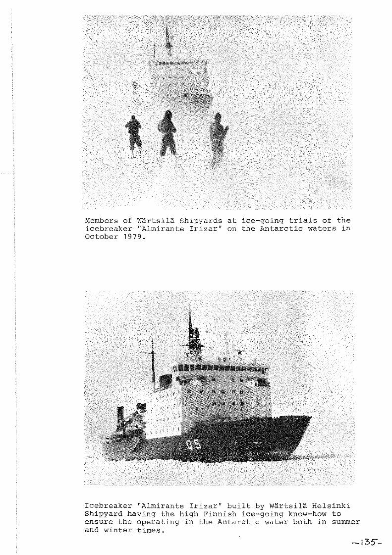
Members of Wärtsilä Shipyards at ice-going trials of the icebreaker "Almirante Irizar" on the Antarctic waters in October 1979.
Icebreaker "Almirante Irizar" built by Wärtsilä Helsinki Shipyard having the high Finnish ice-going know-how to ensure the operating in the Antarctic water both in summer and winter times.
-135'"-

Latest developroent,on gear instr~mentat~on
by Peter Stewart
Dr. Peter Stewart informed the meeting on the latest developments in gear instrumentation for trawl engineering studies at the Marine Laboratory (Aberdeen). At the moment a new type of underwater loadcell and a net speed log with a 12 hour recording capacity are under development. The development of a spreadmeter and otterboard instruments measuring the angles of heel, tilt and attack is completed. Deck loadcells and headline height meters are commercial available. Dr. Stewart called attention to a new shackle-type cf loadcell. In the discussion several applications of doppler-log and wireless netsounder were mentioned.
-136-

MODEL EXPERIMENTS 0Ii HOPE TRAliLS! ,WALE 1 I,
by: B. 'Iran ~!arl"n
1. Introduction
In September 1978 and July 1979 trials were done on 1/4th seale models in the vicinity of Sardinia. This research wss a co-operative programme of the Institut für Fangtechnik in Hamburg, W. Germany and the Netherlands Institute for Fishery Investigations in IJmuiden, Holland. The main objective was to make picturas and films of saveral rope trawl models and to do messurements in order to compars these with the full scale trials done abosrd the FRV "Tridens" on similsr nets in November 1977 and 1978. Several construction problems were dealt with, like the cutting of the "shark teeth" at the junction of the ropes to the sdjacent netting panels and the design of the shape of the framelines and the lengths of the ropes. Direct observation is the only way to find out the extent of distortion in parts of the nato The area chosen was very suitable for this purpose. A very nies sea temperature combined with a good visibility made the working conditions easy for the divers. Other requirements were a calm see state and a sandy bot tom for bottom trawl experiments not mentioned here. The depth of the aea bed should not be much ovar 15 meters.
2. Geers tested
The models, scale 1: 4, were deri ved from a 1736 meshes palagic ropt> trawl (see figures 1 end 2) on whieh extended tests have bean done in the years 1977 end 1978 (see reference). The shepe of the framelinea is based on the catexlsry curve leading to the rope lengths given in the drawing. In addition to thia gear a silllilar net wi th a meshed upper squar.'€i has been studied.
The seeond model was identical but for the front part, the design of whieh has been done with a computer programme especially written for this purpose. This routine calculates the length of the ropes and the frame-line sections using the assumption that the ropes are equally loaded and the elongation could be neglected (a correction of elongation due to a nominal load has been t.aken into account when constructing the net). The dimensions cf these rope panels are given in figures 5 and 6. The mesh/twine-size scale factor hae not been kept constant over the full length of the nets, bacause some emall-mesh net material was not available at the time. For panels IV to VII this scale factor was chosen at 1/2 instead of 1/4, leading to a reduction
lactor for the number of meahes in normal and twine directions of 1/2, in order to scale the twine area proportionally with the factor (1/4)2 = 1/16.
N -! oLL ! $ N m - ol.a= OCd fs
with: Nm = number of meshes of model across and in depth, not in ftll arp$
Nis = same for full seale net
~L = length scale faetor m) (1/4) for this case
-137-
0( = a
0( = d
mesh size seale faetor
twine diameter seale faetor in this ease 1/2
Henee: N = 1~ $ N m 172 fs => [ .1 • N
2 fs
~ => mostlY:F.= 'xa
= Nm]
The position of floats on the headline of the models is given in figure 8. The magnitude of floatation has been scaled down according to the scale faetor of forces, weights, volumes, etc (=(1/4)3), leading to a eertain amount of floats of a given diameter and buoyaney.
The Süberkrüb doors of 4.7 m2 were sealed down to the size (1/4th seale) and the weight. Even the eentre of gravity of both doors was kept in aecordanee with the full size ones. Other parts of the rigging were sealed down to the size rather than the weight, exeept for the bridle weights.
Several ways of eutting the " s hark teeth" have been tried. The best results were found with eutting C (figure 7), based on the method of eutting used at the V.E.B. Fischkombinat at Rostock (see Chapter 6).
2~_~~~~~~_!~~~~~g~~ The experiments on the seale models were done on small fishing boats around Sardinia, an area perfectly suitable for underwater filming. The following parameters were measured during the trials: - towing speed - port and starboard warp load - headline height - depth of the headline - door spread - wing-end spread - wing-end height - seetion height (at junction of ropes to netting) - the depth of the seabed
200 Ke transdueers were placed on the headline centre, the starboard wing-end, at the junction of ropes to netting and on top of the starboard door. The warp loads were measured with 500 kg load cells attaehed to the warps and the ship. The speed was measured with an Ott-log, mounted on a special strut to keep it well away from the ship's hull. Direct observations Were done by a team of divers from the German Navy, in collaboration with the Institut für Fangtechnik in Hamburg, under the guidance of ing. W. Horn, who took most pictures and films. Changes to the ge ar could easily be made by the divers without the necessity to heave up. The effect of tide and eurrents was judged to be neglectable, no reciproeal courses were sailed. The technique used for full scale measurement has been deseribed in reference (2) and (3) to a gr,,".t detail and will not be mentioned here.
4. Comparison of model experiments with full scale results ----------------------------------------------------------4.1. Rope trawl with meshed upper square The full scale values are higher over the range of speeds used, irrespective of the bridle weight, although with 750 kgf weight the difference deereases with speed. Both the wing-end spread an the headline height are bigger in full scale, the difference be~ng largest with 750 kgf bridle weight.
-138-

The door spread did not match the full scale value, indicating the model doors being hydrodynamically less efficient. These results agree with the drag of the model being considerably bigger than the comparative full seale value. The more drag a
ge ar has the less it opens. In figure 12 the drags of two models are plotted against speed together with the full seale values of the rope trawl with the meshed upper square. At 4.0 knots the model with the meshed upper square has 70% more drag, at 5.0 knots the difference turned out to be 60%.
4.2. Rope trawl with floatation, catenary shaped headline The wing-end area is plot ted against speed in figure 13 for the 600 kgf weight ease and in figure 14 for the 750 kgf ease. Both show the same tendency, the wing-end area of the full scale trawls is eonsiderably larger (some 40% at 4.5 knots). The addition of 150 kg bridle weight on each side had a similar effeet on both model and full scale trawls. The wing-end areas are increased by some 5%. With 600 kg the headline height diminished at the same rate for model and prototype, but with 750 kg the full scale ge ar seemed to have a headline height, that reduces faster when increasing speed. The differences in wing-end area decrease slightly with rising speed, but the rate of change is not very rouch dependent on the magnitude of the weights on the lower wing-ends (figure 15 and 16). The discrepancies in drag are not as large as with the trawl with meshed upper square. The model results seem to be rather sensitive to the length of warps paid out, in eontrast with the full scale values, where this dependancy is not so distinct. At 4.0 knots the model has 15% more drag and with 5 knots the difference rises to 38% (figure 17).
2!_!~~_~!!~:!_~!_!!~~!~!~~~_~~_!~~_:~~E~!~~_~~~~~~~~_~~E~_!~~~! In figure 18 the wing-end area of the computer designed rope trawl is plotted against speed, for two different values of the bridle weight. The influence of the floats on the headline is hard to distinguish. At low speeds the no-floats condition seems to lead to larger wing-end areas, whereas at 5.5 knots there is no difference at all, irrespective cf the bridle weights used. The model floats were chosen in order to scale the buoyancy in the right order and not the size, and therefore not the drag. This may account for the undistinctive results at high speeds.
6. Results of direct observation
A lot of information ean be learned from direct observation of the gears, either by taking pictures or films. The rope trawl with meshed upper square did not show any significant distortion, apart from the pie ces of netting used to connect the top panel to the sides. It can be clearly Seen from figures 19a-g, that this netting is much too slack. The overall shape of the net looks quite well. The netsonde cable and the wing-end transducers can be distinguished on figure 199. Figures 20a-j show details of the computer designed rope trawl without floatation. The shape of the trawl is very well indeed, with the attachment point of ropes to netting almost in one perpendicular plane. The "sharkteeth" cutting of the toppanel (see figure 8 and 20h,i,j) gives the least distortion, that of aide and lower panel considerably more.
-139-

A similar design of the toppanel cutting is therefore favourable from a net shape point of view. It is based on having a narrow band of smaller meshes, at the junction of ropes to netting. From figure 20d it can clearly be seen, that the assumption of straight line sections along the framelines is a valid one. There seem to be no significant differences in net shape between the computer aided design and the design based on the catenary shape. 2 Finallyaseale model of the Süberkrüb doors (4.7 m full scale) is shown in figure 21, with a transducer on top (200 KC) looking aoross to the other door. In most cases the doors were heeling inward and were tilted backwards.
References
(1) Modelonderzoek aan gesleepte vistuigen RIVO, TO 77-08, August 1977. Bob van Marlen
(2) Rope trawl development RIVO, TO 78-02, May 1978, Bob van Marlen
(3) Rope trawl development - further experiments RIVO, TO 79-03. May 1979. Bob van Marlen and David N. MacLennan
-140-

TABLE OF EXPERIMENTS
1. Rope trawl with meshed upper square, catenary headline, no floats
Haul no.
T78/2.3 VF79/1 VF79/2
T77/2,3 T78/5,6 VF79/3
Scale
1:1 1:4 1:4 1: 1 1:1 1:4
Bridle extension (m) -----------4.4 4.4 2.4 4.4 4.4 2.4
warp-!~~S!!:_~~l
450-650 300 400
450-650 550 400
2. Rope trawl with floatation, catenary ahaped headline
Haul no.
T77/15 T78/9 T78/10 VF78/6 VF78/7
T77/12,13 T78/7,8 T77/14 VF78/8 VF78/9
Scale
--- ... ------1:1 1: 1 1:1 1:4 1: 4 1:1 1:1 1:1 1 :4 1:4
Bridle ~~!~~!!!~!dm)
4.4 4.4 4.4 4.4 2.4 2.4 4.4 4.4 2.4 2.4
3. Computer designed rope trawl
Haul no.
------.... ---- ....
VF78/2 VF78/3 VF79/6 VF79/8 VF78/4 Vn8/5 VF79/7
Scale
1: 4 1:4 1 :4 1:4 1 :4 1 :4 1:4
Bridle extension (m)
4.4 2.4 2.4 4.4
2.4 2.4 2.4
Warp-!~~6!!:_~~1
450-650 550 550-850 400 400
450-650 550 450-650 400 600
Warplength (m)
400 400 400 400 400 600 400
bridle ~~~6!: !:d~5f)
600 600 600
750 750 750
Bridle ~~~6!:!!!_~!:6f)
600 600 600 600 600
750 750 750 750 750
Bridle weights ~~6!L_
600 600 600 600
750 750 750
-141-
float
yes yes no no
yes yes no

U/~l.-'EJ~ ~ r,,~' i:)rv"':' ". -f'I"-·A'::': .....
Tor,,! LEAfc,rH ;/ElwL,;"E ;::;,,/j) Fc..oTRoPE
10 r1
112
:100 POD
:100 200
100 eso
so
i.Y.3B
1;/28
:1c/18
2t/.f B
AA!
so
so R;f t:
,,-~j;:)l:~ ~ ;:,-;. ,!;;. ;: {.~~,.
t: TOTHL LE.JGTr/
o SiDE ,,~oPE <l
'" <i -:.';- 62 r7 '" '.
\\ ~ ~ / K'" ,,~'
" Q~ -.{}'<:}'\lt:)tQcliJ Rt~~,/
\::
"','" ~ "" ~~ '" - ~t~," r~i{"
M/W }23
6'3 7ll'
foo 200
\.100 250
50
J,liB
1;/113
1;/1,9
J>!i 13
Rt/ 50
so Rt/' f;t
11>,' / I /N' $121: /f --,--- ---- ---"--1'-
/71;.517 . . r-t1"1 r;
"-" Vr
I, ~" ~ \I I:: l:\
'" ~~
" '" " "I '<1~ " h: t "." 1:'-,.:
\rj ~ ~ C' I ~ ,;, 4 '>-" "" '" '0 <t- <l: ~ " r'- ~~
I
ll.l
I
, r( 4. t ","::;--1:: ':t"'~ \-.. " n I -r
I bo I ~bD 1 I ry
"k'~-IC:' 11 c
100 1200
I +-.1501/00
':>0011/0
2,101/0
:lJa 110
!'.TD' fNoD
P1sLI2 Rru :1500
-r-,21%;;1 i?TEJ( 1000
clr';ir Rn-x I, dODO
Ploj'il J?n~y 2200
210/60 /? T':X .:fs'!!?..
~::~~ ____ ~~=-'~~ __________________________________________ -r __________ --ZTDrPt 1 Ben:.iming F!G_: i,_ RDPE = TRAkiL
lJERivE D FRon .ci:j
_________ .!...F-"'=U;;:L-:.:::L, - -iKF\LE - , -1000 -:1200 f(r; ! 73 <1 d Schaa! -f: 5"00 Gecontro!eerd
R/Vo, TECH;.! RES, lJEp' r-Gmk,n~)U:;-{~~~'7';~/qj-A", .... "n:dH ~,,,>,ld,,,,d~n ~<>Il~'" d. w ...
A4 Formaat
R;tngschikmcrk
" _,_____ ________ -=14_<:::. ______ _

---
Q-..
,'>} :<:: -'" ,,", !\.
~ ~ % ~ l;; .:t
. , , ,
I (J-.. ::t ~rl------~~~---~--~~
z'i
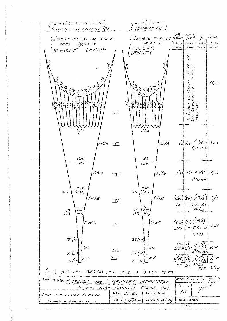
i70/' ",,' ou//lAi 1f7/V~
_ Pli/jE", - 9,1 BOVEh:.?!(E.E
i(!EI'16TE Or-lLJEK- EA/ 13DV""I,
PEES :1750 1';7
HEADLiNE i-ENGTI-i
'" ." :...:: ~
'" ""~ <i?;.CQ";}~~~':$ •. ~ 's: ~ ). ~ ~..:>
" >:;$ '<::I' G' >;;;j -------
:IOD ------200
:Ir/i? 8
:!oo 100 \ (200)
:/;-/:18
')0 \.Iod /2-5 cSO
2S{s0 ! I
P;-/.:fB
, h';-/ 25(s~ ,
.2.5 tf) I/?,y'
..L
JIr
K
y
31L
:stn::
...., .-J I _l,_ t.....:. I' /' v. _..c...,
)ZjjKRhIT /2.) I . I _ .. M?. !icSfi r/.. -\ ~.EA/6rE L'-YPCEs' HES/{ S/2E 'j--' /-DVL
(
:/5; 50 H /,c;V;:;,E!/7/?6-..,! c-p.p"j Ü'~~i' S/DEL(NE /';ynR2/,""l"Yn :.'/K.TL /;Y /"":'
\ LENGTH J-I~ -- -I '" ':t
:;;
:/C'3
c, , Vi
~ 'v ~. :t v,
'< t ~ ~
.~
~. '" , 'l ~ ~
k '< ~ '" \( <t ,,' '< t: ~ ~ '" "-''l ~ ),
'0 '< " -\.j:::-, ~ q",
1:Id-
N:lt3 6'012'00 ;;IO/J ! ~c::;
6':3 :166-
100 (00 1(200)
Ir/IE
:!r/.i'8
50 fOO, I2-S .?SO.
2'i(SO)'
!!,v.:fE
1 IRr/ 25 (S~J !RY 25 {SO
RI", (SO
:1001"0 ?"/V I 5;00
flcr 100
(::15") (?"7 (21%:] 3/5 75 so R Ie.< 5c;
::'/1)/"-'"
(.5tl0!foJ (:1%-) 250 20 RI.« 5<
2.)0/3
s,t!i!
/00 20 ::"Jof}j
(cOO ~O) ("':~) C',()O ;p, <Y./J
&301 0'01 .P/o~ :/,30 \:' j, IRI"'?3 6 '5 2-; 2J O/.2) ./
( )
T,cT. 3;;d!l \ ". OR\GlfJAL 'JlES'IGf'J) NOT \JSED IN FlCTl{F.,L HoJ;EL
;;rC;;~.Lc"'D y,.q ............ 73~'<:------~ --------Be,,",'ng FIG,3 HODE!.. YRry Li/HEI/HET tfOlJE[TRF/h/L
- IY;:;R-''';C;~<?,; ';';'I<~OTr'; -(5CAlE 114) fein", 136 c
!vO F.D. TECHA/.. f)N1)ER:2. S<haa! -::1:-10-0 1 Gccontro!ecrd _ A4 R A ____________ ._. _________________ + __ L.. ____ _
Getekcn,.l /) Ir' r",- Gnien 30 -:5'"- '7Q R:anglchikmerk A,-""",,«h, ~_,<>,h~ho"d<n ~(.!t~'" Je ........ r::r:. .. lcr6~ /
-144-

-t-~ ~
$ ~ Dj~
" ;;j ffi-{: ~ ~ffi ~ iQ
"- kct " " ,,- ~ ~ ~ \2 ~- I;; " > ~ ~ "_. __ ""_,J...,:, __ .~.< ____ .... ~ __ .

,-
FlG.5
4.500
{PEESLENGTE 16.29 m HEADUNE lENGTH 0°
0\ V1
'" o
W<,1
O· 0.'535
0}7
11 Ii
....
I~ I~ li /g li '" U1 0
3.000
",0,
<0
"
~!
86 rtlaz<zf1.. ~ a. '" 100 rnrn
LI =1Xla = 0.35 C c( = -40°)
o ry
SeJ1~ming VERDEUNG ONOER.. - E.N "BOVENPEES t..'jNENNEf S<.Hr'\RL I:""t f
-,oPI>ANE.L COHPrA.TE.R. DESIGNED ROPE TRl'ttvL
-146-
GEL'JKE VERLENGINCi
formu[ NR. 736 a.
OATUH 26 JUNI IS78 A4 Scha:' __ !_~":~ I Gecontro!eerd __ + ___ -''-______ _
Ge(ek~nd 'J$vHT GeIicn )...UHI.""CC;'C ""o,t.~ho~<fc" .. olr~'" de ..... <
R~ngschikmcrk.

, --_ ..
()\
(j) (j) 111
.Jj
r O·
.... ... ~ VI
'" 0 0
2..500
~ ... V1 p
'" '" Q
'" Q> U> 0
2.152-
o ... .. '"
'" tl>
'" 0
:--~ 0
3
fPEESLENGTE : 15.00 m LENGTH OF SIDELINE
F16.b srDt=- PAN!3- ROPE IRRw L tf" Ih SCA LE 'JlEStGNED WtTf-{ COHPLtTER.
r a;;: rnOCl5w~.rDns
c( ~ INSTElI-tOEK,
-< a= HESIi SIZE c(.= HANGII'JG
ANGLE (<:1-312) "'«zcrl ,Q ~ 100 mIT\.
LI ~ 0.35 (e<: ~ 40 0)
Hronarning VERDEUNG ZClPEZEN (VERSMALD) L 'JNENNET SCHAFtL l:.4 .
GEL'JKE VERLENG1NG
Formaat Nf(, 736 b
SchJ.l.! 1: 50 A4 --._-_ ... -- .-,-.-.--.---- 1-1 --'-------
IJRTUH 26 JVNI 1978 Gecontrolecrd
,l"a'''HHht .. <><>,b~ho,,4~n y"I,~,U de "'cl Gctckcnd :B v ti GCllen Ranzschikrnerk -147-

{ ONOERKFlNT LD'vJER l'AhJEL
{MRRSW:.JDTE He:SHSIZ-E
10 eH.
[ Z:.J KANTEN S/llE 'fANEL-5
[MARSW'VDTE JO CI1. [HESK SIZE
{ BOVENKANT lCP l'ANEL
{ 11~:t11:TE 5 CH.
oNTwERP N.F\.V. 1)D1<.- ~~NENNE:r
RG.7 SEVERAL CUTnNGS OF SHARKTEETHS SCflLE l/Lt. B,o"n;og DIVERSE SNITVORMEN Bel OVERGFING VRN L 'JNEN
IN NETWERK VOOR NODELNET '736 (I :4) fOrlT.au
A4 f\'R. 736:n Sch~;J.1 Gccontroleerd cr"·IP4TER. 1JESIGNED RUFE.
'lRAWL. ... _._ ..... _.-...... +1. __ ..L... ____ _
Ranglchikmerk -148-AV!.",.,«ht ."o<L~h"vd'l\ .01[.", d~ ... ~t Getekend ]}vH GClicn 2- IO-l'3

_------ --~~~:-:~(' cl J-----'-~:<~--,--';~~-\L -;':~-~-'~-l------:;:';;-::' =, --.--~ -'~--':-::--, -; ---I
-6iJ"- I"'V L __ ~'~~:~=:: .. _: ___ ~~_; ( IW1, L ___ ____ ~Ln_~~~_~ ___ ~~~~~~ _
__ , ____ l~='.:!_
---------------
I
'w 5'LI
:;JNnQtGH A CJldf\B.U:O
$~fll\r\'J<1. Gt:
w~G /,0'0 '7 l'f'I'2J YJ'1'J1Y>r;)PJo "1>:Jr~}
~b <;:;S I '" N'>V1j "lcvo~S'r-b l)'U.11=) VI "91 :::: 9
v..tu..J 'CL. ::oe sz>
,I)
\ \
\\ \\
\.,1 \
3
\ \
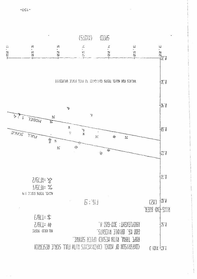
l'l . .c N V1 :s1 !.Il iSl iSl iS! ''C f-I --.----+--.--.-+---...... - ... -1--'
C/5LJA= ~ I/EUA= %
ElBL1= t U8Ll= #:
::;1531 (TLi nv
5 ' '°1 1 _.1 ' .J .J
GJJd5 W lJ
\11 iS!
----t~-···---~rn
(~~) "Jrg
. UJ~H QN gnU1
'[)lij""r' U'J 11'] '''115]11 H1 j ~ ltH1\ll 3dfTii JULI!G] fJ.j~i.1i1 \d ~ 1 Ii 11]0 UD
IDtHJSJ~ ]lö)S 110J H11!i 51ilJW! ~JdXJ mau JO NOS! ~Hd!!o) E mx ;::1'1

Vl
( SlCrW ~J2d5
1: w w lSl Vl 1'il V1 1']. V1 1S!
T---·--~_.-- --~------'i'-- .. ----------~----- -----'~---.. -______ 7u. '1 p~ Li
I." .~
0~~" r
r: '51 B- 17\ L.J ~...JI\- Y-J
h: I ]llDS
9/BLl= 'S 5/Fl/J= % EI LLl= :t ULL1= :#
I: I T1H)S
o - _______
h: I . Wh' ~: I: I . H h' h . lX3 'W ßSS-ßGh :H19N31d~8M
'SlH91JM ]la!~9 '9~ OSL H2i:H
YM

:EJi:
~.fl
H/U HEI5HT
7fJiJ ( M • )
"VJ ~' ll.lC1
I
F I 5. 11 t-lODEL TEST:; V5. FULL S<.:Fll.E RD~ETRRWL HITH MESHED UPPER S@URRE. (1736 MESHES)
<>.. <>..
% =T77/2 R ==T77/3
# =T7B/2 $: :=: T7 B/3 + =T7B/S" * :=:T7B/6
@=VF79/3
22.[;;r 7.?~* + t>: 7:>0 KG.
I 7. * " ", o·
""~~~~ 16.m
16.1]
IYJill
12.m
7.
.$.
+ <'<.
~ * /"-,..,. '7 /'4 /+
*
7. 74:
~
, ~'V>..
O$":"f'''"'''
+'- /"'+ ""' /.~ FULL
'. ~
Ei0lZJ K[f~~ +
~(I:Lj)
SCRLE
$:
$:
m C:j.·-------;--~ 'U Q
I ---1-- + I ----I lSl !'l f,! (;l IS!
lSl !J1 IS! U1 l5l tJ\ lSl
1'1 1'1 :r :r !J1 lil u;
SPEED (KNDTS)
-152-

~~~.~'_ .. " ..
"!onn',;:
(22.~ 350
19f
(1'3.~-) '\65
®
",<:' s-<'
<-fv -<!:' ®
-l''V Y0'<'
#"d $
0 __ -
EE EE
EI)
(j'l
~~ v'0 ® o (l)
(~_())I "~I/
,10
I
(12..:..8) 200
®
[2]
lB I1!fB 1 o
fll 8IA0
w
<4 ~ !ZI
W #: !ZI ß/IA
VI "f'" i" A. ,p,9~ ~
x
f V
t AA 11' +A
+
\
* {:;,~ v ,~
11" *" K-'" A ~ / ,( ~ ~
V + ,{.v~. (~,b) . + :if v 4'~/
150 . i'*r #" /
(ti ,,: Vif * //
j' 1t / /'
i-~ . FIG,12.
/' /~
/
/ <2>
EI>
e; IV , <8>
® IW o 8 8
00 "I 8
III EB~~ WfB
IA fB ~6 1
/},.
Ci'l / 0 ~~
[gj 121
+ v )\
x x _v, ",'P/
~. ;f-0-.
V'
::DRAGS vs. 5P"'ED C' ) ~ FULL SIZE 'f,L\LUE
"
Co ) I
0= VF75{i
"" ~ Vf73/2. V) I 6) = Vf75/3 -' w A o 1::
A ~ 'vF75/6 V = VF7317
" I <4 = VF79/8 ~
w !ZI = VF 78/Z _-l
5 EJ = Vf 'iS/3 (0 l2'J = VF78/4
LU -'
If! = VF78/5
* = Tl7/4 + = T77/6
~ A=T~/Z ~ X=T~D ~ X=Tm~ 2 Y=T7&5
#=T78ffi
~ -153-(6,f5i -----'-:20-, (",0 )----------2,sfc S,;)-SrEED--3.~1(60KN01S --,..-
------------------------------_.

I JZl riß! 3
tUE
fiRE~
f501
, M~,I ff.eJ
~-15.: 13 COMPRRISON OF MODEL TE5TS NI1H FULL SCRLE EXPERIMENTS. ROPE TRRWL WITH Fl.DATRTION. 500 K5. 6RIDLEWEI5HTS. J..!RRPLENGTH: llLl0'-BS"0 11.
F"LJU_ 5CRLE
4t '"' rn / I s: ::I>T7B/9
% ==na/ I [J
~7. 7. ~,:t; "'; ~ SCALE J \ Li
nl
*
E~L
B.
r. H"
.~/. -u- '-..... +- ~: ""tr ~'........ 4> * *K~ * ::i.i: ~ :$:
* =VF7El/Ei + =VF7S/7
;tp; ~"-~,\. --.........
'.e "-"$
* ".k
*::f:+ 'K
* ------ ......... ~~ + + ---------
a 17. r . ...l\U.
RLL VRlUE5 EQUIVRLENT FULL 5CRLE.
H.11\+-------··· I .. -----;-------.----;--.-------{-- .. -----+---- -----j ~ ~ ~ ~ ~ N ~ m ~ m ~ m ~ ~
f'1 1'1 :r :r l!! tJI t>
5FETD (KNOT5)
-154-

H.",I
H.!ß
UJ I
ALL VALUES EGUIVRLENT FUUL 5CALE • , t
nL-- I i I I I I '!iI fil IS! !SI lI! ISI fil
fil lJ1 !SI IJI l\l \JI ISI . . f'I M 'J' 'J' \JI 111 UI
SPEED (KNDTS)
-155-

(SlIm)!) <lJ3d5
VI w w m Vl N Vl m Vl ~ ~ m ~ ~ m m N 1------------1------------1------------1--- --- -f----------+------~<J'J!
~ ; ; '", 3lH)5 llru lN3'HA r na3 53fllHA Tl" 1 ~ "" "" • 'J'
71 ~LJ 1''''-
tfhl
L/~jL3A"" ~ 9/!::JL.:lA::: 0
h; I :nl::D5
~ I /bJL1~ % 5/BL1= :$:
SI/U.l.:::#
:nl:D5 jjnJ
: 0
. H 0SfJ--VlQlh ; H19i'l3'ldm_lI'1 S1H913M 31al~2 'g)i 009
S1801J H11M jMHd13dD~ 31f-D5
Ti!U '5,\ 51531 T:l<JI-JN
o 00
SI . ~ll j
( . y.j)
1H913H
l"ri~l 1" _C
f/H
j"j'R
,rJJE

H/L
l1fLT -. I HE I 13tH
F 15. ,.
"'j ['1 (1.;:; }"""
+"'
\' '-,
iLr:+ "'-~
"Jd f.1 .• '1
I 'n [~,! 0.." f
I "1 ".,) l.r· .11.1
I lö.r~t
,-) .. ~-;
..,. /. :l.:
q ,.
.... ~
16
..u. • r
..u • .., ..
:#:
" :j: " -7<-",
j.: ..... ,." ..e, ",-
MDl)EL. TE5T5 VC.,. FilL.t. S(HL.E RDPETf~RI-1l. HIT H FLORT AT I m~ . 75:0 KG. SR 1 DLEW: 1 EHT5. WRRPLEN5TH:YD0-6S0 M. EXl. 2. L1I1. / Lj. LI M .
.J-I. '1r
~!,!.. ,-i'
'" .,. ~h""" "".' . . - " ,/'"..$ ~',.!..
:i:
"'c:.. ". ot- .......... ::'ij. ,/. Jt. " ~ ~:'. .l};...,
FUL.L 5(RLE
#=,TTI/12 ::1;:"'177/13 ;;~ =TTI/ I LI & =T-n'V7 * =T76/8
5CRLE I: LI
kl "'Vr:-7 EJ/B El ~~VF'7ElI9
/. -+ .". '""
'" ,~~ :$:
1--_____ i'J I ~.________ ('j r)-, Ir'" _._ r;:r JLJ 0.1,; ...",_~ ___
I
:::::---.-. _'--'" "1
Q 0 ~--""I2l~ lZl f!l 1 ______ -vJ ' -----..
I'j·j . .1~,
I2.rZt
Q l;;J Q
I i Hl.L VRLUE5 E8U I Vf,l.un HILL ::'CR!..E
!P.li:~ .. ,- ... -........ - .. --... {---... -.... ----- ... --.-.-f-• . _- .--,---- .... _f- .. .. , ," " .o, fi! It. t~ lt. Ll
FI r'I :r :r
SPEEr>
--.- .~- '.-.. ~ --'1 r~ t>l
li1
(nJU15 )
._--'--- ---1-- -_ ... - .. ,-; ~ r.:: l1 r.;:
tr. u:
-157-

ToM'JE
(,'2,,4) 350
KGF.
(ill,t; 300
M"'-250
Cts,,§ 200
FlG. 17 DRJ'lGS Vs. SPleED ROTE 'TRAWL \JITH FL09Tr1TION CATENARY SHflPED HEIlDLINE
c- .. ) 0: FULL SCALE VALUE
+ *+ *" ~ ~~
*+
*' *' * t
o a.
~~~ 'OlM VI ~~ ®- *
~ ~ -+
* *
-~~
t-
~ ~~*
Pe.
o 'T
"'*",VF78/6 lJ..l t=VF7817 ci '1«= \/Fl81ß ~ -+- == VF78/8
~,o"] Ax+ /' "':RP V1 V1 a. ,- +
" * x,J'? 4- / x ®~4-' + / VlX ~ +
+~ T 7711'2. X=T77/13 *=T 77/14
®
V!lfr + "Ir (') ,
'V"lr++' o
tU\' V1=T77/15 ::l. 4-:=.T77/16 V)
:::i\0=T7817 i2 0== T78/ g
A=T78f8 V=T78/10
-158-
~~6)1---'--2,O IT4,O) ---'------2Sf(50)SPc'ED 3.01 (60) KNOTS ,...

I J:r XlEt 3
r-15. 18
WI~J5-END RRER V5. SPEED, ßRIDLE WEI6HT RND FLDTRTIO~. 5CRLE I: LI CfJIWLlTER Dt~51 r~iEj) RDP[ Thr:I·'L.
r. .Sj" IJ/.: Hr~r~Fi
r,rJ
"'+ ETH1 1:::5.
I, .. 1
.hf
I 7:::0 KG.
t' r·1
"'Ll .. I '--......- Y I -----QS/7
Tl r-' "'-',.,-.. 1 ',''''-- ,; ......... • _1 ,~~ __ vF" 7"/ _____
FL.OFlTH'i ION
:#= "V f-"/H /;;! -t '-" vFm (3
!2! :: V ,. .... ;rl/' I GJ '~VF"/H/~~
ND j--'L.mn HT I DN
°7 \1'---"1/'/0 ; .. : t" I ~': t:.'-"
S- :.~ V F -;~]/ El
ra :~Vr-7~/'i
I --. --- " 6· n ,..." -------_ -- ........ J Ci I Cl --........ ,..-"'T f VF?d/--~'::::-"----_ --rs}~:· !!:.'. n. i .,..-,-
~.J" S - ... ---_~.---,--_. {.~""",_. :.1", A. _~--",,-
I '-- --- ~""i"-"" ? -' -""7 ."""<' ,'''~! 1-/ ."""'-
/"-_,,,_ ."h. ____ ...... :-:-... " r:;~ I -... -.. , l' ''';'- "'-
FY' I ''''''l';~F~C~: ''i.=: ==c:..f;S~ I Q [• f'J'-'" I/I ._~.,-_. ""~ , :" " t:....... _1'.1'_ " ... -~_~ .. "!!..,.
I ....' . /1 I .- '- • -. , . .----",,* ~--- t -f,j--.--..:;r .... _. /-··r .. __ . __
~- .., Ic~'\"-____ 1 .po ~« ... --...-" ~~ 0:.:.~ /-; ' . .:..:::.::;; , ~..... >t." I ,~
",.l .3-r ..•. i 1ß I?-.l--'-'" 1;J.f----c-I
.,..J RLL VRLUES [QU I VRI.F:NT FLJt.l. C~<:f1LE l!! I.!.f,··---- ..... ---- .. ; .. · ........... _ .. -j- -........ --.-;- ---· .. 1 .... -- ··1· .. · .... -----.. ·· .. ·-·,
~ N N N I~ N N .. • .>. lt1 r,~ I.t. r~ 1(; 1'''':
11 i1 :r :r 1i1 L1 UJ
5PrTD (KNOTS)
-159-

FIG. : 19 Cl
RO'PE JRAwL \NI TH ME5HED (APfER. SQUARE >. SCFH-E \: <;
FIG.: 13c. VI E'vJ FRON A ßOVE 5TA R. 'Bo A R.D srDE
.. Ibo_
.. FIG.: 19 b FRoNT VIEU,W
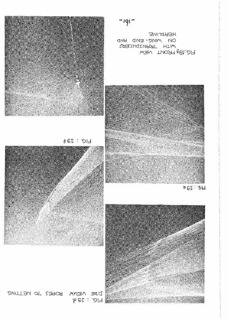
3NnCL\:I3H <lNt:f <J f'\I3 - 9f\11fVI. NO SCJ3J hC! 5; NHCiL H..L 11'\
M31f\ Jj\l()lli 66V'9l::l
9NI..L13N QL S'.:;JdO~ /'\11311\ 3<1.IS
f 10]: : '98

1? 07: : . 9\::1
~dlA JNOOId H.l.nOhll.3N ifV\61C!.L
;:JdOC! <13N9IS3<L Cl3.l.ndhICD 02 : '91d

13N\::Id.. ~3fV101 fOZ :'91d
i;JNtiJ... :;:)([1.) <JClbt09cH:liS'
606 : '98
"'1;;;1M::ld.. ::1([1,5" a~BOg 'clldJS 002 : '91.:1
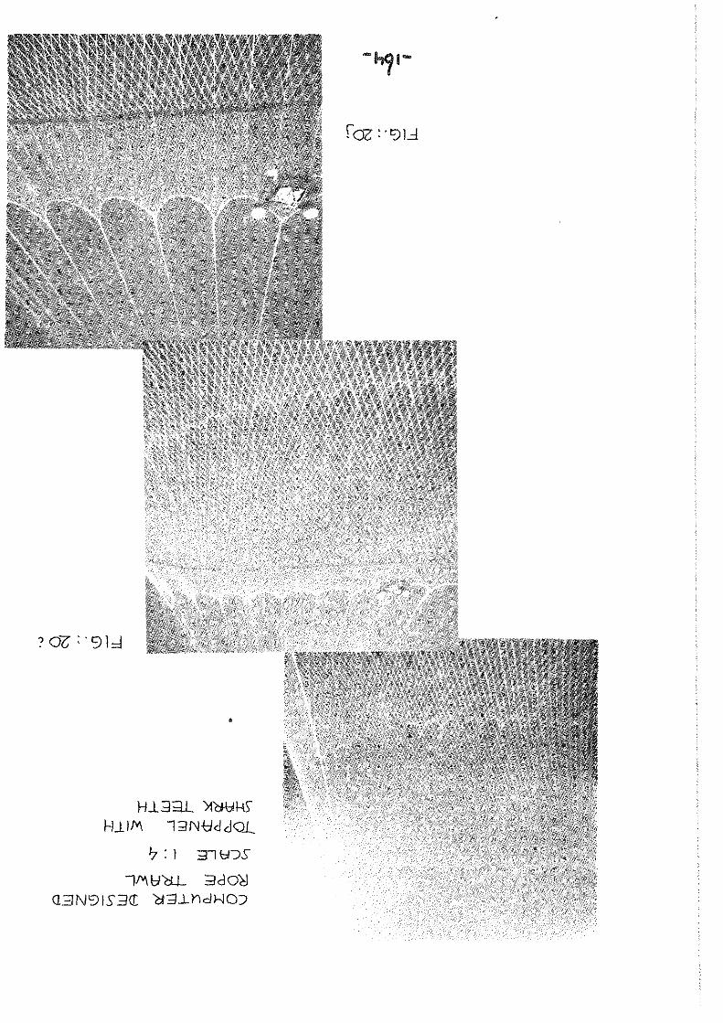
HL~;;u. >1WkS" H~IM 1;JNtldJQ-L
'? : 1 ::::Tl \:;I"JS
il'\b''aL 3do~
Q3N91S3CL Cl3..Lhdl-.JO:;i

<l,QL
NO "Cl3'Jh<1SNtletL I-llIM. (Ojo:;,) l]l".d "wL't;7) CAOQ([ 9hcOfef39Y)S- .::J<) 13<10H 311::05
JG : . 91;:\

3. R"oommendations
At the end of the ~eetin, the convenor r~iscd tae queetion cf thc Boxt meeting place end asked su,gestions for a speoial topio for the 1981 Workin, Group-mecting. The Comlllit'tlllll Chairman Dr. G. Kure invited bota th .. Engineering and Fieh Rcaetion Working Group to Illellt eimultaneoualy in Nan'tea (Franee) from 4-8 Kay 1981. TUie invitatlon ~as acecpted wii;h thanks. Next in the disousoion on tho epecial topic it was noted that in general far too lees a'ttention ie paid by the Working Group on low-enerlY fiohin, methode. It was further no'ted 'that sOllle member oountries heve reeearch in this tield planned. TUe meeting accepted therefore the !ollowing recommendatioul
In view of the continuinl concern about ihe effect cf the high cost of enerlY on fiahing activiti~e, i t ie recommended thai the Werkin, Group on RtuH'Iarch lI.nd Enlineerinl Aapecte cf Fiahing Geer, Veeeele end Equipment should meet in Hantlle from 4-8 Mal 1981, to ceneider in partioular lew energy coneumption fiehin, methode, recent developmenta in this field and requiremente for future reaearch.
-166-