13818423.pdf - University of Glasgow
259
5ENS0RLESS CONTROL OF THE SYNCHRONOUS RELUCTANCE MOTOR A THESIS SUBMITTED TO THE DEPARTMENT OF ELECTRONICS k ELECTRICAL ENGINEERING OF the U niversity of G lasgow FOR THE DEGREE OF DOCTOR OF PHILOSOPHY By Rolf Lagerquist August 1993 © Rolf Lagerquist, 1993
-
Upload
khangminh22 -
Category
Documents
-
view
1 -
download
0
Transcript of 13818423.pdf - University of Glasgow

5ENS0RLESS CONTROL OF THE SYNCHRONOUS RELUCTANCE MOTOR
A THESIS
SUBMITTED TO
THE DEPARTMENT OF ELECTRONICS k ELECTRICAL ENGINEERING
OF
t h e U n i v e r s i t y o f G l a s g o w
FOR THE DEGREE OF
DOCTOR OF PHILOSOPHY
By
Rolf Lagerquist
A ugust 1993
© Rolf Lagerquist, 1993

ProQuest Number: 13818423
All rights reserved
INFORMATION TO ALL USERS The quality of this reproduction is dependent upon the quality of the copy submitted.
In the unlikely event that the author did not send a com p le te manuscript and there are missing pages, these will be noted. Also, if material had to be removed,
a note will indicate the deletion.
uestProQuest 13818423
Published by ProQuest LLC(2018). Copyright of the Dissertation is held by the Author.
All rights reserved.This work is protected against unauthorized copying under Title 17, United States C ode
Microform Edition © ProQuest LLC.
ProQuest LLC.789 East Eisenhower Parkway
P.O. Box 1346 Ann Arbor, Ml 48106- 1346

V4-
2
GLASGOW I UNIVERSITYl ib r a r y

A b s t r a c t
This thesis presents sensorless closed-loop speed control for the synchronous reluc
tance m oto r . T he sensorless control is based on to rque vector control. This is
believed to be the first im p lem en ta t ion of to rque vector control. It has been im ple
m en ted using a high-speed digital signal processor DSP9G002.
A constan t curren t-angle controller (with ro tor position sensor) for th e syn
chronous re luc tance m oto r was also developed on the sam e system . T h is controller
was used as a benchm ark for the sensorless to rque vector control. It was also used to
verify s im ulations and constant curren t-ang le strategies. This is believed to be the
first im p lem en ta t ion of a num ber of original control s tra teg ies for th e synchronous
re luc tance m otor.
E x p e r im en ta l results for sensorless opera tion a 120W axially lam in a te d syn
chronous reluc tance m otor are presented and com pared with opera tion with a speed
sensor and sim ulations. U nder sensorless opera tion a (cons tan t- to rque) speed range
of 400-1500rpm has been achieved. W ith constan t-pow er flux-weakening opera tion
to the top speed was ex tended from 1500rpm to 2750rpm. T h e drive can w ith s ta n d
a full-load s tep-change within this speed range w ithou t losing synchronism under
sensorless control.
All the necessary equations for th e various aspects of the perfo rm ance of to rque
vector control have been developed. T he effects of flux-linkage offset e rrors on the
speed e s t im a to r and to rque e s tim a to r have been analysed. Transien t errors in the
speed e s t im a to r due to sudden load changes have also been analysed.
3

4

C o n te n ts
A bstract 3
A cknow ledgem ent 17
Definitions 19
1 Introduction 21
1.1 P ro jec t o b j e c t iv e s ........................................................................................................... 22
1.2 W h a t ’s n e w ......................................................................................................................23
1.3 Thesis o v e r v i e w ...............................................................................................................25
1.4 Chronological h istory of the developm ent of synchronous re luctance
m o t o r s ..................................................................................................................................26
1.5 Developm ents in control s tra teg ies for the synchronous re luc tance m oto r 30
1 C urrent A n g le C ontrol using R o to r P o s it io n Sensor 33
2 Fully Digital Constant Current-angle Controller 35
2.1 I n t r o d u c t i o n ...................................................................................................................... 35
2.2 T he ideal synchronous reluc tance m a c h i n e ....................................................... 36
2.2.1 S ta to r s e l f - i n d u c ta n c e s .................................................................................. 37
2.2.2 M utual i n d u c t a n c e s ..........................................................................................39
5

2.2.3 DQ-axis t r a n s f o r m a t i o n s ............................................................................ 39
2.2.4 Basic m oto r e q u a t i o n s .................................................................................... 41
2.2.5 C urren t vector control for the synchronous re luc tance m o to r . 42
2.3 Philosophy behind DSP based synchronous re luc tance m o to r controller 44
2.4 A dap ting sim ulation to rea l-tim e o p e r a t i o n .................................................. 46
2.5 Control O v e r v i e w ......................................................................................................48
2.6 Im p lem en ta t ion of a DSP based constan t curren t angle contro ller . . 50
2.6.1 H a r d w a r e ......................................................................................................... 50
2.6.2 P rogram S tru c tu re and O p e r a t i o n .............................................................. 51
2.6.3 I m p r o v e m e n ts .................................................................................................. 54
3 C onstant Current Angle Control - R esults 55
3.1 S teady -s ta te perform ance t e s t s ............................................................................55
3.2 D ynam ic perfo rm ance t e s t ................................................................................... 58
3.2.1 S im ula tion r e s u l t s ...............................................................................................59
3.2.2 E xper im en ta l results ..................................................................... 59
3.3 S u m m a r y .................................................................................................................. 61
II S en sorless C ontrol o f th e Synchronou s R e lu c ta n c e
M otor 69
4 Survey of sensorless operation for reluctance and P M drives 71
4.1 Sensorless opera tion in stepping and switched re luc tance m oto rs . . . 71
4.2 Sensorless opera tion of p e rm a n en t m agnet m o t o r s ..................................... 74
4.3 Sensorless opera tion of synchronous re luctance m o t o r s ............................. 77
4.4 Selection of m ethod for im p lem en ta t ion of sensorless c o n t r o l ................... 79
6

5 T heory of Torque Vector Control of the Synchronous R e luctance
M otor 83
5.1 I n t r o d u c t i o n ........................................................................................................................ 83
5.2 Torque Vector Control Principle V M otor E q u a t io n s ........................................ 83
5.3 Torque Vector Control - F u r the r A n a ly s i s ...............................................................89
5.3.1 C u rren t and d-q I n d u c ta n c e s .........................................................................89
5.3.2 E f f i c i e n c y ............................................................................................................. 93
5.3.3 R a te of change of T o r q u e ................................................................................ 94
5.3.4 Flux-linkage r i p p l e ........................................................................................... 97
5.4 F lux-W eaken ing and Torque Vector Control.............. ............................................99
6 Im p lem en tation of Sensorless Torque Vector Control 105
6.1 Control O v e r v i e w ........................................................................................................... 105
6.2 H ardw are O v e r v ie w ........................................................................................................106
6.3 S ta to r F lux-linkage and Torque E s t i m a t o r .........................................................108
6.4 Speed E s t im a to r ........................................................................................................... 112
6.4.1 Flux-linkage switching n o i s e ....................................................................... 112
6.4.2 C hange in speed-es tim ate due to to rque c h a n g e ................................ 113
6.4.3 Flux-linkage offset influence on speed e s t i m a t e .................................... 114
6.4.4 Speed e s tim a to r im p le m e n ta t io n ................................................................122
6.5 Speed and Torque C o n t r o l l e r .................................................................................... 123
7 Sensorless control - R esults 125
7.1 S ta r tu p .............................................................................................................................. 126
7.2 Speed E s t im a to r V S im u la t io n ..................................................................................126
7.3 D ynam ic P e r f o r m a n c e ............................ .............................................................. 128
7

7.4 F lux-w eakening O p e r a t i o n ....................................................................................... 132
7.5 S te ad y -S ta te P e r f o r m a n c e ....................................................................................... 132
8 Conclusions 137
8.1 S u m m a ry and fu r th e r w o r k .......................................................................................140
A M otor and S y stem D ata 143
B D esign of D S P Controller and IG B T inverter 145
B .l I n t r o d u c t i o n .....................................................................................................................145
B.1.1 C ontro ller I m p l e m e n t a t i o n ........................................................................ 145
B . l . 2 Power e lectronics and interface im p lem en ta tion ............................146
B.2 Design of D S P based Control H a r d w a r e ..............................................................147
B.2.1 Selection of P r o c e s s o r ................................................................................... 147
B.2.2 Selection of Processor B o a r d .................................................................... 148
B .2.3 D SP C on tro ller A r c h i t e c t u r e .................................................................... 149
B.2.4 DSP96002 M em ory A r c h i t e c tu r e .............................................................151
B.2.5 M em ory Configuration B ackplane Bus D e s i g n ............................152
B .2.6 E xpansion Board # 1 ...................................................................................162
B .2 .7 E xpansion B oard # 2 ...................................................................................167
B.3 O pera tion of Power I n v e r t e r ...................................................................................172
B.3.1 C on tro ller I n t e r f a c e ...................................................................................... 173
B.3.2 In te rface Specification ...............................................................................174
B .3.3 Pow er E lectron ics C ircuit ....................................................................... 175
C T V C Software Overview' 179
D Stand-alone analog front-end for inverter 183
8

E P ublications 185
E .l Sensorless Cont rol of the Synchronous R e luc tance M o t o r ........................187
E.2 Control of Synchronous R eluctance M a c h in e s .................................................. 199
E.3 A spects of the Control of Synchronous R e luc tance M a c h i n e s ................ 229
E.4 DSP96002 Based High Perfo rm ance Digital Vector C o n t r o l l e r ................ 239
E.5 T h e synchronous re luctance m oto r for m otion control app lica tions . . 245
R eferences 255
9

- t H

List o f T ab les
1 O ptim al Torque Vector Control Voltage Vectors
2 S teady -S ta te Speed Regulation ...............................
11


List o f F ig u re s
1 M ain classes of synchronous re luctance m o t o r s ...................................................26
2 Synchronous re luctance m oto r phasor d i a g r a m ...................................................37
3 Original synchronous re luctance m oto r control s t ru c tu re ............................ 46
4 Simplified synchronous re luctance m oto r control s t ru c tu re .........................47
5 P W M inverter voltage vector p o s i t i o n s ................................................................. 49
6 Voltage space vector PW M p r i n c i p l e .....................................................................49
7 C o n s ta n t current angle controller flow chart ...................................................... 53
8 Torque vs. curren t angle in 120W synchronous re luc tance m oto r . . . 56
9 F undam en ta l power-factor vs. curren t angle (in 120W synchronous
re luc tance m o t o r ............................................................................................................57
10 Efficiency vs. cu rren t angle in 120VV synchronous re luc tance m o to r . . 58
11 S im ula ted speed reversal ± 1400 rpm , speed .............................................................62
12 S im ula ted speed reversal ± 1400 rpm , to rq u e ........................................................... 62
13 S im ula ted speed reversal ± 1400rpm , d-axis c u r r e n t ............................................63
14 S im ula ted speed reversal ± 1400 rpm , q-axis c u r re n t ............................................63
15 S im ula ted step-load change (0 - 0 .84Nm ), sp e ed .................................................. 64
16 S im ula ted step-load change (0 - 0 .84Nm ), to rq u e .................................................64
17 E xpe r im en ta l speed reversal =pl400rpm, speed ......................................................65
18 E x p e r im en ta l speed reversal =pl400rpm, to rq u e ....................................................65
13

19
20
21
22
23
24
25
26
27
28
29
30
31
32
33
34
35
36
37
38
39
40
41
42
43
E xper im en ta l speed reversal 1400rpm, d-axis c u r r e n t ...................................66
E xperim en ta l speed reversal =fl400rpm , q-axis c u r r e n t ................................... 66
E xper im en ta l step-load change (0 - 0.84Nm ), speed ..........................................67
E xperim en ta l step-load change (0 - 0 .84Nm ), to rq u e ........................................67
Synchronous R eluc tance M otor Phasor D i a g r a m ............................................. 84
T V C to rque and cu rren t m agn itudes vs. flux-linkage a n g l e ....................... 86
P W M inverter voltage vector p o s i t i o n s ................................................................88
T V C Voltage Vectors for s ta to r flux-linkage vector in region 1 . . . . 88
H ardw are im plem en ta tion of T V C ...........................................................................89
T V C - C urren ts as function of t o r q u e ................................................................... 91
CA C - C urren ts as function of Torque ................................................................92
S a tu ra ted L j vs. to rque (T V C Sz C A C ) ................................................................92
Theoretica l cu rren t m ag n i tu d e in T V C V CAC ............................................. 93
R a te of C hange of Torque @ 4 0 0 r p m .................................................................... 98
R a te of C hange of Torque @ 1 0 0 0 r p m .................................................................99
R a te of C hange of Torque @ 1 5 0 0 r p m ...............................................................100
Space vector of flux-linkage accelerating from 1500rpm to 2750rpm . . 100
Full-load flux-linkage and cu rren t angle vs. speed ........................................102
Full-load m oto r cu rren ts and to rque vs. s p e e d ............................................... 103
C ontro ller o v e r v i e w ...................................................................... 106
H ardw are o v e r v i e w ...................................................................................................... 107
D iag ram m atic ha rdw are o v e r v i e w .........................................................................107
S ta to r flux-linkage and to rque e s t i m a t o r .......................................................... 109
In teg ra to r circuit for flux-linkage c a lc u la t o r ...................................................... 110
Analog Processing U n i t ...............................................................................................110
14

44
45
40
47
48
49
50
51
52
53
54
55
56
57
58
59
60
61
62
63
64
65
66
H ardw are im plem en ta tion of T V C sector d e c o d i n g ....................................... I l l
T V C f l u x - l i n k a g e ..........................................................................................................113
Offset flux-linkage circles ........................................................................................115
Relative speed-es tim a te with @1% flux-linkage offset ................................118
R elative speed-es tim a te with @10% flux-linkage o f f s e t ................................ 118
R elative speed-es tim a te with @50%) flux-linkage offset ............................ 119
Speed regula tion w ith no flux-linkage offset ...................................................119
Speed regulation with 5% flux-linkage offset in speed e s tim a to r only 120
Speed regulation with 5% flux-linkage offset in to rq u e e s tim a to r only 120
Speed regula tion with 5% flux-linkage offset in speed <C to rque es ti
m ato rs .............................................................................................................................121
Speed e s t im a to r .......................................................................................................... 122
Speed V Torque c o n t r o l l e r ........................................................................................ 123
E lectrocraft PM load m oto r (left), V ib ro m e te r to rq u e transducer , and
axially lam in a te d synchronous re luc tance m o to r ...............................................125
Flux-linkage during s ta r tu p .................................................................................... 126
Phase-Volt age and C urren t during s t a r t u p .......................................................127
Sensorless: S im ula ted Speed Reversal ={=1500rpm..........................................127
Sensorless: Speed Reversal = f l 5 0 0 r p m ................................................................ 128
Sensorless: Speed Reversal 4 0 0 r p m ................................................................ 129
Sensorless: Speed Reversal ^ p l5 0 0 r p m ................................................................ 130
Using Speed-Sensor: Speed Reversal 1 5 0 0 r p m ............................................130
Sensorless: Step-load change 0-0.86Nm @ 1 5 0 0 r p m ...................................131
Sensorless: S tep-load change 0-0.86Nm @ 4 0 0 rp m .......................................131
Using Speed-Sensor: Step-load change 0-0.86Nm @ 4 0 0 r p m ..................... 132
15

67
68
69
70
71
72
73
74
75
76
77
78
79
80
81
82
83
133
134
134
135
147
149
150
155
158
160
163
168
171
171
173
181
183
Sensorless: S ta r t 0 - 2 7 5 0 r p m .......................................................
Phase C urren t @1500rpm for T V C C A C ..........................
Efficiency @1500rpm for T V C CAC .................................
Power fac tor @1500rpm for TV C M P F C ..........................
Block d iagram of synchronous reluctance m oto r controller
M otorola DSP96002ADS Developm ent Board ...................
DSP96002 C ontrol U nit ...............................................................
Partia l-D ecoding and Buffer C i r c u i t .........................................
DSP96002ADS Boot E P R O M Assembly L i s t i n g ...............
Port A Bus-BulTer C i r c u i t ...........................................................
Interface B o a r d # 1 ..........................................................................
Interface b o a rd # 2 .............................................................................
Phaseleg T im ing Control C ircuit ............................................
Switching P a t te rn In P ro g ram m ab le T im er Mode. . . .
Power Inverter Overview ...........................................................
Flow-"diagram, sensorless T V C program ..............................
S tand-a lone analog controller ...................................................
16

A c k n o w le d g e m e n t
T h an k s to m y supervisor Professor T im J. E. Miller for help and advice.
T hanks to “T h e C o m m it te e of Vice-Chancellors and P rincipals of the Universities
of the U nited K ingdom " and the “Scottish Power E lectronics and Electrical Drives
C onsortium " for financial support.
T he au tho r also thanks: F. F le tt V Analog Devices for con tr ibu tion of linear and
data-conversion devices, I. Duthie, A. H utton V M otorola for the DSP96002 de
velopm ent system , S. E. Wood Brook C rom pton for the m otor , D. S ta ton for
designing th e axially lam ina ted synchronous re luctance m o to r rotor. V . Soong for
theore tica l and s ta t ic da ta for the m otor, J. Kelly for m aking th e ro tor, and P. Miller
for building the power electronics.
17

D efin it io n s
Sensorless O pera tion w ithout speed or shaft-position sensor
S Y N C H R E L = Synchronous re luctance m oto r (non-proprie ta ry a b b rev ia t ion )
CA C = Constan t current angle controller
C C IA C = Constant current in the most inductive axis control
T V C = Torque Vector Control
PM = Perm anen t m agnet
A D C = Analog to digital converter
DAC = Digital to analog converter
A F E = Analog front-end
Q = R otor angle (s ta to r reference)
0 = Absolute flux-linkage angle (s ta to r reference)
£ — Curren t angle (ro tor reference)
b = Voltage angle (ro tor reference)
b' = Flux-linkage angle (ro tor reference, resis tance correc ted voltage angl
V — Power factor angle
R — Phase resistance
L d = Most inductive-axis inductance
L , — Least inductive-axis inductance
X d = Most inductive-axis reactance
X , = Least inductive-axis reac tance
= Most inductive-axis flux-linkage
= Least inductive-axis flux-linkage
f — Induc tance ra tio L d / L q
19

20
V
v
7A
id
iq
i
h
I
T
Trr
= Voltage space vector
= Peak voltage vector m agn itude (umaXsin - pc ~l,nkVs
T T I U X 5
Pm
U,’ , U>e
Um
V
T control
= C urren t space vector
= Flux-linkage space vector
= instan taneous d-axis curren t
= instan taneous q-axis curren t
= in stan taneous cu rren t m agn itude + i 2q)
= d-axis curren t space vector
= q-axis curren t space vector
= Torque
= M ax im um to rque
= M ax im um to rque at base speed
= M echanical power
= Electrical rotor speed
= M echanical ro tor speed
= Pole pairs
= Control interval
SI un i ts are used th roughout

C h a p te r 1
I n t r o d u c t io n
Increasing in terest lias been shown in the synchronous re luctance m oto r in recent
years, part icu la r ly in the ax ia lly -lam inated designs. T he in terest in th e synchronous
re luc tance m oto r can be justified by considering the advantages of the synchronous
re luc tance m oto r with respect to p e rm an en t-m ag n e t and induction m otors [1]:
1. It is likely to be m ore efficient than the induction m o to r since th e re are no
ro to r copper losses. This will be especially im por tan t for low speed opera tion .
2. It produces com parab le to rque to the induction m otor. U nder to rque vector
control or ‘'constan t-curren t-in-the-m ost-inductive-axis '* control (C C IA C ) the
drive has a large overload to rque capability.
3. T he ro to r is rugged and not subject to th e te m p e ra tu re constra in ts of p e rm a
nent m agne t m otors.
4. Since it is a synchronous m achine, field oriented control is rela tively sim ple to
im p lem en t.
5. It can easily be ope ra ted under a flux-weakening regime, unlike pe rm anen t
m ag n e t m otors.
6. As th e induction m otor , it produces sm oo th to rque and is quiet in opera tion ,
unlike th e switched re luc tance m otor.
21

22 C H A P T E R 1 I N T R O D U C T I O N
T he ax ia lly -lam ina ted designs from the late 1980s onwards do not have a s ta r t in g
squirrel-cage; this im proves th e saliency-ratio £ and hence th e to rque and efficiency.
W ithou t the s ta r t in g cage the synchronous re luctance m o to r cannot be used for
direct-on-line s ta r ts , b u t requires to be driven by an inverter to keep the ro to r and
flux in synchronism . M ost inverter drives use a sensor to m easu re the ro to r position
to achieve this. However, the ro tor position sensor has been a m a jo r com pla in t
against variable speed inverter drives as it is expensive and fragile, and can p reven t
use in hostile env ironm ents .
W hereas sensorless control for switched reluctance m otors has been heavily in
vestigated [2. 3, 4] this has not been th e case for the synchronous re luc tance m otor .
A prom ising sensorless control m ethod developed for the synchronous PM m oto r
which should be applicable to the synchronous re luctance m o to r can be found in [5].
E l-A ntab ly proposes a m e th o d for sensorless control of the synchronous re luc tance
m otor in [6]; this was fu r th e r developed by Bolognani [7]. Bolognani im p lem en ted
a curren t angle de tec tion system ; however he only observed th e angle and did not
drive an inverter.
This thesis presents an im p lem en ta t ion of fully sensorless closed-loop speed con
trol. T he controller is based a round the torque vector control theory originally de
veloped by Boldea [S]. T h e to rque vector control im plem ents an inner to rque loop.
Closed-loop speed control has been im plem ented by e s tim a tin g the ro to r speed from
the flux-linkage vectors angu la r velocity. A constan t cu rren t-ang le controller with
a ro to r position sensor has also been im plem ented to use as a b en ch m ark for the
sensorless control a lgorithm s.
1.1 P ro jec t o b jec tiv es
At th e s ta r t of th e p roject th e re were two m ain problem s th a t needed to be addressed:
1. W h a t control a lgo r i thm s to use over a wide range of speed and torque?
2. Is it possible to o p e ra te w ithou t a shaft position sensor?

1 2 . W H A T ' S N E W 23
Question 1 was addressed rigorously for the first t im e by Betz [9]. Betz laid
down th e fundam en ta l theory, b u t only for an ideal m o to r model w ithou t losses
or sa tu ra tion . Because th e synchronous re luctance m o to r is known to be highly
non-linear, a tes t p ro g ram m e was essential to verify the predictions.
To explain question 2 th e original reasons for being in terested in th e synchronous
reluc tance m o to r have to be discussed. Brook C rom pton (a m oto r m an u fa c tu re r who
supported th e project in its initial stages) wanted a low-cost vector-controlled drive
to com pete with induction m o to r drives, but with s im pler control. If sensorless con
trol could be achieved it would be possible e lim ina te th e 1000-line encoder (costing
upw ards of 2?70) norm ally required in AC drives.
A no ther reason is th a t a wide range of applications can not s tand the cost of
an encoder. C om pressor drives is a very cost sensitive application th a t would not
s tand the cost of an encoder. This is especially t ru e for the he rm etic compressor.
Hostile opera t ing env ironm en ts is ano the r reason for w anting sensorless control.
E nv ironm en ta l factors th a t m ay preclude the use of encoders or resolvers are: ex
trem e te m p e ra tu re s (aircraft ), v ibra tions, d ir t , etc.
T he proposed sensorless system is based around a digital signal processor. T he
cost of a digital signal processor is a t the present equal to or m ore th an th a t of
a resolver. However, in 5-20 years t im e the price of t o d a y ’s h igh-perfo rm ance dig
ital signal processors will have d ropped dram atically . T he price of encoders and
resolvers, which are precision electro-mechanical devices, will p robab ly rem ain at
their p resent price level. Therefore it m akes sense to investigate w h e t te r th e en
coder could be replaced by a ‘“sensorless control schem e’’.
1.2 W h a t ’s new
This section gives an overview of w hat new developm ents are presented in this thesis.
• E xpe r im en ta l verification of the control s tra teg ies and s im ula tions developed
by B etz [10]. for the constan t curren t-angle controlled synchronous re luc tance

C H A P T E R 1 I N T R O D U C T I O N
m otor.
T he to rque vector control a lgo rithm originally proposed by Boldea [8] for th e
synchronous re luc tance m o to r has been im plem ented on a real drive system
for the first t im e.
A sensorless speed e s t im a to r for th e th e synchronous re luc tance m o to r under
to rque vector control is proposed and im plem ented .
T he first opera tiona l im p lem en ta t ion of a fully sensorless closed-loop speed
controlled synchronous re luc tance m o to r is presented. T h e control includes
f lux-weakening operation .
An expression for selecting the a p p ro p r ia te flux-linkage m ag n i tu d e based on
desired (full-load) to rque and current angle for opera tion under to rque vector
control has been derived.
An expression for the m o to r cu rren ts as functions of load under to rque vector
control has been derived.
An expression for the ra te of change of to rque for to rque vector control has
been derived.
An a p p ro x im a te expression for expected flux-linkage ripple has been developed.
A lgorithm s for flux-weakening opera t ion of T V C have been developed and
im plem en ted .
A dvan tages of flux-weakening opera t ion under to rque vector control relative
to opera t ion under curren t-ang le control are shown.
Analysis of the influence of flux-linkage offset on speed and to rque es tim ates .
Analysis of th e effect of load change on speed es tim a te .
D em o n s tra tio n of speed reversals.
D em ons tra tion of load transien ts .

1.3. T H E S I S O V E R V I E W 25
• E xpe r im en ta l investigation of th e lim its to lovv-speed opera tion w ith TV C.
1.3 T hesis overview
T he thesis is div ided into two parts . P a r t I is concerned with opera tion of the syn
chronous re luc tance m oto r using cons tan t-cu rren t angle control with a ro to r position
sensor. T h e cons tan t curren t-ang le contro ller is im plem ented on a high speed digital
signal processor. T h e philosophy beh ind the use of the digital signal processor, the
im p lem en ta t ion , and results are p resen ted . The results from P a r t I will be used as a
benchm ark for the controls used in P a r t II. Part I also covers the derivation of basic
m o to r equations for readers un fam iliar with th e synchronous re luc tance m otor.
P a r t II s ta r ts by reviewing previous works on sensorless control of the syn
chronous re luc tance m otor. T he principles of the to rque vector control a lgorithm
theory originally developed by Boldea [8] are then explained. This is followed by
fu r th e r analysis of the to rque vector control. T he ac tua l im p lem en ta t ion of a closed-
loop speed control sys tem for the synchronous re luctance m oto r is then presented.
T h e effect on speed e s tim a tion of flux-linkage offsets and to rque changes are ana l
ysed. Results for bo th fully sensorless to rque vector control and to rque vector control
w ith speed sensor are then presented.
For the reader in te rested in the contro ller hardw are design a full account of the
developm ent of the digital controller an d IG B T -inverte r can be found in A ppendix B.
A ppend ix B can be useful for the reader con tem p la t ing build ing a digital controller.
T h e final two sections in the in troduc tion presents a brief chronological account
of th e developm ent of the synchronous reluc tance m oto r and its control. T he first
section m ain ly describes the developm ents in the design of the th e ac tua l m o to r itself
from 1923 to 1993. T h e section on control s tra tegies for the synchronous re luctance
m o to r is na tu ra lly shorte r because field-oriented inverters only becam e available in
the last half of the 1980s. Before field-oriented control th e perfo rm ance of the m otor
was m ain ly d ic ta ted by the ro to r design. W ith field-oriented control the perfo rm ance
ob jec tives can be m ore freely chosen.

26 C H A P T E R 1 I N T R O D U C T I O N
Figure 1: Main classes of synchronous re luctance m otors (Source [12])
1.4 C hronological h istory of th e d eve lop m en t of
synchronous re luctance m otors
The salient pole synchronous re luctance m o to r (Fig. la -b ) is one of the oldest types
of m otors , p reda t ing the induction m otor by m any years [11]. A t first it was used
only in in s t ru m e n ta t io n , bu t la ter it becam e m ore widely used due to its sim plic ity
and cons tan t speed. These early m otors were usually l im ited to a few h.p . due to
low efficiency and pow er/w eight ratio [11].
O ne of the first papers to thoroughly analyse the synchronous re luc tance m o
tor was by Kostko [11] (1923). Previously th e general opinion had been th a t the
synchronous re luc tance m oto r was inheren tly inferior to o ther types of a.c. m otor .
K o s tko ’s paper shows th a t th is inferiority was due to the use of poorly designed
rotors. He claims th a t th e synchronous re luc tance m o to r can be designed w ith com
parab le perfo rm ance to the a.c. induction m otor . Kostko realised the im p o r tan ce of
having a high saliency ra tio ( L d / L q), and th a t the way to achieve this is to divide
the ro to r into separa te sections along the lines of the m ost inductive axis. Kostko
developed the theory and proposed a segm ented s tru c tu re s im ilar to Fig. lc. Kostko

1 4 C H R O N O L O G I C A L H I S T O R Y O F T H E D E V E L O P M E N T O F S Y N C H R O N O U S R E L U C T A N C E M O T O R S 27
calcu la ted that a m o to r with two sections should develop 80% of th e to rque of a
s im ilarly sized induction m otor (1923 design), and th a t with 4 sections it could
be fu rthe r improved. C om paring th e 4 segm ent m oto r to a salient-pole design it
gives several t im es the torque. T he saliency ratio of this design is p red ic ted to be
25.6. Kostko also realised th a t the slot-leakage flux (which prevents low L q) can be
m in im ized by having a large num ber of segments.
W ork on the synchronous re luctance m oto r was reviewed in th e m id 1960s. T he
work at th is t im e was generally split between the salient pole (Fig. la -b ) and
segm ented rotor designs (Fig. lc-d).
Lee [13] produced (1960) a low-speed salient-pole synchronous re luc tance m otor
(Fig. lb ) . T h e m o to r had a solid ro tor and a herm etic-can design which lim ited th e
saliency ratio.
T he salient-pole designs were fu rthe r developed by Lawrenson in 1964-67 [14,
15, 16]. A sa tu ra te d saliency ratio of 2.58 for th e salient-pole design was ob tained .
A modified design using insulated pole-segments im proved th e saliency ra t io to 4.5.
T he segm ented design had a reported average efficiency of 75% and a power factor
of 0.52.
In 1967 Fong [17] presented a synchronous re luc tance m o to r design with a
squirrel-cage induction m o to r ro tor with pa r t of the periphera l iron cut away (sim ilar
to Fig. l a ) . The average efficiency was 50% and th e power factor 0.45.
By 1970 Fong [18] had moved on to segm ental ro tor designs derived from Kostko 's
(1923) suggested designs. Fong's design had two flux-barriers punched out of a
s tan d a rd induction m o to r lam ination . He achieved excellent an u n s a tu ra te d saliency
ra tio of 10.7 which was reduced to 5.5 at full load. This design com pares well against
a s im ilar induction m oto r . T he efficiency and power-factor of the re luc tance m oto r
were 76% and 0.7 respectively. T he values for the induction m o to r were 77.8% and
0.87 respectively. This shows th a t a t least for small m otors (3.25 h.p. in th is case)
the synchronous re luc tance m otor can com pete with the induction m otor .

28 C H A P T E R 1 I N T R O D U C T I O N
In 1972 H onsinger [19, 20] published a paper on a new intrinsically s tab le seg
m en ted synchronous reluc tance m oto r design. Honsinger s ta tes th a t the re is a con
flict betw een designing for high to rque (high L d / L q) and for large s tab le opera t ing
area. His solution for ob ta in ing a large stab le opera t ing area and high to rque was
to use sa tu ra b le bridges. These bridges give an induc tance ra tio of 1.04 a t light
load and 4.15 a t full load. T he inductance ratios in his 1971 design [19], which did
not use bridges, are 4.5 u n sa tu ra te d and 4.49 sa tu ra ted . This paper shows th e clas
sical com prom ises needed when the synchronous reluc tance m o to r is designed for
open-loop (and l ine -s ta r t) opera tion . Clearly the power-factor (and consequently
the efficiency) suffers a t light loads because of the low inductance ratio .
T h e 1970s saw an increased interest in th e line-start axially lam in a te d syn
chronous reluc tance m o to r (Fig. If). C ru ickshank [21] reported an in d u c ta n ce ratio
of 5.2 using a design based on a (prim itive) C-core design. This design was also used
by Menzies (1972) [22, 23]. Menzies ob ta ined induc tance ratios of 4 (u n sa tu ra te d )
to 2.7 (sa tu ra ted ) .
A pap e r on th e dynam ic perfo rm ance of the axially lam ina ted synchronous m o
tor by Rao [24] (1976) shows th a t the axially lam ina ted ro tor is superior to the
segm ented rotor. T he perfo rm ance advantages are in the areas of power factor, effi
ciency, pu ll-out, and pull-in torque. An inductance ra t io of 6.8 and efficiency of 86%
are reported . T he values for a segm ental s t ru c tu re are 3.3 and 80% respectively. It
m ust be noted th a t the m o to r used is ra ted a t 15 h.p. whereas the m otors described
previously have been in the range 1-10 h.p.
In 1985 E l-A ntab ly [25] showed w hat is assum ed to be the first, axially lam in a ted
ro tor designed not using C-cores (Fig. le) . T he m oto r was ra ted 15 h .p. and designed
for l ine -s ta r t opera tion . T he new s tru c tu re has a m uch larger pole-arc to pole-pitch
ra tio (0.94) com pared to the C-core design (0.5). T he advan tage of th is is t h a t the
Ld axis induc tance is increased. A very good efficiency of 94% is repo r ted for this
m otor. T h e corresponding power factor is 0.89. This m o to r has becom e known as
‘‘the W estinghouse (synchronous reluctance) m o to r '1.
T h e rotors presen ted so far have all been designed for l ine-start applications.

1.4. C H R O N O L O G I C A L H I S T O R Y O F T H E D E V E L O P M E N T O F S Y N C H R O N O U S R E L U C T A N C E M O T O R S 29
It should be no ted tha t the axially lam ina ted s tru c tu re s presented for line-starting
have not shown any great advantages over a well designed segm ented s truc tu re .
In th e la te 1980s there was a revival of th e synchronous re luctance m otor. This
was p a r t ly fuelled by d isenchan tm en t with the switched re luc tance m otor; bu t en
abled by developm ents in power electronics and digital control. T he use of inverter
technology m ean t th a t the design of the synchronous re luctance m oto r could be
changed considerably as there was no longer a need for a s ta r t in g cage or dam ping
bars.
T h e re ap p ear to be two main directions of design th a t followed the in troduc tion
of field orien ted controls. T he first design is a con tinuation of th e axially lam ina ted
s truc tu re , but with m uch finer lam inations. T he second design is a very sim ple
2-pole dum bbell-shaped ro tor used in very high speed applications.
An early analysis of a 2-pole axially lam ina ted ro to r was perform ed by F ra t ta
and Vagati in [26].
T he first finely axially lam ina ted synchronous re luc tance m oto r w ithout a
s ta r ting-cage or dam per-ba rs was m ade by P la t t [1] in 1990 (Fig. le) . T he m o
to r had a lam ina tion to barr ier ra tio of 1:1. T he nu m b er of lam ina tions appears to
be 10. T h e m easu re induc tance ra t io was 10.5 u n sa tu ra te d and 8.8 sa tu ra ted . Only
s ta t ic test resu lts were presented . One of the claims m ade in the analysis is th a t the
ro tor runs cool because there is no ro tor curren t.
The cla im m ad e by P la t t th a t the finely axially lam in a ted m o to r opera ted with
a cold ro to r was refuted by M arongiu and Vagati in [27]. It was shown th a t the
ro tor losses are in the sam e class as the ro tor losses in an induction m achine. The
losses are cla im ed to be due to the s lo tted n a tu re of the s ta to r . It was also claimed
th a t th is prob lem can be solved by reducing the nu m b er of lam ina tions and properly
re la ting th e n u m b er to th e num ber of s ta to r tee th .
A s tudy in op t im iza tion of the ro to r geom etry for highest induc tance ra t io was
perform ed by Miller in [2S] (1991) and fu rthe r developed by S ta ton in [12] (1993).
S ta ton showed th a t the m ax im u m possible induc tance ra t io in a s lo tted s ta to r (D132)

30 C H A P T E R 1 I N T R O D U C T I O N
with an ideal 4-pole rotor is 30 u nsa tu ra te d and 14 (heavi ly- )sa turated. T h e cor
responding rat ios for an axially lamina ted rotor are 11 and 8. S ta ton 's rotor (Fig.
I f) is different f rom P la t t ' s (Fig. le) in t h a t is uses a square shaft., mak ing the
cons truc t ion slightly easier.
An axial ly l am ina ted 2-pole synchronous reluc tance generator was presen ted by
Boldea in [29]. T h e induc tance rat io for this m o to r was 16 sa tu ra ted . As expec ted
2-pole designs give higher inductance rat io than 4-pole designs, main ly due to less
s ta to r slot leakage. One of the problems with the axially lamina ted 2-pole designs is
t h a t the re is no shaft th rough the rotor. Boldea used kevlar pole holders to secure
t h e ro to r lamina t ions onto the shaft ends. Efficiencies of up to 92% and power
factors of 0.8 were reported.
A s imple single-barrier design was presented by Miller in [28] (Fig. Id). T h e
design is s imple, but has an induc tance rat io of only 4.0. However the drive produced
50% m ore to rque than a comparab le induct ion m o to r based on equal losses. T h e
low-speed to rque is about 30% lower than a switched re luctance of s imilar f rame
size.
T h e salient-pole design has prevai led in super high-speed-motors . In 1989-91
Fukao a nd Chiba [30, 31, 32] repor ted on high-speed (48,000rpm) drives with 85%
efficiency and power factors of 0.46. The induc tance rat io of this m o to r was 2.86.
1.5 D ev e lop m en ts in control strateg ies for th e
synchronous reluctance m otor
T h e control deve lopments of the synchronous reluctance m oto r are easily divided
into two groups; l ine-s tart and inverter driven.
The first group is concerned with ope ra t ing from a f ixed-frequency, and fixed-
a m p l i t u d e vol tage source. T h e m a x i m u m efficiency point of the m oto r is found in
the s tab le region. However, the m a x i m u m efficiency is only ob tained at one specific
o p e ra t in g point. T h e efficiency of the m oto r is a funct ion of the saliency rat io .

1.5. D E V E L O P M E N T S IN C O N T R O L S T R A T E G I E S F O R T H E S Y N C H R O N O U S R E L U C T A N C E M O T O R 31
However , the sa.liency-ra.tio can not be maximized because of need for a s ta r t ing
cage. A no the r factor prevent ing opt imizing for saliency rat io is t h a t the motor
becomes less s table as the induc tance rat io increases. O p t imiza t io n for saliency
rat io m ay thus lead to less t han o p t im u m performance [33]. Most of the papers on
control of the l ine-s tart synchronous reluctance m o to r are concerned with design to
op t im ize pull-in torque, pull-out torque, efficiency, and power factor. Work in this
field has been done by Honsinger [34], Lawrenson [14], and Finch [33, 35].
W i th the appearance of field-oriented inverters be t t e r control s t ra tegies for the
synchronous reluctance motor became possible. T h e research in the control of the
synchronous reluc tance m oto r has been concerned with establ ishing the pe rformance
l im ita t ion of the sys tem and also control s t ra tegies for op t im iz ing various control
object ives.
T h e first really thorough analysis of the synchronous reluctance m o to r was pe r
formed by Betz in 1991 [9, 10, 36]. The m ain l imita t ion of this work was tha t it
a s sum ed no iron-losses and no satu ra t ion. However, he showed a range of in te rest
ing rela t ionsh ips between different control object ives for the synchronous reluctance
motor . Control object ives considered were: m ax im u m to rque per a m p e re control,
m a x i m u m power factor control , m ax im u m rate of change of to rque control, cons tan t
current in the most induct ive axis control , and f lux-weakening operat ion . T h e con
di tion for m a x i m u m ra te of change of to rque had earl ier (1987) been presen ted by
Ch iba in [37].
F ra t t a [38] and Xu [39] looked at more special forms (spindle dr ive appl icat ions)
of high-speed control of the synchronous reluc tance motor .
In [39] (1991) Xu also considered the influence of iron loss and sa tu ra t ion on
the m a x i m u m to rque per am pere and m a x i m u m efficiency modes of opera t ion . It
was found tha t the cur rent angles were significantly different f rom w ha t was found
when assuming an ideal m o to r [10]. In [40] Xu considered a m e th o d for observing
the curren ts actua l ly flowing in the magne t iz ing branch of the circuit . He did not
consider how to control the magne t iz ing currents .
In 1992 Betz [41, 42] include sa tu ra t ion and iron-losses in his analysis. Betz

32 C H A P T E R 1. I N T R O D U C T I O N
concludes tha t t ak ing varia tions in ironloss res is tance and Ld into account does
not change the resul ts much from when they are assumed to be constant as in [39].
Ano ther interest ing resul t also observed in [39] is t h a t the current angle for m a x i m u m
efficiency is much larger t han th a t for the ideal motor . Using a non-sa tu ra ted model
(bu t including iron-loss) p roduced resul ts very close to the ideal model .
Betz also observed t h a t the synchronous reluc tance m oto r model including iron
loss and sa tu ra t ion could be f lux-weakened much the same as the ideal motor . How
ever, the f lux-weakening angle was qui te different f rom the one for the ideal model .
An ap p ro x im a te solut ion for the flux-weakening angle which did not t ake into ac
count varia t ion in i ron loss res istance or sa tu ra t ion was developed. However , the
a pp rox im a te angle was erroneous enough to be of l it tle real value.
In [8] Boldea shows s imulat ions of a new control m e thod , to rque vector control ,
for the synchronous reluc tance motor . This m e th o d keeps cons tant flux-linkage
m ag n i tu d e and a lmos t all change in current occurs in the least induct ive axis. T his
ensures fast torque response. Boldea also shows t h a t his synchronous reluc tance
m o to r can p roduce 5 t imes the rated to rque of the induct ion m oto r a t up to 2 /3 the
rated speed. However , it must be m ent ioned tha t these resul ts were s imulat ions and
tha t t h e q-axis curren t was 10 t imes the rat ed current . Of course 10 t imes rat ed
cu i ren t in a real m o to r is not realistic.
Sensorless ope ra t ion m ethods for the synchronous reluc tance m o to r have been
proposed by E l -A ntab ly [6], Bolognani [7], and Boldea [8]. Works tha t involve
sensorless control are reviewed in P a r t II, C h a p te r 4.

P a r t I
C u r r e n t A ng le C o n tro l u s in g
R o to r P o s i t io n S en so r
33

C h a p te r 2
Fully D ig ita l C o n s ta n t
C u r r e n t - a n g le C o n tro l le r
2.1 In troduction
This chap te r descr ibes the deve lopm ent and implementa t ion of a fully digital con
trol ler for the synchronous reluc tance machine. T h e control ler uses a fast digital
signal processor, the Motorola DSP 96002. A shaft posit ion sensor is used in the
control descr ibed in this chapter .
Basic m o to r equa t ions and current angle control of the synchronous reluc tance
m o to r will be introduced . The phi losophy behind the deve lopment of the control ler
will then be covered, followed by implem en ta t io n and control s t ruc tu re details. E x
perim enta l resul ts will be presented and compared with s imulat ions in chap te r 3.
Curren t angle control is one of the most obvious m e th o d s for vector control of
synchronous reluc tance motors. It is par t i cular ly im p o r ta n t to invest igate this mode
of opera t ion to have a benchm ark with which the sensorless and semi-sensorless
m e thods used in P a r t II can be compared.
A no ther im p o r ta n t reason for developing this control software was so tha t the
cur rent angle control a lgori thms for the synchronous reluc tance m oto r developed by
Betz [9] could be verified. As only a s imulat ion p rogram had been used to test and
35

36 C H A P T E R 2. F U L L Y D I G I T A L C O N S T A N T C U R R E N T - A N G L E C O N T R O L L E R
develop the algori thms, it was vital to back the s imulat ions up with experimental
data . If s imulat ions and experimenta l resul ts agreed it implied t h a t the s imulat ions
are correct and th a t s imulat ions can be used to develop fu r the r control methods .
2.2 The ideal synchronous re luctance m achine
This section is concerned with the derivation of various m oto r quant i t ie s and i n
equat ions used elsewhere in this thesis. This section is in tended as an in troduc t ion
for readers who are not famil iar with the basic equa t ions or operat ion of the syn
chronous reluctance motor .
T h e s ta tor of a normal th ree phase AC m oto r consists of th ree phases a, b, and
c each of which is s inusoidally d i s t r ibuted in the s tator. T h e rotor of a synchronous
reluctance m oto r has an posit ion dependen t permeance . This is i l lustrated in Tig.
2. T h e rotor has a set of s tee l- laminat ions spaced by a noi l -magnetic mater ia l . It is
clear tha t the pe rm eance of the rotor is grea ter if flux en ters the rotor in the direct ion
of the steel l amina t ions (d-axis) because it will t ravel most of the di s tance through
the rotor in a high pe rm eance mate r i a l (steel). If the flux ente red perpend icu la r to
the lamina t ions (q-axis) it would have to t ravel most of the di s tance th rough a low
permeance mate r ia l (air). It is this difference in re luc tance t ha t produces the to rque
in the synchronous reluc tance motor .
To simplify the analysis it is assumed th a t the m oto r is a synchronous reluc tance
m oto r without any sa tu ra t ion effects. It is also assumed tha t the windings and
the space m m f are sinusoidally dis t r ibuted. T h e no ta t ion used by Fi tzgerald and
Kingsley in [43] will be used.
T h e relat ionship between applied vol tage and curren t for each of the phases can
be wri t ten as:
v = R i + ^ (1)at
where v is the phase-vol tage, i is the phase-current , R is the phase resis tance, and
A is the f.ux-linkage.

2.2 T H E I D E A L S Y N C H R O N O U S R E L U C T A N C E M A C H I N E 37
q-axis
p-axis
d-axis
Rea-axis
Figure 2: Synchronous reluctance m oto r phasor d iag ram
T h e circuits a, b, and c all have their own resistance and self- inductance. Between
the circuits there are also m utua l inductances. The m u tua l i nduc tance and self-
inductances also vary with the rotor position a . T h e le t ter C denotes posit ion
dependent self- or m u tu a l- induc tance . T he flux-linkage can be wr i t t en in m a t r ix
form as a funct ion of inductances as [43]:
'A a ' ' C aa £ab C ac~
A b — Cba C-bb Cbc
.Ac . _Cca £cb C cc.
1 .P
____
1
ib
1U * oo1
All t h e inductances in the above equat ions are funct ions of a and are thus t im e
varying.
2.2.1 S ta tor se l f - in du ctan ces
T he self-inductance in a phase will always have a posit ive value but it will be m o d u
lated by a second ha rm on ic funct ion due to the difference in d- and q-axis pe rm eance .
From the diagram in Fig. 2 it can be seen th a t the self induc tance of phase a [Caa)
will have a m a x i m u m when the rotor is aligned wi th the phase at a = 0° and
a = ISO0. Similar ly it will have m in im u m at a = 90° and a = 270°.

38 C H A P T E R 2. F U L L Y D I G I T A L C O N S T A N T C U R R E N T - A N G L E C O N T R O L L E R
The m m f of phase a is a cosine wave centered on th e phase a axis. T h e peak
m m f is given by the equa t ion Fa = N aia where N a is the effective tu rns n u m b e r of
phase a. T h e m m f of phase a can then be decomposed into the rotor d-q frame by
th e following equations:
F d a = F a cos a (3)
F qa = F a cos (a + 90°) = —F a sin a (4)
where a is the angle between phase a and the d-axis.
Having decomposed the m m f wave in d and q components , the air -gap flux in
each axis can be ca lculated as [43]:
^ gda = FdaV gd - F av gd cos a (5)
'j'gqa = F qaT gq = - F aVgq Sin a (6)
where V gd and V gq denote the pe rm eance coefficient in the d- and q-axis respectively.
T h e pe rm eance will be here be regarded as known quant i t ie s . However, they ac tual ly
depend on machine geomet ry and satu ra t ion.
T he air-gap flux linking phase a can now be found as:
'f* gaa = $ gda cos a - $ gqa sm a (7)
^ g aa = Fa(Vgd cos2 Q + VggSm'2 a) (8 )
^ pad = Nai. ( p *‘ +n v ” + COS2 q ) ( 9 )
Since induc tance is the p ropor t iona l i ty factor t h a t rela tes flux-linkage to cur rent ,
the self-inductance C gaa of phase a due to the air -gap flux can be found as:
Cgaa = = N l ^ ± Vsn + Vad ~ cos 2a ) (10)
Fgaa — ^gO T Lg2 COS 2Q (11)
where L g0 is a cons tan t t e rm and L g2 is the a m p l i t u d e of the second ha rm on ic [43].
To get the to tal self induc tance of the phase, the leakage inductance , L a/, of the
phase m us t be included [43].
£ a a — L a l F C g a a ( 1 2 )
Caa — L aa0 T L g 2 COS 2Q (13)

2 . 2 T H E I D E A L S Y N C H R O N O U S R E L U C T A N C E M A C H I N E 39
w llC F C LaaO — Pal T P gO
T h e self-inductance equa t ions for all the phases are thus:
P aa PaaO T Pg2 COS 2(5
£bb = L aa0 + L g 2 cos (2a + 120°) (14)
Pcc — L aao + Lg2 COs(2q — 1 2 0 ° )
2.2 .2 M u tu a l in d u cta n ces
T he m u tu a l induc tances also have a second order ha rm onic because of the rotor
shape. T h e m u tu a l in duc tance between phase a and b can be found by evaluat ing
the air-gap flux linking phase b when only phase a is excited. Using (7) and replacing
q by a — 120°.
^gda cos(o - 120°) - gqa sin(<> - 120°)
Subs t i t u t i n g in from (5) and (6):
'f '^a = F a [Pgd cos q cos ( a — 120°) T P gq sin a s in (a — 120°)]
gba — A 0 * aPgd + Pgq Pgd ~ Pgq
4 2c o s ( 2 q — 1 2 0 c
( 15)
( 1 6)
17
T h e m u tu a l induc tance bet ween phases a and b then becomes [43] (neglect ing small
a m oun t of flux not crossing air-gap):
NaVgbaPgba — = — O . b L g o - f L g 2 c o s ( 2 q — 1 2 0 c ( 1 8 )
T h e s ta to r m utua l - induc tances for all phases are thus:
Pgab — P g b a ~ — 0 . § P gQ -f P g 2 C0 S ( 2 0 L — 1 2 0 C
P'gbc — P g c b — T P g 2 COS 2 q
P g a c — P g c a ~ ~ 0 . 5 P gQ + L g2 COs(2q + 12QC
(19)
2.2.3 D Q -a x is transform at ions
T he m o to r equa t ions in sect ion 2.2 can be considerably simplified for synchronous
m achines by t rans fo rming th e m into a synchronous rotor reference frame. T h e rotor

40 C H A P T E R 2. F U L L Y D I G I T A L C O N S T A N T C U R R E N T - A N G L E C O N T R O L L E R
reference f rame is of ten call the d-q frame where the d or direct axis is aligned with
the rotor . T h e q or q u a d ra tu re axis is pe rpend icula r to the d-axis.
Taking the general case when all th ree phases are excited, the m m f can then be
decomposed into a d and a q-axis componen t [43].
F d = N a [za c o s Q - f z/> c o s ( q — 1 2 0 ° ) + zc c o s ( a + 1 2 0 ° ) ] ( 2 0 )
F q = N a [— i a s i n a — z*, s i n ( a — 1 2 0 ° ) — i c s i n ( a - f 1 2 0 ° ) ] ( 2 1 )
T h e cu rren ts id and iq can be defined in a similar fashion. A rb i t r a ry constants
kd and k q are included.
id = kd [ia cos a + it c o s ( q — 120°) + i c c o s ( q + 120°)]
l q = kq [—za s i n a — ib s in(o — 120°) — zc s in ( a + 120°)]
This can be used to s implify (20) and (21). Thus
*7 N * ■kd = —J—ldkd
F -9 — i 7Kq
99
;23)
(24)
t o
Notice the s implicity of (24), (25) compared to (20), (21).
T h e cons tan ts are chosen to simplify the pe rfo rmance equa t ions descr ibed in the
next sect ion. It is com m on to take kd and kq as being 2/3 . Thus
id = 2 /3 [za cos o-fi z’f, c.os(o — 120°) + zc c o s ( q + 120°)] (26)
i q = 2 /3 [ — za sin a -f ib s in (a — 120°) T ic s in ( a + 120°)] (27)
These t rans fo rm at ions are of ten referred to as the Blondel or Park t r a n s fo rm a
tions.
If t h e m o to r is a ssumed to connected in a Y, which is usually the case for inverter
dr iven motor s , the t ransfo rms from s ta to r to d-q form can be wr i t t en in m a t r ix
no ta t ion as:
Id 2
. ?9 . = 3
c o s a cos (a — 120°) cos ( a + 120c
— sin a s in (a — 120°) s in (a + 120°
1
iO .
po .
p1
- . i c .
( 28 )

2. 2. T H E I D E A L S Y N C H R O N O U S R E L U C T A N C E M A C H I N E 41
The reverse t rans form going from dq quant i t ies to s ta to r quant i t ies can s imilarly
be wr i t t en as:
cos q — sin q
cos(q — 120°) — s in ( a — 120°) (29)
cos(q -f 120°) — s in (a + 120°)
The relationships for vol tage and flux-linkage are exact ly the same and can be
wr i t t en by replacing the current by vol tage or flux-linkage respectively.
ra
ib =
iuJ
■ r1
» .. . u .
2.2.4 B as ic m otor equations
Using the dq- transformations on the flux-linkages and cur rents the resul ts are:
A d = Ldid (30)
Xq = L qiq (31)
These new inductances are rela ted to those used in the previous sect ion as follows:
Ld = L ai -f 3 / 2 ( T 5o T Tp2) (32)
L q = L al + 3 / 2 ( L 5o - L g2) (33)
Ld and L q are known as the direct and q u a d ra tu re synchronous induc tances [43].
By using dq- trans formations on the vol tage equa t ions they can be wr i t t en as:
v>d = Rid + ~r,^d — A qU (34)at
vq = R i q H— — \ q + Xdco (35)at
where co = d a / d t the electrical angula r velocity. T h e dq cur rents and vol tages are
shown in the phasor diagram Fig. 2 on page 37. Note t h a t the phasor diagram
shows the s teady-s ta te case where the d i /d t components are zero.
T h e above equa t ions are the basic equat ions needed to analyse the synchronous
reluc tance motor .
The sign convent ion adop ted is t h a t appl ied vol tage and current into the s ta to r
windings are posit ive, and th a t posit ive currents produce posit ive flux-linkages.

42 C H A P T E R 2. F U L L Y D I G I T A L C O N S T A N T C U R R E N T - A N G L E C O N T R O L L E R
To com ple te the m oto r equat ions the expressions for power and to rque are
needed. T h e in s tan taneous power in the m oto r is given by:
P = vaia + Vfcifc + v ci c (36)
The power can be wr i t t en in t e rm s of dq quant i t i es using (36) and (29) as:
P = 3 / 2 ( v did + v qig) (37)
T he to rque developed can be found by using the power equa t ion (37) and sub
s t i tu t ing the vol tages using (34) and (35). Also u> is the electrical rotor speed in
rad ians related to the mechanical roto r speed as uj = p • u;m, where p is the n u m b e r
of pole-pairs. T h e e lec tromagnet ic to rque is thus [43]:
T = | • p • (Adiq - Aqi d) (38)
where the torque is posit ive for motoring action.
Al ternat ively the to rque can be wri t ten in t e rm s of inductances, curren t m ag n i
tude (i = y ji2d -f i 2) and th e angle between the d-axis and the curren t as:
T = - 2 - p - ( L d - L , ) - C - S-̂ (39)
It should be no ted t h a t the induc tance Lj is a non-l inear funct ion of the current id.
T h e above equa t ions fully specify the ideal Y-connected synchronous reluctance
m oto r in t e rm s of curren ts , voltages, power, and mechanica l torque.
2.2 .5 C urrent vec to r control for th e synchronous re lu c
ta n c e m otor
Vector control for electrical motors is in general descr ibed as control th rough a p
pl icat ion of cu rren t or vol tage vectors. Under vec tor control the current or vol tage
vector is controlled in bo th m ag n i tu d e and phase. Vector control of electrical motors
is generally accepted as a m e thod for ex tr ac t ing b e t t e r performance, both dynamic
and s tat ic.

2.2. T H E I D E A L S Y N C H R O N O U S R E L U C T A N C E M A C H I N E 43
In this section the special case of vector control where the curren t vector m a g
n i tude and phase are control led is considered. T he appl icable torque equa t ion for
this mode of operat ion is (39). From (39) it is clear t h a t the to rque depends on the
current angle £ (see Fig. 2), and tha t the m a x i m u m to rque occurs with a current
angle of 45° for a fixed current m agni tude .
The choice of current angle will affect the m o to r perfo rmance in different ways.
T he curren t angles corresponding to different pe rformance object ives were identified
by Betz in [9, 10] as:
1. M a x im u m Torque Control (MTC) . This refers to the well-known m a x im u m
torque per a m pere control strategy. This is ob tained with a curren t angle
£ = f radians. The speed at which the inverter runs out of volts using this
control m e thod is known as the rated speed, u>q.
2. M a x im u m R ate of Change of Torque Control ( M R C T C ) . Th is refers to the
control s t ra tegy proposed in [37] where the rate of change of torque is op t i
mised. T h e required current angle for this is: £ = t a n -1 £, where £ is the rat io
L d/ L q.
3. M a x im u m Power Factor Control (M P F C ) . Thi s control opera tes the machine
at the highest power factor obtainable . This gives the lowest ra t io of inverter
kVA rat ing to ou tput power. T h e required curren t angle is [10]:
£ = t a n -1 (40)
4. Cons tan t Cur ren t in the Induct ive Axis Control (CCIAC). Thi s control m e thod
keeps the curren t in the most induct ive axis cons tant and varies the current
in the least induct ive (q-axis) to control the torque. Of all t h e s tra tegies this
s t ra tegy gives the highest r a te of change of to rque at low speeds [10]. However,
at ra ted speed and torque the M R C T C has t h e highest r a te of change of to rque
of all the methods .
5. Field Weakening Control (F W C ) . W hen the inverter runs out of volts a t high
speeds, the current angle is increased to m ain ta in constant power. T h e curren t

44 C H A P T E R 2 F U L L Y D I G I T A L C O N S T A N T C U R R E N T - A N G L E C O N T R O L L E R
angle required for opera t ion above ra ted speed is [10]:
+ i ) - \ / ( e + i ) - 4 ^£ = t an
lUJr(41)
It should be no ted t h a t the current angle in all cases (except certa in C C IA C
condit ions) is 45° or larger. This means t h a t the opera t ing point is intr insical ly
unstable . Most control lers therefore use a rotor posit ion sensor so tha t the current
vector can be placed at the desired posit ion relative to the rotor. The m o to r can
thus be opera ted s tably even at an intrinsically uns tab le curren t angle.
T he control of the m o to r usually takes place in the dq-frame since under s teady-
s ta te all t h e variables are represented by DC-values. This simplifies the control
considerably, even if measured values must be t ransfo rmed into dq-frame before
the control action and then t rans fo rmed back into s ta to r reference frame before
control ling the real system.
2.3 P h ilo sop h y beh ind D S P based synchronous
re lu ctan ce m otor controller
T he phi losophy behind the deve lopment of this control sys tem was to min imise the
t im e from when an idea is conceived until it can be tes ted out on an actua l system.
As explained in appendix B the most flexible way to develop new control a lgori thms
is to use a digital processor to execute the control a lgori thms. It is usual to first
tes t ou t new ideas using a s imulat ion. It is obvious t h a t t im e can be saved if the
s imulat ion code and the rea l- t ime control code could be developed in paral lel . T h e
mos t efficient way of achieving this paral le l ism is to share the same code be tween
the s imulat ion and the control program.
To im plem en t this shar ing of code it would be ideal if the two p rog ram m es were
merged into one uni t in which one could select e i ther a ha rdw are interface to a real
m o to r or a s imulat ion of a motor . In mos t cases a s imulat ion and the control ler
sys tem will not use the same processor and hence not the same instruct ion set. By

2. 3 P H I L O S O P H Y B E H I N D D S P B A S E D S Y N C H R O N O U S R E L U C T A N C E M O T O R C O N T R O L L E R 45
wri t ing the code in a high-level language the pecul iari t ies of a processor 's instruct ion
set can be hidden from the p rogram mer , and a compiler will t rans la te the high-level
inst ruc t ions into processor-specific instruct ions. In mos t cases the use of a high-
level language will result in larger and slower code than if a program was wr i t t en in
assembler for a specific processor. This loss of perfo rmance m us t be accep ted if the
deve lopm ent t im e is critical. T h e only way of compensa t ing the pe rformance is to
ensure t h a t the rea l- t ime control system uses a processor t h a t is sufficiently fast so
t h a t the control does not suffer. Another advantage of high-level languages is tha t
the code is s t r uc tu red , more readable , and mainta inable .
A no the r issue which is im p o r ta n t for a quick deve lopment cycle is how variables
are s tored. T h e most convenient way of performing calculat ions is to use float ing
point variables. W h e n perfo rming opera t ions with float ing-point variables one does
not have to consider factors such as scaling and var iable range. Floa t ing-point vari
able opera t ions however tend to be slow 011 most processors. The o ther type of
var iables are fixed-point or integers. Thi s type of variable d e m a nds tha t the pro
g r a m m e r pays close at ten t ion to the scaling and range l imita t ions of the variables
used. T h e use of fixed-point variables will generally resul t in the fastest program.
However , to ensure that variables are kept in range and have enough accuracy (scal
ing) at all t imes can take a huge a m oun t of t ime. Clearly it is desirable to use
floating-point, variables to min imize development t ime, and fo r tuna te ly there exist
processors with float ing-point hardware bui lt in. T h e speed of float ing-point h a rd
ware can also vary considerably between processors. Float ing-poin t digital signal
processors are generally fastest and can often execu te a floating-point, mult ip ly in one
inst ruc t ion cycle. To sum m ar i se the requi rem ents for a short idea to implem enta t ion
t im e is to:
1. Use a high-level language.
2. Use f loat ing-point variables.
3. Use a fast digital signal processor with bui l t in f loat ing-point opera t ions in
ha rdware .

46 C H A P T E R 2. F U L L Y D I G I T A L C O N S T A N T C U R R E N T - A N G L E C O N T R O L L E R
CCIACC U R R E N T
REFf+I
CX d e s ire dSPA C E
V EC TO RPWMGEN
MACHINEP.l.
Sim ulation
CACC U R R E N T
REF(+Z
STATEFEEDBACKMTC CURRENT
AVERAGEROBSERVERM RCTC
CTRLCONTROL
SELECTO R TYPE RLSEPARAM ETERESTIM ATOR
CCIAC
X'formAUTO
LOOKUPTABLE C U R R E N T
ANGLECALC
TOROUEESTIMATOR
Figure 3: Original synchronous reluctance m oto r control s t ruc tu re
2.4 A d ap tin g sim ulation to real-tim e op eration
As s ta ted in 2.3 the re are great advantages in combin ing the opera t ions of the
s imulat ion and real - t ime control programs, as long as the processor t h a t is going to
execu te them is fast enough. T h e processor chosen to implement this sys tem is a
digital signal processor (Motorola DSP96002-33) capable of execut ing f loating-point
inst ruct ions in one inst ruct ion cycle [44]. It was thus decided to use a combined
s imulat ion / real - t ime control program. The DSP96002 was also one of the fastest
f loating-point digital signal processor available at the t ime. The DSP96002-33 has
an inst ruct ion cycle t im e of 60ns. However, the DSP96002-33 was found not to
be powerful enough to execute cer ta in par t s of the original s imulat ion program in
real-t ime.
To speed the deve lopment of the rea l- t ime control software a s imulat ion p ro
g r a m m e wr i t t en by Dr. R.E. Betz [42] was used as a base from which to develop a
combined s im u la t ion / rea l - t im e control version. T he control s t ruc tu re of the original
combined control p rog ram is shown in Fig. 3. T he first th ing to realise f rom this
figure is tha t the p rogram was not wr i t t en with real - t ime opera t ion in m ind , and
would t ake far too long to execute if used as it is shown in Fig. 3. Consequent ly the
p rogram had to be simplified even if this was contrary to the philosophy behind the
control ler.

2.4 A D A P T I N G S I M U L A T I O N T O R E A L - T I M E O P E R A T I O N 47
vq(pwm)
( 0 d e s i re d
vd(pwm)
MTCO B SE R V E R
CTRLM PFC
TYPECCIAC
AUTO iqm
C U R R E N TA NG LECALC
TORQUEESTIMATOR
LOOKUPTABLE
CONTROLSE LEC TO R
STATEFEEDBACK
X'form
CURRENTAVERAGER
FIELDWEAKENING
CCIACC U R R E N T
REF
CACC U R R E N T
REF
Sim ulation
MACHINES PA C EV E C T O R
PWMG E N
Ld(idm) Lookup Table
Figure 4: Simplified synchronous reluctance m oto r control s t ru c tu re
Fig. 4 shows the new simplified version. T h e m ain componen t t h a t has been
modified is the mach ine pa ra m e te r es t imator . In the s imulat ion the m ach ine p a r a m
e te r e s t im a to r used a recursive least square e s t im a to r (RLSE), this is a pa r t i cu la r ly
c om pu ta t iona l intensive process. The opera t ion of the R L SE m ach ine p a ra m e te r
e s t im a to r is fully descr ibed in [42]. In the s imulat ion the m a in m o to r pa ra m e te r s
R , Z/ff, and L q were es t imated. However, this can be simplified since L q is known
to be fairly constant regardless of i q. R varies with t e m p e ra t u re bu t is not critical
for the control . This leaves Ld-, which is dependen t on id- It is i m p o r t a n t to know
Ld since it is an impor tan t part of the control equat ions. Ld is a s t rong funct ion of
id and it can thus be es t im a ted qu i te well by using a lookup-tab le of Ld as a func
t ion of id- T he RLSE machine p a ra m e te r e s t im a to r was thus replaced by a s imple
lookup-table , which does not use much execut ion t ime.
T h e m ain purpose of bui lding this control ler was to provide a b e n c h m a rk for
sensorless control methods . Since it was not likely t h a t any sensorless posit ion
control would be made , the ou ter posit ion control ler was also rem oved to increase
the execut ion speed. Posi t ion control was not needed to verify the cons tan t current
control a lgor i thms or s imulat ions.
It should also be noted th a t constant speed operat ion is p robab ly t h e m ode of
opera t ion most used.

48 C H A P T E R 2. F U L L Y D I G I T A L C O N S T A N T C U R R E N T - A N G L E C O N T R O L L E R
2.5 C ontrol O verview
As can be seen from Fig. 4 the control ler support s speed control . The speed con
trol ler is a convent ional PI controller which produces a curren t m a g n i tu d e d e m a n d
signal. T h e curren t d e m a n d signal f rom the speed control ler is l imited to the m a x
im um allowable m oto r current . T h e integral pa r t of the control ler is unde r curren t
l imit cons tr a in t condi t ions prevented from sa tu ra t ing unnecessar i ly (ant i -w indup) .
T he curren t m ag n i tu d e de m a nd signal is then passed on to an id, i q curren t
reference generator . T he current references genera ted will obviously depend on the
control selected with the control selector.
For cons tan t curren t angle control m e thods the id curren t is given by id = I cos £,
and the iq cu rren t is given by i q = I s ine . For C C IA C the id cu rren t is fixed and
set a t a p r ede te rm ined level. T h e iq cu rren t for C C IA C is re la ted to the d e m a n d e d
current m ag n i tu d e as i q = J I 2 — i 2d
T h e id and i q desired curren ts are then passed on to separa te PI control lers.
The o u tp u t s f rom the id and iq PI regulators are desired Vd and vq respectively. To
prevent the ro tat ional (u?) t e rms in (34) and (35) f rom causing s t a t e d i s tu rbance the
rotat ional vol tage componen ts in each axis are calculated in the s ta te-feedback block
and added to the vol tage d em and from the PI controllers. This in effect decouples
the two dq vol tage equa t ions from each other.
T h e d e m a n d e d Vd and v q vol tages are then t ransfo rmed back into s ta to r reference
frame and used to genera te a voltage space vector using the a lgor i thm given in [45].
Fig. 5 shows the possible voltage vectors. In addi t ion to the vectors shown there are
two zero vol tage vectors. T h e desired vol tage space vector Vrej is then decomposed
into th ree par ts . Th is is i l lus tra ted in Fig. 6. Over the control interval A the
inverter vol tage vector V\ is applied for a t im e G\ and vol tage vec tor V2 is applied
for t im e a 2. If there is any t im e left after the two voltage vectors have been applied
a zero vol tage vector is applied during the remain ing t im e (A — (7\ — o 2). On average
over t h e control interval A these voltage vectors will form the desired vol tage vector

2 5. C O N T R O L O V E R V I E W 49
c o
Figure 5: P W M inverter vol tage vector posit ions
Figure 6: Voltage space vector P W M principle
Vrtj . T h e du ra t ion of oq and rr2 can be calculated by:
cr2 =
IKr e f
\/3 1IKre /
\ / 3 \ V D C - l i n k
A sin(60° — 7 )
A sin(7 ).
(42)
(43)
T h e vol tage vector is then applied to the m achine (or s imulat ion) . T h e absolute
ro tor posit ion and s ta to r phase currents (averaged over one control cycle) are m e a
sured. Using the m easu red rotor posit ion the phase cur rents are t rans fo rm ed into
t h e dq frame.
Based on the id cu rren t Ld is e s t im a ted using a lookup table. Elec t romagne t i c
t o rque is also e s t im a ted based on the e s t im a ted L d and the m easu red i d and i q .
However , it is not used in the control a lgori thms.
T h e ro tor speed, uq is calculated by taking the difference be tween the rotor
posit ion a in the cu rren t control interval and the previous control interval and
then div iding by the control interval. To el imina te quant isa t ion noise the o u t p u t is

50 C H A P T E R 2 F U L L Y D I G I T A L C O N S T A N T C U R R E N T - A N G L E C O N T R O L L E R
filtered using a digital first order “RC-fi lter’* with a cutofF-frequency of 280 Hz. (In
the original s imulat ion the speed was e s t im a ted using an algori thm found in [46].
The algor i thm in [46] relies on knowledge of the load p a ram ete rs such as iner t ia
and friction. However since the RL SE p a ra m e te r e s t im a to r was too com puta t iona l
intensive for real t im e im plem en ta t io n this could obviously not be used.)
If the rotor speed exceeds the base speed then flux-weakening opera t ion is used.
Under f lux-weakening the desired current angle is cont inuously u p d a te d according
to equa t ion (41).
T he au to set t ing on the control type selects an a u tom a t ic bum p-free t ransfe r
between the CC IA C and M T C methods . C C IA C is selected for low speeds and low
torques while M T C is used for higher speeds and torques. This maximises the r a t e
of change of to rque according to the load condit ions [42]. The selection is done using
a 3-dimensional lookup tab le of curren t m agn i tu de , speed, and inductance ratio.
2.6 Im p lem en ta tion o f a D S P based constant
current angle controller
This section descr ibes the hardware and software of the synchronous reluc tance
m oto r controller.
2.6.1 H ardw are
T h e sys tem consists of a power-electronics uni t and a DSP-control uni t . T he power-
electronics is designed for opera t ion from a 415V 3-phase supply, and can handle
an o u tp u t power of 7.5kYV. T he power-electronics uni t is capable of handl ing small
am o u n t of regenerat ion (100W cont inuously) into the inverter . This can be ex te nded
with an external resistive load.
T h e DSP-control ler un i t consists of a powerful Motoro la DSP96002 opera t in g
at 33.33 MHz, advanced 12bit analog to digital converters (ADC), 12bit digital to
analog converters (DAC) and a resolver to digital converte r (RDC). The abso lute

2 6 I M P L E M E N T A T I O N O F A D S P B A S E D C O N S T A N T C U R R E N T A N G L E C O N T R O L L E R 51
rotor posit ion is measured using a resolver. Motor curren ts are m easured using
high-bandwid th flux-nulling current sensors. T h e DACs are used to ou tpu t internal
control variables for real - t ime monitor ing.
T h e philosophy behind this control ler was to create a general tes t facility tha t
would enable tes ts of a lmos t any sinusoidally excited mach ine wi thout having to
bui ld m achine specific hardware for each type of machine. To achieve this full
digital control implem ented in software is used, and has been taken to the ex t rem e
by having the processor directly control the phase leg switching t imes using vol tage
space vector P W M .
Full details of the power-electronics and the DSP-contro l l er unit can be found in
Append ix B.
T h e control and user interface is ent irely done over an RS-232 serial link. The
user can issue s imple c om m ands to control the opera t ion of the m oto r and receive
s ta tus information using a s imple termina l . Several of the control pa ram ete rs can
be changed on-line through the t e rm in a l interface. If a c om pu te r is connected to
the control ler the c om pute r can be used to a u to m a te complex c o m m a n d sequences.
2.6.2 P ro g ra m S tructure and O p era t ion
T h e control program runn ing on the DSP was wr i t t en main ly in C. with a small
pa r t ( < 1%) in assembler. T he program flow is shown in Fig. 7, this follows the
conceptua l control flow out l ined in section 2.5 closely. T hus only par t i cu la r points
of interest will be covered in this section.
T h e program consists of an in te r rupt dr iven m ain control loop and a background
processing loop, bo th wr i t t en in C. T he main control loop is execu ted every 576ps
( the control interval). This gives a m a x i m u m switching frequency of 1.8 kHz.
Upon enter ing the m ain rou t ine the first t ask is to se tup the vol tage P W M
sequence. From section 2.5 it is known th a t the desired vol tage vector is crea ted
by applying two of the 6 possible vectors for t imes oq and oq. The P W M over one
control interval is implemented in hardware. Fi rs t the s ta r t i ng vector is appl ied to

52 C H A P T E R 2 F U L L Y D I G I T A L C O N S T A N T C U R R E N T - A N G L E C O N T R O L L E R
the inverter , the t imes a t which th e second vector is to be applied and when the zero
vol tage vector is to applied is p rog ram m ed into a ha rdw are t imer . The ha rdw are
t imer will t hen pe rfo rm the necessary switch of phaseleg s ta tes dur ing the control
interval wi thou t the DSP having to be involved (see also B.2.7).
T h e phase cu rren ts are then read from the ADCs and averaged. Thi s uses a
specific fea ture of t he AD 1332 A D C which allows it to s tore 32 or 16 samples before
in te r rup t ing the processor. This in te r rup t was used to en te r the main control in te r
rupt routine. In this im p lem en ta t io n the ADCs are set to in te r rup t when 16 samples
have been acquired. T h e ADC sample rate is control led by a p ro g ra m m a b le 16bit
t imer , and thus the control interval can be control led by p rog ram m ing the t imer .
The sample frequency used is 27.7kHz, this gives a good e s t im a te of the average
curren t over the control interval. The phase cur rents are then t rans fo rm ed into
dq-frame.
The t r ans fo rm at io n into dq -frame and back into s ta to r- f rame are done using
Parks equations. These equa t ions make extensive use of cos and sin funct ions. T h e
C-l ibrary cos and sin funct ions had to be replaced with lookup tables as they were
far too slow. T h e tables used are 1024 en try 180° ones and thus have a resolution of
0.18°. This is sufficient as the resolver is set to produce 1 Obit resul ts i.e. a resolut ion
of 0.35°.
T h e id and iq cu rren ts are pred ic ted forward so t h a t an e s t im a te for thei r value
at the end of the curren t control interval is ob tained. Th is is done so t h a t the
s ta te feedback circuit which decouples the two curren t PI control lers by add in g th e
ro tat ional vol tage t e rm s to the desired Vd and vq voltages experiences a m in im u m
control delay. T h e predic t ion is done purely by looking at the r a te of change of
cur rent in each axis and p rojec t ing this forward by one control interval.
T h e serial comm unica t io n and co m m a n d processing is split between th e in te r rup t
dr iven main control loop and the background processing loop. To ensure t h a t loss
of cha rac te rs will not occur , the serial inpu t register is polled for charac te rs a t each
control interval . As the control interval is ope ra t ing at 1.8kHz and the m a x i m u m
cha rac te r ra t e is a bou t 960 charac te rs per second it is obvious t h a t the D S P will not

2. 6 I M P L E M E N T A T I O N O F A D S P B A S E D C O N S T A N T C U R R E N T A N G L E C O N T R O L L E R 53
Interrupt Entry-point M a n C ontrol Loop (5 6 0 jis intervals)
1 .P ro g ra m Tim ers with PW M s e q u e n c e
an d ac tiva te
2. R e a d alls sam p led d a ta a n d ro tor position.
A v e rag e d a ta sam p les .
3. T ran sfo rm m e a su re d c u r re n ts into dq -fram e
4 . C h e c k seria l irpu t for ch a ra c te rs .
Act o n s to p com m and .
5. P u t re ce iv e d ch a rac te r in input ring buffer.
S igna l m a n roulm if EOL
6. E s tim a te Ld using id a n d lookup tab le
7. P red ic t cu rren ts and to rq u e p ro d u c ed over
c u rren t control interval.
S .C a ic u la te s p e e d
9. Perfo rm S p e e d PI
oorttrol
1 '
10. C a lcu la te d es ire d cu rren t a n g le
11. C alcu la te d es ire d id an d iq
12. Perform PI control of
id an d iq
r
13. C ac lu la le d es ire d vd a n d vq
(including s ta te fe ed -b ack )
1 '
14. T ransform vd an d vq g e n e ra te PWM se q u e n c e . S to re s e q u e n c e for u se in
next control interval.
E ndInterrupt-routine
P ro c e ss in g
15. Is co m m an d buffer re a d y
EOL)_V
16. In terpret C o m m a n d B utter
17 E x e c u te c o m m a n d s from b uffer
(If s a n e )
Figure 7: Cons tan t cu rrent angle controller flow chart
lose any characters .
T h e in te r rup t routine will continuously look for a s top c o m m a n d charac te r “S"
in the inpu t s t r eam. This is the only c o m m a n d th a t is processed by the in te r rup t
rou t ine and can a ppear in the middle of any c o m m a n d s t r eam. T h e act ion taken
is to s top the motor . O the r c om m a nds are line buffered and only processed by
the background processing loop once a carriage re tu rn charac te r is entered. The
c om m unica t ion between the in te rrupt rou t ine and the background rou t ine is setup
with a double buffer and a set of semaphores .
T h e m a in reason for not processing every th ing in the in te r rup t rou t ine is t h a t
some of the c om m a nds are requests to pr int ou t information over the serial link. If
this was done in the in te r rup t rou t ine the process would hal t while charac ter s were
pr in ted over the serial link. This is obviously not desirable. W h e n pr in t ing is done
in the background processing rout ine it will not affect the control operat ion as it

54 C H A P T E R 2 F U L L Y D I G I T A L C O N S T A N T C U R R E N T - A N G L E C O N T R O L L E R
only uses spare t im e in the control intervals to process the pr inting.
However , as bo th the in te r rup t and the background processing loops were wr i t t en
in C, and the compiler had a r a the r liberal use of registers which is insufficiently
docum en ted , all the registers had to be restored and saved when en ter ing and leaving
the i n te r rup t procedure. This context switching takes a bou t 45 instruct ion cycles
(2.7/rs).
2.6.3 Im p r o v em e n ts
The m a in im provemen t needed in this control ler is to increase the control f requency.
Cur ren t ly it is runn in g at l .Sk lfz which is too low for high speed f lux-weakening
operat ion. It is believed th a t the slow control f requency can be a t t r ib u t e d to two
main factors.
The first factor is the qual i ty of the code produced by the In te rmetr ics C c o m
piler. It is generally acknowledged th a t the C compiler can only realise a b o u t 10%
of the DS P 's poten t ia l . This can be compared to the C compiler for the A T & T
DSP32C which realises abou t 50% of its potent ia l . However, this might also be due
to suitabi l i ty of the different instruc t ion sets and a rch i tectures of the two processors
with respect to gene ra t ing efficient C code.
The other factor is t h a t as the p rogram was wr i t t en in a m odu la r and sof tware
engineer ing sense correct fashion it contains a large am oun t of funct ion calls. It
appears t h a t funct ion calls are a par t i cular ly weak point of the compile r /p rocessor .
It should be possible to increase the speed of the p rogram by s imply rem oving all
funct ion calls and replacing t h e m with in-line code.

C h a p te r 3
C o n s ta n t C u r r e n t A n g le C o n tro l
— R e s u l ts
A simulat ion p rogram was used to test the control a lgori thms developed by Betz
[9. 10,41 . 42]. To verify the validity of these s imulat ions they mus t be c ompared with
exper im en ta l da ta . In this chapter experimental and s imulat ion da ta are presented
and compared .
Equal ly im p o r ta n t , the experimental da ta creates an im p o r ta n t set of benchm ark
resul ts. T h e be nchm arks are used to compare sensorless control implem enta t ions
with controls opera t ing with a posit ion sensor.
3.1 S tea d y -sta te perform ance te sts
T h e s teady -s ta te tes ts given in Figs. 8, 9, and 10 are used to i l lus tra te the m oto r
per fo rmance with respect to curren t angle.
In Fig. 8 it can be seen t h a t instead of being sinusoidally shaped , the measured
to rque versus current angle is skewed towards the right. This skewing is caused by
s a tu ra t ion of the most induct ive axis induc tance Ld . W hen the curren t angle, £, is
small m ore current is in the d-axis causing Ld to sa tu ra te . T h e s a tu ra t ion reduces
the inductance . Thus the torque produced for a specific current m ag n i tu d e becomes
55

56 C H A P T E R 3. C O N S T A N T C U R R E N T A N G L E C O N T R O L - R E S U L T S
C a lc u la t e dM e a s u r e d
0.8
0.6
0 .4
0.2
0 10 20 3 0 40 50 60 70 8 0 90C u rre n t a n g le [deg]
Figure 8: Torque vs. cu rren t angle (Jpkase = 1.7.4rms) in 120W synchronous reluct ance m o to r
lower. At high curren t angles the d-axis current becomes small and the induc tance
approaches its u n s a tu r a t e d value.
Thi s means t h a t m a x i m u m to rque is not produced at 45° as expected for an
ideal m oto r , bu t is achieved at a slightly higher cur ren t angle due to the sa tu ra t ion
effects.
Not ice t h a t the to rque curve goes to zero before the current angle reaches zero
degrees. This is because the curve shows the load torque. T h e load torque is
m easu red after the m o to r f riction and windage losses has occurred.
Fig. 9 shows the fundam en ta l power factor (cosy?) of the motor . T h e appa ren t
power factor ( W / V A ) is not very useful for comparisons with theory because the
vol tage is essent ia lly a square-wave when the m o to r is opera ted from an inverter .
The s teady-s ta te theory does not account for square-wave voltages. Theory predicts
t h a t t h e m a x i m u m fundam en ta l power factor will occur when the curren t angle is
e = t a n -1 Using u n s a tu r a te d induc tance values e becomes 70°. From the
graph the m a x i m u m fundam en ta l power factor occurs a t 75°. It can thus be said to
be good correlat ion be tween the theory and the experimenta l data . The calculated

3.1 S T E A D Y - S T A T E P E R F O R M A N C E T E S T S 57
C a lc u la t e dM e a s u r e d
0.8
0.6
0 .4
0.2
3 0 70 900 10 20 40 50 60 8 0C u rre n t a n g le [deg]
Figure 9: Funda m en ta l power-factor ( c o s ^ ) vs. current angle ( I phast = F 7 Arms) in 120W synchronous reluc tance moto r
power factor is lower than the measured power factor because resis tance is not taken
into account when calculat ing the power factor.
T h e efficiency curve in Fig. 10 shows th a t the m a x i m u m efficiency of the m oto r
occurs a t about the same point as the m a x i m u m torque. This is as expected since
the 120W m oto r has a relat ive large per un i t res is tance. T he per un i t res is tance goes
down for larger drives (eg. above 5kW), and in t h a t case the shape of the efficiency
curve will change. The calculated efficiency is higher than the measured because it
only takes resistive losses into account . It is also im p o r ta n t to note t h a t the efficiency
curve is qui te fiat around its m a x i m u m efficiency point and could be varied ±15°
w i thou t much variat ion in the efficiency. For comparison the m a x i m u m efficiency
of the synchronous reluctance m o to r was measured to be 68%. Th is compares well
with the induct ion m oto r (using the same s ta to r) which has an efficiency of 61%.
This m a y again be par t icu la r to the small m o to r size used.

58 C H A P T E R 3. C O N S T A N T C U R R E N T A N G L E C O N T R O L - R E S U L T S
LU
C a lc u la t e dM e a s u r e d
0.8
0.6
0 .4
0.2
0 20 3 0 50 60 70 8 0 9010 4 0C u rre n t a n g le [deg]
Figure 10: Efficiency vs. curren t angle ( I vhaae = 1 . 7 Arms) in 120W synchronous reluctance m oto r
3.2 D y n a m ic perform ance test
T he dynam ic tests which consist of speed reversals and s tep- load changes are used to
verify tha t the s imulat ions are valid. The experimenta l da ta also sets a b e nc hm a rk
for the sensorless control m e th o d used in Pa r t II.
T h e m oto r used in these tes ts is essent ial ly the same as the one used in the o ther
tes ts except t h a t it has a 415V s ta to r whereas the o ther tes ts use a m oto r with a
115V stator . A conversion factor of 3.6 is thus needed to convert between the two
(for cu r ren t and vol tage). T h e sys tem pa ram ete rs used were:
Motor:
L d
Ltph ase ? R
Pole-pairs , p
1 p h aserated
= 2.6H( unsa t)
1.7H(sat)
= 390m H
= 98ft
— 2
= 240Vrms(Y)

3. 2 D Y N A M I C P E R F O R M A N C E T E S T 59
'p h a serated
LJ771 b a s e
Tra te d
= 0.4 7 Arms
= 1500rpm
= 0.95 Nm
Load d a ta (motor and load):
Iner t ia = 0.00044 k g m 2
Frict ion coefficient = 0.00015 N m -s / r ad
Inverter Sz control data:
VDC-link ~ 600V
T c o n t r o l — 5 16 / / S
M a x im u m inverter switching frequency = 1.8kHz
3.2.1 S im u lat ion results
Figures 11, 12, 13, and 14 shows the m o t o r ’s response to a change of speed reference
between ± 1400 rpm . The opera t ing m ode being used is m a x i m u m to rque per am pere
control (M T C) . T h e machine moves between these two speeds in abou t 150ms with
very l it tle overshoot , and accurately follows the de m a nde d speed in s teady-sta te .
Notice also the the close correlation between d em anded and actua l torque.
Figures 15 and 16 shows the response to a step-load change in to rque from 0%
to 90% of r a ted to rque applied at 0.5s and removed at 1.25s. The control m e thod
used here is CC IA C, whose main difference from the o ther control m e thods is tha t
the current in the d-axis is kept constant . As can be seen the speed dips by a small
am o u n t when the load is applied. Figure 16 shows the increase in shaft to rque as
the load is being applied. Notice also the fast rise t im e of the torque.
3.2.2 E x p er im en ta l results
These resul ts was obta ined using the control sys tem descr ibed in 2.6. The load
mach ine was a pe rm anen t magne t servo m oto r control led by an Electrocraft BRU

60 C H A P T E R 3 C O N S T A N T C U R R E N T A N G L E C O N T R O L - R E S U L T S
control ler. T h e d a t a was sampled a t 1 MHz using a 1 2 bit Nicolet d a ta acquisi t ion
system. T h e sampled d a ta set was reduced before p lo t t ing by averaging 100 sample
points for each point plot ted. This reduces the sample frequency to lOkllz which is
more t h a n sufficient when considering t h a t the control f requency is 1.8kHz.
Figures 17, 18, 19, and 20 show the experimenta l resul ts using a m a x i m u m
to rque pe r a m p e r e control (M T C ) s t ra tegy doing speed reversal f rom -1400rpm to
-f 1400rpm. T h e speed reversal is done in abou t 100-150ms, and there is negligible
overshoot . As can be seen these resul ts agree well with the s imulat ion results in
Figs. 11-14.
T he r ipple in the d-axis and q-axis curren ts is caused by the current d e m a n d
from th e speed control ler. The m agn i tude of the r ipple is inversely proport ional to
the inver te r switching frequency. It is also worth not ic ing tha t the q-axis curren t
has a larger a m o u n t of curren t r ipple around the nominal desired value compared to
the d-axis cur rent . This is because the q-axis inductance is considerably lower than
the d-axis induc tance .
O th e r control m e th o d s such as M P F C and M R C T C did lit tle to influence the
opera t ion excep t t h a t the speed reversal t imes were increased due to less available
torque. It was difficult to not ice any difference in the r a te of change of to rque of the
different m ethods . To be able to t ake advantage of the higher to rque bandw id th of
M R C T C it would obviously be necessary to increase the bandw id th of speed control
loop.
Figures 21 and 22 show the performance of the sys tem using cons tan t curren t in
the m os t induct ive axis control (CCIAC ) when applying a s tep-load from 0 % to 90%
of the r a t e d torque of the motor . T h e dip in speed is due to the l imited ban d w id th
and delays in the speed control loop. To really take advantage of the synchronous
reluc tance m ach ine a much higher speed control bandw id th m us t be used. In the
current sys tem the speed control loop bandw id th is l imited by the 1 .8 kHz switching
frequency. T h e experimenta l d a t a obtained agreed with the s imulat ions.

3. 3. S U M M A R Y 61
3.3 Sum m ary
• A DSP based drive sys tem for the synchronous reluc tance m o to r (SYN-
C H R E L ) has been bui lt . It has been shown th a t this sys tem can be used
to faci li ta te rapid tes t ing of new control methods . T h e increased development
speed is obtained by the use of source code (with min imal modif icat ions) f rom
simulat ions in the real - t ime control system.
• Control s tra tegies [9] for the S Y N C H R E L have been verified and shown to
agree well with the experiments .
• The sys tem has shown good dynamic performance wi thou t any s tab i l i ty prob
lems.
• The field weakening capabi l i ty lias not been tes ted fully as the d-q frame
movement with the present control interval gets too large at high speeds. If
this was to be tes ted the control code would have to undergo considerable
modification: in par t i cular , funct ion calls must be removed. A m ore powerful
DSP m ay also be used for this.
In conclusion the main goals of P a r t I have been achieved: a tes t facili ty for new
control a lgor i thms has been made , s imulat ions and control a lgori thms have been
verified, and benchm ark da ta for operat ion with a rotor posit ion sensor has been
ob tained.

Shaf
t to
rque
(N
m)
Shaf
t sp
eed
(rpm
)
62 C H A P T E R 3. C O N S T A N T C U R R E N T A N G L E C O N T R O L - R E S U L T S
1500
A - speed reference1000
B - speed
500
-500
-1000
-15000 0.5 1.5 2 2.5
Tim e (secs)
Figure 1 1 : S imula ted speed reversal ± 1400 rpm , speed.
2
1.5
1
0.5
0
- 0.5
-1
- 1.5
-20 0.5 1 1.5 2 2.5
Tim e (secs)
Figure 12: Simulated speed reversal ±1400rpm , torque.
Solid - m achine torque
-1Dashed - desired torque

3.3. S U M M A R Y 63
1 ---------------j----------------------------------
Solid - m achine cur
-JDashed - R ef cur
L . _ _ L i L----- ;--------------------------- 1— -------------------------1-----------------------------
T-----------------1----------------- i-----------------1----------------- 1-----------------0 0.5 1 1.5 2 2.5
Tim e (secs)
Figure 13: Simula ted speed reversal ± 1 4 0 0 rp m , d-axis current .
c .E<
l
0.8
0.6
0.4
0.2
0
- 0.2
- 0.4
- 0.6
- 0.8
-1
r
0 0.5
r
Solid - machine cur
Dashed - R ef cur
I
1 1.5
Tim e (secs)
2.5
Figure 14: Simulated speed reversal ±1400rpm . q-axis current

Shaf
t to
rque
(N
m)
Shaf
t sp
eed
(rpm
)
64 C H A P T E R 3 C O N S T A N T C U R R E N T A N G L E C O N T R O L - R E S U L T S
1600
1400
1200
1000
800
600
400
200
00 0.5 1 1.5 2 2.5
Tim e (secs)
Figure 15: S imula ted s tep- load change (0 - 0 .84Nm), speed.
■ ----- . , . . . y......... y y
1----- ------------E— ---------
Solid - machine speed
Dashed - desired speed
1■ I....................... i ............................ i .....................
0.6
0.4
0.2
- 0.2
- 0.40 0.5 2 2.51.5
Tim e (secs)
Figure 16: Simulated step-load change (0 - 0.84Nm), torque.

Shaf
t to
rque
(N
m)
Shaf
t sp
eed
(rpm
)
3.3. S U M M A R Y 65
1500
1000
500
-500
-1000
-15000 0.5 1.51 2 2.5
Tim e (secs)
Figure 17: E xper im en ta l speed reversal =|=1400rpm, speed.
2.5
0.5
- 0.50 0.5 1.51 2 2.5
Tim e (secs)
Figure 18: Experimental speed reversal =pl400rpm, torque.

Q ax
is cu
rren
t (A
mp)
35
D
axis
curr
ent
(Am
p)
66 C H A P T E R 3. C O N S T A N T C U R R E N T A N G L E C O N T R O L - R E S U L T S
0.8
0.7
0.6
0.5
0.4
0.3
0.2
0.1
00 0.5 1 1.5 2 2.5
Tim e (secs)
;ure 19: Expe r im en ta l speed reversal 1400rpm, d-axis cur rent .
l
0.8
0.6
0.4
0.2
0
- 0.2
- 0.40 0.5 1 1.5 2 2.5
Tim e (secs)
Figure 20: Experimental speed reversal 1400rpm, q-axis current.

3.3. S U M M A R Y 67
1400
1200 -
1000E£-o 800I
600
400
200
0 1.5 2 2.50.5 1
Tim e (secs)
Figure 21: Exper im en ta l s tep- load change (0 - 0 .84Nm), speed.
0.8
0.6c
Zu3c r 0.4c
0.2
- 0.22.50.5
Tim e (secs)
Figure 22: Experimental step-load change (0 - 0.84Nm), torque.

6 8 C H A P T E R 3. C ON S T A N T C U R R E N T ANGLE CON TROL - RESULTS

P a r t I I
S ensorless C o n tro l o f t h e
S y n c h ro n o u s R e lu c ta n c e M o to r
69

C h a p te r 4
S u rv e y o f senso rless o p e r a t io n for
r e lu c ta n c e a n d P M d r iv es
This chap te r reviews possible m ethods for sensorless operat ion of the synchronous
reluc tance motor . There has been a definite lack of art icles on this specific subject .
Only th ree art icles [6 , 7. 8 ] proposing sensorless control m e thods specifically for the
sensorless control of the synchronous reluc tance m o to r have been identified.
On the general subjec t of sensorless control the re has been qu i te a lot of activity,
par t i cu la r ly in the areas of switched re luc tance, s tepp ing motors , brushless-DC and
synchronous PM.
4.1 Sensorless op eration in s t e p p i n g and s w i t c h e d
reluctance m otors
T h e switched r e luctance m o to r differs f rom the synchronous r e luc tance m oto r in
t h a t it has saliencv on both roto r and s ta tor . T h e switched r e luc tance m oto r also
uses pulsed cu rren ts instead of s inusoidal currents . The de tec t ion m e thods used are
thus only in tended to de tec t the posit ions when to c o m m u ta t e . T he re is therefore
no need for a cont inuous posit ion es t im a te in the switched r e luc tance motor . T h e
m a jo r i ty of m e thods used for sensorless control of the switched re luc tance m oto r
71

72 C H A P T E R 4 S U R V E Y O F S E N S O R L E S S O P E R A T I O N F O R R E L U C T A N C E A N D PM D R I V E S
rely on the pulsed n a tu r e of the dr ive current. As the synchronous re luctance m oto r
uses s inusoidal currents these m ethods are not appl icable or would become very
complica ted.
Frus and Kuo [47] presen ted a m e th o d for opera t ing s tep motors wi thou t posit ion
feedback in 1976. It is indicated th a t the the detec t ion m e th o d uses some fea tu re of
the cu r ren t waveform and m ay be specific to the m o to r used. However, no details
of the de tec t ion m e thod used are given. Kuo and Cassa t [48] presented a fu r the r
deve lopm ent on this in 1977. Kuo concludes t h a t only features in the current tha t
occur af ter the phase is switched off can be used. Two points in the waveform are
identified t h a t can be used for com m uta t ion . A similar scheme was also proposed
by Bakhuizen in 1979 [49].
In a 1985 pa te n t a scheme for sensorless com m u ta t io n of s tepping motor s was
proposed by Hill and Acarnley [3]. T h e c om m uta t ion is based on dr iving circuits
with a hysteresis control led current . T h e switching frequency of the hysteresis con
trol ler depends on the induc tance of the phase. As the phase induc tance is posit ion
de pe nden t the switching frequency will also vary with rotor posit ion. As a cer
ta in f requency is reached the m oto r is c om m uta te d . T h e m ain problem with this
m e th o d is t h a t the cu rren t level in the phase causes sa tu ra t ion and this changes the
inductance . A no the r prob lem is tha t at high speeds the motional e m f will become
significant and this introduces a fur ther change in the switching frequency. At very
high speeds there m ay even not be enough vol tage to cause the necessary chopping.
P a n d a and A m a ra tu n g a [4] also proposed a s imilar scheme to Hil l ’s. However ,
the motiona l em f effects are also compensa ted for, to allow operat ion at higher
speeds.
In [50] M acM inn proposes a scheme for c o m m u ta t in g the switched r e luc tance
motor . T h e scheme uses im pedance sensing by probing un-exci ted phases of the
motor . T h e un-exci ted phase is applied a short vol tage pulse of fixed durat ion. As
the cu r ren t in the phase when apply ing the vol tage is zero the curren t level a t the
end of the interval will depend on the induc tance in the phase. T he induc tance in
the phase varies with posit ion hence the posit ion can be de te rmined . T h e phase

4.1 S E N S O R L E S S O P E R A T I O N IN S T E P P I N G A N D S W I T C H E D R E L U C T A N C E M O T O R S 73
induc tance variation is however not completely sinusoidal, bu t exhibi ts a f la t tening
at the unal igned position. However , the area where detec t ion is needed is outside
the fiat area. T he c om m uta t ion is s imply done by compar ing the curren t a t the end
of the probe pulse with a set level and if the m easu rem en t is largest then the motor
would be c om m uta ted .
The m e th o d of probing un-exci ted phases in the switched r e luc tance m o to r was
explored more rigorously by Harris and Lang in [51]. Secondary effects t h a t can
affect posit ion sensing are examined . The examined effects include: eddy curren ts
in m oto r laminat ions , inverter switching noise, magne t ic coupl ing between motor
phases , and quant izat ion in troduced by digital implem enta t ions . Solutions to the
secondary effects included l imiting the probing to t imes when there was m in im u m
coupling between excited and probing phases. Eddy curren ts were addressed by
allowing t h e m to decay and then take a two point m ea s u rem e n t to get the current
rise t ime. Harr is report s a c om m uta t ion accuracy of ± 1 % of an electr ical cycle
th roughout the speed range.
A m ethod for com m u ta t in g the switched r e luctance m o to r based on flux-linkage
m ea su rem e n ts was proposed by Hedlund and Lundberg [52]. T h e proposed scheme
is based on flux-linkage m easu rem en ts in the exci ted phases. L'sing the fact t h a t the
flux-linkage can be obtained as Li = f (v — R i ) d t , the t im e at which a p rede te rm ined
level of flux-linkage is reached in the m oto r is measured . T h e t im e delay from the
sensed t im e point to when the c om m uta t ion should occur is then ca lculated. A
problem with this m e thod is bo th the curren t level in the phase and the m oto r
speed must be taken into account when calculat ing the t im e delay.
A simple opt ion to improve s tabi li ty and efficiency of the switched re luc tance
m o to r was proposed by Bass, Ehsani , and Miller [53]. T h e efficiency of the switched
re luc tance m oto r generally improves with smal ler dwell angles. However , if the
dwell angle is too small the m o to r can not produce enough to rque and will lose
synchronism. The m ethod proposed by Bass is essent ia lly an open-loop sys tem th a t
m odu la te s the dwell angle so t h a t good efficiency is achieved at the sam e t im e as the
m o to r remains in synchronism for variable loads. T h e dwell angle is m o d u la te d as a

74 C H A P T E R 4 S U R V E Y O F S E N S O R L E S S O P E R A T I O N F O R R E L U C T A N C E A N D PM D R I V E S
funct ion of the DC-l ink current . Increasing DC-l ink curren t indicates a larger load
and the dwell angle is increased to ensure t h a t the m oto r does not pul l-out . The
actual c o m m u ta t io n in this scheme is done open-loop wi thout any posit ion feedback.
4.2 Sensorless op eration o f p erm anent m agnet
m otors
The p e rm a n e n t m agne t m oto r shares m any features with the synchronous reluctance
motor . In pa r t icu la r the sinusoidally excited synchronous P M m oto r is very similar
to the synchronous reluctance motor . Because of the similari ty, sensorless m ethods
for the P M m oto r will be reviewed in light of their sui tabi l i ty for appl icat ion to
the synchronous reluctance motor . The main difference between a synchronous PM
and a synchronous reluctance m oto r is the product ion of the main to rque p roducing
flux. In the P M m oto r this flux is produced by the p e rm a nen t m agne t s and is not
much influenced by the s ta to r currents . In a synchronous reluc tance m o to r there are
no m agne t s to produce the flux and hence it m us t be produced by passing cur ren t
th rough the s ta to r windings.
Wu and Slernon [5] used the flux produced by the m agne ts in the P M m oto r
to achieve sensorless control. The flux-linkage in a brushless PM m o to r is main ly
produced by the m agne t s on the rotor and is thus fixed in posit ion to re la t ive to the
rotor . T h e flux-linkage was obtained by analog integrat ion of (v — R i ) . Having o b
tained the posit ion of the flux-linkage vector the curren t vector is applied at 90° using
a hysteresis cu rrent control ler. The re are two problems with this scheme. T h e first
p rob lem is t h a t at low speeds the vol tage across the phase resistance becomes d o m
inant and thus l imits low speed operat ion. T h e lowest opera t ing frequency ob ta ined
by Wu was 1 .0 Hz. T h e other problem is offsets in the flux-linkage m easu rem en ts .
However, the offset can easily be corrected in the PM m oto r by m on ito r ing the circle
descr ibing the es t im a ted flux-linkage. If there is an offset the centre of the circle will
be offset and the offsets can thus be easily compensa ted for. This offset c o m p e n
sation is only feasible since the flux-linkage is only marg inal ly affected by current

4.2. S E N S O R L E S S O P E R A T I O N O F P E R M A N E N T M A G N E T M O T O R S 75
flowing in the s ta tor . This m e thod of sensorless control is not appl icable to the
synchronous reluc tance m o to r because the flux-linkage vector posit ion in the syn
chronous reluc tance m oto r is not fixed in relat ion to the rotor. In the synchronous
reluc tance motor the flux-linkage vector posit ion depends on the appl ied current .
A m ethod based on the back-emf a n d /o r th i rd -harmonic vol tage was proposed by
Jufer and Ossani [54] for the square wave dr ive PM synchronous m o to r (brushless-
DC and s tepping motor ) . This m ethod again depends on having a s t rong field
produced by p e rm anen t magnets . Jufer shows various ways of de te rm in in g the
back-emf. T h e best m e th o d to de te rm ine the back-emf appears to be to use a
micro t ransfo rmer to obtain the current derivative. Alterna t ive ly t h e integral of
the back-emf can be used instead. The reason for using these m e th o d s is t h a t the
e s t im a ted back-emf signal is much cleaner, in pa r t icu la r when used with a chopper
t y p e supply. Using the zero crossings of the back-emf the m o to r can be c o m m u ta t e d
at 180° intervals. Using the third ha rm onic vol tage in the neu t ra l po in t of the m o to r
in conjunct ion with the back-emf, the m oto r can be c o m m u ta t e d using 1 2 0 ° pulses.
Again there is a lower speed limit to this type of drive. This m e th o d is not really
appl icable to the synchronous reluctance m oto r as it uses the fixed flux-linkage field
crea ted by the pe rm anen t magne ts to effect the c om m uta t ion . Th is m e t h o d also
assumes th a t the phase inductance does not vary with posit ion. In the synchronous
reluctance m oto r there are large induc tance varia tions with rotor posit ion.
In [55, 56] Acarnley and Er tugrul propose a m e th o d for sensorless control of the
pe rm a nen t m agne t m oto r t h a t is based on flux-linkage and l ine-current e s t ima t ion .
T h e control using 120° conduct ion and sinusoidal currents is de m o n s t ra t e d . The
algor i thm has a two current- loop s t ruc tu re , with an ou ter loop used to correct po
sition and an inner loop used to correct the e s t im a ted flux-linkage. T h e posit ion is
e s t im a ted forward using polynomial curve fitting. At the next control interval the
posit ion is corrected based on the difference be tween the e s t im a ted phase cur rents
( from flux-linkage e s t ima te) and the measured phase currents . T h e inner loop uses
the pred ic ted rotor posit ion to t ransfo rm the e s t im a ted flux-linkage into curren t
t h a t is compared with m easured currents . This is used to correct the flux-linkage

76 C H A P T E R 4 S U R V E Y O F S E N S O R L E S S O P E R A T I O N F O R R E L U C T A N C E A N D P M D R I V E S
est imate . Posi t ion independen t phase inductance is assumed. T h e sys tem has only
been verified using off-line calculations. The off-line d a ta appear to give good p o
sition est ima tes . However , there appears to be a delay between the e s t im a ted and
actual rotor posit ion: this could cause problems when the e s t im a ted posit ion is used
to control the inverter . It is c la imed th a t the m ethod should also work for re luc
tance motors . It is possible t h a t it m ay work, bu t the posit ion varying induc tance
introduces a fu r the r unknown variable. Fu r th e r the flux-linkage vector is no longer
fixed with respec t to the rotor position.
A m e th o d for sensorless control of a direct dr ive servo m oto r (low speed P M )
was proposed by K a t su sh im a [57]. This m e th o d uses uses the fact t h a t a PM s yn
chronous m o to r has a salient pole character is t ic whether it is of the salient pole
or cylindrical type. Th is characte r isa t ion is caused by pe rm eance varia t ion in the
s ta to r due to s a tu ra t ion caused by the p e rm a nen t m agne t field. As this m e th o d
is based on the posit ion dependen t varia tion in phase induc tance it is im m edia te ly
clear t h a t it m igh t be su i table for appl icat ion to the synchronous reluctance motor .
The m e thod de te rm ines the posit ion of the rotor by using two coord ina te sys tems
located at 90° to each other . Assuming that the rotor is aligned two each coord i
nate sys tems the expected voltages are calculated based on the current m easu red
(using the normal dq- fr ame equat ions) . The rat io of the difference ob ta ined with
measured and calcula ted voltages for the two coord inate sys tems gives the abso lu te
rotor posit ion. T h e experimenta l ly obta ined rotor posit ion shows good correspon
dence with the ac tua l roto r posit ion. A m e th o d for de te rmin ing the direction of the
rotor (m agne t) a t s tandst i l l is also presented. The obvious flaw in this de tec t ion
m ethod , if applied to a synchronous reluc tance motor , is t h a t it relies on the m o to r
pa ram ete rs . In a synchronous reluctance m o to r the most induc t ive axis induc tance
depends s trongly on the current in the axis. This dependency might cause prob lems
unless a control s t r a tegy such as C C IA C is used. C C IA C keeps the cur rent in the
d-axis cons tan t . However , instabi li t ies might still occur.

4 3 S E N S O R L E S S O P E R A T I O N O F S Y N C H R O N O U S R E L U C T A N C E M O T O R S
4.3 Sensorless op eration o f synchronous reluc
tance m otors
T he first m e thod for sensorless control of the synchronous reluc tance m oto r was
proposed by El -Antab ly and Zubeck in 1985 [6 ]. T hey also proposed to opera te with
cur rent angles outs ide the ±45° s ta t ic s tabi l i ty region. This would give the highest
efficiency as it is obtained with current angles larger th a n 45°. A shaft posit ion sensor
(resolver) was used to dynamical ly s tabi lize the operat ion. An equivalent circuit of
the reluc tance m oto r [16] t h a t includes s ta to r res istance, leakage reactance, iron,
friction and windage losses, and position varying resistance and reac tance was used.
T h e power being diss ipated in the posit ion varying resistance can be ob tained by
sub t rac t ing the power being diss ipated in the s ta to r res is tance and the equivalent
phase resis tance from the average power going into the motor . If the rotor speed
and a m oto r cons tant I \ 2 [16] are known then the curren t angle can be calculated.
The problems with m e thod are that it uses an equivalent s teady -s ta te model and the
average power. This m eans that the cur rents and voltages mus t be fil tered to ob ta in
the fundam en ta l cur rents and voltages. Thi s fil tering causes a considerable delay,
and can cause s tabi l i ty problems. Fur the r the es t imat ion of the various losses in the
m o to r and the m o to r constan t I \ 2 can be difficult. It appears tha t this m e th o d of
sensorless operat ion was never implemented.
Bolognani [7] proposed a s imilar sensorless control scheme which also de tec ts
and controls the cur rent angle. Bolognani’s m e th o d would a p p e a r to be easier
to implement than E l -A n ta b ly ’s. Bolognani’s m e thod relies on the m easurem ent of
v cos and v sin 9 . Cla iming slow m oto r dynamics Bolognani simplifies his equa t ions
by ignoring all t e rm s containing did/dt or diq/d t . In the s teady -s ta te this is of course
valid. However , any change in torque, error in posit ion e s t ima te , or switching ripple
m a y cause an inaccura te es t imate , and eventua l ly this m ay lead to instabil ity. The
equa t ions also requ ire knowledge of the rotor speed. Again this depends on the
accuracy of previous est ima tes . Sa tu ra t ion effects on Ld will probab ly not be a
prob lem as Bolognani opera tes using constant cu rrent in the most induct ive axis

78 C H A P T E R 4 S U R V E Y O F S E N S O R L E S S O P E R A T I O N F O R R E L U C T A N C E A N D P M D R I V E S
control (CCIAC). Bolognani shows some experimenta l resul ts t h a t use open-loop off
line d a t a processing. T h e m e thod appears to give a reasonable es t imate . However , as
it is not used in the control of the m oto r any instabil i ty due to feedback would not be
shown in these resul ts. A fur ther problem is t h a t to ob tain the fundam en ta l vcos^p
and v sin y fil tering m us t be used. The filtering will in troduce a phase lag which also
may cause instabi l i ty in the system. Fur th e r work on the actua l implem en ta t ion of
this m e th o d appear s not to have been publ ished, if indeed any has been done.
Boldea, Fu, and Nasar [8 ] proposed a m ethod for fast closed-loop to rque control in
1991 of the synchronous reluc tance motor . T he m ode of opera t ion has been te rm ed
Torque Vector Control (TVC). A sensorless imp lem en ta t io n of to rque vector control
was also proposed at the same t ime. T h e m e th o d is based on opera t ion with cons tan t
f lux-linkage magn i tu de . To achieve synchronism, the to rque and f lux-magnitude are
control led such tha t the flux-linkage angle never exceeds the s table ±45° opera t ing
area. It should be noted th a t the m a x im u m efficiency flux-linkage angle is around
1*2° for a m oto r with a saliency rat io of 6 . Hence m a x i m u m efficiency is ob ta ined at
an intr insical ly s tab le opera t ing point. This is in contras t to curren t angle control
m e thods where the m a x i m u m efficiency is at an intr insical ly uns tab le opera t ing
point. T he flux-linkage is proposed to be e s t im a ted by in tegra t ing (r' — /??). The
flux-linkage and torque are calculated instantaneously. T h e current posit ion of the
f lux-linkage vector is de te rm ined to be in one of 6 sectors. Depend ing on which
sector the flux-linkage vector is in, there exist 4 vol tage vectors tha t can be applied
to change current or flux-linkage m agn i tu de . It is i m p o r ta n t to note t h a t this m e th o d
does not make any assumpt ions of s teady-s ta te operat ion. It does not m ake use of
any m o to r equat ions either . T h e only m achine p a ra m e te r t h a t needs to be known
is the s ta to r res is tance. The l imita t ion of this m e thod is tha t a t low speeds the
vol tage across the resis tance becomes dom inan t . If the resis tance is not known
accurate ly (it varies wi th t e m p e ra tu re ) it m ay cause the flux-linkage e s t im a te to be
incorrect . If an incorrect flux-linkage posit ion is used synchronism could be lost.
Boldea presen ted some s imulat ion resul ts for operat ion of Torque Vector Control
with a posit ion sensor. These s imulat ions showed fast dynamic response. However,
4 4 S E L E C T I O N O F M E T H O D F O R I M P L E M E N T A T I O N O F S E N S O R L E S S C O N T R O L 79
the s imulat ion resul ts presen ted had curren ts more t han 1 0 t imes the rated motor
current in t h e m (in q-axis). No experimenta l resul ts were publ ished by Boldea.
4.4 S election o f m eth od for im p lem en ta tion of
sensorless control
T he m ethods t h a t have been presented in this chap te r were considered for imple
m en ta t ion of sensorless control for the synchronous reluc tance motor .
T he m ethods has been evaluated using the following criteria:
• Sui tabi l i ty for opera t ion with synchronous reluctance motor .
• M in im um risk of loss of synchronism.
• M in im um phase- lag in control loop responsible for synchronism.
• Allow m oto r to opera te efficiently.
• Intr insic stabili ty.
• Depend on as few m o to r pa ram ete rs as possible.
• Method should require as l it t le comput in g power as possible.
The m ethods obviously unsui tab le for implem enta t ion of sensorless control for a
synchronous reluc tance m o to r include: all m e th o d s descr ibed for s tepp ing motors ,
switched r e luc tance motor , and m ethods relying on back-emf.
The m e th o d proposed by Acarnley and Er tugru l [55, 56] is not su i table as it
assumes a non-sal ient rotor . It is c la imed th a t m e th o d can be ex tended to cover
salient-pole machines . T h e extensions would probab ly m ake the m e th o d very c o m
plex and t im e consuming.
T he m ethod proposed by K a tsush im a for a PM m oto r is not sui table for the
synchronous reluc tance m oto r due to its s t rong dependence on m o to r pa ram ete rs .

80 C H A P T E R 4 S U R V E Y O F S E N S O R L E S S O P E R A T I O N F O R R E L U C T A N C E A N D P M D R I V E S
T h e prob lem with the m e thod proposed by E l-Antably [6 ] and the m e th o d pro
posed by Bolognani [7] is tha t they bo th rely on m easu rem en t of fundam en ta l quan-
tities. T h e fundam en ta l quant i t ie s combined with most of the m o to r pa ra m e te r s are
used to calcu late the current-angle . The problem is t h a t low-pass fil tering is used
to ob ta in the fundam en ta l quanti t ies. The filtering will in troduce a delay which
m ay cause instabi li t ies a closed-loop system. Fu r the rmore , the m a x i m u m efficiency
occurs with current-angles larger than 45°. Thus the sys tem m ust opera te in an
intr insically uns table region to obtain m a x i m u m efficiency. T h e effects of ope ra t ing
in an uns tab le region m ay fur ther amplify the possibi li ty of instabil i ty due to delays
in the control . BolognanTs proposed m e th o d is fu r ther compromised by ignoring
did/d t and d iq/d t .
The to rque vector control m e thod proposed by Boldea [8 ] provides closed loop
torque control without knowledge of any m oto r pa ra m e te r except for the phase resis
tance. A ccura te knowledge of the phase resis tance is only im p o r ta n t when ope ra t ing
at low speeds. The m e th o d opera tes with flux-linkages and so it is not sensi t ive to
sa tu ra t ion effects. T h e phase-lag is kept to a m in im u m since to rque vector con
trol opera tes with in st an taneous quant i t ies and hence no fil tering is needed. The
m a x i m u m efficiency occurs with flux-linkage angles smaller than 45°. Hence to rque
vector control can ope ra tes in an intr insically s table opera t ing a rea with m a x i m u m
efficiency. T h e m ethod can be im plem en ted without the need of microprocessors.
Torque vector control provides quick to rque response because all the change of cu r
rent occurs in the least induct ive axis.
T h e l imita t ion of to rque vector control is t h a t it does not ope ra te well at very low
speeds (withou t accura te knowledge of phase resis tance) , and t h a t the m a x i m u m
efficiency is only obtained at ra ted torque. However, m a x i m u m efficiency can be
ob tained for any opera t ing point by adjust ing the flux-linkage m agn i tu de . Some
dynam ic response is lost when op t im iz ing for efficiency.
Even with these l imita t ions , to rque vector control appear s to be the control
m e th o d th a t satisfies the most of the cri ter ia listed above. It was thus decided to
use torque vector control as the basis for implem ent ing sensorless control for the

4.4 S E L E C T I O N O F M E T H O D F O R I M P L E M E N T A T I O N O F S E N S O R L E S S C O N T R O L 81
synchronous reluc tance motor .

C H A P T E R 4 SURVEY OF SENSORLESS OPERATI ON FOR R ELU C T A N C E AND PM DRIVES

C h a p te r 5
T h e o ry o f T o rq u e V e c to r C o n tro l
o f t h e S y n c h ro n o u s R e lu c ta n c e
M o to r
5.1 In troduction
This chap te r presents the torque vector control theory originally developed by Boldea
[8 ]. T he most a t t r ac t ive feature of to rque vector control is t h a t it can be used
for sensorless closed-loop to rque control. The theoret ical analysis of to rque vector
control has been ex tended in this thesis with respect to ra t e of change of torque,
cu rrents , efficiency, flux-linkage ripple, and f lux-weakening control .
5.2 Torque Vector C ontrol P r in cip le &: M otor
E quations
T h e theory of to rque vector control (TVC ) was first descr ibed by Boldea in [58].
Torque vector control uses closed-loop control of torque, flux-linkage m agn i tude and
posi tion to achieve synchronism of the rotor and the flux-linkage vector. Neglect ing
iron losses the equa t ions for torque vector control can be wr i t t en , in s ta to r reference
83
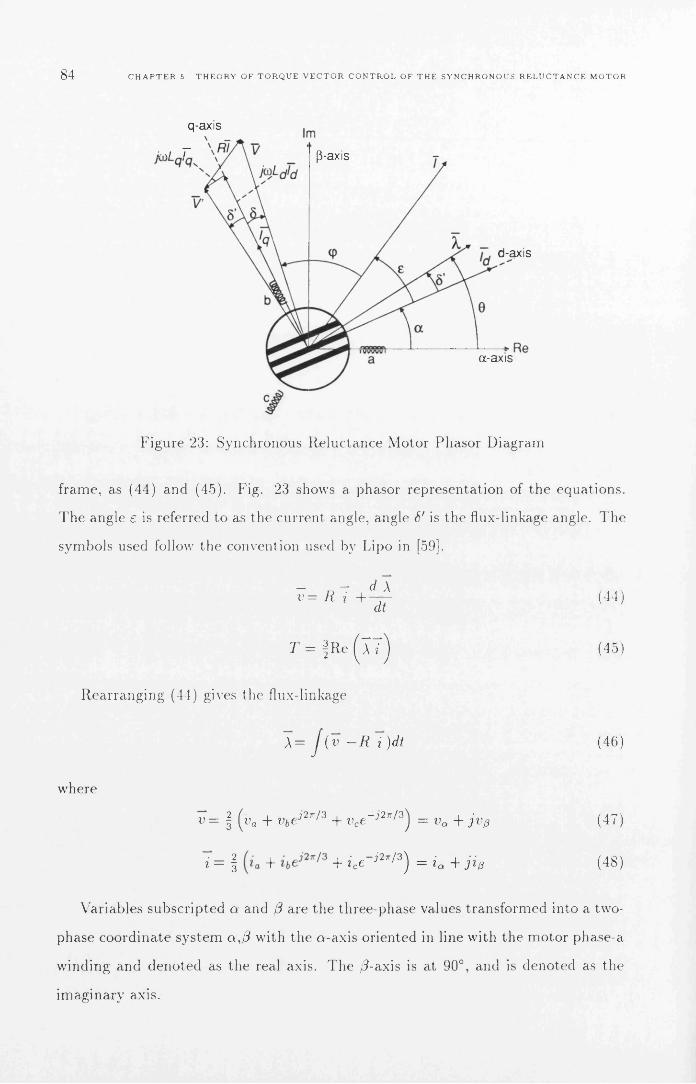
84 C H A P T E R 5. T H E O R Y O F T O R Q U E V E C T O R C O N T R O L O F T H E S Y N C H R O N O U S R E L U C T A N C E M O T O R
q-axis\
fir,/ r p-axis
d-axis
a-axis
Figure 23: Synchronous Reluctance Motor Phasor Diagram
frame, as (44) and (45). Fig. 23 shows a phasor representat ion of the equations.
T h e angle e is referred to as the current angle, angle S' is the flux-linkage angle. T h e
symbols used follow the convention used by Lipo in [59].
T7= i? 7 + ^ 4 (44)at
T = | R c ( X T ) (45)
Rea r rang ing (44) gives the flux-linkage
A= J ( v - R i )dt (46)
where
v = | (ua + v bej2n/3 + vce _j27r/3) = vQ + j v p (47)
i — | T + ice ■?27r/ 3 ̂ = ia -f j i p (48)
Variables subscr ip ted a and /3 are the three-phase values t ransfo rmed into a two-
phase coord ina te sys tem a,/7 with the a -ax is or iented in line with the m o to r phase-a
winding and deno ted as the real axis. T h e /7-axis is a t 90°, and is denoted as the
imaginary axis.

5. 2 T O R Q U E V E C T O R C O N T R O L P R I N C I P L E M O T O R E Q U A T I O N S 85
In this scheme the rotor posit ion is not used, or detected. It relies purely on
or ien ta t ion of s ta to r flux-linkage and to rque control. T h e flux-linkage angle, S', is
indirect ly control led through the control of to rque and f lux-magnitude .
In an ideal m oto r with R = 0 the vol tage angle, 6, and the flux linkage angle, S',
are ident ical .
Torque is re la ted to the curren t and vol tage angle as [59]:
9>3 ,2sin L£1 = -2p { L d L q) i — —
t = I p' 1 1 ' ( l- \ sin 2S' o ' 1 i '
L q L d U ' 2 / 2 = T q ~ T dmA;
sin 2 S'
(49)
(50)
Under constant current angle control, the m a x i m u m efficiency for the tes t m oto r
at ra t ed speed (1500rpm). to rque (0.95Nm) and current (1.7A) was found using a
current angle, e, of 55°. T h e angle is larger than 45° because of sa tu ra t ion effects.
Under the sam e condit ions as s ta ted above the corresponding flux-linkage angle
is given by
S' — tan - l — tan £ .Ld
(51)
As Ld is s trongly dependen t on the flux-linkage m ag n i tu d e equa t ions (50) and
(51) must be solved numerical ly to de te rm ine the flux-linkage m ag n i tu d e t h a t s a t
isfies the requi red full-load torque and curren t angle requi rements .
Foi the test motor the flux-linkage angle corresponding to a cu rren t angle of
55° was 1 2 ° (0 . 2 rad) . T hus unde r flux-linkage control the m o to r has an inherent
to rque m arg in of 33° before it becomes uns tab le by moving beyond 45°. This means
tha t the m oto r is inherent ly s table under flux-linkage angle control whereas it is
inheren t ly uns tab le under cons tan t curren t angle control since e > 45°.
Fig. 24 shows the behaviour of the curren t and torque for different flux-linkage
m agni tudes . It can easily be apprec ia ted t h a t for best possible inherent s tab i l i ty the
f lux-magnitude should be chosen as large as possible under curren t and vol tage l imit
constraints . However as efficiency is also an aim, the f lux-magnitude m us t be reduced
so that the full-load opera t ing point coincides with the m a x i m u m efficiency point . It
must also be noted tha t the curren t increases considerably when exceeding the ra ted

86 C H A P T E R S. T H E O R Y O F T O R Q U E V E C T O R C O N T R O L O F T H E S Y N C H R O N O U S R E L U C T A N C E M O T O R
12Current @ 0 .2 5 V s -----Current @0.20Vs ------Current @ 0.15 V s ------Torque @0.25Vs —Torque @0.20Vs ------Torque @ 0.15Vs ......
10
Q .<8
c0)3OoS 6E
20)13c r
£4
2
00.0 0.2 0.4 0.6 0.8 1.0 1.2 1.61.4
Fiux-linkage Angle 6’ [rad]
Figure 24: Torque and curren t m agn i tude vs. flux-linkage angle with flux-linkage m ag n i tu d e as a p a ra m e te r
flux-linkage angle. T V C normally opera tes with vol tage angles t h a t ensure opera t ion
within the current l imit , but after a load change is appl ied it m ay t rans ien t ly slip
back to a larger vol tage angle due to delays in the control loop.
To achieve synchron ism with the rotor T V C controls the applied vol tage so
tha t the flux-linkage m ag n i tu d e is cons tant and the m a x i m u m torque , calculated by
(45), is l imited so t h a t the flux-linkage angle is kept less t han 45°. T he flux-linkage
m ag n i tu d e is control led by apply ing vol tage vectors t h a t are directed towards the
cen tre of the rotor to decrease the m ag n i tu d e or outwards to increase t he m agn i tu de .
T h e to rque is controlled by applying vol tage vectors t h a t e i ther advance the flux-
linkage vec tor in the direction of ro ta t ion to increase the torque , or oppose the
direction of ro ta t ion to reduce the torque.
As the flux-linkage vector is the integral of the applied vol tage vector (46), it
will move in the direct ion of the applied vol tage vector for as long as the vol tage
vector is applied. T h e vol tage angle is thus indirect ly control led by the to rque and
flux-linkage m agn i tude . An increasing to rque causes an increasing flux-linkage angle.

5. 2 T O R Q U E V E C T O R C O N T R O L P R I N C I P L E & M O T O R E Q U A T I O N S 87
Flux- Sector 1 2 3 4 5 6A -fve T - v e V2 I 3 V4 Vs v6 ViA -fve T - v e v6 V V2 V3 v 4 v 5
A — ve T -fve V3 v 4 Vs v 6 V V2A — ve T - v e v 5 v 6 Vi v 2 V3 v 4
Table 1 : Opt imal Torque Vector Control Voltage Vectors
T V C is designed to provide a s imple and fast control a lgor i thm t h a t can be im
plemented in ha rdware without the use of a microprocessor . Torque vector control
uses a six-pulse voltage source inverter (Fig. 25). By using a ha rdw are im p lem e n ta
t ion it can be assumed tha t it will control the inverter switching at a r a te which is
fast enough to m ake it unnecessary to m odu la te the appl ied vol tage vectors. Hence
the only available vol tage vectors are the six in Fig. 25. Since there are only six
vol tage vectors available it is sufficient to de te rm ine the flux-linkage vector posit ion
to be in one of the six sectors defined in Fig. 25. As T V C opera tes a t the inverter
m a x i m u m switching frequency the to rque de m a n d is reduced to a s imple choice of
increase or decrease ( + / —). The flux-linkage m agn i tude is l ikewise l imited to a
choice of increase or decrease ( + / — ).
For the case when the flux-linkage vector is in sector 1 (Fig. 26) one of four
vol tage vectors can be applied. If the flux m agn i tude should be increased and the
torque should be posit ive then V2 should be applied to advance the flux vector. If
the flux is too large and a positive to rque is de m a nde d then V3 should be applied.
If nega t ive torque is dem anded then Vq would be applied to increase the flux and V5
to decrease the flux. A compact table of op t im al vol tage vectors for all t he different
cases of flux-linkage posit ion and desired control inpu ts [8 ] is listed in Table. 1 .
A high-speed low-tech implementa t ion of to rque vector control could be achieved
using op -amps, com parator s , a small R O M look-up table arid 4 analog multipl iers ,
ideal ly sui ted for implem enta t ion as an ASIC (Fig. 27).
At no point in the T V C algor i thm is there a need to know a ny th ing but the
desired flux-linkage m agn i tude and the associated m a x i m u m torque. In par t i cu la r
the absence of any rel iance 011 knowledge of Ld and L q should be noted; this can be
con tras ted to the conventional constant current angle control t h a t needs to know Ld

88 C H A P T E R 5. T H E O R Y O F T O R Q U E V E C T O R C O N T R O L O F T H E S Y N C H R O N O U S R E L U C T A N C E M O T O R
1
C 0 (1,0 ,0)
Figure 25: P W M inverter vol tage vector posit ions
P
torque p ostive fli>x‘ increasing
torque postive flux d ecreasin g
torque n egative torque negativeflux d ecreasin g flux increasing
Figure 26: T V C Voltage Vectors for s ta to r flux-linkage vector in region 1
and L q to com pensa te for the speed - term cross coupling between the d and q axis
cur rent equat ions.
To summ ar ise , the advantages of T V C are:
1 . Self synchronised torque control.
2. Inherent ly s table (S' < 45°) a t m a x i m u m efficiency opera t ing point.
3. Simple h a rdw are imp lem en ta t ion possible, no microprocessor necessary.
4. Does not need to know L q, L j or sa tu ra t ion character ist ic .

5.3. T O R Q U E V E C T O R C O N T R O L - F U R T H E R A N A L Y S I S 89
'PX
SectorCalc
Torque select (+/-)
Flux-link position (1-6)
Flux-link select (+/-)
TVClook-up
ROM
P 1a
Figure 27: H ardware implem en ta t io n of T V C
5.3 Torque V ector Control - Further A nalysis
This section expands on cer ta in aspects of to rque vector control descr ibed in the
previous section that different ia te it from constant current angle control schemes.
5.3.1 Current and d-q In d u cta n ces
T h e cur rent unde r to rque vector control is expec ted to be higher t han for constant
current angle control at light loads as a cer ta in amoun t of cu rren t is needed to
m a in ta in the constant flux m agn i tu de . For a cons tan t angle control ler the curren t
m ag n i tu d e can be directly derived from the to rque equa t ion as:
T — 2 Pil'd
™ o , , , , — 2 sin 2eT = -„p(Ld - L
— TI
f p ( L d - L , ) * p
(52)
(53)
(54)
For to rque vector control the cu rren t can be expressed as a funct ion of flux m agn i tude
and torque:
A = L did + jLqiq (-55)

90 C H A P T E R 5. T H E O R Y O F T O R Q U E V E C T O R C O N T R O L O F T H E S Y N C H R O N O U S R E L U C T A N C E M O T O R
= L l i l 2 : 2'dLd
(56)
(57)
S u b s t i tu t in g (57) in to (53) gives the following to equa tions for id and i q:
— 2 / — 4 4LlLlT2A ± \ A 3
,‘2 _ V ^p(Ld- L q)
2 L(58)
— 2h 4 4L 2L 2J2
A T \l A d 93V ip(Ld- L q)
(59)
C om bin ing (58) and (59) we can ob ta in an expression for the cu rren t m agn itude :
\
/ — * 4 4 /2 L 2 T 2A ± J A d <y
V 2 p( Ld—Lq)
213+
!
— 2- 4 4L 2 L 2 T 2
A A 1— ------2 p(Ld — Lq)
2 l \(60)
/
From (58, 59, 60) it clear th a t there exist two solutions for the id and iq cu rren ts ,
one on e ither side of the peak of th e to rque versus voltage angle curve (Fig. 24).
T he opera t ing point located on the left-hand side of the peak is s tab le as to rque
increases with increasing voltage angle, b u t the opera t ing point on th e r igh t-hand
side is only s tab le if opera ted w ith a shaft position sensor. However, a m o to r would
never be o p e ra ted on the righ t-hand side of the to rque peak as th e cu rren t levels
here are very large, and the opera t ing poin t is unstable .
T h e flux m a g n i tu d e as a function of desired cu rren t angle and to rque can be
derived by su b s t i tu t in g equa tion (57) into (52) and as ^ = t a n t the flux m ag n i tu d e*dbecomes:
A= \
T ( L l + L * t a n 2 £)
\ p (L d - tan(61)
E qua tion (61) is useful when de te rm in ing w hat flux level to use w hen the cu rren t
angle and desired to rque are known. For the 120W synchronous re luc tance m o to r the
flux-linkage m a g n i tu d e giving m ax im u m efficiency (£=55°) a t full load ( T = 0 .95N m )

5. 3 T O R Q U E V E C T O R C O N T R O L - F U R T H E R A N A L Y S I S 91
3.0Current Magnitude -----
2.5
2.0
<
3o
0.5
0.20.0 0.4 0.6 0.8 1.0 1.2Torque [Nm]
Figure 28: C u rren t M agnitude , Id and I q as function of to rque under Torque Vector C ontro l, A = 0 .2 Ys. ( 1 2 0 V Synchronous re luc tance m otor)
was 0 .2 Vs. T he curren t angle that gives m ax im u m efficiency is best de te rm ined
from m easured efficiency curves.
Figs. 28 and 29 show the curren ts in the 120W synchronous re luc tance m oto r
as function of to rque . From Fig. 28 it can be seen th a t under to rque vector control
the d-axis curren t rem ains almost constan t and the q-axis curren t increases almost
linearly with torque. Higher induc tance ratios lead to a f la t te r d-axis cu rren t curve.
For the constan t angle controller case (Fig. 29) th e id and iq cu rren ts b o th increase
in th e sam e proportion with increasing torque. N orm ally when considering e q u a
tions for the synchronous re luc tance m oto r they have to be solved num erica lly as
induc tance in the m ost inductive axis, Ld , decreases non-linearlv with increasing
curren t due to sa tu ra tio n . In the case of to rque vector control a sim plification m ay
be possible since the d-axis curren t rem ains fairly cons tan t irrespective of torque.
Fig. 30 shows the varia tion in Ld as a function of to rque for to rque vector and
constant angle control. For to rque vector control th e varia tion in Ld is 2.6%. For
constan t angle control the varia tion in Ld is 17.4%. Hence Ld m ay be taken as
constan t for to rque vector control, bu t not for constan t angle controllers.

92 C H A P T E R 5. T H E O R Y O F T O R Q U E V E C T O R C O N T R O L O F T H E S Y N C H R O N O U S R E L U C T A N C E M O T O R
3.0Current Magnitude ; -----
2.5
2.0
1.5
0.5
0.0 0.2 0.4 0.6Torque [Nm]
0.80.0
Figure 29: C u r ren t M agnitude , Id and I q as function of Torque under C ons tan t Angle C ontro l, £ = 55°. (120W Synchronous re luc tance m otor)
0.18
0.16
0.14(CAC 55 deg) —
fTVC) -----0.12
X
® 0.10
roo0.08
0.06
0.04
0.02
0.0I0.2 0.4 0.6
Torque [Nm]0.8
Figure 30: S a tu ra te d Ld vs. Torque. Torque Vector Control (A = 0.2Vs)and C ons ta n t Angle C ontrol (e= 55°)

5. 3. T O R Q U E V E C T O R C O N T R O L - F U R T H E R A N A L Y S I S 93
3.0Current Magnitude (CAC 55 deg) —
Current Magnitude (TVC) —
2.5
2.0
0.5
0.0 0.2 0.80.4 0.6Torque [Nm]
Figure 31: Theore tica l cu rren t m ag n i tu d e as function of to rque in T V C and CAC controllers. R a ted to rque = 0.95Nm.
5.3.2 Efficiency
Torque vector control opera tes with a constan t flux-linkage m ag n i tu d e at all loads.
T he use of constan t flux-linkage m eans th a t the re will be always cu rren t flowing in
the m o to r to m ain ta in the flux, even in no-load situa tions . T h e effect th is has on the
perfo rm ance will depend on loss m echan ism s in the m otor. In the 120W test m o to r
th e iron-losses were found to be relatively independen t of the load, and m ostly a
function of the flux-linkage ripple (see section 5.3.4). However the m a jo r pa r t of th e
loss was found to be due to copper loss.
To com pare th e difference in losses of to rque vector control and constan t angle
control it should thus be sufficient to com pare th e copper losses. Fig. 31 shows the
cu rren t m ag n i tu d e for a cons tan t angle control (CA C ) of 55° co m pared with to rque
vector control. T h e flux-linkage m ag n i tu d e is set to achieve the m ax im u m efficiency
cu rren t angle a t a load of 0 .95Nm (100% of ra ted torque). As can be seen the copper
losses of th e two control m e th o d s will be a lm ost the sam e for loads ranging from
60% to 1 1 0 % of ra te d torque. O u ts ide this range T V C has larger copper losses than
constan t angle controllers, especially a t low loads.

94 C H A P T E R 5. T H E O R Y O F T O R Q U E V E C T O R C O N T R O L O F T H E S Y N C H R O N O U S R E L U C T A N C E M O T O R
Torque vector control has fast dynam ic to rque response com pared to constan t
curren t angle controllers since the curren ts in th e m o to r can be changed faster. T he
to rque change is faster under T V C as a lm ost all th e cu rren t change occurs in the
least inductive axis whereas for constan t curren t angle control th e change in cu rren t
is equal in bo th axis.
T he efficiency of to rque vector control could be increased a t low loads by inc lud
ing an efficiency op tim is ing loop th a t would lower th e flux-linkage m ag n i tu d e when
the m o to r is o p e ra t ing at light loads. However, some of the dynam ic response of
T V C would have to be sacrificed if efficiency op tim is ing is used because th e flux-
linkage m ag n i tu d e would have to be rebu il t before full to rque could be produced .
This would m ake T V C dynam ic perfo rm ance on a par with constan t cu rren t angle
controllers.
5.3.3 R a te o f change o f Torque
To evaluate the dynam ic perfo rm ance of to rque vector control com pared to constant
cu rren t angle control, th e ra te of change of to rque m ust be derived. T h roughou t the
derivation it is assumed that s tator resistance can be ignored.
T he ra te of change of to rque for torque vector control operation (i.e. constant
f lux-linkage magnitude) can be derived as follows. T he to rque equation (-50) can be
w ri t ten in dq coord ina tes as:
A,Ag (62)
T he dq-voltage equa tions can be w ritten as:
t = I pi 1
T d
V d = ® f L - u \ q (63)ot
Vq = ^ - + U ) \ d (64)at
Taking th e derivative of (62) and s u b s t i tu t in g (63) and (64) into th e result:

5. 3 T O R Q U E V E C T O R C O N T R O L - F U R T H E R A N A L Y S I S 95
IP1
— ^'^d) T Xq(Vd T ^'Ag)} (65)'q L d
T he following identities can he found from the space vector d iagram (Fig. 23)
An Vdsin 8 = —- = —
A vc ^d Vq
COS o = — = —A v
(6 6 )
(67)
Using th e above identities th e ra te of change of to rque for torque vector control
can be w r i t ten in te rm s of flux-linkage angle as:
d r
dt = I pi l
L q LdA {u — u’A) cos 28 (6 8 )
S u b s t i tu t in g (50) back into (6 8 ) to gives the ra te of change of to rque for torque
vector control in te rm s of torque:
d T~ d t
1 1
Lq L dA {v — u;A) cos sin < 2 T /
T d\ : (69)
T he ra te of change of to rque for constant current angle control will now be
derived, again assuming that s tator resistance can b( ignored. T h e cu rren t form of
th e to rq u e equa tion (70) will be used to derive the ra te of change of torque.
T = f p [Ld - Lq] i = § p [Ld - Lq] idi< 70)
From th e space vector d iagram (Fig. 23):
'I 'Z ii = i d + i2 i ; 29
£ £ iV = v d + V
2 , , . 2 9
s in e — —
IdCOS £ = —
(71)
(72)
(73)
(74)
T he dq cu rren ts can be expressed in term s of to rque and curren t angle by com
bining (70), (71) and e ithe r (73) or (74).
id = y j i2 — iq = \ A 2 (1 - s in2 e) =
iq = \ j I 2 — i'd = y j i2{ 1 - cos2 e) =
T
\ fp [ L d ~ L ,COt £
T
qP \Ld ~ L qtan
(75)
(76)

96 C H A P T E R b T H E O R Y O F T O R Q U E V E C T O R C O N T R O L O F T H E S Y N C H R O N O U S R E L U C T A N C E M O T O R
T he vo ltage dq-equations (63, 64) in cu rren t form are (assum ing th a t L q and Ld
are not functions of t im e , i.e. ignoring sa tu ra tion effects):
j d i d .Vd — V'd LOljqlq (77j
r) *= L q- ^ + u L di d (78)
S u b s t i tu t in g (75) in to (77) and (76) in to (78):
QVd = L d V cot e — V T — u)Lqy / T t an e (79)
atQv q = L qV tan £ — V T — u j L d ' / T c o te (80)
at
S u b s t i tu t in g (79) and (80) in to (72):
2 L j c o t e f d y L y r tan 6 L*q U n e ( d \ 2 L ^ T c o teAT [ d t J ^ l P [Ld - L q\ ^ AT [ d t ) p [ L d - L q]
(81)
R ea rrang ing (81) gives the r a te of change of to rque for constant current angle
opera tion :
L 2{ cot e + L 2 tan ejAT V dt 9P[Ld ~ L
— — 2 d t
/ v 2 u>2T \T1 / j /OQ'\ L 2d cot t + L 2 tan e | p [Ld - L q\ J
As can be seen from (69) and (82) the ra te of change of to rque for th e controllers
are com plex functions of T , uj, Ld and L q. To help u nde rs tand ing th e rela tionsh ip of
the r a te of change of to rque betw een the to rque vector controller and the constan t
curren t angle controller consider Fig. 32 to Fig. 34. T h e re are a n u m b e r of rem arks
th a t can be m ade:
• T V C ra te of change of to rq u e is always superior to constan t curren t angle
control at light loads and low speeds.
• R a te of change of to rque for to rque vector control depends m ain ly on speed,
and is inversely p roportiona l to it.

5. 3. T O R Q U E V E C T O R C O N T R O L - F U R T H E R A N A L Y S I S 97
• R a te of change of to rque for to rque vector control is a lm ost constan t regardless
of torque.
• R a te of change of to rque for constan t curren t angle control is a s trong function
of torque.
• T he to rque level a t which constan t curren t angle control ra te of change of
to rque exceeds to rque vector control is approx im ate ly inversely proportional
to speed.
It should also be noted th a t in the worst case the r a te of change of to rque for
to rque vector control is only about a factor of 2 lower th an constan t curren t angle
control. W hereas constant angle control is significantly worse a t low speeds and
light loads. Also note that the results presen ted here are specific to the 120W
synchronous re luctance m otor used th roughou t this thesis. F u r th e r note that the
inverter is capable of delivering a sinusoidal voltage 25% larger th an th e required
base-speed voltage, th is is to ensure th a t the m o to r has sufficient d y n a m ic response
at speeds a t and above the base speed. From (6 8 ), if the voltages are exactly equal
the r a te of change of to rque for to rque vector control goes to zero a t and above base-
speed. This is also th e case for opera tion with 45° constan t curren t angle at ra ted
speed and torque. A no ther im p o r tan t result of using a slightly high DO-link voltage
is tha t under to rque vector control there is always a high ra te of change of to rque
available regardless of opera t ing poin t. T he m in im u m ra te of change of to rque for
th e 120W m oto r under to rque vector control was 0 .4 N m /m s (0 .4 2 p .u . /m s) which
should be m ore than sufficient for most applications.
5.3.4 F lux-l inkage ripple
Flux-linkage ripple affects the m oto r perfo rm ance as a secondary ironloss effect, but
m ore im p o r ta n t ly it controls the am oun t of filtering necessary in th e speed e s tim a to r
(section 6.4). It is therefore im p o r tan t to quan tify the flux-linkage ripple in te rm s
of opera tiona l p a ram ete rs .

98 C H A P T E R 5 T H E O R Y O F T O R Q U E V E C T O R C O N T R O L O F T H E S Y N C H R O N O U S R E L U C T A N C E M O T O R
1 6 0 0
CA C
1 4 0 0
1200C/5
z1000
8 0 0
Oo£<5cr
6 0 0
4 0 0
200
0 0.2 0.8 1.20 .4 0.6T o rq u e [Nm]
1
Figure 32: R a te of C hange of Torque @400rpm for to rque vector control (T V C ) and constan t curren t angle control (CA C ). (CAC set for m ax im um efficiency, t= 5 5 ° )
F irs t assum e th a t the cu rren t vector is aligned with an induc tance given by:
Li = L q + (Ld — L q) cose. (83)
F u r th e r assum e th a t the voltage available to change the flux-linkage is:
F a A = ^3 ̂ D C —l i n k ~ (84)
T hen th e change in flux-linkage over one control interval is given by:
A \ rp | V D C - l i n k - u \control T , j T s
L q + ( L d ~ L q ) C O S E(85)
In the case for the controller in use where the DC-link voltage is 150V and th e
control interval, T controi, is 96/xs th e average flux-linkage ripple is ± 1 7 m V s. or ± 8 %
a t the ra ted speed of 1500rpm. At zero speed the flux-linkage ripp le is ± 23% , and
a t the top speed of 2750rpm (using flux-weakening) the flux-linkage ripple is ±12% .
All figures quo ted are full load figures with £=55°.
Fig. 35 shows a t race of the flux-linkage as th e m o to r accelerates from 1500rpm
to 2750rpm under flux-weakening. T he opera tiona l p a ra m e te rs for Fig. 35 are:
A=0.25Vs, V D c - i i n k = 2 0 0 V and T contro]=104//s. T he expected flux-linkage ripple

5.4 F L U X - W E A K E N I N G A N D T O R Q U E V E C T O R C O N T R O L 99
1 400
TVC —CA C —
1200
■S' 1000£2 .§6 8 0 0
i -T5acrcJCOo<9
cr
6 0 0 —
4 0 0
200
0 0.2 0.4 0.6T o rq u e [Nm]
0.8 1 1.2
Figure 33: R a te of Change of Torque @1000rpm for to rque vector control (T V C ) and constan t curren t angle control (CA C ). (CAC set for m ax im u m efficiency, e = 55°)
using (85) is ± 1 2 % full load. ±7% no load @1500rpm. At 2750rpm the corresponding
figures are ± 1 7 % and ± 13% respectively. T h is agrees w ith the flux-linkage ripple
values from Fig. 35 which are ± 8 % @ 1500rpm and ± 14% @2750rpm. This m eans
equation (85) can be used to pred ic t the flux-linkage ripple. If the flux-linkage ripple
can be p red ic ted it is also possible to predict the am oun t of filtering needed in the
speed e s t im a to r for a pa rt icu la r control interval, m o to r type and DC-link voltage.
5.4 F lux-W eakening and Torque V ector C ontrol
Flux-w eakening is used to ope ra te above the ra ted speed of a m otor . T h e te rm flux-
weakening is derived from the term field-weakening which was used for separa te ly
excited D C -m otors. W hen the separa te ly excited m oto r reaches its base speed the
m oto r voltage is equal to the supply voltage. To fu rthe r increase the speed the field-
curren t would be decreased. T h e decrease in field curren t n a tu ra lly also resu lted in
a decrease in to rque per am pere .
As there is no separa te ly excited field w inding in a synchronous re luc tance m oto r
the te rm flux-weakening is used to signify th a t th e to ta l flux in th e m o to r is reduced

100 C H A P T E R 5 T H E O R Y O F T O R Q U E V E C T O R C O N T R O L O F T H E S Y N C H R O N O U S R E L U C T A N C E M O T O R
1000
9 0 0
8 0 0
(/)z
7 0 0
scr&
t—
6 0 0
15®cr.cre
5 0 0
■COo®•atr
4 0 0
3 00
200
100
1.20.6T o rq u e (Nm)
0.8 10.2 0.40
Figure 34: R a te of C hange of Torque @1500rpm for to rque vector control (T V C ) and co n s tan t cu rren t angle control (CAC). (CAC set for m ax im u m efficiency, £=55°)
F igure 35: Space vector of flux-linkage when accelerating form from 1500rpm to “2750rpm using flux-weakening. (0 .116Vs/div .)

5.4 F L U X - W E A K E N I N G A N D T O R Q U E V E C T O R C O N T R O L 101
when opera t ing above base speed. T he m ax im um to rque is usually kept inversely
p roportiona l to the speed when opera ted above base speed. This gives constant
power in the flux-weakening range. T he flux-weakening range is often referred to as
th e constan t power speed range (C P S R ) [36, 10, 60].
C ons tan t power opera tion above the base speed is easily im p lem en ted for to rque
vector control. W hen the m oto r reaches base speed the inverter has reached its
voltage limit and can not increase th e voltage fu rther. To go above the base speed
th e voltage m ust thus be kept constan t a t th e base speed level. As the voltage
m ag n i tu d e is given by:
\ V \ = u > \ \ \ (8 6 )
It is clear th a t to go above the base speed the flux-linkage m ag n i tu d e m ust be
reduced as:
| A | = — | A 6o. e | ( 8 7 )UO
As flux-linkage m ag n i tu d e is one of the d irec tly controlled p a ra m e te rs in to rque
vector control th is is easily achieved. Similarly th e m ax im u m to rque for constan t
power opera tion above base speed is given by:
Pm = Tujm = constan t (8 8 )
T1 _ ^'bast rp /CQ\^ max — 1 max \o a )uJ
T he m ax im u m to rque of the to rque/flux-linkage angle curve is reduced w hen the
flux-linkage m ag n i tu d e is reduced. It is vital to l im it the m ax im u m to rque dem and
because excess to rque dem and would push th e flux-linkage angle beyond the 45°
po in t and th e m oto r would lose synchronism . Since to rque is d irec tly controlled by
to rq u e vector control this is easily im plem ented .
T he behav iour of the flux-linkage angle and the id, iq and cu rren t m ag n i tu d e
is shown in Fig. 36 and 37. It has been shown in [60] th a t the theore tical flux-
w eakening range with e s t im a ted ironloss, for the m o to r used, is 2.52:1 and the m ea
sured range is 2.13:1. It should be noted th a t th e flux-linkage angle is significantly

102 C H A P T E R 5. T H E O R Y O F T O R Q U E V E C T O R C O N T R O L O F T H E S Y N C H R O N O U S R E L U C T A N C E M O T O R
90Current Angle
Flux-linkage Angle80
60
0540
30
20
0 500 1000 1500 2000 2500 3000Sp eed [rpm]
Figure 36: Full-load flux-linkage and current angle vs. speed. (C ons tan t power opera tion above base speed.) (Base speed = 1500rpm.)
less th an 45° when opera t ing w ith in this speed range, ensuring th a t the to rque vector
control rem ains stable.
It is im p o r ta n t to note th a t as to rque vector control opera tes on the m easured
flux-linkage and to rque , th e control is not affected by varia tions in the m ach ine
inductances . T h e g rea t s im plicity in achieving flux-weakening opera tion for to rque
vector control can be con tras ted by the complex opera tions th a t m u st be perform ed
by a curren t angle controller.
T h e required curren t angle for flux-weakening opera tion for a cu rren t angle con
tro ller for an ideal m o to r is given in [42] as:
w r a ted
which is clearly m ore com plex th an (87) and (89). Also no te the dependency on Ld, a
p a ra m e te r th a t varies strongly w ith id and hence torque. T h e correct d e te rm ina tion
of Ld is essentia] to p roper flux-weakening opera tion and m ust be e s t im a ted o n
line [9]. F u r th e r , to control a real m o to r the iron loss resis tance m ust also be
e s t im a ted and an even m ore com plex equation for the cu rren t angle m ust be used if
f lux-weakening is to be perform ed under curren t angle control [41]. All th is m akes

5.4 F L U X - W E A K E N I N G A N D T O R Q U E V E C T O R C O N T R O L 103
Current Magnitude ------
2.5 Torque
EZ
ScroI-oO<cE3o
0.5
0 500 1000 1 500 2000 2500 3000Sp eed [rpm]
Figure 37: Full-load m otor curren ts and to rque vs. speed. (C onstan t power opera tion above base speed.) (Base speed = 1500rpm.)
flux-weakening control under curren t-ang le control m ore com plex th a n for to rque
vector control.

104 C H A P T E R 5 THEORY OF T O R Q U E V E C T O R C ON T R O L OF THE S YNC HR ON OU S R E L UC TA NC E M O T O R

C h a p te r 6
I m p le m e n ta t io n o f S enso rless
T o rq u e V e c to r C o n tro l
6.1 C ontrol O verview
A sensorless speed control sys tem has been im plem en ted around the to rque vector
control a lgorithm described in section 5.2. T he com ple te system results in a fully
sensorless closed-loop speed control drive system for th e synchronous re luc tance
m otor. T he control s t ru c tu re for the system is shown in Fig. 38. T h e sys tem
consists two control loops: an ou te r speed loop and an inner to rque loop. T he ou ter
speed control loop uses a s ta n d a rd P l-con tro lle r to provide a to rque d e m a n d signal
to the to rque vector control a lgorithm . T h e inpu t to th e P l-con tro lle r is a speed
error signal which is derived from the difference betw een the desired and e s t im a ted
speed. T he speed e s tim a to r uses th e speed of the flux-linkage vector to e s t im a te the
ro to r speed. T h e flux-linkage vector is e s t im a ted from th e m o to r te rm ina l voltages
and curren ts .
T he inner to rque loop is im p lem en ted using the to rq u e vector control a lgorithm
(see section 5.2). T he to rque vector control a lgorithm requires the to rque and flux-
linkage m ag n i tu d e to be ob ta ined . T he e lec trom agnetic to rque and flux-linkage
m a g n i tu d e are e s t im a ted from th e m o to r te rm ina l voltages and curren ts .
105

106 C H A P T E R 6. I M P L E M E N T A T I O N O F S E N S O R L E S S T O R Q U E V E C T O R C O N T R O L
Sp eedEstimator
Flux STorque Estimator
ControllerTorque Vector
Controller Inverter
Figure 38: Controller overview
6.2 H ardw are O verview
A digital signal processor (D SP), the DSP96002 from M otorola, has been used to
im p lem en t m ost of the control a lgorithm s. A n analog circuit has been used to
transfo rm 3-phase quan ti t ie s into two phase-quan ti ties and to in teg ra te ( v —R i )
to ob ta in flux-linkage to ob ta in the flux-linkage vector. Analog com ponen ts were
used to reduce the execution t im e of the a lgorithm s and provide a qua li ty flux-linkage
es tim a te . T h e sensorless to rque control a lgo r ithm does not require th e use of a DSP.
It could have been im plem en ted entirely in analog and digital hardw are . However,
the developm ent t im e was g rea tly reduced using a DSP for the en tire system .
T he control a lgorithm s are execu ted every 9 6 / / S , giving a m ax im u m switching
frequency of 5 .2kllz . T he sensorless speed e s t im a te and the speed m easu red using
a resolver is o u tp u t on digital to analog converters for rea l-t im e m o n ito r ing and
com parison.
T he sys tem un its are shown in Fig. 39. T h e o ther m ain un it in add it ion to the
DSP un it is the inverter . T he inverter is a th ree-phase hard-sw itched IG B T system .
T he inverter has built-in dead-band genera tors and o ther p ro tec tion fea tu res such
as over cu rren t and voltage pro tec tion circuits. T h e inverter un i t also con ta ins flux-
nulling high band -w id th cu rren t transducers . T h e inverter is ra ted for a DC-link
voltage of 600V and a peak phase curren t of 50A. T he inverter is however used with
a DC-link voltage of 150V and cu rren t t ran sducers set for a m a x im u m curren t of
1 2 .5A as th is is m ore su itab le for the test m otor.

6. 2 H A R D W A R E O V E R V I E W 107
Dynamometer IGBT Inverter
Test Motor Analog Processing DSP-Controller Voltage Monitor Unit Unit
F igure 39: H ardw are overview
R e s o lv e r
3phAC
(0 ,1) (0 ,1) (0 ,1)
10 slot Passive Backplane (VME style)
3ph-2ph Transform Analog Integrators
VoltageSourceInverter
Motorola ADS96002
DSP96002-33.3MHZ
128KWord SRAM
6 x AD1332 12bit ADC
1 x AD2S80 10bit RDC
1 x OSC1758 Ref-Osc.
4 x AD767 12bit DAC Digital I/O
RS232 Serial Comm Base Drive Control
Figure 40: D iag ram m atic ha rdw are overview
For fu r th e r details of the D S P system see B.2, and inverter see section B.3.
A vo ltage-m on ito r is used to m easure the m o to r phase-voltages using a high-
im p e d a n ce resistor network. It interfaces with the analog-processing unit which
e s t im a te s th e flux-linkage and does 3-phase to 2-phase transfo rm . T h e voltage-
m o n ito r is kept separa te from th e rest of the control e lectronics for safety reasons.
For T Y C control software deta ils see A ppendix C.

108 C H A P T E R 6. I M P L E M E N T A T I O N O F S E N S O R L E S S T O R Q U E V E C T O R C O N T R O L
6.3 S ta tor F lux-linkage and Torque E stim ator
Torque vec to r control requires the flux-linkage vector and to rque to be e s t im a ted .
Using a ro to r position sensor the s ta to r cu rren ts could be t ransfo rm ed in to the
ro to r d-q f ram e and ca lcu la ted as Adq = Ldid + j L qi q. However, as th e a im is to
produce a sensorless schem e the s ta to r flux-linkage m ust be e s t im a ted using (47).
T he im p lem e n ta t io n of the flux-linkage e s t im a to r is shown in Fig. 41 [8 ). T he
cu rren ts and voltages are transfo rm ed into a 2 ph s ta to r coord ina te sy s tem using
op-am ps. T h e flux-linkage is found by analog in tegra tion of the voltage.
As expec ted there was some drift in the DC o u tp u t level from the analog in teg ra
tors. However, m ost of th e drift was caused by D C -drift in the cu rren t and voltage
t ran sd u cers and hence there would be no great advan tage to perform th e in teg ra
tion digitally in th e DSP. Analog in tegra tion also gives a m ore a ccu ra te resu lt th an
digital in teg ra t ion due to the d iscre te n a tu re of digital in tegration . To com pensa te
for the in te g ra to r in p u t drift the DC-gain of the in teg ra to rs was l im ited to lOx by
paralle ling th e in teg ra to r capac ito r with a resistor (Fig. 42). A fair a m o u n t of the
offset p rob lem s can p robab ly be con tr ibu ted to th e d is tr ibu ted configuration of the
system ; c u rre n t t ran sducers in th e inverter un it , voltage tran sducers in th e voltage
m on ito r u n i t , and in teg ra to rs in th e analog-processing unit. In a d is t r ib u ted system
like th is th e re are possibilities for ground loops t h a t m igh t affect opera t ion . It can
be expec ted th a t a single un it solution would provide m uch b e t te r pe rfo rm ance with
respect to th e offset p roblem .
T he drif t com pensa tion in troduces a gain erro r when ope ra t ing a t low speeds.
T h e gain erro r causes the e s t im a ted flux-linkage m ag n i tu d e to be 25% too low
@400rpm, resu lting in an increased flux-linkage m ag n i tu d e in th e m o to r a t low
speeds. Th is increase in flux a t low speeds does not in fact influence th e control
m uch. T h e cu rren t m ag n i tu d e stays v irtua lly constan t . T he voltage angle is de
creased giving a slightly lower fundam en ta l power fac tor and efficiency. A positive
side effect of th e increased flux m ag n i tu d e is increased to rque reserve. T h e increase
in flux occurs at low speeds so th e re is no risk of runn ing out of volts.

6. 3. S T A T O R F L U X - L I N K A G E A N D T O R Q U E E S T I M A T O R 109
AnalogProcessing
Unit2 /3 -1/3 -1/3
D S P . T -X a Ip
Figure 41: S ta to r flux-linkage and to rque e s t im a to r
T he conventional m ethod used to com pensa te for in teg ra to r offset m easures the
d is tance th e cen tre of the flux-linkage circle has moved from the origin and com
p en sa te for this [5]. This m e th o d is fine for PM m otors as th e flux is cons tan t and
m ain ly produced by m agnets and there is a rela tively small con tr ibu tion due to the
cu rren ts in the machine. However, to rque vector control can not use th is approach
because th e flux-linkage is being produced by th e curren ts , and is controlled so
th a t th e m easu red flux-linkage describes a “perfec t” circle. T h e ac tua l flux-linkage
m ag n i tu d e will thus under offset conditions vary as it ro ta t ing . C om pensa t ion for
DC-offset under T V C is done by recording the offset values whenever th e m oto r is
s topped and su b trac tin g th e offset values from th e m easured values when the m oto r
is runn ing . T he influence of flux-linkage offset on th e sensorless control schem e will
be discussed fu rthe r in section 6.4.
Since th e calculation of to rque and flux-linkage m ag n i tu d e (squared) are m uch
s im pler to perform digitally th a n analogly, and since th ey are not com pu ta tiona l
in tensive th ey were com pu ted by the DSP. T he square of th e flux m ag n i tu d e was

C H A P T E R 6. I M P L E M E N T A T I O N O F S E N S O R L E S S T O R Q U E V E C T O R C O N T R O L
(V-RI)
Figure 42: In teg ra to r circuit for flux-linkage ca lcu la tor
Figure 43: Analog Processing Unit

6. 3. S T A T O R F L U X - L I N K A G E A N D T O R Q U E E S T I M A T O R 111
Torque Vector Control ROM Lookup Table
Flux-linkage a
Flux-linkage pSector Decoding:
S2 = A B X 8> S3 = /A B /Y-v3
S5= /A /B /X S6= A/B YOV-r
Phase A control (1/0) Phase B control (1/0) Phase C control (1/0)
Torque Selector (pos/neg)
0V
Torque demand
Flux-linkage demand Flux-linkage mag. (inc/dec)
ToInverter
F igure 44: H ardw are im plem en ta t ion of T V C sector decoding
used since finding the square-root would be very t im e consuming.
As T V C only requires the flux-linkage vector position to be de te rm ined to be in
one of the six sectors in Fig. 25 the position can be uniquely identified by tes t ing for
th e sign of A0 , the sign of \ g and a m ag n i tu d e com parison \ /3 | | and |AQ|. These
tes ts are perform ed by the DSP on the raw flux-linkage values from the analog
in tegra to r. Use of the a rc tan function to d e te rm in e the position of the flux-linkage
vector is thus not necessary for the to rque loop and this saves valuable C P U tim e.
T he position tes t could also have been im plem en ted in h a rdw are by use of a few
com para to rs and op-am ps. Fig. 44 shows an exam ple of how this can be done. The
to rq u e vector control voltage-vector-selector from Table 1 and sector decoding can
be incorpora ted into a single ROM .
At low speeds the m otional voltage com ponen t becom es less th a n or equal to
th e voltage across the s ta to r resistance. It thus becomes im p o r ta n t th a t th e correct
value of s ta to r resis tance is used in the flux-linkage e s tim a to r . A wrong s ta to r
resis tance value causes an offset in the flux-linkage angle. T he offset can cause the
to rque vector control a lgorithm to de tec t and use the wrong flux-linkage sector. This
m ay be a l im iting factor when considering low speed opera tion because an incorrect
sector e s t im a te will most likely cause loss of synchronism .

11*2 C H A P T E R 6. I M P L E M E N T A T I O N O F S E N S O R L E S S T O R Q U E V E C T O R C O N T R O L
6.4 S p eed E stim ator
To achieve sensorless closed loop speed control the ro to r speed m ust be e s t im a ted
from th e te rm in a l cu rren t and voltages. T he ro tor speed can be e s t im a ted by cal
cu la ting th e speed of th e e s t im a ted flux-linkage vector using (91). T he speed of the
flux-linkage vector can be used to e s t im a te the ro tor speed since in the s tead y -s ta te
the flux-linkage vector and the ro tor are synchronised and hence ro ta te w ith the
sam e speed. T h e flux-linkage was used ra th e r th an th e cu rren t or voltage vectors to
e s t im a te th e ro to r speed because it has a m uch cleaner waveform th an the others .
T h e re are th ree po ten tia l p roblem s with this approach:
1 . T h e raw flux-linkage vector is not uniform and constan t , b u t contains large
a m o u n ts of sw itching noise.
2. D uring to rque changes the flux-linkage vector is tem porar i ly no longer sy n
chronised to the rotor.
3. Offset in th e flux-linkage e s t im a te causes a speed varia tion at the electrical
ro to r frequency
6.4.1 F lux-l inkage sw itch in g noise
Even though th e flux-linkage waveforms m ay look qu ite sinusoidal (Fig. 57, page 126)
th ey con ta in huge am o u n ts of sw itching noise (Fig. 45) due the fact th a t th e flux-
linkage vector can m ove backwards during any p a r t icu la r control interval. However,
on average th e flux-linkage vector moves in the direction of ro ta tion . This sw itching
noise would inject huge a m oun t of noise in the speed e s t im a te if it was not filtered
before th e differential of the flux-linkage vector position was taken.
S im ula tions and tes t proved th a t qu ite hard filtering was required to get a usable
speed e s tim a te . To save t im e and for s im plic ity a s im ple digital RC type filter was

S P E E D E S T I M A T O R 113
Figure 45: T V C flux-linkage. (0.25Vspk)
used. T he flux-linkage waveform was filtered using a first o rder (RC) filter with
fc = 16Hz. T he filter in troduces a delay of 2-5ms, which n a tu ra lly afTects the b a n d
w id th of th e controller. This delay would not be accep tab le if this flux-linkage vector
position e s t im a te was used in the to rque control loop. However, as the position is
only used in the speed e s tim a to r this m ay be acceptable .
6.4.2 C han ge in s p e e d -e s t im a te due to torque change
This problem is due to the fact th a t the angle S' changes when th e m o to r to rque
changes. W hen S' changes the position of the flux-linkage vector re la tive to the ro tor
changes. This m eans th a t t rans ien tly th e ro tor and flux-linkage vector are no longer
synchronised, b u t move relative to each other. T he filters will tend to suppress this,
b u t the effect gets magnified by the differentiation tak ing place to o b ta in th e speed.
W hen ro ta t in g in a positive direction an increase in to rque d e m a n d will lead to
an increase in the flux-linkage angle, this m eans th a t the flux-linkage vector will
have to advance relative to the rotor. This m akes the speed e s t im a to r th ink tha t
th e speed has increased m ore than it in ac tual fact has. This also has to be seen in
th e light th a t the increase in dem and was a result of the ro to r speed decreasing in
th e first place. This m ight result in a som ew hat sluggish behaviour.
To quan tify this effect one can use the to rque (50) and the ra te of change of to rque
equa tion (6 8 ) as a s ta r t in g point. Assum ing small varia tions around an opera ting
point the ra te of change of to rque can be assum ed to constan t. T he to rque equation

114 C H A P T E R 6. I M P L E M E N T A T I O N O F S E N S O R L E S S T O R Q U E V E C T O R C O N T R O L
can then be used to e x tra c t an e s t im a te of the change in S' w .r.t . a to rque change.
To get an idea abou t w hat the effect m ight be on the speed e s tim a te a case
s tudy is useful. Take the case w here the m o to r is ro ta t in g a t 750rpm and the to rque
changes from 0.1 to 0.95Nm. T he ra te of change of to rque a t O.INm is 1600N m /s
decreasing to 1500N m /s @ 0.95Nm (assum ing constan t speed of 750rpm). T he
change in S' over one control interval is then 0.006rad. T he corresponding erro r in
speed is 600rpm , this error will last until th e to rque reaches the desired value after
500/is. N ote th a t these es t im a tions assum e th a t no filtering is used.
Speed .e rro r = -7 - — = — — -— = 6 2 .5 rad /s ~ 600rpm (92)T Control 9 6 / / $
Sim ulations and expe r im en ts have shown th a t because of th e filtering used to re
move the effects of sw itching noise the effects of to rque changes are largely rem oved.
T he only place they m anifest them selves is by a small kink in the speed e s t im a te
during speed reversal. W hen apply ing step load changes this effect can not be seen.
Hence it was not deem ed necessary to fu rthe r com pensa te for th is effect. It m ay
be possible to use the to rque equation to e s t im a te the change in S' and use th is to
com pensa te the speed e s tim a to r . This effect can be m inim ised by l im iting th e ra te
of change of torque.
6.4.3 F lux-l inkage offset influence on sp ee d e s t im a te
T he offsets th a t occur in th e flux-linkage while th e m o to r is runn ing can not be
com pensa ted for since the to rque vector control a lgorithm forces the m easu red values
to ap p ear as a circle centered a t w ha t in rea lity is an offset origin. T he varia tion
in speed e s t im a te and ac tua l speed due to offsets in the flux-linkage m easu rem en ts
m anifests itself in two d is t inc t ways:
1 . At low speeds the ro tor speed is m o du la ted by a signal with a frequency equal
to the e lectrical ro tor frequency. T he speed e s t im a te in th is s itua tion would
ind ica te cons tan t ro tor speed.

6.4. S P E E D E S T I M A T O R 115
^ m a c h in eS h if te d t ru e f lu x -lin k a g e v e c to r
E s t im a te d f lu x -lin k ag e v e c to r
D e s ire dflu x -lin k ag e-Circle
E s t im a te dflu x -lin k ag ea rd e — T ru e f lu x -lin k ag e v e c to r
Machinec e n t r e
E s t im a te dflu x -lin k ag ec e n t r e
Figure 46: Offset flux-linkage circles
2 . At high speed the the speed-controller ban d w id th is reached and th e load acts
as a filter and produces a s tab le ro tor speed. U nder th is condition the speed
varia tion is evident in the speed e s tim a te , but not in th e ro to r speed. (This
ripple in the e s t im a te m ay m ake th e speed controller uns tab le under certa in
conditions.)
Offsets in the flux-linkage e s t im a te th a t occur during the opera t ion are not com
p ensa ted for and cause the real flux-linkage vector to be m oved off-centre. T he
m easu red flux linkage appears centred , bu t the speed of th e e s t im a ted flux-linkage
vector is m o d u la te d by a sinusoidally shaped function w ith a frequency equal to the
electrical ro tor frequency.
In tu itive ly it is easy to ap p rec ia te t h a t this will cause a speed varia tion. T he
visualisation is done as follows:
S ta r t off bv assum ing th a t the controller can ac tua lly control th e est imated speed
to be constant and also th a t the estimated flux-linkage m ag n i tu d e is cons tan t , th is
is a valid a ssum ption as long as the controller b an d w id th is large enough.
F u r th e r assum e th a t the ro to r is aligned in the direction of the poin t at which
th e est imated flux-linkage vector touches the estimated flux-linkage circle. (This is
t ru e in the limit where the speed goes to zero.) It can then easily be seen th a t the

116 C H A P T E R 6. I M P L E M E N T A T I O N O F S E N S O R L E S S T O R Q U E V E C T O R C O N T R O L
angle to th a t po in t from th e center of the ro to r is different from the angle from the
cen te r of the est imated flux-linkage.
Now consider m oving this point along the estimated flux-linkage circle at a fixed
speed, in th is case the angle of the est imated flux-linkage changes a t a constant ra te ,
bu t th e ra te a t which the the angle centred a t the ro to r-cen tre does not change at
th e sam e ra te . This can easily be proved by m oving th e est imated flux-linkage angle
by 90°, in th is case th e angle from the cen tre of th e ro to r is less th a n 90°. As the
t im e taken for th is m ovem ent is th e same, bu t the angu lar d istance is different the
two vectors m ust have moved at a different speed. (T here will also be an erro r due to
the m o d u la tio n of the actual to rque , and consequently the angle betw een th e ro tor
and th e flux-linkage vector. However, th is is believed to be a secondary effect.)
An equa tion for the speed varia tion can be derived as follows, assum ing th a t th e
offset e rror occurs in the a axis. From Fig. 46:
tan a =
xp =
tan 7 =
tan 7 =
cos q =
tan 7 =
ta n 7 =
sin ad a V cos a + k
X ax Q tan q
+ < / / x Q tan q
£ q + X ° fJX Qt = > X Q = X COS QXx cos a tan a
x cos a + x °jj cos a tan a
COS Q - f
7 = tan - l sin q
cos q -f k + 1
(cos a -f k ) 2
(93)
(9 -1 )
(95)
(96)
(97)
(98)
(99)
( 100)
(101)

6 4 S P E E D E S T I M A T O R 117
w here k = - 2̂ L , the relative m ag n i tu d e erro r in the flux-linkage m easu rem en t.
Therefore:
d j _ 1 1
dcx 2 _j_ r sin a 2 (cos Q -f k ) ‘[cos a + k _
c/ 7 k + 1
da (cos a + k ) 2 -f s in 2 a
( 102)
(103)
Hence
daA 7 = (104;
A 7 d~j A qA/ da A t
(105)
(106)
w here is m easu red speed and is ac tua l speed. T he speed error is thus:
'err — ^ t r u e ^ ’m e o s
— ^ t r u e c ’ t ru edaS j
— u' t r u e | 1 ^ ) ( 1 0 /
T h e speed varia tion can be p lo tted as seen in Figs. 47, 48 and 49. T h e offset of
these wave forms depends on th e individual offset in each axis. T h e rela tive speed
error a p p e ars to be a non-linear function of th e flux-linkage offset. Also no te th a t
when th e flux-linkage offset is less th an 1 0 % th e speed-error waveform is almost
sinusoidal, b u t becomes increasingly d is to r ted w ith larger offsets.
T h e flux-linkage offset also affects the to rq u e controller. T h e flux-linkage offset
causes a m odu la tion of the torque . This occurs because the e s t im a ted flux-linkage
m ag n i tu d e and in effect the ac tua l m o to r flux-linkage m ag n i tu d e varies with the
ro to r position . This varia tion also occurs a t th e electrical ro to r frequency. This
to rque m o du la tion will cause a varia tion in th e actual ro to r speed. If th e speed
controller has high enough b an d w id th this effect can be suppressed . T h e relative
to rque m o d u la tio n m ag n i tu d e will be proportiona l to twice th e re la tive flux-linkage
varia tion since to rque is p roportiona l to flux-linkage squared.

118 C H A P T E R 6. I M P L E M E N T A T I O N O F S E N S O R L E S S T O R Q U E V E C T O R C O N T R O L
1.035
1.03
1.025
1.02
- 1.015
1.01
1.005
0.995
0.99500100 200 700 800300
Electrical400
Electrical rotor position [deg)600
Figure 47: R elative speed -es tim a te with @1% flux-linkage offset
1.35
5.1.25
•S 1.05
0.95
0.9300
Electrical500 600 700 800100 200 400
Electrical rotor position [deg]
Figure 48: Relative speed-es tim a te with @10% flux-linkage offset
As the sys tem forms a closed loop it is difficult to visualise the way flux-linkage
offset will in te rac t with th e to rque and speed controllers (it is also load dependen t) .
A good way to o b ta in an apprec ia tion of the effects is to s im ula te the system . Fig.
50 is a ben ch m ark tes t @750rpm where there are no flux-linkage offsets. (A 0-0.5N m
step load is applied a t 2=0 .5s.) Fig. 51 shows the resu lts of in jecting a 5% flux-
linkage offset in th e speed e s t im a to r a axis only. In Fig. 52 the effect of flux-linkage
offset in just th e to rq u e e s t im a te is shown. Fig. 53 shows the real-life s itua tion where

6 4 S P E E D E S T I M A T O R 119
■n 4
500100 200 400Electrical rotor position [deg]
300Electrical
600 700 800
Figure 49: Relative speed-es tim ate w ith @50% flux-linkage offset
850Estimated speed -----
True speed -----
750
I
650
5501.20 0.2 0.4 0.6 0.8 1 1.4
Time [s]
Figure 50: Speed regulation w ith no flux-linkage offset
the flux-linkage offset affects bo th the speed and to rque e s t im a te sim ultaneously .
N otice th a t th e effect of offset on the to rque controller is considerably less th an
th e effect of offset on th e speed es tim a to r . F u r th e r observe t h a t the speed-ripple is
ac tua lly less in the case where th e flux-linkage offset affects bo th to rq u e and speed
controllers th an when only one is affected. Surprisingly, bu t fo rtuna te ly , these two
effects seems to cancel each o ther ra th e r th an to accum ula te .

120 C H A P T E R 6. I M P L E M E N T A T I O N O F S E N S O R L E S S T O R Q U E V E C T O R C O N T R O L
850Estimated speed -----
i True speed -----
750
E&
650
5501.20 0.2 0.80.4 0.6 1.41
Time [s]
Figure 51: Speed regulation with 5% flux-linkage offset in speed e s t im a to r only
850Estimated speed -----
True speed -----
750
E&
C/5650
5501.20 0.2 0.6 0.80.4 1.41
Time [s]
Figure 52: Speed regulation with 5% flux-linkage offset in to rque e s t im a to r only
Considering ways to im prove th e speed e s t im a te it would should ap p a ren tly be
possible to filter out the speed variation using a band-s top filter cen te red on th e
electrical ro tor frequency. Doing th is would result in the case where only the to rque
controller is affected by flux-linkage offset (Fig. 52) and not give any im provem en t.
It m igh t seem logical to notch filter the to rque controller as well, b u t th is can not
be done as th e to rq u e controller need a high ban d w id th with m in im al delay.
A no ther m eth o d m igh t be to e s t im a te the speed only once per revolution. Th is
would result in the correct speed es tim a te , but th e bandw id th is so low th a t any

6 4 S P E E D E S T I M A T O R 121
850Estimated speed -----
True speed -----
750
EQ-
650
5501.20 0.2 0.4 0.6 0.8 1 1.4
Time [s]
Figure 53: Speed regulation with 5% flux-linkage offset in speed & to rque es tim a to rs
speed varia tion due to the offset effect in the to rque controller would not be cor
rectable . T hen net effect would be as shown in Fig. 52.
W hereas bo th these suggestions would provide a clean speed e s t im a te w ith the
effects of the flux-linkage offset suppressed, it will not work in p rac tice because the
to rq u e is also affected.
A s ta te observer based approach was also a t te m p te d in s im ulation . T he observer
provided an ex trem ely sm ooth speed es tim a te . T h e s tea d y -s ta te error was also very
low. However, the biggest failing of the observer based approached is th a t it tries
to model th e whole system . This is fine as long as th e sys tem does not change.
W h e n th e re is a change in the system such as a change in iner t ia or to rque th en the
observer will take a long t im e to respond. This is because the observer and the real
system are forced together using integral action only. To im prove th e response of
an observer based system all the system p a ram ete rs m ust be identified on-line with
m in im al delay. T he on-line identification of system p a ram ete rs would be too costly
in c o m pu ta tiona l t im e to im plem ent on th e cu rren t system .
T he best (and m aybe only) way to ensure th a t one can get a quality speed
e s t im a te is to ensure by design that, th e flux-linkage m easu rem en ts are offset free.
T h e e s t im a te when there is no flux-linkage offsets are quite good as can be seen in

122 C H A P T E R 6. I M P L E M E N T A T I O N O F S E N S O R L E S S T O R Q U E V E C T O R C O N T R O L
X.a
X p
► co
Figure 54: Speed e s tim a to r
Fig. 50.
6.4 .4 S p e ed e s t im a to r im p lem en ta t io n
T he speed e s t im a to r has been im plem en ted digitally in the DSP. T he speed e s t im a to r
ca lcu la tes th e speed of the flux-linkage vector to ob tain a ro tor speed e s tim a te .
T h e block d iagram of the speed e s tim a to r is shown in Fig. 54. F irs t th e a , ft
flux-linkage signals are filtered using low-pass filters with 16Hz cut-off frequency to
rem ove the switching noise.
T h e position is then de te rm ined using a four q u a d ra n t a rc tan2 function on the
q . 0 flux-linkages. T he s tanda rd a rc tan function in the DSP C-library was found to
be too slow for rea l-t im e opera tion . It was replaced by a 1024 (90°) e n try look-up
tab le w ith a bisection search a lgorithm , which yielded significantly fas ter opera tion
a t the cost of decreased accuracy in the a rc tan2 function. T he resolution of the new
a rc tan 2 function is 0.09°, which gives an equivalent resolution of a lm ost 1 in 4000.
This is m ore th a n good enough considering th a t m ost drives are opera ted with 1000
line encoders.
T h e differential of the flux-linkage vector is ca lcu la ted by tak ing the difference
in flux-linkage vector position over a control interval of 96/^s. T he differentia tion
process na tu ra lly tends to am plify any noise in the position e s tim a te . A fu rthe r
low-pass filter w ith cut-off frequency of 25Hz was applied to th e o u tp u t of the
d ifferen tia tor to rem ove this noise.

6. 5 S P E E D A N D T O R Q U E C O N T R O L L E R 123
S p e e d P l-contro llerLim: T,
r - ^ J \D esired S p e e dT orque C ontro ller
......E stim a ted S p e e d —
E stim a ted Torque
M axim um Torque
T orque d e m a n d (p o s/n eg )
K l>Torque C ontro ller O verride
Figure 55: Speed & Torque controller
6.5 Speed and Torque C ontroller
An overall view of the speed and to rque controller was given in Fig. 38 on page 106,
Fig. 55 gives an expanded view of this.
T he speed controller is a s tan d a rd proportional-in tegra l (P I) controller. T he
speed controller accepts as inpu ts the desired and the e s t im a ted speed. T he differ
ence is a error signal which is then amplified by a fixed gain ( I\ p) to p roduce the a
to rque dem and signal proportiona l to the speed error. T he p roportiona l to rque de
m an d is also in teg ra ted in an in teg ra to r with gain T he o u tp u t of the in tegra to r
is l im ited to the m o to r ’s ra te d to rque to p reven t in teg ra to r w indup. T he integral
and proportiona l to rque dem and signals are then added to p roduce an overall to rque
dem and signal which is fed into the to rque controller.
T he to rque controller used is qu ite sim ple as the to rque vector control a lgorithm
only accepts request for positive or negative torque . T he desired to rque from the
speed controller is com pared with the e s t im a ted m oto r torque. If th e m o to r to rque
is less than the desired to rque a request for positive to rque is passed to the T V C
control a lgo r ithm , o therw ise a request for negative to rque is passed.
T he to rque vector control a lgorithm m ay override any to rque request passed
to it if th e m o to r to rque is larger th an the ra ted torque . If the m o to r to rque is
positive and larger th an the ra ted to rque then a negative to rque d e m a n d overrides
any previous selection. Likewise if a negative m o to r to rque of m ag n i tu d e grea ter
th an the ra ted to rque is m easured then a positive to rque request overrides and is

124 C H A P T E R C I M P L E M E N T A T I O N O F S E N S O R L E S S T O R Q U E V E C T O R C O N T R O L
applied.
Fixed se tt ings going in to th e to rque vector controller are flux-linkage vector
m ag n i tu d e and m ax im u m torque. These two se tt ings are continuously ad jus ted
when th e m o to r is ope ra t ing above base speed, i.e. using flux-weakening. Below
base speed these two se tt ings could be used to form p a r t of an efficiency optim iz ing
ou ter loop.
T he m ost p rob lem atic aspect of the speed controller was the r ipple in e s t im a ted
speed due to offsets in the flux-linkage. T he effects of this were m ost no ticeable at
h igher speeds as th e r ipple frequency approached the speed controller bandw id th and
could have caused instability . T he proportiona l gain of the PI speed controller m ust
be set rela tively low so tha t the to rque dem and signal does not get undu ly d is tu rbed
by the speed e s t im a te r ipple caused by the flux-linkage offset. Careful tun ing of the
PI gains and the filter se ttings resu lted in a s tab le system with a speed varia tion of
an app rox im ate ly fixed m ag n i tu d e (25rpm ), which is clearly visible a t low speeds.
At high speeds the load tends to filter out th e ripple from the actual speed.

C h a p te r 7
S enso rless c o n tro l — R e s u l t s
To explore th e perform ance and l im ita tions of th e sensorless closed-loop speed con
tro ller an experim en ta l se t-up with a 120W axially lam ina ted synchronous reluc
tan ce m oto r was used. T he m oto r has a s ta n d a rd induction m o to r s ta to r with a
low-voltage winding. T he test m o to r and the load m achine were coupled with a Vi-
b ro m e te r to rque tran sducer using flexible ru b b er couplings. - T h e load m ach ine was
a brushless pe rm anen t m agnet m oto r powered by an E lectrocraft BRU controller.
S.. *»«**
F igure 56: Electrocraft PM load m oto r (left), V ib ro m e te r to rque tran sducer , and axially lam in a ted synchronous reluc tance m otor.
125
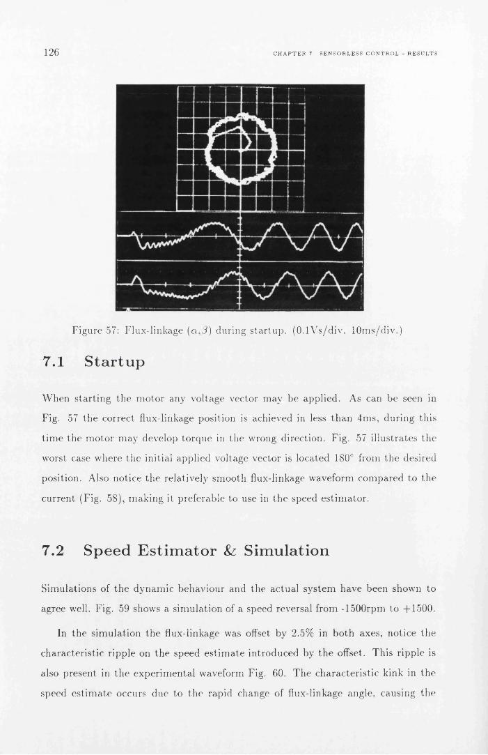
126 C H A P T E R 7. S E N S O R L E S S C O N T R O L - R E S U L T S
Figure 57: Flux-linkage (a,/?) during s ta r tu p . (O .lV s/d iv . lO m s/d iv .)
7.1 S tartup
W hen s ta r t in g the m o to r any voltage vector m ay be applied . As can be seen in
Fig. 57 the correct flux-linkage position is achieved in less th a n 4m s, during this
t im e the m o to r m ay develop to rque in the wrong direction. Fig. 57 i llus tra tes the
worst case w here the initial applied voltage vector is located 180° from the desired
position. Also notice th e relatively sm ooth flux-linkage waveform com pared to the
cu rren t (Fig. 58), m ak ing it p referable to use in th e speed e s tim a to r .
7.2 S peed E stim ator & S im ulation
Sim ulations of the dynam ic behav iour and the ac tua l sys tem have been shown to
agree well. Fig. 59 shows a s im ula tion of a speed reversal from -1500rpm to +1500.
In the sim ula tion the flux-linkage was offset by 2.5% in bo th axes, notice the
charac te r is t ic ripp le on the speed e s t im a te in troduced by th e offset. This r ipp le is
also present in th e experim en ta l waveform Fig. 60. T he charac te r is t ic kink in the
speed e s t im a te occurs due to the rapid change of flux-linkage angle, causing the

7.2. S P E E D E S T I M A T O R & S I M U L A T I O N 127
Figure 58: Phase-V oltage (top) and C urren t (b tm ) du r ing s ta r tu p . (50V /d iv ,2A /d iv , lO m s/d iv .)
2000
1500
1000
500
-500
-1000
-1500
-20000 1 0 7 0 80 0 2 03 0 4 0 5 0 6 0 9 1
2000
1500
1000
500
-500
-1000
-1500
-20000 0 1 0 2 0 3 0 4 0 5 0 6 0 7 0.8 0 9 1
Figure 59: Sensorless: S im ula ted Speed Reversal 1500rpm. E s t im a te d Speed (top) True Speed (b tm ). (5 0 0 rp m /d iv , O .ls /d iv .)
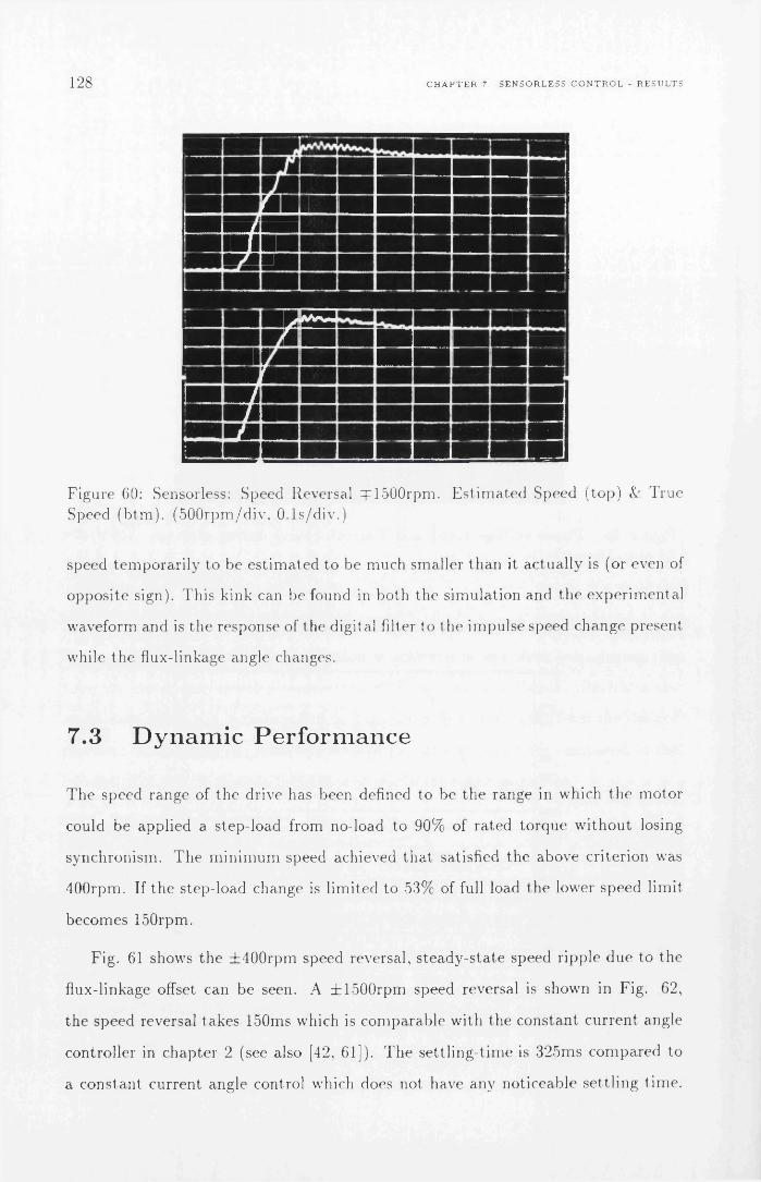
128 C H A P T E R 7. S E N S O R L E S S C O N T R O L - R E S U L T S
E E S S E■ ■ ■ ■ ■WM mm M tE mmiwmu■MWFMM wmmm ■i
sSpSi
352S ■S E E E E ■ iS■■m1WBM mm mm ■i
wmmm EFigure 60: Sensorless: Speed Reversal =pl500rpm. E s t im a te d Speed (top) Sz T rue Speed (b tm ). (5 0 0 rp m /d iv , O .ls /d iv .)
speed tem pora r i ly to be e s t im a ted to be much sm aller th a n it ac tua lly is (or even of
opposite sign). This kink can be found in both the s im ulation and th e expe r im en ta l
waveform and is the response of the digital filter to the im pulse speed change present
while th e flux-linkage angle changes.
7.3 D y n a m ic Perform ance
T he speed range of th e drive has been defined to be the range in which th e m oto r
could be applied a s tep-load from no-load to 90% of ra ted to rque w ith o u t losing
synchronism . T he m in im u m speed achieved th a t satisfied the above c riter ion was
400rpm . If th e s tep-load change is l im ited to 53% of full load the lower speed limit
becom es 150rpm.
Fig. 61 shows the ± 4 0 0 rp m speed reversal, s tead y -s ta te speed ripp le due to the
flux-linkage offset can be seen. A ± 1 500 rpm speed reversal is shown in Fig. 62,
the speed reversal takes 150ms which is com parab le with the cons tan t c u rren t angle
controller in ch ap te r 2 (see also [42, 61]). T h e se tt l ing -t im e is 325ms com pared to
a cons tan t cu rren t angle control which does not have any noticeable se tt l ing tim e.

7.3. D Y N A M I C P E R F O R M A N C E 129
Figure 61: Sensorless: Speed Reversal 400rpm. Torque (top) <Y Speed (b tm ) . (0 .5 N m /d iv , 2 0 0 rp m /d iv , O .ls /d iv .)
This is not a fault of T Y C itself, which has excellent response when used with a
speed sensor (Fig. 63), b u t a function of the speed es tim a to r .
T he response of th e drive to a 90% step-load change is shown in Figs. 64 & 65,
notice th a t th e speed dip is constan t in m ag n i tu d e and the recovery t im e is the sam e
at 400rpm and 1500rpm. T he m agn itude of the speed dip is a function of the delay
in th e speed e s t im a to r and the recovery t im e a function of the available acceleration
torque . T he recovery t im e for T V C is 400ms com pared to a cons tan t cu rren t angle
controller recovery t im e of 200ms. If opera ted with a speed sensor (Fig. 6 6 ) the
initial dip is m uch less due to the shorter delay before the change in speed is sensed.
Hence the recovery t im e is also reduced.
T he lowest ope ra t ing speed of to rque vector control when used with a speed
sensor was found to be 50rpm . Below this speed the res is tance te rm in the voltage
becomes too dom inan t to achieve p roper synchronism , inclusion of a s ta to r resis tance
e s t im a to r should im prove this.

130 C H A P T E R 7. S E N S O R L E S S C O N T R O L - R E S U L T S
iw m m m =
■p»iinFTwimiiwn»pwffflPfWfBS■■
BBS■jm
— 1 mmmammn i«w n pa ■■ h
■j Mlrmmm
Pgpa■P■p ■■■ wa amB ■s a■p B s
Figure 6*2: Sensorless: Speed Reversal =pl500rpm. Torque (top) & Speed (b tm ). (0 .5N m /d iv , 5 0 0 rp m /d iv , O .ls /d iv .)
Figure 63: Using Speed-Sensor: Speed Reversal 1500rpm. Torque (top) &: Speed (b tm ). (0 .5 N m /d iv , 5 0 0 rp m /d iv , O .ls /d iv .)

7.3. D Y N A M I C P E R F O R M A N C E 131
M'lf • '" I »fV ’ ■ iiiJUlathAaidUnjui^
Figure 64: Sensorless: S tep-load change 0 -0 .S6 N m @1500rpm. Torque (top) Speed (b tm ). (0 .5 N m /d iv , 2 0 0 rpm /d iv , O .ls /d iv .)
F igure 65: Sensorless: Step-load change 0-0.S6Nm @400rpm. Torque (top) Speed (b tm ) . (0 .5 N m /d iv , 2 0 0 rpm /d iv , O .ls /d iv .)

132 C H A P T E R 7. S E N S O R L E S S C O N T R O L - R E S U L T S
Figure 6 6 : Using Speed-Sensor: Step-load change 0-0.86Nm @400rpm. Torque (top) & Speed (b tm ). (0 .5 N m /d iv , 2 0 0 rp m /d iv , O .ls /d iv .)
7.4 F lu x-w eak en in g O peration
T he speed range was ex tended beyond th e base speed (1500rpm ) using flux-
weakening. Above the base speed the m o to r is ope ra t ing with cons tan t power. T h e
m ax im u m speed a t which the drive could be applied a 90% step-load was 2750rpm ,
giving a constan t-pow er-speed range of 1.83:1. T he m ax im u m constan t power-speed
range for th e m o to r used is 2.13:1 [60]. T h e lim iting factor a t this speed is probab ly
a com bina tion of low switching frequency, and small flux-linkage m agn itude . Fig.
67 shows th e m o to r accelera ting from Orpm to 2750rpm. Notice th e charac te r is t ic
slowdown in acceleration when th e flux-weakening region is en tered (1500rpm ).
7.5 S tea d y -S ta te P erform ance
T he phase cu rren t vs. to rque is p lo tted in Fig. 6 8 . This agrees well w ith the
theo re tica l cu rren t (Fig. 31). T h e m easu red cu rren ts are slightly larger th an the
theo re tica l , bu t th is is to be expected as th e theore tical results do not include iron
losses.

7.5. S T E A D Y - S T A T E P E R F O R M A N C E 133
Figure 67: Sensorless: S tart 0-2750rpm. T orque (top) &: Speed (b tm ). (0 .5 N m /d iv , lOOOrpm/div, O .ls /d iv .)
T h e efficiency is shown in Fig. 69. As expected the efficiency of to rque vector
control is lower th an constan t curren t angle control, except at ra ted torque . T he
m ajo r part of the losses in the m o to r was due to copper losses (re latively high
per unit resistance). T he iron losses were found to be an a lm ost constant 13\\
regardless of speed and torque. 1 he efficiency could easily be im proved by applying
an efficiency op tim ising ou ter loop to ad ju s t the flux-linkage m agn itude . However
this would affect the dynam ic response.
A com parison of power fac tor for to rq u e vector control and m ax im um power
factor cons tan t cu rren t angle control (M P F C ) is shown in Fig. 70. As can be seen
the power factors of the two control m e th o d s converge when the to rque is increased.
T he two curves are shifted 0.07Nm w ith respect to each o th e r because the to rque
vector control is set for m ax im u m efficiency a t ra ted to rque while M P F C is set for
m ax im u m power factor.
T h e s tea d y -s ta te speed regulation ( tab le 2) of th e drive is generally b e t te r than
± 5 % for speeds in the range 400-2750rpm. T h e absolu te speed regulation is a lm ost
constant at speeds below base speed, and m ost likely due to offsets in th e flux-linkage
m easu rem en ts . Using a speed sensor (resolver) im proved the speed regulation by a

134 C H A P T E R 7. S E N S O R L E S S C O N T R O L - R E S U L T S
TVC CAC 55 deg
2.5
0.5
0 0.2 0.4 0.8 1.20.6 1Torque [Nm]
Figure 6 8 : P hase C urren t @1500rpm for to rque vector control (T V C ) and constan t cu rren t angle control (CAC)
0.8TVC
CAC 55 deg —0.7
0.6
0.5S'cy
3=LU
0.4
0.3
0.2
0 0.2 0.4 1.20.6 0.8 1Torque [Nm]
Figure 69: Efficiency @1500rpm for to rque vector control (TV C ) and constan t cu rren t angle control (CA C )
factor of 2.
It should be rem arked th a t th e resolution of th e o u tp u t speed signal is a t m ost
1.5rpm. F u r th e r th e speed sensor has a resolution of only 10 bits. T h e noise m ay
fu r th e r have been amplified by a short sam pling t im e. These factors probab ly con
t r ib u te s to the high frequency noise of abou t ± 8 rpm on top of a slower signal. A
higher resolution speed sensor and longer sam ple intervals should perhaps have been
used to im prove th e signal to noise ra t io in the reference signal. T h e speed regulation

7.5. S T E A D Y - S T A T E P E R F O R M A N C E 135
0.8TVC
MPFC (69deg)0.7
0.6
0.5
0.4
0.3
0.2
0 0.2 1.20.4 0.6 0.8Torque [Nm]
Figure 70: Power factor @1500rpm for to rque vector control (T V C ) and m ax im u m power factor constan t curren t angle control (M P F C )
Speed [rpm] No-load [rpm] Full-load [rpm]150 ± 2 5 ± 2 5400 ± 2 0 ± 3 0
1 0 0 0 ± 2 0 ± 2 0
1500 ± 4 0 ± 4 02750 ± 5 0 ± 5 0
Table 2: S teady -S ta te Speed Regula tion
resu lts m ay thus be a bit pessimistic.

C H A PT E R 7. SEN SO R LESS C O N TRO L - R ESU LTS

C h a p te r 8
C o n c lu s io n s
A constan t cu rren t-ang le controller for synchronous re luc tance m otors has been im
plem ented using a M otorola DSP9G002-33 signal processor. T h e control program
was a modified version of a sim ulation program . A control and switching frequency
of 1 .8 kHz was ob ta ined . T he low sw itching frequency was a t t r ib u te d to too frequent
use of sub rou tine calls, DSP9()002 not being very efficient on C-style sub rou tine calls,
and less th a n op tim al C-compiler. To im prove the speed the control p rogram should
be re-w ritten w ithou t any subrou tine calls. R e-w riting in assem bler would of course
give the fastest execution.
T he cons tan t cu rren t-ang le control a lgorithm s developed and s im u la ted by by
Betz [9] were im p lem en ted . Good correlation betw een the s im ula ted and th e e x p e r
im enta l d a ta was ob ta ined . T he cons tan t curren t-ang le controller resu lts a re used
as a b en ch m ark for the sensorless to rque vector controller developed.
Sensorless closed-loop speed control has been successfully im p lem en ted for the
synchronous re luc tance m otor. T he control consists of an inner self-synchronising
to rque loop, and an ou ter speed control loop. T h e to rque vector control theory
proposed by Boldea [8 ] has been used for the inner to rque loop. T h e speed control
was im p lem en ted using a norm al P l-contro ller . T h e speed was e s t im a ted from the
angu lar velocity of the flux-linkage vector.
Analog in teg ra tion of (u — R i) is used to m easu re the th e flux-linkage vector. T he
137

138 C H A P T E R 8 C O N C L U S I O N S
rest of th e control was im p lem en ted using the sam e DSP96002 system as used in
th e cons tan t curren t-ang le controller. T he control frequency for the sensorless con
tro ller was 10.4kHz. T he inverter switching frequency was 5.2kHz, half the control
frequency.
Fully sensorless opera tion has been achieved with a base speed range of 400rpm-
1500rpm in which a step-load change of 90% full-load to rque can be applied . For
a step-load of 50% full-load to rque the speed range can be ex tended downw ards to
150rpm.
T he fac to r th a t l im its the low speed opera tion of to rque vector control is the
u n ce r ta in knowledge of the phase resistance. At very low speeds any error in the
res is tance m ay cause th e position of the flux-linkage vector to be de te rm ined incor
rectly. This m ay result in a loss of synchronism . W hen perform ing speed reversals
the drive will pass th rough the low speed region fast enough not to lose synchronism .
W hen op e ra t in g with a speed sensor the lower range m ay be ex tended because a
s tep load change will not cause the speed to dip as low.
F lux-w eakening opera tion has been im plem en ted to ex tend the top speed using
c o n s tan t power opera t ion above 1500rpm. T he constan t-pow er speed-range achieved
was 1.81:1, th is com pares well w ith the 2.13:1 speed range ob ta ined under curren t-
angle control by Soong [60]. Overall speed range is thus 6.9:1 for 90% step-load
change, and 18:1 if step-load changes of less th an 50% are used. F lux-w eakening
unde r to rque vector control is significantly easier to im p lem en t th an under curren t-
angle control because d e te rm in a t io n of the correct curren t-ang le is dependen t on
bo th sa tu ra t io n and the iron-loss resistance. Torque vector control however, opera tes
using d irec t flux-linkage and to rque control and hence is no t m uch affected.
T h e s tea d y -s ta te speed regula tion for sensorless to rque vector control in th e speed
range 400-1500rpm was ± 5 % - ± 2 % . T he speed regula tion ob ta ined when using
a speed sensor was ± 3 % - ± l % . This is com parab le to opera tion under constan t
cu rren t-ang le control. T he speed-regula tion under to rque vector control is adversely
affected by flux-linkage offsets. F lux-linkage offsets will cause a pu lsa ting to rque
th a t affects the opera t ion of b o th sensorless and resolver opera tion . T he flux-linkage

139
offsets cause a fu rthe r problem with sensorless opera tion by in jecting a d is tu rb an ce ,
pu lsa ting at the ro to r frequency, in to the speed e s t im a te itself.
T he d y n am ic perfo rm ance has been evaluated by perfo rm ing speed reversals
and apply ing step-load changes. To go from -1500rpm to -flSOOrpm u n d e r to rque
vector control takes abou t 150ms regardless of w he ther a speed sensor is used or
not. This is a lm ost exactly the sam e as was ob ta ined for th e cons tan t cu rren t-ang le
controller. T h e speed reversal t im e is m ain ly governed by the am o u n t of to rque th e
drive produces, which is th e sam e in all cases. T he m ain difference betw een th e
sensorless opera tion and opera tion with a speed sensor is th e se tt l ing t im e. W ith
a speed sensor ( to rque vector control or curren t-ang le control) th e drive does not
overshoot. However, when opera t ing under sensorless control it over-shoots and
takes abou t 325ms to settle . This is m ain ly due to the delay caused by filtering and
the ab rup t change in to rque which m akes the speed e s t im a to r th in k the speed is
lower than w hat it ac tua lly is.
T he response of th e sensorless to rque vector control to a s tep increase in to rque
from 0% to 90% of ra ted to rque was a 130rpm dip in speed with a recovery t im e of
400ms. T he dip in speed and recovery t im e was largely cons tan t regardless of speed.
T he dip is m ain ly a function of the delay in the speed e s tim a to r . T he corresponding
da ta for a constan t cu rren t-ang le control was 120rpm and 200ms. For to rq u e vector
control with speed sensor the dip was 70rpm w ith a recovery t im e of 50ms.
T he theore tical ra te of change of to rque for to rque vector control is h igher at
low speeds and light loads th a n w hat it is for a efficiency op tim ized c u rre n t angle
controller. This implies th a t th e to rque vector controller should have a fas te r to rque
response. W ith varying loads to rque vector control has a m uch m ore cons tan t ra te
of change of to rque th a n constan t curren t-ang le controllers. How m uch th is has
to say in p rac tice is difficult to assess. It seems th a t the r a te of change of to rque
is high enough for bo th to rque vector control and cons tan t cu rren t-ang le control
to have l i t tle influence on th e speed reversal. Torque vector control w ith a speed
sensor seems to have a slight edge w ith regard to step-load changes. However, the
differences are so small th a t it m ay be due to different tun ing of th e P l-con tro llers .

140 C H A P T E R 8 C O N C L U S I O N S
T he efficiency of th e basic to rque vector control m atches th a t of the m a x im u m
efficiency co n s ta n t cu rren t-ang le controller only a t ra ted speed and to rque . T he
efficiency of to rq u e vector control becomes worse a t lighter loads. However, an
efficiency op tim iz ing loop can be p u t a round the speed and to rque loops. T h e
efficiency op tim iz ing loop would be used to regula te the flux-linkage m ag n i tu d e to
ob ta in m a x im u m efficiency at all opera t ing points. Some dynam ic response would
have to be sacrificed. T he dynam ic response of to rque vector control would then
becom e co m p arab le with th a t of th e constan t curren t-ang le control. T h e m ax im u m
efficiency for th e test m o to r was 70%. This m ight seem low, b u t th e m o to r is only
ra ted 1 20W and has a rela tively high resis tance com pared to larger m otors . T he
efficiency is g rea te r th an th a t of the original induction m oto r (61.2%).
T he power fac tor of an efficiency op tim ized constan t cu rren t-ang le control and
a to rque vector controller coincides a t the ra ted to rque and speed. At lower speeds
th e co n s tan t cu rren t-ang le controller is be tte r . T he power factor a t ra ted speed and
to rque for to rque vector control was 0.62 com pared with 0 . 6 6 for a m ax im u m power
factor co n s ta n t curren t-ang le control. T he m ax im um fu n d a m e n ta l power fac tor for
the m o to r is 0.9 (pa r t ly due to its resistive charac te r is t ic ) . T h e fu n d a m e n ta l power
factor for th e original induction m o to r was 0.7.
8.1 S u m m ary and further work
A fully-sensorless closed-loop-speed-control synchronous re luc tance m o to r speed
drive has been p roduced . It has a wide base-speed range of 3.75:1 and can be
e x tended to 6.8:1 using constan t-pow er flux-weakening. T he tran s ien t p e rfo rm ance
is no t as good as for a drive w ith a speed sensor. However, to rque vector control
can be used w ith a cheap speed sensor (eg. tacho genera to r) and can then provide
co m parab le or b e t te r perfo rm ance th an constan t cu rren t angle controllers w ithou t
the need for an expensive ro tor position sensor (encoder/reso lver) .
T h e efficiency a t light loads is not as good as for a cons tan t cu rren t-ang le con
troller, bu t can easily be im proved.

8.1. S U M M A R Y A N D F U R T H E R W O R K 141
Typical applications th a t can accept the perfo rm ance of a fully sensorless im
p lem e n ta t io n are: H eating and air-condition ing system s, p u m p drives and electrical
vehicles. For hostile environm ent applications sensorless opera tion m ay be so desir
able th a t some com prom ise on perfo rm ance is acceptable .
T he to ta lly sensorless opera tion requires a t th e m om ent th e com pu ting power of
a DSP. However, it should be possible to im p lem en t a in teger version to run on a
80196 or possibly even a 8051.
T he basic to rque vector control is simple and ideally suited for im p lem en ta t ion
as an ASIC providing closed loop to rque control. If th e drive was opera ted with
an inexpensive speed sensor such as a tacho-genera to r a system w ith good dynam ic
pe rfo rm ance and low cost could be m ade. In bo th cases use of to rque vector control
will save th e coset of a / '7 0 -T 2 0 0 reso lver/op tica l encoder while re ta in ing closed-
loop speed control. Torque vector control is ideal for app lications th a t only require
to rque control eg. electric power drills.
F u tu re work includes: im p lem en ta tion of to rque vector control in ASIC, im
proving speed es tim a to r , im p lem en ting efficiency o p tim iza tion , and enhanced or
a l te rn a t iv e schem e for sensorless low speed opera tion .
By im plem en ting the T V C in an ASIC higher sw itching frequencies can be used
w ithou t concern about processing power. An increased switching frequency would
n a tu ra l ly im prove the to rque quality and reduce flux-linkage ripple.
R educed flux-linkage ripple would also m ean th a t less f iltering is needed in the
speed e s t im a to r thus reducing the delay and im prove perform ance. Since the speed-
loop only needs a rela tively slow u p d a te frequency a low-cost processor could be
used to im p lem en t fully sensorless to rque vector control.
T h e fully sensorless to rque vector control system could possibly even in teg ra ted
in to a single sm art-pow er m odu le including power devices, m ixed-m ode ASIC and
m icroprocessor (eg. 8051).

C H A P T E R 8 C O N C L U S I O N S

A p p e n d ix A
M o to r a n d S y s te m D a t a
M otor:
L j = 180m H (unsat)
] 52m II (sat)
L q = 24.5m II
Rphase, R = 8 . I Q
Pole-pairs , p = 2
V p h a s e ra te d = 6 6 Vrm s(Y )
V a s e ra te d = 1.7 Arm s
u mha,€ = 1500rpm
T rated = 0.95 N m
Load d a ta (m oto r and load):
Iner t ia = 0.00044 kgm 2
Friction coefficient = 0.00015 N m / r a d / s
Inver ter control data:
V D C —link = 150 V
Apeak = 0 .2 VS
T V C control:
143

144 A P P E N D I X A M O T O R A N D S Y S T E M D A T A
^control — 96//S
M a x im u m Inverter sw itching frequency = 5.2kHz

A p p e n d ix B
D es ig n o f D S P C o n tro l le r a n d
I G B T in v e r te r
B . l In trod u ction
B.1 .1 C ontrol ler I m p le m e n ta t io n
T h e philosophy behind this contro ller was to m ake a controller capab le of im ple
m en tin g any control a lgorithm th a t might be devised for the synchronous re luctance
m o to r . This chap te r describes the ha rdw are design choices, im p lem en ta t io n , p ro b
lems encoun te r ed during deve lopm ent, and solutions. O ne of the earliest design
decisions to be taken is the decision of how to im plem ent the controller:
1 . H ardw are-only im p lem en ta t ion using discrete devices and ICs: T h is design
would result in a controller th a t m igh t be overly com plex or have lim ited
flexibility. It m ight require m a jo r m odifications to im p lem en t new a lgorithm s,
and would be su itab le only for small-scale production .
2 . H ardw are-on ly im p lem en ta t ion using application-specific ICs (A SIC): Using
ASICs the hardw are com plex ity could be reduced and e x t r a flexibility added
to the system . However th e deve lopm ent of ASICs is expensive and if an
a lgo r ithm needs revising new ASICs m ight have to be m ade. T h is design
145

146 A P P E N D I X B D E S I G N O F D S P C O N T R O L L E R A N D I G B T I N V E R T E R
would be su itab le for large scale p roduction .
3. M icroprocessor execu ting control algorithm s: Using a m icroprocessor the re
su lt is a clean ha rdw are design th a t would require no or m inor h a rdw are modifi
ca tions for im p lem en ta t ion of new control a lgorithm s. New control a lgorithm s
can be im p lem en ted by software upgrades. This m ethod requires a powerful
m icroprocessor and this m igh t a t present m ake th e design su itab le only suited
for research and deve lopm ent or for special cost-insensitive applications.
Of th e above designs the software-based design (3) was chosen as it is an ideal
p la tfo rm on which to develop new control s trategies. It offers a fast tes t cycle w here
a lgorithm s can be tes ted w ith in m inu tes after they are developed.
B.1 .2 P o w er e lec tron ics and interface im p le m e n ta t io n
T he power ra t in g of the inverter is also a decision th a t had to be m ad e at an early
stage in th e deve lopm ent. It was decided to design th e inverter for a continuous
o u tp u t power of 7.5kW . This choice was m ade because m otors of th is power ra t ing
s ta r t to exh ib i t charac te r is t ics s im ilar to those of larger m achines; several m otors
and fram es of th is size were available; and there is a large body of design and
pe rfo rm ance d a ta on induction m otors at this power-level. It is also a very widely
used ra t in g in th e industry .
As can be seen from Fig. 71 there is a na tu ra l division betw een th e low-voltage
control e lec tronics and the power inverter. It thus m akes sense to m ake a tw o-unit
system . By having the control electronics in a separa te box it is p ro tec ted from m ost
of th e electrical noise e m it te d by th e power electronics. By also c rea ting an in terface
specification for th e in terface betw een the two un its a m ix -and -m atch approach of
controllers and inverters can be adop ted in th e fu tu re as m ore controllers and in v e r t
ers are be ing bu ilt using th is interface. T he advan tages of this m o d u la r approach
have a lready been proven as a s im ple hardw are-only th ree-phase c u rren t controller
has been bu il t using th e inverter described in this thesis. T h e sim ple hardw are-only

B 2. D E S I G N O F D S P B A S E D C O N T R O L H A R D W A R E 147
Resolver
Base Drive IGBTs
MG50Q2YS91
415V ACOver Voltage, Over Current
Protection
R esis tiv eN e u tra l
Motorola ADS96002
DS P96002-33 3M Hz
128KWord SRAM
6 x AD1332 12bit ADC1 x AD2S80 10bit RDC 1 x OSC1758 Rel-Osc.
Phase currents.DC link voltage & current. Absolute Rotor Position.
Opto-Links:3 x phase control 1 x enable 1 x fault
4 x AD767 12bit DAC Digital I/O
RS232 Serial Comm Base Drive Control
RS232
10 slot Passive Backplane (VME style)Voltage Sensors: DC-link and MotorNeutral using AD202 Isolation Amplifier
Current Sensors: LEM LA50P flux nulling current sensor
Figure 71: Block diagram of synchronous re luc tance m o to r controller
controller is used for s tead y -s ta te m oto r charac te r isa tion tes ts , a descrip tion of th is
controller can be found in section D.
B .2 D esign o f D S P based C ontrol H ardw are
B.2 .1 S e lec t ion o f P rocessor
T he selection of processor was based on the idea of having a system w here a s im ula
tion p rogram could be converted into a rea l-tim e control p rogram with the m in im um
n u m b er of modifications. To do this th e processor had to:
1. S uppo rt f loating-point opera tions in hardw are.
2 . S uppo rt high-level languages.
3. E xecu te code fast.
T h e m ain com peti to rs were the Texas In s t ru m e n ts TM S320C50 and th e M otorola
DSP96002-33. B oth processors are digital signal processors (D SP) and support
f loating-point opera tions . C-compilers were available for bo th processors.

148 A P P E N D I X B. D E S I G N O F D S P C O N T R O L L E R A N D 1 G B T I N V E R T E R
T h e re would a p p e a r not to be m uch difference betw een th e two processors. T h e
TM S320C 50 has a long pedigree in rea l-t im e control app lica tions, bu t it is backw ards
c om pa tib le w ith earlier versions of the TM S320 series which had a ra th e r peculiar
in s truc t ion -se t . T he DSP96002 however is a new design w here th e instruction-se t
has been c o ns truc ted with high-level languages in m ind .
T h e D SP96002 was chosen over the TM S320 on th e m er i t of an enhanced in
s truc tion set, which should result in faster code. T h e D S P96002’s perfo rm ance
when clocked a t 33.3M Hz is 16.5 M IP S and 49.5M F L O P S peak th ro u g h p u t . This
is slightly fas ter then the TM S320C50. A no ther a t t r a c t iv e fea tu re of the M otorola
DSP96002 is th a t it uses a “super sca la r” design allowing m ore th an one in struction
per cycle. T h e bus in terface of the DSP96002 is also pa rt icu la r ly well su ited for
in terfacing to bo th fast and slow peripheral-devices as th e n u m b er of wait s ta tes is
ind iv idually p ro g ram m ab le for different pa rts of the m em ory. T h is ensures o p t im u m
perfo rm ance of bo th m em o ry and periphera l devices.
B .2 .2 S e lec t io n o f P ro cesso r Board
Having selected th e DSP96002 it was decided to get a ready -m ade processor board
as th e 96002 opera tes a t 33.3M Hz which m akes design of th e P C B critical, and
requires a m ulti- layer PC B . DSP96002-based processor boards were available from
Loughborough Sound Images and from Motorola.
T h e Loughborough Sound Im ages board is a PC expansion board . To in terface
h a rdw are to th is system is by a p rop r ie ta ry expansion bus called a “D S P -l ink” .
E x te rna l devices such as A D -converters would have to be ex te rnal as it is difficult to
work on developm ent boards inside a PC , and because th e power supply in a P C is
not in tended to drive analog circuitry. T he DSP-link would have to be brought out
from th e P C on a r ibbon cable to in terface with the ex te rna l devices. As the system
is going to be used in an electrically noisy env ironm en t where high voltages and
cu rren ts are being sw itched, it seems foolish to have high-speed T T L signal runn ing
over a long r ibbon-cable . T he delivery da te was also unce r ta in for th is board .
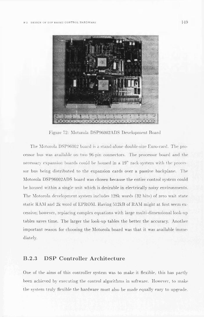
B. 2. D E S I G N O F D S P B A S E D C O N T R O L H A R D W A R E 149
Figure 72: M otorola DSP96002ADS D evelopm ent Board
T he M otorola DSP96002 board is a s tand-a lone double-size Euro-card . T h e p ro
cessor bus was available on two 96-pin connectors. T he processor board and the
necessary expansion boards could be housed in a 19v raek-system with th e p roces
sor bus being d is tr ib u ted to the expansion cards over a passive backplane. The
M otorola DSP96002ADS board was chosen because th e en tire control sys tem could
be housed w ith in a single unit which is desirable in e lectrically noisy env ironm en ts .
T he M otorola developm ent system includes 128k words (32 bits) of zero wait s ta te
s ta t ic R A M and 2 k word of E P R O M . Having 512kB of R A M m igh t a t first seem ex
cessive; however, replacing complex equations w ith large m ulti-d im ensiona l look-up
tab les saves t im e. T he larger the look-up tab les th e b e t te r th e accuracy. A no ther
im p o r ta n t reason for choosing th e M otorola board was th a t it was available im m e
diately.
B .2 .3 D S P C ontrol ler A rc h i te c tu r e
One of the a im s of this controller system was to m ake it flexible, th is has p a r t ly
been achieved by execu ting the control a lgorithm s in software. However, to m ake
the system tru ly flexible the hardw are m ust also be m ade equally easy to upgrade.

150 A P P E N D I X B. D E S I G N O F D S P C O N T R O L L E R A N D I G B T I N V E R T E R
tumsat
Figure 73: DSP96002 Control Unit
T he bes t m e th o d for achieving flexibility is to use a system where all th e system
c om ponen ts th a t are likely to change reside on separa te plug-in boards.
T h e DSP96002AD S board is of a double Euro-card size type, with the processor
buses b rough t ou t on two IEC 603-2 (DIN 41612) 96/96 V M E bus style connectors .
T he controller is thus well su ited for building into a 19” rack system which is fu n d a
m en ta lly based a round th e idea of plug-in m odules. It was decided to use a s ta n d a rd
19” rack of double E uro -card height to house the DSP board and have a passive b ack
plane d is t r ib u t in g the D S P ’s d a ta and address bus to the expansion m odules (Fig.
73). Fig. 71 shows a block d iag ram of the com plete c o n tro l le r / inver te r system . T he
D SP control system is located at th e lower left of the d iag ram , where th e DSP96002
can be seen connected to the expansion cards th rough th e passive backp lane (ca p a
ble of housing 10 expansion cards depend ing on com ponent height). To th e r igh t of
th e D SP board are th e two expansion boards th a t a t p resent m ake up th e control
hardw are . T h e functions of the expansion boards are described in full in sections
B.2.6 and B.2.7.

B. 2. D E S I G N O F D S P B A S E D C O N T R O L H A R D W A R E 151
B .2 .4 D S P 9 6 0 0 2 M e m o r y A rc h i tec tu re
Before describ ing the im p lem en ta t ion of the controller using the DSP96002ADS
developm ent board , the m em ory a rch i tec tu re and bus interfaces of th e DSP96002
chip [44] m ust be exam ined .
From the p ro g ram m er 's point of view there are th ree separa te m em o ry spaces
in the DSP96002. Each m em ory space is 32 bits wide and is addressed using 32-bit
linear addressing. T he first is the P m em ory, w here all p rogram code is s tored . T he
o thers are X and 5’ m em ory, used to store constan ts and variables. X and Y m em ory
can each hold a single-precision floating-point n u m b er in each location. T ogether X
and Y form L mem ory. L m em ory is used to store double-precision floating-point
n um bers or o the r da ta types th a t can be conveniently accessed using a single po in te r
for two da ta i tem s, such as com plex num bers .
M oving to a hardw are des igner’s point of view, th e advan tages of form ing L
m em ory is th a t the processor has two identical 32-bit address and d a ta buses known
as port A and port B. By placing X m em ory on po r t A and Y m em ory on port B
one can fetch two da ta i tem s, using parallel d a ta moves, in just one bus cycle. All
m em ory m ust be m ap p ed e ither to port A or to p o r t B, excep t a small am o u n t th a t
is in ternal R A M /R O M and processor control registers. T h e 4 giga-word of m em ory
for each m em ory space P, X, Y is individually m ap p e d to po r ts A and B on a 512
m ega-word segment basis. This m eans th a t for each space th e re are 8 segm ents
th a t can be m ap p e d to e i the r p o r t A or port B. T h e m ap p in g is controlled th rough
a processor control register located in ternally in the processor a t the top of th e X
m em ory.
T he DSP96002 has th e facility to control th e num ber of wait s ta te s used for
m em ory access, to allow slow m em ory or devices to be used. T h e n u m b er of wait
s ta tes is controlled separa te ly for each port A /B and the m em o ry spaces X / Y / P .
T he nu m b er of wait s ta tes can be individually selected in th e range 0-15.

152 A P P E N D I X B. D E S I G N O F D S P C O N T R O L L E R A N D I G B T I N V E R T E R
B .2 .5 M e m o r y C onfigurat ion & B ackp lan e B u s D es ig n
On a typical m icroprocessor system one expects to find a large range of devices
connected to the processor bus. Some processors such as th e Intel x 8 6 series have
special in s truc t ions to access an I /O m em ory space. T h e DSP96002 does not have
a special m em ory space for I /O devices, so m em ory and I /O devices m ust share th e
sam e m em ory space.
W hen decoding the address lines to select a specific device it m ay be done fully,
in which case the device appears in only one location of the m em ory m ap. To fully
decode an address gives the highest u til isa tion of the m em ory space, b u t m igh t
require a large n u m b er of devices to im plem ent th e decoding circuit which in tu rn
m igh t slow the sys tem down.
A part ia l decoding schem e will result in th e sam e device appear ing in m ult ip le
places in the m em ory m ap . However the part ia l decoding is fast and m akes the
decoding circuit s im pler. Not all devices have the sam e response t im e, so the in
sertion of wait s ta te s is required for slow devices. On m ost processors the insertion
of wait s ta tes is done by having a hardw are w a it-s ta te genera to r which will use the
chip-select lines from the address decoder to ac tiva te th e insertion of wait s ta tes
when accessing slow devices.
As not m an y I /O devices use m ore than 16-bit wide d a ta buses, it is only neces
sary to buffer and b ring the lower 16 b its of th e d a ta bus onto th e backplane.
M em ory M apping and D ecod ing
As th e DSP96002 does not have a special I /O access m ode all I /O devices are
m ap p e d to m em o ry addresses toge the r with R O M and RAM . T he DSP96002ADS
deve lopm ent board has been configured as follows:
2 k word E P R O M : P or t A, P -m em ory , Address FFOOOOOOh-FFFFFFFFh.
32k word R A M : Port B, X-m em ory, Address OOOOOOOOh-lFFFFFFFh.
32k word R A M : P o r t B, Y-m em ory, Address OOOOOOOOh-lFFFFFFFh.

B. 2. D E S I G N O F D S P B A S E D C O N T R O L H A R D W A R E 153
T he m em ory on the DSP96002ADS has been only p a r t ly decoded, so th e con ten t
of the E P R O M and RAM repea ts itself th rough th e assigned m em ory range.
T he I /O devices 011 the expansion bus have been assigned the following m em ory
space
I /O Devices : P o r t A, X-m em ory, Address lOOOOOOOh-FEFFFFFFh.
I /O Devices : Port A, Y-m em ory, Address lOOOOOOOh-FEFFFFFFh.
P ar tia l decoding is used th roughou t the system and th e decoding schem e does
not differentia te between X- and Y -m em ory access. T he devices will be accessed as
X- or Y -m em ory depending on the speed of the device as expla ined in section B.2.5.
T h e address decoding used is as follows:
A31-A28 : Full decoding for board select.
A27-A16 : Not Present on Backplane.
A15-A4 : Pa r tia l decoding for selection of device in board .
A3-A0 : In te rnal register select in device.
T he decoding system requires each expansion board to fully decode th e 4 most
significant address lines as a board select address. Board address # 0 is not used
because this address range is assigned to RA M on po r t B. B oard address # 1 5 is
not used e ithe r since it is p a r t ly reserved for D SP in te rnal control registers. T he
m ax im u m n u m b er of expansion boards is thus 14.
T h e boards are not required to follow any special decoding schem e for the lower
15 address lines. T he following scheme has been used for th e boards m ad e so far and
it is an advan tage to keep as m uch as possible of the bus in terface on th e expansion
cards s im ilar so developm ent t im e is not wasted.
T h e decoding circuit used is shown in principle in Fig. 74, and functions as
follows:
A3-A0 is buffered and fed to any device requiring in ternal register select.

154 A P P E N D I X B. D E S I G N O F D S P C O N T R O L L E R A N D I G B T I N V E R T E R
A15-A4 is used to select the ind iv idual devices in the following way: Each address
line controls a separa te device and is O Red with the active low board select line
giving an ac tive low o u tp u t when th e device is selected. Using th is schem e th e
m ax im u m n u m b er of devices pe r board is 12. T h is is qu ite economical as each
add it iona l device only requires an OR ga te to be added to the decoding logic. It is
not envisaged th a t th e m ax im u m n u m b er of 1 2 devices per expansion board will be
a l im ita tion .
A31-A26 is com pared with the D IP-sw itch se tt ing and genera tes a board select
signal.
I /O D ev ice A ccess T im ing
T he DSP96002 does not support a hardw are w a it-s ta te genera to r , b u t allow software
to set th e n u m b er of wait s ta tes on a pe r-po r t and m em ory-space basis. O ne could
get away with accessing all devices a t the speed required by th e slowest device,
however th is wastes t im e if large am o u n ts of d a ta are to be read from fast devices.
To ensu re m ax im u m perfo rm ance this system has a fast and a slow access m ode for
I/O devices.
To achieve th is all X and V m em ory RA M on the DSP96002ADS is configured
to be on port B. All P m em ory is m ap p e d to port A. All I/O devices are accessed
th rough por t A as X or Y m em ory.
To ensure m ax im u m program perfo rm ance the 25ns s ta t ic -R A M port A P-
m em ory , and po r t B X- and Y -m em ory are accessed using zero wait s ta tes. To get
the m a x im u m perfo rm ance from fast devices po r t A Y -m em ory is set p rog ram m ed
to 2 w ait s ta tes . T h is gives an access t im e of 90ns which is equivalent to a bus speed
of 10MHz. To access a device using th is speed it should be read from or w r i t te n to
as Y -m em ory.
T h e slow devices which would not be able to respond to the fast 2 -w ait-s ta te
access of Y -m em ory can be accessed as port A X-m em ory. T he p o r t A X -m em ory
has been p ro g ra m m e d to use 5 wait s ta tes . This gives an access t im e of 180ns which

B. 2. D E S I G N O F D S P B A S E D C O N T R O L H A R D W A R E 155
GND
Card Address Select
S1
0001
0 30 4
■[ W R' >
GNO H GNO h- GNO t - GND h-
GNDvcc
1A1 1A2 1 A3 1A42A12A22A32A4
1Y2 1Y3 1Y4 2Y1 2Y2 2Y3 2Y4
[ aD < 6 -1 5 ~
csr >CARO SEL ' >
L' > C; > -
CS2- >
• OcO-7>
CARD SEL
A1 B1A2 B2A3 B3A4 B4AS B5A6 B6A7 B7AS BS
GDIR
Note:aTS* = DSP Transfer Strobea(A,D)x = Backplane signal {Address, Data} unbuffered a{A,D}Bx = Backplane signal {Address, Data) buffered All logic Motorola FAST
I aA<15> p resto' >
Figure 74: P ar tia l-D ecod ing and Buffer C ircu it used on Expansion Boards (ex trac t)
156 A P P E N D I X B D E S I G N O F D S P C O N T R O L L E R A N D 1 G BT I N V E R T E R
is equivalent to a bus speed of 5.56M Hz. An access speed of 5.56MHz is a lm ost
universally accep tab le to any I /O devices, except for very old devices.
This configuration of m em ory and assigning of wait s ta tes is in tended to give
good I /O p erfo rm ance and near o p t im u m program execution. T he only com prom ise
on p rogram perfo rm ance is th a t X- and Y -m em ory reside on th e sam e por t. This
m eans th a t any L m em ory access and parallel d a ta moves will take two m em ory
access cycles instead of one. How m an y L m em ory accesses or parallel d a ta moves
th a t are used in a p rogram depends on how the p rogram was genera ted . H and
w ritten highly op tim ised assem bly code tends to use m ore parallel d a ta moves th an
compiler genera ted code. T he controller is in tended to be p rog ram m ed in a high
level language and so th e pe rfo rm ance im p ac t, due to X- and Y -m em ory being 011
the sam e po r t , m igh t not be noticeable. If the DSP96002 had allowed wait s ta tes
to be assigned on the sam e basis as m em ory is m ap p e d to specific po r ts the system
could have been designed w ithou t any perfo rm ance com prom ises.
D S P 9 6 0 0 2 A D S D evelop m en t S ystem Im p lem en tation Issues
T he M otorola DSP96002AD S app lica tion developm ent system board is connected
to a P C using a M otorola p rop rie ta ry in terface board in th e PC . Using the supplied
d e b u g /m o n i to r p rogram 96002 code can be downloaded from the P C to th e DSP.
T he m on ito r p rogram can also be used to en te r p rogram s s tra igh t into the DSP for
tes t purposes.
T he D SP is configured to boot (s ta r t a fter reset) from P m em ory address
F F F F F F F E h on po r t A, which is m ap p e d to the E P R O M mem ory. As supplied
the E P R O M s are b lank and will m ost likely^ genera te an illegal in s truction in te r
rup t. T he in te r ru p t vectors are located at the beginning of the RA M s ta r t in g at
OOOOOOOOh. At power-up these locations will contain random d a ta causing random
code to be executed .
N orm ally th e D SP will be ha lted from the P C using the debug interface, at
th is po in t and code is downloaded an executed . This m ight be sufficient if th e

B. 2 D E S I G N O F D S P B A S E D C O N T R O L H A R D W A R E 157
board is used only for eva lua ting code; however, we cannot have a system th a t
controls power electronics s ta r t execu ting random instructions . T h e consequence of
execu ting random code can have qu ite dangerous effects if connected to an energised
drive system .
Clearly the E P R O M s m ust be p rog ram m ed to avoid executing random code. T he
E P R O M s th a t cam e with the developm ent system where 35ns u l tra fast E P R O M s
so th a t code could be executed from th e E P R O M s with zero wait s ta tes . T he
facility for p rogram m ing special devices like these were not available so th e special
35ns E P R O M s were replaced w ith s tan d a rd 150ns E P R O M s. This can be done since
a fter a reset the DSP is runn ing as default w ith 15 wait s ta tes and the m em ory cycle
t im e of the processor becomes -180ns. T he 150ns E P R O M s are thus fast enough for
execu ting the code at s ta r tu p . However, when runn ing with zero wait s ta tes the
E P R O M s are no longer readab le as they would be accessed using a cycle t im e of
30ns which is well beyond their capability.
To achieve the m ax im um perfo rm ance p rogram s should be execu ted from m e m
ory with zero wait s ta tes , hence the E P R O M s cannot be used to s tore the m ain
program . Instead the program is downloaded after each pow er-up from the PC .
This m ethod of working gives a short developm ent cycle since there is no need to
bu rn new E P R O M s for each revision of the control p rogram . C learly th is is not
su itab le for a p ro d u c t th a t is to be pu t in p roduction , bu t it works well in a research
env ironm en t.
T he boot R O M s are w ri t ten so th a t they contain only enough code to take the
developm ent board into a known s ta te at power-up w ithou t affecting the subsequen t
execution of th e control program ; hence they need not be rep ro g ram m ed w ith each
new revision of the control p rogram . T he expansion boards should be designed such
th a t they en te r a “safe” s ta te after reset or power-up. Once board-in it ia l isa tion
code in the E P R O M s has execu ted the D SP goes in to an endless do -no th ing loop
and s tays in the loop until th e processor is ha lted by th e P C and a p rogram is
dow nloaded in to RA M and set to execute. T h e in itia lisa tion code is shown in Fig.
75, and its opera tion is explained below.

158 A P P E N D I X B D E S I G N O F D S P C O N T R O L L E R A N D I G B T I N V E R T E R
1 ; B00TR0M.ASM2 ; Programs DSP96002ADS to map memory to correct ports3 ; Version 1.04 org pa:$fffffffe ;Reset Vector Address5 jmp boot-start ;Jump to Boot Routine6 org pa:$ffffe000 ;Start of EPROM7 boot-start reset ;Reset all on chip Peripherals8 ;and Interrupt Mask Registers9 move #$00010100,d0.1 ;Map Addresses to Physical Memory Port10 move d O .1,x :$fffffffc ;Write to Port Select Register11 lol jmp lol ;Wait here until Host takes Control
Figure 75: DSP96002ADS Boot E P R O M Assem bly Listing
Lines 4 and 5 set the reset vector to point to the s ta r t of th e E P R O M .
Line 7 resets all th e in ternal periphera l devices and in te r ru p t m ask registers in
the DSP96002.
T he m ost im p o r ta n t lines are 9 and 10; here the DSP is p rog ram m ed to m ap X
and Y m em ory in th e range 00000000h-l F F F F F F F h to p o r t B. If th is was not done,
d a ta downloaded from th e host to X or Y m em ory would be w ritten to non-exis ten t
m em ory on port A.
Line 1 1 is an infinite loop w here th e processor waits for the host co m p u te r (P C )
s ta r t downloading the control program . T he processor is ha lted th rough the O N C E
(on-chip-em ula tor) debugging in terface by the host com pute r . T he O N C E can com
plete ly control the opera t ion of the processor. The control program is downloaded
th rough the O N C E interface. Once th e control program is downloaded the proces
sors in s truc t ion po in te r register is set to the s ta r t of the control p rogram , and the
processor released.
Backplane Im plem entation Issues
T h e DSP96002ADS m akes the address- and da ta -bus available on two IEC 603-
2 (DIN 41612) 96/96 connectors. T h e connector signal layout p a r t ly follows the
V M E bus layout; however it differs in a few im p o r ta n t places. In p a r t icu la r some
of the da ta - and address-bus signals use V M E bus signal lines not in tended to carry

B. 2. D E S I G N O F D S P B A S E D C O N T R O L H A R D W A R E 159
high-frequency signals. This m akes it impossible to connect the DSP96002ADS
direc tly to an “off the sh e lf ' V M E b u s backplane.
Since a s ta n d a rd V M E bus backp lane was not su itab le , two u n c o m m it ted BICC-
Vero backplanes were purchased . T he backplanes had room for 10 IEC 603-2 (DIN
41612) 96/96 connectors each giving a m ax im u m nu m b er of expansion cards of 9;
however, the ac tual num ber of expansion boards will depend on the height of the
ind iv idual boards.
To test th e DSP and backp lane a small tes t p rogram was executed; however
when th e D SP was connected to the backp lane the DSP would no longer execute
the program correctly. T he p rogram would execu te correctly when s ingled-stepped,
and by tr ia l-and-erro r it was found tha t the DSP would only run when all m em ory
access was slowed down with 4 wait s ta tes.
It was clearly unaccep tab le to run th e control p rogram with 4 wait s ta tes . By
exam in ing the da ta -bus with an oscilloscope it was found th a t the backp lane ca-
pacitive ly loaded the signal lines too much giving long rise- and fall-times. After
looking at the DSP96002ADS circu it d iagram s it becam e clear th a t th e address- and
d a ta -b u s were connected s tra igh t from the DSP96002 to the backp lane connectors.
T h e re were buffers on the DSP96002ADS but u n fo r tuna te ly these only buffered the
on-board m em ory. It seems a bit odd th a t M otoro la would m ake a system th a t is so
obviously suited to be plugged s tra igh t into a backp lane but not buffering the bus
going to the connectors when th e DSP96002 itself can only drive two T T L loads.
Having identified why th e D SP would not run when connected to th e backplane
th e solution was clearly to insert some form of bus buffers. Ideally th e best solution
would be to m ake a new C P U board with buffers on board . However th is was not
a p rac tica l solution in this case as su itab le m ultilayer P C B m ak ing facilities were
no t available. A no ther solution would be to m ake an active backp lane with built-
in buffers. This still involves m ak ing a m ulti- layer P C B and is not an acceptab le
solution. T he solution th a t was decided on was to m ake and insert a small bus-
buffer board betw een the DSP96002 connector and th e backp lane connector. An
u n fo r tu n a te consequence of inserting the board is th a t th e D SP board now p ro trudes

160 A P P E N D I X B D E S I G N O F D S P C O N T R O L L E R A N D I G B T I N V E R T E R
NoteaA O -31. port A a d d re s s bos aDO-31 * port A d a ta bus aT S - Port A T ransfer Strobe aS 1 - P or X/Y m em ory se lec t aFV W « port A read /w n te s e lec t
I *vw-
Figure 76: Port A Bus-Buffer C ircuit
abou t 1 cm ou tside th e sub-rack m aking it im possible to fit a flush front-panel. T he
DSP board fo rtuna te ly does not p ro tru d e ou tside the m ain-rack.
Since only D SP port A is used to com m un ica te with th e I /O devices it was only
necessary to buffer th is port. On port B only four signals needed to be brought
th rough to th e backplane: the th ree in te r ru p t lines and th e reset line. T he in te r ru p t
lines are inpu ts and th e reset line is well buffered already. T he board betw een po r t
B and th e backp lane only serves as a connection board for 4 signal lines (irqa, irqb,
irqc and reset). T he buffers on port A use M otorola 74F241 and 74F245 FA ST
bus-driver ICs, capab le of sinking 48mA and sourcing 15mA, m ak ing them su itab le
for driv ing capacitive loads such as backplanes. T he delay in these buffers is in the
order of 3-5ns. T he d a ta -bus buffers only t ra n sm it X and Y m em ory accesses to
th e backp lane , since th is is w ha t is needed for access to the I /O devices, reducing
the backp lane activity . This helps to reduce rad ia ted e lec tro -m agnetic noise which
m igh t affect a n a log circuitry.
Having inserted the bus-buffer board (Fig. 76) the DSP could now execu te the
tes t p rog ram successfully with zero wait s ta tes , showing th a t th e buffer board does
not in troduce excessive load, crosstalk or ringing on th e DSP board .
T h e bus buffer board did not solve all p roblem s. W rong values would som etim es

B 2 D E S I G N O F D S P B A S E D C O N T R O L H A R D W A R E 161
be read from or w ritten to I /O devices. Spurious accesses to devices would also
in te rm i t te n t ly be generated .
E xam in ing the data- and address-bus on the backp lane it was found th a t there
was severe ringing on the signal lines, th e signal could go as high as 8 V and as low as
-2V. T he ringing was found to last for m ore th a n 40ns. This ringing would cause the
address decoders to glitch the chip-select signals to random devices. T he “Transfer
S trobe (T S ) r signal from the D SP signals th a t d a ta and address lines are s table ,
and goes active 15ns after th e da ta - and address-buses are applied. Ringing will
thus still be going on when the bus is signalled as stable. T h is p rob lem m igh t not
affect slower devices, but fast devices m igh t easily be triggered by the ringing. T he
digital o u tp u t (on board # 2 ) consists of 74F 174 D-flip-flops and is a p r im e exam ple
of a fast device. T he 74F174 can react to a pulse of 4ns w id th or less. T he 74F174
would latch random da ta th rough during th e t im e when the address- and da ta -bus
was still ringing. This problem was first noticed because serial com m unica tions
would stop working when th e digital o u tp u t was accessed. T h e cause was found to
be th a t random da ta on the digital o u tp u ts would reset the serial-chip because the
serial-chip reset is controlled by one of d ig ital o u tp u ts .
At first it was a t te m p te d to te rm in a te the bus w ith s ta n d a rd 220R /330R resistor
networks. T h is reduced the spikes bu t did no t solve all the problem s. It was noticed
th a t th e boards would behave differently if th e select address was m ostly ‘l ’s or ‘0 ’s
fro m when it was m ostly a m ix. This ind ica ted th a t there were also p roblem s with
t ran s it ions from one line affecting ad jacen t signal lines, known as crosstalk between
th e lines. An experim en t was carried ou t on the backplane. Rows a and c on the
backp lane was connected to 0V giving g round tracks betw een each of th e row b signal
lines. A s ta n d a rd T T L square wave was applied to one of the row b signal line and
a oscilloscope was connected to an ad jacen t row b signal line which was pulled-up to
5V th rough a 1.5kD resistor. On the ad jacen t t rack positive and negative spikes of
a lm ost IV were recorded a t the edge of each square wave. This is a a cross coupling
of abou t 2 0 %, far in excess of w hat is to le rab le when considering th a t th e noise
m argin of T T L logic is only 0.4V. T he p rob lem will be worse on th e lines driven by

162 A P P E N D I X B D E S I G N O F D S P C O N T R O L L E R A N D I G B T I N V E R T E R
th e 74F241 and 74F245 buffer c ircuits since the crosstalk is dependen t on the rise
and fall t im e of th e signals. FA ST T T L has a rise t im e of 2ns versus norm al T T L 's
6 ns, thus using FA ST T T L increases the crosstalk.
T h e re is no t m uch th a t can be done with crosstalk except for slowing down the
edges, no t really an option in a 33.3MHz system . T he only prac tica l solution was
to go for a b e t te r designed backplane. An u n c o m m it ted backp lane of the desired
qua li ty was no t ob ta inab le , so th e 5 layer BICC-V ero V M E bus backplane origi
nally considered was ob ta ined . This backplane is t e rm in a te d 330R /470R and has a
p a te n te d system of m icro str ip signal guard tracks betw een the signal tracks. These
guard tracks form OV loops a round each signal line. T he original choice of the u n
c o m m it te d backp lane was m ade before it was realised th a t a bus-buffer board had
to be in ser ted betw een the DSP and the backplane. W ith the bus-buffer board in
place th e re-assignm ents of the signal lines to avoid V M E bus signal lines not in
ten d ed for high speed signals could easily be im p lem en ted . If a bus-buffer board
was not needed this re-assignm ent would have resu lted in an ex tra pa tch board ,
which a t th e t im e was undesirable . T he cost (T‘250) of th e V M E bus backp lane was
also th o u g h t excessive a t the t im e com pared to the u n c o m m it ted backplane (£ 4 8 ) .
T he new backp lane solved the problem s of ringing and crosstalk. It was found th a t
th e m a x im u m bus-speed for the fast devices was an accep tab le 10MHz. This speed
com pares well w ith the 8 MHz bus speed used in PCs. To save cost only one of the
backp lanes were changed to the V M E bus type. T he o the r backplane, which only
carries th e in te r ru p t and reset lines, still uses th e old ty p e backplane. T here is how
ever a l im ita tio n in t h a t only one of the th ree in te r ru p ts m ay be in use, o therw ise
false in te r ru p ts m ay be produced due to crosstalk.
B .2 .6 E x p a n s io n Board # 1
T he function perfo rm ed on this board is to acquire the analog inpu t signals using
analog to digital converters. T he board has 6 analog inpu ts a t 12 b its resolution.
T h e ro to r position is m easu red using a resolver to d igital converter.

B. 2. D E S I G N O F D S P B A S E D C O N T R O L H A R D W A R E 163
V.
Figure 77: In terface B o a r d # 1 : A D C s,T im er , Resolver Interface.
T h e card can be m apped in to m em ory a t any of the 14 available address ranges.
The devices on this board in terface to the backp lane th rough a set of b i-d irec tional
d a ta buffers (Fig. 74). T he buffers are placed close to th e backp lane connecto r
to m in im ise capacitive loading on th e backp lane and reduce th e possibilities for
crosstalk.
T he expansion board has been m ade using th e speedw ire system . Speedw ire is
significantly faster and m ore com pact th an wire-wrap. Speedwire boards fea tu re a
ground p lane which reduces “ground bounce ,? by reducing the ground re tu rn p a th
im pedance . T h e signal wires run close to the g round-p lane giving a m ore controlled
im pedance on th e signal lines th an for wire-wrap or s im ple double-layer P C B s. W hen
using speedw ire a t te n t io n m ust be paid not to use long parallel runs of wires in close
proxim ity , o therw ise there is a strong possibility of crosstalk.

164 A P P E N D I X B D E S I G N O F D S P C O N T R O L L E R A N D I G B T I N V E R T E R
Analog to D igita l Converters
To chose a su itab le analog to digital converter (ADC) the app lication requ irem en ts
had to be considered. T h is application requires accu ra te m easu rem en t of th e analog
values of th e respective curren ts and voltages. To define “ac c u ra te ” is no t easy, b u t
generally it is considered sufficient to have a resolution of 1 0 b its or m ore.
T he sam pling speed of the ADCs is also im p o r ta n t . T he m ax im u m sam pling
speed of m ost ADCs is around JCtOkHz. Flash converters have m uch g rea te r speed,
b u t m ost are l im ited to 8 b its resolution. For typical m o to r app lications th e control
frequency is a round 5kHz; however, if m ore than one sam ple can be ob ta ined during
a control in terval these can be averaged or digitally filtered to ob ta in a cleaner signal.
Special features m ust also be taken into account, for exam ple, th re e -s ta te m i
croprocessor interface, fast microprocessor interface for DSP app lica tions, or o ther
special features. W h en looking for a su itab le ADC the Analog Devices AD1332 was
found to have some very in teresting features. T he AD1332 has a reso lu tion of 12
bit, m ean ing th a t a signal can be resolved into 1 p a rt in 4096 ( ± 1 / 2 LSB). This s a t
isfies the need for accuracy. T he m ax im um sam pling ra te of the AD1332 is 125kHz,
satisfying th e sam pling ra te requirem ent.
W h a t really d istinguished this ADC from the rest was definitely th e special
features:
1 . T h e AD1332 has on-board anti-aliasing filters which can easily be tuned with
ex te rna l capacitors , m aking ex te rnal anti-aliasing filters unnecessary.
2. T h e chip has a 12-bit wide fast D S P /m icroprocesso r interface, m ak ing retrieval
of sam pled values quick.
3. T h e AD1332 is capable of a m as te r /s la v e configuration in which one m as te r
controls th e sam pling of o ther AD 1332s. This ensures synchronous sam pling
on all channels.
4. T h e best fea tu re of the AD1332 is the buffering of sam pled values. T h e AD 1332
is capab le of s toring 32 samples in a F irs t- In -F irs t-O u t buffer on th e chip before

B. 2. D E S I G N O F D S P B A S E D C O N T R O L H A R D W A R E 165
it has to be read by the DSP. T he AD1332 can c rea te an in te r ru p t on e ithe r full
or half-full buffer. This m eans th a t the associated in te r ru p t overhead in the
DSP can be reduced by a factor of 32 or 16 respectively. T he half-full in te r ru p t
has its advantages as th e in te r ru p t la tency ( t im e taken from an in te r ru p t is
genera ted until it is serviced) can be g rea te r since the re is no danger of buffer
overflow or d a ta overrun. T he A D I 332 can also be used in a s ta n d a rd one-
in te r ru p t per sam ple mode.
T h e AD 1332 was chosen on the m erit of its special fea tures listed above. In
p a r t icu la r since on a DSP96002 th e in te r ru p t overhead can be as m uch as 5 //s if
a full con tex t switch has to be perform ed. (A full context switch being defined as
preserv ing all registers and switching stacks.) T he t im e saved per control interval
by using th e buffered m ode can thus be as m uch as 160/xs or 80/is depend ing on
w he the r full or half-full in te r ru p t is used. It was chosen to have 6 A D Cs in the
system . Having 6 ADCs should cover m ost configurations typical for AC m otor
applications. W ith 6 AD Cs all voltages and cu rren ts of a th ree -phase m o to r could
be m on ito red . A no ther possibility is to use 2 to m on ito r th e cu rren t vector and 2
for th e flux-linkage vector leaving two spare for o ther control inpu ts , for exam ple
speed from tacho-genera to r and desired speed.
T h e input range of th e AD 1332 was set to ± 5 V , which produces an offset na tu ra l
b inary o u tp u t . T he A D l332s are all connected toge the r w ith one as m aste r . This
ensure th a t all samples are taken at the sam e in s tan t . T he sam ple ra te is controlled
by an i8254 16-bit p rog ram m ab le t im er. T he AD1332 has an in ternal divide-by-20
circuit and th e i8254 is clocked by a 10MHz crysta l oscillator. T h e sam ple ra te is
thus ad ju s tab le in the range 7.7Hz to the m ax im u m sam ple ra te of 125kHz in steps
of 7.7Hz. T h e re is however a lim it on the lower sam pling ra te set by how m uch the
in te rnal sam ple and hold amplifier can be allowed to droop during th e conversion.
T he m an u fa c tu re r 's recom m ended m in im u m is 20kHz.
T h e m as te r AD 1332 is connected to th e DSP96002 in te r ru p t C. th is in te r ru p t
can be triggered e ither a t the com pletion of each conversion or a t full or half-full
buffer. T he A D I 332 is accessed using the backplanes fast m ode which m eans th a t

166 A P P E N D I X B D E S I G N O F D S P C O N T R O L L E R A N D I G B T I N V E R T E R
each d a ta poin t can be read in ju s t 90ns. If the ADCs are used in half-full buffer
m ode and all th e 6 AD Cs are in use it will take only 23//s to re tr ieve the 96 d a ta
points. No p rob lem s were encoun tered during deve lopm ent using the AD1332.
R otor P osit ion M easurem ent
T he position of th e ro to r is im p o r ta n t if vector based control is to be used. T he
accuracy of th e m easu red ro to r position can influence the pe rfo rm ance of the control.
G enerally a resolution of 1000 per revolution is considered sufficient.
To m easu re the ro to r position there is a choice betw een optical increm ental
encoders, op tical abso lu te encoders and resolvers. T he increm enta l optical encoder
was no t used because on power-up the ro tor position can not be de te rm ined . T he
abso lu te optical encoder has its d isadvantage in th e nu m b er of signal lines used if
it is a parallel device. O ptica l encoders in general are fragile using e ithe r glass or
th in m eta l disks. O ptical encoders also tend to use T T L level signals m ak ing them
susceptib le to electrical noise.
A resolver was chosen as these devices are m ore rugged th an an optical encoder,
and give abso lu te position with only 6 wires. Resolvers also use balanced signals
giving th em increased noise im m unity . T he opera tion of a resolver is qu ite simple:
a sine wave is applied to a wound ro to r th rough a ro ta t in g transfo rm er. T here are
two coils p laced p e rpend icu la r to each o ther on the s ta to r . These coils produce
voltages p roport iona l to cosa and s in a respectively, w here a is th e angle rela tive to
th e position of th e first coil. T h e cosa and s ina signals are converted into a digital
position signal using a resolver to digital converter (R D C ).
T he R D C used in th is design is the tried and proven A D 2 SS0 A R D C from Analog
Devices. T he AD2SS0A can be p rogram m ed to p roduce an accuracy of 10, 12, 14 or
16 bits. T h e m ax im u m speed is a function of the accuracy selected. T he AD2S80A
was set to 1 0 -b its as this is a c cu ra te enough for m ost applications, giving a m ax im um
speed of 1020rps according to th e m a n u fa c tu re r ’s d a ta for a 5.6kHz sine wave source.
T he AD2S80A uses a ra t io -m etr ic m eth o d for de te rm in ing the position; however the

B. 2. D E S I G N O F D S P B A S E D C O N T R O L H A R D W A R E 167
overall accuracy depends on the m ag n i tu d e of the signals being as close to 2 Vrm s as
possible. T he accuracy is also best if a harm onic-free sinusoidal oscillator is used,
such as the Analog Devices OSC1758. T he OSC1758 is capab le of driving a resolver,
and was set to p roduce a 5.6kIIz sine wave. T h e frequency was chosen such th a t the
frequency is still w ith in the opera t ing range of the resolver and a t th e sam e t im e high
enough to ope ra te the AD2S80A at the m ax im u m opera t ing speed. T he AD2S80A
is a track ing device and can p roduce a result 2/zs after it is requested . Even if this
position is locked until a new conversion is s ta r te d , the device will con tinue to track
the ro to r position in the background. This device is accessed using the slow bus
m ode, and 110 problem s were encountered using it.
B .2 .7 E xp an s ion Board # 2
This board provides analog rea l-t im e o u tp u t , serial com m unica tion , general digital
I/O and a specialised power inverter drive interface. T he general descrip tion of the
expansion board is the sam e as for expansion board # 1 , as they bo th use th e same
bus in terface circuit design (section B.2.6). Following below is a descrip tion of how
the functions have been im plem ented .
Digital to A nalog Converters
T he controller has four digital to analog converters. These converters are used to
m o n ito r in ternal program variables in real t im e. Variables th a t are com m only o u tp u t
th rough these devices are: z9, speed, to rque and p rogram s ta tu s . T h e program
s ta tu s can be used as a simple profiler to d e te rm in e “hot sp o ts” in th e program .
T h e DACs can also be used to control ex te rnal analog devices; for exam ple , an
ex te rna l analog cu rren t controller could be im p lem en ted . T h e D SP would o u tp u t
desired cu rren t m ag n i tu d e and angle. T he ex te rnal analog circuit would do the
ac tua l cu rren t control and control the switching of the transis to rs .
Analog Devices AD767 analog to digital converters were chosen. These devices
can p roduce an o u tp u t of ± 5 V with an accuracy of 1 2 b its from a offset na tu ra l

168 A P P E N D I X B. D E S I G N O F D S P C O N T R O L L E R A N D I G B T I N V E R T E R
Figure 78: In terface b o a rd # 2 : D A C s,T im ers , Serial I /O , Digital I /O and Inverter op tica l I /O .
b inary in pu t. T h is m atches th e charac te r is t ic of the DACs. A problem was e ncoun
tered using these devices, because the chip ac ts as a t ra n sp a re n t latch . W hen the
chip is selected slight ringing on the da ta bus during th e first ns after th e devices
were selected som etim es caused th e devices to p roduce a very short o u tp u t glitch
before se tt l ing a t th e desired value. To solve th is prob lem th e falling edge of the
select pulse to th e devices were delayed to ensure th a t th e d a ta bus was s tab le before
th e d ig ita l d a ta was ga ted th rough to the analog o u tp u t .
Serial Interface
A serial in terface is inco rpora ted in to the design. T he serial in terface is used during
deve lopm en t for debugging, and can be used to send com m ands during opera t ion and
B. 2. D E S I G N O F D S P B A S E D C O N T R O L H A R D W A R E 169
to re tr ieve s ta tu s inform ation from the controller. T he serial in terface is im plem ented
using an Intel i8251 universal asynchronous receiver and t r a n s m i t te r (U A R T).
T h e i8251 requires two clock signals: the first is the baud ra te clock and the
second is th e system clock. T h e C P U s th a t were around when the i8251 was designed
used clock frequencies around 5M Hz and the sys tem clock was the sam e as the C P U
clock. T he iS251 is an old device and cannot hand le the fast bus m ode, b u t works
fine with th e slow bus m ode. An artificial 5M Hz system clock is provided by one of
th e 16-bit t im ers in an iS254. T he baud ra te is controlled by an o th e r of th e th ree
16-bit t im ers in the i8254. T h is system can p roduce m ost s ta n d a rd baud rates from
a 10MHz crys ta l, and is typically used at 9600bps.
To convert between the iS251’s T T L level and RS232-C level signals a M axim
M AX233 chip is used. This chip only requires a 5V supply as it has on-board
charge-pum ps and capacitors to genera te ± 9 V exceeding the ± 7 volts called for in
the RS232-C s ta n d a rd by 2 volts.
Digital I /O
T he sys tem has one 16-bit digital inpu t and one 16-bit digital o u tp u t . T h e digital
inpu t is im p lem en ted using two 74F244 gated latches. T h e digital o u tp u t is im p le
m en ted using th ree 74F 174 D -type flip-flops. T hese devices are accessed using the
fast bus access mode.
This s im ple im p lem en ta t ion was chosen in preference to m ore advanced solutions
using p ro g ra m m a b le I /O devices because it was desirable to have th e I /O as fast as
possible. T h e digital I /O was also only in tended for controlling in te rna l controller
I /O devices, no t as a general interface port. T h e I /O is d is t r ib u ted betw een the
expansion boards using a ribbon-cable . At present 3 (2 free) in p u t and 3 (2 free)
o u tp u t b its are d is tr ib u ted over the cable w ith th e option of add ing two m ore signals.
T h e o u tp u t s ta tu s cannot be re tr ieved from th e digital o u tp u t as can be done
from p ro g ra m m a b le I /O devices. T h is m eans th a t it is necessary to keep a copy
of th e digital o u tp u t s ta tu s in mem ory. To keep the in tegrity of th is system the

170 A P P E N D I X B D E S I G N O F D S P C O N T R O L L E R A N D I G B T I N V E R T E R
copy of th e digital o u tp u t shouM be read, m odified, w ritten back into m em ory and
to the digital o u tp u t w ithou t in terruption . This m u s t be taken care of in software,
m ak ing it slightly m ore difficuh com pared to using a p ro g ram m ab le I /O devices
and a processor th a t su ppo rts read-modify-write . T h e DSP96002 does not suppo rt
general read-m odify -w rite so using p rog ram m ab le I /O would not have given any
advantages.
Inverter Drive Interface
This c ircuit norm ally interfaces directly to the power inverter and directly controls
the switching of the inverter phaselegs. T he in terface has four fibre-optic o u tp u ts
t h a t connect the controller to the power electronics. O ptica l fibre have been used
as these signals has to be sent a considerable d is tance in an e lectrically noisy envi
ronm en t. If electrical signals were used the re would be a real risk of them picking
up e lec tro -m agnetic noise, which could cause undesired sw itching of th e inverter
transis to rs . O ptical fibres are totally im m une to e lec tro -m agnetic fields and so any
possibility of the inver ter switching due to noise pick-up has been removed.
T h ree of the o u tp u ts are used to control th e s ta te of the ind iv idual phaselegs.
If the o u tp u t is t ra n s m i t t in g light the uppe r t ran s is to r in a phaseleg will be tu rn e d
on, if not the lower will be tu rned on. T he last o u tp u t is used to disable or enable
all of th e tran s is to rs in all of the phaselegs: th is is done so th a t the DC-link voltage
can be rem oved from th e m o to r (by the high im pedance s ta te of th e transis to rs) .
On power-up and after a reset all the o u tp u ts are reset, d isabling the phaselegs to
ensure th a t th e m o to r is no t energised before the control software has been loaded.
T he circuit which drives the th ree phaseleg control optical o u tp u ts can op e ra te
in th ree m odes, depend ing on w hat type of control is being executed . Fig. 79
shows a discrete-logic version of one phase of the phaseleg control circuit which is
im p lem en ted in a PAL. T h e function of the m odes will be described, b u t the ac tua l
p rog ram m ing sequence will not. T he possible m odes are:
1 . Direct drive: T he s ta te of each of the optical o u tp u ts is d irec tly controlled

B. 2 . D E S I G N O F D S P B A S E D C O N T R O L H A R D W A R E 171
IMOOE >
I GATE >
Figure 79: Phaseleg T im ing Control Circuit
T
*0 t1 l0 t1 l0 t1
Figure 80: Sw itching P a t te rn In P ro g ra m m a b le T im e r M ode,
from the DSP. This is s im ilar to using a no rm al digital latch.
2 . P ro g ra m m a b le Frequency: Each o u tp u t can be p rog ram m ed to o u tp u t a fixed
f requency pulse. This m ode can be used to clock ex te rnal control circuits . In
th is m ode th e interface is not connected d irectly to the power inverter , bu t
m igh t be used to drive a sine wave genera tor.
3. P ro g ra m m a b le T im er Switching: In this m ode the c ircuit is p ro g ra m m e d once
per control interval T. T he initial s ta tes of the phaselegs are set when pro
g ram m in g the circuit. T he phaselegs can also be p ro g ram m ed to change s ta te
a t t im e {t0a, t 0 6 , t 0c} respectively after th e s ta r t of th e in terval, as i l lu s tra ted
in Fig. 80.
W h en the th ree o u tp u ts are com bined, this c ircuit can genera te a m a x im u m of 4
different s ta tes during the control in terval T. N orm ally the re is only need for th ree
different s ta tes during a control interval. T he prac tica l use of this c ircu it by control
software is covered in chap te r 2.6 W ith o u t this c ircuit th e processor would e ither
have to poll a t im er at regular intervals or use an in te r ru p t to u p d a te th e phaseleg

17*2 A P P E N D I X B. D E S I G N O F D S P C O N T R O L L E R A N D 1 G B T I N V E R T E R
s ta tes du r ing th e control interval, w asting valuable processor t im e. At the s ta r t of
a control in terval the initial s ta tes of the phaselegs will be set. Each phaseleg can
then change its s ta te once during the control interval using a J8254 t im er . T he iS254
contains 3 ind iv idual t im ers which can be p rog ram m ed to change the s ta te of an
optical o u tp u t to w ith in 2 0 0 ns of th e desired sw itching tim e.
B .3 O p eration o f Pow er Inverter
This section describes the opera tion of th e power inverter . P e te r Miller designed and
built th e power inverter , and a lthough it was not designed by m yself this section has
been included for com pleteness as the power electronics forms an significant p a r t of
the system .
T he inver te r is the part of the system th a t converts the control signals in to ac tual
voltage or c u rre n t applied to the m otor. T he inverter shown in Fig. 81 is a voltage
source inverter , in which the constan t source voltage is app rox im ated by a large
capacito r supplied from rectified 3-ph 415V m ains. T he m oto r phases are applied
e ither a co n s tan t positive or negative voltage th rough the inverter switches. M odern
inverters in th e kW range often switch between the two voltages a t ra tes of 2-50kHz,
th e higher th e frequency the less cu rren t and to rque ripple. U ltrasonic sw itching
frequency also reduces audib le noise. The applied voltage is averaged over t im e , and
if the correct firing pulses are applied to the 6 t rans is to rs a sinusoidal cu rren t can
be achieved.
T he inver ter specifications are:
Continuous o u tp u t power
AC inpu t power (m ax)
O u tp u t voltage
O u tp u t C u rren t
Max sw itching frequency
Power devices
lOkVA
Three-phase 415V 50Hz
D epends on Control A lgorithm
1 0 A rm s, 50Apeak
10kHz
3 IG B T m odules

B. 3 . O P E R A T I O N O F P O W E R I N V E R T E R 173
Soff-SlartDC Link
CapacitanceThree-Phase
RectifierThree-Phase
Inverter
3-phinput Dump
Transistor
Phase A Drive Phase B Drive Phase C Drive Enable Inverter Inverter Fault
Protection Circuitry and Base Drives
Phase A Current ■+ Phase B Current •# Phase C Current DC Link Voltage ♦ DC Link Current
Neutral - Resistive-Neutral Voltage
Main Control Board
Three-PhaseMotor
Figure 81: Power Inverter Overview
(1200V, 50A)
Regenera tive Power : 25Apeak @ DC-link voltage
(continuous, with ex te rna l load)
P ro tec t ion : Over C urren t (phase & link)
: Over Voltage (DC-link)
B.3 .1 C ontrol ler Interface
T he inverter has been designed to allow the control a lgorithm designer m ax im u m
flexibility by allowing direct control of the switching of the transis to rs . To m inim ise
the risk to the inverter from being destroyed by controller errors, a set of safety
fea tures has been incorpora ted . To p ro tec t the m o to r and inverter from overcurren ts
th e peak cu rren t in the m o to r phases and the DC-link are m on ito red . If any of the
cu rren ts exceeds the set lim its the controller tr ip s out. A hea t sink t e m p e ra tu re
sensor p ro tec ts th e inverter from long t im e overload conditions. To p ro tec t the
phaselegs from being blown-up by shoo t- th rough the controller is not allowed control
over individual trans is to rs , but must t re a t each phaseleg as a un it being e ithe r at the

174 A P P E N D I X B D E S I G N O F D S P C O N T R O L L E R A N D I G B T I N V E R T E R
positive rail or th e negative rail of the DC-link. T he inverter has an in te rna l lockout
c ircuit t h a t p reven ts s im ultaneous ON conditions when a phaseleg is changing sta te .
T he inver te r provides th e controller with 4 optical fibre inpu ts to control the
th ree phaselegs. T h ree of these control the individual phaseleg s ta tes and th e fourth
is used to d isab le all 6 trans is to rs , in effect m ak ing the m o to r te rm in a ls “safe” by
p u t t in g a high im pedance load betw een the m o to r te rm ina ls and the D C-link voltage.
An op tica l fibre fau lt ind ica to r is also provided.
T he inver te r p resents the controller with in s tan taneous curren t m easu rem en ts
taken using high ban d w id th (100kHz) flux-nulling cu rren t sensors. T h e cu rren ts
m easured are th e 3 phase cu rren ts and the DC-link curren t. T h e inver te r also
provides m ea su rem e n ts of the DC-link voltage and the voltage betw een th e m oto r
n eu tra l po in t and a resistive neu tra l point (of possible use in sensorless control).
T he voltage m easu rem en ts have qu ite a low b an d w id th (2kHz) due to th e use of
A D 202JN isolation amplifiers; however, the isolation is excellent a t ±2000V . T he
full in terface specification is given below.
B .3 .2 Interface Specif ica t ion
Phase Contro ls :
4 x O p tica l Inpu ts :
In p u t Device :
Use C onnec tor :
Fault In d ic a to r :
1 x O ptica l O u tp u t :
O u tp u t Device :
Use C onnec to r :
H P Versatile Link HFBR-2521. 1
HP Versatile Link HFBR-4511.
H P Versatile Link HFBR-2522. 2
H P Versatile Link HFBR-4501.
Analog O u tp u ts :
C onnec to r : DB-15 (Female)
P in -ou t : 1) P hase 1 C urren t

B. 3 O P E R A T I O N O F P O W E R I N V E R T E R 175
2) Phase 2 C urren t
3) Phase 3 C urren t
4) DC-link C urren t
5) DC-link Voltage
6 ) N eutra l - R esistive-N eutra l Voltage
8 ) Screen
7,9-15) Signal G round (C onnect All)
Scale P hase C urren ts
DC-link C urren t
DC-link Voltage
N eutra l Voltage
= 20A/'V 3
= 2 0 A /V
= 200V / V
= 100V /V
T erm ina t ion C urren ts
\ rolt ages
= 50D 4
> lOOkD
B .3 .3 P ow er E lectron ics Circuit
T h e m ain power c ircuit is clearly shown in Fig. 81. T h e in p u t power (3-ph 415V)
is rectified by 6 diodes. T he rectified o u tp u t from th e diodes is applied to a bank
of capac ito r ( to ta l 4500^/F, 770V) giving a DC-link voltage level of ap p ro x im ate ly
600V. A th y r is to r is placed betw een the diodes and the capacito rs to l im it th e inrush
cu rren t th ro u g h the diodes in to the capacitor when power is applied . W hen power is
applied the thy ris to r is off and th e capacitors are charged slowly th rough th e resis tor
th a t is in parallel with the thyris to r . After the capac ito r has been charged to near
‘ Light on in p u t m arked “E nab le” on inverter back panel enables th e phaselegs for opera tion , no light d isables all transis tors . Light on inpu ts m arked “P hase 1” , “P hase 2” , and “P h ase 3” on the back panel of th e inverter tu rn s the upper trans is to r of the ind iv idual phase on and th e lower off. No light tu rn s the lower trans is to r on and the upper off.
■'Light on o u tp u t indicates inverter ready. No light indicates inverter no t- ready or a fault has occurred.
3For m ore th a n one tu rns on cu rren t transducers reduce by nu m b e r of tu rns.4Special cable contains 50Q te rm in a to rs in connector on controller end.

176 A P P E N D I X B D E S I G N O F D S P C O N T R O L L E R A N D I G B T I N V E R T E R
its working voltage th e th y r is to r is ga ted and cu rren t is allowed to flow freely from
th e rectifier to the capac i to r and on to the transis to rs . T he thy ris to r is continuously
ga ted to p reven t it sw itching off if the curren t goes below the holding cu rren t.
T he connection betw een the capacitors and the tran s is to rs is often referred to as
the “D C -link” . T he DC-link is usually m ade of solid copper-bars with de-coupling
capac ito rs placed close to the t rans is to rs to reduce th e s tray im pedance fu rther. It
is im p o r ta n t to keep the s tray im pedance of the DC-link low to reduce voltage spikes
caused by s tray in duc tance when th e trans is to rs are switching. W hen regenerating
th e DC-link voltage kept down by d um ping excess energy in to a resistive load, this
du m p in g s ta r ts when th e DC-link voltages increases above 713V (118%) and stops
when the voltage has been reduced to 662V (110%). An overvoltage t r ip occurs if
the voltage rises to 739V (123%).
T h e 6 trans is to rs and associated freewheeling diodes are divided in to th ree
phaselegs with an uppe r and a lower transis to r. T he phaselegs used are Toshiba
M G50QYS91 IG B T s ra ted 50A-1200V, packaged in m odules con ta in ing 2 t ra n s is
tors and 2 diodes.
T h e I G B T ’s advan tage is th a t it is a voltage controlled device like a M O S F E T
while still re ta in ing the power hand ling capability of the b ipolar trans is to r. T he
sw itching t im e of these devices is less th an 2/is and the on -s ta te co llec to r-em itte r
voltage is 2.7V. To tu rn on an IG B T a positive ga te voltage m u s t be applied with
respect to the I G B T s e m i t te r te rm ina l. T he voltage po ten t ia l of th e upper t ra n s is
t o r ’s e m i t t e r will vary from 0 to th e full DC-link voltage, as the phase leg is switched.
To m a in ta in a constan t ga te voltage on the uppe r t rans is to rs each upper t ran s is to r
m u st have a separa te floating ga te drive. Isolation was achieved using high isolation
ra t ing power supplies and opto-couplers. A lthough the lower trans is to rs all could
have used a com m on drive c ircuit 6 identical ga te drive m odules were used, each
with an in tegral power supply.
By using identical m odules sho rte r design t im e was achieved. T he ga te drive
m odules use a single rail 15V power supply. To ensure rap id switching of the t r a n
sistors each ga te should be driven positive and negative; however if the sw itching

B. 3. O P E R A T I O N O F P O W E R I N V E R T E R 177
speed is not too critical it is possible to ju s t drive the ga te positive and have a
resis tor betw een gate and e m i t te r to discharge the gate on tu rn off. In th is inverter
a com prom ise is reached in th a t the ga te is driven betw een + 12.3V in the on s ta te
and -2.7V in the off s ta te . This is achieved by genera ting a low im p ed an ce voltage
source a t + 2 .7V and connecting this to the e m it te r . T he supply zero voltage is thus
-2.7 re la tive to th e e m itte r . Having a negative ga te voltage also gives b e t te r m argin
against induced voltages tu rn in g th e device on.
As can be seen from Fig. 81 there is a danger of des troying th e tran s is to rs if
bo th an uppe r and a lower tran s is to r was tu rn e d on a t the sam e t im e , as th is would
effectively short circuit the DC-link. To prevent th is from h a ppen ing th e IG B T gate
drive circuit interlocks th e uppe r and lower drive signals, w ith a delay of 5//s between
one t ran s is to r tu rn ing off and until th e o ther is tu rned on. T he lockou t- tim e selected
is a com prom ise betw een having an accep tab le safety m arg in against shoo t- th rough
and l im iting the inverter sw itching frequency.

A P P E N D I X B D E S I GN O F DS P C O N T R O L L E R AND I G B T I N V E R T E R

A p p e n d ix C
T V C S o ftw are O v e rv ie w
T he control program for the sensorless to rque vector controller was w r i t ten in 99%
ANSI C. T he C -language is highly s tandard ised and available on a large range of
system s, m aking the program portab le .
T he control p rog ram was w r i t ten so th a t it includes both a rea l-t im e version
and a sim ulation w ith in the sam e source code. T he selection of s im ula tion or real
t im e version is done a t compile t im e by m eans of a com piler definition. This m akes
the program sm aller and m arginally fas ter than if an i f-s ta tem en t was used during
execution.
Com piling for s im ula tion includes the 4 th order R u n g e -K u t ta (R K 4) solver which
solves the non-linear m o to r equations. Com piling for rea l-t im e execution replaces
the R I\4 solver by a ha rdw are in terface rou tine th a t controls the inver te r and reads
in m easured results . T h e inpu ts and o u tp u ts from b o th the RK 4 solver and the
rea l-t im e hardw are interface are identical and the rest of the code thus rem ains
unchanged regardless of s im ulation or rea l-tim e opera tion .
T he ex tra code requ ired for the rea l-t im e im p lem en ta t io n of the control program
is m inim al. T he rea l- t im e version has a single very t igh t in te r ru p t rou tine which is
called every 8 //s when new d a ta is available from th e analog to digital converters.
Only every 12th value is s tored in R A M , and a flag is set to inform th e m ain rou tine
th a t new d a ta is available and a new control interval can begin. 1 1 of th e d a ta points
179

180 A P P E N D I X C. T V C S O F T W A R E O V E R V I E W
are discarded so th a t th e t im e betw een the control interval s ta r t and the t im e when
the 12th d a ta po in t was sam pled is m inim ized. T he d a ta read are a-/3 flux-linkages
and curren ts . T h e control interval is de te rm ined by the coun ter in the in te r ru p t
routine. T he m in im u m control interval possible is de te rm ined by first runn ing with
a long control interval while m onito ring the t im e necessary to execu te the m ain
control code.
T he s t ru c tu re of the m ain p rogram is op tim ized for speed. This m eans th a t
re-usability of code has been sacrificed to increase speed. In pa r t icu la r the control
loop of the p rogram contains no function calls. T he hardw are in terface functions
are ac tually in-line assem bly code. It is im p o r ta n t to rem ove any function calls as
the DSP96002 / In te rm e tr ics C has a pa rt icu la r ly large overhead for function calls.
T he p rogram s t ru c tu re of the m ain control loop in the p rogram is shown in the
flow-chart in Fig. 82. T he p rogram flow is as follows:
1. W ait a t th is po in t un til the in te r ru p t rou tine has set th e flag, i.e. when 96/zs
has passed.
2. Take th e cu rren t and flux-linkage values th a t the in te r ru p t rou tine stored in
RA M in raw fo rm at and convert them into floating poin t values.
3. Apply th e voltage vector th a t was calcu la ted in the last control interval.
4. D e te rm ine in which of the 6 sectors the flux-linkage vector is, th is is used when
selecting the voltage vector for the next interval in 15.
5. C alcu la te to rque and flux-linkage m ag n i tu d e squared . T h e square of the flux-
m ag n i tu d e is used to avoid the t im e consum ing square-root function.
6 . F ilte r th e flux-linkage values th rough a 16Hz low-pass filter before using th em
in th e speed e s tim a to r .
7. E s t im a te speed by first de te rm in ing the flux-linkage vector position using the
a rc ta n 2 function , and then tak ing the difference in position from the last con
trol interval.
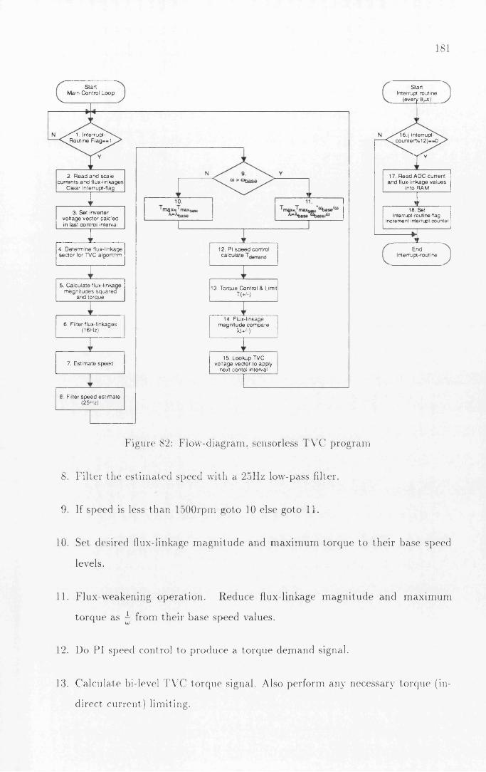
181
S ta r t M ain C on tro l L o o p
• '" 'l . IrtierTupl-^ R o u tin e F la g -« 1
2 . R e a d a n d s c a le c u r re n ts a n d llu x -lin k a g e s
C le a r ln terrup<-(lag
3 . S e t in v e rte r v o l ta g e v e c to r c a lc e d in la s t co n tro l in terva l
4 . D e te rm in e flux -linkage s e c to r to r TV C a lg o rith m
12. PI s p e e d co n tro l c a lc u la te
5. C a lc u la te flux-linkai m e g n i tu d e s s q u a r e c
a n d to rq u e
13. T o rq u e C on tro l & Limit T (+ /-)
14. F lux -linkage m a g n itu d e c o m p a re
M + /- )
6. F ilter f lu x -lin k a g e s (1 6 H z)
15. L o o k u p TV C v o lta g e v e c to r to a p p ly
n ex t c o n to l in terval7. E s tim a te s p e e d
i. F ilter s p e e d e s t im a te(2 5 H z)
S ta rt In terrup t ro u tin e
(e v e ry 8 fis)
16 .( In terru p t------- ^ ^ c o u n t e r ^ o ^ ) —0
y y
17. F lead A D C c u rre n t a n d flu x -lin k ag e v a lu e s
in to FIAM
r18 Set
Interrupt-routine flag. Increm ent interrupt counter
E n dIn te rru p t-ro u tin e
Figure 82: F low -diagram , sensorless T V C program
8 . F i lte r the e s t im a ted speed with a 25IIz low-pass filter.
9. If speed is less than 1500rpm goto 10 else goto 1 1 .
10. Set desired flux-linkage m ag n i tu d e and m ax im u m to rque to the ir base speed
levels.
1 1 . F lux-w eakening opera tion . R educe flux-linkage m a g n i tu d e and m ax im um
to rque as ^ from the ir base speed values.
12. Do PI speed control to produce a to rque dem and signal.
13. C a lcu la te bi-level T V C to rque signal. Also perform any necessary to rque (in
direct curren t ) lim iting.

182 A P P E N D I X C. T V C S O F T W A R E O V E R V I E W
14. C alcu la te bi-level flux-linkage dem and signal.
15. Using flux-linkage sector and the bi-level to rque and flux-linkage m ag n i tu d e
signals use lookup tab le to find desired voltage vector to be applied in next
control interval.
16. In te r ru p t routine: Is this t im e a m ultip le of 12? If not ex it , else continue.
(12 * 8fis= 96fis).
17. In te r ru p t routine: Read th e current and flux-linkage values from the analog to
digital converter and store th em in RAM for use by the m ain control rou tine.
18. In te r ru p t routine: Set the flag to ind ica te tha t new cu rren t and flux-linkage
values are available and the control rou tine can continue.
For full hardw are de ta ils see A ppendix B

A p p e n d ix D
S ta n d -a lo n e an a lo g f ro n t -e n d for
in v e r te r
T he analog-front-end (A FE ) was built to provide an easy to op e ra te facility for
charac te r is ing 3-phase synchronous m otors. T h is controller is radically different
from the controllers presented in the m ain body of this thesis in tha t it only control
the curren t being fed into the m o to r and does not control to rque or speed as the
DSP based controllers do. Torque is however m anua lly controlled by the opera to r .
T h e A F E is in tended to be used with a d y n a m o m e te r which provides constan t
speed opera tion . T he opera to r can control the cu rren t a n g le /c u r re n t m ag n i tu d e or
the d-axis and q-axis curren ts individually, thus m ak ing it easy to fully character ise
H ysteresisCurrentControl
RDC 4 offset
C O S 'S N LOOKUP
TABLE
2 phto
3 phPow er
E le c t o n e sC urren t Angle
A n a lo g '—1R am p
C om p an so nC urren tControl
DAC LCD
A n a lo g F ro n t-e n d
Figure 83: S tand-a lone analog controller
183

184 A P P E N D I X D S T A N D - A L O N E A N A L O G F R O N T - E N D F O R I N V E R T E R
th e s te a d y -s ta te perform ance.
T h e A F E m easures th e ro to r d-axis position using a resolver, this is converted
into a 1 1 -bit digital signal. T he curren t angle can be inpu t using e ither an analog
or d ig ital signal. A p o ten t io m e te r is provided on th e front panel for inpu ting the
analog cu rren t angle. T he analog cu rren t angle signal is converted into an 1 1 -bit
b inary offset value, th is is added to the digital ro tor position. T h e digital cu rren t
angle signal is displayed on a LCD for m onitoring.
T h e digital position of the curren t vector is then fed into a R O M sin /cos lookup
table . T h e RO M contains tab les for m otors with 1 to 4 pole pairs, configurable
with dip-switches. T he RO M produces a 1 2 -bit b inary offset a ,/^ -curren t reference.
The 2-phase a,/? reference is transfo rm ed into an equivalent 3-phase rep resen ta tion
corresponding to the m o to r phases.
T h e 3-phase reference cu rren ts are then used to control the m o to r cu rren ts using
e ither hysteresis control or ram p-com parison control. Hysteresis control changes the
s ta te of an inverter leg when th e current error exceeds a set hysteresis band. T he
o u tp u t from the hysteresis control is ga te a t 50/zs in tervals l im iting the m ax im u m
switching frequency to 10kHz. R am p-com parison com pares the cu rren t error with
a reference ram p , w ith no error a 50% du ty cycle is p roduced .
T h e A F E conforms to the inver te r in terface specifications in section B.3.2. This
is the s tan d a rd inverter in terface which uses fiber-optic control signals and analog
curren t-loops for analog signals.

A p p e n d ix E
P u b l ic a t io n s
185

A P P E N D I X E P U B L I CA T I ON S

E. l S E N S O R L E 5 S C O N T R O L O F T H E S Y N C H R O N O U S R E L U C T A N C E M O T O R 187
E . l Sensorless C ontrol o f th e Synchronous R e
luctance M otor
Annual M eeting IE E E - In d u s t ry A pplica tions Society
Toronto. C anada , O ctober 3-8, 1993

188 A P P E N D I X E P U B L I C A T I O N S
Sensorless Control of the Synchronous Reluctance Motor
R. Lagerquist', I. Boldea2, T.J.E. M iller1
1 University o f G lasgow 2Polytechnic Institute o f TimisoaraSPEED Laboratory 1900 Timisoara
DepL o f Electronics & Electrical Eng. RomaniaG lasgow G12 8LT, Scotland
Abstract - In this paper a sensorless closed-loop speed control for the synchronous reluctance motor Is presented. The sensorless control Is based on the Torque Vector Control. It has been Implemented using a high-speed digital processor DSP96002. Experimental results for a 120W axially laminated synchronous reluctance motor are presented and compared with operation with a speed sensor and simulations. A base speed range of 400-1500rpm has been achieved. The top speed was extended to 2750rpm using flux-weakening. The drive can be applied a full-load step-change within this speed range without losing synchronisation.
I. Introduction
Increasing interest has been shown in the synchronous reluctance motor in recent years particularly in the axially- laminated design first introduced by Cruickshank [4] in 1966 and further developed by [5]. The later axially- laminated designs do not have a starting squirrel-cage; this improves the saliency-ratio and hence torque and efficiency. Without the starting cage the synchronous reluctance motor can not be used for direct-on-line starts, but requires to driven by an inverter to keep the rotor and flux in synchronism. Most inverter drives use a sensor to measure the rotor position to achieve this. However, the rotor position sensor has been a major complaint in variable speed inverter drives as it is expensive, fragile and can prevent use in hostile environments.
Whereas sensorless control for sw itc h ed relu ctan ce m otors has been heavily investigated [6,7,10] this has not been the case for the synchronous reluctance motor. Promising sensorless control methods developed for the synchronous PM motor, which should be applicable to the synchronous reluctance motor can be found in [12], El- Antably proposes a method for sensorless control o f the synchronous reluctance motors in [5]; this was further developed by Bolognani [3]. Bolognani implemented a current angle detection system, however he only observed the angle and did not drive an inverter.
This paper presents the implementation of a closed loop torque controller based on theory developed by Boldea [2], C losed-loop speed control has been implemented by
estimating the rotor speed from the flux-linkage vector velocity.
II. Torque Vector Control Principle & Motor Equations
The principle o f torque vector control (TVC) as described by Boldea in [2] has been used to implement an inner torque loop. Torque vector control is based on the control of torque, flux-linkage magnitude and position to achieve synchronisation o f the rotor and the flux-linkage vector.
Neglecting iron losses the equations for torque vector control can be written, in stator reference frame as ( 1) and (2). Fig. 1 shows a phasor representation o f the equations.The angle e is referred to as the current angle, angle 8' is thevoltage or flux-linkage angle: this follow s the convention used by Lipo in [9].
V = R i + ̂ - ( 1)d t
T = $ p Ref I I ' ) = i p ( x a I p - Xp/ a ) (2)
q-axis
I . d -ax is
a-ax is
Fig. 1. Synchronous Reluctance Motor Ptiasor Diagram.

E . l . S E N S O R L E S S C O N T R O L O F T H E S Y N C H R O N O U S R E L U C T A N C E M O T O R 189
Rearranging (1) g ives the flux-linkage
l = j (V- Rl )d i
where
V = $ ( v a + Vb e j2 * 13 + Vc e ~j2nl3)
= Va +jVp
i = i i Ja + J b e j2 * n + I C e~ j2 n l3 )
= I a + ^ p
(3)
(4)
(5)
p = pole pairs.Variables subscripted a and (3 are the three-phase values
transformed into a two-phase co-ordinate system a ,p with the a-ax is oriented in line with the motor phase-a winding and denoted as the real axis. The [3-axis is at 90°, and is denoted as the imaginary axis.
In this scheme the rotor position is not used, or detected, it relies purly on orientation of stator flux-linkage and torque control. The flux-lmkage angle, 8', is indirectly controlled through the control o f torque and flux-magnitude.
In an ideal motor with R - 0 the voltage angle, 8, and the flux linkage angle, S', are identical.
Torque is related to the current and voltage angle as
,2 sin 2cT = \ p { L d - L q ) l
T misin 28'
= \P1
Ld
(6)
(7)sin 28'
Under constant current angle control, the maximum efficiency for the test motor at rated speed (1500rpm), torque (0.95Nm) and current (1.7A ) was found using a current angle, e, o f 55°. The angle is larger than 45° because of saturation effects.
Under the same conditions as stated above thecorresponding flux-linkage angle is given by
S - tan '1 — laneL, (8)
As Ld is strongly dependent on the flux-linkage magnitude equations (7) and (8) must be solved numerically to determine the flux-linkage magnitude that satisfies the required full-load torque and current angle requirements.
For the test motor the flux-linkage angle corresponding to a current angle o f 55° was 12° (0.2 rad). Thus under flux- linkage control the motor has an inherent torque margin of 33° degrees before it becom es unstable by moving beyond 45°. This means that the motor is inherently stable under
flux-linkage angle control whereas it is inherently unstable under constant current angle control since o 4 5 ° .
Fig. 2 show the behaviour of the current and torque for different flux-linkage magnitudes. It can easily be appreciated that for best possible inherent stability the flux- magmtude should be chosen as large as possible under current and voltage limit constraints. However as efficiency is also an aim, the flux-magnitude must be reduced so that the full-load operating point coincides with the maximum efficiency poinL It must also be noted that the current increases considerably when exceeding the rated torque. TVC normally operates with voltage angles that ensures operation within the current limit, but after a load change is applied it may transiently slip back to a larger voltage angle due to delays in the control loop.
To achieve synchronisation with the rotor TVC controls the applied voltage so that the flux-linkage magnitude is constant and the maximum torque, calculated by (2), is limited so that the flux-linkage angle kept less than 45°.
The flux-linkage magnitude is controlled by applying voltage vector that are directed towards the center of the rotor to decrease the magnitude and outwards to increase the magnitude. The torque is controlled by applying voltage vectors that either advances the flux-linkage vector in the direction o f rotation to increase the torque or oppose the direction o f rotation to reduce the torque.
As the flux-linkage vector is the integral o f the applied voltage vector (3), it will m ove in the direction of the applied voltage vector for as long as the voltage vector is applied. The voltage angle is thus indirectly controlled by the torque and flux-linkage magnitude, an increasing torque causing an increased angle.
TVC is designed to provide a sim ple fast control algorithm that can be implemented in hardware without the use o f a microprocessor.
d a re n t @0 25Vs CUTOnl @0.20VS Current @0.15Vs: Torque @0 23V* Torque @0 20V* Torque @015 Vs
Flux-linKege Angle 6 (rad]
Fig. 2 Torque and C urrent M agnitude vs. flux angle.Flux-linkage peak-m agm tude as param eter

190 A P P E N D I X E P U B L I C A T I O N S
Torque vector control uses a six-pulse voltage source inverter (Fig. 3) and by being able to be a hardware implementation it can be assumed that it will control the inverter switching at a rate which makes it unnecessary to modulate the applied voltage vectors. Hence the only available voltage vectors are the six in Fig.3.
Since there are only six voltage vectors available it is sufficient to determine the position flux-linkage vector position to be in one o f the six sectors defined in Fig.3. As TVC operate the inverter maximum switching the torque demand is reduced to a sim ple choice o f increase or decrease (+/-). The flux-linkage magnitude is likewise limited to a choice o f increase or decrease (+/-).
For the case when the flux-linkage vector is in sector <D (Fig. 4) one o f four voltage vectors can be applied. If the flux magnitude should be increased and the torque should be positive then V2 should be applied to advance the flux vector. If the flux is too large, but the torque should still be positive then V3 should be applied. If the torque should be negative then V6 would be applied to increase the flux and Vs to decrease the flux. A compact table o f optimal voltage vectors for all the different cases o f flux-linkage position and desired control inputs is listed in Table I.
A high-speed low -tech implementation o f torque vector control could be achieved using op-amps, comparators, a small ROM look-up table and 4 analog multipliers, ideally suited for implementation as an ASIC.
TABLE 1
R u n -S e c to r 1 2 3 4 5 6
X +vc T -t-ve\ v4 v \ v6 V!
X + v e T - v e Vl v : v ? v4 V<
X - v e T » v e 4 V4 v l v 2
X -v e T - v e Vi vl h - Vi Vi
At no point in the TVC algorithm is there a need to know anything but the desired flux-linkage magnitude and the associated maximum torque. In particular the absence of the any reliance on know ledge o f Ld and L q should be noted, this is can be contrasted to the conventional constant current angle control that needs to know Ld and L a to compensate for the speed term cross coupling between the d and q axis current equations.
To summarise the advantage o f TVC are:1) S elf synchronised torque control.2) Inherently stable (5'<45°) at maximum efficiency
operating point.3) Sim ple hardware implementation possible, no
microprocessor necessary.4) D oes not need to know
characteristic.L j or saturation
'
yrfoj.iN—
Fig. 3. Six Pulse PWM Inverter
P
torque postive ftm'ncreasng
torque postrve (lux decreasing
torque negative torque negativellux decreasing tlux increasing
Fig. 4 TV C Voltage V ectors for stator flux-linkage vector in region 1.
III. Flux Weakening and Torque Vector Control
Constant power operation above the base speed is easily implemented for torque vector control. When the motor reaches the base speed the inverter has reached its voltage limit. To go above the base speed the voltage must be kept constanL A s the voltage magnitude is given by
M - U . W - <9 >
It is clear that to go above the base speed the flux-linkage magnitude must be reduced as
<10>(OfAs TVC directly controls the flux-linkage magnitude this
is easily achieved.Similarly for the maximum torque for constant power
operation above base speed is:
rm = Tv>m ( i i )
T = t0 bast j ( 1 2 )
m*X CO mmxb a se ' K ’
The maximum torque o f the torque/flux-linkage angle curve is reduced when the flux-linkage magnitude is reduced. It is vital to limit the maximum torque demand because excess torque demand would push the flux-linkage
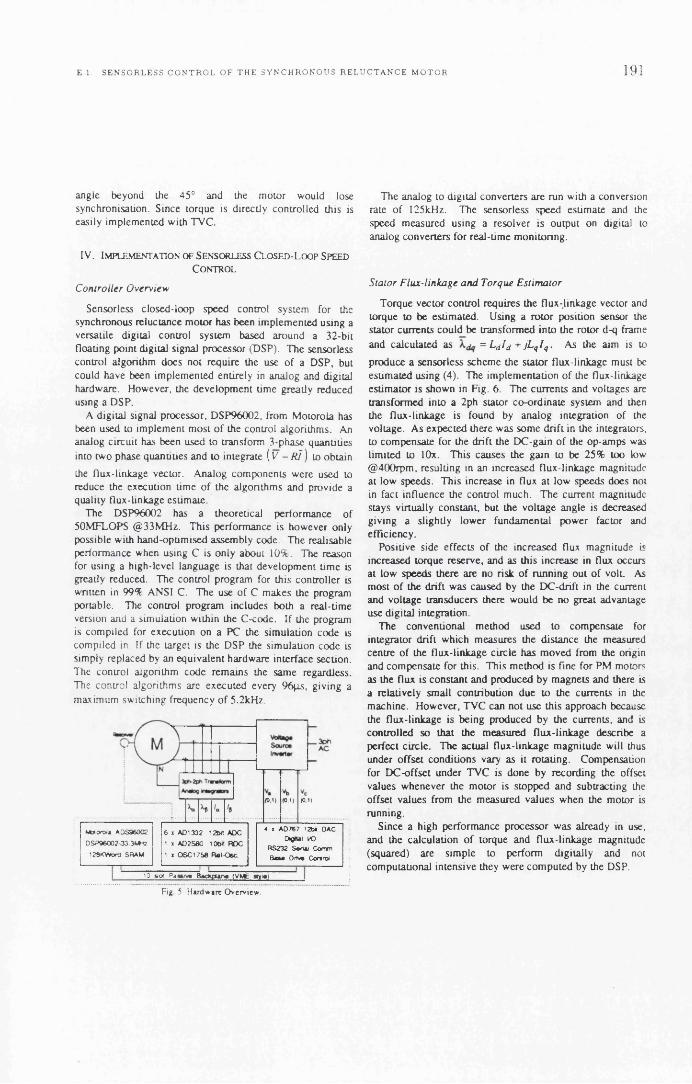
E . l . S E N S O R L E S S C O N T R O L O F T H E S Y N C H R O N O U S R E L U C T A N C E M O T O R 191
angle beyond the 45° and the motor would lose synchronisation. Since torque is directly controlled this is easily implemented with TVC.
IV. Implementation of Sensorless Closed-Loop Speed Control
C o n tro lle r O v erv iew
Sensorless closed-loop speed control system for the synchronous reluctance motor has been implemented using a versatile digital control system based around a 32-bit floating point digital signal processor (DSP). The sensorless control algorithm does not require the use o f a DSP, but could have been implemented entirely in analog and digital hardware. However, the developm ent time greatly reduced using a DSP.
A digital signal processor, D SP96002, from Motorola has been used to implement most o f the control algorithms. An analog circuit has been used to transform 3-phase quantities into two phase quanuties and to integrate ( V - R l ) to obtain
the flux-linkage vector. Analog components were used to reduce the execution time o f the algorithms and provide a quality flux-linkage esum aie.
The DSP96002 has a theoretical performance o f 50MFLOPS @ 33M H z. This performance is however only possible with hand-optimised assem bly code. The realisable performance when using C is only about 10%. The reason for using a high-level language is that developm ent time is greatly reduced. The control program for this controller is written in 99% ANSI C. The use o f C makes the program portable. The control program includes both a real-time version and a simulation within the C-code. If the program is com piled for execution on a PC the simulation code is compiled in. If the target is the DSP the simulation code is simply replaced by an equivalent hardware interface section. The control algorithm code remains the same regardless. The control algorithms are executed every 96jis, giving a maximum switching frequency o f 5.2kHz.
(0 .1) (0,1) (01 )
' 3 5101 P assiv e B acA pU rx (VM 6 g y w i
M otorola ADS960C2
D SP96002-33 3U~fc
128KVVora SRAM
4 i AO767 1204 OAC Digital I/O
RS232 Sana) Conm B**» Drtwa Control
6 x ADI 332 I2bfl ADC 1 * AD2S80 10M ROC 1 i OSC1758 Raf-Osc.
Fig 5. Hardware Overview
The analog to digital converters are run with a conversion rate o f 125kHz. The sensorless speed estimate and the speed measured using a resolver is output on digital to analog converters for real-time monitoring.
S ta to r F lu x -lin kage a n d T orqu e E stim a to r
Torque vector control requires the flux-linkage vector and torque to be estimated. Using a rotor position sensor the stator currents could be transformed into the rotor d-q frame and calculated as = Ld Id + jL qI q . As the aim is to
produce a sensorless scheme the stator flux-linkage must be estimated using (4). The implementation o f the flux-linkage estimator is shown in Fig. 6. The currents and voltages are transformed into a 2ph stator co-ordinate system and then the flux-linkage is found by analog integration of the voltage. A s expected there was som e drift in the integrators, to compensate for the drift the DC-gain o f the op-amps was limited to lOx. This causes the gain to be 25% too low @ 400rpm , resulting in an increased flux-linkage magnitude at low speeds. This increase in flux at low speeds does not in fact influence the control much. The current magnitude stays virtually constant, but the voltage angle is decreased giving a slightly lower fundamental power factor and efficiency.
Positive side effects o f the increased flux magnitude is increased torque reserve, and as this increase in flux occurs at low speeds there are no risk o f running out o f volt. As most o f the drift was caused by the DC-drift in the current and voltage transducers there would be no great advantage use digital integration.
The conventional method used to compensate for integrator drift which measures the distance the measured centre o f the flux-linkage circle has m oved from the origin and compensate for this. This method is fine for PM motors as the flux is constant and produced by magnets and there is a relatively small contribution due to the currents in the machine. However, TVC can not use this approach because the flux-linkage is being produced by the currents, and is controlled so that the measured flux-linkage describe a perfect circle. The actual flux-linkage magnitude will thus under offset conditions vary as it rotating. Compensation for DC -offset under TVC is done by recording the offset values whenever the motor is stopped and subtracting the offset values from the measured values when the motor is running.
Since a high performance processor was already in use, and the calculation o f torque and flux-linkage magnitude (squared) are sim ple to perform digitally and not computational intensive they were com puted by the DSP.

192 A P P E N D I X E P U B L I C A T I O N S
(-1/3) (-1/3)
Fig. 6. Siaior Flux and Torque Etuinalor.
As TVC only requires the flux-linkage vector position to be determined to be in one o f the six sectors in Fig. 3 the position can be uniquely identified by testing for the sign o f
, the sign of and a magnitude comparison V3|Xp j and
|Xa |. These test are performed by the DSP on the unfiltered
flux-linkage values from the analog integrator. Use o f the arctan funcuon to determine the positron o f the flux-linkage vector is thus not necessary for the torque loop and this saves valuable CPU time. The position test could also have been implemented in analog hardware by use o f a few comparators and op-amps.
At low speeds the motional voltage component becomes less than or equal to the voltage across the stator resistance. It thus becom es important that the correct value o f stator resistance is used in the flux-linkage estimator. A wrong stator resistance value causes an offset in the flux-linkage angle, and cause the TVC algorithm to detect and use the wrong flux-linkage sector.
S p e ed E stim a tor
The flux-linkage is used to estimate the rotor speed as this has a relatively clean wave form. In the steady-state the flux-linkage vector is synchronised to the rotor and the flux- linkage vector speed is the true rotor speed. However, transiently when torque demand is changed the speed estimate will be effected, because the flux-linkage vector m oves relatively to the rotor to produce the new torque level. A increase in demanded torque will cause the flux- linkage vector to m ove opposite to the speed o f rotation
causing the speed estim ate to be low until a new steady-state position is reached. Similarly for a reduction in torque demand, but the speed is in this case over estimated.
These effects can be minim ised by limiting the rate of change o f torque. If it is not desirable to limit the rate of change o f torque the speed estimator could be disabled during large torque demand changes.
The speed estimator has been implemented digitally in the DSP. The speed estimator differentiate the position o f the flux-linkage vector to obtain an estim ate o f the speed (13).
The speed estimator determines the position using a four quadrant arctan2 function. The standard arctan function in the DSP C-library was found to be too slow. It was replaced, by a 1024 (90°) entry look-up table and bisection search algorithm. Even tough the flux-linkage wave forms look quite sinusoidal they require filtering before use in the speed-estimator. Unfiltered flux-linkage wave forms result in a speed estimate with high frequency jitter since the flux- linkage vector may move either way during a control interval. The flux-linkage wave form was filtered using a first order filter w ith /c=16H z. The filter introduces a delay o f 2-5m s, however as the position is only used in the speed estimator, and not by the torque-loop, this is acceptable.
Another method for speed estimation was also tried, this method used the crossing from one flux-sec tor to another to estimate the speed. However, the discontinuous nature of the estimator and the code-required to avoid false detection proved to cause more problems, and took just as long to execute as the method using a arctan look-up table method.
O ffsets in the flux-linkage estim ate that occur during the operation is r.ot compensated for and cause the real flux- linkage vector to be moved off-center. The measured flux linkage is still centred, but the speed o f the measured flux- linkage vector is modulated by a sinusoidally shaped function with a frequency equal to the electrical rotor frequency.
i
Fig. 7. T V C flux-linkage. (0 .25V Spk).

E. l S E N S O R L E S S C O N T R O L O F T H E S Y N C H R O N O U S R E L U C T A N C E M O T O R 193
S p ee d a n d T orqu e C o n tro lle r
The torque controller used is quite simple as the torque vector control algorithm only accepts request for positive or negative torque. The desired torque from the speed controller is compared with the estimated motor torque, if the motor torque is less than the desired torque a request for positive torque is passed to the TVC control algorithm, otherwise a request for negative torque is passed
The torque vector control algorithm may override any torque request passed to it if the motor torque is larger than the rated torque. If the motor torque is positive larger than the rated torque then a negative torque demand overrides any previous selection, likewise if a negative motor torque o f magnitude greater than the rated torque is measured then a positive torque request overrides and is applied.
The speed controller however is more involved and is linked closely to the speed estimator described above. A conventional PI speed controller was used as basis, but required som e m odification to work well.
The most problematic aspect o f the speed controller was the ripple in estimated speed due to offsets in the flux- linkage. The effects o f this was most noticeable at higher speeds as the ripple frequency approached the speed controller bandwidth and caused oscillation. There were basically two approaches to solve this problem; to increase the bandwidth of the speed estimator or to filter out the speed variation. To further low-pass filter the speed estimate would result in slow dynamic response which was not desirable. The filtering was reduced and hence the speed estimator bandwidth increased, this increased the ripple present in the speed estimate. However, the PI gain was increased, and this combined with the increased bandwidth gave improved dynamic response while at the same ume maintain the steady state accuracy. The resultant speed variation is o f an approximately fixed magnitude (25rpm) and is clearly visible at low speeds. This variation in the speed estimate could eliminated at high speeds by averaging over one revolution. However at low speeds this would seriously degrade the dynamic response o f the system. It might be possible to use a notch filter with variable center frequency to remove the variation, but this has not been attempted.
P erform an ce Issues
Torque vector control operates with a constant flux- linkage magnitude at all loads. The use o f constant flux- linkage means that there will always current to flowing in the motor to maintain the flux, even in no-load situations. The effect this has on the performance will depend on loss m echanisms in the motor. In the 120W test motor the iron- losses were found to be relatively independent o f the load, and mostly a function o f the flux-linkage npple.
To compare the difference in losses o f torque vector control and constant angle control it should thus be sufficient to compare the copper losses. Fig. 8. shows the current magnitude for a constant angle control (CAC) of 55° compared with torque vector control. The flux-linkage magnitude is set to achieve the maximum efficiency current angle at a load o f INm. As can be seen the copper losses of the two control methods will be alm ost the same for loads ranging from 60% to 110% o f rated load. Outside this range TVC has a larger copper losses than constant angle controllers, especially at low loads.
Torque vector control has fast dynamic torque response compared to constant current angle controllers since the currents in the motor can be changed faster. The torque change is faster under TVC as alm ost all the current change occurs in the least inductive axis whereas for constant current angle control the change in current is equal in both axis.
The efficiency o f torque vector control could be increased at low loads by including a efficiency optim ising loop that would lower the flux-linkage magnitude when the motor is operating at light loads. However, som e the dynamic response o f TVC would have to be sacrificed if efficiency optimising is used because the flux-linkage magnitude would have to be rebuilt before full torque could be produced, this would make TVC dynamic performance on par with constant current angle controllers.
V. Results
To explore the performance and limitations o f the sensorless closed-loop speed controller an experimental setup with a 120W axially laminated synchronous reluctance motor was used. The motor has a standard induction motor stator with a low -voltage winding. The test motor and the load machine was coupled with a Vibrometer torque transducer using flexible rubber couplings. The load machine was a brushless permanent magnet motor powered by an Electrocrafl BRU controller.
Fig. 8. Theoretical Current magnitude at function of torque in TVC and con I tan t current angle controllers.

194 A P P E N D I X E P U B L I C A T I O N S
Fig. 9. Flux-linkige (a£) during sun-up.0. lVs/div. lOmt/div.
1 ! !/! _ ...
! ii I/ 4_ -
■ 11 u 1) l< u U i/ u u '
Fig.ll. Sentorieu: Simulated Speed Reven»l -/+1500rpm. Estimated Speed (lop) & True Speed (bun).
500rpm/div, 0.1«/div
Fig. 10. Phase-Voluge (top) and Current (btm) during sun-up 50V/div, 2A/div, 10ms/div
Startup
When siarung the motor any voltage vector may be applied. As can be seen in Fig. 9 the correct flux-linkage position is achieved in less than 4m s, during this time the motor may develop torque in the wrong direction. Fig. 9 illustrates the worst case where the initial applied voltage vector located 180° from the desued position.
Also notice the relatively smooth flux-linkage wave form compared to the current (Fig. 10), making it preferable to use in the speed estimator.
S p e ed E stim a to r & S im u la tion
Simulations o f the dynamic behaviour and the actual system has been shown to agree well. Fig. 11 shows a simulation of a speed reversal from -1500rpm to +1500.
Fig.12. Seniorlesj: Speed Reversal -/+1500rpm.Estimated Speed (tup) &. True Speed (bun).
500rpm/div. O.ls/div
In the simulation the flux-linkage was offset by 2.5% in both axis, notice the characteristic ripple on the speed estimate introduced by the offset. This ripple is also present in the experimental wave form Fig. 12.
The characteristic kink in the speed estimate occur due to the rapid change o f flux-linkage angle, causing the speed temporarily to be estimated to be much smaller than it actually is (or even o f opposite sign). This kink can be found in both the simulation and the experimental wave form and is the response o f the digital filter to the impulse speed change present while the flux-linkage angle changes.
D yn a m ic P erfo rm a n ce
The speed range o f the drive has been defined to be the range in which the motor could be applied a step-load from no-load to 90% o f rated torque without losing

E 1 S E N S O R L E S S C O N T R O L O F T H E S Y N C H R O N O U S R E L U C T A N C E M O T O R 195
Fig.13. Sentorleu: Speed ReveruJ -/+400rpm, Torque (top) & Speed (btm).
0.5Nm/div, 200rprcv/div, O.li/div.
Fig.15. Uiing Speed-Senior Speed Revertel -/+1500rpm. Torque (top) & Speed (btm).
0.5Nm/div, 500rpm/div, O.li/div.
Fig.14 Seniorlesi: Speed Reversal -/♦1500rpm, Torque (lop) & Speed (btm)
0.5Nm/div, 500rpm/div, 0.1 s/div
Fig.16. Sensorlen: Step-load change 0-0.86Nm (2>1 SOOrpm Torque (lop) & Speed (btm).
0.5Nm/div, 200rpm/div, O.lj/div.
synchronisation. The minimum speed achieved that satisfied the above criterion was 400rpm. If the step-load change is limited to 53% o f full load the lower speed limit becomes 150rpm.
Fig. 13 shows the a +/-400rpm speed reversal, steady- state speed ripple due to the flux-linkage offset can be seen. A +/-1500rpm speed reversal is shown in F ig .14, the speed reversal takes 150ms which compares well with the 130ms for the constant current angle controller in [1,8]. The settling-time is 325m s compared to 140ms for constant current angle control. This is not a fault o f TVC itself, which has excellent response when used with a speed sensor (Fig. 15), but a function o f the speed estimator.
The response o f the drive to a 90% step-load change is shown in Figs. 16 & 17, notice that the speed drop is constant in magnitude and the recovery lime is the same at
400rpm and 1500rpm. The magnitude o f the speed drop is a function o f the delay in the speed estimator and the recovery time a function o f the available acceleration torque. The recovery time for TVC is 400m s compared to a constant current angel controller recovery time o f 200ms.
If operated with a speed sensor (Fig. 18) the initial drop is much less due to the shorter delay before the change in speed is sensed. Hence the recovery time is also reduced.
The limit o f torque vector control when used with a speed sensor was found to be 50rpm. B elow this speed the resistance term in the voltage becom es too dominant to achieve proper synchronisation, inclusion o f a stator resistance estimator should improve this.

196 A P P E N D I X E P U B L I C A T I O N
Fig.17. Senaorkat: Step-load change 0-0.86Nm @400rpm Torque (top) & Speed (btm).
0.5Nm/div, 200rpnv/div, 0. la/div.
Fig. 19. Senaorieai: Stan 0-2750rpm, Torque (top) & Speed (btm).
0.5Nm/div, lOOOrpm/div, 0. li/div.
Fig. 18. Uiing Speed-Senior Step-load change 0-0.86Nm @400rpm Torque (top) & Speed (btm).
0.5Nm/div, 200rpm/div, O.li/div.
S tea d y -S ta te P erfo rm a n ce
The phase current vs. torque is plotted in Fig. 20 this agrees w ell with the theoretical current (Fig. 8). The measured currents are slightly larger than the theoretical, but this is to be expected as the theoretical does not include ironlosses.
The efficiency is shown in Fig. 21 as expected the efficiency o f torque vector control is lower than constant current angle control, except at rated torque.
The efficiency could easily be improved by applying a efficiency optim ising outer loop to adjust the flux-linkage magnitude. However this would affect the dynamic response.
The steady-state speed regulation (table II) o f the drive is generally better than +/-5% for speeds in the range 400- 2750rpm. The absolute speed regulation is almost constant at speeds below base speed, and most likely due to offsets in the flux-linkage measurements.
F lu x-w eaken in g O p e ra tio n
The speed range was extended beyond the base speed (1500rpm) using flux-weakening. Above the base speed the motor is operating with constant power. The maximum speed at which the drive could be applied a 90% step-load was 2750rpm, giving a constant power-speed range of 1.83:1. The maximum constant power-speed range for the motor used is 2.13:1 [11]. The limiting factor at this speed is probably a com bination o f low switching frequency, small flux-linkage magnitude. Fig. 19 shows the motor accelerating from Orpm to 2750rpm. Notice the characteristic slow dow n in acceleration when the flux- weakening region is reached (1500rpm).
3
2 S
2
1 3
1
0 5
0To#qu«(Nm|
Fig. 20. Phase Current @ 1500rpm for torque vector control (TVC) and constant current angle control (CAQ.

E . l . S E N S O R L E S S C O N T R O L O F T H E S Y N C H R O N O U S R E L U C T A N C E M O T O R 197
08
0 7
06
0 5
0 4
0 5
0 2
0 10
0 0 2 0 4 0 6 0 6 1 12Torqu* (Nmj
Fig. 21. Efficiency @ 1500rpm for torque vector control (TVC) and constant current angle control (CAQ.
Table IISt e a d y -St a te S pe ed R e o i i > tion
No-losd [torn! Full-lo»d Irani
*/-25 *1-25*00 +/-30iOCC •♦7-20
. . . ;;oo ....... ./-4I. +/-402750 ♦/-50
VI. Conclusion
An implementation o f sensorless closed-loop sensorless speed control for the synchronous reluctance motor is presented. The drive has been shown to have a base speed range o f 400rpm- 1500rpm in which a step-load change of 90% full-load torque can be applied. For a step-load of 50% full-load torque the speed range can be extended downwards to 150rpm. Flux-weakening operation has been implemented. The constant power-speed range achieved was 1.81:1. Overall speed range is 6.9:1 for 90% step-load change, and 181 if step-load changes o f less than 50% are used.
The basic torque vector control is simple and ideally suited for implementation as an ASIC providing closed looptorque control.
For demanding applications (or applications that cantolerate a speed sensor) torque vector control combined with an (inexpensive) tacho-generator should provide excellentperformance.
VII. Appendix Motor & System Data:L(f=180mH(unsat), 152mH(sat); L(?=24.5mH;
V „ f= * = 8. in ; P=2; Vfa^ 1 1 0 V r m s (Y ) ;Iraled= 1.7Arms; ( 0 ^ ^ = 1 5 0 0 rpm; Tralej= 0 .95 Nm; Inertia (motor and load)=0.00044 kgm 2;Friction coefficient=0.00015 Nm/rad/s;V fc ,/tnJk= 150V; Xpt(jt=0.2V s; TVC control interval: 96ps; Maximum Inverter switching frequency: 5.2kHz.
Acknowledgment
The authors thanks: F. Flett &. Analog D evices for contribution o f linear and data-con version devices. I.Dulhie, A. Hutton & Motorola for the DSP96002 developm ent system , SJE. W ood & Brook Crompton for the motor, D.Staton for designing the axially laminted synchronous reluctance motor rotor and for theoretical and static data for the motor, J. Kelly for making the rotor, P. Miller for designing and building the power electronics.
R.L. thanks: The Committee o f Vice-Chancellors and Principals o f the Universities o f the United Kingdom and the Scottish Power Electronics and Electrical Drives Consortium for financial support. D iscussions with W.L. Soong are also gratefully acknowledged by RJ-.
References
[I] Betz R-E., Lagerquisl R., Jovanovic M., Miller TJE., Middleton R.H., “Conlroi of synchronous rclucunce machines". IEEE Trans. Industry Applications, in press.
|2] Boldea 1., Fu Z.X., Nasar S.A., "Digital simulation of a vectorcontrolled axially-laminated anisotropic synchronous motor scrvo-dnve", Electric machines and Power Systems, vol. 19. pp415-426. 1991.
(3] Bolognani S., "Torque angle calculator for sensorless reluctance motor drives", EPE Firenze, pp. 4-013 - 4-017, 1991.
(4] C rui cits hank AJ.O., Menzies R.W., “Axially laminated anisotropic rotors for reluctance motors", Proc IEE, PlB, vol.113, pp2058- 2060, 1966.
(5] El-Antably A., "Proposed control startegy for cageless reluctance motor using terminal voltage and currents '. Annual Meeting IEEE-IAS, pp 753-758, 1985.
|6) Eshani M., Husain L, Kulkami A.B., “Elimiation of direct position sensor and current sensor m switched reluctance motor drives", Annual Meeting IEEE-IAS, pp 518-524, 1990.
[7] Hill RJ , Acamley P.P., Colville W., "Stepping motors and drive circuits thcrfcr", United States Patent 4,520,302, May 28, 1985
[8] Lagerquist R., Beu R.E, Miller TJE., "DSP96002 based high performance digital vector controller for synchronous reluctance motors", International Conference on Electrical Machines, Manchester, pp903-907, 1992.
[9] Lipo T.A., Vagati A., MaJesani L., Fukao R., “Synchronous reluctance motors and drives - A new alternative”. Tutorial held 4 Oct 1992, Annual Meeting IEEE-IAS, 1992
[10] Panda S.K., Amaratunga F.AJ., “Switched reluctance motor drive without direct rotor positon", Annual Meeting IEEE-IAS, pp 525-530, 1990
[II] Soong W.L., MillerTJ.E., “Practical field-weakening performance of the five classes of brush I ess synchronous AC motor drive", EPE 1993, in press.
[12] Wu R., Slemon G.R, “A permanent magnet motor dnve without a shaft sensor". Annual Meeung IEEE-IAS, pp 553-558, 1990.

A PPE N D IX E PU BLICA TIO N S

E 2 C O N T R O L O F S Y N C H R O N O U S R E L U C T A N C E M A C H I N E S 199
E.2 C ontrol o f Synchronous R elu ctan ce M a
chines
IE E E Transactions on In d u stry A pplications
In press, 1993

200 A P P E N D I X E P U B L I C A T I O N
C o n t ro l of S y n c h ro n o u s R e lu c ta n c e M a c h in e s
R.E. B e tz 1,R. L agerqu ist2, M. J o v a n o v ic1, T .J.E. M iller2and R.H. M id d le to n 1
D epartm ent of Electrical and C om p u ter Engineering U niversity o f Newcastle , C allaghan, N S W , 2308,
Australia.
Abstract
This paper develops a com prehensive approach to the control o f inverter-fed synchronous
reluctance m achines (S Y N C R E L ), based on the machine 's ideal model. From the theory a
control simulation is designed. Simulation and experimental results are presented. The
effects o f saturation and iron losses are bneflv considered.
Introduction
The Synchronous Reluctance M achine (SY N C R M ) is an AC machine with a rotor that has a
d ifferent perm eance on the D and Q axes (Pd and Pq). The simplest ro tor that produces this
effect is “dum b-be ll” shaped. Such primitive rotors however, only produce a relatively small
d ifference in the perm eance o f the two axes of the rotor. As shall be seen in the following
analysis the difference and ratio between these perm eances are two of the crucial parameters
that determ ine the perform ance o f the machine (the larger the Pd-Pq d ifference and P J P q
ratio the better the m achines properties). Therefore these rotors are o f little practical use.
Various other designs have been proposed for the SY N C R M rotor over the years, but the
designs that obtain the m ax im um Pd- Pq and P J P q use an axial lamination principle. Figure 1
is a cross-section o f a typical 4 pole machine with axially laminated rotor. The material
between the laminations can be any non-m agnetic material - slot insulation, aluminium,
copper and even injection m oulded plastic can be used.
The main m otivations for studying the SY N C R M a re : -
(i) T he control o f the S Y N C R M appears to be sim pler com pared to field oriented control
o f induction machines.
(ii) T he S Y N C R M is a synchronous machine, and this is advantageous in some
applications.
1 D epartm en t o f E lectrica l and C o m p u te r E n g ineering , U niversity o f N ew castle , C a llag h an , N SW , 2308, A ustra lia .2 D epartm en t o f E lectro n ic and E lectrica l E ng in eerin g , U n iversity o f G lasgow , G 12 8Q Q , U nited K ingdom .

E. 2 C O N T R O L O F S Y N C H R O N O U S R E L U C T A N C E M A C H I N E S 201
(iii) T h e S Y N C R M has a “co ld” rotor. This has several implications - the S Y N C R M can be
used in niche appiciations where a cold rotor is required; but more importantly it means
that the S Y N C R M potentially is more efficient than the induction machine. Therefore
for the same total losses the S Y N C R M appears to be capable of a higher pow er density
than the induction machine.
(iv) T he non-axiallv laminated S Y N C R M is suitable for very high speed applications.
(v) T he S Y N C R M is robust similar to the induction machine.
Q a x is
D axis
Figure 1 : C ro ss-section o f sy n chronous re luctance m achine with ax ia lly lam in ated ro to r
M ost o f the early work carried out on the SY N C R M has been for dead on-line start
applications. Such m achines require a squirrel cage to allow the m achine to start with mains

202 A P P E N D I X E P U B L I C A T I O N S
frequency input. This constraint com prom ises perform ance. The machines which are the
subject o f this paper have no rotor cage, thereby allowing design for optimal Pd / P ratio.
The term S Y N C R E L will be coined for these machines.
In com parison to the induction machine, the control o f the S Y N C R E L has been largely
ignored. T he main control param eter in the S Y N C R E L is the angle of the current vector with
respect to the high permeance axis o f the machine. In this paper this axis is the D axis of the
machine (see Figure 1). A significant paper by Chiba and Fukao [1] found that the ideal
machine m ax im u m rate of change of torque is obtainable if the current angle with respect to
the rotor axis is 6t = tan “; g , where c = Ld l Lq . The inherent param eter dependence is not
addressed.
A nother paper of note is by Fratta. Vagati and Villata [2]. The control for the S Y N C R E L
was derived in a flux oriented reference frame. This allowed the developm ent of a rapid
torque response control with a field weakening strategy. Issues of param eter dependence
again were not addressed.
The final paper of interest is by Xu, Xu. Lipo and Novotny [3]. This paper tackles the control
difficulties associated with saturation and core losses. The key result is that saturation and
core losses can make a significant difference to the rotor angles for m axim um torque/am pere
and m ax im um efficiency.
This paper consists o f two main sections. The first carries out an analysis o f the ideal
S Y N C R E L and highlights its basic perform ance parameters and their inter-relationships for
the following control strategies:-
1. M ax im u m torque control (M TC):- m ax im um torque/am pere obtained by setting
Q . - k 14 .
2. M ax im u m rate of change of torque control (M R C TC ):- control proposed in [ 1] where
6t = tan -1 g.
3. M ax im u m pow er factor control (M PFC):- obtained when 6i = tan ' 1 .
4. Constant current in inductive axis control (CCIA C):- control strategy where constant
curren t is maintained in the D axis, and torque is m anipulated by the Q axis current.
The m ain limitation of the analysis is that it has been done for the ideal machine (i.e. no
saturation or losses). By using the ideal machine one is able to develop expressions which
allow the theoretical limits o f the ideal m achine perform ance to be determined. Despite the

E. 2 C O N T R O L O F S Y N C H R O N O U S R E L U C T A N C E M A C H I N E S 203
ideal m achine limitation, interesting insights into the S Y N C R E L ’s properties are gained.
C onsideration is also given to the effects that saturation and iron losses have on the
perform ance o f a “ rea l” machine. M ore detailed consideration is given to saturation and iron
loss aspects o f the SY N C R E L in [9], Strategies for estimating the D axis inductance on-line
are developed, and simulations of their perform ance are presented.
The second section of the paper details the design o f a digital controller based on the analysis
o f the previous section. This controller is suitable for im plementation on a Digital Signal
P rocessor (DSP). Simulation results for the controller are presented. Experim ental results
for the contro ller im plem ented on a Motorola 96002 Digital Signal Processor are then
presented.
Mathematical Modelling
The conventional D Q equations for the ideal S Y N C R E L using standard notation a re :-
This form o f the machine equations is not suitable for generating machine independent
perform ance inform ation. In order to make this possible the equations are norm alised based
on the perfo rm ance o f a machine operated at m axim um torque per ampere. If coo is the
angular v e lo c i ty o f the breakpoint in the rated torque-speed characteristic and io is the rated
current then the o ther bases for the normalisation are defined as fo l lo w s:-
( 1)
i. + Ri + o)LJj ( 2 )
r = {Ld - L q)idiq (3)
T0 = \ / 2 ( L U- L q)i20 (4)
(5)
(6)
The norm alised m achine variables therefore beco m e :-
r <P<Pn=— CO,
<Po
CO V(7)T, V
T O Vo
A pplying the above normalisation's to (1), (2) and (3) and assuming that the m ach ine
resistances can be ignored the following can be d e r iv e d :-

204 A P P E N D I X E P U B L I C A T I O N S
V 2 4 f 1 . (O' .v- 1 — Pldn ~ lqn
U0 S(8)
V2 ; , .
V̂ = “ F T T 7 7 7 ^ ^+ H. £^0
T„ = i] sin 20
(9)
( 10)
where p = — .d i
Utilising the fact that i ] = i] n + C toge tf>er HO) allows the normalised currents to be
written as:-
L. = J — coiOldn 2
ian = J — tan#,v 7 1
( 1 1 )
( 12)
Therefore (8 ) and (9) can be written totally in terms o f the torque and the current a n g le : -
Vcot 0 ,
V(13)
v,« =+ 1
-y/tan j— j — ^ N 7 + & W 7 co t6 > , (14)
It should be noted that (13) and (14) assume that 0 is not a function o f time and can therefore
be m oved outside the “ p ” operator. In other words this means that the following analysis is
constrained to constant angle controllers (C A C ’s).
Since v 2 = + v 2n then after some manipulation the following expression relating the
voltage applied to the machine torque, rate o f change of torque and the current angle can be
found (note that this is the same as the expression in [ 1] except that a different norm alisation
has been u sed ) :-

E. 2 C O N T R O L O F S Y N C H R O N O U S R E L U C T A N C E M A C H I N E S 205
The rem ain ing important expression for the S Y N C R E L machine is the pow er factor
expression. This can be derived using trigonometry from the vector d iagram of the
m a c h in e : -
Inter-relationships
The re la tionsh ips between the M T C (i.e. 0, — k I 4 ) and the M R C T C (i.e. f? = tan- ' c ) shall be
investigated first. These two control strategies exhibit a duality property with respect to their
rated torque and break frequencies.
If the m achine is operating at rated current for both control strategies then from ( TO ) the
torque for the M T C control is r n = 1 and for the M R CTC r„ = 2 c / ( c : + 1). For large c the
m ax im um torque using M R C T C is very' low.
If p r n = 0 in (15) then the following expression is obtained for the norm alised angular
velocitv o f the m a c h in e : -
Under the condition of rated current if the applied frequency is increased until the feeding
inverter runs out o f volts then v n = 1 and r /i = s in 2 0 in (17). Therefore the general
expression for the break frequency in the torque-speed characteristic is:—
M R C T C control trades off output torque in order to gain a higher break frequency in the
to rque-speed characteristic. Since the input voltage and current are equal for both the control
strategies then the power factors are also equal. A nother interesting result is that the above
TCD re lationship is unique between M TC, M R C T C and the constant pow er trajectory' that can
be traversed between them [4].
(16)
(17)
CDsin 2 0 (tan 0 + q 1 cot 0 )
c~ +1(18)
Therefore for M T C , (D nmax = 1, and for M R C T C , c o nmax = (c 2 + l ) / 2 c . T h e re fo re : -
( ^ n ^ n m a x ) « / 4 — ( ̂ n m a i^ _ ^ (19)

206 A P P E N D I X E P U B L I C A T I O N S
The other variable o f interest is the relationship between the rate o f change of torque for the
two cases. T he M R C T C control was derived in [ 1] by optim ising for rate of change of
torque. Substitu ting for each angle into (15) and taking the ratio we get:—
Since ( c : + 1) / 2c > 1 for c > 1 then the above ratio is always greater than 1. Note that as the
crnTn product in the above expression increases then the ratio increases.
A question which arises from the above analysis is w hether the Tnconmax product obtained for
the M T C and M R C T C strategies is optimal, which is the same as asking whether the power
factor is optimal. This question is important because power factor of the ideal machine
directly affects the kVA required from the inverter supply for a given output shaft power.
The angle o f optimal power factor is obtained by differentiating (16) and equating to zero.
The result is that the m axim um pow er factor is obtained if the machine is operated with
Substituting this into (16) gives the following well known expression for m ax im um power
fac to r : -
Figure 2 plots pow er factor for the optimal current angle and the 7t / 4 current angle. Note
that as c increases operating at optimal power factor angle begins to show a significant
difference. T he figure also serves to highlight the importance o f obta in ing a good ( > 5 ) q
value so that the inverter size relative to the shaft output power can be reduced.
( 20 )
(2 1 )
The com para tive perform ance of the M PFC strategy relative to the M T C and the M R C T C
strategies can be seen in (23) and (24). For both CDnmax and p r n the M PFC is m idw ay between
M T C and M R C T C [4].

E. 2 C O N T R O L O F S Y N C H R O N O U S R E L U C T A N C E M A C H I N E S 207
The £ Parameter
Since both the M R C T C and the M PFC are dependent on know ledge of the g pa ram eter then
the question arises to how accurately this param eter must be known. In o rder to assess this a
sensitivity analysis was carried out in [4] to determine the effect o f inaccurate know ledge of
C on the control objective of each controller. The sensitivity functions evaluated were
A 77/ 77* and A y / y* where 77’ is the power factor and y* is the rate o f change o f torque,
obtained when there is no error in c .
The main conclusions are that M PFC is relatively insensitive to g and can tolerate e rrors o f
±30% without much perform ance lose. M R C T C on the other hand is sensitive to g both in
terms of rate of change o f torque and power factor. H ow ever if g is known to ± 1 0 % the
error from optim um perform ance is not too great. For both M PFC and M R C T C larger values
of c decrease the param eter sensitivity.
Parameter Estimator for g
To im plem ent a controller for the S Y N C R E L it is clear that the g param eter needs to be
0.6 Max. torq/ampuua: 0.5Cz.u<v£cr> 0.4
0.3
0.2
Inductance Ratio Figure 2: Pow er Factor versus Inductance Ratio

208 A P P E N D I X E P U B L I C A T I O N S
known. The L q value is a lmost constant under all operating conditions since the flux path is
dom ina ted by air in the Q axis. However, L d in reality is a state dependent param eter due to
the saturation o f the D axis o f the machine. One way to obtain g under all operating
conditions is to measure L q and the Ld vs id relationship for the particular m achine being
controlled , and then store these in lookup tables.
A lternatively , one can attempt to identify these crucial parameters on-line. This approach has
the advantage that to some degree the inverter-controller system has becom e decoupled from
the m achine . T herefore for a given pow er rating, an inverter can support a variety o f
d ifferent m achines without having to m odify any lookup tables.
There are a num ber o f techniques that can be used to estimate the inductance ratio o f a
S Y N C R E L machine. Most estimation schemes used in the adaptive control literature are
variants o f the basic Recursive Least Squares Estimator (RLSE). Such techniques are
applicable to teh estim ation o f the resistance and inductance values of the SY N C R E L
machine. For exam ple , if (2) is discretized using an Euler approxim ation o f the derivative the
fo llowing expression can be written for the Q axis current:-
and A = sam pling interval.
An erro r iq( k ) - i q( k ) can be constructed where iq(k ) corresponds to an estimate o f iq ( k )
genera ted from (25) using the estimated values for the machine parameters. This error can
then be used to d n v e a RLSE to update the estimates o f the parameters. The classical form of
the R L S E equations for the scalar case appear in (27).
iq(k + \) = Q(k )T<t>(k) (25)
where
"LI LJ ’ v<t>(k) = [iq(k) 0){k)id(k) v9(£)]
(26)
Q (k + 1) = G (k ) + L (k + l)[y(k + 1) - <&(k)T Q(k)]
P (k + 1) = - ( I - U k + \)<&(k)T)P(k)7 (27)
1 ® ( k ) T P(k)<b(k)

E 2 C O N T R O L O F S Y N C H R O N O U S R E L U C T A N C E M A C H I N E S 209
where a = y = 1 for o rdinary least squares, and a = 1 - y, 0 < 7 < 1 for exponentia lly
weighted least squares. The m em ory of the estimator (i.e. the num ber o f previous states
which affect the estimate) is approxim ate ly l / ( l - y ) . Square root based update techniques
for the P matrix are often used because they offer superior numerical properties.
The estimation is based on the Q axis equation for two reasons :-
(a) The equation does not involve incremental values of the D or Q axis inductances.
(b) The Q axis current is the most "ac tive” o f the currents for the control strategies
considered. This is im portant in order to supply a persistently exciting input for the
estimator.
The traditional technique for using (27) would be to estimate the 0 param eters defined in
(26). Once known then the /?, L d , and L , values can be solved for (since the param eter
equations form three independent equations). H owever this technique does not perform very
well in situations where any of the parameters being estimated are state dependent (as is the
case for the L d inductance in the SY N C R EL). This is due to the fact that the param eter
undergoes very fast changes, and the estim ator is always lagging behind the true value o f the
parameter. What is required is a technique that can estimate the instantaneous values o f the
state dependent L d param eter. This can be achieved using a least squares approach by
estimating the saturation characteristic of the machine (which is essentially constant and not a
state dependent quantity).
T he characteristic which must be estimated is the L d vs id curve. This curve can be m odelled
in a num ber o f different ways - for example, as a polynomial, or perhaps as a sum of
exponentials. If the characteristic is modelled as a polynomial then the equation for L d has
the general form:-
~ cnld ( k ) n + cn-\id ( k Y ' + +clid ( k ) + cQ (28)
If (28) is substituted into (25) then the new 0 can be found consisting o f the above ‘c ’
coefficients . Once the ‘c ’ coefficients have been determined by the R LSE then the value of
L d for any id can be determ ined from (28). Improved perform ance can also be ob ta ined by
using apriori known inform ation. For example, the value o f the L q inductance is constan t
under all operating conditions. If this and the resistance are know n then the only pa ram ete r to
be estim ated is the D axis inductance. By decreasing the degrees o f f reedom the es t im ato r
perform ance improves.

2 1 0 A P P E N D I X E P U B L I C A T I O N S
An alternative set o f basis functions for the Ld inductance are the exponentia ls . These have
been chosen because o f their ability to represent the types o f curves that are typical of
saturation characteristics. Using exponentia ls it is possible to m odel the Z^value as:-
Equation (29) can similarly be substituted into (25) and the new © determ ined. It has been
found that the use o f the exponential basis functions is superior to the polynom ial
approxim ation as it often requires a 6th order polynomial to obtain a good fit to the saturation
characteristic. This m eans that even for the case where Lq and R are assum ed to be know n, 7
param eters (the V coefficients) have to be estimated. On the o ther hand for the exponential
version only 2 or 3 param eters have to be estimated in order to gain acceptable fits. For any
choosen set o f exponentia ls one has to choose the power terms ‘a . b ' etc.
T w o other estim ation techniques are discussed in [4], Both these techniques are valid only if
the d i / dt is small in the m achine (i.e. the machine is in steady state).
Field Weakening
Separately excited D.C. m achines and vector controlled induction m achines can increase their
shaft angular velocity above rated speed so that they operate with constant power. This is
achieved by w eakening the field within the machine. In a S Y N C R E L m achine the concept of
the “ field” is not easily visualised since the torque production technique does not involve the
interaction o f a field in the airgap and a current in the rotor. Nevertheless, a constant pow er
characteristic can be obtained from the S Y N C R E L machine under certain form s of control.
From the steady state version o f (15) the following expression for torque is o b ta in ed :-
The normal characteristic o f the S Y N C R E L with constant current angle when it runs out of
(29)
T (30)
volts is °c 1 / co].
To im plem ent constan t pow er operation in the region con > 1 then the required characteristic is
oc 1 / con. For this to hold then from (3 0 ) :-

E 2 C O N T R O L O F S Y N C H R O N O U S R E L U C T A N C E M A C H I N E S 211
If a M T C strategy is em ployed then Tn = 1 at con = 1. Therefore K =
equation has to be solved for 6[ with a)n > 1:-
- 1ta n # + c : c o t# = 0
c0 .
Hence the fo llow ine
(32)
An explicit solution can be simply obtained for this equation by letting x = ta n # . Therefore
x{cr + 1)c o . = (33)
which is a simple quadratic equation that can be solved for x and consequently for ta n # .
Equation (33) is plotted in Figure 3 for a num ber o f different values o f c . The following
observations can be made from this F igure :-
• As c increases there is a corresponding increase in the field w-eakening range.
• There is a limiting frequency beyond which field weakening cannot occur. At this
point there is no Qt solution to (33) for a particular con and therefore the \ / c o n
90 r--------------- i ■ ' !------------------------------- 1---------------1 '
80=̂5
70
V c=2
C 40Vt
30 I-
20
=̂4
0 J— 2 .61.2 1.4 L6 178 2 2XL 2AN orm alized F re q u e n c y
2.8
Figure 3 : Current angle required for field weakening

2 1 2 A P P E N D I X E P U B L I C A T I O N S
characteris tic can no longer be maintained.
• For values o f c > 3 the # versus con curve becomes almost linear up to the field
w eak en in g limit.
• For values of g > 3 the difference between the 0 versus con curves becomes very
The frequenc ies corresponding to the point where field weakening stops occurring are the
conmax f requency for the M R C TC . This can be easily proved by differentiating (33). For
values o f g > 3 the m axim um normalised field weakening frequency is approxim ately
and then use a tan"1 lookup table to find the current angle. Alternative approxim ate
techniques which do not require the tan"1 table appear in [4],
F ield w eaken ing using the M PFC strategy has also been investigated. Whilst it is possible to
field w eaken , the range is not as large as for M TC since it is the difference between the knee
o f the M P F C characteristic (which is at a higher frequency than the MTC) and the knee o f the
M R C T C . Furtherm ore the current required by the m achine increases beyond the rated value.
Constant Current in D Axis Control
T hus far the only control strategies which have been considered are constant angle controllers
(C A C 's) — ie. the current vector angle is m aintained constant for all torques and shaft angular
velocities (<co„ud). The question which naturally arises is whether this is the best strategy
for all c ircum stances .
small.
c / 2 [4],
The curren t angle for field w eakened operation can be found by solving (33) to give
x = (34)
This question is answ ered in [4], It was found that the d r n / di for all the C A C strategies was
low er than C C IA C (Constant Current in Inductive Axis Control) when the machine output
torque an d /o r shaft angular velocity was som ewhat less than rated values.

E ' C O N T R O L O F s v , c “ » ° « r e l u c t a n c e m a c h . n e s
21.3
The relevant equations for the rate of change of torque for the CAC strategies can be simply derived by rearranging (15) under the appropriate angle condition.
For CCIAC the following expression for the p ' z n can be derived [4]:-
p ' T- =
where p ' s d / U o dt).(35)
The p 'r . equations are complex expressions o f r „ and The CCIAC expression has theadded variable of Ian. The following observations can be made:-
• The positive and negative p ' z n for the CAC’s are symmetric [4 ].
• The negative p 'zn for the CCIAC is always greater than the positive p ’zn (see (35) ).
Figure 4 : Three dinrensronal n e w o f conuo l change over surface.

214 A P P E N D I X E P U B L I C A T I O N S
• The M R C T C has the largest p ' z n of all the CAC's as expected [4].
• At high angular velocities the C A C strategies are clearly superior in terms o f p ' z n, the
C C A IC being superior at lower angular velocities [4],
An added com plica tion is that as I ^ decreases the p ' z n performance of the C C IA C improves
at higher speeds. Therefore a simple constant I ^ control strategy for C C IA C is not optimal.
A nother difficulty is how to arrange a bumpless transfer between the C C IA C and CAC.
The change over surface between C C IA C and M TC calculated taking into account the
difficulties m entioned above is shown in Figure 4. For operating points below the surface
C C IA C should be used, and those above MTC. The surface itself gives the value o f I ^ for
C CIA C. For m ore details see [4],
Saturation and Iron Loss Effects
The analysis o f the S Y N C R E L up to this point has concentrated on the ideal model o f the
m achine. H o w ev e r in a “ real” S Y N C R E L the effects of saturation and iron losses may have a
significant effect on the current angles adopted for some o f the control strategies being
considered.
As m entioned previously, if the rotor o f the S Y N C R E L is axially laminated then the Q axis o f
the m achine has a very low permeance. Consequently this axis usually shows minimal
saturation, and in most cases the Lq inductance can be considered to be the unsaturated value.
The high perm eance D axis on the o ther hand usually shows significant saturation when the
m achine is being operated near or at rated conditions. This saturation is the com bined effect
o f saturation in the stator yoke, s tator teeth and the rotor laminations, and can reduce the Ld
inductance by as m uch as 50%.
Iron losses in the S Y N C R E L occur in two parts o f the magnetic structure - the stator and the
rotor. The losses in the stator are o f similar origin to those in a conventional induction
m achine stator. T he rotor would ideally have zero losses (since the spacial flux wave in the
m achine is ro tating at the same angular velocity as the rotor, and therefore the rotor sees a
constant flux wave), how ever in reality the rotor can be subjected to high frequency flux
changes as the ro tor axial laminations interact with the stator teeth. If the stator is badly
designed (ie. with wide teeth openings) these losses may be considerable. In addition
considerable eddy current losses can occur in the Q axis if there are no slots in the rotor
lam ination sheets (these slots should be perpendicular to the axial direction).
The above two losses can be incorporated into the model o f the machine resulting the model
show n in Figure 5 [3], where Rm is an equivalent resistance to represent the iron losses. As

E 2 C O N T R O L O F S Y N C H R O N O U S R E L U C T A N C E M A C H I N E S 215
can be seen /?„ a llows input current to be diverted away from the torque producing branch of
the m ach ine model.
Depending on the particular machine,
iron loss or saturation effects may
dominate the variations o f the optim al
current angles from those predic ted by
the ideal model. In [9] the effects o f
stator iron loss and saturation were
considered for a m achine with very
high stator iron losses (the m achine
parameters were reported in [3]).
Rotor iron losses were explicitly
ignored, however it w ould appear that
they were implicitly included in the
stator iron loss, hence the low
equivalent resistance value obtained.
Although the results in this paper
were for a particular set o f extrem e
machine parameters some more
general conclusions could be drawn,
w m cn are i tem ised o e tow :-
(i) In a high iron loss machine the saturation effects can be ignored for M T C since the
optimal angle of the current vector is so large that the D axis current cannot cause
significant saturation.
(ii) The angles for m ax im um power factor and m axim um rate of change o f torque are large
enough for axially laminated machines that saturation usually does not have to be
considered.
(iii) Iron losses serve to improve the value of the power factor above that predic ted from the
ideal model.
(iv) The presence of the iron loss resistance m oves the m inim um kVA angle slightly away
from the m ax im u m pow er factor angle.
(v) T he ideal angles o f operation for m ax im um power factor and m axim um rate o f change
o f torque are reasonably close to those found with saturation and iron losses accounted
for.
Q a x is
Figure 5 : Saturation and Iron Loss Model
216 A P P E N D I X E P U B L I C A T I O N S
(vi) M axim um torque per ampere may be effected significantly by saturation and iron
losses. The optimal angle is increased above the 45 predicted from the ideal model.
T he m agnitude o f this change depends to a large degree on the value of the iron loss
resistance. Suffice to say that for iron loss values typical o f a standard induction
m achine the angle difference m ay not be significant. M axim um efficiency angles are
similarly affected.
(vii) Field w eakening range is decreased by saturation and iron loss effects.
The general picture to em erge from this study was that the effects o f saturation and iron
losses vary in significance depending on the machine. In some cases the optimal angles of
operation for the control strategies considered in [9] may be very close to those indicated by
the ideal model. Studies carried out on machines with iron loss values much closer to those
o f a similarly rated induction machine indicate that iron loss effects can be ignored and the
angle variations for m ax im um torque per ampere are primarily due to the saturation o f the
D axis. Furtherm ore it has been observed that the optimal angles for m ax im um torque per
ampere and m ax im um efficiency under this condition do not vary much from the ideal model
values. The other important point to emerge from [9] was that the general inter-relationships
developed in this paper hold for the non-ideal machine.
SYNCREL controller simulator
In order to test the control ideas outlined above a simulation was developed. From the outset
one o f the main design objectives was to w nte it in such a m anner that the code could be
easily ported to a Digital Signal Processor (DSP) system for real-time implementation.
Therefore, the simulation includes such things as the PW M generator, a pipelined control
evaluation procedure to prevent com putational delay from altenng the control output times,
and a m achine model which includes saturation effects.
The m ach ine used for the both the simulation and experim ental results had an axially
laminated rotor and used a standard 120 Watt 3 phase induction machine stator. It had the
fo llowing parameters
Ld = 2 .6H (unsaturated); 1.68H(saturated)
Lq = 0 .39H
Rs = 98Q
Poles = 4
q = 6 .7(unsaturated); 4.3 (saturated)
Fraud = 1 2 0 W

E. 2 C O N T R O L O F S Y N C H R O N O U S R E L U C T A N C E M A C H I N E S 217
Ir ^ = 0 ' 47AmP ™ S V,„„ = 440 V mis
and the load had the following parameters:-
M om ent o f inertia J=0 .00044 kgrrf
Friction coefficient f= 0 .00005 N m sec
From Figure 6 it can be seen that the controller supports both position and speed control. The
controllers used in the current regulator, speed and position control loops are conventional PI
controllers with anti-wind up. In order to elim inate state disturbances in the current loop due
to the rotational voltages, state feedback is used [5]. The desired voltages produced by the
current loop are fed to a space vector PW M generator [6], and the resultant PW M w aveform s
drive a model o f the machine. Whilst the machine model s imulates the saturation effects o f
the machine, core losses have been neglected in the simulation results presented. The
m achine model is based on the flux linkage model o f the machine. Instantaneous D axis
inductance values are determ ined by using the Xd vs id curves for the particular m achine. The
m odel is solved using an automatic step size 4th order Runge-Kutta routine.
An angular velocity observer is used to obtain good estimates o f the angular velocity from
shaft position m easurem ents [7].
T he sampling of the currents occurs a num ber o f times per control interval (20 times in the
s im uladon results presented) and the m easurem ents are averaged to eliminate the effects o f
CCIACCURRENT
REFP.I.
0 d e s i r e d SPACEVECTOR
PWMGEN
MACHINEPLUSLOADSIM.
CACCURRENT
REF^ P.I.
STATEFEEDBACKMTC X ’formOBSERVER
MRCTC
MPFC FIELDWEAKENING
CONTROLSELECTOR PT ^ F
PARAM ETERESTIM ATO R
CCIAC
CURRENTAVERAGERALTO Iqm
LOOKUPTABLE CURRENT
ANGLECALC
Figure 6 : Block diagram of the SYNCREL simulation program

218 A P P E N D I X E P U B L I C A T I O N S
noise and specific sampling points. The control interval for the results presented in this paper
is 5 0 0 / isec (which is also the frequency o f the individual inverter leg firings). Reasonable
perform ance can be obtained for control periods as long as several milliseconds.
The param eter estimator is a RLSE implemented with UD factorisation [10] and exponential
forgetting factor as presented in (27). Even though it is possible to estimate all the machine
param eters (R, Ld and L^), the estimator s perform ance is improved considerab ly by only
estimating Ld using the exponential basis functions as discussed previously . It should be
noted that the Ld estimate is the static and not the dynamic inductance o f the m achine, as it is
this value which is relevant to the torque production o f the machine and consequently the
current reference generators in the control system. As previously m entioned the incremental
inductance is not required for the estimation equations since this is based on the Q axis
equation of the machine. In this expression the Ld value only features in a rotational voltage
term. The incremental inductance however, is required for the current predictions used in the
control strategy, and this is easily calculated by taking the derivative o f the L, es tim ator basis
function using the estimated coefficients. This is the same as determ ining the slope of the
L d vs id saturation characteristic.
A control change over surface as per Figure 4 has been stored as a matrix . This is used by the
control selector block to decide when to change from CCIAC to C A C when “ A U T O ” control
selection is on. The control type influences the type o f current reference genera tor used (i.e.
for C C IA C or CAC) as well as the current angles when in CA C mode.
In order to account for finite com putation time, control for the next control interval is
com puted at the current control interval using predictions of the system variables at the next
control interval, and then applied at the next control interval. This m eans that a whole control
interval time is available for com putation , and there is no skewing in the application o f the
control output due to com putation time. Simple Euler approxim ations to the machine's
differential equations are used to carry out these predictions. One point to note is that there is
a significant effect due to the dL d / did term in the equation that predicts the D axis current.
Since the saturation characteristic is being estimated this term is easily found. The CD
observer naturally produces CD and 6 estimates for the next control time.

E. 2 C O N T R O L O F S Y N C H R O N O U S R E L U C T A N C E M A C H I N E S 219
Some performance results
from the simulation are
presented in Figures 7a,b,
8a,b,c,d and 9. In all the
simulations the estimated
value of Ld is used in the
controllers. Figures 7a
and 7b display the
performance o f the
SY N C R E L in position
control mode. The
control strategy being
applied is C C IA C . Note
the excellent torque
performance. Figures 8a,
b, c and d are all plots of
various quantities when the objective of the control is to track a speed reference. The control
strategy being used is M TC. Figure 8a shows the response of the SY N C R E L to a changing
speed reference between ±1400 rpm. The m achine is able to move between these two speeds
in approx im ate ly 150 millisecs with very little overshoot.
“■joZOV
I Dashed - rcl'crcnce-20
-40
-600.2 0.5 0.6 0.7 OS0.3 09
Figure 7a : Position control perform ance
1.5,
0.5
2
-0.5
0.60.2 0.3 0.4 0.7 0.9
Time (secs)
Figure 7b : Machine torque
Figure 8b shows the
torque output o f the
machine during speed
control. T he actual
machine torque accurately
follows the reference
torque being p roduced by
the speed PI controller.
Figures 8c and 8d show
the D and Q axis currents
for the m achine during the
test.
Figure 9 plots the estimate
of the Ld inductance
during the speed control
test whose results appear

2 2 0 A P P E N D I X E. P U B L I C A T I O N S
in F igures 8a-d . The param eter estimation technique is the R L SE outlined in (27), and it is
using the fo llow ing exponentia l basis function:-
L, = c,e li‘d + c,e l0‘‘' + cn (36)
500IT £1 0
f ..
i i
A speed reference
B speed
0.5 1 1.5
Tone ( s e a )
Figure 8a : Speed control performance.
When the simulation begins the initial values
of the V coefficients are incorrect. As can
be seen from the f isure the estimated L ,w a
param eter quicly converges to the correct
value. From this point the estimate
accurately tracks the true value. Notice that
when the true Ld changes with id the
estimated Ld follows immediately.
In order to obtain good perform ance from
the R LSE the standard UD algorithm as
outlined in [10] was m odified as fo l lo w s :-
• limits were set on the diagonal elements o f the UD factorization.
• the gain o f the estim ator was m ade a function of the inverse of the magnitude of the
current.
W ithout these adjustments the Ld estimates had large overshoots at the transient points and
poor accuracy during the constant Ld regions.
0.5 k f -
oL r-
Soiid • maciUDs bxquc
D ai bed desired torque
L
Figure 8b : Torque performance
Figures 10a, b show the perform ance o f the
speed control under a transient load torque
condition. The control strategy being used in
this case is CCIAC. A load torque o f 0.8 N m
(which is close to rated torque) is applied to
the shaft o f the machine at 0.5 seconds and
rem oved at 0 .75 seconds. As can be seen
from Figure 10a the m achine speed dips a
little at the point o f application o f the load
torque. Figure 10b shows increase in the
shaft torque as a result o f the applicadon of
the load torque. Note the rapid rise o f the
torque.

E. 2 C O N T R O L O F S Y N C H R O N O U S R E L U C T A N C E M A C H I N E S 221
h
v
Solid mxciuoe c
Dashed Re/ cur
I
I
Soud - macoioe cur
Daabad - R*/ cur
. f l1 4 !
j H -------- -F - P i—
O0.4 »-
•0.6- -
0.8 ►*
J---------
4
Figure 8c : D axis current Figure 8d : Q axis current
IS, -S o lid -e s tL d Dashed - irue Ld
141 ,-------------------------------------------------------------0 0.5 1 1.5 2 2.5
Time (sees)
Figure 9 : E stim ator performance
Experimental Results
In order to test some o f the control strategies outline above an experimental system was
developed. This system is based on a M otorola 96002 D SP and custom built power
electronic hardware using IGBT's. A totally digital control im plementation was chosen in
o rder to maxim ise the flexibility of the experim ental system. The use o f the pow erful 96002
D S P wras deem ed necessary in order to allow the majority of the software to be written in
high level language and use floating point arithmetic. Figure 11 is a block d iagram o f the test
system. For further details on the hardw are refer to [11]. T he expenm enta i data was
collected on a Nicolet data aquisition system sam pling at 1 Mhz using 12 bit A/D conveners .

2 2 2 A P P E N D I X E P U B L I C A T I O N S
1200 H -
Figure 10a : T rans ien t torque speed response Figure 10b : Shaft torque
H ie data files produced were processed so that the number of data points could be reduced for
plotting. This processing involved averaging each 100 points in the original file and
generating a single data point for this value. The resultant files were then plotted.
Resolver
Base DriveIGBTs
MG50Q2YS91
M Over Voltage, Over Current
Protection
R a s is liveN eu tral
o
415V AC
Motorola ADS96002 DSP96002-33.3MHZ
128KWord SRAM
6 x AD1332 12bit ADC 1 x AD2S80 10btt RDC 1 x OSC1758 Ref-Osc.
Phase currents DC link voltage & current
Absolute Rotor Position
Opto-Links:3 x phase control 1 x enable 1 x fault
4 x AD757 12bit DAC Digital I/O
RS232 Senal Comm Base Drive Control
RS232I
10 slot Passive Backplane (VME style)Voltage Sensors: DC-link and MotorNeutral using AD202 Isolation Amplifier
Current Sensors: LEM LA50P flux nulling current sensor
Figure 11 : E xperim ental system
In order to im plem ent the control, the simulation program (which was 99% A N SI C) was
ported over to the DSP hardware im plem entation . Because the 96002 supports hardw are
floating point the only changes required in the software were to accom m odate interfacing to
the various input-output devices and setting up the software to operate in a real-tim e
environm ent. Unfortunately the com pile r technology currently available for the 96002 does

E. 2 C O N T R O L O F S Y N C H R O N O U S R E L U C T A N C E M A C H I N E S 223
500 --------
Ii ^
500 i— ......
not p roduce highly optim ised code, and consequently the control interval was som ewhat
com prom ised . This m eant that testing of operation into the field weakening range was not
feasible w ithout translating the program into assembly language.
The program used for the experimental
results presented is a restricted version o f
that used for the simulation. The
restnctions were imposed in order to keep
the control interval as short as possible. The
main restriction was that the program did
not im plem ent param eter estimation.
Instead the saturation characteristic for the
test machine w-as m easured and the stored in
a firmware lookup table. The control
a lgorithms themselves were im plemented as
outlined earlier.Figure 12a : Experim en ta l speed perform ance .
f t .....
Figure 12b : T o rq u e perform ance .
Figures 12a-d are the experimental results
obtained using a m ax im um torque/ampere
(M TC) control strategy for speed reversal
from -1400rpm to + 1400rpm. The speed
reversal has been affected in approximately
100-150 millisecs. These results closely
match those obtained in the simulation
results presented earlier (see Figures 8a-d).
Notice that the lower inductance in the Q
axis is evident in the larger rapid variations
o f the Q axis current around the nominal
desired value.
E xperim ents were also ea rn e d out for CCIAC, M R C T C and M PFC. The plots obtained for
C C IA C w'ere very similar to those obtained for the M TC, the only differences being that the
D axis curren t rem ains constant. The actual speed and torque perform ance was almost the
same as the above. The results for M R C T C and M PFC are also similar except that the torque
vlaues produced are lower in line with the earlier theoretical predictions. In order to take
advantage o f the extra S Y N C R E L torque bandwidth offered by M R C T C a higher bandwidth
controller is required for the speed control loop.

224 A P P E N D I X E P U B L I C A T I O N S
0 .7 h
I0.6P
IO.JL
u o r --------------- r- -
I J m
i TUuiiif mif!ii,,WfWmn̂rr«Rn
Figure 12c : D axis current Figure 12d : Q axis current
Figures 13a,b show the perform ance of the C C IA C control under a transient disturbance
torque condition. The disturbance torque applied to the shaft is 80% of rated torque. Note
the small speed changes that occur when the torque is applied and rem oved. These changes
are largely a result of the bandwidth o f the speed control loop, which is s ignificantly less than
the torque bandwidth that the S Y N C R E L itself can achieve. The experimental results closely
match those obtained from the simulation.
e7.
Tune (tecs)
tsooC-1
Figure 13a : Experimental speed under transient torque Figure 13b : Shaft torque.
Conclusions
The follow ing conclusions can be drawn from the results presented in this paper:-

E 2. C O N T R O L O F S Y N C H R O N O U S R E L U C T A N C E M A C H I N E S 225
• The t product for the M TC and the M R C TC strategies are the same. This
re lauonship is unique for these two control strategies and the constant m ax im um
pow er curve that exists between them.
• The M R C T C gives the m axim um torque-speed curve break frequency.
• M axim um pow er factor can be obtained from a S Y N C R E L machine if the current
angle is tan~: .
• The T„ and p r n performance o f M PFC lies between M TC and M RCTC.
• For the same output power M PFC allows significant reductions in inverter size for
C > 5.
• M PFC is insensitive to c errors.
• M R C T C is sensitive to know ledge of c .
• The M T C strategy can be field weakened to a frequency corresponding to the break
frequency of the M R C T C strategy.
• The M R C T C strategy cannot be constant pow er field weakened.
• The C A C strategies give poor p r n perform ance at low values of rn and/or low values
o f a;,.
• C C IA C strategies offer im proved p z n performance over CAC's at low speeds and/or
torques.
• Virtually all performance param eters for the SY N C R E L m achine, for all the control
strategies are improved by a larger c ratio. This serves to highlight the im portance of
designing the machine to m axim ise c .
It has been observed that if the iron losses in the SY N C R E L are o f the same order as those of
an equivalent sized induction machine, then the effect o f the iron losses on the optimal angles
o f operation calculated using the ideal m odel can be ignored without significant error.
Furtherm ore , all of the above conclusions hold in general for a non-ideal m achine, although
there may be some variations in details.

226 A P P E N D I X E P U B L I C A T I O N S
The experimental results were obtained using essentially the same program as the simulation.
T h e control a lgorithm s were those evaluated using the idealized analysis o f the machine and
were found to perfo rm very well and in reasonable agreem ent with the simulations.
References
[1] A. Chiba and T. Fukao, “ A Closed Loop Control o f Super High Speed Reluctance
M otor for Quick Torque R esponse”, Conference Record. IEEE-IAS Annual Meeting,
Atlanta, Oct. 1987.
[2] A. Fratta, A. Vagati and F. Villata, “ Control o f a Reluctance Synchronous M otor for
Spindle A pplica tions” , IPEC, Japan, 1990.
[3] L. Xu, X. Xu, T.A. Lipo and D.W. Novotny, "V ecto r Control o f a Synchronous
Reluctance M otor including Saturation and Iron Loss” , IEEE Trans, on Industry
Applications. Vol. 27, No. 5, Sept/Oct 1991.
[4] R.E. Betz, "Theoretical Aspects o f the Control o f Synchronous Reluctance M ach ines” ,
IEE Proceedings-B , Vol. 139, No. 4, July 1992.
[5] R.D. Lorenz and D.B Lawson, “ Perform ance o f Feedforw ard Current Regulators for
F ie ld -O nen ted Induction M achine Contro llers” , IEEE Trans. Industry Applications,
Vol. IA-23, No. 4, Ju ly /A ugust 1987.
[6] H.W . Van der Broeck, H.C. Skudelnv and G. Stanke, “ Analysis and Realisation o f a
Pulse Width M odula tor based on Voltage Space V ectors” , Conference Record, IEEE-
IAS Annual M eeting, 1986, pp. 244-251.
[7] R.D. Lorenz, K. Van Patten, “ High Resolution Velocity Estimation for All Digital A.C.
Servo D rives” , Conference Record, IEEE-IA S Annual M eeting, October 1988, pp.
363-368.
[8] D.A. Staton, T.J.E. Miller and S.E. W ood, “ Optimisation o f the Synchronous
Reluctance M otor G eo m etry ” , IEE E M D Conference , London, Sept. 1991.
[9] R.E. Betz, M. Jovanovic , R. Lagerquist and T.J.E . Miller, “ Control Strategies for the
Synchronous Reluctance M achine Including Saturation and Iron Losses” , Proceedings
o f EEEE IAS A nnual M eeting, Houston, Texas, Oct, 1992.
[10] Karl J. A strom and B jom W ittenm ark , C om puter Controlled Systems, Prentice-Hall
Information and Systems Sciences Series, 1984.

E. 2 C O N T R O L O F S Y N C H R O N O U S R E L U C T A N C E M A C H I N E S 227
[11] R. Lagerquist, R.E. Betz and T.J.E. Miller. "D S P96002 Based High Perform ance
Digital Vector C ontroller for Synchronous Reluctance M otors” , International
C onference on Electric M achines. ICEM 92, M anchester, September, 1992.
Acknowledgments
The author wishes to thank the Science and Engineering Research Council (SE R C ) and
Professor T.J.E. M iller and his Scottish Power Electronics and Electric D rives (SPE E D )
C onsortium for m aking this work possible through their financial support.
The authors would like to acknowledge Mr. Peter Miller who constructed m uch o f the
hardware for the experimental system, and Dr. David Staton who designed the 120 Watt
S Y N C R E L rotor.
oOo

228 A P P E N D I X E PUBLI CATI ONS

A S P E C T S O F T H E C O N T R O L O F S Y N C H R O N O U S R E L U C T A N C E M A C H I N E S 229
.3 A sp ects o f th e C ontrol o f Synchronous R e
luctance M achines Including Satu ration and
Iron Losses
A nnual M eeting IE E E -In d u s try A pp lica tions Society
H ouston , Texas, O ctober 1992

230 A P P E N D I X E P U B L I C A T I O N S
Aspects of the Control of Synchronous Reluctance Machines Including Saturation
and Iron Losses
R.E. B etz1 M. Jovanovic1 R. Lagerquist2 T.J.E. M iller2
1Department o f Electrical and Computer Engineering University o f Newcastle, Callaghan, NSW,
Australia, 2308.
A b s tr a c t— This paper considers aspects o f the control o f Synchronous R eluctance M achines driven from an inverter when the effects o f saturation and iron losses are taken into account. The control strategies considered are:— m axim um torque control (ie m axim um torque per am pere), m axim um pow er factor control, m aximum rate o f change o f torque control, m axim um efficiency control and field w eakening control.
Introduction
Most o f the early work carried out on the synchronous reluctance machine (SynRM ) was related to the line starl machine. The presence o f an induction machine cage for starting together with other factors meant that the SynRM design was a compromise. "This compromise manifested itself in terms o f poor performance, especially in relation to power factor. However if the machine is controlled via an inverter then the starting cage can be removed from the rotor and it can be designed to give the maximum inductance ratio. The term SYNCREL has been coined for the cageless, electronically controlled SynRM. Interest in this machine has been motivated by the inherently nigged nature o f the SynRM, the improved performance o f the SYNCREL, and the promise that small to medium size high performance drives may be have simpler control using the SYNCREL as compared to the vector controlled induction machine.
Current research activity into the SYNCREL is concerned with establishing the performance limitations o f the system, as well as control techniques which optimise various aspects o f the machines operation. Papers [1,2,3] consider the ideal model o f the SYNCREL. They establish some interesting relationships between a number o f different control objectives for the SYNCREL. The main limitation o f this work is that iron losses and saturation were ignored. Papers [5,6] look at more specialised forms o f SYNCREL control under similar assumptions. Reference [6] considered the
2Scottish Power Electronics and Electric Drives Consortium,
Department o f Electronics and Electrical Engineering, University o f Glasgow, G12 8QQ,
United Kingdom.
effects that saturation and iron losses have on maximum torque per ampere and maximum efficiency operation. It was found that the optimal current angles o f operation wxre significantly different from those obtained for the ideal model [1]. Finally [7] considered a technique using an observer to identify the current flow ing in the magnetising branch o f the machine. How the magnetising currents are to be controlled is not considered.
The purpose o f the work w hich is the subject o f this paper is to examine in more detail the effects o f iron losses and saturation on the performance o f the SYNCREL. This involves two steps — the developm ent o f expressions for the relevant control objectives accounting for iron losses and saturation, and secondly plot out and comment on curves o f these expressions. In the follow ing discussion and analysis the D axis o f the machine is considered to lie on the high permeance axis o f the machine. The control strategies considered are:—
i) Maximum torque control (M TC) :— This refers to the well knowm maximum torque per ampere control strategy. For the ideal machine the optimal current angle (with respect to the D axis) is n / 4 radians.
ii) Maximum rate o f change o f torque control (MRCTC):— This refers to the control strategy which enables the SYNCREL to maximise the d r / d t where T is the torque o f the machine. For the
ideal machine the current angle Qt = tan-1 £ where £
•s L J L q [ 1].
iii) Maximum power factor control (MPFC):— This refers to the control strategy where the machine is operated so that the input power factor is maximised. For the ideal model the current angle is
0,— tan*1^ ” [1]. For the ideal machine this
strategy leads to the minimum kVA rating for the inverter.
iv) Maximum efficiency control (MEC):— This refers to
the control strategy where the Pin / PB ratio for the

E. 3 A S P E C T S O F T H E C O N T R O L O F S Y N C H R O N O U S R E L U C T A N C E M A C H I N E S 231
machine is minimised. For the ideal machine the
current angle is 0, = n / 4 .
v) Field weakening control (FWC):— This refers to the control strategy when the machine is operating above rated speed. The desired torque characteristic is:-
1r « —
(l) (1)
- tan
For the ideal machine it can be shown [1] that the required angle to obtain this characteristic above rated speed is:—
2 co„ !J (2)
where Q)n s th e normalised angular velocity
(a>r = ( 0 / ( 0 „, (0o s rated angular velocity).
M a t h e m a t ic a l p r e u m in a r ie s
A ) The SYNCREL M o d e lThe DQ model o f the SYNCREL used for the derivation
o f the follow ing expressions is shown in Fig 1 [6, 7], The equations for this model are:—
— R . b . + L, d l ds
d t-a>A„. +
dkjd t
d i d X ^
I - i-1 1 F 1 A- °-
'dm +d t
iRm
d^am '
1qm + U *dm + .d t
3 \
1 P >. dm‘ qm qm'dm /
results since L, is dominated by the other inductances in the
model and for most machines Rs is small compared to R m . The expressions will be developed for a 2 phase single pole pair machine.
B) M aximum Torque C o n tr o lAfter some manipulation it is possible to gain the
follow ing expression for the torque produced by theSYNCREL with iron losses:-
, 6i)(Rmtanei -0jLdm)r=(Ldm-Lam)Rm'
(1-r tan- 9l )(Rm‘ + co-LdmL qmY
(4)where
‘mag = yj‘ds2 + l q s2 = magnitude o f current
L d m = L j > L qm = L q since L, = 0 .In order to find the precise maximum torque per ampere
angle then the non-linear characteristic curves for Rn
( R n v sA m) and L dm ( L dm vs idm) have to be included into (4). The resultant equation is transcendental and very com plex and has to be solved numerically. This factor also makes it impossible to obtain a closed form expression for the maximum torque per ampere current angle.
In order to sim plify the expression if one considers thal R m and Ld are constants (the latter assumption is not
unreasonable since the current angle is usually » n 1 4 and consequently there is little saturation) then (4) can be
differentiated with respect to d t and equated to zero. The
result is the follow ing expression for the optimal maximum torque per ampere current angle:—
6 . tan'
(3)
where:—
^ds = Lt'dl + ^dm
~ Ll'qs + q̂m^dm = Ld m 1 dm
^qm ^qm‘qm
R m s iron loss resistance
In the case o f a machine which has saturation then the
L<im value is a function o f the current flowing in the d axis o f the machine.
In order to sim plify the expressions in the remainder of
the paper the leakage inductance term ( L , ) and stator
resistance ( R s ) w ill be assumed to be zero (except for the
MEC case). This should result in very little error in the
o * m(L d + L . )
R j - ( 0 2LqL„caR„(Ld + L q ) Y
Rm2 - ( o 2L d L q
(5)
D axis
Q axis
Fig 1 : DQ Model of SYNCREL

232 A P P E N D I X E P U B L I C A T I O N S
If /?m —»=» then 6 ’ —» n / 4 as expected.
C) M ax im um P o w e r F a c to r Con tro lThe expression for power factor in the SYNCREL with
iron losses is:—
COS 0 = ■ ---------- ■ ■ -
j L j 2(Rm cos 6, +<aLq sin 6 ,)2 + Lq2(Rm sin 0, -caLd cosO, )*
(6)As with (4) above, the evaluation o f this expression is
complicated by the dependence o f R m and Ld on the current magnitude and angle (even though this does not explicitly appear in (6)). The fact that current magnitude has an influence on the expression obviously means that the power factor is now a state dependent quantity, as compared to the ideal machine situation where it only depends on the machine parameters [1],
In order to obtain an expression for the maximum power
factor a constant Rm and L d assumption is again used, allow ing (6) to be differentiated to give the follow ing equation, which can be solved for the optimal power factor angle.
4 . 2oL j } . 2coL, ̂ . L /tan 6 : ------------tan 0 . -----------— tan9 . -----^c = 0
Rm R -L „ L 2m m a q (7)
If R m —» » then t a n a s expected from [1).
Substituting for ta n # / in (6) one gets the follow ingexpression for the maximum power factor:—
Rm(Ld - L ) tan©/ +(aLdL (1 + tan* 0/ ) cos0m„ =-------------------------------- -------------------L 2 { R m2 + 0 ) 2Ld 2 ) l a n * e ; + 2 o R mLdLq (Ld - L q )
tan0 /(1 + tan2 9," ) + [Rm2(L d2 + I , 2) +
2o)2L d2L qz ]tan2 d ’ + Ld : (b)2L 2 + Rm: )
( 8 )
D. M axim um R a te o f C h a n g e o f Torque C on tro lThe determination o f the expression for the rate o f change
o f torque in the situation where iron losses and saturation are included is quite m essy. Under the condition that
leakage and stator resistance are neglected, and R m and Ld
are constant and the machine is being operated with cons tan t current angle then the expression for the rate o f change o f torque is:—
p X = 2*(Ldm-Lqm)l*nemL d J + L 2 U n 2 6 m
(9)where 6 m = the angle o f the magnetising current
Differentiating (9) and equating to zero one finds that the optimal angle o f operation for maximum rate o f change of torque is:—
e‘m = tan_1̂ =- = ^ = £ i r ( 10)Equation (10) is the same expression obtained for the
ideal machine model in [ 1], since the m agnetising section of the machine is the same as the ideal machine. If (10) is substituted into (9) then the follow ing expression for the maximum rate o f change o f torque is obtained:—
. . „ lT(Ljm ~ L ) j 2 2( p T ) a „ = 2 ,1— — — \’z - 0 ) 2 t 2
2 L . L
> the ma 2 r ( R m - ( 0L QmU n e m ) + L dmPT
■'dm qm
The input current to the machine can be expressed as—
2 R m ^ { L dm- L qm) U n 6 m
(2 r R m + L qmp i ) U n e m + 2 r w L dm
2Rm̂ ( L dm-Lqm)\an6m( 12)
Using (12) together with the fact that tan#, = iq / id
and tan#m = ta n 6 m an expression for the optimal input terminal current angle can be found:—
8 ' = tan"\Ldm (^m ) j 2 L dmT + y ( Ldm ~ Lqm ~ 2 Ldml qm(M 2 X )
V< m (Rm - w L dm) j 2 L qmx + , j L dJ L dm- L qm- 2 L dmLqmco: r )
(13)The expression for maximum rate o f change o f torque
becomes much more com plex if saturation is allow ed in the
magnetic material. This is due to the fact that the L dm
inductance is a function o f the current which is a function of time. After considerable manipulation the follow ing expression for p x can be found:—
B + J b 2 - 4 A C
2 A (14)where:—* = (L dm ) t a n t a n 2 0 m ) +
p x =
{ L ^ )2 t + 2 r ta n # ,
B = (Ldm - ) l * n e mx [ 2 ( L dm - )
+Xldm ]
c = [2(1^- L ^ ) J r ( L dm- L qm) ta n O m + TLdm'j [(Ldm2 _Lqm 2 ton2 e m )(0 2x - ( L ^ - L ^ v 2 tan#m]
dL,_= ■ dij
Note that if L ^ = 0 then (14) becom es (9).

E 3 A S P E C T S O F T H E C O N T R O L O F S Y N C H R O N O U S R E L U C T A N C E M A C H I N E S 233
E) M ax im um Effic iency C o n tr o lThe maximum efficiency angle can be found by
m inim ising the expression for the power into the machine under the condition o f constant power output.
The expression for the power input to the machine (including stator resistance in the model) is:—
P.. = P.i + ■CliRm‘m<i/i LdJRm2 +U2Lq2
Rm2+<̂ jLq 2
L j R m2+co2Ld22
(sin (20, + 5 2 ) + sin 8 2 j
J
sin (20 , -<5] +sin<5,)
(15)where:—
, caL6] = tan” —
R_<5-, = tan -1
Rm
Similarly the output power expression is:—
co(Ld - E q ) R m2‘mag: J r „ : + c o 7LaP =
2 ( R m2 + co2LJ Lq ):
...(s in (2 0 , + 5 ; - <5, ) + sin(5j + S2))
(16)
Letting the output power be Pdesircd and the angular
velocity be cod then using (15) and (16) the following expression for the input power under the constant output power condition can be found:—
________ PjeartdP________A (sin(20, + S : - <5,) + sin(<5, + S- ))
.. .[/? + c (sin (26 , - ) + sin 5 j ) - D(sin(20, ) + sin<52)]
(17)where:—
P . =
4 ^ d t B r t d ^ d Lq)Rm ^ Pm + ^ d t s i r t d kq S ̂ mB = 2 R s ( R m2 + (Od^ tdL d L 0 )
C = a>j
s i s
tRmLd^Rm'D - a)desiraJRmI-q -Jr*'E = 8
2R,The minimum input power can be found by taking the
derivative o f (17) with respect to 01. Even under the
constant R m and L d assumption the result is a very messy
expression for the optimal 6 t .
F) F ie ld W eaken ed C o n tr o lThe concept o f field weakening ir. the SYNCREL is not
as straight forward as in the DC machine for exam ple. Field weakening occurs w hen the machine is to operate over the knee in the torque-speed curve. The normal characteristic
for the SYNCREL in this region is T < x l / 0 ) ' . The objective o f field weakening is to make the machine give
constant power for a range o f frequencies above rated coo,
ie. the torque characteristic is t « 1 / o j for (0 > (0o where
(0o srated angular velocity. Under these conditions the
follow ing equation can be derived which can be solved for the Field weakening angle:—
6; = tan"- F - j F 2 - 4 G H
2 G( 1 8 )
where:—F = ( L d - L q ) [2 RmLdL q(0 2Po - (R 2 - co2L d L q ) v ] ]
G = caLq [L qPa {R m2 + co2Ld 2 ) - Rm ( L d - L q ) v 2 j
H = o ± d [{L d - L q )R mv 2 + L dPa (R m2 + ( 0 2L 2 )\
If R m —> «= then the expression becom es that o f (2). Equation (18) can be used to calculate the approximate Field
weakening angle if the values o f R m and L d are considered
to be constant. A more precise angle can be calculated if
the functional relationships for R m and Ld are used. In this
case the solution method is a com plex numerical procedure.
Observations
In order to generate the relevant plots for the above equations experimental machine data is required. The follow ing plots all use the data for the machine in [6] w hich is reproduced below' in a slightly altered form for convenience. The test condition for these parameters
was:— 0) - 800 rpm (coe ~ 167.55rad/sec, pole pairs=2),
P0 = 0 (ie. zero torque output). The Q axis inductance
Lq = 0 .0055H , and stator resistance Rs = 0 . 2 0 .TABLE 1 : MACHINE PARAMETERS
•dm A, L d R m
2.83 0.1111 0.039 12.657.75 0.3114 0.040 17.0212.18 0.4480 0.037 19.2720.77 0.5447 0.026 21.0424.74 0.5603 0.023 21.7428.05 0.5788 0.021 22.55
A) M ax im um Torque P e r A m p e r eConsidering maximum torque control. If (4) is solved for
the current magnitude using the precise R m vs A and
Ldm vs idm curves contained in Table 1 then Fig. 1 results.

234 A P P E N D I X E P U B L I C A T I O N S
This diagram has been generated under the condition that the output power is 508 Watts and (D is as per the Table 1 data. The plots for the higher output powers are very similar. As can be seen from Fig. 1 the maximum torque
per ampere operation angle is approximately 57 . This result corresponds very w ell with that obtained by [6], whose calculated results were obtained by assuming a
constant R m resistance. The insensitivity to the power
output (and hence the current output level) can be
understood if the L ^ and Rm curves are plotted out for the
various cases. Because the current angle is » n / 4 then the
saturation o f L d is virtually zero. For larger power
variations the change in the iron loss resistance is more significant, and would result in larger variations in the optimal angle.
If the approximate expression o f (5) is solved for the two
power output cases then the angle obtained is 57 . It should be noted that this equation is being soived with a good
estimate o f Rm (1 8 f t ) . However if the flux level varies
widely from that which corresponds to this value o f R m then
the error increases. For the reason explain above L d does
not have a significant effect on the approximate equation.
B) M axim um P o w e r F a c to rIn the ideal SYNCREL model the maximum power factor
point o f operation was also the minimum kVA point of operation o f the machine. The minimum kVA point of operation is important because o f the implications on the size/rating o f the inverter.
Fig. 2a show s a plot o f (6) for Po = 508W atts and
Pa = 1130Watts. There is virtually no difference between
the optimal power factor angle or the optimal power factor value for either case. The optimal power factor angle
calculated from the ideal model is 70 , therefore the iron loss has had a minimal effect on the angle. The maximum power factor value from the ideal case is [ 1] :—
whereas for the real machine model the value is ~ 0.82. The presence o f the resistance in the model results in this improvement. If the approximate equations (7)and (8) are
evaluated with Rm = 18ft and Z .^ = 0 .0 4 0 H then the
optimal power factor angle is 72 and the optimal power factor value is 0.81. The approximation gives reasonable values compared to the exact solution.
power factor angle does not guarantee that the machine w ill be operating at minimum kVA. Fig. 2b shows the kVA for a variety o f current angles. Notice that the angle for the minimum kVA from the inverter does not correspond to the maximum power factor angle (although it is still quite
Power Factor vs Current Angie
£
Current Magnitude vt thela22,21
20
19
16
15
14
13
1270 8020 30 5040 60
C unenl angle idegsi
Fig 1 : Current magnitude for constant output power = 508 Watts
?o * l 130 W ans
30 40 50 60 70
Current Angie (D e p i
Fig 2a : Power factorKva vs Current AngleT
1.6
1.4
1.2
0.6
0.470 80 9030 50 6020 40
Current Angle (D egj i
Fig 2b : kVAUnlike the ideal machine model case, the maximum
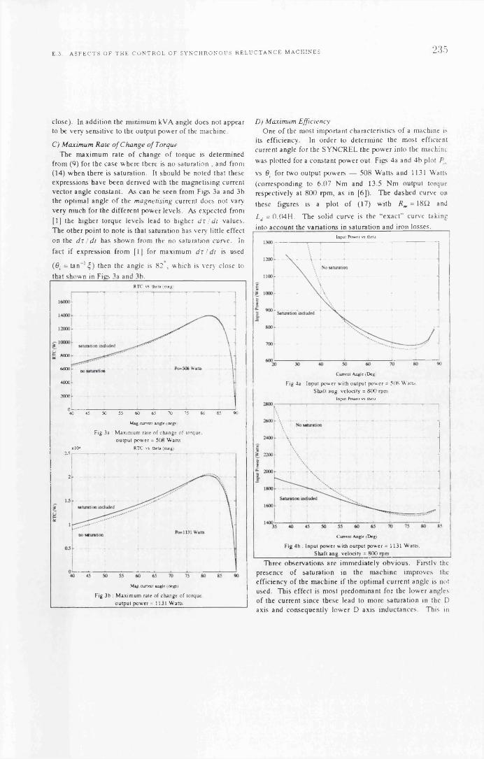
E 3 A S P E C T S O F T H E C O N T R O L O F S Y N C H R O N O U S R E L U C T A N C E M A C H I N E S 235
close). In addition the minimum kVA angle does not appear to be very sensitive to the output power of the machine.
C ) M axim um R a te o f C h a n g e o f TorqueThe maximum rate o f change o f torque is determined
from (9) for the case where there is no saturation , and from (14) when there is saturation. It should be noted that these expressions have been derived with the magnetising current vector angle constant. As can be seen from Figs 3a and 3b the optimal angle o f the m agn etisin g current does not vary very much for the different power levels. As expected from [1] the higher torque levels lead to higher d r / d t values. The other point to note is that saturation has very little effect on the d r / d t has shown from the no saturation curve. In
fact if expression from [ 1] for maximum d r ! d t is used
(0, = tan"1 £ ) then the angle is 82 , which is very close to
D ) M axim um E ffic iencyOne o f the most important characteristics o f a machine is
its efficiency. In order to determine the most efficient current angle for the SYNCREL the power into the machine
was plotted for a constant power out. Figs 4a and 4b plot Pin
vs 6 i for two output powers — 508 Watts and 1131 Watts
(corresponding to 6.07 Nm and 13.5 Nm output torque respectively at 800 rpm, as in [6]). The dashed curve on
these figures is a plot o f (17) with R m = 18f2 and
Ld = 0 .0 4 H . The solid curve is the “exact” curve takinginto account the variations in saturation and iron losses.
Lnpul Power vs theia
Current Angie (Deg)
Fig 4a : lnpul power wilh oulpul power = 5 0 8 W 'atts.
Shall ang. velocity = 800 rpmInput Power vs thela
Current Angie (Deg)
Fig 4b : Input power with output power = 1131 Watts, Shaft ang. velocity = 800 rpm
Three observations are immediately obvious. Firstly the presence o f saturation in the machine improves the efficiency o f the machine if the optimal current angle is not used. This effect is most predominant for the lower angles o f the current since these lead to more saturation in the D axis and consequently lower D axis inductances. This in
that shown in Figs 3a and 3b.RTC vs theta (mag)
8000
6000
4000
2000
050 55 70 75 80 85 0040 45 60 *5
Mag-current w g it I d t p i
Fig 3a : Maximum rale of change of torque, output power = 508 Watts
xlO4 RTC vs tbeia (mag)IS
£U
M ag.current angle (degsi
Fig 3b : Maximum rate of change of torque, output power = 1131 Watts

236 A P P E N D I X E P U B L I C A T I O N S
turn means that there is less induced voltage to drive current through the iron loss resistor. Secondly, there is very little difference between the optimal efficiency current angle predicted by the approximate solution and that determined from the precise curve. Finally the optimal efficiency angle is much greater than that predicted by the ideal model (71/4) .
The “exact” curves for the efficiency were not found by solving (17) transcendentally, but were computed by using a simpler and more direct set o f equations as shown below:—
r-21 I ta n 0 ,- | i ^ + ± | = 0
(20 )
where P d is the constant output power.Field W eakening Approx Angle
Appeox OeJd weakening
350 400 450 500 550 600 650 700 750 800 850
Angular Veiocity ( Rad. sec i
Fig 5a : Field weakening anglesC urrent M agnitude - fie ld W eakening
350 400 450 500 550 600 650 700 750 800 850
Angular Velocity (rad/sec)
Fig 5b : Current magnitude when field weakening
Equation (20) is solved (using the characteristics in Table
1) for the magnetising currents idm and i . These in turn
are substituted into (3) under steady state conditions to give
the terminal currents i^ and / and the terminal voltages
v^and v The input power is then sim ply:—
K = ‘V * + V * * (21)
F ) F ie ld W eakeningFigures 5a and 5b show the field weakening angle and
current magnitude when field weakening is being attempted. Field weakening is entered into when the angular velocity of a machine is increased to the point where the machine runs out o f volts. In the case which is plotted the machine was assumed to be running at 1750 rpm with an input current magnitude o f 15 Amps. From this data then the other “rated” conditions were evaluated. Normally this is a
straight forward operation, however with the non-linear R m
and L d characteristics this is not the case. The rated voltage
under the above conditions was va = 105 volts and
r raied= 5-4 Nm. The rated power was therefore
Pa = xratcd0)o / p p , which in this case was 990 Watts. This
was the constant power value which had to be maintained into the Field weakening region.
Fig 5a shows the field weakening angle for angular velocities above the “rated” value. The dashed line is using
(18) with both Rm and L d constant at 18Q and 0.04H respectively. The solid line denotes the exact Field weakening curve, evaluated taking into account the
variations in /?mand Ld . One point which is immediately
obvious is that both curves are o f sim ilar form, and just displaced. The approximate equation underestimates the Field angle required.
Fig 5b shows the current magnitude corresponding to the field weakening plot o f Fig 5a. The current magnitude decreases as field weakening begins since the machine is approaching the maximum efficiency operating point, and the power output is constant. However as the frequency is raised the current eventually increases above the initial rated value o f 15 Amps. The frequency where the current magnitude exceeds 15 Amps is the maximum field
weakening frequency (approximately 2 x (0 o ). This is much
less than the field weakening frequency predicted by the
ideal model [1] o f 3.6 x co o .
C o n c l u s io n s
This paper has developed the expressions for maximum torque per ampere, maximum power factor, maximum rate o f change o f torque and field weakening for the SYNCREL when the machine is subject to saturation and iron losses.
The derived expressions were then examined graphically using the parameters o f the machine in [6], The follow ing conclusions/observations can be made from this analysis:—

E 3 A S P E C T S O F T H E C O N T R O L O F S Y N C H R O N O U S R E L U C T A N C E M A C H I N E S 237
i) When the variations in R m and L d are incorporated into
the machine model the D axis current angle for the maximum torque per ampere varies very little from that obtained in [6], but dramatically from that predicted by the ideal model [1). Indeed if the approximate expression (5) is evaluated the optimum obtained is in good agreement with the exact answer.
ii) The maximum power factor angle for the machine is at an angle greater than the maximum torque per ampere. The angle for maximum power factor varies little with the output power o f the machine. It was found that the point o f maximum power is not necessarily the point o f minimum kVA.
iii) The maximum rate o f change o f torque magnetising current angle varies very little with the output power from the machine. In addition there is little error between the expression which ignores saturation and the more precise expression.
iv) The angle o f maximum efficiency is much greater than that predicted by the ideal model, as was observed by[6]. If the non-saturating model is used (but including the iron losses) then the angle obtained for the maximum efficiency is very close to the exact value. The angle o f maximum efficiency appears to vary very little with output power. The efficiency o f the saturating machine improves compared to the nonsaturating machine for lower values o f the current angles.
v) The SYNCREL model with saturation and iron losses can be field weakened in the same manner as the ideal model [ 1]. However the field weakening angle using the non-ideal models are at considerable variance with the ideal model — the field weakening angles are much larger. The approximate expression for the field weakening angle, whilst o f the same general form for the field weakening curve as the exact case, is erroneous enough to be o f little practical use.
A general observation that can be made about all the strategies considered is that the current angle o f operation is usually large so that the saturation in the D axis inductance is minimal, even for the higher output powers. This would indicate that the identification o f the saturated values o f the
L d inductance may not be required in a practical controller. The iron loss resistance on the other hand plays a crucial role in determining the optimum angles o f operation. In
some cases a constant value o f R m can be used, but in others
greater precision is required.The above observations are preliminary in nature. Much
more work is required to see if the observations for the example machine hold in general. The ultimate objective is to develop control strategies for the machine which will be able to optimise the performance.
A c k n o w l e d g m e n t s
R.E. Betz would like to acknowledge the Science andEngineering Research Council, the Scottish PowerElectronics and Electric Drives Consortium and ProfessorT.J.E. Miller for their financial and equipment supportduring the preliminary phases o f this work.
References
[1] R.E. Betz, “Theoretical Aspects o f the Control of Synchronous Reluctance M achines”, to appear IEE P roceed in gs, P a r t B.
[2] R.E. Betz and T.J.E. Miller, “Aspects o f the Control o f Synchronous Reluctance M achines”, P ro ceed in g s E uropean P o w e r E le c tro n ic s C o n fe ren ce EPE'91, F loren ce , Sept 6-9, 1991.
[3] R.E. Betz, “Control o f Synchronous Reluctance Machines”, A n n u a l M ee tin g IEEE-IAS, D earborn
USA, pp 456-462, Sept 29-Oct 4, 1991[4] A. Chiba and T. Fukao, “A Closed Loop Control of
Super High Speed Reluctance Motor for Quick Torque Response”, A n n u al M ee tin g IEEE-IAS. A tlan ta , USA, Oct 1987.
[5] A. Fratta, A. Vagati and F. Villata, “Control o f a Reluctance Synchronous Motor for Spindle Applications”, IPE C , Japan , 1990.
[6] L. Xu, X. Xu, T.A. Lipo and D.W . Novotny, “Vector Control o f a Synchronous Reluctance Motor including Saturation and Iron Losses”, IEE E Trans on Industry A pp lica tion s , vol. 27, no. 5, pp 977-985, Sept/Oct 1991
[7] L. Xu and J. Yao, “A Compensated Vector Control Scheme o f a Synchronous Reluctance Motor including Saturation and Iron Losses”, A n n u a l M ee tin g IEEE- IAS, D earborn , USA, pp 298-304, Sept 29-Oct 4. 1991.

A P P E N D IX E P U B L IC A T IO N

D S P 9 6 0 0 2 B A S E D HIGH P E R F O R M A N C E D I G I T A L V E C T O R C O N T R O L L E R 239
.4 D S P 9 60 0 2 B ased H igh Perform ance D ig ita l
V ector C ontroller for Synchronous R e lu c
tan ce M otors
In te rna tiona l Conference on E lectrical M achines
M anchester UK, 15-17 S ep tem ber 1992

240 A P P E N D I X E. P U B L I C A T I O N S
D SP96002 B a s e d H i g h P e r f o r m a n c e D i g i t a l V e c t o r C o n t r o l l e r f o r S y n c h r o n o u s R e l u c t a n c e M o t o r s
R. Lagerquist1 R.B. Betz2 T.J.E. Miller3
*,3S cottish Power E lectronics & Electrical E>rives Consortium . D epartm ent o f Electronics & Electrical Engineering,
University o f G lasgow , G12 8 0 0 .U nited Kingdom.
A bstractThis paper presents a 7 .5k W vector controller for
the c a g e le s s synchronous reluctance motors (SYNCHREL). The con tro ller features vo ltage space v ector PW M w ith advanced control algorithm s {1,21 im plem ented entirely in softw are. The controller em p loys a high perform ance D S P 9 6 0 0 2 d igita l signal processor.
T he con tro ller has sh ow n itse lf capable o f con tro llin g the SY N C H R EL w ith good dynam ic perform ance.
T he first sec tio n o f the paper presents the hardwareand softw are im plem entation o f the controller.
T he secon d se c tio n presents dynam ic response and perform ance data. The perform ance is good com pared to an induction m otor u sin g the sam e frame and w indings.
In troductionC om m ercia l controllers o ften rely on the
com b ination o f a m icro-contro ller and an application sp ec ific integrated circu it (ASIC) to im plem ent the control. T he use o f an ASIC o ften m eans that the controller is lim ited to one type o f m achine. In a research environm ent or o n e -o ff production the d evelo p m en t o f an ASIC w ould be co stly and counterproductive if the con tro ller w ere to be used to control other m otor types.
T he con tro ller presented in this paper uses a high speed d ig ita l sign al processor (DSP) to im plem ent the entire control in softw are. The DSP controls the sw itch in g o f the phases d irectly and can w ith an appropriate program control any 3-phase sinusoidally excited m otor. B y u sin g a DSP and softw are only approach, w e have d ev e lo p ed a general test facility for sin u so id a lly excited m otors. B y load in g appropriate softw are the con tro ller is ea sily converted to operate w ith d ifferen t m otor types.
V ector control o f the synchrel is im portant as the perform ance characteristics are d irectly dependent on the p lacem en t o f the current v ector relative to the m ost in d uctive a x is (d -ax is) o f rotor. T he DSP controller
2 Departm ent o f E lectrical <fc C om puter Engineering. University o f N ew castle, Callaghan.
A ustralia. 2308.
im plem ents the fo llo w in g control strategies id entified by B etz in [1,2]:
1.
2 .
3.
4.
5.
M axim um Torque Control (M T C ). T his refers to the w ell-k n ow n m axim um torque per am pere control strategy. T his is obtained w ith a current
angle 0 = 71 /4 radians. The speed at w h ich the
inverter runs out o f vo lts u sin g this control m ethod
is know n as the rated sp eed , co0 .
M axim um Rate o f C hange o f Torque Control (M R C T C ). T his refers to the control strategy proposed in [3] w here the rate o f ch an ge o f torque is op tim ised . The required current an gle for this is:
0 = tan_1£,, w here £ is the ratio L d / L q .
M axim um Pow er Factor Control (m p fc). T his control operates the m ach ine at the h ighest pow er factor obtainable. T his g iv es the lo w est ratio o f inverter kV A rating to output torque. The required
current angle is [2]: 0 = tan- 1 ^ .
Constant Current in the Inductive A x is Control ( c c ia c ) . This control m ethod keeps the current in the m ost inductive ax is constant and varies the current in the least inductive (q -ax is) to control the torque. O f all the strategies this strategy g iv es the highest rate o f change o f torque at lo w sp ee d s [2].
Field W eaken ing Control (F w c). W hen the inverter runs out o f vo lts the current angle is increased to m aintain constant pow er at h igher sp eed s. The current angle required for operation a b ove rated speed is [2]:
6 = tan'2 (0 „
C0n = (D /(O0
T his paper describes the hardware and softw are o f the DSP controller, and presents exp erim en ta l results. The perform ance is com pared w ith a com parable induction m otor.

E 4 D S P 9 6 0 0 2 B A S E D HI GH P E R F O R M A N C E D I G I T A L V E C T O R C O N T R O L L E R 241
R eso lv
B ase Di m
M G 50Q 2Y S91
415V ACO e i V oltage O ver C urren t
P ro tection
R r a r i v tf+mjlrm
O pto-links 3 x p h a se control
x enable 1 x fault
□M otoro la A D S 9 6 0 0 2
D S P 9 6 0 0 2 -3 3 .3 M H z
128K W orp SR A M
6 x A D 1332 12bit ADC 1 x A D 2S8C 1 0bit RDC 1 x O S C 1 7 5 8 R e t-O sc
P h a s e cu rre n ts D C link v o lta g e & c u rren t
A b so lu te R otor P osition
4 x A D 767 12 b it DAC
Digital I O
R S 2 3 2 S e ria l C o m m
B a s e Drive C on tro l
10 slot P assrve Backplane ( W E style)V oltag e S e n s o r s D C -link a n d M o to rN eu tra l u s in g A D 2 0 2 Iso la tx in Am plifier
C u rre n t S e n s o r s . LEM L A 50P flux nulling c u r re n t s e n s o r
Figure 1. DSP based SYNCHREL vector controller.
DSP based V ector C ontroller
T he ph ilosop h y behind this controller w as to create a general test fac ility that w ould enable tests o f alm ost any sin u so id a lly excited m achine w ithout having to build m achine sp e c ific hardware for each type o f m ach ine. To a ch iev e this full d igital control im plem ented in softw are is used, and has been taken to the extrem e by h avin g the p rocessor control the phase leg sw itch ing tim es u sin g vo ltage space vector PW M .
T he controller is d esign ed to handle loads o f 7 .5kW w ith a m axim um phase current o f 50A . The drive can a lso be used for regenerative action . At present the m axim um regenerated p ow er a llow ed is 100W .
T he user interface to the controller is via a term inal. The user can issue sim p le com m ands to control the operation o f the m otor and receive status in form ation . Several o f the control parameters can be ch an ged on -lin e through the term inal interface. If a com p uter is con n ected to the controller it can be used to issu e com p lex com m and se q u en ces.
Features o f the M otorola D SP96002
The M otorola D S P 9 6 0 0 2 uses a super scalar design a llo w in g more than one instruction per c y c le , and has a true IEEE floa tin g point unit. W hen clocked at 3 3 .3 M H z it offers 16.5 M IPS and 49 .5 M FLO PS peak throughput. T his perform ance is h ow ever not attainable u sin g current high lev e l language com p ilers. The bus in terface o f the DSP is w ell suited for in terfacing to both fast and slow p erip h era l-dev ices as the num ber o f w ait states is in d iv id u ally program m able for d ifferent parts o f the m em ory . This ensures optim um perform ance o f m em ory and peripheral d ev ices .
H ardw are
betw een the tw o units are transm itted over optical fibre. A n a lo g sign a ls are transm itted u sin g 50£2 current loop s. The ch osen interface m ethods enhance the system 's noise im m unity.
Pow er E lectronics
The inverter’s D C -link is drivenfrom a 3 phase 4 1 5 V rectified A C m ains sup p ly . T he D C -link capacitance is 4 5 0 0 p F . ToshibaM G 50Q 2Y S 91 insulated gate b ipolar transistor (IGBT) m odu les w ith a rating o f 1 200V 5 0 A are used for the three phase legs. The IGBT gate drive circu its drives the gates w ith both p ositive and
negative voltage to ensure rapid and precise sw itch in g .
B y incorporating protection for D C -linkover/under-voltage, and D C -link and phase over current, the unit is m ade s e lf p rotecting. S e lf protection in the p ow er electron ics unit is im portant during the co m m issio n in g stage o f new control program s.
The unit has four high bandw idth f lu x -n u llin g LEM L A 50P current sensors m easuring D C -link and phase currents. D C -link voltage is m easured u sin g an A D 2 0 2 iso la tion am plifier. The m easuring and control electron ics are thus tota lly insulated from the high voltage p ow er e lectron ics.
D SP-control unit
A s can be seen from figure 1 the control unit is a bus based system . The processor and peripheral cards plug into a standard V M E sty le p a ss iv e back plane. The back plane can accom m odate a m axim um o f 10 expansion cards facilita ting easy ex p an sion o f the system . The d esign a llo w s for the use o f tw o d ifferent bus speeds w h en a ccess in g d ev ices on the bus. For fast d ev ices the access tim es used is 9 1 n s, s lo w d e v ic e s are accessed w ith 180ns. O n-board m em ory is a ccesse d at m axim um speed , 30ns.
The system con sists currently o f three d ou b le s iz e Eurocards housed in a standard 19” rack en closure . The boards are:
P r o c e s s o r b o a r d
The p rocessor board used is the DSP96002ADS develop m en t board from M otorola. It features 128k words o f 32bit static RAM and operates w ith a c lo ck frequency o f 33 .3 M H z. U nfortunately this processor board is not capable o f driv ing the back plane d irectly , and requires an external bus-buffer board.
T he vector contro ller is sp lit into a d igital control- umt and a p ow er-e lectron ics unit. D igital signals

242 A P P E N D I X E P U B L I C A T I O N S
VA U O O IIO U
CCIAC vq(pw m )CURRENT
S P A C EV E C T O R
PW MG EN
MACHINE
CAC C U R R E N T
R E Frvd(pw m )
CU RREN TAVERAGER
CTRLRELD
WEAKENINGC O N T R O LSELECTOR R L SE
PA R A M ETER ESTIM A TO R X formA U TO
LO O K U P
TORQUEe
ESTIM ATOR
C U R R E N TANG LECALC
Figure 2. Control Structure B lock D iagram
D a ta a c q u is i t io n b o a r d
The data acq u isition is responsib le for sam p lin g all an a log m easurem ents required, and to drive and d ecod e the shaft p osition from a resolver. The board w as m ade u sin g S peedW ire as this system is fast and w ell suited for bus work.
A n a lo g to dig ita l co n version is perform ed by six A D 1 3 3 2 s 12-bit ADCs. T h ese d ev ices suit the ap p lication esp e c ia lly w e ll as they incorporate a 32 entry FIFO w h ich buffers the sam p les and generates an interrupt at either full or h alf-fu ll buffer. T he sam ple period is controlled by an Intel 8 2 5 4 16-bit program m able tim er driven by a 10M H z oscillator. T he sy stem is set up to use the half-fu ll interrupt to initiate a n ew control interval.
A t the start o f the control interval each ADC conta ins 16 data points stored in the FIFOs; these are read w ith an a ccess tim e o f 91n s for each point. By interrupting the p rocessor o n ly o n ce during the control in terval, overhead that w ou ld have resulted from 15 additional interrupts has been elim inated .
The rotor position is m easured on ce each control interval u s in g a resolver that g iv es an absolute position sign a l. T h e rotor o f the resolver is excited by a harm onic free, high pow er 5 .6k H z sinusoidal o sc illa to r , O S C 1 7 5 8 . The reso lver produces sin and cos w a v e form s corresp on d ing to the rotor position . T hese sign a ls are d ecod ed by an A D 2 S 8 0 resolver to d igital con verter (RDC). T he RDC is capable o f d eliverin g 16- bit accu racy , but it is used at 10-bit accuracy to enable h igh -sp eed operation.
B a s e d r i v e c o n tr o l a n d a n a lo g o u tp u t b o a r d
An i8 2 5 1 UARTand an i8 2 5 4 tim er form s the serial com m u n ica tio n interface . U s in g the i8 2 5 4 as a baud
rate generator a w id e range o f baud rates can be program m ed.
Four A D 7 6 7 12-bit d ig ita l to an a log converters (d a c ) are used to output real tim e data that w ou ld be im possib le to transmit over a lo w sp>eed serial line.
The base drive control circuit's function is to produce a desired vo ltage vector. The desired vo ltage vector is m ade up o f three d istinct v o lta g e vectors w hich during the control interval add up to the desired voltage vector. The base drive control c ircu it con sists o f an i8 2 5 4 16-bit tim er, op tica l Fibre transm itters and glue log ic . The DSP w ill at the start o f a control interval set the state o f the phase legs and program the tim er to change the state at particular tim es during the control interval. The use o f a tim er saves p rocessor ex ecu tion tim e because the processor d o es not constan tly have to poll a tim er to determ ine w h en to sw itch the phase legs.
Programming EnvironmentThe DSP program s can be w ritten in C or assem b ler
and are com p iled , assem b led , linked and relocated to produce an absolute program file on a PC. The program file is dow nloaded to the DSP's RAM through a specia l PC-adapter card con n ected to the d ebug interface o f the DSP. If program s w ere not dow nloaded to RAM from the PC four eprom s w ou ld have to be program med for each program /debug c y c le , thus considerable tim e is saved during d evelop m en t using this system .
Control program structureThe control program running on the DSP
im plem ents the fo llo w in g operating m odes; MTC, MRCTC, MPFC, CCIAC and FWC. The control program is based on the SYNCHREL sim u lation program described

E 4 D S P 9 6 0 0 2 B A S E D HI GH P E R F O R M A N C E D I G I T A L V E C T O R C O N T R O L L E R 243
in [ 1] and con sists o f 99% A N S I-C cod e w hich uses floa tin g poin t arithm etic throughout. The use o f floa tin g p oin t variab les and b asin g the control program on an e x is t in g sim u la tion program , written in C, has d rastically reduced d evelop m en t tim e.
The con tro l interval is at present 5 7 6 p s and with
som e production en g in eer in g could either be reduced or m ake it p oss ib le to use a less exp en sive processor, e .g . D S P 5 6 0 0 0 . T h is w’ould in vo lve rew riting in assem b ler and/or con version to fixed -p oin t arithm etic.
C ontrol StructureFigure 2 sh o w s the structure o f the vector
controller. A s can be seen , the controller supports both speed and p ositio n control. The control structure m ay look c o m p le x , h ow ev er the program flow is quite straightforw ard. The control program con sists o f a m ain program w h ich d oes com m and interpretation / response, and an interrupt routine w h ich execu tes the actual control a lgorithm s. The flow o f the interrupt program is as fo llow s:
1. Program tim ers w ith vo ltage space vector PW M pattern for current control interval.
2 . Read in all sam pled data and rotor position . A verages sam pled data and convert currents into d-q fram e va lu es.
3 . C h eck seria l input for characters. A cts on stop com m and and pass other characters to the main program for interpretation.
4. E stim ate m ach ine param eters (L j , R) using recursive least squares (RLS) estim ator.
5 . Predict currents and average torque over the current control interval.
6. P redict rotational v e lo c ity u sin g ou observer.
7. For p ositio n con tro l, ca lcu late desired speed u sin g PI control.
8. U s in g se lected control type perform Field w ea k en in g ca lcu la tion to determ ine required current an gle.
9. C alcu late the desired torque u sin g PI control from the desired speed and current angle.
12. C alcu late d- and q -ax is current reference va lu es based on desired torque, speed and current angle va lu es.
13. C alcu late desired d-q vo lta g es from the desired d-q currents u sin g PI control. Correct voltage for term s due to resistance and m otional em f.
14. C alcu late the m ost e ffic ien t sw itch in g pattern that a ch iev es the required vo ltage vector using v o lta g e space v ecto r PW M [5 ], save the pattern for use at start o f next control interval.
Results and Conclusion
T able 1 sh o w s that the perform ance o f the SYNCHREL is better than a com parable induction m otor. Figure 3 sh o w s the d-q currents, and phase current and
vo ltage . The vo ltage show's a characteristic chopped s ix -step w ave form . Figure 4 sh o w s the drive d o in g a speed reversal in 0 .1 s , the tim e for M PFC is 0 .0 9 4 s and C C IA C is 0 .1 7 s. Figure 5 sh ow s a step torque ch an ge, the torque reaches the required level after 3 3 m s.
A high perform ance D SP based drive sy stem has been built. The system has sh o w n goo d dynam ic perform ance. The e ffic ien cy o f the SYNCHREL proved to be good . The field w ea k en in g cap ab ility has not been tested fu lly as the d-q fram e m ovem en t, w ith the present control interval, gets too large at h igh sp eeds.
Full-Load Param etersM TC
120W SYNCHREL
120W Induction M otor
Shaft Power [Wl 142.5 120
Speed [RPM] 1500 1360
Torque [Nm] 0.90 0.84
Load Current [A] 0.3998 0.46
Supply V oltage [V] 438.0 40 0
VA Rating 303.29 318.7
Pow er Factor 0.6678 0.62
Efficiency [%] 70.34 61.2
Total Losses [W] 60.03 76
Table 1. SYNCHREL and Induction M otor Perform ance Data
0.5? A '
1
0.0 A '
05?A
0.57A
1
0.0*
4 5 7A
t - r
- - ■■■■ -to iSec . —
600 ,
V
0.0V
•600V
Figure 3. V oltage and Current w a v e form s for M TC operation. o)=1400rpm , T = 0 .8 4 N m .Top: d-q currents. B ottom : phase current and v o lta g e .

244 A P P E N D I X E. P U B L I C A T I O N S
3 r r rNm flPW
1 1000ton m i f A
1 V y V V1
•1 1000 7to« m
1
■3
1
-3000ton m i
-200 u5ec 200 r15«c — — eOOmSec
Figure 4 . S p eed reversal during M T C operation, co = + /- 1 4 0 0 rpm.
1
I1
1Nm
1
0 . Nn
i
§ 8 J
I -
»
1
0RPtl
A „
\ A ^
200 t i e c — - . a o c i Sec — 60C
Figure 5. S tep load change during M TC operation. o)=1400rpm , T = 0 .1 4 N m - 0 .8 4 N m (0 .1 7 p .u .-l.O p.u.).
2 .6 0 H
1 .68 H
0 .3 9 H
9 8 .0 Q
0 .4 7 A
Figure 6 . C ro ss-sec tio n o f 120W A x ia lly Lam inated S yn ch ron ou s R eluctance M otor.
S y n c h r e l D ata
The SYNCHREL rotor is an ax ia lly lam inated d esign show n in Figure 6. It is u sin g the sam e fram e and w indings as the induction m otor it is com pared w ith .
Ld (unsat) =
Ld (Idpk= 0 .6 1 A )
Lq
^ phase @ 2 0 C =
Rated Phase Current =
AcknowledgementsThe authors w ould like to thank the fo llo w in g com panies and individuals:
The C o m m itte e o f V ic e - C h a n c e l lo r s a n d P r in c ip a l s o f
th e U n iv e r s i t ie s o f th e U n ite d K in g d o m (CVCP ORS- award) and the S c o t t i s h P o w e r E le c t r o n ic s a n d
E le c tr ic a l D r iv e s C o n s o r tiu m (SPEED) for Financial support o f R. Lagerquist.S c ie n c e a n d E n g in e e r in g R e s e a r c h C o u n c i l (SERC) for financial support o f R.E. B etz (v is it in g F ello w sh ip ).F . F le t t & A n a lo g D e v ic e s for contribution o f linear and data-conversion d ev ices .I. D u th ie , A . H u tto n & M o to r o la for the DSP d evelopm ent system .S .E . W o o d & B r o o k C r o m p to n for the m otor.D . S ta to n for d esig n in g the SYNCHREL rotor, and for theoretical and static data for the SYNCHREL.J . K e l ly for m aking the SYNCHREL rotor.P . M il le r for d esig n in g and b u ild in g the pow er electron ics.
References:[1] B etz R E, "Control o f Synchronous
R eluctance M achines", A nnual M eetin g IE E E -IA S , Sept 29-O ct 4, Dearborn, U S A , 1991 .
[2] B etz R E, M iller T J E, "A spects o f the Control o f Synchronous R elu ctan ce M achines", EPE Firenze, pp. 1 -380 - 1 -385 , 1991
[3] Chiba A , Fukao T , "A C losed L oop C ontrol o f super H igh Speed R eluctance M otor for Q u ick Torque R esponse", Annual M eetin g IE E E -IA S , A tlanta , U S A , 1987.
[4] Lorenz R D , V an Patten K, "High R eso lu tion V elocity Estim ator for A ll D ig ita l A C Servo D rives", Annual M eeting IE E E -IA S, pp 3 6 3 -3 6 8 , 1988 .
[5] van der B roeck H W , Sk u deln y H C, StankeG, "A nalysis and R ealization o f a Pulse W idth M odulator B ased on V oltage S p ace V ectors", A nnual M eeting IE E E -IA S, pp 2 4 4 -2 5 1 , 1986 .

E.5. T H E S Y N C H R O N O U S R E L U C T A N C E M O T O R F O R M O T I O N C O N T R O L A P P L I C A T I O N S 245
E.5 T he synchronous re luctance m otor for m o
tion control applications
21st A nnual Sym posium on Increm enta l M otion Control System s and Devices
San Jose, California, Ju n e 15-19, 1992

246 A P P E N D I X E P U B L I C A T I O N S
THE SYNCHRONOUS RELUCTANCE MOTOR FOR MOTION CONTROL APPLICATIONS
JR H endershot Jr TJE Miller, DA Staton, R Lagerqulst
Magna Physics Corp. SPEED Laboratory, University of Glasgow
Hillsboro OHIO 45133 Glasgow G12 8LT, UK
Abstract
The synchronous reluctance motor is under renewed
development and evaluation for motion-control applications
and vanable-speed dnves. Although it has a long history as
a line-start motor with a cage winding on the rotor, recent
developments have focussed on the cageless motor with
cuirent-regulated PWM inverter control. Because of the field-
orientation of this type of drive, and the enhanced
electromagnetics without the starting cage, much higher
performance is possible, not only in terms of efficiency and
power-factor, but also in terms of control performance. In
order to realise these benefits the a x ally-I am mated rotor
construction is virtually essential, as this is the only structure
that permits a sufficiently high saliency ratio to achieve
competitive performance The stator and the power electronic
circuit are similar to those used with induction motors or
brushless DC motors. Consequently many of the advantages
claimed for the switched reluctance motor can be realised
using standard components. These advantages include high
efficiency at low speed, constant-power operation over a wide
speed range, and freedom from permanent magnets. In
addition, the synchronous reluctance motor has lower torque
npple and is quieter than the equivalent switched reluctance
motor.
1. INTRODUCTION
This p a p e r rev iew s th e sy n ch ro n o u s re lu c tan ce m otor
(Synchrel m otor) in th e light of re c e n t d ev e lo p m en ts in its
e le c tro m ag n e tic d e s ig n a n d its e lectron ic control.
The S ynchrel motor has many of the advantages of the
switched reluctance (SR) motor, yet it u ses standard
components in common with brushless DC or induction
motors, including the stator and the power-electronic circuit
The torque npple is also less than that of the SR motor.
The mam advantages of the S y n c h r e l motor are as follows:
1. Freedom from permanent magnets
2. A wide speed range at constant power
3. Synchronous operation, leading to high efficiency
and the ability to maintain full torque at zero speed
(which is difficult with induction motors)
The m an disadvantages are as follows:
1. In small motors the torque/ampere and the
torque/volume are lower than in PM motors
2. A sinewave drive is required, with continuous shaft
position feedback for orientation of the stator MMF
3. A small airgap is required, comparable to that of
induction motors
The first of these disadvantages will becom e much less
significant in larger motors, say, over 5-1 OkW in rating,
because of the high cost of m agnets in large motors, and also
because the reluctance motor performance improves rapidly
with increasing size.

E. 5 . T H E S Y N C H R O N O U S R E L U C T A N C E M O T O R F O R M O T I O N C O N T R O L A P P L I C A T I O N S 247
Fig. 1 Segmental (upper) and axially-laminated (lower) synchronous reluctance motors. The segm ental type shown here has an amortisseur winding and is self-starting. The axially-laminated type has a higher saliency ratio but requires shaft position feedback and a current-controlled PWM (field-onented) inverter.
248 A P P E N D I X E P U B L I C A T I O N S
The performance of the S y n c h r e l motor depends critically on
the XyXq rabo or saliency ratio, and in order to achieve a
high saliency rabo the axially-laminated construcbon is
virtually essenbal, Fig. 1. This form of construcbon was
introduced by Cruickshank et al [1], but it has been ’re
invented" recently without the cage winding, and coupled with
the modem vector-controlled type of PWM inverter. Both of
these modifications bring significant performance advantages.
One of the main reasons for the current interest in the
S y n c h r e l motor is that it is seen as a potenbai aJtemabve to
the switched reluctance motor, providing most of the
advantages with few of the disadvantages (non-standard
components, high noise and torque npple). Several papers on
the S y n c h r e l motor and its predecessors are listed in the
References.
2. THE SYNCHRONOUS RELUCTANCE MOTOR
The S y n c h r e l motor is a true AC motor: this m eans that
it has a rotabng MMF produced by polyphase sinewave
currents flowing in sine-disfributed windings, exacby like the
inducbon motor or the sinewave brushless DC permanent-
magnet motor. In fact, the stator can be idenbcal to that of
either of these motors. Apart from slotbng, and the fact that
the windings are not perfecby sine-distributed, it sabsfies the
necessary condibons for the producbon of constant instantaneous torque (i.e. zero torque npple). These
condibons are the sam e on es that make possible the use of
dq-axts theory, and therefore the synchronous reluctance
motor can be controlled by a field-oriented AC controller in
much the sam e way as any other synchronous machine. This
is the preferred form of control for high-performance
applicabons.
The use of standard components in the stator, the
winding configuration, and the power electronic circuit means
that the charactensbcs of the reluctance motor can be
achieved with minimum re-investment in new tooling and
design techniques.
S ync h r el vs. Induction Motor
First, because there is no slip, the rotor lo sses are lower
than those of the inducbon motor. This is important at low
speed, where the torque is limited by rotor lo sses. The
S y n c h r e l motor should have higher power factor and higher
conbnuous torque rabng at low speed, when compared to the
inducbon motor. The higher power factor translates into a
lower inverter kVA requirement The differences may typically
be of the order of a few percent which may not seem great
but in specialty applicabons such as electnc vehicle dnves a
few percent in kVA or efficiency can make a large difference.
The fulMoad efficiency at rated speed, and the speed
range at constant power, should also exceed the values
obtainable with inducbon motors However, a ll the
performance advantages of the synchronous reluctance motor
are obtainable only with a sufficienby high saliency ratio, that
is, the rabo between the d-axis and q-axis synchronous
reactances Tests on a series of D132 motors have shown
that in order to outperform the inducbon motor by a significant
margin over the enbre speed range, the saliency rabo needs
to be at least 8:1. This high value is extremely difficult to
achieve with segmental-rotor designs such a s the one shown
in Fig 1. Indeed it appears that such a high value is possible
only with the axially-laminated construcbon. Note that the
axially-laminated rotor cannot be built from the material
punched out of the stator laminabon, but requires fresh
material in the form of cut stnp which must be formed,
stacked, and bolted to a square or hexagonal shaft.
S y n c h re l vs. Brushless PM Motor
The S y n c h r e l motor is free from the attendant problems
of permanent m agnets, but the price paid for this is a
signibcanby lower torque per ampere in small frame sizes. On
the other hand, the S y n c h r e l motor has a naturally inverse
speed/torque characteristic, and with the correct control

E. 5. T H E S Y N C H R O N O U S R E L U C T A N C E M O T O R F O R M O T I O N C O N T R O L A P P L I C A T I O N S 249
strategy it can maintain constant-power operation over a wide
speed range, which is approximately equal to half the
saliency ratio. In large sizes (say, over 10kW) the pnce of
magnets is often prohibitive, while the performance of the
S y n c h r e l motor improves with size. Therefore there is likely
to be a size range where the S y n c h r e l motor has a clear
advantage as a synchronous brushless motor with high
efficiency and power factor, especially if operation is required
at very low or very high speeds.
S y n c h re l vs. Switched Reluctance Motor
The most striking advantage of the switched reluctance
motor over inducbon motors is the ability to maintain full
torque down to very low speed without exceeding the thermal
limits. As a synchronous machine, the S y n c h r e l motor has
the sam e charactensbc. Unlike the switched reluctance motor,
it does not suffer from high torque npple because it is a true
synchronous AC motor. But its raw power density may be
somewhat lower than that of the switched reluctance motor
3. CONTROL OF THE SYNCHREL MOTOR
The S y n c h r e l motor requires correct MMF onentabon to
be maintained at all load points, necessitabng a vector type
of current-controlled PWM inverter with precise shaft-posibon
feedback (e g a resolver, 1000-line encoder, or equivalent).
Such transducers are, of course, also used with field-onented
control in inducbon motor drives; but whereas the inducbon-
motor has line-start capability as a back-up operabng mode,
this is not the ca se with the cageless S y n c h r e l motor. Unlike
the inducbon motor, the S y n c h r e l motor cannot be operated
stably without vector control. Earlier types of self-starbng
synchronous reluctance motors with amorbsseur (cage)
windings could run open-loop, but their performance is
significantly lower than that of the controlled cageless type
discussed here.
The torque angle, i.e. the onentabon of the MMF with
respect to the rotor posrbon, is not as simple as might be
supposed. In the classical theory of the synchronous
machine, the electromagnebc torque is given by the equabon
T = mpldlq(Ld - Lq)(1)
= pi2 sin2y2
where m is the number of phases, p is the number of pole-
pairs, Ld and Lq are the direct- and quadrature-axis
synchronous inductances respectively, and y is the torque
angle. This equabon is often quoted in isoiabon and is
interpreted to mean that the torque per ampere is maximized
if the inductance difference is maximized and the torque
angle maintained at a constant 45°. However, this ignores the
fact that the inverter voltage is limited, and in order to
minimize the volt-ampere product the torque single should be
given by
These considerations apply to steady-state operation only. In
steady-state operation the angle may be chosen to maximize
the power-factor or the torque per ampere, but not both at the
sam e bme. If dynamics are important, for exam ple operation
at high speed with a constant-power characterisbc, or
maintaining constant speed with a rapidly varying load torque,
then the angle must be controlled by a more complex type of
algorithm that is comparable in complexity to those used in
field-oriented control of inducbon motors. Several altemabve
algorithms for this purpose have been developed and
analyzed by Betz [10], and sin expenmental vector controller
has been designed and built in the SPEED laboratory [11],

A P P E N D I X E P U B L I C A T I O N
Resolver
Base DriveIGBTs
MG50Q2YS91
415V ACOver Voltage, Over Current
Protection
o
Motorola ADS96002
DSP96002-33.3MH2
128KWord SRAM
6 x AD1332 12bit ADC 1 x AD2S80 10bit RDC 1 x 0SC1758 Ret-Osc.
Phase currents.DC link voltage & current
Absolute Rotor Position.
Opto-Unks:3 x phase control 1 x enable1 x fault
4 x AD767 12bit DACDigital I/O
RS232 Serial Comm Base Drive Control
RS232
10 slot Passive Backplane (VME style)Voltage Sensors: DC-link and MotorNeutral using AD202 Isolation Amplifier
Current Sensors: LEM LA50P flux nulling current sensor
Fig. 2 DSP based S ynchrel motor controller
SPACEVECTOR
PWMGEN
MACHINE
CACCURRENT
REPL* P.l.
OBSERVER
RLSEPARAMETERESTIMATOR
CURRENTANGLECALC
Fig. 3 Synchrel motor controller block diagram

E.5. T H E S Y N C H R O N O U S R E L U C T A N C E M O T O R F O R M O T I O N C O N T R O L A P P L I C A T I O N S 251
This controller is shown in Figs. 2 and 3. The rating is
7.5kW with 415V 3-phase AC input at 50Hz. The power
semiconductor devices are IGBT modules and the main
control processor is the Motorola D SP96002 clocked at
33MHz. The control algorithms descnbed in [10,11] are ail implemented in the block diagram in Fig. 3 as alternatives
that can be selected by software switches tor expenmental
evaluation The complexity of a production version would not
be nearly so great a s suggested by this diagram. The real
time code for the DSP control w as denved from a simulation
of the entire drive in C' which was ported to the DSP
development system and re-compiled for the 96002, a
process which drastically cuts the development time required
for system s of this complexity.
4. PRELIMINARY PERFORMANCE COMPARISON DATA
The following data provides a companson between the
performance of three motors in D132 totally-enclosed fan-
ventilated frames The data is a highly condensed summary
of a se n e s of tests and studies, but it provides an idea of the
main differences at rated load and full speed. None of the
S y n c h r e l motor test data w as ta k e n with th e new controller
descnbed in Section 3, since these tests are still incomplete.
The test data presented here was obtained with a modified
commercial induction motor inverter
The three motors are as follows :
1. A commercial induction motor designed for sinewave
operation at 50Hz, in a D132 aluminium frame.
2. A synchronous reluctance motor built into the
induction motor stator, with an axially-laminated
rotor.
3 A commercial switched reluctance motor (also
descnbed in Ref 9) designed for vanable-speed
operation from 300-1500 rpm in a D132 cast-iron
frame.
The perform ance com parison d ep en d s very m uch on
how the m ach ines are rated. Two tables of data are given,
corresponding to two different ratings for the AC motors
Table 1 has them rated at 11kW, which is the maximum
continuous thermal rating of the induction motor running from
a sinew ave supply at full speed.
When the induction motor is operated from a PWM
inverter, its fuil-speed rating has to be decreased to 6 kW (40
Nm at 1471 rpm) so that the maximum torque can be
provided all the way down to zero speed without exceeding
the temperature-nse on which the sinew ave rating of 11 kW
is based. Therefore in Table 2 the motors are compared at
the reduced rating.
In order to provide comparison data with the SRM at the
sam e ratings, the SRM data is calculated by PC-SRD,
starting with the normal rating (7.5kW) and modifying the
winding turns (from 7CVpole at 7.5kW to 77 at 6kW and 58 at
1 ikW) to give approximately the sam e output power a s the
two AC motors. The modelling of this particular SRM with PC-
SRD is known to be very accurate at the full-load point and
the error introduced by scaling the turns is considered to be
negligible for the present purposes
Com parison at 11 kW rating (Table 1)
At the maximum thermal rating the synchronous
reluctance motor has an efficiency nearly 1.5% higher than
that of the induction motor (09.6% compared with 88.2%), but
its power factor is slightly lower (0.855 compared with 0.867).
The efficiency of the switched reluctance motor lies between
the figures for the two AC motors at 89.2%, but its inverter
kVA requirement is higher: 122.4 kVA compared with 115
kVA (see N otes). These differences are not large, and are
not likely to be significant for general p u rp ose adjustable-
speed drives. But in applications such as com pressor drives
or electric vehicle traction, where efficiency at sustained full
load operation is a critical parameter, the synchronous
reluctance motor com es out clearly ahead, with the highest
efficiency but a lower kVA requirement than the switched

252 A P P E N D I X E. P U B L I C A T I O N S
reluctance motor (and with all components standard except
the rotor and the inverter control algorithm).
C om parison at 6 kW rating (Table 2)
For full variable-speed operation this is the correct rating
figure to u se as a basis for com pan son. Now the switched
reluctance motor has the highest efficiency (89%) but it is
only marginally better than the 88.8% of the induction motor.
However, the power factor of the induction motor, at what is
essentially a part-load rating, is significantly lower than at full
load and its kVA requirement is 80.3 kVA compared with 69.4
for the switched reluctance motor. It is interesting that the
kVA per kW for the switched reluctance motor does not
change appreciably between the two ratings The
synchronous reluctance motor now has the lowest efficiency,
at 88.2%, but it also has the lowest kVA requirement at
63 .5kVA.
"Tiis basis of comparison does not really bring out the
major differences between the SRM and the two AC motors.
These differences are likety to be more pronounced at very
low speeds. Although we do not have test data to verify this,
we know that the synchronous and the switched reluctance
motors do not need to be de-rated for PWM inverter
operation, and we can assu m e that any de-rating necessary
to permit low-speed operation (with reduced cooling) will be
quite small, because th ese motors have no slip lo sses and
they can maintain their effective power-factor over the entire
speed range. The de-rating of the induction motor w as from
73 Nm to 40 Nm, a reduction of 45%. If half of this de-rating
was required for low-speed operation of the reluctance
motors, they would be delivering about 56 Nm at low speed,
which is about 40% more torque than the induction motor. A
test calculation with PC-SRD show s that at 55 Nm and 300
rpm, the lo sses in the switched reluctance motor are only
about half the full-load value and the winding currerrt-density
is only 0.9 of the full-load value.
PARAMETER Induction Synchrel SRM
Full-load shaft power (kW) 11.0 11.0 10.9
Full-load speed (rpm) 1439 1500 1500
Full-load torque (Nm) 73.0 70.0 69 1
Transistor peak kVA requirement 115.0 114.9 122.4
Full-load power-factor 0.867 0.855 NA
Full-load efficiency % 88 2 89.55 89.2
Inductance ratio NA 11.2" ,
Table 1 Com parison data at 11 kW

E. 5. T H E S Y N C H R O N O U S R E L U C T A N C E M O T O R F O R M O T I O N C O N T R O L A P P L I C A T I O N S 253
PARAMETER Induction Synchrel SRM
Full-load shaft power (kW) 6.0 6.0 6.1
Full-load sp eed (rpm) 1471 1500 1500
Full-load torque (Nm) 39.8 38.2 38.9
Transistor peak kVA requirement 80.3 63.5 69 4
Full-load power-factor 0.688 0.856 NA
Full-load efficiency % 8d 8 88.2 89.0 |
Inductance ratio NA 11.6 11.6
Table 2 C om parison data at 6 kW
N otes The induction-motor data is appropriate to a
commercial motor designed for m ass production rather than
for the ultimate performance The synchronous reluctance
motor u ses the sam e stator and the sam e aurgap length The
figures for the synchronous reluctance motor are estim ates
and do not include any allowance for end-winding inductance;
they are therefore slightly optimistic, but it is calculated that
this effect reduces the inductance ratio by 13% and increases
the kVA requirement by only 2.5%. The kVA requirement is
evaluated as the product of the number of transistors times
the peak current times the DC link voltage in the controller,
and the surprisingly low kVA requirement of the synchronous
reluctance motor should be noted. This is due to the high
saliency ratio achievable with the axially-laminated
construction The efficiencies calculated for the switched
reluctance motor are based on the use of 3% Silicon steel
The other two motors u se low-carbon steel in the stator but
the synchronous reluctance rotor has 1.5% Silicon steel
laminations.
5. CONCLUSION
The synchronous reluctance motor appears to offer several
of the advantages of the switched reluctance motor while
retaining many com ponents in common with the induction
motor, including the stator and the power electronic controller
circuit. At the maximum thermal rating the synchronous
reluctance motor has the highest efficiency and lowest kVA
requirement. But at the maximum thermal low-speed rating of
the induction motor, the switched reluctance motor has the
highest efficiency Indications are that at low speeds both
reluctance motors should be capable of more torque than the
induction motor, perhaps by as much as 40%, with the
synchronous reluctance motor having the advantage of lower
kVA than the switched reluctance motor.
ACKNOWLEDGEMENT
The authors would like to thank Stephen E. Wood of Brook
Crompton, Huddersfield, for close collaboration on this pro|ect
and especially for the test data and calculations on the
induction and synchronous reluctance motors. The S y n c h r e l
motor control algonthms mentioned in Section 3 were
onginated by Dr. Robert Betz of the University of Newcastle,
NSW, Australia, dunng a Visiting Fellowship in the SPEED
Laboratory supported by the UK Science and Engineenng
Research Council Several colleagues in the SPEED
laboratory have contributed to the test programme.

254A P P E N D I X E. P U B L I C A T I O N S
7. REFERENCES
1. Cruickshank AJO, Anderson AF, and Menzies RW : Theory and performance of reluctance motors with axially laminated anisotropic rotors*, IEE Proceedings, 118, No. 7, July 1971, pp. 887-894
2. Miller TJE, Staton DA, and Wood SE . "Optimization of the synchronous reluctance motor geometry*, IEE Conference on Electrical M achines and Drives, London, September 13-15, 1991
3. Xu L, Lipo T, and Rao SC : "Analysis of a new variable- speed singly-salient reluctance motor utilizing only two transistor sw itches’ , IEEE Transactions, IA-26, No. 2, Mar/Apr 1990
4 Fratta A, Vagati A and Villata F : 'Control of a reluctance synchronous motor for spindle applications", International Power Electronics Conference, Tokyo, Apnl 1990, pp. 708- 715
5. Fukao T, Chiba A and Matsui M : T e s t results on a super high-speed amorphous-iron reluctance motor", IEEE Transactions, IA-25, No. 1, pp. 119-125
6. Honsinger V.B. : "The inductances Ld and Lq of reluctance machines", IEEE Transactions, PAS-90, No. 1, Jan/Feb 1971, pp. 298-304
7. Lawrenson PJ and Gupta SK : "Developments in the performance and theory of segmental-rotor reluctance machines", IEE Proceedings, 114
8. Miller, TJE, Staton, DA, and Wood, SE : ‘Maximizing the Saliency Ratio of the Synchronous Reluctance Motor", paper submitted for publication in Proceedings IEE, 17 January 1992
9. Hams, MR and Miller, TJE : "Comparison of Design and Performance Parameters in Switched Reluctance and Induction Motors", IEE Conference on Electrical Machines and Drives, London, September 1989
10. Betz RE : "Control of synchronous reluctance machines", IEEE IAS Annual Meeting, Dearborn, Septem ber 28-October 4, 1991, Conference Record, pp. 456-462
11. Lagerquist R, Betz RE and Miller TJE : "DSP96002 based vector controller for synchronous reluctance motors", to be published in International Conference on Electric Machines (ICEM’92), Manchester, September 13-15, 1992

R e fe re n c e s
[1 ] D. P la t t , “R eluc tance m o to r w ith s trong ro tor an iso tropy” , in I E E E Ind. Appl.
Society A n nua l Meeting. 1990, pp. 225-229.
[2] M. Ehsan i, I. Husain, and A. B. Kulkarni, “E lim ia tion of d irect position sensor
and curren t sensor in switched reluc tance m o to r drives” , in I E E E Ind. Appl.
Society A n n u a l M eeting , 1990, pp. 518-524.
[3] R. J. Hill, P. P. A earn ley, and W. Colville, “S tepp ing m oto rs and drive circuits
th e r fo r” , in United States Patent Jf .520.302. May 1985.
[4] S. K. P an d a and F. A. J. A m a ra tu n g a , “Switched re luc tance m o to r drive w ith
out direct ro tor positon sensor” , in IE E E Ind. Appl. Society A n n u a l M eeting ,
1990, pp. 525-530.
[5] R. Wu and G. R. Slemon, “A p e rm a n en t m agne t m o to r drive w ithou t a shaft
sensor” , in IE E E Ind. Appl. Society A nnua l M eeting , 1990, pp. 553-558.
[6 ] A. E l-A ntably , “Proposed control s ta r tegy for cageless re luc tance m o to r using
te rm ina l voltage and cu rren ts” , in IE E E Ind. Appl. Society A n n u a l Meeting.
1985, pp. 753-758.
[7] S. Bolognani, “Torque angle ca lcu la tor for sensorless re luc tance m o to r drives” ,
in European Power Electronics Conference , 1991, pp. 4 -013-4-017 .
[8 ] I. Boldea, Z. X. Fu, and S. A. Nasar, “Torque vector control ( tve) of axially-
lam ina ted anisotropic (ala) re luc tance m o to rs” , Electrical M achines and Power
S y s te m s , vol. 19, pp. 381-398, 1991.
255

256 RE FERENCES
[9] R. E. Betz, “C ontro l of synchronous re luc tance m ach ines” , in I E E E Ind. Appl.
Socie ty A n n u a l M eeting , 1991, pp. 456-462.
[10] R. E. Betz and T. J . E. Miller, “Aspects of the control of synchronous re luc tance
m ach ines” , in European Pow er Electronics Conference , 1991, pp. 1 -380-1-385 .
[11] J . K. Kostko, “Po lyphase reaction synchronous m o to r” , Journa l o f the A I E E ,
vol. 24, 1923.
[12] D. A. S ta ton , T. J. E. Miller, and S. E. W ood, “M axim izing th e salicncy ra tio
of the synchronous re luc tance m o to r” , Proc. IE E , vol. 140, no. 4, pp. 249-259,
1993.
[13] C. H. Lee, “T h e theory and design of a very slow-speed re luc tance m o to r” ,
Journa l o f the A I E E , pp. 1638-1689, February 1960.
[14] P. J. Lawrenson and L. A. Agu, “Theory and perfo rm ance of po lyphase re luc
tance m ach ines” , Proc. IE E , vol. I l l , no. 8 , pp. 1435-1445, 1964.
[15] P. J . Lawrenson and L. A. Agu, “Low-inertia re luctance m ach ines” , Proc. IE E ,
vol. I l l , no. 12, pp. 2017-2025, 1964.
[16] P. J. Lawrenson and S. I\. G u p ta , “Developm ents in th e pe rfo rm ance and
theo ry of segm en ta l-ro to r re luc tance m o to rs” , Proc. IE E , vol. 114, no. 5, pp.
645-653, 1967.
[17] W . Fong, “C hange-speed re luc tance m o to rs” , Proc. IE E , vol. 114, no. 6 , pp.
797-801, 1967.
[18] W . Fong and J. S. C. H tsu , “New type of re luc tance m o to r" , Proc. I E E , vol.
117, no. 3. pp. 545-551, 1970.
[19] V. B. Honsinger, “T he inductances C and lq of re luc tance m ach in es” , I E E E
Trans. Pow er App. Syst., vol. PAS-90, no. 1 , pp. 298-304, 1971.
[20] V. B. H onsinger, “Inheren tly s tab le reluc tance m otoros having im poved p e r
fo rm ance” , I E E E Ti'ans. Pow er App. Syst., vol. PAS-91, pp. 1544-1554, 1972.

REFERENCES 257
[21] A. J. O. C ru ickshank , A. F. A nderson, and R. W. Menzies, “Theory and
pe rfo rm ance of re luctance m otors with axially lam ina ted anisotropic ro to rs” ,
Proc. IE E , vol. 118, pp. 887-894, 1971.
[22] R. W . Menzies, “Theory and opera tion of re luc tance m oto rs with axially lam
inated aniso tropic rotors i - analysis” , I E E E Trans. Pow er App. Syst., vol.
PAS-91, no. 1 , pp. 35-41, 1972.
[23] R. W . M enzies, R. M. M a th u r , and H. W . Lee, “Theory and opera tion of
re luc tance m otors with axially lam ina ted aniso tropic ro tors ii - synchronous
perfo rm ance" . IE E E Trans. Pow er App. Syst., vol. PAS-91, no. 1 , pp. 41-45,
1972.
[24] S. C. Rao. “Dynam ic pe rfo rm ance of re luc tance m otors with m agnetica lly
anisotropic ro to rs” , IE E E Ti'ans. Power App. Syst., vol. PAS-95, no. 4, pp.
1369-1376, 1976.
[25] A. E l-A n tab ly and T. L. H udson, “T he design and s tea d y -s ta te perfo rm ance
of a high-efficiency re luc tance m o to r” , in IE E E Ind. Appl. Society A nnua l
Meeting, 1985, pp. 770-777.
[26] A. F r a t t a and A. Vagati, “Axially lam ina ted re luc tance m otor: an analy tica l
approach to the m agnetic b ehav iou r” , in Proc. Int. Conf. Electrical Machines.
1988, pp. 1-6.
[27] I. M arongiu and A. F ra t ta , “Im proved m odelling if a d is t r ib u ted synchronous
re luc tance m ach ine” , in IE E E Ind. Appl. Society A n n u a l M eeting , 1991.
[28] T. J. E. Miller, A. H u tton , C. Cossar, and D. A. S ta ton , “Design of a syn
chronous re luc tance m oto r drive” , IE E E Trans. Ind. Appl., vol. 27, no. 4, pp.
741-749, 1991.
[29] I. Boldea, Z. X. Fu. and S. A. Nasar, “H igh-perfo rm ance re luc tance gen e ra to r” ,
Proc. IEE, vol. 140. no. 2 , 1993.

258 REFERENCES
[30] T. Fukao, A. Chiba , and M. M atsu i , “Test results on a super-high-speed
am orphous-iron re luc tance m o to r” , I E E E Trans. Ind. A p p l ., vol. 25, no. 1 ,
pp. 119-125, 1989.
[31] A. C h iba , F. N akam ura , and T. Fukao, “Inductances of cageless reluctance-
synchronous m achines having nonsonusoidal space d is tr ib u t io n s” , in I E E E Ind.
Appl. Socie ty A n n u a l M eeting , 1989, pp. 314-319.
[32] A. C hiba , F. N akam ura , T . Fukao, and M. A. R a h m a n , “Inductances of
cageless reluctance-synchronous m achines having nonsinusoidal space d is t r ib u
t io n s” , I E E E Trans. Ind. Appl.. vol. 27, no. 1 , pp. 44-51, 1991.
[33] J. W . F inch and P. J. Lawrenson, “R eluc tance m o to rs” , Proc. IE E , vol. 125,
no. 12, pp. 1350-1356, 1978.
[34] V. B. Flonsinger, “S tead y -s ta te perfo rm ance of reluc tance m ach ines” , IE E E
Trans. Pow er App. Syst., vol. PAS-90, no. 1 . pp. 305-317. 1971.
[35] J. W . F inch and P. J. Lawrenson, “Asynchronous pe rfo rm ance of single-phase
re lu c tan ce m o to rs” , Proc. I E E , vol. 126, no. 12, pp. 1249-1254, 1979.
[36] R. E. Betz , “T heore tica l aspects of the control of synchronous reluc tance m a
ch ines” , Proc. IEE , vol. 139, no. 4, 1992.
[37] A. C h ib a and T. Fukao, “A closed loop control of super high speed re luc tance
m o to r for quick to rque response” , in IE E E Ind. Appl. Society A n n u a l Meeting,
1987.
[38] A. F ra t ta , A. Vagati, and F. V illa ta , “Control of super high speed re luc tance
m o to r for quick to rque response” , in IP E C , 1990.
[39] L. X u, X. Xu, T. A. Lipo, and D. W . Novotny, “Vector control of a re luc tance
synchronous m oto r including sa tu ra tio n and iron losses” , IE E E Trans. Ind.
Appl., vol. 27, no. 5, pp. 977-9S5, S e p t /O c t 1991.

RE FERENCES 259
[40] L. Xu and J. Yao, “A com pensa ted vector control schem e of a synchronous
re luc tance m oto r including sa tu ra tion and iron losses” , in I E E E Ind. Appl.
Society A nnua l M eeting , 1991, pp. 298-304.
[41] R. E. Betz , M. Jovanovic, R. Lagerquist, and T. J . E. Miller, ‘‘Aspects of
synchronous re luc tance m achines including sa tu ra t io n and iron losses” , in IE E E
Ind. Appl. Society A nnua l M eeting , 1992, pp. 456-463.
[42] R. E. Betz , R. Lagerquist, M. Jovanovic, T. J. E. Miller, and R. H. M iddleton ,
“Control of synchronous re luc tance m ach ines” , IE E E Trans. Ind. Appl., 1993,
in press.
[43] A. E. F itzgerald and C. K. Kingsley, Electric M ach inery , M cG raw Hill, second
edition , 1961.
[44] M otorola Inc., D SP 96002 IE E E Floating-Point Dual-Port Processor User's
M anual , 1989.
[45] H. W. van der Broeck, IE C. Skudelny, and CL S tanke, “Analysis and realization
of a pulse w id th m o d u la to r based on voltage space vec to rs” , in I E E E Ind. Appl.
Society A nn u a l M eeting , 1986, pp. 244-251.
[46] R. D. Lorenz and K. van P a t te n , “High resolution velocity e s t im a to r for all
d igital ac servo drives” , in I E E E Ind. Appl. Society A n nua l M eeting , 1988, pp.
363-368.
[47] J. R. Frus and B. C. Kuo, “Closed-loop control of s tep m otors w i th o u t feedback
encoders ", in Fifth A nnua l S ym pos ium on Increm enta l M otion Control Sys tem s
and Devices , 1976, pp. C C - l - C C - 1 1 .
[48] B. C. K uo and A. Cassa t, “On cu rren t de tec tion in variab le -re luctance step
m o to rs” , in Sixth A nnua l Sym pos ium on Increm enta l M otion Control Sys tem s
and Devices , 1977, pp. 205-220.
[49] A. J. C. Bakhuizen , “On self-synchronisation of s tepp ing m o to rs ” , in In te rn a
tional conference in stepping m otors and sy s te m s , 1979.

260 REFERENCES
[50] S. R. M acM inn, C. M. S tephens, and P. M. Szezesny, “Switching re luc tance
m o to r drive sys tem and laundering a p p a ra tu s em ploying sa m e ” , in United
States Pa ten t 4 ,959 ,596 , Sep 1990.
[51] W . D. Harris and J. H. Lang, “A sim ple m otion e s t im a to r for variab le-re luctance
m o to rs” , I E E E Trans. Ind. Appl., vol. 26, no. 2, pp. 237-243, 1990.
[52] G. H edlund and H. L undberg , “A m oto r energizing c ircu it” , in United S ta tes
P aten t 4,868,478, Sept 1989.
[53] J. T. Bass, M. Ehsani, and T. J. E. Miller, “R obust to rque control of switched-
re luc tance m otors w ithou t a shaft position sensor” , IE E E Transactions on IE,
vol. 33, no. 3, pp. 212-216, 1986.
[54] M. Jufer and R. Osseni, “Back em f indirect de tec tion for self c o m m u ta t io n
of synchronous m o to rs” , in European Pow er Electronics Conference, 1987, pp.
1125-1129.
[55] P. P. Acarnley and N. E rtugru l , “R otor position es tim a tion in pm m o to rs” , in
I E E E Ind. Appl. Society A n n u a l Meeting, 1992, pp. 622-626.
[56] P. P. A carnley and N. E rtug ru l , “A new algorithm for sensorless opera t ion of
p e rm a n e n t m ag n e t m o to rs” , in Proc. Int. Conf. Electrical M achines, 1992, pp.
414-421.
[57] H. K a tsu sh im a , S. M iyazaki, H. W atnabe , and T. Fujii, “A m easur ing m eth o d
of ro to r position of the d irect drive servo m o to r” , in IP E C , 1990.
[58] I. Boldea, Z. X. Fu, and S. A. Nasar, “Digital s im ulation of a vector controlled
ax ia lly - lam ina ted aniso tropic synchronous m o to r servo-drive” , Electrical M a
chines and Pow er S y s te m s , vol. 19, pp. 415-426, 1991.
[59] T. A. Lipo, A. Vagati, L. M alesani, and R. Fukao, “Synchronous re luc tance m o
tors and drives - a new a l te rn a t iv e ” , IE E E Ind. Appl. Society A nnual M eeting
Tutoria l, Oct. 1992.

RE FERENCES 261
[60] W. L. Soong and T. J. E. Miller, “P ractica l field-weakening perfo rm ance of
th e five classes of brushless synchronous ac m o to r d r ive” , in European Pow er
Electronics Conference , 1993, in press.
[61] R. Lagerquist, R. E. Betz, and T. J. E. Miller, “Dsp96002 based high perfor
m ance digital vector controller for synchronous re luc tance m o to rs” , in Proc.
Int. Conf. Electrical M achines , 1992, pp. 903-907.
GLASGOWUNIVERSITYLIBRARY