1380.40C - Federal Aviation Administration
172
-
Upload
khangminh22 -
Category
Documents
-
view
4 -
download
0
Transcript of 1380.40C - Federal Aviation Administration
12/21/92 1380.4OC
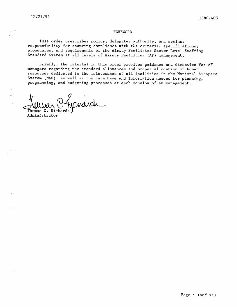
FOREWORD
This order prescribes policy, delegates autborit'y, and assigns responsibility for assuring compldance with the criteria, specifications, procedures, and requirements of the Airway Facilities Sector Level Staffing Standard System at all levels of Airway Facilities (AF) management.
Briefly, the material in this order provides guidance and direction for AF managers regarding the standard allowances and proper allocation of human resources dedicated to the maintenance of all facilities in the National Airspace System (NAS), as well as the data base and infiormation needed for planning, programming, and budgeting processes at each echelon of AF management.
/.
Administrator .
Page i (and ii)
., ‘,,,_ .-., _ . .._. ..^. -._, ̂,__ ._ _..( _‘ -- ..~

12/21/92
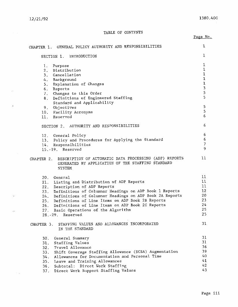
TABLE OF CONTENTS
1380.4OC
Page No.
CHAPTER 1. GENERAL POLICY AUTHORITY AND RESPONSIBILITIES
SECTION 1. INTRODUCTION
1. 2. 3. 4. 5. 6. 7. 8.
9. 10. 11.
Purpose Distribution Cancellation Background Explanation of Changes Reports Changes to this Order Definitions of Engineered Staffing Standard and Applicability Objectives Facility Acronyms Reserved
SECTION 2. AUTHORITY AND RESPONSIBILITIES 6
12. General Policy 13. Policy and Procedures for Applying the Standard 14. Responsibilities 15.-19. Reserved
CHAPTER 2. DESCRIPTION OF AUTOMATIC DATA PROCESSING (ADP) REPORTS GENERATED BY APPLICATION OF THE STAFFING STANDARD SYSTEM
20. General 11 21. Listing and Distribution of ADP Reports 11 22. Description of ADP Reports 11 23. Definitions of Columnar Headings on ADP Book 1 Reports 12 24. Definitions of Columnar Headings on ADP Book 2A Reports 20 25. Definitions of Line Items on ADP Book 2B Reports 23 26. Definitions of Line Items on ADP Book 2C Reports 24 27. Basic Operations of the Algorithm 25 28. -29. Reserved 25
CHAPTER 3. STAFFING VALUES AND ALLOWANCES INCORPORATED IN THE STANDARD
30. General Summary 31 31. Staffing Values 31 32. Travel Allowance 36 33. Shift Coverage Staffing Allowance (SCSA) Augmentation 39 34. Allowances for Documentation and Personal Time 40 35. Leave and Training Allowances 41 36. Subtotal: Direct Work Staffing 42 37. Direct Work Support Staffing Values 43
1
5 5 6
31
Page iii

1380.4OC
TABLE OF CONTENTS
12/21/92
Page No.
38. Engineering Management and Administrative Support 39. Reserved
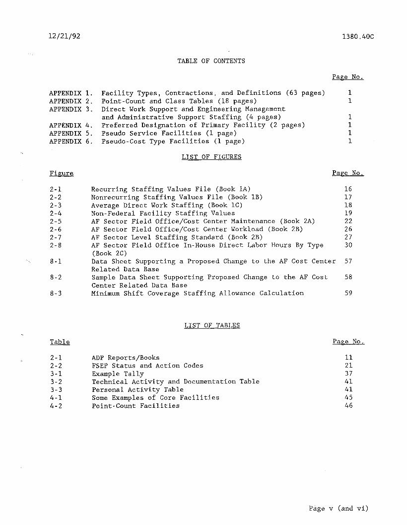
CHAPTER 4. THE CLASS STRUCTURE AND POINT-COUNT SYSTEMS
40. General 45 41. Facility Type 45 42. Class Determination 46 43. -49. Reserved 46
CHAPTER 5. PROCEDURES FOR USING THE AF STAFFING STANDARDS IN THE AGENCY BUDGET PROCESS
50. General 51. Computer Application of the Staffing Standard 52. Issuance of Call for Estimates (Order 2500.13) 53. Sector/Regional Response to the Call 54. Washington Headquarters Review 55. Descriptive Outline of Events 56. -59. Reserved
CHAPTER 6. TRAINING PIPELINE ANALYSIS
60. -69. Reserved
CHAPTER 7. REFINEMENT AND REVALIDATION OF THE AF STAFFING STANDARD SYSTEM
70. Introduction 51 71. Refinement and Revalidation 51 72. -79. Reserved 52
CHAPTER 8. UPDATING STAFFING STANDARDS
80. General 81. Data Base Files 82. ADP Report Summary 83. Data Base Changes 84. Staffing Standard System Operation 85. Regional Airway Facilities Division 86. AF Sector Office 87. Updating Formats 88. Staffing Standard System Timetable 89. Reserved
43 43
45
47
47 47 47 47 48 48 49
50
50
51
53
53 53 53 53 53 54 54 54 54 54
Page iv
12/21/92 1380.4OC
TABLE OF CONTENTS
PaPe No.
APPENDIX 1. Facility Types, Contractions, and Definitions (63 pages) 1 APPENDIX 2. Point-Count and Class Tables (18 pages) APPENDIX 3. Direct Work Support and Engineering Management
and Administrative Support Staffing (4 pages) APPENDIX 4. Preferred Designation of Primary Facility (2 pages) APPENDIX 5. Pseudo Service Facilities (1 page) APPENDIX 6. Pseudo-Cost Type Facilities (1 page)
LIST OF FIGURES
Figure
2-1 2-2 2-3 2-4 2-5 2-6 2-7 2-8
8-1
8-2
8-3 Minimum Shift Coverage Staffing Allowance Calculation 59
Table
Recurring Staffing Values File (Book 1A) Nonrecurring Staffing Values File (Book 1B) Average Direct Work Staffing (Book 1C) Non-Federal Facility Staffing Values AF Sector Field Office/Cost Center Maintenance (Book 2A) AF Sector Field Office/Cost Center Workload (Book 2B) AF Sector Level Staffing Standard (Book 2B) AF Sector Field Office In-House Direct Labor Hours By Type (Book 2C)
1
Pase No.
16 17 ia 19 22 26 27 30
Data Sheet Supporting a Proposed Change to the AF Cost Center 57 Related Data Base Sample Data Sheet Supporting Proposed Change to the AF Cost 58 Center Related Data Base
LIST OF TABLES
2-l ADP Reports/Books 11 2-2 FSEP Status and Action Codes 21 3-l Example Tally 37 3-2 Technical Activity and Documentation Table 41 3-3 Personal Activity Table 41 4-l Some Examples of Core Facilities 45 4-2 Point-Count Facilities 46
Page No.
Page v (and vi)
..-- ,^ - ..-. ._.-. _-_- " . ..-~ ,--i-. . , _.... "_.-X.- -"- ".__ .._._ ~_ _

12/21/92
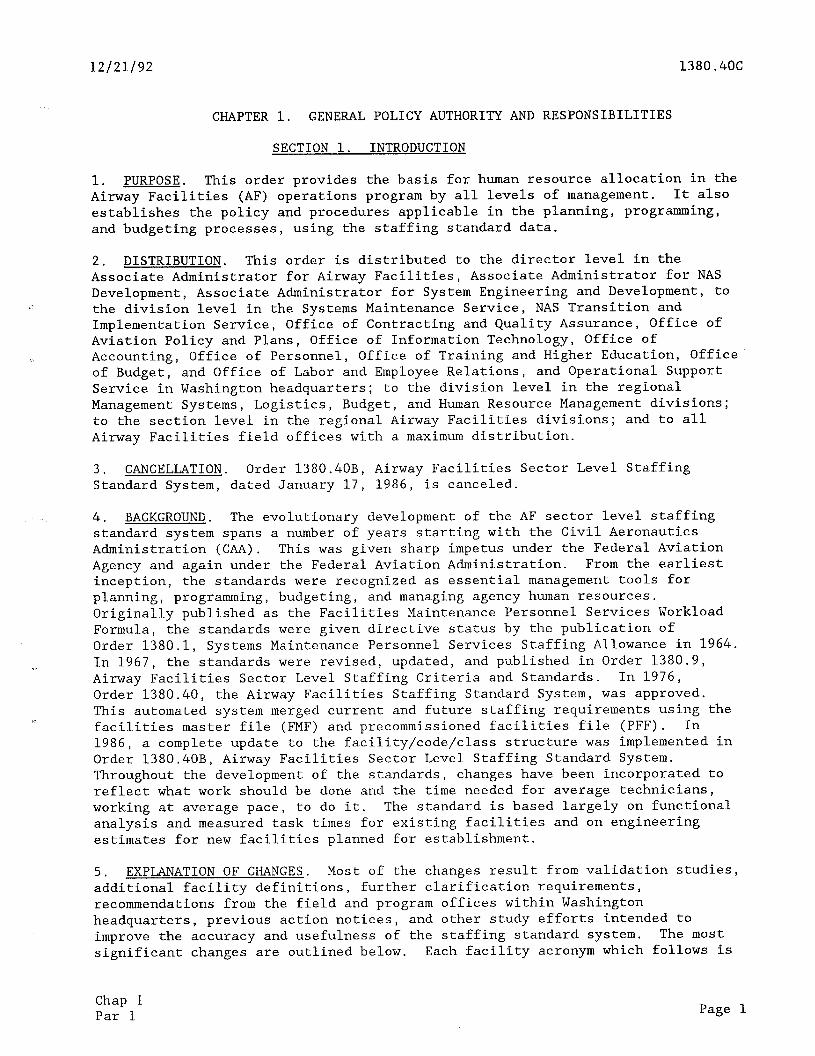
CHAPTER 1. GENERAL POLICY AUTHORITY AND RESPONSIBILITIES
1380.4OC
SECTION 1. INTRODUCTION
1. PURPOSE. This order provides the basis for human resource allocation in the Airway Facilities (AF) operations program by all levels of management. It also establishes the policy and procedures applicable in the planning, programming, and budgeting processes, using the staffing standard data.
2. DISTRIBUTION. This order is distributed to the director level in the Associate Administrator for Airway Facilities, Associate Administrator for NAS Development, Associate Administrator for System Engineering and Development, to the division level in the Systems Maintenance Service, NAS Transition and Implementation Service, Office of Contracting and Quality Assurance, Office of Aviation Policy and Plans, Office of Information Technology, Office of Accounting, Office of Personnel, Office of Training and Higher Education, Office of Budget, and Office of Labor and Employee Relations, and Operational Support Service in Washington headquarters; to the division level in the regional Management Systems, Logistics, Budget, and Human Resource Management divisions; to the section level in the regional Airway Facilities divisions; and to all Airway Facilities field offices with a maximum distribution.
3. CANCELLATION. Order 1380.40B, Airway Facilities Sector Level Staffing Standard System, dated January 17, 1986, is canceled.
4. BACKGROUND. The evolutionary development of the AF sector level staffing standard system spans a number of years starting with the Civil Aeronautics Administration (CAA). This was given sharp impetus under the Federal Aviation Agency and again under the Federal Aviation Administration. From the earliest inception, the standards were recognized as essential management tools for planning, programming, budgeting, and managing agency human resources. Originally published as the Facilities Maintenance Personnel Services Workload Formula, the standards were given directive status by the publication of Order 1380.1, Systems Maintenance Personnel Services Staffing Allowance in 1964. In 1967, the standards were revised, updated, and published in Order 1380.9, Airway Facilities Sector Level Staffing Criteria and Standards. In 1976, Order 1380.40, the Airway Facilities Staffing Standard System, was approved. This automated system merged current and future staffing requirements using the facilities master file (FMF) and precommissioned facilities file (PFF). In 1986, a complete update to the facility/code/class structure was implemented in Order 1380.40B, Airway Facilities Sector Level Staffing Standard System. Throughout the development of the standards, changes have been incorporated to reflect what work should be done and the time needed for average technicians, working at average pace, to do it. The standard is based largely on functional analysis and measured task times for existing facilities and on engineering estimates for new facilities planned for establishment.
5. EXPLANATION OF CHANGES. Most of the changes result from validation studies, additional facility definitions, further clarification requirements, recommendations from the field and program offices within Washington headquarters, previous action notices, and other study efforts intended to improve the accuracy and usefulness of the staffing standard system. The most significant changes are outlined below. Each facility acronym which follows is
Chap 1 Par 1 Page 1
1380.4OC 12/21/92
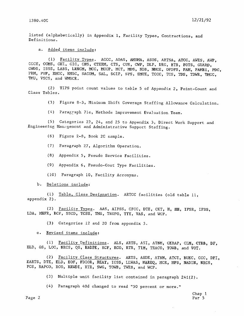
listed (alphabetically) in Appendix 1, Facility Types, Contractions, and Definitions.
a. Added items include:
(1) Facility Types. ACCC, ADAS, AMSMA, ASOS, ARTSA, ATCC, AWIS, AWP, CCCH, CCMS, CHI, CIC, CNS, CTERM, CTS, CUE, CWP, DLP, DRG, ETB, FOTS, GUARD, GWDS, ISSS, LABS, LRNCM, MCC, MCCP, MCT, MD'S, NDB, NMCE, OFDPS, PAM, PAMRI, PDC, PRM, PUP, RMCC, RMSC, SACOM, SAL, SCIP, SPS, SMUX, TCCC, TCS, TDS, TDWR, TMCC, TMU, VSCS, and WMSCR.
(2) TIPS point count values to table 5 of Appendix 2, Point-Count and Class Tables.
(3) Figure 8-3, Minimum Shift Coverage Staffing Allowance Calculation.
(4) Paragraph 71e, Methods Improvement Evaluation Team.
(5) Categories 22, 24, and 25 to Appendix 3, Direct Work Support and Engineering Management and Administrative Support Staffing.
(6) Figure 2-8, Book 2C sample.
(7) Paragraph 27, Algorithm Operation.
(8) Appendix 5, Pseudo Service Facilities.
(9) Appendix 6, Pseudo-Cost Type Facilities.
(10) Paragraph 10, Facility Acronyms.
b. Deletions include:
(1) Table, Class Designation. ARTCC facilities (old table 11, appendix 2).
(2) Facility Types. AAS, AIFSS, CFCC, DTE, CKT, H, HH, IFSR, IFSS, LDA, MHFR, RCF, SSCD, TCSS, TM'S, TROPO, TTY, VAS, and WCP.
(3) Categories 12 and 20 from appendix 3.
C. Revised items include:
(1) Facility Definitions. ALS, ARTS, ASI, ATBM, CERAP, CLM,. CTRB, DF, ELD, GS, LOC, NRCS, QS, RBDPE, RCF, RCO, RTR, TIM, TRACO, TOWB, and VOT.
(2) Facility Class Structures. ARTS, ASDE, ATBM, ATCT, BUEC, CCC, DFI, EARTS, DTE, ELD, EOF, FDIOR, HEAT, ICSS, LLWAS, MAREQ, MCR, MPS, NADIN, NRCS, PCS, RAPCO, RCO, RRWDI, RTR, SWG, TOWB, TWEB, and WCP.
(3) Multiple unit facility list contained in paragraph 24i(2).
(4) Paragraph 40d changed to read "50 percent or more."
Page 2 Chap 1 Par 5
12/21/92
(5) Paragraph 71b(6) added "allowances."
1380.406
(6) Revision in leave and training allowances for new holiday (Martin Luther King's birthday)
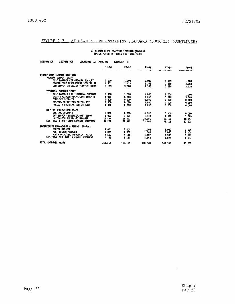
(7) Revised Figure 2-7, AF Sector Level Staffing Standard (Book ZB), to remove systems Performance specialty (SPS) from support staffing.
(8) Revised Figures 2-3, Average Direct Work Staffing '(Book 1C) and Figure 2-4, Non-Federal Facility Staffing Values.
(9) Revised page designations in table of contents for chapters 7 and 8.
(10) Revised Figure 8-1, Data Sheet Supporting Change to the AF Cost Center Related Data Base and Figure 8-2, Sample Data Sheet Supporting Change to the AF Cost Center Related Data Base.
(11) Paragraph 87 revised to include the addition of figure 8-3.
(12) Appendix 3 revised to accommodate the addition and deletion of category codes and current staffing values.
(13) Appendix 4, Preferred Designation of Primary Facility, revised to accommodate changes in facility acronyms.
(14) Paragraph 25e revised to change terminology and work years.
(15) Paragraph 26 revised to accommodate new figure 2-8, Definitions of Columnar Headings on ADP Book 2C Reports.
d. Other Changes:
(1) Class and point count tables realigned.
(2) References to Washington headquarters changed to reflect reorganization.
(3) AID facility relocated in its proper alphabetical order.
(4) Paragraphs 6 through 9 realigned to accommodate revised paragraph 6 (old 6 - 8 is now 7 - 9).
(5) RTCCS added.
6. REPORTS.
a. Recurring Staffing Values File (Book 1A). This book is an automated data processing (ADP) report containing equipment/facility-related data; i.e., the standard direct maintenance values for each identified facility acronym, class9 and facility identification code in the Facility, Service, and Equipment Profile (FSEP). This book is issued by ASM-200 to the regions for their use in producing the staffing standards.
Chap 1 Par 5 Page 3
1380.4OC 12/21/92
b. Nonrecurring Staffing Values File (Book 1B). This book is a data base containing staffing values for transition and startup requirements on new facilities; i.e., observing facilities and equipment (F&E) by the Systems Maintenance Service, Maintenance Operations Division, ASM-200, initial training, joint acceptance inspection (JAI), infant mortality, etc. This book is issued to the regions for their use in producing the staffing standards.
C. Average Direct Work Staffing (Book 1C). This book is a report which provides the average direct work staffing values and allowances for each facility, including travel (but not support staffing). This report is generated by each region and for the nation as a whole.
d. Non-Federal Facility Staffing Values. This book is a data base which provides staffing values for non-Federal facilities. This book is issued by ASM-200 to the regions.
e. AF Sector Field Office/Cost Center Maintenance (Book 2A). This book is a report containing the annual direct maintenance and travel time values for all FAA and contractor-maintained facilities by cost center. This book is also produced by the regions using the staffing standards and analysis system (SSAS). One issuance coincides with the Call for Estimates issued by the Office of Budget in January of each year. The regional offices will annotate copies and return these to ASM-200 for their supporting input. See events schedule for budgetary application contained in Chapter 5, Procedures For Using The AF Staffing Standard In The Agency Budget Process, paragraph 55, for complete details and cycle process. This book, together with Book 2B, forms the basic supportive documents for field maintenance full-time equivalent (FTE) employee- year requests. The SSAS production in July is used for distributing obtained resources equitably to each region on October 1 of each fiscal year.
f. AF Sector Field Office/Cost Center Workload and Sector Level Staffing Standard (Book 2B). This book is a report that adds support staffing to direct work staffing for each AF sector. Regional and national summaries are also produced. The issuance coinciding with the Call for Estimates allows the regions to annotate copies and supply these to ASM-200 for their supporting input. See events schedule contained in chapter 5, paragraph 55, for complete details and cycle process.
g* AF Sector Field Office In-House Direct Labor Hours By Type (Book 2C). This book is an ADP report containing the maintenance hours expended by activity for each facility in a cost center; i.e., electronic periodic maintenance (PM) and corrective maintenance (CM), environmental PM and CM, electronic travel, environmental travel, etc.
h. Figure 8-1. This figure provides a standard format for regional use when reporting changes to their cost center code data bases via letter to ASM-200. This is to be submitted as changes occur in a region's sector data.
1. Cost Center Code Table (CCCT). The CCCT is a data base containing minimum shift coverage staffing requirements for each cost center assignment. Figure 8-1 is to be submitted by regional AF divisions to ASM-200 as changes occur and prior to semi-annual productions of the staffing standard.
Page 4 Chap 1 Par 6
12/21/92 1380.4OC
j. Facility, Service, and Equipment Profile (FSEP). The FSEP is a data base depicting current equipment/facilities and planned changes.
k. Regional Project Manapement System (RPMS). An F&E data base depicting planned new commissionings and major replacements.
7. AUTHORITY TO CHANGE. Changes to this order will be approved in accordance with the provisions of the latest edition of Order 1380.34, FAA Staffing Standard Program. Changes to this order may be issued, after appropriate coordination by the Director, Systems Maintenance Service, with the exception of Chapter 1, General Policy Authority and Responsibilities, and chapter 5, which involve policy, delegation of authority, assignment of responsibility, or allocation of resources. The Administrator reserves the authority to approve such changes. This authority may not be redelegated.
8. DEFINITION OF ENGINEERED STAFFING STANDARD AND APPLICABILITY.
a. Engineered Staffing Standard. Standards are engineered by work measurement of hands-on time required for PM and CM, auxiliary tasks, and nonrecurring transition tasks, combined with personal and administrative allowances, shift coverage, actual travel requirements, recurring training, leave, holiday requirements, and addition of calculated support staffing at the sector level. Staffing values are based on direct observation during required task exercises at representative facilities and on engineering estimates. Using sound statistical methods, the data needed to validate the standard values and allowances are periodically reviewed and incorporated in the AF sector level staffing standard data base for use at all maintenance operational levels in the NAS.
b. Applicability. In the context defined above, the AF sector level staffing standard system is applicable at all levels of management in the AF organizational structure. It serves as the key data base for fiscal planning, cost/benefit analysis, human resource allocation, mathematical modeling and effects simulation exercises, life-cycle cost analyses, and resource management.
9. OBJECTIVE,S. This order is designed to provide:
a. Facility type definitions and nomenclature, class, and staffing allowances needed at all levels of AF management in the FAA systems maintenance program.
b. A control file of data elements for correlation with the FSEP, budgeting, planning, programming, and cost accounting systems.
C. National workload standards applicable to sector level development of requirements and regional allocations of resources.
10. FACILITY ACRONYMS
a. Facility acronyms in this order conform with the latest edition of Order 1375.4, Standard Data Elements and Codes -- Facility Identification and Supplemental Standards.
Chap 1 Par 6
Page 5
1380.4OC 12/21/92
b. Facility acronyms such as FSS, IFSS, AFSS, ARTCC, and ATCT when used in the context of this order are referring to equipment and not to reporting for duty locations (i.e., not to buildings or structures as a complex or staffed facility). See appendix 1 for definition of acronyms.
11. RESERVED.
SECTION 2. AUTHORITY AND RESPONSIBILITIES
12. GENERAL POLICY. Efficient management of AF sectors requires the use of refined management techniques that include the application of an objective and credible staffing standard. This standard will be used for the determination of staffing levels required to accomplish the assigned workload and may be used as a base in productivity measurements, methods, and procedures studies.
a. This order is designed to assist in meeting these needs through the publication of an engineered staffing standard covering the maintenance function at the AF sectors.
b. Generally, the staffing values and allowances published in this order are based on observed and measured data, compiled under the direction of professional industrial engineers of ASM-200.
C. The data base must continue to be comprehensive and representative, periodically updated and refined by the application of scientifically accepted measurement techniques, and fully representative of an engineered staffing standard in support of the AF operations program.
13. POLICY AND PROCEDURES FOR APPLYING THE STANDARD.
a. Application of the Standard at the Regional Level. It is FAA policy to maximize delegation of authority to the regional AF division manager and to rely on them for proper use of their resources. In consonance with this organizational concept and its accompanying broad delegation of authority, it is intended that the AF sector level staffing standard system be applied with flexibility. It is expected that each regional AF division manager, and his/her staff, will apply and acquire a knowledge and expertise in the determination of staffing requirements for AF sectors. Accordingly, the regional AF division manager may produce the regional staffing standard using the SSAS and, at his/her discretion, request staffing that varies from that generated. The following parameters are designed to provide a practical framework for resource allocation within the region without infringing on the authority delegated to the regional AF division manager:
(1) The regional AF division manager shall justify staffing requests that exceed the total regional AF sector staffing generated by application of the standard.
(2) The regional AF division manager shall include in his/her budget response an explanation when he/she proposes to provide for an individual sector staffing which deviates from that generated by the standard by more than 15 percent.
Page 6 Chap 1 Par 10

12/21/92 1380.4OC
(3) The regional AF division manager may distribute authorized staffing among his/her AF sectors as he/she believes necessary as long as it is done within the specific limitations of authority to adjust funds and staffing as delegated by the latest edition of Order 2500.30, Delegation of Authority to Adjust Regional and Center Fiscal Programs in the Operations Activities of the Operations Appropriation, and as long as notification is provided to the Associate Administrator for AF along with justification or rationale for so doing. Assignment of staffing to a given AF sector may vary from that generated through application of the staffing standard due to such factors as anticipated attrition and expected performance level of resources provided. The standard should, however, serve as a baseline in considerations, and an explanation of variances in applying the standard at the sector level should also be sent to ASM-200 to provide feedback bearing on the continuing validity or improvement of the standard.
b. Application of the Standard at the Sector Level. Staffing allocation at the sector level shall be based on the standard. All proposed deviations must be justified in writing to the regional AF division manager. Of particular concern is the cross utilization of support, engineering management, and administrative staffing with direct work staffing generated by the standard system. Cross utilization should be used only to satisfy temporary requirements, because such diversions of resources tend to reduce the efficiency of both staff and direct work capabilities at the sector level.
c. AF Sector Related Data Base Update. Whenever there is a change in AF sector configuration affecting the sector cost center related data base in the staffing standard system, a change request letter should be sent to ASM-200. This should be done whenever AF sectors or AF sector field offices (SFO) are combined, relocated, newly established, changed in type category, reassigned to another adjacent region, etc.
d. Staffing Values File (SVF). If there is an unanticipated change in workload at a given facility caused by modernization or modification, changed PM schedules, maintainability, technology, methodology, etc., a change request letter should be sent through administrative channels to notify ASM-200 that facility workload as depicted in the SVF may need to be updated.
14. RESPONSIBILITIES. Basic authority and responsibility for the accomplishment of various actions required in forecasting trends in maintenance activities in order to meet the planning needs of various offices and services of FAA and for the conduct of the agency's budgetary programs and estimates are detailed in order. This order assigns the following additional responsibilities in the staffing standards area:
a. Regional AF Division Managers. Regional AF division managers are responsible for reviewing and evaluating presentations generated by application of the staffing standard for acceptability and for providing Washington headquarters with specific detailed recommendations when believed that the standard should be modified. After review at the regional level, items of significance shall be transmitted to the Director, System Maintenance Service, ASM-1. Regional supplements are not authorized.
Chap 1 Par 13 Page 7
1380.4OC 12/21/92
b. Systems Maintenance Service. The Systems Maintenance Service is responsible for:
(1) Submitting staffing recommendations based on application of the standard following the procedures detailed in chapter 5 of this order.
(2) Reviewing regional recommendations for modification of the standard and coordinating with the Office of Aviation Policy and Plans concerning needed modifications.
(3) Evaluating periodically, in conjunction with the Office of Aviation Policy and Plans, the continued validity of the standard as indicated by analysis of regional proposals for modification and comparison of requested staffing levels with staffing generated by application of the staffing standard system.
(4) Participating and/or leading studies to refine and/or revalidate the staffing standard.
(5) Advising the Office of Aviation Policy and Plans and the Office of Budget of changes in AF policies, procedures, and equipment that may affect the continuing validity of the standard or the integrity of related budget estimates, and jointly determining the impact and the resultant need for modification of the standard.
(6) Coordinating with the Office of Labor and Employee Relations when it appears that the application of this standard or any subsequent modification of this standard may have an impact on the numbers of employees represented by a labor union.
e. Office of Aviation Policy and Plans. The Office of Aviation Policy and plans is responsible for participating with the Systems Maintenance Service in the review of proposed modifications to the standard; in the evaluation of the standard's continued validity; in the development of recommendations for actions to effect needed modifications of the standard as outlined in Order 1380.34 and in the participation and/or direction of studies to refine and/or revalidate the staffing standard system.
d. Office of Budpet. The Office of Budget is responsible for ensuring that the staffing standard is integrated with the budget process.
e. Office of Human Resource Development. The Office of Human Resource Development is responsible for ensuring that the AF staffing standard is integrated with the personnel planning process; developing and disseminating personnel attrition, washout, and other related information for use in determining the need for advance recruitment and training; and participating in the review and coordination of proposed modifications to the AF staffing standard system when the proposed revision has a major impact on personnel programs.
f. Office of Labor and Employee Relations. The Office of Labor and Employee Relations is responsible for providing labor relations staff advice, upon request, and arranging to carry out management's obligations to unions
Page 8 Chap 1 Par 14
12/21/92 1380.4OC
having exclusive recognition when it appears that the application of this standard or any subsequent modification may have an impact on the numbers, working conditions, or positions of employees represented by such unions.
15.-19. RESERVED.
Chap 1 Par 14 Page 9 (and 10)

12/21/92 1380.4OC
CHAPTER 2. DESCRIPTION OF AUTOMATIC DATA PROCESSING (ADP) REPORTS GENERATED BY APPLICATION OF THE STAFFING STANDARDS SYSTEM
20. GENERAL. This chapter describes the process used to apply the AF sector level staffing standard system and discusses the ADP reports produced by application of the standard. Development of the total sector staffing requirement for budget or other purposes involves merging the facility inventory file with the engineered SVF. The inventory file is made up from the FSEP.
21. LISTING AND DISTRIBUTION OF ADP REPORTS. A number of ADP reports (or computer printouts) are produced when the standard's staffing values and allowances are applied to the inventory file using the SSAS. Table 2-1, ADP Reports/Books, shows the various ADP reports produced by application of the staffing standard.
TABLE 2-1. ADP REPORTS/BOOKS
FIGURE NUMBER TITLE
2-l Recurring Staffing Values File (Book 1A)
2-2 Nonrecurring Staffing Values File (Book 1B)
2-3 Average Direct Staffing (Book 1C)
2-4 Non-Federal Facility Staffing Values
2-5 AF Sector Field Office/Cost Center Maintenance (Book 2A)
2-6 AF Sector Field Office/Cost Center Workload (Book 2B)
2-7 AF Sector Level Staffing Standard (Book 2B)
2-8 AF Sector Field Office In-House Direct Labor Hours By Type (Book 2C)
22. DESCRIPTION OF ADP REPORTS. Each of the figures listed in table 2-l is described below. The book designation contained in the title of each figure corresponds with an identification also printed in the ADP report. Staffing values shown in figures 2-l through 2-5 and 2-8 are expressed in terms of annual hours, while work-year totals shown in figure 2-6 are expressed in terms of FTE years. Staffing values and work-year totals shown on figures 2-l through 2-8 are for illustrative purposes only. Paragraphs 23 through 26 provide a detailed definition of the columnar headings in figures 2-l through 2-8.
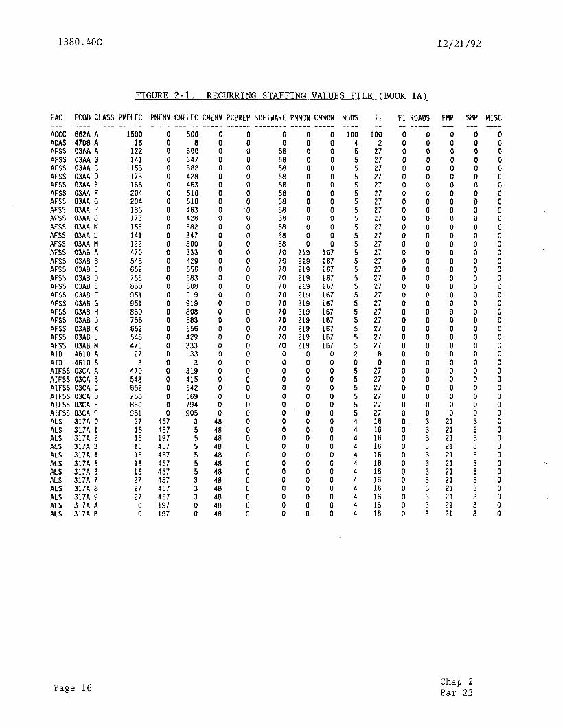
a. Figure 2-1, Recurrinp Staffing Values File (Book 1A). This report displays the annual values (in hours) for each facility by identification code, type, and class. The listed values have been developed from study data in most instances. When study data is not available, when totally new facilities are added to the system, and when existing facilities undergo major modification, an engineering estimate is used until study data becomes available.
Chap 2 Par 20 Page 11
1380.4OC 12/21/92
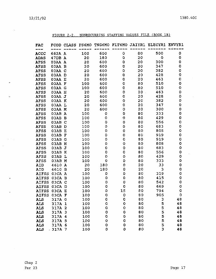
b. Figure 2-2, Nonrecurring Staffing Values File (Book LB). This ADP report shows the additional time to start up new facilities. It shows the time for sector support of F&E, initial training, and initial flight check required during the period 6 months prior to a new commissioning or a major replacement. It shows the time for JAI and additional CM required during the first year following a new commissioning or major replacement (swapout).
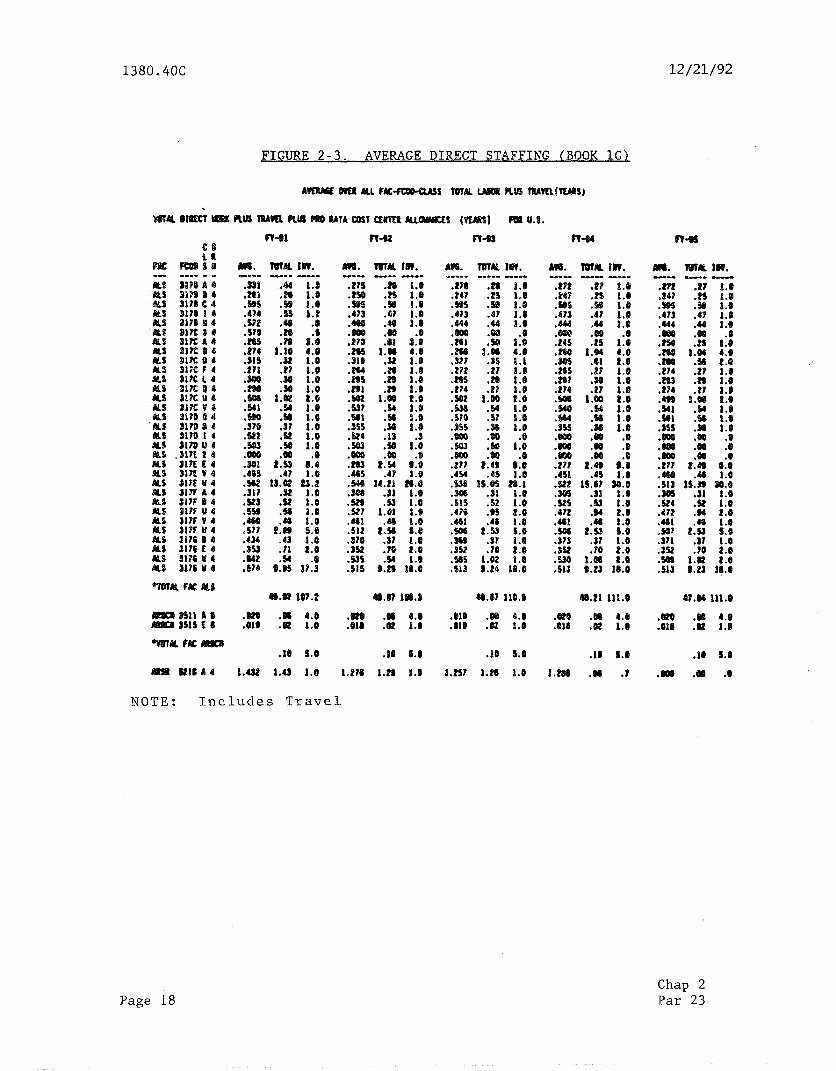
C. Figure 2-3, Average Direct Staffing (Book lCZ_. This ADP report shows average direct staffing in annual work years and number of facility years for each of 5 fiscal years. A half of a facility year (.5) means the facility is maintained for only one-half year.
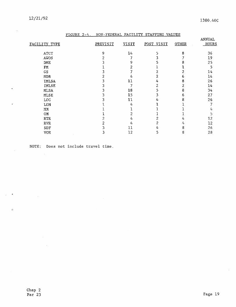
d. Figure 2-4, Non-Federal Facility Staffing Values. This ADP report lists the mean annual values (in employee-hours) computed for each of the activities associated with non-Federal facilities.
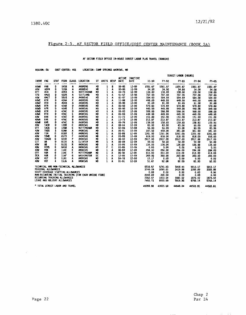
e. Figure 2-5, AF Sector Field Office/Cost Center Maintenance (Book 2A). This report reflects the annual direct maintenance and travel time values for all FAA-maintained facilities. In addition, this report identifies the facility types, facility identification numbers, active dates, and locations of all the facilities for which each cost center is or will be responsible.
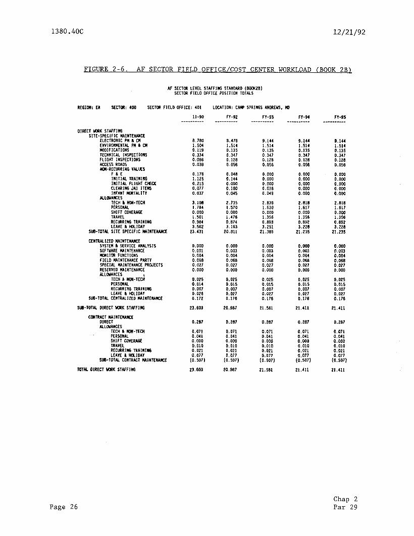
f. Figure 2-6, AF Sector Field Office/Cost Center Workload (Book 2B). This printout shows cost center workload by category of work, rolled up from direct maintenance through auxiliary tasks, startup staffing, travel, and allowances. There is a page for each cost center. A cost center may be an entire SF0 or a unit. The cost center may be used to capture all the facilities maintained by a unit or crew requiring shift coverage staffing augmentation.
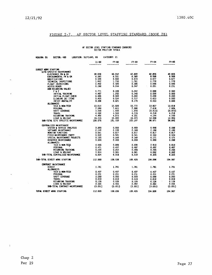
g. Figure 2-7, AF Sector Level Staffing, Standard (Book 2B). A Book 2B page exists for direct work staffing for each cost center, each sector, each region, and the Nation as a whole. A direct work support staffing page is added at the sector level. The sector pages summarize all the cost center pages in that sector and add values for support staffing. The region page is a summation of all the pages for the sectors belonging to that region and the national staffing standard is the summation of all nine regions.
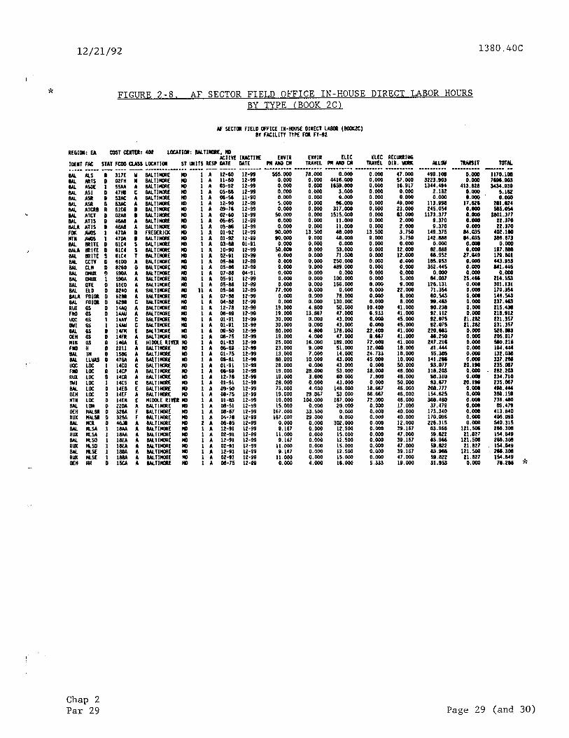
h. Figure 2-8, AF Sector Field Office In-House Direct Labor Hours By Type (Book ZC). A Book 2C page exists for each cost center. This report reflects the annual work hours by category and facility type in a cost center.
23. DEFINITIONS OF COLUMNAR HEADINGS ON ADP BOOK 1 REPORTS. The following subparagraphs define the columnar headings used on the ADP reports which have been previously discussed and identified as figures 2-1 through 2-4. A more detailed discussion of the standard is contained in Chapter 3, Staffing Values and Allowances Incorporated in the Standard.
a. Facility Identification Code. The last four characters of the facility identification code are established by Order 1375.4.
b. Class. Class is a supplement to the facility code, further defining of all the equipment in the NAS in a mutually exclusive and exhaustive fashion. The overall class determination is discussed in chapter 4.
Page 12 Chap 2 Par 22
12/21/92 1380.4OC
C. Facility Type. This is an alpha contraction using up to five characters to represent the basic type of facility. Definitions of each facility type or acronym are provided in appendix 1.
d. Recurring Direct Time Values. These time values show the annual HANDS ON steady state time required for maintenance and repair of the NAS equipment. These time values are direct work only and do not show direct work support staffing requirements. The recurring direct time values are required each year the facility is in a commissioned status. See figure 2-l.
(1) PM is recurring preventive-type work.
(a) Electronic PM is electrical- or electronic-type work intended to extend the useful life of equipment and preclude failures.
(b) Environmental PM is electrical-, mechanical-, and structures- and grounds-type work intended to extend the useful life of equipment and real property and preclude failures and deterioration.
(2) CM is repair of failed conditions.
(a) Electronic CM is repair of failed electrical and electronic equipment.
(b) Environmental CM is repair or restoration of electrical-, mechanical-, structures and grounds-type equipment/facilities.
(c) Printed circuit board repair is reserved for depot and central repair facility level maintenance and is currently not being used.
(3) Software maintenance is air traffic programming attributable to specific facility types.
(4) Monitor function is centralized troubleshooting and quality control-type work.
(a) PM is centralized recurring preventive work.
(b) CM is centralized repair of failed conditions.
(5) Auxiliary is additional facility related work as follows:
(a) Modification is for average expected equipment alteration- type work.
(b) Technical inspection (TI) is actual inspection not including region administration.
(c) Flight inspection (FL) is periodic verification of service.
(d) Access road is for maintenance of the first half mile from 6 facility (only if applicable).
Chap 2 Par 23
Page 13
1380.4OC 12/21/92
(e) Field maintenance program (FMP) is for centralized environmental maintenance.
(f) Special maintenance project (SMP) is for average special centralized maintenance.
e. Nonrecurring Values. These time values are added on a one-time basis only. (See Book lB, figure Z-2.)
(1) Six months prior to commissioning.
(a) F&E is observing and assisting installation.
(b) Initial training is learning new systems,
(c) Flight check is initial service verification.
(2) First year of commissioning.
(a) Clearing JAI items is correcting discrepancies uncovered during JAI.
(b) Infant mortality CM is repair of expected burn-in failures.
1 Electronic is repair of additional first-year failures of electrical- and electronic-type work.
2 Environmental is repair of additional first-year failures of electrical-, mechanical-, structures- and grounds-type work.
f. Average Overall FAG-FCOD-CLASS Total Labor Plus Travel. See Book lC, figure 2-3.
(1) Brown represents Brown Book chapter. The Brown Book is now named the Capitai investment Plan.
(2) Average represents the average employee-years (EY) for each facility, facility code, and class in the national inventory.
(3) Inventory represents the number of units of each facility, facility code, and class in the inventory, expressed in facility-years of maintenance requirement (i.e., 6 months of maintenance requirement is shown as .5 facility-years in the inventory).
(4) Total represents the total labor years plus travel for each facility, facility code, and class in the inventory (AVG X INV).
(5) Each column represents a fiscal year.
Page 14 Chap2 Par 23
12/21/92 1380.4OC
g. Non-Federal Facility Staffing Values. (See Figure 2-4.) The columnar headings are self-explanatory and this figure reflects the annual work hours allotted for each type of non-Federal facility in the inventory. These work hour figures include administrative and maintenance activities associated with each facility.
Chap 2 Par 23 Page 15
-,. _. . ,.. , ., .
1380.4OC 12/21/92
FAC FCOD CLASS PMELEC --- ---- ---em ------
FIGURE 2-l. RECURRING STAFFING VALUES FILE (BOOK 1A)
ACCC 662A A AOAS 47DB A AFSS 03A.A A AFSS 03AA B AFSS 03AA C AFSS 03AA 0 AFSS 03A.A E AFSS 03AA F AFSS D3AA G AFSS 03AA H AFSS 03AA J AFSS 03AA K AFSS 03AA L AFSS 03AA M AFSS 03AB A AFSS 03AE B AFSS 03AB C AFSS 03AB D AFSS 03AB E AFSS 03AB F AFSS 03AB G AFSS 03AB H AFSS 03AB J AFSS 03AB K AFSS 03AB L AFSS 03AB M AID 4610 A AID 4610 B AIFSS 03CA A AIFSS 03CA B AIFSS 03CA C AIFSS 03CA 0 AIFSS 03CA E AIFSS 03CA F ALS 317A 0 ALS 317A 1 ALS 317A 2 ALS 317A 3 ALS 317A 4 ALS 317A 5 ALS 317A 6 ALS 317A 7 ALS 317A 6 ALS 317A 9 ALS 317A A ALS 317A B
1500
1:: 141 153 173 185 204 204 185 173 153 141 122 470 548 652 756 860 951 951 860 756 652 548 470
27 3
470
iz; 756 860 951
27
:: 15 15
:: 27 27 27
0 0
PMENV CMELEC CMENV PCBREP SOFTWARE PMMON CMMON --w-e ------ ----- --____ -_____-- _-___ -----
0 0
: 0
i
i 0 0 0 0 0 0
i 0 0 0
i 0
: 0 0 0 0 0
0" 0 0
457 457 197 457 457 457 457 457 457 457 197 197
500 8
300 347 382 428 463 510 510 463 428 382 347 300 333 429 556 683 808 919 919 808 683 556 429 333
33 3
319 415 542 669 794 905
3
:
:
: 3 3
i 0
0 0 0 0 0 0 0
ii 0 0 0 0 0 0 0 0 0 0 0 0 0 0
i 0 0 0
i 0
i 0
48 48 48 48 48
i:: 48 48 48 48 48
0
5:
:: 58 58
:: 58 56 58 58 58 70 70 70 70 70 70 70 70 70
:: 70
0
i 0 0 0 0 0 0 0 0 0 0 0 0 0 0
i 0
0 0
: 0 0 0
i 0 0 0 0 0
219 219 219 219 219 219 219 219 219 219 219 219
0 0 0 0 0
8 0 0
i 0 0
: 0 0 0 0 0
0 0 0
: 0 0
: 0 0 0 0 0
167 167 167 167 167 167 167 167 167 167 167 167
i 0 0
ii 0 0 0
i 0
0” 0 0 0
i 0
MODS ----
100 4
z
: 5
55 5 5
: 5 5
: 5 5
i: 5 5
i: 5 2
E 5 5
: 5
: 4 4 4 4 4 4 4 4 4 4
TI --
100 2
27
s: 27 27
;: 27 27 27 27 27 27 27 27 27 27
;: 27 27 27 27 27
8 0
27 27 27 27 27 27
ii
:66
:; 16
:z
:i 16
FI ROADS -- -----
FMP ---
0
8
:
8
: 0 0
i 0 0 0 0 0 0 0 0 0
8
ii 0
00 0 0 0 0 0
21 21 21
;:
;: 21 21
;: 21
SMP ---
0 0 0
i
:
i i 0
; 0
8
i 0 0 0 0 0 0
00 0 0
i 0 0 0 0 0 3
i 3 3
i: 3 3
i 3
MISC w-e-
0 0 0 0 0
: 0 0
i 0 0
8
: 0 0
i 0 0
8 0 0
: 0 0 0 0 0
I: 0
i
i 0 0
ii 0
Page 16 Chap 2 Par 23
1380.4OC 12/21/92
FIGURE 2-2. NONRECURRING STAFFING VALUES FILE (BOOK 1B)
FAG FCOD CLASS FSBMO TNG6MO FLTBMO JAIYRl ELECYRl ENVYWl m-e m-w- -m--m -m-Y- -m.---- ---me- ------ ---m-e- -,---- ACCC 662A A ADAS 47DB A AFSS 03AA A AFSS Q3AA B AFSS 03AA C AFSS 03AA D AFSS 03A.A E AFSS 03AA F AFSS 03A.A G AFSS 03AA H AFSS 03AA J AFSS 03AA K AFSS 03AA L AFSS 03AA M AFSS 03AB A AFSS 03AB B AFSS 03AB C AFSS O3AB D AFSS Q3AB E AFSS 03AB F AFSS 03AB G AFSS 03AB H AFSS 03AB J AFSS 03AB K AFSS 03AB L AFSS O3AB M AID 4610 A AID 4610 B AIFSS 03CA A AIFSS 03CA B AIFSS 03CA C AIFSS 03CA D AIFSS 03CA E AIFSS 03CA F ALS 317A 0 ALS 317A 1 ALS 31719 2 ALS 317A 3 ALS 3178 4 AIS 317A 5 ALS 317A 6 ALS ,317A 7
100 600 20 180 20 600 20 600 20 600 20 600 28 600
100 600 100 600
20 600 20 608 20 600 20 600 20 600
100 0 100 0 100 0 100 0 100 0 100 0 100 0 100 0 100 0 100 0 100 0 PO8 0
20 180 20 180
100 0 100 0 100 0 100 cl 100 0 lQ0 0 100 0 100 0 108 0 100 0 100 0 100 8 100 0 100 0
80 20 20 20 20 20 20 80 80 28 20 20 26 20 80 80 $0 80 80 80 $0 $0 80 8Q $0 $0 20 28
0 80 $8 80
0 0
80 80 80 $0
0 0 0
80
500 0
300 347 382 428 463 510 510 463 428 382 347 300 333 429 556 683 808 919 919 808 683 556 429 333
33 3
319 415 542 669 794 905
3 5 5 5 5 5 5 3
0 0 0 0 8 0 0 0 0 0 0 0 0 0 0 0 0 0 0 0 0 0 0 0 0 0 0 0 0 0 0 0 0 0
48 48 48 48 48 48 48 48
Chap 2 Par 23 Page 17
1380.406
FIGURE 2-3. AVERAGE DIRECT STAFFING (BOOK lC1
12/21/92
mo s19c I4 al% $lYc me a5 WC 0 4 KS 31X f 4 mo 319Cl4
:t 2% 2 KP 1011c 11 4 IIS SW?0 0 4 Kt SlfD 6 4 as% Ol?D t 4
2: off :: MS ‘w6.24 Y% St?’ P 4 a.5 91F1 Y 4 &S PIWA4 mll flPf $ 4 YS PI?fUI AhO 3llFf V 4 m.5 OlPf u 4 KS 3116 m 4 &J 4176 2 4 ms 24196 as a mt am II 4
=¶lK fK KO
Ram h a
n-91
m. lml 111.
331 A4 1.1) .2Bl .oI) 1.0 .595 .58 1.a .blb
A5 ‘:f -572 .em
:E .o I.0 .DP 1.0
.%P
.903 :E :*t .ow' .oo :0
2: **53 Q.a .a7 I.0
:z '3*02 Bea .i 1.0 .523 .%¶ :E f*i .a69 .I 1:o .5?f 2.40 5.43 .434 .41 1.6 .w .a 2.0 .WP ,394 *:E 19::
.l@ L.0
‘.a2 1.42 1.6
n-u
m. Tow IA. --es --e -e.
,295
:E :E f-i .% 1:m
.4?3 Am0 :: t*:
:% ‘0
:E 0:o
J85 ‘:E roe .¶1S :Z 28 *:I?
.rnl :s t-i
.IBz 1.66 I:6
.w .34 1.6
.%I .I a.0 ,355 .sra :E “2
:E :z “:i
:z **3a *.O .b? 1.0 Aa& 14:;‘1 2.;
.52n .5a 1:o .Y? 1.81 1.9 .11 .40 1.0 .5l2 2.% 5.0 .3ra .x+2 :K :*tl .9)3 .w 1:6 ,515 o.28 1m.o
4l.n 169.9
:E A2 .a 4.5 1.0
.I0 6.0
1.296 1.28 1.6
Aa. -s--w --me --we
.2?8 .P( a.0
.24? .2J a.0
.895 .I 1.0
.an
.a44 :z :4
:E ‘9
:z r:e
13% “:2 :*: .292 .a? 1:m
:E .?9 .2¶ 1.0 1.6
:z ‘.oo 2*o .310 :s:: :*i .353 .w *:a
:E :z 1::
:E *:E s*: .6W .43 1:c .538 15.05 2&l :E .Sl .aB 1.0 1.0
.4P6 .93 2.0
.I1 .46 11.0
*50e ‘:1”: :*cs .669 .s32 .96 2:o .395 1.02 1.6 .513 8.24 16.0
a&w 110.0
.91D .I 4.0
.Ol# .02 1.0
.lO 6.6
I.239 1.8 1.0
Mb. mtM 1111. -- -- -m-s
.m .29 1.8
.26? .I3 a.e
.%5 .yP 1.e
.4?3 .a9 1.6
.4e6 A4 1.0
:E 1::
:E ‘:6”: ::t :g: 30 .2t 1.6 1.0
.2?4 .29 1.0
.%m a.80 2.0
:E ,333 .a00
:E :i
2;; 2.43 .41 0.0 1.6 .322 13.61 S6.0 :E .a 1.0
.472 :t :*i
.481 .a4 1:o
:z “:E :-: .%2 .90 2:o .w 1.a 1.0 .313 9.23 19.0
1.21 111.0
:fi .m 4.s .02 1.0
.lO 6.6
1. .@a .t
n-#
m. WIK He. c_ -w-
,292 .I7 1.e .24? .25 1.8 .n3 .blf 5 :*:
:Z .ee 1:o
.2% 1: 1:: :z 1:: :.;
.2?4 .29 I:0
.a0 29 1.0
.294 .29 1.9
:E “:Z :*i .%I J33
:; ;:;
:Z :k?
1: .e
:E 2:: it
:z 13:: :*:
rE
A 1:o .52 1.6 .ea 2.e
.a61 .49 I.@
:E z-U $** .ri? 1.0 .332 .?O 2.0 .w 1.w 2.0 .I13 9.23 ll.m
at.64 111.0
:E .om a.9 .02 1.9
.I9 5.0
.mo Aa .o
NOTE: Includes Travel
Page 18 Chap 2 Par 23
12/21/92 1380.4OC
FACILITY TYPE
ATCT AWOS DME FM GS NDB IMLSA IMLSE MLSA MLSE LOC LOM MM OM RTR RVR SDF VOR
FIGURE 2-4. NOM-FEDE?=\L FACILITY STAFFING VALUES
PREVISIT VISIT POST VISIT OTHER
9 14 5 8 2 7 3 7 3 9 5 8 1 2 1 1 3 7 2 2 2 4 2 6 3 11 4 8 3 7 2 2 3 18 5 8 3 15 3 6 3 11 4 8 1 4 1 1 1 1 1 1 1 2 1 1 2 4 2 4 2 4 2 4 3 11 4 8 3 12 5 8
NOTE: Does not include travel time.
Chap 2 Par 23
AN'NLIAL HOURS
36 19 25
5 14 14 26 14 34 27 26
7 4 5
12 12 26 28
Page 19

1380.4OC 12/21/92
24. DEFINITIONS OF COLUMNAR HEADINGS ON ADP BOOK 2A REPORTS. In addition to those items defined above, the Book 2A reports contain the following data elements as shown in figure 2-5:
a. REGION. Two-letter region identifier.
b. COST CENTER. Sector/SF0 cost center code. This is the numeric or alphanumeric code assigned to each sector and SFO.
C. IDENT. Location identification. The alpha location identifier (example: JAX, JAXA, JAXB).
d. FAC ALPHA. Facility type. Alpha code from appendix 1.
e. STATUS. FSEP status or action code. An alpha code in this data field indicates the status of the facility as shown in the facility/service (FFA) screen, while a numeric code indicates the action code as shown in the facility precommissioned file (FPF) screen. These codes are shown in Table 2-2, FSEP Status and Action Codes.
f. FAC IDENTIFICATION CODE. Last four characters of the facility identification code from Order 1375.4.
g- CLASS. Subclassification of facility alpha from appendix 1.
h. LOCATION/STATE. Location name and state (as entered in the FSEP).
1. UNITS. Number of commissioned facilities (units).
(1) Single Unit Facilities. These are individual entities; i.e., a single facility type at one location, such as VOR, ATCT, and GS facilities. These facilities are listed on individual lines in the FSEP with a count of one.
(2) Multiple Unit Facilities. These are supporting-type facilities identical in nature and adjacently located, such as five living quarters at one location. These facilities are listed on one line in the FSEP, with a count (such as five) indicating the number of identical facilities at the same location. The facilities currently in this category are:
ATCC ELD LIVQ MCR OFFRD TR VEHS
air traffic controller chair Electrical distribution system Living quarters Multichannel recorder Heavy equipment and off-road vehicles Trails and roads Vehicles (excluding MX and OFFRD)
ACTIVE DATE. Date record starts being active for staffing purposes (dati'record starts generating staffing).
k. INACTIVE DATE. Date record stops being active for staffing purposes. During any one fiscal year, a facility will generate staffing for the number of months it is active. For example, if a facility is active for 9 of the
Page 20 Chbp 2 Par 24
12/21/92 1380.406
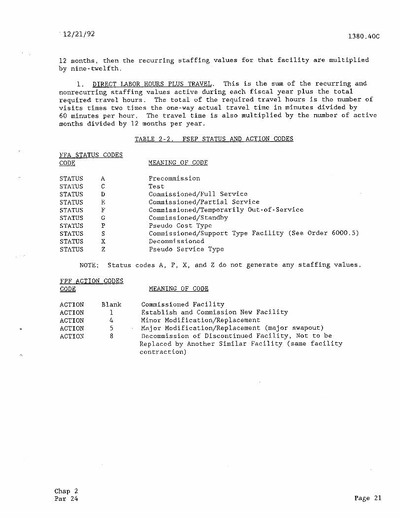
12 months, then the recurring staffing values for that facility are multiplied by nine-twelfth.
1. DIRECT LABOR HOURS PLUS TRAVEL. This is the sum of the recurring and nonrecurring staffing values active during each fiscal year plus the total required travel hours. The total of the required travel hours is the number of visits times two times the one-way actual travel time in minutes divided by 60 minutes per hour. The travel time is also multiplied by the number of active months divided by 12 months per year.
TABLE 2-2. FSEP STATUS AND ACTION CODES
FFA STATUS CODES CODE MEANING OF CODE
STATUS A Precommission STATUS C Test STATUS D Commissioned/Full Service STATUS E Commissioned/Partial Service STATUS F Commissioned/Temporarily Out-of-Service STATUS G Commissioned/Standby STATUS P Pseudo Cost Type STATUS S Commissioned/Support Type Facility (See Order 6000.5) STATUS X Decommissioned STATUS Z Pseudo Service Type
NOTE: Status codes A, P, X, and Z do not generate any staffing values.
FPF ACTION CODES CODE WING OF CODE
ACTION Blank Commissioned Facility ACTION 1 Establish and Commission New Facility ACTION 4 Minor Modification/Replacement
.e ACTION 5 Major Modification/Replacement (major swapout) ACTION 8 Decommission of Discontinued Facility, Not to be
Replaced by Another Similar Facility (same facility ,l contraction)
Chap 2 Par 24 Page 21
1380.4OC L2/2h/92
Figure 2-5. AF SECTOR FIELD OFFICE/COST CENTER MAINTENANCE (BOOK 2AJ
AF SECTOR FIELD OFFICE IN-HOUSE DIRECT LARC# PLUS TRAVEL (6DMA)
REBILM: El
IDENT FAC m-_-m -s-w- Aow PAPa
2 RBPl4 lx.0
ST0 RnLR AW a)#1 AWE RTR AWL RTR AWA RTR AWD RTR AWB RTR AWC RTR AW RVR AWA RVR ADW RVR
TKJI E TAcn AW TDDS AW TIM Aw Tw6 AW TRACD Cl1 II6 Mu In AW VEHS AW VW OTT VOR
E VOR VOT
Aw VOT
COST CENTER: 401 LOCATION: CARP SPRINGS ANDREUS. MD
ACTIVE INACTlVE STAT FCOO CLASS LOCAllOW ST UNITS RESP DATE
5458 51HA 42EA 5626 5616 4ZM 42AB 42Aa 42m 42Ac 42AC 47AE 47AE 47AE 1269 1280 61MA 8280 6173 0230 6130 8130 8450 IlAE 1lAE 11AF 1191 1l.M
ANLXEUS no ANDREUS no NOTTINGW HO SUITLAND ANDREUS z: ANDREW.5 no ANDREVS MO ANCREWS no ANDREUS no ANNIE& MO ANDREUS no ANDREW ANoREus w" ANCREW MO ANDREUS ND ROTTINGWlll MD ANDREUS MD ANDREUS MO ANDREUS MD ANOREUS MD CLINTON MO ANOREUS ANDRWS ii ANDREVS NOTTINGIW ii UASHINGTON CC ANDREUS ANDREUS
1 8
: ::
: i
: ::
t i
: ::
: ::
: :: 1 A 1 A 1 A 1 A 1 A
: : 7 c
i ::
f A” 1 A
06-85 05-86 04-76 01-67 01-67 11-86 OS-86 06-60 06-60 06-60 06-60 11-73 11-73 W-76 08-64 02-66 06-91 OS-86 OS-86 06-60 09-89 05-86 05-86 06-60 06-59 12-66 04-76 01-91
DATE --_--_--
12-99 12-99 12-99 12-99 12-99 12-99 12-99 12-99 12-99 12-99 12-99 12-99 12-99 12-99 12-99 12-99 12-99 12-99 12-99 12-99 12-99 12-99 12-99 12-99 12-99 12-99 12-90 12-99
TECMNICAL AN0 NON-TECHNKAL &LWANCES PERSDNAL ALLLWARCES SHIFT COVERAGE STAFFING ALLOUANCES NON-RECLRTRINC INITIAL TRAINING (FOR EACH UIIQlE FCC01 RECURRING TRAINING ALLWANCES LEAVE AND WXIOAY ALLDUARCES
6516.61 5741.93 5958.45 5913.17 3740.28 3295.61 3419.88 3393.69
0.00 0.00 0.00 0.00 2340.00 300.00 0.00 0.00 2062.07 1633.54 1883.62 1870.42 7462.72 6635.66 6816.90 6769.14
* TOTAL OIRECT LABOR MO TRAVEL 49096.88 43655.66 44848.04 44533.81
11-90 FY-92 -m----e_- _--------
DIRECT LADfIR (HOW)
1501.67 34.00
136.00 107 .oo 594.00 449.00
91.00 570.60 449.00 566.00 449.00 151.00 213.87 159.93
63.00 63.00
307.50 1261 .OO
816.00 2617.00
50.00 136.00
0.00 264.00 413.00 360.00
13.17 51.67
1501.67 34.00
136.00 707.00 594.00 449.00
91.00 570.60 449.00 566.00 449.00 151.00 213.87 159.93
63.00 63.00
459.00 1261.00
618.00 2617.00
50.00 136.00
2e:z 413:oo 360.00
0.00 62.00
FY-93 ------w-e
1501.67 34.w
138.00 707.00 594.00 449.00
91.00 57o.w 449.w 566.00 449.00 151.00 213.67 159.93
63.00 63.W
361 .OO 1261.00
816.00 2617.W
50.00 136.00
0.00 284.00 413.00 360.00
0.00 62.00
FY-94 -----_---
1501.67 34.00
130.00 ID7 .DO 594.00 449.00
91.00 570.60 449.00 566.W 449 .oo 151.00 213.07 159.93
63.00 63.00
381 .oo 1261.00
616.00 2617.00
50.00 136.00
2E 413:w 360.W
0.00 62.00
FY-95 --mm--m-e
1501.67 34.DO
136.00 707.00 594.00 449.w
91.00 570.6D 449.00 568.w 449.00 151.w 213.87 159.93
63.00 63.00
361.00 1261.00
616.00 2617.00
50.00 136.00
0.00 284.00 413.00 360.00
0.00 62.00
5913.17 3393.89
0.00
1e7E Em: 14
44533 .a1
Page 22 Chap 2 Par 24

12/21/92 1380.4OC
25. DEFINITIONS OF LINE ITEMS ON ADP BOOK 2B REPORTS. In addition to those items defined earlier, Book 2B reports contain the following data elements as shown in figures 2-6 through 2-7:
a. Direct Work Staffing in Emnlovee-Years.
(1) Site-Specific Maintenance. Facility-generated workload performed at the facility site. Includes hardware PM and CM, modifications, technical inspections, access roads, nonrecurring values, and allowances.
(2) Centralized Maintenance. Facility-generated workload performed at a centralized or remote location or performed by employees who are charged to a nonsector cost center, such as an FMP crew. Includes printed circuit board repairs, software maintenance activities, monitor functions, field maintenance program activities, special maintenance projects, and allowances.
(3) Contract Maintenance. All facility-generated workload performed by contract. Includes allowances. Can be interpreted as the number of people that would be required if FAA employees were to perform this workload in-house. Data source is entered at the facility level showing responsibility code for contract or percent contract for portions of facilities.
b. Direct Work Sunoort Staffing. This section of the AF staffing standard system calculates an individual line entry for each position type of work generated.
(1) Program Sunoort Staff (Training and Instruction and Logistics and Supply) *
(a) Assistant Manager for Program Support.
(b) Proficiency Development Specialist.
(c) Field Logistics Specialist/Supply Clerk.
(2) Technical Sunoort Staff (Systems Operations and Systems Analysis).
(a) Assistant Manager for Technical Support.
(b) Staff Engineer/Technician in Depth.
(c) Computer Operator.
(d) Systems Operations Specialist.
(e) Assistant Environmental Support Engineer/Engineering Technician.
(3) On-site Supervision Staff (management and supervision).
(a) Systems Engineer/Assistant Systems Engineer.
chap 2 Par 25 Page 23
1380.4OC
(b) Environmental Support Engineer/Unit Supervisor.
12/21/92
(c) Unit/Watch Supervisor/SF0 Manager.
C. Subtotal: Direct Work Support Staffing. This is the summation of the line items listed under the headings shown immediately above.
d. Engineering Management and Administrative Support Staff. This section of the standard uses an individual line for each position type of work generated. The applicable position types of work are shown below:
(1) Sector Manager.
(2) Assistant Sector Manager.
(3) Administrative Officer/Secretary/Stenographer/Clerk-Typist.
e. Total Workvears. This is the summation of all preceding entries, showing the total number of workyears (FTE employee-years of workload) of all types that are generated by application of the staffing standard. Each of the four totals reflects the number of facilities that are anticipated to be in the sector's facility inventory for each year shown on the ADP report.
26. DEFINITIONS OF LINE ITEMS ON ADP BOOK 2C REPORTS. The column headings and associated meanings for BOOK 2C are as follows.
a. IDENT. Three- or four-letter location identifier.
b. FACILITY. Facility-type alpha code from appendix 1.
C. STATUS. Status and action codes for FSEP records.
d. FACILITY IDENTIFICATION CODE. Last four characters of the FAC CODE from Order 1375.4.
e. CTASS. Subclassification of the facility alpha code from appendix 1.
f. LOCATION. City name.
g* STATE. State name.
h. NUMBER OF UNITS. Number of commissioned facilities.
j. ACTIVE DATE. Status and action date for FSEF records w'nich is tine date records become active for staffing purposes (generates staffing).
k. INACTIVE DATE. Date record ceases to be active for staffing purposes (no longer generates staffing).
Page 24 Chap 2 Par 25

12/21/92 1380.4OC
1. ENVIRONMENTAL PM and CM. Annual hands-on hours for environmental periodic and CM.
m. ENVIRONMENTAL TRAVEL. Annual environmental travel hours (includes miscellaneous travel for TI, modifications, and FMP/SMP).
n. ELECTRONIC PM & CM. Annual hands-on hours for electronic PM and CM.
0. ELECTRONIC TRAVEL. Annual electronic travel hours (includes miscellaneous travel for TI's and FI's, modifications, and FMP/SMP).
P. OTHER DIRECT WORK. Hands-on hours for all other BOOK 1A categories of work; i.e., software maintenance, monitor function PM and CM, auxillary, etc.
q. ALLOWANCES. Allowances for personal and administrative time, leave and holiday, and prorated shift coverage staffing allowance augmentation.
r. I&U&L. TD"YSITION. Prorated nonrecurring hours for BOOK 1B categories of -work (6 months prior to and the first year following commissioning).
27. Basic Operation of the Algorithm. The algorithm groups all records of the same facility alpha and location identifier into a family. These records are then arranged by active date within a family. The active date is the date the facility record starts generating staffing. The active date corresponds to the status date in the FSEP record. The inactive date for the first record in the family is then calculated. The inactive date for the first record is the active date for the next family record (minus 1 month) and so on. The swapout date (or date of major replacement) is merely the date for start of first year nonrecurring staffing values and coincides with the major equipment replacement date. The swapout date should be entered to show a major replacement has occurred in the recent past. A FSEP record can be input to show a change will occur to a facility. This record may show the facility will change cost centers at the change date. The change record may also show the facility will change to contract maintenance responsibility, the travel data will change, or that the facility will be replaced at the active date. The minimum data elements required to show a facility change are region, cost center, action code, change date, new facility type, new facility code, new class, location identifier, power source code, responsibility code, environmental travel minutes one-way, environmental visits, electronic travel minutes one-way, and electronic visits. Note, that since the records are ordered by facility alpha and location identifier, an additional field must be filled if either of these change (i.e., old facility alpha or old location identifier). The first record in time determines what the Old Facility Alpha or Old Location Identifier was. To show a future decommissioning, enter an additional/future FSEP record.
28. -29. RESERVED.
Chap 2 Par 26 Page 25
1380.4OC 12/21/92
FIGURE 2-6. AF SECTOR FIELD OFFICE/COST CENTER WORKLOAD (BOOK 2B)
AF SECTOII LEVEL STAFFING STANDARD (BOOKPa) SECTOR FIELO OFFICE POSITION TOTALS
REGIMI: EA SECTOR: 400 SECTOR FIELD OFFICE: 401
11-90
DIRECT WRK STAFFING SITE-SPECIFIC MAINTENANCE
ELECTRONIC PM & CM ENVIRONMENTAL PM & CM I(OOIFKCAlIONS TECHNICAL INSPECTIONS FLIGHT INSPECTIONS ACCESS R'JAOS NON-RECURRING VALUES
F6E INITIAL lRAININ6 INITIAL FLIGHT CHECK CLEARIN JAI ITEM INFANT MRTALITY
ALLWANCES TECH I NON-TECH PERSONAL SHIFT COVERAGE TRAVEL RECLRRING TRAINING LEAVE b tiOLIMY
SUB-TOTAL SITE SPECIFIC lUINlENARCE
CENlRALIZEO IUINTENANCE SYSTEM b SERVICE ANALYSIS SOFlUME MAINTENANCE IllNllCG FUNCTIONS FIELD MAINTENANCE PAJtlY SPECIAL IUINTENANCE PRWECTS RESERVE0 MINTENANCE ALLOUANCES
TECH b ml-TECI; PERSONAL RECURRIRG TRAINII LEAVE 6 HoLIOAY
SIB-TOTAL CENTRALIZED MAINTENANCE
0.025 0.025 0.025 0.025 0.025 0.014 0.015 0.015 0.015 0.015 0.007 0.007 0.007 0.007 0.007 0.028 0.027 0.027 0.027 0.027 0.172 0.178 0.176 0.176 0.170
SUB-TOTAL DIRECT VCl(K STAFFIRG 23.603 20.987 21.561 21.411 21.411
CMlRACl lUlNlEMNCE DIRECT ALLWANCES
TECH 6 NWTECH PERSONAL SHIFT COVERAGE TRAVEL RECUIRIN6 TRAININ LEAVE 6 HOLIDAY
SW-TOTAL CONTRACT MINTENANCE
0.267
0.071 0.041 0.000 0.010 0.021 0.077
(0.507)
23.603
0.287
0.071 0.041 0.000 0.010 0.021 0.077
(0.507)
20.987
0.287
0.071 0.041 0.000 0.010 0.021 0.077
(0.507)
21.581
0.287 0.2B7
0.071 0.041 0.000 0.010 0.021 0.077
(0.507)
0.071 0.041 0.000 0.010 0.021 0.077
(0.507)
TOTAL DIRECT WRK STAFFIN
a.780 1.504 0.119 0.334 0.086 0.039
0.176 1.125 0.215 0.077 0.037
3.1oa 2.735 2.839 2.aia 2.818 I.784 1.570 1.630 1.617 1.617 0.000 0.000 0.000 0.000 o.ooil I.501 1.476 1.356 1.356 1.358 0.984 0.874 0.898 0.892 0.892 3.562 3.163 3.251 3.228 3.226
23.431 20.811 21.385 21.235 21.235
0.000 0.001 0.004 0.068 0.027 0.000
LOCATION: CAMP SPRIMIS ANOREUS. MD
FY-92 FY-93 --------we ------mm__
FY-94 FY-95 ---m-_-w-- __--_--__-
a.476 9.144 9.144 9.144 I.514 1.514 1.514 1.514 0.135 0.135 0.135 0.135 0.347 0.347 0.347 0.347 0.128 0.128 0.128 0.128 0.056 0.056 0.056 0.056
0.048 0.144 0.000 0.100 0.045
0.000 0.000 0.000 0.038 0.049
0.000 0.000 0.000 0.000 0.000
0.000 0.000 0.000 0.000 0.000
0.000 0.000 0.000 0.003 0.003 0.003 0.004 0.004 0.004 0.068 o.oa4 0.068 0.027 0.027 0.027 0.000 0.000 0.000
a0G-i 0:004 0.068 0.027 0.000
21.411 21.411
Page 26 Chap 2 Par 29
12/21/92 E380.40C
FIGURE 2-7. AF SECTOR LEVEL STAFFING STANDARD (BOOK 2B1
AF SECTO(( LEVEL STAFFI!& STANOARD [WCKtB) SECTOR POSITIon TOTALS
RESIW: LA SECTal: 400 LBCWTI~: SUITLAm. IO CATEaY: 21
DIRECT MORK STAFFIf% SITE-SPECIFIC kiAIRTENAMX
ELECTROllIC PM (i 0I EfkR0~tdTAL PM I Q( WOIFICATIOMS TECMICAL I#SPECTIms FLIGHT I~SPECTIORlS ACCESS ROAM ilO+MECLIRRIH6 VALUES
FbE IIITIAL TRAIMI InITIAl Fl16HT CH(X CLEAR1116 JAI ITEMS IWFAOlT WORTALITY
ALLWANCES TECH 6 NOW-TECH PERSONAL SHIFT COVERAGE TRAVEL RECURRIMS TRAIWIK6 LEAVE L MKIOAY
SW-TOTAL SITE SPECIFIC MAINTENANCE
CEMTRALIZEO MAIWTEWAWCE SYSTEM 8 SERVICE ANALYSIS SOFTWARE UAIWTENAMCE Wo#ITOR FIJMCTIOHS FIELO lUINTEWACE PARTY SPECIAL HAINTEMANCE PROJECTS RESERVED #AIWTEWX& ALLWAWCES
TECH 8 MM-TE$H PERSONAL RECURRM TRAIMffi LEAVE I NOLIDAY
SUB-TOTAL CENTRALIZED MIWTENAHCE
SIB-TOTAL DIRECT WXK STAFFIffi
COWRACT MIWTENARCE DIRECT ALLCUAWXS
TECH L MM-TECH PERSOWAL SHIFT COVERAGE TRAVEL RECLRRIffi TRAIWI LEAVE 5 IKXIDAY
SUSTOTAL CMTRACT ~IWT~~
TOT& DIRECTMCRK STAFFIffi 112.690 108.038
11-90 FY-92 -----_____ _---------
FY-93 FY-94 FY-95 --_-_----- _-c_-____-
36.036 40.242 42.822 42.855 42.855 6.395 8.551 6.593 9.599 a.588 0.596 0.664 0.674 0.677 0.677 1.642 1.130 1.761 1.770 1.770 0.452 0.536 0.596 0.596 0.596 0.190 0.244 0.241 0.251 0.251
Q.VVl 6.326 0.042 0.000 0.000 4.467 1.202 0.240 0.000 0.000 0.660 0.045 0.003 0.000 0.000 0.405 0.534 0.211 0.023 0.000 0.309 0.621 0.176 0.023 0.000
13.914 13.620 13.772 7.960 1.911 7.999 3.548 1.465 l..S55 4.604 4.344 4.216 4.482 4.273 4.331
16.215 15.460 15.673 106.676 101.720 103.107
13.627 13.616 7.616 V.809
‘::;;;I ‘yg’
4.144 4:143 14.998 14 .I493 96.671 98.642
0.000 0.000 0.000 0.000 2.149 2.159 2.160 2.160 0.661 0.011 O.EI7 0.817 0.534 0.541 0.541 0.543 0.165 0.169 0.169 0.171 0.000 0.000 0.000 o.ooo
~~~ ok7 0.543 0.171 0.000
0.666 0.909 0.909 cl.910 0.910 0.4Vl 0.491 0.497 0.497 0.497 0.254 0.265 0.265 0.265 0.265 0.914 0.961 0.961 0.962 0.962 5.014 6.318 6.319 6.325 6.325
112.690 108.038 I#. 426 104.996 104.967
1.763 1.768 l.V’Bi 1.761 1.761
0.437 0.431 0.251 0.251 0.000 0.000 0.010 0.010 0.126 0.128 0.46% 0.464
(3.051) (3.051)
0.437 0.251 0.000 0.010 0.128 0.464
(3.051)
109.426
0.437 0.251 0.000 0.010 0.128 0.464
(a.osn)
104.996
0.437 0.251 o.oao 0.010 0.128 a.464
(3.051)
104.967
Chap 2 Par 29 Page 27
1380.4OC Y-2/21/92
FIGURE 2-7. AF SECTOR LEVEL STAFFING STANDARD (BOOK 2~) (CONTINUED~
IF SECTOR LEVEL STAFFING STAKOARD (E!UX?B) SECTOR POSITION TOTALS FOR TOTAL LABC#
REIIWJ: EA sEcTDR: 400 LDcAfIoR: SUITLAND. 110 CATEWRY: 21
11-90 n-92 FY-93 FY-94 -.,----me_- ___---____ __-------_ __-_______
DIRECT WRK SUPPDRT STAFFIM PRWRAJI SWORTSTAFF
ASST t!ANAWR FDR PRo6RuI SUPPORT PROFICIENCY DEVELOPMENT SPECIALIST GEH SUPPLY SPECIALIST/SUPPLY CLERK
TEMKAL SUPWRT STAFF ASST MANAGER FOR TECHIIICAL SW'P(x(T STAFF ENGIREER/TECMICIAM INOEPTH CWPUTCR OPERATOR SYSTEUS OPERATI'XS SPfCIALlST FACILITY COC4fOINATIOM OFFICER
DR SITE SWERVISIOII STAFF SYSTEM5 EIWHEER ENV SUPPWIT ENGIHEER/thIT SWVR ~IT/!dAlCH SUPWSFO MRA6ER
SW-TOTAL DIRECT HRK SUPPORT STAFFIIIG
EffiIREERIRS IIAMAGEMR 6 AWNS. SUPPDRT SECTWl MAHAGER ASST SECTOR UANAGER AWR OFCRISECISTEWCLK TYPIST
SIB-TOTAL ERG. 1167. & ADMIH. OVERHEAD
TDTALEW'LOYEEYEARS
:-ii! is03
o.wo o.ow 0.000 0.030 O.ooO 1.000 1.000 1.000 1.000 1.000
19.444 16.683 16.696 16.152 16.147 34.261 32.970 33.360 32.111 32.103
l.WO 1.000 4.282 6.202
153.253
::iZ 3.306
l.oJJD 1.000 1.000 5.666 5.736 5.510 o.ow 0.000 0.000 0.000 0.000 0.000 0.000 0.000 0.000
Ei 4.110 6.110
147.110
1.000 1.006 l.OW 2.362 2.269 2.266 3.366 3.160 3.179
I.000 1.000 4.162 6.162
146.946
l.WO 1.000 3.998 5.998
143.105
:z 0: 000
o”:Ei
:z 31997 5.997
143.067
Page 28 Chap 2 Par 29
12/21/92 1380.4OC
* FIGURE 2-8. AF SECTOR FIELD OFFICE IN-HOUSE DIRECT LABOR HOURS BY TYPE (BOOK 2C)
AT SECTOII FIELD WFICE Ill-HDUS2 DI2ECTLllsOl (BIWC) 6Y FKILITY TYPE FL67 FY-62
REIIQ: EA cm cmm: 402 LouTIm: 6M11wn2.10 ACTIVE In4cTIvc ENVIR ElVlR 2LEC LLEC t?ECL6!2lffi
IBEt FK flATFtDDCUSSLOCATIOI ST UITS RESP DA12 DATE PnAnocn TRAVEL m AnD a YRAVEL DIR. MmK YLW ?RAlsIT Tow _____ _____ __---_- ----- --------------- ___-- --em ------ _______- ---_--_--- _--____-_ _-__------ ___-_-___- --________ ----_____- --__-___ -___ __
3172 MTlmmE 1 A 12-W 12-99 sss.ooo 76.090 0.040 o.ooo 47.w 49O.lW 1170.11 D2FH 6ALTIHDilE 1 A 11-60 12-99 0.000 o.ooo 4418.999
0.000 16&9.909 s7.w 3223.903 i%i
4li626 7666.9a3
SMA WTII*RE 1 A 03-92 12-99 0.W 11.917 1344.494 4lW 6ALllWXE 1 A OS-66 12-99 0.000 3.9QD o.ooo 2.162 o.oQo ""5G
CTALTIlmE 1 A 06-M 11-90 xz 0.000 O.OQO 0.000 0.040 O.wo' .
f : :I;: ;::: S.000 0.064 4s.ODD 113.996 17.626 2*%i
0.000 3F:ii 2.l.OOD 24S.OW 0.000 %A54
UK % YEi :z 47M 6lC4 6lC4
iALln6lRf WTIlVXE EALTI)(RE 6ALTIM2 8ALTIlllRE FREIIERIO( BUlllYRE 6UllkKVlE WTIBO6E 6ALlMXE 6ALllMdUE BALTIIVXE 9AlTHNIE 6ALliKVlE MLTINXE 6ALTI)ORE 6NTINXtE MLllnmE fflTIlUJ7E l!ALTIkVXE BAlTllORE 6ALrllNlilE WTllOllE 6ALTHXE 7lIml.E RIVER FIALTIMRE
i%IZ 6ALTIHLXE BALTIKRE eALTIwxE BUTINXE BILllI(ORE 6ALllmOAE taDmE RIVER BMTliSRE BALTIlanE IULTiIYI(IE MLTIMXE WTImRE 6UTlWORE BALTIWRE MATImE WTIIVXIE MLTHUXE MLTImE
_ .- ~. 1 A 02-M 12-99 1 A 06-85 12-99
6lC4 6lrn 6266
iit 6lEO 6240 6266 62Bo 14Aa 14Au 14AV 14Y
:z
:kE
:z I4co 14CP 14P 14cs 14E6 14LF 14EI 22M 326A 32BA 46.N IMA IBM 1QEA
1 A 85-66 12-99 1 A 01-92 12-96 1 A 01-92 12-99 1 A 05-68 01-91 1 A lo-90 12-99 1 A 02-91 12-99
52% 0.000 0.000
9o.ooo so.wo
0.000 3o.ooo
O.wQ 0.000 0.000 0.000 0.000 0.000
77.006 O.wM o.ovo
19.wO 19.ccJO 3o.oca 3o.OD9 Ko.oal lS.aoa 2s.DM 23.wO lf.Dw nn.ooo ze.wl 19.909 lS.ooo 26.DD9 73.ooo 14.009 19.m lS.004
167.009 167.Ocil
0.000 9.167
1t.OW 9.167
11.W 9.167
11.0&O O.CQO
0.004 lSiS.wO 0.000 11.000 0.000 ll.w)o
13.500 4ll.ooo 9.050 4B.ooo 0.000 0.000 0.000 0.040 ES O.CQO 2SO.Dw
2301.371 22.370 22.370
402.180
Q.ooo 469.Mnl 0.009 O.QOO o.ooo 1W.W o.ooo 166.9M 0.000 0.000 O.OVO 76.900 O.ooO lJO.ob0 4.6W 5o.ooo
13.967 47.oDO O.OQO 43.DOn O.WO 43.mO 4.800 4.ooo '::%i
16.004 169:9w 9.000 51.096
i A 02-91 12-99 1 A 12-91 12-99 1 A 02-91 It-SS 1 A W-IS 12-W
O.ooO 0.000 o.ooo 0.000 a.ooo 0.040 o.ooo O.UOO 0.000
13.Sw E.ooo 0.000
:E 0:mo 0.000 0.000 O.wO 0.000 0.000 0.000
1;::
0:ooo 0.000
22.400 6.667
72.ODO 12.040 24.733 45.090
0.000 lO.OW
:z la:667 66.667 72.000 O.WO 0.000 O.O.30 O.OQO o.mo o.ooo 0.000
i:E O.ooO 5.333
i3.ooo 2.OOD 2.Om 3.750 3.750 0.000
12.mo 12.CQO
Eli 0.000 S.000 9.ooo
22.090 8.oa o.ooo
41.00@ 41.m 45.000 4s.DOO 41.Om 41.990 41.ooo 1I.W 10.ooo lO.ooO
%Z 4E.DOD 5o.oQo 46.DDD 46.069 46.909 17.owJ 4o.wD 40.090 lZ.cim 39.167 47.ooo 39.167 47.090 39.167 47.cw lB.000
li73.377 9.370 9.3?0
149.375 142.666
0.000 R2.886 60.952
lbS.033
““o:Z 64.987
126.13L 71.351
ii:42 90.238 92.112 92.075 82.075
220.693 66.250
247.216 $1.444 55.305
141.268 63.677
116.203 96.310 93.677
208.777 154.625 306.460
37.679 173.340 l70.066 226.315
63.9M S9.622 83.968 59.822 83.91 1.822 91.9%
xz 0:ooo
04.0% 04.0%
%fJ 27:649 o.mo O.OQO o.ow
25.466 O.CQO 0.m o.ooo
::Z
2% 21.262
0.000 0.004 o.om
~Ei 0:OQO
'::E
2::z
:G?J 0:olm o.ooo O.OW O.wQ 0.000
121.5w 21.627
'KZ 321.SO6
21.627 O.WO
366.673
19:*: 179:601 443.953 Ml.445
0.04lO 214.553 301.131 170.3S4 144.5-43 237.463 21s.436 219.912 231.3S7 231.357
ii!:;
E% 132h 337.266 295.067
. :E: 23S:l!67 49a.444 369.19 736.480
m.479 413.340 406.B6 S40.315 266.3m
:xi 1S4:649 266.3m
Chap 2 Par 29 Page 29 (and. 30)

12/21/92 1380.4OC
CHAPTER 3. STAFFING VALUES AND ALLOWANCES INCORPORATED IN THE STANDARD
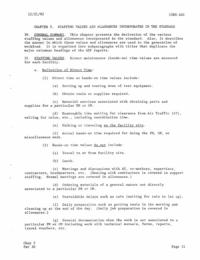
30. GENERAL SUMMARY. This chapter presents the derivation of the various staffing values and allowances incorporated in the standard. Also, it describes the manner in which these values and allowances are used in the generation of workload. It is organized into subparagraphs with titles that duplicate the major columnar headings of the ADP reports.
31. STAFFING VALUES. Direct maintenance (hands-on) time values are measured for each facility.
a. Definition of Direct Time:
(1) Direct time or hands-on time values include:
(a) Setting up and tearing down of test equipment.
(b) Obtain tools or supplies required.
(c) Materiel services associated with obtaining parts and supplies for a particular PM or CM.
(d) Reasonable time waiting for clearance from Air Traffic (AT), waiting for telco, etc., including coordination time.
(e) Walking or traveling on the facility site.
(f) Actual hands-on time required for doing the PM, CM, or miscellaneous work.
(2) Hands-on time values do not include:
(a) Travel to or from facility site.
(b) Lunch.
(c) Meetings and discussions with AT, co-workers, supervisor, contractors, headquarters, etc. (Dealing with contractors is covered in support staffing. Normal meetings are covered in allowances.)
(d) Ordering materials of a general nature not directly associated to a particular PM or CM.
(e) Unavoidable delays such as rain (waiting for rain to let up).
(f) Daily preparation such as getting tools in the morning and cleaning up at the end of the day. (Daily job preparation is covered in allowances.)
(g) General documentation when the work is not associated to a particular PM or CM including work with technical manuals, forms, reports, travel vouchers, etc.
Chap 3 Par 30 Page 31
1380.4OC
(h) Training activities.
12/21/92
b. Direct Maintenance Measurement. Direct maintenance (hands-on) time values are measured for each facility type in the following areas:
(1) Perodic maintenance. Includes recurring preventive maintenance required by national orders and CM (less than 12 minutes) which is inherent to the preventive maintenance and is discovered and corrected during the preventive maintenance task.
(a) Electronic.
(b) Environmental.
(2) Corrective Maintenance. Time required to restore failed equipment.
(a) Electronic.
(b) Environmental.
(c) Printed Circuit Board Repair. For repairs normally performed in centrally located repair facilities or the depot.
(3) Software Maintenance. Computer programming and modification functions.
(4) Monitor Function. Console operations actually performed from a remote site.
(a) Periodic Maintenance. Console operations performed from a remote site to accomplish recurring preventive maintenance tasks required by national order, such as ground check of a VHF Omnidirectional Range (VOR).
(b) Corrective Maintenance. Console operations performed from a remote site to restore failed conditions (this may include reset, switch over, change channels, etc.).
(5) Auxiliarv. Auxiliary tasks required for maintaining normal operations.
(a) Modifications.
(b) Technical Inspections.
(c) Flight Inspections.
(d) Access Roads. Time spent to maintain the entrance way to facility buildings. Includes the first one-half mile of roadway from the building.
Page 32 Chap 3 Par 31
12/21/92 1380.4OC
(e) Field Maintenance Program. Time required to accomplish field maintenance program. Some regions accumulate this type of work for accomplishment at the regional level.
(f) Special Maintenance Projects.
(6) Nonrecurring Direct Time Values. These transition time values are hands-on direct maintenance time values required during the start-up of new facilities or major replacements such as the second generation very high frequency omnidirectional range tactical air navigational system (VORTAC).
(a) Six Months Prior to Commissioning. Additional time required immediately prior to a new commissioning or major replacement (swapout).
installation. 1 Facilities and Equipment. Time to observe equipment
2 Initial Training. Time required for additional training on new equipment.
2 Flight Check. Time required for the initial flight inspection of new equipment.
(b) First Year of Commissioning. Additional time required during the first year of a new system or major replacement.
1 Clearing JAI Items. Time required for correcting items found during the JAI.
2 Additional Corrective Maintenance. Time to repair the additional failures that normally occur during start-up of new equipment.
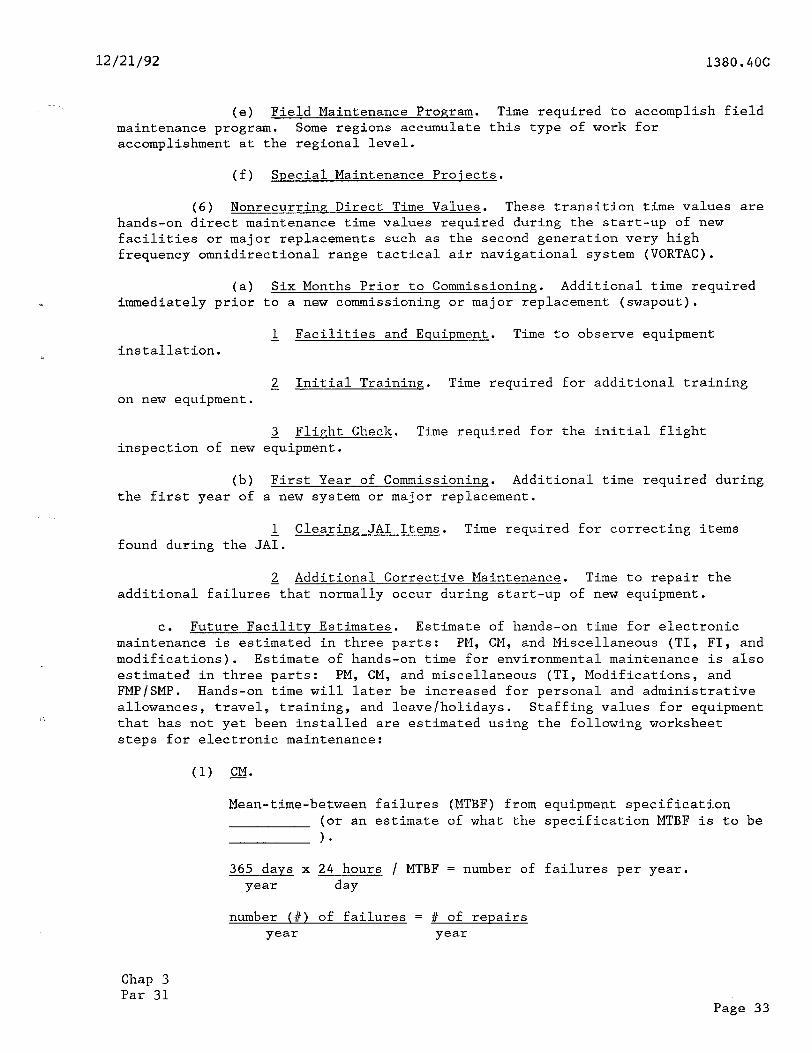
C. Future Facility Estimates. Estimate of hands-on time for electronic maintenance is estimated in three parts: PM, CM, and Miscellaneous (TI, FI, and modifications). Estimate of hands-on time for environmental maintenance is also estimated in three parts: PM, CM, and miscellaneous (TI, Modifications, and FMP/SMP. Hands-on time will later be increased for personal and administrative allowances, travel, training, and leave/holidays. Staffing values for equipment that has not yet been installed are estimated using the following worksheet steps for electronic maintenance:
(1) CM.
Mean-time-between failures (MTBF) from equipment specification (or an estimate of what the specification MTBF is to be 1.
365 days x 24 hours / MTBF = number of failures per year. year day
number (#) of failures = # of repairs year year
Chap 3 Par 31
Page 33
1380.4OC u/21/92
Using a similar type of equipment, already operational, we can use to estimate average repair time ( or an estimate of what the average repair time may be .>
# of hours X # of repairs = # of CM hours repair year year
(2) PM's -0
Approximate number of times per year that one technician will visit facility to perform PM's. = number of one technician visits/year,
Approximate number of times per year that two technicians together will visit facility per year to perform PM's. = number of two technician visits per year.
On the average, approximately how much hands-on time will each technician spend onsite performing PM's during each visit:
(a) One technician by self = /technician.
(b) Two technicians together = /technician.
# of one tech. visits X hands-on time + year one tech. visit
2 X # of two tech. visits X hands-on time year two tech. visit
= total hands-on time/year.
(3) Miscellaneous. (TI, FI, Modifications, and FMP/SMP).
Approximate number of times per year one and/or two electronic maintenance technicians will visit facility
for miscellaneous direct work (TI, FI, mod, and FMP/SMP).
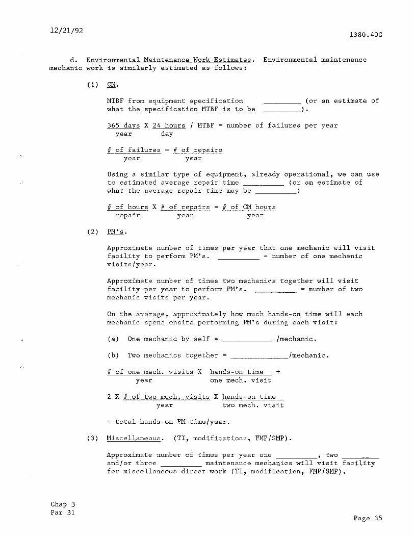
NOTE: If not known, averages for similar equipment should be used or experts from field sectors should be consulted. Approximate hands-on time per technician per visit
# of tech. visits X hands-on time = hands-on time per year. year tech. visit
(4) Subtotal.
CM (electronic) PM (electronic)
+ Misc. (electronic) Direct electronic maintenance for future facility.
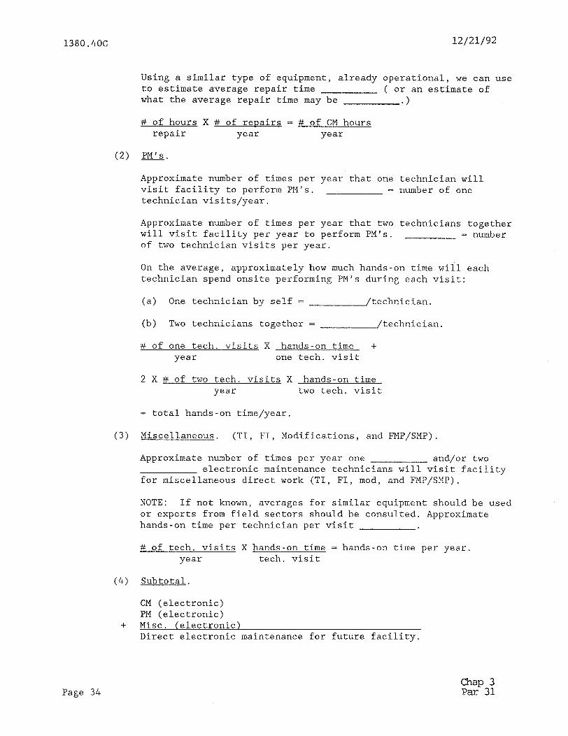
Page 34 Chap 3 Par 31
12/21/92 1380.4OC
d. Environmental Maintenance Work Estimates. Environmental maintenance mechanic work is similarly estimated as follows:
(1) CM.
MTBF from equipment specification (or an estimate of what the specification MTBF is to be 1.
365 days X 24 hours / MTBF = number of failures per year year day
# of failures = # of repairs year year
Using a similar type of equipment, already operational, we can use to estimated average repair time (or an estimate of what the average repair time may be >
f of hours X # of repairs = # of CM hours repair year year
(2) PM's.
Approximate number of times per year that one mechanic will visit facility to perform PM's. = number of one mechanic visits/year.
Approximate number of times two mechanics together will visit facility per year to perform PM's. = number of two mechanic visits per year.
On the average, approximately how much hands-on time will each mechanic spend onsite performing PM's during each visit:
(a) One mechanic by self = /mechanic.
(b) Two mechanics together = /mechanic.
f of one mech. visits X hands-on time- + year one mech. visit
2 X I of two mech. visits X hands-on time year two mech. visit
= total hands-on ?M time/year.
(3) Miscellaneous. (TI, modifications, FMPISMP).
Approximate number of times per year one , two and/or three maintenance mechanics will visit facility for miscellaneous direct work (TI, modification, FMP/SMP).
Chap 3 Par 31
Page 35
1380.4OC 12/21/92
NOTE: If not known, averages for similar equipment should be used or experts from field sectors should be consulted. Approximate HANDS-ON time per mechanic per visit .
# of mech. visits X hands-on time = total hands-on time year mech. visit year
(4) Subtotal.
CM (environmental) PM (environmental)
+ Miscellaneous (environmental) Direct environmental maintenance for future facility.
e. Final total follows.
Direct electronic maintenance + Direct environmental maintenance
Direct maintenance
f. Final Application. Direct maintenance value is put in the FSEP for the future facility and staffing standard algorithm increases value by allowances for personal and administrative time, leave, training, and actual travel time required.
32. TRAVEL ALLOWANCE. Actual travel time in employee-years is added to each cost center in the site-specific travel line. For each cost center, the travel is the sum of the travel time for each facility. For the sector, this travel time is the sum of all the cost center travel time in the sector. For the region, this travel time is the sum of all the sector travel time in the region. These travel time allowances only apply to travel required by sector level direct work staff personnel. Travel by technical support, administrative, and management personnel is excluded from these allowances. The travel time entered in the FSEP data files is the one-way travel time (in minutes) and includes only travel to the job site from the work station. Travel time on the job site is already included in the direct maintenance PM, CM, and auxiliary times.
a. Counting Number of Visits Required. Visits are to be counted for direct work only. Therefore, supervisory and managerial visits should not be counted. If a supervisor performs direct work, then the visit should be counted.
(1) The number of visits may include visits required for both environmental and electronics technician work, but should not include extra trips .for lunch or breaks. If two technicians are required to visit the facility concurrently, this should be counted as two visits. Not-required casual visits of an elective nature should not be counted.
(2) Where there is currently no travel time required, all zeros should be entered in the travel time field and in the number of visits field.
Page 36 Chap 3 Par 31
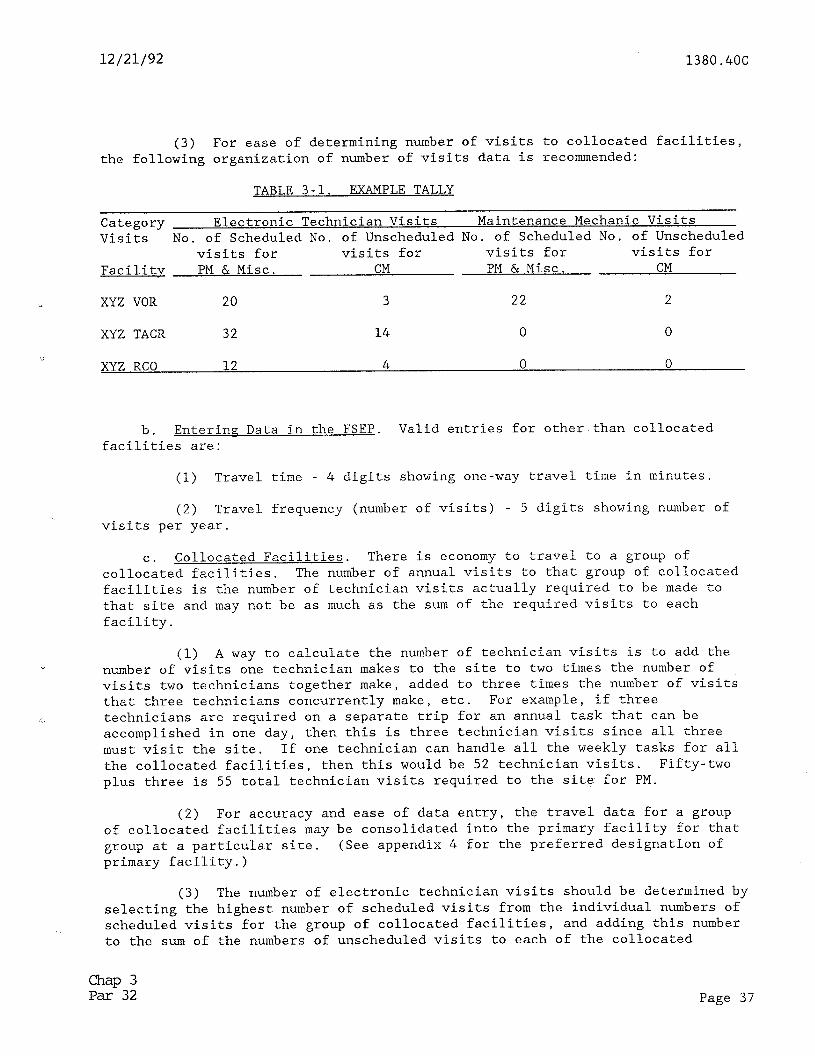
12/21/92 1380.4OC
(3) For ease of determining number of visits to collocated facilities, the following organization of number of visits data is recommended:
TABLE 3-1. EXAMPLE TALLY
Category Electronic Technician Visits Maintenance Mechanic Visits Visits No. of Scheduled No. of Unscheduled No. of Scheduled No. of Unscheduled
visits for visits for visits for visits for Facility PM & Misc. CM PM & Misc. CM
.a XYZ VOR 20 3 22 2
XYZ TACR 32 14 0 0
i XYZ RCO 12 4 0 0
b. EnterinP Data in the FSEP. Valid entries for other than collocated facilities are:
(1) Travel time - 4 digits showing one-way travel time in minutes.
(2) Travel frequency (number of visits) - 5 digits showing number of visits per year.
C. Collocated Facilities. There is economy to travel to a group of collocated facilities. The number of annual visits to that group of collocated facilities is the number of technician visits actually required to be made to that site and may not be as much as the sum of the required visits to each facility,
Y (1) A way to calculate the number of technician visits is to add the
number of visits one technician makes to the site to two times the number of visits two technicians together make, added to three times the number of visits that three technicians concurrently make, etc. For example, if three technicians are required on a separate trip for an annual task that can be accomplished in one day, then this is three technician visits since all three must visit the site. If one technician can handle all the weekly tasks for all the collocated facilities, then this would be 52 technician visits. Fifty-two plus three is 55 total technician visits required to the site for PM.
(2) For accuracy and ease of data entry, the travel data for a group of collocated facilities may be consolidated into the primary facility for that group at a particular site. (See appendix 4 for the preferred designation of primary facility.)
(3) The number of electronic technician visits should be determined by selecting the highest number of scheduled visits from the individual numbers of scheduled visits for the group of collocated facilities, and adding this number to the sum of the numbers of unscheduled visits to each of the collocated
Chap 3 Par 32 Page 37
, .- ,. . . _” ,.._ j . .-_ .,.. .__. I .* \ ̂ _*,_ .._ ._. _. ~.
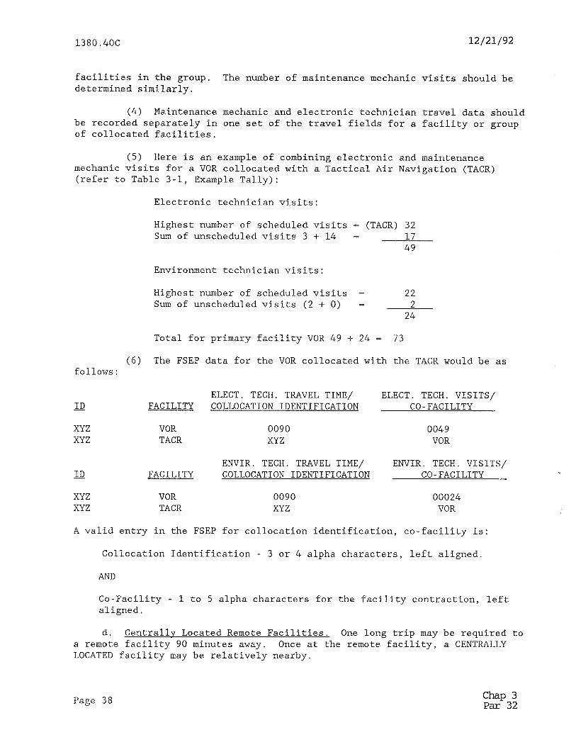
1380.406 12/21/92
facilities in the group. The number of maintenance mechanic visits should be determined similarly.
(4) Maintenance mechanic and electronic technician travel data should be recorded separately in one set of the travel fields for a facility or group of collocated facilities.
(5) Here is an example of combining electronic and maintenance mechanic visits for a VOR collocated with a Tactical Air Navigation (TACR) (refer to Table 3-1, Example Tally):
Electronic technician visits:
Highest number of scheduled visits = (TACR) 32 Sum of unscheduled visits 3 + 14 = - 17
49
Environment technician visits:
Highest number of scheduled visits = 22 Sum of unscheduled visits (2 + 0) = 2
24
Total for primary facility VOR 49 + 24 = 73
(6) The FSEP data for the VOR collocated with the TACR would be as follows:
ELECT. TECH. TRAVEL TIME/ ELECT. TECH. VISITS/ ID FACILITY COLLOCATION IDENTIFICATION CO-FACILITY
XYZ VOR 0090 0049 XYZ TACR XYZ VOR
ENVIR. TECH. TRAVEL TIME/ ENVIR. TECH. VISITS/ ID FACILITY COLLOCATION IDENTIFICATION CO-FACILITY
XYZ VOR 0090 00024 XYZ TACR XYZ VOR
A valid entry in the FSEP for collocation identification, co-facility is:
Collocation Identification - 3 or 4 alpha characters, left aligned.
AND
Co-Facility - 1 to 5 alpha characters for the facility contraction, left aligned.
d. Centrally Located Remote Facilities. One long trip may be required to a remote facility 90 minutes away. Once at the remote facility, a CENTRALLY LOCATED facility may be relatively nearby.
Page 38 chap 3 Par 32
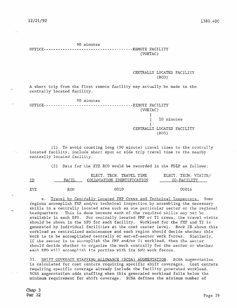
12/21/92 1380.4OC
90 minutes OFFICE--------------------------------------REMOTE FACILITY
(VORTAC)
CENTRALLY LOCATED FACILITY @CO)
A short trip from the first remote facility may actually be made to the centrally located facility.
90 minutes OFFICE--------------------------------------REMOTE FACILI'I'Y
(VORTAC) I I 10 minutes I
CENTRALLY LOCATED (RCO)
(1) To avoid counting long (90 minute) travel times located facility, include short spur or side trip travel time centrally located facility.
FACILITY
to the centrally to the nearby
(2) Data for the XYZ RCO would be recorded in the FSEP as follows:
ELECT. TECH. TRAVEL TIME ELECT. TECH. VISITS/ ID FACIL COLLOCATION IDENTIFICATION CO-FACILITY
XYZ RCO 0010 00016
e. Travel by Centrallv Located FMP Crews and Technical Inspectors. Some regions accomplish FMP and/or technical inspection by assembling the necessary skills in a centrally located area such as one particular sector or the regional headquarters. This is done because each of the required skills may not be available in each SFO. For centrally located FMP or TI crews, the travel visits should be shown in the SF0 for each facility. Workload for the FMP and TI is generated by individual facilities at the cost center level. Book 2B shows this workload as centralized maintenance and each region should decide whether this work is to be accomplished centrally or out-of-sector work forces. Similarly, if the sector is to accomplish the FMP and/or TI workload, then the sector should decide whether to organize the work centrally for the sector or whether each SF0 will accomplish its portion with its SF0 work forces.
33. SHIFT COVERAGE STAFFING ALLOWANCE (SCSA) AUGMENTATION. SCSA augmentation is calculated for cost centers requiring specific shift coverages. Cost centers requiring specific coverage already include the facility generated workload. SCSA augmentation adds staffing when this generated workload falls below the minimum requirement for shift coverage. SCSA defines the minimum number of
Chap 3 Par 32 Page 39
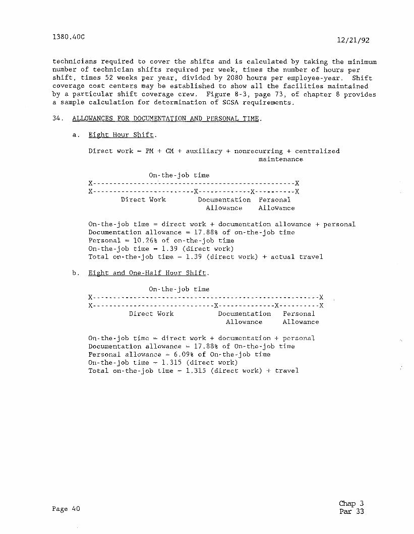
1380.4OC 12/21/92
technicians required to cover the shifts and is calculated by taking the minimum number of technician shifts required per week, times the number of hours per shift, times 52 weeks per year, divided by 2080 hours per employee-year. Shift coverage cost centers may be established to show all the facilities maintained by a particular shift coverage crew. Figure a-3, page 73, of chapter 8 provides a sample calculation for determination of SCSA requirements.
34. ALLOWANCES FOR DOCUMENTATION AND PERSONAL TIME.
a. Eipht Hour Shift.
Direct work = PM + CM + auxiliary + nonrecurring + centralized maintenance
On-the-job time x--------------------------------------------------x X----------------------- --x-------------x----------x
Direct Work Documentation Personal Allowance Allowance
On-the-job time = direct work + documentation allowance + personal Documentation allowance = 17.88% of on-the-job time Personal = 10.26% of on-the-job time On-the-job time = 1.39 (direct work) Total on-the-job time = 1.39 (direct work) + actual travel
b. Eight and One-Half Hour Shift.
On-the-job time x--------------------------------------------------------x x------------------------------x--------------x----------x
Direct Work Documentation Personal Allowance Allowance
On-the-job time = direct work + documentation -I- personal Documentation allowance = 17.88% of On-the-job time Personal allowance = 6.09% of On-the-job time On-the-job time = 1.315 (direct work) Total on-the-job time = 1.315 (direct work) + travel
Page 40 Chap 3 Par 33
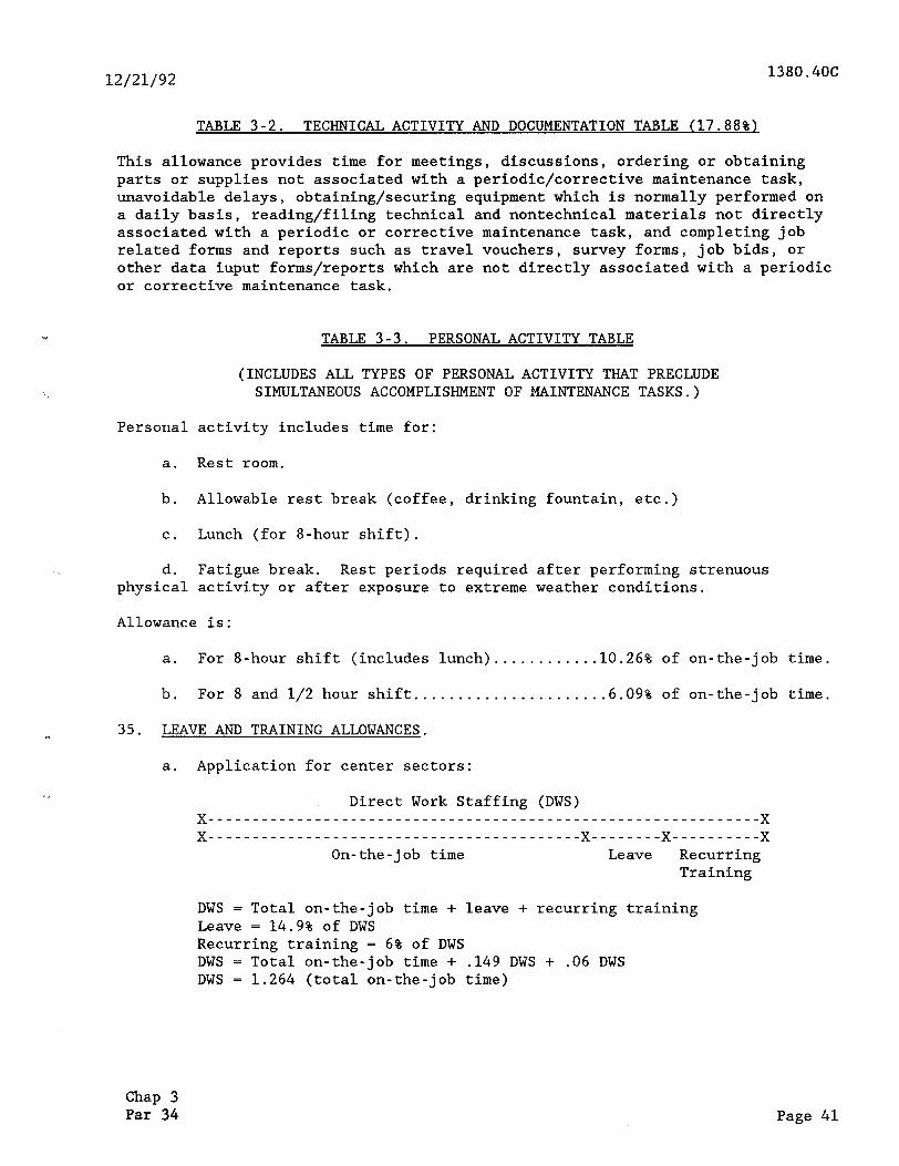
12/21/92 1380.4OC
TABLE 3-2. TECHNICAL ACTIVITY AND DOCUMENTATION TABLE (17.88%x
This allowance provides time for meetings, discussions, ordering or obtaining parts or supplies not associated with a periodic/corrective maintenance task, unavoidable delays, obtaining/securing equipment which is normally performed on a daily basis, reading/filing technical and nontechnical materials not directly associated with a periodic or corrective maintenance task, and completing job related forms and reports such as travel vouchers, survey forms, job bids, or other data iuput forms/reports which are not directly associated with a periodic or corrective maintenance task.
TABLE 3-3. PERSONAL ACTIVITY TABLE
(INCLUDES ALL TYPES OF PERSONAL ACTIVITY THAT PRECLUDE SIMULTANEOUS ACCOMPLISHMENT OF MAINTENANCE TASKS.)
Personal activity includes time for:
a. Rest room.
b. Allowable rest break (coffee, drinking fountain, etc.)
C. Lunch (for 8-hour shift).
d. Fatigue break. Rest periods required after performing strenuous physical activity or after exposure to extreme weather conditions.
Allowance is:
a. For 8-hour shift (includes lunch).......... ..10.26% of on-the-job time.
b. For 8 and l/2 hour shift......................6.09% of on-the-job time.
35. LEAVE AND TRAINING ALLOWANCES.
a. Application for center sectors:
Direct Work Staffing (DWS) x--------------------------------------------------------------x x------------------------------------------x--------x----------x
On-the-job time Leave Recurring Training
DWS = Total on-the-job time + leave + recurring training Leave = 14.9% of DWS Recurring training = 6% of DWS DWS = Total on-the-job time + .149 DWS + .06 DWS DWS = 1.264 (total on-the-job time)
Chap 3 Par 34 Page 41
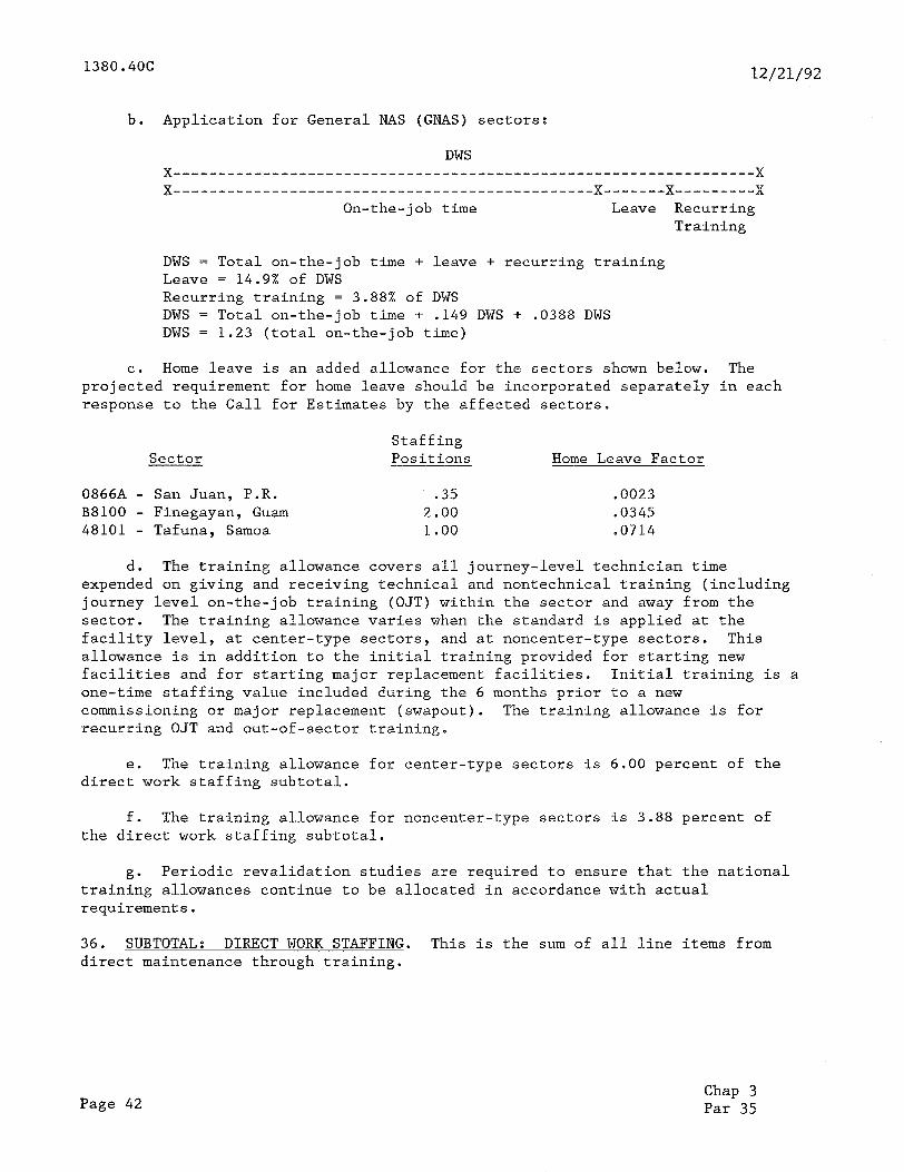
1380.401: 12/21/92
b. Application for General NAS (GNAS) sectors:
DWS x-----------------------------------------------------------------x X -----------------------------------------------x-------x---------x
On-the-job time Leave Recurring Training
DWS = Total on-the-job time + leave + recurring training Leave = 14.9% of DWS Recurring training = 3.88% of DWS DWS = Total on-the-job time + .149 DWS + .0388 DWS DWS = 1.23 (total on-the-job time)
C. Home leave is an added allowance for the sectors shown below. The projected requirement for home leave should be incorporated separately in each response to the Call for Estimates by the affected sectors.
Sector Staffing Positions Home Leave Factor
08668 - San Juan, P.R. .35 .0023 B8100 - Finegayan, Guam 2.00 .0345 48101 - Tafuna, Samoa 1.00 -0714
d. The training allowance covers all journey-level technician time expended on giving and receiving technical and nontechnical training (including journey level on-the-job training (OJT) within the sector and away from the sector. The training allowance varies when the standard is applied at the facility level, at center-type sectors, and at noncenter-type sectors. This allowance is in addition to the initial training provided for starting new facilities and for starting major replacement facilities. Initial training is a one-time staffing value included during the 6 months prior to a new commissioning or major replacement (swapout). The training allowance is for recurring OJT and out-of-sector training.
e. The training allowance for center-type sectors is 6.00 percent of the direct work staffing subtotal.
f. The training allowance for noncenter-type sectors is 3.88 percent of the direct work staffing subtotal.
g. Periodic revalidation studies are required to ensure that the national training allowances continue to be allocated in accordance with actual requirements.
36. SUBTOTAL: DIRECT WORK STAFFING. This is the sum of all line items from direct maintenance through training.
Page 42 Chap 3 Par 35
12/21/92 1380.4OC
37. DIRECT WORK SUPPORT STAFFING VALUES.
a. General. This section of the standard is divided into three parts:
(1) Program support.
(2) Technical support.
(3) On-site supervision.
b. Annlication at the Sector Level. The direct work support staffing is determined by the formula shown in appendix 3. The formula calculates direct work support staffing according to the category of the sector as shown in appendix 3.
38. ENGINEERING MANAGEMENT AND ADMINISTRATIVE SUPPORT. The management and administrative support staffing allowance is determined by the formula shown in appendix 3.
39. RESERVED.
Chap 3 Par 37 Page 43 (and 44)

12/21/92 1380.4OC
CHAPTER 4. THE CLASS STRUCTURE AND POINT-COUNT SYSTEMS
40. GENERAL. The AF sector level staffing standard is constructed in such a manner that discrete staffing values are provided for not only each type of facility, but also for each class and model number within each type listed in the FSEP. Hence, it is vitally important that each sector manager maintain constant surveillance to ensure that correct data are shown in these files.
a. Facility identification codes are used to differentiate between facilities which have the same facility-type identification, but are significantly different in terms of their equipment composition. Different equipment configurations of a given facility may be assigned a facility I., identification code when their differences affect staffing, maintenance procedures, or supply support. Order 1375.4 prescribes the standards and codes for use in agency data systems for the purpose of identifying and classifying
'; / facility data. These standards provide the basis for uniform accumulation and presentation of such data in program and management data systems. The facility identification standards are intended to include all facilities associated with the NAS in an operating or supporting capacity which must be identified for financial or program management purposes.
b. Most facilities in the system are given individual status in the FSEP by listing each as a separate record; i.e., single unit facilities. An exception to this rule is in the case of support-type facilities such as LIVQ, SB, UB, VEHS, etc., which are listed as one-line items in the FSEP for each type and location and given a total allowance equal to the numbers of like units times the allowance per unit. See paragraph 24i(2).
C. For energy conservation purposes some facilities, e.g., ALS-2 and SSALR have been configured to be switchable from one facility type to another. Regardless of use ratio between the two facility types, the maintenance effort must be in keeping with the facility having the greatest workload. Therefore, such a facility should be identified as the facility type having the greater allowance.
iI * d. A facility will be considered solid-state when the majority of the equipment is solid-state (50 percent or more).
s 41. FACILITY TYPE. Facility types are classified either as point-count or nonpoint-count (core) facilities.
a. Nonnoint-Count (Core) Facilities. In these facilities, there is such a high degree of standardization in the numbers and kinds of equipment components associated with the facility that, for staffing purposes, it is not necessary to go below the facility level.
TABLE 4-l. SOME EXAMPLES OF CORE FACILITIES
ALS ARTS ARSR MCR LLWAS FDIOC FDIOR RRWDI RBDE RCF RLCT RMCF RMLT RCLR
Chap 4 Par 40 Page 45
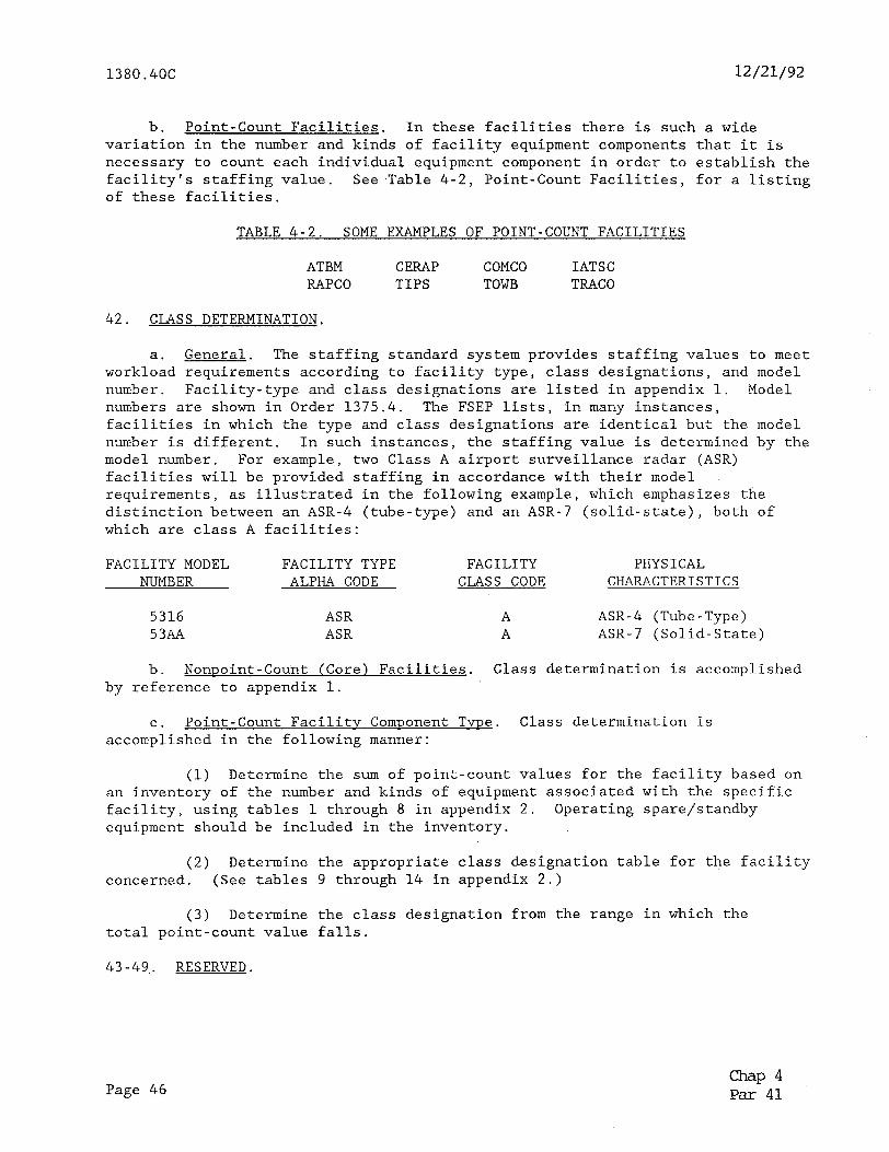
1380.4OC 12/21/92
b. Point-Count Facilities. In these facilities there is such a wide variation in the number and kinds of facility equipment components that it is necessary to count each individual equipment component in order to establish the facility's staffing value. See Table 4-2, Point-Count Facilities, for a listing of these facilities.
TABLE 4-2. SOME EXAMPLES OF POINT-COUNT FACILITIES
ATBM CERAP COMCO IATSC RAPCO TIPS TOWB TRACO
42. CLASS DETERMINATION.
a. General. The staffing standard system provides staffing values to meet workload requirements according to facility type, class designations, and model number. Facility-type and class designations are listed in appendix 1. Model numbers are shown in Order 1375.4. The FSEP lists, in many instances, facilities in which the type and class designations are identical but the model number is different. In such instances, the staffing value is determined by the model number. For example, two Class A airport surveillance radar (ASR) facilities will be provided staffing in accordance with their model requirements, as illustrated in the following example, which emphasizes the distinction between an ASR-4 (tube-type) and an ASR-7 (solid-state), both of which are class A facilities:
FACILITY MODEL NUMBER
FACILITY TYPE ALPHA CODE
FACILITY CLASS CODE
PHYSICAL CHARACTERISTICS
5316 53AA
ASR ASR
A ASR-4 (Tube-Type) A ASR-7 (Solid-State)
b. Nonooint-Count (Core) Facilities. Class determination is accomplished by reference to appendix 1.
C. Point-Count Facilitv Component Tvoe. Class determination is accomplished in the following manner:
(1) Determine the sum of point-count values for the facility based on an inventory of the number and kinds of equipment associated with the specific facility, using tables 1 through 8 in appendix 2. Operating spare/standby equipment should be included in the inventory.
(2) Determine the appropriate class designation table for the facility concerned. (See tables 9 through 14 in appendix 2.)
(3) Determine the class designation from the range in which the total point-count value falls.
43-49,. RESERVED.
Page 46 -P 4 Par 41
12/21/92
CHAPTER 5. PROCEDURES FOR USING THE AF STAFFING STANDARD IN THE AGENCY BUDGET PROCESS
1380.406
50. GENERAL. The AF sector level staffing standard shall be used to develop field maintenance workload requirements for regional budget submissions. This chapter describes procedures for using the standard in the budget process.
51. COMPUTER APPLICATION OF THE STAFFING STANDARD. Integration of the staffing values into the agency's budgetary process requires an accurate, up-to-date facility inventory file. This file is comprised of those facilities that are in test or commissioned status in the FSEP and those anticipated to be commissioned or changed, as projected from the regional project managers systems (RPMS) into the FSEP. Total AF sector workload requirements are developed by downloading FSEP data into the SSAS at the regional level and in Washington headquarters. This effectively merges FSEP data with the SVF. This merge will be performed for actual resource distribution in July and for budgeting during January.
52. ISSUANCE OF CALL FOR ESTIMATES. In the fall of each year, the Office of Budget issues a Call for Estimates. This provides program guidance and instructions for developing estimates for the maintenance of the NAS and leased communications. The staffing standard reflecting total workload requirements by region, sector, and SF0 will be forwarded in response to the Call for Estimates.
53. SECTOR/REGIONAL RESPONSE TO THE CALL.
General. The SSAS allows regional headquarters to produce their staff:ng standard (though the SF0 is controlled by ASM-200).
b. Sector. Sector responses to the staffing portion of the Call for Estimates begin with sector review of Book 2A for FI accuracy. If the sector manager agrees that Book 2A is accurate, concurrence shall be forwarded to the region. Error and omissions shall be annotated on Book 2A and a copy returned to the region.
C. Regional Office
(1) The regional office is responsible for reviewing and maintaining accurate records in the FSEP and SSAS. Regional review of the FSEP should include a thorough inspection of the facility identification code, class, status, responsibility, and cost center code data fields, as these fields directly affect the accuracy of the staffing standard.
(2) The regional office will evaluate requests for changes in the AF sector/SF0 totals differing from the staffing standard in terms of the region's ability to adjust staffing resources among sectors. When excesses or deficiencies become significant at the regional level, justification will be required to support the total regional staffing requests,
(3) When regional review determines that no adjustment to the staffing presentation totals is required, concurrence is annotated on the regional AF sector totals report. Entries in the FI may require change. These changes may require revision to entries in either the SSAS, the FSEP, or both.
-P 5 Par 50 Page 47
1380.406: 12/21/92
(4) When regional management decides that an adjustment to total workload is necessary, the exception is annotated directly on the report.
(5) After regional coordination has been completed, two advance copies of the regional AF sector totals ADP report, with justification, will.be sent to the ASM-200. The advance copies will be due prior to the date specified in the call for submission of regional budget estimates to the Office of Budget.
(6) The annotated regional AF sector totals ADP report shall agree with and support the total AF field maintenance submission by the region. Totals from the annotated regional AF sector totals ADP report will be carried over to complete figure AAF-2 in regional budget estimates. This procedure will be further explained in the latest edition of Order 2500.10, Operations Appropration Call for Estimates.
54. WASHINGTON HEADQUARTERS REVIEW.
a. ASM-200 is responsible for reviewing the SSAS-generated staffing presentations as well as all annotations made by regional offices. The staffing levels shown on these printouts are the basis for the total field position recommendation to the Office of Budget. The Office of Budget will also review regional response to the Call for Estimates in accordance with established practice.
b. Total field maintenance staffing requirements for the Systems Maintenance Service, as developed through the preceding events, are included in the agency's detailed budget preparation. This SSAS application generates the official field maintenance staffing requirements, subject to review within the agency and approval by the Administrator. It becomes a part of the basis for the agency's official staffing request in its budget submission. The official budget submission then undergoes review by the Office of the Secretary of Transportation, Office of Management and Budget, and the Congress.
55. DESCRIPTIVE OUTLINE OF EVENTS. The following outline describes various events in the budget process.
EVENT NUMBER DATE EVENT DESCRIPTION
1 October APPLICATION OF THE STAFFING STANDARD SYSTEM. In each budget cycle, the Washington office initiates production of the engineered staffing standard. This production run will be used to budget for the fiscal year starting 2 years hence. The staffing standard production started here will also be used as a tentative distribution of resources for the next fiscal year.
November ISSUANCE OF CALL FOR ESTIMATES. The Office of Budget issues budget year Call for Estimates.
Page 48 Chap 5 Par 53
12/21/92
3 December
4 January
5 April
1.
6 May
7 June
8 September
9 February
56.-59. RESERVED.
1380.4OC
SECTOR/REGIONAL REVIEW OF STAFFING PRESENTATIONS. Regions submit copies of the staffing standard reports and diskettes, with supporting comments, to ASM-200 (Book 2A and 2B); and prepare their budget request for in-house personnel resources.
REGIONAL RESPONSE TO CALL. Regions submit responses to the Call for Estimates to the Office of Budget.
STAFFING REVIEWS BY HEADQUARTERS. Another staffing merge is also begun for actual distribution of obtained staffing resources at the beginning of the fiscal year in October.
SUBMISSION OF SPRING PREVIEW. The Systems Maintenance Service provides data for making the Spring Preview submission for the budget year to the Office of the Secretary of Transportation.
OST REVIEW. The Office of the Secretary of Transportation conducts a review of FAA's detailed budget submission.
OMB REVIEW. The Office of Management and Budget reviews FAA/OST's detailed budget submission. Based on OMB's decisions, FAA prepares the budget package to be incorporated in the President's Budget to be submitted to the Congress. AAF distributes personnel resources for the starting fiscal year based on the staffing standard production which started in April.
CONGRESSIONAL BUDGET REVIEW. The House and Senate conduct review hearings on the Department of Transportation budget submission for approval and appropriation of funds.
Chap 5 Par 55 Page 49 (and 50)
. . .,._” . ..-. ?_~ ..,. .._._ :_ _., ._-_- .___. ,_ ._. _.;_ _.._ .._..___ __

12/21/92 1380.4OC
CHAPTER 7. REFINEMENT AND REVALIDATION OF THE AF STAFFING STANDARD SYSTEM
70. INTRODUCTION. The development of the AF sector level staffing standard system and its integration into the agency's budgetary process represents a significant accomplishment. However, additional work needs to be done in the areas of refinement and revalidation of staffing values in order to ensure system quality, continuing viability, and credibility.
71. REFINEMENT AND REVALIDATION.
a. General. The current staffing standard is developed in accordance with such factors as number and type of facilities mix of solid-state versus tube-type equipment, organizational structure, assumed training status of the work force, and specific maintenance policies. These policies consist of such items as required restoration time, equipment redundancy policy, PM schedules, and establishment of acceptable facility outage levels. The large number and variety of types of facilities, their wide geographical distribution, and the extensive and varied employee skill requirements within AF sectors presented great challenges during the development of the staffing standard. The magnitude of the task was so great that measured data on all facilities was planned to be obtained and revised on a recurring basis. In many cases, the standard employs engineering estimates that are several years old. There is an ongoing effort to collect additional data and to develop additional staffing values to revalidate or replace the engineering estimates as well as to revise engineered standards which have become out of date due to changes in maintenance procedures.
b. Areas Requiring Refinement Action. The following list is representative of those areas in which refinement actions are underway:
(1) Revalidation of staffing values.
(2) Shift coverage staffing allowance augmentation.
(3) Development of future facility staffing value estimates.
(4) Validation of support staffing values.
(5) Point-count facilities.
(6) Allowances
(7) Transition staffing values
(8) Technical inspections
C. Refinement Studies. The Systems Maintenance Service and the Office of Aviation Policy and Plans determine which areas require refinement action, set priorities, and allocate resources for accomplishment of specific studies. In such studies, the required sample size will be kept as small as possible within the basic requirement for achieving statistical reliability. Upon development, study plans, including proposed scheduling and field participation, are distributed for regional comment. Regional and AF sector advice, assistance, and participation in these studies are necessary.
Chap 7 Par 70
Page 51
1380.4OC 12/21/92
d. Staffing Standard Change Control Team. A staffing standards change control team will review all proposed changes in workload values and all new workload values planned to be introduced into the staffing standard system. The team will meet once (twice, if necessary) each year and will also review priorities for facility standard revisions. The team is chaired by the ASM-200 with representatives from the Office of Aviation Policy and Plans, concerned development program, SEIC, and a regional AF division representative. The Director, Systems Maintenance Service, approves changes to the staffing standard on which all team members agree. The Associate Administrator for Airway Facilities reviews all disputed changes.
e. Methods Improvement Evaluation Team. Prior to development or revision of engineered standards studies will be accomplished to assure proper levels of maintenance and proper maintenance procedures. A methods improvement evaluation team will review and evaluate facilities and equipment for candidate selections to be studied. Excellent candidates include poor performers, as evidenced by the outage reporting system, and those which are labor intensive, as evidenced by their staffing standards requirements. Other possible candidates are those facilities which have undergone major technological state-of-the-art changes. The selected facilities/equipments will undergo an intensive methods improvement study process. This process employs well tested industrial engineering techniques aimed towards eliminating or minimizing labor intensive activities. While the emphasis is concentrated on labor intensity, other factors such as maintainability and reliability improvement are also affected and considered during this process. A resprestative from the NAS System Engineering Service and the NAS Transition and Implementation Service will be invited to participate. This team will be chaired by the ASM-200 with representatives from the Office of Aviation Policy and Plans, APO-500, Program Office, Maintenance Engineering Division, ASM-110, 120, and 140, and an AF division regional representative. The team composition is similar to staffing standards change control team and in many cases will be the same people meeting at the same time addressing both issues simultaneously. Study results and recommendations will be processed through the ASM-100 for implementation.
72.-79. RESERVED.
Page 52
Chap 7 Par 71

12 /21/92 1380.4OC
CHAPTER 8. UPDATING STAFFING STANDARDS
80. GENERAL, The AF sector level staffing standard system is supported by computer programs using a series of data base files to generate ADP reports labeled Books 1 and 2. In order to ensure the accuracy of these reports, the data base must reflect current information regarding authorized staffing values by facility-type, class, and model (facility identification code) as well as the proper cost center code, facility status, etc.
81. DATA BASE FILES. The system data is contained in three major files:
a. Facility, service, and equipment profile.
b. Cost center code table (CCCT).
C. Staffing value file.
82. ADP REPORT SUMMARY. The ADP reports are in six formats in Books 1 and 2. They reflect the updated contents of the three data base files, as follows:
a. The Book 1A report contains the basic current facility-related data; i.e., the standard direct maintenance values for each facility type, class, and model in the system.
b. The Book 1B report shows nonrecurring values for starting up new facilities.
C. The Book 1C report is the final rollup of Book 1, providing the average staffing values and allowances, excluding travel, for each facility. Book 1C does not include support staffing.
d. The non-Federal facility staffing allowance is an unnumbered, special ADP report and is included in the Book 1 run. It provides staffing values for non-Federal facilities in annual hours of direct maintenance workload.
e. The Book 2A report reflects the merge of the SVF with the FSEP; i.e., the direct maintenance allowance for each facility type, class, and model by cost center code, location, and facility status.
f. The Book 2B report is the final rollup of Book 2, providing the staffing allowance for each region, AF sector, and SFO/unit in the system, sorted by cost center code. It also provides a national summary of total allowances in the system.
g* The Book 2C report provides the annual hours expended by category of work or activity for each facility-type in a cost center.
83. DATA BASE CHANGES. The responsibility for initiating changes is distributed to all levels of management according to the level of address in the data base architecture.
84. STAFFING STANDARD SYSTEM OPERATION. The regional AF divisions at the request of ASM-200 accomplish the assembly of regional input to the data base
Chap 8 Par 80 Page 53
1380.4OC 12/21/92
files listed in paragraph 81, the periodic merging of these files, and the scheduling of issuances listed in paragraph 82 as follows:
a. Continuous updating of the facility-related, sector-related, and table-related (appendix 2) data base in the SVF.
b. Continuous updating of the national FSEP by direct retrieval from regional data base files.
C. Semiannual merge of the FSEP with the SVF file and issuance of Books 1 and 2 computer reports.
85. REGIONAL AF DIVISION. Each regional AF division is responsible for providing updated inputs to ASM-200.
86. AF SECTOR OFFICE. Each AF sector manager is responsible for reviewing the FSEP input files and the AF SF0 direct maintenance - Book 2A output file (which identifies all present and planned facilities) for accuracy within sector purview and providing updated information through channels to ASM-200.
* 87. UPDATING FORMATS. Figures 8-1, 8-2, and 8-3 illustrate the format required for updates to the cost center code table. *
88. STAFFING STANDARD SYSTEM TIMETABLE. The schedule of events in the process of maintaining the currency of the AF sector level staffing standard system is listed as follows:
a. FSEP Data Cutoff Dates. The cutoff date for update data input to regional FSEP for the staffing standard is the last working day of April for initial distributions and the last working day of October for long range plans, i.e., budget calls, tentative distributions, etc..
b. Cost Center Update Lead Time. Update data inputs to the sector cost center codes have to be in ASM-200 15 working days prior to the cutoff date for FSEP data as in a above.
C. Computer Report Issuance. Books 1 and 2 are scheduled for issuance on the fifteenth working day of January and July.
89. RESERVED.
Page 54 -P 8 Par 84

1380.4OC 12/21/92
* Figure 8-1, Data Sheet Sunnortinp ProDosed Change To The AF Cost Center Related Data Base
1. Effective Date of Change
2. Region
3. Location (Ident, City, State, Office Type, Unit Type)
New
4. Cost Center Code of
Organization being Changed
5. Sector Headquarters Cost
Center Code
6. Sector Type (category number from
Order 1380.40, appendix 3)
7. Shift Coverage Requirements
(hours/day; days/week; i.e. 24hrs/7days)
8. Justification:
Airway Facilities Division Approval:
Approved:
Manager, Maintenance Operations Division (only required for change in sectors)
Computer Entry By:
Date Entered:
(Show both old and all new data)
Chap 8 Par 89 Page 55 (and 56)
*

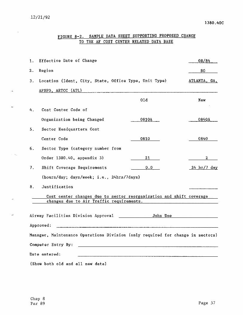
12/21/92 1380.4OC
1.
2.
3.
*" 4.
5.
6.
7.
8.
FIGURE 8-2. SAMPLE DATA SHEET SUPPORTING PROPOSED CHANGE TO THE AF COST CENTER RELATED DATA BASE
Effective Date of Change
Region
Location (Ident, City, State, Office Type, Unit Type}
AFSFO, ARTCC (ATL)
Old
Cost Center Code of
Organization being Changed 0810A
Sector Headquarters Cost
Center Code 0810
Sector Type (category number from
Order 1380.40, appendix 3) 21
Shift Coverage Requirements 0.0
(hours/day; days/week; i.e., 24hrs/7days)
Justification
08/84
so
ATLANTA. GA,
New
0840A
0840
2
24 hr/7 day
Cost center changes due to sector reorganization and shift coverage changes due to Air Traffic requirements.
Airway Facilities Division Approval
Approved:
John Doe
Manager, Maintenance Operations Division (only required for change in sectors)
Computer Entry
Date entered:
(Show both old
By:
and all new data)
Chap 8 Par 89 Page 57
. _ . , __- . . . ..- . . .^l __ - ” --_.,. _ ,,_.. -, _- .._.I _i ..--.- . . . __. . _ -_ .._,_ _- _. _... ._ - ._ __“_ __
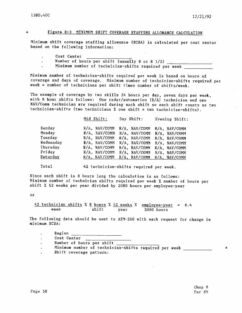
138Ov4OC 12/21/92
* Figure 8-3 MINIMUM SHIFT COVERAGE STAFFING ALLOWANCE CALCULATION.
Minimum shift coverage staffing allowance (SCSA) is calculated per cost center based on the following information:
Cost Center . Number of hours per shift (usually 8 or 8 l/Z) . Minimum number of technician-shifts required per week
Minimum number of technician-shifts required per week is based on hours of coverage and days of coverage. Minimum number of technician-shifts required per week = number of technicians per shift times number of shifts/week.
The example of coverage by two skills 24 hours per day, seven days per week, with 8 hour shifts follows: One radar/automation (R/A) technician and one NAV/Comm technician are required during each shift so each shift counts as two technician-shifts (two technicians X one shift = two technician-shifts).
Mid Shift: Day Shift: Evening Shift:
Sunday Monday Tuesday Wednesday Thursday Friday Saturday
R/A, NAV/COMM R/A, NAV/COMM R/A, NAV/COMM R/A, NAV/COMM R/A, NAV/COMM R/A, NAV/COMM R/A, NAV/COMM R/A, NAV/COMM R/A, NAV/COMM R/A, NAV/COMM R/A, NAV/COMM R/A, NAV/COMM R/A, NAV/COMM R/A, NAV/COMM R/A, NAV/COMM R/A, NAV/COMM R/A, NAV/COMM R/A, NAV/COMM R/A, NAV/COMM R/A, NAV/COMM R/A, NAV/COMM
Total 42 technician-shifts required per week.
Since each shift is 8 hours long the calculation is as follows: Minimum number of technician shifts required per week X number of hours per shift X 52 weeks per year divided by 2080 hours per employee-year
or
42 technician shifts X 8 hours X 52 weeks X employee-year = 8.4 week shift year 2080 hours
The following data should be sent to ASM-260 with each request for change in minimum SCSA:
. Region Cost Center Number of hours per shift
. Minimum number of technician-shifts required per week *
. Shift coverage pattern:
Page 58 Chap 8 Par 89
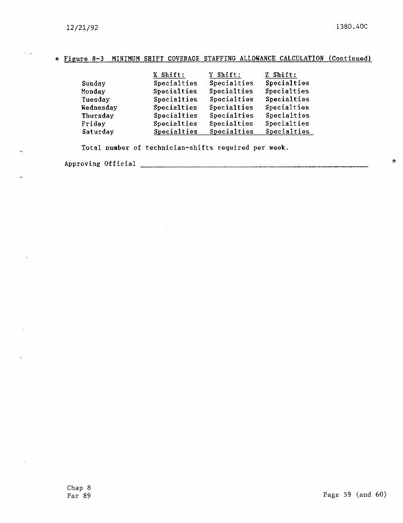
12/21/92 1380.406
* Figure 8-3 MINIMUM SHIFT COVERAGE STAFFING ALLOWANCE CALCULATION (Continued)
Sunday Monday Tuesday Wednesday Thursday Friday Saturday
X Shift: Y Shift: 2 Shift: Specialties Specialties Specialties Specialties Specialties Specialties Specialties Specialties Specialties Specialties Specialties Specialties Specialties Specialties Specialties Specialties Specialties Specialties Specialties Specialties Specialties
Total number of technician-shifts required per week.
Approving Official *
Chap 8 Par 89 Page 59 (and 60)

12/21/92 1380.4OC Appendix 1
APPENDIX 1. FACILITY TYPES, CONTRACTIONS, AND DEFINITIONS
1. GENERAL.
a. An electronic and electromechanical facility which generates staffing requirements has an alpha contraction or facility type assigned to it to facilitate uniformity in reporting through ADP systems. These contractions as well as all associated facility identification codes are outlined in the latest edition of Order 1375.4. To determine complete identifying data for a facility, first determine the facility contraction and class using this appendix. Then determine the facility identification code/model using Order 1375.4.
b. Facility workload differences for solid-state versus tube-type equipment are a function of the facility identification code/model as discussed in chapter 4. Only the facility type and class codes listed in this appendix will be used to generate staffing when entered into the facility, system, and equipment profile (FSEP). Pseudo facilities and services do not generate staffing, but can still be entered into the FSEP.
2. FACILITY-TYPE DEFINITIONS AND CLASS. Facility-type definitions and class structures are listed on the following pages according to the sections described below:
SECTION NUMBER
1
: 4 5 6 7 8
1:
:: 13
FACILITY-TYPE CODE PAGE NUMBER
ACCC - AWP BDIS - BUEC CBI - CWP DARC - DTE EARTS - FSS GATR - ISSS LABS - LRNCM MALS - NXRAD OARTS - QS RAPCO - RVR SACOM - SWG TACAN - TWEB UB - WSM
1: 1 ii 15 - 19 21 - 23 25 - 29 30 - 35 37 - 39 41 - 47 49 - 53 55 - 61 63 - 66 67 - 71 63 - 75
3. FACILITY IDENTIFICATION CODES. The Office of Information Technology is responsible for coordinating changes to these codes with users prior to their final approval for publication. Any user of the FSEP may submit a request to the Maintenance Operations Division, ASM-200, for a new facility contraction, facility identification code, or expansion of model codes. The request should be in writing, explaining the need and use. ASM-200 will forward all supportable requests to the Office of Information Technology, AIT-300, to make appropriate revisions to the facility identification/model codes in Order 1375.4.
Page 1 (and 2)

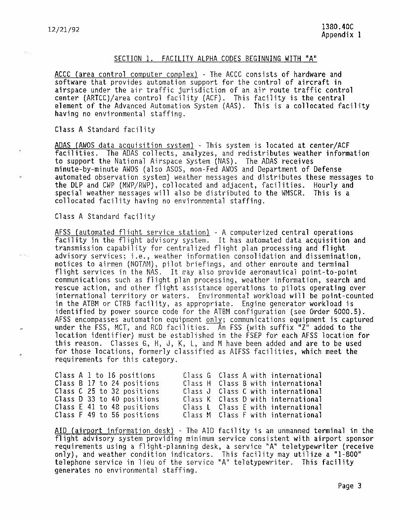
12/21/92
SECTION 1. FACILITY ALPHA CODES BEGINNING WITH "A"
1380.4OC Appendix 1
ACCC (area control computer complex) - The ACCC consists of hardware and software that provides automation support for the control of aircraft in airspace under the air traffic jurisdiction of an air route traffic control center (ARTCC)/area control facility (ACF). This facility is the central element of the Advanced Automation System (AAS). This is a collocated facility having no environmental staffing.
Class A Standard facility
ADAS (AWOS data acquisition system) - This system is located at center/ACF facilities. The ADAS collects, analyzes, and redistributes weather information to support the National Airspace System (NAS). The ADAS receives minute-by-minute AWOS (also ASOS, non-Fed AWOS and Department of Defense automated observation system) weather messages and distributes these messages to the DLP and CWP (MWP/RWP), collocated and adjacent, facilities. Hourly and special weather messages will also be distributed to the WMSCR. This is a collocated facility having no environmental staffing.
Class A Standard facility
AFSS (automated fliqht service station) - A computerized central operations facility in the flight advisory system. It has automated data acquisition and transmission capability for centralized flight plan processing and flight advisory services; i.e., weather information consolidation and dissemination, notices to airmen (NOTAM), pilot briefings, and other enroute and terminal flight services in the NAS. It may also provide aeronautical point-to-point communications such as flight plan processing, weather information, search and rescue action, and other flight assistance operations to pilots operating over international territory or waters. Environmental workload will be point-counted in the ATBM or CTRB facility, as appropriate. Engine generator workload is identified by power source code for the ATBM configuration (see Order 6000.5). AFSS encompasses automation equipment on1.v; communications equipment is captured under the FSS, MCT, and RCO facilities. An FSS (with suffix "Z" added to the location identifier) must be established in the FSEP for each AFSS location for this reason. Classes G, H, J, K, L, and M have been added and are to be used for those locations, formerly classified as AIFSS facilities, which meet the requirements for this category.
Class A 1 to 16 positions Class G Class A with international Class B 17 to 24 positions Class H Class B with international Class C 25 to 32 positions Class J Class C with international Class D 33 to 40 positions Class K Class D with international Class E 41 to 48 positions Class L Class E with international Class F 49 to 56 positions Class M Class F with international
AID (airport information desk) - The AID facility is an unmanned terminal in the flight advisory system providing minimum service consistent with airport sponsor requirements using a flight-planning desk, a service "A" teletypewriter (receive only), and weather condition indicators. This facility may utilize a "l-800" telephone service in lieu of the service "A" teletypewriter. This facility generates no environmental staffing.
Page 3
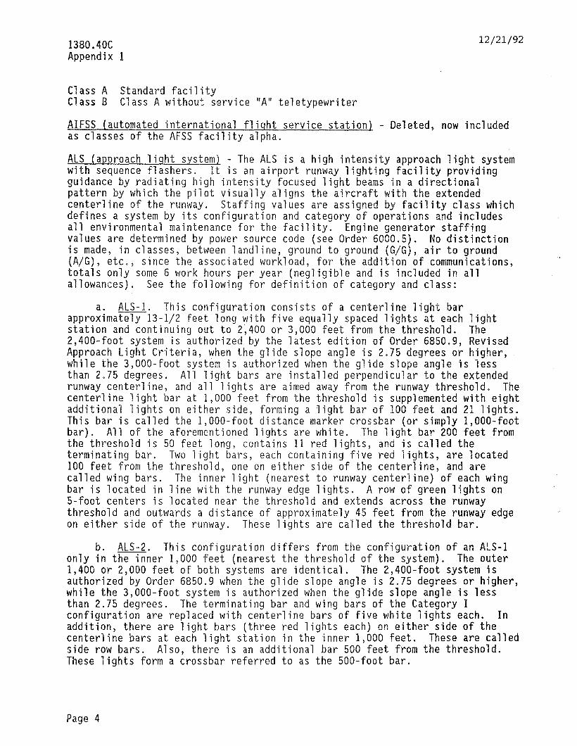
1380.4OC Appendix 1
12/21/92
Class A Standard facility Class B Class A without service "A" teletypewriter
AIFSS (automated -international fliqht service station) - Deleted, now included as classeS of the AFSS facility,alpha.
ALS (approach liqht system) - The ALS is a high intensity approach light system with sequence flashers. It is an airport runway lighting facility providing guidance by radiating high intensity focused light beams in a directional pattern by which the pilot visually aligns the aircraft with the extended centerline of the runway. Staffing values are assigned by facility class which defines a system by its configuration and category of operations and includes all environmental maintenance for the facility. Engine generator staffing values are determined by power source code (see Order 6000.5). No distinction is made, in classes, between landline, ground to ground (G/G), air to ground IA/G), etc. 9 since the associated workload, for the addition of communications, totals only some 6 work hours per year (negligible and is included in all allowances). See the following for definition of category and class:
ALS-1 This configuration consists of a centerline ligh% bar approz;mami3-112 feet long with five equally spaced lights at each light station and continuing out to 2,400 or 3,000 feet from the threshold. The 2,400-foot system is authorized by the latest edition of Order 6850.9, Revised Approach Light Criteria, when the glide slope angle is 2.75 degrees or higher, while the 3,000-foot system is authorized when the glide slope angle is less than 2.75 degrees. All light bars are installed perpendicular to the extended runway centerline, and all lights are aimed away from the runway threshold. The centerline light bar at 1,000 feet from the threshold is supplemented with eight additional lights on either side, forming a light bar of 100 feet and 21 lights. This bar is called the l,OOO-foot distance marker crossbar (or simply l,OOO-foot bar). All of the aforementioned lights are white. The light bar 200 feet from the threshold is 50 feet long, contains 11 red lights, and is called the terminating bar. Two light bars, each containing five red lights, are located 100 feet from the threshold, one on either side of the centerline, and are called wing bars. The inner light (nearest to runway centerline) of each wing bar is located in line with the runway edge lights. A row of green lights on 5-foot centers is located near the threshold and extends across the runway threshold and outwards a distance of approximately 45 feet from the runway edge on either side of the runway. These lights are called the threshold bar.
b. ALS-2. This configuration differs from the configuration of an ALS-1 only in the inner 1,000 feet (nearest the threshold of the system). The outer 1,400 or 2,000 feet of both systems are identical. The 2,400-foot system is authorized by Order 6850.9 when the glide slope angle is 2.75 degrees or higher, while the 3,000-foot system is authorized when the glide slope angle is less than 2.75 degrees. The terminating bar and wing bars of the Category I configuration are replaced with centerline bars of five white lights each. In addition, there are light bars (three red lights each) on either side of the centerline bars at each light station in the inner 1,000 feet. These are called side row bars. Also, there is an additional bar 500 feet from the threshold. These lights form a crossbar referred to as the 500-foot bar.
Page 4
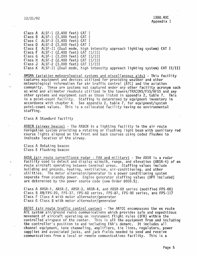
12/21/92 1380.4OC Appendix 1
Class A ALSF-1 (2,400 feet) CAT I Class B ALSF-1 (3,000 feet) CAT I Class C ALSF-2 (2,400 feet) CAT I Class D ALSF-2 (3,000 feet) CAT I Class E ALSF-II (Dual mode, high intensity approach lighting system) CAT I Class F ALSF-I. (2,400 feet) CAT II/III Class G ALSF-I (3,000 feet) CAT II/III Class H ALSF-2 (2,400 feet) CAT II/III Class J ALSF-2 (3,000 feet) CAT II/III Class K ALSF-II (Dual mode, high intensity approach lighting system) CAT II/III
AMSMA (aviation meteoroloqical systems and miscellaneous aids) - This facility captures equipment and devices utilized for providing weather and other meteorological information for air traffic control (ATC) and the aviation community. These are systems not captured under any other facility acronym such as wind and altimeter readouts utilized in the towers/TRACONS/FSS/AFSS and any other systems and equipment such as those listed in appendix 2, table 7. This is a point-count facility. Staffing is determined by equipment inventory in accordance with chapter 4. See appendix 2, table 7, for equipment/system point-count values. This is a collocated facility having no environmental staffing.
Class A Standard facility
ARBCN (airway beacon) - The ARBCN is a lighting facility in the air route navigation system providing a rotating or flashing light beam with auxiliary red course lights aligned on the front and back courses using coded flashes to indicate location of the airway.
Class A Rotating beacon Class E Flashing beacon
ARSR (air route surveillance radar - FAA and military) - The ARSR is a radar facility used to detect and display azimuth, range, and elevation (ARSR-4) of en route aircraft operating between terminal areas. Staffing values include building and grounds, heating, ventilation, air-conditioning, and other utilities. The motor alternator/generator is a power conditioning system separate from standby power. Engine generator staffing values (UPT included) are determined by the power source code (see Order 6000.5).
Class A ARSR-1, ARSR-2, ARSR-3, ARSR-4, and ARSR-60 series (modified FPS-60) Class B AN/FPS-20, FPS-37, FPS-60 series, FPS-87, FPS-90 series, and FPS-117 Class F Class A with motor alternator/generator Class G Class B with motor alternator/generator
ARTCC (air route traffic control center), - The ARTCC encompasses the en route ATC system air/ground radio communications which provides safe and expeditious movement of aircraft operating on instrument flight rules (IFR) within the controlled airspace of the center. This is all the equipment from and including the controller's position to and including FAA's demarc. It includes all channel equipment, tone channeling, amplifiers, tie lines, regulators, power supplies and associated jacks, and jack fields needed to send and receive communications from a local or remote communications facility. This is a
Page 5
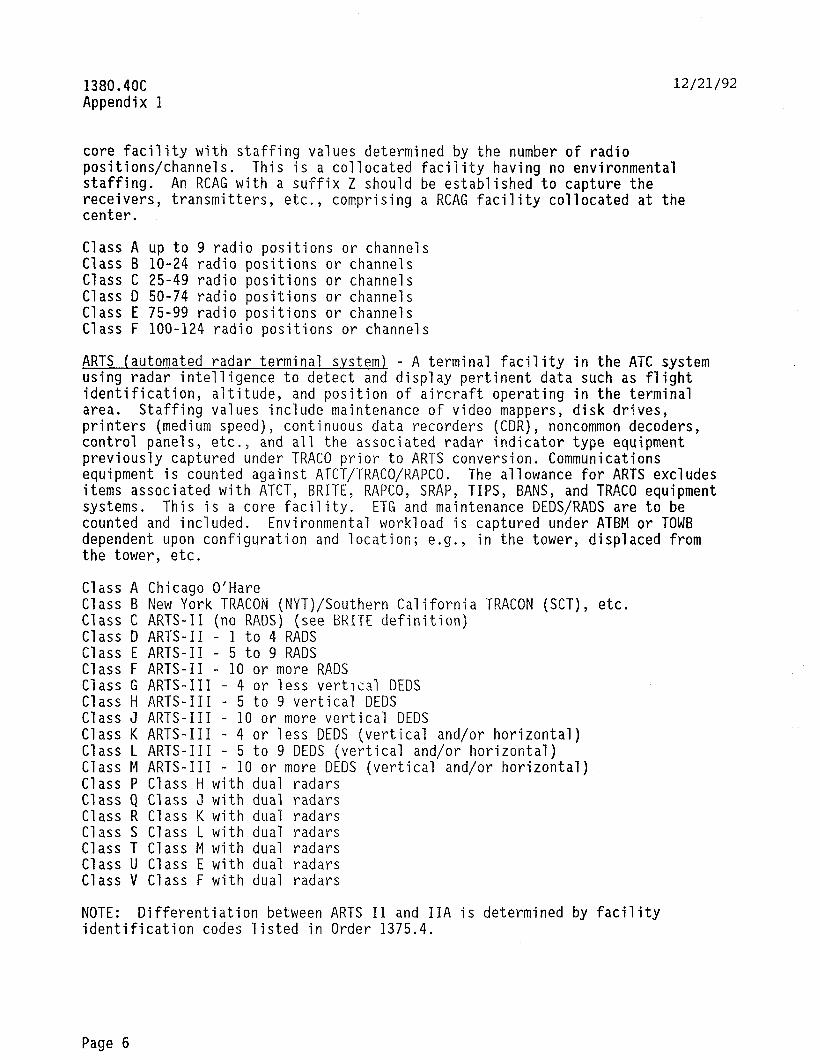
1380.4OC Appendix 1
12/21/92
core facility with staffing values determined by the number of radio positions/channels. This is a collocated facility having no environmental staffing. An RCAG with a suffix Z should be established to capture the receivers, transmitters, etc., comprising a RCAG facility collocated at the center.
Class A up to 9 radio positions or channels Class B lo-24 radio positions or channels Class C 25-49 radio positions or channels Class D 50-74 radio positions or channels Class E 75-99 radio positions or channels Class F loo-124 radio positions or channels
ARTS (automated radar terminal system) - A terminal facility in the ATC system using radar intelligence to detect and display pertinent data such as flight identification, altitude, and position of aircraft operating in the terminal area. Staffing values include maintenance of video mappers, disk drives, printers (medium speed), continuous data recorders (CDR), noncommon decoders, control panels, etc., and all the associated radar indicator type equipment previously captured under TRACO prior to ARTS conversion. Communications equipment is counted against ATCT/TRACO/RAPCO. The allowance for ARTS excludes items associated with ATCT, BRITE, RAPCO, SRAP, TIPS, BANS, and TRACD equipment systems. This is a core facility. ETG and maintenance DEDS/RADS are to be counted and included. Environmental workload is captured under ATBM or TOWB dependent upon configuration and location; e.g., in the tower, displaced from the tower, etc.
Class A Chicago O'Hare Class B New York TRACON (NYT)/Southern California TRACON (SCT), etc. Class C ARTS-II (no RADS) (see BRITE definition) Class D ARTS-II - 1 to 4 RADS Class E ARTS-II - 5 to 9 RADS Class F ARTS-II - 10 or more RADS Class G ARTS-III - 4 or less vertical DEDS Class H ARTS-III - 5 to 9 vertical DEDS Class J ARTS-III - 10 or more vertical DEDS Class # ARTS-III - 4 or less DEDS (vertical and/or horizontal) Class L ARTS-III - 5 to 9 DEDS (vertical and/or horizontal) Class M ARTS-III - 10 or more DEDS (vertical and/or horizontal) Class P Class H with dual radars Class Q Class 3 with dual radars Class R Class K with dual radars Class S Class L with dual radars Class T Class M with dual radars Class U Class E with dual radars Class V Class F with dual radars
NOTE: Differentiation between ARTS II and IIA is determined by facility identification codes listed in Order 1375.4.
Page 6
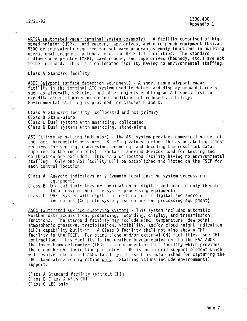
12/21/92 1380.4OC Appendix 1
ARTSA (automated radar terminal system assembly) - A facility comprised of high speed printer (HSP), card reader, tape drives, and card punch equipment (Univac 9300 or equivalent) required for software program assembly functions in building operational programs, patches, etc. for ARTS III facilities. The standard medium speed printer (MSP), card reader, and tape drives (Kennedy, etc.) are not to be included. This is a collocated facility having no environmental staffing.
Class A Standard facility
ASDE (airport surface detection equipment) - A short range airport radar facility in the terminal ATC system used to detect and display ground targets such as aircraft, vehicles, and other objects enabling an ATC specialist to expedite aircraft movement during conditions of reduced visibility. Environmental staffing is provided for classes B and D.
Class A Standard facility, collocated and not primary Class B Stand-alone Class C Dual systems with mosiacing, collocated Class D Dual systems with mosiacing, stand-alone
AS1 (altimeter settinq indicator1 - The AS1 system provides numerical values of the local barometric pressure. Staffing values include the associated equipment required for sensing, conversion, encoding, and decoding the resultant data supplied to the indicator(s). Portable aneriod devices used for testing and calibration are excluded. This is a collocated facility having no environmental staffing. Only one AS1 facility will be established and listed on the FSEP for each control location.
Class A Aneroid indicators only (remote locations; no system processing equipment)
Class B Digital indicators or combination of digital and aneroid onlv (Remote locations; without the system processing equipment)
Class C DASI system with digital or combination of digital and aneroid indicators (Complete system; indicators and processing equipment)
ASOS (automated surface observinq s.ystem) - This system includes automatic weather data acquisition, processing, recording, display, and transmission functions. The standard facility may include wind, temperature, dew point, atmospheric pressure, precipitation, visibility, and/or cloud height indication (CHI) capability built-in. A Class B facility shall noJ also show a CHI facility in the FSEP. For stand-alone and/or external CHI facilities, see CHI contraction. This facility is the weather bureau equivalent to the FAA AWOS. The laser beam ceilometer (LBC) is a component of this facility which provides the cloud height indication parameter. LBC is an interim support element which will evolve into a full ASOS facility. Class C is established for capturing the LBC stand-alone configuration only. Staffing values include environmental support.
Class A Standard facility (without CHI) Class B Class A with CHI Class C LBC only
Page 7
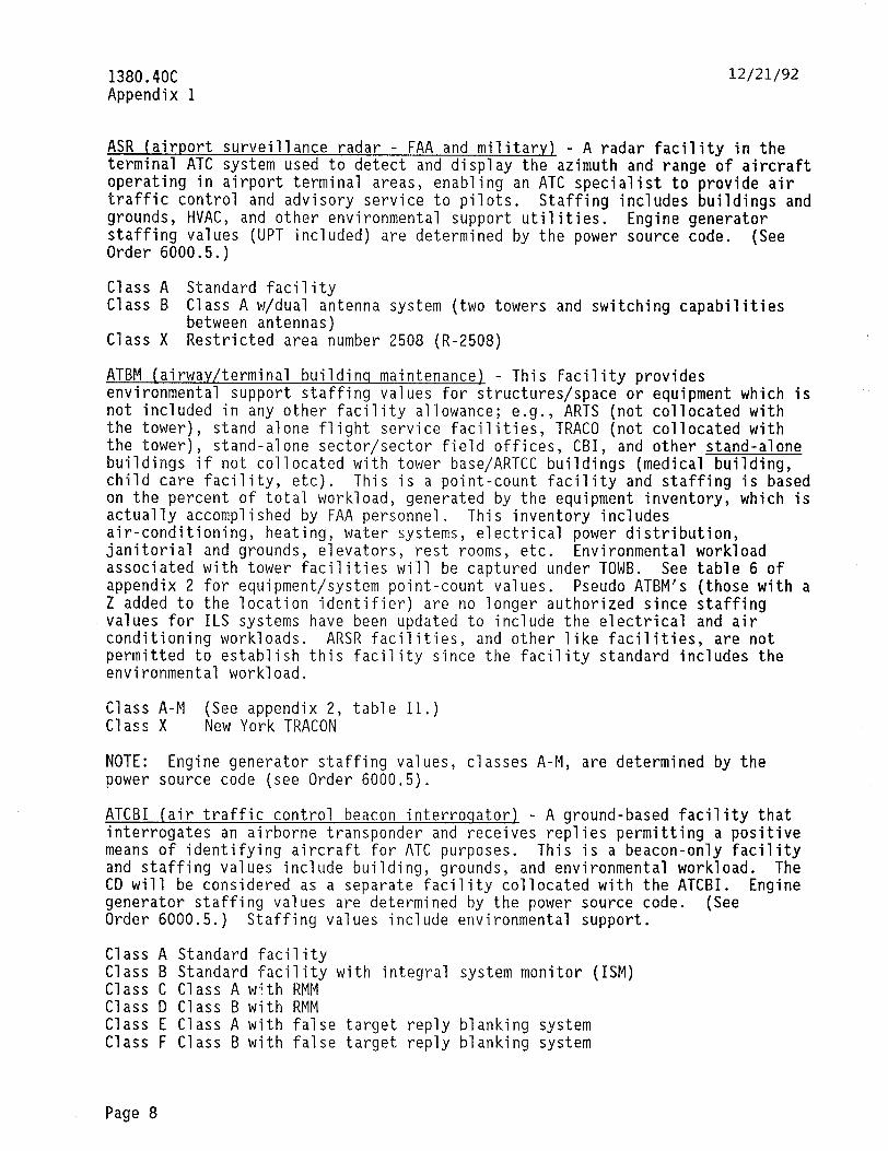
1380.4OC Appendix 1
12/21/92
ASR (airport surveillance radar - FAA and military1 - A radar facility in the terminal ATC system used to detect and display the azimuth and range of aircraft operating in airport terminal areas, enabling an ATC specialist to provide air traffic control and advisory service to pilots. Staffing includes buildings and grounds, HVAC, and other environmental support utilities. Engine generator staffing values (UPT included) are determined by the power source code. (See Order 6000.5.)
Class A Standard facility Class B Class A w/dual antenna system (two towers and switching capabilities
between antennas) Class X Restricted area number 2508 (R-2508)
ATBM (airwav/terminal buildinq maintenance) - This facility provides environmental support staffing values for structures/space or equipment which is not included in any other facility allowance; e.g., ARTS (not collocated with the tower), stand alone flight service facilities, TRACO (not collocated with the tower), stand-alone sector/sector field offices, CBI, and other stand-alone buildings if not collocated with tower base/ARTCC buildings (medical building, child care facility, etc). This is a point-count facility and staffing is based on the percent of total workload, generated by the equipment inventory, which is actually accomplished by FAA personnel. This inventory includes air-conditioning, heating, water systems, electrical power distribution, janitorial and grounds, elevators, rest rooms, etc. Environmental workload associated with tower facilities will be captured under TOWB. See table 6 of appendix 2 for equipment/system point-count values. Pseudo ATBM's (those with a Z added to the location identifier) are no longer authorized since staffing values for ILS systems have been updated to include the electrical and air conditioning workloads. ARSR facilities, and other like facilities, are not permitted to establish this facility since the facility standard includes the environmental workload.
Ei;;: i-M (See appendix 2, table 11.) New York TRACON
NOTE: Engine generator staffing values, classes A-M, are determined by the power source code (see Order 6000.5).
ATCBI (air traffic control beacon interroqator) - A ground-based facility that interrogates an airborne transponder and receives replies permitting a positive means of identifying aircraft for ATC purposes. This is a beacon-only facility and staffing values include building, grounds, and environmental workload. The CD will be considered as a separate facility collocated with the ATCBI. Engine generator staffing values are determined by the power source code. (See Order 6000.5.) Staffing values include environmental support.
Class A Standard facility Class B Standard facility with integral system monitor (ISM) Class C Class A with RMM Class D Class B with RMM Class E Class A with false target reply blanking system Class F Class B with false target reply blanking system
Page 8
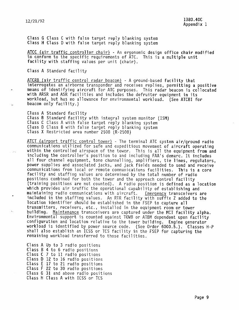
12/21/92 1380.4OC Appendix 1
ATCC (air traffic controller chair) - An ergonomic design office chair modified to conform to the specific requirements of ATC. This is a multiple unit facility with staffing values ‘per unit (chair).
Class A Standard facility
ATCRB (air traffic control radar beacon) - A ground-based facility that interrogates an airborne transponder and receives replies, permitting a positive
(Y means of identifying aircraft for ATC purposes. This radar beacon is collocated with ARSR and ASR facilities and includes the defruiter equipment in its workload, but has no allowance for environmental workload. beacon only facility.)
(See ATCBI for
Class A Standard facility Class B Standard facility with integral system monitor (ISM) Class C Class A with false target reply blanking system Class D Class B with false target reply blanking system Class X Restricted area number 2508 (R-2508)
ATCT (airport traffic control tower) - The terminal ATC system air/ground radio communications utilized for safe and expeditious movement of aircraft operating within the controlled airspace of the tower. This is all the equipment from and including the controller's position to and including FAA's demarc. It includes all four channel equipment, tone channelling, amplifiers, tie lines, regulators, power supplies and associated jacks, and jack fields needed to send and receive communications from local or remote communications facilities. This is a core facility and staffing values are determined by the total number of radio positions combined for both the tower and the approach control facility (training positions are not counted). A radio position is defined as a location which provides air traffic the operational capability of establishing and maintaining radio communications with aircraft. Emerqency transceivers are included in the staffing values. An RTR facility with suffix Z added to the location identifier should be established in the FSEP to capture all transmitters, receivers, etc., building.
installed in the equipment room or tower Maintenance transceivers are captured under the MCT facility alpha.
Environmental support is counted against TOWB or ATBM dependent upon facility configuration and location relative to the tower building. workload is identified by power source code.
Engine generator (See Order 6000.5.). Classes H-P
shall also establish an ICSS or TCS facility in the FSEP for capturing the remaining workload transferred to those facilities.
Class G Class C with false target reply blanking system Class H Class D with false target reply blanking system
Class A Up to 3 radio positions Class B 4 to 6 radio positions Class C 7 to 11 radio positions Class D 12 to 16 radio positions Class E 17 to 21 radio positions Class F 22 to 30 radio positions Class G 31 and above radio positions Class H Class A with ICSS or TCS
Page 9
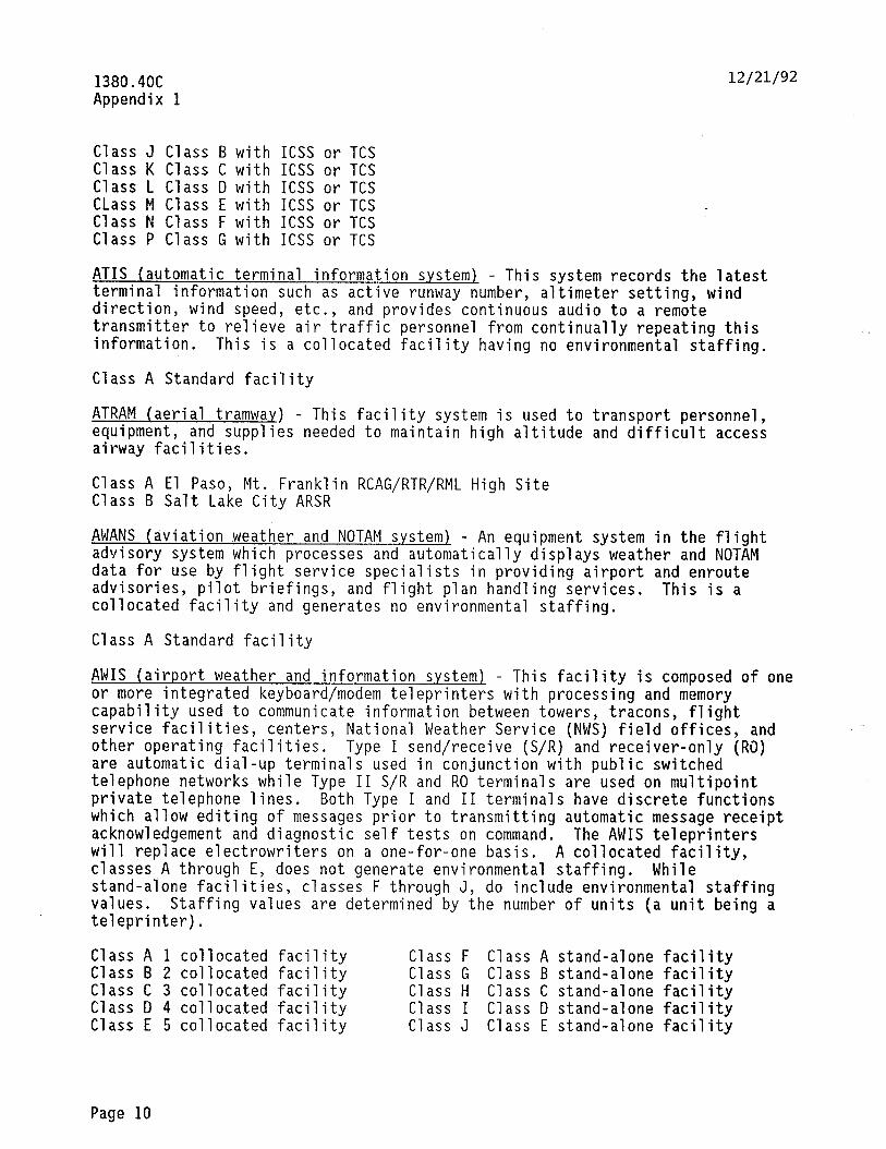
AWIS (airport weather and information system) - This facility is composed of one or more integrated keyboard/modem teleprinters with processing and memory capability used to communicate information between towers, tracons, flight service facilities, centers, National Weather Service (NWS) field offices, and other operating facilities. Type I send/receive (S/R) and receiver-only (Ri)) are automatic dial-up terminals used in conjunction with public switched telephone networks while Type II S/R and RO terminals are used on multipoint private telephone lines. Both Type I and II terminals have discrete functions which allow editing of messages prior to transmitting automatic message receipt acknowledgement and diagnostic self tests on command. The AWIS teleprinters will replace electrowriters on a one-for-one basis. A collocated facility, classes A through E, does not generate environmental staffing. While stand-alone facilities, classes F through J, do include environmental staffing values. Staffinq values are determined by the number of units (a unit being a teleprinter). -
- .
Class A 1 collocated facility Class F Class A stand-alone faci lity Class B 2 collocated facility Class G Class B stand-alone faci lity Class C 3 collocated facility Class H Class C stand-alone faci lity Class D 4 collocated facility Class I Class D stand-alone faci lity Class E 5 collocated facility Class J Class E stand-alone faci lity
12/21/92 1380.4OC Appendix 1
Class J Class B with ICSS or TCS Class K Class C with ICSS or TCS Class L Class D with ICSS or TCS CLass M Class E with ICSS or TCS Class N Class F with ICSS or TCS Class P Class G with ICSS or TCS
ATIS (automatic terminal information system) - This system records the latest terminal information such as active runway number, altimeter setting, wind direction, wind speed, etc., and provides continuous audio to a remote transmitter to relieve air traffic personnel from continually repeating this information. This is a collocated facility having no environmental staffing.
Class A Standard facility
ATRAM (aerial tramway) - This facility system is used to transport personnel, equipment, and supplies needed to maintain high altitude and difficult access airway facilities.
Class A El Paso, Mt. Franklin RCAG/RTR/RML High Site Class B Salt Lake City ARSR
AWANS (aviation weather and NOTAM s.ystem) - An equipment system in the flight advisory system which processes and automatically displays weather and NOTAM data for use by flight service specialists in providing airport and enroute advisories, pilot briefings, and flight plan handling services. This is a collocated facility and generates no environmental staffing.
Class A Standard facility
Page 10
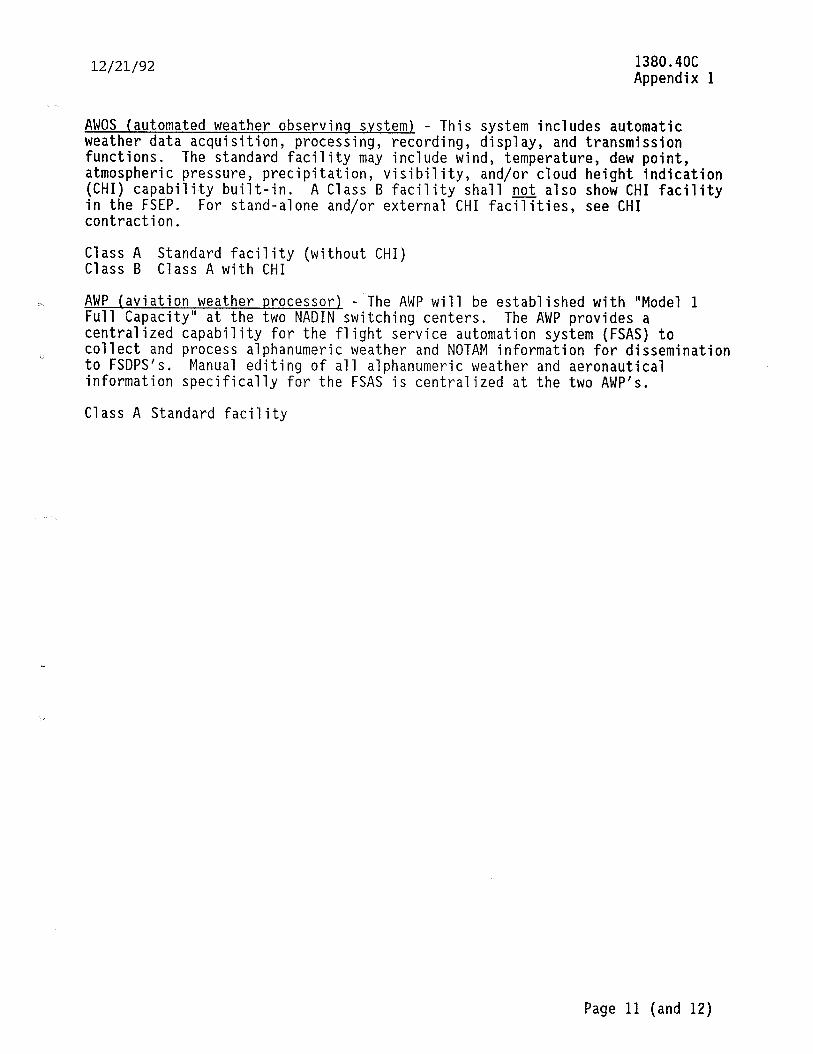
12/21/92 1380.4OC Appendix 1
AWOS (automated weather observinq system) - This system includes automatic weather data acquisition, processing, recording, display, and transmission functions. The standard facility may include wind, temperature, dew point, atmospheric pressure, precipitation, (CHI) capability built-in.
visibility, and/or cloud height indication
in the FSl?P. A Class B facility shall noJ. also show CHI facility
For stand-alone and/or external CHI facilities, see CHI contraction.
Class A Standard facility (without CHI) Class B Class A with CHI
%L AWP (aviation weather processor) - The AWP will be established with "Model 1 Full Capacity" at the two NADIN switching centers. The AWP provides a centralized capability for the flight service automation system (FSAS) to
ij collect and process alphanumeric weather and NOTAM information for dissemination to FSDPS's. Manual editing of all alphanumeric weather and aeronautical information specifically for the FSAS is centralized at the two AWP's.
Class A Standard facility
Page 11 (and 12)

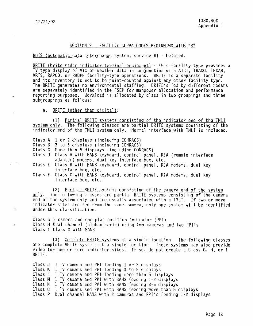
12/21/92
SECTION 2. FACILITY ALPHA CODES BEGINNING WITH "B"
1380.4OC Appendix 1
BDIS (automatic data interchanqe system, service B) - Deleted.
BRITE (brite radar indicator terminal equipment) - This facility type provides a TV type display of ATC or weather data in conjunction with ATCT, TRACO, TRCAB, ARTS, RAPCO, or RBDPE facility-type operations. BRITE is a separate facility and its inventory is not to be point-counted against any other facility type. The BRITE generates no environmental staffing. BRITE's fed by different radars are separately identified in the FSEP for manpower allocation and performance reporting purposes. Workload is allocated by class in two groupings and three subgroupings as follows:
a. BRITE (other than diqitall:
(1) Partial BRITE systems consistinq of the indicator end of the TMLI svstem only. The following classes are partial BRITE systems consisting of the indicator end of the TMLI system only. Normal interface with TMLI is included.
Class A 1 or 2 displays (including CONRACS) Class B 3 to 5 displays (including CONRACS) Class C More than 5 displays (including CONRACS) Class D Class A with BANS keyboard, control panel, RIA (remote interface
adapter) modems, dual key interface box, etc. Class E Class B with BANS keyboard, control panel, RIA modems, dual key
interface box, etc. Class F Class C with BANS keyboard, control panel, RIA modems, dual key
interface box, etc.
(2) Partial BRITE svstems consistins of the camera end of the svstem 0nl.y. The following classes are partial BRITE systems consisting of the camera end of the system only and are usually associated with a TMLT. If two or more indicator sites are fed from the same camera, only one system will be identified under this classification.
Class G 1 camera and one plan position indicator (PPI) Class H Dual channel (alphanumeric) using two cameras and two PPI’s Class I Class G with BANS
(3) Complete BRITE svstems at a sinqle location. The following classes are complete BRITE systems at a single location. These systems may also provide video for one or more indicator sites. If so, do not create a Class G, H, or I BRITE.
Class J 1 TV camera and PPI feeding 1 or 2 displays Class K 1 TV camera and PPI feeding 3 to 5 displays Class L 1 TV camera and PPI feeding more than 5 displays Class M 1 TV camera and PPI with BANS feeding 1-2 displays Class N 1 TV camera and PPI with BANS feeding 3-5 displays Class 0 1 TV camera and PPI with BANS feeding more than 5 displays Class P Dual channel BANS with 2 cameras and PPI’s feeding l-2 displays
Page 13
___ ” .- _ .,_...., _. . . _;i ._ *.__:.s._^ .._.-. -- ._, -_ (.
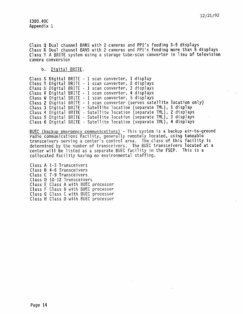
1380.4OC Appendix 1
12/21/92
Class Q Dual channel BANS with 2 cameras and PPI's feeding 3-5 displays Class R Dual channel BANS with 2 cameras and PPI’s feeding more than 5 displays Class Y A BRITE system using a storage tube-scan converter in lieu of television camera conversion
b. Diqital BRITE.
Class S Digital BRITE - 1 scan converter, 1 display Class T Digital BRITE - 1 scan converter, 2 displays Class U Digital BRITE - 1 scan converter, 3 displays Class V Digital BRITE - 1 scan converter, 4 displays Class W Digital BRITE - 1 scan converter, 5 displays Class 2 Digital BRITE - 1 scan converter (serves satellite location only) Class 3 Digital BRITE - Satellite location (separate TML), 1 display Class 4 Digital BRITE - Satellite location (separate TML), 2 displays Class 5 Digital BRITE - Satellite location (separate TML), 3 displays ' Class 6 Digital BRITE - Satellite location (separate TML), 4 displays
BUEC (backup emerqency communications) - This system is a backup air-to-ground radio communications facility, generally remotely located, using tuneable transceivers serving a center's control area. The class of this facility is determined by the number of transceivers. The BUEC transceivers located at a center will be listed as a separate BUEC facility in the FSEP. This is a collocated facility having no environmental staffing.
Class A l-3 Transceivers Class B 4-6 Transceivers Class C 7-9 Transceivers Class D lo-12 Transceivers Class E Class A with BUEC processor Class F Class B with BUEC processor Class G Class C with BUEC processor Class H Class D with BUEC processor
Page 14
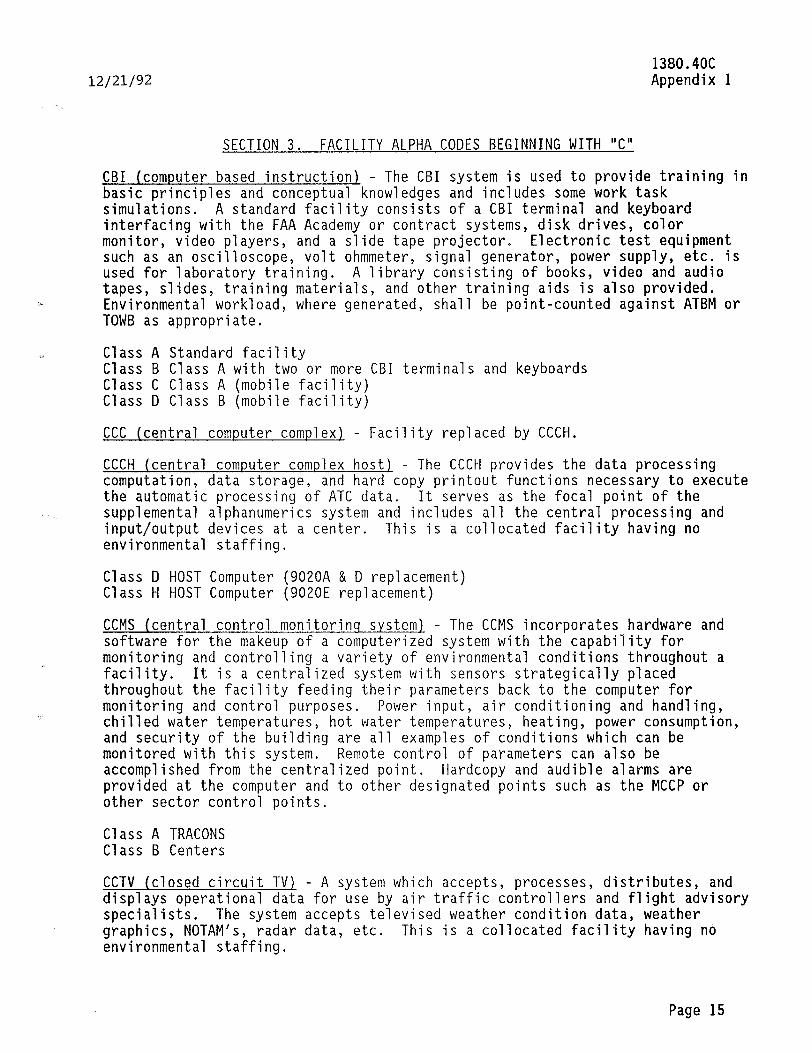
12/21/92
SECTION 3. FACILITY ALPHA CODES BEGINNING WITH "C"
1380.4OC Appendix 1
CBI (computer based instruction) - The CBI system is used to provide training in basic principles and conceptual knowledges and includes some work task simulations. A standard facility consists of a CBI terminal and keyboard interfacing with the FAA Academy or contract systems, disk drives, color monitor, video players, and a slide tape projector. Electronic test equipment such as an oscilloscope, volt ohmmeter, signal generator, power supply, etc. is used for laboratory training. A library consisting of books, video and audio tapes, slides, training materials, and other training aids is also provided. Environmental workload, where generated, shall be point-counted against ATBM or TOWB as appropriate.
Class A Standard facility Class B Class A with two or more CBI terminals and keyboards Class C Class A (mobile facility) Class D Class B (mobile facility)
CCC (central computer complex) - Facility replaced by CCCH.
CCCH (central computer complex host) - The CCCH provides the data processing computation, data storage, and hard copy printout functions necessary to execute the automatic processing of ATC data. It serves as the focal point of the supplemental alphanumerics system and includes all the central processing and input/output devices at a center. This is a collocated facility having no environmental staffing.
Class D HOST Computer (9020A & D replacement) Class H HOST Computer (9020E replacement)
CCMS (central control monitorinq system1 - The CCMS incorporates hardware and software for the makeup of a computerized system with the capability for monitoring and controlling a variety of environmental conditions throughout a facility. It is a centralized system with sensors strategically placed throughout the facility feeding their parameters back to the computer for monitoring and control purposes. Power input, air conditioning and handling, chilled water temperatures, hot water temperatures, heating, power consumption, and security of the building are all examples of conditions which can be monitored with this system. Remote control of parameters can also be accomplished from the centralized point. Hardcopy and audible alarms are provided at the computer and to other designated points such as the MCCP or other sector control points.
Class A TRACONS Class B Centers
CCTV (closed circuit TV) - A system which accepts, processes, distributes, and displays operational data for use by air traffic controllers and flight advisory specialists. The system accepts televised weather condition data, weather graphics, NOTAM's, radar data, etc. This is a collocated facility having no environmental staffing.
Page 15
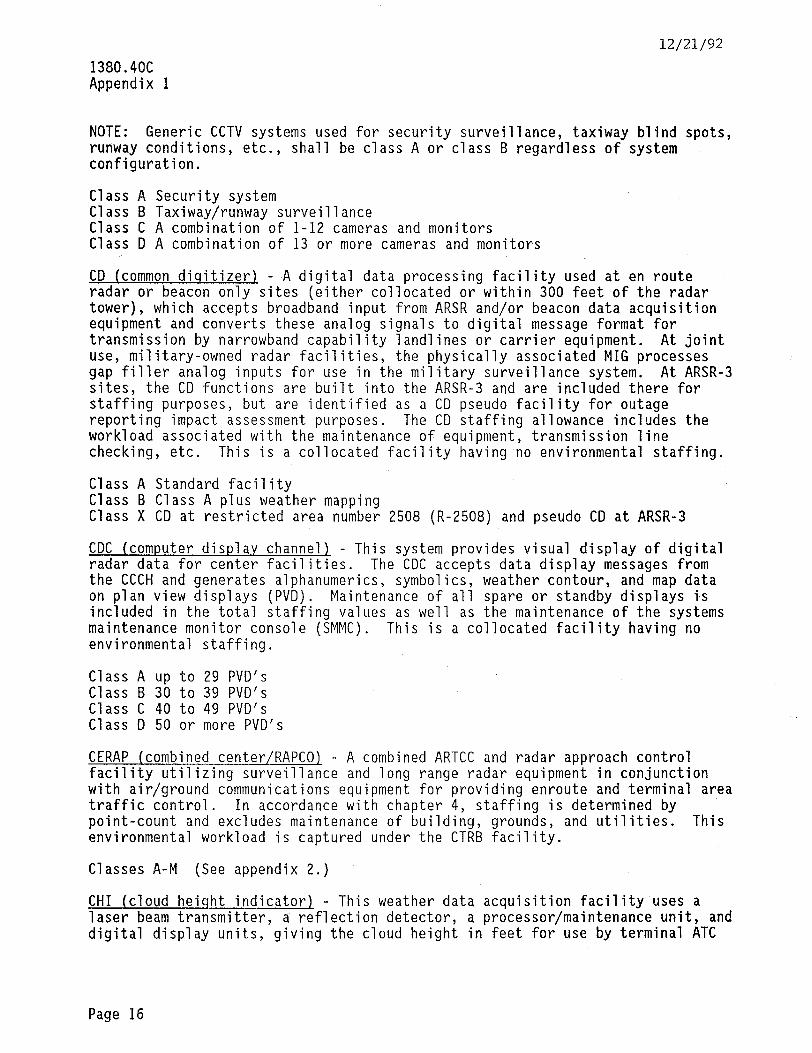
12/21/92
1380.4OC Appendix 1
NOTE: Generic CCTV systems used for security surveillance, taxiway blind spots, runway conditions, etc., shall be class A or class B regardless of system configuration.
Class A Security system Class B Taxiway/runway surveillance Class C A combination of 1-12 cameras and monitors Class D A combination of 13 or more cameras and monitors
CD (common dioitizer) - 'A digital data processing facility used at en route radar or beacon only sites (either collocated or within 300 feet of the radar tower), which accepts broadband input from ARSR and/or beacon data acquisition equipment and converts these analog signals to digital message format for transmission by narrowband capability landlines or carrier equipment. At joint use, military-owned radar facilities, the physically associated MIG processes gap filler analog inputs for use in the military surveillance system. At ARSR-3 sites, the CD functions are built into the ARSR-3 and are included there for staffing purposes, but are identified as a CD pseudo facility for outage reporting impact assessment purposes. The CD staffing allowance includes the workload associated with the maintenance of equipment, transmission line checking, etc. This is a collocated facility having no environmental staffing.
Class A Standard facility Class B Class A plus weather mapping Class X CD at restricted area number 2508 (R-2508) and pseudo CD at ARSR-3
CDC (computer display channel) - This system provides visual display of digital radar data for center facilities. The CDC accepts data display messages from the CCCH and generates alphanumerics, symbolics, weather contour, and map data on plan view displays (PVD). Maintenance of all spare or standby displays is included in the total staffing values as well as the maintenance of the systems maintenance monitor console (SMMC). This is a collocated facility having no environmental staffing.
Class A up to 29 PVD's Class B 30 to 39 PVD's Class C 40 to 49 PVD's Class D 50 or more PVD's
CERAP (combined center/RAPCO) - A combined ARTCC and radar approach control facility utilizing surveillance and long range radar equipment in conjunction with air/ground communications equipment for providing enroute and terminal area traffic control. In accordance with chapter 4, staffing is determined by point-count and excludes maintenance of building, grounds, and utilities. This environmental workload is captured under the CTRB facility.
Classes A-M (See appendix 2.)
CHI (cloud heiqht indicator), - This weather data acquisition facility uses a laser beam transmitter, a reflection detector, a processor/maintenance unit, and digital display units, giving the cloud height in feet for use by terminal ATC
Page 16
12/21/92 1380.4OC Appendix 1
personnel. The system generates a pulsating laser beam in a vertical direction, receives the laser beam reflection from the cloud base, and converts the reflected laser pulses into digital format for transmission to local ATC display units and also in American Standard Code for Information Interchange (ASCII) for teletype circuits.
Class A Standard facility
CIC (customs interface controller) - The CIC is used for interfacing the center computers with the Customs Service security equipment and systems utilized at airports and other locations. These will be located at Albuquerque, NM; Miami FL; Palmdale, CA; and Oakland, CA. This is a core facility which is collocated having no environmental staffing.
Class A Standard facility
CKT (control circuit equipment) - Facility has been deleted.
CLM (control line maintenance) - This facility classification provides staffing values for the maintenance of FAA-owned or -maintained control, communications, and video lines/cables associated with the control facility only; Intrabuilding wiring/cabling excluded. The class of this facility will be determined by the number of pairs in use multiplied by the number of cable feet (from demarcation to demarcation); e.g., a 26-pair cable, 200,000 feet in length, equals 5,200,OOO foot/pair (FT*PR) cable. Locations having less than 100,000 FT*PR in use will not constitute a separate CLM facility. Only one FSEP entry per control facility is authorized. See ELD for power cable and TIM for telephone cable.
Class A 100,000 - 500,000 FT*PR Class B 500,001 - l,OOO,OOO FT*PR Class C l,OOO,OOl - 1,500,OOO FT*PR Class D Over 1,500,OOO FT*PR
CMLT (communications microwave link terminal) - A terminal microwave facility operating at 8.4 GHz or lower frequency band and used for voice/data communications. This facility may be replaced by RCLT in the replacement/ trunking program. See RCLT. This is a collocated facility having no environmental staffing.
Class A Standard facility (up to 60 channels) Class B 61 - 120 channels Class C 121 or more channels Class D Special class for Oakland Class E Special class for Boron system
CNS (consolidated NOTAM service) - The CNS system provides the NOTAM formatting and editing capabilities for the NAS and also serves as the centralized NOTAM data base. It will consolidate and replace the current domestic and international NOTAM system. It incorporates general purpose, automatic data processing hardware, and system support software for performing its formatting, editing, storage, subsystem monitoring, and NOTAM distribution functions. This is a collocated facility having no environmental staffing.
Class A Standard facility (NFDC Washington headquarters.)
Page 17
1380.4OC Appendix 1
12/21/92
COMCO (command communications outlet) - A facility consisting of data transmitters/receivers, teletypewriters, crypto, and recording units integrated as an equipment system communications function for Washington headquarters, regional offices, centers (ARTCC's,), etc. This is a point-count facility. Staffing is determined by equipment inventory in accordance with chapter 4. This facility generates no environmental staffing.
Classes A-P (See appendix 2.)
CTERM (computer terminals) - This facility is composed of computer terminals, printers, modems, etc., utilized in the NAS. Administrative terminals and word processors are excluded. Its capability includes the acceptance, processing, distribution, storage, display, and printing of messages under program control or by manual command. Examples include NAPRS (NAS Plan) equipment, IOT's (input/output terminal), MDT's (maintenance data terminal), etc., or such devices if not included in the facility standard for which it may be a part of. This is a core facility with class determination by the number of units. One unit consists of a terminal, modem, controller, display, and printer or any combination for a total of four of these items. This is a collocated facility having no environmental staffing. This facility replaces data terminal equipment (DTE).
Class A 1 unit Class F 6 units Class B 2 units Class G 7 units Class C 3 units Class H 8 units Class D 4 units Class ,J 9 units Class E 5 units Class K 10 units
CTRB (center buildinq maintenance) - This facility classification provides for the center, EARTS, and CERAP building maintenance requirements (including engine generators), janitorial, air-conditioning, heat, water, sewerage, grounds maintenance, and building electrical services. The CCMS and power conditioning system (PCS) are not included in CTRB and shall be entered as separate line items in the FSEP. This is a core facility with staffing based on the percent of total workload which is actually accomplished in-house (FAA).
Class A Standard Facility Class B EARTS Facility Class C Class A with NADIN switching center Class D Expanded building New York center Class E CERAP
CTS (coded time source) - This system includes the time system master/slave clocks and appurtenant (centers only). This is a collocated facility having no environmental staffing.
Class A Single time system with 10 or less slave clocks Class B Dual time system with 10 or less slave clocks Class C Single time system with lo-50 slave clocks Class D Dual time system with lo-50 clocks Class E Single time system with 51-100 slave clocks
Page 18

12/21/92 1380.4OC Appendix 1
Class F Dual time system with 51-100 slave clocks Class G Single time system with 101-200 slave clocks Class H Dual time system with 101-200 slave clocks
CUE (computer update equipment) - This is the equipment associated with flight data processing which provides information and input capabilities at each controller position via CRT output and keyboard input. It includes the nonradar keyboard multiplexers (NRKM), common logic unit equipment (CLUE), quick action keyboard (QAKB), etc. This is a collocated facility having no environmental staffing.
Class A up to 19 positions Class B 20-29 positions Class C 30-39 positions Class D 40-49 positions Class E 50-59 positions Class F 60-69 positions Class G 70-79 positions Class H 80-89 positions Class J 90-99 positions Class K loo-109 positions Class L 110-119 positions
Class M 120-129 positions Class N 130-139 positions Class P 140-149 positions Class Q 150-159 positions Class R 160-169 positions Class S 170-179 positions Class T 180-189 positions Class U 190-199 positions Class V ZOO-209 positions Class W 210-219 positions
CWP (central weather processor) - The CWP is a system composed of two elements, meteorologist weather processor (MWP) and real-time weather processor (RWP). The MWP is a computer-based, interactive meteorological data processing service. The RWP will mosaic NEXRAD radar and provide these products'and other time-critical and operationally significant weather information for use by air traffic controllers via the AAS. The RWP will also transmit a subset of its weather products to the DLP for uplink to pilots via the MODE S data link. Full system capacity will be achieved in two phases; Phase I MWP only and Phase II MWP and RWP. This is a collocated facility having no environmental staffing.
Class A Phase I - MWP only Class B Phase II - MWP and RWP - full system capacity
Page 19 (and 20)


12/21/92
SECTION 4, FACILITY ALPHA CODES BEGINNING WITH "D"
1380.4OC Appendix 1
DARC (direct access radar channel) - This solid-state facility equipment subsystem accepts, automatically processes, for display on ATC consoles.
and distributes digitized radar data It is a backup system to the CDC/DCC. This is a
collocated facility having no environmental staffing.
Class A Standard facility (excluding allowances listed in CDC/DCC definitions) Class B MT-DARC Class M With mosaic system capability (including staffing allowance for PVD and
radar control equipment) Class R DARC with mosaic for restricted area number 2508 (R-2508)
DCC (disp1a.y channel complex). - This facility equipment system provides visual display of digital radar data for en route ATC facilities. This display channel complex is used with HOST computer configurations at some NAS Stage A centers which utilize the 9020E in the DCC channel in lieu of the CDC. Maintenance of all spare or standby PVD's, keyboards, radar keyboard multiplexers (RKM), display generators (DG), and the systems maintenance monitor console (SMMC) are included in the total staffing values. environmental staffing.
This is a collocated facility having no
Class A Fort Worth Class B New York and Washington Class F Chicago and Cleveland
DF (direction finder - UHF/VHF) - A radio receiver operating in the ultra high frequency (UHF) or very high frequency (VHF) band equipped with a directional sensing antenna used to take bearings on aircraft transmitters. It receives the aircraft radio signals, processes them, and provides a visual display of the direction of the aircraft relative to the facility on the control facility indicator console. Staffing is included for facility antenna systems, receiver, one simulator (when collocated at the flight service facility), receiver site indicator, remoting equipment, Class C).
and environmental support (if stand-alone; i.e., If collocated, no environmental staffing is generated.
Class A Class B
Class C
Class D Class E Class F Class G Class H
Complete DF collocated at the flight service facility (includes DFI) Remote DF collocated with another facility (indicator identified as DFI at control point) Remote DF stand alone primary facility (indicator identified as DFI at control point) Class A with simulator Class A with RMM Class B with RMM Class C with RMM Class D with RMM
DFI (direction finder indicator) - This facility is located at a control facility such as a flight service facility. It consists of the indicator and remoting equipment for processing information from remote DF receiver sites and providing a visual display of the direction of the aircraft relative to the facility on the control facility indicator console. A simulator may be included
Page 21
1380.4013 Appendix 1
12/21/92
for training purposes. This is a collocated facility having no environmental staffing.
Class A Standard facility Class 6 Class A with simulator Class C Class A with multiple indicators, 2-5 Class D Class B with multiple indicators, 2-5 Class E Class A with multiple indicators, 6-10 Class F Class B with multiple indicators, 6-10
DLP (data link processor) - This system consists of a SEQUOIA System 200 fault tolerant computer system employing a central processor and a number of input/output (I/O) and mass storage devices. The DLP will respond to airborne NAS user requests for weather products using the mode select (MODES) beacon system data link. These systems will be installed at the center/ACF facilities only. This is a collocated facility having no environmental staffing. This facility replaces the WCP.
Class A Standard facility
DME (distance measurinq equipment) - A terminal area or en route navigation facility consisting of a transponder which automatically transmits encoded signals in response to airborne equipment interrogations providing the pilot with direct readout indication of aircraft distance from the identified DME facility. If collocated, no environmental staffing is generated.
Class A Single system, stand-alone Class L Class A with RMM Class B Dual system, stand-alone Class M Class B with RMM Class C Single system, collocated-GS Class N Class C with RMM Class D Dual system, collocated-GS Class P Class D with RMM Class E Single system, collocated-LOC Class Q Class E with RMM Class F Dual system, collocated-LOC Class R Class F with RMM Class G Single system, collocated-VOR Class S Class G with RMM Class H Dual system, collocated-VOR Class T Class H with RMM Class J Single system, collocated-NDB Class U Class J with RMM Class K Dual system, collocated-NDB Class V Class K with RMM
NOTE: RMM is remote maintenance monitoring vice remote monitor.
DMER (distance measurinq equipment remaininq) - A terminal or en route navigation facility using TACR-type equipment with only the distance measuring portion of the facility commissioned and the azimuth antenna disabled, but still installed at the site.
Class A RTC-1 TMC with single transponder Class B RTC-2/3 TMC with single transponder Class C 2nd generation with RMM Class 1 RTC-1 TMC with dual transponder Class 2 RTC-2/3 TMC with dual transponder
DMUX (data multiplexer)+ - A data multiplexer, such as the paradyne modem, enabling a number of independent data transmission requirements to be consolidated in a single transmission channel whose speed equals the sum of the
Page 22
12/21/92 1380.4OC Appendix 1
input channels. The data multiplexing network (DMN) uses this technology to interconnect many FAA facilities, providing multiple data transmission paths with a minimum number of discrete channels. multiplexers,
This equipment consist of modems, automated network management system (ANMS), clock boxes, channel
service units/data service units (CSU/DSU), and various ancillary equipment including digital A/B switches, port sharing devices, modem sharing devices, hot standby switches, and patch panels. providing real-time monitoring,
The ANMS's will be located at centers only
capabilities. redundant paths, and automatic switching
Each modem is considered a unit. This facility covers all modems not otherwise captured as part of another facility. This is a collocated facility having no environmental staffing.
Class A 10 units or less Class B 11 to 49 units Class C 50 units and more
DRG (data receiver qroupl - This facility is the equipment which provides the interface with modems, DARC, HOST, radars, and the SMMC/ESMMC/MCCP in centers. This is a collocated facility having no environmental staffing.
Class A 1-5 DRG's Class B 6-10 DRG's Class C 11 or more DRG's
DTE (data terminal equiomentl - Deleted; replaced by CTERM.
Page 23 (and 24)

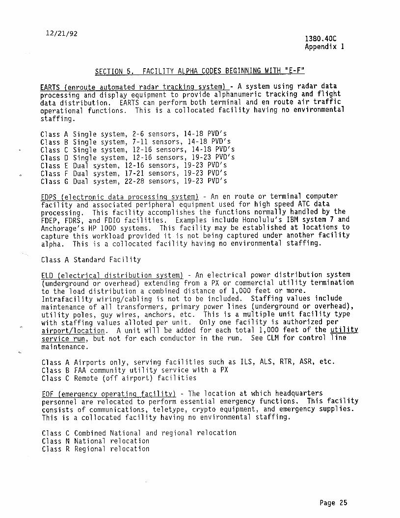
12/21/92 1380.4OC Appendix 1
SECTION 5. FACILITY ALPHA CODES BEGINNING WITH “E-F”
EARTS (enroute automated radar trackinq system) - A system using radar data processing and display equipment to provide alphanumeric tracking and flight data distribution. EARTS can perform both terminal and en route air traffic operational functions. This is a collocated facility having no environmental staffing.
Class A Single system, 2-6 sensors, 14-18 PVD's Class B Single system, 7-11 sensors, 14-18 PVD's
_i Class C Single system, 12-16 sensors, 14-18 PVD's Class D Single system, 12-16 sensors, 19-23 PVD's Class E Dual system, 12-16 sensors, 19-23 PVD's
0 Class F Dual system, 17-21 sensors, 19-23 PVD's Class G Dual system, 22-28 sensors, 19-23 PVD's
EDPS (electronic data processinq system) - An en route or terminal computer facility and associated peripheral equipment used for high speed ATC data processing. This facility accomplishes the functions normally handled by the FDEP, FDRS, and FDIO facilities. Examples include Honolulu's IBM system 7 and Anchorage's HP 1000 systems. This facility may be established at locations to capture this workload provided it is not being captured under another facility alpha. This is a collocated facility having no environmental staffing.
Class A Standard Facility
ELD (electrical distribution system) - An electrical power distribution system (underground or overhead) extending from a PX or commercial utility termination to the load distribution a combined distance of 1,000 feet or more. Intrafacility wiring/cabling is not to be included. Staffing values include maintenance of all transformers, primary power lines (underground or overhead), utility poles, guy wires, anchors, etc. This is a multiple unit facility type with staffing values alloted per unit. Only one facility is authorized per 0 airport/location. A unit will be added for each total 1,000 feet of the utility service run, but not for each conductor in the run. See CLM for control line maintenance.
Class A Airports only, serving facilities such as ILS, ALS, RTR, ASR, etc. Class B FAA community utility service with a PX Class C Remote (off airport) facilities
EOF (emerqency operatinq facility) - The location at which headquarters personnel are relocated to perform essential emergency functions. This facility consists of communications, teletype, crypt0 equipment, and emergency supplies. This is a collocated facility having no environmental staffing.
Class C Combined National and regional relocation Class N National relocation Class R Regional relocation
Page 25

1380.4OC Appendix 1
12/21/92
ERMS (environmental remote monitorinq subsystem) - This facility will perform within the remote maintenance monitoring subsystem (RMMS) as a fully functioning, stand-alone, remote monitoring subsystem (RMS) whose primary purpose is to monitor and control environmental equipment in a wide variety of NAS facilities. This equipment will consist of a microprocessor-based cell controller having four data communications interfaces, sensors, a sensor power supply, and an uninterruptable power supply. The four interfaces include the maintenance processor subsystem (MPS), portable maintenance data terminal (PMDT), sensors, and the remote sensor. This system will provide broad operational functions consisting of the parametric monitoring and control of electrical power systems, environmental conditioning systems, smoke and fire detection systems, and security systems.
Class A Standard facility
ETB (embedded threshold bar). The portion of a light lane consisting of light fixtures installed below ground level, in the pavement, and associated with a runway.
Class A On a Catagory I runway. Class B On a Catagory II/III runway.
FAC (fire department, crash, and rescue equipment) - The equipment represented by this facility type should be point-counted against ATBM or TOWB as appropriate.
FDEP (flisht data entrv and printout.1 - An equipment subsystem providing a direct interface between the air traffic controller and a central computer for remotely entering and receiving flight data information at tower cabs, TRACO's, RAPCO's, or ARTS facilities within the center's control area. The allowance includes the maintenance of all FDEP equipment for each subsystem. This is a collocated facility having no environmental staffing. This facility will be replaced by FDIOC and FDIOR under the FDIO equipment replacement program.
Class A Data computer control unit (DCCU) with one alphanumeric keyboard (ANK) and two flight strip printers (FSP's)
Class B DCCU with two ANK's and three or more FSP's
NOTE: Each DCCU generates a separate FDEP facility.
FDIOC (fliqht data input/output center) - A system providing an interface between an air traffic controller and the center comouter. The FDIOC provides flight plan data in printed form. This system replaces FSP computer update (CU)/FSP equipment and FDEP adaptors at centers. Staffing includes the maintenance of printer control units (PCU), en route replacement flight strip printers (RFSP), and central control units (CCU) which control the FDIOR's. This is a collocated facility having no environmental staffing.
Class J lo-19 RFSP's Class A 20-30 RFSP's Class B 31-40 RFSP's Class C 41-50 RFSP's
Page 26
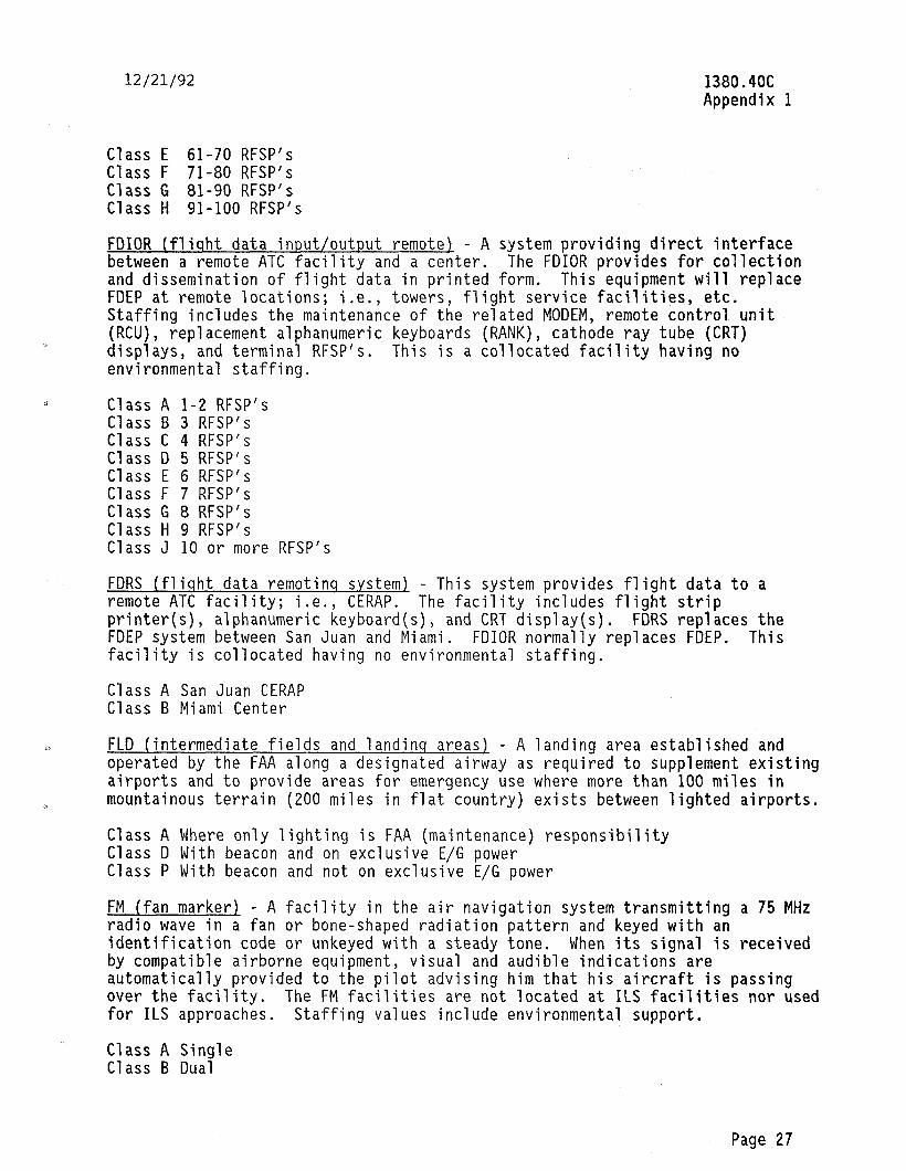
12/21/92 1380.4OC Appendix 1
Class E 61-70 RFSP's Class F 71-80 RFSP's Class G 81-90 RFSP's Class H 91-100 RFSP's
FDIOR (fliqht data input/output remote) - A system providing direct interface between a remote ATC facility and a center. The FDIOR provides for collection and dissemination of flight data in printed form. This equipment will replace FDEP at remote locations; i.e., towers, flight service facilities, etc. Staffing includes the maintenance of the related MODEM, remote control unit (RCU), replacement alphanumeric keyboards (RANK), cathode ray tube (CRT) displays, and terminal RFSP's. This is a collocated facility having no environmental staffing.
Class A l-2 RFSP's Class B 3 RFSP's Class C 4 RFSP's Class D 5 RFSP's Class E 6 RFSP's Class F 7 RFSP's Class G 8 RFSP's Class H 9 RFSP's Class J 10 or more RFSP's
FDRS (fliqht data remotinq system) - This system provides flight data to a remote ATC facility; i.e., CERAP. The facility includes flight strip printer(s), alphanumeric keyboard(s), and CRT display(s). FDRS replaces the FDEP system between San Juan and Miami. FDIOR normally replaces FDEP. This facility is collocated having no environmental staffing.
Class A San Juan CERAP Class B Miami Center
FLD (intermediate fields and landinq areas) - A landing area established and operated by the FAA along a designated airway as required to supplement existing airports and to provide areas for emergency use where more than 100 miles in mountainous terrain (ZOO miles in flat country) exists between lighted airports.
Class A Where only lighting is FAA (maintenance) responsibility Class D With beacon and on exclusive E/G power Class P With beacon and not on exclusive E/G power
FM (fan marker) - A facility in the air navigation system transmitting a 75 MHz radio wave in a fan or bone-shaped radiation pattern and keyed with an identification code or unkeyed with a steady tone. When its signal is received by compatible airborne equipment, visual and audible indications are automatically provided to the pilot advising him that his aircraft is passing over the facility. The FM facilities are not located at ILS facilities nor used for ILS approaches. Staffing values include environmental support.
Class A Single Class B Dual
Page 27
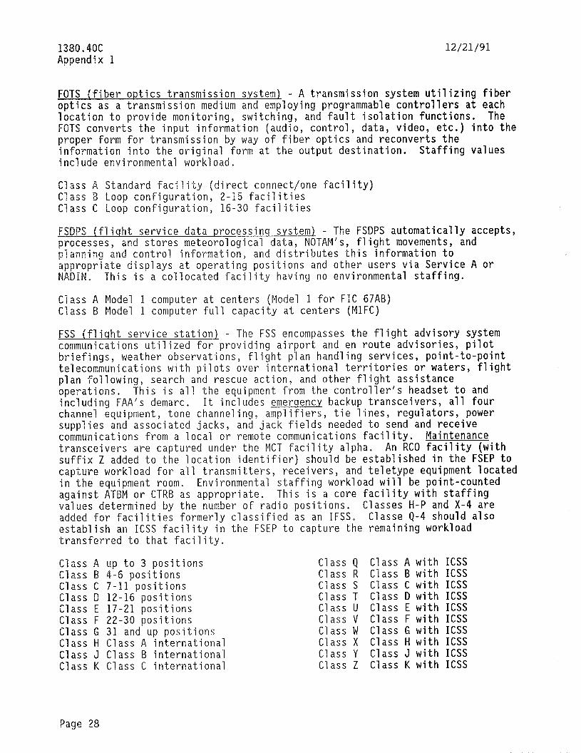
1380.4QC Appendix 1
12/21/91
FQTS (fiber optics transmission system1 - A transmission system utilizing fiber optics as a transmission medium and employing programmable controllers at each location to provide monitoring, switching, and fault isolation functions. The FQTS converts the input information (audio, control, data, video, etc.) into the proper form for transmission by way of fiber optics and reconverts the information into the original form at the output destination. Staffing values include environmental workload.
Class A Standard facility (direct connect/one facility) Class B Loop configuration, Z-15 facilities Class C Loop configuration, 16-30 facilities
FSDPS (fliqht service data processinq system) - The FSDPS automatically accepts, wocesses. and stores meteorolosical data, NOTAM's, fliqht movements, and plannina ind control information, and distributes this information to appropryate displays at operating positions and other users via Service A or NADIN, This is a collocated facility having no environmental staffing.
Class A Model I computer at centers (Model 1 for FIC 67AB) Class 5 Model 1 computer full capacity at centers (MlFC)
FSS (fliqht service station) - The FSS encompasses the flight advisory system communications utilized for providinq airport and en route advisories, pilot briefings, weather observations, flight pian handling services, point-to-point telecommunications with pilots over international territories or waters, flight plan following, search and rescue action, and other flight assistance operations. This is all the equipment from the controller's headset to and including FAA's demarc. It includes emerqency backup transceivers, all four channel equipment, tone channeling, amplifiers, tie lines, regulators, power supplies and associated jacks, and jack fields needed to send and receive communications from a local or remote communications facility. Maintenance transceivers are captured under the MCT facility alpha. An RCO facility (with suffix Z added to the location identifier) should be established in the FSEP to capture workload for all transmitters, receivers, and teletype equipment located in the equipment room. Environmental staffing workload will be point-counted against ATBM or CTRB as appropriate. This is a core facility with staffing values determined by the number of radio positions. Classes H-P and X-4 are added for facilities formerly classified as an IFSS. Classe Q-4 should also establish an ICSS facility in the FSEP to capture the remaining workload transferred to that facility.
Class A up to 3 positions Class B 4-6 positions Class C 7-11 positions Class D 12-16 positions Class E 17-21 positions Class F 22-30 positions Class G 31 and up positions Class H Class A international Class J Class B international Class K Class C international
Class Q Class A with ICSS Class R Class B with ICSS Class S Class C with ICSS Class T Class D with ICSS Class U Class E with ICSS Class V Cl ass F with ICSS Class W Class G with ICSS Class X Class H with ICSS Class Y Class J with ICSS Class Z Class K with ICSS
Page 28
12/21/92
Class L Class D international Class M Class E international Class N Class F international Class P Class G international
1380.4OC Appendix 1
Class 1 Class L with ICSS Class 2 Class M with ICSS Class 3 Class N with ICSS Class 4 Class P with ICSS
Page 29 (and 30)

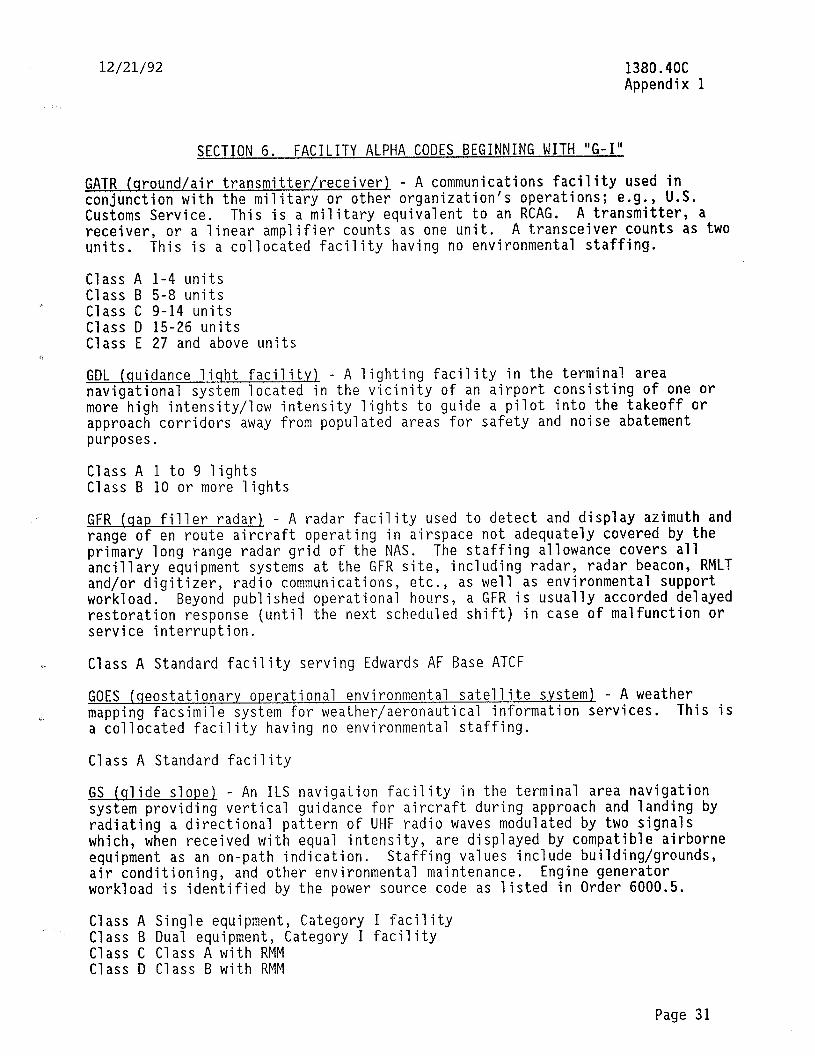
12/21/92 1380.4OC Appendix 1
SECTION 6. FACILITY ALPHA CODES BEGINNING WITH "G-I"
GATR (ground/air transmitter/receiver) - A communications facility used in conjunction with the military or other organization's operations; e.g., U.S. Customs Service. This is a military equivalent to an RCAG. A transmitter, a receiver, or a linear amplifier counts as one unit. A transceiver counts as two units. This is a collocated facility having no environmental staffing.
Class A 1-4 units Class B 5-8 units Class C 9-14 units Class D 15-26 units Class E 27 and above units
GDL (quidance liqht facility) - A lighting facility in the terminal area navigational system located in the vicinity of an airport consisting of one or more high intensity/low intensity lights to guide a pilot into the takeoff or approach corridors away from populated areas for safety and noise abatement purposes.
Class A 1 to 9 lights Class B 10 or more lights
GFR (qap filler radar) - A radar facility used to detect and display azimuth and range of en route aircraft operating in airspace not adequately covered by the primary long range radar grid of the NAS. The staffing allowance covers all ancillary equipment systems at the GFR site, including radar, radar beacon, RMLT and/or digitizer, radio communications, etc., as well as environmental support workload. Beyond published operational hours, a GFR is usually accorded de1 ayed restoration response (until the next scheduled shift) in case of malfunction or service interruption.
Class A Standard facility serving Edwards AF Base ATCF
GOES (qeostationary operational environmental satellite system) - A weather mapping facsimile system for weather/aeronautical information services. This is a collocated facility having no environmental staffing.
Class A Standard facility
GS (slide slope) - An ILS navigation facility in the terminal area navigation system providing vertical guidance for aircraft during approach and landing by radiating a directional pattern of UHF radio waves modulated by two signals which, when received with equal intensity, are displayed by compatible airborne equipment as an on-path indication. Staffing values include building/grounds, air conditioning, and other environmental maintenance. Engine generator workload is identified by the power source code as listed in Order 6000.5.
Class A Single equipment, Category I facility Class B Dual equipment, Category I facility Class C Cl ass A with RMM Class D Class B with RMM
Page 31
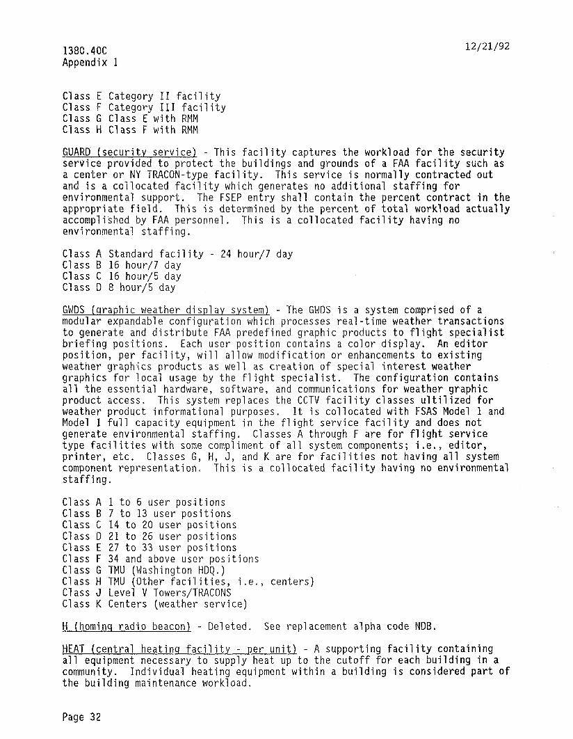
1380.4QC Appendix 1
12/21/92
Class E Category II facility Class F Category III facility Class G Class E with RMM Class H Class F with RMM
GUARD (security service) - This facility captures the workload for the security service provided to protect the buildings and grounds of a FAA facility such as a center or NY TRACON-type facility. This service is normally contracted out and is a collocated facility which generates no additional staffing for environmental support. The FSEP entry shall contain the percent contract in the appropriate field, This is determined by the percent of total workload actually accomplished by FAA personnel. This is a collocated facility having no environmental staffing.
Class A Standard facility - 24 hour/7 day Class 5 I6 hour/7 day Class C 16 hour/5 day Class D 8 hour/5 day
GWDS (graphic weather display s.ystem) - The GWDS is a system comprised of a modular expandable configuration which processes real-time weather transactions to generate and distribute FAA predefined graphic products to flight specialist briefing positions. Each user position contains a color display. An editor position, per facility, will allow modification or enhancements to existing weather graphics products as well as creation of special interest weather graphics for local usage by the flight specialist. The configuration contains all the essential hardware, software, and communications for weather graphic product access. This system replaces the CCTV facility classes ultilized for weather product informational purposes. It is collocated with FSAS Model 1 and Model 1 full capacity equipment in the flight service facility and does not generate environmental staffing. Classes A through F are for flight service type facilities with some compliment of all system components; i.e., editor, printer, etc. Classes G, H, J, and K are for facilities not having all system component representation. This is a collocated facility having no environmental staffing.
Class A 1 to 6 user positions Class 5 7 to 13 user positions Class C 14 to 20 user positions Class D 21 to 26 user positions Class E 27 to 33 user positions Class F 34 and above user positions Class G TMU (Washington HDQ.) Class H TMU (Other facilities, i.e., centers) Class J Level V Towers/TRACONS Class K Centers (weather service)
H (hominq radio beacon). - Deleted. See replacement alpha code NDB.
HEAT (central heatinq facility - per unit) - A supporting facility containing all equipment necessary to supply heat up to the cutoff for each building in a community. Individual heating equipment within a building is considered part of the building maintenance workload.
Page 32
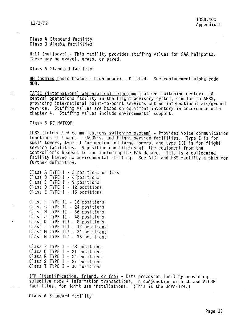
12/2/92 1380.4OC Appendix 1
Class A Standard facility Class B Alaska facilities
HELI (heliport) - This facility provides staffing values for FAA heliports. These may be gravel, grass, or paved.
Class A Standard facility
HH (hominq radio beacon - hiqh power) - Deleted. See replacement alpha code NDB.
IATSC (international aeronautical telecommunications switchinq center) - A central operations facility in the flight advisory system, similar to AFSS, providing international point-to-point services but no international air/ground service. Staffing values are based on equipment inventory in accordance with chapter 4. Staffing values include environmental support.
Class 5 KC NATCOM
ICSS (inteqrated communications switchinq system) - Provides voice communication functions at towers, TRACON's, and flight service facilities. Type I is for small towers, type II for medium and large towers, and type III is for flight service facilities. A position constitutes all the equipment from the controller's headset to and including the FAA demarc. This is a collocated facility having no environmental staffing. further definition.
See ATCT and FSS facility alphas for
Class A TYPE I - 3 positions or less Class B TYPE I - 6 positions Class C TYPE I - 9 positions Class D TYPE I - 12 positions Class E TYPE I - 15 positions
Class F TYPE II - 16 positions Class G TYPE II - 24 positions Class H TYPE II - 36 positions Class J TYPE II - 48 positions Class K TYPE III - 8 positions Class L TYPE III - 12 positions Class M TYPE III - 24 positions Class N TYPE III - 36 positions
Class P TYPE I - 18 positions Class Q TYPE I - 21 positions Class R TYPE I - 24 positions Class S TYPE I - 27 positions Class T TYPE I - 30 positions
IFF (identification, friend, or foe) - Data processor facility providing selective mode 4 information transactions, in conjunction with CD and ATCRB facilities, for joint use installations. (This is the GAPA-124.)
Class A Standard facility
Page 33
-;. ,-- . _.____ % ,----, _.-. I . ) i_. .
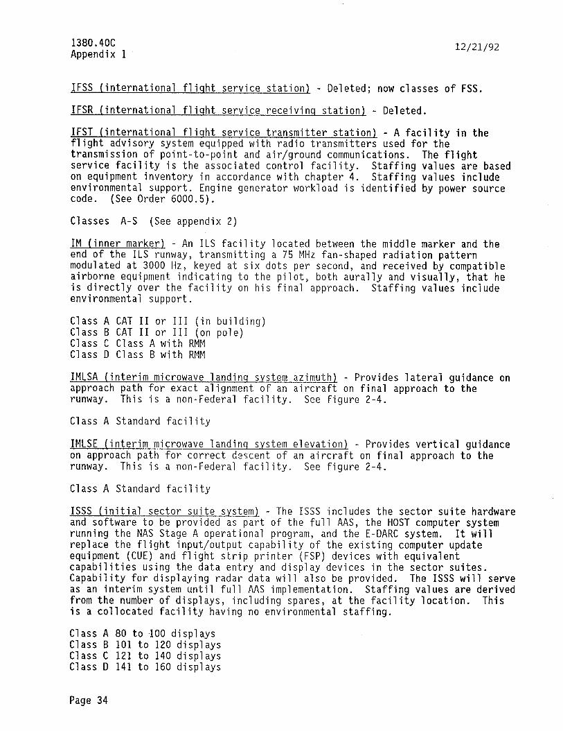
1380.4OC Appendix 1
12/21/92
IFSS (international flisht service station9 - Deleted; now classes of FSS.
IFSR (international fliqht service receivinq station9 - Deleted.
IFST (international fliqht service transmitter station9 - A facility in the flight advisory system equipped with radio transmitters used for the transmission of point-to-point and air/ground communications. The flight service facility is the associated control facility. Staffing values are based on equipment inventory in accordance with chapter 4. Staffing values include environmental support. Engine generator workload is identified by power source code. (See Order 6000.5).
Classes A-S (See appendix 2)
IM (inner marker9 - An ILS facility located between the middle marker and the end of the ILS runway, transmitting a 75 MHz fan-shaped radiation pattern modulated at 3000 Hz, keyed at six dots per second, and received by compatible airborne equipment indicating to the pilot, both aurally and visually, that he is directly over the facility on his final approach. Staffing values include environmental support.
Class A CAT II or III (in building) Class B CAT II or III (on pole) Class C Class A with RMM Class D Class B with RMM
IMLSA (interim microwave landing system azimuth9 - Provides lateral guidance on approach path for exact alignment of an aircraft on final approach to the runway. This is a non-Federal facility, See figure 2-4.
Class A Standard facility
IMLSE (interim microwave landinq system elevation) - Provides vertical guidance on approach path for correct descent of an aircraft on final approach to the runway. This is a non-Federal facility, See figure 2-4.
Class A Standard facility
ISSS (initial sector suite system) - The ISSS includes the sector suite hardware and software to be provided as part of the full AAS, the HOST computer system running the NAS Stage A operational program, and the E-DARC system. It will replace the flight input/output capability of the existing computer update equipment (CUE) and flight strip printer (FSP) devices with equivalent capabilities using the data entry and display devices in the sector suites. Capability for displaying radar data will also be provided. The ISSS will serve as an interim system until full AAS implementation. Staffing values are derived from the number of displays, including spares, at the facility location. This is a collocated facility having no environmental staffing.
Class A 80 to 100 displays Class B 101 to 120 displays Class C 121 to 140 displays Class D 141 to 160 displays
Page 34
12/21/92 1380.4OC Appendix 1
SECTION 7. FACILITY ALPHA CODES BEGINNING WITH "L"
LABS (leased A & B service) - This facil the analysis, coordination, and problem such as the Western Union GS-200 system facility.
.
Class A Standard facility
ity provides a staffing allowance for resolution time for contractor equipment
This facility replaces the TTY
LCOT (UHF/VHF link terminal) - Radio terminal facilities used in lieu of landlines, consisting of all the equipment at one site used for transmission/reception of intelligence and control functions. A single UHF/VHF link terminal is the controlling or controlled end consisting of a radio transmitter or receiver, or both, along with the associated transmit/receive voice or carrier frequency channels. This facility may be replaced by RCLT in the replacement/trunking program. This is a collocated facility having no environmental staffing.
Class A Standard facility
LDA (localizer directional AID1 - Deleted. Now incorporated in the LOC facility alpha.
LDIN (lead-in liqht facility) - A facility in the terminal area navigation system providing directional light guidance to aircraft in approach patterns or landing procedures. Facility configuration consists of a series of flashing lights augmented by steady burning lights, where required, located to visually guide an aircraft through an approach corridor bypassing high density residential, hazardous terrain, commercial, or obstruction areas.
LIVQ (livinq quarters). - This facility classification provides : staffing allowances for the maintenance of FAA-owned/leased living quarters used as employee residences. This is a support-type multiple unit facility that includes staffing allowances for maintenance of all appliances and furnishings. Facilities maintained by contract will be included as FSEP entries with the contract responsibility code. Where only a portion of the staffing is obtained by contract, show the percent of workload which is contracted out in the percent contract field. See QS for watchstander quarters and transient quarters.
Class Class Class Class
A Standard facility B Class A with A/G radio control C Class A with G/G radio control D Class A with a combination of A/G and G/G radio contra 1
Class A Two bedroom or larger apartment/house residence Class B One bedroom or efficiency apartment/house residence
LLWAS (low level wind shear alert system) - This facility provides a low-level wind shear alert warning for use by air traffic controllers in a terminal ATC environment. It consists of a center field sensor and one or more wind shear sensors installed at strategic positions on or adjacent to an airport using telemetering connection to a digital processor with ancillary visual and audible
Page 35
1380.4OC Appendix 1
12/21/92
warning indicators in the central operations facility. Staffing values include environmental support.
Class A 1 to 6 sensors Class I3 7 to 12 sensors Class C 13 to 18 sensors Class D 19 to 24 sensors
LMM (compass locator at the ILS middle marker) - A radio beacon located at the ILS middle marker site used mainly for ILS approaches. It transmits a continuous carrier L/MF radio wave in an omnidirectional pattern enabling the pilot of an aircraft equipped with an automatic direction finder to determine his bearing relative to the middle marker. All radio beacons located or used as above, regardless of output power, etc., will be treated as compass locators. Staffing values include environmental support for antenna structures.
Class A Standard facility Class B Class A with RMM
LNKR (link repeater1 - A receiver/transmitter facility which relays radio communications between two LCOT's or between intermediate LNKR's in a radio link system using UHF/VHF frequency bands. A site at which two independent two-way radio circuits from different sources are repeated will be counted as two LNKR's (the terminal may or may not be the same). A site at which the UHF/VHF link terminal received intelligence is converted into voice or carrier frequency channels for local utilization and also retransmitted to another location will be counted as two or more (as appropriate) terminal facilities rather than a repeater facility. See LCOT. This system may be replaced by RCLR in the replacement/trunking program. This is a collocated facility having no environmental staffing.
Class A Standard facility
LOC (localizerl - A terminal facility that provides an approach path for exact alignment of an aircraft on approach to a runway (ILS application) or fulfills special requirements for noise abatement, special air corridors, obstruction avoidance, departure guidance, etc. (LDA application). Staffing values include environmental support maintenance. Engine generator workload is identified by power source code (see Order 6000.5). Distinction between ILS and LDA type LOC's is determined by the facility code contained in Order 1375.4.
Class A Single Class E Category II facility Class B Dual Class F Category III facility Class C Class A with RMM Class G Class E with RMM Class D Class B with RMM Class H Class F with RMM
LOM (compass locator at the ILS outer marker) - A radio beacon located at the ILS outer marker site, used primarily for ILS approaches, which transmits a continuous carrier, L/MF radio wave in an omnidirectional pattern, enabling the pilot of an aircraft equipped with a radio direction finder to determine his bearing relative to the outer marker. All radio beacons, regardless of output power, that are located or used as above, will be treated as compass locators.
Page 36
12/21/92 1380.4OC Appendix B
Staffing values include environmental support for antenna structures. Engine generator workload is identified by power source code, (See Order 6000.5.)
Class A Less than 50 watts rated output power Class B 50 to 300 watts rated output power Class C Above 300 watts rated output power Class D Class A with RMM Class E Class B with RMM Class F Class C with RMM
LRNCM (lonq ranqe naviqation C monitor) - There are two types of Loran-C monitors maintained by FAA technicians. Loran data monitors collocated with VHF omnidirectional range (VOR) transmitters provide calibration data for Loran-C nonprecision approaches. The Loran-C data monitors are owned and maintained the FAA. Data from the monitors are collected remotely from a centraT facility at the Aeronautical Center for later processing and publication. Loran-C system area monitors or primary chain monitor system (PCMS) typically are located in airport facilities and provide data for the actual control of Loran-C signal transmissions. Loran-C PCMS monitors are owned by the U.S. Coast Guard (USCG) as are the Loran-C transmitter stations. Most Loran-C PCMS monitors are maintained by the FAA technicians in accordance with an FAA/USCG agreement. Classes A and C staffing values do not include environmental maintenance while class B does.
Class A Standard facility (collocated with VOR) Class B PCMS facility (FAA airport location; stand-alone) Class C PCMS facility (FAA airport location; collocated)
Page 37 (and 38)

12/21/92
SECTION 8. FACILITY ALPHA CODE BEGINNING WITH "M-N"
1380.4OC Appendix 1
MALS (medium-intensit.y approach lishtinq system) - An airport lighting facility providing visual guidance to the pilot by radiating medium-intensity focused light beams by which the pilot visually aligns the aircraft with the extended runway centerline. Classes A and B are landline controlled.
Class A Standard facility without sequence flasher Class B With sequence flashing lights added to l,OOO-, 1,200-, and 1,400-ft.
bars, manual control (MALSF) Class C Class A with A/G remote radio control Class D Class B with A/G remote radio control Class E Class A with G/G remote radio control Class F Class B with G/G remote radio control Class G Class A with A/G and G/G remote radio control Class H Class B with A/G and G/G remote radio control
MALSR (medium-intensity ALS (MALS) with runwav aliqnment indicator liqhts) - This is a MALS facility with sequence flashers installed from 1,600 to 2,400 feet from the runway threshold. Maximum spacing between lights is 200 feet. The standard facility is landline controlled.
Class A Standard facility Class B Class A with A/G radio control Class C Class A with G/G radio control Class D Class A with A/G and G/G radio control Class F Class A with threshold bar Class G Class B with threshold bar Class H Class C with threshold bar Class J Class D with threshold bar
MAPS (meteroloqical and aeronautical presentation s.ystem) - A computerized central control facility in the flight advisory system. It provides automatic data acquisition, processing, storage, retrieval, display, and transmission capability for flight plan handling, flight advisories, weather and aeronautical information consolidation and dissemination, etc., for use by flight service specialists and pilots operating in the NAS. It is a prototype of AFSS and serves peripheral FSS's. This is a collocated facility having no environmental staffing.
Class A Standard facility
MAREQ (marine equipment boats and docks1 - The MAREQ classification includes the maintenance of docks, boats, etc. Classes A-H are limited to boats powered by engines rated at or above 30 hp. Class J is for skiffs, jon boats, canoes, and small portable outboard motors (under 30 hp). This allowance includes engine maintenance.
Class A Boats to 20-l/2 feet, outboard engine Class B Boats 21 feet and over, outboard engine Class C Class A with dock/trailer maintenance Class D Class B with dock maintenance Class E Class A with inboard engine
Page 39
1380.4OC Appendix 1 12/21/92
Class F Class B with inboard engine Class G Class C with inboard engine Class H Class D with inboard engine Class J Skiffs, jon boats, canoes, and small engines (under 30 hp)
MCC (maintenance control center) - The MCC contains the necessary equipment and other resources which permits maintenance commands, control, and management of NAS facilities by means of status monitoring and control of RMM-capable NAS facilities; provides coordination of the maintenance workforce in restoration and maintenance activities; provides sector management with the data and information to effectively manage maintenance resources; and serves as centers for communication and coordination during emergencies (natural, defense, and accident), flight inspections, etc. Examples of MCC equipment will include the MPS, RMCC, data terminals, printers, etc. This is a collocated facility having no environmental staffing.
Class A ARTCC/ACF facility Class B General NAS facility
MCCP (maintenance control center processor/maintenance monitor console) - Formerly ESMMC (enhanced systems maintenance monitor console) - The MCCP is composed of multiple,workstations supported by backroom processors and a local area network (LAN) which provides the interface capabilities required for a center/ACF facility. In addition, the workstation area has all the communications, radar, and data handling capabilities of the SMMC which it replaces. It provides the interface with systems/equipments, organizations, processes, and personnel within and outside the center/ACF facility for the following functions: (1) coordination for facility restorations and outages, (2) facility outage reporting, (3) PM scheduling and accomplishment reporting, (4) scheduling and recording of facility certificatons, (5) coordination of aircraft accident activities, and (6) coordination for flight inspection activities. This is a collocated facility having no environmental staffing.
Class A Standard facility
MCR (multichannel recorder) - The MCR records all audio information transmitted or received by the air traffic specialist at an operating position. Staffing values include work associated with the recorders, amplifiers, reproducers, recorder tape changing, etc. This is a multiple unit facility. One unit consists of a recorder, usually with two tape decks. This is a collocated facility having no environmental staffing.
Class A up to 50 channels Class B Class A without tape change requirements by tech Class C 51-100 channels Class D 101-150 channels Class E 151-200 channels Class F 201-250 channels Class G 251-300 channels Class H 301 and above channels Class J Class C without tape change requirements by tech Class K Class D without tape change requirements by tech
Page 40
12/21/92 1388.4OC Appendix 1
Class L Class E without tape change requirements by tech Class M Class F without tape change requirements by tech Class N Class G without tape change requirements by tech Class P Class H without tape change requirements by tech
MCT (maintenance communications transceivers) - The MCT captures the workload for VHF transceivers used by maintenance personnel to coordinate activities with ATC, flight inspection, and other personnel. It excludes operational transceivers used for emergency backup communications and transceivers used with NRCS. The MCT units are usually mobile types in vehicles or are collocated with other facilities and, therefore, do not generate environmental staffing. Maintenance transceivers located in the radio equipment rooms of ATCT, FSS, etc., facilities are included. Only one facility shall be established per sector or SFO. This is a collocated facility having no environmental staffing.
Class A 1 - 10 transceivers Class B 11 - 20 transceivers Class C 21 or more transceivers
MDS (master demarcation system) - This system is a passive voice-frequency interconnection device that provides a circuit cross-connection capability, circuit monitoring and patch jack appearances, and circuit signal isolation to assist in the identification and isolation of line or equipment failures. It is designed to provide a physical point-of-separation between site customer premise equipment (CPE) and the communication circuits entering and leaving the facility over the service vendors transmission systems and/or radio communications link (RCL) systems. This separation point includes line-side cross-connect frames, circuit routing unit (CRU) interconnection terminations, jackpanel interconnection terminations as required, and drop-side cross-connect frames. This facility is normally restricted to the center environment. See TDS for the mini-demarc application utilized for other locations and facilities. This is a collocated facility having no environmental staffing.
Class A Standard facility (manual and passive) Class B Class A with CRU (automatic circuit routing capability)
MHFR (military heisht finder radar1 - Deleted.
MIG (military interface group) - Data processor facility for processing tube-type ARSR, CD, and IFF data to format required for military regional operations control center (ROCC) needs and ROCC height and other request/control data into tube-type ARSR, CD, and IFF facilities. Converts data to and from military message formats. This facility is physically associated with the CD, but is defined separately due to the specialized function meeting military interface requirements. This facility type will be established at JSS sites only. This is a collocated facility having no environmental staffing.
Class A Standard facility Class X Interface function at JSS data tie site
MIM (militarv interface modification) - Data processor facility for processing ARSR-3 and IFF data to format required for military ROCC needs and ROCC height and other request/control data into ARSR-3 and IFF facilities. Converts ARSR-3
Page 41

1380.4OC Appendix 1
12/21/92
digital data to and from military message formats. This facility is physically associated with the ARSR-3, but is defined separately due to the specialized function meeting military interface requirements. This facility type will be established at JSS sites only. This is a collocated facility having no environmental staffing.
Class A Standard facility
MLSA (microwave landinq system azimuth) - An MLS facility in the terminal area electronic navigation system providing precision horizontal guidance for aircraft during approach and landing by projecting a directional microwave radio beam which is decoded by compatible airborne equipment into aircraft bearing with respect to the runway centerline.
Class A Standard facility
MLSBA (microwave landinq system back azimuth) - Provides guidance for aircraft users during departures and missed approaches. See MLSA.
Class A Standard facility
MLSD (microwave landinq system distance measurinq equipment precision). - Provides two modes of distance information. The initial approach (IA) mode is exactly the same as conventional DME and uses existing avionic equipment. The final approach (FA) mode provides increased accuracy and is referred to as precision information. See MLSA.
Class A Standard facility
MLSE (microwave landinq system elevation) - Provides vertical guidance along a selected approach slope with continuous proportional up-down guidance near the path's center and is sometimes called elevation #l. See MLSA.
Class A Standard facility
MLSF (microwave landinq s.ystem flare) - Facility deleted.
MM (middle marker) - An ILS facility located approximately 3,500 feet from the runway threshold on the extended centerline, transmitting a 75 MHz fan-shaped radiation pattern modulated at 1,300 Hz, keyed alternately with dots and dashes, received by compatible airborne equipment indicating to the pilot, both aurally and visually, that he is passing over the facility. Staffing values include environmental support.
Class A In building, Category I Class C Pole-mounted, Category I Class D CAT II or III facility (in building) Class E CAT II or 111 facility (pole-mounted) Class F Class A with RMM Class G Class C with RMM Class H Class D with RMM Class J Class E with RMM
Page 42

12/21/92 1380.4OC Appendix 1
MOBIL (mobile laboratory) - A mobile facility (van, motor home, trailer, etc.) that normally has built-in equipment, electronic and/or mechanical, to perform its designated function. Examples of this facility would be a test equipment calibration laboratory or a regional frequency van. (A vehicle assigned to haul personnel, spare parts, and small items of test equipment would not be considered a MOBIL.) A MOBIL will not be counted as a VEHS, CBI, or OFFRD.
Class A Self-propelled vehicle Class B Trailer
MODE S (mode S/data link) - A ground-based facility that discretely interrogates each aircraft transponder and processes the aircraft replies for ATC purposes. It also provides data link capability. This equipment replaces the ATCRB and ATCBI. Class A does not include environmental staffing. Class B includes environmental staffing.
Class A Standard facility collocated Class B Stand-alone (formerly a beacon-only site (BOS)).
MPS (maintenance processinq system) - The MPS is comprised of a data processing system designed to monitor and control remote facilities; i.e., 2nd generation VORTAC, etc. This is a collocated facility having no environmental staffing. It is one of the elements of and will normally be located in the MCC facility.
Class A Standard facility Class B With enchanced processor
MX (mobile enqine or qenerator plant) - These mobile engine generators are generally stored at a specific location and are moved to an operating location when required. If located permanently at one location for primary power sources, the mobile engine generator should be classified as a PX.
Class A Above 10 kVA (trailer or van) Class B 10 kVA or less (including small portables)
NADIN (national airspace data interchanqe network) - An integrated telecommunications record system which provides centralized switching control and digital data processing as well as network distribution of flight plan, weather, NOTAM, and ATC messages in the NAS. It also provides an interface with international data interchange systems. CTRB captures the environmental workload.
Class A Switching center (Atlanta and Salt Lake City) Class B Concentrator (at Centers) Class C Class A with packet switching node (at Salt Lake City and Atlanta
switching centers) Class D Class B with Packet switching node (at Centers)
Page 43
.I_ .,....- _-- . ...l,...., ____ ..” _ _, .- .
1380.4OC Appendix 1
12/21/92
NDB (non-directional beacon) - This facility transmits a continuous carrier radio wave in the low frequency band (190-535 khz) in an omnidirectional pattern enabling the pilot of an aircraft equipped with a radio direction finder to determine his bearing relative to the facility. This facility is sometimes called a homer or homing beacon. This facility type includes MH facilities which have less than 50 watts and HH facilities which have in excess of 2,000 watts outputs. NDB facilities are not located at an ILS marker site nor are they used mainly for ILS approaches. Staffing values include environmental support. This facility replaces the H and HH facility contractions.
Class A Up to 2,000 watts rated output power Class B Cl ass A with RMM Class C 2,001 and above watts rated output power Class D Class C with RMM
NMCE (network monitor control equipment) - The NMCE is a processor based switching system for remote testing and alternate route capability for all circuits provided by the FAA utility using RCL, leased vendors, or both. Staffing values include time spent for internal/external coordination, troubleshooting, and line performance monitoring activities.
Class A Standard facility
NRCS (national radio communications system) - This system provides communications support for national, regional, and local activities. The HF/UHF/VHF radios are deployed in base, mobile, and repeater stations. An associated unit is a single handheld transceiver or a mobile transceiver with or without linear amplifers.
This facility does not include equipment at EOF locations. A base is a fixed station at a central operations facility or some other defined control point. This is a collocated facility having no environmental staffing.
a. HF SSB stations only
Class A Sector/SF0 Class B Centers, regional office, Technical Center, or Aeronautical Center Class C Washington headquarters
b. FM stations only
Class D Base with I-10 associated units Class E Base with 11-20 associated units Class F Base with 21 or more associated units Class G Repeater - fixed Class H Repeater - portable Class J l-10 units without base Class K 11-20 units without base Class L 21 or more units without base
Page 44
12/21/92 1380.4OC Appendix 1
NXRAD (next qeneration weather radar) - Doppler-processing radar devoted strictly to weather tracking and identifying storm systems. for the radar site equipment only.
Staffing values are The remote/indicator site staffing is
captured under the PUP facility alpha. Staffing values include environmental support.
Class A Standard facility
Page 45 (and 46)


12/21/92
SECTION 9. FACILITY ALPHA CODES BEGINNING WITH "O-Q"
1380.4OC Appendix 1
OARTS (oceanic air route trackinq system) - A subsystem adjunct to an automated center for processing flight plan updates and displaying the position of aircraft in transit on transoceanic flights. The staffing values include all the hardware and software maintenance functions prerequisite to OARTS operational support in the en route ATC environment. This is a collocated facility having no environmental staffing.
Class A Standard facility
OAW (off airwa.ys weather station) - An NWS facility where off-airways weather data is collected, analyzed, and disseminated via FAA data interchange facilities in the national flight advisory system. The communications equipment is normally owned and maintained by the FAA. The weather service normally maintains the weather equipment but may be FAA maintained by regional agreement. This is a collocated facility having no environmental staffing.
Class A Automatic meteorological observation system (AMOS) Class B All other weather stations
ODALS (omnidirectional airport liqhtinq system) - An airport lighting system which provides omnidirectional orientation by visual vectoring with remote control of light intensity from cockpit and the tower/flight service facility. The standard facility utilizes landline control.
Class A Standard facility Class B Class A with A/G radio control Class C Class A with G/G radio control Class D Class A with a combination of A/G and G/G radio control
ODAPS (oceanic display and planninq system) - Provides automated flight data and conflict probe to allow effective assignment of routes and altitudes. Includes a display and a stand-alone processor. This is a collocated facility having no environmental staffing.
Class A Standard facility
OFDPS (offshore fliqht data processinq system) - The OFDPS is a processor subsystem which handles the flight data processing routine at EARTS facilities. It is incorporated into the EARTS facility for this purpose. A system is considered to be the total configuration at the locations identified in the classes below. Staffing values include the total workload for the system configuration; i.e., main and standby, single equipment, training facility, etc. Only one facility per location is to be established in the FSEP unless additional discrete service is provided to a satellite or other facility via another system configuration. This is a collocated facility having no environmental staffing.
Class A Honolulu system 7 system Class B Anchorage HP 1000 system Class C San Juan syatem 7 system
Page 47
1380.4OC Appendix 1
12/21/92
OFFRD (heavy equipment and off-road vehicles) - This includes, but is not limited to, graders, equipment,
forklifts, tractors, snow cat, snowmobile, snow-removal rock crushers, asphalt plants, and heavy mobile equipment not
normally requiring a license for highway travel (except MX equipment). This is a multiple unit facility, and staffing values are per unit.
Class A Up to 25 horsepower Class 5 25 to 150 horsepower Class C Over 150 horsepower
OLD (qeneral oil distribution system) - This classification provides staffing values for FAA-maintained bulk storage and fuel distribution systems used as a centrally controlled source for transporting fuel to other facility locations. The values cover maintenance of all pumps, pipelines, bulk storage tanks, valves, controls, etc., where commercial service is not available. A fuel storage tank, with or without a pump, qualify for entry as OLD in the FSEP.
for one building (except PX) does not OLD maintained by contract should have a
contract responsibility code.
Class A Serves PX facility Class B Serves 2-5 buildings Class C Serves 6-10 buildings Class D Serves over 10 buildings
OM (outer marker) - An ILS facility located 4 to 7 miles from the runway threshold on the extended centerline, transmitting a 75 MHz fan-shaped radiation pattern modulated at 400 Hz, keyed at two dashes per second, and received by compatible airborne equipment indicating to the pilot, both aurally and visually, that he is passing over the facility and can begin his final approach. Staffing values include environmental support.
Class A In building, Category I Class C Pole-mounted, Category I Class D Category II or III facility (equipment in building) Class E Category II or III facility (pole-mounted equipment) Class F Class A with RMM Class G Class C with RMM Class H Class D with RMM Class J Class E with RMM
PAM (peripheral adapter module) - This facility comprises the units which were incorporated into the 9020A & D systems which were not scheduled for replacement with the HOST. installation.
This facility is to be established in the FSEP following HOST This is a collocated facility having no environmental staffing.
Class A Standard facility
PAMRI (peripheral adapter module replacement item) - The PAMRI will replace the data input/output capability of the existing PAM and DRG interface equipment with more reliable equipment having enhanced capabilities. It will consist of commercially available hardware and software. The existing HOST software shall be modified to accommodate the PAMRI. The PAMRI will be fully compatible with the ISSS. It will provide the interface between the processor of the HOST and
Page 48
12/21/92 1380.4OC Appendix 1
the many peripherals such as radar, looped sim interfaces, etc. All PAMRI’s will be identical, varying only in quantities of adapter type interfaces installed and in software adaptation to the operational configuration of the individual facilities. This is a collocated facility having no environmental staffing.
Class A Standard facility
PAP1 (precision approach path indicator) - A simple visual aid to assist pilots during their approach to landing. It enables pilots to acquire the correct glide slope and subsequently to maintain their position on it, thus ensuring an accurate approach and landing. The PAP1 system consists of four sharp transition projector units located at the side of the runway, spaced laterally at 23.5-foot intervals. A second complementary set is normally provided on the opposite side of the runway. The setting angles of the red/white interfaces of the four units are graded; the differences in angle between the units being typically 20 minutes of arc.
The nominal glide slope is midway between the angular settings of the center pair of units and the on-glide-slope signal and is thus two red and two white lights in the bar. If the aircraft goes below the glide slope, the pilot will see a progressively increasing number of red lights. Conversely, if the aircraft goes above the glide slope, the number of white lights seen is increased.
Class A Standard facility
PAR (precision approach radar) - A radar facility in the terminal area navigational system used to detect and display, with a high degree of accuracy, azimuth, range, and elevation of aircraft on the final approach to a runway enabling the ATC specialist to provide advisory service to the pilot. Staffing values include environmental support.
Class A Standard facility
PCS (power conditioninq system) - The PCS equipment is a stand-alone system provided at hiqh priority facilities to ensure conditioned and continuous alternating current (AC) electrical power to critical loads. The PCS system is designed to operate from either commercial or standby en.gine generator AC sources. It provides conditioned AC power to critical loads at all times, including AC power source transfers. The PCS includes internal or external batteries whose direct currect (DC) output is converted to AC power. A module consists of a rectifier, batteries, inverter, and associated controls. This facility includes the systems formerly known as UPS. A PCS facility should be established for each complete system meeting the criteria contained in this definition and class structure.
Class A single module, single phase, up to 25KVA Class B Single module, 3 phase, up to 25KVA Class C Single module, 3 phase, 26 to 75KVA Class D Single module, 3 phase, 76 to 250KVA Class E Multiple module (3-5), 3 phase, up to 250KVA Class F Multiple module (3-5), 3 phase, 251KVA and above
Page 49
-“--~ - , - - - . - -^ , - . __i , . . , . ” , .
1380.4OC Appendix 1
12/21/92
PDC (pre-departure clearance system) - A system located in the air traffic control tower (ATCT) that is used to transmit departure clearances to aircraft, using digital data communications. PDC is comprised of a rack of computer and communications equipment located in a tower equipment room and a terminal in the tower cab for controller interaction. Flight plan data is entered into the PDC system through a passive tap on the flight data imput/output (FDIO) remote control unit.
Class A Single keyboard and monitor in the ATCT Class B Dual keyboards and monitors in the ATCT
PRM (precision runway monitor) - This facility is a secondary radar type system, similar to the MODES, which operates and updates targets at a faster rate than that of the normal ATCRB or MODES type systems (approximately twice as fast). This faster rate of update allows for improved accuracy in predicting target locations thus effecting quicker responses from both the controller and pilot. This system will be utilized to increase the efficiency of operations at parallel runway configured locations, reducing the IFR runway separation minimums below the current 4,300 ft, for simultaneous IFR approaches. This is a collocated facility having no environmental staffing. This is a core facility type.
Class A Standard facility Class B Dual antennas (2 towers with switching capability)
PUP (principal user processor) - This facility receives the NEXRAD data products and provides the request, display, storage, annotation, and distribution of products by operational personnel. It contains the dedicated hardware and software required for graphics processing, local control, status monitoring, local annotation, and product achieving. System equipment includes the system console and primary workstation composed of two high resolution color graphics monitors, mouse, dedicated color reproducing hardcopy device, and an applications terminal for keyboard entry. This is a collocated facility having no environmental workload. Staffing values for PUP only.
Class A Standard facility
PX (primary power enqine or qenerator plant) - Primary power plant is the main source of power and is normally the power plant for the community. Where a movable, portable, or mobile plant is installed permanently, it is treated as a primary power plant.
Class A 1 to 100 kVA - one engine Class B 25 to 500 kVA per unit - two engines Class C 25 to 500 kVA per unit - three engines Class D 25 to 500 kVA per unit - four engines Class E 25 to 500 kVA per unit - five engines Class F 25 to 500 kVA per unit - six engines Class G Over 100 kVA - one engine
QS (quarters buildinq - other than LIVQL - A QS building is that type normally used by watchstanding personnel for on-site standby quarters or for emergency use when required (includes transient quarters). To qualify, the facility must
Page 50
12/21/92 1380.4OC Appendix 1
have kitchen (with range, refrigerator, and sink), bathroom, and sleeping areas. Sleeping and eating facilities in a shop or storeroom do not qualify (nor do ARSR facilities). Family-occupied living quarters are not to be reported under this facility type - (see LIVQ).
Class A Up to 1,500 square feet Class B 1,501-3,000 square feet Class C Over 3,000 square feet
Page 51 (and 52)


12/21/92 1380.4OC Appendix 1
SECTION 10. FACILITY ALPHA CODES BEGINNING WITH "R"
RAPCO (radar approach control - Air Force) - An ATC facility using radar equipment in conjunction with air/ground communications, ASR, ATCRB, and control and display equipment. This is a point-count facility. Where collocated with ARTS, communications and other equipment not included in ARTS will be point-counted against RAPCO. Environmental staffing values are counted against ATBM.
Class A-9 (See appendix 2.)
RBC (rotatins beam ceilometer) - This is a weather observation facility measuring the height above ground level of the lower layer of clouds or obscuring phenomenon at a point along the approach path to an ILS runway. Facility configuration includes the rotating beam transmitter, receiver unit, and indicator. Staffing values include environmental support.
Class A Standard facility
RBDE (radar briqht display equipment) - Provides CRT display of radar data allowing viewing under bright light or high ambient lighting conditions (945 line systems, type 3, 4, 5, and 6 systems). Total configuration includes workload for control and patch panel, beacon decoder, control rack assembly, mappers, scan converters, displays, and control equipment. The RBDE system includes all the radar equipment installed from the RMLT termination panel for one enroute surveillance radar and/or control-end equipment. This is a collocated facility having no environmental staffing.
Class 0 Less than 10 scan converters (SCE) Class Q lo-19 SCE's Class R 20-29 SCE's' Class S 30 or more SCE's
RBDPE (radar beacon data processor equipment) - This type facility provides TPX-42 radar beacon data processing with direct altitude and identity coded signals for display in a terminal ATC environment. The class structure is determined by the number of displays. Staffing values include maintenance of video mappers, control panels, other associated ASR indicator site equipment, etc. Facilities with BRITE-type displays only should claim these under the BRITE facility and assign Class C for the RBDPE facility. This is a separate facility system and should not be point-counted against TRCAB, TRACO, RAPCO, RATCF, ARTS, or BRITE. This is a collocated facility having no environmental staffing. See ATCT, TRCAB, TRACO, or RAPCO for communications.
Class C No displays Class D 4 or less displays Class E 5 to 9 displays Class F 10 or more displays
RBPM (remote beacon performance monitor), - This is a transponder, remote system monitor (RSM) that receives interrogations from, and transmits replies to, the ATCBI and/or ATCRB for monitoring purposes. (This type facility has been referred to as a "parrot in a tree.") See ATCBI and ATCRB for ISM locations.
Page 53
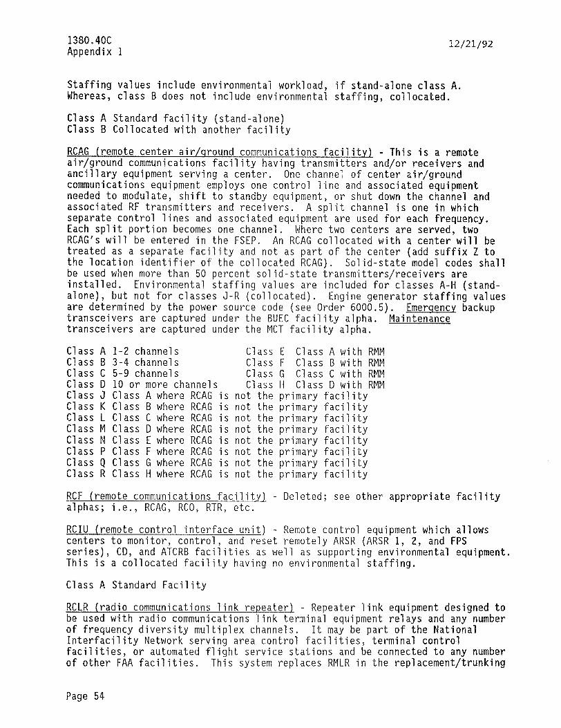
138004OC Appendix 1
12/21/92
Staffing values include environmental workload, if stand-alone class A. Whereas, class B does not include environmental staffing, collocated.
Class A Standard facility (stand-alone) Class B Collocated with another facility
RCAG (remote center air/qround communications facilitvl - This is a remote air/ground communications facility having transmitters and/or receivers and ancillary equipment serving a center. One channel of center air/ground communications equipment employs one control line and associated equipment needed to modulate, shift to standby equipment, or shut down the channel and associated RF transmitters and receivers. A split channel is one in which separate control lines and associated equipment are used for each frequency. Each split portion becomes one channel. Where two centers are served, two RCAG's will be entered in the FSEP. An RCAG collocated with a center will be treated as a separate facility and not as part of the center (add suffix Z to the location identifier of the collocated RCAG), Solid-state model codes shall be used when more than 50 percent solid-state transmitters/receivers are installed. Environmental staffing values are included for classes A-H (stand- alone), but not for classes J-R (collocated). Engine generator staffing values are determined by the power source code (see Order 6000.5). Emerqenc.y backup transceivers are captured under the BUEC facility alpha. Maintenance transceivers are captured under the MCT facility alpha.
Class A 1-2 channels Class E Class A with RMM Class B 3-4 channels Class F Class B with RMM Class C 5-9 channels Class G Class C with RMM Class D 10 or more channels Class H Class D with RMM Class J Class A where RCAG is not the primary facility Class K Class B where RCAG is not the primary facility Class L Class C where RCAG is not the primary facility Class M Class D where RCAG is not the primary facility Class N Class E where RCAG is not the primary facility Class P Class F where RCAG is not the primary facility Class Q Class G where RCAG is not the primary facility Class R Class H where RCAG is not the primary facility
RCF (remote communications faci1it.y) - Deleted; see other appropriate facility alphas; i.e., RCAG, RCO, RTR, etc.
RCIU (remote control interface unit) - Remote control equipment which allows centers to monitor, control, and reset remotely ARSR (ARSR 1, 2, and FPS series), CD, and ATCRB facilities as well as supporting environmental equipment. This is a collocated facility having no environmental staffing.
Class A Standard Facility
RCLR (radio communications link repeater) - Repeater link equipment designed to be used with radio communications link terminal equipment relays and any number of frequency diversity multiplex channels. It may be part of the National Interfacility Network serving area control facilities, terminal control facilities, or automated flight service stations and be connected to any number of other FAA facilities. This system replaces RMLR in the replacementjtrunking
Page 54
12/21/92 1380.4OC Appendix 1
program and may also replace those facilities formerly designated as LNKR. See RCLT for terminal-type facilities for this link-type system. Environmental staffing values are included for classes A, B, and C only. Engine generator staffing values are determined by the power source code. (See Order 6000.5.)
Class A Repeater with no voice data multiplexing (VDM) drops Class B Repeater with 1-96 VDM drops Class C Repeater with 97 and above VDM drops Class D Class A collocated (no environmental staffing) Class E Class B collocated (no environmental staffing) Class F Class C collocated (no environmental staffing) Class P Passive reflector
RCLT (radio communications link terminal) - Terminal link equipment designed for any number of frequency diversity multiplexing channels. This facility can be used in lieu of lines for transmission of video information, analog voice data, radar broadband and/or digital data, etc. It may be part of the National Interfacility Network serving area control facilities, terminal control facilities, or AFSS's and may be connected to any number of other FAA facilities. This system replaces RMLT in the replacement/trunking program and may also replace those facilities formerly designated as LCOT and CMLT. See RCLR for repeater type facilities for this link-type system. This is a collocated facility having no environmental staffing.
Class A l-96 VDM channels Class B 97-600 VDM channels Class C 601 and above VDM channels
RCO (remote communications outlet) - A remoted or peripheral facility providing radio communication services between flight advisory specialists at flight service facilities and aircraft pilots. If the equipment installed in one building serves both flight service facilities and a primary ATC central operations facility, there should be an entry in the FSEP for each type operation served; i.e., RTR, RCAG, or BUEC and RCO. See definition for RTR, BUEC, and RCAG. A transmitter, a receiver, or a linear amplifier each count one unit. An RCO with suffix 2 added to its location identifier should be established for radio communications equipment; i.e., transmitters, receivers, etc., located in the flight service facility equipment room. Emerqencv backup transceivers are excluded and are captured under the FSS or BUEC facilities. Maintenance transceivers are captured under the MCT facility. EOF's will be listed as EOF and not as RCO. Staffing values include environmental support when it is a stand-alone or primary facility on1.v (classes A through K and 0). RCO's when collocated, and not the primary facility, will not capture the environmental workload. Classes P through Y and Z do not include environmental staffing.
Class A 1-4 units (See Class 0) Class P Class A collocated Class B 5-8 units Class Q Class B collocated Class C 9-14 units Class R Class C collocated Class D 15-22 units Class S Class D collocated Class E 23 and above units Class T Class E collocated Class F Class A with tone control Class U Class F collocated Class G Class B with tone control Class V Class G collocated
Page 55
1380.4OC Appendix 1
12/21/92
Class H Class C with tone control Class W Class H collocated Class J Class D with tone control Class X Class J collocated Class K Class E with tone control Class Y Class K collocated Class 0 Single frequency outlet (Reference the latest edition of order 6520.4) Class Z Class 0 collocated
REIL (runway end identification liqhts) - An airport lighting facility in the terminal area navigation system consisting of one flashing white high intensity light installed at each approach end corner of a runway and directed towards the approach zone, which enables the pilot to identify the threshold of a usable runway.
Class A Standard facility (unidirectional) Class B Class A with landline control Class C Class A with runway edge light control Class D Class A with A/G radio control Class E Class A with G/G radio control Class F Class A with combination of A/G and G/G radio control Class G Standard facility (omnidirectional) Class H Class G with runway edge light control Class J Class G with A/G radio control Class K Class G with G/G radio control Class L Class G with combination of A/G and G/G radio control
RID (runway incursion device) - An electronic device utilized for preventing runway incursions. A set of four electronic reminders with two modes of operation are utilized. One mode is the lamps only where the large red lamps flash at l/2 second intervals. The other mode provides both lamps and voice indications. This system is connected into the radio communications frequencies for monitoring runway commands given by the controller each time the frequency is keyed. Two configurations are possible: (1) main unit only or (2) main unit with a slave unit. This system is found in the ATCT facilities. This is a collocated facility having no environmental staffing.
Class A Standard facility (main unit only) Class B Class A with a slave unit
RMCC (remote monitor control center) - This facility is the VORTAC remote monitor and control equipment consisting of two input/output terminals (IOT) and two teletypewriters (TTY) and associated electronic equipments. It communicates with the VORTAC facility control processor unit (FCPU) via one of 16 RMCF's to complete all human interface functions remotely. It is collocated having no environmental staffing.
Class A Monitoring 1 to 19 VOR/DME/TACR's Class B Monitoring 20 to 39 VOR/DME/TACR's Class C Monitoring 40 to 59 VOR/DME/TACR's Class D Monitoring 60 to 79 VOR/DME/TACR's Class E Monitoring 80 to 99 VOR/DME/TACR'.s Class F Monitoring 100 to 128 VOR/DME/TACR's
Page 56

12/21/92 1380.4QC Appendix 1
RMCF (remote monitor control facility) - An RMCF monitors and controls the 2nd Generation VOR/DME/TACR equipment. It consists of a display, keyboard, printer, and associated electronic equipment. This is a collocated facility having no environmental staffing. A separate facility shall be entered for each RMCF capable of monitoring and controlling eight VOR/DME/TACR facilities.
Class A Monitoring one VOR/DME/TACR Class B Monitoring two VOR/DME/TACR's Class C Monitoring three VOR/DME/TACR's Class D Monitoring four VOR/DME/TACR's Class E Monitoring five VOR/DME/TACR's Class F onitoring six VOR/DME/TACR's Class G Monitoring seven VOR/DME/TACR's Class H Monitoring eight VOR/DME/TACR's
RMLR (radar microwave link repeater) - A facility in the microwave link system which relays broadband/narrowband radar and voice/data communications. This system will be replaced by RCLR in the replacement/trunking program. At RMLR's with PCS equipment, a PCS will be established as a separate facility. Staffing values are based on RMLR equipment models (RML-1, 2, 3, 4, 5, 6, FRQ-11, etc.) and include environmental credit based on the classes below. Engine or generator staffing is identified by power source code. (See Order 6000.5.)
C'Iass A Standard facility (workload includes RF TX/RX channels with tower and antenna system)
Class B Class A with multiplexer Class C Class A with diversity Class D Passive reflector without tower (no RF equipment installed) Class E Passive reflector with tower (no RF equipment installed) Class F Class A collocated with another RMLR (no allowance for building and
grounds and environmental equipment) Class G Class B collocated with another RMLR (no allowance for building and
grounds and environmental equipment) Class H Class C collocated with another RMLR (no allowance for building and
grounds and environmental equipment) Class X restricted area number 2508 (R-2508)
RMLT (radar microwave link terminal) - A terminal microwave facility transmitting broadband/narrow band radar and voice/data communications. Two RMLT's are used with each RML system. Staffing values include credit for the dish, tower, and passive reflector normally associated with an RMLT site even if the tower and reflector are remotely located. This system will be replaced by RCLT in the replacement/trunking program. Staffing is based on RMLT equipment models (RML-1, 2, 3, 4, 5, 6, FRQ-11, etc.) according to the classes below. In the class structure, the term SUPERGROUP refers to a subcarrier frequency generation chain capable of providing up to 60 discrete channels. Addition of the VDM allows transmission of narrowband radar and other data. This is a collocated facility having no environmental staffing.
Class A Standard facility Class B With VDM and up to two supergroups Class C With VDM and three or more supergroups
Page 57
1380.4OC Appendix 1
12/21/92
Class D Class A with defruiters, line matching amplifiers and networks at military RADAR sites
Class X Restricted area number 2508 (R-2508)
RMSC (remote monitorins subsystem concentrator) - The RMSC is a unit comprised of a microprocessor, RF link, power supply, and associated electronics which receives data inputs from each RMS facility connected to it and combines the data inputs into a composite data response for transfer to the MPS (next level processor). The RMSC transfers workload to the MPS. This is a collocated facility having no environmental staffing.
Class A Standard faciltiy Class B Link control unit (LCU)
RRH (remote readout hysrothermometers) - The hygrothermometer is an instrument system designed for indicating or recording dew point and air temperatures through the use of remote readout thermometers. The major assemblies consist of a thermal shield (located in the field) and dew point/air temperature indicators
!&kload ocated in a weather observatory). Staffing values include environmental
.
Class A Standard facility
RRWDI (radar remote weather display indicator) - This equipment processes and displays real-time weather information from selected FAA and NWS radar sites (see RRWDS). facilities.
This equipment was previously point-counted at central operations For facility classing purposes each processor is a unit and each
display is a unit. This is a collocated facility having no environmental staffing.
Class A l-3 units Class B 4-6 units Class C 7-9 units Class D lo-12 units Class E 13-15 units Class F 16-18 units Class G 19-21 units
RRWDS (radar remote weather display system) - This equipment, located at selected FAA and NWS radars, provides real-time weather information to FAA and weather service facilities. facility at radar sites.
It is to be added to the FSEP as a separate Equipment located at the center or flight service
facility will be added as a separate RRWDI. This is a collocated facility having no environmental staffing.
Class A Standard facility
RTCCS (remote tower communications control system) - A system that provides BRITE/BANS control and entry capability between a tower and ARTS/EARTS computer. This is a collocated facility having no environmental staffing.
Class A Standard facility
Page 58
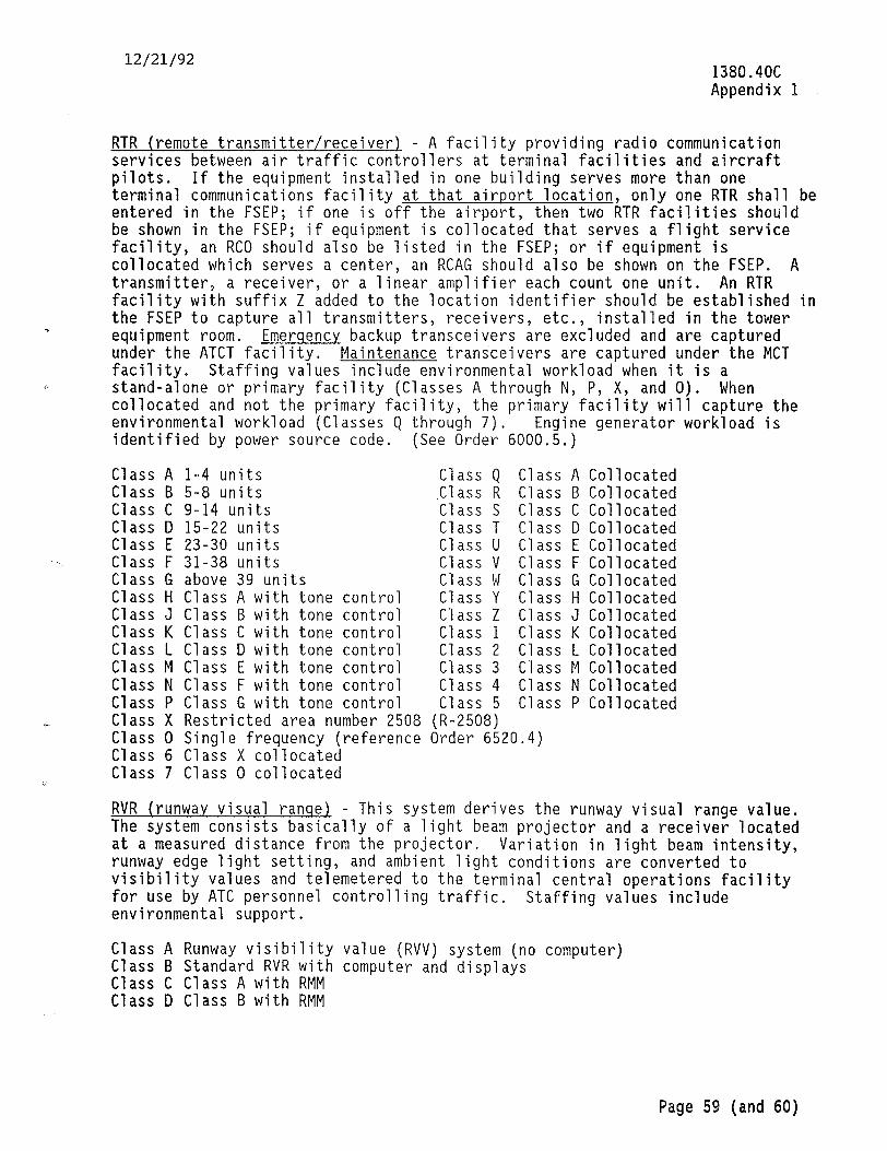
12/21/92 1380.4OC Appendix 1
RTR (remote transmitter/receiver) - A facility providing radio communication services between air traffic controllers at terminal facilities and aircraft pilots. If the equipment installed in one building serves more than one terminal communications facility at that airport location, only one RTR shall be entered in the FSEP; if one is off the airport, then two RTR facilities should be shown in the FSEP; if equipment is collocated that serves a flight service facility, an RCO should also be listed in the FSEP; or if equipment is collocated which serves a center, an RCAG should also be shown on the FSEP. A transmitter, a receiver, or a linear amplifier each count one unit. An RTR facility with suffix Z added to the location identifier should be established in the FSEP to capture all transmitters, receivers, etc., installed in the tower equipment room. Emerqency backup transceivers are excluded and are captured under the ATCT facility. Maintenance transceivers are captured under the MCT facility. Staffing values include environmental workload when it is a stand-alone or primary facility (Classes A through N, P, X, and 0). When collocated and not the primary facility, the primary facility will capture the environmental workload (Classes Q through 7). Engine generator workload is identified by power source code. (See Order 6000.5.)
Class A 1-4 units Class Q Class A Collocated Class B 5-8 units Class R Class B Collocated Class C 9-14 units Class S Class C Collocated Class D 15-22 units Class T Class D Collocated Class E 23-30 units Class U Class E Collocated Class F 31-38 units Class V Class F Collocated Class G above 39 units Class W Class G Collocated Class H Class A with tone control Class Y Class H Collocated Class J Class B with tone control Class Z Class J Collocated Class K Class C with tone control Class 1 Class K Collocated Class L Class D with tone control Class 2 Class L Collocated Class M Class E with tone control Class 3 Class M Collocated Class N Class F with tone control Class 4 Class N Collocated Class P Class G with tone control Class 5 Class P Collocated Class X Restricted area number 2508 (R-2508) Class 0 Single frequency (reference Order 6520.4) Class 6 Class X collocated Class 7 Class 0 collocated
RVR (runway visual ranqe) - This system derives the runway visual range value. The system consists basically of a light beam projector and a receiver located at a measured distance from the projector. Variation in light beam intensity, runway edge light setting, and ambient light conditions are converted to visibility values and telemetered to the terminal central operations facility for use by ATC personnel controlling traffic. Staffing values include environmental support.
Class A Runway visibility value (RVV) system (no computer) Class B Standard RVR with computer and displays Class C Class A with RMM Class D Class B with RMM
Page 59 (and 60)

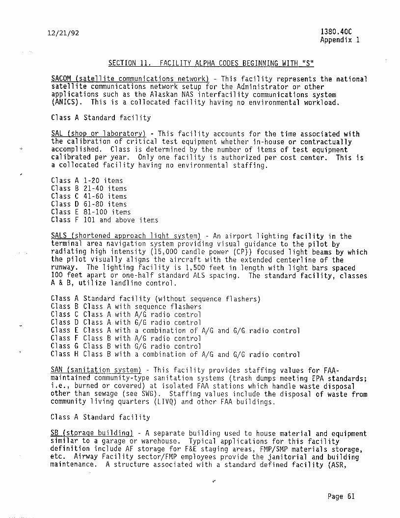
12/21/92
SECTION 11. FACILITY ALPHA CODES BEGINNING WITH I’S”
the national SACOM (satellite communications network) - This facility represents satellite communications network setup for the Administrator or other applications such as the Alaskan NAS interfacility communications system (ANICS). This is a collocated facility having no environmental workload.
Class A Standard facility
SAL (shop or laboratory) - This facility accounts for the time associated with the calibration of critical test equipment whether in-house or contractually accomplished. Class is determined by the number of items of test equipment calibrated per year. Only one facility is authorized per cost center. This is a collocated facility having no environmental staffing.
Class A l-20 items Class B 21-40 items Class C 41-60 items Class D 61-80 items Class E 81-100 items Class F 101 and above items
SALS (shortened approach liqht s.ystem) - An airport lighting facility in the terminal area navigation system providing visual guidance to the pilot by radiating high intensity (15,000 candle power (CP)) focused light beams by which the pilot visually aligns the aircraft with the extended centerline of the runway. The lighting facility is 1,500 feet in length with light bars spaced 100 feet apart or one-half standard ALS spacing, A & B, utilize landline control.
The standard facility, classes
Class A Standard facility (without sequence flashers) Class B Class A with sequence flashers Class C Class A with A/G radio control Class D Class A with G/G radio control Class E Class A with a combination of A/G and G/G radio control Class F Class B with A/G radio control Class G Class B with G/G radio control Class H Class B with a combination of A/G and G/G radio control
SAN (sanitation system) - This facility provides staffing values for FAA- maintained community-type sanitation systems (trash dumps meeting EPA standards;
burned or covered) at isolated FAA stations which handle waste disposal $$ than sewage (see SWG). Staffing values include the disposal of waste from community living quarters (LIVQ) and other FAA buildings,
Class A Standard facility
SB (storaoe buildins) - A separate building used to house material and equipment similar to a garage or warehouse. Typical applications for this facility definition include AF storage for F&E staging areas, FMP/SMP materials storage, etc. Airway Facility sector/FMP employees provide the janitorial and building maintenance. A structure associated with a standard defined facility (ASR,
b'
Page 61
,. -., .._" _ _. I _ .
1380.4OC Appendix 1

I380.4OC Appendix I
12/21/92
ARSR, GS, LOC, VOR, ALS, MALSR, etc.) is excluded. Buildings less than 1100 square feet do not count.
Class A Warehouse (1000 - 3000 sq, ft.) Class 5 Warehouse (over 3000 sq. ft.) Class H Heavy equipment shelter Class R Cold storage warehouse Class T Warehouse [Guam) Class kJ Warehouse (less than 1000 sq. ft.)
SCC (s.vstems command center) - This ATC central operations facility is the systems command center which integrates the functions of the central flow control facility (CFCF), the central altitude reservation facility (WWF), the ATS contingency command post (ATSCCP), the airport reservation office (ARO), and other associated functions required to ensure the safety and effectiveness of air traffic in the NAS. It is located at FAA headquarters. Maintenance staffing allowance is based on workload, This is a collocated facility having no environmental staffing.
Class A Standard facility.
SCIP (surveillance and communications interface processor) - A firmware programmable processor which provides the interfaces between the local and remote sites, the ARTS computer, indicator site displays, and the beacon processing equipment. This facility is associated with the ASR-9 system. Local and remote applications will be utilized. The local SCIP processes the weather, radar target, and channel data for transmission to the remote site. It also supplies the necessary data for driving the local maintenance plan position indicator (PPI). The remote SCIP processes data similarly at the indicator site, but can drive up to 8 PPI's. A second remote SCIP can be added, the dual remote SCIP, for supplying another remote site with the same radar data. The remote unit also provides remote control of the radar system. The local SCIP workload is captured by the ASR facility alpha. This is a collocated facility having no allowance for environmental workload. The staffing allowance is for the SCIP on'Jy; PPI's, beacon equipment, etc., are captured by other appropriate facility alphas (TRACO, ARTS, etc.).
Class A Standard facility - 1 Remote SCIP Class 5 2-4 remote SCIP's Class C 5-7 remote SCIP's
SMUX (statistical multiplexer) - This facility combines multiple low-speed asynchronous channels (each of which is typically transmitting data only a fraction of the time) into a synchronous channel whose speed may be significantly lower than the sum of the asynchronous channel speeds. Short term buffering and dynamic bandwidth allocation make this possible. The STATMUX network supports the CBI, TMS, and MMS operational requirements. This is a collocated facility having no allowance for environmental workload.
Class A I-3 units Class B 4-6 units
Page 62
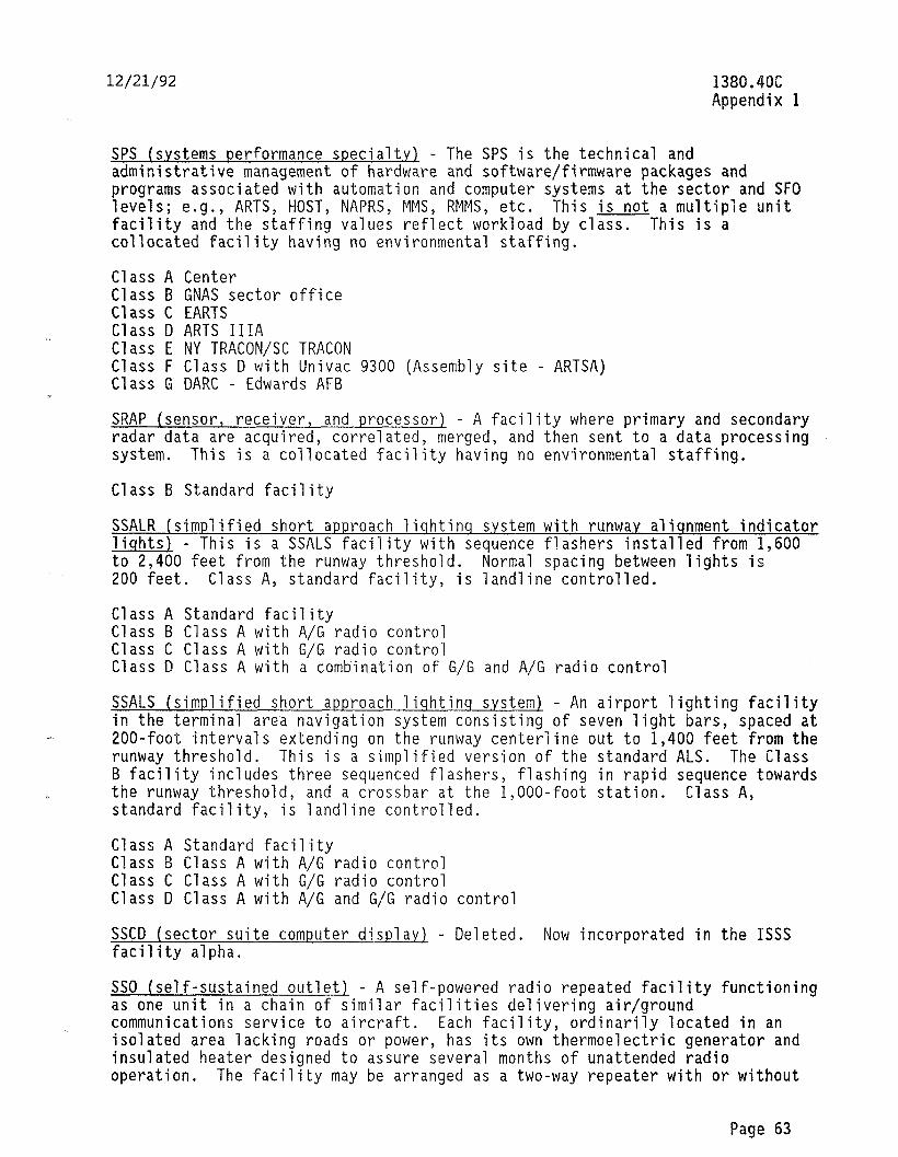
12/21/92 1380.4OC Appendix 1
SPS (systems performance specialty) - The SPS is the technical and administrative management of hardware and software/firmware packages and programs associated with automation and computer systems at the sector and SF0 levels; e.g., ARTS, HOST, NAPRS, MMS, RMMS, etc. This is not a multiple unit facility and the staffing values reflect workload by class. This is a collocated facility having no environmental staffing.
Class A Center Class B GNAS sector office Class C EARTS Class D ARTS IIIA Class E NY TRACON/SC TRACON Class F Class D with Univac 9300 (Assembly site - ARTSA) Class G DARC - Edwards AFB
SRAP (sensor, receiver, and processor) - A facility where primary and secondary radar data are acquired, correlated, merged, and then sent to a data processing system. This is a collocated facility having no environmental staffing.
Class B Standard facility
SSALR (simplified short approach liqhtinq system with runway aliqnment indicator liqhts) - This is a SSALS facility with sequence flashers installed from 1,600 to 2,400 feet from the runway threshold. Normal spacing between lights is 200 feet. Class A, standard facility, is landline controlled.
Class A Standard facility Class B Class A with A/G radio control Class C Class A with G/G radio control Class D Class A with a combination of G/G and A/G radio control
SSALS (simplified short approach liqhtinq s.ystem) - An airport lighting facility in the terminal area navigation system consisting of seven light bars, spaced at 200-foot intervals extending on the runway centerline out to 1,460 feet from the runway threshold. This is a simplified version of the standard ALS. The Class B facility includes three sequenced flashers, flashing in rapid sequence towards the runway threshold, and a crossbar at the l,OOO-foot station. Class A, standard facility, is landline controlled.
Class A Standard facility Class B Class A with A/G radio control Class C Class A with G/G radio control Class D Class A with A/G and G/G radio control
SSCD (sector suite computer display) - Deleted. Now incorporated in the ISSS facility alpha.
SSO (self-sustained outlet) - A self-powered radio repeated facility functioning as one unit in a chain of similar facilities delivering air/ground communications service to aircraft. Each facility, ordinarily located in an isolated area lacking roads or power, has its own thermoelectric generator and insulated heater designed to assure several months of unattended radio operation. The facility may be arranged as a two-way repeater with or without
Page 63
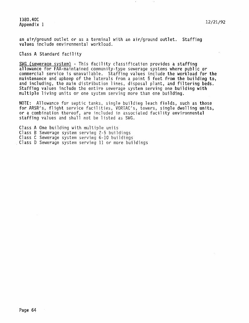
1380.4OC Appendix 1
12/21/92
an air/ground outlet or as a terminal with an air/ground outlet. Staffing values include environmental workload.
Class A Standard facility
SWG (seweraoe system) - This facility classification provides a staffing allowance for FAA-maintained community-type sewerage systems where public or commercial service is unavailable. Staffing values include the workload for the maintenance and upkeep of the laterals from a point 5 feet from the building to, and including, the main distribution lines, disposal plant, and filtering beds. Staffing values include the entire sewerage system serving one building with multiple living units or one system serving more than one building.
NOTE: Allowance for septic tanks, single building leach fields, such as those for ARSR's, flight service facilities, VORTAC's, towers, single dwelling units, or a combination thereof, are included in associated facility environmental staffing values and shall not be listed as SWG.
Class A One building with multiple units Class B Sewerage system serving 2-5 buildings Class C Sewerage system serving 6-10 buildings Class D Sewerage system serving 11 or more buildings
Page 64
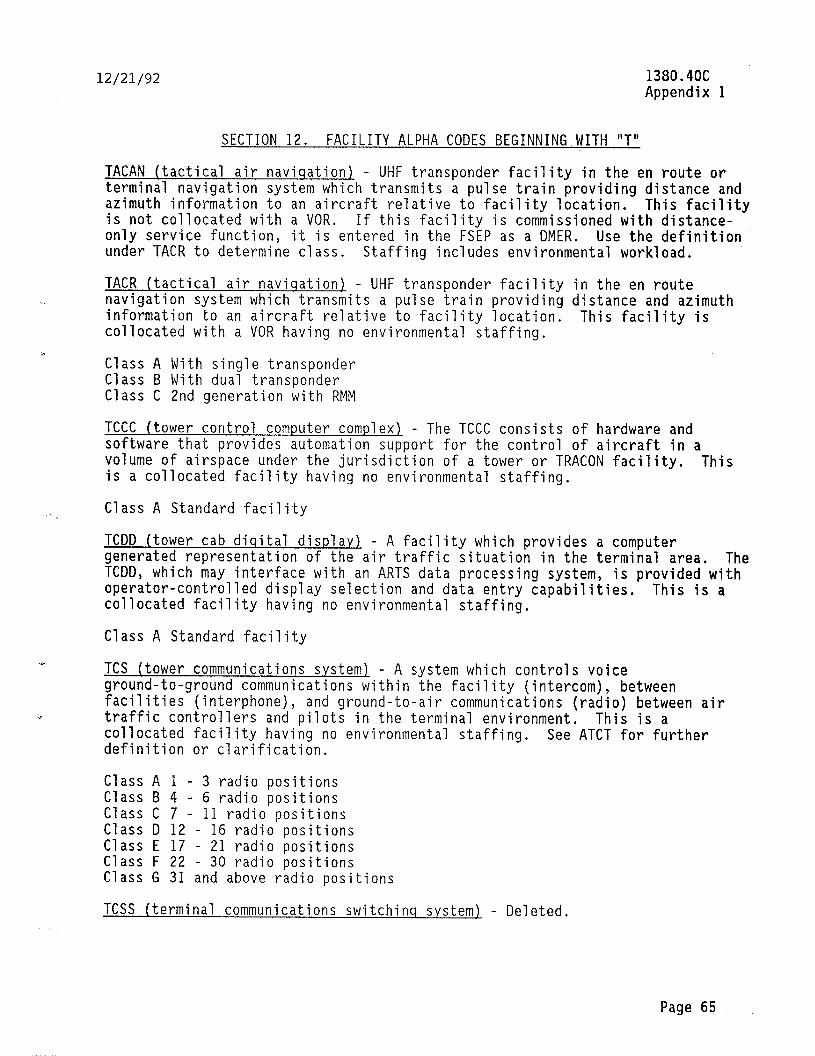
12/21/92 1380.4OC Appendix 1
SECTION 12. FACILITY ALPHA CODES BEGINNING WITH "T"
TACAN (tactical air naviqation) - UHF transponder facility in the en route or terminal navigation system which transmits a pulse train providing distance and azimuth information to an aircraft relative to facility location. This facility is not collocated with a UOR. If this facility is commissioned with distance- only service function, it is entered in the FSEP as a DMER. Use the definition under TACR to determine class, Staffing includes environmental workload.
TACR (tactical air naviqation) - UHF transponder facility in the en route navigation system which transmits a pulse train providing distance and azimuth information to an aircraft relative to facility location. collocated with a VOR having no environmental staffing.
This facility is
Class A With single transponder Class B With dual transponder Class C 2nd generation with RMM
TCCC (tower control computer complex) - The TCCC consists of hardware and software that provides automation support for the control of aircraft in a volume of airspace under the jurisdiction of a tower or TRACON facility. This is a collocated facility having no environmental staffing.
Class A Standard facility
TCDD (tower cab diqital display) - A facility which provides a computer generated representation of the air traffic situation in the terminal area. The TCDD, which may interface with an ARTS data processing system, is provided with operator-controlled display selection and data entry capabilities. This is a collocated facility having no environmental staffing.
Class A Standard facility
Y
TCS (tower communications system) - A system which controls voice ground-to-ground communications within the facility (intercom), between facilities (interphone), and ground-to-air communications (radio) between air traffic controllers and pilots in the terminal environment. This is a collocated facility having no environmental staffing. See ATCT for further definition or clarification.
Class A 1 - 3 radio positions Class B 4 - 6 radio positions Class C 7 - 11 radio positions Class D 12 - 16 radio positions Class E 17 - 21 radio positions Class F 22 - 30 radio positions Class G 31 and above radio positions
TCSS (terminal communications switchinq system) - Deleted.
Page 65
‘_ ._. ._ . . . _ -.
1380.4OC Appendix II
12/21/92
TDDS (terminal data display s.ystem) - A system that accepts, processes, distributes, and displays general purpose video information in a control facility. This system utilizes a dedicated computer, data input terminal, and display monitors. Staffing is determined by the number of units (each display counts as a unit). This is a collocated facility having no environmental staffing.
Class A 1 to 10 units Class B 11 and above units
TDS (telecommunications demarcation system) - This facility is the standardized demarcation point for isolation of vendor and Government equipment at terminal facilities. This facility is an adjunct to the MDS facility at the centers (commonly known as the mini-demarc). It allows faster problem isolation, flexibility in configurations, and facilitates cutover of recompeted circuits. This is a collocated facility having no allowance for environmental workload.
Class A Wall mounted - up to 24 circuits Class B Wall mounted - up to 48 circuits Class C Rack mounted - up to 24 circuits Class D Rack mounted - up to 48 circuits
TDWR (terminal doppler weather radar). - A radar utilized for the detection of hazardous weather conditions such as windshear, microbursts and gust fronts, winds, precipitation, thunderstorms, and turbulence at an airport. This information is provided to air traffic on displays at terminal facilities. Staffing values include environmental workload.
Class A Standard facility Class B C-band radar
TELEX (telephone exchanqe) - The TELEX system includes the telephone exchange and associated terminating equipment, building and grounds, interconnecting lines and cables (including those assigned to control specialized voice circu usage), TELRAD, EXITONE, EAGLE, EXECUTONE, switches, etc., and all standard telephone instruments owned or leased by the FAA; i.e., telephones, PBX,
it
handsets, etc. Specialized terminating equipment such as call commander or 102 systems are chargeable to the facility in which they are installed. This is a collocated facility having no environmental staffing.
Class D 30I/Tower (Alaskan Region) Class E 301/RAPCO (Edwards Air Force Base ATCF) Class F 300/Center (Alaskan Region) Class G 10 or less instruments Class l-l 11 to 50 instruments Class J Over 50 instruments Class K Other types of 300 series systems
TIM ((TELCO) interface maintenance1 - This facility accounts for the time associated with the coordination and assistance provided in the maintenance of telephone lines. It includes the time spent in performing TELCO line runs, problem notification to TELCO, awaiting TELCO arrival, and other coordination with TELCO. This facility shall only be established at central operations
Page 66

12/21/92 1380.40C Appendix 1
facilities; e.g., centers, flight service facilities, towers, etc. Telephone line maintenance on other facilities is included in the facility allowance. This is a collocated facility having no environmental staffing.
Class A 4-20 pairs of telephone lines Class B 21-50 pairs of telephone lines Class C 51-100 pairs of telephone lines Class D 101-200 pairs of telephone lines Class E Over 201 pairs of telephone lines
TIPS (terminal information processinq system) - This system accepts, processes, distributes, and displays flight and other nonradar data for an entire terminal area. It is used by ATC personnel in conjunction with tower, TRACO, TRCAB, and ARTS facility control operations. This is a point-count facility with the AF staffing values being based on equipment inventory in accordance with chapter 4. This is a collocated facility having no environmental staffing. Do not add points from other tables.
Class A-M (See tables 5 and 14 of appendix 2.)
TMCC (traffic manaqement computer complex) - A computer system remotely connected to the air traffic control command center (ATCCC) located at FAA headquarters. This is a collocated facility having no environmental staffing. This facility replaces CFCC.
Class B Traffic management system (TMS) - Phase I Configuration Class C Traffic management system (TMS) - Phase II Configuration
TMLI (television microwave link indicator) - The receiving end of a TV microwave link system used to receive radar, beacon, and video map data in TV format at satellite towers or a center. Staffing values include the receiver and antenna but not the BRITE displays, which shall be captured in a separate FSEP entry for the BRITE facility. This is a collocated facility having no environmental staffing.
Class A Standard facility
TMLR (television microwave link repeater) - A repeater used at an intermediate point in a TV microwave link system described under TMLI. Staffing values include one transmitter, one receiver, two antennas, structural support, and ancillary interface equipment. Staffing values include environmental workload.
Class A Standard facility Class B Passive reflector
TMLT (television microwave link transmitter) - The transmit end of a TV microwave link system described under TMLI. Staffing values do not include ancillary equipment such as BRITE. This is a collocated facility having no environmental staffing.
Class A Standard facility
Page 67
1380.4OC Appendix 1
12/21/92
TMU (traffic manaqement unit.1 - This system performs local flow management functions at the center/ACF's, Washington headquarters, and selected terminal facilities and is comprised of automated workstations, computer entry/readout devices, communications, FSP's, PVD's or aircraft situation displays (ASD's), and the associated satellite transmission equipment. This is a collocated facility having no environmental staffing.
Class A ARTCC/ACF Class B TRACON Class C ATCT Class D Washington headquarters
TOWB (tower buildins). - This facility provides for the tower and attached base ouilding and related ground maintenance requirements including all the air-conditioning, heating, water, building, and electrical service and associated engine or generator control equipment. See table 6 of appendix 2 for equipment point-count values. Point-count items from all other tables are excluded. Engine generator staffing is identified by power source code (see Order 6000.5), If not fully maintained by the FAA, the percent contract field in the FSEP should reflect the portion which is accomplished by FAA.
Class A-M (See appendix 2, table 11.)
TR (trails and roads) - This facility provides staffing values for FAA access roads used for vehicular travel. Normal roads of less than l/2 mile used for access to most facilities should not be entered in the FSEP as a TR but are included in the primary facility serlned; i.e., environmental. This is a support-type facility in the multiple, unit category as described in paragraph 24i(2), with staffing allocated per mile, rounding off fractions to the nearest whole number; i.e., 0.5 to 1.49 miles = 1 unit; 1.5 to 2.49 miles = 2 units, etc.
Class A Standard facility
TRACO (terminal radar approach control) - This facility type identifies locations where the ARTS and the IFR room are not located in or adjacent to the tower base building and/or facilities without ARTS or RBDPE reqardless of IFR room location. This facility will only be authorized under these conditions. K RTR with suffix Z in the location identifier will be established to capture the workload for all transmitters, receivers, etc., that are located in the equipment room. Emerqenc.y backup transceivers will be captured under this facility. Maintenance transceivers will be captured under the MCT facility alpha. All other electronic equipment not identified as another facility type will be point-counted against TRACO for class determination. Environmental staffing values will be point-counted against ATBM or TOWB dependent upon configuration and location relative to the tower base building. Engine generator staffing values will be identified by power source code. (See Order 6000.5.)
Class A-3 (see appendix 2)
Page 68

12/21/92 1380.4OC Appendix 1
TRCAB (terminal radar approach control in tower cab) - The equipment represented by this facility has been captured by ARTS, ATCT, RBDPE, TRACO, or BRITE. ARTS, ATCT, RBDPE, TRACO, and BRITE for appropriate facility definition and
(See
usage.)
TTY (teletype) - Deleted. See replacement alpha contraction LABS.
TWEB (transcribed weather broadcast) - This system records weather information for different areas of a flight advisory service and automatically sequences it in audio form via telephone lines to a VOR, LOM, or NDB facility to be transmitted. function
The HIWAS (hazardous in-flight weather advisory service) is a added to TWEB and is identified by a class of this facility in lieu of
a separate facility identification code. no environmental staffing.
This is a collocated facility having
Class A Standard facility Class B Class A with HIWAS function
Page 69 (and 70)
. ._ .~.. .~ -.. ,_. -.. -... ._ _.-li___-..x_


12/21/92 1380.4OC Appendix 1
SECTION 13. FACILITY ALPHA CODES BEGINNING WITH “U-W”
UB (utilitv buildins) - A building used to house a laundry, restaurant, recreation facility, hangar, FMP shop, environmental equipment repair shop with associated shop equipment, electrical distribution equipment, engine generator, and stationary equipment. Structures and shop areas associated with a standard defined facility (ALS, ASR, ARSR, GS, LOC, MALSR, VOR, HEAT, and WSM) are excluded. Fiberglass, equipment trailers, prefabs, and buildings less than 100 square feet are also excluded.
Class A Standard facility Class C Commissary Class E Separate building for engine generator Class H Hangar Class L Laundry Class M Multifunction hangar Class R Environmental maintenance repair shop Class S Shops Class X Restricted area number 2508 (R-2508)
VAS (vortex advis0r.v svstem) - Deleted.
VASI (visual approach slope indicator) - An airport lighting facility in the terminal area navigation system used primarily under VFR conditions, providing vertical guidance to aircraft during approach and landing by radiating a directional pattern of high intensity red and white focused light beams that indicate to the pilot that he is "on path" if he sees red/white, "above path” if white/white, and "below path" if red/red. Lamp brightness is changed to preset levels by the operator on manual systems and by the system itself on automatic systems. Classes A through E are landline controlled.
Class A 2-box, 2-bar system Class B 4-box, 2-bar system Class C 12-box, 2-bar system Class D 6-box, 3-bar system Class E 16-box, 3-bar system Class F Class A with A/G radio control Class G Class B with A/G radio control Class H Class C with A/G radio control Class J Class D with A/G radio control Class K Class E with A/G radio control Class L Class A with G/G radio control Class M Class B with G/G radio control Class N Class C with G/G radio control Class P Class D with G/G radio control Class Q Class E with G/G radio control Class R Class A with combination of A/G and G/G radio control Class S Class B with combination of A/G and G/G radio control Class T Class C with combination of A/G and G/G radio control Class U Class D with combination of A/G and G/G radio control Class V Class E with combination of A/G and G/G radio control
Page 71
1380.4OC Appendix 1
12/21/92
VEHS (vehicle maintenance) - This facility provides staffing values (per unit) for the maintenance of motor vehicles used for transporting personnel, equipment, and supplies. ATRAM, FAC, MAREQ, MX, and OFFRD equipment are excluded from this classification. This is a multiple unit facility as described in paragraph 241(2).
Class A Passenger vehicle, van, or truck, GSA-owned, contract or GSA maintained Class B Passenger vehicle, van, or truck, FAA-owned, contract or FAA maintained Class C Passenger vehicle, van, or truck, owned by another agency, maintained by
FAA
Note: To receive staffing values for travel time and trips, all vehicles in class A (GSA) must have responsibility code C and the percent contract data field must be left blank.
VOR (VHF omnidirectional ranqe) - A facility radiating a VHF radio wave modulated by two signals whose relative phases are compared, resolved, and displayed by a compatible airborne receiver to give the pilot a direct indication of bearing relative to the facility. Staffing values include environmental support workload. Engine generator workload is identified by the power source code (see Order 6000.5).
Class A Single equipment Class B Dual equipment Class C Single equipment (doppler) Class D Dual equipment (doppler) Class E 2nd generation Class G 2nd generation (doppler)
VOT (VHF omnidirectional ranqe test) - This facility radiates a signal modulated by two frequencies with relative phases that are constant which provid a fixed azimuth indication to aircraft for VOR equipment calibration and verification. The VOT may be either collocated or a stand-alone facility. Environmental staffing is included in the stand-alone facility. When collocated, it will be captured by the primary facility.
Class A Standard facility (collocated) Class B Stand-alone
VSCS (voice switchinq and control s.ystem) - A system which will control voice ground-to-ground communications within the facility (intercom), between facilities (interphone), and ground-to-air communications (radio) between air traffic controllers and pilots at a center/ACF facility. This is a collocated facility having no environmental staffing.
Class A l-35 positions Class B 36-62 positions Class C 63-120 positions Class D 121-140 positions Class E 141-160 positions Class F 161-180 positions Class G 181-200 positions Class H 201-220 positions
Page 72
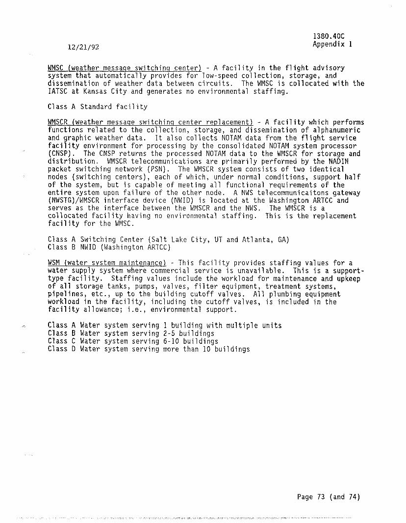
12/21/92 1380.4OC Appendix 1
WMSC (weather messaqe switchinq center) - A facility in the flight advisory system that automatically provides for low-speed collection, storage, and dissemination of weather data between circuits. The WMSC is collocated with the IATSC at Kansas City and generates no environmental staffing.
Class A Standard facility
WMSCR (weather messaqe switchinq center replacement) - A facility which performs functions related to the collection, storage, and dissemination of alphanumeric and graphic weather data. It also collects NOTAM data from the flight service facility environment for processing by the consolidated NOTAM system processor (CNSP). The CNSP returns the processed NOTAM data to the WMSCR for storage and distribution. WMSCR telecommunications are primarily performed by the NADIM packet switching network (PSN). The WMSCR system consists of two identical nodes (switching centers), each of which, under normal conditions, support half of the system, but is capable of meeting all functional requirements of the entire system upon failure of the other node. A NWS telecommunicaitons gateway (NWSTG)/WMSCR interface device (NWID) is located at the Washington ARTCC and serves as the interface between the WMSCR and the NWS. The WMSCR is a collocated facility having no environmental staffing. This is the replacement facility for the WMSC.
Class A Switching Center (Salt Lake City, UT and Atlanta, GA) Class B NWID (Washington ARTCC)
WSM (water system maintenance) - This facility provides staffing values for a water supply system where commercial service is unavailable. This is a support- type facility. Staffing values include the workload for maintenance and upkeep of all storage tanks, pumps, valves, filter equipment, treatment systems, pipelines, etc., up to the building cutoff valves. All plumbing equipment workload in the facility, including the cutoff valves, is included in the facility allowance; i.e., environmental support.
Class A Water system serving 1 building with multiple units Class B Water system serving 2-5 buildings Class C Water system serving 6-10 buildings Class D Water system serving more than 10 buildings
Page 73 (and 74)


12/21/92 1380.4OC Appendix 2
APPENDIX 2. POINT-COUNT AND CLASS TABLES
TABLE OF CONTENTS
POINT-COUNT TABLES
1. Communications (Radio and Tone Control) Equipment Point-Count Values
4 2. 3. 4. 5. 6.
Radar Equipment Point-Count Values Air Traffic Control Beacon Equipment Point-Count Values Data Interchange/Send/Receive Systems Point-Count Values Digital Processing and Data Transfer Equipment Point-Count Values Airway Terminal Building (ATBM) and Tower Building Equipment (TOWB) Point-Count Values
7. Weather Equipment Point-Count Values 8. Miscellaneous Electronic Equipment Point-Count Values
TITLE PAGE
10 11 12
CLASS TABLES
TITLE PAGE
9. Class Designation - Miscellaneous Facilities 10. Class Designation - CERAP Facilities 11. Class Designation - ATBM and TOWB Facilities 12. Class Designation - Other Facilities With No More Than 10,800
Points 13. Class Designation - Other Facilities With More Than 10,800 Points 14. Class Designation - Ancillary Facilities
12 13 15
16 17 18
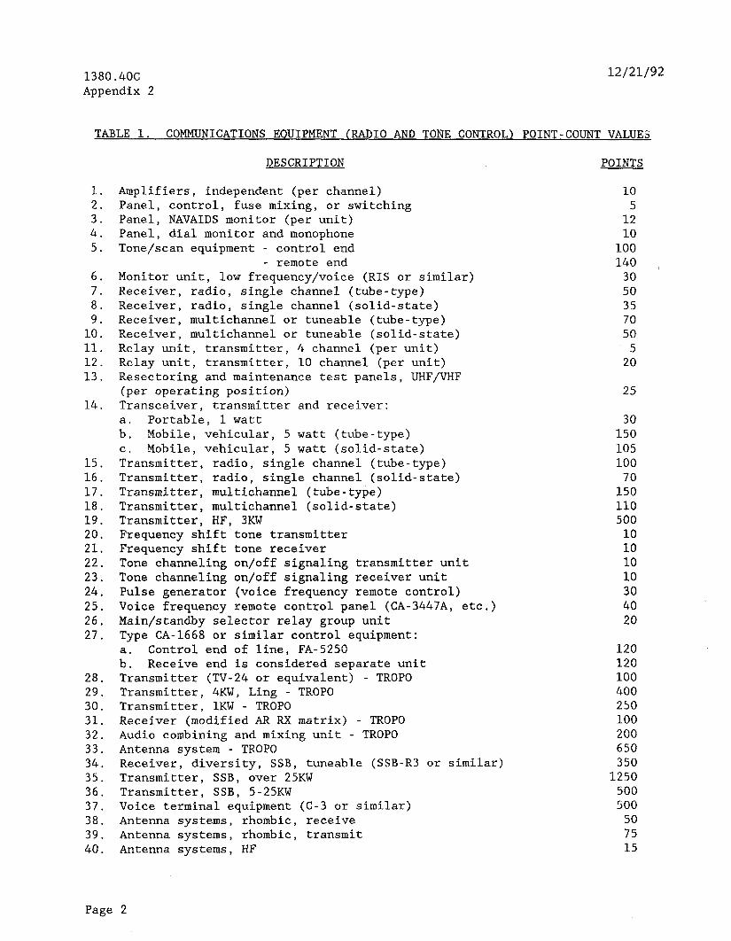
1380.4OC Appendix 2
12121192
TABLE 1. COMMUNICATIONS EQUIPMENT (RADIO AND TONE CONTROL) POINT-COUNT VALUES
DESCRIPTION POINTS
1. Amplifiers, independent (per channel) 2. Panel, control, fuse mixing, or switching 3. Panel, NAVAIDS monitor (per unit) 4. Panel, dial monitor and monophone 5. Tone/scan equipment - control end
6. 7. 8. 9.
10. 11. 12. 13.
14.
15. 16. 17. 18. 19. 20. 21. 22. 23. 24. 25. 26. 27.
28. 29. 30. 31. 32. 33. 34. 35. 36. 37. 38. 39. 40.
- remote end Monitor unit, low frequency/voice (RIS or similar) Receiver, radio, single channel (tube-type) Receiver, radio, single channel (solid-state) Receiver, multichannel or tuneable (tube-type) Receiver, multichannel or tuneable (solid-state) Relay unit, transmitter, 4 channel (per unit) Relay unit, transmitter, 10 channel (per unit) Resectoring and maintenance test panels, UHF/VHF ~;;s~~;:~;ing position)
transmitter and receiver:
,": Portable, 1 watt Mobile, vehicular, 5 watt (tube-type)
C. Mobile, vehicular, 5 watt (solid-state) Transmitter, radio, single channel (tube-type) Transmitter, radio, single channel (solid-state) Transmitter, multichannel (tube-type) Transmitter, multichannel (solid-state) Transmitter, HF, 3KW Frequency shift tone transmitter Frequency shift tone receiver Tone channeling on/off signaling transmitter unit Tone channeling on/off signaling receiver unit Pulse generator (voice frequency remote control) Voice frequency remote control panel (CA-3447A, etc.) Main/standby selector relay group unit Type CA-1668 or similar control equipment:
ba: Control end of line, FA-5250 Receive end is considered separate unit
Transmitter (TV-24 or equivalent) - TROPO Transmitter, 4KW, Ling - TROPO Transmitter, 1KW - TROPO Receiver (modified AR RX matrix) - TROPO Audio combining and mixing unit - TROPO Antenna system - TROPO Receiver, diversity, SSB, tuneable (SSB-R3 or similar) Transmitter, SSB, over 25KW Transmitter, SSB, 5-25KW Voice terminal equipment (C-3 or similar) Antenna systems, rhombic, receive Antenna systems, rhombic, transmit Antenna systems, HF
I
10 5
12 10
100 140
30 50 35 70 50
5 20
25
30 150 105 100 70
150 110 500
10 10 10 10 30 40 20
120 120 100 400 250 100 200 650 350
1250 500 500
50 75 15
Page 2

12/21/92 1380.4OC Appendix 2
41. 42. 43. 44. 45. 46. 47. 48. 49. 50. 51. 52. 53. 54.
55.
56. 57. 58. 59.
60.
DESCRIPTION POINTS
Antenna systems, VHF/UHF Multicoupler, vacuum tube Multicoupler, passive Multiplex/demultiplex, voice (TD-97, TD-98, or similar) Transceiver, SSB, (KWM-2 or similar) Teletypewriter terminal (Kineplex or similar) Teletypewriter terminal (4-channel FCC-5 or similar) Antenna systems (log periodic) Voice operated gain adjustment device (VOGAD) Antenna farms (per acre) Voice terminal unit (FTA-15 or similar) Interphones/intercom (per drop) Microphone or speaker Types FA-5571 and FA-5572 remote control system (control end-of-line, including indicator) remote end is included in allowance for remote facility RF linear amplifier, 600 watt maintenance and band switching Linear amplifier, AM-6154/GRT-21 or AM-6155/GRT-22 BUEC system, switching equipment at ARTCC (processor) BUEC system at ARTCC (each AT BUEC control position) Solid state channel control equipment similar to FA-8165, FA-9334, or FA-9600 (per position) ILS interlock system, per ILS component (GS, IM, MM, LOC) interlocked
5 15
5 70
225 800 400
25 30
4 50 10
5
100
50 35
1500 20
25
50
Page 3
,.. _^ _.
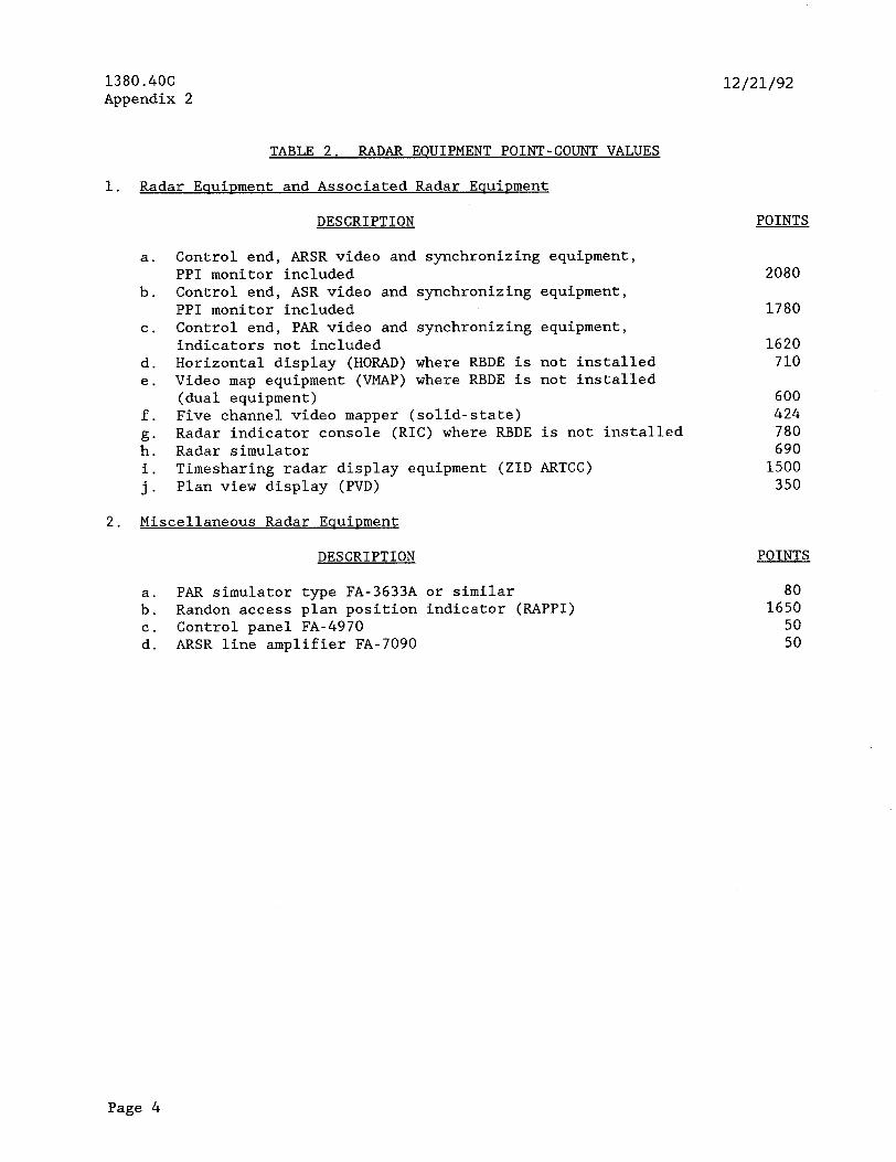
1380.4OC Appendix 2
12/21/92
TABLE 2. RADAR EQUIPMENT POINT-COUNT VALUES
1. Radar EouiDment and Associated Radar EClUiDIIEnt
a.
b.
C.
d. e.
f.
2: i. j.
DESCRIPTION
Control end, ARSR video and synchronizing equipment, PPI monitor included Control end, ASR video and synchronizing equipment, PPI monitor included Control end, PAR video and synchronizing equipment, indicators not included Horizontal display (HORAD) where RBDE is not installed Video map equipment (VMAP) where RBDE is not installed (dual equipment) Five channel video mapper (solid-state) Radar indicator console (RIC) where RBDE is not installed Radar simulator Timesharing radar display equipment (ZID ARTCC) Plan view display (PVD)
2. Miscellaneous Radar EquiDment
DESCRIPTION POINTS
a. PAR simulator type FA-3633A or similar b. Randon access plan position indicator (RAPPI)
:: Control panel FA-4970 ARSR line amplifier FA-7090
POINTS
2080
1780
1620 710
600 424 780 690
1500 350
80 1650
50 50
Page 4
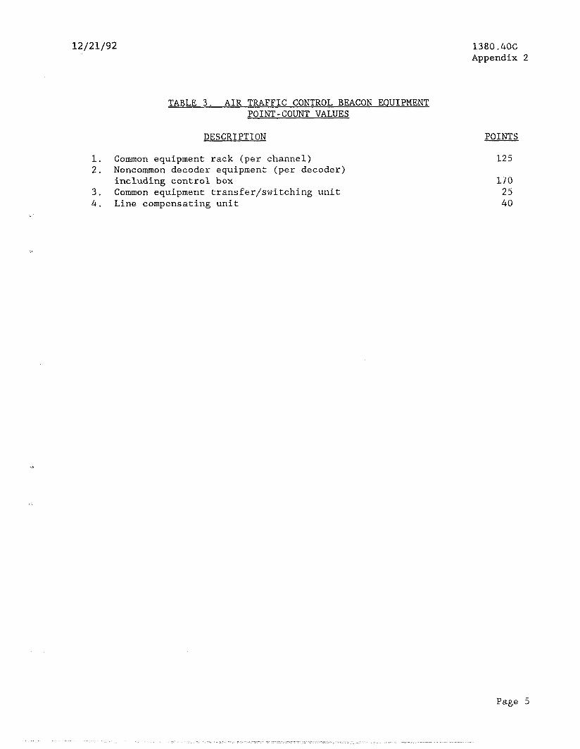
12/21/92
TABLE 3. AIR TRAFFIC CONTROL BEACON EQUIPMENT POINT-COUNT VALUES
DESCRIPTION
1. Common equipment rack (per channel) 2. Noncommon decoder equipment (per decoder)
including control box 3. Common equipment transfer/switching unit 4. Line compensating unit
1380.4OC Appendix 2
POINTS
125
170 25 40
Page 5
.^ I “. ., i --.
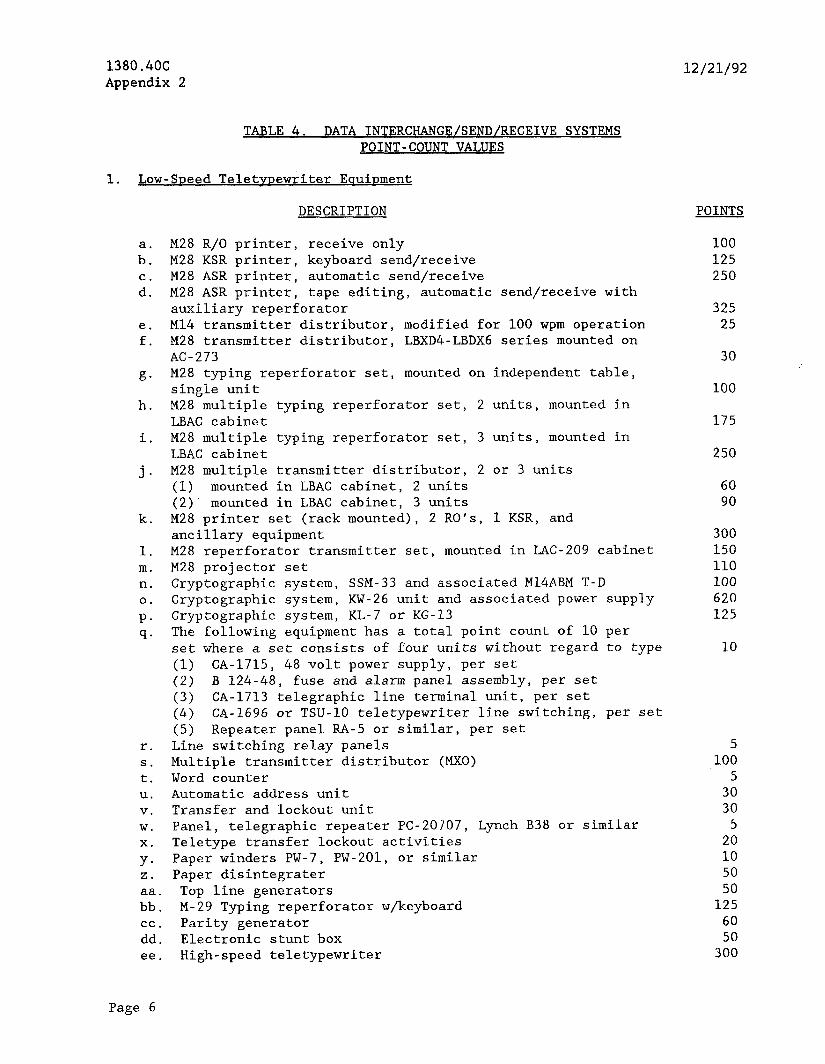
1380.4OC Appendix 2
TABLE 4. DATA INTERCHANGE/SEND/RECEIVE SYSTEMS POINT-COUNT VALUES
12/21/92
1. Low-Soeed Teletypewriter Eouinment
DESCRIPTION
ba: M28 R/O printer, receive only M28 KSR printer, keyboard send/receive
C. M28 ASR printer, automatic send/receive d. M28 ASR printer, tape editing, automatic send/receive with
auxiliary reperforator e. Ml4 transmitter distributor, modified for 100 wpm operation f. M28 transmitter distributor, LBXD4-LBDXG series mounted on
AC-273 g- M28 typing reperforator set, mounted on independent table,
single unit h. M28 multiple typing reperforator set, 2 units, mounted in
LBAC cabinet i. M28 multiple typing reperforator set, 3 units, mounted in
LBAC cabinet j. M28 multiple transmitter distributor, 2 or 3 units
(1) mounted in LBAC cabinet, 2 units (2) mounted in LBAC cabinet, 3 units
k. M28 printer set (rack mounted), 2 RO's, 1 KSR, and ancillary equipment
1. M28 reperforator transmitter set, mounted in LAC-209 cabinet m. M28 projector set n. Cryptographic system, SSM-33 and associated M14ABM T-D 0. Cryptographic system, KW-26 unit and associated power supply P* Cryptographic system, KL-7 or KG-13 q. The following equipment has a total point count of 10 per
set where a set consists of four units without regard to type (1) CA-1715, 48 volt power supply, per set (2) B 124-48, fuse and alarm panel assembly, per set (3) CA-1713 telegraphic line terminal unit, per set (4) CA-1696 or TSU-10 teletypewriter line switching, per set (5) Repeater panel RA-5 or similar, per set
r. Line switching relay panels s. Multiple transmitter distributor (MXO) t. Word counter U. Automatic address unit V. Transfer and lockout unit W. Panel, telegraphic repeater PC-20707, Lynch B38 or similar X. Teletype transfer lockout activities Y- Paper winders PW-7, PW-201, or similar 2. Paper disintegrater
tba: Top line generators M-29 Typing reperforator w/keyboard
Z: Parity generator Electronic stunt box
ee. high-speed teletypewriter
POINTS
100 125 250
325 25
30
100
175
250
60 90
300 150 110 100 620 125
10
5 100
5 30 30
5 20 10 50 50
125 60 50
300
Page 6
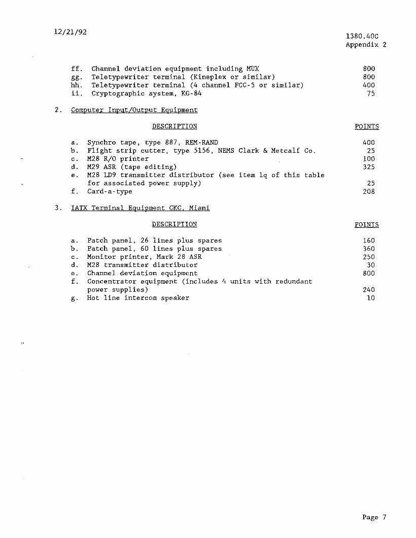
12/21/92 1380.4OC Appendix 2
ff. Channel deviation equipment including MUX
fl:: Teletypewriter terminal (Kineplex or similar) Teletypewriter terminal (4 channel FCC-5 or similar)
ii. Cryptographic system, KG-84
2. Comnuter Input/Outnut EouiDment
DESCRIPTION POINTS
Synchro tape, type 887, REM-RAND Flight strip cutter, type 5156, NEMS Clark & Metcalf Co.
:: M28 R/O printer M29 ASR (tape editing)
e. M28 LD9 transmitter distributor (see item lq of this table for associated power supply)
f. Card-a-type
3. IATX Terminal Equipment CKC, Miami
DESCRIPTION POINTS
a. Patch panel, 26 lines plus spares b. Patch panel, 60 lines plus spares C. Monitor printer, Mark 28 ASR d. M28 transmitter distributor e. Channel deviation equipment f. Concentrator equipment (includes 4 units with redundant
power supplies) is* Hot line intercom speaker
800 800 400
75
400 25
100 325
25 208
160 360 250
30 800
240 10
Page 7
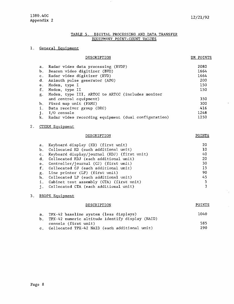
1380.4OC Appendix 2 12/21/92
TABLE 5. DIGITAL PROCESSING AND DATA TRANSFER EOUIPMENT POINT-COUNT VALUES
1. General Eouipment
h. i.
ii:
DESCRIPTION
Radar video data processing (RVDP) Beacon video digitizer (BVD) Radar video digitizer (RVD) Azimuth pulse generator (APG) Modem, type I Modem, type II Modem, type III, ARTCC to ARTCC (includes monitor and control equipment) Fixed map unit (FXMU) Data receiver group (DRG) I/O console Radar video recording equipment (dual configuration)
2. CTERM Equipment
b”: C.
d. e. f.
it: i. j.
DESCRIPTION POINTS
Keyboard display (KD) (first unit) Collocated KD (each additional unit) Keyboard display/journal (KDJ) (first unit) Collocated KDJ (each additional unit) Controller/journal (CJ) (first unit) Collocated CJ (each additional unit) Line printer (LP) (first unit) Collocated LP (each additional unit) Cabinet test assembly (CTA) (first unit) Collocated CTA (each additional unit)
3. RBDPE Equipment
DESCRIPTION POINTS
a. TPX-42 baseline system (less displays) b. TPX-42 numeric altitude identify display (NAID)
console (first unit) C. Collocated TPX-42 NAID (each additional unit)
DM POINTS
2080 1664 1664
200 150 150
350 300 416
1248 1250
20 10 40 20 30 15 90 45
5 3
1040
585 290
Page 8
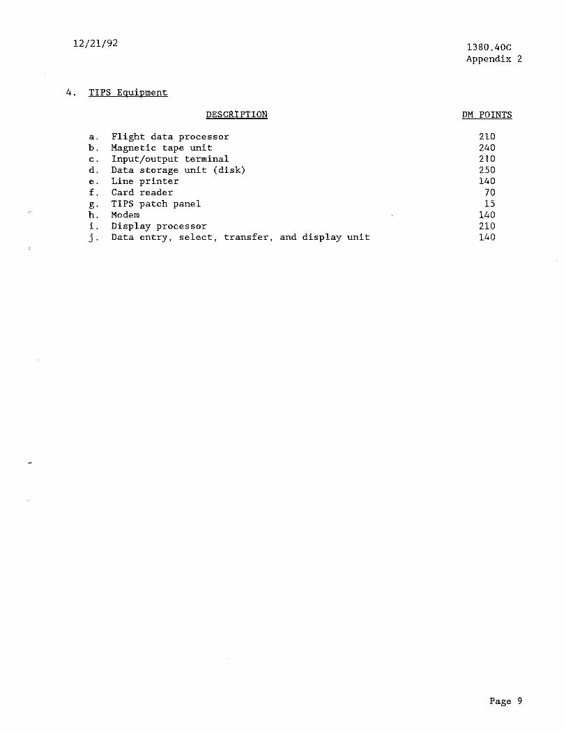
12/21/92 1380.4OC Appendix 2
4. TIPS Eauipment
a. b.
2
;:
E: i. j.
DESCRIPTION
Flight data processor Magnetic tape unit Input/output terminal Data storage unit (disk) Line printer Card reader TIPS patch panel Modem Display processor Data entry, select, transfer, and display unit
DM POINTS
210 240 210 250 140
70 15
140 210 140
Page 9

1380.4OC Appendix 2 12/21/92
1. 2. 3.
4.
5. 6. 7. 8. 9.
10. 11. 12. 13. 14. 15. 16. 17.
TABLE 6. AIRWAY TERMINAL BUILDING (ATBM) AND TOWER BUILDING EQUIPMENT (TOWB) POINT-COUNT VALUES
DESCRIPTION POINTS
Tower cab Other tower floors, per 1,000 sq. ft. General building
b": First 1,000 sq. ft. Each additional 1,000 sq. ft.
General grounds
b": First 1,000 sq. ft. Each additional 1,000 sq. ft.
Restroom, each Air handling units and controls, each Direct expansion A/C, each Boiler systems, each Obstruction lighting, per TOWB Other lighting, per system Window A/C unit, each Smoke detector, each Portable CO2 fire extinguisher, each Electric motors and controls, each Heating coils, each Electrical distribution system, per panel Drop tube system, per TOWB
79.7 36.1
53.0 26.0
16.0 8.0
93.5 15.5 15.2
107.5 20.5 34.1
8.9 1.5 1.1 3.0 1.9 1.0
45.0
Page 10

12/21/92 1380.4OC Appendix 2
TABLE 7. WEATHER EQUIPMENT POINT-COUNT VALUES
DESCRIPTION POINTS
1. Wind measuring equipment (speed and direction transmitters), per system
2. Wind measuring equipment (speed and direction), per indicator 3. Hygrothermometer 4. Pilot to forecaster (control end, less typewriter) 5. Enroute weather equipment display system (EWEDS) display 6. Wind speed retransmitter 7. Video camera or keyboard display
a. First indicator b. Each additional indicator
5 15 15 50 50
3
35 20
Page 11
- -- -- I: _ .- ,-. _ -: --. --... i- - - - _.. _^
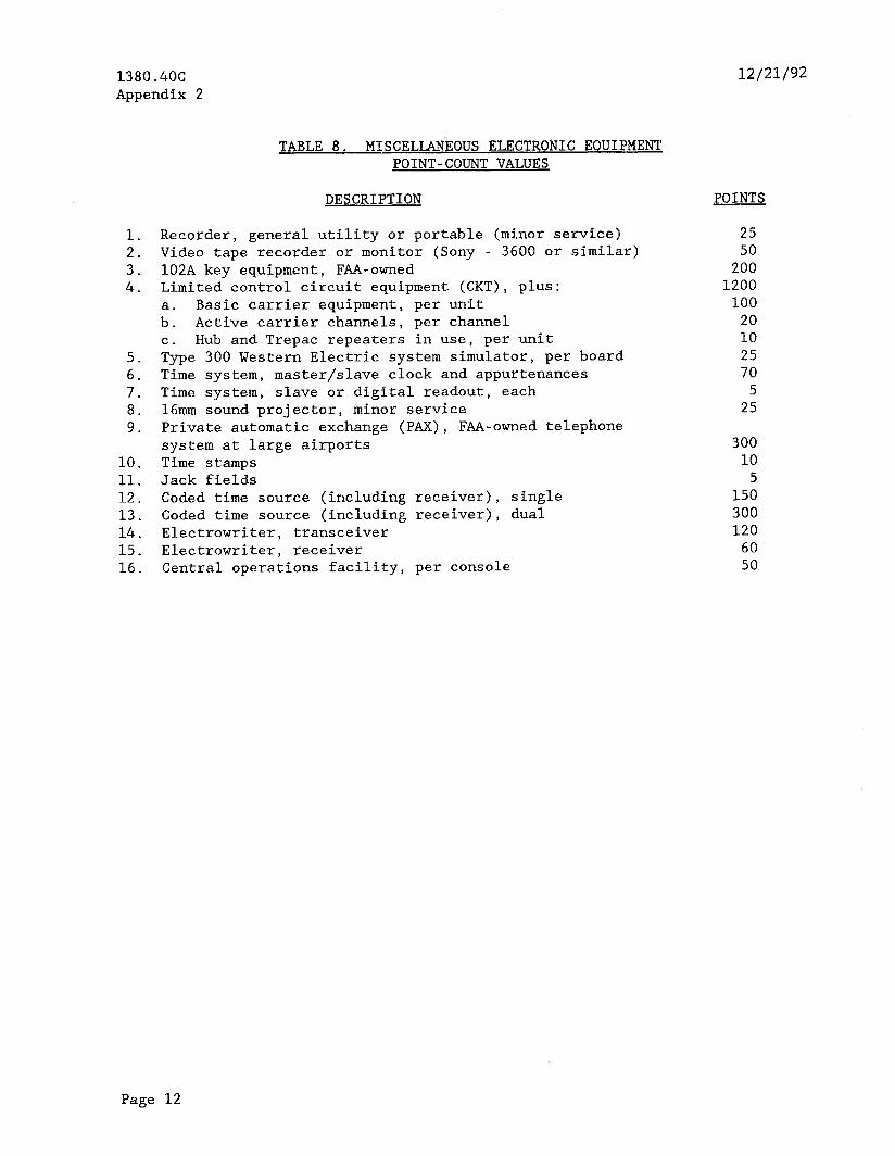
1380.4OC Appendix 2
12/21/92
1. 2. 3. 4.
5. 6. 7. 8. 9.
10. 11. 12. 13. 14. 15. 16.
TABLE 8. MISCELLANEOUS ELECTRONIC EQUIPMENT POINT-COUNT VALUES
DESCRIPTION POINTS
Recorder, general utility or portable (minor service) Video tape recorder or monitor (Sony - 3600 or similar) 102A key equipment, FAA-owned Limited control circuit equipment (CKT), plus:
ba: Basic carrier equipment, per unit Active carrier channels, per channel
C. Hub and Trepac repeaters in use, per unit Type 300 Western Electric system simulator, per board Time system, master/slave clock and appurtenances Time system, slave or digital readout, each 16mm sound projector, minor service Private automatic exchange (PAX), FAA-owned telephone system at large airports Time stamps Jack fields Coded time source (including receiver), single Coded time source (including receiver), dual Electrowriter, transceiver Electrowriter, receiver Central operations facility, per console
25 50
200 1200
100 20 10 25 70
5 25
300 10
5 150 300 120
60 50
Page 12
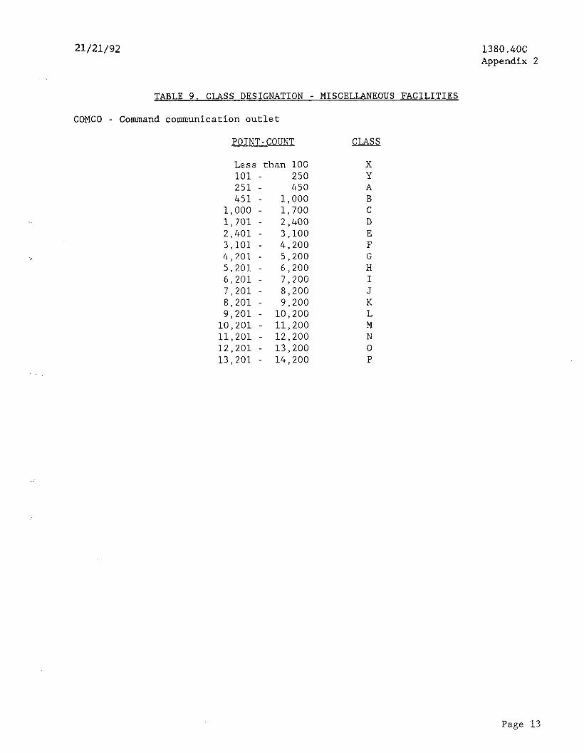
21/21/92 1380.4OC Appendix 2
TABLE 9. CLASS DESIGNATION - MISCELLANEOUS FACILITIES
COMCO - Command communication outlet
POINT-COUNT CLASS
Less than 100 101 - 250 251 - 450 451 - 1,000
1,000 - 1,700 1,701 - 2,400 2,401 - 3,100 3,101 - 4,200 4,201 - 5,200 5,201 - 6,200 6,201 - 7,200 7,201 - 8,200 8,201 - 9,200 9,201 - 10,200
10,201 - 11,200 11,201 - 12,200 12,201 - 13,200 13,201 - 14,200
X Y A B C D E F G H I J K L M N 0 P
Page 13
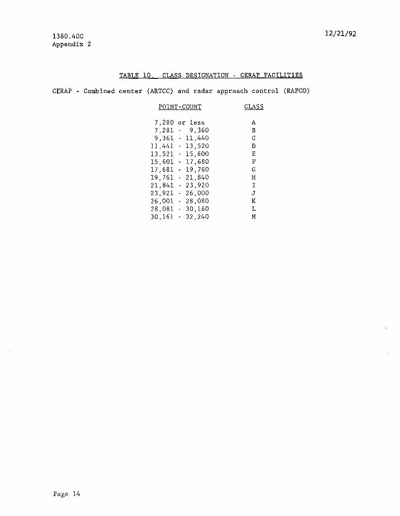
1380.4OC Appendix 2
TABLE 10. CLASS DESIGNATION - CERAP FACILITIES
CERAP - Combined center (ARTCC) and radar approach control (RAPCO)
POINT-COUNT CLASS
7,280 or less 7,281 - 9,360 9,361 - 11,440
11,441 - 13,520 13,521 - 15,600 15,601 - 17,680 17,681 - 19,760 19,761 - 21,840 21,841 - 23,920 23,921 - 26,000 26,001 - 28,080 28,081 - 30,160 30,161 - 32,240
A B C D E F G H I J K L M
12/21/92
Page 14
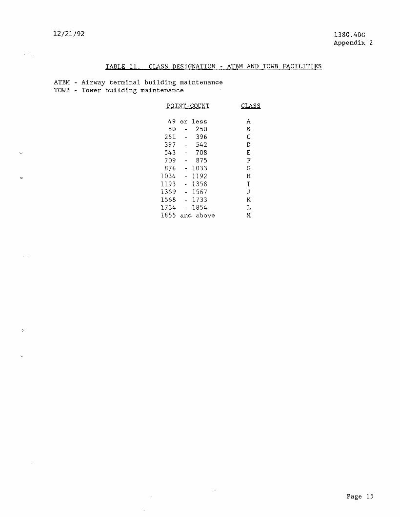
12/21/92
TABLE 11. CLASS DESIGNATION - ATBM AND TOWB FACILITIES
ATBM - Airway terminal building maintenance TOWB - Tower building maintenance
POINT-COUNT CLASS
49 or less 50 - 250
251 - 396 397 - 542 543 - 708 709 - 875 876 - 1033
1034 - 1192 1193 - 1358 1359 - 1567 1568 - 1733 1734 - 1854 1855 and above
A B C D E F G H I J K L M
1380.4OC Appendix 2
Page 15
__. .- .,, ” . i .__... .._ -..._._ - ..” ._.._.._.-. ~._.

1380.4OC Appendix 2
12/21/92
TABLE 12. CLASS DESIGNATION - OTHER FACILITIES WITH NO MORE THAN 10.800 POINTS
IFST - International flight service transmitter station RAPCO - Radar approach control TRACO - Terminal radar approach control
POINT-COUNT CLASS
1,800 or less 1,801 - 2,800 2,801 - 3,800 3,801 - 4,800 4,801 - 5,800 5,501 - 6,800 6,801 - 7,800 7,801 - 8,800 8,801 - 9,800 9,801 - 10,800
A B C D E F G H I J
Page 16
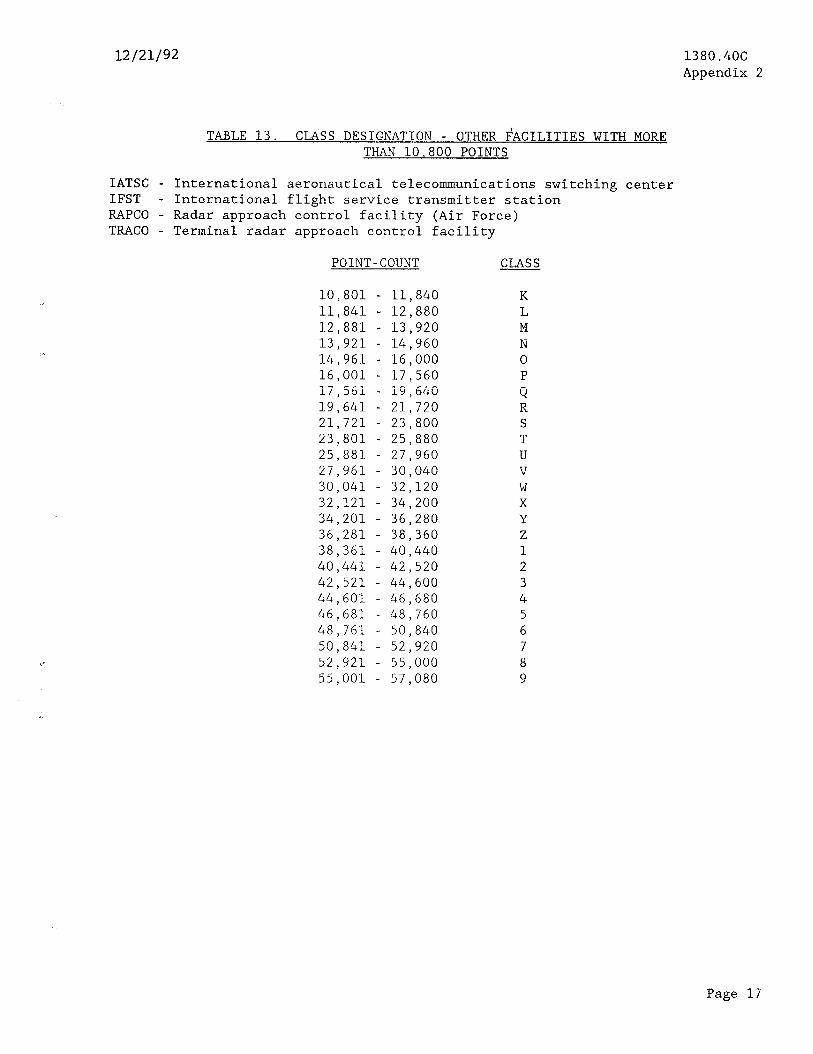
12/21/92 1380.4OC Appendix 2
TABLE 13. chc3s DESIGNATION - OTHER FACILITIES WITH MORE THAN 10.800 POINTS
IATSC - International aeronautical telecommunications switching center IFST - International flight service transmitter station RAPCO - Radar approach control facility (Air Force) TRACO - Terminal radar approach control facility
POINT-COUNT CLASS
10,801 - 11,840 11,841 - 12,880 12,881 - 13,920 13,921 - 14,960 14,961 - 16,000 16,001 - 17,560 i7,56i - i9,640 19,641 - 21,720 21,721 - 23,800 23,801 - 25,880 25,881 - 27,960 27,961 - 30,040 30,041 - 32,120 32,121 - 34,200 34,201 - 36,280 36,281 - 38,360 38,361 - 40,440 40,441 - 42,520 42,521 - 44,600 44,601 - 46,680 46,681 - 48,760 48,761 - 50,840 50,841 - 52,920 52,921 - 55,000 55,001 - 57,080
K L M N 0 P Q R S T U V W X Y Z 1 2 3 4 5 6 7 8 9
Page 17
.- ,... I" x . _ .i . . . . .." ~.. ,

1380.4OC Appendix 2
12/21/92
TABLE 14. CLASS DESIGNATION - ANCILLARY FACILITIES
TIPS - Terminal information processing system
POINT-COUNT CLASS POINT-COUNT CLASS
166 or less 167 - 287 288 - 407 408 - 527 528 - 648 649 - 768 769 - 888 889 - 1,009
1,010 - 1,129 1,130 - 1,249 1,250 - 1,369 1,370 - i,490 1,491 - 1,610 1,611 - 1,730 1,731 - 1,851 1,852 - 1,971 1,972 - 2,091 2,092 - 2,212 2,213 - 2,212 2,333 - 2,452
A B C D E F G H I J K L M N 0
i R S T
2,453 - 2,573 2,574 - 2,693 2,694 - 2,813 2,814 - 2,934 2,935 - 3,054 3,055 - 3,174 3,175 - 3,294 3,295 - 3,414 3,415 - 3,535 3,536 - 3,655 3,656 - 3,776 3,777 - 3,896 3,897 - 4,016 4,017 - 4,137 4,138 - 4,257
U V W X Y Z 1 2 3 4 5 6 7 a 9
Page 18
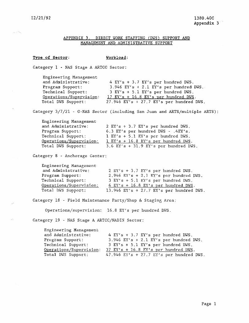
12/21/92 1380.4OC Appendix 3
APPENDIX 3. DIRECT WORK STAFFING (DWS) SUPPORT AND MANAGEMENT AND ADMINISTRATIVE SUPPORT
Type of Sector: Workload:
Category 1 - NAS Stage A ARTCC Sector:
Engineering Management and Administrative: 4 EY's + 3.7 EY's per hundred DWS. Program Support: 3.946 EY's + 2.1 EY's per hundred DWS. Technical Support: 3 EY's + 5.1 EY's per hundred DWS. Operations/Supervision: 17 EY's + 16.8 EY's per hundred DWS.
Total DWS Support: 27.946 EY's + 27.7 EY's per hundred DWS.
Category 3/7/21 - G-NAS Sector (including San Juan and ARTS/multiple ARTS):
Engineering Management and Administrative: 2 EY's + 3.7 EY's per hundred DWS. Program Support: 6.3 EY's per hundred DWS - .4EY's. Technical Support: 1 EY's + 5.1 EY's per hundred DWS. Operations/Supervision: 1 EY's + 16.8 EY's per hundred DWS. Total DWS Support: 3.6 EY's + 31.9 EY's per hundred DWS.
Category 8 - Anchorage Center:
Engineering Management and Administrative: 2 EY's + 3.7 EY's per hundred DWS.
Program Support: 2.946 EY's + 2.1 EY's per hundred DWS. Technical Support: 3 EY's + 5.1 EY's per hundred DWS. Operations/Supervision: 6 EY's + 16.8 EY's per hundred DWS. Total DWS Support: 13.946 EY's + 27.7 EY's per hundred DWS.
Category 18 - Field Maintenance Party/Shop & Staging Area:
Operations/supervision: 16.8 EY's per hundred DWS.
Category 19 - NAS Stage A ARTCC/NADIN Sector:
Engineering Management and Administrative: 4 EY's + 3.7 EY's per hundred DWS. Program Support: 3.946 EY's + 2.1 EY's per hundred DWS. Technical Support: 3 EY's + 5.1 EY's per hundred DWS. Operations/Supervision: 37 EY's + 16.8 EY's per hundred DWS. Total DWS Support: 47.946 EY's + 27.7 EY's per hundred DWS.
Page 1
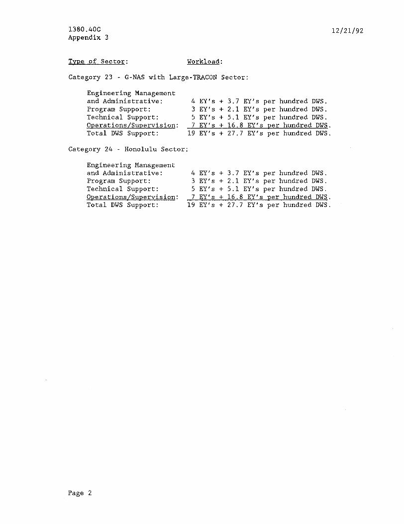
1380.406 Appendix 3
12/21/92
Tvve of Sector: Workload:
Category 23 - G-NAS with Large-T&ICON Sector:
Engineering Management and Administrative: 4 EY's + 3.7 EY's per hundred DWS. Program Support: 3 EY's + 2.1 EY's per hundred DWS. Technical Support: 5 EY's + 5.1 EY's per hundred DWS. Operations/Supervision: 7 EY's + 16.8 EY's per hundred DWS. Total DWS Support: 19 EY's + 27.7 EY's per hundred DWS.
Category 24 - Honolulu Sector:
Engineering Management and Administrative: 4 EY's + 3.7 EY's per hundred DWS. Program Support: 3 EY's + 2.1 EY"s per hundred DWS. Technical Support: 5 EY's + 5.1 EY's per hundred DWS. Operations/Supervision: 7 EY's + 16.8 EY's per hundred DWS. Total DWS Support: 19 EY's + 27.7 EY's per hundred DWS.
Page 2
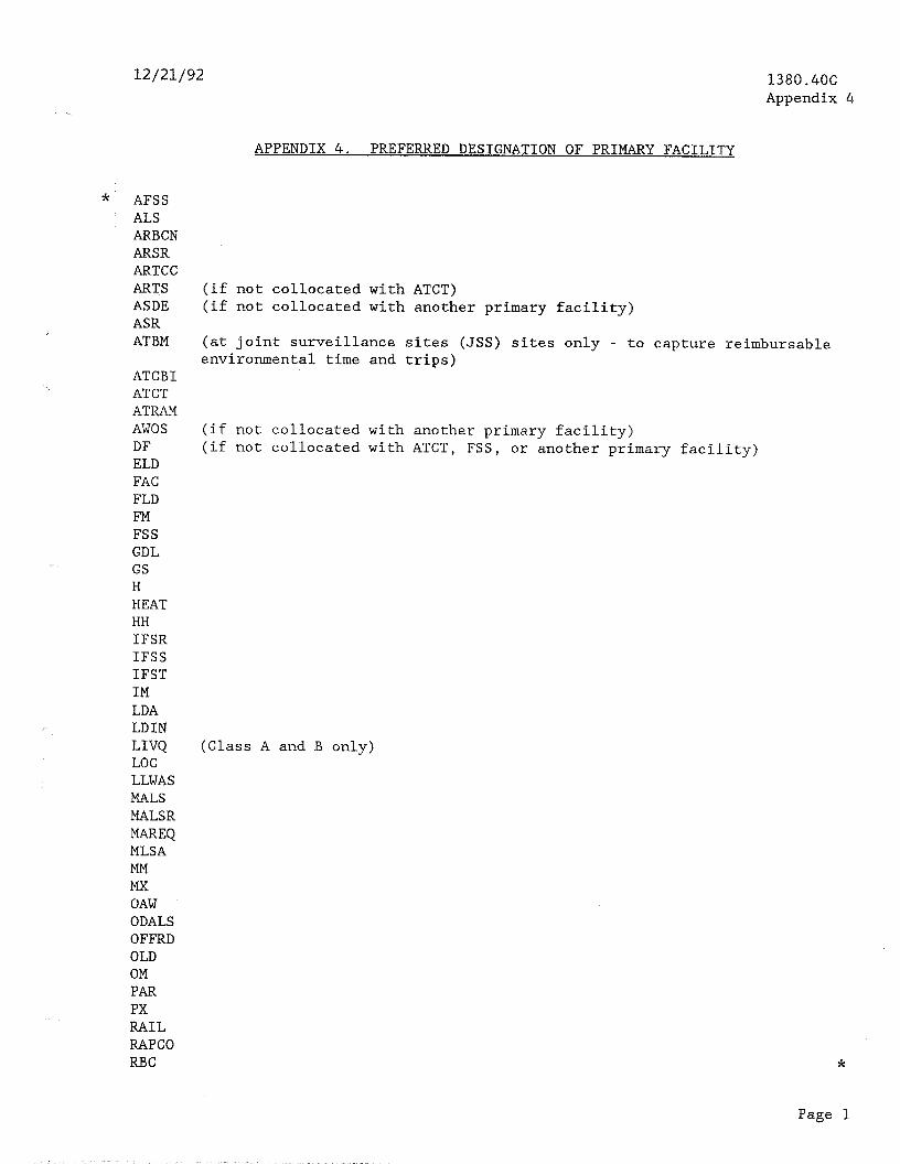
12/21/92 1380.4OC Appendix 4
APPENDIX 4. PREFERRED DESIGNATION OF PRIMARY FACILITY
* AFSS ALS ARBCN ARSR ARTCC ARTS ASDE ASR ATBM
ATCBI ATCT ATRAM AWOS DF ELD FAC FLD FM FSS GDL GS H HEAT HH IFSR IFSS IFST IM LDA LDIN LIVQ LOC LLWAS MALS MALSR MAREQ MLSA MM Mx OAW ODALS OFFRD OLD OM PAR PX RAIL RAPCO RBC
(if not collocated with ATCT) (if not collocated with another primary facility)
(at joint surveillance sites (JSS) sites only - to capture reimbursable environmental time and trips)
(if not collocated with another primary facility) (if not collocated with ATCT, FSS, or another primary facility)
(Class A and B only)
*
Page 1
_ ; __ - . ". -- - .

1380.4OC Appendix 4
* RCAG RCO (if not collocated with another primary facility) REIL RMLR
RTR RVR SALS SAN SB SSALR SSALS sso (if not collocated with another primary facility) SWG TMLR (if not collocated with another primary facility) VASI VOR WSM (if not collocated with another primary facility)
12/21/92
*
Page 2
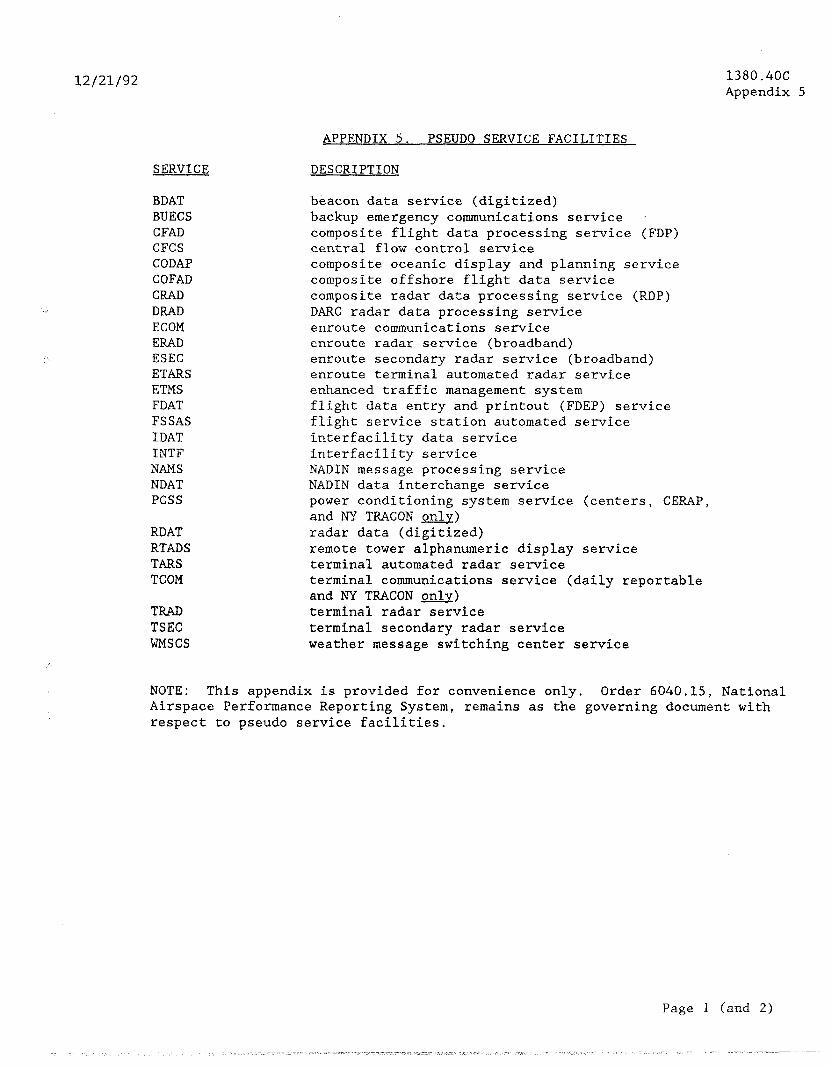
12/21/92 1380.4OC Appendix 5
SERVICE
BDAT BUECS CFAD CFCS CODAP COFAD CRAD DRAD ECOM ERAD ESEC ETARS ETMS FDAT FSSAS IDAT INTF NAMS NDAT PCSS
RDAT RTADS TARS TCOM
TRAD TSEC WMSCS
APPENDIX 5. PSEUDO SERVICE FACILITIES
DESCRIPTION
beacon data service (digitized) backup emergency communications service composite flight data processing service (FDP) central flow control service composite oceanic display and planning service composite offshore flight data service composite radar data processing service (RDP) DARC radar data processing service enroute communications service enroute radar service (broadband) enroute secondary radar service (broadband) enroute terminal automated radar service enhanced traffic management system flight data entry and printout (FDEP) service flight service station automated service interfacility data service interfacility service NADIN message processing service NADIN data interchange service power conditioning system service (centers, CERAP, and NY TRACON &) radar data (digitized) remote tower alphanumeric display service terminal automated radar service terminal communications service (daily reportable and NY TRACON only) terminal radar service terminal secondary radar service weather message switching center service
NOTE: This appendix is provided for convenience only. Order 6040.15, National Airspace Performance Reporting System, remains as the governing document with respect to pseudo service facilities.
Page 1 (and 2)
. _ .;_. .~ . . ..__ "_" ,. _.

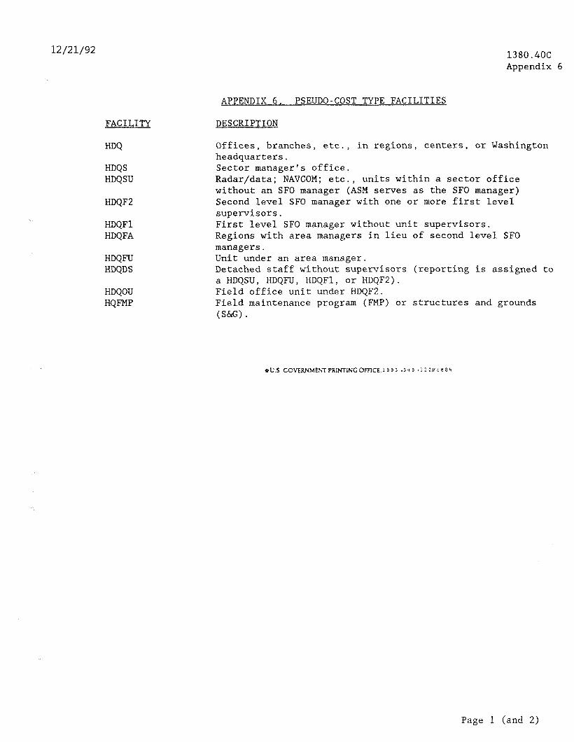
12/21/92 1380.4OC Appendix 6
FACILITY
HDQS HDQSU
HDQF2
HDQFl HDQFA
HDQFU HDQDS
HDQOU HQFMP
APPENDIX 6. PSEUDO-COST TYPE FACILITIES
DESCRIPTION
Offices, branches, etc., in regions, centers, or Washington headquarters. Sector manager's office. Radar/data; NAVCOM; etc., units within a sector office without an SF0 manager (ASM serves as the SF0 manager) Second level SF0 manager with one or more first level supervisors. First level SF0 manager without unit supervisors. Regions with area managers in lieu of second level SF0 managers. Unit under an area manager. Detached staff without supervisors (reporting is assigned to a HDQSU, HDQFU, HDQFl, or HDQF2). Field office unit under HDQF2. Field maintenance program (FMP) or structures and grounds (S&G) *
4 u.s COVERNMEM PRINTING OFFICE 13 3 3 -3 4 3 .I 2 OP 5 8 8 4
Page 1 (and 2)


-- , . , . j. _(_. .