order - Federal Aviation Administration
102
ORDER 6110.7E MAINTENANCE OF THE OCEANIC DISPLAY AND PLANNING SYSTEM (ODAPS) September 17, 2003 U.S. DEPARTMENT OF TRANSPORTATION FEDERAL AVIATION ADMINISTRATION Distribution:Selected Airway Facilities Field and Regional Offices; ZAF − 600 Initiated By:AOS − 300
-
Upload
khangminh22 -
Category
Documents
-
view
0 -
download
0
Transcript of order - Federal Aviation Administration

ORDER6110.7E
MAINTENANCE OF THE OCEANIC DISPLAY AND PLANNING SYSTEM(ODAPS)
September 17, 2003
U.S. DEPARTMENT OF TRANSPORTATIONFEDERAL AVIATION ADMINISTRATION
Distribution:�Selected Airway Facilities Field and Regional Offices; ZAF − 600 ��Initiated By:�AOS − 300

RECORD OF CHANGES DIRECTIVE NO. 6110.7E
CHANGE SUPPLEMENTS CHANGE SUPPLEMENTSTO
BASICOPTIONAL TO
BASICOPTIONAL
FAA FORM 1320-5 (6-80) USE PREVIOUS EDITION
6110.7E9/17/03
Page i
FOREWORD
1.�PURPOSE.
This handbook provides guidance and prescribestechnical standards and tolerances, and procedures
applicable to the maintenance and inspection of theOceanic Display And Planning System (ODAPS) au−
tomation. It also provides information on specialmethods and techniques which will enable mainte−nance personnel to achieve optimum performance
from the equipment. This information augments in−formation available in instruction books and other
handbooks, and complements the latest edition of Or−der 6000.15, General Maintenance Handbook for Air−way Facilities.
2.�DISTRIBUTION.
This directive is distributed to selected offices and
services within Washington headquarters, the Wil−liam J. Hughes Technical Center, the Mike Monroney
Aeronautical Center, regional Airway Facilities divi−sions, and Airway Facilities field offices having thefollowing facilities/equipment: ODAPS.
3.�CANCELLATION.
This order cancels Order 6110.7D, Maintenance
of the Oceanic Display and Planning System (ODAPS)dated 1/22/02.
4.�EXPLANATION OF CHANGES.
a.Configuration Control Decision (CCD) N22771authorizes the addition of the ODAPS equipment and
channel interface cables for the Host and OceanicComputer System Replacement (HOCSR) Phase 3
program. The Symmetrix 5630 and Service Processor(SP), and the Monitor and Control (M&C) subsystemwill be added to the ODAPS. Additional Enterprise
Systems Connection (ESCON) channel interfacecables will be connected to Channel Path Identifiers
(CHPID) 82, 83, DA, and DB.
b.CCD N23617 uses the IBM 6400 − 050 printeras a coaxial−attached replacement for the existing
3268 Keyboard Video Display Terminal (KVDT)Printer Replacements (KPR). This is part of the
HOCSR Phase 4 program.
c.CCD N23980 uses the IBM 6400 − 015 printeras a coaxial−attached replacement for the existingIBM 4245 − 012 High Speed Printer (HSP). This is
part of the HOCSR Phase 4 program.
5.�MAINTENANCE AND MODIFICATIONPROCEDURE.
a.The Order 6000.15, this handbook, the applica−ble equipment instruction book and other applicablehandbooks shall be consulted and used together by
the maintenance technician in all duties and activitiesfor the maintenance of the ODAPS automation. These
documents shall be considered collectively as thesingle official source of maintenance policy and direc−tion authorized by the Operational Support (AOS)
Program. References located in the appropriate para−graphs of this handbook entitled Chapter 3, Standards
and Tolerances, Chapter 4, Periodic Maintenance,and Chapter 5, Maintenance Procedures shall indi−cate to the user whether this handbook and/or the
equipment instruction book shall be consulted fora particular standard, key inspection element or per−
formance parameter, performance check, mainte−nance task, or maintenance procedure.
b.The latest edition of Order 6032.1, Modifica−
tion to Ground Facilities, Systems, and Equipmentin the National Airspace System, contains compre−hensive direction concerning the development, autho−
rization, implementation, and recording ofmodifications to facilities, systems, and equipment
in commissioned status. It supersedes all instructionspublished in earlier editions of maintenance technicalhandbooks and related directives.
c.Modifications to equipment that are listed inNAS − MD − 001, National Airspace System (NAS)Configuration Management Document, as baselined
under configuration management shall be in accor−dance with the latest edition of Order 1800.66, Config−
uration Management Policy.
6.�FORMS LISTING.
In addition to the forms required by Order 6000.15,FAA Forms 6110 − 6 and 6110 − 7, Technical Perfor−
mance Records, will be maintained for each ODAPSfacility. These forms are available from the FAA Logis−
tics Center (FAALC) under National Stock Numbers

6110.7E9/17/03
Page iii
TABLE OF CONTENTS
Paragraph Page
Chapter 1. GENERAL INFORMATION AND REQUIREMENTS
100. Objective 1. . . . . . . . . . . . . . . . . . . . . . . . . . . . . . . . . . . . . . . . . . . . . . . . . . . . . . . 101. Safety 1. . . . . . . . . . . . . . . . . . . . . . . . . . . . . . . . . . . . . . . . . . . . . . . . . . . . . . . . . . 102. Coordination 1. . . . . . . . . . . . . . . . . . . . . . . . . . . . . . . . . . . . . . . . . . . . . . . . . . . . 103. Certification 1. . . . . . . . . . . . . . . . . . . . . . . . . . . . . . . . . . . . . . . . . . . . . . . . . . . . . 104. Aircraft Accident 1. . . . . . . . . . . . . . . . . . . . . . . . . . . . . . . . . . . . . . . . . . . . . . . . . 105. Flight Inspection 2. . . . . . . . . . . . . . . . . . . . . . . . . . . . . . . . . . . . . . . . . . . . . . . . . 106. Technical Inspection 2. . . . . . . . . . . . . . . . . . . . . . . . . . . . . . . . . . . . . . . . . . . . . . 107. Periodic Maintenance 2. . . . . . . . . . . . . . . . . . . . . . . . . . . . . . . . . . . . . . . . . . . . 108. Test Equipment and Tools for Periodic Maintenance 2. . . . . . . . . . . . . . . . . . 109. References 2. . . . . . . . . . . . . . . . . . . . . . . . . . . . . . . . . . . . . . . . . . . . . . . . . . . . .
110. -199. Reserved 4. . . . . . . . . . . . . . . . . . . . . . . . . . . . . . . . . . . . . . . . . . . . . . . . . . . . . . .
Chapter 2. TECHNICAL CHARACTERISTICS
200. System Introduction 5. . . . . . . . . . . . . . . . . . . . . . . . . . . . . . . . . . . . . . . . . . . . . . 201. System Functional Overview 5. . . . . . . . . . . . . . . . . . . . . . . . . . . . . . . . . . . . . . 202. System Description 5. . . . . . . . . . . . . . . . . . . . . . . . . . . . . . . . . . . . . . . . . . . . . . 203. System Theory of Operation 17. . . . . . . . . . . . . . . . . . . . . . . . . . . . . . . . . . . . . . 204. Symmetrix 5630 DASD M&C Subsystem 20. . . . . . . . . . . . . . . . . . . . . . . . . . . .
205. -299. Reserved 22. . . . . . . . . . . . . . . . . . . . . . . . . . . . . . . . . . . . . . . . . . . . . . . . . . . . . . .
Chapter 3. STANDARD AND TOLERANCES
300. General 23. . . . . . . . . . . . . . . . . . . . . . . . . . . . . . . . . . . . . . . . . . . . . . . . . . . . . . . . . 301. ODAPS 24. . . . . . . . . . . . . . . . . . . . . . . . . . . . . . . . . . . . . . . . . . . . . . . . . . . . . . . . . 302. FDPS 25. . . . . . . . . . . . . . . . . . . . . . . . . . . . . . . . . . . . . . . . . . . . . . . . . . . . . . . . . . 303. DASD Subsystem 26. . . . . . . . . . . . . . . . . . . . . . . . . . . . . . . . . . . . . . . . . . . . . . . . 304. MTS 27. . . . . . . . . . . . . . . . . . . . . . . . . . . . . . . . . . . . . . . . . . . . . . . . . . . . . . . . . . . 305. S1RPAM Subsystem 28. . . . . . . . . . . . . . . . . . . . . . . . . . . . . . . . . . . . . . . . . . . . . 306. ISD Subsystem 28. . . . . . . . . . . . . . . . . . . . . . . . . . . . . . . . . . . . . . . . . . . . . . . . . . 307. TP Subsystem 29. . . . . . . . . . . . . . . . . . . . . . . . . . . . . . . . . . . . . . . . . . . . . . . . . . . 308. AIDCS Subsystem 29. . . . . . . . . . . . . . . . . . . . . . . . . . . . . . . . . . . . . . . . . . . . . . . 309. ODL Subsystem 30. . . . . . . . . . . . . . . . . . . . . . . . . . . . . . . . . . . . . . . . . . . . . . . . . 310. Symmetrix 5630 DASD M&C Subsystem 31. . . . . . . . . . . . . . . . . . . . . . . . . . . .
311. -399. Reserved 32. . . . . . . . . . . . . . . . . . . . . . . . . . . . . . . . . . . . . . . . . . . . . . . . . . . . . . .
Chapter 4. PERIODIC MAINTENANCE
400. General 33. . . . . . . . . . . . . . . . . . . . . . . . . . . . . . . . . . . . . . . . . . . . . . . . . . . . . . . . .

6110.7E 9/17/03
Page iv
TABLE OF CONTENTS (Continued)
Paragraph Page
Section 1. PERFORMANCE CHECKS
401. Daily 34. . . . . . . . . . . . . . . . . . . . . . . . . . . . . . . . . . . . . . . . . . . . . . . . . . . . . . . . . . . 402. Weekly 34. . . . . . . . . . . . . . . . . . . . . . . . . . . . . . . . . . . . . . . . . . . . . . . . . . . . . . . . . 403. Monthly 36. . . . . . . . . . . . . . . . . . . . . . . . . . . . . . . . . . . . . . . . . . . . . . . . . . . . . . . . . 404. Quarterly 37. . . . . . . . . . . . . . . . . . . . . . . . . . . . . . . . . . . . . . . . . . . . . . . . . . . . . . . 405. Semiannually 42. . . . . . . . . . . . . . . . . . . . . . . . . . . . . . . . . . . . . . . . . . . . . . . . . . . . 406. Annually 43. . . . . . . . . . . . . . . . . . . . . . . . . . . . . . . . . . . . . . . . . . . . . . . . . . . . . . . . 407. As Required 46. . . . . . . . . . . . . . . . . . . . . . . . . . . . . . . . . . . . . . . . . . . . . . . . . . . . .
408. -449. Reserved 46. . . . . . . . . . . . . . . . . . . . . . . . . . . . . . . . . . . . . . . . . . . . . . . . . . . . . . .
Section 2. OTHER MAINTENANCE TASKS
450. Reserved 47. . . . . . . . . . . . . . . . . . . . . . . . . . . . . . . . . . . . . . . . . . . . . . . . . . . . . . . 451. Weekly 47. . . . . . . . . . . . . . . . . . . . . . . . . . . . . . . . . . . . . . . . . . . . . . . . . . . . . . . . . 452. Reserved 48. . . . . . . . . . . . . . . . . . . . . . . . . . . . . . . . . . . . . . . . . . . . . . . . . . . . . . . 453. Monthly 48. . . . . . . . . . . . . . . . . . . . . . . . . . . . . . . . . . . . . . . . . . . . . . . . . . . . . . . . . 454. Quarterly 51. . . . . . . . . . . . . . . . . . . . . . . . . . . . . . . . . . . . . . . . . . . . . . . . . . . . . . . 455. Semiannually 52. . . . . . . . . . . . . . . . . . . . . . . . . . . . . . . . . . . . . . . . . . . . . . . . . . . . 456. Annually 55. . . . . . . . . . . . . . . . . . . . . . . . . . . . . . . . . . . . . . . . . . . . . . . . . . . . . . . . 457. Every 3 Years 56. . . . . . . . . . . . . . . . . . . . . . . . . . . . . . . . . . . . . . . . . . . . . . . . . . . 458. Every 4 Years 57. . . . . . . . . . . . . . . . . . . . . . . . . . . . . . . . . . . . . . . . . . . . . . . . . . . 459. As Required 57. . . . . . . . . . . . . . . . . . . . . . . . . . . . . . . . . . . . . . . . . . . . . . . . . . . . .
460. -499. Reserved 57. . . . . . . . . . . . . . . . . . . . . . . . . . . . . . . . . . . . . . . . . . . . . . . . . . . . . . .
Chapter 5. MAINTENANCE PROCEDURES
500. General 59. . . . . . . . . . . . . . . . . . . . . . . . . . . . . . . . . . . . . . . . . . . . . . . . . . . . . . . . . 501. Remote Support Facility Operations for the 9672-RA4 Processor 59. . . . . . 502. Remote Support Operations for the ODAPS 5630 DASD
Subsystem 60. . . . . . . . . . . . . . . . . . . . . . . . . . . . . . . . . . . . . . . . . . . . . . . . . . . . . .
Section 1. PERFORMANCE CHECK PROCEDURES
503. FAA Form Entries 61. . . . . . . . . . . . . . . . . . . . . . . . . . . . . . . . . . . . . . . . . . . . . . . . 504. Check T-Bar Variswitch Operation and Battery Backup 61. . . . . . . . . . . . . . . 505. Check Power Cords, Cables, and Connectors 61. . . . . . . . . . . . . . . . . . . . . . . 506. Service Level Certification 64. . . . . . . . . . . . . . . . . . . . . . . . . . . . . . . . . . . . . . . . 507. Check S1RPAM Processor Interface Cards 64. . . . . . . . . . . . . . . . . . . . . . . . . 508. Check G3 Switchover Operation 65. . . . . . . . . . . . . . . . . . . . . . . . . . . . . . . . . . . 509. Check TP or ISD Server Switchover Operation 65. . . . . . . . . . . . . . . . . . . . . . 510. Check TP or ISD LAN Switchover Operation 66. . . . . . . . . . . . . . . . . . . . . . . . 511. Check TP SC Switchover Operation 66. . . . . . . . . . . . . . . . . . . . . . . . . . . . . . . . 512. Check IBM RISC/6000 770 or 771 Processor 66. . . . . . . . . . . . . . . . . . . . . . . . 513. Check Disk Array/6000 67. . . . . . . . . . . . . . . . . . . . . . . . . . . . . . . . . . . . . . . . . . .
6110.7E9/17/03
Page v
TABLE OF CONTENTS (Continued)
Paragraph Page
514. Check IBM 4226 or 4232 Line Printer 68. . . . . . . . . . . . . . . . . . . . . . . . . . . . . . 515. Check S1RPAM Processor Replacement Operation 68. . . . . . . . . . . . . . . . . . 516. Check S1RPAM Processor External Interfaces 68. . . . . . . . . . . . . . . . . . . . . . 517. Check IBM 7026-H50 Processor 69. . . . . . . . . . . . . . . . . . . . . . . . . . . . . . . . . . 518. Check ME800A Short Haul Modems 70. . . . . . . . . . . . . . . . . . . . . . . . . . . . . . . 519. Check Lamps and Audible Tone of the HMC Alarm Box 70. . . . . . . . . . . . . . . 520. Check Universal Power Supply 600 or 1000 71. . . . . . . . . . . . . . . . . . . . . . . . . 521. Check ODAPS-AIDCS-FIR Interfaces (New York ARTCC) 71. . . . . . . . . . . . 522. Check ODAPS-AIDCS-FIR Interfaces (Oakland ARTCC) 72. . . . . . . . . . . . . 523. ODL Unit Level Certification 73. . . . . . . . . . . . . . . . . . . . . . . . . . . . . . . . . . . . . . . 524. ODL System Level Certification 73. . . . . . . . . . . . . . . . . . . . . . . . . . . . . . . . . . . . 525. ODL Service Level Certification 73. . . . . . . . . . . . . . . . . . . . . . . . . . . . . . . . . . . . 526. Check ODL Server Switchover Operation 74. . . . . . . . . . . . . . . . . . . . . . . . . . . 527. Check ODL LAN Switchover Operation 74. . . . . . . . . . . . . . . . . . . . . . . . . . . . . 528. Symmetrix 5630 M&C Maintenance Procedures 74. . . . . . . . . . . . . . . . . . . . . 529. EMC 5630 Disk Drive/Power Supply Replacement Validation 75. . . . . . . . . .
530. -549. Reserved 76. . . . . . . . . . . . . . . . . . . . . . . . . . . . . . . . . . . . . . . . . . . . . . . . . . . . . . .
Section 2. OTHER MAINTENANCE TASKS PROCEDURES
550. Clean Printer 82. . . . . . . . . . . . . . . . . . . . . . . . . . . . . . . . . . . . . . . . . . . . . . . . . . . . 551. Clean Tape Drive 82. . . . . . . . . . . . . . . . . . . . . . . . . . . . . . . . . . . . . . . . . . . . . . . . 552. Clean and Inspect Cabinet 82. . . . . . . . . . . . . . . . . . . . . . . . . . . . . . . . . . . . . . . . 553. Clean Air Filter 82. . . . . . . . . . . . . . . . . . . . . . . . . . . . . . . . . . . . . . . . . . . . . . . . . . 554. Fan Operational Check 82. . . . . . . . . . . . . . . . . . . . . . . . . . . . . . . . . . . . . . . . . . . 555. Clean and Inspect Equipment 83. . . . . . . . . . . . . . . . . . . . . . . . . . . . . . . . . . . . .
556. -574. Reserved 83. . . . . . . . . . . . . . . . . . . . . . . . . . . . . . . . . . . . . . . . . . . . . . . . . . . . . . .
Section 3. SPECIAL MAINTENANCE PROCEDURES
575. Online Certification Data Requirements 84. . . . . . . . . . . . . . . . . . . . . . . . . . . . . 576. -599. Reserved 84. . . . . . . . . . . . . . . . . . . . . . . . . . . . . . . . . . . . . . . . . . . . . . . . . . . . . . .
Chapter 6. FLIGHT INSPECTION
600. -699. Reserved 85. . . . . . . . . . . . . . . . . . . . . . . . . . . . . . . . . . . . . . . . . . . . . . . . . . . . . . .
Chapter 7. MISCELLANEOUS
700. Abbreviations and Acronyms 87. . . . . . . . . . . . . . . . . . . . . . . . . . . . . . . . . . . . . . 701. -799. Reserved 90. . . . . . . . . . . . . . . . . . . . . . . . . . . . . . . . . . . . . . . . . . . . . . . . . . . . . . .
Appendix 1. CERTIFICATION REQUIREMENTS
Table 1. En Route Surveillance Automated Flight Plan (ESAFP) Service 2. . . . . . . . Table 2. Surveillance Flight Plan System (SFS) 3. . . . . . . . . . . . . . . . . . . . . . . . . . . . . . Table 3. Surveillance Processing System (SPS) 4. . . . . . . . . . . . . . . . . . . . . . . . . . . . .
6110.7E 9/17/03
Page vi
LIST OF ILLUSTRATIONS
Figure Page
2-1. ODAPS Subsystem Diagram 6. . . . . . . . . . . . . . . . . . . . . . . . . . . . . . . . . . . . . 2 -2. ODAPS IBM 9672 Channel Interconnects 8. . . . . . . . . . . . . . . . . . . . . . . . . 2 -3. ODAPS IBM 3274 Terminal Interconnects 9. . . . . . . . . . . . . . . . . . . . . . . . . 2 -4. ODAPS S1RPAM Configuration Diagram 12. . . . . . . . . . . . . . . . . . . . . . . . . . 2 -5. Oakland ODAPS Cable Configuration Diagram (TP) 13. . . . . . . . . . . . . . . . 2 -6. New York ODAPS Cable Configuration Diagram (TP) 14. . . . . . . . . . . . . . . 2 -7. ISD System Architecture Diagram 15. . . . . . . . . . . . . . . . . . . . . . . . . . . . . . . . . 2 -8. ODAPS AIDCS Cable Configuration Diagram 16. . . . . . . . . . . . . . . . . . . . . . 2 -9. Oakland ODAPS Cable Configuration Diagram (ODL) 18. . . . . . . . . . . . . . .
2 -10. New York ODAPS Cable Configuration Diagram (ODL) 19. . . . . . . . . . . . . 2 -11. Symmetrix DASD Monitor and Control 21. . . . . . . . . . . . . . . . . . . . . . . . . . . . . 5 -1. Technical Performance Record (2 Sheets) 62. . . . . . . . . . . . . . . . . . . . . . . . . 5 -2. Success Criteria for Disk Drive Replacement (logall.log) 77. . . . . . . . . . . . 5 -3. Indication for Disk Drive Resynchronization in Progress
(logall.log) 78. . . . . . . . . . . . . . . . . . . . . . . . . . . . . . . . . . . . . . . . . . . . . . . . . . . . . . 5 -4. Success Criteria for Disk Drive Resynchronization Complete
(logall.log) 79. . . . . . . . . . . . . . . . . . . . . . . . . . . . . . . . . . . . . . . . . . . . . . . . . . . . . . 5 -5. Environmental Log File with No Errors Present (env.log) 80. . . . . . . . . . . . 5 -6. Environmental Log File with Example Error Present (env.log) 81. . . . . . . .

6110.7E9/17/03
Page 1
CHAPTER 1. GENERAL INFORMATION AND REQUIREMENTS
100.�OBJECTIVE.
This handbook provides the necessary guidance, tobe used in conjunction with information availablein instruction books and other handbooks, for the
proper maintenance of the Oceanic Display And Plan−ning System (ODAPS) automation. It does not cover
associated plant, communications, or alternating cur−rent (ac) power equipment maintenance.
101.�SAFETY.
Personnel shall observe all pertinent safety pre−cautions when performing duties on the equipment.
Refer to Order 6000.15, General Maintenance Hand−book for Airway Facilities, for guidance.
102.�COORDINATION.
a.Maximum availability is of prime importanceto the users of Airway Facilities (AF) systems, ser−
vices, and equipment. Maintenance should thereforebe accomplished, to the extent practicable, on the of−fline operating equipment. When it is necessary to
perform maintenance on the online operating equip−ment, it shall be coordinated with the appropriate
personnel to preclude unanticipated shutdowns.
b.AF personnel shall be familiar with the role
of the ODAPS in the National Airspace System (NAS)so that facility shutdowns can be coordinated with
the proper agency and non−agency personnel. Partic−ularly, AF personnel shall thoroughly coordinate withAir Traffic Operations (ATO) personnel, in advance,
any maintenance activity that may adversely effectthe use of a commissioned facility. Furthermore, AF
personnel must be familiar enough with ATO proce−dures to ensure that notification is made sufficientlyearly to allow ATO personnel to take appropriate
action. It is expected that ATO personnel will recog−nize the need for releasing equipment at the time
scheduled for maintenance and will cooperate in thefurtherance of practices that assure continuous andreliable operation. See Order 6000.15 for additional
guidance.
c.AF personnel are also responsible for keepingATO personnel advised of the operational status ofall system, subsystem, facilities and equipment. When
unscheduled interruptions occur, prompt notificationshall be made to cognizant ATO personnel. They shallbe advised immediately when equipment fails, service
is restored, the established tolerances are exceeded,or the established tolerances are expected to be ex−
ceeded so that ATO can issue the NOtice To AirMen(NOTAM), re−route air traffic, and/or take other nec−essary action. This is especially important where
standby or spare equipment is not immediately avail−able.
103.�CERTIFICATION.
Refer to Order 6000.15 for general guidance onthe certification of systems, subsystems, and equip−
ment. Refer to appendix 1 of this handbook for thespecific certification requirements of the ODAPS. TheNAS Operations Manager/NAS Area Specialist
(NOM/NAS) shall initiate daily certification ofEn�route Surveillance Automated Flight plan
(ESAFP) Service and weekly certification of Surveil−lance Flight plan System (SFS). The Airway Trans−portation System Specialist (ATSS) shall initiate
quarterly certification of Surveillance Processing Sys−tem (SPS).
104.�AIRCRAFT ACCIDENT.
After receiving information that an aircraft acci−dent has occurred within the service area of the facility
for which they are responsible, the following mini−mum actions are required of cognizant AF personnel.See the latest edition of Order 8020.11, Aircraft Acci−
dent and Incident Notification, Investigation, and Re−porting.
a.Check the Facility Maintenance Log (FAA
Form 6030 − 1 and/or applicable Maintenance Man−agement System (MMS) entries) to determine the sta−
tus of the system at the time of the accident.
b.Record all Technical Performance Record(TPR) data as found and any other system parameters
considered necessary to establish the operational ca−pability of the system.
c.Review the Facility Maintenance Log and the
TPR and compile all data pertinent to the accident.
d.Certify entries of FAA Form 6030 − 1 or MMSand the TPR. In all cases have another electronics
Chap 1Par 100

6110.7E 9/17/03
Page 2
technician or the supervisor certify the entry, includ−ing the date and time of the entry.
e.AF Accident Investigation. Once ATO re−leases the accident notification message, the AF sector
manager will initiate a technical facility evaluation.In addition, the Regional AF Division will designate
a Regional AF Accident Representative as a coordina−tor of the AF contribution to the accident investiga−tion and as a liaison with the FAA
investigator−in−charge. See Order 8020.11, for the de−tails of and the procedures for the investigation and
reporting of an ODAPS related aircraft accident orincident.
f.Records. All station records such as logs, meterreading forms, etc., are official documents and, as
such, may be required in case of an investigation re−garding a local aircraft accident and should be safe−guarded.
g.It is imperative that all records be kept current,
concise, and accurate. These checks shall be madecarefully and completed rapidly. All station records,
such as facility logs, meter readings forms, etc., areofficial documents. They will be needed during aninvestigation of a local aircraft accident. Additionally,
these records will be used for investigating other situ−ations when the operation of the facility is questioned.
105.�FLIGHT INSPECTION.
Since ODAPS receives no sensor inputs directly,no ODAPS flight inspection is required. All ODAPS
sensor inputs undergo required flight inspection un−der other system procedures.
106.�TECHNICAL INSPECTION.
Facility inspections are among the more effective
management controls for ensuring the required quali−ty level of maintenance work and equipment and sys−tem performance. See Order 6000.15 for general
guidance on inspections and the latest edition of Or−der 6040.6, Airway Facilities NAS Technical Evalua−
tion Program (RIS:AF 6040 − 8) for details on theintervals and requirements for formal inspections.
107.�PERIODIC MAINTENANCE.
Chapter 4 of this order establishes the tasks andschedules that are required for the periodic mainte−
nance of the ODAPS automation. These tasks, asscheduled, are the minimum required for the ODAPSautomation to meet minimum performance stan−
dards.
108.�TEST EQUIPMENT AND TOOLS FORPERIODIC MAINTENANCE.
The test equipment required for performing rou−
tine maintenance of the ODAPS automation are man−aged by the latest edition of Order 6200.4, Test
Equipment Management Handbook. Tools and sup−plies are specified and managed by the latest editionof Order 4630.2, Standard Allowance of Supplies and
Working Equipment for National Airspace SystemFacilities.
109.�REFERENCES.
a.The instruction books and orders which applyto the ODAPS equipment are listed below.
(1)6NASP − 5462, Interim Situation Display
(ISD), Computer System Operator’s Manual
(2)6NASP − 5263, Interim Situation Display(ISD), Software User’s Manual
(3)6NASP − 5162, Interim Situation Display,Hardware Design Document
(4)6IBM 3268 Printer Models 1, 2 and 2c
Maintenance Information, SY27 − 0201 − 4
(5)6IBM Maintenance Diagnostic Program
Local 3274 Model 1B/1D Display System On−LineTests, D99 − 3274A − 01
(6)6IBM 3380 Online Test (OLT) User’s Guide,
D99 − 3380A − 02
(7)6IBM 3480 Online Tests (OLTs),D99 − 3480A − 00
(8)6IBM Maintenance Diagnostic Program3880 Storage Director Online Test, DCL − 3880A − 02(D99 − 3880A − 01)
(9)6IBM 4245 Printer Models 12 and 20Maintenance Information Manual, Volume 1
(10)6IBM 4245 Printer Models 12 and 20
Maintenance Information Manual, Volume 2
(11)6TI 6110.11, Diagnostic User’s Guide for
the Series/1 Replacement (S1R) and Series/1 Replace−ment Peripheral Adapter Module (S1RPAM) VolumeII
(12)6TI 6110.10, Hardware Installation andMaintenance Manual for the Series/1 Replacement(S1R) and Series/1 Replacement Peripheral Adapter
Module (S1RPAM) Volume I
Chap 1 Par 104
6110.7E9/17/03
Page 3
(13)6TI 6110.9, Series/1 Replacement (S1R)and Series/1 Replacement Peripheral Adapter Module(S1RPAM) Handbook
(14)6IBM RS/6000 Enterprise Server Model
H50 User’s Guide SA38 − 0546 − 00
(15)6IBM RS/6000 Diagnostic Information forMultiple Bus Systems SA38 − 0509 − 06
(16)6Order 6000.15, General Maintenance
Handbook for Airway Facilities
(17)6Order 6032.1, Modification to GroundFacilities, Systems, and Equipment in the National
Airspace System
(18)6NAS − MD − 001, National AirspaceSystem (NAS) Configuration Management Document
(19)6Order 1800.66, Configuration Manage−
ment Policy
(20)6Order 8020.11, Aircraft Accident andIncident−Notification, Investigation, and Reporting
(21)6Order 6040.6, Airway Facilities NAS Tech−
nical Evaluation Program
(22)6Order 6200.4, Test Equipment Manage−ment Handbook
(23)6Order 4630.2, Standard Allowance ofSupplies and Working Equipment for National
Airspace System Facilities
(24)6AIX Version 3.2 System ManagementGuide: Operating System and Devices, IBM, Order
Number GC − 2486 − 00
(25)6AIX Version 4.3 System ManagementGuide: Operating System and Devices, IBM, Order
Number SC23 − 4126 − 00
(26)6AIX Version 3.2 Problem Solving Guideand Reference, IBM, Order Number SC23 − 2204 − 04
(27)6Maintenance Information for the IBM6091 Color Display (Model 19i), IBM, Order Number
SY66 − 0117 − 00
(28)6Setup and Operation for the 6091 ColorDisplays, IBM, Order Number GA23 − 2114 − 03
(29)6IBM 4226 Printer User’s Reference, IBM,
Order Number GA18 − 7182 − 00
(30)64226 Printer Operator Reference, IBM,Order Number GA18 − 7183 − 00
(31)67018 POWER Server Models 770 and 771Operator Guide, IBM, Order Number
SA23 − 2698 − 00
(32)6Certainty ARRAY/6000 Model 505/510
Deskside Series, Installation Guide, Cambex Corpora−tion, Order Number 081 − 448 − 003 Rev. C
(33)6IBM 3151 ASCII Display Station Models11, 31, and 41 Guide to Operations, IBM, Order Num−
ber GA18 − 2633 − 02
(34)6User’s Manual Power Line Filter &
Distribution Unit Model 2 − 1000/6FA1, CYBEREXInc., UM − 2 − 1000/6FA1:1, September 1991
(35)6User’s Manual Power Line Filter &Distribution Unit Model 600/6FA1, CYBEREX Inc.,
UM − 600/6FA1
(36)6RS232 Fallback Switch User’s Manual,
Black Box Corporation
(37)6TI 6130.6 Hardware Design Data (HDD)
Instruction Book Flight Data Input/Output (FDIO)System, Volume 1, Sections 1 − 10 (FDIO − 51B)
(38)6POWERstation and POWERserverCommon Diagnostic and Service Guide, IBM, Order
Number SA23 − 2687
(39)6NASP − 9102, Equipment Instruction
Book, Oceanic Display and Planning System(ODAPS), Hardware Design Document for the Tele−
communications Processor
(40)6NASP − 9557, Instruction Book, Oceanic
Display and Planning System (ODAPS), Operator’sManual for the Telecommunications Processor
(41)6NASP − 9257, Software Instruction Book,Oceanic Display and Planning System (ODAPS),
User’s Manual for the Telecommunications Processor
(42)6TI 6110.2, Equipment Instruction Book,
Oceanic Display and Planning System (ODAPS) Op−erations and Maintenance Manual for the Telecom−munications Processor
(43)64232 Printer User’s Guide, IBM,
SA24 − 4386 − 01
(44)64232 Printer Operator Panel Instruc−
tions, IBM, SA24 − 4387 − 01
(45)6IBM Info Window II 3153 ASCII Display
User’s Guide, IBM, Order Number GA27 − 4083 − 01
Chap 1Par 109

6110.7E 9/17/03
Page 4
(46)6TI 6110.4, Interim Situation Display In−struction Book
(47)6TI 6110.5, Interim Situation Display
(ISD) NDI/COTS Equipment Documentation
(48)6IBM S/390 Support Element OperationsGuide, GC38 − 3108 − 03
(49)6IBM S/390 Installation Manual,
SY24 − 6156 − 04
(50)6IBM S/390 Service Guide, SY24 − 6158 − 04
(51)6IBM S/390 Hardware Management Con−
sole Operations Guide, GC38 − 0459 − 00
(52)6IBM S/390 Parts Catalog, S123 − 1151 − 04
(53)6NASP − 7211, Computer System Opera−
tors Manual (CSOM) for the Air Traffic Services(ATS) Interfacility Data Communications System(AIDCS)
(54)6NASP − 7201, Software User Manual(SUM) for the Air Traffic Services (ATS) InterfacilityData Communications System (AIDCS)
(55)6TI 6110.6, Operation and MaintenanceTechnical Instruction Manual (OMTIM) for the AirTraffic Services (ATS) Interfacility Data Communica−
tions System (AIDCS)
(56)6HP NetServer LC II User Guide, HP PartNumber 5965 − 2497
(57)6ViewSonic E655 User’s Guide
(58)6Epson Printer User’s GuideLQ − 570+/1070+
(59)6Motorola Codex 3600 Series User’s Manual
(60)6Channel−to−Channel Adapter or 3088MCCU Exerciser On−Line Test User Guide,
D99 − 3150A − 05
(61)6NASP − 7214, Oceanic Data Link (ODL),Computer System Operation Manual (CSOM)
(62)6TI 6110.15, Technical Instruction Manual
for the Oceanic Data Link
(63)6Order 6110.9, Electronic Equipment Mod−ification Handbook Oceanic Display and Planning
System
(64)6RS/6000 Enterprise Server Model H80Series Service Guide
(65)6CDRL D038, System Problem Determina−tion and Maintenance Manual
(66)6RS/6000 Enterprise Server Model H80Series User’s Guide
(67)6Catalyst 2900 Series XL InstallationGuide, Cisco Systems
(68)6CDRL D038, Storage Subsystem Certifica−tion Manual
(69)6NCD NCBridge Software ReferenceManual
(70)6Ethercom Model EFTT1003 User’sManual
(71)6Symmetrix Model 3630/5630 ProductManual
(72)6Device Support Facilities User’s Guide
(73)6IBM 6400 Line Matrix Printers Mainte−
nance Information Manual Cabinet and PedestalModels, S246 − 0117 − 06
(74)6IBM 6400 Line Matrix Printers SetupGuide, S246 − 0116 − 02
b.System specifications are available in the fol−lowing document:
(1)6FAA − E − 2713, ODAPS Specifications
(2)6FAA − ER − 2889, Telecommunication Pro−
cessor Specification
(3)6FAA − ER − 2896, Interim Situation Display
Specification
(4)6CDRL D0027, Host and Oceanic Computer
Replacement System, Oceanic Computer SubsystemFunctional Specification Baseline
c.The ODAPS utilizes equipment whose mainte−nance is not covered in this handbook. See the latestedition of Order 6170.9, Maintenance of Communica−
tion Multiplex (MUX) Equipment, and the latest edi−tion of Order 6170.10, Maintenance of Data
Multiplexing Network Equipment, for the mainte−nance of the Bell Dataphone 1600 modem, the NipponElectronics Co. (NEC) 2400 MR Data Modem, the
General Datacomm 201C and 202 modems, and theCodex 6250 Statistical Multiplexers.
110.−199.�RESERVED.
Chap 1 Par 109

6110.7E9/17/03
Page 5
CHAPTER 2. TECHNICAL CHARACTERISTICS
200.�SYSTEM INTRODUCTION.
The ODAPS improves Air Traffic Control (ATC) foroceanic areas serviced by the FAA. Seven existing ocean−
ic control centers have been consolidated into two, lo−cated in the New York and Oakland Air Route TrafficControl Centers (ARTCC). ODAPS will provide each
site with automated functions and capabilities whichare almost identical to those existing in ARTCCs. It willalso support controllers by providing the data needed
to grant safe and efficient clearances to aircraft passingthrough oceanic airspaces.
201.�SYSTEM FUNCTIONAL OVERVIEW.
a.The ODAPS exchanges flight plan data and
general flight information with the NAS host comput−er. The ISD is responsible for displaying data from
ODAPS and relaying controller inputs back toODAPS. National Airspace Data Interchange Net−work (NADIN) 1A supports the ODAPS interface with
Service A, the Aeronautical Fixed Telecommunica−tions Network (AFTN), and Aeronautical Radio, Inc.
This interface supports the exchange of weather−re−lated data, flight movements, and various other sup−port data. The AIDCS transfers operational flight
information between ODAPS and non−US Flight In−formation Regions (FIR) for flights that are expected
to cross the boundary between US airspace and for−eign airspace. The AIDCS translates the flight infor−mation between the NAS format required by ODAPS
and the International Civil Aviation Organization(ICAO) format required by the FIRs.
b.The ODAPS transmits to North American Air
Defense Command Regional Operations Control Cen−ters the flight plans of aircraft heading toward the
United States and penetrating the outer Air DefenseIdentification Zone, the Canadian Air Defense Identifi−cation Zone, or the Distant Early Warning Identification
Zone. The Telecommunications Processor (TP) Serverssupport the ODAPS interface with TP workstations andThermal Flight Strip Printers (TFSP) using an Insti−
tute of Electrical and Electronic Engineers (IEEE)802.5 token ring fiber optic Local Area Network (LAN).
The TP workstation monitor provides an operator witha visual display of flight strips, general information, andweather messages. TP workstation monitors also pro−
vide a visual display for editing messages and for scrol−
ling through a historical recording of messages received.The TP System Console provides an interface to TPfor identification of problems and for providing correc−
tive action. TFSPs are used to print flight progress andcoordination strips. The ODAPS also exchanges flight
data with the Enhanced Traffic Management System(ETMS).
c.The ODL servers support the ODAPS interfacewith ODL workstations and TFSP using an IEEE
802.5 token ring fiber optic LAN. The ODL worksta−tion monitor provides an operator with all the TPfunctionality. The ODL workstation also provides a
visual display for Controller/Pilot Data Link Commu−nications (CPDLC) message processing, outgoing
data communications with Radio Operators (RO) formessage processing with High Frequency (HF)equipped aircraft, and NADIN II interface for CPDLC
position reports to ODAPS. The ODL System Consoleprovides an interface for identification of problems
and for providing corrective action. TFSPs are usedto print flight progress and coordination strips.
202.�SYSTEM DESCRIPTION.
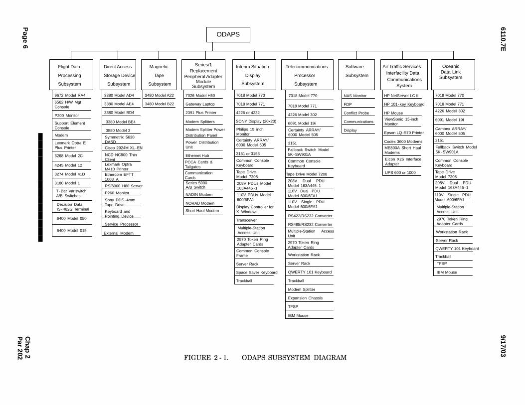
a.The ODAPS is composed of eight subsystems,each of which is discussed in the paragraphs that fol−low. These subsystems are shown in Figure 2 − 1,
ODAPS Subsystem Diagram.
(1)6Flight Data Processing Subsystem(FDPS).
(a)6Processor 9672 − RA4 − G3.
16S/390 Parallel Enterprise Server.Each S/390 Parallel Enterprise Server 9672 ModelRA4, Generation 3 (G3), can be divided into four func−
tional subsystems: processor, storage, channel, andpower.
26Processor Subsystem. The9672 − RA4 is a Complimentary Metal Oxide Semicon−
ductor (CMOS) processor running at approximately 32Million Instructions Per Second (MIPS), expandable to
45 MIPS within the same processor family. Each proces−sor subsystem consists of four Processing Units (PU).A PU is the hardware computing element of the comput−
er.
Chap 2Par 200
6110.7E9/17/03
Pag
e 6C
hap
2P
ar 202
Symmetrix 5630DASD
ODAPS
Flight Data
Processing
Subsystem
Direct Access
Storage Device
Subsystem
Magnetic
Tape
Subsystem
Series/1
Subsystem
Software
Subsystem
Telecommunications
Processor
Subsystem
3380 Model AD4
3380 Model AE4
3380 Model BD4
3880 Model 3
3380 Model BE4
3480 Model A22
3480 Model B22
7026 Model H50
Gateway Laptop
2391 Plus Printer
Modem Splitter Power
Modem Splitters
Ethernet Hub
A/B Switch
NADIN Modem
7018 Model 770
7018 Model 771
4226 or 4232
SONY Display (20x20)
3151 or 3153
NAS Monitor
FDP
Conflict Probe
Communications
Display
7018 Model 771
4226 Model 302
6091 Model 19i
3151
Tape Drive Model 7208
RS422/RS232 Converter
RS485/RS232 Converter
Workstation Rack
Server Rack
QWERTY 101 Keyboard
Trackball
Modem Splitter
Expansion Chassis
TFSP
7018 Model 770
IBM Mouse
Interim Situation
Display
Transceiver
Server Rack
Space Saver Keyboard
Trackball
NORAD Modem
Short Haul Modem
Air Traffic Services
HP NetServer LC II
HP 101-key Keyboard
HP Mouse
Epson LQ-570 Printer
Interfacility DataCommunications
System
Codex 3600 Modems
UPS 600 or 1000
Distribution Panel
9672 Model RA4
6562 H/W MgtConsole
P200 Monitor
Support ElementConsole
Modem
Lexmark Optra EPlus Printer
3268 Model 2C
4245 Model 12
3274 Model 41D
3180 Model 1
Power DistributionUnit
PCCA Cards &Tailgates
CommunicationCards
Philips 19 inchMonitor
Certainty ARRAY/6000 Model 505
Common ConsoleKeyboard
Tape DriveModel 7208
208V PDUs Model163A445 -1
110V PDUs Model600/6FA1
Display Controller forX -Windows
Multiple-Station Access Unit
2970 Token RingAdapter Cards
Common ConsoleFrame
Certainty ARRAY/6000 Model 505
Fallback Switch Model5K -SW901A
Common ConsoleKeyboard
208V Dual PDUModel 163A445-1110V Dual PDUModel 600/6FA1
110V Single PDUModel 600/6FA1
Multiple-Station AccessUnit
2970 Token RingAdapter Cards
ViewSonic 15-inchMonitor
ME800A Short HaulModems
Eicon X25 InterfaceAdapter
7018 Model 770
7018 Model 771
3151
Server Rack
Trackball
Cambex ARRAY/6000 Model 505
Common ConsoleKeyboard
Tape DriveModel 7208
Multiple-Station Access Unit
2970 Token RingAdapter Cards
OceanicData Link
Subsystem
4226 Model 302
6091 Model 19I
Fallback Switch Model5K -SW901A
208V Dual PDUModel 163A445-1
110V Single PDUModel 600/6FA1
Workstation Rack
QWERTY 101 Keyboard
TFSP
IBM Mouse
Decision DataIS -482G Terminal
T-Bar VariswitchA/B Switches
ReplacementPeripheral Adapter
Module Subsystem
Series 5000
External Modem
Cisco 2924M XL-EN
NCD NC900 Thin ClientLexmark Optra M410 PrinterEthercom EFTT1003_A
RS/6000 H80 Server
P260 Monitor
Sony DDS-4mm Tape Drive
Keyboard and Pointing Device
Service Processor6400 Model 050
6400 Model 015
FIGURE 2 − 1.��ODAPS SUBSYSTEM DIAGRAM
6110.7E9/17/03
Page 7
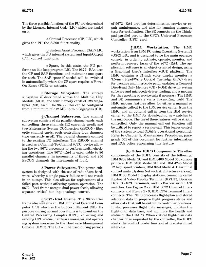
The three possible functions of the PU are determinedby the Licensed Internal Code (LIC) which are loadedon it.
a6Central Processor (CP) LIC, whichgives the PU the S/390 functionality.
b6System Assist Processor (SAP) LIC,
which gives the PU internal system and Input/Output(I/O) control functions.
c6Spare, in this state, the PU per−
forms an idle loop program LIC. The 9672 − RA4 usesthe CP and SAP functions and maintains one spare
for each. The SAP spare if needed will be switchedin automatically, where the CP spare requires a PowerOn Reset (POR) to activate.
36Storage Subsystem. The storagesubsystem is distributed across the Multiple ChipModule (MCM) and four memory cards of 128 Mega−
bytes (MB) each. The 9672 − RA4 can be configuredfrom a minimum of 512 MB up to 8 Gigabytes (GB).
46Channel Subsystem. The channel
subsystem consists of six parallel channel cards, eachcontrolling three channels (12 currently used); and
two Enterprise System CONnection (ESCON) fiberoptic channel cards, each controlling four channels(two currently used). The parallel channels connect
to the existing I/O interfaces. The ESCON channelis used as a Channel−To−Channel (CTC) device allow−
ing the two 9672 processors to perform health check−ing operations. The 9672 − RA4 is expandable to 96parallel channels (in increments of three), and 256
ESCON channels (in increments of four).
56Power Subsystem. The power sub−system is designed with the use of redundant hard−
ware, whereby a single power failure will not resultin an outage. This also allows for replacement of a
failed part without affecting system operation. The9672 − RA4 frame accepts dual power feeds, allowingseparate critical bus input voltage sources.
669672 − RA4 Frame. The 9672 − RA4frame also contains an IBM Thinkpad Personal Com−puter (PC) which is the Support Element (SE). Its
purpose during normal operations is to maintain theCentral Processing Complex (CPC), collecting and
sending CPC status, hardware messages and operat−ing system messages to the Hardware ManagementConsole (HMC). The SE will be used during periods
of 9672 − RA4 problem determination, service or re−pair maintenance, and also for running diagnostictests for certification. The SE connects via the Think−
pad parallel port to the CPC’s Universal ProcessorController (UPC) card.
76HMC Workstation. The HMC
workstation is an IBM PC using Operating System/2(OS/2) LIC, and is designed to be the main operatorconsole, in order to activate, operate, monitor, and
perform recovery tasks of the 9672 − RA4. The ap−plication software is an object oriented design, using
a Graphical User’s Interface (GUI) platform. TheHMC contains a 21−inch color display monitor; a3.5−inch Read/Write Optical Cartridge (ROC) drive
for backups and microcode patch updates; a CompactDisc−Read Only Memory (CD − ROM) drive for system
software and microcode driver loading; and a modemfor the reporting of service calls if necessary. The HMCand SE communicate via a Token−Ring LAN. The
HMC modem features allow for either a manual orautomatic callout to the IBM service center from the
HMC, and an optional call in from the IBM servicecenter to the HMC for downloading new patches tothe microcode. The use of these features will be strictly
controlled. Only the manual call out function willbe utilized to report a service call. This leaves control
of the system to local ODAPS operational personnel.Refer to Chapter 5, Maintenance Procedures, para−graph 501 of this document for further information
and FAA policy concerning this feature.
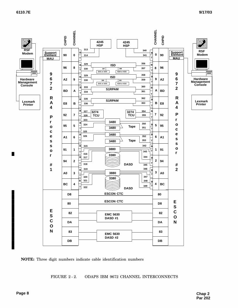
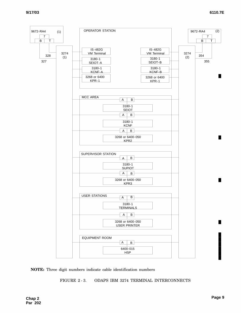
(b)6Other FDPS Components. The othercomponents of the FDPS consists of the following;
IBM 3268 Model 2C and IBM 6400 Model 050 consoleprinters, IBM 6400 Model 015 and IBM 4245 Model12 high speed printers, IBM 3274 Model 41D terminal
control units (System Network Architecture version),IBM 3180 Model 1 display stations, commonly called
Keyboard Video Display Terminal (KVDT), DecisionData IS − 482G terminals, and T − Bar Variswitch A/Bswitches. See Figure 2 − 2, IBM 9672 Channel Inter−
connects and Figure 2 − 3, IBM 3274 Terminal Inter−connects. The FDPS processes flight−plan and stored
adaption data to prepare flight progress strips andother data that will be output to controller positions.It also processes flight data messages, updates the
flight−plan data base, and monitors the health andstatus of the ODAPS. When critical flight−plan data
changes or is requested by the controller, the FDPSstarts the conflict probe function at predeterminedintervals.
Chap 2Par 202
6110.7E 9/17/03
Page 8
390
388
389
387
326
A
5
0
8
9
B
6
1
2
3
4
9672
RA4
Processor
#2
3880
3880
3480
SupportElement
MAU
9672
RA4
Processor
#1
HardwareManagement
Console
RSFModem
3274TCU
4245HSP
S1RPAM
ISD
Tape
DASD
LexmarkPrinter
7
4245HSP
ISD
3274TCU
3480
3480
3480
3380
3380
Tape
DASD
A
5
0
9
B
6
1
2
3
4
8
7
SupportElement
MAU
RSFModem
HardwareManagement
Console
LexmarkPrinter
340
341
3151 or 3153 4226 or 4232
3151 or 3153 4226 or 4232
313
314
329
330
329
330
333
334
335
336
356
357
358
359
360
361
362
363
327
328
354
355
350
351
352
353
323
324
325
316317
315
318
320
321
319
322
347
348
349
345
346
343
344
342
T
B
T
B
T
B
T
B
T
B
T
B
T
B
T
B
T
B
T
B
T
B
T
B
T
B
T
B
T
B
T
B
T
B
T
B
T
B
T
B
T
B
T
B
T
B
T
B
BD
95
90
96
A2
E8
A1
91
94
A0
BC
92
D8
80
BD
95
90
96
A2
E8
A1
91
94
A0
BC
92
ESCON CTC
ESCON CTC
CH
PID
CH
AN
NE
L
CH
AN
NE
L
CH
PID
S1RPAM
DA
ESCON
ESCON
82
DB
83
80
D8
DA
82
DB
83
EMC 5630DASD #1
EMC 5630DASD #2
NOTE:CThree digit numbers indicate cable identification numbers
FIGURE 2 − 2.��ODAPS IBM 9672 CHANNEL INTERCONNECTS
Chap 2 Par 202
6110.7E9/17/03
Page 9
3180-1SEIOT-A
3180-1KCNF-A
3268 or 6400KPR-1
3180-1KCNF
A B
3268 or 6400-050KPR2
A B
3180-1SEIOT
B
3180-1SEIOT-B
3180-1KCNF-B
3268 or 6400KPR-1
6400-015HSP
A B
3268 or 6400-050USER PRINTER
A B
3180-1TERMINALS
A B
3180-1SUPIOT
A B
3268 or 6400-050KPR3
A B
7B T
9672-RA4 (1)
328
327
3274(1)
3274(2)
7
9672-RA4 (2)
354
355
OPERATOR STATION
MCC AREA
SUPERVISOR STATION
USER STATIONS
A
IS-482GVM Terminal
IS-482GVM Terminal
B T
EQUIPMENT ROOM
NOTE:CThree digit numbers indicate cable identification numbers
FIGURE 2 − 3.��ODAPS IBM 3274 TERMINAL INTERCONNECTS
Chap 2Par 202
6110.7E 9/17/03
Page 10
(2)6Direct Access Storage Device (DASD).
(a)63880/3380 Subsystem. The DASD sub−system consists of IBM 3380 Models AD4, AE4, BD4,and BE4 DASDs and IBM 3880 Model 3 Storage Con−
trol Units (SCU). The IBM 3380 is a large capacity,high−performance disk storage unit. The IBM 3380
Models AE4 and BE4 have a capacity of 5 GB, anaverage seek time of 17 milliseconds (ms), and a datatransfer rate of 3 MB per second. The IBM 3380 Mod−
els AD4 and BD4 have a capacity of 2.5 GB, an averageseek time of 15 ms, and a data transfer rate of 3 MB
per second. This subsystem satisfies the ODAPS diskstorage requirements.
(b)6Symmetrix 5630 DASD Subsystem.
16The EMC Symmetrix 5630 DASD sub−system is the replacement for the IBM 3880 Disk Stor−
age Director/3380 DASD elements. It is comprisedof two identical units: Disk Subsystem 1 and DiskSubsystem 2, each containing the functions of the
Director and DASD in one cabinet.
26The 5630 DASD configurations forARTCCs contain two ESCON channel cards to con−
nect to the ODAPS 9672 central processors with datatransfer rates up to 17 MB per second; two Fibre chan−nel cards to connect to the DASD Monitor and Control
(M&C) subsystem, which provides equipment andsoftware for monitoring the DASD as well as other
devices within its own subsystem; four disk directorson two board assemblies control the eight 36 GB diskdevice arrays. The physical disk device arrays are
partitioned by defining logical 3380 Count Key Data(CKD) type disk volumes, or Fixed−Block Architecture
(FBA) open systems format volumes. Some open sys−tems FBA volumes will be defined on each Symmetrix,but such volumes are reserved for future use. Two
512 MB Cache memory boards provide the hardwarenecessary to interface between the Host processor,disk directors, and disk arrays. This feature of the
Symmetrix is known as Integrated Cached Disk Array(ICDA) technology, and allows for faster data transfer.
Each Symmetrix implements Redundant Array of In−dependent Disks (RAID) technology. As a result, alldata stored in Symmetrix will be mirrored using
RAID − 1 (mirroring).
36Each Symmetrix 5630 presents the ap−pearance of an IBM 3990 Storage Director and multi−
ple 3380 − D/E−disk devices to the channel/Hostprocessor. It provides the necessary low−level trans−formation of the requested functions from Channel
Command Word (CCW) program directives to the ac−
tual directives known by Symmetrix. The emulationprocess within each Symmetrix insulates the channel/Host processor from the actual physical implementa−
tion semantics of the DASD.
46The 5630 battery subsystem maintainspower for approximately 3 minutes to the entire sub−
system if ac power fails. The main power subsystemoperates on 208 Volt (V) ac single−phase input powerat frequencies of 50 or 60 Hertz (Hz). Two power
supplies provide +5 V, +12 V, and +24 V power tothe Symmetrix components.
56The Service Processor is a laptop com−
puter in each Symmetrix 5630, which provides theability to manage various aspects, including the down−
loading of configuration data to the directors and pro−viding diagnostic and maintenance utilities for theSymmetrix. The Service Processor will primarily be
used by EMC customer engineers. It is located onthe inside of the front door of each Symmetrix 5630.
The Service Processor interfaces with Symmetrixcomponents via an RS − 232 interface and/or anEthernet Hub and has an attached 33.6 Kilobytes per
second (Kbps) external modem for communicatingwith the EMC Customer Support Center when Sym−metrix detects an error condition. The external mo−
dem is generally placed in the space on the lower leftinside the front of the cabinet and uses a separate
110 Vac single−phase power feed. This modem willbe used with a dial out only configuration, and onlywhen required by EMC to render a repair to the 5630.
(c)65630 DASD M&C. The 5630 DASDM&C provides an external interface to monitor andcontrol the storage device’s functionality without in−
terfering with the operational mission of the storagedevice and/or degrading its performance. The M&C
is responsible for acquiring storage device configura−tion parameters, monitoring all state and statuschanges, and reporting all monitored data. The M&C
also provides monitor and control for the M&C serverworkstations and other M&C devices on the network.
For a more detailed description of the M&C, referto paragraph 204.
(3)6Magnetic Tape Subsystem (MTS). TheMTS consists of IBM 3480 Model A22 Magnetic Tape
Control Units (MTCU) and IBM 3480 Model B22Magnetic Tape Units (MTU). This subsystem satisfies
the online data storage requirements of ODAPS.
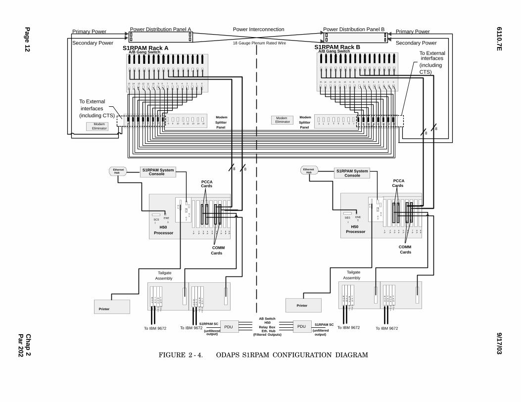
(4)6S1RPAM Subsystem. The S1RPAM sub−system consists of two sets of the following equipment:IBM 7026 Model H50 processor, Gateway 5100 or
5150 notebook system console, Bay Networks Ether−
Chap 2 Par 202
6110.7E9/17/03
Page 11
net Hub, eight powered B&B Electronics modem split−ters, modem splitter power distribution panel,Cyberex Power Distribution Unit (PDU), an Auto−
matic Switching System Series 5000 A/B Switch anda Lexmark matrix printer. All components except the
printer are housed in a Crenlo rack. In addition, theS1RPAM subsystem also contains NEC 2400M mo−dem (Oakland), General DataComm 201C modem
(New York), ME801A/ME801B Sync Short Haul mo−dems, Bell 1600 modem (Oakland), Codex 6250 multi−
plexor, and ME800A Asynch−Short Haul modems. SeeFigure 2 − 4, S1RPAM Configuration Diagram. Thissubsystem interfaces the FDPS to a variety of commu−
nication lines from other facilities. These lines sup−port the exchange of flight data and related support
information. The S1RPAM subsystem also interfacesthe FDPS to local devices.
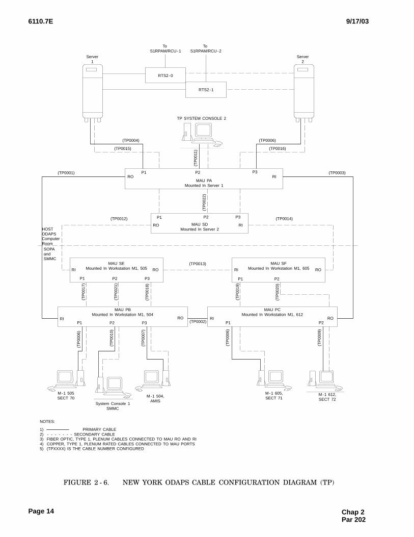
(5)6TP Subsystem. The TP subsystem con−
sists of IBM 7018 Model 770 or Model 771 RISC/6000processor, IBM 4226 Model 302 printer, IBM 6091Model 19−inch color display, Certainty ARRAY/6000
disk, IBM 3151 ASCII display, IBM 7208 tape drive,Cyberex Model 163A445 − 1 208 V power distribution
unit, Cyberex Model 600/6FA1 110 V power distribu−tion unit, Black Box powered Multi−station AccessUnit (MAU) with Ring In/Ring Out (RIRO) fiber in−
terface, Black Box Model SK − SW901A RS232 fall−back switches, Loral Initial Sector Suite Rack, Black
Box 3−port modem splitter, a RM060 converter rack(expansion chassis) which holds a power supply, aBlack Box RS232/RS485 converter to interface with
the CCK, an TFSP, an IBM QWERTY 101 keyboard,Measurement Systems Trackball or IBM mouse, and
19−inch (width) Rack. An example of the ARTCC TPin Oakland is shown in Figure 2 − 5, Oakland ODAPSCable Configuration Diagram (TP), and New York
ARTCC is shown in Figure 2 − 6, New York ODAPSCable Configuration Diagram (TP). This subsystem
provides a visual display of update, general informa−tion, weather, and flight strip messages. It also pro−vides an input interface for controller entered
messages.
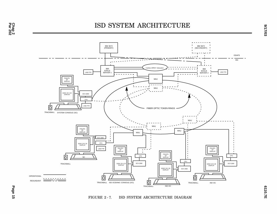
(6)6ISD Subsystem. The ISD subsystem con−sist of IBM 7018 Model 770 or Model 771 Reduced
Instruction Set Computer (RISC)/6000 processors(site dependent), IBM 4226 or 4232 line printer, SONY
20x20 color display, a 19−inch Philips auxiliary dis−
play, ARRAY/6000 disk, IBM 3151 or 3153 AmericanStandard Code for Information Interchange (ASCII)display, IBM 7208 tape drive, Cyberex Model
163A445 − 1 208 V PDU, Cyberex Model 600/6FA1110 V PDU, a Display Controller for X − Windows
(DCX), a transceiver, a Black Box powered MAU withRIRO fiber interface, Server Rack, a Common ConsoleKeyboard (CCK), a Space Saver Keyboard, Measure−
ment Systems Trackball, and a Common ConsoleFrame. See Figure 2 − 7, ISD System Architecture Dia−
gram. The subsystem interfaces the Flight Data Proc−essing Subsystem (FDPS) to ISD Servers, which areconnected to ISD Oceanic Consoles (OC).
(7)6ODAPS Software Subsystem. The
ODAPS software subsystem consists of the followingsoftware modules: the NAS monitor, the FDPS pro−
gram, the conflict probe subsystem program, theS1RPAM program, and the ISD program.
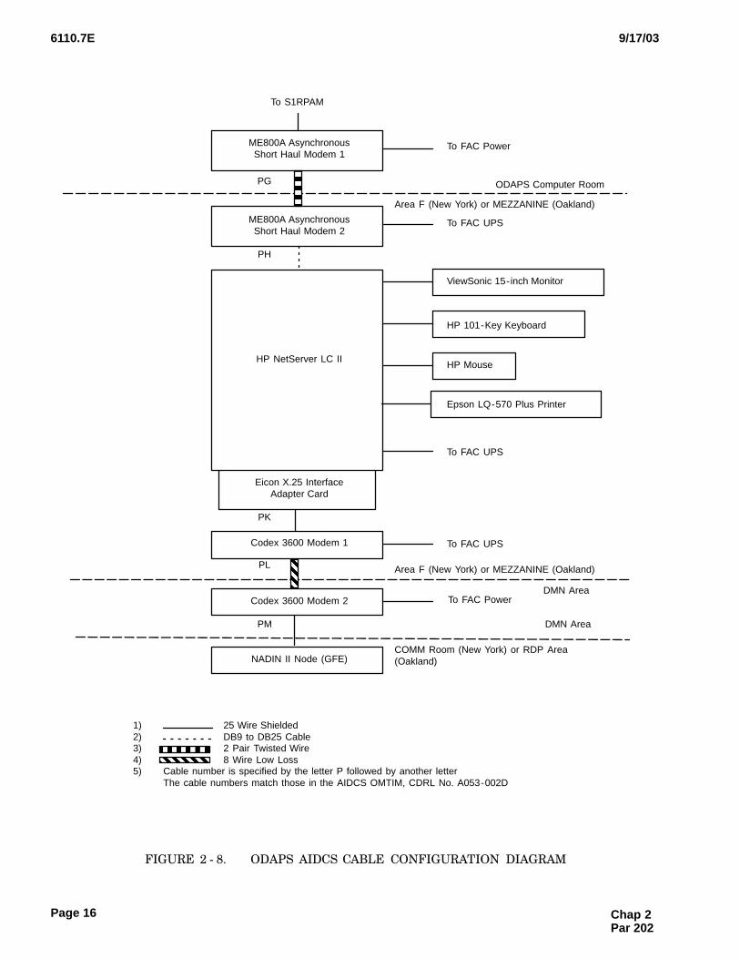
(8)6AIDCS Subsystem. The AIDCS consistsof one Hewlett Packard (HP) NetServer LC II system
computer, one HP D4950B ABA 101−key enhancedkeyboard, one HP mouse, one ViewSonic E65515−inch Super Video Graphics Adapter (SVGA) moni−
tor, one Epson LQ−570 Plus printer, two MotorolaCodex 3600 modems, two Black Box ME800A asyn−
chronous short haul modems, one Eicon X.25 inter−face adapter, and one American Power Conversion(APC) Smart Universal Power Supply (UPS) 600 or
1000. The HP NetServer LC II system computer con−sists of an Intel Pentium II 266 − MHz processor,
32 − MB of Random Access Memory (RAM), a 2 − GBremovable hard drive, a 1.44 − MB floppy disk drive,a 24X CD − ROM, two serial communication port
adapters, a parallel printer port, and an Eicon HighSpeed Interface (HSI/PC) 1 − MB X.25 interface card.
The ODAPS AIDCS Cable Configuration�Dia−gram�is shown in figure 2 − 8. This subsystem inter−faces to the S1RPAM via a pair of Black Box ME800A
asynchronous short haul modems and to NADIN IIvia a pair of Codex modems. These interfaces are used
by this subsystem to exchange flight information mes−sages with ODAPS via the S1RPAM and with non−USFIRs via NADIN. This subsystem provides a visual
display of flight information, the status of the connec−tions to ODAPS and the FIRs, and error information.
It also provides an interface for controller input.
Chap 2Par 202
6110.7E9/17/03
Pag
e 12C
hap
2P
ar 202
S1RPAM Rack AA/B Gang Switch
ENE
TSCS
TailgateAssembly
EthernetHub
Printer
015
S1RPAM Rack BA/B Gang Switch
11
T
I
H50Processor
TailgateAssembly
EthernetHub
Printer
PCCACards
COMMCards
PCCACards
COMMCards
To IBM 9672
To External interfaces(including CTS)
S1RPAM SystemConsole
To External
Splitter
Modem
Panel
To IBM 9672 To IBM 9672 To IBM 9672
S1RPAM SystemConsole
H50Processor
PDU PDU S1RPAM SC
(unfilteredoutput)
AB SwitchH50
Relay BoxEth. Hub
(Filtered Outputs)
S1RPAM SC
(unfilteredoutput)
ModemEliminator
ModemEliminator
I
ENESCS
Splitter
Modem
Panel
14 13 12 11 10 9 8 7 6 5 4 3 2 1
1514131211109876543210
015 14 13 12 11 10 9 8 7 6 5 4 3 2 1
1514131211109876543210
BUS
IN
BUS
IN
TAG
IN
TAG
IN
BUS
OUT
BUS
OUT
TAG
OUT
TAG
OUT
BUS
IN
TAG
IN
BUS
OUT
TAG
OUT
BUS
IN
TAG
IN
BUS
OUT
TAG
OUT
1P
2P
3P
4P
5P
6P
7P
8P
9P
1P
2P
3P
4P
5P
6P
7P
8P
9P
P1
S1
S3
62
P1
S1
S3
62
8 8
88
Power Distribution Panel A Power Distribution Panel BPrimary Power
Secondary Power
Primary Power
Secondary Power
Power Interconnection
18 Gauge Plenum Rated Wire
interfaces(includingCTS)
I
FIGURE 2 − 4.��ODAPS S1RPAM CONFIGURATION DIAGRAM

6110.7E9/17/03
Page 13
TPServer
1
TPServer
2
TP SYSTEM CONSOLE 2
RO RIP1 P2 P6
RO
P1 P2 P3
RI
(TPM0001)
MAU PAMounted In TP Server 1
MAU SDMounted In TP Server 2
(TPM0003)
(TPM0004) (TPM0006)
HOSTODAPSComputerRoom
P1 P2 P3
MAU SGMounted In M1 Console #727
MAU SHMounted In M1 Console #519
(TPM0005)
RI ROP2 P4 P6
MAU PDMounted In M1 Console #727
P1 P6
MAU PEMounted In M1 Console #519
(TPM0002)
RI RORI RO
(TP
0029
)
(TP
0026
)
(TP
M00
19)
(TP
M00
08)
(TP
M00
12)
(TP
M00
18)
1) PRIMARY CABLE2) - - - - - - - SECONDARY CABLE3) FIBER OPTIC, TYPE 1, PLENUM CABLES CONNECTED TO MAU RO AND RI4) COPPER, TYPE 1, PLENUM RATED CABLES CONNECTED TO MAU PORTS5) (TPMXXXX) IS THE CABLE NUMBER CONFIGURED
NOTES:
MEZZANINE
(TP
M00
20)
(TP
M00
21)
(TP
M00
22)
(TP
M00
23)
(TP
M00
24)
(TP
M00
25)
P4 P5 P6 P7(T
P00
27)
(TP
0028
)
(TP
0030
)
P1 P2 P3 P5 P6
(TP
M00
07)
(TP
M00
09)
(TP
M00
10)
(TP
M00
11)
(TP
M00
13)
(TP
M00
15)
(TP
M00
14)
(TP
M00
16)
(TP
M00
17)
OC7M1 #733
OC2M1 #725
OC1M1 #723
AO1M1 #715
OC3M1 #623
System Console 1
OC4M1 #621
OC9M1 #523
OC5M1 #521
AO5M1 #513
OC6M1 #507
AO4M1 #613
RTS2-1
SOPA and SMMC
P1 P3 P5 P7
RI RO
RTS2-0
To S1RPAM/RCU-1
To S1RPAM/RCU-2
P2 P3 P5
FIGURE 2 − 5.��OAKLAND ODAPS CABLE CONFIGURATION DIAGRAM (TP)
Chap 2Par 202
6110.7E 9/17/03
Page 14
Server1
Server2
TP SYSTEM CONSOLE 2
(TP0004)
(TP0015)
(TP0006)
(TP0016)
RO RIP1 P2 P3
RO
P1 P2 P3
RI
(TP0001)
MAU PAMounted In Server 1
MAU SDMounted In Server 2
(TP0003)
(TP0012) (TP0014)
HOSTODAPSComputerRoomSOPAandSMMC
P1 P2 P3 P1 P2
MAU SEMounted In Workstation M1, 505
MAU SFMounted In Workstation M1, 605
(TP0013)
RI ROP1 P2 P3
MAU PBMounted In Workstation M1, 504
RI ROP1 P2
MAU PCMounted In Workstation M1, 612
(TP0002)
RI RORI RO
(TP
0020
)
(TP
0019
)
(TP
0018
)
(TP
0021
)
(TP
0017
)
(TP
0022
)
(TP
0006
)
(TP
0010
)
(TP
0007
)
(TP
0006
)
(TP
0009
)
1) PRIMARY CABLE2) - - - - - - - SECONDARY CABLE3) FIBER OPTIC, TYPE 1, PLENUM CABLES CONNECTED TO MAU RO AND RI4) COPPER, TYPE 1, PLENUM RATED CABLES CONNECTED TO MAU PORTS5) (TPXXXX) IS THE CABLE NUMBER CONFIGURED
NOTES:
(TP
0011
)
M -1 504,AMIS
M-1 505SECT 70
M-1 605,SECT 71
M-1 612,SECT 72
System Console 1SMMC
RTS2-1
RTS2-0
To S1RPAM/RCU-1
To S1RPAM/RCU-2
FIGURE 2 − 6.��NEW YORK ODAPS CABLE CONFIGURATION DIAGRAM (TP)
Chap 2 Par 202
6110.7E9/17/03
Pag
e 15C
hap
2P
ar 202
PHILIPS19”
DISPLAY
SONY 20 X 20DISPLAY
MAU
MAU
MAUMAU
MAU
FIBER OPTIC TOKEN RINGS
DCX 2000
CPU
LINE PTR
SC
TRACKBALL
PHILIPS19”
DISPLAY
SONY 20 X 20DISPLAY
DCX 2000
CPU
ISD OCEANIC CONSOLE (OC)TRACKBALL
MAU
PHILIPS19”
DISPLAY
SONY 20 X 20DISPLAY
DCX 2000
CPU
ISD OCTRACKBALL
SONY 20 X 20DISPLAY
DCX 2000
CPU
ISD OCTRACKBALL
PHILIPS19”
DISPLAY
SONY 20 X 20DISPLAY DCX 2000
SYSTEM CONSOLE (SC)TRACKBALL
CPU
LINE PTR
LINE PTR
IBMEAGLE
SERVER 1
Cambex ARRAY SubsystemIBM
EAGLESERVER 2 LINE PTR
IBM 9672(SECONDARY)
IBM 9672(PRIMARY)
ODAPS
ISD
OPERATIONAL
REDUNDANT
ISD SYSTEM ARCHITECTURE
PHILIPS19”
DISPLAY
FIGURE 2 − 7.��ISD SYSTEM ARCHITECTURE DIAGRAM
6110.7E 9/17/03
Page 16
To S1RPAM
ME800A AsynchronousShort Haul Modem 1
PG
To FAC Power
To FAC UPS
ODAPS Computer Room
Area F (New York) or MEZZANINE (Oakland)
ViewSonic 15-inch Monitor
HP 101-Key Keyboard
HP Mouse
Epson LQ-570 Plus Printer
PH
ME800A AsynchronousShort Haul Modem 2
HP NetServer LC II
Eicon X.25 InterfaceAdapter Card
To FAC UPS
To FAC UPS
PK
Codex 3600 Modem 1
PL
NADIN II Node (GFE)
Codex 3600 Modem 2
PM
ÊÊÊÊÊÊ
ÈÈÈÈ
To FAC PowerDMN Area
DMN Area
COMM Room (New York) or RDP Area(Oakland)
1) 25 Wire Shielded2) DB9 to DB25 Cable3) 2 Pair Twisted Wire4) 8 Wire Low Loss5) Cable number is specified by the letter P followed by another letter
The cable numbers match those in the AIDCS OMTIM, CDRL No. A053-002D
ËËËËÈÈÈÈÈÈÈÈ
Area F (New York) or MEZZANINE (Oakland)
FIGURE 2 − 8.��ODAPS AIDCS CABLE CONFIGURATION DIAGRAM
Chap 2 Par 202
6110.7E9/17/03
Page 17
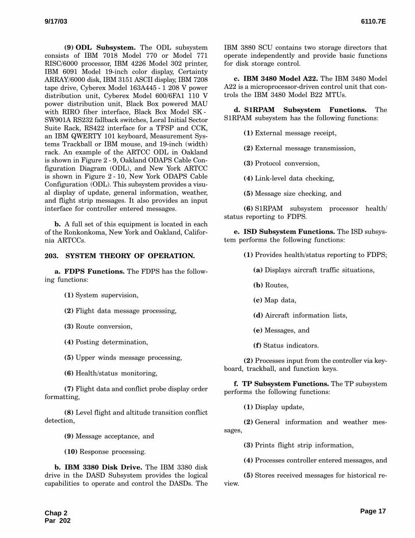
(9)6ODL Subsystem. The ODL subsystemconsists of IBM 7018 Model 770 or Model 771RISC/6000 processor, IBM 4226 Model 302 printer,
IBM 6091 Model 19−inch color display, CertaintyARRAY/6000 disk, IBM 3151 ASCII display, IBM 7208
tape drive, Cyberex Model 163A445 − 1 208 V powerdistribution unit, Cyberex Model 600/6FA1 110 Vpower distribution unit, Black Box powered MAU
with RIRO fiber interface, Black Box Model SK −SW901A RS232 fallback switches, Loral Initial Sector
Suite Rack, RS422 interface for a TFSP and CCK,an IBM QWERTY 101 keyboard, Measurement Sys−tems Trackball or IBM mouse, and 19−inch (width)
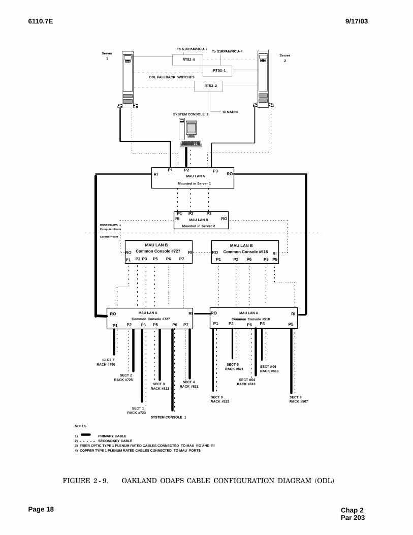
rack. An example of the ARTCC ODL in Oaklandis shown in Figure 2 − 9, Oakland ODAPS Cable Con−
figuration Diagram (ODL), and New York ARTCCis shown in Figure 2 − 10, New York ODAPS CableConfiguration (ODL). This subsystem provides a visu−
al display of update, general information, weather,and flight strip messages. It also provides an input
interface for controller entered messages.
b.A full set of this equipment is located in each
of the Ronkonkoma, New York and Oakland, Califor−nia ARTCCs.
203.�SYSTEM THEORY OF OPERATION.
a.FDPS Functions. The FDPS has the follow−
ing functions:
(1)6System supervision,
(2)6Flight data message processing,
(3)6Route conversion,
(4)6Posting determination,
(5)6Upper winds message processing,
(6)6Health/status monitoring,
(7)6Flight data and conflict probe display orderformatting,
(8)6Level flight and altitude transition conflictdetection,
(9)6Message acceptance, and
(10)6Response processing.
b.IBM 3380 Disk Drive. The IBM 3380 diskdrive in the DASD Subsystem provides the logical
capabilities to operate and control the DASDs. The
IBM 3880 SCU contains two storage directors thatoperate independently and provide basic functionsfor disk storage control.
c.IBM 3480 Model A22. The IBM 3480 ModelA22 is a microprocessor−driven control unit that con−
trols the IBM 3480 Model B22 MTUs.
d.S1RPAM Subsystem Functions. The
S1RPAM subsystem has the following functions:
(1)6External message receipt,
(2)6External message transmission,
(3)6Protocol conversion,
(4)6Link−level data checking,
(5)6Message size checking, and
(6)6S1RPAM subsystem processor health/
status reporting to FDPS.
e.ISD Subsystem Functions. The ISD subsys−
tem performs the following functions:
(1)6Provides health/status reporting to FDPS;
(a)6Displays aircraft traffic situations,
(b)6Routes,
(c)6Map data,
(d)6Aircraft information lists,
(e)6Messages, and
(f)6Status indicators.
(2)6Processes input from the controller via key−board, trackball, and function keys.
f.TP Subsystem Functions. The TP subsystemperforms the following functions:
(1)6Display update,
(2)6General information and weather mes−
sages,
(3)6Prints flight strip information,
(4)6Processes controller entered messages, and
(5)6Stores received messages for historical re−
view.
Chap 2Par 202
6110.7E 9/17/03
Page 18
ÏÏÏ
ÏÏ
ÏÏÏÏÏÏ
ÏServer
2
P1
P2
SYSTEM CONSOLE 2
P2
Ï
P3
Mounted in Server 1
P3
P1
P1
P2P1
HOST/ODAPS
Computer Room
Control Room
P6P5 P1 P2 P3 P5
P2 P3 P5 P6 P1 P2 P3 P5
P3
RORI MAU LAN A
RORI
RI
RIRORIRO
RORIRO
MAU LAN B
Mounted in Server 2
MAU LAN B
Common Console #727 MAU LAN B
Common Console #518
MAU LAN A
Common Console #727
MAU LAN A
Common Console #518
SYSTEM CONSOLE 1
SECT 7RACK #750
SECT 2RACK #725
SECT 3RACK #823
SECT 1RACK #723
SECT 5RACK #521
SECT 9RACK #523
SECT A09RACK #513
SECT 6RACK #507
RTS2-0
RTS2-1
Server
1
To S1RPAM/RCU-3To S1RPAM/RCU-4
To NADIN
ODL FALLBACK SWITCHES
NOTES
1) PRIMARY CABLE2) SECONDARY CABLE3) FIBER OPTIC TYPE 1 PLENUM RATED CABLES CONNECTED TO MAU RO AND RI4) COPPER TYPE 1 PLENUM RATED CABLES CONNECTED TO MAU PORTS
RTS2-2
P6
P6
SECT A04RACK #613
P7
P7
SECT 4RACK #821
FIGURE 2 − 9.��OAKLAND ODAPS CABLE CONFIGURATION DIAGRAM (ODL)
Chap 2 Par 203

6110.7E9/17/03
Page 19
ÏÏÏÏÏÏ
ÏÏ
ÏÏ
ÏÏ
Ï Server
2
ÏÏÏ
P1
Ï
P2
SYSTEM CONSOLE 2
P2
Ï
ÏÏ
P3
Mounted in Server 1
P3
P1
Ï Ï
P1
P2P1
ÏÏ
HOST/ODAPSComputer Room
New Control
Room/AMCC
P5P4 P4 P1 P2 P3
P2 P3 P4 P5 P1 P2 P3 P4
P3
RORI MAU LAN A
RORI
RI
RIRORIRO
RORIRO
MAU LAN B
Mounted in Server 2
MAU LAN BCommon Console #237
MAU LAN BCommon Console #102
MAU LAN A
Common Console #237
MAU LAN A
Common Console #102
SYSTEM CONSOLE 1
SECT 72
RACK #137
SECT 87
RACK #233
SECT 84
RACK #238
SECT 88
RACK #226
SECT 70
RACK #108
SECT 89
RACK #212
SECT 71
RACK #111
SECT 90
RACK #204
RTS2-0
RTS2-1
Server
1
To S1RPAM/RCU3To S1RPAM/RCU4
To NADIN
ODL FALLBACK SWITCHES
NOTES
1) PRIMARY CABLE
2) SECONDARY CABLE
3) FIBER OPTIC TYPE 1 PLENUM RATED CABLES CONNECTED TO MAU RO AND RI
4) COPPER TYPE 1 PLENUM RATED CABLES CONNECTED TO MAU PORTS
RTS2-2
FIGURE 2 − 10.��NEW YORK ODAPS CABLE CONFIGURATION DIAGRAM (ODL)
Chap 2Par 203
6110.7E 9/17/03
Page 20
g.ODAPS Software Subsystem Functions.The ODAPS software subsystem performs the follow−ing functions:
(1)6Receives plan messages,
(2)6Departure messages,
(3)6Amendment messages,
(4)6Creates a data base for all aircraft that areoperating within a oceanic sector, and
(5)6Gives the controller early notification ofpotential conflicts between aircraft in oceanic air−
space.
h.AIDCS Subsystem Functions. The AIDCSSubsystem performs the following functions:
(1)6External message receipt,
(2)6External message transmission,
(3)6Message field validation,
(4)6Message format conversion,
(5)6Message delivery assurance,
(6)6Response message processing,
(7)6Flight data base creation and maintenance,
(8)6External interface status monitoring,
(9)6Controller input processing,
(10)6Message logging,
(11)6Message printing, and
(12)6Display updating.
i.ODL Subsystem Functions. The ODL Sub−system performs the following functions:
(1)6Existing TP functionality,
(2)6CPDLC message processing (air/ground
communications processing),
(3)6Outgoing data communications with ROsfor message processing with HF−equipped aircraft,
(4)6NADIN II interface for CPDLC Position
Report transmittal to the ODAPS,
(5)6Message composition automation at opera−tional positions,
(6)6Message archival for historical and legalpurposes,
(7)6Multi−sector processing support,
(8)6Controller−to−Controller communications
(E − Mail capability),
(9)6Data Reduction and Analysis (DR&A) func−tionality,
(10)6Controller−to−RO messages, and
(11)6CPDLC message processing redundancy.
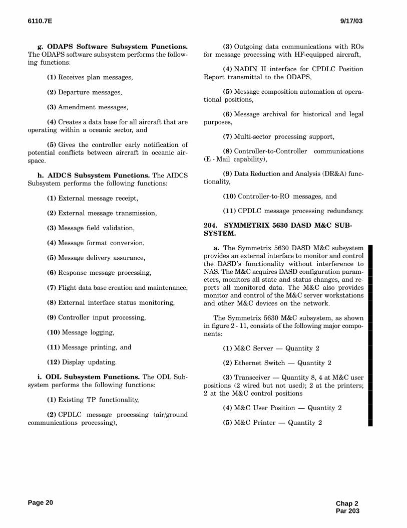
204.�SYMMETRIX 5630 DASD M&C SUB−SYSTEM.
a.The Symmetrix 5630 DASD M&C subsystemprovides an external interface to monitor and control
the DASD’s functionality without interference toNAS. The M&C acquires DASD configuration param−eters, monitors all state and status changes, and re−
ports all monitored data. The M&C also providesmonitor and control of the M&C server workstations
and other M&C devices on the network.
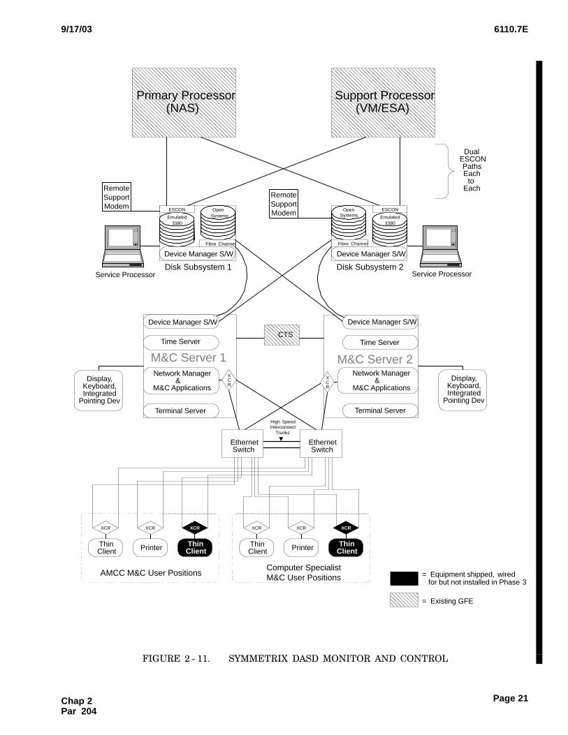
The Symmetrix 5630 M&C subsystem, as shownin figure 2 − 11, consists of the following major compo−
nents:
(1)6M&C Server N Quantity 2
(2)6Ethernet Switch N Quantity 2
(3)6Transceiver N Quantity 8, 4 at M&C user
positions (2 wired but not used); 2 at the printers;2 at the M&C control positions
(4)6M&C User Position N Quantity 2
(5)6M&C Printer N Quantity 2
Chap 2 Par 203
6110.7E9/17/03
Page 21
ÌÌÌÌÌÌÌÌÌ
RemoteSupportModem
ÑÑÑÑÑÑÑÑÑÑÑÑÑÑÑÑÑÑÑÑÑÑÑÑÑÑÑÑÑÑÑÑÑÑÑÑÑÑÑÑÑÑÑÑÑÑÑÑ
Primary Processor(NAS)
ÓÓÓÓÓÓÓÓÓÓÓÓÓÓÓÓÓÓÓÓÓÓÓÓÓÓÓÓÓÓÓÓÓÓÓÓÓÓÓÓÓÓÓÓÓÓÓÓ
Support Processor(VM/ESA)
Emulated3380
OpenSystems
Device Manager S/W
ESCON
Fibre Channel
OpenSystems
Device Manager S/W
M&C Server 1 M&C Server 2Network Manager
&M&C Applications
Network Manager&
M&C Applications
Time ServerTime ServerCTS
Display,Keyboard,Integrated
Pointing DevTerminal ServerTerminal Server
Computer SpecialistM&C User Positions
DualESCONPathsEach
toEach
XCR
Disk Subsystem 1 Disk Subsystem 2
ÑÑÑÑÑÑ
= Existing GFE
Device Manager S/W Device Manager S/W
Service Processor Service Processor
High SpeedInterconnect
Trunks
ThinClient
XCR
ThinClient
XCR
Printer
XCR
AMCC M&C User Positions = Equipment shipped, wiredfor but not installed in Phase 3
RemoteSupportModem
Emulated3380
ESCON
Fibre Channel
XCR
ThinClient
XCR
ThinClient
XCR
Printer
XCR
Display,Keyboard,Integrated
Pointing Dev
EthernetSwitch
EthernetSwitch
FIGURE 2 − 11.��SYMMETRIX DASD MONITOR AND CONTROL
Chap 2Par 204
6110.7E 9/17/03
Page 22
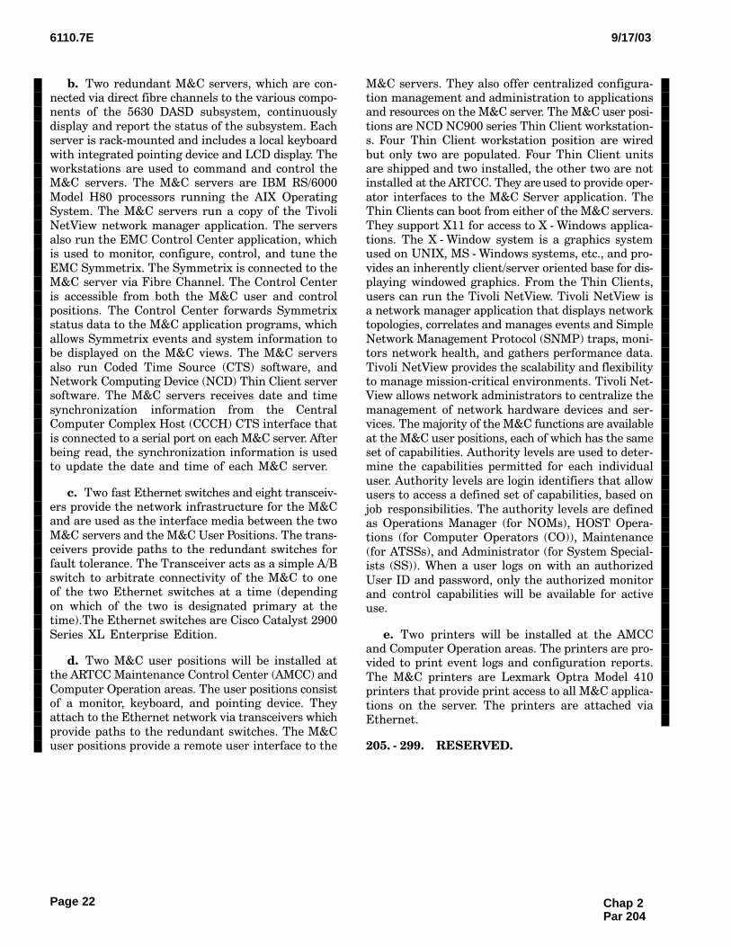
b.Two redundant M&C servers, which are con−nected via direct fibre channels to the various compo−nents of the 5630 DASD subsystem, continuously
display and report the status of the subsystem. Eachserver is rack−mounted and includes a local keyboard
with integrated pointing device and LCD display. Theworkstations are used to command and control theM&C servers. The M&C servers are IBM RS/6000
Model H80 processors running the AIX OperatingSystem. The M&C servers run a copy of the Tivoli
NetView network manager application. The serversalso run the EMC Control Center application, whichis used to monitor, configure, control, and tune the
EMC Symmetrix. The Symmetrix is connected to theM&C server via Fibre Channel. The Control Center
is accessible from both the M&C user and controlpositions. The Control Center forwards Symmetrixstatus data to the M&C application programs, which
allows Symmetrix events and system information tobe displayed on the M&C views. The M&C servers
also run Coded Time Source (CTS) software, andNetwork Computing Device (NCD) Thin Client serversoftware. The M&C servers receives date and time
synchronization information from the CentralComputer Complex Host (CCCH) CTS interface that
is connected to a serial port on each M&C server. Afterbeing read, the synchronization information is usedto update the date and time of each M&C server.
c.Two fast Ethernet switches and eight transceiv−ers provide the network infrastructure for the M&Cand are used as the interface media between the two
M&C servers and the M&C User Positions. The trans−ceivers provide paths to the redundant switches for
fault tolerance. The Transceiver acts as a simple A/Bswitch to arbitrate connectivity of the M&C to oneof the two Ethernet switches at a time (depending
on which of the two is designated primary at thetime).The Ethernet switches are Cisco Catalyst 2900
Series XL Enterprise Edition.
d.Two M&C user positions will be installed atthe ARTCC Maintenance Control Center (AMCC) and
Computer Operation areas. The user positions consistof a monitor, keyboard, and pointing device. Theyattach to the Ethernet network via transceivers which
provide paths to the redundant switches. The M&Cuser positions provide a remote user interface to the
M&C servers. They also offer centralized configura−tion management and administration to applicationsand resources on the M&C server. The M&C user posi−
tions are NCD NC900 series Thin Client workstation−s. Four Thin Client workstation position are wired
but only two are populated. Four Thin Client unitsare shipped and two installed, the other two are notinstalled at the ARTCC. They are used to provide oper−
ator interfaces to the M&C Server application. TheThin Clients can boot from either of the M&C servers.
They support X11 for access to X − Windows applica−tions. The X − Window system is a graphics systemused on UNIX, MS − Windows systems, etc., and pro−
vides an inherently client/server oriented base for dis−playing windowed graphics. From the Thin Clients,
users can run the Tivoli NetView. Tivoli NetView isa network manager application that displays networktopologies, correlates and manages events and Simple
Network Management Protocol (SNMP) traps, moni−tors network health, and gathers performance data.
Tivoli NetView provides the scalability and flexibilityto manage mission−critical environments. Tivoli Net−View allows network administrators to centralize the
management of network hardware devices and ser−vices. The majority of the M&C functions are available
at the M&C user positions, each of which has the sameset of capabilities. Authority levels are used to deter−mine the capabilities permitted for each individual
user. Authority levels are login identifiers that allowusers to access a defined set of capabilities, based on
job responsibilities. The authority levels are definedas Operations Manager (for NOMs), HOST Opera−tions (for Computer Operators (CO)), Maintenance
(for ATSSs), and Administrator (for System Special−ists (SS)). When a user logs on with an authorized
User ID and password, only the authorized monitorand control capabilities will be available for activeuse.
e.Two printers will be installed at the AMCCand Computer Operation areas. The printers are pro−vided to print event logs and configuration reports.
The M&C printers are Lexmark Optra Model 410printers that provide print access to all M&C applica−
tions on the server. The printers are attached viaEthernet.
205. − 299.�RESERVED.
Chap 2 Par 204
6110.7E9/17/03
Page 23
CHAPTER 3. STANDARD AND TOLERANCES
300.�GENERAL.
a.This chapter prescribes the standards and tol−
erances for the ODAPS automation, as described inOrder 6000.15. All key performance parameters and/
or key inspection elements are identified by an arrow(�) placed to the left of the applicable item.
b.The equipment is grouped by subsystem, rather
than by facility, since all subsystems are duplicatedat each facility.
Chap 3Par 300
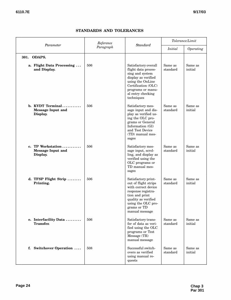
6110.7E 9/17/03
Page 24
STANDARDS AND TOLERANCES
ParameterReference
Standard
Tolerance/Limit
ParameterReference
ParagraphStandard
Initial Operating
301.�ODAPS.
a. Flight Data Processing . . . and Display.
506 Satisfactory overall
flight data proces−sing and system
display as verifiedusing the OnLine
Certification (OLC)programs or manu−al entry checking
techniques
Same as
standard
Same as
initial
b. KVDT Terminal . . . . . . . . . . . Message Input andDisplay.
506 Satisfactory mes−
sage input and dis−play as verified us−
ing the OLC pro−grams or General
Information (GI)and Test Device(TD) manual mes−
sages
Same as
standard
Same as
initial
c. TP Workstation . . . . . . . . . . . Message Input andDisplay.
506 Satisfactory mes−
sage input, scrol−ling, and display as
verified using theOLC programs or
TD manual mes−sages
Same as
standard
Same as
initial
d. TFSP Flight Strip . . . . . . . . Printing.
506 Satisfactory print−
out of flight stripswith correct device
response registra−tion and print
quality as verifiedusing the OLC pro−grams or TD
manual message
Same as
standard
Same as
initial
e. Interfacility Data . . . . . . . . . Transfer.
506 Satisfactory trans−
fer of data as veri−fied using the OLC
programs or TestMessage (TR)
manual message
Same as
standard
Same as
initial
f. Switchover Operation . . . . 508 Successful switch−
overs as verifiedusing manual re−
quests
Same as
standard
Same as
initial
Chap 3 Par 301
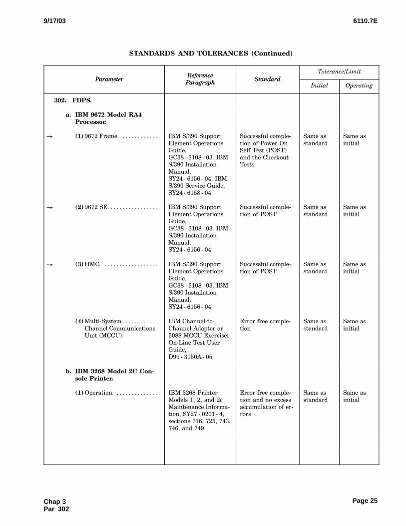
6110.7E9/17/03
Page 25
STANDARDS AND TOLERANCES (Continued)
Tolerance/Limit
StandardReference
ParagraphParameter
OperatingInitialStandard
Reference
ParagraphParameter
302.�FDPS.
a. IBM 9672 Model RA4Processor.
� (1) 9672 Frame. . . . . . . . . . . . . IBM S/390 Support
Element OperationsGuide,
GC38 − 3108 − 03. IBMS/390 Installation
Manual,SY24 − 6156 − 04. IBMS/390 Service Guide,
SY24 − 6158 − 04
Successful comple−
tion of Power OnSelf Test (POST)
and the CheckoutTests
Same as
standard
Same as
initial
� (2) 9672 SE. . . . . . . . . . . . . . . . . IBM S/390 Support
Element OperationsGuide,
GC38 − 3108 − 03. IBMS/390 Installation
Manual,SY24 − 6156 − 04
Successful comple−
tion of POST
Same as
standard
Same as
initial
� (3) HMC. . . . . . . . . . . . . . . . . . . IBM S/390 Support
Element OperationsGuide,
GC38 − 3108 − 03. IBMS/390 Installation
Manual,SY24 − 6156 − 04
Successful comple−
tion of POST
Same as
standard
Same as
initial
(4) Multi−System . . . . . . . . . . . .
Channel CommunicationsUnit (MCCU).
IBM Channel−to−
Channel Adapter or3088 MCCU Exerciser
On−Line Test UserGuide,
D99 − 3150A − 05
Error free comple−
tion
Same as
standard
Same as
initial
b. IBM 3268 Model 2C Con−sole Printer.
(1) Operation. . . . . . . . . . . . . . . IBM 3268 Printer
Models 1, 2, and 2cMaintenance Informa−
tion, SY27 − 0201 − 4,sections 716, 725, 743,
746, and 749
Error free comple−
tion and no excessaccumulation of er−
rors
Same as
standard
Same as
initial
Chap 3Par 302
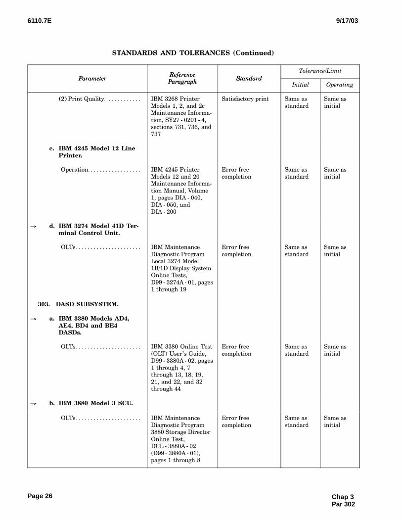
6110.7E 9/17/03
Page 26
STANDARDS AND TOLERANCES (Continued)
Tolerance/Limit
StandardReference
ParagraphParameter
OperatingInitialStandard
Reference
ParagraphParameter
(2) Print Quality. . . . . . . . . . . . IBM 3268 Printer
Models 1, 2, and 2cMaintenance Informa−
tion, SY27 − 0201 − 4,sections 731, 736, and
737
Satisfactory print Same as
standard
Same as
initial
c. IBM 4245 Model 12 LinePrinter.
Operation. . . . . . . . . . . . . . . . . . IBM 4245 Printer
Models 12 and 20Maintenance Informa−
tion Manual, Volume1, pages DIA − 040,
DIA − 050, andDIA − 200
Error free
completion
Same as
standard
Same as
initial
� d. IBM 3274 Model 41D Ter−minal Control Unit.
OLTs. . . . . . . . . . . . . . . . . . . . . . IBM Maintenance
Diagnostic ProgramLocal 3274 Model
1B/1D Display SystemOnline Tests,
D99 − 3274A − 01, pages1 through 19
Error free
completion
Same as
standard
Same as
initial
303.�DASD SUBSYSTEM.
� a. IBM 3380 Models AD4,AE4, BD4 and BE4DASDs.
OLTs. . . . . . . . . . . . . . . . . . . . . . IBM 3380 Online Test
(OLT) User’s Guide,D99 − 3380A − 02, pages
1 through 4, 7through 13, 18, 19,
21, and 22, and 32through 44
Error free
completion
Same as
standard
Same as
initial
� b. IBM 3880 Model 3 SCU.
OLTs. . . . . . . . . . . . . . . . . . . . . . IBM Maintenance
Diagnostic Program3880 Storage Director
Online Test,DCL − 3880A − 02
(D99 − 3880A − 01),pages 1 through 8
Error free
completion
Same as
standard
Same as
initial
Chap 3 Par 302
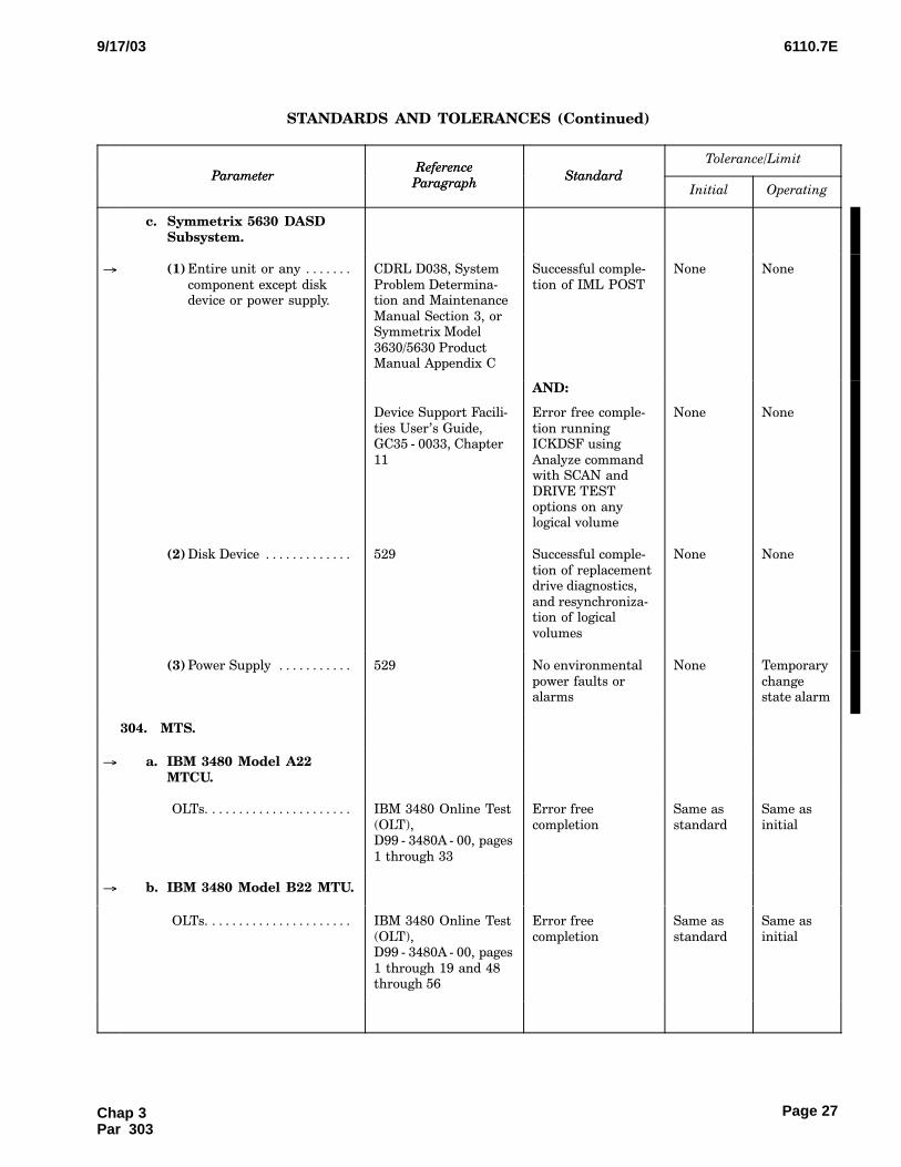
6110.7E9/17/03
Page 27
STANDARDS AND TOLERANCES (Continued)
Tolerance/Limit
StandardReference
ParagraphParameter
OperatingInitialStandard
Reference
ParagraphParameter
c. Symmetrix 5630 DASDSubsystem.
� (1) Entire unit or any . . . . . . .
component except diskdevice or power supply.
CDRL D038, System
Problem Determina−tion and Maintenance
Manual Section 3, orSymmetrix Model
3630/5630 ProductManual Appendix C
Successful comple−
tion of IML POST
None None
AND:
Device Support Facili−
ties User’s Guide,GC35 − 0033, Chapter
11
Error free comple−
tion runningICKDSF using
Analyze commandwith SCAN and
DRIVE TESToptions on anylogical volume
None None
(2) Disk Device . . . . . . . . . . . . . 529 Successful comple−
tion of replacementdrive diagnostics,
and resynchroniza−tion of logical
volumes
None None
(3) Power Supply . . . . . . . . . . . 529 No environmental
power faults oralarms
None Temporary
changestate alarm
304.�MTS.
� a. IBM 3480 Model A22MTCU.
OLTs. . . . . . . . . . . . . . . . . . . . . . IBM 3480 Online Test
(OLT),D99 − 3480A − 00, pages
1 through 33
Error free
completion
Same as
standard
Same as
initial
� b. IBM 3480 Model B22 MTU.
OLTs. . . . . . . . . . . . . . . . . . . . . . IBM 3480 Online Test
(OLT),D99 − 3480A − 00, pages
1 through 19 and 48through 56
Error free
completion
Same as
standard
Same as
initial
Chap 3Par 303

6110.7E 9/17/03
Page 28
STANDARDS AND TOLERANCES (Continued)
Tolerance/Limit
StandardReference
ParagraphParameter
OperatingInitialStandard
Reference
ParagraphParameter
305.�S1RPAM SUBSYSTEM.
� a. IBM 7026 Model H50RISC/6000 Processor.
(1) H50 Diagnostics. . . . . . . . . 517; IBM RISC/6000
Enterprise ServerModel H50 User’s
Guide,SA38 − 0546 − 00, Chap−
ter 8, Steps 1 − 5
Error free
completion
Same as
standard
Same as
initial
(2) S1RPAM . . . . . . . . . . . . . . . .
Diagnostics.
507; TI 6110.11 Error free
completion
Same as
standard
Same as
initial
(3) S1RPAM Wrap . . . . . . . . . .
Diagnostics.
516; TI 6110.11 Error free
completion
Same as
standard
Same as
initial
b. Lexmark 2391 Plus . . . . . . Matrix Printer.
TI 6110.10 Error free
completion
Same as
standard
Same as
initial
c. S1RPAM Replacement . . . . Operation.
515 Successful
replacement asverified using
manual requests
Same as
standard
Same as
initial
306.�ISD SUBSYSTEM.
� a. IBM RISC/6000 Model . . . . 770 or 771.
Error free
completion
Same as
standard
Same as
initial
b. IBM 4226 or 4232 . . . . . . . Line Printer Operation.
514; IBM 4226 Printer
User’s Reference,GA18 − 7182 − 0, pages
5 − 3 through 5 − 4.IBM 4232 Printer
User’s Guide,SA24 − 43506 − 01,Chapter 4
Error free
completion
Same as
standard
Same as
initial
� c. Sony 20x20 Color . . . . . . . . Display.
TI 6110.4 Error free
completion
Same as
standard
Same as
initial
d. Server Switchover. . . . . . . . 509 Successful
switchovers asverified using
manual requests
Same as
standard
Same as
initial
Chap 3 Par 305
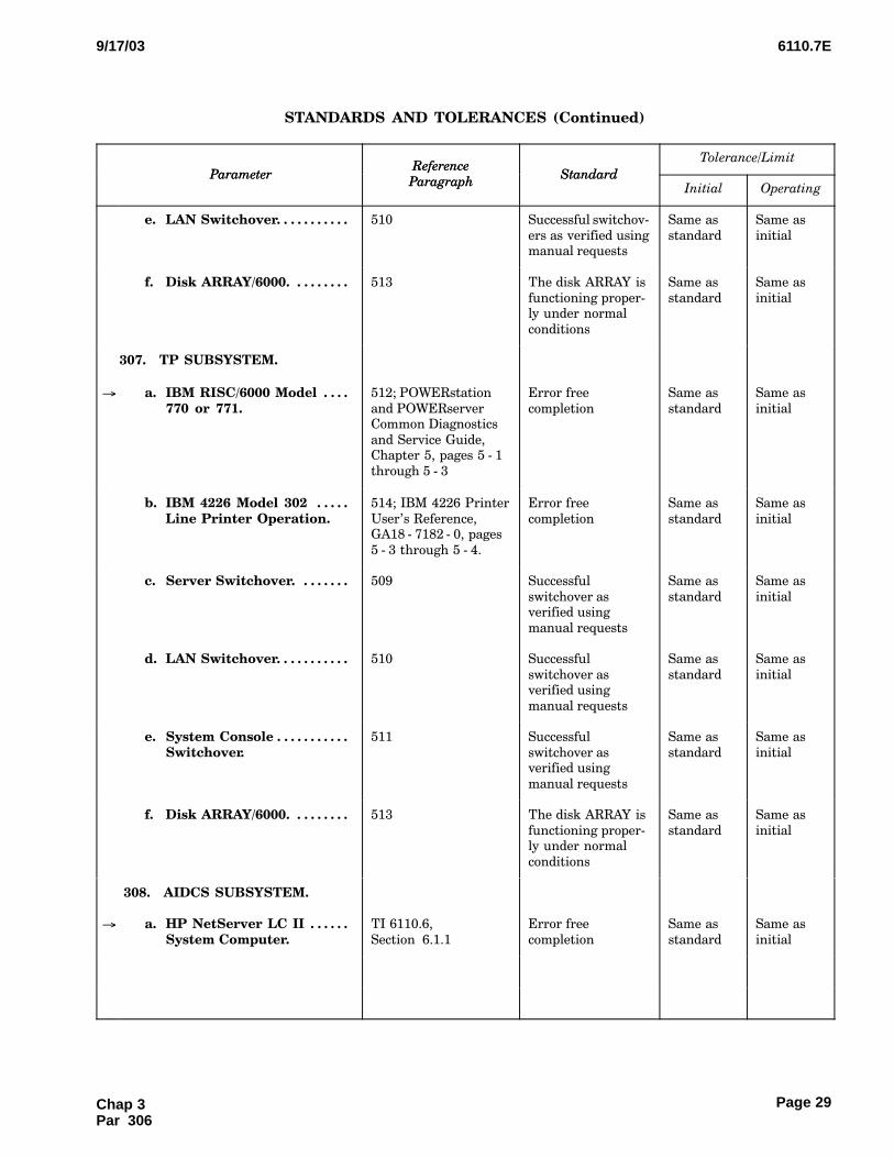
6110.7E9/17/03
Page 29
STANDARDS AND TOLERANCES (Continued)
Tolerance/Limit
StandardReference
ParagraphParameter
OperatingInitialStandard
Reference
ParagraphParameter
e. LAN Switchover. . . . . . . . . . . 510 Successful switchov−
ers as verified usingmanual requests
Same as
standard
Same as
initial
f. Disk ARRAY/6000. . . . . . . . . 513 The disk ARRAY is
functioning proper−ly under normal
conditions
Same as
standard
Same as
initial
307.�TP SUBSYSTEM.
� a. IBM RISC/6000 Model . . . . 770 or 771.
512; POWERstation
and POWERserverCommon Diagnostics
and Service Guide,Chapter 5, pages 5 − 1
through 5 − 3
Error free
completion
Same as
standard
Same as
initial
b. IBM 4226 Model 302 . . . . . Line Printer Operation.
514; IBM 4226 Printer
User’s Reference,GA18 − 7182 − 0, pages
5 − 3 through 5 − 4.
Error free
completion
Same as
standard
Same as
initial
c. Server Switchover. . . . . . . . 509 Successful
switchover asverified using
manual requests
Same as
standard
Same as
initial
d. LAN Switchover. . . . . . . . . . . 510 Successful
switchover asverified using
manual requests
Same as
standard
Same as
initial
e. System Console . . . . . . . . . . . Switchover.
511 Successful
switchover asverified using
manual requests
Same as
standard
Same as
initial
f. Disk ARRAY/6000. . . . . . . . . 513 The disk ARRAY is
functioning proper−ly under normal
conditions
Same as
standard
Same as
initial
308.�AIDCS SUBSYSTEM.
� a. HP NetServer LC II . . . . . . System Computer.
TI 6110.6,
Section�6.1.1
Error free
completion
Same as
standard
Same as
initial
Chap 3Par 306

6110.7E 9/17/03
Page 30
STANDARDS AND TOLERANCES (Continued)
Tolerance/Limit
StandardReference
ParagraphParameter
OperatingInitialStandard
Reference
ParagraphParameter
b. Epson LQ − 570 Printer. . . . TI 6110.6,
Section�6.1.2
Ink level is ade−
quate and printingoperation causes
paper advance anddisplays correct
character heightand width
Same as
standard
Same as
initial
c. ME800A Short Haul . . . . . . Modems.
518 Green front panel
Transmit Data(TD) or Receive
Data (RD) lightflashes approxi−
mately twice persecond
Same as
standard
Same as
initial
d. Eicon X.25 Interface . . . . . . Adapter.
TI 6110.6,
Section�6.1.4
Color of all FIR
names in AIDCSaddress list are yel−
low or green
Same as
standard
Same as
initial
e. UPS 600 or 1000. . . . . . . . . . 520 The LED labeled
OOn Line" is lit
Same as
standard
Same as
initial
f. ODAPS − AIDCS − FIR . . . . . Interfaces (New YorkARTCC).
521 A TR message is
sent from ODAPSthrough AIDCS to
a FIR. ODAPS re−ceives a DT re−
sponse within 30seconds.
Same as
standard
Same as
initial
g. ODAPS − AIDCS − FIR . . . . . Interfaces (OaklandARTCC).
522 A TR message is
sent from ODAPSto AIDCS. ODAPS
receives a DT re−sponse within 5 to
10 seconds. A MISmessage is sentfrom AIDCS to a
FIR (if necessary).AIDCS receives a
LAM responsewithin 30 seconds.
Same as
standard
Same as
initial
309.�ODL SUBSYSTEM.
a. IBM RISC/6000 Model . . . . 770 or 771.
512 Error free
completion
Same as
standard
Same as
initial
b. IBM 4226 or 4232 . . . . . . . . Line Printer.
514 Error free
completion
Same as
standard
Same as
initial
Chap 3 Par 308
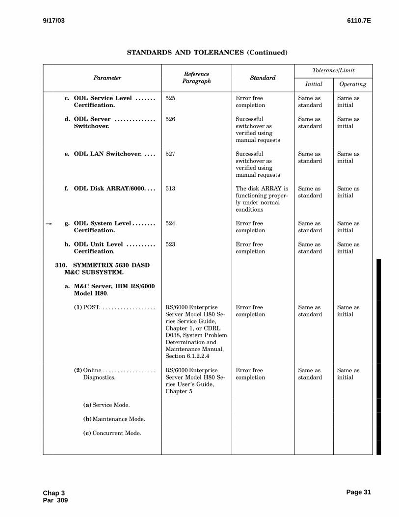
6110.7E9/17/03
Page 31
STANDARDS AND TOLERANCES (Continued)
Tolerance/Limit
StandardReference
ParagraphParameter
OperatingInitialStandard
Reference
ParagraphParameter
c. ODL Service Level . . . . . . . Certification.
525 Error free
completion
Same as
standard
Same as
initial
d. ODL Server . . . . . . . . . . . . . . Switchover.
526 Successful
switchover asverified using
manual requests
Same as
standard
Same as
initial
e. ODL LAN Switchover. . . . . 527 Successful
switchover asverified using
manual requests
Same as
standard
Same as
initial
f. ODL Disk ARRAY/6000. . . . 513 The disk ARRAY is
functioning proper−ly under normal
conditions
Same as
standard
Same as
initial
� g. ODL System Level . . . . . . . . Certification.
524 Error free
completion
Same as
standard
Same as
initial
h. ODL Unit Level . . . . . . . . . . Certification.
523 Error free
completion
Same as
standard
Same as
initial
310.�SYMMETRIX 5630 DASDM&C SUBSYSTEM.
a. M&C Server, IBM RS/6000Model H80.
(1) POST. . . . . . . . . . . . . . . . . . . RS/6000 Enterprise
Server Model H80 Se−ries Service Guide,
Chapter 1, or CDRLD038, System Problem
Determination andMaintenance Manual,Section 6.1.2.2.4
Error free
completion
Same as
standard
Same as
initial
(2) Online . . . . . . . . . . . . . . . . . .
Diagnostics.
RS/6000 Enterprise
Server Model H80 Se−ries User’s Guide,
Chapter 5
Error free
completion
Same as
standard
Same as
initial
(a) Service Mode.
(b)Maintenance Mode.
(c) Concurrent Mode.
Chap 3Par 309

6110.7E 9/17/03
Page 32
STANDARDS AND TOLERANCES (Continued)
Tolerance/Limit
StandardReference
ParagraphParameter
OperatingInitialStandard
Reference
ParagraphParameter
(3) Standalone . . . . . . . . . . . . . .
Diagnostics.
RS/6000 Enterprise
Server Model H80 Se−ries User’s Guide,
Chapter 5
Error free
completion
Same as
standard
Same as
initial
b. Ethernet Switch, Cisco2924M XL − EN.
POST. .. . . . . . . . . . . . . . . . . . Catalyst 2900 Series
XL Installation Guide,Cisco Systems, Chap−
ter 3, or CDRL D038,Storage Subsystem
Certification Manual,Section 3.4.1.2
Error free
completion
Same as
standard
Same as
initial
c. M&C User Position, . . . . . . NCD NC900 Thin Client.
CDRL D038, System
Problem Determina−tion and Maintenance
Manual
POST. .. . . . . . . . . . . . . . . . . . Section 6.1.2.5, and
the NCD NCBridgeSoftware Reference
Manual, Chapter 5
Error free
completion
Same as
standard
Same as
initial
d. Printer, Lexmark . . . . . . . . . Optra M410..
CDRL D038, System
Problem Determina−tion and Maintenance
Manual
POST. .. . . . . . . . . . . . . . . . . . Section 6.1.2.6 Error free
completion
Same as
standard
Same as
initial
e. Transceiver LAN . . . . . . . . . Data Paths, EthercomEFTT1003 − A.
CDRL D038, System
Problem Determina−tion and Maintenance
Manual
Observe Light Emitting . . . . .
Diodes (LED) ON switch.
Sections 6.1.2.7 and
3.1.4, and EthercomModel EFTT1003
User’s Manual, page 6
Error free
completion
None None
f. Fibre Channel Connec−tivity.
Execute Oinq" . . . . . . . . . . . . .
command from AIX commandline.
528b Oinq" command
responds with listof SCSI devices
None None
311. − 399.�RESERVED.
Chap 3 Par 310
6110.7E9/17/03
Page 33
CHAPTER 4. PERIODIC MAINTENANCE
400.�GENERAL.
a.This chapter establishes all the maintenanceactivities which are required for the ODAPS automa−
tion on a periodic, recurring basis, and the schedulesfor their accomplishment. The chapter is divided intotwo sections. The first section identifies the perfor−
mance checks (i.e., test, measurements, and observa−tions) of normal operating controls and functions,
which are necessary to determine whether operationis within established tolerances/limits. The secondsection identifies other tasks which are necessary to
prevent deterioration and ensure reliable operation.Refer to Order 6000.15 for additional general guid−
ance.
b.In addition to the periodic, recurring activitiesspecified in this chapter, Order 6000.15 establishes
requirements for routine maintenance and other spe−
cific maintenance activities which are to be performedfor all AF equipment
c.All reference paragraphs pertaining to stan−
dards and tolerance/limits are found in chapter 3 ofthis order, unless otherwise stated.
d.The performance checks and maintenance
tasks are not to be taken as the minimum work re−quired for proper maintenance, rather as the maxi−mum interval permitted between tasks. This chapter
will reference specific paragraphs for the mainte−nance activities listed in the individual equipment
instruction books and their frequency of accomplish−ment.
e.Additional maintenance activities, not listed
in the instruction books, will refer the user to chapter5 of this handbook for the appropriate maintenance
procedures.
Chap 4Par 400
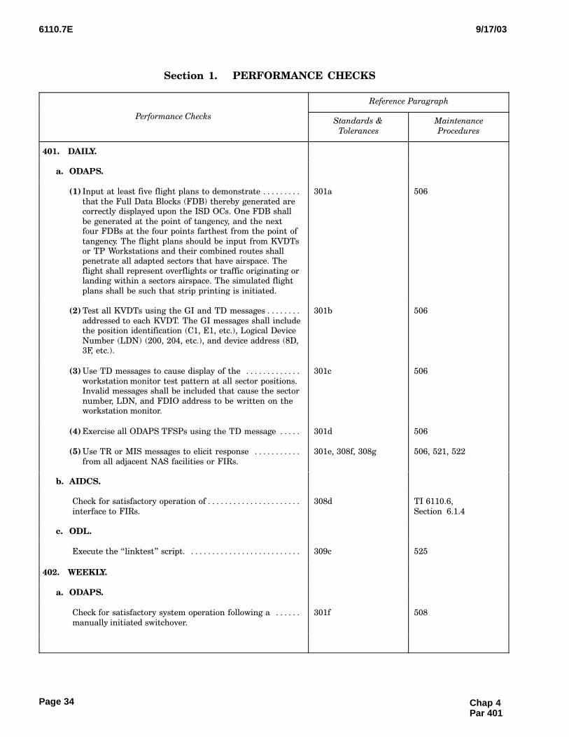
6110.7E 9/17/03
Page 34
Section 1.CCCPERFORMANCE CHECKS
Reference Paragraph
Performance ChecksStandards &
Tolerances
Maintenance
Procedures
401.�DAILY.
a. ODAPS.
(1) Input at least five flight plans to demonstrate . . . . . . . . .
that the Full Data Blocks (FDB) thereby generated arecorrectly displayed upon the ISD OCs. One FDB shall
be generated at the point of tangency, and the nextfour FDBs at the four points farthest from the point of
tangency. The flight plans should be input from KVDTsor TP Workstations and their combined routes shallpenetrate all adapted sectors that have airspace. The
flight shall represent overflights or traffic originating orlanding within a sectors airspace. The simulated flight
plans shall be such that strip printing is initiated.
301a 506
(2) Test all KVDTs using the GI and TD messages . . . . . . . .
addressed to each KVDT. The GI messages shall includethe position identification (C1, E1, etc.), Logical Device
Number (LDN) (200, 204, etc.), and device address (8D,3F, etc.).
301b 506
(3) Use TD messages to cause display of the . . . . . . . . . . . . .
workstation monitor test pattern at all sector positions.Invalid messages shall be included that cause the sector
number, LDN, and FDIO address to be written on theworkstation monitor.
301c 506
(4) Exercise all ODAPS TFSPs using the TD message . . . . . 301d 506
(5) Use TR or MIS messages to elicit response . . . . . . . . . . .
from all adjacent NAS facilities or FIRs.
301e, 308f, 308g 506, 521, 522
b. AIDCS.
Check for satisfactory operation of . . . . . . . . . . . . . . . . . . . . . .
interface to FIRs.
308d TI 6110.6,
Section�6.1.4
c. ODL.
Execute the Olinktest" script. . . . . . . . . . . . . . . . . . . . . . . . . . . 309c 525
402.�WEEKLY.
a. ODAPS.
Check for satisfactory system operation following a . . . . . .
manually initiated switchover.
301f 508
Chap 4 Par 401

6110.7E9/17/03
Page 35
Section 1.CCCPERFORMANCE CHECKS (Continued)
Performance Checks
Reference Paragraph
Performance ChecksMaintenance
Procedures
Standards &
Tolerances
b. TP.
(1) Servers.
Check for satisfactory system operation following . . . . .
a manually initiated switchover.
307c 509
(2) LAN.
Check for satisfactory system operation following . . . . .
a manually initiated switchover.
307d 510
(3) SCs.
Check for satisfactory system operation following . . . . .
a manually initiated switchover.
307e 511
(4) Disk ARRAY/6000.
Check that the disk ARRAY is operating correctly. . . . . 307f 513
c. ISD.
(1) Servers.
Check for satisfactory system operation following . . . . .
a manually initiated switchover.
306d 509
(2) LAN.
Check for satisfactory system operation following . . . . .
a manually initiated switchover.
306e 510
(3) Disk ARRAY/6000.
Check that the disk ARRAY is operating correctly. . . . . 306f 513
d. S1RPAM.
Check for satisfactory system operation following . . . . . . . .
a manually initiated replacement.
305c 515
e. AIDCS.
UPS 600 or 1000.
Check for satisfactory operation of UPS. . . . . . . . . . . . . . 308e 520
Chap 4Par 402
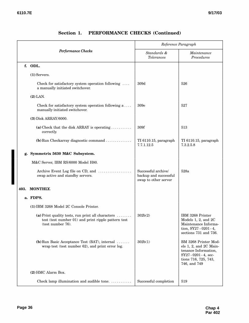
6110.7E 9/17/03
Page 36
Section 1.CCCPERFORMANCE CHECKS (Continued)
Performance Checks
Reference Paragraph
Performance ChecksMaintenance
Procedures
Standards &
Tolerances
f. ODL.
(1) Servers.
Check for satisfactory system operation following . . . .
a manually initiated switchover.
309d 526
(2) LAN.
Check for satisfactory system operation following a . . . .
manually initiated switchover.
309e 527
(3) Disk ARRAY/6000.
(a) Check that the disk ARRAY is operating . . . . . . . . . . .
correctly.
309f 513
(b)Run Checkarray diagnostic command . . . . . . . . . . . . . . TI 6110.15, paragraph
7.7.1.12.5
TI 6110.15, paragraph
7.3.2.5.8
g. Symmetrix 5630 M&C Subsystem.
M&C Server, IBM RS/6000 Model H80.
Archive Event Log file on CD, and . . . . . . . . . . . . . . . . . .
swap active and standby servers.
Successful archive/
backup and successfulswap to other server
528a
403.�MONTHLY.
a. FDPS.
(1) IBM 3268 Model 2C Console Printer.
(a) Print quality tests, run print all characters . . . . . . . .
test (test number 01) and print ripple pattern test(test number 76).
302b(2) IBM 3268 Printer
Models 1, 2, and 2CMaintenance Informa−
tion, SY27 − 0201 − 4,sections 731 and 736.
(b)Run Basic Acceptance Test (BAT), internal . . . . . . .
wrap test (test number 62), and print error log.
302b(1) BM 3268 Printer Mod−
els 1, 2, and 2C Main−tenance Information,
SY27 − 0201 − 4, sec−tions 716, 725, 743,
746, and 749
(2) HMC Alarm Box.
Check lamp illumination and audible tone. . . . . . . . . . . . Successful completion 519
Chap 4 Par 402
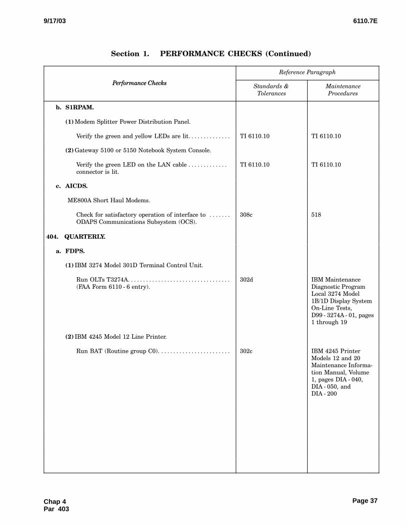
6110.7E9/17/03
Page 37
Section 1.CCCPERFORMANCE CHECKS (Continued)
Performance Checks
Reference Paragraph
Performance ChecksMaintenance
Procedures
Standards &
Tolerances
b. S1RPAM.
(1) Modem Splitter Power Distribution Panel.
Verify the green and yellow LEDs are lit. . . . . . . . . . . . . . TI 6110.10 TI 6110.10
(2) Gateway 5100 or 5150 Notebook System Console.
Verify the green LED on the LAN cable . . . . . . . . . . . . .
connector is lit.
TI 6110.10 TI 6110.10
c. AICDS.
ME800A Short Haul Modems.
Check for satisfactory operation of interface to . . . . . . .
ODAPS Communications Subsystem (OCS).
308c 518
404.�QUARTERLY.
a. FDPS.
(1) IBM 3274 Model 301D Terminal Control Unit.
Run OLTs T3274A. . . . . . . . . . . . . . . . . . . . . . . . . . . . . . . . . .
(FAA Form 6110 − 6 entry).
302d IBM Maintenance
Diagnostic ProgramLocal 3274 Model
1B/1D Display SystemOn−Line Tests,
D99 − 3274A − 01, pages1 through 19
(2) IBM 4245 Model 12 Line Printer.
Run BAT (Routine group C0). . . . . . . . . . . . . . . . . . . . . . . . 302c IBM 4245 Printer
Models 12 and 20Maintenance Informa−
tion Manual, Volume1, pages DIA − 040,
DIA − 050, andDIA − 200
Chap 4Par 403
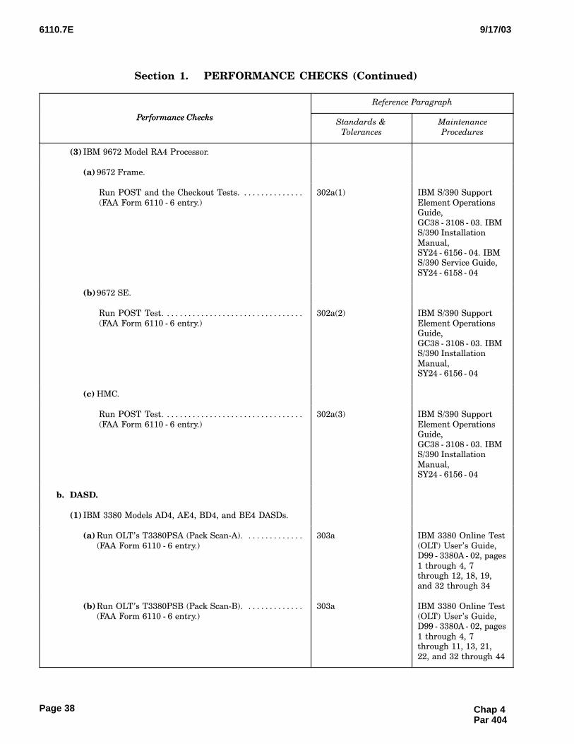
6110.7E 9/17/03
Page 38
Section 1.CCCPERFORMANCE CHECKS (Continued)
Performance Checks
Reference Paragraph
Performance ChecksMaintenance
Procedures
Standards &
Tolerances
(3) IBM 9672 Model RA4 Processor.
(a) 9672 Frame.
Run POST and the Checkout Tests. . . . . . . . . . . . . . .
(FAA Form 6110 − 6 entry.)
302a(1) IBM S/390 Support
Element OperationsGuide,
GC38 − 3108 − 03. IBMS/390 Installation
Manual,SY24 − 6156 − 04. IBMS/390 Service Guide,
SY24 − 6158 − 04
(b)9672 SE.
Run POST Test. . . . . . . . . . . . . . . . . . . . . . . . . . . . . . . . .
(FAA Form 6110 − 6 entry.)
302a(2) IBM S/390 Support
Element OperationsGuide,
GC38 − 3108 − 03. IBMS/390 Installation
Manual,SY24 − 6156 − 04
(c) HMC.
Run POST Test. . . . . . . . . . . . . . . . . . . . . . . . . . . . . . . . .
(FAA Form 6110 − 6 entry.)
302a(3) IBM S/390 Support
Element OperationsGuide,
GC38 − 3108 − 03. IBMS/390 Installation
Manual,SY24 − 6156 − 04
b. DASD.
(1) IBM 3380 Models AD4, AE4, BD4, and BE4 DASDs.
(a) Run OLT’s T3380PSA (Pack Scan−A). . . . . . . . . . . . . .
(FAA Form 6110 − 6 entry.)
303a IBM 3380 Online Test
(OLT) User’s Guide,D99 − 3380A − 02, pages
1 through 4, 7through 12, 18, 19,
and 32 through 34
(b)Run OLT’s T3380PSB (Pack Scan−B). . . . . . . . . . . . . .
(FAA Form 6110 − 6 entry.)
303a IBM 3380 Online Test
(OLT) User’s Guide,D99 − 3380A − 02, pages
1 through 4, 7through 11, 13, 21,
22, and 32 through 44
Chap 4 Par 404
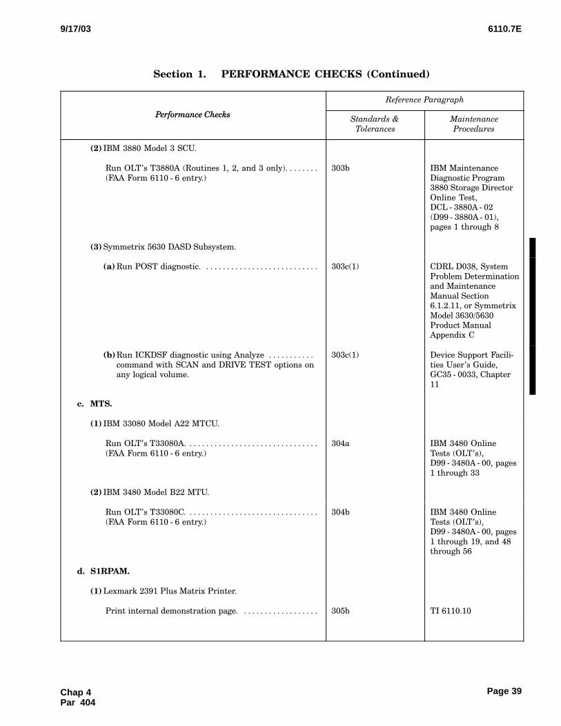
6110.7E9/17/03
Page 39
Section 1.CCCPERFORMANCE CHECKS (Continued)
Performance Checks
Reference Paragraph
Performance ChecksMaintenance
Procedures
Standards &
Tolerances
(2) IBM 3880 Model 3 SCU.
Run OLT’s T3880A (Routines 1, 2, and 3 only). . . . . . . .
(FAA Form 6110 − 6 entry.)
303b IBM Maintenance
Diagnostic Program3880 Storage Director
Online Test,DCL − 3880A − 02
(D99 − 3880A − 01),pages 1 through 8
(3) Symmetrix 5630 DASD Subsystem.
(a) Run POST diagnostic. . . . . . . . . . . . . . . . . . . . . . . . . . . . 303c(1) CDRL D038, System
Problem Determinationand Maintenance
Manual Section6.1.2.11, or Symmetrix
Model 3630/5630Product ManualAppendix C
(b)Run ICKDSF diagnostic using Analyze . . . . . . . . . . .
command with SCAN and DRIVE TEST options onany logical volume.
303c(1) Device Support Facili−
ties User’s Guide,GC35 − 0033, Chapter
11
c. MTS.
(1) IBM 33080 Model A22 MTCU.
Run OLT’s T33080A. . . . . . . . . . . . . . . . . . . . . . . . . . . . . . . .
(FAA Form 6110 − 6 entry.)
304a IBM 3480 Online
Tests (OLT’s),D99 − 3480A − 00, pages
1 through 33
(2) IBM 3480 Model B22 MTU.
Run OLT’s T33080C. . . . . . . . . . . . . . . . . . . . . . . . . . . . . . . .
(FAA Form 6110 − 6 entry.)
304b IBM 3480 Online
Tests (OLT’s),D99 − 3480A − 00, pages
1 through 19, and 48through 56
d. S1RPAM.
(1) Lexmark 2391 Plus Matrix Printer.
Print internal demonstration page. . . . . . . . . . . . . . . . . . . 305b TI 6110.10
Chap 4Par 404

6110.7E 9/17/03
Page 40
Section 1.CCCPERFORMANCE CHECKS (Continued)
Performance Checks
Reference Paragraph
Performance ChecksMaintenance
Procedures
Standards &
Tolerances
(2) IBM 7026 Model H50 RISC/6000 Processor.
Run Diagnostics. . . . . . . . . . . . . . . . . . . . . . . . . . . . . . . . . . . .
(FAA Form 6110 − 6 entry.)
305a(1) 517; IBM RISC/6000
Enterprise ServerModel H50 User’s
Guide,SA38 − 0546 − 00, Chap−
ter 8, Steps 1 − 5
(3) System.
(a) Run S1RPAM Diagnostics except selected Offline . . .
Diagnostics. (FAA Form 6110 − 6 entry.)
305a(2) 507; TI 6110.11
(b)Run S1RPAM Wrap Diagnostics. . . . . . . . . . . . . . . . . . .
(FAA Form 6110 − 6 entry.)
305a(3) 516; TI 6110.11
e. ISD.
(1) Server.
Run Central Processing Unit (CPU) Diagnostics. . . . . . .
(FAA Form 6110 − 6 entry.)
306a 512
(2) OC.
Run CPU Diagnostics. . . . . . . . . . . . . . . . . . . . . . . . . . . . . . .
(FAA Form 6110 − 6 entry.)
306a 512
(3) SC.
Run CPU Diagnostics. . . . . . . . . . . . . . . . . . . . . . . . . . . . . . .
(FAA Form 6110 − 6 entry.)
306a 512
(4) IBM 4226 or 4232 Line Printer.
Run Printer Self Test. . . . . . . . . . . . . . . . . . . . . . . . . . . . . . . 306b 514
f. TP.
IBM RISC 6000/770 or 771 CPU.
(1) Server.
Run CPU Diagnostics. . . . . . . . . . . . . . . . . . . . . . . . . . . . . . .
(FAA Form 6110 − 6 entry.)
307a 512
(2) Workstation.
Run CPU Diagnostics. . . . . . . . . . . . . . . . . . . . . . . . . . . . . . .
(FAA Form 6110 − 6 entry.)
307a 512
Chap 4 Par 404
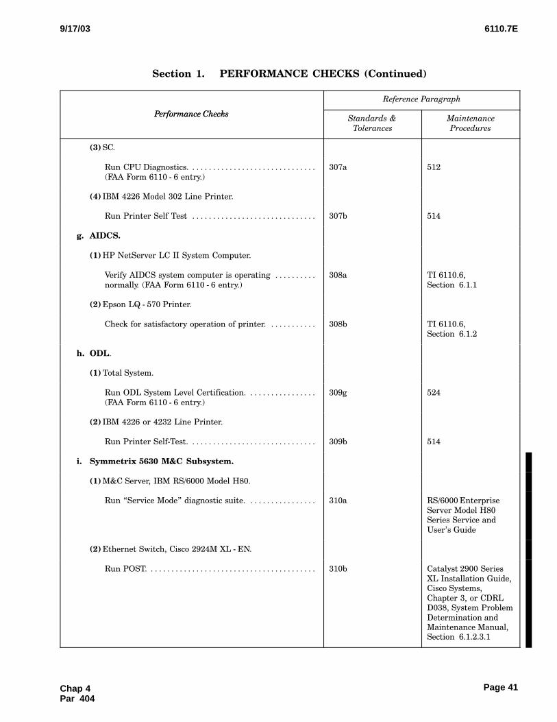
6110.7E9/17/03
Page 41
Section 1.CCCPERFORMANCE CHECKS (Continued)
Performance Checks
Reference Paragraph
Performance ChecksMaintenance
Procedures
Standards &
Tolerances
(3) SC.
Run CPU Diagnostics. . . . . . . . . . . . . . . . . . . . . . . . . . . . . . .
(FAA Form 6110 − 6 entry.)
307a 512
(4) IBM 4226 Model 302 Line Printer.
Run Printer Self Test . . . . . . . . . . . . . . . . . . . . . . . . . . . . . . 307b 514
g. AIDCS.
(1) HP NetServer LC II System Computer.
Verify AIDCS system computer is operating . . . . . . . . . .
normally. (FAA Form 6110 − 6 entry.)
308a TI 6110.6,
Section�6.1.1
(2) Epson LQ − 570 Printer.
Check for satisfactory operation of printer. . . . . . . . . . . . 308b TI 6110.6,
Section�6.1.2
h. ODL.
(1) Total System.
Run ODL System Level Certification. . . . . . . . . . . . . . . . .
(FAA Form 6110 − 6 entry.)
309g 524
(2) IBM 4226 or 4232 Line Printer.
Run Printer Self−Test. . . . . . . . . . . . . . . . . . . . . . . . . . . . . . . 309b 514
i. Symmetrix 5630 M&C Subsystem.
(1) M&C Server, IBM RS/6000 Model H80.
Run OService Mode" diagnostic suite. . . . . . . . . . . . . . . . . 310a RS/6000 Enterprise
Server Model H80Series Service and
User’s Guide
(2) Ethernet Switch, Cisco 2924M XL − EN.
Run POST. . . . . . . . . . . . . . . . . . . . . . . . . . . . . . . . . . . . . . . . . 310b Catalyst 2900 Series
XL Installation Guide,Cisco Systems,
Chapter 3, or CDRLD038, System Problem
Determination andMaintenance Manual,Section�6.1.2.3.1
Chap 4Par 404
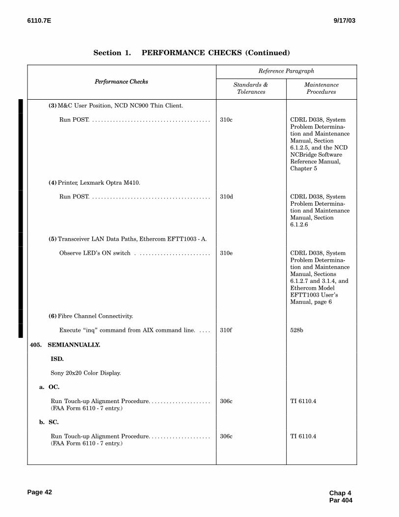
6110.7E 9/17/03
Page 42
Section 1.CCCPERFORMANCE CHECKS (Continued)
Performance Checks
Reference Paragraph
Performance ChecksMaintenance
Procedures
Standards &
Tolerances
(3) M&C User Position, NCD NC900 Thin Client.
Run POST. . . . . . . . . . . . . . . . . . . . . . . . . . . . . . . . . . . . . . . . . 310c CDRL D038, System
Problem Determina−tion and Maintenance
Manual, Section6.1.2.5, and the NCD
NCBridge SoftwareReference Manual,Chapter 5
(4) Printer, Lexmark Optra M410.
Run POST. . . . . . . . . . . . . . . . . . . . . . . . . . . . . . . . . . . . . . . . . 310d CDRL D038, System
Problem Determina−tion and Maintenance
Manual, Section6.1.2.6
(5) Transceiver LAN Data Paths, Ethercom EFTT1003 − A.
Observe LED’s ON switch . . . . . . . . . . . . . . . . . . . . . . . . . 310e CDRL D038, System
Problem Determina−tion and Maintenance
Manual, Sections6.1.2.7 and 3.1.4, and
Ethercom ModelEFTT1003 User’sManual, page 6
(6) Fibre Channel Connectivity.
Execute Oinq" command from AIX command line. . . . . 310f 528b
405.�SEMIANNUALLY.
ISD.
Sony 20x20 Color Display.
a. OC.
Run Touch−up Alignment Procedure. . . . . . . . . . . . . . . . . . . . .
(FAA Form 6110 − 7 entry.)
306c TI 6110.4
b. SC.
Run Touch−up Alignment Procedure. . . . . . . . . . . . . . . . . . . . .
(FAA Form 6110 − 7 entry.)
306c TI 6110.4
Chap 4 Par 404
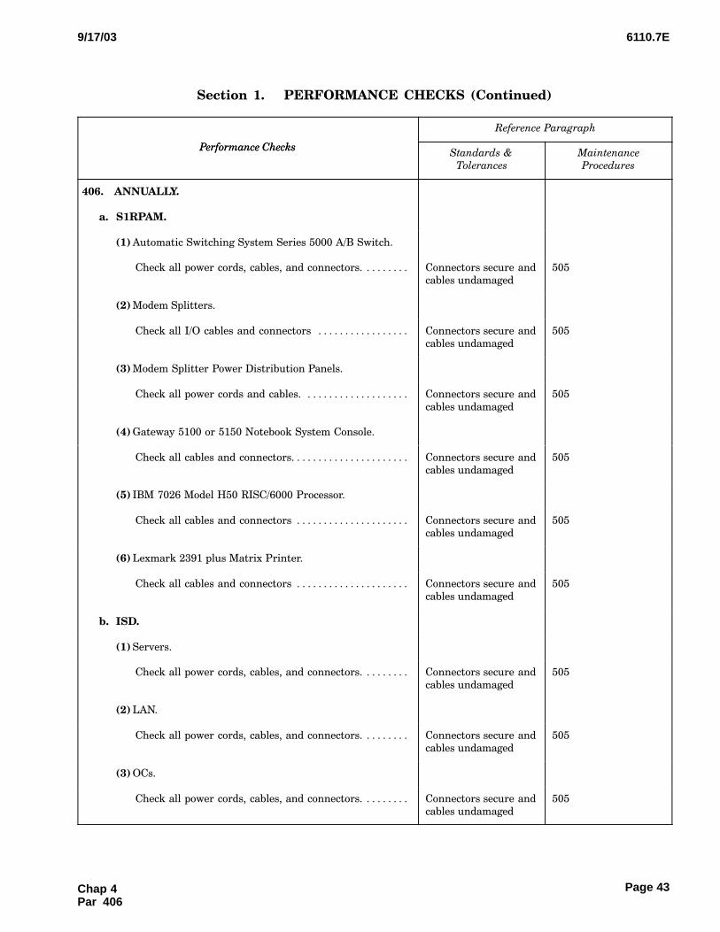
6110.7E9/17/03
Page 43
Section 1.CCCPERFORMANCE CHECKS (Continued)
Performance Checks
Reference Paragraph
Performance ChecksMaintenance
Procedures
Standards &
Tolerances
406.�ANNUALLY.
a. S1RPAM.
(1) Automatic Switching System Series 5000 A/B Switch.
Check all power cords, cables, and connectors. . . . . . . . . Connectors secure and
cables undamaged
505
(2) Modem Splitters.
Check all I/O cables and connectors . . . . . . . . . . . . . . . . . Connectors secure and
cables undamaged
505
(3) Modem Splitter Power Distribution Panels.
Check all power cords and cables. . . . . . . . . . . . . . . . . . . . Connectors secure and
cables undamaged
505
(4) Gateway 5100 or 5150 Notebook System Console.
Check all cables and connectors. . . . . . . . . . . . . . . . . . . . . . Connectors secure and
cables undamaged
505
(5) IBM 7026 Model H50 RISC/6000 Processor.
Check all cables and connectors . . . . . . . . . . . . . . . . . . . . . Connectors secure and
cables undamaged
505
(6) Lexmark 2391 plus Matrix Printer.
Check all cables and connectors . . . . . . . . . . . . . . . . . . . . . Connectors secure and
cables undamaged
505
b. ISD.
(1) Servers.
Check all power cords, cables, and connectors. . . . . . . . . Connectors secure and
cables undamaged
505
(2) LAN.
Check all power cords, cables, and connectors. . . . . . . . . Connectors secure and
cables undamaged
505
(3) OCs.
Check all power cords, cables, and connectors. . . . . . . . . Connectors secure and
cables undamaged
505
Chap 4Par 406
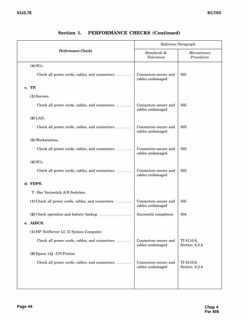
6110.7E 9/17/03
Page 44
Section 1.CCCPERFORMANCE CHECKS (Continued)
Performance Checks
Reference Paragraph
Performance ChecksMaintenance
Procedures
Standards &
Tolerances
(4) SCs.
Check all power cords, cables, and connectors. . . . . . . . . Connectors secure and
cables undamaged
505
c. TP.
(1) Servers.
Check all power cords, cables, and connectors. . . . . . . . . Connectors secure and
cables undamaged
505
(2) LAN.
Check all power cords, cables, and connectors. . . . . . . . . Connectors secure and
cables undamaged
505
(3) Workstations.
Check all power cords, cables, and connectors. . . . . . . . . Connectors secure and
cables undamaged
505
(4) SCs.
Check all power cords, cables, and connectors. . . . . . . . . Connectors secure and
cables undamaged
505
d. FDPS.
T − Bar Variswitch A/B Switches.
(1) Check all power cords, cables, and connectors. . . . . . . . . Connectors secure and
cables undamaged
505
(2) Check operation and battery backup. . . . . . . . . . . . . . . . . . Successful completion 504
e. AIDCS.
(1) HP NetServer LC II System Computer.
Check all power cords, cables, and connectors. . . . . . . . . Connectors secure and
cables undamaged
TI 6110.6,
Section�6.2.4
(2) Epson LQ − 570 Printer.
Check all power cords, cables, and connectors. . . . . . . . . Connectors secure and
cables undamaged
TI 6110.6,
Section�6.2.4
Chap 4 Par 406

6110.7E9/17/03
Page 45
Section 1.CCCPERFORMANCE CHECKS (Continued)
Performance Checks
Reference Paragraph
Performance ChecksMaintenance
Procedures
Standards &
Tolerances
(3) ME800A Short Haul Modems.
Check all power cords, cables, and connectors. . . . . . . . . Connectors secure and
cables undamaged
TI 6110.6,
Section�6.2.4
(4) Eicon X.25 Interface Adapter.
Check all power cords, cables, and connectors. . . . . . . . . Connectors secure and
cables undamaged
TI 6110.6,
Section�6.2.4
(5) UPS 600 or 1000.
Check all power cords, cables, and connectors. . . . . . . . . Connectors secure and
cables undamaged
TI 6110.6,
Section�6.2.4
f. ODL.
(1) Servers.
Check all power cords, cables, and connectors. . . . . . . . . Connectors secure and
cables undamaged
505
(2) LAN.
Check all power cords, cables, and connectors. . . . . . . . . Connectors secure and
cables undamaged
505
(3) Workstations.
Check all power cords, cables, and connectors. . . . . . . . . Connectors secure and
cables undamaged
505
(4) System Consoles.
Check all power cords, cables, and connectors. . . . . . . . . Connectors secure and
cables undamaged
505
g. Symmetrix 5630 M&C Subsystem.
M&C Server, IBM RS/6000 Model H80.
Check tape drive operation. . . . . . . . . . . . . . . . . . . . . . . . . . Error free operation CDRL D038, System
Problem Determina−tion and Maintenance
Manual, Section6.1.2.4, and the SONY
SDT − 10000 DigitalData Storage (DDS)Drive Unit Operator’s
Guide
Chap 4Par 406
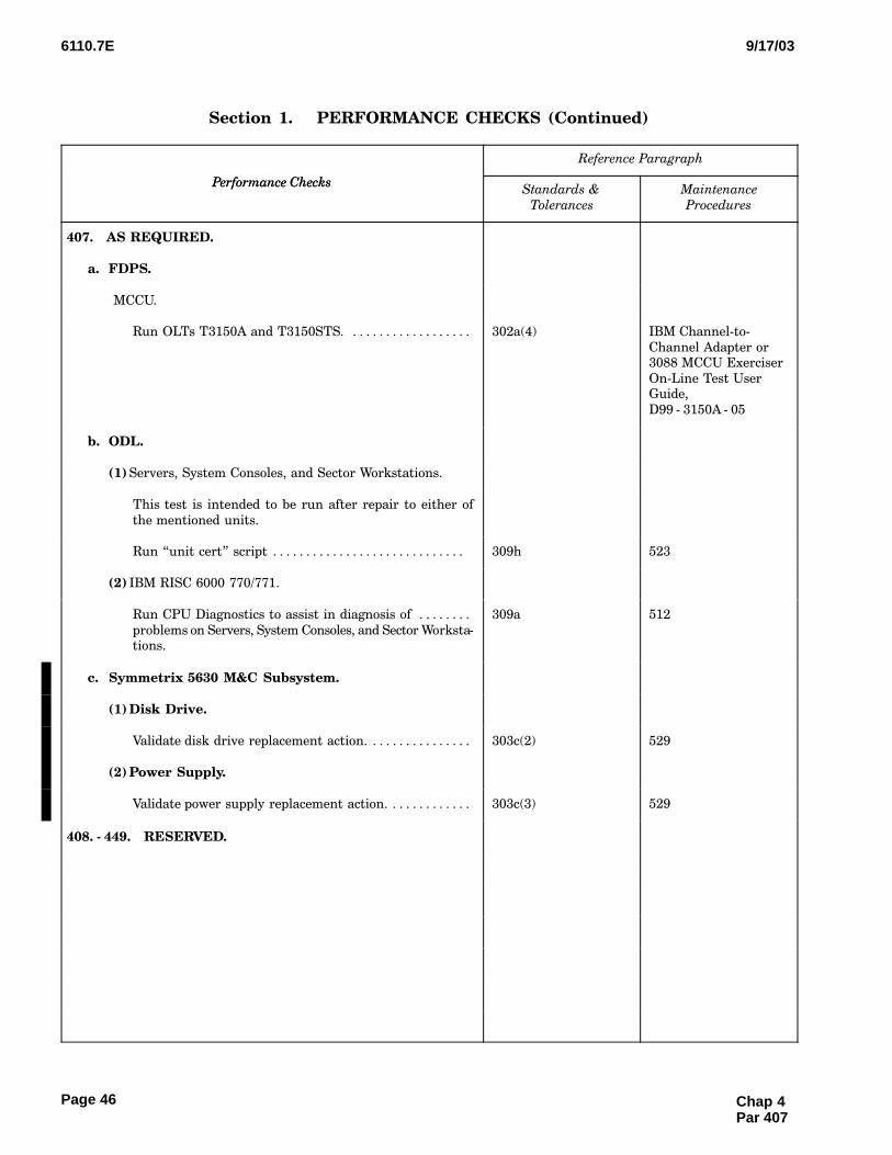
6110.7E 9/17/03
Page 46
Section 1.CCCPERFORMANCE CHECKS (Continued)
Performance Checks
Reference Paragraph
Performance ChecksMaintenance
Procedures
Standards &
Tolerances
407.�AS REQUIRED.
a. FDPS.
MCCU.
Run OLTs T3150A and T3150STS. . . . . . . . . . . . . . . . . . . 302a(4) IBM Channel−to−
Channel Adapter or3088 MCCU Exerciser
On−Line Test UserGuide,
D99 − 3150A − 05
b. ODL.
(1) Servers, System Consoles, and Sector Workstations.
This test is intended to be run after repair to either of
the mentioned units.
Run Ounit cert" script . . . . . . . . . . . . . . . . . . . . . . . . . . . . . 309h 523
(2) IBM RISC 6000 770/771.
Run CPU Diagnostics to assist in diagnosis of . . . . . . . .
problems on Servers, System Consoles, and Sector Worksta−tions.
309a 512
c. Symmetrix 5630 M&C Subsystem.
(1) Disk Drive.
Validate disk drive replacement action. . . . . . . . . . . . . . . . 303c(2) 529
(2) Power Supply.
Validate power supply replacement action. . . . . . . . . . . . . 303c(3) 529
408. − 449.�RESERVED.
Chap 4 Par 407

6110.7E9/17/03
Page 47
Section 2.CCCOTHER MAINTENANCE TASKS
Reference Paragraph
Maintenance TasksStandards &
Tolerances
Maintenance
Procedures
450.�RESERVED.
451.�WEEKLY.
a. FDPS.
(1) IBM 4245 Model 12 Line Printer.
(a) Clean and vacuum print chain, clean gate, . . . . . . . . .
and front area of the printer.
Visibly clean IBM 4245 Printer
Models 12 and 20Maintenance Informa−
tion Manual, Volume1, page TTE − 050
(b)Check for correct ribbon skew. . . . . . . . . . . . . . . . . . . . . Correctly skewed IBM 4245 Printer
Models 12 and 20Maintenance Informa−
tion Manual, Volume2, pages FRO − 140
through FRO − 200
(c) Run test pattern routine (routine 61), . . . . . . . . . . . . .
print/skip/space exerciser (routine 63), character setarrangement test (routine 66), and print quality pat−
tern (routine number 67).
Characters easily dis−
cernible
IBM 4245 Printer
Models 12 and 20Maintenance Informa−
tion Manual, Volume1, pages DIA − 040,
DIA − 050, DIA − 110,DIA − 130, DIA − 210through DIA − 270,
and DIA − 290
(d)Print error low . . . . . . . . . . . . . . . . . . . . . . . . . . . . . . . . . . No excessive accu−
mulation of errors
IBM 4245 Printer
Models 12 and 20Maintenance Informa−
tion Manual, Volume1, pages LSE − 020 and
LSE − 030
(2) Reserved.
b. ISD.
(1) OCs.
(a) Inspect console for cleanliness. . . . . . . . . . . . . . . . . . . . Visibly clean 555
(b) Inspect console for damage. . . . . . . . . . . . . . . . . . . . . . . Console undamaged TI 6110.4
(c) Inspect console for proper display presentation. . . . . Clear and precise dis−
play images
TI 6110.4
Chap 4Par 450

6110.7E 9/17/03
Page 48
Section 2.CCCOTHER MAINTENANCE TASKS (Continued)
Maintenance Tasks
Reference Paragraph
Maintenance TasksMaintenance
Procedures
Standards &
Tolerances
(2) System Consoles.
(a) Inspect console for cleanliness. . . . . . . . . . . . . . . . . . . . Visibly clean 555
(b) Inspect console for damage. . . . . . . . . . . . . . . . . . . . . . . Console undamaged TI 6110.4
(c) Inspect console for proper display presentation. . . . . Clear and precise dis−
play images
TI 6110.4
c. AIDCS.
HP NetServer LC II System Computer.
(1) Inspect monitor for cleanliness. . . . . . . . . . . . . . . . . . . . . . . Visibly clean 555
(2) Extract log files from system. . . . . . . . . . . . . . . . . . . . . . . . . Log files are extracted
from the computersystem
NASP − 7211,
Section�3.2.3.1
d. ODL.
IBM 7208 Tape Drive.
Clean and inspect tape drive. . . . . . . . . . . . . . . . . . . . . . . . Error free completion 551
452.�RESERVED.
453.�MONTHLY.
a. ISD.
(1) Server.
(a) Clean Cathode Ray Tube (CRT) and keyboard. . . . . . Visibly clean 555
(b)Vacuum interiors and check for obstructions. . . . . . . . Visibly clean 552
(c) Check CPU cooling fans for proper operation. . . . . . . Visibly operating 554
(2) OC.
(a) Clean CRT and keyboard. . . . . . . . . . . . . . . . . . . . . . . . . Visibly clean 555
(b)Vacuum interiors and check for obstructions. . . . . . . . Visibly clean 552
(c) Check CPU cooling fans for proper operation. . . . . . . Visibly operating 554
(d)Check display driver cooling fans for proper . . . . . . .
operation.
Visibly operating 554
Chap 4 Par 451
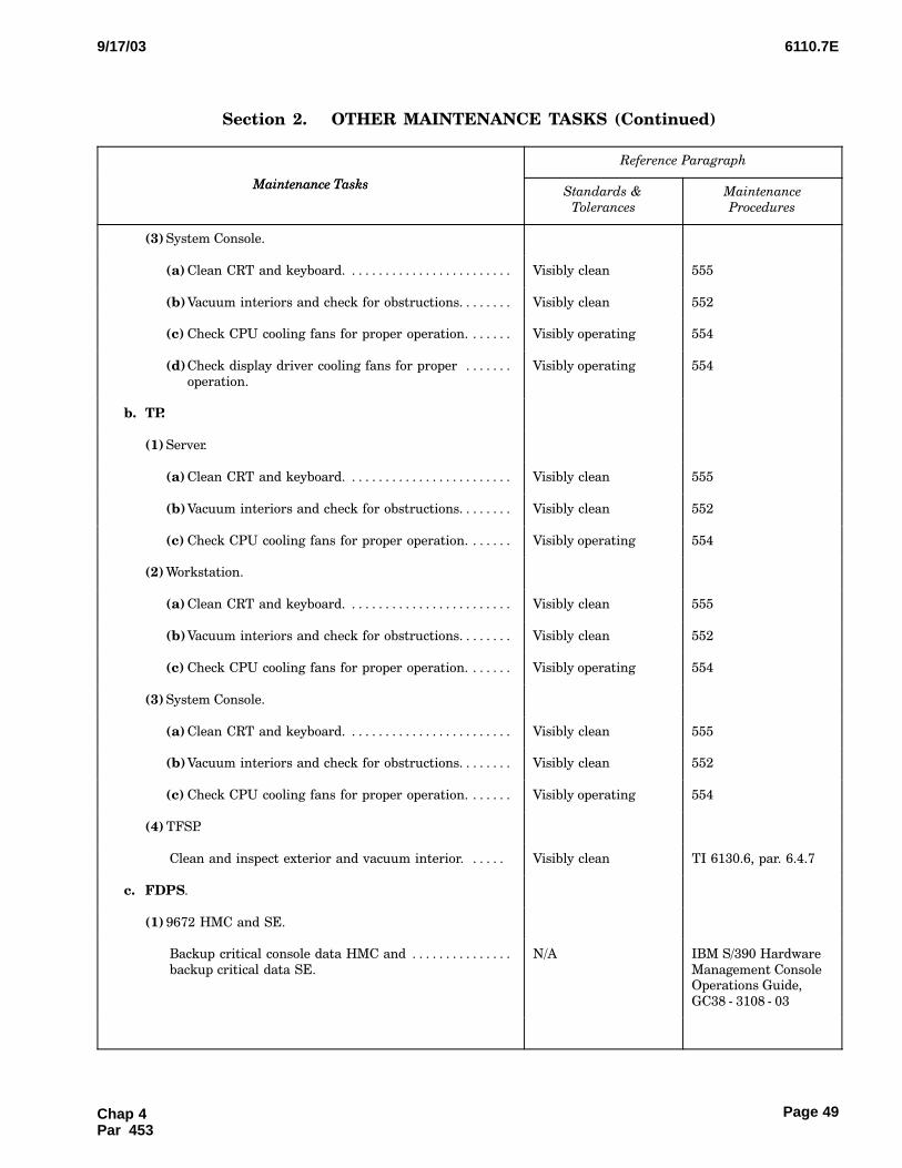
6110.7E9/17/03
Page 49
Section 2.CCCOTHER MAINTENANCE TASKS (Continued)
Maintenance Tasks
Reference Paragraph
Maintenance TasksMaintenance
Procedures
Standards &
Tolerances
(3) System Console.
(a) Clean CRT and keyboard. . . . . . . . . . . . . . . . . . . . . . . . . Visibly clean 555
(b)Vacuum interiors and check for obstructions. . . . . . . . Visibly clean 552
(c) Check CPU cooling fans for proper operation. . . . . . . Visibly operating 554
(d)Check display driver cooling fans for proper . . . . . . .
operation.
Visibly operating 554
b. TP.
(1) Server.
(a) Clean CRT and keyboard. . . . . . . . . . . . . . . . . . . . . . . . . Visibly clean 555
(b)Vacuum interiors and check for obstructions. . . . . . . . Visibly clean 552
(c) Check CPU cooling fans for proper operation. . . . . . . Visibly operating 554
(2) Workstation.
(a) Clean CRT and keyboard. . . . . . . . . . . . . . . . . . . . . . . . . Visibly clean 555
(b)Vacuum interiors and check for obstructions. . . . . . . . Visibly clean 552
(c) Check CPU cooling fans for proper operation. . . . . . . Visibly operating 554
(3) System Console.
(a) Clean CRT and keyboard. . . . . . . . . . . . . . . . . . . . . . . . . Visibly clean 555
(b)Vacuum interiors and check for obstructions. . . . . . . . Visibly clean 552
(c) Check CPU cooling fans for proper operation. . . . . . . Visibly operating 554
(4) TFSP.
Clean and inspect exterior and vacuum interior. . . . . . Visibly clean TI 6130.6, par. 6.4.7
c. FDPS.
(1) 9672 HMC and SE.
Backup critical console data HMC and . . . . . . . . . . . . . . .
backup critical data SE.
N/A IBM S/390 Hardware
Management ConsoleOperations Guide,
GC38 − 3108 − 03
Chap 4Par 453

6110.7E 9/17/03
Page 50
Section 2.CCCOTHER MAINTENANCE TASKS (Continued)
Maintenance Tasks
Reference Paragraph
Maintenance TasksMaintenance
Procedures
Standards &
Tolerances
(2) IS − 482G VM Terminals.
Clean CRT and keyboard. . . . . . . . . . . . . . . . . . . . . . . . . . . Visibly clean 555
d. AIDCS.
HP NetServer LC II System Computer.
(1) Clean CRT and keyboard. . . . . . . . . . . . . . . . . . . . . . . . . . . . Visibly clean 555
(2) Vacuum interiors and check for obstructions. . . . . . . . . . . Visibly clean 552
(3) Check CPU cooling fans for proper operation. . . . . . . . . . Visibly operating 554
(4) Remove automatically generated e−mail messages. . . . . . . Automatically gener−
ated e−mail messagesare removed from the
system
TI 6110.6, Section�5.5
e. ODL.
(1) Server.
(a) Clean CRT and keyboard. . . . . . . . . . . . . . . . . . . . . . . . . Visibly clean 555
(b)Vacuum interiors and check for obstructions. . . . . . . . Visibly clean 552
(c) Check CPU cooling fans for proper operation. . . . . . . Visibly operating 554
(2) Workstation.
(a) Clean and inspect CRT and keyboard. . . . . . . . . . . . . . Visibly clean 555
(b)Vacuum interiors and check for obstructions. . . . . . . . Visibly clean 552
(c) Check CPU cooling fans for proper operation. . . . . . . Visibly operating 554
(3) System Console.
(a) Clean and inspect CRT and keyboard. . . . . . . . . . . . . . Visibly clean 555
(b)Vacuum interiors and check for obstructions. . . . . . . . Visibly clean 552
(c) Check CPU cooling fans for proper operation. . . . . . . Visibly operating 554
(4) TFSP.
Clean and inspect exterior and vacuum interior. . . . . . . Visibly clean TI 6130.6, par. 6.4.7
Chap 4 Par 453
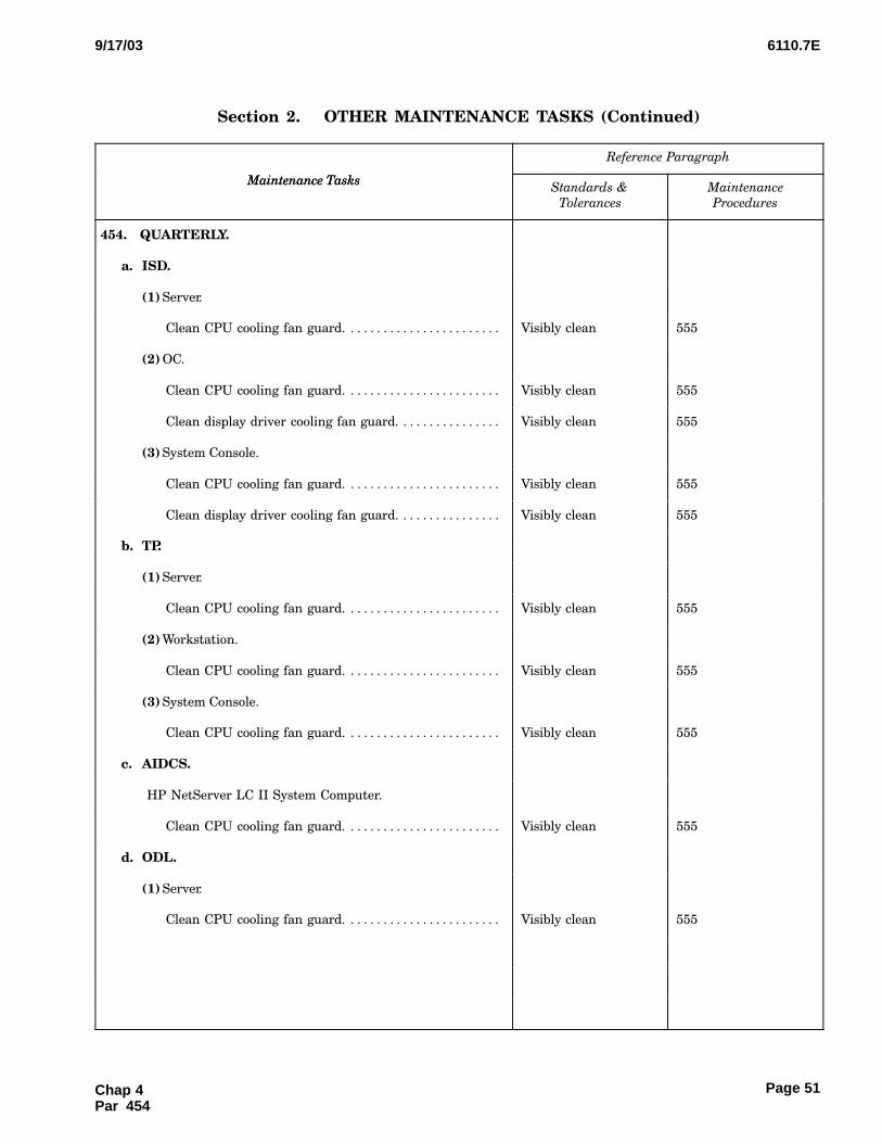
6110.7E9/17/03
Page 51
Section 2.CCCOTHER MAINTENANCE TASKS (Continued)
Maintenance Tasks
Reference Paragraph
Maintenance TasksMaintenance
Procedures
Standards &
Tolerances
454.�QUARTERLY.
a. ISD.
(1) Server.
Clean CPU cooling fan guard. . . . . . . . . . . . . . . . . . . . . . . . Visibly clean 555
(2) OC.
Clean CPU cooling fan guard. . . . . . . . . . . . . . . . . . . . . . . . Visibly clean 555
Clean display driver cooling fan guard. . . . . . . . . . . . . . . . Visibly clean 555
(3) System Console.
Clean CPU cooling fan guard. . . . . . . . . . . . . . . . . . . . . . . . Visibly clean 555
Clean display driver cooling fan guard. . . . . . . . . . . . . . . . Visibly clean 555
b. TP.
(1) Server.
Clean CPU cooling fan guard. . . . . . . . . . . . . . . . . . . . . . . . Visibly clean 555
(2) Workstation.
Clean CPU cooling fan guard. . . . . . . . . . . . . . . . . . . . . . . . Visibly clean 555
(3) System Console.
Clean CPU cooling fan guard. . . . . . . . . . . . . . . . . . . . . . . . Visibly clean 555
c. AIDCS.
HP NetServer LC II System Computer.
Clean CPU cooling fan guard. . . . . . . . . . . . . . . . . . . . . . . . Visibly clean 555
d. ODL.
(1) Server.
Clean CPU cooling fan guard. . . . . . . . . . . . . . . . . . . . . . . . Visibly clean 555
Chap 4Par 454
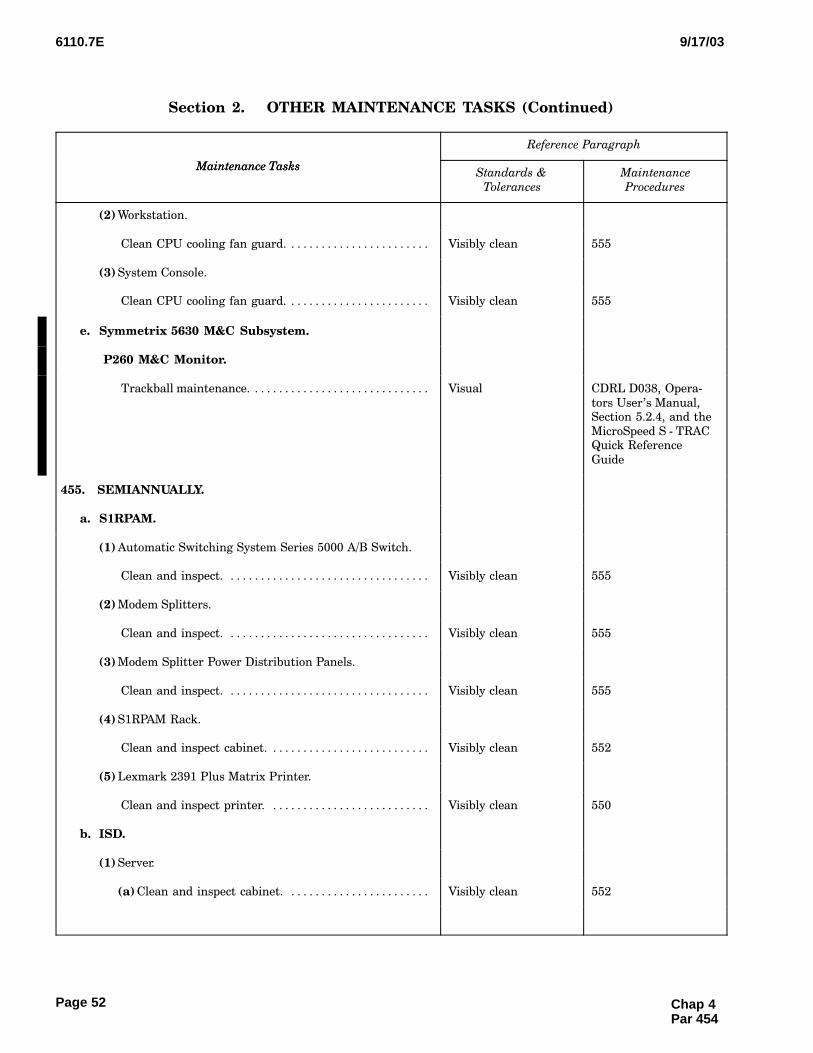
6110.7E 9/17/03
Page 52
Section 2.CCCOTHER MAINTENANCE TASKS (Continued)
Maintenance Tasks
Reference Paragraph
Maintenance TasksMaintenance
Procedures
Standards &
Tolerances
(2) Workstation.
Clean CPU cooling fan guard. . . . . . . . . . . . . . . . . . . . . . . . Visibly clean 555
(3) System Console.
Clean CPU cooling fan guard. . . . . . . . . . . . . . . . . . . . . . . . Visibly clean 555
e. Symmetrix 5630 M&C Subsystem.
P260 M&C Monitor.
Trackball maintenance. . . . . . . . . . . . . . . . . . . . . . . . . . . . . . Visual CDRL D038, Opera−
tors User’s Manual,Section 5.2.4, and the
MicroSpeed S − TRACQuick Reference
Guide
455.�SEMIANNUALLY.
a. S1RPAM.
(1) Automatic Switching System Series 5000 A/B Switch.
Clean and inspect. . . . . . . . . . . . . . . . . . . . . . . . . . . . . . . . . . Visibly clean 555
(2) Modem Splitters.
Clean and inspect. . . . . . . . . . . . . . . . . . . . . . . . . . . . . . . . . . Visibly clean 555
(3) Modem Splitter Power Distribution Panels.
Clean and inspect. . . . . . . . . . . . . . . . . . . . . . . . . . . . . . . . . . Visibly clean 555
(4) S1RPAM Rack.
Clean and inspect cabinet. . . . . . . . . . . . . . . . . . . . . . . . . . . Visibly clean 552
(5) Lexmark 2391 Plus Matrix Printer.
Clean and inspect printer. . . . . . . . . . . . . . . . . . . . . . . . . . . Visibly clean 550
b. ISD.
(1) Server.
(a) Clean and inspect cabinet. . . . . . . . . . . . . . . . . . . . . . . . Visibly clean 552
Chap 4 Par 454
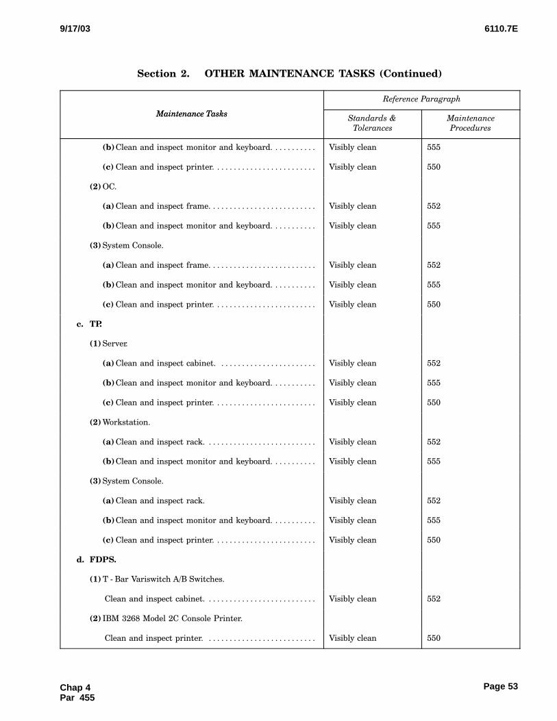
6110.7E9/17/03
Page 53
Section 2.CCCOTHER MAINTENANCE TASKS (Continued)
Maintenance Tasks
Reference Paragraph
Maintenance TasksMaintenance
Procedures
Standards &
Tolerances
(b)Clean and inspect monitor and keyboard. . . . . . . . . . . Visibly clean 555
(c) Clean and inspect printer. . . . . . . . . . . . . . . . . . . . . . . . . Visibly clean 550
(2) OC.
(a) Clean and inspect frame. . . . . . . . . . . . . . . . . . . . . . . . . . Visibly clean 552
(b)Clean and inspect monitor and keyboard. . . . . . . . . . . Visibly clean 555
(3) System Console.
(a) Clean and inspect frame. . . . . . . . . . . . . . . . . . . . . . . . . . Visibly clean 552
(b)Clean and inspect monitor and keyboard. . . . . . . . . . . Visibly clean 555
(c) Clean and inspect printer. . . . . . . . . . . . . . . . . . . . . . . . . Visibly clean 550
c. TP.
(1) Server.
(a) Clean and inspect cabinet. . . . . . . . . . . . . . . . . . . . . . . . Visibly clean 552
(b)Clean and inspect monitor and keyboard. . . . . . . . . . . Visibly clean 555
(c) Clean and inspect printer. . . . . . . . . . . . . . . . . . . . . . . . . Visibly clean 550
(2) Workstation.
(a) Clean and inspect rack. . . . . . . . . . . . . . . . . . . . . . . . . . . Visibly clean 552
(b)Clean and inspect monitor and keyboard. . . . . . . . . . . Visibly clean 555
(3) System Console.
(a) Clean and inspect rack. Visibly clean 552
(b)Clean and inspect monitor and keyboard. . . . . . . . . . . Visibly clean 555
(c) Clean and inspect printer. . . . . . . . . . . . . . . . . . . . . . . . . Visibly clean 550
d. FDPS.
(1) T − Bar Variswitch A/B Switches.
Clean and inspect cabinet. . . . . . . . . . . . . . . . . . . . . . . . . . . Visibly clean 552
(2) IBM 3268 Model 2C Console Printer.
Clean and inspect printer. . . . . . . . . . . . . . . . . . . . . . . . . . . Visibly clean 550
Chap 4Par 455

6110.7E 9/17/03
Page 54
Section 2.CCCOTHER MAINTENANCE TASKS (Continued)
Maintenance Tasks
Reference Paragraph
Maintenance TasksMaintenance
Procedures
Standards &
Tolerances
(3) IBM 6400 Model 050 Console Printer.
Clean and inspect printer. . . . . . . . . . . . . . . . . . . . . . . . . . . Visibly clean IBM 6400 Line Matrix
Printers MaintenanceInformation Manual
Cabinet and PedestalModels,
S246 − 0117 − 00
(4) IBM 6400 Model 015 High Speed Printer.
Clean and inspect printer. . . . . . . . . . . . . . . . . . . . . . . . . . . Visibly clean IBM 6400 Line Matrix
Printers MaintenanceInformation Manual
Cabinet and PedestalModels,
S246 − 0117 − 00
e. MTS.
IBM 3480 Model B22 MTU.
Clean and inspect tape drive. . . . . . . . . . . . . . . . . . . . . . . . Successful completion 551
f. AIDCS.
(1) HP NetServer LC II System Computer.
(a) Clean and inspect case. . . . . . . . . . . . . . . . . . . . . . . . . . . Visibly clean 552
(b)Clean and inspect monitor and keyboard. . . . . . . . . . . Visibly clean 555
(2) ME800A Short Haul Modems.
Clean and inspect. . . . . . . . . . . . . . . . . . . . . . . . . . . . . . . . . . Visibly clean 555
(3) Eicon X.25 Interface Adapter.
Clean and inspect. . . . . . . . . . . . . . . . . . . . . . . . . . . . . . . . . . Visibly clean 555
(4) UPS 600 or 1000.
Clean and inspect. . . . . . . . . . . . . . . . . . . . . . . . . . . . . . . . . . Visibly clean 555
(5) Epson LQ − 570 Printer.
Clean and inspect printer. . . . . . . . . . . . . . . . . . . . . . . . . . . Visibly clean 550
Chap 4 Par 455
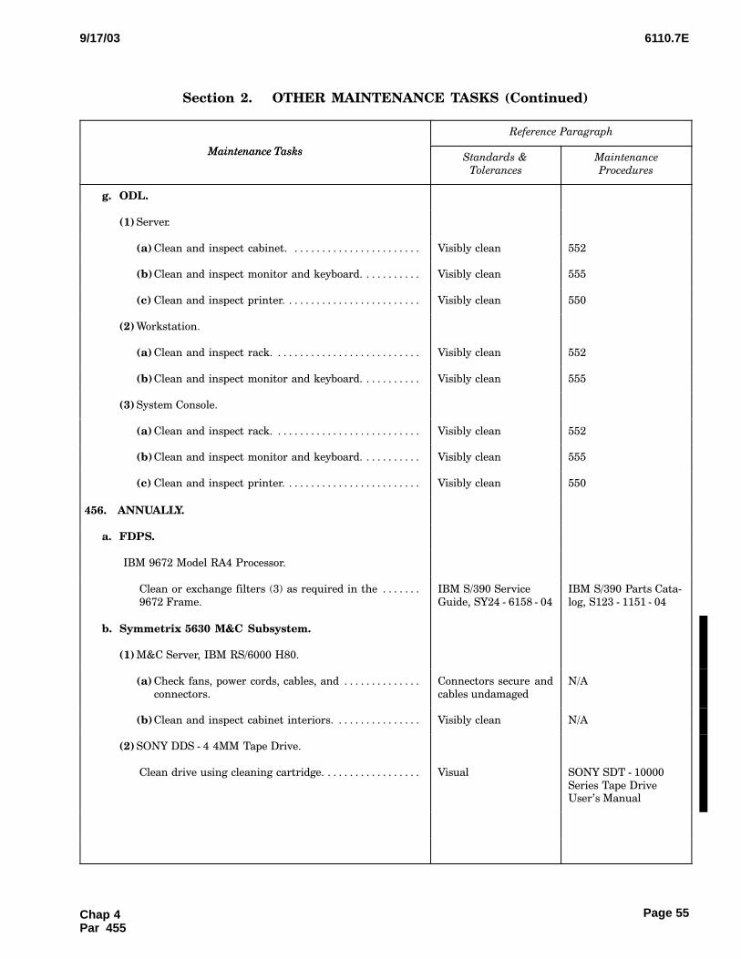
6110.7E9/17/03
Page 55
Section 2.CCCOTHER MAINTENANCE TASKS (Continued)
Maintenance Tasks
Reference Paragraph
Maintenance TasksMaintenance
Procedures
Standards &
Tolerances
g. ODL.
(1) Server.
(a) Clean and inspect cabinet. . . . . . . . . . . . . . . . . . . . . . . . Visibly clean 552
(b)Clean and inspect monitor and keyboard. . . . . . . . . . . Visibly clean 555
(c) Clean and inspect printer. . . . . . . . . . . . . . . . . . . . . . . . . Visibly clean 550
(2) Workstation.
(a) Clean and inspect rack. . . . . . . . . . . . . . . . . . . . . . . . . . . Visibly clean 552
(b)Clean and inspect monitor and keyboard. . . . . . . . . . . Visibly clean 555
(3) System Console.
(a) Clean and inspect rack. . . . . . . . . . . . . . . . . . . . . . . . . . . Visibly clean 552
(b)Clean and inspect monitor and keyboard. . . . . . . . . . . Visibly clean 555
(c) Clean and inspect printer. . . . . . . . . . . . . . . . . . . . . . . . . Visibly clean 550
456.�ANNUALLY.
a. FDPS.
IBM 9672 Model RA4 Processor.
Clean or exchange filters (3) as required in the . . . . . . .
9672 Frame.
IBM S/390 Service
Guide, SY24 − 6158 − 04
IBM S/390 Parts Cata−
log, S123 − 1151 − 04
b. Symmetrix 5630 M&C Subsystem.
(1) M&C Server, IBM RS/6000 H80.
(a) Check fans, power cords, cables, and . . . . . . . . . . . . . .
connectors.
Connectors secure and
cables undamaged
N/A
(b)Clean and inspect cabinet interiors. . . . . . . . . . . . . . . . Visibly clean N/A
(2) SONY DDS − 4 4MM Tape Drive.
Clean drive using cleaning cartridge. . . . . . . . . . . . . . . . . . Visual SONY SDT − 10000
Series Tape DriveUser’s Manual
Chap 4Par 455
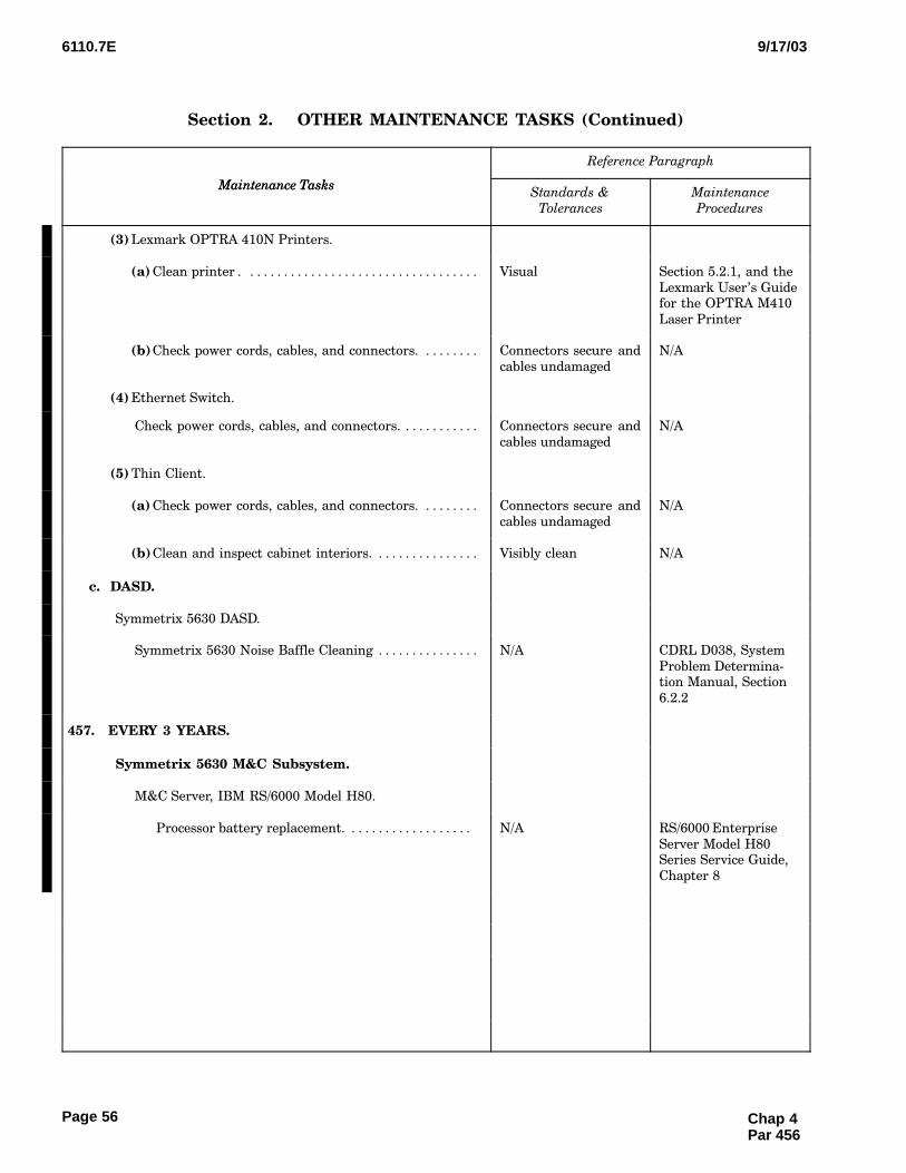
6110.7E 9/17/03
Page 56
Section 2.CCCOTHER MAINTENANCE TASKS (Continued)
Maintenance Tasks
Reference Paragraph
Maintenance TasksMaintenance
Procedures
Standards &
Tolerances
(3) Lexmark OPTRA 410N Printers.
(a) Clean printer . . . . . . . . . . . . . . . . . . . . . . . . . . . . . . . . . . . Visual Section 5.2.1, and the
Lexmark User’s Guidefor the OPTRA M410
Laser Printer
(b)Check power cords, cables, and connectors. . . . . . . . . Connectors secure and
cables undamaged
N/A
(4) Ethernet Switch.
Check power cords, cables, and connectors. . . . . . . . . . . . Connectors secure and
cables undamaged
N/A
(5) Thin Client.
(a) Check power cords, cables, and connectors. . . . . . . . . Connectors secure and
cables undamaged
N/A
(b)Clean and inspect cabinet interiors. . . . . . . . . . . . . . . . Visibly clean N/A
c. DASD.
Symmetrix 5630 DASD.
Symmetrix 5630 Noise Baffle Cleaning . . . . . . . . . . . . . . . N/A CDRL D038, System
Problem Determina−tion Manual, Section
6.2.2
457.�EVERY 3 YEARS.
Symmetrix 5630 M&C Subsystem.
M&C Server, IBM RS/6000 Model H80.
Processor battery replacement. . . . . . . . . . . . . . . . . . . N/A RS/6000 Enterprise
Server Model H80Series Service Guide,
Chapter 8
Chap 4 Par 456

6110.7E9/17/03
Page 57
Section 2.CCCOTHER MAINTENANCE TASKS (Continued)
Maintenance Tasks
Reference Paragraph
Maintenance TasksMaintenance
Procedures
Standards &
Tolerances
458.�EVERY 4 YEARS.
DASD.
Symmetrix 5630 DASD.
Symmetrix 5630 Battery Replacement . . . . . . . . . . . . N/A CDRL D038, System
Problem Determina−tion Manual, Section
6.2.1
459.�AS REQUIRED.
a. MTU.
IBM 3480 Model B22 MTU.
Clean and inspect tape drive . . . . . . . . . . . . . . . . . . . . . Successful completion 551
b. Symmetrix 5630 M&C Subsystem.
P260 M&C Monitor.
(1) Clean monitor exterior surface. . . . . . . . . . . . . . . . . . . . . . . Visual Section 5.2.2, and
P260 User Guide
(2) Keyboard maintenance. . . . . . . . . . . . . . . . . . . . . . . . . . . . . . Visual Section 5.2.3, and the
IBM SpacesaverKeyboard User’s
Manual
460. − 499.�RESERVED.
Chap 4Par 458
Page 57 (and 58)
6110.7E9/17/03
Page 59
CHAPTER 5. MAINTENANCE PROCEDURES
500.�GENERAL.
a.This chapter establishes the procedures for ac−complishing the various essential maintenance activi−ties required for the ODAPS automation, on either
a periodic or incidental basis. This chapter is dividedinto three sections. The first describes the procedures
to be used in making the performance checks listedin chapter 4, section 1. The second section describesthe procedures for doing the tasks listed in chapter
4, section 2. The third section describes the proceduresfor doing special tasks, usually non−scheduled and
not listed in chapter 4. Refer to Order 6000.15 foradditional general guidance.
b.The procedure contained herein supplementsthose found in the equipment instruction books.
501.�REMOTE SUPPORT FACILITY OP−ERATIONS FOR THE 9672 − RA4 PROCES−SOR.
a.Background.
(1)6As delivered by the manufacturer, the IBM
9672 − RA4 HMC is configured with a modem andRemote Support Facility (RSF) software. If the RSFfunction is enabled and a telephone line is provided,
the HMC can automatically dial out to the IBM RSFto report hardware malfunctions as they occur and
an IBM service engineer may dial into observe systemoperation or download software to the HMC.
(2)6There are operational concerns with thisremote support function. One is that, it is difficult
to determine if the system connects and disconnectsproperly with IBM. In addition, the ability to remotely
push new software to the HMC has the potential toimpair the government’s configuration managementof the system. However, the most driving concern with
this approach is that it may be possible for a technical−ly skilled outsider to exploit this connection for unau−
thorized purposes, potentially putting the entiresystem at risk.
b.Policy. HMC communications shall be strictlyregulated by both software and hardware controls.
(1)6Software Controls.
(a)6Inbound Calls. The call in feature ofthe HMC’s RSF shall be disabled and the modem shall
be configured to not answer incoming calls.
(b)6Outbound Calls. The call home fea−ture shall only be initiated via ODAPS operator ortechnician intervention, as opposed to automatic dial−
ing.
(2)6Hardware Controls. The modem shall bephysically disconnected from the telephone line at
all times with one exception: the modem shall onlybe connected to the telephone line to permit an autho−
rized call home and disconnected immediately aftercompletion of the call.
(3)6Verification. The operator shall respondto either an audible or visual alert mechanism inform−
ing the operator that the system needs to call home.The operator or technician shall notify the NOM, in
accordance with local site procedures, prior to con−necting the telephone line and configuring the ap−propriate HMC screens to permit the call. Once the
call has been completed, the operator or technicianshall physically disconnect the telephone line from
the modem and reset the appropriate HMC screensto their original configuration.
(4)6Conditions. The call home shall not be
permitted from an HMC which is connected to a 9672running operational NAS. The call home shall onlyoccur from a standby or offline system. When a non−
severe hardware error occurs, a switchover will notautomatically occur and the system will remain online
and operational. In this case, the site shall follow localprocedures to either place a voice service call in theusual fashion or perform a manual switchover at an
appropriate time to permit a call home from the stand−by or offline system.
c.Responsibilities.
(1)6The ARTCC Security Administrator shall
periodically check to ensure that the telephone lineto the 9672 HMC is physically disconnected unless
the system is using the line in response to a servicecall home situation.
(2)6The ARTCC ODAPS computer operator ortechnician shall contact the NOM upon notification
Chap 5Par 500
6110.7E 9/17/03
Page 60
by the system that it has detected a hardware anomalyand must call home.
(3)6The ARTCC ODAPS computer operator ortechnician shall connect the HMC’s modem to the
phone line and configure the appropriate HMC soft−ware screens to permit the call after voice coordina−
tion with an authorized IBM service representative.Once the transfer of data is complete, the computeroperator shall disconnect the telephone line from the
modem and reset the appropriate HMC softwarescreens to their original configuration.
502.�REMOTE SUPPORT OPERATIONSFOR THE ODAPS 5630 DASDSUBSYSTEM.
a.Background.
(1)6The EMC 5630 DASD subsystem came fromthe manufacturer with an external modem used inthe commercial environment to constantly report any
errors back to the EMC central engineering supportfacility. The call home feature can be either enabled
or disabled via the service processor laptop computer.These modems also allows the EMC engineering staffto dial−in and observe error conditions in order to
isolate the problem, determine severity, order replace−ment parts, etc.
(2)6Although dial−out or call home software
has been disabled, there are continuing operationalconcerns with this external interface’s dial−in capa−bility. Changes could be made without the local site’s
knowledge, possibly changing the baseline configura−tion of the 5630 subsystem.
b.Policy. The EMC external modem interfaceshall be strictly regulated by both software and hard−
ware controls.
(1)6Software Controls.
(a)6Inbound Calls. The software applica−tion on the 5630 service processor, which controls
the dial−in feature of the 5630, is always active andcan only be prevented by physical hardware discon−nection.
(b)6Outbound Calls. The local EMC cus−
tomer engineer disables the call home feature atinstallation time, per the System Support Modifica−tion (SSM). This prevents error messages to the sys−
tem operators each time a problem is detected, and
the service processor attempts, and then fails, to re−port the error to the EMC support center.
(2)6Hardware Controls. The modem shall bephysically disconnected from the telephone line at
all times with one exception: the modem shall onlybe connected to the telephone line to permit an autho−
rized dial−in by the EMC support center in orderto repair the unit, or the sending out of error datato the EMC support center by the customer engineer,
and disconnected immediately after use.
(3)6Procedure. After a service call is made toEMC to respond to an error received concerning the
5630, the customer engineer may determine a connec−tion of the modem is necessary in order to isolatethe problem. This usually involves microcode type
problems instead of simple board, power supplies, ordisk device replacements. Once the troubleshooting,
error reporting, or problem determination is com−pleted, and the customer engineer does not need theEMC support center connection any longer, the opera−
tor or technician shall physically disconnect the tele−phone line from the modem.
(4)6Conditions. The phone line for the EMC
support center modem shall not be connected to a5630 running operational NAS. This would requirerepair during low activity time, such as the midshift.
Logical Disk Device Address (LDDA) must be set toUnavailable before connecting the modem tele−
phone line. Depending on which set of drives is beingused in the system (5630 − 1 contains 820, 822, 826;5630 − 2 contains 920, 922, 926), two LDDAs may need
to be placed Unavailable, necessitating a HOST sys−tem shutdown, if the site would rather not run on
one mirrored LDDA during repairs.
c.Responsibilities.
(1)6The ARTCC Security Administrator shall
periodically check to ensure that the telephone line(s)to the 5630 DASD subsystems are physically discon−
nected.
(2)6The ARTCC ODAPS computer operator ortechnician shall contact the NOM upon notificationby the customer engineer, that a connection to the
EMC support center, via the 5630 modem is necessary.The NOM will ensure the affected LDDAs are config−
ured out of the operational system prior to the modemconnection. Once the modem is no longer requiredfor problem determination, or restoration, the modem
is to be disconnected from the telephone line.
Chap 5Par 501

6110.7E9/17/03
Page 61
Section 1. PERFORMANCE CHECK PROCEDURES
503.�FAA FORM ENTRIES.
Order 6000.15 contains policy, guidance, and de−tailed instructions for field use of FAA Forms 6110 − 6
and 6110 − 7, Technical Performance Records, as ap−plicable to the ODAPS. These forms are available
from the FAA Logistics Center (FAALC) under Na−tional Stock Numbers (NSN) 0052 − 00 − 905 − 8002and 0052 − 00 − 905 − 9000 respectively in units of
pads, 50 sheets per pad. Entries shall be made in accor−dance with the instructions published in Order
6000.15. Figure 5 − 1, Technical Performance Recordin this handbook contains a sample of FAA Forms6110 − 6 and 6110 − 7, that show typical entries for
normal and unsatisfactory conditions that may beencountered.
504.�CHECK T − BAR VARISWITCH OPER−ATION AND BATTERY BACKUP.
a.Object. This test verifies that the T − Bar Vari−switch A/B switch is operating properly and that thebattery backup on the Master Control Module is op−
erational.
b.Discussion. The battery backup saves the
switch settings that are programmed into the MasterControl Module in case of a power failure. Themanufacturer indicated that the backup battery has
a 10−year life. If this test is unsuccessful, and the Mas−ter Control Module needs to be replaced, the new Mas−
ter Control Module will need to be programmed. Referto Order 6110.9, Electronic Equipment ModificationHandbook Oceanic Display and Planning System,
Chapter 9, Installation of the T − Bar Variswitch A/BSwitches, Change 11. Re−run this test after the new
Master Control Module is programmed. Do not dis−card the old Master Control Module as it is possibleto replace the backup battery.
c.Test Equipment Required. None.
d.Conditions. None.
e.Detailed Procedure.
(1)6Switch the T − Bar Variswitch Master Con−trol Module to A. Verify that all of the A/B switches
indicate A or indicate A or B as programmed in theDo−List. Switch the T − Bar Variswitch Master ControlModule to B. Verify that all of the A/B switches indi−
cate B or indicate A or B as programmed in the Do−List. Switch the T − Bar Variswitch Master Control
Module to A. Verify that all of the A/B switches indi−cate A or indicate A or B as programmed in the Do−List.
(2)6Verify that all of the A/B switches indicateA. Switch the individual A/B switches to A if necessary.Switch each individual A/B switch one at a time to
B. Verify that each individual A/B switch indicatesB. Switch each individual A/B switch one at a time
to A. Verify that each individual A/B switch indicatesA.
(3)6Power OFF the T − Bar Variswitch by un−
plugging the power supply cords. Wait 15 seconds.Power the T − Bar Variswitch back ON.
(4)6Repeat paragraphs 504e(1) and 504e(2).
505.�CHECK POWER CORDS, CABLES,AND CONNECTORS.
a.Object. This check is performed in order to
verify that all connections are tight and cables areundamaged.
b.Discussion. None.
c.Test Equipment Required. None.
d.Conditions. This procedure should be donewith the associated equipment powered down.
e.Detailed Procedure. Check that all cords,
cables, and connectors are securely plugged into theproper outlets and the cables are undamaged.
Chap 5Par 503
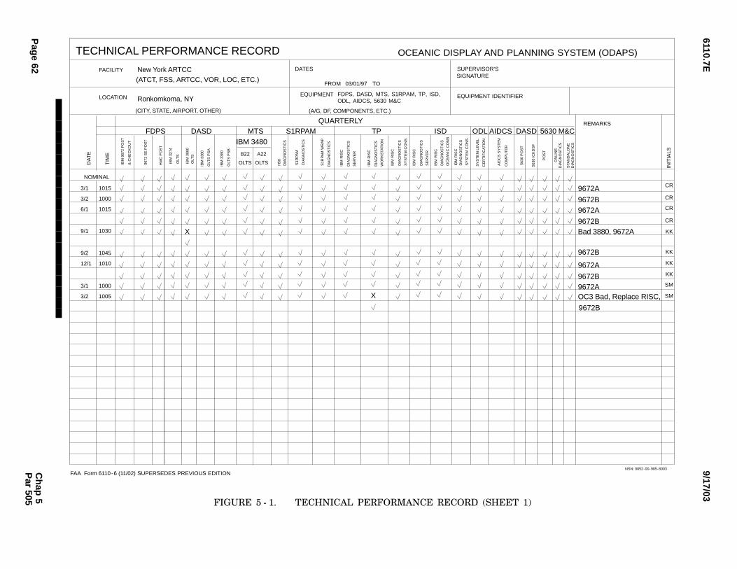
9/17/036110.7E
Pag
e 62C
hap
5P
ar 505
TECHNICAL PERFORMANCE RECORD
FACILITY
LOCATION
DATES
FROM TO
EQUIPMENT
SUPERVISOR’SSIGNATURE
EQUIPMENT IDENTIFIER
REMARKS
(CITY, STATE, AIRPORT, OTHER)
NOMINAL
FAA
DA
TE
TIM
E
INIT
IALS
NSN: 0052-00-905-8003
(ATCT, FSS, ARTCC, VOR, LOC, ETC.)
�
OCEANIC DISPLAY AND PLANNING SYSTEM (ODAPS)
(A/G, DF, COMPONENTS, ETC.)
DIA
GN
OS
TIC
S
SY
ST
EM
CO
NS
.
IBM
RIS
C
QUARTERLY
DIA
GN
OS
TIC
S
SE
RV
ER
IBM
RIS
C
DIA
GN
OS
TIC
S
WO
RK
STA
TIO
N
IBM
RIS
C
DIA
GN
OS
TIC
S
S1R
PAM
H50
S1R
PAM
WR
AP
DIA
GN
OS
TIC
S
DIA
GN
OS
TIC
S
TPS1RPAM
A22
DASDFDPS
OLTS
B22
OLTS
MTSIBM 3480
IBM
338
0
IBM
388
0
IBM
338
0
IBM
327
4
IBM
967
2 P
OS
T
OLT
S P
SB
OLT
S
OLT
S
& C
HE
CK
OU
TISD
DIA
GN
OS
TIC
S
SE
RV
ER
IBM
RIS
C
DIA
GN
OS
TIC
S
OC
EA
NIC
CO
NS
IBM
RIS
C
DIA
GN
OS
TIC
S
SY
ST
EM
CO
NS
.
IBM
RIS
C
03/01/97
New York ARTCC
Ronkomkoma, NY
3/1
3/2
6/1
9/1
9/2
12/1
3/1
3/2
CR
CR
CR
CR
KK
KK
KK
KK
SM
SM
1015
1000
1015
1030
1045
1010
1000
1005 X
X
OLT
S P
SA
HM
C P
OS
T
9672
SE
PO
ST
SY
ST
EM
LE
VE
L
AID
CS
SY
ST
EM
CE
RT
IFIC
AT
ION
CO
MP
UT
ER
ODL AIDCS
FDPS, DASD, MTS, S1RPAM, TP, ISD, ODL, AIDCS, 5630 M&C
Form 6110-6 (11/02) SUPERSEDES PREVIOUS EDITION
5630
PO
ST
5630
ICK
DS
F
PO
ST
DIA
GN
OS
TIC
S
5630 M&C
STA
ND
ALO
NE
ON
LIN
E
DIA
GN
OS
TIC
S
9672A
9672B9672A
9672BBad 3880, 9672A
9672B
9672A
9672B9672A
9672B
OC3 Bad, Replace RISC,
DASD
FIGURE 5 − 1.��TECHNICAL PERFORMANCE RECORD (SHEET 1)
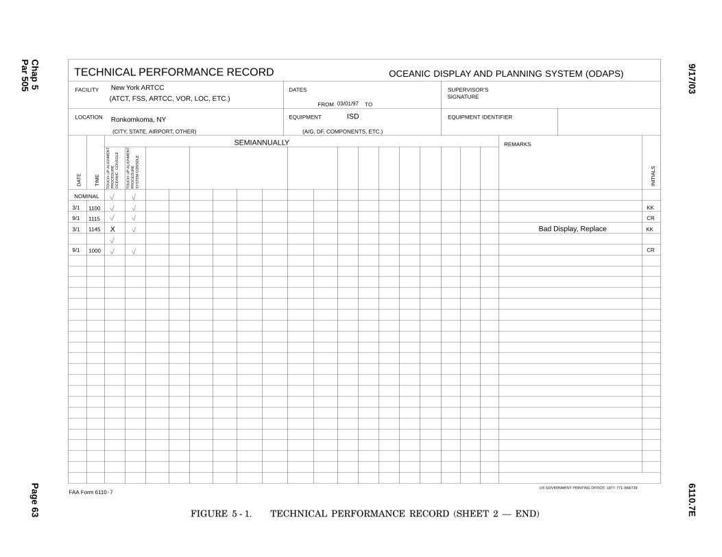
6110.7E9/17/03
Ch
ap 5
Pag
e 63P
ar 505
TECHNICAL PERFORMANCE RECORD
FACILITY
LOCATION
DATES
FROM TO
EQUIPMENT
SUPERVISOR’SSIGNATURE
EQUIPMENT IDENTIFIER
REMARKS
(CITY, STATE, AIRPORT, OTHER)
NOMINAL
FAA Form 6110-7
DA
TE
TIM
E
INIT
IALS
US GOVERNMENT PRINTING OFFICE: 1977-771-068/739
�
OCEANIC DISPLAY AND PLANNING SYSTEM (ODAPS)
(A/G, DF, COMPONENTS, ETC.)
ISD
SEMIANNUALLY
(ATCT, FSS, ARTCC, VOR, LOC, ETC.)03/01/97
New York ARTCC
Ronkomkoma, NY
3/1
9/1
3/1
9/1
1100
1115
1145
1000
TO
UC
H-U
P A
LIG
NM
EN
TP
RO
CE
DU
RE
Bad Display, Replace
KK
KK
CR
CR
X
TO
UC
H-U
P A
LIG
NM
EN
TP
RO
CE
DU
RE
S
YS
TE
M C
ON
SO
LE
OC
EA
NIC
CO
NS
OLE
FIGURE 5 − 1.��TECHNICAL PERFORMANCE RECORD (SHEET 2 N END)
6110.7E 9/17/03
Page 64
506.�SERVICE LEVEL CERTIFICATION.
a.Object. These certification procedures areused to verify that the ODAPS is capable of perform−
ing its intended function.
b.Discussion.
(1)6Certification Techniques Available.OLC actions can be performed with minimal interfer−
ence to the on−going ATC operations. This servicelevel certification should be performed during periodsof low traffic activity, and with the approval of the
ATC staff on duty. This procedural guidance is generalin nature, yet specific enough to support certification
of this service.
(2)6Certification Requirements. The ser−vice certification requirements are listed in Appendix
1, Certification Requirements.
c.Test Equipment Required. None.
d.Conditions. None.
e.Detailed Procedure.
(1)6Ascertain that the most current OLC pro−gram is loaded and available for call−up. Refer to para−
graph 575 for the minimum data requirements.
(2)6Coordinate proposed certification actionswith ATC.
(3)6Run the ODAPS OLC module or the manualprocedures necessary to verify the certification pa−rameters listed in appendix 1.
(4)6Evaluate the results and enter the certifica−
tion status in the MMS.
(5)6Restore the system to normal, purging thesimulation data, as necessary.
507.�CHECK S1RPAM PROCESSOR INTER−FACE CARDS.
a.Object. The object of this task is to run theS1RPAM diagnostics for:
(1)6Lexmark Matrix Printer.
(2)6PCI Bus to Channel Adapter (PCCA) Cards.
(3)6Emulex Communication Cards.
(4)6CTS (note: assumes redundant CTS sig−nals).
b.Discussion.
(1)6All of the steps of this test should be fol−lowed when testing on the S1RPAM.
(2)6For further information on this test, refer
to TI 6110.11.
c.Test Equipment Required. None.
d.Conditions. The test should be run on the
redundant S1RPAM processor, with the printer op−erational.
e.Detailed Procedure.
(1)6Ensure that the redundant subsystem(S1RPAM) is made inactive.
(2)6Terminate the S1RPAM operational soft−ware by entering 2 at the S1RPAM Main Menu onthe S1RPAM console and press <enter>.
(3)6Enter Y when prompted OAre you sure?Y/N" and press <enter>.
(4)6Select menu option 4 (Diagnostic Menu)
at the S1RPAM Operational Software Main Menuand press <enter>.
NOTE:CIt is easiest to maximize the operatormenu prior to starting diagnostics.
(5)6Select menu option 1 for Printer Diagnos−
tics on the S1RPAM Diagnostic Menu and press <en−ter>.
(6)6Enter y if sequence printed correctly or nif sequence printed incorrectly.
(7)6 Select menu option 2 for PCCA card diag−nostics on the S1RPAM Diagnostic Menu and press
<enter>.
(8)6Select which PCCA card to test (pbca0 or
pbca1) by entering either 1 or 2 and pressing <en−ter>.
(9)6Ensure ODiagnostic Passed" message is re−
ceived.
(10)6Repeat for other PCCA card by enteringeither 2 or 1 after test completes (15 − 20 seconds)
and press <enter>.
Chap 5Par 506

6110.7E9/17/03
Page 65
(11)6Ensure ODiagnostic Passed" message is re−ceived.
(12)6Enter q to quit the PCCA card test aftertest completes (15 − 20 seconds).
(13)6Press <enter> to return to the main
menu.
(14)6Select menu option 3 for communicationcard diagnostics on the S1RPAM Diagnostic Menu
and press <enter>.
(15)6Select which Emulex card to test (mlx0or mlx1) by entering either 1 or 2 and pressing <en−ter>.
(16)6Repeat for other Emulex card by entering
either 2 or 1 after test completes (5 − 10 seconds) andpress <enter>.
(17)6Enter q to quit the communication cardtest after test completes (5 − 10 seconds) and press
<enter>.
(18)6Select menu option 4 for Offline Diagnos−tics Tests (ODT) S1RPAM on the S1RPAM Diagnostic
Menu and press <enter>.
(19)6Enter n when prompted ODo you wantto enable any devices? <Y/N>" and press <enter>.
(20)6Enter 1 (for the CTS diagnostic) at themenu selection and press <enter>.
(21)6Select which clock to test (CLOCK1 or
CLOCK2) by entering either 1 or 2 and pressing <en−ter>.
(22)6Enter an integer value, 0 for continuous,
or s for stop on error when prompted OHow manytimes do you want to run the diagnostic?" and press<enter>.
(23)6Enter 2, for verbose option, and press <en−
ter>.
(24)6Enter Ctrl−C to stop the test if 0 or s wereselected.
(25)6Press <enter> after completion.
(26)6Enter q and <enter> to return to theS1RPAM Diagnostics Menu.
(27)6Enter y or n when prompted ONeed to
print diagnostics results?" and press <enter>.
(28)6Enter q and <enter> to return to theS1RPAM Main Menu.
(29)6Restart the S1RPAM Operational Soft−ware by selecting menu option 1 and <enter>.
(30)6Give system back to the system operator
after receiving message that S1RPAM Initializationhas completed.
508.�CHECK G3 SWITCHOVER OPER−ATION.
a.Object. This task is to verify that the ODAPS
can perform a successful switchover.
b.Discussion. None.
c.Test Equipment Required. None.
d.Conditions. Standby Central Processing Unit
(CPU) is available for switchover.
e.Detailed Procedure.
(1)6Perform ESAFP Service certification to
check CPU operations.
(2)6Check KCNF Monitor status. Ensure thatthe NAS Standby/VM CPU is Redundant and avail−able.
(3)6On the KVDT type SWVR and press <en−
ter>.
(4)6Check KCNF Monitor status. The CPU thatindicates OO" and the CPU that indicates OR" willbe just the opposite after a successful switchover.
(5)6Perform ESAFP Service certification after
completion of a successful switchover to check CPUoperations.
(6)6After successful completion of ESAFP ser−vice certification, have the computer operator restore
VM on the NAS standby CPU.
509.�CHECK TP OR ISD SERVER SWITCH−OVER OPERATION.
a.Object. This task is to verify that the TP orISD server can perform a successful switchover opera−
tion.
b.Discussion. These procedures are found inNASP − 9257 or NASP − 5263.
c.Test Equipment Required. None.
Chap 5Par 507

6110.7E 9/17/03
Page 66
d.Conditions. Redundant TP or ISD Serveravailable in standby.
e.Detailed Procedure.
(1)6TP.
(a)6At the TP SC enter the command:
REPL <Enter>
(b)6To set the server available as the redun−dant unit after a switchover, enter this command atthe TP SC:
SETA <Enter>
(2)6ISD.
At the KVDT enter the command:
REPL <ODC1,ODC2> <Enter>
510.�CHECK TP OR ISD LAN SWITCHOVEROPERATION.
a.Object. This task is to verify that the TP orISD LAN can perform a successful switchover opera−tion.
b.Discussion. To perform a switchover of theLAN, the STOP command is issued. The redundant
LAN will become operational and the former opera−tional LAN becomes redundant. These procedures are
found in NASP − 9257 or NASP − 5263. The name giv−en to the LAN is an adaptable parameter and willbe shown in this procedure as parameter name.
c.Test Equipment Required. None.
d.Conditions. Redundant LAN available in
standby.
e.Detailed Procedure. At the TP or ISD SC
enter the command:
STOP parameter name <Enter>
511.�CHECK TP SC SWITCHOVER OPERA−TION.
a.Object. This task is to verify that the TP SCcan perform a successful switchover operation.
b.Discussion. These procedures are found in the
TP SUM.
The STOP command allows the user to stopa specified TP subsystem component or the TP sys−tem. The START command allows the user to start
a specified TP subsystem component or the TP sys−tem, The name given to the SC is an adaptable param−
eter and will be used in this procedure.
c.Test Equipment Required. None.
d.Conditions. Redundant TP SC available instandby.
e.Detailed Procedure.
(1)6At the TP SC enter the command:
STOP parameter name <Enter> if SC 1 ison line and SC 2 is in standby, or
STOP parameter name <Enter> if SC 2 is
online and SC 1 is in standby
(2)6Then at the TP SC enter the command:
START parameter name <Enter> if SC 1was switched offline, or
START parameter name <Enter> if SC 2was switched offline
512.�CHECK IBM RISC/6000 770 OR 771PROCESSOR.
a.Object. This task is to run the IBM RISC/6000770 or 771 Processor Diagnostics.
b.Discussion. For further information on these
tests, refer to chapter 5 of POWERstation and POW−ERserver Common Diagnostics and Service Guide.
c.Test Equipment Required. On ISD, IBM3151 or 3153 Maintenance Terminal.
d.Conditions. Redundant Server, TP Worksta−
tion, ODL Workstation, ISD OC or SC available offlineand CPU keys available. These tests can be performedon the redundant server or SC and any ISD OC, TP
Workstation or ODL Workstaton. On ISD, the IBM3151 or 3153 monitor, keyboard, and cable must be
used to perform this check.
e.Detailed Procedure.
(1)6At the TP, ODL or ISD SC enter the com−mand: STOP parameter name <Enter> to stopthe RISC/6000 that the diagnostics are going to be
run on.
Chap 5Par 509
6110.7E9/17/03
Page 67
(2)6Set the mode switch to the Service position.
(3)6Set the power switch on the RISC/6000 toOFF.
(4)6ISD ONLY. Attach the IBM 3151 or 3153
Maintenance Terminal to the S1 serial port of theCPU. The CPU must be reset in order for the CPU
to recognize the Maintenance Terminal. The Mainte−nance Terminal only needs to be configured one time.
(5)6Set the power switches on all of the attached
devices to ON.
(6)6Set the power switch on the RISC/6000 toON.
(7)6When the diagnostic program has loadedcorrectly, the Diagnostic Operating Instruction Ver−sion 2.4.3.1 screen will be displayed with verbiage
explaining what the diagnostics are.
(8)6To continue running the diagnostics, press<Enter>.
(9)6A FUNCTION SELECTION screen ap−pears. Use the arrow keys to move the cursor to theDiagnostic Routines selection and press <Enter>.
(10)6If required, identify the terminal beingused and press <Enter>.
(11)6A DIAGNOSTIC MODE SELECTION
screen appears. Move the cursor to the System Verifi−cation selection and press <Enter>.
(12)6A DIAGNOSTIC SELECTION screen is
displayed. This screen shows all the possible hardwareresources that can be tested. Move the cursor to the
System Checkout selection and press <Enter>. Thisselection will test all the hardware that does not re−quire manual intervention. The hardware that will
be tested is the same for each RISC/6000 with thefollowing additional equipment: server N tape drive,
channel attach, SC N line printer. This test takesapproximately 15 minutes to complete.
(13)6Press <Enter> to return to the DIAG−
NOSTIC SELECTION screen.
(14)6The diagnostics are now complete. Pressthe F10 key to return to the first screen.
(15)6Press the F3 key to exit the diagnostics.
A window will be displayed stating that a system shut−
down is about to occur. Press the F3 key to continuethe shutdown.
(16)6A screen full of messages will be displayed.
The last message will be Halt completed and thescreen will go black. This shutdown takes approxi−
mately 4 minutes to complete.
(17)6ISD ONLY. Disconnect the MaintenanceTerminal cable from the S1 serial port of the CPU.
(18)6Set the mode switch to Normal and pressthe power ON button. Once the RISC/6000 has per−formed all its powerup procedures, it is ready to be
put back into service.
(19)6To return the RISC/6000 to service, enterthe following at the SC:
START parameter name <Enter>
513.�CHECK DISK ARRAY/6000.
a.Object. This task is to check that the disk
ARRAY is functioning normally
b.Discussion. For further information on this
procedure, refer to chapter 4 of the CertaintyARRAY/6000 Installation Guide.
c.Test Equipment Required. None.
d.Conditions. The TP, ODL or ISD system isrunning operationally.
e.Detailed Procedure.
(1)6Open the front door of Server1 and locatethe disk ARRAY unit.
(2)6Locate the storage Line Replaceable Units
(LRU) of the disk drives.
(3)6There are two LEDs on the front of eachof the LRUs. These two LEDs can be lit in two differ−
ent combinations and be operating normally. The twostatuses are as follows:
LEDs TStatus Indication
LRU green On LRU is operatingLRU amber Off normally
LRU green Off LRU is operatingLRU amber Off normally. The LRU is
inactive and there is no
fault.
Chap 5Par 512
6110.7E 9/17/03
Page 68
Any other combination of LEDs being lit is anerror condition. Refer to TI 6110.2, TI 6110.4, orTI 6110.15 for a diagram of the disk array.
(4)6When complete, close the front door.
514.�CHECK IBM 4226 OR 4232 LINEPRINTER.
a.Object. This task is to check that the line print−
er is functioning properly.
b.Discussion. For further information on thisprocedure, refer to chapter 5 of the IBM 4226 Printer
User’s Reference Manual for the 4226, or chapter 4of the IBM 4232 Printer User’s Guide for the 4232.
c.Test Equipment Required. None.
d.Conditions. The line printer is powered ON.
e.Detailed Procedure.
(1)6Press the Menu/Quit button to enter thefunction menu on the 4226 or press test when the
4232 is not ready.
(2)6Press the Item ↓ or Item ↑ until the PrintDemo message or Printer Demonstration appears on
the display.
(3)6Press the Start/Stop button on the 4226,or the Enter or Start button on the 4232 to start the
print demo. A description of the printer and its char−acteristics are printed.
(4)6To stop the printer test, press the start/stop
button on the 4226, or the Stop button on the 4232.
(5)6Press the Menu/Quit button to exit thefunction menu on the 4226, or the Cancel Print buttonon the 4232 to exit the test mode.
515.�CHECK S1RPAM PROCESSOR RE−PLACEMENT OPERATION.
a.Object. The object of this task is to verify that
the S1RPAM can perform a successful replacementoperation.
b.Discussion. All of the following steps should
be performed on the operational S1RPAM. Note:Steps are written assuming PAM1 is operational andPAM2 is redundant. Ensure this configuration is cor−
rect before continuing.
c.Test Equipment Required. None.
d.Conditions. The test should be run on the
operational S1RPAM processor, with the printer op−erational and the second S1RPAM showing redundant
status.
e.Detailed Procedure.
(1)6Perform ESAFP Service Certification inAppendix 1, Table 1 to check S1RPAM operation.
(2)6Replace the operational S1RPAM processorby typing at KVDT:
REPL PAM1 <Enter>
S1RPAM responds with the message (atKVDT):REPL PAM1 ...REPLACED WITH PAM2
(3)6Inspect the status of PAM1 and PAM2 onthe KCNF: PAM2 is shown to be Operational (O),
and PAM1 is shown to be Redundant (R).
(4)6Perform ESAFP Service Certification inAppendix 1, Table 1 after completion of a successfulReplace to check S1RPAM operation.
516.�CHECK S1RPAM PROCESSOR EX−TERNAL INTERFACES.
a.Object. The object of this task is to run the
S1RPAM Wrap diagnostics. This test does not usethe live interfaces. The Automatic Switching SystemSeries 5000 A/B switch is placed in the wrap position,
so that the signal is driven from the communicationcard out to the Automatic Switching System Series
5000 A/B Switch and back.
b.Discussion. Read the Detailed Procedure
thoroughly and coordinate with the ATC staff on dutybefore performing this test. It is critical that the Auto−matic Switching System Series 5000 A/B Switch is
set to the Up or Wrap position during this test. Forfurther information on this test, refer to TI 6110.11.
c.Test Equipment Required. None.
d.Conditions. This test can only be run on theredundant S1RPAM processor and does not requiretaking any operational interfaces offline.
e.Detailed Procedure.
(1)6Ensure that the redundant subsystem(S1RPAM) is made inactive.
(2)6Terminate the S1RPAM operational soft−ware by entering 2 and <enter> at the S1RPAM Main
Menu on the S1RPAM console.
Chap 5Par 513
6110.7E9/17/03
Page 69
(3)6Enter Y and <enter> when prompted OAreyou sure? Y/N".
(4)6 Select menu option 4 (Diagnostic Menu)at the S1RPAM Operational Software Main Menu
and press <enter>.
NOTE:CIt is easiest to maximize the operatormenu prior to starting diagnostics.
(5)6Enable the gang switch key on the Automat−
ic Switching System Series 5000 A/B Switch andswitch all ports from the Down or Device position
to the Up or Wrap position to test all ports.
(6)6Select menu option 5 for Run Wrap TestDiagnostics On the S1RPAM Diagnostic Menu andpress <enter>.
(7)6Enter y When prompted ODo you want toenable any devices? <Y/N>" and press <enter>.
(8)6Select ALL DEVICES by entering 1 andpress <enter>.
(9)6Select ALL ENABLED DEVICES by enter−
ing 1 and press <enter>.
(10)6Enter an integer value, 0 for continuous,or s for stop on error when prompted OHow many
times do you want to run the diagnostic?" and press<enter>.
(11)6Enter 2, for verbose option, and press
<enter>.
(12)6Enter a message and press <enter> orpress <enter> to use the default message whenprompted to ‘Enter the message to be sent’.
(13)6If 0 or s were selected enter Ctrl−C and
hold for a few seconds to stop the test.
(14)6Press <enter> after completion.
(15)6Enter q and <enter> to return to theS1RPAM Diagnostics Menu.
(16)6Enter y or n when prompted ONeed to
print diagnostics results?" and press <enter>.
(17)6Enter q and <enter> to return to theS1RPAM Main Menu.
(18)6Enable the gang switch key on the Auto−
matic Switching System Series 5000 A/B Switch and
switch all ports from the Up or Wrap position to theDown or Device position.
(19)6Restart the S1RPAM Operational Soft−ware by selecting menu option 1 and <enter>.
(20)6Give system back to the system operator
after receiving message that S1RPAM Initializationhas completed.
517.�CHECK IBM 7026 − H50 PROCESSOR.
a.Object. The object of this task is to run the
IBM supplied H50 Diagnostic tests. This test doesnot use the S1RPAM operational software or the liveinterfaces. The H − 50 POST will also be run.
b.Discussion. For further information on thistest, refer to document IBM RS/6000 Enterprise Serv−
er Model H50 User’s Guide SA38 − 0546 − 00, pages8 − 1 through 8 − 4.
c.Test Equipment Required. None.
d.Conditions. This test can only be run on the
redundant S1RPAM processor and does not requiretaking any operational interfaces offline. TheS1RPAM operational software will not be running.
The laptop must be attached as an ASCII terminalattached to the S1 port.
e.Detailed Procedure.
(1)6Ensure that the redundant subsystem
(S1RPAM) is made inactive.
(2)6Terminate the S1RPAM operational soft−ware by entering 2 and <enter> at the S1RPAM Main
Menu on the S1RPAM console.
(3)6Enter Y and <enter> when prompted OAre
you sure? Y/N".
(4)6Open HyperTerminal window.
(5)6Login at Console login prompt as root userby typing root and press <enter>.
(6)6Enter root’s password and press <enter>.
(7)6Load the Diagnostics CD − ROM Version
4.3.2.1 in the H50 CD drive.
(8)6Shutdown the H50 processor in the Hyper−
Terminal window. Type shutdown − F at the AIXprompt and press <enter>.
(9)6Wait for Halt Completed to be displayed
on the HyperTerminal screen.
Chap 5Par 516
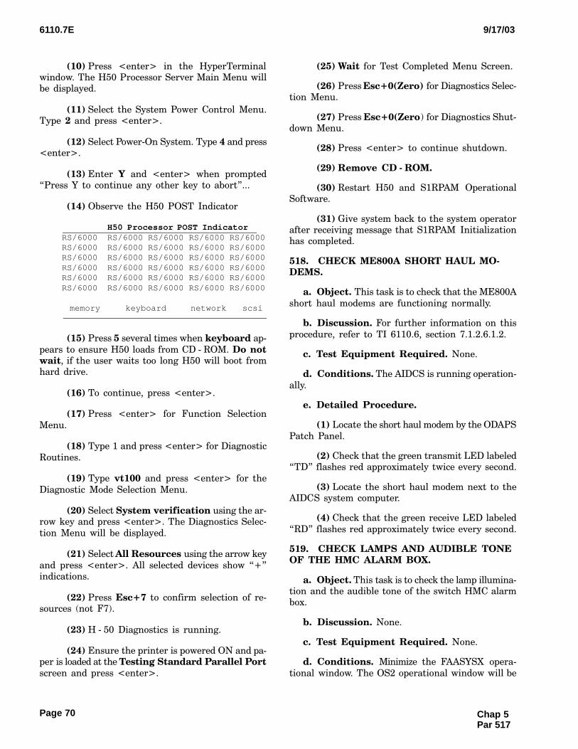
6110.7E 9/17/03
Page 70
(10)6Press <enter> in the HyperTerminalwindow. The H50 Processor Server Main Menu willbe displayed.
(11)6Select the System Power Control Menu.Type 2 and press <enter>.
(12)6Select Power−On System. Type 4 and press<enter>.
(13)6Enter Y and <enter> when promptedOPress Y to continue any other key to abort"...
(14)6Observe the H50 POST Indicator
H50 Processor POST Indicator RS/6000 RS/6000 RS/6000 RS/6000 RS/6000 RS/6000 RS/6000 RS/6000 RS/6000 RS/6000 RS/6000 RS/6000 RS/6000 RS/6000 RS/6000 RS/6000 RS/6000 RS/6000 RS/6000 RS/6000 RS/6000 RS/6000 RS/6000 RS/6000 RS/6000 RS/6000 RS/6000 RS/6000 RS/6000 RS/6000
memory keyboard network scsi
(15)6Press 5 several times when keyboard ap−
pears to ensure H50 loads from CD − ROM. Do notwait, if the user waits too long H50 will boot fromhard drive.
(16)6To continue, press <enter>.
(17)6Press <enter> for Function Selection
Menu.
(18)6Type 1 and press <enter> for Diagnostic
Routines.
(19)6Type vt100 and press <enter> for the
Diagnostic Mode Selection Menu.
(20)6Select System verification using the ar−row key and press <enter>. The Diagnostics Selec−
tion Menu will be displayed.
(21)6Select All Resources using the arrow key
and press <enter>. All selected devices show O+"indications.
(22)6Press Esc+7 to confirm selection of re−sources (not F7).
(23)6H − 50 Diagnostics is running.
(24)6Ensure the printer is powered ON and pa−per is loaded at the Testing Standard Parallel Portscreen and press <enter>.
(25)6Wait for Test Completed Menu Screen.
(26)6Press Esc+0(Zero) for Diagnostics Selec−tion Menu.
(27)6Press Esc+0(Zero) for Diagnostics Shut−down Menu.
(28)6Press <enter> to continue shutdown.
(29)6Remove CD − ROM.
(30)6Restart H50 and S1RPAM OperationalSoftware.
(31)6Give system back to the system operatorafter receiving message that S1RPAM Initializationhas completed.
518.�CHECK ME800A SHORT HAUL MO−DEMS.
a.Object. This task is to check that the ME800A
short haul modems are functioning normally.
b.Discussion. For further information on this
procedure, refer to TI 6110.6, section 7.1.2.6.1.2.
c.Test Equipment Required. None.
d.Conditions. The AIDCS is running operation−
ally.
e.Detailed Procedure.
(1)6Locate the short haul modem by the ODAPS
Patch Panel.
(2)6Check that the green transmit LED labeledOTD" flashes red approximately twice every second.
(3)6Locate the short haul modem next to theAIDCS system computer.
(4)6Check that the green receive LED labeled
ORD" flashes red approximately twice every second.
519.�CHECK LAMPS AND AUDIBLE TONEOF THE HMC ALARM BOX.
a.Object. This task is to check the lamp illumina−tion and the audible tone of the switch HMC alarmbox.
b.Discussion. None.
c.Test Equipment Required. None.
d.Conditions. Minimize the FAASYSX opera−
tional window. The OS2 operational window will be
Chap 5Par 517

6110.7E9/17/03
Page 71
displayed, containing the HOST ALARM TEST andHOST ALARM ACKNOWLEDGE icons. Check to seethat only the NO ALARM lamp is illuminated. This
test can be performed on both the operational andredundant HMC without impact system operation.
e.Detailed Procedure.
(1)6At the HMC, click on the HOST ALARMTEST icon. The CRITICAL lamp and audible tone
should come on.
(2)6At the HMC, click on the HOST ALARM
ACKNOWLEDGE icon. The CRITICAL lamp and au−dible tone should disperse. The NO ALARM lampshould be the only indicator illuminated.
520.�CHECK UNIVERSAL POWER SUPPLY600 OR 1000.
a.Object. This task is to check that the APCSmart UPS 600 or 1000 is functioning normally.
b.Discussion. For further information on this
procedure, refer to TI 6110.6, section 3.1.5.
c.Test Equipment Required. None.
d.Conditions. The AIDCS is running operation−ally.
e.Detailed Procedure.
(1)6Locate the UPS 600 or 1000 below theAIDCS system computer.
(2)6Check that the LED on the front panel ofthe UPS labeled On Line is lit.
521.�CHECK ODAPS − AIDCS − FIR INTER−FACES (NEW YORK ARTCC).
a.Object. This task is to check that the ODAPS −
AIDCS − FIR interfaces are functioning normally.
b.Discussion. For further information on this
procedure, refer to TI 6110.6, section 6.1.4.
c.Test Equipment Required. None.
d.Conditions. The AIDCS is running operation−
ally.
e.Detailed Procedure.
NOTE:CIn the following procedures, XXX refersto the three letter AIDCS interfacility address
name of a particular FIR, such as ZCP for Piarcoand ZCG for Gander.
(1)6If the outbound interface for XXX is notoperational, then set the outbound interface for XXX
operational by entering the following at an ODAPS
KVDT:
OPIO XXXO
(2)6If the inbound interface for XXX is not op−erational, then set the inbound interface for XXX op−
erational by entering the following at an ODAPSKVDT:
OPIO XXXI
(3)6To test the communication path betweenODAPS and the FIR XXX via the AIDCS, enter the
following at an ODAPS KVDT:
TR XXX |PING
When the AIDCS receives this message, it transmits
an Application Status Message (ASM) to the FIRXXX. The FIR should respond with a Logical Ac−
knowledgement Message (LAM). Upon receiving theLAM, the AIDCS sends a DT response back to ODAPSto be displayed at the ODAPS KVDT used to enter
the TR message.
(4)6Within 30 seconds a DT message should be
displayed at the ODAPS KVDT used to enter the TRmessage with the following format:
DT ZNNN PING hhmmss tim
(a)6where NNN is the ODAPS messagenumber of the initial TR message, hhmmss is the
system clock time of the FIR’s AIDCS at the timethe FIR transmitted the LAM, and the tim is the
total elapsed time in seconds between the time theASM was transmitted by the ARTCC AIDCS and thetime the LAM was received by the ARTCC AIDCS.
A sample DT message is shown below:
DT Z342 PING 172248 016
(b)6In this case, the ODAPS message num−ber for the TR message was 342, the system clocktime of the FIR’s AIDCS at the time the FIR trans−
mitted the LAM response was 172248, and the total
Chap 5Par 519
6110.7E 9/17/03
Page 72
elapsed time between the transmission of the ASMand the receipt of the LAM by the ARTCC AIDCSwas 16 seconds.
(5)6If the outbound interface for XXX is to bestopped following the test, then set the outbound in−
terface non−operational by entering the following atan ODAPS KVDT:
NPIO XXXO
(6)6If the inbound interface for XXX is to bestopped following the test, then set the inbound inter−face non−operational by entering the following at an
ODAPS KVDT:
NPIO XXXI
(7)6Repeat paragraph 521e(1) through 521e(6)
for all FIRs that are adapted.
522.�CHECK ODAPS − AIDCS − FIR INTER−FACES (OAKLAND ARTCC).
a.Object. This task is to check that the ODAPS −AIDCS − FIR interfaces are functioning normally.
b.Discussion. For further information on thisprocedure, refer to TI 6110.6, section 6.1.5.
c.Test Equipment Required. None.
d.Conditions. The AIDCS is running operation−ally.
e.Detailed Procedure.
NOTE:CIn the following procedures, XXX refersto the three letter AIDCS interfacility addressname of a particular FIR, such as TYO for Tokyo
and TTT for Tahiti.
(1)6ODAPS − AIDCS Interface
(a)6If the outbound interface for XXX is not
operational, then set the outbound interface for XXX
operational by entering the following at an ODAPS
KVDT:
OPIO XXXO
(b)6If the inbound interface for XXX is not
operational, then set the inbound interface for XXX
operational by entering the following at an ODAPSKVDT:
OPIO XXXI
(c)6To test the communication path be−tween ODAPS and the AIDCS, enter the followingat an ODAPS KVDT:
TR XXX |TEST
When the AIDCS receives this message, it sends aDT response back to ODAPS to be displayed at theODAPS KVDT used to enter the TR message.
(d)6Within 5 − 10 seconds a DT responseshould be displayed at the ODAPS KVDT used to enter
the TR message with the following format:
DT ONNN TEST
16where NNN is the ODAPS messagenumber of the initial TR message. A sample DT mes−
sage is shown below:
DT O342 TEST
26In this case, the ODAPS message num−ber for the TR message was 342.
(e)6If the outbound interface for XXX is tobe stopped following the test, then set the outbound
interface non−operational by entering the followingat an ODAPS KVDT:
NPIO XXXO
(f)6If the inbound interface for XXX is to
be stopped following the test, then set the inboundinterface non−operational by entering the following
at and ODAPS KVDT:
NPIO XXXI
(g)6Repeat paragraph 522e(1)(a) through522e(1)(f) for all FIRs that are adapted.
(2)6AIDCS − FIR Interface
(a)6If the FIR name to be tested (e.g., Tokyo)
in the ADDRESS list at the AIDCS is red in color,then the AIDCS communication link to NADIN is
down. Proceed no further.
(b)6In the ADDRESS list at the AIDCS, click
on the FIR name (e.g., Tokyo) for which the End−To−End Certification is to be performed. The diamondpreceding the FIR name should turn green.
(c)6Click the button labeled − − TESTLINE − − . The FIR name that was selected in step
(b) should turn yellow (if it is not already yellow).
(d)6In the menu bar of the AIDC INTER−
FACE TO ADJACENT FIRs window at the AIDCS,
Chap 5Par 521
6110.7E9/17/03
Page 73
click on the Messages menu item. A pull−down menuis displayed.
(e)6In the pull−down menu, click on the MISmenu item. A Miscellaneous Free Text Message win−
dow is displayed.
(f)6In the FLID/Functional Address box ofthe Miscellaneous Free Text Message window, type:
/ASUP
(g)6Move the cursor to the Message Text boxof the Miscellaneous Free Text Message window by
pressing <Tab>.
(h)6In the Message Tex box of the Miscella−neous Free Text Message window, type: COMMTEST.
(i)6In the Miscellaneous Free Text Message
window, click SEND. The Miscellaneous Free TextMessage window closes and the Miscellaneous (MIS)
message is sent to the FIR.
(j)6Within 30 seconds the FIR name selectedin step b should turn green indicating that a LAMresponse has been received from the FIR for the MIS
message.
(k)6Repeat paragraph 522e(2)(a) through522e(2)(j) for all FIRs that are adapted.
523.�ODL UNIT LEVEL CERTIFICATION.
a.Object. These certification procedures are
used to verify that an ODL CPU is capable of perform−ing its intended function. Reference TI 6110.15, sec−tion 7 for detailed information.
b.Discussion. Unit level certification should beperformed on spare system consoles, workstations orservers before placing them into a restored system
or after maintenance has been performed. This proce−dural guidance is general in nature, yet specific
enough to support certification of this unit.
c.Test Equipment Required. None.
d.Conditions. Maintenance has been completedon a Server, System Console, or Sector Workstation.
e.Detailed Procedure. The detailed proce−dures and certification requirements are documented
in TI 6110.15, section 7.3.2.6.
524.�ODL SYSTEM LEVEL CERTIFICA−TION.
a.Object. These certification procedures areused to verify that the ODL system is capable of per−
forming its intended function.
b.Discussion. System level certification shouldbe performed during periods of low traffic activity,and with the approval of the ATC staff on duty. This
procedural guidance is general in nature, yet specificenough to support certification of this system. The
recommended timeframe to execute is quarterly.
c.Test Equipment Required. None.
d.Conditions. The total ODL System must be
in a completely stopped status before performing Sys−tem level certification.
e.Detailed Procedure.
(1)6Observe the System Console display toverify all the necessary devices are operational.
(2)6Coordinate proposed certification actions
with ATC.
(3)6At the system console, bring ODL offlineby typing:
OSTOP SYSTEM"
(4)6When system is in stopped status, refer toTI 6110.15, section 7.3.2.7 for detailed requirementsand operating procedures.
(5)6When testing is completed, restart system
using normal start−up procedures.
525.�ODL SERVICE LEVEL CERTIFICA−TION.
a.Object. The service level certification proce−dures are used to verify that the ODL system is capable
of performing its intended OLC function.
b.Discussion. Communications actions can beperformed with minimal interference to the on−goingATC operations. This service level certification should
be performed during periods of low traffic activity,and with the approval of the ATC staff on duty. This
procedural guidance is general in nature, yet specificenough to support certification of this service.
c.Test Equipment Required. None.
d.Conditions. None.
Chap 5Par 522

6110.7E 9/17/03
Page 74
e.Detailed Procedure.
(1)6Observe the System Console display to
verify all the necessary devices are operational.
(2)6Coordinate proposed certification actions
with ATC.
(3)6At the system console, run the ODL OLC
program by typing:
OLINKTEST"
in the message composition window. Refer also to TI
6110.15, section 7.3.2.8.
(4)6Evaluate the results and enter the certifica−
tion status in the facility maintenance log.
526.�CHECK ODL SERVER SWITCHOVEROPERATION.
a.Object. This task is to verify that the ODL
Server can perform a successful switchover operation.
b.Discussion. The replace functionality proce−
dures are found in NASP − 7214, section 3.2.7.1.
c.Test Equipment Required. None.
d.Conditions. Redundant ODL Server available
in standby.
e.Detailed Procedure.
(1)6Replace the operational ODL Server by typ−ing at the ODL System Console:
REPL <ENTER>
(The command response to the REPL com−mand is command accepted, followed by serverx tak−
ing over, and the final message is serverx is nowoperational.)
(2)6Observe the status at the System Console,the previous redundant server has become the opera−tional server and the previous operational server is
now in redundant status.
527.�CHECK ODL LAN SWITCHOVER OP−ERATION.
a.Object. This task is to verify that the ODLLAN can perform a successful switchover operation.
b.Discussion. To perform a switchover of the
LAN, the STOP command is issued. The redundantLAN will become operational and the former opera−tional LAN becomes redundant. These procedures are
found in NASP − 7214, appendix B, Table B − 2, StatusMessages. The name given to the LAN is an adaptable
parameter and will be used in this procedure.
c.Test Equipment Required. None.
d.Conditions. Redundant LAN available in
standby.
e.Detailed Procedure.
(1)6At the ODL System Console enter the com−
mand:
STOP Oparameter name" <ENTER>
(2)6Observe the LAN switch took place correct−ly.
528.�SYMMETRIX 5630 M&C MAINTE−NANCE PROCEDURES.
a.Swap Active and Standby Servers.
(1)6Archive the Event Log file for the primaryserver on CD before demoting it.
(2)6Insert a CD into the drive on the H80 I/O
processor (M&C rack front).
(3)6From the primary server, select File optionfrom the Topology Map menu bar.
(4)6Select Archive command from the pull−down menu.
(5)6Observe two entries in the Events List: one
states that the archive has started and the other statesthat the archive has completed.
(6)6Determine which M&C server is primaryby observing the M&C Events List title bar and M&C
icons in the map view.
(7)6Select the server icon that is to become pri−mary.
(8)6Right trackball click on the icon.
Chap 5Par 525
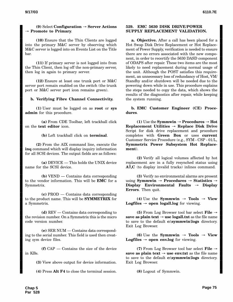
6110.7E9/17/03
Page 75
(9)6Select Configuration � Server Actions� Promote to Primary.
(10)6Ensure that the Thin Clients are logged
into the primary M&C server by observing whichM&C server is logged into on Events List on the Titlebar.
(11)6If primary server is not logged into fromthe Thin Client, then log off the non−primary server,then log in again to primary server.
(12)6Ensure at least one trunk port or M&C
server port remain enabled on the switch (the trunkport or M&C server port icon remains green).
b.Verifying Fibre Channel Connectivity.
(1)6User must be logged on as root or sysadmin for this procedure.
(a)6From CDE Toolbar, left trackball click
on the text editor icon.
(b)6Left trackball click on terminal.
(2)6From the AIX command line, execute theinq command which will display inquiry information
for all SCSI devices. The output fields are as follows:
(a)6DEVICE N This holds the UNIX devicename for the SCSI device.
(b)6VEND N Contains data corresponding
to the vendor information. This will be EMC for aSymmetrix.
(c)6PROD N Contains data corresponding
to the product name. This will be SYMMETRIX fora Symmetrix.
(d)6REV N Contains data corresponding to
the revision number. On a Symmetrix this is the microcode version number.
(e)6SER NUM N Contains data correspond−
ing to the serial number. This field is used then creat−ing sym device files.
(f)6CAP N Contains the size of the device
in KBs.
(3)6View above output for device information.
(4)6Press Alt F4 to close the terminal session.
529.�EMC 5630 DISK DRIVE/POWERSUPPLY REPLACEMENT VALIDATION.
a.Objective. After a call has been placed for a
Hot Swap Disk Drive Replacement or Hot Replace−ment of Power Supply, verification is needed to ensure
there are no errors associated with the new compo−nent, in order to recertify the 5630 DASD componentof ODAPS after repair. These two items are the most
likely to need replacement during normal usage ofthe unit. Although the POST satisfies this require−
ment, an unnecessary loss of redundancy of Host, VM/Standby and/or shutdown will be needed due to thepowering down while in use. This procedure explains
the steps needed to copy the data, which shows theresults of the diagnostics after repair, while keeping
the system running.
b.EMC Customer Engineer (CE) Proce−dures.
(1)6Use the Symmwin � Procedures � HotReplacement Utilities � Replace Disk DriveScript for disk drive replacement and procedure
completes with Green Box or uses currentCustomer Service Procedure (e.g., SYM − CSP − 01/L,
Symmetrix Power Subsystem Hot Replace−ment).
(2)6Verify all logical volumes affected by hot
replacement are in a fully resynched status usingA7,C (to display invalid tracks) inlines command.
(3)6Verify no environmental alarms are presentusing Symmwin � Procedures � Statistics �Display Environmental Faults � DisplayErrors. Then quit.
(4)6Use the Symmwin � Tools � ViewLogfiles � open logall.log for viewing.
(5)6From Log Browser tool bar select File �save as plain text � use logall.txt as the file name
to save to the default c:\symmwin\logs directory.Exit Log Browser.
(6)6Use the Symmwin � Tools � ViewLogfiles � open env.log for viewing.
(7)6From Log Browser tool bar select File �save as plain text � use env.txt as the file nameto save to the default c:\symmwin\logs directory.Exit Log Browser.
(8)6Logout of Symmwin.
Chap 5Par 528

6110.7E 9/17/03
Page 76
c.FAA Maintenance Personnel Procedures.
(1)6Copy the env.txt and logall.txt file ontoto a site provided diskette as follows:
(a)6On Symmetrix service processor rightclick on MS Start button.
(b)6Select: Explore All Users.
(c)6From Folders select: c:\symmwin\logsdirectory.
(d)6Insert blank floppy diskette into serviceprocessor diskette drive.
(e)6Right click on env.txt.
(f)6Select: Send To � Floppy Drive (a).
(g)6Right click on logall.txt.
(h)6Select: Send To � Floppy Drive (a).
(i)6Close Explorer window and removediskette from Service Processor.
(2)6If validating the replacement action for aDisk Drive, browse the logall.txt file from any PCusing any MS browser application (e.g., MS Word,
Notepad, etc.). Reference Figure 5 − 2, SuccessCriteria for Disk Drive Replacement (logall.log),
Figure 5 − 3, Indication for Disk Drive Resynchroniza−tion in Progress (logall.log), and Figure 5 − 4, SuccessCriteria for Disk Drive Resynchronization Complete
(logall.log) , for validation criteria.
(3)6If validating the replacement action for a
Power Supply, browse the env.txt file from any PCusing any MS browser application (e.g., MS Word,
Notepad, etc.). Reference Figure 5 − 5, EnvironmentalLog File with No Errors Present (env.log) and Figure5 − 6, Environmental Log File with Example Error
Present (env.log) for validation criteria.
530. − 549.�RESERVED.
Chap 5Par 529
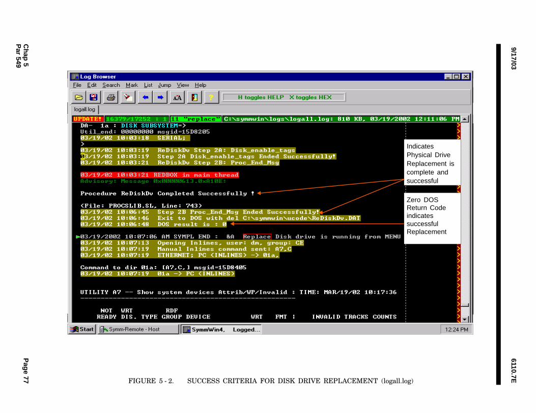
6110.7E9/17/03
Ch
ap 5
Pag
e 77P
ar 549
IndicatesPhysical DriveReplacement iscomplete andsuccessful
Zero DOSReturn CodeindicatessuccessfulReplacement
FIGURE 5 − 2.��SUCCESS CRITERIA FOR DISK DRIVE REPLACEMENT (logall.log)
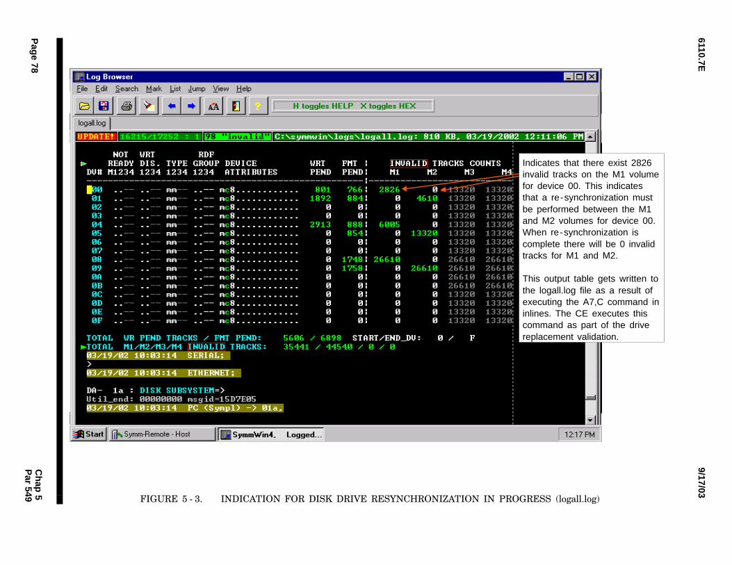
9/17/036110.7E
Pag
e 78C
hap
5P
ar 549
Indicates that there exist 2826invalid tracks on the M1 volumefor device 00. This indicatesthat a re-synchronization mustbe performed between the M1and M2 volumes for device 00.When re-synchronization iscomplete there will be 0 invalidtracks for M1 and M2.
This output table gets written tothe logall.log file as a result ofexecuting the A7,C command ininlines. The CE executes thiscommand as part of the drivereplacement validation.
FIGURE 5 − 3.��INDICATION FOR DISK DRIVE RESYNCHRONIZATION IN PROGRESS (logall.log)

6110.7E9/17/03
Ch
ap 5
Pag
e 79P
ar 549
When re-synchronizationis complete there will bezero invalid tracks for M1and M2 for each device.
FIGURE 5 − 4.��SUCCESS CRITERIA FOR DISK DRIVE RESYNCHRONIZATION COMPLETE (logall.log)

9/17/036110.7E
Pag
e 80C
hap
5P
ar 549
No environmentalfaults indicate asuccessful powersupply replacement.
Note: It is possiblethat charge statealarms may bedisplayed. This isnormal and is notindicative of anunsuccessful powersupply replacement.
FIGURE 5 − 5.��ENVIRONMENTAL LOG FILE WITH NO ERRORS PRESENT (env.log)

6110.7E9/17/03
Ch
ap 5
Pag
e 81P
ar 549
Example indicates possibleunsuccessful power supplyreplacement.
Note that the presence ofother faults such as:
Power Fail Alarm PS1Power Fail Alarm PS2
are also indicative of anunsuccessful power supplyreplacement.
FIGURE 5 − 6.��ENVIRONMENTAL LOG FILE WITH EXAMPLE ERROR PRESENT (env.log)
6110.7E 9/17/03
Page 82
Section 2.CCCOTHER MAINTENANCE TASKS PROCEDURES
550.�CLEAN PRINTER.
a.Object. This task is performed so that dirt anddebris will not jam the printer.
b.Discussion. None.
c.Equipment Required. A vacuum cleaner
with a small flexible crevice attachment.
d.Conditions. The cleaning shall be performed
with the printer power OFF.
e.Detailed Procedure. Vacuum out all dust andpaper pieces from the paper handling areas.
551.�CLEAN TAPE DRIVE.
a.Object. This task is performed so that dust
and dirt will not degrade the read/write operationof the tape drive.
b.Discussion. None.
c.Equipment Required. A tape drive cleaningtape.
d.Conditions. The IBM 3480 Model B22 MTUcleaning is required semiannually or as required when
CLEAN is displayed on the message display panel.The IBM 7208 tape drive cleaning is required weekly.
e.Detailed Procedure. Insert the cleaning tape
into the drive. The message UNLOADING will dis−play on the message display panel while the cleaning
tape is in the drive. The tape will eject from the drivewhen finished.
552.�CLEAN AND INSPECT CABINET.
a.Object. This task is performed so that dustand dirt will not degrade the operation of the enclosed
equipment and so that unscheduled interruptions ofservice will be avoided by detecting pending mechani−cal failure.
b.Discussion. None.
c.Equipment Required.
(1)6A vacuum cleaner with a small flexible crev−ice attachment.
(2)6Hand tools.
d.Conditions. The cleaning shall be performedwith the equipment power OFF.
e.Detailed Procedure.
(1)6Vacuum accumulated dust and debris.
(2)6Check cable and Printed Circuit Board(PCB) connections.
(3)6Check for stressed components.
(4)6Lubricate as necessary.
553.�CLEAN AIR FILTER.
a.Object. This task is performed so that dust
and dirt will not clog the filter.
b.Discussion. This procedure only applies tonon−fiberglass filters. Fiberglass filters should be re−
placed instead of cleaned.
c.Equipment Required. Hand tools.
d.Conditions. The cleaning shall be performed
with the power OFF.
e.Detailed Procedure.
(1)6Remove the air filter from unit.
(2)6Clean air filter.
554.�FAN OPERATIONAL CHECK.
a.Object. This check is performed in order toavoid equipment overheating due to fan failure.
b.Discussion. Fan failure usually occurs as a
result of bearing failure or winding failure.
(1)6Bearings may seize due to lack of lubrica−tion or the accumulation of dirt. This condition canbe detected by feeling for overheating while the fan
is operating. On ac fans, this can also be detectedby manually checking for excessive drag while the
fan is stopped. Bearings may get too sloppy due towear. This condition can be anticipated by listeningfor excessive noise while the fan is operating or by
manually checking for excessive play while the fanis stopped.
Chap 5Par 550
6110.7E9/17/03
Page 83
(2)6Windings may short or open circuit due tocontinued overheating. This condition can be antici−pated by feeling and looking for any signs of overheat−
ing while the fan is operating.
c.Equipment Required. None.
d.Conditions. The operating checks shall beperformed while the fan is under a typical operational
thermal and acoustic load.
e.Detailed Procedure. See the manufacturer’sinstruction book for the procedure to access the fan
or fans. Then perform the following checks:
(1)6While the fan is operating, look and feelfor evidence of overheating and listen for excessive
bearing noise.
(2)6On equipment which may be powereddown, while the fan is stopped, feel for excessive bear−ing drag or wear.
555.�CLEAN AND INSPECT EQUIPMENT.
a.Object. This task is performed so that dustand dirt will not degrade the operation of the equip−
ment and so that unscheduled interruptions of servicewill be avoided by detecting pending mechanical fail−ure.
b.Discussion. None.
c.Equipment Required.
(1)6A damp cloth.
(2)6A non−toxic cleanser.
d.Conditions. The cleaning shall be performedwith the equipment power OFF.
e.Detailed Procedure.
(1)6Remove dirt, grease, and oil with a dampcloth and a non−toxic cleanser or soap.
(2)6Wipe off residue with a water−damped cloth.
556. − 574.�RESERVED.
Chap 5Par 554

6110.7E 9/17/03
Page 84
Section 3.CCCSPECIAL MAINTENANCE PROCEDURES
575.�ONLINE CERTIFICATION DATA RE−QUIREMENTS.
a.Object. This paragraph defines the minimum
data requirements for the OLC program simulationfiles.
b.General. The OLC program provides the
NOM/NAS with a highly flexible, online means ofverifying the certification parameters of the system.The certification files used for OLC are generated
using the SIMulation (SIM) program, followed by useof the verification post processor program. These files
are identical to the files generated by the simulationprogram, except for the block of data added to theend of the header record. These files include the data
necessary to assist the system engineer in verificationof the certification parameters specified.
c.Detailed Procedure. The data file require−ments for ODAPS certification consist of the inputmessages necessary to verify the flight data processing
and the I/O capability of the system. The minimumrequirements are listed below.
(1)6Input at least five flight plans to demon−
strate that the FDBs thereby generated are correctlydisplayed upon the ISD OCs. One FDB shall be gener−
ated at the point of tangency, and the next four FDBsat the four points farthest from the point of tangency.
The flight plans should be input from KVDTs or TPworkstations, and their combined routes shall pene−trate all adapted sectors that have airspace. The flight
shall represent overflights or traffic originating orlanding within a sector’s airspace. The simulated
flight plans shall be such that strip printing is initi−ated.
(2)6Test all KVDTs using the GI and TD mes−sages addressed to each KVDT. The GI messages shallinclude the position identification (C1, E1, etc.), LDN
(200, 204, etc.), and device addresses (8D, 3F, etc.).
(3)6Use TD messages to cause display of the
workstation monitor test pattern at all sector posi−tions. Invalid messages shall be included that cause
the sector number, LDN, and FDIO address to be writ−ten on the workstation monitor.
(4)6Exercise all ODAPS TFSPs using the TDmessage.
(5)6Use TR or MIS messages to elicit responsefrom all the adjacent NAS facilities or FIRs. If certifi−
cation is performed when the adjacent facility or FIRis not operational, a normal response will not be re−ceived from that facility or the FIR.
576. − 599.�RESERVED.
Chap 5Par 575

6110.7E9/17/03
Page 85
CHAPTER 6. FLIGHT INSPECTION
600. − 699.�RESERVED.
Page 85 (and 86)Chap 6Par 600

6110.7E9/17/03
Page 87
CHAPTER 7. MISCELLANEOUS
700.�ABBREVIATIONS AND ACRONYMS.
The following acronyms, abbreviations, and unitsare used in this document.
ac alternating current
AF Airway Facility
AFTN Aeronautical Fixed Telecommunica−tions Network
AIDCS ATS Interfacility Data Communica−tions System
AMCC ARTCC Maintenance Control Cen−
ter
AOS Operational Support Service
APC American Power Conversion
ARTCC Air Route Traffic Control Center
ARTS Automated Radar Terminal System
ASCII American Standard Code for Infor−mation Interchange
ASM Application Status Message
ATC Air Traffic Control
ATO Air Traffic Operations
ATS Air Traffic Service
ATSS Airway Transportation System Spe−cialist
BAT Basic Acceptance Test
CCC Central Computer Complex
CCD Configuration Control Decision
CCCH Central Computer Complex Host
CCK Common Console Keyboard
CCW Channel Command Word
CD − ROM Compact Disc−Read Only Memory
CDRL Contract Data Requirements List
CE Customer Engineer
CHPID CHannel Path IDentifier
CKD Count Key Data
CMOS Complimentary Metal Oxide Semi−
conductor
CO Computer Operator
COMM COMMunications
CP Central Processor
CPC Central Processing Complex
CPDLC Controller/Pilot Data Link Commu−nications
CPU Central Processing Unit
CRT Cathode Ray Tube
CSOM Computer System Operation Manu−
al
CTC Channel To Channel
CTS Coded Time Source
DASD Direct Access Storage Device
DCX Display Controller for X−Windows
DDS Digital Data Storage
DR&A Data Reduction & Analysis
DT Data Test
DUG Diagnostic User’s Guide
E − MAIL Electronic Mail
ED Early Drop
ESA Enterprise System Architecture
Chap 7Par 700
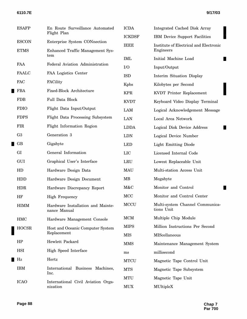
6110.7E 9/17/03
Page 88
ESAFP En Route Surveillance AutomatedFlight Plan
ESCON Enterprise System CONnection
ETMS Enhanced Traffic Management Sys−tem
FAA Federal Aviation Administration
FAALC FAA Logistics Center
FAC FACility
FBA Fixed−Block Architecture
FDB Full Data Block
FDIO Flight Data Input/Output
FDPS Flight Data Processing Subsystem
FIR Flight Information Region
G3 Generation 3
GB Gigabyte
GI General Information
GUI Graphical User’s Interface
HD Hardware Design Data
HDD Hardware Design Document
HDR Hardware Discrepancy Report
HF High Frequency
HIMM Hardware Installation and Mainte−
nance Manual
HMC Hardware Management Console
HOCSR Host and Oceanic Computer SystemReplacement
HP Hewlett Packard
HSI High Speed Interface
Hz Hertz
IBM International Business Machines,Inc.
ICAO International Civil Aviation Orga−
nization
ICDA Integrated Cached Disk Array
ICKDSF IBM Device Support Facilities
IEEE Institute of Electrical and Electronic
Engineers
IML Initial Machine Load
I/O Input/Output
ISD Interim Situation Display
Kpbs Kilobytes per Second
KPR KVDT Printer Replacement
KVDT Keyboard Video Display Terminal
LAM Logical Acknowledgement Message
LAN Local Area Network
LDDA Logical Disk Device Address
LDN Logical Device Number
LED Light Emitting Diode
LIC Licensed Internal Code
LRU Lowest Replaceable Unit
MAU Multi−station Access Unit
MB Megabyte
M&C Monitor and Control
MCC Monitor and Control Center
MCCU Multi−system Channel Communica−
tions Unit
MCM Multiple Chip Module
MIPS Million Instructions Per Second
MIS MIScellaneous
MMS Maintenance Management System
ms millisecond
MTCU Magnetic Tape Control Unit
MTS Magnetic Tape Subsystem
MTU Magnetic Tape Unit
MUX MUltipleX
Chap 7Par 700
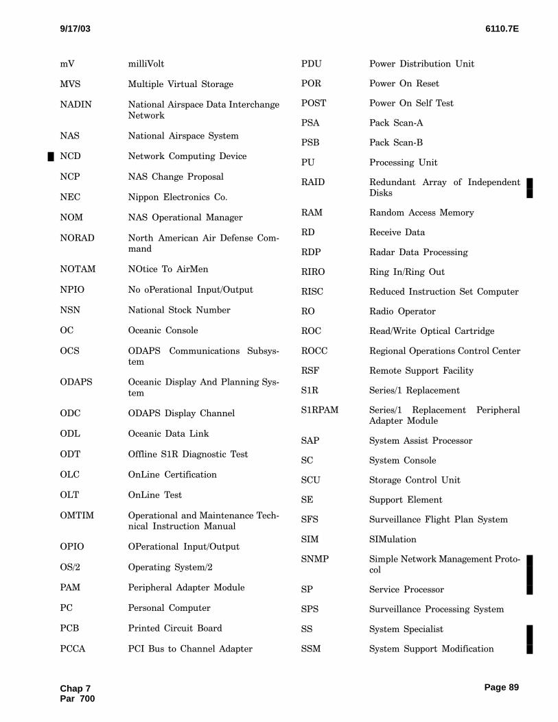
6110.7E9/17/03
Page 89
mV milliVolt
MVS Multiple Virtual Storage
NADIN National Airspace Data Interchange
Network
NAS National Airspace System
NCD Network Computing Device
NCP NAS Change Proposal
NEC Nippon Electronics Co.
NOM NAS Operational Manager
NORAD North American Air Defense Com−mand
NOTAM NOtice To AirMen
NPIO No oPerational Input/Output
NSN National Stock Number
OC Oceanic Console
OCS ODAPS Communications Subsys−tem
ODAPS Oceanic Display And Planning Sys−
tem
ODC ODAPS Display Channel
ODL Oceanic Data Link
ODT Offline S1R Diagnostic Test
OLC OnLine Certification
OLT OnLine Test
OMTIM Operational and Maintenance Tech−nical Instruction Manual
OPIO OPerational Input/Output
OS/2 Operating System/2
PAM Peripheral Adapter Module
PC Personal Computer
PCB Printed Circuit Board
PCCA PCI Bus to Channel Adapter
PDU Power Distribution Unit
POR Power On Reset
POST Power On Self Test
PSA Pack Scan−A
PSB Pack Scan−B
PU Processing Unit
RAID Redundant Array of IndependentDisks
RAM Random Access Memory
RD Receive Data
RDP Radar Data Processing
RIRO Ring In/Ring Out
RISC Reduced Instruction Set Computer
RO Radio Operator
ROC Read/Write Optical Cartridge
ROCC Regional Operations Control Center
RSF Remote Support Facility
S1R Series/1 Replacement
S1RPAM Series/1 Replacement PeripheralAdapter Module
SAP System Assist Processor
SC System Console
SCU Storage Control Unit
SE Support Element
SFS Surveillance Flight Plan System
SIM SIMulation
SNMP Simple Network Management Proto−col
SP Service Processor
SPS Surveillance Processing System
SS System Specialist
SSM System Support Modification
Chap 7Par 700
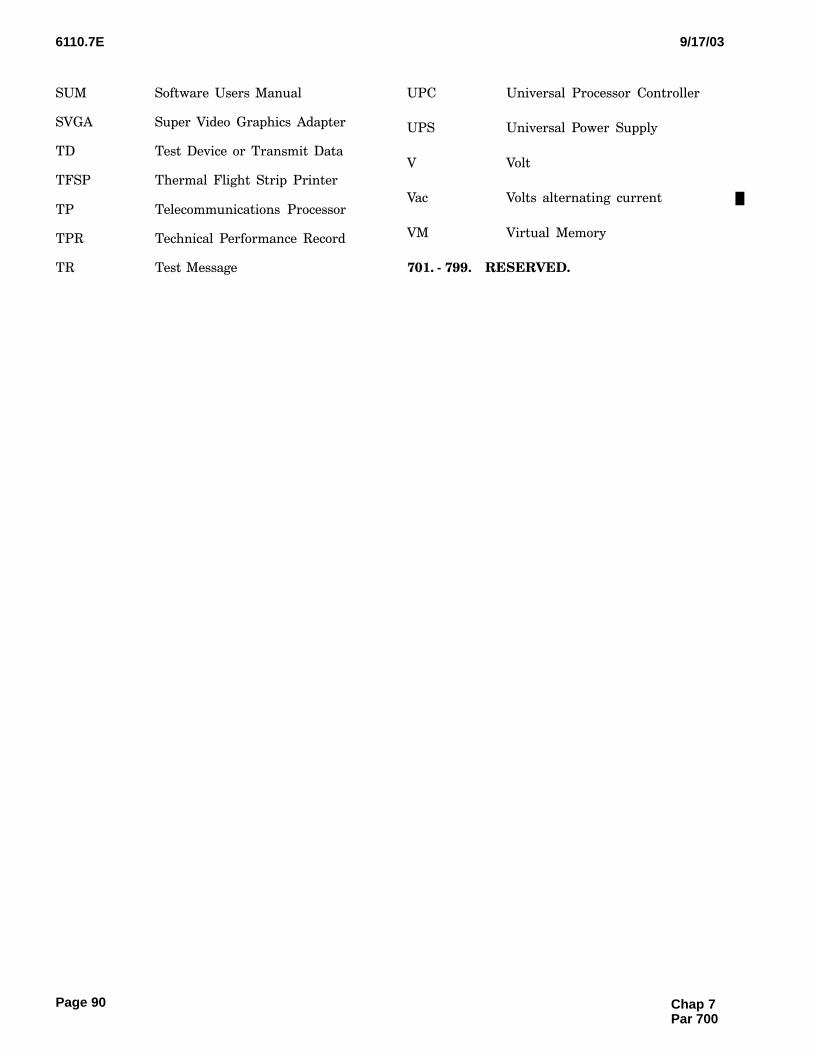
6110.7E 9/17/03
Page 90
SUM Software Users Manual
SVGA Super Video Graphics Adapter
TD Test Device or Transmit Data
TFSP Thermal Flight Strip Printer
TP Telecommunications Processor
TPR Technical Performance Record
TR Test Message
UPC Universal Processor Controller
UPS Universal Power Supply
V Volt
Vac Volts alternating current
VM Virtual Memory
701. − 799.�RESERVED.
Chap 7Par 700
6110.7E9/17/03Appendix 1
Page 1
APPENDIX 1. CERTIFICATION REQUIREMENTS
1.�GENERAL.
This chapter contains certification requirementsfor surveillance automated fight plan services pro−
vided in the en route oceanic ATC environment, andcertification requirements for constituent systemsused to provide these services. Refer to Order 6000.15
for general guidance on the certification of servicesand systems.
2.�SERVICES.
Surveillance services provide a means for ATC per−sonnel to determine aircraft position, course, and
identification during aircraft operations. This serviceis certified as ESAFP Service in accordance withtables included in this appendix. ESAFP is a mutually
dependent surveillance service, relying on a combina−tion of ATC systems, to provide ATC personnel with
a means to determine aircraft identification over theoceans. The service enhances ATC capabilities bylinking real−time flight data with flight plan data,
and therefore automating the handling of surveil−lance data to appropriate ATC sectors. It depends on
systems used to provide similar services for the EnRoute environment and on systems used to file, route,update, and terminate flight plans.
3.�SYSTEMS.
Centralized, distributed, or back−up surveillanceprocessing systems, and surveillance flight planningsystems are utilized to provide these services. Each
system is certified as SPS, or SFS, in accordance withthis appendix.
4.�EXCEPTIONS.
Order 6000.15 permits certification with excep−
tions where a system provides somewhat less thanits full functional benefit but is still useable; e.g., oneprocessor is taken out of service, yet other processors
are still contributing to the en route surveillance ser−vice. Outstanding exceptions may be certified in ac−
cordance with the following tables for the specificpurpose of removing the exceptions.
5.�FUTURE SYSTEMS.
For future planning purposes, systems that pro−
vide the above services or are used for testing or proto−typing shall be certified in accordance with Order6000.15.

6110.7E 9/17/03Appendix 1
Page 2
TABLE 1.��EN ROUTE SURVEILLANCE AUTOMATED FLIGHT PLAN (ESAFP) SERVICE
Service Certification Parameter Reference Paragraph
ESAFP Knowledge that all constituent systems
are certified.
None (go/no go)
Normal indications on Monitor and
Control.
None (go/no go)
Satisfactory flight data processing and
display.
301a and 401a(1)
Satisfactory KVDT message input and
display.
301b and 401a(2)
Satisfactory Flight Data Entry and Dis−
play message input.
301c and 401a(3)
Satisfactory flight strip printer. 301d and 401a(4)
Satisfactory interfacility data transfer. 301e, 308f, 308g, and 401a(5)
Successful execution of the ODL linkt−
est command.
309c and 401c
NORMAL CERTIFICATION INTERVAL: Daily.
MAXIMUM CERTIFICATION INTERVAL: 36 hours.
ALLOWABLE EXCEPTIONS: None.
PERSON RESPONSIBLE FOR CERTIFICATION: NOM/NAS
CERTIFICATION ENTRIES IN MAINTENANCE MANAGEMENT SYSTEM (MMS): ESAFP certified.
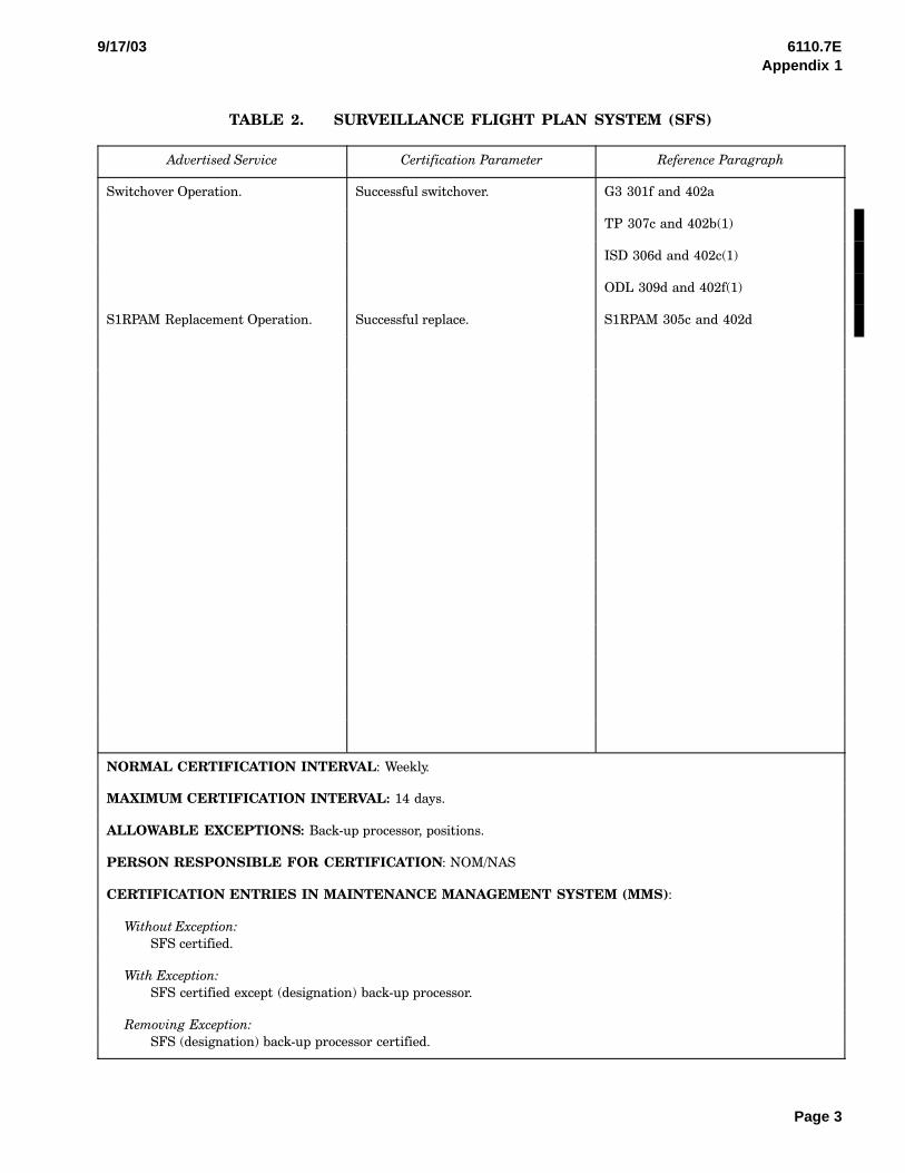
6110.7E9/17/03Appendix 1
Page 3
TABLE 2.��SURVEILLANCE FLIGHT PLAN SYSTEM (SFS)
Advertised Service Certification Parameter Reference Paragraph
Switchover Operation. Successful switchover. G3 301f and 402a
TP 307c and 402b(1)
ISD 306d and 402c(1)
ODL 309d and 402f(1)
S1RPAM Replacement Operation. Successful replace. S1RPAM 305c and 402d
NORMAL CERTIFICATION INTERVAL: Weekly.
MAXIMUM CERTIFICATION INTERVAL: 14 days.
ALLOWABLE EXCEPTIONS: Back−up processor, positions.
PERSON RESPONSIBLE FOR CERTIFICATION: NOM/NAS
CERTIFICATION ENTRIES IN MAINTENANCE MANAGEMENT SYSTEM (MMS):
Without Exception:
SFS certified.
With Exception:
SFS certified except (designation) back−up processor.
Removing Exception:
SFS (designation) back−up processor certified.

6110.7E 9/17/03Appendix 1
Page 4
TABLE 3.��SURVEILLANCE PROCESSING SYSTEM (SPS)
Advertised Service Certification Parameter Reference Paragraph
Processing Capability. Processor test. G3 302a(1) and 404a(3)(a)
S1RPAM 305a(1) and 404d(2)
TP 307a, 404f(1), 404f(2), and 404f(3)
ISD 306a, 404e(1), 404e(2), and 404e(3)
AIDCS 308a and 404g(1)
ODL 309g and 404h(1)
5630 M&C 310a and 404i(1)
Storage Capability. Data retrieval test. DASD 303a and 404b(1), 303c(1) and
404b(3)
MTU 304b and 404c(2)
Control Capability. Verification test. HMC 302a(3) and 404a(3)(c)
SE 302a(2) and 404a(3)(b)
TCU 302d and 404a(1)
SCU 303b and 404b(2)
MTCU 304a and 404c(1)
Connectivity Capability. External interface wrap test. S1RPAM 305a(3) and 404d(3)(b)
Interface cards, printer, and coded time
source.
S1RPAM 305a(2) and 404d(3)(a)
NORMAL CERTIFICATION INTERVAL: Quarterly.
MAXIMUM CERTIFICATION INTERVAL: 120 days.
ALLOWABLE EXCEPTIONS: Back−up processor, positions.
PERSON RESPONSIBLE FOR CERTIFICATION: ATSS with certification authority.
CERTIFICATION ENTRIES IN MAINTENANCE MANAGEMENT SYSTEM (MMS):
Without Exception:
SPS certified.
With Exception:
SPS certified except (designation) back−up processor.
Removing Exception:
SPS (designation) back−up device certified.

CASE FILE/ NAS CHANGE PROPOSAL
ForCMUse
Case File Received Date NCP Issuance Date NCP Number
Page 1 of __________
1. Case File Number 2.
3. Scope of Change 4. Reason For Change
5. Priority 7. Supplemental Change Form
7a. Supplemental Change
7b. Supplemental Change Initiation
8. Case File Originator 9. Originator’s Organization 10. Telephone Number 11. Case File Initiation Date
12. Type of Document Affected 13. Baseline Document Number(s)
14. CI Subsystem Designator 15. FA Type 16. CI Component Designator
17. Facility Identifier (FACID) 18. Facility Code (FACCODE) 19. Cost Center Code 20. Software System Version
21. Title
22. Description: (a) identification of problem, (b) proposed change, (c) interface impact, (d) cost estimate (e) funding source (f) benefits/risks,(g) Schedule (h) Other (e.g. logistics, quality, etc.)
(P;EASE TYPE OR PRINT NEATLY)
Local
Test
NationalSafety
Requirements Change
Technical Upgrade
Design Error
Normal
Time-Critical
Urgent
ECR/ECP TES N/A
CPFSTI
SPECDWG
MTBKIRD/ICD
Blocks 1 through 22 are to be completed by originator and/or the NCP coordinator. If a block is not applicable, write n/a. Attach additional sheets ifnecessary. See current revision of NAS-MD-001 for detailed completion instructions.
FAA Form 1800-2 (5-99) — Supersedes Previous Edition
Baseline Other
Parts Unavailability
Systems Interface
6. Justification of Time Critical/Urgent Priority
No. _______________________
Date ______________________
(a)
(b)
(c)
(d)
(e)
(f)
(g)
(h)
NSN:0052-00-801-6005
________________________________

Case File Number NCP NumberPage 2 of ___
23. Name and Title of Originator’s Immediate Supervisor
24. Facility/SMO Review (AT/AF) 25. Regional Review
Name
Routing Signature
Date
Recommend Approval
Signature Date
Routing Symbol Date Concur Non-Concur Name Routing Symbol Date Concur Non-Concur
SymbolRouting SignatureSymbol
(Type/Print Clearly)
Date
Routing Signature
Date
SymbolRouting SignatureSymbol
DateDate
24a. Comments Routing Signature/Configuration Mgr/NCP Coordinator/Symbol
Date
Reg Exec Sec
25a. Comments
26.
(Attach additional sheets if necessary)
Reviewers Routing Symbol Date Concur Non-Concur Recommend Disapproval(Return original to originatingoffice through the Regional NCPCoordinator)
Routing SignatureSymbol
DateRecommended Must Evaluators
(Attach additional sheets if necessary) (Attach additional sheets if necessary)
27.
Recommend Approval Disapprove(Return to Originator)(Enter into CM/STAT. Forward to Prescreening)
PRESCREENINGPrescreening Office __________________
Prescreening Comments:
New Requirement
For Internal Configuration Management Use Only
FAA FORM 1800-2 (5 -99) Supersedes Previous Edition NSN:0052 -00-801 -6005