
1150 Donnybrook Road Tract has be - Amazon AWS
119
1 / 7 Dear Paul City of Whittlesea Amendment C241wsea – Shenstone Park Precinct Structure Plan – 1150 Donnybrook Road Tract has been engaged by Donnybrook Road Unit Trust (our client) to lodge a submission to Amendment C241wsea to the Whittlesea Planning Scheme, being the Shenstone Park Precinct Structure Plan (the PSP). As you are aware from our previous discussions with the VPA and City of Whittlesea (Council), Our client has acquired the landholding located at 1150 Donnybrook Road, Donnybrook (Property). The Property forms part of the PSP and is clearly identified in Figure 1. Figure 1: 1150 Donnybrook Road, Donnybrook On behalf of our client, we congratulate the VPA on the Exhibition of Amendment C241wsea and all the work done to date by the VPA and Council. Furthermore, we take this opportunity to provide a submission on key matters of interest to our client regarding the PSP. The matters raised in this submission should be read alongside the following enclosed documents: Tract Consultants Pty Ltd ACN: 055 213 842 ATF Tract Consultants Unit Trust ABN: 75 423 048 489 Quality Endorsed Company ISO 9001: Licence No. 2095 Level 6, 6 Riverside Quay, Southbank, VIC 3006 (03) 9429 6133 www.tract.com.au Paul Cassidy Director – Outer Melbourne Victorian Planning Authority Level 25, 35 Collins Street MELBOURNE VIC 3000 via email: [email protected] c/- Amendment C241wsea or Shenstone Park 15 November 2019 1150 Donnybrook Road, Donnybrook
-
Upload
khangminh22 -
Category
Documents
-
view
1 -
download
0
Transcript of 1150 Donnybrook Road Tract has be - Amazon AWS
1 / 7
Dear Paul
City of Whittlesea Amendment C241wsea – Shenstone Park Precinct Structure Plan – 1150 Donnybrook Road
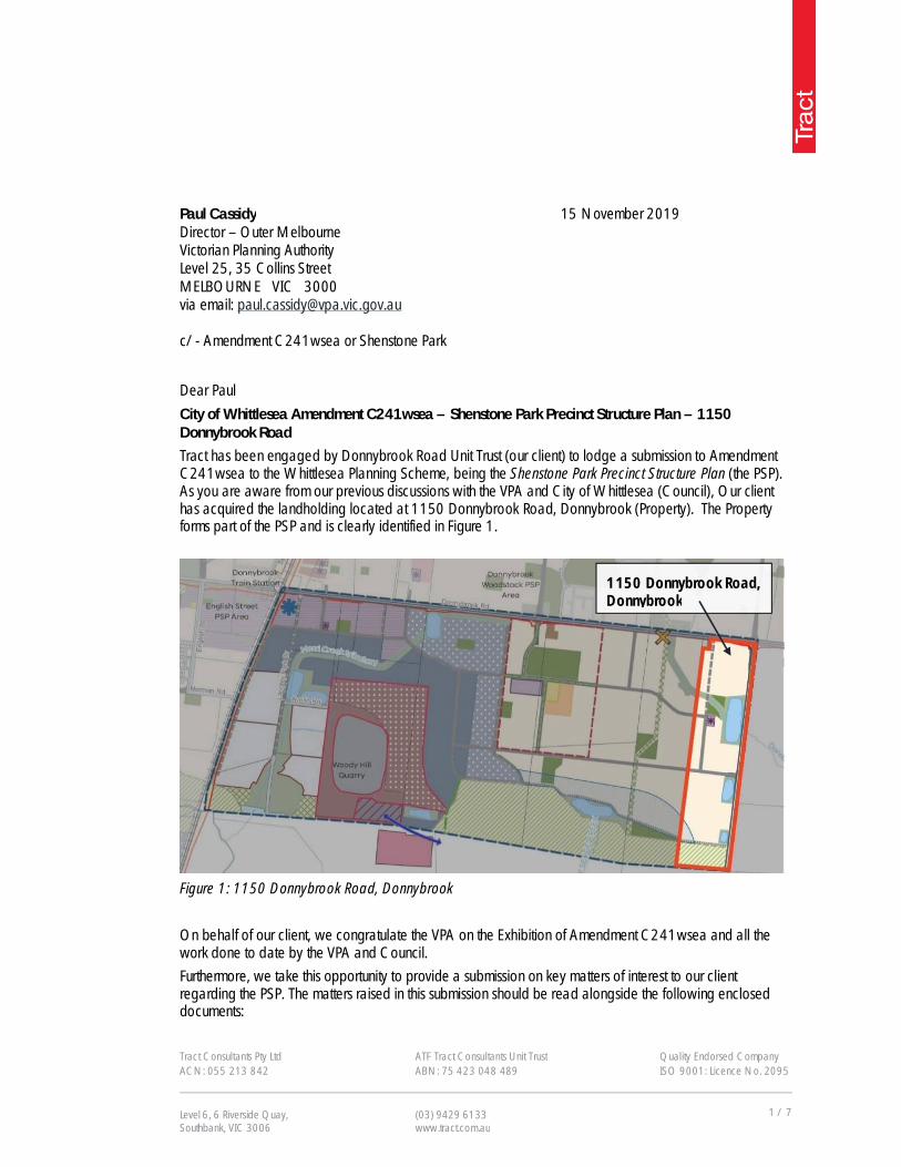
Tract has been engaged by Donnybrook Road Unit Trust (our client) to lodge a submission to Amendment C241wsea to the Whittlesea Planning Scheme, being the Shenstone Park Precinct Structure Plan (the PSP). As you are aware from our previous discussions with the VPA and City of Whittlesea (Council), Our client has acquired the landholding located at 1150 Donnybrook Road, Donnybrook (Property). The Property forms part of the PSP and is clearly identified in Figure 1.
Figure 1: 1150 Donnybrook Road, Donnybrook
On behalf of our client, we congratulate the VPA on the Exhibition of Amendment C241wsea and all the work done to date by the VPA and Council.
Furthermore, we take this opportunity to provide a submission on key matters of interest to our client regarding the PSP. The matters raised in this submission should be read alongside the following enclosed documents:
Tract Consultants Pty Ltd ACN: 055 213 842
ATF Tract Consultants Unit Trust ABN: 75 423 048 489
Quality Endorsed Company ISO 9001: Licence No. 2095
Level 6, 6 Riverside Quay, Southbank, VIC 3006
(03) 9429 6133 www.tract.com.au
Paul Cassidy Director – Outer Melbourne Victorian Planning Authority Level 25, 35 Collins Street MELBOURNE VIC 3000 via email: [email protected] c/- Amendment C241wsea or Shenstone Park
15 November 2019
1150 Donnybrook Road, Donnybrook

Tract
City of Whittlesea Amendment C241wsea – Shenstone Park Precinct Structure Plan – 1150 Donnybrook Road
2 / 7
Preliminary Services Report – Creo Consultants (30 October 2019) Stormwater Management Plan – Rain Consulting (October 2019) Arborist Report – TreeLogic (01 February 2017) Boundary Plan – Veris (April 2018) Concept Plan – Human Habitats (14 November 2019) Environmental Site Assessment – ATMA 27 April 2017; and cover letter regarding site assessment
and contamination summary 31 May 2017.
There are several matters raised in our submission and we would welcome the opportunity further discuss these matters with you at your convenience.
1. Precinct Structure Plan (PSP)
1.1. The PSP includes three retarding basins, a waterway connecting to the larger retarding basin and two irregular-shaped credited open space areas abutting the waterway comprising 1.08ha. Our client is generally supportive of the open space location, however proposes a slight reduction in the area of the open space at the proposed location (to 0.8ha) and the addition of to a small passive open space area of 0.28ha to be proposed to abut RB-06 in order to provide increased amenity for the benefit of residents in the southern part of this area of the PSP. The overall land take for credited open space is proposed to remain unchanged at 1.08ha (as proposed in the enclosed Concept Plan – Human Habitats (13 November 2019).
1.2. Table 7 - Open Space Delivery Guide of the PSP lists the protection of tree groups and the stony knoll as attributes of LP-04. An approved Cultural Heritage Management Plan (CHMP) relating to the Property has previously been provided to the VPA and Council. The approved CHMP recommends the removal of the stony knoll, which has been supported by Council. In accordance with the approved CHMP, we suggest removing reference to the protection of tree groups and stony knolls as stipulated in Table 7.
1.3. The PSP includes a Local Convenience Centre (LCC) to be located directly south of the passive open
space within the Property. Our client is of the opinion that the LCC is not viable in the proposed location and proposes that it be relocated to the north-east corner of the Property on the south-west corner of the future Donnybrook Road and Koukoura Drive intersection.
If this option is not supported by the VPA and Council, we recommend the proposed LCC be removed entirely from the PSP and the land reverted to residential land. The components of the LCC (East), as outlined in Table 4 - Local Town Centre Composition and Delivery Guide, should subsequently form part of the retail and commercial allowance for the larger Shenstone Park Local Town Centre.
1.4. The PSP includes an east-west connector road which terminates at the proposed LCC. In order to
create an improved design outcome whilst providing a better traffic engineering outcome, we suggest the proposed east-west connector road is re-aligned so it can successfully continue to the eastern boundary of the PSP area into a future left-in/left-out intersection on Koukoura Drive. This proposed alignment has been previously confirmed with Vic Roads Senior Transport Planner, Frank Deserio, in April 2017 and subsequently advised to the VPA and Council.

Tract
City of Whittlesea Amendment C241wsea – Shenstone Park Precinct Structure Plan – 1150 Donnybrook Road
3 / 7
1.5. The PSP shows that the south-west corner of the Property is identified as a future residential area.
Plan 15 - Buffers, Noise Amenity Area and Measurement Length of the PSP identifies this portion of future residential land as affected by a 550 metre Phillips sensitive use buffer associated with the Phillips Quarry. It appears that this is simply a mapping error as the proposed buffer shown in the PSP does not conform with the Quarry Impact Assessment prepared by GHD.
Figure 18 in the addendum to the GHD Quarry Impact Assessment measures the separation from the extraction limit rather than the land boundary and as a result, does not affect the future residential land identified on the Property. In accordance with the advice prepared by GHD, the Phillips sensitive use buffer shown in the PSP should be removed from the future residential land located on the Property.
1.6. Plan 5 - Image, Character, Housing and Heritage of the PSP identifies several trees across the PSP. Upon review of vegetation across the precinct, we advise that two of the trees on the Property have been incorrectly nominated.
The tree abutting Donnybrook Road and referenced as tree number 17 (Swamp Gum) in the supporting Arboriculture Assessment prepared by Treetec is considered of ‘high value’ in the Treetec report. However, an independent review conducted by Treelogic on behalf of our client nominates the same tree as of ‘moderate value’ due to its fair-to-poor structure. We recommend this tree be removed from Plan 5.
The Treetec report identifies tree number 25 (Manna Gum) as of ‘medium value’ with fair-to-poor structure. However, the same review conducted by Treelogic attributes no rating as this tree was identified as failing in health due to senescence. We recommend this tree also be removed from Plan 5.
1.7. Plan 5 also identifies the dry stone wall abutting Donnybrook Road to be of high-to-moderate significance. The proposed schedule to Clause 52.33 Post Boxes and Dry Stone Walls would require a permit to remove the dry stone wall fronting Donnybrook Road. Respectfully, the dry stone wall would need to be removed as part of the proposed arterial works and should simply be identified for removal with an amendment to the schedule to Clause 52.33 to include “Medium” retention value as being able to be removed without a planning permit.
1.8. Plan 15 - Buffers, Noise, Amenity Area and Measurement Length of the PSP applies a measurement
length restriction of 590 metres in relation to the north-south gas pipeline.
The plan also shows the same measurement length running north across the adjacent Donnybrook and Woodstock PSP. However, the measurement length that has been adopted for the Donnybrook and Woodstock PSP is 341 metres and contains the same infrastructure. It is recommended that the PSP remain consistent and adopt 341 metres.
1.9. Table 8 - Stormwater Drainage and Water Treatment Infrastructure of the PSP identifies the location, area and responsibility of the retarding basin/wetlands.

Tract
City of Whittlesea Amendment C241wsea – Shenstone Park Precinct Structure Plan – 1150 Donnybrook Road
4 / 7
Subsequent to a comprehensive assessment undertaken by Rain Consulting and Creo Consultants on behalf of our client, the following changes are recommended to be implemented: RBWL-02:
RBWL-02 is incorrectly identified as being the responsibility of Council rather than Melbourne Water;
The area of the RBWL-02 is to comprise 6.0ha (and not 5.52ha); and, The adjoining waterway to comprise a maximum width of 45 metres.
RBWL-05:
The area of the RBWL-05 is to comprise 2.1ha (and not 1.76ha). RBWL-06:
RBWL-06 is incorrectly labelled as being located on Parcel 16 rather than Parcel 17; and The area of the RBWL-05 is to comprise 0.2ha (and not 0.75ha).
1.10. Table 9 - Precinct Infrastructure Plan of the PSP identifies three culverts along the length of Koukoura
Drive. Creo Consultants have reviewed the culvert descriptions and proposed pipe dimensions, and propose the following revisions:
Culvert PSP Proposal Creo recommendation
CU-01 4 x 1500mm pipes 6 x 900mm pipes
CU-02 2 x 1050mm pipes NIL
CU-03 2 x 1050mm pipes 2 x 1050mm pipes
As outlined in the table above, it has been determined that the proposed pipes for CU-02 are not required. It is recommended that reference to CU-02 in the PSP is removed.
1.11. The Parcel Specific Land Budget Table found in section 4.1 of the PSP includes an incorrect total area for PSP Property ID 17. The total area identified in the PSP is 67.38ha. The enclosed boundary plan confirms the correct total area is 67.28ha. It is recommended that the PSP is revised to reflect the correct size of the Property.
2. Housing and Development Layout
2.1. Table 2 and 3 of the PSP provide guidance on the anticipated housing lot sizes and lot yield. Residential areas outside of the walkable catchment area are anticipated to have a minimum average density of 17 dwellings per hectare. This ratio would apply across all residential land within the Property. It is recommended that residential areas abutting water catchments, open

Tract
City of Whittlesea Amendment C241wsea – Shenstone Park Precinct Structure Plan – 1150 Donnybrook Road
5 / 7
space and fronting onto connector roads have the same density as residential areas within the walkable catchment area (minimum average density of 25 dwellings per hectare). Plan 11- Public Transport and Pathways nominates several connector roads, including both Koukoura Drive and Donnybrook Road as “bus capable roads”. We suggest that residential areas within 200 metres of bus capable roads and a waterway also have a minimum average dwelling density of 25 dwellings per hectare. This would still enable generous lot sizes to accommodate detached dwellings but also encourage greater housing diversity through the development of dual occupancies, multi-unit housing sites and walk up flats. Increased housing densities would allow for greater passive surveillance around these key streets and open space areas, whist continuing to implement the Housing and Development Layout requirements and guidelines included on Page 14 of the PSP.
3. Urban Growth Zone
3.1. Clause 4.0 of the proposed Urban Growth Zone - Schedule 7 (UGZ7) includes conditions and
requirements for permits. Page 9 outlines the requirements of the Land Management Co-operative Agreement (LMCA) in relation to the BCS conservation area shown on Plan 3 of the PSP. The BCS conservation area is classified as ‘Nature Conservation’ under the Melbourne Strategic Assessment (MSA). The Melbourne Strategic Assessment outlines conservation strategies for growth corridors and was approved under the Commonwealth Environment Protection and Biodiversity Conservation Act 1999 . The MSA requires Nature Conservations to be acquired by the State government, as opposed to be being gifted by land owners. The drafting of the LMCA requirements in UGZ7 should be revised to align with the MSA and ensure the BCS conservation area will be acquired by the State and not required to be gifted by landowners (or maintained in perpetuity or until acquisition by the landowner).
3.2. Clause 3.0 of the UGZ7 includes application requirements relating to Environmental Site Assessments. Our client has provided advice to the VPA and Council confirming that the Property comprises low contamination (not medium), as referred to the ATMA report. It is recommended that the Property is removed from Table 2 of UGZ7.
3.3. Clause 4.0 of the UGZ7 includes a condition for salvaging and translocating of native vegetation or
threatened species. The PSP clearly nominates the BCS area and where native vegetation must be retained. Therefore, it is suggested that this condition is not necessary and should be removed from UGZ7.
4. Utilities
4.1. Plan 13 - Utilities in the PSP proposes a new sewer rising main and pump station.
The location identified in the PSP does not take into consideration the current expanded development area which has resulted from the reduction in the adjacent BCS conservation area. Considering the
Tract
City of Whittlesea Amendment C241wsea – Shenstone Park Precinct Structure Plan – 1150 Donnybrook Road
6 / 7
proposed residential land identified in the PSP, the most suitable location for a pump station would be at the south-east corner of the Property within the proposed area of RBWL-06 on Plan 12.
4.2. Plan 12 - Integrated Water Management of the PSP identifies three retarding basins on the Property. The requirements listed under 3.7.1 should state that Melbourne Water will be responsible for any outfall from any retarding basin outside of the PSP boundary.
5. Precinct Infrastructure Plan / Infrastructure Contribution Plan
5.1. Table 9 - Precinct Infrastructure Plan of the PSP nominates 100% internal apportionment of works related to IN05, IN06 and CU-01, CU-02 and CU-03. We support the proposed internal apportionment.
5.2. Amendment C241wsea does not include a draft Infrastructure Contributions Plan (ICP). The draft ICP should be made publicly available via this amendment process and incorporated at the same time as the PSP into the Whittlesea Planning Scheme.
This will ensure landowners are not unfairly burdened by higher land taxes and urban council rates on land that cannot be developed whilst waiting for the approval of the ICP.
5.3. Table 1 - Summary Land Use Budget of the PSP deducts land identified for utilities from the Net
Developable Area on the basis that they are not proposed to be developed for purposes beyond their designation of utilities. It is therefore suggested that land designated for utilities be zoned Public Use Zone Schedule 1 and remain outside of the land budget and a more defined plan be included in the PSP directing the use and development of the land in more specificity. Alternatively, if the land is intended to be used and developed for industrial purposes, it is recommended that the land be added into the land budget so that it provides infrastructure contributions under the future ICP.
5.4. The Woody Hill Quarry is also deducted from the land budget and a portion of the Quarry is proposed to be rezoned from Farming Zone to the Special Use Zone, which would also exempt the Quarry from ICP charges being applied to the land.
This would appear unreasonable as the Quarry would expect to use and benefit from facilities such as IN01 and IN02 heading north and IN06 and RD-01 Koukoura Drive east (which then provides further north-south arterial function). It is also likely that the land will cease to operate for quarry purposes within the life of the PSP and ICP and likely be developed for industrial purposes in the future. It is therefore recommended that the PSP include an alternative Future Urban Structure (Plan 3) on how the road network and layout of the area would occur subject to the future closure of the Quarry, and that traffic analysis etc be reviewed based on that revised layout so as to inform the ultimate land use of the PSP area. The Quarry land should also be apportioned as development land for industrial purposes and attributed to ICP contributions so that when it is further developed following conclusion of Quarry use, it can fairly contribute to the infrastructure.

Tract
City of Whittlesea Amendment C241wsea – Shenstone Park Precinct Structure Plan – 1150 Donnybrook Road
7 / 7
6. Reservation of rights As expressed previously, we would welcome the opportunity to meet and discuss these matters with you. Our client does however reserve their rights to make further submissions to a convened Planning Panel that may be appointed by the Minister to consider submissions, if we are unable to resolve these matters with you directly. Our client also reserves their right to make further submissions on any matter that may be of interest to them including in response to any other submissions which may be made by any other party.
We look forward to resolving the above matters with you to ensure the ongoing prosperity of Victoria including the settlement of the PSP area.
Please do not hesitate to contact me to discuss any matter as required on 0427-201-111, or by email as below.
Kind regards,
Justin Slater Director Tract [email protected] CC: George Saisanas – Manager Strategic Planning Whittlesea City Council
Author: Tass Palios Reviewer: Eric Sfyridis Job No: 180018 Date: 30 October 2019
Prepared for: Donnybrook Road Unit Trust Pty Ltd
Preliminary Services Report:
Lot 2, 1150 Donnybrook Road, Donnybrook
Contents
INTRODUCTION ................................................................................................................................................................. 3
THE PROPERTY ................................................................................................................................................................. 3
DRAINAGE .......................................................................................................................................................................... 4
COUNCIL DRAINAGE WORKS .......................................................................................................................................... 4
MELBOURNE WATER DRAINAGE SCHEME WORKS..................................................................................................... 4
SEWER RETICULATION .................................................................................................................................................... 5
POTABLE WATER SUPPLY .............................................................................................................................................. 5
RECYCLED WATER ........................................................................................................................................................... 6
ELECTRICITY SUPPLY ...................................................................................................................................................... 6
GAS SUPPLY ...................................................................................................................................................................... 7
TELECOMMUNICATIONS .................................................................................................................................................. 7
CONCLUSION ..................................................................................................................................................................... 7

Preliminary Services Report: Lot 2 1150 Donnybrook Road, Donnybrook
Introduction Creo Consultants Pty Ltd have been engaged by Donnybrook Road Unit Trust Pty Ltd to provide preliminary engineering advice with respect to the provision of services and infrastructure to Lot 2, 1150 Donnybrook Road, Donnybrook.
The information contained herein reflects discussions with officers of City of Whittlesea and the various servicing authorities and agencies involved in land development in the municipality. The final outcomes may be subject to some variation at the time any formal development agreement is entered at the subdivision stage.
The Property The subject land, known as Lot 2, 1150 Donnybrook Road, Donnybrook, is located within the Whittlesea City Council, approximately 30 kilometres north of the Melbourne Central Business District.
The subject land is approximately 67 hectares in area.
The site has historically been used as agricultural land (farming, grazing etc.) which is typical of the local area. The Darebin Creek tributary runs diagonally across the northern portion of the site. The topography over the site is generally flat, sloping from north-west to the south east with the highest elevation being approximately 239m AHD and the lowest elevation being approximately 233m AHD. Refer to Figure 1 below for details.
Figure 1 Subject Land

Preliminary Services Report: Lot 2 1150 Donnybrook Road, Donnybrook
Drainage The City of Whittlesea is the Responsible Authority for local drainage infrastructure whilst the Melbourne Water Corporation (Melbourne Water) has responsibility for main drainage.
Council Drainage Works All internal drainage shall be designed and constructed generally in accordance with the Metropolitan Planning Authority (MPA) Engineering Design and Construction Manual.
Council/MPA requires that underground drainage be constructed within the development to cater for a 1 in 5-year stormwater event. Provision shall also be made to ensure that the runoff resulting from a 100-year ARI storm is able to pass through the subdivision along streets and reserves. The finished surface level of all allotments shall be a minimum of 300mm above the 100-year ARI level.
Melbourne Water Drainage Scheme Works The subject land is located within the Woodstock West Drainage Scheme (no. 4566). This drainage scheme is currently in a preliminary stage. This means that engineering investigations and cost estimates have been undertaken though not finalised.
The Woodstock West Drainage Scheme identifies the need to construct scheme pipes, a constructed waterway (within a 45m wide corridor) and three wetland/retarding basins within the subject land to provide the necessary water management measures to mitigate the impact of urban development on water quality and quantity, whilst providing amenity and maintaining ecological values. Refer to Figure 2 below for the scheme details.
The developer will be required to enter into and comply with an agreement with Melbourne Water for the provision of drainage works and the acceptance of surface and storm water from the subject land directly or indirectly into Melbourne Water’s drainage system.
Figure 2 Melbourne Water Drainage Scheme Works
Preliminary Services Report: Lot 2 1150 Donnybrook Road, Donnybrook
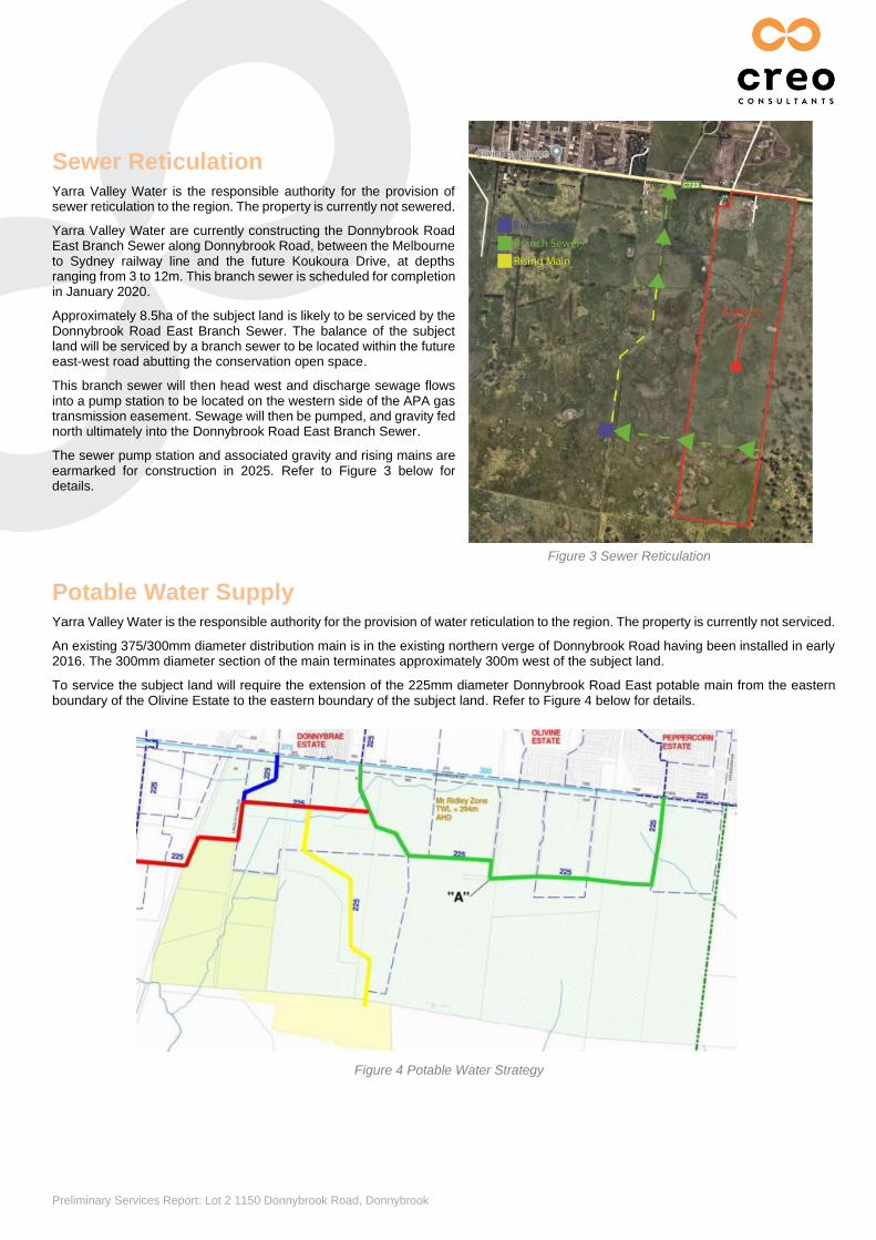
Sewer Reticulation Yarra Valley Water is the responsible authority for the provision of sewer reticulation to the region. The property is currently not sewered.
Yarra Valley Water are currently constructing the Donnybrook Road East Branch Sewer along Donnybrook Road, between the Melbourne to Sydney railway line and the future Koukoura Drive, at depths ranging from 3 to 12m. This branch sewer is scheduled for completion in January 2020.
Approximately 8.5ha of the subject land is likely to be serviced by the Donnybrook Road East Branch Sewer. The balance of the subject land will be serviced by a branch sewer to be located within the future east-west road abutting the conservation open space.
This branch sewer will then head west and discharge sewage flows into a pump station to be located on the western side of the APA gas transmission easement. Sewage will then be pumped, and gravity fed north ultimately into the Donnybrook Road East Branch Sewer.
The sewer pump station and associated gravity and rising mains are earmarked for construction in 2025. Refer to Figure 3 below for details.
Figure 3 Sewer Reticulation
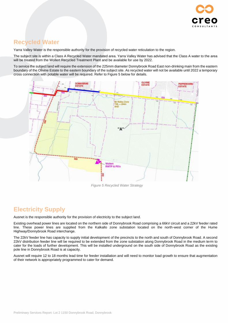
Potable Water Supply Yarra Valley Water is the responsible authority for the provision of water reticulation to the region. The property is currently not serviced.
An existing 375/300mm diameter distribution main is in the existing northern verge of Donnybrook Road having been installed in early 2016. The 300mm diameter section of the main terminates approximately 300m west of the subject land.
To service the subject land will require the extension of the 225mm diameter Donnybrook Road East potable main from the eastern boundary of the Olivine Estate to the eastern boundary of the subject land. Refer to Figure 4 below for details.
Figure 4 Potable Water Strategy
Preliminary Services Report: Lot 2 1150 Donnybrook Road, Donnybrook
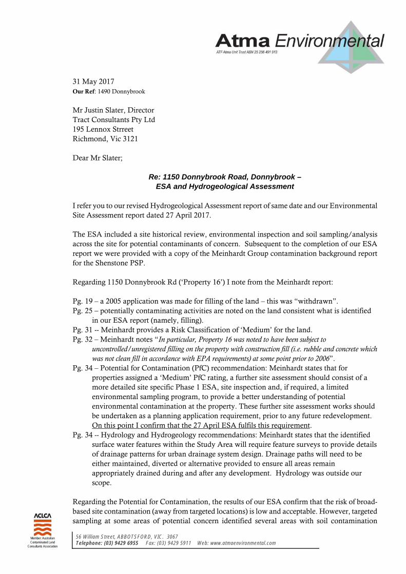
Recycled Water Yarra Valley Water is the responsible authority for the provision of recycled water reticulation to the region.
The subject site is within a Class A Recycled Water mandated area. Yarra Valley Water has advised that the Class A water to the area will be treated from the Wollert Recycled Treatment Plant and be available for use by 2022.
To service the subject land will require the extension of the 225mm diameter Donnybrook Road East non-drinking main from the eastern boundary of the Olivine Estate to the eastern boundary of the subject site. As recycled water will not be available until 2022 a temporary cross connection with potable water will be required. Refer to Figure 5 below for details.
Electricity Supply Ausnet is the responsible authority for the provision of electricity to the subject land.
Existing overhead power lines are located on the northern side of Donnybrook Road comprising a 66kV circuit and a 22kV feeder rated line. These power lines are supplied from the Kalkallo zone substation located on the north-west corner of the Hume Highway/Donnybrook Road interchange.
The 22kV feeder line has capacity to supply initial development of the precincts to the north and south of Donnybrook Road. A second 22kV distribution feeder line will be required to be extended from the zone substation along Donnybrook Road in the medium term to cater for the loads of further development. This will be installed underground on the south side of Donnybrook Road as the existing pole line in Donnybrook Road is at capacity.
Ausnet will require 12 to 18 months lead time for feeder installation and will need to monitor load growth to ensure that augmentation of their network is appropriately programmed to cater for demand.
Figure 5 Recycled Water Strategy

Preliminary Services Report: Lot 2 1150 Donnybrook Road, Donnybrook
Gas Supply Gas supply is the responsibility of APA Group.
There are two existing high-pressure gas transmission pipelines (a 300mm diameter and 400mm diameter pipeline) that traverse in a north-south direction within 1100 Donnybrook Road.
A City Gate has been constructed on the western edge of the transmission pipeline easement on the southern side of Donnybrook Road to reduce gas pressure so that it is suitable for distribution and reticulation.
An existing 300mm diameter gas distribution main extends west along Donnybrook Road from the City Gate. Gas supply for the subject land will be provided from the existing 300 mm diameter gas distribution line in Donnybrook Road which is located approximately 450m from the subject land.
Refer to Figure 6 for details
Telecommunications NBN Co will be the responsible authority for delivery of telecommunications to this site.
Existing Telstra underground cables are located on the south side of Donnybrook Road extending approximately 500m to the east of Langley Park Drive. Overhead Telstra cables extend west along Donnybrook Road from this location.
NBN Co has advised that there are no obstacles to the provision of telecommunications for the subject site. Telecommunication infrastructure will be extended from existing infrastructure along Donnybrook Road, Woodstock.
Under the current National Broadband Network (NBN) rollout system, the developer will be required to provide and meet the cost of adequately sized and located pit and pipe conduit infrastructure within developments to accommodate the fibre network. NBN will levy a deployment charge on developers for infrastructure. The charge is currently $600 for a single dwelling and $400 for multi dwellings.
Conclusion Infrastructure investigations have concluded that the site has no servicing constraints to development.
Figure 6 Existing Transmission Pipeline and City Gate
56 William Street, ABBOTSFORD, VIC. 3067 Telephone: (03) 9429 6955 Fax: (03) 9429 5911 Web: www.atmaenvironmental.com
Member: Australian Contaminated Land
Consultants Association
31 May 2017 Our Ref: 1490 Donnybrook
Mr Justin Slater, Director Tract Consultants Pty Ltd 195 Lennox Strreet Richmond, Vic 3121 Dear Mr Slater;
Re: 1150 Donnybrook Road, Donnybrook – ESA and Hydrogeological Assessment
I refer you to our revised Hydrogeological Assessment report of same date and our Environmental Site Assessment report dated 27 April 2017. The ESA included a site historical review, environmental inspection and soil sampling/analysis across the site for potential contaminants of concern. Subsequent to the completion of our ESA report we were provided with a copy of the Meinhardt Group contamination background report for the Shenstone PSP. Regarding 1150 Donnybrook Rd (‘Property 16’) I note from the Meinhardt report: Pg. 19 – a 2005 application was made for filling of the land – this was “withdrawn”. Pg. 25 – potentially contaminating activities are noted on the land consistent what is identified
in our ESA report (namely, filling). Pg. 31 -- Meinhardt provides a Risk Classification of ‘Medium’ for the land. Pg. 32 – Meinhardt notes “In particular, Property 16 was noted to have been subject to
uncontrolled/unregistered filling on the property with construction fill (i.e. rubble and concrete which was not clean fill in accordance with EPA requirements) at some point prior to 2006”.
Pg. 34 – Potential for Contamination (PfC) recommendation: Meinhardt states that for properties assigned a ‘Medium’ PfC rating, a further site assessment should consist of a more detailed site specific Phase 1 ESA, site inspection and, if required, a limited environmental sampling program, to provide a better understanding of potential environmental contamination at the property. These further site assessment works should be undertaken as a planning application requirement, prior to any future redevelopment. On this point I confirm that the 27 April ESA fulfils this requirement.
Pg. 34 -- Hydrology and Hydrogeology recommendations: Meinhardt states that the identified surface water features within the Study Area will require feature surveys to provide details of drainage patterns for urban drainage system design. Drainage paths will need to be either maintained, diverted or alternative provided to ensure all areas remain appropriately drained during and after any development. Hydrology was outside our scope.
Regarding the Potential for Contamination, the results of our ESA confirm that the risk of broad-based site contamination (away from targeted locations) is low and acceptable. However, targeted sampling at some areas of potential concern identified several areas with soil contamination
Re: 1150 Donnybrook Road, Donnybrook –
ESA and Hydrogeological Assessment
31 May 2017
Page 2
above site assessment guidelines. The identified contamination is considered to be readily manageable pending further investigation and remediation. Pending completion of the further investigations and confirmation of the remedial actions taken, the PfC should remain as ‘medium’. In accordance with Ministerial Direction No. 1 “Potentially Contaminated Land” (1989) and the DSE General Practice Note “Potentially Contaminated Land” (June 2005), an Environmental Audit of the site (or part thereof) is not, however, considered required. Yours very truly, ATMA ENVIRONMENTAL PTY. LTD.
Glenn Berry, Director | Principal Environmental Geologist
The Donnybrook Road Unit TrustLevel 2, 339 King StreetWest Melbourne. Vic. 3003
Project Ref.: 1492B Donnybrook Date: 31 May 2017
Prepared for:
HYDROGEOLOGICAL ASSESSMENT:1150 DONNYBROOK ROAD, DONNYBROOK, VICTORIA
EnvironmentalATF Atma Unit Trust ABN 25 256 491 913
Atma
56 William Street, Abbotsford, VIC. 3067 Web: www.atmaenvironmental.comTelephone: (03) 9429 6955 Fax: (03) 9429 5911MEMBER: Australian
Contaminated LandConsultants Association

Report Finalisation and Distribution
PROJECT REFERENCE: #1492B Donnybrook
REPORT TITLE: Hydrogeological Assessment: 1150 Donnybrook Road, Donnybrook, Vic.
DATE: 31st May 2017
PROJECT MANAGER:
Richard Jolley, B.Eng.(Env)(Hons), B.Sc.(Env)Environmental Consultant
PEER REVIEW BY:
Glenn R Berry, CEnvP, B.Sc. (Spec. Geol.) Principal Environmental Consultant
This document is copyrighted by Atma Environmental Pty Ltd. It is and shall remain the property of Atma Environmental Pty Ltd and may only be used for the purposes for which is was commissioned and in accordance with our Terms of Agreement for Professional Services and subject to any limitations noted. This report is prepared solely for the use of the person or organisation to which it is addressed and is not to be reproduced in whole, or in part, or included in any other document without our written permission. No responsibility or liability to any third party is accepted for any damages arising out of the use of this property by a third party.
DOCUMENT STATUS:
Revision No. Status Date Prepared By Reviewer
0 Final 25/05/2017 RJ GRB1 Revised 26/05/2017 GRB GRB2 Revised 31/05/2017 GRB GRB
Z:\Atma shared files\PROJECTS\1492B Donnybrook (Hydro)\02 …\1492-B Donnybrook HA Rev2.docx
DISTRIBUTION LIST:
No. of Copies
Document Status
Date CopyType
Distributed to:
1 Revision 1 26/05/2017 pdfThe Trustee for Donnybrook Unit Trust (Attn: Mr Marco Liali)
1 Revision 1 26/05/2017 pdf Atma Environmental (File)
Unless indicated, this report has been provided by Atma Environmental Pty Ltd in an electronic format. Atma Environmental Pty Ltd considers the office archival version to be binding. Documents in an electronic format are provided for the convenience of the recipient and we request that they ensure that the integrity of this electronic information is maintained. Storage of this electronic information should at a minimum comply with all legal requirements.
© 2017, Atma Environmental Pty Ltd (ATF Atma Unit Trust ABN: 25 256 491 913) 56 William Street, Abbotsford VIC. 3121 Telephone: (03) 9429 6955 Fax: (03) 9429 5911 Web: www.atmaenvironmental.com
Page i
Table of Contents
EXECUTIVE SUMMARY ............................................................................ 1
1 INTRODUCTION .......................................................................................... 2
1.1 Background ........................................................................................................... 2 1.2 Assessment Objectives & Scope .......................................................................... 2 1.3 Regional Planning Perspective ............................................................................. 3
2 SITE IDENTIFICATION AND DESCRIPTION.............................................. 3
3 PHYSICAL / HYDROGEOLOGICAL SETTING RECORDS ........................ 4
3.1 Topography ........................................................................................................... 4 3.2 Hydrology / Surface Water Receptors ................................................................... 4 3.3 Local and Regional Geology ................................................................................. 4 3.4 Regional Hydrogeology and Groundwater Bore Search ....................................... 5 3.5 Acid Sulfate Soil Hazard Maps .............................................................................. 6 3.6 Salinity Issues ....................................................................................................... 6 3.7 Groundwater Management Areas ......................................................................... 7 3.8 Groundwater Dependant Ecosystems .................................................................. 7
4 SITE RECONNAISSANCE ........................................................................... 8
5 ASSESSMENT CONCLUSIONS & RECOMMENDATIONS ....................... 9
6 LIMITATIONS AND EXCEPTIONS OF ASSESSMENT .............................. 9
7 REFERENCES ........................................................................................... 10
Tables
Table A Site Characteristics Table B Newer Volcanics Aquifer Characteristics
Figures
Figure 1 Site Location Figure 2 Site Details Figure 3 Groundwater and Geology
Appendices
Appendix A Background Documents
o Planning Property Reports o Feature Survey Plan

Page ii
Appendix B Hydrogeological Records
o Regional Topographic & Surface Water Map o Anticipated Groundwater Depth (VVG) o Local Groundwater Well Map & Well Data Search o Salinity Province 132 Mapping o Groundwater Management Areas o Groundwater Dependant Ecosystems Map
Appendix C Site Inspection Photographs

Hydrogeological Assessment: 1150 Donnybrook Road, Donnybrook, Vic.
31 May 2017
Page 1
EXECUTIVE SUMMARY The site under investigation is identified as 1150 Donnybrook Road, Donnybrook and covers an area of 67.26 hectares. The site is located within the prospective Shenstone Precinct Structure Plan. It is proposed for urban development including housing, roads, parks/drainage and a conservation area. Atma Environmental was commissioned to complete this Hydrogeological Assessment (HA), to satisfy the subdivision application information requirement. The objective of this investigation was to determine the potential for impacts on the proposed development, including any measures required to mitigate the impacts of groundwater on the development and the impact of the development on groundwater; and to provide an appraisal with respect to further hydrogeological assessment works that may be required prior to development of the site. The records review suggest that the site is located on Newer Volcanics geology with regional groundwater in the range for “Segment B” and anticipated to be flowing in a south-easterly direction. The site is not within a Land Subject to Inundation Overlay area and no portions are zoned Urban Floodway. Inspection of the site did not identify any damp or saturated areas, groundwater seeps or springs, or surface water features other than the unnamed drain and dams. Groundwater depth is anticipated to be between less than 5 and 20 m depth. Two groundwater bores were found to be located on the site; drilled in 1984 and 1991. No water levels were recorded, however, the TDS confirms the groundwater is in the range of Segment B and screened depths are recorded as being between 12 and 41 m. Perched water is considered unlikely. Groundwater may be at shallow depths (less than 5 m), particularly along the unnamed drainage line and eastern boundary, although our site inspection and review of aerial photos indicates that areas of discharging groundwater/perennially moist soil conditions do not exist. This ought to be confirmed by future geotechnical testing at the time of road design. Deep excavations greater than 5 m depth may experience groundwater inflow and their design should also be informed by specific geotechnical investigation, as required. In the context of the anticipated planning scheme requirements, this hydrogeological assessment suggests an absence of any significant hydrogeological constraints that would render the site unsuitable for development. Urban development generally may contribute to impacts on groundwater. Direct impacts on features such as groundwater dependant ecosystems or losses to extractive groundwater resources are not anticipated. Site development should consider the range of engineering measures available to limit potential effects on groundwater. Further hydrogeological assessment work prior to development of the site is not considered necessary.
Hydrogeological Assessment: 1150 Donnybrook Road, Donnybrook, Vic.
31 May 2017
Page 2
1 INTRODUCTION
1.1 Background
The site under investigation is identified as 1150 Donnybrook Road, Donnybrook, Vic. The site is located within the prospective Shenstone Precinct Structure Plan (PSP) with urban development (including housing, roads, open spaces and a conservation area) of the land proposed. As part of the planning process, Council requires a hydrogeological assessment of the groundwater conditions on the site and the potential impacts on the proposed development, including any measures required to mitigate the impacts of groundwater on the development; and the impact of the development on groundwater. To satisfy the subdivision application requirement, Atma Environmental was commissioned to complete this Hydrogeological Assessment (HA) for the land. Figure 1 shows the site’s regional location and Figures 2 provides overall site details. Refer to Appendix A for the planning property report and existing features survey.
1.2 Assessment Objectives & Scope
The objective of this investigation was to determine the potential for impacts on the proposed development, including any measures required to mitigate the impacts of groundwater on the development; and the impact of the development on groundwater so as to provide an appraisal with respect to further hydrogeological assessment works that may be required prior to development of the site. The investigation was commissioned by The Trustee for Donnybrook Unit Trust. The scope of work was as set out in our fee proposal reference Q17-2598 dated 19 April 2017 and included:
• Site identification and description; • Topographic setting and hydrology; • Local geology and hydrogeology review; • Identification of regional/on-site hydrogeological factors such as areas of dryland
salinity, swamps and groundwater dependant ecosystems; • Review of local planning scheme/site survey plans; • Hydrogeological site inspection; • Groundwater database review and plotting of groundwater occurrence and type of
uses; • Review of registered groundwater bores within proximity of the site; • Findings and conclusions as to our assessment of hydrogeological risks on the
development or on groundwater and any mitigating measures recommended.

Hydrogeological Assessment: 1150 Donnybrook Road, Donnybrook, Vic.
31 May 2017
Page 3
1.3 Regional Planning Perspective
In March 2017, Meinhardt Group Pty Ltd prepared a background report on the site history and potential for land contamination for land spanning the proposed Shenstone Precinct Structure Plan (PSP) area (Meinhardt, 2017). The scope of the work was limited to a review of selected publically available historical information, a review of planning maps, a review of regulatory databases, a site walkover (selected sites) and compilation of all the obtained information. Meinhardt Group Pty Ltd made the following comments in relation to Hydrogeology at the site. Two main aquifers are present at the site; the upper Newer Volcanics aquifer, and the deeper regional bedrock aquifer within the Silurian aged Melbourne Formation. The estimated depth to groundwater ranges from 5 to 10 m below ground level (bgl). The upper aquifer is fractured basalt comprising of New Volcanics, consisting of basalt and scoria. Groundwater salinity ranges from 1,001 – 3,500 mg/L. Three groundwater bores (IDs 68872, 68948, WRK968901) were located on the Site, identified as being for domestic/stock use.
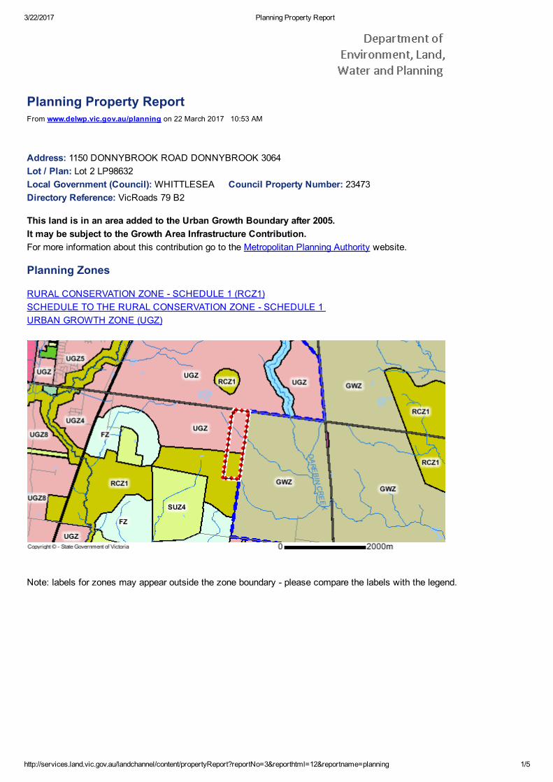
2 SITE IDENTIFICATION AND DESCRIPTION The area under assessment is identified as No. 1150 Donnybrook Road, Donnybrook. The site is situated within the Whittlesea Council and is located approximately 30 km north of Melbourne’s central business district. Figure 1 shows the location and regional site setting in the 2015 Melway Edition 42. General site information and details of the surrounding land are listed on Table A. The planning property report is given in Appendix A.
Table A. Site Characteristics
Site Address 1150 Donnybrook Road, Donnybrook, Victoria
Approximate Area 67.26 ha; rectangular shape – not including house block in northwest corner.
Lot & Plan Lot 2 LP98632
Site Identification Certificate of Title Volume 8993 Folio 430
Local Government Whittlesea Council
VicRoads Reference 79-B2
Zoning
Urban Growth Zone – (UGZ) (North section of the site) Rural Conservation Zone – Schedule 1 (South section of the site) Environmental Significance Overlay – Schedule 4 (South section of the site) No Land Subject to Inundation Overlay (LSIO) applies.
Current Site Use &
Features
The site is currently an unoccupied agricultural property with associated dwellings and farm sheds. Features include three dams, single storey brick dwelling, nearby sheds (galvanized iron construction) and two above-ground
Hydrogeological Assessment: 1150 Donnybrook Road, Donnybrook, Vic.
31 May 2017
Page 4
tanks.
Proposed Use Residential (770 conventional-density lots) with passive open space and conservation areas.
Adjacent Land Uses
North – Agricultural/Rural Residential (UGZ) East – Agricultural/Rural Residential (GWZ) South – Vacant Land (RCZ1) West – Agricultural/Rural Residential (UGZ & RCZ1)
3 PHYSICAL / HYDROGEOLOGICAL SETTING RECORDS
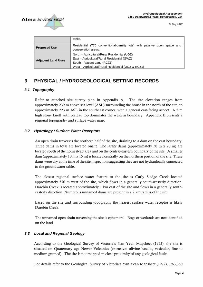
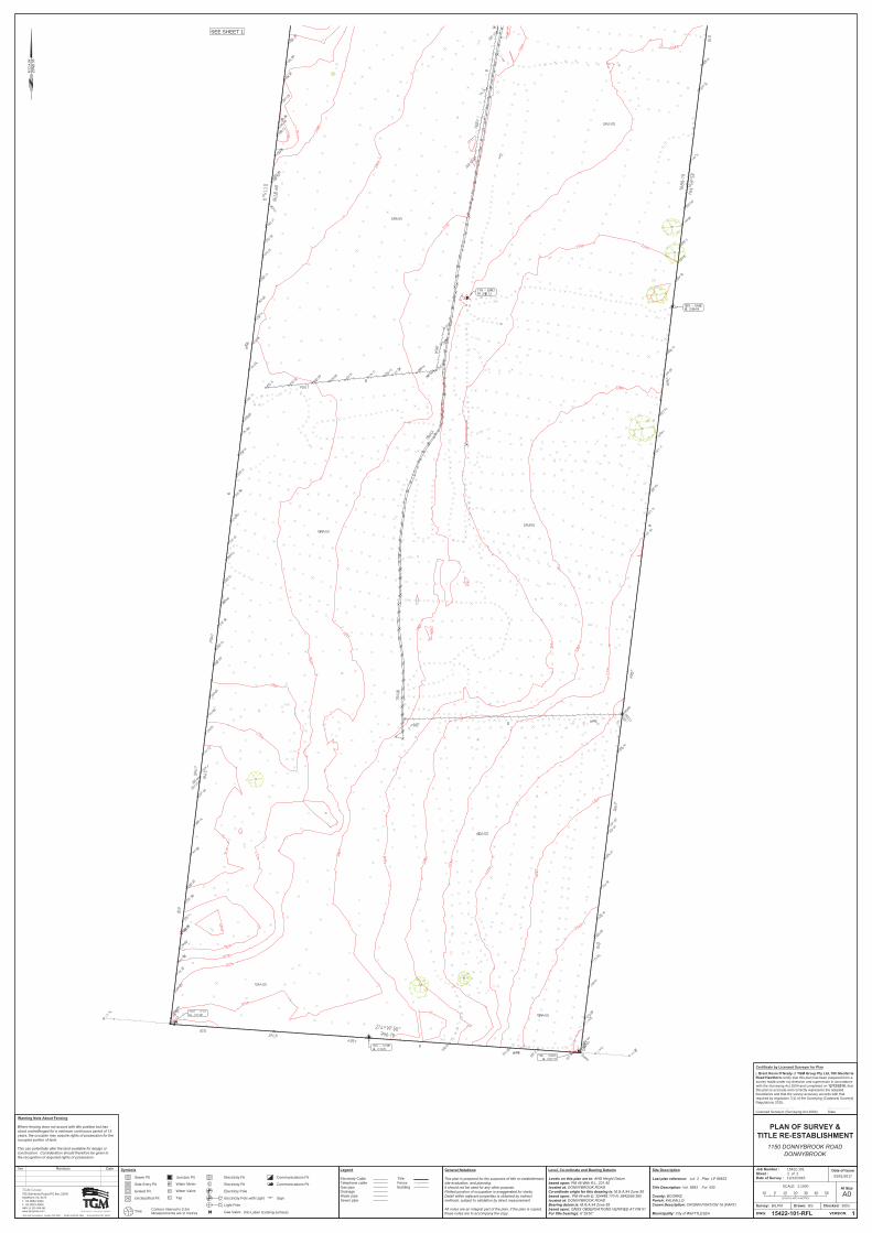
3.1 Topography
Refer to attached site survey plan in Appendix A. The site elevation ranges from approximately 239 m above sea level (ASL) surrounding the house in the north of the site, to approximately 223 m ASL in the southeast corner, with a general east-facing aspect. A 5 m high stony knoll with plateau top dominates the western boundary. Appendix B presents a regional topography and surface water map.
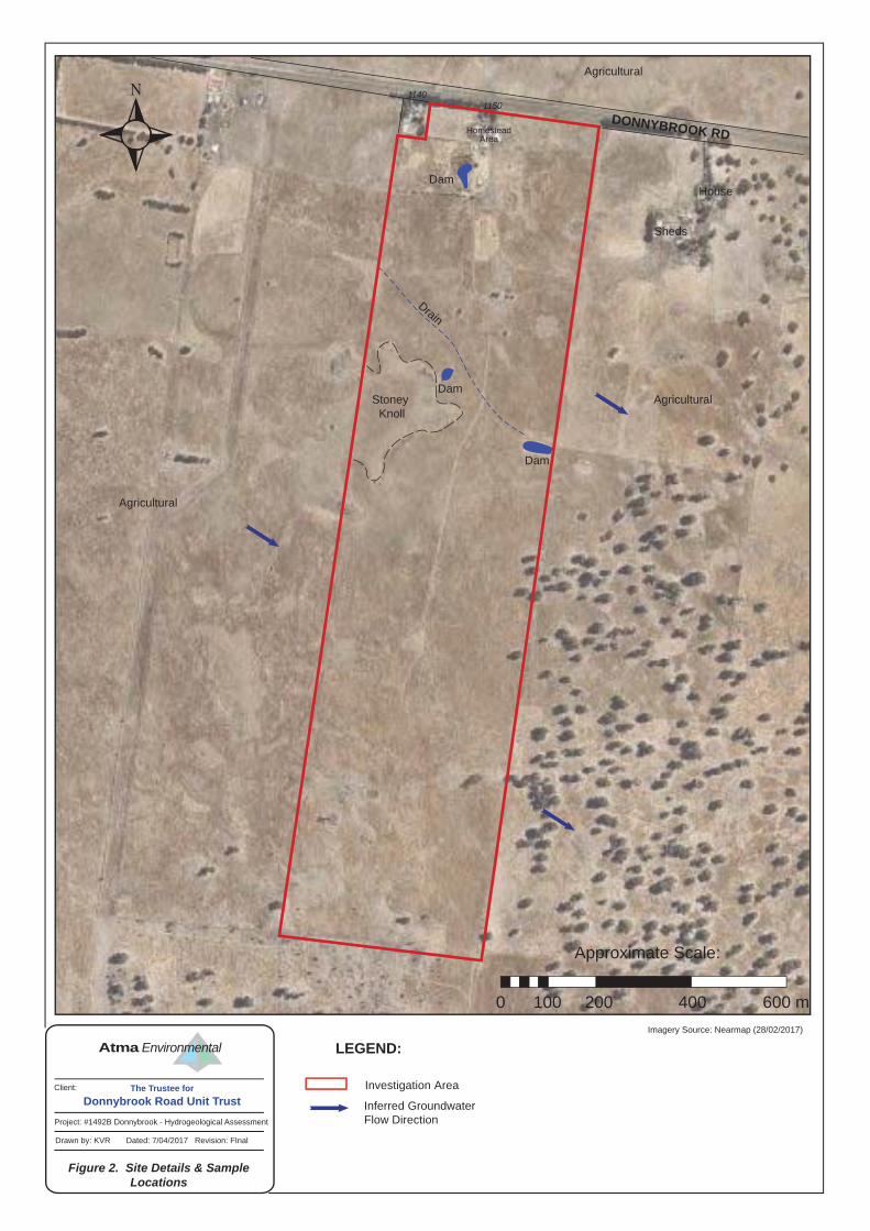
3.2 Hydrology / Surface Water Receptors An open drain traverses the northern half of the site, draining to a dam on the east boundary. Three dams in total are located onsite. The larger dams (approximately 50 m x 20 m) are located south of the homestead area and on the central-eastern boundary of the site. A smaller dam (approximately 10 m x 15 m) is located centrally on the northern portion of the site. These dams were dry at the time of the site inspection suggesting they are not hydraulically connected to the groundwater table. The closest regional surface water feature to the site is Curly Sledge Creek located approximately 570 m west of the site, which flows in a generally south-westerly direction. Darebin Creek is located approximately 1 km east of the site and flows in a generally south-easterly direction. Numerous unnamed dams are present in a 2 km radius of the site.
Based on the site and surrounding topography the nearest surface water receptor is likely Darebin Creek. The unnamed open drain traversing the site is ephemeral. Bogs or wetlands are not identified on the land.
3.3 Local and Regional Geology According to the Geological Survey of Victoria’s Yan Yean Mapsheet (1972), the site is situated on Quaternary age Newer Volcanics (extrusive: olivine basalts, vesicular, fine to medium grained). The site is not mapped in close proximity of any geological faults. For details refer to the Geological Survey of Victoria’s Yan Yean Mapsheet (1972), 1:63,360
Hydrogeological Assessment: 1150 Donnybrook Road, Donnybrook, Vic.
31 May 2017
Page 5
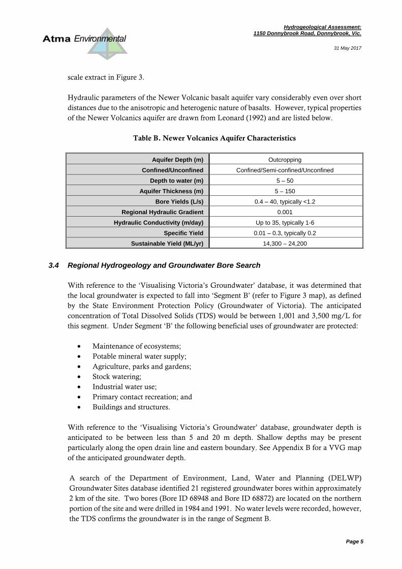
scale extract in Figure 3. Hydraulic parameters of the Newer Volcanic basalt aquifer vary considerably even over short distances due to the anisotropic and heterogenic nature of basalts. However, typical properties of the Newer Volcanics aquifer are drawn from Leonard (1992) and are listed below.
Table B. Newer Volcanics Aquifer Characteristics
Aquifer Depth (m) Outcropping
Confined/Unconfined Confined/Semi-confined/Unconfined
Depth to water (m) 5 – 50
Aquifer Thickness (m) 5 – 150
Bore Yields (L/s) 0.4 – 40, typically <1.2
Regional Hydraulic Gradient 0.001
Hydraulic Conductivity (m/day) Up to 35, typically 1-6
Specific Yield 0.01 – 0.3, typically 0.2
Sustainable Yield (ML/yr) 14,300 – 24,200
3.4 Regional Hydrogeology and Groundwater Bore Search With reference to the ‘Visualising Victoria’s Groundwater’ database, it was determined that the local groundwater is expected to fall into ‘Segment B’ (refer to Figure 3 map), as defined by the State Environment Protection Policy (Groundwater of Victoria). The anticipated concentration of Total Dissolved Solids (TDS) would be between 1,001 and 3,500 mg/L for this segment. Under Segment ‘B’ the following beneficial uses of groundwater are protected:
• Maintenance of ecosystems; • Potable mineral water supply; • Agriculture, parks and gardens; • Stock watering; • Industrial water use; • Primary contact recreation; and • Buildings and structures.
With reference to the ‘Visualising Victoria’s Groundwater’ database, groundwater depth is anticipated to be between less than 5 and 20 m depth. Shallow depths may be present particularly along the open drain line and eastern boundary. See Appendix B for a VVG map of the anticipated groundwater depth. A search of the Department of Environment, Land, Water and Planning (DELWP) Groundwater Sites database identified 21 registered groundwater bores within approximately 2 km of the site. Two bores (Bore ID 68948 and Bore ID 68872) are located on the northern portion of the site and were drilled in 1984 and 1991. No water levels were recorded, however, the TDS confirms the groundwater is in the range of Segment B.
Hydrogeological Assessment: 1150 Donnybrook Road, Donnybrook, Vic.
31 May 2017
Page 6
• Bore 68872 (c. 1984) is reportedly screened 35 to 41 m in basalt with a yield of 2.4 L/s. • Bore 68948 (c. 1991) is reportedly screened 12 to 24 m in basalt with a yield of 4.0 L/s. • Queries on the DELWP website were unable to find a record for the third bore
referenced by Meinhardt (WRK968901). A map showing type and locations of nearby registered groundwater bores is provided in Appendix B. Available data indicates that the bores present in the vicinity of the site are registered for:
• Stock and domestic purposes (11 bores, including the two boreholes identified onsite), • Stock (four bores), • Domestic purposes (one bore), • Non-groundwater (two bores), • Unknown use (three bores).
A map of the surrounding groundwater bores is provided in Appendix B. Appendix B also shows bore details summarised in tables and the two bores located on site are detailed in extracts from VVG.
Based on surrounding topography and proximity of the hydrologic receptors, groundwater is expected to flow towards the southeast.
3.5 Acid Sulfate Soil Hazard Maps
Acid Sulfate Soil Hazard Maps and Guidelines for Coastal Victoria (Department of Primary Industries, July 2002) were reviewed for information pertaining to the site. According to the Coastal Acid Sulfate Soil Hazard map (Melbourne T7822 sheet) the site is not located within an identified area of Acid Sulfate Soil, nor is the Site within the estimated extent of Probable Acid Sulfate Soils.
3.6 Salinity Issues Salinity issues may arise: from an imbalance in the hydrological cycle of the landscape (dryland salinity); where saline groundwater tables rise, under the direct influence of irrigation, to a level which limits plant growth (irrigation salinity); or, as a result of a combination of excess water and excess salt in the environment (urban salinity). A large area of Victoria is affected by dryland salinity. Tree clearing and common agricultural practices, such as fallowed soil have caused groundwater levels to rise. The rising groundwater dissolves salt stored in soil and rock. Where the groundwater rises to within two metres of the ground surface, discharge of salty groundwater can occur to the soil. The result can be secondary or (i.e.) induced salinity. Agricultural areas in Victoria affected by dryland salinity have been mapped in the Victorian
Hydrogeological Assessment: 1150 Donnybrook Road, Donnybrook, Vic.
31 May 2017
Page 7
Soil Salinity Monitoring Project (DSE, 2007). In 2010, the Department of Primary Industries re-visited the ‘Salinity Provinces’ concept as a way of categorising salinity occurrence, risk and management options across Victoria. The site falls within Salinity Province 132, Lancefield Sunbury. Each Province contains discrete salinity impacted areas where there is a concentration or higher incidence of land and/or water salinisation, which may, or may not have been mapped. Examination of mapping for Province 132 indicates that a recorded salinity area is adjacent northwest of the site. Examination of aerial photography for the period 2002 to present does not appear to support the DSE mapping outcome at this location near the Site, or such impact is very slight. DSE has not mapped any salinity impacted areas coincident with the Site. The relevant Victoria Resources Online web page for Whittlesea Craigieburn Salinity Province 132 is given in Appendix B.
3.7 Groundwater Management Areas Groundwater in Victoria is managed based on three classified units: Groundwater Management areas (GMA), Water Supply Protection Areas (WSPA), or Unincorporated Areas (UA). GMAs or WSPAs are determined by the Department of Sustainability and Environment as areas intensively developed (or having the potential to be developed) for groundwater extraction. With GMAs or WSPAs groundwater extraction is metered and monitored and subject to a Permissible Consumptive Volume (PVC) which stipulates the volume of water that may be extracted. The site is not located in a GMA or WSPA suggesting that groundwater within the study area is not intensively developed or managed for extractive purposes. Refer to Appendix B for a map of Groundwater Areas produced from Earth Resources’ GeoVic portal (Department of Economic Development, Jobs, Transport and Resources, 2015).
3.8 Groundwater Dependant Ecosystems
Potential Groundwater Dependent Ecosystems (GDE) are ecosystems identified within the landscape as likely to be at least partly dependent on groundwater. State-wide screening analysis has been performed to identify locations of potential terrestrial GDEs, including wetland areas. Potential groundwater dependent ecosystems are ecosystems that may be threatened by activities such as drainage and groundwater pumping. The characteristics of a potential GDE area are: 1. Has access to groundwater. By definition a GDE must have access to groundwater. For
GDE occurrences associated with wetlands and river systems the water table will be at surface with a zone of capillary extension. In the case of terrestrial GDE's (outside of wetlands and river systems), these are dependent on the interaction between depth to water table and the rooting depth of the vegetation community.

Hydrogeological Assessment: 1150 Donnybrook Road, Donnybrook, Vic.
31 May 2017
Page 8
2. Has summer (dry period) use of water. Due to the physics of root water uptake, GDEs will use groundwater when other sources are no longer available; this is generally in summer for the Victorian climate. The ability to use groundwater during dry periods creates a contrasting growth pattern with surrounding landscapes where growth has ceased.
3. Has consistent growth patterns, vegetation that uses water all year round will have perennial growth patterns.
4. Has growth patterns similar to verified GDEs. The available mapping does not indicate the degree of groundwater dependence, only locations in the landscape of potential groundwater dependent ecosystems. This dataset does not directly support interpretation of the amount of dependence or the amount of groundwater used by the regions highlighted within the maps. Where areas are indicated as a GDE, further analysis and more detailed field-based data collection are required to support this because the mapping will over-estimate the extent of terrestrial GDEs. For example riparian zones along sections of rivers and creeks and recharging groundwater or forested regions that are accessing large unsaturated regolith water stores. The terrestrial GDE layer polygons are classified based on the expected depth to groundwater (i.e. shallow 5 m). GDE Mapping for the Port Phillip and Westernport Catchment Management Authority is referenced (extract provided in Appendix B). No GDE areas exist on the site, nor in close proximity.
4 SITE RECONNAISSANCE K. van Rensburg of Atma Environmental, conducted a site inspection on 3rd April 2017. Photographs are provided in Appendix C and refer to Figure 2 for details from the site inspection and locations of the features noted below.
At the time of the inspection, the property was unoccupied. Observations
• The open drain that traverse the site was dry upon inspection; • All dams (three) onsite were observed to be dry; • There were no areas indicative of groundwater discharge such as waterlogging,
swamps, wetlands, or springs. • A groundwater bore was observed on the northern boundary, north of the main
residence, corresponding to the location of one of the two registered stock & domestic use bores (refer to Section 3.4);
• An above-ground water tank is located to the southwest of the main shed. South of the water tank a smaller shed is present housing pump infrastructure;
• Basalt outcrops were noted at several locations across the site;
Hydrogeological Assessment: 1150 Donnybrook Road, Donnybrook, Vic.
31 May 2017
Page 9
• A former vegetable patch was identified to the west of the hay shed; • An overgrown orchard was identified to the south of the hay shed.
5 ASSESSMENT CONCLUSIONS & RECOMMENDATIONS
The records review suggest that the site is located on Newer Volcanics geology with regional groundwater in the range for “Segment B” and anticipated to be flowing in a south-easterly direction. The site is not within a Land Subject to Inundation Overlay. Inspection of the site did not identify any damp or saturated areas, groundwater seeps or springs, or surface water features other than the unnamed drain and dams. Groundwater depth is anticipated to be between less than 5 and 20 m depth. Two groundwater bores were found to be located on the Site; drilled in 1984 and 1991. No water levels were recorded, however, the TDS confirms the groundwater is in the range of Segment B and screened depths are recorded as being between 12 and 41 m.
Perched water is considered unlikely. Groundwater may be at shallow depths (less than 5 m), particularly along the unnamed drainage line and eastern boundary, although our site inspection and review of aerial photos indicates that areas of discharging groundwater/perennially moist soil conditions do not exist. This ought to be confirmed by future geotechnical testing at the time of road design. Deep excavations greater than 5 m depth may experience groundwater inflow and their design should also be informed by specific geotechnical investigation, as required. In the context of the anticipated planning scheme requirements, this hydrogeological assessment suggests an absence of any significant hydrogeological constraints that would render the site unsuitable for development. Urban development generally may contribute to impacts on groundwater by increasing the amount of impermeable area, thereby reducing groundwater recharge and increasing surface water runoff. Direct impacts on features such as groundwater dependant ecosystems or losses to extractive groundwater resources are not anticipated. Measures available to limit potential impacts of development on groundwater include the use of rainwater gardens, water tanks, permeable pavements and other water management technologies in such a way that the current hydrological regime of regional surface water flow and groundwater recharge are unaltered.
6 LIMITATIONS AND EXCEPTIONS OF ASSESSMENT This report describes the work undertaken and has been compiled for the use of the Donnybrook Road Unit Trust only. Its conclusions are only valid for the purpose for which it was requested.
Hydrogeological Assessment: 1150 Donnybrook Road, Donnybrook, Vic.
31 May 2017
Page 10
It is valid only when it is in original form and any person other than Donnybrook Road Unit Trust who rely on the report without specific reference to and permission from Atma Environmental Pty Ltd, do so at their own risk. While every care has been taken in the compilation of this report, to the extent that its conclusions are based on the analysis of the data made available by your organisation or by a third party, no responsibility or liability is accepted for consequences arising from either errors or omissions in that data, changes in the site condition between the time of the inspection and issuance of this report, or from factors or data which were not made available to Atma Environmental Pty Ltd. Environmental reports document the property conditions at the time they are inspected. These conditions may change over time. This report documents the anticipated hydrogeological conditions at the time they are conducted. Actual site conditions may vary. This preliminary hydrogeological assessment has not included any groundwater depth measurements or chemical analysis. The conditions of groundwater throughout the site may vary from as indicated by this desktop review.
7 REFERENCES
Department of Economic Development, Jobs, Transport and Resources, “Earth Resources – GeoVic”. 2015. http://er-info.dpi.vic.gov.au/sd_weave/registered.htm DSE (Department of Sustainability and Environment). Victorian Soil Salinity Monitoring Project. 2017
Federation University. Visualising Victoria’s Groundwater, “Groundwater Database Search.” www.vvg.org.au Geological Survey of Victoria. Yan Yean Mapsheet, 1:63,360 scale, 1972.
Leonard J., “Port Phillip region groundwater systems: future use and management”. Victoria Department of Water Resources, 1992. Meinhardt Group Pty Ltd, “City of Whittlesea, Shenstone Park Precinct Structure Plan, Preliminary Environmental Contamination Assessment”, Project No: 116442. March 2017.
Victoria Department of Natural Resources and Environment “Victorian Groundwater Beneficial Use Map Series, South Western Victoria Water Table Aquifers.’’ 1995. Victoria Department of Planning & Community Development, “Planning Property Reports.” www.dcpd.vic.gov.au/planning Victorian Environmental Protection Authority, “State Environmental Protection Policy (Groundwaters of Victoria)”, EPA Victoria Publication 288, October 1997.
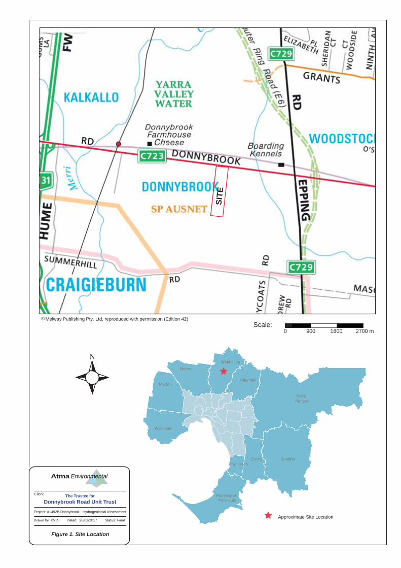
Figure 1. Site Location
Client:
EnvironmentalAtma
Melway Publishing Pty. Ltd, reproduced with permission (Edition 42)©
Project: #1492B Donnybrook - Hydrogeolocial Assessment
Drawn by: KVR Dated: 28/03/2017 Status: FinalApproximate Site Location
The Trustee for
Donnybrook Road Unit Trust
SIT
E
Scale:0 900 1800 2700 m
Imagery Source: Nearmap (28/02/2017)
Dam
Dam
Drain
Dam
Client:
Project: #1492B Donnybrook - Hydrogeological Assessment
Figure 2. Site Details & Sample Locations
Drawn by: KVR Dated: 7/04/2017 Revision: FInal
Environmental Atma
The Trustee for
Donnybrook Road Unit Trust
Investigation Area
LEGEND:
Inferred Groundwater Flow Direction
Approximate Scale:
0 100 200 400 600 m
DONNYBROOK RD
11401150
House
Sheds
Agricultural
Agricultural
Agricultural
Stoney Knoll
HomesteadArea
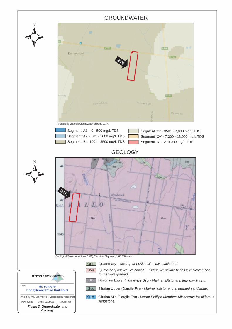
GROUNDWATER
GEOLOGY
Visualising Victorias Groundwater website, 2017.
Geological Survey of Victoria (1972); Yan Yean Mapsheet, 1:63,360 scale.
Project: #1492B Donnybrook - Hydrogeological Assessment
Drawn by: RJ Dated: 22/05/2017 Status: Final
Figure 3. Groundwater and Geology
Client:
Environmental Atma
Silurian Upper (Dargile Fm) - Marine: siltstone, thin bedded sandstone. Sud
Qrm Quaternary - swamp deposits, silt, clay, black mud.
Qvn Quaternary (Newer Volcanics) - Extrusive: olivine basalts; vesicular, fineto medium grained.
Segment ‘A2’ - 501 - 1000 mg/L TDSSegment ‘A1’ - 0 - 500 mg/L TDS
Segment ‘B’ - 1001 - 3500 mg/L TDS
Segment ‘C-’ - 3501 - 7,000 mg/L TDSSegment ‘C+’ - 7,000 - 13,000 mg/L TDSSegment ‘D’ - >13,000 mg/L TDS
The Trustee for
Donnybrook Road Unit Trust
Dlh Devonian Lower (Humevale Sst) - Marine: siltstone, minor sandstone.
Dlh
Silurian Mid (Dargile Fm) - Mount Phillipa Member: Micaceous fossiliferous sandstone.
Sum
SITE
SITE
Background Documents
APPEN
DIX
A


No.1140
No.1150
Ver Revision Date
BS,PM
A0
03/01/2017
BS BOG
TGM Group765 Glenferrie Road (PO Box 2304)
F
JAS-ANZ Accredited: Quality ISO 9001 - OH&S AS/NZS 4801 - Environment ISO 14001
Hawthorn Vic 3122T
03 9819 490903 8862 9333
Melbourne I Geelong I Ballaratwww.tgmgroup.comABN 11 125 568 461
LENGTHS ARE IN METRES
10 10 20 30 400
SCALE 1:1000
50
15422-1011 of 212/12/2016
Grated Pit
Side Entry Pit
Junction Pit Electricity Pit
Electricity Pit
Communications Pit
Communications Pit
Sewer Pit
Unclassified Pit Tap
Water Meter
Electricty Pole
Electricity Pole with Light
Light Pole
Gas ValveTree
Sign
Water Valve
6°18'50"
I, of certify that this plan has been prepared from a
survey made under my direction and supervision in accordancewith the Surveying Act 2004 and completed on , thatthis plan is accurate and correctly represents the adoptedboundaries and that the survey accuracy accords with thatrequired by regulation 7(1) of the Surveying (Cadastral Surveys)Regulations 2015....................................... ........................Licensed Surveyor (Surveying Act 2004) Date
(No Label: Existing surface)Measurements are in metresContour interval is 0.2m
Electricity CableTelephone cableGas pipeDrainageWater pipeSewer pipe
TitleFenceBuilding
SEE SHEET 2
Ver Revision Date
BS,PM
A0
03/01/2017
BS BOG
TGM Group765 Glenferrie Road (PO Box 2304)
F
JAS-ANZ Accredited: Quality ISO 9001 - OH&S AS/NZS 4801 - Environment ISO 14001
Hawthorn Vic 3122T
03 9819 490903 8862 9333
Melbourne I Geelong I Ballaratwww.tgmgroup.comABN 11 125 568 461
15422-1012 of 212/12/2016
Grated Pit
Side Entry Pit
Junction Pit Electricity Pit
Electricity Pit
Communications Pit
Communications Pit
Sewer Pit
Unclassified Pit Tap
Water Meter
Electricty Pole
Electricity Pole with Light
Light Pole
Gas ValveTree
Sign
Water Valve
6°18'50"
I, of certify that this plan has been prepared from a
survey made under my direction and supervision in accordancewith the Surveying Act 2004 and completed on , thatthis plan is accurate and correctly represents the adoptedboundaries and that the survey accuracy accords with thatrequired by regulation 7(1) of the Surveying (Cadastral Surveys)Regulations 2015....................................... ........................Licensed Surveyor (Surveying Act 2004) Date
(No Label: Existing surface)Measurements are in metresContour interval is 0.2m
Electricity CableTelephone cableGas pipeDrainageWater pipeSewer pipe
TitleFenceBuilding
LENGTHS ARE IN METRES
10 10 20 30 400
SCALE 1:1000
50
SEE SHEET 1
Hydrogeological Records
APPEN
DIX B

1492B Donnybrook - Regional Topography and Surface Water MapLegend
Disclaimer: This map is a snapshot generated from Victorian Government data. This material may be of assistance toyou but the State of Victoria does not guarantee that the publication is without flaw of any kind or is wholly appropriatefor your particular purposes and therefore disclaims all liability for error, loss or damage which may arise from relianceupon it. All persons accessing this information should make appropriate enquiries to assess the currency of data.
Map Scale 1:25,000May 22, 2017 2:31:24 PM
0 550 1100 m.
Copyright © State Government of Victoria. Service provided by www.land.vic.gov.au
Map Centre - VicRoads 79 B2
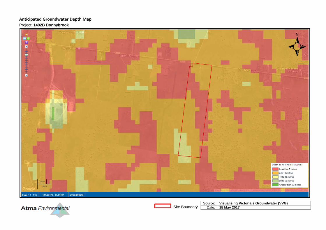
Anticipated Groundwater Depth Map
Project: 1492B Donnybrook
Source: Visualising Victoria’s Groundwater (VVG)
Date: 15 May 2017
Site Boundary
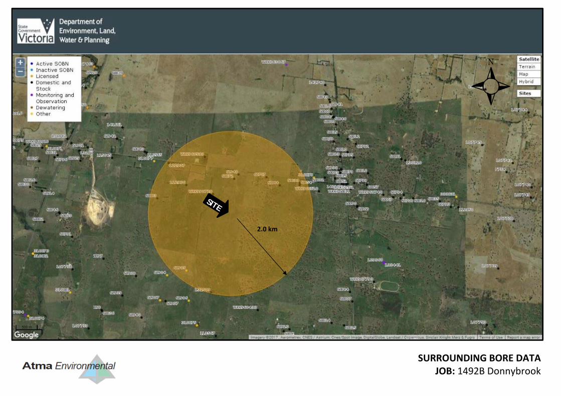
SITE
SURROUNDING BORE DATA JOB: 1492B Donnybrook
2.0 km
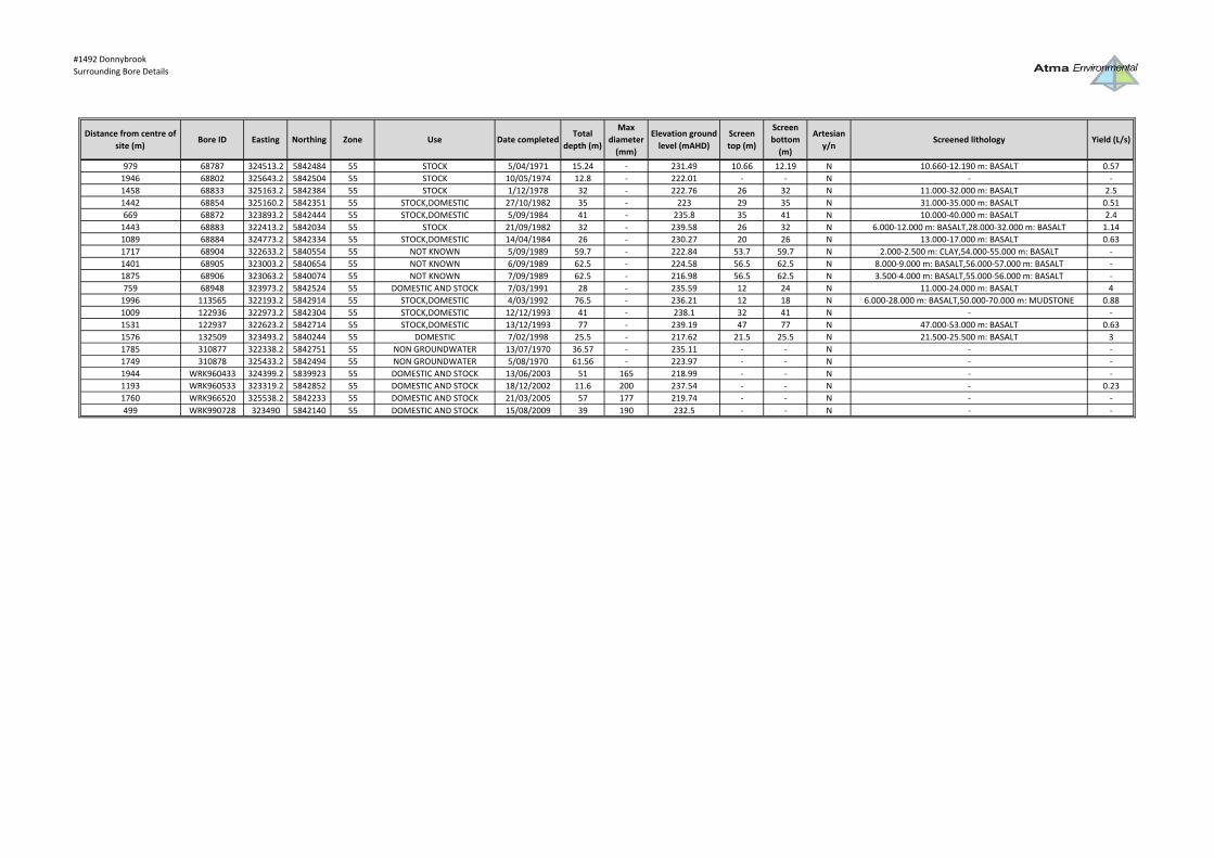
#1492 DonnybrookSurrounding Bore Details
Distance from centre of site (m)
Bore ID Easting Northing Zone Use Date completedTotal
depth (m)
Max diameter (mm)
Elevation ground level (mAHD)
Screen top (m)
Screen bottom (m)
Artesian y/n
Screened lithology Yield (L/s)
979 68787 324513.2 5842484 55 STOCK 5/04/1971 15.24 ‐ 231.49 10.66 12.19 N 10.660‐12.190 m: BASALT 0.571946 68802 325643.2 5842504 55 STOCK 10/05/1974 12.8 ‐ 222.01 ‐ ‐ N ‐ ‐1458 68833 325163.2 5842384 55 STOCK 1/12/1978 32 ‐ 222.76 26 32 N 11.000‐32.000 m: BASALT 2.51442 68854 325160.2 5842351 55 STOCK,DOMESTIC 27/10/1982 35 ‐ 223 29 35 N 31.000‐35.000 m: BASALT 0.51669 68872 323893.2 5842444 55 STOCK,DOMESTIC 5/09/1984 41 ‐ 235.8 35 41 N 10.000‐40.000 m: BASALT 2.41443 68883 322413.2 5842034 55 STOCK 21/09/1982 32 ‐ 239.58 26 32 N 6.000‐12.000 m: BASALT,28.000‐32.000 m: BASALT 1.141089 68884 324773.2 5842334 55 STOCK,DOMESTIC 14/04/1984 26 ‐ 230.27 20 26 N 13.000‐17.000 m: BASALT 0.631717 68904 322633.2 5840554 55 NOT KNOWN 5/09/1989 59.7 ‐ 222.84 53.7 59.7 N 2.000‐2.500 m: CLAY,54.000‐55.000 m: BASALT ‐1401 68905 323003.2 5840654 55 NOT KNOWN 6/09/1989 62.5 ‐ 224.58 56.5 62.5 N 8.000‐9.000 m: BASALT,56.000‐57.000 m: BASALT ‐1875 68906 323063.2 5840074 55 NOT KNOWN 7/09/1989 62.5 ‐ 216.98 56.5 62.5 N 3.500‐4.000 m: BASALT,55.000‐56.000 m: BASALT ‐759 68948 323973.2 5842524 55 DOMESTIC AND STOCK 7/03/1991 28 ‐ 235.59 12 24 N 11.000‐24.000 m: BASALT 41996 113565 322193.2 5842914 55 STOCK,DOMESTIC 4/03/1992 76.5 ‐ 236.21 12 18 N 6.000‐28.000 m: BASALT,50.000‐70.000 m: MUDSTONE 0.881009 122936 322973.2 5842304 55 STOCK,DOMESTIC 12/12/1993 41 ‐ 238.1 32 41 N ‐ ‐1531 122937 322623.2 5842714 55 STOCK,DOMESTIC 13/12/1993 77 ‐ 239.19 47 77 N 47.000‐53.000 m: BASALT 0.631576 132509 323493.2 5840244 55 DOMESTIC 7/02/1998 25.5 ‐ 217.62 21.5 25.5 N 21.500‐25.500 m: BASALT 31785 310877 322338.2 5842751 55 NON GROUNDWATER 13/07/1970 36.57 ‐ 235.11 ‐ ‐ N ‐ ‐1749 310878 325433.2 5842494 55 NON GROUNDWATER 5/08/1970 61.56 ‐ 223.97 ‐ ‐ N ‐ ‐1944 WRK960433 324399.2 5839923 55 DOMESTIC AND STOCK 13/06/2003 51 165 218.99 ‐ ‐ N ‐ ‐1193 WRK960533 323319.2 5842852 55 DOMESTIC AND STOCK 18/12/2002 11.6 200 237.54 ‐ ‐ N ‐ 0.231760 WRK966520 325538.2 5842233 55 DOMESTIC AND STOCK 21/03/2005 57 177 219.74 ‐ ‐ N ‐ ‐499 WRK990728 323490 5842140 55 DOMESTIC AND STOCK 15/08/2009 39 190 232.5 ‐ ‐ N ‐ ‐
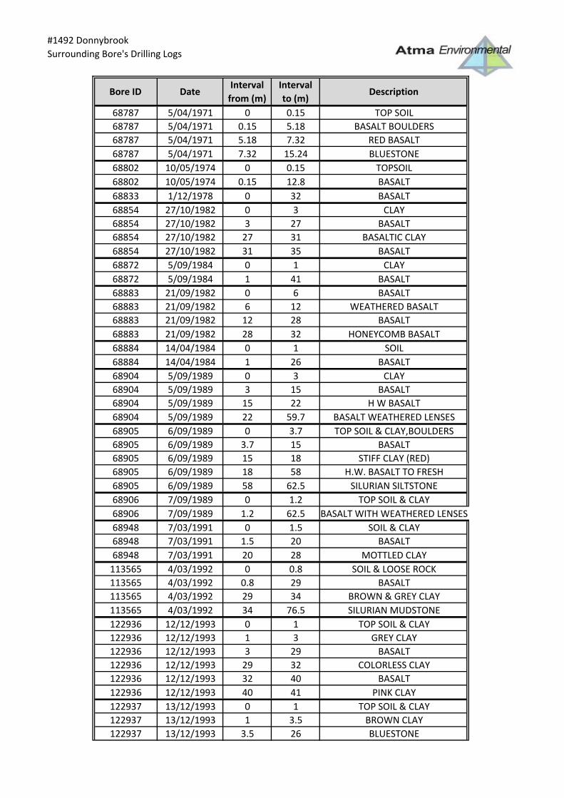
#1492 DonnybrookSurrounding Bore's Drilling Logs
Bore ID DateInterval
from (m)Interval to (m)
Description
68787 5/04/1971 0 0.15 TOP SOIL68787 5/04/1971 0.15 5.18 BASALT BOULDERS68787 5/04/1971 5.18 7.32 RED BASALT68787 5/04/1971 7.32 15.24 BLUESTONE68802 10/05/1974 0 0.15 TOPSOIL68802 10/05/1974 0.15 12.8 BASALT68833 1/12/1978 0 32 BASALT68854 27/10/1982 0 3 CLAY68854 27/10/1982 3 27 BASALT68854 27/10/1982 27 31 BASALTIC CLAY68854 27/10/1982 31 35 BASALT68872 5/09/1984 0 1 CLAY68872 5/09/1984 1 41 BASALT68883 21/09/1982 0 6 BASALT68883 21/09/1982 6 12 WEATHERED BASALT68883 21/09/1982 12 28 BASALT68883 21/09/1982 28 32 HONEYCOMB BASALT68884 14/04/1984 0 1 SOIL68884 14/04/1984 1 26 BASALT68904 5/09/1989 0 3 CLAY68904 5/09/1989 3 15 BASALT68904 5/09/1989 15 22 H W BASALT68904 5/09/1989 22 59.7 BASALT WEATHERED LENSES68905 6/09/1989 0 3.7 TOP SOIL & CLAY,BOULDERS68905 6/09/1989 3.7 15 BASALT68905 6/09/1989 15 18 STIFF CLAY (RED)68905 6/09/1989 18 58 H.W. BASALT TO FRESH68905 6/09/1989 58 62.5 SILURIAN SILTSTONE68906 7/09/1989 0 1.2 TOP SOIL & CLAY68906 7/09/1989 1.2 62.5 BASALT WITH WEATHERED LENSES68948 7/03/1991 0 1.5 SOIL & CLAY68948 7/03/1991 1.5 20 BASALT68948 7/03/1991 20 28 MOTTLED CLAY
113565 4/03/1992 0 0.8 SOIL & LOOSE ROCK113565 4/03/1992 0.8 29 BASALT113565 4/03/1992 29 34 BROWN & GREY CLAY113565 4/03/1992 34 76.5 SILURIAN MUDSTONE122936 12/12/1993 0 1 TOP SOIL & CLAY122936 12/12/1993 1 3 GREY CLAY122936 12/12/1993 3 29 BASALT122936 12/12/1993 29 32 COLORLESS CLAY122936 12/12/1993 32 40 BASALT122936 12/12/1993 40 41 PINK CLAY122937 13/12/1993 0 1 TOP SOIL & CLAY122937 13/12/1993 1 3.5 BROWN CLAY122937 13/12/1993 3.5 26 BLUESTONE
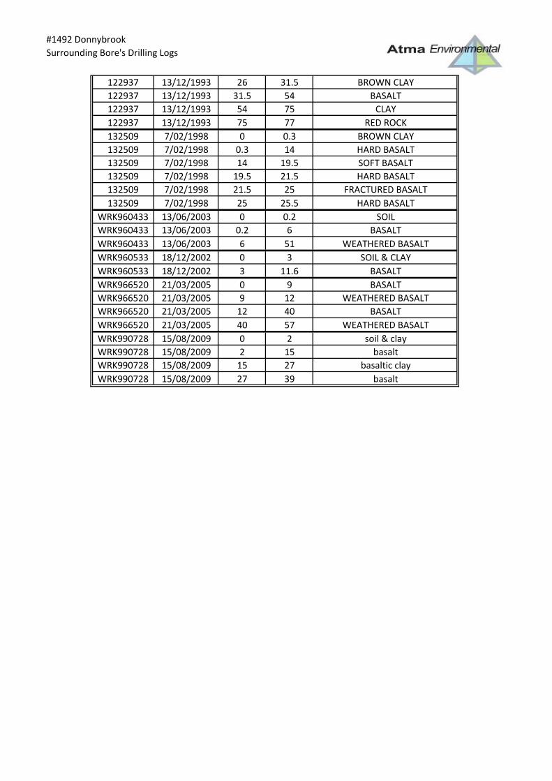
#1492 DonnybrookSurrounding Bore's Drilling Logs
122937 13/12/1993 26 31.5 BROWN CLAY122937 13/12/1993 31.5 54 BASALT122937 13/12/1993 54 75 CLAY122937 13/12/1993 75 77 RED ROCK132509 7/02/1998 0 0.3 BROWN CLAY132509 7/02/1998 0.3 14 HARD BASALT132509 7/02/1998 14 19.5 SOFT BASALT132509 7/02/1998 19.5 21.5 HARD BASALT132509 7/02/1998 21.5 25 FRACTURED BASALT132509 7/02/1998 25 25.5 HARD BASALT
WRK960433 13/06/2003 0 0.2 SOILWRK960433 13/06/2003 0.2 6 BASALTWRK960433 13/06/2003 6 51 WEATHERED BASALTWRK960533 18/12/2002 0 3 SOIL & CLAYWRK960533 18/12/2002 3 11.6 BASALTWRK966520 21/03/2005 0 9 BASALTWRK966520 21/03/2005 9 12 WEATHERED BASALTWRK966520 21/03/2005 12 40 BASALTWRK966520 21/03/2005 40 57 WEATHERED BASALTWRK990728 15/08/2009 0 2 soil & clayWRK990728 15/08/2009 2 15 basaltWRK990728 15/08/2009 15 27 basaltic clayWRK990728 15/08/2009 27 39 basalt

#1492 DonnybrookSurrounding Bore's Laboratory Data
Bore ID Reading dateInterval
from (m)Interval to (m)
Parameter nameParamete
r valueUnit of measure
68787 5/04/1971 10.66 12.19 Conductivity (µS/cm) 5153 µS/cm @ 25°C68787 5/04/1971 10.66 12.19 Calcium, as Ca 49 mg/L68787 5/04/1971 10.66 12.19 Chloride, as Cl 1338 mg/L68787 5/04/1971 10.66 12.19 Carbonate, as CO3 12 mg/L68787 5/04/1971 10.66 12.19 Hardness, as CaCO3 (calc.) 945 mg/L68787 5/04/1971 10.66 12.19 Bicarbonate, as HCO3 971 mg/L68787 5/04/1971 10.66 12.19 Potassium, as K 24 mg/L68787 5/04/1971 10.66 12.19 Sodium, as Na 797 mg/L68787 5/04/1971 10.66 12.19 Sulphate, as SO4 62 mg/L68787 5/04/1971 10.66 12.19 DME Silicate, as SIO3 58 mg/L68787 5/04/1971 10.66 12.19 Magnesium, as Mg 200 mg/L68787 5/04/1971 10.66 12.19 Total Soluble Salts (Summation 3511 mg/L68872 5/09/1984 35 41 Conductivity (µS/cm) 2600 µS/cm @ 25°C68872 5/09/1984 35 41 Total Alkalinity, as CaCO3 570 mg/L68872 5/09/1984 35 41 Calcium, as Ca 18 mg/L68872 5/09/1984 35 41 Chloride, as Cl 520 mg/L68872 5/09/1984 35 41 Hardness, as CaCO3 600 mg/L68872 5/09/1984 35 41 Bicarbonate, as HCO3 695.122 mg/L68872 5/09/1984 35 41 Potassium, as K 16 mg/L68872 5/09/1984 35 41 Sodium, as Na 360 mg/L68872 5/09/1984 35 41 Nitrate + Nitrite, as N(0.003d 1.8 mg/L68872 5/09/1984 35 41 Silica, reactive as SiO2 17 mg/L68872 5/09/1984 35 41 Sulphate, as SO4 52 mg/L68872 5/09/1984 35 41 Iron, total as Fe 23 mg/L68872 5/09/1984 35 41 Magnesium, as Mg 140 mg/L68872 5/09/1984 35 41 Total Dissolved Solids, 105C 1757.374 mg/L68884 30/05/1984 20 26 Conductivity (µS/cm) 5500 µS/cm @ 25°C68884 30/05/1984 20 26 Total Alkalinity, as CaCO3 640 mg/L68884 30/05/1984 20 26 Calcium, as Ca 64 mg/L68884 30/05/1984 20 26 Chloride, as Cl 1500 mg/L68884 30/05/1984 20 26 Hardness, as CaCO3 1000 mg/L68884 30/05/1984 20 26 Bicarbonate, as HCO3 780.488 mg/L68884 30/05/1984 20 26 Potassium, as K 24 mg/L68884 30/05/1984 20 26 Sodium, as Na 740 mg/L68884 30/05/1984 20 26 Nitrate + Nitrite, as N(0.003d 8.6 mg/L68884 30/05/1984 20 26 Silica, reactive as SiO2 51 mg/L68884 30/05/1984 20 26 Sulphate, as SO4 87 mg/L68884 30/05/1984 20 26 Iron, total as Fe 4.6 mg/L68884 30/05/1984 20 26 Magnesium, as Mg 220 mg/L68884 30/05/1984 20 26 Total Dissolved Solids, 105C 3366.898 mg/L68948 7/03/1991 12 24 Conductivity (µS/cm) 1800 µS/cm @ 25°C68948 7/03/1991 12 24 Total Alkalinity, as CaCO3 300 mg/L68948 7/03/1991 12 24 Calcium, as Ca 25 mg/L68948 7/03/1991 12 24 Chloride, as Cl 330 mg/L68948 7/03/1991 12 24 Hardness, as CaCO3 320.345 mg/L68948 7/03/1991 12 24 Bicarbonate, as HCO3 365.854 mg/L68948 7/03/1991 12 24 Potassium, as K 10 mg/L68948 7/03/1991 12 24 Sodium, as Na 220 mg/L68948 7/03/1991 12 24 Nitrate & Nitrite, as N(0.15de 7.9 mg/L68948 7/03/1991 12 24 Silica, total as SiO2 58 mg/L68948 7/03/1991 12 24 Sulphate, as SO4 62 mg/L68948 7/03/1991 12 24 Iron (Undigested), as Fe 1.8 mg/L68948 7/03/1991 12 24 Magnesium, as Mg 62 mg/L68948 7/03/1991 12 24 Total Dissolved Solids, 105C 1013 mg/L
122936 20/12/1993 32 41 Conductivity (µS/cm) 3900 µS/cm @ 25°C

#1492 DonnybrookSurrounding Bore's Laboratory Data
Bore ID Reading dateInterval
from (m)Interval to (m)
Parameter nameParamete
r valueUnit of measure
122936 20/12/1993 32 41 Calcium, as Ca 29 mg/L122936 20/12/1993 32 41 Hardness, as CaCO3 (calc.) 821 mg/L122936 20/12/1993 32 41 Sodium, as Na 580 mg/L122936 20/12/1993 32 41 Nitrate & Nitrite, as N(0.15de 0.87 mg/L122936 20/12/1993 32 41 Iron (Undigested), as Fe 3.6 mg/L122936 20/12/1993 32 41 Magnesium, as Mg 180 mg/L122937 20/12/1993 47 77 Conductivity (µS/cm) 3900 µS/cm @ 25°C122937 20/12/1993 47 77 Calcium, as Ca 29 mg/L122937 20/12/1993 47 77 Hardness, as CaCO3 (calc.) 780 mg/L122937 20/12/1993 47 77 Sodium, as Na 560 mg/L122937 20/12/1993 47 77 Nitrate & Nitrite, as N(0.15de 0.89 mg/L122937 20/12/1993 47 77 Iron (Undigested), as Fe 3.7 mg/L122937 20/12/1993 47 77 Magnesium, as Mg 170 mg/L

2017522 Groundwater Monitoring Database
http://spatial.federation.edu.au/ccma_bores/admin/view_bore.php?bore_id=4098544&print_mode=true&database=dse_gms 1/6
Bore Details: 68872 Normal Version
Bore Details
Bore ID 68872
Datum Longitude Latitude MGA zone Easting(m) Northing(m)
GDA 1994 145.006440 -37.548195 55 323893.2 5842444.2
Surveyed Elevation (m AHD) Digitised Elevation (m AHD) Location Accuracy Total Depth Completion date
235.80 41.00 1984-09-05
Bore Authority Bore type Bore use 1 Bore use 2 Bore use 3
Groundwater Domestic Stock
Monitoring status Monitoring frequency Parish Old Bore ID Local Bore name
Not Monitored
Construction Details
Driller SAMMASSIMO F
Drilling method Down-Hole Hammer Percussion
Casing type Casing diameter Casing From depth Casing To depth
125.0 mm 35.00 m
Screen type Screen diameter Screen aperture Screened from Screened to Screened in
4.00 mm 35.00 m 41.00 m BASA

2017522 Groundwater Monitoring Database
http://spatial.federation.edu.au/ccma_bores/admin/view_bore.php?bore_id=4098544&print_mode=true&database=dse_gms 2/6
Aquifer
Aquifer Summary Details
Aquifer from (m) Aquifer to (m) Aquifer material Aquifer Name Source
Water from (m) Water to (m) Lithology
SWL when constructed (m) EC when constructed (mS/cm) TDS when constructed (mg/l)
Pumping Test
Pumping test date1984-09-05
00:00:00
Pump depth (m)
Pump type AIR
Pumping rate (l/s)
Pumping time
(hh:mm)
Drawdown (m)
Recovery time
(hh:mm)
Pumping data
source
Aquifer parameters
Transmissivity (m2/day)
Hydraulic conductivity (m/d)
Storativity
Yield (l/s) 2.40
Data Source
Aquifer Summary Details
Aquifer from (m) Aquifer to (m) Aquifer material Aquifer Name Source
Water from (m) Water to (m) Lithology
SWL when constructed (m) EC when constructed (mS/cm) TDS when constructed (mg/l)
Pumping Test
Pumping test date1984-09-05
00:00:00
Pump depth (m)
Pump type AIR
Pumping rate (l/s) 2.40
Pumping time
(hh:mm)
Drawdown (m)
Recovery time
(hh:mm)
Pumping data
source
Aquifer parameters
Transmissivity (m2/day)
Hydraulic conductivity (m/d)
Storativity
Yield (l/s)
Data Source

2017522 Groundwater Monitoring Database
http://spatial.federation.edu.au/ccma_bores/admin/view_bore.php?bore_id=4098544&print_mode=true&database=dse_gms 3/6
Monitoring
No water level records available for this bore

2017522 Groundwater Monitoring Database
http://spatial.federation.edu.au/ccma_bores/admin/view_bore.php?bore_id=4098544&print_mode=true&database=dse_gms 4/6
Chemistry
Hydrochemistry Details
This content requires the Adobe Flash Player. Get Flash.
Bore 68872
Sample date 1984-09-05 00:00:00
Purged? NO
Field Readings Laboratory Readings
Electrical Conductivity (EC) 2.60 mS/cm
pH (pH) 8.50
Total dissolved solids (TDS) 1757.37 mg/l
Major Ions Other Ions
Alkalinity (CO3=+HCO3-) 570.00 meq/L
Bicarbonate ions (HCO3-) 695.12 mg/L
Calcium Ions (Ca++) 18.00 mg/l
Chloride ions (Cl-) 520.00 mg/l
Potassium Ions (K+) 16.00 mg/l
Sodium Ions (Na+) 360.00 mg/l
Sulphate ions (SO4=) 52.00 mg/l
Elements Isotopes
iron (Fe) 23.00 mg/l
magnesium (Mg) 140.00 mg/l

2017522 Groundwater Monitoring Database
http://spatial.federation.edu.au/ccma_bores/admin/view_bore.php?bore_id=4098544&print_mode=true&database=dse_gms 5/6
Lithology
Lithology details for bore: 68872
Log Type From (m) To (m) Description
Driller 0.00 1.00 CLAY
Driller 1.00 41.00 BASALT

2017522 Groundwater Monitoring Database
http://spatial.federation.edu.au/ccma_bores/admin/view_bore.php?bore_id=4098544&print_mode=true&database=dse_gms 6/6
Stratigraphy
No stratigraphy information for this bore
Further links
View this bore in the DELWP Water Measurement Information System (WMIS) system
Disclaimer: The content of this web site is provided for information purposes only. No claim is made as to the accuracy of authenticity of thecontent of the website. In no event will the Corangamite CMA, University of Ballarat or its agents and employees be liable for the accuracy ofthe information contained on this web site nor its use or reliance placed on it. Information is considered to be true and correct at the time ofpublication. Changes in circumstances after the time of publication may impact on the accuracy of this information.
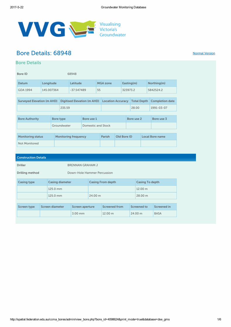
2017522 Groundwater Monitoring Database
http://spatial.federation.edu.au/ccma_bores/admin/view_bore.php?bore_id=4098624&print_mode=true&database=dse_gms 1/6
Bore Details: 68948 Normal Version
Bore Details
Bore ID 68948
Datum Longitude Latitude MGA zone Easting(m) Northing(m)
GDA 1994 145.007364 -37.547489 55 323973.2 5842524.2
Surveyed Elevation (m AHD) Digitised Elevation (m AHD) Location Accuracy Total Depth Completion date
235.59 28.00 1991-03-07
Bore Authority Bore type Bore use 1 Bore use 2 Bore use 3
Groundwater Domestic and Stock
Monitoring status Monitoring frequency Parish Old Bore ID Local Bore name
Not Monitored
Construction Details
Driller BRENNAN GRAHAM J
Drilling method Down-Hole Hammer Percussion
Casing type Casing diameter Casing From depth Casing To depth
125.0 mm 12.00 m
125.0 mm 24.00 m 28.00 m
Screen type Screen diameter Screen aperture Screened from Screened to Screened in
3.00 mm 12.00 m 24.00 m BASA
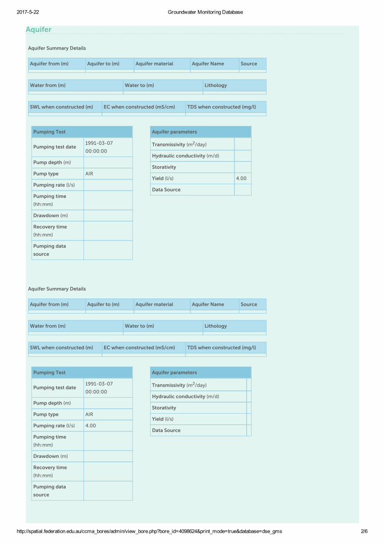
2017522 Groundwater Monitoring Database
http://spatial.federation.edu.au/ccma_bores/admin/view_bore.php?bore_id=4098624&print_mode=true&database=dse_gms 2/6
Aquifer
Aquifer Summary Details
Aquifer from (m) Aquifer to (m) Aquifer material Aquifer Name Source
Water from (m) Water to (m) Lithology
SWL when constructed (m) EC when constructed (mS/cm) TDS when constructed (mg/l)
Pumping Test
Pumping test date1991-03-07
00:00:00
Pump depth (m)
Pump type AIR
Pumping rate (l/s)
Pumping time
(hh:mm)
Drawdown (m)
Recovery time
(hh:mm)
Pumping data
source
Aquifer parameters
Transmissivity (m2/day)
Hydraulic conductivity (m/d)
Storativity
Yield (l/s) 4.00
Data Source
Aquifer Summary Details
Aquifer from (m) Aquifer to (m) Aquifer material Aquifer Name Source
Water from (m) Water to (m) Lithology
SWL when constructed (m) EC when constructed (mS/cm) TDS when constructed (mg/l)
Pumping Test
Pumping test date1991-03-07
00:00:00
Pump depth (m)
Pump type AIR
Pumping rate (l/s) 4.00
Pumping time
(hh:mm)
Drawdown (m)
Recovery time
(hh:mm)
Pumping data
source
Aquifer parameters
Transmissivity (m2/day)
Hydraulic conductivity (m/d)
Storativity
Yield (l/s)
Data Source

2017522 Groundwater Monitoring Database
http://spatial.federation.edu.au/ccma_bores/admin/view_bore.php?bore_id=4098624&print_mode=true&database=dse_gms 3/6
Monitoring
No water level records available for this bore
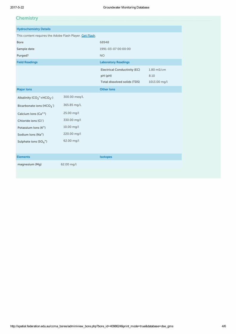
2017522 Groundwater Monitoring Database
http://spatial.federation.edu.au/ccma_bores/admin/view_bore.php?bore_id=4098624&print_mode=true&database=dse_gms 4/6
Chemistry
Hydrochemistry Details
This content requires the Adobe Flash Player. Get Flash.
Bore 68948
Sample date 1991-03-07 00:00:00
Purged? NO
Field Readings Laboratory Readings
Electrical Conductivity (EC) 1.80 mS/cm
pH (pH) 8.10
Total dissolved solids (TDS) 1013.00 mg/l
Major Ions Other Ions
Alkalinity (CO3=+HCO3-) 300.00 meq/L
Bicarbonate ions (HCO3-) 365.85 mg/L
Calcium Ions (Ca++) 25.00 mg/l
Chloride ions (Cl-) 330.00 mg/l
Potassium Ions (K+) 10.00 mg/l
Sodium Ions (Na+) 220.00 mg/l
Sulphate ions (SO4=) 62.00 mg/l
Elements Isotopes
magnesium (Mg) 62.00 mg/l

2017522 Groundwater Monitoring Database
http://spatial.federation.edu.au/ccma_bores/admin/view_bore.php?bore_id=4098624&print_mode=true&database=dse_gms 5/6
Lithology
Lithology details for bore: 68948
Log Type From (m) To (m) Description
Driller 0.00 1.50 SOIL & CLAY
Driller 1.50 20.00 BASALT
Driller 20.00 28.00 MOTTLED CLAY

2017522 Groundwater Monitoring Database
http://spatial.federation.edu.au/ccma_bores/admin/view_bore.php?bore_id=4098624&print_mode=true&database=dse_gms 6/6
Stratigraphy
No stratigraphy information for this bore
Further links
View this bore in the DELWP Water Measurement Information System (WMIS) system
Disclaimer: The content of this web site is provided for information purposes only. No claim is made as to the accuracy of authenticity of thecontent of the website. In no event will the Corangamite CMA, University of Ballarat or its agents and employees be liable for the accuracy ofthe information contained on this web site nor its use or reliance placed on it. Information is considered to be true and correct at the time ofpublication. Changes in circumstances after the time of publication may impact on the accuracy of this information.

Salinity Province 132 Mapping
Project: 1492B Donnybrook
SITE BOUNDARY Source: Department of Economic Development,
Jobs, Transport and Resources
Date: 24 May 2017

Department of Economic Development, Jobs, Transport and Resources
1492B Donnybrook - Groundwater Management Areas Legend
Disclaimer: This map is a snapshot generated from Victoria Government data. This material may be of assistance to you but the State of Victoria does not guarantee that the publication is without flaw of any kind or is wholly appropriate for your particular purposes and therefore disclaims all liability for error, loss or damage which may arise from reliance upon it. All persons accessing this information should make appropriate enquiries to assess the currency of the data.
Map Scale: 1:273,649
Projection: Geographic GDA94
Generated from GeoVic 3 Map Created Wed May 24 2017 09:55:24 GMT+1000 (AEST)
rjolley
Stamp
rjolley
Text Box
SITE
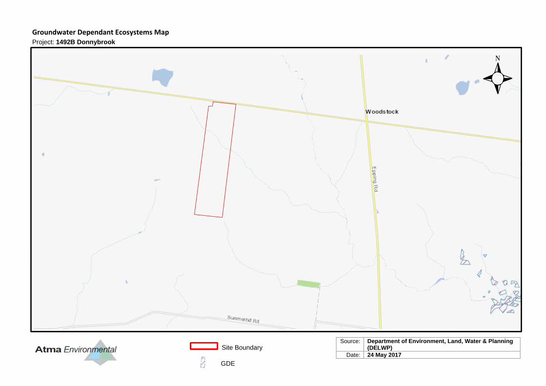
Groundwater Dependant Ecosystems Map
Project: 1492B Donnybrook
Source: Department of Environment, Land, Water & Planning (DELWP)
Date: 24 May 2017
Site Boundary
GDE
Site Inspection Photographs
APPEN
DIX C

Dry dam #1 Dry dam #2
Looking south from shed area Looking east near centre of siteAtma EnvironmentalRef.: #1492B Donnybrook
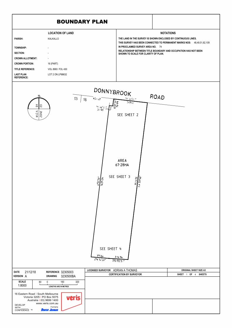
LOCATION OF LAND
CROWN PORTION:
TITLE REFERENCE:
LAST PLAN
CROWN ALLOTMENT:
PARISH:
SECTION:
TOWNSHIP:
REFERENCE:
NOTATIONS
0LENGTHS ARE IN METRES
SCALE
CERTIFICATION BY SURVEYOR
THE LAND IN THE SURVEY IS SHOWN ENCLOSED BY CONTINUOUS LINES.THIS SURVEY HAS BEEN CONNECTED TO PERMANENT MARKS NOS:IN PROCLAIMED SURVEY AREA NO.RELATIONSHIP BETWEEN TITLE BOUNDARY AND OCCUPATION HAS NOT BEENSHOWN TO SCALE FOR CLARITY OF PLAN.
DEVELOPWITH ______CONFIDENCE ™
Formerly
16 Eastern Road I South MelbourneVictoria 3205 I PO Box 5075
Australia I 03) 9699 1400www.veris.com.au
REFERENCEVERSION DRAWINGDATE LICENSED SURVEYOR ORIGINAL SHEET SIZE A3
SHEET 1 OF SHEETS
BOUNDARY PLAN
LOT 2 ON LP98632
VOL 8993 FOL 430
16 (PART)
-
-
-
KALKALLO
1:800080 160 320
48,49,51,82,10974
3230500BAA21/12/18 32305003 ADRIAN A THOMAS
4

LENG
THS
ARE
IN M
ETRE
S
SCAL
ELI
CENS
ED S
URVE
YOR
DRAW
ING
0
VERS
ION
DATE
REFE
RENC
E
SHEE
T
DE
VE
LOP
WIT
H _
____
_C
ON
FID
EN
CE
™Fo
rmer
ly
16 E
aste
rn R
oad
I Sou
th M
elbo
urne
Vic
toria
320
5 I P
O B
ox 5
075
Aus
tralia
I 0
3) 9
699
1400
ww
w.v
eris
.com
.au
ORIG
INAL
SHE
ET S
IZE
A3AD
RIAN
A T
HOMA
S1:1
250
12.5
2550
A21/12
/1832
3050
0BA
3230
5003
2 of 4
BO
UN
DA
RY
PLA
N
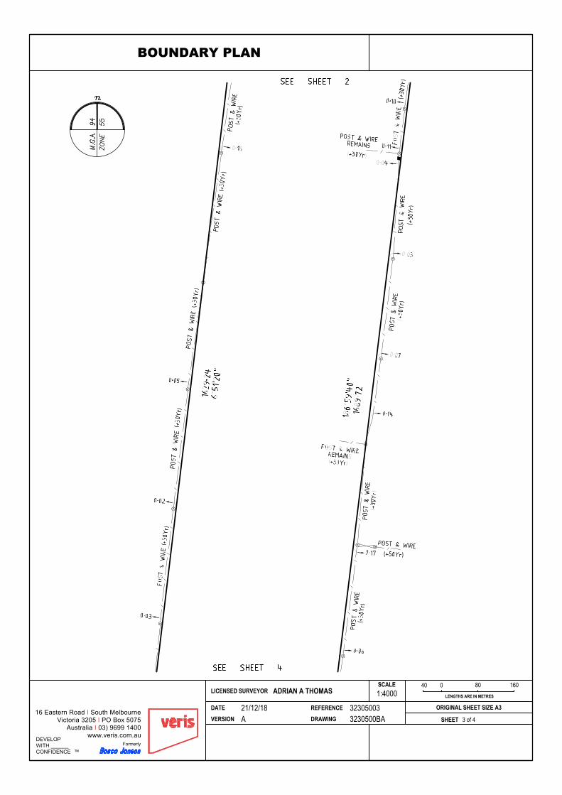
0LENGTHS ARE IN METRES
SCALE
DEVELOPWITH ______CONFIDENCE ™
Formerly
16 Eastern Road I South MelbourneVictoria 3205 I PO Box 5075
Australia I 03) 9699 1400www.veris.com.au
REFERENCEVERSION DRAWINGDATE
LICENSED SURVEYOR
SHEET
ORIGINAL SHEET SIZE A3
1:400040 80 160
BOUNDARY PLAN
3230500BAA21/12/18 32305003
ADRIAN A THOMAS
3 of 4
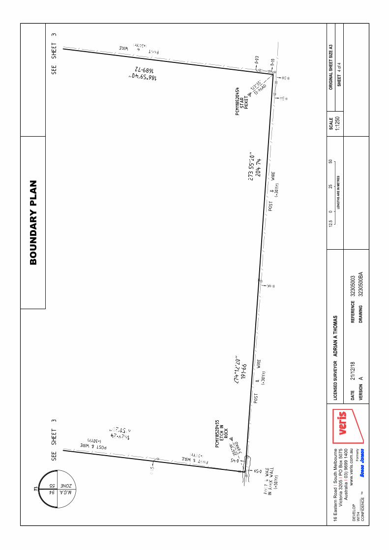
LENG
THS
ARE
IN M
ETRE
S
SCAL
ELI
CENS
ED S
URVE
YOR
DRAW
ING
0
VERS
ION
DATE
REFE
RENC
E
SHEE
T
DE
VE
LOP
WIT
H _
____
_C
ON
FID
EN
CE
™Fo
rmer
ly
16 E
aste
rn R
oad
I Sou
th M
elbo
urne
Vic
toria
320
5 I P
O B
ox 5
075
Aus
tralia
I 0
3) 9
699
1400
ww
w.v
eris
.com
.au
ORIG
INAL
SHE
ET S
IZE
A3AD
RIAN
A T
HOMA
S1:1
250
12.5
2550
A21/12
/1832
3050
0BA
3230
5003
4 of 4
BO
UN
DA
RY
PLA
N
Lot 2, 1150 Donnybrook Rd, Donnybrook | Stormwater Management Plan | Creo Consulting i
Lot 2, 1150 Donnybrook Rd, Donnybrook
Stormwater Management Plan Prepared for Creo Consulting October 2019
Lot 2, 1150 Donnybrook Rd, Donnybrook | Stormwater Management Plan | Creo Consulting ii
Table of Contents 1 Lot 2, 1150 Donnybrook Road, Donnybrook ................................................... 1
2 Outlining Assumptions ...............................................................................................3
3 Melbourne Water Developer Services Scheme Reviews and Pre-development Advice .............................................................................................................. 5
3.1 North Catchment ................................................................................................ 6
3.2 South Catchment ................................................................................................ 6
4 Site Hydrology .................................................................................................................. 7
4.1 North Catchment ................................................................................................. 7
4.2 South Catchment ................................................................................................. 7
5 Site Water Quality ......................................................................................................... 8
6 Proposed Developed Catchment Conditions ............................................ 9
6.1 Scheme Works – North Catchment ........................................................ 9
6.1.1 Waterway Corridor ........................................................................................ 9
6.1.2 Retarding Basin Design ............................................................................. 11
6.1.3 High-flow Bypass ........................................................................................... 13
6.1.4 Water Quality Treatment Train ........................................................... 13
6.1.5 Downstream “Clean-out” Works ......................................................... 18
6.2 Scheme Works – South Catchment ...................................................... 18
6.2.1 Scheme Pipe ..................................................................................................... 18
6.2.2 Retarding Basin Design ........................................................................ 18
6.2.3 Water Quality Treatment Train .................................................... 20
6.3 Overall Site Water Quality Treatment Train (North and South Catchments)........................................................................................................................ 22
7 Recommendations ..................................................................................................... 25
8 References .......................................................................................................................26
Appenidx A. RORB and MUSIC Layouts............................................................. 27
Appenidx B. Melbourne Water Meeting Minutes (29/09/2019) ........... 32
Appenidx C. Melbourne Water Pre-Development Advice .................... 36
Figure 1-1 Site Zoning ....................................................................................................... 1
Figure 1-2 Site Locality ................................................................................................... 2
Figure 1-3 Site Terrain ..................................................................................................... 3
Figure 3-1 Property border and proposed works per Melbourne Water’s pre-development advice ................................................................................ 5
Figure 6-1 Typical hydraulic cross-section – North Catchment Waterway 10
Figure 6-2 Typical cross section of Corridor (Melbourne Water, 2013) 11
Figure 6-3 Indicative Hydraulic Asset Locations and Sizes .............12
Figure 6-4 SB2North cross-section .................................................................. 14
Figure 6-5 SB2South cross-section ....................................................................... 14
Figure 6-6 WL2 long-section ......................................................................................... 16
Figure 6-7 North Catchment Water Quality Treatment Train Concept Design ............................................................................................................................................ 17
Figure 6-8 Indicative Hydraulic Asset Locations and Sizes RB3 ..... 20
Figure 6-9 SB3 cross-section .........................................................................................21
Figure 6-10 SB4 cross-section ......................................................................................21
Lot 2, 1150 Donnybrook Rd, Donnybrook | Stormwater Management Plan | Creo Consulting iii
Figure 6-11 WL3 long-section ........................................................................................ 23
Figure 6-12 South Catchment Water Quality Treatment Train Concept Design ..................................................................................................................... 24
Figure 8-1 RORB Model Layouts North Catchment ....................................... 28
Figure 8-2 RORB Model Layouts South Catchment ................................. 29
Figure 8-3 Music Model Layout North ................................................................ 30
Figure 8-4 Music Model Layout South ............................................................ 31

Lot 2, 1150 Donnybrook Rd, Donnybrook | Stormwater Management Plan | Creo Consulting iv
Project Name Lot 2, 1150 Donnybrook Rd, Donnybrook Client Creo Consulting Rain ID 37R01 Document Name
37R01_v01_1150DonnybrookRdDonnybrook
Version History
Version Number Status Authors Reviewer v01a Draft Rianda Mills, Luke Cunningham, Dr Cintia Dotto LJC V01 Final Rianda Mills, Luke Cunningham, Dr Cintia Dotto RBM
Disclaimer
This report is prepared by Rain Consulting for its client’s purposes only. The contents of this report are provided expressly for the named client for its own use. No responsibility is accepted for the use of or reliance upon this report in whole or in part by any third party. The report is prepared with information supplied by the client and possibly other stakeholders. While care is taken to ensure the veracity of information sources, no responsibility is accepted for information that is withheld, incorrect or that is inaccurate. This report has been compiled at the level of detail specified in the report and no responsibility is accepted for interpretations made at more detailed levels than so indicated.
//cover image// Concept Waterway Corridor – Rain Consulting 2018
Rain Consulting acknowledges the Boon Wurrung and Woiwurrung (Wurundjeri) people of the Kulin Nation who are the Traditional Owners of the land on which we work, live and play.
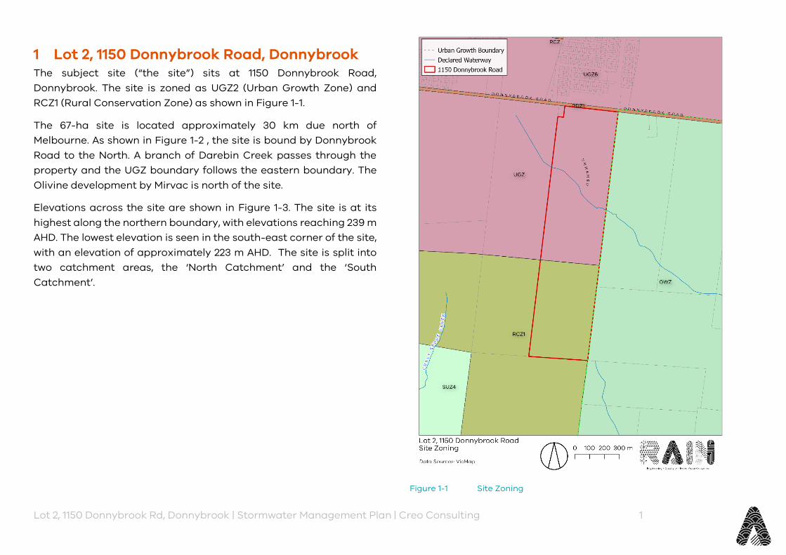
Lot 2, 1150 Donnybrook Rd, Donnybrook | Stormwater Management Plan | Creo Consulting 1
1 Lot 2, 1150 Donnybrook Road, Donnybrook The subject site (“the site”) sits at 1150 Donnybrook Road, Donnybrook. The site is zoned as UGZ2 (Urban Growth Zone) and RCZ1 (Rural Conservation Zone) as shown in Figure 1-1.
The 67-ha site is located approximately 30 km due north of Melbourne. As shown in Figure 1-2 , the site is bound by Donnybrook Road to the North. A branch of Darebin Creek passes through the property and the UGZ boundary follows the eastern boundary. The Olivine development by Mirvac is north of the site.
Elevations across the site are shown in Figure 1-3. The site is at its highest along the northern boundary, with elevations reaching 239 m AHD. The lowest elevation is seen in the south-east corner of the site, with an elevation of approximately 223 m AHD. The site is split into two catchment areas, the ‘North Catchment’ and the ‘South Catchment’.
Figure 1-1 Site Zoning
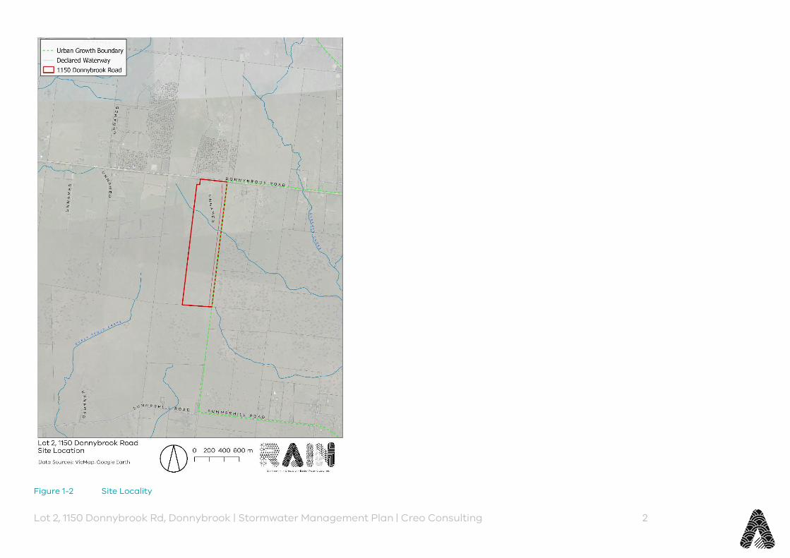
Lot 2, 1150 Donnybrook Rd, Donnybrook | Stormwater Management Plan | Creo Consulting 2
Figure 1-2 Site Locality

Lot 2, 1150 Donnybrook Rd, Donnybrook | Stormwater Management Plan | Creo Consulting 3
Figure 1-3 Site Terrain
2 Outlining Assumptions Pre-development advice (Melbourne Water reference MWA-1150900) was provided by Melbourne Water and is available in Appendix C.
A meeting was held with Melbourne Water on the 26th of September 2019 to discuss project particulars. There is currently no PSP for the site, however Melbourne Water have agreed that the work to date may be provided to relevant stakeholders for consideration. Melbourne Water staff with greater knowledge of the site were on leave at the time of the meeting, therefore Melbourne Water considers discussions as preliminary only. Full minutes of the meeting are provided in Appendix B. Key details are noted here below and reiterated throughout this report in the relevant sections for clarity:
‣ There is currently no activity on the site immediately adjacent to the west, although this is within the UGZ;
‣ The inflow level from the west was assumed to be 500 mm below NGL;
‣ The waterway through the site to the Northern wetland and retarding basin will be determined by the hydraulic width per Melbourne Water guidelines;
‣ The Northern retarding basin outlet per the RORB model was 229.2 m AHD while feature survey at the property suggested 230.0 m AHD. This will be addressed within this report;
‣ There are currently no plans for the downstream property (outside UGZ) as there is no PSP in place. Therefore we are to assume discharge to the surface of the downstream site;
‣ If the future PSP dictates that there must be a waterway or pipe through the downstream property, the Northern wetland and retarding basin could be lowered again in future
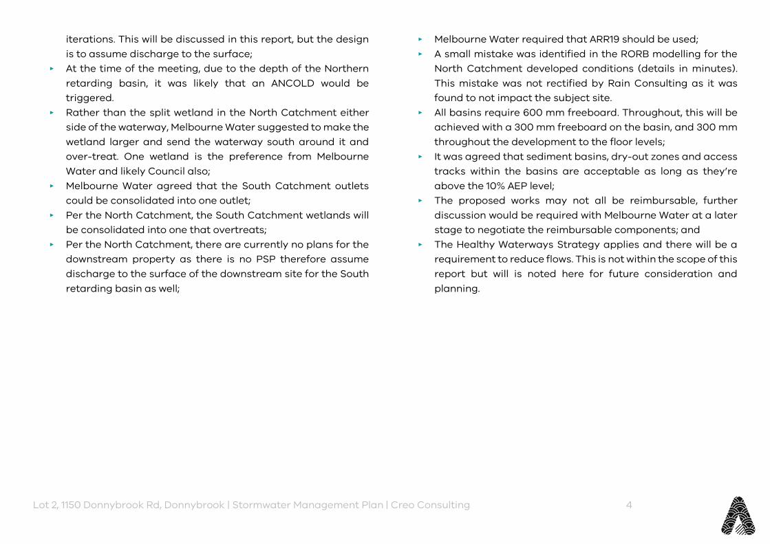
Lot 2, 1150 Donnybrook Rd, Donnybrook | Stormwater Management Plan | Creo Consulting 4
iterations. This will be discussed in this report, but the design is to assume discharge to the surface;
‣ At the time of the meeting, due to the depth of the Northern retarding basin, it was likely that an ANCOLD would be triggered.
‣ Rather than the split wetland in the North Catchment either side of the waterway, Melbourne Water suggested to make the wetland larger and send the waterway south around it and over-treat. One wetland is the preference from Melbourne Water and likely Council also;
‣ Melbourne Water agreed that the South Catchment outlets could be consolidated into one outlet;
‣ Per the North Catchment, the South Catchment wetlands will be consolidated into one that overtreats;
‣ Per the North Catchment, there are currently no plans for the downstream property as there is no PSP therefore assume discharge to the surface of the downstream site for the South retarding basin as well;
‣ Melbourne Water required that ARR19 should be used; ‣ A small mistake was identified in the RORB modelling for the
North Catchment developed conditions (details in minutes). This mistake was not rectified by Rain Consulting as it was found to not impact the subject site.
‣ All basins require 600 mm freeboard. Throughout, this will be achieved with a 300 mm freeboard on the basin, and 300 mm throughout the development to the floor levels;
‣ It was agreed that sediment basins, dry-out zones and access tracks within the basins are acceptable as long as they’re above the 10% AEP level;
‣ The proposed works may not all be reimbursable, further discussion would be required with Melbourne Water at a later stage to negotiate the reimbursable components; and
‣ The Healthy Waterways Strategy applies and there will be a requirement to reduce flows. This is not within the scope of this report but will is noted here for future consideration and planning.
Lot 2, 1150 Donnybrook Rd, Donnybrook | Stormwater Management Plan | Creo Consulting 5
3 Melbourne Water Developer Services Scheme Reviews and Pre-development Advice
The site is covered by the Woodstock West (4566) Developer Services Scheme (DSS). Pre-development advice outlined the following expected drainage works and design criteria shown in Table 3-1, and the property border and proposed scheme works shown in Figure 3-1. Note per the meeting held with Melbourne Water and outlined in section 2, WL3 and WL4 will be consolidated into one wetland in the location of WL3. Further, D1-D2 is not considered here as it is mostly offsite, apart from the WL2 outlet specifics at D1.
Table 3-1 Expected drainage works and design criteria from Melbourne Water pre-development advice
Node Ref. Approx. Length (m)
Asset/Ownership
A8-A9 285 Melbourne Water Channel WL2 Melbourne Water Wetland RB2/RB2LA Melbourne Water Retarding Basin
including land acquisition D1-D2 500 Melbourne Water Cleanout Works B1-B2 310 Council Pipeline WL3 Council Wetland RB3/RB3LA Council Retarding Basin including
land acquisition WL4/WL4LA Council Wetland including land
acquisition
Figure 3-1 Property border and proposed works per Melbourne Water’s pre-development advice
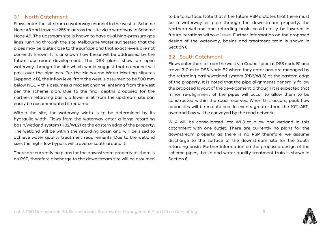
Lot 2, 1150 Donnybrook Rd, Donnybrook | Stormwater Management Plan | Creo Consulting 6
3.1 North Catchment Flows enter the site from a waterway channel in the west at Scheme Node A8 and traverse 285 m across the site via a waterway to Scheme Node A9. The upstream site is known to have dual high-pressure gas lines running through the site. Melbourne Water suggested that the pipes may be quite close to the surface and that exact levels are not currently known. It is unknown how these will be addressed by the future upstream development. The DSS plans show an open waterway through the site which would suggest that a channel will pass over the pipelines. Per the Melbourne Water Meeting Minutes (Appendix B), the inflow level from the west is assumed to be 500 mm below NGL – this assumes a modest channel entering from the west per the scheme plan. Due to the final depths proposed for the northern retarding basin, a lower inlet from the upstream site can easily be accommodated if required.
Within the site, the waterway width is to be determined by its hydraulic width. Flows from the waterway enter a large retarding basin/wetland system (RB2/WL2) at the eastern edge of the property. The wetland will be within the retarding basin and will be sized to achieve water quality treatment requirements. Due to the wetland size, the high-flow bypass will traverse south around it.
There are currently no plans for the downstream property as there is no PSP, therefore discharge to the downstream site will be assumed
to be to surface. Note that if the future PSP dictates that there must be a waterway or pipe through the downstream property, the Northern wetland and retarding basin could easily be lowered in future iterations without issue. Further information on the proposed design of the waterway, basins and treatment train is shown in Section 6.
3.2 South Catchment Flows enter the site from the west via Council pipe at DSS node B1 and travel 310 m to DSS Node B2 where they enter and are managed by the retarding basin/wetland system (RB3/WL3) at the eastern edge of the property. It is noted that the pipe alignments generally follow the proposed layout of the development, although it is expected that minor re-alignment of the pipes will occur to allow them to be constructed within the road reserves. When this occurs, peak flow capacities will be maintained. In events greater than the 10% AEP, overland flow will be conveyed by the road network.
WL4 will be consolidated into WL3 to allow one wetland in this catchment with one outlet. There are currently no plans for the downstream property as there is no PSP therefore, we assume discharge to the surface of the downstream site for the South retarding basin. Further information on the proposed design of the scheme pipes, basin and water quality treatment train is shown in Section 6.
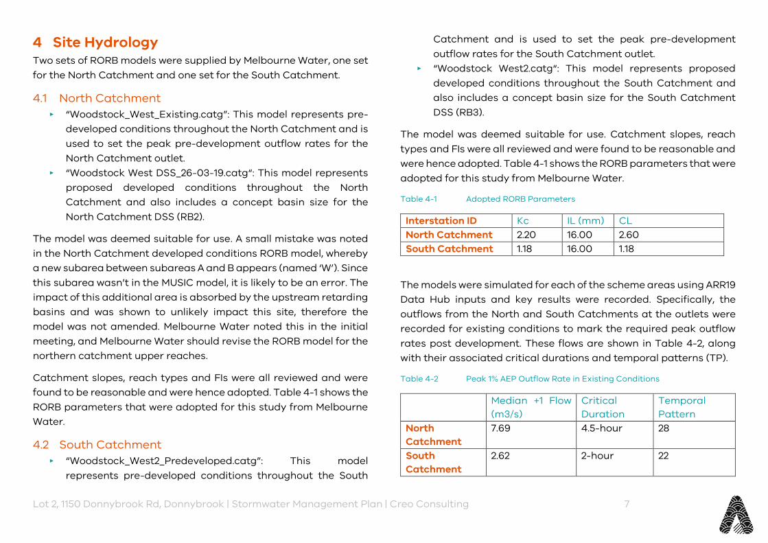
Lot 2, 1150 Donnybrook Rd, Donnybrook | Stormwater Management Plan | Creo Consulting 7
4 Site Hydrology Two sets of RORB models were supplied by Melbourne Water, one set for the North Catchment and one set for the South Catchment.
4.1 North Catchment ‣ “Woodstock_West_Existing.catg”: This model represents pre-
developed conditions throughout the North Catchment and is used to set the peak pre-development outflow rates for the North Catchment outlet.
‣ “Woodstock West DSS_26-03-19.catg“: This model represents proposed developed conditions throughout the North Catchment and also includes a concept basin size for the North Catchment DSS (RB2).
The model was deemed suitable for use. A small mistake was noted in the North Catchment developed conditions RORB model, whereby a new subarea between subareas A and B appears (named ‘W’). Since this subarea wasn’t in the MUSIC model, it is likely to be an error. The impact of this additional area is absorbed by the upstream retarding basins and was shown to unlikely impact this site, therefore the model was not amended. Melbourne Water noted this in the initial meeting, and Melbourne Water should revise the RORB model for the northern catchment upper reaches.
Catchment slopes, reach types and FIs were all reviewed and were found to be reasonable and were hence adopted. Table 4-1 shows the RORB parameters that were adopted for this study from Melbourne Water.
4.2 South Catchment ‣ “Woodstock_West2_Predeveloped.catg”: This model
represents pre-developed conditions throughout the South
Catchment and is used to set the peak pre-development outflow rates for the South Catchment outlet.
‣ “Woodstock West2.catg“: This model represents proposed developed conditions throughout the South Catchment and also includes a concept basin size for the South Catchment DSS (RB3).
The model was deemed suitable for use. Catchment slopes, reach types and FIs were all reviewed and were found to be reasonable and were hence adopted. Table 4-1 shows the RORB parameters that were adopted for this study from Melbourne Water.
Table 4-1 Adopted RORB Parameters
Interstation ID Kc IL (mm) CL North Catchment 2.20 16.00 2.60 South Catchment 1.18 16.00 1.18
The models were simulated for each of the scheme areas using ARR19 Data Hub inputs and key results were recorded. Specifically, the outflows from the North and South Catchments at the outlets were recorded for existing conditions to mark the required peak outflow rates post development. These flows are shown in Table 4-2, along with their associated critical durations and temporal patterns (TP).
Table 4-2 Peak 1% AEP Outflow Rate in Existing Conditions
Median +1 Flow (m3/s)
Critical Duration
Temporal Pattern
North Catchment
7.69 4.5-hour 28
South Catchment
2.62 2-hour 22
Lot 2, 1150 Donnybrook Rd, Donnybrook | Stormwater Management Plan | Creo Consulting 8
5 Site Water Quality A MUSIC model covering the drainage scheme was provided by Melbourne Water. The catchment setups in the model were found to be in alignment with the latest Melbourne Water MUSIC Guidelines (MW, 2018).
The catchment areas and developed fraction impervious values were adopted to match with the scheme RORB model.

Lot 2, 1150 Donnybrook Rd, Donnybrook | Stormwater Management Plan | Creo Consulting 9
6 Proposed Developed Catchment Conditions It is important to note, that at the time of preparation of this report, no development layout was known. The developers wished to complete this report to gather an indication of required stormwater assets. It is likely that the shape, alignment and configuration of the proposed assets will change to suit a development layout, and calculations will be updated at the time. Rain Consulting has followed conservative assumptions to allow for the greatest future flexibility in the development layout.
Given that the development layout was not available, flood modelling of the site for proposed conditions has not been completed. It is suggested that this is completed at a later stage.
6.1 Scheme Works – North Catchment The North Catchment scheme works comprise the following components:
‣ A waterway corridor; ‣ A retarding basin; ‣ A high flow bypass; ‣ A wetland and associated sediment basins and sediment
drying area; and, ‣ Downstream “clean-out” works
As discussed in Section 2, the upstream gas pipeline will impact the invert levels entering the site. Conservative assumptions have been made throughout the calculations which allow for future scenarios of inverts once the upstream development is planned by others.
6.1.1 Waterway Corridor A waterway corridor is required to convey flows from where they enter the North Catchment in the west, to the retarding basin and
continue as a narrower bypass south around the proposed wetland. The waterway will be a constructed waterway, which aim to establish characteristics of a natural waterway for the area. This will bring higher ecological, social and amenity value to the development.
The total waterway corridor width was determined by first calculating the hydraulic width to cater for the peak 1% AEP flow rate from the developed conditions RORB modelling, then consulting Waterway Corridors Guidelines (Melbourne Water, 2013).
6.1.1.1 Hydraulic Width Manning’s roughness values are expected to vary throughout the corridor depending on vegetation types and densities of planting. A conservative and constant value of 0.060 was used as a representative roughness. The waterway is designed with 1 in 5 side slopes. Specifics of the waterway are shown in Table 6-1, while Figure 6-1 shows a typical hydraulic cross-section for the waterway.
Table 6-1 Waterway Corridor Design
North Depth (m) 0.7 Bottom Width (m) 17.0 Top Width (m) 24.0 Length (m) 205 Slope 1 in 219 Capacity (m3/s) 11.42 Required Capacity (m3/s) 11.26 Peak Velocity (m/s) 0.8
The waterway length of 205 m is shorter than the suggested 285 m in the scheme. This is due to the required size of the basin and wetland being larger than allowed for in the scheme.

Lot 2, 1150 Donnybrook Rd, Donnybrook | Stormwater Management Plan | Creo Consulting 10
Velocities through the waterways are generally around 0.8 m/s which is deemed acceptable. Further hydraulic modelling is recommended when the final landform has been developed to understand the likely shear stress through the waterway corridor. Where shear stress is high, vegetation selection becomes important and can further be mitigated through the placement of rock throughout the waterway in strategic locations.
A low flow channel will sit within the base of the waterway (see below for further details).
Figure 6-1 Typical hydraulic cross-section – North Catchment Waterway
6.1.1.2 Subzone Width and Total Width Per Melbourne Water (2013), the waterway corridor will be made up of two sub zones which together comprise the total waterway corridor
width, as shown in Figure 6-2. The widths selected cross-reference with those required for a hydraulic width of 25 m:
‣ The central 30 m of the corridor will be the ‘Core Riparian Zone’ (CRZ). The CRZ will convey low and will be fully vegetated with native vegetation. The highly vegetated CRZ will be the hub of biodiversity functions within the corridor and will provide all necessary inputs for a healthy instream ecosystem.
‣ On either side of the CRZ will be the ‘Vegetated Buffer’ (VB). The VB is in place largely to protect the CRZ from edge effects. The total VB width must be 15 m. This 15 m total VB width would then require an active edge (i.e. a road) along the length of the waterway that allows for maintenance vehicles. Otherwise, the total VB width will be 25 m to incorporate provision of maintenance tracks suitable for vehicular traffic. The vegetation within the VB will be of similar type to the CRZ and the development will seek advice from Melbourne Water on any site-specific vegetation that may be required. Therefore, the total waterway corridor width will be 45 m with an active edge, or 55 m without.
It is noted that the required 1% AEP hydraulic width is 24 m which results in an overall corridor width of 45 m. Per Melbourne Water (2013), a 45 m wide corridor is suitable for hydraulic widths of up to 35 m. This provides some certainty to the development that if upstream development requires different invert levels, the final corridor width is unlikely to be impacted.
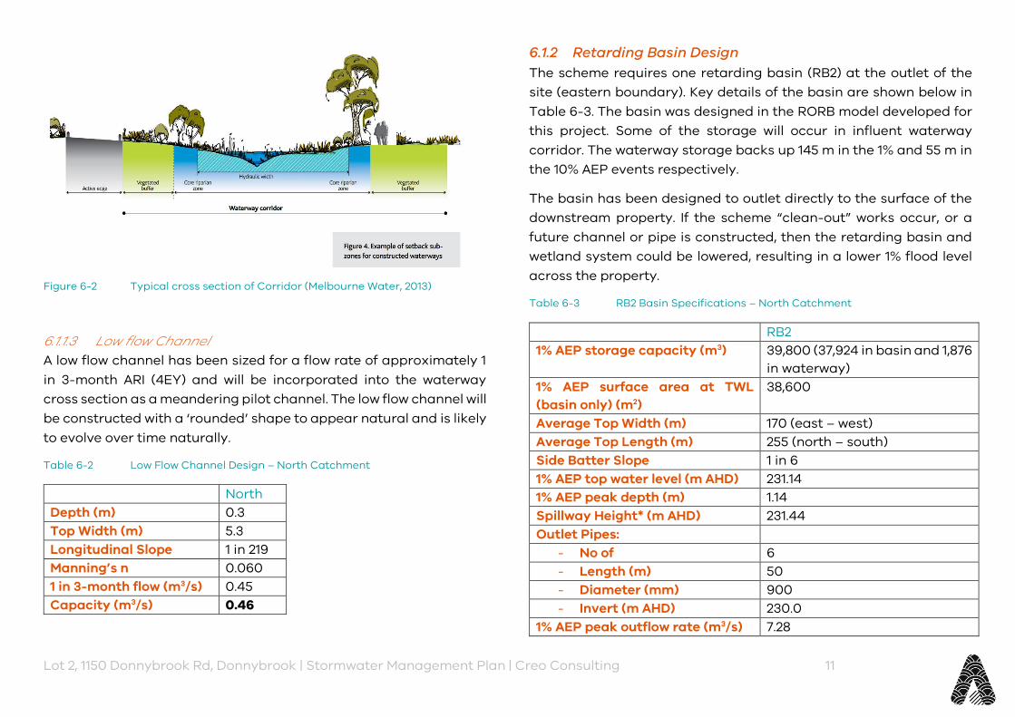
Lot 2, 1150 Donnybrook Rd, Donnybrook | Stormwater Management Plan | Creo Consulting 11
Figure 6-2 Typical cross section of Corridor (Melbourne Water, 2013)
6.1.1.3 Low flow Channel A low flow channel has been sized for a flow rate of approximately 1 in 3-month ARI (4EY) and will be incorporated into the waterway cross section as a meandering pilot channel. The low flow channel will be constructed with a ‘rounded’ shape to appear natural and is likely to evolve over time naturally.
Table 6-2 Low Flow Channel Design – North Catchment
North Depth (m) 0.3 Top Width (m) 5.3 Longitudinal Slope 1 in 219 Manning’s n 0.060 1 in 3-month flow (m3/s) 0.45 Capacity (m3/s) 0.46
6.1.2 Retarding Basin Design The scheme requires one retarding basin (RB2) at the outlet of the site (eastern boundary). Key details of the basin are shown below in Table 6-3. The basin was designed in the RORB model developed for this project. Some of the storage will occur in influent waterway corridor. The waterway storage backs up 145 m in the 1% and 55 m in the 10% AEP events respectively.
The basin has been designed to outlet directly to the surface of the downstream property. If the scheme “clean-out” works occur, or a future channel or pipe is constructed, then the retarding basin and wetland system could be lowered, resulting in a lower 1% flood level across the property.
Table 6-3 RB2 Basin Specifications – North Catchment
RB2 1% AEP storage capacity (m3) 39,800 (37,924 in basin and 1,876
in waterway) 1% AEP surface area at TWL (basin only) (m2)
38,600
Average Top Width (m) 170 (east – west) Average Top Length (m) 255 (north – south) Side Batter Slope 1 in 6 1% AEP top water level (m AHD) 231.14 1% AEP peak depth (m) 1.14 Spillway Height* (m AHD) 231.44 Outlet Pipes:
- No of 6 - Length (m) 50 - Diameter (mm) 900 - Invert (m AHD) 230.0
1% AEP peak outflow rate (m3/s) 7.28
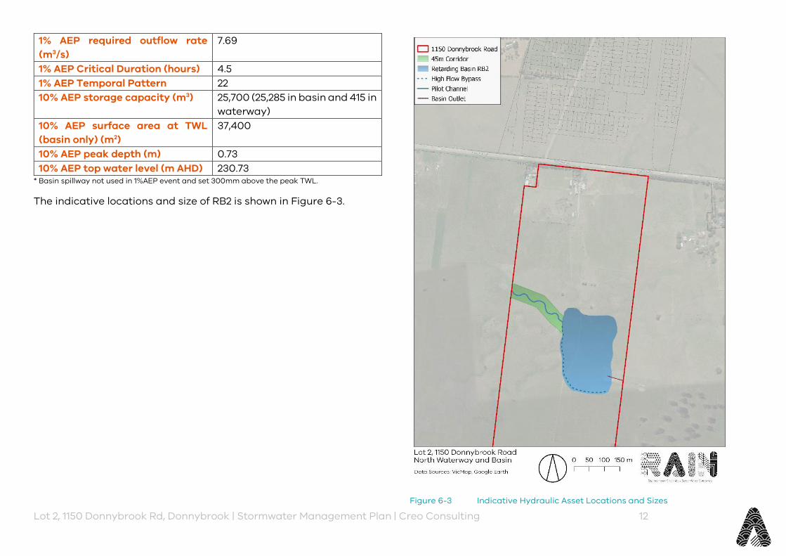
Lot 2, 1150 Donnybrook Rd, Donnybrook | Stormwater Management Plan | Creo Consulting 12
1% AEP required outflow rate (m3/s)
7.69
1% AEP Critical Duration (hours) 4.5 1% AEP Temporal Pattern 22 10% AEP storage capacity (m3) 25,700 (25,285 in basin and 415 in
waterway) 10% AEP surface area at TWL (basin only) (m2)
37,400
10% AEP peak depth (m) 0.73 10% AEP top water level (m AHD) 230.73
* Basin spillway not used in 1%AEP event and set 300mm above the peak TWL.
The indicative locations and size of RB2 is shown in Figure 6-3.
Figure 6-3 Indicative Hydraulic Asset Locations and Sizes

Lot 2, 1150 Donnybrook Rd, Donnybrook | Stormwater Management Plan | Creo Consulting 13
6.1.3 High-flow Bypass A high-flow bypass is required around the wetland through the retarding basin footprint. The high-flow bypass has been sized as the gap flow between the 3-month flow (which will be diverted to the wetland) and the 10% AEP event. Details of the high-flow bypass are shown below in Table 6-4.
Table 6-4 High Flow Bypass – North Catchment
North Depth (m) 1.0 Top Width (m) 12 Longitudinal Slope 1 in 219 Manning’s n 0.060 Gap flow (m3/s) 5.30 Capacity (m3/s) 5.44
6.1.4 Water Quality Treatment Train The treatment train strategy for the site consists of sedimentation ponds and wetlands to achieve best practice treatment targets, which were designed according to the latest Melbourne Water wetland design guidelines (MW, 2018). The development of the treatment train strategy for the study site and overall scheme was based on the discussions with Melbourne Water.
Figure 6-7 shows the proposed layout for the water quality assets for the North Catchment. The proposed strategy will treat site-derived runoff and relies on sedimentation basins to remove 95% of the 125 µm particles from the development and wetlands that were sized to overtreat the runoff from the incoming catchments to avoid the adoption of numerous wetland systems. The North Catchment treatment train comprises:
‣ Two sedimentation basins (SB2South and SB2North) to cater for the south and north portions of the northern catchment located on the south and north sides of the proposed waterway respectively.
‣ A wetland (WL2) is proposed to cater for the runoff from the external catchments and the north portion of the northern catchment.
6.1.4.1 Sediment Basins 6.1.4.1.1 Upstream Off-site Sediment Basin (SBB)
A sedimentation basin (SBB) proposed to cater for the external catchments in the west is proposed in the overall DSS. MUSIC results indicated the proposed design in the original MUSIC model provided by Melbourne Water was undersized as it would require a clean-out every 3 years and this would impact on the sizes of the sedimentation ponds proposed for the study site. The sedimentation basin was re-sized to achieve a 5-year clean-out frequency. Suggested design parameters for the offsite SBB are in Table 6-5. The SBB should be reviewed by Melbourne Water prior to the upstream site being developed.
6.1.4.1.2 Onsite Sediment Basins (SB2North & SB2South)
The following outlines the design considerations for the North Catchment sediment basins and required associated infrastructure:
‣ Sediment basin design parameters are shown in Table 6-5. ‣ The sediment basins were sized to capture 95% of coarse
particles ≥ 125 µm diameter for the peak three-month ARI. ‣ The sediment basins were sized to provide sediment storage
volume equivalent to the five years of sediment up to 500 mm below of the NWL.
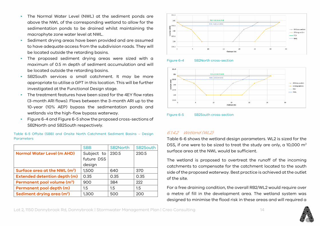
Lot 2, 1150 Donnybrook Rd, Donnybrook | Stormwater Management Plan | Creo Consulting 14
‣ The Normal Water Level (NWL) at the sediment ponds are above the NWL of the corresponding wetland to allow for the sedimentation ponds to be drained whilst maintaining the macrophyte zone water level at NWL.
‣ Sediment drying areas have been provided and are assumed to have adequate access from the subdivision roads. They will be located outside the retarding basins.
‣ The proposed sediment drying areas were sized with a maximum of 0.5 m depth of sediment accumulation and will be located outside the retarding basins.
‣ SB2South services a small catchment. It may be more appropriate to utilise a GPT in this location. This will be further investigated at the Functional Design stage.
‣ The treatment features have been sized for the 4EY flow rates (3-month ARI flows). Flows between the 3-month ARI up to the 10-year (10% AEP) bypass the sedimentation ponds and wetlands via the high-flow bypass waterway.
‣ Figure 6-4 and Figure 6-5 show the proposed cross-sections of SB2North and SB2South respectively.
Table 6-5 Offsite (SBB) and Onsite North Catchment Sediment Basins – Design Parameters
SBB SB2North SB2South Normal Water Level (m AHD) Subject to
future DSS design
230.5 230.5
Surface area at the NWL (m2) 1,500 640 370 Extended detention depth (m) 0.35 0.35 0.35 Permanent pool volume (m3) 900 384 222 Permanent pool depth (m) 1.5 1.5 1.5 Sediment drying area (m2) 1,300 500 200
Figure 6-4 SB2North cross-section
Figure 6-5 SB2South cross-section
6.1.4.2 Wetland (WL2) Table 6-6 shows the wetland design parameters. WL2 is sized for the DSS, if one were to be sized to treat the study are only, a 10,000 m2 surface area at the NWL would be sufficient.
The wetland is proposed to overtreat the runoff of the incoming catchments to compensate for the catchment located to the south side of the proposed waterway. Best practice is achieved at the outlet of the site.
For a free draining condition, the overall RB2/WL2 would require over a metre of fill in the development area. The wetland system was designed to minimise the flood risk in these areas and will required a
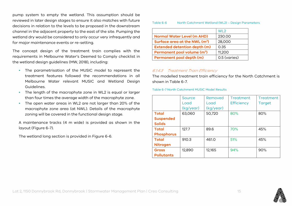
Lot 2, 1150 Donnybrook Rd, Donnybrook | Stormwater Management Plan | Creo Consulting 15
pump system to empty the wetland. This assumption should be reviewed in later design stages to ensure it also matches with future decisions in relation to the levels to be proposed in the downstream channel in the adjacent property to the east of the site. Pumping the wetland dry would be considered to only occur very infrequently and for major maintenance events or re-setting.
The concept design of the treatment train complies with the requirements in Melbourne Water’s Deemed to Comply checklist in the wetland design guidelines (MW, 2018), including:
‣ The parametrisation of the MUSIC model to represent the treatment features followed the recommendations in all Melbourne Water relevant MUSIC and Wetland Design Guidelines.
‣ The length of the macrophyte zone in WL2 is equal or larger than four times the average width of the macrophyte zone.
‣ The open water areas in WL2 are not larger than 20% of the macrophyte zone area (at NWL). Details of the macrophyte zoning will be covered in the functional design stage.
A maintenance tracks (4 m wide) is provided as shown in the layout (Figure 6-7).
The wetland long section is provided in Figure 6-6.
Table 6-6 North Catchment Wetland (WL2) – Design Parameters
WL2 Normal Water Level (m AHD) 230.00 Surface area at the NWL (m2) 28,000 Extended detention depth (m) 0.35 Permanent pool volume (m3) 11,200 Permanent pool depth (m) 0.5 (varies)
6.1.4.3 Treatment Train Efficiency The modelled treatment train efficiency for the North Catchment is shown in Table 6-7.
Table 6-7 North Catchment MUSIC Model Results
Source Load (kg/year)
Removed Load (kg/year)
Treatment Efficiency
Treatment Target
Total Suspended Solids
63,060 50,720 80% 80%
Total Phosphorus
127.7 89.6 70% 45%
Total Nitrogen
910.3 461.0 51% 45%
Gross Pollutants
12,890 12,165 94% 90%
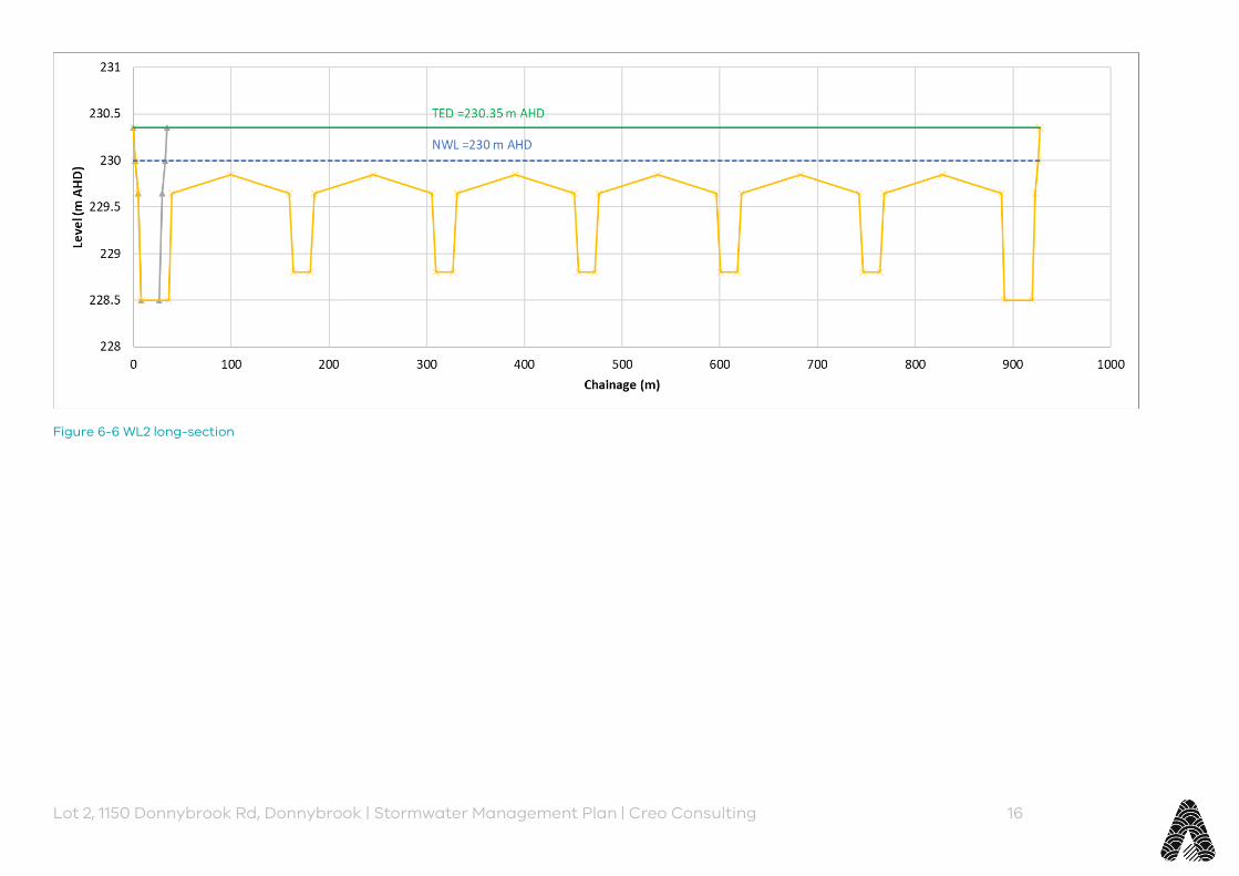
Lot 2, 1150 Donnybrook Rd, Donnybrook | Stormwater Management Plan | Creo Consulting 16
Figure 6-6 WL2 long-section
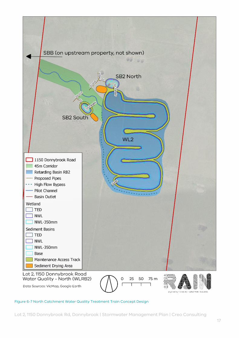
Lot 2, 1150 Donnybrook Rd, Donnybrook | Stormwater Management Plan | Creo Consulting 17
Figure 6-7 North Catchment Water Quality Treatment Train Concept Design
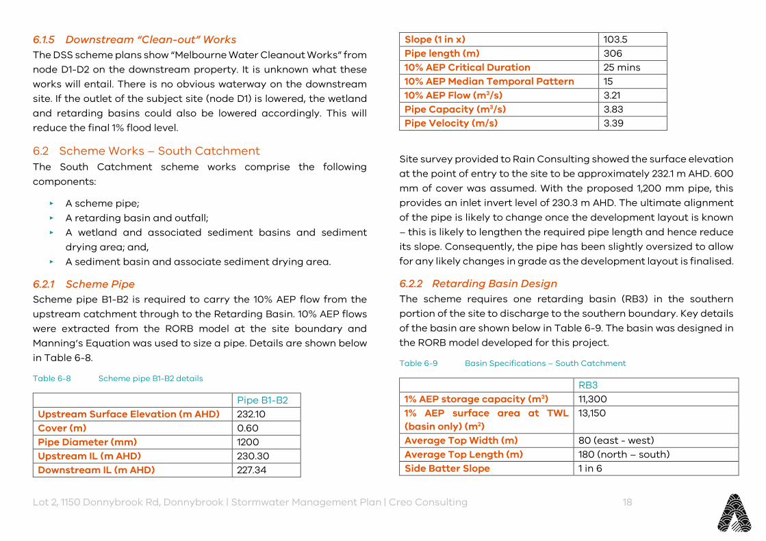
Lot 2, 1150 Donnybrook Rd, Donnybrook | Stormwater Management Plan | Creo Consulting 18
6.1.5 Downstream “Clean-out” Works The DSS scheme plans show “Melbourne Water Cleanout Works” from node D1-D2 on the downstream property. It is unknown what these works will entail. There is no obvious waterway on the downstream site. If the outlet of the subject site (node D1) is lowered, the wetland and retarding basins could also be lowered accordingly. This will reduce the final 1% flood level.
6.2 Scheme Works – South Catchment The South Catchment scheme works comprise the following components:
‣ A scheme pipe; ‣ A retarding basin and outfall; ‣ A wetland and associated sediment basins and sediment
drying area; and, ‣ A sediment basin and associate sediment drying area.
6.2.1 Scheme Pipe Scheme pipe B1-B2 is required to carry the 10% AEP flow from the upstream catchment through to the Retarding Basin. 10% AEP flows were extracted from the RORB model at the site boundary and Manning’s Equation was used to size a pipe. Details are shown below in Table 6-8.
Table 6-8 Scheme pipe B1-B2 details
Pipe B1-B2 Upstream Surface Elevation (m AHD) 232.10 Cover (m) 0.60 Pipe Diameter (mm) 1200 Upstream IL (m AHD) 230.30 Downstream IL (m AHD) 227.34
Slope (1 in x) 103.5 Pipe length (m) 306 10% AEP Critical Duration 25 mins 10% AEP Median Temporal Pattern 15 10% AEP Flow (m3/s) 3.21 Pipe Capacity (m3/s) 3.83 Pipe Velocity (m/s) 3.39
Site survey provided to Rain Consulting showed the surface elevation at the point of entry to the site to be approximately 232.1 m AHD. 600 mm of cover was assumed. With the proposed 1,200 mm pipe, this provides an inlet invert level of 230.3 m AHD. The ultimate alignment of the pipe is likely to change once the development layout is known – this is likely to lengthen the required pipe length and hence reduce its slope. Consequently, the pipe has been slightly oversized to allow for any likely changes in grade as the development layout is finalised.
6.2.2 Retarding Basin Design The scheme requires one retarding basin (RB3) in the southern portion of the site to discharge to the southern boundary. Key details of the basin are shown below in Table 6-9. The basin was designed in the RORB model developed for this project.
Table 6-9 Basin Specifications – South Catchment
RB3 1% AEP storage capacity (m3) 11,300 1% AEP surface area at TWL (basin only) (m2)
13,150
Average Top Width (m) 80 (east - west) Average Top Length (m) 180 (north – south) Side Batter Slope 1 in 6
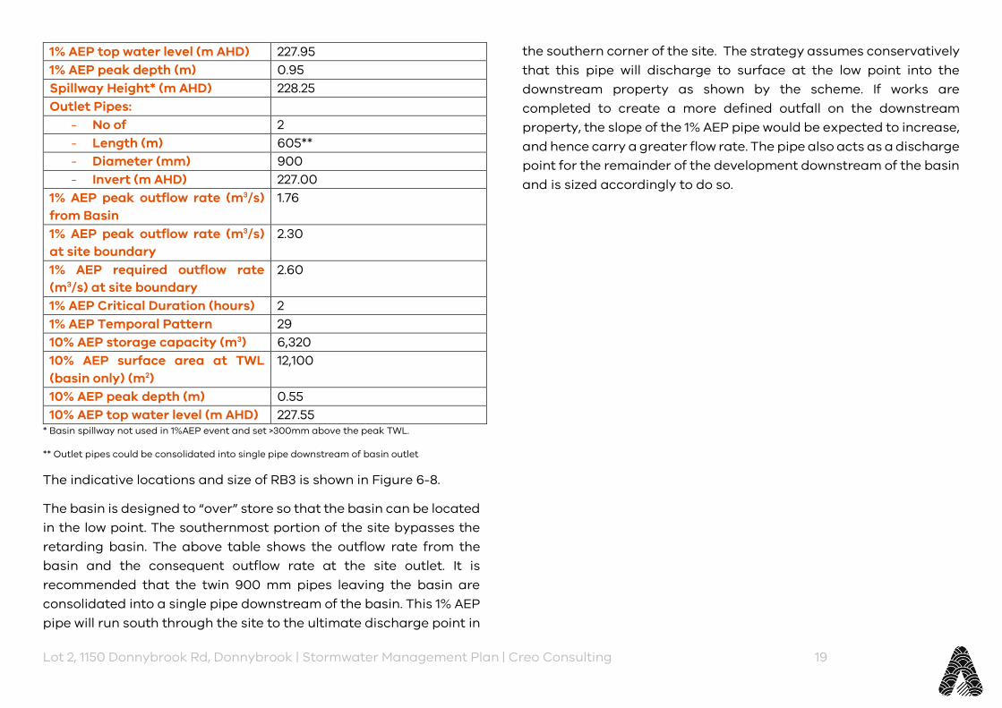
Lot 2, 1150 Donnybrook Rd, Donnybrook | Stormwater Management Plan | Creo Consulting 19
1% AEP top water level (m AHD) 227.95 1% AEP peak depth (m) 0.95 Spillway Height* (m AHD) 228.25 Outlet Pipes:
- No of 2 - Length (m) 605** - Diameter (mm) 900 - Invert (m AHD) 227.00
1% AEP peak outflow rate (m3/s) from Basin
1.76
1% AEP peak outflow rate (m3/s) at site boundary
2.30
1% AEP required outflow rate (m3/s) at site boundary
2.60
1% AEP Critical Duration (hours) 2 1% AEP Temporal Pattern 29 10% AEP storage capacity (m3) 6,320 10% AEP surface area at TWL (basin only) (m2)
12,100
10% AEP peak depth (m) 0.55 10% AEP top water level (m AHD) 227.55
* Basin spillway not used in 1%AEP event and set >300mm above the peak TWL.
** Outlet pipes could be consolidated into single pipe downstream of basin outlet
The indicative locations and size of RB3 is shown in Figure 6-8.
The basin is designed to “over” store so that the basin can be located in the low point. The southernmost portion of the site bypasses the retarding basin. The above table shows the outflow rate from the basin and the consequent outflow rate at the site outlet. It is recommended that the twin 900 mm pipes leaving the basin are consolidated into a single pipe downstream of the basin. This 1% AEP pipe will run south through the site to the ultimate discharge point in
the southern corner of the site. The strategy assumes conservatively that this pipe will discharge to surface at the low point into the downstream property as shown by the scheme. If works are completed to create a more defined outfall on the downstream property, the slope of the 1% AEP pipe would be expected to increase, and hence carry a greater flow rate. The pipe also acts as a discharge point for the remainder of the development downstream of the basin and is sized accordingly to do so.
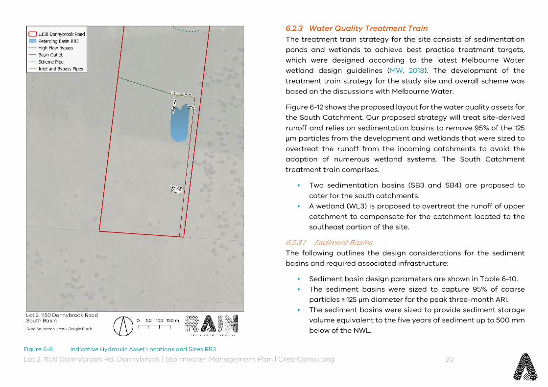
Lot 2, 1150 Donnybrook Rd, Donnybrook | Stormwater Management Plan | Creo Consulting 20
Figure 6-8 Indicative Hydraulic Asset Locations and Sizes RB3
6.2.3 Water Quality Treatment Train The treatment train strategy for the site consists of sedimentation ponds and wetlands to achieve best practice treatment targets, which were designed according to the latest Melbourne Water wetland design guidelines (MW, 2018). The development of the treatment train strategy for the study site and overall scheme was based on the discussions with Melbourne Water.
Figure 6-12 shows the proposed layout for the water quality assets for the South Catchment. Our proposed strategy will treat site-derived runoff and relies on sedimentation basins to remove 95% of the 125 µm particles from the development and wetlands that were sized to overtreat the runoff from the incoming catchments to avoid the adoption of numerous wetland systems. The South Catchment treatment train comprises:
‣ Two sedimentation basins (SB3 and SB4) are proposed to cater for the south catchments.
‣ A wetland (WL3) is proposed to overtreat the runoff of upper catchment to compensate for the catchment located to the southeast portion of the site.
6.2.3.1 Sediment Basins The following outlines the design considerations for the sediment basins and required associated infrastructure:
‣ Sediment basin design parameters are shown in Table 6-10. ‣ The sediment basins were sized to capture 95% of coarse
particles ≥ 125 µm diameter for the peak three-month ARI. ‣ The sediment basins were sized to provide sediment storage
volume equivalent to the five years of sediment up to 500 mm below of the NWL.
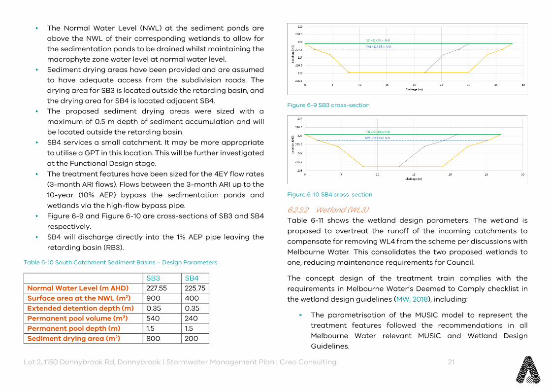
Lot 2, 1150 Donnybrook Rd, Donnybrook | Stormwater Management Plan | Creo Consulting 21
‣ The Normal Water Level (NWL) at the sediment ponds are above the NWL of their corresponding wetlands to allow for the sedimentation ponds to be drained whilst maintaining the macrophyte zone water level at normal water level.
‣ Sediment drying areas have been provided and are assumed to have adequate access from the subdivision roads. The drying area for SB3 is located outside the retarding basin, and the drying area for SB4 is located adjacent SB4.
‣ The proposed sediment drying areas were sized with a maximum of 0.5 m depth of sediment accumulation and will be located outside the retarding basin.
‣ SB4 services a small catchment. It may be more appropriate to utilise a GPT in this location. This will be further investigated at the Functional Design stage.
‣ The treatment features have been sized for the 4EY flow rates (3-month ARI flows). Flows between the 3-month ARI up to the 10-year (10% AEP) bypass the sedimentation ponds and wetlands via the high-flow bypass pipe.
‣ Figure 6-9 and Figure 6-10 are cross-sections of SB3 and SB4 respectively.
‣ SB4 will discharge directly into the 1% AEP pipe leaving the retarding basin (RB3).
Table 6-10 South Catchment Sediment Basins – Design Parameters
SB3 SB4 Normal Water Level (m AHD) 227.55 225.75 Surface area at the NWL (m2) 900 400 Extended detention depth (m) 0.35 0.35 Permanent pool volume (m3) 540 240 Permanent pool depth (m) 1.5 1.5 Sediment drying area (m2) 800 200
Figure 6-9 SB3 cross-section
Figure 6-10 SB4 cross-section
6.2.3.2 Wetland (WL3) Table 6-11 shows the wetland design parameters. The wetland is proposed to overtreat the runoff of the incoming catchments to compensate for removing WL4 from the scheme per discussions with Melbourne Water. This consolidates the two proposed wetlands to one, reducing maintenance requirements for Council.
The concept design of the treatment train complies with the requirements in Melbourne Water’s Deemed to Comply checklist in the wetland design guidelines (MW, 2018), including:
‣ The parametrisation of the MUSIC model to represent the treatment features followed the recommendations in all Melbourne Water relevant MUSIC and Wetland Design Guidelines.

Lot 2, 1150 Donnybrook Rd, Donnybrook | Stormwater Management Plan | Creo Consulting 22
‣ The length of the macrophyte zone in WL3 is equal or larger than four times the average width of the macrophyte zone.
‣ The open water areas in WL3 are not larger than 20% of the macrophyte zone area (at NWL). Details of the macrophyte zoning will be covered in the functional design stage.
A maintenance track (4 m wide) is provided as shown in the layout (Figure 6-12). The wetland long section is provided in Figure 6-11.
Table 6-11 South Catchment Wetland (WL3) – Design Parameters
WL3 Normal Water Level (m AHD) 227.00 Surface area at the NWL (m2) 8,900 Extended detention depth (m) 0.35 Permanent pool volume (m3) 3,560 Permanent pool depth (m) 0.5 (varies)
6.2.3.3 Treatment Train Efficiency The modelled treatment train efficiency is shown in Table 6-12.
Table 6-12 South Catchment MUSIC Model Results
Source Load (kg/year)
Removed Load (kg/year)
Treatment Efficiency
Treatment Target
Total Suspended Solids
26,360 20,860 79% 80%
Total Phosphorus
53.5 36.0 67% 45%
Total Nitrogen
383.2 175.0 46% 45%
Gross Pollutants
5,310 5,020 95% 90%
6.3 Overall Site Water Quality Treatment Train (North and South Catchments)
The treatment train results for the entire scheme leaving the site are shown in Table 6-13.
Table 6-13 MUSIC Model Results Whole of Scheme
Source Load (kg/year)
Removed Load (kg/year)
Treatment Efficiency
Treatment Target
Total Suspended Solids
89,420 71,530 80% 80%
Total Phosphorus 181.2 125.6 69% 45% Total Nitrogen 1,293.5 636.0 49% 45% Gross Pollutants 18,200 17,185 94% 90%
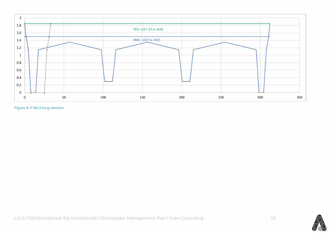
Lot 2, 1150 Donnybrook Rd, Donnybrook | Stormwater Management Plan | Creo Consulting 23
Figure 6-11 WL3 long-section

Lot 2, 1150 Donnybrook Rd, Donnybrook | Stormwater Management Plan | Creo Consulting 24
Figure 6-12 South Catchment Water Quality Treatment Train Concept Design
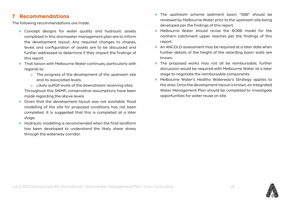
Lot 2, 1150 Donnybrook Rd, Donnybrook | Stormwater Management Plan | Creo Consulting 25
7 Recommendations The following recommendations are made:
Concept designs for water quality and hydraulic assets completed in this stormwater management plan are to inform the development layout. Any required changes to shapes, levels and configuration of assets are to be discussed and further addressed to determine if they impact the findings of this report.
That liaison with Melbourne Water continues, particularly with regards to:
o The progress of the development of the upstream site and its associated levels.
o Likely outfall levels of the downstream receiving sites. Throughout this SWMP, conservative assumptions have been made regarding the above levels.
Given that the development layout was not available, flood modelling of the site for proposed conditions has not been completed. It is suggested that this is completed at a later stage.
Hydraulic modelling is recommended when the final landform has been developed to understand the likely shear stress through the waterway corridor.
The upstream scheme sediment basin “SBB” should be reviewed by Melbourne Water prior to the upstream site being developed per the findings of this report.
Melbourne Water should revise the RORB model for the northern catchment upper reaches per the findings of this report.
An ANCOLD assessment may be required at a later date when further details of the height of the retarding basin walls are known.
The proposed works may not all be reimbursable, further discussion would be required with Melbourne Water at a later stage to negotiate the reimbursable components.
Melbourne Water’s Healthy Waterway’s Strategy applies to the area. Once the development layout is known, an Integrated Water Management Plan should be completed to investigate opportunities for water reuse on site.

Lot 2, 1150 Donnybrook Rd, Donnybrook | Stormwater Management Plan | Creo Consulting 26
8 References Melbourne Water, 2009 – Constructed Waterways in Urban Developments Guidelines, 2009.
Melbourne Water, 2013 – Waterway Corridors: Guidelines for greenfield development areas within the Port Phillip and Westernport Region. Version 1, October 2013.
Melbourne Water, 2018 – Healthy Waterways Strategy, 2018
Melbourne Water, 2018 - MUSIC Guidelines. Input parameters and modelling approaches for MUSIC users in Melbourne Water’s service area, 2018
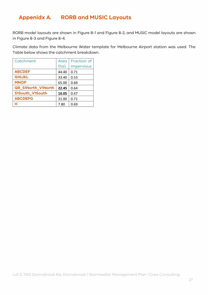
Lot 2, 1150 Donnybrook Rd, Donnybrook | Stormwater Management Plan | Creo Consulting 27
Appenidx A. RORB and MUSIC Layouts
RORB model layouts are shown in Figure 8-1 and Figure 8-2, and MUSIC model layouts are shown in Figure 8-3 and Figure 8-4.
Climate data from the Melbourne Water template for Melbourne Airport station was used. The Table below shows the catchment breakdown.
Catchment Area (ha)
Fraction of Impervious
ABCDEF 44.40 0.71 GHIJKL 33.40 0.53 MNOP 65.00 0.69 QR_S1North_V1North 22.45 0.64 S1South_V1South 10.05 0.47 ABCDEFG 31.00 0.71 H 7.80 0.69
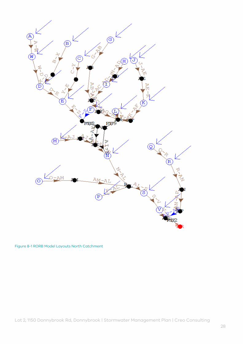
Lot 2, 1150 Donnybrook Rd, Donnybrook | Stormwater Management Plan | Creo Consulting 28
Figure 8-1 RORB Model Layouts North Catchment
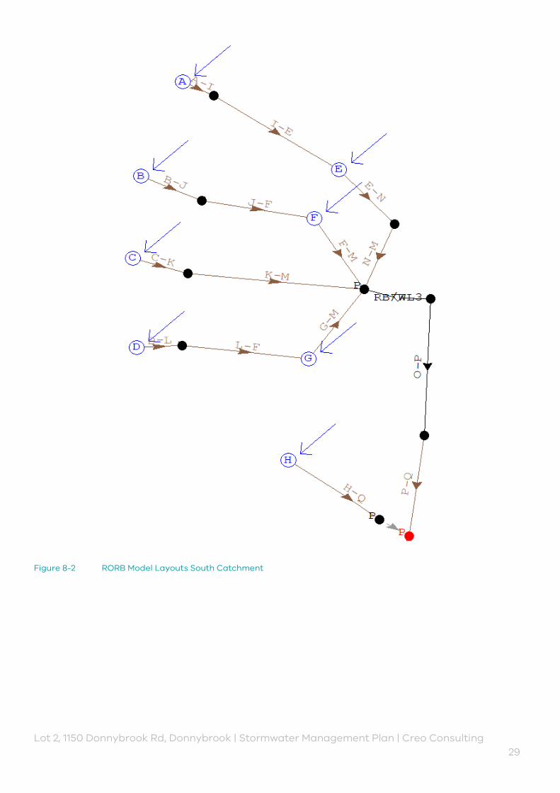
Lot 2, 1150 Donnybrook Rd, Donnybrook | Stormwater Management Plan | Creo Consulting 29
Figure 8-2 RORB Model Layouts South Catchment

Lot 2, 1150 Donnybrook Rd, Donnybrook | Stormwater Management Plan | Creo Consulting 30
Figure 8-3 Music Model Layout North
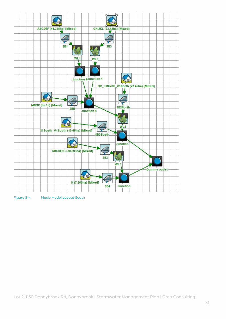
Lot 2, 1150 Donnybrook Rd, Donnybrook | Stormwater Management Plan | Creo Consulting 31
Figure 8-4 Music Model Layout South
Lot 2, 1150 Donnybrook Rd, Donnybrook | Stormwater Management Plan | Creo Consulting 32
Appenidx B. Melbourne Water Meeting Minutes (29/09/2019)
Lot 2, 1150 Donnybrook Rd, Donnybrook | Stormwater Management Plan | Creo Consulting 33
Project: 1150 Donnybrook Road, Donnybrook
Date: 26 September 2019
Time: 3 – 4 pm
Location: Melbourne Water
Attendees: Binh Nguyen (MW), Mayank Khanna (MW), Rianda Mills (Rain), Luke Cunningham (Rain)
Meeting Goal: Broadly discuss water quality and quantity requirements for the site.
Actions: Rain actions in Orange, MW actions in Purple
Key Discussion Points
Luke provided a site overview and summary of the Rain scope of work.
North Portion of Site
Site immediately adjacent to the west has not commenced. As far as MW know, nobody is active on that site – MK
Discussion around the inflow level from the west. o Luke suggested 500 mm below NGL. o Further discussion that duel large gas mains run through neighbouring site and they
may influence the level that enters our site. o Rain to check to see if as cons for the gas main are available. o If gas main is forcing inlet to the site to be lower, we may run into issues where the RB
drowns the upstream pipe. ▪ Council may not support flap gates to protect upstream (MK) ▪ Drowning the upstream pipe in a 1% AEP may not be an issue (BN)
o Development (Olivine) further upstream being designed by SMEC – they may know more about the gas line (Alan Bairn (?) is contact). Mayank to check if he has anything he can forward Rain from SMEC to help, or put Rain in contact with Alan.
o Ultimate outcome for this project may be that sensitivity checks required as we won’t know the inlet level with any certainty until upstream developer moves in.
Waterway through the site to the wetland/RB will be determined by hydraulic width. All agreed that it’s likely to be around 60m corridor. Rain to check.
Discussion around the Retarding Basin: o Outlet in the RORB model is 229.2 m AHD and feature survey at property boundary
suggests 230.0 m AHD. o No plans at this stage for the downstream property as no PSP, hence for now we will
need to assume discharge to the surface of downstream site (MW). o Rain to investigate lifting RB and wetland up around 800 mm to accommodate. o If future PSP dictates waterway or pipe through downstream property, basin and
wetland can easily be lowered again in future iterations. Rain to discuss these options in final report but to assume discharge to surface – MW agreed.
o ANCOLD will likely be triggered (MK), Rain acknowledged this and will flag it for functional stage.
Lot 2, 1150 Donnybrook Rd, Donnybrook | Stormwater Management Plan | Creo Consulting 34
Discussion around wetlands: o Luke presented concept for a split balanced wetland with a high-flow bypass through
the centre. o Binh suggested to make north wetland bigger and send waterway south around it
and over-treat so that the southern catchment is accommodated. 1 wetland is the preference from MW and likely from Council too (relevant to south)
o Rain to further model the wetland to investigate if it can be combined into one and still have an effective high flow bypass.
o MW to Confirm that single basin which overtreats is acceptable.
South Portion of Site
Luke presented the proposed concept of trying to consolidate the 2 southern outlets into 1. o MW agree this would be a good outcome.
Luke asked if we could (similar to the idea for the north) overtreat in the wetland and then not treat the small (8-9 ha) small catchment in the south.
o MW agree that this again would be good as 1 wetland is better than 2 for maintenance. Rain to confirm if this is possible via MUSIC.
o MW to Confirm that single basin which overtreats is acceptable. Outlet for the south needs to assume direct to surface also. No plans currently downstream
– PSP does not exist, therefore exact future outlet location not known. o Rain to discuss potential options in report, but assume discharge to surface from
basin.
General Discussion Items
Discussion was held around whether ARR87 or ARR19 should be used as the information provided is conflicting. MW confirmed to update everything to ARR19 (BN)
A small mistake has been identified in the RORB modelling for developed conditions in the north catchment. A new subarea between A and B appears (named ‘W’) – isn’t in the MUSIC model so suggest it could be an error. Unlikely to impact this site. MW to note.
Retarding Basins general o Basins all require 600mm freeboard (MK) o 3m deep basin from bank to base of wetland may be too deep (BN)
▪ Mayank suggests identification of land take for different depth basins to understand sensitivities. Rain to consider sensitivity test as part of investigation.
o Luke checked what MWs opinion on sediment basins within the basins are: ▪ All ok if they’re above the 10% AEP level. Same with dry-out and access tracks
(MW). Carolina B is the expert on the scheme – she’s away at the moment and not back until 6th
October. MW made particular note that all works we propose may not be reimbursable. We need to
not assume this moving forward and further guidance can be provided when a solid plan is available.
Mayank suggested that the Healthy Waterways Strategy applies and that there will be a requirement to reduce flows in the area.
Lot 2, 1150 Donnybrook Rd, Donnybrook | Stormwater Management Plan | Creo Consulting 35
o Not within scope of the SWMP but site will likely need an Integrated Water Management Plan down the line to look at alternate water options and reuse. Rain to have this as a recommendation in the report. MW agreed that this is appropriate for now.
MEETING CLOSE.
Lot 2, 1150 Donnybrook Rd, Donnybrook | Stormwater Management Plan | Creo Consulting 36
Appenidx C. Melbourne Water Pre-Development Advice
30 September 2019
Luke Cunningham Rain Consulting 58a Glenola Road
Chelsea VIC 3196 Dear Luke,
Proposal: Pre-development advice Site location: Lot No 2, 1150 DONNYBROOK ROAD DONNYBROOK 3064
Melbourne Water reference: MWA-1150900
Date referred: 04/09/2019
Development Services Scheme: Woodstock West (4566) Development Service Scheme.
Thank you for your application requesting pre-development information for the above mentioned property. The following development advice is applicable to the property :
Drainage Agreement
Prior to the issue of a Statement of Compliance, the Owner must enter into and comply with an agreement with Melbourne Water Corporation, under the Water Act
1989, for the provision of drainage works and the acceptance of surface and storm water from the subject land directly or indirectly into Melbourne Water's drainage system. The agreement may include the following components.
Drainage Contributions
A drainage agreement usually includes the payment of drainage contributions, where a property is being developed. These contributions are used to recover the cost of constructing drainage works such as:
Main drains, retarding basins, waterway improvements and flood mitigation works that will mitigate hydraulic impacts of the development/subdivision.
Wetlands and Water Sensitive Urban Design WSUD elements to mitigate stormwater quality risks to Melbourne Water's drainage system.
The contributions are based on the increased load to the drainage system created by
the development. The site in question is located within Melbourne Water's Woodstock West (4566)
Development Services Scheme. Melbourne Water advises that the current residential contribution rates are:
Woodstock West (4566) Status: Preliminary
$125,239/Ha, comprising of a hydraulic charge of $88,221/Ha and a
stormwater quality charge of $37,018/Ha
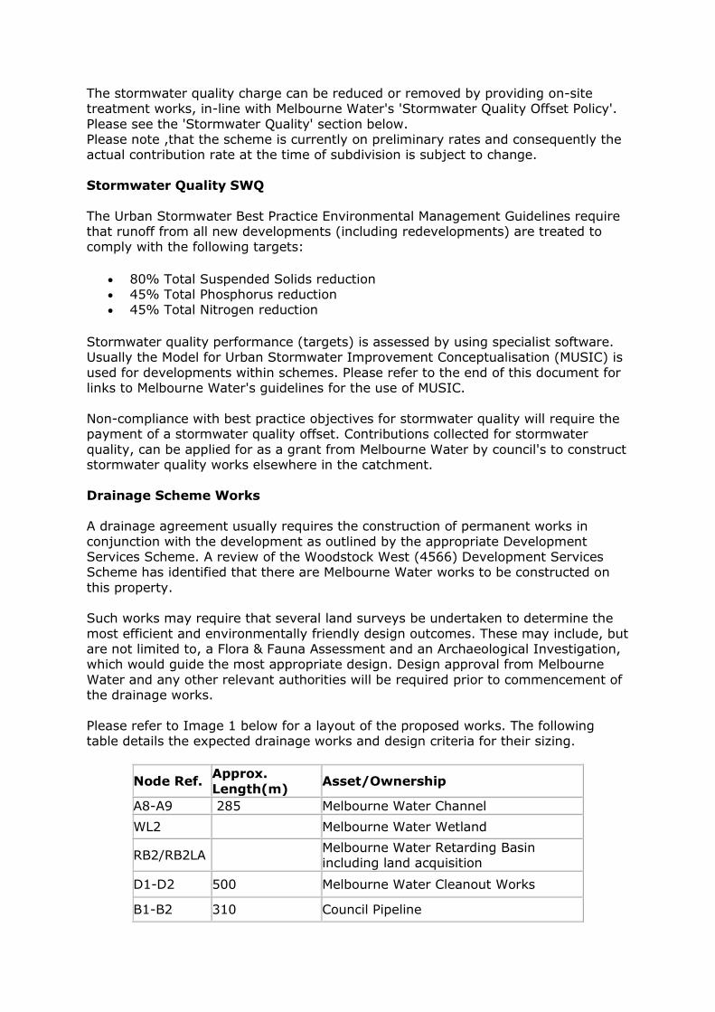
The stormwater quality charge can be reduced or removed by providing on-site treatment works, in-line with Melbourne Water's 'Stormwater Quality Offset Policy'.
Please see the 'Stormwater Quality' section below. Please note ,that the scheme is currently on preliminary rates and consequently the actual contribution rate at the time of subdivision is subject to change.
Stormwater Quality SWQ
The Urban Stormwater Best Practice Environmental Management Guidelines require that runoff from all new developments (including redevelopments) are treated to comply with the following targets:
80% Total Suspended Solids reduction 45% Total Phosphorus reduction 45% Total Nitrogen reduction
Stormwater quality performance (targets) is assessed by using specialist software. Usually the Model for Urban Stormwater Improvement Conceptualisation (MUSIC) is
used for developments within schemes. Please refer to the end of this document for links to Melbourne Water's guidelines for the use of MUSIC.
Non-compliance with best practice objectives for stormwater quality will require the payment of a stormwater quality offset. Contributions collected for stormwater
quality, can be applied for as a grant from Melbourne Water by council's to construct stormwater quality works elsewhere in the catchment.
Drainage Scheme Works A drainage agreement usually requires the construction of permanent works in
conjunction with the development as outlined by the appropriate Development Services Scheme. A review of the Woodstock West (4566) Development Services Scheme has identified that there are Melbourne Water works to be constructed on
this property. Such works may require that several land surveys be undertaken to determine the
most efficient and environmentally friendly design outcomes. These may include, but are not limited to, a Flora & Fauna Assessment and an Archaeological Investigation, which would guide the most appropriate design. Design approval from Melbourne
Water and any other relevant authorities will be required prior to commencement of the drainage works.
Please refer to Image 1 below for a layout of the proposed works. The following table details the expected drainage works and design criteria for their sizing.
Node Ref. Approx.
Length(m) Asset/Ownership
A8-A9 285 Melbourne Water Channel
WL2 Melbourne Water Wetland
RB2/RB2LA Melbourne Water Retarding Basin including land acquisition
D1-D2 500 Melbourne Water Cleanout Works
B1-B2 310 Council Pipeline

WL3 Council Wetland
RB3/ RB3LA Council Retarding Basin including land
acquisition
WL4/ WL4LA
Council Wetland including land acquisition
Please be advised that this information may be refined and/or modified upon any application for a works or Non-works offer.
Image 1: Property boarder and proposed works
Specific Property Advice
The Melbourne Water Woodstock West (4566) Development Service Schemes are currently in a preliminary stage. This means that engineering
investigations and cost estimates have been undertaken though not finalised. Preliminary contribution rates currently apply.
The developer must negotiate any temporary works with downstream
landowner(s) to obtain a free draining outfall solution through their
property/ies. Approval must be granted and forwarded to Melbourne Water before construction of the drainage works commences.
Please note any costs associated with temporary works required to ensure
adequate outfall are not reimbursed by Melbourne Water and are to be
borne by the developer. The developer will need to negotiate the alignment of the permanent and temporary works with the affected
landowners. Approval will need to be granted and forwarded to Melbourne Water before construction of the drainage works begins.
When designing Melbourne Water works including channel and wetland, consideration will need to be given to the invert levels in conjunction with
the gas main crossing on the neighbouring property.
The developer is to negotiate with downstream landowners to obtain a free draining outfall through their property. Approval is to be forwarded to Melbourne Water for our records prior to construction commencing.
The development is to make provision for overland flows from the
upstream catchment utilising roads and/or reserve. Alignment of roads and reserves with any adjoining estates must ensure continuity and provide uninterrupted conveyance of overland flows.
A stormwater management strategy must be submitted and approved by
Melbourne Water and Council. The strategy must demonstrate the following:
o The proposed alignment for any 20% AEP drainage infrastructure; o The 1% AEP flood extent, water surface elevations and the direction
of major overland flow paths; o Functional Layout plan and staging plan including proposed scheme
works and associated timing of works; o That the layout adequately accommodates the overland flows; o The details of the outfall/s for the development and calculations of
the flow volumes for the 1% AEP storm event within the property; o Designs addressing the interface of lots adjacent to a drainage
reserve, must be prepared to the satisfaction of Council and Melbourne Water;
o Stormwater runoff from the subdivision will achieve State Environment Protection Policy (Waters of Victoria) objectives for
environmental management of stormwater; o Concept design plans and MUSIC model for any Melbourne Water
Retarding Basins or Wetlands demonstrating that the designated
surface area can accommodate the required stormwater storage and treatment assets in accordance with Melbourne Water’s
Constructed Wetland and Retarding Basin Guidelines;
Overland Flow Paths Melbourne Water expects that upon any application for certification of any
subdivision plan associated with the property, due consideration must be given to the alignment of roads and reserves with any adjoining estates, to ensure continuity and provide uninterrupted conveyance of overland flows. These overland flow paths
must be designed in accordance with the safety criteria outlined in the Standards and Specifications section on the Planning and Building of Melbourne Water's website.
Before starting any works, a separate application, direct to Melbourne Water, must be made for any new or modified storm water connection to Melbourne Water's
drains or watercourses. Before accepting an application, evidence must be provided demonstrating that council has considered that it is not feasible to connect to the local drainage system.
Water Sensitive Urban Design WSUD
WSUD is a design process that enables localised collection and treatment of stormwater runoff. Melbourne Water acknowledges the potential for WSUD to be incorporated into the development to enable sustainable management of stormwater
across the property and to compliment the social and environmental values of the area.
Melbourne Water recommends that initiatives such as sediment ponds, bio-filtration systems, grassed swales, grey water re-use, rainwater tanks and porous soils be
considered in the design of the development. Stormwater runoff from paved areas can also be a valuable resource for irrigating trees, grassed areas and landscaped garden beds.
Offer Application
Prior to any application for an offer of drainage contributions, Melbourne Water requests that you forward a drainage strategy demonstrating that the proposed drainage plan for the property coincides with the intent of Melbourne Water's
Woodstock West (4566) Development Services Scheme. The following information should be included within the strategy:
General site information Options for the proposed drainage of the property Consideration for Water Sensitive Urban Design
Advice Links
For further information on Melbourne Water's role in planning please refer to the following links:

Contribution Rates: https://www.melbournewater.com.au/planning-and-building/developer-guides-and-resources/drainage-schemes-and-
contribution-rates-0-2
Drainage Schemes: https://www.melbournewater.com.au/planning-and-building/developer-guides-and-resources/drainage-schemes-and-contribution-rates
Water Sensitive Urban
Design- https://www.melbournewater.com.au/planning-and-building/stormwater-management/introduction-wsud
Reducing Water Quality Contributions/Stormwater Offset Rate review - https://www.melbournewater.com.au/planning-and-building/developer-
guides-and-resources/drainage-schemes-and-contribution-rates-0-3
Overland Flow Paths (These overland flow paths will need to be designed in accordance with the safety criteria outlined in the Standards and Specifications section of Melbourne Water's Planning and Building website
found on https://www.melbournewater.com.au/planning-and-building/developer-guides-and-resources/standards-and-specifications
Working near or Connection to MW assets-https://www.melbournewater.com.au/planning-and-building/work-or-build-
near-our-assets-or-easements
Stormwater Quality: The Urban Stormwater Best Practice Environmental Management Guidelines require that runoff from all new developments
(including redevelopments) be treated to comply with the following, 'Best Practice' standards criteria: Removal of 80% of the suspended solid annual load, 45% of total phosphorus and 45% of total nitrogen annual loads.
http://www.publish.csiro.au/book/2190
Disclaimers The feasibility information provided in this email is conceptual/indicative only and
must be used in conjunction with an informed catchment analysis when undertaking the detailed design.
Under the QA process the consultant is required to perform their own informed catchment analysis and calculations for the design of scheme assets which reflects the actual development and on ground conditions. As a part of the functional
design process your calculations, assumptions, models and catchment analysis are to be submitted for our acceptance/records.
Please note that as schemes develop and Melbourne Water receives additional information, the conceptual/indicative advice you have been provided as part of the feasibility request may now be outdated. Under the QA process it is the
responsibility of the consultant to certify that all information provided to Melbourne Water is correct having completed their own detailed catchment analysis.
This information is preliminary and forms no contractual agreement between your company and Melbourne Water. Melbourne Water reserves the right to alter any or all of the information provide in this letter.

For general development enquiries contact our Customer Service Centre on 131 722.
Regards,
Achira Weerasinghe Urban Growth Services Cc:,,Email:
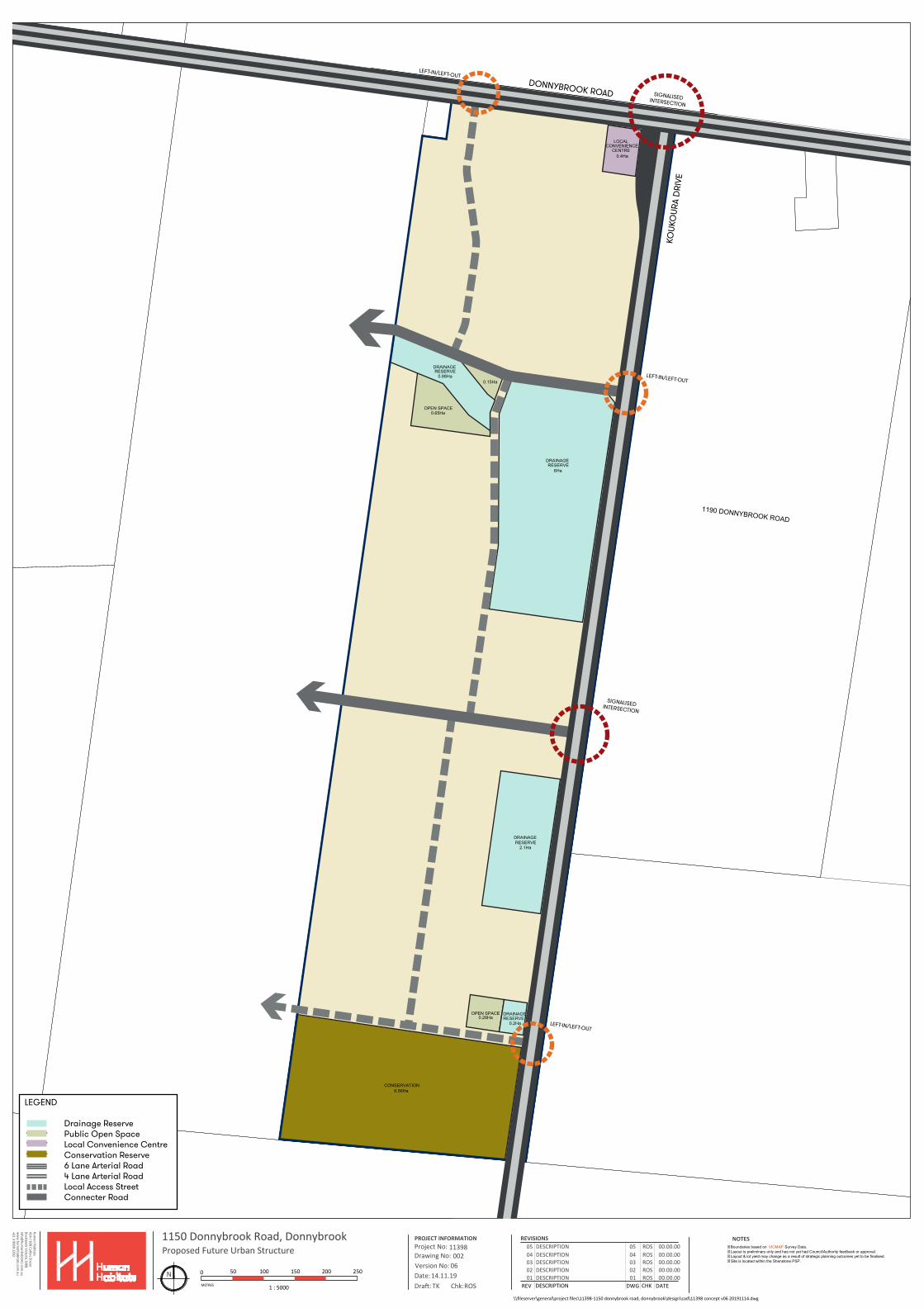
DONNYBROOK ROAD
1190 DONNYBROOK ROAD
Human Habitats
424 / 838 Collins StreetDocklands Victoria 3008info@
humanhabitats.com
.auw
ww
.humanhabitats.com
.au+61 3 9909 2202 Proposed Future Urban Structure 002Drawing No:
DATEREV DESCRIPTION DWG CHK
PROJECT INFORMATIONProject No:
Date:Version No:
REVISIONS
Dra : Chk:
1150 Donnybrook Road, Donnybrook11398
0614.11.19TK ROS
0102030405
DESCRIPTION 01 ROS 00.00.00DESCRIPTION ROS 00.00.00DESCRIPTION ROS 00.00.00DESCRIPTION ROS 00.00.00DESCRIPTION ROS 00.00.00
02030405
0
1 : 5000
50 100 150 200 250
METRES
NOTES
\\fileserver\general\project files\11398-1150 donnybrook road, donnybrook\design\cad\11398 concept v06 20191114.dwg
N
�Boundaries based on VICMAP Survey Data.� Layout is preliminary only and has not yet had Council/Authority feedback or approval.� Layout & lot yield may change as a result of strategic planning outcomes yet to be finalised.� Site is located within the Shenstone PSP.
DRAINAGERESERVE
0.88Ha
0.65Ha
0.15Ha
DRAINAGERESERVE
6Ha
DRAINAGERESERVE
2.1Ha
CONSERVATION6.56Ha
OPEN SPACE
DRAINAGERESERVE
LOCALCONVENIENCE
CENTRE0.4Ha
OPEN SPACE0.28Ha
0.2Ha
LEGEND
Drainage Reserve Public Open Space Local Convenience Centre Conservation Reserve 6 Lane Arterial Road 4 Lane Arterial Road Local Access Street Connecter Road
DONNYBROOK ROAD SIGNALISED INTERSECTION
LEFT-IN/LEFT-OUT
LEFT-IN/LEFT-OUT
LEFT-IN/LEFT-OUT
SIGNALISED INTERSECTION
KOUK
OUR
A D
RIVE