NG-1 1150 / 1500 / 2000 / 3000 Stand-Alone Nitrogen ...
85
NG-1 1150 / 1500 / 2000 / 3000 Stand-Alone Nitrogen Generator System Installation Manual TFP1275 APRIL 2021
-
Upload
khangminh22 -
Category
Documents
-
view
0 -
download
0
Transcript of NG-1 1150 / 1500 / 2000 / 3000 Stand-Alone Nitrogen ...

NG-1 1150 / 1500 / 2000 / 3000 Stand-Alone Nitrogen Generator System Installation ManualTFP1275 APRIL 2021

TFP1275 Page 1 of 84
Table of Contents
1. General ..……………………………………………………………………………………………………………….. 2
a. Safety b. System and Product Information c. Technical Specifications d. Operational Information
2. Start-Up and Operational Procedures ………………....………………………………………….……. 17
a. Installation b. Start-Up Procedure c. Normal Operation d. Fire Sprinkler System Maintenance Procedure
3. Sequence of Operation …………………………………………………………………………………………. 26
4. Auxiliary Equipment ..……………………………………………………………………………………………. 30
a. Oxygen-Removal Vent – TYCO TAV-D Vent b. Oxygen-Removal Vent – TYCO TSV-D SMART Vent c. Monitoring – Corrosion Detection d. Monitoring – Nitrogen Purity Level
5. Commissioning………………………………………………………………………………………………………. 46
a. Commissioning Procedure b. Commissioning Checklist
6. Maintenance………………………………………………………………………………………………………….. 58
a. Safety, Maintenance, Troubleshooting Warnings b. Routine Checks c. Nitrogen Purity and Flow Rate d. Filter Replacement e. Vent Maintenance f. Generator Configuration Diagram g. Troubleshooting h. Wiring Diagrams
7. Appendix ……………………………………………………………………………………………………..……….. 82
a. System Summary b. Inspection, Testing, and Maintenance Report

TFP1275 Page 2 of 84
General
SAFETY
Safety Guidelines
The manual contains safety information that is important to know and understand. The information is provided for the safety of the installers, operators and users of the TYCO Nitrogen Generation Systems, as well as the nitrogen generation equipment.
The Installation and Operations Manual that is supplied with each nitrogen generation system must be read thoroughly and be completely understood prior to installing and operating the TYCO Nitrogen Generation System. All appropriate safety standards for the handling of gases as determined by local, state or national laws and regulations are to be followed at all times.
General Safety Information
IMPORTANT: Read all the safety information in the manual prior to operating the equipment. Use of the equipment in a manner not specified within the manual could impair the protection provided by the nitrogen generation system and could result in an unintended release of pressure which could cause serious injury or damage. Only qualified personnel can perform commissioning, servicing and repair procedures.
When handling, installing, or operating the nitrogen generation equipment, the personnel must employ safe engineering practices and observe all related local, state and national regulations, health, and safety procedures, and legal requirements for safety.
Ensure the nitrogen generation equipment is depressurized and electrically isolated, before performing any maintenance or troubleshooting instructions specified in this manual.
The warnings covered in this manual are the most known potential hazards, but by definition cannot be all-inclusive. If the user employs an operating procedure, item of equipment, or method of working that is not specifically recommended by Johnson Controls, the user must ensure that the equipment will not be damaged or become hazardous to any persons or property.
Cautions and Warnings
CAUTION: Do not install the TYCO Nitrogen Generator or Air Compressor Package in an area where ammonia, sulfur dioxide, hydrogen sulfide, mercaptans, chlorides, chlorine, oxides of nitrogen, acid fumes, solvent vent vapors, and ozone vapors or similar contaminates exist. The equipment can be damaged by ammonia and other vapors shortening membrane life.
WARNING: Do not operate the TYCO Nitrogen Generation System if damaged during shipment, handling or use. Damage could result in injury or property damage.

TFP1275 Page 3 of 84
WARNING: Operation of the nitrogen membrane above the rated design pressure could be hazardous. Do not connect the nitrogen generation equipment to compressed air sources that can exceed the maximum rated pressure without installing pressure controls and safety relief devices in the compressed air supply line
Specific procedures must be developed for maintenance and servicing of the equipment where the nitrogen membrane is located. Appropriate labels must be continuously displayed in all areas where personnel might be exposed to a nitrogen atmosphere under normal and abnormal conditions.
WARNING: Nitrogen is nontoxic and largely inert. Rapid release of nitrogen gas into an enclosed space displaces the oxygen and can cause an asphyxiation hazard.
Maintenance and Troubleshooting Warnings
1. Nitrogen Generator includes 120-240 VAC 50/60 Hz voltage inside cabinet – exercise caution and do not touch any wiring connections when power is applied to the unit.
2. Nitrogen Generator has hot surfaces inside cabinet when nitrogen generator is operating and after nitrogen generator has turned off – exercise caution when working on nitrogen generator while operating and after nitrogen generator has shut off. (Wear Hand Protection, where needed)
Lifting and Troubleshooting Instructions
Nitrogen Generators weigh in excess of 100 lbs (45 kg). When lifting and/or carrying a nitrogen generator, proper lifting and carrying techniques must be considered.
1. Keep a wide base of support – Feet should be shoulder-width apart with one knee slightly in front of the other.
2. Squat down bending at hips and knees – If needed, one knee on the floor and other knee in front, bent at a right angle.
3. Keep good posture - Look straight ahead with back straight, chest out, and shoulders back. 4. Slowly lift by straightening your hips and knees (not your back) - Keep your back straight, and
don't twist as you lift. 5. Hold the load as close to body as possible. 6. Use feet to change direction - Small steps. 7. Lead with hips as changing direction - Keep shoulders in line with hips as you move. 8. Set down load carefully - Squatting with the knees and hips only.

TFP1275 Page 4 of 84
SYSTEM and PRODUCT INFORMATION
Dry Pipe Nitrogen Inerting (DPNI)
Dry Pipe Nitrogen Inerting technology is used to control oxygen corrosion in dry pipe and/or preaction fire sprinkler systems. DPNI is executed by employing a “fill and purge” differential pressure cycle (breathing) within the sprinkler pipe network. The “fill and purge” pressure cycle consists of venting the system pressure by 3-5 psi (.2-.3 bar), followed by replacing the vented pressure back into the system. This breathing process uses a nitrogen rich gas stream, typically 98% or greater, for a specific length of time (typically 14 days or less), until a nitrogen-rich, or inert, atmosphere exists within the sprinkler pipe network. By changing the atmosphere inside the pipe network to 98% or higher nitrogen content, the available oxygen content is reduced to a level that will not allow appreciable corrosion of the fire sprinkler pipe. With the level of oxygen corrosion reduced to near zero the effective life of the fire sprinkler system is greatly extended. Systems that implement a DPNI corrosion control strategy should never develop leaks when maintained properly.
Dry Pipe Nitrogen Inerting Equipment
Nitrogen Generator
The TYCO Nitrogen Generator is an on-site nitrogen generation system that is designed to be installed in-line between the compressed air supply and the fire sprinkler system riser(s) in dry pipe and preaction fire sprinkler systems. The TYCO Nitrogen Generator cabinet includes three external ball valves, the inlet valve for connection to the compressed supply air, the outlet valve for connection to the fire sprinkler system(s), and the by-pass valve between the inlet and outlet valves to allow for nitrogen generator maintenance or sprinkler system “fast fill” needs. The TYCO Nitrogen Generator has been sized with an air compressor to meet the NFPA 13 30-minute fill requirement for dry pipe and preaction fire sprinkler systems. The TYCO Nitrogen Generator facilitates “fill and purge” breathing in the fire sprinkler system and has been paired with a TYCO TAV-D Vent or a TYCO TSV-D SMART Vent installed on the fire sprinkler riser.
Nitrogen Generator Features
The TYCO Nitrogen Generators with the “fill and purge” breathing technology include the following features:
• Removal of corrosive oxygen from the entire sprinkler system in fourteen (14) days or less • All equipment is installed in the sprinkler riser room for easier installation and servicing • No refrigerated dryers or nitrogen storage tanks required • Nitrogen generation system monitoring • Membrane separation technology with 20-year service life • Minimal maintenance requirements

TFP1275 Page 5 of 84
Oxygen Removal Vent
To completely remove the oxygen in a dry pipe or preaction fire sprinkler system, it is necessary to install a vent on the main riser of each fire sprinkler system. Vents allow for a system to breathe, which requires a 3-5 psig (.2-.3 bar) pressure range to facilitate removal of oxygen gas from the system. Supervisory nitrogen gas is supplied to the system until the air maintenance device reaches the high-end pressure. The vent slowly releases the gas mixture inside the sprinkler system through the restricted orifice until the system reaches the low-end pressure at which point supervisory nitrogen is supplied to the system again. This process is repeated numerous times until the atmosphere inside the piping network reaches at least 98% nitrogen. The vent is crucial for expedient mixing of the gas and elimination of oxygen inside the system within the specified timeframe. TYCO offers two (2) DPNI vents – the TSV-D SMART Vent and the TAV-D Vent. The TSV-D SMART Vent is an automated vent that when activated will open and vent for the necessary amount of time to achieve the desired inert inner pipe atmosphere, and close automatically when the process is completed. This process is initiated by depressing the “vent” pushbutton on the vent’s control panel. The TAV-D is a manual vent that requires an operator to open the vent’s isolation ball valve when venting is desired, and after a specified time (typically 14 days or less) when the breathing process is completed the operator must manually close the isolation ball valve on the vent.
Oxygen Removal Vent Features
The TYCO oxygen removal vents with the “fill and purge” breathing technology include the following features:
• Removal of corrosive oxygen from the entire sprinkler system in fourteen (14) days or less • All equipment is installed in the sprinkler riser room for easier installation and servicing • No support hanger required • Backpressure regulator preventing system depressurization from vent • In-line filter to protect restricted venting orifice from contamination
Recommended Monitoring Equipment
In-Line Corrosion Detectors
The TYCO In-Line Corrosion Detector (TILD) is designed to provide an early warning of corrosion activity within the fire sprinkler system. The TILD features a double wall construction that incorporates a thin milled section of pipe (.035” (0.9mm)) surrounded by a full thickness piece of pipe to detect and alert to the presence of corrosion activity. If corrosion occurs the milled section of the TILD will fail prior to the failure of any other section of the pipe wall. When the milled section fails it allows the system to pressurize the chamber outside the milled section of pipe which activates the attached pressure switch on the TILD. The pressure switch can be remotely monitored through a building monitoring system, or locally through the TYCO Remote Test Station (TRTI) which is included with the TILD.

TFP1275 Page 6 of 84
The TILD is placed at strategic locations within the fire sprinkler piping network where corrosion has the highest potential of occurring.
• Wet Systems - The TILD is located in high point of the sprinkler system, typically at the air/water interface in a branch line, where air will be trapped as the system is filled with water.
• Dry Systems - The TILD is located in a horizontal portion of the supply main piping where trapped water will accumulate.
SMART Gas Analyzer
The TYCO SMART Gas Analyzer provides continuous real-time nitrogen/oxygen concentration levels within a dry pipe or preaction fire sprinkler system. The analyzer samples discharge gas from an adjacent TYCO TAV-D Vent or TSV-D SMART Vent. It is equipped with programmable outputs for one of three different oxygen concentration levels (1%, 3%, and 5%), providing early warning to a user when the nitrogen concentration within the fire sprinkler system falls below the desired level. The TSGA is also equipped with an RS-485 port for optional remote control and monitoring and can also display either oxygen or nitrogen concentration.
Handheld Gas Analyzer
The TYCO handheld gas analyzer allows for quick, convenient reading of nitrogen gas purity levels. The gas analyzer can be connected to any of the sample ports on the TYCO devices such as the nitrogen generator or a vent. Additional sampling ports can be ordered and placed at any point on the systems where gas purity monitoring is desired.

TFP1275 Page 7 of 84
TECHNICAL SPECIFICATIONS
Nitrogen Generators NG-1 1150 Dimensions 24.5"(622mm) W x 52.5"(1,334mm) H x 8.5"(216mm) D Dimensions with Bypass Assembly 32.5"(826mm) W x 52.5"(1,334mm) H x 8.5"(216mm) D Weight 152 lbs (69kg) Air Compressor Output 14.3 SCFM/858 SCFH (405 L/min) Nitrogen Gas Output 4.0 SCFM/240 SCFH (113.3 L/min) Largest Single Zone Capacity @ 40 psig (2.8 bar) 1,150 gallons (4,353 Liters) Largest Single Zone Capacity @ 20 psig (1.4 bar) 2,300 gallons (8,706 Liters) Largest Cumulative System Capacity 6,500 gallons (24,605 Liters) NG-1 1500 Dimensions 24.5"(622mm) W x 52.5"(1,334mm) H x 8.5"(216mm) D Dimensions with Bypass Assembly 32.5"(826mm) W x 52.5"(1,334mm) H x 8.5"(216mm) D Weight 152 lbs (69kg) Air Compressor Output 24 SCFM/1,440 SCFH (680 L/min) Nitrogen Gas Output 4.0 SCFM/240 SCFH (113.3 L/min) Largest Single Zone Capacity @ 40 psig (2.8 bar) 2,025 gallons (7,666 Liters) Largest Single Zone Capacity @ 20 psig (1.4 bar) 4,050 gallons (15,331 Liters) Largest Cumulative System Capacity 11,000 gallons (41,640 Liters) NG-1 2000 Dimensions 24.5"(622mm) W x 76"(1,930mm) H x 12.5"(318mm) D Dimensions with Bypass Assembly 32"(813mm) W x 76"(1,930mm) H x 12.5"(318mm) D Weight 300 lbs (136kg) Air Compressor Output 24 SCFM/1,440 SCFH (688.1 L/min) Nitrogen Gas Output 7.1 SCFM/426 SCFH (201 L/min) Largest Single Zone Capacity @ 40 psig (2.8 bar) 2,025 gallons (7,666 Liters) Largest Single Zone Capacity @ 20 psig (1.4 bar) 4,050 gallons (15,331 Liters) Largest Cumulative System Capacity 18,500 gallons (70,030 Liters) NG-1 3000 Dimensions 24.5"(622mm) W x 76"(1,930mm) H x 12.5"(318mm) D Dimensions with Bypass Assembly 32"(813mm) W x 76"(1,930mm) H x 12.5"(318mm) D Weight 300 lbs (136kg) Air Compressor Output 35 SCFM/2,100 SCFH (991.1 L/min) Nitrogen Gas Output 9.2 SCFM/552 SCFH (260.1 L/min) Largest Single Zone Capacity @ 40 psig (2.8 bar) 2,900 gallons (10,978 Liters) Largest Single Zone Capacity @ 20 psig (1.4 bar) 5,800 gallons (21,955 Liters) Largest Cumulative System Capacity 22,500 gallons (85,172 Liters)

TFP1275 Page 8 of 84
Technical Specifications – All Generators Location Dry Indoor Use Altitude Up to 6,560 ft (2,000m) Temperature Range 40°F - 105°F (5°C - 40°C) Pollution Degree 2 Nitrogen Generator Cabinet Power Supply 120VAC/1ph/60Hz (230VAC/1 ph/50Hz) Power Consumption 2 Amps Overvoltage Category II Air Inlet Connection ½" NPT Female Nitrogen/Air Bypass Output Connection ½" NPT Female Drain Connection ¼" NPT Female Filter Replacement Part # TNGFLTS Nitrogen Quality
N2 Purity at Discharge: 98% (maximum of 2.0% oxygen) N2 Pressure at Discharge: Min: 15 psig (1 bar); Max: feed air pressure minus 15 psig (1 bar) N2 Water Dew Point: Less than -70°F (-57°C)
FM Approved – Standard 1035 UL Listed – 508A Industrial Control Panel CE Certification

TFP1275 Page 9 of 84
Air Compressors – AMERICAS Region TNGC-1150 (Vertical) Dimensions 20"(508mm) (L) x 32"(508mm) (W) x 70"(1,778mm) (H) Weight 435 lbs (197kg) Power Supply 460VAC/3 ph/60Hz – 7.6 Amps Power Supply (Optional) 208VAC/3 ph/60Hz – 17.5 Amps Air Compressor Output 14.3 SCFM/858 SCFH (405 L/min) Air Storage Tank Output Connection ½" NPT Female TNGC-1500/2000 (Vertical) Dimensions 23.6"(600mm) (L) x 38.1"(968mm) (W) x 70.1"(1,781mm) (H) Weight 573 lbs (260kg) Power Supply 460VAC/3 ph/60Hz - 11 Amps Power Supply (Optional) 208VAC/3 ph/60Hz – 25.3 Amps Air Compressor Output 24 SCFM/1,440 SCFH (688.1 L/min) Air Storage Tank Output Connection ½" NPT Female TNGC-1500/2000-2 (Duplex/Horizontal) Dimensions 84.2"(2,140mm) (L) x 34.6"(878mm) (W) x 48.2"(1,224mm) (H) Weight 1,265 lbs (574kg) Power Supply 460VAC/3 ph/60Hz - 11 Amps Power Supply (Optional) 208VAC/3 ph/60Hz – 25.3 Amps Air Compressor Output 24 SCFM/1,440 SCFH (688.1 L/min) Air Storage Tank Output Connection ½" NPT Female TNGC-3000 (Vertical) Dimensions 43.2”(1,097mm) (L) x 30"(762mm) (W) x 76.6"(1,946mm) (H) Weight 1,545 lbs (701kg) Power Supply 460VAC/3 ph/60Hz - 14 Amps Power Supply (Optional) 208vAC/3 ph/60Hz – 32.2 Amps Air Compressor Output 35 SCFM/2,100 SCFH (991.1 L/min) Air Storage Tank Output Connection 1" NPT Female TNGC-3000-2 (Duplex/Horizontal) Dimensions 87.5"(2,222mm) (L) x 35.8"(910mm) (W) x 51.5"(1,308mm) (H) Weight 1,545 lbs (701kg) Power Supply 460VAC/3 ph/60Hz - 14 Amps Power Supply (Optional) 208VAC/3 ph/60Hz – 32.2 Amps Air Compressor Output 35 SCFM/2,100 SCFH (991.1 L/min) Air Storage Tank Output Connection 1" NPT Female Storage Tank Drain Connection ½" NPT Female Auto-Drain Connection ¼" NPT Female Auto-Drain Power Supply 120VAC/1 ph/60Hz; Can Connect to N2 Generator Power Supply Temperature Range 40°F - 105°F (5°C - 40°C)

TFP1275 Page 10 of 84
Air Compressors – Rest of World TNGC-1150 (Horizontal) Dimensions 23.9"(606mm) (L) x 62.4"(1,584mm) (W) x 43.7"(1,111mm) (H) Weight 295.4 lbs (134kg) Power Supply 400VAC/3 ph/50Hz – 13 Amps Air Compressor Output 14.3 SCFM/858 SCFH (405 L/min) Air Storage Tank Output Connection ½" BSPP Female TNGC-1500/2000 (Horizontal) Dimensions 23.3"(592mm) (L) x 60.6"(1,540mm) (W) x 47.2"(1,200mm) (H) Weight 416.7 lbs (189kg) Power Supply (Standard) 400VAC/3 ph/50Hz - 17 Amps Air Compressor Output 24 SCFM/1,440 SCFH (688.1 L/min) Air Storage Tank Output Connection ½" BSPP Female TNGC-3000 (Horizontal) Dimensions 23.9"(606mm) (L) x 60.6"(1,540mm) (W) x 47.2"(1,200mm) (H) Weight 443.2 lbs (201kg) Power Supply 400/3 ph/50Hz - 22 Amps Air Compressor Output 35 SCFM/2,100 SCFH (991.1 L/min) Air Storage Tank Output Connection ½" BSPP Female Auto-Drain Connection ½" BSPP Female Auto-Drain Power Supply 220VAC/1 ph/50Hz; Can Connect to N2 Generator Power Supply Temperature Range 40°F - 105°F (5°C - 40°C)
Compressor Power Supply: Other voltage options may be available based on your region. Please contact Johnson Controls Technical Services for more information.
Air Compressor Start-Up Kits - One Required per Air Compressor, Included with Compressor Includes Oil, Filters, Vibration Pads, and Flex Hose
NOTE: The appropriate oil must be installed in air compressor and vibration pads must be installed under air compressor to ensure air compressor warranty.

TFP1275 Page 11 of 84
DIMENSIONS – GENERATOR CABINETS NG-1 1150 / NG-1 1500
NG-1 1150 / NG-1 1500
24.5” (622mm)
32.5” (826mm)
8.5” (216mm)
52.5” (1,334mm)
12.5” (318mm)
24.5” (622mm)
32” (813mm)
76” (1,930mm)

TFP1275 Page 12 of 84
DIMENSIONS – COMPRESSORS, AMERICAS REGION
(Front View) (Side View) (Front View) (Side View) TNGC-1150 Air Compressor TNGC-1500/2000 Air Compressor
TNGC-1500/2000-2 Duplex Air Compressor
(Front View) (Side View) TNGC-3000 Air Compressor TNGC-3000 Duplex Air Compressor
32” (813mm)
70” (1,778mm)
38.1” (968mm)
70” (1,778mm)
20” (508mm)
70” (1,778mm)
23.6” (599mm)
70” (1,778mm)
34.6” (878mm)
84.2” (2,140mm)
48.2” (1,224mm)
43.2” (1,097mm)
76.6” (1,946mm)
30” (762mm)
76.6” (1,946mm)
87.5” (2,222mm)
35.8” (910mm)
51.5” (1,308mm)

TFP1275 Page 13 of 84
DIMENSIONS – COMPRESSORS, REST OF WORLD
23.9” (606mm)
43.7” (1,111mm)
62.4” (1,584mm)
43.7” (1,111mm)
TNGC-1150 Air Compressor
(Front View) (Side View)
23.3” (592mm)
47.2” (1,200mm)
60.6” (1,540mm)
47.2” (1,200mm)
TNGC-1500/2000 Air Compressor
(Front View) (Side View)
23.9” (606mm)
47.2” (1,200mm)
60.6” (1,540mm)
47.2” (1,200mm)
TNGC-3000 Air Compressor
(Front View) (Side View)

TFP1275 Page 14 of 84
OPERATIONAL INFORMATION
System Operating Pressures
When multiple dry-pipe and/or preaction fire sprinkler systems are connected to one nitrogen generator, the fire sprinkler systems must operate at the same supervisory gas pressure.
In applications where multiple dry pipe or preaction fire sprinkler systems are connected to one nitrogen generator and there is more than one supervisory gas pressure a TYCO Nitrogen Interface Controller (TNIC) must be included in the project.
System Operating Pressure Adjustments
The nitrogen generator operating pressure settings in conjunction with the pressure setting of the fire sprinkler system’s air maintenance device(s) are established and set during the installation process.
• The operating pressure settings of the fire sprinkler air maintenance device(s) or the nitrogen generator must not be readjusted after the system has been commissioned.
• Any adjustments to the operating pressure settings of the fire sprinkler air maintenance device(s) or the nitrogen generator will have an adverse effect on the nitrogen inerting process and could damage the nitrogen generation equipment.
• Any changes to the fire sprinkler air maintenance device(s) or nitrogen generator operating pressure settings must be authorized by Johnson Controls.
Sprinkler System Gauge Accuracy
The accuracy of the gauges used in fire sprinkler systems can affect the operating pressure of the fire sprinkler system as well as determining the required 3-5 psig (.2-.3 bar) pressure range needed to properly remove the oxygen from a fire sprinkler system. NFPA 25 indicates that gauges in excess of ±3% must be replaced or recalibrated. FM Global allows the gauges used in fire sprinkler systems to be accurate within ±2% over the center third of its scale and ±3% over the remaining two-thirds of its scale. This can become paramount when operating a low-pressure valve sprinkler system with an operating pressure of 15-20 psig (1-1.4 bar).
Example: NFPA 25 – A 200 psi (14 bar) gauge with ±3% accuracy equates to ±6 psi (.4 bar) variance in the actual pressure reading of the gauge. Therefore, a sprinkler system indicating a 40 psig (2.8 bar) operating pressure can actually be operating between 34 psig (2.3 bar) and 46 psig (3.2 bar).
FM Global - A 200 psi (14 bar) gauge with ±2% accuracy in the center third of the gauge equates to ±4 psi (.3 bar) variance in the actual pressure reading of the gauge; and ±3% accuracy in the upper and lower third of the gauge equates to ±6 psi (.4 bar) variance in the actual pressure reading of the gauge.
• A 200 psi (14 bar) gauge on a sprinkler system indicating a 100 psig (6.9 bar) (center third of the gauge) operating pressure can actually be operating between 96 psig (6.6 bar) and 104 psig (7.2 bar).
• A 200 psi (14 bar) gauge on a sprinkler system indicating a 20 psig (1.4 bar) (lower third of the gauge) operating pressure can actually be operating between 14 psig (.9 bar) and 26 psig (1.8 bar).

TFP1275 Page 15 of 84
A sprinkler system using a low-pressure valve with a 200 psi (14 bar) gauge indicating a 15 psig (1 bar) operating pressure can actually be operating between 9 psig (.6 bar) and 21 psig (1.4 bar); which could be close to the low-air alarm/trip pressure of the sprinkler system.
The digital controller in the TYCO Nitrogen Generator used to turn-on and turn-off the nitrogen generator is accurate to < ±1.5%.
To ensure proper operation of the sprinkler system and the nitrogen generator, calibrate the sprinkler system operating pressure to the turn-on pressure of the nitrogen generator using the Air Maintenance Device (AMD) Pressure Adjustment Procedure in the Maintenance Section of this manual.
The procedure aligns the sprinkler system operating pressure to the turn-on pressure of the nitrogen generator; reducing the potential of the nitrogen generator turn-on pressure to be set near the low-air alarm/trip pressure of the sprinkler system.
Sprinkler System Air Maintenance Device
Dry pipe and preaction fire sprinkler systems are to be configured to use a single air maintenance device (AMD) for each dry pipe and preaction fire sprinkler system in accordance with NFPA 13.
• Applications where multiple fire sprinkler systems are served with a single AMD has been known to cause nitrogen generators to short cycle due to the air restriction that the AMD imposes on the nitrogen supply line. Short cycling of the nitrogen generator can cause damage to the system components and may affect the manufacturer’s warranty.
AMD operation is directly affected by the inlet pressure to the AMD. To ensure the AMD operates properly with the nitrogen generator, use the Air Maintenance Device (AMD) Pressure Adjustment Procedure in the Maintenance Section of this manual.
Fire Sprinkler System Leak Rates
The leak rate of a dry pipe or preaction fire sprinkler system will have direct effect on the nitrogen generator run frequency or on/off cycles. The maximum allowable leak rate in a fire sprinkler system as defined by NFPA-13 is 1.5 psig (.1 bar) within a 24-hour period. The design specifications of TYCO Nitrogen Generators is based on 6.0 psig (.4 bar) leak rate within a 24-hour period. Sprinkler systems with a leak rate in excess of 6.0 psig (.4 bar) within a 24-hour period will cause the nitrogen generator run frequency to increase resulting in a greater wear on system components and a potential reduction in the service life of the nitrogen generator. Sprinkler systems with a leak rate greater than 6.0 psig (.4 bar) in 24-hours must be repaired to ensure the anticipated service life of the nitrogen generator is met.

TFP1275 Page 16 of 84
NOTES: The run frequency of the nitrogen generator in this chart is based on nitrogen generator operation outside of the 14-day nitrogen inerting process with the vent closed.
Excessive cycle count could indicate an air compressor/nitrogen generator short cycling issue. Contact Johnson Controls before proceeding – visit the CONTACT US page at www.tyco-fire.com for the contact information by location.
Sprinkler Leak Rate to TYCO Nitrogen Generator Run Cycle Comparison
Leak Rate psig (bar)/24 Hr
Generator Cycle Time Time between cycles
Hrs.
Cycles per Day
Cycles per
Week
Leak Rate psig (bar)/24 Hr
Generator Cycle Time Time between cycles
Hrs.
Cycles per Day
Cycles per
Week 1.5 (.10) * 80 < 1 3 15.0 (1.0) 8 3 21 2.0 (.14) 60 < 1 3 15.5 (1.1) 7.7 4 22 2.5 (.17) 48 < 1 4 16.0 (1.1) 7.5 4 23 3.0 (.20) 40 < 1 5 16.5 (1.2) 7.3 4 23 3.5 (.24) 34.3 < 1 5 17.0 (1.2) 7.1 4 24 4.0 (.28) 30 < 1 6 17.5 (1.2) 6.9 4 25 4.5 (.31) 26.7 < 1 7 18.0 (1.2) 6.7 4 25 5.0 (.35) 24 1 7 18.5 (1.3) 6.6 4 26 5.5 (.38) 21.8 2 8 19.0 (1.3) 6.3 4 27
6.0 (.41)*** 20 2 9 19.5 (1.3) 6.2 4 27 6.5 (.45) 18.5 2 9 20 (1.4) 6 4 28 7.0 (.48) 17.1 2 10 21 (1.4) 5.7 5 30 7.5 (.52) 16 2 11 22 (1.5) 5.5 5 31 8.0 (.55) 15 2 12 23 (1.6) 5.2 5 33 8.5 (.59) 14.1 2 12 24 (1.7) 5 5 34 9.0 (.62) 13.3 2 13 25 (1.7) 4.8 5 35 9.5 (.66) 12.6 2 14 26 (1.8) 4.6 6 37
10.0 (.69) 12 2 14 27 (1.9) 4.5 6 38 10.5 (.72) 11.4 3 15 28 (1.9) 4.3 6 39 11.0 (.76) 10.9 3 16 29 (2.0) 4.2 6 40 11.5 (.79) 10.4 3 17 30 (2.1) 4 6 42 12.0 (.83) 10 3 17 31 (2.1) 3.9 7 43 12.5 (.86) 9.6 3 18 32 (2.2) 3.8 7 45 13.0 (.90) 9.2 3 19 33 (2.3) 3.7 7 46 13.5 (.93) 8.9 3 19 34 (2.3) 3.6 7 47 14.0 (.97) 8.6 3 20 35 (2.4) 3.5 7 48 14.5 (1.0) 8.3 3 21 36 (2.5) ** 3.4 8 50
* NFPA-13 Allowable leak rate. ** NFPA-25 Allowable leak rate. *** Allowable leak rate for TYCO Nitrogen Generators. Higher leak rates may reduce the service life of
the nitrogen generator.

TFP1275 Page 17 of 84
Start-up and Operational Procedures
INSTALLATION
Installation of the TYCO Nitrogen Generator and air compressor requires eight (8) steps: 1. Mount the nitrogen generator cabinet in the appropriate location 2. Mount the air compressor in the appropriate location 3. Connect the dedicated power supply to the nitrogen generator cabinet 4. Connect the dedicated power supply to the air compressor 5. Plumb the air supply line between the air compressor and the nitrogen generator 6. Plumb the nitrogen/air supply line to the dry pipe and/or preaction sprinkler risers being served 7. Plumb the condensate drain line to floor drain or building exterior 8. Connect nitrogen generator output signals to BMS or fire alarm system, where applicable
NOTE: Review and follow air compressor manufacturer’s published instructions to ensure proper installation of the air compressor.
Wire Gauge Chart
1. Ensure an appropriately rated disconnect switch and circuit breaker (minimum 15 Amps and a SCCR of 5 kVA) are installed in a suitable and accessible location in accordance with the applicable national and/or local codes (i.e. NFPA 70).
2. The circuit breaker and disconnect are to be easily identifiable as associated with the equipment.
Ensure the ground wire is properly connected to the ground terminal(s) of the equipment using appropriately sized ground wire.
Wire Gauge Chart Size Amperage Diameter Resistance
(AWG) 60° C (140° F) 75° C (167° F) 90° C (194° F) (Inches) (mm) (Ohms / 1,000 ft) (Ohms / km) 18 .0403 1.024 6.385 20.95 16 .0508 1.291 4.016 13.17 14 15 15 15 .0641 1.628 2.525 8.282 12 20 20 20 .0808 2.053 1.588 5.211 10 30 30 30 .1019 2.588 .9989 3.277 8 36 43 48 .1285 3.264 .6282 2.061
Step 1: Mounting the nitrogen generator cabinet
The TYCO Nitrogen Generator is designed to be mounted directly to the floor and/or the wall at the appropriate location. Several factors should be considered in choosing the proper mounting location for the nitrogen generator:
· Access to required power supply (dedicated circuit) · Access to sprinkler risers being supplied from nitrogen generator · Access to drain for the condensate discharge line · Clearance in front of the unit to open the cabinet door and for servicing the equipment · Cleanliness of the environment and air intake

TFP1275 Page 18 of 84
The cabinet includes pre-punched holes in the feet for floor mounting and holes in the back panel for wall mounting using standard anchors.
NOTE: When floor mounting the generator cabinet, Ensure the cabinet is firmly anchored to a flat/level surface. When wall mounting the generator cabinet, Ensure the cabinet is firmly anchored to a wall, the wall is structurally sound, and cable of supporting the generator cabinet.
Step 2: Mounting the air compressor
The air compressor is designed to be mounted directly to the floor at the appropriate location. Several factors should be considered in choosing the proper mounting location for air compressor:
· Access to required power supply (dedicated circuit) · Access to nitrogen generator · Access to drain for the condensate discharge line · Clearance around the air compressor for servicing the equipment · Cleanliness of the environment and air intake
The air compressor includes pre-punched holes in the feet for floor mounting using standard anchors.
NOTE: 1. Ensure the air compressor is firmly anchored to a flat/level surface. 2. Install vibration pads between mounting feet of the air compressor and the floor. NOT Installing
vibration pads will void manufacturer’s air compressor warranty.
Step 3: Nitrogen Generator Power Supply
The TYCO Nitrogen Generator requires a dedicated power supply to prevent interaction with other equipment. The incoming power supply line is connected to the top of the terminal blocks inside the nitrogen generator cabinet. The terminal connections are labeled L1, N, and G.
Required nitrogen generator power supply: 120VAC/1 phase/60Hz (220-240VAC/1 phase/50Hz) dedicated 20 amp circuit.
120 VAC/60Hz
220-240VAC/50Hz
120VAC/1 Phase 60 Hz Connections
G L1 N
220-240VAC/1 Phase 50 Hz Connections
G L1 N

TFP1275 Page 19 of 84
NOTE: Ensure an appropriately rated disconnect switch and circuit breaker (minimum 15 Amps and a SCCR of 5 kVA) are installed in a suitable and accessible location in accordance with the Applicable national and/or local codes (i.e. NFPA 70).
Step 4: Air Compressor Power Supply
The air compressor requires a dedicated power supply to prevent interaction with other equipment. Provide a means of power disconnect adjacent to the air compressor in accordance with manufacturer’s published instructions and in accordance with the applicable national and/or local codes (i.e. NFPA 70). The incoming power supply line is connected to the terminal block inside the NEMA 4 power supply box on the air compressor. Please consult the manual provided with each compressor for more details.
NOTE: Confirm the available power source is compatible with the wiring configuration of the air compressor. Contact Johnson Controls if there is a discrepancy. Visit the CONTACT US page at www.tyco-fire.com for the contact information by location.
The auto-drain power supply can be connected to the nitrogen generator power supply.
Figure 2 – AMERICAS Power Supply Connections
NOTE: Ensure an appropriately rated disconnect switch and circuit breaker (minimum 15 Amps and a SCCR of 5 kVA) are installed in a suitable and accessible location in accordance with the Applicable national and/or local codes (i.e. NFPA 70).
Step 5: Plumb the Air Supply Line to Nitrogen Generator
Connect the air discharge plumbing from the air compressor to the air inlet of the nitrogen generator using a minimum ½” black steel, galvanized steel, or copper lines. The air compressor start-up kit includes a flex-hose connection to be installed between the air compressor and nitrogen generator to reduce vibration.
Step 6a: Plumb the Nitrogen/Air Supply Line – No Additional Air Compressor (Figure 3a)
The nitrogen/air discharge plumbing from the TYCO Nitrogen Generator must be connected directly to the dry pipe or preaction valve trim using a minimum ½” black steel, galvanized steel, or copper lines. The size of the nitrogen/air supply line must be based on both the length of pipe between the nitrogen generator and fire sprinkler systems and the total volume of fire sprinkler systems being supplied.
460v/3 phase or
208v/3 phase Landing Points
Labeled L1, L2, L3

TFP1275 Page 20 of 84
NOTE: The TYCO Nitrogen Generator requires an in-line Air Maintenance Device (AMD) such as the TYCO AMD-1 which is equipped with an on-board field adjustable pressure regulator for each sprinkler system being served.
Figure 3a
Step 6b: Plumb the Nitrogen/Air Supply Line – With Separate Air Compressor (Figure 3b)
A separate air compressor can be used as a back up to the nitrogen generator. In this application, the nitrogen/air discharge plumbing from the TYCO Nitrogen Generator and the separate air compressor are connected to the dry pipe or preaction valve trim with isolation ball valves in each supply line using a minimum ½” black steel, galvanized steel, or copper lines. The size of the nitrogen/air supply line must be based on both the length of pipe between the nitrogen generator and fire sprinkler systems and the total volume of fire sprinkler systems being supplied.
NOTE: The TYCO Nitrogen Generator requires an in-line Air Maintenance Device (AMD) such as the TYCO AMD-1 which is equipped with an on-board field adjustable pressure regulator for each sprinkler system being served.
Figure 3b
Air/Nitrogen Supply Line
Dry Pipe/Preaction System Control Valve
Nitrogen Generator/Air Compressor
Air/Nitrogen Supply Line
Isolation Ball Valve
Back-Up Air Compressor Nitrogen Generator/Air Compressor
Isolation Ball Valve
Air Supply Line
Air/Nitrogen Supply Line
Dry Pipe/Preaction System Control Valve
TFP1275 Page 21 of 84
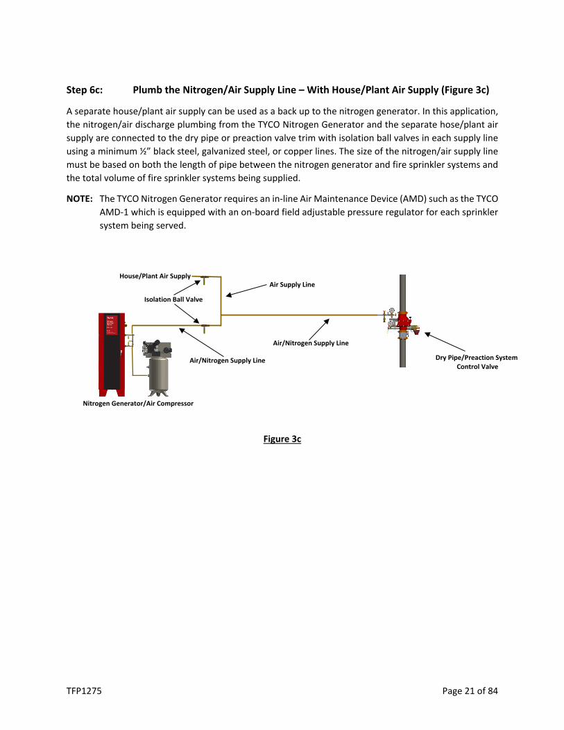
Step 6c: Plumb the Nitrogen/Air Supply Line – With House/Plant Air Supply (Figure 3c)
A separate house/plant air supply can be used as a back up to the nitrogen generator. In this application, the nitrogen/air discharge plumbing from the TYCO Nitrogen Generator and the separate hose/plant air supply are connected to the dry pipe or preaction valve trim with isolation ball valves in each supply line using a minimum ½” black steel, galvanized steel, or copper lines. The size of the nitrogen/air supply line must be based on both the length of pipe between the nitrogen generator and fire sprinkler systems and the total volume of fire sprinkler systems being supplied.
NOTE: The TYCO Nitrogen Generator requires an in-line Air Maintenance Device (AMD) such as the TYCO AMD-1 which is equipped with an on-board field adjustable pressure regulator for each sprinkler system being served.
Figure 3c
Isolation Ball Valve
House/Plant Air Supply Air Supply Line
Air/Nitrogen Supply Line
Air/Nitrogen Supply Line
Nitrogen Generator/Air Compressor
Dry Pipe/Preaction System Control Valve

TFP1275 Page 22 of 84
Step 7: Plumb the Condensate Drain Line
The TYCO Nitrogen Generator will occasionally discharge a small amount of condensate water from the coalescing filters inside the cabinet.
The air compressor will discharge a small amount of condensate water periodically from the air receiver tank auto-drain. The condensate water discharge time and frequency are based on the settings of the auto-drain. Depending on region, the auto-drain requires 120VAC or 220VAC unswitched power supply and can be connected to the same power supply as the nitrogen generator. Ensure the auto-drain is connected and the power supply is active.
Recommend: Set the discharge frequency (OFF Time) to twenty (20) minutes and the discharge time (ON Time) to ten (10) seconds. Adjust as necessary.
It is recommended that the ¼” drain connection be plumbed to a floor drain or building exterior. When plumbing to a drain is not feasible an evaporative collection chamber can be used.
Step 8: System Signals and Monitoring, where used
The nitrogen generator cabinet has two (2) system signals and five (5) outputs that can be monitored by the facility’s building management system (BMS) or fire alarm system.
Two (2) system signals:
• Bypass Alarm - The nitrogen generator operating in the bypass mode which is activated when the bypass valve is in the “fast fill” position to fill the fire sprinkler system and the air supplied directly from the air compressor has reached a pressure of 20 psig (1.4 bar). (Flashing Amber Light)
• Leak Monitor - The nitrogen generator is equipped with a leak monitor audible signal which is activated when the nitrogen generator runs excessively. (Audible Signal)
Five (5) system output signals for monitoring through a building monitoring system, if desired:
• Nitrogen Generator Running Mode - Form C Contacts (Energized When Running, LED On) • Bypass Mode Alarm - Form C Contacts (Normally De-Energized, LED Off) • Nitrogen Generator Loss of Power - Form C Contacts (Normally Energized, LED On) • Leak Monitoring - Form C Contacts (Normally De-Energized, LED Off) • Nitrogen System Supply Line Pressure - Analog Signal

TFP1275 Page 23 of 84
Standard
E Version
Description Normally Open Contact Connections (i.e. Fire Alarm)
Normally Closed Contact Connection (i.e. B.A.S.)
Relay LED Connections Relay LED Connections Nitrogen Generator Running Output (Running) Energized On 11&12 Energized On 11&14 By-Pass Alarm Monitoring Output De-Energized Off 11&14 De-Energized Off 11&12 Nitrogen Generator Power Monitoring Output Energized On 11&12 Energized On 11&14 Leak Monitoring Output De-Energized Off 11&14 De-Energized Off 11&12
Monitoring Relay Contact Rating 250 VAC/ 6 Amps
Relay Contacts – De-Energized NC (12)
COM (11) NO (14)
Relay Coil A1 A2
By-Pass Alarm Monitoring Output
Nitrogen Generator Power Monitoring Output
Leak Monitoring Output Nitrogen Generator
Running Output Nitrogen Supply Line Pressure
(Analog Signal)
By-Pass Alarm Monitoring Output
Nitrogen Generator Power Monitoring Output
Leak Monitoring Output
Nitrogen Generator Running Output
Nitrogen Supply Line Pressure (Analog Signal)

TFP1275 Page 24 of 84
START-UP PROCEDURE
Only qualified personnel should commission the new equipment into service once it is installed. Once the nitrogen generator has been configured, there should be no reason for re-adjusting. To start-up the generator or to put back in service, follow these steps:
NOTE: For component locations, see Generator Configuration Diagram - Maintenance Section.
1. Verify that the air compressor is functioning properly. 2. Verify that the automatic drain on the compressor is functioning properly. 3. Verify the air maintenance devices have been set to the system operating or “high end”
breathing pressure. 4. Important - Verify the nitrogen generator turn-on pressure is 3-5 psig (.2-.3 bar) psig below the
air maintenance device set pressure/sprinkler system supervisory gas operating pressure. 5. Important - Verify the nitrogen generator turn-on pressure is 3-5 psig (.2-.3 bar) psig above the
low air alarm set pressure. 6. Verify the nitrogen generator is in the nitrogen generation mode with the air inlet isolation ball
valve and the nitrogen outlet isolation ball valve in the open position; and the air bypass isolation ball valve in the closed position.* * The only time the nitrogen generator should need to be in the “air bypass” position is for the
NFPA 13 30-min system fill time requirement. 7. Turn the cabinet power switch ON. The generator will begin filling the system with nitrogen.
System Filling Procedure
The sprinkler system(s) is filled using the air from the air compressor connected to the nitrogen generator to meet the NFPA 13 30-minute fill requirement.
1. Close the nitrogen generator’s air inlet isolation ball valve and the nitrogen outlet isolation ball valve.
2. Open the nitrogen generator’s air bypass isolation ball valve.
NOTE: Bypass Alarm indicator will flash.
3. Open the fast fill valve and close the regulated valve of the appropriate air maintenance device (AMD)’s necessary to fill the sprinkler system(s).
4. Close the fast fill and regulated AMD valves on any system not being filled. 5. Air compressor will start running. 6. Once the sprinkler system(s) obtain the desired pressure:
a. Open the nitrogen generator’s air inlet isolation ball valve and the nitrogen outlet isolation valve.
b. Close the nitrogen generator’s air bypass isolation ball valve.
NOTE: Bypass Alarm indicator will turn off.
c. Close the appropriate AMD fast fill valve and open the AMD regulated valve. d. Open AMD regulated valves that were previously closed on any systems not being filled.
7. Initiate the fourteen (14) day nitrogen inerting process (See Nitrogen Inerting Process).

TFP1275 Page 25 of 84
8. Once the nitrogen inerting process is completed, the TYCO Nitrogen Generator will continue to automatically operate when any of the associated sprinkler systems require nitrogen.
Nitrogen Inerting Process
1. TAV-D Vents a. Open the ball valve on the TYCO TAV-D Vent to initiate the fourteen (14) day nitrogen
inerting process. b. Close the ball valve on the TYCO TAV-D Vent at the completion of the fourteen (14) day
nitrogen inerting process. 2. TSV-D SMART Vents
a. Depress the “Vent” pushbutton on the TYCO SMART Vent Controller which energizes the solenoid on the SMART Vent to initiate the fourteen (14) day nitrogen inerting process.
b. At the completion of the fourteen (14) day nitrogen inerting process the SMART Vent Controller will automatically close the vent by de-energizing the solenoid.
NORMAL OPERATION
Once in service, the nitrogen generator requires no additional intervention to function properly. Generator settings should not be altered without first consulting with Johnson Controls and the unit should not be powered down for any reason other than maintenance. To take the generator out of service for maintenance, follow these steps:
1. Close the AMD regulated and fast fill valve on the appropriate fire sprinkler system. 2. Power off generator cabinet. 3. Depressurize the nitrogen generator cabinet and/or air compressor before performing any work
on either the nitrogen generator or the air compressor.
FIRE SPRINKLER SYSTEM MAINTENANCE PROCEDURE
In the event the fire sprinkler system requires maintenance or repair, the following procedure ensures the nitrogen inerting process will continue to function properly.
1. Close the AMD regulated and fast fill valve on the appropriate fire sprinkler system. 2. Depressurize the fire sprinkler system. 3. Complete the maintenance or repair work on the fire sprinkler system. 4. Open the appropriate fire sprinkler system AMD to pressurize the appropriate fire sprinkler
system (See System Filling Procedure).

TFP1275 Page 26 of 84
Sequence of Operation
Once in service, the nitrogen generator requires no additional intervention to function properly. Generator settings should not be altered without consulting with Johnson Controls and the unit should not be powered down or bypassed for any reason other than a service or maintenance procedure as detailed in the Maintenance Section. The nitrogen generator operates in two (2) modes, Nitrogen Inerting Mode and Supervisory Gas Mode.
Nitrogen Inerting Mode
The application of supervisory nitrogen gas to a dry pipe or preaction fire sprinkler system using the TYCO Dry Pipe Nitrogen Inerting (DPNI) protocol is fundamentally different than the traditional application of compressed air as a supervisory gas. Because the DPNI protocol uses a process called “fill and purge breathing” it requires small (3-5 psig (.2-.3 bar)) supervisory pressure fluctuations in the fire sprinkler system(s) to remove oxygen before it can cause corrosion.
• The nitrogen generator and compressor will cycle on to increase the pressure in all fire sprinkler systems connected to the nitrogen generator.
• Once the high-end pressure of the breathing cycle is reached the air compressor and nitrogen generator will turn off and the fire sprinkler system(s) will depressurize gradually through the oxygen removal vent(s).
• Once the low-end pressure of the breathing cycle is reached, the air compressor and nitrogen generator automatically turn on to repeat the process.
• The high-end/turn-off pressure is determined by the pressure setting of the fire sprinkler system(s) air maintenance device (AMD) and the low-end/turn-on pressure is determined by the nitrogen generator’s integral pressure transducer.
• The air compressor and nitrogen generator are simultaneously cycling the pressure in all fire sprinkler system(s) by 3-5 psig (.2-.3 bar) during each cycle. This will result in longer run times of the air compressor and nitrogen generator than a traditional air compressor configured to supply supervisory gas.
• The DPNI “fill and purge breathing” protocol described above is performed for a fourteen (14) day period, during this time the system pressure will fluctuate between the high-end and low-end breathing pressures.
• Once the fourteen (14) day period is complete and the ball valve on the TAV-D vent is closed or the SMART vent is automatically closed, the run frequency of the air compressor and nitrogen generator is reduced.
It is important to remember that closing the vents will not affect the runtime of the air compressor and nitrogen generator. It will only affect the frequency that the air compressor and nitrogen generator will run. The nitrogen generator and air compressor are designed to run for up to two (2) hours at a time when filling all the systems with 3-5 psig (.2-.3 bar) of high purity nitrogen. If air compressor and nitrogen generator runtimes are greater than four (4) hours, contact Johnson Controls.

TFP1275 Page 27 of 84
TYCO Nitrogen Generator Pressure Cycling for Dry Pipe and Preaction Fire Sprinkler Systems
OPERATING NOTES: 1. The nitrogen generator produces nitrogen increasing the pressure in the nitrogen supply line which increases the pressure in the fire
sprinkler system. 2. When the pressure in the fire sprinkler system reaches the pressure setting of the Air Maintenance Device (AMD), the AMD closes (no
longer needing supervisory gas). 3. The nitrogen generator continues to produce nitrogen increasing the pressure in the nitrogen supply line until the cut-out pressure is
reached and the nitrogen generator shuts off. 4. When the pressure in the fire sprinkler system decreases (inerting process or normal operation) below the pressure of the AMD, the
AMD opens (needing supervisory gas). 5. The pressure in the nitrogen supply line equalizes with the pressure in the fire sprinkler system. 6. When the pressure in the nitrogen supply line and the fire sprinkler system decreases to the cut-in pressure of the nitrogen generator,
the nitrogen generator turns on. 7. The nitrogen generator produces nitrogen increasing the pressure in the nitrogen supply line and the fire sprinkler system, repeating
the nitrogen filling cycle. 8. The nitrogen inerting "fill & purge" process requires a 3-5 psig (.2-.3 bar) range between the cut-in pressure of the nitrogen generator
and the pressure of the AMD to nitrogen inert the fire sprinkler system within 14 days.
GRAPH NOTE: The pressures reflected in the graph are representative of the operating pressures in a typical dry pipe or preaction fire sprinkler system. Actual operating pressures may vary.

TFP1275 Page 28 of 84
Supervisory Gas Mode
Once the DPNI “fill and purge breathing” protocol is complete the nitrogen generator will automatically operate in the Supervisory Gas Mode. Whenever a fire sprinkler system needs supervisory gas the nitrogen generator and compressor will automatically operate.
• The vents no longer operate to depressurize the systems. • When the sprinkler systems reach the low-end pressure, the nitrogen generator and compressor
will automatically turn on to increase the pressure in all fire sprinkler systems connected to the nitrogen generator.
• Once the high-end pressure of the breathing cycle is reached the air compressor and nitrogen generator will automatically turn off.
• It is important to remember that closing the vents will not affect the runtime of the air compressor and nitrogen generator it will only affect the frequency of the runtime of the air compressor and nitrogen generator. The nitrogen generator and air compressor are designed to run for up to two (2) hours at a time when filling all the systems with 3-5 psig (.2-.3 bar) of high purity nitrogen.
If air compressor and nitrogen generator runtimes are greater than four (4) hours, contact Johnson Controls.
Restart of the Nitrogen Inerting Process
Whenever the fire sprinkler system(s) are serviced and refilled with air, the TYCO DPNI protocol using the “fill and purge breathing” process must be reinitialized.
• TAV-D Vent: o Open the manual vent isolation ball valve to begin the venting process. o The isolation ball valve on the manual vent(s) will need to be closed after fourteen (14)
days to stop the Nitrogen Inerting Mode and begin the Supervisory Gas Mode. • TSV-D SMART Vent:
o Depress the “Vent” button on the SMART Vent control box which energizes the solenoid on the SMART Vent to begin the venting process.
o The SMART Vent(s) will automatically close at the end of the fourteen (14) day inerting period and the nitrogen generator and compressor will automatically transition from the Nitrogen Inerting Mode to the Supervisory Gas Mode.

TFP1275 Page 29 of 84
System Power Loss
In the event of a system power loss, all programmed information in the nitrogen generator is stored in the nitrogen generator and the nitrogen generator will automatically restart once system power is restored.
• Where TAV-D vents are installed, the system will automatically return to Nitrogen Inerting Mode or Supervisory Gas Mode, depending on which mode the nitrogen generator was in when the power loss occurred.
o If the TAV-D vent ball valve is open (Nitrogen Inerting Mode), then the ball valve needs to be manually closed upon completion of the fourteen (14) day DPNI process. The air compressor and nitrogen generator will automatically transition to the Gas Supervisory Mode.
• Where TSV-D SMART vents are installed, the system will automatically return to the Supervisory Gas Mode. When the system power loss is during the fourteen (14) day DPNI process, the DPNI process will need to be reinitialized.
o Depress the “Vent” button on the SMART vent control box which energizes the solenoid on the SMART vent.
o The nitrogen generator and compressor will automatically cycle on operating in the nitrogen inerting mode.
o Upon completion of the fourteen (14) day DPNI process, the vents automatically close and the air compressor and nitrogen generator will automatically transition to the Gas Supervisory Mode.

TFP1275 Page 30 of 84
Auxiliary Equipment
OXYGEN-REMOVAL VENT – TYCO TAV-D VENT
Specifications
Model Number: TAV-D
Service Pressure: Up to 175 PSIG (12 Bar) System Connection: 1 in. NPT Male Temperature Range: 40°F to 120°F (4.5°C to 49°C) Dimensions: 12.0 in. (W) x 4.65 in. (D) x 9.1 in. (H)
(305 mm (W) x 118 mm (D) x 231 mm (H))
Support Hanger Not Required General Description
The TYCO TAV-D Vent provides oxygen venting in dry pipe and preaction fire sprinkler systems. The restricted venting orifice allows oxygen to be vented from the fire sprinkler system at a controlled rate to achieve a minimum nitrogen concentration of 98%. The TYCO TAV-D Vent is equipped with a levered float valve that allows gas to discharge but prevents liquid water from leaking through the restricted venting orifice in the event water enters the fire sprinkler system. A backpressure regulator is also included to prevent total system depressurization from the vent assembly. A special fitting is provided to receive 5/32” tubing when the vent is used in conjunction with the TYCO SMART Gas Analyzer.
Installation Instructions
1. The TYCO TAV-D Vent is equipped with a ball valve to be connected to the fire sprinkler riser. The contractor must install a 1” outlet (welded or mechanical) to connect the vent assembly to the sprinkler system on the system side of the main control valve. The ball valve must remain in the closed position until the TYCO Nitrogen Generator System has been commissioned.
NOTE: The vent assembly does not require a support hanger.
2. Install the vent assembly in a level position. Recommended mounting height is 5’-10’ (1.5-3m) above the finished floor, but a minimum of 2’ (.6m) above the dry pipe or preaction valve.
NOTE: Piping to the vent assembly cannot be installed in a configuration that would trap water and prevent drainage to the sprinkler system; a water trap impedes the ability of the vent assembly to vent oxygen from the fire sprinkler system.
For use under U.S. Patents 8,720,591, 9,144,700, 9,186,533 and 9,610466 B2

TFP1275 Page 31 of 84
3. Inspection of the vent assembly should be performed after installation and hydrostatic testing of the fire sprinkler system. Inspection should be performed periodically thereafter in accordance with the applicable national codes, NFPA codes and standards, and/or the authority having jurisdiction.
NOTE: Inspection must include the condition of the in-line filter and checking for blockage in the “Y” strainer and the restricted venting orifice.
Operating Instructions
1. Verify the vent assembly has been equipped with a restricted venting orifice downstream of the backpressure regulator.
NOTE: If the vent assembly is not equipped with a restricted venting orifice, please contact Johnson Controls. The restricted venting orifice must be installed before proceeding with the steps below.
2. Determine the low air alarm pressure and the turn-on pressure of the nitrogen generator.
3. Choose a pressure setting for the backpressure regulator that is above the low air alarm pressure but below the turn-on pressure of the nitrogen generator.
4. Pull the knob out from the regulator to adjust pressure setting. Turn the knob clockwise to raise the pressure, counter-clockwise to lower the pressure.
5. Close the ball valve and allow device to depressurize through restricted venting orifice to pressure setting. Make adjustment to pressure setting using the knob, then open ball valve to pressurize device and close ball valve again to check pressure setting. Repeat process until desired pressure setting is achieved.
NOTE: This process can only be performed when fire sprinkler system is at normal operating pressure.
6. Push knob back into regulator until it clicks into place.
7. Once the TYCO Nitrogen Generator System has been commissioned, open the isolation ball valve on the vent assembly. The TYCO TAV-D Vent is now open and actively venting oxygen from the fire sprinkler system. It should remain open for approximately 14 days or less, until the system nitrogen concentration reaches 98% or greater. Use a TYCO Handheld Gas Analyzer to verify the gas concentration inside the fire sprinkler system.
8. Close the isolation ball valve. Failure to close the manual ball valve after fourteen (14) days or less, once fire sprinkler system nitrogen concentration reaches 98% will result in additional oxygen corrosion damage to the system and unnecessary run time of the air compressor and nitrogen generator.
9. If the sprinkler system actuates or another event introduces oxygen to the sprinkler system the manual ball valve must be opened again for a period of fourteen (14) days to vent oxygen from the system.

TFP1275 Page 32 of 84
TYCO TAV-D Vent Components
Gas Sample Port
Float Valve
“Y” Strainer
with Ball Valve
In-Line Filter
Connection to Sprinkler System
Restricted Venting Orifice
Backpressure Regulator
Muffler
½” Quick Connect Isolation Ball Valve
TYCO TAV-D Vent Installation Schematic
Nitrogen Supply
TYCO TAV-D Vent
Dry Pipe/Preaction Sprinkler Valve
Fire Sprinkler Riser
1” Outlet Required
TFP1275 Page 33 of 84
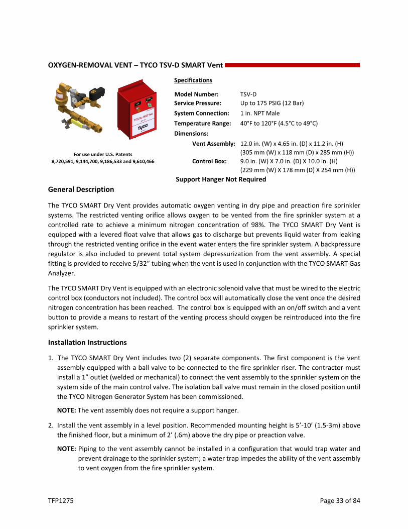
OXYGEN-REMOVAL VENT – TYCO TSV-D SMART Vent
Specifications
Model Number: TSV-D Service Pressure: Up to 175 PSIG (12 Bar) System Connection: 1 in. NPT Male Temperature Range: 40°F to 120°F (4.5°C to 49°C) Dimensions:
Vent Assembly: 12.0 in. (W) x 4.65 in. (D) x 11.2 in. (H) (305 mm (W) x 118 mm (D) x 285 mm (H))
Control Box: 9.0 in. (W) X 7.0 in. (D) X 10.0 in. (H) (229 mm (W) X 178 mm (D) X 254 mm (H))
Support Hanger Not Required General Description
The TYCO SMART Dry Vent provides automatic oxygen venting in dry pipe and preaction fire sprinkler systems. The restricted venting orifice allows oxygen to be vented from the fire sprinkler system at a controlled rate to achieve a minimum nitrogen concentration of 98%. The TYCO SMART Dry Vent is equipped with a levered float valve that allows gas to discharge but prevents liquid water from leaking through the restricted venting orifice in the event water enters the fire sprinkler system. A backpressure regulator is also included to prevent total system depressurization from the vent assembly. A special fitting is provided to receive 5/32” tubing when the vent is used in conjunction with the TYCO SMART Gas Analyzer.
The TYCO SMART Dry Vent is equipped with an electronic solenoid valve that must be wired to the electric control box (conductors not included). The control box will automatically close the vent once the desired nitrogen concentration has been reached. The control box is equipped with an on/off switch and a vent button to provide a means to restart of the venting process should oxygen be reintroduced into the fire sprinkler system.
Installation Instructions
1. The TYCO SMART Dry Vent includes two (2) separate components. The first component is the vent assembly equipped with a ball valve to be connected to the fire sprinkler riser. The contractor must install a 1” outlet (welded or mechanical) to connect the vent assembly to the sprinkler system on the system side of the main control valve. The isolation ball valve must remain in the closed position until the TYCO Nitrogen Generator System has been commissioned.
NOTE: The vent assembly does not require a support hanger.
2. Install the vent assembly in a level position. Recommended mounting height is 5’-10’ (1.5-3m) above the finished floor, but a minimum of 2’ (.6m) above the dry pipe or preaction valve.
NOTE: Piping to the vent assembly cannot be installed in a configuration that would trap water and prevent drainage to the sprinkler system; a water trap impedes the ability of the vent assembly to vent oxygen from the fire sprinkler system.
For use under U.S. Patents 8,720,591, 9,144,700, 9,186,533 and 9,610,466

TFP1275 Page 34 of 84
3. The second component of the TYCO SMART Dry Vent is the electric control box. The control box must be installed on a wall or vertical surface adjacent to the vent assembly installation location.
4. Provide conductors from 120VAC/60Hz (230VAC/50Hz) power supply to designated terminals in the electric control box in accordance with the applicable national and/or local codes (i.e. NFPA 70). The device draws less than 2 amps. Contractor must drill hole in the control box to provide access for the 120VAC/60Hz (230VAC/50Hz) power supply conductors.
5. Provide conductors to connect the 120VAC/60Hz (24VDC) coil leads of the electronic solenoid valve on the vent assembly to the designated terminals in the electric control box in accordance with applicable national and/or local codes (i.e. NFPA 70). Contractor must drill hole on side or top of the control box to provide access.
6. The green power switch on the electric control box must remain in the OFF position until the TYCO Nitrogen Generator has been commissioned.
7. Inspection of the vent assembly should be performed after installation and hydrostatic testing of the fire sprinkler system. The inspection should be performed periodically thereafter in accordance with the applicable national codes, NFPA codes and standards, and/or the authority having jurisdiction.
NOTE: Inspection must include verifying the condition of the inline filter and checking for blockage in the “Y” strainer and the restricted venting orifice.
Operating Instructions
1. Verify the vent assembly has been equipped with a restricted venting orifice downstream of the backpressure regulator.
NOTE: If the vent assembly is not equipped with a restricted venting orifice, please contact Johnson Controls. The restricted venting orifice must be installed before proceeding with the steps below.
2. Determine the low air alarm pressure and turn-on pressure of the nitrogen generator.
3. Choose a pressure setting for the backpressure regulator that is above the low air alarm pressure but below the turn-on pressure of the nitrogen generator.
NOTE: This process can only be performed when the solenoid on the vent is energized (power on and VENT button depressed), and fire sprinkler system is at normal operating pressure.
4. Pull the knob out from the regulator to adjust pressure setting. Turn the knob clockwise to raise the pressure, counter-clockwise to lower the pressure.
5. Close the isolation ball valve and allow device to depressurize through restricted venting orifice to pressure setting. Make adjustment to pressure setting using the knob, then open the isolation ball valve to pressurize device and close the isolation ball valve again to check pressure setting. Repeat process until desired pressure setting is achieved.

TFP1275 Page 35 of 84
6. Push knob back into regulator until it clicks into place.
7. Verify the timer settings inside the electric control box. The settings should be as follows: mode set to ‘E’, scale set to ‘20, 30, 40, 50, 60’, range set to ‘10h’, and timer knob set to ‘35’. If needed, a small flathead screwdriver can be used to make the timer setting adjustments.
8. Once the TYCO Nitrogen Generator System has been commissioned, open the isolation ball valve on the vent assembly, turn the green power switch on the electric control box to the ON position and push the orange VENT button. The button should now be illuminated.
9. The TYCO SMART Dry Vent is now open and actively purging oxygen from the fire sprinkler system. It will remain open for approximately fourteen (14) days. The orange VENT button will turn off when the vent is closed.
10. If the sprinkler system actuates or another event introduces oxygen to the sprinkler system press the orange VENT button to restart the purging cycle.
TSV-D 120VAC/60Hz Wiring Diagram TSV-D 230VAC/50Hz Wiring Diagram
TYCO Dry SMART Vent Control Box

TFP1275 Page 36 of 84
In-Line Filter Assembly
Filter Housing Filter
Pressure Relief Valve
TYCO Dry SMART Vent Assembly
TYCO SMART Dry Vent Installation Schematic
Wiring Harness Installed in
Conduit Vent Assembly
Fire Sprinkler Riser
Control Box Mounted to
Adjacent Wall
Nitrogen Supply
½” Quick Connect
Connection To Sprinkler System
Solenoid
Gas Sampling Port
In-Line Filter HOUSING
Float Valve
Backpressure Regulator Restricted Venting
Orifice
Muffler
“Y” Strainer with Ball Valve
Isolation Ball Valve

TFP1275 Page 37 of 84
MONITORING – CORROSION DETECTION
TYCO In-Line Corrosion Detector (TILD)
General Description
The TYCO In-Line Corrosion Detector (TILD) is designed to provide an early warning indication of internal corrosion activity in water-based fire sprinkler systems. The device is designed to be installed where corrosion is most likely to occur: the air/water interface. A cross-section of the device shows the two key attributes that allow for early detection of corrosion: an externally milled section of the pipe that creates a “thin wall” section and a pressure chamber created by an external sleeve welded over the pipe. The thin wall section of the device will fail before other system piping to provide an early warning indication. The TYCO In-Line Corrosion Detector is equipped with a pressure switch to monitor the pressure chamber. The TYCO In-Line Corrosion Detector can be remotely monitored through a buildings monitoring system, or locally through the TYCO Remote Test Station (TRTI), which is included with the TILD.
Installation Instructions
The TYCO In-Line Corrosion Detector is manufactured as a spool of piping with roll grooved ends for easy insertion into the fire sprinkler piping using standard mechanical couplings (supplied by others). All models of the TYCO In-Line Corrosion Detectors are eighteen (18) inches in length. The variety of pipe schedules and metal are listed in the table under ordering information.
Pressure
Specifications
Model Number: TILD
Service Pressure: 175 psi Temp. Rating: -40°F to 120°F (-40°C to 49°C) Elec. Connection: dry contact Pipe Size: 1.25 in. – 8 in. Pipe Schedule: Sch. 10 or Sch. 40 Pipe Material: Black Steel or Galvanized
US. PAT. NO. 9,095,736
Pressure Chamber
Pressure Switch
“Thin Wall” Milled Section
TFP1275 Page 38 of 84
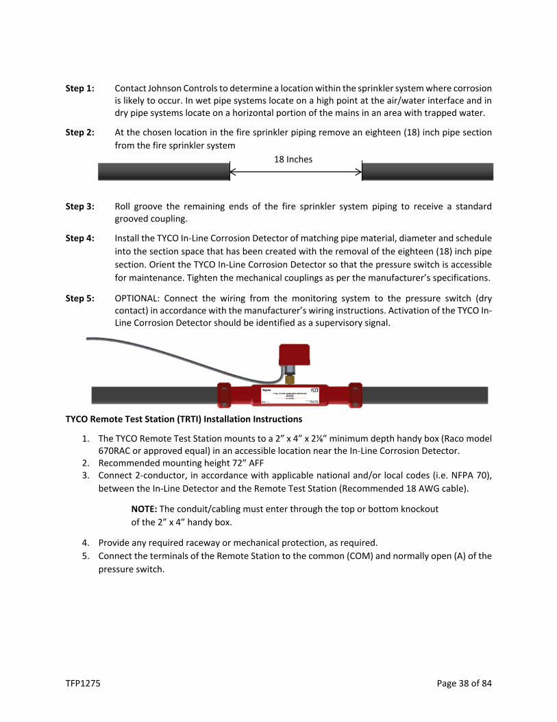
Step 1: Contact Johnson Controls to determine a location within the sprinkler system where corrosion is likely to occur. In wet pipe systems locate on a high point at the air/water interface and in dry pipe systems locate on a horizontal portion of the mains in an area with trapped water.
Step 2: At the chosen location in the fire sprinkler piping remove an eighteen (18) inch pipe section from the fire sprinkler system
Step 3: Roll groove the remaining ends of the fire sprinkler system piping to receive a standard grooved coupling.
Step 4: Install the TYCO In-Line Corrosion Detector of matching pipe material, diameter and schedule into the section space that has been created with the removal of the eighteen (18) inch pipe section. Orient the TYCO In-Line Corrosion Detector so that the pressure switch is accessible for maintenance. Tighten the mechanical couplings as per the manufacturer’s specifications.
Step 5: OPTIONAL: Connect the wiring from the monitoring system to the pressure switch (dry contact) in accordance with the manufacturer’s wiring instructions. Activation of the TYCO In-Line Corrosion Detector should be identified as a supervisory signal.
TYCO Remote Test Station (TRTI) Installation Instructions
1. The TYCO Remote Test Station mounts to a 2” x 4” x 2⅛” minimum depth handy box (Raco model 670RAC or approved equal) in an accessible location near the In-Line Corrosion Detector.
2. Recommended mounting height 72” AFF 3. Connect 2-conductor, in accordance with applicable national and/or local codes (i.e. NFPA 70),
between the In-Line Detector and the Remote Test Station (Recommended 18 AWG cable).
NOTE: The conduit/cabling must enter through the top or bottom knockout of the 2” x 4” handy box.
4. Provide any required raceway or mechanical protection, as required. 5. Connect the terminals of the Remote Station to the common (COM) and normally open (A) of the
pressure switch.
18 Inches

TFP1275 Page 39 of 84
Model EPS10-2 Pressure Switch Electrical Connections
TYCO Remote Test Station (TRTI) Remote Test Station Operation Flowchart
Response to Device Activation
Activation of the pressure switch indicates that the thin wall section of the device has failed and the pressure chamber is exposed to system pressure. Contact Johnson Controls for instructions regarding replacement and testing of the failed In-Line Corrosion Detector.
Not Activated Activated
B
Switch 1 Switch 2 A
B
A
COM COM
Switch 1 Switch 2
B B
A A
COM COM
Re-Test TILD Replace Batteries
(2 x 2032 Batteries Required)
TILD ACTIVATED due to Corrosion
TILD Operating Properly
Depress Amber LED
Push-Button
Depress Red LED
Push-Button
CONTACT Johnson Controls AMBER LED
Push-Button Illuminates
YES NO
RED LED Push-Button Illuminates
YES NO
Terminal Strip Connections

TFP1275 Page 40 of 84
Battery Test and Replacement
1. Depress Amber LED Push Button. If Amber LED does not illuminate, battery replacement is required.
2. Remove Remote Test Station from electrical mounting box, remove four (4) back cover screws, remove two (2) 2032 batteries from battery holder.
3. Replace Battery with two (2) Energizer Part No. CR2032 Only*, re-install battery holder in backbox, reinstall back cover with four (4) screws and reinstall Remote Test Station in electrical mounting box.
* Use Of Another Battery May Present A risk Of Fire Or Explosion.
CAUTION: Battery May Explode if Mistreated. Do Not Recharge, Disassemble Or Dispose Of In Fire
These cells are intended for use at ordinary temperatures where anticipated high temperature excursions are not expected to exceed 100o C (212o F)

TFP1275 Page 41 of 84
MONITORING – NITROGEN PURITY LEVEL
TYCO SMART Gas Analyzer (TSGA)
Specifications
Model Number: TSGA Sensor Type: Zirconium Dioxide Electrical Connection: 120-240VAC, 50-60 Hz/.5A
24VDC/2A Signal Output: 0-5VDC linear output
4-20mA linear output Output Display: %O2 or %N2 Resolution: 1dp (nn.n%) Accuracy: 1% Sample Connection: 5/32” nylon tubing quick connect Dimensions: 8.0 in. (W) X 6.0 in. (D) X 10.0 in. (H)
(203mm (W) X 152mm (D) X 254mm (H))
General Description
The TYCO SMART Gas Analyzer provides a continuous real-time monitoring of nitrogen/oxygen concentration levels within a dry pipe or preaction fire sprinkler system. The analyzer samples discharge gas from an adjacent TYCO TAV-D Vent or TSV-D SMART Vent. The gas flows out of a restricted orifice on the vent through pressure-rated tubing to provide slow, controlled flow to the analyzer. One TSGA analyzer is recommended with each TYCO Nitrogen Generation System.
The TSGA has many different functions. It is equipped with a programmable contact closure for one of three different oxygen concentration levels (1%, 3%, and 5%), which will provide early warning to a user when the nitrogen concentration within the fire sprinkler system falls below the desired level. The TSGA is also equipped with an RS-485 port for optional remote control and monitoring. The TSGA can also display either oxygen or nitrogen concentration.
The TSGA is equipped to protect itself from damage, and also let the user know if the sensor is in poor health. Five minutes after the sensor is powered on, it begins a self-diagnostic protocol. If at this time the O2 level is below .3%, the alarm relay will energize, and the sensor will automatically shut itself down. It will reboot automatically after 24 hours and resume reading gas concentration levels. Pumping at extremely low oxygen levels can eventually cause damage to the sensor. If the sensor detects rapid deviation in oxygen content it will signal an error and energize the alarm relay without shutting down.
Installation Notes
1. When connecting the TSGA Gas Analyzer to a fire sprinkler system using the TAV-D Vent, a dedicated TAV-D Vent is required to provide a continuous gas stream to analyze. The muffler in the TAV-D must be removed and replaced with a 5/32” push-connect fitting.
For use under U.S. Patent 9,144,700 and 9,186,533

TFP1275 Page 42 of 84
2. When connecting the TSGA Gas Analyzer to a fire sprinkler system using the TSV-D SMART Vent, the quick disconnect sampling port in the TSV-D must be removed and replaced with a 5/32” push-connect fitting.
Installation Instructions
1. Mount the TYCO SMART Gas Analyzer on a wall adjacent to the TAV-D Vent or the TSV-D SMART Vent (not included).
2. Once mounted, connect the 5/32” tubing to the push-connect fitting on the top of the TSGA.
3. Connect the opposite end of the tubing to the push-connect fitting on the outlet of the TAV-D or TSV-D Vent.
TYCO SMART Gas Analyzer with Dedicated TAV-D Dry Vent Assembly
TYCO SMART Gas Analyzer with TSV-D Dry SMART Vent Assembly
5/32” Tubing Between
Vent and TSGA
5/32” Push Fitting
Gas Sampling Port to be Removed and Replaced with 5/32” Push Fitting
5/32” Push Fitting
5/32” Tubing Between Vent and TSGA
Muffler to be Removed and Replaced with 5/32” Push Fitting

TFP1275 Page 43 of 84
4. With the incoming power off, connect the incoming 120-240VAC 50/60 Hz power supply to block “J6”.
5. Select the appropriate gas concentration level to be displayed on the TSGA using 1 of Switch 1. Nitrogen (N2) or Oxygen (O2).
Note: N2 is recommended
6. When monitoring and a (N.O.) contact closure required, connect to the “Over” contacts on block J5 (J5-1 & J5-2).
a. If a LOW Nitrogen (N2)/HIGH Oxygen (O2) percentage alarm is desired, select the corresponding O2 concentration level using dip 2, 3 or 4 of Switch 1 to energize the “OVER” relay output.
b. Dip 2 of Switch 1 (5%) is recommended.
7. When monitoring and an analog output is required, connect positive lead to AOUT+ (J4-1) and negative lead to AOUT– (J4-2).
a. Turn on dip 1 of Switch 2 to select 4-20mA output.
b. Use dip 2 of Switch 2 to select 5V (for 0-5V) or 10V (for 0-10V).
8. If RS-485 remote control/monitoring is desired, connect RS-485 leads to D+ (J4-4), D- (J4-5) and DGND (J4-6).
Alarm Bypass While Nitrogen Inerting Feature
The “Over” contacts can be bypassed from transmitting a low nitrogen signal to the building monitoring system during the 14-day nitrogen inerting process when the TSGA is used in conjunction with the TSV-D SMART Vent.
1. Connect the spare normally closed (NC) contacts (terminals 8 and 11) in the TSV-D SMART Vent Controller with the normally open (NO) contacts of the TSGA-Terminals J5-1 and J5-2.
2. Connect the output of the TSGA and TSV-D to the building monitoring system.
3. Connect the building monitoring system’s end-of-line supervision device (if needed)
Operating Instructions
1. Once unit is verified to be wired correctly, power unit on. The status LED light will repeatedly flash green two times quickly for two (2) minutes. The sensor heater is warming up during this period.
2. After the two-minute warm-up period, the sensor and status LED light will flash green one time repeatedly indicating normal operation. At this time, the display will show the current average concentration of the feed gas

TFP1275 Page 44 of 84
PC Board Wiring Diagram Inerting Bypass Wiring Diagram
Calibration
The TYCO Model TSGA SMART Gas Analyzer is factory calibrated to read a 20.9% oxygen level. As elevation increases, the density of the Oxygen molecules in the air decreases. Decreased Oxygen molecules in the air can cause the SMART Gas Analyzer to display slight inaccuracies in the displayed Oxygen/Nitrogen percentage concentration value.
Note: Please contact Johnson Controls before any calibration adjustment
To recalibrate the SMART Gas Analyzer:
1. Allow SMART Gas Analyzer to sample fresh compressed air for a minimum of 10-minutes. 2. Switch N2/O2 switch (SW 1-1) to “O2” position. 3. If Digital Display Not Reading approximately 20.9%, switch “CAL” switch (SW 2-4) to CAL position. 4. Allow SMART Gas Analyzer to remain in “Calibration Mode” and sample the gas for a minimum of
10-minutes to allow SMART Gas Analyzer to re-calibrate. 5. Switch “CAL” switch (SW 2-4) to “Off” position. 6. Verify digital display is reading approximately 20.9%. 7. Switch N2/O2 switch (SW 1-1) to “N2” position
TSV-D Connections
Building Monitoring
System
TSGA “Over”
Connections
E-O-L Supervision
Device
J5-1
J5-2
11
8
Block J6 AC - L1 AC - N AC - GND
Block J4 A Out + A Out - D + D - D GND
Block J5 Over
SW1 SW2

TFP1275 Page 45 of 84
PC Board – LED Locations
LED Identification Chart
STATUS LED Color Flash Code Condition
Red 1 ERROR: Low O2 Level (<.3%)
Red 2 ERROR: Assymetry >5%
Green 1 Normal Operation
Green 2 Heater Warming Up
Green 3 Averaging Calibration Value
Green 4 Set Calibration Value If Needed
Alarm LED
Over LED
SW1 SW2
Tx LED
Rx LED
5V Pwr LED
Heater LED
Status LED
Display Port
Zr02 Port

TFP1275 Page 46 of 84
Commissioning
COMMISSIONING PROCEDURE
Safety Warning
Commissioning of nitrogen generator is to be performed by qualified personnel. Prior to any system commissioning on the nitrogen generator, ensure that the nitrogen generator is isolated from all system risers. Failure to do so can result in system damage and/or personal injury.
Nitrogen Generator Pressure Settings
Prior to setting the cut-in and cut-out pressures of the nitrogen generator, identify the following sprinkler system pressures:
1. Sprinkler system operating pressure/Air Maintenance Device (AMD) pressure.
NOTE: When the nitrogen generator is connected to multiple dry pipe and preaction systems, the fire sprinkler systems must operate at the same supervisory gas pressure.
2. Sprinkler system low air alarm pressure. 3. Sprinkler system trip pressure.
Once the sprinkler system pressures have been identified, determine the cut-in and cut-out pressures of the nitrogen generator.
1. The nitrogen generator cut-in pressure is to be 3-5 psig (.2-.3 bar) below the operating/AMD pressure of the sprinkler system(s).
2. The nitrogen generator cut-in pressure needs to be 3-5 psig (.2-.3 bar) above the low air alarm pressure of the sprinkler system(s).
3. The nitrogen generator cut-out pressure is preset from the factory at 85 psig (5.9 bar) which should be adequate for most applications. Should a higher cut-out pressure be needed, adjust the cut-out pressure using the cut-out pressure adjustment procedure.
Sprinkler System Air Maintenance Device (AMD) Pressure
The proper operation of the nitrogen generator and the dry pipe nitrogen inerting (DPNI) process is dependent on the sprinkler system’s air maintenance device (AMD) pressure setting. Sprinkler system AMD pressure settings less than 3 psig (.2 bar) above the nitrogen generator cut-in pressure or greater than 5 psig (.3 bar) above the nitrogen generator cut-in pressure will have an adverse effect on the service life of the nitrogen generator.
Verify the AMD pressure setting using the Air Maintenance Device (AMD) Pressure Adjustment Procedure in the Maintenance Section of this manual.
Nitrogen Generator Pressure Adjustments
The nitrogen generator cut-in and cut-out pressure settings are established and set as part of the commissioning process of the nitrogen generator and do not need to be readjusted unless the fire sprinkler system parameters change. Any adjustments to the nitrogen generator cut-in and cut-out

TFP1275 Page 47 of 84
pressure settings will affect the TYCO TAV-D Vent or TSV-D SMART Vent backpressure regulator settings, which will require readjusting the backpressure regulators to coincide with the changes to the nitrogen generator cut-in and cut-out pressure settings.
NOTE: Any changes to the nitrogen generator cut-in and cut-out pressure settings or the vent backpressure regulator settings must be authorized by and under the direction of Johnson Controls.
1. Locate the Pressure Transducer in the nitrogen generator. (See Maintenance Section for Generator Configuration Diagram).
2. Adjust the nitrogen generator cut-in pressure. (See Maintenance Section for Nitrogen Generator Pressure Adjustment Procedure).
3. Adjust the nitrogen generator cut-out pressure, if needed. (See Maintenance Section for Nitrogen Generator Pressure Adjustment Procedure).
Nitrogen Generator Start Up and System Check Instructions
Once the cut-in and cut-out pressures have been determined and programmed into the Pressure Transducer, the nitrogen generator can be started to verify nitrogen production and nitrogen purity.
1. Verify the nitrogen generator is in the “nitrogen generation mode”. 2. Verify the “fast fill” valves of all appropriate air maintenance devices (AMDs) are closed. 3. Close the regulated valve of all appropriate air maintenance device (AMDs). 4. Turn on the nitrogen generator (if nitrogen generator is not already on). 5. Close nitrogen outlet valve on nitrogen generator 6. Partially open the nitrogen production flow meter isolation ball valve to automatically start the
nitrogen generator to generate nitrogen. NOTE: Adjust the position of the flow meter isolation ball valve so that the pressure indicated on
the Pressure Transducer is approximately 15-20 psig (1-1.4 bar) and remains constant between the nitrogen generator’s cut-in and cut-out pressures.
7. Allow the nitrogen generator to operate in the nitrogen production mode for approximately five (5) minutes to allow the nitrogen generator to obtain optimum operating temperature.
NOTE: Air compressor must remain running continuously during the nitrogen generation cycle. If the air compressor cycles during the nitrogen generation cycle or an excessive amount of air is being exhausted from the excess air regulator muffler, the excess air regulator in the nitrogen generator may require adjustment. (See Maintenance Section for Excess Air Adjustment Procedure).
8. Connect the Handheld Gas Analyzer to the quick connect gas sampling port in the nitrogen generator to verify the nitrogen purity is 98%.
NOTE: Prior to connecting the Handheld Gas Analyzer to the nitrogen generator, calibrate the Handheld Gas Analyzer using the calibration procedures. (See Maintenance Section for Nitrogen Purity Check Procedure).

TFP1275 Page 48 of 84
9. The nitrogen purity was verified to be producing 98% nitrogen purity prior to equipment shipment from Johnson Controls. Should the purity not be 98%, contact Johnson Controls prior to making changes to the nitrogen purity.
a. If the nitrogen purity is above 98%, decrease the nitrogen purity by turning the Nitrogen Flow Control Valve counterclockwise in ⅛ turn increments (See Generator Configuration Diagram).
b. If nitrogen purity is below 98%, increase the nitrogen purity by turning the Nitrogen Flow Control Valve clockwise in ⅛ turn increments (See Generator Configuration Diagram).
IMPORTANT NOTE: Nitrogen purity and nitrogen production rate are inversely proportional in the nitrogen generator. As the nitrogen purity increases (above 98%) the nitrogen production rate decreases (lower SCFH) and as the nitrogen purity decreases (below 98%) the nitrogen production rate increases (higher SCFH). Lower nitrogen production rates will increase system fill times resulting longer run times of the nitrogen generator.
10. Verify and document the nitrogen production rate as indicated on the flow meter in the nitrogen generator. Compare the documented nitrogen production rate with the nitrogen generator production rates in the Maintenance Section of this manual. (See Maintenance Section for Nitrogen Production Flow Rate Procedure).
11. Close the nitrogen production flow meter isolation ball valve, allow the pressure to increase to the nitrogen generator’s cut-out pressure and the nitrogen generator to shut off.
12. Once nitrogen generator has shutoff, monitor the pressure transducer digital display to ensure the pressure indicated remains constant and does not decrease.
a. If pressure decreases, a leak within the nitrogen cabinet exists, leak check all piping and fittings within the nitrogen generator and repair leaks as necessary.
13. Open nitrogen generator’s nitrogen outlet isolation ball valve and confirm the nitrogen supply line to the air maintenance device (AMD)’s does not contain any leaks, repair leaks as necessary.
14. Open the regulated valve of all appropriate air maintenance devices (AMDs) and confirm the “fast fill” valves of all appropriate air maintenance devices (AMDs) are closed.
15. The nitrogen generator is ready to protect the fire sprinkler system(s).
NOTE: Once the nitrogen generator is operational and if the nitrogen generator experiences short cycling issues, the short cycling is a result of an erratically operating air maintenance device. (See Maintenance Section for Nitrogen Generator Short Cycling Prevention Procedure).
Nitrogen Generator Leak Monitor Alarm
The nitrogen generator and air compressor are designed to run for up to two (2) hours at a time when filling all the systems with 3-5 psig (.2-.3 bar) of high purity nitrogen. If air compressor and nitrogen generator runtimes are greater than four (4) hours, the nitrogen generator activates an audible alarm and the leak monitor output contacts.
Verify the Leak Monitor Alarm is configured using the Nitrogen Generator Leak Monitor Adjustment Procedure in the Maintenance Section of this manual.

TFP1275 Page 49 of 84
Oxygen Removal Vent Setup and Pressure Regulator Adjustment Instructions
Once the nitrogen generator has been commissioned, the oxygen removal vents can be commissioned.
1. Verify the vent assembly is equipped with a restricted venting orifice downstream of the backpressure regulator.
a. If the vent assembly is not equipped with a restricted venting orifice, please contact the Johnson Controls Technical Services team for your region.
2. Based on the nitrogen generator cut-in pressure and the sprinkler system low alarm pressure, adjust the pressure setting for the backpressure regulator.
a. Choose a pressure setting for the backpressure regulator that is above the low air alarm pressure and below the turn-on pressure of the nitrogen generator.
b. TAV-D Oxygen Removal Vents: i. Pull the knob out from the regulator to adjust pressure setting. Turn the knob
clockwise to raise the pressure, counter-clockwise to lower the pressure. ii. Close the isolation ball valve and allow device to depressurize through the
restricted venting orifice to pressure setting. Make adjustment to pressure setting using the knob, then open the isolation ball valve to pressurize device and close the isolation ball valve again to check pressure setting. Repeat process until desired pressure setting is achieved.
NOTE: This process can only be performed when fire sprinkler system is at normal operating pressure.
iii. Push knob back into regulator until it clicks into place. iv. Once the TYCO Nitrogen Generator System has been commissioned, open the
isolation ball valve on the vent assembly. The TYCO TAV-D Vent is now open and actively venting oxygen from the fire sprinkler system.
v. The isolation ball valve should remain open for approximately fourteen (14) days or until the system nitrogen concentration reaches 98% or greater.
NOTE: Use a TYCO Handheld Gas Analyzer to verify the gas concentration inside the fire sprinkler system.
vi. At the conclusion of the fourteen (14) day DPNI process, close the isolation ball valve.
NOTE: Failure to close the isolation ball valve after fourteen (14) days or once fire sprinkler system nitrogen concentration reaches 98% will result in additional oxygen corrosion damage to the system and unnecessary run time of the air compressor and nitrogen generator.
vii. If the sprinkler system actuates or another event introduces oxygen to the sprinkler system, the isolation ball valve must be opened again for a period of fourteen (14) days to vent oxygen from the system.
c. SMART Oxygen Removal Vents: i. Verify the timer settings inside the electric control box. The settings should be

TFP1275 Page 50 of 84
as follows: mode set to ‘E’, scale set to ‘20, 30, 40, 50, 60’, range set to ‘10h’, and timer knob set to ‘35’. If needed, a small flathead screwdriver can be used to adjust the timer settings.
NOTE: The green power switch on the electric control box must be in the ON position and the orange VENT button depressed with both the green power switch and the orange VENT button illuminated to adjust the vent pressure regulator.
ii. Pull the knob out from the regulator to adjust pressure setting. Turn the knob clockwise to raise the pressure, counter-clockwise to lower the pressure.
iii. Close the isolation ball valve and allow device to depressurize through restricted venting orifice to pressure setting. Make adjustment to pressure setting using the knob, then open the isolation ball valve to pressurize device and close the isolation ball valve again to check pressure setting. Repeat process until desired pressure setting is achieved.
NOTE: This process can only be performed when fire sprinkler system is at normal operating pressure.
iv. Push knob back into regulator until it clicks into place. v. Once the TYCO Nitrogen Generator System has been commissioned, open the
isolation ball valve on the vent assembly, turn the green power switch on the electric control box to the ON position and push the orange VENT button. The button should now be illuminated.
vi. The TYCO SMART Dry Vent is now open and actively venting oxygen from the fire sprinkler system. It will remain open for approximately fourteen (14) days.
vii. At the conclusion of the oxygen venting cycle, the orange VENT button will extinguish and the vent will automatically close.
viii. If the sprinkler system actuates or another event introduces oxygen to the sprinkler system press the orange VENT button to automatically restart the oxygen venting cycle.
Using Nitrogen Generators with Low Pressure Valves
When connecting a TYCO nitrogen generator to a low-pressure valve, additional considerations need to be evaluated. Due to the inherent operating pressures (i.e. 20 psi / 1.4 bar or below), the operational tolerances are tighter which reduces the pressure range for the “fill and purge” pressure cycling to operate.
1. Typical trip pressure for low-pressure valve is 7 psi (0.48 bar). 2. Typical low air alarm pressure for low pressure valve is 10 psi (0.69 bar). 3. Typical operating pressure for a low-pressure valve is 13 psi (0.9 bar) minimum and 18 psi (1.24
bar) maximum.
Based on this information, the “fill and purge” breathing cycle needs to be reduced to a 3-psi breathing range and determine the vent orifice size based on a 3-psi (0.21 bar) breathing range.

TFP1275 Page 51 of 84
1. Adjust the sprinkler system air maintenance device (AMD) to 18 psig (1.24 bar) NOTE: If a NG-1 100 or NG-1 250 is used on a single sprinkler system without an air maintenance
device (AMD), set the nitrogen generator cut-out (turn-off) pressure to 18 psig (1.24 bar). 2. Set the nitrogen generator cut-in (turn-on) pressure to 15 psig (1.03 bar). 3. In the pressure transducer in the nitrogen generator cabinet, in the EF Menu (Extended Function
Menu) section, activate the “OSET” function by changing the function from “No” to “Yes”.
Check the operation and interaction between the nitrogen generator and the sprinkler system air maintenance device (AMD).
NOTE: ALL pressures are measured from the Sprinkler System Air Gauge, unless otherwise indicated.
1. Reduce sprinkler system pressure 2 psi (0.14 bar) to approximately 16 psig (1.10 bar). 2. Manually turn on nitrogen generator and allow sprinkler system to refill and generator shut off
a. If sprinkler system pressure has returned to 18 psig (1.24 bar), check nitrogen generator cut-in (turn-on) function.
b. If sprinkler system pressure is not returned to 18 psig (1.24 bar), use the Air Maintenance Device (AMD) Pressure Adjustment Procedure in the Maintenance Section of this manual.
3. Reduce sprinkler system pressure to 15 psig (1.03 bar). a. If nitrogen generator automatically turns on, the nitrogen generator and sprinkler system
air gauge are in alignment. b. If nitrogen generator does not automatically turn on, the nitrogen generator and sprinkler
system air gauge are NOT in alignment i. Verify pressure indicated on nitrogen generator pressure transducer
Example: Nitrogen generator pressure transducer indicates 16 psig (1.10 bar) and the sprinkler system air gauge indicates 15 psig (1.03 bar) – 1 psig (0.07 bar) difference between nitrogen generator pressure transducer and sprinkler system air gauge.
ii. Change the nitrogen generator cut-in (turn-on) pressure to align with pressure indicated on nitrogen generator pressure transducer. Example: Change cut-in (RP) pressure form 15 psig (1.03 bar) to 16 psig (1.10 bar).
iii. The nitrogen generator and sprinkler system air gauge are in alignment. 4. Allow nitrogen generator to fill the sprinkler system to 18 psig (1.24 bar) and the nitrogen
generator to shutoff. 5. Repeat process to confirm nitrogen generator is automatically turning on and turning off as well
the sprinkler system air gauge is operating between 15 psig (1.03 bar) and 18 psig (1.24 bar).

TFP1275 Page 52 of 84
COMMISSIONING CHECKLIST
Fire Sprinkler System - General
Verify and document the quantity of dry/preaction fire sprinkler systems connected to the nitrogen generator: Yes Qty. _________
Verify and document the capacity of each dry/preaction fire sprinkler systems connected to the nitrogen generator (gallons or sq. ft.): Yes
Sys. #1 _________________ Sys. #9 _________________ Sys. #17 _________________
Sys. #2 _________________ Sys. #10 _________________ Sys. #18 _________________
Sys. #3 _________________ Sys. #11 _________________ Sys. #19 _________________
Sys. #4 _________________ Sys. #12 _________________ Sys. #20 _________________
Sys. #5 _________________ Sys. #13 _________________ Sys. #21 _________________
Sys. #6 _________________ Sys. #14 _________________ Sys. #22 _________________
Sys. #7 _________________ Sys. #15_________________ Sys. #23 _________________
Sys. #8 _________________ Sys. #16_________________ Sys. #24 _________________
Verify and document the make and model of air maintenance device(s): __________________________
Verify and document the pressure settings of the air maintenance device(s): _______________________
Verify and document the Systems(s) High Air Alarm Pressure: __________________________
Verify and document the Systems(s) Low Air Alarm Pressure: __________________________
Verify and document the Systems(s) Trip Pressure: __________________________
Verify and document the make and model of accelerator: __________________________ Air Compressor - Existing
Verify and document the location of the air compressor: __________________________
Verify and document the manufacturer of the air compressor: __________________________
Verify and document the model number of the air compressor: __________________________
Verify and document the serial number of the air compressor: __________________________
Verify and document the air compressor on/off pressure settings: __________________________

TFP1275 Page 53 of 84
Verify and document if an air compressor exists and whether the existing air compressor(s) to remain:
� Yes � No If existing Yes: � Primary � Backup � Meet NFPA 13 30-Minute Fill Requirement Verify and document whether the fire sprinkler system(s) are supplied by house air: � Yes � No If Yes, what pressure: ________
Air Compressor - New
Verify and document the location of the air compressor: __________________________
Verify and document the manufacturer of the air compressor: __________________________
Verify and document the model number of the air compressor: __________________________
Verify and document the serial number of the air compressor: __________________________
Verify and document the air compressor on/off pressure settings: __________________________
Verify and document the air compressor power supply voltage: __________________________
Verify and document whether the air compressor(s) is/are installed correctly: � Yes � No
If No, explain: _________________________________________________________________________
Verify and document whether the air compressor(s) is/are wired correctly: � Yes � No
If No, explain: _________________________________________________________________________
Verify and document whether the air compressor(s) rotation is correct: � Yes � No
NOTE: If rotation incorrect on 3-phase motor, reverse any two of the three incoming power wires to reverse the rotation
Verify and document if air compressor receiver tank auto-drain(s) is/are powered: � Yes � No
Verify and document the auto-drain(s) is configured for on time of 10 seconds and off time frequency is 20 minute (maximum): � Yes � No
Verify and document whether the auto-drain is/are plumbed to a drain: � Yes � No
Nitrogen Generator Equipment
Verify and document the location of the nitrogen generator(s): ________________________
Verify and document the quantity of the nitrogen generator(s): ________________________
Verify and document the model number of the nitrogen generator(s): ________________________

TFP1275 Page 54 of 84
Verify and document the serial number of the nitrogen generator(s): ________________________
Verify and document whether the nitrogen generator(s) is/are installed correctly: � Yes � No
If No, explain: _________________________________________________________________________
Verify and document whether the nitrogen generator(s) is/are wired correctly: � Yes � No
If No, explain: _________________________________________________________________________
Programming of nitrogen generator’s Pressure Transducer
Turn On/Off Power Switch to the “On” position
Verify and document the cut-in or turn-on pressure of the nitrogen generator is 3-5 psig (.2-.3 bar) below operating pressure of the dry/preaction fire sprinkler systems’ air maintenance device(s): � Yes � No
If No, change the cut-in or turn-on pressure of the nitrogen generator to be 3-5 psig (.2-.3 bar) below operating pressure of the dry/preaction fire sprinkler systems’ air maintenance device(s) using the Pressure Transducer Programming Procedure.
Verify and document that the cut-in or turn-on pressure of the nitrogen generator is above the low air alarm pressure of the dry/preaction fire sprinkler system(s): � Yes � No
Verify and document the cut-in or turn-on pressure of the nitrogen generator: ______________________
Verify and document the cut-out or turn-off pressure of the nitrogen generator is 45 psig (3.1 bar) above operating pressure of the dry/preaction fire sprinkler systems’ air maintenance device(s): � Yes � No
If No, change the cut-out or turn-off pressure of the nitrogen generator to be 45 psig (3.1 bar) above operating pressure of the dry/preaction fire sprinkler systems’ air maintenance device(s) using the Pressure Transducer Programming Procedure.
Verify and document the cut-out or turn-off pressure of the nitrogen generator: _____________________
Verify and document that the air inlet valve(s), nitrogen outlet valve(s), and bypass valve(s) is/are operating properly: � Yes � No
Verify and document the feed air pressure is between 150-175 psig (10-12 bar) and below, but close to the air compressor cutoff pressure: � Yes � No
Change if needed. Document regulator setting: ________________________________
Verify and document the instrument air pressure regulator is set to 95 psig (6.5 bar): � Yes � No
Change if needed. Document regulator setting: ________________________________
Verify and document the nitrogen back pressure regulator is set to 85 psig (5.9 bar): � Yes � No
Change if needed. Document regulator setting: ________________________________

TFP1275 Page 55 of 84
Open the isolation ball valve to the internal flow meter.
NOTE: Adjust the position of the flow meter isolation ball valve so that the pressure indicated on the Pressure Transducer is approximately 15-20 psig (1-1.4 bar) and remains constant between the nitrogen generator’s cut-in and cut-out pressure.
Connect the handheld gas analyzer (THGA) to the gas sampling port of the nitrogen generator.
Allow the nitrogen generator to operate in nitrogen production mode for approximately five (5) minutes to ensure proper operating temperature of the nitrogen generator prior to adjusting nitrogen purity or measuring nitrogen production rate.
NOTE: The nitrogen generator will obtain optimum operating pressure faster if the nitrogen generator cabinet door is closed.
Adjust to Flow Control Valve in the nitrogen generator to obtain a nitrogen output purity level of 98%.
NOTE: Nitrogen purity and nitrogen production rate are inversely proportional in the nitrogen generator. As nitrogen purity increases, production decreases. Increase nitrogen purity by turning Flow Control Valve clockwise and decrease nitrogen purity by turning Flow Control Valve counter-clockwise
Verify and document the nitrogen output purity concentration: __________________________
Verify and document the nitrogen production rate as indicated on the flow meter: __________________
Compare documented nitrogen output purity concentration and nitrogen production rate levels with the Shop Test Report provided in the nitrogen generator.
1. Readjust nitrogen output purity level using Flow Control Valve, as necessary, to obtain nitrogen output purity levels and nitrogen production rate comparable to the Shop Test Report, if discrepancies are significant.
2. If unable to obtain comparable nitrogen output purity levels and nitrogen production rate, contact Johnson Controls. Visit the CONTACT US page at www.tyco-fire.com for contact information by location.
Close the isolation ball valve to the internal flow meter.
Disconnect the handheld gas analyzer (THGA) from the gas sampling port of the nitrogen generator.
Leak check all plumbing throughout the nitrogen generator, include the air supply from the air compressor and the nitrogen supply to the fire sprinkler systems, repair any leaks found.
Verify and document that the no leaks exist in the nitrogen generator, air compressor supply line and fire sprinkler supply line: � Yes � No
Verify and document air inlet and nitrogen outlet ball valves are in the open position; and the air bypass ball valve is in the closed position with the nitrogen generator in the nitrogen generation position: � Yes � No

TFP1275 Page 56 of 84
Oxygen Removal Vents – TAV-D / TSV-D
Verify and document the appropriate orifices for each venting device are available: � Yes � No
NOTE: Ensure the appropriate orifice is installed in the appropriate vent for each fire sprinkler system.
The restricted venting orifice size is determined by the sprinkler system capacity (gallons). The restricted venting orifice ensures the oxygen removal process is completed in all fire sprinkler systems within the same approximate timeframe and within fourteen (14) days.
TAV-D Oxygen Removal Vent
Verify and document the model and serial number of each oxygen removal vent installed: � Yes � No
Determine the pressure setting of the backpressure regulator of oxygen removal vent
1. The backpressure regulator setting must be below the cut-in or turn-on pressure of the nitrogen generator and above the low air alarm pressure of the fire sprinkler system.
Verify and document the appropriate orifice in the oxygen removal vent: � Yes � No
Install the appropriate orifice in the oxygen removal vent.
Adjust the backpressure regulator setting on the oxygen removal vent:
1. Open and close the isolation ball valve on the oxygen removal vent to determine the pressure setting of the backpressure regulator.
2. Pull the knob out from the regulator to adjust pressure setting. Turn the knob clockwise to raise the pressure, counter-clockwise to lower the pressure.
3. Repeat process until desired pressure setting is achieved.
NOTE: This process can only be performed when fire sprinkler system is at normal operating pressure.
4. Once the desired pressure has been obtained on the backpressure regulator, push the knob onto the regulator until it clicks into place.
Verify and document the backpressure regulator set point: ___________
Verify and document the appropriate orifice in the oxygen removal vent: � Yes � No
Install the appropriate orifice in the oxygen removal vent.
Verify and document isolation ball valve left in open position: � Yes � No
TSV-D SMART Oxygen Removal Vent
Verify and document model and serial number of each oxygen removal vent installed: � Yes � No
Verify and document serial number of each oxygen removal vent control box installed: � Yes � No

TFP1275 Page 57 of 84
Verify and document that the control box is properly installed: � Yes � No
If No, explain: _________________________________________________________________________
Verify and document wiring between the control box and the vent is properly installed: � Yes � No
If No, explain: _________________________________________________________________________
Verify the control box timer is programmed properly:
1. Mode is set to “E” � Yes � No 2. Scale is set to “20-60” � Yes � No 3. Range is set to “10h” � Yes � No 4. Dial is set to “34” � Yes � No
Turn On the control box. Verify and document control box is operating properly: � Yes � No
If No, explain: _________________________________________________________________________
Determine the pressure setting of the backpressure regulator of oxygen removal vent.
1. The backpressure regulator setting must be below the cut-in or turn-on pressure of the nitrogen generator and above the low air alarm pressure of the fire sprinkler system.
Adjust the backpressure regulator setting on the oxygen removal vent:
1. Turn on the power switch to the control box and depress the “Vent” button. 2. Open and close the isolation ball valve on the oxygen removal vent to determine the pressure
setting of the backpressure regulator. 3. Pull the knob out from the regulator to adjust pressure setting. Turn the knob clockwise to raise
the pressure, counter-clockwise to lower the pressure. 4. Repeat process until desired pressure setting is achieved.
NOTE: This process can only be performed when fire sprinkler system is at normal operating pressure.
5. Once the desired pressure has been obtained on the backpressure regulator, push the knob onto the regulator until it clicks into place.
Verify and document the backpressure regulator set point: ___________
Verify and document the appropriate orifice in the oxygen removal vent: � Yes � No
Install the appropriate orifice in the oxygen removal vent.
Verify and document isolation ball valve left in open position: � Yes � No
Verify All sprinkler systems in service: � Yes � No
Verify the Fire alarm system in service: � Yes � No

TFP1275 Page 58 of 84
Maintenance
SAFETY, MAINTENANCE, TROUBLESHOOTING WARNING
Safety Warnings
All maintenance is to be performed by qualified personnel. Prior to any system maintenance on the nitrogen generation system, ensure that the nitrogen generator is isolated from the compressed air supply and all system risers. Ensure that the nitrogen generation system and the associated piping that is to be manipulated is completely depressurized prior to performing any maintenance. Failure to do so can result in system damage and/or personal injury.
Maintenance and Troubleshooting Warnings
1. Nitrogen Generator includes 120-240VAC 50/60 Hz voltage inside cabinet – exercise caution and do not touch any wiring connections when power is applied to the unit.
2. Nitrogen Generator has hot surfaces inside cabinet when nitrogen generator is operating and after nitrogen generator has turned off – exercise caution when working on nitrogen generator while operating and after nitrogen generator has shut off. (Wear Hand Protection, where needed)
ROUTINE CHECKS
The nitrogen generators require limited maintenance; however, it is advisable to routinely check the generator to ensure functionality. The following is a checklist and schedule for routine inspection.
Check Occurrence Verify all valves have smooth operation - clean and un-corroded Quarterly Verify all manual valves fully open and close Quarterly Verify compressor is turning on/off at low/high pressure Quarterly Verify correct nitrogen purity level out of cabinet sampling port Quarterly Verify pressure gauges are in working order Quarterly Change oil in air compressor (per manufacturer’s recommendations) Quarterly/500 hrs Verify there are no noticeable leaks on unit Quarterly Check coalescing filters Semi-annually Check for loose connections in cabinet and control box Semi-annually Check air compressor filter, replace as necessary Semi-annually Check air receiver tank auto-drain strainer, clean as necessary Annually Replace coalescing filters Annually Verify Oxygen Removal Vent In-Line Filter and Y-Strainer are clean Annually Verify no air or water leaks in Oxygen Removal Vent Annually
Nitrogen Generator Excess Air Adjustment Procedure
Air compressors used to meet the NFPA 13 30-minute fill requirement typically have a higher production rate than the maximum feed rate of the nitrogen generator separation membrane. When using the same air compressor to meet the NFPA 30-minute fill requirement and nitrogen production, the compressed air

TFP1275 Page 59 of 84
rate to the separation membrane must be held constant below the air compressor cut-out (turn-off) pressure to eliminate short cycling of the air compressor during the nitrogen production cycle. To prevent air compressor cycling, an excess air bleed-off assembly is included in the nitrogen generator. The excess air bleed-off assembly regulator is adjusted so that the air compressor operating pressure when running in the nitrogen production mode is below the cut-out pressure of the air compressor allowing the air compressor to operate continuously throughout the nitrogen production cycle.
1. If the air compressor’s air receiver tank pressure gauge and the excess air bleed-off regulator gauge, when operating, are more than 10-15 psig (.7-1 bar) below the cut-out (turn-off) pressure of the air compressor during nitrogen production cycle, decrease excess air bleed-off regulator (turn regulator clockwise). This raises the relief pressure of the regulator by exhausting less air thereby increasing the air compressor operating pressure resulting in increased nitrogen production.
2. If the air compressor is cycling during the nitrogen production cycle, increase excess air bleed-off regulator (turn regulator counter-clockwise) until the pressure gauge on the regulator is approximately 10-15 psig (.7-1 bar) below the cut-out (turn-off) pressure of the air compressor. This lowers the relief pressure of the regulator by exhausting more air thereby decreasing the air compressor operating pressure, resulting in sustained operation below the air compressor cut-out (turn-off) pressure thus eliminating the air compressor short cycling.
NITROGEN PURITY AND FLOW RATE
Nitrogen Purity Level Check Procedure
Nitrogen purity level in the fire sprinkler system can be checked by inserting the TYCO Handheld Gas Analyzer (THGA) into the nitrogen sampling port in the nitrogen generator cabinet or the gas sampling port on the TAV-D or TSV-D Vent.
1. Power On the THGA by depressing the power on button. 2. Calibrate the THGA by depressing and holding the calibration button for three (3) seconds until
“CAL” is displayed.
NOTE: To calibrate analyzer, unscrew sampling hose from analyzer and move back and forth until reading is displayed.
a. THGA must be recalibrated if nitrogen percentage displayed is above 80.1% or below 78.1% when reading normal atmosphere, not connected to the nitrogen generator cabinet or vent.
b. Recommended to recalibrate analyzer daily when in use.
3. Once the THGA is calibrated, insert the quick disconnect of the sampling hose into the sampling port in the nitrogen generator cabinet/vent.
NOTE: Nitrogen generator must be operating in “nitrogen production mode” to sample nitrogen in cabinet. Vent must be open to sprinkler system pressure to sample nitrogen in sprinkler system.

TFP1275 Page 60 of 84
4. Allow one (1) minute for the THGA to stabilize, verify and document reading on THGA (nitrogen level should be approximately 98%). If nitrogen level from generator is below 96%, contact Johnson Controls.
Handheld Gas Analyzer - Factors Influencing Accurate Readings
1. Elevation changes will affect the accuracy of the nitrogen purity readings. The deviation of the nitrogen purity can be approximately 1% per 250 feet of elevation.
a. Calibration of the instrument should be performed when elevation at which the product used changes more than 500 feet.
2. Temperature effects the accuracy of the nitrogen purity readings. The gas analyzer will hold calibration and correctly read nitrogen purity ±3% when thermal equilibrium within the operating temperature range. The device must be thermally stable when calibrated and allowed to thermally stabilize after experiencing temperature changes before readings are accurate.
a. For best results, perform the calibration procedure at a temperature close to the temperature where analysis will occur.
b. Allow adequate time for the sensor to equilibrate to a new ambient temperature.
CAUTION: “CAL Err St” may result from a sensor that has not reached thermal equilibrium.
Nitrogen Generator Leak Monitor Adjustment Procedure
The nitrogen generator leak monitor configuration can be verified by checking the settings of the leak monitor alarm module in the nitrogen generator cabinet (See Generator Configuration Diagram).
1. Locate the Leak Monitor (Finder) Module in the nitrogen generator 2. Verify the module scale setting (white control) is set to ‘24h’ 3. Verify the module timer setting (blue control) is set to ‘4’ 4. If needed, a small flathead screwdriver can be used to adjust the controls.
NOTE: If adjustment needed, turn controls fully clockwise and then counter-clockwise before setting at the identified positions.
Display
Calibration Button
Sampling Hose
Power On Button Quick Disconnect

TFP1275 Page 61 of 84
Nitrogen Production Flow Rate Check Procedure The production rate of the nitrogen generator can be verified using the production flow meter in the nitrogen generator cabinet (See Generator Configuration Diagram).
1. With the nitrogen generator powered and in the nitrogen production mode: a. Partially open the nitrogen production flow meter isolation ball valve to automatically
start the nitrogen generator.
NOTE: Adjust the position of the flow meter isolation ball valve so that the pressure indicated on the Pressure Transducer is approximately 15-20 psig (1-1.4 bar) and remains constant between the nitrogen generator’s cut-in and cut-out pressures.
b. Close the nitrogen generator’s nitrogen outlet isolation ball valve. c. Read and document the nitrogen production flow rate on the nitrogen production flow
meter. i. Flow rate indicated is in standard cubic feet per hour (SCFH).
ii. The production rate is measured using the center of the silver ball in the flow meter.
iii. If production flow rate is lower than anticipated, verify the excess air assembly is not exhausting too much air. (See Nitrogen Generator Excess Air Adjustment Procedure)
d. Open the nitrogen generator’s nitrogen outlet isolation ball valve. e. Close the flow meter isolation ball valve. f. Compare the nitrogen production flow rate with the nitrogen production values listed in
the following chart.
Nitrogen Generator Flow Rates
Nitrogen Generator Production Rate – SCFH (L/min) Bypass Mode
Nitrogen Generation Mode 70 psig
(4.8 bar) 100 psig (6.9 bar)
150 psig (10.3 bar)
NG-1 100 Wall Mount w/ Integral Air Compressor 150 (70.8) 20 (9.4) N/A N/A NG-1 250 Wall Mount w/ Integral Air Compressor 198 (93.5) N/A 27 (12.7) N/A NG-1 500 Wall Mount w/ Integral Air Compressor 342 (161.4) N/A N/A 44 (20.8) NG-1 1000 Skid Mount w/ Integral Air Compressor 600 (283.2) N/A 76 (35.9) N/A NG-1 1150 Stand-Alone w/ 5 hp Air Compressor 858 (404.9) N/A 130 (61.4) 240 (113.3) NG-1 1500 Stand-Alone w/ 7.5 hp Air Compressor 1,458 (688.1) N/A 130 (61.4) 240 (113.3) NG-1 2000 Stand-Alone w/ 7.5 hp Air Compressor 1,458 (688.1) N/A 225 (106.2) 425 (200.6) NG-1 3000 Stand-Alone w/ 10 hp Air Compressor 2,100 (991.1) N/A 285 (134.5) 550 (259.6)
NOTE: If production flow rate is lower than flow rates in the production chart, check pressure regulator
of the excess bleed off assembly.
If production flow rate identified and documented varies more than 10% of the flow rates in the production chart, contact Johnson Controls.

TFP1275 Page 62 of 84
Nitrogen Generator Short Cycling Prevention Procedure (NG-1 2000/3000 Only)
In situations where the nitrogen generator experiences short cycling, the short cycling is typically the result of an erratically operating air maintenance device (AMD). Installations where the AMD doesn’t close properly or partially closes, the nitrogen supply line pressure increases to the cut-out pressure of the nitrogen generator before the sprinkler systems being supplied are at operating pressure. Because one or more of the supplied systems did not reach operating pressure once the nitrogen generator shuts off the nitrogen supply line depressurizes through the AMD and into the sprinkler system(s). This depressurization allows the nitrogen generator to turn on and repeat the process of filling the nitrogen supply line.
NOTES:
• Exacerbated by a small or short nitrogen supply line between the nitrogen generator. • Nitrogen Generator Short Cycling Prevention Device regulator should be fully closed unless used. • Typically not needed in most applications. Adjust as necessary, when needed.
Procedure:
1. Increase set point of AMD to prevent premature shut-off of AMD regulator 2. If set point modifications do not prevent short-cycling, repair (clean out) or replace the erratically
operating AMD 3. If AMD repair/replacement unsuccessful, the nitrogen generator includes a short cycling
prevention assembly. a. The short cycling prevention assembly allows a controlled leak after the sprinkler system’s
AMD closes, and during the pressurizing of the supply line to the cut-out pressure of the nitrogen generator.
b. If needed, the short cycle prevention regulator is to be adjusted to open at 10 psig (.7 bar) above the sprinkler system operating /AMD set pressure.
i. Normal Operation - Regulator should be closed completely ii. Short Cycle Prevention - Adjust regulator to open 10 psig (.7 bar) above the
sprinkler system operating /AMD set pressure. 1. Turn regulator clockwise to increase pressure 2. Turn regulator counter-clockwise to decrease pressure
NOTE: The short cycle prevention assembly is not a substitute for repairing an erratically operating AMD,
the short cycle prevention assembly reduces short cycling of the nitrogen generator by increasing the time to pressurize the nitrogen supply line.
Air Maintenance Device (AMD) Pressure Adjustment Procedure
The sprinkler system air maintenance device (AMD) operating pressures are determined by the sprinkler system valve, system water pressure and water delivery time requirements as defined by NFPA 13. The AMD operating pressures should not need to be readjusted unless one of the above fire sprinkler system parameters change.
The following procedure has been developed to account for: 1. Tolerances of the gauges used on fire sprinkler systems

TFP1275 Page 63 of 84
2. Inlet pressure fluctuations to the AMD resulting in pressure fluctuations of the AMD. 3. Interaction between AMDs when multiple sprinkler systems are connected to a single nitrogen
generator.
NOTES:
• When the nitrogen generator is connected to multiple dry pipe and preaction systems, the fire sprinkler systems must operate at the same supervisory gas pressure.
• Any changes to the AMD pressure settings must be correlated with the nitrogen generator cut-in (turn-on) and cut-out (turn-off) pressure settings; and be authorized by and under the direction of Johnson Controls.
• Accuracy of pressure gauges typically used in the fire sprinkler industry can vary as much as 8-12 psi (.6-.8 bar) (See Operational Information - Sprinkler System Gauge Accuracy).
Determine the operating pressure for all AMDs connected to a single nitrogen generator. The operating pressure must be the same for all AMDs.
NOTE: AMDs operating at different operating pressures will have an adverse effect on the operation and can reduce the service life of the nitrogen generator.
Initial Setting of AMDs
Step 1: Close the valves to all accelerators on the sprinkler systems (if installed). Step 2: Systems not being checked - Close the all AMD valves. Step 3: System being checked - Verify the AMD fast fill (bypass) valve is closed and the inlet/outlet
(regulated) valves are open. Step 4: Temporarily set the cut-in (turn-on) pressure of the nitrogen generator to 15 psig (1 bar)
below the cut-out (turn-off) pressure of the nitrogen generator. (Use the Nitrogen Generator Pressure Adjustment Procedure in the Maintenance Section of this manual).
Step 5: Use the flow meter ball valve to relieve gas from nitrogen/air supply line to sprinkler system’s AMD allowing the nitrogen generator to cycle on and off.
Step 6: System being checked - Adjust the AMD to the predetermined set pressure. Step 7: Repeat Steps 4, 5 and 6 for each additional AMD connected to the nitrogen generator.
AMD Operation with Nitrogen Generator - Verification
Step 1: Systems not being checked - Close the all AMD valves. Step 2: System being checked - Verify the AMD fast fill (bypass) valve is closed and the inlet/outlet
(regulated) valves are open. Step 3: Set the cut-in (turn-on) pressure of the nitrogen generator to 3-5 psig (.2-.3 bar) below the
AMD set pressure. (Use the Nitrogen Generator Pressure Adjustment Procedure in the Maintenance Section of this manual).
Step 4: Slowly drain 3-5 psi (.2-.3 bar) of pressure out of the sprinkler system. Step 5: Use the flow meter ball valve to relieve gas from nitrogen/air supply line to sprinkler system
AMDs allowing the nitrogen generator to turn on.

TFP1275 Page 64 of 84
Step 6: Allow the sprinkler system to fill with nitrogen while monitoring digital display of the pressure transducer in nitrogen generator. • As pressure increases in sprinkler system and on the pressure transducer digital display
(through the AMD), the pressure increase will be gradual. • When the sprinkler system operating pressure reaches the AMD set pressure and the
AMD closes: o The pressure on the sprinkler system air gauge will stop rising o The pressure on the pressure transducer digital display will increase at a rapid pace
until the nitrogen generator turns off (cut-out pressure). Step 7: Compare the pressure indicated on the pressure transducer digital display at the transition
(gradual increase to rapid increase) with the pressure indicated on the system air pressure gauges.
NOTE: The pressure indicated on the pressure transducer digital display at the transition of gradual to rapid increase will be the pressure at which the AMD pressure regulation device is currently set.
• If the pressure indicated on the pressure transducer digital display at the transition (gradual increase to rapid increase) is the sprinkler system’s target pressure, proceed to Step 9.
• If the pressure indicated on the sprinkler system’s air pressure gauge at the transition (gradual increase to rapid increase) is LESS THAN the sprinkler system’s target pressure, proceed to Step 8a.
• If the pressure indicated on the sprinkler system’s air pressure gauge at the transition (gradual increase to rapid increase) is MORE THAN the sprinkler system’s target pressure, proceed to Step 8b.
Step 8a: If the pressure on the sprinkler system’s air pressure gauge is LESS THAN the target operating pressure, increase the pressure setting of the AMD by ¼ of a turn increment (cw) (increment can be different at discretion of operator) and return to Step 5.
Step 8b: If the pressure on the sprinkler system’s air pressure gauge is MORE THAN the target operating pressure, decrease the pressure setting of the AMD by ¼ of a turn increment (ccw) (increment can be different at discretion of operator) and return to Step 4.
Step 9: Repeat Steps 5, 6 and 7 to verify that the operating pressure readings are consistent. • If the pressure reading is as expected, mark the location of the indicator on the sprinkler
system air pressure gauge of the system being tested (and on the AMD pressure gauge if applicable).
Step 10a: Other sprinkler systems not tested - If there is another system supplied by the nitrogen generator, proceed to that system and return to Step 2.
Step 10b: No other sprinkler systems to test - If there are no other systems supplied by the nitrogen generator to be tested, proceed to Step 11.
Step 11: Test operation of nitrogen generator with all sprinkler systems operating. • Confirm AMD fast fill (bypass) valve(s) are closed and the regulated valve(s) are open on
all the system AMD(s). • Slowly drain 1-2 psi (.07-.14 bar) of pressure out of one (1) of the sprinkler systems. • Use the flow meter ball valve to relieve gas from nitrogen/air supply line to sprinkler
system AMDs allowing the nitrogen generator to turn on. • Allow nitrogen generator to fill the sprinkler system(s) and turn-off.

TFP1275 Page 65 of 84
• Compare sprinkler system pressures on all systems are the same as the target operating pressure.
• If system pressures are NOT the same as the target operating pressure, repeat Step 8, as necessary.
• If system pressures are the same as the target operating pressure, proceed to Step 12. Step 12: Determine the nitrogen generator cut-in (turn-on) pressure by subtracting 5 psig (.3 bar) from
the target system operating pressure determined at the beginning of this procedure. • If subtracting 5 psig (.3 bar) from the target operating pressure results in a cut-in (turn-on)
pressure that is within 3 psig (.2 bar) of the low air alarm, subtract 3 psig (.2 bar) from the target operating pressure.
• If subtracting 3 psig (.2 bar) from the target operating pressure results in a pressure that is within 3 psig (.2 bar) of the low air alarm, contact Johnson Controls for direction.
Step 13: Program the cut-in (turn-on) pressure into the digital pressure transducer in the nitrogen generator (Use the Nitrogen Generator Pressure Adjustment Procedure in the Maintenance Section of this manual).
Step 14: Slowly depressurize the sprinkler system(s) individually to the cut-in (turn-on) pressure where the generator turns on and verify: • The pressure setting on the AMD and sprinkler system air pressure gauge when the
nitrogen generator turns on. • That a low air alarm is not received on any fire sprinkler system supplied by the nitrogen
generator prior to the nitrogen generator turning on. • The nitrogen generator fills the sprinkler system(s) to the appropriate operating pressure
and then turns off. Step 15: Confirm all AMD fast fill (bypass) valve(s) are closed and the regulated valve(s) are open on
all the system AMD(s). Step 16: Open all valves to the accelerators on the sprinkler systems (if installed).
END OF PROCEDURE

TFP1275 Page 66 of 84
Nitrogen Generator Pressure Adjustment Procedure
The nitrogen generator cut-in (turn-on) and cut-out (turn-off) pressure settings are established and set during the commissioning process of the nitrogen generator and do not need to be readjusted unless the fire sprinkler system parameters change. Any adjustments to the nitrogen generator cut-in and cut-out pressure settings will affect the TYCO TAV-D Vent or TSV-D SMART Vent backpressure regulator settings, which will require readjusting the backpressure regulators to coincide with the changes to the nitrogen generator cut-in and cut-out pressure settings. (Pressure Transducer Location, See Generator Configuration Diagram)
NOTE: Any changes to the nitrogen generator cut-in and cut-out pressure settings or the vent backpressure regulator settings are to be authorized by and under the direction of Johnson Controls.
Cut-In Pressure Adjustment
1. Locate the Pressure Transducer inside the nitrogen generator cabinet.
2. Depress and hold the “DOWN” (right) key for a minimum of two (2) seconds to enter Programming Mode
(“Set Hold Key!” will be displayed followed by the cut-out (SP) pressure displayed).
3. Depress the “DOWN” (right) key on the Pressure Transducer to display the cut-in (RP) pressure
4. Depress the “ENTER” key (the cut-in (RP) pressure will “Flash”).
5. Using the “UP” or “DOWN” key change the cut-in (RP) pressure until the desired pressure is displayed on the LCD screen.
6. Depress the “ENTER” key.
7. Depress both the “UP” or “DOWN” keys simultaneously to exit the Programming Mode and return to the Display Mode.
Cut-Out Pressure Adjustment
1. Locate the Pressure Transducer inside the nitrogen generator cabinet.
2. Depress and hold the “DOWN” (right) key for a minimum of two (2) seconds to enter Programming Mode
(“Set Hold Key!” will be displayed followed by the cut-out (SP) pressure displayed).
3. Depress the “ENTER” key (the cut-out (SP) pressure will “Flash”).
4. Using the “UP” or “DOWN” key change the cut-out (SP) pressure until the desired pressure is displayed on the LCD screen.
5. Depress the “ENTER” key.
6. Depress both the “UP” or “DOWN” keys simultaneously to exit the Programming Mode and return to the Display Mode.
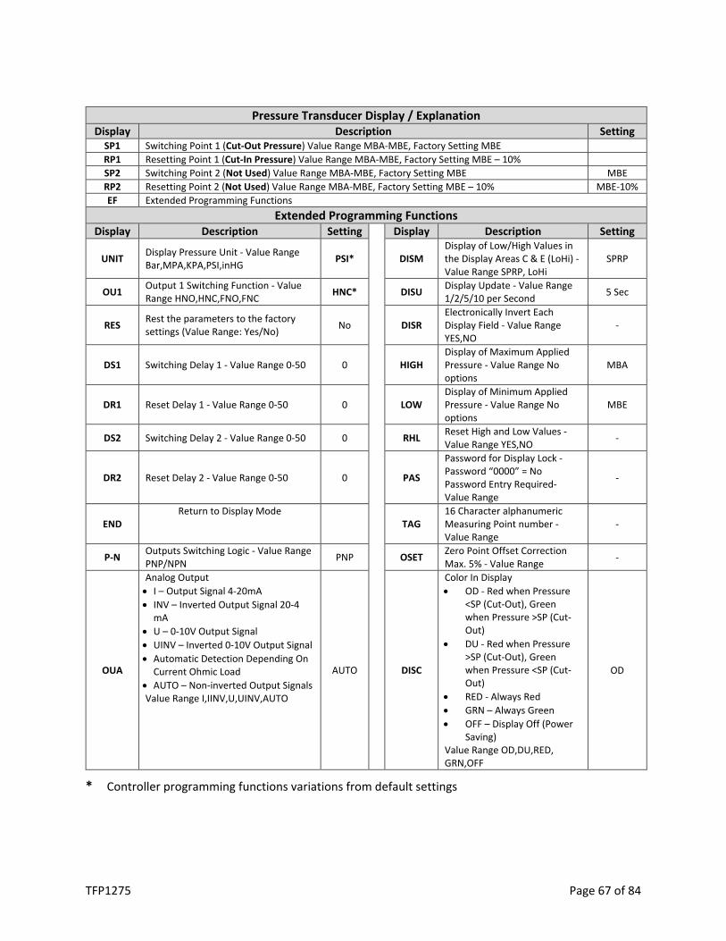
TFP1275 Page 67 of 84
Pressure Transducer Display / Explanation Display Description Setting
SP1 Switching Point 1 (Cut-Out Pressure) Value Range MBA-MBE, Factory Setting MBE RP1 Resetting Point 1 (Cut-In Pressure) Value Range MBA-MBE, Factory Setting MBE – 10% SP2 Switching Point 2 (Not Used) Value Range MBA-MBE, Factory Setting MBE MBE RP2 Resetting Point 2 (Not Used) Value Range MBA-MBE, Factory Setting MBE – 10% MBE-10% EF Extended Programming Functions
Extended Programming Functions Display Description Setting Display Description Setting
UNIT Display Pressure Unit - Value Range Bar,MPA,KPA,PSI,inHG PSI* DISM
Display of Low/High Values in the Display Areas C & E (LoHi) - Value Range SPRP, LoHi
SPRP
OU1 Output 1 Switching Function - Value Range HNO,HNC,FNO,FNC HNC* DISU Display Update - Value Range
1/2/5/10 per Second 5 Sec
RES Rest the parameters to the factory settings (Value Range: Yes/No) No DISR
Electronically Invert Each Display Field - Value Range YES,NO
-
DS1 Switching Delay 1 - Value Range 0-50 0 HIGH Display of Maximum Applied Pressure - Value Range No options
MBA
DR1 Reset Delay 1 - Value Range 0-50 0 LOW Display of Minimum Applied Pressure - Value Range No options
MBE
DS2 Switching Delay 2 - Value Range 0-50 0 RHL Reset High and Low Values - Value Range YES,NO -
DR2 Reset Delay 2 - Value Range 0-50 0 PAS
Password for Display Lock - Password “0000” = No Password Entry Required- Value Range
-
END Return to Display Mode
TAG 16 Character alphanumeric Measuring Point number - Value Range
-
P-N Outputs Switching Logic - Value Range PNP/NPN PNP OSET Zero Point Offset Correction
Max. 5% - Value Range -
OUA
Analog Output • I – Output Signal 4-20mA • INV – Inverted Output Signal 20-4
mA • U – 0-10V Output Signal • UINV – Inverted 0-10V Output Signal • Automatic Detection Depending On
Current Ohmic Load • AUTO – Non-inverted Output Signals Value Range I,IINV,U,UINV,AUTO
AUTO DISC
Color In Display • OD - Red when Pressure
<SP (Cut-Out), Green when Pressure >SP (Cut-Out)
• DU - Red when Pressure >SP (Cut-Out), Green when Pressure <SP (Cut-Out)
• RED - Always Red • GRN – Always Green • OFF – Display Off (Power
Saving) Value Range OD,DU,RED, GRN,OFF
OD
* Controller programming functions variations from default settings

TFP1275 Page 68 of 84
Pressure Transducer Error and Warning Messages OL - OVERPRESS Applied Pressure > End of Measuring Range Set Pressure within the Measuring Range UL - UNDERPRESS Applied Pressure > Start of Measuring Range ERR1 - GEN.ERROR General Error Contact Johnson Controls ERR2 - SHORTOUT1 Short Circuit Present Output 1 Rectify Short-Circuit and Disconnect
Supply Voltage Temporarily to Return Outputs to Normal Operation
ERR2 - SHORTOUT2 Short Circuit Present Output 2
ERR3 - OVERVOLTG Supply Voltage >30 VDC1 Correct Power Supply Voltage ERR4 - LOWVOLTG Supply Voltage <17 VDC1 ATT1 - SHIFT RP1 Switching Point is Set Below Existing Resetting Point.
The Resetting Point is Automatically Set with Smallest Possible Hysteresis Below New Switching Point
Press ◊ Button to Acknowledge Message ATT1 - SHIFT RP2
ATT2 – ADJ>LIMIT During Zero Point Adjustment, Applied Pressure is Outside Permissible Limits of 5% of the Range
Press ◊ Button to Acknowledge Message
LOCK - KEYLOCKED If Key Lock is Active, System will Attempt to go into Programming Mode
Enter Password
1 The Outputs Switch Off if the Supply Voltage Exceeds 30VDC or Falls Below 17VDC
FILTER REPLACEMENT
TYCO Nitrogen Generator Filters
The stand-alone nitrogen generator models contain three (3) separate cartridge filters and a water separator. It is recommended that each filter be replaced at a minimum as part of an annual preventative maintenance program. Johnson Controls offers a replacement filter kit for each model. When maintained properly the nitrogen separation membrane will have an expected service life of 20 years.
Differential pressure indicators are included on the center and left filter housings to provide a visual indication when the cartridge filters are dirty and need replacement. The filter housings have a “Green” area near the base of the top of the housing to indicate flow through the filter housing.
The visual indications are:
• Indicator with “Green” area displayed - Air flow through the generator filters is acceptable. • Indicator with “Green” area NOT displayed - cartridge filters are dirty and filters need to be
replaced immediately.
Johnson Controls recommends that all cartridge filters (Filters 1,2 & 3) in the nitrogen generator be replaced once a “Green” indication is not displayed.

TFP1275 Page 69 of 84
Stand-Alone Nitrogen Generator Filter Replacement Kit Installation Instructions (Filter Replacement Kit for NG-1 1150/1500/2000/3000 Nitrogen Generator Cabinet)
Kit Contents:
Part Description Location Qty. 5-Micron Coalescing Filter Right Filter Housing 1 1-Micron Coalescing Filter Center-Left Filter Housing 1 .01-Micron Coalescing Filter Left Filter Housing 1
*Water Separator should be inspected and cleaned during any filter change.
NOTE: Before beginning the filter replacement process, ensure all internal components are cool to the touch. Components can be very hot after long run cycles and can present risk of injury.
Replacement Guide:
1. Isolate nitrogen generator by closing inlet and outlet valves.
2. Drain air pressure from unit by slowly opening air bleed-off valve adjacent to the filter assembly.
3. Remove filter housing of 5-Micron Coalescing Filter Housing by pulling down on blue housing lock and turning filter housing counter-clockwise.

TFP1275 Page 70 of 84
4. Remove black plastic filter plate underneath filter by turning counter-clockwise. Remove old Coalescing Filter from the filter housing.
5. Replace with new 5-Micron Coalescing Filter, re-install black filter plate, re-install filter housing turning filter housing clockwise until blue housing lock latches.
6. Repeat this process for 1-Micron and .01-Micron filters adjacent to water separator, using the kit contents table as a guide to match the filters with the correct housings. Be very careful to do this process one filter at a time to ensure the filters do not get mixed in the process.

TFP1275 Page 71 of 84
NOTE: The 1-Micron and .01-Micron Filters do not include black plastic filter plate and screw directly into the top of the housing.
.01-Micron Coalescing Filter 1-Micron Coalescing Filter Water Separator 5-Micron Coalescing Filter
.01-Micron Coalescing Filter 1-Micron Coalescing Filter
7. Inspect Water Separator and clean as necessary.

TFP1275 Page 72 of 84
8. Close air bleed-off valve.
9. Slowly open inlet and outlet valves.
For further filter replacement orders, contact Johnson Controls. Visit the CONTACT US page at www.tyco-fire.com for the contact information by location.

TFP1275 Page 73 of 84
VENT MAINTENANCE
TYCO Oxygen Removal Vents (TAV-D / TSV-D)
Maintenance Instructions
1. TAV-D Vent - The TYCO TAV-D Vents must be inspected annually at minimum. While isolation ball valve is in the open position, check for air/water leaks and ensure the pressure gauge is displaying normal system pressure.
2. TSV-D SMART Vent - The TYCO TSV-D Vents must be inspected annually at minimum. While isolation ball valve is in the open position and the VENT button is illuminated, check for air/water leaks and ensure the pressure gauge is displaying normal system pressure.
3. TAV-D / TSV-D Vents - While isolation ball valve is in the closed position the inspection must include the condition of the in-line filter, and blockage in the “Y” strainer and restricted venting orifice. Depressurize the in-line filter housing by pressing the pressure relief valve on the bottom of the housing. Twist the filter housing counter-clockwise until it can be removed to expose the filter element.
4. TAV-D / TSV-D Vents - The filter element in the in-line filter should be replaced if a visual inspection reveals a significant collection of debris.
In-Line Filter Replacement Instructions
1. Close the isolation ball valve.
2. Depressurize the housing by pressing the pressure relief valve on the bottom of the in-line filter housing.
3. Remove the lower section of the in-line filter housing by turning the filter housing counterclockwise.
NOTE: A rubber o-ring/seal is located between the upper and lower sections of the filter housing.
4. Remove the old filter by turning the filter counterclockwise.
5. Replace with new filter. The filter is secured to the housing by turning the filter clockwise.
NOTE: Ensure the filter is secured only finger/hand tight.
6. Install the rubber o-ring/seal on the lower section of the filter housing.
7. Re-install the filter housing by turning the filter housing clockwise.
NOTE: Ensure the filter housing is secured only finger/hand tight.
8. Open the isolation ball valve.
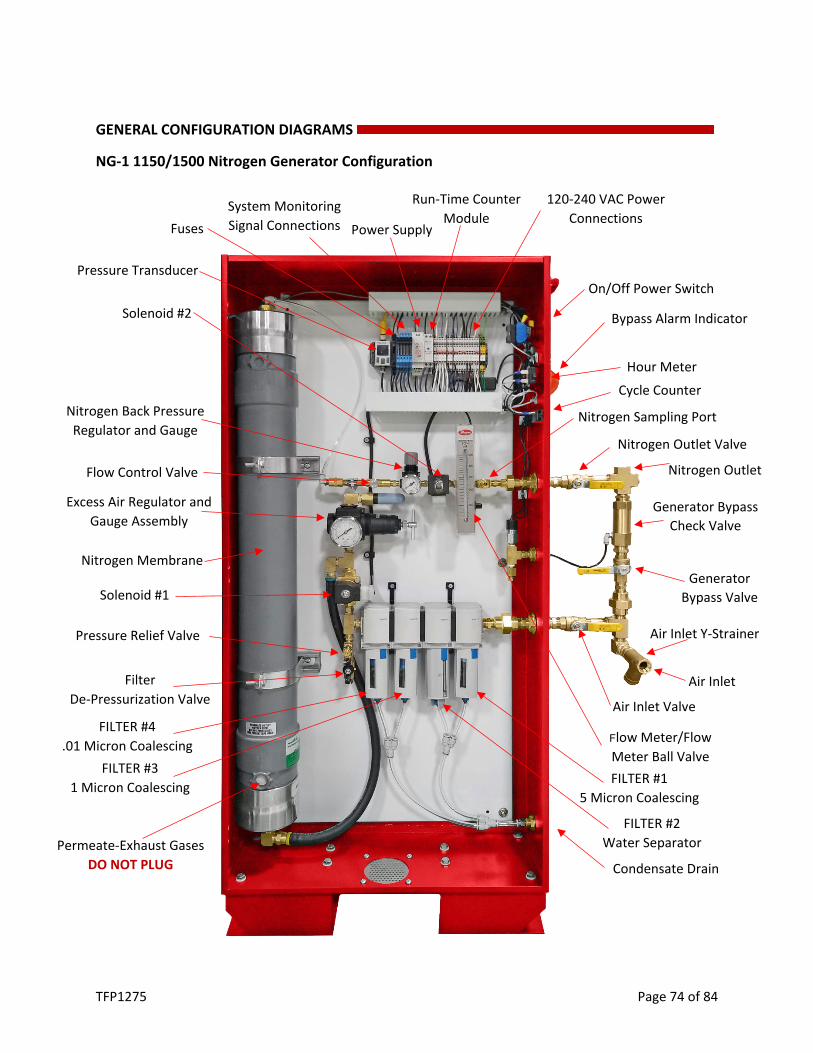
TFP1275 Page 74 of 84
GENERAL CONFIGURATION DIAGRAMS
NG-1 1150/1500 Nitrogen Generator Configuration
Flow Meter/Flow Meter Ball Valve
Pressure Transducer
Fuses
FILTER #1 5 Micron Coalescing
FILTER #4 .01 Micron Coalescing
FILTER #3 1 Micron Coalescing
Flow Control Valve
Solenoid #1
Excess Air Regulator and Gauge Assembly
Solenoid #2
Nitrogen Sampling Port Nitrogen Back Pressure Regulator and Gauge
On/Off Power Switch
Nitrogen Outlet Valve
Nitrogen Outlet
Generator Bypass Valve
Air Inlet
Air Inlet Valve
Bypass Alarm Indicator
Hour Meter
Nitrogen Membrane
System Monitoring Signal Connections Power Supply
120-240 VAC Power Connections
Run-Time Counter Module
Pressure Relief Valve
Filter De-Pressurization Valve
Air Inlet Y-Strainer
Generator Bypass Check Valve
Cycle Counter
Permeate-Exhaust Gases DO NOT PLUG
FILTER #2 Water Separator
Condensate Drain

TFP1275 Page 75 of 84
NG-1 2000/3000 Nitrogen Generator Configuration
Nitrogen Membrane
Excess Air Regulator and Gauge
Filter De-Pressurization
Valve
Pressure Transducer
Nitrogen Back Pressure Regulator and Gauge
Solenoid #1
Pressure Relief Valve
Flow Control Valve
Fuses
Power Supply Run-Time Counter Module
120-240 VAC Power Connections System Monitoring
Signal Connections
Solenoid #2
Permeate-Exhaust Gases DO NOT PLUG
Air Inlet Valve
Air Inlet
Generator Bypass Valve
Nitrogen Sampling Port
Short Cycle Prevention Assy.
FILTER #4 .01 Micron Coalescing
FILTER #3 1 Micron Coalescing
FILTER #1 5 Micron Coalescing
Air Inlet Y-Strainer
Generator Bypass Check Valve
FILTER #2 Water Separator
Nitrogen Outlet Valve
Nitrogen Outlet
Cycle Counter
Bypass Alarm Indicator
Generator Run Time Hour Meter
On/Off Power Switch
Flow Meter and Flow Meter Isolation Valve
Condensate Drain

TFP1275 Page 76 of 84
TROUBLESHOOTING
Safety Warning
All troubleshooting is to be performed by qualified personnel. Prior to any system troubleshooting on the nitrogen generation system, ensure that the nitrogen generator is isolated from the compressed air supply and all system risers. Be aware of pressurized system components as some of the troubleshooting procedures require system components to be pressurized. Failure to do so can result in system damage and/or personal injury.
SYMPTOM PROBLEM RESOLUTION Nitrogen generator not running No lights or indicators on generator Check incoming power and fuses in nitrogen generator
Nitrogen generator not running
Generator lights and indicators on
The nitrogen generator may be in the depressurizing phase of the breathing cycle. When sprinkler system reaches the generator cut-in pressure, the nitrogen generator will automatically turn on. (normal operation) Check status of solenoids/angle seat valves in generator. o Solenoids should be energized (LED on) when running o Angle Seat Valve should be energized (center pin out) when
running. Check system pressure: o If system pressure above cut-in pressure of generator, reduce
system pressure below cut-in pressure and check generator operation.
o If system pressure below cut-in pressure of generator, check power to air compressor.
Nitrogen not flowing in sprinkler system
Verify nitrogen generator is not in by-pass mode Place nitrogen generator in nitrogen generation mode.
While the nitrogen generator running, use a gas analyzer to measure the nitrogen output quality. (See Commissioning / Maintenance Section)
If the nitrogen reading is below 97%, contact Johnson Controls.
While the nitrogen generator running, measure generator production flow rate through flow meter. (See Commissioning / Maintenance Section)
Compare generator production rate to system commissioning documentation and/or factory test report. If significantly lower, contact Johnson Controls.
Nitrogen generator is short cycling
Pressure on generator digital display decreases after generator shuts off with sprinkler system AMD open.
Close inlet to sprinkler system AMD, if pressure continues to decrease, check for leaks in generator cabinet and supply line.
With AMD closed, the pressure on generator digital display remains constant after generator shuts off.
• AMD partially opening allowing minimal nitrogen flow to sprinkler system results in generator short cycling. Adjust, repair or replace AMD as necessary.
• Verify the AMD pressure is 3-5 psig (.2-.3 bar) above nitrogen generator cut-in pressure. Adjust as necessary
• Adjust the Short Cycling Prevention Regulator
Air compressor is short cycling
Air compressor short cycles with the nitrogen generator in the standby mode
Check supply line from air compressor to nitrogen generator for leaks.
Nitrogen generator remains on while air compressor short cycles
• Verify the excess air regulator pressure is set 5-10 psig (.3-.7) below air compressor cutout pressure. Adjust as necessary. Air compressor should continue to operate until nitrogen generator shuts off. (See Commissioning / Maintenance Section)
• Verify production flow rate and nitrogen purity levels Nitrogen generator running continuously or running more than 4 hours
Generator in nitrogen generation mode with AMD open and unable to pressurize sprinkler system.
Close AMD. If system supply line pressurizes, check sprinkler system for leaks or inoperable AMD (AMD not automatically closing).

TFP1275 Page 77 of 84
WIRING DIAGRAMS

TFP1275 Page 78 of 84

TFP1275 Page 79 of 84

TFP1275 Page 80 of 84

TFP1275 Page 81 of 84

TFP1275 Page 82 of 84
Appendix
SYSTEM SUMMARY
Existing Air Compressor Cut-In (psig/bar)
Cut-Out (psig/bar)
Gen. Backup
30-Min. Fill Manufacturer Model Number Serial Number
New Air Compressor Cut-In
(psig/bar) Cut-Out
(psig/bar) Manufacturer Model Number Serial Number Air Maintenance Device (AMD) Pressure
(psig/bar)
Sprinkler System Pressure (psig/bar) Manufacturer Model Number
Trip Pressure Low Air Alarm High Alarm Nitrogen Generator Cut-In
(psig/bar) Cut-Out
(psig/bar) Model Number Serial Number Nitrogen Inerting Vent Vent
Serial Number Control Panel Serial Number
Orifice Model Number
Vent Pressure Regulator (psig)

TFP1275 Page 83 of 84
INSPECTION, TESTING, AND MAINTENANCE REPORT
Customer Date Address Inspector City Customer No. State Contract No. ZIP Inspection No.
All maintenance is to be performed by qualified personnel. Prior to any system maintenance on the nitrogen generation system, ensure that the nitrogen generator is isolated from the compressed air supply and all system risers. Ensure that the nitrogen generation system and the associated piping that is to be manipulated is completely depressurized prior to performing any maintenance. Failure to do so can result in system damage and/or personal injury.
Sprinkler System Information (psig) N/A Verified Qty of Systems AMD Set Pressure AMD Manufacturer Low Air Alarm Pressure AMD Model No. System Trip Pressure
Nitrogen Generator Air Compressor Information Cut-In
(psig) Cut-Out
(psig) N/A Verified Manufacturer Model No. Serial No.
Existing/Backup Air Compressor Information Cut-In
(psig) Cut-Out
(psig) N/A Verified Manufacturer Model No. Serial No
Nitrogen Generator Information Cut-In
(psig) Cut-Out
(psig) N/A Verified Manufacturer Model No. Serial No.
Air Compressor – Quarterly Maintenance Hrs. N/A Verified Verify run time (hours) on air compressor (use nitrogen generator hour meter) Verify compressor is turning on/off at low/high pressure Verify pressure gauges are in working order (replace as necessary) Verify all manual valves fully open and close (repair or replace as necessary) Verify all manual valves operate smooth-clean and un-corroded (repair/replace if needed) Check air compressor filter(s) (clean or replace as necessary) Check electrical connections in control box and pressure switch (repair as necessary) Check air compressor and supply piping for leaks (repair as necessary)
Air Compressor – Splash Lubricated Check drive belt and drive belt tension (repair or replace as necessary) Replace crankcase oil (3 months or 500 hours whichever comes first)
Air Compressor – Oil-Less Rebuild compressor cylinders (5,000 hours)

TFP1275 Page 84 of 84
Nitrogen Generator – Quarterly Maintenance Hrs. Count: N/A Verified
Verify run time (hours) on nitrogen generator – Hour Meter Verify cycle count on nitrogen generator – Cycle Counter Verify nitrogen generator is turning on/off at low/high pressure Verify pressure gauges are in working order (replace as necessary) Verify all manual valves fully open and close (repair or replace as necessary) Verify all manual valves operate smooth-clean and un-corroded (repair/replace if needed) Check coalescing filter gauge(s) (replace filters as necessary) Indication: Check electrical connections in cabinet, control box and pressure switch (repair if needed) Verify correct nitrogen purity level out of cabinet sampling port N2 Purity: Verify nitrogen production level through cabinet flow meter SCFH: Check nitrogen generator and supply piping for leaks (repair as necessary) Nitrogen Generator – Annual Maintenance Hrs. Count:
N/A Verified Verify run time (hours) on nitrogen generator – Hour Meter Verify cycle count on nitrogen generator – Cycle Counter Verify nitrogen generator is turning on/off at low/high pressure Verify pressure gauges are in working order (replace as necessary) Verify all manual valves fully open and close (repair or replace as necessary) Verify all manual valves operate smooth-clean and un-corroded (repair/replace if needed) Replace coalescing filters Check electrical connections in cabinet, control box and pressure switch (repair if needed) Verify correct nitrogen purity level out of cabinet sampling port N2 Purity: Verify nitrogen production level through cabinet flow meter SCFH: Check nitrogen generator and supply piping for leaks (repair as necessary) Nitrogen Vents – Quarterly Maintenance N/A Verified Inspect “Y” strainer for dirt and debris (clean as necessary) Insect vent filter dirt and debris (clean/replace as necessary) Verify pressure regulator and gauges are in working order (replace as necessary) Verify the pressure regulator closes at the determined set pressure (repair/replace if needed) Verify all manual valves fully open and close (repair or replace as necessary) Verify all manual valves operate smooth-clean and un-corroded (repair/replace if needed) Check electrical connections in control cabinet and solenoid (SMART Vent) (repair if needed) Verify correct nitrogen purity level out of vent sampling port N2 Purity: Check vent and piping for leaks (repair as necessary) Corrosion Monitoring – Quarterly Maintenance N/A Verified Verify corrosion detector has not activated (replace probe/detector if needed) Verify remote test station batteries operational (replace if needed) Verify all manual valves fully open and close (repair or replace if needed) Verify all manual valves operate smooth-clean and un-corroded (repair/replace if needed) Check electrical connections on corrosion detector pressure switch & monitoring equipment Check device and piping for leaks (repair if needed) Permanent Gas Analyzer – Quarterly Maintenance N/A Verified Verify correct nitrogen purity level displayed on Gas Analyzer N2 Purity: Check electrical connections in control cabinet (repair if needed) Check nitrogen sampling tubing for leaks (repair if needed)