1 SECTION 09 06 00 SCHEDULE FOR FINISHES PART I - VA ...
140
09 06 00 - 1 SECTION 09 06 00 SCHEDULE FOR FINISHES PART I – GENERAL 1.1 DESCRIPTION This section contains a coordinated system in which requirements for materials specified in other sections shown are identified by abbreviated material names and finish codes in the room finish schedule or shown for other locations. 1.2 MANUFACTURERS Manufacturer’s trade names and numbers used herein are only to identify colors, finishes, textures and patterns. Products of other manufacturer’s equivalent to colors, finishes, textures and patterns of manufacturers listed that meet requirements of technical specifications will be acceptable upon approval in writing prior to bid date by Resident Engineer and Architect. 1.3 SUBMITALS Submit in accordance with SECTION 01 33 23, SHOP DRAWINGS, PRODUCT DATA, AND SAMPLES provide quadruplicate samples for color approval of materials and finishes specified in this section. 1.4 APPLICABLE PUBLICATIONS A. Publications listed below form a part of this specification to the extent referenced. Publications are referenced in text by basic designation only. B. MASTER PAINTING INSTITUTE: (MPI) 2001....................Architectural Painting Specification Manual
-
Upload
khangminh22 -
Category
Documents
-
view
1 -
download
0
Transcript of 1 SECTION 09 06 00 SCHEDULE FOR FINISHES PART I - VA ...

09 06 00 - 1
SECTION 09 06 00SCHEDULE FOR FINISHES
PART I – GENERAL
1.1 DESCRIPTION
This section contains a coordinated system in which requirements for materials specified in other
sections shown are identified by abbreviated material names and finish codes in the room finish
schedule or shown for other locations.
1.2 MANUFACTURERS
Manufacturer’s trade names and numbers used herein are only to identify colors, finishes, textures
and patterns. Products of other manufacturer’s equivalent to colors, finishes, textures and patterns
of manufacturers listed that meet requirements of technical specifications will be acceptable upon
approval in writing prior to bid date by Resident Engineer and Architect.
1.3 SUBMITALS
Submit in accordance with SECTION 01 33 23, SHOP DRAWINGS, PRODUCT DATA, AND SAMPLES provide
quadruplicate samples for color approval of materials and finishes specified in this section.
1.4 APPLICABLE PUBLICATIONS
A. Publications listed below form a part of this specification to the extent referenced. Publications
are referenced in text by basic designation only.
B. MASTER PAINTING INSTITUTE: (MPI)
2001....................Architectural Painting Specification Manual

09 06 00 - 2
PART 2- PRODUCTS
2.1 DIVISION 03 – CONCRETE
A. SECTION 03 45 00, PRECAST ARCHITECTURAL CONCRETE
Finish Color Texture Finish Manufacturer Mfg. ColorName/No.
Match Existing Match Existing Match Existing Hanson StructuralPrecast
Match Existing
2.2 DIVISON 04 – MASONRY
A. Section 04 05 13, MASONRY MORTARING
Finish Code Manufacturer Mfg. Color Name
Local Types N, S and M Natural
B. Section 04 20 00, UNIT MASONRY
1. FACE BRICK (FB)
Finish Code Size Pattern Manufacturer Mfg. ColorName/No.
FB-1 Modular Stain (Smooth) Robinson Brick Larimer
2.CONCRETE MASONRY UNIT (CMU)
Type Size Pattern Finish Mfg. ColorName/No.
CMU Standard Nominal 6”x8”x16” Running Regular face Natural Grey

09 06 00 - 3
C. Section 04 72 00, CAST STONE MASONRY
Material Size Color, Texture,Finish, Grain
Pattern Stone Source
Calcium SilicateMasonry Units
Nominal 12x24x4 Driftwood,Sandblasted (Match
Existing)
Match Existing ArriscraftInternational
2.3 DIVISION 05 – METALS
A. SECTION 05 12 00, STRUCTURAL STEEL FRAMING
Component Finish Color
Structural Steel Shop Prime per specifications (donot prime items to receive spray-on
fireproofing)
-
B. SECTION 05 31 00, STEEL DECKING, SECTION 05 36 00, COMPOSITE METAL DECKING
Component Color
Steel Deck See Specs
Composite Deck See Specs

09 06 00 - 4
C. SECTION 05 50 00, METAL FABRICATION
Item Finish Color
Handrails (interior) Prime and Paint P-2
Guardrails (interior) Prime and Paint P-2
Stair Stringers Prime and Paint P-2
Underside of Stairs Prime and Paint P-1 (terminate at inside corner)
Steel Pipe Railings (exterior) Prime and Paint P-6
Edge Guards Angles for Opening inSlabs
Prime -
Steel Grating and Frames Galvanize Grating/Prime Frames -
Loose Lintels Prime and Paint P-6
Steel Ladders (exterior) Hot-Dip Galvanize, Prime and Paint P-7
Steel Ladders (interior) Prime and Paint P-2
Steel Ladder Rungs and Brackets Match ladder Match ladder
09 06 00 - 5
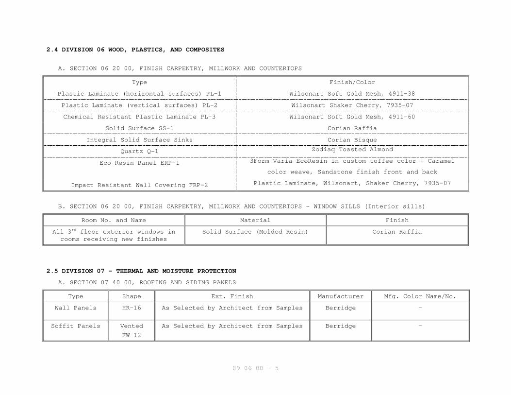
2.4 DIVISION 06 WOOD, PLASTICS, AND COMPOSITES
A. SECTION 06 20 00, FINISH CARPENTRY, MILLWORK AND COUNTERTOPS
Type Finish/Color
Plastic Laminate (horizontal surfaces) PL-1 Wilsonart Soft Gold Mesh, 4911-38
Plastic Laminate (vertical surfaces) PL-2 Wilsonart Shaker Cherry, 7935-07
Chemical Resistant Plastic Laminate PL-3 Wilsonart Soft Gold Mesh, 4911-60
Solid Surface SS-1 Corian Raffia
Integral Solid Surface Sinks Corian Bisque
Quartz Q-1 Zodiaq Toasted Almond
Eco Resin Panel ERP-1 3Form Varia EcoResin in custom toffee color + Caramel
color weave, Sandstone finish front and back
Impact Resistant Wall Covering FRP-2 Plastic Laminate, Wilsonart, Shaker Cherry, 7935-07
B. SECTION 06 20 00, FINISH CARPENTRY, MILLWORK AND COUNTERTOPS - WINDOW SILLS (Interior sills)
Room No. and Name Material Finish
All 3rd floor exterior windows inrooms receiving new finishes
Solid Surface (Molded Resin) Corian Raffia
2.5 DIVISION 07 - THERMAL AND MOISTURE PROTECTION
A. SECTION 07 40 00, ROOFING AND SIDING PANELS
Type Shape Ext. Finish Manufacturer Mfg. Color Name/No.
Wall Panels HR-16 As Selected by Architect from Samples Berridge -
Soffit Panels Vented
FW-12
As Selected by Architect from Samples Berridge -

09 06 00 - 6
B. SECTION 07 54 23, THERMOPLASTIC POLYOLEFIN (TPO) ROOFING
Finish Manufacturer Mfg. Color Name/No.
White See Specs White
C. SECTION 07 60 00, FLASHING AND SHEET METAL
Item Material Finish
Copings Galvanized Steel Fluorocarbon Finish
Exposed Flashings Galvanized Steel Fluorocarbon Finish
D. SECTION 07 71 00, ROOF SPECIALITIES
Item Material Finish Manufacturer Color
Roof Hatch Steel Prime and Paint Bilco P-7
E. SECTION 07 92 00, JOINT SEALANTS
Location Color Manufacturer Manufacturer Color
Masonry Expansion Joints By Architect from Samples
Precast Concrete Panels By Architect from Samples
New to Existing Walls By Architect from Samples
Building Expansion Joints By Architect from Samples
Masonry Sealed Joints By Architect from Samples
Stone Sealed Joints By Architect from Samples

09 06 00 - 7
F. SECTION 07 95 13, EXPANSION JOINT COVER ASSEMBLIES
Material Finish Manufacturer Mfg. Model No.
Floor Component
Cover Plate(interior only)
Aluminum Clear Anodized C/S Group PC-400
Wall Component
Cover Plate
(interior only)
Aluminum Clear Anodized C/S Group AFW & AFWC Series
2”, 4” and 6”
Ceiling Component
Cover Plate
(interior only)
Aluminum Clear Anodized C/S Group AFW & AFWC Series
2” and 6”
Exterior Wall
Cover Plate
Aluminum Mill C/S Group ESC-400 and ESC-600
Roof Covers Aluminum Mill C/S Group SRJ-600 and SRJW-600
2.6 DIVISION 08 - OPENINGS
A. SECTION 08 11 13, HOLLOW METAL DOORS AND FRAMES
Paint both sides of door and frames same color
Component Color of Paint Type and Gloss
Door (Interior) P-2 / Semi-Gloss
Frame (Interior) P-2 / Semi-Gloss
Window frame (Interior) P-2 / Semi-Gloss
Door (Exterior) P-6 / Semi-Gloss
Frame (Exterior) P-6 / Semi-Gloss

09 06 00 - 8
B. SECTION 08 14 00, WOOD DOORS
Component Finish/Color
Doors Select White Birch – Clear
C. SECTION 08 31 13, ACCESS DOORS AND FRAMES
Material Finish/Color
Steel P-1
D. SECTION 08 41 13, EXTERIOR ALUMINUM-FRAMED ENTRANCES AND STOREFRONTS
Material Finish Manufacturer Manufacturer Color Name/No.
Aluminum Anodized Kawneer Bronze, Selected by Architect
Glass G-1 and G-2 AGC or PPG See Section 08 80 00
E. SECTION 08 41 13, INTERIOR ICU-STYLE DOOR SYSTEMS
Material Finish Manufacturer Manufacturer Color Name/No.
Aluminum Anodized Besam EntranceSolutions
Clear Anodized
Glass G-1 AGC or PPG Clear Tempered
F. SECTION 08 63 00, METAL-FRAMED SKYLIGHTS
Component Material Manufacturer Mfg. Color Name/No.
Frame Aluminum Kalwall Aluminum (FluoropolymerCoated)
Glazing Translucent Fiberglass Kalwall White

09 06 00 - 9
G. SECTION 08 71 00, BUILDERS HARDWARE
Item Material Finish
Door Hardware See Specs See Specs
H. SECTION 08 80 00, GLAZING
Glazing Type Manufacturer Mfg. Color Name/No.
G-1 PPG or AGC Clear Tempered
G-2 PPG or AGC Bronze Tempered, Final color asselected by Architect
G-3 Pilkington Mirropane T.M.
G-4 FireLite Plus Clear
I. SECTION 08 90 00, LOUVERS AND WALL VENTS
Item Material Finish Manufacturer Mfg. Color Name/No.
Louver Aluminum Kynar500/Hylar 5000 Ruskin As Selected by Architect
2.7 DIVISION 09 - FINISHES
A. SECTION 09 30 13, CERAMIC TILING
1. CERAMIC MOSAIC TILE (FT)
Color Size Shape Pattern Manufacturer Mfg. Color Name/No.
Oro Miele CR83 2” x 2” Square Costa Rei American Olean Oro Miele CR83

09 06 00 - 10
2. SECTION 09 30 13, CERAMIC TILING
Finish Code Manufacturer Mfg. Color Name/No
CT-1 American Olean Costa Rei, Oro Miele CR83,
12” x 12”
CT-2 American Olean Costa Rei, Oro Meile CR83, Bullnose3” x 12”
3. SECTION 09 30 13, GROUT
Finish Code Manufacturer Mfg. Color Name/No.
GT-1 Laticrete Mushroom, 39
4. SECTION 09 30 13, MARBLE THRESHOLDS
Marble Type Manufacturer Mfg. Color Name/No.
Thassos American Olean White Marble M420

09 06 00 - 11
B. SECTION 09 51 00, ACOUSTICAL CEILINGS
Finish Code Component Color Pattern Manufacturer Mfg Name/No.
Exposed SuspensionSystem
White Armstrong CeilingSystems
Prelude XL 15/16”Exposed Tee System
AT-1 Type III
Form 2
White Armstrong CeilingSystems
Fissured, 755
AT-2 Type III
Form 2
White Armstrong CeilingSystems
Dune Second Look,2712
AT-3 Type VXX White Gold Bond Gridstone GypsumCeiling Panels with2-mil vinyl laminate
finish
C. SECTION 09 65 13, RESILIENT BASE STAIR TREADS AND ACCESSORIES
Finish Code Item Height Manufacturer Mfg Name/No.
RB-1 Rubber Base (RB) 4 ½” Johnsonite Diplomat Cinnamon,MW-76-A
RB-2 Rubber Base (RB) 4” Johnsonite Cove Cinnamon, DC-76
RB-3 Rubber Base (RB) 4” Johnsonite Silhouette Cinnamon,MW-76-J
RST-1 Resilient StairTreads and Riser
(RST)
Johnsonite Raised SquareTread/Riser
Cinnamon, RTR-SQ
IRB-1 Integral Rubber Base 6” Nora Sanitary Base Motherof Pearl, 1581
PEW-1 Resilient Chair Rail 3” Johnsonite Fortis Cinnamon,CHR-76

09 06 00 - 12
D. SECTION 09 65 16, VINYL SHEET FLOORING (VSF)
Finish Code Pattern name Manufacturer Mfg. Color Name/No.
VSF-1 Beechnut Teknoflor Natural Collection, 52209
VSF-2 Medium Walnut Teknoflor Fireside Collection, 31097
VSF-3 Juparana Taupe Teknoflor Granite II Collection, 8652
VSF-4 Comera Teknoflor Agate Collection, 09023
VSF-5 Apple Teknoflor Rainscapes Collection, 22005
E. SECTION 09 65 16, VINYL SHEET FLOORING, HEAT WELDED SEAMS (WSF)
Finish Code Pattern name Manufacturer Mfg. Color Name/No.
WSF-1 WR52209 Teknoflor To match VSF-1
WSF-2 WR8652 Teknoflor To match VSF-3
F. SECTION 09 65 16, RUBBER SHEET FLOORING (SRF)
Finish Code Item Height Manufacturer Mfg Name/No.
SRF-1 Sheet RubberFlooring (SRF)
3.0 mm sheet Nora Noraplan/Environcare Morning
Dew, 2946
SRF-2 Sheet RubberFlooring (SRF)
3.0 mm sheet Nora Noraplan/Environcare Sage,
2949
H. SECTION 09 68 00, CARPET (CP)
Finish Code Pattern Manufacture Mfg. Color Name/No.
CP-1 Karira 40003 Tandus Burnished Copper, 01608
CP-2 Hercules NOP Van Dijk Zinc, 06

09 06 00 - 13
1. SECTION 09 68 00, CARPET EDGE STRIP
Finish Code Material Manufacturer Mfg. Color Name/No.
CES-01 Metal Schluter Annodized Aluminum
CES-02 Vinyl Johnsonite Cinnamon, 76
I. SECTION 09 72 16, VINYL COATED FABRIC WALLCOVERING (W)
Finish Code Manufacturer Mfg. Color Name/No.
W-1 Maharam Sari 399426, Goldenrod 025
W-2 MDC, Bolta Jessamine Skipping Stone, BB-JE-17
W-3 MDC, Bolta Jessamine So Succulent, BB-JE-11
J. SECTION 09 91 00, PAINT AND COATINGS
1. MPI Gloss and Sheen Standards
Gloss @60 Sheen @85
Gloss Level 1 a traditional matte finish-flat max 5 units, and max 10 units
Gloss Level 2 a high side sheen flat-“a velvet-like” max 10 units, and
finish 10-35 units
Gloss Level 3 a traditional “egg-shell like” finish 10-25 units, and 10-35 units
Gloss Level 4 a “satin-like” finish 20-35 units, and min. 35 units
Gloss Level 5 a traditional semi-gloss 35-70 units
Gloss Level 6 a traditional gloss 70-85 units
Gloss level 7 a high gloss more than 85 units

09 06 00 - 14
2. Paint code Gloss Manufacturer Mfg. Color Name/No.
P-1 Level 5 Sherwin Williams Antique White, SW6119
P-2 Level 5 Sherwin Williams Camelback, SW6122
P-3 Level 5 Sherwin Williams Ruskin Room Green, SW0042
P-4 Level 5 Sherwin Williams Golden Fleece, SW6388
P-5 Level 5 Benjamin Moore Cloudy Sky, 2122-30
P-6 Level 5 Sherwin Williams Bronze to match storefronts
P-7 Level 5 Sherwin Williams Match color selected formetal wall panels at
penthouse
Mechanical and ElectricalIdentification Painting
Refer to Painting Specification
2.8 DIVISION 10 - SPECIALTIES
A. SECTION 10 14 00, INTERIOR SIGNS
Sign Type Component Manufacturer Mfg. Color Name/No.
Arch Fusion 29 See Schedule Takeform See Schedule and Spec
09 06 00 - 15
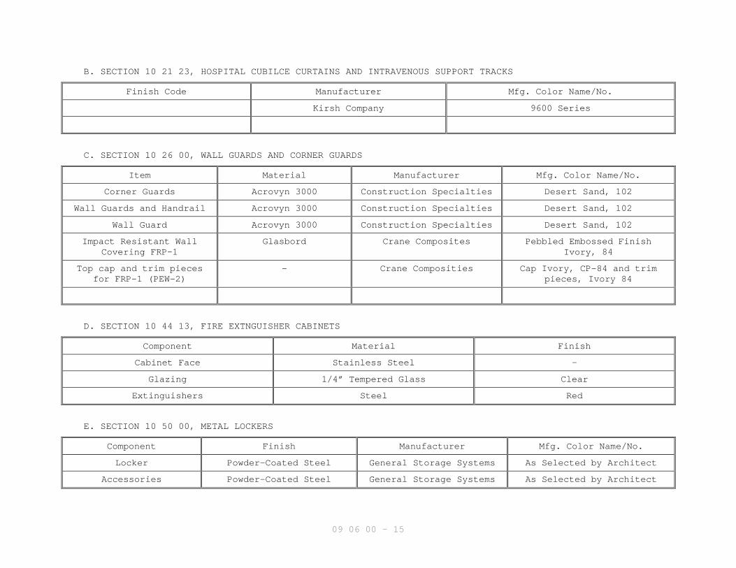
B. SECTION 10 21 23, HOSPITAL CUBILCE CURTAINS AND INTRAVENOUS SUPPORT TRACKS
Finish Code Manufacturer Mfg. Color Name/No.
Kirsh Company 9600 Series
C. SECTION 10 26 00, WALL GUARDS AND CORNER GUARDS
Item Material Manufacturer Mfg. Color Name/No.
Corner Guards Acrovyn 3000 Construction Specialties Desert Sand, 102
Wall Guards and Handrail Acrovyn 3000 Construction Specialties Desert Sand, 102
Wall Guard Acrovyn 3000 Construction Specialties Desert Sand, 102
Impact Resistant WallCovering FRP-1
Glasbord Crane Composites Pebbled Embossed FinishIvory, 84
Top cap and trim piecesfor FRP-1 (PEW-2)
- Crane Composities Cap Ivory, CP-84 and trimpieces, Ivory 84
D. SECTION 10 44 13, FIRE EXTNGUISHER CABINETS
Component Material Finish
Cabinet Face Stainless Steel -
Glazing 1/4” Tempered Glass Clear
Extinguishers Steel Red
E. SECTION 10 50 00, METAL LOCKERS
Component Finish Manufacturer Mfg. Color Name/No.
Locker Powder-Coated Steel General Storage Systems As Selected by Architect
Accessories Powder-Coated Steel General Storage Systems As Selected by Architect

09 06 00 - 16
2.9 DIVISION 12 - FURNISHINGS
A. SECTION 12 24 00, WINDOW SHADES
Component Material Manufacturer Mfg. Color Name/No.
Shade Cloth See Specs MechoShades 0911 Porcelain
Support Hardware See Specs MechoShades -
2.10 DIVISION 22 - PLUMBING
A. SECTION 22 40 00, PLUMBING FIXTURES AND TRIM
Item Color
Water Closet White
Counter-Mounted Sinks Stainless Steel
Scrub Sinks White
Lavatories White
Mop Sink White
Service Sink White
Shower Pan As Selected by Architect from Samples
Drinking Fountains Stainless Steel
Patient Swingettes Tops – Corian Raffia
Base – Arvinyl, Flamenco Cherry #806250 – 7 mil
Utility Boxes and Covers Stainless Steel

09 06 00 - 17
2.11 DIVISON 26 - ELECTRICAL
A. SECTION 26 51 00, BUILDING LIGHTING INTERIOR
Fixture Type Exterior Finish Color
See Luminaire Schedule - -
PART III EXECUTION
3.1 FINISH SCHEDULES & MISCELLANEOUS ABBREVIATIONS
FINISH SCHEDULE & MISCELLANEOUS ABBREVIATIONS
Term Abbreviation
Access Flooring AFAccordion FoldingPartition
AFP
Acoustical Ceiling ATAcoustical Ceiling,Special Faced
AT (SP)
Acoustical Metal PanCeiling
AMP
Acoustical Wall Panel AWPAcoustical WallTreatment
AWT
Acoustical Wallcovering AWFAnodized AluminumColored
AAC
Anodized AluminumNatural Finish
AA
Baked On Enamel BEBrick Face BRBrick Flooring BFBrick Paving BPCarpet CPCarpet Athletic Flooring CAF
Carpet Module Tile CPTCeramic Glazed FacingBrick
CGFB
Ceramic Mosaic Tile FTCTConcrete CConcrete Masonry Unit CMUDivider Strips Marble DS MBEpoxy Coating ECEpoxy Resin Flooring ERFExisting EExposed Divider Strips EXPExterior EXTExterior Finish System EFSExterior Paint EXT-PExterior Stain EXT-STFabric Wallcovering WFFacing Tile SCTFeature Strips FSFloor Mats & Frames FMFloor Tile, Mosaic FTFluorocarbon FCFolding Panel Partition FPFoot Grille FGGlass Masonry Unit GUMUGlazed Face CMU GCMUGlazed Structural FacingTile
SFTU

09 06 00 - 18
Granite GTGypsum Wallboard GWBHigh Glazed Coating SCLatex Mastic Flooring LMLinear Metal Ceiling LMCLinear Wood Ceiling LWCMarble MBMaterial MATMortar MMulti-Color Coating MCNatural Finish NFPaint PPaver Tile PVTPerforated Metal Facing(Tile or Panels)
PMF
Plaster PLPlaster High Strength HSPLPlaster Keene Cement KCPlastic Laminate HPDLPolypropylene FabricWallcovering
PFW
Porcelain Paver Tile PPTQuarry Tile QTRadiant Ceiling PanelSystem
RCP
Resilient Stair Tread RSTRubber Base RB
Rubber Tile Flooring RTSpandrel Glass SLGStain STStone Flooring SFStructural Clay SCSuspension DecorativeGridsGrids
SDG
Terrazzo Portland Cement PCTTerrazzo Tile TTTerrazzo, Thin SetTextured Gypsum CeilingPanel
TGC
Textured Metal CeilingPanel
TMC
Thin set Terrazzo TSTVeneer Plaster VPVinyl Base VBVinyl Coated FabricWallcovering
W
Vinyl Composition Tile VCTVinyl Sheet Flooring VSFVinyl Sheet Flooring(Welded Seams)
WSF
Wall Border WBWood WD
3.2 FINISH SCHEDULE SYMBOLS
Symbol Definition** Same finish as adjoining walls- No color requiredE ExistingXX To match existingEFTR Existing finish to remainRM Remove
09 06 00 - 19
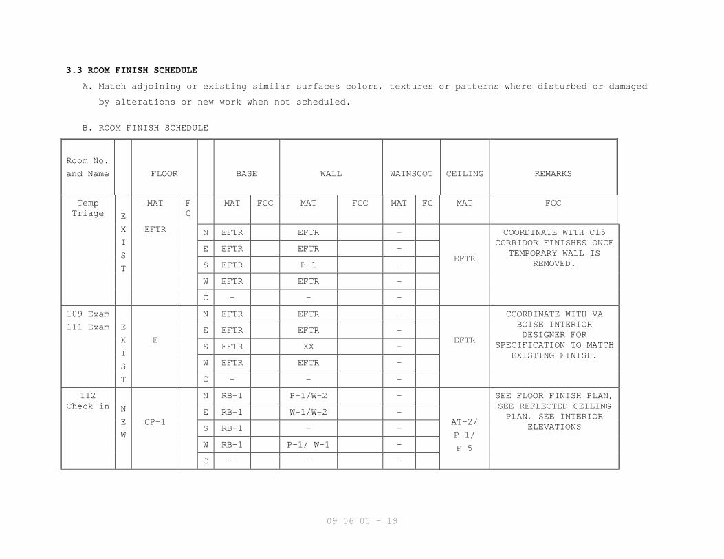
3.3 ROOM FINISH SCHEDULE
A. Match adjoining or existing similar surfaces colors, textures or patterns where disturbed or damaged
by alterations or new work when not scheduled.
B. ROOM FINISH SCHEDULE
Room No.
and Name FLOOR BASE WALL WAINSCOT CEILING REMARKS
TempTriage E
X
I
S
T
MAT
EFTR
FC
MAT FCC MAT FCC MAT FC MAT FCC
N EFTR EFTR -
EFTR
COORDINATE WITH C15CORRIDOR FINISHES ONCE
TEMPORARY WALL ISREMOVED.
E EFTR EFTR -
S EFTR P-1 -
W EFTR EFTR -
C - - -
109 Exam
111 Exam E
X
I
S
T
E
N EFTR EFTR -
EFTR
COORDINATE WITH VABOISE INTERIORDESIGNER FOR
SPECIFICATION TO MATCHEXISTING FINISH.
E EFTR EFTR -
S EFTR XX -
W EFTR EFTR -
C - - -
112Check-in N
E
W
CP-1
N RB-1 P-1/W-2 -
AT-2/
P-1/
P-5
SEE FLOOR FINISH PLAN,SEE REFLECTED CEILINGPLAN, SEE INTERIOR
ELEVATIONS
E RB-1 W-1/W-2 -
S RB-1 - -
W RB-1 P-1/ W-1 -
C - - -
09 06 00 - 20
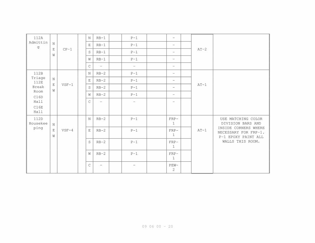
112AAdmittin
gN
E
W
CP-1
N RB-1 P-1 -
AT-2E RB-1 P-1 -
S RB-1 P-1 -
W RB-1 P-1 -
C - - -
112BTriage112EBreakRoom
C16DHall
C16EHall
N
E
W
VSF-1
N RB-2 P-1 -
AT-1E RB-2 P-1 -
S RB-2 P-1 -
W RB-2 P-1 -
C - - -
112DHousekeeping
N
E
W
VSF-4
N RB-2 P-1 FRP-1
AT-1
USE MATCHING COLORDIVISION BARS AND
INSIDE CORNERS WHERENECESSARY FOR FRP-1.P-1 EPOXY PAINT ALLWALLS THIS ROOM.
E RB-2 P-1 FRP-1
S RB-2 P-1 FRP-1
W RB-2 P-1 FRP-1
C - - PEW-2

09 06 00 - 21
112FWaiting N
E
W
CP-1
N RB-1 W-1 -
AT-2/
P-5
QUARTZ TOP CAP (Q-1)AT EAST PARTITION WALL
ONLY; CHAIR RAIL(PEW-1) AT WEST WALLONLY, SEE INTERIORELEVATIONS, SEE
REFLECTED CEILING PLAN
E RB-1 ERP-1 FRP-2
S RB-1 W-1 -
W RB-1 W-2 FRP-2
C - Q-1 PEW-1
112GElectric
al
112HElectric
al
N
E
W
-
N RB-2 P-1 -
P-1E RB-2 P-1 -
S RB-2 P-1 -
W RB-2 P-1 -
C - - -
112J
Closet N
E
W
VSF-1
N RB-2 P-1 -
P-1E RB-2 P-1 -
S RB-2 P-1 -
W RB-2 P-1 -
C - - -
112K
Toilet N
E
W
CT-1/
FT-1
N CT-1 P-1 CT-1
P-1
SEE INTERIORELEVATIONS, SEE FLOORFINISH PLAN, PROVIDECT-1 FROM FINISHEDFLOOR TO FINISHEDCEILING AT SHOWER
WALLS. P-1 EPOXY PAINTALL WALLS AND SHOWERCEILING THIS ROOM.
E CT-1 P-1 CT-1
S CT-1 P-1 CT-1
W CT-1 P-1 CT-1
C - - CT-2

09 06 00 - 22
116
Decontamination
N
E
W
FT-1
N CT-1 CT-1 -
P-1
P-1 EPOXY PAINT ALLWALLS AND CEILING THIS
ROOM.E CT-1 CT-1 -
S CT-1 CT-1 -
W CT-1 CT-1 -
C - - -
C15
Corridor N
E
W
VSF-1/VSF-2
N RB-1 - -
AT-2/
P-1/
P-5
SEE FLOOR FINISH PLAN,SEE INTERIOR
ELEVATIONS (SIMILAR),SEE REFLECTED CEILINGPLAN, QUARTZ TOP CAP(Q-1) AND WALL PANELWAINSCOT (FRP-2) ATWEST PARTITION WALL
ONLY.
PROVIDE FINISHES ASSPECIFIED UNDER BASEBID. SEE ARCHITECTURALBID ALTERNATE SHEET.
E RB-1 W-1 -
S RB-1 W-1
W RB-1 W-1/ERP-1
FRP-2
C - Q-1 -
C16
Corridor N
E
W
VSF-1/VSF-2/VSF-3/VSF-4
N RB-1 W-1 -
AT-2/
P-1
SEE FLOOR FINISH PLAN,SEE REFLECTED CEILINGPLAN, SEE ENLARGEDFLOOR FINISH PLAN.
E RB-1 W-1 -
S RB-1 W-1 -
W RB-1 W-1 -
C - - -
C16B
Vestibule
EXIST
CP-2
N RB-1 P-1 -
AT-2
REMOVE EXISTINGFINISHES. PATCH/FILLSURFACES TO RECEIVE
NEW FINISH.
E RB-1 P-1 -
S RB-1 P-1 -
W RB-1 P-1 -
C - - -

09 06 00 - 23
C16C
Vestibule
NEW
CP-2
N RB-1 P-1 -
AT-2E RB-1 P-1 -
S RB-1 P-1 -
W RB-1 P-1 -
C - - -
ST14
Stair N
E
W
VSF-3/
RST-1
N RB-2 P-1 -
-
EXTEND FINISHES OFSTAIR TOWER FROM FIRSTFLOOR TO PENTHOUSE
LEVEL.
E RB-2 P-1 -
S RB-2 P-1 -
W RB-2 P-1 -
C - - -
226
235 E
X
I
S
T
E
N EFTR EFTR -
EFTR
COORDINATE WITH VABOISE INTERIORDESIGNER FOR
SPECIFICATION TO MATCHEXISTING FINISH.
E EFTR EFTR -
S EFTR XX -
W EFTR EFTR -
C - - -
ST24
Stair N
E
W
VSF-3/
RST-1
N RB-2 P-1 -
-
EXTEND FINISHES OFSTAIR TOWER FROM FIRSTFLOOR TO PENTHOUSE
LEVEL.
E RB-2 P-1 -
S RB-2 P-1 -
W RB-2 P-1 -
C - - -
308CO.R. 2
308FO.R. 1
EXIST
SRF-1/
SRF-2
N IRB-1 P-1 -
P-1
REMOVE EXISTINGFINISHES. PATCH/FILLSURFACES TO RECEIVENEW FINISH. EXISTINGFINISHES TO REMAIN AS
BID ALTERNATE.
E IRB-1 P-1 -
S IRB-1 P-1 -
W IRB-1 P-1 -
C - - -

09 06 00 - 24
308D
Anestesia
Workroom
EXIST
SRF-1
N IRB-1 P-1 -
AT-1
REMOVE EXISTINGFINISHES. PATCH/FILLSURFACES TO RECEIVENEW FINISH. EXISTINGFINISHES TO REMAIN AS
BID ALTERNATE.
E IRB-1 P-1 -
S IRB-1 P-1 -
W IRB-1 P-1 -
C - - -
309A
ICU
Surgery
Storage
EXIST
VSF-4
N RB-2 P-1 FRP-1
AT-1
USE MATCHING COLORDIVISION BARS AND
INSIDE CORNERS WHERENECESSARY FOR FRP-1,
REMOVE EXISTINGFINISHES. PATCH/FILLSURFACES TO RECEIVE
NEW FINISH.
E RB-2 P-1 FRP-1
S RB-2 P-1 FRP-1
W RB-2 P-1 FRP-1
C - - PEW-2
310
SutureStorage
NEW
SRF-1
N IRB-1 P-1 - AT-1 PROVIDE FINISHES ASSPECIFIED UNDER BASEBID. SEE ARCHITECTURALBID ALTERNATE SHEET.
E IRB-1 P-1 -
S IRB-1 P-1 -
W IRB-1 P-1 -
C - - -

09 06 00 - 25
311Orthoped
icStorage
N
E
W
SRF-1
N IRB-1 P-1 FRP-1
AT-1 USE MATCHING COLORDIVISION BARS AND
INSIDE CORNERS WHERENECESSARY FOR FRP-1,
PROVIDE FINISHES ASSPECIFIED UNDER BASEBID. SEE ARCHITECTURALBID ALTERNATE SHEET.
E IRB-1 P-1 FRP-1
S IRB-1 P-1 FRP-1
W IRB-1 P-1 FRP-1
C - - PEW-2
325
Classroom
NEW
CP-1
N RB-3 P-1 - AT-2
E RB-3 P-1 -
S RB-3 P-1 -
W RB-3 P-1 -
C - - -
326 ICU/
SurgeryWaiting
N
E
W
CP-1
N RB-1 W-1 FRP-2
AT-2 QUARTZ TOP CAP (Q-1)AT WEST PARTITION WALLONLY; CHAIR RAIL (PEW-1) AT N, E, S WALLS,
SEE INTERIORELEVATIONS
E RB-1 W-1 FRP-2
S RB-1 W-1 FRP-2
W RB-1 ERP-1 FRP-2
C - Q-1 PEW-1

09 06 00 - 26
327ConsultationRoom
N
E
W
CP-1
N RB-1 W-2 -
AT-2E RB-1 W-2 -
S RB-1 W-2 -
W RB-1 W-2 -
C - - -
328Women’sRestroom
329Men’s
Restroom
354StaffToilet
N
E
W
CT-1
N CT-1 P-1 CT-1
P-1
SEE INTERIORELEVATIONS. P-1 EPOXYPAINT ALL WALLS THESE
ROOMS.
E CT-1 P-1 CT-1
S CT-1 P-1 CT-1
W CT-1 P-1 CT-1
C - - CT-2
330NurseStation
N
E
W
VSF-1
N RB-3 - -
AT-2/
P-1/P-5
SEE REFLECTED CEILINGPLAN, SEE FLOOR FINISH
PLANE RB-3 - -
S RB-3 - -
W RB-3 W-2 -
C - - -
330A
GasStorage
N
E
W
VSF-1
N RB-2 P-1 -
P-1E RB-2 P-1 -
S RB-2 P-1 -
W RB-2 P-1 -
C - - -

09 06 00 - 27
331 IsoPatientRoom 1
333 IsoPatientRoom 3
N
E
W
VSF-1
N RB-3 W-2 -
P-1
PROVIDE FINISHES ASSPECIFIED UNDER BASEBID. SEE ARCHITECTURALBID ALTERNATE SHEET.
E RB-3 W-2 -
S RB-3 W-2 -
W RB-3 W-2 -
C - - -
332 IsoPatientRoom
334 IsoPatientRoom
N
E
W
VSF-1
N RB-3 W-3 -
P-1
PROVIDE FINISHES ASSPECIFIED UNDER BASEBID. SEE ARCHITECTURALBID ALTERNATE SHEET.
E RB-3 W-3 -
S RB-3 W-3 -
W RB-3 W-3 -
C - - -
335PatientRoom 5
337PatientRoom 7
338PatientRoom 9
N
E
W
VSF-1
N RB-3 W-2 -
AT-2
PROVIDE FINISHES ASSPECIFIED UNDER BASEBID. SEE ARCHITECTURALBID ALTERNATE SHEET.
E RB-3 W-2 -
S RB-3 W-2 -
W RB-3 W-2 -
C - - -
336PatientRoom 6
339PatientRoom 10
341PatientRoom 8
N
E
W
VSF-1
N RB-3 W-3 -
AT-2
PROVIDE FINISHES ASSPECIFIED UNDER BASEBID. SEE ARCHITECTURALBID ALTERNATE SHEET.
E RB-3 W-3 -
S RB-3 W-3 -
W RB-3 W-3 -
C - - -

09 06 00 - 28
340AlcoveStorage
N
E
W
VSF-2
N RB-3 P-1 FRP-2
AT-2/P-1
SEE FLOOR FINISH PLAN,SEE REFLECTED CEILINGPLAN, SEE INTERIOR
ELEVATIONS, CHAIR RAIL(PEW-1) AT N WALL ONLYWHERE FRP-2 IS LOCATED
E RB-3 - -
S RB-3 P-1 -
W RB-3 - -
C - - PEW-1
342CleanLinen345CleanUtility
N
E
W
VSF-4
N RB-2 P-1 FRP-1
AT-1
USE MATCHING COLORDIVISION BARS AND
INSIDE CORNERS WHERENECESSARY FOR FRP-1.P-1 EPOXY PAINT ALLWALLS THESE ROOMS.
E RB-2 P-1 FRP-1
S RB-2 P-1 FRP-1
W RB-2 P-1 FRP-1
C - - PEW-2
343 HeadNurseOffice
N
E
W
CP-1
N RB-2 P-1 -
AT-1E RB-2 P-1 -
S RB-2 P-1 -
W RB-2 P-1 -

09 06 00 - 29
352HouseStaffWorkRoom
353StaffLocker
357ClinicalNurse
Specialist
C - - -
348StaffLounge
350Conferen
ceReport
N
E
W
VSF-1
N RB-2 P-1 -
AT-1E RB-2 P-1 -
S RB-2 P-1 -
W RB-2 P-1 -
C - - -
344 Med
Storage
347Nourishm
ent
N
E
W
VSF-4
N RB-2 P-1 -
AT-1
P-1 EPOXY PAINT ALLWALLS THESE ROOMS.
E RB-2 P-1 -
S RB-2 P-1 -
W RB-2 P-1 -
C - - -
09 06 00 - 30
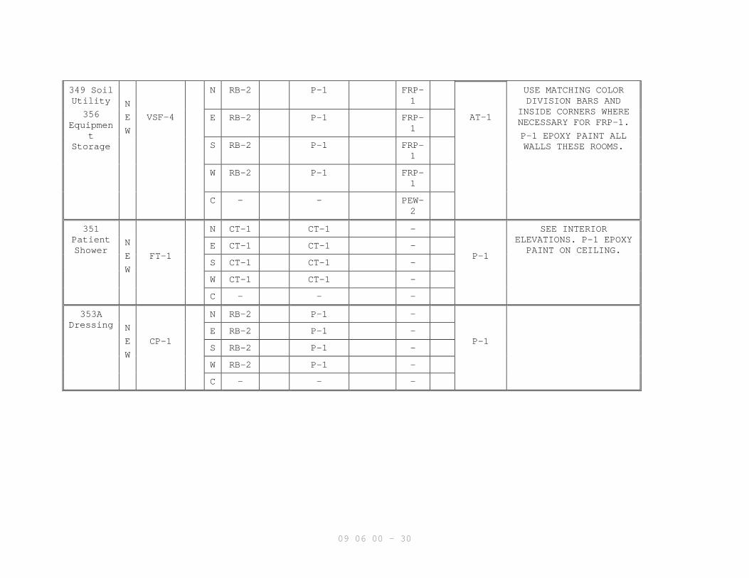
349 SoilUtility
356Equipmen
tStorage
N
E
W
VSF-4
N RB-2 P-1 FRP-1
AT-1
USE MATCHING COLORDIVISION BARS AND
INSIDE CORNERS WHERENECESSARY FOR FRP-1.
P-1 EPOXY PAINT ALLWALLS THESE ROOMS.
E RB-2 P-1 FRP-1
S RB-2 P-1 FRP-1
W RB-2 P-1 FRP-1
C - - PEW-2
351PatientShower
N
E
W
FT-1
N CT-1 CT-1 -
P-1
SEE INTERIORELEVATIONS. P-1 EPOXYPAINT ON CEILING.E CT-1 CT-1 -
S CT-1 CT-1 -
W CT-1 CT-1 -
C - - -
353ADressing N
E
W
CP-1
N RB-2 P-1 -
P-1E RB-2 P-1 -
S RB-2 P-1 -
W RB-2 P-1 -
C - - -

09 06 00 - 31
355 HSKP
N
E
W
VSF-4
N RB-2 P-1 FRP-1
P-1
USE MATCHING COLORDIVISION BARS AND
INSIDE CORNERS WHERENECESSARY FOR FRP-1.P-1 EPOXY PAINT ALL
WALLS AND CEILING THISROOM.
E RB-2 P-1 FRP-1
S RB-2 P-1 FRP-1
W RB-2 P-1 FRP-1
C - - PEW-2
358P.A.C.U. N
E
W
VSF-1/
VSF-2
N RB-3 P-1 -
AT-2
SEE FLOOR FINISH PLAN,SEE INTERIOR
ELEVATIONS, PROVIDEFINISHES AS SPECIFIEDUNDER BASE BID. SEEARCHITECTURAL BID
ALTERNATE SHEET. P-1EPOXY PAINT ALL WALLS
THIS ROOM.
E RB-3 P-1 -
S RB-3 P-1 FRP-2
W RB-3 P-1 -
C - - PEW-1
360
O.R. 3
362
O.R. 4
N
E
W
SRF-1/
SRF-2
N IRB-1 P-1 -
P-1
SEE FLOOR FINISH PLAN,
PROVIDE FINISHES ASSPECIFIED UNDER BASEBID. SEE ARCHITECTURALBID ALTERNATE SHEET.P-1 EPOXY PAINT ALLWALLS AND CEILING
THESE ROOMS.
E IRB-1 P-1 -
S IRB-1 P-1 -
W IRB-1 P-1 -
C - - -

09 06 00 - 32
361Scrub
361ASub-
Sterile/Supply
363CleanSupply
N
E
W
SRF-1
N IRB-1 P-1 FRP-1
AT-1
USE MATCHING COLORDIVISION BARS AND
INSIDE CORNERS WHERENECESSARY FOR FRP-1,
SEE INTERIORELEVATIONS,
PROVIDE FINISHES ASSPECIFIED UNDER BASEBID. SEE ARCHITECTURALBID ALTERNATE SHEET.P-1 EPOXY PAINT ALLWALLS THESE ROOMS.
E IRB-1 P-1 FRP-1
S IRB-1 P-1 FRP-1
W IRB-1 P-1 FRP-1
C - - PEW-2
C34Public
Corridor
C37
PublicCorridor
N
E
W
VSF-1
N RB-1 W-1 -
AT-2E RB-1 W-1 -
S RB-1 W-1 -
W RB-1 W-1 -
C - - -
C36Public
CorridorN
E
W
VSF-1/
VSF-2
N RB-1 W-1 -
AT-2
QUARTZ TOP CAP (Q-1)AND WALL PANEL
WAINSCOT (FRP-2) ATEAST PARTITION WALLONLY, SEE INTERIOR
ELEVATIONS, SEE FLOORFINISH
E RB-1 W-1/ERP-1
FRP-2
S RB-1 W-1 -
W RB-1 W-1 -
C - Q-1 -
C38 ICUHall N
E
W
VSF-1/
VSF-2
N RB-3 P-1 -
AT-2/P-1/P-5
SEE FLOOR FINISH PLAN,SEE REFLECTED CEILING
PLANE RB-3 P-1 -
S RB-3 P-1 -
W RB-3 P-1 -
C - - -

09 06 00 - 33
C39 ICUHall N
E
W
VSF-1/
VSF-2
N RB-3 P-1 -
AT-2/P-1/P-5
SEE FLOOR FINISH PLAN,
SEE REFLECTED CEILINGPLAN
E RB-3 W-2 -
S RB-3 P-1 -
W RB-3 P-1 -
C - - -
C40 ICUHall N
E
W
VSF-1/
VSF-2
N RB-3 P-1 -
AT-2
SEE FLOOR FINISH PLAN
E RB-3 - -
S RB-3 P-1 -
W RB-3 P-1 -
C - - -
C41Staff
CorridorN
E
W
VSF-1
N RB-3 P-1 -
AT-1E RB-3 P-1 -
S RB-3 P-1 -
W RB-3 P-1 -
C - - -
C42Public
CorridorN
E
W
VSF-1
N RB-1 W-1 -
AT-2E RB-1 - -
S RB-1 W-1 -
W RB-1 W-1 -
C - - -
C43
PublicCorridor
N
E
W
VSF-1
N RB-1 W-1 -
AT-2E RB-1 W-1 -
S RB-1 W-1 -
W RB-1 W-1 -
C - - -

09 06 00 - 34
C44
CleanHall
N
E
W
SRF-1
N IRB-1 P-1 FRP-1
AT-1
USE MATCHING COLORDIVISION BARS AND
INSIDE CORNERS WHERENECESSARY FOR FRP-1,
SEE INTERIORELEVATIONS
PROVIDE FINISHESS ASSPECIFIED UNDER BASEBID. SEE ARCHITECTURALBID ALTERNATE SHEET.
E IRB-1 P-1 FRP-1
S IRB-1 P-1 FRP-1
W IRB-1 P-1 FRP-1
C - - PEW-2
ST34
Stair N
E
W
VSF-3/
RST-1
N RB-2 P-1 -
-
EXTEND FINISHES OFSTAIR TOWER FROM FIRSTFLOOR TO PENTHOUSE
LEVEL.
E RB-2 P-1 -
S RB-2 P-1 -
W RB-2 P-1 -
C - - -
PH4
Penthouse
PH5
CommRoom
PH6
ElecRoom
N
E
W
-
N RB-2 P-1 -
-E RB-2 P-1 -
S RB-2 P-1 -
W RB-2 P-1 -
C - - -
ST44
Stair N
E
W
VSF-3/
RST-1
N RB-2 P-1 -
P-1
EXTEND FINISHES OFSTAIR TOWER FROM FIRSTFLOOR TO PENTHOUSE
LEVEL.
E RB-2 P-1 -
S RB-2 P-1 -
W RB-2 P-1 -
C - - -
--- E N D---
07-10M
09 22 16 - 1
SECTION 09 22 16NON-STRUCTURAL METAL FRAMING
PART 1 - GENERAL
1.1 DESCRIPTION
This section specifies steel studs wall systems, shaft wall systems,
ceiling or soffit suspended, wall furring, fasteners, and accessories
for the screw attachment of gypsum board, or other building boards.
1.2 RELATED WORK
A. Load bearing framing: Section 05 40 00, COLD-FORMED METAL FRAMING.
B. Support for wall mounted items: Section 05 50 00, METAL FABRICATIONS.
C. Pull down tabs in steel decking: Section 05 36 00, COMPOSITE METAL
DECKING.
D. Ceiling suspension systems for acoustical tile: Section 09 51 00,
ACOUSTICAL CEILINGS and
1.3 TERMINOLOGY
A. Description of terms shall be in accordance with ASTM C754, ASTM C11,
ASTM C841 and as specified.
B. Underside of Structure Overhead: In spaces where steel beams are shown,
the underside of structure overhead shall be the underside of the beams
or metal deck above.
C. Thickness of steel specified is the minimum bare (uncoated) steel
thickness.
1.4 SUBMITTALS
A. Submit in accordance with Section 01 33 23, SHOP DRAWINGS, PRODUCT DATA,
AND SAMPLES.
B. Manufacturer's Literature and Data:
1. Studs, runners and accessories.
2. Hanger inserts.
3. Channels (Rolled steel).
4. Furring channels.
5. Screws, clips and other fasteners.
1.5 DELIVERY, IDENTIFICATION, HANDLING AND STORAGE
In accordance with the requirements of ASTM C754.
1.6 APPLICABLE PUBLICATIONS
A. The publications listed below form a part of this specification to the
extent referenced. The publications are referenced in the text by the
basic designation only.
B. American Society For Testing And Materials (ASTM)
A123-09.................Zinc (Hot-dip Galvanized) Coatings on Iron and
Steel Products
07-10M
09 22 16 - 2
A653/A653M-09...........Steel Sheet, Zinc-Coated (Galvanized) or Zinc-
Iron Alloy Coated (Galvannealed) by the Hot-Dip
Process
A641-09.................Zinc-Coated (Galvanized) Carbon Steel Wire
C11-10..................Terminology Relating to Gypsum and Related
Building Materials and Systems
C635-07.................Manufacture, Performance, and Testing of Metal
Suspension System for Acoustical Tile and Lay-in
Panel Ceilings
C636-06.................Installation of Metal Ceiling Suspension Systems
for Acoustical Tile and Lay-in Panels
C645-09.................Non-Structural Steel Framing Members
C754-09.................Installation of Steel Framing Members to Receive
Screw-Attached Gypsum Panel Products
C841-03(R2008)..........Installation of Interior Lathing and Furring
C954-07.................Steel Drill Screws for the Application of Gypsum
Panel Products or Metal Plaster Bases to Steel
Studs from 0.033 in. (0.84 mm) to 0.112 in.
(2.84 mm) in Thickness
C1002-07................Steel Self-Piercing Tapping Screws for the
Application of Gypsum Panel Products or Metal
Plaster Bases to Wood Studs or Steel Studs
E580-09.................Application of Ceiling Suspension Systems for
Acoustical Tile and Lay-in Panels in Areas
Requiring Moderate Seismic Restraint.
PART 2 - PRODUCTS
2.1 PROTECTIVE COATING
Galvanize steel studs and runners (track), with coating designation of
G-60 minimum, per ASTM 123.
2.2 STEEL STUDS AND RUNNERS (TRACK)
A. ASTM C645, modified for thickness specified and sizes as shown.
1. Use ASTM A525 steel, 0.75 mm (0.0296-inch) thick bare metal (20 gauge
drywall)or 30 mil equivalent 24 gauge, as manufactured by Scafio
“Supreme Framing System” or approved equal.
2. Runners same thickness as studs.
B. Provide not less than two cutouts in web of each stud, approximately 300
mm (12 inches) from each end, and intermediate cutouts on approximately
610 mm (24-inch) centers.
C. Doubled studs for openings and studs for supporting concrete
backer-board.
D. Studs 3658 mm (12 feet) or less in length shall be in one piece.

07-10M
09 22 16 - 3
E. Shaft Wall Framing:
1. C-H Studs.
2.3 FURRING CHANNELS AND COLUMN WALLBOARD SNAP CLIPS
A. Rigid furring channels (hat shape): ASTM C645.
B. Rolled Steel Channels: ASTM C754, cold rolled; or, ASTM C841, cold
rolled.
C. Column Drywall Clips: 2” deep by 2-3/8” wide by 2” high galvanized
steel clips. Approved product: “The Claw” as manufactured by Claw
International. Any substitutions must have a 3/4” body to the clip.
Column drywall clips shall have a No. 25 MSG galvanized angle with 1-
1/2” legs placed over clips before first layer of gypsum board per UL
Design No. X536.
2.4 FASTENERS, CLIPS, AND OTHER METAL ACCESSORIES
A. ASTM C754, except as otherwise specified.
B. For fire rated construction: Type and size same as used in fire rating
test.
C. Fasteners for steel studs thicker than 0.84 mm (0.033-inch) thick. Use
ASTM C954 steel drill screws of size and type recommended by the
manufacturer of the material being fastened.
D. Clips: ASTM C841 (paragraph 6.11), manufacturer’s standard items. Clips
used in lieu of tie wire shall have holding power equivalent to that
provided by the tie wire for the specific application.
E. Concrete ceiling hanger inserts (anchorage for hanger wire and hanger
straps): Steel, zinc-coated (galvanized), manufacturers standard items,
designed to support twice the hanger loads imposed and the type of
hanger used.
F. Tie Wire and Hanger Wire:
1. ASTM A641, soft temper, Class 1 coating.
2. Gage (diameter) as specified in ASTM C754 or ASTM C841.
G. Power Actuated Fasteners: Type and size as recommended by the
manufacturer of the material being fastened.
H. Flat Strap and Backing Plate: Steel sheet for blocking and bracing in
length and width indicated.
1. Minimum Base Metal Thickness: 0.033 inch (0.84 mm).
2.5 SUSPENDED CEILING SYSTEM FOR GYPSUM BOARD (OPTION)
A. Conform to ASTM C635, heavy duty, with not less than 35 mm (1-3/8 inch)
wide knurled capped flange face designed for screw attachment of gypsum
board.
B. Wall track channel with 35 mm (1-3/8 inch) wide flange.

07-10M
09 22 16 - 4
PART 3 - EXECUTION
3.1 INSTALLATION CRITERIA
A. Where fire rated construction is required for walls, partitions,
columns, beams and floor-ceiling assemblies, the construction shall be
same as that used in fire rating test.
B. Construction requirements for fire rated assemblies and materials shall
be as shown and specified, the provisions of the Scope paragraph (1.2)
of ASTM C754 and ASTM C841 regarding details of construction shall not
apply.
3.2 INSTALLING STUDS
A. Install studs in accordance with ASTM C754, except as otherwise shown or
specified.
B. Space studs not more than 406 mm (16 inches) on center.
C. When studs extend to underside of structure overhead, install a
deflection top track capable of accommodating 1/2” of vertical movement
after the building dead load is in place.
D. Where studs are shown to terminate above suspended ceilings, provide
bracing as shown or extend studs to underside of structure overhead.
E. Extend studs to underside of structure overhead for fire rated
partitions, smoke partitions, shafts and sound rated partitions.
F. Openings:
1. Frame jambs of openings in stud partitions and furring with two studs
placed back to back or as shown.
2. Fasten back to back studs together with 9 mm (3/8-inch) long Type S
pan head screws at not less than 600 mm (two feet) on center,
staggered along webs.
3. Studs fastened flange to flange shall have splice plates on both
sides approximately 50 X 75 mm (2 by 3 inches) screwed to each stud
with two screws in each stud. Locate splice plates at 610 mm (24
inches) on center between runner tracks.
G. Fastening Studs:
1. Fasten studs located adjacent to partition intersections, corners and
studs at jambs of openings to flange of runner tracks with two screws
through each end of each stud and flange of runner.
2. Do not fasten studs to top runner track when studs extend to
underside of structure overhead.
H. Chase Wall Partitions:
1. Locate cross braces for chase wall partitions to permit the
installation of pipes, conduits, carriers and similar items.
2. Use studs or runners as cross bracing not less than 63 mm (2-1/2
inches wide).

07-10M
09 22 16 - 5
I. Form building seismic or expansion joints with double studs back to back
spaced 75 mm (three inches) apart plus the width of the seismic or
expansion joint.
J. Form control joint, with double studs spaced 13 mm (1/2-inch) apart.
3.3 INSTALLING WALL FURRING FOR FINISH APPLIED TO ONE SIDE ONLY
A. In accordance with ASTM C754, or ASTM C841 except as otherwise specified
or shown.
B. Wall furring-Stud System:
1. Framed with 63 mm (2-1/2 inch) or narrower studs, 406 mm (16 inches)
on center.
2. Brace as specified in ASTM C754 for Wall Furring-Stud System or brace
with sections or runners or studs placed horizontally at not less
than three foot vertical intervals on side without finish.
3. Securely fasten braces to each stud with two Type S pan head screws
at each bearing.
3.4 INSTALLING SUPPORTS REQUIRED BY OTHER TRADES
A. Provide for attachment and support of electrical outlets, plumbing,
laboratory or heating fixtures, recessed type plumbing fixture
accessories, access panel frames, wall bumpers, grab bars, marker
boards, tackboards, wall-hung casework, handrail brackets, recessed fire
extinguisher cabinets and other items like auto door buttons and auto
door operators supported by stud construction.
B. Provide additional studs where required. Install metal backing plates,
or special metal shapes as required, securely fastened to metal studs.
3.5 INSTALLING SHAFT WALL SYSTEM
A. Conform to GA File No. WP 705 for two-hour fire rating.
B. Position J runners at floor and ceiling with the short leg toward finish
side of wall. Securely attach runners to structural supports with power
driven fasteners at both ends and 600 mm (24 inches) on center.
C. After liner panels have been erected, cut C-H studs and E studs, from 9
mm (3/8-inch) to not more than 13 mm (1/2-inch) less than
floor-to-ceiling height. Install C-H studs between liner panels with
liner panels inserted in the groove.
D. Install full-length steel E studs over shaft wall line at intersections,
corners, hinged door jambs, columns, and both sides of closure panels.
E. Suitably frame all openings to maintain structural support for wall:
1. Provide necessary liner fillers and shims to conform to label frame
requirements.
2. Frame openings cut within a liner panel with E studs around
perimeter.

07-10M
09 22 16 - 6
3. Frame openings with vertical E studs at jambs, horizontal J runner at
head and sill.
3.5 INSTALLING FURRED AND SUSPENDED CEILINGS OR SOFFITS
A. Install furred and suspended ceilings or soffits in accordance with ASTM
C754 or ASTM C841 except as otherwise specified or shown for screw
attached gypsum board ceilings.
1. Space framing at 406 mm (16-inch) centers for gypsum board anchorage.
B. Concrete slabs on steel decking composite construction:
1. Use pull down tabs when available.
2. Use power activated fasteners when direct attachment to structural
framing can not be accomplished.
C. Where beams are more than 1219 mm (48 inches) apart, provide
intermediate hangers so that spacing between supports does not exceed
1219 mm (48 inches). Use clips, bolts, or wire ties for direct
attachment to steel framing.
D. Existing concrete construction exposed or concrete on steel decking:
1. Use power actuated fasteners either eye pin, threaded studs or drive
pins for type of hanger attachment required.
2. Install fasteners at approximate mid height of concrete beams or
joists. Do not install in bottom of beams or joists.
E. Steel decking without concrete topping:
1. Do not fasten to steel decking 0.76 mm (0.0299-inch) or thinner.
2. Toggle bolt to decking 0.9 mm (0.0359-inch) or thicker only where
anchorage to steel framing is not possible.
F. Installing suspended ceiling system for gypsum board (ASTM C635 Option):
1. Install only for ceilings to receive screw attached gypsum board.
2. Install in accordance with ASTM C636.
a. Install main runners spaced 1200 mm (48 inches) on center.
b. Install 1200 mm (four foot) tees not over 600 mm (24 inches) on
center; locate for edge support of gypsum board.
c. Install wall track channel at perimeter.
3.6 TOLERANCES
A. Fastening surface for application of subsequent materials shall not vary
more than 3 mm (1/8-inch) from the layout line.
B. Plumb and align vertical members within 3 mm (1/8-inch.)
C. Level or align ceilings within 3 mm (1/8-inch.)
- - - E N D - - -

09-10
09 29 00 - 1
SECTION 09 29 00GYPSUM BOARD AND GYPSUM SHEATHING
PART 1 - GENERAL
1.1 DESCRIPTION
This section specifies installation and finishing of gypsum board and
gypsum sheathing board.
1.2 RELATED WORK
A. Installation of steel framing members for walls, partitions, furring,
soffits, and ceilings: Section 05 40 00, COLD-FORMED METAL FRAMING, and
Section 09 22 16, NON-STRUCTURAL METAL FRAMING.
B. Acoustical Sealants: Section 07 92 00, JOINT SEALANTS.
C. Lay in gypsum board ceiling panels: Section 09 51 00, ACOUSTICAL
CEILING.
1.3 TERMINOLOGY
A. Definitions and description of terms shall be in accordance with ASTM
C11, C840, and as specified.
B. Underside of Structure Overhead: In spaces where steel beams are shown,
the underside of structure overhead shall be the underside of the beams
or metal deck above.
C. "Yoked": Gypsum board cut out for opening with no joint at the opening
(along door jamb or above the door).
1.4 SUBMITTALS
A. Submit in accordance with Section 01 33 23, SHOP DRAWINGS, PRODUCT DATA,
AND SAMPLES.
B. Manufacturer's Literature and Data:
1. Cornerbead and edge trim.
2. Finishing materials.
3. Laminating adhesive.
4. Gypsum board, each type.
C. Shop Drawings:
1. Typical sound rated assembly, showing treatment at perimeter of
partitions and penetrations at gypsum board.
1.5 DELIVERY, IDENTIFICATION, HANDLING AND STORAGE
In accordance with the requirements of ASTM C840.
1.6 ENVIRONMENTAL CONDITIONS
In accordance with the requirements of ASTM C840.
1.7 APPLICABLE PUBLICATIONS
A. The publications listed below form a part of this specification to the
extent referenced. The publications are referenced in the text by the
basic designation only.

09-10
09 29 00 - 2
B. American Society for Testing And Materials (ASTM):
C11-08..................Terminology Relating to Gypsum and Related
Building Materials and Systems
C475-02.................Joint Compound and Joint Tape for Finishing
Gypsum Board
C840-08.................Application and Finishing of Gypsum Board
C919-08.................Sealants in Acoustical Applications
C954-07.................Steel Drill Screws for the Application of Gypsum
Board or Metal Plaster Bases to Steel Stud from
0.033 in. (0.84mm) to 0.112 in. (2.84mm) in
thickness
C1002-07................Steel Self-Piercing Tapping Screws for the
Application of Gypsum Panel Products or Metal
Plaster Bases to Wood Studs or Steel Studs
C1047-05................Accessories for Gypsum Wallboard and Gypsum
Veneer Base
C1177-06................Glass Mat Gypsum Substrate for Use as Sheathing
C1658-06................Glass Mat Gypsum Panels
C1396-06................Gypsum Board
E84-08..................Surface Burning Characteristics of Building
Materials
C. Underwriters Laboratories Inc. (UL):
Latest Edition..........Fire Resistance Directory
D. Inchcape Testing Services (ITS):
Latest Editions.........Certification Listings
PART 2 - PRODUCTS
2.1 GYPSUM BOARD
A. Gypsum Board: ASTM C1396, Type X, 16 mm (5/8 inch) thick unless shown
otherwise. Shall contain a minimum of 20 percent recycled gypsum.
B. Coreboard or Shaft Wall Liner Panels.
1. ASTM C1396, Type X.
2. ASTM C1658: Glass Mat Gypsum Panels.
3. Coreboard for shaft walls 406 mm (16 inches) wide by required
lengths 25 mm (one inch) thick with paper faces treated to resist
moisture.
C. Gypsum cores shall contain a minimum of 95 percent post industrial
recycled gypsum content. Paper facings shall contain 100 percent post-
consumer recycled paper content.
2.2 GYPSUM SHEATHING BOARD
A. ASTM C1396, Type X, water-resistant core surfaced with fiberglass mats,
16 mm (5/8 inch) thick, where located on drawings.

09-10
09 29 00 - 3
B. ASTM C1396, water-resistant core surfaced with fiberglass mats, 13 mm
(1/2 inch) thick, where located on drawings.
C. ASTM C1177.
D. Basis-of-Design: DensGlass Sheathing as manufactured by Georgia-Pacific
Gypsum LLC.
2.3 ACCESSORIES
A. ASTM C1047, except form of 0.39 mm (0.015 inch) thick zinc coated steel
sheet or rigid PVC plastic.
B. Flanges not less than 22 mm (7/8 inch) wide with punchouts or
deformations as required to provide compound bond.
2.4 FASTENERS
A. ASTM C1002 and ASTM C840, except as otherwise specified.
B. ASTM C954, for steel studs thicker than 0.84 mm (0.033 inch).
C. Select screws of size and type recommended by the manufacturer of the
material being fastened.
D. For fire rated construction, type and size same as used in fire rating
test.
E. Clips: Zinc-coated (galvanized) steel; gypsum board manufacturer's
standard items.
2.5 FINISHING MATERIALS AND LAMINATING ADHESIVE
ASTM C475 and ASTM C840. Free of antifreeze, vinyl adhesives,
preservatives, biocides and other VOC. Adhesive shall contain a maximum
VOC content of 50 g/l.
PART 3 - EXECUTION
3.1 GYPSUM BOARD HEIGHTS
A. Extend all layers of gypsum board from floor to underside of structure
overhead on following partitions and furring:
1. Two sides of partitions:
a. Fire rated partitions.
b. Smoke partitions.
c. Sound rated partitions.
d. Full height partitions shown (FHP).
2. One side of partitions or furring:
a. Inside of exterior wall furring or stud construction.
b. Room side of room without suspended ceilings.
c. Furring for pipes and duct shafts, except where fire rated shaft
wall construction is shown.
d. Corridor partitions.

09-10
09 29 00 - 4
3. Extend all layers of gypsum board construction used for fireproofing
of columns from floor to underside of structure overhead, unless
shown otherwise.
B. In locations other than those specified, extend gypsum board from floor
to heights as follows:
1. Not less than 102 mm (4 inches) above suspended acoustical ceilings.
2. At ceiling of suspended gypsum board ceilings.
3. At existing ceilings.
3.2 INSTALLING GYPSUM BOARD
A. Coordinate installation of gypsum board with other trades and related
work.
B. Install gypsum board in accordance with ASTM C840, except as otherwise
specified.
C. Moisture and Mold–Resistant Assemblies: Provide and install moisture and
mold-resistant glass mat gypsum wallboard products with moisture-
resistant surfaces complying with ASTM C1658 where shown and in
locations which might be subject to moisture exposure during
construction.
D. Use gypsum boards in maximum practical lengths to minimize number of end
joints.
E. Bring gypsum board into contact, but do not force into place.
F. Ceilings:
1. For single-ply construction, use perpendicular application.
2. For two-ply assembles:
a. Use perpendicular application.
b. Apply face ply of gypsum board so that joints of face ply do not
occur at joints of base ply with joints over framing members.
G. Walls (Except Shaft Walls):
1. When gypsum board is installed parallel to framing members, space
fasteners 305 mm (12 inches) on center in field of the board, and 203
mm (8 inches) on center along edges.
2. When gypsum board is installed perpendicular to framing members,
space fasteners 305 mm (12 inches) on center in field and along
edges.
3. Stagger screws on abutting edges or ends.
4. For single-ply construction, apply gypsum board with long dimension
either parallel or perpendicular to framing members as required to
minimize number of joints except gypsum board shall be applied
vertically over "Z" furring channels.
5. For two-ply gypsum board assemblies, apply base ply of gypsum board
to assure minimum number of joints in face layer. Apply face ply of
09-10
09 29 00 - 5
wallboard to base ply so that joints of face ply do not occur at
joints of base ply with joints over framing members.
6. For three-ply gypsum board assemblies, apply plies in same manner as
for two-ply assemblies, except that heads of fasteners need only be
driven flush with surface for first and second plies. Apply third ply
of wallboard in same manner as second ply of two-ply assembly, except
use fasteners of sufficient length enough to have the same
penetration into framing members as required for two-ply assemblies.
7. No offset in exposed face of walls and partitions will be permitted
because of single-ply and two-ply or three-ply application
requirements.
8. Control Joints ASTM C840 and as follows:
a. Locate at both side jambs of openings if gypsum board is not
"yoked". Use one system throughout.
b. Not required for wall lengths less than 9144 mm (30 feet).
c. Extend control joints the full height of the wall or height of
soffit/ceiling membrane.
H. Acoustical or Sound Rated Partitions, Fire and Smoke Partitions:
1. Cut gypsum board for a space approximately 3 mm to 6 mm (1/8 to 1/4
inch) wide around partition perimeter.
2. Coordinate for application of caulking or sealants to space prior to
taping and finishing.
3. For sound rated partitions, use sealing compound (ASTM C919) to fill
the annular spaces between all receptacle boxes and the partition
finish material through which the boxes protrude to seal all holes
and/or openings on the back and sides of the boxes. STC minimum
values as shown.
I. Electrical and Telecommunications Boxes:
1. Seal annular spaces between electrical and telecommunications
receptacle boxes and gypsum board partitions.
J. Accessories:
1. Set accessories plumb, level and true to line, neatly mitered at
corners and intersections, and securely attach to supporting surfaces
as specified.
2. Install in one piece, without the limits of the longest commercially
available lengths.
3. Corner Beads:
a. Install at all vertical and horizontal external corners and where
shown.
b. Use screws only. Do not use crimping tool.
4. Edge Trim (casings Beads):
09-10
09 29 00 - 6
a. Where gypsum board terminates against dissimilar materials and at
perimeter of openings, except where covered by flanges, casings or
permanently built-in equipment.
b. Where gypsum board surfaces of non-load bearing assemblies abut
load bearing members.
c. Where shown.
3.3 INSTALLING GYPSUM SHEATHING
A. Install in accordance with ASTM C840, except as otherwise specified or
shown.
B. Use screws of sufficient length to secure sheathing to cold-formed metal
framing.
C. Space screws 9 mm (3/8 inch) from ends and edges of sheathing and 200 mm
(8 inches) on center. Space screws a maximum of 203 mm (8 inches) on
center on intermediate framing members.
D. Apply 1200 mm by 2400 mm or 2700 mm (4 ft. by 8 ft. or 9 foot) gypsum
sheathing boards vertically with edges over framing.
3.4 CAVITY SHAFT WALL
A. Coordinate assembly with Section 09 22 16, NON-STRUCTURAL METAL FRAMING,
for erection of framing and gypsum board.
B. Conform to GA File No. WP 705 for two-hour fire rating
C. Cut coreboard (liner) panels 25 mm (one inch) less than floor-to-ceiling
height, and erect vertically between J-runners on shaft side.
1. Where shaft walls exceed 4267 mm (14 feet) in height, position panel
end joints within upper and lower third points of wall.
2. Stagger joints top and bottom in adjacent panels.
D. Gypsum Board:
1. Two hour wall:
a. Erect base layer (backing board) vertically on finish side of wall
with end joints staggered. Fasten base layer panels to studs with
25 mm (one inch) long screws, spaced 610 mm (24 inches) on center.
b. Use laminating adhesive between plies in accordance with UL or FM
if required by fire test.
c. Apply face layer of gypsum board required by fire test vertically
over base layer with joints staggered and attach with screws of
sufficient length to secure to framing staggered from those in
base, spaced 305 mm (12 inches) on center.
2. One hour wall with one layer on finish side of wall: Apply face layer
of gypsum board vertically. Attach to studs with screws of sufficient
length to secure to framing, spaced 305 mm (12 inches) on center in
field and along edges.

09-10
09 29 00 - 7
3. Where coreboard is covered with face layer of gypsum board, stagger
joints of face layer from those in the coreboard base.
E. Treat joints, corners, and fasteners in face layer as specified for
finishing of gypsum board.
3.5 FINISHING OF GYPSUM BOARD
A. Finish joints, edges, corners, and fastener heads in accordance with
ASTM C840. Provide Level 3 finish at 1st and 2nd floor shell spaces,
penthouse spaces, electrical and communications closets and above all
ceilings. Otherwise Provide level 4 finish throughout entire project
except use level 5 finish at the following locations:
1. 1St Floor: VESTIBULES C16B and C16C, Corridors C15 and C16, Check-In
112 and Waiting 112F.
2. 3rd Floor: Corridors C34, C36, C37, C42 and C43, Waiting Room 326,
PACU 328, ICU Halls C38, C39 and C40, Alcove Storage 340, Men’s
Toilet 329, Women’s Toilet 328, Nurse Station 330 and all Patient
Rooms 331 through 341.
B. Before proceeding with installation of finishing materials, assure the
following:
1. Gypsum board is fastened and held close to framing or furring.
2. Fastening heads in gypsum board are slightly below surface in dimple
formed by driving tool.
C. Finish joints, fasteners, and all openings, including openings around
penetrations, on that part of the gypsum board extending above suspended
ceilings. Sanding is not required of surfaces above suspended ceilings.
3.6 REPAIRS
A. After taping and finishing has been completed, and before decoration,
repair all damaged and defective work, including nondecorated surfaces.
B. Patch holes or openings 13 mm (1/2 inch) or less in diameter, or
equivalent size, with a setting type finishing compound or patching
plaster.
C. Repair holes or openings over 13 mm (1/2 inch) diameter, or equivalent
size, with 16 mm (5/8 inch) thick gypsum board secured in such a manner
as to provide solid substrate equivalent to undamaged surface.
D. Tape and refinish scratched, abraded or damaged finish surfaces
including cracks and joints in non decorated surface to provide smoke
tight construction, fire protection equivalent to the fire rated
construction and STC equivalent to the sound rated construction as
indicated on plans.
- - - E N D - - -
03-09M
09 30 13 - 1
SECTION 09 30 13CERAMIC/PORCELAIN TILING
PART 1 - GENERAL
1.1 DESCRIPTION
This section specifies ceramic tile, marble thresholds, waterproofing
membranes for shower pans, and crack isolation membranes.
1.2 RELATED WORK
A. Sealing of joints where specified: Section 07 92 00, JOINT SEALANTS.
B. Color, texture and pattern of field tile and trim shapes, size of field
tile, trim shapes, and color of grout specified: Section 09 06 00,
SCHEDULE FOR FINISHES.
C. Metal and resilient edge strips at joints with new resilient flooring:
Section 09 65 16, RESILIENT SHEET FLOORING.
D. Cementitious Backer Units: Section 06 16 63, CEMENTITIOUS SHEATHING.
E. Waterproofing Membrane applied to frame wall construction below
cementitious backer units: Section 06 16 63, CEMENTITIOUS SHEATHING.
1.3 SUBMITTALS
A. Submit in accordance with Section 01 33 23, SHOP DRAWINGS, PRODUCT DATA,
AND SAMPLES.
B. Samples:
1. Base tile, each type, each color, each size.
2. Mosaic floor tile panels, 225 mm by 225 mm (9 inches by 9 inches),
each type, color, size and pattern.
3. Wall (or wainscot) tile, each color, size and pattern.
4. Trim shapes, bullnose cap and cove including bullnose cap and base
pieces at internal and external corners of vertical surfaces, each
type, color, and size.
C. Product Data:
1. Ceramic, marked to show each type, size, and shape required.
2. Waterproofing membrane for shower pan.
3. Latex-Portland cement mortar and grout.
1.4 DELIVERY AND STORAGE
A. Deliver materials in containers with labels legible and intact and
grade-seals unbroken.
B. Store material to prevent damage or contamination.
1.5 APPLICABLE PUBLICATIONS
A. Publications listed below form a part of this specification to the
extent referenced. Publications are referenced in text by basic
designation only.

03-09M
09 30 13 - 2
B. American National Standards Institute (ANSI):
A10.20-05...............Safety Requirements for Ceramic Tile, Terrazzo,
and Marble Works
A108.1A-05..............Installation of Ceramic Tile in the Wet-Set
Method with Portland Cement Mortar
A108.1B-05..............Installation of Ceramic Tile on a Cured Portland
Cement Mortar Setting Bed with dry-Set or latex-
Portland Cement Mortar
A108.1C-05..............Contractors Option; Installation of Ceramic Tile
in the Wet-Set method with Portland Cement
Mortar or Installation of Ceramic Tile on a
Cured Portland Cement Mortar Setting Bed with
Dry-Set or Latex-Portland Cement Mortar
A108.4-05...............Installation of Ceramic Tile with Organic
Adhesives or Water Cleanable Tile Setting Epoxy
Adhesives
A108.5-05...............Installation of Ceramic Tile with Dry-Set
Portland Cement Mortar or Latex-Portland Cement
Mortar
A108.6-05...............Installation of Ceramic Tile with Chemical
Resistant, Water Cleanable Tile-Setting and
Grouting Epoxy
A108.8-05...............Installation of Ceramic Tile with Chemical
Resistant Furan Resin Mortar and Grout
A108.10-05..............Installation of Grout in Tilework
A108.11-05..............Interior Installation of Cementitious Backer
Units
A108.13-05..............Installation of Load Bearing, Bonded, Waterproof
Membranes for Thin-Set Ceramic Tile and
Dimension Stone
A118.1-05...............Dry-Set Portland Cement Mortar
A118.3-05...............Chemical Resistant, Water Cleanable Tile-Setting
Epoxy and Water Cleanable Tile-Setting and
Grouting Epoxy Adhesive
A118.4-05...............Latex-Portland Cement Mortar
A118.5-05...............Chemical Resistant Furan Mortars and Grouts for
Tile Installation
A118.6-05...............Standard Cement Grouts for Tile Installation
A118.9-05...............Cementitious Backer Units

03-09M
09 30 13 - 3
A118.10-05..............Load Bearing, Bonded, Waterproof Membranes for
Thin-Set Ceramic Tile and Dimension Stone
Installation
A136.1-05...............Organic Adhesives for Installation of Ceramic
Tile
A137.1-88...............Ceramic Tile
C. American Society For Testing And Materials (ASTM):
A185-07.................Steel Welded Wire Fabric, Plain, for Concrete
Reinforcing
C109/C109M-07...........Standard Test Method for Compressive Strength of
Hydraulic Cement Mortars (Using 2 inch. or [50-
mm] Cube Specimens)
C241-90 (R2005).........Abrasion Resistance of Stone Subjected to Foot
Traffic
C348-02.................Standard Test Method for Flexural Strength of
Hydraulic-Cement Mortars
C627-93(R2007)..........Evaluating Ceramic Floor Tile Installation
Systems Using the Robinson-Type Floor Tester
C954-07.................Steel Drill Screws for the Application of Gypsum
Board on Metal Plaster Base to Steel Studs from
0.033 in (0.84 mm) to 0.112 in (2.84 mm) in
thickness
C979-05.................Pigments for Integrally Colored Concrete
C1002-07................Steel Self-Piercing Tapping Screws for the
Application of Panel Products
C1027-99(R2004).........Determining “Visible Abrasion Resistance on
Glazed Ceramic Tile”
C1028-07................Determining the Static Coefficient of Friction
of Ceramic Tile and Other Like Surfaces by the
Horizontal Dynamometer Pull Meter Method
C1127-01................Standard Guide for Use of High Solids Content,
Cold Liquid-Applied Elastomeric Waterproofing
Membrane with an Integral Wearing Surface
C1178/C1178M-06.........Standard Specification for Coated Glass Mat
Water-Resistant Gypsum Backing Panel
D4397-02................Standard Specification for Polyethylene Sheeting
for Construction, Industrial and Agricultural
Applications
D5109-99(R2004).........Standard Test Methods for Copper-Clad
Thermosetting Laminates for Printed Wiring
Boards

03-09M
09 30 13 - 4
D. Marble Institute of America (MIA): Design Manual III-2007
E. Tile Council of America, Inc. (TCA):
2007....................Handbook for Ceramic Tile Installation
PART 2 - PRODUCTS
2.1 TILE
A. Comply with ANSI A137.1, Standard Grade, except as modified:
1. Inspection procedures listed under the Appendix of ANSI A137.1.
2. Abrasion Resistance Classification:
a. Tested in accordance with ISO 10545-7.
b. Class 3 or better.
3. Slip Resistant Tile for Floors:
a. Coefficient of friction, when tested in accordance with ASTM
C1028, required for level of performance:
1) Not less than 0.6 (wet condition) for shower areas.
2) Not less than 0.7 for dry conditions.
4. Mosaic tile may be mounted or joined together by a resinous bonding
material along tile edges.
5. Do not use back mounted tiles in showers unless certified by
manufacturer as suitable for application in wet areas and with list
of successful in-service performance locations.
6. Factory Blending: For tile with color variations, within the ranges
selected during sample submittals blend tile in the factory and
package so tile units taken from one package show the same range in
colors as those taken from other packages and match approved samples.
7. Factory-Applied Temporary Protective Coating:
a. Protect exposed face surfaces (top surface) of tile against
adherence of mortar and grout by pre-coating with a continuous
film of petroleum paraffin wax, applied hot.
b. Do not coat unexposed tile surfaces.
B. Unglazed Ceramic Mosaic Tile: Nominal 6 mm (1/4 inch) thick with cushion
edges.
C. Wall Tile: Cushion edges, glazing, as specified in Section 09 06 00,
SCHEDULE FOR FINISHES.
D. Trim Shapes:
1. Conform to applicable requirements of adjoining floor and wall tile.
2. Use slip resistant trim shapes for horizontal surfaces of showers.
3. Use trim shapes sizes conforming to size of adjoining field wall tile
including existing spaces unless detailed or specified otherwise in
Section 09 06 00, SCHEDULE FOR FINISHES.
4. Internal and External Corners:

03-09M
09 30 13 - 5
a. Square internal and external corner joints are not acceptable.
b. External corners including edges: Use bullnose shapes.
c. Internal corners: Use cove shapes.
d. Base to floor internal corners: Use special shapes providing
integral cove vertical and horizontal joint.
e. Base to floor external corners: Use special shapes providing
bullnose vertical edge with integral cove horizontal joint. Use
stop at bottom of openings having bullnose return to wall.
f. Wall top edge internal corners: Use special shapes providing
integral cove vertical joint with bullnose top edge.
g. Wall top edge external corners: Use special shapes providing
bullnose vertical and horizontal joint edge.
h. For unglazed ceramic mosaic and glazed wall tile installed in
dry-set Portland cement mortar, latex-Portland cement mortar, and
organic adhesive (thin set methods), use cove and surface bullnose
shapes as applicable.
2.2 SETTING MATERIALS OR BOND COATS
A. Conform to TCA Handbook for Ceramic Tile Installation.
B. Latex-Portland Cement Mortar: ANSI A118.4.
1. For wall applications, provide non-sagging, latex-Portland cement
mortar complying with ANSI A118.4.
2. Prepackaged Dry-Mortar Mix: Factory-prepared mixture of Portland
cement; dry, redispersible, ethylene vinyl acetate additive; and
other ingredients to which only water needs to be added at Project
site.
C. Organic Adhesives: ANSI A136.1, Type 1.
2.3 WATERPROOF MEMBRANES (SHOWER PAN)
A. General: Manufacturer’s standard product that complies with ANSI
A118.10 and is recommended by the manufacturer for the application
indicated. Include reinforcement and accessories recommended by
manufacturer.
B. Chlorinated Polyethylene Sheet: Nonplaticized, chlorinated polyethylene
faced on both sides with nonwoven polyester fabric; 0.030-inch nominal
thickness.
1. Products: Subject to compliance with requirements, available
products that may be incorporated into the Work include, but are not
limited to, the following:
a. Noble Company (The); Nobleseal TS.

03-09M
09 30 13 - 6
2.4 GROUTING MATERIALS
A. Coloring Pigments:
1. Pure mineral pigments, limeproof and nonfading, complying with ASTM
C979.
2. Add coloring pigments to grout by the manufacturer.
3. Job colored grout is not acceptable.
B. Polymer-Modified Tile Grout:
1. ANSI A118.7.
2. Polymer Type: Ethylene vinyl acetate or acrylic additive, in dry,
redispersible form, prepackaged with other dry ingredients.
2.5 PATCHING AND LEVELING COMPOUND
A. Portland cement base, polymer-modified, self-leveling compound,
manufactured specifically for resurfacing and leveling concrete floors.
Products containing gypsum are not acceptable.
B. Shall have minimum following physical properties:
1. Compressive strength - 25 MPa (3500 psig) per ASTM C109/C109M.
2. Flexural strength - 7 MPa (1000 psig) per ASTM C348 (28 day value).
3. Tensile strength - 600 psi per ANSI 118.7.
4. Density – 1.9.
C. Capable of being applied in layers up to 38 mm (1-1/2 inches) thick
without fillers and up to 100 mm (four inches) thick with fillers, being
brought to a feather edge, and being trowelled to a smooth finish.
D. Primers, fillers, and reinforcement as required by manufacturer for
application and substrate condition.
E. Ready for use in 48 hours after application.
2.6 MARBLE
A. Soundness Classification in accordance with MIA Design Manual III
Groups.
B. Thresholds:
1. Group A, Minimum abrasive hardness (Ha) of 10.0 per ASTM C241.
2. Honed finish on exposed faces.
3. Thickness and contour as shown.
4. Fabricate from one piece without holes, cracks, or open seams; full
depth of wall or frame opening by full width of wall or frame
opening; 19 mm (3/4-inch) minimum thickness and 6 mm (1/4-inch)
minimum thickness at beveled edge.
5. Set not more than 13 mm (1/2-inch) above adjoining finished floor
surfaces, with transition edges beveled on a slope of no greater than
03-09M
09 30 13 - 7
1:2. On existing floor slabs provide 13 mm (1/2-inch) above ceramic
tile surface with bevel edge joint top flush with adjacent floor.
6. One piece full width of door opening. Notch thresholds to match
profile of door jambs.
2.7 WATER
Clean, potable and free from salts and other injurious elements to
mortar and grout materials.
2.8 CLEANING COMPOUNDS
A. Specifically designed for cleaning masonry and concrete and which will
not prevent bond of subsequent tile setting materials including patching
and leveling compounds and elastomeric waterproofing membrane and coat.
B. Materials containing acid or caustic material not acceptable.
2.9 FLOOR MORTAR BED REINFORCING
ASTM A185 welded wire fabric without backing, MW3 x MW3 (2 x 2-W0.5 x
W0.5).
PART 3 - EXECUTION
3.1 ENVIRONMENTAL REQUIREMENTS
A. Maintain ambient temperature of work areas at not less than 16 degree C
(60 degrees F), without interruption, for not less than 24 hours before
installation and not less than three days after installation.
B. Maintain higher temperatures for a longer period of time where required
by manufacturer's recommendation and ANSI Specifications for
installation.
C. Do not install tile when the temperature is above 38 degrees C (100
degrees F).
D. Do not install materials when the temperature of the substrate is below
16 degrees C (60 degrees F).
E. Do not allow temperature to fall below 10 degrees C (50 degrees F) after
fourth day of completion of tile work.
3.2 ALLOWABLE TOLERANCE
A. Variation in plane of sub-floor, including concrete fills leveling
compounds and mortar beds:
1. Not more than 1 in 1000 (1/8 inch in 10 feet) where latex-Portland
cement mortar setting beds and chemical-resistant bond coats are
used.
B. Variation in Plane of Wall Surfaces:
1. Not more than 1 in 800 (1/8 inch in eight feet) where latex-Portland
cement mortar or organic adhesive setting materials is used.

03-09M
09 30 13 - 8
3.3 SURFACE PREPARATION
A. Cleaning New Concrete or Masonry:
1. Chip out loose material, clean off all oil, grease dirt, adhesives,
curing compounds, and other deterrents to bonding by mechanical
method, or by using products specifically designed for cleaning
concrete and masonry.
2. Use self-contained power blast cleaning systems to remove curing
compounds and steel trowel finish from concrete slabs where ceramic
tile will be installed directly on concrete surface with thin-set
materials.
3. Steam cleaning or the use of acids and solvents for cleaning will not
be permitted.
B. Patching and Leveling:
1. Mix and apply patching and leveling compound in accordance with
manufacturer's instructions.
2. Fill holes and cracks and align concrete floors that are out of
required plane with patching and leveling compound.
a. Thickness of compound as required to bring finish tile system to
elevation shown.
b. Float finish.
c. At substrate expansion, isolation, and other moving joints, allow
joint of same width to continue through underlayment.
3. Apply patching and leveling compound to concrete and masonry wall
surfaces that are out of required plane.
4. Apply leveling coats of material compatible with wall surface and
tile setting material to wall surfaces, other than concrete and
masonry that are out of required plane.
C. Mortar Bed for Slopes to Drains:
1. Slope compound to drain where drains are shown.
2. Install mortar bed in depressed slab sloped to drains not less than 1
in 200 (1/16 inch per foot).
3. Allow not less than 50 mm (2 inch) depression at edge of depressed
slab.
4. Screed for slope to drain and float finish.
5. Cure mortar bed for not less than seven days. Do not use curing
compounds or coatings.
D. Walls:
1. In showers or other wet areas refer to Section 06 16 63, CEMENTITIOUS
SHEATHING for sheathing and waterproofing requirements.
2. Apply patching and leveling compound to concrete and masonry surfaces
that are out of required plane.

03-09M
09 30 13 - 9
3. Apply leveling coats of material compatible with wall surface and
tile setting material to wall surfaces, other than concrete and
masonry that are out of required plane.
E. Existing Floors and Walls:
1. Remove existing composition floor finishes and adhesive. Prepare
surface by grinding, chipping, self-contained power blast cleaning or
other suitable mechanical methods to completely expose uncontaminated
concrete or masonry surfaces. Follow safety requirements of ANSI
A10.20.
2. Remove existing concrete fill or topping to structural slab. Clean
and level the substrate for new setting bed and waterproof membrane.
3.4 MARBLE
A. Secure thresholds in position with minimum of two stainless steel
dowels.
B. Set in latex-Portland cement mortar bond coat.
C. Set threshold to finish 12mm (1/2 inch) above ceramic tile floor unless
shown otherwise, with bevel edge joint top flush with adjacent floor
similar to TCA detail TR611-02.
3.5 CERAMIC TILE - GENERAL
A. Comply with ANSI A108 series of tile installation standards in
"Specifications for Installation of Ceramic Tile" applicable to methods
of installation.
B. Comply with TCA Installation Guidelines:
C. Installing Mortar Beds for Floors:
1. Install mortar bed to not damage waterproof membrane/shower pan; 32
mm (1-1/2 inch) minimum thickness.
2. Install floor mortar bed reinforcing centered in mortar fill.
3. Screed finish to level plane or slope to drains where shown, float
finish.
4. For thin set systems cure mortar bed not less than seven days. Do not
use curing compounds or coatings.
D. Setting Beds or Bond Coats:
1. Set wall tile installed over concrete backer board in latex-Portland
cement mortar, ANSI A108.1B.
2. Set trim shapes in same material specified for setting adjoining
tile.
E. Workmanship:
1. Lay out tile work so that no tile less than one-half full size is
used. Make all cuts on the outer edge of the field.
2. Set tile firmly in place with finish surfaces in true planes. Align
tile flush with adjacent tile unless shown otherwise.

03-09M
09 30 13 - 10
3. Form intersections and returns accurately.
4. Cut and drill tile neatly without marring surface.
5. Cut edges of tile abutting penetrations, finish, or built-in items:
a. Fit tile closely around electrical outlets, piping, fixtures and
fittings, so that plates, escutcheons, collars and flanges will
overlap cut edge of tile.
b. Seal tile joints water tight as specified in Section 07 92 00,
JOINT SEALANTS, around electrical outlets, piping fixtures and
fittings before cover plates and escutcheons are set in place.
6. Completed work shall be free from hollow sounding areas and loose,
cracked or defective tile.
7. Remove and reset tiles that are out of plane or misaligned.
8. Floors:
a. Extend floor tile beneath casework and equipment, except those
units mounted in wall recesses.
b. Align finish surface of new tile work flush with other and
existing adjoining floor finish where shown.
c. In areas where floor drains occur, slope to drains where shown.
d. Shove and vibrate tiles over 200 mm (8 inches) square to achieve
full support of bond coat.
9. Walls:
a. Cover walls and partitions from floor to ceiling, or from floor to
nominal wainscot heights shown with tile.
b. Finish reveals of openings with tile, except where other finish
materials are shown or specified.
c. At window openings, provide tile stools and reveals, except where
other finish materials are shown or specified.
d. Finish wall surfaces behind and at sides of casework and
equipment, except those units mounted in wall recesses, with same
tile as scheduled for room proper.
10. Joints:
a. Keep all joints in line, straight, level, perpendicular and of
even width unless shown otherwise.
b. Make joints 2 mm (1/16 inch) wide for glazed wall tile and mosaic
tile work.
11. Back Buttering: For installations indicated below, obtain 100 percent
mortar coverage by complying with applicable special requirements for
back buttering of tile in referenced ANSI A108 series of tile
installation standards:
a. Tile wall installations in wet areas, including showers.

03-09M
09 30 13 - 11
b. Tile wall installations composed of tiles 200 by 200 mm (8 by 8
inches or larger.
3.6 THIN SET CERAMIC TILE INSTALLED WITH LATEX-PORTLAND CEMENT MORTAR
A. Installation of Tile: ANSI A108.5, except as specified otherwise.
B. Slope tile work to drains not less than 1 in 100 (1/8 inch per foot).
3.7 THIN SET CERAMIC AND PORCELAIN TILE INSTALLED WITH ORGANIC ADHESIVE
A. Installation of Tile: ANSI A108.4.
3.8 CERAMIC TILE INSTALLED WITH WATERPROOFING MEMBRANCE/SHOWER PAN
A. Surface Preparation: Prepare surfaces as specified in paragraph 3.3.
B. Installation of Waterproofing Membrane.
1. Prime surfaces, where required, in accordance with manufacturer's
instructions.
2. Install per manufacturer’s recommendations.
3. Extend material over flashing rings of drains and turn up vertical
surfaces to overlap wall waterproofing not less than 100 mm (four
inches).
4. After installation, test for leaks with 25 mm (one inch) of water for
24 hours.
3.9 GROUTING
A. Grout Type and Location:
1. Grout for wall and base tile and unglazed mosaic tile: Polymer-
modified grout.
B. Workmanship:
1. Install and cure grout in accordance with the applicable standard.
3.10 MOVEMENT JOINTS
A. Prepare tile expansion, isolation, construction and contraction joints
for installation of sealant. Refer to Section 07 92 00, JOINT SEALANTS.
B. TCA details EJ 171-02.
C. At expansion joints, rake out joint full depth of tile and setting bed
and mortar bed. Do not cut waterproof membrane.
D. Rake out grout at joints between tile at toe of base, and where shown
not less than 6 mm (1/4 inch) deep.
3.11 CLEANING
A. Thoroughly sponge and wash tile. Polish glazed surfaces with clean dry
cloths.
B. Methods and materials used shall not damage or impair appearance of tile
surfaces.
C. The use of acid or acid cleaners on glazed tile surfaces is prohibited.
D. Clean tile as recommended by the manufacturer of the grout and bond
coat.
03-09M
09 30 13 - 12
3.12 PROTECTION
A. Keep traffic off tile floor, until grout and setting material is firmly
set and cured.
B. Where traffic occurs over tile floor, cover tile floor with not less
than 9 mm (3/8 inch) thick plywood, wood particle board, or hardboard
securely taped in place. Do not remove protective cover until time for
final inspection. Clean tile of any tape, adhesive and stains.
3.13 TESTING FINISH FLOOR
A. Test floors in accordance with ASTM C627 to show compliance with codes 1
through 10.
- - - E N D - - -

10-10
09 51 00 - 1
SECTION 09 51 00ACOUSTICAL CEILINGS
PART 1- GENERAL
1.1 DESCRIPTION
A. Metal ceiling suspension system for acoustical ceilings.
B. Acoustical units.
1.2 RELATED WORK
A. Color, pattern, and location of each type of acoustical unit:
Section 09 06 00, SCHEDULE FOR FINISHES.
1.3 SUBMITTAL
A. Submit in accordance with Section 01 33 23, SHOP DRAWINGS, PRODUCT DATA,
AND SAMPLES.
B. Samples:
1. Acoustical units, each type, with label indicating conformance to
specification requirements.
2. Colored markers for units providing access.
C. Manufacturer's Literature and Data:
1. Ceiling suspension system, each type, showing complete details of
installation, including suspension system specified to match existing
and upward access system details for concealed grid systems.
2. Acoustical units, each type
1.4 DEFINITIONS
A. Standard definitions as defined in ASTM C634.
B. Terminology as defined in ASTM E1264.
1.5 APPLICABLE PUBLICATIONS
A. Publications listed below form a part of this specification to extent
referenced. Publications are referenced in the text by basic
designation only.
B. American Society for Testing and Materials (ASTM):
A641/A641M-03...........Zinc-coated (Galvanized) Carbon Steel Wire
A653/A653M-07...........Steel Sheet, Zinc-Coated (Galvanized) or Zinc-
Iron Alloy-coated (Galvannealed) by the Hot-Dip
Process
C423-07.................Sound Absorption and Sound Absorption
Coefficients by the Reverberation Room Method
C634-02 (E2007).........Standard Terminology Relating to Environmental
Acoustics

10-10
09 51 00 - 2
C635-04.................Metal Suspension Systems for Acoustical Tile and
Lay-in Panel Ceilings
C636-06.................Installation of Metal Ceiling Suspension Systems
for Acoustical Tile and Lay-in Panels
E84-07..................Surface Burning Characteristics of Building
Materials
E119-07.................Fire Tests of Building Construction and
Materials
E413-04.................Classification for Rating Sound Insulation.
E580-06.................Application of Ceiling Suspension Systems for
Acoustical Tile and Lay-in Panels in Areas
Requiring Seismic Restraint
E1264-(R2005)...........Classification for Acoustical Ceiling Products
PART 2- PRODUCTS
2.1 METAL SUSPENSION SYSTEM
A. ASTM C635, heavy-duty system, except as otherwise specified.
1. Ceiling suspension system members may be fabricated from either of
the following unless specified otherwise.
a. Galvanized cold-rolled steel, bonderized.
b. Extruded aluminum.
2. Use same construction for cross runners as main runners. Use of
lighter-duty sections for cross runners is not acceptable.
B. Exposed grid suspension system for support of lay-in panels:
1. Exposed grid width not less than 22 mm (7/8 inch) with not less than
8 mm (5/16 inch) panel bearing surface.
2. Fabricate wall molding and other special molding from the same
material with same exposed width and finish as the exposed grid
members.
3. On exposed metal surfaces apply baked-on enamel flat texture finish
in color to match adjacent acoustical units unless specified
otherwise in Section 09 06 00, SCHEDULE FOR FINISHES.
2.2 PERIMETER SEAL
A. Vinyl, polyethylene or polyurethane open cell sponge material having
density of 1.3 plus or minus 10 percent, compression set less than 10
percent with pressure sensitive adhesive coating on one side.
B. Thickness as required to fill voids between back of wall molding and
finish wall.
C. Not less than 9 mm (3/8 inch) wide strip.

10-10
09 51 00 - 3
2.3 WIRE
A. ASTM A641.
B. For wire hangers: Minimum diameter 2.68 mm (0.1055 inch).
C. For bracing wires: Minimum diameter 3.43 mm (0.1350 inch).
2.4 ANCHORS AND INSERTS
A. Use anchors or inserts to support twice the loads imposed by hangers
attached thereto.
B. Hanger Inserts:
1. Fabricate inserts from steel, zinc-coated (galvanized after
fabrication).
2. Flush ceiling insert type:
a. Designed to provide a shell covered opening over a wire loop to
permit attachment of hangers and keep concrete out of insert
recess.
b. Insert opening inside shell approximately 16 mm (5/8 inch) wide by
9 mm (3/8 inch) high over top of wire.
c. Wire 5 mm (3/16 inch) diameter with length to provide positive
hooked anchorage in concrete.
C. Clips:
1. Galvanized steel.
2. Designed to clamp to steel beam or bar joists, or secure framing
member together.
3. Designed to rigidly secure framing members together.
4. Designed to sustain twice the loads imposed by hangers or items
supported.
D. Tile Splines: ASTM C635.
2.5 CARRYING CHANNELS FOR SECONDARY FRAMING
A. Fabricate from cold-rolled or hot-rolled steel, black asphaltic paint
finish, free of rust.
B. Weighing not less than the following, per 300 m (per thousand linear
feet):
Size mm SizeInches
Cold-rolled
Kg Pound
Hot-rolledKg Pound
38 1 1/2 215.4 475 508 1120
50 2 267.6 590 571.5 1260
2.6 ACOUSTICAL UNITS
A. Acoustical Panels Type AT-1:
1. Surface Texture: Medium
2. Composition: Mineral Fiber

10-10
09 51 00 - 4
3. Color: White
4. Size 48” x 24” x 5/8”
5. Edge Profile: Square Lay-In for interface with Prelude Exposed Tee
6. Noise Reduction Coefficient (NRC): ASTM C 423; Classified with UL
label on product carton, 0.55
7. Ceiling Attenuation Class (CAC): ASTM C 1414; Classified with UL
label on product carton, 30
8. Emissions Testing: Section 01350 Protocol, <13.5 ppb of formaldehyde
when used under typical conditions required by ASHRAE Standard 62.1-
2004, “Ventilation for Acceptable Indoor Air Quality”
9. Flame Spread: ASTM E 1264; Class A (UL)
10. Light Reflectance (LR): ASTM E 1477; White Panel: Light Reflectance:
0.81
11 Dimensional Stability: Standard –Space is enclosed, weatherproofed,
HVAC systems operating
12. Antimicrobial Protection: None
13. Acceptable Product: Fissured, 755 as manufactured by Armstrong World
Industries
B. Acoustical Panels Type AT-2
1. Surface Texture: Fine
2. Composition: Mineral Fiber
3. Color: White
4. Size 48” x 24” x 3/4”
5. Edge Profile: Angled Tegular for interface with Prelude Exposed Tee
6. Noise Reduction Coefficient (NRC): ASTM C 423; Classified with UL
label on product carton, 0.50
7. Ceiling Attenuation Class (CAC): ASTM C 1414; Classified with UL
label on product carton, 35
8. Emissions Testing: Section 01350 Protocol, <13.5 ppb of formaldehyde
when used under typical conditions required by ASHRAE Standard 62.1-
2004, “Ventilation for Acceptable Indoor Air Quality”
9. Flame Spread: ASTM E 1264; Class A (UL)
10. Light Reflectance (LR): ASTM E 1477; White Panel: Light Reflectance:
0.83
11 Dimensional Stability: HumiGuard Plus – Temperature is between 32F
(0C) and 120F (49C). It is not necessary for the area to be
enclosed or for HVAC systems to be functioning. All wet work must be
complete and dry.

10-10
09 51 00 - 5
12. Antimicrobial Protection: BioBlock Plus – Resistance against the
growth of mold/mildew and gram positive and gram negative odor and
stain causing bacteria.
13. Acceptable Product: Dune Second Look, 2712 as manufactured by
Armstrong World Industries
C. Acoustical Panels Type AT-3
1. Surface Finish: 2 mil white stipple vinyl laminate
2. Composition: Gypsum Core
3. Color: White
4. Size 48” x 24” x 1/2”
5. Edge Profile: Square for interface with Prelude Exposed Tee
6. Sound Attenuation: ASTM E 1414, 43dB
7. Ceiling Attenuation Class (CAC): NGC Report #6098001
8. Flame Spread: ASTM E 84; 5
9. Light Reflectance (LR): 1 (75% or greater)
10. Acceptable Product: Gold Bond Gridstone Gypsum Ceiling Panels, GB
5045 as manufactured by National Gypsum Company
2.7 ACCESS IDENTIFICATION
A. Markers:
1. Use colored markers with pressure sensitive adhesive on one side.
2. Make colored markers of paper of plastic, 6 to 9 mm (1/4 to 3/8 inch)
in diameter.
B. Use markers of the same diameter throughout building.
C. Color Code: Use following color markers for service identification:
Color...................Service
Red.....................Sprinkler System: Valves and Controls
Green...................Domestic Water: Valves and Controls
Yellow..................Chilled Water and Heating Water
Orange..................Ductwork: Fire Dampers
Blue....................Ductwork: Dampers and Controls
Black...................Gas: Laboratory, Medical, Air and Vacuum
D. The contractor installing the above listed service(s) shall be
responsible for installing required colored markers for their own work.
Contractor removing existing suspended ceilings shall be responsible for
installing new color coded markers in locations that had markers.
PART 3 EXECUTION
3.1 CEILING TREATMENT
A. Treatment of ceilings shall include sides and soffits of ceiling beams,
furred work 600 mm (24 inches) wide and over, and vertical surfaces at

10-10
09 51 00 - 6
changes in ceiling heights unless otherwise shown. Install acoustic
tiles after wet finishes have been installed and solvents have cured.
B. Lay out acoustical units symmetrically about center lines of each room
or space unless shown otherwise on reflected ceiling plan.
C. Moldings:
1. Install metal wall molding at perimeter of room, column, or edge at
vertical surfaces.
2. Install special shaped molding at changes in ceiling heights and at
other breaks in ceiling construction to support acoustical units and
to conceal their edges.
D. Perimeter Seal:
1. Install perimeter seal between vertical leg of wall molding and
finish wall, partition, and other vertical surfaces.
2. Install perimeter seal to finish flush with exposed faces of
horizontal legs of wall molding.
E. Existing ceiling:
1. Where extension of existing ceilings occur, match existing.
2. Where acoustical units are salvaged and reinstalled or joined, use
salvaged units within a space. Do not mix new and salvaged units
within a space which results in contrast between old and new acoustic
units.
3. Comply with specifications for new acoustical units for new units
required to match appearance of existing units.
3.2 CEILING SUSPENSION SYSTEM INSTALLATION
A. General:
1. Install metal suspension system for acoustical tile and lay-in panels
in accordance with ASTM C636, except as specified otherwise.
2. Use direct or indirect hung suspension system or combination thereof
as defined in ASTM C635.
3. Support a maximum area of 1.48 m2 (16 sf) of ceiling per hanger.
4. Prevent deflection in excess of 1/360 of span of cross runner and
main runner.
5. Provide extra hangers, minimum of one hanger at each corner of each
item of mechanical, electrical and miscellaneous equipment supported
by ceiling suspension system not having separate support or hangers.
6. Provide not less than 100 mm (4 inch) clearance from the exposed face
of the acoustical units to the underside of ducts, pipe, conduit,
secondary suspension channels, concrete beams or joists; and steel
beam or bar joist unless furred system is shown,
7. Use main runners not less than 1200 mm (48 inches) in length.

10-10
09 51 00 - 7
8. Install hanger wires vertically. Angled wires are not acceptable
except for seismic restraint bracing wires.
9. Install end hangers at 200 mm (8 inches) maximum from wall, for main
and cross runners.
10. Attach hangers to main and cross runners to allow easy removal of
acoustical tile and lay-in panels. All hangers shall be taut with 3
complete turns around self.
B. Anchorage to Structure:
1. Concrete:
a. Install hanger inserts and wire loops required for support of
hanger and bracing wire in concrete forms before concrete is
placed. Install hanger wires with looped ends through steel deck
if steel deck does not have attachment device.
b. Use eye pins or threaded studs with screw-on eyes in existing or
already placed concrete structures to support hanger and bracing
wire. Install in sides of concrete beams or joists at mid height.
2. Steel:
a. When steel framing does not permit installation of hanger wires at
spacing required, install carrying channels for attachment of
hanger wires.
(1) Size and space carrying channels to insure that the maximum
deflection specified will not be exceeded.
(2) Attach hangers to steel carrying channels, spaced four feet on
center, unless area supported or deflection exceeds the amount
specified.
b. Attach carrying channels to the bottom flange of steel beams
spaced not 1200 mm (4 feet) on center before fire proofing is
installed. Weld or use steel clips to attach to beam to develop
full strength of carrying channel.
C. Direct Hung Suspension System:
1. As illustrated in ASTM C635.
2. Support main runners by hanger wires attached directly to the
structure overhead.
3. Maximum spacing of hangers, 1200 mm (4 feet) on centers unless
interference occurs by mechanical systems. Use indirect hung
suspension system where not possible to maintain hanger spacing.
D. Indirect Hung Suspension System:
1. As illustrated in ASTM C635.
2. Space carrying channels for indirect hung suspension system not more
than 1200 mm (4 feet) on center. Space hangers for carrying channels
not more than 2400 mm (8 feet) on center or for carrying channels

10-10
09 51 00 - 8
less than 1200 mm (4 feet) or center so as to insure that specified
requirements are not exceeded.
3. Support main runners by specially designed clips attached to carrying
channels.
E. Seismic Ceiling Bracing System:
1. Construct system is accordance with ASTM E580.
2. Connect bracing wires to structure above as specified for anchorage
to structure and to main runner or carrying channels of suspended
ceiling at bottom.
3.3 ACOUSTICAL UNIT INSTALLATION
A. Cut acoustic units for perimeter borders and penetrations to fit tight
against penetration for joint not concealed by molding.
B. Install lay-in acoustic panels in exposed grid with not less than 6 mm
(1/4 inch) bearing at edges on supports.
1. Install tile to lay level and in full contact with exposed grid.
2. Replace cracked, broken, stained, dirty, or tile not cut for minimum
bearing.
C. Markers:
1. Install markers of color code specified to identify the various
concealed piping, mechanical, and plumbing systems.
2. Attach colored markers to exposed grid on opposite sides of the units
providing access.
3.5 CLEAN-UP AND COMPLETION
A. Replace damaged, discolored, dirty, cracked and broken acoustical units.
B. Leave finished work free from defects.
- - - E N D - - -

04-08M
09 65 13 - 1
SECTION 09 65 13RESILIENT BASE AND ACCESSORIES
PART 1 - GENERAL
1.1 DESCRIPTION
This section specifies the installation of rubber base, rubber chair
rail, and resilient stair treads/risers.
1.2 RELATED WORK
A. Color and texture: Section 09 06 00, SCHEDULE FOR FINISHES.
B. Integral base with sheet flooring: Section 09 65 16, RESILIENT SHEET
FLOORING.
1.3 SUBMITTALS
A. Submit in accordance with Section 01 33 23, SHOP DRAWINGS, PRODUCT DATA,
AND SAMPLES.
B. Manufacturer's Literature and Data:
1. Description of each product.
2. Base and stair material manufacturer's recommendations for adhesives.
3. Application and installation instructions.
C. Samples:
1. Base: 150 mm (6 inches) long, each type and color.
2. Resilient Stair Treads: 150 mm (6 inches) long.
1.4 DELIVERY
A. Deliver materials to the site in original sealed packages or containers,
clearly marked with the manufacturer's name or brand, type and color,
production run number and date of manufacture.
B. Materials from containers which have been distorted, damaged or opened
prior to installation will be rejected.
1.5 STORAGE
A. Store materials in weather tight and dry storage facility.
B. Protect material from damage by handling and construction operations
before, during, and after installation.
1.6 APPLICABLE PUBLICATIONS
A. The publication listed below form a part of this specification to the
extent referenced. The publications are referenced in the text by the
basic designation only.
B. American Society for Testing and Materials (ASTM):
F1344-04................Rubber Floor Tile
F1859-04................Rubber Sheet Floor Covering without Backing
F1860-04................Rubber Sheet Floor Covering with Backing
F1861-02................Resilient Wall Base
04-08M
09 65 13 - 2
C. Federal Specifications (Fed. Spec.):
RR-T-650E...............Treads, Metallic and Non-Metallic, Nonskid
PART 2 - PRODUCTS
2.1 GENERAL
Use only products by the same manufacturer and from the same production
run.
2.2 RESILIENT BASE
A. ASTM F1861, 3 mm (1/8 inch) thick, 100 mm (4 inches) high, Type TP
Rubber, Thermoplastics, Group 2-layered with molded top. Style B-cove.
B. ASTM F-1861, 9.52 MM (3/8 inch) thick, 11.43 cm (4-1/2 inch) high, Type
TP Rubber, Thermoplastics, Group 1. Style A-profile.
C. ASTM F-1861, 3mm (1/8 inch) thick, 152 mm (5.96 inches) high. Style C-
integral sanitary base.
2.3 RESILIENT TREADS WITH INTEGRATED RISER
A. Rounded square raised disc pattern: 2” hinged, square nose
configuration, .210” to .153” tapered tread with integral riser.
B. Nosing shape to conform to sub-tread nosing shape.
2.4 RESILIENT CHAIR RAIL
A. Manufactured from a homogeneous composition of polyvinyl chloride (PVC)
B. ASTM E 648, Standard test method for critical radiant flux of 0.45
watts/cm2, Class I
C. Abrasion resistance: ASTM D 3389 - .22 mg/cycle
D. Millwork chair rails to be 8 foot lengths per piece
E. Thickness: 3/16”, height 3”
F. Acceptable product: Fortis resilient chair rail by Johnsonite.
2.5 PRIMER (FOR CONCRETE FLOORS)
As recommended by the adhesive and tile manufacturer.
2.6 LEVELING COMPOUND (FOR CONCRETE FLOORS)
Provide products with latex or polyvinyl acetate resins in the mix.
2.7 ADHESIVES
A. Use products recommended by the material manufacturer for the conditions
of use.
B. Use low-VOC adhesive during installation. Water based adhesive with low
VOC is preferred over solvent based adhesive.
PART 3 - EXECUTION
3.1 PROJECT CONDITIONS
A. Maintain temperature of materials above 21o C (70 F), for 48 hours
before installation.

04-08M
09 65 13 - 3
B. Maintain temperature of rooms where work occurs, between 21o C and 27o C
(70oF and 80oF) for at least 48 hours, before, during, and after
installation.
C. Do not install materials until building is permanently enclosed and wet
construction is complete, dry, and cured.
3.2 INSTALLATION REQUIREMENTS
A. The respective manufacturer's instructions for application and
installation will be considered for use when approved by the Resident
Engineer.
B. Submit proposed installation deviation from this specification to the
Resident Engineer indicating the differences in the method of
installation.
C. The Resident Engineer reserves the right to have test portions of
material installation removed to check for non-uniform adhesion and
spotty adhesive coverage.
3.3 PREPARATION
A. Examine surfaces on which material is to be installed.
B. Fill cracks, pits, and dents with leveling compound.
C. Level to 3 mm (1/8 inch) maximum variations.
D. Do not use adhesive for leveling or filling.
E. Grind, sand, or cut away protrusions; grind high spots.
F. Clean substrate area of oil, grease, dust, paint, and deleterious
substances.
G. Substrate area dry and cured. Perform manufacturer’s recommended bond
and moisture test.
H. Preparation of existing installation:
1. Remove existing base and stair treads including adhesive.
2. Do not use solvents to remove adhesives.
3. Prepare substrate as specified.
3.4 BASE INSTALLATION
A. Location:
1. Unless otherwise specified or shown, where base is scheduled, install
base over toe space of base of casework, lockers, and where other
equipment occurs.
2. Extend base scheduled for room into adjacent closet, alcoves, and
around columns.
B. Application:
1. Apply adhesive uniformly with no bare spots.
2. Set base with joints aligned and butted to touch for entire height.

04-08M
09 65 13 - 4
3. Before starting installation, layout base material to provide the
minimum number of joints with no strip less than 600 mm (24 inches)
length.
a. Short pieces to save material will not be permitted.
b. Locate joints as remote from corners as the material lengths or
the wall configuration will permit.
C. Form corners and end stops as follows:
1. Style B
a. Score back of outside corner.
b. Score face of inside corner and notch cove.
2. Style A
a. Miter inside and outside corners.
3. Style C
a. Use preformed corners as supplied by manufacturer.
D. Roll base for complete adhesion.
3.5 STAIR TREAD AND RISER INSTALLATION
A. Prepare surfaces to receive the treads and risers in accordance with
applicable portions of paragraph, preparation.
B. Layout of Treads and Risers.
1. No joints will be accepted in treads.
2. Set full treads on intermediate and floor landings.
C. Application:
1. Apply adhesive uniformly with no bare spots.
2. Roll and pound treads and risers to assure adhesion.
3.6 CLEANING AND PROTECTION
A. Clean all exposed surfaces of base and adjoining areas of adhesive
spatter before it sets.
B. Keep traffic off resilient material for at least 72 hours after
installation.
C. Clean and polish materials in the following order:
1. After two weeks, scrub resilient base, and tread/riser materials with
a minimum amount of water and a mild detergent. Leave surfaces clean
and free of detergent residue. Polish resilient base to a gloss
finish.
2. Do not polish tread and sheet rubber materials.
D. When construction traffic is anticipated, cover tread materials with
reinforced kraft paper and plywood or hardboard properly secured and
maintained until removal is directed by the Resident Engineer.
E. Where protective materials are removed and immediately prior to
acceptance, replace damaged materials and re-clean resilient materials.

04-08M
09 65 13 - 5
Damaged materials are defined as having cuts, gouges, scrapes or tears
and not fully adhered.
- - - E N D - - -

07-10
09 65 16 - 1
SECTION 09 65 16RESILIENT SHEET FLOORING
PART 1 - GENERAL
1.1 DESCRIPTION
A. This Section specifies vinyl sheet flooring and rubber sheet floor
covering.
B. Installation of sheet flooring including following:
1. Heat welded seams.
2. Cold welded seams to integral rubber base.
1.2 RELATED WORK
A. Concrete floors: Section 03 30 00, CAST-IN-PLACE CONCRETE.
B. Color, pattern and texture: Section 09 06 00, SCHEDULE FOR FINISHES.
C. Integral rubber base: Section 09 65 13, RESILIENT BASE AND ACCESSORIES.
1.3 QUALITY CONTROL-QUALIFICATIONS:
A. The Contracting Officer shall approve products or service of proposed
manufacturer, suppliers, and installers, and the Contractor shall submit
certification that:
1. Heat welded seaming is manufacturer's prescribed method of
installation.
2. Installer is approved by manufacturer of materials and has technical
qualifications, experience, trained personnel, and facilities to
install specified items.
3. Manufacturer's product submitted has been in satisfactory operation,
on three installations similar and equivalent in size to this project
for three years. Submit list of installations.
B. The sheet vinyl floor coverings shall meet fire performance
characteristics as determined by testing products, per ASTM test method,
indicated below by Underwriters Laboratories, Inc. (UL) or another
recognized testing and inspecting agency acceptable to authorities
having jurisdiction.
1. Critical Radiant Flux: 0.45 watts per sq. cm or more, Class I, per
ASTM E648.
2. Smoke Density: Less than 450 per ASTM E662.
C. The floor covering manufacturer shall certify that products supplied for
installation comply with local regulations controlling use of volatile
organic compounds (VOC’s).
1.4 SUBMITTALS
A. In accordance with Section 01 33 23, SHOP DRAWINGS, PRODUCT DATA, AND
SAMPLES, submit following:
B. Manufacturer's Literature and Data:

07-10
09 65 16 - 2
1. Description of resilient material and accessories to be provided.
2. Resilient material manufacturer's recommendations for adhesives, weld
rods, sealants, and underlayment.
3. Application and installation instructions.
C. Samples:
1. Sheet material, 38 mm by 300 mm (1-1/2 inch by 12 inch), of each
color and pattern with a welded seam using proposed welding rod 300
mm (12 inches) square for each type, pattern and color.
2. Shop Drawings and Certificates: Layout of joints showing patterns
where joints are expressed, and type and location of obscure type
joints. Indicate orientation of directional patterns.
3. Certificates: Quality Control Certificate Submittals and lists
specified in paragraph, QUALIFICATIONS.
1.5 PROJECT CONDITIONS
A. Maintain temperature of floor materials and room, where work occurs,
above 18 C (65 F) and below 38 C (100 F) for 48 hours before, during
and for 48 hours after installation. After above period, room
temperature shall not fall below 13 C (55 F).
B. Construction in or near areas to receive flooring work shall be
complete, dry and cured. Do not install resilient flooring over slabs
until they have been cured and are sufficiently dry to achieve a bond
with adhesive. Follow flooring manufacturer’s recommendations for bond
and moisture testing.
C. Building shall be permanently enclosed. Schedule construction so that
floor receives no construction traffic when completed.
1.6 DELIVERY, STORAGE AND HANDLING
A. Deliver materials to site in original sealed packages or containers;
labeled for identification with manufacturer's name and brand.
B. Deliver sheet flooring full width roll, completely enclosed in factory
wrap, clearly marked with the manufacturer's number, type and color,
production run number and manufacture date.
C. Store materials in weathertight and dry storage facility. Protect from
damage due to handling, weather, and construction operations before,
during and after installation. Store sheet flooring on end with ambient
temperatures maintained as recommended by manufacturer.
D. Store sheet flooring on end.
E. Move floor coverings and installation accessories into spaces where they
will be installed at least 48 hours in advance of installation.

07-10
09 65 16 - 3
1.7 APPLICABLE PUBLICATIONS
A. Publications listed below form a part of this specification to extent
referenced. Publications are referenced in text by basic designation
only.
B. American Society For Testing Materials (ASTM):
E648-09.................Critical Radiant Flux of Floor-Covering Systems
Using a Radiant Energy Source.
E662-09.................Specific Optical Density of Smoke Generated by
Solid Materials.
F710-08.................Practice for Preparing Concrete Floors and Other
Monolithic Floors to Receive Resilient Flooring.
F1303-04................Sheet Vinyl Floor Covering with Backing.
F1869-04................Moisture Vapor Emission Rate of Concrete
Subfloor using Anhydrous Calcium Chloride
F1913-04................Sheet Vinyl Flooring without Backing
F2170-09................Determining Relative Humidity in Concrete Floor
Slabs using In-situ Probes
C. Resilient Floor Covering Institute (RFCI):
Recommended Work Practices for Removal of Resilient Floor Coverings.
1.8 SCHEDULING
Interior finish work such as drywall finishing, concrete, ceiling work,
and painting work shall be complete and dry before installation.
Mechanical, electrical, and other work above ceiling line shall be
completed. Heating, ventilating, and air conditioning systems shall be
installed and operating in order to maintain temperature and humidity
requirements.
1.9 WARRANTY:
Submit written warranty, in accordance with FAR clause 52.246-21,
Warranty of Construction requirements except that warranty period shall
be extended to include two (2) years.
PART 2 - PRODUCTS
2.1 SHEET VINYL FLOOR COVERINGS (VSF)
A. Sheet Vinyl Floor Coverings with backing: ASTM F 1303:
1. Type (Binder Content): Type 1
2. Wear-Layer Thickness: Grade 1.
3. Overall Thickness: 2.34 non cushioned
4. Interlayer Material: Fiberglass

07-10
09 65 16 - 4
5. Backing Class: Polyester Mesh
6. Wear Surface: Embossed
B. Size: Provide maximum size sheet vinyl material produced by manufacturer
to provide minimum number of joints. Sheet width: 6 feet.
C. Each color and pattern of sheet flooring shall be of same production
run. See Schedule of Finishes 09 06 00.
2.2 WELDING ROD:
Product of floor covering manufacturer in color shall match field color
of sheet vinyl covering.
2.3 APPLICATION MATERIALS AND ACCESSORIES
A. Floor and Base Adhesive: Type recommended by sheet flooring material
manufacturer for conditions of use.
B. Mastic Underlayment (for concrete floors): Provide products with latex
or polyvinyl acetate resins in mix. Condition to be corrected shall
determine type of underlayment selected for use.
2.4 RUBBER SHEET FLOORING (SRF)
A. Unbacked Rubber Sheet Floor Covering: ASTM F 1859
1. Type: Type 1, mottled
2. Thickness: 3mm
3. Hardness: ASTM D2240 Shore Type A, required > 75
4. Wear Surface: Smooth
B. Minimum nominal thickness 3 mm (0.12 inch); 1219 mm (4 ft) minimum
width.
C. Smoke density: less than 450 per ASTM E662.
D. Color and pattern of sheet flooring of the same production run. See
Schedule of Finishes 09 06 00.
E. Integral-Rubber-Base Accessories:
1. Corners: Metal inside and outside corners and end stops provided
or approved by manufacturer.
2. Cold Weld between integral base and flooring with coordinated
color weld compound as selected by Interior Designer.
2.5 ADHESIVES
Water resistant type recommended by the sheet flooring manufacturer for
the conditions of use. VOC not to exceed 50g/L
2.6 LEVELING COMPOUND (FOR CONCRETE FLOORS)
Provide cementitious products with latex or polyvinyl acetate resins in
the mix.

07-10
09 65 16 - 5
2.7 PRIMER (FOR CONCRETE SUBFLOORS)
As recommended by the adhesive or sheet flooring manufacturer.
2.8 EDGE STRIPS
A. Homogeneous composition of polyvinyl chloride (PVC), high quality
additives, and colorants.
B. 25 mm (1 inch) wide, Coordinate with appropriate materials for
transition type.
C. Securely adhere to floor utilizing manfacturer’s recommended adhesive.
2.9 SEALANT
A. As specified in Section 07 92 00, JOINT SEALANTS.
B. Compatible with sheet flooring.
PART 3 - EXECUTION
3.1 PROJECT CONDITIONS
A. Maintain temperature of sheet flooring above 36 C (65 F), for 48 hours
before installation.
B. Maintain temperature of rooms where sheet flooring work occurs above
36 C (65 F), for 48 hours, before installation and during
installation.
C. After installation, maintain temperature at or above 36 C (65 F.)
D. Building is permanently enclosed.
E. Wet construction in or near areas to receive sheet flooring is complete,
dry and cured.
3.2 SUBFLOOR PREPARATION
A. Concrete Subfloors: Verify that concrete slabs comply with ASTM F710.
1. Installer shall examine surfaces on which resilient sheet flooring is
to be installed, and shall advise Contractor, in writing, of areas
which are unacceptable for installation of flooring material.
Installer shall advise Contractor which methods are to be used to
correct conditions that will impair proper installation. Installation
shall not proceed until unsatisfactory conditions have been
corrected.
2. Slab substrates dry, free of curing compounds, sealers, hardeners,
and other materials which would interfere with bonding of adhesive.
Determine adhesion and dryness characteristics by performing bond and
moisture tests recommended by Resilient Floor Covering Institute
recommendations in manual RFCI-MRP.
B. Broom or vacuum clean substrates to be covered by sheet vinyl floor
coverings immediately before installation. Following cleaning, examine

07-10
09 65 16 - 6
substrates to determine if there is visually any evidence of moisture,
alkaline salts, carbonation, or dust.
C. Primer: If recommended by flooring manufacturer, prior to application of
adhesive, apply concrete slab primer in accordance with manufacturer’s
directions.
D. Correct conditions which will impair proper installation, including
trowel marks, pits, dents, protrusions, cracks or joints.
E. Fill cracks, joints, depressions, and other irregularities in concrete
with leveling compound.
1. Do not use adhesive for filling or leveling purposes.
2. Do not use leveling compound to correct imperfections which can be
corrected by spot grinding.
3. Trowel to smooth surface free of trowel marks, pits, dents,
protrusions, cracks or joint lines.
F. Clean floor of oil, paint, dust and deleterious substances. Leave floor
dry and cured free of residue from existing curing or cleaning agents.
G. Moisture Testing: Perform moisture and pH test as recommended by the
flooring and adhesive manufacturers. Perform test locations starting on
the deepest part of the concrete structure. Proceed with installation
only after concrete substrates meet or exceed the manufacturer’s
requirements. In the absence of specific guidance from the flooring or
adhesive manufacturer the following requirements are to be met:
1. Perform moisture vapor emission tests in accordance with ASTM F1869.
Proceed with installation only after substrates have a maximum
moisture-vapor-emission rate of 1.36 kg of water/92.9 sq. m (3lb of
water/1000 sq. ft.) in 24 hours.
2. Perform concrete internal relative humidity testing using situ probes
in accordance with ASTM F2170. Proceed with installation only after
concrete reaches maximum 75 percent relative humidity level
measurement.
H. Preparation shall include the removal of existing resilient floor and
existing adhesive. Do not use solvents to remove adhesives. Coordinate
with Asbestos Abatement Section if asbestos abatement procedures will
be involved.
I. Remove existing resilient flooring and adhesive completely in accordance
with Resilient Floor Covering Institute recommendations in manual RFCI-
WP. Solvents shall not be used.
3.3 INSTALLATION OF FLOORING
A. Install work in strict compliance with manufacturer's instructions and
approved layout drawings.

07-10
09 65 16 - 7
B. Maintain uniformity of sheet floor covering direction and avoid cross
seams.
C. Arrange for a minimum number of seams and place them in inconspicuous
and low traffic areas, but in no case less than 150 mm (6 inches) away
from parallel joints in flooring substrates.
D. Match edges of resilient floor coverings for color shading and pattern
at seams.
E. Where resilient sheet flooring abuts other flooring material floors
shall finish level.
F. Extend sheet vinyl floor coverings into toe spaces, door reveals,
closets, and similar openings.
G. Inform the Resident Engineer of conflicts between this section and the
manufacturer's instructions or recommendations for auxiliary materials,
or installation methods, before proceeding.
H. Install sheet in full coverage adhesives.
1. Air pockets or loose edges will not be accepted.
2. Trim sheet materials to touch in the length of intersection at pipes
and vertical projections; seal joints at pipe with waterproof cement
or sealant.
I. Keep joints to a minimum; avoid small filler pieces or strips.
J. Follow manufacturer’s recommendations for seams at butt joints. Do not
leave any open joints that would be readily visible from a standing
position.
K. Follow manufacturer’s recommendations regarding pattern match, if
applicable.
L. Installation of Edge Strips:
1. Locate edge strips under center lines of doors unless otherwise
indicated.
2. Securely adhere to floor utilizing manfacturer’s recommended
adhesive.
3.4 WELDING
A. Heat weld all joints of flooring and base using equipment and procedures
recommended by flooring manufacturer.
B. Welding shall consist of routing joint, inserting a welding rod into
routed space, and terminally fusing into a homogeneous joint.
C. Upon completion of welding, surface across joint shall finish flush,
free from voids, and recessed or raised areas.
D. Fusion of Material: Joint shall be fused a minimum of 65 percent through
thickness of material, and after welding shall meet specified
characteristics for flooring.

07-10
09 65 16 - 8
3.5 CLEANING
A. Clean small adhesive marks during application of sheet flooring and base
before adhesive sets, excessive adhesive smearing will not be accepted.
B. Remove visible adhesive and other surface blemishes using methods and
cleaner recommended by floor covering manufacturers.
C. Clean and polish materials per flooring manufacturer’s written
recommendations.
D. Vacuum floor thoroughly.
E. Do not wash floor until after period recommended by floor covering
manufacturer and then prepare in accordance with manufacturer’s
recommendations.
F. Upon completion, Resident Engineer shall inspect floor and base to
ascertain that work was done in accordance with manufacturer's printed
instructions.
G. Perform initial maintenance according to flooring manufacturer’s written
recommendations.
3.6 PROTECTION:
A. Protect installed flooring as recommended by flooring manufacturer
against damage from rolling loads, other trades, or placement of
fixtures and furnishings.
B. Keep traffic off sheet flooring for 24 hours after installation.
C. Where construction traffic is anticipated, cover sheet flooring with
reinforced kraft paper properly secured and maintained until removal is
authorized by the Resident Engineer.
D. Where protective materials are removed and immediately prior to
acceptance, repair any damage, re-clean sheet flooring, lightly re-apply
polish and buff floor.
- - - E N D - - -

08-08M
09 68 00 - 1
SECTION 09 68 00CARPETING
PART 1 - GENERAL
1.1 DESCRIPTION
Section specifies carpet, edge strips, adhesives, and other items
required for complete installation.
1.2 RELATED WORK
A. Color and texture of carpet and edge strip: Section 09 06 00, SCHEDULE
FOR FINISHES.
B. Resilient wall base: Section 09 65 13, RESILIENT BASE AND ACCESSORIES.
1.3 QUALITY ASSURANCE
A. Carpet installed by installers approved by the carpet manufacturer.
B. Certify and label the carpet that it has been tested and meets criteria
of CRI IAQ Carpet Testing Program for indoor air quality.
1.4 SUBMITTALS
A. Submit in accordance with Section 01 33 23, SHOP DRAWINGS, PRODUCT DATA,
AND SAMPLES.
B. Product Data:
1. Manufacturer’s catalog data and printed documentation stating
physical characteristics, durability, resistance to fading and flame
resistance characteristics for each type of carpet material and
installation accessory.
2. Manufacturer’s printed installation instructions for the carpet,
including preparation of installation substrate, seaming techniques
and recommended adhesives and tapes.
3. Manufacturer’s certificate verifying carpet containing recycled
materials include percentage of recycled materials as specified.
C. Samples:
1. Carpet: "Production Quality" samples 300 x 300 mm (12 x 12 inches) of
carpets, showing quality, pattern and color specified in Section 09
06 00, SCHEDULE FOR FINISHES.
2. Floor Edge Strip (Molding): 150 mm (6 inches) long of each color and
type specified.
3. Base Edge Strip (Molding): 150 mm (6 inches) long of each color
specified.
D. Shop Drawings: Installers layout plan showing seams and cuts for sheet
carpet and carpet module.
E. Maintenance Data: Carpet manufacturer’s maintenance instructions
describing recommended type of cleaning equipment and material, spotting
and cleaning methods and cleaning cycles.

08-08M
09 68 00 - 2
1.5 DELIVERY AND STORAGE
A. Deliver carpet in manufacturer’s original wrappings and packages clearly
labeled with manufacturer’s name, brand, name, size, dye lot number and
related information.
B. Deliver adhesives in containers clearly labeled with manufacturer’s
name, brand name, number, installation instructions, safety instructions
and flash points.
C. Store in a clean, dry, well ventilated area, protected from damage and
soiling. Maintain storage space at a temperature above 16 degrees C (60
degrees F) for 2 days prior to installation.
1.6 ENVIRONMENTAL REQUIREMENTS
Areas in which carpeting is to be installed shall be maintained at a
temperature above 16 degrees C (60 degrees F) for 2 days before
installation, during installation and for 2 days after installation. A
minimum temperature of 13 degrees C (55 degrees F) shall be maintained
thereafter for the duration of the contract. Traffic or movement of
furniture or equipment in carpeted area shall not be permitted for 24
hours after installation. Other work which would damage the carpet shall
be completed prior to installation of carpet.
1.7 WARRANTY
Carpet and installation subject to terms of "Warranty of Construction"
FAR clause 52.246-21, except that warranty period is extended to two
years.
1.8 APPLICABLE PUBLICATIONS
A. Publication listed below form a part of this specification to extent
referenced. Publications are referenced in text by basic designation
only.
B. American National Standards Institute (ANSI):
ANSI/NSF 140-07.........Sustainable Carpet Assessment Standard
C. American Association of Textile Chemists and Colorists (AATCC):
AATCC 16-04.............Colorfastness to Light
AATCC 129-05............Colorfastness to Ozone in the Atmosphere under
High Humidities
AATCC 134-06............Electric Static Propensity of Carpets
AATCC 165-99............Colorfastness to Crocking: Textile Floor
Conerings-AATCC Crockmeter Method
D. American Society for Testing and Materials (ASTM):
ASTM D1335-05...........Tuft Bind of Pile Yarn Floor Coverings
ASTM D3278-96 (R2004)...Flash Point of Liquids by Small Scale Closed-Cup
Apparatus

08-08M
09 68 00 - 3
ASTM D5116-06...........Determinations of Organic Emissions from Indoor
Materials/Products
ASTM D5252-05...........Operation of the Hexapod Tumble Drum Tester
ASTM D5417-05...........Operation of the Vettermann Drum Tester
ASTM E648-06............Critical Radiant Flux of Floor-Covering Systems
Using a Radiant Heat Energy Source
E. The Carpet and Rug Institute (CRI):
CRI 104-02..............Installation of Commercial Carpet
PART 2 - PRODUCTS
2.1 CARPET
A. Physical Characteristics CP-1:
1. Carpet free of visual blemishes, streaks, poorly dyed areas, fuzzing
of pile yarn, spots or stains and other physical and manufacturing
defects.
2. Manufacturers standard construction commercial carpet:
a. Broadloom; maximum width to minimum use
3. Provide static control to permanently control static build upto less
than 3.5 kV when tested at 20 percent relative humidity and 21
degrees C (70 degrees F) in accordance with AATCC 134.
4. Pile Height: Maximum 5.5 mm (0.217 inch).
5. Pile Fiber: TDX nylon
6. Pile Type: Tufted Patterned Tip Shear.
7. Backing materials: Manufacturer’s unitary backing designed for glue-
down installation using recovered materials: Super-Lok enriched latex
backing.
8. Appearance Retention Rating (ARR): Carpet shall be tested and have
the minimum 3.5-4.0 Severe ARR when tested in accordance with either
the ASTM D 5252 (Hexapod) or ASTM D 5417 (Vettermann) test methods
using the number of cycles for short and long term tests as
specified.
9. Tuft Bind: Minimum force of 40 N (10 lb) required to pull a tuft or
loop free from carpet backing. Test per ASTM D1335.
10. Colorfastness to Crocking: Dry and wet crocking and water bleed,
comply with AATCC 165 Color Transference Chart for colors, minimum
class 4 rating.
11. Colorfastness to Ozone: Comply with AATCC 129, minimum rating of 4 on
the AATCC color transfer chart.
12. Delamination Strength: Minimum of 440 N/m (2.5 lb/inch) between
secondary backing.
13. Flammability and Critical Radiant Flux Requirements:

08-08M
09 68 00 - 4
a. Test Carpet in accordance with ASTM E 648.
b. Class I: Not less than 0.45 watts per square centimeter.
14. Density: Average Pile Yarn Density (APYD):
a. Corridors, lobbies, entrances, common areas or multipurpose rooms,
open offices, waiting areas and dining areas: Minimum APYD 6000.
b. Other areas: Minimum APYD 4000.
15. VOC Limits: Use carpet and carpet adhesive that comply with the
following limits for VOC content when tested according to ASTM D
5116:
a. Carpet, Total VOCs: 0.5 mg/sq.m x hr.
b. Carpet, 4-PC (4-Phenylcyclohexene): 0.05 mg/sq.m x hr.
c. Carpet, Formaldehyde: 0.05 mg/sq.m x hr.
d. Carpet, Styrene: 0.4 mg/sq.m x hr.
e. Adhesive, Total VOCs: 10.00 mg/sq.m x hr.
f. Adhesive, Formaldehyde: 0.05 mg/sq.m x hr.
g. Adhesive, 2-Ethyl-1-Hexanol: 3.00 mg/sq.m x hr.
16. Acceptable Product: Karira 40003 as manufactured by Tandus Flooring.
B. Physical Characteristics CP-2:
1. Carpet free of visual blemishes, streaks, poorly dyed areas, fuzzing
of pile yarn, spots or stains and other physical and manufacturing
defects.
2. Manufacturers standard construction commercial carpet:
a. Broadloom; maximum width to minimum use
3. Provide static control to permanently control static build upto less
than 3.5 kV when tested at 20 percent relative humidity and 21
degrees C (70 degrees F) in accordance with AATCC 134.
4. Pile Height: Maximum 10.16 mm (0.400 inch).
5. Pile Fiber: Blend of 17-240 DPF Solution Dyed UV Stabilized ASOTA
Polypopylene
6. Pile Type: Hobnail.
7. Backing materials: Manufacturer’s unitary backing designed for glue-
down installation using recovered materials: composite rubber.
8. Appearance Retention Rating (ARR): Carpet shall be tested and have
the minimum 3.5-4.0 Severe ARR when tested in accordance with either
the ASTM D 5252 (Hexapod) or ASTM D 5417 (Vettermann) test methods
using the number of cycles for short and long term tests as
specified.
9. Tuft Bind: Minimum force of 40 N (10 lb) required to pull a tuft or
loop free from carpet backing. Test per ASTM D1335.

08-08M
09 68 00 - 5
10. Colorfastness to Crocking: Dry and wet crocking and water bleed,
comply with AATCC 165 Color Transference Chart for colors, minimum
class 4 rating.
11. Colorfastness to Ozone: Comply with AATCC 129, minimum rating of 4 on
the AATCC color transfer chart.
12. Delamination Strength: Minimum of 440 N/m (2.5 lb/inch) between
secondary backing.
13. Flammability and Critical Radiant Flux Requirements:
a. Test Carpet in accordance with ASTM E 648.
b. Class I: Not less than 0.45 watts per square centimeter.
14. Density: Average Pile Yarn Density (APYD):
a. Corridors, lobbies, entrances, common areas or multipurpose rooms,
open offices, waiting areas and dining areas: Minimum APYD 6000.
b. Other areas: Minimum APYD 4000.
15. VOC Limits: Use carpet and carpet adhesive that comply with the
following limits for VOC content when tested according to ASTM D
5116:
a. Carpet, Total VOCs: 0.5 mg/sq.m x hr.
b. Carpet, 4-PC (4-Phenylcyclohexene): 0.05 mg/sq.m x hr.
c. Carpet, Formaldehyde: 0.05 mg/sq.m x hr.
d. Carpet, Styrene: 0.4 mg/sq.m x hr.
e. Adhesive, Total VOCs: 10.00 mg/sq.m x hr.
f. Adhesive, Formaldehyde: 0.05 mg/sq.m x hr.
g. Adhesive, 2-Ethyl-1-Hexanol: 3.00 mg/sq.m x hr.
16. Acceptable Product: Hercules NOP Continuum as manufactured by Van
Dijk Contract.
C. Shall meet platinum level of ANSI/NSF 140.
D. Color, Texture, and Pattern: As specified in Section 09 06 00, SCHEDULE
FOR FINISHES.
2.2 ADHESIVE AND CONCRETE PRIMER
A. Waterproof, resistant to cleaning solutions, steam and water,
nonflammable, complies with air-quality standards as specified.
Adhesives flashpoint minimum 60 degrees C (140 degrees F), complies with
ASTM D 3278.
B. Seam Adhesives: Waterproof, non-flammable and non-staining.
2.3 SEAMING TAPE
A. Permanently resistant to carpet cleaning solutions, steam, and water.
B. Recommended by carpet manufacturer.
2.4 EDGE STRIPS (MOLDING)
A. Metal:

08-08M
09 68 00 - 6
1. Hammered surface aluminum, pinless, clamp down type designed for the
carpet being installed.
2. Floor flange not less than 38 mm (1-/2 inches) wide, face not less
than 16 mm (5/8 inch) wide.
3. Finish: Clear anodic coating unless specified otherwise in Section 09
06 00, SCHEDULE FOR FINISHES.
B. Vinyl Edge Strip:
1. Beveled floor flange minimum 50 mm (2 inches) wide.
2. Beveled surface to finish flush with carpet for tight joint and other
side to floor finish.
3. Color as specified in Section 09 06 00, SCHEDULE FOR FINISHES.
2.5 LEVELING COMPOUND (FOR CONCRETE FLOORS)
A. Provide Portland cement bases polymer modifier with latex or polyvinyl
acetate resin manufactured specifically for resurfacing and leveling
concrete floors. Products containing gypsum are not acceptable.
B. Determine the type of underlayment selected for use by condition to be
corrected.
PART 3 - EXECUTION
3.1 SURFACE PREPARATION
A. Examine surfaces on which carpeting is to be installed.
B. Clean floor of oil, waxy films, paint, dust and deleterious substances
that prevent adhesion, leave floor dry and cured, free of residue from
curing or cleaning agents and existing carpet materials.
C. Correct conditions which will impair proper installation, including
trowel marks, pits, dents, protrusions, cracks or joints.
D. Fill cracks, joints depressions, and other irregularities in concrete
with leveling compound.
1. Do not use adhesive for filling or leveling purposes.
2. Do not use leveling compound to correct imperfections which can be
corrected by spot grinding.
3. Trowel to smooth surface free of trowel marks, pits, dents,
protrusions, cracks or joint lines.
E. Test new concrete subfloor prior to adhesive application for moisture
and surface alkalinity per CRI 104 Section 6.3.1 or per ASTM E1907.
3.2 CARPET INSTALLTION
A. Do not install carpet until work of other trades including painting is
complete and dry.
B. Install in accordance with CRI 104 direct glue down installation.
1. Relax carpet in accordance with Section 6.4.

08-08M
09 68 00 - 7
2. Comply with indoor air quality recommendations noted in Section 6.5.
3. Maintain temperature in accordance with Section 15.3.
C. Secure carpet to subfloor of spaces with adhesive applied as recommended
by carpet manufacturer.
D. Follow carpet manufacturer's recommendations for matching pattern and
texture directions.
E. Cut openings in carpet where required for installing equipment, pipes,
outlets, and penetrations.
1. Bind or seal cut edge of sheet carpet and replace flanges or plates.
2. Use additional adhesive to secure carpets around pipes and other
vertical projections.
F. Broadloom Carpet:
1. Install per CRI 104, Section 8.
2. Lay broadloom carpet lengthwise in longest dimension of space, with
minimum seams, uniformly spaced to provide a tight smooth finish,
free from movement when subjected to traffic.
3. Use tape-seaming method to join sheet carpet edges. Do not leave
visible seams.
3.3 EDGE STRIPS INSTALLATION
A. Install edge strips over exposed carpet edges adjacent to uncarpeted
finish flooring.
B. Anchor metal strips to floor with suitable fasteners. Apply adhesive to
edge strips, insert carpet into lip and press it down over carpet.
C. Anchor vinyl edge strip to floor with adhesive apply adhesive to edge
strip and insert carpet into lip and press lip down over carpet.
3.4 PROTECTION AND CLEANING
A. Remove waste, fasteners and other cuttings from carpet floors.
B. Vacuum carpet and provide suitable protection. Do not use polyethylene
film.
C. Do not permit traffic on carpeted surfaces for at least 48 hours after
installation. Protect the carpet in accordance with CRI 104.
D. Do not move furniture or equipment on unprotected carpeted surfaces.
E. Just before final acceptance of work, remove protection and vacuum
carpet clean.
3.5 SURPLUS MATERIAL
A. Contractor is to provide one piece of surplus field carpet (12’ x 24’)
to the VA. Carpet shall be of same dye lot and run as field carpet used
on project.
- - - E N D - - -

04-08M
09 72 16 - 1
SECTION 09 72 16VINYL-COATED FABRIC WALL COVERINGS
PART 1 - GENERAL
1.1 DESCRIPTION
Section specifies vinyl coated fabric wallcovering and installation.
1.2 RELATED WORK
A. Color, pattern, type, direction of hanging and areas to receive
wallcovering: Section 09 06 00, SCHEDULE FOR FINISHES.
B. Edge and corner guards: Section 10 26 00 WALL AND DOOR PROTECTION.
1.3 SUBMITTALS
A. Submit in accordance with Section 01 33 23, SHOP DRAWINGS, PRODUCT DATA,
AND SAMPLES.
B. Samples:
1. Each type and pattern as specified in Section 09 06 00, SCHEDULE FOR
FINISHES.
2. Size: Full width of mill run.
C. Manufacturer's Certificates:
1. Compliance with CFFA W-101D.
2. Wallcovering manufacturer's approval of adhesive.
D. Manufacturer's Literature and Data:
1. Primer and adhesive.
2. Installation instructions.
3. Maintenance instructions, including recommended materials and methods
for maintaining wallcovering with precautions in use of cleaning
material.
1.4 QUALITY ASSURANCE
A. Finish one complete space with each type (color and pattern) of
wallcovering showing specified colors and patterns.
B. Use approved sample spaces as a standard for work throughout the
project.
1.5 DELIVERY, STORAGE AND HANDLING
A. Deliver in original unopened containers bearing the manufacturer's name,
brand name, and product designation.
B. Store in accordance with manufacturer's instructions.
C. Handle to prevent damage to material.
1.6 APPLICABLE PUBLICATIONS
A. Publications listed below form a part of this specification to the
extent referenced. Publications are referenced in the text by the basic
designation only.

04-08M
09 72 16 - 2
B. Chemical Fabrics and Film Association, Inc., (CFFA):
Document 2575-96........Vinyl Coated Fabric Wallcovering
C. American Society for Testing and Materials (ASTM)
G21-96 (R2002)..........Determining Resistance of Synthetic Polymeric
Materials to Fungi
PART 2 - PRODUCTS
2.1 VINYL COATED FABRIC WALLCOVERING
A. Content: 100% Vinyl
B. Backing: Polyester/Cotton Osnaburg
C. Flammability: Class A
1. ASTM-E84 tunnel test
2. NFPA 255
3. NFPA 286
D. Type II (Medium Duty).
2.2 ADHESIVE
A. Use only water-based adhesive having volatile organic compounds not more
than 50 g/l.
B. Vermin and mildew resistant.
PART 3 - EXECUTION
3.1 JOB CONDITIONS
A. Temperatures:
1. Do not perform work until surfaces and materials have been maintained
at minimum of 60 F. for three days before work begins.
2. Maintain minimum temperatures of 60 F. until adhesives are dried or
cured.
B. Lighting:
1. Do not proceed unless a minimum lighting level of 15 candlepower per
square foot occurs.
2. Measure light level at mid-height of wall.
C. Ventilation:
1. Provide uniform continuous ventilation in space.
2. Ventilate for a time for not less than complete drying or curing of
adhesive.
D. Protect other surfaces from damage which may be caused by this work.
E. Remove waste from building daily.
3.2 SURFACE CONDITION
A. Inspect surfaces to receive wallcoverings to assure that:
1. Patches and repairs are completed.
2. Surface are clean, smooth and prime painted.
04-08M
09 72 16 - 3
B. Do not proceed until discovered defects have been corrected by other
trades and surfaces are ready to receive wallcovering.
C. Carefully remove electrical outlet and switch plates, mechanical
diffusers, escutcheons, registers, surface hardware, fittings and
fastenings, prior to starting work.
D. Carefully store items for reinstallation.
3.3 APPLICATION OF ADHESIVE
A. Mix and apply adhesives in accordance with manufacturer's directions.
B. Prevent adhesive from getting on face of wallcovering.
C. Apply adhesive to wallcovering back.
3.4 WALLCOVERING INSTALLATION
A. Use wallcovering of same batch or run in an area. Use fabric rolls in
consecutive numerical sequence of manufacture.
B. Install material completely adhered, smooth, clean, without wrinkles,
air pockets, gaps or overlaps.
C. Extend wallcovering continuous behind non-built-in casework and other
items which are close to but not bolted to or touching the walls.
D. Install wallcovering before installation of resilient base. Extend
wallcovering not more than 6 mm (1/4 inch) below top of resilient base.
E. Install panels consecutively in order in which they are cut from the
roll including filling spaces above or below windows, doors, or similar
penetrations.
F. Do not install horizontal seams.
G. Except on match patterns, hang fabric by reversing alternate strips,
except as recommended by the manufacturer.
H. Cutting:
1. Cut on a work table with a straight edge.
2. Joints or seams that are not cut clean are unacceptable.
3. Trim additional selvage to achieve a color and pattern match at
seams. Overlapped seams are not allowed.
4. Contractor is to double cut all seams unless specified otherwise by
the wallpaper manufacturer.
5. If double cutting on the wall is necessary, place a three inch strip
of Type I wallcovering under pasted edge.
a. Do not cut into wall surface.
b. After cutting, remove strip and excess adhesive from seam before
proceeding to next seam.
c. Smooth down seam in adhesive for tight bond and joint.
I. Trim strip-matched patterns, which are not factory pre-trimmed.
J. Inside Corners:
1. Wrap wallcovering around corner.
04-08M
09 72 16 - 4
2. Do not seam within 50 mm (2 inches) of inside corners.
3. Double cut seam.
K. Outside Corners:
1. Wrap wallcovering around corner.
2. Do not seam within 150 mm (6 inches) of outside corners.
3. Double cut seam.
3.5 PATCHING
A. Replace surface damaged wallcovering in a space as specified for new
work:
1. Replace full height of surface.
2. Replace from break in plane to break in plane when same batch or run
is not used. Double cut seams.
3. Adjoining differential colors from separate batches or runs are not
acceptable.
B. Correct loose or raised seams with adhesives to lay flat with tight
bonded joint as specified for new work.
3.6 CLEANING AND INSTALLING TEMPORARY REMOVED ITEMS
A. Remove adhesive from wallcovering as work proceeds.
B. Remove adhesives where spilled, splashed or splattered on wallcoverings
or adjacent surfaces in a manner not to damage surface from which it is
removed.
C. Reinstall previously removed electrical outlet and switch plates,
mechanical diffusers, escutcheons, registers, surface hardware, fittings
and fastenings.
3.7 SURPLUS MATERIAL
A. Contractor is to provide one full roll of surplus wall coverings of each
type used on the project to the VA. Wall coverings shall be of same dye
lot and batch or run as that used on the project.
- - - E N D - - -

FM06-02M
09 91 00 - 1
SECTION 09 91 00PAINTING
PART 1 - GENERAL
1.1 DESCRIPTION
A. Section specifies field painting.
B. Section specifies prime coats which, may be applied in shop under other
sections.
C. Painting includes shellacs, stains, varnishes, coatings specified,
striping or markers, and identity markings.
D. Contractor(s) installing the herein-mentioned system(s) shall be
responsible for all required identity markings and painting of their own
work.
1.2 RELATED WORK
A. Shop prime painting of steel and ferrous metals: Divisions 5, 8, 10, 11,
12, 13, and 14 sections.
B. Prefinished flush doors with transparent finishes: Section, 08 14 00
INTERIOR WOOD DOORS.
1.3 SUBMITTALS
A. Submit in accordance with Section 01 33 23, SHOP DRAWINGS, PRODUCT DATA,
AND SAMPLES.
B. Manufacturer's Literature and Data:
Before work is started, or sample panels are prepared, submit
manufacturer's literature, indicating brand names, product type, color,
gloss level, coating composition, Federal Specification Number or
manufacturers name or product number where applicable, and certificates
as specified.
C. Sample Panels:
1. After painters' materials have been approved and before work is
started submit sample panels showing each type of finish sheen and
color specified. All paint color panels shall have each coat sprayed
per manufacturers’ required thickness.
2. Attach labels to panel stating the following:
a. Federal Specification Number or manufacturers name and product
number of paints used.
b. Product type and color.
c. Name of project.
3. Strips showing not less than 25 mm (1 inch) wide strip of primer
coat, 25 mm (1 inch) wide strip of body coat over primer coat, and 74
mm (3 inch) wide strip of finish coat over body and primer coats.

FM06-02M
09 91 00 - 2
4. The VA has established and retains Q-Panels of approved colors used
at this facility. The contractor shall submit his Q-Panels to the VA
to match approved color and finish sheen.
D. Samples of identity markers.
1.4 DELIVERY, AND STORAGE
A. Deliver materials to site in manufacturer's sealed container marked to
show following:
1. Name of manufacturer
2. Product type
3. Batch number
4. Instructions for use
5. Safety precautions
6. Material Safety Data Sheets
B. In addition to manufacturer's label, provide a label legibly printed as
following:
1. Federal Specification Number, where applicable, and name of material.
2. Surface upon which material is to be applied.
3. If paint or other coating, state coat types; prime, body or finish.
C. Maintain space for storage, and handling of painting materials and
equipment in a neat and orderly condition to prevent spontaneous
combustion from occurring or igniting adjacent items.
D. Store materials at site at least 24 hours before using, at a temperature
between 18 and 30 K (65 and 85 F).
1.5 APPLICABLE PUBLICATIONS
A. Publications listed below form a part of this specification to the
extent referenced. Publications are referenced in the text by basic
designation only.
B. AMERICAN CONFERENCE OF GOVERNMENTAL INDUSTRIAL HYGIENISTS (ACGIH):
ACGIH TLV-BKLT-1992.....Threshold Limit Values (TLV) for Chemical
Substances and Physical Agents and Biological
Exposure Indices (BEIs)
ACGIH TLV-DOC...........(sixth Edition...Documentation of Threshold
Limit Values and Biological Exposure Indices.
C. Federal Specifications (Fed. Spec.):
P-W-155C................Wax Floor, Water-Emulsion
INT AMD 1
TT-C-535B(2)............Coating, Epoxy, Two Component, For Interior Use
On Metal, Wood, Wallboard, Painted Surfaces,
Concrete And Masonry
TT-C-542E...............Coating, Polyurethane, Oil Free, Moisture Curing

FM06-02M
09 91 00 - 3
TT-C-1883A..............Coating, Clear, Fire Retardant, Two Component
Polyurethane, Thermal Insulating (Intumescent)
TT-E-487D(1)............Enamel, Floor And Deck
TT-E-489H...............Enamel, Alkyd, Gloss Low VOC Content
TT-E-506K...............Enamel, Alkyd, Gloss, Tints And White (For
Interior Use)
TT-E-508C...............Enamel, Interior, Semi-gloss, Tints And White
TT-E-545C...............Primer, (Enamel, Undercoat Alkyd Odorless,
Interior, Flat, Tints And White)
TT-F-322D...............Filler, Two-Component Type, For Dents, Cracks,
INT AMD 1...............Small-Holes And Blow-Holes
TT-F-340C...............Filler, Wood, Plastic
TT-F-1098D..............Filler Block, Solvent-Thinned, for Porous
Surfaces (Concrete Block, Cinder Block, Stucco
Etc.)
TT-P-19D................Paint Latex (Acrylic Emulsion, Exterior Wood And
Masonry)
TT-P025E(2).............Primer, Coating, Exterior Undercoat For Wood,
Ready-Mixed, White And Tints
TT-P-26C(1).............Paint, Interior, White, Tints And Black, Fire
Retardant
TT-P-28G................Paint, Aluminum, Heat Resisting (1200 degrees F)
TT-P-29J................Paint, Latex
INT AMD 2
TT-P-30E(1).............Paint, Alkyd, Odorless, Interior, Flat, White
And Tints
TT-P-38E................Paint, Aluminum (Ready-mixed)
TT-P-59E(1).............Paint, Ready Mix, International Orange (Not For
Residential Use)
TT-P-95C(1).............Paint, Rubber, For Swimming Pools And Other
Concrete And Masonry Surfaces
TT-P-96D(2).............Paint, Latex-Base, For Exterior Surfaces (White
And Tints)
TT-P-102E...............Paint, Oil (Alkyd Modified, Exterior, Low VOC)
INT AMD 1
TT-P-641G(1)............Primer Coating, Zinc Dust-Zinc Oxide (For
Galvanized Surfaces)
TT-P-645B...............Primer, Paint, Zinc-Molybdate, Alkyd Type
TT-P-650D...............Primer Coating, Latex Base, Interior, White (For
Gypsum Wallboard, or Plaster)

FM06-02M
09 91 00 - 4
TT-P-664D...............Primer Coating, Alkyd, Corrosion-Inhibiting,
Lead And Chromate Free, VOC-Compliant
TT-P-791B...............Putty, Pure-Linseed-Oil Type (For Wood-Sash-
Glazing)
TT-P-1411A..............Paint, Copolymer-Resin, Cementitious (For
Waterproofing Concrete and Masonry Walls)
TT-P-1511B..............Paint, Latex (Gloss And Semi-gloss, Tints And
White) (For Interior Use)
TT-P-2119...............Paint, Latex-Base, High Traffic Area, Flat And
Eggshell Finish, (Low Luster), (For Interior
Use)
TT-S-176E(1)............Sealer, Surface, Varnish Type, Floor, Wood And
Cork
TT-S-179B(1)S...........Sealer, Surface, Pigmented Oil, For Plaster And
Wallboard
TT-S-711CS..............Stain, Oil Type, Wood, Interior
D. Commercial Item Description (CID):
A-A-1272................Plaster, Gypsum (Spackling Compound)
A-A-1555................Water Paint, Powder (Cementitious, White and
Colors)
A-A-2210................Filler, Wood Paste
E. Western Wood Products Association (WWPA):
Research Note No.312- Revised Jan 30, 1985 Painting Over Knots
F. Steel Structures Painting Council (SSPC):
SP 1-89.................No. 1, Solvent Cleaning
SP 2-89.................No. 2, Hand Tool Cleaning
SP 3-89.................No. 3, Power Tool Cleaning
G. Military Specifications (Mil. Spec.):
MIL-P-21035B............Paint, High Zinc Dust Content, Galvanizing,
Repair
H. American National Standards Institute (ANSI):
ANSI-A13.1-81...........Scheme for the Identification of Piping Systems
I. American Society for Testing and Materials (ASTM):
D260-86..........Boiled Linseed Oil
PART 2 - PRODUCTS
2.1 MATERIALS
A. Where manufacturers’ products are specified herein, products of other
manufacturers that are considered equivalent to those specified may be
used provided they are approved “equal” products.

FM06-02M
09 91 00 - 5
B. Paint Systems presently in use and approved at this facility are as
follows:
1. Exterior Paint Systems for:
a. Metal (Light to Moderate Industrial Exposure, i.e. doors, frames,
trim, louvers, handrails, etc.):
1) Primer Coat:
a) “XIM” Water Based Adhesion Promoting Exterior Primer/Sealer,
U.M.A. (Over previously painted or factory primed
surfaces).
b) “Sherwin Williams” Kem Kromik Universal Metal Primer, B50Z
Series, Rust Inhibitive, low VOC. (Over bare ferrous metal
only).
2) Body and Finish Coats: “Sherwin Williams” DTM Waterborne
Acrylic Semi-Gloss Coating, B66W200 Series, 100% Acrylic.
b. Metal (High Performance Industrial Exposure, i.e. Electrical and
Mechanical equipment, etc.):
1) Primer Coat:
a) “XIM” Water Based Adhesion Promoting Exterior Primer/Sealer,
U.M.A. (Over previously painted or factory primed
surfaces).
b) “Sherwin Williams” Kem Kromik Universal Metal Primer, B50Z
Series, Rust Inhibitive, low VOC. (Over bare ferrous metal
only).
2) Body and Finish Coats: ”Sherwin Williams” Corothane II
Polyurethane Satin, B65-200 Series, 2-Component, VOC Compliant,
Aliphatic Acrylic Modified Polyurethane.
2. Interior Paint Systems for:
a. New Gypsum Board or Previously Painted Wall and Ceiling Surfaces
(General Use Areas):
1) Primer Coat (When required for use by this section): “Sherwin
Williams” PrepRite ProBlock Interior/Exterior Latex
Primer/Sealer, B51W20.
2) Body and Finish Coats: “Sherwin Williams” Harmony™ Low Odor
Interior Latex Semi-Gloss Enamel, B10W951, Vinyl Acrylic.
Finish (units @ 60): 35-45.
b. New Gypsum Board and Ceiling Surfaces (Toilet Rooms, Shower Rooms,
Decontamination, Clean/Sterile Areas and other areas where epoxy
paint is called out in Finish Schedule):
1) Primer Coat: “Sherwin-Williams” ProGreen 200 Latex Primer

FM06-02M
09 91 00 - 6
2) Body and Finish Coat: “Sherwin-Williams” Pro Industrial Pre-
Catalyzed Epoxy, K46-150 Series, Semi-Gloss, single-component.
c. Metal (General Purpose unless otherwise specified, i.e. doors,
frames, trim, ceiling fan coil covers, TV brackets, handrails,
furniture, lockers, wall and ceiling expansion joint covers,
electrical panel covers, exposed piping, etc.):
1) Primer Coat:
a) “XIM” Water Based Adhesion Promoting Exterior Primer/Sealer,
U.M.A. (Over previously painted or factory primed
surfaces).
b) “Sherwin Williams” Kem Kromik Universal Metal Primer, B50Z
Series, Rust Inhibitive, low VOC. (Over bare ferrous metal
only).
2) Body and Finish Coats: “Sherwin Williams” ProClassic
Waterborne Acrylic Semi-Gloss Enamel, B31W51. Finish (units @
60): 35-45.
d. Metal (High Use Areas, i.e. floor grates, floor expansion joint
plates, etc.):
1) Primer Coat: “Sherwin Williams” Solvent Based Catalyzed
Recoatable Epoxy Primer, B67 Series, 2-Component.
(Note: Contractor shall apply a test area on each different
existing finish type and test for solvent attack after proper
surface preparation work is completed. If no sign of attack after
24 hours allow one week before testing for adhesion).
2) Body Coat: “Sherwin Williams” Tile Clad II Solvent Based
Epoxy Coating, B62 Series, 2-Component.
3) Finish Coat: “Sherwin Williams” ArmorSeal 700HS Clear Water
Based Epoxy Floor Coating, B70 Series, 2-Component, (6H Pencil
Hardness or Greater).
e. Concrete Floors:
1) Primer Coat:
a) “XIM” 400 Solvent Based Bonder and Primer/Sealer, low VOC.
(Over previously painted concrete.
b) “Sherwin Williams” Tile Clad II Solvent Based Epoxy
Coating, B62 Series, 2-Component, reduced 25% with reducer
54. (Over new concrete surfaces).
2) Body Coat: “Sherwin Williams” Tile Clad II Solvent Based
Epoxy Coating, B62 Series, 2-Component.

FM06-02M
09 91 00 - 7
3) Finish Coat: “Sherwin Williams” ArmorSeal 700HS Clear Water
Based Epoxy Floor Coating, B70 Series, 2-Component, (6H Pencil
Hardness or Greater).
C. Additional product information:
1. Identity markers options:
a. Pressure sensitive vinyl markers.
b. Snap-on coil plastic markers
2.2 PAINT PROPERTIES
A. Use ready-mixed (including colors), except two component polyesters,
paints having metallic powders packaged separately and paints requiring
specified additives.
B. Materials finely ground, uniform in consistency and readily dispersed to
form a smooth and homogeneous fluid.
C. Where no requirements are given in the referenced specifications for
primers, use primers with pigment and vehicle, compatible with substrate
and finish coats specified.
2.3 REGULATORY REQUIREMENTS
A. Paint materials shall conform to the restrictions of the local
Environmental and Toxic Control jurisdiction.
1. Volatile Organic Compounds (VOC): VOC content of paint materials
shall not exceed local, state or district requirements.
2. Lead-Base Paint:
a. Comply with Section 410 of the Lead-Based Paint Poisoning
Prevention Act, as amended, and with implementing regulations
promulgated by Secretary of Housing and Urban Development.
b. Regulations concerning prohibition against use of lead-based paint
in federal and federally assisted construction, or rehabilitation
of residential structures are set forth in Subpart F, Title 24,
Code of Federal Regulations, Department of Housing and Urban
Development.
3. Asbestos: Materials shall not contain asbestos.
4. Chromate, Cadmium, Mercury, Silica: Materials shall not contain zinc-
chromate, strontium-chromate, Cadmium, mercury or mercury compounds
or silica sand.
5. Human Carcinogens: Materials shall not contain any of the ACGIH-BKLT
and ACGHI-DOC confirmed or suspected human carcinogens.
FM06-02M
09 91 00 - 8
PART 3 - EXECUTION
3.1 JOB CONDITIONS
A. Safety: Observe required safety regulations and manufacturer's warning
and instructions for storage, handling and application of painting
materials.
1. Take necessary precautions to protect personnel and property from
hazards due to falls, injuries, toxic fumes, fire, explosion, or
other harm.
2. Deposit soiled cleaning rags and waste materials in metal containers
approved for that purpose. Dispose of such items off the site at end
of each day’s work.
B. Atmospheric and Surface Conditions:
1. Do no exterior or interior painting in foggy, damp, or rainy weather.
When building is completely enclosed, interior work may be painted.
2. Paint exterior and interior surfaces when ambient temperature is
between 10 and 32 degrees C (50 and 90 degrees F), except when
otherwise designated in manufacturer's printed instructions.
Maintain interior temperatures until paint dries hard.
3. Do no exterior painting when it is windy and dusty.
4. Do no painting in direct sunlight or on surfaces, which will soon be
warmed by the sun.
5. Apply only on clean, dry, and frost free surfaces except as follows:
a. Apply water thinner acrylic and cementitious paints to damp (not
wet) surfaces where allowed by the manufacturer’s printed
instructions.
b. Dampened with a fine mist of water on hot dry days concrete and
masonry surfaces to which water thinned acrylic and cementitious
paints are applied to prevent excessive suction and to cool
surface.
6. Varnishing:
a. Apply in clean areas and in still air.
b. Before varnishing vacuum and dust area.
c. Immediately before varnishing wipe down surfaces with a tack rag.
3.2 SURFACE PREPARATION
A. Method of surface preparation is optional, provided results of finish
painting produce solid even color and texture specified with no
overlays.
B. General:
1. Remove prefinished items not to be painted such as lighting fixtures,
cover plates, escutcheon plates, surface hardware and trim, fittings

FM06-02M
09 91 00 - 9
and fastenings, mechanical diffusers and covers, and similar items
for reinstallation after paint is dried.
2. Remove items for reinstallation and complete painting of such items
and adjacent areas when item or adjacent surface is not accessible or
finish is different.
3. See other sections of specifications for specified surface conditions
and prime coat.
4. Clean surfaces for painting with materials and methods compatible
with substrate and specified finish. Remove any residue remaining
from cleaning agents used. Do not use solvents, acid, or steam on
concrete and masonry.
C. Ferrous Metals:
1. Remove oil, grease, soil, drawing and cutting compounds, flux and
other detrimental foreign matter by use of solvents, emulsions,
cleaning compounds, or by steam cleaning, as defined in SSPC-SP 1.
2. Remove loose mill scale, rust, and paint, by hand or power tool
cleaning, as defined in SSPC-SP 2 and SSPC-SP 3, except where high
temperature aluminum paint is used, prepare surface in accordance
with paint manufacturer’s instructions.
3. Fill dents, holes and similar voids and depressions in flat exposed
surfaces of hollow steel doors and frames, access panels, and similar
items specified to have semi-gloss or gloss finish with metal filler
compound. Finish flush with adjacent surfaces.
a. This includes flat head countersunk screws used for permanent
anchors
b. Do not fill screws of item intended for removal such as glazing
beads.
4. Spot prime abraded and damaged areas in shop prime coat, which expose
bare metal with same type of paint used for prime coat. Feather edge
of spot prime to produce smooth finish coat.
5. Spot prime abraded and damaged areas, which expose bare metal of
factory, finished items with paint as recommended by manufacturer of
item.
D. Zinc-Coated (Galvanized) Metal and Aluminum Surfaces Specified Painted:
1. Clean surfaces to remove grease, oil and other deterrents to paint
adhesion, with toluene, xylene or similar solvents in accordance with
SSPC-SP 1.
2. Spot coat abraded and damaged areas of zinc-coating which expose base
metal, using zinc rich paint MIL Spec MIL -P-21035, on hot-dip zinc-
coated items and spot prime with zinc dust primer, Fed Spec. TT-P-
641.

FM06-02M
09 91 00 - 10
E. Gypsum Plaster and Gypsum Board:
1. Remove efflorescence, loose and chalking plaster or finishing
materials.
2. Remove dust, dirt, and other deterrents to paint adhesion.
3. Fill holes, cracks, and other depressions with spackling compound
CID-A-A-1555 finished flush with adjacent surface, with texture to
match texture of adjacent surface. Patch holes over 25 mm (1-inch)
in diameter as specified in Section for plaster or gypsum board.
3.3 PAINT PREPARATION
A. Thoroughly mix painting materials to ensure uniformity of color,
complete dispersion of pigment and uniform composition.
B. Do not thin unless necessary for application and when finish paint is
used for body and prime coats. Use materials and quantities for
thinning as specified in manufacturers printed instructions.
C. Remove paint skins, then strain paint through commercial paint strainer
to remove lumps and other particles.
D. Mix two component and two-part paint and those requiring additives in
such a manner as to uniformly blend as specified in manufacturers
printed instructions unless specified otherwise.
E. For tinting required to produce exact shades specified, use color
pigment recommended by the paint manufacturer.
3.4 APPLICATION
A. Start of surface preparation or painting will be construed as acceptance
of the surface as satisfactory for the application of materials.
B. Unless otherwise specified, apply paint in three coats; prime, body, and
finish. When two coats applied to prime coat is the same, first coat
applied over primer is body coat and second coat is finish coat.
C. Apply each coat evenly and cover substrate completely.
D. Allow not less than 24 hours between application of succeeding coats,
except as allowed by manufacturer's printed instructions, and approved
by Resident Engineer.
E. Finish surfaces to show solid even color, free from runs, lumps,
brushmarks, laps, holidays, or other defects.
F. Apply by brush, roller or spray, except as otherwise specified.
G. Do not spray paint in existing occupied buildings or spaces unless
approved by Resident Engineer, except in spaces sealed from existing
occupied spaces.
1. Apply painting materials specifically required by manufacturer to be
applied by spraying,
2. In areas, where paint is applied by spray, mask or enclose with
polyethylene, or similar air tight material with edges and seams

FM06-02M
09 91 00 - 11
continuously sealed including items specified in WORK NOT PAINTED,
motors, controls, telephone, and electrical equipment, fronts of
sterilizes and other recessed equipment and similar prefinished
items.
H. Do not paint in closed position operable items such as access doors and
panels, window sashes, overhead doors, and similar.
3.5 PRIME PAINTING
A. After surface preparation, prime surfaces before application of body and
finish coats, except as otherwise specified.
B. Spot prime and apply body coat to damaged and abraded painted surfaces
before applying succeeding coats.
C. Shop applied prime coats shall comply with requirements of this section.
D. Additional field applied prime coats over factory applied prime coats
are required and shall comply with requirements of this section.
E. Prime rebates for face glazing of steel.
F. Apply prime coat in same manner as body and finish coats.
1.
G. Metals except boilers, incinerator stacks, and engine exhaust pipes:
1. Steel and iron: Ferrous metal primer. Use epoxy coating where finish
of epoxy coating is specified.
2. Zinc-coated steel and iron: Zinc dust primer.
3. Aluminum scheduled to be painted: Zinc molybdate primer.
4. Terne metal: Ferrous metal primer.
5. Copper and copper alloys scheduled to be painted: Zinc molybdate
primer.
6. Machinery not factory finished: Enamel, Alkyd, Gloss Low VOC content.
7. Asphalt coated metal: Aluminum paint.
8. Metal over 94 degrees C. (200 degrees F), Boilers, Incinerator
Stacks, and Engine Exhaust Pipes: Heat Resistant Paint, 650 degrees C
(1200 degrees F).
H. Gypsum Board and Hardboard :
1. Surfaces scheduled to have acrylic emulsion or latex emulsion finish:
Use acrylic emulsion or latex emulsion respectively.
2. Surfaces scheduled to receive vinyl coated fabric wallcovering:
Use enamel body coat and primer.
3. Use epoxy coating for surfaces scheduled to receive epoxy finish.
I. Concrete Floors:
1. Epoxy Floor Enamel.
3.6 EXTERIOR FINISHES
A. Apply following finish coats as specified.
B. Steel and Ferrous Metal.

FM06-02M
09 91 00 - 12
1. Two coats, one body and one finish coat, on exposed surfaces, except
on surfaces over 94 degrees C (200 degrees F).
2. One coat of heat resistant paint on surfaces over 94 degrees K (200
degrees F) and on surfaces of boiler, stacks and engine exhaust
pipes.
C. Machinery without factory finish except for primer: One coat Enamel,
Alkyd, Gloss Low VOC content.
3.7 INTERIOR FINISHES
A. Apply two coats of paint, one body and one finish coat by brush and
roller, over prime coat on all surfaces, unless specified otherwise.
B. Apply two coats of paint, one body and one finish coat by spray, over
prime coat as follows:
1. Fan coil and convector covers (wall and floor tye).
2. Electrical panel covers.
3. Expansion joint covers, to be painted.
C. Omit body and finish coats on surfaces concealed after installation
except electrical conduit containing conductors over 600 volts.
D. Miscellaneous:
1. Apply where specified and as shown on drawings.
2. Aluminum Paint: Two coats (AP)
3. Gold Paint: Two coats (GP)
4. Existing acoustical units scheduled to be repainted except acoustical
units with a vinyl finish:
a. Clean units free of dust, dirt, grease, and other deterrents to
paint adhesion.
b. Mineral fiber units: One coat of latex-emulsion paint (LE).
c. Cement board and metal units: One coat of alkyd flat (AK) or semi-
gloss (SG).
d. Units of organic fiber or other material not having a class A
rating: One coat of fire retardant paint (FR).
5. Interstitial floor markings: One coat floor enamel (FR).
3.8 REFINISHING EXISTING PAINTED SURFACES
A. Clean, patch and repair existing surfaces as specified under surface
preparation.
B. Remove and reinstall items as specified under surface preparation.
C. Remove existing finishes or apply separation coats to prevent non-
compatible coatings from having contact.
D. Patched or Replaced Areas in Surfaces and Components: Apply spot prime,
body, and finish coats as specified for new work to repaired areas or
replaced components.

FM06-02M
09 91 00 - 13
E. Apply body and finish coats over plane surface to nearest break in
plane, such as corner, reveal, or frame.
F. In existing rooms and areas where alterations occur, clean existing
stained and natural finished wood retouch abraded surfaces and then give
entire surface one coat of polyurethane varnish (PV).
G. Apply paint or transparent finish as specified.
H. Coat knots and pitch streaks showing through old finish with knot sealer
before refinishing.
I. Sand or dull glossy surfaces prior to painting.
J. Sand existing coatings to a featheredge so that transition between new
and existing finish will not show in finished work.
3.9 PAINT COLOR
A. Color and gloss of finish coats is as specified in this section and on
the drawings.
B. For additional requirements regarding color see Articles, REFINISHING
EXISTING PAINTED SURFACE and MECHANICAL AND ELECTRICAL FIELD PAINTING
SCHEDULE.
C. Coat Colors:
1. Color of priming coat: Lighter than body coat.
2. Color of body coat: Lighter than finish coat.
3. Color prime and body coats to not show through the finish coat and to
mask surface imperfections or contrasts.
D. Painting, Caulking, Closures, and Fillers Adjacent to Casework:
1. Paint to match color of casework where casework has a paint finish.
2. Paint to match color of wall where casework is stainless steel,
plastic laminate, or varnished wood.
3.10 MECHANICAL AND ELECTRICAL WORK FIELD PAINTING SCHEDULE
A. Field painting of mechanical and electrical work, consists of cleaning,
touching-up abraded shop prime coats, and applying prime, body and
finish coats to materials and equipment if not factory finished in space
scheduled to be finished.
B. In spaces not scheduled to be finish painted, paint as specified under
paragraph G, colors.
C. Paint various systems specified in Divisions 2, 21, 22, 23 and 24.
D. Paint after tests have been completed.
E. Finish painting of mechanical and electrical equipment is not required
when located in interstitial spaces, above suspended ceilings, in
concealed areas such as pipe and electric closets, pipe basements, pipe
tunnels, trenches, attics, roof spaces, shafts and furred spaces except
on electrical conduit containing feeders 600 volts or more, unless
otherwise noted.

FM06-02M
09 91 00 - 14
F. Omit field painting of items specified in Subparagraph, WORK NOT
PAINTED.
G. Color:
1. Paint items having no color specified to match surrounding surfaces.
2. Paint colors as specified except for following:
a. White ....................Exterior unfinished surfaces of enameled
plumbing fixtures. Insulation coverings on condensate piping.
b. Gray......................Heating, ventilating, and air
conditioning equipment (except as required to match surrounding
surfaces). Water and sewage treatment equipment and sewage
ejection equipment.
c. Aluminum Color............Steam generation system (bare piping,
fittings, hangers, supports, valves, traps and miscellaneous
ironwork in contact with pipe).
d. Federal Safety Red........Exposed fire protection piping hydrants,
post indicators, electrical conducts containing fire alarm control
wiring, and fire alarm equipment.
e. Federal Safety Orange.....Entire lengths of electrical conduits
containing feeders 600 volts or more.
H. Apply paint on properly prepared and primed surface as specified under
Articles EXTERIOR FINISHES and INTERIOR FINISHES, unless otherwise
specified:
1. Exterior Locations:
a. Paint vent and exhaust pipes, normal temperature, under 94 degrees
K (200 degrees F), roof drains, exposed piping, galvanized and
zinc-copper alloy metal, and similar items.
2. Interior Locations:
a. Paint the following items when exposed to view:
1) Metal under 94 degrees K (200 degrees F) of items such as bare
piping, fittings, hangers and supports.
2) Equipment and systems such as hinged covers and frames for
control cabinets and boxes, electric conduits, and panel
boards.
3) Heating, ventilating, air conditioning, plumbing equipment, and
machinery having shop prime coat and not factory finished.
4) Paint existing exposed equipment and systems such as heating,
ventilating, air conditioning, plumbing equipment, exposed
piping and conduits, and electrical panel board covers as shown
on the drawings to be painted.

FM06-02M
09 91 00 - 15
b. Apply two coats of high temperature over 650 degrees K (1200
degrees F) paint to ferrous metal surface over 94 degrees K (200
degrees F) of following items:
1) Steam line flanges, bare pipe, fittings, valves, hangers and
supports over 94 degrees K (200 degrees F).
c. Paint electrical conduits containing cables rated 600 volts or
more, two coats Federal Safety Orange in exposed and concealed
spaces full length of conduit.
3. Other exposed locations:
a. Cloth jackets of insulation of ducts and pipes in connection with
plumbing, air conditioning, ventilating refrigeration and heating
systems: Two coats of acrylic emulsion.
3.11 BUILDING AND STRUCTURAL WORK FIELD PAINTING
A. Painting and finishing of interior and exterior work except as specified
under Paragraph Work Not Painted.
1. Painting and finishing of new and existing work including colors and
gloss of finish selected is as specified and shown on the drawings
2. Painting of disturbed, damaged and repaired or patched surfaces when
entire space is not scheduled for complete repainting or refinishing.
3. Painting of ferrous metal and galvanized metal.
4. Identity painting and safety painting.
B. Building and Structural Work Not Painted:
1. Prefinished items:
a. Casework, doors, metal panels, wall covering, and similar items
specified factory finished under other sections.
b. Factory finished equipment and building components such as metal
wall panels.
2. Finished surfaces:
a. Hardware except ferrous metal.
b. Anodized aluminum, stainless steel, chromium plating, copper, and
brass, except as otherwise specified.
c. Signs, fixtures, and other similar items integrally finished.
3. Concealed surfaces:
a. Inside duct shafts, interstitial spaces, pipe basements, crawl
spaces, pipe tunnels, above ceilings, attics, except as otherwise
specified.
b. Inside walls or other spaces behind access doors or panels.
c. Surfaces concealed behind permanently installed casework and
equipment.
4. Moving and operating parts:
FM06-02M
09 91 00 - 16
a. Shafts, chains, gears, mechanical and electrical operators,
linkages, and sprinkler heads, and sensing devices.
b. Tracks for overhead or coiling doors, shutters, and grilles.
5. Labels:
a. Code required label, such as Underwriters Laboratories Inc.,
Inchcape Testing Services, Inc., or Factory Mutual Research
Corporation.
b. Identification plates, instruction plates, performance rating, and
nomenclature.
6. Galvanized metal:
a. Exterior chain link fence and gates, corrugated metal areaways,
and gratings.
b. Gas Storage Racks.
c. Except where specifically specified to be painted.
7. Metal safety treads and nosings.
8. Gaskets.
9. Concrete curbs, gutters, pavements, retaining walls, exterior exposed
foundation walls, and interior walls in pipe basements.
10.Face brick.
11.Structural steel encased in concrete, masonry, or other enclosure.
12.Structural steel to receive sprayed-on fire proofing.
13.Ceilings, walls, columns in interstitial spaces.
14.Ceilings, walls, and columns in pipe basements.
3.12 IDENTITY MARKING SCHEDULE
A. Identify designated service in accordance with ANSI A13.1, unless
specified otherwise. Apply identity markings and painting as specified
on exposed piping, piping above removable ceilings, piping in accessible
pipe spaces, interstitial spaces, and piping behind access panels.
1. Legend shall be adhesively-applied identity marker labels.
2. Apply legends adjacent to changes in direction, on branches, where
pipes pass through walls or floors, adjacent to operating accessories
such as valves, regulators, strainers and cleanouts a minimum of
12,200 mm (40 feet) apart on straight runs of piping. Identification
next to plumbing fixtures is not required.
3. Locate legends clearly visible from operating position.
4. Use arrow to indicate direction of flow.
5. Identify pipe contents with sufficient additional details such as
temperature, pressure, and contents to identify possible hazard.
Insert working pressure shown on drawings where asterisk appears for
Medium, and Low Pressure designations as follows:

FM06-02M
09 91 00 - 17
a. Medium Pressure - 104 to 413 Kpa (15 to 59 psi).
b. Low Pressure - 103 Kpa (14 psi) and below
6. Legend name in full or in abbreviated form as follows:
PIPING COLOR OFEXPOSED PIPING
COLOR OFBACKGROUND
COLOR OFLETERS
LEGENDABBREVIATIONS
Chilled WaterSupply - Green White Ch. W. Sup.Chilled WaterReturn - Green White Ch. W. Ret.Air-InstrumentControls - Green White
Air-Inst.Cont.
Drain Line - Green White DrainMedium PressureSteam - Yellow Black M.P. Stm.___*Low PressureSteam - Yellow Black L.P. Stm.___*Low PressureCondensateReturn - Yellow Black L.P. Ret.___*Hot WaterHeating Supply - Yellow Black
H. W. Htg.Sup.
Hot WaterHeating Return - Yellow Black
H. W. Htg.Ret.
GravityCondensateReturn - Yellow Black
Gravity Cond.Ret.
PumpedCondensateReturn - Yellow Black
Pumped Cond.Ret.
Cold Water(Domestic) White Green White C. W. Dom.Hot Water(Domestic)-
Supply White Yellow Black H. W. Dom.Sanitary Waste - Green White San. WasteSanitary Vent - Green White San. VentStorm Drainage - Green White St. DrainAtmospheric Vent - Green White ATVOral Evacuation - Green White Oral Evac.Fire ProtectionWater-
Sprinkler Red Red WhiteAuto.-
SprinklerStandpipe Red Red White Stand.Sprinkler Red Red While Drain
Fire ProtectionElectrical-Box &Cover Red Red While
Fire AlarmSystem
7. Electrical Conduits containing feeders over 600 volts, apply legends
with 50 mm (2 inch) high black numbers and letters, showing the
voltage class rating. Provide legends where conduits pass through
walls and floors and at maximum 6100 mm (20 foot) intervals in

FM06-02M
09 91 00 - 18
between. Use labels with yellow background with black border and
words Danger High Voltage Class, 5000, 15000, or 25000.
B. Fire and Smoke Partitions:
1. Identify partitions above ceilings on both sides of partitions except
within shafts in letters not less than 64 mm (2 1/2 inches) high.
2. Legend message: “SMOKE PARTITION” or, “FIRE PARTITION” as
applicable.
3. Locate not more than 6100 mm (20 feet) on center on corridor sides of
partitions, and with a least one message per room on room side of
partition.
4. Use legend color that contrasts with color of substrate.
C. Identify columns in pipe basements and interstitial space:
1. Apply stenciled number and letters to correspond with grid numbering
and lettering shown.
2. Numbers and letters shall be 100 mm (4 inches) high, locate 450 mm
(18 inches) below overhead structural slab.
3. Apply on four sides of interior columns and on inside face only of
exterior wall columns.
4. Color:
a. Use black on concrete columns.
b. Use white or contrasting color on steel columns.
3.13 PROTECTION CLEAN UP, AND TOUCH-UP
A. Protect work from paint droppings and spattering by use of masking, drop
cloths, removal of items or by other approved methods.
B. Upon completion, clean paint from hardware, glass and other surfaces and
items not required to be painted of paint drops or smears.
C. Before final inspection, touch-up or refinished in a manner to produce
solid even color and finish texture, free from defects in work which was
damaged or discolored.
- - - E N D - - -

06-08M
10 14 00 - 1
SECTION 10 14 00SIGNAGE
PART 1 - GENERAL
1.1 DESCRIPTION
A. This section specifies interior signage for room numbers, directional
signs, code required signs and temporary interior signs.
1.2 RELATED WORK
A. Lighted EXIT signs for egress purposes are specified under Division 26,
ELECTRICAL.
B. Sign Schedule: See attached Sign Schedule for sign quantities and
requirements.
1.3 MANUFACTURER'S QUALIFICATIONS
Sign manufacturer shall provide evidence that they regularly and
presently manufacture signs similar to those specified in this section
as one of their principal products.
1.4 SUBMITTALS
A. Submit in accordance with Section 01 33 00, SHOP DRAWINGS, PRODUCT DATA
AND SAMPLES.
B. Samples: Two sign types with backers, with letters and symbols, each
type in the colors and fonts specified. Submit 2 sets. One set of
samples will be retained by Resident Engineer, other returned to
Contractor.
C. Plans: Sign location plan, showing location, type and total number of
signs required.
D. Shop Drawings: Scaled for manufacture and fabrication of sign types.
Identify materials, show joints, welds, anchorage, accessory items,
mounting and finishes.
1.5 DELIVERY AND STORAGE
A. Deliver materials to job in manufacturer's original sealed containers
with brand name marked thereon. Protect materials from damage.
B. Package to prevent damage or deterioration during shipment, handling,
storage and installation. Maintain protective covering in place and in
good repair until removal is necessary.
C. Deliver signs only when the site and mounting services are ready for
installation work to proceed.
D. Store products in dry condition inside enclosed facilities.
06-08M
10 14 00 - 2
1.6 APPLICABLE PUBLICATIONS
A. The publications listed below form a part of this specification to the
extent referenced. The publications are referenced in the text by the
basic designation only.
B. American Society for Testing and Materials (ASTM):
B209-07.................Aluminum and Aluminum-Alloy Sheet and Plate
B221-06.................Aluminum and Aluminum-Alloy Extruded Bars, Rods,
Wire, Shapes, and tubes.
C. Federal Specifications (Fed Spec):
MIL-PRF-8184F...........Plastic Sheet, Acrylic, Modified.
MIL-P-46144C............Plastic Sheet, Polycarbonate
1.7 MINIMUM SIGN REQUIREMENTS
A. Permanent Rooms and Spaces:
1. Tactile and Braille Characters, raised minimum 0.793 mm (1/32 in).
Characters shall be accompanied by Grade 2 Braille.
2. Type Styles: Characters shall be Helvetica.
3. Character Height: Minimum 16 mm (5/8 in) high, Maximum 50 mm (2 in).
4. Mounting Location and Height: As noted in schedule. Mounted on wall
adjacent to the latch side of the door and to avoid door swing and
protruding objects.
1.8 COLORS AND FINISHES:
As listed below and in Signage Schedule.
PART 2 - PRODUCTS
2.1 GENERAL
A. Signs of type, size and design shown on the drawings and as specified.
B. Signs complete with lettering, framing and related components for a
complete installation.
C. Provide graphics items as completed units produced by a single
manufacturer, including necessary mounting accessories, fittings and
fastenings.
D. Do not scale drawings for dimensions. Contractor to verify and be
responsible for all dimensions and conditions shown by these drawings.
Resident Engineer to be notified of any discrepancy in drawing, in field
directions or conditions, and/or of any changes required for all such
construction details.
E. The Sign Contractor, by commencing work of this section, assumes overall
responsibility, as part of his warranty of work, to assure that
assemblies, components and parts shown or required within the work of
the section, comply with the Contract Documents. The Contractor shall

06-08M
10 14 00 - 3
further warrant: That all components, specified or required to
satisfactorily complete the installation are compatible with each other
and with conditions of installations.
2.2 PRODUCTS
A. Basis-of-Design Product: Subject to compliance with requirements,
signage shall be Fusion 29 as manufactured by Takeform Architectural
Graphics, One Mahar Way, Medina, NY 14103, 1.800.528.1398 or comparable
product by a manufacturer approved by Architect and Resident Engineer
prior to bid.
B. The signage shall incorporate a decorative laminate face with applied
graphics, including all tactile requirements in adherence to ADA
specifications.
C. All signs shall have a matching appearance and be constructed utilizing
similar manufacturing processes to assure a consistent look throughout.
D. Materials:
1. Sign face shall be 0.035” (nominal) standard grade, high pressure
surface laminate. Painted faces are not acceptable.
2. The substrate shall be a natural fiber wood. The sign shall
incorporate balanced construction with the core sandwiched between
laminates to prevent warping. Laminate on the sign face only shall
not be acceptable.
3. Tactile lettering shall be precision machined, raised 1/32”, matte
PETG and subsurface colored for scratch resistance.
4. Signs shall incorporate a metal accent bar. Bars shall be anodized
with a brushed satin finish.
2.3 SIGN STANDARDS
A. Specifications:
1. Type Style: Helvetica Bold HB102.
2. Raised Text Color: Espresso CO402.
3. Insert Color/Graphic: White Paper.
4. Insert Text Color: Black CO101.
5. Face Material: Alaskan Slate LT7270.
6. Backer Material: Mahogany Woodcut LW6929.
7. Metal Accent: Natural.
2.4 SIGN TYPES
A. General:
1. The interior sign system is comprised of sign types that are called
out in the Sign Schedule. A few signs within that schedule are
labeled as “Custom” signs. These are signs that do not fit within
the manufacturer’s standard line of sign types, but will need to be
06-08M
10 14 00 - 4
provided and fabricated with similar materials and construction to
provide a consistent look.
2.5 FABRICATION
A. The signage shall be capable of accepting paper or acetate inserts to
allow changing and updating as required. Insert components shall have a
non-glare acrylic window and shall be inlayed flush to sign face.
B. The signage shall, with the exception of directories, directionals, and
custom signs, be a uniform 8½” width to facilitate inserts printed on
standard width paper.
C. The signage contractor shall provide and install all signage inserts.
D. Manufacturer shall provide a template containing layout, font, color,
artwork and trim lines to allow Owner to produce inserts on laser or ink
jet printer. The template shall be in an Acrobat or Word format (pdf).
E. The laminates (front and back) shall be pressure laminated and precision
machined together to a 90-degree angle. Edges shall be smooth, void of
chips, burrs, sharp edges and marks.
F. The signage shall utilize a water based adhesive. The adhesive shall be
nonhazardous and shall allow for flexing and deflection of the adhered
components due to changes in temperature and moisture without bond
failure.
G. All signs shall be provided with appropriate mounting hardware.
Hardware shall be finished and architectural in appearance and suitable
for the mounting surface.
H. No signs are to be manufactured until final sign message schedule and
location review has been completed by the Architect and Resident
Engineer.
PART 3 - EXECUTION
3.1 INSTALLATION
A. Protect products against damage during field handling and installation.
Protect adjacent existing and newly placed construction and finishes as
necessary to prevent damage during installation. Paint and touch up any
exposed fasteners and connecting hardware to match color and finish of
surrounding surface.
B. Mount signs in proper alignment, level and plumb according to the sign
location plan and the dimensions given on elevation and sign location
drawings. Where otherwise not dimensioned, signs shall be installed
where best suited to provide a consistent appearance throughout the
project. When exact position, angle, height or location is in doubt,
contact Resident Engineer for clarification.

06-08M
10 14 00 - 5
C. Contractor shall be responsible for all signs that are damaged, lost or
stolen while materials are on the job site and up until the completion
and final acceptance of the job.
D. Remove or correct signs or installation work Resident Engineer
determines as unsafe or as an unsafe condition.
E. At completion of sign installation, clean exposed sign surfaces. Clean
and repair any adjoining surfaces that became soiled or damaged as a
result of installation of signs.
F. Locate signs as shown on the Sign Location Plans.
G. Certain signs may be installed on glass. A blank glass back up is
required to be placed on opposite side of glass exactly behind sign
being installed. This blank glass back up is to be the same size as sign
being installed.
H. Contractor will be responsible for verifying that behind each sign
location there are no utility lines that will be affected by
installation of signs. Any damage during installation of signs to
utilities will be the sole responsibility of the Contractor to correct
and repair.
I. Installer to conduct a pre-installation survey prior to manufacturing to
verify message schedule copy and sign locations. Each location shall be
noted using low tack vinyl. Full scale renderings of directories shall
also be provided. Any location discrepancy or message issues shall be
submitted to the Resident Engineer and Architect for review.
- - - END - - -

Veteran Affairs Medical Center
Boise, Idaho
Project Name: Replace Modernize Surgery/ICU
Project Number: 531-317
First FloorTakeForm Sign
Room No. Room Name Sign Type Tag Text Notes
Custom** See interior elevation112 Check-In BOISE VA MEDICAL CENTER *Located on soffit above desk
112 Check-In Custom** National VA Seal **LOGO**
See interior elevation for sizeand mounting heights.
Custom** See interior elevation for size112 Check-In ADMITTING
112A112A Admitting F29B-BH* Standard Room ID ADMITTING *Add room number to sign
112B112B Triage F29B-BH* Standard Room ID TRIAGE *Add room number to sign112D Housekeeping F29A-BH Small Room ID 112D112E Break Room F29A-BH Small Room ID 112E
112G Electrical F29A-BH Small Room ID 112G
112H Electrical F29A-BH Small Room ID 112H
112I Comm/Data F29A-BH Small Room ID 112I
112J Closet F29A-BH Small Room ID 112J112K Toilet F29-BB-K2* Unisex Restroom ID RESTROOM/SHOWER *Add Shower to sign
116116 Decontamination F29B-BH* Standard Room ID DECONTAMI *Add room number to sign117 Electrical F29A-BH Small Room ID 117C15 Corridor F29B-BH Standard Room ID STAFF ONLYC15 Corridor F29B-BH Standard Room ID STAFF ONLYC16 Corridor F29F-ABC Single Row/Stud Mount * *Coordinate with VA: Terri ColeST14 Stair F29-BB-K2 Stair Identification STAIRS
ST14 Stair F29-BB-K2 Stair Identification FIRE EXIT THIS LEVEL
Locate in stair tower at door onfirst floor landing.
ST14 Stair F29-BB-K2 Stair Identification EXIT
Locate in stair tower at exit dooron first floor landing.

Veteran Affairs Medical Center
Boise, Idaho
Project Name: Replace Modernize Surgery/ICU
Project Number: 531-317
Second FloorTakeForm Sign
Room No. Room Name Sign Type Tag Text Notes
ST24 Stair F29-BB-K2 Stair Identification STAIRS
ST24 Stair F29-BB-K2 Stair Identification FIRE EXIT ON LEVEL 1
Locate in stair tower at door onsecond floor landing.
Third FloorTakeForm Sign
Room No. Room Name Sign Type Tag Text Notes
308C O.R. 2 F29A-BH Small Room ID OR 2308D Anesthesia Workroom F29A-BH Small Room ID 308D308F O.R. 1 F29A-BH Small Room ID OR 1309 Anesthesia Office F29B-D1 Room ID w/Small Insert 309
309A ICU/Surgery Storage F29A-BH Small Room ID 309A309B
309B Pharmacy F29B-BH* Standard Room ID PHARMACY *Add room number to sign310 Suture Storage F29A-BH Small Room ID 310311 Orthopedic Storage F29A-BH Small Room ID 311
325
325 Classroom F29B-BH* Standard Room ID CLASSROOM *Add room number to sign
326
326 ICU/Surgery Waiting RoomF29B-BH* Standard Room ID WAITING ROOM *Add room number to sign
327
327 Consultation Room F29B-BH* Standard Room ID CONSULTATION ROOM *Add room number to sign
328 Women's Restroom F29B-BB-K2 Women's Restroom WOMEN'S RESTROOM
329 Men's Restroom F29B-BB-K2 Men's Restroom MEN'S RESTROOM
330
330 Nurse Station F29B-BH* Standard Room ID NURSE STATION *Add room number to sign
330A Gas Storage F29A-BH Small Room ID 330A
331 Iso Patient Room 1
332 Iso Patient Room 2
333 Iso Patient Room 3
334 Iso Patient Room 4
335 Patient Room 5
336 Patient Room 6

Veteran Affairs Medical Center
Boise, Idaho
Project Name: Replace Modernize Surgery/ICU
Project Number: 531-317
337 Patient Room 7
338 Patient Room 9
339 Patient Room 10
341 Patient Room 8
342 Clean Linen F29A-BH Small Room ID 342
343 Head Nurse Office F29B-D1 Room ID w/Small Insert 343
344 Med Storage F29A-BH Small Room ID 344
345 Clean Utility F29A-BH Small Room ID 345
347
347 Nourishment F29B-BH* Standard Room ID NOURISHMENT *Add room number to sign
348 Staff Lounge F29A-BH Small Room ID 348
349 Soiled Utility F29A-BH Small Room ID 349
350
350 Conference Report F29B-F2S Conference Room CONFERENCE ROOM
351 Patient Shower F29B-BB-K2 Unisex Restroom PATIENT SHOWER
352 House Staff Work Room F29A-BH Small Room ID 352
353 Staff Locker F29A-BH Small Room ID 353
354 Staff Toilet F29B-BB-K2 Unisex Restroom RESTROOM
355 HSKP F29A-BH Small Room ID 355
356 Equipment Storage F29A-BH Small Room ID 356
357 Clinical Nurse Specialist F29B-D1 Room ID w/Small Insert 357
358
358 PACU F29B-BH* Standard Room ID P.A.C.U *Add room number to sign
358
358 PACU F29B-BH* Standard Room ID P.A.C.U *Add room number to sign
359 F29A-BH Small Room ID 359
360 O.R. 3 F29A-BH Small Room ID OR 3
362 O.R. 4 F29A-BH Small Room ID OR 4
363 Clean Supply F29A-BH Small Room ID 363
C34 Public Corridor F29F-ABC Single Row/Stud Mount * *Coordinate with VA: Terri Cole
C37 Public Corridor F29B-BH Standard Room ID INTENSIVE CARE UNIT
DO NOT ENTER.
USE PHONE FOR ASSISTANCE
C37 Public Corridor F29B-BH Standard Room ID
C40 ICU Hall F29B-BH Standard Room ID STAFF ONLY

Veteran Affairs Medical Center
Boise, Idaho
Project Name: Replace Modernize Surgery/ICU
Project Number: 531-317
C43 Public Corridor F29B-BH Standard Room ID STAFF ONLY
STAFF ONLY
C44 Clean Hall Custom**Vinyl 4" H Letters DO NOT ENTER Provide on public side of door.
STAFF ONLY
C44 Clean Hall Custom**Vinyl 4" H Letters DO NOT ENTER Provide on public side of door.
ST31 Stair F29-BB-K2 Stair Identification STAIRS
ST31 Stair F29-BB-K2 Stair Identification FIRE EXIT ON LEVEL 1
Locate in stair tower at door onthird floor landing.
ST34 Stair F29-BB-K2 Stair Identification STAIRS
ST34 Stair F29-BB-K2 Stair Identification FIRE EXIT ON LEVEL 1
Locate in stair tower at door onthird floor landing.
Penthouse
Sign
Room No. Room Name Sign Type Tag Text Notes
ST44 Stair F29-BB-K2 Stair Identification STAIRS
ST44 Stair F29-BB-K2 Stair Identification ROOF ACCESS THIS LEVEL
Locate in stair tower at door onpenthouse floor landing.
ST44 Stair F29-BB-K2 Stair Identification FIRE EXIT ON LEVEL 1
Locate in stair tower at door onpenthouse floor landing.

Veteran Affairs Medical Center
Boise, Idaho
Project Name: Replace Modernize Surgery/ICU
Project Number: 531-317
Manufacturer/Representative
Takeform 800-528-1398 www.takeform.com
Kayser Wesner Kevin Kayser 503-235-0776 [email protected]
Signage Specifications
Fusion 29
Face Material: Alaskan Slate LT7270
Backer Material: Mahogany Woodcut LW6929
Metal Accent: Natural
Font: Helvetica Bold HB102
Raised Text Color: Espresso CO402
Insert Color/Graphic: White Paper
Insert Text Color: Black CO101
Notes
1 All signs to be mounted at 60" from the center of the sign to the finished floor unless otherwise noted.
2 All signs to be mounted outside of entry door of the space specified unless otherwise noted.
3 All signs to be mounted on wall adjacent to the latch side of door unless otherwise noted.
4 Provide tactilesigns at toilet and shower rooms and stairwell entrances and exits.
5 Provide shop submitttal drawings for all signs and types for review by design team and client.

02-08M
10 21 23 - 1
SECTION 10 21 23CUBICLE CURTAIN TRACKS
PART 1 - GENERAL
1.1 DESCRIPTION
This section specifies cubicle curtain track (C.C.T.).
1.2 RELATED WORK
Steel shapes for suspending track assembly: Section 05 50 00, METAL
FABRICATIONS and Section 09 51 00, ACOUSTICAL CEILINGS.
1.3 SUBMITTALS
A. Submit in accordance with Section 01 33 23, SHOP DRAWINGS, PRODUCT DATA,
AND SAMPLES.
B. Shop Drawings: Showing layout of tracks and method of anchorage.
C. Manufacturer's Literature and Data:
Cubicle curtain track.
1.4 DELIVERY, STORAGE AND HANDLING
A. Deliver material in original package marked to identify the contents,
brand name, and the name of the manufacturer or supplier.
B. Store in dry and protected location. Store so as to not bend or warp the
tracks.
C. Do not open packages until contents are needed for installation, unless
verification inspection is required.
1.5 APPLICABLE PUBLICATIONS
A. The publications listed below form a part of this specification to the
extent referenced. The publications are referenced in the text by the
basic designation only.
B. American Society for Testing and Materials (ASTM):
B221-06.................Aluminum and Aluminum-Alloy Extruded Bars, Rods,
Wire, Shapes, and Tubes.
B456-03.................Electrodeposited Coatings for Copper Plus Nickel
Plus Chromium and Nickel Plus Chromium
C. The National Association of Architectural Metal Manufacturers (NAAMM):
AMP 500 Series..........Metal Finishes Manual
PART 2 - PRODUCTS
2.1 CUBICLE CURTAIN TRACKS
A. Surface mounted:
1. Channel Tracks (Surface Mounted Type): Extruded aluminum, ASTM B221,
alloy 6063, temper T5 or T6, channel shaped, with smooth inside
raceway for curtain carriers.

02-08M
10 21 23 - 2
B. Curtain Carriers: Nylon or delrin carriers, with either nylon or delrin
wheels on metal, delrin, or nylon axles. Equip each carrier with either
stainless steel, chromium plated brass or steel hooks with swivel, or
nickel chromium plated brass or stainless steel bead chain and hook
assembly, or delrin carriers may have moulded on delrin hooks. Hook for
bead chain may be the same material and finish as the bead chain or may
be chromium plated steel. Provide 2.2 carriers for every 300 mm
(onefoot) of each section of each track length, plus one additional
carrier.
C. End Stop Connectors, Ceiling Flanges and Other Accessories: Fabricate
from the same material with the same finish as the tracks or from nylon.
D. Hangers and Fittings: Fabricate from the same material with the same
finish as the tracks. Hangers may be round or square for channel tracks
and round for tubular tracks. Design fittings to be compatible with
design of tracks and to safely transmit the track load to the hangers.
E. At end of each section of track, make provision for insertion and
removal of carriers. Design to prevent accidental removal of carrier.
Any operating mechanism shall be removable with common tools.
2.2 FASTENERS
A. Exposed Fasteners, Screws and Bolts: Stainless steel or chromium/nickel
plated brass.
B. Concealed Fasteners, Screws and Bolts: Hot-dip galvanized (except in
high moisture areas use stainless steel).
C. Metal Clips: Anchor curtain tracks to exposed grid of lay-in acoustical
tile ceilings, with concealed metal (butterfly) type or two piece snap
locking type ceiling clip of high strength spring steel. When it is not
possible to install the metal ceiling clip, the cubicle curtain track
may be screwed to the ceiling grid.
2.3 FINISHES
A. Aluminum: Chemically etched medium matte, with clear anodic coating,
Class II Architectural, 0.4 mils thick .
B. Chrome/Nickel Plating: Satin or polished finish as specified, ASTM B546,
minimum thickness of chromium plate as follows:
1. 0.2 mil on copper alloys.
2. 0.4 mil on steel.
C. Stainless Steel: No. 4 in accordance with NAAMM Metal Finishes Manual.
2.4 FABRICATION
A. Weld and grind smooth joints of fabricated components.

02-08M
10 21 23 - 3
B. Form tracks and bends of lengths that will produce the minimum number of
joints. Make track sections up to 4800 mm (16 feet) without joints. Form
corner bend on a 300 mm (12 inch) radius.
C. Provide steel anchor plates, supports, and anchors for securing
components to building construction.
D. Form flat surface without distortion.
E. Shop assemble components and package complete with anchors and fittings.
PART 3 - EXECUTION
3.1 INSTALLATION
A. Install tracks after finish painting and ceiling finishing operations
are complete.
B. Install track level and hangers plumb and securely anchor to the ceiling
to form a rigid installation.
C. Anchor surface mounted curtain tracks directly to exposed grid of lay-in
acoustical tile ceilings with suitable fasteners, spaced approximately
600 mm (24 inches) on center.
D. Anchor surface mounted curtain tracks to gypsum board ceilings with a
minimum of 3 mm (1/8-inch) diameter fastenings or concealed clips spaced
not more than 900 mm (three feet) on center.
E. Securely fasten end stop caps to prevent their being forced out by the
striking weight of carriers.
F. Remove damaged or defective components and replace with new components
or repair to the original condition.
3.2 ACCEPTANCE
A. Track shall be installed neat, rigid, plumb, level and true, and
securely anchored to the overhead construction.
B. Carrier units shall operate smoothly and easily over the full range of
travel.
- - - E N D - - -

01-11
10 26 00 - 1
SECTION 10 26 00WALL AND DOOR PROTECTION
PART 1 - GENERAL
1.1 DESCRIPTION
This section specifies wall guards (crash rails or bumper guards),
handrail/wall guard combinations, corner guards and door/door frame
protectors and high impact wall covering.
1.2 RELATED WORK
A. Structural steel corner guards: Section 05 50 00, METAL FABRICATIONS.
B. Armor plates and kick plates not specified in this section: Section 08
71 00, DOOR HARDWARE.
C. Color and texture of aluminum and resilient material: Section 09 06 00,
SCHEDULE FOR FINISHES.
D. Plastic laminate impact resistant wall covering: Section 06 20 00,
FINISH CARPENTRY, MILLWORK AND COUNTERTOPS.
1.3 SUBMITTALS
A. Submit in accordance with Section 01 33 23, SHOP DRAWINGS, PRODUCT DATA,
AND SAMPLES.
B. Shop Drawings: Show design and installation details.
C. Manufacturer's Literature and Data:
1. Handrail/Wall Guard Combinations.
2. Wall Guards.
3. Corner Guards.
4. High Impact Wall covering and trim moldings
D. Test Report: Showing that resilient material complies with specified
fire and safety code requirements.
1.4 DELIVERY AND STORAGE
A. Deliver materials to the site in original sealed packages or containers
marked with the name and brand, or trademark of the manufacturer.
B. Protect from damage from handling and construction operations before,
during and after installation.
C. Store in a dry environment of approximately 21° C (70 degrees F) for at
least 48 hours prior to installation.
1.5 APPLICABLE PUBLICATIONS
A. Publications listed below form a part of this specification to extent
referenced. Publications are referenced in text by basic designation
only.
B. American Society for Testing and Materials (ASTM):
A167-99(R2009)..........Stainless and Heat-Resisting Chromium-Nickel
Steel Plate, Sheet, and Strip

01-11
10 26 00 - 2
B221-08.................Aluminum and Aluminum-Alloy Extruded Bars, Rods,
Wire, Shapes, and Tubes
D256-06.................Impact Resistance of Plastics
D635-06.................Rate of Burning and/or Extent and Time of
Burning of Self-Supporting Plastics in a
Horizontal Position
E84-09..................Surface Burning Characteristics of Building
Materials
C. The National Association of Architectural Metal Manufacturers (NAAMM):
AMP 500-06..............Metal Finishes Manual
D. National Fire Protection Association (NFPA):
80-10...................Standard for Fire Doors and Windows
E. Society of American Automotive Engineers (SAE):
J 1545-05...............Instrumental Color Difference Measurement for
Exterior Finishes.
F. Underwriters Laboratories Inc. (UL):
Annual Issue............Building Materials Directory
PART 2 - PRODUCTS
2.1 MATERIALS
A. Stainless Steel: ASTM A167, Type 302B.
B. Aluminum Extruded: ASTM B221, Alloy 6063, Temper T5 or T6. Aluminum
alloy used for colored anodizing coating shall be as required to produce
specified color.
C. Resilient Material:
1. Extruded and injection molded acrylic vinyl or extruded polyvinyl
chloride meeting following requirements:
a. Minimum impact resistance of 1197 ps (25 ft lbs per sq.ft) when
tested in accordance with ASTM D256 (Izod impact, ft.lbs. per inch
notch).
b. Class 1 fire rating when tested in accordance with ASTM E84,
having a maximum flame spread of 25 and a smoke developed rating
of 450 or less.
c. Rated self extinguishing when tested in accordance with ASTM D635.
d. Material shall be labeled and tested by Underwriters Laboratories
or other approved independent testing laboratory.
e. Integral color with all colored components matched in accordance
with SAE J 1545 to within plus or minus 1.0 on the CIE-LCH scales.
f. Same finish on exposed surfaces.

01-11
10 26 00 - 3
2.2 CORNER GUARDS
A. Resilient, Shock-Absorbing Corner Guards: Surface mounted type of 6 mm
1/4-inch corner) formed to profile shown.
1. Snap-on corner guard formed from resilient material, minimum 2 mm
(0.078-inch) thick, free floating on a continuous 1.6 mm (0.063-inch)
thick extruded aluminum retainer. Provide appropriate mounting
hardware, cushions and base plates as required.
2. Provide factory fabricated end closure caps at top and bottom of
surface mounted corner guards.
2.3 WALL GUARDS AND HANDRAILS
A. Resilient Wall Guards and Handrails:
1. Handrail/Wall Guard Combination: Snap-on covers of resilient
material, minimum 2 mm (0.078-inch) thick, shall be free-floated on a
continuous, extruded aluminum retainer, minimum 1.8 mm (0.072-inch)
thick, anchored to wall at maximum 760 mm (30 inches) on center.
2. Wall Guards (Crash Rails): Snap-on covers of resilient material,
minimum 2.8 mm (0.110-inch) thick, shall be free-floated over 50 mm
(two-inch) wide aluminum retainer clips, minimum 2.3 mm (0.090-inch)
thick, anchored to wall at maximum 600 mm (24 inches) on center,
supporting a continuous aluminum retainer, minimum 1.6 mm (0.062-
inch) thick; or, shall be free-floated over a continuous extruded
aluminum retainer, minimum 2.3 (0.090-inch) thick anchored to wall at
maximum 600 mm (24 inches) on center.
3. Provide handrails and wall guards (crash rails) with prefabricated
and closure caps, inside and outside corners, concealed splices,
cushions, mounting hardware and other accessories as required. End
caps and corners shall be field adjustable to assure close alignment
with handrails and wall guards (crash rails). Screw or bolt closure
caps to aluminum retainer.
2.4 HIGH IMPACT WALL COVERING
A. Fabricate from vinyl acrylic or polyvinyl chloride resilient material
minimum 6mm (0.06 inch) thick designed specially for interior use.
B. Coordinate with guard rail protection material and supplier for proper
fit, installation and color.
C. Provide adhesive as recommended by the wall covering manufacturer.
D. Provide manufacturer’s matching trim and top cap.
2.5 FASTENERS AND ANCHORS
A. Provide fasteners and anchors as required for each specific type of
installation.
01-11
10 26 00 - 4
B. Where type, size, spacing or method of fastening is not shown or
specified, submit shop drawings showing proposed installation details.
2.6 FINISH
A. In accordance with NAAMM AMP 500 series.
B. Aluminum:
1. Exposed aluminum: AAC22A31 chemically etched medium matte, with clear
anodic coating, Class II Architectural, 0.4 mil thick. AA-C22A32
chemically etched medium matte with integrally colored anodic
coating, Class II Architectural 0.4 mil thick.
2. Concealed aluminum: Mill finish as fabricated, uniform in color and
free from surface blemishes.
C. Stainless Steel: NAAMM finish Number 4.
D. Resilient Material: Embossed texture and color in accordance with SAE J
1545 and as specified in Section 09 06 00, SCHEDULE FOR FINISHES.
PART 3 - INSTALLATION
3.1 RESILIENT CORNER GUARDS
Install corner guards on walls in accordance with manufacturer's
instructions.
3.2 RESILIENT HANDRAIL WALL GUARD COMBINATIONS AND RESILIENT WALL GUARDS(CRASH RAIL)
Secure guards to walls with brackets and fasteners in accordance with
manufacturer's details and instructions.
3.3 HIGH IMPACT WALL COVERING
A. Surfaces to receive protection shall be clean, smooth and free of
obstructions.
B. Apply with adhesive in controlled environment according to
manufacturer’s recommendations.
C. Install manufacturer’s matching trim moldings according to
manufacturer’s recommendations.
- - - E N D - - -

02-08M
10 28 00 - 1
SECTION 10 28 00TOILET, BATH, AND LAUNDRY ACCESSORIES
PART 1 - GENERAL
1.1 DESCRIPTION
A. This section specifies manufactured items usually used in dressing
rooms, toilets, baths, locker rooms and at sinks in related spaces.
B. Items Specified:
1. Grab Bars
2. Shower curtain rods.
3. Clothes hooks, robe or coat.
4. Metal framed mirror.
5. Mop racks.
6. Soap and Shampoo Holder.
7. Folding Shower Seat.
8. Diaper changing station.
C. This section also specifies custom fabricated items used in toilets and
related spaces.
1.2 SUBMITTALS
A. Submit in accordance with Section 01 33 23, SHOP DRAWINGS, PRODUCT DATA,
AND SAMPLES.
B. Shop Drawings:
1. Each product specified.
2. Metal framed mirrors, showing fillers and design and installation of
units when installed on ceramic tile wainscots and offset surfaces.
3. Shower Curtain rods, showing required length for each location.
4. Grab bars, showing design and each different type of anchorage.
5. Show material and finish, size of members, and details of
construction, installation and anchorage of mop racks.
C. Manufacturer's Literature and Data:
1. All accessories specified.
2. Show type of material, gauges or metal thickness in inches, finishes,
and when required, capacity of accessories.
3. Show working operations of spindle for toilet tissue dispensers.
4. Mop racks.
D. Manufacturer's Certificates:
1. Anodized finish as specified.
1.3 QUALITY ASSURANCE
A. Each product shall meet, as a minimum, the requirements specified, and
shall be a standard commercial product of a manufacturer regularly
presently manufacturing items of type specified.

02-08M
10 28 00 - 2
B. Each accessory type shall be the same and be made by the same
manufacturer.
C. Each accessory shall be assembled to the greatest extent possible before
delivery to the site.
D. Include additional features, which are not specifically prohibited by
this specification, but which are a part of the manufacturer's standard
commercial product.
1.4 PACKAGING AND DELIVERY
A. Pack accessories individually to protect finish.
B. Deliver accessories to the project only when installation work in rooms
is ready to receive them.
C. Deliver inserts and rough-in frames to site at appropriate time for
building-in.
D. Deliver products to site in sealed packages of containers; labeled for
identification with manufacturer's name, brand, and contents.
1.5 STORAGE
A. Store products in weathertight and dry storage facility.
B. Protect from damage from handling, weather and construction operations
before, during and after installation in accordance with manufacturer's
instructions.
1.6 APPLICABLE PUBLICATIONS
A. Publications listed below form a part of this specification to the
extent referenced. Publications are referenced in the text by the basic
designation only.
B. American Society for Testing and Materials (ASTM):
A167-99(R2004)..........Stainless and Heat-Resisting Chromium-Nickel
Steel Plate, Sheet and Strip.
A176-99(R2004)..........Stainless and Heat-Resisting Chromium Steel
Plate, Sheet, and Strip
A269-07.................Seamless and Welded Austenitic Stainless Steel
Tubing for General Service
A312/A312M-06...........Seamless and Welded Austenitic Stainless Steel
Pipes
A653/A653M-07...........Steel Sheet, Zinc-Coated (Galvanized) or Zinc-
Iron Alloy-Coated (Galvannealed) by the Hot-Dip
Process
B221-06.................Aluminum and Aluminum-Alloy Extruded Bars, Rods,
Wire, Shapes, and Tubes
B456-03.................Electrodeposited Coatings of Copper Plus Nickel
Plus Chromium and Nickel Plus Chromium
C1036-06................Flat Glass

02-08M
10 28 00 - 3
C1048-04................Heat-Treated Flat Glass-Kind HS, Kind FT Coated
and Uncoated Glass
D635-06.................Rate of Burning and/or Extent and Time of
Burning of Self Supporting Plastics in a
Horizontal Position
F446-85 (R2004).........Consumer Safety Specification for Grab Bars and
Accessories Installed in the Bathing Area.
A269-07.................Seamless and Welded Austenitic Stainless Steel
Tubing for General Service
D3453-01................Flexible Cellular Materials - Urethane for
Furniture and Automotive Cushioning, Bedding,
and Similar Applications
D3690-02................Vinyl-Coated and Urethane-Coated Upholstery
Fabrics
C. The National Association of Architectural Metal Manufacturers (NAAMM):
AMP 500 Series..........Metal Finishes Manual
AMP 500-505-88..........Metal Finishes Manual and Finishes for Stainless
Steel
D. American Welding Society (AWS):
D10.4-86 (R2000)........Welding Austenitic Chromium-Nickel Stainless
Steel Piping and Tubing
E. Federal Specifications (Fed. Specs.):
A-A-3002................Mirrors, Glass
FF-S-107C (2)...........Screw, Tapping and Drive
FF-S-107C...............Screw, Tapping and Drive.
WW-P-541E(1)............Plumbing Fixtures (Accessories, Land Use) Detail
Specification
PART 2 PRODUCTS (SEE DRAWING ACCESSORY SCHEDULE FOR BASIS-OF-DESIGN PRODUCTS)
2.1 MATERIALS
A. Aluminum: ASTM B221, alloy 6063-T5 and alloy 6463-T5.
B. Stainless Steel:
1. Plate or sheet: ASTM A167, Type 302, 304, or 304L, except ASTM A176
where Type 430 is specified, 0.0299-inch thick unless otherwise
specified.
2. Tube: ASTM A269, Alloy Type 302, 304, or 304L.
C. Stainless Steel Tubing: ASTM A269, Grade 304 or 304L, seamless or
welded.
D. Stainless Steel Pipe: ASTM A312; Grade TP 304 or TP 304L.
E. Steel Sheet: ASTM A653, zinc-coated (galvanized) coating designation
G90.

02-08M
10 28 00 - 4
F. Glass:
1. ASTM C1036, Type 1, Class 1, Quality q2, for mirrors .
2.2 FASTENERS
A. Concealed Fasteners: Steel, hot-dip galvanized (except in high moisture
areas such as showers or bath tubs use stainless steel).
B. Screws:
1. ASME B18.6.4.
2. Fed Spec. FF-S-107, Stainless steel Type A.
C. Adhesive: As recommended by manufacturer for products to be joined.
2.3 FINISH
A. In accordance with NAAMM AMP 500 series.
B. Anodized Aluminum:
1. AA-C22A41 Chemically etched medium matte, with clear anodic coating,
Class I Architectural, 0.7-mil thick.
C. AA-M32 Mechanical finish, medium satin.
1. Stainless Steel: NAAMM AMP 503, finish number 4.
2. Ferrous Metal:
a. Shop Prime: Clean, pretreat and apply one coat of primer and bake.
b. Finish: Over primer apply two coats of alkyd or phenolic resin
enamel, and bake.
2.4 FABRICATION - GENERAL
A. Welding, AWS D10.4.
B. Grind dress, and finish welded joints to match finish of adjacent
surface.
C. Form exposed surfaces from one sheet of stock, free of joints.
D. Provide steel anchors and components required for secure installation.
E. Form flat surfaces without distortion. Keep exposed surfaces free from
scratches and dents. Reinforce doors to prevent warp or twist.
F. Isolate aluminum from dissimilar metals and from contact with building
materials as required to prevent electrolysis and corrosion.
G. Hot-dip galvanized steel, except stainless steel, anchors and fastening
devices.
H. Shop assemble accessories and package with all components, anchors,
fittings, fasteners and keys.
I. Key items alike.
J. Provide templates and rough-in measurements as required.
K. Round and deburr edges of sheets to remove sharp edges.
2.5 GRAB BARS
A. Fed. Spec WW-P-541/8B, Type IV, bars, surface mounted, Class 2, grab
bars and ASTM F446.
02-08M
10 28 00 - 5
B. Fabricate of stainless steel :
1. Stainless steel: Grab bars, flanges, mounting plates, supports,
screws, bolts, and exposed nuts and washers.
C. Concealed mount.
D. Bars:
1. Fabricate from 32 mm (1-1/4 inch) outside diameter tubing.
a. Stainless steel, minimum 1.2 mm (0.0478 inch) thick.
2. Fabricate in one continuous piece with ends turned toward walls,
except swing up and where grab bars are shown continuous around three
sides of showers, bars may be fabricated in two sections, with
concealed slip joint between.
3. Continuous weld intermediate support to the grab bar.
E. Flange for Concealed Mounting:
1. Minimum of 3mm (1/8 inch) thick, approximately 80 mm (3 1/8 inch)
high by 50 mm (2 inch) wide, with provisions for not less than three
set screws for securing flange to back plate.
2. Insert grab bar through center of the flange and continuously weld
perimeter of grab bar flush to back side of flange.
2.6 SHOWER CURTAIN RODS
A. Stainless steel tubing, ASTM A569, minimum 1.27 mm (0.050 inch) wall
thickness, 32 mm (1 1/4 inch) outside diameter.
B. Flanges, stainless steel rings, 66 mm (2 5/8 inch) minimum outside
diameter, with 2 holes opposite each other for 6 mm (1/4 inch) stainless
steel fastening bolts. Provide a set screw within the curvature of each
flange for securing the rod.
C. Intermediate support for rods over 1829 mm (six feet) long. Provide
adjustable ceiling flanges with set screws, tubular hangers and
stirrups.
2.7 CLOTHES HOOKS-ROBE OR COAT
A. Fabricate hook units either of chromium plated brass with a satin nickel
finish, using 6 mm (1/4 inch) minimum thick stock, with edges and
corners rounded smooth to the thickness of the metal, or 3 mm (1/8 inch)
minimum radius.
2.8 METAL FRAMED MIRRORS
A. Fed. Spec. A-A-3002 metal frame; stainless steel, type 430.
B. Mirror Glass:
1. Minimum 6 mm (1/4 inch) thick.
2. Set mirror in a protective vinyl glazing tape.
C. Frames:
1. Channel or angle shaped section with face of frame not less than 9 mm
(3/8 inch) wide. Fabricate with square corners.

02-08M
10 28 00 - 6
2. Use 0.9.5 mm (0.0379 inch) thick stainless steel, with clear anodized
finish 0.4 mils thick.
3. Filler:
a. Where mirrors are mounted on walls having ceramic tile wainscots
without a tile extension at the mirror flush with wall above,
provide fillers at void between back of mirror and wall surface.
b. Fabricate fillers from same material and finish as the mirror
frame, contoured to conceal the void behind the mirror at sides
and top.
D. Back Plate:
1. Fabricate backplate for concealed wall hanging of either zinc-coated,
or cadmium plated 0.9 mm (0.036 inch) thick sheet steel, die cut to
fit face of mirror frame, and furnish with theft resistant concealed
wall fastenings.
2. Use set screw type theft resistant concealed fastening system for
mounting mirrors.
E. Mounting Bracket:
1. Designed to support mirror tight to wall.
2. Designed to retain mirror with concealed set screw fastenings.
2.9 MOP RACKS
A. Minimum 865mm (34 inches) long with three holders and four hooks.
B. Clamps:
1. Minimum of 1.3 mm (0.050-inch) thick stainless steel bracket
retaining channel with a hard rubber serrated cam; pivot mounted to
channel.
2. Clamps to hold handles from 13 mm (1/2-inch) minimum to 32 mm (1-1/4
inch) maximum diameter.
C. Support:
1. Minimum of 1 mm (0.0375 inch) thick stainless steel hat shape channel
to hold clamps away from wall.
2. Drill wall flange for 3 mm (1/8 inch) fasteners above and below clamp
locations.
D. Secure clamps to support with oval head machine screws or rivets into
continuous reinforcing back of clamps.
E. Finish on Stainless Steel: AMP 503-No. 4.
2.10 SOAP AND SHAMPOO HOLDER AT SHOWERS
A. Porcelain unit recessed into wall.
1. Single unit with 1 soap compartment and 1 tall shampoo compartment.
2. Color as selected by Architect from manufacturer’s full range of
colors.

02-08M
10 28 00 - 7
2.11 L-SHAPED FOLDING SHOWER SEAT
A. Frame:
1. Type-304, satin-finish stainless steel, 16-gauge (1.6mm), 1-1/4"
(32mm) square tubing, and 18-gauge (1.2mm), 1" (25mm)
diameter seamless tubing.
B. Seat:
1. One-piece, 1/2" (13mm) thick, solid phenolic with matte-finish,
ivory-colored, melamine surfaces, and black phenolic-resin core.
2. Seat shall be reversible for left- or right-hand installation in the
field.
3. Seat shall be attached to wall by two 3" diameter mounting flanges
constructed of type 304, 3/16" (5mm) thick stainless steel with satin
finish.
4. Shower seat shall comply with barrier-free accessibility guidelines.
5. Seat shall be able to lock in upright position when not in use. L-
shaped folding shower seats when properly installed and maintained,
have sufficient strength to support a single user up to
a maximum static load of 360 lbs (163 kg).
2.12 BABY-CHANGING STATION
A. Exterior:
1. Type-304, satin-finish stainless steel, 18-gauge.
B. Interior:
1. One-piece, high-density, blow molded polyethylene.grey-colored.
2. Microban antimicrobial treated.
C. Hinge:
1. Reinforced continuous steel hinge.D. Mounting plate:
a. 11 gauge mounting plates and mounting hardware.
E. Operation:
1. Concealed pneumatic cylinder for controlled opening and closing.
PART 3 - EXECUTION
3.1 PREPARATION
A. Before starting work notify Resident Engineer in writing of any
conflicts detrimental to installation or operation of units.
B. Verify with the Resident Engineer the exact location of accessories.
3.2 INSTALLATION
A. Set work accurately, in alignment and where shown. Items shall be plumb,
level, free of rack and twist, and set parallel or perpendicular as
required to line and plane of surface.

02-08M
10 28 00 - 8
B. Toggle bolt to steel anchorage plates in frame partitions or hollow
masonry.
C. Install accessories in accordance with the manufacturer's printed
instructions and ASTM F446.
D. Install accessories plumb and level and securely anchor to substrate.
E. Install accessories in a manner that will permit the accessory to
function as designed and allow for servicing as required without
hampering or hindering the performance of other devices.
F. Align mirrors, dispensers and other accessories even and level, when
installed in battery.
G. Install accessories to prevent striking by other moving, items or
interference with accessibility.
3.3 SCHEDULE OF ACCESSORIES - SEE DRAWINGS FOR ACCESSORY SCHEDULE
3.4 CLEANING
After installation, clean as recommended by the manufacturer and protect
from damage until completion of the project.
- - - E N D - - -
10-01M
10 44 13-1
SECTION 10 44 13FIRE EXTINGUISHER CABINETS
PART 1 - GENERAL
1.1 DESCRIPTION
A. This section covers recessed fire extinguisher cabinets and fire
extinguishers.
1.2 SUBMITTALS
A. Submit in accordance with Section 013323, SAMPLES AND SHOP DRAWINGS.
B. Manufacturer's Literature and Data: Fire extinguisher cabinet including
installation instruction and rough opening required.
PART 2 - PRODUCTS
2.1 FIRE EXTINGUISHER CABINET
A. Semi-recessed type with 64mm (2½ inch) radius rolled edge, Cosmopolitan
Series 1037V17 by J.L. Industries with Cosmic 10E extinguisher.
2.2 FABRICATION
A. Form body of cabinet from 0.9 mm (0.0359 inch) thick sheet steel.
B. Fabricate door and trim number 304 stainless steel all face joints fully
welded and ground smooth.
1. Glaze doors with 6 mm (1/4 inch) thick fully tempered float glass
complying with ASTM C 1048, Condition A, Type 1, Quality g3, kind FT,
Class 1 (clear).
2. Design doors to open 180 degrees.
3. Provide continuous hinge, flush cup pull (ADA compliant), and
adjustable roller catch.
4. Identify fire extinguisher in cabinet with FIRE EXTINGUISHER
lettering applied to door. Lettering to be vertical, Black.
C. Manufacturers: Subject to compliance with requirements, provide products
by on of the following:
1. J.L. Industries
2. Larsen’s Manufacturing Co.
3. Potter-Roemer, Inc.
4. Or approved equal
2.3 FIRE EXTINGUISHER
A. General: Provide fire extinguisher in each cabinet shown on drawings.
B. Multipurpose Dry Chemical Type: UL-rated 4A:60B:C, 10-lb nominal
capacity, in enameled steel container.
2.4 FINISH
A. Finish interior of cabinet body with baked-on semi-gloss white enamel.
B. Finish door and trim with manufacturer’s standard number 304 stainless
steel, with number 4 satin finish.

10-01M
10 44 13-2
PART 3 - EXECUTION
A. Install fire extinguisher cabinets in prepared openings and secure in
accordance with manufacturer's instructions.
B. Install cabinet so that bottom of cabinet is 991 mm (39 inches) above
finished floor.
- - - E N D - - -

11-94M
10 50 00-1
SECTION 10 50 00LOCKERS
PART 1 - GENERAL
1.1 DESCRIPTION
A. Staff lockers.
B. Locker benches.
1.2 RELATED WORK
Color of Finish: Section 09 06 00, SCHEDULE OF FINISHES.
1.3 QUALITY ASSURANCE
Products of manufacturers regularly engaged in manufacturing lockers of
type specified and shown.
1.4 SUBMITTALS
A.Submit in accordance with Section 01 33 23, Shop Drawings, Product Data,
and Samples.
B.Submit full range of manufacturer’s standard colors for initial
selection.
C.Manufacturer's Literature and Data for lockers and locks:
D.Key list, showing lock and key number, locker number, room number and
building number where locker is located.
1.5 APPLICABLE PUBLICATIONS
A. Publications listed below form a part of this specification to extent
referenced. Publications are referenced in text by basic designation
only.
B. Federal Specifications (Fed. Spec.):
AA-L-00486H(1)................Lockers, Clothing, Steel
NOTICE 1
FF-B-588C(1)..................Bolt, Toggle; And Expansion Sleeve, Screw
FF-S-325......................Shield, Expansion; Nail, Expansion; And
Nail
INT AMD 3 Drive Screw (Devices, Anchoring, Masonry)
C. Military Specifications:
MIL-W-28581B..................Wardrobes: Clothing, Composite Wood and
Metal
1.6 DELIVERY, STORAGE AND HANDLING
A. Do not store outside. Protect from damage.
B. Handle to prevent damage to lockers or building components.
PART 2 - PRODUCTS
2.1 STAFF LOCKERS
A. Metal lockers with Z-Style door and shelf, double tier.

11-94M
10 50 00-2
1. Basis-of-Design Product: Subject to compliance with requirements,
available manufacturers offering comparable products to the
following:
a. General Storage Systems (GSS), Decor Tri-Lok Pro-Line Club
Lockers.
b. Body: Fabricated from minimum 24 gauge steel. Intermediate
shelf shall be 20 gauge minimum.
c. Frame: Fabricate from welded channel sections. Incorporate
ventilation slots into frame.
d. Doors: Full double pan box welded construction with a 16 gauge
outer door panel and a full width 24 gauge inner door panel.
e. Number plates: Number consecutively within each room or space.
f. Size: 305 mm (12-inches) wide and 457 mm(18 inches) deep, 1981
mm (72-inches) high.
g. Accessories: Provide sloping tops or note less than 0.953mm
(0.036-inch) thick sheet steel, flush filler plates of not less
than 0.953mm (0.036-inch) thick sheet steel and bases of not
less than 1.5 mm (0.0598-inch) thick sheet steel.
h. Color: As selected by architect from manufacturer’s full range.
2.2 FASTENERS
A. For securing lockers to adjoining construction; toggle or expansion
bolts, 6 mm (1/4-inch) in diameter, or other appropriate size and type
of fastenings as required for each specific type installation.
B. Use toggle bolts, Fed. Spec. FF-B-588, in hollow masonry and frame
construction.
C. Use expansion bolts, Fed. Spec. FF-S-325 in solid masonry or concrete.
Do not use lead, fiber or plastic shield.
D. Where type, size, or spacing of anchorage is not shown or specified,
show on shop drawings proposed fastenings and method of installation.
2.3 LOCKS, KEYING AND NUMBERING
A. Locks:
1. Staff lockers:
a. Provide locking mechanism capable of being secured with a user-
supplied padlock, either keyed padlock or combination padlock.
b. Number lockers consecutively within a space or room.
2.4 BENCHES
A. Locker benches shall be laminated maple, 1-1/4” finished thickness. All
corners are to be rounded and sanded. Top, edges and bottom shall have
a minimum of one coat clear finish.
11-94M
10 50 00-3
B. Bench tops shall be 9-1/2” wide and furnished in whole foot increments
as shown on the plans.
C. Tops to be mounted on pedestals consisting of 1-1/4” O.D. tubing with
minimum 10 gauge steel flanges welded to each end. Finish pedestals to
match lockers.
D. Overall height of bench assembly shall be 17-1/2”.
PART 3 - EXECUTION
3.1 INSTALLATION
A. Assemble lockers as specified by manufacturer.
B. Touch-up any abraded or damaged finish with matching paint.
C. Clean or repair all dirt or stains.
D. Remove any protective wrappings from lockers and components.
E. Staff lockers:
1. Closures: Secure closures with sheet metal screws to tubular or
channel members of units, or with bolts where exposed on inside.
2. Filler Plates: Secure filler plates to top members unless otherwise
shown. Secure filler plates more than six inches in width to top
edge and fasten by screws to a continuous 25 by 25 mm (1 by 1-inch,
1 mm (0.0747-inch) thick steel angle secured to ceiling with toggle
bolts.
3. Base: Install per manufacturer’s recommendations.
4. Tops: Install sloping tops or filler plates as specified.
F. Benches: Provide no fewer than two pedestals for each bench, uniformly
spaced. Securely fasten tops of pedestals to undersides of bench tops,
and anchor bases to floor.
3.2 ANCHORAGE
A. To Walls: Except as otherwise shown, anchor lockers through back near
top and bottom with 5 mm (3/16-inch) toggle bolt in hollow construction.
1. Do not anchor to wood grounds.
2. Fastenings and anchorage for lockers to metal stud partitions: Use
toggles bolts or as shown.
B. Sloping Tops: Filler Plates, and Closures
1. Fasten sloping tops with oval-head sheet metal screws inserted from
interior including flush closures on exposed ends of sloping tops.
2. Closures for openings larger than 6 mm (1/4-inch) wide between lockers
and adjacent walls; either flat steel closure strips, scribed to
required contours, 1 mm or (0.0359-inch) thick machined formed fillers
with returns.
3. Finish same color as lockers.
4. Spacers:

11-94M
10 50 00-4
a.Where lockers are fastened to walls, provide spacers, permanently
mounted on lockers for fasteners.
b.Thickness of spacers required to fill space between back of locker
and wall face.
c.Designed so wall face or back of locker is not deformed when
fastener is tightened.
C. Do not expose bolts on front of lockers.
3.3 ADJUSTING
A. Adjust lockers so doors operate without binding and do not require force
over two pounds to close and lock in position.
B. Adjust locks to operate freely without dead bolt binding or bearing
against sides of strike.
- - - E N D - - -