1 July, 2011 - ICTP
29
2291-6 Joint ICTP-IAEA Course on Science and Technology of Supercritical Water Cooled Reactors Igor PIORO 27 June - 1 July, 2011 Faculty of Energy Systems and Nuclear Science University of Ontario Institute of Technology 2000 Simcoe Str. North Oshawa ON L1H 7K4 Canada INTRODUCTION TO THERMODYNAMICS
-
Upload
khangminh22 -
Category
Documents
-
view
0 -
download
0
Transcript of 1 July, 2011 - ICTP

2291-6
Joint ICTP-IAEA Course on Science and Technology of Supercritical Water Cooled Reactors
Igor PIORO
27 June - 1 July, 2011
Faculty of Energy Systems and Nuclear Science University of Ontario Institute of Technology
2000 Simcoe Str. North Oshawa ON L1H 7K4 Canada
INTRODUCTION TO THERMODYNAMICS

1
JOINT ICTP-IAEA COURSE
ON SCIENCE AND TECHNOLOGY OF SCWRS
LECTURE SC06
INTRODUCTION TO THERMODYNAMICS
Professor Igor Pioro
Faculty of Energy Systems and Nuclear Science
University of Ontario Institute of Technology
2000 Simcoe Str. North, Oshawa ON L1H 7K4 Canada
Phone: 1-905-721-8668 ext. 2880; E-mail: [email protected]
Trieste, Italy
June 27 - July 1, 2011

2
CONTENTS
PART 1. SIMPLIFIED THERMODYNAMIC SUPERCRITICAL RANKINE
CYCLES ........................................................................................................................ 3 1.1. Introduction ............................................................................................................. 4 1.2. Cycles without Heat Regeneration .......................................................................... 5 1.2.1. No-Reheat Cycle .......................................................................................... 5 1.2.2. Single-ReheatCycle ....................................................................................... 7 1.2.3. Double-ReheatCycle ................................................................................... 10
1.3. Cycle with Heat Regeneration .............................................................................. 12
1.4. Conclusions ........................................................................................................... 14
PART 2. SCWRS RANKINE CYCLES ............................................................................... 15 2.1. Review of Existing SC Turbines at Coal-Fired Thermal Power Plants ................ 15 2.2. Possible Thermodynamic Cycles for SCWRs....................................................... 15 2.3. Thermodynamic Analysis of Direct Cycles for SCWRs....................................... 20
PART 3. CO-GENERATION OF HYDROGEN ................................................................. 22 CONCLUSIONS ..................................................................................................................... 24
ACKNOWLEDGEMENTS ................................................................................................... 25 NOMENCLATURE ................................................................................................................ 25
REFERENCES ........................................................................................................................ 27

3
PREFACE
This lecture is devoted to supercritical “steam” Rankine cycles and consists of three parts: Part 1.
Simplified Thermodynamic Cycles; Part 2. SCWRs Cycles; and Part 3. Co-Generation of
Hydrogen. All these parts are based on a course of the classical engineering thermodynamics.
Therefore, for all general terms, thermodynamics laws and principles, please refer to general
engineering thermodynamic textbooks, for examples: Çengel and Boles (2011); Borgnakke and
Sontag (2009); Moran and Shapiro (2008). Also, this lecture is based on the material presented
in Lecture SC02 Introduction and Historical Development of SCWRS.

4
PART 1. SIMPLIFIED THERMODYNAMIC SUPERCRITICAL RANKINE CYCLES
1.1. Introduction
Currently there are a number of Generation IV SuperCritical Water-cooled nuclear Reactor
(SCWR) concepts under development worldwide. The main objectives for developing and
utilizing SCWRs are: 1) Increase gross thermal efficiency of current Nuclear Power Plants
(NPPs) from 33 – 35% to approximately 45 – 50%, and 2) Decrease capital and operational costs
and, in doing so, decrease electrical-energy costs.
SCW NPPs will have much higher operating parameters compared to those of current NPPs (i.e.,
pressures of about 25 MPa and outlet temperatures up to 625°C). Additionally, SCWRs will
have a simplified flow circuit in which steam generators, steam dryers, steam separators, etc. will
be eliminated. Furthermore, SCWRs operating at higher temperatures can facilitate an
economical co-generation of hydrogen through thermo-chemical cycles (particularly, the copper-
chlorine cycle) or direct high-temperature electrolysis.
To decrease significantly development costs of an SCW NPP, to increase its reliability, and to
achieve similar high thermal efficiencies as advanced fossil-fuel steam cycles it should be
determined whether SCW NPPs can be designed with a steam-cycle arrangement that closely
matches that of mature SuperCritical (SC) fossil-fuel thermal power plants (including their SC
turbine technology). The state-of-the-art SC steam cycles in fossil-fuel power plants are
designed with a single-steam reheat and regenerative feedwater heating and reach thermal steam-
cycle efficiencies up to 54% (i.e., net plant efficiencies of up to 43 - 48% on a Higher Heating
Value (HHV) Basis).
Before analyzing actual SC “steam” cycles simplified no-reheat, single-reheat, and double-reheat
cycles without heat regeneration and a single-reheat cycle with heat regeneration based on the
expected steam parameters of future SCW NPPs will be analyzed first in terms of their thermal
efficiencies.
On this basis, several conceptual steam-cycle arrangements of pressure-tube SCWRs, their
corresponding T–s diagrams and steam-cycle thermal efficiencies (based on constant isentropic
turbine and polytropic pump efficiencies) are presented in this lecture.
Also, one of the main objectives of this lecture is to analyze possible steam-cycle arrangements
and to evaluate conceptually their complexity and adaptability to current SCW NPP concepts.
The following analysis provides a thermodynamic comparison of three possible steam-cycle
arrangements: 1) No-reheat cycle; 2) Single-reheat cycle; and 3) Double-reheat cycle. Moreover,
the thermodynamic benefit of regenerative heating is also presented based on a single-reheat
cycle.
All of the steam-cycle arrangements considered here are based on the Rankine cycle, and all of
the cycles are based on the main “steam” pressure and temperature of 25 MPa and 625 °C,
respectively. Where reheat is present, the reheat temperature was assumed to be 625 °C or 700
°C as indicated. All cycles are based on a condensing pressure of 6.8 kPa. The amount of cycle-

5
heat input (Q) listed in Tables 1 – 4 is based on a cycle with the total useable work (“thermal
output”) of 1200 MWth.
It should be noted that thermal-cycle efficiencies listed in Tables 1 to 4 are based on the
following simplifying assumptions:
Isentropic turbine efficiency of 88% for all turbine sections (cylinders);
No mechanical losses (e.g., bearing losses);
No steam turbine packing leakage or gland steam-system losses;
No turbine exhaust losses;
No generator losses;
84% polytropic efficiency for all pumps;
Reactor feed-pump discharge pressure is 127% of turbine throttle pressure;
Condensate pump discharge pressure is 0.7 MPa (100 psi) above the deaerator pressure;
Reheat system ∆P is 8% of the cold reheat pressure;
Turbine extraction piping ∆P is 5% of turbine stage pressure and includes turbine nozzle
losses;
No piping heat losses; and
No reactor heat losses.
For illustration purposes, the T–s diagrams show irreversible compression and both reversible
(dashed line) and irreversible (solid line) expansions. For the purpose of T–s diagrams heat
addition takes place at constant pressure (i.e., not all system pressure drops are shown in the T–s
diagrams).
1.2. Cycles without Heat Regeneration
1.2.1. No-Reheat Cycle
The most basic steam-cycle configuration that could be used in an SCW NPP is the non-reheat
cycle without heat regeneration. A simplified cycle arrangement and the corresponding T–s
diagram of a no-reheat cycle are shown in Figs. 1a and 1b, respectively. The corresponding
heat-transfer rates of this cycle are listed in Table 11.
Saturated feedwater (i.e., condensate) from a condenser (Point 1: Pressure 6.8 kPa and
temperature 38.4°C) enters a pump, which compresses the condensate (water) to a supercritical
operating pressure (Point 2: Pressure 31.8 MPa and temperature 40.8°C). After that, the
supercritical water is heated in a preheater (for simplification purposes the preheater is
considered to be a part of the reactor) between Points 2 and 3 from 40.8°C to 350°C. The
preheater outlet pressure shown in Fig. 1a is only for reference purposes. It is expected that, due
to the relatively low flow rates inside the reactor and piping, the pressure drop from the pump
discharge to the reactor outlet might be as little as 1 – 2 MPa.
1 The water/steam properties were calculated using WinSteam 3.1 software, which is based on the 1997 formulations
published by the International Association for the Properties of Water and Steam (IAPWS-IF97).

6
Further on, supercritical water continues to flow through the steam generator (reactor), being
heated from 350°C to 625°C (Points 3 – 4).
In the next step, supercritical water (here it is better to say supercritical “steam”, because this
actually incorrect term suits better in connection with SC turbines) at the pressure of 25 MPa and
temperature of 625°C (Point 4) enters the turbine where it expands and produces mechanical
work by rotating the turbine shaft connected to an electrical-generator rotor. Inside the turbine,
the steam expands and pressure and temperature drop; and saturated steam at a low pressure
leaves the turbine at Point 5 (pressure 6.8 kPa and temperature 38.4°C).
The steam is condensed at the pressure of 6.8 kPa and saturation temperature of 38.4°C inside a
condenser (Points 5 – 1). The condenser is basically a heat exchanger that is using water from a
cooling tower, river or lake as cooling medium. The water (condensate) leaves the condenser as
saturated liquid (in reality it would be slightly subcooled) and enters the pump (Point 1), thus
completing the thermodynamic cycle.
(a) (b)
Fig. 1: No-Reheat Cycle Layout (a) and Corresponding T–s Diagram (b).
Table 1: No-Reheat Cycle Heat-Transfer Rates.
Main “Steam” Temperature, °C 625
Mass Flow Rate , kg/s 870
Stage ΔH, kJ/kg Q, MWth
Pumps 38 33
Preheater 1407 1225
Reactor 1961 1707
Turbine –1379 –1200
Condenser –2027 –1765
Efficiency with pump work, % 40.5
Efficiency without pump work, % 40.9

7
The difference between the energy added to the cycle (energy added in the reactor plus energy
added by the pumps) and the heat rejected through the condenser represents the useful work
generated by this configuration. The efficiency of the cycle is the ratio of total useful work and
heat added to the cycle. As per Table 1, the total thermal energy added to the cycle is 3406 kJ/kg.
The energy rejected through the condenser is 2027 kJ/kg. Therefore, the thermal efficiency of
the cycle is about 40.5% if the work provided by the pumps is included as a heat source, and
40.9% if the heat added by the pumps is neglected or considered ”free” energy.
The advantages of this no-reheat cycle as part of an SCW NPP are:
1) A relatively simple general SCW NPP layout that lowers capital costs associated with the
design, construction and operation of an NPP; and
2) A relatively simple SCWR design, which can be a Pressure Tube (PT) or Pressure Vessel
(PV) types.
However, there are currently no SC turbines operating without a reheat stage. This is mainly due
to economic reasons. Also, it should be noted that a high main “steam” pressure in no-reheat
turbines results in high turbine exhaust moisture and would require technical means to prevent
moisture induced erosion in the low-pressure stages of the turbine. Also, the thermal efficiency
of a no-reheat SCWR NPP might not be high enough to be competitive with the efficiencies of
current SC or combined-cycle thermal power plants.
1.2.2. Single-Reheat Cycle
It is well known that steam reheat increases the thermal efficiency of the cycle Çengel and Boles
(2011); Borgnakke and Sontag (2009); Moran and Shapiro (2008)). Moreover, steam reheat
reduces the amount of moisture in the last stages of the turbine, therefore eliminating the need
for moisture removal equipment. In general, incorporation of a single reheat in modern power
plants improves the cycle efficiency by 2 to 4%, compared to the no-reheat cycle, by increasing
the average temperature at which heat is added to the steam. For that reason, the vast majority of
SC thermal power plants operating around the world employ SC “steam” generators and turbines
with a single-reheat cycle (for details, see Lecture SC02 or Pioro and Duffey (2007)).
A single-reheat steam-cycle arrangement is shown in Fig. 2a. The corresponding T–s diagram
and heat-transfer rates are shown in Fig. 2b and Table 2, respectively. Compared to the no-
reheat cycle the single-reheat cycle uses two turbine sections or cylinders: a High-Pressure (HP)
turbine and an Intermediate- (IP) or/and a Low-Pressure (LP) turbine(s) (Mokry et al., 2008).
Moreover, a steam-reheat is added to the cycle.
The SC “steam” from a reactor is expanded inside the HP turbine from the supercritical pressure
of 25 MPa and temperature of 625°C (Point 4) to an intermediate pressure of 5.3 MPa and
temperature of 382°C (Point 5). The subcritical-pressure steam leaves the HP turbine in a
superheated state and is sent back to the reactor where it is re-heated from 382°C to 625°C (Point
6). After the reactor reheat, the superheated reheat steam is expanded in the IP/LP turbine(s) to a
sub-atmospheric pressure of 6.8 kPa and temperature of 38.4°C (Point 7), at which it is
condensed in the condenser.

8
For this arrangement, the total heat energy added to the cycle is approximately 3986 kJ/kg and
the energy rejected through the condenser is 2289 kJ/kg. Thus, the thermal efficiency of the
cycle is about 42.6% if the work provided by the pumps is included as a heat source, and 43.0%
if the heat added by the pumps is neglected or considered ”free” energy.
If a higher steam-reheat temperature is achieved, for example 700°C, the thermal efficiency
would rise by about 0.9%. However, this increase in temperature may be very expensive
accounting on special materials to be used inside the reactor. Therefore, on the current level of
technology, this option may not be viable in spite of the increased thermal efficiency.
In order to maximize the thermal-cycle efficiency of the SCW NPPs it would be beneficial to
include nuclear steam reheat, similar to the reheat cycle of fossil power plants. This nuclear
steam reheat is easier to implement inside PT reactors compared to PV reactors. Currently, the
development challenges are to minimize the higher costs of materials needed at higher
temperatures, and to enhance safety and performance margins despite increased pressures, while
retaining the economic advantages.
Also, if the steam reheat is adopted at lower pressures, even higher temperatures (limited only by
materials corrosion rates) could allow direct thermochemical production of hydrogen, due to
increased reaction rates, which could be utilized in fuel cells, hydrogen vehicles and as a part of
chemical processing or hydrocarbon upgrading.
The advantages of the single-reheat cycle are:
1) Higher thermal efficiency, which corresponds to that of the current SC thermal power
plants.
2) High reliability due to proven state-of-the-art SC turbine technology; and
3) Reduced development costs based on a wide variety of SC turbines manufactured by
various companies worldwide.
However, the major disadvantage is that significant changes are required to the reactor design
due to addition of the nuclear steam reheat at lower pressures. Also, the NPP layout is more
complex compared to that of the no-reheat cycle.

9
(a)
(b)
Figure 2: Single-Reheat Cycle Layout (a) and Corresponding T–s Diagram (b).

10
Table 2: Single-Reheat Cycle Heat-Transfer Rates.
Steam Temperature Main/Reheat, °C 625 / 625 625 / 700
Mass Flow Rate, kg/s 707 659
Stage ΔH, kJ/kg Q, MWth ΔH, kJ/kg Q, MWth
Pump 38 27 38 25
Preheater 1407 994 1407 928
Reactor 1961 1385 1961 1292
HP Turbine –421 –298 –441 –291
Reheater 580 410 775 511
LP Turbine –1277 –902 –1380 –910
Condenser –2288 –1617 –2360 –1556
Efficiency with pump work, % 42.6 43.5
Efficiency without pump work, % 43.0 43.9
1.2.3. Double-Reheat Cycle
In general, every time when steam in-between turbine stages is re-heated, the thermal efficiency
of the cycle is improved. However, the additional reheat also increases capital costs of
equipment. It has been determined in the past that the use of more than two reheat stages is not
practical in SC thermal power plants, because the theoretical improvement in the thermal
efficiency from the second reheat is approximately only half of that which resulted from a single
reheat. The fact that there are only a few double-reheat turbines currently operating around the
world (Mokry et al., 2008) appears to support the finding that there is a diminishing return for
every reheat stage added.
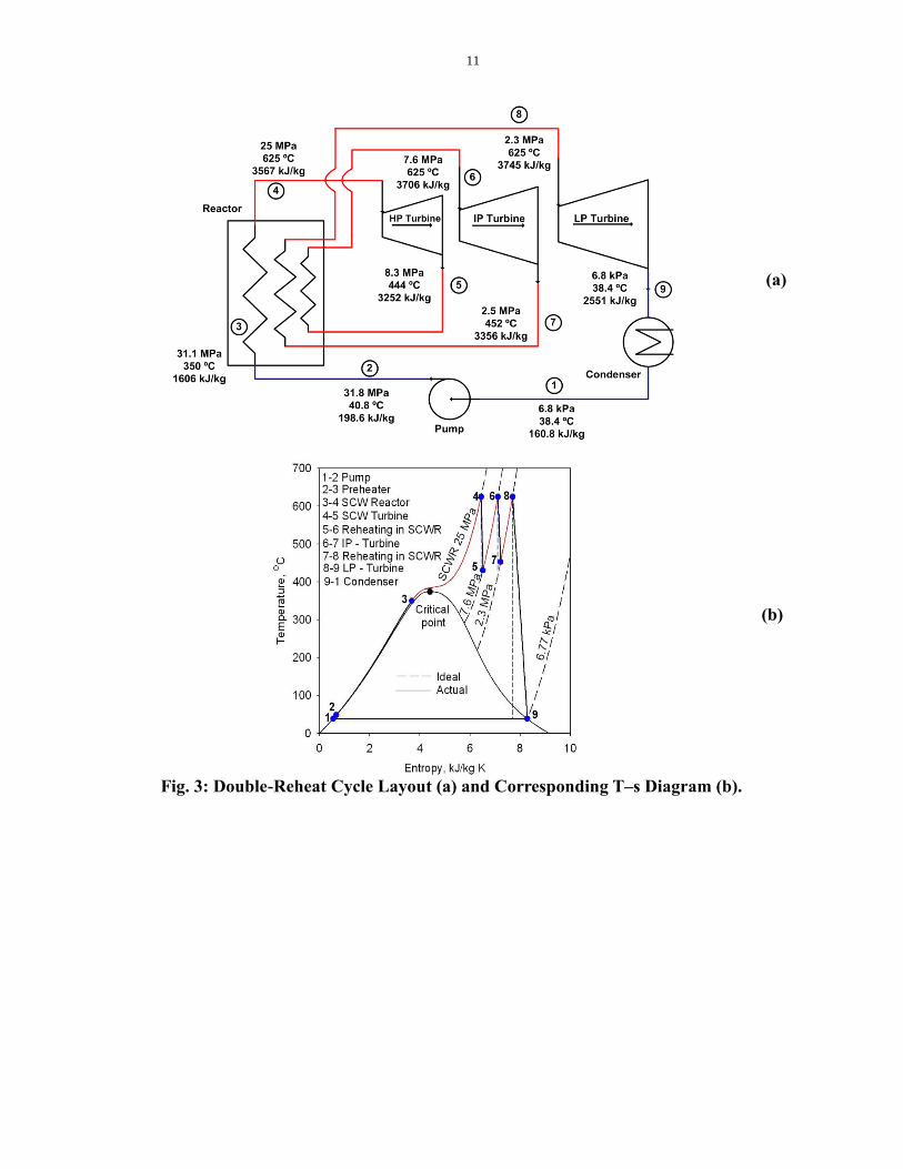
The double-reheat cycle arrangement and the corresponding T–s diagram are shown in Figs. 3a
and 3b, respectively. The corresponding heat-transfer rates are listed in Table 3. In comparison
to the single-reheat cycle (for details, see Section 1.2.2) the double-reheat cycle has three turbine
sections: 1) HP turbine; 2) IP turbine(s); and 3) LP turbine(s). Moreover, the second steam
reheat is added to the reactor.
The SC “steam” from the reactor is expanded inside the HP turbine from the supercritical
pressure of 25 MPa and temperature of 625°C (Point 4) to an intermediate pressure of 7.6 MPa
and temperature of 444°C (Point 5). The subcritical pressure steam leaves the HP turbine in a
superheated state and is sent back to the reactor where it is heated from 444°C to 625°C (Point
6). After the reactor reheater, the superheated steam is expanded in the IP turbine(s) to a
pressure of 2.3 MPa and temperature of 452°C (Point 7). The subcritical-pressure steam leaves
the IP turbine in a superheated state and is sent back to the reactor where it is heated from 452°C
to 625°C (Point 8). After the second reactor reheater, the superheated steam is expanded in the
LP turbine(s) to sub-atmospheric pressure of 6.8 kPa and temperature of 38.4°C (Point 9), and
condensed in the condenser.
11
(a)
(b)
Fig. 3: Double-Reheat Cycle Layout (a) and Corresponding T–s Diagram (b).
12
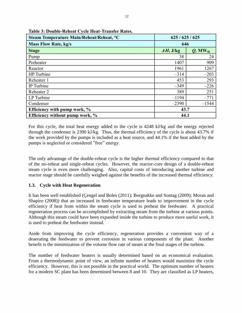
Table 3: Double-Reheat Cycle Heat-Transfer Rates.
Steam Temperature Main/Reheat/Reheat, °C 625 / 625 / 625
Mass Flow Rate, kg/s 646
Stage ΔH, J/kg Q, MWth
Pump 38 24
Preheater 1407 909
Reactor 1961 1267
HP Turbine –314 –203
Reheater 1 453 293
IP Turbine –349 –226
Reheater 2 389 251
LP Turbine –1194 –771
Condenser –2390 –1544
Efficiency with pump work, % 43.7
Efficiency without pump work, % 44.1
For this cycle, the total heat energy added to the cycle is 4248 kJ/kg and the energy rejected
through the condenser is 2390 kJ/kg. Thus, the thermal efficiency of the cycle is about 43.7% if
the work provided by the pumps is included as a heat source, and 44.1% if the heat added by the
pumps is neglected or considered ”free” energy.
The only advantage of the double-reheat cycle is the higher thermal efficiency compared to that
of the no-reheat and single-reheat cycles. However, the reactor-core design of a double-reheat
steam cycle is even more challenging. Also, capital costs of introducing another turbine and
reactor stage should be carefully weighed against the benefits of the increased thermal efficiency.
1.3. Cycle with Heat Regeneration
It has been well established (Çengel and Boles (2011); Borgnakke and Sontag (2009); Moran and
Shapiro (2008)) that an increased in feedwater temperature leads to improvement in the cycle
efficiency if heat from within the steam cycle is used to preheat the feedwater. A practical
regeneration process can be accomplished by extracting steam from the turbine at various points.
Although this steam could have been expanded inside the turbine to produce more useful work, it
is used to preheat the feedwater instead.
Aside from improving the cycle efficiency, regeneration provides a convenient way of a
deaerating the feedwater to prevent corrosion in various components of the plant. Another
benefit is the minimization of the volume flow rate of steam at the final stages of the turbine.
The number of feedwater heaters is usually determined based on an economical evaluation.
From a thermodynamic point of view, an infinite number of heaters would maximize the cycle
efficiency. However, this is not possible in the practical world. The optimum number of heaters
for a modern SC plant has been determined between 8 and 10. They are classified as LP heaters,

13
Deaerators (mixing chambers) and HP heaters depending on the operating pressure and the type
of heat exchanger used.
As previously mentioned, the exact point where extraction steam is taken from plays an
important role in the efficiency of the thermal cycle and also depends on the turbine design.
It is difficult to show the benefit of the regenerative-feedwater heating in a T–s diagram, because
the flow rates at the various points in the cycle are not the same and hence, the areas within the
T–s diagram do not represent the total work and heat rejection of the cycle. For the same reason,
it is not meaningful to show the heat sources and sinks in Table 4 on the basis of energy per unit
mass (kJ/kg). Table 4 is based on a total useful heat of 1200 MWth.
The arrangement analyzed below involves three feedwater heaters: one LP heater, one deaerator
and one HP heater (for details, see Fig. 4 and Table 4). Steam is extracted from the HP turbine
and used to heat the feedwater flowing through the Heat Exchanger (HX) 3 (closed-type
feedwater heater). The LP turbine supplies extraction steam for the LP feedwater heater (HX1).
Also, a fraction of the steam exhausted from the HP turbine is diverted to heat the water in the
deaerator (HX2).
Fig. 4: Single-Reheat Cycle with Heat Regeneration through Single Deaerator and Two
Feedwater Heaters.
Table 4 summarizes the heat transfer rates and thermal efficiency associated with this cycle (see
Fig. 4). The total heat added to the cycle is approximately 2564 MWth. At the same time, the
heat rejected in the condenser is approximately 1364 MWth. Thus, the thermal efficiency is
about 46.8% if the work provided by the pumps is included as a heat source, and 47.7% if the
heat added by the pumps is neglected or considered ”free” energy.

14
As can be seen from Tables 2 and 4 the thermal efficiencies of the regenerative single-reheat
cycles are significantly higher than those for the single-reheat cycle without regeneration. The
optimum number of feedwater heaters would have to be determined through a cost-benefit
analysis.
Table 4: Mass-Flow and Heat-Transfer Rates through System Components.
Steam Temperature
Main / Reheat, °C 625 / 625
Stage m, kg/s Q, MWth
Pumps (total) N/A 48
Feedwater Heater (HX1) 754 514
Deaerator 754 230
Feedwater Heater (HX2) 1058 433
Reactor 1058 2076
HP Turbine 1058 –388
Reheater 864 440
LP Turbine 754 –812
Condenser 594 –1364
Efficiency with pump work, % 46.8
Efficiency without pump work, % 47.7
The regenerative cycle presented in this section represent a viable basis for a future SCW NPP.
The optimum number of regenerative heaters should be investigated – it is likely going to be
higher (see Fig. 5) than what was presented herein for illustration of efficiency trends (for
details, see Duffey et al., 2008a,b). However, it is clear that the calculated thermal efficiencies
with regenerative heating are significantly higher than those of currently operating NPPs. The
increase in efficiency is high enough to justify the increased costs associated with the design,
construction and operation of this new type SCW NPPs.
1.4. Conclusions
The following conclusions can be made:
1) Four simplified SCW NPP thermodynamic cycles (main “steam” parameters – pressure of
25 MPa and temperature of 625°C; reheat steam parameters – pressure of 2.3 – 7.6 MPa
and temperature of 625°C (700°C) and the corresponding arrangements have been
investigated in terms of their thermal efficiency, assuming isentropic turbine efficiencies of
88% for all turbine sections and 84% polytropic efficiency for all pumps: (I) cycles without
heat regeneration: (1) no-reheat cycle – 40.5% thermal efficiency; (2) single-reheat cycle –
42.6% thermal efficiency; and (3) double-reheat cycle – 43.7% thermal efficiency; and (II)
cycles with heat regeneration: (4) single-reheat cycle with three feedwater heaters – 46.8%
thermal efficiency. And
2) Based on the abovementioned analysis the single-reheat cycle with heat regeneration and
the corresponding arrangement appears to be the most advantageous as a basis for an SCW
NPP.
15
PART 2. SCWRS RANKINE CYCLES
2.1. Review of Existing SC Turbines at Coal-Fired Thermal Power Plants
SC-“steam” turbines of medium and large capacities (450 – 1200 MWel) have been used very
successfully at many coal-fired power plants for more than fifty years. Their steam-cycle
thermal efficiencies have reached nearly 54%, which is equivalent to a net-plant efficiency of
approximately 43 – 48% on an HHV basis.
An analysis of SC-turbine data (see Lecture SC02) showed that:
The vast majority of the modern and upcoming SC turbines are single-reheat-cycle
turbines;
Major “steam” inlet parameters of these turbines are: The main or primary SC “steam” – P
= 24 – 25 MPa and T = 540 – 600°C; and the reheat or secondary subcritical-pressure
steam – P = 3 – 5 MPa and T = 540 – 620°C. And
Only very few double-reheat-cycle turbines were manufactured so far. The market demand
for double-reheat turbines disappeared due to economic reasons after the first few units
were built.
Based on the analysis of SC coal-fired power plants data the following two major conclusions
can be drawn:
1) Direct single-reheat regenerative thermodynamic cycle (Rankine cycle) is the basic cycle
for the vast majority of modern SC coal-fired thermal power plants. And
2) Current level of inlet parameters for SC turbines are: The main or primary SC “steam” – P
= 25 – 30 MPa and T = 600 – 625°C; and the reheat or secondary steam – P = 3 – 7 MPa
and T = 600 – 625°C.
Therefore, the best option for SCWR development is to match at least the current SC turbine
parameters. Only in this case, we will have significant savings in development costs, resources
and time. However, SCWRs are not SC steam generators and some special requirements will
apply.
2.2. Possible Thermodynamic Cycles for SCWRs
In general, we have a solid basis for SCWR development:
Pressurized Water Reactor’s (PWR’s) technology (current pressures up to 16 MPa);
Boiling Water Reactor’s (BWR’s) once-through or direct cycle;
Supercritical “steam” turbines and other equipment from coal-fired power plants;
Materials, which can withstand high pressures and temperatures, and aggressive medium
such as supercritical water; And
Experience of nuclear steam reheat at several BWR NPPs in Russia and USA (Pioro et al.,
2010a; Saltanov et al., 2010)
16
However, it should be admitted that the major problem for the SCWR development is reliability
of materials at high pressures and temperatures, aggressive medium such as supercritical water
plus high neutron flux. To resolve this problem SCW loops must be designed and built in
experimental reactors with neutron-flux levels, thermalhydraulic and other parameters
corresponding to that of SCWRs.
In general, the following thermodynamic cycles can be used in SCW NPPs (for more details, see
(Duffey et al., 2008c; Naidin et al., 2009; Pioro et al., 2010b and 2008):
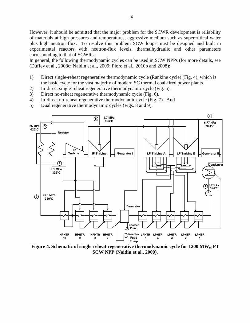
1) Direct single-reheat regenerative thermodynamic cycle (Rankine cycle) (Fig. 4), which is
the basic cycle for the vast majority of modern SC thermal coal-fired power plants.
2) In-direct single-reheat regenerative thermodynamic cycle (Fig. 5).
3) Direct no-reheat regenerative thermodynamic cycle (Fig. 6).
4) In-direct no-reheat regenerative thermodynamic cycle (Fig. 7). And
5) Dual regenerative thermodynamic cycles (Figs. 8 and 9).
Figure 4. Schematic of single-reheat regenerative thermodynamic cycle for 1200 MWel PT
SCW NPP (Naidin et al., 2009).

17
Figure 5. Schematic of in-direct single-reheat regenerative thermodynamic cycle for 1200
MWel PV or PT SCW NPP (Thind et al., 2010).
Figure 6. Schematic of direct no-reheat regenerative thermodynamic cycle for 1200 MWel
PV or PT SCW NPP (Naidin et al., 2009).

18
Figure 7. Schematic of in-direct no-reheat regenerative thermodynamic cycle for 1200
MWel PV or PT SCW NPP (Thind et al., 2010).
Figure 8. Schematic of dual no-reheat primary (SCW) loop and single-reheat secondary
(superheated steam) loop regenerative thermodynamic cycle for 1200 MWel PV or PT SCW
NPP (Thind et al., 2010).

19
HPTIPT
LPTReactor
HTP
CND
CEPHP Heaters LP Heaters
SG
FWP
Reactor Building Turbine Building
Dea
Drain
Pump
25MPa, 625°C
7MPa419°C
6.3MPa, 625°C
315°C
620kPa288°C
500kPa, 250°C
121°C
5kPa
Figure 9. Schematic of dual single-reheat regenerative thermodynamic cycle for 1200 MWel
PT SCW NPP (Duffey et al., 2008c): High-pressure units located in Reactor Building for
increased safety.
In the direct cycle, SC “steam” from an SCWR is fed directly to an SC turbine. This concept
eliminates the need for complex and expensive equipment such as steam generators (heat
exchangers). From a thermodynamic perspective, this allows for high steam pressures and
temperatures, and results in the highest cycle thermal efficiency for the given parameters. The
direct single-reheat cycle with current SC “steam” parameters will have the gross thermal
efficiency of about 52% and no-reheat cycle – about 51% (Naidin et al., 2009). However, the
direct single-reheat cycle is easier to implement in PT SCWR and might be impossible to
implement in PV SCWRs. The direct no-reheat cycle can be implemented in both types of
SCWRs.
The single-reheat cycle is widely used in thermal power industry, but we have not found any
information on thermal power plants operating on the no-reheat cycle. The major technical
challenge for the no-reheat cycle is relatively high moisture content at the outlet of the LP
turbine (about 19%). However, the moisture can be reduced by implementing contoured
channels in the inner casing for draining the water and moisture removal stages.
The indirect and dual cycles utilize heat exchangers (steam generators) to transfer heat from the
reactor coolant to a turbine. The indirect cycle has the safety benefit of containing the potential
radioactive particles inside the primary coolant. Also, this cycle arrangement prevents deposition
of various substances from the reactor coolant on turbine blades. However, the heat-transfer
process through heat exchangers reduces the maximum temperature in the secondary-loop
20
coolant at least by 25 – 75°C, thus lowering the efficiency of the cycle. Also, heat exchangers
(steam generators) can be quite large units with about 200 thousand square meters of heat
transfer surfaces (Duffey et al., 2008c; Thind et al., 2010).
From the SCWR design point of view, the following can be concluded:
The single-reheat cycle has the advantage of higher thermal efficiency (compared to that of
the no-reheat cycle) and reduced development costs due to a wide variety of single-reheat
SC turbines manufactured by companies worldwide. The major disadvantage is the
increased design complexity associated with the introduction of steam-reheat (SHR)
channels to the reactor core (Fig. 10). And
The no-reheat cycle offers a simplified SCW NPP layout, contributing to lower capital
costs. However, the efficiency of this cycle is lower and no-reheat SC turbine has been
possibly developed.
As such, configurations based on the single-reheat and no-reheat cycles were chosen for the
analysis in this lecture.
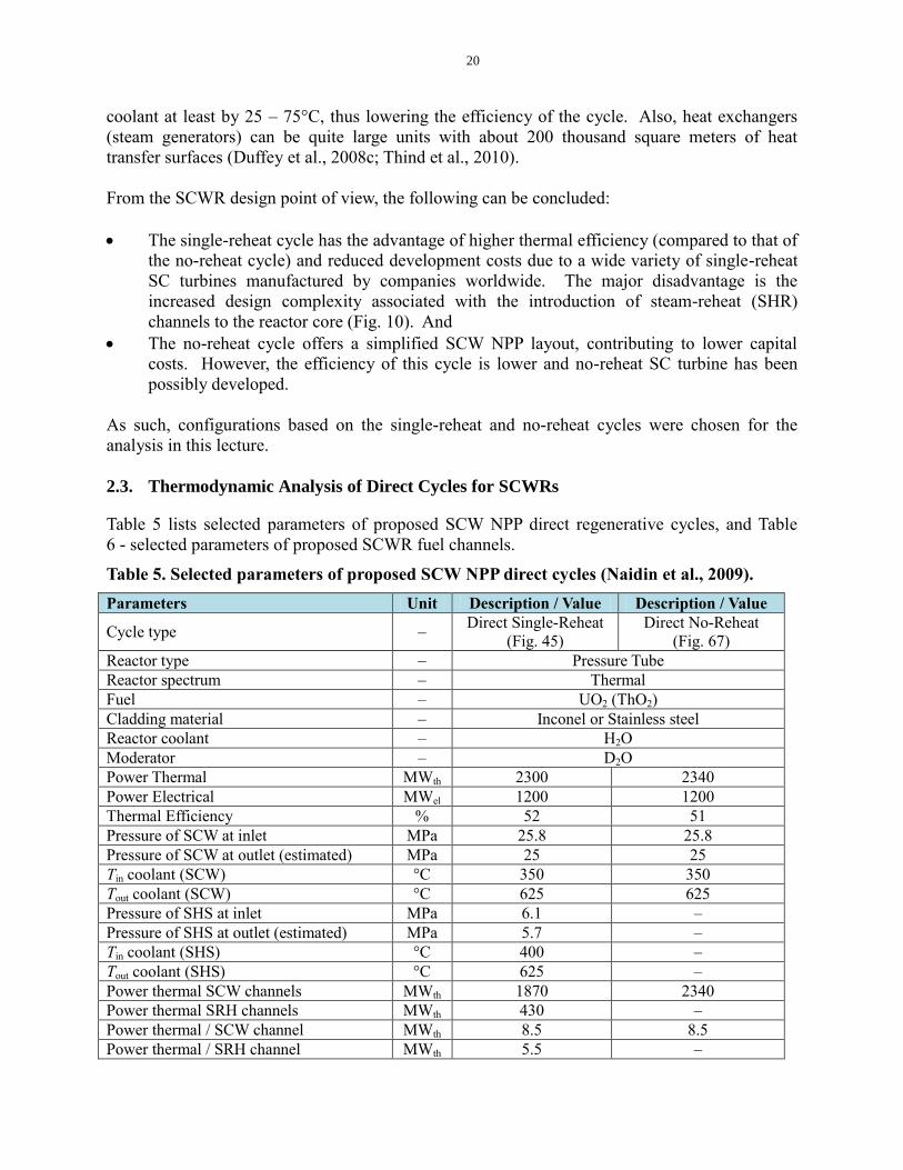
2.3. Thermodynamic Analysis of Direct Cycles for SCWRs
Table 5 lists selected parameters of proposed SCW NPP direct regenerative cycles, and Table
6 - selected parameters of proposed SCWR fuel channels.
Table 5. Selected parameters of proposed SCW NPP direct cycles (Naidin et al., 2009).
Parameters Unit Description / Value Description / Value
Cycle type – Direct Single-Reheat
(Fig. 45)
Direct No-Reheat
(Fig. 67)
Reactor type – Pressure Tube
Reactor spectrum – Thermal
Fuel – UO2 (ThO2)
Cladding material – Inconel or Stainless steel
Reactor coolant – H2O
Moderator – D2O
Power Thermal MWth 2300 2340
Power Electrical MWel 1200 1200
Thermal Efficiency % 52 51
Pressure of SCW at inlet MPa 25.8 25.8
Pressure of SCW at outlet (estimated) MPa 25 25
Tin coolant (SCW) °C 350 350
Tout coolant (SCW) °C 625 625
Pressure of SHS at inlet MPa 6.1 –
Pressure of SHS at outlet (estimated) MPa 5.7 –
Tin coolant (SHS) °C 400 –
Tout coolant (SHS) °C 625 –
Power thermal SCW channels MWth 1870 2340
Power thermal SRH channels MWth 430 –
Power thermal / SCW channel MWth 8.5 8.5
Power thermal / SRH channel MWth 5.5 –
21
Parameters Unit Description / Value Description / Value
# of fuel channels (total) – 300 270
# of SCW channels – 220 270
# of SRH channels – 80 –
Total flow rate of SCW kg/s 960 1190
Total flow rate of SHS kg/s 780 –
Flow rate / SCW channel kg/s 4.37 4.37
Flow rate / SRH channel kg/s 10 –
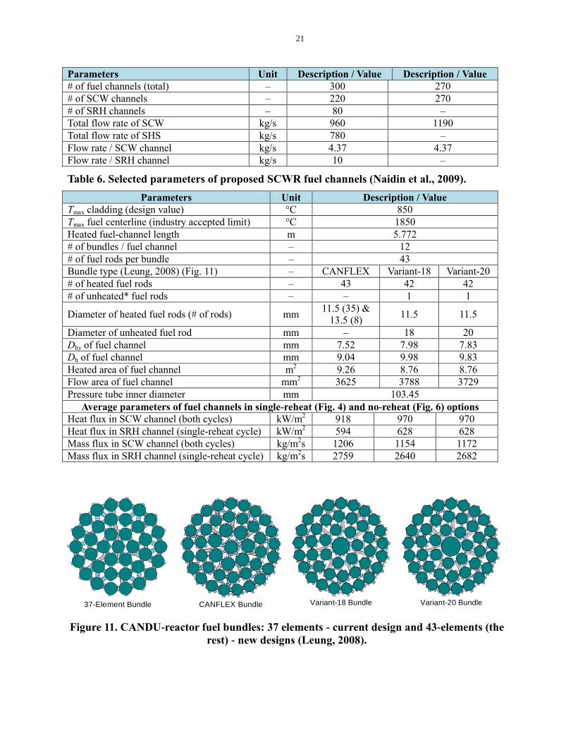
Table 6. Selected parameters of proposed SCWR fuel channels (Naidin et al., 2009).
Parameters Unit Description / Value
Tmax cladding (design value) °C 850
Tmax fuel centerline (industry accepted limit) °C 1850
Heated fuel-channel length m 5.772
# of bundles / fuel channel – 12
# of fuel rods per bundle – 43
Bundle type (Leung, 2008) (Fig. 11) – CANFLEX Variant-18 Variant-20
# of heated fuel rods – 43 42 42
# of unheated* fuel rods – – 1 1
Diameter of heated fuel rods (# of rods) mm 11.5 (35) &
13.5 (8) 11.5 11.5
Diameter of unheated fuel rod mm – 18 20
Dhy of fuel channel mm 7.52 7.98 7.83
Dh of fuel channel mm 9.04 9.98 9.83
Heated area of fuel channel m2 9.26 8.76 8.76
Flow area of fuel channel mm2 3625 3788 3729
Pressure tube inner diameter mm 103.45
Average parameters of fuel channels in single-reheat (Fig. 4) and no-reheat (Fig. 6) options
Heat flux in SCW channel (both cycles) kW/m2 918 970 970
Heat flux in SRH channel (single-reheat cycle) kW/m2 594 628 628
Mass flux in SCW channel (both cycles) kg/m2s 1206 1154 1172
Mass flux in SRH channel (single-reheat cycle) kg/m2s 2759 2640 2682
Figure 11. CANDU-reactor fuel bundles: 37 elements - current design and 43-elements (the
rest) - new designs (Leung, 2008).
Variant-20 BundleVariant-18 Bundle
CANFLEX Bundle37-Element Bundle
Variant-20 BundleVariant-18 Bundle
CANFLEX Bundle37-Element Bundle

22
PART 3. CO-GENERATION OF HYDROGEN
Due to the well-known contribution of greenhouse gas emissions generated by fossil fuels to
global warming, worldwide research is being conducted to identify a clean energy carrier. As
such, hydrogen was identified as one of the promising options. However, most of the hydrogen
supply currently available is obtained from fossil fuels through reforming processes, which
release greenhouse gases.
Hydrogen is needed in large quantities by many industrial sectors, i.e., Canadian oil sands,
petroleum products, agriculture, and transportation. Thus, a technology suitable for large-scale
sustainable production of hydrogen needs to be developed and implemented. Thermo-chemical
water splitting is one of the most promising technologies for hydrogen generation without the
negative consequences of pollutants. By using intermediate compounds, a series of chemical and
physical processes decompose water into its two constituents. Thermo-chemical hydrogen
production is also much more efficient than other methods, such as electrolysis, because the heat
is used directly to produce hydrogen, rather than being converted first to electrical energy.
Although over about 200 thermo-chemical cycles have been identified (Naterer et al., 2010,
2009), proof-of-principle demonstrations have been completed only for a few of them. However,
most of these processes use process heat above 800°C, thus requiring very high temperatures that
are not currently available in nuclear or thermal power plants. The copper-chlorine (Cu-Cl) cycle
is the only demonstrated cycle functioning at a lower temperature of approximately 500°C,
which makes it suitable for linkage with a SCW NPP cycle. The relatively lower operating
temperature can also lead to a reduction in material and maintenance costs.
Table 7: Chemical reaction steps and basic parameters of the copper-chlorine cycle.
Step Reaction
Temperatur
e Range
(C)
Feed/Output
1 2Cu(s) + 2HCl(g) →
CuCl(l) + H2(g) 430 – 475
Feed:
Output:
Electrolytic Cu + dry HCl + Q
H2 + CuCl(l) salt
2
2CuCl(s) → 2CuCl (aq)
→ CuCl2(aq) + Cu(s)
Ambient
(electrolysis
)
Feed:
Output:
Powder/granular CuCl and HCl +
V
Cu and slurry containing HCl
and CuCl2
3 CuCl2(aq) → CuCl2(s) <100 Feed:
Output:
Slurry containing HCl and CuCl2
+ Q
Powder/granular CuCl2 +
H2O/HCl vapors
4 2CuCl2(s) + H2O(g) →
CuO*CuCl2(s) + 2HCl(g) 400
Feed:
Output:
Powder/granular CuCl2 +
H2O(g) + Q
Powder/granular CuO*CuCl2 +
2HCl (g)
5 CuO*CuCl2(s) → 2CuCl(l)
+ 1/2O2(g) 500
Feed:
Output:
Powder/granular CuO* CuCl2(s)
+ Q
Molten CuCl salt + oxygen
Q - thermal energy and V - electrical energy

23
Currently, UOIT (University of Ontario Institute of Technology) in collaboration with AECL and
other partners are developing the Cu-Cl cycle with a maximum temperature in the cycle of up to
500°C (for details, see Table 7 and Naterer et al. (2010), (2009)). Therefore, using the high-
temperature heat from a SCWR to heat water and endothermic reactors in the hydrogen-
production loop is a viable option. Heat exchangers of a recuperator-type have to be used for
this purpose.
As mentioned in previous sections, due to the high temperature coolant at the reactor outlet, the
SCW NPP cycles are suitable for hydrogen co-generation. Figure 12 shows the heat extraction
points for the no-reheat configuration. As such, the first extraction point would be that located
directly on the main SC “steam” lines coming from the reactor core. The temperature and
pressure of the liquid are 625°C and 25 MPa, respectively. The SC “steam” is used to heat the
water and endothermic reactors in the hydrogen loop through a heat exchanger, as shown in
Figure 12. The cooler fluid at the outlet of the heat exchanger is returned at a suitable point
along the feedwater heating system.
Alternatively, another source of high-quality heat is identified to be the superheated steam
coming from the exhaust of the HP Turbine. The temperature and pressure of the fluid are 460°C
and 9.2 MPa, respectively. Similar to the above discussion, this steam can be used to heat the
water in the hydrogen loop, using a heat exchanger.
The third possible option is to divert steam from the HP Turbine extraction point. According to
Figure 12, this fluid is heating the feedwater passing through HP HTR9. However, a portion of
this high-quality steam (approximately 12.5 MPa and 500°C) can be used to heat up the process
water in the hydrogen loop.
Figure 12: Heat-extraction points for H2 co-generation associated with no-reheat SCW
NPP.
24
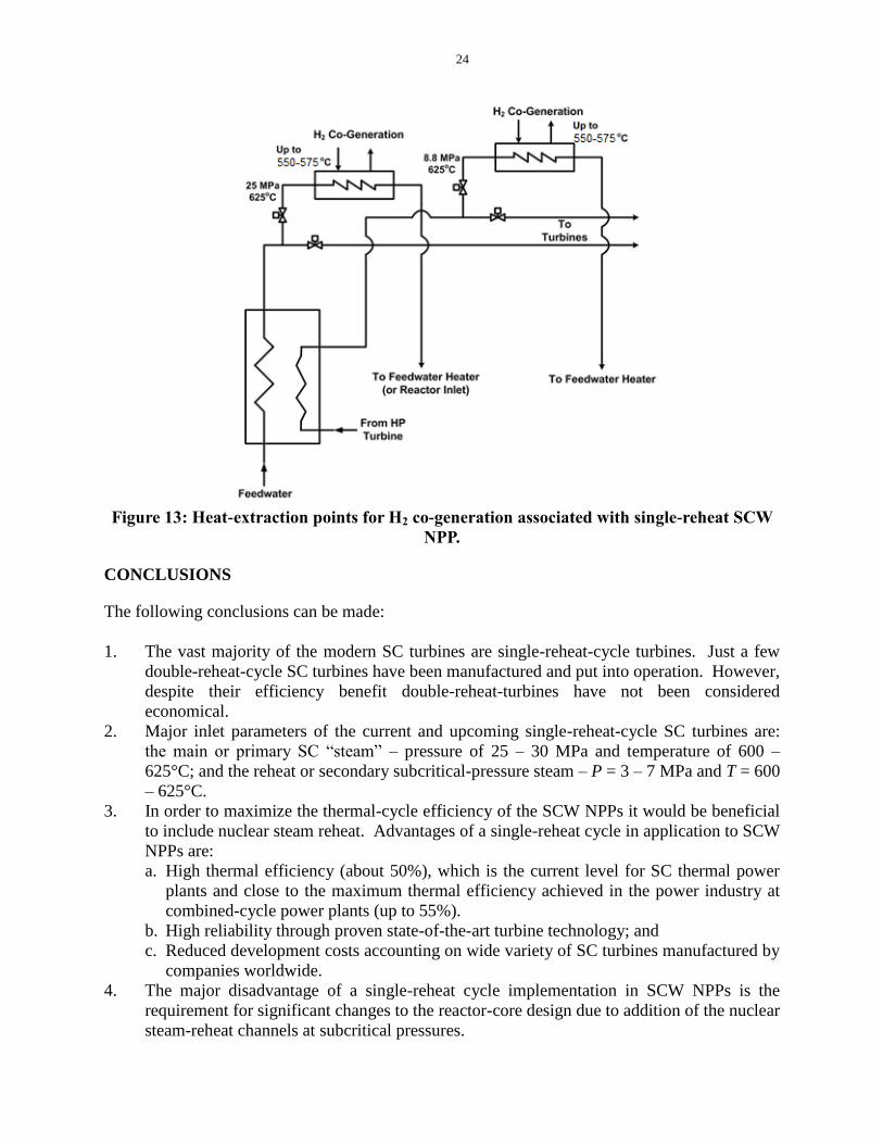
Figure 13: Heat-extraction points for H2 co-generation associated with single-reheat SCW
NPP.
CONCLUSIONS
The following conclusions can be made:
1. The vast majority of the modern SC turbines are single-reheat-cycle turbines. Just a few
double-reheat-cycle SC turbines have been manufactured and put into operation. However,
despite their efficiency benefit double-reheat-turbines have not been considered
economical.
2. Major inlet parameters of the current and upcoming single-reheat-cycle SC turbines are:
the main or primary SC “steam” – pressure of 25 – 30 MPa and temperature of 600 –
625°C; and the reheat or secondary subcritical-pressure steam – P = 3 – 7 MPa and T = 600
– 625°C.
3. In order to maximize the thermal-cycle efficiency of the SCW NPPs it would be beneficial
to include nuclear steam reheat. Advantages of a single-reheat cycle in application to SCW
NPPs are:
a. High thermal efficiency (about 50%), which is the current level for SC thermal power
plants and close to the maximum thermal efficiency achieved in the power industry at
combined-cycle power plants (up to 55%).
b. High reliability through proven state-of-the-art turbine technology; and
c. Reduced development costs accounting on wide variety of SC turbines manufactured by
companies worldwide.
4. The major disadvantage of a single-reheat cycle implementation in SCW NPPs is the
requirement for significant changes to the reactor-core design due to addition of the nuclear
steam-reheat channels at subcritical pressures.

25
5. Based on the abovementioned analysis, the direct or in-direct single-reheat cycles with heat
regeneration and the corresponding arrangement appear to be the most advantageous as a
basis for a SCW NPP. However, other cycles, for example, dual cycles might be
considered.
ACKNOWLEDGEMENTS
Financial supports from the IAEA; International Strategic Opportunities Program Ministry of
Research and Innovation (Ontario, Canada); NSERC Discovery Grant and
NSERC/NRCan/AECL Generation IV Energy Technologies Program are gratefully
acknowledged.
NOMENCLATURE
pc average specific heat, J/kg∙K,
bw
b
TT
HH w
D inside diameter, m
G mass flux, kg/m2s
H enthalpy, J/kg
h heat transfer coefficient, W/m2K
k thermal conductivity, W/m∙K
m mass-flow rate, kg/s
P pressure, Pa
Q heat-transfer rate, W
T temperature, ºC
Greek letters
dynamic viscosity, Pa∙s
density, kg/m3
Dimensionless numbers
Nu Nusselt number
k
Dh
Pr average Prandtl number
k
c p
Re Reynolds number
DG
Subscripts
b bulk
ch channel
el electrical
h heated
hy hydraulic
in inlet
26
out outlet
pc pseudocritical
max maximum
th thermal
w wall
Abbreviations
AECL Atomic Energy Canada Limited
AHFP Axial Heat Flux Profile
BWR Boiling Water reactor
CANDU CANada Deuterium Uranium (reactor)
CANFLEX CANDU FLEXible (fuelling)
CEP Condensate Extraction Pump
CL CenterLine
CND Condenser
Dea Deaerator
FWP Feed Water Pump
HF Heat Flux
HHV Higher-Heating Value
HP High Pressure
HPT High Pressure Turbine
HTC Heat Transfer Coefficient
HTR HeaTeR
HWR Heavy Water Reactor
HX Heat eXchanger
ID Inside Diameter
IP Intermediate Pressure (turbine)
IPT Intermediate Pressure Turbine
KP-SKD Channel Reactor of Supercritical Pressure (in Russian abbreviations)
LHV Lower-Heating Value
LP Low Pressure
LPT Low Pressure Turbine
LWR Light Water Reactor
Mix Ch Mixing Chamber (deaerator)
NA Not Available
NPP Nuclear Power Plant
OD Outside Dimater
PT Pressure Tube (reactor)
PV Pressure Vessel (reactor)
PWR Pressurized Water Reactor
RFP Reactor Feed Pump
RMS Root Mean Square
SC SuperCritical
SCW SuperCritical Water
SCWR SuperCritical Water Reactor
SG Steam Generator
SH SHeath
SHS SuperHeated Steam
SRH Steam ReHeat
UOIT University of Ontario Institute of Technology

27
REFERENCES
Borgnakke, C. and Sontag, R.E., 2009. Fundamentals of Thermodynamics, J. Wiley & Sons, 7th
edition, New York, NY, USA, 894 pages.
Çengel, Yu.A. and Boles, M.A., 2011. Thermodynamics. An Engineering Approach, 7th
ed.,
McGraw-Hill, New York, NY, USA, 2011, 1024 pages.
Duffey, R.B., Pioro, I.L. and Kuran, S., 2008a. Advanced Concepts for Pressure-Channel
Reactors: Modularity, Performance and Safety, JSME J. of Power and Energy Systems,
Vol. 2, No. 1.
Duffey, R.B., Pioro, I., Zhou, T., Zirn, U., Kuran, S., Khartabil, H. and Naidin, M., 2008b.
SCWRs: Current and Future Concepts – Steam-Cycle Options, Proc. ICONE-16,
Orlando, FL, USA, May 11–15, Paper #48869.
Duffey, R.B., Pioro, I., Zhou, T., Zirn, U., Kuran, S., Khartabil, H. and Naidin, M., 2008c.
Supercritical Water-Cooled Nuclear Reactors (SCWRs): Current and Future Concepts -
Steam-Cycle Options, Proc. ICONE-16, Orlando, FL, USA, May 11-15, Paper #48869, 9
pages.
Leung, L.K., 2008. Effect of CANDU Bundle-Geometry Variation on Dryout Power, Proc.
ICONE-16, Orlando, FL, USA, May 11-15, Paper #48827.
Mokry, S., Naidin, M., Baig, F., Gospodinov, Ye., Zirn, U., Bakan, K., Pioro, I. and Naterer, G.,
2008. Conceptual Thermal-Design Options for Pressure-Tube SCWRs with
Thermochemical Co-Generation of Hydrogen, Proc. ICONE-16, Orlando, FL, USA, May
11–15, Paper #48313.
Moran, M.J. and Shapiro, H.N., 2008. Fundamentals of Engineering Thermodynamics, J. Wiley
& Sons, 6th
edition, New York, NY, USA, 928 pages.
Naidin, M., Mokry, S., Pioro, I., Duffey, R., and Zirn, U., 2009. SCW NPPs: Layouts and
Thermodynamic Cycles, Proc. Int. Conf. “Nuclear Energy for New Europe”, Bled,
Slovenia, Sep. 14-17, Paper #704.
Naterer, G.F., Suppiah, S., Stolberg, L.,..., Pioro, I. et al., 2010. Canada’s Program on Nuclear
Hydrogen Production and the Thermochemical Cu-Cl Cycle, Int. J. of Hydrogen Energy
(IJHE), Vol. 35, pp. 10905-10926.
Naterer, G., Suppiah, S., Lewis, M., ..., Pioro, I. et al., 2009. Recent Canadian Advances in
Nuclear-Based Hydrogen Production and the Thermochemical Cu-Cl Cycle, Int. J. of
Hydrogen Energy (IJHE), Vol. 34, pp. 2901-2917.
Pioro, I., Saltanov, Eu., Naidin, M., et al., 2010a. Steam-Reheat Option in SCWRs and
Experimental BWRs, Report for NSERC/NRCan/AECL Generation IV Energy
Technologies Program (NNAPJ) entitled “Alternative Fuel-Channel Design for SCWR”
with Atomic Energy of Canada Ltd., Version 1, UOIT, Oshawa, ON, Canada, March, 128
pages.
Pioro I., Zirn U., Duffey R., Naidin M., Mokry S., Gospodinov Ye. and Baig F., 2008.
Supercritical Water-Cooled Nuclear Reactors: Thermodynamic-Cycles Options, Proc. 6th

28
International Conference on Heat Transfer, Fluid Mechanics and Thermodynamics
(HEFAT-2008), June 30 - July 2, Pretoria, South Africa, Paper #PI1.
Pioro, I., Naidin, M., Mokry, S., et al., 2010b. General Layouts of Supercritical-Water NPPs,
Proc. ICONE-18, Xi'an, China, May 17-21, Paper #29993.
Saltanov, Eu., Peiman, W., Farah, A., King, K., Naidin, M. and Pioro, I., 2010. Steam-Reheat
Options for Pressure-Tube SCWRs, Proc. ICONE-18, Xi'an, China, May 17-21, Paper
#29972.
Thind, H., Pioro, I., and Harvel G., 2010. Supercritical Water-Cooled Nuclear Reactor with
Intermediate Heat Exchangers, Proc. ICONE-18, Xi'an, China, May 17-21, Paper #30104.