1 Chapter 1 1-1 DATA COMMUNICATIONS The term ...
44
1 Chapter 1 1-1 DATA COMMUNICATIONS The term telecommunication means communication at a distance. What is a data? The word data refers to information presented in whatever form is agreed upon by the parties creating and using the data. What is a Data communications ? Data communications are the exchange of data between two devices via some form of transmission medium such as a wire cable. What are the characteristics for effectiveness of a data communication ? delivery, accuracy, timeliness and jitter. 1. Delivery: The system must deliver data to the correct destination. Data must be received by the intended device or user and only by that device or user. 2. Accuracy: The system must deliver the data accurately. Data that have been altered in transmission and left uncorrected are unusable. 3. Timeliness: The system must deliver data in a timely manner. Data delivered late are useless. In the case of video and audio, timely delivery means delivering data as they are produced, in the same order that they are produced, and without significant delay. This kind of delivery is called Real-Time Transmission. 4. Jitter: Jitter refers to the variation in the packet arrival time. It is the uneven delay in the delivery of audio or video packets. For example, let us assume that video packets are sent every 30ms. If some of the packets arrive with 30-ms delay and others with 40-ms delay, an uneven quality in the video is the result. DATA COMPONENTS A data communications system has five components (see figure 1.1) 1. Message: The message is the information (data) to be communicated. Popular forms of information include text, numbers, pictures, audio and video. 2. Sender: The sender is the device that sends the data message. It can be a computer, workstation, telephone handset, and so on. 3. Receiver: The receiver is the device that receives the message. It can be a computer, workstation, telephone handset, television, and so on. 4. Transmission medium: The transmission medium is the physical path by which a message travels from sender to receiver. Some examples of transmission media include twisted-pair wire, coaxial cable, fiber-optic cable, and radio waves. 5. Protocol: A protocol is a set of rules that govern data communications. It represents an agreement between the communicating devices. Without a protocol, two devices may be connected but not communicating, just as a person speaking English cannot be understood by a person who speaks only kannada.
-
Upload
khangminh22 -
Category
Documents
-
view
1 -
download
0
Transcript of 1 Chapter 1 1-1 DATA COMMUNICATIONS The term ...

1
Chapter 1
1-1 DATA COMMUNICATIONS
The term telecommunication means communication at a distance.
What is a data?
The word data refers to information presented in whatever form is agreed upon by the parties creating and
using the data.
What is a Data communications ?
Data communications are the exchange of data between two devices via some form of transmission medium
such as a wire cable.
What are the characteristics for effectiveness of a data communication ?
delivery, accuracy, timeliness and jitter.
1. Delivery: The system must deliver data to the correct destination. Data must be received by the
intended device or user and only by that device or user.
2. Accuracy: The system must deliver the data accurately. Data that have been altered in transmission
and left uncorrected are unusable.
3. Timeliness: The system must deliver data in a timely manner. Data delivered late are useless. In the
case of video and audio, timely delivery means delivering data as they are produced, in the same
order that they are produced, and without significant delay. This kind of delivery is called Real-Time
Transmission.
4. Jitter: Jitter refers to the variation in the packet arrival time. It is the uneven delay in the delivery of
audio or video packets. For example, let us assume that video packets are sent every 30ms. If some
of the packets arrive with 30-ms delay and others with 40-ms delay, an uneven quality in the video is
the result.
DATA COMPONENTS
A data communications system has five components (see figure 1.1)
1. Message: The message is the information (data) to be communicated. Popular forms of
information include text, numbers, pictures, audio and video.
2. Sender: The sender is the device that sends the data message. It can be a computer,
workstation, telephone handset, and so on.
3. Receiver: The receiver is the device that receives the message. It can be a computer,
workstation, telephone handset, television, and so on.
4. Transmission medium: The transmission medium is the physical path by which a message
travels from sender to receiver. Some examples of transmission media include twisted-pair wire,
coaxial cable, fiber-optic cable, and radio waves.
5. Protocol: A protocol is a set of rules that govern data communications. It represents an
agreement between the communicating devices. Without a protocol, two devices may be
connected but not communicating, just as a person speaking English cannot be understood by a
person who speaks only kannada.

2
Fig: 1.1
Types of Data Representation:
Text
In data communication, text is represented as a bit pattern, a sequence of bits (0s or 1s). Different
sets of bit patterns have been designed to represent text symbols. Each set is called a code, and the process
of representing symbols is called coding. Today, the prevalent coding system is called Unicode, which uses
32 bits to represent a symbol or character used in any language in the world. The American Standard
Code for Information Interchange (ASCII) developed some decades ago in the United States, now
constitutes the first 127 characters in Unicode and is also referred to as Basic Latin.
Numbers
Numbers are also represented by bit patterns. However, a code such as ASCII is not used to
represent numbers; the number is directly converted to a binary number to simplify mathematical
operations.
Images
Images are also represented by bit patterns. In its simplest form, an image is composed of a matrix
of pixels (picture elements), where each pixel is a small dot. The size of the pixel depends on the resolution.
For example, an image can be divided into 1000 pixels or 10,000 pixels. In the second case, there is a better
representation of the image (better resolution), but more memory is needed to store the image.
After an image is divided into pixels, each pixel is assigned a bit pattern. The size and the value of the
pattern depend on the image. For an image made of only black-and-white dots (e.g., a chessboard), a 1-bit
pattern is enough to represent a pixel.
If an image is not made of pure white and pure black pixels, you can increase the size of the bit pattern
to include gray scale. For example, to show four levels of gray scale, you can use 2-bit patterns. A black
pixel can be represented by 00, a dark gray pixel by 01, a light gray pixel by 10, and a white pixel by 11.
There are several methods to represent colour images. One method is called RGB, so called because
each colour is made of a combination of three primary colours: red, green, and blue. The intensity of each
colour is measured, and a bit pattern is assigned to it. Another method is called YCM, in which a colour is
made of a combination of three other primary colours: yellow, cyan, and magenta.
Audio
Audio refers to the recording or broadcasting of sound or music. Audio is by nature different from
text, numbers, or images. It is continuous, not discrete. Even when we use a microphone to change voice or
music to an electric signal, we create a continuous signal.

3
Video
Video refers to the recording or broadcasting of a picture or movie. Video can either be produced as
a continuous entity (e.g., by a TV camera), or it can be a combination of images, each a discrete entity,
arranged to convey the idea of motion. Again we can change video to a digital or an analog signal.
Data Flow Communication between two devices can be simplex, half-duplex, or full-duplex as shown in figure 1.2
Simplex
In simplex mode, the communication is unidirectional, as on a one-way street. Only one of the two
devices on a link can transmit; the other can only receive (see figure 1.2a).
Keyboards and traditional monitors are examples of simplex devices. The keyboard can only introduce
input; the monitor can only accept output. The simplex mode can use the entire capacity of the channel to
send data in one direction.
Half-Duplex
In half-duplex mode, each station can transmit and receive, but not at the same time. When one
device is sending, the other can only receive, and vice versa (see figure 1.2b).
The half-duplex mode is like a one-lane road with traffic allowed in both directions. When cars are
travelling in one direction, cars going the other way must wait.
In a half-duplex transmission, the entire capacity of a channel is taken over by whichever of the two devices
is transmitting at the time.
Examples: Walkie-talkie and CB (citizens band) radios are both half-duplex systems.
The half-duplex mode is used in cases where there is no need for communication in both directions at the
same time; the entire capacity of the channel can be utilized for each direction.
Full-Duplex
In full duplex mode (also called duplex), both stations can transmit and receive simultaneously (see
figure 1.2c).
The full-duplex mode is like a two-way street with traffic flowing in both directions at the same time.
In full-duplex mode, signals going in one direction share the capacity of the link with signals going in the
other direction.
This sharing can occur in two ways; Either the link must contain two physically separate transmission paths,
one for sending and the other for receiving; or the capacity of the channel is divided between signals
travelling in both directions.
One common example of full-duplex communication is the telephone network. When two people are
communicating by a telephone line, both can talk and listen at the same time.
The full-duplex mode is used when communication in both directions is required all the time. The
capacity of the channel, however, must be divided between the two directions.

4
Fig:1.2
1-2 NETWORKS
A network is a set of devices (often referred to as nodes) connected by communication links. A node can be
a computer, printer, or any other device capable of sending and/or receiving data generated by other nodes
on the network.
Distributed Processing
A Network is a set of devices/nodes connected by communication links, each device capable of sending
or receiving data generated by other nodes.
Most networks use Distributed Processing, in which the task is divided among multiple computers
Network Criteria
The most important criteria are Performance, Reliability and Security
Performance: Is often evaluated by two networking metrics, Throughput and delay.
Performance depends on number of factors like transit time (time taken for a msg to travel from one device
to another), no. of users, type of transmission medium, efficiency of hardware and software.
Reliability: It is the accuracy of delivery, also measured by frequency of failure
Security: Protecting data from unauthorized access and implementing policies and procedures for recovery.
Physical Structures- Types of connections
A network is a set of communication devices connected by media links. .
The Possible types of connections are Point-to-Point and Multipoint
* In a point-to-point connection, two and only two devices are connected by a dedicated link .
* The entire capacity of the link is reserved for transmission between the two devices.
* The links can be of microwave or satellite or a cable connecting the two ends.
Ex: Changing television channels by remote control.

5
In a multipoint connection, three or more devices share a link.
Ex: LAN
Types of connections: point-to-point and multipoint
Physical Structures- Physical Topology
Topology refers to the physical or logical arrangement of a network.
i.e two or more devices connect to a link, two or more links form a topology.
Four basic topologies are: mesh, star, bus and ring topology.
* In a Mesh topology, every device has a dedicated point-to-point link to every other device
* A mesh network with n nodes need n(n-1) physical links and n(n-1)/2 for duplex links.
* To accommodate the links, every device on the mesh must have (n-1) I/O ports.

6
Advantages of Mesh Topology:
* Use of dedicated links eliminates traffic problems that can occur with shared links.
* It is Robust, If one link becomes unusable, the entire system will not fail.
* Enables Privacy or security, message travels along a dedicated line and only intended recipient sees it.
* Point-to-point links make fault identification easy. Traffic can be routed to avoid links with suspected
problems.
Disadvantages of Mesh topology:
* Installation and reconnection are difficult, b’coz every device must be connected to every other device.
* Sheer bulk of wiring require more accommodation space.
* The hardware required to connect each link(I/O Ports and cable) can be expensive.
Ex: Connection of telephone regional offices.
Star topology
* Each device has a dedicated point-to-point link only to a central controller, usually called a hub.
* The controller acts as an exchange: If one device wants to send data to another, it sends data to the
controller, which then relays to the other device.
* Therefore no direct traffic between devices.
A star topology connecting four stations
Advantages of STAR Topology
* Less Expensive, each device needs only one port and one link.
* Easy to install and reconfigure.
* Less cabling & additions, moves and deletions involve only one connection
* Is robust: If one link fails only that is affected, others remain active.
* As long as hub is working, it can be used to monitor link problems.
Disadvantages of STAR Topology:
* Dependency of the whole topology on one single point. If the hub goes down, the whole
system is dead.
* Although a STAR requires less cabling than a mesh, it requires more cabling than some other
topologies.
Ex: High-speed LAN’s.
Bus Topology:
* is Multipoint. One Cable links all devices in a network.
* Nodes are connected to the bus cable by drop lines and taps.
* There is a limit on the number of taps a bus can support and the distance between the taps.
* As a signal travels along the backbone, some of its energy is transformed into heat, thereby
weakening the signal as it travels farther and farther.

7
Advantages of Bus Topology
*Ease of installation.
*Uses less cabling than Mesh or Star topologies.
Disadvantages of Bus Topology
* Difficult reconnection and fault isolation
* Difficult to add new devices as it may require modification or replacement of the backbone.
* A fault in the bus cable stops all transmission. The damaged area reflects signals back in the
originating direction, creating noise in both directions.
Ex: Ethernet LAN’s
In a Ring Topology
* Each device has a dedicated point-to-point connection with only the two devices on either side of it.
* A signal is passed along the ring in one direction, from device to device, until it reaches its destination.
* Each device in the ring incorporates a repeater
* when a device receives a signal intended for another device, the repeater regenerates the bits and
passes them along.
Advantages of Ring Topology
* Relatively easy to install and reconfigure.
* Fault isolation is simplified, If one device does not receive a signal within a specified period, it
can issue an alarm, the alarm alerts the network operator to the problem location.
Disadvantages
* Unidirectional traffic can be a disadvantage, a break in the ring can disable the entire network.
* This can be solved by using a dual ring or a switch closing the break.
Network Models
The two best known models are the OSI model and the Internet Model.
OSI Model defines a seven layer network.
Internet model defines a five layer network.

8
Categories of Networks
A network can be categorized as a local area network (LAN), a metropolitan-area network (MAN), or a
wide area network (WAN).
The networks are determined by their size
LAN covers an area less than 2 miles.
A WAN can be worldwide.
Networks of size in between are referred to as MAN and span tens of miles. Ex. Telephone
network, or cable TV network
LAN is privately owned and links the devices in a single office, building or campus.
LAN’s are designed to allow resources to be shared between personal computers.
The resources to be shared can include H/W (eg. Printer) , S/W (eg. An application program) or data.
Ex: Client-Server Applications, Here size of the LAN may be determined by Licensing
restrictions ( No. of users per software/ no. of users allowed to access OS)
LAN’s are distinguished from other networks by Transmission media and Topology
Most common LAN topologies are bus, ring and Star
LAN speeds are normally 100 or 1000 Mbps
LAN
A WAN is a data communication system spanning states, countries, or the whole world.
A WAN can be a switched WAN or a Point-to-point WAN
Switched WAN connects the end systems, which comprises of a router that connects to another
LAN or WAN (Ex: ATM Networks)
Point-to-point WAN is a leased line from a telephone or a cable TV provider that connects a
home computer or small LAN to an ISP

9
Metropolitan Area Networks
A metropolitan area network (MAN) is a network with a size between a LAN and a WAN.
It normally covers the area inside a town or a city.
A good example of a MAN is the part of the telephone company network that can provide a high-speed
DSL line to the customer.
Another example is the cable TV network that originally was designed for cable TV, but today can also be
used for high-speed data connection to the Internet.
Interconnection of Networks
An internet is a network of networks or is a collection of many separate networks.
As an example, consider an organization that has two offices, one on the east with a Star topology LAN
and the other on the west with a Bus topology LAN.
A switched WAN is used as a backbone WAN for connecting these LAN’s to the president’s computer.
Three point-to-point WAN’s are required to connect the LAN’s to the switched WAN.
These point-to-point WAN’s can be a high speed DSL line or a cable modem line.
THE INTERNET
The Internet has revolutionized many aspects of our daily lives. It has affected the way we do business as
well as the way we spend our leisure time. The Internet is a communication system that has brought a
wealth of information to our fingertips and organized it for our use.
Brief History
In 1960’s The Advanced Research Projects Agency (ARPA) in the Department of Defense (DoD)
showed interest in finding a way to connect computers to share research findings.
In 1967, ARPA presented its ideas for ARPANET. The idea was that each host computer would be
attached to a specialized computer, called IMP(Interface Message Processor). The IMP’s in turn
would be connected to one another.
By 1969 ARPANET was a reality. Software called the Network Control Protocol (NCP) provided
communication between the hosts.
In 1973, TCP/IP - the protocol suite for the Internet was outlined.
IP responsible for routing
TCP responsible for higher level functions such as segmentation, reassembly and error detection

10
The Internet Today
Most end users who want Internet connection use the services of ISPs (Internet Service Providers)
There are local, regional, national, and international Internet service providers (ISPs).
At the top of the hierarchy are the International ISP’s that connect nations.
National ISP’s are backbone networks created and maintained by specialized companies.
These backbone networks are connected by complex switching stations called NAPs (Network Access
Points)
Regional ISPs are smaller ISPs that are connected to one or more national ISPs.
Local ISPs provide direct service to end users.
The local ISPs can be connected to regional ISPs or directly to National ISPs
Each level of hierarchy differ in terms of Data rate.
PROTOCOLS AND STANDARDS
In this section, we define two widely used terms: protocols and standards. First, we define protocol, which is
synonymous with rule. Then we discuss standards, which are agreed-upon rules.
A protocol is a set of rules that governs data communication;
The key elements of a protocol are syntax, semantics, and timing.
Syntax: Refers to the structure or format of data. Ex: A simple protocol might expect first 8 bits
to be address of sender, next 8 bits to be address of receiver and the rest the message.
Semantics: Refers to the meaning of each section of bits. Ex: Address identify the route to be
taken or the final destination

11
Timing: Refers to two things, When data should be sent and how fast they can be sent. Ex:
Sender produces data at 100Mbps, Receiver processes data at 1Mbps, the transmission channel
gets overloaded and data will be lost.
Standards are necessary to ensure that products from different manufacturers can work together as
expected.
Data communications standards fall into two categories
de facto (Meaning ―by fact‖ or ―by convention‖). Those standards have not approved by an
organized body but have been adopted as standards through wide spread use.
de jure (Meaning ―by law‖ or ―by regulation‖). Those standards have been legislated by an
recognized body.
Standards Organizations
The ISO, ITU-T, ANSI, IEEE, and EIA are some of the organizations involved in standards creation.
International Organisation for Standardization (ISO): The ISO is a multinational body whose
membership is drawn mainly from the standards creation committees of various governments throughout the
world. The ISO is a active in developing cooperation in the realms of scientific, technological, and
economic activity.
International Telecommunication Union-Telecommunication Standards Sector (ITU-T): The United
Nations formed, as a part of its International Telecommunication Union (ITU), a committee, the
Consultative committee for International Telegraphy and Telephony (CCITT). This committee was
devoted to the research and establishment of standards for telecommunications in general and for phone and
data systems in particular. On March 1, 1993, the name of this committee was changed to the International
Telecommunication Union-Telecommunication Standards Sector (ITU-T).
American National Standards Institute (ANSI): Despite its name the American National Standards
Institute is a completely private, non-profit corporation not affiliated with the U.S federal government.
Institute of Electrical and Electronics Engineers (IEEE): The Institute of Electrical and Electronics
Engineers is the largest professional engineering society in the world. International in scope, it aims to
advance theory, creativity, and product quality in the fields of electrical engineering, electronics, and radio s
well as in all related branches of engineering. As one of its goals, the IEEE oversees the development and
adoption of International Standards for computing and communications.
Electronic Industries Association (EIA): Aligned with ANSI, the Electronic Industries Association is a
non-profit organisation devoted to the promotion of electronics manufacturing concerns.
Standards committees are procedural bodies and by nature slow-moving. Forums are special-interest
groups that quickly evaluate and standardize new technologies.
All communications technology is subject to regulation by government agencies as FCC (Federal
Communications Commission)
Internet Standards
An Internet Standard is a thoroughly tested specification that is adhered to by those who work with
Internet.
There is a procedure by which a specification attains Internet Standard. It begins with an Internet draft , a
working document with no official status, Upon recommendation from Internet authorities a draft may be
published as a RFC (Request for Comment). Each RFC is edited, assigned a number and made available to
interested parties. RFCs are then categorized according to their requirement level

12
Chapter 2
Network Models
2-1 LAYERED TASKS
We use the concept of layers in our daily life. As an example, let us consider two friends who communicate
through postal mail. The process of sending a letter to a friend would be complex if there were no services
available from the post office.
Tasks involved in sending a letter
Hierarchy
Tasks must be done in the order given in the hierarchy, The letter must be written and dropped in the
mailbox before being picked up by the letter carrier.
Each layer at the sender’s site uses the services of the layer immediately below it.
The two popular models of networking are OSI (Open Systems Interconnection) Model and TCP/IP
Model.
The TCP/IP protocol suite became the dominant commercial architecture because it was used and tested
extensively in the internet; the OSI model was never fully implemented.
2-2 THE OSI MODEL
Established in 1947, the International Standards Organization (ISO) is a multinational body dedicated to
worldwide agreement on international standards.
An ISO standard that covers all aspects of network communications is the Open Systems Interconnection
(OSI) model. It was first introduced in the late 1970s.
An open system is a set of protocols that allows any two different systems to communicate regardless
of their underlying architecture.

13
The purpose of the OSI model is to show how to facilitate communication between different systems
without requiring changes to the logic of the underlying hardware and software.
The OSI model is not a protocol; it is a model for understanding and designing a network
architecture that is flexible, robust, and interoperable.
ISO is the organization.
OSI is the model.
OSI is a layered model for the design of network systems that allows communication between different
systems regardless of their architecture.
OSI model is composed of seven ordered layers: Physical, Data link, Network, Transport, Session,
Presentation, Application.
Each layer uses the services provided by the layer below it and provides certain services for the layer above
it.
Seven layers of the OSI model
Layered Architecture
As a message travels from device A to device B, it may pass through many intermediate nodes. These
intermediate nodes usually involve only the first three layers of the OSI model.
Layer x on one machine communicates with layer x on another machine, this communication is governed by
protocols.
The processes on each machine that communicate at a given layer are called peer-to-peer processes
governed by peer-to-peer protocols.
Peer-to-peer processes
At the physical layer communication is direct, However at higher layers communication must move
through other layers.
Each layer in the sending device adds its own information to the message it receives and passes the whole
package to the layer below it.
At the receiving machine, the message is unwrapped layer by layer with each process (layer) removing the
data meant for it.

14
The interaction between layers in the OSI model
Organization of the layers.
The seven layers can be organized in three subgroups.
Layers 1, 2 and 3 are the Network support layers – Deal with the physical aspects of moving data
from one device to another ( such as electrical specifications, physical connections, physical
addressing, transport timing and reliability).
Layers 5, 6 and 7-session Presentation,and application are the User support layers – Allow
interoperability among unrelated software systems.
Layer 4 Transport layer- links the two subgroups – Ensures that what the lower layers have
transmitted is in a form that upper layers can use.
Upper layers are implemented in software, lower layers are a combination of hardware and
software except physical layer which is mostly hardware.
In fig 2.4, D7 means the data unit at layer 7, D6 means data unit at layer 6 and so on.
At each layer a header or trailer (only in data link layer) is encapsulated.
At physical layer, it is changed into an electromagnetic signal and transported along a link.
Encapsulation is another aspect of data communications in the OSI model.

15
An exchange using the OSI model
2-3 LAYERS IN THE OSI MODEL
Physical Layer
The physical layer coordinates the functions required to transmit a bit stream over a physical medium
It deals with the mechanical and electrical specifications of the interface and transmission medium.
It also defines the procedures and functions that physical devices and interfaces have to perform for
transmission to occur.
The physical layer is responsible for movement of
individual bits from one hop (node) to the next.
\
The physical layer is also concerned with the following functions:
Physical characteristics of interfaces and medium.
Representation of bits.
Data Rate
Synchronization of bits
Line configuration
Physical topology
Transmission mode
1. Physical characteristics of interfaces and medium: The physical layer defines the characteristics
of the interface between the devices and the transmission medium. It also defines the type of
transmission medium.

16
2. Representation of bits: The physical layer data consists of a stream of bits (sequence of 0s or 1s)
with no interpretation. To be transmitted, bits must be encoded into signals – electrical or optical.
The physical layer defines the type of encoding (how 0s and 1s are changed to signals).
3. Data rate: The transmission rate – the number of bits sent each second – is also defined by the
physical layer. In other words, the physical layer defines the duration of a bit, which is how long it
lasts.
4. Synchronization of bits: The sender and receiver not only must use the same bit rate but also must
be synchronized at the bit level. In other words, the sender and the receiver clocks must be
synchronized.
5. Line configuration: The physical layer is concerned with the connection of devices to the media. In
a point-to-point configuration, two devices are connected through a dedicated link. In a multipoint
configuration, a link is shared among several devices.
6. Physical topology: The physical topology defined how devices are connected to make a network.
Devices can be connected by using a mesh topology (every device is connected to every other
device), a star topology (devices are connected through a central device), a ring topology (each
device is connected to the next, forming a ring), a bus topology (every device is on a common link),
or a hybrid topology (this is a combination of two or more topologies).
7. Transmission mode: The physical layer also defines the direction of transmission between two
devices: simplex, half-duplex, or full-duplex. In simplex mode, only one device can send; the other
can only receive. The simplex mode is a one-way communication. In the half-duplex mode, two
devices can send and receive, but not at the same time. In a full-duplex (or simply duplex) mode,
two devices can send and receive at the same time.
Data Link Layer
The data link layer transforms the physical layer, a raw transmission facility, to a reliable link. It makes the
physical layer appear error-free to upper layer (network layer).
The data link layer is responsible for moving frames from one hop (node) to the next.
The data link layer is responsible for delivering data units from one station to the next without errors.
It’s also responsible for the following:
Framing
Physical Addressing
Flow control
Error control
Access control

17
1. Framing: The data link layer divides the stream of bits received from the network layer into
manageable data units called frames.
2. Physical addressing: If frames are to be distributed to different systems on the network, the data
link layer adds a header to the frame to define the sender and/or receiver of the frame. If the frame is
intended for a system outside the sender’s network, the receiver address is the address is the address
of the device that connects to the network to the next one.
3. Flow control: If the rate at which the data are absorbed by the receiver is less than the rate at which
data are produced in the sender, the data link layer imposes a flow control mechanism to avoid
overwhelming the receiver.
4. Error control: The data link layer adds reliability to the physical layer by dding mechanism to
detect and retransmit damaged or lost frames. It also uses a mechanism to recognize duplicate
frames. Error control is normally achieved through a trailer added to the end of the frame.
5. Access control: When two or more devices are connected to the same link, data link layer protocols
are necessary to determine which device has control over the link at any given time.
The data link layer is responsible for moving
frames from one hop (node) to the next.
As the below figure shows, communication at the data link layer occurs between two adjacent nodes. To
send data from A to F, three partial deliveries are made.
First, the data link layer at A sends a frame to the data link layer at B (a router).
Second, the data link layer at B sends a new frame to the data link layer at E.
Finally, the data link layer at E sends a new frame to the data link layer at F. Note that the frames that are
exchanged between the three nodes have different values in the headers.
The frame from A to B has B as the destination address and A as the source address.
The frame from B to E has E as the destination address and B as the source address.
The frame from E to F has F as the destination address and E as the source address. The values of the
trailers can also be different if error checking includes the header of the frame

18
Network Layer The network layer is responsible for the delivery of individual packets from the source host to the
destination host.
. Other responsibilities include:
Logical addressing
Routing
1. Logical addressing: The physical addressing implemented by the data link layer handles the
addressing problem locally. If a packet passes the network boundary, we need another addressing
system to help distinguish the source and destination systems. The network layer adds a header to
the packet coming from the upper layer that, among other things, includes the logical addresses of
the sender and receiver.
2. Routing: When independent networks or links are connected to create internetworks (network of
networks) or a large network, the connecting devices (called routers or switches) route or switch the
packets to their final destination. One of the functions of the network layer is to provide this
mechanism.
The network layer is responsible for the
delivery of individual packets from
the source host to the destination host.
As the figure shows, now we need a source-to-destination delivery. The network layer at A sends the packet
to the network layer at B. When the packet arrives at router B, the router makes a decision based on the final
destination (F) of the packet. As we will see in later chapters, router B uses its routing table to find that the
next hop is router E. The network layer at B, therefore, sends the packet to the network layer at F.

19
Transport Layer The transport layer is responsible for the process-to-process delivery of the entire message
A process is an application program running on a host, whereas the network layer oversees source-to-
destination delivery of individual packets.
The transport layer, on the other hand, ensures that the whole message arrives intact and in order, overseeing
both error control and flow control at the source-to-destination level.
. Other responsibilities include:
Service-point addressing
Segmentation and reassembly
Connection control
Flow control
Error Control
1. Service-point addressing: Computer often runs several programs at the same time. For this reason,
source-to-destination delivery means delivery not only from one computer to the next but also from
a specific process (running program) on one computer to a specific process (running program) on the
other. The transport layer header must therefore include a type of address called a service-point
address (or port address). The network layer gets each packet to the correct process on that
computer.
2. Segmentation and reassembly: A message is divided into transmittable segments, with each
segment containing a sequence number. These numbers enable the transport layer to reassemble the
message correctly upon arriving at the destination and to identify and replace packets that were lost
in transmission.
3. Connection control: The transport layer can be either connectionless or connection-oriented. A
connectionless transport layer treats each segment as an independent packet and delivers it to the
transport layer at the destination machine. A connection-oriented transport layer makes a connection
with the transport layer at the destination machine first before delivering the packets. After all the
data are transferred the connection is terminated.
4. Flow control: Like the data link layer, the transport layer is responsible for flow control. However,
flow control at this layer is performed end to end rather than across a single link.
5. Error control: Like the data link layer, the transport layer is responsible for error control.
However, error control at this layer is performed process-to-process rather than across a single link.
The sending transport layer makes sure that the entire message arrives at the receiving transport

20
layer without error (damage, loss, or duplication). Error correction is usually achieved through
retransmission.
The transport layer is responsible for the delivery
of a message from one process to another.
Session Layer It establishes, maintains, and synchronizes the interaction among communicating systems.
The Session layer is the network dialog controller. Other responsibilities include
Dialog control
Synchronization: Allowing a process to add check points or synchronization points, to a
stream of data
Specific responsibilities of the session layer include the following:
1. Dialog control: The session layer allows two systems to enter into a dialog. It allows the
communication between two processes to take place in either half-duplex (one way at a time) or full-
duplex (two ways at a time) mode.
2. Synchronization: The session layer allows a process to add checkpoints, or synchronization
points, to a stream of data. For example, if a system is sending a file of 2000 pages, it is advisable to
insert checkpoints after every 100 pages to ensure that each 100-page unit is received and
acknowledged independently. In this case, is a crash happens during the transmission of page 523;
the only pages that need to be resent after system recovery are pages 501 to 523. Pages previous to
501 need not be resent. Figure 2.12 illustrates the relationship of the session layer to the transport
and presentation layers.
The session layer is responsible for dialog
control and synchronization.

21
Presentation Layer Presentation layer is concerned with the syntax and semantics of the information exchanged between
two systems. Other responsibilities include:
Translation
Encryption
Compression
1. Translation: The processes (running program) in two systems are usually exchanging information
in the form of character strings, numbers, and so on. The information must be changed to bit streams
before being transmitted. Because different computers use different encoding systems, the
presentation layer is responsible for interoperability between these different encoding methods. The
presentation layer at the sender changes the information from its sender-dependent format into a
common format into its receiver-dependent format.
2. Encryption: To carry sensitive information, a system must be able to ensure privacy. Encryption
means that the sender transforms the original information to another form and sends the resulting
message out over the network. Decryption reverses the original process to transform the message
back to its original form.
3. Compression: Data compression reduces the number of bits contained in the information. Data
compression becomes particularly important in the transmission of multimedia such as text, audio,
and video.
The presentation layer is responsible for translation, compression, and encryption.

22
Application Layer
Of the many application services available, the figure shows only three: X.400 (message-handling services),
X.500 (directory services), and file transfer, access, and management (FTAM). The user in this example
employs X.400 to send an e-mail message.
The application layer enables the user to access the network.
It provides user interfaces and support for services such as electronic mail, remote file access and
transfer, shared database management and other distributed information services.
The application layer is responsible for
providing services to the user.
Specific services provided by application layer include:
Network virtual terminal
File transfer, access and management
Mail services
Directory services
1. Network virtual terminal: A network virtual terminal is a software version of a physical terminal,
and it allows a user to log on to a remote host. To do so, the application creates a software emulation
of a terminal at the remote host. The user’s computer talks to the software terminal which, in turn,
talks to the host, and vice versa. The remote host believes it is communicating with one of its own
terminals and allows the user to log on.
2. File transfer, access, and management: This application allows a user to access files in a remote
host (to make changes or read data), to retrieve files from a remote computer for use in the local
computer, and to manage or control files in a remote computer locally.
3. Mail services: This application provides the basis for e-mail forwarding and storage.
4. Directory services: This application provides distributed database sources and access for global
information about various objects and services.

23
Summary of Layers
2-4 TCP/IP PROTOCOL SUITE
The layers in the TCP/IP protocol suite do not exactly match those in the OSI model. The original TCP/IP
protocol suite was defined as having four layers: host-to-network, internet, transport, and application.
However, when TCP/IP is compared to OSI, we can say that the TCP/IP protocol suite is made of five
layers: physical, data link, network, transport, and application.
The first four layers provide physical standards, network interfaces, internetworking, and transport functions
that correspond to the first four layers of the OSI model.
The three topmost layers in the OSI model, however, are represented in TCP/IP by a single layer called the
application layer.
At the physical and data link layers, TCP/IP does not define any specific protocol. It supports all
standard protocols.
At the network layer (the internetwork layer), TCP/IP supports the Internetworking Protocol (IP) which in
turn uses four supporting protocols: ARP, RARP, ICMP and IGMP
At the transport layer, TCP/IP defines three protocols: Transmission Control Protocol (TCP), User
Datagram Protocol (UDP), and Stream Control Transmission Protocol (SCTP). At the network layer, the
main protocol defined by TCP/IP is the Internetworking Protocol (IP); there are also some other protocols
that support data movement in this layer.
Internetworking Protocol (IP)
A best effort delivery service, the term best effort means that IP provides no error checking or tracking.
Datagram can travel along different routes and can arrive out of sequence or be duplicated. IP does not keep
track of the routes and has no facility for reordering data grams once they arrive at their destination.
Address Resolution Protocol
The Address Resolution Protocol (ARP) is used to associate a logical address with a physical address.
Reverse Address Resolution Protocol
It is used when a computer is connected to a network for the first time or whwn a diskless computer is
booted.

24
Internet Control Message Protocol
The Internet Control Message Protocol (ICMP) is a mechanism used by hosts and gateways to send
notification of datagram problems back to the sender.
Transport Layer
IP is a host-to-host protocol, meaning that it can deliver a packet from one physical device to another. USP
and TCP are transport level protocols responsible for delivery of a message from a process (running
program) to another process. A new transport layer protocol, SCTP, has been devised to meet the needs of
some newer applications.
Transmission Control Protocol
TCP is a reliable stream transport protocol. The term stream, in this context, means connection-oriented: A
connection must be established between both ends of a transmission before either can transmit data.
At the sending end of each transmission, TCP divides a stream of data into smaller units called segments.
Each segment includes a sequence number for reordering after receipt, together with an acknowledgement
number for the segments received.
Segments are carried across the internet inside of IP datagram’s. At the receiving end, TCP collects each
datagram as it comes in and reorders the transmission based on sequence numbers.
TCP/IP and OSI model
The application layer in TCP/IP is equivalent to session, presentation and application layers in the OSI
Model.

25
Chapter 3
Data and Signals
To be transmitted, data must be transformed to electromagnetic signals.
3-1 ANALOG AND DIGITAL
Data and signals can be either analog or digital. The term analog refers to information that is continuous;
digital refers to information that has discrete states.
Data can be analog or digital. Analog data such as sounds made by a human voice are continuous and
take continuous values. Digital data such as data stored in computer memory have discrete states and
take discrete values.
ANALOG AND DIGITAL signals
An analog signal has infinitely many levels of intensity over a period of time.
A digital signal can have only a limited number of defined values.
Signals can be analog or digital. Analog signals can have an infinite number of values in a range;
digital signals can have only a limited number of values.
Comparison of analog and digital signals
Periodic and Nonperiodic signals
Both analog and digital signals can take one of the two forms: periodic or nonperiodic (aperiodic)
A periodic signal completes a pattern within a measurable time frame, called a period, and
repeats that pattern over subsequent identical periods. The completion of one full pattern is
called a cycle.
A nonperiodic signal changes without exhibiting a pattern or cycle that repeats over time
Periodic analog signals can be classified as simple or composite. A simple periodic analog signal, a sine
wave, cannot be decomposed into simpler signals. A composite periodic analog signal is composed of
multiple sine waves.
In data communications, we commonly use periodic analog signals b’coz they need less bandwidth
and nonperiodic digital signals as they can represent variation in data.
Periodic Analog Signals

26
Can be classified as simple as composite
A simple periodic analog signal, a sinewave,cannot be decomposed into simple signals
A composite periodic anolog signal is composed of multiple sine waves
Sine wave
It is a form of periodic analog signal
It can be represented by three parameters
Peak amplitude
Frequency and
Phase
Peak amplitude of a signal is the absolute value of its highest intensity ,proportional to its energy it
carries.It is measured in volts.
Period refers to the amount of time in seconds, a signal needs to complete 1 cycle.
Frequency : refers to the number of periods in 1s.
f=1/T and T=1/f
Frequency and period are the inverse of each other

27
Period expressed in seconds Frequency expressed in Hertz(Hz)
Example:
Express a period of 100 ms in microseconds, and express the corresponding frequency in kilohertz.
Solution:
From Table we find the equivalent of 1 ms. we make the following substitutions:
100 ms = 100 10-3
s = 100 10-3
106 ms = 10
5 ms
Now we use the inverse relationship to find the frequency, changing hertz to kilohertz
100 ms = 100 10-3
s = 10-1
s
f = 1/10-1
Hz = 10 10-3
KHz = 10-2
KHz
Frequency is the rate of change with respect to time. Change in a short span of time means high
frequency. Change over a long span of time means low frequency.
If a signal does not change at all, its frequency is zero. If a signal changes instantaneously, its
frequency is infinite.
Phase: describes the position of the waveform relative to time 0.
It indicates the states of the first cycle
Three sine waves with same amplitude and frequency
But diff phases.

28
Wavelength
Is another characterics of a signal travelling through a transmission medium.
Wavelength depends on both frequency and the medium.
Wavelength is the distance a simple signal can travel in one period
Wavelenth =propagation speed*period= propagation speed/frequency
λ =c/f in vaccum
Light is propagated with a speed of 3*10 to the power of 8 m/s
Speed is lower in air and even lower in cable
λ = c/f = 3*108
= 0.75 * 10-6
m = 0.75 µm
4*104
In co-axial or fiber optic cable Wavelength is shorter (0.5 µm)
Time and Frequency domains
A single-frequency sine wave is not useful in data communications; we need to change one or more of
its characteristics to make it useful.
When we change one or more characteristics of a single-frequency signal, it becomes a composite
signal made of many frequencies.
Composite signals:
A composite signal is made of many simple sine waves.
A signal frequency sine wave is not useful in data communication. We need to send a composite
signal, a signal made of many simple sine waves.
French mathematician JEAN-BAPTISTE FOURIER showed that any composite signal is actually a
combination of simple sine waves with different frequencies, amplitude and phases.
A composite signal can be periodic or non-periodic.
A periodic composite signal can be decomposed into a series of simple sine waves with discrete
frequencies – they have integer values (1,2,3,4,5,…).
A non periodic composite signals can be decomposed into a combination of an infinite no of simple
sine waves with continuos frequencies, that have real vaues.

29
A Composite periodic signal
Bandwidth:
The range of frequencies contained in a composite signal is its BANDWIDTH.
Ex: composite signal contains frequencies between 1000 and 5000 its bandwidth is 5000-1000=4000.
Bandwidth of periodic signal
The bandwidth is a property of a medium: It is the difference between the highest and the lowest
frequencies that the medium can satisfactorily pass.
It is the difference between the highest and lowest frequencies contained in that signal.
1. If a periodic is decomposed into five sine waves with frequencies of 100,300,500,700 and 900hz.
What is its bandwidth? Draw the spectrum assuming all components have a max amplitude of
10v.
B = fh - fl = 900 - 100 = 800 Hz
The spectrum has only five spikes, at 100, 300, 500, 700, and 900

30
A periodic signal has a bandwidth of 20hz. The highest frequency is 60hz. What is the lowest
frequencies ? draw the specrum if signal contains all freq with same amplitude.
B = fh - fl
20 = 60 - fl
fl = 60 - 20 = 40 Hz
Digital signals: 1 can be encoded as a positive voltage
0 as zero voltage.
Digital signal can have more than two levels . we can send more than 1 bit for each level.

31
In general if a signal has L levels each level needs log2 L bits.
Bit rate
Most digital signals are nonperiodic. The bit rate is the number of bits sent in 1s, expressed in bits per
second(bps).
Example Assume we need to download text document at the rate of 100 pages per minute .what is the required bit
rate of the channel?
Solution
A page is an average of 24 lines with 80 characters each line. If we assume that one character require 8
bits,the bit rate is
100*24*80*8=1,636,000bps=1.636 mbps
Example
A digitized voice channel,made by dititizing a 4khz bandwidth analog voice signal.we need to sample the
signal at twice the highest frequency.we assume that each sample requires 8 bits.what is the required bit
rate?
Solution
2*4000*8=64,000 bps=64 kbps
Example
What is the bit rate for the high definition Tv (hdtv)?
Solution:
HDTV uses digital signal to high quality video signals .HDTV screen is normally a ratio of 16:9 , which
means the screen is wider. There are 1920 by pixels per screen , and the screen is renewed 30 times per
second. Twenty four bits represents one color pixel .we can calculate the bit rate as
1920*1080*30*24=1,492,992,000 or 1.5 g bps
32
BIT LENGTH
The concept of the wavelength for an analog signal :the distance one cycle occupies on the transmission
medium.
For digital signal The bit length is the distance one bit occupies on the transmission medium.
Bit length = propogation speed * bit durtation
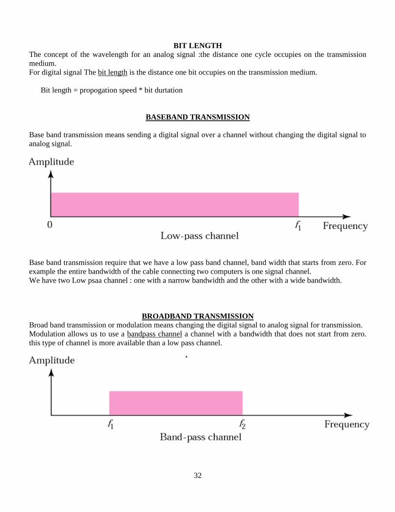
BASEBAND TRANSMISSION
Base band transmission means sending a digital signal over a channel without changing the digital signal to
analog signal.
Base band transmission require that we have a low pass band channel, band width that starts from zero. For
example the entire bandwidth of the cable connecting two computers is one signal channel.
We have two Low psaa channel : one with a narrow bandwidth and the other with a wide bandwidth.
BROADBAND TRANSMISSION
Broad band transmission or modulation means changing the digital signal to analog signal for transmission.
Modulation allows us to use a bandpass channel a channel with a bandwidth that does not start from zero.
this type of channel is more available than a low pass channel.

33
a digital signal is converted to a composite analog signal. We have used a single frequency analog signal the
amplitude of the carrier has been changed to look like the digital signal.
If the available channel is a bandpass channel,we cannot send the digital signal directly to the channel,we
need to convert the digital signal to an analog signal before transmission.
3-2 TRANSMISSION IMPAIRMENT
Signals travel through transmission media, which are not perfect. The imperfection causes signal
impairment. This means that the signal at the beginning of the medium is not the same as the signal at the
end of the medium. What is sent is not what is received. Three causes of impairment are attenuation,
distortion, and noise.
Attenuation
Attenuation means loss of energy.
When a signal travels through a medium, it loses some of its energy in overcoming the resistance of the
medium which is converted to heat.
To compensate the loss, amplifiers are used to amplify the signal.

34
Decibel (dB) is the unit that measures the relative strengths of two signals or one signal at two different
points.
dB = 10 log10 (P2/P1) (Defined in terms of power)
Where P1 and P2 are the powers of a signal at points 1 and 2 respectively
dB = 20 log10 (V2/V1) (Defined in terms of voltage)
Power is proportional to square of voltage.
Suppose a signal travels through a transmission medium and its power is reduced to one-half. This
means that P2 is (1/2)P1. In this case, the attenuation (loss of power) can be calculated as
A loss of 3 dB (–3 dB) is equivalent to losing one-half the power.
A signal travels through an amplifier, and its power is increased 10 times. This means that P2 = 10P1 .
In this case, the amplification (gain of power) can be calculated as
One reason that engineers use the decibel to measure the changes in the strength of a signal is that decibel
numbers can be added (or subtracted) when we are measuring several points (cascading) instead of just two.
In the above a signal travels from point 1 to point 4. In this case, the decibel value can be calculated as

35
The signal has gained in power
Sometimes the decibel is used to measure signal power in milliwatts. In this case, it is referred to as
dBm and is calculated as dBm= 10 log10 Pm , where Pm is the power in milliwatts. Calculate the
power of a signal with dBm = −30.
Solution
We can calculate the power in the signal as
The loss in a cable is usually defined in decibels per kilometer (dB/km). If the signal at the beginning
of a cable with −0.3 dB/km has a power of 2 mW, what is the power of the signal at 5 km?
Solution
The loss in the cable in decibels is 5 × (−0.3) = −1.5 dB. We can calculate the power as
Distortion
Distortion means that the signal changes its form or shape. Distortion can occur in a composite signal
made of different frequencies.
Each signal component has its own propagation speed and therefore its own delay in arriving at the final
destination.
Differences in delay may create a difference in phase, means signal components at the receiver have
phases different from what they had at the sender.

36
Noise
There are several types of noise : Thermal noise, Induced noise, Crosstalk and Impulse noise.
Thermal noise is the random motion of electrons in a wire which creates an extra signal.
Induced noise comes from sources such as motors and appliances. The device acts as a sending
antenna and the transmission medium acts as a receiving antenna.
Crosstalk is the effect of one wire on the other.one wire acts as a sending antenna and the other
wire acts as a receiving antenna.
Impulse noise is a spike that comes from power lines, lightning
To find bit rate limit we need to know the signal-to-noise ratio
SNR = average signal power/ average noise power
A high SNR means the signal is less corrupted by noise and
Low SNR means the signal more corrupted by noise
SNR is described in decibel units SNRdB = 10log10 SNR.
Figure shows the effect of noise on a signal
The power of a signal is 10 mW and the power of the noise is 1 μW; what are the values of SNR and
SNRdB ?
Solution
The values of SNR and SNRdB can be calculated as follows:

37
The values of SNR and SNRdB for a noiseless channel are
We can never achieve this ratio in real life; it is an ideal.
Two cases of SNR: a high SNR and a low SNR
DATA RATE LIMITS
A very important consideration in data communications is how fast we can send data, in bits per second,
over a channel. Data rate depends on three factors:
1. The bandwidth available
2. The level of the signals we use
3. The quality of the channel (the level of noise)
Two theoretical formulas were developed to calculate the data rate: by Nyquist for noiseless channel and
another by Shannon for a noisy channel
Noiseless Channel: Nyquist Bit Rate
BitRate = 2*B*log2 L
Where B is the bandwidth of the channel, L is the number of signal levels used to represent data and
BitRate is the bit rate in bits per second

38
We can have any bit rate by increasing the number of signal levels which is theoretically correct but
practically there is a limit
Increasing the levels of a signal may reduce the reliability of the system. B’coz the receiver must be
very sophisticated to distinguish between different signals.
Consider a noiseless channel with a bandwidth of 3000 Hz transmitting a signal with two signal levels.
The maximum bit rate can be calculated as
Consider the same noiseless channel transmitting a signal with four signal levels (for each level, we
send 2 bits). The maximum bit rate can be calculated as
We need to send 265 kbps over a noiseless channel with a bandwidth of 20 kHz. How many signal
levels do we need?
Solution
We can use the Nyquist formula as shown:
Since this result is not a power of 2, we need to either increase the number of levels or reduce the bit rate. If
we have 128 levels, the bit rate is 280 kbps. If we have 64 levels, the bit rate is 240 kbps.
Noisy Channel: Shannon Capacity
In reality, we cannot have a noiseless channel. In 1944 Claude Shannon introduced a formula to
determine highest data rate for a noisy channel
Capacity = B * log2(1+SNR)
Where B is the bandwidth of the channel, SNR is the signal-to-noise ratio and capacity is the capacity of
the channel in bits per second
This formula defines a characteristic of the channel not the method of transmission.
Consider an extremely noisy channel in which the value of the signal-to-noise ratio is almost zero. In
other words, the noise is so strong that the signal is faint. For this channel the capacity C is calculated
as

39
This means that the capacity of this channel is zero regardless of the bandwidth. In other words, we cannot
receive any data through this channel.
We can calculate the theoretical highest bit rate of a regular telephone line. A telephone line normally
has a bandwidth of 3000. The signal-to-noise ratio is usually 3162. For this channel the capacity is
calculated as
This means that the highest bit rate for a telephone line is 34.860 kbps. If we want to send data faster than
this, we can either increase the bandwidth of the line or improve the signal-to-noise ratio.
The signal-to-noise ratio is often given in decibels. Assume that SNRdB = 36 and the channel
bandwidth is 2 MHz. The theoretical channel capacity can be calculated as
For practical purposes, when the SNR is very high, we can assume that SNR + 1 is almost the same as
SNR. In these cases, the theoretical channel capacity can be simplified to
For example, we can calculate the theoretical capacity of the previous example as
We have a channel with a 1-MHz bandwidth. The SNR for this channel is 63. What are the
appropriate bit rate and signal level?
Solution
First, we use the Shannon formula to find the upper limit.

40
The Shannon formula gives us 6 Mbps, the upper limit. For better performance we choose something
lower, 4 Mbps, for example. Then we use the Nyquist formula to find the number of signal levels.
The Shannon capacity gives us the upper limit; the Nyquist formula tells us how many signal levels we
need.
PERFORMANCE
One important issue in networking is the performance of the network—how good is it? Bandwidth,
Throughput, Latency, Bandwidth-Delay Product are the factors that are used to determine network
performance
In networking, we use the term bandwidth in two contexts.
The first, bandwidth in hertz, refers to the range of frequencies in a composite signal or the
range of frequencies that a channel can pass.
The second, bandwidth in bits per second, refers to the speed of bit transmission in a channel or
link.
The bandwidth of a subscriber line is 4 kHz for voice or data. The bandwidth of this line for data
transmission
can be up to 56,000 bps using a sophisticated modem to change the digital signal to analog.
If the telephone company improves the quality of the line and increases the bandwidth to 8 kHz, we
can send 112,000 bps by using the same technology as mentioned in the above example.
Throughput
Throughput is a measure of how fast we can send data through a network.
Bandwidth in bits per second and throughput seem the same, but they are actually not.
Bandwidth is a potential measurement of a link.
Throughput is an actual measurement of how fast we can send data

41
Ex: We may have a link with a bandwidth of 1Mbps but the devices connected to the end of the link
may handle only 200kbps
A network with bandwidth of 10 Mbps can pass only an average of 12,000 frames per minute with
each frame carrying an average of 10,000 bits. What is the throughput of this network?
Solution
The throughput is almost one-fifth of the bandwidth in this case.
Latency (Delay)
Latency defines how long it takes for an entire message to completely arrive at the destination from the
time the first bit is sent out from the source.
Latency is made up of four components: Propagation time, Transmission time, Queuing Time,
Processing Delay.
Propagation time measures the time required for a bit to travel from the source to destination
Propagation Time = Distance / Propagation Speed
Transmission time is the time between the first bit leaving the sender and the last bit arriving at the
receiver.
Transmission time = message size / bandwidth
The third component in latency is the queuing time, the time needed for each intermediate or end device
to hold the message before it can be processed.
Queuing time is not a fixed factor, it changes with the load imposed on the network.

42
When there is heavy traffic on the network, the queuing time increases.
What is the propagation time if the distance between the two points is 12,000 km? Assume the
propagation speed to be 2.4 × 10⁸ m/s in cable.
Solution
We can calculate the propagation time as
The example shows that a bit can go over the Atlantic Ocean in only 50 ms if there is a direct cable between
the source and the destination.
What are the propagation time and the transmission time for a 2.5-kbyte message (an e-mail) if the
bandwidth of the network is 1 Gbps? Assume that the distance between the sender and the receiver is
12,000 km and that light travels at 2.4 × 10⁸ m/s.
Solution
We can calculate the propagation and transmission time as shown on the next
Note that in this case, because the message is short and the bandwidth is high, the dominant factor is the
propagation time, not the transmission time. The transmission time can be ignored.
What are the propagation time and the transmission time for a 5-Mbyte message (an image) if the
bandwidth of the network is 1 Mbps? Assume that the distance between the sender and the receiver is
12,000 km and that light travels at 2.4 × 10⁸ m/s.
Solution
We can calculate the propagation and transmission times as shown on the next.
Note that in this case, because the message is very long and the bandwidth is not very high, the dominant
factor is the transmission time, not the propagation time. The propagation time can be ignored.

43
Bandwidth-Delay Product
Bandwidth and delay are two performance metrics of a link, the product of these two called the
bandwidth-delay product is what is important in data communications.
Case 1: Assume that we have a link with a bandwidth of 1bps, also assume that the delay of the link is 5
s ; There can be maximum 5 bits at any time on the link
Case 2: Assume that we have a link with a bandwidth of 4bps, also assume that the delay of the link is 5
s ; There can be maximum 20 bits at any time on the link
Filling the link with bits for case 1
We can think about the link between two points as a pipe. The cross section of the pipe represents the
bandwidth, and the length of the pipe represents the delay. We can say the volume of the pipe defines the
bandwidth-delay product, as shown in Figure
The bandwidth-delay product defines the number of bits that can fill the link.

44