1 09242020 SECTION 21 05 00 COMMON WORK RESULTS ...
341
214002.5 / OREGON STATE CAPITOL CAMS 2B COMMON WORK RESULTS FOR FIRE SUPPRESSION 21 05 00 - 1 CONTRACT DOCUMENTS 09242020 SECTION 21 05 00 COMMON WORK RESULTS FOR FIRE SUPPRESSION PART 1 GENERAL 1.01 SUMMARY A. This Section includes: 1. This Section includes Design-Build Work. The intent of Division 21 Specifications and the accompanying Drawings is to provide a complete and workable facility with complete systems as shown, specified and required by applicable codes. Include all work specified in Division 21 and shown on the accompanying Drawings, including appurtenances, connections, etc., in the finished job. 2. The Division 21 Specifications and the accompanying Drawings are complimentary and what is called for by one shall be as binding as if called for by both. Items shown on the Drawings are not necessarily included in the Specifications and vice versa. Specifications shall supersede drawings in case of conflict, except sprinkler head locations where shown on the plans take precedence. 3. Imperative language is frequently used in Division 21 Specifications. Except as otherwise specified, requirements expressed imperatively are to be performed by the Contractor. 4. The Drawings that accompany the Division 21 Specifications are diagrammatic. They do not show every offset, bend, tee, or elbow which may be required to install work in the space provided and avoid conflicts. Offsets and transitions shall be assumed at a minimum at each duct crossing, structural penetrations through shear walls or beams, structural grids where ceiling heights are restricted, and at piping mains. Follow the Drawing as closely as is practical to do so and install additional bends, offsets and elbows where required by local conditions from measurements taken at the Building, subject to approval, and without additional cost to the Owner. Piping and sprinkler head locations shall meet the Architectural design intent for the building in addition to applicable code. The right is reserved to make any reasonable changes in sprinkler head location prior to roughing-in, without cost impact. 5. Furnish piping, pipe fittings, valves, gauges and incidental related items as required for complete systems. Identify valves, piping and equipment components to indicate their function and system served. B. Related Sections include: 1. Section 21 10 00, Water Based Fire Suppression Systems 1.02 RELATED WORK A. The General and Supplemental Conditions apply to this Division, including but not limited to: 1. Drawings and specifications. 2. Public ordinances, permits. 3. Include payments and fees required by governing authorities for work of this Division. B. Division 01, General Requirements, applies to this Division. 1.03 QUALITY ASSURANCE A. Regulatory Requirements: 1. All products and equipment shall comply with Oregon Revised Statute (ORS) 453.005(7)(e) prohibiting pentabrominated, octabrominated, and decabrominated diphenyl ethers. Where products or equipment within this specification contain these banned substances, provide complying products and equipment from approved manufacturers with equal performance characteristics. 2. General: All work and materials shall conform to the local and State codes, and all Federal, State and other applicable laws and regulations. 3. Contractor responsible for obtaining and payment for all permits, licenses, and inspection certificates required in accordance with provisions of Contract Documents.
-
Upload
khangminh22 -
Category
Documents
-
view
0 -
download
0
Transcript of 1 09242020 SECTION 21 05 00 COMMON WORK RESULTS ...

214002.5 / OREGON STATE CAPITOL CAMS 2B COMMON WORK RESULTS FOR FIRE SUPPRESSION 21 05 00 - 1
CONTRACT DOCUMENTS 09242020
SECTION 21 05 00
COMMON WORK RESULTS FOR FIRE SUPPRESSION
PART 1 GENERAL
1.01 SUMMARY
A. This Section includes:
1. This Section includes Design-Build Work. The intent of Division 21 Specifications and the accompanying Drawings is to provide a complete and workable facility with complete systems as shown, specified and required by applicable codes. Include all work specified in Division 21 and shown on the accompanying Drawings, including appurtenances, connections, etc., in the finished job.
2. The Division 21 Specifications and the accompanying Drawings are complimentary and what is called for by one shall be as binding as if called for by both. Items shown on the Drawings are not necessarily included in the Specifications and vice versa. Specifications shall supersede drawings in case of conflict, except sprinkler head locations where shown on the plans take precedence.
3. Imperative language is frequently used in Division 21 Specifications. Except as otherwise specified, requirements expressed imperatively are to be performed by the Contractor.
4. The Drawings that accompany the Division 21 Specifications are diagrammatic. They do not show every offset, bend, tee, or elbow which may be required to install work in the space provided and avoid conflicts. Offsets and transitions shall be assumed at a minimum at each duct crossing, structural penetrations through shear walls or beams, structural grids where ceiling heights are restricted, and at piping mains. Follow the Drawing as closely as is practical to do so and install additional bends, offsets and elbows where required by local conditions from measurements taken at the Building, subject to approval, and without additional cost to the Owner. Piping and sprinkler head locations shall meet the Architectural design intent for the building in addition to applicable code. The right is reserved to make any reasonable changes in sprinkler head location prior to roughing-in, without cost impact.
5. Furnish piping, pipe fittings, valves, gauges and incidental related items as required for complete systems. Identify valves, piping and equipment components to indicate their function and system served.
B. Related Sections include:
1. Section 21 10 00, Water Based Fire Suppression Systems
1.02 RELATED WORK
A. The General and Supplemental Conditions apply to this Division, including but not limited to:
1. Drawings and specifications.
2. Public ordinances, permits.
3. Include payments and fees required by governing authorities for work of this Division.
B. Division 01, General Requirements, applies to this Division.
1.03 QUALITY ASSURANCE
A. Regulatory Requirements:
1. All products and equipment shall comply with Oregon Revised Statute (ORS) 453.005(7)(e) prohibiting pentabrominated, octabrominated, and decabrominated diphenyl ethers. Where products or equipment within this specification contain these banned substances, provide complying products and equipment from approved manufacturers with equal performance characteristics.
2. General: All work and materials shall conform to the local and State codes, and all Federal, State and other applicable laws and regulations.
3. Contractor responsible for obtaining and payment for all permits, licenses, and inspection certificates required in accordance with provisions of Contract Documents.

214002.5 / OREGON STATE CAPITOL CAMS 2B COMMON WORK RESULTS FOR FIRE SUPPRESSION 21 05 00 - 2
CONTRACT DOCUMENTS 09242020
4. All fire protection system designs must bear the stamp and seal of the registered Professional Engineer who prepared the documents. The Engineer’s stamp certifies that the work was done under the Engineer’s supervision and control. Certification from NICET technicians, or other contractors, cannot replace the certification by the Engineer. Verify/coordinate with local building department for their specific requirements.
B. Materials and equipment shall be new. Work shall be of good quality, free of faults and defects and in conformance with the Contract Documents.
C. Apparatus shall be built and installed to deliver its full rated capacity at the efficiency for which it was designed.
D. The entire system and apparatus shall operate at full capacity without objectionable noise or vibration.
E. For remodel projects, the existing system must remain fully operational, or provisions made to provide coverage while the new system is being installed. New installation switchover shall require minimal down time. Provide method to maintain fire protection or fire watch during any system down time. Include any related cost for materials or labor that is needed for providing continuous coverage.
F. All equipment shall be installed level and true. Housekeeping pads and curbs shall account for floor or roof slope.
G. Materials and Equipment:
1. Each piece of equipment furnished shall meet all detailed requirements of the Drawings and Specifications and shall be suitable for the installation shown. Equipment not meeting all requirements will not be acceptable, even though specified by name along with other manufacturers.
2. Where two or more units of the same class of equipment are furnished, use products of the same manufacturer. Component parts of the entire system need not be products of same manufacturer.
3. Furnish all materials and equipment of size, make, type, and quality herein specified.
4. Equipment scheduled by performance or model number shall be considered the basis of the design. If other specified manufacturer's equipment is provided in lieu of the basis of design equipment the contractor is responsible for all changes and costs which may be necessary to accommodate this equipment, including different sizes and locations for connections, different electrical characteristics, different dimensions, different access requirements or any other differences which impact the project.
H. Workmanship:
1. General: All materials shall be installed in a neat and professional manner.
2. Manufacturer’s Instructions: Follow manufacturer’s directions where they cover points not specifically indicated. If they are in conflict with the Drawings and Division 21 Specifications, obtain clarification before starting work.
I. Cutting and Patching:
1. Cutting, patching, and repairing for the proper installation and completion of the work specified in this Division including plastering, masonry work, concrete work, carpentry work, and painting shall be performed by skilled craftsmen of each respective trade in conformance with the appropriate Division of Work.
2. Additional openings required in building construction shall be made by drilling or cutting. Use of jackhammer is specifically prohibited.
3. Fill holes which are cut oversize so that a tight fit is obtained around the sleeves passing through.
4. Beams or columns shall not be pierced without permission of Architect and then only as directed.

214002.5 / OREGON STATE CAPITOL CAMS 2B COMMON WORK RESULTS FOR FIRE SUPPRESSION 21 05 00 - 3
CONTRACT DOCUMENTS 09242020
5. All new or existing work cut or damaged shall be restored to its original condition. Where alterations disturb lawns, paving, walks, etc., the surfaces shall be repaired, refinished, and left in condition existing prior to commencement of work.
1.04 SUBMITTALS
A. Certified Shop Drawings:
1. The Drawings indicate the general layout of the piping and various items of equipment. Coordination with other trades and with field conditions will be required. For this purpose, prepare fire protection system layout Drawings showing locations and types of head or outlets, alarm valves and devices, pipe sizes and cutting lengths, test tees and valves, drain valves, and other related items. Shop Drawings shall be new drawings prepared by Contractor and not reproductions or tracings of Architect’s Drawings. Overlay drawings with shop drawings of other trades and check for conflicts. All drawings shall be same size as Architect’s Drawings with title block similar to the Drawings and identifying Architect’s drawing number or any reference drawings. All drawings shall be fully dimensioned including both plan and elevation dimensions. Shop drawings cannot be used to make scope changes.
B. Shop drawings shall be prepared in three-dimensional format:
1. Shop drawings shall include but are not limited to:
a. Sprinkler head layout drawings overlaid with ceiling and floor plans.
b. Sprinkler floor plans, including all piping, equipment and heads to a minimum of 1/4-inch equals 1-foot scale or same as plans, whichever is greater.
C. Superplot plans of above ground work with a colored overlay of all trades including, but not limited to, HVAC piping, HVAC equipment, plumbing piping and equipment, sprinklers, lighting, lighting controls, cable tray, fire alarm devices, electrical power conduit, and ceiling system to a minimum of 1/2-inch equals 1-foot scale.
1. Beam penetration drawings indicating beam penetrations meeting the requirements indicated on the floor plans and on the structural drawings to a minimum of 1/4-inch equals 1-foot scale.
D. Slab penetration drawings of HVAC, plumbing, sprinklers, lighting and electrical to a minimum of 1/4-inch equals 1-foot scale.
1. Submit shop drawings for review prior to beginning fabrication. Additional shop drawings may be requested when it appears that coordination issues are not being resolved in the field or when there is a question as to whether contract documents are being complied with or the design intent is being met.
E. Product Data:
1. In general, submit product data for review on all scheduled pieces of equipment, on all equipment requiring electrical connections or connections by other trades, and as required by each specification section or by drawing notes. Include manufacturer’s detailed shop drawings, specifications and data sheets. Data sheets shall include capacities, RPM, BHP, pressure drop, design and operating pressures, temperatures, and similar data. Manufacturer’s abbreviations or codes are not acceptable
2. Provide sample of each type of sprinkler head.
3. Indicate equipment operating weights including bases and weight distribution at support points.
4. In the case of equipment such as wiring devices, time switches, valves, etc., specified by specific catalog number, a statement of conformance will suffice.
F. Test Reports: Submit certificates of completion of tests and inspections.

214002.5 / OREGON STATE CAPITOL CAMS 2B COMMON WORK RESULTS FOR FIRE SUPPRESSION 21 05 00 - 4
CONTRACT DOCUMENTS 09242020
G. Submission Requirements:
1. Refer to Division 01 for additional requirements related to submittals.
2. Shop Drawings:
a. Provide three sets of Drawings showing sprinkler head locations and layout coordinated with architectural ceiling details to the Architect for review prior to submitting Drawings to insurance underwriter and Fire Marshal.
b. Provide six sets of Drawings and calculations to the Architect to be sent to the Owner’s insurance underwriter for approval.
c. Then submit six sets of approved Drawings to Architect for final review.
3. Product Data:
a. Submit electronic copies of shop drawings and product data for Work of Division 21 in PDF format with each item filed under a folder and labeled with its respective specification section number, article and paragraph and mark, if applicable.
b. Include a complete index in the original submittal. Indicate both original items submitted and note stragglers that will be submitted at a later date to avoid delay in submitting.
c. All shop product data shall be submitted in a single submittal. Partial submittals will not be accepted. Re-submittals submitted after return of the original binder shall include a tab similar to that originally submitted. Upon receipt of the returned re-submittals, insert them in the previously submitted binder.
H. Contractor Responsibilities: It shall be the Contractor’s responsibility to:
1. See that all submittals are submitted at one time and are in proper order.
2. Ensure that all equipment will fit in the space provided.
3. Assure that all deviations from Drawings and Specifications are specifically noted in the submittals. Failure to comply will void review automatically.
1.05 OPERATING AND MAINTENANCE MANUAL, PARTS LISTS, AND OWNER’S INSTRUCTIONS
A. Refer to Division 01, General Requirements for additional requirements.
B. Submit three bound copies of manufacturer’s operation and maintenance instruction manuals and parts lists for each piece of equipment or item requiring servicing. Literature shall be on 8-1/2 by 11-inch sheets or catalogs suitable for side binding. Submit data when the work is substantially complete, packaged separately, and clearly identified in durable 3-ring binder. Include name and contact information for location of source parts and service for each piece of equipment. Clearly mark and label in each submittal, the piece of equipment provided with the proper nameplate and model number identified. Provide wiring diagrams for all electrically powered equipment.
C. Instruct Owner thoroughly in proper operation of equipment and systems, in accordance with manufacturer’s instruction manuals. Operating instructions shall cover all phases of control.
D. Furnish competent engineer knowledgeable in this building system for minimum of one 8-hour day to instruct Owner in operation and maintenance of systems and equipment. Contractor shall keep a log of this instruction including dates, times, subjects, and those present and shall present such log when requested by Architect.
1.06 PROJECT CONDITIONS
A. Existing Conditions: Prior to bidding, verify and become familiar with all existing conditions by visiting the site, and include all factors which may affect the execution of this Work. Include all related costs in the initial bid proposal.
B. Coordinate exact requirements governed by actual job conditions. Check all information and report any discrepancies before fabricating work. Report changes in time to avoid unnecessary work.
C. Coordinate shutdown and start-up of existing, temporary, and new systems and utilities. Notify Owner, City, and Utility Company.

214002.5 / OREGON STATE CAPITOL CAMS 2B COMMON WORK RESULTS FOR FIRE SUPPRESSION 21 05 00 - 5
CONTRACT DOCUMENTS 09242020
1.07 WARRANTY
A. Provide a written guaranty covering the work of this Division (for a period of one calendar year from the date of acceptance by the Owner) as required by the General Conditions.
B. Provide manufacturer’s written warranties for material and equipment furnished under this Division insuring parts and labor for a period of one year from the date of Owner acceptance of Work of this Division.
C. Correct warranty items promptly upon notification.
1.08 PROVISIONS FOR LARGE EQUIPMENT
A. Contractor shall make provisions for the necessary openings in building to allow for admittance of all equipment.
1.09 TEST REPORTS AND CERTIFICATES
A. Contractor shall submit one copy of all test reports and certificates specified herein to the Architect.
1.10 SUBSTITUTIONS
A. Contractor shall submit any requests for product substitutions in accordance with the Instructions to Bidders and the General and Supplemental Conditions.
1.11 ALTERNATES
A. Comply with Division 01 Section, “Alternates”.
B. Refer to Electrical Drawings for detailed information relating to the appropriate alternates.
PART 2 PRODUCTS
2.01 ACCESS PANELS
A. Furnish under this Division as specified in another Division of work.
2.02 PIPE SLEEVES
A. Interior Wall and Floor Sleeves: 18-gauge galvanized steel or another pre-approved water tight system.
B. Interior Wall and Floor Sleeves (fire rated): Fire rated and water tight system approved by Authority Having Jurisdiction and Owners Insurance underwriter, with rating equal to floor or wall penetration, and designed specifically for the floor or wall construction, piping material, size and service.
C. Exterior Wall Sleeves: Cast iron.
D. On Grade Floor Sleeves: Same as exterior wall sleeves.
2.03 FLOOR, WALL, AND CEILING PLATES
A. Furnish stamped split type plates as follows:
1. Floor Plates: Cast brass, chromium plated.
2. Wall and Ceiling Plates: Spun aluminum.
2.04 MACHINERY GUARDS
A. Furnish guards for protection on all rotating and moving parts of equipment. Provide guards for all drives and motor pulleys, regardless of being enclosed in a metal cabinet.
B. Design guards so as not to restrict air flow or heat transfer.
C. Provide shaft holes in guards for easy use of tachometers at pulley centers. Guards shall be easily removable for pulley adjustment or removal and changing of belts.
D. All guards shall meet OSHA requirements including back plates.
2.05 ELECTRICAL EQUIPMENT
A. General: All equipment and installed work shall be as specified under Division 26, Electrical.

214002.5 / OREGON STATE CAPITOL CAMS 2B COMMON WORK RESULTS FOR FIRE SUPPRESSION 21 05 00 - 6
CONTRACT DOCUMENTS 09242020
B. Motors:
1. Motors shall be furnished as integral part of driven equipment. They shall be drip-proof induction type with ball bearings unless noted otherwise. Motors shall be built to NEMA Standards for the service intended. The motors shall be rated for the voltage specified, suitable for operation within the range of 10 percent above to 10 percent below the specified voltage.
2. Motors shall be Baldor, Westinghouse, General Electric or approved equal.
3. Where provided, refer to Equipment Schedules on the Drawings for motor horsepower, voltage and phase.
4. Refer to individual product sections for additional motor requirements.
5. Motors shall have built-in thermal overload protection, or be protected externally with separate thermal overload devices with low voltage release or lockout. Hermetically sealed motors shall have quick trip devices.
C. Starters: Provided under Division 26, Electrical, suitable for performing the control functions required, with the exception of self-contained equipment and where the starters are furnished as part of the control package.
D. Equipment Wiring: Interconnecting wiring within or on a piece of fire suppression equipment shall be provided with the equipment unless shown otherwise. This does not include the wiring of motors, starters, and controllers provided under Division 26, Electrical.
E. Control Wiring: All control wiring for fire suppression equipment shall be provided hereunder.
F. Codes: All electrical equipment and products shall bear the Underwriters label as required by governing codes and ordinances.
PART 3 EXECUTION
3.01 COORDINATION
A. Coordinate fire protection piping and appurtenances with ducts, other piping, electrical conduit, and other equipment.
B. All fire protection piping and equipment shall be concealed except in area without ceilings and as noted on the Drawings.
C. Locate piping, heads, and equipment where shown on Drawings.
3.02 GENERAL
A. Install fire protection systems to serve the entire building.
B. The drawings indicate approximate locations of piping, sprinkler zones, and types of systems. The drawings do not indicate the locations of sprinkler heads in ceiling areas. In general, sprinklers shall be located in the center of ceiling panels and symmetrically within rooms and down corridors, coordinated with and in pattern with lights and grilles. Deviations must be approved.
C. Locations of all sprinkler heads, outlets, piping, and appurtenances are not shown in all areas and, therefore, are to be installed in accord with code requirements.
D. Location of heads shown in ceiling areas may be changed if required by code requirements, but only after review by the Architect for new head locations for each specific instance.
3.03 SLEEVES
A. Interior Floor and Wall Sleeves: Provide sleeves large enough to provide clearances around pipe outside diameter as required by NFPA. Penetrations through mechanical room and fan room floors shall be made watertight by packing with safing insulation and sealing with Tremco Dymeric Sealant or approved water tight system.

214002.5 / OREGON STATE CAPITOL CAMS 2B COMMON WORK RESULTS FOR FIRE SUPPRESSION 21 05 00 - 7
CONTRACT DOCUMENTS 09242020
B. Sleeves through Rated Floors and Walls: Similar to interior sleeves except install fire-rated system approved by Authority Having Jurisdiction and Owner’s Insurance Underwriter, with rating equal to floor or wall penetration, and designed specifically for the floor or wall construction, piping material, size and service. Firestopping work shall comply with requirements of Section 07 84 00, Firestopping.
C. Exterior Wall Sleeves Below Grade: Large enough to allow for caulking and made watertight. Caulking shall be from outside using link-seal modular wall and casing seal or lead and oakum. Secure sleeves against displacement.
D. On Grade Floor Sleeves: Same as below grade exterior wall sleeves, caulked from inside.
E. Exterior Wall Sleeves Above Grade: Similar to interior wall sleeves except caulk outside with Tremco Dymeric Sealant.
F. Layout work prior to concrete forming. Do all cutting and patching required. Reinforce sleeves to prevent collapse during forming and pouring.
G. All floor sleeves shall maintain a water barrier by providing a water tight seal or they shall extend 1-inch above finished floor except through mechanical equipment room floors and shafts where sleeves shall extend 2 inches above finished floor level. Sleeves through roof shall extend 8 inches above roof. Wall sleeves shall be flush with face of wall unless otherwise indicated. Sleeves through planters shall extend 8 inches above planter base.
H. Do not support pipes by resting pipe clamps on floor sleeves. Supplementary members shall be provided so pipes are floor supported.
I. Special sleeves detailed on the Drawings shall take precedence over this section.
3.04 FLOOR, WALL, AND CEILING PLATES
A. Install on piping passing through finished walls, floors, ceilings, partitions, and plaster furrings. Plates shall completely cover opening around pipe and duct.
B. Secure wall and ceiling plates to pipe or structure.
C. Plates not required in mechanical rooms or unfinished spaces.
3.05 CLEANING
A. General: Clean equipment and piping of stampings and markings (except those required by codes), iron cuttings, and other refuse.
B. Painted Surfaces: Clean scratched or marred painted surfaces of rust or other foreign matter and paint with matching color industrial enamel, except as otherwise noted.
C. Additional requirements are specified under specific Sections of this Division.
3.06 EQUIPMENT PROTECTION
A. Keep pipe and conduit openings closed by means of plugs or caps to prevent the entrance of foreign matter. Protect piping, conduit, equipment and apparatus against dirty water, chemical or mechanical damage both before and after installation. Restore damaged or contaminated equipment, or apparatus to original conditions or replace at no cost to the Owner.
B. Protect bright finished shafts, bearing housings, and similar items until in service. No rust will be permitted.
C. Cover or otherwise suitably protect equipment and materials stored on the job site.
3.07 ACCESSIBILITY
A. General: Locate valves, indicating equipment or specialties requiring frequent reading, adjustments, inspection, repairs, and removal or replacement conveniently and accessibly with reference to the finished building.
B. Gauges: Install gauges so as to be easily read from the floors, platforms, and walkways.

214002.5 / OREGON STATE CAPITOL CAMS 2B COMMON WORK RESULTS FOR FIRE SUPPRESSION 21 05 00 - 8
CONTRACT DOCUMENTS 09242020
3.08 PAINTING
A. General: Coordinate painting of fire suppression equipment and items with products and methods in conformance with Section 09 90 00, Painting and Coating.
B. Equipment Rooms and Finished Areas:
1. Hangers, Miscellaneous Iron Work, Structural Steel Stands, Tanks, and Equipment Bases: Paint one coat of black enamel.
2. Steel Valve Bodies and Bonnets: One coat of black enamel.
3. Equipment: One coat of red machinery enamel. Do not paint nameplates.
4. Sprinkler Heads: Not painted.
C. Concealed Spaces (above ceilings, not visible):
1. Hangers, Miscellaneous Iron Work, Valve Bodies, and Bonnets: Not painted.
D. Sprinkler Piping:
1. Concealed from View: Not painted.
2. Exposed to View: Paint pipe and hangers exposed to view, including in equipment spaces, with one coat approved rust inhibiting primer. Final finish coat as specified in conformance with Section 09 90 00, Painting and Coating.
3. Exterior: Wire brush and apply two coats of rust-inhibiting primer and one coat of grey exterior machinery enamel. Final finish coat as specified in conformance with the appropriate Division of Work, Painting.
4. Alarm Bell: Factory paint with two coats of red enamel.
3.09 ADJUSTING AND CLEANING
A. General:
1. Before operating any equipment or systems, make thorough check to determine that systems have been flushed and cleaned as required and equipment has been properly installed, lubricated, and serviced. Check factory instructions to see that installations have been made accordingly and that recommended lubricants have been used.
2. Use particular care in lubricating bearings to avoid damage by over-lubrication and blowing out seals. Check equipment for damage that may have occurred during shipment, after delivery, or during installation. Repair damaged equipment as approved or replace with new equipment.
B. Piping:
1. Clean interior of all piping before installation.
2. Flush sediment out of all piping systems.
3.10 ELECTRICAL EQUIPMENT
A. Fire Suppression systems shall not be installed in switchgear rooms, transformer vaults, telephone rooms, or electric closets except as indicated.
B. Fire Suppression systems shall not pass over switchboards or electrical panelboards. Where conflicts exist, bring to attention of Architect.
END COMMON WORK RESULTS FOR FIRE SUPPRESSION

214002.5 / OREGON STATE CAPITOL CAMS 2B COMMISSIONING FOR FIRE SUPPRESSION 21 08 00 - 1
CONTRACT DOCUMENTS 09242020
SECTION 21 08 00
COMMISSIONING FOR FIRE SUPPRESSION
PART 1 GENERAL
1.01 SUMMARY
A. The commissioning process is described in future Section 01 91 00, Commissioning, provided by the Owner/Commissioning Agent at a later date.
B. Provide all labor and materials required to complete the commissioning of those Division 21 systems and equipment identified as Commissioned Systems and Equipment in Section 01 91 00, Commissioning.
C. Related Sections include:
1. Section 01 91 00, Commissioning.
2. All Sections of Division 21.
1.02 SUBMITTALS
A. Refer to Section 01 91 00, Commissioning.
1.03 COMMISSIONING SCOPE OF WORK - COMMISSIONING AGENT
A. Refer to Section 01 91 00, Commissioning.
1.04 COMMISSIONING SCOPE OF WORK - CONTRACTOR
A. Refer to Section 01 91 00, Commissioning.
PART 2 PRODUCTS
2.01 TEST EQUIPMENT
A. Refer to Section 01 91 00, Commissioning.
PART 3 EXECUTION
3.01 MEETINGS
A. Refer to Section 01 91 00, Commissioning.
3.02 INSTALLATION, CHECK-OUT, START-UP, AND PREFUNCTIONAL CHECKS
A. Refer to Section 01 91 00, Commissioning.
3.03 FUNCTIONAL TESTING
A. Refer to Section 01 91 00, Commissioning.
3.04 TRAINING OF FACILITY OPERATING STAFF, AND BUILDING OCCUPANTS
A. Refer to Section 01 91 00, Commissioning.
END COMMISSIONING FOR FIRE SUPPRESSION

214002.5 / OREGON STATE CAPITOL CAMS 2B WATER BASED FIRE SUPPRESSION SYSTEMS 21 10 00 - 1
CONTRACT DOCUMENTS 09242020
SECTION 21 10 00
WATER BASED FIRE SUPPRESSION SYSTEMS
PART 1 GENERAL
1.01 SUMMARY
A. This Section includes: This Section includes Design-Build work. Provide a complete automatic fire sprinkler/combination standpipe system with zoning (and sprinkler head) layout as indicated on the Drawings.
1.02 QUALITY ASSURANCE
A. Provide a complete automatic fire sprinkler/combination standpipe system with zoning (and sprinkler head) layout as indicated on the Drawings.
B. Regulatory Requirements:
1. As a minimum, sprinkler system shall comply with NFPA 13 and local Fire Marshal requirements.
2. Comply with Factory Mutual requirements for Hazard Class and System Design.
C. Hydraulically Calculated Sprinkler System: Sprinkler system to be hydraulically calculated grid system designed to provide:
1. Light Hazard Occupancies: (0.10 GPM/Ft2 density at most remote 1500 square feet) for public areas, living spaces, or designated by the local fire marshal with an excess of 10 PSI additional pressure requirements incorporated into the design over specified pressure requirements.
2. Ordinary Hazard Occupancies Group I: (0.15 GPM/Ft2 density at most remote 1500 square feet) for mechanical rooms, and parking areas, or designated by the local fire marshal with an excess of 10 PSI additional pressure requirements incorporated into the design over specified pressure requirements.
D. NFPA 13 (without the use of exceptions found in NFPA 13 systems minimum guideline) shall be used for the location, sizing, and installation of piping and sprinkler systems unless local fire marshal or owner’s insurance underwriter requirements are more stringent. Exceptions must be approved by the Engineer prior to usage.
E. Water Service Pressure Basis of Design: Coordination was done to determine fire service water pressure used to develop the fire sprinkler system design information included herein. The Contractor shall be required to obtain current flow test information prior to starting their design of the fire sprinkler system.
F. Automatic sprinklers within elevator hoistways and machine rooms shall comply with ANSI A17.1-102.2 (c) 4 requirements.
1.03 SUBMITTALS
A. Provide submittal in accordance with Section 21 05 00, Common Work Results for Fire Suppression.
PART 2 PRODUCTS
2.01 ACCEPTABLE MANUFACTURERS
A. As indicated for each product.
B. Other Manufacturers: Submit Substitution Request.
2.02 WET STANDPIPE VALVE (EXPOSED)
A. 2-1/2-inch by 2-1/2-inch female x male angle hose valve with 1-1/2-inch reducer, cap and chain.
B. Acceptable Manufacturers:
1. Potter-Roemer Model 4065
2. Equivalent by Standard.

214002.5 / OREGON STATE CAPITOL CAMS 2B WATER BASED FIRE SUPPRESSION SYSTEMS 21 10 00 - 2
CONTRACT DOCUMENTS 09242020
2.03 SPRINKLER HEADS
A. Acceptable Manufacturers:
1. Viking
2. Reliable Automatic Sprinkler
3. Victaulic
4. Tyco Fire Products
B. General:
1. Fire sprinklers shall be of one manufacturer throughout building. No mixing of sprinkler brands shall be permitted.
2. Sprinklers shall be of all brass frame construction with a coated metal-to-metal seating mechanism. Sprinklers utilizing non-metal parts in the sealing portion of the sprinkler are strictly prohibited.
3. Sprinklers shall have a quick response frangible bulb type fusible element with a temperature rating of 155 or 200 degrees F or shall have a fast response metal type fusible element with a temperature rating of 165 or 212 degrees F.
4. Sprinklers shall have a 1/2-inch NPT, a standard orifice, and a 5.6 nominal K Factor.
5. Sprinklers shall be UL listed and FM Approved for working water pressures up to 175 psi. Sprinkler heads in dry and pre-action type systems shall be installed per NFPA 13.
6. All heads shall be U.L. approved for application and installation.
C. Provide high temperature (212 degrees F) heads for mechanical rooms, areas below skylights, other areas which have high heat producing equipment to prevent accidental trippage.
D. Sprinklers Installed in Finished Ceilings: Quick response, recessed, bulb type, finish and color to be selected by Architect, 165 degrees F unless required otherwise.
E. Sprinklers Installed in Finished Ceilings: Quick response, concealed pendant with drop-off cover plate, color and finish to be selected by Architect, 155 degrees F unless required otherwise.
F. Sprinklers Installed in Unfinished Ceiling Areas (or Above Finished Ceilings Where Required): Pendant or up-right fusible solder type, rough bronze finish and shall be of adequate temperature for the hazard.
G. Sprinklers Installed in Exterior Perimeter Areas: Quick response, horizontal dry sidewall sprinkler, fusible solder type, polished chrome finish.
H. “Life Safety Type” Sprinkler Heads (Window Wash to Maintain Ratings at Glazed Openings at Enclosed Stairs): Quick response, chrome finish, horizontal sidewall or pendant vertical sidewall, Central Model WS Window Sprinkler, or similar listed sprinkler for this application.
I. Flexible Stainless Steel Hose:
1. UL rated, FM approved stainless steel hose assembly for individual sprinkler connections, Victaulic Vic-Flex.
2. Drop includes a UL approved braided hose with a bend radius to 2-inch to allow for proper installation in confined spaces.
3. Provide union joints for ease of installation.
4. Attach flexible drop to the ceiling grid using a one-piece open gate bracket. The bracket allows installation before the ceiling tile is in place.
5. The braided drop system is UL listed and FM Approved for sprinkler services to 175 psi (1206 kPa).
2.04 FLOW SWITCH
A. Description: U.L. listed electric flow switch with retard. Provide required accessories.
B. Single pole type with normally open and normally closed contacts. Location as shown. Provide all required related trimmings. Provide one set of contacts for use by the Fire Alarm Contractor. Coordinate with pipe size.
C. Manufacturer: Potter Electric Model VSR-F.

214002.5 / OREGON STATE CAPITOL CAMS 2B WATER BASED FIRE SUPPRESSION SYSTEMS 21 10 00 - 3
CONTRACT DOCUMENTS 09242020
2.05 TAMPER SWITCH
A. Description: Each sprinkler system control valve shall be equipped with a tamper switch listed by Underwriters Laboratories for the particular location and type of valve supervised. The switch shall initiate a supervisory signal upon a maximum of two complete turns of a valve wheel or closure of ten percent, whichever is less. The tamper switch shall have the number of poles provided to coordinate with the fire alarm system manufacturer.
B. Manufacturer: Potter Electric Signal Company Model PCVS.
2.06 FIRE DEPARTMENT TEST STATION
A. Description: One piece, compact, floor test module for standard alarm test loop, threaded.
B. Manufacturer:
1. Victaulic Style 720
2. Equivalent by Viking
2.07 VALVES
A. Acceptable Manufacturers:
1. Where only one manufacturer’s model is listed, equivalent products by those specified below, or equal, are acceptable.
a. Gate, Swing Check:
1) Jenkins
2) Crane
3) Hammond
4) Nibco
5) Kennedy
b. Silent Check:
1) Jenkins
2) Mueller
3) Metraflex
4) Gustin-Bacon
c. Butterfly:
1) Jenkins
2) Nibco
3) Keystone
4) Victaulic
5) Gustin-Bacon
d. Specialty:
1) Nibco
2) Conbraco
2. All such valves shall be of one manufacturer.
3. All gate, butterfly and check valves shall meet current MSS standards.
4. Bronze gate and check valves shall be made with dezincification-resistant materials. Bronze valves made with copper alloy (brass) containing more than 15 percent zinc are not permitted.
5. Full lug and grooved butterfly valves shall be suitable for bi-directional dead end service at full rated pressure without use or need of a downstream flange.
6. Valves in Insulated Piping: Valves shall have 2-inch stem extensions and the following features:
a. Gate Valves: Shall be rising stem type.
b. Butterfly Valves: Shall have extended necks.
7. Valve ends may be threaded, flanged, soldered, or grooved as applicable to piping system.
8. Provide ball drip drains, test orifices, and other related items as required to provide a complete fire protection system.

214002.5 / OREGON STATE CAPITOL CAMS 2B WATER BASED FIRE SUPPRESSION SYSTEMS 21 10 00 - 4
CONTRACT DOCUMENTS 09242020
B. Gate Valves:
1. Bronze Gate: Bronze body, bronze screwed bonnet, bronze solid wedge, OS and Y pattern, rising stem, pre-grooved stem for supervisory switch mounting,175 psi CWP, UL listed, FM approved; Nibco T-104.
2. Iron Gate: Iron body, bronze trim, OS and Y pattern, solid wedge, pre-grooved stem for supervisory switch mounting, 175 psi CWP, UL listed, FM approved; Nibco F-607-OTS.
C. Check Valves:
1. Horizontal Bronze Swing Check: Bronze body, bronze-mounted, TFE disc, 150 psi SWP, 300 psi CWP; Nibco T-443-Y, Nibco S-433-Y. Check valves in main riser path shall be FM approved.
2. Horizontal Iron Swing Check: Iron body, bronze-mounted, regrinding bronze disc and seat ring, 200 psi CWP; Nibco F-918-B. Check valves in main riser path shall be FM approved.
3. Vertical and Silent Check Valves: Iron body, stainless steel spring, wafer type, globe style, 200 psi CWP; Nibco 910-B. Check valves in main riser path shall be FM approved.
D. Butterfly Valves:
1. Iron Butterfly: Ductile iron body, aluminum-bronze disc and one-piece stainless steel shaft, copper bushing, fasteners and pins shall not be used to attach stem to disc, gear operator, stem neck length to accommodate insulation where applicable, EPDM liner or disc, 200 psi CWP; Nibco LD 2000 (lug style), Nibco GD-4765 (grooved ends). Butterfly valves in main riser path shall be FM approved.
E. Specialty Valves:
1. Drain Valves: Bronze ball valve, garden hose end, cap and chain 3/4-inch size, bronze cast body, chrome-plated full port ball, with handle, Teflon seat, threaded body packnut design (no threaded stem designs allowed) with adjustable stem packing, 600 psi CWP; Nibco T-585-70-HC.
2. Gauge Cocks: Brass, tee handle, male to female, 200 psi working pressure, 1/4-inch; Conbraco 41 series, or equal.
2.08 BLACK STEEL PIPE
A. General: Pipe shall be UL listed and FM approved for fire protection use. Fittings and joints must be UL listed with pipe chosen for use. Listing restrictions and installation procedures per NFPA 13 and state and local authorities for fire protection use. Pipe/fittings must be hot-dipped galvanized in accordance with ASTM A53 for all dry pipe sprinkler systems.
B. Pipe: ASTM A135 or A53:
1. For Fire Protection:
a. Schedule 10 or Schedule 40 in sizes up to 5 inches.
b. 0.134-inch wall thickness for 6 inches.
c. 0.188-inch wall thickness for 8 inches and 10 inches.
d. 0.330-inch wall thickness for 12 inches.
C. Fittings: Roll grooved ends with mechanical couplings as specified.
D. Service Above Grade: Fire protection system only for sizes listed, as approved by NFPA 13.
2.09 FLANGED JOINTS
A. Flanged Joints: Flanges shall be cast iron or steel for screwed piping and forged steel welding neck for welded line sizes. Pressure rating and drilling shall match the apparatus, valve, or fitting to which they are attached. Flanges shall be in accordance with ANSI B16.1; 150 lb. for system pressures to 150 psig; 300 lb. for system pressures 150 psig to 400 psig. Gaskets shall be 1/16-inch thick, Cranite or equal, ring type, coated with graphite and oil to facilitate making a tight joint. Make joint using American Standard hexagon head bolts, lock washers, and nuts (per ASTM A307 GR.B) for service pressures to 150 psig; alloy steel stud bolts, lock washer, and American Standard hexagon head nuts (per ASTM A307 GR.B) for service pressures 150 psig to 400 psig. Use length of bolt required for full nut engagement. Provide electro-cad plated bolts and nuts.

214002.5 / OREGON STATE CAPITOL CAMS 2B WATER BASED FIRE SUPPRESSION SYSTEMS 21 10 00 - 5
CONTRACT DOCUMENTS 09242020
2.10 MECHANICAL PIPE COUPLINGS AND FITTINGS
A. Acceptable Manufacturers:
1. Victaulic
2. Gruvlok
B. Couplings and Fittings: Coupling housing to be zero flex rigid type coupling with angled bolt pad design. Similar to Victaulic Type 07. Flexible couplings to be used only when expansion contraction, deflection or noise and vibration is to be dampened. Flexible Coupling to be similar to Victaulic Type 77. Coupling gasket similar to Victaulic's Grade E molded synthetic rubber per ASTM D-73.5, Grade No. R615BZ. Coupling bolts oval neck track head type with hexagonal heavy nuts per ASTM A-183.
2.11 EXPANSION JOINTS AND COMPENSATORS
A. Acceptable Manufacturers:
1. Flexonics
2. Keflex
3. Hyspan
4. Metraflex
5. Other Manufacturers: Submit Substitution Request.
B. Description:
1. Expansion compensators to be of the packless, externally pressurized type to allow for axial movement constructed of stainless steel bellows, stainless steel shroud, integral guide rings, internal liner, limit stops, with drain port and plug.
2. All materials of construction and pressure ratings shall be appropriate for the application as specified for each piping material and service.
3. UL listed and FM approved for fire protection use. Listing restrictions and installation procedures per NFPA 13 and state and local authorities for fire protection use.
2.12 EXPANSION LOOPS/SEISMIC EXPANSION JOINTS
A. Acceptable Manufacturers:
1. Metraflex Metraloop.
2. Other Manufacturers: Submit Substitution Request.
B. Description:
1. Flexible stainless steel hose and braid connector sized to allow ± 2 feet (total travel of 4 feet) without failure.
2. Connector shall accept differential support displacement without damaging pipe, equipment connections, or support connections.
3. All materials of construction and pressure ratings shall be appropriate for the application,
4. UL listed and FM approved for fire protection use. Listing restrictions and installation procedures per NFPA 13 and state and local authorities for fire protection use.
2.13 PRESSURE GAUGES
A. Acceptable Manufacturers:
1. Marsh
2. Ashcroft
3. Weiss
4. Trerice
5. Weksler
6. Tel-Tru
B. Description: 4-1/2-inch dial, molded black polypropylene turret case.
214002.5 / OREGON STATE CAPITOL CAMS 2B WATER BASED FIRE SUPPRESSION SYSTEMS 21 10 00 - 6
CONTRACT DOCUMENTS 09242020
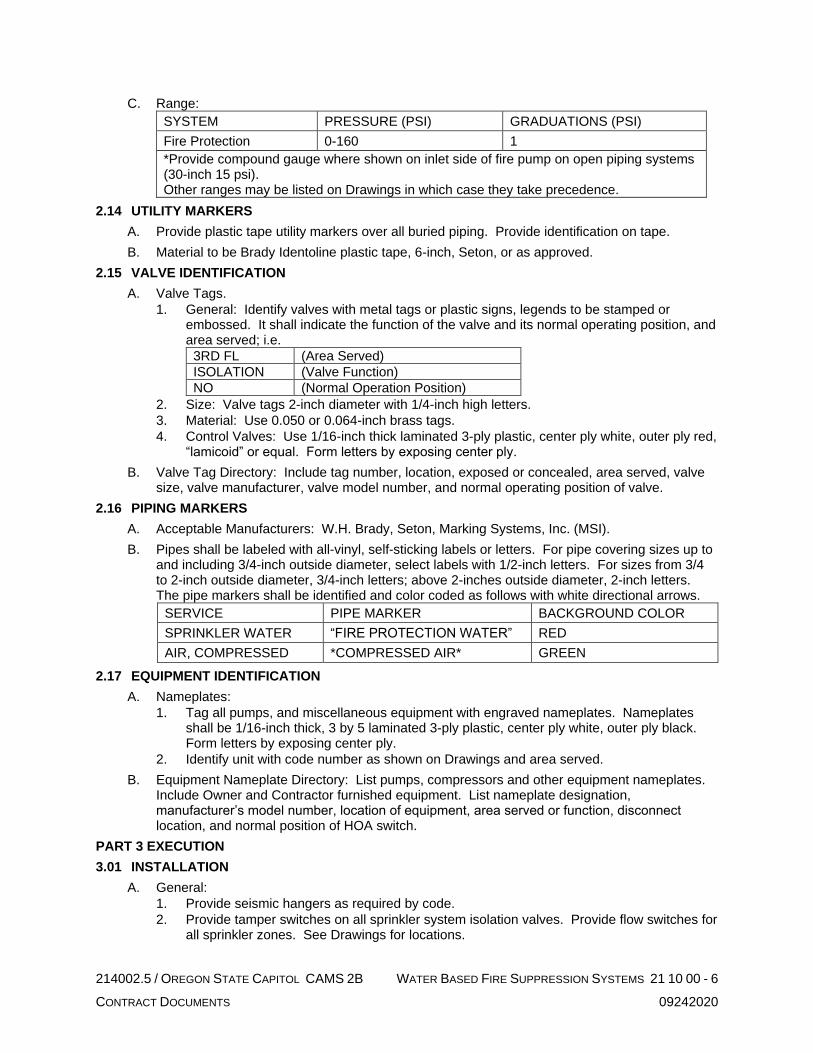
C. Range:
SYSTEM PRESSURE (PSI) GRADUATIONS (PSI)
Fire Protection 0-160 1
*Provide compound gauge where shown on inlet side of fire pump on open piping systems (30-inch 15 psi). Other ranges may be listed on Drawings in which case they take precedence.
2.14 UTILITY MARKERS
A. Provide plastic tape utility markers over all buried piping. Provide identification on tape.
B. Material to be Brady Identoline plastic tape, 6-inch, Seton, or as approved.
2.15 VALVE IDENTIFICATION
A. Valve Tags.
1. General: Identify valves with metal tags or plastic signs, legends to be stamped or embossed. It shall indicate the function of the valve and its normal operating position, and area served; i.e.
3RD FL (Area Served)
ISOLATION (Valve Function)
NO (Normal Operation Position)
2. Size: Valve tags 2-inch diameter with 1/4-inch high letters.
3. Material: Use 0.050 or 0.064-inch brass tags.
4. Control Valves: Use 1/16-inch thick laminated 3-ply plastic, center ply white, outer ply red, “lamicoid” or equal. Form letters by exposing center ply.
B. Valve Tag Directory: Include tag number, location, exposed or concealed, area served, valve size, valve manufacturer, valve model number, and normal operating position of valve.
2.16 PIPING MARKERS
A. Acceptable Manufacturers: W.H. Brady, Seton, Marking Systems, Inc. (MSI).
B. Pipes shall be labeled with all-vinyl, self-sticking labels or letters. For pipe covering sizes up to and including 3/4-inch outside diameter, select labels with 1/2-inch letters. For sizes from 3/4 to 2-inch outside diameter, 3/4-inch letters; above 2-inches outside diameter, 2-inch letters. The pipe markers shall be identified and color coded as follows with white directional arrows.
SERVICE PIPE MARKER BACKGROUND COLOR
SPRINKLER WATER “FIRE PROTECTION WATER” RED
AIR, COMPRESSED *COMPRESSED AIR* GREEN
2.17 EQUIPMENT IDENTIFICATION
A. Nameplates:
1. Tag all pumps, and miscellaneous equipment with engraved nameplates. Nameplates shall be 1/16-inch thick, 3 by 5 laminated 3-ply plastic, center ply white, outer ply black. Form letters by exposing center ply.
2. Identify unit with code number as shown on Drawings and area served.
B. Equipment Nameplate Directory: List pumps, compressors and other equipment nameplates. Include Owner and Contractor furnished equipment. List nameplate designation, manufacturer’s model number, location of equipment, area served or function, disconnect location, and normal position of HOA switch.
PART 3 EXECUTION
3.01 INSTALLATION
A. General:
1. Provide seismic hangers as required by code.
2. Provide tamper switches on all sprinkler system isolation valves. Provide flow switches for all sprinkler zones. See Drawings for locations.

214002.5 / OREGON STATE CAPITOL CAMS 2B WATER BASED FIRE SUPPRESSION SYSTEMS 21 10 00 - 7
CONTRACT DOCUMENTS 09242020
3. A corrosion-resistant metal placard shall be provided on riser indicating location number of sprinklers, design criteria, water demand, and date of installation.
4. Install fire sprinklers in exhaust ductwork from grease hood per NFPA 13. Provide access doors for sprinkler access per NFPA 96 and IBC. Provide access doors at a maximum of 10 feet on center in horizontal run. Provide a dry pendant sprinkler head at top of ductwork to prevent freezing.
5. Provide fire sprinkler guards on exposed sprinklers in areas subject to damage.
6. Quick response sprinklers shall be listed for installation in an Ordinary Hazard occupancy when installed in an Ordinary Hazard occupancy.
B. Flexible Sprinkler Head Drop:
1. Install per manufacturer’s installation requirements.
2. Coordinate head location with all other trades to assure space is available to maintain proper radius requirements.
3. Provide flexible sprinkler drops of appropriate length as conditions require.
4. Provide flexible sprinkler drops at all sprinkler heads located in suspended, dropped, or acoustical ceilings. In hard lid ceiling areas, provide flexible heads at Contractor’s option.
C. Sprinklers in Elevator Hoistways and Machine Rooms:
1. Reference Division 26 for heat detectors provided to disconnect mainline power of elevator prior to application of water from the sprinklers.
2. A shutoff valve with tamper switch will be provided for each branch service serving these spaces and shall be located in an accessible location outside these spaces.
D. Sprinklers Above Finished Ceilings:
1. Include heads above finished ceilings if structure is combustible, or if steel beams are not provided with spray-on fire proofing.
E. Electrical: All electrical work shall comply with Division 26.
F. Hangers and Supports:
1. Install sprinkler system and service main piping, hangers, and supports in accordance with NFPA 13.
2. Install standpipe piping, hangers, and supports in accordance with NFPA 14.
3. Connections to structural framing shall not introduce twisting, torsion, or lateral bending in the framing members. Provide supplementary steel as required.
G. Pressure Gauges:
1. Provide gauges where specified, shown on Drawings, or required by code.
2. Install additional gauges as required and as recommended by equipment manufacturer or their representative.
3. Locate all gauges so that they may be conveniently read at eye level or easily viewed and read from the floor or from the most likely viewing area, i.e., platform, catwalk, etc.
4. Install instruments over 6-feet-6-inches above floor, to be viewed from the floor, with face at 30 degrees to horizontal.
5. Provide instrument gauge cock at inlets.
H. Valves:
1. Provide valves at connections to equipment where shown or required for equipment isolation.
2. Install all valves accessible and same size as connected piping.
3. Provide separate support for valves where necessary.
4. Provide drain valves in all low points in the piping system, and at equipment, as required by code, and as indicated.
5. Fire Suppression Service:
a. In piping 2-inches and smaller; bronze gate valve, bronze swing check valve, vertical check valve.
b. In piping 2-1/2-inches and larger; iron gate valve, iron swing check valve, vertical check valve.

214002.5 / OREGON STATE CAPITOL CAMS 2B WATER BASED FIRE SUPPRESSION SYSTEMS 21 10 00 - 8
CONTRACT DOCUMENTS 09242020
c. U.L. approved butterfly valves.
d. Silent check valves on pump discharge.
6. Provide gauge cocks for all pressure gauges.
I. Piping Preparation:
1. Measurements, Lines and Levels:
a. Check dimension at the building site and establish lines and levels for work specified in this Section.
b. Establish all inverts, slopes, and elevations by instrument, working from an established datum point. Provide elevation markers for use in determining slopes and elevations in accordance with Drawings and Specifications.
c. Use established grid and area lines for locating trenches in relation to building and boundaries.
J. Piping:
1. Hold piping as tight to structure as possible. In general, run piping in areas without ceilings parallel to building elements in a neat, professional manner.
2. Pipe inspector test connections to exterior and discharge as approved by local applicable governing authorities.
3. Provide test tees as required.
4. Install unions in all non-flanged piping connections to apparatus and adjacent to all screwed control valves, and appurtenances requiring removal for servicing so located that piping may be disconnected without disturbing the general system.
5. Mechanical Couplings:
a. On systems using galvanized pipe and fittings, fittings shall be galvanized at factory.
b. Before assembly of couplings, lightly coat pipe ends and outside of gaskets with approved lubricant.
c. Pipe grooving in accordance with manufacturer’s specifications contained in latest published literature.
6. Install all piping as to drain per NFPA 13.
7. Support all piping independently at apparatus so that its weight shall not be carried by the equipment.
8. Utility Marking: Installed over the entire length of the underground piping utilities. Install plastic tape along both sides and the center line of the trenches at the elevation of approximately 12 inches above the top of utility.
9. Underground Water System: Prior to testing pipe provide concrete thrust blocks at changes in direction. Block size as required for types of fittings involved.
K. Drain Piping:
1. Pitch drain piping 1/2-inch per 10-feet minimum; no traps allowed.
2. Discharge drain piping to outside with suitable splash plate to a location as approved by the architect.
L. Piping Joints:
1. Pipe and fittings shall be joined using methods and materials recommended by manufacturer in conformance with standard practice and applicable codes. Cleaning, cutting, reaming, grooving, etc. shall be done with proper tools and equipment. Hacksaw pipe cutting prohibited. Peening of welds to stop leaks not permitted.
2. No couplings installed in floor or wall sleeves.
3. Steel Piping:
a. Screwed Joints: Pipes cut evenly with pipe cutter reamed to full inside diameter with all burrs and cuttings removed. Joints made up with suitable lubricant or Teflon tape applied to male threads only, leaving two threads bare. Joints tightened so that not more than two threads are left showing. Junctions between galvanized steel waste pipe and bell of cast iron pipe shall be made with tapped spigot or half coupling on steel pipe to form spigot end and caulked.

214002.5 / OREGON STATE CAPITOL CAMS 2B WATER BASED FIRE SUPPRESSION SYSTEMS 21 10 00 - 9
CONTRACT DOCUMENTS 09242020
b. Flanged Joints: Pressure rating of flanges shall match valve or fitting joined. Joint gaskets shall be coated with graphite and oil.
4. Welded Joints:
a. Preparation for Welding: Bevel piping on both ends before welding:
1) Use following weld spacing on all buttwelds:
NOMINAL PIPE WALL THICKNESS SPACING BEVEL
1/4-inch or less 1/8-inch 37-1/2
Over 1/4-inch, less than 3/4-inch 3/16-inch 27-1/2
2) Before welding, remove all corrosion products and foreign material from surfaces.
b. Welded Joints: Joints shall be made by the “arc-welding” process using certified welders. Port openings of fittings must match the inside diameter of the pipe to which they are welded. Use full radius welding elbows for all turns, use welding tees for all tees. Reducing fittings must be used for size reduction. “Weldolets” may be used for branches up through one-half the pipe size of the main to which they are attached. Nipples are not allowed.
c. Welding Operation:
1) After deposition, clean each layer of weld metal to remove slag and scale by wire brushing or grinding. Chip where necessary to prepare for proper deposition of next layer.
2) Weld reinforcement no less than 1/16-inch not more than 1/8-inch above normal surface of jointed sections. Reinforcement crowned at center and taper on each side to surfaces being joined. Exposed surface of weld shall present professional appearance and be free of depressions below surface of jointed members.
3) No welding shall be done when temperature of base metal is lower than 0°F. Material to be welded during freezing temperatures shall be made warm and dry before welding is started. Metal shall be “warm to the hand” or approximately 60°F.
5. Ductile Iron Pipe: Install joints per manufacturer’s written instructions.
M. Expansion Loops / Seismic Expansion Joints:
1. Install at building seismic expansion joints.
2. Install in other locations indicated on the drawings.
3. Install per manufacturer’s installation instructions.
N. Pipe Wrap:
1. Apply per manufacturer’s written instructions.
2. Apply wrapping to fittings in field after installation.
3.02 IDENTIFICATION
A. Valve Identification:
1. Valve Tags:
a. Attach to valve with a brass chain.
b. Valve tag numbers shall be continuous throughout the building for each system. Contractor shall obtain a list for each system involved from the Owner.
2. Valve Tag Directory: Post final copy in Operation and Maintenance Manual.
B. Piping Markers:
1. Unless recommendations of ANSI A13.1, 1981 are more stringent, apply labels or letters after completion of pipe cleaning, painting, or other similar work, as follows:
a. Every 20 feet along continuous exposed lines.
b. Every 10 feet along continuous concealed lines.
c. Adjacent to each valve and stubout for future.
d. Where pipe passes through a wall, into and out of concealed spaces.
e. On each riser.

214002.5 / OREGON STATE CAPITOL CAMS 2B WATER BASED FIRE SUPPRESSION SYSTEMS 21 10 00 - 10
CONTRACT DOCUMENTS 09242020
f. On each leg of a “T”.
g. Locate conspicuously where visible.
2. Further, apply labels or letters to lower quarters of the pipe on horizontal runs where view is not obstructed or on the upper quarters when pipe is normally viewed from above. Apply arrow labels indicating direction of flow. Arrows to be the same color and sizes as identification labels.
C. Equipment Identification:
1. Nameplates: Attach to prominent area of equipment, either with sheet metal screws, brass chain, or contact cement as applicable.
2. Nameplate Directory: Post final copy in Operation and Maintenance Manual.
3.03 EXTRA STOCK
A. Provide additional number of heads of each type and temperature rating installed as required to meet NFPA 13 requirements.
B. Provide storage cabinet or cabinets as required to receive reserve sprinkler heads and special installation tools required.
C. Provide index label for each head indicating manufacturer, model, orifice size of K-factor, and temperature rating.
D. Provide, inside cabinet a list of heads stored within and brief description of where installed.
E. Locate cabinet near sprinkler control station as approved.
3.04 FIELD QUALITY CONTROL
A. Tests and Inspections:
1. Perform all tests and arrange for required inspections of installed system as required.
2. Notify the Architect 48 hours prior to any test or inspection.
3. Final test and certification shall be provided in the presence of an Owner representative. Coordinate hereunder.
B. Inspection Service:
1. At start of warranty year, execute inspection agreement.
2. Without additional charge to Owner, make quarterly inspection of system during year.
a. Check and operate all control valves.
b. Lubricate valve parts.
C. Report each inspection to Owner.
END WATER BASED FIRE SUPPRESSION SYSTEMS

214002.5 / OREGON STATE CAPITOL CAMS 2B COMMON WORK RESULTS FOR PLUMBING 22 05 00 - 1
CONTRACT DOCUMENTS 09242020
SECTION 22 05 00
COMMON WORK RESULTS FOR PLUMBING
PART 1 GENERAL
1.01 SUMMARY
A. The intent of Division 22 Specifications and the accompanying Drawings is to provide a complete and workable facility with complete systems as shown, specified and required by applicable codes. Include all work specified in Division 22 and shown on the accompanying Drawings, including appurtenances, connections, etc., in the finished job.
B. The Division 22 Specifications and the accompanying Drawings are complementary and what is called for by one shall be as binding as if called for by both. Items shown on the Drawings are not necessarily included in the Specifications and vice versa. Specifications shall supersede drawings in case of conflict.
C. Imperative language is frequently used in Division 22 Specifications. Except as otherwise specified, requirements expressed imperatively are to be performed by the Contractor.
D. The Drawings that accompany the Division 22 Specifications are diagrammatic. They do not show every offset, bend, tee, or elbow which may be required to install work in the space provided and avoid conflicts. Offsets and transitions shall be assumed at a minimum at each duct crossing, structural penetrations through shear walls or beams, structural grids where ceiling heights are restricted, and at piping mains. Follow the Drawing as closely as is practical to do so and install additional bends, offsets and elbows where required by local conditions from measurements taken at the Building, subject to approval, and without additional cost to the Owner. The right is reserved to make any reasonable changes in fixture location prior to roughing-in, without cost impact.
1.02 RELATED WORK
A. The General and Supplemental Conditions apply to this Division, including but not limited to:
1. Drawings and Specifications
2. Public Ordinances, Permits
3. Include payments and fees required by governing authorities for work of this Division.
B. Division 01, General Requirements, applies to this Division.
1.03 QUALITY ASSURANCE
A. Regulatory Requirements:
1. All products and equipment shall comply with Oregon Revised Statute (ORS) 453.005(7)(e) prohibiting pentabrominated, octabrominated, and decabrominated diphenyl ethers. Where products or equipment within this specification contain these banned substances, provide complying products and equipment from approved manufacturers with equal performance characteristics.
2. General: All work and materials shall conform to the local and State codes, and all Federal, State and other applicable laws and regulations.
3. Contractor responsible for obtaining and payment for all permits, licenses, and inspection certificates required in accordance with provisions of Contract Documents.
B. Materials and equipment shall be new. Work shall be of good quality, free of faults and defects and in conformance with the Contract Documents.
C. Apparatus shall be built and installed to deliver its full rated capacity at the efficiency for which it was designed.
D. The entire plumbing system and apparatus shall operate at full capacity without objectionable noise or vibration.
E. All equipment shall be installed level and true. Housekeeping pads and curbs shall account for floor or roof slope.

214002.5 / OREGON STATE CAPITOL CAMS 2B COMMON WORK RESULTS FOR PLUMBING 22 05 00 - 2
CONTRACT DOCUMENTS 09242020
F. Materials and Equipment:
1. Each piece of equipment furnished shall meet all detailed requirements of the Drawings and Specifications and shall be suitable for the installation shown. Equipment not meeting all requirements will not be acceptable, even though specified by name along with other manufacturers.
2. Where two or more units of the same class of equipment are furnished, use products of the same manufacturer. Component parts of the entire system need not be products of same manufacturer.
3. Furnish all materials and equipment of size, make, type, and quality herein specified.
4. Equipment scheduled by performance or model number shall be considered the basis of the design. If other specified manufacturer's equipment is provided in lieu of the basis of design equipment the contractor is responsible for all changes and costs which may be necessary to accommodate this equipment, including different sizes and locations for connections, different electrical characteristics, different dimensions, different access requirements or any other differences which impact the project.
G. Workmanship:
1. General: All materials shall be installed in a neat and professional manner.
2. Manufacturer’s Instructions: Follow manufacturer’s directions where they cover points not specifically indicated. If they are in conflict with the Drawings and Division 22 Specifications, obtain clarification before starting work.
H. Cutting and Patching:
1. Cutting, patching, and repairing for the proper installation and completion of the work specified in this Division including plastering, masonry work, concrete work, carpentry work, and painting shall be performed by skilled craftsmen of each respective trade in conformance with the appropriate Division of Work.
2. Additional openings required in building construction shall be made by drilling or cutting. Use of jackhammer is specifically prohibited.
3. Fill holes which are cut oversize so that a tight fit is obtained around the sleeves passing through.
4. Beams or columns shall not be pierced without permission of Architect and then only as directed.
5. All new or existing work cut or damaged shall be restored to its original condition. Where alterations disturb lawns, paving, walks, etc., the surfaces shall be repaired, refinished, and left in condition existing prior to commencement of work.
1.04 SUBMITTALS
A. Shop Drawings:
1. The Contract Drawings indicate the general layout of the piping, and various items of equipment. Coordination with other trades and with field conditions will be required. For this purpose, prepare Shop Drawings of all piping, and equipment installations. Shop Drawings shall be new drawings prepared by Contractor and not reproductions or tracings of Architect’s Drawings. Overlay drawings with shop drawings of other trades and check for conflicts. All drawings shall be same size as Architect’s Drawings with title block similar to Contract Drawings and identifying Architect’s Drawing number or any reference drawings. All drawings shall be fully dimensioned including both plan and elevation dimensions. Shop drawings cannot be used to make scope changes.
2. Shop drawings shall be prepared in three-dimensional format.
3. Shop drawings shall include but are not limited to:
a. Plumbing site plan drawn to same scale as Site Plan.
b. Complete floor plans with plumbing to a minimum of 1/4-inch equals 1-foot scale.
c. Plumbing in mechanical rooms to a minimum of 1/2-inch equals 1-foot scale.
d. Sections of congested areas to a minimum of 1/2-inch equals 1-foot scale.
e. Fabricated Equipment: Scale and drawing sizes to suit Contractor except equipment shall not be less than 1/2-inch equals 1-foot scale.

214002.5 / OREGON STATE CAPITOL CAMS 2B COMMON WORK RESULTS FOR PLUMBING 22 05 00 - 3
CONTRACT DOCUMENTS 09242020
f. Superplot plans of above ground work with a colored overlay of all trades including, but not limited to, HVAC piping, HVAC equipment, plumbing piping and equipment, sprinklers, lighting, lighting controls, cable tray, fire alarm devices, electrical power conduit, and ceiling system to a minimum of 1/2-inch equals 1-foot scale.
g. Superplot plans of below ground work with a colored overlay of all trades including, but not limited to, structural footings and foundation, HVAC piping, civil piping, plumbing piping, and power conduit to a minimum of 1/2-inch equals 1-foot scale.
h. Beam penetration drawings indicating beam penetrations meeting the requirements indicated on the floor plans and on the structural drawings to a minimum of 1/4-inch equals 1-foot scale.
i. Slab penetration drawings of HVAC, plumbing, sprinklers, lighting and electrical to a minimum of 1/4-inch equals 1-foot scale.
4. Submit shop drawings for review prior to beginning fabrication. Additional shop drawings may be requested when it appears that coordination issues are not being resolved in the field or when there is a question as to whether contract documents are being complied with or the design intent is being met.
B. Product Data:
1. In general, submit product data for review on all scheduled pieces of equipment, on all equipment requiring electrical connections or connections by other trades, and as required by each specification section or by Drawing notes. Include manufacturer’s detailed shop drawings, specifications, and data sheets. Data sheets shall include capacities, RPM, BHP, pressure drop, design and operating pressures, temperatures, and similar data. Manufacturer’s abbreviations or codes are not acceptable.
2. List the name of the motor manufacturer and service factor for each piece of equipment.
3. Indicate equipment operating weights including bases and weight distribution at support points.
4. In the case of equipment such as wiring devices, time switches, valves, etc., specified by specific catalog number, a statement of conformance will suffice.
C. Submission Requirements:
1. Shop Drawings and Product Data:
a. Refer to Division 01 for additional requirements related to submittals.
b. Submit electronic copies of shop drawings and product data for Work of Division 22 in PDF format with each item filed under a folder and labeled with its respective specification section number, article, and paragraph and mark, if applicable.
c. Include a complete index in the original submittal. Indicate both original items submitted and note stragglers that will be submitted at a later date to avoid delay in submitting.
d. The bulk of the shop drawings and product data, excepting Controls and Instrumentation, shall be included with the original submittal. Controls and Instrumentation submittals may lag but shall be complete when submitted. Partial submittals will not be accepted. Other stragglers submitted after return of the original binder shall include a tab similar to that originally submitted. Upon receipt of the returned late submittal, insert them in the previously submitted binder.
D. Contractor Responsibilities: It shall be the Contractor’s responsibility to:
1. See that all submittals are submitted at one time and are in proper order.
2. Ensure that all equipment will fit in the space provided.
3. Assure that all deviations from Drawings and Specifications are specifically noted in the submittals. Failure to comply will void review automatically.
1.05 OPERATING AND MAINTENANCE MANUAL, PARTS LISTS, AND OWNER’S INSTRUCTIONS
A. Refer to Division 01 for additional requirements.

214002.5 / OREGON STATE CAPITOL CAMS 2B COMMON WORK RESULTS FOR PLUMBING 22 05 00 - 4
CONTRACT DOCUMENTS 09242020
B. Submit three bound copies of manufacturer’s operation and maintenance instruction manuals and parts lists for each piece of equipment or item requiring servicing. Literature shall be on 8-1/2 by 11-inch sheets or catalogs suitable for side binding. Submit data when the work is substantially complete, packaged separately, and clearly identified in durable 3-ring binder. Include name and contact information for location of source parts and service for each piece of equipment. Clearly mark and label in each submittal, the piece of equipment provided with the proper nameplate and model number identified. Provide wiring diagrams for all electrically powered equipment.
C. Instruct Owner thoroughly in proper operation of equipment and systems, in accordance with manufacturer’s instruction manuals. Operating instructions shall cover all phases of control.
D. Furnish competent engineer knowledgeable in this building system for minimum of five 8-hour days to instruct Owner in operation and maintenance of systems and equipment. Contractor shall keep a log of this instruction including dates, times, subjects, and those present and shall present such log when requested by Architect.
1.06 PROJECT CONDITIONS
A. Existing Conditions: Prior to bidding, verify and become familiar with all existing conditions by visiting the site, and include all factors which may affect the execution of this Work. Include all related costs in the initial bid proposal.
B. Coordinate exact requirements governed by actual job conditions. Check all information and report any discrepancies before fabricating work. Report changes in time to avoid unnecessary work.
C. Coordinate shutdown and start-up of existing, temporary, and new systems and utilities. Notify Owner, City, and Utility Company.
1.07 WARRANTY
A. Provide a written guaranty covering the work of this Division (for a period of one calendar year from the date of acceptance by the Owner) as required by the General Conditions.
B. Provide manufacturer’s written warranties for material and equipment furnished under this Division insuring parts and labor for a period of one year from the date of Owner acceptance of Work of this Division.
C. Correct warranty items promptly upon notification.
1.08 PROVISIONS FOR LARGE EQUIPMENT
A. Contractor shall make provisions for the necessary openings in building to allow for admittance of all equipment.
1.09 TEST REPORTS AND CERTIFICATES
A. Contractor shall submit one copy of all test reports and certificates specified herein to the Architect.
1.10 SUBSTITUTIONS
A. Contractor shall submit any requests for product substitutions in accordance with the Instructions to Bidders and the General and Supplemental Conditions.
1.11 ALTERNATES
A. Comply with Division 01 Section, “Alternates”.
B. Refer to Electrical Drawings for detailed information relating to the appropriate alternates.
PART 2 PRODUCTS
2.01 ACCESS PANELS
A. Furnish under this Division as specified in another Division of work.
2.02 PIPE SLEEVES
A. Interior Wall and Floor Sleeves: 18-gauge galvanized steel, or another pre-approved system.

214002.5 / OREGON STATE CAPITOL CAMS 2B COMMON WORK RESULTS FOR PLUMBING 22 05 00 - 5
CONTRACT DOCUMENTS 09242020
B. Interior Wall and Floor Sleeves (fire rated): Fire rated and water tight system approved by Authority Having Jurisdiction and Owner’s Insurance underwriter, with rating equal to floor or wall penetration, and designed specifically for the floor or wall construction, piping material, size and service.
C. Exterior Wall Sleeves: Cast iron.
D. On Grade Floor Sleeves: Same as exterior wall sleeves.
E. Water Tight Sleeves: Combination steel pipe sleeves with water stop and anchor plate; Link Seal Model WS, mated with synthetic rubber links interlocked with bolts and nuts; Link Seal Model LS.
2.03 FLOOR, WALL, AND CEILING PLATES
A. Furnish stamped split type plates as follows:
1. Floor Plates: Cast brass, chromium plated.
2. Wall and Ceiling Plates: Spun aluminum.
2.04 ELECTRICAL EQUIPMENT
A. General: All equipment and installed work shall be as specified under Division 26, Electrical.
B. Coordinate with the electrical Drawings and electrical contractor for minimum electrical equipment bracing requirements based on the available interrupting current (AIC) rating at the bus of the panelboard or switchboard serving the piece of equipment. Provide equipment that meets the bracing requirement.
C. Equipment Wiring: Interconnecting wiring within or on a piece of mechanical equipment shall be provided with the equipment unless shown otherwise. This does not include the wiring of motors, starters and controllers provided under Division 26, Electrical.
D. Control Wiring: All control wiring for plumbing equipment shall be provided herewith.
E. Codes: All electrical equipment and products shall bear the Underwriters label as required by governing codes and ordinances.
PART 3 EXECUTION
3.01 ACCESS PANELS
A. Install in accord with manufacturer’s recommendations, coordinated with architectural features.
B. Provide 2-hour fire rated doors where required bearing the U.L. label.
C. Furnish 18-inch by 18-inch panels for ceilings and for access to equipment in soffits and shafts, and 12-inch by 12-inch for walls unless indicated otherwise.
D. Furnish where indicated and where required to access valves, trap primers, shock arresters, and other appurtenances requiring operation, service or maintenance. Submit proposed locations for review prior to installation.
3.02 SLEEVES
A. Interior Floor and Wall Sleeves: Provide sleeves large enough to provide 3/4-inch clearances around pipe or ductwork. Where pipe or ductwork is insulated, insulation shall pass continuously through sleeve with 3/4-inch clearance between insulation and sleeve. Penetrations through mechanical room and fan room floors shall be made watertight by packing with safing insulation and sealing with Tremco Dymeric Sealant or approved system.
B. Sleeves Through Rated Floors and Walls: Similar to interior sleeves except install fire-rated system approved by Authority Having Jurisdiction and Owner’s insurance underwriter, with rating equal to floor or wall penetration, and designed specifically for the floor or wall construction, piping material, size, and service. Firestopping work shall comply with requirements of Section 07 84 00, Firestopping.

214002.5 / OREGON STATE CAPITOL CAMS 2B COMMON WORK RESULTS FOR PLUMBING 22 05 00 - 6
CONTRACT DOCUMENTS 09242020
C. Exterior Wall Sleeves Below Grade: Provide water tight sleeves. Install at pipes entering building below grade and where shown. Adjust to provide positive hydrostatic seal. Contractor shall be responsible for following manufacturer’s procedure for installing and tightening seal. Secure sleeves against displacement.
D. On Grade Floor Sleeves: Same as below grade exterior wall sleeves, caulked from inside.
E. Exterior Wall Sleeves Above Grade: Similar to interior wall sleeves except caulk outside with Tremco Dymeric Sealant.
F. Layout work prior to concrete forming. Do all cutting and patching required. Reinforce sleeves to prevent collapse during forming and pouring.
G. All floor sleeves shall maintain a water barrier by providing a water tight seal or they shall extend 1-inch above finished floor except through mechanical equipment room floors and shafts where sleeves shall extend 2-inches above finished floor level. Sleeves through roof shall extend 8 inches above roof. Wall sleeves shall be flush with face of wall unless otherwise indicated. Waste stacks using carriers shall have sleeves flush with floor and sealed. Sleeves through planters shall extend 8 inches above planter base.
H. Do not support pipes by resting pipe clamps on floor sleeves. Supplementary members shall be provided so pipes are floor supported.
I. Special sleeves detailed on drawings shall take precedence over this Section.
3.03 CLEANING
A. General: Clean plumbing equipment, fixtures and piping of stampings and markings (except those required by codes), iron cuttings, and other refuse.
B. Painted Surfaces: Clean scratched or marred painted surfaces of rust or other foreign matter and paint with matching color industrial enamel, except as otherwise noted.
C. Additional requirements are specified under specific Sections of this Division.
3.04 EQUIPMENT PROTECTION
A. Keep pipe and conduit openings closed by means of plugs or caps to prevent the entrance of foreign matter. Protect piping, conduit, fixtures, equipment and apparatus against dirty water, chemical or mechanical damage both before and after installation. Restore damaged or contaminated fixtures, equipment, or apparatus to original conditions or replace at no cost to the Owner.
B. Protect bright finished shafts, bearing housings, and similar items until in service. No rust will be permitted.
C. Cover or otherwise suitably protect equipment and materials stored on the job site.
3.05 ACCESSIBILITY
A. General: Locate valves, thermometers, cleanout fittings and other indicating equipment or specialties requiring frequent reading, adjustments, inspection, repairs, and removal or replacement conveniently and accessibly with reference to the finished building.
B. Thermometers and Gauges: Install thermometers and gauges so as to be easily read from the floors, platforms and walkways.
3.06 FLOOR, WALL, AND CEILING PLATES
A. Install on piping and ductwork passing through finished walls, floors, ceilings, partitions, and plaster furrings. Plates shall completely cover opening around pipe.
B. Secure wall and ceiling plates to pipe, insulation, or structure.
C. Plates shall not penetrate insulation vapor barriers.
D. Plates not required in mechanical rooms or unfinished spaces.

214002.5 / OREGON STATE CAPITOL CAMS 2B COMMON WORK RESULTS FOR PLUMBING 22 05 00 - 7
CONTRACT DOCUMENTS 09242020
3.07 PAINTING
A. General: Coordinate painting of mechanical equipment and items with products and methods in conformance with Section 09 90 00, Painting and Coating. All exposed work under this division shall receive either a factory painted finish or a field prime coat finish, except:
1. Exposed copper piping.
2. Aluminum jacketed outdoor insulated piping.
B. Equipment Rooms and Finished Areas:
1. Insulation: Not painted.
2. Hangers, Uninsulated Piping, Miscellaneous Iron Work, Structural Steel Stands, Uninsulated Tanks, and Equipment Bases: Paint one coat of black enamel.
3. Steel Valve Bodies and Bonnets: One coat of black enamel.
4. Brass Valve Bodies: Not painted.
5. Equipment: One coat of grey machinery enamel. Do not paint nameplates.
C. Concealed Spaces (above ceilings, not visible):
1. Insulation: Not painted.
2. Hangers, Uninsulated Piping, Miscellaneous Iron Work, Valve Bodies and Bonnets: Not painted.
D. Exterior Steel: Wire brush and apply two coats of rust-inhibiting primer and one coat of grey exterior machinery enamel.
E. Exterior Black Steel Pipe: Wire brush and apply two coats of rust-inhibiting primer and one coat of exterior enamel. Painting schemes shall comply with ANSI A13.1.
3.08 ADJUSTING AND CLEANING
A. Before operating any equipment or systems, make thorough check to determine that systems have been flushed and cleaned as required and equipment has been properly installed, lubricated, and serviced. Check factory instructions to see that installations have been made accordingly and that recommended lubricants have been used.
B. Use particular care in lubricating bearings to avoid damage by overlubrication and blowing out seals. Check equipment for damage that may have occurred during shipment, after delivery, or during installation. Repair damaged equipment as approved or replace with new equipment.
3.09 ELECTRICAL EQUIPMENT
A. Piping for plumbing systems not serving electrical space shall not be installed in any switchgear room, transformer vault, telephone room, or electric closet except as indicated.
B. Piping for plumbing systems shall not pass over switchboards or electrical panelboards. Where conflicts exist, bring to attention of Architect.
3.10 EQUIPMENT CONNECTIONS
A. Make final connections to equipment specified in sections other than Division 22 of the specifications and Owner furnished equipment in accordance with manufacturer’s instructions and shop drawings furnished and as indicated.
B. Piping:
1. Connections shall include hot and cold water, natural gas, sanitary waste and vent.
2. Provide valves and specialties as specified and as detailed on the Drawings. Provide increasers, reducers, and any other fittings required for complete installation.
3. All piping connections shall be independently supported to prevent undue strain on equipment.
END COMMON WORK RESULTS FOR PLUMBING

214002.5 / OREGON STATE CAPITOL CAMS 2B GENERAL DUTY VALVES AND SPECIALTIES FOR PLUMBING 22 05 23 - 1
CONTRACT DOCUMENTS 09242020
SECTION 22 05 23
GENERAL DUTY VALVES AND SPECIALTIES FOR PLUMBING
PART 1 GENERAL
1.01 SUMMARY
A. This Section includes:
1. Valves
2. General Purpose Gauge Cocks
3. Balance Fittings
1.02 SUBMITTALS
A. Submit product data.
1.03 DEFINITIONS
A. CWP: Cold Working Pressure
B. EPDM: Ethylene Propylene Copolymer Rubber
C. NBR: Acrylonitrile-Butadiene, Buna-N, or Nitrile Rubber
D. NRS: Nonrising Stem
E. OS&Y: Outside Screw and Yoke
F. RS: Rising Stem
G. PTFE: Polytetraflouroethylene Plastic
H. SWP: Steam Working Pressure
I. Lead Free: Refers to the wetted surface of pipe, fittings, and fixtures in potable water systems that have a weighted average lead content ≤0.25 percent per Safe Drinking Water Act as amended January 4, 2011, Section 1417.
1.04 QUALITY ASSURANCE
A. ASME Compliance:
1. ASME B16.10 for ferrous valve dimensions.
2. ASME B31.9 for building services piping valves.
B. NSF Compliance: NSF/ANSI 61 and/or NSF/ANSI 372 for valve materials for potable-water service. Valves for domestic water must be 3rd Party Certified.
PART 2 PRODUCTS
2.01 ACCEPTABLE MANUFACTURER VALVES
A. General: Where only NIBCO INC. figure numbers are listed, equivalent products by those specified below are acceptable.
1. Gate, Globe:
a. Victaulic
b. Crane
c. Kennedy
d. Stockham
e. Milwaukee
f. Walworth
g. Hammond
2. Balancing:
a. Bell and Gossett
b. Armstrong
c. Tour and Anderson
d. Nibco

214002.5 / OREGON STATE CAPITOL CAMS 2B GENERAL DUTY VALVES AND SPECIALTIES FOR PLUMBING 22 05 23 - 2
CONTRACT DOCUMENTS 09242020
3. Butterfly:
a. Victaulic
b. Gruvlok
c. Crane
d. Walworth
e. Milwaukee
f. Metraflex
4. Ball:
a. Gruvlok
b. Apollo
c. Crane
d. Hammond
e. Milwaukee
f. Victaulic
B. Other Manufacturers: Submit Substitution Request.
C. All such valves shall be of one manufacturer.
D. Valve ends may be threaded, flanged, soldered, or grooved, as applicable to piping system. Refer to Section 22 21 13, Pipe and Pipe Fittings Plumbing for allowable fittings.
2.02 GATE VALVES
A. Bronze Gate: Bronze body, bronze trim, bronze screwed bonnet; solid wedge, 150 psi steam rating, 300 psi WOG, Nibco 134.
B. Lead Free Bronze Gate: Lead Free Silicon Bronze corrosion resistant body and trim, screwed bonnet; solid wedge, NSR, 300 psi CWP, NIBCO S/T-113-LF.
C. Iron Gate, OS&Y: Iron body, bronze trim, OS and Y pattern, solid wedge, 150 psi rating; Nibco 637.
D. Lead Free Iron Gate: Class 125, OS&Y, Cast or Ductile Iron body, Stainless steel or Lead Free silicon bronze corrosion resistant trim, OS and Y pattern, solid wedge, 200 psi rating; NIBCO F-617-O-LF or F-619-RW.
2.03 GLOBE VALVES
A. Bronze Globe and Angle Globe: Bronze body, bronze mounted, renewable composition disc, 150 psi rating; Nibco 235 or 335.
2.04 BALL VALVES
A. Bronze Ball: Bronze cast body, chrome-plated full port ball, with handle, Teflon seat, 600 psi WOG, 150 psi steam; Nibco 585-80.
B. Lead Free Bronze Ball: Two piece, full port, Lead Free silicon bronze body, Stainless steel or silicon bronze trim, Reinforced PTFE or TFE seats, 600 psi CWP NIBCO T/S-585-80-LF or T/S-585-66-LF.
2.05 BUTTERFLY VALVES
A. Ductile iron body, nickel chrome plated disc, and stainless steel shaft, with lever handle and locking feature on valves 6 inches and less, gear operator on valves 8 inches and over; stem neck length to accommodate insulation where applicable, EPDM liner, 200 psi water; Nibco 2000, Nibco 4765.
B. Lead Free Butterfly Valve: Ductile iron body, Lead Free Aluiminum Bronzedisc and stainless steel stem, with lever handle and locking feature on valves 6 inches and less, gear operator on valves 8 inches and over; stem neck length to accommodate insulation where applicable, EPDM liner, 200 psi water; NIBCO LD- 2000N-3/5,

214002.5 / OREGON STATE CAPITOL CAMS 2B GENERAL DUTY VALVES AND SPECIALTIES FOR PLUMBING 22 05 23 - 3
CONTRACT DOCUMENTS 09242020
2.06 BALANCING VALVE
A. Lead-Free Calibrated:
1. Bronze, Ametal (copper-alloy), or ductile iron body, brass globe or ball, differential pressure readout valves with integral checks, calibrated plate, integral pointer, suitable for tight shutoff, memory stops, threaded, grooved or soldered ends, 250 psi water, NSF/ANSI 61 compliant, Bell and Gossett Lead-Free Circuit Setter Plus.
2.07 SPECIALTY VALVES
A. Gas Cock: Forged brass body, hard chromium plated forged brass ball, with handle, rubber seats meeting ASTM D471, 175 psi WOG, entire unit tested to latest version of ANSI Z21.15, AGA and UL listed; Wooster, Parker, Watts, Jamesbury, PGL, ASCO.
B. Gauge Cocks: Brass, tee handle, male to female, 200 psi working pressure, 1/4-inch; Apollo 41 series.
C. Drain Valves: Bronze globe valve or full port ball valve, garden hose end, cap and chain 3/4-inch size.
2.08 SYSTEM SPECIALTIES
A. Manual Air Vents: Coin type; Dole No. 9 or approved equal.
B. Pressure/Temperature Test Plug.
1. Acceptable Manufacturers:
a. Peterson Engineering, Inc.
b. Universal Lancaster
c. Sisco
d. Trerice
e. Other Manufacturers: Submit Substitution Request.
2. General: 1/2-inch N.P.T. fitting to receive either a temperature or pressure probe 1/8-inch O.D., fitted with a color coded and marked cap with gasket.
3. Material: Solid brass with valve core of Nordel.
4. Rating: Minimum 300 psig at 275 degrees F.
5. Gauges and Thermometers: Supply Owner with two pressure gauge adapters with 1/8-inch O.D. probe and two five-inch stem pocket test thermometers 25 degrees F to 125 degrees F for chilled water, 40 degrees F to 240 degrees F for heating water.
2.09 WATER RELIEF VALVES
A. Acceptable Manufacturers.
1. Consolidated
2. Kunkle
3. Bell and Gossett
4. Armstrong
5. Cash Acme
6. Other Manufacturers: Submit Substitution Request.
B. Description: Bronze or steel body, stainless steel or bronze, pressure settings to 160 psi at 250 degrees F, conforming to Section IV of ASME Code, size per manufacturer’s recommendations based on Code, setting as indicated; Kunkle Model 537.
PART 3 EXECUTION
3.01 INSTALLATION
A. Provide valves at connections to equipment where shown or required for equipment isolation.
B. Provide separate support for valves where necessary.
C. Provide drain valves in all low points in the piping system, at coils and equipment, and as indicated.

214002.5 / OREGON STATE CAPITOL CAMS 2B GENERAL DUTY VALVES AND SPECIALTIES FOR PLUMBING 22 05 23 - 4
CONTRACT DOCUMENTS 09242020
3.02 APPLIED LOCATIONS PLUMBING VALVES
A. In piping 2-inches and smaller:
System Valve Types
Gate Globe Swing Check
Ball
Domestic Hot Lead Free Bronze
Lead Free Bronze
Lead Free Bronze
Not Allowed
Domestic Cold Lead Free Bronze
Lead Free Bronze
Lead Free Bronze
Not Allowed
Industrial Cold Water
Bronze Bronze Bronze Not Allowed
B. In piping 2-1/2-inches and larger:
System Valve Types
Gate Globe Ball Butterfly
Domestic Hot Lead Free Iron
Lead Free Iron
Not Allowed Lead Free Ductile Iron
Domestic Cold Lead Free Iron
Lead Free Iron
Not Allowed Lead Free Ductile Iron
Industrial Cold Water
Iron Iron Not Allowed Ductile Iron
C. Calibrated balancing valves on domestic hot water. Size balancing valves based on the published performance curve characteristics for the scheduled flow rate for each location to ensure proper operation at design conditions.
D. Provide gauge cock for all pressure gauges.
3.03 VALVE IDENTIFICATION
A. General: Identify valves to indicate their function and system served.
B. See Section 22 05 53, Identification for Plumbing Piping and Equipment/
3.04 CHAIN OPERATORS
A. All valves in equipment rooms or fan rooms used for equipment or coil isolation and more than 8-feet above floor shall be installed with stem horizontal and equipped with chain wheels and chains extending to 6-feet above floor.
3.05 INSTALLATION
A. Manual Air Vents:
1. Install at all high points where automatic air vents are not used, where noted, and where required for proper venting of system.
2. Install in accordance with manufacturer’s recommendations.
B. Test Plugs: Install where indicated and in accordance with the manufacturer’s recommendations.
C. Water Relief Valves:
1. Install where indicated, and in accordance with manufacturer’s instructions. Pipe discharge to nearest floor drain using Schedule 40 steel pipe.
END GENERAL DUTY VALVES AND SPECIALTIES FOR PLUMBING

214002.5 / OREGON STATE CAPITOL CAMS 2B HANGERS SUPPORTS AND ANCHORS FOR PLUMBING 22 05 29 - 1
CONTRACT DOCUMENTS 09242020
SECTION 22 05 29
HANGERS SUPPORTS AND ANCHORS FOR PLUMBING
PART 1 GENERAL
1.01 SUMMARY
A. This Section includes:
1. Supports and anchors for piping system.
B. Related Sections include:
1. Section 22 05 48, Vibration and Seismic Controls for Plumbing Piping and Equipment
2. Section 22 07 00, Insulation for Plumbing
3. Section 22 21 13, Pipe and Pipe Fittings Plumbing
1.02 SUBMITTALS
A. Submit the following:
1. Shop Drawings of Contractor-fabricated piping support structures.
2. No other submittals required under this Section.
PART 2 PRODUCTS
2.01 SUPPORTS, ANCHORAGE, AND RESTRAINT
A. General: Provide pipe hangers and supports in accordance with the following:
1. When supports, anchorages, and seismic restraints for equipment, and supports and seismic restraints for conduit, piping, and ductwork are not shown on the Drawings, the Contractor shall be responsible for their design.
2. Seismic restraints and anchorages shall resist seismic forces as specified in the latest edition of the International Building Code for the seismic zone in which the project is constructed.
3. Seismic restraint shall not introduce excessive stresses in the piping caused by thermal expansion or contraction.
4. Connections to structural framing shall not introduce twisting, torsion, or lateral bending in the framing members. Provide supplementary steel as required.
5. Seismic restraints shall be in accordance with the latest edition of the SMACNA “Seismic Restraint Manual - Guidelines for Mechanical Systems” for the Seismic Hazard Level corresponding to the seismic zone in which the project is constructed.
6. Seismic restraints shall be in accordance with the applicable code.
7. Seismic restraints shall follow the provisions described in Section 22 05 48, Vibration and Seismic Controls for Plumbing Piping and Equipment.
B. Engineered Support Systems: The following support systems shall be designed, detailed, and bear the seal of a professional engineer registered in the State having jurisdiction.
1. Supports and seismic restraints for suspended piping.
2. Support frames such as pipe racks or stanchions for piping which provide support from below.
3. Piping support frame anchorage to supporting slab or structure.
2.02 SUPPORTS, GENERAL
A. Fabricate support members from welded standard structural shapes, pipe, and plate to carry the necessary rollers, hangers, and accessories as required. Support piping less than 4-inch pipe size from or by prefabricated roll-formed channels with necessary accessories to adequately support piping system.
B. Acceptable Manufacturers:
1. Unistrut
2. Superstrut
3. Powerstrut and Kinline
4. B-Line Systems

214002.5 / OREGON STATE CAPITOL CAMS 2B HANGERS SUPPORTS AND ANCHORS FOR PLUMBING 22 05 29 - 2
CONTRACT DOCUMENTS 09242020
5. AnvilStrut
C. Supports and Accessories: Preformed roll-formed channels and accessories with matching compatible accessories as shown, as specified, and as required.
D. Dissimilar Metal Protection: Hydra-Zorb cushions or Cush-a-strip.
E. Clamps: Super Strut Series 700 through 702 or AnvilStrut Series 1000 through 1200.
2.03 PIPE ATTACHMENTS
A. Acceptable Manufacturers: Anvil as noted or equivalent products by Superstrut, B-Line Systems, Tolco, Michigan Hanger.
B. Uninsulated Horizontal Copper Piping:
1. 2-inch and Smaller: Anvil CT-65, CT-69, CT-99C.
2. Larger than 2-inch: Anvil 260 field or factory copper plated, plastic coated or other recognized industry methods. Electricians’ tape is unacceptable.
C. Insulated Horizontal Copper Pipe with Hangers Inside of Insulation: Same as Uninsulated Horizontal Copper Pipe.
D. Insulated Horizontal Copper Pipe with Hangers Outside of Insulation:
1. 2-inch and Smaller: Anvil 65, 70, 104 or 260.
2. Larger than 2-inch: Anvil 260.
E. Other Uninsulated Horizontal Pipe:
1. 2-inch and Smaller: Anvil 65, 70, 104 or 260.
2. Larger than 2-inch: Anvil 260.
F. Other Insulated Horizontal Pipe With Hangers Inside of Insulation:
1. 2-inch and Smaller: Anvil 65, 70, 104, 260 or 300.
2. Larger than 2-inch: Anvil 260.
G. Other Insulated Horizontal Pipe with Hangers Outside of Insulation:
1. 2-inch and Smaller: Anvil 65, 70, 104 or 260.
2. Larger than 2-inch: Anvil 260.
H. Riser Clamps Copper Pipe:
1. 4-inch and Smaller: Anvil CT-121, CT-121C or 261C.
2. Larger than 4-inch: Anvil 261C.
I. Riser Clamps Other Piping: Anvil 261.
2.04 PIPE ROLLERS, INSULATION PROTECTION SHIELDS, AND INSULATION PROTECTION SADDLES
A. Acceptable Manufacturers: Anvil as noted or equivalent Super Strut, B-Line Systems, Tolco, Michigan Hangers.
B. Pipe Rollers: Anvil 174 or 274 as required. Size for pipe plus insulation for insulated pipe.
C. Insulation Protection Shields: Anvil 167.
D. Insulation Protection Saddles: Anvil 160 through 166A as required. Saddles for copper pipe, factory or field copper plated.
2.05 BUILDING ATTACHMENTS
A. Acceptable Manufacturers: Anvil as listed or equivalent products by Elcen, Superstrut, B-Line Systems, Tolco, Michigan Hangers.
B. Beam Hangers:
1. On piping 6-inch and smaller: Anvil 86 with retaining clip Fig. 89.
2. On piping larger than 6-inch: Anvil 228, or 292.
C. Inserts: Anvil 152 malleable iron or 281 steel inserts. Inserts sized for required rod to support load being carried.

214002.5 / OREGON STATE CAPITOL CAMS 2B HANGERS SUPPORTS AND ANCHORS FOR PLUMBING 22 05 29 - 3
CONTRACT DOCUMENTS 09242020
D. Expansion Plugs: Similar and equal to Phillips “red-head” self-drilling flush shell selected for safety factor of 4.
E. Powder actuated fasteners with silencers as approved by Architect.
PART 3 EXECUTION
3.01 HANGERS AND SUPPORTS
A. General:
1. Install all support systems as detailed and in accordance with manufacturer’s recommendations. Provide pipe racks, pipe stands, trapeze hangers, etc., as required and as detailed on the Drawings.
2. Provide adjustable hangers for all pipes complete with inserts, adjusters, bolts, nuts, swivels, all-thread rods, etc., except where specified otherwise.
3. Arrange for grouping of parallel runs of horizontal piping to be supported together on trapeze type hangers where possible. Where piping of various sizes is to be supported together by trapeze hangers, space hangers for smallest pipe size or install intermediate supports for smaller diameter pipe. Do not use wire or perforated metal to support piping and do not support piping from other piping.
4. Except as otherwise indicated for exposed continuous pipe runs, install hangers and supports of same type and style as installed for adjacent similar piping.
5. Install all cast iron piping in accordance with Cast Iron Soil Pipe Industry (CISPI) Standards.
6. Support all piping within 2 feet of each change of direction on both sides of fitting.
B. Insulated Piping Systems:
1. See Section 22 07 00, Insulation for Plumbing for insulation requirements.
2. Insulated Piping Systems with Vapor Barrier Insulation:
a. Install hangers outside of insulation.
b. On piping 1-1/2-inches and larger, provide insulation protection shields at each support location.
3. Insulated Piping Systems with Non-Vapor Barrier Insulation:
a. At the contractor’s option, hangers may be installed inside or outside of insulation for piping 2-inches and smaller.
b. If hangers are installed outside of insulation, provide insulation protection shields at all support locations on piping 1-1/2-inches and larger.
c. On piping larger than 2-inches, provide insulation saddles at each support location.
4. Insulation Protection:
a. Band insulation protection shields firmly to insulation to prevent slippage.
b. Tack weld insulation protection saddles to steel pipe. Braze saddles to copper pipe.
C. Vertical Piping:
1. Support with U-clamps fastened to wall to hold piping away from wall unless otherwise approved.
2. Riser clamps on steel pipe to be directly welded to pipe. Riser clamps on copper pipe to be installed directly under fitting.
3. Risers that are not subject to thermal change to be supported at each floor of penetration.
4. Risers that are subject to thermal change require engineered supports. Size supports to carry all forces exerted by piping system when in operation. Riser supports shall follow the provisions described in Section 22 05 48, Vibration and Seismic Controls for Plumbing Piping and Equipment.

214002.5 / OREGON STATE CAPITOL CAMS 2B HANGERS SUPPORTS AND ANCHORS FOR PLUMBING 22 05 29 - 4
CONTRACT DOCUMENTS 09242020
D. Horizontal Piping:
1. Trapeze Hangers: Multiple pipe runs where indicated shall be supported on channels with rust resistant finish. Provide all necessary rods and supporting steel.
2. Support Spacing: Provide support at minimum spacing per MSS SP-69-1996 Pipe Hangers and Supports - Selection and Application:
a. Support piping within 2-feet of each change in direction.
b. Steel Pipe, Copper Tubing:
Minimum Pipe Size Max. Span Steel Max. Span Copper Rod Size
1-inch and smaller 7 feet 5 feet 1/4-inch
1-1/4-inch to 2-inch 8 feet 8 feet 3/8-inch
2-1/2-inch to 3-inch 11 feet 9 feet 1/2-inch
4-inch to 5-inch 14 feet 12 feet 1/2-inch
6-inch 17 feet 14 feet 1/2-inch
8-inch or larger 19 feet 16 feet 5/8-inch
c. Fuel Gas Piping: Support in accordance with local code requirements.
d. Plumbing Piping: Support in accordance with local plumbing code.
e. Piping provided with acoustical lagging wrap shall be supported a maximum of 5-feet on center. Install hangers outside of acoustical lagging.
E. Building Attachments:
1. Fastening or attaching to steel deck (without concrete fill) is prohibited. It will be necessary to support all piping from structural members, beams, joists, or provide intermediate angle iron supporting members between joists. Supports may be attached to concrete filled steel deck with load limitations shown on the structural drawings or otherwise obtained from the structural engineer.
2. Provide horizontal bracing on all horizontal runs 1-1/2-inches and larger and exceeding 50-feet in length at 75-foot intervals and as required to provide stabilized piping systems.
3. Provide all additional structural steel angles, channels, or other members required to support piping where structures do not occur as required for proper support.
4. Arrange supports to prevent eccentric loading of joists and joist girders. Locate supports at joist panel points.
END HANGERS SUPPORTS AND ANCHORS FOR PLUMBING

214002.5 / OREGON STATE CAPITOL CAMS 2B VIBRATION AND SEISMIC CONTROLS FOR PLUMBING PIPING AND EQUIPMENT 22 05 48 - 1
CONTRACT DOCUMENTS 09242020
SECTION 22 05 48
VIBRATION AND SEISMIC CONTROLS FOR PLUMBING PIPING AND EQUIPMENT
PART 1 GENERAL
1.01 SUMMARY
A. This Section includes:
1. Seismic restraint of piping.
B. Related Sections include:
1. Section 22 05 29, Hangers, Supports, and Anchors for Plumbing
1.02 QUALITY ASSURANCE
A. A single manufacturer shall select and furnish all isolation required with integral isolators meeting all the isolation and seismic requirements of this specification.
B. Isolation performance requirements are indicated in the specifications.
C. Isolator Stability and Rated Capacity:
1. Spring diameters not less than 0.8 of the compressed height of the spring at rated load.
2. Springs shall have a minimum additional travel to solid equal to 50 percent of the rated deflection.
D. Seismic Restraints:
1. Restraint of piping to be in accordance with the current state and local Building Code.
2. All calculations shall be in accordance with current state and local Building Code.
1.03 SUBMITTALS
A. Submit the following:
1. Submit Shop Drawings showing complete details of construction for steel and concrete bases including:
a. Dimensions
b. Isolation selected for each support point.
c. Details of mounting brackets for isolator.
d. Weight distribution for each isolator.
e. Code number assigned to each isolator.
2. Submit product data and calculation sheets for isolators, showing:
a. Size, type, load rating and rated deflection of each required isolator.
B. Installation report as specified in Part 3 of this Section.
C. Operation and Maintenance Data
1.04 ACCEPTABLE MANUFACTURERS
A. Amber Booth
B. Mason Industries, Inc.
C. Kinetics Corporation
D. Vibrex
E. Approved equal, meeting all of the conditions and requirements specified herein.
1.05 CONTRACTOR RESPONSIBILITY
A. All vibration isolation devices, including auxiliary steel bases and pouring forms, shall be designed and furnished by a single manufacturer or suppliers.
B. Adequately restrain all piping to resist seismic forces. Design and select restraint devices to meet seismic requirements as defined in the latest issue of the International Building Code under Earthquake Design and applicable state and local codes.

214002.5 / OREGON STATE CAPITOL CAMS 2B VIBRATION AND SEISMIC CONTROLS FOR PLUMBING PIPING AND EQUIPMENT 22 05 48 - 2
CONTRACT DOCUMENTS 09242020
C. In addition, the contractor shall have the following responsibilities:
1. Selection, installation, adjustment and performance of vibration isolators which will meet the requirements given on the plans or in the specifications.
2. Provide Engineering drawings, details, supervision, and instruction to assure proper installation and performance.
3. Provide whatever assistance necessary to ensure correct installation and adjustment of the isolators.
PART 2 PRODUCTS
2.01 ISOLATING SLEEVES
A. Provided for all piping through walls and floors of penthouses. Size for piping as required.
B. Manufacturers:
1. Potter-Roemer PR Isolators
2. Grinnell Semco Trisolators
2.02 SEISMIC RESTRAINTS
A. General Requirements:
1. Seismic restraints shall be provided for all piping, both supported and suspended.
2. Bracing of piping shall be in accordance with the code and with the provisions set forth in the SMACNA seismic restraint manual.
3. The structural requirements for the restraints, including their attachment to the building structure, shall be reviewed and approved by the structural engineer.
B. Bracing of Pipes:
1. Provide seismic bracing of all piping as detailed below to meet the building code requirements:
a. Exception: Piping suspended by individual hangers 12-inches or less in length, as measured from the top of the pipe to the bottom of the support where the hanger is attached, need not be braced where the following criteria are met.
1) Seismic braces are not required on high deformability piping when the Ip=1.0 and provisions are made to avoid impact with larger pipe or mechanical components or to protect the pipe in the event of such impact and the nominal pipe size is 3-inches diameter or less.
2) Seismic braces are not required on high deformability piping when the Ip=1.5 and provisions are made to avoid impact with larger pipe or mechanical components or to protect the pipe in the event of such impact and the nominal pipe size is 1-inch diameter or less.
2. Seismic braces for pipes on trapeze hangers may be used.
3. Provide flexibility in joints where pipes pass through building seismic joints or expansion joints, or where pipes connect to equipment.
4. Cast iron pipe of all types, glass pipe, and any other pipe jointed with a shield and clamp assembly, where the top of the pipe is 12-inches or more from the supporting structure, shall be braced on each side of a change in direction of 90 degrees or more. Riser joints on unsupported sections of piping shall be braced or stabilized between floors.
5. Vertical risers shall be laterally supported with a riser clamp at each floor. For buildings greater than six stories high or for piping subject to thermal change, all risers shall be engineered individually.
C. Suspended Piping:
1. Seismic cable restraints shall consist of galvanized steel aircraft cables sized to resist seismic loads with a minimum safety factor of two and arranged to provide all-directional restraint.
2. Cable must be pre-stretched to achieve a certified minimum modulus of elasticity. Cable end connections shall be steel assemblies that swivel to final installation angle and utilize two clamping bolts to provide proper cable engagement.

214002.5 / OREGON STATE CAPITOL CAMS 2B VIBRATION AND SEISMIC CONTROLS FOR PLUMBING PIPING AND EQUIPMENT 22 05 48 - 3
CONTRACT DOCUMENTS 09242020
3. Cable assemblies shall be type SCB at the ceiling and at the clevis bolt, SCBH between the hanger rod and the clevis or SCBV if clamped to a beam, all as manufactured by Mason Industries, Inc.
4. Steel angles, sized to prevent buckling, shall be clamped to pipe or equipment rods utilizing a minimum of three ductile iron clamps at each restraint location when required. Welding of a minimum of three ductile iron clamps at each restraint location when required. Welding of support rods is not acceptable. Rod clamp assemblies shall be type SRC or UC as manufactured by Mason Industries, Inc.
5. Pipe clevis cross-bolt braces are required in all restraint locations. They shall be special purpose preformed channels deep enough to be held in place by bolts passing over the cross bolt. Clevis cross brace shall be type CCB as manufactured by Mason Industries, Inc.
2.03 EXPANSION JOINT/SEISMIC CONNECTOR
A. T304 stainless steel hose and braid, sized to allow +/- 2 feet (total travel of 4 feet) without failure, Schedule 40 radius elbows and 180 degree bend, flange or weld end Schedule 40 fittings. Metraflex only.
B. Connector shall accept differential support displacement without damaging pipe, equipment connections, or support connections.
PART 3 EXECUTION
3.01 GENERAL
A. Do not install any pipe which makes rigid contact with the building. "Building" includes slabs, beams, studs, walls, etc.
B. The installation or use of vibration isolators must not cause any change of position of equipment or piping which would result in stresses in piping connections or misalignment of shafts or bearings. In order to meet this objective, equipment and piping shall be maintained in a rigid position during installation. The load shall not be transferred to the isolator until the installation is complete and under full operational load.
C. Correct, at no additional cost, all installations which are defective in workmanship or materials.
3.02 PREPARATION
A. Treat all isolators, including springs, hardware and housing, with a corrosion protective coating of epoxy powder or electro galvanizing.
B. Coat steel frames exposed to weather with a rustproof metal primer.
C. Provide hot dipped galvanizing on steel frames as indicated on the plans for corrosion protection in severe conditions.
3.03 INSTALLATION
A. General:
1. Install isolation where indicated on the Drawings by type and location and where indicated below.
2. The assigned code number shall be marked on the isolators and bases to assure placement in the proper location.
3. Rubber grommets and washers shall be provided to isolate the bolt from the building structure. Under no circumstances shall the isolation efficiency be destroyed when bolting the isolators to the building structure.

214002.5 / OREGON STATE CAPITOL CAMS 2B VIBRATION AND SEISMIC CONTROLS FOR PLUMBING PIPING AND EQUIPMENT 22 05 48 - 4
CONTRACT DOCUMENTS 09242020
B. Flexible Connectors:
1. Expansion Joint/Seismic Connector: Provide for all piping services where they cross expansion or seismic joints.
3.04 SEISMIC RESTRAINTS
A. General:
1. Install and adjust seismic restraints so that the piping support is not degraded by the restraints.
2. Restraints must not short circuit vibration isolation systems or transmit objectionable vibration or noise.
B. Bracing of Pipes:
1. Branch lines may not be used to brace main lines.
2. Transverse bracing shall be at 40 feet maximum, except where a lesser spacing is indicated in the SMACNA tables for bracing of pipes
3. Longitudinal bracing shall be at 80 feet maximum except where a lesser spacing is indicated in the tables. In pipes where thermal expansion is a consideration, an anchor point may be used as the specified longitudinal brace provided that it has a capacity to resist both the seismic load and the additional force induced by expansion and contraction.
4. A rigid piping system shall not be braced to dissimilar parts of the building or to two dissimilar building systems that may respond differently during an earthquake.
5. Transverse bracing for one pipe section may also act as longitudinal bracing for a pipe section of the same size connected perpendicular to it if the bracing is installed within 24 inches of the elbow or tee.
6. Subject to confirmation by field inspection, seismic bracing is not required on piping when the piping is supported by rod hangers and the hangers in the entire run are 12-inches or less in length from the top of the pipe to the supporting structure, hangers are detailed to avoid bending of the hangers and their attachments and provisions are made for piping to accommodate expected deflections.
C. Piping, Cable Method:
1. The cables shall be adjusted to a degree of slackness approved by the Structural Engineer.
2. The uplift and downward restraint nuts and Mason type RW neoprene covered steel rebound washers for the Type 6 hangers shall be adjusted so that there is a maximum 1/4-inch clearance.
3.05 FIELD QUALITY CONTROL
A. Installation Report: Isolation manufacturer’s representative shall confirm that all isolation is installed correctly and submit report stating that isolators are installed as shown on Shop Drawings, isolators are free to work properly, and that installed deflections are as scheduled and as specified.
END VIBRATION AND SEISMIC CONTROLS FOR PLUMBING PIPING AND EQUIPMENT

214002.5 / OREGON STATE CAPITOL CAMS 2B IDENTIFICATION FOR PLUMBING PIPING AND EQUIPMENT 22 05 53 - 1
CONTRACT DOCUMENTS 09242020
SECTION 22 05 53
IDENTIFICATION FOR PLUMBING PIPING AND EQUIPMENT
PART 1 GENERAL
1.01 SUMMARY
A. This Section includes: Identify valves, piping and equipment components of the mechanical systems to indicate their function and system served.
1.02 SUBMITTALS
A. Submit the following:
1. Valve Tag Directory: Submit for approval prior to fabrication of valve tags.
2. Equipment Nameplate Directory: Submit for approval prior to fabrication.
3. Operating and Maintenance Data: Include a copy of valve tag and equipment nameplate directories in each set of Operating and Maintenance manuals.
PART 2 PRODUCTS
2.01 VALVE IDENTIFICATION
A. Valve Tags:
1. General: Identify valves with metal tags, legends to be stamped or embossed. It shall indicate the function of the valve and its normal operating position; i.e.,
56 HW (NUMBER AND CONTENT OF PIPE)
ISOLATION (VALVE FUNCTION)
NO (NORMAL OPERATION POSITION)
2. Size: Valve tags 2-inch diameter with 1/4-inch high letters.
3. Material: Use 0.04-inch brass tags.
4. Automatic Valves and Regulating Valves: Use 1/16-inch thick laminated 3-ply plastic, center ply white, outer ply red, “lamicoid” or equal. Form letters by exposing center ply.
5. Buildings Systems: Contact the Owner for coordination with existing building tagging system and supplementary information required for any specific system before valve tagging begins.
B. Valve Tag Directory: Include tag number, location, exposed or concealed, service, valve size, valve manufacturer, valve model number, and normal operating position of valve.
2.02 PIPING MARKERS
A. Acceptable Manufacturers:
1. W.H. Brady
2. Seton
3. Marking Systems, Inc. (MSI)
4. Other Manufacturers: Submit Substitution Request.
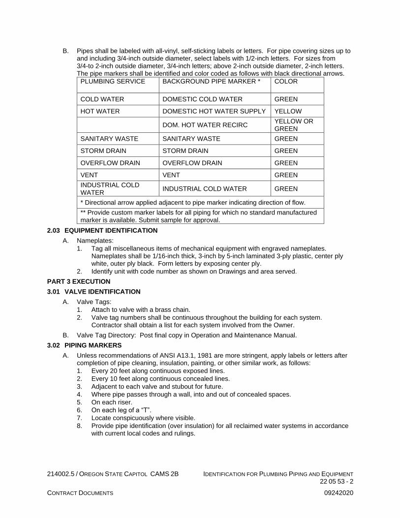
214002.5 / OREGON STATE CAPITOL CAMS 2B IDENTIFICATION FOR PLUMBING PIPING AND EQUIPMENT 22 05 53 - 2
CONTRACT DOCUMENTS 09242020
B. Pipes shall be labeled with all-vinyl, self-sticking labels or letters. For pipe covering sizes up to and including 3/4-inch outside diameter, select labels with 1/2-inch letters. For sizes from 3/4-to 2-inch outside diameter, 3/4-inch letters; above 2-inch outside diameter, 2-inch letters. The pipe markers shall be identified and color coded as follows with black directional arrows.
PLUMBING SERVICE BACKGROUND PIPE MARKER * COLOR
COLD WATER DOMESTIC COLD WATER GREEN
HOT WATER DOMESTIC HOT WATER SUPPLY YELLOW
DOM. HOT WATER RECIRC YELLOW OR GREEN
SANITARY WASTE SANITARY WASTE GREEN
STORM DRAIN STORM DRAIN GREEN
OVERFLOW DRAIN OVERFLOW DRAIN GREEN
VENT VENT GREEN
INDUSTRIAL COLD WATER
INDUSTRIAL COLD WATER GREEN
* Directional arrow applied adjacent to pipe marker indicating direction of flow.
** Provide custom marker labels for all piping for which no standard manufactured marker is available. Submit sample for approval.
2.03 EQUIPMENT IDENTIFICATION
A. Nameplates:
1. Tag all miscellaneous items of mechanical equipment with engraved nameplates. Nameplates shall be 1/16-inch thick, 3-inch by 5-inch laminated 3-ply plastic, center ply white, outer ply black. Form letters by exposing center ply.
2. Identify unit with code number as shown on Drawings and area served.
PART 3 EXECUTION
3.01 VALVE IDENTIFICATION
A. Valve Tags:
1. Attach to valve with a brass chain.
2. Valve tag numbers shall be continuous throughout the building for each system. Contractor shall obtain a list for each system involved from the Owner.
B. Valve Tag Directory: Post final copy in Operation and Maintenance Manual.
3.02 PIPING MARKERS
A. Unless recommendations of ANSI A13.1, 1981 are more stringent, apply labels or letters after completion of pipe cleaning, insulation, painting, or other similar work, as follows:
1. Every 20 feet along continuous exposed lines.
2. Every 10 feet along continuous concealed lines.
3. Adjacent to each valve and stubout for future.
4. Where pipe passes through a wall, into and out of concealed spaces.
5. On each riser.
6. On each leg of a “T”.
7. Locate conspicuously where visible.
8. Provide pipe identification (over insulation) for all reclaimed water systems in accordance with current local codes and rulings.

214002.5 / OREGON STATE CAPITOL CAMS 2B IDENTIFICATION FOR PLUMBING PIPING AND EQUIPMENT 22 05 53 - 3
CONTRACT DOCUMENTS 09242020
B. Further, apply labels or letters to lower quarters of the pipe on horizontal runs where view is not obstructed or on the upper quarters when pipe is normally viewed from above. Apply arrow labels indicating direction of flow. Arrows to be the same color and sizes as identification labels.
C. Install tags on specialty gas piping valves with brass chain.
END IDENTIFICATION FOR PLUMBING PIPING AND EQUIPMENT
214002.5 / OREGON STATE CAPITOL CAMS 2B PRESSURE TESTING FOR PLUMBING SYSTEMS 22 05 90 - 1
CONTRACT DOCUMENTS 09242020
SECTION 22 05 90
PRESSURE TESTING FOR PLUMBING SYSTEMS
PART 1 GENERAL
1.01 SUMMARY
A. This Section includes:
1. Pressure Testing of Piping Systems
1.02 QUALITY ASSURANCE
A. Code Compliance: Perform required tests in the presence of the authority having jurisdiction.
B. Owner Witness: Perform all tests in the presence of the Owner’s representative.
C. Engineer Witness: The Engineer or Engineer’s representative reserves the right to observe all tests or selected tests to assure compliance with the specifications.
D. Simultaneous Testing: Test observations by the authority having jurisdiction, the Owner’s representative and the Engineer’s representative need not occur simultaneously.
1.03 SUBMITTALS
A. Submit the following:
1. Test Reports:
a. Submit certificate of completion, inspection and test by authority having jurisdiction on required piping systems.
b. Submit certificate of test approval by Owner’s representative on all systems.
c. The Engineer’s representative will record witnessed tests.
PART 2 PRODUCTS – NOT APPLICABLE
PART 3 EXECUTION
3.01 GENERAL
A. Piping: Test prior to concealment, insulation being applied, and connection to equipment, fixtures, or specialties. Conduct tests with all valves but those used to isolate the test section 10 percent closed.
B. Leaks: Repair all leaks and retest until stipulated results are achieved.
C. Notification: Advise the Construction Manager 72 hours in advance of each test. Failure to so notify will require test to be rescheduled.
D. Testing Equipment: Provide all necessary pumps, gauges, connections and similar items required to perform the tests.
3.02 TESTING REQUIREMENTS
A. Sanitary and Roof Drainage Systems: Test entire system or sections of system by closing all openings in piping except highest opening and filling system with water to point of overflow. If system is tested in sections, plug each opening except highest opening of section under test and fill each section with water, but none with less than l0 feet head of water. Keep water in system or in portions under test for at least 45 minutes before inspection starts. Test for 2 hours with no drop allowed. Locate and repair leaks.
B. Domestic Water Systems: Test entire system by closing all openings in piping except highest opening and filling system with water to point of overflow. Keep water in system under test for a minimum of 45 minutes before inspection starts. Test at full working pressure for 2 hours with no drop allowed. Locate and repair leaks.

214002.5 / OREGON STATE CAPITOL CAMS 2B PRESSURE TESTING FOR PLUMBING SYSTEMS 22 05 90 - 2
CONTRACT DOCUMENTS 09242020
C. Piping - General: Test all piping as noted below, with no leaks or loss in pressure for time indicated. Repair or replace defective piping until tests are completed successfully:
Plumbing Systems Test Pressure Test Medium Test Duration
Industrial water 150 psig Water 4 hours
END PRESSURE TESTING FOR PLUMBING SYSTEMS

214002.5 / OREGON STATE CAPITOL CAMS 2B TESTING, ADJUSTING AND BALANCING FOR PLUMBING 22 05 93 - 1
CONTRACT DOCUMENTS 09242020
SECTION 22 05 93
TESTING, ADJUSTING AND BALANCING FOR PLUMBING
PART 1 GENERAL
1.01 SUMMARY
A. This Section includes:
1. Testing and balancing of domestic hot water recirculation systems.
2. Testing and balancing of pumping systems.
1.02 QUALITY ASSURANCE
A. Acceptable Testing and Balancing Firms:
1. A.I.R., Inc.
2. Air Balance Specialty, Inc.
3. Neudorfer Engineers, Inc.
4. Northwest Engineering Services
5. Pacific Coast Air Balance
6. Accurate Balancing Agency, Inc.
B. Other Firms: Submit Substitution Requests prior to Bid Date.
C. Industrial Standards: Testing and Balancing shall conform to NEBB, American Society of Heating, Refrigerating, and Air Conditioning Engineers (ASHRAE), and American National Standards Institute (ANSI) as follows:
1. NEBB: Comply with Procedural Standards for Testing, Adjusting Balancing of Environmental Systems.
2. ASHRAE: Comply with recommendations pertaining to measurements, instruments, and testing, adjusting and balancing.
3. ANSI:
a. S1.4 Specifications for sound level meters.
b. S1.11 Specifications for Octave-Band and Fractional-Octave-Band analog and digital filters.
D. Instrument Certification: All instruments used shall be accurately calibrated and certified within six months of balancing and maintained in good working order.
E. Test Observation: If requested, the tests shall be conducted in the presence of the Architect or the Architect’s representative.
F. Pre-Balancing Conference: Prior to starting balancing, general techniques shall be reviewed with the Engineer. This conference must occur prior to measuring existing conditions. Measuring of existing conditions must occur prior to any demolition or new work. The conference will review existing conditions and systems to be affected by the project.
1.03 SUBMITTALS
A. Submit the following:
1. Balancing Log: Include all water outlets, actual field measured water volume, and percentage of design volumes. Provide drawings identifying location of all outlets.
2. Equipment Data Sheets: Indicate actual equipment performance, model numbers, bearing and belt data, motor nameplate data, and final balanced motor data.
3. Additional Data: Submit all additional data as provided by Associated Air Balance Council (AABC) Standard forms.
4. Number of Copies: Submit 6 copies of the above completed information to the Engineer for review and insertion into the Operating and Maintenance Data.
5. Instrument Certification: When requested, submit certificate of calibration for all equipment to be used.
B. Record data on NEBB forms or forms approved by the Architect.

214002.5 / OREGON STATE CAPITOL CAMS 2B TESTING, ADJUSTING AND BALANCING FOR PLUMBING 22 05 93 - 2
CONTRACT DOCUMENTS 09242020
1.04 PROJECT CONDITIONS
A. Where existing systems are to be adjusted, establish flow rates in all branches prior to making any modifications to system. Submit preliminary report indicating existing conditions prior to making any modifications to existing systems. Adjust central equipment as required and restore all unmodified branches and outlets to original condition. Obtain existing system drawings from Owner and become familiar with extent and nature of existing systems.
B. Do not perform final testing, adjusting, and balancing work until equipment has been completely installed and operating continuously as required.
C. Conduct testing and balancing with clean strainers and filters in place. Clean strainers, etc., prior to performing hydronic testing and balancing.
1.05 WARRANTIES
A. In addition to the Requirements of the Contract, include an extended warranty of six months after completion of test and balance work during which time the Architect at his discretion may request a recheck or resetting of any equipment or device listed in the test reports.
PART 2 PRODUCTS – NOT APPLICABLE
PART 3 EXECUTION
3.01 DOMESTIC HOT WATER RECIRCULATION SYSTEMS
A. General: Make measurements in accordance with Industrial Standards specified above. Record on appropriate forms.
B. Preliminary:
1. List complete data of tested equipment and verify against Contract Documents.
2. Open all line valves to full open position.
3. Set master mixing valve as described by manufacturer’s recommendations to achieve desired leaving water temperature.
4. For each pump:
a. Verify rotation.
b. Test and record pump shut-off head.
c. Test and record pump wide-open head.
5. Verify proper system pressures.
C. Distribution:
1. Read and adjust water flow for design conditions.
2. Set all memory stops and mark position of adjuster on balancing valves.
3.02 AUTOMATIC CONTROL SYSTEM
A. In cooperation with control manufacturer’s representative, set and adjust automatically operated devices to achieve required sequence of operations.
B. Testing organization shall verify all controls for proper calibration and list controls requiring adjustment by control system installer.
3.03 COORDINATION
A. Coordinate work with other trades to ensure rapid completion of the project.
B. Deficiencies noted during the course of balancing in the mechanical installation shall be promptly reported to the Architect to allow corrective action to proceed.
C. Periodic review of progress shall be provided as requested.
END TESTING, ADJUSTING AND BALANCING FOR PLUMBING

214002.5 / OREGON STATE CAPITOL CAMS 2B INSULATION FOR PLUMBING 22 07 00 - 1
CONTRACT DOCUMENTS 09242020
SECTION 22 07 00
INSULATION FOR PLUMBING
PART 1 GENERAL
1.01 SUMMARY
A. This Section includes:
1. Insulation for piping and equipment.
B. Related Sections include:
1. Section 22 05 29, Hangers, Supports, and Anchors for Plumbing
1.02 QUALITY ASSURANCE
A. Regulatory Requirements:
1. All insulating products shall comply with the Oregon Revised Statute (ORS) 453.005(7)(e) prohibiting pentabrominated, octabrominated, and decabrominated diphenyl ethers. Where products within this specification contain these banned substances, provide complying products from approved manufacturers with equal performance characteristics.
2. Flame and Smoke Ratings: Installed composite flame spread not to exceed 25 and smoke developed not to exceed 50 as tested by UL 723.
3. Energy Codes: Local Building and Energy Codes shall govern where insulation performance requirements for thickness exceeds thickness specified.
B. Protection: Protect against dirt, water, chemical, or mechanical damage before, during, and after installation. Repair or replace damaged insulation at no additional cost.
C. Source Quality Control:
1. Service: Use insulation specifically manufactured for service specified.
2. Labeling: Insulation labeled or stamped with brand name and number.
3. Insulation and accessories shall not provide any nutritional or bodily use to fungi, bacteria, insects, rats, mice, or other vermin, shall not react corrosively with equipment, piping, or ductwork, and shall be asbestos free.
1.03 SUBMITTALS
A. Submit the following:
1. Product Data: For each type including density, conductivity, thickness, jacket, vapor barrier, and flame spread and smoke developed indices.
PART 2 PRODUCTS
2.01 ACCEPTABLE MANUFACTURERS
A. Equivalent products by Johns Manville, Knauf, Owens Corning, and CertainTeed are acceptable.
B. All such insulation shall be of one manufacturer.
C. Other Manufacturers: Submit Substitution Request.
2.02 PIPE INSULATION
A. Fiberglass: Split sectional or snap-on type with 0.23 per inch maximum thermal conductivity (K-factor) at 75 degrees F mean temperature, 850 degrees F maximum service rating and white, vapor barrier jacket with pressure sensitive closure system. Johns Manville Microlok HP.
B. Calcium Silicate: Sectional with 14 pcf nominal density, 0.40 maximum K-factor at 300 degrees F mean temperature and 1200 degrees F maximum service rating. Johns Manville Thermo-12 Gold.
C. Elastomeric: Expanded closed cell, 0.27 per inch maximum K-factor at 75 degrees F mean temperature, 220 degrees F maximum service rating with fitting covers and paintable surface. Armacell AP Armaflex, Rubatex.

214002.5 / OREGON STATE CAPITOL CAMS 2B INSULATION FOR PLUMBING 22 07 00 - 2
CONTRACT DOCUMENTS 09242020
D. Polyolefin: Semi-rigid polyolefin form snap-on or slip over type with 0.24 per inch maximum thermal conductivity (K-factor) at 75 degrees F mean temperature -165 degrees F to 210 degrees F service factor and paintable surface. End joints in insulation on piping with fluid temperatures normally below 65 degrees F fuse sealed in accordance with the manufacturer’s instructions. Joints longitudinal joints and other end joints made with manufacturer’s approval contact adhesive in accordance with the manufacturer’s instructions. Joints may be pre-glued or pre-coated with adhesive where applicable.
2.03 ACCESSORIES PIPING
A. Adhesives:
1. Fiberglass: Zeston Z-Glu.
2. Calcium Silicate: Benjamin Foster 30-36.
3. Elastomeric: Armacell 520.
4. Polyolefin: As approved by the insulation manufacturer.
B. Cements:
1. Insulating: Ryder.
2. Heat Transfer: Zeston Z-20.
C. Wire Mesh: 1-inch mesh with 20-gauge annealed steel wire.
D. Pipe Fitting Covers: One piece PVC insulated pipe fitting covers. Zeston, Ceel-Co.
E. Grooved Coupling Insulation: One piece PVC insulated fitting cover, Zeston, Ceel-Co.
F. Metal Pipe Jacket: 0.016-inch thick aluminum jacket with formed fitting covers, aluminum snap straps and sealant.
G. Cloth Facing: Presized fiberglass cloth.
H. Tapes: Pressure sensitive, weather resistant, and for temperatures up to 150°F. Zeston Z-tape.
I. Paint: Ultraviolet resistant latex paint with special adherence capabilities to the PVC fitting covers, elastomeric, aluminum facing, Kraft paper, tapes and adhesives.
PART 3 EXECUTION
3.01 GENERAL
A. Workmanship:
1. Installation: Insulation installed in first class, neat professional manner.
2. Applicators: Applicators shall be employed by firm that specializes in insulation work.
B. Preparation: Surfaces of piping and equipment clean, free of oil or dirt, and dry before insulation is applied.
C. Stamps: ASME stamps, UL labels, and similar stamps and labels shall not be covered.
3.02 PLUMBING PIPE AND EQUIPMENT INSULATION APPLIED LOCATIONS
A. Insulation Applied Locations – Plumbing Piping:
System Pipe Size Insulation Type Insulation Thickness
Notes
Domestic Cold Water, Above Grade
1-1/4-inch and smaller
Fiberglass, all purpose jacket or Elastomeric or Polyolefin
1-inch Note 1 Note 2
Above 1-1/4-inch
Fiberglass, all purpose jacket
1-1/2-inch Note 1
Industrial Cold Water, Above Grade
1-1/4-inch and smaller
Fiberglass, all purpose jacket or Elastomeric or Polyolefin
1-inch Note 1 Note 2
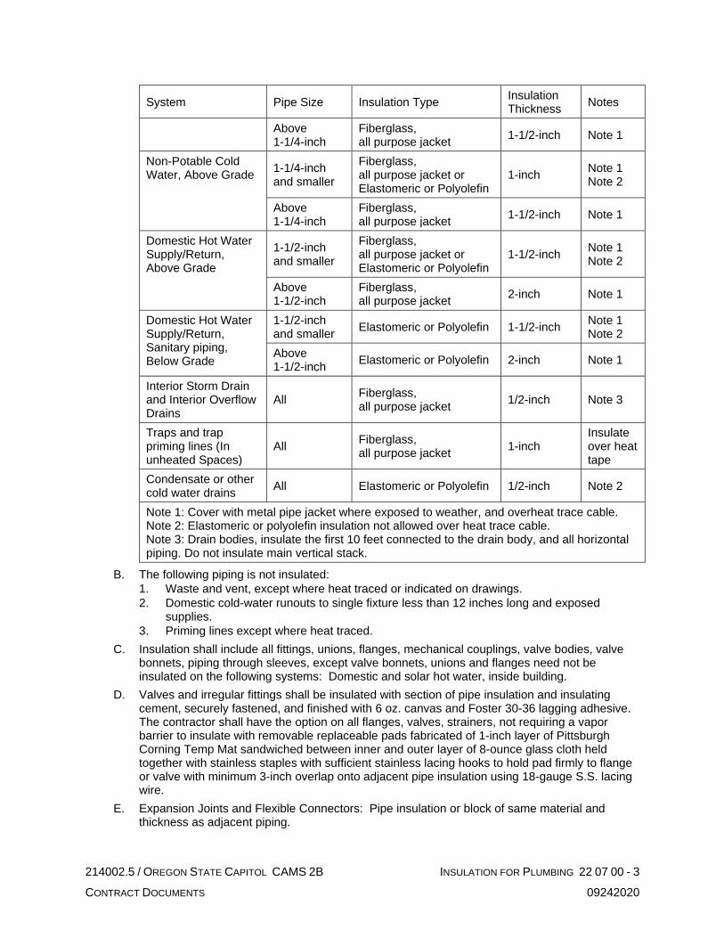
214002.5 / OREGON STATE CAPITOL CAMS 2B INSULATION FOR PLUMBING 22 07 00 - 3
CONTRACT DOCUMENTS 09242020
System Pipe Size Insulation Type Insulation Thickness
Notes
Above 1-1/4-inch
Fiberglass, all purpose jacket
1-1/2-inch Note 1
Non-Potable Cold Water, Above Grade
1-1/4-inch and smaller
Fiberglass, all purpose jacket or Elastomeric or Polyolefin
1-inch Note 1 Note 2
Above 1-1/4-inch
Fiberglass, all purpose jacket
1-1/2-inch Note 1
Domestic Hot Water Supply/Return, Above Grade
1-1/2-inch and smaller
Fiberglass, all purpose jacket or Elastomeric or Polyolefin
1-1/2-inch Note 1 Note 2
Above 1-1/2-inch
Fiberglass, all purpose jacket
2-inch Note 1
Domestic Hot Water Supply/Return, Sanitary piping, Below Grade
1-1/2-inch and smaller
Elastomeric or Polyolefin 1-1/2-inch Note 1 Note 2
Above 1-1/2-inch
Elastomeric or Polyolefin 2-inch Note 1
Interior Storm Drain and Interior Overflow Drains
All Fiberglass, all purpose jacket
1/2-inch Note 3
Traps and trap priming lines (In unheated Spaces)
All Fiberglass, all purpose jacket
1-inch Insulate over heat tape
Condensate or other cold water drains
All Elastomeric or Polyolefin 1/2-inch Note 2
Note 1: Cover with metal pipe jacket where exposed to weather, and overheat trace cable. Note 2: Elastomeric or polyolefin insulation not allowed over heat trace cable. Note 3: Drain bodies, insulate the first 10 feet connected to the drain body, and all horizontal piping. Do not insulate main vertical stack.
B. The following piping is not insulated:
1. Waste and vent, except where heat traced or indicated on drawings.
2. Domestic cold-water runouts to single fixture less than 12 inches long and exposed supplies.
3. Priming lines except where heat traced.
C. Insulation shall include all fittings, unions, flanges, mechanical couplings, valve bodies, valve bonnets, piping through sleeves, except valve bonnets, unions and flanges need not be insulated on the following systems: Domestic and solar hot water, inside building.
D. Valves and irregular fittings shall be insulated with section of pipe insulation and insulating cement, securely fastened, and finished with 6 oz. canvas and Foster 30-36 lagging adhesive. The contractor shall have the option on all flanges, valves, strainers, not requiring a vapor barrier to insulate with removable replaceable pads fabricated of 1-inch layer of Pittsburgh Corning Temp Mat sandwiched between inner and outer layer of 8-ounce glass cloth held together with stainless staples with sufficient stainless lacing hooks to hold pad firmly to flange or valve with minimum 3-inch overlap onto adjacent pipe insulation using 18-gauge S.S. lacing wire.
E. Expansion Joints and Flexible Connectors: Pipe insulation or block of same material and thickness as adjacent piping.

214002.5 / OREGON STATE CAPITOL CAMS 2B INSULATION FOR PLUMBING 22 07 00 - 4
CONTRACT DOCUMENTS 09242020
3.03 PIPING INSTALLATION
A. General:
1. Joints: Coat both sides of complete joining area with applicable adhesive.
a. Longitudinal Joints: Make joints on top or back of pipe to minimize visibility. Except foam plastic, seal with closure system or 3-inch wide tape.
b. Butt Joints: Butt lightly together and, except for foam plastic, seal with 3-inch wide tape or butt straps.
c. Multiple Layered Insulation: Joints staggered.
2. Access: Strainer and other items requiring service or maintenance with easily removable and replaceable section of insulation to provide access.
3. Voids: Fill all voids, chipped corners and other openings with insulating cement or material compatible with insulating material. In insulation with Heat Tracing: Where piping is shown or specified to be heat traced, bed heat tape into heat transfer cement with insulation over heat tape and cement.
4. Seal joints, seams and fittings of metal watertight jackets at exterior locations.
B. Fiberglass Insulation: Exterior insulation encased in metal jacket.
C. Calcium Silicate Insulation:
1. Secure with 18-gauge wire embedded into insulation.
2. Cover with continuous vapor barrier jacket.
D. Elastomeric and Polyolefin Insulation:
1. Slit full length and snap around pipe.
2. Make cuts perpendicular to insulating surface leaving no cut section exposed.
3. Do not stretch insulation to cover joints or fittings.
4. Seal joints in elastomeric insulation with adhesive.
5. Seal joints in polyolefin as specified hereinbefore.
6. Exterior insulation painted with two coats of specified paint in accordance with the manufacturer’s instructions and encase in metal jacket.
7. Sealing joints with tape will not be allowed.
E. Fittings: Insulation specified with continuous vapor barrier, the vapor barrier must not be violated.
1. On Elastomeric and Polyolefin Insulation: Fittings covered with covers made up of mitered sections of insulation or with formed pipe fitting covers.
2. In Other Insulation: Fittings covered with insulation to the same level of the adjoining insulation or fill with insulating cement. Finish with pipe fitting covers or cloth facing and tape.
F. Unions, Mechanical Joints, Valves, Etc.
1. General:
a. As specified for fittings.
b. Minimum thickness same as specified for piping.
2. Unions: Build up insulation at least 1/2-inch beyond adjoining insulation.
3. Flanges: With square corners. Where flanges are not insulated, terminate adjacent insulation so flange bolts can be removed.
4. Flanged Valves: Insulation with square corners.
G. Vapor Barrier Insulation:
1. Refer to Section 22 05 29, Hangers Supports and Anchors for Plumbing for support requirements.
2. Piping which requires vapor barrier protection shall have a continuous vapor barrier, which may not be pierced or broken. The following piping systems require vapor barrier protection:
a. Domestic cold-water.
b. Industrial cold-water.
c. Non-potable cold-water.

214002.5 / OREGON STATE CAPITOL CAMS 2B INSULATION FOR PLUMBING 22 07 00 - 5
CONTRACT DOCUMENTS 09242020
d. All other piping systems with a nominal operating temperature below 65 degrees F.
3. Vapor Barrier Insulation:
a. Insulation for pipe requiring vapor barrier protection 1-1/4-inch or smaller, insulation continuous through pipe hangers and rollers.
b. For pipe 1-1/2-inch and larger, 18-inch section of calcium silicate, same thickness as pipe insulation with continuous vapor barrier jacket at each hanger or roller. Provide pipe shield specified in Section 22 05 29, Hangers Supports and Anchors for Plumbing.
H. Non-Vapor Barrier Insulation:
1. Refer to Section 22 05 29, Hangers Supports and Anchors for Plumbing for support requirements.
2. At contractor’s option, insulation may be interrupted at supports. Butt insulation tight to support.
3. If contractor elects to continue insulation at supports, installation as specified for piping systems with vapor barrier installation.
4. Void between saddle and pipe filled with insulation.
I. Acoustical Wrap:
1. Install in accordance with the manufacturer’s instructions.
2. Applied locations for piping systems:
a. Where specified or indicated on drawings.
3.04 FIELD QUALITY CONTROL
A. Field Test: All systems shall be tested and approved prior to installation of insulation.
B. Existing Insulation:
1. Repair existing insulation damaged during construction.
2. Make neat connections where new and existing insulation meet.
3. Where existing piping, or equipment is removed, cover existing surfaces neatly to match existing.
END INSULATION FOR PLUMBING
214002.5 / OREGON STATE CAPITOL CAMS 2B COMMISSIONING FOR PLUMBING 22 08 00 - 1
CONTRACT DOCUMENTS 09242020
SECTION 22 08 00
COMMISSIONING FOR PLUMBING
PART 1 GENERAL
1.01 SUMMARY
A. The commissioning process is described in Section 01 91 00, Commissioning.
B. Provide all labor and materials required to complete the commissioning of those Division 22 systems and equipment identified as Commissioned Systems and Equipment in Section 01 91 00, Commissioning.
C. Related Sections include:
1. Section 01 91 00, Commissioning.
2. All Sections of Division 22.
1.02 SUBMITTALS
A. Refer to Section 01 91 00, Commissioning.
1.03 COMMISSIONING SCOPE OF WORK - COMMISSIONING AGENT
A. Refer to Section 01 91 00, Commissioning.
1.04 COMMISSIONING SCOPE OF WORK - CONTRACTOR
A. Refer to Section 01 91 00, Commissioning.
PART 2 PRODUCTS
2.01 TEST EQUIPMENT
A. Refer to Section 01 91 00, Commissioning.
PART 3 EXECUTION
3.01 MEETINGS
A. Refer to Section 01 91 00, Commissioning.
3.02 INSTALLATION, CHECK-OUT, START-UP, AND PREFUNCTIONAL CHECKS
A. Refer to Section 01 91 00, Commissioning.
3.03 FUNCTIONAL TESTING
A. Refer to Section 01 91 00, Commissioning.
3.04 TRAINING OF FACILITY OPERATING STAFF, AND BUILDING OCCUPANTS
A. Refer to Section 01 91 00, Commissioning.
END COMMISSIONING FOR PLUMBING

214002.5 / OREGON STATE CAPITOL CAMS 2B PIPE AND PIPE FITTINGS PLUMBING 22 21 13 - 1
CONTRACT DOCUMENTS 09242020
SECTION 22 21 13
PIPE AND PIPE FITTINGS PLUMBING
PART 1 GENERAL
1.01 SUMMARY
A. This Section includes: Furnish piping, pipe fittings, and incidental related items as required for complete piping systems.
1.02 QUALITY ASSURANCE
A. Regulatory Requirements.
1. Piping material and installation to meet requirements of the local plumbing, fire, and building codes and serving utility requirements.
2. Provide chlorination of domestic cold and hot water piping in accordance with County and State health requirements.
B. All grooved joint couplings and fittings shall be the products of a single manufacturer. Grooving tools shall be of the same manufacturer as the grooved components.
1. All castings used for coupling housings, fittings, valve bodies, etc., shall be date stamped for quality assurance and traceability.
C. Pipe Cleaning: Should any pipe be plugged or should foaming of water systems occur, disconnect piping, reclean, and reconnect without additional expense to the Owner.
D. Correct any damage to the building or systems resulting from failure to properly clean the system without additional expense to the Owner.
E. All products with a wetted surface installed in potable water systems shall be UL classified in accordance with ANSI / NSF-61 for potable water service, and shall be certified to the low lead requirements of NSF-372.
1.03 SUBMITTALS
A. Submit the Following:
1. List of piping materials indicating the service it is being used for. (Do not submit piping product data).
2. Product data on mechanical couplings and related components, double wall fuel oil pipe and fittings, and polypropylene waste and vent pipe.
B. Test Reports and Certificates: Submit certificates of inspections and pipe tests to Owner.
C. Other: Make certified welders’ certificates available.
PART 2 PRODUCTS
2.01 ACCEPTABLE MANUFACTURERS
A. As indicated.
2.02 CAST IRON SOIL PIPE, SERVICE WEIGHT (NO-HUB)
A. General: A code approved hubless system conforming to Cast Iron Soil Pipe Institute Standard 301.
B. Pipe and Fittings: Service weight hubless cast iron conforming to ASTM A 74, marked with the collective trademark of the Cast Iron Soil Pipe Institute (CISPI) and listed by NSF International. Tyler, AB&I, or Charlotte.
C. Gaskets: Compression type conforming to ASTM C 564.
D. Couplings:
1. Above Grade: Band type coupling in conformance with Cast Iron Soil Pipe Institute (CISPI) 310-90, consisting of stainless steel clamp and corrugated shield assemblies with a neoprene sealing sleeve ANSI A21.6, ANSI A21.10 Fittings.

214002.5 / OREGON STATE CAPITOL CAMS 2B PIPE AND PIPE FITTINGS PLUMBING 22 21 13 - 2
CONTRACT DOCUMENTS 09242020
2. Buried: Husky 28-gauge 304 stainless steel hubless type clamp and orange corrugated shield assemblies (80-inch pound torque) with neoprene sealing gaskets (ASTM-C-564), or Clamp-All (125-inch pound torque), 24-gauge 304 stainless steel hubless type clamp, and shield assemblies with neoprene sealing gaskets (ASTM-C-564).
3. Service:
a. Sanitary, storm, and overflow drain.
b. Vent piping 2 inches and above.
2.03 DUCTILE IRON WATER PIPE
A. Pipe: Ductile iron pipe conforming to ANSI A21.51.
B. Fittings: Below grade, Class 150 “Boltite” mechanical joint type complete with gaskets, bolts, and nuts, or “Tyton” for joints employing a single gasket for the joint seal with bell-and-spigot pipe. Above grade, mechanical couplings and fittings as specified herein. Provide interior pipe coating per ANSI Regulation listed.
C. Service:
1. Below grade, incoming domestic water main, 4 inches and over.
2.04 BLACK STEEL PIPE, SCHEDULE 40
A. General: Fittings and joints must be UL listed for use with pipe chosen for use. Listing restrictions and installation procedures per state and local authorities must be followed.
B. Pipe: Schedule 40 conforming to ASTM A 135 or A 53.
C. Fittings: 150 lb. screwed malleable iron on 2 inches and below, Schedule 40 welding fittings conforming to ASTM A 234 for 2-1/2 inches and above or mechanical couplings on select piping as herein specified. Fittings below grade shall be welding fittings. All elbows on pumped systems shall be long radius type. Short radius elbows not acceptable for use except as approved on a case by case basis.
D. Service:
1. Vent lines.
2.05 GALVANIZED STEEL PIPE
A. Pipe: Schedule 40 conforming to ASTM A 135 or A 53.
B. Fittings: 150 lb. screwed galvanized malleable iron on 2-inch and below, Victaulic, Gruvlok, Gustin-Bacon, or Mech Line full flow galvanized, grooved end on 2-1/2-inch and above. Provide grooved type gasketed couplings and fittings for pipe 2-1/2-inch and above.
C. Service:
1. Miscellaneous indirect waste piping.
2. At Contractor’s option, waste and vent piping 1-1/2-inches and under, above grade.
3. Pumped waste (above grade only).
2.06 COPPER PIPE
A. Pipe: Hard drawn copper tubing, Class L or K, ASTM B 88.
B. Fittings: Wrought copper, 150 PSI; ANSI B16.22 for soldered joints, ANSI B16.50 for brazed joints; Chase, Revere, Mueller or approved equal. At Contractor’s option, a system using mechanically extracted collars in main with branch line inserted to not obstruct flow may be used on domestic water piping above ground, similar to T-drill.
C. Service:
1. Domestic hot and cold-water piping below ground (Type K, hard drawn) on piping 3-inches and smaller.
2. Domestic hot and cold-water piping above ground (Type L, hard drawn) on piping 4-inches and smaller.
3. Trap priming lines (Type L, annealed).
4. Industrial cold water above grade (Type L) on piping 4-inch and smaller.
5. Pumped waste (DWV).

214002.5 / OREGON STATE CAPITOL CAMS 2B PIPE AND PIPE FITTINGS PLUMBING 22 21 13 - 3
CONTRACT DOCUMENTS 09242020
6. Miscellaneous drains and overflows.
2.07 FLANGED JOINTS
A. Flanged Joints: Flanges shall be cast iron or steel for screwed piping and forged steel welding neck for welded line sizes. Pressure rating and drilling shall match the apparatus, valve, or fitting to which they are attached. Flanges shall be in accordance with ANSI B16.1; 150 lb. for system pressures to 150 PSIG; 300 lb. for system pressures 150 PSIG to 400 PSIG. Gaskets for all flanged services, except steam and pumped condensate, shall be Garlock 3700 or equal, 1/8-inch thick, non-metallic type. Gaskets for steam and pumped condensate shall be Flexitaulic Style CG or equal, 1/8-inch thick, semi-metallic type. Make joint using American Standard hexagon head bolts, lock washers, and nuts (per ASTM A307 GR.B) for service pressures to 150 PSIG; alloy steel stud bolts, lock washer, and American Standard hexagon head nuts (per ASTM A307 GR.B) for service pressures 150 PSIG to 400 PSIG. Use length of bolt required for full nut engagement. Provide electro-cad plated bolts and nuts on cold and chilled water lines.
2.08 UNIONS
A. 150 PSI malleable iron, brass to iron seat, ground joint, black or galvanized to match pipe. 200 PSI WOG bronze, ground joint, solder type for copper tubing.
1. Unions or flanges for servicing or disconnect are not required in installations using grooved mechanical joint couplings. (The couplings shall serve as disconnect points.)
B. Dielectric fittings shall be nationally listed, have a dielectric thermoplastic interior lining, and meet requirements of ASTM F-492. Fittings shall be suitable for the pressure and temperature to be encountered.
2.09 SOLDER AND BRAZING
A. Brazed Joints:
1. Wrought Copper Piping Fittings: Westinghouse Phos-Copper or Dyna-Flow by J.W. Harris Co., Inc.
2. Applied locations:
a. All below grade piping.
b. All above grade piping larger than 2-inches for the following services: Industrial cold-water, domestic hot and cold-water, and pumped waste.
c. Joints in Domestic Hot and Cold-Water Piping: Use mechanically extracted collars. Braze in accordance with Copper Development Association Copper Tube Handbook using BCUP series filler material.
B. Soldered Joints:
1. Wrought Copper Pipe Fittings: All-State 430 with Duzall Flux, Engelhard Silvabrite with Engelhard General Purpose Flux or J.W. Harris Co.
2. Valves, Cast Fittings or Bronze Fittings: Harris Stay-Silv-15 or Handy & Harmon Sil-Fos.
3. Applied locations: Above grade piping 2-inch and smaller for the following services: Industrial cold water, domestic hot and cold water, pumped waste, trap priming lines.
2.10 UTILITY MARKERS
A. Provide plastic tape utility markers over all buried piping. Provide identification on tape.
B. Material to be Brady Identoline plastic tape, 6-inch, Seton, or as approved.
2.11 PIPE WRAPPING
A. For all below ground steel piping and fittings, provide complete covering of Scotchrap No. 51, 20 mil thickness, protective tape applied over Scotchrap pipe primer applied at one gal/800 SF of pipe surface.
B. At Contractor’s option as approved, pipe may be furnished with factory applied jacket of “X-tru-coat” with Scotchrap as previously specified for field joints.

214002.5 / OREGON STATE CAPITOL CAMS 2B PIPE AND PIPE FITTINGS PLUMBING 22 21 13 - 4
CONTRACT DOCUMENTS 09242020
2.12 FLEXIBLE CONNECTOR
A. Expansion Joint/Seismic Connector:
1. T304 stainless steel hose and braid, sized to allow +/- 2 feet (total travel of 4 feet) without failure, Schedule 40 radius elbows and 180 degree bend, flange or weld end Schedule 40 fittings. Metraflex only.
2. Connector shall accept differential support displacement without damaging pipe, equipment connections, or support connections.
3. In steel piping systems, three Victaulic flexible couplings may be used in lieu of a flexible connector for vibration attenuation and stress relief at equipment connections. The couplings shall be placed in close proximity to the vibration source.
B. Service:
1. Vent lines.
2. Miscellaneous drains and overflows.
3. Domestic hot and cold-water piping.
4. Industrial cold-water piping.
PART 3 EXECUTION
3.01 PREPARATION
A. Measurements, Lines and Levels:
1. Check dimension at the building site and establish lines and levels for work specified in this Section.
2. Establish all inverts, slopes, and manhole elevations by instrument, working from an established datum point. Provide elevation markers for use in determining slopes and elevations in accordance with Drawings and Specifications.
3. Use established grid and area lines for locating trenches in relation to building and boundaries.
3.02 EXCAVATION AND BACKFILL
A. General: Perform all necessary excavation and backfill required for the installation of mechanical work in accord with Division 02. Repair pipelines or other work damaged during excavation and backfilling.
B. Excavation: Excavate trenches to the necessary depth and width, removing rocks, roots, and stumps. Include additional excavation to facilitate utility crossovers, additional offsets, etc. Excavation material is unclassified. Width of trench shall be adequate for proper installation of piping. The trench shall be widened, if not wide enough for a proper installation.
C. Bedding: All cast iron, steel, and copper piping shall be full bedded on sand. Place a minimum 4-inch deep layer on the leveled trench bottom for this purpose. Remove the sand to the necessary depth for piping bells and couplings to maintain contact of the pipe on the sand for its entire length. Lay all other piping on a smooth level trench bottom so that contact is made for its entire length.
D. Backfill: Place in layers not exceeding 8 inches deep, and compact to 95 percent of standard proctor maximum density at optimum moisture content. Earth backfill shall be free of rocks over 2-inches in diameter and foreign matter. Disposal of excess material as directed.
1. Interior: All backfill under interior slabs shall be bank sand or pea gravel.
2. Exterior: Excavated material may be used outside of buildings at the Contractor’s option. The first 4 inches shall be sand, and final 12-inch layer course shall be soil in any event.
3.03 PIPING INSTALLATION
A. Install unions in all non-flanged piping connections to apparatus and adjacent to all screwed control valves, traps, and appurtenances requiring removal for servicing so located that piping may be disconnected without disturbing the general system.

214002.5 / OREGON STATE CAPITOL CAMS 2B PIPE AND PIPE FITTINGS PLUMBING 22 21 13 - 5
CONTRACT DOCUMENTS 09242020
B. Mechanical Pipe Couplings and Fittings.
1. All grooved joint couplings, fittings, valves, and specialties shall be the products of a single manufacturer. Grooving tools shall be of the same manufacturer as the grooved components.
2. Flexible couplings to be used only when expansion, contraction, deflection or noise and vibration is to be dampened, as detailed or specified.
3. On systems using galvanized pipe and fittings, fittings shall be galvanized at factory.
4. Before assembly of couplings, lightly coat pipe ends and outside of gaskets with approved lubricant.
5. Pipe grooving in accordance with manufacturer’s specifications contained in latest published literature.
6. Gaskets shall be molded and produced by the coupling manufacturer, and shall be suitable for the intended service.
7. The coupling manufacturer’s factory trained representative shall provide on-site training for the Contractor’s field personnel in the use of grooving tools and installation of grooved joint products. The representative shall periodically visit the project site to ensure best practices in grooved installation are being followed. (A distributor’s representative is not considered qualified to conduct the training or field visits.)
C. Install all piping as to vent and drain. Install according to manufacturer’s recommendations.
D. Support all piping independently at apparatus so that its weight shall not be carried by the equipment.
E. Run piping clear of tube cleaning or removal/replacement access area on heat exchangers, water heaters, etc.
F. Utility Marking: Installed over the entire length of the underground piping utilities. Install plastic tape along both sides and the center line of the trenches at the elevation of approximately 12 inches above the top of utility.
G. Underground Water System: Prior to testing pipe provide concrete thrust blocks at changes in direction. Block size as required for types of fittings involved.
H. Dielectric Fittings: Provide dielectric couplings, unions, or flanges between dissimilar metals. In addition, provide dielectric couplings as required to isolate cathodically protected piping and equipment.
I. No-Hub Couplings: Install per manufacturer’s instructions.
3.04 PIPING JOINTS
A. Pipe and fittings shall be joined using methods and materials recommended by manufacturer in conformance with standard practice and applicable codes. Cleaning, cutting, reaming, grooving, etc., shall be done with proper tools and equipment. Hacksaw pipe cutting prohibited. Peening of welds to stop leaks not permitted.
B. Copper Piping: Pipe cut evenly with cutter, ream to full inside diameter; end of pipe and inside of fitting thoroughly cleaned and polished. Joint shall be uniformly heated, and capillary space completely filled with solder or braze material, leaving full bead around entire circumference.
C. No couplings installed in floor or wall sleeves.
D. Steel Piping:
1. Screwed Joints: Pipes cut evenly with pipe cutter reamed to full inside diameter with all burrs and cuttings removed. Joints made up with Teflon liquid dope or Teflon tape applied to male threads only, leaving two threads bare. Joints tightened so that not more than two threads are left showing. Junctions between galvanized steel waste pipe and bell of cast iron pipe shall be made with tapped spigot or half coupling on steel pipe to form spigot end and caulked.
2. Flanged Joints: Pressure rating of flanges shall match valve or fitting joined. Joint gaskets shall be coated with graphite and oil.
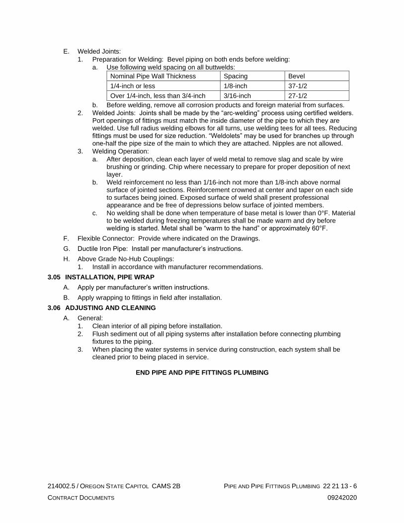
214002.5 / OREGON STATE CAPITOL CAMS 2B PIPE AND PIPE FITTINGS PLUMBING 22 21 13 - 6
CONTRACT DOCUMENTS 09242020
E. Welded Joints:
1. Preparation for Welding: Bevel piping on both ends before welding:
a. Use following weld spacing on all buttwelds:
Nominal Pipe Wall Thickness Spacing Bevel
1/4-inch or less 1/8-inch 37-1/2
Over 1/4-inch, less than 3/4-inch 3/16-inch 27-1/2
b. Before welding, remove all corrosion products and foreign material from surfaces.
2. Welded Joints: Joints shall be made by the “arc-welding” process using certified welders. Port openings of fittings must match the inside diameter of the pipe to which they are welded. Use full radius welding elbows for all turns, use welding tees for all tees. Reducing fittings must be used for size reduction. “Weldolets” may be used for branches up through one-half the pipe size of the main to which they are attached. Nipples are not allowed.
3. Welding Operation:
a. After deposition, clean each layer of weld metal to remove slag and scale by wire brushing or grinding. Chip where necessary to prepare for proper deposition of next layer.
b. Weld reinforcement no less than 1/16-inch not more than 1/8-inch above normal surface of jointed sections. Reinforcement crowned at center and taper on each side to surfaces being joined. Exposed surface of weld shall present professional appearance and be free of depressions below surface of jointed members.
c. No welding shall be done when temperature of base metal is lower than 0°F. Material to be welded during freezing temperatures shall be made warm and dry before welding is started. Metal shall be “warm to the hand” or approximately 60°F.
F. Flexible Connector: Provide where indicated on the Drawings.
G. Ductile Iron Pipe: Install per manufacturer’s instructions.
H. Above Grade No-Hub Couplings:
1. Install in accordance with manufacturer recommendations.
3.05 INSTALLATION, PIPE WRAP
A. Apply per manufacturer’s written instructions.
B. Apply wrapping to fittings in field after installation.
3.06 ADJUSTING AND CLEANING
A. General:
1. Clean interior of all piping before installation.
2. Flush sediment out of all piping systems after installation before connecting plumbing fixtures to the piping.
3. When placing the water systems in service during construction, each system shall be cleaned prior to being placed in service.
END PIPE AND PIPE FITTINGS PLUMBING

214002.5 / OREGON STATE CAPITOL CAMS 2B PLUMBING FIXTURES 22 40 00 - 1
CONTRACT DOCUMENTS 09242020
SECTION 22 40 00
PLUMBING FIXTURES
PART 1 GENERAL
1.01 SUMMARY
A. This Section includes:
1. Plumbing Fixtures
2. Fixture Trim
3. Drainage Products
4. Miscellaneous Plumbing Items
1.02 SUBMITTALS
A. Submit the following:
1. Product data for each item specified.
2. Operating and Maintenance Data:
PART 2 PRODUCTS
2.01 ACCEPTABLE MANUFACTURERS
A. Manufacturers are stated for each fixture specified. The following manufacturers are also acceptable, except when indicated "only".
B. Drainage Products:
1. J.R. Smith
2. Josam
3. Sioux Chief
4. Zurn
5. Wade
6. Watts Drainage
7. Woodford
8. Mifab
C. Fixtures:
1. American Standard
2. Kohler
3. Sloan
4. Toto
D. Shock Arrestors:
1. PPP
2. J.R. Smith.
E. Trap Primer Stations: PPP.
F. Exposed Waste and Supply Piping Insulation Kits:
1. Truebro
2. McGuire
G. Other Manufacturers: Submit Substitution Request.
2.02 FIXTURE TRIM
A. Supply Stops: Chicago cast brass rigid riser supplies with loose key angle stops, wall flanges, NPT female inlet, all chrome plate finish; equivalent NPT McGuire (LK series), Brasscraft (SCR series) or NPT stops by fixture supplier.
B. Traps.
1. For floor drains, provide coated cast iron P-trap; recessed, screw jointed or bell and spigot.
2. For other fixtures, provide 17-gauge, chrome plated cast brass P-Traps with solder bushings, and clean-out.

214002.5 / OREGON STATE CAPITOL CAMS 2B PLUMBING FIXTURES 22 40 00 - 2
CONTRACT DOCUMENTS 09242020
C. Support Rims: Hudee stainless steel rims, if sink not furnished with integral rim.
D. Vacuum Breakers: Chicago Faucet, A.W. Cash or Febco chrome plated.
2.03 PLUMBING FIXTURES
A. Exposed Waste and Supply Piping Insulation Kits: McGuire Prowrap insulation kit for exposed supplies and waste piping below ADA lavatories and ADA sinks.
2.04 DRAINAGE PRODUCTS
A. HB-1 Hose Bibb: Chicago 952 series, chrome-plated, removable key, 3/4-inch hose thread, integral vacuum breaker.AD-1 Area Drain: J.R. Smith 2142 series, cast iron body and 12-inch round heavy duty vandal-proof ductile iron tractor grate, no-hub outlet and sediment bucket.
B. FD-1 Floor Drain (Unfinished Areas): J.R. Smith 2110 series, round cast iron grate, cast iron body, no-hub outlet, sediment bucket.
C. FS-1 Floor Sink (mechanical room indirect waste): J.R. Smith3041series floor sink with 8-inch deep receptor, basket strainer, 1/2 cast iron grate, no-hub outlet and flashing collar.
D. AD-1 Area Drain: J.R. Smith 2250 series, heavy duty, vandal-proof, cast iron body, collar, and tractor grate, slotted sediment bucket.
E. AD-3 Area Drain (Roof): J.R. Smith 9700 series, adjustable strainer head, flashing clamp with seepage holes.
F. DAD-1 Depressed Area Drain: J.R. Smith 2090 series, cast iron body, flashing clamp, backwater valve.
G. RD-1 Roof Drain: J.R. Smith 1330 series, 8-1/2-inch low profile diameter dome, cast iron body
H. OD-1 Overflow Drain: J.R. 1330 Smith series, 8-1/2-inch low profile diameter dome, cast iron body, 2-inch water dam.
I. PD-1 Planter Drain: J.R. Smith 1901 series, cast iron body, flashing clamp, stainless steel perforated gravel stop with PVC standpipe with orifice and solid secured cover.
J. FCO Floor Cleanout: J.R. Smith 4020 series, round vandal resistant, nickel bronze top.
K. Trap Priming Valves: Precision Plumbing Products Prime-time electronic trap priming manifold including but not limited to: atmospheric vacuum breaker, pre-set 24 hour clock, manual over ride, 120V solenoid valve, calibrated manifold for equal water distribution, 3/4-inch water hammer arrestor. Components pre-installed in recessed steel cabinet with SS access door.
PART 3 EXECUTION
3.01 FIXTURE TRIM
A. Provide plumbing fixture trim where applicable on fixtures, including but not limited to supply stops, traps, support rims, and vacuum breakers.
B. Provide rough-in and final piping connection to fixtures. Carefully review all construction documents to assure that all fixtures are provided with necessary services for a complete operating system.
C. Rigidly secure rough-in piping, and other service piping to structure.
3.02 PLUMBING FIXTURES
A. Floor Drain and Floor Sinks:
1. Set top flush with finished floor.
2. Provide flashing clamp for all drain bodies installed in floors provided with waterproof membranes.
B. Cleanout:
1. Where shown or required.
2. Cover set flush with finished surface.

214002.5 / OREGON STATE CAPITOL CAMS 2B PLUMBING FIXTURES 22 40 00 - 3
CONTRACT DOCUMENTS 09242020
C. Roof and Area Drains: Provide sump receivers for all drains except poured in place installations. Provide extension section as required to compensate for the specified insulation thickness above the roof slab or deck.
3.03 PRIMING VALVES
A. All floor drains, floor sinks and similar traps shall be primed. Use minimum 3/8-inch type K annealed copper tubing. Primer line to be continuous and without joints.
B. Where priming valves are installed in finished rooms, conceal in wall and provide access panel.
C. Coordinate locations of electronic trap primer stations with electrical contractor for 120V service.
END PLUMBING FIXTURES

214002.5 / OREGON STATE CAPITOL CAMS 2B COMMON WORK RESULTS FOR HVAC 23 05 00 - 1
CONTRACT DOCUMENTS 09242020
SECTION 23 05 00
COMMON WORK RESULTS FOR HVAC
PART 1 GENERAL
1.01 SUMMARY
A. The intent of Division 23, HVAC Specifications and the accompanying Drawings is to provide a complete and workable facility with complete systems as shown, specified and required by applicable codes. Include all work specified in Division 23, HVAC and shown on the accompanying Drawings, including appurtenances, connections, etc., in the finished job.
B. The Division 23, HVAC Specifications and the accompanying Drawings are complementary and what is called for by one shall be as binding as if called for by both. Items shown on the Drawings are not necessarily included in the Specifications and vice versa. Specifications shall supersede drawings in case of conflict.
C. Imperative language is frequently used in Division 23 Specifications. Except as otherwise specified, requirements expressed imperatively are to be performed by the Contractor.
D. The Drawings that accompany the Division 23 Specifications are diagrammatic. They do not show every offset, bend, tee, or elbow which may be required to install work in the space provided and avoid conflicts. Offsets and transitions shall be assumed at a minimum at each duct crossing, structural penetrations through shear walls or beams, structural grids where ceiling heights are restricted, and at piping mains. Follow the Drawing as closely as is practical to do so and install additional bends, offsets and elbows where required by local conditions from measurements taken at the Building, subject to approval, and without additional cost to the Owner. The right is reserved to make any reasonable changes in outlet location prior to roughing-in, without cost impact.
1.02 RELATED WORK
A. The General and Supplemental Conditions apply to this Division, including but not limited to:
1. Drawings and Specifications
2. Public ordinances, permits.
3. Include payments and fees required by governing authorities for work of this Division.
B. Division 1, General Requirements, applies to this Division.
1.03 QUALITY ASSURANCE
A. Regulatory Requirements:
1. All products and equipment shall comply with Oregon Revised Statute (ORS) 453.005(7)(e) prohibiting pentabrominated, octabrominated, and decabrominated diphenyl ethers. Where products or equipment within this specification contain these banned substances, provide complying products and equipment from approved manufacturers with equal performance characteristics.
2. General: All work and materials shall conform to the local and State codes, and all Federal, State and other applicable laws and regulations.
3. Contractor responsible for obtaining and payment for all permits, licenses, and inspection certificates required in accordance with provisions of Contract Documents.
B. Materials and equipment shall be new. Work shall be of good quality, free of faults and defects, and in conformance with the Contract Documents.
C. Apparatus shall be built and installed to deliver its full-rated capacity at the efficiency for which it was designed.
D. The entire mechanical system and apparatus shall operate at full capacity without objectionable noise or vibration.
E. All equipment shall be installed level and true. Housekeeping pads and curbs shall account for floor or roof slope.

214002.5 / OREGON STATE CAPITOL CAMS 2B COMMON WORK RESULTS FOR HVAC 23 05 00 - 2
CONTRACT DOCUMENTS 09242020
F. Materials and Equipment:
1. Each piece of equipment furnished shall meet all detailed requirements of the Drawings and Specifications and shall be suitable for the installation shown. Equipment not meeting all requirements will not be acceptable, even though specified by name along with other manufacturers.
2. Where two or more units of the same class of equipment are furnished, use products of the same manufacturer. Component parts of the entire system need not be products of same manufacturer.
3. Furnish all materials and equipment of size, make, type, and quality herein specified.
4. Equipment scheduled by performance or model number shall be considered the basis of the design. If other specified manufacturer's equipment is provided in lieu of the basis of design equipment the contractor is responsible for all changes and costs which may be necessary to accommodate this equipment, including different sizes and locations for connections, different electrical characteristics, different dimensions, different access requirements or any other differences which impact the project.
G. Workmanship:
1. General: All materials shall be installed in a neat and professional manner.
2. Manufacturer’s Instructions: Follow manufacturer’s directions where they cover points not specifically indicated. If they are in conflict with the Drawings and Division 23 Specifications, obtain clarification before starting work.
H. Cutting and Patching:
1. Cutting, patching, and repairing for the proper installation and completion of the work specified in this Division including plastering, masonry work, concrete work, carpentry work, and painting shall be performed by skilled craftsmen of each respective trade in conformance with the appropriate Division of Work.
2. Additional openings required in building construction shall be made by drilling or cutting. Use of jackhammer is specifically prohibited.
3. Fill holes which are cut oversize so that a tight fit is obtained around the sleeves passing through.
4. Beams or columns shall not be pierced without permission of Architect and then only as directed.
5. All new or existing work cut or damaged shall be restored to its original condition. Where alterations disturb lawns, paving, walks, etc., the surfaces shall be repaired, refinished, and left in condition existing prior to commencement of work.
1.04 SUBMITTALS
A. Shop Drawings:
1. The Contract Drawings indicate the general layout of the piping, ductwork, and various items of equipment. Coordination with other trades and with field conditions will be required. For this purpose, prepare Shop Drawings of all piping, ductwork and equipment installations. Shop Drawings shall be new drawings prepared by Contractor and not reproductions or tracings of Architect’s Drawings. Overlay drawings with shop drawings of other trades and check for conflicts. All drawings shall be same size as Architect’s Drawings with title block similar to Contract Drawings and identifying Architect’s Drawing number or any reference drawings. All drawings shall be fully dimensioned including both plan and elevation dimensions. Shop drawings cannot be used to make scope changes.
2. Shop drawings shall be prepared in three-dimensional format.
3. Shop drawings shall include but are not limited to:
a. Complete floor plans with sheet metal and HVAC piping to a minimum of 1/4-inch equals 1-foot scale.
b. Sheet metal and HVAC piping of mechanical and fan rooms to a minimum of 1/2-inch equals 1-foot scale.
c. Sections of congested areas to a minimum of 1/2-inch equals 1-foot scale.
d. Controls and Instrumentation: Scale and drawing sizes to suit controls supplier.

214002.5 / OREGON STATE CAPITOL CAMS 2B COMMON WORK RESULTS FOR HVAC 23 05 00 - 3
CONTRACT DOCUMENTS 09242020
e. Fabricated Equipment: Scale and drawing sizes to suit contractor except equipment shall not be less than 1/4-inch equals 1-foot scale.
f. Superplot plans of above ground work with a colored overlay of all trades including, but not limited to, HVAC piping, HVAC equipment, plumbing piping and equipment, sprinklers, lighting, lighting controls, cable tray, fire alarm devices, electrical power conduit, and ceiling system to a minimum of 1/2-inch equals 1-foot scale.
g. Superplot plans of below ground work with a colored overlay of all trades including, but not limited to, structural footings and foundation, HVAC piping, civil piping, plumbing piping, and power conduit to a minimum of 1/2-inch equals 1-foot scale.
h. Beam penetration drawings indicating beam penetrations meeting the requirements indicated on the floor plans and on the structural drawings to a minimum of 1/4-inch equals 1-foot scale.
i. Slab penetration drawings of HVAC, plumbing, sprinklers, lighting and electrical to a minimum of 1/4-inch equals 1-foot scale.
j. Fabrication drawings of radiant ceiling panels, architectural metal ceiling, including panel penetrations for lighting, sprinkler heads, fire alarm devices, and any other penetrations.
4. Submit shop drawings for review prior to beginning fabrication. Additional shop drawings may be requested when it appears that coordination issues are not being resolved in the field or when there is a question as to whether contract documents are being complied with or the design intent is being met.
B. Product Data:
1. In general, submit product data for review on all scheduled pieces of equipment, on all equipment requiring electrical connections or connections by other trades, and as required by each specification section or by Drawing notes. Include manufacturer’s detailed shop drawings, specifications and data sheets. Data sheets shall include capacities, RPM, BHP, pressure drop, design and operating pressures, temperatures, and similar data. Manufacturer’s abbreviations or codes are not acceptable.
2. List the name of the motor manufacturer and service factor for each piece of equipment.
3. Indicate equipment operating weights including bases and weight distribution at support points.
4. In the case of equipment such as wiring devices, time switches, valves, etc., specified by specific catalog number, a statement of conformance will suffice.
C. Submission Requirements:
1. Shop Drawings and Product Data:
a. Refer to Division 01 for additional requirements related to submittals.
b. Submit electronic copies of shop drawings and product data for Work of Division 23 in PDF format with each item filed under a folder and labeled with its respective specification section number, article, and paragraph and mark if applicable.
c. Include a complete index in the original submittal. Indicate both original items submitted and note stragglers that will be submitted at a later date to avoid delay in submitting.
d. The bulk of the shop drawings and product data, excepting Controls and Instrumentation, shall be included with the original submittal. Controls and Instrumentation submittals may lag but shall be complete when submitted. Partial submittals will not be accepted. Other stragglers submitted after return of the original binder shall include a tab similar to that originally submitted. Upon receipt of the returned late submittal, insert them in the previously submitted binder.
D. Contractor Responsibilities: It shall be the Contractor’s responsibility to:
1. See that all submittals are submitted at one time and are in proper order.
2. Ensure that all equipment will fit in the space provided.
3. Assure that all deviations from Drawings and Specifications are specifically noted in the submittals. Failure to comply will void review automatically.

214002.5 / OREGON STATE CAPITOL CAMS 2B COMMON WORK RESULTS FOR HVAC 23 05 00 - 4
CONTRACT DOCUMENTS 09242020
1.05 OPERATING AND MAINTENANCE MANUAL, PARTS LISTS, AND OWNER’S INSTRUCTIONS
A. Refer to Division 01, General Requirements for additional requirements.
B. Submit three bound copies of manufacturer’s operation and maintenance instruction manuals and parts lists for each piece of equipment or item requiring servicing. Literature shall be on 8-1/2-inch by 11-inch sheets or catalogs suitable for side binding. Submit data when the work is substantially complete, packaged separately, and clearly identified in durable 3-ring binder. Include name and contact information for location of source parts and service for each piece of equipment. Clearly mark and label in each submittal, the piece of equipment provided with the proper nameplate and model number identified. Provide wiring diagrams for all electrically powered equipment.
C. Instruct Owner thoroughly in proper operation of equipment and systems, in accordance with manufacturer’s instruction manuals. Operating instructions shall cover all phases of control.
D. Furnish competent engineer knowledgeable in this building system for minimum of five 8-hour days to instruct Owner in operation and maintenance of systems and equipment. Contractor shall keep a log of this instruction including dates, times, subjects, and those present and shall present such log when requested by Architect.
1.06 PROJECT CONDITIONS
A. Existing Conditions: Prior to bidding, verify and become familiar with all existing conditions by visiting the site, and include all factors which may affect the execution of this Work. Include all related costs in the initial bid proposal.
B. Coordinate exact requirements governed by actual job conditions. Check all information and report any discrepancies before fabricating work. Report changes in time to avoid unnecessary work.
C. Coordinate shutdown and start-up of existing, temporary, and new systems and utilities. Notify Owner, City, and Utility Company.
1.07 WARRANTY
A. Provide a written guaranty covering the work of this Division (for a period of one calendar year from the date of acceptance by the Owner) as required by the General Conditions.
B. Provide manufacturer’s written warranties for material and equipment furnished under this Division insuring parts and labor for a period of one year from the date of Owner acceptance of Work of this Division.
C. Correct warranty items promptly upon notification.
1.08 PROVISIONS FOR LARGE EQUIPMENT
A. Contractor shall make provisions for the necessary openings in building to allow for admittance of all equipment.
1.09 TEST REPORTS AND CERTIFICATES
A. Contractor shall submit one copy of all test reports and certificates specified herein to the Architect.
1.10 SUBSTITUTIONS
A. Contractor shall submit any requests for product substitutions in accordance with the Instructions to Bidders and the General and Supplemental Conditions.
PART 2 PRODUCTS
2.01 ACCESS PANELS
A. Furnish under this Division as specified in another Division of work.
2.02 PIPE AND DUCT SLEEVES
A. Interior Wall and Floor Sleeves: 18-gauge galvanized steel, or another pre-approved system.

214002.5 / OREGON STATE CAPITOL CAMS 2B COMMON WORK RESULTS FOR HVAC 23 05 00 - 5
CONTRACT DOCUMENTS 09242020
B. Interior Wall and Floor Sleeves (fire rated): Fire rated and water tight system approved by Authority Having Jurisdiction and Owner’s Insurance Underwriter, with rating equal to floor or wall penetration, and designed specifically for the floor or wall construction, piping material, size and service.
C. Water Tight Sleeves: Combination steel pipe sleeves with water stop and anchor plate; Link Seal Model WS, mated with synthetic rubber links interlocked with bolts and nuts; Link Seal Model LS.
2.03 FLOOR, WALL, AND CEILING PLATES
A. Furnish stamped split type plates as follows:
1. Floor Plates: Cast brass, chromium plated.
2. Wall and Ceiling Plates: Spun aluminum.
2.04 MACHINERY GUARDS
A. Furnish guards for protection on all rotating and moving parts of equipment. Provide guards for all metal fan drives and motor pulleys, regardless of being enclosed in a metal cabinet.
B. Design guards so as not to restrict air flow at fan inlets resulting in reduced capacity.
C. Provide shaft holes in guards for easy use of tachometers at pulley centers. Guards shall be easily removable for pulley adjustment or removal and changing of belts.
D. All guards shall meet OSHA requirements including back plates.
E. Provide inlet and outlet screens on all fans in plenums or where exposed to personnel.
2.05 ELECTRICAL EQUIPMENT
A. General: All equipment and installed work shall be as specified under Division 26, Electrical.
B. Coordinate with the electrical Drawings and electrical contractor for minimum electrical equipment bracing requirements based on the available fault current rating at the bus of the panelboard or switchboard serving the piece of equipment. Provide equipment with a Short Circuit Current Rating (SCCR) that meets the bracing requirement.
C. Motors – AC Induction:
1. Motors shall be furnished as integral part of driven equipment. They shall be drip proof induction type with ball bearings unless noted otherwise. Motors 1 HP and above shall be premium energy efficient type, except for emergency equipment motors. Motors shall be built to NEMA Standards for the service intended. The motors shall be rated for the voltage specified, suitable for operation within the range of 10 percent above to 10 percent below the specified voltage.
2. Energy efficient motors shall be Baldor, Westinghouse, and General Electric or approved equal.
3. The motor shall meet the efficiency standards identified in the table below as determined using the IEEE Method B test at full load.
Minimum Motor Efficiencies
RPM IEEE 112B Efficiency
HP KW 900 1200 1800 3600
1 0.75 -- 82.5 85.5 80.0
1.5 1.15 -- 86.5 86.5 85.5
2 1.53 -- 87.5 86.5 86.5
3 2.3 84.0 89.5 89.5 88.5
5 3.8 85.5 89.5 89.5 89.5
7.5 5.6 87.5 91.7 91.7 91.0
10 7.5 88.5 91.7 91.7 91.7
15 7.5 88.5 91.7 92.4 91.7

214002.5 / OREGON STATE CAPITOL CAMS 2B COMMON WORK RESULTS FOR HVAC 23 05 00 - 6
CONTRACT DOCUMENTS 09242020
Minimum Motor Efficiencies
RPM IEEE 112B Efficiency
20 15.9 90.2 92.4 93.0 92.4
25 18.8 91.0 93.0 93.6 93.0
30 22.5 91.0 93.6 94.1 93.0
40 30.0 91.7 94.1 94.5 93.6
50 37.5 92.4 94.1 94.5 94.1
60 45.0 93.0 94.5 95.0 94.1
75 56.3 93.0 95.0 95.4 94.5
100 75.0 93.0 95.4 95.4 95.0
4. Refer to Equipment Schedules on the Drawings for motor horsepower, voltage, and phase.
5. Refer to individual product sections for additional motor requirements.
6. Furnish motors on belt drive equipment of nominal nameplate horsepower not less than 120 percent of equipment brake horsepower required for performance specified.
7. Motors shall have built-in thermal overload protection, or be protected externally with separate thermal overload devices with low voltage release or lockout. Hermetically sealed motors shall have quick trip devices.
8. All motors controlled by variable frequency drives shall be inverter duty rated and have Class F insulation or better. They shall also be able to withstand repeated voltage peaks of 1600 volts with rise times of 0.1 microseconds and greater in accordance with NEMA Standard MG1 Part 31.
9. Motors served from variable frequency drives shall be equipped with shaft grounding system which shall provide a path for current to flow between the shaft and motor frame. SGS or equal.
10. Motors located in environment air plenums not tied to air handling functions shall be totally enclosed type motors.
11. Motors installed on cooling towers shall be totally enclosed type TEFC.
D. Motors – Electronic Commutation (EC):
1. Motors shall be furnished as integral part of driven equipment.
2. Permanently lubricated with ball bearings unless noted otherwise.
3. Internal motor circuitry shall convert AC power supplied to the motor to DC power to operate the motor.
4. Motor shall be speed controllable down to 20 percent of full speed.
5. Motor efficiency shall be minimum of 85 percent at all speeds.
6. Refer to Equipment Schedules on the Drawings for motor horsepower, voltage, and phase.
7. Refer to individual product sections for additional motor requirements.
8. Motors shall have built-in thermal overload protection, or be protected externally with separate thermal overload devices with low voltage release or lockout. Hermetically sealed motors shall have quick trip devices.
9. Motors located in environment air plenums not tied to air handling functions shall be totally enclosed type motors.
E. Starters: Provided under Division 26, Electrical, suitable for performing the control functions required, with the exception of self-contained equipment and where the starters are furnished as part of the control package.
F. Equipment Wiring: Interconnecting wiring within or on a piece of mechanical equipment shall be provided with the equipment unless shown otherwise. This does not include the wiring of motors, starters, and controllers provided under Division 26, Electrical.

214002.5 / OREGON STATE CAPITOL CAMS 2B COMMON WORK RESULTS FOR HVAC 23 05 00 - 7
CONTRACT DOCUMENTS 09242020
G. Control Wiring: All control wiring for mechanical equipment shall be provided under Section 23 09 00, Instrumentation and Controls for HVAC.
H. Codes: All electrical equipment and products shall bear the Underwriters label as required by governing codes and ordinances.
PART 3 EXECUTION
3.01 ACCESS PANELS
A. Install in accord with manufacturer’s recommendations, coordinated with architectural features.
B. Provide 2-hour fire rated doors where required bearing the U.L. label.
C. Furnish 18-inch by 18-inch panels for ceilings and for access to equipment in soffits and shafts, and 12-inch by 12-inch for walls unless indicated otherwise.
D. Furnish where indicated and where required to access valves, fire/smoke dampers, trap primers, shock arresters, and other appurtenances requiring operation, service, or maintenance. Submit proposed locations for review prior to installation.
3.02 SLEEVES
A. Interior Floor and Wall Sleeves: Provide sleeves large enough to provide 3/4-inch clearances around pipe or ductwork. Where pipe or ductwork is insulated, insulation shall pass continuously through sleeve with 3/4-inch clearance between insulation and sleeve. Penetrations through mechanical room and fan room floors shall be made watertight and airtight by packing with safing insulation and sealing with Tremco Dymeric Sealant or approved system.
B. Sleeves Through Rated Floors and Walls: Similar to interior sleeves except install fire rated system approved by Authority Having Jurisdiction and Owner’s Insurance Underwriter, with rating equal to floor or wall penetration, and designed specifically for the floor or wall construction, piping or duct material, size and service. Firestopping work shall comply with requirements of Section 07 84 00, Firestopping.
C. Sleeves specified or indicated at fire damper penetrations shall take precedence over this article.
D. Exterior Wall Sleeves Above Grade: Similar to interior wall sleeves except caulk outside with Tremco Dymeric Sealant.
E. Layout work prior to concrete forming. Do all cutting and patching required. Reinforce sleeves to prevent collapse during forming and pouring.
F. All floor sleeves shall maintain a water barrier by providing a water tight seal or they shall extend 1-inch above finished floor except through mechanical equipment room floors and shafts where sleeves shall extend 2 inches above finished floor level. Sleeves through roof shall extend 8 inches above roof. Wall sleeves shall be flush with face of wall unless otherwise indicated.
G. Do not support pipes by resting pipe clamps on floor sleeves. Supplementary members shall be provided so pipes are floor supported.
H. Special sleeves detailed on drawings shall take precedence over this section.
3.03 CLEANING
A. General: Clean mechanical equipment, piping and ductwork of stampings and markings (except those required by codes), iron cuttings, and other refuse.
B. Painted Surfaces: Clean scratched or marred painted surfaces of rust or other foreign matter and paint with matching color industrial enamel, except as otherwise noted.
C. Additional requirements are specified under specific Sections of this Division.

214002.5 / OREGON STATE CAPITOL CAMS 2B COMMON WORK RESULTS FOR HVAC 23 05 00 - 8
CONTRACT DOCUMENTS 09242020
3.04 EQUIPMENT PROTECTION
A. Keep pipe, ductwork, and conduit openings closed by means of plugs or caps to prevent the entrance of foreign matter. Protect piping, conduit, ductwork, equipment, and apparatus against dirty water, chemical, or mechanical damage both before and after installation. Restore damaged or contaminated fixtures, equipment, or apparatus to original conditions or replace at no cost to the Owner.
B. Protect bright finished shafts, bearing housings, and similar items until in service. No rust will be permitted.
C. Cover or otherwise suitably protect equipment and materials stored on the job site.
3.05 ACCESSIBILITY
A. General: Locate valves, thermometers, cleanout fittings and other indicating equipment or specialties requiring frequent reading, adjustments, inspection, repairs, and removal or replacement conveniently and accessibly with reference to the finished building.
B. Thermometers and Gauges: Install thermometers and gauges so as to be easily read from the floors, platforms, and walkways.
3.06 FLOOR, WALL, AND CEILING PLATES
A. Install on piping and ductwork passing through finished walls, floors, ceilings, partitions, and plaster furrings. Plates shall completely cover opening around pipe and duct.
B. Secure wall and ceiling plates to pipe, insulation, or structure.
C. Plates shall not penetrate insulation vapor barriers.
D. Plates not required in mechanical rooms or unfinished spaces.
3.07 PAINTING
A. General: Coordinate painting of mechanical equipment and items with products and methods in conformance with the appropriate Division of Work, Painting. All exposed work under this division shall receive either a factory painted finish or a field prime coat finish, except:
1. Exposed copper piping.
2. Aluminum jacketed outdoor insulated piping.
B. Equipment Rooms and Finished Areas:
1. Insulation: Not painted.
2. Hangers, Uninsulated Piping, Miscellaneous Iron Work, Structural Steel Stands, Uninsulated Tanks, and Equipment Bases: Paint one coat of black enamel.
3. Steel Valve Bodies and Bonnets: One coat of black enamel.
4. Brass Valve Bodies: Not painted.
5. Equipment: One coat of grey machinery enamel. Do not paint nameplates.
6. Grilles, Diffusers, Registers: Paint sheet metal and visible ductwork behind grilles, diffusers, and registers flat black.
C. Concealed Spaces (above ceilings, not visible):
1. Insulation: Not painted.
2. Hangers, Uninsulated Piping, Miscellaneous Iron Work, Valve Bodies and Bonnets: Not painted.
D. Exterior Steel: Wire brush and apply two coats of rust-inhibiting primer and one coat of grey exterior machinery enamel.
E. Exterior Black Steel Pipe: Wire brush and apply two coats of rust-inhibiting primer and one coat of exterior enamel. Painting schemes shall comply with ANSI A13.1.
3.08 ADJUSTING AND CLEANING
A. Before operating any equipment or systems, make thorough check to determine that systems have been flushed and cleaned as required and equipment has been properly installed, lubricated, and serviced. Check factory instructions to see that installations have been made accordingly and that recommended lubricants have been used.

214002.5 / OREGON STATE CAPITOL CAMS 2B COMMON WORK RESULTS FOR HVAC 23 05 00 - 9
CONTRACT DOCUMENTS 09242020
B. Use particular care in lubricating bearings to avoid damage by over-lubrication and blowing out seals. Check equipment for damage that may have occurred during shipment, after delivery, or during installation. Repair damaged equipment as approved or replace with new equipment.
3.09 ELECTRICAL EQUIPMENT
A. Ductwork or piping for mechanical systems not serving electrical space shall not be installed in any switchgear room, transformer vault, telephone room, or electric closet except as indicated.
B. Ductwork or piping for mechanical systems shall not pass over switchboards or electrical panelboards. Where conflicts exist, bring to attention of Architect.
3.10 EQUIPMENT CONNECTIONS
A. Make final connections to equipment specified in sections other than Division 23, HVAC of the specifications and Owner-furnished equipment in accordance with manufacturer’s instructions and shop drawings furnished and as indicated.
B. Piping:
1. Connections shall include steam supply, steam vent and condensate.
2. Provide valves and specialties as specified and as detailed on the Drawings. Provide increasers, reducers, and any other fittings required for complete installation.
3. All piping connections shall be independently supported to prevent undue strain on equipment.
C. Ductwork: Make connections equipment in strict accordance with manufacturer’s instructions.
END COMMON WORK RESULTS FOR HVAC

214002.5 / OREGON STATE CAPITOL CAMS 2B VARIABLE FREQUENCY DRIVES FOR HVAC EQUIPMENT 23 05 14 - 1
CONTRACT DOCUMENTS 09242020
SECTION 23 05 14
VARIABLE FREQUENCY DRIVES FOR HVAC EQUIPMENT
PART 1 GENERAL
1.01 SUMMARY
A. This Section includes: Variable frequency drives.
1.02 SUBMITTALS
A. Submit the following:
1. Product data on variable frequency drives and related components.
2. Start-up log/check list showing successful operation.
3. Operation and maintenance data.
PART 2 PRODUCTS
2.01 VARIABLE FREQUENCY DRIVES
A. Acceptable Manufacturers:
1. Reliance
2. Toshiba
3. ABB
4. Emerson
5. Yaskawa
6. Square D
7. Siemens
8. Saftronics
9. Allen-Bradley
10. Danfoss
11. Franklin
12. Other Manufacturers: Submit substitution request.
B. General Description:
1. Variable frequency AC motor drive (VFD) to be of pulse width modulated (PWM) inverter type. The VFD designed to convert 60 Hz input power to adjustable frequency output power to provide positive speed control to standard induction motors. The VFD to be dedicated variable torque design for specific use with centrifugal loads.
2. Provide completely solid state variable frequency power and logic unit.
3. Speed control to be stepless throughout the range under variable torque load on continuous basis. Speed controlled by remote building energy management system providing 4-20MA input signal to drive and remote start/stop signal. Coordinate with Section 23 09 00, Instrumentation and Controls for HVAC.
4. Provide adjustable frequency control with diode bridge/capacity input designed to provide high, constant power factor of 0.95 regardless of load or speed and eliminate SCR line noise.
5. Equipment will be designed and manufactured in accordance with applicable current NEMA and IEEE recommendations and be designed for installation per NEC. Equipment will be UL listed and bear the UL label.
6. Control shall be suitable for operation in ambient temperatures of 0 to 40 degrees C.
7. Every VFD shall be factory tested with an AC induction motor 100 percent loaded and temperature cycled within an environmental chamber at 104 degrees F.
C. Self-Protection and Reliability Features:
1. Adjustable current limit to 60 to 110 percent of drive rating.
2. Adjustable instantaneous overcurrent trip.
3. Under voltage trip.
4. Over temperature trip.

214002.5 / OREGON STATE CAPITOL CAMS 2B VARIABLE FREQUENCY DRIVES FOR HVAC EQUIPMENT 23 05 14 - 2
CONTRACT DOCUMENTS 09242020
5. Short circuit protection phase to phase and phase to ground faults phase rotation insensitive.
6. Momentary power loss, more than 17 milliseconds.
7. Transient protection against all normal transients and surges in incoming power line.
8. Orderly shutdown in event of any of above conditions, drive shall be designed to shut down safely without component failure.
9. Provide visual indication and manual reset.
D. Standard Features:
1. Drive logic shall be microprocessor based. Control logic shall be isolated from power circuitry.
2. Stand-alone operation to facilitate start up and troubleshooting procedures.
3. VFD shall be UL 508C listed for drives serving a single motor or UL 508A listed for drives serving multiple motors, for use on distribution systems with 22,000 AIC.
4. Output voltages shall be equal to applied input voltage.
5. Isolated signal inputs.
6. Frequency Stability. Output frequency will be held to +0.1 percent of maximum frequency regardless of load, +10 percent input voltage change or temperature changes within ambient specification.
7. Built-in digital display shall indicate output frequency, voltage, and current and shall provide indication of over current, over voltage, current limit, ground fault, over temperature, input power on, minimum or maximum speed adjustment, power on, fault condition. Display shall be on panel face.
8. Start/Stop Control - Controlled decelerated stop.
9. Primary and secondary fused for a control circuit transformer.
10. Minimum and maximum speed control.
11. Adjustable Accel/Decel - independently adjustable 10-100 seconds.
12. Hand-Off auto switches.
13. Programmable Auto Restart - after power outage.
14. Provide fused disconnect, including auxiliary contacts to isolate control circuit when disconnect is in “OFF” position, except fused disconnects not required where packaged equipment is provided with a single point connection with single point disconnect and internal overcurrent protection for VFD and motors.
15. Remote contacts for fault, and ON/OFF status.
16. Adjustable motor output voltage.
17. Analog output voltage of 0-10 VDC, -20 MA proportional to control output frequency.
18. Provide a NEMA 1 enclosure for indoor applications and NEMA 3R enclosure for outdoor applications to isolate each motor starter and control section with its associated disconnect switch.
19. Manual speed control for each motor.
20. Provide RF and EMI noise suppression network to limit RF and EM interference.
21. Provide isolated analog output signals for volts, amps, and frequency, from each VFD for connection to the building energy management system.
22. Provide line (input) reactors.
23. Provide output filters for all VFDs located more than 25 conductor feet from the motor they serve. Output reactors shall permit VFDs to be located up to 350 feet from the motors they serve.
24. VFD shall be designed to catch a spinning load in forward and reverse direction.
25. Harmonic calculations shall be performed on a manufacturer supplied Harmonic Analysis program to provide conformance with IEEE 519-1992.

214002.5 / OREGON STATE CAPITOL CAMS 2B VARIABLE FREQUENCY DRIVES FOR HVAC EQUIPMENT 23 05 14 - 3
CONTRACT DOCUMENTS 09242020
E. Communications:
1. Provide factory installed communication chip for direct network connection to DDC Control System specified in Section 23 09 00, Instrumentation and Controls for HVAC. Interface shall allow for all control and interface functions specified herein and in Section 23 09 00, Instrumentation and Controls for HVAC. Interface control functions and information shall include, but not be limited to the following:
a. Start/Stop
b. Drive Fault
c. Drive Fault Codes
d. Percent Output
e. Speed
f. Power
g. Drive Temp
h. KWH
i. Run Time
PART 3 EXECUTION
3.01 VARIABLE FREQUENCY DRIVE INSTALLATION
A. Install VFD in accordance with manufacturer’s written installation instructions.
B. Install on strut support stand.
C. Provide one drive for each motor as scheduled.
3.02 START UP
A. General: Comply with manufacturer’s instructions for startup.
B. Startup shall be provided under the direct supervision of the manufacturer’s representative with factory trained personnel.
3.03 FIELD QUALITY CONTROL
A. Prior to installation, manufacturer’s representative shall coordinate variable speed drive control interface with the controls contractor and verify that intended installation (controls, wiring, etc.) complies with the manufacturer’s recommendations.
B. Field Test: Except where initial variable speed drive operation clearly shows the performance meets or exceeds the requirements, test to show compliance. Tests performed by the manufacturer’s representative in the presence of the Engineer.
END VARIABLE FREQUENCY DRIVES FOR HVAC EQUIPMENT

214002.5 / OREGON STATE CAPITOL CAMS 2B METERS AND GAUGES FOR HVAC 23 05 19 - 1
CONTRACT DOCUMENTS 09242020
SECTION 23 05 19
METERS AND GAUGES FOR HVAC
PART 1 GENERAL
1.01 SUMMARY
A. This Section includes:
1. Thermometers
2. Pressure Gauges
3. Differential Pressure Gauges
1.02 SUBMITTALS
A. Submit the following:
1. Products listed in this section
2. Operating and Maintenance Data
PART 2 PRODUCTS
2.01 THERMOMETERS, WATER
A. Acceptable Manufacturers:
1. Ashcroft
2. Weiss
3. Trerice
4. Marsh
5. Weksler
6. Tel-Tru
7. Other Manufacturers: Submit Substitution Request.
B. Direct drive 4-1/2-inch dial type, stainless steel case, separable sockets, stem length to penetrate minimum of 1/2 pipe diameter, adjustable face, extension necks where required to clear insulation.
C. Range:
HVAC Systems Temperature °F Graduations (°F)
Chilled Water 25-125 1
Heating Water 30-240 2
2.02 PRESSURE GAUGES - GENERAL
A. Acceptable Manufacturers:
1. Marsh
2. Ashcroft
3. Weiss
4. Trerice
5. Weksler
6. Tel-Tru
7. Other Manufacturers: Submit Substitution Request.
B. Description: 4-1/2-inch dial, molded black polypropylene turret case.
C. Range:
HVAC Systems Pressure (psi) Graduations (psi)
Chilled Water 0-100 1
Heating water 0-100 1
Other ranges may be listed on Drawings in which case they take precedence.
2.03 DIFFERENTIAL PRESSURE GAUGES
A. Description: Surface mounted diaphragm-actuated dial type with zero pointer adjustment. Provide 4-inch minimum dial diameter with black figures on a white background.

214002.5 / OREGON STATE CAPITOL CAMS 2B METERS AND GAUGES FOR HVAC 23 05 19 - 2
CONTRACT DOCUMENTS 09242020
B. Tubing: Copper; polytube may be used if concealed inside walls.
C. Manufacturer:
1. Across Filters: Dwyer magnahelic Model 2002-AF, 0-2.0 inches of water range with air filter gauge accessory package.
PART 3 EXECUTION
3.01 INSTALLATION - GENERAL
A. Provide gauges where shown on Drawings.
B. Install all gauges as required and as recommended by equipment manufacturer or their representative.
C. Extend all connections, wells, cocks, or gauges to a minimum of 1-inch beyond insulation thickness of the various systems.
D. Locate all gauges so that they may be conveniently read at eye level or easily viewed and read from the floor or from the most likely viewing area (i.e., platform, catwalk, etc.).
E. Install instruments over 6-feet-6-inches above floor, to be viewed from the floor, with face at 30 degrees to horizontal.
3.02 INSTALLATION - PRESSURE GAUGES
A. Provide instrument gauge cock at inlets.
B. Locate pressure gauge taps for measuring pressure drop or increase across coils, etc., as close to the device as possible.
END METERS AND GAUGES FOR HVAC

214002.5 / OREGON STATE CAPITOL CAMS 2B GENERAL DUTY VALVES AND SPECIALTIES FOR HVAC 23 05 23 - 1
CONTRACT DOCUMENTS 09242020
SECTION 23 05 23
GENERAL DUTY VALVES AND SPECIALTIES FOR HVAC
PART 1 GENERAL
1.01 SUMMARY
A. This Section includes:
1. Valves
2. General Purpose Gauge Cocks
3. Balance fittings
1.02 SUBMITTALS
A. Submit Product Data
B. Submit balancing valve schedule with manufacturer, model, size, flow rate and pressure drop.
C. Submit automatic flow control valve schedule with manufacturer, model, size, flow rate and pressure drop.
D. Submit pressure independent control valve schedule with manufacturer, model, size, flow rate and pressure drop.
PART 2 PRODUCTS
2.01 ACCEPTABLE MANUFACTURER VALVES
A. General: Where only Nibco figure numbers are listed, equivalent products by those specified below are acceptable.
1. Gate, Globe:
a. Victaulic
b. Crane
c. Kennedy
d. Stockham
e. Milwaukee
f. Walworth
g. Hammond
2. Balancing:
a. DeZurik
b. Homestead
c. Bell and Gossett
d. Armstrong
e. Walworth
f. Taco
g. Wheatley
h. Tour and Andersson
i. Victaulic
j. Gruvlok
k. Nibco
l. Griswold
3. Butterfly:
a. Victaulic
b. Gruvlok
c. Crane
d. Walworth
e. Milwaukee
f. Metraflex
4. Ball:
a. Gruvlok

214002.5 / OREGON STATE CAPITOL CAMS 2B GENERAL DUTY VALVES AND SPECIALTIES FOR HVAC 23 05 23 - 2
CONTRACT DOCUMENTS 09242020
b. Apollo
c. Crane
d. Hammond
e. Milwaukee
f. Victaulic
B. Other Manufacturers: Submit Substitution Request.
C. All such valves shall be of one manufacturer.
D. Valve ends may be threaded, flanged, soldered, or grooved, as applicable to piping system. Refer to Section 23 21 13, Pipe and Pipe Fittings HVAC for allowable fittings.
2.02 GATE VALVES
A. Bronze Gate: Bronze body, bronze trim, bronze screwed bonnet; solid wedge, 150 PSI steam rating (use bonnet on steam service), 300 PSI WOG, Nibco 134.
B. Iron Gate, OS&Y: Iron body, bronze trim, OS and Y pattern, solid wedge, 150 PSI rating; Nibco 637.
2.03 GLOBE VALVES
A. Bronze Globe and Angle Globe: Bronze body, bronze mounted, renewable composition disc, 150 PSI rating; Nibco 235 or 335.
B. Iron Globe: Iron body, bronze mounted, OS and Y pattern, renewable composition disc, 125 PSI rating; Nibco 718-B.
2.04 BALL VALVES
A. Bronze Ball: Bronze cast body or forged brass, chrome-plated full port ball, with handle, Teflon seat, 300 PSI WOG, 150 PSI steam; Nibco 585-70 or Victaulic Series 589.
B. PVC Ball: PVC Body, trunion mounted, Teflon seat, Viton seals, socket type connection; True Blue GSR Asahi.
2.05 BUTTERFLY VALVES
A. Ductile iron body, electroless-nickel chrome plated disc and stainless steel shaft (shaft shall be offset from the disc centerline to provide complete 360-degree circumferential seating), with lever handle and locking feature on valves 6-inches and less, gear operator on valves 8-inches and over; stem neck length to accommodate insulation where applicable, pressure responsive EPDM liner, 300 PSI water; Victaulic MasterSeal, Nibco 2000, Nibco 4765.
B. Copper Grooved Piping System Butterfly Valve: Nylon coated or Cast bronze body per Copper Development Agency-836, ductile iron disc encapsulated with EPDM coating, lever handle up to 6-inches, gear operator on valves 8-inches and greater, stem length to accommodate insulation, 300 PSI water; Victaulic Series 608, per ASTM A-584.
1. Grooved ends shall be manufactured to copper-tubing sizes. Flaring tube or fitting ends to accommodate alternate sized couplings is not permitted.
2.06 BALANCING VALVE
A. Calibrated:
1. Bronze, Ametal (copper-alloy), or ductile iron body, brass globe or ball, differential pressure readout valves with integral checks, calibrated plate, integral pointer, suitable for tight shutoff, memory stops, threaded, grooved, or soldered ends, 250 PSI water; Victaulic, Tour Anderson, Bell and Gossett CB.
2. Size balancing valves based on the published performance curve characteristics for the scheduled flow rate for each location to ensure proper operation at design conditions.
B. Eccentric Plug:
1. Cast iron body, EPT coated plug, pressure measuring ports, flanged or grooved cut end, memory stop, 2-inch square actuating nut for sizes up to 6-inch, above 6-inch gear operator, 175 PSI; Victaulic Series 365 or DeZurik 118-F.

214002.5 / OREGON STATE CAPITOL CAMS 2B GENERAL DUTY VALVES AND SPECIALTIES FOR HVAC 23 05 23 - 3
CONTRACT DOCUMENTS 09242020
2. Size balancing valves based on the published performance curve characteristics for the scheduled flow rate for each location to ensure proper operation at design conditions.
2.07 SPECIALTY VALVES
A. Gauge Cocks: Brass, tee handle, male to female, 200 PSI working pressure, 1/4-inch; Conbraco 41 series.
B. Drain Valves: Bronze globe valve or full port ball valve, garden hose end, cap and chain 3/4-inch size.
2.08 SYSTEM SPECIALTIES
A. Manual Air Vents: Coin type; Dole No. 9 or approved equal.
B. Automatic Air Vents:
1. Acceptable Manufacturers:
a. Hoffman No. 78
b. Amtrol
c. Armstrong
d. Spirax/Sarco
e. Spirotop
f. Other Manufacturers: Submit Substitution Request.
2. Description: Water main type, cast brass body, built-in check valve, 1/8-inch I.P.S. top tapping for moisture discharge, 3/4-inch size, 150 PSI operating pressure.
C. Pressure/Temperature Test Plug:
1. Acceptable Manufacturers:
a. Peterson Engineering, Inc.
b. Universal Lancaster
c. Sisco
d. Trerice
e. Other Manufacturers: Submit Substitution Request.
2. General: 1/2-inch N.P.T. fitting to receive either a temperature or pressure probe 1/8-inch O.D., fitted with a color coded and marked cap with gasket.
3. Material: Solid brass with valve core of Nordel.
4. Rating: Minimum 300 PSIG at 275 degrees F.
5. Gauges and Thermometers: Supply Owner with two pressure gauge adapters with 1/8-inch O.D. probe and two five-inch stem pocket test thermometers 25-125 degrees F for chilled water, 40-240 degrees F for heating water.
2.09 STRAINERS
A. Acceptable Manufacturers:
1. Nibco
2. Armstrong
3. McAlear
4. Sarco
5. Steamflo
6. Mueller
7. R.P. & C. Company
8. Titan Flow Control
9. Grooved Coupling Systems:
a. Gruvlok
b. Victaulic
10. Other Manufacturers: Submit Substitution Request.
B. Wye Pattern:
1. Cast Iron: Cast iron body, 125 PSI, 1/16-inch perforated type 304 stainless screen.

214002.5 / OREGON STATE CAPITOL CAMS 2B GENERAL DUTY VALVES AND SPECIALTIES FOR HVAC 23 05 23 - 4
CONTRACT DOCUMENTS 09242020
PART 3 EXECUTION
3.01 INSTALLATION
A. Provide valves at connections to equipment where shown or required for equipment isolation.
B. Install all valves and strainers in accessible locations and same size as connected piping (not the size of the equipment connection), except balancing valves shall be sized by the Contractor to properly balance the flow.
C. Provide separate support for valves where necessary.
D. Provide drain valves in all low points in the piping system, at coils and equipment, and as indicated.
3.02 APPLIED LOCATIONS HVAC VALVES
A. In piping 2-inches and smaller:
System Valve Types
Gate Globe Ball Butterfly
Chilled Water Not Allowed Bronze Bronze Not Allowed
Heating Water Not Allowed Bronze Bronze Not Allowed
B. In piping 2-1/2-inches and larger:
System Valve Types
Gate Globe Ball Butterfly
Chilled Water Iron Iron Not Allowed Ductile Iron
Heating Water Iron Iron Not Allowed Ductile Iron
C. Calibrated balancing valves 2-1/2-inches and smaller, on water coils and in piping systems in accordance with manufacturer’s recommendations.
D. Eccentric Plug Valves 3-inches and larger, on water coils and in piping systems in accordance with manufacturer’s recommendations.
E. Provide gauge cock for all pressure gauges.
F. Provide gate valves with pressure type packing glands for heating water boiler shutoff applications. Valves shall meet requirements of ASME Boiler and Pressure Vessel Code, Section IV, Article 7 for Stop Valves.
3.03 VALVE IDENTIFICATION
A. General: Identify valves to indicate their function and system served.
B. See Section 23 05 53, Identification for HVAC Piping and Equipment.
3.04 CHAIN OPERATORS
A. All valves in equipment rooms or fan rooms used for equipment or coil isolation and more than 8 feet above floor shall be installed with stem horizontal and equipped with chain wheels and chains extending to 6 feet above floor.
3.05 INSTALLATION
A. Manual Air Vents:
1. Install at all high points where automatic air vents are not used, where noted, and where required for proper venting of system.
2. Install in accordance with manufacturer’s recommendations.
B. Automatic Air Vents:
1. Install automatic air vents at high points where air can collect in water systems where indicated. Route drain lines from vent to nearest floor drain.
2. Install 3/4-inch globe shut-off valve ahead of air vent. Install ball valve where bucket drainage is required.

214002.5 / OREGON STATE CAPITOL CAMS 2B GENERAL DUTY VALVES AND SPECIALTIES FOR HVAC 23 05 23 - 5
CONTRACT DOCUMENTS 09242020
C. Grooved Mechanical Pipe Valve End Connections:
1. Refer to Specification 23 21 13, Pipe and Pipe Fittings HVAC for allowed service installations.
2. Shall be installed in accordance with the manufacturer’s published installation instructions.
3. Gaskets shall be molded and produced by the coupling manufacturer and shall be suitable for the intended service.
4. The coupling manufacturer’s factory trained representative:
a. Shall provide on-site training for the Contractor’s field personnel in the use of grooving tools and installation of grooved joint products.
b. Shall periodically visit the project site to ensure best practices in grooved installation are being followed.
c. A distributor’s representative is not considered qualified to conduct the training or field visits.
D. Test Plugs: Install where indicated and in accordance with the manufacturer’s recommendations.
E. Strainer:
1. Provide valved blow off for each strainer of same size as plugs with maximum size of 1-1/2-inches. Pipe blow off full size and terminate over floor drains except finned tube, reheat coils, fan coils, terminal units, and unit heaters.
2. Applied Locations HVAC:
a. Cast iron wye, chilled and heating water.
END GENERAL DUTY VALVES AND SPECIALTIES FOR HVAC

214002.5 / OREGON STATE CAPITOL CAMS 2B HANGERS, SUPPORTS, AND ANCHORS FOR HVAC 23 05 29 - 1
CONTRACT DOCUMENTS 09242020
SECTION 23 05 29
HANGERS, SUPPORTS, AND ANCHORS FOR HVAC
PART 1 GENERAL
1.01 SUMMARY
A. This Section includes: Supports and anchors for piping systems and equipment.
B. Related Sections include:
1. Section 23 05 48, Vibration and Seismic Controls for HVAC Piping and Equipment
2. Section 23 07 00, Insulation for HVAC
3. Section 23 21 13, Pipe and Pipe Fittings HVAC
1.02 QUALITY ASSURANCE
A. Provide pipe and equipment hangers and supports in accordance with the following:
1. When supports, anchorages, and seismic restraints for equipment, and supports and seismic restraints for conduit, piping, and ductwork are not shown on the Drawings, the contractor shall be responsible for their design.
2. Seismic restraints and anchorages shall resist seismic forces as specified in the latest edition of the International Building Code for the seismic zone in which the project is constructed.
3. Seismic restraint shall not introduce excessive stresses in the piping caused by thermal expansion or contraction.
4. Connections to structural framing shall not introduce twisting, torsion, or lateral bending in the framing members. Provide supplementary steel as required.
5. Seismic restraints shall be in accordance with the latest edition of the SMACNA “Seismic Restraint Manual - Guidelines for Mechanical Systems” for the Seismic Hazard Level corresponding to the seismic zone in which the project is constructed.
6. Seismic restraints shall be in accordance with the applicable code.
7. Seismic restraints shall follow the provisions described in Section 23 05 48, Vibration and Seismic Controls for HVAC Piping and Equipment.
B. Engineered Support Systems: The following support systems shall be designed, detailed, and bear the seal of a Professional Engineer registered in the State having jurisdiction.
1. Supports and seismic restraints for suspended piping and equipment.
2. Support frames such as pipe racks or stanchions for piping and equipment which provide support from below.
3. Equipment and piping support frame anchorage to supporting slab or structure.
1.03 SUBMITTALS
A. Submit the following:
1. Shop Drawings of contractor fabricated support structures.
2. Structural Details and Calculations: Submit structural details and calculations substantiating that building structure, anchorages, and fabricated steel braces can safely withstand maximum calculated loads.
3. No other submittals required under this Section.
PART 2 PRODUCTS
2.01 SUPPORTS, GENERAL
A. Fabricate support members from welded standard structural shapes, pipe, and plate to carry the necessary rollers, hangers, and accessories as required. Support piping less than 4-inch pipe size from or by prefabricated roll-formed channels with necessary accessories to adequately support piping system.
B. Acceptable Manufacturers:
1. Unistrut
2. Superstrut

214002.5 / OREGON STATE CAPITOL CAMS 2B HANGERS, SUPPORTS, AND ANCHORS FOR HVAC 23 05 29 - 2
CONTRACT DOCUMENTS 09242020
3. Powerstrut and Kinline
4. B-Line Systems
5. AnvilStrut
C. Supports and Accessories: Preformed roll-formed channels and accessories with matching compatible accessories as shown, as specified, and as required.
D. Dissimilar Metal Protection: Hydra-Zorb cushions or Cush-a-strip.
E. Clamps: Super Strut Series 700 through 702 or AnvilStrut Series 1000 through 1200.
2.02 PIPE ATTACHMENTS
A. Acceptable Manufacturers: Anvil as noted or equivalent products.
1. Superstrut
2. B-Line Systems
3. Tolco
4. Michigan Hanger
B. Uninsulated Horizontal Copper Piping:
1. 2-inch and Smaller: Anvil CT-65, CT-69, CT-99C.
2. Larger than 2 inches: Anvil 260 field or factory copper plated, plastic coated or other recognized industry methods. Electrician’s tape is unacceptable.
C. Insulated Horizontal Copper Pipe with Hangers Inside of Insulation:
1. Same as Uninsulated Horizontal Copper Pipe.
D. Insulated Horizontal Copper Pipe with Hangers Outside of Insulation.
1. 2-inch and Smaller: Anvil 65, 70, 104 or 260.
2. Larger than 2 inches: Anvil 260.
E. Other Uninsulated Horizontal Pipe:
1. 2-inch and Smaller: Anvil 65, 70, 104 or 260.
2. Larger than 2 inches: Anvil 260.
F. Other Insulated Horizontal Pipe With Hangers Inside of Insulation:
1. 2-inch and Smaller: Anvil 65, 70, 104, 260 or 300.
2. Larger than 2 inches: Anvil 260.
G. Other Insulated Horizontal Pipe with Hangers Outside of Insulation:
1. 2-inch and Smaller: Anvil 65, 70, 104 or 260.
2. Larger than 2 inches: Anvil 260.
H. Riser Clamps Copper Pipe:
1. 4-inch and Smaller: Anvil CT-121, CT-121C or 261C.
2. Larger than 4 inches: Anvil 261C.
I. Riser Clamps Other Piping: Anvil 261.
2.03 PIPE ROLLERS, INSULATION PROTECTION SHIELDS, AND INSULATION PROTECTION SADDLES
A. Acceptable Manufacturers: Anvil as noted or equivalent products.
1. Super Strut
2. B-Line Systems
3. Tolco
4. Michigan Hangers
B. Pipe Rollers: Anvil 174 or 274 as required. Size for pipe plus insulation for insulated pipe.
C. Insulation Protection Shields: Anvil 167.
D. Insulation Protection Saddles: Anvil 160 through 166A as required. Saddles for copper pipe, factory or field copper plated.

214002.5 / OREGON STATE CAPITOL CAMS 2B HANGERS, SUPPORTS, AND ANCHORS FOR HVAC 23 05 29 - 3
CONTRACT DOCUMENTS 09242020
2.04 BUILDING ATTACHMENTS
A. Acceptable Manufacturers: Anvil as listed or equivalent products.
1. Elcen
2. Superstrut
3. B-Line Systems
4. Tolco
5. Michigan Hangers
B. Beam Hangers:
1. On piping 6-inch and smaller: Anvil 86 with retaining clip Fig. 89.
2. On piping larger than 6 inches: Anvil 228, or 292.
C. Inserts: Anvil 152 malleable iron or 281 steel inserts. Inserts sized for required rod to support load being carried.
D. Expansion Plugs: Similar and equal to Phillips “red-head” self-drilling flush shell selected for safety factor of 4.
E. Powder actuated fasteners with silencers as approved by Architect.
PART 3 EXECUTION
3.01 HANGERS AND SUPPORTS
A. General:
1. Install all support systems as detailed and in accordance with manufacturer’s recommendations. Provide pipe racks, pipe stands, trapeze hangers, etc., as required and as detailed on the Drawings.
2. Provide adjustable hangers for all pipes complete with inserts, adjusters, bolts, nuts, swivels, all-thread rods, etc., except where specified otherwise.
3. Arrange for grouping of parallel runs of horizontal piping to be supported together on trapeze type hangers where possible. Where piping of various sizes is to be supported together by trapeze hangers, space hangers for smallest pipe size or install intermediate supports for smaller diameter pipe. Do not use wire or perforated metal to support piping and do not support piping from other piping.
4. Except as otherwise indicated for exposed continuous pipe runs, install hangers and supports of same type and style as installed for adjacent similar piping.
5. Support all piping within 2 feet of each change of direction on both sides of fitting.
B. Insulated Piping Systems:
1. See Section 23 07 00, Insulation for HVAC for insulation requirements.
2. Insulated Piping Systems with Vapor Barrier Insulation:
a. Install hangers outside of insulation.
b. On piping 1-1/2 inches and larger, provide insulation protection shields at each support location.
3. Other insulated Piping Systems with Non-Vapor Barrier Insulation:
a. At the Contractor’s option, hangers may be installed inside or outside of insulation for piping 2 inches and smaller.
b. If hangers are installed outside of insulation, provide insulation protection shields at all support locations on piping 1-1/2 inches and larger.
c. On piping larger than 2 inches, provide insulation saddles at each support location.
4. Insulation Protection:
a. Band insulation protection shields firmly to insulation to prevent slippage.
b. Tack weld insulation protection saddles to steel pipe. Braze saddles to copper pipe.
C. Vertical Piping:
1. Support with U-clamps fastened to wall to hold piping away from wall unless otherwise approved.

214002.5 / OREGON STATE CAPITOL CAMS 2B HANGERS, SUPPORTS, AND ANCHORS FOR HVAC 23 05 29 - 4
CONTRACT DOCUMENTS 09242020
2. Riser clamps on steel pipe to be directly welded to pipe. Riser clamps on copper pipe to be installed directly under fitting.
3. Risers that are not subject to thermal change to be supported at each floor of penetration.
4. Risers that are subject to thermal change require engineered supports. Size supports to carry all forces exerted by piping system when in operation. Riser supports shall follow the provisions described in Section 23 05 48, Vibration and Seismic Controls for HVAC Piping and Equipment.
D. Horizontal Piping:
1. Trapeze Hangers: Multiple pipe runs where indicated shall be supported on channels with rust resistant finish. Provide all necessary rods and supporting steel.
2. Support Spacing: Provide support at minimum spacing per MSS SP-69-1996 Pipe Hangers and Supports - Selection and Application:
a. Support piping within 2 feet of each change in direction.
b. Steel Pipe, Copper Tubing:
Minimum Pipe Size Max. Span Steel Max. Span Copper Rod Size
1-inch and smaller 7 feet 5 feet 1/4-inch
1-1/4 inches to 2 inches 8 feet 8 feet 3/8-inch
2-1/2 inches to 3 inches 11 feet 9 feet 1/2-inch
4 inches to 5 inches 14 feet 12 feet 1/2-inch
6 inches 17 feet 14 feet 1/2-inch
8 inches or larger 19 feet 16 feet 5/8-inch
10 inches 20 feet 18 feet 3/4-inch
12 inches 23 feet 19 feet 7/8-inch
14 inches 25 feet 1-inch
16 inches 27 feet 1-inch
c. Piping provided with acoustical lagging wrap shall be supported a maximum of 5 feet on center. Install hangers outside of acoustical lagging.
E. Building Attachments:
1. Fastening or attaching to steel deck (without concrete fill) is prohibited. It will be necessary to support all piping from structural members, beams, joists, or provide intermediate angle iron supporting members between joists. Supports may be attached to concrete filled steel deck with load limitations shown on the structural drawings or otherwise obtained from the structural engineer.
2. Provide horizontal bracing on all horizontal runs 1-1/2-inches and larger and exceeding 50-feet in length at 75-foot intervals and as required to provide stabilized piping systems.
3. Provide all additional structural steel angles, channels, or other members required to support piping where structures do not occur as required for proper support.
4. Arrange supports to prevent eccentric loading of joists and joist girders. Locate supports at joist panel points.
END HANGERS, SUPPORTS, AND ANCHORS FOR HVAC
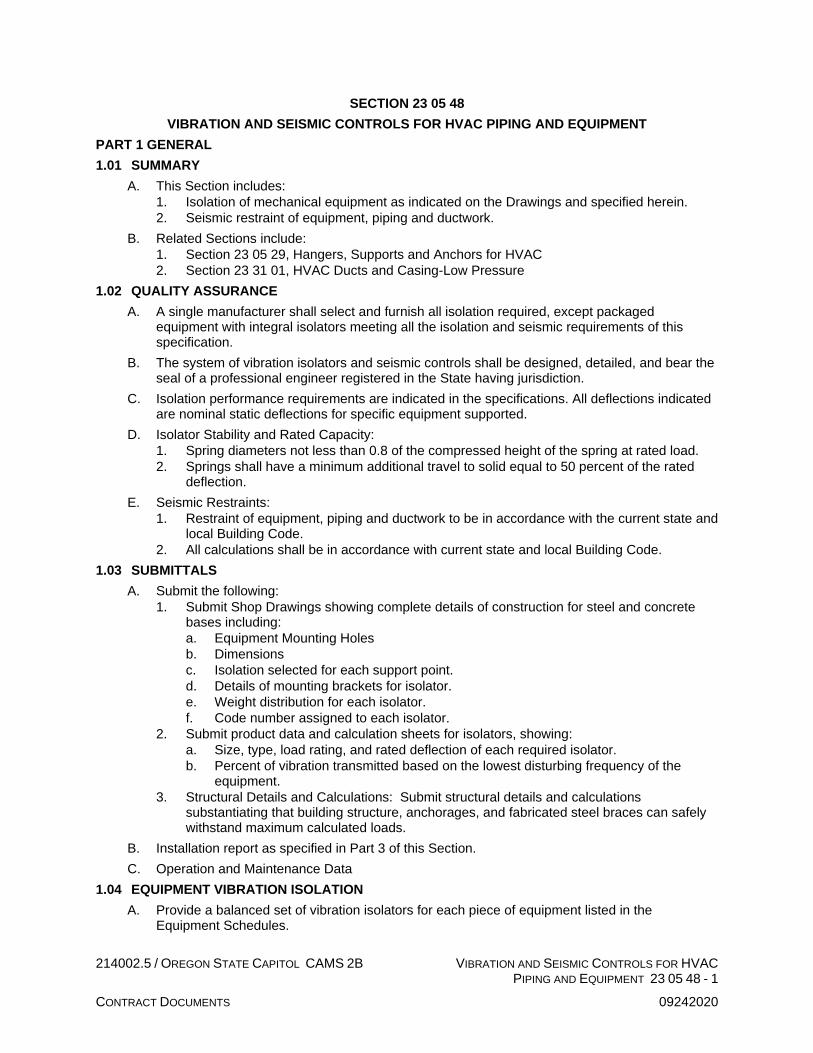
214002.5 / OREGON STATE CAPITOL CAMS 2B VIBRATION AND SEISMIC CONTROLS FOR HVAC PIPING AND EQUIPMENT 23 05 48 - 1
CONTRACT DOCUMENTS 09242020
SECTION 23 05 48
VIBRATION AND SEISMIC CONTROLS FOR HVAC PIPING AND EQUIPMENT
PART 1 GENERAL
1.01 SUMMARY
A. This Section includes:
1. Isolation of mechanical equipment as indicated on the Drawings and specified herein.
2. Seismic restraint of equipment, piping and ductwork.
B. Related Sections include:
1. Section 23 05 29, Hangers, Supports and Anchors for HVAC
2. Section 23 31 01, HVAC Ducts and Casing-Low Pressure
1.02 QUALITY ASSURANCE
A. A single manufacturer shall select and furnish all isolation required, except packaged equipment with integral isolators meeting all the isolation and seismic requirements of this specification.
B. The system of vibration isolators and seismic controls shall be designed, detailed, and bear the seal of a professional engineer registered in the State having jurisdiction.
C. Isolation performance requirements are indicated in the specifications. All deflections indicated are nominal static deflections for specific equipment supported.
D. Isolator Stability and Rated Capacity:
1. Spring diameters not less than 0.8 of the compressed height of the spring at rated load.
2. Springs shall have a minimum additional travel to solid equal to 50 percent of the rated deflection.
E. Seismic Restraints:
1. Restraint of equipment, piping and ductwork to be in accordance with the current state and local Building Code.
2. All calculations shall be in accordance with current state and local Building Code.
1.03 SUBMITTALS
A. Submit the following:
1. Submit Shop Drawings showing complete details of construction for steel and concrete bases including:
a. Equipment Mounting Holes
b. Dimensions
c. Isolation selected for each support point.
d. Details of mounting brackets for isolator.
e. Weight distribution for each isolator.
f. Code number assigned to each isolator.
2. Submit product data and calculation sheets for isolators, showing:
a. Size, type, load rating, and rated deflection of each required isolator.
b. Percent of vibration transmitted based on the lowest disturbing frequency of the equipment.
3. Structural Details and Calculations: Submit structural details and calculations substantiating that building structure, anchorages, and fabricated steel braces can safely withstand maximum calculated loads.
B. Installation report as specified in Part 3 of this Section.
C. Operation and Maintenance Data
1.04 EQUIPMENT VIBRATION ISOLATION
A. Provide a balanced set of vibration isolators for each piece of equipment listed in the Equipment Schedules.

214002.5 / OREGON STATE CAPITOL CAMS 2B VIBRATION AND SEISMIC CONTROLS FOR HVAC PIPING AND EQUIPMENT 23 05 48 - 2
CONTRACT DOCUMENTS 09242020
B. Isolation work to include, but not necessarily be limited to, the following:
1. Isolation support of motor-driven equipment.
2. Isolation support of air-handling housings.
3. Isolation support of piping, piping risers, and ductwork.
4. Penetration isolation of pipework, ductwork, and conduits through walls, floors or ceilings.
5. Flexible connections of ductwork and piping to equipment.
C. Each piece of rotating equipment must meet a reasonable criterion for maximum vibration levels at each bearing, while in operation. The criteria for varying operating speeds are given as follows:
1. Rotating equipment operating peak vibration velocities must not exceed 0.08 inch/second.
2. If it is discovered that the operating vibration velocities exceed this criteria, the equipment shall be repaired or replaced at no expense to the Owner until approval of the equipment is given by the Engineer.
D. Any components or materials not specially mentioned herein, but necessary to the proper vibration isolation of the equipment, shall be provided.
1.05 ACCEPTABLE MANUFACTURERS
A. Amber Booth
B. Mason Industries, Inc.
C. Kinetics Corporation
D. Vibrex
E. Approved equal, meeting all of the conditions and requirements specified herein.
1.06 CONTRACTOR RESPONSIBILITY
A. All vibration isolation devices, including auxiliary steel bases and pouring forms, shall be designed and furnished by a single manufacturer or suppliers.
B. Adequately restrain all equipment, piping, and ductwork to resist seismic forces. Design and select restraint devices to meet seismic requirements as defined in the latest issue of the International Building Code under Earthquake Design and applicable state and local codes.
C. In addition, the contractor shall have the following responsibilities:
1. Selection, installation, adjustment, and performance of vibration isolators which will meet the requirements given on the plans or in the specifications.
2. Provide Engineering drawings, details, supervision, and instruction to assure proper installation and performance.
3. Provide whatever assistance necessary to ensure correct installation and adjustment of the isolators.
PART 2 PRODUCTS
2.01 TYPE 1 - NEOPRENE WAFFLE PAD
A. 3/4-inch thick neoprene waffle pads with pattern repeating on 1/2-inch centers.
B. Select Duro rating for maximum deflection at average load rating.
C. Include load distribution steel plate as required.
D. Include anchor bolt grommet as required.
E. Acceptable Manufacturer: Mason Type “Super W” or “Super WM” and “HG Grommet”; Similar Amber-Booth, Kinetics Corporation.
2.02 TYPE 7 - ISOLATING SPRING HANGERS
A. Combination rubber-in shear and steel spring isolators installed on the hanger rods.
B. Provide minimum deflection of 1-inch.

214002.5 / OREGON STATE CAPITOL CAMS 2B VIBRATION AND SEISMIC CONTROLS FOR HVAC PIPING AND EQUIPMENT 23 05 48 - 3
CONTRACT DOCUMENTS 09242020
C. Isolators shall have the proper deflection to allow the piping to deflect as a unit with the pump isolators.
D. Hangers designed for 30 degree angular movement.
E. Minimum deflection shall be 1-inch.
F. Manufacturer: Mason 30N, similar Amber-Booth, Consolidated Kinetics, Vibrex.
2.03 ISOLATING SLEEVES
A. Provided for all piping through walls and floors of penthouses and chiller room. Size for piping as required.
B. Manufacturers: Potter-Roemer PR isolators or Grinnell Semco Trisolators.
2.04 SEISMIC RESTRAINTS
A. General Requirements:
1. Seismic restraints shall be provided for all equipment, piping and ductwork, both supported and suspended.
2. Bracing of piping and ductwork shall be in accordance with the code and with the provisions set forth in the SMACNA seismic restraint manual.
3. The structural requirements for the restraints, including their attachment to the building structure, shall be reviewed and approved by the Structural Engineer.
4. Attachments to supported or suspended equipment must be coordinated with the equipment manufacturer.
B. Supported Equipment:
1. All-directional seismic snubbers shall consist of interlocking steel members restrained by a one-piece molded neoprene bushing of bridge bearing neoprene.
2. Bushing shall be replaceable and a minimum of 1/4-inch thick. Rated loadings shall not exceed 1000 PSI.
3. An air gap of 1/4-inch shall be incorporated in the snubber design in all directions before contact is made between the rigid and resilient surfaces.
4. Snubber end caps shall be removable to allow inspection of internal clearances. Neoprene bushings shall be rotated to ensure no short circuits exist before systems are activated.
5. Snubber shall be type Z-1225 as manufactured by Mason Industries, Inc.
C. Bracing of Pipes:
1. Provide seismic bracing of all piping as detailed below to meet the building code requirements:
a. Exception: Piping suspended by individual hanger’s 12-inches or less in length, as measured from the top of the pipe to the bottom of the support where the hanger is attached, need not be braced where the following criteria are met.
1) Seismic braces are not required on high deformability piping when the Ip=1.0 and provisions are made to avoid impact with larger pipe or mechanical components or to protect the pipe in the event of such impact and the nominal pipe size is 3-inches diameter or less.
2) Seismic braces are not required on high deformability piping when the Ip=1.5 and provisions are made to avoid impact with larger pipe or mechanical components or to protect the pipe in the event of such impact and the nominal pipe size is 1-inch diameter or less.
2. Seismic braces for pipes on trapeze hangers may be used.
3. Provide flexibility in joints where pipes pass through building seismic joints or expansion joints, or where pipes connect to equipment.
4. Cast iron pipe of all types, glass pipe, and any other pipe jointed with a shield and clamp assembly, where the top of the pipe is 12-inches or more from the supporting structure, shall be braced on each side of a change in direction of 90 degrees or more. Riser joints on unsupported sections of piping shall be braced or stabilized between floors.

214002.5 / OREGON STATE CAPITOL CAMS 2B VIBRATION AND SEISMIC CONTROLS FOR HVAC PIPING AND EQUIPMENT 23 05 48 - 4
CONTRACT DOCUMENTS 09242020
5. Vertical risers shall be laterally supported with a riser clamp at each floor. For buildings greater than six stories high or for piping subject to thermal change all risers shall be engineered individually.
D. Bracing of Ductwork:
1. Brace rectangular ducts with cross sectional areas of 6 square feet and larger. Brace flat oval ducts in the same manner as rectangular ducts. Brace round ducts with diameters of 28-inches and larger. Brace flat oval ducts the same as rectangular ducts of the same nominal size.
2. Exception: No bracing is required if the duct is suspended by hangers 12 inches or less in length, as measured from the top of the duct to the bottom of the support where the hanger is attached, and the Ip=1.0.
3. Transverse bracing shall occur at the interval specified in the SMACNA tables or at both ends if the duct run is less than the specified interval. Transverse bracing shall be installed at each duct turn and at each end of a duct run, with a minimum of one brace at each end.
4. Longitudinal bracing shall occur at the interval specified in the SMACNA tables with at least one brace per duct run. Transverse bracing for one duct section may also act as longitudinal bracing for a duct section connected perpendicular to it if the bracing is installed within four feet of the intersection of the ducts and if the bracing is sized for the larger duct. Duct joints shall conform to SMACNA duct construction standards.
5. Install duct flex connections at equipment connections to accept expected differential displacement and protect the equipment connection from damage.
E. Suspended Equipment and Piping and Ductwork:
1. Seismic cable restraints shall consist of galvanized steel aircraft cables sized to resist seismic loads with a minimum safety factor of two and arranged to provide all-directional restraint.
2. Cable must be pre-stretched to achieve a certified minimum modulus of elasticity. Cable end connections shall be steel assemblies that swivel to final installation angle and utilize two clamping bolts to provide proper cable engagement.
3. Cable assemblies shall be type SCB at the ceiling and at the clevis bolt, SCBH between the hanger rod and the clevis or SCBV if clamped to a beam, all as manufactured by Mason Industries, Inc.
4. Steel angles, sized to prevent buckling, shall be clamped to pipe or equipment rods utilizing a minimum of three ductile iron clamps at each restraint location when required. Welding of a minimum of three ductile iron clamps at each restraint location when required. Welding of support rods is not acceptable. Rod clamp assemblies shall be type SRC or UC as manufactured by Mason Industries, Inc.
5. Pipe clevis cross-bolt braces are required in all restraint locations. They shall be special purpose preformed channels deep enough to be held in place by bolts passing over the cross bolt. Clevis cross brace shall be type CCB as manufactured by Mason Industries, Inc.
2.05 FLEXIBLE HOSE CONNECTOR
A. Flexible stainless steel hoses shall be manufactured using type 304 stainless steel hose and braid with one fixed and one floating raised face carbon steel plate flange.
B. Sizes 2-1/2-inches and smaller may have threaded male nipples or copper sweat ends. Grooved ends are acceptable in all sizes in grooved piping systems. Weld ends are not acceptable. Copper sweat end hoses for water service shall be all copper or bronze construction.
C. Hose shall have close pitch annular corrugations for maximum flexibility and low stiffness. Tested hose stiffness at various pressures must be included in the submittals.
D. Hose shall be capable of continuous operation at 150 PSI and system test pressure when installed in piping systems.

214002.5 / OREGON STATE CAPITOL CAMS 2B VIBRATION AND SEISMIC CONTROLS FOR HVAC PIPING AND EQUIPMENT 23 05 48 - 5
CONTRACT DOCUMENTS 09242020
E. Hose shall be the same size as the pipe it connects and have pipe thread connectors on both ends with male or female end adapters as required.
F. Manufacturers: Mason type BSS, FFL, MN, CPS or CPSB, similar HCi, Metraflex.
PART 3 EXECUTION
3.01 GENERAL
A. Do not install any equipment or pipe which makes rigid contact with the building. "Building" includes slabs, beams, studs, walls, etc.
B. The installation or use of vibration isolators must not cause any change of position of equipment or piping which would result in stresses in piping connections or misalignment of shafts or bearings. In order to meet this objective, equipment and piping shall be maintained in a rigid position during installation. The load shall not be transferred to the isolator until the installation is complete and under full operational load.
C. Correct, at no additional cost, all installations which are defective in workmanship or materials.
3.02 PREPARATION
A. Treat all isolators, including springs, hardware and housing, with a corrosion protective coating of epoxy powder or electro galvanizing.
B. Coat steel frames exposed to weather with a rustproof metal primer.
C. Provide hot dipped galvanizing on steel frames as indicated on the plans for corrosion protection in severe conditions.
3.03 INSTALLATION
A. General:
1. Install isolation where indicated on the Drawings by type and location and where indicated below.
2. The assigned code number shall be marked on the isolators and bases to assure placement in the proper location.
3. Anchor isolator seismic housing baseplate to floor.
4. Rubber grommets and washers shall be provided to isolate the bolt from the building structure. Under no circumstances shall the isolation efficiency be destroyed when bolting the isolators to the building structure.
B. Type 1 – Neoprene Waffle Pad:
1. Service:
a. Floor Mounted Indoor Air Handling Units (AHU-201, AHU-202)
C. Type 7 – Isolating Spring Hangers:
1. Service:
a. Vane Axial Fans (GEF-002)
b. Unit Heaters (UH-201, UH-202)
D. Flexible Connectors:
1. Flexible Hose Connectors: Provide as indicated on the drawings.
3.04 SEISMIC RESTRAINTS
A. General:
1. Install and adjust seismic restraints so that the equipment, piping, and ductwork support is not degraded by the restraints.
2. Restraints must not short circuit vibration isolation systems or transmit objectionable vibration or noise.

214002.5 / OREGON STATE CAPITOL CAMS 2B VIBRATION AND SEISMIC CONTROLS FOR HVAC PIPING AND EQUIPMENT 23 05 48 - 6
CONTRACT DOCUMENTS 09242020
B. Supported Equipment:
1. Each vibration isolation frame for supported equipment shall have a minimum of four seismic snubbers mounted as close as possible to the vibration isolators and/or the frame extremities.
2. Care must be taken so that the 1/4-inch air gap in the seismic restraint snubber is preserved on all sides in order that the vibration isolation potential of the isolator is not compromised. This requires that the final snubber adjustment be completed after the vibration isolators are properly installed and the installation approved.
C. Bracing of Pipes:
1. Branch lines may not be used to brace main lines.
2. Transverse bracing shall be at 40 feet maximum, except where a lesser spacing is indicated in the SMACNA tables for bracing of pipes.
3. Longitudinal bracing shall be at 80 feet maximum except where a lesser spacing is indicated in the tables. In pipes where thermal expansion is a consideration, an anchor point may be used as the specified longitudinal brace provided that it has a capacity to resist both the seismic load and the additional force induced by expansion and contraction.
4. A rigid piping system shall not be braced to dissimilar parts of the building or to two dissimilar building systems that may respond differently during an earthquake.
5. Transverse bracing for one pipe section may also act as longitudinal bracing for a pipe section of the same size connected perpendicular to it if the bracing is installed within 24 inches of the elbow or tee.
6. Subject to confirmation by field inspection, seismic bracing is not required on piping when the piping is supported by rod hangers and the hangers in the entire run are 12-inches or less in length from the top of the pipe to the supporting structure, hangers are detailed to avoid bending of the hangers and their attachments and provisions are made for piping to accommodate expected deflections.
D. Bracing of Ductwork:
1. Hanger straps must be positively attached to the duct within 2-inches of the top of the duct with a minimum of two #10 sheet metal screws.
2. A group of ducts may be combined in a larger frame so that the combined weights and dimensions of the ducts are less than or equal to the maximum weight and dimensions of the duct for which bracing details are selected.
3. Walls, including gypsum board nonbearing partitions, which have ducts running through them, may replace a typical transverse brace. Provide solid blocking around duct penetrations at stud wall construction.
4. Unbraced ducts shall be installed with a 6-inch minimum clearance to vertical ceiling hanger wires.
E. Suspended Equipment, Piping, and Ductwork Cable Method:
1. The cables shall be adjusted to a degree of slackness approved by the Structural Engineer.
2. The uplift and downward restraint nuts and Mason type RW neoprene covered steel rebound washers for the Type 6 hangers shall be adjusted so that there is a maximum 1/4-inch clearance.
3.05 FIELD QUALITY CONTROL
A. Installation Report: Isolation manufacturer’s representative shall confirm that all isolation is installed correctly and submit report stating that isolators are installed as shown on Shop Drawings, isolators are free to work properly, and that installed deflections are as scheduled and as specified.
END VIBRATION AND SEISMIC CONTROLS FOR HVAC PIPING AND EQUIPMENT

214002.5 / OREGON STATE CAPITOL CAMS 2B IDENTIFICATION FOR HVAC PIPING AND EQUIPMENT 23 05 53 - 1
ASI 301 10302020
SECTION 23 05 53
IDENTIFICATION FOR HVAC PIPING AND EQUIPMENT
PART 1 GENERAL
1.01 SUMMARY
A. This Section includes: Identify valves, piping and equipment components of the mechanical systems to indicate their function and system served.
1.02 SUBMITTALS
A. Submit the following:
1. Valve Tag Directory: Submit for approval prior to fabrication of valve tags.
2. Equipment Nameplate Directory: Submit for approval prior to fabrication.
3. Operating and Maintenance Data: Include a copy of valve tag and equipment nameplate directories in each set of Operating and Maintenance manuals.
PART 2 PRODUCTS
2.01 VALVE IDENTIFICATION
A. Valve Tags:
1. General: Identify valves with metal tags, legends to be stamped or embossed. It shall indicate the function of the valve and its normal operating position; i.e.,
56 HW (NUMBER AND CONTENT OF PIPE)
ISOLATION (VALVE FUNCTION)
NO (NORMAL OPERATION POSITION)
2. Size: Valve tags 2-inch diameter with 1/4-inch high letters.
3. Material: Use 0.04-inch brass tags.
4. Automatic Valves and Regulating Valves: Use 1/16-inch thick laminated 3-ply plastic, center ply white, outer ply red, “lamicoid” or equal. Form letters by exposing center ply.
5. Buildings Systems: Contact the Owner for coordination with existing building tagging system and supplementary information required for any specific system before valve tagging begins.
B. Valve Tag Directory: Include tag number, location, exposed or concealed, service, valve size, valve manufacturer, valve model number, and normal operating position of valve.
2.02 PIPING MARKERS
A. Acceptable Manufacturers:
1. W.H. Brady
2. Seton
3. Marking Systems, Inc. (MSI)
4. Other Manufacturers: Submit Substitution Request.
B. Pipes shall be labeled with all-vinyl, self-sticking labels or letters. For pipe covering sizes up to and including 3/4-inch outside diameter, select labels with 1/2-inch letters. For sizes from 3/4 to 2-inch outside diameter, 3/4-inch letters; above 2-inches outside diameter, 2-inch letters. The pipe markers shall be identified and color coded as follows with black directional arrows.
HVAC SERVICE BACKGROUND PIPE MARKER * COLOR
CHILLED WATER ”CHILLED WATER SUPPLY” GREEN
”CHILLED WATER RETURN” GREEN
HEATING WATER “HEATING WATER SUPPLY” YELLOW OR GREEN
“HEATING WATER RETURN” YELLOW
HIGH TEMP HEATING WATER
“HIGH TEMP HEATING WATER SUPPLY”
YELLOW OR GREEN

214002.5 / OREGON STATE CAPITOL CAMS 2B IDENTIFICATION FOR HVAC PIPING AND EQUIPMENT 23 05 53 - 2
ASI 301 10302020
HVAC SERVICE BACKGROUND PIPE MARKER * COLOR
“HIGH TEMP HEATING WATER RETURN”
YELLOW
CONDENSER WATER ”CONDENSER SUPPLY” GREEN
”CONDENSER RETURN” GREEN
* Directional arrow applied adjacent to pipe marker indicating direction of flow.
2.03 EQUIPMENT IDENTIFICATION
A. Nameplates:
1. Tag all air handling supply units, terminal units, and miscellaneous items of mechanical equipment with engraved nameplates. Nameplates shall be 1/16-inch thick, 3 by 5-inch laminated 3-ply plastic, center ply white, outer ply black. Form letters by exposing center ply.
2. Identify unit with equipment tag as shown on Drawings and area served.
B. Equipment Nameplate Directory: List air handlers, terminal units, and other equipment nameplates. Include Owner and Contractor furnished equipment. List nameplate designation, manufacturer’s model number, location of equipment, area served or function, disconnect location, and normal position of HOA switch.
PART 3 EXECUTION
3.01 VALVE IDENTIFICATION
A. Valve Tags:
1. Attach to valve with a brass chain.
2. Valve tag numbers shall be continuous throughout the building for each system. Contractor shall obtain a list for each system involved from the Owner.
B. Valve Tag Directory: Post final copy in Operation and Maintenance Manual.
3.02 PIPING MARKERS
A. Unless recommendations of ANSI A13.1, 1981 are more stringent, apply labels or letters after completion of pipe cleaning, insulation, painting, or other similar work, as follows:
1. Every 10 feet along continuous exposed lines.
2. Every 10 feet along continuous concealed lines.
3. Adjacent to each valve and stubout for future.
4. Where pipe passes through a wall, into and out of concealed spaces.
5. On each riser.
6. On each leg of a “T”.
7. Locate conspicuously where visible.
B. Further, apply labels or letters to lower quarters of the pipe on horizontal runs where view is not obstructed or on the upper quarters when pipe is normally viewed from above. Apply arrow labels indicating direction of flow. Arrows to be the same color and sizes as identification labels.
3.03 EQUIPMENT IDENTIFICATION
A. Nameplates: Attach to prominent area of equipment, either with sheet metal screws, brass chain, or contact cement as applicable.
B. Nameplate Directory: Post final copy in Operation and Maintenance Manual.
END IDENTIFICATION FOR HVAC PIPING AND EQUIPMENT

214002.5 / OREGON STATE CAPITOL CAMS 2B PRESSURE TESTING FOR HVAC SYSTEMS 23 05 90 - 1
ASI 301 10302020
SECTION 23 05 90
PRESSURE TESTING FOR HVAC SYSTEMS
PART 1 GENERAL
1.01 SUMMARY
A. This Section includes: Pressure testing of piping and ductwork systems.
1.02 QUALITY ASSURANCE
A. Code Compliance: Perform required tests in the presence of the authority having jurisdiction.
B. Owner Witness: Perform all tests in the presence of the Owner’s representative.
C. Engineer Witness: The Engineer or Engineer’s representative reserves the right to observe all tests or selected tests to assure compliance with the specifications.
D. Simultaneous Testing: Test observations by the authority having jurisdiction, the Owner’s representative and the Engineer’s representative need not occur simultaneously.
1.03 SUBMITTALS
A. Submit the following:
1. Test Reports:
a. Submit certificate of completion, inspection, and test by Authority Having Jurisdiction on required piping systems.
b. Submit certificate of test approval by Owner’s representative on all systems.
c. For ductwork testing, submit the Test Report. Test Report shall contain description of the testing procedure and results, including recommendation for any remedial actions needed. The Engineer’s representative will record witnessed tests.
PART 2 PRODUCTS – NOT APPLICABLE
PART 3 EXECUTION
3.01 GENERAL
A. Piping: Test prior to concealment, insulation being applied, and connection to equipment, fixtures, or specialties. Conduct tests with all valves but those used to isolate the test section 10 percent closed.
B. Ductwork: Test prior to connection to equipment and before applying insulation.
C. Leaks: Repair all leaks and retest until stipulated results are achieved.
D. Notification: Advise the Architect 72 hours in advance of each test. Failure to so notify will require test to be rescheduled.
E. Testing Equipment: Provide all necessary pumps, gauges, connections and similar items required to perform the tests.
3.02 TESTING REQUIREMENTS
A. Medium Pressure Ductwork:
1. Test all ductwork systems at 4-inch static pressure, using a Pacific Air Products Port-O-Lab or Rolok, or a McGill Airflow LEAK DETECTIVE testing machine or approved equivalent.
2. All ductwork testing shall be conducted in accordance with latest published version of the SMACNA HVAC Air Duct Leakage Test Manual.
3. Prior to testing verify that all medium pressure ductwork has been sealed to meet the SMACNA Seal Class A. for all joints, seams and at al duct wall penetrations.
4. Medium pressure ductwork leakage shall be less than or meet the requirement of the following SMACNA Leakage Classes:
a. Rectangular Metal – Class 6
b. Round or Flat Oval – Class 3
5. Maximum allowable leakage is defined as Cubic Feet per Minute (CFM) air leakage per 100 square feet SURFACE AREA of duct section tested.
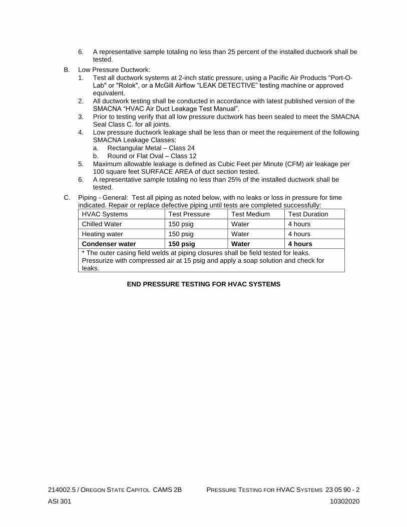
214002.5 / OREGON STATE CAPITOL CAMS 2B PRESSURE TESTING FOR HVAC SYSTEMS 23 05 90 - 2
ASI 301 10302020
6. A representative sample totaling no less than 25 percent of the installed ductwork shall be tested.
B. Low Pressure Ductwork:
1. Test all ductwork systems at 2-inch static pressure, using a Pacific Air Products "Port-O-Lab" or "Rolok", or a McGill Airflow “LEAK DETECTIVE” testing machine or approved equivalent.
2. All ductwork testing shall be conducted in accordance with latest published version of the SMACNA “HVAC Air Duct Leakage Test Manual”.
3. Prior to testing verify that all low pressure ductwork has been sealed to meet the SMACNA Seal Class C. for all joints.
4. Low pressure ductwork leakage shall be less than or meet the requirement of the following SMACNA Leakage Classes:
a. Rectangular Metal – Class 24
b. Round or Flat Oval – Class 12
5. Maximum allowable leakage is defined as Cubic Feet per Minute (CFM) air leakage per 100 square feet SURFACE AREA of duct section tested.
6. A representative sample totaling no less than 25% of the installed ductwork shall be tested.
C. Piping - General: Test all piping as noted below, with no leaks or loss in pressure for time indicated. Repair or replace defective piping until tests are completed successfully:
HVAC Systems Test Pressure Test Medium Test Duration
Chilled Water 150 psig Water 4 hours
Heating water 150 psig Water 4 hours
Condenser water 150 psig Water 4 hours
* The outer casing field welds at piping closures shall be field tested for leaks. Pressurize with compressed air at 15 psig and apply a soap solution and check for leaks.
END PRESSURE TESTING FOR HVAC SYSTEMS

214002.5 / OREGON STATE CAPITOL CAMS 2B TESTING, ADJUSTING, AND BALANCING FOR HVAC 23 05 93 - 1
CONTRACT DOCUMENTS 09242020
SECTION 23 05 93
TESTING, ADJUSTING, AND BALANCING FOR HVAC
PART 1 GENERAL
1.01 SUMMARY
A. This Section includes:
1. Testing and Balancing of Air Systems
2. Testing and Balancing of Hydronic Systems
3. Testing and Balancing of Miscellaneous Mechanical Equipment
B. Related Sections include:
1. Section 23 09 00, Instrumentation and Controls for HVAC
1.02 QUALITY ASSURANCE
A. Acceptable Testing and Balancing Firms:
1. A.I.R., Inc.
2. Air Balance Specialty, Inc.
3. Neudorfer Engineers, Inc.
4. Northwest Engineering Services
5. Pacific Coast Air Balance
6. Accurate Balancing Agency, Inc.
B. Other Firms: Submit Substitution Requests prior to Bid Date.
C. Industrial Standards: Testing and Balancing shall conform to NEBB, American Society of Heating, Refrigerating, and Air Conditioning Engineers (ASHRAE), and American National Standards Institute (ANSI) as follows:
1. NEBB: Comply with Procedural Standards for Testing, Adjusting Balancing of Environmental Systems.
2. ASHRAE: Comply with recommendations pertaining to measurements, instruments, and testing, adjusting and balancing.
3. ANSI:
a. S1.4 Specifications for sound level meters.
b. S1.11 Specifications for Octave-Band and Fractional-Octave-Band analog and digital filters.
D. Instrument Certification: All instruments used shall be accurately calibrated and certified within six months of balancing and maintained in good working order.
E. Test Observation: If requested, the tests shall be conducted in the presence of the Architect or the Architect’s representative.
1.03 SUBMITTALS
A. Submit the following:
1. Balancing Log: Include all air and water outlets, actual field measured air and water volume, and percentage of design volumes. Provide drawings identifying location of all outlets.
2. Equipment Data Sheets: Indicate actual equipment performance, model numbers, bearing and belt data, motor nameplate data, and final balanced motor data.
3. Additional Data: Submit all additional data as provided by Associated Air Balance Council (AABC) Standard forms.
4. Number of Copies: Submit six copies of the above completed information to the Engineer for review and insertion into the Operating and Maintenance Data.
5. Instrument Certification: When requested, submit certificate of calibration for all equipment to be used.
B. Record data on NEBB forms or forms approved by the Architect.

214002.5 / OREGON STATE CAPITOL CAMS 2B TESTING, ADJUSTING, AND BALANCING FOR HVAC 23 05 93 - 2
CONTRACT DOCUMENTS 09242020
1.04 PROJECT CONDITIONS
A. Where existing systems are to be adjusted, establish flow rates in all branches prior to making any modifications to system. Submit preliminary report indicating existing conditions prior to making any modifications to existing systems. Adjust central equipment as required and restore all unmodified branches and outlets to original condition. Obtain existing system drawings from Owner and become familiar with extent and nature of existing systems.
B. Do not perform final testing, adjusting, and balancing work until heating, ventilating, and air conditioning equipment has been completely installed and operating continuously as required.
C. Conduct air testing and balancing with clean filters in place. Clean strainers, etc., prior to performing hydronic testing and balancing.
1.05 WARRANTIES
A. In addition to the Requirements of the Contract, include an extended warranty of six months after completion of test and balance work during which time the Architect at his discretion may request a recheck or resetting of any equipment or device listed in the test reports.
PART 2 PRODUCTS – NOT APPLICABLE
PART 3 EXECUTION
3.01 GENERAL REQUIREMENTS
A. Balance to maximum measured flow. Deviation from specified values of ±10 percent at terminal device and ±5 percent at equipment, or mean sound level deviation of 15 decibels. Advise Engineer if deficiencies are generally noted to enable proper corrective actions.
3.02 AIR SYSTEMS
A. General: Make measurements in accord with Industrial Standards specified above. Record on appropriate forms.
B. Preliminary:
1. Identify and list size, type, and manufacturer of all equipment to be tested including air outlets and inlets.
2. Use manufacturer’s ratings for equipment to make required calculations except where field test shows ratings to be impractical.
C. Central System:
1. Set speed to provide air volume at farthest run without excess static pressure. Provide additional sheaves and belts as required to accomplish speed adjustment.
2. Read and adjust air supply, return, and exhaust fan units to deliver design conditions at minimum O.S.A. and at 100 percent O.S.A.
3. Adjust all automatic dampers, outside air, return air, and exhaust dampers for design conditions.
4. Read static air pressure conditions on all air handling equipment including filter and coil pressure drops and total pressure across the fan. A Dwyer Series 400 air velocity meter only shall be used for final static pressures at equipment and where critical readings are required.
5. Measure temperature conditions across all outside air, return air, and exhaust dampers to check leakage.
6. Read and record motor data and amperage draw.
7. For variable volume systems, establish minimum static pressure required at sensing point to permit operation over entire VAV range. Adjust supply and return fan speed so that at maximum demand the associated VFD is controlling the motor of motor nameplate RPM to 100 percent. Adjust return fan speed so that return air volumes track with supply air volume minus exhaust air volume.
8. Assist controls contractor in establishing minimum outside air damper positions.

214002.5 / OREGON STATE CAPITOL CAMS 2B TESTING, ADJUSTING, AND BALANCING FOR HVAC 23 05 93 - 3
CONTRACT DOCUMENTS 09242020
D. Distribution:
1. Evaluate all building and room pressure conditions to determine adequate supply and return air conditions. Generally, the building shall be balanced to be slightly positive to outdoors.
2. Evaluate all building and room pressure conditions to determine adequate performance of the system to maintain temperatures without draft.
3. Perform multipoint pitot traverses to confirm instrumentation, shaft tightness, fan operation, etc. Pitot traverses shall be performed using a Dwyer Series 400 air velocity meter only with applicable duct probe.
4. Mark all balancing dampers.
3.03 HYDRONIC SYSTEMS
A. General: Make measurements in accord with Industrial Standards specified above. Record on appropriate forms.
B. Preliminary:
1. List complete data of tested equipment and verify against Contract Documents.
2. Open all line valves to full open position, close coil by-pass stop valves, then set mixing control valve to full coil flow.
3. For each pump:
a. Verify Rotation
b. Test and record pump shut-off head.
c. Test and record pump wide-open head.
4. Verify proper system pressures.
5. Verify air vents in high points of water are properly installed and operating freely.
C. Central Equipment:
1. Check all conditions at all coils for required performance at design conditions.
2. Check conditions at all primary source equipment for performance of design conditions.
3. Read and record pump heads, motor data, and amperage draw.
D. Distribution:
1. Read and adjust water flow for design conditions.
2. Set all memory stops and mark position of adjuster on balancing valves.
3.04 AUTOMATIC CONTROL SYSTEM
A. In cooperation with control manufacturer’s representative, set and adjust automatically operated devices to achieve required sequence of operations.
B. Testing organization shall verify all controls for proper calibration and list controls requiring adjustment by control system installer.
3.05 COORDINATION
A. Coordinate work with other trades to ensure rapid completion of the project.
B. Deficiencies noted during the course of air balancing in the mechanical installation shall be promptly reported to the Architect to allow corrective action to proceed.
C. Periodic review of progress shall be provided as requested.
END TESTING, ADJUSTING, AND BALANCING FOR HVAC

214002.5 / OREGON STATE CAPITOL CAMS 2B CLEANING OF HVAC EXISTING DUCTWORK 23 05 94 - 1
CONTRACT DOCUMENTS 09242020
SECTION 23 05 94
CLEANING OF HVAC EXISTING DUCTWORK
PART 1 GENERAL
1.01 SUMMARY
A. This section defines the minimum requirements necessary to render existing HVAC components clean and to verify the cleanliness through inspection and/or testing in accordance with items specified herein and applicable NADCA Standards. Removal of visible surface contaminants and deposits from within the HVAC system in strict accordance with these specifications.
B. The HVAC system includes any interior surface of the facility’s air distribution system for conditioned spaces and/or occupied zones. This includes the entire heating, air-conditioning and ventilation system from the points where the air enters the system to the points where the air is discharged from the system. The return air grilles, return air ducts to the air handling unit (AHU), the interior surfaces of the AHU, mixing box, coil compartment, condensate drain pans, supply air ducts, fans, fan housing, fan blades, turning vanes, filters, filter housings, reheat coils and supply diffusers are all considered part of the HVAC system. The HVAC system may also include other components such as dedicated exhaust and ventilation components and make-up air systems.
1.02 QUALITY ASSURANCE
A. Membership: The HVAC system cleaning contractor shall be a certified member of the National Air Duct Cleaners Association (NADCA) or shall maintain membership in a nationally recognized non-profit industry organization dedicated to the cleaning of HVAC systems.
B. Certification: The HVAC system cleaning contractor shall have a minimum of one (1) Air System Cleaning Specialist (ASCS) certified by NADCA on a full time basis or shall have staff certified by a nationally recognized certification program and organization dedicated to the cleaning of HVAC systems.
C. Supervisor Qualification: A person certified as an ACSC by NADCA or maintaining an equivalent certification by a nationally recognized program and organization shall be responsible for the total work herein specified.
D. Experience: The HVAC system cleaning contractor shall submit records of experience in the field of HVAC system cleaning as requested by the Owner. Bids shall only be considered from firms which are regularly engaged in HVAC system maintenance with an emphasis on HVAC system cleaning and decontamination.
E. Equipment, Materials and Labor: The HVAC system cleaning contractor shall possess and furnish all necessary equipment, materials, and labor to adequately perform the specified services.
1. The Contractor shall assure that its employees have received safety equipment training, medical surveillance programs, individual health protection measures and manufacturer’s product and material safety data sheets (MSDS) as required for the work by the U.S. Occupational Safety and Health Administration and as described by this specification. For work performed in countries outside of the U.S.A., Contractors should comply with applicable national safety codes and standards.
2. The Contractor shall maintain a copy of all current MSDS documentation and safety certifications at the site at all times, as well as comply with all other site documentation requirements of applicable OSHA programs and this specification.
3. Contractor shall submit to the Owner all Material Safety Data Sheets (MSDS) for all chemical products proposed to be used in the cleaning process.
F. Licensing: The HVAC system cleaning contactor shall provide proof of maintaining the proper license(s), if any as required to do work in this State. Contractor shall comply with all Federal, State, and local rules, regulations, and licensing requirements.

214002.5 / OREGON STATE CAPITOL CAMS 2B CLEANING OF HVAC EXISTING DUCTWORK 23 05 94 - 2
CONTRACT DOCUMENTS 09242020
1.03 STANDARDS
A. NADCA Standards: The HVAC system cleaning contractor shall perform the services specified here in accordance with the current published standards of the National Air Duct Cleaners Association (NADCA).
1. All terms in this specification shall have their meaning defined as stated in the NADCA Standards.
2. NADCA Standards must be followed with no modification or deviations being allowed.
1.04 APPLICABLE STANDARDS AND PUBLICATIONS
A. The following current standards and publications of the issues currently in effect form a part of this specification to the extent indicated by any reference thereto:
1. National Air Duct Cleaners Association (NADCA): “Assessment, Cleaning and Restoration of HVAC Systems (ACR 2005)” 2004.
2. National Air Duct Cleaners Association (NADCA): “Understanding Microbial Contamination in HVAC Systems” 1996.
3. National Air Duct Cleaners Association (NADCA): “Introduction to HVAC System Cleaning Services” 2004.
4. National Air Duct Cleaners Association (NADCA): Standard 05 “Requirements for the Installation of Service Openings in HVAC Systems” 2004.
5. Underwriters/ Laboratories (UL): UL Standard 181.
6. American Society of Heating, Refrigerating and Air Conditioning Engineers (ASHRAW): Standard 62-89 “Ventilation for Acceptable Indoor Air Quality.”
7. American Society of Heating, Refrigerating and Air Conditioning Engineers (ASHRAE): Standard 62-89 “Ventilation for Acceptable Indoor Air Quality.”
8. Environmental Protection Agency (EPA): “Building Air Quality” December 1991.
9. Sheet Metal and Air Conditioning Contractors’ National Association (SMACNA): “HVAC Duct Construction Standards – Metal and Flexible” 1985.
10. North American Insulation Manufacturers Association (NAIMA): Cleaning Fibrous Glass Insulated Air Duct Systems” 1993.
1.05 SUBMITTALS
A. Submit qualification of the HVAC System Cleaning Contractor.
PART 2 PRODUCTS - NOT APPLICABLE
PART 3 EXECUTION
3.01 HVAC SYSTEM COMPONENT INSPECTIONS AND SITE PREPARATIONS
A. HVAC System Component Inspection: Prior to the commencement of any cleaning work, the HVAC system cleaning contractor shall perform a visual inspection of the HVAC system to determine appropriate methods, tools, and equipment required to satisfactorily complete this project. The cleanliness inspection should include air handling units and representative areas of the HVAC system components and ductwork. In HVAC systems that include multiple air handling units, a representative sample of the units should be inspected.
B. The cleanliness inspection shall be conducted without negatively impacting the indoor environment through excessive disruption of settled dust, microbial amplification or other debris. In cases where contamination is suspected and/or in sensitive environments where even small amounts of contaminant may be of concern, environment engineering control measures should be implemented.
1. Damage system components found during the inspection shall be documented and brought to the attention of the Owner.
C. Site evaluation and Preparation: Contractor shall conduct a site evaluation and establish a specific, coordinated plan which details how each area of the building will be protected during the various phases of the project.

214002.5 / OREGON STATE CAPITOL CAMS 2B CLEANING OF HVAC EXISTING DUCTWORK 23 05 94 - 3
CONTRACT DOCUMENTS 09242020
D. Inspector Qualifications: Qualified personnel should perform the HVAC cleanliness inspection to determine the need for cleaning. At minimum, such personnel should have an understanding of HVAC system design and experience in utilizing accepted indoor environmental sampling practices, current industry HVAC cleaning procedures and applicable industry standards.
3.02 GENERAL HVAC SYSTEM CLEANING REQUIREMENTS
A. Containment: Debris removed during cleaning shall be collected and precautions must be taken to ensure that Debris is not otherwise dispersed outside the HVAC system during the cleaning process.
B. Particulate Collection: Where the Particulate Collection Equipment is exhausting inside the building, HEPA filtration with 99.97% collection efficiency for 0.3-micron size (or greater) particles shall be used. When the Particulate Collection Equipment is exhausting outside the building, mechanical cleaning operations shall be undertaken only with Particulate Collection Equipment in place, including adequate filtration to contain Debris removed from the HVAC system. When the Particulate Collection Equipment is exhausting outside the building, precautions shall be taken to locate the equipment down wind and away from all air intakes and other points of entry into the building.
C. Controlling Odors: Measures shall be employed to control odors and/or mist vapors during the cleaning process.
D. Component Cleaning: Cleaning methods shall be employed such that all HVAC system components must be visibly clean as defined in applicable standards (see NADCA Standards). Upon completion, all components must be returned to those settings recorded just prior to cleaning operations.
E. Air-Volume Control Devices: Dampers and any air-directional mechanical devices inside the HVAC system must have their position marked prior to cleaning, and upon completion, must be restored to their marked position.
F. Service Openings: The Contractor shall utilize service openings, as required for proper cleaning, at various points of the HVAC system for physical and mechanical entry and inspection.
1. Contractor shall utilize the existing service openings already installed in the HVAC system where possible.
2. Other openings shall be created where needed and they must be created so they can be sealed in accordance with industry codes and standards.
3. Closures must not significantly hinder, restrict, or alter the airflow within the system.
4. Closures must be properly insulated to prevent heat loss/gain or condensation on surfaces within the system.
5. Openings must not compromise the structural integrity of the system.
6. Construction techniques used in the creation of openings should conform to requirements of applicable building and fire codes, applicable NFPA, SMACNA, and NADCA Standards.
7. Cutting service openings into flexible duct is not permitted. Flexible duct shall be disconnected at the ends as needed for proper cleaning and inspection.
8. Rigid fiber glass duct systems shall be resealed in accordance with NAIMA recommended practices. Only closure techniques that comply with UL Standard 181 or UL Standard 181a are suitable for fiber glass duct system closures.
9. All service openings capable of being re-opened for future inspection or remediation shall be clearly marked and shall have their location reported to the Owner in project report documents.
G. Ceiling Sections (Tile): The Contractor may remove and reinstall ceiling sections to gain access to HVAC systems during the cleaning process.
H. Air Distribution Devices (Registers, Grilles, and Diffusers): The Contractor shall clean all air distribution devices.

214002.5 / OREGON STATE CAPITOL CAMS 2B CLEANING OF HVAC EXISTING DUCTWORK 23 05 94 - 4
CONTRACT DOCUMENTS 09242020
I. Air Handling Units, Terminal Units (VAV, Dual Duct Boxes, etc.), Blowers and Exhaust Fans: The Contractor shall insure that supply, return, and exhaust fans and blowers are thoroughly cleaned. Areas to be cleaned include blowers, fan housings, plenums (except ceiling supply and return plenums), scrolls, blades or vanes, shafts, baffles, dampers, and drive assemblies. All visible surface contamination deposits shall be removed in accordance with NADCA Standards. Contractor shall:
1. Clean all air handling units (AHU) internal surfaces, components and condensate collectors and drains.
2. Assure that a suitable operative drainage system is in place prior to beginning wash down procedures.
3. Clean all coils and related components, including evaporator fins.
J. Duct Systems: Contractor shall:
1. Create service openings in the system as necessary in order to accommodate cleaning of otherwise inaccessible areas.
2. Mechanically clean all duct systems to remove all visible contaminants, such that the systems are capable of passing Cleaning Verification Tests (see NADCA Standards).
3.03 HEALTH AND SAFETY
A. Safety Standards: Cleaning contractors shall comply with applicable Federal, State, and local requirements for protecting the safety of the Contractor’s employees, building occupants, and the environment. In particular, all applicable standards of the Occupational Safety and Health Administration (OSHA) shall be followed when working in accordance with this specification.
B. Occupant Safety: No processes or materials shall be employed in such a manner that they will introduce additional hazards into occupied spaces.
C. Disposal of Debris: All debris removed from the HVAC System shall be disposed of in accordance with applicable Federal, State, and local requirements.
3.04 MECHANICAL CLEANING METHODOLOGY
A. Source Removal Cleaning Methods: The HVAC system shall be cleaned using Source Removal mechanical cleaning methods designed to extract contaminants from within the HVAC system and safely remove contaminants from the facility. It is the Contractor’s responsibility to select Source Removal methods that will render the HVAC system visibly clean and capable of passing cleaning verification methods (see applicable NADCA Standards) and other specified tests, in accordance with all general requirements. No cleaning method or combination of methods shall be used which could potentially damage components of the HVAC system or negatively alter the integrity of the system.
1. All methods used shall incorporate the use of vacuum collection devices that are operated continuously during cleaning. A vacuum device shall be connected to the downstream end of the section being cleaned through a predetermined opening. The vacuum collection device must be of sufficient power to render all areas being cleaned under negative pressure, such that containment of debris and the protection of the indoor environment are assured.
2. All vacuum devices exhausting air inside the building shall be equipped with HEPA filters (minimum efficiency) including hand-held vacuums and wet-vacuums.
3. All vacuum devices exhausting air outside the facility shall be equipped with Particulate Collection including adequate filtration to contain Debris removed from the HVAC system. Such devices shall exhaust in a manner that will not allow contaminants to re-enter the facility. Release of debris outdoors must not violate any outdoor environment standards, codes, or regulations.
4. All methods require mechanical agitation devices to dislodge debris adhere to interior HVAC system surfaces, such that debris may be safely conveyed to vacuum collection devices. Acceptable methods will include those, which will not potentially damage the integrity of the ductwork, nor damage porous surface materials such as liners inside the ductwork or system components.

214002.5 / OREGON STATE CAPITOL CAMS 2B CLEANING OF HVAC EXISTING DUCTWORK 23 05 94 - 5
CONTRACT DOCUMENTS 09242020
B. Methods of Cleaning Fibrous Glass Insulated Components:
1. Fibrous glass thermal or acoustical insulation elements present in any equipment or ductwork shall be thoroughly cleaned with HEPA vacuuming equipment, while the HVAC system is under constant negative pressure and not permitted to get wet in accordance with applicable NADCA and NAIMA standards and recommendations.
2. Cleaning methods used shall not cause damage to fibrous glass components and will render the system capable of passing Cleaning Verification Tests (see NADCA Standards).
C. Damage Fibrous Glass Material:
1. Evidence of damage: If there is any evidence of damage, deterioration, delaminating, friable material, mold or fungus growth, or moisture such that fibrous glass materials cannot be restored by cleaning or resurfacing with an acceptable insulation repair coating, they shall be identified for replacement.
2. Replacement: when requested or specified. Contractor must be capable of remediating exposed damaged insulation in air handlers and/or ductwork requiring replacement.
3. Replacement material: In the event fiber glass materials must be replaced, all materials shall conform to applicable industry codes and standards, including those of UL and SMCNA.
4. Replacement of damaged insulation is not covered by this Specification.
D. Cleaning of Coils:
1. Any cleaning method may be used which will render the Coil Visibly Clean and capable of passing Coil Cleaning Verification (see applicable NADCA Standards). Coil drain pans shall be subject to Non-Porous Surfaces Cleaning Verification. The drain for the condensate drain pan shall be operational. Cleaning methods shall not cause any appreciable damage to, displacement of, inhibit heat transfer or erosion of the coil surface or fin, and shall conform to coil manufacturer recommendations when available. Coils shall be thoroughly rinsed with clean water to remove any latent residues.
E. Antimicrobial Agents and Coatings:
1. Antimicrobial agents shall only be applied if active fungal growth is reasonably suspected or where unacceptable levels of fungal contamination have been verified through testing.
2. Application of any antimicrobial agents used to control the growth of fungal or bacteriological contaminants shall be performed after the removal of surface deposits and debris.
3. When used, antimicrobial treatments and coatings shall be applied in strict accordance with the manufacturer’s written recommendations and EPA registration listing.
4. Antimicrobial coatings shall be applied according to the manufacturer’s written instructions; Coatings shall be sprayed directly onto interior ductwork surfaces, rather than “fogged” downstream onto surfaces.
3.05 CLEANLINESS VERIFICATION
A. General: verification of HVAC system cleanliness will be determined after mechanical cleaning and before the application of any treatment or introduction of any treatment related substance to the HVAC system, including biocidal agents and coatings.
B. Visual inspection: The HVAC system shall be inspected visually to ensure that no visible contaminants are present.
1. If no contaminants are evident through visual inspection, the HVAC system shall be considered clean; however, the Owner reserves the right further verify system cleanliness through Surface Comparison Testing or the NADCA vacuum test specified in the NADCA Standards.
2. If visible contaminants are evident through visual inspection, those portions of the system where contaminants are visible shall be re-cleaned and subjected to re-inspection for cleanliness.
3. NADCA vacuum test analysis should be performed by a qualified third party experienced in testing of this nature.

214002.5 / OREGON STATE CAPITOL CAMS 2B CLEANING OF HVAC EXISTING DUCTWORK 23 05 94 - 6
CONTRACT DOCUMENTS 09242020
C. Verification of Coil Cleaning:
1. Cleaning must restore the coil pressure drop to within 10 percent of the pressure drop measured when the coil was first installed. If the original pressure drop is not known, the coil will be considered clean only if the coil is free of foreign matter and chemical residue, based on a thorough visual inspection (see NADCA Standards).
3.06 PRE-EXISTING SYSTEM DAMAGE
A. Provide notice of any pre-existing systems damage to Owner prior to any work.
3.07 POST-PROJECT REPORT
A. At the conclusion of the project, the Contractor shall provide a report to the Owner indicating the following:
1. Success of the cleaning project, as verified through visual inspection and/or gravimetric analysis.
2. Areas of the system found to be damaged and/or in need of repair.
END CLEANING OF HVAC EXISTING DUCTWORK

214002.5 / OREGON STATE CAPITOL CAMS 2B INSULATION FOR HVAC 23 07 00 - 1
ASI 301 10302020
SECTION 23 07 00
INSULATION FOR HVAC
PART 1 GENERAL
1.01 SUMMARY
A. This Section includes:
1. Insulation for Piping
2. Ductwork (external)
3. Ductwork (internal)
4. Equipment
B. Related Sections include:
1. Section 23 05 29, Hangers, Supports, and Anchors for HVAC
2. Section 23 31 01, HVAC Ducts and Casing – Low Pressure
1.02 QUALITY ASSURANCE
A. Regulatory Requirements.
1. All insulating products shall comply with the Oregon Revised Statute (ORS) 453.005(7)(e) prohibiting pentabrominated, octabrominated, and decabrominated diphenyl ethers. Where products within this specification contain these banned substances, provide complying products from approved manufacturers with equal performance characteristics.
2. Flame and Smoke Ratings: Installed composite flame spread not to exceed 25 and smoke developed not to exceed 50 as tested by UL 723.
3. Energy Codes: Local Building and Energy Codes shall govern where insulation performance requirements for thickness exceeds thickness specified.
B. Protection: Protect against dirt, water, chemical, or mechanical damage before, during, and after installation. Repair or replace damaged insulation at no additional cost.
C. Source Quality Control:
1. Service: Use insulation specifically manufactured for service specified.
2. Labeling: Insulation labeled or stamped with brand name and number.
3. Insulation and accessories shall not provide any nutritional or bodily use to fungi, bacteria, insects, rats, mice, or other vermin, shall not react corrosively with equipment, piping, or ductwork, and shall be asbestos free.
1.03 SUBMITTALS
A. Submit the following:
1. Product Data: For each type including density, conductivity, thickness, jacket, vapor barrier, and flame spread and smoke developed indices.
PART 2 PRODUCTS
2.01 ACCEPTABLE MANUFACTURERS
A. Equivalent products by Johns Manville, Knauf, Owens Corning and CertainTeed.
B. All such insulation shall be of one manufacturer.
C. Other Manufacturers: Submit Substitution Request.
2.02 PIPE INSULATION
A. Fiberglass: Split sectional or snap-on type with 0.23 per inch maximum thermal conductivity (K-factor) at 75 degrees F mean temperature, 850 degrees F maximum service rating and white, vapor barrier jacket with pressure sensitive closure system. Johns Manville Microlok HP.
2.03 DUCTWORK BLANKET INSULATION
A. Fiberglass: 1.0 PCF nominal density, 0.25 per inch maximum K-factor at 75 degrees F mean temperature, 250 degrees F minimum operating temperature limit. Johns Manville Microlite Type 100 with facing as follows:
1. Exposed: FSK facing (foil scrim Kraft) or vinyl - white appearance.

214002.5 / OREGON STATE CAPITOL CAMS 2B INSULATION FOR HVAC 23 07 00 - 2
ASI 301 10302020
2. Concealed with Vapor Barrier: FSK reinforced foil and paper.
3. Concealed without Vapor Barrier: Facing not required.
2.04 DUCT INSULATION, INTERNAL
A. Description: Fiberglass with airstream surface protected with a glass mat facing that contains an EPA registered anti-microbial agent proven to resist microbial growth as determined by ASTM G21 and G22, 1-inch thick unless indicated otherwise. 2-inch thick insulation shall have 0.24 per inch maximum K-Factor at 75 degrees F mean temperature. Johns Manville Duct Liner PM for rectangular ductwork.
B. Acoustical Absorption Coefficients: With minimum NRC of 0.70 for 1-inch and 0.90 for 2-inch as tested in accordance with ASTM C-423-90, type A mounting.
C. Liner must meet ASTM C1071.
2.05 DUCT, PIPE, AND TERMINAL UNIT ACOUSTICAL WRAP
A. Barrier shall be constructed of a 0.10-inch thick mass loaded, limp vinyl sheet bonded to a layer of reinforced aluminum foil on one side. The barrier shall have a nominal density of 1 pound per square foot and minimum STC rating of 28. The barrier shall have a minimum thermal conductivity value of 0.29 and a rated service temperature range of -40 degrees F to 220 degree F. Barrier shall have a flame spread index of no more than 10 and a smoke development index of less than 40.
B. The decoupling layer shall be a combination of 1-inch fiberglass batting, non-woven porous scrim-coated glass cloth, quilted together in a matrix of 4-inch diamond stitch pattern which encapsulates the glass fibers. The composite material shall be fabricated to include a nominal 6-inch wide barrier overlap tab extending beyond the quilted fiber glass to facilitate a leak-tight seal around field joints.
C. Kinectics Noise Control model KNM-100ALQ.
2.06 DUCT ENCLOSURE, FIRE RATED
A. Johns Manville:
1. Material:
a. 2-hour Rated: Johns Manville “Super Firetemp M”, minimum 3-inch thickness, ASTME2336, 2-hour rated assembly.
2. Joint: Johns Manville “Super Calstik” adhesive, modified sodium silicate adhesive.
B. Firemaster:
1. Material: Thermal Ceramics “Firemaster” duct wrap ceramic fiber blanket, minimum 3-inch total thickness, ASTM E2336, 2-hour rated assembly.
C. Fyrewrap:
1. Material: Unifrax “Fyrewrap” duct wrap fiberglass blanket, 3-inch thickness for 2-hour rated assembly. ASTM E2336.
2.07 ACCESSORIES PIPING
A. Adhesives:
1. Fiberglass: Zeston Z-Glu
B. Cements:
1. Insulating: Ryder
2. Heat Transfer: Zeston Z-20
C. Wire Mesh: 1-inch mesh with 20-gauge annealed steel wire.
D. Pipe Fitting Covers: One piece PVC insulated pipe fitting covers. Zeston, Ceel-Co.
E. Grooved Coupling Insulation: One piece PVC insulated fitting cover. Zeston, Ceel-Co.
F. Metal Pipe Jacket: 0.016-inch thick aluminum jacket with formed fitting covers, aluminum snap straps and sealant.
G. Cloth Facing: Pre-sized fiberglass cloth.

214002.5 / OREGON STATE CAPITOL CAMS 2B INSULATION FOR HVAC 23 07 00 - 3
ASI 301 10302020
H. Tapes: Pressure sensitive, weather resistant, and for temperatures up to 150 degrees F. Zeston Z-tape.
I. Paint: Ultraviolet resistant latex paint with special adherence capabilities to the PVC fitting covers, elastomeric, aluminum facing, Kraft paper, tapes and adhesives.
2.08 ACCESSORIES DUCTWORK
A. Adhesives.
1. Fiberglass: Zeston Z-Glu
2. Duct Insulation, Internal: Benjamin Foster 85-20
B. Weld Pins: Duro-Dyne with NC-1 nylon stop clips.
C. Cements:
1. Insulating: Ryder
2. Heat Transfer: Zeston Z-20
D. Wire Mesh: 1-inch mesh with 20-gauge annealed steel wire.
E. Mastic: Chicago Mastic
1. Vapor Barrier: 17-475
2. Outdoor Mastic: 16-110 white
F. Cloth Facing: Presized fiberglass cloth.
G. Tapes: Pressure sensitive, weather resistant, and for temperatures up to 150 degrees F. Zeston Z-tape.
H. Paint: Ultraviolet resistant latex paint with special adherence capabilities to the PVC fitting covers, , aluminum facing, Kraft paper, tapes and adhesives.
PART 3 EXECUTION
3.01 GENERAL
A. Workmanship:
1. Installation: Insulation installed in first class, neat professional manner.
2. Applicators: Applicators shall be employed by firm that specializes in insulation work.
B. Preparation: Surfaces of piping, ductwork and equipment clean, free of oil or dirt, and dry before insulation is applied.
C. Stamps: ASME stamps, UL labels, and similar stamps and labels shall not be covered.
3.02 HVAC PIPE AND EQUIPMENT INSULATION APPLIED LOCATIONS
A. Insulation Applied Locations – HVAC Piping.
System Pipe Size
Insulation Type
Insulation Thickness
High Temp Heating Water (to 180°F) Piping to 1977 Wings
1-1/4 inch and smaller
Fiberglass 1 1/2-inch
1-1/2 inch and above
Fiberglass 2-inch
Chilled Water
1-1/4 inch and smaller
Fiberglass 1-inch
1-1/2 inch and above
Fiberglass 1 1/2-inch
Condenser Water (where used for water-side economizer)
All Fiberglass 1 1/2-inch

214002.5 / OREGON STATE CAPITOL CAMS 2B INSULATION FOR HVAC 23 07 00 - 4
ASI 301 10302020
B. Insulation shall include all fittings, unions, flanges, mechanical couplings, valve bodies, valve bonnets, piping through sleeves, except valve bonnets, unions and flanges need not be insulated on the following systems:
1. Hot water heating inside building.
C. Piping insulation is not required between the control valve and coil on run-outs when the control valve is located within 4 feet of the coils and the pipe size is 1-inch or less.
D. Valves, and irregular fittings shall be insulated with section of pipe insulation and insulating cement, securely fastened, and finished with 6-ounce canvas and Foster 30-36 lagging adhesive. The Contractor shall have the option on all flanges, valves, strainers, not requiring a vapor barrier to insulate with removable replaceable pads fabricated of 1-inch layer of Pittsburgh Corning Temp Mat sandwiched between inner and outer layer of 8-ounce glass cloth held together with stainless staples with sufficient stainless lacing hooks to hold pad firmly to flange or valve with minimum 3-inch overlap onto adjacent pipe insulation using 18-gauge S.S. lacing wire.
E. Expansion Joints and Flexible Connectors: Pipe insulation or block of same material and thickness as adjacent piping.
3.03 PIPING INSTALLATION
A. General:
1. Joints: Coat both sides of complete joining area with applicable adhesive.
a. Longitudinal Joints: Make joints on top or back of pipe to minimize visibility. Except foam plastic, seal with closure system or 3-inch wide tape.
b. Butt Joints: Butt lightly together and, except for foam plastic, seal with 3-inch wide tape or butt straps.
c. Multiple Layered Insulation: Joints staggered.
2. Access: Strainer and other items requiring service or maintenance with easily removable and replaceable section of insulation to provide access.
3. Voids: Fill all voids, chipped corners and other openings with insulating cement or material compatible with insulating material. In insulation with Heat Tracing: Where piping is shown or specified to be heat traced, bed heat tape into heat transfer cement with insulation over heat tape and cement.
4. Seal joints, seams and fittings of metal watertight jackets at exterior locations.
B. Fiberglass Insulation: Exterior insulation encased in metal jacket.
C. Fittings: Insulation specified with continuous vapor barrier, the vapor barrier must not be violated.
1. Insulation: Fittings covered with insulation to the same level of the adjoining insulation or fill with insulating cement. Finish with pipe fitting covers or cloth facing and tape.
D. Unions, Mechanical Joints, Valves, Etc.:
1. General:
a. As specified for fittings.
b. Minimum thickness same as specified for piping.
2. Unions: Build up insulation at least 1/2-inch beyond adjoining insulation.
3. Flanges: With square corners. Where flanges are not insulated, terminate adjacent insulation so flange bolts can be removed.
4. Flanged Valves: Insulation with square corners.
E. Vapor Barrier Insulation:
1. Refer to Section 23 05 29, Hangers, Supports and Anchors for support requirements.
2. Piping which requires vapor barrier protection shall have a continuous vapor barrier, which may not be pierced or broken. The following piping systems require vapor barrier protection:
a. Chilled Water
b. All other piping systems with a nominal operating temperature below 65 degrees F.

214002.5 / OREGON STATE CAPITOL CAMS 2B INSULATION FOR HVAC 23 07 00 - 5
ASI 301 10302020
3. Vapor Barrier Insulation:
a. Insulation for pipe requiring vapor barrier protection 1-1/4-inch or smaller, insulation continuous through pipe hangers and rollers.
b. For pipe 1-1/2-inch and larger, 18-inch section of calcium silicate, same thickness as pipe insulation with continuous vapor barrier jacket at each hanger or roller. Provide pipe shield specified in Section 23 05 29, Hangers, Supports and Anchors.
F. Non-Vapor Barrier Insulation:
1. Refer to Section 23 05 29, Hangers, Supports and Anchors for support requirements.
2. At Contractor’s option, insulation may be interrupted at supports. Butt insulation tight to support.
3. If Contractor elects to continue insulation at supports, installation as specified for piping systems with vapor barrier installation.
4. Void between saddle and pipe filled with insulation.
3.04 EQUIPMENT INSTALLATION
A. General: Install true and smooth. Insulation over curved surfaces shall conform to curves of surface:
1. Access: Insulated removable heads, water boxes, pump casings, access, etc., that require service, inspection or maintenance shall be provided with covers or section that are easily removable and replaceable. Reinforce openings in adjacent insulation with metal beading. In vapor barriered insulation, coat joints with vapor barrier mastic.
2. Voids, Depressions and Cavities: All voids, chipped corners and other openings shall be filled with insulating cement or material compatible with insulating material.
3. Vapor Barriered Insulation: Where insulation is specified to have a vapor barrier, the barrier shall not be pierced or broken.
a. Tears, etc., shall be coated with vapor barrier mastic and patched with insulation facing or tape.
b. Staples brush coated with vapor barrier coating.
c. All raw edges coated with vapor barrier mastic shall be covered and cover shall be sealed to equipment surface.
4. Non-Vapor Barriered Insulation:
a. Tears, etc., shall be patched with insulation facing or tape.
b. All raw edges shall be covered and neatly beveled to the equipment surface.
5. Multilayered Insulation: With staggered joints.
B. Expansion Joints: Covered with larger size pipe insulation to allow full movement and be removable, ends turned back to pipe, coat with vapor barrier mastic on joints in vapor barriered system and finished with cloth facing cemented to insulation with adhesive.
3.05 DUCT INSULATION APPLIED LOCATIONS
A. General:
1. All external insulation with continuous vapor barriers unless specifically noted otherwise.
2. Internally lined shall be lined completely to grille or diffuser or to indicated terminal points. Dimension shown are net inside of liner.
3. Internally lined ductwork need not be externally insulated.
4. In addition to locations described in specification, internally line medium, low, return and exhaust air ductwork where shown on drawings.
B. Insulation Applied Location – HVAC Ductwork:
System Location Duct Type Insulation Type Thickness Notes
Medium Pressure Supply*
All Rectangular Internally Lined 1-1/2 inch
Low Pressure Supply*
All Rectangular Internally Lined 1-1/2 inch

214002.5 / OREGON STATE CAPITOL CAMS 2B INSULATION FOR HVAC 23 07 00 - 6
ASI 301 10302020
System Location Duct Type Insulation Type Thickness Notes
Return Air* (Not insulated except:)
All Rectangular Internally Lined
1 inch unless otherwise indicated
Exhaust Air* (not insulated except)
15-feet upstream and downstream of fans
All Internally Lined
1-inch unless otherwise indicated
Outside Air (Untempered)
In mechanical rooms
Rectangular Internally Lined 2 inch
Supply and Return Plenums
All All Internally Lined 2 inch Note1
Transfer Air
All All Internally Lined 1-inch
* In addition to applied locations listed in this table, provide internally lined ductwork where indicated on drawings. Note 1: Insulation not required on factory fabricated insulated housings and plenums (AHP).
3.06 DUCTWORK INSTALLATION
A. General:
1. Install in accordance with manufacturer’s instruction.
2. The vapor barrier shall be continuous. Tears, holes, staples, etc., shall be coated with vapor barrier mastic and patch with facing or tape. Joints between insulation and access with vapor barrier mastic.
3. Insulation at access panels to be removable or attached to panel with edges of panel and opening reinforced with metal beading.
B. External Blanket Insulation:
1. Insulation secured to ductwork with 20-gauge snap wires 24 inches on center and at all joints.
2. Joints and seams lapped a minimum of 3 inches and sealed with jacket tape.
C. Internal Duct Liner:
1. The coated surface shall face air stream.
2. Weld pins spaced maximum of 15 inches on center in both directions and within 2 inches of all corners and joints. Weld pins flush with liner surface.
3. Complete duct surface coated with adhesive and insulation pressed tightly thereto.
4. Edges at terminal points shall be provided with metal beading and heavily coated with adhesive.
5. All joints and corners shall be heavily coated with adhesive.
6. Damaged areas replaced or heavily coated with adhesive.
D. Duct Enclosure - Fire Rated:
1. Installation: Per manufacturer’s instructions.
2. Joints:
a. Attached boards shall be cemented and attached to one another. Mating surfaces shall be “buttered” with a 1/8-inch layer adhesive.
b. Secure fiberglass type material with stainless steel banding (type 304).

214002.5 / OREGON STATE CAPITOL CAMS 2B INSULATION FOR HVAC 23 07 00 - 7
ASI 301 10302020
3. Support: The duct enclosure may be hung from a conventional “trapeze” arrangement. Adequate support shall be provided at the bottom of vertical runs. On multi-story vertical runs, the Firetemp enclosure shall be supported at each story penetration with an angle iron collar attached to the Firetemp.
4. Expansion: Adequate clearance shall be provided at the end of all straight runs to allow for expansion of the metal duct inside the enclosure.
E. Plenums: Insulation on floors protected by wire mesh.
F. Blank Off Panels: Insulation, enclosed with sheet metal on all sides. All joints with vapor barrier mastic and taped.
G. Volume Dampers: Where volume dampers do not allow for continuous insulation, terminate insulation clear of handle sweep and finish edges to maintain vapor barrier and to prevent damage to the insulation.
3.07 DUCT, PIPE, AND TERMINAL UNIT ACOUSTICAL WRAP
A. Installed in accordance with the manufacturer’s instructions.
B. Applied locations for piping and duct systems:
1. All variable and constant volume terminal units with maximum air volumes over 2000 CFM. Wrap installed such that control devices are easily accessible without circumventing the acoustical value.
2. Where specified or indicated on drawings.
3.08 FIELD QUALITY CONTROL
A. Field Test: All systems shall be tested and approved prior to installation of insulation.
B. Existing Insulation:
1. Repair existing insulation damaged during construction.
2. Make neat connections where new and existing insulation meet.
3. Where existing piping, ductwork or equipment is removed, cover existing surfaces neatly to match existing.
4. Where existing insulation is damaged or missing, notify the Architect prior to performing to work.
END INSULATION FOR HVAC

214002.5 / OREGON STATE CAPITOL CAMS 2B COMMISSIONING FOR HVAC 23 08 00 - 1
CONTRACT DOCUMENTS 09242020
SECTION 23 08 00
COMMISSIONING FOR HVAC
PART 1 GENERAL
1.01 SUMMARY
A. The commissioning process is described in future Section 01 91 00, Commissioning, provided by the Owner/Commissioning Agent at a later date.
B. Provide all labor and materials required to complete the commissioning of those Division 23 systems and equipment identified as Commissioned Systems and Equipment in Section 01 91 00, Commissioning.
C. Related Sections include:
1. Section 01 91 00, Commissioning
2. All Sections of Division 23.
1.02 SUBMITTALS
A. Refer to Section 01 91 00, Commissioning.
1.03 COMMISSIONING SCOPE OF WORK - COMMISSIONING AGENT
A. Refer to Section 01 91 00, Commissioning.
1.04 COMMISSIONING SCOPE OF WORK - CONTRACTOR
A. Refer to Section 01 91 00, Commissioning.
PART 2 PRODUCTS
2.01 TEST EQUIPMENT
A. Refer to Section 01 91 00, Commissioning.
PART 3 EXECUTION
3.01 MEETINGS
A. Refer to Section 01 91 00, Commissioning.
3.02 INSTALLATION, CHECK-OUT, START-UP, AND PREFUNCTIONAL CHECKS
A. Refer to Section 01 91 00, Commissioning.
3.03 FUNCTIONAL TESTING
A. Refer to Section 01 91 00, Commissioning.
3.04 TRAINING OF FACILITY OPERATING STAFF AND BUILDING OCCUPANTS
A. Refer to Section 01 91 00, Commissioning.
END COMMISSIONING FOR HVAC

214002.5 / OREGON STATE CAPITOL CAMS 2B INSTRUMENTATION AND CONTROLS FOR HVAC 23 09 00 - 1
CONTRACT DOCUMENTSADDENDUM 02 0924202012102020
SECTION 23 09 00
INSTRUMENTATION AND CONTROLS FOR HVAC
PART 1 GENERAL
1.01 SUMMARY
A. This Section includes: Provide complete automatic control system.
B. Related Sections include:
1. Section 22 05 93, Testing, Adjusting and Balancing for Plumbing
2. Section 23 21 13, Pipe and Pipe Fittings HVAC
3. Section 23 05 93, Testing, Adjusting and Balancing for HVAC
4. Section 23 08 00, Commissioning for HVAC
1.02 QUALITY ASSURANCE
A. Control work shall be provided by single company with specialists in the type of work required, so that only one control manufacturer is responsible for all control and automation work for project.
B. Provide coordination with other contractors or subcontractors for work required by other trades for accomplishment of control work.
C. Prior to substantial completion, controls contractor must demonstrate to Owner that system is operating per the Specifications and final adjustments have been made as approved.
D. System, including all components and appurtenances, shall be configured and installed to yield a Mean Time Between Failure (MTBF) of at least 1,000 hours.
1.03 SUBMITTALS
A. System Drawings: The submittals shall be prepared on AutoCAD format and shall include the following:
1. Equipment installation, block diagrams, and wiring diagrams.
2. DDC panel physical layout and schematics.
3. Sensor and control wiring and installation drawings which identify each component and show all interconnected or interlocked components.
4. Material and equipment descriptive material such as catalog cuts, diagrams, performance curves, and other data to demonstrate conformance with specifications.
5. Details of connections to power sources, including grounding.
6. Details of surge protection device installations.
7. Instrumentation and control diagrams.
8. Complete a written description of control sequences, including existing equipment and new equipment.
9. List of connected data points, including DDC panels to which they are connected, and input device (sensor, etc.).
10. Valve and damper schedules indicating flows, pressure drops, CVs, and actuator type.
11. Graphics: System graphics for review prior to implementation of programming
B. Equipment Data: The submittals shall include complete data for all materials, including field and system equipment.
C. Software Data: The submittals shall consist of complete descriptions of system, command, and applications software as specified. Include description of control sequences which are software based using detailed logic flow diagrams. Diagrams shall indicate logic used to achieve control sequence of calculation specified, and shall show relationship between control sequence and application software packages specified.
D. Testing Submittals: Provide test plan and test procedures for approval. Explain in detail, step-by-step, actions and expected results to demonstrate compliance with the requirements of this specification and methods for simulating necessary conditions of operation to demonstrate performance of the system. Test plan and test procedures shall demonstrate capability of system to monitor and control equipment and to accomplish control and monitoring specified.

214002.5 / OREGON STATE CAPITOL CAMS 2B INSTRUMENTATION AND CONTROLS FOR HVAC 23 09 00 - 2
CONTRACT DOCUMENTSADDENDUM 02 0924202012102020
E. Operation and Maintenance Manuals: Provide three complete sets of manuals bound in loose-leaf binders within 30 days after completing acceptance tests. Identify each manuals contents on cover. Manuals shall include names, addresses, and telephone numbers of each subcontractor installing equipment and systems, and of nearest service representatives for each item of equipment and each system. Place tab sheets at beginning of each chapter or section and at beginning of each appendix. Final copies delivered after completion of the acceptance tests shall include all modifications made during installation, checkout, and acceptance. Operation and Maintenance Manuals to include hardware manual, software manual, operations manual, and maintenance manual.
1. Hardware Manual: Furnish a hardware manual describing all equipment provided, including:
a. General description and specifications.
b. Installation and checkout procedures.
c. Equipment electrical schematics and layout drawings.
d. System schematics and I-O wiring lists.
e. Alignment and calibration procedures.
2. Software Manual: The software manual shall describe all furnished software. The manual shall be oriented to programmers and shall describe calling requirements, data exchange requirements, data file requirements, and other information necessary to enable proper integration, loading, testing, and program execution. Provide one software manual per Operator’s Terminal.
3. Operator’s Manual: The operator’s manual shall provide all procedures and instructions for operation of the system, including:
a. DDC Panels and Peripherals
b. System Start-Up and Shutdown Procedures
c. Use of System, Command, and Applications Software
d. Alarm Presentation
e. Recovery and Restart Procedures
f. Report Generation
g. System Schematic Graphics
h. Provide One Operator’s Manual per Operator’s Terminal
4. Maintenance Manual: The maintenance manual shall provide descriptions of maintenance for all equipment including inspection, periodic preventive maintenance, fault diagnosis, and repair or replacement of defective components.
5. Acceptance Test Forms: Maintenance manual shall include copies of signed-off acceptance test forms.
1.04 ACCEPTANCE TESTING AND TRAINING
A. Site Testing:
1. General: Contractor shall provide all personnel, equipment, instrumentation, and supplies necessary to perform testing. Owner or Owner’s representative will witness and sign off on acceptance testing.
2. Acceptance Test: Contractor shall demonstrate compliance of completed control system with contract documents. Using approved test plan, all physical and functional requirements of project shall be demonstrated.
B. Training:
1. General: Contractor shall conduct training courses for designated personnel in operation and maintenance of system. Training shall be oriented to specific system being installed under this contract. Training manuals shall be provided for each trainee, with two additional copies provided for archival at project site. Manuals shall include detailed description of the subject matter for each lesson. Copies of audiovisuals shall be delivered to Owner. Training day is defined as 8 hours of classroom instruction, including two 15-minute breaks and excluding lunch time, Monday through Friday, during normal first shift in effect at training facility. Notification of any planned training shall be given to the Owner’s representative at least 15 days prior to the training.

214002.5 / OREGON STATE CAPITOL CAMS 2B INSTRUMENTATION AND CONTROLS FOR HVAC 23 09 00 - 3
CONTRACT DOCUMENTSADDENDUM 02 0924202012102020
2. Operator’s Training I: First course shall be taught at supplier’s facility for period of two consecutive training days. Upon completion, each student, using appropriate documentation, should be able to perform elementary operations with guidance and describe general hardware architecture and functionality of system.
3. Operator’s Training II: Second course shall be taught at project site for a period of one training day after completion of contractor’s field testing. Course shall include instruction on specific hardware configuration of installed system and specific instructions for operating the installed system. Upon completion, each student should be able to start system, operate the system, recover the system after failure, and describe the specific hardware architecture and operation of system.
4. Operator’s Training III: Third course shall be taught at project site for period of one training day no later than six months after completion of the acceptance test. Course will be structured to address specific topics that students need to discuss and to answer questions concerning operation of system. Upon completion, students should be fully proficient in system operation and have no unanswered questions regarding operation of installed system.
PART 2 PRODUCTS
2.01 ACCEPTABLE MANUFACTURERS/INSTALLERS
A. Acceptable Manufacturers/Installers:
1. APOGEE System by Siemens Building Technologies
2. Alerton by Environmental Control
3. Automated Logic by Climatech
4. Unless otherwise noted, installed by manufacturer.
B. Other Manufacturers: Submit Substitution Request.
2.02 SYSTEM DESCRIPTION
A. General:
1. Provide a complete control system, consisting primarily of electronic direct digital control devices.
2. System shall consist of modular and distributed microprocessor based control and monitoring units connected together by communications trunks. System shall be capable of global data sharing and communication between controllers.
3. System architecture shall be distributed and not rely on central processing unit (CPU) for sharing point data between controllers, or for control functions requiring data from other controllers.
4. System shall have multipurpose controller(s) consisting of CPU, system program, memory, power supply and input/output drivers which communicated with terminal equipment controllers through a communications network.
5. Provide operator’s interface.
6. Provide all equipment, installation, wiring and accessories as required but not necessarily specified to accomplish operations as described.
B. Environmental Conditions: The DDC panels and all other field equipment shall be rated for continuous operation under ambient environmental conditions of 35 degrees F to 120 degrees F dry bulb and 10 percent to 95 percent relative humidity, noncondensing. Instrumentation and control elements shall be rated for continuous operation under the ambient environmental temperature, pressure, humidity, and vibration conditions specified or normally encountered for the installation. Install all control devices in an enclosure suitable for the installed environment.
C. System Accuracy and Display:
1. DDC system to control space temperature with a range of 50 degrees F to 85 degrees F ±1 degrees F for conditioned space (display to nearest 0.5 degrees F); 15 degrees F to 130 degrees F ±1 degrees F for unconditioned space (display to nearest 0.5 degrees F). Return air humidity controlled to 20 percent RH to 85 percent RH ±3 percent RH.

214002.5 / OREGON STATE CAPITOL CAMS 2B INSTRUMENTATION AND CONTROLS FOR HVAC 23 09 00 - 4
CONTRACT DOCUMENTSADDENDUM 02 0924202012102020
2. DDC system to control duct temperature with a range of 40 degrees F to 140 degrees F ±1 degrees F (display to nearest 0.5 degrees F).
3. Water temperature with a range of 30 to 100 degrees F ±1 degrees F (display to nearest 0.5 degrees F); the range of 100 degrees F to 300 degrees F ±2 degrees F (display to nearest 0.5 degrees F); and water temperatures for the purpose of performing BTU calculations using differential temperatures to ±0.5 degrees F using matched sensors (display to nearest 0.5 degrees F).
4. Pressure with a range for the specific application ±5 percent of range.
2.03 MATERIALS AND EQUIPMENT
A. Controls and Power Wiring:
1. General: Electric equipment and wiring shall be in accordance with Division 26. Manual or automatic control and protective or signal devices required for operation specified, and any control wiring required for controls and devices, shall be provided hereunder.
2. Wiring:
a. Field and Subfield Panels: Voltage in panels shall not exceed 120 volts. Where devices are wired to higher voltages, mount in suitable individual enclosures or group in separate control panel. Coordinate electrical power supply with Division 26.
b. Motor Control Centers: Responsibility for correct voltage of holding coils and starter wiring in pre-wired motor control centers interfacing with automatic controls is included hereunder.
c. Wiring for DDC systems communications buses shall be two conductor minimum 18-gauge foil-shielded, stranded twisted pair cable rated at 300 VDC or more than 80 degrees C.
3. Communications Links Surge Protection: Protect all communications equipment against surges induced on any communications link. All cables and conductors which serve as communications links shall have surge protection circuits installed that meet the requirements of REA PE-60d.
4. Communications Links Overvoltage Protection: Protect all communications equipment against overvoltage on any communications link conductors. All cables and conductors which serve as communications links shall have overvoltage protection for voltages up to 480 VAC RMS, 60 Hz installed. Instrument fuses or fusible resistors are acceptable for this application.
5. Power Line Surge Protection: Protect all equipment connected to AC circuits from power line surges. Fuses shall not be used for surge protection.
B. Control Panels:
1. Wall mounted control panels shall be provided as required to contain all relays, terminal strips, power supplies and other equipment in building control system.
2. Panels shall be U.L. listed, minimum NEMA 1, minimum 14-gauge steel with stiffeners, continuous hinge doors, locking handles, single point latch.
2.04 CONTROL DEVICES
A. Temperature Instruments:
1. Room Combination Temperature/Relative Humidity/Carbon Dioxide Sensors:
a. Temperature Transmitter:
1) Thermistor type with accuracy of ±0.4 degrees F at 70 degrees F.
2) Operating range 50 degrees F to 95 degrees F; linear to DDC system.
3) Single point sensing element in wall-mounted ventilated enclosure.
4) Insulating backplate if mounted on exterior wall.
b. Relative Humidity Transmitter:
1) Thin film capacitive type with accuracy of ±2 percent RH.
2) Operating range of 10 to 80 percent RH @ 25 degrees C (77 degrees F).
3) Output range 0 to 100 percent RH.

214002.5 / OREGON STATE CAPITOL CAMS 2B INSTRUMENTATION AND CONTROLS FOR HVAC 23 09 00 - 5
CONTRACT DOCUMENTSADDENDUM 02 0924202012102020
c. Carbon Dioxide Transmitter:
1) Non-dispersive infrared type with accuracy of ±30 ppm @ 25 degrees C (77 degrees F).
2) Output Range 0 to 2,000 PPM.
d. Sensor shall not have digital readout display.
e. Sensor shall have user adjustment based on DDC programmed offset.
f. Sensor shall have user push-button override. Override switch shall override night setback mode to normal (day) mode when activated by occupant. Override switch may be locked out, overridden, or limited through software from central work station.
g. Based on: Veris Industries CW series.
h. Applied Spaces: Typical all occupied spaces.
2. Room Temperature Sensor:
a. Temperature Transmitter:
1) Thermistor type with accuracy of ±0.4 degrees F at 70 degrees F.
2) Operating range 50 degrees F to 95 degrees F; linear to DDC system.
3) Single point sensing element in wall-mounted ventilated enclosure, stainless steel face-plate.
4) Insulating backplate if mounted on exterior wall.
b. Sensor shall not have digital readout display.
c. Sensor shall have user adjustment based on DDC programmed offset.
d. Based on: Johnson Controls TE-6300 series.
e. Applied Spaces: Unoccupied storage and utility spaces.
3. Duct Temperature Sensors: Thermistor with accuracy of ±0.5 degrees F at 32 degrees F, averaging type consisting of array of single point sensing elements, securely mounted in duct or plenum; operating range 0 to 100 degrees F; linear signal; 20-foot element.
4. Outside Air Temperature Sensor: Thermistor with accuracy of ±0.5 degrees F at 32 degrees F; Range -60 to 120 degrees F, single element, linear, with weather and sun shield for exterior mounting.
5. Low Temperature Limit Thermostat: Minimum 20-foot capillary sensing element, triggering on low temperature as sensed by any 6-inch segment; snap acting, normally open contacts, manual reset, line voltage.
6. Liquid Immersion Temperature Sensor: Thermistor, with accuracy of ±0.5 degrees F at 32 degrees F, stainless steel well and assembly, range 40 to 240 degrees F.
B. Humidity Instruments:
1. Duct Humidity Transmitter: Capacitive type sensor and transmitter, linear output signal, automatic temperature compensating, air filter, ±2 percent RH accuracy from 0 to 100 percent RH, industrial quality.
C. Carbon Monoxide Detector: Electrochemical sensing Carbon Monoxide gas monitor. Based on Vulcain 201TQ1 Series.
Detection Range: 0-250 PPM
Accuracy: +/- 3 percent
Outputs: 4-20 mA, at contractors option a Network Converter may be used.
Relay Output Rating: 5A, 30 Vdc or 250 Vac (resistive load)
Power Requirements: 17-27 Vac, 24-38 Vdc, 250mA
Operating Temperature Range:
-4 degrees F to 122 degrees F (-20 to 50 degrees C)
Operating Humidity Range: 10 percent -95 percent RH, Non-condensing
Display: Sensor shall not be provided with digital display.

214002.5 / OREGON STATE CAPITOL CAMS 2B INSTRUMENTATION AND CONTROLS FOR HVAC 23 09 00 - 6
CONTRACT DOCUMENTSADDENDUM 02 0924202012102020
D. Nitrogen Dioxide Detector: Catalytic sensing Nitrogen Dioxide gas monitor. Based on Vulcain VA201TQ1 Series.
Detection Range: 0-10 PPM
Accuracy: +/- 3 percent
Outputs: 4-20 mA, at contractors option a Network Converter may be used.
Relay Output Rating: 5A, 30 Vdc or 250 Vac (resistive load)
Power Requirements: 17-27 Vac, 24-38 Vdc, 250mA
Operating Temperature Range:
-22 degrees F to 122 degrees F (-30 to 50 degrees C)
Operating Humidity Range: 15 percent - 90 percent RH, Non-Condensing
Display: Sensor shall not be provided with digital display.
E. Motorized Valves: Equip with equal percentage with tight shutoff. Two position valves shall be line size (two position ball valves shall be full port), modulating water valves shall be sized at 5 PSI drop or as shown on the Drawing. Screwed ends except 2-1/2-inch and larger valves with flanged ends. Select valves to modulate smoothly at all system pressures and flows. Select valves with close-off ratings and spring ranges designed to operate at the maximum flows and maximum available pump heads scheduled without leakage. Bubble tight butterfly valves acceptable on 2-1/2-inch lines and above for two-position action only. Air handling unit heating and cooling coil valves shall be sized for 5 PSI drop, unless otherwise noted on drawings.
F. Valve and Damper Operators:
1. Electronic modulating actuators with low voltage DC or current positioning signal. Each actuator shall have current limiting circuitry incorporated in its design to prevent damage to the actuator. Modulating actuators shall be provided and shall accept 0-10 VDC or 2-10 VDC or 4-20 mA input signal. Actuators shall provide the minimum torque required for proper close-off against the system pressure for the required application. The spring return feature shall permit normally open or normally closed positions of the valve or damper. All direct shaft mount rotational actuators shall have external adjustable stops to limit the travel in either direction. Actuators shall be powered by 24 VAC. The actuator shall provide a clamp position feedback signal of 2-10 VDC. The feedback signal shall be independent of the input signal, and may be used to parallel other actuators and provide true position indication.
G. Flow Switches: Provide McDonnell Miller or approved equal. Install in piping in such a manner so as to eliminate nuisance fluttering. Provide time delay relays where required to eliminate false alarms when equipment is started. Differential pressure type. Current switches set for pump or fan normal current ranges are acceptable.
H. Differential Pressure Switch: Required for proof of flow on fans and pumps. Setpoint adjustable with operating range of 0.5 to 12 inches WG for fans, and 5 to 30 feet WC for pumps. Contactor to close when set pressure differential is met or exceeded.
I. Differential Pressure Transducer: Provides value of pressure drop across filter bank through DDC system. Operating range 0 to 2 inches WC, linear, accurate to ±2.5 percent of span.
J. Duct Static Pressure Transmitter: Operating range 0 to 5 inches WC for duct mounted transmitter and 0 to 5 inches WC for fan high limit transmitters. Sensors either diaphragm or rigid element bellows, electronic type. Each transmitter shall be provided with stop cock and tubing for attacking portable pressure gauge. Sensing tube securely mounted in duct with appropriate fitting. Accuracy ±1 percent of span, maximum response time one (1) second.
K. Current Transformer: Current status switch, adjustable setpoint 1-135A, ±1 percent of range, capable of monitoring motor’s status and detection of belt breaking or slipping. Hawkeye 700, or approved equal.
L. Piping Pressure Transmitter: Operating range 0 to 50 PSIG, linear to DDC. Provide threadolet for mounting to pipe installed by others. Accuracy ±1 percent of range.

214002.5 / OREGON STATE CAPITOL CAMS 2B INSTRUMENTATION AND CONTROLS FOR HVAC 23 09 00 - 7
CONTRACT DOCUMENTSADDENDUM 02 0924202012102020
M. Products of Combustion Detectors: Duct smoke detectors are provided under Division 28 with single set of SPDT auxiliary contacts for control contractor connection.
N. End Switches: Turret head type SPDT. Square D Class 9007, Type C54B2, or equal.
O. VAV Actuators: All actuators shall be proportional 24 VAC actuators using a 4 to 20 mA range of control signals. Actuators shall stop automatically at end of travel and shall include a permanently lubricated gear train. Actuators shall be furnished by the controls manufacturer and factory installed and tested by the terminal unit manufacturer.
P. Airflow Transmitters: Provide transmitter with 4-20 mA output signal, accurate to ±0.25 percent for full range, range selected based on the actual flow element and expected velocity pressure, and linear output on velocity turndown of 10 to 1. Setra Model C264. Provide a calibration certificate for each unit.
2.05 DDC FIELD PANELS
A. Multipurpose Controllers:
1. Multipurpose controllers shall be stand alone microprocessor based panels, enclosed in sturdy metal enclosure with two standard RS232 interface ports, network communications module, power supply, and battery back-up.
2. Panels will be used to connect field sensors and control devices. Each panel shall be fully supervised to detect failures. Construct panel so that all functions are implemented on replaceable circuit boards to permit field maintenance. Panels shall be completely field programmable through portable terminal. Each DDC panel is to have minimum 8-hour battery backup system.
3. Each DDC panel shall be linked with data trunk cable to other controllers and Operator’s Terminals to distribute information. Field panels shall continuously exchange data through trunk cable without requiring output to input wiring between panels. The system shall be arranged so that all operations are maintained without the central computer being connected to the system.
4. Upon failure of the DDC field panel, including transmission failure, the panel shall automatically force the controls to remain in the last command status.
5. Provide a real time clock with calendar maintaining seconds, minutes, hours, and days of the week, accurate to ±10 seconds per day.
6. Provide sufficient memory to perform all specified and shown DDC field panel functions and operations, including all spares. Each DDC panel to have 10 percent minimum spare memory board spacing.
7. Each DDC field panel shall contain hardware to support power fail automatic restart.
8. Provide locking type mounting cabinets with common keying.
9. DDC field panel shall have built-in diagnostics to display to operator interface terminal any sensor transmitting signal out of its design range.
10. All control logic shall be done with software resident in each local DDC panel. Auxiliary relays may be used only when required for load contact rating.
11. Panels shall be U.L. listed.
B. Terminal Equipment Controller:
1. Terminal equipment controllers shall be provided for each piece of equipment as specified and shall include all point inputs and outputs as necessary to perform specified control sequences.
2. Each controller shall be independent of other network communications. Controller shall receive real time data from central work station or multipurpose controller.
3. Controller shall utilize proportional, integral, and derivative (PID) algorithms which shall be field adjustable.
4. Data base and sequence of operation programs shall be stored in non-volatile EEPROM and EPROM.
5. Controllers shall be networked through communications link to the Multipurpose controller.
6. Controllers shall be powered from 24 VAC source. Provide dedicated power source. Coordinate with Division 26.

214002.5 / OREGON STATE CAPITOL CAMS 2B INSTRUMENTATION AND CONTROLS FOR HVAC 23 09 00 - 8
CONTRACT DOCUMENTSADDENDUM 02 0924202012102020
7. VAV box controllers shall include differential pressure transducer connected to manufacturers standard velocity sensor, and shall include provisions for both automatic and manual calibration of transducer to ensure against drift. Controller shall incorporate algorithm to allow for modulation of hot water heating valve, and supplementary hot water radiation valve. Fan-powered terminal units shall control series or parallel fan as appropriate. Provide fan status proof current switch.
2.06 CONNECTION TO EXISTING NETWORK
A. General: Communication between all peer-to-peer DDC control panels shall be via TCP/IP over the existing Ethernet system.
B. Provide all software and system integration to seamlessly integrate to the existing server for common system graphics, alarming, paging out of alarms via existing paging system.
C. Connect existing DDC control system to the new system specified herein.
D. New equipment installed and the existing equipment and components controlled by the existing DDC system are to be controllable directly from the existing new DDC control system.
2.07 BACNET COMPATIBILITY
A. DDC System and components shall be BACnet Data Communications Protocol compliant.
B. System shall be fully integrated and installed as a complete package of BACnet compliant controls and instrumentation
C. System shall be capable of seamless BACnet integration with all existing BACnet compliant devices as well as future BACnet compliant devices.
D. No portals or third party devices shall be required for integration with existing or future equipment.
E. All devices utilized in the BACnet interface shall be BACnet Testing Laboratories (BTL) listed and labeled.
2.08 OPERATOR INTERFACE SYSTEM
A. Web Based Access: Provide a web-based controls interface with at least five user login accounts and password each with the capability of different access privileges that performs all data access, operator’s commands, alarm notification, requests for reports, file generation, diagnostics, and modifications. Controls shall also be accessible in mechanical room by direct connection from a laptop to a data port. The Contractor shall provide a temporary computer located on-site in the mechanical room until the commissioning, testing, and balancing has been completed. The Contractor shall provide a temporary computer located inside the mechanical room with all software and capabilities necessary to support commissioning, testing, and balancing and other activities required for project completion.
B. Graphics: Provide a complete graphics package with the following features:
1. Provide separate schematic diagram depicting each system. Diagrams to show all major components such as fans, dampers, heating and cooling coils, humidifiers, pumps, heat exchangers, chillers, boilers, towers, ductwork, piping, etc., arranged to convey to viewer system configuration and flow of each system.
2. Provide plot plan, riser plan, and selected floor plans of all buildings with the location of each mechanical room and major equipment location indicated.
3. Provide symbols superimposed on each schematic to indicate each control device including control valves, damper motors, temperature sensors, pressure sensors, etc. Provide real time dynamic displays of the temperature, humidity, pressure, flow rate, run status, alarm status etc. adjacent to each control symbol. Arrange CPU to update each displayed analog and digital value minimum of every 15 seconds.
4. Provide indication of all setpoints, with each setpoint value located adjacent to each sensed value.
5. Provide visual indication identifying calculated values separate from measured values.
6. Provide means to allow the user to easily change or add graphics via computer assisted drawing function utilizing freehand mouse.

214002.5 / OREGON STATE CAPITOL CAMS 2B INSTRUMENTATION AND CONTROLS FOR HVAC 23 09 00 - 9
CONTRACT DOCUMENTSADDENDUM 02 0924202012102020
7. Provide means to allow user to transfer repeated system schematics and symbols between graphics without redrawing them. Provide symbol library arranged to store all commonly used symbols.
8. Provide a “telescoping” or “zoom” program to allow use to move from plot plan to mechanical room plan, to system graphic to control device display by simply clocking the mouse.
9. Provide dual function windowing program to allow user to view a split screen and toggle between simultaneous operations.
C. Trend Data Collection and Historical Data:
1. Provide trending capabilities that allow the user to easily monitor and preserve records of system activity over an extended period of time. Any system point may be trended automatically at time-intervals, time-synchronized intervals, change of value, or by-event all of which shall be user-definable. Trend data shall be collected stored on hard disk for future diagnostics and reporting. Automatic Trend collection may be scheduled of zones, events, and reports. Additionally, trend data may be archived to network drives or removable disk media for future retrieval.
2. Trend data reports shall be provided to allow the user to view all trended point data. Display data in both tabular and graphical format. Reports may be customized to include individual points or predefined groups of selected points. Provide additional functionality to allow predefined groups of up to 250 trended points to be easily transferred online to Microsoft Excel.
3. The following trend data shall be provided for review by the commissioning agent:
a. Adequate trending data shall be maintained to evaluate system performance and diagnose system problems. Controls Contractor is responsible for trending all points necessary to evaluate all controlled equipment. Controls Contractor to coordinate with the Cx regarding trend intervals and specific points to be trended. The following systems shall be trended and trend data shall be provided for review by the commissioning agent at 15-minute intervals unless otherwise directed.
b. Building electrical, natural gas, domestic water, chilled water flow, heating water flow.
c. All monitored temperatures including but not limited to space, supply, return, outside air, mixed air, chilled water, heating water, steam, pumped condensate, etc.
d. All occupancy modes as they apply to each piece of controlled equipment including but not limited to optimal start, occupied, unoccupied, temporarily occupied (override, etc.), night low limit, night high limit, and night purge.
e. All motor run commands and motor proofs for all fans and pumps.
f. All VFD Speeds for controlled equipment.
g. All measured airflows for both air handlers and volume control units.
h. All damper positions for both air handlers and volume control units.
i. All heating and cooling valve positions.
j. All occupancy sensor indications used for HVAC control.
k. All heat recovery system operation.
l. All set points including but not limited to occupied and unoccupied space temperature, supply air temperature, hydronic supply temperature, radiant heating and cooling temperature, pumping pressure, fan static pressure, etc.
m. All supporting information necessary to evaluate setpoint reset sequences.
n. All Operating schedules for all controlled equipment.
o. All loop tuning variables.
2.09 APPLICATION PROGRAMS
A. General: Provide user-programmable DDC system programs with library of base-level predefined functions with user specified parameters.
B. Time of Day Scheduling:
1. A minimum of six schedules shall be provided for equipment operation.
2. Seven unique days per schedule shall be provided.
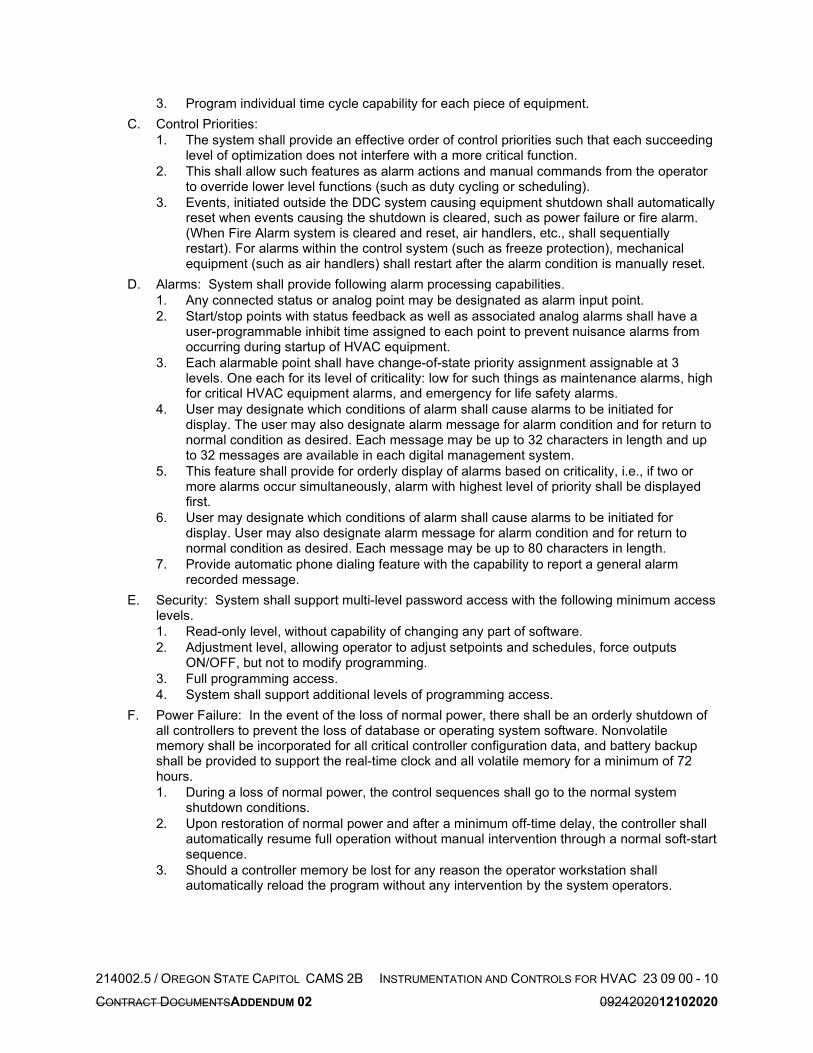
214002.5 / OREGON STATE CAPITOL CAMS 2B INSTRUMENTATION AND CONTROLS FOR HVAC 23 09 00 - 10
CONTRACT DOCUMENTSADDENDUM 02 0924202012102020
3. Program individual time cycle capability for each piece of equipment.
C. Control Priorities:
1. The system shall provide an effective order of control priorities such that each succeeding level of optimization does not interfere with a more critical function.
2. This shall allow such features as alarm actions and manual commands from the operator to override lower level functions (such as duty cycling or scheduling).
3. Events, initiated outside the DDC system causing equipment shutdown shall automatically reset when events causing the shutdown is cleared, such as power failure or fire alarm. (When Fire Alarm system is cleared and reset, air handlers, etc., shall sequentially restart). For alarms within the control system (such as freeze protection), mechanical equipment (such as air handlers) shall restart after the alarm condition is manually reset.
D. Alarms: System shall provide following alarm processing capabilities.
1. Any connected status or analog point may be designated as alarm input point.
2. Start/stop points with status feedback as well as associated analog alarms shall have a user-programmable inhibit time assigned to each point to prevent nuisance alarms from occurring during startup of HVAC equipment.
3. Each alarmable point shall have change-of-state priority assignment assignable at 3 levels. One each for its level of criticality: low for such things as maintenance alarms, high for critical HVAC equipment alarms, and emergency for life safety alarms.
4. User may designate which conditions of alarm shall cause alarms to be initiated for display. The user may also designate alarm message for alarm condition and for return to normal condition as desired. Each message may be up to 32 characters in length and up to 32 messages are available in each digital management system.
5. This feature shall provide for orderly display of alarms based on criticality, i.e., if two or more alarms occur simultaneously, alarm with highest level of priority shall be displayed first.
6. User may designate which conditions of alarm shall cause alarms to be initiated for display. User may also designate alarm message for alarm condition and for return to normal condition as desired. Each message may be up to 80 characters in length.
7. Provide automatic phone dialing feature with the capability to report a general alarm recorded message.
E. Security: System shall support multi-level password access with the following minimum access levels.
1. Read-only level, without capability of changing any part of software.
2. Adjustment level, allowing operator to adjust setpoints and schedules, force outputs ON/OFF, but not to modify programming.
3. Full programming access.
4. System shall support additional levels of programming access.
F. Power Failure: In the event of the loss of normal power, there shall be an orderly shutdown of all controllers to prevent the loss of database or operating system software. Nonvolatile memory shall be incorporated for all critical controller configuration data, and battery backup shall be provided to support the real-time clock and all volatile memory for a minimum of 72 hours.
1. During a loss of normal power, the control sequences shall go to the normal system shutdown conditions.
2. Upon restoration of normal power and after a minimum off-time delay, the controller shall automatically resume full operation without manual intervention through a normal soft-start sequence.
3. Should a controller memory be lost for any reason the operator workstation shall automatically reload the program without any intervention by the system operators.

214002.5 / OREGON STATE CAPITOL CAMS 2B INSTRUMENTATION AND CONTROLS FOR HVAC 23 09 00 - 11
CONTRACT DOCUMENTSADDENDUM 02 0924202012102020
2.10 INPUT/OUTPUT (I/O) FUNCTIONS
A. Analog Inputs (AI): The AI function shall monitor each analog input, perform A-to-D conversion, and hold the digital value in a buffer for interrogation. Provide signal conditioning for each analog input. Individually calibrate all analog inputs for zero and span, in hardware or in software. Minimum 12 bit A to D resolution.
B. Analog Outputs (AO): The AO function shall accept digital data, perform D-to-A conversion, and output a signal compatible with the operator. Individually calibrate all analog outputs for zero and span. Provide short circuit protection. Minimum 8 bit D to A resolution.
C. Digital Inputs (DI): The DI function shall accept on/off, open/close, or other change of state (two-state data) indications. Provide isolation and protection against input voltage up to 180 Vac peak.
D. Digital Outputs (DO): The DO function shall provide contact closures for momentary and maintained operation of output devices. Closures shall have a minimum duration of 0.1 second.
2.11 UPS PRODUCT SPECIFICATIONS
A. General: Provide an uninterruptable power supply (UPS) for each DDC field panel. The UPS shall be fed by 120V AC emergency power circuits. The UPS shall be floor or wall mountable.
B. UPS: Provide MGE Pulsar UPS, or pre-bid approved equal. Products shall carry UL 1778 listing. Base sizing on peak current requirements of connected load, plus 15 percent factor of safety. Provide manufacturer’s standard three-year comprehensive warranty, including batteries.
PART 3 EXECUTION
3.01 INSTALLATION
A. Mounting Panels: Locate panels where shown on Drawings or near item of equipment to be controlled, but not on equipment itself.
B. DDC Field Panels: Provide number of panels required to accommodate all DI, DO, AI, and AO points and all hardware and software to accomplish specified control sequenced. Locate all panels in mechanical or electrical rooms. Submit proposed locations for approval prior to preparing control drawings.
C. Pneumatic Signals: The use of pneumatic signals to start and stop motors is not allowed.
D. Electrical:
1. Provide control wiring for all control devices and control panels.
2. Run all control wiring in conduit.
3. Provide power wiring for all control devices and control panels. Utilized designated circuits in electrical power panels. Refer to Electrical Drawings. If no circuits are designated for DDC Controls, submit detailed request for use of spare circuits at no additional cost.
4. All power wiring to be installed in conduit.
5. Grounding: Instrumentation and communication grounding shall be installed as necessary to preclude ground loops, noise, and surges from adversely affecting system operation.
6. Control voltage shall be limited to maximum of 120 volts.
7. Where relay coil is connected to load side of motor starter to energize with motor operation, external control circuit shall be properly fused with fuse block located in respective starter enclosure.
8. Where relays are used to control single phase motors directly, provide contacts rated for not less than horsepower rating of largest motor switched by relay.
E. Identification: Provide engraved nameplates identifying all switches, lights and starters, and each control device where control function is not readily apparent.
F. Room Thermostats and Room Sensors:
1. Wall Thermostats and Room Sensors without User Adjustment: Mount at height of 60 inches above finished floor.
2. Provide insulating back on thermostats mounted on exterior walls.

214002.5 / OREGON STATE CAPITOL CAMS 2B INSTRUMENTATION AND CONTROLS FOR HVAC 23 09 00 - 12
CONTRACT DOCUMENTSADDENDUM 02 0924202012102020
3. Provide one thermostat for each zone of temperature control.
4. Submit proposed locations for approval prior to preparing control drawings, where not shown or alternate location is proposed.
G. Carbon Monoxide Detector:
1. Mount sensors at 5 feet above finished floor as indicated on the plans.
2. Provide sensor quantity as indicated on plans or as required by sensor coverage rating (maximum 50-foot radius).
3. Operate system to maintain less than 25 ppm. Alarm if levels exceed 200 ppm for longer than 15 minutes.
4. Refer to sequence of operations for more information on sensor use.
H. Nitrogen Dioxide Detector:
1. Mount sensor at 1-foot below ceiling structure or as indicated on the plans.
2. Provide sensor quantity as indicated on plans or as required by sensor coverage rating (maximum 50-foot radius).
3. Operate system to maintain less than 0.75 ppm. Alarm if levels exceed 2 ppm for longer than 15 minutes.
4. Refer to sequence of operations for more information on sensor use.
I. Carbon Dioxide Sensor:
1. Mount sensor at 5 feet above finished floor or as indicated on the plans.
2. Provide sensor quantity as indicated on plans or as required by sensor coverage rating (max. 20-foot radius).
3. Alarm above 850 PPM.
4. Refer to sequence of operations for more information on sensor use.
3.02 SEQUENCE OF OPERATIONS
A. Custom variable air volume, air handling units with supply and return fans:
1. Occupied Cycle: All associated equipment to operate on time-based schedule. Initial setting: 24/7 operation.
a. Fan Enable/Disable:
1) The supply and return fans shall run continuously.
b. Economizer Control:
1) Minimum Outside Air: The outside airflow measuring station shall signal the DDC controller which shall modulate the normally closed minimum outside air damper, normally open return damper, and normally closed relief damper to positions required to maintain minimum outside air setpoint. If minimum outside air damper is not able to achieve minimum flow setpoint, enable and modulate the main outside air damper to achieve setpoint.
2) Demand Ventilation: Room air carbon dioxide sensor shall signal the DDC controller which resets the required minimum outside air quantity from the baseline minimum flow rate, indicated above, up to the maximum outside air flow rate when the carbon dioxide level in the return air exceeds the maximum acceptable value of 1000 PPM. When the minimum outside air CFM has reached its maximum value and the carbon dioxide level in the room air continues to exceed the maximum acceptable value for a period of more than 10 minutes, the DDC controller shall reset the air terminal unit minimum CFM settings from the Low Minimum CFM setpoint to the Minimum CFM setpoint.

214002.5 / OREGON STATE CAPITOL CAMS 2B INSTRUMENTATION AND CONTROLS FOR HVAC 23 09 00 - 13
CONTRACT DOCUMENTSADDENDUM 02 0924202012102020
3) Fixed Dry Bulb Outside Air Economizer Mode: Unit shall be equipped with a fixed dry bulb 100% economizer mode in accordance with ASHRAE 90.1. In this mode, economizer to modulate to the fully open position, as required, to maintain discharge air temperature setpoint as sensed at the mixed air temperature sensor. When the economizer reaches the fully open position, enable cooling valve operation as required to maintain setpoint. Maintain fully open economizer unless the outside air temperature exceeds the return air temperature during economizer cooling mode, at which point the outside air damper and exhaust air damper shall revert to minimum positions subject to demand ventilation sequences. Economizer mode disables when outside air temperature exceeds 75F.
c. Discharge Air Temperature Reset:
1) A discharge air temperature sensor shall signal the DDC controller which shall modulate in sequence the normally closed main outside air and normally closed relief air dampers, the normally open return air damper, the normally open heating coil valve, and the normally closed cooling coil valve to maintain a 55 degree F discharge air temperature.
2) The discharge air temperature setpoint shall be reset to 65 degrees F when the outside air temperature is below 40 degrees F. Discharge air temperature reset shall be accomplished using a linear schedule starting at 40 degrees F, with full reset occurring at 30 degrees F outside air temperature.
d. Discharge Air Pressure Reset:
1) An end-of-line discharge air static pressure sensor shall signal the DDC controller which shall signal the variable speed controller to control the supply fan to maintain the required discharge static pressure setpoint. All system air terminal units shall signal the DDC controller which shall reset the discharge air static pressure setpoint. The setpoint shall be limited by maximum and minimum values determined during performance testing or balancing.
2) Reset the discharge static setpoint to maintain the maximum terminal unit damper position at 90 percent open as fan speed is increasing and 95 percent open when fan speed is decreasing. Setpoint changes should not occur in the deadband region.
3) Setpoint shall reset down by 0.2 inH2O (initial setting) every 5 minutes (initial setting) when the maximum zone damper position is 90 percent and reset up by 0.2 inH2O (initial setting) every 5 minutes (initial setting) when the maximum damper position is 95 percent.
2. Startup Mode:
a. Allow ample time for the return, relief and outside air dampers to open before starting fans.
b. Supply and return fans shall slowly ramp up, in no less than 60 seconds, to discharge air plenum static pressure initial setpoint.
3. Shutdown Mode:
a. When the air handling unit is not in operation, the following conditions shall exist:
1) The supply and return fans shall not operate.
2) All dampers and valves shall be in their normal de-energized positions.
4. Alarms/Safeties:
a. A smoke detector located in the return air duct shall signal the DDC controller, which shall initiate the shutdown mode upon detection of smoke in the airstream. An alarm shall be generated.
b. A low limit detection thermostat located between the heating and cooling coils shall signal the DDC controller, which shall initiate the shutdown mode upon sensing a temperature below 40 degrees F. An alarm shall be generated.
c. A differential pressure sensor located across any filter bank shall signal the DDC controller, which shall generate an alarm when the static pressure drop exceeds 0.75 inH2O.

214002.5 / OREGON STATE CAPITOL CAMS 2B INSTRUMENTATION AND CONTROLS FOR HVAC 23 09 00 - 14
CONTRACT DOCUMENTSADDENDUM 02 0924202012102020
d. A discharge air plenum static pressure sensor shall signal the DDC controller which shall override the supply fan speed control algorithm to limit the static pressure to a maximum of 3 inH2O. If the static pressure exceeds 3.5 inH2O, the DDC controller shall initiate the shutdown mode and generate an alarm. A manual software reset shall be required if the pressure peaks at 3.75 inH2O.
e. A manual supply fan differential pressure switch shall be hardwired to shut down the supply fan and generate alarm if the differential pressure across the fan exceeds 5.0 inH2O.
f. A manual return fan differential pressure switch shall be hardwired to shut down the return fan and generate alarm if the differential pressure across the fan exceeds 3.0 inH2O.
g. Each variable speed controller shall signal the DDC controller in the event of drive/control failure. An alarm shall be generated.
h. If any fan command value does not match fan run status value for a period of longer than 5 minutes, generate alarm and initiate shutdown mode.
i. A signal from the fire alarm panel shall signal the DDC controller to initiate the shutdown mode and generate alarm.
j. If any flow station measurement value is greater than +/- 10 percent of the setpoint value for longer than 10 minutes, generate alarm.
k. If the supply air temperature value is greater than +/- 5 percent of the setpoint value for longer than 10 minutes, generate alarm.
l. If the return air CO2 level exceeds 1500 PPM for longer than 15 minutes, generate alarm.
B. Variable Volume Air Terminal Unit with Reheat Coil:
1. A space temperature sensor shall signal the DDC controller, which shall modulate the air damper between its cooling maximum and low minimum CFM to maintain the required space temperature setpoints and meet ventilation requirements.
a. Occupied Heating Setpoint: 70 degrees F (adjustable).
b. Occupied Cooling Setpoint: 75 degrees F (adjustable).
2. During normal operation when cooling, heating and ventilation are not required, unit shall maintain the scheduled low minimum CFM setpoint.
3. When temperature falls below space heating setpoint, reset CFM to the heating CFM setpoint and modulate heating valve as required to maintain the space heating setpoint.
4. As temperature rises above the space cooling setpoint, reset CFM to the cooling CFM setpoint as required to maintain the space cooling setpoint.
5. When cooling or heating modes are not active, the room air carbon dioxide sensor for the associated AHU shall signal the DDC controller based on high room air CO2 level setpoint (1000 ppm), which shall reset the CFM setpoint from the low minimum CFM setpoint to the minimum CFM setpoint. The CFM setpoint shall revert to the low minimum CFM value when the carbon dioxide level drops below 800 ppm unless heating or cooling modes become active which will take priority over the ventilation sequence.
6. Terminal units with occupancy sensors shall indicate when units are able to initiate a standby mode. When standby mode is activated, space heating and cooling setpoints shall be offset by +/- 5F from the occupied setpoints.
a. Occupied Standby Heating Setpoint: 65 degrees F
b. Occupied Standby Cooling Setpoint: 78 degrees F.
7. When system is in unoccupied mode, terminal unit dampers shall remain in the fully open position.
C. Zone Temperature Global Adjustment:
1. General: All occupied zone temperature setpoints shall be adjustable from single user input. The intent is to allow facilities to adjust occupancy setpoints for all occupied portions of the building at once.
2. Warm Weather Adjustment: Space cooling temperature setpoint shall be 78 degrees F (adjustable).

214002.5 / OREGON STATE CAPITOL CAMS 2B INSTRUMENTATION AND CONTROLS FOR HVAC 23 09 00 - 15
CONTRACT DOCUMENTSADDENDUM 02 0924202012102020
3. Cold Weather Adjustment: Space heating temperature setpoint shall be 68 degrees F (adjustable).
D. Parking Garage Exhaust (GEF-002):
1. Start-up Mode:
a. The Start-up Mode shall be initiated either manually by operator command, or automatically where indicated in System Equipment sequences below.
b. Release all System Equipment to operate in the Normal Operation Mode per individual System Equipment sequences below.
2. Normal Operation Mode:
a. The Garage Exhaust System shall operate in the Normal Operation Mode as determined by a time-based schedule. Schedule for 24/7 operation.
b. Monitor the CO level in the space at CO sensors located as shown on the Drawings.
c. Monitor the NO2 level in the space at NO2 sensors located as shown on the Drawings.
d. If at all sensor locations CO level is below 25 PPM and NO2 level is below 0.75 PPM: Garage Exhaust Fan shall be off.
e. If at any sensors either CO level is between 25 PPM and 50 PPM or NO2 level is between 0.75 and 1 PPM: Garage Exhaust Fan shall run at low speed.
f. If at any sensor either CO level is above 50 PPM or NO2 level is above 1 PPM: Garage Exhaust Fan shall run at high speed for a minimum of 10 minutes or until CO concentration level drops below 50 PPM and NO2 concentration level drops below 1 PPM.
3. Shut-down Mode:
a. The Garage Exhaust Fan shall not operate.
4. Alarms and Safeties:
a. Variable Frequency Drive (VFD) Alarms: Each VFD shall signal the DDC controller in the event of VFD shutdown. In the event of VFD shutdown, initiate the Shutdown Mode for the affected equipment.
b. Indoor Air Quality:
1) Generate an alarm in the event the CO concentration exceeds 200 PPM at any sensor for 10 minutes (adjustable).
2) Generate an alarm in the event the NO2 concentration exceeds 2 PPM at any sensor for 10 minutes (adjustable).
3) CO or NO2 Sensor Failure: Generate an alarm in the event any CO or NO2 sensor fails. Operate the Garage Exhaust Fan at maximum speed.
c. Additional Points For Monitoring Only: Monitor the following additional points not required for control sequences.
d. Monitor and report motor speed, peak current and energy use at all Variable Frequency Drives.
E. Unit Heaters:
1. Cycle fan and the normally open, two-position, two-way control valve to maintain 50 degrees F room temperature.
2. Room temperature sensor shall signal the DDC controller which shall generate an alarm in the event of a room temperature below 40 degrees F.
3. Alarm/Safeties:
a. Low Temperature Alarm: Generate alarm is space temperature falls below 40 degrees F, adjustable.
b. High Temperature Alarm: Generate alarm is space temperature rises above 80 degrees F, adjustable.
F. Finned Tube.
1. General: The unit shall operate on a time-based schedule.
2. Unoccupied Cycle:
a. Modulate the heating valve to maintain the space temperature setpoint.

214002.5 / OREGON STATE CAPITOL CAMS 2B INSTRUMENTATION AND CONTROLS FOR HVAC 23 09 00 - 16
CONTRACT DOCUMENTSADDENDUM 02 0924202012102020
b. Space temperature setpoint: 50°F (adjustable).
3. Occupied Cycle:
a. Modulate the heating valve to maintain the space temperature setpoint.
b. Space temperature setpoint: 60°F (adjustable).
4. Heating shall be disabled when outside air is greater than 45F.
END INSTRUMENTATION AND CONTROLS FOR HVAC

214002.5 / OREGON STATE CAPITOL CAMS 2B PIPE AND PIPE FITTINGS HVAC 23 21 13 - 1
ASI 301 10302020
SECTION 23 21 13
PIPE AND PIPE FITTINGS HVAC
PART 1 GENERAL
1.01 SUMMARY
A. This Section includes: Furnish piping, pipe fittings, and incidental related items as required for complete piping systems, and treatment of HVAC water systems.
1.02 QUALITY ASSURANCE
A. Regulatory Requirements:
1. Piping material and installation to meet requirements of the local building codes and serving utility requirements.
B. All grooved joint couplings and fittings shall be the products of a single manufacturer. Grooving tools shall be of the same manufacturer as the grooved components.
1. All castings used for coupling housings, fittings, valve bodies, etc., shall be date stamped for quality assurance and traceability.
C. Pipe Cleaning: Should any pipe be plugged or should foaming of water systems occur, disconnect piping, re-clean, and reconnect without additional expense to the Owner.
D. Correct any damage to the building or systems resulting from failure to properly clean the system without additional expense to the Owner.
1.03 SUBMITTALS
A. Submit the following:
1. List of piping materials indicating the service it is being used for. (Do not submit piping product data).
2. Product data on mechanical couplings and related components, double wall fuel oil pipe and fittings, and polypropylene waste and vent pipe.
3. Certificate of completion.
4. Treatment Reports.
B. Test Reports and Certificates: Submit certificates of inspections and pipe tests to Owner.
C. Other: Make certified welders’ certificates available.
PART 2 PRODUCTS
2.01 ACCEPTABLE MANUFACTURERS
A. As indicated.
2.02 BLACK STEEL PIPE, SCHEDULE 40 AND STANDARD
A. Pipe: Schedule 40 conforming to ASTM A 135 or A 53. Schedule 40 up to 10-inch diameter. Standard weight for 12-inch diameter and above.
B. Fittings: 150 lb. screwed malleable iron on 2 inches and below, Schedule 40 welding fittings conforming to ASTM A 234 for 2-1/2 inches and above or mechanical couplings on select piping as herein specified. Fittings below grade shall be welding fittings. All elbows on pumped systems shall be long radius type. Short radius elbows not acceptable for use except as approved on a case by case basis.
C. Service:
1. Chilled and heating water piping up to and including 6-inches.
1.2. Condenser water piping above ground.
2.03 COPPER PIPE
A. Pipe: Hard drawn copper tubing, Class L, ASTM B 88.
B. Fittings:
1. Wrought copper, 150 psi; ANSI B16.22 for soldered joints, ANSI B16.50 for brazed joints; Chase, Revere, Mueller or approved equal.

214002.5 / OREGON STATE CAPITOL CAMS 2B PIPE AND PIPE FITTINGS HVAC 23 21 13 - 2
ASI 301 10302020
C. Service:
1. Chilled and heating water piping (Type L, hard drawn) up to and including 4-inches.
2. Coil condensate drains and traps.
2.04 FLANGED JOINTS
A. Flanges shall be cast iron or steel for screwed piping and forged steel welding neck for welded line sizes.
B. Pressure rating and drilling shall match the apparatus, valve, or fitting to which they are attached.
C. Flanges shall be in accordance with ANSI B16.1; 150 lb. for system pressures to 150 psig; 300 lb. for system pressures 150 psig to 400 psig.
D. Gaskets for all flanged services, except steam and pumped condensate, shall be Garlock 3700 or equal, 1/8-inch thick, non-metallic type.
E. Gaskets for steam and pumped condensate shall be Flexitaulic Style CG or equal, 1/8-inch thick, semi-metallic type.
F. Make joint using American Standard hexagon head bolts, lock washers, and nuts (per ASTM A307 GR.B) for service pressures to 150 psig; alloy steel stud bolts, lock washer, and American Standard hexagon head nuts (per ASTM A307 GR.B) for service pressures 150 psig to 400 psig.
G. Use length of bolt required for full nut engagement. Provide electro-cad plated bolts and nuts on cold and chilled water lines.
2.052.04 UNIONS
A. 150 psi malleable iron, brass to iron seat, ground joint, black or galvanized to match pipe. 200 psi WOG bronze, ground joint, solder type for copper tubing.
B. Dielectric fittings shall be nationally listed, have a dielectric thermoplastic interior lining, and meet requirements of ASTM F-492. Fittings shall be suitable for the pressure and temperature to be encountered.
2.062.05 MECHANICAL PIPE COUPLINGS AND FITTINGS
A. Acceptable Manufacturers:
1. Victaulic
2. Anvil Gruvlok 7401, 7001
3. Other Manufacturers: Submit Substitution Request.
B. Couplings: Ductile iron conforming to ASTM A 536, Grade 65-45-12, rust inhibiting paint.
C. Fittings: Ductile iron conforming to ASTM A 536, Grade 65-45-12. Elbows shall be long radius type.
D. Bolts and Nuts: Zinc electroplated track head bolts conforming to ASTM A 183.
E. Gasket: Grade “E” EPDM:
1. Temperature Range: -30 degrees F to 230 degrees F.
2. Flushseal, Installation Ready or Flush Gap configuration.
F. Service:
1. Chilled Water
2.072.06 SOLDERING AND BRAZING
A. Brazed Joints:
1. Westinghouse Phos-Copper
2. Dyna-Flow by J.W. Harris Co., Inc.
3. Applied locations:
a. All below grade piping.
b. All above grade piping larger than 2-inches for the following services: heating water, chilled water.

214002.5 / OREGON STATE CAPITOL CAMS 2B PIPE AND PIPE FITTINGS HVAC 23 21 13 - 3
ASI 301 10302020
B. Soldered Joints:
1. Wrought Copper Pipe Fittings: All-State 430 with Duzall Flux, Engelhard Silvabrite with Engelhard General Purpose Flux or J.W. Harris Co.
2. Valves, Cast Fittings or Bronze Fittings: Harris Stay-Silv-15 or Handy & Harmon Sil-Fos.
3. Applied locations: Above grade piping 2-inch and smaller for the following services: Heating water, chilled water, condenser water, heat recovery water, industrial cold water, trap priming lines.
C. Valves, Cast Fittings or Bronze Fittings: Harris Stay-Silv-15 or Handy & Harmon Sil-Fos.
2.082.07 PIPE WRAPPING
A. For all below ground steel piping and fittings, provide complete covering of Scotchrap No. 51, 20 mil thickness, protective tape applied over Scotchrap pipe primer applied at 1 gal/800 SF of pipe surface.
B. At Contractor’s option as approved, pipe may be furnished with factory applied jacket of “X-tru-coat” with Scotchrap as previously specified for field joints.
PART 3 EXECUTION
3.01 PREPARATION
A. Measurements, Lines, and Levels:
1. Check dimension at the building site and establish lines and levels for work specified in this Section.
2. Establish all inverts, slopes, and manhole elevations by instrument, working from an established datum point. Provide elevation markers for use in determining slopes and elevations in accordance with Drawings and Specifications.
3. Use established grid and area lines for locating trenches in relation to building and boundaries.
3.02 PIPING INSTALLATION
A. Install unions in all non-flanged piping connections to apparatus and adjacent to all screwed control valves, traps, and appurtenances requiring removal for servicing so located that piping may be disconnected without disturbing the general system.
B. Mechanical Pipe Couplings and Fittings:
1. All grooved joint couplings, fittings, valves, and specialties shall be the products of a single manufacturer. Grooving tools shall be of the same manufacturer as the grooved components.
2. Flexible couplings to be used only when expansion, contraction, deflection or noise and vibration is to be dampened, as detailed or specified.
3. On systems using galvanized pipe and fittings, fittings shall be galvanized at factory.
4. Before assembly of couplings, lightly coat pipe ends and outside of gaskets with approved lubricant.
5. Pipe grooving in accordance with manufacturer’s specifications contained in latest published literature.
6. Gaskets shall be molded and produced by the coupling manufacturer, and shall be suitable for the intended service.
7. The coupling manufacturer’s factory trained representative shall provide on-site training for the contractor’s field personnel in the use of grooving tools and installation of grooved joint products. The representative shall periodically visit the project site to ensure best practices in grooved installation are being followed. (A distributor’s representative is not considered qualified to conduct the training or field visits.)
C. Install all piping as to vent and drain. Install according to manufacturer’s recommendations.
D. Support all piping independently at apparatus so that its weight shall not be carried by the equipment.
E. Run piping clear of tube cleaning or removal/replacement access area on coilsetc.

214002.5 / OREGON STATE CAPITOL CAMS 2B PIPE AND PIPE FITTINGS HVAC 23 21 13 - 4
ASI 301 10302020
F. Dielectric Fittings: Provide dielectric couplings, unions, or flanges between dissimilar metals. In addition, provide dielectric couplings as required to isolate cathodically protected piping and equipment.
3.03 PIPING JOINTS
A. Pipe and fittings shall be joined using methods and materials recommended by manufacturer in conformance with standard practice and applicable codes. Cleaning, cutting, reaming, grooving, etc. shall be done with proper tools and equipment. Hacksaw pipe cutting prohibited. Peening of welds to stop leaks not permitted.
B. Copper Piping: Pipe cut evenly with cutter, ream to full inside diameter; end of pipe and inside of fitting thoroughly cleaned and polished. Joint shall be uniformly heated, and capillary space completely filled with solder or braze material, leaving full bead around entire circumference.
C. No couplings installed in floor or wall sleeves.
D. Steel Piping:
1. Screwed Joints: Pipes cut evenly with pipe cutter reamed to full inside diameter with all burrs and cuttings removed. Joints made up with suitable lubricant or Teflon tape applied to male threads only, leaving two threads bare. Joints tightened so that not more than two threads are left showing. Junctions between galvanized steel waste pipe and bell of cast iron pipe shall be made with tapped spigot or half coupling on steel pipe to form spigot end and caulked.
2. Flanged Joints: Pressure rating of flanges shall match valve or fitting joined. Joint gaskets shall be coated with graphite and oil.
0.1. Welded Joints:
.a. Preparation for Welding: Bevel piping on both ends before welding:
a.b. Use following weld spacing on all buttwelds:
Nominal Pipe Wall Thickness Spacing Bevel
1/4 inch or less 1/8 inch 37-1/2
Over 1/4 inch, less than 3/4 inch 3/16 inch 27-1/2
b.c. Before welding, remove all corrosion products and foreign material from surfaces.
.d. Welded Joints: Joints shall be made by the “arc-welding” process using certified welders. Port openings of fittings must match the inside diameter of the pipe to which they are welded. Use full radius welding elbows for all turns, use welding tees for all tees. Reducing fittings must be used for size reduction. “Weldolets” may be used for branches up through one-half the pipe size of the main to which they are attached. Nipples are not allowed.
3.2. Welding Operation:
a. After deposition, clean each layer of weld metal to remove slag and scale by wire brushing or grinding. Chip where necessary to prepare for proper deposition of next layer.
b. Weld reinforcement no less than 1/16-inch not more than 1/8-inch above normal surface of jointed sections. Reinforcement crowned at center and taper on each side to surfaces being joined. Exposed surface of weld shall present professional appearance and be free of depressions below surface of jointed members.
c. No welding shall be done when temperature of base metal is lower than 0°F. Material to be welded during freezing temperatures shall be made warm and dry before welding is started. Metal shall be “warm to the hand” or approximately 60°F.
c.d.
F. Screwed Joints: Use Teflon tape or Teflon liquid dope applied to male threads only.
G. Flexible Couplings: Provide where indicated on the Drawings.
3.04 CHEMICAL TREATMENT PIPING
A. Valves used for chemical treatment service shall be stainless steel.

214002.5 / OREGON STATE CAPITOL CAMS 2B PIPE AND PIPE FITTINGS HVAC 23 21 13 - 5
ASI 301 10302020
3.05 PIPE WRAP
A. Apply per manufacturer’s written instructions.
B. Apply wrapping to fittings in field after installation.
3.06 ADJUSTING AND CLEANING
A. General:
1. Clean interior of all piping before installation.
2. Flush sediment out of all piping systems after installation before connecting mechanical equipment to the piping.
3. When placing the water systems in service during construction, each system shall be cleaned by circulating a solution with 1000 ppm of trisodium phosphate for 24 hours, then drained, flushed and placed in service.
4. Clean all strainers prior to placing in service.
END PIPE AND PIPE FITTINGS HVAC

214002.5 / OREGON STATE CAPITOL CAMS 2B HVAC DUCTS AND CASING-LOW PRESSURE 23 31 01 - 1
CONTRACT DOCUMENTS 09242020
SECTION 23 31 01
HVAC DUCTS AND CASING-LOW PRESSURE
PART 1 GENERAL
1.01 SUMMARY
A. This Section includes: Low pressure ductwork and fittings.
B. Related Sections include:
1. Section 23 05 48, Vibration and Seismic Controls for HVAC Piping Equipment
2. Section 23 07 00, Insulation for HVAC
3. Section 23 33 00, Air Duct Accessories
1.02 QUALITY ASSURANCE
A. Installer Qualifications: Work performed by qualified, experienced mechanics, in accordance with the manual of Duct and Sheet Metal Construction of the Sheet Metal and Air Conditioning Contractors National Association and these Specifications.
B. Regulatory Requirements:
1. Entire ductwork system, including materials and installation, installed in accordance with NFPA 90A.
2. Ductwork and components shall be listed as U.L. 181, Class I air duct, flame rating not to exceed 25 and smoke rating not to exceed 50.
1.03 SUBMITTALS
A. Submit the following:
1. Provide catalog data on each product specified hereunder.
2. Schedule of duct construction standards.
3. Provide shop drawings showing materials and construction details for single wall housing plenum.
4. Provide shop drawings showing construction details, support, and seismic restraint of ductwork distribution systems.
PART 2 PRODUCTS
2.01 SUPPORTS, ANCHORAGE AND RESTRAINTS
A. General:
1. When supports, anchorages, and seismic restraints for equipment, and supports and seismic restraints for ductwork are not shown on the Drawings, the Contractor shall be responsible for their design.
2. Seismic restraints and anchorages shall resist seismic forces as specified in the latest edition of the International Building Code for the seismic zone in which the project is constructed.
3. Seismic restraints shall follow the provisions described in Section 23 05 48, Vibration and Seismic Control for HVAC Piping and Equipment.
4. Seismic restraints shall not introduce stresses in the ductwork caused by thermal expansion or contraction.
5. Connections to structural framing shall not introduce twisting, torsion, or lateral bending in the framing members. Provide supplementary steel as required.
B. Suspended Ductwork: Seismic restraints shall be in accordance with the latest edition of the SMACNA “Seismic Restraint Manual - Guidelines for Mechanical Systems” for the seismic hazard level corresponding to the seismic zone in which the project is constructed.
C. Engineered Support Systems: The following support systems shall be designed, detailed, and bear the seal of a professional engineer registered in the State having jurisdiction:
1. Supports and seismic restraints for suspended ductwork and equipment.
2. Support frames for ductwork and equipment which provide support from below.
3. Equipment and ductwork support frame anchorage to supporting slab or structure.

214002.5 / OREGON STATE CAPITOL CAMS 2B HVAC DUCTS AND CASING-LOW PRESSURE 23 31 01 - 2
CONTRACT DOCUMENTS 09242020
2.02 SHEET METAL DUCTWORK
A. Fabricate from galvanized steel, unless noted otherwise.
B. Minimum gauge, duct construction, joint reinforcing, fittings, hangers and supports shall be in accordance with SMACNA “HVAC Duct Construction Standards – Metal and Flexible”, Latest Edition.
C. Duct Classification: Ducts shall be considered low pressure when design velocities are 2000 fpm or less and maximum static pressure is 2-inches WG positive or negative.
1. The following ductwork constructed in accordance with minimum reinforcement requirements for static pressure class of 1/2-inch WG positive or negative.
a. Supply ductwork downstream from terminal units.
b. Supply, return or exhaust ductwork serving fans scheduled to operate at less than 1/2-inch WG.
c. Supply, return, or exhaust branch ductwork which serves one or two inlets/outlets.
2. The following ductwork constructed in accordance with minimum reinforcement requirements for static pressure class of 1- inch WG positive or negative.
a. Supply, return, or exhaust ductwork serving fans scheduled to operate at less than 1-inch WG. On supply fans pressure drops for louvers, coils, clean filters, and sound traps may be deleted from scheduled fan static.
b. Supply, return, or exhaust ductwork serving multiple duct branches where contractor can demonstrate that pressures will not exceed 1- inch WG positive or negative.
c. Boiler direct vent combustion air intake ductwork.
d. Water heater direct vent combustion air intake ductwork.
3. The following ductwork constructed in accordance with minimum reinforcement requirements for static pressure class of 2-inches WG positive or negative.
a. Supply, return, or exhaust ductwork serving fans scheduled to operate at pressures greater than 1-inch WG positive or negative.
D. Longitudinal seams on rectangular duct shall be Pittsburgh or Button punch snap lock. Snap lock seams for round duct may be used only on ducts classified for 1/2-inch WG. Longitudinal seams for round ducts using lap and rivet, spot weld, or fillet weld may be used only on ducts classified for statics 1-inch WG or less.
E. Joining and reinforcing systems manufactured by Ductmate, Roloc, or TDC are acceptable. Ductmate 35 is equivalent to SMACNA “J”, and Ductmate 25 is equivalent to SMACNA “F”.
F. Use of adjustable round elbows not permitted.
2.03 FLEXIBLE DUCTS
A. Acceptable Manufacturers:
1. Thermaflex M-KE
2. Gen Flex IMP-25S
3. Other Manufacturers: Submit Substitution Request.
B. Description: Flexible air duct with CPE or metal film liner permanently bonded to coated spring steel wire helix with 1-inch thick fiberglass insulation blanket covered with fiberglass reinforced metal film vapor barrier jacket. Duct rated for 6-inch WG positive and 1-inch WG negative.
2.04 EXPOSED OR VISIBLE DUCTWORK IN FINISHED SPACES
A. Round:
1. Material: Round or flat oval, machine formed, spiral lock-seam galvanized sheet metal ductwork of thicknesses as listed for sheet metal duct. Paintable surface.
2. Fittings: Machine formed, shop fabricated, with welded seams, designed for easiest air flow, similar to United Sheet Metal numbers listed.
a. Mitered Elbow with Turning Vanes: Type EV-90-2.
b. Radius Elbows: Type E090-5. Similar for less than 90 degree elbows.
c. Tees: Type Con-T-1.
d. Reducing Fittings: May be used unless noted otherwise.

214002.5 / OREGON STATE CAPITOL CAMS 2B HVAC DUCTS AND CASING-LOW PRESSURE 23 31 01 - 3
CONTRACT DOCUMENTS 09242020
B. Rectangular: Same as for sheet metal ductwork but paintable surface. All reinforcing shall be inside. Use special care to prevent imperfections in the metal surface.
PART 3 EXECUTION
3.01 APPLIED LOCATIONS
A. Supply ductwork on downstream side of terminal box. Galvanized sheet metal ductwork, lined where indicated on the Drawings or as specified in Section 23 07 00, Insulation for HVAC.
B. Supply Ductwork from Spin-In Fittings to Supply Outlet Collar Connection: Flexible duct, maximum 4 feet - 0-inch length.
C. Return Air Trunk Ductwork from End Run to Unit Connection: Galvanized sheet metal ductwork, lined where indicated on the Drawings or as specified in Section 23 07 00, Insulation for HVAC.
D. Exhaust Ductwork: Galvanized sheet metal ductwork, lined where indicated on the Drawings or as specified in Section 23 07 00, Insulation for HVAC.
E. Ductwork between Transfer Grilles: Galvanized sheet metal ductwork, lined where indicated on the Drawings or as specified in Section 23 07 00, Insulation for HVAC.
F. Exposed or Visible Ductwork in Finished Spaces: Sheet metal as specified for application, lined where indicated on the Drawings or as specified in Section 23 07 00, Insulation for HVAC.
3.02 INSTALLATION
A. Ductwork:
1. Seal traverse joints with an approved mastic during joining procedure or tape after joining to provide airtight duct system.
2. Low pressure ductwork hanger and support systems in accordance with SMACNA “HVAC Duct Construction Standards – Metal and Flexible”. Wire supports are not allowed.
3. Provide supplementary steel for support of ductwork in shafts and between building structural members.
4. Fabricate changes in direction to permit easy air flow, using full 1.5D radius bends or fixed turning vanes in square elbows. Radius elbows less than 1.5D radius shall have splitter vanes.
5. Change in duct size or shape necessitated by interference made using rectangular equivalents of equal velocity.
6. Where pipe, structural member, or other obstruction passes through a duct, provide streamlined sheet metal collar around member and increase duct size to maintain net free area. Fit collar and caulk to make air tight.
B. Sound Attenuation (Internal Insulation):
1. Provide sound attenuation duct where shown and as specified under Section 23 07 00, Insulation for HVAC.
2. Duct dimensions shown are net inside attenuating material.
C. Dampers: Install where shown and where necessary to complete final balancing of system. Install regulators as specified in Section 23 33 00, Air Duct Accessories for each specific project condition. Leave all dampers locked wide open in preparation for balancing.
D. Flexible Connectors: Make connections to fans and other rotating equipment with flexible connectors with 2-inch minimum clearance between casing and ductwork. Not required on internally spring isolated units.
E. Spin-in Fittings:
1. Install at branch takeoffs to outlets using round or flex duct.
2. Connect to flexible duct with draw band strap and minimum of two wraps of duct tape.
3. Leave all dampers locked wide open.
F. Flexible Ducts:
1. Make connections at ends using draw band strap and a minimum of 2 wraps of duct tape.

214002.5 / OREGON STATE CAPITOL CAMS 2B HVAC DUCTS AND CASING-LOW PRESSURE 23 31 01 - 4
CONTRACT DOCUMENTS 09242020
2. Suspend center spans from structure above using wire as required by code. Connect to manufacturer’s eyelet on jacket or use 1- inch wide galvanized steel strap with single loop at top and smooth edges.
3. Suspending duct by laying it on the ceiling is prohibited.
4. Avoid crimping flex duct. All changes in direction shall be made using 2D radius. Duct connections to grilles, registers and diffusers using less than 2D radius bends are not acceptable. Where space is constricted, use sheet metal elbows or Thermaflex Flex Boots (or equal).
G. Ductwork, Exposed or Visible in Finished Areas:
1. Use extreme care in handling and installing.
2. Replace all dented or damaged sections.
3. Install ductwork straight and true, parallel to building lines.
4. Make all connections with pop rivets using couplings where applicable. Grind all raw edges smooth and apply paintable sealant to cover imperfections.
5. Remove all excess sealant to provide a finished joint.
6. Provide floor, wall, and ceiling plates as specified in Section 23 05 00, Common Work Results for HVAC.
7. Finish, clean and prime all ductwork and hangers for painting.
3.03 FIELD QUALITY CONTROL
A. Coordination with Balance Agency:
1. Provide services of a sheet metal person familiar with the system ductwork to provide assistance to the balancing agency during the initial phases of air balancing in locating all sheet metal dampers.
2. Install missing dampers required to complete final balancing.
END HVAC DUCTS AND CASING-LOW PRESSURE

214002.5 / OREGON STATE CAPITOL CAMS 2B HVAC DUCTS AND CASING-MEDIUM PRESSURE 23 31 02 - 1
CONTRACT DOCUMENTS 09242020
SECTION 23 31 02
HVAC DUCTS AND CASING-MEDIUM PRESSURE
PART 1 GENERAL
1.01 RELATED DOCUMENTS
A. Drawings and general provisions of the Contract, including General and Supplementary Conditions and Division 01, General Requirements Specification Sections, apply to this Section.
B. The provisions of Section 23 05 00, Common Work Results for HVAC, apply to work specified in this Section.
1.02 SUMMARY
A. This Section includes: Medium Pressure Ductwork and Fittings
B. Related Sections include:
1. Section 23 05 48, Vibration and Seismic Controls for HVAC Piping and Equipment
2. Section 23 05 90, Pressure Testing for HVAC Systems
3. Section 23 07 00, Insulation for HVAC
4. Section 23 33 00, Air Duct Accessories
1.03 QUALITY ASSURANCE
A. Installer Qualifications: Work performed by qualified, experienced mechanics, in accordance with the manual of Duct and Sheet Metal Construction of the Sheet Metal and Air Conditioning Contractors National Association and these Specifications.
B. Regulatory Requirements:
1. Entire ductwork system including materials and installation, installed in accordance with NFPA 90A.
2. Ductwork and components shall be listed as UL 181 Class I air duct, flame rating not to exceed 25 and smoke rating not to exceed 50.
1.04 SUBMITTALS
A. Submit the following:
1. Shop Drawings of ductwork specified hereunder. Include details of supports and seismic restraint of ductwork distribution systems.
2. Product data on medium pressure round and flat oval ductwork and fittings.
3. Schedule of rectangular duct construction standards.
PART 2 PRODUCTS
2.01 SUPPORTS, ANCHORAGE, AND RESTRAINTS
A. General:
1. When supports, anchorages, and seismic restraints for equipment and supports and seismic restraints for ductwork are not shown on the Drawings, the contractor shall be responsible for their design.
2. Seismic restraints and anchorages shall resist seismic forces as specified in the latest edition of the International Building Code for the seismic zone in which the project is constructed.
3. Seismic restraints and anchorages shall resist seismic forces as specified in the latest edition of the International Building Code for the seismic zone in which the project is constructed.
4. Seismic restraints shall follow the provisions described in Section 23 05 48, Vibration and Seismic Controls for HVAC Piping and Equipment.
5. Seismic restraints shall not introduce stresses in the ductwork caused by thermal expansion or contraction.
6. Connections to structural framing shall not introduce twisting, torsion, or lateral bending in the framing members. Provide supplementary steel as required.

214002.5 / OREGON STATE CAPITOL CAMS 2B HVAC DUCTS AND CASING-MEDIUM PRESSURE 23 31 02 - 2
CONTRACT DOCUMENTS 09242020
B. Suspended Ductwork: Seismic restraints shall be in accordance with the latest edition of the SMACNA “Seismic Restraint Manual - Guidelines for Mechanical Systems” for the seismic hazard level corresponding to the seismic zone in which the project is constructed.
C. Engineered Support Systems: The following support systems shall be designed, detailed, and bear the seal of a professional engineer registered in the State having jurisdiction:
1. Supports and seismic restraints for suspended ductwork and equipment.
2. Support frames for ductwork and equipment which provide support from below.
3. Equipment and ductwork support frame anchorage to supporting slab or structure.
2.02 GENERAL
A. Fabricate from galvanized steel unless otherwise noted.
B. Minimum gauge, duct construction, joint reinforcing, fittings, hangers, and supports in accordance with the latest edition of SMACNA “HVAC Duct Construction Standards”, Third Edition, 2005.
C. Duct Classification: Ducts shall be considered medium pressure when design velocities exceed 2000 fpm or static pressure is 2.0-inches W.G. or greater positive. Ducts constructed in accordance with minimum reinforcement requirements for static pressure class of 4 inches positive.
2.03 SINGLE WALL ROUND DUCT AND FITTINGS
A. Materials:
1. Medium pressure round ductwork up to 36-inch diameter spiral lock seam. Round ducts over 36 inches in diameter either spiral lock seam or shop fabricated with longitudinal seams.
2. Takeoffs: Main and branch takeoffs similar to United Spiral Uniform Duct fittings type SRHTC, SRHTL, or SRHL, typically. No saddle fittings allowed. All fittings welded. Saddle fittings with pop rivet fasteners and sealed with high pressure duct sealer may be used only when adding takeoff fittings to existing duct.
3. Transitions, Elbows:
a. Transitions of concentric type or eccentric type to maintain elevations detailed, with not more than 15 degree angle variation on sloped portion.
b. 90 degree elbows of 5 piece design with centerline radius equal to 1-1/2 of duct diameter minimum. Mitered elbows not allowed.
c. 60 degree and 45 degree elbows of 3 piece design with long radius.
d. Y-Branch fittings similar to United Uniseal SRHY or SRHYR. Bull head tees not allowed.
2.04 RECTANGULAR STEEL DUCTWORK
A. Fabricate from galvanized steel unless noted otherwise.
B. Longitudinal seams shall be Pittsburg type. Button punch snap lock may be used only if sheetmetal screws are added on 24-inch centers.
C. Joining and reinforcement systems as manufactured by Ductmate, Roloc, or TDC are acceptable. Ductmate 35 is equivalent to SMACNA “J” reinforcement and Ductwork 25 is equivalent to SMACNA “F”. Fasten ductmate to duct with sheetmetal screws minimum of 6-inch on center.
D. Fittings:
1. Fabricate fittings for easiest airflow using radius elbows with center-line radius elbows equal to 1-1/2 times the duct dimension in the plane of the turn.
2. Transitions: Concentric or eccentric type to maintain elevations with not more than 15 degree angle variation on sloped portion.
3. Conical Taps: For branch take-off to terminal unit, construct with inlet 4-inches wider than outlet and no raw edges inside.

214002.5 / OREGON STATE CAPITOL CAMS 2B HVAC DUCTS AND CASING-MEDIUM PRESSURE 23 31 02 - 3
CONTRACT DOCUMENTS 09242020
E. Use of mitered elbows with turning vanes is not acceptable except where indicated on drawings. Radius elbows with centerline radius less than 1.5D radius shall be vaned type and may be used only with approval of engineer.
PART 3 EXECUTION
3.01 APPLIED LOCATIONS
A. Supply ductwork on upstream side of air terminal unit.
B. Supply ductwork serving fans scheduled to operate at pressures greater than 2-inches WG positive.
C. Supply ductwork 20 feet downstream of air handling equipment and the first 6 feet of duct mains connect to the vertical ducts at each floor with round or oval double walled ductwork.
D. Acoustical line plenums on discharge of rooftop units. Plenum size shall be sufficient for supply duct connections as shown on plans, minimum plenum size shall be same as unit opening.
3.02 MEDIUM PRESSURE ROUND DUCTWORK INSTALLATION
A. Install in accordance with manufacturer’s instructions and with the latest edition of SMACNA "HVAC Duct Construction Standards".
B. Seal all traverse and longitudinal joints with high pressure duct sealer and wrap with duct sealer tape or hard cast with minimum 2-inch overlap.
C. Field connections for ducts 36-inch diameter and less for round duct and 42-inches major axis and less for oval ducts not requiring additional reinforcing shall use slip on connections. Other ducts shall use flanged joint connections, fabricated and sealed per manufacturer’s instructions.
D. Branch takeoffs rigidly connected to terminal unit without flex duct.
3.03 MEDIUM PRESSURE RECTANGULAR DUCT INSTALLATION
A. Install duct, fittings, supports, and hangers in accordance with the latest edition of SMACNA “HVAC Duct Construction Standards”.
B. Seal traverse and longitudinal joints with high pressure duct sealer and wrap with duct sealer tape or hard cast with minimum 2-inch overlap.
C. Provide supplementary steel for support of ductwork in shafts and between building structural members.
D. Change in duct size or shape necessitated by interference shall be made using rectangular equivalents of equal velocity.
3.04 FIELD QUALITY CONTROL
A. Field Tests: Perform leakage tests in accord with Section 23 05 90, Pressure Testing for HVAC Systems.
END HVAC DUCTS AND CASING-MEDIUM PRESSURE
214002.5 / OREGON STATE CAPITOL CAMS 2B AIR DUCT ACCESSORIES 23 33 00 - 1
CONTRACT DOCUMENTS 09242020
SECTION 23 33 00
AIR DUCT ACCESSORIES
PART 1 GENERAL
1.01 SUMMARY
A. This Section includes:
1. Medium and Low Pressure Duct Accessories
2. Sealants and Tapes
3. Flexible Connectors
4. Fire Dampers
5. Access Doors
6. Spin-In
7. Automatic Dampers
8. Drain Pans
B. Related Sections include:
1. Section 23 09 00, Instrumentation and Controls for HVAC
2. Section 23 31 01, HVAC Ducts and Casing-Low Pressure
1.02 QUALITY ASSURANCE
A. Work performed by qualified, experienced mechanics in accordance with the manual of Duct and Sheet Metal Construction of the National Association of Sheet Metal and Air Conditioning Contractors and these Specifications.
B. Install entire ductwork system, including materials and installation, in accordance with NFPA 90A.
C. Flexible connectors, flexible equipment connections, tapes and sealants listed as UL 181, Class I air duct. Flame spread rating not to exceed 25 and smoke developed rating not to exceed 50.
1.03 SUBMITTALS
A. Submit the following: Product data for Duct Accessories.
1. Medium Pressure Duct Accessories:
a. Acoustical Turning Vanes
b. Access Doors
c. Bell Mouth Fittings
d. Duct Sealer
2. Low Pressure Duct Accessories:
a. Access Doors
b. Automatic Dampers
c. Duct Sealer
3. Fire Dampers:
a. Fire Dampers
B. Operation and Maintenance Data: Automatic dampers, fire dampers.
PART 2 PRODUCTS
2.01 MEDIUM PRESSURE DUCT ACCESSORIES
A. Acceptable Manufacturers:
1. As indicated.
2. Other Manufacturers: Submit Substitution Request.
B. Duct Sealer:
1. Based On: McGill Airseal Zero.
2. Description: Suitable for indoor/outdoor use, rated to 10-inch WG, Maximum Flame Spread/Smoke Developed Rating of 25/50, maximum VOC of 420 g/L less water. SCAQMD Rule 1168 compliant.

214002.5 / OREGON STATE CAPITOL CAMS 2B AIR DUCT ACCESSORIES 23 33 00 - 2
CONTRACT DOCUMENTS 09242020
C. Flexible Connector:
1. Peabody Noise Control/Kinetics Model KNM-100B, Polymer Adhesive.
2. Description: One pound per square foot density, barium sulphate load vinyl material with fiberglass reinforcing.
D. Turning Vane Assemblies:
1. Sheet Metal Vanes: Multiple radius hollow vane air foil type with 4-1/2-inch inside radius, galvanized steel construction.
2. Runners: Embossed type.
E. Acoustical Turning Vanes: Multiple radius air foil type, perforated steel construction with fiberglass fill. AirSan Acoustiturn or as approved.
F. Access Doors:
1. Manufacturers:
a. United Sheetmetal APR or ASR
b. Metco
c. Semco
d. Cesco
e. Ruskin
f. Nailor-Hart
g. Or approved equal.
2. Round, oval or rectangular to match duct, single wall to open against positive duct pressure, fastened with spring clips, pressure seal gasket, fastened with chain. Double wall access doors similar except provide insulated frame and insulated door.
G. Bell Mouth Fittings: Round or flat oval, radius of 0.20 D minimum.
2.02 LOW PRESSURE DUCT ACCESSORIES
A. Acceptable Manufacturers:
1. As indicated.
2. Other Manufacturers: Submit Substitution Request.
B. Damper Regulators:
1. Ventlok model numbers used, similar products by Young, Durodyne or approved equal are acceptable.
2. Dial Regulator: Concealed or exposed duct in unfinished spaces, blade lengths 18-inch and less, 3/8-inch, Ventlok 635 or 638 for insulated duct. For blade lengths, 19-inches and above, similar except 1/2-inch shafts.
3. Dial Regulator: Exposed duct finished space, 3/8-inch, Ventlok 640.
4. Dial Regulator: Concealed, not accessible, blade lengths 18-inch and less, 3/8-inch Ventlok 666 regulator with 680 mitered gear assembly where right angle turn is necessary. Blade lengths 19 inches and above, similar except 1/2-inch shafts.
5. End Bearings: For ducts rated to 1-inch WG, open end, Ventlok 607. For ducts rated above 1-inch WG, closed end, Ventlok 609. Exposed ductwork, finished spaces, Ventlock 609. Spring end bearings not allowed.
C. Volume Damper Fabrication:
1. Single blade dampers reinforced or crimped for rigidity, with pivot rod extending through duct. Dampers over 12-inches high use multiple opposed blade damper. Single blade damper no larger than 12-inches by 48-inches. Multiple blade damper factory fabricated, Ruskin MD-35 or equal.
2. Minimum gauge and duct construction in accordance with SMACNA “HVAC Duct Construction Standards”, latest edition.
3. Splitter and butterfly dampers fabricated of 18-gauge galvanized steel.
4. Dampers of length suitable to close branch ducts without damper flutter.
5. Damper blade must be aligned with handle and index pointer.

214002.5 / OREGON STATE CAPITOL CAMS 2B AIR DUCT ACCESSORIES 23 33 00 - 3
CONTRACT DOCUMENTS 09242020
D. Flexible Equipment Connections: 30 ounce Ventfabrics Ventglas or Duro Dyne neoprene coated fire retardant glass fabric or approved equal.
E. Spin-in Fittings:
1. Sheet Metal Duct: Straight pattern sheet metal spin-in fitting with scoops designed for connection to sheet metal ductwork, volume damper, and locking quadrant. Construction with spot welds or rivets. “Button-punch” fabrication prohibited.
2. Fiberglass Duct: Straight pattern sheet metal spin-in fitting with scoops designed for connection to fiberglass ductwork volume damper, and locking quadrant. Construction shall be with spot welds or rivets. “Button-punch” fabrication prohibited.
F. Duct Sealer:
1. Based On: McGill Airseal Zero.
2. Description: Suitable for indoor/outdoor use, rated to 10-inch WG, Maximum Flame Spread/Smoke Developed Rating of 25/50, maximum VOC of 420 g/L less water. SCAQMD Rule 1168 compliant.
G. Duct Tape for Sheet Metal: ARNO C520 duct tape similar United, Duro Dyne, Nashua, Polymer Adhesive.
H. Tape and Adhesive/Activator System for Sheet Metal: Hardcast, Polymer Adhesive.
I. Turning Vane Assemblies:
1. Sheet Metal Vanes: Multiple radius hollow vane air foil type 2-inch (small vane) or 4-1/2-inch (large vane) inside radius, galvanized steel construction.
2. Runners: Push-on type.
3. Acoustical Vanes: Multiple radius air foil type, perforated steel construction with fiberglass fill. AirSan Acoustiturn or as approved.
J. Access Doors:
1. Manufacturer:
a. Air Balance
b. Ruskin
c. Metco
d. Durodyne
e. Cesco
f. Nailor-Hart
g. Or approved equal.
2. Doors complete with steel frame, steel door with backing plate, cam latches (two on units 14-inch by 14-inch and larger), hinge and gasketing. Doors on insulated or lined ducts shall be insulated.
3. Grease Duct Access Door: Construct of metal thickness equal to metal duct, doors air and grease tight with hinge and hand operable latches. Ductmate.
4. Size:
Duct Width or Duct Diameter Net Access Door Opening
Up to 8-inch 6-inch by 6-inch
9-inch to 12-inch 8-inch by 8-inch
13-inch to 20-inch 12-inch by 12-inch
21-inch to 30-inch 16-inch by 14-inch
31-inch to 42-inch 18-inch by 14-inch
Over 42-inch Two 16-inch by 14-inch
K. Drip Pans: Provide Type 304 stainless steel drip pans for cooling coils and exhaust heat recovery coils on built-up units as indicated.
L. Louver Blank-off Panels: At air intake or exhaust louvers which are only partially active area, blank off inactive area with sheet metal closure panels caulked airtight, secured to louver frame and insulated with 2-inch rigid fiberglass insulation per Section 23 07 00, Insulation for HVAC.

214002.5 / OREGON STATE CAPITOL CAMS 2B AIR DUCT ACCESSORIES 23 33 00 - 4
CONTRACT DOCUMENTS 09242020
M. Automatic Dampers:
1. Description: Multi-blade air foil type, except where either dimension is less than 10 inches a single blade may be used. Maximum blade length to be 48-inches. Provide parallel blades for positive or modulating mixing service and opposed blades for throttling service. Blades to be interlocking, minimum 16-gauge galvanized steel.
2. Dampers shall have compression type edge seals and side seating stops. Damper blades shall be reinforced, have continuous full length axle shafts, axle to axle linkage and/or operating "jackshafts" as required to provide coordinated tracking of all blades. Dampers over 25 square feet in area to be in two or more sections, with interconnected blades. Dampers shall have a maximum air leakage of 3 cfm per square foot at 1-inch WG pressure. Provide all automatic dampers except those specified to be provided with units. Tested in accordance with AMCA Standard No. 500. Based on Ruskin CD-60.
3. Damper Operators: Refer to Section 23 09 00, Instrumentation and Controls for HVAC.
4. Manufacturers:
a. Ruskin
b. Greenheck
c. Air Balance
d. Cesco
e. Or equal.
2.03 FIRE DAMPERS
A. Acceptable Manufacturers:
1. Where Ruskin is the only manufacturer indicated, equivalent products may be furnished.
B. Static Fire Dampers:
1. Code Compliance: Provide static fire dampers with a U.L. 555 label for fire rating indicated and in conformance with NFPA 90A.
2. Dampers shall be integrally hinged, folding blade curtain type, for installation in ductwork complete with 160 degrees F fire link and retainer.
3. Dampers shall be suitable for horizontal or vertical installation as required. Furnish stainless steel closure springs and cam lock for complete damper closure on dampers to be installed in vertical air flow positions.
4. Low pressure, 1-1/2-hour: For use in partitions up to 2-hour rating with damper out of air stream for supply.
a. Ruskin Model IBD2 Style B for supply.
b. Ruskin Model IBD2 Style A for return or exhaust.
5. Low pressure, 3-hour: for use in partitions over 2-hour rating with damper out of air stream for supply.
a. Ruskin Model IBD23 Style B for supply.
b. Ruskin Model IBD23 Style A for return or exhaust.
PART 3 EXECUTION
3.01 INSTALLATION
A. Install all devices as shown on the Contract Drawings and per manufacturer’s recommendations.
B. Medium Pressure Duct Accessory installation specified under Section 23 31 02, HVAC Ducts and Casting-Medium Pressure.
C. Low Pressure Duct Accessory installation specified under Section 23 31 01, HVAC Ducts and Casting-Low Pressure.
D. Fire Dampers:
1. Install dampers in accordance with NFPA 90A and manufacturer’s written recommendations.
2. Size and locate dampers as shown on Drawings
3. Install dynamic fire dampers in correct position with regards to direction of air.

214002.5 / OREGON STATE CAPITOL CAMS 2B AIR DUCT ACCESSORIES 23 33 00 - 5
CONTRACT DOCUMENTS 09242020
4. Where dampers are not accessible for servicing by removing an outlet, provide access doors for servicing. Doors shall be compatible with the duct in which they are installed.
E. Size and locate dampers as shown on Drawings:
1. Where dampers are not accessible for servicing by removing an outlet, provide access doors for servicing. Doors shall be compatible with the duct in which they are installed.
F. Access Doors: Install where indicated and at all duct mounted coils, humidifiers, automatic control dampers, smoke dampers, fire dampers, air flow stations, to provide access for cleaning and maintenance.
G. Automatic Dampers: Install where indicated and are not specified with equipment or in Section 23 09 00, Instrumentation and Controls for HVAC. Coordinate damper operators with Section 23 09 00, Instrumentation and Controls for HVAC.
H. Drip Pans: Install under each cooling coil and exhaust heat recovery coil as indicated. Provide drain connection from each drip pan and pipe to nearest floor drain through trap. Drip pans over 6 feet in length require drain connections from both ends. Pitch drip pans in direction of air flow and to drain.
I. Louver Blank-off Panels: Install blank-off panels on unused portions of louvers.
END AIR DUCT ACCESSORIES

214002.5 / OREGON STATE CAPITOL CAMS 2B DUCT SILENCERS 23 33 19 - 1
CONTRACT DOCUMENTS 09242020
SECTION 23 33 19
DUCT SILENCERS
PART 1 GENERAL
1.01 SUMMARY
A. This Section includes:
1. Duct Silencers
1.02 RELATED SECTIONS
A. Division 01, General Requirements
B. Division 23, Heating, Ventilating, and Air Conditioning (HVAC)
C. Section 23 31 01, HVAC Ducts and Casing-Low Pressure
D. Section 233102, HVAC Ducts and Casing-Medium Pressure
E. Section 233300, Air Duct Accessories
1.03 QUALITY ASSURANCE
A. Silencer performance characteristics, including insertion loss, pressure drop, and generated noise, attained through testing in accordance with the latest ASTM E477 test standard for acoustical duct silencers.
B. Performance Data:
1. Obtain from the manufacturer’s NVLAP accredited laboratory.
2. Laboratory performance verification in the manufacturer’s test facility may be requested, in which case a comparative test report made available to the engineer.
C. Combustion ratings for acoustic media equal to or less than the combustion ratings noted below when tested in accordance with ASTM E84 or UL723:
1. Flame Spread Classification: < 25
2. Smoke Development Rating: < 50
D. Silencers factory fabricated and supplied by the same manufacturer.
E. Construct silencers in accordance with ASHRAE and SMACNA standards for the pressure and velocity classification specified for the air distribution system in which it is installed.
1.04 SUBMITTALS
A. Submit the following:
1. Manufacturer’s performance data for dynamic insertion loss, generated noise, and pressure drop provided and obtained in accordance with ASTM E477.
2. Schedule of data for each silencer with the size, configuration, airflow rate, and airflow direction.
PART 2 PRODUCTS
2.01 MANUFACTURERS
A. Duct Silencers
1. Price
2. Vibro-Acoustics
3. Ruskin
4. Dynasonics
5. Commercial Acoustics
6. Semco
7. IAC
8. Other Manufacturers: Submit substitution request.
2.02 DUCT SILENCERS
A. Pressure rated airtight at 8-inch wg differential between inside and outside of silencer.

214002.5 / OREGON STATE CAPITOL CAMS 2B DUCT SILENCERS 23 33 19 - 2
CONTRACT DOCUMENTS 09242020
B. Acoustical Fill Material:
1. Inorganic Glass Fiber:
a. Not less than 4 pcf density.
b. Not less than 5 percent compression.
c. Inert, vermin resistant, and moisture resistant.
PART 3 EXECUTION
3.01 INSTALLATION
A. Install in ducts per manufacturer’s recommendations.
B. Seal space between each module with nosing strips and duct sealer to prevent air from passing between modules.
C. Where attenuators are installed directly on concrete, provide 30 roofing felt or 1-inch roofing insulation under attenuators. Not required when attenuators do not come in contact with concrete.
END DUCT SILENCERS

214002.5 / OREGON STATE CAPITOL CAMS 2B HVAC FANS 23 34 00 - 1
CONTRACT DOCUMENTS 09242020
SECTION 23 34 00
HVAC FANS
PART 1 GENERAL
1.01 SUMMARY
A. This Section includes:
1. Vane Axial Fans
1.02 RELATED SECTIONS
A. Division 01, General Requirements
B. Division 23, Heating, Ventilating, and Air Conditioning (HVAC)
1.03 SUBMITTALS
A. Submit the following:
1. Shop Drawings: Showing dimensions, details of construction.
2. Product Data: Showing performance of fans.
3. Operation and Maintenance Data
4. Submit certified sound power ratings for each fan.
PART 2 PRODUCTS
2.01 MANUFACTURERS
A. Vane Axial Fans:
1. Greenheck
2. Cook
3. Twin City
4. Joy
5. Strobic Air
6. Trane
7. Woods
8. Other Manufacturers: Submit substitution request.
2.02 VANE AXIAL FANS
A. General Description: Axial flow fans as indicated, AMCA rated, standard factory finish.
B. Fans:
1. Fan Blades: air foil design.
2. Minimum 14-gauge welded steel housing, welded steel straightening vanes, companion flanges on both ends.
3. Statically and dynamically balanced in the factory as an assembly within its own bearings with a maximum full amplitude shaft deflection at bearings not to exceed 0.001-inch at 1200 RPM to meet ANSI S 2.19 G2.5 balance quality grade.
4. Bearings grease lubricated with grease lines extended to exterior of fan housing. Bearings have minimum L-10 life of 80,000 hours per AFBMA Standards.
5. Provide automatic controllable blade pitch assembly complete with industrial type pneumatic operator with pilot positioner.
C. Motor: Integrally mounted, 1800 RPM maximum, with pre-lubricated sealed ball bearings. Suitable for across-the-line starter. Refer to Section 23 05 00, Common Work Results for HVAC for energy efficient motor requirements.
D. Vibration Isolation: Refer to Section 23 05 48 Vibration and Seismic Controls for HVAC Piping and Equipment.
E. Drives: Fans direct drive with motor in line with airflow and accessible through fan.
F. Accessories:
1. Where indicated provide automatic motorized inlet dampers, inlet bell with screen, outlet cone, and supports.

214002.5 / OREGON STATE CAPITOL CAMS 2B HVAC FANS 23 34 00 - 2
CONTRACT DOCUMENTS 09242020
PART 3 EXECUTION
3.01 INSTALLATION, GENERAL
A. Provide flexible connections on inlet and discharge duct connection. Flexible connection for vane axial fans to be barium loaded vinyl.
3.02 VANE AXIAL FANS
A. Mount on structural steel supports angle iron with springs, restraints, snubbers, and structural steel base.
B. Provide access door of adequate size at fan outlet for removal of fan motor.
END HVAC FANS

214002.5 / OREGON STATE CAPITOL CAMS 2B AIR TERMINAL UNITS 23 36 00 - 1
CONTRACT DOCUMENTS 09242020
SECTION 23 36 00
AIR TERMINAL UNITS
PART 1 GENERAL
1.01 SUMMARY
A. This Section includes:
1. Terminal Units
1.02 QUALITY ASSURANCE
A. Select units for sound levels, maximum pressure drops, and maximum inlet velocity as specified.
1.03 SUBMITTALS
A. Submit the following:
1. Catalog data, construction details, and performance characteristics for each type and size of terminal unit.
2. Data showing compliance with discharge and radiated sound power level specified.
3. Provide computer calculations for heating coils supplied with unit.
4. Operating and maintenance data.
PART 2 PRODUCTS
2.01 SINGLE DUCT CONSTANT OR VARIABLE VOLUME TERMINAL UNITS
A. Acceptable Manufacturers:
1. Carnes
2. Titus
3. Environmental Technologies
4. Trane
5. Price
6. Tuttle and Bailey
7. Nailor Hart
8. Anemostat
9. Krueger
10. Other Manufacturers: Submit Substitution Request.
B. Description: Single duct, medium velocity, pressure independent, variable volume.
C. Constructed of minimum 22-gauge galvanized steel. Construction to be leakproof with all joints sealed and all access doors gasketed. Leakage rate to be 15 cfm at 3.0-inch differential S.P. Provide access door for cleaning of coil as an integral part of the unit. Interior lined with coated dual density or matt faced insulation meeting NFPA 90A requirements with lining in accordance with U.L. l8l.
D. Volume Regulator Assembly (DDC Controls):
1. Controller and actuator provided by 23 09 00, Instrumentation and Controls for HVAC, factory mounted in NEMA 1 enclosure.
2. Provide averaging type velocity sensor utilizing multiple sensing points.
3. Air valves all metal construction, non-corrosive, with bearings self-lubricating and moving parts replaceable in the field.
4. Assembled unit tested, factory preset, and guaranteed to provide ±5 percent total maximum air flow rate through an inlet pressure range to 3.0-inches water.
E. Air static pressure drop across terminal unit not to exceed 0.35-inch WG without coil and 0.6-inch WG with water coil. Maximum inlet duct velocities shall not exceed 2200 fpm.

214002.5 / OREGON STATE CAPITOL CAMS 2B AIR TERMINAL UNITS 23 36 00 - 2
CONTRACT DOCUMENTS 09242020
F. Sound ratings shall be tested as power level l0-l2 watts in accordance with ARI/ADC 880 standard and ASHRAE Standard 36B-72 at 1.5-inch WG inlet static pressure. Unit discharge airborne and casing radiated sound not to exceed following rated sound power levels:
Maximum Airborne Sound Power (db)
CFM
Octave Band and Center Frequency (Hz)
63 125 250 500 1K 2K 4K
0 - 300 -- 63 64 60 60 60 52
301 – 400 68 65 65 63 60 60 52
401 – 800 71 68 67 67 60 60 52
801 – 1200 73 72 68 67 60 60 52
1201 – 2000 73 75 69 67 60 60 54
2001 and above -- 80 78 76 67 67 60
* Units must have 5-feet of 2-inch thick lined duct or 3-feet-0-inch IAC MS sound trap provided with unit at units discharge to meet acoustic design goals
Maximum Radiated Sound Power (db)
CFM
Octave Band and Center Frequency (Hz)
1 2 3 4 5 6 7
63 125 250 500 1K 2K 4K
0-2000 71 68 61 61 55 55 50
2001 and above*
* Units must have loaded vinyl wrap over 2-inch thick insulation
G. Water Heating Coils: See Section 23 82 00, Convection Heating and Cooling Units for specification.
PART 3 EXECUTION
3.01 INSTALLATION, TERMINAL UNITS
A. Support terminal units from structure using thread rod and brackets provided. Provide vibration isolation as indicated on plans, and as specified. Make a rigid duct connection to the inlet with minimum length of straight duct upstream of unit as recommended by the manufacturer or as noted whichever is greater.
B. Refer to Section 23 07 00, Insulation for HVAC for duct lining requirements at outlet of terminal units. Maintain 3-feet clear in front of control enclosure.
C. Arrange units for operation with control system. Coordinate with the work specified in Section 23 09 00, Instrumentation and Controls for HVAC.
D. Provide a minimum of 5-feet of ductwork prior to first spin-in fitting or outlet branch duct takeoff.
E. Install terminal unit to allow for complete access to controls, and all items requiring maintenance or adjustment. When electrical disconnect is used, coordinate required clearance with NEC requirements, 36-inches minimum. In all other cases, maintain a minimum of 30-inches clearance directly in front of the controls.
F. Mount terminal unit controller, actuator to primary air valve, coil connections, control valve, and piping specialties on the same side of the terminal unit.
G. Install filters prior to operating equipment. Replace filters after substantial completion.
END AIR TERMINAL UNITS

214002.5 / OREGON STATE CAPITOL CAMS 2B AIR OUTLETS AND INLETS 23 37 00 - 1
CONTRACT DOCUMENTS 09242020
SECTION 23 37 00
AIR OUTLETS AND INLETS
PART 1 GENERAL
1.01 SUMMARY
A. This Section includes:
1. Diffusers and Grilles
1.02 RELATED SECTIONS
A. Division 01, General Requirements
B. Division 23, Heating, Ventilating, and Air Conditioning (HVAC)
C. Section 23 33 00, Duct Accessories
1.03 SUBMITTALS
A. Submit the following:
1. Shop Drawings: Showing dimensions and details of construction.
2. Product Data
PART 2 PRODUCTS
2.01 MANUFACTURERS
A. Where only Titus figure numbers are listed, equivalent products by the following manufacturers by using only one:
1. Carnes
2. Price
3. Krueger
4. Tuttle & Bailey
5. Anemostat
6. Nailor
7. Other Manufacturers: Submit substitution request.
2.02 DIFFUSERS AND GRILLES
A. Ceiling Return Grille (C-1): Perforated face modular ceiling grille, steel panel, with duct adapters for round or rectangular as indicated, lay-in tee bar ceiling, or surface mounted as required (coordinate with architectural reflected ceiling plan), white baked enamel finish, Titus PAR.
PART 3 EXECUTION
3.01 INSTALLATION
A. Install diffusers tight to their respective mounting surfaces.
B. Installed plumb and true with room dimensions and accurately centered on projections as shown on the Architectural reflected ceiling plans.
C. Install extractors behind duct mounted sidewall supply grilles, and where shown. Turning vanes allowable if condition is the last outlet on a branch.
D. Set pattern control for directions of throw as shown on Drawings prior to air balancer arriving on Project.
E. Paint ductwork behind outlets flat black.
3.02 PERFORMANCE
A. Unit sizing is based on air being introduced at 20 degrees F temperature differential and being diffused at the 5-foot level to a velocity not greater than 50 FPM and a temperature differential not greater than 1.5 degrees F. Units are also selected so as not to exceed the NC-30 curve.
END AIR OUTLETS AND INLETS
214002.5 / OREGON STATE CAPITOL CAMS 2B CENTRAL HVAC EQUIPMENT 23 70 00 - 1
CONTRACT DOCUMENTS 09242020
SECTION 23 70 00
CENTRAL HVAC EQUIPMENT
PART 1 GENERAL
1.01 SUMMARY
A. This Section includes:
1.02 CUSTOM INDOOR AIR HANDLING UNITS RELATED SECTIONS
A. Division 01, General Requirements
B. Division 23, Heating, Ventilating, and Air Conditioning (HVAC)
C. Section 23 05 14, Variable Frequency Drives for HVAC Systems
D. Section 23 05 48, Vibration and Seismic Controls for HVAC Piping and Equipment
E. Section 23 07 00, Insulation for HVAC
F. Section 23 09 00, Instrumentation and Controls for HVAC
G. Section 23 82 00, Convection Heating and Cooling Units
1.03 SUBMITTALS
A. Submit the following:
1. Shop Drawings showing details of construction, dimensions, arrangement of components, and isolation.
2. Product Data
3. Operating and Maintenance Data
4. Specified Testing Requirements
PART 2 PRODUCTS
2.01 CUSTOM INDOOR AIR HANDLING UNITS
A. Manufacturers:
1. York
2. Haakon
3. Huntair
4. Energy Labs
5. Other Manufacturers: Submit substitution request.
B. Description:
1. Variable volume, multi-zone, draw-through custom fabricated air handling units consisting of return plenum, return fan section with motor and drive, mixing section, pre-filter and final filter sections, heating, cooling coil sections, access sections, supply fan with motor and drive, discharge plenum sections, and interior lighting contained in an insulated steel casing mounted on a common steel base.
2. Arrange components as specified and as indicated on drawings.
C. Unit Casing:
1. Casing of 16-gauge steel reinforced and braced for operation to 10-inches WG. Caulk and seal seams to make unit water and air tight.
2. Leakage rate of the casing not to exceed 0.5 percent of unit airflow at 1.25 times the rated static pressure unless units require factory shipping splits or installation or unit airflow is less than 5000 CFM. The leakage rate for units with shipping splits and airflow under 5000 CFM, 1 percent.
3. Support unit on continuous structural steel C-channel supports around the perimeter of the unit with intermediate angle and channel framework to limit deflection to 0.25-inch on 240-inch unsupported spans. Units less than or equal to 20-feet in length shall have a minimum 4-inch channel, and units greater than 20-feet in length shall have a minimum 6-inch channel.
4. Provide safety grating at all floor openings, with top of grating even with floor.

214002.5 / OREGON STATE CAPITOL CAMS 2B CENTRAL HVAC EQUIPMENT 23 70 00 - 2
CONTRACT DOCUMENTS 09242020
5. Floor to be 3/16-inch aluminum checkerplate
6. Provide bellmouth duct fittings at unit supply discharge connection. Bellmouths to have minimum radius/duct diameter of 0.20.
7. Insulation of entire cabinet (walls, roof, base, corners, doors) 2-inch thick minimum, R-8 minimum. Insulation 3 pounds/cubic-feet. Faced rigid fiberglass insulation or polyurethane foam, with internal liner of 22-gauge perforated metal throughout.
8. Provide access doors for inspection of fan and motor, coils, filters, dampers, attenuators, and other components. Access doors of double wall construction same gauge and insulation as the casing.
9. Provide continuous piano hinge fastened to door frame. Door frame of 16-gauge steel continuously welded.
10. Provide continuous perimeter of closed cell neoprene gasket to form an air tight seal.
11. Provide heavy duty door handles which can be operated on both sides of door.
12. Provide suitable means for latching door in both the open and closed positions.
13. Provide wired glass window for inspection of fan and motor and on access downstream of cooling coil.
14. Doors: Not less than 24-inches wide at fan access sections and not less than 18-inches wide at other access locations.
15. Manufacturers’ standard factory finish. Entire unit exterior including doors, louvers, hoods, and other miscellaneous items shall be finished to match.
D. Fan Section:
1. Fan type and capacity as indicated on the drawings.
2. Minimum fan efficiency. 65 percent.
3. Factory install fan inlet airflow measuring stations where indicated.
4. Statically and dynamically balanced in its own bearings with a maximum full amplitude shaft deflection at bearings not to exceed 0.001-inch at 1200 RPM.
5. Provide spherical roller bearings, 80,000 hour L-10 life per AFBMA Standards.
6. Motor and Drive:
a. Integrally mounted 1800 or 1200 rpm motor, with pre-lubricated sealed ball bearings.
b. V-belt drive sized for 150 percent of motor horsepower, with cast iron fixed sheaves.
c. Multiple belt drives.
d. Sheaves statically and dynamically balanced.
e. Refer to Section 23 05 00, Common Work Results for HVAC for energy efficient motor requirements.
E. Vibration Isolators:
1. Provide as an integral part of each unit as indicated. Refer to Section 23 05 48, Vibration and Seismic Controls for HVAC Piping and Equipment.
2. Coordinated weights and location of support points with the vibration isolation equipment supplier.
3. Provide vibration isolator restraints.
F. Water Coils:
1. See Schedule for capacities and Section 23 82 00, Convection Heating and Cooling Units.
2. Provide stainless steel support rack so that coils can individually be removed without disturbing other coils.
3. Provide stainless steel drain pan for each level of cooling coils.
4. Drain pan shall be double sloped, in direction of air flow and toward drain connection.
G. Filters: See Schedule for sizes. Provide suitable access doors, slide rack, and sealant strips for filters specified.
H. Flexible Connections:
1. Refer to Section 23 33 00, Air Duct Accessories.
I. Dampers:
1. Provide multi-blade dampers as indicated and specified elsewhere.

214002.5 / OREGON STATE CAPITOL CAMS 2B CENTRAL HVAC EQUIPMENT 23 70 00 - 3
CONTRACT DOCUMENTS 09242020
2. Provide minimum outside air damper so that damper is closed with motor shaft retracted and at minimum flow position with motor fully extended.
3. Arrange return air and minimum outside air dampers to discharge against each other for maximum mixing in the mixing box prior to the coil.
J. Sound Requirements:
1. The manufacturer shall furnish sound power levels at the supply air connection, return air connection, outside air opening, relief air openings and casing radiation for each air handling unit.
2. Sound power level (re: 10-12 watts) when producing scheduled airflow (CFM) at static pressure shall not exceed following in any octave band:
Octave Band Center Frequency (HZ)
63 125 250 500 1000 2000 4000 8000
Supply Air 83 84 93 89 85 83 80 69
Outside Air 74 76 82 75 72 72 65 57
Return Air 83 89 83 80 80 82 76 70
Relief Air 75 77 83 76 73 73 66 57
Casing Radiated 79 77 87 74 73 69 59 50
3. Sound performance shall be based on modeled data using manufacturer’s software.
K. Lights and Convenience Receptacles:
1. Provide factory-mounted lighting fixtures so that each section of the unit is illuminated. Marine type lightings with protective metal cage and glass seals. Provide compact fluorescent lamp.
2. Separate switch mounted on the unit with an indicator light.
3. Install duplex receptacles on inside wall of each fan section, and on the outside of the unit on the two longest sides.
L. Electrical:
1. Provide single point 460V power connection on exterior of unit to serve all electrical loads. Factory install and wire all VFDs, starters, disconnects, circuit breakers, fuses, lighting and convenience outlets (and other 460V equipment). Provide transformers and separate circuit breakers for all 120V circuits.
2. Mount VFDs, starters and other electrical equipment.
3. Provide separate, 120V circuit for controls, wired to control enclosure. Coordinate with Section 23 09 00, Instrumentation and Controls for HVAC.
4. Provide junction boxes and wiring at splits for field connections between splits for units shipped in sections.
5. Provide flexible conduit connections to all motors.
6. Electrical work in accordance with NEC and Division 26, electrical of this specification.
PART 3 EXECUTION
3.01 INSTALLATION
A. Indoor Air Handling Unit:
1. Install with air filters in place before operating unit.
2. Mount on steel base which may be integral with unit.
3. Pipe drain pan to floor drain with 3-inch minimum trap seal.
B. Flexible Connections:
1. Provide flexible connections between fans and the connected ducts or plenums.
2. Install with 1-inch space between the fan and connecting duct with fabric snug but not stretched tightly.
3. Provide accurate alignment between fan and duct.
4. Secure in place with flanged connections. Do not crimp into the duct construction. Ends of the screws shall not project into the duct more than 1/8-inch.

214002.5 / OREGON STATE CAPITOL CAMS 2B CENTRAL HVAC EQUIPMENT 23 70 00 - 4
CONTRACT DOCUMENTS 09242020
C. Existing Buildings:
1. Units shall be shipped in sections or field assembled from a factory kit. A factory representative shall be present for the duration of the field assembly.
END CENTRAL HVAC EQUIPMENT

214002.5 / OREGON STATE CAPITOL CAMS 2B CONVECTION HEATING AND COOLING UNITS 23 82 00 - 1
CONTRACT DOCUMENTS 09242020
SECTION 23 82 00
CONVECTION HEATING AND COOLING UNITS
PART 1 GENERAL
1.01 SUMMARY
A. This Section includes:
1. Cooling Coils, Water
2. Heating Coils, Water
3. Finned Tube Radiators
4. Unit Heaters
1.02 SUBMITTALS
A. Submit the following:
1. Catalog data showing dimensions and performance.
2. Computer calculations for coil performance.
3. Operation and Maintenance Data: , finned tube radiation, unit heaters.
PART 2 PRODUCTS
2.01 COOLING COILS, WATER
A. Acceptable Manufacturers:
1. Pace
2. Trane
3. McQuay
4. Carrier
5. Colmac
6. Dunham-Bush
7. York
8. Heatcraft
9. Other Manufacturers: Submit Substitution Request.
B. Description:
1. Coils of nonferrous extended surface construction with continuous 16-gauge galvanized steel casing for installation in air supply unit or ductwork as shown on Drawings.
2. Primary surface of seamless copper tubing rolled into headers with copper bushings or brazed into nonferrous headers.
3. Fins shall be nonferrous, mechanically bonded to tubes, with fin spacing of 12 fins per inch maximum.
4. Coils tested at 300 psi hydrostatic pressure, guaranteed for 150 psi working pressure.
5. Arranged for serpentine flow in continuous circuits with counterflow between air and water without turbulating means; provide air vents at each coil.
6. Supply and return connections on same side, with supply on bottom, downstream of air flow.
7. 0.008-inch minimum fin thickness; 0.024-inch minimum tube wall thickness; 0.035-inch straight stock for U-turns.
8. Capacity certified in accordance with ARI Standard 410-72. Face velocity not to exceed 500 fpm at specified air flow.
2.02 HEATING COILS, WATER
A. Air Handlers: Same as specified for cooling coils. 8 fins per inch maximum and minimum of 2 rows. Face velocity not to exceed 500 fpm.
B. Terminal Reheating Coils: 0.0045-inch minimum fin thickness; 0.016-inch minimum tube wall thickness; 10 fins per inch maximum. Coils supplied as integral part of terminal unit are acceptable.

214002.5 / OREGON STATE CAPITOL CAMS 2B CONVECTION HEATING AND COOLING UNITS 23 82 00 - 2
CONTRACT DOCUMENTS 09242020
2.03 FINNED TUBE RADIATORS
A. Acceptable Manufacturers:
1. Runtal
2. Modine
3. Other Manufacturers: Submit Substitution Request.
B. Panel radiator: Capacity, dimensions and length as indicated on schedules and drawings.
C. Element: The element shall be cold rolled low carbon steel, fully welded, with flat oval water tubes of 0.058-inch minimum thickness. Header piping shall be 3/4-inch NPT. Working pressure of 85 psi.
D. Finish: Gloss powder coat finish of color to be selected by Architect. Architect to select from manufacturer’s standard colors.
E. Mounts: Provide wall mounting brackets.
2.04 UNIT HEATERS
A. Acceptable Manufacturers:
1. Trane Model P or S as scheduled
2. Modine
3. Stearling
4. McQuay
5. Ted Reed
6. Reznor
7. Air Therm
8. Dunham Bush
9. Other Manufacturers: Submit Substitution Request.
B. Horizontal discharge with discharge louvers or vertical discharge with louver cone diffuser. Include water coil, fan, motor, controls and baked enamel finish.
PART 3 EXECUTION
3.01 INSTALLATION
A. Cooling Coils: Installed in air handling units as standard with manufacturer or in ductwork as shown.
B. Heating Coils: Installed in air supply units as standard with manufacturer or in ductwork as shown.
C. Finned Tube Radiators: Mount on wall using wall mounting channels.
D. Unit Heaters: Suspend from structure with 5/8-inch diameter rods. Refer to Drawings and Section 23 05 48, Vibration and Seismic Controls for HVAC Piping and Equipment for vibration isolation and seismic bracing requirement.
E. Damaged Coils: Make every effort to prevent damage to both built-up coils and coils of packaged equipment. Comb damaged coil fins to be straight.
END CONVECTION HEATING AND COOLING UNITS

214002.5 / OREGON STATE CAPITOL CAMS 2B COMMON WORK RESULTS FOR ELECTRICAL 26 05 00 - 1
CONTRACT DOCUMENTS 09242020
SECTION 26 05 00
COMMON WORK RESULTS FOR ELECTRICAL
PART 1 GENERAL
1.01 SUMMARY
A. This Section includes Design-Build work:
1. The intent of Division 26 Specifications and Drawings is to provide a complete and workable facility, with complete systems as required by applicable codes, as indicated, and as specified.
2. Include all work specified in Division 26 and indicated on Drawings, including appurtenances, connections, fasteners, and accessories required to make a complete working system, whether indicated or not indicated.
B. The Division 26 Specifications and the accompanying Drawings are complementary, and what is called for by one shall be as binding as if called for by both.
1. Items shown on the Drawings are not necessarily included in the Specifications and vice versa.
2. In case of conflict, Specifications supersede Drawings.
C. Imperative language used in Division 26 Sections addresses the Contractor, as specified in Division 01 General Requirements, Summary of Work Section.
1.02 REFERENCES
A. The latest adopted revisions of the publications listed below apply to these Specifications as referenced:
1. International Building Code (IBC).
2. National Electrical Code (NEC).
3. National Fire Protection Association (NFPA).
4. National Electrical Manufacturers Association (NEMA).
5. National Electrical Contractors Association (NECA).
6. American National Standards Institute (ANSI).
7. Institute of Electrical and Electronic Engineers (IEEE).
8. Underwriters Laboratories (UL).
9. Oregon Administrative Rules (OAR).
10. The publications are referred to in the text by acronym or initials in parentheses above.
1.03 SYSTEM DESCRIPTION
A. Ground Systems:
1. Provide complete ground systems indicated.
2. Include conduit system, transformer housings, switchboard frame, and neutral bus, motors, and miscellaneous grounds required by Contract Documents and by applicable codes.
B. System Identification:
1. Clearly identify all elements of the Project electrical system to indicate the loads served, or the function of each item of equipment, connected under this work.
2. Comply with requirements of Division 26 Section, Identification, and with applicable codes.
C. Drawings:
1. The Drawings are diagrammatic: they do not show every offset, bend, tee, or elbow which may be required to install work in the space provided and avoid conflicts with other construction.
a. Prior to installing work, take field dimensions, and note conditions available for, installation.
b. Follow the Drawings as closely as practical to do so, and install additional bends, offsets, and elbows where required by installation conditions.
1) Additional offsets, bends, and other connectors are subject to approval by Project Engineer.
214002.5 / OREGON STATE CAPITOL CAMS 2B COMMON WORK RESULTS FOR ELECTRICAL 26 05 00 - 2
CONTRACT DOCUMENTS 09242020
2) Install additional offsets, bends, and other connectors without additional cost to Owner.
c. The right to make any reasonable changes in outlet location prior to roughing in is reserved to the Owner’s Representative.
2. Luminaire Designations:
a. Lower case letters adjacent to devices or luminaires indicate switching arrangement or circuit grouping.
b. Numbers adjacent to devices indicate circuit connection.
3. Circuits and Switching:
a. Do not change branch circuiting and switching indicated; nor combine homeruns, without Engineer’s prior approval.
b. Do not combine or change feeder runs.
4. Circuit Conductors:
a. Include phase, neutral, ground, travelers, and switchlegs required by the control and circuiting arrangement indicated.
b. Provide a dedicated neutral conductor with each circuit, do not use a shared neutral conductor between phases unless specifically requested or directed.
1.04 SUBMITTALS
A. Comply with Division 01 General Requirements, Submittal Procedures Section.
B. Shop Drawings and Equipment Data:
1. Combine electrical shop drawings and equipment data in Submittal binders.
2. Include in Submittal binders:
a. A complete index of materials and equipment required by Specifications to be documented by submittals.
b. Manufacturer’s detailed specifications and data sheets to fully describe equipment furnished.
c. All deviations from the Drawings and Specifications, noted on the submittals. Failure to comply will automatically void any implied approval for use of the equipment on this project.
C. Installation Drawings:
1. Submit prior to starting installation.
2. Show all outlets, devices, terminal cabinets, conduits, wiring, and connections required for the complete system described.
D. Record Drawings:
1. Keep record drawings up to date as the work progresses.
2. Show all changes, deviations, addendum items, change orders, corrections, and other variations from the Contract Drawings.
3. Keep record drawings at the jobsite and available for the Architect’s review.
4. At the completion of the work, incorporate all deviations from the installation drawings to indicate “as-built” conditions.
E. Operation and Maintenance Data:
1. As specified in Division 1 Section, “Closeout Procedures”.
2. Provide a separate manual or chapter for each system as follows:
a. Medium voltage distribution system.
b. Low voltage distribution system.
c. Emergency power system.
d. Standby power system.
e. Fire alarm system.
f. Lighting system.
g. Lighting control system.
h. Power metering and monitoring system.
3. Description of system.

214002.5 / OREGON STATE CAPITOL CAMS 2B COMMON WORK RESULTS FOR ELECTRICAL 26 05 00 - 3
CONTRACT DOCUMENTS 09242020
4. Operating Sequence and Procedures:
a. Step-by-step procedure for system start-up, including a pre-start checklist.
1) Refer to controls and indicators by nomenclature consistent with that used on panels and in control diagrams.
b. Detailed instruction in proper sequence, for each mode of operation (i.e., day-night, staging of equipment).
c. Emergency Operation:
1) If some functions of the equipment can be operated while other functions are disabled, give instructions for operations under those conditions.
2) Include here only those alternate methods of operations (from normal) which the operator can follow when there is a partial failure or malfunctioning of components or other unusual condition.
d. Shutdown Procedure:
1) Include instructions for stopping and securing the equipment after operation.
2) If a particular sequence is required, give step-by-step instructions in that order.
5. Preventive Maintenance:
a. Schedule for preventive maintenance.
1) State the recommended frequency of performance of each preventive maintenance task such as cleaning, inspection, and scheduled overhauls.
b. Cleaning: Provide instructions and schedules for all routine cleaning and inspection with recommended lubricants.
c. Inspection: If periodic inspection of equipment is required for operation, cleaning, or other reasons, indicate the items to be inspected and give the inspection criteria.
d. Provide instructions for lubrication and adjustments required for preventive maintenance routines. Identify test points and given values for each.
6. Manufacturer’s Brochures:
a. Include manufacturer’s descriptive literature covering devices and equipment used in the system, together with illustrations, exploded views, and renewal parts lists.
b. Edit manufacturer’s standard brochures so that the information applying to the actual installed equipment is clearly defined.
7. Results of performance testing, as specified in Part 3 of This Section.
F. Submittals Procedures:
1. Review and recommendations by the Architect or Engineer are not to be construed as change authorizations.
2. If discrepancies are discovered between the materials or equipment submitted, and the Contract Documents, either prior to or after the data is processed, the Contract Documents govern.
1.05 QUALITY ASSURANCE
A. Regulatory Requirements:
1. All products and equipment shall comply with Oregon Revised Statute (ORS) 453.005(7)(e) prohibiting pentabrominated, octabrominated and decabrominated diphenyl ethers. Where products or equipment within this specification contain these banned substances, provide complying products and equipment from approved manufacturers with equal performance characteristics.
2. Provide work and materials conforming to:
a. Local and State codes.
b. Federal and State laws and regulations.
c. Other applicable laws and regulations.
3. Obtain and pay for all permits, licenses, and inspection certificates required by authorities having jurisdiction.
4. Pay any other fees required by governing authorities for work of this Division.
B. Install only electrical products listed by a recognized testing laboratory, or approved in writing by the local inspection authority as required by governing codes and ordinances.
214002.5 / OREGON STATE CAPITOL CAMS 2B COMMON WORK RESULTS FOR ELECTRICAL 26 05 00 - 4
CONTRACT DOCUMENTS 09242020
1.06 SITE VISITATION
A. The Contractor shall visit the site prior to bidding and become familiar with existing conditions and all other factors which may affect the execution of the work. Coordination of installation of equipment with prior bid packages previously issued shall be completed. Include all related costs in the initial bid proposal.
1.07 COORDINATION
A. Coordinate Work of This Division with all other trades to ensure proper installation of electrical equipment.
1. Review Drawings of other trades or crafts to avoid conflicts with cabinets, counters, equipment, structural members, and other possible impediments to electrical work.
2. Report potential conflicts to Architect prior to rough-in.
3. Proceed with rough-in following Architect’s directives to resolve conflicts.
4. In general, the Architectural Drawings govern.
B. Verify the physical dimension of each item of electrical equipment to fit the available space. Contractor’s responsibility includes:
1. Coordination of the equipment to fit into the available space.
2. Access routes through the construction.
C. Layout Drawings:
1. Equipment arrangement shown on Drawings is diagrammatic to indicate general equipment sizing and spatial relationship. Contractor shall include, as part of distribution equipment submittal, a scaled floor plan which includes all equipment shown with their submitted sizes. Include all feeder conduit routing, both above-ground and underground, including termination points at equipment. Submit for Engineer’s review prior to commencing work.
2. Provide additional wiring details at switchboards, motor control centers, and other areas where work is of sufficient complexity to warrant additional detailing for coordination.
3. Submit layout drawings for approval prior to commencing field installation.
D. Where electrical connections are required for equipment provided as Work of other Divisions, coordinate rough-in and wiring requirements for that equipment with its supplier and installer prior to commencing work. Notify Architect and Engineer of any discrepancies between the actual rough-in and wiring requirements, and those identified on Drawings for resolution prior to installation.
E. Arrange raceways, wiring, and equipment to permit ready access to switches, motors, and control components:
1. Doors and access panels shall be kept clear.
F. Coordinate electrical, telephone, and other utility services with the appropriate serving utility.
1. No additional compensation will be allowed the Contractor for connection fees or additional work or equipment required by the serving utility, but not covered in the Drawings or Specifications.
G. Coordinate underground work with other contractors working on the site:
1. Coordinate particularly with contractors installing storm sewer, sanitary sewer, water, and irrigation lines to avoid conflicts.
2. Common trenches may be used with other trades, providing clearances required by codes and ordinances are maintained.
H. Coordinated Shop Drawings:
1. Shop drawings shall be prepared in three-dimensional format.
2. Shop drawings shall include but are not limited to:
a. Superplot plans of above ground work with a colored overlay of all trades including, but not limited to, HVAC piping, HVAC equipment, plumbing piping and equipment, sprinklers, lighting, lighting controls, cable tray, fire alarm devices, electrical power conduit, and ceiling system to a minimum of 1/2-inch equals 1-foot scale.

214002.5 / OREGON STATE CAPITOL CAMS 2B COMMON WORK RESULTS FOR ELECTRICAL 26 05 00 - 5
CONTRACT DOCUMENTS 09242020
b. Superplot plans of below ground work with a colored overlay of all trades including, but not limited to, structural footings and foundation, HVAC piping, civil piping, plumbing piping, and power conduit to a minimum of 1/2-inch equals 1-foot scale.
c. Beam penetration drawings indicating beam penetrations meeting the requirements indicated on the floor plans and on the structural drawings to a minimum of 1/4-inch equals 1-foot scale.
d. Slab penetration drawings of HVAC, plumbing, sprinklers, lighting and electrical to a minimum of 1/4-inch equals 1-foot scale.
e. Fabrication drawings of radiant ceiling panels, architectural metal ceiling, including panel penetrations for lighting, sprinkler heads, fire alarm devices, and any other penetrations.
1.08 CHANGE ORDERS
A. All supplemental cost proposals by the Contractor shall be accompanied with a complete itemized breakdown of labor and materials. At the Architect’s request, Contractor’s estimating sheets for the supplemental cost proposals shall be made available to the Architect. Labor shall be separated and allocated for each item of work.
1.09 WARRANTY
A. Provide a written warranty covering the work of this Division as required by the General Conditions.
1. Incandescent lamps are excluded from this warranty.
B. Apparatus:
1. Free of defects of material and workmanship and in accord with the Contract Documents.
2. Built and installed to deliver its full rated capacity at the efficiency for which it was designed.
3. Operate at full capacity without objectionable noise or vibration.
C. Include in Contractor’s warranty for Work of Division 26 system damage caused by failures of any system component.
1.10 ALTERNATES
A. Comply with Division 01, General Requirements, Alternates Section.
B. Refer to Electrical Drawings for detailed information relating to the appropriate alternates.
PART 2 PRODUCTS
2.01 GENERAL
A. Where specified materials or methods conflict with applicable codes, the more stringent requirement applies.
B. Provide apparatus built and installed to deliver its full rated capacity at the efficiency for which it was designed.
C. Ensure that entire electrical system operates at full capacity without objectionable noise or vibration.
D. Materials and Equipment:
1. Use materials and equipment that are:
a. New.
b. Of quality meeting or exceeding specified standards.
c. Free of faults and defects.
d. Conforming to Contract Documents.
e. Of size, make, type, and quality specified.
f. Suitable for the installation indicated.
g. Manufactured in accordance with NEMA, ANSI, U.L. or other applicable standards.
h. Otherwise as specified in Division 1 Section, “Product Requirements”.
2. Equipment not meeting all requirements will not be acceptable, even though specified by name.

214002.5 / OREGON STATE CAPITOL CAMS 2B COMMON WORK RESULTS FOR ELECTRICAL 26 05 00 - 6
CONTRACT DOCUMENTS 09242020
3. Where two or more units of the same class of equipment are furnished, use products of the same manufacturer.
a. Component parts of the entire system need not be products of same manufacturer.
4. Basis of Design:
a. Equipment scheduled or specified by performance or model number shall be considered the Basis of Design.
b. If other equipment is provided in lieu of the Basis of Design equipment, assume responsibility for all changes and costs which may be necessary to accommodate this equipment, including, but not limited to:
1) Different sizes and locations for connections.
2) Different dimensions.
3) Different access requirements.
4) Any other differences.
PART 3 EXECUTION
3.01 INSTALLATION
A. General:
1. Provide a complete properly operating system for each item of equipment specified.
2. Install materials in a neat and professional manner.
3. Comply with equipment manufacturer’s written instructions, the best industry practices, and the Contract Documents.
4. Comply with latest published NECA Standard of Installation, and provide competent supervision.
B. Clarification:
1. Where there is a conflict among manufacturer’s instruction, best practice, and the Documents, request clarification from the Architect prior to rough-in.
2. Architect’s decision will be final.
3. Work installed without clarification shall be removed and corrected by the Contractor at no cost to the Owner.
C. Existing walls and ceilings shown with new devices may not be intended for architectural demolition or modification. Verify intended architectural scope at existing surfaces prior to installing new pathways or devices. Coordinate alternate conduit routing and device locations with architect where necessary.
1. Existing concrete, block or brick walls are considered not accessible and may require use of Surface Mounted Raceway (SMR) if existing concealed raceway and device boxes are not available for reuse or do not meet the intent of the design (i.e. proximity to egress path, point of use, etc.). Coordinate route and installation where SMR is required with the Architect/Engineer prior to rough-in. The contractor will be responsible for reinstalling SMR routed without such prior approval to the Architects satisfaction.
2. Existing stud walls (wood or metal) with or without blocking with plaster, plasterboard or paneling finish are considered accessible with accessible ceiling, attic, tunnel, or crawl space above, below, or adjacent. Remove, patch, and repair finished surface as required to conceal rough-in for new device locations. If it is determined that a specific instance will not permit concealment of rough-in due to obstructions such as beams, headers, and other structural elements prior approval before rough-in from the Architect is required.
3.02 INSTALLATION IN RATED CONSTRUCTION
A. Firestopping is required at ducts, conduits, and other electrical elements penetrating fire-rated construction assemblies.
B. Comply with firestop materials manufacturer’s written instructions to prevent spread of smoke or fire through sleeves or block-outs penetrating rated fire barriers.
C. Firestopping work shall comply with requirements of Section 07 84 00, Firestopping.

214002.5 / OREGON STATE CAPITOL CAMS 2B COMMON WORK RESULTS FOR ELECTRICAL 26 05 00 - 7
CONTRACT DOCUMENTS 09242020
3.03 EXCAVATION AND BACKFILL
A. Perform all necessary excavation and backfill for the installation of electrical work in compliance with Division 31, Earthwork.
B. For direct burial cable or non-metallic conduit, a minimum 3-inch cover of sand or clean earth fill shall be placed all around the cable or conduit on a leveled trench bottom. Lay all steel conduit on a smooth level trench bottom, so that contact is made for its entire length. Water shall be removed from trench while electrical conduit is being laid.
C. Place backfill in layers not exceeding 8-inches deep and compact to 95 percent of maximum density at optimum moisture to preclude settlement.
1. Interior: Bank sand or pea gravel.
2. Exterior: Excavated material with final 8 inches clean soil.
D. Following backfilling, grade all trenches to the level of surrounding soil. All excess soil shall be disposed of at the site as directed.
E. Provide 6-inches wide vinyl tape marked "ELECTRICAL" in backfill, 12-inches below finished grade, above all high voltage cable or conduit runs.
F. Coordinate patching of all asphalt or concrete surfaces disturbed by this work with General Contractor.
3.04 NOISE CONTROL
A. Minimize transmission of noise between occupied spaces.
B. Outlet Boxes:
1. Do not install outlet boxes on opposite sides of partitions back to back.
2. Do not use straight through outlet boxes, except where indicated.
C. Conduit:
1. Route conduit along corridors or other “noncritical” space to minimize penetrations through sound rated walls, or through non-sound-rated partitions between occupied spaces.
2. Grout solid and airtight all penetrations through sound rated partitions.
3. Use flexible connections or attachments between independent wall structures.
a. Do not rigidly connect (i.e., bridge) independent wall structures.
D. Do not install contactors, transformers, starters, and similar noise-producing devices on walls that are common to occupied spaces, unless otherwise indicated.
1. Where such devices are indicated to be mounted on walls common to occupied spaces, use shock mounts, or otherwise isolate them to prevent the transmission of noise to the occupied spaces.
E. Ballasts, contactors, starters, transformers, and like equipment which are found to be noticeably noisier than other similar equipment on the project will be deemed defective and shall be replaced.
3.05 EQUIPMENT CONNECTIONS
A. General:
1. Provide complete electrical connections for all items of equipment requiring such connections, including incidental wiring, materials, devices, and labor necessary for a finished working installation.
2. Verify the location and method for connecting to each item of equipment prior to roughing-in.
3. Check the amperage, maximum overcurrent protection, voltage, phase and similar attributes of each item of equipment before rough-in and connection.
B. Motor Connections:
1. Make motor connections for the proper direction of rotation.
2. Minimum Size Flex for Mechanical Equipment: 1/2-inch; except at small control devices where 3/8-inch flex may be used.
3. Exposed Motor Wiring: Jacketed metallic flex with minimum 6-inches slack loop.

214002.5 / OREGON STATE CAPITOL CAMS 2B COMMON WORK RESULTS FOR ELECTRICAL 26 05 00 - 8
CONTRACT DOCUMENTS 09242020
4. Do not test run pump motors until liquid is in the system.
C. Control devices and wiring relating to the HVAC systems are furnished and installed under Division 23, HVAC; except for provisions or items indicated in Division 26 Drawings and Specifications.
3.06 EQUIPMENT SUPPORT
A. Minimum Support Capacity:
1. Provide fastening devices and supports for electrical equipment, luminaires, panels, outlets, and cabinets capable of supporting not less than four times the ultimate weight of the object or objects fastened to or suspended from the building structure.
B. Luminaire Supports:
1. Support luminaires from the building structure.
2. Use supports that provide proper alignment and leveling of luminaires.
3. Where permitted at exposed luminaires, install flexible connections neat and straight, without excess slack, and attached to the support device.
C. Support all junction boxes, pull boxes, or other conduit terminating housings located above the suspended ceiling from the floor above, roof, or penthouse floor structure to prevent sagging or swaying.
D. Conduits:
1. Support suspended conduits 1-inch and larger from the overhead structural system with metal ring or trapeze hangers and threaded steel rod having a safety factor of four.
2. Conduits smaller than one 1-inch installed in ceiling cavities, may be supported on the mechanical system supports when available space and support capacity has been coordinated with the subcontractor installing the supports.
3. Anchor conduit installed in poured concrete to the steel reinforcing with No. 14 black iron wire.
E. Powder actuated or similar shot-in fastening devices will not be permitted for any electrical work except by special permission from the Architect.
3.07 ACCESS DOORS
A. Location and size of access doors is Work of Division 26.
B. Furnishing and installation of access doors is work of Division 08 Openings, Access Doors and Frames.
3.08 ALIGNMENT
A. Install panels, cabinets, and equipment level and plumb, parallel with structural building lines.
B. Install distribution equipment and all electrical enclosures fitted neatly, without gaps, openings, or distortion.
C. Properly and neatly close all unused openings with approved devices.
D. Fit surface panels, devices, and outlets with neat, appropriate, trims, plates, or covers without overhanging edges, protruding corners, or raw edges.
3.09 CUTTING AND PATCHING
A. General:
1. Comply with Division 01, General Requirements, Cutting and Patching Section.
2. Restore to original condition new or existing work cut or damaged by installation, testing, and removal of electrical Work.
3. Patch and finish spaces around conduits passing through floors and walls to match the adjacent construction, including painting or other finishes.
4. Clean up and remove all dirt and debris.
B. Make additional required openings by drilling or cutting. Use of jackhammer is prohibited.

214002.5 / OREGON STATE CAPITOL CAMS 2B COMMON WORK RESULTS FOR ELECTRICAL 26 05 00 - 9
CONTRACT DOCUMENTS 09242020
C. Fill holes that are cut oversize so that a tight fit is obtained around the objects passing through.
1. In rated construction, comply with Division 07, Thermal and Moisture Protection, Through-Penetration Firestop Systems.
D. Obtain Architect’s permission and direction prior to piercing beams or columns.
E. Where alterations disturb lawns, paving, walks, and other permanent site improvements, repair and refinish surfaces to condition existing prior to commencement of work.
3.10 PROTECTION OF WORK
A. Protect all electrical work and equipment installed under this Division against damage by other trades, weather conditions, or any other causes.
1. Equipment found damaged or in other than new condition will be rejected as defective.
B. Keep switchgear, transformers, panels, luminaires, and all electrical equipment covered or closed to exclude dust, dirt, and splashes of plaster, cement, paint, or other construction material spray.
1. Equipment not free of all such contamination is not acceptable.
C. Provide enclosures and trims in new condition, free of rust, scratches, and other finish defects.
1. If damaged, properly refinish in a manner acceptable to the Architect.
3.11 UNINTERRUPTED SERVICE
A. Maintain electrical service to all functioning portions of the building throughout construction.
B. Pre-arrange with Owner outages necessary for new construction.
1. Comply with Division 01, General Requirements, Scheduling of Work Section.
2. Apply for scheduled shut-downs minimum 4 weeks prior to time needed and reconfirm a minimum of 72 hours prior to time needed.
3. Contractor is liable for any damages resulting from unscheduled outages or for those not confined to the pre-arranged times. Damages include costs incurred by the Owner and by the Owner’s tenants.
C. Maintain signal and communication systems and equipment in operation at all times.
1. Outages of these systems shall be treated the same as electrical power outages.
D. Maintain telephone services in accordance with Division 01, General Requirements, Temporary Facilities and Controls Section.
3.12 DEMOLITION AND SALVAGE
A. General:
1. Remove or relocate all electrical wiring, equipment, luminaires, etc., as may be encountered in removed or remodeled areas in the existing construction affected by this work.
2. Disconnect electrical service to hard wired equipment scheduled for removal under other Divisions of Work.
3. Wiring which serves usable existing outlets shall be restored and routed clear of the construction or demolition.
4. Safely cut off and terminate all wiring to be abandoned and remove to leave site clean.
B. Reuse of existing:
1. Existing concealed conduits in good condition may be reused for installation of new wiring where available.
2. Existing undamaged, properly supported surface conduits may be reused where surface conduits are called for, if the installation meets all workmanship requirements of the Specifications.
3. Where new wiring is added or existing wiring disturbed in existing branch circuit raceways, all existing wires shall be replaced with new.

214002.5 / OREGON STATE CAPITOL CAMS 2B COMMON WORK RESULTS FOR ELECTRICAL 26 05 00 - 10
CONTRACT DOCUMENTS 09242020
C. Salvage and Disposal:
1. Removed materials, not containing hazardous waste, not scheduled for reuse or salvage to be delivered to the owner shall become the property of the Contractor for removal from the site, except for those items specifically indicated on the Demolition Drawings for salvage or reuse.
2. Materials containing, or possibly containing, hazardous waste shall be identified for removal and disposal by the Owner’s Hazardous Waste Contractor.
3. Neatly store salvaged items at one location at the site where directed by the Owner’s Representative.
4. Salvage properly operating circuit breakers from panels scheduled for removal and use to replace faulty or inadequate breakers in existing panels scheduled to remain.
3.13 WIRING IN PRECAST CONSTRUCTION
A. Coordinate installation of electrical conduit, boxes, fittings, anchors, and miscellaneous items to be concealed in precast concrete assemblies with the General Contractor.
B. Where electrical items are required to be installed in concrete assemblies precast off-site, it will be the Electrical Contractor’s responsibility to place the electrical items necessary in the concrete at the off-site locations or pay for the General Contractor to make arrangements for the installation of these items in the precast assemblies. The Electrical Contractor will be held responsible for the proper placement and locations of electrical items at the off-site location.
3.14 COMPLETION AND TESTING
A. General:
1. Comply with Division 01 General Requirements, Quality Assurance Section.
B. Upon completion, test systems to show that installed equipment operates as designed and specified, free of faults and unintentional grounds.
1. Schedule system tests so that several occur on the same day.
2. Coordinate testing schedule with construction phasing.
3. Conduct tests in the presence of the Architect or its representative.
4. Notify Architect of tests 48 hours in advance.
C. Engage a journeyman electrician with required tools to conduct equipment tests. Arrange to have the equipment factory representative present for those test where the manufacturer’s warranty could be impacted by the absence of a factory representative.
D. Perform tests per the requirements of each of the following systems:
1. Medium voltage distribution system.
2. Low voltage distribution system.
3. Emergency power system.
4. Standby power system.
5. Fire alarm system.
6. Lighting system.
7. Lighting control system.
8. Power metering and monitoring system.
E. Provide a written record of performance tests and submit with operation and maintenance data.
3.15 COMMISSIONING
A. Complete all phases of work so the system, equipment, and components can be checked out, started, calibrated, operationally tested, adjusted, balanced, functionally tested, and otherwise commissioned. Complete systems, including all subsystems, so they are fully functional.
B. Perform commissioning as specified in Section 01 91 00, General Commissioning Requirements, the technical sections, and Section 26 08 00, Commissioning of Electrical Systems.
1. Unless specified otherwise in the technical sections, provide factory startup services for the following items of equipment:
a. Transformers

214002.5 / OREGON STATE CAPITOL CAMS 2B COMMON WORK RESULTS FOR ELECTRICAL 26 05 00 - 11
CONTRACT DOCUMENTS 09242020
b. Primary Switchgear
c. Secondary Switchboards
d. Emergency Power Systems
e. Electrical Distribution System
f. Lighting Control Systems
C. Participation in Commissioning:
1. Provide skilled technicians to checkout, startup, calibrate, and test systems, equipment, and components.
2. The Engineer reserves the right to judge the appropriateness and qualifications of the technicians relative to each item of equipment or system.
D. Resolution of Deficiencies:
1. Corrective work shall be completed in a timely fashion to permit timely completion of the commissioning process. Experimentation to render system performance will be permitted.
E. Verification and Documentation:
1. As each test is performed, the Contractor shall have the commissioning manager observe the physical responses of the system and compare them to the specified requirements to verify the test results.
2. Submit site observation reports for deficiencies in the system.
3. Record the result of individual checks or tests on the pre-approved checklist, test, and report form from the commissioning plan and submit results for review.
END COMMON WORK RESULTS FOR ELECTRICAL

214002.5 / OREGON STATE CAPITOL CAMS 2B MEDIUM VOLTAGE CABLES 26 05 13 - 1
CONTRACT DOCUMENTS 09242020
SECTION 26 05 13
MEDIUM VOLTAGE CABLES
PART 1 GENERAL
1.01 SUMMARY
A. This Section includes:
1. This specification covers UL listed type MV-105, Ethylene-propylene-rubber (EPR) insulated single conductor, multi-conductor and armored power cables rated 5 to 35kV for general applications to be installed indoors or outdoors in duct, conduit, and tray, aerially and directly buried.
2. MV cable terminations.
B. Related Sections include:
1. Section 26 05 26, Grounding and Bonding for Electrical Systems
2. Section 26 05 33, Raceways and Boxes for Electrical Systems
3. Section 26 05 53, Identification for Electrical Systems
4. Section 26 05 80, Electrical Testing
1.02 REFERENCED STANDARDS
A. NEC: National Electric Code.
B. ASTM: American Society For Testing and Materials:
1. ASTM B 3 – Soft or Annealed Copper Wire.
2. ASTM B 8 – Concentric-Lay-Stranded Copper Conductors, Hard, Medium-Hard, or Soft.
3. ASTM B 496 – Compact Round Concentric-Lay-Stranded Copper Conductors.
4. ASTM B 33 – Tinned Soft or Annealed Copper Wire for Electrical Purposes.
C. ICEA/NEMA: Insulated Cable Engineers Association:
1. ICEA S-93-639 / NEMA WC74 Standard for Shielded Power Cables Rated 5-46kV for distribution of electrical energy.
2. ICEA S-97-682 Standard for Shielded Power Cables rated 5-46kV.
D. AEIC: Association of Edison Illuminating Companies:
1. AEIC CS8: Extended Dielectric Shielded Power Cables Rated 5-46kV.
E. Underwriters Laboratories:
1. UL 1072: Standard for MV power Cables.
2. UL 1685: Standard for vertical tray fire propagation and smoke-release test for electrical and optical fiber cables.
F. IEEE: Institute of Electrical and Electronic Engineers:
1. IEEE 1202 – Standard for Flame-Propagation Testing of Wire and Cable.
1.03 SUBMITTALS
A. Submit product data for the following materials:
1. 5kV cable
2. 15kV cable
B. Submit pulling tension calculations and planed pulling methodology approved by the cable manufacturer.
C. Submittals of the following materials shall consist only of a listing of the manufacturer’s name and the applicable catalog numbers of the items to be utilized.
1. Connectors
2. Cable Terminations
D. Submit cable testing data per testing requirements of Part 3.
PART 2 PRODUCTS
2.01 ACCEPTABLE MANUFACTURERS – MEDIUM VOLTAGE CABLE
A. Kerite

214002.5 / OREGON STATE CAPITOL CAMS 2B MEDIUM VOLTAGE CABLES 26 05 13 - 2
CONTRACT DOCUMENTS 09242020
B. Okonite
C. General Cable
D. Southwire
E. Other Manufacturers: Submit Substitution Request.
2.02 GENERAL
A. Cable shall bear a tag containing name of manufacturer, NEC designation, and year and month of manufacture.
B. All cables shall be UL listed as type MV 105.
C. Cables to be used in a cable tray application shall be UL listed for such and factory labeled “FOR CT USE.”
2.03 SINGLE CONDUCTOR MEDIUM VOLTAGE CABLE
A. Cable: Insulated cable rated 5kV/15kV as indicated.
B. Conductor: Copper or Aluminum. Sizes indicated on drawings are based on copper conductors and establish the minimum required ampacity when using aluminum. Conductor stranding shall conform to ASTM B8 or B496. All insulation shall be free striping from the conductor.
C. Conductor Shield (stress control layer): Extruded semi-conducting thermosetting compound with thickness and properties in accordance with ICEA S-97-682.
D. Insulation: Ethylene Propylene Rubber (EPR), 105C, contrasting in color with the shield layers. The nominal insulation thickness shall be as shown in the table below. Physical and electrical properties shall be in accordance with S-97-682 for Class III insulation.
Voltage Class. Insulation Level Nominal Thickness (mils)
5kV / 8kV 133% / 100% 115
15kV 133% 220
25kV / 35kV 133% / 100% 345
E. Insulation Shield: Extruded thermoset semi-conducting polymeric layer, free stripping from the insulation. It shall be in contact with the outer surface of the insulation and shall be free stripping, leaving no conducting particles or other residue on the insulation surface. The layer shall be legibly identified as being semi-conducting. The thickness and properties of the layer shall be in accordance with ICEA S-97-682.
F. Metallic Shield: 5mil annealed copper tape shield with a nominal 25 percent overlap. The tape shall meet the requirements of ICEA S-97-682.
G. Jacket: Overall thermoplastic flame retardant-polyvinyl chloride (PVC) jacket in conformance with ICEA S-97-682 and UL 1072. The jacket shall meet the Sunlight Resistance requirements of UL 1072. The jacket thickness shall be as specified in ICEA S-97-682 and UL 1072. The jacket shall contain a reduced coefficient of friction quality to assist in the installation of the product.
2.04 FACTORY TESTS
A. Standard Tests: Provide certified test reports of all applicable tests on cable furnished per AEIC 5 and ICEA to the Engineer at the time of delivery of the cable to the jobsite. When in conflict, the more stringent test shall apply.
2.05 CABLE TERMINATIONS
A. Acceptable Manufacturers:
1. 3M
2. Cooper
3. Elastimold
4. Joslyn
5. Raychem
6. Other Manufacturers: Submit Substitution Request.

214002.5 / OREGON STATE CAPITOL CAMS 2B MEDIUM VOLTAGE CABLES 26 05 13 - 3
CONTRACT DOCUMENTS 09242020
B. Modular Molded Rubber Terminations: IEEE 48, Class 1. Kit form, suitable for use with cable specified, including stress cone, grounding clamp, non-tracking rubber skirts, connector, rubber cap, and lug.
PART 3 EXECUTION
3.01 EXAMINATION
A. Cable to be furnished in continuous lengths on cable reels and shall be free of kinks and defects at time of delivery to the jobsite.
B. Verify conduit size. Use of aluminum conductors may require the use of larger conduit.
C. Verify that conduit is ready to receive work. Use mandrel to determine if installed conduit is suitable for use.
D. Verify field measurements are as shown on the Drawings.
E. Beginning of installation means the Contractor accepts the field conditions of the conduit.
3.02 PREPARATION
A. Thoroughly swab conduits to remove foreign material before pulling cables.
3.03 INSTALLATION
A. Pull cables using suitable lubricants and cable pulling equipment. Submit to Engineer prior to cable installation calculations that indicate the maximum pulling tension of the cable will not be exceeded. Do not exceed cable pulling tensions and bending radius recommended by the manufacturer.
B. A dynamometer shall be utilized on all cable pulls to insure that the maximum allowed cable tension is not exceeded. The Engineer shall be notified prior to all cable pulls. Record the maximum strain of each pull.
C. Avoid abrasion and other damage to cables during installation.
D. Splices are not permitted unless specifically pre-approved by the Engineer.
E. Provide terminals and connectors acceptable for the type of conductor used. Install cable and terminations in accordance with manufacturer’s instructions.
F. Ground cable shield at each termination per manufacturer’s instructions.
G. Individual conductors installed in cable trench and exposed to conductors of other circuits in pull or splice boxes shall be fire wrapped using 3M Scotch 77 tape or equivalent. Apply Scotch 77 tape in one half-lap layer and secure in place with bands of Scotch 69 Glass Cloth Electrical Tape per manufacturer’s recommendations.
3.04 FIELD TESTING QUALITY CONTROL
A. Perform high potential tests on high voltage cables and terminations after installation. Cables to be individually tested in five equal steps to 55,000 volts. Cables shall soak at 55,000 volts for 10 minutes. Record voltage, leakage current, and time. Include all costs in bid for the testing and provide assistance during the test as required. The Contractor shall notify the Architect and the Engineer a minimum of 72 hours prior to testing. The Architect and Engineer must be present during the test and all report data shall be presented to the Architect.
END MEDIUM VOLTAGE CABLES

214002.5 / OREGON STATE CAPITOL CAMS 2B LOW VOLTAGE ELECTRICAL POWER CONDUCTORS AND CABLES 26 05 19 - 1
CONTRACT DOCUMENTS 09242020
SECTION 26 05 19
LOW VOLTAGE ELECTRICAL POWER CONDUCTORS AND CABLES
PART 1 GENERAL
1.01 SUMMARY
A. This Section includes:
1. Copper conductors. Indicated sizes shall be considered minimum for ampacities and voltage drop requirements.
2. Conductors for special systems shall be as recommended by the equipment manufacturer except as noted.
3. Deliver conductors to the job site in cartons, protective covers, or on reels.
B. Related Sections include:
1. Section 26 05 26, Grounding and Bonding for Electrical Systems
2. Section 26 05 33, Raceways and Boxes for Electrical Systems
3. Section 26 05 53, Identification for Electrical Systems
4. Section 26 05 80, Electrical Testing
1.02 REFERENCED STANDARDS
A. ASTM: American Society For Testing and Materials:
1. ASTM B 3 – Soft or Annealed Copper Wire.
2. ASTM B 8 – Concentric-Lay-Stranded Copper Conductors, Hard, Medium-Hard, or Soft.
3. ASTM B 33 – Tinned Soft or Annealed Copper Wire for Electrical Purposes.
B. ICEA: Insulated Cable Engineers Association:
1. S-95-658 – Non-shielded 0-2 kV Cables
C. IEEE: Institute of Electrical and Electronic Engineers:
1. IEEE 383 – Type Test of Class IE Electric Cables, Field Splices, and Connections.
D. UL: Underwriters Laboratories:
1. UL 44 – Rubber-Insulated Wires and Cables.
2. UL 83 – Thermoplastic-Insulated Wires and Cables.
3. UL 1277 – Type TC Power and Control Tray Cable.
1.03 SUBMITTALS
A. Submit product data for the following materials:
1. Single conductor 600-volt power and control conductors.
2. MC Cable
B. Submittals of the following materials shall consist only of a listing of the manufacturer’s name and the applicable catalog numbers of the items to be utilized.
1. Connectors.
2. Branch circuit conductor splices.
3. Splices with compression fitting and heat-shrinkable insulator.
C. Submit cable test data per testing requirements of Part 3.
PART 2 PRODUCTS
2.01 CONDUCTORS – 600V
A. Type:
1. Copper: No. 12 AWG minimum size unless noted otherwise. No. 12 and No. 10, solid or stranded, No. 8 or larger, Class B concentric or compressed stranded.
B. Insulation:
1. THHN/THWN-2 or XHHW-2 for conductors 6 AWG and smaller.
2. XHHW-2 for conductors 4 AWG and larger.
C. Thru wiring in fluorescent luminaires shall be rated for 90 degree C minimum.

214002.5 / OREGON STATE CAPITOL CAMS 2B LOW VOLTAGE ELECTRICAL POWER CONDUCTORS AND CABLES 26 05 19 - 2
CONTRACT DOCUMENTS 09242020
D. Manufacturers:
1. General
2. Essex
3. Southwire
4. Or equivalent.
2.02 POWER LIMITED WIRING
A. Copper, stranded or solid as recommended by the system manufacturer.
B. Insulation shall be appropriate for the system and location used.
2.03 MC CABLE
A. Sheath: Steel or Aluminum, of the interlocking metal type, continuous and close fitting. The sheath shall not be considered a current carrying or grounding conductor.
B. Conductors: Solid copper, of the same ampacity as the conduit/wire system indicated for the specific location. Provide separate green insulated grounding conductors in circuits where an isolated ground is called for.
2.04 CONNECTORS – 600V AND BELOW
A. Branch Circuit Conductor Splices:
1. Live spring type, Scotchlok, Ideal Wire Nut, Buchanan B-Cap, or 3M Series 560 self-stripping type.
B. Cable Splices: Compression tool applied sleeves, Kearney, Burndy, or equivalent with 600V heat shrink insulation. Except where specifically indicated on the plans, all proposed splice locations shall be submitted for review by the Engineer.
C. Terminator Lugs for Stranded Wire:
1. 10 AWG Wire and Smaller: Spade flared, tool applied.
2. 8 AWG Wire and Larger: Compression tool applied, Burndy, Anderson, or equivalent.
3. Setscrew type terminator lugs furnished as an integral part of switches and circuit breakers will be acceptable.
PART 3 EXECUTION
3.01 CONDUCTORS
A. Pulling compounds may be used for pulling all conductors. Clean residue from the conductors and raceway entrances after the pull is made.
B. Pulleys or blocks shall be used for alignment of the conductors when pulling. Pulling shall be in accordance with manufacturer’s specifications regarding pulling tensions, bending radii of the cable, and compounds.
C. Make up and insulate wiring promptly after installation of conductors. Wire shall not be pulled in until all bushings are installed and raceways terminations are completed. Wire shall not be pulled into conduit embedded in concrete until after the concrete is poured and forms are stripped.
D. Provide a dedicated neutral conductor with each branch circuit, do not use a shared neutral conductor between phases unless specifically requested or directed.
3.02 MC CABLE
A. MC cable is allowed only where concealed within wall or ceiling cavities, when routing from final junction boxes to individual device locations.
B. MC cable shall not be used for branch circuit homeruns to branch panelboards. EMT or RMC conduit shall be utilized for all branch circuit homeruns to branch panelboards.
3.03 CONNECTORS
A. Control and special systems wires shall be terminated with a tool applied spade flared lug when terminating at a screw connection.

214002.5 / OREGON STATE CAPITOL CAMS 2B LOW VOLTAGE ELECTRICAL POWER CONDUCTORS AND CABLES 26 05 19 - 3
CONTRACT DOCUMENTS 09242020
B. All screw and bolt type connectors shall be made up tight and retightened after an eight hour period.
C. All tool applied compression connectors shall be applied per manufacturer’s recommendations and physically checked for tightness.
3.04 COLOR CODING
A. Secondary service, feeders, and branch circuit conductors shall be color coded. Phase color code to be consistent at all feeder terminations, A-B-C left-to-right, A-B-C top-to-bottom, or A-B-C front-to-back. Color code shall be as follows:
120/240 volt 208Y/120 volt
Phase
480 volt 480Y/277 volt
Black A Brown
Red B Orange
Blue C Yellow
White Neutral Gray*
Green Ground** Green
* or white with colored (other than green) tracer
**Ground for isolated ground receptacles shall be green with yellow tracer.
B. Use solid color compound or solid color coating for No. 12 and No. 10 branch circuit conductors and neutral sizes.
C. Phase conductors No. 8 and larger color code using one of the following:
1. Solid color compound or solid color coating.
2. Stripes, bands, or hash marks of color specified above.
3. Colored as specified using 3/4-inch wide tape. Apply tape in half overlapping turns for a minimum of three inches for terminal points and in junction boxes, pull boxes, troughs, manholes, and handholes. Apply the last two laps of tape with no tension to prevent possible unwinding. Where cable markings are covered by tape, apply tags to cable stating size and insulation type.
D. Switchlegs, travelers, etc., to be consistent with the phases to which connected or a color distinctive from that listed.
E. Color-coding of the flexible wiring system conductors and connectors shall be the manufacturer’s standard.
F. For modifications and additions to existing wiring systems, color-coding shall conform to the existing wiring system.
3.05 FIELD TESTING
A. All 600-volt rated conductors shall be tested by the Contractor for continuity. Conductors 100A and over in size shall be meggered after installation and prior to termination. Provide the megger, rated 1,000 volts DC, and record and maintain the results, in tabular form, clearly identifying each conductor being tested.
1. Replace cables when test value is less than 15 megohms.
2. Cable test submittal shall include results, equipment used, and date.
END LOW VOLTAGE ELECTRICAL POWER CONDUCTORS AND CABLES

214002.5 / OREGON STATE CAPITOL CAMS 2B GROUNDING AND BONDING FOR ELECTRICAL SYSTEMS 26 05 26 - 1
CONTRACT DOCUMENTS 09242020
SECTION 26 05 26
GROUNDING AND BONDING FOR ELECTRICAL SYSTEMS
PART 1 GENERAL
1.01 SUMMARY
A. This Section includes:
1. Provide complete ground systems as indicated. Include conduit system, transformer housings, switchboard frame and neutral bus, motors, and miscellaneous grounds required.
2. Provide 600 volt insulated main bonding jumper for utility company connection between ground bus in switchgear lineup and ground termination point or service ground in transformer vault as directed by the utility.
3. Provide an insulated ground conductor in every conduit or raceway containing power conductors.
4. Continue existing system as specified herein and shown on the Drawings.
B. Related Sections include:
1. Section 26 05 13, Medium Voltage Cables
2. Section 26 05 19, Low Voltage Electrical Power Conductors and Cables
3. Section 26 05 33, Raceways and Boxes for Electrical Systems
4. Section 26 05 80, Electrical Testing
5. Section 26 22 00, Low Voltage Transformers
6. Section 26 24 13, Switchboards
7. Section 26 24 16, Panelboards
8. Section 26 27 26, Wiring Devices
9. Section 26 29 00, Motor Controllers
PART 2 PRODUCTS
2.01 GROUND CONDUCTORS
A. Green insulated copper for use in conduits, raceways, and enclosures.
B. Bare copper for ground grids and grounding electrode systems.
2.02 CONNECTORS
A. Cast, set screw or bolted type.
B. Form poured, exothermic welds.
C. Grounding lugs where provided as standard manufacturer’s items on equipment.
2.03 GROUND PADS
A. Provide a ground pad at each location shown on the Drawings. Pad shall be 1000A rated copper bus nominally 1/4 by 4 by 12-inch long or as shown on the plans.
B. Provide 1/4-inch and 1/2-inch bolt holes per ANSI TIA/EIA 607 standards for telecom ground bars.
C. Mount ground pads with stand-off devices to provide a minimum of 1-1/2 inches free space behind pad for access to lug nuts and washers.
2.04 GROUND RODS
A. Copperclad steel, 5/8-inch by 10-food long ground rods. Where ground wells are indicated, provide a 12-inch deep, 8-inch diameter precast concrete well with flush lid for accessibility and inspection of welded connections, RCP Vaults No. 12R12A with 12R12-t cover.

214002.5 / OREGON STATE CAPITOL CAMS 2B GROUNDING AND BONDING FOR ELECTRICAL SYSTEMS 26 05 26 - 2
CONTRACT DOCUMENTS 09242020
PART 3 EXECUTION
3.01 INSTALLATION
A. Grounding Conductors: Sized in accordance with Article 250, Tables 250.66 and 250.122 of the National Electrical Code.
B. Grounding Conductor Connectors: Made up tight and located for future servicing and to insure low impedance.
C. Ground the electrical system, the cold-water service, structural steel, and transformers to the building ground grid.
D. All Plug-in Receptacles: Bonded to the boxes, raceways, and grounding conductor.
3.02 GROUND RING
A. Provide exterior ground ring/ground grid as indicated, with pigtails for extension as indicated. All connections shall be exothermic welds.
3.03 UFER GROUND
A. Provide a concrete encased building grounding electrode where shown on the Drawings. Grounding electrode shall consist of a minimum of 20 feet of No. 4/0 bare copper conductor cast into the bottom 6 inches of an exterior concrete foundation or footing.
3.04 EQUIPMENT
A. Provide separate green insulated equipment ground conductor in all non-metallic and flexible electrical raceways. Effectively ground all luminaires, panels, controls, motors, disconnect switches, exterior lighting standards, and noncurrent carrying metallic enclosures. Use bonding jumpers, grounding bushings, lugs, buses, etc., for this purpose.
B. Provide grounding bushings on all feeder conduit entrances to panels and equipment enclosures and bond bushings to enclosures with minimum 10 AWG conductor. Connect the equipment ground to the building system ground. Use the same size equipment ground conductors as phase conductors, up through 10 AWG.
3.05 GROUND PADS
A. Drill ground pads as necessary for attachment of all grounding conductors as required.
B. Utilize 2-hole lugs for terminating 4/0 AWG and larger ground conductors.
C. Bond ground pads to adjacent structural steel with #4/0 bare copper cable, using form poured exothermic welds.
3.06 GROUND RESISTANCE TEST
A. Ground electrode resistance test shall be accomplished with a ground resistance direct-reading single test meter utilizing the Fall-of-Potential method and two reference electrodes. Perform test prior to interconnection to other grounding systems. Orient the concrete-encased ground electrode to be tested and the two reference electrodes in a straight line spaced 50-feet apart. Drive the two reference electrodes 5-feet deep.
B. Test results shall be in writing and shall show temperature, humidity, and condition of the soil at the time of the tests. In the case where the ground resistance exceeds 5 ohms the Engineer will issue additional instructions.
END GROUNDING AND BONDING FOR ELECTRICAL SYSTEMS

214002.5 / OREGON STATE CAPITOL CAMS 2B HANGERS AND SUPPORTS FOR ELECTRICAL SYSTEMS 26 05 29 - 1
CONTRACT DOCUMENTS 09242020
SECTION 26 05 29
HANGERS AND SUPPORTS FOR ELECTRICAL SYSTEMS
PART 1 GENERAL
1.01 SUMMARY
A. This section describes supporting devices for electrical equipment, associated conduit, and cable.
B. Related Sections include:
1. Section 26 05 33, Raceways and Boxes for Electrical Systems
2. Section 26 22 00, Low Voltage Transformers
3. Section 26 24 13, Switchboards
4. Section 26 24 16, Panelboards
5. Section 26 50 00, Lighting
1.02 REFERENCED STANDARDS
A. International Building Code (IBC)
B. Sheet Metal and Air Conditioning Contractors’ National Association (SMACNA)
PART 2 PRODUCTS
2.01 PRODUCTS
A. Hangers: Kindorf B-905-2A channel, H-119-D washer, C105 strap, minimum 1/2-inch rod with ceiling flange, or equal.
B. Pipe Straps: Two-hole galvanized or malleable iron.
C. Support of Open Cabling: NRTL labeled for support of Category 6 cabling, designed to prevent degradation of cable performance and pinch points that could damage cable.
1. Support brackets with cable tie slots for fastening cable ties to brackets.
2. Lacing bars, spools, J-hooks, and D-rings.
3. Straps and other devices.
PART 3 EXECUTION
3.01 INSTALLATION
A. Provide all electrical equipment supports.
B. Install vertical support members for equipment, straight and parallel to building walls.
C. Provide independent supports to structural member for electrical fixtures, materials, or equipment installed in or on ceiling, walls, or in void spaces and/or over furred or suspended ceilings.
D. Do not use other trades’ fastening devices to support electrical equipment materials or fixtures.
E. Do not use supports and/or fastening devices to support other than one particular item.
F. Support conduits within 18 inches of outlets, boxes, panels, cabinets, and deflections.
G. Provide complete seismic anchorage and bracing for the vertical and lateral restraint of conduit, cable trays, bus ducts, and electrical equipment as required by IBC Chapter 16 and the most recent version of the SMACNA Seismic Restraint Manual for Seismic Hazard Level (SHL) A. Shop drawings of bracing systems shall be submitted to the Architect for review and shall bear the seal of a professional engineer registered in the State of Oregon.
3.02 LUMINAIRES
A. Light-Duty Ceiling Systems:
1. Attach No. 12 hanger wire from each corner of the luminaire to the structure above.
2. Positively and securely attach luminaire within 6 inches of each corner to the suspended ceiling framing member by mechanical means.

214002.5 / OREGON STATE CAPITOL CAMS 2B HANGERS AND SUPPORTS FOR ELECTRICAL SYSTEMS 26 05 29 - 2
CONTRACT DOCUMENTS 09242020
B. Intermediate-Duty Ceiling Systems:
1. Positively and securely attach luminaire within 6 inches of each corner to the suspended ceiling framing member by mechanical means.
2. Attach No. 12 hanger wire within 3 inches of each corner of each luminaire.
3. Connect two 12-gauge slack wires from the luminaire housing to the structure above for luminaires weighing less than 56 pounds.
4. Support luminaries weighing 56 pounds or more directly from the structure above with approved hangers attached to each corner of the luminaire.
C. Heavy-Duty Ceiling Systems:
1. Positively and securely attach luminaire within 6 inches of each corner to the suspended ceiling framing member by mechanical means.
2. Connect two 12-gauge slack wires from the luminaire housing to the structure above for luminaires weighing less than 56 pounds.
3. Support luminaries weighing 56 pounds or more directly from the structure above with approved hangers attached to each corner of the luminaire.
3.03 PULL AND JUNCTION BOXES
A. Pull and junction boxes installed within the cavity of a suspended ceiling that is not a fire rated assembly may be attached to the suspended ceiling framing members, provided the following criteria are met:
1. Installation complies with the ceiling system manufacturer’s instructions.
2. Pull or junction box is not larger than 100 cubic inches.
3. The pull or junction box is supported to the main runner with two fastening devices that are designed for framing member application and positively attach or lock to the member.
4. The pull or junction box serves branch circuits and associated equipment in the area.
5. The pull or junction box is within 6 feet of the luminaires supplied.
6. The framing members are not rotated more than 2 degrees after installation.
7. Pull and junction boxes installed within the cavity of a suspended ceiling may be attached to independent support wires, provided the following criteria are met:
a. Independent support wires are taut and connected at both ends, one end to the ceiling framing member and the other to the structure above.
b. Pull or junction box is not larger than 100 cubic inches.
c. The pull or junction box is secured to the independent support wires by two fastening devices that are designed for the application.
d. Independent support wires in a fire-rated ceiling are distinguishable by color, tagging or other effective means.
3.04 CABLES AND RACEWAY
A. Cables and raceway installed within the cavity of a suspended ceiling may be attached to independent support wires provided the following criteria are met:
1. Independent support wires are taut and connected at both ends, one end to the ceiling framing member and the other to the structure above.
2. Raceways are not larger than one inch trade size and cables and bundled cables are not larger than one inch diameter including insulation.
3. Not more than three raceways or cables are supported by any independent support wire and are supported within the top or bottom 12 inches.
4. Cables for telecommunications, data processing, Class 2 power-limited signaling systems, fiber optics, and other power limited systems are securely fastened within 2 feet of each termination and at intervals not to exceed 5 feet or per the manufacturer’s installation instructions.
5. Raceways are secured at intervals required for the type of raceway installed.
6. Cables and raceway are secured to independent support wires by fastening devices and clips designed for the purpose.
7. Independent support wires are distinguishable by color, tagging, or other effective means.

214002.5 / OREGON STATE CAPITOL CAMS 2B HANGERS AND SUPPORTS FOR ELECTRICAL SYSTEMS 26 05 29 - 3
CONTRACT DOCUMENTS 09242020
B. Cables and raceway installed within the cavity of a suspended ceiling may be supported with trapezes constructed of steel rods and channels provided the following criteria are met:
1. The size of the rods, channel, and fastening devices are suitable for the anticipated weight.
2. The spacing of the trapezes meets that required for the type of raceway installed.
3. Cables and raceway are secured to a trapeze by straps designed for the purpose.
4. Cables and raceway do not support other raceway or cables.
5. An appropriately sized seismic bracing system is installed.
END HANGERS AND SUPPORTS FOR ELECTRICAL SYSTEMS

214002.5 / OREGON STATE CAPITOL CAMS 2B RACEWAYS AND BOXES FOR ELECTRICAL SYSTEMS 26 05 33 - 1
CONTRACT DOCUMENTS 09242020
SECTION 26 05 33
RACEWAYS AND BOXES FOR ELECTRICAL SYSTEMS
PART 1 GENERAL
1.01 SUMMARY
A. This Section includes:
1. Raceways and conduits of specified types for all electrical system wiring, except where clearly indicated otherwise.
2. All fittings, boxes, hangers, and appurtenances required for the conduits and raceways.
3. Size raceways and conduits as indicated. Where no size is indicated, conduit may be the minimum code permitted size for the quantity of conductors installed, based upon NEC tables for conductors with type THW insulation.
B. Related Sections include:
1. Section 26 05 13, Medium Voltage Cables
2. Section 26 05 19, Low Voltage Electrical Power Conductors and Cables
3. Section 26 05 26, Grounding and Bonding for Electrical Systems
4. Section 26 05 29, Hangers and Supports for Electrical Systems
5. Section 26 05 53, Identification for Electrical Systems
PART 2 PRODUCTS
2.01 METALLIC CONDUITS
A. Rigid Metal Conduit (RMC): Smooth surfaced heavy wall mild steel tube of uniform thickness and temper, reamed and threaded at each end and protected inside and out with galvanizing, sherardizing, or equivalent process. RMC shall comply with NEC Article 344.
B. Intermediate Metallic Conduit (IMC): Smooth surface, intermediate wall mild steel tube of uniform thickness and temper, reamed and threaded at each end, and protected inside and out with galvanizing, sherardizing, or equivalent process. IMC shall comply with NEC Article 342.
C. Electrical Metallic Tubing (EMT): Smooth surface, thin wall mild steel tube of uniform thickness and temper, galvanized or sherardized on the outside, and enameled on the interior. EMT shall comply with NEC Article 358.
D. Flexible Conduits (Flex):
1. Flexible Metallic Conduit: Interlocking single strip steel construction, galvanized inside and out after fabrication. Flex shall comply with NEC Article 348.
2. Liquid Tight: Similar to flexible metallic conduit, except encased in a liquid tight polyvinylchloride or equivalent outer jacket over the flexible steel core, and shall comply with NEC Article 350.
2.02 NON-METALLIC CONDUITS
A. Rigid Non-Metallic Conduit: Type II PVC Schedule 40, suitable for use with 90°C rated wire. Conduit shall conform to UL Standard 65l and carry appropriate UL listing for above and below ground use.
2.03 WIREWAYS
A. Troughs: Steel, painted, square in cross section, preformed knock-outs on standard spacing, screw cover.
B. Fittings: Tees, elbows, couplings as required for configuration shown on the Drawings.
2.04 FITTINGS
A. RMC and IMC:
1. Threaded Locknuts: Sealing type where used with NEMA 2, 3, 3R, 4, and 12 enclosures.
2. Threaded Bushings: 1-1/4-inch and larger, insulated, grounding type as required under Section 26 05 26, Grounding and Bonding for Electrical Systems.

214002.5 / OREGON STATE CAPITOL CAMS 2B RACEWAYS AND BOXES FOR ELECTRICAL SYSTEMS 26 05 33 - 2
CONTRACT DOCUMENTS 09242020
3. Threaded Couplings: Standard threaded of the same material and as furnished with conduit supplied. Erickson type couplings may be used where required to complete conduit runs larger than 1 inch.
B. EMT:
1. Connectors: Steel compression ring or steel set screw type for conduit termination, with insulated throat, suitable for conditions used. Use lay-in grounding type bushings where terminating grounding conductors.
2. Couplings: Steel compression ring or steel set screw type, concrete tight.
C. Threadless: RMC and IMC couplings and box connectors may be steel threadless, compression ring or set screw type for use with conduits 1-inch and smaller where installed in poured concrete locations or where limited working space makes threaded fittings impractical.
D. Weatherproof Connectors: Threaded.
E. Expansion Couplings: Equivalent to O.Z. type EX with jumper.
F. Seal-Offs: With filler fiber, compound, and removable cover.
2.05 METALLIC BOXES
A. Flush and Concealed Outlet Boxes: Galvanized stamped steel with screw ears for device ring mounting, knock-out plugs, mounting holes, fixture studs if required, RACO or equivalent.
B. Surface Outlet Boxes: Galvanized stamped steel same as above for use on ceilings; cast steel or aluminum with threaded hubs or bosses for use on walls.
C. Large Boxes: Boxes exceeding 4-11/16-inches square when required shall be welded steel construction with screw cover and painted, steel gauge as required by physical size, Hoffman, Circle AW or equivalent.
D. Systems: Boxes for systems devices shall be as recommended by the systems manufacturer, suitable for the equipment installed. Equip with grounding lugs, brackets, device rings, etc., as required.
2.06 NON-METALLIC BOXES
A. PVC, molded enclosures, threaded hubs.
PART 3 EXECUTION
3.01 INSTALLATION
A. Conceal all conduits in finished spaces. Concealed conduits shall run in a direct line with long sweep bends and offsets. RMC and IMC embedded in concrete below grade or in damp locations shall be made watertight by painting the entire male thread with Rustoleum metal primer or equivalent before assembly.
B. Route exposed conduit parallel or at right angles to structural building lines and neatly offset into boxes. Conduits attached directly to building surfaces shall closely follow the surfaces. Conduit fittings shall be used to “saddle” under beams. Drilling or notching of existing beams, trusses on structural members shall be coordinated with Architect prior to commencing.
C. RMC and IMC terminations at boxes, cabinets, and general wiring enclosures shall be rigidly secured with double locknuts and bushings or approved fittings. Conduit shall be screwed in and shall engage at least five threads in hub where conduit boxes with threaded hubs or bosses are used. Insulating bushings shall be used for conduits 1-1/4 inches or larger.
D. Keep conduit and raceways closed with suitable plugs or caps during construction to prevent entrance of dirt, moisture, concrete, or foreign objects. Raceways shall be clean and dry before installation of wire and at the time of acceptance.
E. Pack spaces around conduits with polyethylene backing rods and seal with polyurethane caulking to prevent entrance of moisture where conduits are installed in sleeves or block-outs penetrating moisture barriers.
F. Minimum conduit size shall be 3/4 inch unless noted otherwise on the drawings.

214002.5 / OREGON STATE CAPITOL CAMS 2B RACEWAYS AND BOXES FOR ELECTRICAL SYSTEMS 26 05 33 - 3
CONTRACT DOCUMENTS 09242020
3.02 CONDUIT
A. RMC:
1. RMC may be used in all areas for all wiring systems.
2. RMC shall be installed for all exposed runs of medium voltage circuits outside of the electrical rooms.
3. RMC shall be installed where subject to mechanical injury.
4. RMC shall be installed with threaded fittings made up tight.
B. IMC:
1. IMC may be used for all medium voltage circuits where concealed or where exposed in the electrical rooms.
2. IMC may also be used for all circuits rated 600V and less where not in contact with earth or fill.
3. IMC shall be installed with threaded fittings made up tight.
C. EMT:
1. EMT may be used in all other dry protected locations for circuits rated 600V and less.
2. EMT, whether exposed or concealed, shall be securely supported and fastened at intervals of nominally every 8-feet and within 24-inches of each outlet, ell, fitting, panel, etc.
D. Flex:
1. Flex shall be used for connections to vibration producing equipment and where installation flexibility is required with a minimum 12-inches slack connection.
2. Limit flex length to 36-inches for exposed equipment connections and 72-inches in concealed ceiling and wall cavities.
3. PVC jacketed flex shall be used in wet locations, areas subject to washdown, and exterior locations.
E. PVC:
1. Type II Schedule 40 and 80 PVC may be used underground and in and under interior slabs, poured concrete walls, and where scheduled or noted on the Drawings.
2. Make connections with waterproof solvent cement.
3. Provide RMC at 60 degree and larger bends and where penetrating slabs.
3.03 RACEWAYS
A. Surface metal wireways may be installed at locations to serve motor starters or other control devices where required by a multitude of wiring interconnections or physical layout.
3.04 FITTINGS
A. Metallic raceways and conduits shall be assembled continuous and secured to boxes, panels, etc., with appropriate fittings to maintain electrical continuity. All conduit joints shall be cut square and reamed smooth with all fittings drawn up tight.
B. Crimp-on, tap-on, indenter type, malleable iron or cast set screw fittings shall not be used.
3.05 BOXES
A. General:
1. Outlet boxes shall be of code required size to accommodate all wires, fittings, and devices.
2. Provide multi-gang boxes as required to accept devices installed with no more than one device per gang.
3. Equip all metallic boxes with grounding provisions.

214002.5 / OREGON STATE CAPITOL CAMS 2B RACEWAYS AND BOXES FOR ELECTRICAL SYSTEMS 26 05 33 - 4
CONTRACT DOCUMENTS 09242020
B. Size and Type:
1. Flush wall switch and receptacle outlets used with conduit systems shall be 4 inches square, 1-1/2 inches or more deep, with one or two-gang plaster ring, mounted vertically. Where three or more devices are at one location, use one piece multiple gang tile box or gang box with suitable device ring.
2. Wall bracket and ceiling surface mounted luminaire outlets shall be 4-inch octagon 1-1/2-inches deep with 3/8-inch fixture stud where required. Wall bracket outlets shall have single gang opening where required to accommodate luminaire canopy. Provide larger boxes or extension rings where quantity of wires installed requires more cubic capacity.
3. Junction boxes installed in accessible ceiling or wall cavities or exposed in utility areas shall be a minimum of 4 inches square, 1-1/2 inches deep with appropriately marked blank cover.
4. Boxes for the special systems shall be suitable for the equipment installed. Coordinate size and type with the system supplier.
C. Pull Boxes:
1. Provide pull boxes where shown for installation of cable supports or where required to limit the number of bends in any conduit to not more than three 90-degree bends.
2. Use galvanized boxes of code-required size with removable covers installed so that covers will be accessible after work is completed.
D. Installation:
1. Boxes and outlets shall be mounted at nominal centerline heights shown on the drawings.
2. Adjust heights in concrete masonry unit (CMU) walls to prevent devices or finish plates from spanning masonry joints.
3. Recessed boxes shall be flush with finished surfaces or not more than 1/8-inch back and be level and plumb. Long screws with spacers or shims for mounting devices will not be acceptable. No combustible material shall be exposed to wiring at outlets.
4. Covers for flush mounted boxes in finished spaces shall extend a minimum of 1/4-inch beyond the box edge to provide a finished appearance. Finish edge of cover to match cover face.
5. Boxes installed attached to a stud in sheet rock walls shall be equipped with opposite side box supports equivalent to Caddy #760. Install drywall screw prior to finish taping. Methods used to attach boxes to studs shall not cause projections on the face of the stud to prevent full-length contact of sheet rock to the stud face.
3.06 PULL WIRES
A. Install nylon pull lines in all empty conduits larger than 1-inch where routing includes 25-feet or more in length or includes 180 degrees or more in bends.
B. Where conduits requiring pull lines are stubbed out and capped, coil a minimum of 36-inches of pull line and tape at termination of conduit for easy future access. Label pull lines as to conduit starting or terminations point and intended future use.
END RACEWAYS AND BOXES FOR ELECTRICAL SYSTEMS

214002.5 / OREGON STATE CAPITOL CAMS 2B UNDERGROUND DUCTS AND RACEWAYS FOR ELECTRICAL SYSTEMS 26 05 43 - 1
CONTRACT DOCUMENTS 09242020
SECTION 26 05 43
UNDERGROUND DUCTS AND RACEWAYS FOR ELECTRICAL SYSTEMS
PART 1 GENERAL
1.01 RELATED WORK SPECIFIED ELSEWHERE
A. Section 03 30 00, Cast-In-Place Concrete
B. Section 31 23 33, Trench, Backfilling, and Compacting
1.02 REFERENCED STANDARDS
A. AASHTO: American Association of State Highway and Transportation Officials.
B. ACI: American Concrete Institute.
C. ANSI: American National Standards Institute.
D. ASTM: American Society for Testing and Materials.
E. NEC: National Electrical Code.
F. NEMA: National Electrical Manufacturers Association.
G. UL: Underwriters Laboratories.
1.03 SUBMITTALS
A. Shop Drawings:
1. Submit descriptive details of the manufacturers’ proposed standard product listings, including:
a. Precast manholes, handholes and sump wells.
b. Precast manhole and handhole accessories, including covers and frames.
c. Precast concrete 28-day compressive strength data.
d. Manhole and handhole cement certification.
e. Duct bank cement certification.
f. Duct spacers.
g. Ducts and raceways.
h. Conduit expansion/deflection fittings.
B. Show drawings for precast manholes, precast handholes, precast sump wells and cast-in-place sump wells.
1. Submit shop drawings to engineer. Submit to utility shop drawings for all structures, precast or cast-in-place, which will support utility feeders.
2. Shop drawings shall include:
a. Design criteria signed by professional structural engineer licensed by the State of Oregon.
b. Reinforcing steel locations and concrete covers.
c. Layout of inserts, attachments, and openings.
d. Locations and types of joints.
e. Accessories, including covers, frames, and diamond plate doors where applicable.
C. Duct-Bank Coordination Drawings: show duct profiles and coordination with other utilities and underground structures.
1. Include plans and sections, drawn to scale, and show bends and locations of expansion fittings.
2. Drawings shall be signed and sealed by a qualified professional engineer licensed by the State of Oregon.

214002.5 / OREGON STATE CAPITOL CAMS 2B UNDERGROUND DUCTS AND RACEWAYS FOR ELECTRICAL SYSTEMS 26 05 43 - 2
CONTRACT DOCUMENTS 09242020
PART 2 PRODUCTS
2.01 PRECAST AND CAST-IN-PLACE CONCRETE HANDHOLES, BOXES
A. Handholes and boxes shall be precast concrete, 4,000 psi strength at 28 days, with reinforcing and galvanized checker plate traffic covers designed for AASHTO loading of H-20. Wall thickness shall be 3 inches minimum.
B. Precast units shall conform to ASTM C 478. Size, plan area and clear height shall not be less than shown on the drawings and shall have concrete slab bottoms with sumps.
C. Pulling irons shall be 7/8-inch diameter hot-dip galvanized steel bar with exposed triangular opening.
D. Design:
1. Precast structures shall be designed in accordance with AASHTO “Specification for Highway Bridges.” Concrete and reinforcing shall be designed in accordance with ACI Code 318.
2. Tops and walls of structures shall be designed for AASHTO H-20 highway loading, with 30 percent loading added for impact.
3. Walls shall be designed to withstand all soil pressures, taking into consideration the soil to be encountered and ground water level present at the site.
4. Assume ground water level is at ground surface unless a lower water table is indicated in the boring logs. Precast handhole pull boxes shall be designed and constructed not to float.
E. All structures shall be identified with manufacturer’s name embedded in, or otherwise permanently attached to, an interior wall face.
F. Covers for handholes and boxes shall be spring-assisted galvanized diamond plate door with locking latch, and shall have 3-inch high markings in weld bead, inscribed before galvanizing with the word, “ELECTRICAL,” “COMMUNICATION,” or “DATA.” Covers shall also have identification such as “MH-PA-1.”
G. Acceptable Manufacturers: Utility Vault Company, Hanson, Renton Concrete Products, or equal.
2.02 PRECAST CONCRETE MANHOLES, VAULTS AND SUMP WELLS
A. Manholes shall be precast concrete, minimum 4,000 psi strength at 28 days, with reinforcing and cover designed for AASHTO loading of H-20. Wall thickness shall be 3-inches minimum. Necking and shaft shall have 42-inch minimum clear opening.
B. Precast units shall conform to ASTM C 478. Size, plan area and clear height shall not be less than shown on the drawings with concrete slab bottoms with sumps.
C. Pulling irons shall be 7/8-inch diameter and shall have hot-dip galvanized steel bar with exposed triangular opening.
D. Design:
1. Precast structures shall be designed in accordance with AASHTO “Specification for Highway Bridges.” Concrete and reinforcing shall be designed in accordance with ACI Code 318.
2. Tops and walls of structures shall be designed for AASHTO H-20 highway loading, with 30 percent loading added for impact.
3. Walls shall be designed to withstand all soil pressures, taking into consideration the soil to be encountered and groundwater level present at the site.
4. Assume ground water level is at ground surface unless a lower water table is indicated in the boring logs. Precast manholes shall be designed and constructed not to float.
E. All structures shall be identified with manufacturer’s name embedded in, or otherwise permanently attached to, an interior wall face.

214002.5 / OREGON STATE CAPITOL CAMS 2B UNDERGROUND DUCTS AND RACEWAYS FOR ELECTRICAL SYSTEMS 26 05 43 - 3
CONTRACT DOCUMENTS 09242020
F. Manhole cover and frame shall be Class 30B grey cast iron per ASTM A 48 with machine-finished, flat, bearing surfaces.
G. The frame shall be solid cast ductile iron with a 42-inch round opening. The cover shall have holes for lifting and shall have minimum 2-inch high factory label “TELEPHONE,” “ELECTRIC,” or “ELECTRIC HV,” as appropriate or as noted on the drawings.
H. Verify with utility all requirements for pre-cast manholes, vaults and sump wells serving utility feeders prior to ordering.
I. Acceptable Manufacturers: Utility Vault Company, Hanson, Renton Concrete Products, or equal.
2.03 DUCT LINES
A. Size: Except where otherwise shown on the drawings, ducts and conduits shall not be less than 4-inch trade size.
B. Ducts (concrete-encased): Type II PVC Schedule 40, suitable for use with 90°C rated wire. Conduit shall conform to UL Standard 651 and carry appropriate UL listing for below-ground use.
C. Ducts (direct-buried):
1. Rigid Non-Metallic Conduit: Type II PVC Schedule 40, suitable for use with 90°C rated wire. Conduit shall conform to UL Standard 651 and carry appropriate UL listing for above- and below-ground use.
2. Rigid Metal Conduit: UL 6 galvanized rigid steel. Where metal conduit is shown on the drawings or specified below, conduit shall have a coating of 20 mil bonded PVC, or shall be coated with bituminous asphaltic compound.
D. Ducts for Fiber Optic Trunk Lines (non-metallic): PVC Schedule 40, UL listed for underground use with optical fiber or communications cables. Provide 4-inch by 1-inch nominal innerducts. Innerducts shall be pre-lubricated to meet Bellcore GR356-CORE coefficient of friction requirements. Four-cell color scheme shall be white-orange-green-gray. Coupling shall have O-ring gasket to allow for easy joining yet provide resistance to pull out and to provide a watertight seal. Ducts shall be available in 20-foot sections. Acceptable manufacturers: Carlon, or pre-bid approved equal.
E. Ducts for Fiber Optic Trunk Lines (metallic): Galvanized steel, with factory-installed reverse spin coupling for easy assembly without turning outer shell. Provide 4-inch by 1-inch nominal innerducts. Innerducts shall be pre-lubricated to meet Bellcore GR356-CORE coefficient of friction requirements. Four-cell color scheme shall be white-orange-green-gray. Coupling shall have O-ring gasket to allow for easy joining yet provide resistance to pull out and to provide a watertight seal. Ducts shall be available in 10-foot sections. Acceptable manufacturers: Carlon, or pre-bid approved equal.
F. Manufactured bends shall be not less than 36-inches in radius for conduits 4-inches in diameter or larger. Bends supporting utility feeders shall be minimum size according to utility standards.
G. Submit shop drawings showing intended duct (conduit) routing, vault and manhole locations for utility feeders. Show coordination with existing utilities, existing structure and existing grades.
2.04 SPACERS
A. Factory-fabricated rigid PVC vertical and horizontal interlocking spacers, sized for type and sizes of ducts with which used, and selected to provide minimum of 3-inches separation between ducts while supporting ducts during concreting or backfilling. Acceptable manufacturers: Carlon, Orangeberg, or equal.
2.05 GROUND RODS
A. Ground rods shall be copper-clad steel, 3/4-inch diameter and 10-feet long.
2.06 GROUND WIRE
A. Ground wire shall be stranded bare copper No. 6 AWG minimum.

214002.5 / OREGON STATE CAPITOL CAMS 2B UNDERGROUND DUCTS AND RACEWAYS FOR ELECTRICAL SYSTEMS 26 05 43 - 4
CONTRACT DOCUMENTS 09242020
2.07 CONDUIT EXPANSION/DEFLECTION FITTINGS
A. Conduit expansion/deflection fittings in embedded runs shall be rated for indoor use, outdoor use, buried underground, or embedded in concrete in non-hazardous areas.
B. Fittings shall allow axial expansion or contraction up to 3/4-inch and angular misalignment of the axes of the coupled runs in any direction to 30 degrees. Inner sleeves shall maintain constant inside diameter in any position and provide smooth insulated wireway for protection of wire insulation.
C. Fittings shall have a watertight flexible neoprene outer jacket and tinned copper flexible braid grounding strap.
D. Use with galvanized rigid steel conduit or PVC Schedule 40 conduit utilizing rigid metal conduit nipples and rigid metal to PVC adapters.
E. Acceptable Manufacturers:
1. Crouse-Hinds
2. O-Z/Gendy
3. Or equal.
PART 3 EXECUTION
3.01 CONDUIT ENCASEMENT OR EMBEDMENT (STRUCTURES AND DUCT BANKS)
A. Where concrete encasement is shown on plans, encasement shall be installed as follows:
1. Concrete shall be class 3500-3/4 with red dye.
2. Concrete-embedded conduit shall be separated from the earth by at least 3-inches of concrete. Clearances shall be equal to the conduit diameter, but not less than 1-1/2-inches. Clearances shall also be maintained between conduits encased in slabs. Clearances of less than 1-1/2-inches at conduit crossing and terminating locations are acceptable.
3. Provide conduit expansion/deflection fittings where embedded conduit crosses building expansion joints, passes between two adjacent structures, or passes between a duct bank and structure. Locate conduit expansion/deflection fittings between duct bank and manholes or pull boxes where noted on the drawings.
4. Place duct banks on an undisturbed soil base wherever possible. Where duct banks pass through backfilled areas, the soil base shall be as specified elsewhere in the project manual. Duct banks that run under traffic areas shall be steel reinforced.
5. Locate plastic spacers 5 feet to 8 feet on center as recommended by the manufacturer. Tie entire assembly together using fabric straps; do not use tie wires or reinforcing steel that may form conductive or magnetic loops around ducts or duct groups. Secure spacers to earth and to ducts to prevent conduit flotation during concreting. Conduit runs shall be watertight.
6. Protect conduit ends from damage during construction. When using plugs for protection, a 1/4-inch hole shall be drilled in the lower portion of the plug to provide drainage.
7. Where a conduit is specified “spare” or for future use, install a nylon cord in conduit and fasten at each end.
8. Pull leather-washer-type duct cleaner, with graduated washer sizes through full lengths of ducts immediately after concrete is poured. After the concrete has set but before backfilling, pull a 4-inch-long mandrel having a diameter equal to the conduit’s inside diameter minus 1/2-inch through each conduit. The mandrel shall be lead-covered or painted white so that it will indicate any protrusion on the inside of the conduit.
3.02 PRECAST MANHOLES AND HANDHOLE PULL BOXES
A. Construction:
1. Units may be precast monolithically or may consist of assembled sections.

214002.5 / OREGON STATE CAPITOL CAMS 2B UNDERGROUND DUCTS AND RACEWAYS FOR ELECTRICAL SYSTEMS 26 05 43 - 5
CONTRACT DOCUMENTS 09242020
2. Assembled sections shall have mating edges with tongue-and-groove joints. Joints shall be designed to firmly interlock adjoining components, and provide waterproof junctions. Joints shall be sealed watertight using preformed plastic strips installed in accordance with the manufacturer’s instructions.
3. Furnish lifting devices for proper handling of units.
4. Provide ground rod and sleeve in manhole floors.
5. Install sump with grate.
B. Duct entries shall be a minimum of 14 inches above floor and below ceiling. Cable supports, clamps, or racks shall be provided. Floor shall slope 2 percent in all directions to a sump. Sump shall be a minimum of 8-inches in diameter.
C. Install pulling irons or inserts for pulling eyes, inserts for cable racks, and openings for conduit entry as required. Steel components other than reinforced steel shall be hot-dip galvanized after fabrication. Manholes and handhole pull boxes shall have concrete bottoms.
D. Install drains in electrical manholes and handhole pull boxes with a minimum 4-inch pipe set in the bottom and terminated in a minimum of 1 cubic yard of drain rock.
E. Manholes and handhole pull boxes specifically noted on the drawings shall be drained into the storm water system. Vault shall be sealed watertight and drain coordinated with raceway entries.
3.03 INSTALLATION
A. Install on a level bed of well-tamped gravel or crushed stone, well-graded from the 1-inch to 2-inch sieve.
1. The top of frame and covers shall be flush with the finished surface of pavements, and flush with finished grade in unpaved areas.
2. Set manholes and handholes plumb to limit the depth of standing water to a maximum of 2-inches. Unless otherwise specified, manhole covers shall be set at grade.
3. Construct a sufficient number of precast concrete and mortar courses between top of manhole and manhole frame to reach the required level. Grout the manhole frame to the chimney.
B. Locate underground duct lines and manholes and handholes at the approximate locations shown on the drawings with due consideration given to the location of other utilities, grades, and paving.
C. Provide windows for duct bank terminations and fill with concrete or non-shrink grout after duct placement.
D. Provide pulling irons opposite each duct and conduit entrance. Pulling irons shall be cast in the walls opposite all duct windows approximately 6-inches above the top of the window.
E. Ground Rods and Grounding:
1. Rods shall protrude approximately 4-inches above the manhole floor.
2. In precast manholes, drive a ground rod into the earth through the floor sleeve. After the manhole is set in place, fill the sleeve with sealant to make a watertight seal.
F. Ground Wires:
1. Install ground wires around the inside perimeter of the manhole and anchor them to the walls.
2. Connect the wires to the ground rods by exothermic welding or approved compression process to form solid metal joints.
3. Bond the ground wires to the exposed non-current-carrying metal parts of racks, etc., in the manholes. Also bond the wires to duct bank bare equipment grounding conductors.
3.04 TRENCHING
A. Excavate trenches in accordance with Section 31 23 33, Trenching, Backfilling, and Compacting.

214002.5 / OREGON STATE CAPITOL CAMS 2B UNDERGROUND DUCTS AND RACEWAYS FOR ELECTRICAL SYSTEMS 26 05 43 - 6
CONTRACT DOCUMENTS 09242020
B. Work with extreme care near existing utilities to avoid damaging them. Cut the trenches neatly and uniformly.
C. For Concrete-Encased Ducts:
1. After excavation of the trench, drive stakes in the bottom of the trench at 4-foot intervals to establish the grade and route of the duct bank.
2. Pitch the trenches uniformly toward manholes or both ways from high points between manholes for the required duct line drainage. Avoid pitching the ducts towards buildings.
3. The walls of the trench may be used to form the side walls of the duct bank provided that the soil is self-supporting and that the concrete envelope can be poured without soil inclusions. Use forms where the soil is not self-supporting.
4. After the concrete-encased duct has sufficiently cured, backfill the trench in accordance with Section 31 23 33, Trenching, Backfilling, and Compacting.
3.05 DUCT LINE INSTALLATIONS
A. General:
1. Duct line shall be in accordance with the NEC, as shown on the drawings, and as specified.
2. Slope duct to drain toward manholes and away from building and equipment entrances. Pitch shall be not less than 4-inches in 100-feet. Curved sections in duct lines shall consist of long sweep bends with a minimum radius of 5-feet in the horizontal and vertical directions unless noted otherwise. The use of manufactured bends is limited to building entrances and stub-ups to equipment.
3. Underground conduit stub-ups to equipment inside buildings shall be galvanized rigid steel and shall extend at least 10-feet outside the building foundation. Stub-ups to equipment, mounted on outdoor concrete slabs, shall be galvanized rigid steel and shall extend at least 5 feet from edge of slab. Install insulated grounding bushings on the terminations. Couple the steel conduits to the ducts with suitable adapters, and encase with 3-inches of concrete.
4. Upon completion of the duct bank installation, pull a standard flexible mandrel through each duct. The mandrel shall be at least 12-inches long, and shall have a diameter 1/2-inch less than the inside diameter of the duct. After mandreling, pull a brush with stiff bristles through each duct to remove the loosened particles. The diameter of the brush shall be equal to or slightly larger than the diameter of the duct.
5. Seal the ducts and conduits at building entrances and at outdoor equipment terminations with a suitable non-hardening compound.
B. Fiber Optic Trunk Conduits:
1. Conduits shall be joined, terminated and sealed with fittings, materials and methods recommended by the manufacturer. Supply all necessary fittings and materials for a complete fiber optic conduit/duct system.
2. Submit a complete material list for approval prior to purchasing materials. This list shall indicate locations of material usage.
C. Concrete-Encased Ducts:
1. Duct lines shall consist of single or multiple duct assemblies encased in concrete, and installed with top of duct bank not less than 36 inches below established grade unless otherwise indicated. Ducts shall be uniform in size and material throughout the installation.
2. Rigid base and intermediate spacers shall securely support and maintain uniform spacing of the duct assembly at least 3-inches above the trench bottom during pouring of concrete. Spacer spacing shall not exceed 8-feet. Use a minimum of 3 spacers for each 20-foot length of duct.
3. Clearances between individual ducts:
a. For like service, clearance shall be not less than 3-inches.
b. For high voltage power and telephone services, clearance shall be not less than 6 inches.

214002.5 / OREGON STATE CAPITOL CAMS 2B UNDERGROUND DUCTS AND RACEWAYS FOR ELECTRICAL SYSTEMS 26 05 43 - 7
CONTRACT DOCUMENTS 09242020
c. For high voltage and 600 volt services, clearance shall be not less than 3-inches.
d. Provide tie wires to prevent displacement of the ducts during pouring of concrete. Tie wires shall not act as substitutes for spacers.
4. Terminate duct lines at window openings in manhole walls as shown on the drawings. Adjust window openings to correspond with duct line inverts. All ducts shall be fitted with end bells.
5. Couple the ducts in staggered rows and layers to ensure maximum strength and rigidity of the duct bank.
6. Extend the concrete envelope encasing the ducts at least 3 inches beyond the outside walls of the outer ducts and conduits.
7. Install reinforcing steel bars within the top and bottom of each concrete envelope within 5-feet of the building, at manhole wall penetrations, under roadways, and between concrete pours. Where shown on the drawings, incorporate additional steel reinforcing in the duct envelopes.
8. Keep ducts clean of earth, sand, or gravel during construction, and seal with tapered plugs upon completion of each portion of the work.
9. Where new ducts, conduits, and concrete envelopes are to be joined to existing manholes, make the joints with the proper fittings and fabricate the concrete envelopes to ensure smooth, durable transitions.
10. Place a continuous strip of utility warning tape approximately 12-inches above ducts before backfilling trenches. See Section 31 23 33, Trenching, Backfilling, and Compacting, for tape description and installation requirements.
D. Direct Burial Duct and Conduits:
1. Install direct burial ducts and conduits only where shown on the drawings.
2. Ducts and conduits shall be joined and terminated with fittings recommended by the conduit manufacturer.
3. Tops of ducts and conduits shall be not less than 24-inches below grade.
4. Do not kink the ducts or conduits.
5. Place a continuous strip of utility warning tape approximately 12-inches above ducts or conduits before backfilling trenches. See Section 31 23 33, Trenching, Backfilling, and Compacting, for tape description and installation requirements.
END UNDERGROUND DUCTS AND RACEWAYS FOR ELECTRICAL SYSTEMS

214002.5 / OREGON STATE CAPITOL CAMS 2B SEISMIC RESTRAINTS FOR ELECTRICAL RACEWAYS AND EQUIPMENT 26 05 45 - 1
CONTRACT DOCUMENTS 09242020
SECTION 26 05 45
SEISMIC RESTRAINTS FOR ELECTRICAL RACEWAYS AND EQUIPMENT
PART 1 GENERAL
1.01 SUMMARY
A. This Section includes:
1. Seismic Bracing
2. Channel Type Elements
3. Bolting Accessories
B. Related Sections include:
1. Section 26 05 29, Hangers and Supports for Electrical Systems
1.02 REFERENCED STANDARDS
A. The following are the referenced standards:
1. SMACNA Sheet Metal and Air Conditioning Contractor’s National Association
2. AISC American Institute of Steel Construction
3. ASTM American Society for Testing and Materials
4. AWS American Welding Society
5. IBC International Building Code
6. ICC International Code Council
7. OSHPD Office of Statewide Health Planning and Development
1.03 QUALITY ASSURANCE
A. General Requirements:
1. Provide seismic restraints for equipment, both supported and suspended, conduits, and cable tray systems.
2. Bracing of conduits and cable trays in accordance with the provisions set forth in the SMACNA seismic restraint manual.
3. Review and approve structural requirements for restraints, including their attachment to the building structure by a registered structural engineer in the same state as the project.
4. Attachments to supported or suspended equipment must be coordinated with the equipment manufacturer.
B. Bracing of Conduits:
1. Provide seismic bracing of conduit as detailed below:
2. Exception: Conduits suspended by individual hangers 12-inches or less in length, as measured from the top of the conduit to the bottom of the support where the hanger is attached, need not be braced.
a. Brace electrical conduits 2-1/2-inch nominal diameter or larger.
b. Brace conduits located in electrical rooms, boiler rooms, mechanical equipment rooms, and refrigeration mechanical rooms that are 1-1/4-inch nominal diameter and larger.
C. Suspended Equipment and Raceways:
1. Cable Method: The seismic restraint shall consist of a combination of stranded steel aircraft cable with an added nut and neoprene and steel washer.
2. Cable attachment details, cable size, and the neoprene and steel washers shall be sized by the manufacturer and are to be indicated in the shop drawings.
3. Provide detailed shop drawings for approval in sufficient time to allow structural attachment work to be incorporated into the normal work sequence.

214002.5 / OREGON STATE CAPITOL CAMS 2B SEISMIC RESTRAINTS FOR ELECTRICAL RACEWAYS AND EQUIPMENT 26 05 45 - 2
CONTRACT DOCUMENTS 09242020
D. Seismic restraints, including anchors to building structure, designed by a registered professional structural engineer licensed in the state of Oregon. Design includes:
1. Number, size, capacity, and location of anchors for floor- or roof-mounted equipment. For curb-mounted equipment, provide design of attachment of both the unit to the curb and the curb to the structure. For units weighing greater than 2500 pounds, or curbs more than 10-feet long, provide substantiating calculations the curb can accept the prescribed seismic forces.
2. Number, size, capacity, and location of seismic restraint devices and anchors for vibration-isolation and suspended equipment. Provide calculations, test data, or California OSHPD approval number verifying the horizontal and vertical ratings of the seismic restraint devices.
3. Number, size, capacity, and location of braces and anchors for suspended raceways, bus ducts, and cable trays on as-built plan drawings.
a. Select a single seismic restraint system pre-designed to meet the requirements of the latest edition of the IBC such as the 1999 Mason Industries Seismic Restraint Guidelines for Suspended Piping, Ductwork, and Electrical Systems.
b. Details or designs from separate seismic restraint guidelines are not acceptable. Installation not addressed by the selected system shall be designed, detailed, and submitted alone with the as-built plan drawings.
c. Maximum seismic loads shall be indicated on drawings at each brace location. Drawings shall bear the stamp and signature of the registered professional structural engineer licensed in the state of Oregon who designed the layout of the braces.
E. Supports, Hangers, and Anchors: Comply with the requirements of Section 26 05 29, Hangers and Supports for Electrical Systems, except anchor (expansion) bolts used for connection Level 3 have expansion anchor capacities equal to 50 percent of the ICC research report values.
1.04 SUBMITTALS
A. Product Data: Submit product data for products specified herein.
B. Shop Drawings:
1. Submit shop drawings complying with the requirements of the Quality Assurance article of this Section.
2. Stamp shop drawings by a professional structural engineer licensed in the state of Oregon.
3. Approve submittals prior to rack fabrication and installation.
C. Calculations:
1. Submit seismic calculations indicating restraint loadings resulting from the design seismic forces presented in the Quality Assurance article of this Section.
2. Include proper anchorage details and when applicable and include consideration of the types of concrete.
3. Certify by a professional structural engineer licensed in the State of Oregon.
D. Certifications:
1. Submit certification of seismic restraint’s and building structural member’s capability to safely accept loads resulting from seismic forces calculated in the previous paragraph.
2. Tests in three planes clearly showing ultimate strength and appropriate safety factors performed by independent laboratories and certified by a professional structural engineer licensed in the state of Oregon or calculations by a professional structural engineer licensed in the state of Oregon are acceptable.

214002.5 / OREGON STATE CAPITOL CAMS 2B SEISMIC RESTRAINTS FOR ELECTRICAL RACEWAYS AND EQUIPMENT 26 05 45 - 3
CONTRACT DOCUMENTS 09242020
PART 2 PRODUCTS
2.01 SEISMIC BRACING
A. Steel fabrication, in accordance with AISC M011 Manual, with structural steel shapes of ASTM A 36 steel.
B. Welding in accordance with AWS D1.1.
C. Design and sizes as required.
D. Fastenings, bracing, and assembly selected by a professional structural engineer licensed in the state of Oregon.
E. Show that the maximum stress in any structural steel member will not exceed 18,000 psi.
2.02 CHANNEL TYPE ELEMENTS
A. 12-gauge formed steel, 1-5/8-inch square prime painted or chromate dip finish. Use spring-in nuts with grooves.
2.03 BOLTING ACCESSORIES
A. Machine bolts with semi-finished nuts.
PART 3 EXECUTION
3.01 INSTALLATION
A. Provide support assemblies to meet the seismic zone indicated. Equipment shall be braced and anchored to conform to the requirements listed under the Quality Assurance article of this Section.
B. Seismically brace raceways, cable trays, and suspended bus duct to conform to the requirements listed under the Quality Assurance article of this Section.
C. Provide pipeline seismic flexible connectors where piping crosses building earthquake joints. Arrange raceways and connectors for the amount of motion required. Maintain continuity of the grounding system for each of the joints.
D. Do not use powder-actuated inserts.
E. Seismic Restraints:
1. Attach to structural members of the building, which are capable of withstanding the design load of the seismic restraint.
2. Ensure load capacity of the structural members is greater than or equal to the capacity of the seismic restraint.
END SEISMIC RESTRAINTS FOR ELECTRICAL RACEWAYS AND EQUIPMENT

214002.5 / OREGON STATE CAPITOL CAMS 2B IDENTIFICATION FOR ELECTRICAL SYSTEMS 26 05 53 - 1
CONTRACT DOCUMENTS 09242020
SECTION 26 05 53
IDENTIFICATION FOR ELECTRICAL SYSTEMS
PART 1 GENERAL
1.01 SUMMARY
A. This Section includes: Clearly and properly identify the complete electrical system to indicate the loads served or the function of each item of equipment connected under this scope of work.
B. Related Sections include:
1. Section 26 05 13, Medium Voltage Cables
2. Section 26 05 19, Low Voltage Electrical Power Conductors and Cables
3. Section 26 05 33, Raceways and Boxes for Electrical Systems
4. Section 26 09 43, Network Lighting Controls
5. Section 26 11 16, Secondary Unit Substations
6. Section 26 13 13, Medium Voltage Circuit Breaker Switchgear
7. Section 26 22 00, Low Voltage Transformers
8. Section 26 24 13, Switchboards
9. Section 26 24 16, Panelboards
10. Section 26 27 26, Wiring Devices
11. Section 26 29 00, Motor Controllers
12. Section 26 32 13, Engine Generators
13. Section 26 50 00, Lighting
14. Section 28 30 01, Fire Detection and Communications
PART 2 PRODUCTS
2.01 LABELS
A. Pre-printed: Permanent material pre-printed with black on white, with adhesive backing, Brady, 3M or equivalent.
B. Engraved Laminated Plastic: 3-ply laminated plastic, colors indicated herein, with beveled edges, engraved letters and stainless steel screw attachment. Nameplate length to suit engraving. Adhesive attachment is not acceptable.
C. Clear Plastic Tape: Black (normal) or red (emergency or standby) 12-point Helvetica medium text, clear adhesive backing, field printed with proper equipment for device labeling. Brother P-Touch, Dyno-tape, Kroy, or equal.
D. Wire Markers: White with black numbers, adhesive backed tape on dispenser roll, Brady, 3M or equivalent.
E. Feeder Conduit Marking: Provide one-piece snap-around vinyl feeder conduit markers for feeder conduits. Provide custom label, black letters on orange background indicating destination equipment, 1.25-inch high letters (min) – Seton #M440 Series. Provide additional one-piece snap-around vinyl label, black letters on orange background for voltage designation (i.e., 277/480V, 120/208V). Secure labels to conduits using plastic tie wrap, 2 per label.
F. Marker Pen: Black permanent marker suitable for writing on metallic surfaces.
PART 3 EXECUTION
3.01 GENERAL
A. Nameplate and text coloring:
1. Normal: Black nameplate with white lettering.
2. Emergency: Orange nameplate with black lettering.
3. Standby: Yellow nameplate with black lettering.
4. UPS: Blue nameplate with white lettering.

214002.5 / OREGON STATE CAPITOL CAMS 2B IDENTIFICATION FOR ELECTRICAL SYSTEMS 26 05 53 - 2
CONTRACT DOCUMENTS 09242020
3.02 SWITCHGEAR, SWITCHBOARDS, DISTRIBUTION PANELS, MOTOR CONTROL CENTERS
A. Provide engraved laminated plastic nameplates for all main and feeder protective devices indicating the function or the load served (e.g., ELEV-5, PANEL 4HA, AHU-5, or SPARE) and the protective device trip rating (i.e., 175A). Text height: 3/8-inch.
B. Provide engraved laminated plastic nameplate for all bussed spaces indicating the maximum ampere rating of future breaker, switch or starter that may be installed (e.g., SPACE (225A)). Text height: 3/8-inch.
C. Provide engraved laminated plastic nameplate on the face of equipment enclosure as follows:
1. Line 1: Equipment identification (e.g., MDP, SDP, or MCC 4H). Text height: 3/4-inch.
2. Line 2: Equipment voltage, phase and wire quantity (e.g., 480Y/277V, 3PH, 4W). Text height: 1/2-inch.
D. Provide additional engraved laminated plastic nameplate to indicate upstream source and location of upstream source as follows:
1. Line 1: Upstream source equipment (e.g., FED FROM MDP). Text height: 3/8-inch.
2. Line 2: Location of upstream source (e.g., MAIN ELEC ROOM 102). Text height: 3/8-inch.
3. Confirm final room designations with Architect and Owner prior to procurement of nameplates.
3.03 DISTRIBUTION TRANSFORMERS
A. Provide engraved laminated plastic nameplate on the face of the equipment enclosure as follows:
1. Line 1: Equipment identification (e.g., T-N2P). Text height: 3/4-inch.
2. Line 2: Equipment kVA rating, primary and secondary voltages (e.g., 150kVA, PRI: 480V, SEC: 208Y/120V). Text height: 1/2-inch.
B. Provide additional engraved laminated plastic nameplate to indicate upstream source and location of upstream source as follows:
1. Line 1: Upstream source equipment (e.g., FED FROM MDP). Text height: 3/8-inch.
2. Line 2: Location of upstream source (e.g., MAIN ELEC ROOM 102). Text height: 3/8-inch
3. Confirm final room designations with Architect and Owner prior to procurement of nameplates.
3.04 STATIC UNINTERRUPTIBLE POWER SUPPLIES
A. Provide engraved laminated plastic nameplate on the face of the equipment enclosure as follows:
1. Line 1: Equipment identification (e.g., UPS MDF). Text height: 3/4-inch.
2. Line 2: Equipment kVA rating (e.g., 150kVA). Text height: 1/2-inch.
3. Line 3: Input and output voltages (e.g., INPUT: 480V, SEC: 208Y/120V). Text height: 1/2-inch.
B. Provide additional engraved laminated plastic nameplate to indicate upstream source and location of upstream source as follows:
1. Line 1: Upstream source equipment (e.g., FED FROM MDP). Text height: 3/8-inch.
2. Line 2: Location of upstream source (e.g., MAIN ELEC ROOM 102). Text height: 3/8-inch.
3. Confirm final room designations with Architect and Owner prior to procurement of nameplates.
C. Provide additional nameplates to identify input circuit breaker, maintenance bypass input breaker, output breaker, etc., as applicable.
3.05 PLUG-IN BUSWAY AND PLUG-IN CIRCUIT BREAKERS
A. Provide engraved laminated plastic nameplate on the side of each plug-in busway at each core electrical room as follows:
1. Line 1: Bus riser identification (e.g., LIGHTING BUS RISER, or POWER BUS RISER). Text height: 3/4-inch.

214002.5 / OREGON STATE CAPITOL CAMS 2B IDENTIFICATION FOR ELECTRICAL SYSTEMS 26 05 53 - 3
CONTRACT DOCUMENTS 09242020
2. Line 2: Bus riser ampere rating, voltage, phase, and wire quantity (e.g., 1600A, 480Y/277V, 3PH, 4W). Text height: 1/2-inch.
B. Provide engraved laminated plastic nameplate on the face of plug-in circuit breaker as follows:
1. Line 1: Equipment served identification (e.g., T-N2P). Text height: 3/4-inch.
2. Line 2: Circuit breaker trip rating, voltage, phase and wire quantity (e.g., 175A, 480V, 3PH, 3W). Text height: 1/2-inch.
3.06 BRANCH CIRCUIT PANELBOARDS
A. Provide engraved laminated plastic nameplate on the face of each panelboard centered above the door as follows:
1. Line 1: Equipment identification (e.g., PANEL 4HA). Text height: 1/2-inch.
2. Line 2: Equipment voltage, phase and wire quantity (e.g., 480Y/277V, 3PH, 4W). Text height: 3/8-inch.
B. Indicate feeder source, feeder wire size, and feeder breaker or fuse size with plastic tape labels on the inside of the panel door.
C. Provide typewritten panel directories, with protective, clear transparent covers, accurately accounting for every breaker installed including spares.
1. Schedules shall use the actual room designations assigned by name or number near completion of the work and not the space designation on the Drawings. Confirm final room designations with Architect and Owner prior to completion of work.
2. Each load description shall include a room or area designation whether indicated on the Drawings or not.
3.07 EQUIPMENT
A. Provide engraved laminated plastic nameplate on the face of all disconnect switches, motor starters, relays, contactors, etc. indicating equipment served (e.g., AHU-1) and equipment load (e.g., 20HP). Provide additional engraved laminated plastic nameplate indicating serving panel designation and circuit number.
B. Provide clear plastic tape label for all relays, contactors, time switches and miscellaneous equipment provided under this Division of work indicating equipment served.
3.08 FEEDER CONDUIT
A. Provide feeder conduit marker for all electrical feeders.
B. Markers shall be provided when exiting source equipment and located along the entire conduit length 20 feet on centers in exposed areas, above ceilings and upon entering or leaving an area or room.
3.09 DEVICES
A. Label each receptacle plate with preprinted clear plastic tape indicating serving panel and circuit number (e.g., PANEL 2PA-5). Clean all oils, dirt and any foreign materials from plate prior to label application. Receptacles connected to a GFCI protected circuit downstream from the protecting device shall be so labeled.
3.10 RACEWAYS AND BOXES
A. Label all pull boxes and junction boxes for systems with paint or marker pen on box cover identifying system. Where box covers are exposed in finished areas, label inside of cover. Covers shall be color labeled as follows: 480Y/277V wiring - orange; 208Y/120V wiring - black; fire alarm - red; communications - green; security - blue.
B. Label each end of pull wires left in empty conduits with tags or tape indicating location of other end of wire.
3.11 SYSTEMS
A. Complex control circuits may utilize any combination of colors with each conductor identified throughout, using wraparound numbers or letters. Use the number or letters shown where the Drawings or operation and maintenance data indicate wiring identification.

214002.5 / OREGON STATE CAPITOL CAMS 2B IDENTIFICATION FOR ELECTRICAL SYSTEMS 26 05 53 - 4
CONTRACT DOCUMENTS 09242020
B. Label the fire alarm and communication equipment zones, controls, indicators, etc., with machine printed labels or indicators appropriate for the equipment installed as supplied or recommended by the equipment manufacturer.
3.12 EXISTING EQUIPMENT
A. Provide new nameplates and labels for existing distribution equipment in accordance with panel descriptions shown on the Drawings. Provide new labels for feeder devices where labels are non-existent, incorrect or confusing on existing distribution panels affected by this work.
B. Equip existing branch circuit panelboards scheduled to remain with new, accurate, typed, circuit directories where circuiting changes are made.
END IDENTIFICATION FOR ELECTRICAL SYSTEMS
214002.5 / OREGON STATE CAPITOL CAMS 2B ELECTRICAL TESTING 26 05 80 - 1
CONTRACT DOCUMENTS 09242020
SECTION 26 05 80
ELECTRICAL TESTING
PART 1 GENERAL
1.01 SUMMARY
A. This Section includes:
1. Perform field tests and operational checks to assure that all electrical equipment, both Contractor and Owner supplied, is operational within industry and manufacturer’s tolerances and is installed in accordance with design specifications.
2. The tests and operational check shall determine the suitability for energization.
3. Schedule tests and give a minimum of one week’s advance notice of time and date to the Architect and Owner for any major systems tests specified in this Section.
B. Related Sections include:
1. Section 26 05 13, Medium Voltage Cables.
2. Section 26 05 19, Low Voltage Electrical Power Conductors and Cables.
3. Section 26 05 26, Grounding and Bonding for Electrical Systems.
4. Section 26 09 13, Electrical Power Monitoring and Control.
5. Section 26 09 43, Network Lighting Controls.
6. Section 26 13 13, Medium Voltage Circuit Breaker Switchgear.
7. Section 26 24 13, Switchboards.
8. Section 26 24 16, Panelboards.
9. Section 26 29 00, Motor Controllers.
10. Section 26 32 13, Engine Generators.
11. Section 26 36 23, Automatic Transfer Switches.
12. Section 28 30 01, Fire Detection and Communications.
1.02 TESTING CRITERIA
A. General:
1. The testing company shall provide the equipment and technical personnel to perform all tests and inspections. The contractor shall, at his expense, furnish any personnel necessary to assist in the testing and inspection.
2. When the tests and inspections have been completed, a label shall be attached to all devices tested. The label shall provide the name of the testing company, the date of the tests, and the initials of the Engineer who performed the tests.
B. Responsibilities:
1. The Contractor shall clean the equipment, torque down all accessible bolts according to the equipment manufacturer’s instructions, perform routine insulation resistance tests on all branch and feeder circuits, continuity checks on all branch and control wiring, and rotation tests for all distribution and utilization equipment. The Contractor shall furnish a complete set of current plans and specifications to the testing company prior to commencement of any testing. At each test site, the Contractor shall provide any test control power necessary to perform the tests specified. The test organization shall be consulted as to the specific power requirements. The Contractor shall notify the testing organization when the equipment and systems are ready for their inspections and testing. After review by the testing engineer, the Contractor shall correct any deficiencies noted by the testing company.
2. The Contractor shall be responsible for having the manufacturer of each equipment and/or system provide factory trained representatives(s) that will perform all required functional testing, checkout, and repairs in order to pronounce the equipment and/or systems meet the requirements of these specifications and Drawings and it is ready for startup testing and commissioning by the testing organization as specified hereafter.
3. The Engineer, in conjunction with the Utility, shall furnish settings of protective devices.

214002.5 / OREGON STATE CAPITOL CAMS 2B ELECTRICAL TESTING 26 05 80 - 2
CONTRACT DOCUMENTS 09242020
4. The testing organization shall notify the Engineer prior to the commencement of any testing. The testing organization shall set and adjust the protective devices and associated auxiliary timing devices in accordance with the values furnished by the Engineer. The testing organization shall maintain a written record of all tests and, upon completion of the test, include them in a final report. The report shall detail any deficiencies in the system material, workmanship, or design.
C. Implementation:
1. Safety practices shall comply with applicable state and local safety orders, as well as with the Occupational Safety and Health Act (OSHA). Compliance with the National Fire Protection Association (NFPA) standard NFPA 70E, and the Accident Prevention Manual for Industrial Operations of the National Safety Council shall be observed.
2. Tests, other than phase rotation and operational tests, shall only be performed on apparatus that is deenergized. The testing company’s lead test engineer for the project shall be a designated safety representative and shall supervise testing observations and safety requirements. Work shall not proceed until he had determined that it is safe to do so.
3. Power circuits shall have conductors shorted to ground by a hotline grounding device approved for the purpose. Warning signs and protective barriers shall be provided as necessary to conduct the tests safely.
D. Reports:
1. General: Provide full documentation of all tests in the form of a report.
2. The test report shall include the following sections:
a. Scope of testing.
b. Equipment tested.
c. Description of test.
d. Test results.
e. Conclusions and recommendations.
f. Appendix, including test forms.
3. Each piece of equipment shall be recorded on a data sheet listing the condition of the equipment as found and as left. Included shall be recommendations for any necessary repair and/or replacement parts. The data sheets shall indicate the name of the engineer who tested the equipment and the date of the test completion.
4. Record copies of the completed test report shall be submitted no more than 30 days after completion of the testing and inspection.
1.03 REFERENCES
A. The testing and inspection shall comply with all applicable sections of the applicable codes and standards listed in Section 26 05 00, Common Work Results for Electrical of the project specifications.
B. The inspection and testing shall comply with the project plans and specifications, as well as with the manufacturer’s drawings, instruction manuals, and other applicable data that may be provided by the Engineer, for the apparatus tested.
1.04 QUALIFICATIONS
A. The testing organization may be an independent division of the manufacturer of the assembled products being tested. If an outside testing organization is utilized, a representative of the manufacturer shall be under Contract by the testing company. He shall be present during all testing to ensure the testing is performed properly and that nay deficiencies discovered are promptly corrected.
B. The testing organization shall be a full service company that employs factory trained test engineers capable of troubleshooting, as well as identifying power equipment problems. All work outlined shall be performed under the full time, on-site supervision of a graduate engineer with a minimum of 5 years of field testing experience. Upon request, the testing company shall submit proof of its qualifications.
214002.5 / OREGON STATE CAPITOL CAMS 2B ELECTRICAL TESTING 26 05 80 - 3
CONTRACT DOCUMENTS 09242020
PART 2 PRODUCTS
2.01 TESTING EQUIPMENT
A. The testing agency shall have a calibration program which maintains all applicable test instrumentation within rated accuracy. The accuracy shall be traceable to the National Bureau of Standards in an unbroken chain. Instruments shall be calibrated in accordance with the following frequency schedule:
1. Field Instruments: 6 months maximum.
2. Laboratory Instruments: 12 months.
3. Leased Specialty Equipment: 12 months (where accuracy is guaranteed by lessor). Dated calibration labels shall be visible on all test equipment.
PART 3 EXECUTION
3.01 EQUIPMENT TO BE TESTED
A. Low Voltage Electrical Power Conductors and Cables - Section 26 05 19.
1. For all circuits rated 400 Amperes or higher perform tests listed in the NETA 2007 Acceptance Testing Specifications for Low-Voltage Cables, section 7.3.2.
B. Medium-Voltage Cable - Section 26 05 13.
1. Perform tests listed in the NETA 2007 Acceptance Testing Specifications for Medium Voltage Cable, section 7.3.3.
C. Medium-Voltage Circuit Breaker Switchgear - Section 26 13 13.
1. Switchgear: Perform tests listed in the NETA 2007 Acceptance Testing Specifications for Switchgear and Switchboard Assemblies, section 7.1.
2. Circuit Breakers: Perform tests listed in the NETA 2007 Acceptance Testing Specifications for Vacuum Medium Voltage Circuit Breakers, section 7.6.2.3.
3. Protective Relays: Perform tests listed in the NETA 2007 Acceptance Testing Specifications for Protective Relays, section 7.9, using the tests applicable to each relay based on its protective functions.
4. Instrument Transformers: Perform tests listed in the NETA 2007 Acceptance Testing Specifications for Instrument Transformers, section 7.10.
5. Station Batteries: Perform tests listed in the NETA 2007 Acceptance Testing Specifications for Direct Current Systems, sections 7.18.1 and 7.18.2.
6. Lightning Arresters: Perform tests listed in the NETA 2007 Acceptance Testing Specifications for Surge Arresters, section 7.19.
D. Secondary Unit Substations - Section 26 11 16.
1. Switchgear: Perform tests listed in the NETA 2007 Acceptance Testing Specifications for Switchgear and Switchboard Assemblies, section 7.1.
2. Transformers: Perform tests listed in the NETA 2007 Acceptance Testing Specifications for Transformers, section 7.2.1.2.
3. Circuit Breakers: Perform tests listed in the NETA 2007 Acceptance Testing Specifications for Low-Voltage Power Circuit Breakers, section 7.6.1.2.
4. Ground-Fault Protection Systems: Perform tests listed in the NETA 2007 Acceptance Testing Specifications for Ground-Fault Protection Systems, section 7.14
E. Switchboards - Section 26 24 13.
1. Switchboards: Perform tests listed in the NETA 2007 Acceptance Testing Specifications for Switchgear and Switchboard Assemblies, section 7.1.
2. Circuit Breakers: Perform tests listed in the NETA 2007 Acceptance Testing Specifications for Low-Voltage Circuit Breakers, section 7.6.1.1.
F. Grounding and Bonding for Electrical Systems - Section 26 05 26.
1. Perform tests listed in the NETA 2007 Acceptance Testing Specifications for Grounding Systems, section 7.13.

214002.5 / OREGON STATE CAPITOL CAMS 2B ELECTRICAL TESTING 26 05 80 - 4
CONTRACT DOCUMENTS 09242020
G. Panelboards - Section 26 24 16.
1. Panelboards: Perform tests listed in the NETA 2007 Acceptance Testing Specifications for Switchgear and Switchboard Assemblies, section 7.1. Only those tests applicable to panelboards need be performed, no electrical tests of the circuit breakers need to be performed.
H. Motor Controllers - Section 26 29 00.
I. Automatic Transfer Switches - Section 26 36 23.
1. Transfer Switches: Perform tests listed in the NETA 2007 Acceptance Testing Specifications for Automatic Transfer Switches, section 7.22.3.
J. Fire Alarm and Communications - Section 28 30 01.
1. Fire Alarm System: Perform tests listed in Section 28 30 01.
K. Electrical Power Monitoring and Control - Section 26 09 13.
1. Instrument Transformers: Perform tests listed in the NETA 2007 Acceptance Testing Specifications for Instrument Transformers, section 7.10.
2. Metering Functions: Perform tests listed in the NETA 2007 Acceptance Testing Specifications for Metering, section 7.11.
END ELECTRICAL TESTING

214002.5 / OREGON STATE CAPITOL CAMS 2B COMMISSIONING FOR ELECTRICAL 26 08 00 - 1
CONTRACT DOCUMENTS 09242020
SECTION 26 08 00
COMMISSIONING FOR ELECTRICAL
PART 1 GENERAL
1.01 RELATED DOCUMENTS
A. Drawings and general provisions of the Contract, including General and Supplementary Conditions and Division 01, General Requirements Specification Sections, apply to this Section.
B. The provisions of Section 26 05 00, Common Work Results for Electrical, apply to work specified in this Section.
C. The Work of this Section is supplemental to and does not supersede any other requirements of the Contract Documents.
1.02 SUMMARY
A. The commissioning process is described in future Section 01 91 00, Commissioning, provided by the Owner/Commissioning Agent at a later date.
B. Provide all labor and materials required to complete the commissioning of those Division 26 systems and equipment identified as Commissioned Systems and Equipment in Section 01 91 00, Commissioning.
C. Related Sections include:
1. Section 01 91 00, Commissioning
2. All Sections of Division 26.
1.03 SUBMITTALS
A. Refer to Section 01 91 00, Commissioning.
1.04 COMMISSIONING SCOPE OF WORK - COMMISSIONING AGENT
A. Refer to Section 01 91 00, Commissioning.
1.05 COMMISSIONING SCOPE OF WORK - CONTRACTOR
A. Refer to Section 01 91 00, Commissioning.
PART 2 PRODUCTS
2.01 TEST EQUIPMENT
A. Refer to Section 01 91 00, Commissioning.
PART 3 EXECUTION
3.01 MEETINGS
A. Refer to Section 01 91 00, Commissioning.
3.02 INSTALLATION, CHECK-OUT, START-UP, AND PREFUNCTIONAL CHECKS
A. Refer to Section 01 91 00, Commissioning.
3.03 FUNCTIONAL TESTING
A. Refer to Section 01 91 00, Commissioning.
3.04 TRAINING OF FACILITY OPERATING STAFF AND BUILDING OCCUPANTS
A. Refer to Section 01 91 00, Commissioning.
END COMMISSIONING FOR ELECTRICAL

214002.5 / OREGON STATE CAPITOL CAMS 2B LIGHTING CONTROL DEVICES 26 09 23 - 1
CONTRACT DOCUMENTS 09242020
SECTION 26 09 23
LIGHTING CONTROL DEVICES
PART 1 GENERAL
1.01 SUMMARY
A. This Section includes:
1. Control Stations
2. Standalone Room Controllers
3. Occupancy/Vacancy Sensors
4. Photosensor
5. Relays, Switchpacks, and Room Controllers
6. Power Supplies and Transformers
7. Emergency Lighting Control Relays
8. Low Voltage Control Wiring
9. Test Equipment
B. Responsibilities and participation under Division 26, Electrical in the automatic dimming system installation and commissioning process.
C. Installation, connection, adjustment, and testing of the equipment including labor, materials, tools appliances, wire, junction boxes and equipment necessary for and incidental to the delivery, installation and furnishing of a completely operational lighting control system
1.02 RELATED SECTIONS
A. Division 01, General Requirements
B. Division 26, Electrical
C. Section 26 09 93, Sequence of Operations for Lighting Controls
D. Section 26 27 26, Wiring Devices
E. Section 26 50 00, Lighting
1.03 GENERAL REQUIREMENTS
A. Provide qualified personnel for participation in commissioning tests, including seasonal testing required after the initial commissioning.
B. Providing equipment, materials, and labor necessary to correct deficiencies found during the commission process which fulfill contract and warranty requirements.
C. Provide Operating and Maintenance Data and Record Drawings to the Test Engineer for verification, organization, and distribution.
D. Provide assistance to the Test Engineer to develop and edit descriptions of system operation.
E. Providing training for the systems specified in this Division with coordination by the Test Engineer and Commissioning Agent.
1.04 SUBMITTALS
A. Shop drawings:
1. Submittal drawings with a complete system diagram to show quantity of devices, location in the building, dimensions and required wiring.
2. Occupancy sensors, show the required quantity to cover the space controlled (note: this may be more than the quantity shown on the drawings.
3. The locations shown on the drawings are for reference only and coordinated with the manufacturer and Architect for final quantity and location during the bid process to allow for allowance of proper quantity, wiring lengths and installation coordination)
4. Provide physical samples of user interface devices and visually exposed control devices for approval by Owner and Architect.
B. Product data with wiring schematics for system and user interface components
C. Installation and Record Drawings
214002.5 / OREGON STATE CAPITOL CAMS 2B LIGHTING CONTROL DEVICES 26 09 23 - 2
CONTRACT DOCUMENTS 09242020
D. Operation and Maintenance Manuals:
1. Include product data of system components, one line diagrams of installed components and their locations throughout the building, a final floor plan noting the locations of devices installed above ceilings, behind access panels or in concealed but accessible spaces and the lighting zones or devices they control.
2. Final relay schedule with the zone of control, location of control zone, voltage, power feed, time clock setting, photocell set point, switch, or dimmer stations controlling the relay, and sweep function set points will be provided by the contractor.
1.05 DEFINITIONS
A. BACNET Protocol for integration with BAS/BMS/EMS
B. BAS / BMS / EMS Building Automated System, Building Management System, Energy Management System
C. CS Control Station
D. D Dimming Wall Switch
E. DT Dual Technology (PIR + U)
F. FC Footcandles. The metric for measuring light levels / illuminance levels
G. GUI Graphic User Interface
H. LCP Lighting Control Panel
I. LED Light Emitting Diode
J. LonWorks Protocol for integration with BAS/BMS/EMS
K. OS/VS Occupancy Sensor / Vacancy Sensor,
1. Occupancy sensors provide automatic on and automatic shut-off.
2. Vacancy sensors provide automatic shut-off only, and require manual-on.
L. PC Photocell
M. PIR Passive Infrared Technology
N. RS RS-232 Connection for AV Integration
O. SC Scene Control
P. TC Timeclock, or astronomical timeclock
Q. U Ultrasonic Technology
R. WS Wall Switch
S. WS/O Wallbox Occupancy Sensor Switch
1. Wall Switch with integrated Occupancy Sensor
1.06 SYSTEM DESCRIPTION
A. Control Stations:
1. Control Station Types:
a. Provide control stations for occupant lighting control as scheduled on the drawings and may include and/or combine the following type of individual control type within a single station:
1) On/Off Switching
2) Dimming Raise/Lower
3) Occupancy/Vacancy Sensor
B. Relays, Switchpacks, and Room Controllers:
1. Analog and Digital: Room controller devices to accept line voltage input as well as input from any combination of control stations, occupancy/vacancy sensors and/or daylight sensors and produce the required effect (switching or dimming) on up to four zones of connected lighting.
C. Occupancy/Vacancy Sensing:
1. Reduce electric energy consumption by reducing or eliminating lighting energy use in unoccupied spaces by switching lighting off with occupancy and/or vacancy sensors.

214002.5 / OREGON STATE CAPITOL CAMS 2B LIGHTING CONTROL DEVICES 26 09 23 - 3
CONTRACT DOCUMENTS 09242020
D. Photoelectric Daylight Harvesting:
1. Daylit Areas:
a. Reduce electric energy consumption during daylight hours by reducing the light output of the electric lighting system via continuous dimming in response to measured lighting levels provided by daylight within the building interior.
b. Dimming zones will correlate with the distribution of daylight within the space as noted on plans.
E. Emergence Override: Provide automatic load control relay devices for controlling egress lighting circuiting.
PART 2 PRODUCTS
2.01 MANUFACTURERS
A. Basis of Design Manufacturer:
1. Acuity nLight to match existing building standard.
B. Products described in this section are to be provided by the single BOD (basis of design), or approved alternate, manufacturer, listed above, or by a compatible, BOD approved third party alternate manufacturer.
1. Manufacturer series numbers are identified herein to establish the minimum level of quality for each product.
2. Comparable products that meet the requirements of the specification by other acceptable manufacturers identified herein are acceptable with prior approval.
3. Other or equivalent Manufacturers and Products: Submit Substitution Request, complying with requirements of Division 00, Procurement and Contracting Requirements.
2.02 NETWORK RELAY PANEL
A. Basis of Design: nLight nARP
1. Relay control of exterior lighting must be connected to interior wireless nAIR lighting control via nARP panel.
2. LC&D relay panels do not interface with nAIR and are therefore not permitted.
3. Existing LC&D relay panels to be demolished and replaced with new nARP panel and all relays relocated to new panel. Refer to plans for relay schedules.
2.03 CONTROL STATIONS
A. Central Headend/Timeclock
1. Provide astronomical & timeclock functionality to control:
a. Embedded wireless nLight controls
b. Wired nLight controls
c. Relay panel zones
2. nLight Eclipse
B. Relay Panel
1. Existing LC&D relay panel to be replaced by new nLight relay panel compatible with central astronomical timeclock control.
2. 24-relay panel per side (East/West)
3. nLight ARP
C. Control Station Types:
1. Scene Select: Provide 4 scene selection control station including discrete, engraveable pushbuttons allowing on/off and raise/lower control of entire space and means for occupants to select from4 scenes indicated on drawings.
2. On/Off:
a. Provide control stations with raise/lower and on/off for the number of zones indicated in that area.
b. Controls lighting in entire space if no zones indicated on plans.
3. Dimming/Raise Lower:
a. Provide individual pushbuttons for on and off control of zones indicated on plans.
b. Controls lighting in entire space if no zones indicated on plans.

214002.5 / OREGON STATE CAPITOL CAMS 2B LIGHTING CONTROL DEVICES 26 09 23 - 4
CONTRACT DOCUMENTS 09242020
4. Integral Occupancy:
a. Automatically switches lighting on when occupant enters space.
b. Switches lights off after predetermined period of vacancy.
c. Controls lighting in entire space.
5. Integral Vacancy:
a. Includes pushbuttons for occupant manual on/off and dimming control of lighting in space.
b. Automatically switches lights off after predetermined period of vacancy.
c. Includes provision to revert to occupancy control in absence of configurable amount of daylight.
d. Controls lighting in entire space.
D. Wallbox Occupancy Sensor Switches:
1. 180 degree coverage, type as shown on plan (PIR, ultrasonic or dual-technology), configurable automatic-on or manual on operation, 3-wire type, daylight override, adjustable time-out, selectable walk-through mode and override off switch. Single or dual relay type as required or as shown on Drawings.
E. Digital Control Stations:
1. Provide control stations with configuration as indicated or as required to control the loads as indicated.
2. General Requirements:
a. Power: Class 2 (low voltage).
b. UL listed.
c. Provide faceplates with concealed mounting hardware, with matching finish.
d. Borders, logos, and graduations to use laser engraving or silk-screened graphic process that chemically bonds graphics to faceplate, resistant to removal by scratching and cleaning. Self-Adhesive labels not permitted.
e. Finish: As specified for wall controls in this Section.
4. Single-Zone or Single-Group:
a. Turn an individual fixture or group of fixtures as shown on plans on and off via button press.
b. Raise and lower light levels via press and hold button.
1) Separate buttons for dimming and on/off functions not allowed.
5. Multi-Scene or Multi-Group:
a. General Requirements:
1) Allows control of any devices part of the lighting control system as indicated on plans.
2) Controls can be programmed with different functionality through system software without any hardware changes. Allows contextual functions based upon button press and press and hold input.
3) Allows for easy reprogramming without hardware replacement.
4) System will automatically update programming without direct human interaction upon replacement of any component.
5) Communications: Utilize RS485 or similar wiring for low-voltage communication.
6) To help occupants understand how to use the lighting control system, engraving requirements should be included for controls. Engraving details should include text size and style.
7) Engrave keypads with button, zone, and scene descriptions as indicated on the drawings.
8) Software Configuration:
a) Single defined action.
b) Buttons can be programmed to perform defined action on press and defined action on release.
c) Buttons can be programmed using conditional logic off of a state variable such as time of day or partition status.

214002.5 / OREGON STATE CAPITOL CAMS 2B LIGHTING CONTROL DEVICES 26 09 23 - 5
CONTRACT DOCUMENTS 09242020
d) Buttons can be programmed to perform automatic sequence of defined actions.
e) Capable of deactivating select keypads to prevent accidental and/or unwanted changes to light levels and other settings.
f) Buttons can be programmed for raise/lower of defined loads.
g) Buttons can be programmed to toggle defined set of loads on/off.
9) Status LEDs:
a) Upon button press, LEDs to immediately illuminate.
b) Time delays inherent in large systems can cause short delays between button press and system confirmation. To avoid any confusion and prevent multiple button presses, keypads should immediately show that the button has been pressed for visual confirmation.
c) LEDs to reflect the true system status. LEDs to remain illuminated if the button press was properly processed or LEDs to turn off if the button press was not processed.
d) Support logic that defines when LED is illuminated:
(1) Scene logic (logic is true when zones are at defined levels).
(2) Room logic (logic is true when at least one zone is on).
(3) Pathway logic (logic is true when at least one zone is on).
(4) Last scene (logic is true when spaces are in defined scenes).
b. Wired Keypads:
1) Style:
a) Mounting: Wall box or low-voltage mounting bracket; provide wall plates with concealed mounting hardware.
2) Design keypads to allow field-customization of button color, configuration, and engraving using field-changeable replacement kits.
3) Terminal block/connector inputs to be over-voltage and miswire-protected against wire reversals and shorts.
4) LEDs next to each button are used during programming and provide feedback when the buttons are pressed.
5) Available with status LEDs.
6) Available in several button configurations and finishes.
2.04 STANDALONE ROOM CONTROLLERS
A. General:
1. Provides a common, standalone interface via dimming and/or switching to a group of 0-10V Dimming or Fixed Output Ballasts and/or 0-10V LED Drivers.
2. Direct conduit connection or provision for mounting to junction box.
3. Physical barriers provided between Class 1 and Class 2 wiring as well as between normal power and emergency power wiring.
4. Dual voltage 120/277V, 60HZ operation, 20A rating for each relay Relays utilize zero crossing technology for increased life.
5. Plenum Rated.
B. Digital Room Controllers and Switchpacks:
1. Replacement of any component requires no reconfiguration or reprogramming.
2. Low voltage connections via CAT5/6 and RJ-45 connectors.
3. On board power supply for a minimum of six accessory devices including, but not limited to occupancy sensors and control stations.
4. Up to four on-board relays and accompanying 0-10V dimming channels.
5. Provision for IR or RF remote for configuration and editing of connected device settings.
a. Provide means to copy settings from on system to another.
6. Field configurable to support, occupancy (automatic on) and vacancy (manual on) control protocol. Daylight harvesting feature for any number of zones.
214002.5 / OREGON STATE CAPITOL CAMS 2B LIGHTING CONTROL DEVICES 26 09 23 - 6
CONTRACT DOCUMENTS 09242020
7. Timeclock Functionality:
a. Provide functionality to directly trigger relay and dimmer settings by timeclock event and:
b. Mask or lock out sensor and/or control station inputs by timeclock event.
C. Analog Room Controllers and Power Packs:
1. On board power supply for a minimum of six accessory devices including, but not limited to occupancy sensors.
2. Up to four on-board relays and accompanying 0-10V dimming channels.
3. Provision for IR or RF remote for configuration and editing of connected device settings.
a. Provide means to copy settings from on system to another.
4. Field configurable to support, occupancy (automatic on) and vacancy (manual on) control protocol with optional daylight harvesting feature.
2.05 OCCUPANCY/VACANCY SENSORS
A. General Requirements:
1. Power Failure Memory: Settings and learned parameters to be saved in non-volatile memory and not lost should power be interrupted and subsequently restored.
2. Furnished with necessary mounting hardware and instructions.
3. NEC Class 1 or 2 devices, refer to plans.
4. Ceiling-Mounted Sensors: Indicate viewing directions on mounting bracket.
5. Wall-Mounted Sensors: Provide swivel-mount base.
6. Ceiling-Mounted Sensors: Provide customizable mask to block off unwanted viewing areas.
7. Isolated Relay: Provide ceiling mounted sensors with an internal isolated relay with Normally Open, Normally Closed, and Common outputs rated at 1A at 30VDC/VAC for use with HVAC control, Data Logging and other control options.
8. Line Voltage sensors accept line voltage input and output switched line voltage directly to controlled luminaires.
a. Line voltage sensors must be capable of occupancy or vacancy control. Operation is to be determined by onboard device settings.
b. Sensor configuration to be made by integral pushbutton or dial controls.
c. Types:
1) PIR: utilize invisible light to determine occupancy.
2) Ultrasonic/Microphonic: utilize audible or subaudible sound to determine occupancy.
3) Dual-Tech: utilize a combination of the above technologies to determine occupancy.
a) Detection of vacancy by both ultrasonic and PIR sensors required to turn lights off.
9. Low Voltage sensors are paired with a switch pack or room controller. Provide digital sensors compatible with room controller/switchpack and balance of system.
a. Low voltage sensors must be capable of occupancy or vacancy control. Operation is to be determined by overall system configuration and/or device settings.
b. Types:
1) PIR: utilize invisible light to determine occupancy.
2) Ultrasonic/Microphonic: Utilize audible or sub-audible sound to determine occupancy.
3) Dual-Tech: Utilize a combination of the above technologies to determine occupancy.
a) Detection of vacancy by both ultrasonic and PIR sensors required to turn lights off.
B. Ceiling Mounted: 360 degree coverage:
1. Automatic-on operation, light-level sensing, adjustable time-out, automatic sensing/adjustment for optimal time-out delay setting, selectable walk-through mode.
2. Low- or line-voltage as shown on Drawings or described in Section 26 09 93, Sequence of Operations for Lighting Controls,

214002.5 / OREGON STATE CAPITOL CAMS 2B LIGHTING CONTROL DEVICES 26 09 23 - 7
CONTRACT DOCUMENTS 09242020
3. Surface mounted, provide power packs as required.
C. Ceiling/Wall Mounted/Corner: 180 degree coverage:
1. Automatic-on operation, light-level sensing, adjustable time-out, automatic sensing/adjustment for optimal time-out delay setting, selectable walk-through mode,
2. Low-voltage with power pack, surface mounted as required.
D. Provide multiple contacts and/or power packs for Low Voltage occupancy sensors that:
1. Control both normal and emergency lighting and require separation of branch circuit wiring systems. In case of occupancy sensor failure, emergency lighting fail to the on state.
2. Control separate lighting control zones. Unless otherwise noted, occupancy sensors are intended to control light in a designated zone or room. Contractor is responsible for providing the required power packs to insure functionality of the system.
3. Provide UL924 listed relay or power pack for to bypass occupancy sensors in event of power failure. During normal operation, relay to operate lighting in conjunction with adjacent normal power lighting.
E. Low Temperature/Wet Location Occupancy Sensor:
1. Provide line voltage occupancy sensors where shown on plans.
2. Automatic-on operation, light-level sensing, adjustable time-out, automatic sensing/adjustment for optimal time-out delay setting, selectable walk-through mode.
3. Temperature Range at least -40 degrees F to +95 degrees F. With a minimum IP 65 rating.
4. Surface mounted, provide auxiliary contacts if required.
F. High Ceiling Occupancy Sensor:
1. Provide low or line voltage occupancy sensors where shown on plans.
2. Automatic-on or manual-on operation, light-level sensing, adjustable time-out, automatic sensing/adjustment for optimal time-out delay setting, selectable walk-through mode.
3. Suitable for mounting heights from 12-feet-40-feet.
4. Surface mounted, provide auxiliary contacts if required.
2.06 PHOTOSENSOR
A. General Requirements:
1. Use NEC Class 2 wiring for low voltage communication.
2. Can be replaced without reprogramming.
3. Photopically corrected to approximate human vision.
4. Daylight sensing equipment will be digital, full range type, self or manually calibrated.
5. Independently control multiple zone(s) of luminaires for maximum energy savings while maintaining even task illumination across the entire area between zones. Refer to drawings for control groupings.
6. Incorporate time delay logic to prevent cycling due to clouds and other short-term influences to lighting levels.
7. Accept indoor, skylight, and outdoor photo sensing heads. Photo sensing control permit the user to specify the actual footcandle level where desired switching occurs.
B. Indoor:
1. Stable output over temperature from 32 degrees F (0 degrees C) to 104 degrees F (40 degrees C).
2. Mounting hardware for permanent no-glue attachment.
C. Outdoor / Rooftop:
1. Outdoor models have a hood over the aperture to shield the sensor from direct sunlight.
2. The outdoor sensor circuitry completely encased in an optically clear epoxy resin.
3. Range between 0 and 750 FC.
2.07 RELAYS, SWITCHPACKS AND ROOM CONTROLLERS
A. Digital:
1. Devices interconnected by pre-terminated CAT5e Cabling or wireless.

214002.5 / OREGON STATE CAPITOL CAMS 2B LIGHTING CONTROL DEVICES 26 09 23 - 8
CONTRACT DOCUMENTS 09242020
2. Configurable to produce the following sequences of operation:
a. Occupancy control: Automatically turns lights on when occupant is detected in space. Automatically turns lights off after a configurable period of vacancy.
b. Vacancy Control: Occupant must manually turn lights in space on, automatically turns lights off after a configurable period of vacancy.
c. Timeclock
d. Daylight Harvesting: Occupant must manually turn lights in space on, automatically dims in response to daylight levels.
2.08 POWER SUPPLIES AND TRANSFORMERS
A. Provide from same manufacturer of equipment served.
B. Compatible with specified photocells and dimming control station protocols.
C. Refer to Section 26 50 00, Lighting, for product specification on luminaire power supplies and transformers.
2.09 EMERGENCY LIGHTING CONTROL RELAYS
A. Manufacturers:
1. Acuity nLight
B. General Requirements
1. Comply with UL924 requirements:
a. If controlled off, must turn on automatically.
b. Provide required egress illuminance along entire egress path.
c. Must not be able to be overridden by building occupants.
2. Unless shown otherwise on drawings, load control relay provided is to control egress lighting along with adjacent normal power lighting except in event of power failure .
3. Device can be integral to other components listed above or operate in conjunction with other lighting control components as a discrete component, but must be fed via UL 1008 compliant power source, such that in event of a power failure, control and dimming signals are bypassed and lighting operates at full power. Fed via the UL 1008 source.
C. Description:
1. Normally closed, electrically held relay, arranged for wiring in parallel with manual or automatic switching contacts.
2. UL924 listed for connected load of 10A at 277V or 120V.
3. UL rated N.C. contacts, minimum 10A rating.
4. Integral surge protection.
5. Two separate status emergency lighting indicators for troubleshooting:
a. Amber LED indicates presence of normal utility power.
b. Red LED indicates presence of unswitched emergency power.
6. Manual and/or automatic diagnostic testing feature.
7. Self-contained enclosure UL listed for installation in indoor or damp locations.
2.10 LOW VOLTAGE CONTROL WIRING
A. 18-gauge shielded cable or as recommended by the manufacturer.
2.11 TEST EQUIPMENT
A. Provide multi-function digital Illuminance meter with detachable receptor head with the following characteristics:
1. Receptor: Silicon photocell type
2. Illuminance Units: Lux or footcandles (switchable)
3. Measuring range: 0.1 to 19,990 lux, 0.01 to 1,999 footcandles
4. Accuracy: ±4 percent ±1 digit of displayed value
5. Cosine Correction Characteristics: Within ±1 percent at 10 degrees; within ±5 percent at 60 degrees.
6. Measuring functions: Illuminance, integrated illuminance, average illuminance.
7. Temperature/humidity drift: Within ±3 percent ±1 digit (of value displayed at 68 degrees F) within operating temperature/humidity range.

214002.5 / OREGON STATE CAPITOL CAMS 2B LIGHTING CONTROL DEVICES 26 09 23 - 9
CONTRACT DOCUMENTS 09242020
8. Operating conditions: 32 degrees F to 104 degrees F) at less than 85 percent humidity.
B. Provide proof of calibration within 12 months of use. Calibration performed by an independent calibration lab approved by the manufacturer of the meter.
PART 3 EXECUTION
3.01 INSTALLATION
A. Submittal data required prior to ordering and installation.
B. General Testing:
1. Functionally test control devices to ensure that control devices, components, equipment and systems are calibrated, adjusted and operate in accordance with approved drawings, specifications, and manufacturers installation instructions.
2. Prepare and complete report of test procedures and results and file with the Owner.
3. Install items per manufacturers written instructions.
C. Control Stations:
1. Control Stations to be combined wherever possible to minimize quantity of discrete gangs.
2. Combine under common cover plates wherever shown together on plans.
D. Low Voltage Wiring:
1. Install in conduit where running through inaccessible areas. Provide plenum rated wiring in accessible ceiling spaces.
2. Test CAT5/6 cables terminated on site prior to wiring of digital lighting control systems. Provide evidence of successful testing to engineer and owner. Factory pre-terminated cabling is not subject to this requirement.
3. Coordinate low voltage wiring connection and location with luminaires to be controlled.
E. Photocell:
1. Install surface mounted on recessed junction box in location best suited for accurate measurement. Avoid placement in high traffic or confined spaces.
F. Occupancy Sensors:
1. For installation of low voltage occupancy sensors in inaccessible ceiling systems, coordinate power pack locations with Architect prior to installation and provide access panels as required, coordinate access panel locations with Architect.
2. Sensor locations identified on Drawings are diagrammatic and are meant to indicate only that occupancy sensing within a given space is required. Locate sensors as required by the manufacturer to provide maximum coverage of the room, to operate as someone enters the room, and to avoid false operation due to persons outside the room passing an open door.
a. Provide additional sensing heads as necessary or per manufacturer’s recommendation to achieve complete coverage of each room.
3. Set sensitivity as required to provide small movement coverage throughout the room without extending coverage beyond the room.
4. System performance testing done with the sensor timing set to the time delay indicated by space type in Section 26 09 93, Sequence of Operations for Lighting Controls.
5. Upon Completion of installation and prior to turning space over to Owner, Contractor reset occupancy sensor automatic self-adjustment settings to insure proper time delay self-adjustment for Owner occupant schedule and room use.
6. Allow for up to 24 hours of callback sensor adjustments to be made by the contractor or occupancy sensor manufacturer qualified installer for up to six months after the owner has taken occupancy of the space.
G. Emergency Lighting Control Relays:
1. Provide unswitched emergency circuit, and unswitched and switched normal circuit to UL924 relay for control of emergency luminaires with remaining room luminaires on normal power.

214002.5 / OREGON STATE CAPITOL CAMS 2B LIGHTING CONTROL DEVICES 26 09 23 - 10
CONTRACT DOCUMENTS 09242020
2. Install each relay within dedicated 4-11/16-inch junction box with double-gang plaster ring for wall or ceiling flush-mount or in a self-contained enclosure from the manufacture, as indicated on Drawings.
3. Where location in ceiling would interfere with removal of ceiling tiles, install relay flush-mounted in nearest wall at ceiling level.
4. Do not locate behind wall switch.
3.02 WORK PRIOR TO COMMISSIONING
A. Complete phases of work so the system can be powered, tested, adjusted, and otherwise commissioned. Under Division 26, Electrical, complete systems, including subsystems, so they are fully functional. This includes the complete installation of equipment, materials, wire, controls, etc., in accordance with the contract documents and related directives, clarifications, change orders, etc.
B. A commissioning plan will be developed by the Test Engineer and approved by the Commissioning Agent. Under Division 26, Electrical, assist the Test Engineer and Commissioning Agent in preparing the commissioning plan by providing necessary information pertaining to the actual equipment and installation. If system modifications and clarifications are in the contractual requirements of this and related sections of work, they will be made at no additional cost to the Owner. If Contractor initiated system changes have been made that alter the commissioning process, the Commissioning Agent will notify the Owner.
C. Specific pre-commissioning responsibilities under Division 26, Electrical are as follows:
1. Factory startup services for the following items of equipment:
a. Lighting Control System
2. Normal startup services required to bring each system into a fully operational state. This includes complete installation and cleaning. The Test Engineer will not begin the commissioning process until each system is documented as being installed complete.
D. Begin commissioning after installation of interior and exterior finishes including but not limited to adjacent roofing, finished floor, wall, and ceiling systems including final painting, furniture and book stacks in place, and other building systems which have direct or indirect influence on the performance and distribution of the daylight and electric lighting systems.
E. Start of commissioning before such items are complete will not relieve Contractor from completing those systems in accordance with the Construction Schedule.
3.03 SEQUENCE OF COMMISSIONING
A. Provide to Architect prior to start of commissioning layout drawings indicating proposed location of measurement points. Proceed with commissioning after review and acceptance by Architect.
B. Illuminance measurements oriented horizontal, facing up, at 30-inches above finished floor. Measurements for a control group occurs at the same location. Ensure constancy of local surface reflectance conditions throughout commissioning of each control group.
C. Ensure no personnel or outside influence affects the amount of flux striking the receptor head during the recording session.
D. Document measurements in clearly understandable format for review by the Architect. Include time of measurement, temperature, and relative humidity.
E. Measure illuminance at least two hours after local sunset with full output of electric lighting. Record integrated illuminance and average illuminance for a 2 hour period.
F. During daylight hours, measure illuminance with electric lighting off, including emergency and nightlight circuits. Record integrated illuminance and average illuminance for a two hour period. Document in clearly understandable format for review by the Architect.
G. Set each photocell to 150 percent of electric-only lighting contribution.
H. After initial setpoint has been set, measure illuminance in 10 minute increments from 1 hour before to 1 hour after local sunset.
I. Submit recorded data to Architect for review.

214002.5 / OREGON STATE CAPITOL CAMS 2B LIGHTING CONTROL DEVICES 26 09 23 - 11
CONTRACT DOCUMENTS 09242020
3.04 TESTING FOR SEASONAL VARIATIONS
A. Timing of Commissioning:
1. Initial Commissioning:
a. Perform to best suit the current time-of-year and cloud cover conditions.
b. Conduct as done as soon as contract work is completed regardless of season.
2. Seasonal Commissioning: Test under full sunlight and full overcast conditions during summer and winter solstice, as well as similar conditions at the spring or fall equinox.
3. Subsequent Commissioning: Ascertain adequate performance during the four seasons.
3.05 PARTICIPATION IN COMMISSIONING
A. Provide skilled technicians to start up systems within Division 26, Electrical. The same technicians made available to assist the Test Engineer and Commissioning Agent in completing the commissioning program as it relates to each system and their technical specialty. Work schedules, time required for testing, etc., will be requested, and coordinated by the Test Engineer. Under Division 26, Electrical, ensure that the qualified technician(s) are available and present during the agreed upon schedules and for sufficient duration to complete the necessary tests, adjustments, and problem resolutions at no additional cost to the Owner.
B. System problems and discrepancies may require additional technician time, Test Engineer time, Commissioning Agent time, redesign, and reconstruction of systems and system components. The additional technician time made available for the subsequent commissioning periods until the required system performance is obtained at no additional cost to the Owner.
C. Commissioning Agent reserves the right to judge the appropriateness and qualifications of the technicians relative to each item of equipment or system. Qualifications of technicians include expert knowledge relative to the specific equipment involved, adequate documentation and tools to service the commission the equipment, and a willingness to work with the Test Engineer and Commissioning Agent to get the job done. Remove technicians from the project at the request of either the Test Engineer or Commissioning Agent.
3.06 RESOLUTION OF DEFICIENCIES
A. In some systems, misadjustments, misapplied equipment, and deficient performance will result in additional work required to commission the systems.
B. Complete work under the direction of the Architect, with input from the Contractor, equipment supplier, Test Engineer, and Commissioning Agent.
C. Whereas members will have input and the opportunity to discuss the work and resolve problems, the Architect will have final jurisdiction on the necessary work to be done to achieve performance.
D. Complete corrective work in a timely fashion to permit timely completion of the commissioning process.
E. Experimentation to render system performance is permitted. If the Commissioning Agent deems the experimentation work to be ineffective or untimely as it relates to the commissioning process, the Commissioning Agent will notify the Owner, indicating the nature of the problem, expected steps to be taken, and the deadline for completion of activities.
F. If deadlines pass without resolution of the problem, the Owner reserves the right to obtain supplementary services, equipment, or both, to resolve the problem.
G. Costs incurred to solve the problems in an expeditious manner will be the Contractor’s responsibility.
3.07 TRAINING
A. Participate in the training of Owner’s engineering and maintenance staff, as required in Divisions 01 through 28, on each system and related components.
B. Conduct training in a classroom setting, with system and component documentation, and suitable classroom training aids.

214002.5 / OREGON STATE CAPITOL CAMS 2B LIGHTING CONTROL DEVICES 26 09 23 - 12
CONTRACT DOCUMENTS 09242020
C. Training classroom sessions and file demonstrations will be videotaped and copies of this material will be provided as part of closeout requirements.
D. Training will be conducted jointly by the test engineer, commissioning agent, the contractor, and the equipment suppliers.
E. Test engineer responsible for highlighting system peculiarities specific to this project.
3.08 SYSTEMS DOCUMENTATION
A. In addition to the requirements of Division 01, General Requirements, update contract documents to incorporate field changes and revisions to system designs to account for actual constructed configurations.
B. Division 26, Electrical, record drawings include architectural floor plans and the individual daylight control systems in relation to actual building layout.
C. Provide in AutoCAD .dwg format for transmittal to the test engineer.
END LIGHTING CONTROL DEVICES

214002.5 / OREGON STATE CAPITOL CAMS 2B SEQUENCE OF OPERATIONS FOR LIGHTING CONTROLS
26 09 93 - 1
CONTRACT DOCUMENTS 09242020
SECTION 26 09 93
SEQUENCE OF OPERATIONS FOR LIGHTING CONTROLS
PART 1 GENERAL
1.01 SUMMARY
A. This Section includes:
1. Abbreviations and Definitions
2. General Controls Approach
3. Space-by-Space Sequence of Operations
1.02 RELATED SECTIONS
A. Division 01, General Requirements
B. Division 26, Electrical
C. Section 26 09 23, Lighting Control Devices
D. Section 26 09 43, Network Lighting Controls
E. Section 26 27 26, Wiring Devices
F. Section 26 50 00, Lighting
1.03 ABBREVIATIONS AND DEFINITIONS:
A. BACNET Protocol for integration with BAS/BMS/EMS
B. BAS / BMS / EMS Building Automated System, Building Management System, Energy Management System
C. D Dimming Wall Switch
D. FC Footcandles. The metric for measuring light levels / illuminance levels
E. GUI Graphic User Interface
F. LCP Lighting Control Panel
G. LonWorks Protocol for integration with BAS/BMS/EMS
H. OS/VS Occupancy Sensor / Vacancy Sensor,
1. Occupancy sensors provide automatic on and automatic shut-off.
2. Vacancy sensors provide automatic shut-off only, and require manual-on.
I. PC Photocell
J. RS RS-232 Connection for AV Integration
K. SC Scene Control
L. TC Timeclock, or astronomical timeclock
M. WS Wall Switch
N. WS/O Wallbox Occupancy Sensor Switch
1. Wall Switch with integrated Occupancy Sensor
1.04 SYSTEM DESCRIPTIONS
A. General Controls Approach:
1. Exterior lighting tied to a relay control (either hardwired central or distributed relay pack with wireless connection) networked to central astronomical timeclock.
2. Interior enclosed spaces shall be tied to a Networked Modular Relay Control System distributed local to the space.
3. Distributed interior control and exterior centralized relay control shall both be tied to central network Gateway.
B. Emergency Egress:
1. Lights indicated as emergency to override to full output during power loss.

214002.5 / OREGON STATE CAPITOL CAMS 2B SEQUENCE OF OPERATIONS FOR LIGHTING CONTROLS
26 09 93 - 2
CONTRACT DOCUMENTS 09242020
2. Provide UL924 bypass for emergency lights such that during normal power conditions the lights function (switch, dim by WS, dim by photocell, etc.) with the rest of the lights in the associated zone, and such that during emergency power conditions the lights override to full output.
PART 2 PRODUCTS - NOT USED
PART 3 EXECUTION
3.01 SPACE-BY-SPACE SEQUENCE OF OPERATION
A. Exterior Lighting:
1. Front entry stairs, Front entry ramps, level 2 courtyard groups
2. Exterior lighting control to be controlled by networked astronomical timeclock.
a. On 30 minutes before Sunset
b. Off 10pm
c. On 5am
d. Off 30 minutes after Sunrise
3. Verify final timeclock settings for each relay group with Owner.
B. Level G – Parking Garage
1. Central, East and West Garage sensor groups.
2. Summary: Motion sensing via integral, fixture-integrated wireless motion sensor, step dim and automatic on/off by timeclock with manual override at main electrical room/LCP.
3. All sensors networked together such that if one sensor is activated, all lights within that zone change synchronously.
4. Verify hours of operation with owner prior to programming.
5. Business Hours:
a. When motion is detected: Lights dim up to 100%
b. After 30 minutes of no motion detected: Lights dim down to 50%.
6. After-Hours:
a. When motion is detected: Lights dim up to 100%
b. After 30 minutes of no motion detected: Lights dim down to off.
C. Level G - East & West pedestrian Halls & Vestibules
1. Summary: Motion sensing via wireless motion sensors in ceiling, step dim and automatic on/off by timeclock with manual override at main electrical room/LCP.
2. All sensors networked together such that if one sensor is activated, all lights within that zone change synchronously.
3. Verify hours of operation with owner prior to programming.
4. Business Hours:
a. When motion is detected: Lights dim up to 100%
b. After 30 minutes of no motion detected: Lights dim down to 50%.
5. After-Hours:
a. When motion is detected: Lights dim up to 100%
b. After 30 minutes of no motion detected: Lights dim down to off.
D. Exterior Exit Passageway
1. Summary: Motion sensing via integral autonomous sensor.
2. Not networked.
3. All Hours:
a. When motion is detected: Lights dim up to 100%
b. After 30 minutes of no motion detected: Lights dim down to 50%.
E. Back of House
1. Summary: Motion sensing via integral, fixture-integrated wireless motion sensor and manual on/off at door. Manual on, automatic off.
2. All sensors networked together such that if one sensor is activated, all lights within that room change synchronously.

214002.5 / OREGON STATE CAPITOL CAMS 2B SEQUENCE OF OPERATIONS FOR LIGHTING CONTROLS
26 09 93 - 3
CONTRACT DOCUMENTS 09242020
F. New Art Illumination at Level 1 East and West Entry
1. Art illumination shall be controlled by networked astronomical timeclock.
2. Schedule shall be during business hours.
3. Verify final timeclock settings with Owner.
G. Penthouses
1. Rooms where personal safety is a concern to have line voltage switches only.
2. Provide signage at entry with words, Turn off the Lights, in large contrasting font. Coordinate sign with architect prior to installation.
H. Other Spaces:
1. Sequence of operations will be provided upon written request for all spaces not listed. Reprogramming may be required of some spaces on site after installation to tune the system and meet the owner, daylight and energy management needs. Provide additional programming for reconfiguration up to 24 hours at no additional cost to the owner or design team.
END SEQUENCE OF OPERATIONS FOR LIGHTING CONTROLS

214002.5 / OREGON STATE CAPITOL CAMS 2B PANELBOARDS 26 24 16 - 1
CONTRACT DOCUMENTS 09242020
SECTION 26 24 16
PANELBOARDS
PART 1 GENERAL
1.01 SUMMARY
A. This Section includes: Provide panelboards for branch circuit distribution as indicated.
B. Related Sections include:
1. Section 26 05 19, Low Voltage Electrical Power Conductors and Cables
2. Section 26 05 26, Grounding and Bonding for Electrical Systems
3. Section 26 05 33, Raceways and Boxes for Electrical Systems
4. Section 26 05 53, Identification for Electrical Systems
5. Section 26 05 73, Overcurrent Protective Device Coordination Study
6. Section 26 05 80, Electrical Testing
1.02 SUBMITTALS
A. Shop Drawings
B. Product Data:
1. Detailed component material list.
2. Voltage rating, amperage rating, bussing material, fault rating, wiring lugs capacity, mounting method, physical size, exterior finish and options.
3. Individual circuit breaker product data sheets.
4. Panel schedules; the panel schedules shall indicate circuit breakers in the same orientation as the construction documents.
PART 2 PRODUCTS
2.01 ACCEPTABLE MANUFACTURERS
A. Panelboards shall be of the same manufacturer as the distribution equipment specified in Section 26 24 13, Switchboards.
2.02 BRANCH PANELBOARDS
A. Branch Circuit Panels: Bolt-on circuit breaker type fitted with metallic flush lift latches and locks keyed alike. Deliver all panel keys to the Owner at completion of the project.
B. Short Circuit Current Rating (SCCR): Fully rated at a value greater than the maximum available short circuit current that can be expected at the panelboard location in the electrical system. Series rating is not permitted.
C. Cabinets:
1. Cabinet rough-in boxes shall be code gauge steel, with dead front covers.
2. Flush panels shall have flush doors with concealed hinges and mounting clamps. Surface panels shall have metal face trims with no sharp edges or corners. Surface panel cabinets shall be fabricated without knockouts and finished to match face trim.
3. All panels shall be door-in-door type with hinged trim fronts and locking latches that provide full access to wiring compartment.
D. Wiring Gutters: A minimum of 4 inches wide except where feeder conductors enter where a minimum of 6 inches clear shall be provided. Feeder conductors to enter directly in line with lug terminals wherever practicable. Provide separate feeder studs for each feeder conductor compression lug.
E. Bussing: Provide one continuous bus bar per phase. Provide copper sized as indicated on the drawings and in accordance with UL standards to limit temperature rise on any current carrying part to a maximum of 65°C above an ambient temperature of 40°C maximum. Full size insulated neutral bars shall be included for panels indicated to have a neutral. Bus bar taps for panels with single pole branches shall be arranged for sequence phasing of the branch circuit devices.

214002.5 / OREGON STATE CAPITOL CAMS 2B PANELBOARDS 26 24 16 - 2
CONTRACT DOCUMENTS 09242020
F. Ground Bus: Provide in each panelboard. Ground bus shall:
1. Have the same rating as the neutral bus.
2. Contain a ground conductor terminal for each available circuit in the panelboard.
3. Have terminals sized for the branch circuit equipment grounding conductors.
G. Isolated Ground Bus: Provide in each panelboard as indicated. Ground bus shall:
1. Be insulated from the panelboard enclosure.
2. Have the same rating as the neutral bus.
3. Contain a ground conductor terminal for each available circuit in the panelboard.
4. Have terminals sized for the branch circuit equipment grounding conductors.
H. Interiors: Main lug only unless otherwise indicated, with dead front shield covering the bus, and bus connectors, with all mounting hardware and bussing for all spaces indicated for future installation of devices. Interior trim shall be of dead front construction. All unused mounting spaces shall be covered with preformed knockouts.
I. Main Circuit Breaker: Where indicated, equip panels indicated with main circuit breakers sized as scheduled and mounted behind door at top of panel for top entrance feeders, and bottom of panel for bottom entrance feeders. Where main circuit breaker size is not indicated, ampere rating shall match feeder ampacity or panelboard rating, whichever is less.
1. Molded case, thermal magnetic bolt-on type and sized as indicated on the Drawings. Circuit breaker shall have an overcenter, trip-free, toggle mechanism that shall provide quick-make, quick-break contact action. Indicate open, closed, or tripped by handle position, with common internal trip crossbar to provide simultaneous tripping for all poles.
2. Circuit breakers shall have a permanent trip action with thermal and magnetic trip elements in each pole. Each thermal element shall be factory calibrated to operate in a 40°C ambient environment. Thermal elements shall be ambient compensating above 40°C.
3. Provide with circuit breaker lock-off device to provide capability to be locked in the open position.
J. Branch Circuit Breakers:
1. Breakers shall be provided with amperage rating, and number of poles as indicated in the Panelboard Schedules.
2. Circuit breakers shall be bolt-on type.
3. Circuit breakers shall have an overcenter toggle mechanism that shall provide quick-make, quick-break contact action. Circuit breakers shall have thermal and magnetic trip elements in each pole. Two and three pole circuit breakers shall have an internal common trip crossbar to provide simultaneous tripping.
4. The exposed faceplates of all circuit breakers shall be flush with one another.
5. Breakers shall have short circuit capacity rating to withstand the maximum short circuit duty that can be expected at the breaker location in the electrical system. Minimum short circuit rating for any circuit breaker: 10,000 A.I.C. for 120V and 208V breakers, 14,000 A.I.C. for 277V and 480V breakers.
6. Circuit breakers used for switching duty shall be UL listed for that purpose and marked "SWD".
7. Circuit breakers serving heat trace circuits shall be ground fault interrupter (GFI) type with 30 ma ground fault trip rating.
8. Provide circuit breaker lock-off device for each branch circuit breaker.
K. Provide shunt trips, alarms and auxiliary switches as shown on the Drawings.
L. Proved Arc Fault Circuit Interrupter (AFCI) breakers as shown on the Drawings or as required by Code.
2.03 IDENTIFICATION
A. Branch circuit breakers shall be identified with individual circuit numbers adjacent to each breaker with a typewritten card to identify the load controlled by that breaker.

214002.5 / OREGON STATE CAPITOL CAMS 2B PANELBOARDS 26 24 16 - 3
CONTRACT DOCUMENTS 09242020
B. Contractor will be provided with complete schedules of all panelboards as designed prior to start of construction. Schedules will include circuit breaker arrangement, load schedules, and ratings for use in identification of circuits and coordination.
C. Refer to Section 26 05 53, Identification of Electrical Systems, for additional requirements.
PART 3 EXECUTION
3.01 INSTALLATION
A. Install panelboards in accordance with manufacturer’s recommendations.
B. Install panelboards plumb and level, located as shown on the Drawings up 6 feet-6 inches to top unless noted otherwise.
C. Area above panelboard shall be kept clear of all equipment foreign to the electrical installation including piping, ductwork, supports, etc. Coordinate installation with all other trades.
D. Provide identification as specified in Section 26 05 53, Identification of Electrical Systems.
3.02 SPARE CONDUITS
A. Install a spare 3/4-inch conduit from flush panels for each three single pole breakers or spaces provided. Terminate conduits above accessible ceiling or as directed.
END PANELBOARDS

214002.5 / OREGON STATE CAPITOL CAMS 2B WIRING DEVICES 26 27 26 - 1
CONTRACT DOCUMENTS 09242020
SECTION 26 27 26
WIRING DEVICES
PART 1 GENERAL
1.01 SUMMARY
A. This Section includes: Wiring devices and plates for all outlet boxes shown.
B. Related Sections include:
1. Section 26 05 19, Low Voltage Electrical Power Conductors and Cables
2. Section 26 05 26, Grounding and Bonding for Electrical Systems
3. Section 26 05 33, Raceways and Boxes for Electrical Systems
4. Section 26 05 53, Identification for Electrical Systems
5. Section 26 05 80, Electrical Testing
6. Section 26 09 43, Network Lighting Controls
1.02 SUBMITTALS
A. Product Data
PART 2 PRODUCTS
2.01 MATERIALS
A. Wiring devices shall be extra heavy duty grade, with special devices as noted on the Drawings. Should the Drawings indicate a device other than those listed herein, such device shall be of same grade and manufacture as specified below. Furnish a matching plug connector for all special purpose devices that do not have the common 120 volt NEMA 5-20R configuration.
B. All lighting switches and duplex receptacles installed shall have similar appearance characteristics unless noted otherwise.
2.02 WALL SWITCHES
A. Acceptable Manufacturers:
1. Hubbell
2. Leviton
3. Arrow-Hart
4. Pass & Seymour
B. Line Voltage Switches: 20 amp rated, 277 volt, quiet type, extra heavy duty, heavy duty nylon toggle handle, back and side wired with screw terminal connections.
1. As noted on the drawings provide:
a. Pilot light switch: lighted clear toggle.
b. Momentary Contact Switches: 15A, SPDT, center off.
c. Key Switches: 20 ampere, 277V, back and side wired with screw terminal connections.
C. .
D. Except as noted herein, device exposed finish color shall be as follows:
1. Normal power shall be of finish per space type. During the submittal process the architect shall provide a detailed list of spaces and required device finishes. In general, the requirements for faceplates are as follows:
a. Devices located in wood paneling: Black
b. All other areas: White
2. Emergency power: Red
3. Standby power: Red
2.03 RECEPTACLES
A. Acceptable Manufacturers: Hubbell, Leviton, Arrow-Hart, Pass & Seymour.

214002.5 / OREGON STATE CAPITOL CAMS 2B WIRING DEVICES 26 27 26 - 2
CONTRACT DOCUMENTS 09242020
B. Standard straight blade duplex receptacle: 3-wire, 2-pole with grounding, extra heavy duty, 10 amp rated, NEMA 5-20R configuration, back and side wired with screw terminal connections.
1. Provide tamper-resistant as noted on the drawings or NEC required.
2. Provide isolated ground as noted on the drawings or NEC required.
3. Provide surge suppression receptacles as noted on the drawings.
4. Provide two USB charging ports at locations as noted on drawings. USB ports shall be integral to duplex receptacle, each capable of minimum 3000mA charging.
5. Where half of receptacle is noted as automatically controlled on drawings, provide permanent symbol on controlled half. Leviton 5262CH series or approved equal.
C. Ground Fault Interrupting straight blade duplex receptacle: heavy duty, 3-wire, 2-pole with grounding, self-testing, green “ON” LED to indicate power, red “ON” LED to indicate ground fault condition, 20 amp rated, NEMA 5-20R configuration, back and side wired with screw terminal connections.
1. Provide tamper-resistant as noted on the drawings or where NEC required.
2. Provide weather-resistant rating at exterior locations as required by NEC.
D. Clock Outlets: As noted on the drawings and compatible with the specified clock system.
E. Special Purpose Receptacles: As noted on Drawings with NEMA configurations.
F. Except as noted herein, device exposed finish color shall be as follows:
1. Normal power shall be of finish per space type. During the submittal process the architect shall provide a detailed list of spaces and required device finishes. In general, the requirements for faceplates are as follows:
a. Devices located in wood paneling: Black
b. All other areas: white
2. Emergency power: Red
3. Standby power: Red
4. UPS: Blue
5. Isolated Ground: Orange
6. Surge Suppression: Blue
2.04 PLATES
A. Acceptable Manufacturers:
1. Hubbell
2. Leviton
3. Arrow-Hart
4. Pass & Seymour
B. Flush Finish Plates shall be of finish per space type. During the submittal process the architect shall provide a detailed list of spaces and required faceplate finishes. In general, the requirements for faceplates are as follows:
1. Restrooms, kitchens, breakrooms, utility spaces: stainless steel.
2. Devices located in wood paneling: brushed brass.
3. All other areas: white metal.
C. Surface Covers: Galvanized or cadmium plated steel, 1/2-inch raised industrial type with openings appropriate for device installed.
D. Weatherproof: Extra-Duty while in use covers, UL 514D listed, commercial quality diecast aluminum construction, NEMA 3R rated, gasketed, built-in padlock provisions, built-in cord strain relief provisions, gray powder-coated finish, vertical mounting as required for application or other covers of similar construction for other receptacle configurations.
E. Identification: Identify receptacle plates with a pre-printed label indicating serving panel and branch circuit number. Refer to Section 26 05 53, Identification for Electrical Systems.
2.05 OCCUPANCY SENSORS
A. Refer to Section 26 09 43 Network Lighting Controls

214002.5 / OREGON STATE CAPITOL CAMS 2B WIRING DEVICES 26 27 26 - 3
CONTRACT DOCUMENTS 09242020
PART 3 EXECUTION
3.01 INSTALLATION
A. Devices and finish plates to be installed plumb with building lines. Wall mounted receptacles shall be installed vertically at centerline height shown on the Drawings.
B. Finish plates and devices are not to be installed until final painting is complete. Scratched or splattered finish plates and devices will not be accepted.
C. Switches, receptacles and/or other devices ganged into a common enclosure shall be provided with a separation barrier between devices where the combined circuit voltages within the enclosure exceeds 300 volts.
D. Provide GFCI receptacles as shown on the drawings or as NEC required. Provide a GFCI type duplex receptacle in each required location, do not sub-feed normal receptacles downstream of the GFCI receptacle to obtain the GFCI rating.
E. Provide receptacles with GFCI, tamperproof, weather-resistant or hospital grade ratings as shown on the drawings, appropriate for the installation or required by NEC.
3.02 CORD CAPS
A. All special plugs provided with the receptacles shall be given to the Owner in their cartons with a letter stating the date and the Owner’s representative that received the materials.
3.03 COORDINATION
A. The Electrical Drawings indicate the approximate location of all devices. Refer to Architectural elevations, sections, and details for exact locations.
B. Coordinate with equipment installer the locations and methods of connection to devices mounted in cabinets, counters, work benches, service pedestals and similar equipment.
3.04 OCCUPANCY SENSORS
A. Line voltage occupancy sensors shall be provided when installed in inaccessible ceiling system, except when auxiliary contacts are required, in which case a low voltage occupancy sensor shall be provided. For installation of low voltage occupancy sensors in inaccessible ceiling systems, coordinate power pack locations with Architect prior to installation and provide access panels as required.
B. Low voltage occupancy sensors shall be provided when installed in accessible ceiling systems.
C. Sensor locations identified on Drawings are diagrammatic and are meant to indicate only that occupancy sensing within a given space is required. Locate sensors to provide maximum coverage of the room, to operate as someone enters the room, and to avoid false operation due to persons outside the room passing an open door.
D. Provide additional sensing heads as necessary or per manufacturer’s recommendation to achieve complete coverage of each room.
E. Set sensitivity as required to provide small movement coverage throughout the room without extending coverage beyond the room.
F. System performance testing shall be done with the sensor timing set to the minimum time delay available. Once complete coverage of a given room has been demonstrated, set the delay to 15 minutes.
G. Upon Completion of installation and prior to turning space over to Owner, Contractor shall reset occupancy sensor automatic self-adjustment settings to insure proper time delay self-adjustment for Owner occupant schedule and room use.
H. Allow for up to 24 hours of call-back sensor adjustments to be made by the contractor or occupancy sensor manufacturer qualified installer for up to six months after the Owner has taken occupancy of the space.

214002.5 / OREGON STATE CAPITOL CAMS 2B WIRING DEVICES 26 27 26 - 4
CONTRACT DOCUMENTS 09242020
3.05 TESTING
A. Receptacles shall be tested for line to neutral, line to ground, and neutral to ground faults. Correct any defective wiring.
END WIRING DEVICES

214002.5 / OREGON STATE CAPITOL CAMS 2B MOTOR CONTROLLERS 26 29 00 - 1
CONTRACT DOCUMENTS 09242020
SECTION 26 29 00
MOTOR CONTROLLERS
PART 1 GENERAL
1.01 SUMMARY
A. This Section includes:
1. Provide manual or magnetic motor starters of the proper characteristics for equipment as indicated.
2. Provide motor control centers as indicated.
3. Provide switches of proper characteristics as disconnecting means.
B. Related Sections include:
1. Section 26 05 19, Low Voltage Electrical Power Conductors and Cable
2. Section 26 05 26, Grounding and Bonding for Electrical Systems
3. Section 26 05 53, Identification for Electrical Systems
4. Section 26 05 73, Overcurrent Protective Device Coordination Study
5. Section 26 05 80, Electrical Testing
1.02 SUBMITTALS
A. Shop drawings, including the following information.
1. Field Dimensions
2. Description of Materials and Finishes
3. Component Connections
4. Anchorage Methods
5. Installation Procedures
B. Product Data
C. Operating and Maintenance Data
D. Overload (heater) Sizing: A final listing of all motors and the heater size installed for that motor.
PART 2 PRODUCTS
2.01 ACCEPTABLE MANUFACTURERS
A. Motor Control Centers, Motor Starters and Visible Blade Disconnects:
1. Same manufacture as the distribution equipment specified in Section 26 24 13, Switchboards.
2. Allen Bradley
3. Or approved equivalent
B. Horsepower Rated Toggle Switches:
1. Arrow Hart
2. General Electric
3. Hubbell
4. Pass & Seymour
2.02 MOTOR CONTROL CENTERS
A. NEMA Class 1, type B, plug-in construction, floor mounted free standing, 15 inches deep, 20-inch width as required, complete with devices scheduled, terminal boards, wireways, control circuit transformers, fuses, ground bus and neutral bus where indicated.
B. All steel parts, except those used for ground connections, shall be painted with an acrylic baked enamel finish. The surface shall undergo a multi-step treatment process followed by the finish coat. Paint color shall be ANSI standard #49 medium light gray.
C. All bussing shall be tin plated copper. Bussing shall be braced for 65,000A minimum fault current with main bus rating as shown on the Drawings. Bus ratings shall be based on 65°C maximum temperature rise in a 40°C ambient. Vertical bussing shall be copper. The vertical bus shall be securely bolted to the main bus. Provide bussing with provisions for future extension to addition sections.

214002.5 / OREGON STATE CAPITOL CAMS 2B MOTOR CONTROLLERS 26 29 00 - 2
CONTRACT DOCUMENTS 09242020
D. The vertical bus shall connect directly to the main horizontal bus without the use of risers or other intervening connectors. When a back-to-back arrangement is utilized, separate vertical bus shall be provided for both the front and rear units.
E. A tin plated copper ground bus shall be provided the entire length of the motor control center. The ground bus shall have a minimum rating of 300 Amperes, unless otherwise indicated on the drawings. The ground bus shall have a minimum of six holes for each vertical section to accept ground lugs for each load in that section.
F. Each vertical section shall also have a vertical ground bus that is connected to the horizontal ground bus, and shall be installed such that the plug-in units in the section shall engage the ground bus prior to engagement of the power stabs, and shall disengage only after the power stabs are disconnected upon removal of the plug-in unit. Bussing shall be braced for 42,000A minimum fault current with main bus rating as shown on the Drawings with bussing for future extension.
G. Circuit breakers shall be molded case, bolt-in magnetic type where in combination with a motor starter. Where breakers are used for branch circuit or distribution functions, they shall be thermal magnetic type. Breakers shall have short circuit capacity rating to withstand the maximum short circuit duty that can be expected at the breaker location in the electrical system. Minimum short circuit rating for any circuit breaker shall be 10,000 A.I.C. for 120V and 208V breakers, 14,000 A.I.C. for 277V and 480V breakers.
H. Fusible switches shall be quick-make quick-break, horsepower rated, general duty, rated to withstand 100,000A fault current.
I. Wireways shall be provided with no less than 6 inches of height at the top and not less than 9 inches at the bottom. If necessary, a sub-base may be provided. Wireways shall not be obstructed by neutral bussing, terminals, or other devices unless additional space is provided. Vertical wireways shall be provided for wiring to starter compartments for load and control conductors.
J. Future provisions shall include bussing and mounting provisions for future starters in every space provided in the assembly by the manufacturer.
K. All power bussing and splice connections shall be isolated from the unit compartments and the wireways. The horizontal bus shall be isolated from the top wireway with a removable barrier to allow access to the bus and connections for maintenance.
L. Starter units with circuit breaker type disconnects through 250 Amp frame size shall connect to the vertical bus through a spring reinforced stab-on connector. Units with larger disconnects shall connect directly to the vertical bus. Stabs to all plug-in units shall be solidly bussed to the unit disconnect. Cabled stab assemblies shall not be permitted.
M. All motor control center starters shall utilize a disconnect. A magnetic only circuit breaker or fused switch may be used. Disconnect shall be as specified for combination type starters. Sizing shall be as indicated. All starters shall utilize NEMA rated contactors. Starters shall be provided with a three-pole, external manual reset, and overload relays in all phases and a running indicating light.
N. Indicating Lights: LED type. Color to be Green for run, Red for stopped unless otherwise indicated.
O. Each Motor Control Center and each unit within the Motor Control Center shall be identified with an engraved nameplate as specified in Section 26 05 53, Identification for Electrical Systems.
2.03 MOTOR STARTERS
A. Manual starters: NEMA ICS 2, AC general purpose Class A manually operated toggle type full voltage controller for fractional horsepower induction motors, quick-make, quick-break, with thermal overload protection and suitable enclosures.

214002.5 / OREGON STATE CAPITOL CAMS 2B MOTOR CONTROLLERS 26 29 00 - 3
CONTRACT DOCUMENTS 09242020
B. Magnetic starters, Non-reversing: NEMA ICS 2, AC general purpose, full voltage across the line non-reversing type, 120 volt coils, overload relays in each leg, running pilot lights, one normally closed and one normally open auxiliary contacts, 120V control transformers and suitable enclosures. Overload relays shall be an ambient compensated bimetallic type with interchangeable heater pacts. Overload shall be adjustable, have single-phase sensitivity, and manual or automatic reset. Starters shall be suitable for the addition of at least four auxiliary contacts of any arrangement normally open or normally closed. Each starter shall be provided with a NO and a NC auxiliary contacts. The starter shall have a minimum fault interrupting rating of 10,000A.
C. Magnetic Starters, Reversing: NEMA ICS 2, AC general purpose. Reversing starters shall consist of two contactors and a single overload relays assembly. Include electrical interlock and integral adjustable time delay transition between FORWARD and REVERSE rotation. Starters shall be electrically and mechanically interlocked to prohibit line shorts and both starters being energized simultaneously.
D. Magnetic Starters, Two Speed: NEMA ICS 2, AC general purpose. Include electrical interlock and integral adjustable time delay transition between SLOW and FAST speeds. Starters shall be electrically and mechanically interlocked to prohibit both starters being energized simultaneously.
E. Combination Starter/Disconnect, (Circuit Breaker): Combine magnetic motor starter as described above and motor circuit protector disconnect in a common enclosure.
1. Motor Circuit Protector: NEMA AB 1, circuit breaker with integral instantaneous magnetic trip in each pole. Circuit protector shall have an externally operated handle, giving positive visual indication of its ON-OFF position.
2. Thermal Magnetic Circuit Breaker: NEMA AB 1, with integral thermal and instantaneous magnetic trip in each pole. Circuit protector shall have an externally operated handle, giving positive visual indication of its ON-OFF position.
F. Combination Starter/Disconnect, Disconnect Switch Type: Combine magnetic motor starter as described above and non-fused or fused disconnect switch in a common enclosure. Switch type shall be as indicated on the drawings. Switch shall have an externally operated handle that shall give positive visual indication of its ON-OFF position.
1. Non-fused Switch Assemblies: NEMA KS 1, enclosed knife switch with enclosed, but visible blades. Switch shall be rated as indicated on the drawings.
2. Fused Switch Assemblies: NEMA KS 1, enclosed knife switch. Fuse clips shall accept Class R fuses. Switch and fuse sizes shall be as indicated on the drawings.
G. Starter Contacts: Totally enclosed, double break, silver-cadmium-oxide power contacts. Contact inspection or replacement shall be possible without disturbing line or load wiring.
H. Overload Relay: NEMA ICS with one-piece thermal unit construction. Thermal units shall be interchangeable. Overload relay control circuit contact shall be replaceable. Thermal units shall be required for starter to operate.
I. Enclosure: ANSI/NEMA ICS 6, Type 1 as indicated, or as required to meet the conditions of installation.
J. Equip starters with H-O-A selector switches, start-stop stations, or other auxiliary control device listed. Where no auxiliary devices are listed, equip each starter with an H-O-A switch.
K. Control circuit transformer shall be provided in each starter. Transformer shall be sized to accommodate the contactor(s) and all control circuit loads. The transformer shall include primary and secondary fuses in all ungrounded conductors.
L. Provide one normally open and one normally closed auxiliary contacts in each starter, unless additional auxiliary contacts are required. Contacts shall be NEMA ICS 2.
M. All starter units shall be provided with control terminal blocks. Terminal blocks shall be rated at 20-Amperes and shall be accessible from inside the unit with the unit door is opened.
N. Push Buttons: Unguarded, recessed type.

214002.5 / OREGON STATE CAPITOL CAMS 2B MOTOR CONTROLLERS 26 29 00 - 4
CONTRACT DOCUMENTS 09242020
O. Indicating Lights: LED type, color to be Green for run, Red for stopped unless otherwise indicated.
2.04 DISCONNECTS
A. Safety and disconnect switches shall be NEMA type HD (heavy duty), quick-make, quick-break, dual rated with electrical characteristics as required by the system voltage and the load served. Switches shall be equipped with a defeatable cover interlock.
B. Enclosures shall be NEMA l for indoor use, unless specifically noted otherwise and NEMA 3R where installed exposed to the weather or designated by the subscript “WP”.
C. Disconnects shall be fusible or non-fusible as designated on Drawings.
2.05 FUSES
A. Fuses shall be UL Class RK-5 dual element, time delay, current limiting type. The overload thermal time delay element shall be a spring actuated soldered copper assembly in a separate sand free compartment. The short circuit current limiting section shall be copper alloy links encased in quartz sand.
B. Fuses shall be capable of holding 500% of rated current for a minimum of 10 seconds, and carry a UL listed minimum interrupting rating of 200,000 amperes rms symmetrical.
2.06 POWER MODULE (ELEVATOR SHUNT TRIP)
A. Motor rated, fused power switch (size as indicated on drawings) with integral shunt trip attachment, control power transformer, control power fuses and blocks, fuse covers, key to test, pilot lights and fire alarm interface relay to NEMA I enclosure for emergency shutdown of elevator power. Provide auxiliary contacts for elevator battery lowering device to sense if power module was manually or unintentionally turned-off. Bussmann #PS series, Littelfuse, Ferrazshaw-Mersen or approved.
PART 3 EXECUTION
3.01 MOTOR STARTERS
A. Provide the motor starting equipment as shown on the Drawings and coordinate all motor “overload” starter relays.
B. Install the starters at the respective equipment unless shown otherwise.
C. Freestanding starters shall be installed on metal channel support structure.
D. Starters that are installed on exterior walls shall be installed with minimum 1/2-inch channel on wall to allow air space between starter and wall.
E. Where fusible units are provided, install fuses as indicated on the drawings.
F. Thermal overloads (heaters) shall be installed in each starter in accordance with the manufacturer’s recommendations for that motor and the type of associated load. Coordinate proper size when individual power factor capacitors are utilized at the motor.
3.02 DISCONNECT SWITCHES
A. Provide all code required disconnect switches under this work, whether specifically shown or not.
B. Non-fusible disconnect switches required when equipment is not in sight of the branch circuit panel or starter may be horsepower rated, toggle type in suitable enclosure, mounted at or on the equipment.
3.03 MOTOR CONTROL CENTERS
A. Install motor control centers parallel with structural building line. Sections shall fit neatly without gaps, openings, or distortions. All sections shall be installed level and plumb.
B. Seismic Restraint: Provide seismic restraint for all electrical equipment as recommended by SMACNA. Provide shop drawings sealed by a registered Structural Engineer indicating this seismic restraint.

214002.5 / OREGON STATE CAPITOL CAMS 2B MOTOR CONTROLLERS 26 29 00 - 5
CONTRACT DOCUMENTS 09242020
C. All wiring shall be securely tied at intervals not to exceed two feet in wireways.
D. Conduits and raceways entering the assemblies shall be arranged to avoid obstruction of the wireways. So far as practicable conduits shall enter the assembly close to the associated starter section, avoiding criss-crossing and congestion in the wireways.
E. Provide a nominally 2-inch deep concrete pad for all Motor Control Centers.
F. Identification on each starter and motor control center shall be provided as specified in Section 26 05 53, Identification for Electrical Systems and as indicated in this Section.
3.04 FUSES
A. Install fuses for motor protection to best protect the motor without nuisance tripping. Should fuse sizes require changing from what is shown due to variance between the original design information and actual equipment installed, fuses shall be sized in accordance with NEC. In no case shall fuses be sized smaller than the starter heaters on motor circuits.
B. Provide one complete set of spare fuses of each amperage used on this project. Store spare fuses in the spare fuse cabinet.
3.05 COORDINATION
A. Verify the characteristics and the motor full load current for each motor installed, using the actual motor nameplate data. Select and install the proper running overload devices in the starter as per the manufacturer's instructions. Provide the proper overload protection is a part of this Division of the work.
B. Prepare table of all motor full load currents and installed overload devices and submit to the Architect.
END MOTOR CONTROLLERS

214002.5 / OREGON STATE CAPITOL CAMS 2B LIGHTING 26 50 00 - 1
CONTRACT DOCUMENTS 09242020
SECTION 26 50 00
LIGHTING
PART 1 GENERAL
1.01 SUMMARY
A. General Requirements:
1. Provide all lighting outlets indicated on the Drawings with a luminaire of the type designated and appropriate for the location.
2. Luminaires shall be procured through a lighting distributor with a current and valid Oregon business license, operating in a location within 250 miles from the project site.
3. At the time of bid, all light fixtures and lighting controls shall have individual unit prices associated with each piece of lighting equipment. The Contractor shall provide back-up distributor net and Contractor net pricing to the Owner upon request. All change order pricing will be provided with distributor net and Contractor net back-up for review to the Owner. All lighting representative initiated lot price deducts and all-or-none deducts shall be made public to the Owner at the time of bid if specifically requested by the Architect, Owner, or Engineer.
4. Where a luminaire type designation has been omitted and cannot be determined by the Contractor, request a clarification from the Architect and Engineer in writing and provide a suitable luminaire type as directed.
5. Coordinate installation of luminaires with the ceiling installation and all other trades to provide a total system that is neat and orderly in appearance.
6. Install all remote ballasts/drivers/transformers in enclosures as required by luminaire specified or code requirements. Locate remote ballasts/drivers/transformers as shown on drawings; where no location is shown, provide recommendation for approval prior to commencing field installation. Remote mounted ballasts/drivers/transformers shall be located within the distance limitations specified by the ballast manufacturer.
7. Coordinate voltage requirements to each luminaire as indicated on drawings prior to ordering.
8. Coordinate luminaire control requirements with specified lighting control system prior to ordering luminaires. It is the responsibility of the Contractor to coordinate all control requirements and compatibility between the luminaires and control equipment prior to ordering luminaires. Uncoordinated equipment that does not meet the functional requirements of the specification or the design intent shall be replaced by the Contractor with equipment that meets the design specifications and design intent at no additional cost to the Owner or Design Team.
9. Coordinate luminaire installation requirements with all impacted trades prior to ordering. It is the responsibility of the Contractor to coordinate all installation requirements and compatibility between the luminaires and building finish materials prior to ordering luminaires. Uncoordinated equipment that does not meet the specification or the design intent shall be replaced by the Contractor with equipment that meets the design specifications and design intent at no additional cost to the Owner or Design Team.
B. Related Sections include:
1. Section 26 05 19, Low Voltage Electrical Power Conductors and Cables
2. Section 26 05 26, Grounding and Bonding for Electrical Systems
3. Section 26 09 23, Lighting Control Devices
4. Section 26 09 43, Network Lighting Controls
5. Section 26 27 26, Wiring Devices
1.02 QUALITY ASSURANCE
A. The lighting design for this project was based on luminaire types and manufacturers as specified.

214002.5 / OREGON STATE CAPITOL CAMS 2B LIGHTING 26 50 00 - 2
CONTRACT DOCUMENTS 09242020
B. Specified manufacturers are pre-qualified to bid on products where specified. Inclusion of manufacturer and product series does not relieve specified manufacturer from providing product as described in luminaire schedule; modifications to standard product, if required, shall be included with initial bid.
C. Items noted “or equivalent” do not require prior approval but shall be included with the shop drawing submittal.
D. Other “Or Approved” Manufacturers and Products: Submit Substitution Request prior to bid, complying with requirements of Section 01 25 00, Product Options and Substitutions. Approval shall be determined by review of the following luminaire characteristics where applicable. Lack of pertinent data on any characteristic shall constitute justification for rejection of the submittal.
1. Performance:
a. Distribution
b. Utilization
c. Average brightness/maximum brightness.
d. Spacing to mounting height ratio.
e. Visual comfort probability.
2. Construction:
a. Engineering
b. Workmanship
c. Rigidity
d. Permanence of materials and finishes.
3. Installation Ease:
a. Captive parts and captive hardware.
b. Provision for leveling.
c. Through-wiring ease.
4. Maintenance:
a. Relamping ease.
b. Ease of replacement of ballast and lamp sockets.
5. Appearance:
a. Architectural integration.
b. Light tightness.
c. Neat, trim styling.
d. Conformance with design intent.
1.03 SUBMITTALS
A. Submit the following in accordance with Section 26 05 00, Common Work Results for Electrical:
1. Shop Drawings, to include:
a. For All LED Luminaires:
1) Provide a working sample that meets the color temperature, CRI and lumen output specifications. Provide samples at 120v with a cord and plug.
2) Provide with dimmer if the fixture is to be installed in a dimmable space.
3) Samples shall be delivered to the office of the Architect along with product data cut sheets indicating type and selected features to match specifications.
b. Product Data: Provide manufacturer’s published product data information.
c. Luminaire dimensions on a fully dimensioned line drawing.
d. Lamp Information
e. Lamp Socket Information
f. Ballast information using ballast manufacturer’s published product data information. Multiple ballasts may be submitted for single luminaire if compatible with ballast specification included in contract documents. Include certification of lamp and ballast compatibility for all submitted ballasts.
g. Mounting details including clips, canopies, supports, and methods for attachment to structure.
h. U.L. Labeling information.

214002.5 / OREGON STATE CAPITOL CAMS 2B LIGHTING 26 50 00 - 3
CONTRACT DOCUMENTS 09242020
i. Lm-79 and lm-80 testing reports for LED fixtures.
j. Photometric Reports consisting of:
1) Candlepower distribution curves: Provide five plane candlepower distribution data at no more than 5 degree vertical angle increments.
2) Coefficient of utilization table.
3) Zonal lumen summary including overall luminaire efficiency.
4) Luminaire luminance: Provide measured maximum brightness data for luminaires with reflectors and average brightness data for luminaires with refractors.
5) Spacing to mounting height ratio. If parallel and perpendicular ratios differ, provide data on each plane.
6) VCP calculations (where applicable): For general office lighting luminaires, provide typical VCP calculations for ceiling heights between 9-feet and 12-feet at 1-foot increments, for room sizes 20-feet by 20-feet and 30-feet by 30-feet.
k. Provide working fixture samples upon request of the architect, Owner, Lighting Designer, or Engineer.
2. Operation and maintenance data. Prepare two copies of a Lighting Systems Maintenance Manual consisting of the following in a hard-cover binder for review. After review, Architect will deliver one copy to Owner.
a. One complete set of final submittals of actual product installed, including product data and shop drawings. Include product data for actual ballast installed where applicable.
b. List of lamps used in Project, cross-referenced to fixture types, with specific manufacturer’s names and ordering codes.
c. Relamping instructions for lamps that require special precautions (tungsten halogen, metal halide, etc.).
d. Lighting fixture cleaning instruction, including chemicals to be used or avoided.
PART 2 PRODUCTS
2.01 GENERAL
A. Luminaires new and complete with mounting accessories, junction boxes, trims, and lamps.
B. Luminaire assemblies U.L. listed.
C. Luminaires U.L. listed appropriate to mounting conditions and application.
D. Each luminaire family type (downlights, parabolics, etc.) supplied by only one manufacturer.
E. Recessed luminaires installed in fire rated ceilings and using a fire rated protective cover shall be thermally protected for this application and shall carry a fire rated listing.
F. Luminaires installed under canopies, roofs or open areas and similar damp or wet locations shall be U.L. listed and labeled as suitable for damp or wet locations.
2.02 LENSES
A. Prismatic Acrylic:
1. 12-inch by 24-inch and Larger: Extruded of clear virgin acrylic plastic, 0.125-inch minimum overall thickness, 0.100-inch nominal unpenetrated thickness, Pattern 12 with flat sided female prisms running at 45 degrees off panel axis unless otherwise specified in the luminaire schedule. Concave prisms are not acceptable.
B. Opal acrylic.
1. Extruded or injection molded of virgin acrylic plastic, 0.080-inch minimum overall thickness.
2. As specified in the Luminaire Schedule.
C. Opal acrylic overlay: High transmittance type, extruded of virgin acrylic plastic, 0.040-inch overall thickness, with minimum 80 percent light transmittance.
2.03 REFLECTOR CONES
A. Spun of uniform gauge aluminum, free of spinning marks or other defects.

214002.5 / OREGON STATE CAPITOL CAMS 2B LIGHTING 26 50 00 - 4
CONTRACT DOCUMENTS 09242020
B. Shall have an integral trim flange.
C. Color and finish as specified in Luminaire Schedule.
D. All reflectors shall be of the Alzak process, and shall be of the low iridescent type.
E. All luminaires using Alzak reflector cones shall be supplied by the same manufacturer unless directed otherwise in Luminaire Schedule.
2.04 LAMPS
A. Lamp each luminaire with the suitable lamp cataloged for the specific luminaire type and as indicated as manufactured by General Electric, Philips, OSRAM/Sylvania, Venture, Ushio (MR only), EYE (MR only), or approved, or as specifically indicated in the Luminaire Schedule, or as specified herein.
B. Incandescent: Inside frosted, 130 volt rated except where otherwise specified. Reflector (R) flood lamps are not acceptable.
C. Fluorescent:
1. Linear Fluorescent:
a. T-8 Super System: lamps shall be bi-pin type, Tri-Phosphor with Color Rendering Index (CRI) exceeding 85, Correlated Color Temperature (CCT) of 3000k with a minimum initial lumen output of not less than 3100 lumens when operated on a reference ballast with a ballast factor of 1.0. Rated lamp life of not less than 36,000 hours when operated at 3 hours per start. Osram Sylvania XPS, Philips Advantage or General Electric. A ballast compatible with the lamp as a system is required as specified in ballast section.
b. T-5 lamps shall be bi-pin type, Tri-Phosphor with Color Rendering Index (CRI) exceeding 82, Correlated Color Temperature (CCT) of 4100k or as indicated in the Luminaire Schedule.
c. T-12 lamps shall not be used.
d. Provide low mercury (maximum 6 milligrams for standard 48-inch lamp) TCLP-compliant (Toxicity Characteristic Leaching Procedure) lamps for all luminaires.
2. Compact Fluorescent:
a. Of wattage and configuration indicated in Luminaire Schedule, Tri-Phosphor with Color Rendering Index (CRI) exceeding 81, Correlated Color Temperature (CCT) of 3000k or as indicated in the Luminaire Schedule.
b. Amalgam technology to be used wherever at least one manufacturer supplies the specified lamp with that technology.
c. Lamps shall be single ended four-pin plug-in base where available.
d. Self-ballasted lamps shall not be provided unless specifically indicated in the Luminaire Schedule.
3. All fluorescent lamps shall be of the same manufacturer and phosphor coating unless specifically identified in the Luminaire Schedule.
D. Metal Halide:
1. Ceramic arc tube type:
a. Of wattage, configuration, and base style indicated in Luminaire Schedule, ceramic arc tube type with Color Rendering Index (CRI) exceeding 80, Correlated Color Temperature (CCT) of 3000k or as indicated in the Luminaire Schedule.
b. Maximum rated +/- 200 Kelvin color shift over rated lamp life.
c. Universal burn rated.
d. Lamps used in open luminaires shall be rated for such use.
2. Lamps used in open luminaires shall be rated for such use.
E. High Pressure Sodium: Of wattage, base style, color and type indicated in Luminaire Schedule.
F. Light Emitting Diode (LED):
1. Of type and description listed in the luminaire schedule.

214002.5 / OREGON STATE CAPITOL CAMS 2B LIGHTING 26 50 00 - 5
CONTRACT DOCUMENTS 09242020
2. Must meet IES LM 79 and IES LM 80 protocols and requirements.
3. Must carry a minimum full 5-year, non-pro-rated warranty on the LED array and power supply.
G. Special types as indicated in Luminaire Schedule.
2.05 LAMP SOCKETS
A. Of configuration and design to accept standard lamp bases.
B. Linear Fluorescent:
1. T-8: Polycarbonate medium bi-pin rotary lock type, with T12 inhibitor, copper or brass contacts. Straight-in type lamp holders are not acceptable.
2. T-5: Polycarbonate medium bi-pin rotary lock type, copper or brass contacts.
C. Compact Fluorescent:
1. Long twin-tube lamps: Polycarbonate plug-in type with metallic lamp retention spring. Listed for both vertical and horizontal mounting orientation. Provide auxiliary lamp support clip.
2. Compact lamps: Polycarbonate plug-in type with metallic lamp retention spring, 4-pin type, starter-free. Twist-lock lamp holders are not acceptable unless specified in the Luminaire Schedule.
D. High Intensity Discharge:
1. Screw base: Unglazed porcelain body with silver, nickel, or copper alloy screw shell. Pulse start rated where used with pulse start lamp/ballast system.
2. Double-Ended Linear (RSC): Ceramic body with copper-alloy contact pins. Pulse start rated where used with pulse start lamp/ballast system. Contact distance designed for lamp provided.
2.06 BALLASTS
A. Linear Fluorescent:
1. Non-Dimming Electronic T-8 Super System: Ballasts shall meet the requirements of UL 935 and shall bear the appropriate UL label. Tandem wiring between luminaires may be used to minimize the number of ballasts while accomplishing the switching requirements shown on the drawings. Advance, OSRAM/Sylvania, General Electric, or approved. Ballasts shall have the following electrical characteristics:
a. Series wired, Programmed Rapid Start circuitry.
b. High frequency operation, >40kHz.
c. Withstand input power line transients as defined in ANSI C62.41. The ballasts shall tolerate a line voltage variation of ±10 percent.
d. The power factor shall be 98 percent or higher.
e. The lamp crest factor shall measure 1.7 or less for program rapid start ballasts and 1.85 or less for instant start ballasts.
f. The average Ballast Factor shall not exceed .75 under ANSI C82.2 conditions or as indicated in the Luminaire Schedule.
g. A two lamp ballast, when operating two Super System lamps as specified in the lamp section, shall consume 51 watts maximum with a total system efficacy of not less than 95 lumens per watt.
h. Total harmonic distortion of the input current to the electronic ballast shall not exceed 10 percent of the input current and comply with FCC rules and regulations Part 18 concerning the generation of both EMF (electromagnetic interference) and RFI (radio frequency interference).
i. Class “A” sound rated and UL Class “P” thermally protected. The ballast shall be provided with an internal fuse to protect the electrical power supply from internal component failure. The ballast shall also be short-circuit protected in the event of miswiring.

214002.5 / OREGON STATE CAPITOL CAMS 2B LIGHTING 26 50 00 - 6
CONTRACT DOCUMENTS 09242020
2. 10 percent Dimming Electronic: Ballasts shall meet all the specifications for non-dimming electronic ballasts. Tandem wiring between luminaires shall not be used. Must be compatible with dimmers specified under Section 26 27 26, Wiring Devices. Ballast shall start lamp at any preset light output setting. Dimming control shall be by Osram Sylvania powersense or approved to provide continuous, flicker free square law dimming from 100 percent output to 10 percent output.
3. 1 percent Dimming Electronic: Dimming electronic ballasts shall meet all the specifications for non-dimming electronic ballasts. Tandem wiring between luminaires shall not be used. Must be compatible with dimmers specified under Section 26 27 26, Wiring Devices. Ballast shall start lamp at any preset light output setting. Dimming control shall be by Osram Sylvania powersense or approved to provide continuous, flicker free square law dimming from 100 percent output to 1 percent output.
4. Magnetic Ballasts: Provide magnetic ballasts only where specifically indicated in Luminaire Schedule. High power factor, rapid start, energy efficient, full light output premium type or special types as required by the luminaires and lamps specified, C.B.M. and UL labeled class “P”, Advance Kool Koil Mark III, or equal. All ballasts shall be fused with in line fuse located behind ballast compartment cover.
5. Ballasts shall be warranted against defects in materials and workmanship for three years. The warranty shall include either a $10 replacement labor allowance or complete replacement including labor by an agent of the manufacturer.
6. Ballasts shall operate a maximum of two lamps.
B. Compact Fluorescent:
1. Non-Dimming Electronic: Ballasts shall meet the requirements of UL 935, ANSI C82.11 and shall bear the appropriate UL label. Ballast shall be suitable for lamp type(s) specified. Tandem wiring between luminaires shall not be used. Ballast shall employ integral end-of-life shutdown circuit with auto-reset to remove power from the lamp when the ballast senses lamp failure. Advance, OSRAM/Sylvania, Universal Lighting Technologies, or approved. Ballasts shall have the following electrical characteristics:
a. Series wired, Program Rapid Start circuitry.
b. High frequency operation, >50kHz.
c. The power factor shall be 98 percent or higher.
d. The lamp crest factor shall measure 1.5 or less.
e. The average Ballast Factor (BF) shall be a minimum of 98 percent.
f. Total harmonic distortion of the input current to the electronic ballast shall not exceed 10% of the input current and comply with FCC rules and regulations Part 18 concerning the generation of both EMF (electromagnetic interference) and RFI (radio frequency interference).
g. Minimum starting temperature of 0°F ambient. Maximum operating temperature of 120°F ambient.
h. Class “A” sound rated and UL Class “P” thermally protected.
2. 5 percent Dimming Electronic: Ballasts shall meet all the specifications for non-dimming electronic ballasts. Tandem wiring between luminaires shall not be used. Must be compatible with dimmers specified under Section 26 27 26, Wiring Devices Dimming control shall be by line voltage control circuit with a positive line voltage On/Off. Lutron Hi-Lume, Lutron Tu-Wire, Advance MarkX, or approved to provide continuous, flicker free dimming from 100 percent output to 5 percent output.
3. Non-Dimming Electronic: Ballasts shall meet the requirements of UL 935, ANSI C82.11.
C. LED Dimming Drivers: Eldoled or approved LED 0-10v dimming drives shall dim to 0 percent without flicker and shall have the following attributes:
1. Power factor: > 0.90 at full load.
2. 0-10V compatible.
3. Driver, compatible with both sink and current source controllers.
4. Efficient, smooth and flicker-free dimming.
5. Full dimming control: 100-0 percent, choice of linear or logarithmic dimming curve.

214002.5 / OREGON STATE CAPITOL CAMS 2B LIGHTING 26 50 00 - 7
CONTRACT DOCUMENTS 09242020
6. High efficiency over a wide power and voltage range: 86 percent at full load, ≥ 85 percent above 20W output.
7. Maximum (rated) power available over wide LED voltage (30-55V) and LED current range (200-1,050mA).
8. NTC interface for robust thermal management.
9. LED code: programming interface (LED output current, NTC temperature, dimming curve, minimum dimming level) and sensor/extended feature set interface.
10. Independent housing can be modified into shorter, dependent housing.
2.07 FLUORESCENT LUMINAIRES
A. Sheet metal housings: Minimum 22 gauge cold-rolled steel, with welded joints. Exposed weld marks and seams filled and ground smooth.
B. Door Frames for lensed luminaires: White-painted, flat aluminum with mitered corners, rotary cam latches to hinge from either side.
C. Finish: Baked white dry polyester powder, unless otherwise specified, with a minimum average reflectance of 85% on all exposed and light reflecting surfaces. Steel components shall be prepared for finishing with a 5-step zinc phosphating process prior to painting.
D. Luminaires used as air-handling registers for HVAC systems shall meet the requirements of NFPA 90A.
2.08 LINEAR FLUORESCENT LUMINAIRES
A. Extruded Aluminum Housing: One piece housing of AA 6063 T5 extruded aluminum with 0.14 minimum thickness smooth and free of tooling lines in one uninterrupted section of 1-foot to 24feet with the cross sectional dimensions as indicated in the Luminaire Schedule. Section lengths shall be as shown on the drawings and shall be such that the luminaire shall be able to be transported into and out of the installation location after final construction without any building demolition being required.
B. Steel Housing: 20-gauge (0.7mm or 0.027”) minimum, free of dents, scratches, or other defects. Exposed weld marks, joints and seams shall be filled and sanded smooth before finishing. All edges shall be cleaned and dressed to remove sharp edges or burrs. Section lengths shall be as shown on the drawings comprised of 1-foot to 12-foot lengths.
C. End Plates: Die cast end plates shall be mechanically attached without exposed fasteners. End caps shall be minimum 0.125-inch thick.
D. Where housing sections are joined together to form a continuous row, an internal alignment spline shall be provided.
E. Finish:
1. All exposed aluminum surfaces shall be treated with an acid wash and clear water rinse prior to painting. The luminaire shall then be electrostatically painted or powder coated and oven baked in the color indicated in the Luminaire Schedule.
2. All exposed steel surfaces shall be treated with an acid wash and clear water rinse, then prime coated. The luminaire shall then be electrostatically painted or powder coated and oven baked in the color indicated in the Luminaire Schedule.
F. Lens: Mechanically secured from within the housing. Lens shall have interior linear prisms with smooth exterior.
G. Louvers and Reflectors:
1. White Reflectors shall be steel or aluminum, minimum 22 gauge, with hard baked white enamel finish with minimum 85 percent reflectance.
2. Alzak reflectors shall be low iridescent semi-specular or as indicated in the Luminaire Schedule, Alzak® or Coilzak® with minimum reflectance of 90 percent.

214002.5 / OREGON STATE CAPITOL CAMS 2B LIGHTING 26 50 00 - 8
CONTRACT DOCUMENTS 09242020
H. Suspension:
1. Suspension Devices, type as specified in the Luminaire Schedule:
a. Aircraft Cable: Stainless steel type, 3/32-inich nominal diameter, stranded, with positive pressure, field adjustable clamp at fixture connection.
b. Rigid Pendant: 1/2-inch nominal diameter or as specifically shown on drawings. Supplied by fixture manufacturer when available as standard product. At fixture end of stems, provide earthquake type swivel fitting to permit 45-degree swing in any direction away from vertical. Flat canopy to permit splice inspection after installation.
c. Chain hangers: Length to suit fixture mounting height if shown or as field conditions dictate. Use two heavy duty chains with “S” hooks at each suspension point. Length to suit mounting height as shown on Drawings.
d. Suspension system must permit ±13mm (1/2-inch) minimum vertical adjustment after installation.
2. Supports:
a. Provide internal safety cable from fixture body to stud in outlet box.
b. Carry fixture weight to structure and provide horizontal bracing from suspension points to ceiling framing to prevent sideways shifting. Provide diagonal seismic restraint wires per code.
3. Feed Point:
a. Flat-plate canopy to cover outlet box, with holes for support cable and power cord, concealed fasteners to permit splice inspection after installation.
b. At the electrified connection provide straight cord feed. Where emergency feed is required, a separate feed point shall be provided.
c. Power cord: white multi-conductor cord, parallel to support cable (aircraft cable); within pendant (rigid pendant); or flexible conduit (chain hanger).
d. Where emergency feed is required, a separate feed point shall be provided.
4. Non-feed Points:
a. 13mm (1/2 inch) o.d. polished chrome end sleeve, inside threaded 1/4-inch-20, with 50mm (2-inch) diameter. Flat white plate to cover hole in ceiling. Top of cable with ball swaged on end, to fit inside sleeve.
b. Contractor to provide support above ceiling as required.
5. Suspension method shall allow adjustment to be made in hanging length to allow for variance in ceiling height.
6. All exposed paintable suspension components shall have the same finish and color as the luminaire housing.
2.09 LOW VOLTAGE LUMINAIRES
A. Dimensions: Proper for the various wattage noted on the plans and as recommended by the luminaire manufacturer or as specified.
B. Recessed luminaires: Equip with protective thermal cutout and a through-wiring junction box accessible from the ceiling opening of the luminaire.
C. Adjustable Lamp Mechanisms: To have aiming stops which can be permanently set to position lamp vertically and rotationally.
D. Transformers: To provide proper lamp voltage to low voltage lamps.
1. Integral:
a. Magnetic: Encapsulated for silent operation, securely mounted to the luminaire and removable through the aperture for hard ceiling installations or remote where shown on drawings.
b. Electronic: Electronic transformers shall not be provided unless directed in the Luminaire Schedule.

214002.5 / OREGON STATE CAPITOL CAMS 2B LIGHTING 26 50 00 - 9
CONTRACT DOCUMENTS 09242020
2. Remote:
a. Magnetic: Toroidal for silent operation, securely mounted accessible in location shown on drawings. Provide code-sized primary and secondary circuit protection via fuse quantity of secondary circuits as required to serve specified load. Q-Tran or approved.
b. Electronic: Electronic transformers shall not be provided unless directed in the Luminaire Schedule.
E. Finish: All visible surfaces to be of color and texture as directed in Luminaire Schedule. All concealed interior and exterior luminaire surfaces to be matte black.
2.10 TRACK LIGHTING SYSTEMS
A. Lighting Track: Extruded aluminum track with extruded poly-vinyl insulator. Twenty amp, copper conductor strips with separate ground to provide electrical and mechanical connection for the specified track mounted luminaires. Number of circuits as indicated in luminaire schedule, with separate neutrals per circuit. Provide connectors, elbows, stems, feed ends, end caps and fittings to make a complete system.
B. Track Fittings: To provide positive mechanical and electrical connection for track heads to track. Removable fitting either twists into or snaps into specified lighting track.
C. Luminaire dimensions: Proper for the various wattage noted on the plans and as recommended by the luminaire manufacturer or as specified.
D. Adjustable Lamp Mechanisms: To have adjustable aiming which can be set to position lamp vertically and rotationally.
E. Transformers: To provide proper lamp voltage to low voltage lamps. All magnetic transformers to be encapsulated for silent operation. Magnetic and electronic transformers to be integrally mounted to the luminaire.
F. Finish: All visible surfaces to be of color and texture as directed in Luminaire Schedule.
G. Labels: Track and track fittings shall be compatible and be U.L. labeled and listed as a system.
2.11 CUSTOM LUMINAIRES
A. The custom luminaire manufacturer shall not have less than five years of continuous experience in the design and manufacture of custom lighting elements of the type and quality shown.
B. The specifications and drawings are intended to convey the features, function and character of the custom luminaire only and do not necessarily illustrate every component or detail required in the finished piece of equipment.
C. Details and components that are necessary for the proper appearance and functioning of the custom luminaire shall be included.
D. An operational sample prototype luminaire shall be provided for review and revision, if specified, of each custom luminaire type. The sample prototype luminaire shall be installed and connected by the Contractor in a mutually acceptable location for demonstration and evaluation by the design team. The Architect and Lighting Consultant shall be the final judges in determining whether the prototype sample complies with the specifications.
2.12 L.E.D. (LIGHT EMITTING DIODE) LUMINAIRES
A. General: UL listed and labeled as a system. LEDs, LED Drivers, Power supplies, and all associated components are compatible and operate as a complete system.
B. Dimensions: Proper for the wattage noted on the plans and as recommended by the luminaire manufacturer or as specified.

214002.5 / OREGON STATE CAPITOL CAMS 2B LIGHTING 26 50 00 - 10
CONTRACT DOCUMENTS 09242020
C. Power Supply:
1. Integral:
a. Rated for use with the LED array specified. Warranty array and driver as an assembly. 5 year full replacement, non-prorated warranty is required on all electronic components.
2. Remote:
a. Rated for use with the LED array specified. Warranty array and driver as an assembly. 5 year full replacement, non-prorated warranty is required on all electronic components.
D. Controls: Color changing control through 0-10 volt or DMX control as indicated in the Luminaire Schedule and shown on the drawings. Control to be compatible with LED luminaire and associated equipment.
E. Finish: All visible surfaces to be of color and texture as directed in Luminaire Schedule. All concealed interior and exterior luminaire surfaces to be matte black or as recommended by the luminaire manufacturer.
F. Recessed luminaires: Must be rated for use in recessed applications. If required by the Owner or Design Team, the manufacturer must produce test data proving the product is rated for use in recessed applications.
G. CRI: luminaires shall have a minimum Color Rendering Index (CRI) of 80 or higher.
H. Color temperature shall be per the luminaire schedule. The color temperature shall not exceed a +/- tolerance of greater than 2 McAdam Elipses. Over the life of the luminaire.
I. Adjustable Lamp Mechanisms: To have aiming stops which can be permanently set to position lamp vertically and rotationally.
J. Manufacturer shall have at least five years continuous experience in producing LED based lighting systems.
K. Testing: LED luminaires must meet the IES LM-79-08 and LM 80-08 testing requirements. The manufacturer shall provide verification of testing compliance upon request of the Design Team, Contractor or Owner.
L. Disposal and replacement: The LED manufacturer is responsible for the disposal of expired LED arrays and heat sinks. The fixture must be clearly labeled with return information, disposal procedures and manufacturer disposal contact information. All shipping will be paid for by the Owner.
1. The manufacturer is required to inform the Owner of new power requirements and /or lumen output values if new replacement components prior to shipping replacement parts.
2. Disposal and replacement information will be labeled inside the luminaire and in the project operation and maintenance manuals along with all O&M requirements listed in Division 01, General Requirements of the specifications.
PART 3 EXECUTION
3.01 INSTALLATION
A. Installation shall meet the general requirements of NFPA 70, National Electric Code.
B. Mounting heights specified on drawings:
1. Wall mounted luminaires: Shall be to centerline of luminaire.
2. Pendant mounted luminaires: Shall be to bottom of luminaire unless specifically identified in the Luminaire Schedule or on drawings.
C. Support:
1. The luminaires shall be supported by separate means from the building structure and not from the ceiling system, ductwork, piping or other systems.
2. The final decision as to adequacy of support and alignment will be given by the Architect.
D. Level luminaires, align in straight lines, and locate as shown on the architectural elevations and reflected ceiling plan.

214002.5 / OREGON STATE CAPITOL CAMS 2B LIGHTING 26 50 00 - 11
CONTRACT DOCUMENTS 09242020
E. Manufacturer's labels or monograms shall not be visible after luminaire is installed, but must be included for future reference.
F. When lamping tungsten halogen luminaires, use silk gloves to insert lamps.
G. Tungsten halogen luminaires shall not be energized during construction to prevent dust build up on lamp, socket, and lamp chamber. Lamping shall occur as last stage of construction.
H. Recessed luminaires shall have trims which fit neatly and tightly to the surfaces in which they are installed without light leaks or gaps. Where necessary, install heat resistant non-rubber gaskets to prevent light leaks or moisture from entering between luminaires trim and the surface to which they are mounted.
3.02 COORDINATION OF WORK
A. The Architectural Reflected Ceiling Plans shall take preference as to the exact placement of the luminaires in the ceiling.
B. Determine ceiling types in each area and provide suitable accessories and mounting frames where required for recessed luminaires. Luminaire catalog numbers do not necessarily denote specific mounting accessories for type of ceiling in which a luminaire may be installed.
3.03 AIMING
A. Aim luminaires with proper lamps installed.
B. Aim all directional luminaires, including but not limited to luminaires described in the Contract Documents or by the luminaire manufacturer as "aimable," "adjustable," or "asymmetric" as follows:
1. To provide the lighting pattern for which the luminaire is designed.
2. Where aiming cannot be determined, request, in writing, clarification from the Architect, indicating luminaires needing clarification.
C. Re-aim luminaires as determined by Architect during final project walkthrough.
D. Adjustable luminaires shall be installed with “dead” zone of rotation away from intended aiming point.
3.04 PROJECT CLOSEOUT
A. Leave luminaires clean at the time of acceptance of the work. If luminaires are deemed dirty by the Architect at completion of the work, the Contractor shall clean them at no additional cost. Protective plastic wrap is to be removed from parabolic luminaires just prior to Owner acceptance.
B. Provide fixtures with new lamps all operating at time of final acceptance.
1. Exception: For fluorescent dimming fixtures, provide minimum 100 hour/maximum 200 hour, continuously lit lamps or per ballast manufacturer’s recommendations.
C. Provide 10 percent spare stock of all lamps, lenses, power supplies, transformers and ballasts. Label all spares with the luminaire type(s), voltage, and care instructions required.
D. Where incandescent lamps are used for construction lighting, the lamps shall be replaced with new lamps just prior to occupancy by the Contractor at no additional cost to the Owner.
END LIGHTING

214002.5 / OREGON STATE CAPITOL CAMS 2B COMMON WORK RESULTS 27 05 00 - 1
CONTRACT DOCUMENTS FOR COMMUNICATIONS 09242020
SECTION 27 05 00COMMON WORK RESULTS FOR COMMUNICATIONS
GENERAL
RELATED DOCUMENTSA. Drawings and general provisions of the Contract, including General and Supplementary
Conditions and Division 1 Specification Sections, apply to this Section.B. Owner’s Cabling and Rack Standards V1.3a.
SUMMARYA. This section includes general requirements for all Division 27 work and is supplemental and in
addition to the requirements of Division 1.B. It is the intent of this Division of the Specifications and the Contract Drawings to describe and
provide for the furnishing, installing, testing and placing in satisfactory and fully operationalcondition all equipment, materials, devices and necessary appurtenances to provide acomplete communication system. Provide all materials, appliances and apparatus notspecifically mentioned herein or shown on the drawings, but which are necessary to make acomplete, fully operational installation of all communications systems shown on the contractdrawings or described herein. Connect equipment and devices furnished and installed underother Divisions of this specification (or the Owner) under this Division.
C. Workmanship shall be of the best quality and competent and experienced technicians shall beemployed and shall be under the supervision of a competent and experienced foreman.
D. The drawings and specifications are complementary and what is called for (or shown) in eitheris required to be provided as if called for in both. Where conflicting information occurs withinthe drawings and specifications or between the drawings and specifications, the moreexpensive alternative shall be used as a basis for bidding and construction.
E. The Contractor shall prepare a detailed plan of the cutover from existing services to newservices and review with the Owner. The cutover shall only happen once Owner has approvedto proceed.
F. See Division 01 for sequence of work.
WORK IN OTHER DIVISIONSA. See all other specifications for other work which includes but is not limited to:
Cutting and PatchingDoor HardwareElectronic Safety and SecurityEquipment WiringFire StoppingMechanical Control WiringMechanical EquipmentPainting, Refinishing and FinishesTemporary Power
CODES, STANDARDS, ACTS, AGENCIES, PERMITS, INSPECTION FEESA. The following codes, associations, acts, agencies and standards bodies are referenced in the
Division 27 specifications. Perform all work and provide materials and equipment in

214002.5 / OREGON STATE CAPITOL CAMS 2B COMMON WORK RESULTS 27 05 00 - 2
CONTRACT DOCUMENTS FOR COMMUNICATIONS 09242020
accordance with the contract documents, and with the latest referenced codes, associations,acts, agencies and standards bodies listed below.
B. The following codes, acts and agencies shall be complied with as required by law: Americans with Disabilities Act (ADA) National Fire Protection Association (NFPA 70 2014) International Building Code (IBC) (replaced Uniform Building Code in 2000) Federal Communications Commission Rules and Regulations (FCC) National Electrical Safety Code (NESC), current edition National Electrical Code (NFPA Article 70) (NEC), current edition Lightning Protection Code (NFPA 78), current edition National Electrical Safety Code (NESC), current edition Oregon Electrical Specialty Code. Oregon Administrative Rules (OAR), Chapter 918,
Division 305: Electrical Codes and Standards. The NEC and OAR ammendments formthe “Oregon Electrical Specialty Code”, current edition
Occupational Safety and Health Administration (OSHA) Oregon Occupational Safety and Health Division (Oregon OSHA) Local AHJ (includes city/county/state inspectors and State/municipal fire marshals):
State of OregonCity of Salem, OregonMarion County, Oregon
C. Install the communications systems based on the following codes: NFPA 70 (2014) National Electrical Code as adopted and amended by the Local
Jurisdiction. IBC International Building Code as adopted and amended by the Local Jurisdiction.
D. The following organizations, associations and standards bodies and their standards shall beadhered to:
American National Standards Institute (ANSI) National Electrical Manufacturer's Association (NEMA) Underwriter's Laboratories (UL) American Society for Testing and Materials (ASTM) BICSI (A Telecommunications Association) Insulated Cable Engineers Association (ICEA) Institute of Electrical and Electronic Engineers (IEEE) Healthcare Facilities Code (NFPA 99) Rural Utilities Service (RUS) Telecommunications Industry Association (TIA)
E. Install the communications systems based on the following communications specific standards: ANSI/BICSI 002-2014: Data Center Design and Implementation Best Practices. ANSI/NECA/BICSI-568-2006: Standard for Installing Commercial Building
Telecommunications Cabling. BICSI: Customer Owned Outside Plant Design Manual, current edition. BICSI: LAN and Internetworking Design Manual, current edition. BICSI: Telecommunications Distribution Methods Manual, current edition. BICSI: Telecommunications Cabling Installation Manual, current edition. BICSI: Outside Plant Design Reference Manual, current edition. BICSI: Electronic Safety & Security Design Reference Manual, current edition. FCC Part 68: Connection of Terminal Equipment to Telephone Network. FCC Part 76.611: CFR Title 47 Radiation Leakage Standards IEEE 802.11 Wireless Local Area Network Standard, including the IEEE 802.11a,
802.11b, 802.11g, 802.11n, and 802.11ac standards. NEC: NFPA 70, current edition. NEMA: VE1 & VE2 TIA-222 Series: Structural Standard for Antenna Supporting Structures and Antennas.

214002.5 / OREGON STATE CAPITOL CAMS 2B COMMON WORK RESULTS 27 05 00 - 3
CONTRACT DOCUMENTS FOR COMMUNICATIONS 09242020
TIA-455 Series: Standard Test Procedures For Fiber Optic Fibers, Cables, Transducers,Connecting And Terminating Devices, current edition.
TIA-526 Series: Standard Test Procedures For Fiber Optic Systems, current edition. TIA-568-C/D Series: Commercial Building Telecommunications Cabling Standard, current
edition. TIA-569 Series: Commercial Building Standard for Telecommunications Pathways and
Spaces TIA-598 Series: Optical Fiber Cable Color Coding, current edition. TIA-606-B: Administration Standard for CommercialTelecommunications Infrastructure,
current edition. TIA-607-C: Commercial Building Grounding (Earthing) and Bonding Requirements for
Telecommunications, current edition. TIA-758 Series: Customer-owned Outside Plant Telecommunications Infrastructure
Standard, current edition. TIA-942-B: Telecommunications Infrastructure Standard for Data Centers, current edition. TIA-1019 Series: Installation, Alteration, and Maintenance of Antenna Supporting
Structures and Antennas. TIA-1096 Series: Telecommunications Telephone Terminal Equipment Connector
Requirements for Connections of Terminal Equipment to the Telephone Network. TIA-1179: Healthcare Facility Telecommunications Infrastructure Standard, current
edition. TIA: Technical Service Bulletins (TSBs) (related to the above TIA standards). UL 2043 and UL 2239
F. The referenced codes establish a minimum level of requirements. Where provision of thevarious codes conflict with each other, the more stringent provision shall govern. If any conflictoccurs between referenced codes and this specification, the codes are to govern. Compliancewith code requirements shall not be construed as relieving the Contractor from complying withany requirements of the drawings or specifications which may be in excess of requirements ofthe governing codes and rules and not contrary to same.
G. Obtain and pay for all licenses, permits and inspections required by laws, ordinances and rulesgoverning work specified herein. Arrange for inspection of work by the inspectors and give theinspectors all necessary assistance in their work of inspection.
ABBREVIATIONS AND DEFINITIONSA. When the following abbreviations and definitions are used in relation to the work for Division 27
they shall have the following meanings:
Item Meaning
Accepted/Acceptable Work or materials conforming with the intent of the project, and ingeneral, conforming to the pertinent information in the ConstructionDocuments.
Accessible Ceiling Acoustical tile hanging ceilings (“Hard-lid” ceilings, even whenprovided with access panels, are not considered an AccessibleCeiling.)
Approved/Approval The written approval of the Engineer.Accessible/Easy access Access attained without requiring extensive removal of other
materials to gain access.Agreement The contractual agreement between the Owner and the Contractor.AHJ Authority Having Jurisdiction.ARMM Armored Riser CablesBCT Bonding Conductor for TelecommunicationsBET Building Entrance Terminal

214002.5 / OREGON STATE CAPITOL CAMS 2B COMMON WORK RESULTS 27 05 00 - 4
CONTRACT DOCUMENTS FOR COMMUNICATIONS 09242020
Boxes Outlet, Junction or Pull Boxes.CCR Campus Communications RoomCode All applicable codes currently enforced at project location.CommunicationsInfrastructure System: A communications Cabling System combined with a Communications
Raceway System.Compression Compressed using a leverage powered (hydraulic or equivalent)
crimping tool.Concealed Hidden from sight in interstitial building spaces, chases, furred
spaces, shafts, crawl spaces, etc.Connection All materials and labor required for equipment to be fully operational.ConstructionDocuments Collective term for the entire set of bound or unbound material
describing the construction and services required, including allDrawings, Specifications, addenda issued prior to execution of thecontract, and modifications issued after Execution of the Contract(such as change orders, construction change directives,supplemental instructions, etc.).
The Contractor The party responsible for providing the system(s) as indicated herein.Drawings The graphic and pictorial portions of the Contract Documents,
wherever located and whenever issued, showing the design, locationand dimensions of the Work, generally including (but not limited to)plans, elevations, sections, details, schedules and/or diagrams.
EF Entrance FacilitiesEngineer/Consultant The party responsible for producing the communications system(s)
Construction Documents.Exposed Not concealed (see above) and not installed underground.Exterior Location Outside of or penetrating the outer surfaces of the building weather
protective membrane.Final Completion The date when the Engineer confirms in writing that the Contractor
has completed the work in accordance with the ConstructionDocuments, including completion of all punch list items, cleanup workand delivery of all required guarantees, warranties, licenses, releasesand other required deliverables.
Fully Operational Tested, approved, and operating to the satisfaction of the AHJ,manufacturer and contract documents.
Furnish To purchase, supply, and deliver to the project materials in new andoperable condition, ready for installation.
GE Ground EqualizerGEC Grounding Electrode ConductorGoverningRequirements Collective term for regulations, laws, ordinances, codes, rules,
standards, requirements, and guidelines that govern the installationand inspection of the work defined in the Contract Documents. See“Part 1 – General, 1.05 Codes, Standards, Acts, Agencies, Permits,Inspections Fees” herein.
Governing Authorities Entities or their representatives charged with formation and/orenforcement of Governing Requirements, such as the AuthorityHaving Jurisdiction (AHJ).
HH HandholeInstall To place in final position in fully operable, tested condition.Inside Plant (ISP) Infrastructure within a building; includes raceways, cabling,
termination components and racks/cabinets.Mfr. Manufacturer.MH Man hole

214002.5 / OREGON STATE CAPITOL CAMS 2B COMMON WORK RESULTS 27 05 00 - 5
CONTRACT DOCUMENTS FOR COMMUNICATIONS 09242020
NEC National Electrical Code, National Fire Protection Association,Publication #70.
OSP Outside PlantNoted Shown or specified in the contract documents.NRTL Nationally Recognized Testing LaboratoryOr Equivalent Materials approved for use by the Engineer and which are
dimensionally suitable and operationally identical to the specifieditem.
Outside Plant (OSP) Infrastructure exterior to a building.Owner The Owner and the Owner's designated representative(s).Provide Furnish and install.The Project The total construction of which the Work performed under the
Contract Documents may be the whole or a part, and which mayinclude construction by the Owner and/or separate contractors.
Required As required by code, AHJ, contract documents, or manufacturer forthe particular installation to be fully operational.
Substantial Completion The date when all work required by the Construction Documents shallbe complete (subject to the final punch list to be prepared by theEngineer) and on which the applicable jurisdictional authorities haveissued a temporary certification of occupancy.
Section An individual section of the Specifications.Shown on Drawings Noted, indicated, scheduled, detailed, or any other written reference
made on the Drawings.Specifications The portion of the Contract Documents consisting of the written
requirements for materials, equipment, construction systems,standards and workmanship for the Work and performance of relatedservices.
Specification Section(s) One or more sections of the Specifications.Structured CablingSystem (SCS) Alternative term for Communications Cabling SystemWiring Raceway, conductors and connections.The Work The construction and services required by the Contract Documents,
whether completed or partially completed, and all other labor,materials, equipment and services provided or to be provided by theContractor to fulfill the Contractor’s obligations. The Work mayconstitute the whole or a part of the Project.
COORDINATIONA. The Contractor shall meet jointly with the Architectural and Engineering firms to exchange
information and agree on details of equipment arrangements and installation, low voltagerough-in and infrastructure details, communications room size and locations, as well as layoutand installation for all Low Voltage Communications Systems as directed by the Architecturaland Engineering firms.
B. The Contractor shall prepare a detailed plan of the cutover from existing services to newservices and review with the Owner. The cutover shall only happen once Owner has approvedto proceed.
C. Coordinate work with that of the other Contractors and/or other trades doing work on theproject. Examine all drawings and specifications of other trades for construction details andcoordination. Make every reasonable effort to provide timely notice of work affecting othertrades to prevent conflicts or interference as to space requirements, dimensions, openings,block-outs, sleeving or other matters which will cause delays or necessitate work-aroundmethods.

214002.5 / OREGON STATE CAPITOL CAMS 2B COMMON WORK RESULTS 27 05 00 - 6
CONTRACT DOCUMENTS FOR COMMUNICATIONS 09242020
D. Obtain submittals and shop drawings of all equipment with electrical connections furnishedunder other divisions of the specification and by the Owner. Provide all wiring in accordancewith specific equipment requirements. Immediately advise the Architect of any changes whichmay affect the contract price.
E. Special attention is called to the following items. Coordinate all conflicts prior to installation: Location of grilles, pipes, sprinkler heads, ducts and other mechanical equipment so that
all communications outlets and equipment are clear from and in proper relation to theseitems.
Location of cabinets, counters and doors so that communications outlets, and equipmentare clear from and in proper relation to these items.
Recessing and concealing communications materials in CMU walls, concreteconstruction and precast construction.
In every telecommunication room with either active or passive equipment the Contractorshall monitor the work of all trades to assure that the space and clearance requirementsof code are met.
Review specifications for other Divisions of the work to determine where other Divisionsare requiring communication connections. Verify provisions shown on contract drawingsby examining shop drawing submittals of other Divisions prior to submission to theOwner. Do not proceed with ordering of supporting equipment, until characteristics areverified. Proceed with rough only after verification of shop drawings.
F. Digital format copies of bid drawings will be furnished to the successful bidder. Augment biddocuments with additional information to ensure coordination between trades. Provide digitalformat communications systems drawings showing all ceiling devices, fixtures, raceways andcable tray locations and routing to mechanical contractor to be used for coordination drawingsprovided by mechanical contractor. Include dimensions and elevations of devices, fixtures,raceway and cable tray.
G. Furnish, install and place in satisfactory condition all raceways, boxes, conductors andconnections and all other materials required for the communication systems shown or noted inthe contract documents to be complete, fully operational and fully tested upon completion of theproject. Raceways, boxes and ground connections are shown diagrammatically only andindicate the general character and approximate location. Where routings of major racewaysand telecommunication pathways are indicated on plan sheets, the routing informationsupplements the information on diagrams. If no routing information is shown, route the systemsin a manner that will coordinate with new and existing infrastructure and the work of othertrades.
H. Consult the architectural drawings for the exact height and location of all communication andelectrical equipment not specified herein or shown on the drawings. Make any minor changes(less than 6'-6" horizontal) in the location of the raceways, outlets, boxes, devices, wiring, etc.,from those shown on the drawings without extra charge, where coordination requires or if sodirected by the Architect before rough-in.
I. Provide inserts or sleeves for outlet boxes, conductors, cables and/or raceways as required.Coordinate the installation thereof with other trades.
J. The Contractor will not be paid for relocation of work, cuttings, patching and finishing requiredfor work requiring reinstallation due to lack of coordination prior to installation.
WARRANTYA. Refer to General Conditions of the Contract.
CORRECTION OF WORKA. Within one year after the date of Substantial Completion of The Work, the Contractor shall
correct any work found to be not in conformance with the Contract Documents promptly after

214002.5 / OREGON STATE CAPITOL CAMS 2B COMMON WORK RESULTS 27 05 00 - 7
CONTRACT DOCUMENTS FOR COMMUNICATIONS 09242020
written notice from the Owner to do so, unless the Owner has previously given the Contractor awritten acceptance of such condition. This obligation shall survive acceptance of the workunder this Contract and termination of the Contract. The Owner shall give such notice promptlyafter discovery of the condition.
SUBMITTALS AND SHOP DRAWINGSA. The Contractor shall prepare a detailed plan of the cutover from existing services to new
services and review with the Owner. The cutover shall only happen once Owner has approvedto proceed.
B. Submittals and Shop Drawings: Schedule so as not to delay construction schedule and nolater than 60 days after award of contract, submit common brochure(s) with index and dividertabs by specification section, containing all required catalog cuts. Allow two weeks for reviewfor each submittal and resubmittal. Incomplete submittals and shop drawings which do notcomply with these requirements will be returned for correction, revision and resubmittal. SeeGeneral Conditions for format, quantity, etc.
C. Submit in a three ring binder with hardboard covers. Product Submittals shall show: Indicate listing by UL or other approved testing agency. Highlight with yellow or blue marker adequate information to demonstrate materials being
submitted fully comply with contract documents. Review and check all material prior to submittal and stamp "Reviewed and Approved". Provide Manufacturer and/or lab certification that all product materials are PCB-free.
D. Shop drawings shall show: Ratings of items and systems. How the components of an item or system are assembled, interconnected, function
together and how they will be installed on the project. System layout floor plans with complete device layout, point-to-point wiring connection
between all components of the system, wire sizes and color coding. Coordinate with other division shop drawings and submittals. Identify interface points
and indicate method of connection. Communications Rooms: Submit 1/2" = 1'0" detail plans and wall elevations of each
room showing actual size of equipment in place. Identify coordinating elements such asstructural beams or mechanical systems. Submittals shall show coordination among allsuppliers of equipment, including power components, fire alarm, racks, nurse call, publicaddress, security, etc. Submit room layouts at same time as material submittals, andprior to installation of any equipment.
E. The Contractor agrees: Submittals and shop drawings processed by the Architect are not change orders. The purpose of submittals and shop drawings by the Contractor is to demonstrate to the
Engineer that the Contractor understands the design concept. Submittals demonstrate equipment and material Contractor intends to furnish and install
and indicate detailing fabrication and installation methods Contractor intends to use. To accept all responsibility for assuring that all materials furnished under this Division of
the specifications meet, in full, all requirements of the contract documents. To pay for Engineers review cost of submittal review beyond one resubmittal.
F. The Engineer's review is only for general conformance with the design concept of the projectand general compliance with the information given in the contract documents. Corrections orcomments made during this review do not relieve contractor from compliance with therequirements of the drawings and specifications. Contractor is responsible for: Dimensionswhich shall be confirmed and correlated at the job site; fabrication process and techniques ofconstruction; coordination of this work with that of all other trades; performing this work in asafe and satisfactory manner.

214002.5 / OREGON STATE CAPITOL CAMS 2B COMMON WORK RESULTS 27 05 00 - 8
CONTRACT DOCUMENTS FOR COMMUNICATIONS 09242020
G. Submittals and shop drawings are required per the submittals schedule at the end of thisSection.
PROJECT CLOSE-OUTA. Coordinate with close-out provisions in Division 01 - General Requirements.B. Request For Final Punchlist
To request a final electrical punch list, forward a letter to Sparling/Stantec/Stantec, Inc.stating; "The communications work on this project is complete, all punch list items to dateare complete, items a. - i. in the Project Punchlist Procedure paragraph in Section 27 0500 Common Work Results For Communications, Part 1 - General, 1.11.B.2 are completeand the project is ready for final punch list observation."
Project Punchlist Procedure: Perform the following procedures for project closeout ofcommunications portions of work.
Perform testing, tests and documentation per Section 26 01 26 - MaintenanceTesting of Electrical Systems.Color code junction boxes per Section 26 05 33 - Raceways and Boxes ForElectrical Systems.Obtain final electrical permit inspection. Include copies in O & M manual.Provide written warranty in O & M per the General Conditions of the Contract.Furnish Record Drawings per this section.Furnish O & M Manuals per this section.Give instruction periods to Owner's personnel per this section.
COMMUNICATIONS EQUIPMENT OPERATION AND MAINTENANCE (O&M) MANUALSA. Provide O&M manuals required in Division 01 - General Requirements plus one manual for
Stantec for all equipment furnished under Division 27 - Electrical of the specifications. Submit apreliminary copy, complete except for the bound cover, 60 days prior to completion of theproject for checking and review. Deliver final bound corrected copies as noted in Division 01 -General Requirements plus a copy to Stantec 20 days prior to scheduled instruction periods.Obtain a receipt for the manuals and forward a copy of the receipt to the Engineer with the JobCompletion Form.
B. The information included must be the exact equipment installed. Where sheets show theequipment installed and other equipment, the installed equipment shall be neatly and clearlyidentified on such sheets.
C. These O&M manuals shall contain all the information needed to operate and maintain allsystems and equipment provided in the project. Present and arrange information in a logicalmanner for efficient use by the Owner's operating personnel. The information provided shallinclude but not be limited to the following:
Equipment manufacturer, make, model number, size, nameplate data, etc. Description of system configuration and operation including component identification and
interrelations. A master control schematic drawings(s) may be required for this purpose. Dimensional and performance data for specific unit provided as appropriate. Manufacturer's recommended operation instructions. Complete parts list including reordering information, recommended spares and
anticipated useful life (if appropriate). Parts lists shall give full ordering informationassigned by the original parts manufacturer. Relabeled and/or renumbered partsinformation as reassigned by equipment supplier not acceptable.
Shop drawings. Wiring diagrams. Signal equipment submittals shall contain step-by-step circuit description information
designed to acquaint maintenance personnel with equipment operation in each mode ofoperation.
214002.5 / OREGON STATE CAPITOL CAMS 2B COMMON WORK RESULTS 27 05 00 - 9
CONTRACT DOCUMENTS FOR COMMUNICATIONS 09242020
A complete list of local (nearest) manufacturer representative and distributor contacts foreach type of equipment and manufacturer. Include name, company, address, phone,fax, e-mail address, and web site.
D. Furnish complete wiring diagrams for each system for the specific system installed under thecontract. "Typical" line diagrams will not be acceptable unless revised to indicate the exact fieldinstallation.
E. Group the information contained in the manuals in an orderly arrangement by specificationindex. Provide a typewritten index and divider sheets between categories with identifying tabs.Bind the completed manuals with hard board covers not exceeding 5" thick. (Provide two ormore volumes if required.) Signal and communication systems shall be in separate volumes.Imprint the covers with the name of the job, Owner, Architect, Electrical Engineer, Contractorand year of completion. Imprint the back edge with the name of the job, Owner and year ofcompletion. Hard board covers and literature contained may be held together with screw postbinding.
RECORD DRAWINGSA. Continually record the actual electrical system(s) installation on a set of prints kept readily
available at the project during construction. These prints shall be used for this purpose alone. Mark record prints with red erasable pencil. Mark the set to show the actual installation
where the installation varies substantially from the work as originally shown. Accurately locate with exact dimensions all underground and underslab raceways and
stub-outs. Note changes of directions and locations, by dimensions and elevations, as utilities are
actually installed. Include addenda items and revisions made during construction. Erase conditions not constructed or "X-out" and annotate "not constructed" to clearly
convey the actual "as constructed" condition. Organize record drawings sheets in manageable sets, bind and print suitable titles, dates
and other identification on the cover of each set.B. Transmit the record drawing set to the Architect at the completion of the work. Final payment to
the contractor will not be authorized until these prints have been submitted to and accepted bythe Architect.
C. Transfer the changes marked up on the record prints into AutoCAD 2010 (or higher) at thecompletion of the work. Provide two (2) sets of prints, one set of fixed line reproducibledrawings and one set of AutoCAD drawing files on CD Rom. Transmit drawings, CAD files andthe record drawing mark-ups to the Architect. Final payment to the contractor will not beauthorized until these documents have been submitted to and accepted by the Architect.
FINAL ACCEPTANCE REQUESTA. Submit to the Architect, with a copy to the Stantec Engineer, a Stantec Job Completion Form
(form attached in this section) properly filled out prior to the time final acceptance of theelectrical work is requested.
PRODUCTS
GENERALA. All materials and equipment installed shall have been tested and listed by Underwriters
Laboratories or other approved testing organization and shall be so labeled unless otherwisepermitted by the Authority Having Jurisdiction (Inspector).

214002.5 / OREGON STATE CAPITOL CAMS 2B COMMON WORK RESULTS 27 05 00 - 10
CONTRACT DOCUMENTS FOR COMMUNICATIONS 09242020
B. All materials to be new, free from defects and not less than quality herein specified. Materialsshall be designated to insure satisfactory operation and operational life in the environmentalconditions which will prevail where they are being installed.
C. Each type of materials furnished shall be of the same make, be standard products ofmanufacturers regularly engaged in production of such materials and be the manufacturer'slatest standard design.
D. All materials, equipment and systems furnished that include provisions for storing, displaying,reporting, interfacing, inputting, or functioning using date specific information shall performproperly in all respects regardless of the century. Any interface to other new or existingmaterials, equipment or systems shall function properly and shall be century compliant, both inregards to information sent and received.
SUBSTITUTION OF MATERIALSA. No Substitute: Where a specified product is indicated "no substitute", it is the intent of this
specification to require new materials to be compatible with the existing installation or asspecifically requested by the owner. To this end, for certain materials and systems nosubstitution will be allowed.
B. Prior to Bid Opening: Acceptance of products other than those specified will be issued byaddendum to the bid documents only after the following requirements are met and theproposed listed material is determined to meet or exceed the requirements:
Requests for listing to be original material, clearly indicating the product fully complieswith contract documents and be neatly marked with yellow felt tip marker to clearlydefine and describe the product for which listing is requested.
Samples shall be submitted if requested. Requests shall be received 10 days prior to bid opening. Requests containing insufficient information to confirm compliance with contract
documents will not be considered.C. After Award of Contract: Substitution of products will be considered after award of contract only
under the following conditions: The Contractor shall have placed orders for specified materials promptly after contract is
awarded and the specified products can not be delivered to the project to meet theOwner's construction schedule.
The reason for the unavailability is beyond the Contractor's control, i.e., due to strikes,bankruptcy, discontinuance of manufacturer, acts of God.
The specified product is no longer manufactured. There is compelling economic advantage to the Owner. There is compelling sustainable or environmental advantage.
D. In all cases, should a substituted material result in requiring electrical or communicationsystems or building modifications; the Contractor alone shall pay all costs to provide thesemodifications including all costs to the Engineer and Architect for redesign, and updating ofrecord drawings required to accommodate the required modifications.
EXECUTION
PRODUCT DELIVERY, STORAGE AND HANDLINGA. Deliver, store, and handle products according to the manufacturer's recommendations, using
means and methods that will prevent damage, deterioration, and loss, including theft. Handleall equipment carefully to prevent damage, breakage, denting, and scoring of finishes. Do notinstall damaged equipment.

214002.5 / OREGON STATE CAPITOL CAMS 2B COMMON WORK RESULTS 27 05 00 - 11
CONTRACT DOCUMENTS FOR COMMUNICATIONS 09242020
B. Store products subject to damage by the elements above ground, undercover in a weather tightenclosure, with ventilation adequate to prevent condensation. Maintain temperature andhumidity within range required by manufacturer's instruction.
CUTTING BUILDING CONSTRUCTIONA. Obtain permission from the Architect and coordinate with other trades prior to cutting. Locate
cuttings so they will not weaken structural components. Cut carefully and only the minimumamount necessary. Cut concrete with diamond core drills or concrete saws except wherespace limitations prevent the use of such tools.
B. All construction materials damaged or cut into during the installation of this work must berepaired or replaced with materials of like kind and quality as original materials by skilled laborexperienced in that particular building trade.
FIRESTOPPINGA. Apply firestopping to communications penetrations of fire rated floor and wall assemblies to
maintain fire-resistance rating of the assembly. Firestopping materials and installationrequirements are specified in Division 7 section "Firestopping".
PAINTINGA. Items furnished under this Division that are scratched or marred in shipment or installation shall
be refinished with touchup paint selected to match installed equipment finish.
HOUSEKEEPING PADSA. Provide steel reinforced concrete housekeeping pad under each floor mounted switchboard,
transformer, motor control center, generator and/or other free standing electrical equipment.Size 4" greater (horizontal minimum) than base of equipment mounted thereon. Minimumheight 3-1/2". Use 3000-psi (20.7-Mpa), 28 day compressive strength concrete andreinforcement as specified in Division 3 Section "Cast-in-Place Concrete". Chamfer edges andfinish smooth with all blockouts square and plumb.
B. When housekeeping pad is poured on previously poured concrete the pad shall be reinforced(4# rebar, 12" o.c., both ways) and the rebar shall be tied to the existing floor via #4 rebar epoxygrouted into the existing concrete on 18" centers or other acceptable means. The existing slabshall be thoroughly cleaned and prepared for the pad just before the pour.
EQUIPMENT CONNECTIONA. For equipment furnished under this or other Divisions of the specifications, or by owner, provide
complete all electrical connections necessary to serve such equipment and provide requiredcontrol connections to all equipment so that the equipment is fully operational upon completionof the project. Provide disconnect switch as required by code whenever an equipmentconnection is shown on the drawings.
B. Investigate existing equipment to be relocated and provide new connections as required.C. Obtain rough-in requirements for equipment furnished under other divisions of this specification
prior to roughing-in. Review shop drawings and submittals of other Divisions to determinerequirements.

214002.5 / OREGON STATE CAPITOL CAMS 2B COMMON WORK RESULTS 27 05 00 - 12
CONTRACT DOCUMENTS FOR COMMUNICATIONS 09242020
CLEAN UPA. Contractor shall continually remove debris, cuttings, crates, cartons, etc., created by this work.
Such clean up shall be done daily and at sufficient frequency to eliminate hazard to the public,other workers, the building or the Owner's employees. Before acceptance of the installation,Contractor shall carefully clean cabinets, panels, lighting fixtures, wiring devices, cover plates,etc., to remove dirt, cuttings, paint, plaster, mortar, concrete, etc. Blemishes to finishedsurfaces of apparatus shall be removed and new finish equal to the original applied.
Wipe surfaces of electrical equipment. Remove excess lubrication, paint and mortardroppings, and other foreign substances.
Equipment installed prior to final clean-up shall be cleaned by the contractor. Jacks andpatch panels that have construction dirt and dust shall be cleaned to like new condition.
B. Materials recycling and salvage: Recycle all scrap metal. Salvage operable equipment removed from site and deliver to local resale organization.
TESTING AND DEMONSTRATIONA. Demonstrate that all electrical equipment operates as specified and in accordance with
manufacturer's instructions. Perform tests in the presence of the Architect, Owner or Engineer.Provide all instruments, manufacturer's operating instructions and personnel required toconduct the tests. Repair or replace any electrical equipment that fails to operate as specifiedand or in accordance with manufacturer's requirements.
END OF SECTION

�
�������������� ����������������������� �� �� ��� ��� �� ����������������
� ���������� ��� ������� ����� ������������������������
!"#$%&�'(�)*�'+�
,-%.&/$&,�0&/�1%&/$&,�2%-�"%33.&$"0#$%& � 4 #!3 �
50-#�6�����,!&!-07�
68)6�������-!70#!/�/%".3!&# �
��� ����9:;<=>?�:=@�>A=A9:B�C9DE<?<D=?�DF�GHA��D=G9:IGJ�<=IBK@<=>��A=A9:B�:=@��KCCBALA=G:9M��D=@<G<D=?�:=@��<E<?<D=�����CAI<F<I:G<D=��AIG<D=?J�:CCBM�GD�GH<?��AIG<D=��
��� ;=A9N?��:OB<=>�:=@�:IP��G:=@:9@?�Q��R:��
68)'������� .330-4��
��� ����H<?�?AIG<D=�<=IBK@A?�OD=@<=>�:=@�>9DK=@<=>�9ASK<9ALA=G?�FD9�:BB��<E<?<D=����;D9P�:=@�<?�?KCCBALA=G:B�:=@�<=�:@@<G<D=�GD�GHA�9ASK<9ALA=G?�DF��<E<?<D=���:=@��<E<?<D=�����
��� ���TD9PL:=?H<C�?H:BB�OA�DF�GHA�OA?G�SK:B<GM�:=@�IDLCAGA=G�:=@�AUCA9<A=IA@�GAIH=<I<:=?�?H:BB�OA�ALCBDMA@�:=@�?H:BB�OA�K=@A9�GHA�?KCA9E<?<D=�DF�:�IDLCAGA=G�:=@�AUCA9<A=IA@�FD9AL:=��
�������HA�@9:;<=>?�:=@�?CAI<F<I:G<D=?�:9A�IDLCBALA=G:9M�:=@�;H:G�<?�I:BBA@�FD9�VD9�?HD;=W�<=�A<GHA9�<?�9ASK<9A@�GD�OA�C9DE<@A@�:?�<F�I:BBA@�FD9�<=�ODGH���THA9A�ID=FB<IG<=>�<=FD9L:G<D=�DIIK9?�;<GH<=�GHA�@9:;<=>?�:=@�?CAI<F<I:G<D=?�D9�OAG;AA=�GHA�@9:;<=>?�:=@�?CAI<F<I:G<D=?J�GHA�LD9A�AUCA=?<EA�:BGA9=:G<EA�?H:BB�OA�K?A@�:?�:�O:?<?�FD9�O<@@<=>�:=@�ID=?G9KIG<D=��
�������AA��<E<?<D=����FD9�?ASKA=IA�DF�;D9P��
68)X������Y%-Z�$&�%#[!-�/$\$ $%& �
��� ���?�<=@<I:GA@�<=��AIG<D=�������������DLLD=�TD9P�A?KBG?�FD9��DLLK=<I:G<D=?�
68)]������ . #0$&017!�"%& #-."#$%&�
��� ���?�<=@<I:GA@�<=��AIG<D=�������������DLLD=�TD9P�A?KBG?�FD9��DLLK=<I:G<D=?�
68)*������"%/! � #0&/0-/ �0"# �0,!&"$! �5!-3$# �$& 5!"#$%&�2!! �
��� ��DLCBM�;<GH��D@A?J��G:=@:9@?J��IG?J��>A=I<A?J��A9L<G?�:=@��=?CAIG<D=��AA?�:?�@AG:<BA@�<=��AIG<D=�������������DLLD=�TD9P�A?KBG?�FD9��DLLK=<I:G<D=?�
68)+������/!2$&$#$%& �_�011-!\$0#$%& �
����������A><?GA9A@��DLLK=<I:G<D=?��<?G9<OKG<D=��A?<>=A9�
��� ���ab��KGHD9<G<A?�a:E<=>�bK9<?@<IG<D=�
����������:OBA?��9LD9A@�<?A9��:OBA�
���������D=@<=>��D=@KIGD9�
��� �������D=@<=>��D=@KIGD9�FD9��ABAIDLLK=<I:G<D=?�
��� �������K<B@<=>��=G9:=IA��A9L<=:B�
���������:LCK?��DLLK=<I:G<D=�DDL�
a��������=G9:=IA��:I<B<G<A?�
��� ������9DK=@<=>��SK:B<cA9�
b�� �������9DK=@<=>��BAIG9D@A��D=@KIGD9�

�
�������������� ����������������������� �� �� ��� ��� �� ����������������
� ���������� ��� ������� ����� ������������������������
�� ��!!"�!#$%&'()*�
��� �� ��"� #+,'$#((-�).'/$,0)%��)*+,$/��#1'2#+'2-�
��� ����"�3+*,%)��(#$+�
�� ���!"��#,$+)$#$.)�&'()*����#$�&'()*�
�� �����"��+23.+32)%��#1()��-*+)4�,*�+&)�.'45()+)�.'(().+,6)�.'$7,/32#+,'$�'7�#�6',.)�#$%�%#+#�*+23.+32)%�.#1(,$/�*-*+)48�.'55)2�#$%�7,1)2�.#1(,$/�#$%�#**'.,#+)%�%9#2)�#+�#�/,6)$�('.#+,'$�
��� �����"��)().'443$,.#+,'$*��'$%,$/��#.:1'$)�
;�� ���������"��)().'443$,.#+,'$*��2'3$%,$/��3*1#2��).'$%#2-��'$%,$/��3*1#2�
�� ����������"��)().'443$,.#+,'$*��#,$��2'3$%,$/��3*1#2��2,4#2-��'$%,$/��3*1#2�
��� ���"��)().'443$,.#+,'$*�3+()+�
��� ���"��)().'443$,.#+,'$�''4�
��� ��<�"�<)$%'2��3+&'2,0)%�)*)(()2�
<�� ��=�"�='2:��2)#�3+()+�
=����)7)2�+'��).+,'$����������7'2�#%%,+,'$#(��)7,$,+,'$*�#$%��112)6,#+,'$*��
>?@A�����BCDEFGH�GDIJKHKDIL�
��� ��$6,2'$4)$+#(��,4,+#+,'$*"���'�$'+�%)(,6)2�'2�,$*+#((�.#1()*�#$%�.'$$).+,$/�4#+)2,#(*�3$+,(�9)+�9'2:�,$�*5#.)*�,*�.'45()+)�#$%�%2-���$*+#((#+,'$�43*+�1)�5)2�4#$37#.+32)2�)$6,2'$4)$+#(�9#22#$+-�2)M3,2)4)$+*���
��� ��((�/#*�5,5)�(,$)*�*&#((�1)�,%)$+,7,)%�#$%�+#//)%�N�#*��,$)"��'� ��1'$%�/2'3$%�.'$%3.+'2*�+'�+&,*�5,5)N��
>?@O�����GDDCJKIPHKDI�
�����&)��'$+2#.+'2�*&#((�4))+�Q',$+(-�9,+&�+&)��2.&,+).+32#(�#$%��$/,$))2,$/�7,24*�+'�)R.&#$/)�,$7'24#+,'$�#$%�#/2))�'$�%)+#,(*�'7�)M3,54)$+�#22#$/)4)$+*�#$%�,$*+#((#+,'$8�('9�6'(+#/)�2'3/&�,$�#$%�,$72#*+23.+32)�%)+#,(*8�.'443$,.#+,'$*�2''4�*,0)�#$%�('.#+,'$*8�#*�9)((�#*�(#-'3+�#$%�,$*+#((#+,'$�7'2�#((��'9�<'(+#/)��'443$,.#+,'$*��-*+)4*�#*�%,2).+)%�1-�+&)��2.&,+).+32#(�#$%��$/,$))2,$/�7,24*��
��� ��''2%,$#+)�9'2:�9,+&�+&#+�'7�+&)�'+&)2��'$+2#.+'2*�#$%�'2�'+&)2�+2#%)*�%',$/�9'2:�'$�+&)�52'Q).+����R#4,$)�#((�%2#9,$/*�#$%�*5).,7,.#+,'$*�'7�'+&)2�+2#%)*�7'2�.'$*+23.+,'$�%)+#,(*�#$%�.''2%,$#+,'$����#:)�)6)2-�2)#*'$#1()�)77'2+�+'�52'6,%)�+,4)(-�$'+,.)�'7�9'2:�#77).+,$/�'+&)2�+2#%)*�+'�52)6)$+�.'$7(,.+*�'2�,$+)27)2)$.)�#*�+'�*5#.)�2)M3,2)4)$+*8�%,4)$*,'$*8�'5)$,$/*8�1('.:�'3+*8�*())6,$/�'2�'+&)2�4#++)2*�9&,.&�9,((�.#3*)�%)(#-*�'2�$).)**,+#+)�9'2:�#2'3$%�4)+&'%*��
�����%Q3*+�#22#$/)4)$+*�#$%�('.#+,'$*�'7�2)M3,2)%�%)6,.)*�#*�$))%)%��
�����&)��'$+2#.+'2�*&#((�.''2%,$#+)�,$*+#((#+,'$�+,4)�72#4)*�#$%�7,$#(�('.#+,'$S*T�'7�#((�%)6,.)*�9,+&�+&)��2.&,+).+32#(�#$%��$/,$))2,$/�7,24*�#$%�#((�'+&)2�+2#%)*�52,'2�+'�*+#2+,$/�,$*+#((#+,'$�9'2:��
��� �)7)2�+'��).+,'$����������U��'44'$�='2:�)*3(+*�7'2��'443$,.#+,'$*�7'2�#%%,+,'$#(�.''2%,$#+,'$�2)M3,2)4)$+*��
>?@V�����LWLHFX�JFLGCKBHKDI�
��� ��&)��'$+2#.+'2�*&#((�1)�2)*5'$*,1()�7'2�52'.32)4)$+8�,$*+#((#+,'$�#$%�.'44,**,'$,$/�'7�+&)�+)().'443$,.#+,'$*�*+23.+32)%�/2'3$%,$/�*-*+)4�,$.(3%,$/8�13+�$'+�(,4,+)%�+'�)M3,54)$+�2#.:*8�13*1#2*�#$%�5#+&9#-*8�#$%�*&#((�,$*+#((�#((�$).)**#2-�/2'3$%,$/�%9#2)�+'�52'5)2(-�/2'3$%�+&)�)M3,54)$+�,$�+&)�+)().'443$,.#+,'$*�2''4*8�)M3,54)$+�2''4*8�%#+#�2''4*8���8����8�#*�9)((�#*�#((�.#1()�+2#-*�,$�&#((*�#$%�.'22,%'2*�5)2�.322)$+�.'%)*8�*+#$%#2%*�#$%�4#$37#.+32)2�,$*+#((#+,'$�

�
�������������� ����������������������� �� �� ��� ��� �� ����������������
� ���������� ��� ������� ����� ��������������������� ��
!"#$%!"&"'()*�+',�(-")"�)."/%0%/+(%1')*�+',�+)�,%!"/(",�23�(-"��!/-%("/($!+4�+',��4"/(!%/+4��'5%'""!%'5�0%!&)��
��� ��-"��1'(!+/(1!�)-+44�'1(�&+6"�&1,%0%/+(%1')�(1�(-"�"7%)(%'5�("4"/1&&$'%/+(%1')�5!1$',%'5�)3)("&�8%(-1$(�'1(%03%'5�(-"��!/-%("/($!+4�+',��'5%'""!%'5�0%!&)�%'�+,9+'/"�+',�12(+%'%'5�.!%1!*�01!&+4�8!%(("'�+..!19+4�2"01!"�"7"/$(%1'�10�+�&1,%0%/+(%1'��
��� ��-"�19"!+44�.$!.1)"�01!�(-"�("4"/1&&$'%/+(%1')�21',%'5�%'0!+)(!$/($!"�%)�(1�"#$+4%:"�.1("'(%+4)�2"(8""'�&"(+44%/�)$!0+/")�.!",1&%'+'(43�%'�(-"�"9"'(�10�4%5-(%'5*�+/�"4"/(!%/+4�)3)("&�0+$4()*�"4"/(!1&+5'"(%/�%',$/(%1'*�1!�"4"/(!1)(+(%/�,%)/-+!5"���
��� ��-"�5!1$',%'5�+',�21',%'5�%'0!+)(!$/($!"�10�+�("4"/1&&$'%/+(%1'�%')(+44+(%1'�%)�+'�"))"'(%+4�.+!(�10�(-"�19"!+44�("4"/1&&$'%/+(%1'�)3)("&������ ����-"�%'01!&+(%1'�%)�(-%)�)."/%0%/+(%1'�,1")�'1(�!".4+/"�+'3�0","!+4*�)(+("*�41/+4�1!�
+..4%/+24"�/1,")*�4+8)*�+',�!"5$4+(%1')����."/%0%/�+..4%/+(%1')�&+3�/1'(+%'�9+!%+24")�(-+(�+!"�2"31',�(-"�/1'(!14�10�(-%)�)."/%0%/+(%1'���
��� ����-"�.!%&+!3�!").1')%2%4%(3�10�(-"�("4"/1&&$'%/+(%1'�5!1$',%'5�+',�21',%'5�)3)("&�%)�(1�)+0"5$+!,�."!)1''"4*�.!1."!(3*�+',�"#$%.&"'(�0!1&�01!"%5'�"4"/(!%/+4�914(+5")�+',�/$!!"'()��;<�1!"%5'<*�!"0"!)�(1�914(+5"�1!�/$!!"'()�(-+(�'1!&+443�+!"�'1(�/+!!%",�23*�1!�"7."/(",�%'*�(-"�("4"/1&&$'%/+(%1')�,%)(!%2$(%1'�)3)("&)=��
��� ���-"��1'(!+/(1!�)-+44�/1')%,"!�(-"�014418%'5�%'�(-"%!�418�914(+5"�,")%5'>���� �%5-('%'5���� �!1$',�.1("'(%+4�!%)"���� �1'(+/(�8%(-�"4"/(!%/+4�.18"!�/%!/$%()���� �4"/(!1&+5'"(%/�%'("!0"!"'/"�;���=���� +,%1�0!"#$"'/3�%'("!0"!"'/"�;��=���� �4"/(!1&+5'"(%/�/1&.+(%2%4%(3�;���=� �
��� ���-"��1'(!+/(1!�)-+44�2"/1&"�0+&%4%+!�8%(-�(-"�)."/%0%",�"#$%.&"'(�&+'$0+/($!"!?)�!"#$%!"&"'()�01!�5!1$',%'5�����0+$4(3�5!1$',%'5�,")%5'�&+3�!")$4(�%'�%'@$!3�(1�."!)1''"4�+',�1!�,+&+5"�(1�"#$%.&"'(����0�(-"��1'(!+/(1!�0%',)�+�/1'04%/(�2"(8""'�+�41/+4�)+0"(3�/1,"�+',�(-"�&+'$0+/($!"?)�!"#$%!"&"'()*�(-"�/1'04%/(�)-+44�2"�!")149",�8%(-�(-"��$(-1!%(3�A+9%'5�B$!%),%/(%1'�;�AB=�+',�(-"��!/-%("/($!+4�+',��'5%'""!%'5�0%!&)�2"01!"�.!1/"",%'5�8%(-�%')(+44+(%1'��
A�� ����!1$',%'5�%)�(-"�")(+24%)-&"'(�10�+�!"0"!"'/"�01!�"4"/(!%/+4�.18"!�)1$!/"�;+4("!'+(%'5�/$!!"'(�;��=�1!�,%!"/(�/$!!"'(�;��==*�(-"�"4"/(!%/+4�"#$%.&"'(*�1!�21(-���
��� ����1',%'5�%)�(-"�/1''"/(%1'�%'("',",�(1�"#$+4%:"�)+0"43�+',�"00"/(%9"43�(-"�.1("'(%+4�,%00"!"'/"�2"(8""'�(81�&"(+44%/�%("&)�;"�5��+�("4"/1&&$'%/+(%1'�5!1$',�2$)2+!�+',�+�/1&&$'%/+(%1'�/+24"�(!+3=��
B�� ����-"�.!%&+!3�.$!.1)"�10�(-"�"#$%.&"'(�5!1$',%'5�)3)("&�%)�(1�"'-+'/"�."!)1''"4�)+0"(3�+',�!",$/"�(-"�4%6"4%-11,�10�+�0%!"�-+:+!,�23�0+/%4%(+(%'5�(-"�1."!+(%1'�10�19"!/$!!"'(�,"9%/")�)$/-�+)�/%!/$%(�2!"+6"!)����-%)�%)�+/-%"9",�23�!",$/%'5�(-"�+&1$'(�10�%&.",+'/"�+/!1))�(-"�"#$%.&"'(�5!1$',%'5�/1',$/(1!�.+(-8+3����-"�"#$%.&"'(�5!1$',%'5�)3)("&�.!19%,")�+�!"0"!"'/"�01!�(-"�415%/�;/-+))%)=�5!1$',�8%(-%'�(-"�"#$%.&"'(*�8-%/-�2"'"0%()�(-"�)("+,3�)(+("�1."!+(%1')�"4"/(!1'%/�,"9%/")���
C�� ����-"�!"4%+24"�1."!+(%1'�10�(-"�%'01!&+(%1'�(!+').1!(�)3)("&)�%)�,"."',"'(�1'�(-"�%'("5!%(3�10�(-"�"#$%.&"'(�5!1$',%'5�)3)("&��
DEDF GHGIJKG LMKNMOJOIG
��� ����-"�&+%'�/1&.1'"'(�10�(-"�"#$%.&"'(�5!1$',%'5�)3)("&�%)�(-"�"#$%.&"'(�5!1$',%'5�/1',$/(1!*�+9+%4+24"�%'�&+'3�01!&)�%'/4$,%'5>���� �+!"�/1.."!�/1',$/(1!)���� �')$4+(",�/1',$/(1!)���� �"(+44%/�/1',$%()�+',�(-"�'+(%1'+443�!"/15'%:",�(")(%'5�4+21!+(1!3�; ��=�4%)(",�0%((%'5)��

�
�������������� ����������������������� �� �� ��� ��� �� ����������������
� ���������� ��� ������� ����� ������������������������
��� ��� ! "#$%"&!�'&( !�)*&$+,�&(+�#- � ���!%,# +�.%##%(/,���� 01("#%*(�)*2 ,���� 1#! #,�)*2 ,���� � #&!!%"�$&" 3&4� �
5655�����789:;78<8=>?�
��� �(4�+ ,%/(�@&4�( +�#*�) � (-&(" +�.*$�&++%#%*(&!�"&'&"%#4�) 4*(+�#- �,"*' �*.�&�"1$$ (#�'$*A "#�#*�&++$ ,,�#- �*B $&!!�)1%!+%(/�( +,��
��� �,#&)!%,-%(/�&�,1%#&)! �( #3*$C�/$*1(+�%,�"$%#%"&!�%(�/$*1(+%(/�( #3*$C� D1%'@ (#�����( #3*$C�/$*1(+�%,�&!3&4,�$ D1%$ +��� . $�#*������������ $% ,�,#&(+&$+����- �# ! "*@@1(%"&#%*(,�/$*1(+%(/�,4,# @�,-&!!�-&B �&�,%(/! �'*%(#�*.�&##&"-@ (#�&#�#- �@&%(� ! "#$%"&!�/$*1(+%(/� ! "#$*+ �"*(+1"#*$���#- $�&##&"-@ (#,�#*�#- �,4,# @�&$ �@&+ �#*�#- �,#$1"#1$&!�)1%!+%(/�,# !���- �/$*1(+%(/�,4,# @�.*$�#- �)1%!+%(/�,-&!!�) �, #�&,�+ #&%! +�)4������������ $% ,E�3%#-*1#�+ B%&#%*(���!!�D1 ,#%*(,�&)*1#�/$*1(+%(/�,-&!!�) �+%$ "# +�#*�#- ��! "#$%"&!��(/%( $%(/��%$@�+1$%(/�#- �+ ,%/(�&(+�%(,#&!!&#%*(�'-&, ,���
��� � ,%/(�.*$�&+ D1&# �,!&"C�%(�&�"*%!�&#�#- � ! "#$%"&!�, $B%" E�&#�#- �/$*1(+%(/� ! "#$*+ �*$�#- ��$*1(+%(/��! "#$*+ ��4,# @�.*$�#- ��! "#$%"&!��*(#$&"#*$�#*�@&C �#- �"*(( "#%*(����
��� �*(+%(/F������ �' "%.4�&!!�( " ,,&$4�/$*1(+%(/�-&$+3&$ �#*�'$*' $!4�/$*1(+�#- � D1%'@ (#�%(�#- �
# ! "*@�( #3*$C�,'&" ,�' $�"*+ ,E�,#&(+&$+,E�@ #-*+*!*/% ,E�&(+�,' "%.%"&#%*(,����� � !.�#&''%(/�,"$ 3,E�*$�&(4�*#- $�#4' �*.�,"$ 3E�,-&!!�(*#�) �1, +�#*�.*$@�)*(+,�*$�&##&"-�
/$*1(+%(/�-&$+3&$ ����!!�)*(+,�,-&!!�) �%$$ B $,%)! �"*@'$ ,,%*(�"*(( "#*$,�GH�#&'IE�%$$ B $,%)! �"*@'$ ,,%*(�"*(( "#*$,�3%#-�)*!#,�*$� 2*#- $@%"�3 !+,��*(+�#- ���������#*�#- �����3%#-�&(�&''$*'$%&# !4�,%J +�/$*1(+%(/�"*(+1"#*$E�1,%(/�%$$ B $,%)! �"*@'$ ,,%*(�"*(( "#*$,�GH�#&'I�*$� 2*#- $@%"�3 !+�*(�#- �����,%+ E�&(+�%$$ B $,%)! �#3*�-*! �"*@'$ ,,%*(�!1/�*$� 2*#- $@%"�3 !+�*(�#- ���������,%+ ��K- $ �&�����%,�(*#�%(,#&!! +E�)*(+�#- ���������#*�#- ���� ! "#$%"&!�)$&("-�'&( !�)*&$+�, $B%(/�#- �,'&" �#- ���������%,�!*"&# +�%(�G#-%,�"*(( "#%*(�#*�) �@&+ �)4�#- ��! "#$%"&!��*(#$&"#*$I��&�� �$*B%+ �&�,1''! @ (#&!�)*(+�#*�#- ��$*1(+%(/��! "#$*+ ��4,# @�G �/�E�,#$1"#1$&!�
,# !I��
565L�����M87NO7<P=Q8�789:;78<8=>?�
��� �!!�/$*1(+%(/�"*(+1"#*$,�,-&!!�) �,%J +�,1"-�#-&#�%.�#- �@&2%@1@�"1$$ (#�'*,,%)! �.*$�#- �/$*1(+%(/� ! "#$*+ �"*(+1"#*$�'&,, ,�#-$*1/-�#- �# ! "*@@1(%"&#%*(,�/$*1(+%(/�,4,# @E�#- �B*!#&/ �+$*'�*B $�#- �/$*1(+%(/�"*(+1"#*$,�,-&!!�(*#� 2" +����B*!#,��
��� �*(#$&"#*$�,-&!!�(*#�@&C �@*+%.%"&#%*(,�#*�#- � 2%,#%(/�# ! "*@@1(%"&#%*(,�/$*1(+%(/�,4,# @�3%#-*1#�3$%## (�&''$*B&!�.$*@��! "#$%"&!��(/%( $%(/��%$@�%(�&+B&(" ��
565R�����9:PS;>T�P??:7P=Q8�
��� �$*1(+%(/�&(+�)*(+%(/�-&$+3&$ �,-&!!�) �*.�@&(1.&"#1$ $,�,' "%.% +�)4�#-%,�+*"1@ (#��
565U�����V8S;W87TX�?>O7PY8�P=V�ZP=VS;=Y�
��� �&# $%&!,�,-&!!�) �,#*$ +�&""*$+%(/�#*�@&(1.&"#1$ $[,�$ "*@@ (+&#%*(,���(�&++%#%*(E�&(4�@&# $%&!,�&(+�@%," !!&( *1,�+ B%" ,�@1,#�) �,#*$ +�%(�&�!*"&#%*(�'$*# "# +�.$*@�B&(+&!%,@�&(+�3 &#- $���.�&(4�@&# $%&!,�&(+�@%," !!&( *1,�&##&"-@ (#�+ B%" ,�&$ �#*�) �,#*$ +�*1#,%+ E�%#�@1,#�) �"*B $ +�3%#-�'$*B%,%*(�.*$�B (#%!&#%*(�#*�'$ B (#�"*(+ (,&#%*(�&(+�.*$�'$*# "#%*(�.$*@�3 &#- $�&(+�B&(+&!%,@����

�
�������������� ����������������������� �� �� ��� ��� �� ����������������
� ���������� ��� ������� ����� ������������������������
! "�����#$%&'()*�
��� �+�,-.//�01�23415,+664�+-.+�+-1�738/2414�41+.7/,�.34�45.973:,�;56<7414�97+-�+-1�,;187=78.+763�;.8>.:1,�.51�47.:5.??.+78����68.+763,�.51�.;;56@7?.+1�23/1,,�,;187=78.//A�47?13,76314���-1A�.51�738/2414�+6�,-69�+-1�73+13+�6=�+-1�,;187=78.+763,�.34�+6�.74�+-1�+1/186??2378.+763,��63+5.8+65�73�074473:�+-1�B60���-1��63+5.8+65�,-.//�01�51,;63,70/1�=65�=71/4�8665473.+73:�+-1�=73./�/68.+763C,D�97+-�+-1��58-7+18+25./�.34��3:7311573:�=75?,�.34�.//�6+-15�+5.41,�;5765�+6�,+.5+73:�73,+.//.+763�965>��
��� �-1�+1/186??2378.+763,��63+5.8+65�,-.//�<157=A�.//�47?13,763,�.+�+-1�,7+1��
��� �5765�+6�,20?7++73:�+-1�074E�+-1�+1/186??2378.+763,��63+5.8+65�,-.//�8.//�+6�+-1�.++13+763�6=�+-1��58-7+18+25./�.34��3:7311573:�=75?,�.3A�?.+157./,�65�.;;.5.+2,�+-1�+1/186??2378.+763,��63+5.8+65�01/71<1,�+6�01�73.41F2.+1�.34�+6�.3A�3181,,.5A�7+1?,�6=�965>�6?7++14��
G%$H�I�����G$J#KLH*�
! M�N%HO$'%P*�
��� �.32=.8+2515Q����� �-.+,965+-��56428+,��38��C���D��
.�� �.0/1�239.A��56234��+5.;E��� Q�����������65�=71/4�?.32=.8+2514�1F27<./13+�0�� �96��623+73:�R6/1��56234��15?73./E��� Q�����������
��� �.3427+Q�.�� S�����@���T�:5113�063473:�,8519E��� Q���������
��� �63428+65,���� �56<741�.34�73,+.//�.3�7347<742./�S��U��:5113�,-1.+-�73,2/.+14�86;;15�:56234�9751�=56?�
+-1����������65���������+6�1.8-�4.+.�5.8>E�.34�+6�+-1�8.0/1�/.4415�+5.A�97+-73�1.8-�+1/186??2378.+763,�566?�65�������
�����������63473:�863428+65,�01+9113����������65���������.34�4.+.�5.8>,�.34�8.0/1�+5.A�,-.//�01�863318+14�97+-���-6/1E�/63:�0.551/�/2:�97+-�<71973:�973469���620/1�857?;�/2:,�63�863428+65�2,73:�?18-.378./�857?;15���2:�,-.//�01�=.,+1314�97+-�+96�06/+,�.34�4620/1�65�,1/=�/68>73:�32+,���//�?1+./,�,-.//�01�:56234�+6�0.51�?1+./���3+7�86556,763�86?;6234�,-.//�01�.;;/714�01+9113�47,,7?7/.5�?1+./,����
V����������63473:�863318+763,�,-.//�01�?.41�47518+/A�+6�+-1�;673+,�0173:�063414��������������33181,,.5A�863318+763,�65�,;/781,�73�063473:�863428+65,�,-.//�01�.<67414E�02+�9-13�
3181,,.5AE�2,1�.3�.;;56<14�863318+763�.34�;6,7+763�7+�73�.3�.881,,70/1�/68.+763��
G%$H�W����OXOLKH'J(�
! Y������LJJ$#'(%H'J(�JZ�H[O�&J$\�
��� ��665473.+1�.,�51F27514�73��18+763�������������6??63�U65>�1,2/+,�=65��6??2378.+763,�
��� ���11+�97+-�+-1��58-7+18+25./�.34��3:7311573:�=75?,�.34�.//�6+-15�+5.41,�;5765�+6�,+.5+73:�73,+.//.+763�965>�+6�[email protected]:1�73=65?.+763�.34�.:511�63�,8-142/1,E�/68.+763�6=�.//�41<781,E�41+.7/,�6=�1F27;?13+�.55.3:1?13+,E�.34�73,+.//.+763�73+15=.81,��
��� 18654�+-1�.:511?13+,�51.8-14�73�+-1,1�?11+73:,�.34�47,+5702+1�+-1�518654,�+6�.//�;.5+787;.3+,��
�����4B2,+�+-1�.55.3:1?13+,�.34�/68.+763,�6=�1F27;?13+�.34�8.0/73:�,2;;65+,�73�.==18+14�566?,�.34�,;.81�+6�.886??64.+1�.34�6;+7?7]1�+-1�566?�65�,;.81�.55.3:1?13+,��
! ������OX%N'(%H'J(�
��� ���@.?731�;.+-9.A�1/1?13+,�73+13414�=65�8.0/1,��

�
�������������� ����������������������� �� �� ��� ��� �� ����������������
� ���������� ��� ������� ����� ������������������������
��� !"#$%�&"'&'(!)�"'*+!(�'$�&,+-.,%(���-!/0�",/!.,%(1�/,23!�+",%(1�,4)�'+-!"�!3!5!4+(�$'"�/'5&3#,4/!�.#+-�(&,/!�,33'/,+#'4(1�/3!,",4/!(1�#4(+,33,+#'4�+'3!",4/!(1�-,6,")(�+'�/,23!�#4(+,33,+#'41�,4)�'+-!"�/'4)#+#'4(�,$$!/+#47�#4(+,33,+#'4�� !"#$%�+-,+�/,23#47�/,4�2!�#4(+,33!)�/'5&3%#47�.#+-�����/3!,",4/!�"!8*#"!5!4+(��
��� �"!&,"!�.,33�&!4!+",+#'4(�,4)�9!"#$%�+-,+�&!4!+",+#'4(�+-"'*7-�",+!)�$#"!�.,33(�,"!�5,)!�*(#47�&"')*/+(�,&&"'9!)�$'"�+%&!�'$�.,33�&!4!+",+!)��
:�� �"!&,"!�,33�.,33�&!4!+",+#'4(�#4�"!7,")(�+'�",)#,+#'4�(+,4),")(�#$�"!8*#"!)����� �)!4+#$%�&3,4�+'�(*&&'"+�/,23!(�,4)�",/!.,%(�#4�(*(&!4)!)�/!#3#47(�� !"#$%�.!#7-+�'$�
#4)#9#)*,3�+%&!(�,4)�(#6!(�'$�/,23!(�� !"#$%�+-,+�3',)�/,&,/#+%�'$�/,23!�(*&&'"+�(+"*/+*"!(�#(�,)!8*,+!�$'"�!,/-�&,+-.,%��
��� �"'/!!)�.#+-�#4(+,33,+#'4�'43%�,$+!"�*4(,+#($,/+'"%�/'4)#+#'4(�-,9!�2!!4�/'""!/+!)��
��� �'4+",/+'"�(-,33�$#!3)�/''")#4,+!�,33�.'"0�.#+-�+-!��"/-#+!/+*",3�,4)��47#4!!"#47�$#"5(��
;<;=������>?@ABCDE@FGBH>DB�
��� ���"'*4)�!,/-�",/0�!4/3'(*"!�+'������I���J�����I���J�.#+-�,�)!)#/,+!)�5#4#5*5�K�,.7�7"!!4�#4(*3,+!)�/'&&!"�7"'*4)�.#"!��
��� ���"'*4)�+.'�&'(+�",/0(�*(#47�&"'9#)!)�)'*23!�&'(+�7"'*4)#47�+!"5#4,3(�.#+-#4�",/0�/-,44!3����� ,/0�/-,44!3�.#+-�7"'*4)#47�&'(+(�(-,33�2!�3'/,+!)�'4�+-!�"#7-+�(#)!�'$�+-!�",/01�.-!4�
$,/#47�+-!�",/0�$"'4+����� �'44!/+'"�+'�7"'*4)#47�&'(+(�(-,33�2!�+.'�-'3!�/'5&"!((#'4�3*7(1�,(�)!(/"#2!)�#4�
����I�JI�J�,2'9!��:�� �*7(�(-,33�2!�$,(+!4!)�+'�",/0�/-,44!3�.#+-�)'*23!�'"�(!3$�3'/0#47�4*+(����� �33�5!+,3(�(-,33�2!�7"'*4)�+'�2,"!�5!+,3���'4)*/+#9!1�,4+#�/'""'(#'4�/'5&'*4)�(-,33�2!���
,&&3#!)�2!+.!!4�)#((#5#3,"�5!+,3(���
��� �L-!"!�",/0�)'!(�4'+�-,9!�#4+!7",+!)�)'*23!�&'(+�7"'*4)#47�+!"5#4,3(M���� �"'9#)!������.'��'*4+#47�N'3!��"'*4)��!"5#4,3��3'/01��� M�����������+'�+'&�'$�+-!�
2,/0�(#)!�'$�+-!�"#7-+�",/0�/-,44!31�.-!4�$,/#47�+-!�",/0�$"'4+����� �(!��,4)*#+�K�����O���P�7"!!4�2'4)#47�(/"!.1��� M����������+'�5'*4+�7"'*4)#47�
+!"5#4,3�23'/0�+'�",/0�/-,44!3��:�� �-,44!3�(-,33�2!�7"'*4)�+'�2,"!�5!+,3����� �+"#&�7"'*4)�/'4)*/+'"�+'�&!"5#+�QR�2,"!�/'&&!"�,+�2'+-�!4)(�'$�7"'*4)�+!"5#4,3�23'/0����� �&&3%�/'4)*/+#9!1�,4+#�/'""'(#'4�/'5&'*4)�2!+.!!4�7"'*4)�23'/0�+!"5#4,3�,4)�",/0�
/-,44!31�,4)�+'�/'4)*/+'"�,4)�#4(#)!�'$�7"'*4)�23'/0�+!"5#4,3��
;<ST���������UGEVWEX�
��� ������-!��'4+",/+'"�(-,33�4'+�2'4)�+'�7,(�&#Ǘ�(&"#403!"�(%(+!5�&#&!(1�/'3)�.,+!"�&#&!(1�'"�!3!/+"#/,3�&,4!3(��
��� ������&!/#$%�,33�4!/!((,"%�7"'*4)#47�-,").,"!�+'�&"'&!"3%�7"'*4)�+-!�!8*#&5!4+�#4�+-!�4!+.'"0�"''5�&!"�/')!(1�(+,4),")(1�5!+-')'3'7#!(1�,4)�(&!/#$#/,+#'4(��
��� ������!3$�+,&/�(/"!.(1�'"�,4%�'+-!"�+%&!�'$�(/"!.1�(-,33�4'+�2!�*(!)�+'�$'"5�2'4)(�'"�,++,/-�7"'*4)#47�-,").,"!����33�2'4)(�(-,33�2!�#""!9!"(#23!�+.'�-'3!�/'5&"!((#'4�/'44!/+'"(1�!O'+-!"5#/�.!3)(1�'"�2'3+(��
��� �����L#+-#4�+!3!/'5�,4)�(!"9!"�"''5(1��'4+",/+'"�(-,33�#4(+,33�,�7"'*4)#47�2*(2,"�I�������J�,(�&!"�+-!�)",.#47(�,4)�/'44!/+�,�5#4#5*5�K���L��7"!!4�(-!,+-�#4(*3,+!)�/'&&!"�7"'*4)�.#"!�$"'5�+-!���������+'�+-!����1�'"�+'�+-!����!3!/+"#/,3�2",4/-�/#"/*#+�&,4!3�2',")�,4)�!3!/+"')!�7"'*4)#47�(%(+!5��!$!"�+'�����I�JI�J�,2'9!1�,4)�/'5&3%�.#+-� ����,23!���������,4)����������!"#!(�$'"�&"'&!"�(#6#47�'$�/'4)*/+'"(���
��� ������'4)�!8*#&5!4+�+'���������,(�"!8*#"!)�.#+-�,�5#4#5*5�K���L��7"!!4�(-!,+-�#4(*3,+!)�/'&&!"�7"'*4)�.#"!��

�
�������������� ����������������������� �� �� ��� ��� �� ����������������
� ���������� ��� ������� ����� ������������������������
��� ������ �!"#$%&'%!�(#%%)(*#"+�+,- �.)�+-%&)&�*#�.-")�/)*- ��
��� ������"#0'&)�($**'%!�#"�+*-"�1-+,)"+�#%�- �/)*- �)2$'3/)%*�(#%%)(*)&�*#�*,)���������#"������������
4�� ������#33)"�-%&�� #5�(#%%)(*#"+�-%&�#*,)"�&'++'/' -"�/)*- +�+,- �.)�!"#$%&�*#�.-")�/)*- 6�( )-%)&�-%&�(#-*)&�1'*,�-%*'#7'&-%*�3"'#"�*#�(#%%)(*'#%��
��� ������"#0'&)�'"")0)"+'. )�*1#�,# )�(#/3")++'#%� $!�(#%%)(*#"+�-+�&)+("'.)&�'%�����8�98�9�-.#0)��
�
:;<�=>�?:@AB=;�

�
������������� ����������������������� ��������������� ����� ����������������
� ���������� ��� � ������������������ �������
�
!"#$%&'()*(+,()-(
./$01/2!(3&4(#&556'%#/$%&'!(!2!$"5!(
((((((7"'"4/8�
(4"8/$"9(9A"'$!(
� �:;<=>?@�;>A�?B>B:;C�D:EF=@=E>@�EG�HIB��E>H:;JHK�=>JCLA=>?��B>B:;C�;>A��LDDCBMB>H;:N��E>A=H=E>@K��=F=@=E>����DBJ=G=J;H=E>��BJH=E>@K�;>A��BJH=E>��������O��EMME>��E:P�B@LCH@�GE:��EMML>=J;H=E>@�;DDCN�HE�HI=@��BJH=E>���
(!655/42(
� �BJH=E>��>JCLAB@Q�� �BH;C�JE>AL=H@�;>A�G=HH=>?@��� E>MBH;CC=J�JE>AL=H@�;>A�G=HH=>?@��� �ERB@K�B>JCE@L:B@K�;>A�J;S=>BH@��� �;>AIECB@�;>A�SERB@�GE:�BRHB:=E:�L>AB:?:EL>A�J;SC=>?��
(9"3%'%$%&'!�
� ��Q���;CF;>=TBA�:=?=A�@HBBC�JE>AL=H��
� ���Q���CBJH:=J;C�MBH;CC=J�HLS=>?�
� �U�Q���ECNF=>NC��ICE:=AB�
� �Q��=?=A�>E>�MBH;CC=J�JE>AL=H�
� ����Q���=?I�AB>@=HN�DECNBHINCB>B�
(%'3&45/$%&'/8(!6V5%$$/8!(
� �EL:JB�WL;C=HN�JE>H:EC�:BDE:H@��
(((((.4&96#$!�
(5"$/8(#&'96%$!(/'9(3%$$%'7!(
� �;>LG;JHL:B:@Q���LSXBJH�HE�JEMDC=;>JB�<=HI�:BWL=:BMB>H@K�D:EF=AB�D:EALJH@�SN�HIB�GECCE<=>?Q�� �����;SCB��N@HBM@K��>J��� �CC=BA��LSB�Y��E>AL=HZ�;��NJE��>HB:>;H=E>;C��HA���E��� �CBJH:=��CBR��EMD;>N��� �[��BA>BNZ�;�S:;>A�EG������CBJH:=J;C��:ELD��� �ELHI<=:B��EMD;>N��� �IEM;@�Y��BHH@��E:DE:;H=E>��� :�;DD:EFBA�BWL;C��
� �B>B:;C�BWL=:BMB>H@�GE:��BH;C��E>AL=H@�;>A��=HH=>?@Q�� �=@HBA�;>A�C;SBCBA�;@�ABG=>BA�=>� ������K�SN�;�WL;C=G=BA�HB@H=>?�;?B>JNK�;>A�M;:PBA�GE:�=>HB>ABA�CEJ;H=E>�;>A�;DDC=J;H=E>��
� �EMDCN�<=HI�� ��������\ ����
� ��Q���EMDCN�<=HI�� ���������;>A����\��
� �U���E;HBA��HBBC��E>AL=HQ���U��JE;HBA�]:=?=A�@HBBC�JE>AL=H�]������ �EMDCN�<=HI� ���� ����� �E;H=>?��I=JP>B@@Q��������=>JI�_��MMK�M=>=MLM��
� ���Q���EMDCN�<=HI�� �������a�;>A����� ���
� �=HH=>?@�GE:��BH;C��E>AL=HQ���EMDCN�<=HI� ���������;>A����������� �=HH=>?@�GE:����Q�
;�� �;HB:=;CQ���HBBC��

�
������������� ����������������������� ��������������� ����� ����������������
� ���������� ��� � ������������������ �������
�
!�� �"#$%��&'(#)$**+',��� �-#.,*+',��+//+,0*%���1��')�*/$$2�/'�(./&3�&',45+/�/"#$6�&'(#2"+,0�7+/3�����8�6�)./$4�9')�$,:+)',($,/.2�&',4+/+',*�73$)$�+,*/.22$46�.,4�+,&254+,0�92$-+!2$�$-/$),.2�!',4+,0�;5(#$)��
� �'./+,0�9')��+//+,0*�9')��1���'./$4��',45+/%���+,+(5(�/3+&<,$**�'9�������+,&3�=��((>6�7+/3�':$)2.##+,0�*2$$:$*�#)'/$&/+,0�/3)$.4$4�;'+,/*��
� ?'+,/��'(#'5,4�9')����6���6�')���%���##)':$46�.*�4$9+,$4�+,� ������6�!"�.5/3')+/+$*�3.:+,0�;5)+*4+&/+',�9')�5*$�+,�&',45+/�.**$(!2+$*6�.,4�&'(#'5,4$4�9')�5*$�/'�25!)+&./$�.,4�#)'/$&/�/3)$.4$4�&',45+/�;'+,/*�9)'(�&'))'*+',�.,4�/'�$,3.,&$�/3$+)�&',45&/+:+/"��
@ABACDEFGGHI@IBAJKHEL@FAJ@MHEEHANL@
� �.,59.&/5)$)*%��5!;$&/�/'�&'(#2+.,&$�7+/3�)$O5+)$($,/*6�#)':+4$�#)'45&/*�!"�/3$�9'22'7+,0%�� �����.!2$��"*/$(*6��,&��� �22+$4��5!$�P��',45+/Q�.��"&'��,/$),./+',.2��/4���'��� �2$&/)+��2$-��'(#.,"��� �.(*',�P��$**+',*Q��.)2',��2$&/)+&.2��)'45&/*��� ��Q�.��5!!$22�&'(#.,"��� �3'(.*�P��$//*��')#')./+',��� )�.##)':$4�$O5.2��
� �$,$).2�$O5+)$($,/*�9')� ',($/.22+&��',45+/*�.,4��+//+,0*%�� �+*/$4�.,4�2.!$2$4�.*�4$9+,$4�+,� ������6�!"�.�O5.2+9+$4�/$*/+,0�.0$,&"6�.,4�(.)<$4�9')�+,/$,4$4�2'&./+',�.,4�.##2+&./+',��
� �'(#2"�7+/3�� ��������8 ����
� �%���"#$���������1��6�&'(#2"+,0�7+/3� ���������.,4����8���5,2$**�'/3$)7+*$�+,4+&./$4��
� �+//+,0*�9')� �%���'(#2"�7+/3� �������RQ�(./&3�/'�&',45+/�')�/5!+,0�/"#$�.,4�(./$)+.2��
� �'2:$,/�&$($,/*�.,4�.43$*+:$�#)+($)*�*3.22�3.:$�.�1��&',/$,/�'9�����.,4�����0���')�2$**6�)$*#$&/+:$2"6�73$,�&.2&52./$4�.&&')4+,0�/'�������� 6��5!#.)/���=�����$/3'4���>��
@SBTDLU@DAIGBLKVDLU@FAJ@IFSHADEL@
� �.,59.&/5)$)*%��5!;$&/�/'�&'(#2+.,&$�7+/3�)$O5+)$($,/*6�#)':+4$�#)'45&/*�!"�/3$�9'22'7+,0%�� �'99(.,Q�.��$,/.+)�&'(#.,"��� �5!!$22��,&')#')./$4Q�W+22.)<��+:+*+',��� �.(*',�P��$**+',*Q��.)2',��2$&/)+&.2��)'45&/*��� �X��$4,$"Q�.�!).,4�'9������2$&/)+&.2��)'5#��� ��Q�.��5!!$22�&'(#.,"��� �3'(.*�P��$//*��')#')./+',��� �+)$('24����$0).,4��� )�.##)':$4�$O5.2��
� �$,$).2�$O5+)$($,/*�9')��'-$*6��,&2'*5)$*6�.,4��.!+,$/*%�� �'(#2"�7+/3�� ��������8 ����� �'-$*6�$,&2'*5)$*�.,4�&.!+,$/*�+,*/.22$4�+,�7$/�2'&./+',*�*3.22�!$�2+*/$4�9')�5*$�+,�7$/�
2'&./+',*��
� �3$$/��$/.2�5/2$/�.,4��$:+&$��'-$*%���'(#2"�7+/3� ��������.,4����������
� �.*/��$/.2�5/2$/�.,4��$:+&$��'-$*%���'(#2"�7+/3� ��������6�9$))'5*�.22'"6��"#$���6�7+/3�0.*<$/$4�&':$)��
� �'-�$-/$,*+',*�5*$4�/'�.&&'(('4./$�,$7�!5+24+,0�9+,+*3$*�*3.22�!$�'9�*.($�(./$)+.2�.*�)$&$**$4�!'-��
� �(.22��3$$/��$/.2��522�.,4�?5,&/+',��'-$*%�� ���������
� �.*/��$/.2��&&$**6��5226�.,4�?5,&/+',��'-$*%���'(#2"�7+/3� ���������.,4�������R6�&.*/�.25(+,5(�7+/3�0.*<$/$4�&':$)��

�
������������� ����������������������� ��������������� ����� ����������������
� ����� ���� ��� � ������������������!�������
�
� �"#$%&��'(%)��#*+',-)%,.���'/0+1�2"34�������5#&� �������6��10%���2"34�*'#3"#-'-,�4"#$%�*'(%)�2"34�7+-,4�+53*4�-#+%,,�'34%)2",%�"#&"*53%&��� �%35+��#*+',-)%,.���3%%+6�7"#",4%&�"#,"&%�5#&�'-3�2"34�/5#-75*3-)%)8,�,35#&5)&�%#5/%+��� �#3%)"')��5#%+,.���3%%+9�5++�,"&%,�7"#",4%&�2"34�/5#-75*3-)%)8,�,35#&5)&�%#5/%+��
� �5:"#%3,.�� �������6��10%��6�$5+(5#";%&�,3%%+�:'<�2"34�)%/'(5:+%�"#3%)"')�05#%+�5#&�)%/'(5:+%�7)'#36�7"#",4%&�"#,"&%�5#&�'-3�2"34�/5#-75*3-)%)8,�,35#&5)&�%#5/%+��
� �"#$%&�&'')�"#�7)'#3�*'(%)�2"34�7+-,4�+53*4�5#&�*'#*%5+%&�4"#$%��� =%1�+53*4�3'�/53*4�05#%+:'5)&,��� �%35+�:5))"%),�3'�,%05)53%�2")"#$�'7�&"77%)%#3�,1,3%/,�5#&�('+35$%��� �**%,,')1�7%%3�24%)%�)%>-")%&�7')�7)%%,35#&"#$�%>-"0/%#3��� '#/%35++"*�*5:"#%3,�,45++�:%�+",3%&�5#&�+5:%+%&�5,�&%7"#%&�"#� ������6�:1�5�>-5+"7"%&�3%,3"#$�5$%#*16�5#&�/5)?%&�7')�"#3%#&%&�+'*53"'#�5#&�500+"*53"'#��
����@A@BCDEFGH
HIJDKLJMHJIINEBJDEFGH
� -3&''),.���00+1�0534251�0)'&-*3,�5,�,0%*"7"%&�:%+'2�-#+%,,�'34%)2",%�"#&"*53%&.�� �<0',%&��'#&-"3.������� �'#*%5+%&��'#&-"36��:'(%$)'-#&.�������� �#&%)$)'-#&��'#&-"3.�� �6��10%���������O���� �'<%,�5#&��#*+',-)%,6��:'(%$)'-#&.�� �������6��10%�����
� �#&''),.���00+1�0534251�0)'&-*3,�5,�,0%*"7"%&�:%+'2�-#+%,,�'34%)2",%�"#&"*53%&.�� �<0',%&6� '3��-:P%*3�3'��41,"*5+� 5/5$%.�������� �<0',%&6� '3��-:P%*3�3'��%(%)%��41,"*5+� 5/5$%.�������� �<0',%&�5#&��-:P%*3�3'��%(%)%��41,"*5+� 5/5$%.��������534251�+'*53"'#,�"#*+-&%�34%�7'++'2"#$.�5�� �'5&"#$�&'*?��:�� �'))"&'),�-,%&�7')�3)577"*�'7�/%*45#";%&�*5)3,6�7')?+"73,6�5#&�05++%3�45#&+"#$�-#"3,��*�� �%*45#"*5+�)''/,��&�� �5)?"#$�$5)5$%,�
� �'#*%5+%&�"#��%"+"#$,�5#&��#3%)"')��5++,�5#&��5)3"3"'#,.�������� 5/0�')��%3��'*53"'#,.������� �'<%,�5#&��#*+',-)%,.�� ���������10%����
� �"#"/-/��534251��";%.����"#*4�Q���//R�3)5&%�,";%����"#"/-/�,";%�7')�'03"*5+�7":%)�*5:+%,�",����"#*4�Q���//R��
� �534251��"33"#$,.���'/053":+%�2"34�0534251,�5#&�,-"35:+%�7')�-,%�5#&�+'*53"'#��� "$"&�5#&��#3%)/%&"53%��3%%+��'#&-"3.���,%�34)%5&%&�)"$"&�,3%%+�*'#&-"3�7"33"#$,�-#+%,,�
'34%)2",%�"#&"*53%&����'/0+1�2"34� �������������� �O���<3%)#5++1��'53%&6�"$"&��3%%+��'#&-"3,.���,%�'#+1�7"33"#$,�+",3%&�7')�-,%�2"34�34",�310%�'7�*'#&-"3����53*4�5#&�,%5+�5++�P'"#3,6�#"*?,6�5#&�,*)50%,�"#��O��*'53"#$�573%)�"#,35++"#$�*'#&-"3,�5#&�7"33"#$,����,%�5�,%5+5#3�)%*'//%#&%&�:1�34%�7"33"#$�/5#-75*3-)%)�5#&�500+1�"#�5�34"*?#%,,�5#&�#-/:%)�'7�*'53,�)%*'//%#&%&�:1�/5#-75*3-)%)��
� ���.���,%�S,%3,*)%2T�S')T�S*'/0)%,,"'#T6�S,3%%+T�S*5,3�/%35+T�7"33"#$,����'/0+1�2"34� �������������
� '�#'3�"#,35++�5+-/"#-/�*'#&-"3,6�:'<%,6�')�7"33"#$,�"#�*'#35*3�2"34�*'#*)%3%�')�%5)34��
� �#,35++�,-)75*%�0534251,�'#+1�24%)%�"#&"*53%&�'#� )52"#$,��
� '�#'3�"#,35++�#'#/%35++"*�*'#&-"3�24%)%�5/:"%#3�3%/0%)53-)%�%<*%%&,�����&%$���Q�!�&%$��R����

�
������������� ����������������������� ��������������� ����� ����������������
� ���������� ��� � ������������������ �������
�
!"#$%&''&%"(#!
� �)*+,-�./01� �����2� �������2�345�� ��������6 ���7)8�/4903,,30/)4�8:;</8:*:409�:=>:+0�.1:8:�8:;</8:*:409�)4��83./4?9�)8�/4�01/9�380/>,:�38:�908/>0:8����)*+,-�./01� ��������7)8�3,<*/4<*�+301.3-9����)*+,-�./01� �������,/*/030/)49�7)8�0-+:9�)7�+301.3-9�3,,).:5�/4�9+:>/7/>�)>><+34>/:9�345�4<*@:8�)7�7,))89��
� A::+�+301.3-9�30�,:390�6�/4>1:9�B����**C�3.3-�78)*�+383,,:,�8<49�)7�7,<:9�345�90:3*�)8�1)0�.30:8�+/+:9����4903,,�1)8/D)403,�+301.3-�8<49�3@)E:�.30:8�345�90:3*�+/+/4?��
� �)*+,:0:�+301.3-�/4903,,30/)4�@:7)8:�90380/4?�>)45<>0)8�/4903,,30/)4��
� �)*+,-�./01�8:;</8:*:409�/4��:>0/)4������ �F�34?:89�345��<++)809�7)8��)**<4/>30/)49��-90:*9F�7)8�134?:89�345�9<++)809��
� �8834?:�90<@�<+9�9)�><8E:5�+)80/)49�)7�@:459�38:�4)0�E/9/@,:�3@)E:�7/4/91:5�9,3@��
� �4903,,�4)�*)8:�0134�01:�:;</E3,:40�)7�0.)� ��5:?8::�@:459�/4�34-�+301.3-�8<4����<++)80�./01/4����/4>1:9�BG���**C�)7�>134?:9�/4�5/8:>0/)4����0/,/D:�,)4?�835/<9�:,,9�7)8�3,,�)+0/>3,�7/@:8�>3@,:9��
� �)4>:3,�>)45</0�345�����./01/4�7/4/91:5�.3,,92�>:/,/4?92�345�7,))89�<4,:99�)01:8./9:�/45/>30:5����4903,,�>)45</09�+383,,:,�)8�+:8+:45/><,38�0)�@</,5/4?�,/4:9��
� �<++)80�>)45</0�./01/4����/4>1:9�BG���**C�)7�:4>,)9<8:9�0)�.1/>1�3003>1:5��
� �301.3-9��*@:55:5�/4��,3@9H�� <4�>)45</0�,38?:8�0134���/4>1�B���**C�0835:�9/D:2�+383,,:,�)8�30�8/?10�34?,:9�0)�*3/4�8:/47)8>:*:40����1:8:�30�8/?10�34?,:9�0)�8:/47)8>:*:402�+,3>:�>)45</0�>,)9:�0)�9,3@�9<++)80����:><8:�+301.3-9�0)�8:/47)8>:*:40�30�*3=/*<*����7))0�BG�*C�/40:8E3,9��
� �8834?:�+301.3-9�0)�>8)99�@</,5/4?�:=+349/)4�I)/409�30�8/?10�34?,:9�./01�:=+349/)4�7/00/4?9��
� �8834?:�+301.3-9�0)�J::+�3�*/4/*<*�)7�K��/4>1�B���**CL�K��/4>1:9�B���**CL�M�49:80�5/*:49/)4N�)7�>)4>8:0:�>)E:8�/4�3,,�5/8:>0/)49��
� �)�4)0�:*@:5�018:35,:99�7/00/4?9�/4�>)4>8:0:�<4,:99�9+:>/7/>3,,-�3++8)E:5�@-��8>1/0:>0�7)8�:3>1�9+:>/7/>�,)>30/)4��
� �0<@�<+9�0)��@)E:�:>:99:5��:/,/4?9H�� �9:����2����2�)8����7)8�+301.3-9��� �9:�3�>)45</0�@<91/4?�)8�/49<,30:5�7/00/4?�0)�0:8*/430:�90<@�<+9�4)0�0:8*/430:5�/4�1<@9�
)8�/4�34�:4>,)9<8:��
� �18:35:5��)45</0�O)/4092��=+)9:5�0)��:02��3*+2��)88)9/E:2�)8�<05))8��)45/0/)49H���++,-�,/90:5�>)*+)<45�0)�018:359�)7�+301.3-�345�7/00/4?9�@:7)8:�*3J/4?�<+�I)/409����),,).�>)*+)<45�*34<73>0<8:8P9�.8/00:4�/4908<>0/)49��
� �)30�7/:,5�><0�018:359�)4��Q��>)30:5�+301.3-�./01�3�>)88)9/)4�+8:E:40/4?�>)45<>0/E:�>)*+)<45�+8/)8�0)�399:*@,-��
� �:8*/430:�018:35:5�>)45</09�/40)�018:35:5�1<@9�)8�./01�,)>J4<09�)4�/49/5:�345�)<09/5:�)7�@)=:9�)8�>3@/4:09����4903,,�/49<,30:5�@<91/4?9�)4�>)45</09�0:8*/430:5�./01�,)>J4<09��
� �)�4)0�8:,-�)4�,)>J4<09�0)�+:4:0830:�4)4>)45<>0/E:�>)30/4?9�)4�:4>,)9<8:9���:*)E:�>)30/4?9�/4�01:�,)>J4<0�38:3�+8/)8�0)�399:*@,/4?�>)45</0�0)�:4>,)9<8:�0)�399<8:�3�>)40/4<)<9�?8)<45�+301��
� �<0�>)45</0�+:8+:45/><,38�0)�01:�,:4?01����)8�>)45</09�)7���/4>1�B�G�**C�0835:�9/D:�345�,38?:82�<9:�8),,�><00:8�)8�3�?</5:�0)�:49<8:�><0�/9�9083/?10�345�+:8+:45/><,38�0)�01:�,:4?01��
� �4903,,�+<,,�./8:9�/4�:*+0-�+301.3-9����9:�+),-+8)+-,:4:�)8�*)4)7/,3*:40�+,390/>�,/4:�./01�4)0�,:99�0134�����,@�B ��J?C�0:49/,:�908:4?01����:3E:�30�,:390����/4>1:9�BG���**C�)7�9,3>J�30�:3>1�:45�)7�+<,,�./8:����3+�<45:8?8)<45�+301.3-9�5:9/?430:5�39�9+38:�3@)E:�?835:�3,)4?9/5:�+301.3-9�/4�<9:��
� �4903,,�+301.3-�9:3,/4?�7/00/4?9�30�3>>:99/@,:�,)>30/)49�3>>)85/4?�0)� �������345�7/,,�01:*�./01�,/90:5�9:3,/4?�>)*+)<45����)8�>)4>:3,:5�+301.3-92�/4903,,�:3>1�7/00/4?�/4�3�7,<91�90::,�@)=�./01�

�
������������� ����������������������� ��������������� ����� ����������������
� ���������� ��� � ������������������ �������
�
!�"#!$%�&'()*�+#!,)�-!(.$/�!�0.$.1-�1.2.#!*�,'�,-!,�'0�!34!&)$,�+#!,)1�'*�15*0!&)1����$1,!##�+!,-6!7�1)!#.$/�0.,,.$/1�!&&'*3.$/�,'� ��������
� �$1,!##�3)(.&)1�,'�1)!#�+!,-6!7�.$,)*.'*1�!,�!&&)11."#)�#'&!,.'$1����'&!,)�1)!#1�1'�$'�0.,,.$/1�'*�"'8)1�!*)�"),6))$�,-)�1)!#�!$3�,-)�0'##'6.$/�&-!$/)1�'0�)$(.*'$2)$,1����)!#�,-)�.$,)*.'*�'0�!##�+!,-6!71�!,�,-)�0'##'6.$/�+'.$,19�� �-)*)�&'$35.,1�+!11�0*'2�6!*2�,'�&'#3�#'&!,.'$1:�15&-�!1�"'5$3!*.)1�'0�*)0*./)*!,)3�1+!&)1��
� �-)*)�!$�5$3)*/*'5$3�1)*(.&)�+!,-6!7�)$,)*1�!�"5.#3.$/�'*�1,*5&,5*)��� �-)*)�',-)*6.1)�*);5.*)3�"7� ��������
� �'2+#7�6.,-�2!$50!&,5*)*<1�6*.,,)$�.$1,*5&,.'$1�0'*�1'#()$,�6)#3.$/��=��&'$35.,�!$3�0.,,.$/1��
� �8+!$1.'$�>'.$,��.,,.$/19�� �$1,!##�.$�)!&-�*5$�'0�!"'()/*'5$3� ��,-!,�.1�#'&!,)3�6-)*)�)$(.*'$2)$,!#�,)2+)*!,5*)�&-!$/)�2!7�)8&))3�?��3)/���@���3)/��A:�!$3�,-!,�-!1�1,*!./-,�*5$�#)$/,-�,-!,�)8&))31����0)),�@��B�2A����$1,!##�.$�)!&-�*5$�'0�!"'()/*'5$3����C�!$3����D�&'$35.,�,-!,�.1�#'&!,)3�6-)*)�)$(.*'$2)$,!#�,)2+)*!,5*)�&-!$/)�2!7�)8&))3�����3)/���@���3)/��A�!$3�,-!,�-!1�1,*!./-,�*5$�#)$/,-�,-!,�)8&))31�����0)),�@?��2A��
� �$1,!##�,7+)�!$3�;5!$,.,7�'0�0.,,.$/1�,-!,�!&&'22'3!,)�,)2+)*!,5*)�&-!$/)�#.1,)3�0'*�)!&-�'0�,-)�0'##'6.$/�#'&!,.'$19�!�� 5,3''*��'&!,.'$1� ',��8+'1)3�,'��.*)&,��5$#./-,9������3)/���@���3)/���
,)2+)*!,5*)�&-!$/)��"�� 5,3''*��'&!,.'$1��8+'1)3�,'��.*)&,��5$#./-,9������3)/���@�B�3)/���,)2+)*!,5*)�
&-!$/)��&�� �$3''*��+!&)1��'$$)&,)3�6.,-�5,3''*1�6.,-'5,��-71.&!#��)+!*!,.'$9������3)/���
@���3)/���,)2+)*!,5*)�&-!$/)��� �$1,!##�0.,,.$/@1A�,-!,�+*'(.3)�)8+!$1.'$�!$3�&'$,*!&,.'$�0'*�!,�#)!1,���������.$&-�+)*�0'',�'0�#)$/,-�'0�1,*!./-,�*5$�+)*�3)/���@���B�22�+)*�2),)*�'0�#)$/,-�'0�1,*!./-,�*5$�+)*�3)/��A�'0�,)2+)*!,5*)�&-!$/)�0'*��=��&'$35.,1����$1,!##�0.,,.$/@1A�,-!,�+*'(.3)�)8+!$1.'$�!$3�&'$,*!&,.'$�0'*�!,�#)!1,����������.$&-�+)*�0'',�'0�#)$/,-�'0�1,*!./-,�*5$�+)*�3)/���@�������22�+)*�2),)*�'0�#)$/,-�'0�1,*!./-,�*5$�+)*�3)/��A�'0�,)2+)*!,5*)�&-!$/)�0'*�2),!#�&'$35.,1��
� �$1,!##�)8+!$1.'$�0.,,.$/1�!,�!##�#'&!,.'$1�6-)*)�&'$35.,1�&*'11�"5.#3.$/�'*�1,*5&,5*)�)8+!$1.'$�4'.$,1��
� �$1,!##�)!&-�)8+!$1.'$�4'.$,�0.,,.$/�6.,-�+'1.,.'$:�2'5$,.$/:�!$3�+.1,'$�1),,.$/�1)#)&,)3�!&&'*3.$/�,'�2!$50!&,5*)*<1�6*.,,)$�.$1,*5&,.'$1�0'*�&'$3.,.'$1�!,�1+)&.0.&�#'&!,.'$�!,�,.2)�'0�.$1,!##!,.'$����$1,!##�&'$35.,�15++'*,1�,'�!##'6�0'*�)8+!$1.'$�2'()2)$,��
� �'5$,�"'8)1�!,�-)./-,1�.$3.&!,)3�'$��*!6.$/1����0�2'5$,.$/�-)./-,1�'0�"'8)1�!*)�$',�.$3.(.35!##7�.$3.&!,)3:�/.()�+*.'*.,7�,'�����*);5.*)2)$,1����$1,!##�"'8)1�6.,-�-)./-,�2)!15*)3�,'�C&)$,)*D�C,'+D�C"',,'2D�'0�"'8�5$#)11�',-)*6.1)�.$3.&!,)3��
� )&)11)3��'8)1�.$��!1'$*7��!##19���!6�&5,�'+)$.$/�0'*�"'8�.$�&)$,)*�'0�&)##�'0�2!1'$*7�"#'&%:�!$3�.$1,!##�"'8�0#51-�6.,-�15*0!&)�'0�6!##����*)+!*)�"#'&%�15*0!&)�,'�+*'(.3)�!�0#!,�15*0!&)�0'*�!�*!.$,./-,�&'$$)&,.'$�"),6))$�"'8�!$3�&'()*�+#!,)�'*�15++'*,)3�);5.+2)$,�!$3�"'8��
� �'*.E'$,!##7�1)+!*!,)�"'8)1�2'5$,)3�'$�'++'1.,)�1.3)1�'0�6!##1�1'�,-)7�!*)�$',�.$�,-)�1!2)�()*,.&!#�&-!$$)#��
� �5++'*,�"'8)1�'0�,-*))�/!$/1�'*�2'*)�0*'2�2'*)�,-!$�'$)�1.3)�"7�1+!$$.$/�,6'�0*!2.$/�2)2")*1�'*�2'5$,.$/�'$�"*!&%),1�1+)&.0.&!##7�3)1./$)3�0'*�,-)�+5*+'1)��
� �!1,)$�45$&,.'$�!$3�+5##�"'8)1�,'�'*�15++'*,�0*'2�"5.#3.$/�1,*5&,5*)����'�$',�15++'*,�"'8)1�"7�&'$35.,1��
� �),�2),!#�0#''*�"'8)1�#)()#�!$3�0#51-�6.,-�0.$.1-)3�0#''*�15*0!&)��
��),�$'$2),!##.&�0#''*�"'8)1�#)()#����*.2�!0,)*�.$1,!##!,.'$�,'�0.,�0#51-�6.,-�0.$.1-)3�0#''*�15*0!&)��
�
������������� ����������������������� ��������������� ����� ����������������
� ����� ���� ��� � ������������������!�������
�
"#$%%&%"'()"#$%%&%*#%'$"+(#,'$$',+-(".-/"0-112(+0',+-(#"3%(%,/',+-(#"
� �456788�5899:95�74;�5899:9�59785�76�<9496=76>?45�?@�9A69=>?=�@8??=�74;�B788�7559CD8>95����?C<8E�B>6F�=9GH>=9C9465�>4��9I6>?4��������J�899:95�74;��899:9��9785�@?=��?CCH4>I76>?45��76FB7E5�74;��7D8>4K�J�
".+/%#,-33+(L"
� �456788�@>=956?<<>4K�76�<9496=76>?45�?@�@>=9�=769;�@8??=�74;�B788�7559CD8>95����?C<8E�B>6F�=9GH>=9C9465�>4��9I6>?4������M�J�9496=76>?4��>=956?<<>4K�J�
"3/-,%0,+-(�
� �=?69I6�I?76>4K5N�@>4>5F95N�74;�I7D>4965�@=?C�;7C7K9�?=�;969=>?=76>?4��� 9<7>=�;7C7K9�6?�K78:74>O9;�@>4>5F95�B>6F�O>4I�=>IF�<7>46�=9I?CC94;9;�DE�C74H@7I6H=9=��
� 9<7>=�;7C7K9�6?��P��I?76>4K5�?=�<7>46�@>4>5F95�B>6F�C76IF>4K�6?HIFH<�I?76>4K�=9I?CC94;9;�DE�C74H@7I6H=9=��
%()"-."#%0,+-(""

�������������� ����������������������� �� ����� �������������������������
� ���������� ��� � ���� ����� ����������������������� �� ��
!"#$%&�'(�)*�'+�
,-&.!/ �-&0� 122%/# �3%/�"%441&$"-#$%& � 5 #!4 �
�
2-/#�6��.!&!/-7�
�
68)6������/!7-#!0�0%"14!&# �
������9:;<=>?�:=@�>A=A9:B�C9DE<?<D=?�DF�GHA��D=G9:IGJ�<=IBK@<=>��A=A9:B�:=@��KCCBALA=G:9M��D=@<G<D=?�:=@��<E<?<D=����CAI<F<I:G<D=��AIG<D=?J�:CCBM�GD�GH<?��AIG<D=���
�����;=A9N?��:OB<=>�:=@�:IP��G:=@:9@?�Q��R:��
�
68)'������ 144-/5�
��� ���AIG<D=�<=IBK@A?�@<?I9AGA�S�HDDP?J�?B<=>?�:=@�9AB:GA@�:IIA??D9<A?�FD9�?KCCD9G<=>�IDLLK=<I:G<D=?�:=@�DGHA9�BD;�EDBG:>A�I:OBA?�:ODEA�:IIA??<OBA�IA<B<=>?�:=@�OABD;�:IIA??<OBA�9:<?A@�FBDD9�?M?GAL?��
������BB�I:OB<=>�?H:BB�OA�<=?G:BBA@�<=�:CC9DC9<:GA�I:OBA�G9:MJ�ID=@K<G�D9�S�HDDP?�:=@�?H:BB�OA�9DKGA@�;<GH�GHA�OK<B@<=>�B<=A?�;HA=�BA:E<=>�GHA�G9:M�:=@�F:?GA=A@�GD�IA<B<=>�;<9A?�C9DE<@A@�FD9�GHA�CK9CD?A��
��� �BB�I:OB<=>�C:??<=>�GH9DK>H�:�;:BB�D9�:�FBDD9�DKG?<@A�DF�:=�:CC9DEA@�9:IA;:M�;<BB�OA�C9DGAIGA@�:>:<=?G�@:L:>A�OM�<=?G:BB<=>�:�?BAAEA�;<GH�GHA�:CC9DC9<:GA�F<9A�?GDCC<=>�L:GA9<:B�TA�>��I:KBP<=>J�C<BBD;?U��
�
68)V������ 1W4$##-7 ��
������9DE<@A�?KOL<GG:B�<=FD9L:G<D=�<=�:IID9@:=IA�;<GH��AIG<D=������������DLLD=�XD9P�A?KBG?��D9��DLLK=<I:G<D=?�:=@�?KCCBALA=G:9M�9AYK<9ALA=G?�@A?I9<OA@�<=�GH<?�?CAI<F<I:G<D=��
������BD?ADKG��KOL<GG:B?�Z��=�:IID9@:=IA�;<GH��AIG<D=�������������DLLD=�XD9P�A?KBG?�FD9��DLLK=<I:G<D=?��
�
68)[�\1-7$#5�- 1/-&"!�
�����:=>:9?J�?KCCD9G?�:=@�:IIA??D9<A?�?H:BB�OA�B<?GA@�GD��=@A9;9<GA9]?��:OD9:GD9<A?J��=I��G:=@:9@���R���
�����9A��=?G:BB:G<D=��AAG<=>?���D=G9:IGD9�?H:BB�?AG�KC�:�C9A�<=?G:BB:G<D=�LAAG<=>�GD�@<?IK??�IDLLK=<I:G<D=�:=@�DGHA9�BD;�EDBG:>A�I:OBA�?KCCD9G�B:MDKG�;D9P�:=@�<=?G:BB:G<D=�>K<@AB<=A?����D=G9:IGD9�?H:BB�D9>:=<_A�LAAG<=>�:�L<=<LKL�DF�R��@:M?�C9<D9�GD�<=<G<:G<=>�H:=>A9?�:=@�?KCCD9G�<=?G:BB:G<D=�;D9P����GGA=@AA?�?H:BB�<=IBK@A�>A=A9:B�ID=G9:IGD9J�I:OBA�G9:M�ID=G9:IGD9J�I:OBA�ID=G9:IGD9T?UJ�LAIH:=<I:B�ID=G9:IGD9J�?C9<=PBA9�ID=G9:IGD9�BD;�EDBG:>A�?M?GAL�EA=@D9?J��9IH<GAIG�:=@��=><=AA9����K9CD?A�DF�LAAG<=>�?H:BB�OA�GD�IDD9@<=:GA�;D9P�OAG;AA=�GHA�C:9G<A?�GD�H:EA�:�ID=?<?GA=G�B:MDKG�FD9�:BB�IDLLK=<I:G<D=?�:=@�BD;�EDBG:>A�?M?GAL�I:OBA?J�L<=<L<_A�<=GA9FA9A=IA?�:=@�GD�L:PA�I:OBA�?M?GAL�:IIA??<O<B<GM�FD9�FKGK9A�;=A9�LD@<F<I:G<D=?�:=@�L:<=GA=:=IA�H<>H�C9<D9<GM�<??KA�FD9�:BB�<=?G:BBA9?��
�

�������������� ����������������������� �� ����� �������������������������
� ���������� ��� � ���� ����� ����������������������� �� ��
!"#�$�� "%&'(#)�
�
$*+,������-.&/�0!)/�(!01/�)' %"#)�
���2�34456����7897:;<=>�844?�@;A3�;:A=BC7A=>�D7E8=�C=A7;:=C6F�D4G?8;=6�@;A3�����6ACHDAHC=>�D7E8;:B�6I6A=G�C=JH;C=G=:A6F�76�;:>;D7A=>�;:��=DA;4:�������������4GG4:�K4C5�=6H8A6�L4C��4GGH:;D7A;4:6��
����DD=664C;=6M���C49;>=�7??8;D7E8=�7DD=664C;=6�A4�;:>=?=:>=:A8I�6H??4CA�N2N�34456�LC4G�6ACHDAHC=����3;6�;:D8H>=6�=OA=:>=C�EC7D5=A�L4C�G4H:A;:B�GH8A;?8=�2�34456�4:�7�6;:B8=�6H??4CAF�L76A=:=C6�7:>�D87G?6�L4C�D4::=DA;:B�A4�@788F�E=7G6F�C4>6F�>=>;D7A=>�6H??4CA�@;C=6�7:>���7:>�P��HC8;:6�76�C=JH;C=>�L4C�6?=D;L;D�D4:6ACHDA;4:��
����7:HL7DAHC=C������ �����7>>I��7E8=�7A���6=C;=6���� �37A6@4CA3�7?;>�C75���6=C;=6�Q�� C�7??C49=>�=JH;978=:A��
�
$*+$������)%R#�(!01/�)1.ST�)' %"#)��
����>UH6A7E8=�68;:B�D7E8=�6H??4CA6�6H;A7E8=�L4C�?8=:HG6�����;:D3�>;7G=A=C�844?�L4C�V���W���?7;C�����4C���6AC7:>�L;E=C�4?A;D�D7E8=6�4C�;::=C�>HDA���X�;:D3�>;7G=A=C�844?�L4C�V���W���?7;C�����4C���6AC7:>�L;E=C�4?A;D�D7E8=6�4C�;::=C�>HDA��
����DD=664C;=6M���C49;>=�7??8;D7E8=�7DD=664C;=6�A4�;:>=?=:>=:A8I�6H??4CA�68;:B6�LC4G�6ACHDAHC=����3;6�;:D8H>=6�L76A=:=C6�7:>�D87G?6�L4C�D4::=DA;:B�A4�@7886F�E=7G6F�C4>6F�D=;8;:B�A==�E7C6F�>=>;D7A=>�6H??4CA�@;C=6�7:>���7:>�P��HC8;:6�76�C=JH;C=>�L4C�6?=D;L;D�D4:6ACHDA;4:�
����7A=C;78���� �4:6ACHDA;4:M���48I=A3I8=:=�6AC7:>6�@49=:�7:>�87G;:7A=>F�C=;:L4CD=>�6=7G6F�D4::=DA=>����
6A==8�G4H:A;:B�7:>�L76A=:;:B�37C>@7C=����� �H;A7E8=�L4C�?8=:HG�84D7A;4:�;:6A7887A;4:��
����7:HL7DAHC=C���� �����7>>I��7E8=�7A�������6=C;=6���� C�7??C49=>�=JH;978=:A��
�
!"#�Y��/Z/('#.%S�
�
Y*+,������.S)#!11!#.%S�
����H??4CA�788�D7E8=6�:4A�6H??4CA=>�;:�D4:>H;A6�7:>�D7E8=�AC7I�@;A3�2��4456�4C�68;:B6���?7D=�2��4456�4C�68;:B6�7A�7�G7O;GHG�4L�QX�;:D3=6�7?7CA�7:>�7A�=7D3�D37:B=�4L�>;C=DA;4:�4L�A3=�D7E8=6���7;:A7;:�G7O;GHG�67B�4L����;:D3=6�E=A@==:�6H??4CA6��
����:6A788�6H??4CA6�A4�C4HA=�D7E8=6�?7C788=8�7:>�?=C?=:>;DH87C�A4�EH;8>;:B�8;:=6���7:B�D7E8=�6H??4CA6�LC4G�Q�[N�788�A3C=7>�C4>6F�>=>;D7A=>�\[�B7897:;<=>�D=;8;:B�>C4?�@;C=�4C�@788�EC7D5=A6�D4::=DA=>�>;C=DA8I�A4�6ACHDAHC=����4�:4A�6H??4CA�LC4G�A3=�D=;8;:B�BC;>�4C�D=;8;:B�@;C=�6I6A=G��
����C49;>=�A3=�7??C4?C;7A=�6;<=>�2��34456�76�C=JH;C=>����;:;GHG���;:D3�@;>A3�7:>�L87C=>�=>B=6�@3=C=�D7E8=6�=:A=C�7:>�8=79=�6H??4CA�����;:D3�>;7G=A=C�844?�L4C�V��W���?7;C�����D7E8=6�7:>���;:D3�>;7G=A=C�844?�L4C�V��W���?7;C�����D7E8=6��
����C49;>=�GH8A;?8=�34456�7A�=7D3�37:B=C�84D7A;4:�76�C=JH;C=>�EI�D7E8=�D4H:A�7:>�D7E8=�6=BC=B7A;4:�C=JH;C=G=:A6��
����:6A788�D7E8=�EH:>8=6�:4�D846=C�A37:���;:D3=6�;:�788�>;C=DA;4:6�LC4G�E78876A=>�8;B3A�L;OAHC=6���

�������������� ����������������������� �� ����� �������������������������
� ���������� ��� � ���� ����� ��������������������� � �� ��
����!"#$%&#!$�'(%))�"!#�*+,�-+$.�%)%$*/�'.&0$+#1/�%&&.''�&!"#$!)/�2%3+"3�!$�!#(.$�.".$3+4.5�*.5+%�6+#(������%#.3!$1�$%#.5�*.5+%�+"�2%#(6%1'/�&%7).�#$%1'/�6+5.�7%'.�&%7).�'022!$#'�!$�'!-#�&%7).�')+"3�'022!$#'���.2%$%#.�2%#(6%1'�%"5�&%7).�'022!$#'�'(%))�7.�2$!8+5.5�-!$�-+$.�%)%$*/�'.&0$+#1/�%&&.''�&!"#$!)/�2%3+"3�%"5�!#(.$�.".$3+4.5�*.5+%��
���9(.$.�*%+"�2%#(6%1'�%$.�+"5+&%#.5�!"�#(.�5$%6+"3'/�&!"#$%&#!$�'(%))�-!))!6�+"5+&%#.5�2%#(6%1�%'�&)!'.)1�%'�2!''+7).�%&&!$5+"3�#!�-+.)5�&!"5+#+!"'���%#(6%1'�-!$�'*%)).$�&%7).�&!0"#'�'(%))�7.�)%+5�!0#�%"5�5!&0*."#.5�!"�#(.�%'�70+)#�5$%6+"3'�71�#(.�&!"#$%&#!$��
���9(.$.�'2.&+-+&�*%+"�2%#(6%1'�%$.�"!#�+"5+&%#.5/�#(.�&%7).�2%#(6%1'�-!$�%))�&!**0"+&%#+!"�'1'#.*'�'(%))�7.�)%+5�!0#�71�#(.�&!"#$%&#!$�%"5�&!!$5+"%#.5�6+#(�!#(.$�5+'&+2)+".'�%"5�#(.�'1'#.*'�5.'+3".$��
��� �!�"!#�#+.�6$%2�&%7).'�#!�#(.�:�(!!;'����$!8+5.�&%7).�$.#%+".$'�%#�.%&(�:�(!!;��
:�� �$!8+5.�%22)+&%7).�%&&.''!$+.'�#!�+"5.2."5."#)1�'022!$#�:�(!!;'�-$!*�'#$0�$./�+"&)05+"3�.,#."5.$�7$%&;.#�-!$�*!0"#+"3�*0)#+2).�:�(!!;'�!"�%�'+"3).�'022!$#/�-%'#.".$'�%"5�&)%*2'�-!$�&!"".&#+"3�#!�6%))/�7.%*'/�$!5'/�5.5+&%#.5�'022!$#�6+$.'�%"5���%"5�<��0$)+"'�%'�$.=0+$.5�-!$�'2.&+-+&�&!"'#$0&#+!"����
>���#�%�*+"+*0*/�7$%&.�*0)#+2).�:�(!!;�%''.*7)+.'�-$!*�'#$0�$.�6+#(�5+%3!"%)�7$%&.'�%#�.%&(�&(%"3.�!-�5+$.&#+!"����
��� �!!$5+"%#.�#(.�%))!&%#+!"�!-�&.+)+"3�'2%&.�%"5�#(.�*!0"#+"3�.).8%#+!"'�!-�8%$+!0'�'1'#.*'�#!�%))!6�*%+"#."%"&.�%"5�%&&.''+7+)+#1�-!$�-0#0$.�*!5+-+&%#+!"'����%7).�'022!$#'�'(%))�7.�%'�&)!'.�#!�#(.�&.+)+"3�%'�2!''+7).�6(+).�%))!6+"3�&.+)+"3�#+).'�#!�7.�$.*!8.5����022!$#'�'(%))�7.�)!&%#.5�#!�%8!+5�+"#.$-.$."&.�6+#(�*%+"#."%"&.�%&&.''�#!�!#(.$�.=0+2*."#��
?@A BC D?EFGB@

�������������� ����������������������� � ������� �������������������������
� ���������� ��� � ������ ����� ������������ �������!� �� ��
"#$%&'(!)*!+,!--!
$'(./&%"!0(.!10$21'3#"!4'5!$'66/(&$0%&'("!"7"%#6"!
8
905%!:!!!!;#(#50<!
!
:=+:!!!!!!5#<0%#.!.'$/6#(%"!
������>?@ABCD�?BE�CFBF>?G�H>IJADAIBD�IK�LMF��IBL>?NLO�ABNGPEABC��FBF>?G�?BE��PHHGFQFBL?>R��IBEALAIBD�?BE��AJADAIB����HFNAKAN?LAIB��FNLAIBDO�?HHGR�LI�LMAD��FNLAIB���
�����@BF>SD��?TGABC�?BE�?NU�D?LBE?>ED�V���?��
:=+)!!!!!!$'.#"W!"%0(.05."W!0$%"W!0;#($&#"W!9#56&%"W!&("9#$%&'(!4##"!
������IQHGR�@ALM��IEFDO��L?BE?>EDO��NLDO��CFBNAFDO��F>QALD�?BE��BDHFNLAIB��FFD�?D�EFL?AGFE�AB��FNLAIB�������������IQQIB�XI>U�FDPGLD�KI>��IQQPBAN?LAIBD�
�
:=+-!!!!!!!.#"$5&9%&'(!
��� �>IJAEF�>?NF@?R�DRDLFQD�KI>�LMF�ABDL?GG?LAIB�IK�LMF�LFGFHMIBF�N?TGFD�?BE�NIQHPLF>�@A>ABC����BDL?GG?LAIB�DM?GG�ABNGPEF�>?NF@?RDO�IPLGFL�TIYFDO�HG?DLF>�>ABCDO�IPLGFL�TIY�NIJF>�HG?LFD�?BE�LF>QAB?G�T?NU�TI?>ED��
��� �BR�>IIQ�@ALM�?�@?GG�IK�ZS�I>�QI>F�AB�GFBCLM�@AGG�M?JF�?L�GF?DL�IBF�QPE�>ABC�@ALM��[�NIBEPAL����� �IBEPAL�DL?BE?>ED�?>F�EFKABFE�TR��?NAGALR��F>JANFD�@BF>����� X?GG�HG?LFD�?BE�@?GG�TIYFD�DM?GG�TF��FJALIB�T>?BEFE���MF�NIGI>�IK�@?GG�HG?LFD�@AGG�Q?LNM�LMF�
DP>>IPBEABC�@?GG�DP>K?NFD�?D�?HH>IJFE�TR��?NAGALR��F>JANFD��X?GG�HG?LFD�QPDL�TF�ABDL?GGFE�?L�LMF�D?QF�MFACML�?D�DHFNAKAFE�TR��?NAGALAFD��F>JANFD�KI>�HI@F>�IPLGFLDO�KI>�?�CAJFB�?HHGAN?LAIB�\F�C��DL?BE?>E�@?GG�IPLGFLO�I>�@?GG�QIPBLFE�LFGFJADAIB]��
��� �GG�N?TGABC�DM?GG�TF�ABDL?GGFE�AB�?HH>IH>A?LF�N?TGF�L>?RO�NIBEPAL�I>��MIIUD�?BE�DM?GG�TF�>IPLFE�@ALM�LMF�TPAGEABC�GABFD�@MFB�GF?JABC�LMF�L>?R�?BE�K?DLFBFE�LI�NFAGABC�@A>FD�H>IJAEFE�KI>�LMF�HP>HIDF��
��� �?TGF�L>?R�DL?BE?>E�_�@A>F�T?DUFL�� I�ILMF>�@A>FD�@AGG�TF�HPGGFE�ABDAEF�LMF�N?TGF�L>?R�ILMF>�LM?B�E?L?O�JIANFO�?PEAI�I>�JAEFI��
��� �GG�N?TGABC�H?DDABC�LM>IPCM�?�@?GG�I>�?�KGII>�IPLDAEF�IK�?B�?HH>IJFE�>?NF@?R�@AGG�TF�H>ILFNLFE�?C?ABDL�E?Q?CF�TR�ABDL?GGABC�?�DGFFJF�@ALM�LMF�?HH>IH>A?LF�KA>F�DLIHHABC�Q?LF>A?G�\F�C��N?PGUABCO�HAGGI@D]��
�
:=+!!!!!"/16&%%0<"!!
�����>IJAEF�DPTQALL?G�ABKI>Q?LAIB�AB�?NNI>E?BNF�@ALM��FNLAIB�������������IQQIB�XI>U�FDPGLD��I>��IQQPBAN?LAIBD��
������GIDFIPL��PTQALL?GD�_��B�?NNI>E?BNF�@ALM�DFNLAIB�������������IQQIB�XI>U�FDPGLD�KI>��IQQPBAN?LAIBD�
905%!)!!95'./$%"!
!
)=+:!!!!!!a0<<!'/%<#%"!
������M?GG�NIBDADL�IK�?�������Zb�DcP?>FO�����db�EFFH�\QABAQPQ]�TIYO�@ALM�UBINUIPLD�KI>����bO��bO�?BE������b�NIBEPALDO�?D�Q?BPK?NLP>FE�TR��LFFG��ALRO�e��FEBFRO�?NI�I>�FcP?G���

�������������� ����������������������� � ������� �������������������������
� ���������� ��� � ������ ����� ������������ �������!� �� ��
�
"#$"!!!!!!!%&'()'!*)+,-)!.,/0!
������112345678�3894:8�245;�28<=428>857?�@47A�:6BC8�1=7C87�45?76CC82��
�
"#$D!!!!!!!*)+,-)!E(F')G!
�������219438�3894:8�:1982�HC678?�I12�6CC�=5@4283�12�JI=7=28J�1=7C87?����C678?�?A6CC�>67:A�3894:8�HC678?�?H8:4I483�45��8:7415��K�����K���L4245;��894:8?�8M:8H7�@47A�51�3894:8�1H8545;?��
�
"#$N!!!!!!!E&((!O,.)!
�������A6CC�B8�HC6?74:�A6945;�517�C8??�7A65�����H1=53�785?4C8�?7285;7A��
�
EF.'!D!!)P)-&',%/!
!
D#$Q!!!!!!!OF((!%&'()'G!,/!&/,/G&(F')*!,/').,%.!OF((G!O,'R!F--)GGFS()!-),(,/0G!
�������219438�65�4534943=6C�:153=47�I21>�86:A�:1>>=54:67415?�1=7C87�C1:67415�71�:6BC8�726T�12�6::8??4BC8�:84C45;�?H6:8��
�
D#$"! !!!OF((G!O,'R!/%/UF--)G,S()!-),(,/0GV!)P').,%.!OF((G!%.!,/G&(F')*!,/').,%.!!OF((G!
�������219438�65�4534943=6C�:153=47�I21>�86:A�:1>>=54:67415?�1=7C87�C1:67415�71�:6BC8�726T�12�6::8??4BC8�:84C45;�?H6:8��
�
D#$D!!!!!!!.F-)OFWG!
�������A6CC�:15I12>�71�?H8:4I4:67415��8:7415��K���������6:8@6T?�653��1M8?�I12��C8:724:6C��T?78>?�@47A�7A8�633474156C�28<=428>857�7A67�51�C85;7A�1I�2=5�?A6CC�8M:883�����I887�653�?A6CC�517�:157645�>128�7A65�7@1� ��38;288�B853?�12�7A8�8<=496C857�@47A1=7�6�:138�?4X8�H=CC�B1M����219438�H=CC�B1M8?�@A828�58:8??62T�71�:1>HCT�@47A�7A8?8�28<=428>857?����1:678�H=CC�B1M8?�45�?7264;A7�2=5?�15CTY�517�6?�6�28HC6:8>857�I12�65�8CB1@��
������153=47?�@47A�65�4578256C�346>8782�1I�7@1�45:A8?�12�C8??�?A6CC�A698�6�B853�2634=?�67�C86?7�K�74>8?�7A8�4578256C�:153=47�346>8782����153=47?�;286782�7A65�7@1�45:A8?�?A6CC�A698�6�B853�2634=?�67�C86?7����74>8?�7A8�4578256C�:153=47�346>8782���
������219438�65�45?=C6783�B=?A45;�15�6CC�:153=47?�782>456783�45�6�:6B4587�653��12�H=CCB1M8?��
������82>45678�:153=47?�?7=BB83�1=7�6B198�6::8??4BC8�:84C45;�?H6:8�?1�7A67�7A8�:153=47�4?�H626CC8C�@47A�7A8�:84C45;�653�H219438�65�45?=C6745;�B=?A45;��
������82>45678�:153=47�67�:6BC8�726T?�67�65�6::8??4BC8�C1:67415�@47A45�KJ�1I�726T�@47A�65�45?=C6783�B=?A45;�653�H219438�B15345;�Z=>H82��
�
D#$N!!!!!!E&((!S%P)G!
������=CC�B1M8?�?A6CC�B8�?4X83�H82�7A8�I1CC1@45;�76BC8[�

�������������� ����������������������� � ������� �������������������������
� ���������� ��� � ������ ����� ������������ �������!� �� ��
����������"� ��#$%&'()*��
�+%,-$.� /$,.'� �(%0.'� �(1.'� /$,.'�$%&2(3)(�4+2��23,(��$5(� � � � 3,,$.$+%36�&+%,-$.�
�� �� �7� �� �������� 7� ��� �� �������� 8� ��� �� ���� 8� �7� �� �������� ��� ��� �� 7��� ��� �8� �� 7������� ��� ��� 7� 7��� ��� 7�� 8� 8�
9:;<!!!!=>??!@ABCD!
��� E6+%�.E1(�)'366�F(�$%&6-,(,�$%�366�23&(G3E)�+H(2����4((.�6+%0����(3H(�%+.�6())�.'3%������$%&'()�+4�)63&I�3.�(3&'�(%,�+4�.'(�1-66�G$2(��
�
9:;J!!!!BK@LMKN!BODLB!D?LLPLD!
���$)(2�23&(G3E)�.+�F(�$%).366(,�.'2+-0'�46++2)�G$.'�.+1)�7�$%&'()�3F+H(�(3&'�46++2�.+�0$H(�&+%.$%-+-)�&3F6(�2$)(2�&313F$6$.E����6((H()�)'366�F(�4$2().+11(,�G$.'�3%�3112+H(,�4$2().+1�)E).(Q��(4(2�.+�3112+12$3.(��$H$)+%��(&.$+%�R��$2(�3%,��Q+I(��2+.(&.$+%��
�
9:;S!!!!BLTACL?!D=K@LD!
����++2,$%3.(�G$.'�G%(2�2(Q+H36�+4�$%3&.$H(�3%,�3F3%,+%(,�&+QQ-%$&3.$+%)�&3F6()�.'3.�)(2H(�2(Q+,(6(,�)13&()��
��� +.$4E�G%(2�$%�G2$.$%0�G'(%�3&.$H(�.(6(1'+%(�3%,�&+Q1-.(2�&+%,-&.+2)�32(�)(2H$%0�+&&-1$(,�)13&()�3%,�Q-).�F(�2(6+&3.(,�,-(�.+�.'(�2(Q+,(6����
�
�
�
LUC!AV!DL@WOAU!
� �
���������������� ���������������� ���� �������� �������������������
��������������� � � ������������� � � �� �������������
�
!"#$%&'�()�*+�,-�
#./0"�$1.2!�3&1�#&445'%#.$%&'!�!2!$"4!�
�
6"'"1.0�
�
�1"0.$"7�76"'$!���89:;<=��>?@A9B�>9C�>DE� F>9C>;C=�G���>�
�
�!544.12���HA=� :DFAI9�A9D@JC:=K�
� LA;:�?>=E:F�D>?@:�F;>M=����H:�C;>8A9B=�>9C�=N:DAOAD>FAI9=�>;:�DIPN@:P:9F>;M�>9C�8H>F�A=�D>@@:C�OI;�QI;�=HI89R�A9�:AFH:;�A=�;:SJA;:C�FI�?:�N;ITAC:C�>=�AO�D>@@:C�OI;�A9�?IFH���LH:;:�DI9O@ADFA9B�A9OI;P>FAI9�IDDJ;=�8AFHA9�FH:�C;>8A9B=�>9C�=N:DAOAD>FAI9=�I;�?:F8::9�FH:�C;>8A9B=�>9C�=N:DAOAD>FAI9=U�FH:�PI;:�:VN:9=AT:�>@F:;9>FAT:�=H>@@�?:�J=:C�>=�>�?>=A=�OI;�?ACCA9B�>9C�DI9=F;JDFAI9��
��9M�;IIP�8AFH�>�8>@@�IO��<�I;�PI;:�A9�@:9BFH�8A@@�H>T:�>F�@:>=F�I9:�PJC�;A9B�8AFH��W�DI9CJAF����I9CJAF�=F>9C>;C=�>;:�C:OA9:C�?M��>DA@AFM� :;TAD:=��89:;���L>@@�N@>F:=�>9C�8>@@�?IV:=�=H>@@�?:��:TAFI9�?;>9C:C���H:�DI@I;�IO�8>@@�N@>F:=�8A@@�P>FDH�FH:�=J;�;IJ9CA9B�8>@@�=J;O>D:=�>=�>NN;IT:C�?M��>DA@AFM� :;TAD:=��L>@@�N@>F:=�PJ=F�?:�A9=F>@@:C�>F�FH:�=>P:�H:ABHF�>=�=N:DAOA:C�?M��>DA@AFA:=� :;TAD:=�OI;�NI8:;�IJF@:F=U�OI;�>�BAT:9�>NN@AD>FAI9�Q:�B��=F>9C>;C�8>@@�IJF@:FU�I;�8>@@�PIJ9F:C�F:@:TA=AI9R��
��@@�D>?@A9B�=H>@@�?:�A9=F>@@:C�A9�>NN;IN;A>F:�D>?@:�F;>MU�DI9CJAF�I;�X�HIIE=�>9C�=H>@@�?:�;IJF:C�8AFH�FH:�?JA@CA9B�@A9:=�8H:9�@:>TA9B�FH:�F;>M�>9C�O>=F:9:C�FI�D:A@A9B�8A;:=�N;ITAC:C�OI;�FH:�NJ;�NI=:��
��>?@:�F;>M�=F>9C>;C�Y�8A;:�?>=E:F���I�IFH:;�8A;:=�8A@@�?:�NJ@@:C�A9=AC:�FH:�D>?@:�F;>M�IFH:;�FH>9�C>F>U�TIAD:U�>JCAI�I;�TAC:I��
��@@�D>?@A9B�N>==A9B�FH;IJBH�>�8>@@�I;�>�O@II;�IJF=AC:�IO�>9�>NN;IT:C�;>D:8>M�8A@@�?:�N;IF:DF:C�>B>A9=F�C>P>B:�?M�A9=F>@@A9B�>�=@::T:�8AFH�FH:�>NN;IN;A>F:�OA;:�=FINNA9B�P>F:;A>@�Q:�B��D>J@EA9BU�NA@@I8=R��
�
�Z&1[�%'�&$\"1�7%]%!%&'!�
��=�A9CAD>F:C�A9� :DFAI9�������������IPPI9�LI;E�:=J@F=�OI;��IPPJ9AD>FAI9=�
�
�.#$%&'�!5/4%$$.0!�
��;ICJDF��>F>K���I;�:>DH�FMN:�IO�D>?@:�F;>M��� �9D@JC:�C>F>�A9CAD>FA9B�CAP:9=AI9=�>9C�OA9A=H:=�OI;�:>DH�FMN:�IO�D>?@:�F;>M�A9CAD>F:C��
� HIN��;>8A9B=K���I;�:>DH�FMN:�IO�D>?@:�F;>M��� HI8�O>?;AD>FAI9�>9C�A9=F>@@>FAI9�C:F>A@=�IO�D>?@:�F;>M=U�A9D@JCA9B�N@>9=U�:@:T>FAI9=U�>9C�=:DFAI9=�IO�DIPNI9:9F=�>9C�>FF>DHP:9F=�FI�IFH:;�DI9=F;JDFAI9�:@:P:9F=����:=AB9>F:�DIPNI9:9F=�>9C�>DD:==I;A:=U�A9D@JCA9B�D@>PN=U�?;>DE:F=U�H>9B:;�;IC=U�=N@AD:�N@>F:�DI9�9:DFI;=U�:VN>9=AI9�IA9F�>==:P?@A:=U�=F;>ABHF�@:9BFH=U�>9C�OAFFA9B=��
��:@:B>F:C��:=AB9� J?PAFF>@K���I;�=:A=PAD�;:=F;>A9F=��� :A=PAD�:=F;>A9F��:F>A@=K�� AB9:C�>9C�=:>@:C�?M�>�SJ>@AOA:C�N;IO:==AI9>@�:9BA9::;U�@A�D:9=:C�A9�FH:�=F>F:�IO��;:BI9U�8HI�A=�;:=NI9=A?@:�OI;�FH:A;�N;:N>;>FAI9��
� �:=AB9��>@DJ@>FAI9=K���>@DJ@>F:�;:SJA;:P:9F=�OI;�=:@:DFA9B�=:A=PAD�;:=F;>A9F=��� �:F>A@�O>?;AD>FAI9U�A9D@JCA9B�>9DHI;>B:=�>9C�>FF>DHP:9F=�FI�=F;JDFJ;:�>9C�FI�=JNNI;F:C�D>?@:�F;>M=��

� �
���������������� ���������������� ���� �������� �������������������
��������������� � � ������������� � � �� �������������
�
�!"#$%#&'()"�#"*+,#"&"(-.�
��/0/123/4��/56178��7121/�2�9:206;6/4�<=>;/556>720�/7167//=?�3>�4/5617�@2A0/�3=2B�5:<<>=35�274�5/65C6@�A=2@671��� /65C6@�/53=2673��/326058�� 617/4�274�5/20/4�AB�2�9:206;6/4�<=>;/556>720�/7167//=D�06�@/75/4�67�3E/�5323/�>;��=/1>7D�FE>�65�=/5<>756A0/�;>=�3E/6=�<=/<2=236>7��
� �/5617��20@:0236>758���20@:023/�=/9:6=/C/735�;>=�5/0/@3671�5/65C6@�=/53=26735��� �/3260�;2A=6@236>7D�67@0:4671�27@E>=21/5�274�2332@EC/735�3>�53=:@3:=/�274�3>�5:<<>=3/4�@2A0/�3=2B5��
� /65C6@��/=;>=C27@/8���2A0/�3=2B5�274�5:<<>=35�5E200�F63E53274�3E/�/;;/@35�>;�/2=3E9:2G/�C>36>75��� �E/�3/=C�?F63E53274?�C/275�?3E/�@2A0/�3=2B5�F600�=/C267�67�<02@/�F63E>:3�5/<2=236>7�>;�27B�<2=35�FE/7�5:AH/@3/4�3>�3E/�5/65C6@�;>=@/5�5</@6;6/4�?�
� �>C<>7/73��C<>=327@/��2@3>=8�������
�*+'I,-J�'..+#'()"�
��2A0/�3=2B�274�2@@/55>=6/5�5E200�@>C<0B�F63E�����K���
�L>=GC275E6<�5E200�A/�>;�3E/�A/53�9:2063B�274�@>C</73/73�274�/M</=6/7@/4�3/@E76@6275�5E200�A/�/C<0>B/4�274�5E200�A/�:74/=�3E/�46=/@3�5:</=N656>7�>;�2�@>C</73/73�274�/M</=6/7@/4�;>=/C27��
�
!#%O+)-.��
�P"("#'I�#"*+,#"&"(-.�$%#�)'QI"�-#'J.�
��2A0/��=2B5�274��@@/55>=6/58���4/736;6/4�25�4/;67/4�67���������R����S�274�C2=G/4�;>=�673/74/4�0>@236>7D�2<<06@236>7D�274�1=>:74671��� >:=@/��6C63236>758���A3267�@2A0/�3=2B5�274�@>C<>7/735�;=>C�56710/�C27:;2@3:=/=��
� 6T/5�274��>7;61:=236>758�� //�3E/��2A0/��=2B��=2F6715�;>=�5</@6;6@�=/9:6=/C/735�
� 3=:@3:=20��/=;>=C27@/8�� //�2=36@0/5�;>=�6746N64:20�@2A0/�3=2B�3B</5�;>=�5</@6;6@�N20:/5�;>=�3E/�;>00>F671�<2=2C/3/=58�� �76;>=C��>24��653=6A:36>78���2<2A0/�>;�5:<<>=3671�2�:76;>=C0B�4653=6A:3/4�0>24�>7�3E/�6746�@23/4�5:<<>=3�5<27�FE/7�5:<<>=3/4�25�2�56C<0/�5<27�274�3/53/4�2@@>=4671�3>�����K����
� �>7@/73=23/4��>248����0>24�2<<06/4�23�C64<>673�>;�5<27�274�@/73/=067/�>;�3=2B��� �>24�274� 2;/3B��2@3>=58���<<06@2A0/�3>�A>3E�564/�=2605�274�=:71�@2<2@636/5���
�U,#"VQ'.W"-�)'QI"�-#'J.�
�L6=/��25G/3��2A0/��=2B5�5E200�7>3�A/�6753200/4�67��/0/@>C�>>C5�>=� <2@/5��
��27:;2@3:=/=58���� �2A0>;60��/1=274/��� �>></=����67/D��7@��� �E235F>=3E��=>4:@35D��7@��� �<<>N/4�/9:6N20/73�
��/5@=6<36>78�� �>7;61:=236>78��L6=/5�2=/�;>=C/4�673>�2�532742=4���AB���67@E�R���AB�����CCS�F6=/�C/5E�<233/=7�F63E�673/=5/@3671�F6=/5�F/04/4�3>1/3E/=����/5E�5/@36>75�C:53�E2N/�23�0/253�>7/�A>33>C�0>7163:46720�F6=/�20>71�/736=/�0/713E�>;�5/@36>7��
� �23/=62058��X61E�53=/713E�53//0�0>7163:46720�F6=/5�F63E�7>�A/745��� 2;/3B��=>N656>758����F/04�65�:5/4�3>�255/CA0/�3E/�3><�0>7163:46720�F6=/5�>;�3E/�A25G/3�;0271/5�274�3E/���5E2</4�@=>55�F6=/5�3>�C2673267�673/1=63B�>;�@2A0/5�274�6753200/=�52;/3B��

� �
���������������� ���������������� ���� �������� �������������������
��������������� � � ������������� � � �� �������������
�
� !"#$%�&�� '(&!)*'�$#+'!,-$�$*&..�/#�01(-!$*#2�!-�$'&-2&(2�.#-)'*$��/�� #'&!-�,-#�,(�3,(#�,0�0,1(�45!(#��&$6#'��#7'*4�$1/7&(&)(&7*$�/#.,8����0�(#'&!-!-)�
3,(#�'*&-�,-#9�$*,8�'(&:�2#7'*�,-��(&8!-)$��+�� 5!(#��&$6#'��#7'*%����!-+*�;���33<�1$&/.#�.,&2!-)�2#7'*�/:���!-+*#$�;����33<�
8!2#��2�� 5!(#��&$6#'��#7'*%����!-+*�;���33<�1$&/.#�.,&2!-)�2#7'*�/:���!-+*#$�;����33<�
8!2#��#�� 5!(#��&$6#'��#7'*%����!-+*�;���33<�1$&/.#�.,&2!-)�2#7'*�/:�=�!-+*#$�;����33<�
8!2#��0�� 5!(#��&$6#'��#7'*%����!-+*�;���33<�1$&/.#�.,&2!-)�2#7'*�/:����!-+*#$�;����33<�
8!2#��)�� 5!(#��&$6#'��#7'*%����!-+*�;����33<�1$&/.#�.,&2!-)�2#7'*�/:����!-+*#$�;����33<�
8!2#��*�� 5!(#��&$6#'��#7'*%����!-+*�;����33<�1$&/.#�.,&2!-)�2#7'*�/:��=�!-+*#$�;����33<�
8!2#��!�� 5!(#��&$6#'��#7'*%����!-+*�;����33<�1$&/.#�.,&2!-)�2#7'*�/:����!-+*#$�;����33<�
8!2#��� �,--#+',(��$$#3/.!#$%���,.'�8#.2#2�',�7.&'#�$*&7#2�',�0!'�&(,1-2�&2>,!-!-)�'(&:�8!(#$�&-2�3&'!-)�7.&'#����#+*&-!+&..:�>,!-$�&2>&+#-'�'(&:�8!(#$�',�$7.!+#�$#+'!,-$�',)#'*#(�,(�',�+(#�&'#�*,(!",-'&.�0!''!-)$��
� �,--#+',(��$$#3/.:��&7&+!':%�� 7.!+#$�.,+&'#2�8!'*!-�$177,('�$7&-�$*&..�-,'�2!3!-!$*�(&'#2�.,&2!-)�+&7&+!':�,0�+&/.#�'(&:��
� ?&(28&(#�&-2��&$'#-#($%�� *&..�/#�,0�'*#�$&3#�3&-10&+'1(#�&$�+&/.#�'(&:��� �,-'(&+',(�',�!-$'&..���@A�@�+&/.#�'(&:�&-2�;=<��@�+,-21!'$�0(,3�-#8�#-'(&-+#�0&+!.!':�(,,3������',�$#(B#(�(,,3� �����
� �,-'(&+',(�',�!-$'&..�;��<��@�+,-21!'$�0(,3�C&1.'���',�'*#�-#8�#-'(&-+#�0&+!.!':�(,,3��������
�DEFGHIEJK�ELM�NILIKOGK�
� '##.%�� '(&!)*'� #+'!,-�&-2��!''!-)� !2#�&!.$�&-2�1-)$%�� '##.�+,37.!#$�8!'*�'*#�3!-!313�3#�+*&-!+&.�7(,7#('!#$�,0�� ���������
� '##.��(&:� 7.!+#��.&'#$%��� �����������������9�? �� 9��(&2#���9��.&$$����� �!-!$*%��.#+'(,)&.B&-!"#2�/#0,(#�0&/(!+&'!,-��&�� '&-2&(2%���,37.:�8!'*�� ����������/�� ?&(28&(#%���&.B&-!"#29�� ����������+�� �,82#(�+,&'#2�/.&+6�
�
�PEQJG�FHER�EPPGKKSHIGK�
��!''!-)$%���##$9�+(,$$#$9�(!$#($9�#./,8$9�&-2�,'*#(�0!''!-)$�&$�!-2!+&'#29�,0�$&3#�3&'#(!&.$�&-2�0!-!$*#$�&$�+&/.#�'(&:��
��&((!#(� '(!7$%�� &3#�3&'#(!&.$�&-2�0!-!$*#$�&$�0,(�+&/.#�'(&:��
��&/.#�'(&:�$177,('$�&-2�+,--#+',($9�!-+.12!-)�/,-2!-)�>137#($9�&$�(#+,33#-2#2�/:�+&/.#�'(&:�3&-10&+'1(#(��� �,37.:�8!'*�$#+'!,-����������T�(,1-2!-)�&-2��,-2!-)�0,(��,331-!+&'!,-$� :$'#3$���
�KSUHPG�VUEJIFR�PSLFHSJ�
��#$'!-)%���#$'�&-2�!-$7#+'�+&/.#�'(&:$�&++,(2!-)�',�����C����
�

� �
���������������� ���������������� ���� �������� �������������������
��������������� � � ������������� � � �� �������������
�
!"!#$%&'(�
�
�#)*+!�%,)-�&(.%)++)%&'(�
��/01233�42536�17280�24497:;/<�19�����=����
�>;76��20?61��8@6��2536��7280�0A233�/91�56�;/012336:�B;1A;/��63649C�99C0�2/:� @2460��
��/01233�42536�17280�20�2�49C@3616�08016CD�;/43E:;/<�F2016/670D�A93:�:9B/�43;@0D�0E@@971�08016C0D�5277;67�017;@0D�2:GE012536�A97;H9/123�2/:�I671;423�0@3;46�@32160D�6359B0D�76:E4670D�1660D�4790060D�42536�:79@9E10D�2:2@1670D�49I670D�2/:�59/:;/<��
��/01233�42536�17280�09�1A21�1A6�1728�;0�244600;536�F97�42536�;/0123321;9/�2/:�233�0@3;460�276�244600;536�F97�;/0@641;9/�2/:�2:GE01C6/1��
�6C9I6�5E770�2/:�0A27@�6:<60�F79C�42536�17280��
�J9;/�23EC;/EC�42536�1728�B;1A�0@3;46�@32160K�E06�F9E7�0LE276�/64?�4277;2<6�59310�2/:�394?/E10��
��2016/�42536�1728�0E@@9710�19�5E;3:;/<�017E41E76�2/:�;/01233�06;0C;4�760172;/10��
��60;</�F2016/670�2/:�0E@@9710�19�42778�42536�1728D�1A6�425360D�2/:�2�49/46/17216:�392:�9F�����35�M���?<N���
� �3246�0E@@9710�09�1A21�0@2/0�:9�/91�6O466:�C2O;CEC�0@2/0�9/�04A6:E360�97�C2/EF241E767�0@64;F;421;9/0D�2/:�@79I;:6�436272/460�0A9B/�9/��72B;/<0����/01233�;/167C6:;216�0E@@9710�BA6/�42536�B6;<A1�6O466:0�1A6�392:�42778;/<�42@24;18�9F�1A6�1728�7E/<0��
��9/017E41�0E@@9710�F79C�4A2//63�C6C5670D�1A762:6:�79:0D�2/:�91A67�2@@E716/2/460�FE7/;0A6:�58�42536�1728�C2/EF241E767����772/<6�0E@@9710�;/�172@6H6�97�B233�5724?61�F97C�20�76LE;76:�58�2@@3;421;9/��
� E@@971�1728�2006C538�19�@76I6/1�1B;01;/<�F79C�6446/17;4�392:;/<��
��/01233�46/167�AE/<�0E@@9710�F97�0;/<36�72;3�17280�:60;</6:�F97����I670E0����@6746/1�6446/17;4�392:;/<�49/:;1;9/D�B;1A�2�02F618�F24197�9F����
��94216�2/:�;/01233�0E@@9710�24497:;/<�19�����=������9�/91�;/01233�C976�1A2/�9/6�42536�1728�0@3;46�561B66/�0E@@9710��
� E@@971�B;76�520?61�42536�17280�B;1A�46/167�0E@@971�A2/<670D�172@6H6�A2/<670�2/:�B233�5724?610�20�:6167C;/6:�58�F;63:�76LE;76C6/10�2/:�C2/EF241E767�0@64;F;421;9/0��
� E@@971�46/167�0E@@971�A2/<670�2/:�172@6H6�A2/<670�F97�B;76�520?61�17280�B;1A���P�;/4A��M���CC�N�:;2C6167�1A762:6:�79:0D�97�20�76LE;76:�58�C2/EF241E767�0@64;F;421;9/0��
��2?6�49//641;9/0�19�6LE;@C6/1�B;1A�F32/<6:�F;11;/<0�F2016/6:�19�42536�17280�2/:�19�6LE;@C6/1��� E@@971�42536�17280�;/:6@6/:6/1�9F�F;11;/<0����9�/91�42778�B6;<A1�9F�42536�17280�9/�6LE;@C6/1�6/4390E76��
��/01233�6O@2/0;9/�49//641970�BA676�42536�17280�47900�5E;3:;/<�6O@2/0;9/�G9;/10�2/:�;/�42536�1728�7E/0�1A21�6O466:�:;C6/0;9/0�7649CC6/:6:�;/�����=���� @246�49//641970�2/:�061�<2@0�24497:;/<�19�2@@3;42536�012/:27:��
��2?6�4A2/<60�;/�:;7641;9/�2/:�636I21;9/�E0;/<�C2/EF241E767Q0�7649CC6/:6:�F;11;/<0��
��2?6�42536�1728�49//641;9/0�E0;/<�C2/EF241E767Q0�7649CC6/:6:�F;11;/<0��
� 623�@6/61721;9/0�1A79E<A�F;76�2/:�0C9?6�5277;670����9C@38�B;1A�76LE;76C6/10�;/� 641;9/����P����R�6/61721;9/��;76019@@;/<�R�
��/01233�42@@6:�C6123�0366I60�F97�FE1E76�425360�1A79E<A�F;76019@�06236:�42536�1728�@6/61721;9/0�9F�F;76�2/:�0C9?6�5277;670��
��/01233�42536�17280�B;1A�C;/;CEC��S��T�B97?0@246�259I6�42536�17280�19�@67C;1�244600�F97�;/01233;/<�425360��
�

� �
���������������� ���������������� ���� �������� �������������������
��������������� � � ������������� � � �� �������������
�
�!"#$%�&'"(�)'*+,-.,)�
��/012�34/5�67/11�02�849:;<2<�09;<2<�=24�>/;:?/@3:424�6=2@A?A@/3A9;6�?94�6212@32<�@/012�34/5B�/;<�A;�/@@94</;@2�CA37���������D����E������9>=15�CA37�42F:A42>2;36�9?� 2@3A9;�������������49:;<A;8�/;<��9;<A;8�?94�12@34A@/1� 5632>6�/;<� 2@3A9;����������G��49:;<A;8�/;<��9;<A;8�?94��9>>:;A@/3A9;6� 5632>6��
��/012�34/56�CA37�@9>>:;A@/3A9;6�@/012�67/11�02�09;<2<�39823724�CA37�6=1A@2�=1/326�1A632<�?94�849:;<A;8�=:4=9626�94�CA37�1A632<�09;<A;8�H:>=246��
��/012�34/56�CA37�@9;3491�@9;<:@3946�67/11�02�09;<2<�39823724�CA37�6=1A@2�=1/326�1A632<�?94�849:;<A;8�=:4=9626�94�CA37�1A632<�09;<A;8�H:>=246��
�I72;�:6A;8�2=9J5��94�=9C<24�@9/3�=/A;32<�@/012�34/56�/6�/�849:;<A;8�@9;<:@394B�@9>=123215�42>9K2�@9/3A;8�/3�/11�6=1A@2�@9;3/@3�=9A;36�94�849:;<�@9;;2@394�/33/@7>2;3����?324�@9>=123A;8�6=1A@2�39�849:;<A;8�0913�/33/@7>2;3B�42=/A4�372�@9/32<�6:4?/@26�CA37�@9/3A;8�>/324A/16�42@9>>2;<2<�05�@/012�34/5�>/;:?/@3:424��
��9;<�@/012�34/56�39�=9C24�69:4@2�?94�@/0126�@9;3/A;2<�CA37A;�CA37�09;<A;8�@9;<:@3946�6AL2<�/@@94<A;8�39��������B��43A@12��������B�M AL2�9?�F:A=>2;3��49:;<A;8��9;<:@3946�M�
�
�!"#$%�.,N&"$$"&.*,�
��;63/11�@/0126�9;15�C72;�2/@7�@/012�34/5�4:;�7/6�022;�@9>=1232<�/;<�A;6=2@32<��
��/632;�@/0126�9;�794AL9;3/1�4:;6�CA37�@/012�3A26�/@@94<A;8�39�����O����� 2@:42�@/0126�CA37�=12;:>�4/32<�799P�199=�@/012�3A26�94�O21@49�3/=2��
��/632;�@/0126�9;�K243A@/1�4:;6�39�@/012�34/56�2K245��Q�A;@726�D����>>E��
��/632;�/;<�6:==943�@/0126�37/3�=/66�?49>�9;2�@/012�34/5�39�/;93724�94�<49=�?49>�@/012�34/56�39�2F:A=>2;3�2;@196:426����/632;�@/0126�39�372�@/012�34/5�/3�372�=9A;3�9?�2JA3�/;<�6:==943�@/0126�A;<2=2;<2;3�9?�372�2;@196:42����72�@/012�12;837�023C22;�@/012�34/56�94�023C22;�@/012�34/5�/;<�2;@196:42�67/11�02�;9�>942�37/;����A;@726�D�Q���>>E��
��;�2JA63A;8�@9;634:@3A9;B�42>9K2�A;/@3AK2�94�<2/<�@/0126�?49>�@/012�34/56��
�
�!*,,%!&.*,N�
�2>9K2�=/A;3�?49>�/11�@9;;2@3A9;�=9A;36�02?942�>/PA;8�@9;;2@3A9;6���2=/A4�=/A;3�/?324�372�@9;;2@3A9;6�/42�@9>=1232<��
��9;;2@3�=/37C/56�39�@/012�34/56�/@@94<A;8�39�42F:A42>2;36�A;�����O����
�
�R.%$-�S+"$.&(�!*,&'*$�
��24?94>�372�?9119CA;8�32636�/;<�A;6=2@3A9;6�� �?324�A;63/11A;8�@/012�34/56�/;<�/?324�212@34A@/1�@A4@:A345�7/6�022;�2;248AL2<B�6:4K25�?94�@9>=1A/;@2�CA37�42F:A42>2;36��
� OA6:/115�A;6=2@3�@/012�A;6:1/3A9;�?94�</>/82���9442@3�67/4=�@94;246B�=493:024/;@26�A;�@/�012�34/56B�KA04/3A9;6B�/;<�3724>/1�2J=/;6A9;�/;<�@9;34/@3A9;�@9;<A3A9;6B�C7A@7�>/5�@/:62�94�7/K2�@/:62<�</>/82��
� O24A?5�37/3�372�;:>024B�6AL2B�/;<�K913/82�9?�@/0126�A;�@/012�34/56�<9�;93�2J@22<�37/3�=24�>A332<�05�����������O24A?5�37/3�@9>>:;A@/3A9;6�94�</3/�=49@266A;8�@A4@:A36�/42�62=/�4/32<�?49>�=9C24�@A4@:A36�05�0/44A246�94�/42�A;63/112<�A;�62=/4/32�@/012�34/56��
� O24A?5�37/3�37242�/42�;9�A;34:<A;8�A32>6�6:@7�/6�=A=26B�7/;8246B�94�93724�2F:A=>2;3�A;�372�@/012�34/5��
� 2>9K2�<:63�<2=96A36B�A;<:634A/1�=49@266�>/324A/16B�34/67�9?�/;5�<26@4A=3A9;B�/;<�/;5�019@P/82�9?�34/5�K2;3A1/3A9;��

� �
���������������� ���������������� ���� �������� �������������������
��������������� � � ������������� � � �� �������������
�
� !"#$%&&'�"(#)*+,�*%+-�+%.&*�,/%'�01"(,�%(2�*%+-�3/1$(2�+1((*+,"1(�41/�5*+-%("+%&�+1(,"($�",'����-*+6�.1&,*2�+1((*+,"1(#�.*,7**(�#*+,"1(#�41/�+1//1#"1(����&*%(�%(2�/*,1/8$*�"(�#$#)*+,�%/*%#��
� �-*+6�41/�"5)/1)*/&'�#"9*2�1/�"(#,%&&*2�.1(2"(3�0$5)*/#��� �-*+6�41/�5"##"(3:�"(+1//*+,:�1/�2%5%3*2�.1&,#:�.1&,�-*%2#:�1/�($,#���;-*(�41$(2:�/*)&%+*�7",-�#)*+"4"*2�-%/27%/*��
� �*/41/5�<"#$%&�%(2�5*+-%("+%&�+-*+6#�41/�%2*8$%+'�14�+%.&*�,/%'�3/1$(2"(3=�<*/"4'�,-%,�%&&�,%6*144�/%+*7%'#�%/*�.1(2*2�,1�+%.&*�,/%'#����*#,�*(,"/*�+%.&*�,/%'�#'#,*5�41/�+1(,"($�",'����%>"5$5�%&&17%.&*�/*#"#,%(+*�"#���1-5��
���/*)%/*�,*#,�%(2�"(#)*+,"1(�/*)1/,#��
�
�?@ABCDBEAF�
���/1,*+,�"(#,%&&*2�+%.&*�,/%'#�%(2�+%.&*#��� �(#,%&&�,*5)1/%/'�)/1,*+,"1(�41/�+%.&*#�"(�1)*(�,/%'#�,1�#%4*3$%/2�*>)1#*2�+%.&*#�%3%"(#,�4%&&"(3�1.0*+,#�1/�2*./"#�2$/"(3�+1(#,/$+,"1(����*5)1/%/'�)/1,*+,"1(�41/�+%.&*#�%(2�+%.&*�,/%'�+%(�.*�+1(#,/$+,*2�14�7112�1/�5*,%&�5%,*/"%&#�%(2�#-%&&�/*5%"(�"(�)&%+*�$(,"&�,-*�/"#6�14�2%5%3*�"#�1<*/��
� *)%"/�2%5%3*�,1�3%&<%("9*2�4"("#-*#�7",-�9"(+�/"+-�)%"(,�/*+155*(2*2�.'�+%.&*�,/%'�5%($4%+,$/*/��
� *)%"/�2%5%3*�,1�)%"(,�4"("#-*#�7",-�5%,+-"(3�,1$+-$)�+1%,"(3�5%($4%+,$/*2�.'�1/�/*+�155*(2*2�.'�+%.&*�,/%'�5%($4%+,$/*/����
CFG�AH�ICDBEAF�
�������������� ���������������������� ���������� ���� ��������� �����������������
� ���������� ����������������������������������������������� ����� ��������������������� � �
!"#$%&' () *+ ,-
.'/"010&.'/ /.#$! 2'/ 02#"324! 5&0 #&66.'%#2$%&' !4!$"6!
1"'"027
89*8 0"72$"/ /&#.6"'$!
��� �:;<=>?@�;>A�?B>B:;C�D:EF=@=E>@�EG�HIB��E>H:;JHK�=>JCLA=>?��B>B:;C�;>A��LDDCBMB>H;:N��E>A=H=E>@�;>A��=F=@=E>�����DBJ=G=J;H=E>�@BJH=E>@K�;DDCN�HE�HI=@��BJH=E>��
��� <>B:O@��;PC=>?�;>A�;JQ��H;>A;:A@�R���;��
89*( !.66204
��� �BJH=E>��>JCLAB@S���� �IB�<E:Q�:BTL=:BA�L>AB:�HI=@��BJH=E>�JE>@=@H@�EG�D:EF=A=>?�;CC�L>AB:?:EL>A�ALJH@�;>A�
:;JB<;N@�GE:�JEMML>=J;H=E>�@N@HBM@�GE:�HIB�D:EUBJH�;@�=>A=J;HBA�E>��C;>@�E:�=>�HI=@��DBJ=G=J;H=E>��
��� �I=@�@BJH=E>�=>JCLAB@�PEHI�@=HB�L>AB:?:EL>A�JE>AL=H�;>A�ALJHP;>Q@�BVHB:=E:�HE�HIB�PL=CA=>?�D:EDB:�;@�<BCC�;@�L>AB:?:EL>A�JE>AL=H@�L>AB:�HIB�PL=CA=>?�@C;P�;>A�<=HI=>�HIB�PL=CA=>?�B>FBCEDB��
��� �=@H�PBCE<�=>JCLAB@�HIB�ME@H�JEMME>�D:EALJH@�;>A�;DDC=J;H=E>@�GE:�L>AB:?:EL>A�@=HB�A=@H:=PLH=E>�GE:�JEMML>=J;H=E>@��
��� �=:BJH�PL:=BA�JE>AL=HK�ALJH@K�;>A�ALJH�;JJB@@E:=B@����� W;>AIECB@�;>A�PEVB@����� �;>IECB@��
89*- /"5%'%$%&'!
��� �IB�HB:M�XELH@=AB�DC;>HY�MB;>@�HBCBJEMML>=J;H=E>@�=>G:;@H:LJHL:B�AB@=?>BA�GE:�=>@H;CC;H=E>�BVHB:=E:�HE�PL=CA=>?@���
��� �IB�HB:M�XL>AB:?:EL>AY�MB;>@�PBCE<�HIB�>;H=FB�E:�G=>=@IBA�@L:G;JB�EG�HIB�B;:HI���E:�DL:DE@B@�EG�HI=@�@BJH=E>K�XL>AB:�@C;PY�MB;>@�<=HI=>�HIB�PL=CA=>?�B>FBCEDB�;>A�L>AB:�HIB�G=>=@IBA�GCEE:�@L:G;JB�;>A�X@=HBY�AB@=?>;HB@�@H:LJHL:B@�E:�JE>J:BHB�ELH@=AB�HIB�PL=CA=>?�;>A�JE>H;=>BA�?B>B:;CCN�L>AB:�A=:HK�D;F=>?K�@H:BBH@K�E:�ELH@=AB�@H:LJHL:B@��
��� �S�=?=A� E>MBH;CC=J��E>AL=H�
��� ��S�=?=A��BH;CC=J��E>AL=H�
89*, !.Z6%$$27!
��� �:EALJH��;H;S��E:�B;JI�HNDB�EG�D:EALJH����� �>JCLAB�M;>IECB@K�I;>AIECB@�;>A�EHIB:�LH=C=HN�@H:LJHL:B@����� �>JCLAB�;JJB@@E:=B@�GE:�M;>IECB@K�I;>AIECB@K�PEVB@K�;>A�EHIB:�LH=C=HN�@H:LJHL:B@����� �>JCLAB�<;:>=>?�H;DB��
��� �IED��:;<=>?@S���� �LJH��;>Q��EE:A=>;H=E>��:;<=>?@S��IE<�ALJH�D:EG=CB@�;>A�JEE:A=>;H=E>�<=HI�EHIB:�
LH=C=H=B@�;>A�L>AB:?:EL>A�@H:LJHL:B@��;���>JCLAB�DC;>@�;>A�@BJH=E>@K�A:;<>�HE�@J;CBK�;>A�@IE<�PB>A@�;>A�CEJ;H=E>@�EG�BVD;>@=E>�G=HH=>?@��
��� �:BJ;@H�E:��;JHE:N��;P:=J;HBA��;>IECB��H:LJHL:B@S�;���>JCLAB�DC;>@K�BCBF;H=E>@K�@BJH=E>@K�ABH;=C@K�;HH;JIMB>H@�HE�EHIB:�<E:QK�;>A�;JJB@@E:=B@��
P���>JCLAB�ALJH�B>H:N�D:EF=@=E>@K�=>JCLA=>?�CEJ;H=E>@�;>A�ALJH�@=[B@��

�������������� ���������������������� ���������� ���� ��������� �����������������
� ���������� ����������������������������������������������� ����� ��������������������� � �
!���"!#$%&�'&(")*'!&+&",�%&,-(#.��%���"!#$%&�)'-+&�-"%�!*/&'�%&.(0"�-"%�+-"1*#&�)'-+&�.$22*',�'("0.��&���"!#$%&�345567�%&,-(#.��)���"!#$%&�0'*$"%("0�%&,-(#.��0���"!#$%&�%(+&".(*"&%�#*!-,(*".�*)�!-8#&�'-!9�(".&',.:�2$##("0�("�-"%�#(),("0�('*".:�-"%�.$+2.��
1���"!#$%&�;*(",�%&,-(#.��
��� �(&#%�<$-#(,=�!*",'*#�'&2*',.��
>?@A BCD3EFG DHHCIDJKL
��� �##�M*'9�.1-##�!*+2#=�M(,1�,1&�'&<$('&+&",.�-"%�'&!*++&"%-,(*".�*)�,1&�2'*%$!,�+-"$)-!,$'&'.��
>?@N OEL3P KQJPEFEQJH
��� �*",'-!,*'�(.�'&.2*".(8#&�)*'�)(&#%�/&'()(!-,(*"�*)�&R(.,("0�$"%&'0'*$"%�$,(#(,(&.�("�,1&�-'&-�*)�M*'9���**'%("-,(*"�-"%�-�+(,(0-,(*"�2#-"�)*'�M*'9�"&-'�&R(.,("0�$,(#(,(&.�.1-##�8&�!*+2#&,&%�8&)*'&�"&M�M*'9�(.�.,-',&%��
��� �",&''$2,(*"�*)��R(.,("0��*++$"(!-,(*"��&'/(!&S��*�"*,�(",&''$2,�!*++$"(!-,(*"�.&'/(!&�,*�)-!(#(,(&.�*!!$2(&%�8=�M"&'�*'�*,1&'.�$"#&..�2&'+(,,&%�$"%&'�,1&�)*##*M("0�!*"%(,(*".:�-"%�,1&"�*"#=�-),&'�-''-"0("0�,*�2'*/(%&�,&+2*'-'=�.&'/(!&�-!!*'%("0�,*�'&<$('&+&",.�("%(!-,&%S���� *,()=��*".,'$!,(*"��-"-0&'�"*�)&M&'�,1-"�,M*��%-=.�("�-%/-"!&�*)�2'*2*.&%�
(",&''$2,(*"�*)�.&'/(!&����� �*�"*,�2'*!&&%�M(,1�(",&''$2,(*"�*)�.&'/(!&�M(,1*$,�M"&'T.�M'(,,&"�2&'+(..(*"��
>?@U ILVC3DFQIG ILBCEILWLJFH
��� �##��*'9�.1-##�!*")*'+�,*�,1&�'&<$('&+&",.�*)� ��������
��� �##��*'9�.1-##�!*")*'+�,*�,1&�'&<$('&+&",.�*)�-##��&%&'-#:��,-,&�-"%��*!-#��#&!,'(!-#�-"%��&#&!*++$"(!-,(*".�&0$#-,(*".��
>?@X PLHKIEYFEQJ DJP VLJLID3 HYLKEOEKDFEQJH
��� �'*/(%&�-##�#-8*':�+-,&'(-#.:�,**#.:�&<$(2+&",�-"%�.&'/(!&.�'&<$('&%�,*�!*+2#&,&�,1&�M*'9�%&.!'(8&%�1&'&("�-"%�.1*M"�*"�,1&�%'-M("0.�-"%�-.�'&<$('&%�,*�2'*/(%&�-�)$##=�*2&'-,(*"-#�.=.,&+��
��� -!&M-=.�-"%�*,1&'�+-,&'(-#.�-"%�-22$',&"-"!&.�.1-##�8&����#(.,&%:�-22'*/&%�-"%�.$(,-8#&�)*'�,1&�&"/('*"+&",�M1&'&�(".,-##&%��
��� �1&�%'-M("0.:�M1(!1�!*".,(,$,&�-�2-',�*)�,1&.&�.2&!()(!-,(*".:�("%(!-,&�,1&�0&"&'-#�'*$,&�*)�,1&�2-,1M-=�.=.,&+.����*",'-!,*'�.1-##�/&'()=�&R(.,("0�)(&#%�!*"%(,(*".�-"%�!**'%("-,&�&R-!,�'*$,("0:�#*!-,(*":�%(.,-"!&�-"%�#&/&#.�-"%�*,1&'�M*'9�*)�,1(.��&!,(*"�M(,1�*,1&'�,'-%&.�2'(*'�,*�(".,-##-,(*"��
��� *,()=�,1&��&.(0"&'�*'�M"&'Z.�&2'&.&",-,(/&�*)�-"=�!1-"0&.�%$&�,*�!*")#(!,.�M(,1�*,1&'�,'-%&.�M*'9:�*'�%$&�,*�-"=�*,1&'�'&-.*"�*,1&'�,1-"�*)�-�+("*'�"-,$'&�2'(*'�,*�2'*!&&%("0�M(,1�M*'9��
��� �-9&�"&!&..-'=�2'*/(.(*".�)*'�.,*'-0&�*)�+-,&'(-#.�-"%�&<$(2+&",�-,�,1&�.(,&�,*�&".$'&�,1&�<$-#(,=�-"%�!*"%(,(*"�*)�,1&�2'*%$!,�,*�8&�(".,-##&%���.&�*"#=�+-,&'(-#.�-"%�2'*%$!,.�,1-,�-'&�"&M:�)'&&�*)�%&)&!,:�-"%�M1(!1�-''(/&�$"*2&"&%�-"%�("�,1&�*'(0("-#�!*",-("&'�-,�,1&�;*8.(,&��
��� *,()=�,1&��'!1(,&!,�-,�#&-.,�,M*�[�\�)$##�M*'9("0�%-=.�2'(*'�,*�!*/&'("0�*)�!*"!&-#&%�!*++$"(!-,(*".�M*'9��
�������������� ���������������������� ���������� ���� ��������� �����������������
� ���������� ����������������������������������������������� ����� ��������������������� � �
!"#$ % !#&'()$*
%+,- ./0/#"1 #/2(3#/4/0$* 5&# '()$* "0' #")/6"7*
��� �88�9:;<=>?@�A=@?�>;A98B�CD?E�� �������
��� �=>?��>>F@@;:DF@G���� �=88��?:DHI�JH<��;:<@G��:;KD<F�>;H?DH=;=@�>;H<=D?�AFJ@=:DHI�?J9F�DH�FJ>E�<=>?����� �=>?��F9J:J?;:@G��J>?;:B�LJM:D>J?F<�:DID<��N��DH?F:8;>ODHI�@9J>F:@P�@DQF<�L;:�?B9F�JH<�
@DQF�;L�<=>?@�CD?E�CED>E�=@F<P�JH<�@F8F>?F<�?;�9:;KD<F�ADHDA=A�<=>?�@9J>DHI�DH<D>J?F<�CED8F�@=99;:?DHI�<=>?@�<=:DHI�>;H>:F?DHI�;:�MJ>OLD88DHI��
��� �=>?��FJ8JH?G��B@?FA�@EJ88�8DAD?�CJ?F:�DHLD8?:J?D;H�CED8F�J88;CDHI�L;:�A;KFAFH?�;L�?EF�R;DH?��
��� �J:HDHI��J9F��J���F@>:D9?D;HG��S�DH>E�CD<F�AF?J88D>�CJ:HDHI�?J9FP�;:JHIF�DH�>;8;:��M���FT?G�U)"($3&0 V(#3/' 53V/# &!$3) 130/ V/1&6�>���;>J?;:�?B9FG��;>J?;:�CD:F�DH?FI:J8�?;�CJ:HDHI�?J9F�� ;�@F9J:J?F�?:J>F�CD:F�:FW=D:F<��<���JH=LJ>?=:F:G��>;?>E��=:DF<��J::D>J<F��J9F�����;:�J99:;KF<�FW=J8��
%+,% 0&04/$"113) '()$* "0' '()$ "))/**/*
��� �H<F:I:;=H<�X�����8J@?D>��?D8D?DF@��=>?G� ��������P����S��P�����������P�!Y) Z[\ ],P�CD?E�AJ?>EDHI�LD??DHI@�>;A98BDHI�CD?E� ���������MB�@JAF�AJH=LJ>?=:F:�J@�?EF�<=>?��
%+, *(V'()$30.
��� �HHF:<=>?@���� �;H@?:=>?D;HG��:F>D@D;H�FT?:=<F<��N��:F@DH���� �DQF@G����_�?;��_�<DJAF?F:���:;KD<F�J@�DH<D>J?F<�;H�98JH@�;:G�
J���:;KD<F��a��_�DHHF:<=>?@�DH�J�@DHI8F�>;H<=D?����� �=88�?J9FG��:;KD<F�CD?E�bFK8J:�9=88�?J9F�L;:��_�JH<�I:FJ?F:�<DJAF?F:@����� �D:F�:J?DHIG�D@F:�:J?F<���� �J:ODHI@G��;;?JIF@�@EJ88�MF�@FW=FH?DJ88B�AJ:OF<��
%+,] !#/)"*$ 4"0c&1/*
��� �;A98B�CD?E��������d�d��
��� �?:=>?=:J8��F@DIH��;J<DHIG����� �;A98B�CD?E�:FW=D:FAFH?@�DH�e�H<F:I:;=H<��H>8;@=:F��998D>J?D;He��:?D>8F��
��� �HD?@��;>J?F<�DH�;J<CJB@�JH<�?EF:��F8DMF:J?F��:JLLD>��J?E@�MB�XFJKB�;:��F<D=A�NFED>8F@G�X����@?:=>?=:J8�8;J<�:J?DHI�J>>;:<DHI�?;����X��X������
��� �:F>J@?��JHE;8F@G�HF�9DF>F�=HD?@�JH<�=HD?@�CD?E�DH?F:8;>ODHI�AJ?DHI�@F>?D;H@P�>;A98F?F�CD?E�J>>F@@;:DF@P�EJ:<CJ:FP�JH<�LFJ?=:F@��
��� �DH<;C@G��:F>J@?�;9FHDHI@�DH�CJ88@P�J::JHIF<�?;�AJ?>E�<DAFH@D;H@�JH<�F8FKJ?D;H@�;L�J99:;J>EDHI�<=>?@�JH<�<=>?�MJHO@P�98=@�JH�J<<D?D;HJ8����DH>EF@�����AAa�KF:?D>J88B�JH<�E;:DQ;H?J88B�?;�J>>;AA;<J?F�J8DIHAFH?�KJ:DJ?D;H@����� �DH<;C@�@EJ88�MF�8;>J?F<�H;�8F@@�?EJH�S�DH>EF@�����AAa�L:;A�DH?F:D;:�@=:LJ>F@�;L�
CJ88@P�L8;;:@P�;:�:;;L@�;L�AJHE;8F@P�M=?�>8;@F�FH;=IE�?;�>;:HF:@�?;�LJ>D8D?J?F�:J>ODHI�;L�>JM8F@�;H�CJ88@��
��� �DH<;C�;9FHDHI�@EJ88�EJKF�>J@?�DH�98J>FP�CF8<F<�CD:F�LJM:D>�:FDHL;:>FAFH?�L;:�LDF8<�>=??DHI�JH<�MFH<DHI�?;�?DF�DH�?;�>;H>:F?F�FHKF8;9F@�;L�<=>?�MJHO@��
��� �DH<;C�;9FHDHI@�@EJ88�MF�L:JAF<�CD?E�J?�8FJ@?�?C;�J<<D?D;HJ8� ;����@?FF8�:FDHL;:>DHI�MJ:@�DH�>;H>:F?F�J:;=H<�FJ>E�;9FHDHI��

�������������� ���������������������� ���������� ���� ��������� �����������������
� ���������� ����������������������������������������������� ����� ��������������������� � �
��� �!"#$%&%�'"!#(!)&��*"%+,-�������&!���."#/%,�0�1�&!����223�&/.#(4�5!$�5)&)$%�#!"6).&�%"&$*"#%�*"6�,+%%7%�5!$�8$!)"6�$!6��
��� �$!)"6�!6��+%%7%-��$!7.6%�*���."#/�0���223��9��#!"6).&�,+%%7%�."�2*"/!+%�5+!!$,���."#/%,�0���223�5$!2�&/%�:*++�*6;*#%"&�&!4�<)&�"!&�)"6%$"%*&/4�&/%�6)#&,�$!)&%6�5$!2�&/%�5*#.+.&=��
��� >!."&��%*+*"&-��,?/*+&.#�<)&=+�2*&%$.*+�:.&/�*6/%,.!"4�#!/%,.!"4�5+%@.<.+.&=4�*"6�6)$*<.+.&=�?$!?%$&.%,�"%#%,,*$=�&!�:.&/,&*"6�2*@.2)2�/=6$!,&*&.#�?$%,,)$%,�*&�&/%�.",&*++*&.!"�+!#*&.!"�:.&/�&/%�8$!)"6�:*&%$�+%7%+�*&�8$*6%��
ABCD EFGHIJK LMNOPMONK FPPKLLINQKL
��� �*"/!+%��$*2%,�*"6��!7%$��!2?!"%"&,-��!2?+=�:.&/�,&$)#&)$*+�6%,.8"�+!*6."8�,?%#.5.%6�5!$�2*"/!+%����� �$*2%�*"6��!7%$-��%*&/%$?$!!54�8$*=�#*,&�.$!"�#!2?+=."8�:.&/���������1����1�4�
�+*,,�����:.&/�2.++%6�#!7%$�&!�5$*2%�<%*$."8�,)$5*#%,R�6.*2%&%$4����."#/%,�0����223��*���!7%$��.".,/-� !",(.6�5.".,/�,/*++�/*7%�*�2.".2)2�#!%55.#.%"&�!5�5$.#&.!"�!5�������<���?%#.*+��!7%$,-�%#%,,�."�5*#%�!5�#!7%$�6%,.8"%6�&!�*##%?&�5.".,/�2*&%$.*+�."�?*7%6�*$%*,��
��� �!7%$��%8%"6-��*,&�."���%@&�,/*++�$%*6�S����� ���� T�*"6�*�)".U)%�.6%"&.5.%$�5!$�&/%�2*"/!+%��
��� �*"/!+%��)2?��$*2%�*"6��$*&%-���������1����1�4��+*,,����4�8$*=�#*,&�.$!"��
��� �)++."8��=%,�."��!"#$%&%��*++,-��=%<!+&�:.&/�$%."5!$#."8�<*$�5*,&%"."8�.",%$&4���."#/��0���22�3�6.*2%&%$�%=%4�*"6���<=���."#/�0���<=�����223�<!+&��
��� �!$(."8��!*6��2<%66%6�."�V��"#/�0����2234������?,.�0���V���*3��!"#$%&%-���4����+<5�0�1�( 3�2.".2)2�&%",.!"��
��� �)++."8��=%,�."� !"#!"#$%&%��*++,-��=%<!+&�:.&/�$%."5!$#%6�5*,&%"."84�������."#/��0���22�3�6.*2%&%$�%=%4�$*&%6�ADCCWXYZ [\\W]G�2.".2)2�&%",.!"��
��� �)++."8��"�*"6��.5&."8��$!",�."��!"#$%&%��+!!$,-���1�."#/��0���22�3�6.*2%&%$4�/!&�6.?�8*+7*"._%64�<%"&�,&%%+�$!6R�,&$%,,�$%+.%7%6�*5&%$�5!$2."8R�*"6�5*,&%"%6�&!�$%."5!$#."8�$!6���@?!,%6�&$.*"8)+*$�!?%"."8����� �+&.2*&%��.%+6��&$%"8&/-���4����+<5�0�1��( 3�,/%*$�*"6�V�4����+<5�0����( 3�&%",.!"��
��� �!+&."8��",%$&,�5!$��!"#$%&%��&.+.&=��&$)#&)$%��*<+%�*#(,�*"6�&/%$��&&*#/2%"&,-��+*$%64�&/$%*6%6�.",%$&,�!5�"!"#!$$!,.7%4�#/%2.#*+�$%,.,&*"&4�"!"#!"6)#&.7%�&/%$2!?+*,&.#�2*&%$.*+R�����."#/�0���223����<=�������."#/%,�0V��223�6%%?4�5+*$%6�&!�������."#/%,�0���223�2.".2)2�*&�<*,%����� �%,&%6��+&.2*&%��)++!)&��&$%"8&/-���4����+<5�0���( 3�2.".2)2��
��� �$!)"6�!6��+%%7%-���."#/�0���2234��9��#!"6).&�,+%%7%�."�2*"/!+%�5+!!$,���."#/%,�0���223�5$!2�&/%�:*++�*6;*#%"&�&!4�<)&�"!&�)"6%$"%*&/4�&/%�6)#&,�$!)&%6�5$!2�&/%�5*#.+.&=��
�� �@?*",.!"��"#/!$,�5!$��",&*++*&.!"�*5&%$��!"#$%&%��,��*,&-�a."#�?+*&%64�#*$<!"�,&%%+�:%68%�&=?%�:.&/�,&*."+%,,�,&%%+�%@?*"6%$�#+.?�:.&/�����."#/�0���223�<!+&4������+<5�0���( 3�$*&%6�?)++!)&�,&$%"8&/4�*"6�2.".2)2�V1���+<5�0���( 3�$*&%6�,/%*$�,&$%"8&/��
��� �*<+%�*#(��,,%2<+=-��&%%+4�/!&�6.?�8*+7*"._%64�%@#%?&�.",)+*&!$,����� �&*"#/.!",-���,%#&.!"�!$�#/*""%+R�������."#/�0�V�223�"!2."*+�,._%R�?)"#/%6�:.&/����
/!+%,�!"�������."#/�0�1�223�#%"&%$,�5!$�#*<+%�*$2�*&&*#/2%"&����� �$2,-�������."#/%,�0�1�223�:.6%4�+%"8&/,�$*"8."8�5$!2���."#/%,�0���223�:.&/�����+<�
0����(83�2.".2)2�#*?*#.&=�&!��1�."#/%,�0����223�:.&/�����+<�0����(83�2.".2)2�#*?*#.&=���$2,�,/*++�/*7%�,+!&,�*+!"8�5)++�+%"8&/�5!$�#*<+%�&.%,�*"6�<%�*$$*"8%6�5!$�,%#)$%�2!)"&."8�."�/!$._!"&*+�?!,.&.!"�*&�*"=�7%$&.#*+�+!#*&.!"�!"�,&*"#/.!",��
��� �",)+*&!$,-�.8/�8+*_%4�:%&�?$!#%,,�?!$#%+*."�*$$*"8%6�5!$�2!)"&."8�!"�#*<+%�*$2,��

�������������� ���������������������� ���������� ���� ��������� �����������������
� ���������� ����������������������������������������������� ����� ��������������������� � �
!�� �"#$��%&'()*��+,-+")./� +)0&1.%)()*2�3&4%�4+1�#+)$&#$�5($0�0",&)�36()2�)+$�.%'%$%1(+"3�$+�#&7'%�()3"'&$(+)2�&).�5+16&7'%�&$�$%,-%1&$"1%3�&3�'+5�&3����.%*���8��.%*��9���&-&7'%�+4�5($03$&).()*�$%,-%1&$"1%�+4�����.%*���8����.%*��9�5($0+"$�3'",-�&).�&.0%1()*�$+�#'%&)�3"14&#%3�+4�-'&3$(#�."#$32�,%$&''(#�#+)."($32�#+)."($�#+&$()*32�#+)#1%$%2�,&3+)1:2�'%&.2�#&7'%�30%&$032�#&7'%�;%$32�()3"'&$(+)�,&$%1(&'32�&).�#+,,+)�,%$&'3��
<�� �+=%1�>++63/�>%&=:�."$:2�.%3(*)%.�4+1�'(4$3�?��'74�8���� 9�&).�*1%&$%1��1%@"(1%.��
ABCD E FGFHIDJKL
EMNO ACFABCBDJKL
��� �++1.()&$%�'&:+"$�&).�()3$&''&$(+)�+4�."#$32�,&)0+'%32�0&).0+'%32�&).�7+P%3�5($0�4()&'�&11&)*%,%)$�+4�+$0%1�"$('($(%32�3($%�*1&.()*2�&).�3"14&#%�4%&$"1%3�&3�.%$%1,()%.�()�$0%�4(%'.�� +$(4:��1#0($%#$�(4�$0%1%�(3�&�#+)4'(#$�7%$5%%)�&1%&3�+4�%P#&=&$(+)�&).�%P(3$()*�3$1"#$"1%3�+1�&1#0&%+'+*(#&'�3($%3�$+�1%,&()��
��� �++1.()&$%�%'%=&$(+)3�+4�."#$3�&).�."#$�7&)6�%)$1&)#%3�()$+�,&)0+'%32�0&).0+'%32�&).�7+P%3�5($0�4()&'�'+#&$(+)3�&).�-1+4('%3�+4�."#$3�&).�."#$�7&)632�&3�.%$%1,()%.�7:�#++1.()&$(+)�5($0�+$0%1�"$('($(%32�").%1*1+").�+73$1"#$(+)32�&).�3"14&#%�4%&$"1%3��%=(3%�'+#&$(+)3�&).�%'%=&$(+)3�&3�1%@"(1%.�$+�3"($�4(%'.�#+).($(+)3�&).�$+�%)3"1%�$0&$�."#$�1")3�.1&()�$+�,&)0+'%3�&).�0&).0+'%32�&).�&3�&--1+=%.�7:��1#0($%#$��
��� �+,,")(#&$(+)�#+)."($32�."#$7&)632�&).�+$0%1�-&$05&:3�&).�3-&#%3�30&''�7%�1+"$%.�%P&#$':�&3�().(#&$%.�+)��'&)3�&).�#+)$&()�)+�.%=(&$(+)3�7:�$0%��+)$1&#$+12�")'%33�3"#0�.%=(&$(+)�(3�&"$0+1(Q%.�()�51($()*�7:�$0%��%3(*)%1�+1�5)%1R3�%-1%3%)$&$(=%��
��� �)�$0%�%=%)$�&�#+)4'(#$�5($0�&)�").%1*1+").�"$('($:�+1�+$0%1�#+).($(+)�(3�.(3#+=%1%.�."1()*�$0%�%P%#"$(+)�+4�$0%�5+16�+4�$0(3��%#$(+)2�&).�3"#0�#+)4'(#$�-1%=%)$3�()3$&''&$(+)�+4�$0%�3:3$%,�&3�().(#&$%.2��+)$1&#$+1�30&''�(,,%.(&$%':�)+$(4:�$0%��%3(*)%1�+1�5)%1R3�%-1%3%)$&$(=%�+4�3"#0�#+)4'(#$�4+1�1%3+'"$(+)�-1(+1�$+�-1+#%%.()*�5($0�5+16���
EMNS TIHD JLUDBVVBDJKL
��� �)3$&''�."#$3�&##+1.()*�$+� �����������
��� �'+-%/��($#0�."#$3�&�,()(,",�3'+-%�+4��/����.+5)�$+5&1.�,&)0+'%3�&).�0&).0+'%3�&).�&5&:�41+,�7"('.()*3�&).�%@"(-,%)$���'+-%�."#$3�41+,�&�0(*0�-+()$�()�1")3�7%$5%%)�$5+�,&)0+'%32�$+�.1&()�()�7+$0�.(1%#$(+)3��
��� �"1=%3�&).��%).3/��3%���.%*1%%�&)*'%�#+"-'()*3�4+1�3,&''�#0&)*%3�()�.(1%#$(+)���3%�,&)"4&#$"1%.�'+)*�35%%-�7%).3�5($0�&�,()(,",�1&.("3�+4��W�()#0%3�8�����,,2�7+$0�0+1(Q+)$&'':�&).�=%1$(#&'':2�&$�+$0%1�'+#&$(+)3�")'%33�+$0%15(3%�().(#&$%.��
��� �).%1*1+").��+)."($��5%%-3�&).��%).3/���� �+)."($3�30&''�0&=%�)+�,+1%�$0&)��W��.%*1%%3�+4�#","'&$(=%�7%).3�7%$5%%)�-"''�-+()$3��
�0%��W��.%*1%%�,&P(,",�30&''�()#'".%�6(#63�&).�+443%$3����0%1%�($�(3�)+$�-+33(7'%�$+�#+)3$1"#$�&�3%#$(+)�+4�#+)."($�5($0()�$0%��W��.%*1%%�35%%-�,&P(,",2�&)�()$%1,%.(&$%�,&()$%)&)#%�+1�0&).�0+'%�30&''�7%�()3$&''%.��
��� �P#%-$�50%1%�)+$%.�7%'+52�&''�35%%-3�&).�7%).3�30&''�7%�4&#$+1:�,&)"4&#$"1%.�7%).3�5($0�&�,()(,",�1&.("3�+4����$(,%3�$0%�+"$3(.%�.(&,%$%1�+4�$0%�#+)."($�+1�&3�3-%#(4(%.�()��&1$�����
��� �0%1%�-&1&''%'�#+)."($3�&1%�()3$&''%.�5($0()�&�."#$7&)62�$0%�,()(,",�35%%-�1&.("3�+4�%��#+)."($�30&''�7%�$0%�3&,%�$0&$�+4�$0%�'&1*%3$�#+)."($���+1�4"''�@"&1$%1�7%).32�#+)."($3�30&''�7%�7%)$�&).�-'&#%.�()�&�#+)#%)$1(#�,&))%12�5($0�$0%�()3(.%�#+)."($�0&=()*�&�7%).�1&.("3�+4�&$�'%&3$����$(,%3�$0%�'&1*%3$�#+)."($���
��� �)�().(=(."&'�7%).�+1�35%%-�30&''�)+$�%P#%%.����.%*1%%3���

�������������� ���������������������� ���������� ���� ��������� �����������������
� ���������� ����������������������������������������������� ����� ������������� �������!� �
��� �"#� ��$%&'%%�("%%)(�(%)*'*+%$�,-�.%((�+/*0����1%%+�2(�0#+�)%'32++%$�"2+/#4+�"'2++%0�*))'#5*.�#1�+/%��%(2&0%'�#'�40.%((�#+/%'"2(%�20$26*+%$�#0�$'*"20&(����
��� �/%'%�40274%�6#0(+'46+2#0�'%742'%3%0+(�1#'�,%0$�'*$24(�#'�*'6�.%0&+/�$#�0#+�)%'32+�+/%�4(%�#1�1*6+#'-�3*041*6+4'%$�("%%)(8�("%%)(�3*-�,%�12%.$�3*041*6+4'%$�4(20&�1*6+#'-�'%6#33%0$%$�%742)3%0+�4)#0�"'2++%0�*))'#5*.�#1�+/%��%(2&0%'����/%�20+%'0*.�$2*3%+%'�#1�+/%�("%%)�(/*..�0#+�,%�6/*0&%$�$4'20&�+/%�("%%)�12%.$�3*041*6+4'20&�)'#6%((��
��� 9#20+(:��(%�(#.5%0+�6%3%0+%$�;#20+(�20�$46+(�*0$�12++20&(�*0$�3*<%�"*+%'+2&/+�*66#'$20&�+#�3*041*6+4'%'=(�"'2++%0�20(+'46+2#0(���+*&&%'�6#4).20&(�(#�+/#(%�#1�*$;*6%0+�$46+(�$#�0#+�.2%�20�(*3%�).*0%��
��� �46+��0+'*06%(�+#��*0/#.%(�*0$��#06'%+%�*0$��#.-3%'��#06'%+%�>*0$/#.%(:��(%�%0$�,%..(8�()*6%$�*))'#?23*+%.-����206/%(�@����33A�#�6��1#'���206/�@����33A�$46+(8�*0$�5*'-�)'#)#'+2#0*+%.-�1#'�#+/%'�$46+�(2B%(����� �%&20�6/*0&%�1'#3�'%&4.*'�()*620&�+#�%0$�,%..�()*620&����1%%+�@��3A�1'#3�+/%�%0$�,%..�
"2+/#4+�'%$4620&�$46+�.20%�(.#)%�*0$�"2+/#4+�1#'320&�*�+'*)�20�+/%�.20%����� �'#4+�%0$�,%..(�20+#�(+'46+4'%�"*..(�1'#3�,#+/�(2$%(�+#�)'#52$%�"*+%'+2&/+�%0+'*06%(��
�42.$20&��*..��%0%+'*+2#0(:����� �*<%�*�+'*0(2+2#0�1'#3�40$%'&'#40$�$46+�+#�'2&2$�(+%%.�6#0$42+�*+�.%*(+����1%%+�@��3A�
#4+(2$%�+/%�,42.$20&�"*..8�"2+/#4+�'%$4620&�$46+�.20%�(.#)%�*"*-�1'#3�+/%�,42.$20&8�*0$�"2+/#4+�1#'320&�*�+'*)�20�+/%�.20%���(%�12++20&(�3*041*6+4'%$�1#'�$46+�+#�6#0$42+�+'*0(2+2#0���
��� �0(+*..�6#0$42+�)%0%+'*+2#0(�#1�,42.$20&�"*..(�*(�()%6212%$�20��%6+2#0��������C�.%%5%(�*0$��.%%5%��%*.(�1#'��#334026*+2#0(�C�
>�� �%*.20&:��'#52$%�+%3)#'*'-�6.#(4'%�*+�+%'320*+2#0(�#1�$46+(�+/*+�/*5%�6*,.%(�)4..%$���%*.�()*'%�$46+(�*+�+%'320*+2#0(���(%�(%*.20&�6#3)#40$�*0$�).4&(�+#�"2+/(+*0$�*+�.%*(+����)(2&�@�������*A�/-$'#(+*+26�)'%((4'%��
��� �4..20&��#'$:��0(+*..�����.,1��@���� �A�+%(+�0-.#0�6#'$�20�%3)+-�$46+(��
9�� �2'%6+��4'2%$��46+��*0<(:���� �?6*5*+%�+'%06/�,#++#3�+#�)'#52$%�12'3�*0$�4021#'3�(4))#'+�1#'�$46+�,*0<���#3).-�"2+/�
'%742'%3%0+(�20��%6+2#0��������C�*'+/��#520&C�1#'�)'%)*'*+2#0�#1�+'%06/�,#++#3(�1#'�)2)%(�.%((�+/*0���206/%(�@����33A�20�0#320*.�$2*3%+%'��
��� �4))#'+�$46+(�#0�$46+�(%)*'*+#'(�6##'$20*+%$�"2+/�$46+�(2B%8�$46+�()*620&8�*0$�#4+$##'�+%3)%'*+4'%��
��� �)*6%�(%)*'*+#'(�6.#(%�%0#4&/�+#�)'%5%0+�(*&&20&�*0$�$%1#'320&�#1�$46+(8�"2+/�0#+�.%((�+/*0�1#4'�()*6%'(�)%'����1%%+�@��3A�#1�$46+���%64'%�(%)*'*+#'(�+#�%*'+/�*0$�+#�$46+(�+#�)'%5%0+�$2().*6%3%0+�$4'20&�,*6<12..�*0$�-%+�)%'32+�.20%*'�$46+�3#5%3%0+�$4%�+#�%?)*0(2#0�*0$�6#0+'*6+2#0�*(�+%3)%'*+4'%�6/*0&%(���+*&&%'�()*6%'(�*))'#?23*+%.-���206/%(�@����33A�,%+"%%0�+2%'(��
��� �%)+/:��0(+*..�+#)�#1�$46+�,*0<�*+�.%*(+����206/%(�@ ���33A�,%.#"�1202(/%$�&'*$%�40.%((�#+/%'"2(%�20$26*+%$��
��� �%+�%.%5*+2#0�#1�,#++#3�#1�$46+�,*0<�,%.#"�1'#(+�.20%��
�.,#"(:��0(+*..�3*041*6+4'%$�$46+�%.,#"(�1#'�(+4,�4)(�*+�)#.%(�*0$�%742)3%0+8�*+�,42.$20&�%0+'*06%(�+/'#4&/�1.##'8�*0$�*+�6/*0&%(�#1�$2'%6+2#0�20�$46+�'40�40.%((�#+/%'"2(%�20$26*+%$���06*(%�%.,#"(�1#'�(+4,�4)�$46+(�+/'#4&/#4+�.%0&+/�#1�%.,#"��
��� �1+%'�20(+*..20&�12'(+�+2%'�#1�$46+(8�,*6<12..�*0$�6#3)*6+���+*'+�*+�+2%�20�)#20+�*0$�"#'<�+#"*'$�%0$�#1�$46+�'408�.%*520&�$46+(�*+�%0$�#1�'40�1'%%�+#�3#5%�"2+/�%?)*0(2#0�*0$�6#0+'*6+2#0�*(�+%3)%'*+4'%�6/*0&%(�$4'20&�+/2(�)'#6%((��%)%*+�)'#6%$4'%�*1+%'�).*620&�%*6/�+2%'���1+%'�).*620&�.*(+�+2%'8�/*0$�).*6%�,*6<12..�+#���206/%(�@����33A�#5%'�$46+(�*0$�/*0$�+*3)���2'3.-�+*3)�,*6<12..�*'#40$�$46+(�+#�)'#52$%�3*?2343�(4))#'+20&�(+'%0&+/���(%�/*0$�+*3)%'�#0.-���1+%'�).*620&�6#0+'#..%$�,*6<12..�#5%'�120*.�+2%'8�3*<%�120*.�$46+�

�������������� ���������������������� ���������� ���� ��������� �����������������
� ���������� ����������������������������������������������� ����� ��������������������� � �
!"##$!%&"#'�(%�$#)�"*�+,#�(#)�!"-./$%$�0(!1*&//�3&%4�#"+-(/�!"-.(!%&"#���"-./5�3&%4�+$6,&+$-$#%'�&#��$!%&"#��������7�(+%4��"8�*"+�&#'%(//(%&"#�"*�0(!1*&//�-(%$+&(/'��(���/(!$�-&#&-,-���&#!4$'�9���--:�"*�'(#)�('�(�0$)�*"+�),!%�0(#1���/(!$�'(#)�%"�(�-&#&-,-�"*�;�&#!4$'�9����--:�(0"8$�%".�/$8$/�"*�),!%�0(#1��
<�� �(+#��(.$=��,+5�3(+#�%(.$�(..+">&-(%$/5����&#!4$'�9����--:�(0"8$�(//�!"#!+$%$�$#!('$)�),!%'�(#)�),!%�0(#1'���/&2#�%(.$�.(+(//$/�%"�(#)�3&%4&#���&#!4$'�9���--:�"*�!$#%$+/&#$�"*�),!%�0(#1���+"8&)$�(#�())&%&"#(/�3(+#�%(.$�*"+�$(!4����&#!4�9����--:�&#!+$-$#%�"*�),!%�0(#1�3&)%4�"8$+�(�#"-&#(/��?�&#!4$'�9����--:���.(!$�())&%&"#(/�%(.$'����&#!4$'�9����--:�(.(+%@�4"+&A"#%(//5��
BCDB EFGHIJJIHEKF KL MKFMNOHO PIFQKJOGR QIFSQKJOGR IFS TKUOG
��� �+$!('%��"#!+$%$�V(#)4"/$�(#)��(#4"/$��#'%(//(%&"#=���� �"-./5�3&%4��������?���,#/$''�"%4$+3&'$�&#)&!(%$)����� �#'%(//�,#&%'�/$8$/�(#)�./,-0�(#)�3&%4�"+&$#%(%&"#�(#)�)$.%4�!""+)&#(%$)�3&%4�!"##$!%�
),!%'@�%"�-&#&-&A$�0$#)'�(#)�)$*/$!%&"#'�+$6,&+$)�*"+�.+".$+�$#%+(#!$'����� �#/$''�"%4$+3&'$�&#)&!(%$)@�',.."+%�,#&%'�"#�(�/$8$/�0$)�"*�!+,'4$)�'%"#$�"+�2+(8$/@�
2+()$)�*+"-���&#!4�9���--:�'&$8$�%"� "����9�����--:�'&$8$�(#)�!"-.(!%$)�%"�'(-$�)$#'&%5�('�()W(!$#%�,#)&'%,+0$)�$(+%4��
��� �/$8(%&"#'=���� �(#4"/$�""*=��#'%(//�3&%4�+""*%".�(%�/$('%����&#!4$'�9����--:�0$/"3�*&#&'4$)�2+()$����� �(#4"/$��+(-$=��#�.(8$)�(+$('�(#)�%+(**&!3(5'@�'$%�*+(-$'�*/,'4�3&%4�*&#&'4$)�2+()$��
�$%�"%4$+�-(#4"/$�*+(-$'���&#!4�9���--:�(0"8$�*&#&'4$)�2+()$��
��� �+(&#(2$=��#'%(//�)+(&#'�&#�0"%%"-�"*�-(#4"/$'���+"8&)$�#"�/$''�%4(#����&#��"*�+",#)�)+(&#(2$�+"!1�0$/"3�)+(&#�%"�(//"3�*"+�8(,/%�)+(&#(2$��
��� �(#4"/$��!!$''=��&+!,/(+�".$#�&#�-(#4"/$�+""*X�'&A$)�%"�-(%!4�!"8$+�'&A$����� �(#4"/$'�3&%4��&>$)��())$+'=�**'$%�(!!$''�".$#�*+"-�-(#4"/$�!$#%$+/&#$'�%"�(/&2#�
3&%4�/())$+����� �#'%(//�!4&-#$5@�!"#'%+,!%$)�"*�.+$!('%�!"#!+$%$�!"//(+'�(#)�+'@�%"�',.."+%�!('%�&+"#�
*+(-$�%"�!"##$!%�!"8$+�3&%4�-(#4"/$�+""*�".$#���+"8&)$�-"&'%,+$�%&24%�-('"#+5�W"&#%'�(#)�3(%$+.+""*�2+",%�*"+�*+(-$�%"�!4&-#$5��
��� V(+)3(+$=��#'%(//�+$-"8(0/$�4(+)3(+$@�&#!/,)�.,//�$5$'@�!(0/$�'%(#!4&"#'@�YZ[!(0/$�(+-'@�YZ[ \Z]_Yab]R�('�+$6,&+$)�*"+�&#'%(//(%&"#�(#)�',.."+%�"*�!(0/$'�(#)�!"#),!%"+'�(#)�('�&#)&!(%$)��
��� �&$/)��#'%(//$)��"/%��#!4"+'�&#��(#4"/$'�(#)��"#!+$%$�V(#)4"/$'=��"�#"%�)+&//�)$$.$+�%4(#�����?�&#!4$'�9���--:�*"+�-(#4"/$'�(#)���&#!4$'�9���--:�*"+�4(#)4"/$'@�*"+�(#!4"+�0"/%'�&#'%(//$)�&#�%4$�*&$/)���'$�(�-&#&-,-�"*�%3"�(#!4"+'�*"+�$(!4�!(0/$�'%(#!4&"#��
��� �(0$/=��**&>�(�.$+-(#$#%�%(2�"+�/(0$/�%"�$(!4�),!%�"+�+(!$3(5�&#'&)$�-(#4"/$�&)$#%&*5�!"#),&%�#,-0$+@�*(+�$#)�/"!(%&"#@�(#)�*""%(2$�)&'%(#!$����
BCDc dNKeFSEFd
��� �+",#)�,#)$+2+",#)�),!%'�(#)�,%&/&%5�'%+,!%,+$'�(!!"+)�%"��$!%&"#������;�7�+",#)�(#)��"#)�*"+��"--,#&!(%&"#��5'%$-'�7�
BCDf LEOJS geIJEHh MKFHNKJ
��� �$+*"+-�%4$�*"//"3�%$'%'�(#)�&#'.$!%&"#'�(#)�.+$.(+$�%$'%�+$."+%'=���� �$-"#'%+(%$�!(.(0&/&%5�(#)�!"-./&(#!$�3&%4�+$6,&+$-$#%'�"#�!"-./$%&"#�"*�&#'%(//(%&"#�
"*�,#)$+2+",#)�),!%'�(#)�,%&/&%5�'%+,!%,+$'����� �,//�'"/&)�(/,-&#,-�"+�3"")�%$'%�-(#)+$/�%4+",24�),!%�%"�.+"8$�W"&#%�&#%$2+&%5�(#)�
()$6,(%$�0$#)�+()&&@�(#)�%$'%�*"+�",%�"*�+",#)�),!%���+"8&)$�(�-&#&-,-�;�&#!4��9����

�������������� ���������������������� ���������� ���� ��������� �����������������
� ���������� ����������������������������������������������� ����� ������������� �������!� �
""�#�$%&'�"(&)*+$�+,-($�.%����/+*0+&.�12$$�%1�)-0.���1�%34.*-0.2%&4�(*+�2&)20(.+)5�*+"%6+�%34.*-0.2%&4�(&)�*+.+4.��
��� �+4.�"(&7%$+�'*%-&)2&'�.%�+&4-*+�+$+0.*20($�0%&.2&-2.8�%1�'*%-&)2&'�(&)�3%&)2&'�0%&&+0.2%&4���+(4-*+�(&)�*+/%*.�'*%-&)�*+424.(&0+�(4�4/+0212+)�2&��+0.2%&������9�:�*%-&)2&'�(&)��%&)2&'�1%*��%""-&20(.2%&��84.+"4�:�
��� �%**+0.�)+1202+&02+4�(&)�*+.+4.�(4�4/+0212+)�(3%6+�.%�)+"%&4.*(.+�0%"/$2(&0+��
;<=>!?@ABCDCE!
��� �-$$�$+(.7+*�F(47+*�.8/+�)-0.�0$+(&+*5�F2.7�'*()-(.+)�F(47+*�42G+45�.7*%-'7�1-$$�$+&'.7�%1�)-0.4���%$$%F�F2.7�*-33+*�)-0.�4F(3�1%*�12&($�0$+(&2&'�(&)�.%�(4424.�2&�4/*+()2&'�$-3*20(&.�.7*%-'7%-.�)-0.4��
��� �$+(&�2&.+*&($�4-*1(0+4�%1�"(&7%$+45�2&0$-)2&'�4-"/��+"%6+�1%*+2'&�"(.+*2($��
;<=H!BIJKLD@M!NO?LPACMBMDOC!
��� �%&.*(0.%*�47($$�/*%62)+�(4�3-2$.�(&)�*+0%*)�)%0-"+&.�2&1%*"(.2%&�.%�F&+*�(4�4/+0212+)�2&��26242%&���������%""%&��%*Q�+4-$.4�1%*��%""-&20(.2%&��
��� �&)20(.+�$%0(.2%&�%1�($$�-&)+*'*%-&)�*%-.+45�21�)211+*+&.�.7(&�%*2'2&($�)*(F2&'���
ACN!OR!IA?MDOC��

�� �
���������������� ���������������� ���� �� ����� ��� �� ������������������
��������������� � ������������� �������� �����������������������
�
�
!"#$%&' () *+ ,,
!-""."! /'0 !-""." !"/-! 1&2 #&334'%#/$%&'! 5/$67/8! /'0 #/9-%':
:"'"2/-
;<*; 2"-/$"0 0+"'$!
��� �=>?@ABC�>AD�BEAE=>F�G=HI@C@HAC�HJ�KLE��HAK=>MKN�@AMFOD@AB��EAE=>F�>AD� OGGFEPEAK>=Q��HAD@K@HAC�>AD��@I@C@HA��� GEM@J@M>K@HA� EMK@HACN�>GGFQ�KH�KL@C� EMK@HA���
��� �?AE=RC��>SF@AB�>AD�>MT� K>AD>=DC����U>�
�
;<*( !433/28
��� EMK@HA��AMFODECV���� FEEIEC�JH=�G>KL?>Q�>AD�M>SFE�GEAEK=>K@HA�HJ�AHA�J@=E�=>KED�MHACK=OMK@HA�?>FFC�>AD�JFHH=C����� FEEIE�CE>F�CQCKEPC��U�� FEEIE�CE>F�J@KK@ABC����� �=HOK����� @F@MHAE�CE>F>AKC��
����AQ�=HHP�?@KL�>�?>FF�HJ�WR�H=�PH=E�@A�FEABKL�?@FF�L>IE�>K�FE>CK�HAE�POD�=@AB�?@KL��X�MHADO@K������FF�M>SF@AB�G>CC@AB�KL=HOBL�>�?>FF�H=�>�JFHH=�HOKC@DE�HJ�>A�>GG=HIED�=>ME?>Q�?@FF�SE�G=HKEMKED�
>B>@ACK�D>P>BE�SQ�@ACK>FF@AB�>�CFEEIE�?@KL�KLE�>GG=HG=@>KE�J@=E�CKHGG@AB�P>KE=@>F�YE�B��M>OFT@ABN�G@FFH?CZ��
�
;<*[ /03%'%!$2/$%." 2"\4%2"3"'$!
��� �HH=D@A>KE�F>QHOK�>AD�@ACK>FF>K@HA�HJ�KEFEMHPPOA@M>K@HAC�M>SF@AB�?@KL��?AE=]C�KEFEMHPPOA@M>K@HAC�>AD�����EO@GPEAK�>AD�CE=I@ME�COGGF@E=C��
��� �HH=D@A>KE�KEFEMHPPOA@M>K@HAC�HOKFEK�MHAAEMKH=�FHM>K@HAC�?@KL�FHM>K@HA�HJ�GH?E=�=EMEGK>MFEC�>K�E>ML�?H=T�>=E>��
�
;<*, \4/-%$8 /!!42/'#"
��� �ACK>FFE=�_O>F@J@M>K@HACV������ �ACK>FF>K@HA��EMLA@M@>ACV�U� �HJ�@ACK>FFE=C�CL>FF�L>IE�>�MO==EAK�@ACK>FF>K@HA�ME=K@J@M>K@HA�J=HP�
KLE�P>AOJ>MKO=E=����� �ACK>FF>K@HA� OGE=I@C@HAV���ACK>FF>K@HA�CL>FF�SE�OADE=�KLE�D@=EMK�COGE=I@C@HA�HJ�>�MHPGEAKEAK�
>AD�EaGE=@EAME�JH=EP>A�?@KL�MO==EAK�@ACK>FF>K@HA�ME=K@J@M>K@HAC�J=HP�KLE�P>AOJ>MKO=E=��
��� �H=TP>ACL@G�CL>FF�SE�HJ�KLE�SECK�O>F@KQ�>AD�MHPGEAKEAK�>AD�EaGE=@EAMED�KEMLA@M@>AC�CL>FF�SE�EPGFHQED�>AD�CL>FF�SE�OADE=�KLE�D@=EMK�COGE=I@C@HA�HJ�>�MHPGEAKEAK�>AD�EaGE=@EAMED�JH=EP>A��
�
52&04#$!
(<*; !-""."!
��� �>FF� FEEIECV���� KEEF��@GE� FEEIECV��� ������U����U�N��QGE�N��=>DE��N� MLEDOFE���N�b@AM�MH>KEDN�GF>@A�
EADC����� �>CK��=HA��@GE� FEEIECV���>CK�H=�J>S=@M>KED�c?>FF�G@GENc�EO@I>FEAK�KH�DOMK@FE�@=HA�G=ECCO=E�
G@GEN�?@KL�GF>@A�EADC�>AD�@AKEB=>F�?>KE=CKHG�OAFECC�HKLE=?@CE�@AD@M>KED��

�� �
���������������� ���������������� ���� �� ����� ��� �� ������������������
��������������� � ������������� �������� �����������������������
�
�
��� !""#"$�%&'��&()*+,$��"(",'-,+(.��&(��+'"�-,")��/0$*1��&-')��$$"12!+"$3���-!#-(+4")�$,""!�$5"",6�7879:;<=>?@AB78C<DDE�1+(+1*1�,5+FG("$$6�'&*()�,*2"�F!&$")�H+,5�H"!)")�!&(.+,*)+(-!�I&+(,J�H+,5�,-2$�%&'�$F'"H�%-$,"(+(.�,5"�$!""#"�,&�,5"�2&-')��
��������+0"� !""#"$3��� �������K�J� F5")*!"�����
����&!)")����� !""#"$3���+,5�(-+!+(.�%!-(."�%&'�-,,-F5+(.�,&�H&&)"(�%&'1$��
�� �&!)")���&'����� !""#"$3��"1&#-2!"J�,-0"'")�F*0�$5-0")J�-()�$1&&,5�&*,"'�$*'%-F"�H+,5�(-+!+(.�%!-(."�%&'�-,,-F5+(.�,&�H&&)"(�%&'1$��
��� !""#"$�%&'�"F,-(.*!-'��0"(+(.$3���� �-,"'+-!3���-!#-(+4")�$,""!�$5"",����� �+(+1*1��",-!��5+FG("$$3�
-�� �&'�$!""#"�F'&$$�$"F,+&(�'"F,-(.!"�0"'+1","'�!"$$�,5-(����+(F5"$�L�����11M�-()�H+,5�(&�$+)"�!-'."'�,5-(��N�+(F5"$�L����11MJ�,5+FG("$$�$5-!!�2"�������+(F5�L��O�11M��
2�� �&'�$!""#"�F'&$$�$"F,+&(�'"F,-(.!"�0"'+1","'����+(F5"$�L�����11M�&'�1&'"�-()�&("�&'�1&'"�$+)"$�!-'."'�,5-(��N�+(F5"$�L����11MJ�,5+FG("$$�$5-!!�2"����OK�+(F5�LO���11M���
PQRP STUUVUWSUXT SYSZU[S
��� �"$F'+0,+&(3���&)*!-'�$"-!+(.�)"#+F"J�)"$+.(")�%&'�%+"!)�-$$"12!/J�,&�%+!!�-((*!-'�$0-F"�2",H""(�$!""#"�-()�0-,5H-/�&'�F-2!"��
��� �-(*%-F,*'"'$3�� *2I"F,�,&�F&10!+-(F"�H+,5�'"\*+'"1"(,$J�-#-+!-2!"�1-(*%-F,*'"'$�&%%"'+(.�0'&)*F,$�,5-,�1-/�2"�+(F&'0&'-,")�+(,&�,5"��&'G�+(F!*)"J�2*,�-'"�(&,�!+1+,")�,&J�,5"�%&!!&H+(.����� �-$+$�&%��"$+.(��'&)*F,3�� *2I"F,�,&�F&10!+-(F"�H+,5�'"\*+'"1"(,$J�0'&#+)"�&'�F&10-'-2!"�
0'&)*F,�2/�&("�&%�,5"�%&!!&H+(.3�-�� �)#-(F"��'&)*F,$�]� /$,"1$J��(F��2�� �������J��(F��F�� �",'-%!"��&10-(/�L�5"M��)�� �+0"!+("� "-!�-()��($*!-,&'J��(F��"�� �'&F&��'&)*F,$J��(F��
��� "-!+(.�!"1"(,$3�����J��+,'+!"�&'��*(-���'*22"'�+(,"'!&FG+(.�!+(G$�$5-0")�,&�%+,�$*'%-F"�&%�0+0"����(F!*)"�,/0"�-()�(*12"'�'"\*+'")�%&'�0+0"�1-,"'+-!�-()�$+4"�&%�0+0"��
O�� �'"$$*'"��!-,"$3���-'2&(�$,""!J��!-$,+F�&'� ,-+(!"$$�$,""!����� �&(("F,+(.��&!,$�-()��*,$3���-'2&(�$,""!J�H+,5�F&''&$+&(�'"$+$,-(,�F&-,+(.�&'� ,-+(!"$$�$,""!�
&%�!"(.,5�'"\*+'")�,&�$"F*'"�0'"$$*'"�0!-,"$�,&�$"-!+(.�"!"1"(,$���
PQR_ STUUVUWSUXT aZZabcS
��� �"$F'+0,+&(3���-(*%-F,*'")�0!-$,+FJ�$!""#"�,/0"J�H-,"'$,&0�-$$"12!/�1-)"�%&'�"12"))+(.�+(�F&(F'","�$!-2�&'�H-!!����(+,�$5-!!�5-#"�0!-$,+F�&'�'*22"'�H-,"'$,&0�F&!!-'�H+,5�F"(,"'�&0"(+(.�,&�1-,F5�0+0+(.�����
��� �-(*%-F,*'"'$3�� *2I"F,�,&�F&10!+-(F"�H+,5�'"\*+'"1"(,$J�-#-+!-2!"�1-(*%-F,*'"'$�&%%"'+(.�0'&)*F,$�,5-,�1-/�2"�+(F&'0&'-,")�+(,&�,5"��&'G�+(F!*)"J�2*,�-'"�(&,�!+1+,")�,&J�,5"�%&!!&H+(.����� �-$+$�&%��"$+.(��'&)*F,3�� *2I"F,�,&�F&10!+-(F"�H+,5�'"\*+'"1"(,$J�0'&#+)"�&'�F&10-'-2!"�
0'&)*F,�2/�&("�&%�,5"�%&!!&H+(.3�-�� �'"$"-!")� /$,"1$�2�� �00'&#")�"\*+#-!"(,�
�
PQRd cefgZ
��� �"$F'+0,+&(3���&($5'+(G6�'"F&11"()")�%&'�+(,"'+&'�-()�","'+&'�$"-!+(.�&0"(+(.$�+(�(&(�%+'"�'-,")�H-!!$�&'�%!&&'$��

�� �
���������������� ���������������� ���� �� ����� ��� �� ������������������
��������������� � ������������� �������� ��������������� �������!
�
�
��� "#$%#&%'��� �����������������(��&#%)��(�*+,"�-#&%)$.$/�#$%�0+123)�#%42,".$/(�%&5(�-5%.6�6)3)$"�/&+2"��
����),./$��.7'�������*,.�8�������#9(��:�%#5�6+3*&),,.0)�,"&)$/"-��
����#6;#/.$/'���&)3.7)%�#$%�<#6"+&5�*#6;#/)%��
�
=>?@!ABCBDEFG!AGHCHFIA!
��� .1.6+$)� )#1#$",'�� .$/1)�6+3*+$)$"(�,.1.6+$)�J#,)%(�$)2"�62&.$/�)1#,"+3)&.6�,)#1#$",�+<�/&#%)�.$%.6#")%�J)1+K����� �&#%)'���+2&#J1)�8,)1<�1)0)1.$/9�<+&321#".+$�<+&�+*)$.$/,�.$�<1++&,�#$%�+"-)&�-+&.L+$"#1�
,2&<#6),�"-#"�#&)�$+"�<.&)�&#")%����� )#1#$"�,-#11�-#0)�����6+$")$"�+<�����/���+&�1),,�K-)$�6#1621#")%�#66+&%.$/�"+�������� (�
2J*#&"���8����)"-+%���9����� )#1#$"�,-#11�6+3*15�K."-�"-)�"),".$/�#$%�*&+%26"�&)M2.&)3)$",�+<�"-)��#1.<+&$.#��)*#&"3)$"�
+<��)#1"-� )&0.6),N�O "#$%#&%��".6)�<+&�"-)��),".$/�+<��+1#".1)��&/#$.6�3.,,.+$,�<&+3��#&.+2,� +2&6),��,.$/� 3#11� 6#1)�$0.&+$3)$"#1��-#3J)&,�O�
��� .1.6+$)��+#3,'���21".6+3*+$)$"(�,.1.6+$)�J#,)%(�1.M2.%�)1#,"+3)&,�"-#"(�K-)$�3.7)%(�)7*#$%�#$%�62&)�.$�*1#6)�"+�*&+%26)�#�<1)7.J1)(�$+$,-&.$;.$/�<+#3��
�
GPGDQIBEF!
!
R>?S!ACGGTG!BFAIHCCHIBEF!UEV!FEFWUBVGWVHIGX!GCGDIVBDHC!YGFGIVHIBEFA!
��� �+3*15�K."-��������
��� �+3*15�K."-���������<+&�6#J1)�"�#$%�6#J1)�*)$)"&#".+$,��
��� 1))0),�<+&��+$%2.",��)$)"&#".$/��J+0)��&#%)��+$��.&)�#")%��+$6&)")�#$%��#,+$&5��$."��1++&,�#$%��#11,'���� �$")&.+&��)$)"&#".+$,�+<��+$��.&)�#")%��#11,�#$%��1++&,'�
#�� )#1�#$$21#&�,*#6)�J)"K))$�,1))0)�#$%�*#"-K#5�+&�6#J1)(�2,.$/�4+.$"�,)#1#$"�#**&+*&.#")�<+&�,.L)(�%)*"-(�#$%�1+6#".+$�+<�4+.$"����
J�� )#1�,*#6)�+2",.%)�+<�,1))0),�K."-�3+&"#&�+&�/&+2"����#6;�,)#1.$/�3#")&.#1�,+1.%15�J)"K))$�,1))0)�#$%�K#11�,+�$+�0+.%,�&)3#.$����++1�)7*+,)%�,2&<#6),�,3++"-Z�*&+")6"�3#")&.#1�K-.1)�62&.$/��
��� �,)�*.*)�,1))0),�2$1),,�*)$)"&#".+$�#&&#$/)3)$"�&)M2.&),�&)6"#$/21#&�,1))0)%�+*)$.$/����� .L)�*.*)�,1))0),�"+�*&+0.%)�����.$6-�8[���339�#$$21#&�61)#&�,*#6)�J)"K))$�,1))0)�#$%�
*#"-K#5�+&�6#J1)�2$1),,�,1))0)�,)#1�.,�"+�J)�.$,"#11)%!2$1),,�,).,3.6�6&.")&.#�&)M2.&)�%.<<)&)$"�61)#&#$6)��
��� �$,"#11�,1))0),�<+&�K#11�*)$)"&#".+$,�2$1),,�6+&)�%&.11)%�-+1),�+&�<+&3)%�+*)$.$/,�#&)�2,)%����$,"#11�,1))0),�%2&.$/�)&)6".+$�+<�K#11,����2"�,1))0),�"+�1)$/"-�<+&�3+2$".$/�<12,-�K."-�J+"-�,2&<#6),�+<�K#11,����)J2&&�#<")&�62"".$/��
��� �$,"#11�,1))0),�<+&�<1++&�*)$)"&#".+$,���7")$%�,1))0),�.$,"#11)%�.$�<1++&,���.$6-),�8����339�#J+0)�<.$.,-)%�<1++&�1)0)1����$,"#11�,1))0),�%2&.$/�)&)6".+$�+<�<1++&,��
��� 1))0),�<+&��+$%2.",��)$)"&#".$/��+$��.&)�#")%��5*,23��+#&%��,,)3J1.),'���� �,)�6.&621#&�3)"#1�,1))0),�2$1),,�*)$)"&#".+$�#&&#$/)3)$"�&)M2.&),�&)6"#$/21#&�,1))0)%�
+*)$.$/����� )#1�,*#6)�+2",.%)�+<�,1))0),�K."-�#**&+0)%�4+.$"�6+3*+2$%�<+&�/5*,23�J+#&%�#,,)3J1.),��
�� ++<��)$)"&#".+$� 1))0),'�� )#1�*)$)"&#".+$�+<�.$%.0.%2#1�*#"-K#5,�#$%�6#J1),�K."-�<1)7.J1)�J++"�"5*)�<1#,-.$/�2$.",�#**1.)%�.$�6++&%.$#".+$�K."-�&++<.$/�K+&;��

�� �
���������������� ���������������� ���� �� ����� ��� �� ������������������
��������������� � ������������� �������� �����������������������
�
�
��� �!"#$%&"'()*�+,$&-"&��.//��$($,&.,-"(01�� $./�2$($,&.,-"(0�'0-(%�0,$$/�2-2$�0/$$#$0�.()�3$45.(-4./�0/$$#$�0$./0��� $/$4,�0/$$#$�0-6$�,"�.//"7�8"&�9:;<=>?@AB:CCD�.(('/.&�4/$.&�02.4$�!$,7$$(�2-2$�.()�0/$$#$�8"&�-(0,.//-(%�3$45.(-4./�0/$$#$�0$./0��
����()$&%&"'()*�+,$&-"&��.//�.()��/""&��$($,&.,-"(01���(0,.//�4.0,�-&"(�2-2$�0/$$#$0��� -6$�0/$$#$0�,"�.//"7�8"&�9:;<=>?@AB:CCD�.(('/.&�4/$.&�02.4$�!$,7$$(�2.,57.E�"&�4.!/$�.()�0/$$#$�8"&�-(0,.//-(%�0/$$#$�0$./�0E0,$3��
�
FGHI JKLLMLNJLOKNJPJQLR STJQOKKOQSUT
��� �(0,.//�0/$$#$�0$./�0E0,$30�-(�0/$$#$0�-(�$+,$&-"&�4"(4&$,$�7.//0�.()�0/.!0�"(�%&.)$�.,�2.,57.E�$(,&-$0�-(,"�!'-/)-(%��
��� �(0,.//�,E2$�.()�('3!$&�"8�0$./-(%�$/$3$(,0�&$4"33$()$)�!E�3.('8.4,'&$&�8"&�2.,57.E�"&�4.!/$�3.,$&-./�.()�0-6$����"0-,-"(�2.,57.E�"&�4.!/$�-(�4$(,$&�"8�0/$$#$����00$3!/$�3$45.(-4./�0/$$#$�0$./0�.()�-(0,.//�-(�.(('/.&�02.4$�!$,7$$(�2.,57.E�"&�4.!/$�.()�0/$$#$����-%5,$(�!"/,0�.%.-(0,�2&$00'&$�2/.,$0�,5.,�4.'0$�0$./-(%�$/$3$(,0�,"�$+2.()�.()�3.V$�7.,$&,-%5,�0$./��
�
FGHF JKLLMLNJLOKNWSQQSTX STJQOKKOQSUT
��� �(0,.//�0/$$#$�0$./�8-,,-(%0�-(�($7�7.//0�.()�0/.!0�.0�,5$E�.&$�4"(0,&'4,$)��
��� �00$3!/$�8-,,-(%�4"32"($(,0�"8�/$(%,5�,"�!$�8/'05�7-,5�!",5�0'&8.4$0�"8�4"(4&$,$�0/.!0�.()�7.//0����"0-,-"(�7.,$&0,"2�8/.(%$�,"�!$�4$(,$&$)�-(�4"(4&$,$�0/.!�"&�7.//��
��� $4'&$�(.-/-(%�8/.(%$0�,"�4"(4&$,$�8"&30��
����0-(%�%&"',*�0$./�,5$�02.4$�.&"'()�"',0-)$�"8�0/$$#$�0$./�8-,,-(%0��
LTY UW JLZQSUT

� ����������������� ���������������� ���� ������������� �����������������������
��������������� � � ����������� �������������
�
�
�� !"#$�%&�''�((�
#))*$" +!"#$���,*"-)�$!�.##)�/"!!"$0��
�
-+.!�'�0�$�.+1�
�
'2('�.�1+!�3�3# *)�$!��
��� �456789:�58;�9<8<45=�>4?@7:7?8:�?A�BC<��?8B45DBE�78D=F;789��<8<45=�58;� F>>=<G<8B54H��?8;7B7?8:�58;��7@7:7?8���� ><D7A7D5B7?8� <DB7?8:E�5>>=H�B?�BC7:� <DB7?8��
����68<4I:��5J=789�58;�5DK� B58;54;:�L��M5��
'2(%��*))+.N�
��� <DB7?8��8D=F;<:O�� �<=<D?GGF87D5B7?8:�G?F8B789�<=<G<8B:��� �5DKJ?54;:��� �<=<D?GGF87D5B7?8:�<PF7>G<8B�45DK:�58;�D5J78<B:��� �<=<D?GGF87D5B7?8:�D5J=<�45D<65H��� �4?F8;789�58;��?8;789��
����==�45DK�G?F8B<;�<PF7>G<8B�:C5==�J<�G?F8B<;�67BC�:FAA7D7<8B�574�@<8B7=5B7?8�A?4�BC<�<PF7>G<8B�78:B5==<;��
����==�45DK�G?F8B<;�<PF7>G<8B�67==�J<�G?F8B<;�67BC�5B�=<5:B�B6?�:D4<6:�><4�:7;<�F:789����M��:7G7=54�B?�Q78:B<;��R��M�58;�J=5DK�78�D?=?4��
����8H�4??G�67BC�5�65==�?A�SI�?4�G?4<�78�=<89BC�67==�C5@<�5B�=<5:B�?8<�GF;�4789�67BC��T�D?8;F7B�����?8;F7B�:B58;54;:�54<�;<A78<;�JH��5D7=7BH� <4@7D<:��68<4������==�D5J=789�>5::789�BC4?F9C�5�65==�?4�5�A=??4�?FB:7;<�?A�58�5>>4?@<;�45D<65H�67==�J<�>4?B<DB<;�
59578:B�;5G59<�JH�78:B5==789�5�:=<<@<�67BC�BC<�5>>4?>475B<�A74<�:B?>>789�G5B<475=�U<�9��D5F=K789E�>7==?6:V��
�
'2(W�3�/"$"!"#$��
��� � �O���G<47D58� ?D7<BH�?A��7@7=�8978<<4:�
��� ��� �O���F7=;789��8;F:B4H��?8:F=B789� <4@7D<��8B<485B7?85=��
������O���F7=;789��7:B47JFB7?8��45G<�
����4?::��?88<DBO����A5D7=7BH�<85J=789�BC<�B<4G785B7?8�?A�D5J=<�<=<G<8B:�58;�BC<74�78B<4D?88<DB7?8�?4�D4?::�D?88<DB7?8��
�� ��O��=<DB4?G598<B7D�78B<4A<4<8D<��
��� ���O���8:F=5B7?8�;7:>=5D<G<8B�D?88<DB?4��
������O��8B<4G<;75B<��7:B47JFB7?8��45G<�
X�����O���?D5=�54<5�8<B6?4K��
��� ���O��578��7:B47JFB7?8��45G<��
Y�� ���O���5B7?85=�=<DB47D5=��?8B45DB?4:��::?D75B7?8�
�
'2(Z��*[)"!!+1��
��� �4?;FDB��5B5O���?4�<5DC�BH><�?A�>4?;FDB��� �8D=F;<�D?8:B4FDB7?8�;<B57=:E�G5B<475=�;<:D47>B7?8:E�;7G<8:7?8:�?A�78;7@7;F5=�D?G>?8<8B:�58;�>4?A7=<:E�58;�A787:C<:�A?4�<PF7>G<8B�45DK:�58;�D5J78<B:��
��� �8D=F;<�45B<;�D5>5D7B7<:E�?><45B789�DC545DB<47:B7D:E�<=<DB47D5=�DC545DB<47:B7D:E�58;�AF487:C<;�:><D75=B7<:�58;�5DD<::?47<:��
� ����������������� ���������������� ���� ������������� �����������������������
��������������� � � ����������� �������������
�
�
��� �� ��!"#$%&'(����!�)�**+%$)",$�%'�-.+$ *-%,�!��*�/$,,$%&'����%)0+1-� 0"%'2�-0-3",$�%'2�'-),$�%'2�1-,"$0'2�"%1�",,")�*-%,'�,���,�-!�#�!4��� �-,"$0�-.+$ *-%,�"''-*50$-'�"%1�$%1$)",-�1$*-%'$�%'2�#-$&�,'2�0�"1'2�!-.+$!-1�)0-"!"%)-'2�*-,��1��/�/$-01�"''-*5062�)�* �%-%,'2�"%1�0�)",$�%�"%1�'$7-��/�-")��/$-01�)�%%-),$�%��
� .+$ *-%,�")4'�"%1��"5$%-,'(���%)0+1-�#�!4' ")-�!-.+$!-*-%,'�"%1�"))-''�/�!�)"50-�)�%%-),$�%'��
� �!�+%1$%&(���%1$)",-�0�)",$�%��/�&!�+%1$%&�5+'�5"!�"%1�$,'�*�+%,$%&�1-,"$0�'��#$%&�',"%1�//�$%'+0",�!'�"%1�#"00�*�+%,$%&�5!")4-,'���
89:;�<=>?@ABC<?=BD�EFGA<CCBDE�
��� �+"0$/$)",$�%��","(����!�$%',"00-!2�.+"0$/$-1�0"6�+,�,-)�%$)$"%2�$%',"00",$�%�'+ -!3$'�!2�"%1�/$-01�$%' -),�!��
��� -$'*$)��+"0$/$)",$�%��-!,$/$)",-'(����!�-.+$ *-%,�/!"*-'�/!�*�*"%+/"),+!-!��� �"'$'�/�!��-!,$/$)",$�%(���%1$)",-�#�-,�-!�#$,�',"%1�)-!,$/$)",$�%�$'�5"'-1��%�"),+"0�,-',��/�"''-*50-1�)�* �%-%,'��!��%�)"0)+0",$�%��
� �$*-%'$�%-1��+,0$%-��!"#$%&'��/�.+$ *-%,��%$,(���1-%,$/6�)-%,-!��/�&!"3$,6�"%1�0�)",-�"%1�1-')!$5-�*�+%,$%&�"%1�"%)��!"&-� !�3$'$�%'����"'-�)-!,$/$)",$�%��%�,�-�*"H$*+*�%+*5-!��/�)�* �%-%,'�)" "50-��/�5-$%&�*�+%,-1�$%�-")��!")4�,6 -����1-%,$/6�)�* �%-%,'��%�#�$)��)-!,$/$)",$�%�$'�5"'-1��
� �-,"$0-1�1-')!$ ,$�%��/�-.+$ *-%,�"%)��!"&-�1-3$)-'��%�#�$)��,�-�)-!,$/$)",$�%�$'�5"'-1�"%1�,�-$!�$%',"00",$�%�!-.+$!-*-%,'���
89:I�JFBD<CK�BEEF@B=LM�
��� �%',"00-!��+"0$/$)",$�%'(���"50$%&��%',"00-!�*+',��"3-� -!'�%%-0�)-!,$/$-1�56���� ���%�',"//��� �"6�+,�-' �%'$5$0$,6(���!- "!",$�%��/� �� ��!"#$%&'���� �%',"00",$�%� + -!3$'$�%(���%',"00",$�%�'�"00�5-�+%1-!�,�-�1$!-),�'+ -!3$'$�%��/��-3-0����%',"00-!2�#���'�"00�5-� !-'-%,�",�"00�,$*-'�#�-%�N�!4��/�,�$'� -),$�%�$'� -!/�!*-1�",��!�O-),�'$,-���
PB@C�Q�P@?RFLCE�
�
Q9:8�PM@>?@AB=LM�@MJF<@MAM=CE�
��� -$'*$)��-!/�!*"%)-(��.+$ *-%,�/!"*-'�'�"00�#$,�',"%1�,�-�-//-),'��/�-"!,�.+"4-�*�,$�%'�1-,-!*$%-1�"))�!1$%&�,��� �� �����
��� ��-�,-!*�S#$,�',"%1S�*-"%'�S,�-�+%$,�#$00�!-*"$%�$%� 0")-�#$,��+,�'- "!",$�%��/�"%6� "!,'�/!�*�,�-�1-3$)-�#�-%�'+5O-),-1�,��,�-�'-$'*$)�/�!)-'�' -)$/$-1�"%1�,�-�+%$,�#$00�5-�/+006�� -!",$�%"0�"/,-!�,�-�'-$'*$)�-3-%,��
Q9:Q�GBLTG?B@RE�
��� �")4�5�"!1'�"!-�,��5-�$%',"00-1�"'�%�,-1��%�,�-�1!"#$%&'��
��� �$!-�!-,"!1"%,�,!-",-1� 06#��12�U���56��V�56��W�$%)�-'�X���56������56������**Y����* 06�#$,��!-.+$!-*-%,'�/�!� 06#��1�5")4$%&� "%-0'�' -)$/$-1�$%��$3$'$�%��W� -),$�%�S�+&���"! -%,!6�S�� �")45�"!1'�"!-�,��',"!,�WS�����"%1�-H,-%1�,��"��-$&�,��/�VZW[��� �%',"00�5")45�"!1'�#$,���W�$%)��X�����**Y�1$*-%'$�%�3-!,$)"0����+,,�"1O")-%,�'�--,'�,$&�,062�"%1�/�!*�'*��,��&" �/!--�)�!%-!'�"%1�O�$%,'��
� �"$%,-1�#$,��,#��X�Y�)�",��/� "$%,���"$%,-1�/$%$'��$%�,�-�!��*�#$00�5-�0$&�,�)�0�!-1�,��-%�"%)-�!��*�0$&�,$%&��
� �%-�X�Y�/$!-�!-,"!1"%,�',"* �$'�,��5-�0-/,�+% "$%,-1��%�,�-�5�,,�*��/�-")��$%1$3$1+"0� $-)-��/�/$!-�!-,"!1"%,� 06#��1���

� ����������������� ���������������� ���� ������������� �����������������������
��������������� � � ����������� �������������
�
�
� !"�#$%%&'�($)#&�'*+,$-�
��� �./01.23045467���8.369:438�;���<�
��� �.=>5�0/9.?�./@��22566:4A567���@5/3A1A5@�.6�@51A/5@�A/���������;����<�./@�B.4C5@�1:4�A/35/@5@�>:2.3A:/D�.EE>A2.3A:/D�./@�F4:0/@A/F��
����5/54.>�5G0A45B5/367�� �:@0>.4�6355>�:4�.>0BA/0B�0/A36�@56AF/5@�1:4�35>52:BB0/A2.3A:/6�2.=>A/F�60EE:43�./@�2::4@A/.35@�9A38�@AB5/6A:/6�:1�0/A36�3:�=5�60EE:435@��
� �:@0>5��AB5/6A:/7��HA@38�63./@.4@D����A/28�;����BB<�:4�.6�A/@A2.35@�:/�E>./6���� �5I5>����:0/3A/F�J5AF83��K�:4�.6�A/@A2.35@�:/�E>./6��� �5I5>����:0/3A/F�J5AF83�LK�:4�.6�A/@A2.35@�:/�E>./6�� �A/A687���>.2C�=.C5@�E:>?56354�E:9@54�2:.3��� �=3.A/�2.=>5�34.?6�./@�2:BE:/5/36�14:B�6A/F>5�B./01.230454���
� !M�&N*OPQ&+R�S'$Q&T�
��� �./01.23045467���� �8.369:438�;���<�U���E:63�5G0AEB5/3�4.2C�9A38�2.=>5�B./.F5B5/3�28.//5>6�./@�
2:I54A/F6��� �B54A2./��:954��:/I546A:/�;���<�U���E:63�5G0AEB5/3�4.2C�9A38�2.=>5�B./.F5B5/3�
28.//5>6�./@�2:I54A/F6��
��� �5/54.>��4.B5�5G0A45B5/367�� �A634A=03A:/��4.B567���45563./@A/F�B:@0>.4�6355>�:4�.>0BA/0B�0/A36�@56AF/5@�1:4�35>52:BB0/A2.3A:/6�354BA/.>�60EE:43�./@�2::4@A/.35@�9A38�@AB5/6A:/6�:1�0/A36�3:�=5�60EE:435@��
� �:@0>5��AB5/6A:/7��HA@38�2:BE.3A=>5�9A38����������63./@.4@D����A/28�;�L��BB<�E./5>�B:0/3A/F��J5AF83�L�V�:4�.6�A/@A2.35@�:/�E>./6��
� �A/A687���./01.230454K6�63./@.4@D��>.2C�=.C5@�E:>?56354�E:9@54�2:.3��
����>::4��:0/35@�.2C67���:@0>.4�3?E5D�.>0BA/0B�2:/634023A:/��� W543A2.>�./@�8:4AX:/3.>�2.=>5�B./.F5B5/3�28.//5>6D�3:E�./@�=:33:B�2.=>5�34:0F86D�F4:0/@A/F�>0F��
� �>.2C�=.C5@�E:>?56354�E:9@54�2:.3�1A/A68��
����.=>5��./.F5B5/3�1:4�G0AEB5/3��4.B567�� �53.>D�9A38�A/35F4.>�9A45�453.A/A/F�1A/F546��� �>.2C�=.C5@�E:>?56354�E:9@54�2:.3�1A/A68��� W543A2.>�2.=>5�B./.F5B5/3�E./5>6�68.>>�8.I5�14:/3�./@�45.4�28.//5>6D�9A38�2:I546�./@�68.>>�=5�/:�>566�38./�Y�A/2856�A/�./?�@AB5/6A:/�0/>566�:38549A65�/:35@�:/�385�@4.9A/F6��
� W543A2.>�2.=>5�B./.F5B5/3�68.>>�8.I5�2.=>5�B./.F5B5/3�1A/F546�6E.25@�.3�5I54?���./@�E4:IA@5�2.=>5�=5/@�4.@A06�2:/34:>�.3�5.28�1A/F54���:I546�1:4�385�I543A2.>�2.=>5�B./.F546�68.>>�=5�E4:IA@5@�:/�385�14:/3�:1�385�B./.F546�./@�68.>>�=5�:E54.=>5�5A3854�>513�:4�4AF83�8./@5@��
�� H.>>��:0/35@�.2C67���:@0>.4�3?E5D�.>0BA/0B�2:/634023A:/��� W543A2.>�./@�8:4AX:/3.>�2.=>5�B./.F5B5/3�28.//5>6D�3:E�./@�=:33:B�2.=>5�34:0F86D�F4:0/@A/F�>0F��
� �>.2C�=.C5@�E:>?56354�E:9@54�2:.3�1A/A68��� �Y��2.E.2A3?�� �8.369:438�.6? 9A/F���Y��654A56�:4�.EE4:I5@���
� !Z�['\*+%O+[�
��� �:BE>?�9A38�45G0A45B5/36�A/��AIA6A:/��Y� 523A:/�V�4:0/@A/F�./@��:/@A/F�1:4�>5234A2.>� ?635B6�V�1:4�F4:0/@A/F�2:/@023:46�./@�2://523:46��
��� �:BE>?�9A38��� ������Y������

� ����������������� ���������������� ���� ������������� �����������������������
��������������� � � ����������� �������������
�
�
������ !""�#$%&�'(�#�!))%$'(�#� %���� ������*�+�$%&�'(�#*��%�'(�#*�!�'�",) $()!"��$% ,) (%�+��-!. ,$��
����%�'�/, !""()�$!)0�*�)!1(�, ��!�'�)!1",�$!),2!3� %� -,�#$%&�'(�#�1&��1!$*�&�(�#��%��/!"",$� -!���%��4��5��2( -�#$,,��."!� ()�6!)0, �#$%&�'(�#�)%�'&) %$��
�
789:�;<=>;?@A�
��� �%/."3�2( -�����4�4���!�'�����4��B%$�!��3� ,/�%B�"!1,"(�#�/! ,$(!"�*�(�)"&'(�#�"!1,"�� %)0�*�"!/(�! (�#�!'-,�(C,�*�!�'�(�0��&�,'�13�"!1,"�.$(� ,$���
��� �%/."3�2( -�$,D&($,/,� ��(�� ,) (%��������������%//%��5%$0�,�&" ��B%$��%//&�()! (%���
�
E<FG�H�>I>JKG?L@�
�
H89M�?@NG<;;<G?L@�
��� �,�,$!"�� �%/."3�2( -��������� �%/."3�2( -���� �������B%$�"!3%& �!�'�(�� !""! (%��%B�)%//&�()! (%���,D&(./,� �$%%/���� �&�'",*�"!),*�!�'� $!(��)%�'&) %$��!�'�)!1",�� %� ,$/(�!"�.%(� ��2( -%& �,O),,'(�#�/!�&B!) &$,$P��"(/( ! (%���%��1,�'(�#�$!'((������ !""�"!)(�#�1!$��!�'�'(� $(1& (%���.%%"���
��� �"!)0�Q,")$%� 3.,� (,�2$!.��!$,� %�1,�&�,'�B%$�!""�)!1",�1&�'"(�#�!�'��&..%$ ���"!� ()�%$��3"%�� (,�2$!.��!$,��% �!..$%C,'��
����%%$'(�! ,�"!3%& �!�'�(�� !""! (%��%B�)%//&�()! (%���,D&(./,� �2( -��2�,$P�� ,",)%//&�()! (%���!�'�����,D&(./,� �!�'��,$C(),��&.."(,$�����%%$'(�! ,��,$C(),�,� $!�),�!$$!�#,/,� �2( -�"%)!"�,O)-!�#,�)!$$(,$��� �,, �6%(� "3�2( -� ,",)%//&�()! (%���!�'�����,D&(./,� ��&.."(,$�*�"%)!"�,O)-!�#,�)!$$(,$�$,.$,�,� ! (C,�*�!�'��2�,$� %�,O)-!�#,�(�B%$/! (%��!�'�!#$,,�%��', !("��%B�,D&(./,� �!$$!�#,/,� ��!�'�(�� !""! (%��(� ,$B!),���
� ,)%$'�!#$,,/,� ��$,!)-,'�(��/,, (�#��!�'�'(� $(1& ,� -,/� %�% -,$�.!$ ()(.!� ���� �'6&� �!$$!�#,/,� ��!�'�"%)! (%���%B�'(� $(1& (%��B$!/,�*�)$%���)%��,) �*�!�'�.! )-�.!�,"��(��,D&(./,� �$%%/�� %�!))%//%'! ,�!�'�%. (/(R,�!$$!�#,/,� �!�'��.!),�$,D&($,/,� ��%B� ,",.-%�,��2( )-�!�'�����,D&(./,� ��
� �'6&� �!$$!�#,/,� ��!�'�"%)! (%���%B�,D&(./,� �2( -�'(� $(1& (%��B$!/,�*�)$%���)%��,) �*�!�'�.! )-�.!�,"��%B�)!1"(�#��3� ,/��%B�% -,$�)%//&�()! (%��*�,",) $%�()��!B, 3�!�'��,)&$( 3*�!�'�$,"! ,'��3� ,/�� -! ��-!$,��.!),�(�� -,�,D&(./,� �$%%/��
����%%$'(�! ,�"%)! (%��%B�.%2,$�$!),2!3��!�'�$,),. !)",��2( -�"%)! (%���%B�)%//&�()! (%���,D&(./,� �$,D&($(�#�,",) $()!"�.%2,$� %�%.,$! ,��
�
H897�JLSSL@�F>TK?F>S>@GN�ULF�JLSSK@?J<G?L@N�?@NG<;;<G?L@�
��� �%/."3�2( -��������
��� �,!�&$,�(�'()! ,'�/%&� (�#�-,(#- �� %�1% %/�%B�&�( �B%$��&�.,�','�( ,/��!�'� %�),� ,$�%B�&�( �B%$�2!""�/%&� (�#�( ,/���
���V,!'$%%/��!(� ,�!�),W���B�/%&� (�#�-,(#- ��%$�% -,$�"%)! (%��)$( ,$(!�!$,��% �(�'()! ,'*�!$$!�#,�!�'�(�� !""�)%/.%�,� ��!�'�,D&(./,� � %�.$%C(',�/!O(/&/�.%��(1",�-,!'$%%/�)%��(� ,� �2( -� -,�,�$,D&($,/,� ���
���D&(./,� W����� !""� %�B!)("( ! ,��,$C(),*�/!(� ,�!�),*�!�'�$,.!($�%$�$,."!),/,� �%B�)%/.%�,� ��%B�1% -�)%//&�()! (%���,D&(./,� �!�'�% -,$��,!$13�(�� !""! (%������%��,) �(���&)-�!�2!3�!�� %�B!)("( ! ,�B& &$,�'(�)%��,) (�#�2( -�/(�(/&/�(� ,$B,$,�),�2( -�% -,$�( ,/��(�� -,�C()(�( 3��
�� (#- �%B�5!3W���(C,� %�.(.(�#��3� ,/��(�� !"",'�! �!�$,D&($,'��"%.,��

� ����������������� ���������������� ���� ������������� �����������������������
��������������� � � ����������� �������������
�
�
�
�� ��!"#$%&&%$!'"�(')�*'++,"!*%$!'"#�-.".$)%$!'"#�
��� �/001234563/27�89296:563/27�/441:�;<92�856<;5=7>�45?@97>�;3:9;5=7>�/:�45?@9�6:5=7�89296:569�4/24:969�7@5?7>�4/24:969�/:�057/2:=�;5@@7>�/:�A3:9�:569B�A@//:�52B�;5@@�57790?@397��
��� �/24:969� @5?7�52B�C5@@7D���2765@@�7@99E97�A/:�89296:563/27�12@977�4/:9�B:3@@9B�</@97�/:�A/:09B�/89232F7�5:9�179B����2765@@�7@99E97�B1:32F�9:9463/2�/A�7@5?7�52B�;5@@7��
����79�8389�7@99E97�12@977�89296:563/2�5::52F90926�:9G13:97�:94652F1@5:�7@99E9B�/89232F��
����3:9�569B��7790?@397D���2765@@�7@99E97�A/:�89296:563/27�/A�A3:9�:569B�A@//:�52B�;5@@�57790?@397�12@977�/89232F7�4/08563?@9�;36<�A3:976/8�7=7690�179B�5:9�A5?:34569B�B1:32F�4/276:1463/2�/A�A@//:�/:�;5@@��
�� �16�7@99E97�6/�@92F6<�A/:�0/12632F�A@17<�;36<�?/6<�71:A5497�/A�;5@@7��
��� H692B�7@99E97�32765@@9B�32�A@//:7�I�324<97�J���00K�5?/E9�A3237<9B�A@//:�@9E9@��
��� 3L9�8389�7@99E97�6/�8:/E3B9�����324<�JM���00K�5221@5:�4@95:�78549�?96;992�7@99E9�52B�856<;5=�/:�45?@9>�12@977�32B34569B�/6<9:;379��
N�� 95@�78549�/1673B9�/A�7@99E97�;36<�F:/16�A/:�89296:563/27�/A�4/24:969�52B�057/2:=D�� �:/086@=�854O�F:/16�7/@3B@=�?96;992�7@99E9�52B�;5@@�7/�2/�E/3B7�:90532����//@�9H8/79B�71:A5497�70//6<P�8:/6946�F:/16�;<3@9�41:32F��
��� �/26:546/:�7<5@@�179�Q��56<�79:397���R�A/:�5@@�:569B�;5@@�45?@32F�856<;5=�89296:563/27��
S�� �269:3/:��9296:563/27�/A��/2��3:9�569B�C5@@7�52B��@//:7D�� 95@�5221@5:�78549�?96;992�7@99E9�52B�856<;5=�/:�45?@9>�1732F�T/326�795@526�588:/8:3569�A/:�73L9>�B986<>�52B�@/4563/2�/A�T/326����/08@=�;36<�:9G13:909267�32��3E373/2���� 9463/2�US/326� 95@5267�U�
V�� �3:9�569B��7790?@=��9296:563/27D���5326532�32B34569B�A3:9�:5632F�/A�;5@@7>�85:6363/27>�493@32F7>�52B�A@//:7�56�856<;5=�52B�45?@9�89296:563/27����2765@@�7@99E97�52B�795@�856<;5=�52B�45?@9�89296:563/2�7@99E97�;36<�A3:976/8�0569:35@7����/08@=�;36<�:9G13:909267�32��3E373/2���� 9463/2�U�9296:563/2��3:976/8832F�U�
��� //A��9296:563/2� @99E97D�� 95@�89296:563/2�/A�32B3E3B15@�856<;5=7�52B�45?@97�;36<�A@9H3?@9�?//6�6=89�A@57<32F�12367�588@39B�32�4//:B32563/2�;36<�://A32F�;/:O��
����?/E9F:/12B>�H69:3/:�C5@@��9296:563/27D�� 95@�89296:563/27�1732F�7699@�8389>�7@99E97�52B�094<52345@�7@99E9�795@7��� 9@946�7@99E9�73L9�6/�5@@/;�A/:���324<�J���00K�5221@5:�4@95:�78549�?96;992�8389�52B�7@99E9�A/:�32765@@32F�094<52345@�7@99E9�795@7��
����2B9:F:/12B>�H69:3/:�C5@@��9296:563/27D���2765@@�4576�3:/2�8389�7@99E97��� 3L9�7@99E97�6/�5@@/;�A/:���324<�J���00K�5221@5:�4@95:�78549�?96;992�856<;5=�/:�45?@9�52B�7@99E9�A/:�32765@@32F�094<52345@�7@99E9�795@7��
�
�� W�(!).#$'--!"X�
��� �/08@=�;36<������M�����229H��>�U�3:9� 6/8832F�U�
��� �/08@=�;36<���� ������>�U�3:976/8832F� =76907U��:634@9��
�
�� Y�Z%*[Z'%)\#�
��� G1380926�?54O?/5:B7�7<5@@�?9�0/1269B�/2�J�K�;5@@7�A:/0�MU�����6/�]�M_�������54O?/5:B7�7<5@@�?9�0569B�6/�954<�/6<9:�7/�2/�F58�?96;992�?/5:B7�37�0/:9�6<52����U��
��� �54O?/5:B7�7<5@@�?9�7941:9@=�0/1269B�6/�6<9�9H37632F�;5@@7���A�56654<9B�6/�057/2:=�;5@@7>�9H852B5?@9�524</:7�7<5@@�?9�179B�6/�7941:9�6<9�8@=;//B�6/�6<9�;5@@7���54O?/5:B7�56654<9B�6/�761BB9B�;5@@7�7<5@@�<5E9�74:9;7�6<56�89296:569�6<9�761B7�6/�8:/E3B9�7941:9�56654<0926���A�6<9:9�37�8@=;//B�?54O32F�32�6<9�;5@@>�74:9;7�6<56�89296:569�6<9�?54O32F�0569:35@�452�?9�179B�32�@391�/A�89296:5632F�6<9�761B7��

� ����������������� ���������������� ���� ������������� �����������������������
��������������� � � ����������� �������������
�
�
� !"�#$%&'(#)*�&)+*,--,*&.)�
��� �/01233�4567894/1�:2;<0�=71>�92/6?2;16:4:�288:@A4B�7/01233217@/�>2:B=2:4���33�4567894/1�:2;<0�0>233�C4�04;6:43D�C@314B�1@�1>4�?3@@:�=71>�?@6:�C@310���
��� 567894/1�:2;<0�0>233�C4�0688@:14B�21�1>4�1@8�@?�1>4�:2;<�607/E�;2C34�1:2DF�;2C34�:6/=2D�@:�0688@:10�2112;>4B�1@�1>4�=233���>404�0688@:17/E�B4A7;40�0>233�2BB�:7E7B71D�1@�1>4�:2;<�?@:�4204�7/�=@:<7/E�@/�4567894/1�9@6/14B�7/�1>4�:2;<��
���567894/1�;2C7/410�0>233�C4�20049C34B�2/B�04;6:4B�20�:4;@994/B4B�CD�1>4�92/6?2;16:4:���33�B@@:0F�82/430�2/B�4567894/1�0>233�C4�04;6:43D�9@6/14B�1@�1>4�4567894/1�;2C7/41�CD�942/0�@?�?2014/4:0�B407E/4B�1@�?2014/�1>404�B4A7;40��
����33�4567894/1�;2C7/410�2/B�:2;<0�0>233�C4�C@/B4B�1@�1>4�E:@6/B7/E�C60�C2:�=71>�7/B7A7B623�G���H��E:@6/B7/E�;@/B6;1@:0���@983D�=71>�:4567:494/10�7/��7A707@/���� 4;17@/�I�:@6/B7/E�2/B��@/B7/E�?@:�34;1:7;23� D01490�I�?@:�E:@6/B7/E�;@/B6;1@:0�2/B�;@//4;1@:0��
�� �2C43�233�4567894/1�:2;<0�2/B�;2C7/410�1@�9441�1>4�:4567:494/10�@?������������
�
� !J�KL.%)M&)K�
��� �/01233�E:@6/B7/E�2;;@:B7/E�1@���� ������F�I�:@6/B7/EF��@/B7/EF�2/B�34;1:7;23��:@14;17@/I��>2814:��
��� �@983D�=71>��� �������������
����@;214�E:@6/B7/E�C60�C2:�1@�97/797N4�1>4�34/E1>�@?�C@/B7/E�;@/B6;1@:0����2014/�1@�=233�233@=7/E�21�34201���7/;>�O���99P�;342:2/;4�C4>7/B�1>4�E:@6/B7/E�C60�C2:����@//4;1�E:@6/B7/E�C60�C2:�=71>�2�97/7969�Q����H��E:@6/B7/E�434;1:@B4�;@/B6;1@:�?:@9�E:@6/B7/E�C60�C2:�1@�06712C34�434;1:7;23�C673B7/E�E:@6/B��
����@/B�9412337;�4567894/1�1@�1>4�E:@6/B7/E�C60�C2:F�607/E�/@1�092334:�1>2/��@�����H��4567894/1�E:@6/B7/E�;@/B6;1@:��
�� �2014/4:0�?@:�E:@6/B7/E�36E0�0>233�C4�92;>7/4�0;:4=0�=71>�471>4:�/610�@:�12884B�>@340�?@:�04;6:7/E�1>4�E:@6/B7/E�36E�1@�1>4�4567894/1�1@�C4�E:@6/B4B�� 43?�12887/E�0;:4=0�2:4�/@1�2;;4812C34�?@:�E:@6/B7/E�;@//4;17@/0��� �@/B�1>4�0>743B�@?�0>743B4B�;2C34�1@�1>4�E:@6/B7/E�C60�C2:�7/�;@996/7;217@/0�:@@90�2/B�082;40���
� !R�&M#)*&S&T,*&.)�
��� �B4/17?D�0D0149�;@98@/4/10F�=7:7/EF�2/B�;2C37/E�;@983D7/E�=71>��������������
��� �@983D�=71>�:4567:494/10�7/��7A707@/���� 4;17@/�I�/14:7@:��27/17/EI�?@:�827/17/E�C2;<C@2:B0����@:�?7:4�:407012/1�83D=@@BF�B@�/@1�827/1�@A4:�92/6?2;16:4:U0�32C43��
����@983D�=71>�:4567:494/10�7/� 4;17@/�������������@99@/�H@:<�406310�?@:��@996/7;217@/0��
����27/1�2/B�32C43�;@3@:0�?@:�4567894/1�7B4/17?7;217@/�0>233�;@983D�=71>�����������?@:��3200��F��3200�QF�@:��3200���34A43�@?�2B97/701:217@/��
�� �2C430�0>233�C4�8:48:7/14B�@:�;@98614:�8:7/14B�1D84��
�
#)M�.S�+#T*&.)��

�
���������������� ���������������� ���� ������������� �����������������������
��������������� � � ��������������������
�
�
�� !"#$�%&�'(�))�
#**+$" ,!"#$��-, .-#$�� ,-/"$0��
1,2!�'�0�$�2,/�
�
'3)'�2�/,!�4�4# +*�$!��
� �56789:;�69<�:=9=56>�?5@A8;8@9;�@B�CD=��@9C56ECF�89E>G<89:��=9=56>�69<� G??>=H=9C65I��@9<8C8@9;�69<��8A8;8@9���� ?=E8B8E6C8@9� =EC8@9;F�6??>I�C@�CD8;� =EC8@9��
� �79=5J;��6K>89:�69<�6EL� C69<65<;�A���6��
'3)%��+**,2M�
� =EC8@9��9E>G<=;N���� >==A=;�B@5�?6CD76I�69<�E6K>=�?=9=C56C8@9�@B�9@9�B85=�56C=<�E@9;C5GEC8@9�76>>;�69<�
B>@@5;����� �6CD76I;���� �G>C8H@<=��������H8E5@H=C=5F�>6;=5�@?C8H8O=<�@?C8E6>�B8K=5�E6K>89:�P����Q���� 89:>=H@<=�@?C8E6>�B8K=5�E6K>89:���� �6K>=�E@99=EC89:�D65<765=�R����E@99=EC@5�CI?=�S�� �6ELK@9=�E6K>=�>6K=>89:��
'3)(�-, .-#$�� ,-/"$0�4�� 2"1!"#$�
� �6ELK@9=�E6K>89:�;I;C=H�;D6>>�?5@A8<=�89C=5E@99=EC8@9;�K=C7==9�E@HHG98E6C8@9;�=TG8?H=9C�5@@H;F�H689�C=5H896>�;?6E=F�69<�=9C569E=�B6E8>8C8=;�89�CD=�C=>=E@HHG98E6C8@9;�E6K>89:�;I;C=H�;C5GECG5=����6K>89:�;I;C=H�E@9;8;C;�@B�K6ELK@9=�E6K>=;F�89C=5H=<86C=�69<�H689�E5@;;�E@99=EC;F�H=ED698E6>�C=5H896C8@9;F�69<�?6CED�E@5<;�@5�UGH?=5;�G;=<�B@5�K6ELK@9=�C@�K6ELK@9=�E5@;;�E@99=EC8@9��
� �6ELK@9=�E6K>89:�E5@;;�E@99=EC;�H6I�K=�>@E6C=<�89�E@HHG98E6C8@9;�=TG8?H=9C�5@@H;�@5�6C�=9C569E=�B6E8>8C8=;����58<:=<�C6?;�69<�;?>8CC=5;�;D6>>�9@C�K=�G;=<�6;�?65C�@B�K6ELK@9=�E6K>89:��
�
'3)V�1�2W#2*,$ ��2�X+"2�*�$!��
� �=9=56>��=5B@5H69E=N���6ELK@9=�E6K>89:�;I;C=H�;D6>>�E@H?>I�78CD�C569;H8;;8@9�;C69<65<;�89������SY����F�7D=9�C=;C=<�6EE@5<89:�C@�C=;C�?5@E=<G5=;�@B�CD8;�;C69<65<��
�
'3)Z��+-*"!!,/��
� �5@<GEC��6C6N��[@5�=6ED�CI?=�@B�?5@<GEC�89<8E6C=<����� [@5�E@6\86>�E6K>=F�89E>G<=�CD=�B@>>@789:�89;C6>>6C8@9�<6C6�B@5�=6ED�CI?=�G;=<N�
6�� �@H896>�����K�� �898HGH�K=9<89:�56<8G;��E�� �6\8HGH�?G>>89:�C=9;8@9��
� D@?��56789:;N���� I;C=H��6K=>89:� ED=<G>=;N��>=EC5@98E�E@?I�@B�>6K=>89:�;ED=<G>=;F�89�;@BC765=�69<�
B@5H6C�;=>=EC=<�KI��79=5����� I;C=H��6K=>89:� ED=<G>=;N��>=EC5@98E�E@?I�@B�>6K=>89:�;ED=<G>=;�CD6C�65=�?65C�@B�CD=�
E6K>89:�69<�6;;=C�8<=9C8B8E6C8@9�;I;C=H�@B�CD=�;@BC765=����� �6K>89:�6<H898;C56C8@9�<56789:;�69<�?589C@GC;����� ]8589:�<86:56H;�C@�;D@7�CI?8E6>�78589:�;ED=H6C8E;�89E>G<89:�CD=�B@>>@789:N�
6�� �5@;;�E@99=EC;��K�� �6CED�?69=>;��E�� �6CED�E@5<;��

�
���������������� ���������������� ���� ������������� �����������������������
��������������� � � ��������������������
�
�
��� ��� �!�""#!$ �%"&�'%$!(�'%"#) ����#$%*)�+�,"$*"-�% #+.)*# /�%"&� (�0�#)#1%$*�" �%"&�'(2 *!%)��#)%$*�" (*'�.#$0##"�$(#�*" $%))#&�!�+'�"#"$ ��
� 3,%)*4*!%$*�"��%$%5��6����" $%))#�7�8,%)*4*#&�)%2�,$�$#!("*!*%"/�*" $%))%$*�"� ,'#�1* ��/�%"&�4*#)&�*" '#!$����
� �,�!#�8,%)*$2�!�"$��)��#'��$ ��
� 6*#)&�8,%)*$2�!�"$��)��#'��$ ��
� �%*"$#"%"!#��%$%5��6��� ')*!# �%"&�!�""#!$�� �$��*"!),&#�*"�+%*"$#"%"!#�+%",%) ��
�
9:;<� =>?@ABC�?DD>E?FGH�
� �" $%))#��3,%)*4*!%$*�" 5���%.)*"-��" $%))#��+, $�(%1#�'#� �""#)�!#�$*4*#&�.2���� ���"� $%44����� �%2�,$�# '�" *.*)*$25����#'%�%$*�"��4� (�'7��%.)*"-��&+*"* $�%$*�"���%0*"- /�%"&�
4*#)&�$# $*"-�'��-�%+�#)�'+#"$�.2�%"��������� �" $%))%$*�"� ,'#�1* *�"5���" $%))%$*�"� (%))�.#�,"&#��$(#�&*�#!$� ,'#�1* *�"��4�
#-* $#�#&��#!("*!*%"�0(�� (%))�.#�'�# #"$�%$�%))�$*+# �0(#"�I��J��4�$(* � #!$*�"�* �'#�4��+#&�%$����K#!$� *$#��
��� �# $*"-� ,'#�1* ��5���,��#"$)2�!#�$*4*#&�.2���� ��% �%"�����$�� ,'#�1* #��"� *$#�$# $*"-��
� ,�4%!#��,�"*"-��(%�%!$#�* $*! 5��� �&#$#�+*"#&�.2�$# $*"-�*&#"$*!%)�'��&,!$ �%!!��&*"-�$��� ����L��.2�%�8,%)*4*#&�$# $*"-�%-#"!2����&#"$*42�'��&,!$ �0*$(�%''��'�*%$#�+%�J*"- ��4�%'')*!%.)#�$# $*"-�%-#"!2��
��� ��6)%+#� '�#%&��"&#M5�������)# ����� �� +�J#��#1#)�'#&��"&#M5��������)# ��
� �)#!$�*!%)���+'�"#"$ /��#1*!# /�%"&��!!# ��*# 5���* $#&�%"&�)%.#)#&�% �*"#&�*"��6�����/�.2�%�8,%)*4*#&�$# $*"-�%-#"!2/�%"&�+%�J#&�4���*"$#"&#&�)�!%$*�"�%"&�%'')*!%$*�"��
� �#)#!�++,"*!%$*�" ��%$(0%2 �%"&� '%!# 5����+')2�0*$(������N�����
� ���,"&*"-5����+')2�0*$(��� ������N������
�
9:;O�PH@AQHEC7�DBRE?SH7�?FP�T?FP@AFS�
� �# $�!%.)# �,'�"��#!#*'$�%$����K#!$� *$#����� �# $��'$*!%)�4*.#��!%.)#�$��&#$#�+*"#�$(#�!�"$*",*$2��4�$(#� $�%"&�#"&�$��#"&���� #�
�'$*!%)�)� �$# $� #$����� �# $��'$*!%)�4*.#��!%.)#�0(*)#��"��##) ���� #�%"��'$*!%)�$*+#�&�+%*"��#4)#!$�+#$#��$��
1#�*42�$(#�!%.)#�)#"-$(�%"&�)�!%$#�!%.)#�#!$ /� ')*!# /�%"&�!�""#!$��/�*"!),&*"-�$(#�)� �1%),#��4�#%!(���#$%*"�$# $�&%$%�%"&�*"!),&#�$(#��#!��&�*"�+%*"$#"%"!#�&%$%��
��� �# $�#%!(�'%*���4�����!%.)#�4����'#"�%"&� (��$�!*�!,*$ ���
9:;U�VERWHGB�GRFPABARFD�
� "1*��"+#"$%)��*+*$%$*�" 5�����"�$�&#)*1#�����*" $%))�!%.)# �%"&�!�""#!$*"-�+%$#�*%) �,"$*)�0#$�0��J�*"� '%!# �* �!�+')#$#�%"&�&�2/�%"&�$#+'��%�2�XY��� 2 $#+�* ��'#�%$*"-�%"&�+%*"$%*"*"-�%+.*#"$�$#+'#�%$,�#�%"&�(,+*&*$2�!�"&*$*�" �%$��!!,'%"!2�)#1#) �&,�*"-�$(#��#+%*"&#���4�$(#�!�" $�,!$*�"�'#�*�&��
�
9:;Z�GRREPAF?BARF�
� #1* #�$(* �%�$*!)#�$�� '#!*42�!���&*"%$*�"�0*$(��$(#��'%�$*# �*"1�)1#&�*"�4*"%)*[*"-�!�++,"*!%$*�" �#8,*'+#"$����+�0��J��� ##�&*$*"-��" $�,!$*�"�������*"�$(#�1%),%$*�" ��
� ����&*"%$#�)%2�,$�%"&�*" $%))%$*�"��4�$#)#!�++,"*!%$*�" �'%$(0%2 �%"&�!%.)*"-�0*$(��0"#�\ �$#)#!�++,"*!%$*�" �%"&�����#8,*'+#"$�%"&� #�1*!#� ,'')*#� ��

�
���������������� ���������������� ���� ������������� �����������������������
��������������� � � ��������������������
�
�
�
��� �!"#$%&'(�!(')*+(�&,'((-(.$�
� �/0123045� 67789:;���/<32232<�=3:1� 6>?:42:345��8@75/:382A�798B3C/�?8D:=49/�?67789:�D89�82/�E/49��
� �7<94C/� /9B30/;���7C4:/�?8D:=49/�:8�54:/?:�B/9?382�4:��98F/0:�08@75/:382����2?:455�42C�798<94@�?8D:=49/�67<94C/?�:14:�>/08@/�4B4354>5/�=3:132�:=8�E/49?�D98@�C4:/�8D� 6>?:42:345��8@75/:382����7<94C32<�?8D:=49/�?1455�32056C/�87/94:32<�?E?:/@����7<94C/�?1455�32056C/�2/=�89�9/B3?/C�530/2?/?�D89�6?/�8D�?8D:=49/����� �98B3C/����C4E?G�28:30/�:8��=2/9�:8�4558=�?01/C6532<�42C�400/??�:8�?E?:/@�42C�:8�
4558=��=2/9�:8�67<94C/�08@76:/9�/H637@/2:�3D�2/0/??49E���
I&'$�J�I'"KL+$!�
�
J� ��I&$M%&N!�
� �/2/945�/H639/@/2:?;���8@75E�=3:1������O�����
� �4>5/� 67789:;������54>/5/C�D89�?67789:�8D�����O�04>532<A�C/?3<2/C�:8�79/B/2:�C/<94C4:382�8D�04>5/�7/9D89@420/�42C�73201�7832:?�:14:�0865C�C4@4</�04>5/����� 67789:�>940P/:?�=3:1�04>5/�:3/�?58:?�D89�D4?:/232<�04>5/�:3/?�:8�>940P/:?����� �4032<�>49?A�?7885?A�=3C/�>4?/�Q�188P?A�42C���932<?����� :947?�42C�8:1/9�C/B30/?��
� �4CC/9�40P��4>5/�62=4E���� �426D40:69/9?;���
4�� �14:?=89:1�R���S�
� T39/��4?P/:��4>5/��94E?;���� �426D40:69/9?;���
4�� �4>5/��424</@/2:� 856:382?A��20��>�� �4>58D35��20��0�� �887/9����32/A��20��C�� �87/����E08��553/C��6>/�U��82C63:��/�� � ��/:45?��897��
� �82C63:�42C��8V/?;������ �6:5/:�>8V/?�?1455�>/�28�?@455/9�:142���3201/?�R���@@S�=3C/A���3201/?�R���@@S�13<1A�
42C�����W�3201/?�R���@@S�C//7��
� 4:/C�T455��4>532<��/2/:94:382?����7798B/C��426D40:69/9?���� X��4:1� /93/?���Y���
J� J�"I$*+&Z�#*[('�+&[Z(�
� �65:3@8C/�\3>/9��4>5/���� �65:3@8C/��426D40:69/9?;���/B3:82���� �4V3@6@�5/2<:1�D89�629/7/4:/C��65:3@8C/�D3>/9�04>532<�?1455�28:�/V0//C������D//:�
R������@/:/9?S����� �/?0937:382;���9@89/CA��65:3@8C/�R�������SA��4?/9��7:3@3]/C��������@3098@/:/9A�
?:942C�0862:�7/9�C94=32<?A�D3>/9A�:3<1:�>6DD/9A�87:3045�D3>/9�04>5/��4�� �8@75E�=3:1����� �W����O�D89�@/01423045�7987/9:3/?��>�� �8@75E�=3:1������OW���D89�7/9D89@420/�?7/03D304:382?��0�� /:432�D39?:�87:382�32�D39?:�?6>7494<9471�>/58=�D89��������@3098@/:/9�04>5/�9/:432�
?/082C�D89�O��������@3098@/:/9�04>5/��C�� �3?:/C�42C�54>/5/C�>E�42�����400/7:4>5/�:8�46:1893:3/?�14B32<�F693?C30:382�4?�
08@75E32<�=3:1�������A�����O��A�42C��\������D89�:1/�D8558=32<�:E7/?;�/��3?/9�94:/CA��82082C60:3B/;���E7/��\��08@75E32<�=3:1�����OOO��

�
���������������� ���������������� ���� ������������� �����������������������
��������������� � � ��������������������
�
�
����� !"#"��$$%&#�$!'&(�������)��*"��$�+���&",�����)��*"��$������&"��-���!&!"#"��')�.���&)/!)$0(���1���23�*"��$�+���&",������23�*"��$������&"��
��� 4�5*%$(���� 4�5*%$��'.'6(���7#���'6��������"!56'"%$%6������5�8.%��8�� ��8.%�5'6)�-%�9�5*%$:��!8%6:�#&!$:��&)�-6'#;�5'.'6�<0�..�8%��55'6)!&-�$'��������
��+����5�� �";6!&$%)�/!$0��!8%6�5'#&$:��!8%6�$=;%:��&)��--6%-�$%�.%&-$0��$�6%-#.�6�!&$%6>�.<�
&'$�$'�% 5%%)����!&50%<�?�����""@��
� !&-.%"')%�A!8%6���� !&-.%"')%���&#��5$#6%6<(���%>!$'&���� �%<56!;$!'&(���6"'6%):� !&-.%"')%�?� �@:�<$6�&)�5'#&$�;%6�)6�/!&-<:��!8%6:�$!-0$�
8#��%6�.''<%�$#8%:�';$!5�.��!8%6�5�8.%������'";.=�/!$0����� �+����1��'6�"%50�&!5�.�;6';%6$!%<��8���'";.=�/!$0������1+������'6�;%6�'6"�&5%�<;%5!�!5�$!'&<��5���!<$%)��&)�.�8%.%)�8=��&������55%;$�8.%�$'��#$0'6!$!%<�0�>!&-�9#6!<)!5$!'&��<�5'";.=!&-�/!$0�������:�����1��:��&)��A�������'6�$0%��'..'/!&-�$=;%<(�
)��!<%6�6�$%):��'&5'&)#5$!>%(���=;%��A��5'";.=!&-�/!$0�����111����� 4�5*%$(�
���4�5*%$��'.'6(��B%..'/��8����8.%�5'6)�-%�9�5*%$:��!8%6:�#&!$:��&)�-6'#;�5'.'6�<0�..�8%��55'6)!&-�$'����������+��
5���";6!&$%)�/!$0��!8%6�5'#&$:��!8%6�$=;%:��&)��--6%-�$%�.%&-$0��$�6%-#.�6�!&$%6>�.<�&'$�$'�% 5%%)����!&50%<�?�����""@��
�
CDEF�GHIJKLM�NJOPQ�KLOMP�RLQSTLQP�
� ��&#��5$#6%6<(���%>!$'&�
� �6'<<��'&&%5$<��&)���$50���&%.<(���')#.�6�;�&%.<�0'#<!&-�"#.$!;.%�&#"8%6%):����5�8.%�5'&&%5$'6<����� �#"8%6�'���'&&%5$'6<�;%6�A!%.)(���&%��'6�%�50��!8%6�'��5�8.%�'6�5�8.%<��<<!-&%)�$'�
�!%.):�;.#<�<;�6%<��&)�8.�&*�;'<!$!'&<��)%7#�$%�$'�<#!$�<;%5!�!%)�% ;�&<!'&�56!$%6!���
� !&-.%"')%��!8%6�$%6"!&�$!'&����5'&&%5$'6<�/!$0��&-.%��'.!<0%)�2%�)<�
� ��8.%��'&&%5$!&-�2�6)/�6%(���� �'";.=�/!$0��;$!5�.�A!8%6��'&&%5$'6��&$%6"�$%�8!.!$=� $�&)�6)<�?A��� @�
<;%5!�!5�$!'&<�'���������1����:��������1������:��&)��������1���������'";.=�/!$0������1+������
��� �&<%6$!'&�.'<<�&'$�"'6%�$0�&����)8���
CDEU�KGLVJLM�KLOMP�
� �..�5�8.!&-�<0�..�8%�;.%&#"�6�$%)��'""<5';%����������4����
� �..����W�$6#&*�5�8.%�/!..�8%�$%6"!&�$%)�!&����!.8%6$�� ������2���������<$=.%�5'&&%5$'6��$�8'$0�%&)<��
�
CDEX�KGLVJLM�KLOMP�RLQSTLQP�
� �!6%5$!'&�.��'#;.%6:������� �����YY�?<!3%��<�&%%)%)@�Z��/'�/�=�����";%6%����;'/%6�;�<<!&-�/!$0��&�';%6�$!'&�.�A�;�<<8�&)�'����03�$'���03��
� �6!)-%��";.!�!%6(������ ��&#��5$#6%6(�������A���1�����1�1A������ [�..�"'#&$%)����� $%6&�.�!&;#$�'#$;#$�$%<$�;'!&$<�6�$%)��$���23��
� �6#&*��";.!�!%6(���

�
���������������� ���������������� ���� ������������� �����������������������
��������������� � � ��������������������
�
�
��� ��� !�"# $%$&�������'���������(�('������ )�**�+, �#%-����� .#%$��*�/�0 #�, #0 #�#%1#�0,/�#1�$�#%-��#���23��
� ��0�10*/##%$4��,�%$�56������� 7�**�7�8%��#�*%�1#��(�%�"7�9���4��:4���4����-��#�01�,��%�"7�!*,,$�;/#7��,�+,$%�#7�����<�!/**�,!�%�"7�, #0 #�#�0�*%8%*��+, �#%-��#��,�7/=7%$�#7�����:�+%#%$1�!$,+�#7%�!*,,$�,��0*>;,,-����� �**� � 1%-�#�01�;/**�?%�#%$+/��#%-�/�������,7+�#%$+/��#/,���
� �**�1 ?1"$/?%$�-$,01�17�**�?%�#%$+/��#%-�/�����@'A�1#>*%�",��%"#,$��#�?,#7�%�-1��B
CDEF�GHIJKLMKG�
� �,+0*>�;/#7�$%N /$%+%�#1�/���/8/1/,���(� %"#/,��O�$, �-/�=���-��,�-/�=�!,$�*%"#$/"�*� >1#%+1�O�!,$�=$, �-/�=�",�- "#,$1���-�",��%"#,$1��
� �,+0*>�;/#7��� ������(������
�
CDEP�MLQKRMSMTURMIK�VHILJTRW�
� �,+0*>�;/#7�����(�(�����-�����(��!,$���1>1#%+�,!�*�?%*/�=�+�#%$/�*14�/�"* -/�=�*�?%*�1#,"X14�*�+/��#/�=��-7%1/8%14���-�/�X1� 1%-�?>�*�?%*�0$/�#%$1��
� �,+0*>�;/#7�$%N /$%+%�#1�/�� %"#/,��������������,++,��),$X�%1 *#1�!,$��,++ �/"�#/,�1��
�
CDEY�WIJHTQ�ZJU[MR\�TIKRHI[�
� '�"#,$>�#%1#�"�?*%1�,��$%%*1��"",$-/�=�#,������(:������
� '�"#,$>�#%1#�����"�?*%1��"",$-/�=�#,������(:������
� '�"#,$>�#%1#�+ *#/+,-%�,0#/"�*�!/?%$�"�?*%1��"",$-/�=�#,�������(��������-������(:������
� ��?*%�;/**�?%�",�1/-%$%-�-%!%"#/8%�/!�/#�-,%1��,#�0�11�#%1#1���-�/�10%"#/,�1��
� �$%0�$%�#%1#���-�/�10%"#/,��$%0,$#1��
�
VUHR�]�Q QTJRMIK�
�
]DE_�GQKQHU[�
� �*�"X�%*"$,�#/%�;$�01��$%�#,�?%� 1%-�!,$��**�"�?*%�? �-*/�=���-�1 00,$#���*�1#/"�,$��>*,���/%�;$�01��,#��00$,8%-��
� �/�/+ +�?%�-�$�-/ 1�!,$����+/"$,��+ *#/+,-%�!/?%$�"�?*/�=�17�**��,#�%."%%-����:A�a���++b����?*%�+ 1#�?%�$%0*�"%-4�/!�#7%�?%�-�$�-/ 1�7�1�?%%��%."%%-%-��
�
]DEC�cMHMKG�dQReILW�
� )/$/�=��%#7,-&����1#�**�"�?*%1�/��$�"%;�>1���-�"�?*%�#$�>1�%."%0#�;/#7/��",�1,*%14�"�?/�%#14�-%1X14���-�", �#%$1����,�"%�*�$�"%;�>���-�"�?*%1�%."%0#�/�� �!/�/17%-�10�"%1����� ��1#�**�0*%� +�"�?*%�/��%�8/$,�+%�#�*��/$�10�"%14�/�"* -/�=�0*%� +�"%/*/�=1����� �,+0*>�;/#7�$%N /$%+%�#1�!,$�$�"%;�>1���-�?,.%1�10%"/!/%-�/���/8/1/,���(� %"#/,��
O�"%;�>���-��,.%1�!,$�*%"#$/"�*� >1#%+1�O�
� )/$/�=��%#7,-&���,�"%�*�",�- "#,$1���-�"�?*%1�/���""%11/?*%�"%/*/�=14�;�**14���-�!*,,$1�;7%$%�0,11/?*%��
� )/$/�=�;/#7/���"*,1 $%1&��� �-*%4�*�"%4���-�#$�/��"�?*%1�;/#7/��%�"*,1 $%1����,��%"#�#,�#%$+/��*�0,/�#1�;/#7��,�%."%11���-�;/#7, #�%."%%-/�=�+�� !�"# $%$f1�*/+/#�#/,�1�,��?%�-/�=�$�-//����$,8/-%���-� 1%�*�"/�=�?�$1���-�-/1#$/? #/,��10,,*1��

�
���������������� ���������������� ���� ������������� �����������������������
��������������� � � ��������������������
�
�
�
� !��"#$%&''&%"(#�()�*&%+,&-$�
� �./01��2.345���67803�9:;<�����=���.>?������������
� �67803�9:;<�����������@62�8A00�/6B�4:C:>D�.>?�01>D;<�6@�E6>?A:;�.>?�>A7/12�6@�/1>?4�/1;911>�8A00�86:>;4��
� �>4;.00�7.>[email protected];A21?�E6>?A:;�491184�.>?�06>D�2.?:A4�10/694�9<1>1F12�8644:/01��
� �.;<9.3��>4;.00.;:6>�:>��677A>:E.;:6>4�GA:871>;�66745���� �64:;:6>�E6>?A:;�1>?4�.?H.E1>;�;6�.�E62>12�6>�/.EI/6.2?�9<121�.�4:>D01�8:1E1�6@�
803966?�:4�:>4;.001?J�62�:>�;<1�E62>12�6@�2667�9<121�7A0;:801�4<11;4�6@�803966?�.21�:>4;.001?�.26A>?�812:71;12�9.004�6@�2667��
��� �>4;.00�E./01�;2.34�;6�26A;1�E./014�:@�E6>?A:;4�E.>>6;�/1�06E.;1?�:>�;<141�864:;:6>4����� 1EA21�E6>?A:;4�;6�/.EI/6.2?�9<1>�1>;12:>D�2667�@267�6F12<1.?����� B;1>?�E6>?A:;4���:>E<14�K���77LM�./6F1�@:>:4<1?�@0662����� �>4;.00�71;.0�E6>?A:;4�9:;<�D26A>?:>D�/A4<:>D4�.>?�E6>>1E;�9:;<�D26A>?:>D�E6>?AE;62�
;6�D26A>?:>D�434;17��
� �.EI/6.2?45���>4;.00�/.EI/6.2?4�9:;<����:>E<�K�����77L�?:71>4:6>�F12;:E.0����A;;�.?H.E1>;�4<11;4�;:D<;03J�.>?�@627�4766;<�D.8�@211�E62>124�.>?�H6:>;4��
� �6>;2.E;62�4<.00�A41�N��.;<�412:14���O�@62�.00�2.;1?�9.00�E./0:>D�8.;<9.3�81>1;2.;:6>4��
� �00�N��.;<4�:>4;.001?�@62��101E677A>:E.;:6>4�E./0:>D�4<.00�/1�0./101?�9:;<�P�101E67��.;<9.3P��
�
� !Q�"#$%&''&%"(#�()�R&S'T$�
� �67803�9:;<��������
� �1>12.0�1GA:2171>;4�@62��./0:>D5���� �67803�9:;<�������U��������� �67803�9:;<���� ���� ��J�P�./01��127:>.;:6>��2.E;:E14�P���� �>4;.00�����4;301�����;127:>.;:6>�<.2?9.21�A>0144�6;<129:41�:>?:E.;1?����� �127:>.;1�.00�E6>?AE;624V�>6�E./01�4<.00�E6>;.:>�A>;127:>.;1?�10171>;4����.I1�
;127:>.;:6>4�6>03�.;�:>?:E.;1?�6A;01;4J�;127:>.04J�E2644�E6>>1E;4J�.>?�8.;E<�8.>104����� �./014�7.3�>6;�/1�480:E1?��� 1EA21�.>?�4A8862;�E./014�.;�:>;12F.04�>6;�1BE11?:>D����
:>E<14�K����77L�.>?�>6;�7621�;<.>���:>E<14�K����77L�@267�E./:>1;4J�/6B14J�@:;;:>D4J�6A;01;4J�2.EI4J�@2.714J�.>?�;127:>.04��
��� �>4;.00�0.E:>D�/.24�;6�214;2.:>�E./014J�;6�821F1>;�4;2.:>:>D�E6>>1E;:6>4J�.>?�;6�821F1>;�/1>?:>D�E./014�;6�47.0012�2.?::�;<.>�7:>:7A74�21E6771>?1?�/3�7.>[email protected];A212��
��� �A>?01J�0.E1J�.>?�;2.:>�E6>?AE;624�;6�;127:>.0�86:>;4�9:;<6A;�1BE11?:>D�7.>[email protected];A212W4�0:7:;.;:6>4�6>�/1>?:>D�2.?::J�/A;�>6;�0144�;<.>�2.?::�481E:@:1?�:>���� ���� ��J�P�./0:>D��127:>.;:6>��2.E;:E14P��<.8;12����41�0.E:>D�/.24�.>?�?:4;2:/A;:6>�486604��
U�� �6�>6;�:>4;.00�/2A:41?J�I:>I1?J�4E621?J�?1@6271?J�62�./2.?1?�E./01����6�>6;�480:E1�E./01�/1;911>�;127:>.;:6>J�;.8J�62�HA>E;:6>�86:>;4���176F1�.>?�?:4E.2?�E./01�:@�?.7.D1?�?A2:>D�:>4;.00.;:6>�.>?�2180.E1�:;�9:;<�>19�E./01��
��� �60?�X1.;<12��>4;.00.;:6>5���2:>D�E./01�;6�2667�;17812.;A21�/1@621�?12110:>D���Y1.;�0.784�4<.00�>6;�/1�A41?�@62�<1.;:>D��
���� �>�;<1�E677A>:E.;:6>4�1GA:871>;�2667J�:>4;.00�.����@11;�K�7L�06>D�412F:E1�0668�6>�1.E<�1>?�6@�E./01��
���� �A00:>D��./015���67803�9:;<���� ���� ��J�P�A00:>D��./01�P���6>:;62�E./01�8A00�;1>4:6>4��
� �8;:E.0�Z:/12��./01��>4;.00.;:6>5���� �67803�9:;<�������U��������� �./01�7.3�/1�;127:>.;1?�6>�E6>>1E;:>D�<.2?9.21�;<.;�:4�2.EI�62�E./:>1;�76A>;1?��
� �81>��./01��>4;.00.;:6>5�

�
���������������� ���������������� ���� ������������� �����������������������
��������������� � � ��������������������
�
�
��� ��� !""�#!$"%�&�'% (�()*%+)� !"�!�,�-.* %#!"�#!$".�&/%,.��%�� .".#)00/�%#! %)����1!#.��'% (� .*0%�! %�&�(!*,'!*.�!�,�%� .*#)��.# %)��.2/%10.� ��
��� /�1.�,�����#!$".��) �%��!�'%*.'!3�)*�1! ('!34�!�0%�%0/0�)5�6�%�#(.��7����008�!$)-.�#.%"%�&��$3�#!$".��/11)* ���) �0)*.� (!��9��%�#(.��7�����008�!1!* ��
��� �!$".��(!""��) �$.�*/�� (*)/&(�� */# /*!"�0.0$.*��)*�%��#)� !# �'% (�1%1.�4�,/# �4�)*�) (.*�1) .� %!""3�,!0!&%�&�% .0���
� �*)/1�#)��.# %�&�(!*,'!*.�5)*�#!$".��%� )��.1!*! .�")&%#!"�5%.",���
� .1!*! %)��5*)0���� )/*#.�:���� �)01"3�'% (���� �������!�,������9����*.#)00.�,! %)���5)*��.1!*! %�&�/��(%.",.,�
#)11.*�-)%#.�!�,�,! !�#)00/�%#! %)��#!$".�5*)0�1) .� %!"�����)/*#.�4�%�#"/,%�&�.".# *%#!"�1)'.*�"%�.��!�,�.2/%10.� ��
��� .1!*! %)��$. '..��)1.��#)00/�%#! %)���#!$".��)*�#!$".��%���)�0. !""%#�*!#.'!3��!�,�/��(%.",.,�1)'.*�#)�,/# )*��!�,�.".# *%#!"�.2/%10.� ��(!""�$.�!��5)"")'�:�!�� ".# *%#!"�2/%10.� �! %�&��.����(!����;<�:����0%�%0/0�)5���%�#(.��7����008��$�� ".# *%#!"�2/%10.� �! %�&�$. '..����!�,���;<�:����0%�%0/0�)5����%�#(.��7����
008��#�� ".# *%#!"�2/%10.� �! %�&��)*.��(!����;<�:����0%�%0/0�)5����%�#(.��79���
008����� .1!*! %)��$. '..��#)00/�%#! %)���#!$".��%��&*)/�,.,�0. !""%#�*!#.'!3��!�,�
/��(%.",.,�1)'.*�"%�.��)*�.".# *%#!"�.2/%10.� ��(!""�$.�!��5)"")'�:�!�� ".# *%#!"�2/%10.� �! %�&��.����(!����;<�:����0%�%0/0�)5�������%�#(.��79��
008��$�� ".# *%#!"�2/%10.� �! %�&�$. '..����!�,���;<�:����0%�%0/0�)5�9�%�#(.��7����
008��#�� ".# *%#!"�2/%10.� �! %�&��)*.��(!����;<�:����0%�%0/0�)5����%�#(.��7����
008����� .1!*! %)��$. '..��#)00/�%#! %)���#!$".��%��&*)/�,.,�0. !""%#�*!#.'!3��!�,�1)'.*�
"%�.��!�,�.".# *%#!"�.2/%10.� �")#! .,�%��&*)/�,.,�0. !""%#�#)�,/% ��)*�.�#")�/*.���(!""�$.�!��5)"")'�:�!�� ".# *%#!"�2/%10.� �! %�&��.����(!����;<�:���)�*.2/%*.0.� ��$�� ".# *%#!"�2/%10.� �! %�&�$. '..����!�,���;<�:����0%�%0/0�)5���%�#(.��7�9�
008��#�� ".# *%#!"�2/%10.� �! %�&��)*.��(!����;<�:����0%�%0/0�)5�9�%�#(.��7����
008����� .1!*! %)��$. '..���)00/�%#! %)����!$".��!�,�".# *%#!"��) )*��!�,��*!��5)*0.*�4�
��;<��)*�=��!�,��!*&.*:����0%�%0/0�)5��6�%�#(.��7�����008��9�� .1!*! %)��$. '..���)00/�%#! %)����!$".��!�,�>"/)*.�#.� �>%? /*.�:����0%�%0/0�)5�
��%�#(.��7����008���
@ABC�DEFGHIJKKELM�
� �)01"3�'% (�*.2/%*.0.� ��%���%-%�%)�����>%*.� )11%�&���)01"3�'% (������9���4����.?��4�>%*.� )11%�&��
� �)01"3�'% (���� ������4�N>%*.� )11%�&� 3� .0�N��* %#".��
� �)� *!# )*��(!""�/�.�O��! (��.*%.����P�5)*�!""�*! .,�'!""�#!$"%�&�1! ('!3�1.�. *! %)����
�
@ABQ�MFJRLSELM�
� ��� !""�&*)/�,%�&�!##)*,%�&� )���� ������4�N�*)/�,%�&4��)�,%�&4�!�,�".# *%#!"��*) .# %)�N��(!1 .*��
� �)01"3�'% (��� ������9������
� �)�,�0. !""%#�.2/%10.� � )� (.�&*)/�,%�&�$/��$!*4�/�%�&��) ��0!"".*� (!���)��9��*..��)/ �%,.�T!#;. ��U��.2/%10.� �&*)/�,%�&�#)�,/# )*��

�
���������������� ���������������� ���� ������������� �����������������������
��������������� � � ��������������������
�
�
�
� !"�#$%&'#(#)*'#+&�
� �,-./012�323/-4�56476.-./38�90:0.;8�<.,�5<=>0.;�5647>20.;�90/?�����@�@������647>2�90/?�:-AB0:-4-./3�16:�0,-./0105</06.�37-5010-,�0.� -5/06.��@��������,-./0105</06.�16:�>-5/:05<>� 23/-43����� �,40.03/:</06.��><33C�������� �6>6:�56,-�5:633�56..-5/�10->,3�<.,�<77>2�56>6:3�/6�D605-�<.,�,</<�3-:D05-�
=<5E=6<:,38�56..-5/06.38�56D-:38�<.,�><=->3��
� �647>2�90/?�:-AB0:-4-./3�0.��0D0306.�����./-:06:��<0./0.;�16:�7<0./0.;�=<5E=6<:,3���F6:�10:-�:-303/<./�7>2966,8�,6�.6/�7<0./�6D-:�4<.B1<5/B:-:G3�><=->��
� --� -5/06.�����������644B.05</06.3�H6:0I6./<>��<=>0.;�16:�<,,0/06.<>�0,-./0105</06.�:-AB0:-4-./3��� --�D<>B</06.3�16:�,035B3306.�<=6B/��������3/<.,<:,�<3�0/�<77>0-3�/6�/?03� -5/06.���<0./�<.,�><=->�56>6:3�16:�-AB074-./�0,-./0105</06.�3?<>>�5647>2�90/?�����@�@���16:��><33���>-D->�61�<,40.03/:</06.�0.5>B,0.;�67/06.<>�0,-./0105</06.�:-AB0:-4-./3�61�/?03�3/<.,<:,��
� �647>2�90/?�:-AB0:-4-./3�0.� -5/06.�����������644B.05</06.3�H6:0I6./<>��<=>0.;�16:�5<=>-�<.,�<33-/�4<.<;-4-./�361/9<:-��
� �<=>-� 5?-,B>-C���.3/<>>�0.�<�7:640.-./�>65</06.�0.�-<5?�-AB074-./�:664�<.,�90:0.;�5>63-/����03/�0.5640.;�<.,�6B/;60.;�5<=>-3�<.,�/?-0:�,-30;.</06.38�6:0;0.38�<.,�,-3/0.</06.3����:6/-5/�90/?�:0;0,�1:<4-�<.,�5>-<:�7><3/05�56D-:���FB:.03?�<.�->-5/:6.05�5672�61�10.<>�5647:-?-.30D-�35?-,B>-3�16:��:6J-5/��
� �<=>0.;��,40.03/:</06.��:<90.;3C�� ?69�=B0>,0.;�1>66:�7><.3�90/?�5<=>0.;�<,40.03/:</06.�760./�><=->0.;����,-./012�><=->0.;�56.D-./06.�<.,�3?69�><=->3�16:�/->-5644B.05</06.3�5>63-/38�=<5E=6.-�7</?9<23�<.,�5<=>-38�-./:<.5-�7</?9<23�<.,�5<=>-38�/-:40.<>�?<:,9<:-�<.,�7630/06.38�?6:0I6./<>�5<=>-38�96:E�<:-<3�<.,�96:E3/</06.�/-:40.<>�7630/06.38�;:6B.,0.;�=B3-3�<.,�7</?9<238�<.,�-AB074-./�;:6B.,0.;�56.,B5/6:3��
� �<=>-�<.,�K0:-��,-./0105</06.C���� �<=->�-<5?�5<=>-�90/?0.���0.5?-3�L����44M�61�-<5?�/-:40.</06.�<.,�/<78�9?-:-�0/�03�
<55-330=>-�0.�<�5<=0.-/�6:�JB.5/06.�6:�6B/>-/�=6N8�<.,�->3-9?-:-�<3�0.,05</-,����� <5?�90:-�56..-5/-,�/6�=B0>,0.;�46B./-,�,-D05-3�03�.6/�:-AB0:-,�/6�=-�.B4=-:-,�</�
,-D05-�01�56>6:�61�90:-�03�56.303/-./�90/?�<33650</-,�90:-�56..-5/-,�<.,�.B4=-:-,�90/?0.�7<.->�6:�5<=0.-/��
��� N763-,��<=>-3�<.,��<=>-3�0.��<=>-��:<23�<.,�K0:-��:6B;?3C���<=->�-<5?�5<=>-�</�0./-:D<>3�.6/�-N5--,0.;����1--/�L����4M��
��� �<=->�-<5?�/-:40.<>�3/:07�<.,�35:-9�/-:40.<>�0.�-<5?�5<=0.-/8�:<5E8�6:�7<.->��<�� �.,0D0,B<>>2�.B4=-:�90:0.;�56.,B5/6:3�56..-5/-,�/6�/-:40.<>�3/:073�<.,�0,-./012�
-<5?�5<=>-�6:�90:0.;�;:6B7�=-0.;�-N/-.,-,�1:64�<�7<.->�6:�5<=0.-/�/6�<�=B0>,0.;�46B./-,�,-D05-�90/?�.<4-�<.,�.B4=-:�61�7<:/05B><:�,-D05-�<3�3?69.��
=�� �<=->�-<5?�B.0/�<.,�10->,�90/?0.�,03/:0=B/06.�:<5E3�<.,�1:<4-3����� �,-./0105</06.�90/?0.��6..-5/6:�F0->,3�0.�AB074-./�6643�<.,�K0:0.;��>63-/3C���<=->�
-<5?�56..-5/6:�<.,�-<5?�,035:-/-�B.0/�61�5<=>-�/-:40.</0.;�<.,�56..-5/0.;�?<:,9<:-���K?-:-�3040><:�J<5E3�<.,�7>B;3�<:-�B3-,�16:�=6/?�D605-�<.,�,</<�5644B.05</06.�5<=>0.;8�B3-�<�,011-:-./�56>6:�16:�J<5E3�<.,�7>B;3�61�-<5?�3-:D05-��
� �<=->3�3?<>>�=-�7:-7:0./-,�6:�5647B/-:�7:0./-,�/27-�90/?�7:0./0.;�<:-<�<.,�16./�56>6:�/?</�56./:<3/3�90/?�5<=>-�J<5E-/�56>6:�=B/�3/0>>�5647>0-3�90/?�:-AB0:-4-./3�0.�����@�@��8�16:�/?-�16>>690.;C���� �<=>-3�B3-�1>-N0=>-�D0.2>�6:�76>2-3/-:�/?</�1>-N-3�<3�5<=>-3�<:-�=-./��
� �647>2�90/?�:-AB0:-4-./3�0.� -5/06.�������������6446.�K6:E�-3B>/3�16:��644B.05</06.3��
� �>>�O��</?3�0.3/<>>-,�16:��->-5644B.05</06.3�5<=>0.;�3?<>>�=-�><=->-,�90/?�P�->-564��</?9<2P��
�

�
���������������� ���������������� ���� ������������� �����������������������
��������������� � � ��������������������
�
�
�� !� "#$%&�'()%#*+�,-.*/-%�
� �012314�50656�789�:86;0<5:386��
� �0656�789��86;0<5:386=���� >:6?7@@A�:86;0<5�3;5:<7@�2:B01�C7<D05�47501:7@6�231�����<015:2:<75:38�471D:8E6����86;0<5�
<7B@:8E�5014:875:386�:8�<344?8:<75:386�0F?:;4085�13346�231�<34;@:78<0�G:5H�<3@31�<39:8E�231�;:8�766:E840856I�789�:86;0<5�<7B@:8E�<3880<5:386�231�<34;@:78<0�G:5H������JK������
��� >:6?7@@A�:86;0<5�<7B@0�;@7<04085I�<7B@0�5014:875:38I�E13?89:8E�789�B389:8EI�0F?:;4085�789�;75<H�<3196I�789�@7B0@:8E�32�7@@�<34;380856��7���065�:8651?40856�6H7@@�4005�31�0L<009�7;;@:<7B@0�10F?:1040856�:8������JK��������012314�50656�G:5H�7�506501�5H75�<34;@:06�G:5H�;01231478<0�10F?:1040856�:8�M�065��8651?40856�N�31475:O0PM��880LI�<34;@A:8E�G:5H�4076?104085�7<<?17<A�6;0<:2:09�:8�M�076?104085��<<?17<A�N�8231475:O0PM��880L����60�38@A�5065�<3196�789�797;5016�5H75�710�F?7@:2:09�BA�5065�0F?:;4085�478?27<5?101�231�<H7880@�31�@:8D�5065�<382:E?175:38��
��� �;5:<7@�Q:B01��7B@0��0656=�7���065�:8651?40856�6H7@@�4005�31�0L<009�7;;@:<7B@0�10F?:1040856�:8������JK��������60�38@A�5065�<3196�789�797;5016�5H75�710�F?7@:2:09�BA�5065�0F?:;4085�478?27<5?101�231�<H7880@�31�@:8D�5065�<382:E?175:38��
B���:8D�89�53�89��5508?75:38��0656=�<���?@5:4390�B7<DB380�@:8D�4076?1040856=���065�75�K���31������84�:8���9:10<5:38�7<<319:8E�53�������J�����I��05H39��I��80�020108<0�R?4;01��
9���5508?75:38�5065�106?@56�231�B7<DB380�@:8D6�6H7@@�B0�@066�5H78�����9�����0���5508?75:38�5065�106?@56�6H7@@�B0�@066�5H78�5H75�<7@<?@7509�7<<319:8E�53�0F?75:38�:8������JK������
� �757�231�07<H�4076?104085�6H7@@�B0�93<?408509����757�231�6?B4:557@6�6H7@@�B0�;1:8509�:8�7�6?4471A�10;315�5H75�:6�231475509�6:4:@71�53��7B@0�:8���� ������I�31�51786201109�2134�5H0�:8651?4085�53�5H0�<34;?501I�67O09�76�50L5�2:@06I�789�;1:8509�789�6?B4:5509��
� 043O0�789�10;@7<0�<7B@:8E�GH010�5065�106?@56�:89:<750�5H75�5H0A�93�835�<34;@A�G:5H�6;0<:2:09�10F?:1040856��
� 89�53�089�<7B@:8E�G:@@�B0�<386:90109�9020<5:O0�:2�:5�9306�835�;766�50656�789�:86;0<5:386��
� �10;710�5065�789�:86;0<5:38�10;3156��
�
�
$.&�-"�S$,*#-.��

� � ����������������� ���������������� ���� ������������� �������������������������
��������������� � � ��������������������
�
� �
�� !"#$%&'%()%**%
#++,$" -!"#$�%.#/"0#$!-1% -21"$3%
�
4-/!%(%%3�$�/-1%
%
(5*(%/�1-!�6%6# ,+�$!�%
��� �789:;<=�8;>�<?;?78@�A7BC:=:B;=�BD�EF?��B;E78GEH�:;G@I>:;<��?;?78@�8;>� IAA@?J?;E87K��B;>:E:B;=�8;>��:C:=:B;��� A?G:D:G8E:B;� ?GE:B;=H�8AA@K�EB�EF:=� ?GE:B;���
��� �
��� �9;?7L=��8M@:;<�8;>�8GN� E8;>87>�O����
�
(5*&%�,++-/P%
��� ?GE:B;��;G@I>?=Q���� ����G8M@:;<����� �B8R:8@�G8M@?��S�� �8M@?�GB;;?GE:;<�F87>987?H�A8EGF�A8;?@=H�8;>�G7B==�GB;;?GE=����� �?@?GBJJI;:G8E:B;=�BIE@?E�GB;;?GEB7=����� �8M@:;<�=K=E?J�:>?;E:D:G8E:B;�A7B>IGE=��
�
(5*T%6�U"$"!"#$�%
��� ?D?7�EB� ?GE:B;�������������BJJB;�VB7N�?=I@E=�DB7��BJJI;:G8E:B;=�
�
(5*W%X#/Y%"$%#!.�/%6"Z"�"#$�%
��� �=�:;>:G8E?>�:;� ?GE:B;�������������BJJB;�VB7N�?=I@E=�DB7��BJJI;:G8E:B;=�
�
(5*)%�,�!-"$-21�% #$�!/, !"#$%
��� �=�:;>:G8E?>�:;� ?GE:B;�������������BJJB;�VB7N�?=I@E=�DB7��BJJI;:G8E:B;=�
��
(5*[% #6��\%�!-$6-/6�\%- !�\%-3�$ "��\%4�/+"!�\%"$�4� !"#$%U���%
��� �BJA@K�9:EF��B>?=H� E8;>87>=H��GE=H��<?;G:?=H��?7J:E=�8;>��;=A?GE:B;�]??=�8=�>?E8:@?>�:;� ?GE:B;�������������BJJB;�VB7N�?=I@E=�DB7��BJJI;:G8E:B;=��
�
(5*'%-6+"$"�!/-!"Z�%/� ,"/�+�$!�%
��� �BB7>:;8E?�@8KBIE�8;>�:;=E8@@8E:B;�BD�E?@?GBJJI;:G8E:B;=�G8M@:;<�9:EF��9;?7_=�E?@?GBJJI;:G8E:B;=�8;>�����?I:AJ?;E�8;>�=?7C:G?�=IAA@:?7=��
��� �BB7>:;8E?�E?@?GBJJI;:G8E:B;=�BIE@?E�GB;;?GEB7�@BG8E:B;=�9:EF�@BG8E:B;�BD�AB9?7�7?G?AE8G@?=�8E�?8GF�9B7N�87?8��
�
(5*a%�,2+"!!-1�%
��� IMJ:E�I;>?7�A7BC:=:B;=�BD� ?GE:B;�������������BJJB;�VB7N�?=I@E=�DB7��BJJI;:G8E:B;=��
�
(5*b% ,-1"!P%-��,/-$ �%
��� �;=E8@@?7�cI8@:D:G8E:B;=Q���

� � ����������������� ���������������� ���� ������������� �������������������������
��������������� � � ��������������������
�
� �
��� ��� !"�#$% &$'(')'"�*���+#%�+�"' &� ,� - %��+�.'&/$0���()'&/��12'&'$"+�"' &��+�.'&/$��&1�,'#)1�"#$"'&/�%+ /+�2�1#3#) %2#&"�(���&������
��� �&$"�))�"' &��#4-&'4'�&$*�5�6� ,�'&$"�))#+$�$-�))�-�3#���4!++#&"�'&$"�))�"' &�4#+"','4�"' &�,+ 2�"-#�2�&!,�4"!+#+��
5�� �&$"�))�"' &� !%#+3'$' &*���&$"�))�"' &�$-�))�(#�!&1#+�"-#�1'+#4"�$!%#+3'$' &� ,���4 2%#&"#&"��&1�#7%#+'#&4#�, +#2�&�.'"-�4!++#&"�'&$"�))�"' &�4#+"','4�"' &$�,+ 2�"-#�2�&!,�4"!+#+��
��� 8 +92�&$-'%�$-�))�(#� ,�"-#�(#$"�:!�)'"���&1�4 2%#&"#&"��&1�#7%#+'#&4#1�"#4-&'4'�&$�$-�))�(#�#2%) �#1��&1�$-�))�(#�!&1#+�"-#�1'+#4"�$!%#+3'$' &� ,���4 2%#&"#&"��&1�#7%#+'#&4#1�, +#2�&��
�
;<;=>?@ABC@DEF>GHIDJK@F>JL?>MJL?ABLK>
��� �#$"�4�()#$�!% &�+#4#'%"��"��+ N#4"�$'"#����� �#$"�#�4-�%�'+� ,�����4�()#�, +� %#&��&1�$- +"�4'+4!'"$��
�
;<;;>O@DHBPBOJHBIL>JL?>QJDDJLHE>
��� #,#+�" ��'3'$' &����R !%%)#2#&"�+��8�++�&"��� &1'"' &$R�, +��11'"' &�)�.�++�&"��+#:!'+#2#&"$��
��� �+ 3'1#�.�++�&"��, +���2'&'2!2�%#+' 1� ,� &#��#�+0�,+ 2�"-#�1�"#� ,��44#%"�&4#� ,�"-#�. +9�, +��))�'&$"�))�"' &�)�( +��&1�2�"#+'�)$�'&4)!1#1�!&1#+�"-'$�8 +9���,"#+�& "',�'&/�"-#��.&#+�&/'&##+� ,���1#,#4"'3#�'"#20�+#%�'+� +�+#%)�4#�$!4-�'"#2$�.'"-'&����- !+$�.'"- !"�4 $"�" �"-#��.&#+0��))�" �"-#�$�"'$,�4"' &� ,�"-#��.&#+�&/'&##+����
��� �+ 3'1#�� 22 4 %#�&"#+%+'$#�����#�+�7"#&1#1��+ 1!4"�8�++�&"��,+ 2�"-#�1�"#� ,��44#%"�&4#� ,�"-#�. +9������� �-#�7"#&1#1��+ 1!4"�8�++�&"��$-�))�(#�'$$!#1��&1�$'/�(��"-#�2�&!,�4"!+#+��&1�
$-�))�)'$"�"-#� .&#+��$�"-#�- )1#+� ,�"-#�.�++�&"������ �-#�7"#&1#1��+ 1!4"�8�++�&"��$-�))�4 3#+�"-#�"#$"'&/��&1�+#%)�4#2#&"� ,�"-#�)�( +��&1�
2�"#+'�)�, +��))�S�#+2�&#&"��'&9T�4 2% &#&"$����5�� �-#�$"+!4"!+#1�4�()#�$�$"#2�7"#&1#1��+ 1!4"�8�++�&"��$-�))�(#���4 2%)#"#�4#+"','#1�
$�$"#2��$� ,,#+#1�(��� 22 4 %#�, +�"-#� �$"'2�7�%+ 1!4"������ �+ 3'1#��$�%�+"� ,�"-#�('1�+#$% &$#0���)#""#+�,+ 2�"-#�2�&!,�4"!+#+0�$"�"'&/�"-�"�"-#�
%+ 1!4"�$#"� ,,#+#1�.'))�2##"�"-#'+�+#:!'+#2#&"$�" �#&$!+#�"-�"����#+, +2�&4#�8�++�&"��$-�))�(#� ,,#+#1�" �"-#� .&#+��"�"-#�4 2%)#"' &� ,�"-#�%+ N#4"��
��� �+�&$,#+�()#�" ��#%�+"2#&"� ,��12'&'$"+�"'3#� #+3'4#$�U�� V��
WJDH>X>>WDI?YOHG>
>
X<=;>K@L@DJA>
��� !(N#4"�" �4 2%)'�&4#�.'"-�+#:!'+#2#&"$0�%+ 3'1#�%+ 1!4"$�2�&!,�4"!+#1�(�� &#� ,�"-#�$%#4','#1�2�&!,�4"!+#+$����+ 3'1#�"#)#4 22!&'4�"' &$�4�()#��&1�"#+2'&�"' &�#:!'%2#&"�.'"-�%#+, +2�&4#�)#3#)$��&1�4�%�4'"'#$��$�& "#1�-#+#'&��
��� ��+"�&!2(#+$�%+ 3'1#1�'&�"-'$� %#4','4�"' &�-�3#�(##&�4 +1'&�"#1�.'"-�"-#�2�&!,�4"!+#+$�)�"#$"��3�')�()#�%+ 1!4"�)'"#+�"!+#�����+"�&!2(#+$��+#�$!(N#4"�" �4-�&/#�.'"- !"�& "'4#�(��"-#�2�&!,�4"!+#+$���8-#+#���$%#4','4�%�+"�&!2(#+�'$�'&3�)'10�%+ 3'1#�%+ 1!4"�2##"'&/�4 2% &#&"�1#$4+'%"' &��
��� 8-#+#�$%#4','4�'"#2$��+#�4�))#1� !"�'&�"-#�$%#4','4�"' &� +�'&1'4�"#1� &�"-#�1+�.'&/$�, +���$%#4','4��%%)'4�"' &0�!$#�"- $#�%+ 1!4"$� +�2�"#+'�)$0� +��%%+ 3#1�$!($"'"!"#$����8-#+#�& �$%#4','4�4�))� !"$��+#�2�1#�!$#�%+#2'!2�%+ 1!4"$��&1�2�"#+'�)$��
��� � "-�%)#&!2��&1�& &�%)#&!2�4�()#�2���(#�+#:!'+#1�" �(#�'&$"�))#1�, +�"-'$�%+ N#4"���� +1'&�"#�.'"-�2#4-�&'4�)�4 &"+�4" +�" �1#"#+2'&#�#7"#&"� ,�%)#&!2�4#')'&/�4�3'"'#$��

� � ����������������� ���������������� ���� ������������� �������������������������
��������������� � � ��������������������
�
� �
�� �� !"�#$�!%&�'()$�'*$�+% ),� %$�'&�-$�.,$/�0&%� ���! -�$�-.1/�*12� 1/�,.))&%'���� ,'*!�&%��(�&1�'*$�+% ),� %$�1&'� ))%&3$/��� -�$�'*$,�&%�#$�!%&�'()$�'*$�+% ),� %$�1&'�)$%4*''$/�*1�'5$�&3$%5$ /��
67869 :;<=><?@AB;9<;CDE<;?;AFG9
��� �$1$% ���$%0&%4 1!$H���&%*I&1' ��! -�*12�,(,'$4�,5 ���!&4)�(�+*'5�'% 1,4*,,*&1�,' 1/ %/,�*1��� �������JK�����+5$1�'$,'$/� !!&%/*12�'&�'$,'�)%&!$/.%$,�&0�'5*,�,' 1/ %/��
��� �$!'%*! ���&4)&1$1',L��$3*!$,L� 1/��!!$,,&%*$,H���*,'$/� 1/�� -$�$/� ,�/$0*1$/�*1��M�����L�-(� �N. �*0*$/�'$,'*12� 2$1!(L� 1/�4 %"$/�0&%�*1'$1/$/��&! '*&1� 1/� ))�*! '*&1��
��� �%&.1/*12H���&4)�(�+*'5��� ������J������
�
678O9DF:9B@PQ;9
��� ����! -�$,�,5 ���-$�)�$1.4�% '$/�*1�)�$1.4� %$ ,���&�%*,$%�! -�$�R !"$'�+&.�/�-$� !!$)'$/�*1�)�$1.4� %$ ,�.1�$,,� ))%&3$/�-(�'5$���*$1'��
��� � ' �! -�*12�,5 ���-$��$%'*0*$/�� '$2&%(�J�S���JT������! -�*12�,5 ���-$�)�$1.4�% '$/��
��� ��� *%�� -�$��1,5*$�/$/��+*,'$/�� *%��S�$%4 1$1'��*1"��&4)&1$1'T���� � -�$�U !"$'��&�&%H���.$����� � 1.0 !'.%$%H��$3*'&1�
��� �& V* ����J�)�$1.4�% '$/�! -�$L�!&11$!'&%,� 1/�,)�*''$%,�W�,.*' -�$�0&%�.,$�'&�5&%*I&1' ��(�$V'$1/� ����#�,*21 ������ � -�$�� 1.0 !'.%$%,H���
�� �$3*'&1�-�� �$�/$1�!�� �&44 !&)$��/�� �))%&3$/�N.*3 �$1'�
�
678X9:@FBY9B><ZG9
��� ���J��) '!5�! -�$,� %$�1&1�)�$1.4� 1/�3 %(�*1�!&�&%L� !!&%/*12�'&�! -�$��$12'5L�0&%�$ ,(�*/$1'*0*! '*&1H���� [5*'$�W��\���� ��.$�W��\���� $/�W��\���� ]$��&+�W���\���� �% (�W���\�J�� �� !"�W���\� 1/���\���� �%$$1��$�$)5&1$�W�3 %*&.,��$12'5�S.,$/�0&%��$�$)5&1$T�
�
6789DF:9B@PQ;9Y@<Z_@<;9
��� �&))$%�� '!5�� 1$�,���� ����J�% '$/L�K�)&,*'*&1�K�!&1/.!'&%�U���+*'5���������'$%4*1 '*&1L���V��L� 12�$/��K�
)&%'��
��� [*%$�$,,��&))$%�� '!5�� 1$�,���� ����J�% '$/L�K�)&,*'*&1�K�!&1/.!'&%�U���+*'5���������'$%4*1 '*&1L���V��L� 12�$/��K�
)&%'��
��� �.'�$'��&11$!'&%,���� �&�&%H��3&%(�S.1�$,,�0 !$)� '$�*,�/*00$%$%1'�!&�&%L�'5$1�4 '!5�0 !$)� '$�!&�&%T��
��� M !$)� '$H��� '!5��*3*,*&1��J��� *12�$�2 12�+*'5���&%���)&%',���
�� [*%$�$,,��.'�$'����#�����.'�$'��&V�

� � ����������������� ���������������� ���� ������������� �������������������������
��������������� � � ��������������������
�
� �
��� �� !"�#$%&'("�)*$�+�,'+'�*$+!"+�-*.�/�+0��$+!"+��*��"(+*%�'#�,"#(%�-",�������12�3�'-*4"��
��� �*!*%5��4*%6�
7�� 8'!!��*$�+",��"!"90*�"�7'("��!'+"5�� +'��!"##�#+""!�&'("�9!'+":�#�� !"� '� �/�+0�+/*�)*$�+�� �#+$,#�+*�#$99*%+�/'!!�)*$�+",�+"!"90*�"�/�+0�*�"�9*%+��
��� '(;��*$�+",�8�%"��'�' ")"�+���� �����(0�%'(;�)*$�+:�1�<���(0�0� 0:�0*%�=*�+'!�('-!"�)'�' ")"�+���� �'�$&'(+$%"%5�����2�0'+#/*%+0��%*,$(#+���(�3�1�� �*,"!5��'% "��*%�=*�+'!��� ��'�"!���� ���5����>������
�
?@ABCDEFGHFICDFJIKC
��� �'�$&'(+$%"%#5���"!,"��L���>�:��!'%;������>���
��� �'-!"��0'%'(+"%�#+�(#5���%*',-'�,�+69":�%"(*))"�,",�-6�('-!"�)'�$&'(+$%"%�#9"(�&�('!!6�&*%�-%*',-'�,�,'+'�+%'�#)�##�*��'99!�('+�*�#����*'.�'!�('-!"�'�,�'(("##*%�"#�#0'!!�0'4"����*0)��*)��'!��)9",'�("�/�+0�'�%"+$%��!*##�*&����,��)'.�)$)�&%*)���+*�M�>���=��
��� ��>��5���7�����:��69"����N�*%�������� �*���>�8�:�#*!�,:�(*99"%�(*4"%",�#+""!�(*�,$(+*%O� '#���P"(+",:�&*')�����#$!'+�*������ �*$-!"�#0�"!,",�/�+0�����9"%("�+�'!$)��$)�&*�!�#0�"!,�'�,�>��9"%("�+�'!$)��$)�-%'�,��1�� Q'(;"+",�/�+0�/0�+"��N��*%������� $�+'-!"�&*%���,**%���#+'!!'+�*�#��
��� �7���'�,����(*)9!�'�(":�!�#+",�'�,�!'-"!",�-6�'������'(("9+'-!"�+*�'$+0*%�+�"#�0'4�� �P$%�#,�(+�*��'#�(*)9!6�� �/�+0�����>���'�,�/�+0��7������R',�*�'�,��"!"4�#�*��S$�9)"�+R�'�,�R�*))$��+6���+"��'��"!"4�#�*��'�,�',�*���#+%�-$+�*�R��%+�(!"#����69"#�'%"�'#�&*!!*/#5���� ���N��!"�$)�'+",5���69"����N�:�(*)9!6�� �/�+0��7����>������ ���N��#"%�'+",5���69"����NTUCVWCDFXYZ[CDFXY\[CVWCDFXY]:�(*)9!6�� �/�+0�
����>>>��
?@ACDEFGHFICDFJIKC_F\ aF\KC
��� �'�$&'(+$%"%#5���"4�+*���
��� �*'.�'!��'-!"��*��"(+*%#5���69"����:����*0)#��
�
?@AbCHKcXHdHDFXHEcCIFJKIeC
��� �*)9!6�/�+0�����>�>��� "%�"#�'�,�'99!�('-!"�%"S$�%")"�+#����+0�#�#"(+�*���
��� �'-!"��'-"!#���'(0��"�9%��+",�#"!&�',0"#�4":�#)$, "�%"#�#+'�+�!'-"!#�&*%�('-!"#�'�,�&'("�9!'+"#����'-"!#�#0'!!�-"�'99%*9%�'+"!6�#�=",�&*%�('-!"�,�')"+"%����'-"!#�#0'!!�-"�'99%*9%�'+"!6�(*!*%",�&*%�&'("�9!'+"�(*!*%�(*�+%'#+���� $-)�+�#')9!"�!'-"!#�&*%�'99%*4'!��
��� �$+!"+��'-"!#���'(0��"� "�"%'+",:�#"!&�',0"#�4":�#)$, "�%"#�#+'�+�!'-"!#�&*%�&'("9!'+"#���'-"!#�#0'!!�-"�'99%*9%�'+"!6�#�=",�&*%�4�"/�� �&%*)��Mf�� $-)�+�#')9!"�!'-"!#�&*%�'99%*4'!��
�
ZF\XCgCCKGKDhXHEcC
C
g@AiCjKcK\FIC
��� 7*!!*/�)'�$&'(+$%"%#k���#+%$(+�*�#�&*%���#+'!!�� �(*)9*�"�+#�'�,�',P$#+�� �'!!�"S$�9)"�+�'�,�+"!"(*))$��('+�*�#�('-!"#����80"%"��*���#+%$(+�*�#�'%"���(!$,",�/�+0�+0"�"S$�9)"�+:�&*!!*/�'(("9+",���,$#+%6�9%'(+�("#�'�,�/*%;)'�!�;"���#+'!!'+�*��#+'�,'%,#��

� � ����������������� ���������������� ���� ������������� �������������������������
��������������� � � ��������������������
�
� �
��� ��� �!""�#$�%&� '($�)$�*�+�,('��!-*�!,$�'�#-&$!""!$#(-.�/#$0�*1&$�!-*�/!$�'� '((,�+!''#�'�%!$�'#!"&�!&�-�)�&&!'2����0���(-$'!)$('�&0!""�+��'�& (-&#+"��$(��-&1'��$0��#-$�3'#$2�(,�$0�� '($�)$#4��%�!&1'�&�$0'(130(1$�$0��"#,��(,�$0�� '(5�)$��
��� �0���(-$'!)$('�&0!""� '($�)$�!""�$�"�)(%%1-#)!$#(-&��61# %�-$�,'(%�*!%!3�.�!$�!""�$#%�&�*1'#-3�$0��)(-&$'1)$#(-����(�-($�#-&$!""��61# %�-$�#-�$0��$�"�)(%%1-#)!$#(-&�!'�!&�1-$#"�$0��($0�'�$'!*�&�0!4��)(% "�$�*�$0�#'�/('7�#-�$0��!'�!&�&(�$0!$�$0���61# %�-$�/#""�-($�+��%(4�*�('�*!%!3�*��
��� -&1'��$0!$�&!,��#-3'�&&�!-*��3'�&&.�,'(%�!""�/('7�!'�!&.�!'��%!#-$!#-�*�*1'#-3�%(4�%�-$�!-*�#-&$!""!$#(-�(,�%!$�'#!"&��
�� �"�!-�1 �!-*�'�%(4��!""�*�+'#&�3�-�'!$�*�+2�#-&$!""!$#(-�!)$#4#$#�&������ �$0��$�"�)(%%1-#)!$#(-&�!'�!&�,'���(,�*�+'#&�!$�!""�$#%�&��
8�� ��"#4�'�$(��/-�'�$/(�&�$&�(,�!""�& �)#!"�$(("&�& �)#,#)!""2�-��*�*�,('� '( �'�( �'!$#(-.�!*51&$%�-$�!-*�%!#-$�-!-)��(,�)!+"��!-*�)!+"��$�'%#-!$#(-�0!'*/!'��#-&$!""�*�1-*�'�$0#&��(-$'!)$��
��� �""�)!+"�&�&0!""�+�� "�-1%�'!$�*�#-� "�-1%�!'�!&���(�'#&�'�)!+"��5!)7�$�/(1"*�+��!))� $�*�#-� "�-1%�!'�!&�1-"�&&�! '(4�*�+2�$0���"#�-$��
�
9:;<=>?@ABCCBA>D?=@AB?EBFE@=
��� �(% "2�/#$0���� �������+�&$� '!)$#)�&�!-*�������GH.��G�.�G�G�!-*�G��� $!-*!'*&��
�
9:;9=IJBK>?BA>D?==
��� L�'#,#)!$#(-�(,��(-*#$#(-&M�N!%#-��$0��!'�!&�$(�'�)�#4��$0��/('7�!-*�$0��)(-*#$#(-&�1-*�'�/0#)0�$0��O('7�/(1"*�+�� �',('%�*����(-$'!)$('�&0!""�'�%�*2�)(-*#$#(-&�*�$'#%�-$!"�$(�$0�� '( �'�!-*�$#%�"2�)(% "�$#(-�(,�$0��O('7����(�-($� '()��*�1-$#"�1-&!$#&,!)$('2�)(-*#$#(-&�0!4��+��-�)(''�)$�*��
��� N!%#-�� !$0/!2��"�%�-$&�#-$�-*�*�,('�)!+"�&����� L�'#,2� '( (&�*�'(1$�&�(,� !$0/!2&����0�)7�P��((7&.�)(-*1#$&.�)!+"��$'!2&.�!-*�($0�'�
�"�%�-$&�,('�)(% "#!-)��/#$0�& !)��!""()!$#(-&.�)"�!'!-)�&.�#-&$!""!$#(-�$("�'!-)�&.�0!Q!'*&�$(�)!+"��#-&$!""!$#(-.�!-*�($0�'�)(-*#$#(-&�!,,�)$#-3�#-&$!""!$#(-���L�'#,2�$0!$�)!+"#-3�)!-�+��#-&$!""�*�)(% "2#-3�/#$0����)"�!'!-)��'�61#'�%�-$&��
��� �'� !'��/!""� �-�$'!$#(-&�!-*�4�'#,2�$0!$� �-�$'!$#(-&�(,�'!$�*�,#'��/!""&�!'��%!*��1&#-3� '(*1)$&�"!+�"�*�,('�$2 ��(,�/!""� �-�$'!$�*��
R�� �*�-$#,2� "!-�$(�&1 ('$�)!+"�&�!-*�'!)�/!2&�#-�&1& �-*�*�)�#"#-3&���L�'#,2�/�#30$�(,�#-*#4#*1!"�$2 �&�!-*�&#Q�&�(,�)!+"�&���L�'#,2�$0!$�"(!*�)! !)#$2�(,�)!+"��&1 ('$�&$'1)$1'�&�#&�!*�61!$��,('��!)0� !$0/!2��
��� �'()��*�/#$0�#-&$!""!$#(-�(-"2�!,$�'�1-&!$#&,!)$('2�)(-*#$#(-&�0!4��+��-�)(''�)$�*���
9:;S=KIATDE@=B?E=UFDVIEWFI@=
��� ��-�'!"���� �-&$!""�!""�)(% (-�-$&�#-�!))('*!-)��/#$0�$0#&� �)#,#)!$#(-.�$0��! '(4�*��!+"��
��'%#-!$#(-� )0�*1"�.�$0��%!-1,!)$1'�'X&�'�)(%%�-*!$#(-&.�!-*�$0����"�)(%%1-#)!$#(-&��#&$'#+1$#(-��'!/#-3&��
��� �!+"���-&$!""!$#(-�����-�'!"����� -&1'��$0!$�!""�$�"�)(%%1-#)!$#(-&�)!+"��&1 ('$&�YP�0((7&.�)!+"��$'!2.�)(-*1#$&.��$)�Z�
!'��,1""2�#-&$!""�*�+�,('�� '()��*#-3�/#$0�)!+"��#-&$!""!$#(-����$�-(�$#%�&�&0!""�)!+"�&�+��#-&$!""�*�!-*�"�,$�1-&1 ('$�*����$�-(�$#%�&�&0!""�)!+"�&�+��$#��/'! �*�$(�!-2�($0�'�&1 ('$#-3�&$'1)$1'��#-�"#�1�(,�& �)#,#�*�)!+"��&1 ('$&����(�-($�+1-*"��('�$#��/'! �$0��)!+"�&�#-�$0��(4�'0�!*.��4�-�/#$0#-�$0��! '(4�*�)!+"��&1 ('$&����(�-($�!""(/�$0��)!+"��$(�&!3�%('��$0!-����#-)0�&��

� � ����������������� ���������������� ���� ������������� �������������������������
��������������� � � ��������������������
�
� �
��� �� !"#!�$%%�#$&%"'�$!�$%%�!()"'�*+�(,-�(,'!$%%$!( ,.�"'/"#($%%0� ,�1% �2'3.�(,#%+*(,-�*"*(#$!"*�!"%"# ))+,(#$!( ,�'/$#"'���� 4(*"��(-(*�/� !"#!( ,�1 ��#$&%"'�%"1!� ,�1% ��$!�$,0�!()"�*+�(,-�# ,'!�+#!( ,���"'(-,�/� !"#!( ,�! �/�"4",!�/�"''+�"� ,�#$&%"'�1� )�5$%6(,-.�"7+(/)",!�/%$#")",!.� ��� %%"*�*�$--"*�# ,'!�+#!( ,�"7+(/)",!�$,*�)$!"�($%'��
8�� �$(,!$(,�)$,+1$#!+�"�9'��"# ))",*"*�)(,()+)�&",*��$*(+'� 1�!:"�#$&%"'���� �, !�'!�"!#:.�'!�"''.�!(-:!%0�# (%.�&",*� ��#�()/�!:"�5 �6'!$!( ,�#$&%"'�*+�(,-�!:"�(,'!$%%$!( ,� ��5:",�%"$4(,-�!:")� +!� 1�!:"�5$0� 1� !:"��!�$*"'�*+�(,-�!:"�'!$-(,-� 1�!:"�5 �6����:"�� ,!�$#! �.�$!�!:"�� ,!�$#! �'�";/",'"�':$%%��"/%$#"�$%%�$&+'"*� ��'!�"''"*�#$&%"'���
��� �1!"��*�"''(,-�!:"�#$&%"�! �(!'�1(,$%�% #$!( ,.��") 4"� ,%0�", +-:�<$#6"!(,-�! �$%% 5�!:"�# ,*+#! �'�! �&"�'/%$0"*�$,*�!"�)(,$!"*�(,�$�,"$!�$,*�+,(1 �)�1$':( ,���4"�0�"11 �!�5(%%�&"�)$*"�! �)$(,!$(,�<$#6"!(,-�(,!"-�(!0�&0��") 4(,-� ,%0�$'�)+#:�<$#6"!(,-�$'�('�/�$#!(#$%.�! �$## )/%(':�!"�)(,$!( ,���= ��!5('!"*�/$(��#$&%"'.�)$(,!$(,�!:"�)$,+1$#!+�"�'�!5('!(,-� 1�!:"�5(�"�/$(�'�!:� +-:�! �!:"�/ (,!� 1�!"�)(,$!( ,��
��� �,'!$%%�#$&%"�(,�# ,!(,+ +'��+,'�5(!: +!�'/%(#"'� ��)"#:$,(#$%�# +/%"�'�&"!5"",�!:"�#$&%"�/ (,!'� 1� �(-(,�$,*�!"�)(,$!( ,�1 ��!:"�(,!"��&+(%*(,-�$,*�(,!�$�&+(%*(,-�#$&%"��
��� �"�)(,$!"�$%%�#$&%"'�,"$!%0.�5(!:�", +-:�'%$#6�! �/+%%� 11.�!"'!�$,*��"�!"�)(,$!"�"$#:�#$&%"�$'�,""*"*��
��� >:",�/+%%(,-�#$&%"'�!:� +-:�# ,*+(!'.�%"$4"�(,�/%$#"�$%%�*�$-�%(,"'�1 ��1+!+�"�+'"��?�� � �, !�$%% 5�����#$&%"'�! ��+,�/$�$%%"%�5(!:�"%"#!�(#$%�#$&%"'�# ,*+(!'.�+,%"''�!:"0�$�"�
'"/$�$!"*�&0�$�)(,()+)� 1����(,#:"'����,0�!"%"# ))+,(#$!( ,'�#$&%"'�!:$!�)+'!�#� ''� 4"��"%"#!�(#$%�#$&%"'�# ,*+(!'�':$%%�* �' � ,%0�$!����*"-�""�$,-%"'��
��� �'"�!:"�# ,*+(!�(,'!$%%"*�(,�!:"�&+(%*(,-�1 ��!:"�� +!(,-� 1�#$&%"'����--�"-$!"�$%%�#$&%"'�$,*�+'"�# ,*+(!'�'%""4"'�(,'!$%%"*�(,�!:"�5$%%'� 1�$%%�� )'�5(!:�1+%%�:"(-:!�-0/�& $�*�# ,'!�+#!( ,.�! �� +!"�#$&%"'�1� )�!:"�� )�! �!:"�#$&%"�!�$0'�(,�!:"�# ��(* �'����
���� �(%%�> �6�=+�,(!+�"�$,*�� *+%$��=+�,(!+�"�� ,,"#!( ,'@� +!"�#$&%"'�* 5,�!:"�# ,*+(!�'!+&�+/� ��+/�1� )�$�# ,*+(!�'%""4"�! �$�)(%%�5 �6�1+�,(!+�"� ��) *+%$��'0'!")�(,�1""*��� +!"�!:"�#$&%"'�(,! �$,*�5(!:(,�!:"��$#"5$0� 1�!:"�)(%%�5 �6� ��) *+%$��1+�,(!+�"�! �!:"� +!%"!�% #$!( ,�$,*�!"�)(,$!"�!:"�#$&%"'��
���� �,'!$%%�/%",+)��$!"*�#$&%"'�(,�!:"��"!+�,�$(��#"(%(,-'�! �'+// �!�!:"�!"%"# ))+,(#$!( ,� +!%"!'�(,�$*)(!!(,-�$,*�% &&0�$�"$'���
���� �%$#6�A"%#� �!0/"�!("�5�$/'�$�"�! �&"�+'"*�1 ��$%%�#$&%"�&+,*%(,-�$,*�'+// �!���%$'!(#� ���0% ,�!("�5�$/'�$�"�, !�$//� 4"*���
BCDEFGHIJKLMLNHOFPMQRSKF
��� �� 4(*"���/$(������#$&%"'�1� )�!:"�!"%"# ))+,(#$!( ,��� )�! �!:"�# ))+,(#$!( ,� +!%"!'�$'�': 5,� ,�!:"�*�$5(,-'����"�)(,$!"�!:"�#$&%"'� ,! �!"�)(,$!( ,�&% #6'�(,�!:"�!"%"# ))+,(#$!( ,�� )'�$,*� ,! �?�/(,�) *+%$��# ,,"#! �'�$!�!:"� +!%"!�% #$!( ,����� 4(*"����1""!� 1�'"�4(#"�% /�(,�!:"�!"%"# )�� )�� +!"�!:"�#$&%"�(,�!:"�#$&%"�!�$0�! �'+// �!�!:"�'"�4(#"�% /�� +!"�!:"�#$&%"�(,�#$&%"�!�$0�(,�!:"�$##"''(&%"�#"(%(,-�$�"$'�! �!:"�5 �6'!$!( ,'��� +// �!�!:"�#$&%"'�5(!:�T�: 6'�(,'!$%%"*�$!�$�)$;()+)�'"/$�$!( ,� 1�8��(,#:"'�(,�� +!"�1� )�!:"�#$&%"�!�$0�! �!:"�5 �6'!$!( ,� +!%"!��
��� �� 4(*"���/$(������#$&%"'�1� )�!:"�!"%"# ))+,(#$!( ,�� )�! �!:"�# ))+,(#$!( ,� +!%"!'�1 ��A(*" � +�4"(%%$,#"�#$)"�$'�$'�': 5,� ,�!:"�*�$5(,-'����"�)(,$!"�!:"�#$&%"'� ,! �!"�)(,$!( ,�&% #6'�(,�!:"�!"%"# ))+,(#$!( ,�� )�$,*� ,! �?�/(,�) *+%$��# ,,"#! �'�5(!:�$�'+�1$#"�) +,!�& ;�$!�!:"� +!%"!�% #$!( ,�� +!"�!:"�#$&%"�(,�!:"�#$&%"�!�$0�! �'+// �!�!:"�'"�4(#"�% /�� +!"�!:"�#$&%"�(,�#$&%"�!�$0�(,�!:"�$##"''(&%"�#"(%(,-�$�"$'�! �!:"�5 �6'!$!( ,'��� +// �!�!:"�#$&%"'�5(!:�T�: 6'�(,'!$%%"*�$!�$�)$;()+)�'"/$�$!( ,� 1�8��(,#:"'�(,�� +!"�1� )�!:"�#$&%"�!�$0�! �!:"�5 �6'!$!( ,� +!%"!��
��� �� 4(*"�$�# $;($%�#$&%"�1� )�!:"�!"%"# ))+,(#$!( ,�� )�! �!:"��A� +!%"!���"�)(,$!"�!:"�#$&%"'�5(!:�=�# ,,"#! �'�$!�"$#:�",*�� +// �!�!:"�#$&%"'�5(!:�T�: 6'�(,'!$%%"*�$!�$�)$;()+)�'"/$�$!( ,� 1�8��(,#:"'��(,�� +!"��
�

� � ����������������� ���������������� ���� ������������� �������������������������
��������������� � � ��������������������
�
� �
�� !"#$%&'&((")**&(("+,$-."*)/'&("
��� �012345���6730���������8�97:;5<�=01>�?@5�?5;591>>AB397?31B��011>�?1�?@5�91>>AB397?31B�1A?;5?<�7<�<@1CB�1B�?@5�407C3BD<����50>3B7?5�?@5�97:;5<�1B?1�?50>3B7?31B�:;19E<�3B�?@5�?5;591>>AB397?31B�011><�7B4�1B?1�F�63B�>14A;70�91BB59?10<�7?�?@5�1A?;5?�;197?31B����012345����=55?�1=�<502395�;116�7?����;197?31B�� A6610?�?@5�97:;5<�C3?@�G�@11E<�3B<?7;;54�7?�7�>7H3>A>�<56707?31B�1=�I8�3B9@5<�3B�01A?5�=01>�?@5�97:;5�?07J�?1�?@5�C10E<?7?31B�1A?;5?��
�
�� K".&%L$-).$,-"M&N$*&("
��� �012345�?50>3B7?31B�:;19E<�=10�?@5�?50>3B7?31B�1=�7;;�?C3<?54�6730�97:;5<�3B<?7;;54�AB450�?@3<�O10E����1AB?�?@5�?50>3B7?31B�:;19E<�1B?1�?@5�6;JC114�:79E:1704<�3B�?@5�011><����012345�:;19E<�91>6;5?5�C3?@���6730�91BB59?10<P�45<3DB7?31B�<?036<�7B4�C7;;�:079E5?<���
��� �012345�����8P�F�63B�>14A;70�91BB59?10<�=10�?@5�?50>3B7?31B�1=�7;;���6730�97:;5<����
��� �012345�7B�7991>67BJ3BD�=7956;7?5�7B4�10�>1AB?3BD�6;7?5�7?�?@5�766016037?5�1A?;5?�;197?31B����B<?7;;�=7956;7?5<�;525;�7B4�7;3DB�?1�74Q795B?�1A?;5?�=7956;7?5<��
�
�� R"$M&-.$S$*).$,-"
��� �012345�;7:5;<�3B�7991047B95�C3?@�?@5�3B=10>7?31B�345B?3=354�3B�?@5�76601254�97:;5�?50>3B7?31B�<9@54A;5��
��� �012345�1B�7;;�1A?;5?�=7956;7?5<�3B<?7;;54�AB450�?@3<�O10EP�>79@3B5�D5B507?54�;7:5;<�C3?@�?@5�1A?;5?���P�3B�A665097<5�;5??503BD����7:5;�<@7;;�:5�1=�7�91B?07<?3BD�91;10�?1�?@5�=7956;7?5�91;10��
��� �012345�7�>79@3B5�D5B507?54�;7:5;�1B�7;;�?5;591>>AB397?31B<�97:;5<�3B<?7;;54�AB450�?@3<�O10E�C3?@�?@5�97:;5���P�3B�:;79E�A665097<5�;5??503BD�1B�7�650>7B5B?�74@5<325P�C@3?5�;7:5;�<?19EP�9125054�C3?@�7�650>7B5B?�C7?50�05<3<?7B?�<57;50����;795�?@5�;7:5;<�1B�:1?@�5B4<�1=�?@5�97:;5�7B4�B1�>105�?@7B�8T�=01>�?@5�613B?�7?�C@39@�?@5�97:;5�3<�:01E5B�1A?�3B?1�3B43234A7;�916650�6730<�10�<?07B4<�=01>�?@5�91BB59?10�10�?50>3B7?31B�:;19E���;795�?@5�;7:5;�6707;;5;�C3?@�?@5�97:;5����;;�;7:5;<�<@7;;�:5�05743;J�23<3:;5��
��� �7B4�;5??5054�;7:5;�<?19E�C3;;�B1?�:5�79956?54�=10�=3B7;�3B<?7;;7?31B����7B4�;5??5054�<?19E�3<�1B;J�79956?7:;5�=10�A<5�C3?@�?5>61070J�;7:5;3BD�05UA3054�4A03BD�91B<?0A9?31B�6@7<5<��
�� �=�7?�7BJ�?3>5�4A03BD�?@5�601Q59?P�?@5�;7:5;�:591>5<�3;;5D3:;5�10�05>1254P�?@5��1B?079?10�<@7;;�3>>5437?5;J�056;795�3?�C3?@�7�4A6;397?5�605603B?54�;7:5;��
V�� �;;�97:;5���<�<@7;;�:5�:1?@�6@J<397;;J�7B4�23<A7;;J�7995<<3:;5�A61B�91>6;5?31B�1=�?@5�601Q59?��
��� 11>�BA>:50<�7<�<@1CB�1B��1B<?0A9?31B��19A>5B?<�705�B1?�=3B7;�011>�BA>:50<���V3B7;�011>�BA>:50<�C3;;�:5�60123454�4A03BD�91B<?0A9?31B����;;�=3B7;�;7:5;3BD�7B4�601D07>>3BD�?@7?�05=505B95<�011>�BA>:50<�<@7;;�A<5�=3B7;�011>�BA>:503BD����;;�=3B7;�059104�419A>5B?<�7B4���W���419A>5B?<�<@7;;�3B9;A45�:1?@��1B<?0A9?31B��19A>5B?�011>�BA>:50<�7B4�=3B7;�011>�BA>:50<��

� � ����������������� ���������������� ���� ������������� �������������������������
��������������� � � ��������������������
�
� �
�
�
� !"#$%&'(#)*+'%,-#./0,1/'#
��� �234567�����89����:5;��:<=23���2;>?;@�4A2�>?==?B567�>52=C�42343�:6C�563D2E45?63�:6C�D;2D:;2�4234�;2D?;43F���� 63G;2�4A:4�:==�4234�5634;G@2643�@224�?;�2HE22C�:DD=5E:<=2�;2IG5;2@2643�56������8��������
�2;>?;@�42343�B54A�:�42342;�4A:4�E?@D=523�B54A�D2;>?;@:6E2�;2IG5;2@2643�56��662H��9�E?@D=J567�B54A�@2:3G;2@264�:EEG;:EJ�3D2E5>52C�56��662H������32�?6=J�4234�E?;C3�:6C�:C:D42;3�4A:4�:;2�IG:=5>52C�<J�4234�2IG5D@264�@:6G>:E4G;2;�>?;�EA:662=�?;�=56K�4234�E?6>57G;:45?6���:�� �234� J342@�3A:==�<2�L=GK2���M�������:<=2�6:=JN2;�?;�:DD;?O2C�2IG5O:=264��
��� �234�:==�E:<=23�:6C�E?6CGE4?;3�>;?@���4?�������N�>?;�����8�E:<=23�B54A�:�42342;�4A:4�E?@D=523�B54A�D2;>?;@:6E2�;2IG5;2@2643�56������8�����9��2O2=����2����6E=GC2�42343�>?;�=?6754GC56:=�?;�4;:63O2;32�E?6O2;35?6�=?33��
P�� �;?O5C2�2O5C26E2�?>�4234567�:DD:;:4G3�E:=5<;:45?6�:4�<27566567�?>�42345679�:6C�>?;�2O2;J������EA:662=3�?;�=56K3�42342C��
��� �;?O5C2�2O5C26E2�?>�;2D=:E2@264�?>�E?63G@:<=2�4234567�:DD:;:4G39�56E=GC567�@?CG=:;�Q:EK39�D2;�4A2�42342;�@:6G>:E4G;2;R3�;2E?@@26C:45?63��
��� �;?O5C2�2O5C26E2�4A:4�4A2�4234567�:DD:;:4G3�3?>4B:;2�?;�>5;@B:;2�A:3�<226�GDC:42C�4?�EG;;264�;2O535?6�O2;35?6��
8�� S53G:==J�563D2E4�E:<=2�D=:E2@2649�E:<=2�42;@56:45?69�7;?G6C567�:6C�<?6C5679�2IG5D@264�:6C�D:4EA�E?;C39�:6C�=:<2=567�?>�:==�E?@D?62643��
��� �2;>?;@�4A2�>?==?B567�D2;@:6264�=56K�42343�?6�2:EA�����8�����E:<=2F�:�� T5;2@:D�<�� �:<=2��2674A�E�� �;?D:7:45?6��2=:J�C�� �2=:J� K2B�2�� �632;45?6�=?33�>�� 24G;6��?33�7�� �4426G:45?6�4?��;?334:=K�:45?�U��V�A�� �?B2;� G@��4426G:45?6�4?��;?334:=K�:45?�U� ��V�5�� �2:;�26C��;?334:=K�U�M�V�Q�� �?B2;� G@�U� �M�V�K�� IG:=�=2O2=�L:;�26C��;?334:=K�U�LM�V�=?33�=�� �?B2;� G@�IG:=�=2O2=�L:;�26C��;?334:=KU� �LM�V�@�� ����??D�23534:6E2�6�� �2;>?;@:6E2�3A:==�E?@D=J�B54A�@565@G@�E;542;5:�56������8�� 2;523��
��� �234�2D?;43F�

� � ����������������� ���������������� ���� ������������� �������������������������
��������������� � � ��������������������
�
� �
��� ��� !"#$�%&$&�'�(�"&�)�!"&* ("!"#$����� �(�+,%"�&#�,#%,+,% &-��&.-"�("/�($�'�(�"&�)������&.-"�$)&$�$"*$*�0,$),#�$)"�,#*$( !"#$�
$�-"(&#�"�.&#%�'�(��/&(&!"$"(2�,�"�2�'�(��/&(&!"$"(�$)&$�0� -%�#�$�/&**�,'�$)"�,#*$( !"#$�$�-"(&#�"�0"("�$&3"#�&*�0�(*$��&*"���
4�� �(�+,%"�&������#$&,#,#5�&--�,#%,+,% &-��&.-"�("/�($*�,#�$)"�#&$,+"�',-"�*$( �$ ("��'�$)"�$"*$�,#*$( !"#$6*7��
��� �(�+,%"�*�'$0&("�$��%,*/-&1�&#%�/(,#$�,#%,+,% &-�&#%�* !!&(1��&.-"�$"*$�("/�($*�'(�!�$)"�#&$,+"�$"*$�',-"*��
��� "!�+"�&#%�("/-&�"��&.-,#5�0)"("�$"*$�("* -$*�,#%,�&$"�$)&$�$)"1�%��#�$���!/-1�0,$)�*/"�,',"%�("8 ,("!"#$*���"$"*$�&#%�,#*/"�$��&.-,#5�$��%"$"(!,#"���!/-,&#�"��'�("/-&�"%��(�&%%,$,�#&-�0�(3�0,$)�*/"�,',"%�("8 ,("!"#$*��
��� �'$"(�("+,"0��'�$)"���!/-"$"%�$"*$�("* -$*2�$)"��0#"(�#5,#""(�("*"(+"*�$)"�(,5)$�$��("$"*$� /�$�������'�$)"�,#*$&--"%��&.-"*2� $,-,9,#5�$)"���#$(&�$�(:*�$"*$"(�&#%�$)"���#$(&�$�(:*�-&.�(��
�� �'$"(�$)"�,#*$&--&$,�#�,*���!/-"$"2�,#�&%%,$,�#�$����$)"(�("8 ,("%�$"*$,#5�&*�%"*�(,."%�)"(",#2�&#%�&$�* �)�$,!"*�&*�$)"��0#"(�#5,#""(�%,("�$*2�$)"���#$(&�$�(�*)&--�."�/("*"#$�0),-"�$)"��0#"(���#% �$*�&#��/"(&$,#5�$"*$�'�(�&//(�+&-����)"�,#*$&--&$,�#�*)&--�."�%"!�#*$(&$"%�$��."�,#�&���(%&#�"�0,$)�$)"�("8 ,("!"#$*��'�$),*�*/"�,',�&$,�#����#1�%"'"�$*�("+"&-"%�*)&--�."���(("�$"%�/(�!/$-1�&$�$)"���#$(&�$�(;*�"</"#*"�&#%�$)"�$"*$*�/"('�(!"%�&5&,#���
=
�
>?@=AB=C>DEFA?=

214002.5 / OREGON STATE CAPITOL CAMS 2B COMMON WORK RESULTS FOR ELECTRONIC SAFETY AND SECURITY 28 05 00 - 1
CONTRACT DOCUMENTS 09242020
SECTION 28 05 00
COMMON WORK RESULTS FOR ELECTRONIC SAFETY AND SECURITY
PART 1 GENERAL
1.01 SUMMARY
A. The Work to be done under this section of the specifications includes the furnishing of labor, material, equipment, and tools required for the complete installation of the work indicated on the drawings or as specified herein.
B. Materials, as part of the electronic security infrastructure and necessary to its proper operation, but not specifically mentioned or shown on the drawings, furnished and installed without additional charge.
1.02 RELATED SECTIONS
A. Division 01, General Requirements
B. Division 28, Electronic Safety and Security
1.03 QUALITY ASSURANCE
A. Specifications, Standards, and Codes: Complete work in accordance with the following:
1. NFPA National Electrical Code, NFPA 70, 2014 Edition
2. ANSI American National Standards Institute
3. NEMA National Electrical Manufacturers Association
4. TIA Telecommunications Industries Association
5. EIA Electronic Industries Association
6. IEEE Institute of Electrical and Electronics Engineers
7. UL Underwriters Laboratories
8. ASA American Standards Association
9. FCC Federal Communications Commission
10. OSHA Occupational Safety and Health Administration
11. ASTM American Society of Testing Material
12. ADA Americans with Disabilities Act
13. Local city and county ordinances governing electrical work.
14. In the event of conflicts, the more stringent provisions apply.
1.04 WORK INCLUDED
A. The Electronic Security Systems installed and work performed under this division of the Specifications include but not necessarily be limited to the following:
1. Access Control
2. Video Surveillance
3. Conduits, raceways, racks, cabinets and equipment mounting boards as indicated on the Drawings
4. Grounding and Bonding
1.05 DEFINITIONS
A. Terms: The following definitions of terms supplement those of the General Requirements and are applicable to Division 28, Electronic Safety and Security.
B. Provide: Furnish, install, and test (if applicable) complete.
C. Infrastructure Completely install cable, conduit, raceway with required boxes, fittings, connectors, and accessories; completely installed.
D. Work: Materials completely installed, including the labor involved.

214002.5 / OREGON STATE CAPITOL CAMS 2B COMMON WORK RESULTS FOR ELECTRONIC SAFETY AND SECURITY 28 05 00 - 2
CONTRACT DOCUMENTS 09242020
1.06 DRAWINGS
A. Drawings are generally diagrammatic and show the arrangement and location of pathways, outlets, support structures, and equipment. Carefully investigate the structural and finish conditions affecting its work and arrange its work accordingly. Should conditions on the job make it necessary to make adjustments to pathways or materials, advise the Owner and secure approval before proceeding with such Work.
B. Where exact locations are required by equipment for stubbing-up and terminating conduit concealed in floor slabs, request drawings, equipment location drawings, foundation drawings, and other data required by it to locate the concealed conduit before the floor slab is poured.
C. Materials, equipment, or labor not indicated, but which can be reasonably inferred to be necessary for a complete installation. Drawings and Specifications do not undertake to indicate every item of material, equipment, or labor required to produce a complete and properly operating installation.
D. The right is reserved to make reasonable changes in locations of equipment indicated on Drawings prior to rough-in without increase in contract cost.
E. Do not reduce the size or number of conduit runs indicated on the Drawings without the written approval of the Owner.
F. Work installed contrary to Contract Drawings is subject to change as directed by the Owner and no extra compensation will be allowed for making those changes.
G. Location of equipment, support structures, outlets, and similar devices shown on the Drawings are approximate only. Do not scale Drawings. Obtain layout dimensions for equipment from Architectural plans unless indicated on Electronic Security plans.
H. Schematic diagrams shown on the Drawings indicate the required functions only. Technology of a particular manufacturer may be used to accomplish the functions indicated without exact adherence to the schematic Drawings shown. Furnish additional labor and materials required for such deviations at the Contractor’s expense.
I. Verify the ceiling type, ceiling suspension systems, and clearance above hung ceilings prior to ordering cabling and associated hardware. Notify the Engineer of discrepancies.
1.07 SUBMITTALS
A. Submit for approval the details of materials, equipment, and systems to be furnished. Do not proceed Work without the Owner and/or the Project Manager’s approval of the submitted items. Submit three copies of the following:
1. Submittals for individual systems and equipment assemblies that consist of more than one item or component made for the system or assembly as a whole. Partial submittals will not be considered, reviewed, or stored, and such submittals will not be returned except at the request and expense of the Contractor.
2. Generate shop drawings. Modify reviewed and accepted shop drawings to include revisions based upon completion of work. Submit shop drawings with record drawings on hard copy.
3. Shop drawings include equipment racks, patch panels, termination blocks, connection details, rack mounting details, and other details not included in the construction drawings.
4. Materials and equipment listed that are not in accordance with Specification requirements may be rejected.
5. The approval of material, equipment, systems, and shop drawings is a general approval subject to the Drawings, Specifications, and verification of measurements at the job. Approval does not relieve the Contractor from the responsibility of shop drawing errors. Carefully check and correct shop drawings prior to submission for approval.
1.08 QUALITY ASSURANCE
A. Equipment and materials required for installation under these Specifications current model and be new, unused, and without blemish or defect.

214002.5 / OREGON STATE CAPITOL CAMS 2B COMMON WORK RESULTS FOR ELECTRONIC SAFETY AND SECURITY 28 05 00 - 3
CONTRACT DOCUMENTS 09242020
B. Equipment bear labels attesting to Underwriters Laboratories or certification by other recognized laboratory, where subject to label service. Manufacturers of equipment and materials pertinent to these items have been engaged in the manufacture of said equipment a minimum of three years and, if so directed by the Owner, be able to furnish proof of their ability by submitting affidavits and descriptive data about their product including size and magnitude comparable to requirements specified herein.
1.09 CONTRACTOR QUALIFICATIONS
A. Total responsibility for the coordination and installation of the work shown and described in the Drawings and Specifications. Company specializing in the design, fabrication, and installation of integrated Electronic Security Systems.
B. Electronic Security Systems specified installed under the direction of a qualified contractor. Qualification requirements include submittal by the Contractor to the Architect of the following:
1. Have experience with three or more installations of systems comparable in size, complexity, type, and design as specified herein.
2. Perform each of these installations satisfactorily for at least one year after final acceptance by the user. Include the names, locations, and point of contact for these installations as a part of the initial submittal documentation.
3. List of previous projects of this scope, size, and nature, including names and sizes of projects, description of work, time of completion, and names of contact persons for reference.
C. Certify that they are manufacturer-authorized for work to be performed.
1.10 COORDINATION WITH OTHER TRADES
A. Coordinate electronic security work with that of other sections as required ensuring that the entire electronic security work will be carried out in an orderly, complete, and coordinated fashion.
1.11 SITE INVESTIGATION
A. Prior to submitting bids of the project, visit the site of the work to become aware of existing conditions that may affect the cost of the project. Where work under this project requires extension, relocation, reconnections, or modifications to existing equipment or systems, the existing equipment or systems restored to their original condition before the completion of this project.
1.12 PERMITS
A. Obtain permits and inspections for the installation of this work and pay charges incident thereto. Deliver to the Owner certificates of said inspection issued by authorities having jurisdiction.
PART 2 PRODUCTS
2.01 SUBSTITUTIONS
A. Where equipment is identified by manufacturer and catalog number, no substitutions permitted.
B. Where manufacturers of equipment are identified by name, submit for approval products from those manufacturers which meet project requirements. Products from other manufacturers not acceptable.
C. The Owner’s final decision as to whether the submitted equipment is final and binding.
2.02 MATERIALS
A. Materials used in this work are new and bear the inspection label of Underwriters Laboratories Inc. (UL) or certification by other recognized laboratory.

214002.5 / OREGON STATE CAPITOL CAMS 2B COMMON WORK RESULTS FOR ELECTRONIC SAFETY AND SECURITY 28 05 00 - 4
CONTRACT DOCUMENTS 09242020
B. The published standards and requirements of the Telecommunications Industries Association (TIA), National Electrical Manufacturers Association (NEMA), the American National Standard Institute (ANSI), the Institute of Electrical and Electronic Engineers (IEEE), and the American Society of Testing Materials (ASTM) are made a part of these Specifications and apply wherever applicable.
C. Materials and equipment furnished of current production by manufacturers regularly engaged in the manufacture of such items, for which replacement parts are available.
D. When more than one unit of the same class of equipment or material is required, products of a single manufacturer or partner manufacturers that offer a certified solution.
E. Components of an assembled unit need not be products of the same manufacturer, but must offer a certified end-to-end solution.
F. Manufacturers of equipment assemblies, which include components made by others, assume complete responsibility for the final assembled unit.
G. Components compatible with each other and with the total assembly for the intended service.
PART 3 EXECUTION
3.01 EXAMINATION OF CONDITIONS
A. Prior to the start of work, carefully inspect the installed work of other trades and verify that such work is complete to the point where installation may properly commence. Start of work indicates acceptance of conditions.
B. Install equipment in accordance with applicable codes and regulations, the original design, and the referenced standards.
C. In the event of a discrepancy, immediately notify the Project Manager.
D. Do not proceed with installation until unsatisfactory conditions and discrepancies have been fully resolved.
3.02 PROTECTION OF SYSTEMS AND EQUIPMENT
A. Protect materials and equipment from damage during storage at the site and throughout the construction period. Equipment and materials protected during shipment and storage against physical damage, dirt, theft, moisture, extreme temperature, and rain.
B. Damage from rain, dirt, sun, and ground water prevented by storing the equipment on elevated supports and covering the sides with securely fastened protective rigid or flexible waterproof coverings.
C. During installation, equipment protected against entry of foreign matter on the inside and be vacuum-cleaned both inside and outside before testing, operating, or painting.
D. As determined by the Project Manager, damaged equipment fully repaired or removed and replaced with new equipment to fully comply with requirements of the Contract Documents. Decision of the Project Manager final.
E. Damaged paint on equipment and materials repainted with painting equipment and finished with the same quality of paint and workmanship as used by the manufacturer.
3.03 ACCESS TO EQUIPMENT
A. Install equipment in location and manner that will allow convenient access for maintenance and inspection.
B. Working spaces not less than specified in the National Electrical Code (NEC) for voltages specified.

214002.5 / OREGON STATE CAPITOL CAMS 2B COMMON WORK RESULTS FOR ELECTRONIC SAFETY AND SECURITY 28 05 00 - 5
CONTRACT DOCUMENTS 09242020
C. Where the Project Manager determines that the Contractor has installed equipment not conveniently accessible for operation and maintenance, equipment removed and reinstalled, one time only, as directed by the Project Manager, at no additional cost to the Owner. Conveniently accessible is defined as being capable of being reached without the use of ladders or without climbing or crawling under or over obstacles such as motors, pumps, belt guards, transformers, piping, and ductwork.
3.04 CLEANING
A. During construction, and prior to Owner acceptance of the building, remove from the premises and dispose of packing material and debris caused by electronic security work.
B. Remove dust and debris from interiors and exteriors of electrical equipment. Clean accessible current-carrying elements prior to being energized.
3.05 COMPLETION
A. General: Upon completion of the work, remove excess debris, materials, equipment, apparatus, tools, and similar items. Leave the premises clean, neat, and orderly.
B. Results Expected: Complete and operational systems. Set and calibrate controls. Complete testing, start-up, and cleaning work.
C. Maintenance Materials: Deliver to Owner special tools for proper operation and maintenance of the equipment provided under this Specification.
3.06 TESTING AND VERIFICATION
A. Refer to Division 28, Electronic Safety and Security for testing parameters of sub-systems.
B. Test reports: Submit minimum of two weeks prior to final punch walkthrough. Maintain test equipment on-site during punch for sample proof-of-performance tests.
C. Verify that requirements of this Specification are met. Verification through a combination of analyses, inspections, demonstrations, and tests, as described below.
D. Verification by inspection includes examination of items and comparison of pertinent characteristics against the qualitative or quantitative standard set forth in the Specifications. Inspection may require moving or partially disassembling the item to accomplish the verification, included as part of the work at no additional cost to the Owner.
E. Verify by formal demonstrations or tests that the requirements of this Specification have been met. Demonstrate that the electronic security systems, components, and subsystems meet specification requirements in the as-installed operating environment.
F. Carefully plan and coordinate the final acceptance tests so that tests can be satisfactorily completed. Provide necessary instruments, labor, and materials required for tests, and including the equipment manufacturer’s technical representative and qualified technicians in sufficient numbers to perform the tests within a reasonable time period.
G. Satisfy items detailed in the final acceptance check-off list (punch list). Complete representation of specified installation requirements. At the time of final acceptance, punch list items corrected until the system is found to be acceptable to the Owner and the Project Manager.
H. After the Contractor systems have been installed and tested, have the completed test plan signed by the Electronic Security Contractor Project Manager and submitted for approval.
END COMMON WORK RESULTS FOR ELECTRONIC SAFETY AND SECURITY

214002.5 / OREGON STATE CAPITOL CAMS 2B COMMISSIONING FOR FIRE ALARM AND SECURITY 28 08 00 - 1
CONTRACT DOCUMENTS 09242020
SECTION 28 08 00
COMMISSIONING FOR FIRE ALARM AND SECURITY
PART 1 GENERAL
1.01 SUMMARY
A. The commissioning process is described in future Section 01 91 00, Commissioning , provided by the Owner/Commissioning Agent at a later date.
B. Provide labor and materials required to complete the commissioning of those Division 28, Electronic Safety and Security systems and equipment identified as Commissioned Systems and Equipment in Section 01 91 00, Commissioning.
1.02 RELATED SECTIONS INCLUDE:
A. Division 01, General Requirements
B. Division 28, Electronic Safety and Security
C. Section 01 91 00, Commissioning
1.03 SUBMITTALS
A. Refer to Section 01 91 00, Commissioning.
1.04 COMMISSIONING SCOPE OF WORK - COMMISSIONING AGENT
A. Refer to Section 01 91 00, Commissioning.
1.05 COMMISSIONING SCOPE OF WORK - CONTRACTOR
A. Refer to Section 01 91 00, Commissioning.
PART 2 PRODUCTS
2.01 TEST EQUIPMENT
A. Refer to Section 01 91 00, Commissioning.
PART 3 EXECUTION
3.01 MEETINGS
A. Refer to Section 01 91 00, Commissioning.
3.02 INSTALLATION, CHECK-OUT, START-UP AND PREFUNCTIONAL CHECKS
A. Refer to Section 01 91 00, Commissioning.
3.03 FUNCTIONAL TESTING
A. Refer to Section 01 91 00, Commissioning.
3.04 TRAINING OF FACILITY OPERATING STAFF AND BUILDING OCCUPANTS
A. Refer to Section 01 91 00, Commissioning.
END COMMISSIONING FOR FIRE ALARM AND SECURITY

�
���������������� ���������������� ���� �������������������������� �������� � �� ���������������
��������������� � � ������������������������������������������������������������������������������������
��� !"#$%&$'($))$
*�����$�"# +",$�-� �.�$
/*+ $'$0�#�+*,$
'1)'$+�,* �2$2"�3.�# �$
��� �456789:�58;�9<8<45=�>4?@7:7?8:�?A�BC<��?8B45DBE�78D=F;789��<8<45=�58;� F>>=<G<8B54H��?8;7B7?8:�58;��7@7:7?8��� ><D7A7D5B7?8� <DB7?8:E�5>>=H�B?�BC7:� <DB7?8���
��� �68<4I:��5J=789�58;�5DK� B58;54;:�L����
�
'1)%$�3..*+-$
��� �C7:�:<DB7?8�78D=F;<:�;<:798�4<MF74<G<8B:�A?4�<NB<8;789�BC<��5>7B?=��F7=;789I:�<N7:B789�5DD<::�D?8B4?=�58;�4<>=5D789�BC<�;F4<::�5=54G�:H:B<G��
��� �C<�:H:B<G�:C5==�78D=F;<O���� �DD<::�D?8B4?=E�C<5;�<8;�C54;654<E�:?AB654<�58;�>?6<4�:F>>=7<:����� �F4<::�5=54G�B458:G7BB<4:E�4<D<7@<4:E�C<5;�<8;�C54;654<E�:?AB654<�58;�>?6<4�:F>>=7<:����� �<;75��5B<65H:���� �787GFG�<MF74<G<8B:�A?4� H:B<G� <4@<4:���� �=7<8BE�;5B5J5:<�58;�:?AB654<�:F>>?4B�=7D<8:789��P�� �DD<::��?8B4?=��4<;<8B75=:�Q�� �5;9<��4?;FDB7?8�MF7>G<8B���� �58<=:�58;��?8B4?==<4:���� �54;�<5;<4:����� �??4��?:7B7?8� 67BDC<:����� <MF<:B��?�N7B��<@7D<:����� 8;�?A��78<�<:7:B?4:����� �??4��><45B?4��8B<945B7?8��?54;:����� �DD<::��?8B4?=��?6<4� F>>=7<:�58;�8D=?:F4<:����� �5J=<�>4?@7:7?8�58;�=5J?4��P�� �8B4F:7?8��=54G��58<=:��Q�� �8B4F:7?8��=54G�R<H>5;:����� �?B7?8��<B<DB?4:����� �?6<4�58;�D?8B4?=�?A�=7G7B<;�<8<49HE�=?6�784F:CE�<=<DB47A7<;�;??4�C54;654<������ �?8B4?=�?A�C79C�784F:CE�<=<DB47A7<;�C54;654<�58;�58H�5FB?G5B<;�;??4�?><45B?4�78B<4A5D<������ �??4�4?F9C�78������ �4?F8;789�58;��?8;789E�S589<4:�58;� F>>?4B:E� =<<@<:�58;��5BC65H������ =<DB47A7<;�=?DK789�C54;654<�5:�6<==�5:�?BC<4�;??4�;<@7D<:�58;�B<4G785B7?8:������ H:B<G�AF8DB7?8�58;�D?8A79F45B7?8��
'1)($2���+!/ !"#$"T$U"+V$
��� �C<�DF44<8B�5DD<::�D?8B4?=�:H:B<G�7:�G58FA5DBF4<;�JH�� W���
��� �?8B45DB?4�:C5==�J4789�<N7:B789�5DD<::�D?8B4?=�>58<=:E�;??4:E�674<=<::�=?DK:<B:�58;�C54;674<;�;F4<::�5=54G:�F>�B?�BC<�:5G<�C54;654<E�:?AB654<E�=7D<8:789E�4<@7:7?8:�58;�AF8DB7?85=7BH�5:�8<6=H�78:B5==<;�<MF7>G<8B��
����?8B45DB?4�B?�<NB<8;�BC<�<N7:B789�5DD<::�D?8B4?=�58;�4<>=5D<�<N7:B789�;F4<::�5=54G�:H:B<G:E�:H:B<G�AF8DB7?8�58;�@7;<?�:F4@<7==58D<�78B<945B7?8:�78B?�:>5D<:�D?@<4<;�JH�BC<�4<G?;<=����C7:�6?4K�78D=F;<:O���� ��XF487:C�58;�78:B5==�8<6�5DD<::�D?8B4?=E�;F4<::�58;�78B4F:7?8�5=54G�A7<=;E�;5B5�
B458:G7::7?8�58;�D?8B4?==<4�D?G>?8<8B:��

�
���������������� ���������������� ���� �������������������������� �������� � �� ���������������
��������������� � � ������������������������������������������������������������������������������������
��� ��� !"#$�! "%&''�& (�%)�*! &%)�& +��),�!�)(�&--)""�-. %�.'�/& )'"$�-. %�.'')�"$�! /�%�& (�.�%/�%�0.&�("$�"��1)�/�.%)-%!. $�%&*/)��/�.%)-%!. �& (�/.2)��"�//'!)"�3.�� )2�&--)""�-. %�.'�(..�"����
��� ��.1�&*�& (�-. 3!1��)�&--)""�-. %�.'$�(��)""$�)')-%�!3!)(�'.-4! 1�#&�(2&�)�&"�2)''�&"�5!().�"��5)!''& -)�& (�.%#)��! %)1�&%!. "�%.�3� -%!. �&"��),�!�)(�0+�%#)�.2 )�����
����������� !"#$�! "%&''$�%)�*! &%)$�/�.1�&*�& (�-. 3!1��)�".3%2&�)$�& (�'!-) "! 1�. �")�5)�"�& (�-'!) %�2.�4"%&%!. "��
����������� !"#�&''�".3%2&�)�'!-) ")"� )-)""&�+�%.�./)�&%)�&''�2.�4"%&%!. "�-. -���) %'+���� "%&''�".3%2&�)�. �2.�4"%&%!. "�&"�(!�)-%)(�0+��2 )���
6��������� !"#�& (�! "%&''�&''� )-)""&�+$�"+"%)*�"/)-!3!-�-&0'! 1�& (�%)�*! &%!. "��7�������)�3.�*�(!�)-%�"�/)�5!"!. �.3�& +�"�0-. %�&-%�2.�4$�! -'�(! 1�-&0')�! "%&''&%!. $�
%)�*! &%!. "�& (�-. )-%!. "������������ !"#�& (�! "%&''�&''� )-)""&�+�-. (�!%�& (�/&%#2&+�/)���!5!"!. ��7$�! -'�(! 18�
&�� )/&�&%)�-&0'! 1�"�//.�%"�&0.5)�%#)�-)!'! 1��0�� )/&�&%)�) %�& -)�-. (�!%�.��")�!)"���9�:��&%#�! %.��)')-.*�..*"��-�� )/&�&%)��&%)(�2&''�/) )%�&%!. "�2!%#�")�!)"���9�:��&%#��(�� �''�:��&%#"�! "%&'')(�3.��&--)""�-. %�.'�"+"%)*"�"#&''�0)�'&0)')(�2!%#�; )-��!%+�
�&%#2&+;����������� !"#��),�!�)(�"�0*!%%&'"$�()*. "%�&%!. $�%)"%��)"�'%"$�! "%��-%!. $�& (�-'.").�%�
(.-�*) %&%!. ��
�������6�-&0')$�*.(�'&��<&-4"$�/&%-#�/& )'"$�& (�.5)�&''�-#& )'�3.��/& )'�-. )-%!5!%+�"#&''�0)�"�//.�%)($��� $�%)�*! &%)(�& (�%)"%)(�0+��!5!"!. ��7�-. %�&-%.���
�� +"%)*��/)�&%!. ���� %�& -)"������! 1�&--)""�#.��"�=./)�&%.��&(<�"%&0')�%!*)�>. )?$�%#)�) %�& -)"�"#&''�0)�
� '.-4)(������! 1�")�5!-)�#.��"$�%#)�(..��"#&''�)')-%�!-&''+�� '.-4�3.��& �&(<�"%&0')�%!*)�.3���%.����")-. ("�2#) �&�5&'!(�&�%#.�!>)(�&--)""�-&�(�!"�/�)") %)(�%.�%#)�-&�(��)&()�������! 1�.33�#.��"�!3�%#)�(..��!"�4)/%�./) �3.��*.�)�%#& ����")-. ("$�&"�*. !%.�)(�0+�%#)�(..��"2!%-#$�& �&'&�*�"#&''�".� (�&%�%#)�-) %�&'�-. %�.'�� !%����#)�&'&�*�"#&''�/�! %�%!*)�& (�'.-&%!. ��
��� �'!) %�2.�4"%&%!. "�"#&''�&''.2�*. !%.�! 1�.3�&''�(..�"�& (�&'&�*"�2!%#�0.%#�&�'!"%�& (�*&/�! %)�3&-)�����
@ABCDEFEGHIDJKLMGNOLD
��� �� -%!. �.3�&--)""�-. %�.'�%.�&"�(!�)-%)(�0+��2 )�P"�")-��!%+�()/&�%*) %����%�*! !*�*8���� �--)""�-. %�.'�"#&''�*&%-#�)Q!"%! 1�&--)""�-. %�.'�3� -%!. &'!%+�.3�-���) %�"+"%)*����� �''�&--)""�-. %�.'�& (�/�!*&�+�&'&�*�*. !%.�! 1�3� -%!. "�"#&''�0)�&5&!'&0')�%.�-'!) %�
2.�4"%&%!. "�-. -���) %'+������ �--)""�-. %�.'�"+"%)*�"#&''�0)�&0')�%.�! !%!&%)�&�'.-4(.2 �.3�/)�!*)%)��(..�"��
�����--)""�-. %�.'�"+"%)*�"#&''�! %)1�&%)�2!%#�%#)�! %��"!. �&'&�*�"+"%)*�&"��),�!�)(�%.�/�.5!()�&�3�''+�! %)1�&%)(�*. !%.�! 1�& (�&'&�*��)"/. ")�"+"%)*���..�(! &%)�&''�! %)1�&%!. "��),�!�)*) %"�2!%#�%#)��2 )��/�!.��%.�! "%&''&%!. ���
�����--)""�-. %�.'�"+"%)*�"#&''�! %)1�&%)�2!%#�%#)�5!().�"��5)!''& -)�"+"%)*�&"��),�!�)(�%.�/�.5!()�&�3�''+�! %)1�&%)(�*. !%.�! 1�& (�&'&�*��)"/. ")�"+"%)*���..�(! &%)�&''�! %)1�&%!. ��),�!�)*) %"�2!%#�%#)��2 )��/�!.��%.�! "%&''&%!. ���
@ABRDSKTUNJNMTGNOLED
��� �//'!)��& (�.��"�0-. %�&-%.��"#&''8���� V&5)�0)) �! �%#)�0�"! )""�.3�! "%&''! 1�& (�*&! %&! ! 1�%#)�"/)-!3!-�%+/)�.3�"+"%)*�
),�!/*) %�� ()��%#)�/�)") %�3!�*� &*)�3.��&%�')&"%�3!5)�+)&�"����� V&5)�0)) �(!"%�!0�%! 1�& (�.��! "%&''! 1�%#)�"/)-!3!-�0�& (�& (�*.()'�'! )�.3�"+"%)*�
),�!/*) %�3.��&%�')&"%�%#�))�+)&�"�/�!.��%.�%#)�(&%)�. �%#)�-. %�&-%�(.-�*) %"��

�
���������������� ���������������� ���� �������������������������� �������� � �� ���������������
��������������� � � ������������������������������������������������������������������������������������
��� ��� �!" �#�$�%&'&!(�)*�+&,$�!#"&-.���/�&-! -�-# �)0�0 $�&0�!01#2�3&!"���41�'&*& +�0 $�&0/�-�!)�!" �5)%�,&! �3&!"&-�*)10�6�7�")10,�)*���0 41 ,!�*)0�, 0�&# �)-�!" � 41&$/ -!��
89:;<=>?@ABBCD=<
����0)�&+ �,1%/&!!�'�&-*)0/�!&)-�&-��##)0+�-# �3&!"��&�&,&)-���)*�!"&,�,$ #&*&#�!&)-����� �0)+1#!���!�E��F)0� �#"�!($ �)*�$0)+1#!�&-+&#�! +����� ")$��0�3&-.,E���-#'1+ �$'�-,G� ' ��!&)-,G�, #!&)-,G�+ !�&',G��-+��!!�#"/ -!,�!)�)!" 0�
3)02����� �0�3&-.,�,")3&-.�!" �')#�!&)-�)*� �#"�+ �&# ��%�� F'))0�$'�-,�,")3&-.�,&H ��-+�0)1! �)*�#�%' ��-+�0�# 3�(,��#�� ��!! 0(�,&H&-.�#�'#1'�!&)-,�
IJCKB<L<JKMN>OB=<
L9:8<=>?=BAB>BAMP=<
��� � 0!�&-�&! /,�)*� 41&$/ -!��0 �,$ #&*& +�" 0 &-�%(�/�-1*�#!10 0��-+�/)+ '�-1/% 0�!)�&-+&#�! �!" �41�'&!(��-+�*1-#!&)-�'�$ 0*)0/�-# �0 41&0 +�*0)/�!" �,(,! /��-+�&!,�#)/$)- -!,����
��� 1%,!&!1!&)-,�)*� 41�'� 41&$/ -!�% ()-+�!" ��'! 0-�!&� ,�'&,! +�,"�''�% �$ 0/&!! +�)-'(�3&!"�!" �30&!! -�$ 0/&,,&)-�)*�!" � -.&- 0��
L9:L<N=Q<COOR==<OMPBKMD<
��� ��!#"�S&,!&-.�
��� #)-+�0(��)3 0E���������,1$$'(�,(,! /�3&!"�%�!! 0& ,G��1!)/�!&#�%�!! 0(�#"�0. 0G��-+��1!)/�!&#�!0�-,* 0�,3&!#"���� ��!! 0& ,E�� �' +�' �+�#�'#&1/��� &H +�!)�,1,!�&-��-+�)$ 0�! �,(,! /��,�0 41&0 +�%(�
')#�'�#)+ ,G�%1!�-)�' ,,�!"�-�*1''�,(,! /�)$ 0�!&)-�*)0�-)�' ,,�!"�-�T��, #)-+,��-+�*)0����")10,�&-�,!�-+%(�/)+ �
��� ��!! 0(�#"�0. 0�,"�''�#)/$' ! '(�0 #"�0. �%�!! 0& ,�3&!"&-����")10,��
L9:U<OCKN<KRCNRK=<
��� ��-1*�#!10 0E�����
��� �)+ 'E�����G<V����
�����!#"�S&,!&-.�
L9:W<OKRNRPBACD=<
��� /�0!���0+��
��� ��-1*�#!10 0E�����
����)+ 'E�����T��H� /�0!���0+���F�� 0& ,�
�����!#"�S&,!&-.�
L9:X<?CNYR<JKAPBRK<
��� ��-1*�#!10 0E�����
��� �)+ 'E�����F���� 0& ,��
L9:;<RDROBKAZARN<DMO[=RB=<
��� ��&�&,&)-���
L9:\<RDROBKAZARN<OKC=]?CK=<
��� ��&�&,&)-���
�

�
���������������� ���������������� ���� �������������������������� �������� � �� ���������������
��������������� � � ������������������������������������������������������������������������������������
��� !"#"$%&'('")!*'+,"-!
��� ..��/0/1/23���
���4!"#"$%&'('")!5'67%-!
��� ..��/0/1/23���
��8�!)77&!$7+%9$%-!
��� �:3;<:=>;?.?@��� .3>?2A�2?�:BB?20.C�.D;:A�
��� �2C.A@���EF���E�� .?/.1�.=.11.C�
��88!)G&"--!9#9&H!
��� �3>?;1/23��A:?I��:3.A1���� J23.KL.AA�M�N/1>:� .?/.1���� �3>.?A2O/P�M��.>L2?Q� .?/.1�
��� �2L.?� ;BBAK�
����?:31<2?I.?�
���3=A21;?.1�
�� �2;3>/3O��A:>.1�
R�� �.>L2?S��2C;A.�
���T.KB:C���� �;1>2I��ABU:V�>L2�W�X�A/3.�C/1BA:K�
J���:>>.?K��:=S;B�
��8�!-G&,"!9+)!%9H5"&!5&7%"$%'7+!
��� ;?O.��?2>.=>/23@���?2>.=>�=2IB23.3>1�<?2I�02A>:O.�1;?O.1�2?/O/3:>/3O�.P>.?3:A�>2�.D;/BI.3>�U2;1/3O�:3C�.3>.?/3O�>U?2;OU�B2L.?V�=2II;3/=:>/23V�1/O3:AV�=23>?2AV�2?�1.31/3O�A.:C1����3=A;C.�1;?O.�B?2>.=>/23�<2?�.P>.?3:A�L/?/3O�2<�.:=U�=23C;=>2?�.3>?K�=233.=>/23�>2�=2IB23.3>1����� �/3/I;I��?2>.=>/23�<2?��2L.?��233.=>/231�����N�:3C��2?.@���;P/A/:?K�B:3.A�
1;BB?.112?1�=2IBAK/3O�L/>U�?.D;/?.I.3>1�/3��/0/1/23��F� .=>/23�Y�?:31/.3>�N2A>:O.� ;BB?.11/23�<2?��2L�N2A>:O.�A.=>?/=:A��2L.?��/?=;/>1�Y�
��� �/3/I;I��?2>.=>/23�<2?��2II;3/=:>/23V� /O3:AV��23>?2AV�:3C��2L�N2A>:O.��2L.?��233.=>/231@���2IBAK�L/>U�?.D;/?.I.3>1�/3��/0/1/23��F� .=>/23�Y�?:31/.3>�N2A>:O.� ;BB?.11/23�<2?��2L�N2A>:O.�A.=>?/=:A��2L.?��/?=;/>1�Y�:1�?.=2II.3C.C�ZK�I:3;<:=>;?.?�<2?�>KB.�2<�A/3.�Z./3O�B?2>.=>.C��
��� �:IB.?��?2>.=>/23@���:IB.?�1L/>=U.1�23�.3=A21;?.1V�=23>?2A�;3/>1V�B;AA�Z2P.1V�[;3=>/23�Z2P.1V�=:Z/3.>1V�:3C�2>U.?�1K1>.I�=2IB23.3>1�1U:AA�/3/>/:>.�:�>:IB.?�:A:?I�1/O3:A�LU.3�;3/>�/1�2B.3.C�2?�B:?>/:AAK�C/1:11.IZA.C����23>?2A�1>:>/23�=23>?2A�;3/>�:A:?I�C/1BA:K�1U:AA�/C.3>/<K�>:IB.?�:A:?I1�:3C�/3C/=:>.�A2=:>/231��
���D;/BI.3>���� D;/BI.3>�1U:AA�Z.�>U.�1>:3C:?C�B?2C;=>�2<�23.�I:3;<:=>;?.?����3.�I:3;<:=>;?.?�2?�
1K1>.I�:11.IZA.?�:3C�/31>:AA.?�1U:AA�Z.�?.1B231/ZA.�<2?�>U.�.3>/?.�1K1>.I����� �U.�C.1=?/B>/231�U.?./3�2;>A/3.�>U.�<;3=>/231�2<�>U.��==.11��23>?2A� K1>.I\�A2=:>/23�2<�
C.0/=.1�1U:AA�Z.�:1�1U2L3�23�>U.�1U2B�C?:L/3O1����?20/C.�:AA�.D;/BI.3>�3.=.11:?K�<2?�:�=2IBA.>.�:3C�<;AAK�2B.?:>/23:A�1K1>.I���
��8]!-7(% 9&"!9+)!-7(% 9&"!75%'7+-!
��� �?20/C.�12<>L:?.�?.D;/?.C�>2�.PB:3C�>U.�.P/1>/3O�1K1>.I���U.�3.L�12<>L:?.�1U:AA�Z.�>U.�A:>.1>�0.?1/231�:3C�B?20/C.�:AA�>U.�=;??.3>�<.:>;?.1�BA;1�:3K�3.L�:CC�/3�<.:>;?.1�:0:/A:ZA.��
��� �22?C/3:>.�12<>L:?.�?.D;/?.I.3>1�L/>U�>U.��L3.?�B?/2?�>2�/31>:AA:>/23���
�

�
���������������� ���������������� ���� �������������������������� �������� � �� ���������������
��������������� � � ������������������������������������������������������������������������������������
��� !"#$%!&'(!)&*+%!
��� �,--./01230,/��245678���� �,--./01230,/�12456�79255�46�2�-0/0-.-�,:�����;��2/<�79255�1,/:,=-�3,�������:,=�
0/<,,=�12456��
��� �,/3=,5�;0=0/>8���� �,/3=,5�?0=0/>�:,=�<0>0325�:./130,/7�79255�46�����;��-0/0-.-�?039�@���A,53�0/7.5230,/����� �,/3=,5�?0=0/>�:,=�2/25,>�:./130,/7�79255�46�����;��-0/0-.-�?039�@���A,53�0/7.5230,/B�
3?0736<�2/<�79065<6<B����,=���?0=6�3,�-2319�2/25,>�:./130,/�92=<?2=6��
��� ������������� 32/<2=<��24568���C���D�B��EF6��������� �20=6<B���F20=7B�3?0736<B��,������;�B�73=2/<6<�GDH��I�30//6<�1,FF6=�1,/<.13,=7����� �J��0/7.5230,/����� �/79065<6<����� �J��K21L63��@�� C52-6�670732/168���,-F5E�?039����������
��� ������������� 32/<2=<��24568���C���D�B��EF6�������� �20=6<B���F20=7B��,������;�B�73=2/<6<�GDH��I�30//6<�1,FF6=�1,/<.13,=7����� �,5EF=,FE56/6�0/7.5230,/����� �/<0A0<.25�25.-0/.-�:,05�F,5E6736=�32F6�79065<6<�F20=7�?039�����F6=16/3�79065<�1,A6=2>6����� �J��K21L63��@�� �20=7�2=6�12456<�,/�1,--,/�2H07�?039��,������;�B�73=2/<6<�GDH��I�30//6<�1,FF6=�<=20/�
?0=6��D�� C52-6�670732/168���,-F5E�?039����������
�� ������������ �2/.:213.=6=8�
2�� �6=L��6LM�2��6H2/7�1,-F2/E��4�� ���-2=L�N��������236>,=E�@��?039�/,/�1,/<.130A6�:,05�79065<���
��� �671=0F30,/8������,9-B�:,.=�F20=����B�1,A6=6<�?039�2�396=-,F527301�K21L63����� �,-F5E�?039����� ����@@��:,=�-6192/0125�F=,F6=3067����� �,-F5E�?039���������@������:,=�F6=:,=-2/16�7F610:01230,/7����� �,-F5E�?039���������@�����B��236>,=E�@���@�� �0736<�2/<�524656<�4E�2/�����2116F32456�3,�2.39,=03067�92A0/>�K.=07<0130,/�27�1,-F5E0/>�
?039��������2/<��C���D��:,=�396�:,55,?0/>�3EF678�D�� �,--./01230,/7B�076=�236<8���EF6���B�1,-F5E0/>�?039�����@@@����� �=,A0<6�F56/.-�=236<�12456�,/5E�?96=6�=6O.0=6<�4E�1,<6���
C�� ���P��������� 076=�236<B��20=6<��,1L��24568���C���D�B��EF6��������� ��1,/<.13,=B�3?0736<B��,������;�B�73=2/<6<�G��H��I�30//6<�1,FF6=�1,/<.13,=7����� C5.,=0/236<�639E56/6�F=,FE56/6�0/7.5230,/����� �/79065<6<����� �56/.-�K21L63��@�� C52-6�670732/168���C����@�B�C52-6��673��
�
Q&$R!S!%T%)UR#V'!
S�W�!X%'%$&+!
��� �/73255�1,-F,/6/37�0/�211,=<2/16�?039�396�7F610:01230,/7B�7.4-033257B�-2/.:213.=6=Y7�0/73=.130,/7�2/<�5,125�1,<67�2/<�0/<.73=E�732/<2=<7��
��� �,,=<0/236�?039�,396=�3=2<67�:,=�0/73255230,/�,:�211677�1,/3=,5�7E736-�0/36=:2167�?039�?,=L�4E�,396=7��

�
���������������� ���������������� ���� �������������������������� �������� � �� ���������������
��������������� � � ������������������������������������������������������������������������������������
������� !"#$�%&�'()**�+��,�*"-�.�,�&��&(��/�+'"&��!%&"*�'(�#�,.)0"%1'�()-��+��%�.�-"�0�,�����.�-"�0�,�'(�#�,.)0"%1�'�&�'()**�+��2�%&"%!�!'*3�)-)"*)+*��)&�&(��/�+'"&��,!."%1�2�%'&.!2&"�%��
����!4"*").3���%&.�*'�����%,!2&�.'�)%,�#�0�.�'!##*"�'��5�'!55"2"�%&�'"6��'()**�+��"%'&)**�,�&��$"%"$"6��-�*&)1��,.�#�2�%'"'&�%&�0"&(�&(��#.�#�.��#�.)&"�%��5�)**�,�-"2�'����"$"&�,��%�.13�2".2!"&'�'()**�+��.�!&�,�'�#).)&�*3�5.�$�*"%��-�*&)1��2".2!"&'�)'�.� !".�,�+3���,��7����.&"2*��8��9��
�� �**�2�$#�%�%&�!'�,�"%�#*�%!$�'#)2�'�$!'&�+��#*�%!$�.)&�,��.�)##.�-�,�5�.�!'��"%�#*�%!$�'#)2���
:;<=>?@ABCDDCB?E@>
��� �%'&)**�)**�,�-"2�'�&��)�'&)%,).,����!'&�$�"%'&)**)&"�%'��.�-).")&"�%��5�"%'&)**�$�&(�,'�)%,�$)&�.")*'�+�&0��%�*"F��,�-"2�'�'()**�%�&�+��)**�0�,�����%&.)2&�.�$!'&��+&)"%�)!&(�."6)&"�%�5.�$�&(���.2("&�2&�"%��.,�.�&��5"�*,�$�,"53�� !"#$�%&�"%'&)**)&"�%�$�.��&()%��G�(�."6�%&)**3H��.�)%3�,"'&)%2��-�.&"2)**3��
��� �%'&)**�)**�,�-"2�'�*�-�*H�#*!$+H�)%,�0)&�.�&"1(&�0(�.��)##.�#.")&����
����%'&)**�*�2F'�5�.�+�4�'�)%,��%2*�'!.�'�2�%&)"%"%1�'�2!."&3�'3'&�$�2�$#�%�%&'��.�2)+*"%1H�)%,�0("2(�).���)'"*3�)22�''"+*��&���$#*�3��'��.�&��&(��#!+*"2�����4�'�)+�-��2�"*"%1�*�-�*�"%��22!#"�,�).�)'��5�&(��+!"*,"%1�'()**�%�&�+��2�%'",�.�,�)22�''"+*����I!%2&"�%�+�4�'�)%,�'$)**�,�-"2���%2*�'!.�'�+�*�0�2�"*"%1�*�-�*�)%,��)'"*3�)22�''"+*��&���$#*�3��'��.�&(��#!+*"2�'()**�+��2�-�.�,�0"&(�)�'!"&)+*��2�-�.�#*)&��)%,�'�2!.�,�0"&(�&)$#�.#.��5�'2.�0'��
����%'&)**�)**��4#)%'"�%�$�,!*�'�)%,��&(�.�+!'�,�-"2�'�'()**�+��"%'&)**�,�)&�&(��$)"%�#)%�*��.��&(�.�)##.�-�,�*�2)&"�%�7��J���JH���J�.��$9�)%,�&(�".�*�2)&"�%'�'()**�+��,�2!$�%&�,��%�&(��)'�+!"*&�5*��.�#*)%'��
�� �%'&)**��%,��5�*"%��.�'"'&�.'�)&�&(��5"�*,�,�-"2��*�2)&"�%�)%,�%�&�)&�&(��2�%&.�**�.��.�#)%�*�*�2)&"�%��
J�� �)+*"%1K���� &)%,).,'K�
)�� ��$#*3�0"&(��8�����L���$$!%"2)&"�%'��)2F+�%���)+*"%1��+�� ��$#*3�0"&(��8�����L���$$!%"2)&"�%'�M�."6�%&)*��)+*"%1��
NO� P"."%1���&(�,KQ)�� P"."%1���&(�,K���%'&)**�0"."%1�"%�.)2�0)3�)%,�2)+*��&.)3��42�#&�0"&("%�2�%'�*�'H�
2)+"%�&'H�,�'F'H�)%,�2�!%&�.'�)%,��42�#&�"%�)22�''"+*��2�"*"%1�'#)2�'�)%,�"%�13#'!$�+�).,�#).&"&"�%'�0(�.��!%�%2*�'�,�0"."%1�$�&(�,�$)3�+��!'�,����'������*"'&�,�#*�%!$�2)+*��"%��%-".�%$�%&)*�)".'#)2�'H�"%2*!,"%1�#*�%!$�2�"*"%1'�����%2�)*�.)2�0)3�)%,�2)+*�'��42�#&�"%�!%5"%"'(�,�'#)2�'��
��� �)+*��)##*"2)&"�%�.� !".�$�%&'�).��$)4"$!$�&3#"2)*�.� !".�$�%&'�)%,�$)3�+���42��,�,�"5�)**�0�,�+3�$)%!5)2&!.�.��5�'3'&�$�().,0).���
����22�''���%&.�*K���� �%*�''�$)%!5)2&!.�.�.�2�$$�%,'�*).1�.�2�%,!2&�.'H�"%'&)**���������P��0".��"5�
$)4"$!$�,"'&)%2��5.�$�2�%&.�**�.�&��&(��.�),�.�"'�����5&��)%,�"%'&)**���������P��0".��"5�$)4"$!$�,"'&)%2��"'�����5&��
��� J�.�1.�)&�.�,"'&)%2�'H�"%'&)**�R�4&�%,�.R��.�R.�#�)&�.R�$�,!*�'�.�2�$$�%,�,�+3�$)%!5)2&!.�.��5�&(��2�%&.�**�.��
��� �%'&)**�$"%"$!$���������P��'("�*,�,�2)+*��&��.�),�.'�)%,�F�3#),'�&()&�,.)0����$���.�$�.���
��� �%'&)**�$"%"$!$���������P��5.�$�2�%&.�**�.�&���*�2&."5"�,�*�2F"%1�().,0).��"5�,"'&)%2��"'�*�''�&()%�����5&����%'&)**�$"%"$!$���������P��2)+*��5.�$�2�%&.�**�.�&���*�2&."5"�,�*�2F"%1�().,0).��"5�,"'&)%2��"'�+�&0��%�����5&��)%,�����5&������%�&��42��,�����5&���
��� �%'&)**�$"%"$!$���������P��)2�#�0�.�0".��5.�$�&.)%'5�.$�.�&��2�%&.�**�.H�0"&(�)�$)4"$!$�,"'&)%2���5����5&���
��� ��.$)**3��#�%�2�%&)2&'�'()**�+��2�%%�2&�,�&��&(��)22�''�2�%&.�*�'3'&�$�0"&(��%,��5�*"%��.�'"'&�.�2�%%�2&�,�"%�#).)**�*��
8�� $).&��).,'K���.�-",������%�0�2).,'��

�
���������������� ���������������� ���� �������������������������� �������� � �� ���������������
��������������� � � ������������������������������������������������������������������������������������
����� !"#$%���&'!()���� �&&�$� !"#$%��'&'!(�*+,$-+#�#.'&&�/+�-%��+- +*� %�*$#-!+ +�0%$� #1�%�+�0%$� �0+!�*+,$-+1��%�
*'$#2�-.'$�$�3����� �%!('&&2�-&%#+*�-%� '- #�#.'&&�/+�-%��+- +*� %� .+�$� !"#$%��*+ +- $%��#2# +(�4$ .�+�*�
%5�&$�+�!+#$# %!�-%��+- +*�$��#+!$+#����� 6%!�(% $%��*+ +- %!�0&'-+(+� �'�*�'$($�31�-'!+�("# �/+� '7+�� %�',%$*�+�,$!%�(+� '&�
#%"!-+#�%5�5'&#+�'&'!(#�#"-.�'#�!+5&+- $,+�#"!5'-+#1�.+' �#%"!-+#�'�*�%/8+- #�0!%�+� %�(% $%��%!�,$/!' $%���
��� 6%!�(% $%��*+ +- %!�-%�5$3"!' $%�1�($-!%4',+�'� $�('#7�5+' "!+�#.'&&�/+�+�'/&+*�'�*��%!('&&2�-&%#+*� !%"/&+�-%� '- #�#.'&&�/+�4$!+*�$�� .+�-$!-"$ ��
9:� �� +3!' $%�);��� �%%!�0%#$ $%��#4$ -.+#�4$&&�/+�$� +3!' +*�$� %�/% .� .+�'--+##�-%� !%&�#2# +(�'�*� .+�
$� !"#$%��#2# +(���%%!*$�' +�4$ .�%4�+!�5%!�$� +3!' $%��0!%3!'(($�3������� ��������6��'/&$�3)����# '&&�' �'�('<$("(�*$# '�-+�%5����5 ����� �����������'/&$�3)����# '&&�' �'�('<$("(�*$# '�-+�%5������5 ���
=:� �� +!-%();��� '-7�(%"� ��+� !'&�<-.'�3+���$ �$����6�#"00%! $�3� .+�'!+'�%5�4%!7����%%!*$�' +� .+�
+<'- �&%-' $%��4$ .� .+��4�+!�0!$%!� %�$�# '&&$�3����� �!%,$*+�$� +!�-%��+- $%�#� %�'--+##�-%� !%&�#2# +(�'�*�'--+##%!$+#�'#�!+>"$!+*� %�
5'-$&$ ' +�*%%!�!+&+'#+�5+' "!+#��
?@A?BCDEFGHIBDHJBKDLMNDOPB
��� �%� !'- %!�#.'&&�0!%,$*+�$�*+0+�*+� �0' .4'2#�5%!�'--+##�-%� !%&�#2# +(#�-'/&$�3���.$#�$�-&"*+#)���� +0'!' +�-'/&$�3�#"00%! #�'/%,+� .+�-+$&$�3����� +0'!' +�+� !'�-+�-%�*"$ �%!�#+!$+#���Q�R��' .�$� %��+&+-%(�%%(#����� +0'!' +�!' +*�4'&&�0+�+ !' $%�#�4$ .�#+!$+#���Q�R��' .����� �&&�R��' .#�$�# '&&+*�5%!�'--+##�-%� !%&�#2# +(#�#.'&&�/+�&'/+&+*�4$ .�S +-"!$ 2��' .4'2S���� �&&�-'/&$�3�+� +!$�3� .+�'--+##�-%� !%&�0'�+&#�#.'&&�/+�+�-&%#+*�$��-%�*"$ �#%� .' ��%�
4$!$�3�$#�+<0%#+*��
��� �&'-7�T+&-!%� $+�4!'0#�'!+� %�/+�"#+*�5%!�'&&�-'/&+�/"�*&$�3�'�*�#"00%! ���&'# $-�%!��2&%���$+�4!'0#��% �'00!%,+*��
����!%,$*+�'&&�-'/&$�3�'�*�0' .4'2�0+!�#2# +(�!+>"$!+(+� #1�$�-&"*$�3���U�#0'!+�-%�*"- %!#��% �&+##� .'�� 4%�V�W����
?@AXBGJYHLGZGCDLG[HB
��� �*+� $52�#2# +(�-%(0%�+� #1�4$!$�31�'�*�-'/&$�3�-%(0&2$�3�4$ .��������\�\������
��� �!%,$*+��"(/+!+*�4$!+�('!7+!#�%��+'-.� +!($�'&�+�*�%5�'&&�4$!+#1�$��'--%!*'�-+�4$ .�#.%0�*!'4$�3#�"#$�3�0+!('�+� �0!+##"!+�#+�#$ $,+�%!�#&++,+� 20+�('!7+!#��
����%(0&2�4$ .�!+>"$!+(+� #�$���$,$#$%������� +!$%!��'$� $�3�5%!�0'$� $�3�/'-7/%'!*#���6%!�5$!+�!+#$# '� �0&24%%*1�*%��% �0'$� �%,+!�('�"5'- "!+!]#�&'/+&��
��� ++�,'&"' $%�#�5%!�*$#-"##$%��'/%" ��������# '�*'!*�'#�$ �'00&$+#� %� .$#� +- $%����'$� �'�*�&'/+&�-%&%!#�5%!�+>"$0(+� �$*+� $5$-' $%��#.'&&�-%(0&2�4$ .��������\�\���5%!��&'##���&+,+&�%5�'*($�$# !' $%��$�-&"*$�3�%0 $%�'&�$*+� $5$-' $%��!+>"$!+(+� #�%5� .$#�# '�*'!*��
�� �%(0&2�4$ .�!+>"$!+(+� #�$�� +- $%��������������%((%��%!7�+#"& #�5%!��%(("�$-' $%�#��
6�� �&&�R��' .#�%!�-%�*"$ #�$�# '&&+*�5%!�'--+##�-%� !%&�-'/&$�3�#.'&&�/+�&'/+&+*�4$ .�S +-"!$ 2��' .4'2S�
?@A_BLYPLGHIBB
��� �.+�-%(0&+ +*�#2# +(�#.'&&�/+� +# +*�'�*�'5 +!�%�+�#"/#+>"+� �4++7�V($�$("(W�S%��&$�+S�%0+!' $%��*+(%�# !' +*� %�%0+!' +�#' $#5'- %!$&2�$�� .+�0!+#+�-+�%5� .+��!-.$ +- �'�*��4�+!����+# #�#.'&&�$�-&"*+� .+�5%&&%4$�3�' �($�$("()�

�
���������������� ���������������� ���� �������������������������� �������� � �� ���������������
��������������� � � ������������������������������������������������������������������������������������
��� ���� !"#$�#%�� &'�(##�)� �� *#��+&'�(,-�(�-#&.�(� $(�,$-#&.�(�#��� !"#$��/�� �##��%#�&�(� - �0��&�� �##��'�-(� - �0��(�� ��#����!,$"$1�+#�!' !�(##��%#�&�(� - �0�& $$#!�/��"$"!" !�(�2"!'#,!�(##���"$1�!#�
-�++�!' $��3�%�#0���-�!��&-#+,������� ���� !"#$�#%� --�%� !,��+�#%�!'��+4+!�0+�,$(��� --�!"0��5#$�+� $(�0 $, -�
#��� !"#$��%�� ���� !"#$�#%� --�+ %�!4�%� !,��+�#%�!'��+4+!�0+��1�� ���� !"#$�#%�+4+!�0�,$(����#2���% "-,���&#$("!"#$+��'�� ���� !"#$�#%�+4+!�0�,$(���&�$!� -�&#$!�#-�,$"!�% "-,����
6789:;<=>?@><>A@:<>B:C@DE=A@:
��� ��$�� -��F,"��0�$!+)����#G"(�� --�+��G"&�+H�0 !��" -+H� $(��F,"�0�$!�$�&�++ �4�%#��!'��+,&&�++%,-�#��� !"#$�#%�!'���$!"���+4+!�0�%#�� ����"#(�#%�#$��4� �� %!�����-�!"#$�#%�!'��#��� !"#$ -� &&��! $&��!�+!�����#G"(��$�&�++ �4�0 !��" -���F,"��(�%#��!'��2#�.����"$"0"5��"0� &!+�#$�% &"-"!4�#��� !"#$+�2'�$����%#�0"$1�+&'�(,-�(� (I,+!0�$!+� $(�$#$+&'�(,-�(�2#�.��
��� ��+&�"�!"#$�#%�J#�.)���'�� (I,+!0�$!� $(���� "��#%�+4+!�0�"$&-,(�+� --���,!����F,"�0�$!H�+#%!2 ���,�( !�+H�!� $+0"++"#$��F,"�0�$!H�& �(��� (��+H� $(� --�&#$!�#-�(�G"&�+�����#G"(��!'��0 $,% &!,���K+���F,"��(� (I,+!0�$!+� $(� --�#!'���2#�.�$�&�++ �4��
���0��1�$&4� ��G"&�)���'���2$���2"--�"$"!" !��+��G"&��& --+�2'�$�!'��+4+!�0�"+�$#!�%,$&!"#$"$1���#���-4���L, -"%"�(����+#$$�-�+' --�/�� G "- /-��!#���#G"(��+��G"&��!#�!'����-�!��+4+!�0���*,�$"+'�!'���2$���2"!'� �!�-��'#$��$,0/���2'����!'��+��G"&��+,���G"+#��& $�/���� &'�(� !� --�!"0�+��� ��G"&�����+#$$�-�+' --�/�� !�!'��+"!��2"!'"$����'#,�+� %!�����&�"G"$1� ���F,�+!�%#��+��G"&�����
678M:D@ANDB:BD<O=>PC::
��� ��#G"(����&#�(�(� 2"$1+�"$� &&#�( $&��2"!'���F,"��0�$!+�"$�!'"+�+��&"%"& !"#$���
678Q:@R@A?D=A<R:@ST=U;@>?:NU@D<?=N>:<>B:;<=>?@><>A@:VNW;X:;<>T<RC:
��� ��#G"(��+,/0"!! -�"$%#�0 !"#$�"$� &&#�( $&��2"!'�!'����F,"��0�$!+�(�+&�"/�(�"$�!'"+�+��&"%"& !"#$��
�
@>B:NY:C@A?=N>::

�
�
���������������� ���������������� ���� ����� ������������������������
��������������� � � ����������
��� !"#$%&$%'$(($
)!*�"$�+,)�!--.#��$
/., $0$1�#�,.-$
$1�#�,.-$
��� �234� 567389�396:;<54�=>8?343894�@8>�725�@8::8A39BC�� �3<58��D9DB5E597� F475E� 8@7AD>5�G�� HI�396:;<39B�48@7AD>5�72D7�D674�D4�D�?3>7;D:�
ED7>3J�4A37625>I�A8>K47D73894I�957A8>K�?3<58�>568><39BI�6897>8:4I�D9<�6DE5>D4��� �����34=:DF��89378>4��� �8E=D67��8E5��DE5>D4��� �D9I��3:7�D9<�L88E��DE5>D4��� 3B9D:��>D94E344389� F475E��
$,�-. �*$*"�+M�# �$
��� �>DA39B4�D9<� =563D:��>8?343894�8@�725��897>D67I�396:;<39B��595>D:�D9<� ;==:5E597D>F��89<373894I�D==:F�78�7234� 567389��
��� �A95>N4��DO:39B�D9<�D6K� 7D9<D><4������
$�P� �M$*���,!/ !"#$
��� �595>D:C���25��A95>�2D4�5EOD>K5<�;=89�D�=:D9�78�3947D::�E8<3@36D73894�78�725�5J34739B��:845<��3>6;37��5:5?34389�G����H�4F475E�39�4=563@36�D>5D4�8@�725�@D63:37F���25��897>D678>�A3::�=>8?3<5�E8<3@36D73894�78�725��3<58� ;>?53::D965� F475E�396:;<39B�68:8>I�48:3<�47D75�6DE5>D4�D9<�:59454�A37239�;9373Q5<�<8E54I�E8;974I�6DE5>D�28;439B4I�?3>7;D:�ED7>3J�4A37625>I�E893�78>4I�48@7AD>5I�:3659454I�=8A5>�4;==:354I�5R;3=E597�596:84;>54I�>D65ADFI�6DO:39BI�D9<�8725>�D7759<D97�68E=895974�D9<�2D><AD>5�<546>3O5<�39�7234� 567389��
��� �8A5>�D9<�S3>39BC��T;>9342�D9<�3947D::�D::������4F475E�6897>8:�A3>39BI�68==5>I�@3O5>�8=736�D9<�=8A5>�6DO:54I�D9<�D44863D75<�E8;9739B�2D><AD>5����>8?3<5�:86D:3Q5<�6DE5>D�=8A5>�4;==:354�39�<543B9D75<�5R;3=E597�>88E4�D9<�D44863D75<�:8A�?8:7DB5�A3>39B�@8>�6899567389�78�6DE5>D4�����������;93975>>;=73O:5�=8A5>�39=;7�@55<4�78�6DE5>D�=8A5>�4;==:354I�957A8>K�?3<58�478>DB5�<5?3654I�@3O5>�8=736�7>D94E344389�5R;3=E597I�D9<�>5:D75<�5R;3=E597�A3::�O5�=>8?3<5<�OF�725��897>D678>����89<;37�@>8E�D::�6DE5>D4�78�D44863D75<�5R;3=E597�>88E4�A3::�O5�=>8?3<5<����7�A3::�O5�725�>54=8943O3:37F�8@�725� 56;>37F��897>D678>�78�688><39D75�D::���������=8A5>�D9<�689<;37�>5R;3>5E5974�A372�725��3?34389��U�:567>36D:��897>D678>�@8>�R;D9737354�D9<�63>6;37�6D=D637354�D4�>5R;3>5<��
��� �DE5>D��89378>��39K5<��34=:DF4C���DE5>D4�72D7�D>5�<3>567:F�D44863D75<�A372�D9�5?597I�4;62�D4�725�E8?5E597�72>8;B2�D�6897>8::5<�<88>I�A3::�O5�:39K5<�D7�725�E89378>39B�47D7389�?3D�725��66544��897>8:��:D>E��89378>39B� F475E����25�465954�A3::�O5�B58B>D=236D::F�8>35975<I�4;62�D4�A547I�65975>�D9<�5D47��
$�+VM! .-�$
��� �595>D:C���8E=:F�A372�>5R;3>5E5974�8@�725��:845<��3>6;37��5:5?34389�G����H� ;>?53::D965� F475EI��66544��897>8:� F475EI�D9<��97>;4389��57567389� F475E4�G�595>D:�5R;3>5E5974H��
��� 28=��>DA39B4C��� �897>D678>�A3::�39<36D75�5JD67�6DE5>D�=84373894�89�428=�<>DA39B4�D9<�39�688><39D7389�
A372�8725>�7>D<54�D9<�A372�98�8O47>;673894����

�
�
���������������� ���������������� ���� ����� ������������������������
��������������� � � ����������
� ���� !"�� �#$%%�& �'$()�"!%"*%!�$��+�,� �%)�+�,�"!%�%)�-�.+�,� �)!".�"!/) !�+.�#������.)�� !#$�-+���),) ����+)"�$������������,� �,* �.) � )0*$ )/)��+� )-! ($�-�+.�&�( !#$�-�+*1/$��!%+�!�(�+".)(*%)+����
� � !&.$"�/!&+�+*1/$��)(�!+�&! ���,��.)�!"")++�"��� �%�+2+�)/�#$%%�$�"%*()�(2�!/$"�$"��+�,� �)!".�"!/) !����!%%�#�"*)�*&��,��.)�"!/) !�, �/��.)�- !&.$"�/!&�������.)�!%! /�/��$�� �#$�.�*��*+)��,�!�"!/) !�"��� �%%) ����
� �%%�"!/) !+�"���)"�)(�����.)�,$�!%������+2+�)/�#$%%�1)� )�*/1) )(�!+� )'$)#)(�!�(�!&& �')(�12��.)��#�) ���.)�"!/) !��*/1) $�-�+2+�)/�#$%%�1)�)+�!1%$+.)(�& $� ����+*1/$��$�-�+.�&�( !#$�-+�!�(�$�"%*()(�$���.)�+*1/$��!%��
3456787359:;<6=7
74<<>364?@>7A4B;C4<6;5>5=7
��� �$()���!�!-)/)��� �,�#! )�D�� E�� �$%)+���)�� �)�)�)"�� �!�!+��$"�� �)%"��� � �!&& �')(��
7FG:>97A4B4H>A>B67=I=6>A7=9C6J45>7KFA=L7
��� �)�) !%M���.)��$%)+���)�N� ��)"���$()���!�!-)/)��� �,�#! )�D/!�".�)O$+�$�-E�#$%%�1)�!�($-$�!%P��)�#� Q)(P�"�/&*�) �"��� �%%)(P�'$ �*!%�/!� $O�+#$�".$�-�+2+�)/�()+$-�)(�,� ������!&&%$"!�$��+����%%�)0*$&/)���!�(�/!�) $!%+�#$%%�1)�+�!�(! (�"�/&��)��+��.!��! )� )-*%! %2�/!�*,!"�* )(�!�(�*�$%$R)(�$���.)�/!�*,!"�* ) S+�+2+�)/����.)��$()���!�!-)/)��� �,�#! )�#$%%�1)�!��)��) & $+)�%)')%�+�,�#! )�&!"Q!-)��.!���,,) +�!�"�/&%)�)�'$()��+* ')$%%!�")�+�%*��$���+"!%!1%)�, �/���)����.*�( )(+��,�"!/) !+�#.) )�)!".�"!/) !�/!2�1)�!(()(����!�*�$��12�*�$��1!+$+��
��� �� � �,�#! )�!�(��!/) !��$")�+)+M��.) )�+.!%%�1)�!���)��$/)�"�+��!++�"$!�)(�,� �+�,�#! )�!�(�"!/) !�%$")�+)+�,� �,$')�D�E�2)! +���
��� �$()���!�!-)/)��� �,�#! )�D�� EM���.)�T� Q�#$%%�$�"%*()��.)�,�%%�#$�-�& �'$+$��+M��� ��($,$"!�$��+�����.)�+�,�#! )�!+�!� )+*%���,��)#�� � )%�"!�)(�"!/) !+����� �)/��+� !�$��M���.)����� !"�� �#$%%�()/��+� !�)�����.)��#�) �'$()��+� )!/+�$��$/�
!-)+�&) �+)"��(�D$&+E�!��'! $�*+� )+�%*�$���+)��$�-+�D$��"�//���$��) /)($!�)�,� /!��� ���UE�,� ��.)��#�) ����+)%)"��+)&! !�)�+)��$�-+�,� �)!".�$�($'$(*!%�"!/) !���)"� (�$�-� !�)+�#$%%�1)�& �- !//)(�12��.)����� !"�� �,� �!�/$�$/*/��,��)! � )!%��$/)�,� �!%! /+�!�(�� !�+!"�$��+�& �")++)(�12��.)�!"")++�"��� �%�+2+�)/�!�(�,� ��$/)�%!&+)� )"� ($�-��,�!%%���.) �)')��+�����$���()�)"�$���#$%%�1)�$/&%)/)��)(�(* $�-�"��,$-* !��$����,��.)�'$()��+�� !-)�+2+�)/�,� �"!/) !+�+)%)"�)(�12��.)��#�) ����%%���.) �"!/�) !+�#$%%�1)� )"� ()(�"���$�*�*+%2��
7<9A34<67:9A>7<4A>54=7
��� �)�) !%M���.)�$��)- !�)(�,$O)(�� �&!���$%��R��/�D��VE������"!/) !+�#$%%�1)�!�(�/)(�"!/�) !�+2+�)/�"���!$�$�-�!������$�".�� �+/!%%) �$/!-)�,� /!�P��� �P�"�%� �����"!/) !�#$�.�!��!*���$ $+�,$O)(P�'! $,�"!%�� �R��/�%)�+P�!+�$�($"!�)(�����.)��$()�� * ')$%%!�")� ".)(*%)�,�*�(�$���.)�� !#$�-+���U� ���V�(�/)+P�& �'$()�!�.$-.�+&))(�&!���$%��!�(�!��$��)- !%P�$��)%%$�-)��� )")$') �( $') ����.)�*�$��#$%%�1)�"!&!1%)��,�1)$�-�($+"���)"�)(�!�(� )&%!")(�#$�.�!����.) �*�$��#.$%)�+�$%%�*�() �&�#) �D.���+#!&&!1%)E�,� �)!+)��,�/!$��)�!�")���� �O$+���//*�$"!�$��+��� � )"�����$+$���

�
�
���������������� ���������������� ���� ����� ������������������������
��������������� � � ����������
� ����� �!"�� �#$" �� �%��&&% '#(��
��� � )�*����(���"+, -#�.�� /�$$�� )�*��%�"+#*��� �#!$!�0�1#"#��#(2�� )�*� )&& %*�� � %�#%�� )�*��(�&*#%�
��� �$$�"�3#%����4�$$�4�'#���*4%##�1�2�5#�%�6�%%��*5�13!�!3)32���
789:;<97=>?;<7@A==BC7
��� ��3#%��� 6#%� )&&$5�6!$$�,#�6�$$� %�%�"+�3 )�*#(�!��*4#�#D)!&3#�*�%�"+��$ "�*#(�!���#%'#%�1��E2�% 3�F�$#"*%!"�$�% 3�� %� #")%!*5��"$ �)%#�$ "�*#(��*�#�"4�0�*#��%#��� ##�(%�6�!�0��G %�(#*�!$����� � 6#%��)&&$5��4�$$�,#��!H#(��"" %(!�0�* �*4#��)3,#%� G�"�3#%���!*�!���#%'!�0���% �
'!(#���& 6#%��)&&$5�*4�*�4���#� )04�G)�#(� )*&)*��G %�#D)!&3#�*�!*��#%'#��&$)����I��((!*! ���&�%#�"�&�"!*5���4#�& 6#%��)&&$5�6!$$�4�'#�*4#�G $$ 6!�0.��������� !-*##��1�J2�!�(!'!()�$$5�G)�#(� )*&)*��
�2������-*#%��$�,$�(#�*5&#�G)�#�,���������-!3)3�����3&�"�&�"!*5�"��������"")&5���K�L�1��2� G�'#%*!"�$�%�"+��&�"#�(���������(!'!()�$$5��#$#"*�,$#���� %������� )*&)*��#��������)!$*�!���)%0#�&% *#"*! ��
��� D)!&3#�*.�� �$*% �!-����JJ������� �%��&&% '#(��
7MNO;>7O;8>O;<@7
��� �#�#%�$.��% '!(#��!(# ��#" (#%�����%#D)!%#(�,5�*4#�&% P#"*��%�6!�0����(� &#"!G!"�*! ����
��� �4�%�"*#%!�*!"�.�� �4#�(#" (#%��4�$$�(!�&$�5��-������1����-�J�2�!3�0#�6!*4��-�����!3�0#�� %�J-�
����!3�0#��!�����&$!*��"%##���� �4#�(#" (#%��4�$$�(!�&$�5�#�"4� G�����!3�0#���*���!&��1�� �2� %���!&��1���2��� �4#�(#" (#%��4�$$�(#" (#������Q���!3�0#�(�*��G% 3�*4#��#*6 %+���3#%�����(�
�!(# ��" (#%���� �4#�(#" (#%��4�$$��)&& %*�* )%��#D)#�"#���(�0% )&��#D)#�"#��� �4#�(#" (#%��4�$$��)&& %*�"�3#%���!*#��$�%3��!0��$���4#�(#" (#%��4�$$�(!�&$�5��$�%3�
!�(!"�*! ����(��"*!'�*#��$�%3�*#%3!��$� )*&)*��� �4#�(#" (#%��4�$$��)&& %*��#$#"*�,$#�3)$*!��"%##��, %(#%�" $ %��
1/4!*#��%�5��$�"+��EE2��� �4#�(#" (#%��4�$$�,#�#D)!&&#(�6!*4���R!04��#G!�!*! ��R����!�*#%G�"#��)&& %*!�0�
����-�����(!�&$�5��!H#���(����� ��'!(# �" 3& �!*#�'!(# ��!0��$� )*&)*�1���2��� �4#�(#" (#%��4�$$�,#�#D)!&&#(�6!*4�R!04��&##(��#*6 %+�!�*#%G�"#�1������ �
������� ��S2���(���!�*#���"#�& %*�1���� ��2��� �4#�(#" (#%��4�$$��)&& %*��)$*!"��*���!"��*�G %�#GG!"!#�*��#*6 %+�)��0#��� �4#�(#" (#%��4�$$��)&& %*� !�0$#�"4���#$��)(! �(#" (!�0���K�J��� �4#�(#" (#%��4�$$�,#��#*)&�,5�*4#�,% 6�#%������� �4#�(#" (#%��4�$$�4�'#� )&#%! %�%#$!�,!$!*5�6!*4����#3,#((#(�� ��� �""#&*�,$#��#" (#%�.������������-!��� 33)�!"�*! ����,���������%#" �*��!�! ��"������������� �!"�

�
�
���������������� ���������������� ���� ����� ������������������������
��������������� � � ����������
������������ !�����������"�#$$"!%����&'#��
()*+,-.(/0-,)1*))*2,()3)/41(
��� 567�"��$86 ��#7��9�� ��:�"#�9��;��<67�"�!$86 ��6:=�>;#���7���?8�":#��8"#:>@688�">�!"�"� �6%�">9�
#�� 567�"�!$86 �@!�'��>�<!"�%6��!�8"#:>@6>>6!:�#:����A� !:8"!��>6B:#�>�!"�$"!%6����?8�":#��C�!@��8D�<67�"�!$86 �8E$��@!�'��>���
7�� �;��:�8F!"=�>F68 ;� !:8#6:>�8;��:� �>>#"E�<67�"�8!� !$$�"� !:%�">6!:� 5��@!�'��>�� ���>$� 6<6 #86!:�>� 86!:��GH���#:��#>>! 6#8����"#F6:B>���
� 8;�":�8��%�"��:>;6�������F6>8����#6"�C���D���8;�":�8�?8�:��"�#���������!@��8��!���������5���������5�����7���������!@��8��!F�"� '$$�E��!������� ��������� ���������"�#$$"!%����
� ���6#��!:%�"8�"�C��D9�#���������!@��8��!���������� 5������7���������!@��8��!F�"� '$$�E��!������� ��������� ���������"�#$$"!%����
((I-J.*,+(
��� ��:�"#�9������F6"6:B�F6���7��6:>8#�����6:�# !"�#: ��F68;�:#86!:#��#:���! #�� !��>������� #7��>�F6���7��6:>8#�����6:� !:�'68�!<�8;��8E$��"�&'6"�����>�F;�"��6:�8;�� $� 6<6 #86!:>����<�#$$"!%���7E�8;��!F:�"�K�6:8�"6!"�<67�"�"!'8���6:� #7���8"#E>�F6���7��6:>8#�����6:�$��:'@�"#8���6::�"�' 8�#:��6:8�"6!"�<67�"�"!'8���6:� !:�'68�F6���7��6:>8#�����6:�:!:�$��:'@�"#8���6::�"�' 8���;���!:�8"# 8!"�F6���<'":6>;�#:��6:>8#���#��������;#"�F#"��#:��@#8�"6#�>���
��� L!@�"':��!::� 86!:>9���#@�"#� #7��>�F6���7��;!@�"':�7# =�8!��&'6$@�:8�"!!@>�#:��$"!$�"�E�8�"@6:#8����� $�6 �>�F6���:!8�7��#��!F���!:�%6��!�!"�$!F�"� #7�6:B���
��� �#@�"#�$!F�"�F6"6:B�>;#���7��@6:6@'@����B#'B���M�K�>8"#:����#:��8F6>8��K�
��� �"!%6����!F�%!�8#B�� #7���<"!@��&'6$@�:8�"!!@>�8!� #@�"#��! #86!:>�#>�<!��!F>9�� �#8�B!"E�G�<!"�#���8;�":�8���� !::� 86!:>�� 567�"��$86 ��#7�6:B�F;�"����<6:���6:�8;���"#F6:B>�#:��6:� !@$�6#: ��F68;�8;��>$� 6<6�
#86!:>��� �!F�"��#7�6:B���6:6@'@�>6N������M���� �!:8"# 8!"�6>�"�>$!:>67���8!�%�"6<E�#���F6"6:B�>6N�>K�%!�8#B���"!$� #� '�#86!:>�#:�� !:�
�'68�<6���"#86!>���!:8"# 8!"�>;#���7"6:B�#:E��6> "�$#: 6�>�8!�8;��#88�:86!:�!<�8;���F:�"��
(.*+O/,*,+(P02/4I/*2,(
��� 5!"�#����?8�"6!"� #@�"#��&'6$@�:8K�6: �'�6:B� #@�"#>�#:���!F�%!�8#B��$!F�"�>'$$�6�>K�>6�6� !:�#%#�#: ;���6!���C ��D�8E$��6>!�#8!">K�!"�#:!8;�"�#$$"!%���@�8;!��<!"��6B;8:6:B�$"!8� �86!:K�F6���7��$"!%6����#8�7!8;�8;�� #@�"#�#:��6:8�"6!"�8!�8;��7'6��6:B�C7!8;��:�>�!<� #7�6:BD�8!�$"�%�:8��#@#B��<"!@�>'"B�>� #'>���7E��6B;8:6:B�>8"6=�>�6:�8;��%6 6:68E���
P-0/(Q(4R4IS/*2,(
(I2,TS*/(
��� �;��M!"=�>;#���6: �'���8;��6:>8#��#86!:�!<� !:�'68>�<!"��#8#�#:��$!F�"� !::� 86!:>�8!�8;�� #@�"#>�#>�6��:86<6���!:�8;���"#F6:B>���;�� � '"68E��!:8"# 8!"�F6���$"!%6���#��� !:�'68>�<!"�%6��!��&'6$@�:8���!:�'68�<6���>;#���:!8��? ������U��

�
�
���������������� ���������������� ���� ����� ������������������������
��������������� � � ����������
��� !"##"!�$��
��� %&'(�)*+,(-,.�/*'&(-*,0�*1�'&)23&0�&,4�(5620�*1�7*+0-,.0�&,4�)*+,(0�8-//�92�&663*:24�95�(72�*8,23�63-*3�(*�-,0(&//&(-*,�*1�42:-'20;�7&348&32�*3�'*,4+-(���*,(3&'(*3�8-//�32:-28�/*'&�(-*,0;�1-2/40�*1�:-28;�0'2,2�-//+)-,&(-*,;�&,4�&662&3&,'20�*1�2<+-6)2,(�8-(7�(72�*8,23�&0�6&3(�*1�(72�&663*:&/�63*'200����72��*,(3&'(*3�8-//�1-2/4�63*:2�8-(7�&�)&,+&/�=**)�/2,0�(7&(�(72�0'2,2�1-2/4�*1�:-28�63*:-424�&(�2&'7�'&)23&�/*'&(-*,�8-//�63*:-42�'*:23&.2�(*�(72��8,�23>0�0&(-01&'(-*,�&,4�&''26(&,'2����72��*,(3&'(*3�8-//�)*4-15�&,5�42:-'2�/*'&(-*,;�7*+0-,.�*3�)*+,(�+6*,�32<+20(�95�(72��8,23�4+3-,.�(72�8&33&,(5�623-*4�&(�,*�&44-(-*,&/�'*0(�(*�(72��8,23��
�?#?@!A�@"#�B$C?A�
��� �-42*�2<+-6)2,(�/*'&(24�-,�'*,0*/20�&,4�4-0(3-9+(-*,�&32&0�8-//�92�6*82324�95��������:-&�+,-,(233+6(-9/2�6*823�0+66/5����&)23&0�8-//�92�6*82324�13*)�'&)23&�6*823�0+66/-20�63*�:-424�95�(72��*,(3&'(*3�&,4�'*,,2'(24�(*�+,-,(233+6(-9/2�6*823���
��� �//�2/2'(3-'&/�6*823�07&//�92�2<+-6624�8-(7�0+3.2�63*(2'(-*,���//�0+3.2�63*(2'(-*,�42:-'20�07&//�92�.3*+,424�623�(72��&(-*,&/�/2'(3-'&/��*42�D��E��
�F$G�!��H�
��� I*3�3&'J�)*+,(24�2<+-6)2,(;�0+'7�&0�6*823�0+66/-20;�)*,-(*30;�,2(8*3J�:-42*�32'*34230;�2('�;�63*:-42�&//�,2'200&35�3&'J�)*+,(0�&,4�)*+,(-,.�2<+-6)2,(�1*3�2<+-6)2,(�/&5*+(0�07*8,�*,�(72��3&8-,.0��
��� I*3�2,'/*0+32�)*+,(24�2<+-6)2,(;�0+'7�&0�6*823�0+66/-20;�&''200�'*,(3*/�2<+-6)2,(;�I���2<+-6)2,(;�2('�;�63*:-42�&//�,2'200&35�)*+,(-,.�7&348&32�1*3�2<+-6)2,(�)*+,(-,.;�-�2���&'J�6/&(20;�0(&,4�*11>0;�.3*+,4-,.�9&3;�2('��
�#�HK!�#?L?# �
��� �(�-0�(72�0*/2�3206*,0-9-/-(5�*1�(72��*,(3&'(*3�(*�63*4+'2�<+&/-(5�6-'(+320�*,�)*,-(*30�8-(7�0+1�1-'-2,(�93-.7(,200�&(�&//�(-)20�*1�4&5�*3�,-.7(����1�32<+-324;��*,(3&'(*3�8-//�6231*3)�/-.7(-,.�/2:2/�'&/'+/&(-*,0�(*�42(23)-,2�872(723�/*8�/-.7(�02,0-(-:2�'&)23&0�&32�32<+-324����&3(-'+/&3�&((2,�(-*,�8-//�92�.-:2,�(*�,-.7((-)2�'*,4-(-*,0�1*3�2%(23-*3�'&)23&0����1�/*8�/-.7(�'&)23&0�&32�32�<+-324;��*,(3&'(*3�8-//�0+9)-(�(*�(72�*8,23�1*3�&663*:&/�&,4�63*:-42�&0�6&3(�*1�(7-0�M*3J�&(�,*�&44-(-*,&/�'*0(�(*�(72�*8,23��
�@$�N�HGA"!�$��"�O�BA$HA"FF��H�
��� �//�,28�&,4�2%-0(-,.�72&4�2,4�'*,1-.+3&(-*,�&,4�63*.3&))-,.�8-//�92�6231*3)24�95�(72��*,�(3&'(*3��
��� �,5�63*.3&))-,.�*1�,28�42:-'20�0+'7�&0����42:-'20�8-//�92�6231*3)24�95�(72��*,(3&'(*3��
��� �� ��3*.3&))-,.�1*3�7&,4/-,.�&/&3)0�.2,23&(24�95��''200��*,(3*/����/&3)��*,-(*3-,.� 50�(2)�8-//�92�6231*3)24�95�(72��*,(3&'(*3�D'**34-,&(2�8-(7��8,23E��
�!? !��H�
��� �72��*,(3&'(*3�07&//�1-2/4�63*:2�(7&(�(72�0'2,2�*1�:-28�63*:-424�&(�2&'7�'&)23&�/*'&(-*,�8-//�63*:-42�'*:23&.2�(*�(72��8,23>0�0&(-01&'(-*,�&,4�&''26(&,'2���*,(3&'(*3�07&//�42)*,0(3&(2�'&)23&�'+2�+6�*,�&00*'-&(24�2:2,(0�13*)��''200��*,(3*/� 50(2)�&0�32<+-324��
�

�
�
���������������� ���������������� ���� ����� ������������������������
��������������� � � ����������
������ ������
�
214002.5 / OREGON STATE CAPITOL CAMS 2B FIRE DETECTION AND ALARM 28 30 00 - 1
CONTRACT DOCUMENTS 09242020
SECTION 28 30 00
FIRE DETECTION AND ALARM
PART 1 GENERAL
1.01 SUMMARY
A. This Section includes:
1. Control Panel
2. Central Station Reporting
3. Strobe Synchronization
4. Software
5. Remote Equipment
6. Detection Devices
7. Manual Pull Stations
8. Annunciation Devices
9. Electromagnetic Door Holders
10. Addressable Accessories
11. Controlled Devices
12. Cable
1.02 RELATED SECTIONS
A. Division 01, General Requirements
B. Division 28, Electronic Safety and Security
C. Section 26 05 19, Low Voltage Electrical Power Conductors and Cables
D. Section 26 05 33, Raceways and Boxes for Electrical Systems
E. Section 26 05 53, Identification for Electrical Systems
1.03 SUBMITTALS
A. Shop drawings produced in AutoCAD with Fire Marshal's stamp of approval.
B. Product data with wiring schematics.
C. AutoCAD wiring diagrams of each type of device.
D. AutoCAD riser diagram of the complete systems.
E. Battery and voltage drop calculations based on intended routing and wiring.
F. Prepare shop drawings of the system by the manufacturer in AutoCAD and submitted to the Fire Marshal for approval. The approved shop drawings will be utilized as the installation drawings. The shop drawings show actual conduit routing and conductors as to be installed. Update drawings to include revisions and changes to the system during construction and installation.
1.04 QUALITY ASSURANCE
A. Approve and install equipment in accordance with NFPA, ADA and IBC requirements and UL listed both in individual components and as a system. ISO-9000 certified; UL and FM listed and meet NFPA 72.
B. Furnish evidence that there is an experienced and efficient service organization which carries a stock of repair parts for the system to be furnished and that the organization is capable of providing repair service within 24 hours of a trouble call.

214002.5 / OREGON STATE CAPITOL CAMS 2B FIRE DETECTION AND ALARM 28 30 00 - 2
CONTRACT DOCUMENTS 09242020
C. Install system by an electrical contractor experienced in the installation of addressable fire alarm systems and certified by the National Institute for Certification in Engineering Technologies (NICET) for fire alarm systems. Obtain services of the control equipment factory representative to provide engineered system floor plans and point-to-point drawings on AutoCAD. Representative to supervise the installation, system start-up, programming, make final adjustments and provide testing of the completed system. Factory representative to provide a letter of system certification to the Architect.
1.05 CONTRACTOR DESIGN
A. Equipment shown on the contract drawings indicate the general nature of the fire alarm system, but does not necessarily show components required. Provide a complete fire alarm and communications system as needed to meet applicable codes and requirements under this section.
B. Review various sets of drawings for initiating and notification devices, and add devices if needed to comply with the requirements of NFPA 72.
C. Raceway, routing, and wiring for field devices are not shown on the drawings except for a few specific design requirements.
1.06 SYSTEM DESCRIPTION
A. Automatic fire detection systems operate in a local, supervised non-coded fashion. Low voltage operating at 24V DC. Fully addressable with analog technology for sensors. Signal circuits either class A or B without changing modules. Design system Class B. Load circuits to 75 percent capacity maximum.
B. Signal, visual and audible alarms, flow and tamper module circuits supervised for opens, shorts and grounds. Open, short or ground causes a trouble on the system, sound the audible trouble sounder and annunciate at the control and remote annunciator: the device, location, and nature of the trouble condition.
1.07 SYSTEM OPERATION
A. Operation of manual or automatic initiating device cause an audible and visual alarm to sound, activate the control-by-event program and perform auxiliary functions.
B. Annunciate fault in the circuits at the control panel and the remote annunciators.
C. Utilize a single pair of wires to power, transmit, and receive data from the addressable analog initiating devices and to transmit commands to the remote control points. Size wire for the length of communications loop but in no event less than number 18-2 wire size.
1.08 SEQUENCE OF OPERATION
A. The system alarm operation subsequent to the alarm activation of manual station, automatic initiating device, or sprinkler flow/pressure switch is to be as follows:
1. Audible alarm indicating appliances sound a digitized tone until silenced by the alarm silence switch at the control panel.
2. Visual alarm indicating appliances (xenon strobes) display a continuous pattern until extinguished by the alarm silence switch.
3. Doors normally held open by door control devices release. Signal door lock systems to unlock.
4. A supervised signal to notifies an approved central station to activate.
5. Combination fire/smoke dampers de-energizes to normally closed position.
B. Alarm activation of elevator lobby, hoistway, or machine room smoke or heat detector in addition to the operations listed above, cause the elevator cab to be recalled according to the following sequence:
1. If the alarmed detector is on another floor other than the preferred level of egress, recall elevator cab to the preferred level of egress.

214002.5 / OREGON STATE CAPITOL CAMS 2B FIRE DETECTION AND ALARM 28 30 00 - 3
CONTRACT DOCUMENTS 09242020
2. If the alarmed detector is on the main egress level, the elevator cabs recalled to the predetermined alternate recall level as determined by the local authority having jurisdiction.
3. The activation of heat detector in an elevator hoistway or machine room automatically disconnect power to the elevator motor via base-mounted contacts activating the elevator feeder shunt-trip circuit breaker. Refer to drawings.
C. Control panel has a dedicated supervisory service indicator and a dedicated supervisory service acknowledge switch.
D. The activation of standpipe or sprinkler valve tamper switch activates the system supervisory service audible signal and illuminate the indicator at the control panel.
1. Activating the supervisory service acknowledge switch will silence the supervisory audible signal while maintaining the supervisory serviced LED on indicating the tamper contact is still in the off-normal state.
2. Restoring the valve to the normal position cause the supervisory service indicator to extinguish thus indicating restoration to normal position.
E. The activation of sprinkler pre-action system pressure or low air switch activate the system supervisory service audible signal and illuminate the indicator at the control panel.
1. Activating the supervisory service acknowledge switch will silence the supervisory audible signal while maintaining the supervisory service indicator on indicating the pressure/air contact is still in the off-normal state.
2. Restoring the air pressure to the normal causes the supervisory service indicator to extinguish thus indicating restoration to normal position.
F. Immediately display alarm and trouble conditions on the control panel front alphanumeric display and of remote annunciators. If more alarms or troubles are in the system the operator may scroll to display new alarms.
G. Alarm list key that will allow the operator to display alarms, troubles, and supervisory service conditions with the time of occurrence.
H. In normal operation, fire alarm system close combination fire/smoke dampers when corresponding fan system is OFF. Fire alarm system open combination fire/smoke dampers when corresponding fan system is ON.
1.09 CONNECTION TO EXISTING NETWORK
A. General: Communication between peer-to-peer fire alarm control panels via TCP/IP over existing Ethernet, RS-485, RS-232 or other previously established panel system communication protocol.
B. Provide hardware, software and system integration to seamlessly integrate to the existing server for common system graphics, alarming, paging out of alarms via existing system.
C. Provide upgrade to existing control monitoring to accept new alarm points.
PART 2 PRODUCTS
2.01 ACCEPTABLE MANUFACTURERS
A. Siemens
B. Edwards
C. Notifier
D. Simplex
E. Or approved equal.
2.02 GENERAL
A. Furnish labor, materials, and equipment required for a complete and operating system of manual and automatic initiating devices, control panels, auxiliary relays, power supplies with batteries and accessories necessary to accomplish the desired sequence of events.

214002.5 / OREGON STATE CAPITOL CAMS 2B FIRE DETECTION AND ALARM 28 30 00 - 4
CONTRACT DOCUMENTS 09242020
B. Fully electronic and addressable systems as described below with monitoring and annunciation of system alarms and troubles.
2.03 CONTROL PANEL
A. Provide processor, switches, relays, solid state indicator lamps and displays, wiring, terminals, etc., as required for operation, supervision and control of complete system.
B. General: Microprocessor based, point identified system utilizing twisted pair 18 to 12 AWG, depending on distance, class B communication loop. Equip for a minimum of four loops.
C. Cabinet:
1. 16-gauge enameled steel designed for two level access.
2. Level 1 gives access to the interface control panel.
3. Level 2 gives access to the electronics.
D. Outputs: Two general alarm signal circuits, programmable signal circuits, alarm contacts, trouble contacts, and RS485 annunciator line circuit.
E. Controls and Displays: Alarm silence, trouble silence, alarm/trouble acknowledge, and reset switches, 80-character LCD display, touch keypad, and power indicator.
F. Power Supply: Minimum 1.8A of regulated, filtered power at 24 VDC plus 3A unregulated.
G. Failsafe Auxiliary Degrade Alarm Circuit: System will perform basic detection and alarm function and send a signal to the fire department with the CPU failed.
H. Two-Way Loop: System capable of addressing and operating smoke detectors, manual pull stations, open contact devices and addressable auxiliary control relays on the same two-wire communication loop.
I. Battery Back-up:
1. Self-charging sealed lead battery backup for system auxiliary power supplies and remote annunciators in accordance with code requirements (operate 24 hours, then alarm for 5 minutes, minimum).
2. Monitor batteries and initiate a trouble signal if disconnected or discharged more than 15 percent.
2.04 CENTRAL STATION REPORTING
A. Provide universal digital alarm communicator transmitter (UDACT) integral to fire alarm control panel enclosure or in stand-alone enclosure as required.
2.05 STROBE SYNCHRONIZATION
A. Synchronize strobes to 1Hz flash to comply with the Americans with Disabilities Act (ADA).
2.06 SOFTWARE
A. Field Configuration Program:
1. Provide programmable operating instructions for the system resident program stored on a non-volatile EEPROM.
B. Programming:
1. Perform at the location of the fire alarm control using a laptop computer system; hard copy of the system configuration is to be updated and maintained at the site.
C. Control-By-Event:
1. Program each address for selective alarm output, zone verification operation, control point activation on alarm or trouble and transmit alarm to the fire department.
2. Programmed control point activation to provide selective control.
2.07 REMOTE EQUIPMENT
A. Annunciator Control Panels: Alphanumeric display module:
1. 80 character LED/LCD display, back lighted.
2. System acknowledge, signal silence, and system reset touchpad control switches.

214002.5 / OREGON STATE CAPITOL CAMS 2B FIRE DETECTION AND ALARM 28 30 00 - 5
CONTRACT DOCUMENTS 09242020
3. Time/date display.
4. Integral sounder with subsequent alarm/trouble resound.
5. Flush mounting.
B. Transponders:
1. Up to 26 field configurable circuits of any mix.
2. Full LED/LCD display of alarm and trouble per point.
3. Status displays and controls including power, on-line, local alarm and local trouble LED/LCD’s plus reset and lamp test switches.
4. Power supply, charger and battery as required for control panel.
C. Lamp Driver Modules:
1. Field selectable alarm and trouble or alarm only.
2. Integral system trouble lamp on-line/power LED/LCD, alarm and trouble resound with flash function of new events, serial RS-485 interface to control panel, capable of being powered remotely or locally with supervision.
3. Integral lamp test function.
D. Power supplies, with integral chargers and batteries current limited low energy as recommended by the manufacturer but sized for 25 percent spare capacity.
2.08 DETECTION DEVICES
A. Analog photoelectric smoke detectors provide for individual addressing of each detector. Sensor is constantly monitored to measure change in its sensitivity due to the environment caused by dirt, aging, temperature, humidity, etc.
B. Give an advanced indication to the control panel of the need for maintenance and be specific as to where the maintenance is needed. It is to be mounted on a two wire standard device base. Photoelectric detectors located within the elevator shaft rated for installation within a pressurized shaft.
C. Duct smoke detector housing assemblies accommodate the mounting of an analog/addressable detector along with a standard, relay or isolator detector mounting base. Housing protects the measuring chamber from damage and insects. Utilize an air exhaust tube and an air sampling inlet tube that extends into the duct air stream up to twelve feet. Provide drilling templates and gaskets to facilitate locating and mounting the housing.
1. Provide sampling tube length as required to accommodate air duct width.
2. Provide remote status/alarm LED indicator and keyswitch test station for each duct smoke detector.
3. Duct smoke detector air velocity range includes design air velocity of the ductwork in which the duct smoke detector is to be installed.
D. Analog thermal detectors consist of a dual thermistor sensing circuit for fast response. Sensor is continually monitored to measure changes in their sensitivity due to temperature. Advanced indication to the control panel of the need for maintenance and can be specific as to where the maintenance is needed. Mount on a two wire standard device base. Equip thermal detectors in elevator shafts and machine rooms with a set of auxiliary contacts for elevator equipment use. Rate thermal detectors located within elevator shaft for installation within a pressurized shaft.
E. Projected Beam Type Smoke Detectors:
1. 4-wire 24 VDC and powered from the control panel four-wire smoke power source.
2. Consists of a separate transmitter and receiver capable of being powered separately or together.
3. Operate in either a short range of 30-feet to 100-feet or a long range of 100-feet to 300-feet.
4. Feature a bank of four alignment LEDs on both the receiver and transmitter that are used to ensure proper alignment without the use of special tools.

214002.5 / OREGON STATE CAPITOL CAMS 2B FIRE DETECTION AND ALARM 28 30 00 - 6
CONTRACT DOCUMENTS 09242020
5. The beam detector features automatic gain control that compensate for gradual signal deterioration from dirt accumulation on lenses. Ceiling or wall mount as shown on the drawings. Carry out testing out using calibrated test filters. Provide a key activated remote test station.
6. Provide monitor modules for alarm and trouble and control relay module for reset.
F. Provide addressable monitor modules an address for a single, normally open initiating device such as a waterflow switch, manual station, etc. UL approved to extend the sensor loop to lengths up to 2,500-feet.
2.09 ANNUNCIATION DEVICES
A. Horn and Combination Horn/Strobe:
1. Mount to a recessed box with an extension ring.
2. Front of the unit allows for candela light levels as required by ADA for the spacing as installed.
3. Horns provide a 100 dba peak sound output with field adjustable output level.
4. Finish: Match Existing.
B. Strobe Lights:
1. Triangular with FIRE on white plastic lens, polarized 24 VDC, mounting single gang on four square box.
2. Front of the unit allows for candela light levels as required by ADA for the spacing as installed.
3. Strobe candela level adjustable field from 15-110 CD.
4. Mount at 80-inches or as shown on drawings.
5. Finish: Match Existing.
6. The candela rating of each strobe installed apparent to the Fire Marshal and to qualified service personnel either as installed or with the removal of the faceplate. If faceplates are interchangeable between strobes of different ratings the indication of candela rating not on the faceplate.
2.10 ELECTROMAGNETIC DOOR HOLDERS
A. Equipment consists of an armature contact plate with adjustable pivot mount, install on door. Mount behind the door on the wall or floor a heavy-duty electromagnet, in a durable enclosure.
B. Fail-Safe operation, loss of power releases the door holder for the door to close.
C. Unit accepts 12VDC, 24VAC/VDC or 120VAC. Coordinate voltage by the fire alarm system installer/supplier. Circuitry required for the systems operation provided by the system installer.
D. Door holder equipment of the same manufacturer as the fire alarm system to ensure system compatibility and proper UL compatibility listings.
2.11 ADDRESSABLE ACCESSORIES
A. Control Modules:
1. Connects to the same loop as the initiating devices and provides a form C relay contact.
2. Program module to transfer from either a trouble or alarm input from any or combination of any addressable device.
2.12 CONTROLLED DEVICES
A. Mechanical control system for control of air handlers and smoke/fire rated dampers.
B. Fire protection tamper, flow, dry system and preaction system.
2.13 CABLE
A. Plenum rated as recommended by System Manufacturer and the building construction methods.

214002.5 / OREGON STATE CAPITOL CAMS 2B FIRE DETECTION AND ALARM 28 30 00 - 7
CONTRACT DOCUMENTS 09242020
PART 3 EXECUTION
3.01 INSTALLATION
A. General:
1. Install in accordance with code, UFC, UBC, NFPA 72, 101 and the manufacturer’s instructions.
2. Review proper installation of each type of device with manufacturer’s agent.
3. Install wiring, raceway and outlet boxes required for a complete system as indicated in the Contract Documents.
4. Comply with applicable requirements of Section 26 05 33, Raceways and Boxes for Electrical Systems, for boxes and surface mounted raceways.
B. Typical Wiring:
1. Install manufacturer’s recommended listed cable to connect devices as recommended by the manufacturer.
2. Run cable in conduit where exposed to physical damage.
C. Detectors:
1. Locate 48-inches clear of supply air vents and 12-inches clear of lights and sprinkler heads.
2. Install detector heads not more than two weeks prior to substantial completion.
3. Verify the design locations shown conform to the actual construction.
4. Do not locate detectors in close proximity to air supply vents.
5. Bring cases of uncertain applicability to the attention of the Architect for resolution prior to roughing in.
D. Duct Smoke Detectors
1. Provide/maintain working access to duct smoke detectors.
2. Locate duct smoke detectors in accordance with code requirements. Locations must ensure adequate airflow within the duct housing.
3. Locate remote status/alarm LED indicator and keyswitch test station at readily accessible location out of general view directly below duct smoke detector location. Identify locations on fire alarm shop drawings prior to installation.
E. Install remote annunciator as indicated on plans and where required by Fire Marshal. Coordinate prior to rough-in.
F. Provide auxiliary power supplies as required and extend the 120V power to the power supply as required and per NEC.
G. Provide visual devices and alarm devices as required. Device locations are diagrammatic showing intent of area coverage. The exact placement, sound or light level is to be per the requirements and the listing of the manufacturer’s equipment and NFPA 72 installation requirements for the device(s) installed and the building conditions at and adjacent to the device(s).
3.02 LABELING
A. Label alarm initiating devices with 1/2-inch by 1-inch lamicoid nameplates, indicating control panel point designation. Locate nameplates in the vicinity of the device as approved by the Owner.
B. Provide Brady type wire markers to identify conductors at each junction or terminal. Use numbers indicated on the wiring diagrams.
3.03 TESTS
A. Provide the service of a competent, factory-trained technician authorized by the manufacturer of the fire alarm equipment to technically supervise and participate during the programming, final connections, adjustments and tests for the system.

214002.5 / OREGON STATE CAPITOL CAMS 2B FIRE DETECTION AND ALARM 28 30 00 - 8
CONTRACT DOCUMENTS 09242020
B. When the system is complete and prior to the substantial completion, furnish testing equipment and perform the following tests:
C. Before energizing system, check for correct wiring connections and test for short circuits, ground faults, continuity, and insulation.
D. Test the insulation on installed wiring by standard methods as recommended by the equipment manufacturer.
E. Open supervised circuits to see if the trouble signal activates.
F. Ground supervised circuits and verify response of trouble signals.
G. Check installation, supervision, operation, and sensitivity of smoke detectors as recommended by the manufacturer to ascertain that they will avoid false alarm signals yet provide the required automatic detection.
H. Test each device for proper operation and auxiliary function.
I. Submit a print out of the entire test procedure to the engineer with the letter of certification for the completed fire alarm system.
J. When defects in the work are detected, make repairs and repeat the tests as required.
K. Test system for NFPA standby and alarm runtime for the actual load on the system batteries and recharge time of system batteries.
L. Perform required and necessary verification of the system operating functions with the Architect and Owner’s facility staff prior to turnover of the complete system for final test observed by the Fire Department. Perform tests in the presence of the Owner or the Owner’s Representative. A System Certification verifying the proper system operation is required prior to acceptance. Instruct Owner’s personnel in system operation, maintenance and programming for a minimum of 20 hours. The cost of retesting as a result of the failure of the system to operate in accordance with these specifications, drawings, or applicable codes paid for by the contractor to the Owner.
3.04 WARRANTY SERVICE AND INSTRUCTION
A. The fire alarm system will be checked on a monthly basis by the fire alarm system service organization for a period of one year after beneficial occupancy. The monthly checks will consist of reviewing the operation of the system with the Owner’s operating and maintenance personnel, providing additional hands on instruction, and assisting in execution of programming revisions. Each monthly visit will consist of not less than two hours of on-site time and no more than four hours. The monthly visits will be scheduled with the Owner not less than one week in advance.
3.05 EXTRA STOCK/SPARE PARTS
A. Provide the following equipment to be turned over to the owner with the operation and maintenance manuals.
1. Two photoelectric smoke detector heads.
2. Two thermal heat detector heads.
3. One addressable dry contact modules.
4. Two horns.
5. Two horns/strobes.
6. One manual pull stations.
7. One complete set of fuses to match panel counts.
3.06 TRAINING
A. Provide operation and maintenance training for Owner’s personnel.
B. Conduct a minimum of two maintenance training sessions upon completion of the work. Maintenance training sessions include the following:
1. Walk-thru of the completed facilities identifying the location.

214002.5 / OREGON STATE CAPITOL CAMS 2B FIRE DETECTION AND ALARM 28 30 00 - 9
CONTRACT DOCUMENTS 09242020
2. Address\
3. Means of access to every device monitored by the fire alarm system.
C. Conduct training sessions for two operator levels.
D. Operator training: Provide a minimum of three refresher and system update training sessions of on-the-job training.
E. Supervisor training: Provide a system update training session for supervisory functions.
F. Training sessions with fully qualified, trained representative, of the equipment manufacturer who is thoroughly knowledgeable of the specific installation.
END FIRE DETECTION AND ALARM