SECTION 27 05 11 REQUIREMENTS FOR ...
31
27 05 11 - 1 SECTION 27 05 11 REQUIREMENTS FOR COMMUNICATIONS INSTALLATIONS PART 1 - GENERAL 1.1 DESCRIPTION A. This section includes common requirements to communications installations and applies to all sections of Division 27. B. Provide completely functioning communications systems. C. Comply with VAAR 852.236.91 and FAR clause 52.236-21 in circumstance of a need for additional detail or conflict between drawings, specifications, reference standards or code. 1.2 REFERENCES A. Abbreviations and Acronyms 1. Refer to http://www.cfm.va.gov/til/sdetail.asp for Division 00, ARCHITECTURAL ABBREVIATIONS. 2. Additional Abbreviations and Acronyms: A Ampere AC Alternating Current AE Architect and Engineer AFF Above Finished Floor AHJ Authority Having Jurisdiction ANSI American National Standards Institute AWG American Wire Gauge (refer to STP and UTP) AWS Advanced Wireless Services BCT Bonding Conductor for Telecommunications (also Telecommunications Bonding Conductor (TBC)) BDA Bi-Directional Amplifier BICSI Building Industry Consulting Service International BIM Building Information Modeling BOM Bill of Materials BTU British Thermal Units BUCR Back-up Computer Room
-
Upload
khangminh22 -
Category
Documents
-
view
0 -
download
0
Transcript of SECTION 27 05 11 REQUIREMENTS FOR ...

27 05 11 - 1
SECTION 27 05 11
REQUIREMENTS FOR COMMUNICATIONS INSTALLATIONS
PART 1 - GENERAL
1.1 DESCRIPTION
A. This section includes common requirements to communications installations and applies
to all sections of Division 27.
B. Provide completely functioning communications systems.
C. Comply with VAAR 852.236.91 and FAR clause 52.236-21 in circumstance of a need for
additional detail or conflict between drawings, specifications, reference standards or
code.
1.2 REFERENCES
A. Abbreviations and Acronyms
1. Refer to http://www.cfm.va.gov/til/sdetail.asp for Division 00, ARCHITECTURAL
ABBREVIATIONS.
2. Additional Abbreviations and Acronyms:
A Ampere
AC Alternating Current
AE Architect and Engineer
AFF Above Finished Floor
AHJ Authority Having Jurisdiction
ANSI American National Standards Institute
AWG American Wire Gauge (refer to STP and UTP)
AWS Advanced Wireless Services
BCT Bonding Conductor for Telecommunications (also Telecommunications
Bonding Conductor (TBC))
BDA Bi-Directional Amplifier
BICSI Building Industry Consulting Service International
BIM Building Information Modeling
BOM Bill of Materials
BTU British Thermal Units
BUCR Back-up Computer Room
27 05 11 - 2
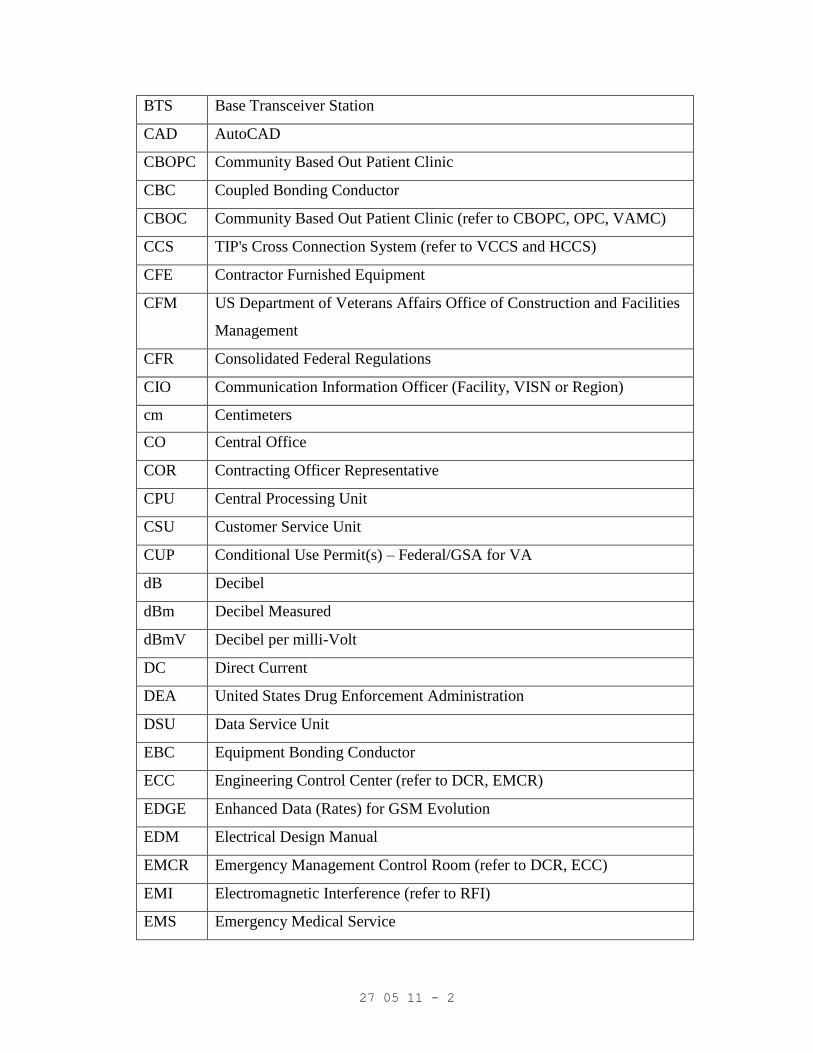
BTS Base Transceiver Station
CAD AutoCAD
CBOPC Community Based Out Patient Clinic
CBC Coupled Bonding Conductor
CBOC Community Based Out Patient Clinic (refer to CBOPC, OPC, VAMC)
CCS TIP's Cross Connection System (refer to VCCS and HCCS)
CFE Contractor Furnished Equipment
CFM US Department of Veterans Affairs Office of Construction and Facilities
Management
CFR Consolidated Federal Regulations
CIO Communication Information Officer (Facility, VISN or Region)
cm Centimeters
CO Central Office
COR Contracting Officer Representative
CPU Central Processing Unit
CSU Customer Service Unit
CUP Conditional Use Permit(s) – Federal/GSA for VA
dB Decibel
dBm Decibel Measured
dBmV Decibel per milli-Volt
DC Direct Current
DEA United States Drug Enforcement Administration
DSU Data Service Unit
EBC Equipment Bonding Conductor
ECC Engineering Control Center (refer to DCR, EMCR)
EDGE Enhanced Data (Rates) for GSM Evolution
EDM Electrical Design Manual
EMCR Emergency Management Control Room (refer to DCR, ECC)
EMI Electromagnetic Interference (refer to RFI)
EMS Emergency Medical Service

27 05 11 - 3
EMT Electrical Metallic Tubing or thin wall conduit
ENTR Utilities Entrance Location (refer to DEMARC, POTS, LEC)
EPBX Electronic Digital Private Branch Exchange
ESR Vendor’s Engineering Service Report
FA Fire Alarm
FAR Federal Acquisition Regulations in Chapter 1 of Title 48 of Code of
Federal Regulations
FMS VA’s Headquarters or Medical Center Facility’s Management Service
FR Frequency (refer to RF)
FTS Federal Telephone Service
GFE Government Furnished Equipment
GPS Global Positioning System
GRC Galvanized Rigid Metal Conduit
GSM Global System (Station) for Mobile
HCCS TIP’s Horizontal Cross Connection System (refer to CCS & VCCS)
HDPE High Density Polyethylene Conduit
HDTV Advanced Television Standards Committee High-Definition Digital
Television
HEC Head End Cabinets(refer to HEIC, PA)
HEIC Head End Interface Cabinets(refer to HEC, PA)
HF High Frequency (Radio Band; Re FR, RF, VHF & UHF)
HSPA High Speed Packet Access
HZ Hertz
IBT Intersystem Bonding Termination (NEC 250.94)
IC Intercom
ICRA Infectious Control Risk Assessment
IDEN Integrated Digital Enhanced Network
IDC Insulation Displacement Contact
IDF Intermediate Distribution Frame
ILSM Interim Life Safety Measures

27 05 11 - 4
IMC Rigid Intermediate Steel Conduit
IRM Department of Veterans Affairs Office of Information Resources
Management
ISDN Integrated Services Digital Network
ISM Industrial, Scientific, Medical
IWS Intra-Building Wireless System
LAN Local Area Network
LBS Location Based Services, Leased Based Systems
LEC Local Exchange Carrier (refer to DEMARC, PBX & POTS)
LED Light Emitting Diode
LMR Land Mobile Radio
LTE Long Term Evolution, or 4G Standard for Wireless Data
Communications Technology
M Meter
MAS Medical Administration Service
MATV Master Antenna Television
MCR Main Computer Room
MCOR Main Computer Operators Room
MDF Main Distribution Frame
MH Manholes or Maintenance Holes
MHz Megaherts (106 Hz)
mm Millimeter
MOU Memorandum of Understanding
MW Microwave (RF Band, Equipment or Services)
NID Network Interface Device (refer to DEMARC)
NEC National Electric Code
NOR Network Operations Room
NRTL OSHA Nationally Recognized Testing Laboratory
NS Nurse Stations
NTIA U.S. Department of Commerce National Telecommunications and

27 05 11 - 5
Information Administration
OEM Original Equipment Manufacturer
OI&T Office of Information and Technology
OPC VA’s Outpatient Clinic (refer to CBOC, VAMC)
OSH Department of Veterans Affairs Office of Occupational Safety and
Health
OSHA United States Department of Labor Occupational Safety and Health
Administration
OTDR Optical Time-Domain Reflectometer
PA Public Address System (refer to HE, HEIC, RPEC)
PBX Private Branch Exchange (refer to DEMARC, LEC, POTS)
PCR Police Control Room (refer to SPCC, could be designated SCC)
PCS Personal Communications Service (refer to UPCS)
PE Professional Engineer
PM Project Manager
PoE Power over Ethernet
POTS Plain Old Telephone Service (refer to DEMARC, LEC, PBX)
PSTN Public Switched Telephone Network
PSRAS Public Safety Radio Amplification Systems
PTS Pay Telephone Station
PVC Poly-Vinyl Chloride
PWR Power (in Watts)
RAN Radio Access Network
RBB Rack Bonding Busbar
RE Resident Engineer or Senior Resident Engineer
RF Radio Frequency (refer to FR)
RFI Radio Frequency Interference (refer to EMI)
RFID RF Identification (Equipment, System or Personnel)
RMC Rigid Metal Conduit
RMU Rack Mounting Unit

27 05 11 - 6
RPEC Radio Paging Equipment Cabinets(refer to HEC, HEIC, PA)
RTLS Real Time Location Service or System
RUS Rural Utilities Service
SCC Security Control Console (refer to PCR, SPCC)
SMCS Spectrum Management and Communications Security (COMSEC)
SFO Solicitation for Offers
SME Subject Matter Experts (refer to AHJ)
SMR Specialized Mobile Radio
SMS Security Management System
SNMP Simple Network Management Protocol
SPCC Security Police Control Center (refer to PCR, SMS)
STP Shielded Balanced Twisted Pair (refer to UTP)
STR Stacked Telecommunications Room
TAC VA’s Technology Acquisition Center, Austin, Texas
TCO Telecommunications Outlet
TER Telephone Equipment Room
TGB Telecommunications Grounding Busbar (also Secondary Bonding Busbar
(SBB))
TIP Telecommunications Infrastructure Plant
TMGB Telecommunications Main Grounding Busbar (also Primary Bonding
Busbar (PBB))
TMS Traffic Management System
TOR Telephone Operators Room
TP Balanced Twisted Pair (refer to STP and UTP)
TR Telecommunications Room (refer to STR)
TWP Twisted Pair
UHF Ultra High Frequency (Radio)
UMTS Universal Mobile Telecommunications System
UPCS Unlicensed Personal Communications Service (refer to PCS)
UPS Uninterruptible Power Supply

27 05 11 - 7
USC United States Code
UTP Unshielded Balanced Twisted Pair (refer to TP and STP)
UV Ultraviolet
V Volts
VAAR Veterans Affairs Acquisition Regulation
VACO Veterans Affairs Central Office
VAMC VA Medical Center (refer to CBOC, OPC, VACO)
VCCS TIP’s Vertical Cross Connection System (refer to CCS and HCCS)
VHF Very High Frequency (Radio)
VISN Veterans Integrated Services Network (refers to geographical region)
VSWR Voltage Standing Wave Radio
W Watts
WEB World Electronic Broadcast
WiMAX Worldwide Interoperability (for MW Access)
WI-FI Wireless Fidelity
WMTS Wireless Medical Telemetry Service
WSP Wireless Service Providers
B. Definitions:
1. BNC Connector (BNC): United States Military Standard MIL-C-39012/21 bayonet-
type coaxial connector with quick twist mating/unmating, and two lugs preventing
accidental disconnection from pulling forces on cable.
2. Bond: Permanent joining of metallic parts to form an electrically conductive path to
ensure electrical continuity and capacity to safely conduct any currents likely to be
imposed to earth ground.
3. Bundled Microducts: All forms of jacketed microducts.
4. Conduit: Includes all raceway types specified.
5. Conveniently Accessible: Capable of being reached without use of ladders, or
without climbing or crawling under or over obstacles such as, motors, pumps, belt
guards, transformers, piping, ductwork, conduit and raceways.
6. DEMARC, Extended DMARC or ENTR: Service provider's main point of
demarcation owned by LEC or service provider and establishes a physical point

27 05 11 - 8
where service provider's responsibilities for service and maintenance end. This point
is called NID, in data networks.
7. Effectively Grounded: Intentionally bonded to earth through connections of low
impedance having current carrying capacity to prevent buildup of currents and
voltages resulting in hazard to equipment or persons.
8. Electrical Supervision: Analyzing a system’s function and components (i.e. cable
breaks / shorts, inoperative stations, lights, LEDs and states of change, from primary
to backup) on a 24/7/365 basis; provide aural and visual emergency notification
signals to minimum two remote designated or accepted monitoring stations.
9. Electrostatic Interference (ESI) or Electrostatic Discharge Interference: Refer to EMI
and RFI.
10. Grounding Electrode Conductor: (GEC) Conductor connected to earth grounding
electrode.
11. Grounding Electrode System: Electrodes through which an effective connection to
earth is established, including supplementary, communications system grounding
electrodes and GEC.
12. Grounding Equalizer or Backbone Bonding Conductor (BBC): Conductor that
interconnects elements of telecommunications grounding infrastructure.
13. Head End (HE): Equipment, hardware and software, or a master facility at originating
point in a communications system designed for centralized communications control,
signal processing, and distribution that acts as a common point of connection between
equipment and devices connected to a network of interconnected equipment,
possessing greatest authority for allowing information to be
exchanged, with whom other equipment is subordinate.
14. Microducts: All forms of air blown fiber pathways.
15. Ohm: A unit of restive measurement.
16. Service Provider Demarcation Point (SPDP): Not owned by LEC or service provider,
but designated by Government as point within facility considered the DEMARC.
17. System: Specific hardware, firmware, and software, functioning together as a unit,
performing task for which it was designed.

27 05 11 - 9
18. Telecommunications Bonding Backbone (TBB): Conductors of appropriate size
(minimum 53.49 mm2 [1/0 AWG]) stranded copper wire, that connect to Grounding
Electrode System and route to telecommunications main grounding busbar (TMGB)
and circulate to interconnect various TGBs and other locations shown on drawings.
1.3 APPLICABLE PUBLICATIONS
A. Applicability of Standards: Unless documents include more stringent requirements,
applicable construction industry standards have same force and effect as if bound or
copied directly into the documents to extent referenced. Such standards are made a part
of these documents by reference.
1. Each entity engaged in construction must be familiar with industry standards
applicable to its construction activity.
2. Obtain standards directly from publication source, where copies of standards are
needed to perform a required construction activity.
B. Government Codes, Standards and Executive Orders: Refer to
http://www.cfm.va.gov/TIL/cPro.asp:
1. Federal Communications Commission, (FCC) CFR, Title 47:
Part 47 Chapter A, Paragraphs 6.1-6.23, Access to
Telecommunications Service, Telecommunications
Equipment and Customer Premises Equipment
Part 90 Rules and Regulations, Appendix C
Chapter XXIII National Telecommunications and Information
Administration (NTIA, P/O Commerce, Chapter XXIII) the
‘Red Book’– Chapters 7, 8 & 9 compliments CFR, Title 47,
FCC Part 15, RF Restriction of Use and Compliance in
“Safety of Life” Functions & Locations
2. US Department of Agriculture, (Title 7, USC, Chapter 55, Sections 2201, 2202 &
2203:RUS 1755 Telecommunications Standards and Specifications for Materials,
Equipment and Construction:
RUS Bull 1751F-640 Design of Buried Cable Plant, Physical Considerations
RUS Bull 1751F-643 Underground Plant Design
RUS Bull 1751F-815 Electrical Protection of Outside Plants,

27 05 11 - 10
RUS Bull 1753F-201 Acceptance Tests of Telecommunications Plants (PC-4)
RUS Bull 345-50 Trunk Carrier Systems (PE-60)
RUS Bull 345-65 Shield Bonding Connectors (PE-65)
RUS Bull 345-72 Filled Splice Closures (PE-74)
RUS Bull 345-83 Gas Tube Surge Arrestors (PE-80)
3. US Department of Commerce/National Institute of Standards Technology,(NIST):
FIPS PUB 1-1 Telecommunications Information Exchange
FIPS 175 Federal Building Standard for Telecommunications
Pathway and Spaces
4. US Department of Defense, (DoD):
MIL-C-39012/21 Connectors, Receptacle, Electrical, Coaxial, Radio
Frequency, (Series BNC (Uncabled), Socket Contact, Jam
Nut Mounted, Class 2)
5. US Department of Justice:
2010 Americans with Disabilities Act Standards for Accessible Design (ADAAD).
6. US Department of Labor, (DoL) - Public Law 426-62 – CFR, Title 29, Part 1910,
Chapter XVII - Occupational Safety and Health Administration (OSHA),
Occupational Safety and Health Standards):
Subpart 7 Approved NRTLs; obtain a copy at
http://www.osha.gov/dts/otpca/nrtl/faq_nrtl.html)
Subpart 35 Compliance with NFPA 101, Life Safety Code
Subpart 36 Design and Construction Requirements for Exit Routes
Subpart 268 Telecommunications
Subpart 305 Wiring Methods, Components, and Equipment for General
Use
Subpart 508 Americans with Disabilities Act Accessibility Guidelines;
technical requirement for accessibility to buildings and
facilities by individuals with disabilities
7. US Department of Veterans Affairs (VA): Office of Telecommunications (OI&T),
MP-6, PART VIII, TELECOMMUNICATIONS, CHAPTER 5, AUDIO, RADIO
27 05 11 - 11
AND TELEVISION (and COMSEC) COMMUNICATIONS SYSTEMS: Spectrum
Management and COMSEC Service (SMCS), AHJ for:
a. CoG, “Continuance of Government” communications guidelines and compliance.
b. COMSEC,“VA wide coordination and control of security classified
communication assets.”
c. COOP, “Continuance of Operations” emergency communications guidelines and
compliance.
d. FAA, FCC, and US Department of Commerce National Telecommunications and
Information Administration, “VA wide RF Co-ordination, Compliance and
Licensing.”
e. Handbook 6100 – Telecommunications: Cyber and Information Security Office of
Cyber and Information Security, and Handbook 6500 – Information Security
Program.
f. Low Voltage Special Communications Systems “Design, Engineering,
Construction Contract Specifications and Drawings Conformity, Proof of
Performance Testing, VA Compliance and Life Safety Certifications for CFM and
VA Facility Low Voltage Special Communications Projects (except Fire Alarm,
Telephone and Data Systems).”
g. SATCOM, “Satellite Communications” guidelines and compliance, and Security
and Law Enforcement Systems – “Coordinates the Design, Engineering,
Construction Contract Specifications and Drawings Conformity, Proof of
Performance Testing, VA Compliance, DEA and Public Safety Certification(s)
for CFM and VA Facility Security Low Voltage Special Communications and
Physical Security Projects.
h. VHA’s National Center for Patient Safety – Veterans Health Administration
(VHA) Warning System, Failure of Medical Alarm Systems using Paging
Technology to Notify Clinical Staff, July 2004.
i. VA’s CEOSH, concurrence with warning identified in VA Directive 7700.
j. Wireless and Handheld Devices, “Guidelines and Compliance,”
k. Office of Security and Law Enforcement: VA Directive 0730 and Health Special
Presidential Directive (HSPD)-12.

27 05 11 - 12
C. NRTL Standards: Refer to https://www.osha.gov/dts/otpca/nrtl/index.html
1. Canadian Standards Association (CSA); same tests as presented by UL
2. Communications Certifications Laboratory (CEL); same tests as presented by UL.
3. Intertek Testing Services NA, Inc., (ITSNA), formerly Edison Testing Laboratory
(ETL) same tests as presented by UL).
4. Underwriters Laboratory (UL):
1-2005 Flexible Metal Conduit
5-2011 Surface Metal Raceway and Fittings
6-2007 Rigid Metal Conduit
44-010 Thermoset-Insulated Wires and Cables
50-1995 Enclosures for Electrical Equipment
65-2010 Wired Cabinets
83-2008 Thermoplastic-Insulated Wires and Cables
96-2005 Lightning Protection Components
96A-2007 Installation Requirements for Lightning Protection Systems
360-2013 Liquid-Tight Flexible Steel Conduit
444-2008 Communications Cables
467-2013 Grounding and Bonding Equipment
486A-486B-2013 Wire Connectors
486C-2013 Splicing Wire Connectors
486D-2005 Sealed Wire Connector Systems
486E-2009 Standard for Equipment Wiring Terminals for Use with
Aluminum and/or Copper Conductors
493-2007 Thermoplastic-Insulated Underground Feeder and Branch
Circuit Cable
497/497A/497B/497C
497D/497E Protectors for Paired Conductors/Communications
Circuits/Data Communications and Fire Alarm
Circuits/coaxial circuits/voltage protections/Antenna Lead
In

27 05 11 - 13
510-2005 Polyvinyl Chloride, Polyethylene and Rubber Insulating
Tape
514A-2013 Metallic Outlet Boxes
514B-2012 Fittings for Cable and Conduit
514C-1996 Nonmetallic Outlet Boxes, Flush-Device Boxes and Covers
651-2011 Schedule 40 and 80 Rigid PVC Conduit
651A-2011 Type EB and A Rigid PVC Conduit and HDPE Conduit
797-2007 Electrical Metallic Tubing
1242-2006 Intermediate Metal Conduit
1449-2006 Standard for Transient Voltage Surge Suppressors
1479-2003 Fire Tests of Through-Penetration Fire Stops
1666-2007 Standard for Wire/Cable Vertical (Riser) Tray Flame Tests
1685-2007 Vertical Tray Fire Protection and Smoke Release Test for
Electrical and Fiber Optic Cables
1861-2012 Communication Circuit Accessories
1863-2013 Standard for Safety, communications Circuits Accessories
1865-2007 Standard for Safety for Vertical-Tray Fire Protection and
Smoke-Release Test for Electrical and Optical-Fiber Cables
2024-2011 Standard for Optical Fiber Raceways
2024-2014 Standard for Cable Routing Assemblies and
Communications Raceways
2196-2001 Standard for Test of Fire Resistive Cable
60950-1 ed. 2-2014 Information Technology Equipment Safety
D. Industry Standards:
1. American Society for Testing and Materials (ASTM):
B1 (2001) Standard Specification for Hard-Drawn Copper Wire
B8 (2004) Standard Specification for Concentric-Lay-Stranded
Copper Conductors, Hard, Medium-Hard, or Soft
D1557 (2012) Standard Test Methods for Laboratory Compaction
Characteristics of Soil Using Modified Effort 56,000 ft-
lbf/ft3 (2,700 kN-m/m3)

27 05 11 - 14
D2301 (2004) Standard Specification for Vinyl Chloride Plastic Pressure
Sensitive Electrical Insulating Tape
B258-02 (2008) Standard Specification for Standard Nominal Diameters
and Cross-Sectional Areas of AWG Sizes of Solid Round
Wires Used as Electrical Conductors
D709-01(2007) Standard Specification for Laminated Thermosetting
Materials
D4566 (2008) Standard Test Methods for Electrical Performance
Properties of Insulations and Jackets for
Telecommunications Wire and Cable
2. American Telephone and Telegraph Corporation (AT&T) - Obtain following AT&T
Publications at https://ebiznet.sbc.com/SBCNEBS/):
ATT-TP-76200 (2013) Network Equipment and Power Grounding, Environmental,
and Physical Design Requirements
ATT-TP-76300(2012) Merged AT&T Affiliate Companies Installation
Requirements
ATT-TP-76305 (2013) Common Systems Cable and Wire Installation and
Removal Requirements - Cable Racks and Raceways
ATT-TP-76306 (2009) Electrostatic Discharge Control
ATT-TP-76400 (2012) Detail Engineering Requirements
ATT-TP-76416 (2011) Grounding and Bonding Requirements for Network
Facilities
ATT-TP-76450 (2013) Common Systems Equipment Interconnection Standards
for AT&T Network Equipment Spaces
ATT-TP-76900 (2010) AT&T Installation Testing Requirement
ATT-TP-76911 (1999) AT&T LEC Technical Publication Notice
3. Building Industry Consulting Service International(BICSI):
ANSI/NECA/BICSI
568-2006 Standard for Installing Commercial Building
Telecommunications Cabling

27 05 11 - 15
NECA/BICSI 607-2011 Standard for Telecommunications Bonding and Grounding
Planning and Installation Methods for Commercial
Buildings
ANSI/BICSI 005-2013 Electronic Safety and Security (ESS) System Design and
Implementation Best Practices
4. Electronic Components Assemblies and Materials Association,(ECA).
ECA EIA/RS-270 (1973) Tools, Crimping, Solderless Wiring Devices –
Recommended Procedures for User Certification
EIA/ECA 310-E (2005) Cabinets, and Associated Equipment
5. Insulated Cable Engineers Association (ICEA):
ANSI/ICEA
S-80-576-2002 Category 1 & 2 Individually Unshielded Twisted-Pair
Indoor Cables for Use in Communications Wiring Systems
ANSI/ICEA
S-84-608-2010 Telecommunications Cable, Filled Polyolefin Insulated
Copper Conductor, S-87-640(2011) Optical Fiber Outside
Plant Communications Cable
ANSI/ICEA
S-90-661-2012 Category 3, 5, & 5e Individually Unshielded Twisted-Pair
Indoor Cable for Use in General Purpose and LAN
Communication Wiring Systems
S-98-688 (2012) Broadband Twisted Pair Cable Aircore, Polyolefin
Insulated, Copper Conductors
S-99-689 (2012) Broadband Twisted Pair Cable Filled, Polyolefin Insulated,
Copper Conductors
ICEA S-102-700
(2004) Category 6 Individually Unshielded Twisted Pair Indoor
Cables (With or Without an Overall Shield) for use in
Communications Wiring Systems Technical Requirements
6. Institute of Electrical and Electronics Engineers (IEEE):

27 05 11 - 16
IEEE C2-2012 National Electrical Safety Code (NESC)
C62.41.2-2002/
Cor 1-2012 IEEE Recommended Practice on Characterization of Surges in
Low-Voltage (1000 V and Less) AC Power Circuits 4)
C62.45-2002 IEEE Recommended Practice on Surge Testing for
Equipment Connected to Low-Voltage (1000 V and Less)
AC Power Circuits
81-2012 IEEE Guide for Measuring Earth Resistivity, Ground Impedance,
and Earth Surface Potentials of a Grounding System
100-1992 IEEE the New IEEE Standards Dictionary of Electrical and
Electronics Terms
602-2007 IEEE Recommended Practice for Electric Systems in
Health Care Facilities
1100-2005 IEEE Recommended Practice for Powering and Grounding
Electronic Equipment
7. National Electrical Manufacturers Association (NEMA):
NEMA 250 (2008) Enclosures for Electrical Equipment (1,000V Maximum)
ANSI C62.61 (1993) American National Standard for Gas Tube Surge Arresters
on Wire Line Telephone Circuits
ANSI/NEMA FB 1 (2012)Fittings, Cast Metal Boxes and Conduit Bodies for
Conduit, Electrical Metallic Tubing EMT) and Cable
ANSI/NEMA OS 1 (2009)Sheet-Steel Outlet Boxes, Device Boxes, Covers, and Box
Supports
TC 3 (2004) Polyvinyl Chloride (PVC) Fittings for Use with Rigid PVC
Conduit and Tubing
NEMA VE 2 (2006) Cable Tray Installation Guidelines
8. National Fire Protection Association (NFPA):
70E-2015 Standard for Electrical Safety in the Workplace
70-2014 National Electrical Code (NEC)
72-2013 National Fire Alarm Code

27 05 11 - 17
75-2013 Standard for the Fire Protection of Information
Technological Equipment
76-2012 Recommended Practice for the Fire Protection of
Telecommunications Facilities
77-2014 Recommended Practice on Static Electricity
90A-2015 Standard for the Installation of Air Conditioning and
Ventilating Systems
99-2015 Health Care Facilities Code
101-2015 Life Safety Code
241 Safeguarding construction, alternation and Demolition
Operations
255-2006 Standard Method of Test of Surface Burning
Characteristics of Building Materials
262 - 2011 Standard Method of Test for Flame Travel and Smoke of
Wires and Cables for Use in Air-Handling Spaces
780-2014 Standard for the Installation of Lightning Protection
Systems
1221-2013 Standard for the Installation, Maintenance, and Use of
Emergency Services Communications Systems
5000-2015 Building Construction and Safety Code
9. Telecommunications Industry Association (TIA):
TIA-120 Series Telecommunications Land Mobile communications
(APCO/Project 25) (January 2014)
TIA-568 Revision/Edition: C Commercial Building
Telecommunications Cabling Standard Set: (TIA-568-C.0-
2 Generic Telecommunications Cabling for Customer
Premises (2012), TIA-568-C.1-1 Commercial Building
Telecommunications Cabling Standard Part 1: General
Requirements (2012), TIA-568-C.2 Commercial Building
Telecommunications Cabling Standard—Part 2: Balanced
Twisted Pair Cabling Components (2009), TIA-568-C.3-1

27 05 11 - 18
Optical Fiber Cabling Components Standard, (2011) AND
TIA-568-C.4 Broadband Coaxial Cabling and Components
Standard (2011) with addendums and erratas
TIA-569 Revision/Edition C Telecommunications Pathways and
Spaces (March 2013)
ANSI/TIA-606-B Administration Standard for Telecommunications
Infrastructure (2012)
TIA-607-B Generic Telecommunications Bonding and Grounding
(Earthing) For Customer Premises (January 2013)
ANSI/TIA-758-B Customer-owned Outside Plant Telecommunications
Infrastructure Standard (April 2012)
TIA-942-A Telecommunications Infrastructure Standard for Data
Centers (March 2014)
TIA-1152 Requirements for Field Testing Instruments and
Measurements for Balanced Twisted Pair Cabling
(September 2009)
1.4 SINGULAR NUMBER
A. Where any device or part of equipment is referred in singular number (such as " rack"),
reference applies to as many such devices as are required to complete installation.
1.5 ADMINISTRATIVE REQUIREMENTS
A. Assign a single communications project manager to serve as point of contact between
Government and contractor.
B. Be proactive in scheduling work.
1. Use of premises is restricted at times directed by COR.
2. Movement of materials: Unload materials and equipment delivered to site. Pay costs
for rigging, hoisting, lowering and moving equipment on and around site or in
building.
3. Coordinate installation of required supporting devices and sleeves to be set in poured-
in-place concrete and other structural components, as they are constructed.

27 05 11 - 19
4. Sequence, coordinate, and integrate installations of materials and equipment for
efficient flow of Work. Plan for large equipment requiring positioning prior to closing
in building.
5. Coordinate connection of materials, equipment, and systems with exterior
underground and overhead utilities and services. Comply with requirements of
governing regulations, franchised service companies, and controlling agencies;
provide required connection for each service.
6. Initiate and maintain discussion regarding schedule for ceiling construction and install
cables to meet that schedule.
C. Communications Project Manager Responsibilities:
1. Assume responsibility for overall telecommunications system integration and
coordination of work among trades, subcontractors, and authorized system installers.
2. Coordinate with related work indicated on drawings or specified.
3. Manage work related to telecommunications system installation in a manner approved
by manufacturer.
1.6 SUBMITTALS
A. Submit in accordance with Section 01 33 23, SHOP DRAWINGS, PRODUCT DATA,
AND SAMPLES.
B. Provide parts list including quantity of spare parts.
C. Provide manufacturer product information. Government reserves the right to require a list
of installations where products have been in operation.
D. Provide Source Quality Control Submittal:
1. Submit written certification from OEM indicating that proposed supervisor of
installation and proposed provider of warranty maintenance are authorized
representatives of OEM. Include individual's legal name, contact information and
OEM credentials in certification.
2. Submit written certification from OEM that wiring and connection diagrams meet
Government Life Safety Guidelines, NFPA, NEC, NRTL, these specifications, and
Joint Commission requirements and instructions, requirements, recommendations,
and guidance set forth by OEM for the proper performance of system.
3. Pre-acceptance Certification.

27 05 11 - 20
E. Installer Qualifications: Submit three installations of similar size and complexity
furnished and installed by installer; include:
1. Installation location and name.
2. Owner’s name and contact information including, address, telephone and email.
3. Date of project start and date of final acceptance.
4. System project number.
5. Description of each system related to this project; include function, operation, and
installation.
F. Test Equipment List:
1. Supply test equipment of accuracy better than parameters to be tested.
2. Submit test equipment list including make and model number:
3. Supply only test equipment with a calibration tag from Government-accepted
calibration service dated not more than 12 months prior to test.
4. Provide sample test and evaluation reports.
1.7 CLOSEOUT SUBMITTALS
A. Provide following closeout submittals prior to project closeout date:
1. Warranty certificate.
2. Evidence of compliance with requirements such as low voltage certificate of
inspection.
3. Project record documents.
4. Instruction manuals that are a part of system.
B. Maintenance and Operation Manuals.
1. Prepare a manual for each system and equipment specified.
2. Furnish on portable storage drive in PDF format or equivalent accepted by COR.
3. Furnish complete manual as specified in specification section, fifteen days prior to
performance of systems or equipment test.
4. Furnish remaining manuals prior to final completion.
5. Identify storage drive "MAINTENANCE AND OPERATION MANUAL" and
system name.

27 05 11 - 21
6. Include name, contact information and emergency service numbers of each
subcontractor installing system or equipment and local representatives for system or
equipment.
7. Operation and Maintenance Data includes:
a. Approved shop drawing for each item of equipment.
b. Internal and interconnecting wiring and control diagrams with data to explain
detailed operation and control of equipment.
c. Safety precautions.
d. Diagrams and illustrations.
e. Test Results and testing methods.
f. Performance data.
g. Warranty documentation indicating end date and equipment protected under
warranty.
h. Appendix; list qualified permanent servicing organizations for support of
equipment, including addresses and certified personnel qualifications.
8. Submit Record Wiring Diagrams within five business days after final cable testing.
C. Service Qualifications: Submit name and contact information of service organizations
providing service to this installation within // four // eight // hours of receipt of
notification service is needed.
1.8 MAINTENANCE MATERIAL SUBMITTALS
A. After approval and prior to installation, furnish COR with the following:
1. A 300 mm (12 inch) length of each type and size of wire and cable along with tag
from coils of reels from which samples were taken.
2. One coupling, bushing and termination fitting for each type of conduit.
3. Samples of each hanger, clamp and supports for conduit and pathways.
4. Duct sealing compound.
1.9 QUALITY ASSURANCE
A. Manufacturer’s Qualifications: Manufacturer must produce, as a principal product, the
equipment and material specified for this project, and have manufactured item for at least
three years.
B. Product and System Qualification:

27 05 11 - 22
1. OEM must have three installations of equipment submitted presently in operation of
similar size and type as this project, that have continuously operated for a minimum
of three years.
2. Government reserves the right to require a list of installations where products have
been in operation before approval.
3. Authorized representative of OEM must be responsible for design, satisfactory
operation of installed system, and certification.
C. Trade Contractor Qualifications: Trade contractor must have completed three or more
installations of similar systems of comparable size and complexity with regards to
coordinating, engineering, testing, certifying, supervising, training, and documentation.
Identify these installations as a part of submittal.
D. System Supplier Qualifications: System supplier must be authorized by OEM to warranty
installed equipment.
E. Telecommunications technicians assigned to system must be trained, and certified by
OEM on installation and testing of system; provide written evidence of current OEM
certifications for installers.
SPEC WRITER NOTE:
1. Use 4 hours for metropolitan areas and 8 hours
for rural areas, in the following paragraph.
F. Manufactured Products:
1. Comply with FAR clause 52.236-5 for material and workmanship.
2. When more than one unit of same class of equipment is required, units must be
product of a single manufacturer.
3. Equipment Assemblies and Components:
a. Components of an assembled unit need not be products of same manufacturer.
b. Manufacturers of equipment assemblies, which include components made by
others, to assume complete responsibility for final assembled unit.
c. Provide compatible components for assembly and intended service.
d. Constituent parts which are similar must be product of a single manufacturer.
4. Identify factory wiring on equipment being furnished and on wiring diagrams.
G. Testing Agencies: Government reserves the option of witnessing factory tests. Notify
COR minimum 15 working days prior to manufacturer performing the factory tests.

27 05 11 - 23
1. When equipment fails to meet factory test and re-inspection is required, contractor is
liable for additional expenses, including expenses of Government.
1.10 FIELD CONDITIONS
A. Where variations from documents are requested in accordance with GENERAL
CONDITIONS and Section 01 33 23, SHOP DRAWINGS, PRODUCT DATA, AND
SAMPLES, connecting work and related components must include additions or changes
to branch circuits, circuit protective devices, conduits, wire, feeders, controls, panels and
installation methods.
B. A contract adjustment or additional time will not be granted because of field conditions
pursuant to FAR 52.236-2 and FAR 52.236-3; a contract adjustment or additional time
will not be granted for additional work required for complete and usable construction and
systems pursuant to FAR 52.246-12.
1.11 WARRANTY
A. Comply with FAR clause 52.246-21.
PART 2 - PRODUCTS
2.1 PERFORMANCE AND DESIGN CRITERIA
A. Provide communications spaces and pathways conforming to TIA 569, at a minimum.
2.2 EQUIPMENT IDENTIFICATION
A. Provide laminated black phenolic resin with a white core nameplates with minimum 6
mm (1/4 inch) high engraved lettering.
B. Nameplates furnished by manufacturer as standard catalog items, unless other method of
identification is indicated.
2.3 WIRE LUBRICATING COMPOUND
A. Provide non-hardening or forming adhesive coating cable lubricants suitable for cable
jacket material and raceway.
2.4 UNDERGROUND CABLES
A. Provide buried closure suitable for enclosing a straight, butt, and branch splice in a
container into which can be poured an encapsulating compound.
B. Provide closure of adequate strength to protect splice and maintain cable shield electrical
continuity in buried environment.
C. Provide re-enterable encapsulating compound maintaining chemical stability of closure.

27 05 11 - 24
D. Provide filled splice cases in accordance with RUS Bull 345-72.
E. Provide gel filled cable meeting requirements of ICEA S-99-689 and //RUS 1755.390//
//RUS 1755.890//.
F. In Vault or Manhole:
1. Provide underground closure suitable to house a straight, butt, and branch splice in a
protective housing into which can be poured an encapsulating compound
2. Closure must be suitable thermoplastic, thermo-set, or stainless steel material
supplying structural strength to pass mechanical and electrical requirements in a vault
or maintenance hole (manhole) environment.
G. Re-Enterable Encapsulating Compound: Product maintaining chemical stability of
closure.
H. Provide gel-filled splice cases in accordance with RUS Bull 345-72.
PART 3 - EXECUTION
3.1 INSTALLATION - GENERAL
A. Coordinate systems, equipment, and materials installation with other building
components.
B. Install systems, materials, and equipment to conform with approved submittal data,
including coordination drawings.
C. Conform to VAAR 852.236.91 arrangements indicated, recognizing that work may be
shown in diagrammatic form or have been impracticable to detail all items because of
variances in manufacturers’ methods of achieving specified results.
D. Install systems, materials, and equipment level and plumb, parallel and perpendicular to
other building systems and components, where installed in both exposed and un-exposed
spaces.
E. Install equipment according to manufacturers' written instructions.
F. Install wiring and cabling between equipment and related devices.
G. Install cabling, wiring, and equipment to facilitate servicing, maintenance, and repair or
replacement of equipment components. Connect equipment for ease of disconnecting,
with minimum interference of adjacent other installations.
H. Provide access panel or doors where units are concealed behind finished surfaces.

27 05 11 - 25
I. Arrange for chases, slots, and openings in other building components during progress of
construction, to allow for wiring, cabling, and equipment installations.
J. Where mounting heights are not detailed or dimensioned, install systems, materials, and
equipment to provide maximum headroom and access for service and maintenance as
possible.
K. Install systems, materials, and equipment giving priority to systems required to be
installed at a specified slope.
L. Avoid interference with structure and with work or other trades, preserving adequate
headroom and clearing doors and passageways to satisfaction of COR and code
requirements.
M. Install equipment and cabling to distribute equipment loads on building structural
members provided for equipment support under other sections; install and support roof-
mounted equipment on structural steel or roof curbs as appropriate.
N. Provide supplementary or miscellaneous items, appurtenances, devices and materials for
a complete installation.
3.2 CUTTING AND PATCHING
A. Perform cutting and patching according to contract general requirements and as follows:
1. Remove samples of installed work as specified for testing.
2. =Perform cutting, fitting, and patching of equipment and materials required to
uncover existing infrastructure in order to provide access for correction of improperly
installed existing or new work.
3. Remove and replace defective work.
4. Remove and replace non-conforming work.
B. Cut, remove, and legally dispose of selected equipment, components, and materials,
including removal of material, equipment, devices, and other items indicated to be
removed and items made obsolete by new work.
C. Provide and maintain temporary partitions or dust barriers adequate to prevent spread of
dust and dirt to adjacent areas.
D. Protect adjacent installations during cutting and patching operations.
E. Protect structure, furnishings, finishes, and adjacent materials not indicated or scheduled
to be removed.

27 05 11 - 26
F. Patch finished surfaces and building components using new materials specified for
original installation and experienced installers.
3.3 FIELD QUALITY CONTROL
A. Provide work according to VAAR 852.236.91 and FAR clause 52.236-5.
B. Provide minimum clearances and work required for compliance with NFPA 70, National
Electrical Code (NEC), and manufacturers' instructions; comply with additional
requirements indicated for access and clearances.
C. Verify all field conditions and dimensions that affect selection and provision of materials
and equipment, and provide any disassembly, reassembly, relocation, demolition, cutting
and patching required to provide work specified or indicated, including relocation and
reinstallation of existing wiring and equipment.
1. Protect facility, equipment, and wiring from damage.
D. Submit written notice that:
1. Project has been inspected for compliance with documents.
2. Work has been completed in accordance with documents.
E. Non-Conforming Work: Conduct project acceptance inspections, final completion
inspections, substantial completion inspections, and acceptance testing and
demonstrations after verification of system operation and completeness by Contractor.
F. Tests:
1. Inspection to be conducted by OEM and factory-certified contractor representative,
and witnessed by COR.
2. Check each item of installed equipment to ensure appropriate NRTL listing labels and
markings are fixed in place.
3. Verify cabling terminations in DEMARC, MCR, TER, SCC, ECC, TRs and head end
rooms, workstation locations and TCO adhere to color code pin assignments and
cabling connections are in compliance with TIA standards.
4. Review entire communications circulating ground system, each TGB and grounding
connection, grounding electrode and outside lightning protection system.
5. Provide results of interim inspections to COR.

27 05 11 - 27
6. If major or multiple deficiencies are discovered, additional interim inspections could
be required until deficiencies are corrected, before permitting further system
installation.
a. Additional inspections are scheduled at direction of COR.
b. Re-inspection of deficiencies noted during interim inspections, must be part of
system’s Final Acceptance Proof of Performance Test.
c. The interim inspection cannot affect the system’s completion date unless directed
by COR.
7. Facility COR will ensure test documents become a part of system’s official
documentation package.
G. Pretesting: Re-align, re-balance, sweep, re-adjust and clean entire system and leave
system working for a “break-in” period, upon completing installation of system and prior
to Final Acceptance Proof of Performance Test.
1. Pretesting Procedure:
a. Verify systems are fully operational and meet performance requirements, utilizing
accepted test equipment and spectrum analyzer.
b. Pretest and verify system functions and performance requirements conform to
construction documents and, that no unwanted physical, aural and electronic
effects, such as signal distortion, noise pulses, glitches, audio hum, poling noise
are present.
2. Measure and record signal, aural and control carrier levels of each DAS RF, voice
and data channel, at each of the following minimum points in system:
a. Utility provider entrance.
b. Buried conduit duct locations.
c. Maintenance Holes (Manholes) and hand holes.
d. ENTR or DEMARC.
e. PBX interconnections.
f. MCR interconnections.
g. MCOR interconnections.
h. TER interconnections.
i. TOR interconnections.

27 05 11 - 28
j. Control room interconnections.
k. TR interconnections.
l. System interfaces in locations listed herein.
m. HE interconnections.
n. System and lightning ground interconnections.
o. Communications circulating ground system.
p. Others as required by AHJ (SMCS 005OP2H3).
3. Provide recorded system pretest measurements and certification that the system is
ready for formal acceptance test to COR.
H. Acceptance Test:
1. Schedule an acceptance test date after system has been pretested, and pretest results
and certification submitted to COR.
2. Give COR fifteen working days written notice prior to date test is expected to begin;
include expected duration of time for test in notification.
3. Test in the presence of the COR.
4. Test system utilizing accepted test equipment to certify proof of performance and Life
and Public Safety compliance, FCC, NRTL, NFPA and OSHA compliance.
a. Rate system as acceptable or unacceptable at conclusion of test; make only minor
adjustments and connections required to show proof of performance.
1) Demonstrate and verify that system complies with performance requirements
under operating conditions.
2) Failure of any part of system that precludes completion of system testing, and
which cannot be repaired within four hours, terminates acceptance test of that
portion of system.
3) Repeated failures that result in a cumulative time of eight hours to affect
repairs is cause for entire system to be declared unacceptable.
4) If system is declared unacceptable, retesting must be rescheduled at
convenience of Government and costs borne by the contractor.
I. Acceptance Test Procedure:

27 05 11 - 29
1. Physical and Mechanical Inspection: The test team representatives must tour major
areas to determine system and sub-systems are completely and properly installed and
are ready for acceptance testing.
2. A system inventory including available spare parts must be taken at this time.
3. Each item of installed equipment must be re-checked to ensure appropriate NRTL
(i.e. UL) certification listing labels are affixed.
4. Confirm that deficiencies reported during Interim Inspections and Pretesting are
corrected prior to start of Acceptance Test.
5. Inventory system diagrams, record drawings, equipment manuals, pretest results.
6. Failure of system to meet installation requirements of specifications is grounds for
terminating testing and to schedule re-testing.
J. Operational Test:
SPEC WRITER NOTES:
1. Refer to specific Division 27 and 28 sections for
procedures to address the system.
1. Individual Item Test: VACO AHJ representative (SMCS 005OP2H3) may select
individual items of // DAS //_____// equipment for detailed proof of performance
testing until 100 percent of system has been tested and found to meet requirements of
the construction documents.
2. Government’s Condition of Acceptance of System Language:
a. Without Acceptance: Until system fully meets conditions of construction
documents, system’s ownership, use, operation and warranty commences at
Government’s final acceptance date.
b. With Conditional Acceptance: Stating conditions that need to be addressed by
contractor or OEM and stating system’s use and operation to commence
immediately while its warranty commences only at Government’s agreed final
extended acceptance date.
c. With Full Acceptance: Stating system’s ownership, use, operation and warranty to
immediately commence at Government’s agreed to date of final acceptance.
K. Acceptance Test Conclusion: Reschedule testing on deficiencies and shortages with
COR, after COR agrees to results of the test, using the generated punch list or

27 05 11 - 30
discrepancy list. Perform retesting to comply with these specifications at contractor's
expense.
L. Proof of Performance Certification:
1. If system is declared acceptable, AHJ (SMCS 005OP2H3) provides COR notice
stating system processes to required operating standards and functions and is
Government accepted for use by facility.
2. Validate items with COR needing to be provided to complete project contract (i.e.
charts & diagrams, manuals, spare parts, system warranty documents executed, etc.).
Once items have been provided, COR contacts FMS service chief to turn over system
from CFM oversight for beneficial use by facility.
3. If system is declared unacceptable without conditions, rescheduled testing expenses
are to be borne by contractor.
3.4 CLEANING
A. Remove debris, rubbish, waste material, tools, construction equipment, machinery and
surplus materials from project site and clean work area, prior to final inspection and
acceptance of work.
B. Put building and premises in neat and clean condition.
C. Remove debris on a daily basis.
D. Remove unused material, during progress of work.
E. Perform cleaning and washing required to provide acceptable appearance and operation
of equipment to satisfaction of COR.
F. Clean exterior surface of all equipment, including concrete residue, dirt, and paint
residue, after completion of project.
G. Perform final cleaning prior to project acceptance by COR.
H. Remove paint splatters and other spots, dirt, and debris; touch up scratches and mars of
finish to match original finish.
I. Clean devices internally using methods and materials recommended by manufacturer.
J. Tighten wiring connectors, terminals, bus joints, and mountings, to include lugs, screws
and bolts according to equipment manufacturer’s published torque tightening values for
equipment connectors. In absence of published connection or terminal torque values,
comply with torque values specified in UL 486A-486B.
27 05 11 - 31
3.5 PROTECTION
A. Protection of Fireproofing:
1. Install clips, hangers, clamps, supports and other attachments to surfaces to be
fireproofed, if possible, prior to start of spray fireproofing work.
2. Install conduits and other items that would interfere with proper application of
fireproofing after completion of spray fire proofing work.
3. Patch and repair fireproofing damaged due to cutting or course of work must be
performed by installer of fireproofing and paid for by trade responsible for damage.
B. Maintain equipment and systems until final acceptance.
C. Ensure adequate protection of equipment and material during installation and shutdown
and during delays pending final test of systems and equipment because of seasonal
conditions.
- - - E N D - - -