('***% Q. A MULTITRANSPUTER PARALLEL PROCESSING ...
72
('***% BARC/1W/E/009 Q. A MULTITRANSPUTER PARALLEL PROCESSING SYSTEM ( MTPPS ) by A. K. Jethra, S. S. Pande, S. P. Borkar, A. N. Khare, M. D. Ghodgaonkar and B. R. Bairi Electronics Division 1993
-
Upload
khangminh22 -
Category
Documents
-
view
1 -
download
0
Transcript of ('***% Q. A MULTITRANSPUTER PARALLEL PROCESSING ...

('***%
BARC/1W/E/009
Q.
A MULTITRANSPUTER PARALLEL PROCESSING SYSTEM( MTPPS )
by
A. K. Jethra, S. S. Pande, S. P. Borkar, A. N. Khare, M. D. Ghodgaonkar and B. R. BairiElectronics Division
1993

BARC/1993/E/009
GOVERNMENT OF INDIAATOMIC ENERGY COMMISSION
U<
A MULTITRANSPUTER PARALLEL PROCESSING SYSTEM (MTPPS)
by
A.k. Jethra, S.S. Pande, S.P. Borkar, A.N. KhareM.D. Ghodgaonkar and B.R. Bairi
Electronics Division
BHABHA ATOMIC RESEARCH CENTREBOMBAY, INDIA
1993

BARC/1993/E/009
BIBLIOGRAPHY DESCRIPTION SHEET FOR TECHNICAL REPORT
(as per IS : 940O - 1980)
01
02
03
04
05
06
07
OB
Security classication c
Distribution :
Report status :
Series :
Report type :
Report No. r
Part No. or Volume No. :
Contract No. :
Unclassified
External
New
BARC External
Technical Report
BARC/1993/E/009
10 Title and subtitle : A multitransputer parallel processingsystem (MTPPS)
11 Collation :
13 Project No. :
69 p., 22 figs., 3 tabs., 3 appendixes
20 Personal author (s) i A.K. Jethra; S.S. Pande; S.P. BorkarjA.N. Khare; M.D. Ghodgaonkar;B.R. Bairi
21 Affiliation of author (s) : Electronics Division, Bhabha AtomicResearch Centre, Bombay
22
23
24
30
31
Corporate author(s) :
Originating unit i
Sponsor(») Name :
Type t
Date of submission :
Publication/Issue date
Bhabha Atomic Research Centre,Bombay - 4OO 085
Electronics Division, BARC, Bombay
Department of Atomic Energy
Government
March 1993
April 1993
contd... (ii)

(ii)
4O Publisher/Distributor i Head, Library and Information Division,
Bhabha Atomic Research Centre, Bombay
42 Form of distribution i Hard Copy
50 Language of text : English
51 Language of summary : English
52 No. of references : 12 refs.
53 Given data on :
60 Abstract :This report describes the design and implementation of * 16node Multitransputer Parallel Processing System. MTPPS, is aplatform for parallel program development. It is a MIMD machinebased on message passing paradigm. The basic compute engine is anInmos Transputer Ims T800-2O. Transputer with local memoryconstitutes the processing element (NODE) ,of this MIMD architecture.Multiple NODES can be connected to each other in an identifiablenetwork topology through the high speed serial links of theTransputer. A Network Configuration Unit (NCU) incorporates thenecessary hardware to provide software controlled networkconfiguration. System is modularly expandable and more NODES can beadded to the system to achieve the required processing power. Thesystem is backend to the IBM-PC which has been integrated into thesystem to provide user I/O interface. PC resources arc available tothe programmer. Interface hardware between the PC and the network oftransputers is INMOS compatible. Therefore, all the commerciallyavailable development software compatible to INMOS products can runon this system.This development work has been carried out under theDAE approved VII Five year Plan Project on the "Modernization ofReactor Control Instrumentation and Development of CAMAC and FASTBUSInstrumentation". While giving the details of Design andimplementation, this report briefly summarises MIMD Architectures,Transputer Architecture and Parallel Processing Software Developmentissues. LINPACK Performance Evaluation of the System and Solutionsof Neutron Physics and Plasma Physics Problem have been discussedalong with results.
70 Keywords/Descriptors : PARALLEL PROCESSING; SPECIFICATIONS;MICROPROCESSORS; FASTBUS SYSTEM; CAMAC SYSTEM; COMPUTER NETWORKS;EQUIPMENT INTERFACES; BENCHMARKS; COMPUTER CODES; NUCLEAR PHYSICS;PLASMA SIMULATION; REACTOR PHYSICS; NEUTRON FLUX; DIFFUSION;MICROCOMPUTERS
Additional Descriptors ! TRANSPUTERS
71 Class No. : INIS Subject Category : E42OO
5 9 Supplementary elements :

Contents
1. Introduction 22. Parallel Processing Architectures 33. Multicomputer Building Blocks 6
3.1 Transputer Architecture 63.2 Programmable Link Switch 93.3 Local Memory 10
4. Multitransputer Parallel Processing System (MTPPS) 104.1 General Description 104.2 Hardware Architecture Overview 114.3 Hardware Building Blocks 12
4.3.1 Processing Nodes 144.3.2 Network Configuration Unit (NCU) 144.3.3 Root Transputer 164.3.4 Host Interface 174.3.5 Back Plane 18
4.4 System Configuration 184.5 Development Software 19
5. Network Configuration 195.1 General Properties of Interconnection Networks 195.2 Single Stage Network Interconnections 20
5.2.1 Chordal Ring 205.2.2 Spanning Bus Hypercube 215.2.3 Torus 215.2.4 Cube-Connected Cycles 225.2.5 R-ary N-cube 225.2.6 Full Ring Binary Tree 235.2.7 Fully Connected Network 23
6. Selecting a Network 247. Communication Schemes 24
7.1 Circuit Switched 257.2 Store and Forward 25
7.2.1 Datagram 257.2.2 Packet Switched 257.2.3 Virtual Circuit 25
7.3 IMS C004 Crossbar Switch 26

8. Network Configuration Software 27
8.1 Software Configuration Language 28
8.2 Hardware Description Language 28
9. Developing Parallel applications 30
9.1 Types of Parallelism 30
9.1.1 Functional Parallelism 30
9.1.2 Data Parallelism 30
9.1.3 Geometric Parallelism 31
9.1.4 Hybrid Parallelism 31
9.2 Detecting Parallelism 31
9.2.1 Loop Distribution 31
9.2.2 Bernstein's Conditions 32
9.3 Communication and Synchronization 33
9.4 System Deadlock 33
10. Performance Analysis 34
10.1 Improving the Performance 34
11. Benchmarking 35
11.1 Linpack and Benchmarking Environment 35
11.2 Linpack and it's Parallelization 36
11.3 Domain Decomposition 37
11.4 Mapping Function and Communication Strategy 38
11.5 Benchmark Performance 38
11.6 Linpack Benchmark Performance (MFlops) 40
12. Application Software 43
12.1 Reactor Physics Problem 43
12.2 Paiticle-in-cell Plasma Simulation 45
13. Conclusion 47
14. Acknowledgements 48
15. References 48
16. Appendix A : OCCAM Overview 50
17. Appendix B : Parallel Matrix Multiplication in OCCAM 56
18. Appendix C : High Level Languages For Parallel Processing 64

ABSTRACT
Multitransputer Parallel Processing System
(MTPPS)
This report describes the design and implementation of a 16 node Multitransputer
Parallel Processing System. MTPPS, is a platform for parallel program development. It is a
MIMD machine based on message passing paradigm. The basic compute engine is an Inmos
Transputer Ims T800-20. Transputer with local memory constitutes the processing element
(NODE) of this MIMD architecture. Multiple NODES can be connected to each other in
an identifiable network topology through the high speed serial links of the Transputer. A
Network Configuration Unit (NCU) incorporates the necessary hardware to provide software
controlled network configuration. System is modularly expandable and more NODES can be
added to the system to achieve the required processing power. The system is backend to the
IBM-PC which has been integrated into the system to provide user I/O interface. PC re-
sources are available to the programmer. Interface hardware between the PC and the network
of transputers is INMOS compatible. Therefore, all the commercially available development
software compatible to INMOS products can run on this system.
This development work has been carried out under the DAE approved VII Five
Year Plan Project on the "Modernization of Reactor Control Instrumentation and Develop-
ment of CAMAC and FASTBUS Instrumentation".
While giving the details of Design and implementation, this report briefly summarises
MIMD Architectures, Transputer Architecture and Parallel Processing Software Develop-
ment issuses. UNPACK Performance Evaluation of the System and Solutions of Neutron
Physics and Plasma Physics Problem have been discussed along with results.

I . INTRODUCTION
Today's nuclear physics experiments are becoming more and more sophisticated
due to the availability of larger detection systems in recent years. The growth in complexity
of the experimental set up is also reflected in the corresponding expansion of both the data
acquisition and the data analysis systems. Even in many low energy nuclear physics experi-
ments, we can have a rate close to 20,000 events/second, each having-a complex structure.
To achieve a good statistical sample in a short time we need a great deal of computing power.
Parallel processing is needed to speed up the system performance for the required massive
data handling in real-time. Parallel processing based on microprocessor technology is an
effective low-cost solution for geting the required computational power. Several such parallel
processing data acquisition systems have been reported (1,2,3,4) in the literature. Further,
parallel processing is an important architectural approach for the development of efficient
knowledge based computer systems incorporating AI concepts. AI application areas of
importance to our nuclear programme are related to safe and reliable operation of Nuclear
power plants, Accelerator control systems and Nuclear physics experiments. Finally, parallel
processing is a front line research area of importance to the present and future advanced
electronics instrumentation and scientific research areas.
Development work on transputer based parallel processing was initiated as an R
& D exercise under the VH Five Year Plan Project on " The Modernization of Reactor
Control Instrumentation and the development of CAMAC and Fastbus Instrumentation ".
This development work began with the intention of creating a total in-house support to meet.
the future demands of high performance real-time computation required for large detectors
real-time Nuclear Data Acquisition Systems, Medical imaging and knowledge based support
systems for Nuclear applications. Development work on parallel processing was initiated to
build up the required expertise and facilities for satisfying the requirements of such appli-
cations in near future.
A multitransputer parallel processing system has been designed and developed to
provide a development platform for studying and evaluating transputer based parallel processing
techniques for diverse applications. This report aims at providing design details of this system
and other related topics regarding the parallel processing development work.
The report begins with a brief introduction to the parallel processing architectures
belonging to the Multiple Instruction Multiple Data (MIMD) class of computer architectures
in Ftynn'f Taxonomy (5). Next are presented, a complete description of the hardware of the
system and available development software. Various network topologies and their properties
have been explained in brief. Design and development of the network configuration software
hai been summarised. Issues and strategies relating to the design of parallel algorithms such

as parallelism, partitioning and inteiprocessor communication have been discussed with a
note on the perfoi ma nee analysis of parallel machines. System evaluation has been carried
out by parallelizing UNPACK Algorithm and iterative algorithms for solving reactor physics
and plasma physics problems. Lastly the details of these program development and result are
reported and discussed.
2. PARALLEL PROCESSING ARCHITECTURES
Parallel Processing has been accepted today as an important architectural approach
to enhance computer performance. Parallel Processors are designated as MIMD machines
in Flynn's Taxonomy. MIMD machines have been classified into two basic architectures,
conventional and novel. Conventional multiprocessing architecture is typified by the multi-
processing machines which have a small number of processors sharing a common memory.
A simplified block diagram of this shared-memory multiprocessor architecture is shown in
fig. 1. Each CPU is free to operate on the memory without appreciable interference from
others.
MEMORY
BUS
Fig. 1: A typical conventional Architecture
A problem can be partitioned into several processes which run concurrently on
each CPU. It would be attractive to increase the number of CPUs to gain more speed. A
problem arises as more CPUs are added to the bus. When one CPU tries to access an address
in memory, it must first get permission from others. Arbitration amongst the CPUs leads to
contention. Each CPU requires a finite amount of time to fetch data/instruction from memory
and while this is going on, the other CPUs must wait if they need data as well. Adding more
CPUs simply makes the problem worse and results in a so called VonNeumann bottleneck.
In VonNeumann machines bottleneck is in the processor to memory communication. In the
conventional architectures of parallel processing the bottleneck k in the processor to processor

communication. The bus band-width is saturated by simultaneous requests from the CPUs.It is for this reason that multiprocessors seldom have more than 4 to 8 CPUs simultaneouslyoperating on a common pool of memory. While, this may be true, commercial systems doexist which are built around conventional architecture and are capable of deleviring peekperformance of a few Giga Flops. Examples are Cray-Ymp, Fujitsu VP-2600/20, NECS x-x etc. However, their cost ranges from 5 to 25 million dollars as they incorporate CPUsdeveloped with ECL or GaAs technology and other special techniques to achieve the stateof art performance. Further growth rate in the band width and hence in the performance islimited by technology. The biggest advantage of the conventional parallel processing archi-tecture is the possibility of providing an user friendly development software support throughan operating system or high level language subroutine calls to initiate new processes, waiton the completion of processes and guard access to data or system resources that can onlybe meaningfully used by one process at a time.
Unlike conventional architectures, "novel" architectures usually have a large numberof processors with distributed memory. Novel architectures are also known as multicomputerarchitectures. Availability of complete processors as low-cost building blocks has broughtincreased attention to these MIMD class of machines, where each processor is fully program-mable and can execute its own program.
A Multicomputer differs from the shared memory multiprocessor in several ways.Processors are not connected to a common bus. Instead each processors has a small f64k to4Mbyte) memory connected to a local bus. The processor with memory is called a node.Internode message passing occurs through high speed serial communication hardware. Thereis no communication bottleneck and the multicomputer^ bandwidth rises linearly with thenumber of nodes.
LOCALBUS
LINK
Fig. 2 (a): A typical multicomputer system
4

Fig. 2 (a) shows a typical multicomputer system. The most notable advantage of the
multicomputer is it's low cost. Multicomputers require less glue logic and fewer support chips
on a per node basis than do the multiprocessors. But harnessing the power of many processors
to solve a problem is an area of software research. However effective exploitation of VLSI
technotogy and moderate cost have made it possible and feasible to use multi computer
architecture as an approach for developing parallel processing system for diverse applications.
Availability of compute engine like Intel Rise Processor i860 (with more than amillion transistors on chip, 80 Mflops performance) designed specially for performancedriven applications such as super work stations and super computers based on parallelprocessing and standard high speed buses like VME. Multibus II, Future, EISA has resultedinto an innovative novel multiprocessing architecture. Such architectures offer powerful andflexible design at a cost much lower than that of conventional architectures.
STANDARD BUS
High speed six-port
— \ 480 Mbyte / sec.
Crossbar switch
BUS
Pig. 2 (b): A novel multiprocessing architecture
The architecture shown in fig. 2 (b) consists of 2 to 32 snugly coupled processors.
Snugly coupled refers to a hybrid multiprocessing model in contrast to a strict shared memory,
tightly coupled or message passing, loosely coupled model. Each board on the bus, shown
in fig. 2(b), has upto four processors. A multiport crossbar switch provides the high speed

interprocessor communication and communication with the shared bus. Mercury ComputerSystems Inc. USA offers such a VME bus multiprocessor system capable of delivering 2.SGFlops using 32 i860 processors with a complete operating environment called mc/os, anda set of develoment toot?. Computer Division, BARG, has developed a highly powerfulParallel Processing system based on 40 MHz Rise Processors. This system known as BPPS(BARC Parallel Processing System) has nine nodes and is realised with indigenously availableMultibus II hardware. The system capable of delivering around 400 Mflops is suitably equippedwith user friendly software development tools.
3. MULTICOMPUTER BUILDING BLOCKS
Present semiconductor technology offers a plethora of high performance VLSImicroprocessors which can be used for building multicomputer nodes e.g. Intel 80286 / 287,386 / 387,486 / 487, and Motorola 68020 / 68588,88000 etc. A good number of multicomputersystems are commercially available at present for example the iPSC hypercube from Intelwhich uses 128 i860s, nCube 2 from Caltech with 1024 custom processors and BBN advancedcomputer with 1 to 25 68020 processors. However, these modern 32-bit or 64-bit micropro-cessors require additional hardware for providing high speed internode communication andexternal memory management. This makes the development of multicomputer parallelprocessing systems not an easy task. In contrast, INMOS Transputer T800, a 32-bit micro-processor was developed with the objective of using it as a component for constructing largecomputer networks. Building multicomputer systems using transputer is relatively easy, requiresvery little logic for external memory interface and is very economical. In the following sectionswe describe building blocks of a transputer based multicomputer architecture.
3.1 TRANSPUTER ARCHITECTURE
Internally the INMOS transputer T800 consists of a memory, processor, floatingpoint unit, and communication system connected via a 32 bit bus. The bus also connects tothe external memory interface, enabling additional local memory to be used.
MEMORY 1NTERFACB
Fig. 3: Transputer Internal Architecture
6

Fig. 3 shows the internal architecture of the T800 transputer. The T800 incorporates4 Kbytes of on-chip RAM. A program that fits into this on-chip reservoir will fetch a wordin one clock cycle i.e. 33 nsecs for the 30 MHz version.
The T800 integer register set is sparse but highly functional. The CPU of the
transputer has only six registers, three of which (A, B and C) used for integer and address
arithmetic form a hardware stack.
Registers
A
B
C
Workspace
Next inst
Operand
Local Workspace
1
Program
Fig. 4: Transputer Registers
As shown in fig. 4 the work space pointer tracks the address of the data that the
active process is using. The instruction pointer is similar to the program counter found in
conventional CPUs and points to the next instruction to be executed. The transputer's operand
register serves as the focal point for instruction processing. A transputer has a relatively small
instruction set which has been designed to be simple for efficient compilation. All transputer
instructions are 1 byte long and typically execute in one to two cycles. Each instruction
consists of a single byte divided into two 4 bit parts. The four most significant bits of the byte
are e function code, and the four least significant bits are a data value. Two functions are
provided to allow the operand of any instruction to be extended in length.
The transputer is designed to execute concurrent processes under direct hardware
control. It has a microcoded scheduler which enables any number of concurrent processes
to be executed together sharing the processor time. This removes the need for a software
kernel. Due to a hardware stack maintained by the microcoded scheduler, most context
switching require only between 1 and 2.5 microseconds.

The transputer uses a two level priority scheme. A process of high priority willexecute as soon as it is ready and it runs till completion or until it must wait for communicationor a timer input. High priority processes can thus be used for interrupt service routines. Lowpriority processes run only when no high priority process is ready and are periodically deschcdulcdto provide an even distribution of processor time between computationally intensive tasks.Low priority tasks are scheduled in a round-robin fashion, run for two time slices at most (atime slice is approximately lms) and are scheduled at the next descheduling point. These areactually instructions like jumps, input/output, end of loop, use of timers etc., which requirevery small amount of data to be served.
The transputer has an on-chip timer which "ticks" every microsecond. This can beused to obtain synchronous interrupts for time-critical processes. The time is accessed byexecuting timer instructions and one can schedule processes tightly for execution at preciseintervals.
The T800's floating-point unit conforms to IEEE standard 754-1985. The T800performs 32-bit floating point multiplication, addition and subtraction in less than 1 microsec,and it requires just over 1 microsec for division. The transputer's FPU can run in parallel withthe integer CPU, there by separating integer and floating point computations.
The most distinguishing feature of the transputer is its four link interfaces. They are
direct memory-access controlled, bidirectional, serial-transmission links and can operate at
upto 20 Mega bits per second. A link between two transputers is implemented by connecting
a link interface on one transputer to the link interface on the other transputer by two
uni-directional signal wires, along which data is transmitted serially. Using these links one can
connect transputers into a variety of topologies discussed in Section 5.
The transputer can be programmed in most standard programming languages, but
its special propci ties are best exploited by programming in Occam. Transputer is in fact an
Occam engine that executes Occam programs in a very efficient way.
Transputer and Occam are based on the mathematical theory perfected by C.A.R.HOARE(7) and known as communicating sequential processes (CSP). Thus, OCCAM andhence the transputer provides direct implementation of the process model of computing. Aprocess is an independent computational unit, with its own program and data, that cancommunicate with other processes. Communication is by message passing, using explicitlydefined channels.
Occam channels are synchronous, point-to-point interconnections between processes.
Synchronization is done via the well known rendezvous concept which means that neither
8

process proceeds before the other is ready to communicate. A process that outputs data ona channel has to wait till the input process is ready to recieve the data and vice-versa. Bachtransputer link provides two Occam channels one in each direction. This allows an applicationdesign, represented in Occam to be directly mapped on to an appropriate network of transputers.An Occam channel is basically a one-way point-to-point pathway between two processes.Communication between two processes on a single transputer is via memory to memory datatransfer and is termed as Soft channel. Between processes on different transputers it is viahardware links. In either case the Occam program is identical, only the link addresses differ.It is this feature that allows the development of concurrent program on one Transputer andthen scale it up on a multitransputer system.
Occam programs are buill from three primitive processes :Assignment - changes the value of a variable
Input - receives a value from a channel
Output - sends a value to a channel
Processes are combined to Form sequential, parallel or alternative constructs :
Sequence - the component processes are executed one after the
other
Parallel - the component processes are executed together
Alternative - the component process which is ready to communicate
first is executed
A construct is itself a process and may therefore be used as a component of another
construct. Conventional sequential programs can be expressed in Occam using variables and
assignments, combined to form sequential constructs. Concurrent programs can be expressed
in Occam using channels, inputs and outputs which are combined to form parallel and
alternative constructs. More obout OCCAM is given in appendix A. Appendix B describes
a Occam program for matrix multiplication. Important features of other languages for parallel
processing like 3L Parallel Fortran and C are outlined in Appendix C.
The combination of execution speed, interrupt handling and multiprocessor capability
makes the transputer difficult to beat in real-time parallel processing applications.
32 Programmable link Switch
Just as the transputer is a building block processor for multicomputer networks,
INMOS programmable link switch (IMS C004) is a switching component required for
interconnecting transputers in a required topology. Details of link switch and network topology
are discussed later in this report (Section 5).

33 Local Memory
Each transputer in a system uses its own local memory. Overall memory bandwidth
is proportional to the number of transputers in the system in contrast to a large global
memory, where the use of additional processors tend to degrade overall memory bandwidth.
Because memory interfaces are not shared, and are seperate from the communi-
cations interfaces, they can be individually optimized for different systems providing high
bandwidth with the minimum of external components.
Availability of high density DRAM (Dynamic Random Access Memory) makes it
possible to provide large memory per node for parallel programs requiring large data and
program area.
4. MULTTTRANSPUTER PARALLEL PROCESSING SYSTEM (MTPPS)
4.1 General Description
A 16 node transputer based parallel processing system has been designed and
developed to cater to a wide range of applications. The basic compute engine is the transputer.
Multiple transputers can be connected through its high speed point to point bidirectional
serial links. Different parallel algorithms demand different interconnection topologies for
optimal performance. The topology required would vary not only across various applications,
but may also vary within the same application. Hence software reconfigurability of the
network topology is the prime design requirement. The system provides static configuration
(i.e, configuration of the network before program execution). It is also useful when different
topologies are required during different phases of program execution. Secondly the hardware
design must support expandability. It must be possible to add nodes to increase the processing
power. Addition of each node not only adds to the communication bandwidth but also addsto the overall memory bandwidth. Besides, the hardware needs to be compatible with the
Inmos products, so that commercially available software runs on it. These are the major
factors dictating the hardware design of the 16 node MIMD machine.
Some of the salient features include :
* Reconfigurability
* 16 nodes
* Node CPU : T800 (20 MHz) Transputer
* Node memory : 4 MB DRAM cycle time « 200 ns
* Root memory : 8 MB DRAM cycle time - 200 ns
10

* 2 bit global synchronising bus
* link speed : 20 MB/sec.
* Single User System with integrated PC-Host
* Performance
20 x 16 (320) Mips (peak) instruction rate
2.9 x 16 (46.4) MFLOPS (peak) floating point performance
4.2 Hardware Architecture Overview
One option of designing a reconfigurable system(8) would have been to provide a
fully configurable system i.e., keeping each of the link connection of the transputerprogrammable through the interconnection unit. The interconnection unit in this case, must
bear the load of programming the connection of all the links and the link switch must be
capable of handling a large number of links. A better approach is to keep some links of the
transputer hardwired and rest of the links programmable through software. Two links of each
transputer, also known as processing elements are connected in a fixed pipeline topology
forming one dimensional array of processing elements (fig. 5).
Rxienwl Link!(16no.)
Fig. 5: Block Diagram of the system
Rest of the two links of each processing elements are brought to the networkconfiguration unit (NCU) for softwired connections. This scheme does not affect the flexi-bility of the interconnection unit considering the fact that any application will employ aconnected graph of processors. Besides the NCU introduces a delay of one and a half bits
11

!.«*
(at the rate 20 M Bits / sec) on each link during data transmission which is avoided on thepipelined links.
The Network Configuration Unit (NCU) provides a cross-bar switching between 32
links (2 links from each processing element). The NCU receives configuration data from the
configure link. Several systems can be cascaded in a chain. NCUs can be cascaded through
it* configure pipe to form an array of NCUs with each NCU controlling the configuration
of its segment of 16 transputers. The configuration data of each NCU is routed through
intermediate NCUs from the root transputer. The processing pipe is maintained by connecting
the "pipe down" of one processing segment to the "pipe up" of following processing segment
in the sequence. The processors of different segments communicate through a set of non-
local links termed as "external links". For each NCU, 8 external links arc connected to its
right and 8 to its left neighbour. With such an architecture, various popular topologies such
as mesh, binary tree, cube etc., can be realised. Mesh of the order of m x n, here m and n
can be of any size as shown in fig. 6. A binary tree using 2 systems is shown in fig. 7. The
system is realised in a VME style computer case containing 10 slots for plug-in modules.
There are modules each containing two transputer nodes, 1 NCU and one Root Module. The
electrical connections between different modules is achieved through a 6 layered backplane.
The links operate at 20 MBits/Sec. Hence special care has been taken in the track layout of
the backplane. . . .
The data communication between the network and the host and downloading of
programs to each node is done through the root transputer. Transputer has an on chip
bootstrap loader. It can either be booted from ROM or one of its serial links. In the former
case, control is transferred to predefined location after reset. In boot from link option, the
transputer, after reset, expects the boot programs from one of its links. The program execution
begins, once the bootstrap program has been loaded in the memory. The 16 node system uses
boot from the link option and the node programs are loaded through the serial link. As the
machine is backend to the host computer (PC), interface between the host and the root
transputer has been provided. Host is used for program development and as an interface to
the outside world.
43 Hardwire Building Blocks
The basic, components of the system are
* Processing nodes
* Network Configuration Unit
* Root Transputer
* Backplane
* Host Interface
12

EXTERNAL LINKS CONNECTED TO
TRANSPUTERS THROUGH NCU
PROCESSING PROCESSING
SEGMENT ELEMENT
FIG. 6: MESH TOPOLOGY
TO ROOTTRANSPUTER
SEGMENT * O 1
N B : DOTTED AND CONTINOUS LINES SHOW LINKS CONNECTED M ADOTTED UNKS ARE NOT A PART OF TREE STRUCTURE.DOUBLE LINES SHOW SOFTWIRED LINK CONNECTIONS.
FX>. 7: BINARY TREE.
13

4.3.1 Processing Nodes
Each node is a 20 MHz T800 transputer with 4 Mbyte of local memory. The memoryis divided into 4 banks of 1 Mbyte each. There is a parity check for each bank. The transputersoperate at 200 ns memory cycle time. The dynamic memory is refreshed by the transputer,which has an on chip refresh controller with 10 bit refresh address counter. Transputersupports "RAS (Row Address Strobe) only" refresh method for refreshing dynamic rams.Memory related parameters like the timing of various memory strobes, refresh interval etc.are programmable. These parameters are programmed through firmware. The entire memoryis refreshed once every 3.7 msecs.
43.2 Network configuration Unit (NCU)
The switching function between links is implemented using two 32 way cross barswitches. Link 2 of each processing element (i.e., a total of 16 links) is brought to one switchand link 3 to the other switch, so that any two processing elements can be connected eitherthrough its link 2 or link 3 (fig. 8).
LINKS No. 2 LINKS No. 3
126External
Links
16
LINK SWITCH
C004
Config.
Link
17 1718 18~ Internal ~
Links I24 to NCU 24
LINK SWITCH
C004
CONFKJiIURE
26)
Config.
Link
ExternalLinks
T414 'OONFIIGURE
PIPE UP i i PIPE DOWN
Fig. 8: Network Configuration Unit
There are 8 link connections between the two link switches. This provides acommunication facility between link 2 and link 3 of different processors. Besides 8 links ofeach switch may be used for I/O or expansion of the system and they are termed as "externallinks". Since the external links are between two systems, they are provided with differentialbuffers.
14

FROCESSINC
SEGMENT
PROCESSING
PIPE
j
ROOTTRANSPUTER
NCUO
H MM n ^
J_r
NCU1
T414
CONFIGURATION
PIPE
NCU2
FIG. 9 : SCHEME FOR CASCADING PROCESSING SEGMENTS.

One of the important aspect of the link switch is its programmability. Link switches
are programmed through commands sent on the configuration iink of the link switch. T414transputer has been employed for the purpose (fig. S and 8). It receives the configuration
data from the Toot transputer through the configuration pipe up and programs the relevant
switch by sending appropriate commands to the link switches. The configuration pipe down
link is provided to cascade NCUs in case of system expansion (Fig.9). The configuration data
of each NCU will be routed through intermediate NCUs.
The design around T414 is similar to that of the processing elements with the
exception that 64 Kbytes of static memory is used and the memory interface firmware is
different.
4.3.3 Root Transputer
Root transputer is designed around T800 transputer with 8 MB of dynamic RAM.
The root transputer has the memory cycle time of 200 ns. The root transputer is upward
compatible to the processing nodes. Additional feature provided is the subsystem control
logic, which allows hierarchical control of the network analysis and monitoring of the error
signal of the network which are all memory mapped (fig. 10 and 11). Down port allows thenetwork of Transputers and the Root Transputer at the same hierarchical level"
UP PORT CONTROLLOGIC
DOWN PORT
BUFFEREDLINKS
• N.
r_ _>^—y
BU
FFE
R
LINKS
T800
MEMORYCONHOURATION
FIRMWARE
SUBSYSTEM
CONTROLLOGIC
8MB OF
PARITY
CHECKED
MEMORY
SUBSYSTEM PORT
LINK SPEEDPROCESSORSPEED AND
OTHER PARAMETERSSELECTION OPTION
Fig. 10: Schematic Diagram of Root Transputer Node.
16

HOSTrc
CONTROL SIGNALSFROM HOST
UP PORT
ROOT
TRANSPUTER
DOWNPORT
SUBSYSTEMPORT
UP
NCU
I DOWN
~1UP
PEO
1"3WN
~)UP
PE1
JDOWN
lyp
PE2 I PE15
DOWN
Fig. 11: SYSTEM CONTROL
4.3.4 Hmt Interface
As the machine is backend to the host (PC), interface to the host is required. Thebasic component in the design of the PC interface is the link adapter. It provides a full duplextransputer link communication with standard microprocessor architecture by converting seriallink data into parallel data streams and vice-versa with full handshake.
BUFFER AND ADDRESSDECODER
SYSTEMCONTROL
7 \
PC BUS
Fig. 12: PC INTERFACE
17
CONTROLSIGNALS
FROM
HOST

The parallel side of the link adapter is mapped as an I/O port to the PC (fig. 12)
and the serial side is connected to one of the links (Host link) of the root transputer. Since
the host link is the only path for the data communication between the network, and the host
computer, it needs to be highly efficient. The host link can operate at 20 Mbits/sec, but the
bottleneck in data transfer comes from the PC side, where it is unable to accept data at such
a high rate. This is partly overcome by providing the DMA facility provided on the Interface
Card. Besides, the data transfer can either be in a polled mode or in an interrupt mode.
43.5 BackPlane
A six layered back plane is designed to carry link and control, signals between
different cards and provide power supply to the cards. Since the links operate at 20 MBits
per second, special care has been taken in the routing of these tracks to minimise cross talk
and reflections.
To minimise track-length,
* NCU is located centrally in the rack.
* The pitch, i.e., the distance between two consecutive slots has been kept
minimum possible at 0.8".
Other measures taken are :
* Maintaining sufficent distance between the tracks.
* Providing the pin assignments on the PI and P2 connectors such that
each link signal is guarded by a ground pin.
* Two ground layers have been provided to make the system immune to
local shifting of the ground plane due to switching transients.
* The node and the NCU cards have series damping and terminating
resistors at the transmitting and the receiving ends respectively to minimise
the effect of reflection.
4.4 System Configuration
The PC-AT and the 16 node parallel processing system are accomodated in a single
crate. The PC related electronics includes a standard PC-AT motherboard, disk controller
card, and VGA display card. Besides it has 3.5" 80 MB hard disk, 3.5", 1.4 MB floppy disk
drive, 5 1/4" 1.2 MB floppy disc drive and VGA monitor. This forms a complete embedded
parallel processing system.
18

45 Development Software
The PC-interface hardware has been so designed, that any INMOS and compatible
software can run on this system. Available development software includes :
1. Network configurer: This tool has been developed to allow automatic configuration
of the network topology according to the user requirement Details are described in
section 8.
2. Transputer Development System : This is an INMOS Occam development system
which provides completely integrated environment. Key features include source level
debugger, network tester and analyser, tools for creating multiprocessor programs in
EPROMs, Occam compiler and folding editor user interface.
3. Standalone Compilers : Occam, parallel C, Fortran and Pascal with debugger and
support for Romable code generation.
5. NETWORK CONFIGURATION
In many scientific and engineering applications on message passing multiprocessor
network, communication is needed between remote processors. This causes a sizable over-
head in the application. Thus, minimising the communication overheads is an important
aspect in designing and developing parallel algorithms. As far as possible, parallel algorithms
are designed to localize or restrict the communication to near neighbours. Different topologies
may be tried and tested to ensure maximum locality of the communication pattern which may
change during different stages of execution (e.g. low level image processing to high level
image interpretation). The topology may be changed at each stage to achieve best possible
performance. Also, sometimes communication may be needed with number of processors
more than a given processor can support. Configuration of a processor network is thus, a
necessary step toward optimising application performance.
5.1 General Properties of Interconnection Networks
The communication network plays a vital role in determining overall performance
of multicomputer systems. If the network cannot provide adequate performance, nodes will
frequently be forced to wait for data arrival. Some properties of interconnection networksare discussed below.
The maximum internode distance, is referred to as the diameter of the interconnec-
tion network. Diameter places a lower bound on the delay required to propagate information
throughout the network. It is the maximum number of links that must be traversed to any
node along a shortest path. Networks that contain relatively large number of nodes but still
19

maintain a small diameter, are referred to as dense networks. Dense networks offer short;nternode distances but are more difficult to construct physically, as the number of nodesbecome large. The network diameter is not a good general measure of a network'scommunication capacity because it is biased towards those using buses. A single bus has samemaximum internode distance as the complete connection. The mean internode distance isthe expected number of hops a typical message will need to reach it's destination. The meaninternode distance is a better measure of average message delay than the maximum internodedistance, but fails to completely define relative communication capacity of different inter-connection networks. The average internode distance depends on the message routingdistribution. Each time a node sends a message to another node, the message must traversesome communication links and pass through intermediate nodes before reaching destinationnode. At destination it causes some computation to occur. Each of the link used, node passedand computation caused on destination node constitute a visit to that link or processing node.Mean number of visits comprising average message is called visit ratio for a node. Visit ratiocan be used to locate the bottleneck devices in the network that limit performance.
Networks are typically classified as single-stage or multi-stage. A multi-stage networkconsits of several stages of switches. Only the first and last stages are connected to a computingnode. In a single stage network each stage is connected to one or more nodes.
5.2 Single-Stage Network Interconnections
5.2.1 Chordal Ring
In chordal ring, cross or chordal connections are established between opposite sidesof a simple ring, reducing the diameter of the network. An optimal choice of chord placementcan reduce the diameter of K-node ring from O(K) to O( V/lC ).
Fig. 13 : Simple Ring and Chordal Ring
20

5.13. Spanning B u Hypercube
This is a D-dimensional lattice of width w in each dimension. Each node is connectedto D buses, one in each of orthogonal dimension. Thus w nodes share a bus in each dimension.Their diameter is constant if the network is expanded by increasing the lattice width w whilekeeping the dimensions fixed. This is because, a single bus has same maximum internode
distance as the complete connection. There is limit tasuch expansion, as the bus contention
problem comes up with increased w. Diameter is of the order of (Log^ K).
A Binary Hypercube is a spanning bus hypercube for w = 2 and the nodes use point
to point connection instead of bus. It offers best expansion increment, thus is a natural choice
where network connectivity has to increase.
Fig. 14; Spanning Bus Hypercube
5.2.3 Torus
This is identical to a spanning bus hypercube except that the bus connecting each
group of w nodes is replaced with a ring of point to point connections. Two-dimensional
lattice or square mesh is the special case of Torus. Diameter in torus is O (wlog, K).
(I S. (1 c
1 H
-I
\
c
/
c
j
\
(V.
(
(
) 1
) 1
Fig. 15 : Torus
21

5.2.4 Cube-Connected Cycles
In this each node of D-dimensional cube is replaced with a ring of D nodes. Eachring node connects to one of the D links incident on vertex. Diameter in this configurationis CHLogj K).
Fig. 16: Cube Connected Cycles
5.2.5 R-ary N-cube
This is a generalization of indirect binary n-cube or butterfly network. Here N isnumber of levels and RN is the number of nodes in each level. The network contains N Rs
nodes each connected to 2R other nodes. The cube is closed, i.e., top and bottom rows ofnodes in the figure given below are the same. Average hop count grows logarithmically withnumber of nodes. Butterfly is less susceptible to bottlenecks for applications exhibiting globaltraffic patterns. These expand very rapidly and are more resiiient to node and link failures.Diameter of this network is of the order of (LogR K).
Level 0
Level 1
Level 2
Level 0
Fig. 17 : 2-ary 3-cube
22

5.2.6 Full Ring Binary Tree
Also called as X-tree, is a simple binary tree with all nodei at each level areconnected in a ring, reducing the communication bottleneck near the tree root. Tree topolo-gies are dense. The diameter grows logarithmically with the number of nodes, O(Logj K).
Fig. 18: X-tree
5.2.7 Fully Connected Network
This is formed by placing a single link between every pair of nodes. This topology
minimizes the hops between pair of nodes at the expense of larger number of branches on
each node. The performance improves as the number of ports is reduced. Diameter in this
case is unity.
Fig. 19 : Fully Connected Network
23

6. SELECTING A NETWORK
For selecting a network, the candidates must be evaluated for their expansion
increments, connectivity, network diameter, mean internode distance and communication
visit link ratio. In addition to these general factors the interconnection should also be weighed
for actual message locality in the application.
For the uniform message routing distribution, the spanning bus hypercube have
smallest mean path length. They are followed by binary hypercube, R-ary N-cube connected
cycles and X-tree.
Initially a network should be incrementally expandable, i.e., it should be possible to
create larger and more powerful multicomputer network by simply adding more nodes to the
network. However, expandability may be limited as in case of root of a tree which quickly
saturates for most message routing distributions as the number of nodes increase.
Situations do arise where factors intrinsic to an intended application dictate the use
of a specific ratio of computation to communication time for messages. When this occurs,
the designer must realize that the incremental performance improvements may saturate. If
performance improvement by incremental network expansion is important, those networks
whose performance is bounded above (by a constant) should be avoided. Such networks can
be identified from following two characteristics.
- diameter linearly related to number of nodes
- assymetry, resulting in communication bottleneck
These bounds apply only for uniform message distribution. With enough locality in
message routing distribution, message passing rates greater than these can be achieved.
7. COMMUNICATION SCHEMES
Packaging constraints limit the number of connections that can be made to a node,
thus placing an upper bound on I/O bandwidth available for that node. As more links are
added to a node, less bandwidth is available for each one. However, increasing the number
of links, reduces the number of traverses needed for many communications. Thus, a tradeoff
exists between bandwidth and the connectivity.
Communication schemes can be broadly classified as the circuit switched and store-
and-forward.
24

I
>' 7.1 Circuit Switched
IIn this scheme, circuits are statically allocated a certain amount of bandwidth regardless
of it's actual use. Routing overhead is only paid when the circuit is setup. So subsequent
; messages can flow through network with little delay. This reduces average delay in circuitscarrying more than one message. In fact, each circuit is implemented as a physical electricalconnection between the communicating parties. Thus, in circuit switched mode, although nobuffering is needed, most bandwidth will be wasted1 in case of bursty communication.
7.2 Store-and-Forward
These schemes avoid the drawback of wasted bandwidth in circuit switched mode.This scheme can be further classified in three types, namely datagram, packet switched andvirtual circuit.
7.2.1 Datagram
This is characterised by the unit of data sent through the network as variable lengthmessage. Because length of each message cannot be predicted, a substantial amount ofcircuitry in each node must be devoted to message buffers. Routing overhead in Datagramapproach is worse than circuit switching, as routing decisions must be made on a hop-by-hopbasis for each message sent into the network.
7.2.2 Packet Switched
This eliminates buffer management problems by dividing each message in a fixed
size packet and they are routed separately through the network. The packets sent from one-» node to another are routed separately and may follow different paths, and may reach the
same destination node in a different order. So these packets have to be reassembled ondestination node, thus incurring additional overhead.
7.23 Virtual Circuit
This mode makes use of best features of circuit switched and packet switchedmodes. A virtual circuit is established between nodes that wish to communicate. Virtualcircuit is nothing but a fixed unidirectional path through a network from one processor toother. All messages sent on this circuit travel along thii path to reach their destination. Themessages are all divided in packets of fixed size. Thus, problems Kke buffering, reassemblyof packets are alleviated in this mode. The routing algorithm need to be applied when thecircuit is established. Other packet can be sent with no time delay. Because of store-and-
25

forword mechanism, network bandwidth is allocated dynamically. Thus removing the problems
associated with both circuit switched mode and packet switched mode.
7.3 IMS C0O4 CROSSBAR SWITCH
INMOS bidirectional serial links provide synchronised communication between
INMOS products and with the outside world. In other words, it is a high speed interconnect
which provides full duplex communication, according to INMOS serial link protocol. Each
link comprises an input channel and output channel. A link between two devices is implemented
by connecting a link interface on one device to a link interface on other device. Every byte
of data sent on a link is acknowledged on the input of the same link, thus each signal line
carries both data and control information.
The INMOS C004, a member of transputer family, is a transparent programmable
link switch designed to provide a full crossbar switch between 32 link inputs and 32 link
outputs. Link switches can be cascaded to any depth without loss of signal integrity and can
be used to construct reconfigurable networks of arbitrary size.
LinkInG-31
i—Nrv 32-to-IMultiplexor
synchronIsat ion outputbufftr
LlnkOUtB
lmtch[5iQ]
32-to-lMultiplexor
synchronisation outputbuffer
tLinM)ut3J
* f̂Controllogio
Conf t gL i nkOutConflgLinklnLinkSpeed
UCCClocffj? Systcn
services-•> CapPlus•* CapHinus
Fig. 20: Inmos C004 Block Diagram
The switch is programmed via a teparate link called Configuration Link. The IMSC004 is internally organised as a set of thirty two 32-to-l multiplexor*. Bach multiplexor hasassociated with it a six bit latch, five bits of which select one input as source of data for thecorresponding output. The latches can be read and written by message sent on configuration
26

link. Each input and output is identified by a number in range 0 to 31. A configurationmessage consisting of one, two or three bytes is transmitted on configuration link. The detailsof these messages is as given below.
Configuration Message . Function
[O][input][output] connects input to output.[I][linkl][!ink2] connect input of linkl to output of Iink2
and input of Iink2 to output of linkl.[2][output] Enquires which input the output is
connected to.[3] Must be sent at the end of configuration
sequences which sets up a connection.[4] Resets the switch. All outputs are
disconnected and held low.[5][output] output is disconnected and held low.[6][linkl][link2] Disconnects the output of linkl and the
output of Iink2.
& NETWORK CONFIGURATION SOFTWARE
Network reconfiguration may be static or dynamic. Static reconfiguration means,configuring a topology before program execution, thus selecting a fixed topology for a givenapplication. In dynamic reconfiguration, topology may be altered at run time to suit differentphases of program execution, thus offering an attractive solution for broader range of applicationpackages.
The network configuration software is meant for partially .configurable parallelprocessing systems. For few connections link switches may be programmed at configurationmessage level. But this job is no longer simple as the network becomes larger and complicated.So a higher level support is achieved in the form of this software. The Network ConfigurationSoftware assesses requirements of the topology against hardware support. Then, if foundfeasible, the topology will be implemented by programming link switches.
All information about the hardware is expressed in a source file (*hrd), in a pseudo-language. Connections of NCUs and link switches, hardware connections between processors,connections of processor links to link switch, and connection from one link switch to otherare all specified in this file. For a given system, no changes are expected in this hardwaredescription file irrespective of application. The requirements of the application are specifiedin a configuration file (*cfg). When developing applications in 3L parallel C, Fortran, or
27

Pascal this file is required. Network configuration Software uses this file for establishing newconnections, thus saving efforts on part of user. After analysing both these files the softwarechecks for all possible errors. Error is any factor which can't be supported on specifiedhardware. Errors are displayed if any. Otherwise, an array of interconnection information isgenerated in addition to a configuration file to configure the tasks that are to run on NCUs.The interconnection information is sent to all NCUs in turn to generate configuration messagesand send them on the configuration links of respective link switches thus programming thelink switches as intended.
Network Configuration Software works with any connection of NCUs and linkSwitches. The facilities in this software can be well understood from the "Hardware Descrip-tion Language" presented below. A pipeline connection is assumed to be specified inconfiguration file. Pipeline can be mapped on any connection. Thus, there is no loss ofgenerality in this assumption. With this we can also connect two links which are not anchoredto same link switch. The limits on number of processors, NCUs etc. can always be increasedby redefining respective constants.
8.1 Software Configuration Language
Processor and Wire statements, are used as they are defined for configuration file
of 3L parallel languages.
8.2 Hardware Description Language
Hardware description = (board.definition)pipeline.description
positive integer = a positive integer varying betweenimplementations
Pipeline.description = Pipe (board.name)board.description = sizes
hardwires
configurationsizes = SIZES
NCU positive integer (0..9)C4 positive integer (0..9)
SLOT positive integer (0..31)
ENDhardwires - HARDWIRES
(hardwireJine)END
28

hardwire.line
rootlinkikrt.id
flotlinkc4.idc4.Bnkroot.to.slot
tlotto.slotc4.to.slot
c4.to.c4
configuration
conf.guration.line
ncu.id
ncu.linkncu.to.rootncu.to.ncu
ncu.to.c4
>• rootto.slot: ikjt.to.slot: c4.to.slot
: c4.to.c4LINK 0...30..31
LINK 0...30..9
* LINK 0..31PIPE UP, rootlink TO SLOT slotid, slotlink
: PIPE DOWN, rootlink TO SLOT slotid, slot.linkSLOT slotid, slotlink TO SLOT slotid, slotlinkC4 c4.id, c4.1ink TO SLOT slotid, slotlinkC4 c4.id,c4.link TO C4 c4.id, c4.1ink
CONFIGURATION(configuration.line)END
= ncu.to.root
: ncu.to.ncu: ncu.to.c4.
0..9
LINK 0..3• NCU ncu.id, ncu.link TO ROOT root.link« NCU ncu.id, ncu.link TO NCU ncu.id, ncu.link
• NCU ncu.id, ncu.link TO C4 c4.id, c4.1ink
29

9. DEVELOPING PARALLEL APPLICATIONS
Broadly, there are two ways of developing a parallel application. By making use ofinherent parallelism in the algorithm or by using altogether new parallel algorithm to solvethe same problem. Some algorithms like recursive window filtering in image processing maybe inherently sequential and we can't obtain same output via same throughput. In such caseseither a new algorithm has to be invented or a different algorithm has to be used to obtainthe same output as the sequential version. Another important aspect to be considered whiledeveloping parallel program is communication. In almost all parallel applications, someintermediate data generated on one processor may be required by other processors. Or somedata available on each processor may be collected to generate new data. To cater for suchmutual data requirements, communication between processors is necessary. Communicationalso serves the purpose of synchronization between the parallel processes. Ideally the gainin speed-up by porting an application on parallel computer should be equal to its collectivepower as compared with one computer. But, because of communication overheads, inherentsequentiaiity in some stages of algorithm, or poor load balance among the processors it maynot be possible to derive the advantage of ideal speedup limit in program execution.
9.1 Types of Parallelism
9.1.1 Functional (Algorithmic, Process) Parallelism
Here the small functions which form parts of overall algorithm are executed ondifferent processors. Thus, each processor performs a different computational task. It is amore fine-grained approach since we try to find concurrently executable operations in theproblem. This approach is particularly well suited for inherently sequential algorithms, whichhave to be applied continuously on different sets of inputs. But, this approach suffers fromexcessive data flow. Also, since the slowest stage determine the overall speed, load balancingis extremely important. A pipeline of processors with data flowing from processor to processoris a typical implementation of functional parallelism.
9.12 Data (Event) ParaDeliinj
This simplest and easiest parallelism is well suited to a wide variety of scientificproblems, where same computation is to be done on different subsets of input data. Allprocessors run the same program simultaneously. Very little inter-processor communicationresult* in low communication overhead which allows excellent speed-up. The solutions offeredby each processor are then combined to obtain complete solution. This implies synchroni-zation among processors, hence such algorithms are called Synchronous Algorithms. Dataparallelkn can be implemented in two ways.
30

• Prescheduled
* Self-scheduled
In a prescheduled implementation, each processor is allocated it's share of computation
at compile time. Prescheduling is possible when the complexity of all subtasks is known. In
self-scheduled implementations the problem is divided in subtasks fat more in number as
compared to the processors. The subtasks schedule themselves as the program execution
proceeds
9.1.3 Geometric Parallelism
This is similar to prescheduled data parallelism except that the boundry values after
the computations must be communicated between near neighbours. This parallelism is suited
to problems with implicit regular geometric structure as in case of field theory and fluid
dynamics or iterative problems where updated boundry values are to be communicated to
neighbours.
9.1.4 Hybrid Parallelism
As may be needed in a given application, data parallelism and functional parallelism
may be executed at different stages of execution to use the best features of both.
9.2 Detecting Parallelism
Inventing or reinventing new algorithms specifically for parallel implementation
coven a major part of literature and is, by and large, of academic interest. The approach of
porting the same algorithm, so as to utilise the possibilities of parallel processing in optimum
way is considered here. For this, the programmer has to detect the scope of parallelisation,
while keeping the structure of overall algorithm same. Some of the techniques for detecting
parallelism are given below.
9.2.1 Loop Distribution
This method consits of decomposing repetitive loops in some more elementary ones.
The statements in a loop are partitioned, so as to form a dependence cycle. A group of
statements S, si, s2, sn are said to form a dependence cycle if S" si" s2 "..."sn ..."S
where, output element of statement at tail of arrow is input to statement at head. This reduces
data dependencies among different partitioned group*. And these groups can be executed
concurrently. Another approach to loop distribution is by splitting the index of a loop equally
among available processors.
31

9.2.2 Bernstein's Conditions
In a sequential program there are some statements Si and Ti. Let Si be
A-f (x ,y )
Where x, y are input variables i.e., x, y 7 in (Si)A is output variable i.e., A 7 out (Si)
Then the Bernstein's conditions are-
1. Statements Si and Ti can be executed in parallel if same results are obtainedirrespective of their sequence of execution.
2. Statements where intersection of input variables of anyone statement withoutput variables of any other statement is null, AND intersection of outputvariables of any one statement with output variable of any other statement isnull, those statements can be executed in parallel.
in(Ti) 6 out(Tj) = 0 for i * jout(Ti) 6 out(Tj) = 0 for i * j
tBernstein's conditions, in short, states that there should be no data dependencies
among statements to be executed in parallel.•
^ Given a sequential program, all statements may not satisfy Bernstein's conditions,* i.e., they may be data dependent in some way or other. To eliminate these dependencies
following techniques may be used.
* Rename : The use of same memory location for different purposecan impose unnecessary sequentiality constraints on parallelprogram. The remaining transformation assigns differentnames to different uses of the same variable. Thus, somedata dependency may be removed.
* Forward Substitution : This means, substituting the right-hand side of an assign-ment statement into right-hand side of other assignmentstatements.
* Scalar Expansion : This changes a variable used inside a repetitive loop intoan element of higher dimensional array.
32
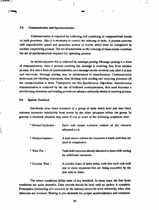
93 Communication and Synchronization
Communication is required for collecting and combining of computational resultson each processor. Also it is necessary to control the ordering of tasks. A process executeswith unpredictable speed and generates actions or events which must be recognized byanother cooperating process. The set of constraints on the ordering of these events constitutethe set of synchronization required for operating process.
In multicomputer this is achieved by message passing. Message passing is a formof communication, since a process receiving the message is receiving data from anotherprocess. It is also a form of synchronization, as a message can.be received only after it is sentand vice-versa. Message passing may be synchronous or asynchronous. Communicationstatements are blocking statements, thus blocking both sending and receiving processes tillthe communication is done. Transputers use this Synchronous Algorithm. Asynchronouscommunication is achieved by the use of buffered communication, thus send becomes anon-blocking statement and sending process can advance arbitrarily ahead of receiving process.
9.4 System Deadlock
Deadlocks arise when members of a group of tasks which hold and thus blockcommon resources indefinitely from access by the other processes within the group. Ingeneral, a deadlock situation may occur if one or more of the following conditions exist.
* Mutual Exclusion : Each task claims exclusive control of the resource
allocated to it.
* Nonpreemption : A task cannot release the resources it holds until they areused to completion.
* Wait For : Tasks hold resources already allocated to them while waitingfor additional resources.
* Circular Wait: A circular chain of tasks exists, such that each task holdone or more resources that are being requested by thenext task in chain.
The above conditions define state of any deadlock. In many ways, the first threeconditions are quite desirable. Data records should be held until an update is complete.Preemption (reclaiming of a resource by the system) cannot be done arbitrarily, when dataresources are involved. Waiting is also desirable for proper synchronization and comrauni-
33

cation. Careful use of these three factors can only save the group of tasks from deadlocks.
10. Performance Analysis
Let us first define terms speed-up and efficiency which describe the performanceof a parallel application.
* Speed-up : This is defined as ratio of time required to execute an applicationsequentially to the time required to execute the same applicationon a parallel computer. For a homogeneous multicomputer systemwith k processors, generally a speed-up up to the factor of k canbe expected.
* Efficiency : Efficiency is the average percentage utilization of speed ofprocessors in a multicomputer system. It is nothing but the speed-up obtained per processor.
A number of factors contribute to limit the speed-up achievable by a parllel algo-rithm on multicomputers (MIMD). An obivious factor is the computational size. If there isnot enough computation work to be done as compared to the communication required toinitiate that work, then any parallel algorithm will show constrained speed-up. This phenome-non is called Amdhal's Law. The work load must also be balanced, so as all processes takesame computational efforts. Lastly, efficient algorithm must be used. An efficent sequentialalgorithm may not necessarily be so efficient for parallel execution.
10.1 Improving the performance
Amdahl's Law states that, if f is the inherently sequential fraction of a computationto be solved by p processors, then the speed up S is limited as
S < 1 / [f + (1 - f) / p]
Sequential parts in the tasks limit the speed-up of the application. If some stage ofprogram execution must be done sequentially then for the corresponding time all otherprocesses will be idle for want of synchronization. So the sequential part of the algorithmshould be minimized for better speed-up.
While minimizing the sequential factor it is necessary to create new processes withproper synchronization. In process creating the code has to be loaded while the other tasksmay be waiting for synchronization. Thus it's too. expensive. Usual practice is to create thedesired number of processes when the algorithm begins execution and to synchronize them
3*

as required. Synchronization needs communication which causes overheads. Thus, frequent
synchronization too, causes significant overheads. So the goal in designing a parallel program
should be to make the grain size as large as possible. Grain size is the amount of work done
between synchronizations.
Another important factor for improving the performance is Load Balancing. It
means equally dividing the total load among the processors, and ideally no processor is idle.
In other words, Load Balancing problem can be defined as the problem of decomposing an
algorithm so as to maximise the speed-up. Static load balancing is the process of optimally
breaking up the problem at the start, then allowing the user code to run with no further
attention. But in case where algorithms are data dependent and probabilistic the load has
to be divided dynamically i.e., at the run time. Such dynamic load balancing would be necessary
for event-driven simulations, adaptive meshes, partical dynamics problems or for simulation
of neural networks with time dependant non uniform activity. The cost of dynamic load
balancing in terms of performance must be weighed against the advantage it will offer.
In conclusion, full advantage of running an application on a parallel computer can
only occur if one can ensure that every processor has equal work load, and minimum
communication.
11. BENCH MARKING
11.1 Unpack and Benchmarking environment
Linpack solves a dense system of linear equations using Gauss Elimination method.
Linpack comes in two versions, single precision and double precision. "Standard Linpack"
solves a system of linear equations of order 100 whereas a large linpack solves a system of
equations of order 1000. The parallel version of the Linpack has been studied on different
number of processors and for different number of equations.
Configuration of the Benchmark16No. of nodes
NODE CPU
Clock
Communication speed
Node Memory
Root Memory
Node Memory Cycle
Root Memory Cycle Time
Compiler
T800 Transputer
20 MHz
20 M bps
4M bytes
8M bytes
200 ns
200 ns
Fortran 3L version 2.0
35

An important factor affecting the efficency of Unpack is the use of Basic LinearAlgebra Subprograms (BLAS). This set of subprograms performs basic operations fromlinear algebra such as computing inner product or adding a multiple of one vector to another.In Unpack, great majority of calculations are done within the BLAS. Improved Unpackperformance can be achieved by using assembly versions of BLAS. The result we report arenot based on such coded BLAS.
A minute study of the linpack algorithm reveals that there are as many data movementsas the number of floating point operations. Hence on a slower memory, performance suffers.The parallel version of the linpack is generalised and can run on any number of processorswith the only precondition that they are connected in a pipelined architecture.
11.2 Unpack and its Parallellisation
Linpack solves a set of linear equations in Fortran environment. Consider a systemof linear equations denoted by
AX = B
where A is n x n matrix assumed to be dense and X and B are vectors of which Bis given and X is to be evaluated. Matrix A is generated through a random number generatorand vector B is obtained by summing the elements of the row of matrix A. Matrix A istriangularised using Gauss Elimination method. Zeroes in the elements below the diagonalare introduced column by column starting from left and working towards right. A multipleof row containing the diagonal element is added to each of the row below it in the submatrix.This constitutes the major operation in the decomposition and needs to be optimally parallelised.Pivoting is done to check for singularity and minimise the numerical errors. The solution isobtained using back substitution. The time (T) taken for triangularisation and backsubstitu-tion is used to compute the performance of the system, given by
MFLOPS = [(2/3)n3 + 2n2] / T
for a system of equations of order n.
It is worth noting that FORTRAN stores arrays columnwise. As one proceeds down
the column, references proceed sequentially in the memory, whereas as one proceeds across
the rows, references jump across the physical memory, the length of the jump being proportional
to length of the column.
Hence, linpack uses column oriented algorithms. Linpack code always references
36

arrays down the columns, not across rows.
11.3 Domain Decomposition
Columns are distributed among processors for parallel implementation. Row pivotingis done. Pivot is chosen to be the element of the maximum absolute value in a column androws are interchanged. No communication is required to determine the pivot element andso the communication overhead is reduced. In this way, the determination of the pivot is donesequentially, on one processor. The decision as to which processor holds the pivot columnis taken locally by each processor. The identity of the pivot is distributed among neighbours.Each node then exchanges the required rows locally. This task is uniformly, distributed amongthe processors and is performed in parallel. Besides, communication is also required todistribute the pivot column. Elimination is then performed. Linear combination of the pivotcolumn is then added to each of the column to its right in the submatrix. Each node operateson the column it holds. The elimination is the major time consuming part, which is uniformlydistributed among the nodes and executed in parallel.
As the columns are eliminated step by step, the size of the submatrix left out to befactored is reduced. If the columns are distributed in blocks, the processor holding the firstblock becomes idle after those many columns have been eliminated. To achieve a balancedload distribution, the columns are distributed in a wrap around manner i.e., consecutivecolumns are distributed on consecutive processors. This ensures that all the processors havesame number of columns still to be factored (to within one column). The backsubstitutionis quite similar to this and need not be discussed.
The parallel algorithm for triangularisation is shown below :
Processor Identity = IFOR k = 1 to n - 1
• sequential *
IF I holds kth column then
find the pivot
Communicate the identity of the pivot rowand the kth columnELSEreceive the identity of the pivot row and the kthcolumn and transmit it to the next neighbour• parallel *Do elimination of columns i holdsEND
37

11.4 Mapping Function and Communication Strategy
The communication strategy is quite simple. Processors are connected in an arraytopology through its links. The node holding the pivot column of the submatrix finds the pivotand transmits the identity of the pivot row to its left as well as to its right neighbour. Eachof these nodes receive this information and transmit it to its immediate neighbour in the array.The information is thus distributed among all the processors.
Program running on each node is same except the nodes of the extreme ends, whichdiffer from the communication point of view as they have only one immediate neighbourwhereas others have two. Each node is supplied with its unique identity and the informationabout number of nodes running the benchmark so that each node decides the column ele-ments under its control and the data communication strategy. The program, thus becomesgeneral and can be run on any number of processors connected in a pipeline. There are noalgorithmic constraints on the number of processors or the order of the equations. I maybe noted that the matrix is generated locally on each processor.
To ensure that all the processors start solving at the same time, a request commandis sent to the first node in the network connected to the root processor. Each processorreceives this command and relays to the next processor until it reaches the extreme end. Atthis point all the idle nodes are waiting for a go command. The last processor sends a gocommand to all the nodes in the pipeline routed through the intermediate nodes and theneach node starts solving the problem and the timer is started. Similarly, the timer is stoppedonly when all the nodes have completed program execution.
11.5 Benchmark Performance
The benchmark tests have been run on a number of processors varying from 1 to16 for single as well as for double precision. The double precision Unpack benchmark forthe equation of order 1000 could not be run on node processors due to shortage of memory.Table 1 shows the observed Unpack performance as a function of number of processors andmatrix size. Fig. 21 shows the three dimensional plot of Unpack speed up. It is observed thatif the number of processors is fixed, the speed increases with the increase in the size of thematrix. This is due to the fact that computation to communication ratio increases withincrease in matrix size.Also, the speed up does not increase linearly with the increase in thenumber of processors for the same size of the matrix. This is due to the increased commu-nication with more number of processors.
38

J
16—
Matrix Size
7.1
16
NaofPr
Fig. 21: 3D Plot of the UNPACK speed up

11.6 UNPACK BENCHMARK PERFORMANCE (MELOPS)
Table 1 : Performance in MFlops
No.of TransputersMatrix Size - 100
Single Precision
Double Precision
Matrix Size - 1000
Single Precision
1
0.4038
0.3511
0.4625
2
0.6699
0.5569
0.8235
4
1.163
0.9482
1.623
8
1.841
1.4590
3.156
16
2.605
1.9930
5.975
Matrix Size Versus Performance in MFlops (Single Precision Floating Point Operation)
^vMatrixSize
1(Seq Code)
1
(Parallel Code)
2
4
6
8
10
12
14
16
100
0.4038
0.3670
0.6699(91.27)
1.163
(79.22)
1.542(70.03)1.841
(62.71)
2.008(56.89)2.287
(51.93)2.459(47.86)
2.605
(44.63)
200
0.4347
0.3868
0.7504(97.00)
1.396
(90.23)
1.957(84.32)
2.450
(79.18)2.886(74.61)
3.273
(70.51)3.623(66.91)
3.938
(63.63)
400
0.4517
0.4035
0.7951(98.53)1.534
(95.05)
2.221(91.74)
2.862
(88.66)3.463(85.82)
4.025
(83.13)4.553(80.60)
5.050
(78.22)
500
0.4553
0.4070
0.8044(98.82)
1.563
(96.01)
2.279(93.33)
2.955
(90.76)3.597(88.38)
4.205
(86.10)4.783
(83.94)
5.334
(81.91)
600
0.4576
0.4105
0.8107(99.10)
1.583
(96.77)2.318
(94.45)
3.020
(92.20)3.691(90.29)
4.332
(88.24)4.946
(86.11)
5.531(84.83)
800
0.4613
0.4141
0.8226
(99.32)
1.614
(97.44)3.279
(95.75)
3.108
(93.82)3.828{92.44)
4.505
(90.66)5.169
(89.16)
5.804(87.60)
1000
0.4625
0.4143
0.8235(99.35)
1.623
(97.98)2.400
(96.60)
3.158
(95.22)3.889
(93.86)
4.603
(92.59)5.298
(91.34)
5.975(90.14)
NB : Figures in brackets indicate the efficiency of paralielisation
40

Marix Size Versus Performance in
\sMatrix Size
Nodps ^""-^
1(SeqCode)
1(Parallel Code)
2
4
6
8
10
12
14
100
0.3511
0.3003
0.5569
(92.72)
0.9482
(78.94)
1.2360
(68.60)
1.4590
(60.73)
1.6380
(54.55)
1.7790
(49.37)
1.8970
(45.12)1.9930
(41.78)
MFlops (Double Precision Floating Point Operation)
200
0.3750
0.3223
0.6202
(96.22)1.1410
(88.51)
1.5810
(81.76)1.9590
(75.98)
2.2890
(71.02)2.5760
(66.61)
2.8310
(62.74)3.0530
(59.20)
400
0.3882
0.3440
0.6564
(98.26)
1.2570(94.09)
1.8080
(90.22)
2.3140
(86.60)
2.7840
(83.35)
3.2180
(80.29)
3.6220
(77.46)3.9910
(74.68)
500
0.3909
0.3369
0.6638
(98.52)1.2820
(95.13)
1.8590
(91.97)
2.3980
(88.97)
2.9030
(86.17)
3.3780
(83.56)
3.8250
(81.10)4.2410
(78.68)
600
0.3928
0.3386
0.6688
(98.76)
1.2990
(95.91)
1.8940
(93.23)
2.4550
(90.63)
2.9870
(88.22)
3.4910
(85.92)
3.9700
(83.75)4.4210
(81.6)
800
0.3941
0.3398
0.6724
(98.94)
1.3120
(96.53)
1.9190
(94.12)
2.4980(91.89)
3.0500
(89.76)
3.5770
(87.72)
4.0800
(85.72)4.5580
(83.84)
NB : Figures in brackets indicate the efficiency of parallelisation
Linpack code was earlier parallelised on a 8-node prototype system (Ref. 9) with
each node having 600 ns memory cycle time. Linpack performance for the 8-node machine
for a matrix size of 100 are observed as 0.848 and 0.6879 MFlops respectively for single
precision and double precision floating point operation. Comparing these results with thecorresponding for MTPPS, it may be noted that a performance improvement by a factor of
2.6 is achieved. This can be explained by the fact that Linpack program has as many memory
accesses as the number of operations. Hence the impact of memory speed on the perform-
ance is drastic. Secondly it is observed that as the number of processors increase, the
communication overheads increase. Moreover it is also observed that as the size of the matrix
increases, efficiency increases. This could be explained by deriving an empirical formula as
for efficiency as follows.
41

For a Unpack benchmark of order m, the number of floating point operations isproportional to m3. Whereas communication is proportional to m2, so that computational tocommunication ratio is given by
""*' - K-mV m* - KmCOB«
where K is proportionality constant
Sequential computational time is say T^, which is the same as T ^ (computationaltime for the problem of given size)
T = T*«i 'amp
For a parallel program running on n transputers, the time taken for communicationwould be
where T^^ is the communication time between 2 processors. Hence the total timefor parallel implementation is given by
assuming only communication over heads and neglecting algorithmic and othermiscellaneous overheads.
Efficiency - T^, / (T,., n) = T^, / [ T ^ + (n -1) T ^ n]
.-. Efficiency = 1 / (1 + n (n -1) / Km)
Where K = T e o . r /TM M
From this formula it can be seen that, for a fixed number of nodes and increasingmatrix size m, efficiency increases. This agrees well with the observed results shown inTable 1 and discussed earlier.
42

Unpack performance of various other systems are tabulated below for reference
Computer
Cray Y-MP / 832
Cray X-MP /832
CDC Cyber 205
CDC 7600
MTPPSELXSI 6420
SUN SPARC Station 1
DEC VAX 8530
ND570
T800 (20 MHz)
PACE-8 (Uniprocessor)
ND-560
ND-500
Sun 386i / 250 25 MHz
IBM AT W/8-287
Unpack benchmark
(MFLOPS)
for Matrix Size = 100
double precision
9070173.32.01.71.30.73
0.38
0.35
0.22
0.22
0.19
0.19
0.012
1Z APPLICATION SOFTWARE
Pew application programs have been parallelised and ported an the 16 node system.
These applications include a Reactor Physics Problem, plasma simulation and the code
FEMINA (Flux Expansion Method In Nodal Analysis). The problem definition and their
performance on the parallel system has been briefly summarised for Reactor Physics Problem
and Plasma Simulation. The fine details of these problems, their parallelisation and perform-
ance analysis are reported seperately (10,11,12).
12-1. Reactor Physio Problem
A basic reactor problem is the determination of the fundamental mode neutron flux
distribution using two group diffusion theory. Neutron fluxes f (g»l,2) obey the diffusion
equations:
43

+ (2,, + Zp.) f, = (vZfl,, + (1)(2)
Here D ( is the diffusion coefficient for neutrons of group g, 2 t and 2 ( are theabsorption and fission cross-sections, Z,, is the slowing down cross-section of the moderatorand v is the mean number of fission neutrons and k, called the kef( eigenvalue is the criticalityparameter.
f( are assumed to vanish at the boundary. The material properties are assumed tobe independent of the position coordinates. Typical values of the reactor parameters areused. The solution of the problem employs finite difference method assuming a uniform meshstructure. Gauss-Siedel method has been used. The domain of the reactor is modelled for128 x 128 grid for the two dimensional case and 128 x 8 x 16 for the three dimensional case.For parallel implementation, the rectangular geometry of the reactor was distributed amongthe processors dividing it equally along the horizontal plane(lO). Different blocks are distrib-uted among different processors and the boundary values of adjacent blocks are exchangedthrough the links.
The code has been developed in Occam. The performance figures are tabulated in
Table 2. The performance figures of the Fortran Version of the same problem have also been
tabulated in Table 2 as observed on MTPPS.
Table 2 : Performance figures
(Program execution time in seconds)
(A) OCCAM VERSION
2-D geometry
32x32
64x64
128x128
256x256
3-D geometry(128x8x16)
1
11.38
83.62
550.25
2974.50
461.85
(3.87)
4
3.13(3.63)
22.20
(3.77)141.54
(3.89)744.09(3.998)
.119.34
(7.55)
8
1.63
(6.92)
11.22(7.45)71.69(7.94)374.47(7.94)
61.19(14.48)
16
0.93(12.26)
5.92(14.13)36.27(15.17)
189.57(15.69)
31.89
44

(B) FORTRAN VERSION
32x32
64x64
128x128
256x256
1
13.5
92.2
566.2
2805.3
4
5.1(2.65)30.9(30.0)
183:2
(3.1)1555.9
8
3.0(4.5)
16.9(5.5)95.9
(5.9)
463.2(6.1)
16
2.1(6.4)
10.0(9.22)52.5
(10.8)242.7(11.6)
NB : Figures in brackets indicate the speed up.
Particle-in-Cell Plasma Simulation
Parallelisation of a Particle-in-Cell Plasma Simulation code has been done on theprototype 8-node multi-transputer parallel processing system. The collective behaviour ofcharged particles subject to their own as well as external electromagnetic fields has beeninvestigated. The plasma is approximated by a large number of point size charges with acomparatively smaller number of finite size particles which move in a computational boxunder electro-magnetic fields. The computational box is discretised into a spatial mesh (orgrid) by sets of parallel lines. At the mesh points the electromagnetic field variables (likecharge density q, electric field E, and magnetic field intensity B) are calculated by solvingMaxwell equations. The current density J is computed through the boundaries of the cells.The particle positions and velocities are calculated using Lorentz equation. New field variablesE, B are calculated at the mesh points by solving the descritised Maxwell equations.
V.E - q/70
V.B - 0VxE - aB/atVxB - (1/c2) (dE/dt + nj)
where c is the velocity of light and ftQ is the free space permeability.
The force P on the particles are calculated from the Lorentz equation
F - q (E + v x B)New velocities v are computed by solving the Newton's equation of motion
45

dv/dt = F/m
Where m is the mass of the particles.
Using the new velocities the particle position are updated. Iterative execution of the
above equations results in consistent evolution of the plasma.
The simulation is carried out on a network of 8 transputers (T800) with each node
having one mega byte of memory having 600 nsec access time. The 8 transputers in the system
are connected as (4 x 2) torous as shown in Fig. 22 to implement the 2 dimensional simulation
with periodic boundary conditions.
3
L
L
host
0
0
root
2
0
Tl
3
3
T8
1
1
0
0
1
3
T2
2
2
T7
|3
1
0
0
1
3
T3
2
2
T6
|3
1
0
C
1
3
T4
1
0
T5
— 3
J
JFig. 22: Layout of the transputer network as a (4 x 2) torous
The root transputer is connected to the front end host system which manages
input-output operations. The programming is done using 3L Parallel C compiler. The simu-
lation program takes from an input file, run time parameters such as the number of particles
to be simulated, dimensions of computational box, constants representing the magnetic field,
plasma frequency and generates files for kinetic, electrostatic total energy and the potentials
on the mesh points. Table 3 show the speed-up and efficiency of the parallel program as a
function of number of processors and the data size. The observations are taken by running
the program with the plasma configured to simulate the two stream instability. During the
initial phase the particles are uniformly distributed so that load is balanced evenly
on each processor. The efficiency is calculated by the relation r\ - S^n, where S, is the
speedup obtained for n transputers.

Table 3
RelativeData Size
13.88.5
14.820
4 nodesSpecdUp
2.963.103.153.163.16
n0.750.770.770.790.79
6 nodesSpeedUp
4.074.664.64.614.6
n0.680.780.770.770.77
8 nodesSpeedUp
5.58.6.186.36.316.3
n0.70.770.790.790.79
* A data size of 1 corresponds to 5048 particles* A data size of 20 corresponds to 1,07,648 particles
Efficiency values improve as the number of particles (data size) increase becausethe interprocessor and global communications overhead is fixed for a given set of transputers.
13. CONCLUSION
Development of the multitransputer parallel processing system, apart'from'provid-ing a development platform for transputer based parallel processing applications, has givensufficent experience in transputer hardware design and other related system concepts. Thisexperience will be useful in designing the future parallel processing instrumentation. Also,the development of benchmark, evaluation and application programs would certainily build-up the sort of experience needed to provide the necessary software support for the intendedfuture applications of transputer based parallel processing. For real-time multicomputerapplications transputer is a suitable choice amongst the available microprocessors today andthe effort* which have gone into this development work would definitely be useful in future.
MTPPS, as a Parallel Processing development Platform is to be extensively used inthe design and implementation of Parallel algorithms for Data Preprocesing in large detec-tor nuclear Data acquisition system, AI tools required to develop knowledge based systemsfor accelerators, Nuclear Physics experiments and Nuclear Power Plant* and other relatedareas relevant to DAE. Apart from this, MTPPS can be used as a low cost high performancescientific problem solving machine and as a general purpose Parallel Processing developmentfacility. With it's elegant and compact size and integrated PC/AT, it can be hooked up to anydesired existing experimental facility through standard inteciace techniques, for Data proc-essing and analysis work.
47

14. ACKNOWLEDGEMENTS
We gratefully acknowledge Dr. G.J. Nair, Seismology Division for checking the au-thenticity of the results obtained by LINPACK parallel code. The valuable support providedby Dr.R. Venkatesan and Dr. S.V.G. Menon, Theoretical Physics Division and Dr. K. Patel,Multidisciplinary Research Section is gratefully acknowledged. We are thankful to Dr. G.S.Singh, Training Division for discussions during the initial phase of development and B. Singhof Electronics division for careful editing and critique of the report. The authors gratefullyacknowledge the assistance in the preparation of this manuscript by Mr. Kevin Fernandesof Electronics division.
15. REFERNCES
1 "Fast preprocessing of physical data in a VME crate based system" G. Maronet.al., IEEE Trans, on NS, vol 36, Nol. Feb 1989.
2 "A VME multiprocessor system for on-line data analysis of Nuclear Physics
experiments" IEEE Trans, on NS, vol 37, No3, June 1990.3 'The Darmstadt-Heidelberg Crystal Ball", B.S. Simon, Journal De Physique,
colloque do, Dec 1980
4 "Parallel Processor Trigger with Distributed Real-Time Kernel", Timo Kor-honen et.al., IEEE Trans, on NS, vol 38, No 2, April 1991.
5 "Very High speed computing systems", Flynn M.J., Proceedings of the IEEEvol 54, No 12, 1966.
6 "Multiprocessing VME", David Libennan, EE TIMES, CMP Publication USA,
issue 640, 6 May 1991.
7 "Communicating Sequential Processes", CAR HOARE, Communications of
the AEM, vol 21, No 8, Aug 1978.
8 "Reconfigurable parallel processing system", A.N. Khare et.al., Proceedings of
the workshop on parallel processing, Feb 7-9, 1990, BARC.
9 "A transputer based parallel processing system and it's LINPACK perform-ance", A. Jethra et.al., WoTUG newsletter Nu.15, July 1991, published byINMOS Ltd., U.K.
48

10 "Parallel Iterative Algorithms for solving fundamental mode neutron fluxdistribution", S. Rajagopalan et.al., Ann. Nucl. Energy, Vol. 18, No.2, publishedby Pergamon Press pic U.K.
11 Issues in Developing Parallel Iterative Algorithms for solving partial differen-..al equations on a transputer based Distributed Parallel Computing System",S.Rajagopalan et.al, Report No. BARC-1513,1990.
12 "Concurrent Particle-in-Cell Plasma Simulation on a multi-transputer parallel
computer", A.N. Khare and Kartik Patel, Report No. BARC/1992/E/015.
49

Appendix A : OCCAM Overview
OCCAM is specifically designed high level language for INMOS family of transput-
' ers that can be used for sequential as well as for parallel execution of a program. The
OCCAM programming language enables an application to be described as a collection of
processes which operate concurrently and communicate through associated channels. In such
a description, each OCCAM process describes the behaviour of one component of the im-
plementation, and each channel describes the connection between components. The collec-
tion of processes described in OCCAM can be executed on a single transputer or a network
of transputers. Concurrancy can be very efficiently maintained in OCCAM.
OCCAM is a highly formatted language, where indentation specifies program structure
and scope rules. Each statement starts on a new line. The starting position of the statement
will group it to precursor construct or process that starts at two columns to the left. A
comment is introduced by the character pair - . It may follow a statement or occupy a line
by itself at the same indentation as the following statement.
OCCAM programs are built from following primitive processes :
v := e aassignment, assign expression e to variable v
c ! e output, output expression e to channel c
c ? v input, input variable v from channel c
SKIP start, do nothing and then end
STOP start, but never proceed and never end
The primitive processes are combined to form constructs :
SEQ sequential
IF conditional
PAR parallel
ALT alernative
A construct is itself a process, and may be used as a component of another construct.
Objects like channels, primitives input, output and constructs PAR, ALT are the specific
additions for concurrent programming. In following paragraphs, OCCAM programming language
is very briefly discussed.
Variable Names
Variable name of any length is allowed if it start with an alphabet and made up of
letters, digits and dot characters; and if it is not any of OCCAM keywords. The upper and
lower case are distinguished.
50

Data Types
INT Integer. 16,32 or 64 in end show length in bits
REAL Real. 32 or 64 in end indicate length in bits
BYTE Integer between 0 and 255, denote character
BOOL Logical truth values TRUE or FALSE
Channel Type and protocolCHAN OF'protocol1
'protocol' specifies the data type or structure a channci is to carry.
Boolean Typess
< >
>
<
> =
< • >
ConstantsVAL
equal to
not equal to
greater than
less than
greater than
less than or
'type' 'name'
or equal to
equal to
IS 'value'
Sequential Process
A SEQence starts with the execution of the first process. Each subsequent process
starts if end when it's predecessor terminates. The SEQence terminate on termination of
the last process.
SEQ
Process1
Process2
ProcessN
Parallel ProcessAll PARallel processes start simultaneously and proceed together. The PAR ter-
minates when all the processes have terminated.
PAR
Processl
Process2
ProcessN
51

Repetitive ProcessesWHILE statement causes the 'process' to be executed repetitively untill the logical
expression 'boolean' is TRUE.
WHILE 'boolean = TRUE'process
Conditional Procenes
IF statement cause the execution of 'processN' if logical expression 'conditkmN' isTRUE. The condition 1 to conditionN are tested sequentially.
IF
conditionl = TRUEprocessl
conditionN = TRUE
processNTRUE
process - no condition is TRUE
Selection ProcessesThe selector expression V is evaluated first, and it's value is used to select one of
the component options and corresponding process for execution.CASEx
a
processA -- selected if variable x = a
bprocessB -- selected if variable x = b
ELSE
process -- else
Alternative Processes
An alternation combines a number of processes guarded by inputs. The alternationperforms the process associated with the guard that is ready first.
ALT
expl -- alternative
processl
expNprocessN
52

Arithmetic inx + y
x - yx • y
x / yxREM
Bit Operators
AV><
OCCAM— add y to x
- subtract y— multiply x
from xbyy
- quotient when x is divided by yy — remainder
bitwise NOT
bitwise AND
bitwise ORbitwise X-ORleft shift
when x is divided by y
•
> > right shift
Procedures
A procedure is a process with a 'name' and this name can be used to represent theprocedure in other processes. The procedure can be defined by the keyword PROC followedby a name and then the process body. End of the procedure is indicated by V.
PROC name ( forma! parameters ) - definition...process body
: — End of procedure
procedure ( arguments ) - instance
FunctionsA function is a process which returns a value of the type 'type' and thus may be used
in expressions. In OCCAM it is guaranteed to have no effect upon any other part of theprogram.
'type' FUNCTION 'name' (formal parameters)
VALOFProcessRESULT expression
: - End of function
In OCCAM, parameters are passed to a procedure or function by reference. Pa-rameter may be passed by value if we explicitly say that the value is to be passed using VALWhen VAL is used like this, the formal parameter is treated as a constant thoughout theprocedure body.
53
Arrays
Thh decleration is used to associate a name to consecutive memory locations. Thesyntax ii
['array size'] TYPE 'array.name'
Arrays may be used as parameters to procedures. Although the size of an array mustbe fixed at compile time, an array passed as a parameter to a procedure need not be of fixed
size. A procedure accepting an array parameter can accept array of any size and can performprocessing on the array by obtaining it's size with SIZE operator.
ReplicatorsThe replicators are used to generate structurally similar units of program code. The
syntax is
REP index = base FOR count
process
REP is one of SEQ, PAR, ALT, or IF. Replicated SEQ is equivalent to a counted
loop. Replicated PAR builds an array of structurally similar parallel processes. Replicated
ALT consists of a number of identically structured alternatives each of which is triggered by
input from a channel. Replicated IF produces a conditional construct with a number of
similarly structured choices.
TimersTiming in OCCAM is provided by declaring named objects of the type TIMER. A
timer behave* like a channel which can only provide input. The value input from a timer is
the current time represented as a value of type INT. Delays can be added to a program by
using a delayed input. This is an input from a timer which cannot proceed until the timereaches a stated value. The operator AFTER followed by an expression representing a timeis used to cause the delay.
PriorityIn real-time programs, to define as to what happens if two processes in a PAR are
ready for execution, or if two alternatives of ALT are ready simultaneously it is necessaryto define their priorities. So OCCAM allows both PAR and ALT processes to be prioritised.This is signified by proceeding the construct with the word PRI. The priorities are assignedaccording to the order of component processes in which they appear in the program.
54

Configuration
An OCCAM application it a group of tasks communicating through channels. To
meet the performance requirements, these tasks along with communicating channel* have
to be mapped on available hardware. This configuration is achieved by following statements
in OCCAM.
PLACE A T : The PLACE statement in OCCAM allows a channel, a variable, an array, or
an I/O channel to be placed at an absolute location, in memory. This may be used to map
channels on hardware links and also to access devices mapped into the transputer's address
space, e.g.
PLACE screen AT 1 :
PORT : OCCAM can address I/O ports as used in conventional computer systems. A port
declaration has a data type, e.g.
PORT OF BYTE serial :
PLACED PAR : To allocate the parallel processes to different processors PLACED PAR
may be used. PLACED PAR is followed by placement, which consists of the number of
processor and a process to be run on it.
PLACED PAR
PROCESSOR p
Process
55

Appendix B : Parallel Matrix Multiplication in OCCAM
Simple matrix multiplication problem is considered here for illustration. Matrix A oforder LxM and B of order MxN are multiplied to get C of order LxN. The source code isgiven followed by the parallel algorithm and flow chart for matrix multiplication.
Algorithm
Matrix Multiplication involves similar computation of LxN elements. With proper loadbalancing (Lj = L/proccssors) rows of matrix C may be calculated in each process. So therows of A are equally divided among all processes. Then part of A and matrix B can bemultiplied to get parts of matrix C If
A . B = C
On i" process the multiplication will be
A,.B = Ci
such that
VA,
and C =
where p = number of processors - 1
Thus for parallel multiplication r* process should have submatrix A, and matrix B to
compute wbmatrix C,. So the master process has to send A. and B and collect C, from every
process. This is represented as flow chart in fig. Bl.
Concurrent OCCAM source for matrix multiplication developed in OCCAM2TOOLSET environment is also given. We are implementing our algorithm on a system withpipeline connection between tasks. Communication patterns are different for first, last andfeat of the processes in pipeline. Procedures 'FIRST, 'LAST' and 'REST handle commu-nication for respective processes. All these call same procedure 'Multiply' for componentmuWpBcadon. TIRST also calls the I/O interface procedures 'Enter' and 'Display1. The entryfunction 'MatrkMultiplication' it in different file as per the OCCAM2 TOOLSET.
56

This can be very easily modified for actual pipeline of processors by replacing the"MatrixMultiplication" by a suitable configuration file.
Muter Task Slave Tasks
Input A and BMake A,s
Propogate As and B I Receive and propogatc A,s and B
MultiplyA.l:. and B
MultiplyA^andB
Collect C,s Collect and send C,s
Output C
Fig. Bl: Flowchart for parallel matrix multiplication
Source Code
#INCLUDE "hostio.inc" - Definition of constant for host I/OPROC Multiply ([ ][ ]INT A, B, C, INT L, M, N)
INTi , j ,k ,a :SEQ i=0 FOR L
SEQj=0FORNSEQ
a : = 0SEQ k=0 FOR M
a := a + (A[i][k]*B[k]D])C[i)D]:=a
P R O C Enter ( C H A N O F S P 6 , ts, [][ ] I N T A , B , I N T L, M , N )#USE "hostio.lib"
BOOL error :SEQ
so.write.nl (fs, ts)fo.writcstring (fs, ts," Matrix Multiplication A(LxM)B(MxN) -
- Element Cfijfj]
' input A and B' host I/O library
' print newline
print string
57
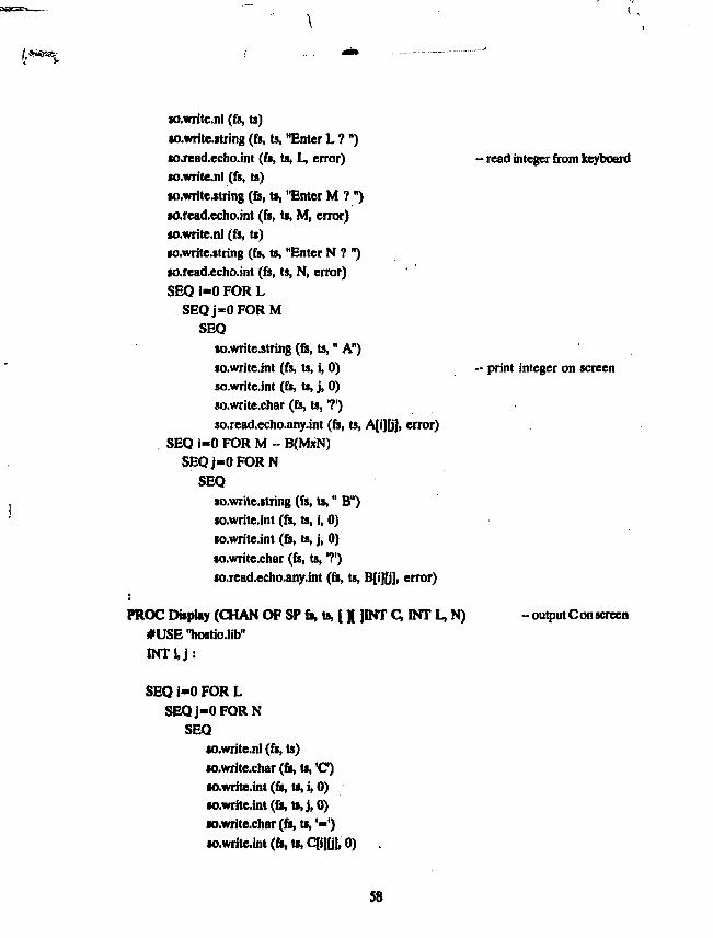
K).write.nl (fs, ts)
•awritejtring (ft, ts, "Enter L ? ")
io.read.echo.int (fi, ts, L, error) - read integer from keyboard«o.write.nl (fs, ts)•o.write.string (ft, ts, "Enter M ?")so.read.echo.int (fs, ti, M, error)so.write.nl (fs, ts)so.write.string (fs, ts, "Enter N ? ")so.rcad.echo.int (fs, ts, N, error)SEQ i«0 FOR L
SEQ j « 0 FORMSEQ
lo.writc.string (fs, ts," A")
so.write.int (fs, ts, i, 0) - print integer on screenso.write.int (fs, ts, j , 0)so.write.char (fs, ts,'?')
so.rcad.ccho.any.int (fs, ts, A[i][j], error)SEQ i - 0 FOR M -- B(MxN)
SEQj-OFORNSEQ
so.writc.string (fs, ts," B")so.write.int (fs, ts, i, 0)io.write.int (fs, ts, j , 0)
so.write.char (fs, ts,'?')so.read.echo.any.int (fs, ts, B[i][j], error)
PROC Display (CHAN OF SP fi, ts, [ X ]INT C, INT L, N) -output Con screen
#USE "hostio.lib"
INTJ.J:
SEQ i - 0 FOR L
SEQj-OFORN
SEQso.write.nl (fs, U)so.write.char (fs, ts, 'C)so.write.int (fs, ts, i, 0)so.write.int (ft, ts,j,O)w.write.char (ft, ts,'«')so.write.int (ft, U, qi](j], 0) .
58

PROC LAST (CHAN OF ANY input, output)INT work, M, N :[5OJJ5OJINT A, B, C :INT I, j , k, th :SEQ
input ? M • receive Binput ? NSEQ i=0 FOR M
SEQj=0FORNinput 7 B[i][j]
input ? work -- receive A
SEQ i=0 FOR workSEQ j=0 FORM
input ? A[i][j]
Multiply (A, B, C, work, M, N) -- Multiply
output I work - Send C
SEQ i=0 FOR work - send results
SEQj=0FORNoutput 1 C[i][jJ
PROC FIRST (CHAN OF SPfr,U, CHAN OF ANY input, output, INT processors)#USE "hostio.lib"
f50][50]lNT A, B, C :
INT L, M, N :INT wk, rm, i, j , k, last, frm, wrk :[50JINT work, from, upto :
SEQEnter(fs, ts, A, B, L, M, N)- divide the rows of A among processorswk :« IVprocessors - divide
rm : - L - (wk'proceitors) ~ remainderlast :•» processors • 1
SEQ i"0 FOR proceuonwork[i]:- wk
59

SEQ i - 0 FOR ranworkfi]:- workfi] + 1
from[0] := 0
SEQ i=0 FOR last
from[i+l] : • from[ij + workpj
- transmit B in networkoutput I M - rowsoutput I N -- columnSEQ 1=0 FOR M
SEQj-OFORNoutput! B[i][j]
- transmit A in network
SEQ i » l FOR last ~ zeroth packet is processed hereSEQ
j := processors-i - first packet for last processoutput! work(j] -- size of packet in rowsSEQ k«=from[j] FOR work[j]
SEQ m - 0 FOR Moutput! A[k][m]
Multiply (A, B, C, work[0], M, N) - Multiply
frm : - work[0] - Collect C
SEQ i - 0 FOR lastSEQ -- collect nearest result first
input ? wrkSEQ k-frm FOR wrk
SEQ n»0 FOR Ninput 7 C[k][n]
frm :» frm + wrk
Display (ft, ts, C, L, N)
so.exit (ft, t», sptjuccess)
60

PROC REST (CHAN OF ANY inputup, outputop, inputdn, uutpuldu, INT p,proce«oti)INT work, M, N :[50][50JINT A, B, C :INT i, j , k , next, last:
SEQnext := p + 1last := processors - next
inputup ? M - receive and propogate Boutputup 1 Minputup ? Noutputup ! NSEQ i=0 FOR M
SEQj=0FORNSEQ
inputup ? B[i][j]outputup ! B[i][j]
SEQ i=0 FOR last - receive mtmmd ASEQ
inputup ? workoutputup I workSEQ k=0 FOR work
SEQ m=0 FOR MSEQ
inputup ? joutputup! j
inputup ? work - receive last part for this processSEQ k=0 FOR work
SEQ m=0 FOR Minputup ? A[k][m]
Multiply (A, B, C, work, M, N) - multiply
- collect and send Coutputdn 1 work - first send result of this 'p'SEQ k-0 FOR work
SEQ n=0 FOR Noutputdn! C[k][n]
61

SEQ i=0 FOR lastSEQ
inputdn ? workoutputdn! workSEQ k=0 FOR work
SEQ n=0 FOR NSEQ
inputdn ? C[k][n]outputdn t C[k][n]
Following is the entry procedure that may be changed for a configuration file toimplement above mentioned procedures on a real pipeline of processors. As per OCCAM2TOOLSET this procedure has to be in a different file.
#INCLUDE "hostio.inc"
PRCC MatrnMuftipIicatkHi (CHAN OF SP fit, to, [ ]INT memory)
#USE"hostio.lib"#USE "matmult"
VAL processors IS 4 :VAL UpRoot IS 0 :VAL DnRoot IS processors-1:INT procs ,pp:
[processors* 1]CHAN OF ANY pipeup, pipedn :
SEQ
procs : - processors
PAR p - 0 FOR processors
SEQp p : - pinputup IS pipeup[p] : - Implemented on pipelineoutputup IS pipcup[p+l] :
62

inputdn IS pipedn[p+l] :
outputdn IS pipedn[p] :
CASEp
UpRootFIRST (fs, ts, inputdn, outputup, procs)
DnRoot
LAST (inputup, outputdn)
ELSEREST (inputup, outputup, inputdn, outputdn, pp, procs)
63

Appendix C : High Level Languages For Parallel Processing
These high level languages are implemented on Transputer with additional features
for supporting parallel processing. These features primarily include the communication between
tasks and the placement of tasks in the network of Transputer. These compilers are available
from INMOS and also from other third-party suppliers. As typical high level language, 3L
Parallel C and 3L Parallel Fortran are described briefly in following paragraphs.
3L Parallel C :
This language is based on original Kernighan and Ritchie definition, but most of the
additional features of the ANSI standard are also supported. Parallel C currently supported
on the 16-bit and 32-bit versions of INMOS Transputer. Important ANSI features relevant
here are
* Support for T2, T4 and T8 families of Transputers.
* In-line transputer assembly language with access to
C variables.
* Optional use of on-chip RAM for variables, enhancing
performance.
* Multi-threaded "tasks" and Semaphores.
* Library for Transputer's channel I/O and timer
functions.
* Microsoft C compatible DOS interface functions
(int86, bdos etc).
* Configurer, to execute multiple tasks in parallel. A
flood-filling configurer is also provided for master-
slave type of applications.
3L Parallel Fortran :
This language is a full implementation of the Fortran 77 language as defined by
ANSI standard X3.9-1978 for the INMOS Transputer. It also provide all of the language
extensions and software tools necessary to write multi-transputer parallel applications. Few
important features are listed below
* Multi-threaded "tasks" synchronized by transputer
channels or by semaphores.
* Library for transputer channel I/O and timer
64

functions.
* Routines to provide access to MS-DOS functions and
the facilities of the host PC.
* Bit-handling intrinsic functions.
* Lower case in program text.
* Performance options allow preferential use of on-chip
RAM.
* Configurer, to execute multiple tasks in parallel. A
flood-filling configurer is also provided for master-
slave type of applications.
65

Published by : M. R. BalakrJshnan,Head, Library & Information-Services Division,Bhabha Atomic Research Centre, Bombay 400 085