Deontic action logic, atomic boolean algebras and fault-tolerance
Upload
khangminh22Category
view
9download
0
Fault tolerance in Parallel DataProcessing Systems
vorgelegt vonDipl.-Inform. Mareike Ruth Höger
Von der Fakultät IV - Elektrotechnik und Informatikder Technischen Universität Berlin
zur Erlangung des akademischen GradesDoktor der Naturwissenschaften
- Dr. rer. nat.-
Promotionaausschuss:
Vorsitzender: Prof. Dr. Manfred HauswirthGutachter: Prof. Dr. Odej Kao
Prof. Dr. Ivona BrandicProf. Dr. Volker Markl
Tag der wissenschaftlichen Aussprache: 30.10.2018
Berlin, 2019


Abstract
These days data is collected any time and everywhere. The number of devices weare using every day is steadily growing. Most of those devices collect data abouttheir usage and environment. That data is no longer gathered to answer a particularhypothesis. Instead, it is gathered to find patterns that could build a hypothesis.The collected data is often semi-structured, may stem from different sources, and isprobably cluttered. The term BigData emerged for this kind of information.
Parallel data processing systems are designed to handle BigData. They work on alarge number of parallel working nodes. The high number of nodes and the longruntime of jobs lead to a high failure probability. Existing fault tolerance strategiesfor parallel data processing systems usually handle faults with full restarts or workin a blocking manner. Either the systems do not consider faults at all, and restartthe entire job if a fault occurs, or they save all intermediate data before they startthe next task.
This thesis proposes better approach to fault tolerance in parallel data processingsystems. The basis of the approach reduces restarts and works in a nonblockingmanner. The introduced ephemeral materialization points hold intermediate datain memory while monitoring the running job. This monitoring enables the systemto choose the sweet spots for materialization. At the same time, the materializationpoints allow the pipelining of data.
Based on this method the thesis introduces several continuous fault tolerance tech-niques. On the one hand, it covers data and software faults, which are not includedby the typical retry methods. On the other hand, it covers further optimizations
i

for jobs with stateless tasks. Stateless tasks do not have to reprocess all their inputto produce the same output, as they do not have to reach a certain state. Thepossibility to run a task at any point of the input stream offers the opportunity forfurther optimizations on the fault tolerance method. In this case it is possible toadd additional nodes to the system during recovery or to skip parts of the inputstream.
The evaluations of the approaches show that they offer a fast recovery with smallruntime and disc space overhead in a failure free case.
ii

Zusammenfassung
Heutzutage werden Daten überall und zu jeder Zeit gesammelt. Die Anzahl anGeräten die wir im alltäglichen Leben verwenden steigt immer weiter. Diese Gerätesammeln Daten über ihre Nutzung und Umgebung. Diese Daten werden nichtgesammelt um eine bestimmte Hypothese zu untermauern, sondern um Muster zufinden die eine Hypothese bilden können. Die gesammelten Daten sind oft semi-strukturiert, können aus verschiedenen Quellen stammen und sind möglicherweisemangelhaft. Der Begriff BigData hat sich für solche Informationen herausgebildet.
Parallele Datenverarbeitungs-Systeme wurden entwickelt um mit BigData zu ar-beiten. Sie arbeiten mit einer Vielzahl von parallelen Arbeitsknoten. Die groSSeAnzahl an Maschinen und die typischerweise lange Verarbeitungszeit führt zu einerhohen Fehlerwahrscheinlichkeit. Existierende Fehlertoleranz Strategien für dieseSysteme nutzen normalerweise komplette Neustarts oder arbeiten blockierendernd.Entweder können sie gar nicht mit Fehlern umgehen und starten den gesamten Jobneu, oder sie speichern alle Zwischenergebnisse bevor der nächste Schritt gestartetwird.
Diese Dissertation hat die Absicht einen besseren Ansatz für Fehlertoleranz in paral-lelen Datenverarbeitungs-Systemen zu finden. Die Grundlage des Ansatzes vermei-det Neustarts und arbeitet in nicht blockierender Weise. Die vorgestellten ephemeralmaterialization points (Flüchtige Materialisierungspunkte) halten Daten im Spe-icher, während der Job untersucht wird. Diese Untersuchung ermöglicht es demSystem die besten Punkte für die Materialisierung zu finden. Diese Materialisierungblockiert die Verarbeitung nicht.
iii

Aufbauend auf dieser Methode stellt die Dissertation verschiedene FehlertoleranzMechanismen für parallele Datenverarbeitungs-Systeme vor. Auf der einen Seitebehandelt es verschiedene Fehlertypen die in den üblichen Neustart Methoden nichtbehandelt werden können, wie Daten- oder Software-Fehler.
Auf der anderen Seite betrachtet sie Optimierungen für Jobs mit zustandslosenTeilschritten. Die Zustandslosen Teilschritte müssen nicht die gesamten hereinkom-menden Daten wieder verarbeiten, da sie keinen Zustand wieder herstellen müssen.Die Möglichkeit einen Teilschritt an jeder Stelle des hereinkommenden Datenstromsneu zu starten eröffnet die Möglichkeit für weitere Optimierungen. Das Systemkann während der Wiederherstellung zusätzliche Knoten zu dem Job hinzufügenoder Teile der hereinkommenden Daten auslassen.
Die Evaluationen der vorgestellten Methoden zeigen, dass sie eine schnelle Wieder-herstellung bieten und gleichzeitig geringe Zusatzkosten in Bezug auf die Laufzeitund den Speicherverbrauch verursachen.
iv

Acknowledgements
It has been a long road to finish this thesis. During that time a lot of people havesupported and helped me to achieve this, and I want to take the time to thank them.
First I want to thank my advisor, Prof. Dr. Odej Kao who offered me the oppor-tunity to work in his research group and supported and advised me during the lastyears. I am deeply grateful for the opportunity, and the many things I have learnedfrom him in those years.
Over the last years, I worked with many colleagues and learned from all of them. Iam thankful for all the discussions, meals and chats I had with all of them. However,I want to especially thank Dr. Alexander Stanik, Dr. Andreas Kliem, and Dr. MarcKörner who shared with me the moments of anxiety and excitement of research andnon-research life.
Furthermore, I would like to thank my parents Angelika und Ingo, and my siblings.They supported me in all those years and had an open ear for my struggles at anytime. I am fortunate to have a family like this. I am deeply grateful for their backingand their unconditional love.
Speaking of unconditional love: I have to thank my girls, Lena and Johanna whotried their best to understand that mom often had to sit behind a screen when sheactually should be playing with them.
Finally, my endless gratitude goes to my husband, Christoph. He always listenedto my ideas, helped me to get my head straight, took the time to think his wayinto the depth of parallel execution and even hunted some bugs with me. He raisedme up from deep lows more than once, without him I would not have been able tofinish this thesis. There are no words that could express my thankfulness for allyour support. I am blessed to have you by my side; I love you.
v

vi

Contents
1 Motivation 1
1.1 Processing . . . . . . . . . . . . . . . . . . . . . . . . . . . . . . . . . 3
1.2 Availability . . . . . . . . . . . . . . . . . . . . . . . . . . . . . . . . 5
1.3 Problem Definition . . . . . . . . . . . . . . . . . . . . . . . . . . . . 6
1.4 Research Method . . . . . . . . . . . . . . . . . . . . . . . . . . . . . 8
1.5 Outline . . . . . . . . . . . . . . . . . . . . . . . . . . . . . . . . . . 8
2 Introduction 11
2.1 Concept of IaaS Clouds . . . . . . . . . . . . . . . . . . . . . . . . . 13
2.1.1 Pricing . . . . . . . . . . . . . . . . . . . . . . . . . . . . . . 14
2.2 Data Flow Systems . . . . . . . . . . . . . . . . . . . . . . . . . . . . 15
2.2.1 Example . . . . . . . . . . . . . . . . . . . . . . . . . . . . . . 17
2.3 Nephele . . . . . . . . . . . . . . . . . . . . . . . . . . . . . . . . . . 18
2.3.1 Pipelines and States . . . . . . . . . . . . . . . . . . . . . . . 20
vii

CONTENTS
2.3.2 Data Exchange . . . . . . . . . . . . . . . . . . . . . . . . . . 21
2.3.3 Example . . . . . . . . . . . . . . . . . . . . . . . . . . . . . . 23
2.3.4 The PACT Layer . . . . . . . . . . . . . . . . . . . . . . . . . 25
2.4 Fault Tolerance . . . . . . . . . . . . . . . . . . . . . . . . . . . . . . 26
2.4.1 Terminology . . . . . . . . . . . . . . . . . . . . . . . . . . . 27
2.4.2 Failure Model . . . . . . . . . . . . . . . . . . . . . . . . . . . 28
2.4.3 Checkpointing and Logging . . . . . . . . . . . . . . . . . . . 31
2.5 Detailed Design Goals and Scope . . . . . . . . . . . . . . . . . . . . 33
2.6 Contribution . . . . . . . . . . . . . . . . . . . . . . . . . . . . . . . 33
2.6.1 Earlier Publication . . . . . . . . . . . . . . . . . . . . . . . . 35
3 Ephemeral Materialization Points 37
3.1 Idea . . . . . . . . . . . . . . . . . . . . . . . . . . . . . . . . . . . . 39
3.2 Recovery . . . . . . . . . . . . . . . . . . . . . . . . . . . . . . . . . . 41
3.2.1 Enforcing Deterministic Data Flow . . . . . . . . . . . . . . . 44
3.2.2 Global Consistent Materialization Point . . . . . . . . . . . . 46
3.2.3 Task and Machine Failures . . . . . . . . . . . . . . . . . . . 48
3.3 Materialization Decision . . . . . . . . . . . . . . . . . . . . . . . . . 49
3.3.1 Monitoring . . . . . . . . . . . . . . . . . . . . . . . . . . . . 49
3.3.2 Decision . . . . . . . . . . . . . . . . . . . . . . . . . . . . . . 50
3.4 Implementation . . . . . . . . . . . . . . . . . . . . . . . . . . . . . . 52
3.4.1 Consumption Logging . . . . . . . . . . . . . . . . . . . . . . 53
3.4.2 Materialization Decision . . . . . . . . . . . . . . . . . . . . . 54
3.4.3 Rollback . . . . . . . . . . . . . . . . . . . . . . . . . . . . . . 56
3.5 Evaluation of Ephemeral Materialization Points . . . . . . . . . . . . 57
viii

CONTENTS
3.5.1 Triangle Enumeration . . . . . . . . . . . . . . . . . . . . . . 58
3.5.2 TPCH-Query3 . . . . . . . . . . . . . . . . . . . . . . . . . . 60
3.5.3 Measurements . . . . . . . . . . . . . . . . . . . . . . . . . . 61
3.5.4 Evaluation of Consumption Logging . . . . . . . . . . . . . . 64
3.6 Related Work . . . . . . . . . . . . . . . . . . . . . . . . . . . . . . . 69
3.7 Summary . . . . . . . . . . . . . . . . . . . . . . . . . . . . . . . . . 71
4 Data- and Software-Faults 73
4.1 Data Fault Tolerance for Flawed Records . . . . . . . . . . . . . . . 74
4.1.1 Skipping flawed Records . . . . . . . . . . . . . . . . . . . . . 74
4.1.2 Implementation . . . . . . . . . . . . . . . . . . . . . . . . . . 78
4.2 Software Fault Tolerance . . . . . . . . . . . . . . . . . . . . . . . . . 79
4.2.1 Memoization of Intermediate Data . . . . . . . . . . . . . . . 80
4.2.2 Implementation in Nephele . . . . . . . . . . . . . . . . . . . 83
4.2.3 Evaluation . . . . . . . . . . . . . . . . . . . . . . . . . . . . 85
4.3 Related Work . . . . . . . . . . . . . . . . . . . . . . . . . . . . . . . 87
4.4 Summary . . . . . . . . . . . . . . . . . . . . . . . . . . . . . . . . . 89
5 Recovery Optimization 91
5.1 Adaptive Recovery . . . . . . . . . . . . . . . . . . . . . . . . . . . . 92
5.1.1 Adding vertices during recovery . . . . . . . . . . . . . . . . . 93
5.1.2 Cost Analysis . . . . . . . . . . . . . . . . . . . . . . . . . . . 98
5.1.3 Implementation . . . . . . . . . . . . . . . . . . . . . . . . . . 106
5.1.4 Evaluation . . . . . . . . . . . . . . . . . . . . . . . . . . . . 108
5.2 Offset Logging . . . . . . . . . . . . . . . . . . . . . . . . . . . . . . 110
ix

CONTENTS
5.2.1 Channel state . . . . . . . . . . . . . . . . . . . . . . . . . . . 111
5.2.2 Implementation . . . . . . . . . . . . . . . . . . . . . . . . . . 112
5.2.3 Evaluation . . . . . . . . . . . . . . . . . . . . . . . . . . . . 115
5.3 Related Work . . . . . . . . . . . . . . . . . . . . . . . . . . . . . . . 118
5.4 Summary . . . . . . . . . . . . . . . . . . . . . . . . . . . . . . . . . 119
6 Conclusion 121
6.1 Recapitulation . . . . . . . . . . . . . . . . . . . . . . . . . . . . . . 122
6.1.1 Hardware-Faults . . . . . . . . . . . . . . . . . . . . . . . . . 122
6.1.2 Software- and Data-Faults . . . . . . . . . . . . . . . . . . . . 123
6.1.3 Recovery Optimization . . . . . . . . . . . . . . . . . . . . . . 125
6.2 Future Work . . . . . . . . . . . . . . . . . . . . . . . . . . . . . . . 126
6.3 Discussion . . . . . . . . . . . . . . . . . . . . . . . . . . . . . . . . . 128
6.3.1 Design decisions . . . . . . . . . . . . . . . . . . . . . . . . . 128
6.3.2 Fault tolerance . . . . . . . . . . . . . . . . . . . . . . . . . . 128
6.3.3 Transparency . . . . . . . . . . . . . . . . . . . . . . . . . . . 129
6.3.4 Cost . . . . . . . . . . . . . . . . . . . . . . . . . . . . . . . . 129
6.4 Conclusion . . . . . . . . . . . . . . . . . . . . . . . . . . . . . . . . 130
A Supplementary Information I
A.1 Tables . . . . . . . . . . . . . . . . . . . . . . . . . . . . . . . . . . . I
A.1.1 Percentages for evaluation from chapter 3.8 . . . . . . . . . . I
A.2 List of Abbreviations . . . . . . . . . . . . . . . . . . . . . . . . . . . III
B Example Code V
x

CHAPTER 1
Motivation
We are living in a world of ever-growing data. On Twitter, users generate about 500million tweets daily1, nearly 95 million pictures, and videos are uploaded to Insta-gram each day. The web 2.0, the rising number of sensors and devices with internetconnections and mobile phones used by the bigger part of the world population,lead to an enormous increase in data. They are part of the internet of things, anetwork of objects which collect data 24/7. As sensors become cheaper over time,one can find them almost everywhere. In smart home environments, they are builtinto windows to detect rain and temperature, and into doors to detect their status.Vendors build sensors into medical devices, cars, entertainments systems, and soon. Those sensors collect data we are producing during our ordinary course of life.Furthermore, our everyday life includes the online world. Social networks produceand link information about people, events, things, and their relationships. Socialplatforms develop special algorithms designed for the newly emerged use cases ofsocial networks.
However, data is not only generated in an automated manner. For example inthe medical sector, large clinical studies collect all possibly interesting data that isrelated to the health and lifestyle of a patient. Modern studies even collect DNAsamples to learn more about common diseases. In January 2015, the United Statesof America announced the collection of DNA samples from at least one million
1http://www.internetlivestats.com/twitter-statistics/
1

CHAPTER 1. MOTIVATION
volunteers during the Precision Medicine Initiative [1]. At the Personal GenomeProject UK everybody can donate their own DNA to make it available to the public,to enable researchers to widen the possibility of genetic testing.
The experiments that run on the Large Hadron Collider (LHC) in CERN are usedto collide proton beams. They produce one petabyte of data per second[2] and sharepart of that data through the CERN OpenData project. This data is collected to see“if the collisions have thrown up any interesting physics"2, not to answer a detailedquestion.
In general, working with data has changed these days. Experiments and data col-lection are typically used to confirm or deny a given hypotheses. Today, lots of datais not accumulate and filtered for a particular purpose. Instead, the informationis gathered just because it is available. In science, this approach is called “discov-ery science". In discovery science the hypotheses are no more the first step in theprocess. The data is. The goal is no longer to approve a given theory, but to findpatterns or anomalies in a given large data set[3]. Data mining usually does thispattern detection. Data mining includes anomaly detection, regression, classifica-tion, association rule learning, clustering, and summarization. However, there areother technologies to work with large datasets depending on the field, e.g., machinelearning, time series analysis, or social network analysis.
Moreover, as big data science evolved researchers found that some algorithms al-though designed for other purposes, like graph retrieval or sampling, can be usedin big data analysis fields too. Joel Dudley et al. just published work in whichthey found three subgroups of type 2 diabetes using a patient network consideringhigh-dimensional electronic medical records[4]. This too included a large data setand a hypothesis-free analysis of the given data.
Additionally to the size of the data, the structure of the data is a new problem. Dataproduced in the ways described above range from structured over semi-structuredup to unstructured data. Unstructured data is not pre-defined by a data model. Asdata is collected whenever possible, even if it is unsure whether it contains interestinginformation, it can be complicated or even unfavorable to define a data model. Datacan come from different sources with different specifications, like sensors of variousvendors or different patient questioning forms in different medical institutes.
Log files, for example, typically collect semi-structured data sets that, without apredefined question to answer. The running system that uses the logging mechanism,saves much information about states and outputs in a semi-structured way. Thatinformation is unimportant as long as the system runs smoothly. If any problemsemerge, those log files contain valuable information about the issue and how the
2https://home.cern/about/computing
2

1.1. PROCESSING
system was behaving at the time it was running correctly. Log files of user actions,for instance, collecting every click in a program, are used to analyze user behaviorto direct development and payment strategies.
1.1 Processing
With the increase of data a new research field emerged and the buzzword Big Datacame up to summarize the issues above. Big Data is still a challenge and has alot of open questions to be answered. Those questions include the collection, pre-computation/filtering and availability of data, the evaluation of the data, how tocombine different data sets and even the question what questions all the data cananswer[5].
Once there is an idea how to use the data its size leads to the question of how toassess it. As described, the data is usually not entirely structured and cleaned up ina database, but consists of a lot of semi-structured or unstructured elements whichmight only contain a small portion of valid information.
The size and the structure of the data ask for new ways of programming. It is nolonger possible to evaluate the data on a single commodity personal computer, andhigh-end servers are expensive. It is necessary to run programs in a parallel manner.However parallel computing is a complex issue and had been usually used with spe-cialized computers and by specialized programmers. Race conditions, dependencies,and manual synchronization are just a few problems that a parallel programmer hasto solve. Creating a parallel program is not suitable for unknown and versatile data.Moreover, the evaluation of data sets is no more limited to big companies with spe-cialized personnel. Everyone can get millions of data sets3 and find out what theywant to know.
This situation asks for a new way of programming parallel evaluation programs. Asthe demand of users working on big data sets is raising, there is a need for a morecomfortable solution. Google did the first step in this direction with the GoogleMapReduce Framework. In 2004 Jeffrey Dean and Sanjay Ghemawat published avery well known paper about Google’s MapReduce[6]. They introduce a parallelexecution environment that raises the pressure of parallelization from the user’sshoulders and enables the user of the environment to run parallel data processingengines on many machines. The main idea leans on the map and reduce conceptknown from functional programming. The user has to implement two functions, amap function that executes the user code to each record of the input data, and areduce function, which combines records with a similar key with some user-defined
3https://github.com/caesar0301/awesome-public-datasets
3

CHAPTER 1. MOTIVATION
functions (UDF). The user does not need to worry about data exchange or depen-dencies. The execution engine takes care of this.
MapReduce is based on two user-defined functions map() and reduce(). Thosefunctions are adapted from functional programming. MapReduce uses and outputskey-value pairs. The map function applies the user-defined code to every key-valuepair of the input. The reduce function sums up its input by performing is func-tionality to a list of records with a similar key. Between the map and the reducefunction, the system performs a re-partitioning step. The output keys of the mapfunction have to be assigned to a reducer, this is done in a load balancing way,usually by a hash function. Then the data is sorted and distributed between thereducers. Apache invented an open source version of MapReduce called Hadoop[7].Hadoop is used among others by Facebook, Twitter or Spotify.
Hadoop as an OpenSource project offers anyone the possibility to write jobs thatrun on a lot of nodes. But there are some drawbacks for MapReduce systems. Firstof all, not every parallel job can be easily written in one MapReduce job. Usecases may need several connected MapReduce jobs. Hadoop or MapReduce do notprovide the possibility to chain jobs automatically. The fact that MapReduce jobsallow only one input makes tasks like joins, that combine every tuple with similarkey of two inputs complicated to program. From this drawbacks, other systemsand programming tools emerged. Apache introduced Pig[8] that creates HadoopMapReduce jobs that are described in an SQL-Like language called PigLatin[9].Apache Hive[10] also offers an SQL-Like language that converts the statements intoMapReduce jobs. Apache Spark[11] uses so-called Resilient Distributed Datasets(RDDs), a portion of the data that can be manipulated parallel. Spark leaves thetwo-staged MapReduce idea for a multi-stage paradigm. Of course, not only Apachecreated systems that try to make the drawbacks of MapReduce better. Systems likeHyracks[12], Dryad[13], or Nephele[14] go beyond the subscribed the strict Map andReduce concept.
As a consequence, everyone can write programs that run on many machines, withoutknowledge of the parallelization and data exchange details. However, although theprograms exist, the limitation of computing power may be the next problem. Forexample, the CERN decided in 2002 to use grid computing to spread the herculeantask of data processing to other computing centers. Additionally, CERN provides avolunteer computing platform LHC@home[15] that enables everyone to donor unusedcomputing time of their private personnel computer to the LHC data processing.However, not only CERN but a lot of other research organizations and universitiesoffer @home projects to increase their computing power, including the probablymost widely known SETI@home4[16]. Which are just two example to use externalcomputing power to solves the worlds big questions.
4http://setiathome.berkeley.edu/
4

1.2. AVAILABILITY
Nevertheless, for a single company, who may have a big data analysis issue fromtime to time, it is not possible to build up a grid or an @home project. Further-more, there might be several occasions when small businesses or end users needadditional computing power for a limited time frame (like additional web serversafter an advertisement campaign). Investing in hardware for those peaks wouldlead to under-utilization of servers. On the other hand, just the number of serverscovering the usual business will not be able to handle the mentioned peaks.
A solution to this issue is services like Amazon EC2[17] or Open TelekomCloud[18],which offer on-demand computing resources. They are part of the Cloud comput-ing idea, “ubiquitous, convenient, on-demand network access to a shared pool ofconfigurable computing resources (e.g., networks, servers, storage, applications, andservices) that can be rapidly provisioned and released with minimal management ef-fort or service provider interaction." [19]. Cloud computing includes several Servicemodels like System as a Service (SaaS), Platform as a Service (PaaS) and Infrastruc-ture as a Service (IaaS). IaaS clouds are large data centers with a high number ofshared-nothing commodity hardware that run virtualized servers which costumerscan book on demand. In the shared nothing architecture, the individual nodes runindependently and do not share disk space or memory. The nodes do not have tocompete with each other for the resources.
The on-demand booking gives a high amount of freedom to the user. It is possibleto get as many CPUs for a big task as needed to solve it quickly, without the needsto maintain a big data center in the own basement. Shortly booked cloud nodescan easily carry slight increases in the usage of a service, e.g., clicks on a shopwebsite. Cloud machines can expand existing data centers, combining the privateserver architecture with a public cloud environment.
1.2 Availability
Nevertheless, cloud vendors do not promise perfect performance and uptime of amachine. The booked machines in a cloud system are virtual machines, usuallywith several virtual instances on one physical computer. As those machines sharethe physical hardware of the host system, hardware that is not designed to behighly available, and as they communicate over the network, failures are likely tooccur. Vendors of cloud computing services give their guarantees of availability of theservices with Service Level Agreements (SLA). Those agreements cover the expectedservice behavior, the measurements for the level of service, and the consequences ofviolations of the contracts.
For example, Amazon guarantees a monthly uptime percentage of 99.95% measuredin 1 minute periods. That means to calculate a risk that during one of 20 one-minute
5

CHAPTER 1. MOTIVATION
slots all machines will be unavailable within more than one region, or in averageonce every 33 hours. Here “unavailable" is defined as “when all of your runninginstances have no external connectivity."[20]. The above calculation does not coverbreakdowns of single instances. If the downtime increases above that 99.95%, theuser is entitled to financial rewards. Other vendors have similar SLAs, usually theiradvertise a monthly 99.95% uptime with similar exclusions. This means the systemsrunning on IaaS Clouds will most likely have to deal with breakdowns.
Those uptime promises may be sufficient for running web servers where downtimesonly reduce profit, and backup servers can start up quickly. However, they are prettymuch useless for parallel processing, as even a failure of one single machine can breakthe entire job. It is therefore necessary to build these systems in a failure tolerantmanner to use them efficiently in the cloud. A system needs to handle breakdown ortemporarily unavailability of machines. Irrespective of the breakdown of machines,there are other failure causes in the context of parallel data processing systems. Asdiscussed above, these systems are designed for parallel execution of Big Data input.The very definition of Big Data includes that the data may be flawed. Flawed datacan cause failures in the user-defined function if the programmer made the wrongassumptions about the data. Those failures can cause the system to crash or justproduce wrong output.
Both cases will lead to a re-execution of the job, which takes up additional resources,adding monetary cost to the user. At the same time, it adds stress to the environ-ment, since the resources that could be idling and potentially shut down[21, 22]have to run on high workload once more. Consuming energy directly and for coolingsystems, that are also usually not emission-free.
It is thus with good cause desirable that a system does not crash because of onefault, but recover from the fault and finishes its work with as less additional resourceusage as possible. For the budget of the person running the system, as well as forthe overall environment.
1.3 Problem Definition
The high number of hardware in a cloud system tends to result in a high possibilityof failure. Especially with the use of commodity hardware that is not particularlyresistant or secured against malfunction. Failures do occur, and will cause parallelexecution jobs to fail, if no fault tolerance mechanisms are applied. This would meanto the re-execution of the entire job, even if just parts of the job failed. This leadsto unnecessary usage of resources, which will cost the user money.
This fact asks for the systems that run in cloud environments to be fault tolerant.
6

1.3. PROBLEM DEFINITION
Those systems have to be able to deal with all kinds of failures: Flaws in the networkor memory, machines that are not reacting anymore or the breakdown of machinesincluding loss of data. Ideally, the system would recognize those failures and handlethem in a way the user does not even see. The perfect fault tolerant system wouldbe able to reduce the time of failure recovery in a way that the runtime of the jobdoes not increase memorably. At the same time, it should be not recognizable incase of a non-failure situation, regarding disk space usage and increase of runtime.Of course, it is impossible to have all of this; a fault tolerant system will always bea trade-off between those wishes.
The main question this thesis is trying to answer is:
“ Given the restrains of parallel data flow systems in IaaS Clouds,how can fault tolerance be achieved in a transparent, fast and space-saving manner for several types of faults? ”
As IaaS clouds are designed for the customer to pay for any service he is using, oneprimary interest for the user is to keep the costs of a computation low. This addsto the general efficiency demand that the computation will finish in the shortestprocessing time possible. An efficient fault tolerant system thus has to add as fewadditional processing time as possible and take up as less disk space as possible, asthe customer will be shared for permanent storage as well.
In summary, there are three requirements:
• Fault tolerance The system should be able to react properly to various kindsof failures. That means noticing the failure and recovering from it.
• Little supplementary costs The fault tolerance should be achieved with aslittle additional costs as possible. Especially the runtime increase for savingnecessary recovery data and recovery has to be noticeably shorter than thecomplete restart of the system. Additionally, it should use as little disk spaceas possible.
• Transparency Ideally the user does not even notice the fact that a failureoccurred. The entire failure recognition and recovery should be as transparentto the user as possible. And the user should be able to run the same jobs heused to run on the system before it implemented fault tolerance.
7

CHAPTER 1. MOTIVATION
1.4 Research Method
Denning et al. state three main paradigms for the computer science discipline:design, abstraction, and theory. Even though the authors state themselves that thethree processes are inseparable, the three paradigms have different focuses and stepsof work[23]. The theory paradigm is a mathematical approach beginning with adefinition, followed by a theorem based on this definitions, an attempt to proof thetheorem and the interpretation of the results. The abstraction is a experimentalapproach and starts with a hypothesis, followed by a model and a prediction. Thenext step is to build an experiment with available data, and then check whether theexperiments confirm the model. The design paradigm is an engineering approachwhich starts with the collection of requirements and specification, the next step isthe implementation followed by testing.
This thesis has its focus in the design paradigm. Each approach for fault toleranceis designed and implemented in an existing data flow system, and the hypothesestested using example jobs, to show if the requirements and predictions are fulfilled.Even though the jobs are implemented for the particular execution engine, they arebased on real world scenarios of parallel execution and adapted from other real worldjobs. As can be seen, using hypothesis and predictions also show that each approachis based on an abstraction step.
The main hypothesis of this thesis is that it is possible to achieve fault tolerance indata flow systems, transparently and faster than state of the art approaches, usingintermediate data. It is based on the processing model described in section 2.2.Each presented approach is based on an hypothesis how it will be useful to achievethe fault tolerance requirements. However, the design and experiments that aim toprove the hypothesis are made in an existing real world data flow execution engine,which shift this part of the work directly to the design paradigm.
1.5 Outline
The remainder of this thesis is structured as follows:
In Chapter 2 the basis of used techniques an the environment of implementa-tion is given.
In Chapter 3 the technique of ephemeral Materialization points and their posi-tioning in the data flow is introduced. The chapter includes the general idea ofephemeral materialization points, the implementation details, and an approach foroptimization.
8

1.5. OUTLINE
The Chapter 4 discusses persistent faults types, namely data and software faults,and the fault tolerance possibilities.
Chapter 5 covers optimization for the recovery process for stateless tasks. Theapproaches covered in this chapter aim to speed up the recovery process.
The conclusion is covered in Chapter 6. The chapters provides a recapitulation ofthe thesis and discusses how it answers the introduced question.
9

CHAPTER 1. MOTIVATION
10

CHAPTER 2
Introduction
Contents2.1 Concept of IaaS Clouds . . . . . . . . . . . . . . . . . . . . 13
2.1.1 Pricing . . . . . . . . . . . . . . . . . . . . . . . . . . . . . 142.2 Data Flow Systems . . . . . . . . . . . . . . . . . . . . . . 15
2.2.1 Example . . . . . . . . . . . . . . . . . . . . . . . . . . . . . 172.3 Nephele . . . . . . . . . . . . . . . . . . . . . . . . . . . . . 18
2.3.1 Pipelines and States . . . . . . . . . . . . . . . . . . . . . . 202.3.2 Data Exchange . . . . . . . . . . . . . . . . . . . . . . . . . 212.3.3 Example . . . . . . . . . . . . . . . . . . . . . . . . . . . . . 232.3.4 The PACT Layer . . . . . . . . . . . . . . . . . . . . . . . . 25
2.4 Fault Tolerance . . . . . . . . . . . . . . . . . . . . . . . . . 262.4.1 Terminology . . . . . . . . . . . . . . . . . . . . . . . . . . 272.4.2 Failure Model . . . . . . . . . . . . . . . . . . . . . . . . . . 282.4.3 Checkpointing and Logging . . . . . . . . . . . . . . . . . . 31
2.5 Detailed Design Goals and Scope . . . . . . . . . . . . . . 332.6 Contribution . . . . . . . . . . . . . . . . . . . . . . . . . . 33
2.6.1 Earlier Publication . . . . . . . . . . . . . . . . . . . . . . . 35
This chapter covers the basic concepts and environments this thesis is placed in. Itdescribes the idea of IaaS Clouds and the implementation details of the data flow
11

CHAPTER 2. INTRODUCTION
System Nephele. Additionally, the chapter gives an overview of the fundamentals offault tolerance concepts in general and checkpointing and logging in particular.
Cloud computing has emerged to the state of the art computing infrastructure. Itallows the use of shared resources over the internet. The user is no more the ownerof the resources like machines, software, or networks. Instead, vendors offer thoseresources and charge the user in a pay-as-you-go concept. The resources are usuallycomfortable and fast to provision. The consumer, may it be a private person oran enterprise, does not have to invest in the infrastructure or provide it himself.Especially for small businesses, investments in such computing infrastructures canbe a risk factor.
The NIST definition[19] of cloud computing differentiates between three types ofservice models: Software as a Service (SaaS), Platform as a Service (PaaS), andInfrastructure as a Service.
The SaaS model delivers centralized hosted software to the customer. The user ofthe software can access it typically over a web browser and can use it on demand.The service provider fees the customer for the subscription to the service, usuallymonthly and per user license. Thus the customers avoid a high initial setup cost, forthe software and potentially needed hardware. At the same time, the customer hasto accept that any data handled with the software reside with the service provider.
The PaaS model offers a platform to run and develop web applications on. Thecostumer does not have to setup and administrate the infrastructure himself; theservice provider takes care of it. In a public PaaS environment, the user can managethe software deployment typically via a web browser. Similarly to the SaaS model,the vendors usually fee the user on a monthly basis.
However, next to these three big service models there are several other possiblevariations. In cloud computing everything can be offered as a service[24]. Thoseservices can often still somehow fit into the three service models. But there are alsoother services that are provided under the aaS name, without fitting into the XaaSstack. One example is Humans as a Service (HuaaS), that offers human intelligenceas a service to solve issues like image recognition that is easy to solve for humans,broadly known as crowd-sourcing.
As the model of Infrastructure as a Service (IaaS) is the basis of the programmingmodel, it will be discussed in more detail in the following section.
12

2.1. CONCEPT OF IAAS CLOUDS
2.1 Concept of IaaS Clouds
There are several vendors of IaaS Clouds these days, for example Amazon EC2 [17],Microsoft Azure[25], Rackspace[26], and GoGrid[27]. The main concept of thoseIaaS clouds is similar. The vendor offers the user the possibility to obtain a virtualmachine (VM) on demand within a few minutes. The user can typically choosebetween different types of machines, which run in different regions of the world.This regioning can be very important for geographical aware load balancing andreplication. Once the customer chooses a machine type, the machine can be startedusing an API and accessed via a web front-end and per SSH. All details of theprovided services, the quality, availability, and responsibilities of client and vendorare defined in Service Level Agreements (SLA). In the SLAs, the service providerand consumer agree on the definition of the service and its degree. They includetechnical definitions for the service including the mean time between failure and themean time to recover. The SLA should also describe how the customer can monitorthe service quality, how a customer has to report issues, and the appointment ofpenalties if the vendor could not provide the defined service level[28].
The VMs are generated from prepared disk images with the guest operating system.Those disk images can be provided by the vendor, but could also be build customlyby the user. This enables the user to build templates that fulfill his needs for thevirtual machine, which includes all necessary software and configuration on startup.One could, for example, have a custom web server pre-configured to be able to run afailover instance fast, which can also be called provisioning an instance. One couldalso have an image with pre-installed parallel execution engine, to bring new nodesinto the system quickly.
A running virtual machine in this context is called an instance. Running severalinstances of with the same disk image is possible. Running several identical machinescan be necessary for load balancing or parallel execution frameworks. It also offersthe possibility to react to usage peeks or lows. The consumer can provision identicalmachines or un-provision instances fast, and thus reduce the cost for idling machines,or the loss of unhappy users.
The customer pays for the machine per hour of usage. Usually, there are differentmachine types with different prices. The instance types differ, among other aspects,in the number of CPUs, and the size of RAM and disk space. This way, the usercan book the virtual machine that suits his needs best with the lowest price. Theuser chooses the necessary image and the instance type he wants and starts upthe machines. The vendor then bills every started hour the machines are assigned.Moreover, the region in which the machines are running has an impact on the priceas well.
13

CHAPTER 2. INTRODUCTION
Additionally to the service of the virtual machines some cloud vendors offer cloudspace for persistent storage of data. The disks of the virtual machines are notpersistent after the machine is unassigned. With the persistent storage, the vendoroffers the user a possibility to save data beyond the assignment period of the instance.Any data saved in the local file system will be inaccessible, once the machine isswitched off. Therefore data that is needed beyond the lifetime of the virtual machinehas to be saved outside of the VM. The pricing for this persistent storage is usuallyby used gigabytes. It raises the needs to reduce the amount of data that a VMsaves in this storage. Furthermore, vendors often price up- and downstream to thepersistent storage as well, thus getting the data out of the vendor’s storage mightbe costly too.
Amazon, for example, offers three storage solutions: The Amazon Elastic BlockStore (Amazon EBS), Amazon Elastic File System (Amazon EFS), and the AmazonSimple Storage Service (Amazon S3). The EBS and the EFS are designed to workwith the EC2 nodes. EBS is a block storage and needs to be formatted by the user.It thus offers the possibility to decide on the file system type. EFS is a networkfile system formatted in the NTFS format. The S3 Service is an object storage thatis independent from EC2 instances. All file storage solutions have their assets anddrawbacks, including pricing, availability, and latency. S3, for instance, is publiclyaccessible, whereas EBS is only accessible via the linked virtual machine, and EFSis only available form AWS services and virtual machines. S3 is the slowest storageservice, EBS the fastest and EFS is in between. In contrast to S3 and EFS, theEBS storage is not scalable. The customer has to choose the best fit for the usagepurpose. The pricing of that storage is typically per GB and month, depending onthe region. Considering the region EU (Ireland) the standerd storage version of S3costs 0.023$ per GB/month (for the first 50TB), EBS 0.11$ per GB/month and EFS0.33$ per GB/month, at the time of writing this thesis.
2.1.1 Pricing
Besides the described model, Amazon offers another alternative to using virtualmachines, so-called spot instances. Those instances are often available at a lowerprice than the usual virtual machine instances. But the user bids a price he is willingto pay for an hour of machine time. The price of the machines varies based on supplyand demand.
Once the price of spot instances reaches or falls under the bid price, the instances aremade available to the user. The machines are then usable until the spot price raisesover the bid price. If the spot price is higher than the bid price, the spot instancewill be terminated. Amazon sends a warning two minutes before the termination,to enable the user to save data or handle other necessary configuration changes.
14

2.2. DATA FLOW SYSTEMS
But still, the machine will be terminated without the user being able to changeanything about it. In a way, s spot instance is not a “computing-power-on-demand"but “computing-power-at-availability".
These instances offer a new a way of scaling out big data analytics on lower cost.In more detail, the user will be able to set a price he is willing to pay for fastercompletion of the job if the analytic system can handle new incoming and leavingnodes. Moreover, the system does not only have to be able to un-provision nodes ondemand but has to manage nodes, which are suddenly unavailable. To make sensibleuse of those instances, it is therefore essential to build a fault-tolerant application.
2.2 Data Flow Systems
The fault tolerance techniques are implemented in Nephele[14], a fork of the exe-cution engine of the Apache Flink system[29]. Nevertheless, the main ideas of theapproaches are transferable to other data flow systems in this area. There are plentyof data flow systems, each with slightly different focus. Those systems include forexample Asterix[30], Dryad[13], and Flink[29].
Those systems are running on clusters or IaaS clouds. The main idea is to havehundreds of -typically virtual- machines and spread the work between them. Theuser writes Jobs for the data flow system, that consist of several tasks that have toexchange data between them. Each task will be spread to several parallel instances ifpossible. The system takes care of the deployment and the data exchange betweenthe tasks. Figure 2.1 shows a possible distribution of tasks to virtual machines.Although the implementation differ in detail, they have several general structuresin common.
A data flow system usually works in a master/worker pattern and controls severalkinds of instances. The typically running black box user code, which causes theprocessing engine to run code without the information about its internal state. Theuser code is usually assumed to be deterministic, i.e., it produces the same output ifit receives the same input. That is a common assumption; nevertheless, some paralleldata processing engines cannot guarantee that the receiving tasks consume the datafrom the producer tasks in the same order at every execution of the job. This non-determinsm in overall execution comes from the fact that the engine decides based onthe data availability which task’s output is read next. Thus, the tasks are expectedto be deterministic, but the system may not be deterministic at every point.
Like in the MapReduce framework, the user does not have to take care of parallelismor data distribution. Instead, he programs jobs, usually given as a directed acyclicgraph (DAG). The DAG is the representation of the data flow. The vertices are
15

CHAPTER 2. INTRODUCTION
VM 1 VM 2
VM 4VM 3 VM 5
VM 6
Task 1
Task 2
Task 3
Task 4
Figure 2.1: Task distribution on VMs
16

2.2. DATA FLOW SYSTEMS
representing the subtasks of the job, and the data flows along the edges. The tasksare written in a sequential user-defined function. The system then uses the graphfor deployment of the subtasks to nodes of the cloud or cluster. As mentioned beforethe general architecture of those data flow systems is based on the master/workerpattern. The master is responsible for deployment and monitoring of the workernodes. The user-defined function that is given by the user will take a record, dosome computation on it and will output a -possibly empty- set of records[31].
The system assumed in this thesis receives jobs described as a directed acyclic graphG = (V,E) where V the vertices are the tasks written by the user and the Edges Eare the communication connections between the tasks, implemented as FIFO queues.Each vertex v ∈ V in the DAG will be split into one or more parallel instances of thetask v1 − vn . A parallel instance will receive a set of records I during its runtimeand will output a set of records O. The task receives it’s records over a set ofinput channels Pvx and will output the records to a set of output channels Svx . Thechannels are the parallel instances of the edges E in the DAG. The internal state ofthe task may change after the processing of a record. Thus, a UDF can be describedas udft : st, r → ⟨s′t, D⟩. Where D is a set of output records.
Even though this definition is based on the state of the task, it is possible to havestateless UDFs where the state s′t is equivalent to the previous state st. A statelesstask does not trace any previous information about other records. In contrast tothat, a stateful task remembers information about the previously processed records.
2.2.1 Example
The figure 2.2 shows an exemplary job for a data flow system. It consists of an inputtask LineReader, which takes a directory in a distributed file system that consiststext files, and reads each file line by line. Each line is put into a record with the linenumber and document path. The first task tasks the line and split it into words,producing an output record for each word, including the line number and documentpath. Those records build the input for the IndexBuilder, which produces a listfor each word, consisting the documents and their line number the word appears in.It will then hand those lists to the IndexOutWriter, which writes the index to thedistributed file system.
Considering the example given above the user-defined function are the LineReader,WordSplit, IndexBuilder, and IndexOutWriter. The LineReader, for example,takes files as records and outputs records containing line number, file path, and theactual line. The LineReader is a stateless task. The state after the processing ofa record is equal to the state before. The IndexBuilder, on the other hand, has tocombine the list of documents with equal words. It holds a list for each word, and
17

CHAPTER 2. INTRODUCTION
LineReader
WordSplit
IndexBuilder
IndexOutWriter
Figure 2.2: Inverted Index Dataflow Job
add the document path of the next record to a list. This means the internal stateof the IndexBuilder depends on the previously processed records.
2.3 Nephele
As mentioned above the prototypical implementation of all concepts of this thesisare made in the execution engine Nephele that was designed and implemented at theresearch group CIT at the TU Berlin under the lead of Odej Kao. The Executionengine was part of a DFN research group called stratosphere that combined it withan entire programming stack, including the PACT programming interface. To givean overview of the concepts of Nephele this subsection describes its characteristics inmore detail. Nephele is written in Java and offers a Java API for the programmingof jobs.
Nephele as aforesaid is designed in a master/worker pattern. In Nephele this masteris called JobManager and the workers are called TaskManager. Given a number ofIP-addresses or a connection to a cloud API the engine will start up a JobManageron one machine and one TaskManager on every other machine. The user is thenable to start a job client, that connects to the JobManager. The user can send ajob via this local job client to the JobManager, which will take over the work ofparallelization and deployment of the job. The client polls progress updates formthe master periodically and presents them to the user.
The programmer writes jobs as a DAG which is called JobGraph. Every vertex in
18

2.3. NEPHELE
TaskTask Instance
Channel
Figure 2.3: JobGraph and ExecutionGraph
the DAG describes a task of the job and is defined by a UDF that is programmedaccording to the API. The edges of the DAG represent the connections betweenthese tasks and therefore the data stream. The user can give a particular degree ofparallelization for each task. It is also possible to define the maximum number oftasks per instance and which tasks should share an instance. There are three typesof communication between tasks: Data can be exchanged over a network, a file, orwithin memory. The latter two types require the two tasks to share an instance.This sharing is ensured by the engine; the user does not have to define it explicitly.
The system translates the JobGraph into a graph that is a close representation of thefinal execution pattern, which includes the actual degree of parallelization and theparticular communication pattern between the parallel instances of each task. Theresulting ExecutionGraph consists of a vertex for each parallel instance of a taskand the tangible connections between them. The vertices in this ExecutionGraphare organized in two layers. One layer is called the GroupVertex and represents thetasks of the job. It contains all parallel instances of this task. An instance of a taskis represented by an ExecutionVertex in the ExcutionGraph.
With this graph, the JobManager assigns all task instances to a virtual machineand deploys the user code to them for execution. It is responsible for building upthe communication pattern and starts the job. The TaskManagers are reportingtheir progress to the JobManager and send heartbeats periodically. A non-reactingTaskManager can be noticed by the missing heartbeats and any exception caught
19

CHAPTER 2. INTRODUCTION
during execution will be reported to the master.
The tasks (i.e., the UDFs) executed by the workers are black box code to the system.The system does not know the behavior of the code. Effectively a task could, forexample, write files, use random numbers, or hold data in its data structure. Thistask cannot be guaranteed to be deterministic or stateless. Nevertheless, for mostof the fault tolerance mechanism described in this thesis, it will be necessary to relyon those assumptions. If so, the assumptions made will be emphasized.
2.3.1 Pipelines and States
As the programmer has any freedom to write his code, it is possible to hold state orwrite data to disk within the code out of control of the Nephele engine. Thus UDFcan be stateful or stateless. This state property of a task has a direct impact on thepossible fault tolerance mechanism. A stateless task can be restarted at any positionof the input stream, without an effect on the output that would be produced. It isalso possible to skip parts of the input data for a stateless task and it would stillprovide the same output for the rest of the input data.
A stateful task, in contrast, depends on all input data to build up its internal state.Skipping parts of the input changes the output of the task, as the internal state ofthe task will be different after consuming it. Unless the system saves the internalstate of the task, the only possibility to restart it correctly is to reprocess the entireinput.
Unfortunately, it is impossible to determine the state property of a task. TheNephele system is not able to inspect the state from the black box code given tothe JobManager. Therefore any task in the Nephele system is deemed to be statefulby default. However, there is an opportunity to the user or some upper layer toindicate a task as stateless using annotations. A stateless task can offer a broaderopportunity for fault tolerance and optimization.
For example, scaling is a typical optimization action to change the system to handlethe current workload. A scalable system can handle the increase and decrease ofresources. Cloud scalability differentiates between horizontal and vertical scaling.Vertical scaling (scale up/down) is done by adding (or removing) computing powerto the existing nodes, e.g., migrate it to a computing instance with more CPU orRAM. Horizontal scaling (scale out/in) means to add or remove more nodes withless powerful computing instances.
Scaling tasks during runtime is only possible with stateless tasks. If data withintasks is saved, for example to group data and send entire groups to the next task, itis impossible to destroy one task to scale-in. On the other hand, if the distribution
20

2.3. NEPHELE
R1 R2R3 R4
R5 R6
R7R8R9
R6
Transfer Envelope Transfer Envelope
Spanning Record
Figure 2.4: Spanning Record over two TransferEnvelopes
of output data for a task depends on the number of consuming tasks, it will not besuitable to scale out the producing task.
Nevertheless, the system does not expect tasks necessarily to be stateless, but italways expects tasks to be deterministic. Given the same sequence of input records,a task is supposed to produce the same sequence of output records.
Data flow systems like Nephele are designed to be pipelined. Each task is processingthe incoming data directly without saving it to disk (aside from File-Channels) orwaiting for the entire output. Naturally, pipelined execution is only possible if theuser code is following this requirement. Unfortunately, not all operations can beexecuted in a pipelined manner. Tasks like joins or sorts need all input data to workcorrectly and have to be handled in a non-pipelined fashion. In the remainder ofthis thesis, those tasks are called pipeline breaker.
In the pipelined case, however, the producer sends data directly to the consumer,the moment it is produced. This data exchange happens over network or in-memory,depending on the location of the tasks. To the system, the exchanged data is justa stream of bytes. However, as this data exchange is an important basis for theupcoming work, it is necessary to look into it in more detail.
2.3.2 Data Exchange
For the tasks, a portion of data is called a record. The user can define a recordusing the Record interface, which requires the programmer to define serializationand deserialization of the record. Apart from that, the programmer can define hisown records depending on the needs of the job. Records thus can be anything from asingle integer to a key-value pair, an entire file, or a combination of complex objects.
21

CHAPTER 2. INTRODUCTION
The execution engine is not aware of the character of the record. Once it receives arecord to send it to the designated consumer, it calls the serialization method, sendsthe bytes to the necessary instance and calls the deserialization method.
However, the records are not sent individually over the network. Records are se-rialized in ByteBuffers, which size can be configured. Once a ByteBuffer is filledwith the serialized data it is wrapped into a so-called TransferEnvelope before itis sent to the consumer. The TransferEnvelope (TE) contains the data, informationabout the source of the data and a sequence number. These ByteBuffers with pre-configured fixed size are analogous to the block size in the HDFS, where data is alsosplit into chunks to handle data distribution efficiently.
Depending on the size of a record, a TE may contain one single record, several smallrecords or just a part of a record. Records are not guaranteed to fit into one TE. If arecord does not fit into the free portion of the buffer, it spans over several envelopes.The deserialization of the record then requires all the envelopes that contain partsof the record. The TransferEnvelopes are sent to the consumer. The connectionbetween the producer and consumer is called a channel.
Each edge of the JobGraph will be translated into two channels between two taskinstances. Depending on the character of the connection those Channels are ei-ther InMemory-, File- or Network-Channels. A link between two task instances isbuild up by one output channel at the producer side and an input channel on theconsumer’s side. Note, that InMemory and File connections are always betweenonly one consumer instance and one producer instance. However, with network con-nections, the number of output channels from the producer matches the numberof consumer task instances. Similarly, the consumer’s number of input channelsmatches the number of producers from which it gets its data. The data in networkchannels are exchanged over a TCP connection.
For each of these output channels, there are distinct output buffers. Thus thesequence numbers within the TransferEnvelope are counted for one particular con-nection between task instances. Records can be defined by the programmer andhave to implement a write and read method for serialization and deserialization. Auser-defined function receives a stream (iterator) of records that can be processedand can output some records to its output channels. There is no 1:1 relation be-tween the number of records that go into a UDF and the number of records that arecoming out. A UDF can generate several, one, or even no output record for a giveninput record. For example, sentences can be split into words, or filtered for nouns,or combined into paragraphs.
The same relation goes for the size of the records. In the first case above, the size ofan output record (a word) is noticeably smaller than an input record (a sentence).The size of the input and output records is not equal, and records of one sequence
22

2.3. NEPHELE
A1
A2
A3
Task A
Repartition
B1
B2
B3
Task B
Repartition
C1
C2
C3
Task C
Host View
Figure 2.5: Data distribution in job and the tasks view
of input records can vary in size drastically. As the user is able to define recordsand has to implement the serialization and deserialization, the engine does not knowthe size of a record before deserializing it. It is therefore impossible to make anypredictions about the shape of the data. The data is a black box to the system too.
2.3.3 Example
Listing 2.1 shows an example Job description of a Nephele Job with four tasks. Oneinput and one output task and two worker task. Each task vertex is defined by a Javaclass, in this example LineReader, WordSplit, IndexBuilder and IndexOutWriter.These vertices are connected using a NETWORK channel. This way Nephele userscan write a job directly for the Nephele engine and submit it to the JobManager.The Java source code can be found in the Appendix at section B
23

CHAPTER 2. INTRODUCTION
public class InvertedIndex {
public static void main(String [] args) {JobGraph jobGraph = new JobGraph("Inverted␣Index␣Job")
;JobFileInputVertex fileReader = new JobFileInputVertex
("Line␣Reader", jobGraph);fileReader.setFileInputClass(LineReader.class);fileReader.setFilePath(new Path(args [0]));fileReader.setNumberOfSubtasks (3);
JobTaskVertex wordSplit = new JobTaskVertex("WordSplit", jobGraph);
wordSplit.setTaskClass(WordSplit.class);wordSplit.setNumberOfSubtasks (3);
JobTaskVertex indexBuilder = new JobTaskVertex("IndexBuilder", jobGraph);
indexBuilder.setTaskClass(IndexBuilder.class);indexBuilder.setNumberOfSubtasks (1);
JobFileOutputVertex indexWriter = newJobFileOutputVertex("Index␣Writer", jobGraph);
indexWriter.setFileOutputClass(IndexOutWriter.class);indexWriter.setFilePath(new Path(args [1]));
try {fileReader.connectTo(wordSplit , ChannelType.
NETWORK , null);wordSplit.connectTo(indexBuilder , ChannelType.
NETWORK , null);indexBuilder.connectTo(indexWriter ,
ChannelType.NETWORK , null);} catch (JobGraphDefinitionException e) {
e.printStackTrace ();return;
}Configuration clientConf = new Configuration ();clientConf.setString("jobmanager.rpc.address",args [2])
;clientConf.setString("jobmanager.rpc.port", args [3]);JobClient jobClient;try {
jobClient = new JobClient(jobGraph , clientConf);
jobClient.submitJobAndWait ();} catch (Exception e) {
e.printStackTrace ();System.exit(-1);
}}
}
Listing 2.1: Example Nephele Job
24

2.3. NEPHELE
LineReader
WordSplit
IndexBuilder
IndexOutWriter
JobGraph ExecutionGraph
Figure 2.6: Job- and Execution Graph for InvertedIndex Job
2.3.4 The PACT Layer
In the stratosphere stack, the programming of a job is usually done using PACT.PACT is a programming interface that allows writing jobs using ParallelizationContracts (PACTs) and a key/value data model. The PACT programming modelis mainly based on an InputContract which is a second-order function and takes aUDF and data as input.
The PACT programming model is closer to the MapReduce paradigm, and actuallythe Map and Reduce functions are examples of PACT contracts. Additionally toMap and Reduce, PACT also provides the Cross, CoGroup, and Match contracts.Cross builds a Cartesian product of its inputs, CoGroup partitions input by keys,and Match matches key/value pairs of its multiple input sources.
Once a PACT job is written, the PACT compiler translates it into a Nephele DAG.The PACT programming model has a declarative character and allows the compilerto potentially translate a PACT program into different execution plans, and thusaim for an optimal setup of the job. During translation, the compiler gives infor-mation about the considered channel types and the degree of parallelization usingannotations. With these annotations, Nephele builds a fitting ExecutionGraph.
25

CHAPTER 2. INTRODUCTION
Once the system chose an execution plan, it transforms it into a Nephele DAG thatconsists of vertices running PACT code that wraps the UDF. Wrapping the UDFmeans the task will not only consist of the original UDF but have added PACTruntime code. That code will be used to pre-process the incoming data to fulfill thegiven guarantees about the input data that are provided by the input contract. Fromthe viewpoint of the Nephele system, this runtime code runs like regular user code.Therefore the Nephele engine does not know the behavior of the PACT runtime codeor the way the original UDF is invoked by PACT, which typically differs from theinvocation in Nephele. In Nephele a UDF is invoked once and fed with its portionof the input data. In PACT a UDF is typically invoked repeatedly with portions ofthe data, for example, data with one particular key. The consequence is that mostof the Nephele tasks that are compiled from a PACT program are stateful tasks,even though PACT asks for the UDF to be stateless between invocations, the inputcontract usually has some state to group the input data.
However, the information about the state property of a task could come right fromthe PACT layer, and it could annotate it to the task. This annotation gives theopportunity to use proper optimization and fault tolerance strategies for these tasks.This feature is possible, but not implemented in the initial system.
2.4 Fault Tolerance
The ideal goal of fault tolerance is to have the system recover from a failure com-pletely transparently to the user and to be not noticeable in case of flawless execu-tion. This is, of course, impossible to achieve. Every achievement in fault toleranceleads to a drawback somewhere else; the system will be slower, take more disk space,utilize more machines or increase other costs. Therefore fault tolerance is always atrade-off between the cost and the degree of fault tolerance.
The way to achieve fault tolerance in this context is typically a form of rollbackrecovery. In case of a failure, the system is reset/rolled back to a previous consistentstate. The most straightforward fault tolerance technique for a data flow system isto restart the entire system automatically once a failure occurs, as the initial stateof the system is a consistent state. This method is easy to program, and it is notnoticeable if no failure occurs. In case of a failure, it leads to a significantly longerjob run and thus longer leases time for the computing instances. If the system shallnot roll back entirely, it is necessary to save consistent states of the system.
The other extreme is to save all intermediate data between tasks to non-volatilememory before giving it to the consuming task. Saving all intermediate data isequivalent to saving the system state after the execution of each task, and then torestart the failed task. This routine is fast during recovery, as only the failed task
26

2.4. FAULT TOLERANCE
has to be reset, but slows down the system significantly in case of a failure-free run.In principle, MapReduce follows this schema as it stores all data after the map taskbefore the reduce tasks start.
The sweet spot for fault tolerance is somewhere in between those two extremes:Saving states occasionally, not after every step. This intuitive solution leads toseveral demands to the user-defined functions and the nature of the saved state.
This section first covers the terminology in the context of fault tolerance. In sub-section 2.4.2 it discusses the failure model, that the fault tolerance approaches arebased on. Subsection 2.4.3 describes the fault tolerance techniques of checkpointingand logging in message passing systems, which are the base of the presented faulttolerance approaches for data flow systems.
2.4.1 Terminology
In the context of fault tolerance, there is a clear distinction between faults, failures,and errors. This terminology is described in several sources [32, 33, 34] and analogto those descriptions this section covers the used vocabularies in fault tolerance.
If a system differs from the expected behavior, this is a failure of the system. Tosee that deviation the normal functioning of the system has to be specified. Unlessthere is a description of what the system is expected to behave like, there can beno failure. If the system conducts in any other way, than the specification asks for,there is a failure. A failure might involve the system being unreachable or producingincorrect output.
Failures can be consistent or inconsistent, where inconsistent or byzantine failures incontrast to consistent failures, do not appear equally to every user of the system. Ifa failure manifests differently to different users or viewpoints, it is inconsistent[32].
An error is an incorrectness of the system that may lead to a failure. Errors do notnecessarily cause failures. Errors can be detected in the system before they evenproduce a failure. At this point, fault tolerance mechanisms can prevent the systemto run into a failure under an error.
Errors, however, occur because of a fault in the system. A fault is an incorrectnessin the system. For user code, that might be code which deviates from the correctsyntax, missing null checks or even just working code that does not fulfill the require-ments. Every system is suspected to have faults, but not every fault will manifestinto an error. This could, for example, be a fault in user code that the system neverreaches during the runtime. Those faults are called latent. Once a fault causes anerror the fault is active. On the other hand, every error that occurs is caused by a
27

CHAPTER 2. INTRODUCTION
fault in the system. Several different faults can lead to the same error.
Faults can be either transient or permanent. The transient fault will only occur fora period, and therefore just cause errors temporarily. Whereas permanent faults, donot disappear over time. Due to the time component of transients faults, they arecomplicated to detect[33].
Coming from these definitions, fault tolerance is the ability to prevent failures of thesystem even though faults exist in the system and parts of the systems fails. Thismeans the system should be working according to its specification even if componentsof the overall systems fail.
Fault tolerance is usually running through several phases: error detection, damageconfinement, error recovery, fault treatment. First of all, an error has to be detected,to do the right things to avoid failure caused by this error. Once the system detectsthe error, it must prevent that the error spreads through other components. Afterthat, the error must be removed. Otherwise, the system would run into failure. Incase of permanent faults, it is not enough to handle the error, as the error will alwaysoccur again if the fault is not removed.
As mentioned above the fault tolerance techniques in this thesis aim to provide faulttolerances for Hardware-, Software- and Data-faults. Hardware-faults are caused byerrors or the breakdown of hardware. This can be, for example, disk failures, enginefailures, or breakdowns of switches. Hardware faults can be permanent or transient.
Software-faults are emerging from programming errors in the user code or third-party libraries. A software error might not cause a fault for every record, but if itoccurs for a record once, it will happen every time that record is processed.
Data-faults are flaws in the Input data that cause the tasks to fail. Note thatSoftware-faults and Data-faults go hand in hand if deficiencies in the data causea UDF to crash, it is because the code made assumptions about the data withouthandling possible deviation.
2.4.2 Failure Model
This thesis separates failures according to two categories: transient and detectable.A failure is either transient or not, and it might be detectable or not. Transientfailures are those, which only occur for an amount of time and will not happen againafterward. In contrast, permanent faults will always occur in the same manner. Adetectable failure is one that the system recognizes either through exceptions, ormissing heartbeats. A non-detectable failure is a failure, that is no identifiable bythe system. Such a failure can only be recognized by the user.
28

2.4. FAULT TOLERANCE
1. Transient faults, which are detectableIn this thesis those faults are covered under Hardware-faults, as the hardwareis the typical cause of this fault type. As the fault is transient, it will not occuragain after a restart. They are covered in chapter 3.
2. Non-transient faults, which are detectableThose failures will occur at every run of the job equally. The system will detectsome kind of error, e.g., an exception, and can, therefore, handle the failure.They are covered in chapter 4.1.
3. Non-transient faults, that are non-detectable (by the system)Obviously the no system is able to recover automatically from non-detectablefailures. However, these failures may be detectable by the user. As they arenot transient, the user may be able to handle the error. A possible solution,on how the system can support the user in cases of these failures is discussedin 4.2
4. Transient faults, that are not detectable (by the system)This type of failure, may be detectable by the user (e.g., a flawed output of thejob), but as it is transient, the only solution is to restart the job. The systemis not able to handle those faults.
In data flow systems, there are generally three types of faults. Either the hardwarehas flaws, this could range from an energy break down, which causes machines tofail, over connectivity problems to flaws in network communication. Sahoo et al.presented an analysis of a 400 node cluster with different workloads and found 664permanent and 143841 temporary hardware related errors in a year[35]. This showsthat those errors are fairly common in distributed environments and have to beaddressed.
Software-faults are usually called bugs and are mistakes in programming or config-uration, for example a missing null check on Objects. Data-faults are flaws in theinput data, missing values in data sets are typical problem, that would lead to afault if it is not addressed by the user code. Sahoo et al. found 1000 software re-lated faults in their year of observation which let to 123 faults[35]. Another examplewould be type conversion problems. Consider a field that is expected to contain aInteger represented as a String containing some string that cannot be parsed to anInteger. Data flaws should be handled by the user code, however if it does not, oneflawed record will cause the entire job to fail permanently.
29

CHAPTER 2. INTRODUCTION
Simulating Faults
In the supposition failure model, Hardware-faults are transient faults, which occurrandomly. They are not bound to a particular job or input. Hardware faults canhappen at any time, and will not necessarily occur in the same manner again. Inorder to simulate hardware faults for evaluation purposes, the hardware must ofcourse not be actually damaged. Instead, hardware faults will be represented byeither killing the running processes of the worker node or killing the user-definedfunction. The first simulation is from the recovery point of view equal to the crash ofa virtual machine, the physical machine, or the operating system, as the connectionto the worker processes is no longer been given in any case. Those faults are typicallydetected by missing heartbeats or failing connections. The second simulation (killingthe UDF) is equivalent to hardware faults that do not cause the machine to crash.Those are transient faults, which are detectable.
Data-faults and Software-faults go hand in hand. It is not always possible to distin-guish between both kinds of failures. A record which has, for example, unexpectedempty fields may cause a crash of the UDF. However, it can only do so if the pos-sibility of an empty field was not considered during programming. This behaviorcould be a bug and therefore a Software-fault. Data-faults are permanent faults.A record, that causes a breakdown of the UDF will do this every time the UDF isinvoked with this record. In the failure model, a Data-fault is expected to causean unhandled exception in the UDF. For evaluation purposes, Data-faults are simu-lated, by changing a UDF so that it will throw an exception for a particular record.Those are non-transient faults, which are detectable.
Software-faults which are not Data-faults are not detectable by the engine. ASoftware-fault or bug, may not crash the system at all, it may only produce thewrong output data. It may, for example, only output the results of the first in-coming record for every other record, or it might never terminate due to an infiniteloop. An UDF that runs smoothly will not appear faulty to the system. ThereforeSoftware-faults can only be detected by the user. He can identify that the finaloutput is not correct, or that the UDF runs longer than expected.
As a Software-fault is not detectable by the system, the requirement of transparencyis not achievable in this case. In fact, the entire fault tolerance approach is a differentone in this case. As the system cannot detect these faults, it can naturally not recoverfrom them. The question that raises with these kinds of faults is: Can the systembe built so that it can support the user in the recovery process?
30

2.4. FAULT TOLERANCE
Master Failures
As mentioned above the fault tolerances mechanisms described in this thesis are sup-posed to handle worker failures. However, the master node is, of course, a possiblepoint of failure as well. If the master (JobManager in Nephele) fails or is not reach-able during execution, the job completion will fail. In Nephele status updates andheartbeats are sent to the JobManager using an RPC call. Sending RPC requestswill fail if the JobManager is not reachable, and therefore cause an IOException atthe TaskManagers. Thus the master is a single point of failure.
Even though a master failure will fail the complete system, there is plenty of researchand solutions to fault tolerance in the case of master failures. The most commonsolution for this issue is the preparation of secondary master nodes that will takeover the work of the original master. Typically, the secondary master will run inparallel to avoid delays because of the startup time. To be able to take over for thefailed primary master, the secondary master has to keep up with the state of theprimary. This can be done in different ways, by doing periodic checkpoints that canbe replayed on the secondary, or status updates from the primary to the secondarynode. This way, the secondary node will provide enough state information to takeover the work quickly. The granularity of information updates and checkpointsusually depends on the consistency guarantee that has to be achieved.
Googles MapReduce checkpoints the master state to GFS and will start a backupmaster from this checkpoint.[36]
However, since master failures and backup nodes are a well-known solution, masterfailures will not be the focus of this thesis. Known solutions can be implemented inNephele similarly to other systems and will offer fault tolerance to the JobManager.The presented fault tolerance mechanisms are based on intermediate data and focuson failures of the other components in the system.
2.4.3 Checkpointing and Logging
In recovery, the saved state of a process is called a checkpoint. The checkpointincludes all necessary information to roll back the process to a consistent state andrestart processing from this saved state. Any operation which was done after thewriting of the checkpoint is not represented in the state of the checkpoint and iseither lost or has to be re-executed.
However, in distributed systems, it is not as simple as rolling back one processthat has failed. The states of processes depend on each other, rolling back justone process would mean that the states of other processes are no more consistent
31

CHAPTER 2. INTRODUCTION
with the rolled-back process. The failed process might have sent messages after thecheckpoint was written. If it rolls back individually, the system would consist ofmessages that a process has received without a process that has sent them. Thisissue can be adapted to data flow systems. Records flowing through the DAG can beconsidered to be messages, and the tasks are the processes in a distributed system.Even though message exchange patterns are very restricted (only sending recordsfrom the producer to the consumer) at any failure, the states of the tasks have tobe reproduced so that a consistent state is reached.
Thus the main challenge in a data flow system is to define the sum of information,which are essential to rollback the complete system to a consistent state. As tasksexchange information between each other, every task may have dependencies uponothers. Rolling back the failed task may hence cause other tasks to rollback. Thiseffect is called rollback propagation and can cause the system to roll back to its initialstate[37].
One solution to this problem is to let tasks create their checkpoints coordinated bya master. This coordination must ensure that the checkpoints represent a consistentstate of the overall system. A consistent state is qualified by the fact, that foreach received message in that state the sending of the message is contained in thecheckpoint of the sending process.
The data flow system is a special case of a message passing system. As the jobs aredescribed by directed acyclic graphs, one task instance can only depend on some ofthe other processes, namely its predecessors and its successors. Significant messageexchange for the rollback of this task instance happens merely between itself and itspre-/successors. Thus a consistent state does not have to consider checkpoints forevery task of the job.
The other specialty in the data flow system is that a state of tasks can only bedescribed by the data it has already processed. This has two implications: Savingthe output-data of a task qualifies as saving its state. Second, it is necessary tosave all data from the first produced tasks to the last. It may be possible to discardrecords if all outputs based on this record is saved to another checkpoint, but itwould mean to monitor each record over the entire job.
In detail, for the given situation, a set of checkpoints that covers a consistent systemstate is a set of checkpoints that includes a checkpoint for every path from the failedtask to the input nodes. This consistent checkpoint coverage is covered in detail inchapter 3 which describes the approach of ephemeral materialization points.
Fault tolerance techniques typically add logging to the checkpointing technique,where all message passing between two checkpoints is saved to a local log file. Withthe log file, the process can reprocess its state, from the checkpointed state to the
32

2.5. DETAILED DESIGN GOALS AND SCOPE
pre-failure state. A checkpoint can be seen as a compressed version of the log repro-cessing up to that point. Every time the state of the processes is checkpointed it canstart a new log, as all entries of the current log are represented in the checkpointedstate.
2.5 Detailed Design Goals and Scope
There are three goals that the design of the fault tolerant system and the prototypeshould reach. First of all, to be transparent to the user, the fault tolerant systemhas to run with the same jobs, that would work in the system without the faulttolerance approach. The user should not change anything in the job.
Second, the fault tolerance mechanism should work without additional informationfrom the user or the upper layer. It can be beneficial for the fault tolerance per-formance to get information. However, the general mechanism should work withoutadditional input.
The third goal is that the fault tolerance implementation should use the existingmechanisms of the system whenever possible and change the internals of the systemas little as possible. The goal is to achieve fault tolerance in the Nephele system,not to optimize the system itself.
As described before, the work focuses on worker or tasks faults, not on faults forthe master node. The fault tolerance strategies are designed for pipelined batchprocessing systems; they do not consider stream processing or iterative processing.
2.6 Contribution
This thesis introduces a technique of materializing and saving intermediate data indataflow systems, that adapts from checkpointing and logging techniques. Usingthis method, the system can recover from various failures and achieve Hardware-,Software- and Data-fault tolerance.
By using intermediate data, the engine can detect and recover from the first twotypes of faults, at least in a restricted environment. The first part of the implemen-tation covers the idea of Ephemeral Materialization points which introducesintermediate data as a first-class citizen. It includes an approach to save interme-diate data efficiently, for jobs of black box UDFs. Additionally, it offers an efficientrecovery process. The ephemeral materialization points are a general approach tocover any transient and detectable fault.
33

CHAPTER 2. INTRODUCTION
The second part of the implementation focuses on the non-transient faults, and howthe materialization points can be used to achieve fault tolerance in those cases or thecase of non-detectable non-transient faults. It discusses the opportunity to supportthe user during the manual error detection and recovery.
Third, the work takes a look at additional optimization techniques that can beadapted given some restrains to the tasks, and offer an opportunity to speed up therecovery. If the system can rely upon particular task characteristics, it is possible tostep away from the general recovery process and use optimization techniques. Thedetails of the approaches including the requirements to the task will be described inchapter 4
The techniques described, are evaluated considering the requirements describedabove. The first question to ask is if the system is able to detect and recoverfrom a simulated failure. In order to answer this question, faults will be generatedin running jobs, and the recovery processes monitored. The transparency of theapproaches is discussed, as transparency is not a measurable value. Does the userof the system have to give additional information or input to the system, or does hehave to engage in the recovery process?
The third requirement is a measurable value. The supplementary cost includesadditional runtime and disk space usage. The question to answer here is whetheran approach adds additional cost and if this cost is acceptable as the benefits of thefault tolerance outweigh the cost. This is done by runtime measurements for testjobs that run on a private cloud environment.
All approaches have been implemented in Nephele, a massively parallel executionengine, which started as a research prototype and developed into the executionengine of Apache Flink and will be described in detail in section 2.3. All experimentalevaluations are presented in the corresponding chapters.
34

2.6. CONTRIBUTION
2.6.1 Earlier Publication
Parts of this thesis have been published in the following publications:
Mareike Höger, Odej Kao, Daniel Warneke, Philipp RichterEphemeral materialization points in stratosphere data management on the cloudAdv. Parallel Comput, 23, 163-181.
Mareike Höger, Odej KaoMemoization of Materialization PointsComputational Science and Engineering (CSE), 2013 IEEE 16th International Con-ference on. IEEE, 2013
Mareike Höger, Odej KaoProgress Estimation in Parallel Data Processing SystemsUbiquitous Intelligence & Computing, Advanced and Trusted Computing, ScalableComputing and Communications, Cloud and Big Data Computing, Internet of Peo-ple, and Smart World Congress (UIC/ATC/ScalCom/CBDCom/IoP/SmartWorld),2016 Intl IEEE Conferences. IEEE, 2016.
Mareike Höger, Odej KaoRecord Skipping in Parallel Data Processing SystemsIn Cloud and Autonomic Computing (ICCAC), 2016 International Conference on(pp. 107-110). IEEE.
Alexander Alexandrov, Rico Bergmann, Stephan Ewen,Johann-Christoph Freytag, Fabian Hueske, Arvid Heise, Odej Kao,Marcus Leich, Ulf Leser, Volker Markl, Felix Naumann, Mathias Peters,Astrid Rheinländer, Matthias J. Sax, Sebastian Schelter, Mareike Höger,Kostas Tzoumas, Daniel WarnekeThe Stratosphere platform for big data analyticsThe VLDB Journal 23(6), 939-964
Alexander Stanik, Mareike Höger, Odej KaoFailover Pattern with a Self-Healing mechanism for high availability Cloud SolutionsIn Cloud Computing and Big Data (CloudCom-Asia), 2013 International Conferenceon (pp. 23-29). IEEE.
35

CHAPTER 2. INTRODUCTION
36

CHAPTER 3
Ephemeral Materialization Points
Contents3.1 Idea . . . . . . . . . . . . . . . . . . . . . . . . . . . . . . . . 393.2 Recovery . . . . . . . . . . . . . . . . . . . . . . . . . . . . . 41
3.2.1 Enforcing Deterministic Data Flow . . . . . . . . . . . . . . 443.2.2 Global Consistent Materialization Point . . . . . . . . . . . 463.2.3 Task and Machine Failures . . . . . . . . . . . . . . . . . . 48
3.3 Materialization Decision . . . . . . . . . . . . . . . . . . . 493.3.1 Monitoring . . . . . . . . . . . . . . . . . . . . . . . . . . . 493.3.2 Decision . . . . . . . . . . . . . . . . . . . . . . . . . . . . . 50
3.4 Implementation . . . . . . . . . . . . . . . . . . . . . . . . 523.4.1 Consumption Logging . . . . . . . . . . . . . . . . . . . . . 533.4.2 Materialization Decision . . . . . . . . . . . . . . . . . . . . 543.4.3 Rollback . . . . . . . . . . . . . . . . . . . . . . . . . . . . . 56
3.5 Evaluation of Ephemeral Materialization Points . . . . . 573.5.1 Triangle Enumeration . . . . . . . . . . . . . . . . . . . . . 583.5.2 TPCH-Query3 . . . . . . . . . . . . . . . . . . . . . . . . . 603.5.3 Measurements . . . . . . . . . . . . . . . . . . . . . . . . . 613.5.4 Evaluation of Consumption Logging . . . . . . . . . . . . . 64
3.6 Related Work . . . . . . . . . . . . . . . . . . . . . . . . . . 693.7 Summary . . . . . . . . . . . . . . . . . . . . . . . . . . . . 71
37

CHAPTER 3. EPHEMERAL MATERIALIZATION POINTS
This chapter introduces the idea of ephemeral materialization points. That is, aunique logging strategy in the scope of parallel data processing engines. Withephemeral materialization points it is possible to monitor the behavior of a jobduring runtime to make a well-grounded decision about saving the task’s outputdata or not. This approach is a fault tolerance technique with a small overheadand without the needs of comprehensive statistical information about the job. Thisapproach is designed and implemented in the Nephele system, which is described insection 2.3. And offers a new approach besides the usual fault tolerance approachesin data-flow systems
There are two possible approaches, either to save intermediate data or to makesnapshots of the entire task or VM. For the ephemeral materialization points, thekey is to save intermediate data. Data flow systems usually do not keep intermediatedata; they hand the data over to the consumer right after production. Thus, unlessdirectly forced by the user (like using FileChannels in Nephele), the data will befugacious and only exist as long as the consumer does not process it. Once theconsumer used a portion of data only the result coming from this data exists in thesystem. The only persistent data are the input source of the job and the result,which the job usually reads from and writes to a persistent file system.
As there are no persistent data in the system during execution, it can only reproducelost data from the job’s input. As a task is a black box to the system and might havean internal state, it is necessary to restart it and reprocess its entire input to enterthe same state it was in before the failure. This means the system has to reproducethe task’s full input. The system is not aware which output is coming from whichinput data, the only solution of reproducing the input of a failed task is to restartthe predecessors. This predecessor restarting leads to a rollback propagation andcauses all tasks upwards the data stream up to the input to restart.
Additionally to that the data distribution in those data flow systems is not deter-ministic: One record may run over another connection at any other job execution.Unfortunately, this also applies to partial restarts of a job. Therefore the order andthe location of the data may change after the restart of the tasks. Considering anexactly-once consistency model, that asks for each record to be processed exactlyonce, this causes all followers of the failed task to restart as well. That is becausethe successors cannot decide whether the data they receive is new unseen data ordata they have already processed. That means, one failed task in the pipeline willlead to a restart of the entire job.
38

3.1. IDEA
3.1 Idea
Saving intermediate data is a form of log-based rollback recovery. Usually check-pointing means to save the state of the processes to disk. In addition to that, it ispossible to log all events between two checkpointing events. Thus it is possible torollback to the state of the checkpoint and replay all logged events.
In opposition, with materialization points there are no states saved during execution.The system only knows about two states of the task: The current and the initialstate. The recovery logic uses the initial state as the last saved state, and thematerialization points as logged events. Events in this context are the sent messagescontaining the data. Recording the events means to write the messages to disk.They already include all information that the recovery process needs.
If intermediate data is stored on disk or in a distributed file system, it is possibleto use this data to reduce the number of tasks that have to restart. The naivesolution is to save the output data of each task to disk. That would enable thefailed task to read directly from the saved data of its predecessors, without theneeds of restarting any other task. Unfortunately saving data to disk causes a highoverhead and increases the runtime of a job. Some tasks in the job may blow up thedata volume drastically and cost a lot to be saved. It is important not to save alldata to provide fault tolerance and an acceptable runtime in case of a failure-freejob run.
This automatically raises the question, where to position materialization points.Setting a materialization point at every third task may hit precisely the tasks thatproduce a high amount of data and are expensive to materialize. The materializationpoints should position themselves at those tasks, which are cheap to store to disk.Meaning those tasks that produce a small amount of data, and the tasks that areexpensive to rerun.
The issue with this requirements is that the described data flow system does not havethat information. The execution engine runs black-box user code. Before runtime, itdoes not have any data on the behavior of the job and its tasks. It is thus impossibleto make a proper decision before the job is running.
The crux is, when the job is running, it already produces data. And as the systemis supposed to behave in a pipelined manner, the producer sends its data directlyto the consumer. Intermediate data in data flow systems are highly fugacious. Thisfact asks for a solution, which enables the possibility to monitor the job duringruntime and still preserve the pipelined character of the system. This solution iscalled ephemeral materialization points.
39

CHAPTER 3. EPHEMERAL MATERIALIZATION POINTS
Task 1
Channel a
Channel b
EphemeralMaterialization Point
Task 2a
Task 2b
Figure 3.1: Saving envelopes in the materialization point
With ephemeral materialization, a copy of the pipelined data is held in main mem-ory during the beginning of a task run. Data that is produced by the task runsover the network to the consuming task; simultaneously, it stays in memory. Dur-ing this time the task is monitored to retrieve information of its characteristics andbehavior. If the limitation of the assigned memory is exceeded, a decision is trig-gered. Based on the collected task information, the ephemeral materialization pointdecides whether the data held in memory is saved to disk or discarded. Every taskis considered as a candidate for keeping intermediate data. During runtime, it willbe determined whether the ephemeral materialization point will discard the data orthe materialization point is made permanent. This is discussed in detail in 3.3.
In the used system data is not exchanged as single records but, wrapped together intoone transport container that includes besides the data, information about sender-receiver, and a sequence number. The container is called TransferEnvelope. There-fore the materialization point does not write data to disk with every produced record.Instead, it writes the data to disk every time a TransferEnevlope is filled and readyfor network transfer. The materialization point writes the envelope to disk andhands it to the network connection afterwards. The consumer receives the data al-most at the same speed as without materialization, just delayed by the time it takesthe producer to write the envelope to disk.
Materialization points can have different states. They can either be complete orpartial. The Materialization point is complete if it has written all data of theproducing task to disk. This is naturally the point after a task has finished itsexecution, and it sends the last TransferEnvelope. As long as the task still producesdata and writes it into the materialization point, it is partial. The recovery is notonly possible from a complete materialization point, but also when it is still partial,and writes data to disk. As the recovery mechanism does not have to wait for a
40

3.2. RECOVERY
materialization point to be complete, the system will not block during recovery.
3.2 Recovery
The recovery from ephemeral materialization points relies on a log-based rollbackrecovery. If a failure occurs, the failed task rolls back to the initial state. Thelogged events are replayed. Replaying the events means that the recovery logic hasto resend all TransferEnvelopes that the materialization point has written. Thusthe rolled back task receives all its input data again.
As mentioned in section 2.3.1, all tasks have to be considered to be stateful, as it isnot possible to find out about the state property of a task unless the user providesthat information. At this point of the fault tolerance approach it must be suitablefor any job that is given to the system, may it be stateful or stateless. Thus, inthe initial implementation of the rollback recovery, all tasks are considered to bestateful.
The materialization points do not save tasks states but the intermediate data. Thusthe only opportunity to bring a task back into the same state it was before thefailure occurred is to roll it back to the last known state, which is the initial state,and from here use the intermediate data to reproduce the state the task was inbefore the failure. Accordingly, the materialization point is similar to a log, thatkeeps all necessary information to achieve a state from the last saved state.
For a task t in a state sxt the corresponding materialization point is a set of recordR = (r1, r2, ...rn) that create the state switches, which bring the task from the initialstate sinitt to the state sxt .
sinitt , r1 → ⟨sit, D1⟩
sit, r2 → ⟨si+1t , D2⟩
...
sx−1t , rn → ⟨sxt , Dn⟩
This can lead to rollback propagation, as the system does not ensure that all taskslog their events. If the failed task needs its input again, but the producing tasksdo not have written a materialization point, they have to rollback themselves toreproduce all output, and so on. Additionally to that, all followers of a rolled backtask have to be restarted.
If a task rolls back, it reproduces all output again from the first record on. As the
41

CHAPTER 3. EPHEMERAL MATERIALIZATION POINTS
Materialization Materialization
Materialization Materialization
Figure 3.2: Rollback propagation
distribution pattern of the data is not necessarily fixed, the successor tasks probablydo not receive the same data again. They therefore have to restart execution anddiscard all produced data. This rollback propagates further to the successors. Therollback propagation will lead to a lot of restarts and may even lead to the dominoeffect[37] and cause a complete restart of the job for one failed vertex.
Figure 3.2 shows a rollback propagation for one failed vertex, that causes the entirejob to restart, even though the predecessor of the failed task has materialized inter-mediate data. The failed task has to restart, therefore the followers have to restart.As the restarted tasks need the input again, the predecessors have to restart, andtheir predecessors have to restart, and thus any of their followers have to restart. Inthis case the materializing task has to restart as well, and the materialization point
42

3.2. RECOVERY
is discarded.
The recovery logic can reduce those restarts if the output stream of a task is forcedto be equal after a task restarts. If a task replays its input, it will receive its inputfrom the first record and therefore produce its output data from the first record.Thus the consuming task will receive its input data from the first record and so on.Unfortunately, the order of the records after a recovery process cannot always beassured to be the same order as in the original job run. This is because a job will bedeterministic, but not determined. Meaning that a job will always produce the sameoutput for an equal input, but it may do so with different internal states during thevarious runs. The output of the job will still be the same, but it is not necessarilyguaranteed, that a task instance will receive the exact data. Note that every task isconsidered to have deterministic behavior.
a b c
Channel
Figure 3.3: Reading from several Channels
One record and its resulting records do not necessarily flow over the exact same paththrough the graph; this is because of the reading behavior of tasks. To optimize theperformance an being able to handle different speeds of tasks, a task is not readingenvelopes in a round robin fashion. Instead, it reads all available envelopes of achannel, and then switches to the next channel that has data available. If envelopesare available, all are read, if not, the task checks the next channel.
Figure 3.3 shows a possible input for a task. The task has three input channel a, b,and c. At the channel a there is one envelope available, at channel b it could read2 envelopes, and the channel c has 3 envelopes available. The task will read the
43

CHAPTER 3. EPHEMERAL MATERIALIZATION POINTS
envelope from channel a, then it switches to channel b. At channel b both availableenvelopes are read, before the task switches to the third channel, where it reads allthree available envelopes.
This way the reading of data is pretty efficient. The system does not block if oneproducer is slower then the other. If one producer lags, the consumer takes the dataof the other producers first. And reading all available data at once reduces switches.However, this technique gives the possibility that the task reads data in differentorder between two job runs if for any reason the speed of the data production varies.Especially in the recovery case, this is the point. During recovery, all input data isavailable immediately, as the replaying threads read it from the checkpoint. Thusall available data from the first producer would be read at once, before the others.This ordering most likely differs from the original one.
3.2.1 Enforcing Deterministic Data Flow
In order to enforce a deterministic behavior, it is necessary to force the same readingorder for the already-processed data. That makes it essential to save the readingorder during the job runtime. The execution engine achieves this saving with atechnique called consumption logging. With consumption logging, the order in whichthe tasks consumes the data is written to disk and is therefore available after a restartof a task, allowing to follow that same order after a restart. The logging mechanismis pretty straightforward. A list is saved, with the channelIDs of the envelope thatthe consumer read at this position. During restart of the system, envelopes are savedin a list at the position equal to the list with the channelIDs. If the head of the listis filled the envelope will be used as input until an empty space is reached and thetask has to wait for the next envelope in order.
Consider a task with four predecessors that produces its input data, as shown infigure 3.4. The task has four input channels, A, B, C, and D. The first producerprocesses data and outputs a large record that spans over three envelopes. Thesecond producer fills one envelope. The task then first reads all three envelopesfrom the first producer before it checks for the next channel. It then reads theone envelope from the second producer. The third producer might be slower andmight not have yet filled any envelopes. Then the fourth producer sends an envelopewhich the consumer reads, In this case followed by the second producer again. TheConsumption log would look like this: (A,A,A,B,D,B)
After a restart, the producers three and four may be faster and send their firstenvelope. Both envelopes are saved, but not yet forwarded to the User DefinedFunction (UDF). The first three envelopes of the channel A are received. Thesethree envelopes can be sent directly to the UDF, as they are the first on the list.
44

3.2. RECOVERY
Task 1a
Task 1b
Task 1c
Task 1d
Channel a
Channel b
Channel c
Channel d
Task 2a, a, a, b, d, b, . . .Consumption Log
Figure 3.4: Consumption log
However, the saved Envelopes from C and D are still not forwarded as the envelopefrom channel B is still outstanding. Once an envelope from Channel B arrives theenvelope from B and D can be handed to the UDF. The envelope from channel Chowever, has still to be saved until the second envelope from channel B was received.The consumption log saves any incoming envelopes during that period. After thesecond envelope from B has arrived, all saved envelopes are free to be processed inthe order of their arrival. Note that the order between the different channels is notimportant at that point anymore, as the data in those envelopes is new data.
This mechanism could raise a deadlock. Each task has only a limited number ofmemory buffers and thus a limited number of buffers it can save before it blocks.Thus if all available memory buffers have filled up before the envelopes at the headof the list arrive, the task would block and stop accepting new envelopes, which itwould need to free the buffers. Therefore, during the consumption logging replay,the buffers are saved to disk to keep the memory free for upcoming envelopes.
45

CHAPTER 3. EPHEMERAL MATERIALIZATION POINTS
Preventing Restarts
With this approach, all restarted tasks are replayed in the exact same way as in theprevious run until they are are in the pre-failure state. This part of the execution,the replay from the initial state to the pre-failure state, is now not only determinedbut deterministic. Note that the tasks are not forced to any order once they producedata beyond the failing state. From this moment on, the arriving data is new tothe tasks and thus new to the successors and thus can be read and processed in anyorder. Of course, the consumption logging is still going on, and the order of thereading is still logged, to be prepared for any other failure in the system.
Depending on the position the failing task has in the graph and the positioningof the materialization point, the consumption logging technique can prevent a highnumber of restarts while being a lightweight solution with a negligibly small overheadduring a nonfailure run. As this method is preventing restarts of tasks that havetheir position behind the failed task, it will naturally have the most benefit theearlier in the job the failure occurs, as it has the more following tasks.
Additionally, the consumption logging gives the opportunity to cover another kindof failure and skip flawed records. This possibility and technique is described in thefollowing chapter 4.1
3.2.2 Global Consistent Materialization Point
As the decisions where materialization points materialize is made more or less un-coordinated (section 3.3 covers the details of the decision-making process), it isnecessary to find the suitable materialization points for recovery in case of a failure.This set of materialization points is called a global consistent materialization point.This global consistent materialization point is the set of materialization points thatincludes all inputs for the failed task and the tasks that have to rollback due torollback propagation.
Definition
A global consistent materialization point is defined as follows:
A global consistent materialization point in a DAG G(E, V ) is a set of local mate-rialization points, which cover all paths from the failed Task (f ∈ V ) to the datasources (S = {s ∈ V |∀v ∈ V : ∄e ∈ E : e = (v, s)}).
A recovery-path p is defined asp = (v1, ..., vf ) : v1, ..., vf ∈ V, v1 ∈ S ∧ ∀i ∈ {1, ..., f − 1} : (vi, vi+1) ∈ E
46

3.2. RECOVERY
Param DescriptionG(E,V) Job graph as directed acyclic graph with edges E and vertices Vf Failed TaskS Datasources. The vertices reading the input for the overall job
p Recovery-path in the DAG.Any connection between a Datasource and the failed Task
M Set of Materialization points. Tasks writing outputs to diskK Global consistent materialization pointP̄ Set of all Paths containing f
Table 3.1: Parameters
As we can define a partial order (V,≤) (according to the direction) we have thefollowing requirements for the global consistent materialization point K ⊆ M withM ⊆ V as the set of all materialization points, and P the set of all recovery-paths.
Correctness {∄k ∈ K : f < k ∧ f = k} ∧Completeness {∀p ∈ P, ∃k ∈ K : k ∈ p} ∧
Correctness:
To find that global consistent materialization point, it is necessary to prove that itdoes not include a failed task. A failed task is not able to replay and is thus, notsuitable for recovery. A global consistent materialization point must not contain thefailed task, or any follower of the failed task.
Completeness:
Secondly, all input of the failed task has to replay, and the materialization point hasto include a local materialization point for every path that contains the failed task.If a path exists, that includes the failed task, but does not provide a materialzationpoint, the replaying will miss part of the input.
Search
Finding a global consistent materialization point is done by breadth-first searchupwards the graph, starting at the data source. In this search, the recovery logicmarks all tasks without materialization points to be restarted, and keeps everymaterialization point for recovery.
An ephemeral materialization point can have one of four states: UNDECIDED if
47

CHAPTER 3. EPHEMERAL MATERIALIZATION POINTS
it has not yet made the decision NONE if the decision was not to write data,PARTIAL if the decision is to write the data, but the task is still producing data,and COMPLETE if the materialization point materializes the data entirely
Ephemeral materialization points that have not been decided yet, that are foundby the search are triggered to make their decision. The materialization point makesthis decision based on the profiling information collected so far. This method avoidsrestarts of tasks that would decide to materialize their data.
3.2.3 Task and Machine Failures
The recovery mechanism described above focuses on task failures. The system de-tects task failures by caught exceptions. The engine catches the exception in thethread that started the UDF, marks the task as failed, and starts the recoveryprocess.
If the task fails before it has received any data, it will restart without any otherrollback propagation. As the task did not produce any data, it is not necessary torestart any other task.
In all other cases, the recovery logic has to find a global consistent materializationpoint. Afterwards, the rollback has to propagate to all tasks between the failed taskand the found global consistent materialization point. All those tasks have to setthemselves to their initial states. The restart has to be propagated to all followersof the failed task as well, because the tasks may not read the data in a deterministicway, and thus may not produce the data in the same order as in the first run.
Machine failures are special cases of a task failure, where all tasks from one machinefail simultaneously. A machine failure is detected by a missing heartbeat. Everyworker periodically sends a heartbeat to the master. If a heartbeat is missing,the master marks the worker and all tasks that where running on that worker asfailed. The master removes the worker from the list of available worker nodes, untilit receives a heartbeat from the machine again. The recovery process, for this, issimilar to single task failure. The recovery logic has to calculate the restarts andreplays for every failed task. The restarted tasks are deployed to a free machine ifone is available. If no machine is available it marks the job failed.
Additionally, the system has to deal with the fact that every locally written material-ization point from this machines becomes unavailable. However, this is just an issueif a materialization point was complete. As all tasks from this machine are failed,they are not suitable for replay, and the system would discard the materializationpoints anyway.
48

3.3. MATERIALIZATION DECISION
The recovery can, however, use complete materialization points for recovery in case ofa machine failure. It is therefore sensible to transfer locally written materializationpoints to a distributed file system once the task has finished and completed thematerialization point.
3.3 Materialization Decision
As described above, the decision whether to make an ephemeral materializationpoint permanent is made locally based on the task’s and job’s characteristics. Theprimary challenge is to make a proper decision, whether to write a materializationpoint or not. As the engine does not know the tasks before they are running, itis necessary to observe the task during execution. The tasks characteristics aremonitored during the execution of the task until no more data can be kept in mainmemory.
3.3.1 Monitoring
There are several possible characteristics of a task that the system can monitor.The Usage of Memory and CPU, and the I/O operations to disk to name just two.However, not all monitoring results may be suitable information for a decision aboutmaterialization points. The central question at this point is which characteristics ofa job are essential to optimize the positioning of the materialization points.
Materialization points are supposed to be at positions that are particularly helpfulduring recovery. A materialization point covers previous executions and preventsthose to be re-executed. It will prevent all tasks before the materialization point fromrestarting if it participates in the recovery. A materialization point decision is alwaysmade for one particular task. Therefore a materialization point is especially valuableif it covers tasks that are hard or expensive to re-execute. Thus a materializationpoint decision should take into account the cost of re-execution of a task in someway.
The other aspect of materialization points is that they ideally should themselves beinexpensive, both during writing and during recovery. The cost of a materializationpoint is dominated by its size, as the cost of writing and reading the materializationpoint defines its cost. Thus, the size of data that the materialization point writes todisk is an important factor in the decision. However, as the task is monitored duringruntime and there is no information of the amount of data that will run through atask at this point it is not possible to make a decision based on the absolute size ofthe data that would be written in the MP. Therefore the size of the materialization
49

CHAPTER 3. EPHEMERAL MATERIALIZATION POINTS
point has to be estimated in some way. The estimation at this point is made by theratio of input and output of a task. The idea behind this estimation is that a taskdecides to materialize its output if it reduces the data noticeably.
Thus the monitoring concentrates on the data input and output of a task and theCPU usage. Even though the information about network and memory usage iscollected to present it to the user of the system, these factors do not influence thedecision. The characteristics that affect the decision are the user-CPU time, thenumber of received bytes, the number of bytes sent and the distance to the lastmaterialization point.
3.3.2 Decision
Data should be materialized if
• materialization of the data is inexpensive ⇒ rate of In-/Output is high
• reprocessing is costly ⇒ high CPU usageIf both are undecidable, the default decision is not to materialize, unless:
• the task is part of more than one path in the graph
In general, there are two types of tasks to consider. One is the pipelined task thatstreams at least one input through the processing. The task processes every recordof the input on its arrival, produces the output immediately, and pipelines it to theconsumer of the output. The other task type is the pipeline-breaking task. Thistask has to receive its entire input before it can start its execution.
The pipelined task allows an assumption about the multiplicity of a task. The ratioof input and output size indicates the increase or decrease of the overall amountof data at the task. In contrast, the pipeline breaking task makes it impossible tomake such an assumption. As it consumes all input data before it produces the firstamount of output data, it is not possible to translate that ratio to a multiplicity. Incase of a pipeline breaker, the average size of the input and output records is used.If the record size decreases drastically after processing it is assumed that the size ofthe entire output will be comparably small.
For the decision, the system uses thresholds that the user can configure. The usercan define a lower and an upper bound for the CPU usage and the input/outputratio. An ephemeral materialization point will change its state to permanent if therate of input and output is higher than the upper bound and discarded if it is smallerthan the lower bound. If the ratio lays between the given bound the CPU usage is
50

3.3. MATERIALIZATION DECISION
used for decision making, and the materialization point will be made permanent ifthe CPU usage is higher than the configured CPU boundaries.
If the CPU usage is under this value, the decision logic checks the position in thegraph. If the task covers more then one output path (i.e., it has more output gatesthan input gates), the materialization point writes its data to disk. Because thistask can be a global consistent materialization point for faults in both paths. Thus,it is beneficent to write a materialization point if the cost boundaries do not disallowit.
Additional Hints
The user or upper processing layer can additionally give some hints to the faulttolerance mechanism.
• The materialization decision for a task can be switch to true or false
• Materialization can be switched off completely
• Materialization can be forced for all tasks.
• The size of input and output records can be propagated to the system
If the user forces a decision, the execution engine applies it without checking otherconditions in the profiling. The hint described in the last point offers the possibilityto make measurements more accurate. The user can pass the size of each consumedand produced record to the materialization system. This information provides abetter base for the decision, especially for stream-breaking tasks.
To avoid the domino effect, there is a coordinated component in the decision-makingprocess. Each task does its own profiling and may come to a decision. As a typicaldistributed pattern in job graphs is the n : n distribution it would be beneficial if alltasks in one group came to the same conclusion. One task that comes to a negativedecision may make the other materialization points useless for recovery. Thereforethe first task deciding it materialization will force this decision to all other tasks inthe group, even though it may be the only task coming to this conclusion.
Enforcing the decision onto other group members has the benefit that it avoids thecase where a few tasks would not materialize and thus make all additional materi-alization overhead useless. However, one could argue, that it may also lead to thecase where one task would decide to materialize even though all other tasks, woulddetermine that this is too expensive and thus increase the overhead. Although thisis theoretically possible, it does not occur as the task would come to this conclusion
51

CHAPTER 3. EPHEMERAL MATERIALIZATION POINTS
because of its high selectivity. If only one task in the group is highly selective, itwill not produce as much output as the other tasks. As a task comes to its decisiononce it is not able to hold any more data in memory, the less selective ones wouldcome to a decision first.
3.4 Implementation
The implementation of the general approach of ephemeral materialization points isprototypically implemented in the Nephele execution engine described in section 2.3.Even though this implementation is done in one particular system, the general ideacan be adapted to other systems and be implemented similarly.
As described above, the materialization of intermediate data has to start from thefirst record. Therefore all produced data is kept in memory until the space is ex-hausted. Nephele sees data as records. Records can be anything from a single integerto complex types combining several objects. A record can be implemented by theuser if he implements the given record interface. The interface includes a read and awrite method for serialization purposes. This write method serializes the producedrecords into ByteBuffers. Those buffers are sent to the next task. To send a bytebuffer it is wrapped in a TransferEnvelope which includes additional informationabout the sender and receiver, and a sequence number.
Each computing node has a fixed number of buffers used for serialization. Duringthe execution, each task requests an empty buffer every time one is needed. At thebeginning of the execution of the task, the filled byte buffers are not sent to theconsuming task immediately but held in memory until all buffers fill up. This is notonly used for fault tolerance purposes but also for lazy deployment and optimization.During this time the tasks behavior is profiled. Once the task has filled all buffers,the profiling information suits as input for the decision making process.
If the decision is to discard the ephemeral materialization point all filled buffers arefreed, and the task sends upcoming buffers to the consuming tasks without furtheractions.
If the decision is to change the materialization point from ephemeral to permanent,the system writes the buffers that are still in the memory to disk. It starts a writethread, which receives the TransferEnvelopes and writes them to a file in the localor in a distributed file system. The user can configure the directory, in which thesystem should save the materialization points. For every materialization point, thewriting thread creates a metadata file and a file that contains the data. Each fileis named with the prefix “cp_" indicating it as a materialization point, followedby the vertexID and a suffix. The metadata file is an empty file, which has a
52

3.4. IMPLEMENTATION
suffix that indicates the status of the materialization point and is either “_partial"for an unfinished materialization point or “_final" for a completed materializationpoint. The system saves data for a materialization point in one or more files with anincrementing suffix “_0" - “_n". These files contain all TransferEnvelopes fromall output channels.
3.4.1 Consumption Logging
The logger that writes the consumption log takes action every time the task receivesan envelope. Any InputChannel that receives a TransferEnvelope will report thisto the EnvelopeConsumptionLog. The ConsumptionLog stores the gateIndex, thechannelIndex within the gate, in an integer. If the task receives several inputs,the inputs are received over different gates. The gates collect the input from severalparallel instances from the input channels. The integer holds the gate index in thefirst 7 bit and the channel index in the following 24 bit. Additionally, it stores aboolean, that indicates whether the data of that envelope is available. The loggerdoes not use this boolean while it writes the consumption log. The recovery logicwill use it when it replays the consumption log. The logger writes the integers into afixed size IntBuffer, and writes the buffer to disk every time it is filled. It writes thefile into the given temporary directory, and each file is named with the “cl_" prefix,indicating that it is a consumption log, followed by the vertexID of the writingvertex. The naming of the log file enables a restarted vertex to find a consumptionlog of a previous run. After the logger has stored the needed data in the buffer, itannounces the availability of data to the input gate.
If a task restarts, it searches the temporary directory for a consumption log filewith its vertexID. If it finds the file, the order of the read envelopes are replayedaccording to the log. Therefore the logging mechanism loads the first buffer fromthe file. After the restart, equal to the initial run, the channels announce anyreceived envelope to the consumption log. However, in contrast to the initial run ofthe task, the consumption log replay saves envelopes in the InputChannel withoutreporting to the input gate that data is available. Usually the InputChannel informsthe InputGate that it has data available once it receives an envelope. During theconsumption log replay it is necessary to replay the order in which the channelsannounce the availability according to the initial order. Therefore the InputChannelsaves the received envelopes, and only announces data availability when it is it’s turn.
The consumption log checks whether the announced envelope is the first in the listof the log. If so, it announces the availability of data from that channel to the inputgate. Otherwise, the logger only marks the entry in the log as available. It willset the mentioned bit in the corresponding integer. Once the first envelope in thelist arrives, the logger can report the availability of it immediately. Afterwards it
53

CHAPTER 3. EPHEMERAL MATERIALIZATION POINTS
checks the next entry in the list. If it is marked available it can be announced andthe next entry is checked until a entry is not available, and no further envelopescan be announced until it arrives. If the last envelope in the log is announced, theother saved envelopes are announced corresponding to the order of their arrival.Note that the order between the channels is not important at that point as, thoseenvelopes contain new data, that was never seen by the succeeding tasks. However,the consumption log will go on logging the next envelopes as described above, in caseanother failure occurs. The log, only containing integers, is a lightweight solutionfor consumption logging.
Algorithm 1 Consumption logging algorithm1: procedure reportEnvelopeAvailability(inputChannel)2: ▷ The inputChannel that received an Envelope3: outstEnv ← loadOutstandingEnvelopes4: if outstEnv ̸ empty then ▷ Still Envelopes to handle from log5: for IntEntry candidate : outstEnv do6: if candidate.getChannel() == inputChannel then
candidate.setDataAvailable();7: end if8: end for9: for IntEntry envelope : outstEnv do
10: if envelope.hasDataAvaiable() thenenvelope.getChannel().announceAvailability();
11: elsebreak
12: end if13: end for14: else
inputChannel.announceAvailability();announcedEnvelopes.put(IntEntry(inputChannel);
15: end if16: end procedure
3.4.2 Materialization Decision
As described in 3.3.1 the decision whether to materialize data or not depends ondifferent profiled data and thresholds. The system implements the statistics aboutthe size of input and output in three different ways. First, the reporting of the dataratio from the upper PACT-Layer, which collects the size of each record given toand the size of each record emitted by the user code and computes the rate.
If this information is not available the Nephele framework collects the statistics using
54

3.4. IMPLEMENTATION
Decision forced
InOut Ratio
User CPU
#Outputs > #Inputs
MaterializeDiscard
to materializenot to m
aterialize
over upper bound under lower bound
over threshold
true
false
Figure 3.5: Decision process
monitoring data. Therefore the system collects the number of bytes received andsent over the network by each task. It sums the number of bytes contained in eachByteBuffer the task sent and each ByteBuffer the task receives during processingand build the arithmetic ratio.
That approach works well for tasks that stream data. If a task is a pipeline breakerand has to collect all its input data before it starts, this mechanism is not suitable.In this case, the ratio would be between the total input size and the first portion ofprocessed output and thus misleadingly indicate a decrease of the data size.
To handle those cases correctly, the system checks whether the task already receivedall input data, i.e., if the task has closed all incoming channels. To be able tomake an assumption about data size, in this case we compare the average size ofthe incoming and outgoing records, by collecting the number of records which havebeen serialized or deserialized from or to the ByteBuffers.
For the decision the collected ratio will be compared to the thresholds, a material-ization point writes its data to disk if the ratio is smaller than the lower bound. Ifthe ratio is higher than the the upper bound it discards the data. In between thesebounds we use the CPU usage for the decision. The ThreadMXBean[38] interfaceprovides information about the amount of CPU used by the user-code. We considera task to be a CPU bottleneck if the CPU-user-time is over 90% of the overall CPUusage and write a materialization point in this case.
55

CHAPTER 3. EPHEMERAL MATERIALIZATION POINTS
3.4.3 Rollback
Two possible scenarios trigger the recovery logic. One failure is a missing heartbeatof an instance. The instance manager checks periodically if it has received heartbeatsfrom all instances. If it misses a heartbeat, it reports the corresponding instanceas dead to the scheduler. If the vertex was writing a materialization point, thescheduler sets the status of the vertex to NONE, as the checkpoint is not usable forrecovery. Afterwards, it marks the vertex as failed.
The other possibility is that the user defined function throws an exception. Inthat case, the RuntimeEnvironment which is responsible for the execution of theUDF catches this exception and reports the failure to the master. In both cases,the corresponding state listener starts the recovery logic. As described before, therecovery searches for the last global consistent materialization point. It begins at thefailed task and explores a breadth-first search against the stream direction. If thepreceding task has written a materialization point, it will replay its data, and if it isundecided, the recovery logic demands the decision immediately. If the predecessorshave decided not to write a materialization point, they have to restart.
After the breadth-first search, the recovery logic holds a set of vertices, which form aglobal consistent materialization point and a set of all vertices between those verticesand the failed one. The latter ones restart. Therefore each of those tasks need tobe canceled first. All canceled tasks, the failed task, and the tasks that will replaytheir materialization points are then deployed again. During the deployment, theTaskManager checks whether a task with the same ID is already running. If sothe task is wrapped by a ReplayTask, which takes care of the replaying while theoriginal task keeps running. If it finds no original task running, it checks whether acompleted checkpoint is available. If it finds a complete materialization point, thesystem starts the task as ReplayTask, if not, the system deploys the task as usual.
At this point not only that task has to restart, but any task down the stream fromthe materialization point. This step is the rollback of the processing to the lastconsistent state, and replay all events, that the materialization point saved.
Reading from Materialization Points
During recovery, the system reads the materialization points. It can recover withboth complete and partial materialization points. To be able to read from partialmaterialization points, i.e., materialization points that currently receive and writedata to disk. materialization points are split into several files. Each finished file canbe read during replay. If all available files are read, the reader waits for the next fileto be finished.
56

3.5. EVALUATION OF EPHEMERAL MATERIALIZATION POINTS
As a materialization point contains the TransferEnvelopes that are usually routedto the corresponding channel and send over the network, reading a materializationpoint means to deserialize the TEs, find the correct channel, and sent it over thenetwork. Recovering a materialization point that has not yet finished writing meansthat the producer task that is writing the checkpoint still produces new TEs. As thereplaying is active, the recovery logic has to keep newly produced envelopes frombeing sent over the network. Otherwise, the task would send them twice, and thereceiving task would discard them anyway as they have too high sequence numbers.
The writing and sending of TEs in Nephele are done with a so-called Forward-ingChain; this chain is a modular sequence of processing steps that the envelopegoes through. In the normal run case, an envelope enters the chain; the first stepis to write the envelope into the materialization point on the disk. Afterwards, it isforwarded to the next part of the chain, which sends the envelope to the network.The final step of the chain recycles the buffers. In case of recovery, the recovery logicremoves the network sending step from the forwarding chain, and envelopes only gointo the materialization point and are recycled afterward. The replay functionalityis the only process doing network transfer in case of a replay.
3.5 Evaluation of Ephemeral Materialization Points
In order to evaluate the functionally of materialization points, there are two mainquestions to be answered.
1. Will the dynamic materialization decision find the “right" tasks to materialize?
2. Will it perform better or equal to other materialization approaches?
The first question is not too easy to answer because “right" is not directly measurable.However, assuming the programmer knows the job and its characteristic complexityand selectivity of tasks, and that he would make a suitable decision, the exampletasks are analyzed and the best-assumed positions from the programmers view arecompared with the actual choice of the system.
The evaluation answers the second question by comparing different versions of mate-rialization; one is to materialize at every task in the job, the second not to materializeonly if the data flows over the network, and the third to make the decision dynam-ically as described here. Note that in contrast to MapReduce materialization, theNephele system still pipelines all the data during materialization. This pipelining isalready expected to have a significantly smaller overhead.
57

CHAPTER 3. EPHEMERAL MATERIALIZATION POINTS
These materialization approaches compare four different failure scenarios, each witherrors at different times in various tasks. The errors will be triggered at the firstquarter, the half, and after three-quarters of the failure-free runtime. Additionally tothat, the runtime without failure compares to the three variations and the runtimewithout writing any intermediate data at all.
As examples serve two different jobs, the TPCH-Query3 and a triangle enumerationjob, written in PACT described in the following.
3.5.1 Triangle Enumeration
Enumeration of triangles is a typical job for social networks. It is used to indicateindirect connections between users or cumulative interactions in the network. Thealgorithm finds those connections by finding triangles in a connection graph. Inorder to do so, two steps are necessary: Finding those edge pairs that have one nodein common, and from that checking if the edge between the other two nodes existsin the task[39]. The job is written in PACT and runs on sample data from the 2009Billion-Triple-Challenge 1 which was converted to integers.
The PACT job for the enumeration of triangles has nine individual tasks. Afterreading data from a file, each row in the file will be a record that represents an edgein the graph. Then all edges ([a,b]) are projected to two edges for each direction ofthe edge ([a,b][b,a]) and handed to a reduce task which counts the edges for eachnode and appends the node to the record.
The next reduce step joins those counts and then on one side a task removes thecounts from the records. This is necessary to get just the edges in the record forthe final match operation. On the other side, the task sorts the edges, so the nodewith the smaller degree is first in the record and therefore the grouping-key for thefollowing reduce, which builds triangle-candidates from the given edges.
In particular, for each tuple of edges [x,y][y,z] the job processes a tuple [x,z] asa possible existing edge to close a triangle. In the last match step, these edge-candidates are matched with the existing edges of the graph to find the existingtriangles.
The interesting part of this job is that the task, which builds the triad candidateshighly increases the data size and a user would never choose it for materialization.Therefore it should not be materialized by our approach as well. Instead, the ma-terialization should be made at the task after the BuildTriads task, Close Triads,where the output is relatively small, and the work that was done by the expensive
1http://vmlion25.deri.ie/
58

3.5. EVALUATION OF EPHEMERAL MATERIALIZATION POINTS
InputEdgesInputFormat
MapProjectEdges
ReduceCountEdges
ReduceJoinCountsAndUniquify
MapToLowerDegreeVertex
Reduce
BuildTriads
MapProjectOutCounts
Match
CloseTriads
OutputTriangleOutputFormat
Figure 3.6: Triangle Enumeration JobGraph
59

CHAPTER 3. EPHEMERAL MATERIALIZATION POINTS
Input
Orders
Input
LineItem
Map
Filter
Map
LineItem
Match
JoinLiO
ReduceAggLiO
Output
Figure 3.7: TPC-H JobGraph
BuildTriad task is saved.
The test runs show, that the dynamic decision approach sets materialization pointsat the tasks JoinCountsAndUniquify and CloseTriads. The materialization of theJoinCountsAndUniquify output is the optimal materialization point at a predecessorof the BuildTriads tasks because it covers both parallel execution paths (ProjectOut-Counts and ToLowerDegreeVertex/BuildTriads). This is the decision reason for thealgorithm, as well. The data did not grow over the threshold, and the task coverstwo paths. The decision for the CloseTriads is based on the data ratio. The taskreduces the data, as it filters the actual triads from all triad candidates.
3.5.2 TPCH-Query3
Another test job to evaluate the overall performance of the ephemeral materializationis the Query3 of the TPCH-Benchmark[40]. The project source code contains thePACT implementation of the TPCH-Query3 as a PACT example.
The job consists of two map tasks selecting and projecting the input, followed by a
60

3.5. EVALUATION OF EPHEMERAL MATERIALIZATION POINTS
matching task executing the join and a reduce task for the aggregation. In the TPCHQuery3 for PACT the join is implemented as a one-sided stream, e.g., the ordersinput is fully read from disk, hashed, and afterwards matched with the streaminginput from line items. Therefore the Orders input is distributed to all nodes overthe network. The output of the join task is distributed over the network as well.For data generation, the generator provided by the TPCH benchmark suite was runwith a scale factor of 100.
The test shows that the dynamic decision approach positions the materializationpoints after the Filter of the LineItems input and at the aggregation step AggLiO.Both tasks reduce the data relative to their input data which brings the ephemeralmaterialization point decision to materialize the output data.
3.5.3 Measurements
The evaluation runs where started on our private cluster. Each machine is running aQuadcore Intel Xeon CPU E3-1230 V2 3.30GHz with 16 GB RAM running CentOSand devices are connected via 1 GBit Ethernet. An HDFS is spanned over thenodes and contains the input data; tasks write all temporary data (including theconsumption logs) on local storage. The job was run exclusively on these machines,but not exclusive in the cluster.
To compare the efficiency of the ephemeral materialization points technique, theevaluation has to compare the behavior in case of failure.The main question is:Do the ephemeral materialization points reduce the runtime in case of a failure incomparison to other materialization techniques? The measurements shown in thisevaluation compare three types of materialization: ephemeral, which is making a dy-namic decision described above, always which fill force materialization at every taskin the job and network, which will only force materialization on network channels.As the benefits of the techniques are highly dependent on the position and the timeof the fault occurrence, runtime measurements are made for different tasks failingand at different times in a non-failure runtime.
Triangle Enumeration
All measurements were made with failures once at BuildTriads task, at the Clos-eTriades task, or the TriangleOutput. This makes it possible to see the differencein efficiency depending on the position of the failure in the job graph. The failureswere triggered at on quarter, half and three-quarter of the failure-free runtime.
The runtime measurements in figures for the Triangle Enumeration in figure 3.8
61

CHAPTER 3. EPHEMERAL MATERIALIZATION POINTS
0
500
1000
1500
2000
2500
3000
Build Triads Close Triads Triangle Output
Tota
l tim
e in
seco
nds
Failed Node
Failure after 1/4 runtime
neverephemeral
alwaysnetwork
0
500
1000
1500
2000
2500
3000
Build Triads Close Triads Triangle Output
Tota
l tim
e in
seco
nds
Failed Node
Failure after 2/4 runtime
neverephemeral
alwaysnetwork
0
500
1000
1500
2000
2500
3000
Build Triads Close Triads Triangle Output
Tota
l tim
e in
seco
nds
Failed Node
Failure after 3/4 runtime
neverephemeral
alwaysnetwork
Figure 3.8: Runtime measurements for Triangle Enumeration
62

3.5. EVALUATION OF EPHEMERAL MATERIALIZATION POINTS
0
500
1000
1500
2000
2500
3000
Tota
l tim
e in
seco
nds
No failure runtime
neverephemeral
alwaysnetwork
Figure 3.9: Fault free runtime measurements for Triangle Enumeration
show that the total runtime in case of a failure is significantly smaller than theother two materialization strategies. The dynamic approach ranges between 59%and 91% of the corresponding runtime without materializing, whereas the runtimefor always materializing ranges between 135% and 271%, and the network approachbetween 113% and 223% of the runtime without materialization in case of a failure.The results show that the difference is way smaller if a task fails that is writing amaterialization point itself. This is because the recovery logic discards the writtenmaterialization point and the restarted tasks will come to the same decision whetherto write the materialization point, in this case the CloseTriades task. The overheadof the first part of writing adds to the overall cost. As assumed the materializationof data is especially beneficial if a fault occurs late in the processing.
Figure 3.9 shows the average runtime for job runs without failure. The measur-ments show that the dynamic materialization approach adds minimal runtime. Theruntime is 102% of the non-materialization job runs. The other two materializingstrategies have significantly higher overhead, always with 243% and network with170% of the runtime without materialization.
TPCH
Similar to the evaluation for the first job, the evaluation for the TPCH job consists ofjob runs, for different materialization strategies, with failures at the LineItems taskand the JoinLIO task. Again the failure occurred at one quarter, half, and threequarters of the fault-free runtime. The measurements also include the comparison,
63

CHAPTER 3. EPHEMERAL MATERIALIZATION POINTS
of job runs without a failure.
The runtime measurements for the TPCH job show similar results. The tasks thatwhere killed are the LineItems task, and the Join task. Again the tasks where killedafter a quarter, half and three-quarter of the runtime.
The runtime measurements show that the total runtime in case of a failure is stillsmaller than the other two materialization strategies, although the difference to the“network" approach is not as significant as in the other Testjob. With these andother Test jobs we found that the advantage of our approach is higher the more tasksare in the tested job, the longer the job is running and the bigger the intermediatedata is.
This is because the main advantage of the given approach is not to write everytask’s data and, therefore, reduce the writing overhead. More tasks in a job lead toa higher probability of tasks that are not chosen to write their output. On the otherhand, a job containing only tasks which produce much bigger output data relativeto the input may cause no intermediate data writing at all.
The measurements without failure show the same small overhead for the ephemeraltechnique. The runtime of the ephemeral approach is 101% of the runtime withoutmaterialization. In contrast to that, the overhead for the always strategy is 160%.
The evaluation shows that the ephemeral materialization point can reduce the run-time in case of a failure compared to the runtime without materialization. In compar-ison to other materialization techniques both the failure and the fault-free runtimeare reduced. At the same time, the runtime gain in the fault-free case are shown tobe negligibly small.
3.5.4 Evaluation of Consumption Logging
In this evaluation, the runtime of a job run with consumption logging is comparedwith the runtime without consumption logging in a failure-free case. This shouldgive an indication for the over the runtime overhead of the consumption loggingtechnique.
To measure the overhead of the technique, the evaluation compares the runtime ofa fault-free job run once with consumption logging and once without. The job isan easy optical character recognition job, that takes pictures, executes a OCR, andbuilds a PDF from the recognized text. Figure 3.12 shows the job graph of theOCR job. The job reads picture files hand those to the optical recognition task thatextracted the text from the pictures and hands them to the PDFCreator. The textis also split into words and sent to the Inverted Index task. As the names indicate
64

3.5. EVALUATION OF EPHEMERAL MATERIALIZATION POINTS
0
500
1000
1500
2000
LineItems Join
Tota
l tim
e in
seco
nds
Failed Node
Failure after 1/4 runtime
neverephemeral
alwaysnetwork
0
500
1000
1500
2000
LineItems Join
Tota
l tim
e in
seco
nds
Failed Node
Failure after 2/4 runtime
neverephemeral
alwaysnetwork
0
500
1000
1500
2000
LineItems Join
Tota
l tim
e in
seco
nds
Failed Node
Failure after 3/4 runtime
neverephemeral
alwaysnetwork
Figure 3.10: Runtime measurements for TPC-H
65

CHAPTER 3. EPHEMERAL MATERIALIZATION POINTS
0
500
1000
1500
2000
Tota
l tim
e in
seco
nds
No failure runtime
neverephemeral
alwaysnetwork
Figure 3.11: Fault free runtime measurements for TPC-H
FileReader
OCR
Index PDFCreator
IndexWriter PDFWriter
Figure 3.12: Jobgraph of OCR Job
66

3.5. EVALUATION OF EPHEMERAL MATERIALIZATION POINTS
86400
86600
86800
87000
87200
87400
87600
87800
88000
88200
DOP 24-6-2
Tota
l tim
e in
ms
Runtime Consumption logging
With CLWithout CL
Figure 3.13: Runtime OCR Job with and without Consumption logging
the PDFCreator task creates a PDF file from the given text and the inverted indexbuilds an inverted index over the entire input.
It is analog to the archiving job Derek Gottfrid wrote for the New York Timesarchiving2. The job generates searchable PDFs for articles from 18511922 given ina TIFF format. He wrote a Hadoop job which reads the 11 million articles datafrom storage and generates the PDFs. Gottfrid deployed the job to an AmazonEC2 Cluster. This job is interesting, because of the real world issue it solves. Thearchiving of data that is not available digitally is a common task these days.
The input was 477MB of data, in 515 .bmp files. The job was executed with differentdegree of parallelism and input sizes as indicated in the measurements.
Figure 3.13 shows the average runtime with and without consumption logging offailure-free job runs, for parallelism of 24 OCR tasks, 6 PDFCreator tasks, and 2InvertedIndex task. The average overhead of the consumption logging method was235 ms which is 0.26% of the average runtime without consumption logging. As canbe seen in the graph, the variation of runtime between the usage of consumptionlogging and the job run without consumption logging is way smaller than the vari-ation between individual job runs. The difference between identical job runs couldcome from the variation in network traffic due to other usages of the cluster.
In Figure 3.14 the DoP is changed to 3 OCR Tasks, 2 PDF Creator Tasks and oneInvertedIndex Task. The difference in runtime was 468 ms in this case, which is0.24% of the runtime without consumption logging.
2open.blogs.nytimes.com/2007/11/01/self-service-prorated-super-computing-fun/
67

CHAPTER 3. EPHEMERAL MATERIALIZATION POINTS
194000
194500
195000
195500
196000
196500
197000
197500
198000
198500
DOP 3-2-1
Tota
l tim
e in
ms
Runtime Consumption logging
With CLWithout CL
Figure 3.14: Runtime OCR Job with and without Consumption logging
The OCR job also runs with a larger data-set of Wikipedia articles. The data-setcontains 16000+ random Wikipedia articles that were converted from HTML toBMP files. The size of the files ranges from 136KB to 30.6 MB, with a total of 4GB.
All measurements show that the consumption logging has a negligible small overheadand is thus an efficient approach to increase fault tolerance.
Additionally to the overhead from writing the consumption log there may be over-head for the recovery phase. As the engine is no more free in the distribution ofdata, it is forced to use the same pattern as before. During a failure-free run, theorder in which the task reads data depends on data availability. Using consumptionlogging, the tasks are forced to read a fixed number of TransferEnvelopes fromone channel at a time. This could cause the task to block even though other datain other channels are available. To avoid this, the incoming envelopes are written todisk during consumption log replay. This behavior could slow down the execution ifthe envelope that has to be read is not available.
However,this is unlikely to happen in practice. In contrast to a normal job run, thedata of the restarted intermediate tasks are immediately available. The input is readfrom materialization points and is thus immediately available, and the task can pro-cess it directly. Nevertheless, network flaws or other outside events may cause sucha slow down anyways. Unfortunately, this possible overhead is hard to measure. Ithighly depends on the job and the environment and is thus not comparable betweendifferent jobs. Therefore we are not able to quantify this possible overhead.
The evaluation shows that the consumption log technique has a small overhead,
68

3.6. RELATED WORK
while avoiding a possibly high number of restarts. Naturally the advantage ofthe consumption log approach is the higher the more tasks are behind the failedtasks. Without consumption logging all tasks that follow the failed task have tobe restarted. The consumption log avoids those restarts. The measurements showthat the overhead is negligibly small, this makes the consumption log a beneficialoptimization for ephemeral materialization points.
3.6 Related Work
Rollback recovery with checkpoints is a standard technique to increase fault tolerancein distributed and database systems and is an often discussed topic[37, 41, 42, 43].In massive parallel processing like MapReduce[6], Dryad[13], or Nephele[14] thesetechniques are inapplicable as they do not take into account issues encountered inthis type of system, like vast amounts of intermediate data and the network as thescarce resource.
MapReduce[6] With the widely cited paper MapReduce: simplified data processingon large clusters Dean and Ghemawat introduced Googles MapReduce: A paral-lelization framework that hides the complexity of parallelization and fault tolerance.The MapReduce framework operates on a master-worker pattern, with the workernodes executing either a map task or a reduce task. The map and reduce functionsare written by the user, the framework expects them to be deterministic. The maptasks write their output to the local file system. The reducer workers can remotelyread their input from the local file system of the mappers.
The fault tolerance mechanisms of MapReduce handle two cases: worker failuresand bad records. Worker failures are detected as the master node pings each workerfrequently. These worker failures have to be separated between map-workers andreduce-workers. A failed map worker has to be re-executed entirely, as the interme-diate data is stored in the local filesystem and not available anymore. The reducetask will be informed about the change so that any reduce worker that did not readits input from the failed mapper can now read it from the alternative mapper thatwas re-executed.
As reducers will store their data in the global file system, it is not necessary to re-executed a finished reducer. However, a reducer that has not completed its work hasto be re-executed. Reducers write their output in temporary private files and willrename the file to the final output file once they finish. If a reducer is re-executedeven though it was struggling but not actually failed would not change the resultof the job, as the renaming would be done on the similar file. This fault-tolerancemethod is based on the fact, that all intermediate data is saved to disk, even withseveral MapReduce jobs in a row. This prevents the system from restarting more
69

CHAPTER 3. EPHEMERAL MATERIALIZATION POINTS
than one task, but it also has a high overhead. In contrast to that, the ephemeralmaterialization points, work with pipelined jobs.
Additionally, to worker failures, MapReduce can skip bad records. If a map orreduce task fails, it sends the sequence number of the current record to the master.If the master receives a failure for the same record a number of times it tells thenext worker to skip this record. This will be discussed in detail in chapter 4.1
RAFT[44] introduces an advanced checkpointing technique for MapReduce. RAFTuses the intermediate data produced by MapReduce anyway and uses it to react totask and worker failures more efficiently. On the one hand, the RAFT conceptpushes intermediate results to worker nodes, and on the other hand, keeps track ofthe offsets of input key-value to intermediate data. Thus the system can partiallyrecompute data if necessary (in case of multiple node failures) and thus reduce therecovery overhead. Nevertheless, the RAFT paradigm relies on the intermediatedata produced by MapReduce which already is a high-overhead method.
ISS[45] Ko et al. introduce an Intermediate Storage System (ISS) that aims to min-imize the runtime overhead of MapReduce jobs, by optimizing the usage of interme-diate data. ISS is implemented as an extension to HDFS which uses asynchronousreplication, rack awareness, and selective replication.
However the described approaches aim to optimize the MapReduce materializationtechniques, that materializes data after every task. The ephemeral materializationpoints try to avoid to save all intermediate data. The listed optimization couldpossibly adapted to ephemeral materialization points too.
SGurad[46] is a fault tolerant Stream Processing Engine(SPE), which uses rollbackrecovery as fault-tolerance mechanism. For that end, the SGuard system uses passivestandby and checkpoints the state of the nodes in a distributed file system. Incontrast to other passive standby techniques, SGurad avoids a full suspend of theoperator during the checkpointing of the state. To copy the state of the operator todisk while it is still running, it takes control of the memory belonging to the streamoperator. It partitions the memory into pages and copies those pages to disk usingan application level copy of write. Pages are marked as read-only, and if an operatortouches a not yet copied page, this pages is copied first. Thus the suspension timeof the operator is reduced.
PPA[47] Li Su and Yongluan Zhou introduce a Passive and Partially Active (PPA)approach for Massive parallel SPE. They use passive checkpoints and backup nodesfor all nodes of the parallel stream processing and active checkpointing for a subset.
In “Storm @ Twitter" Toshniwal et al. introduce Storm a real-time resilientdistributed stream processing engine[48]. Storm can use an “at most once" or an “at
70

3.7. SUMMARY
least once" semantic using acknowledgment of tuples. Despite the fact that storm isalso a non-deterministic data flow, they introduce something similar to a sequencenumber. Each tuple is getting an initial number. After flowing through one task,each record produced from one record will get a sequence number, which computesfrom the parent records sequence number.
The authors compare their approach with handwritten java code. For comparison,they used storm once with and another time without message reliability mechanism.Although the authors argue that their approach without message reliability does nothave significant overhead to native java code, the numbers show that the messagereliability in their system adds three times more CPU utilization and need two moremachines for the same message passing speed.
The last three approaches focus on streaming environments, which are out of scopefor the work in this thesis.
3.7 Summary
This chapter introduced ephemeral materialization points as a low overhead mate-rialization strategy, according to both runtime as well as to disk space usage. Thesystem decides whether to materialize a task or not, based on the profiling of a taskand predefined boundaries. The results show that the presented approach for ma-terialization points finds the same tasks to materialize which a programmer wouldprefer for materialization. The approach is working without any knowledge of theuser code or the input data before the job starts running.
The materialization and the recovery in case of failure are working in a nonblockingmanner and allow therefore pipelining, seeing results incrementally, and continuousqueries. A materialization point writes the data to disk or in a distributed filesystem. Afterwards, the engine sends it over the network to the consuming task.This way, the materialization point technique, ensures that the following tasks donot wait until the materialization point is ready. The experimental results showthat this materialization method reduces the runtime during failure significantlycompared to other materialization techniques that save data after every task.
This chapter also introduces the idea of consumption logging, which reduces thenumber of restarts during recovery. Consumption logging forces a deterministicinput of data for a task even after a restart. This deterministic data stream enablesa task to skip previously processed chunks of data and leads to the fact that taskssucceeding the failed and therefore restarted task do not have to restart themselves.
Evaluations show that this consumption logging does not increase the processing
71

CHAPTER 3. EPHEMERAL MATERIALIZATION POINTS
time of a job noticeably, in case of a failure-free run. Still, it offers a significantreduction of restarts and thus reduces the recovery time in case of a failure.
72

CHAPTER 4
Data- and Software-Faults
Contents4.1 Data Fault Tolerance for Flawed Records . . . . . . . . . 74
4.1.1 Skipping flawed Records . . . . . . . . . . . . . . . . . . . . 744.1.2 Implementation . . . . . . . . . . . . . . . . . . . . . . . . . 78
4.2 Software Fault Tolerance . . . . . . . . . . . . . . . . . . . 794.2.1 Memoization of Intermediate Data . . . . . . . . . . . . . . 804.2.2 Implementation in Nephele . . . . . . . . . . . . . . . . . . 834.2.3 Evaluation . . . . . . . . . . . . . . . . . . . . . . . . . . . 85
4.3 Related Work . . . . . . . . . . . . . . . . . . . . . . . . . . 874.4 Summary . . . . . . . . . . . . . . . . . . . . . . . . . . . . 89
As described in section 2.4.2 the ephemeral materialization points described in theprevious chapter offer fault tolerance for transient and system-detectable failures. Itis possible to recover from transient faults, by restarting a job or parts of the job.This is not possible for persistent faults. A fault that occurs on every run of a taskcauses the system to fail eventually, to show a failure in the output, or to run therecovery process in an infinite loop. To avoid the latter, recovery processes usuallyhave a defined number of retries, after which the job finally fails, and the recoveryre-tries end.
As described before, the transient faults can also be subdivided into system-detectable
73

CHAPTER 4. DATA- AND SOFTWARE-FAULTS
and non-system-detectable faults. Even if a failure is persistent and appears at everyjob run it is not necessarily detectable. A UDF that produces a wrong output for aparticular record, and will, therefore, spoil the job’s output, may still run properlywithout any exception rising. The system is unable to detect the wrongdoing ofthe UDF in this case. And as the system is not able to detect it, it is impossibleto recover from it automatically. The system must rely on the user or upper layersystem to erase the failure. However, it may still be able to support the user in therecovery process.
The upcoming sections present solutions for data- and software faults. Where datafaults are permanent faults that are detectable, and software faults are permanentbut not detectable. Note that both fault tolerance techniques request a veer awayfrom some of the desired design goals described in 2.5.
4.1 Data Fault Tolerance for Flawed Records
Massive parallel data processing engines are designed to handle a massive amountof data. One key aspect of BigData is that it can be flawed, and it is not easilypossible to oversee the structure of the entire data altogether. Execution Engines andprogrammers can not rely on the assumption that data is typically well- structuredand quality-controlled as they might have been in databases. Working with BigDatameans to accept data that is inconsistent and dirty. Even though the programmerof a job should keep that in mind, it is not always possible to foresee the flaws.Especially working with third-party libraries may cause unexpected errors.
Jobs that must handle data with some flawed records would usually fail entirely,using the typical re-execution attempt. Even after restart attempts, the job wouldstill fail at the exact same record every time. Furthermore, the simple restart of atask would not even lead to the information that a particular record caused the fail-ure. In a worst-case scenario, a job will fail after several restart attempts, probablygiving the user or programmer nothing more than an exception coming from a thirdparty library, with no knowledge about the structure of the flawed record.
4.1.1 Skipping flawed Records
Considering an exactly once consistency model, there would not be a chance tochange this behavior. The job will ultimately fail at any given run until the negativerecord is changed or removed from the input. Still, optimization of this behaviorwould be to give the user information about the record that caused the fault. Thiswould ask for the engine to identify and log the record. This would still result in
74

4.1. DATA FAULT TOLERANCE FOR FLAWED RECORDS
a failed job, but would probably give the programmer the necessary informationto improve the UDF. However, if the job allows twisting the consistency model toa more open "at most once" consistency, it would be possible to recover from thisfailure and skip this record at the point of failure. This way the job would finish, atleast with a part of the input data.
Therefore, the engine must be able to identify a record. What might sound trivial,can usually just be achieved with a high amount of overhead. As data can flowthrough the graph over any path, it is not possible to identify a record by its positionin the stream. A task would not be able to decide that it is continuously failing atits input record number x as the record it receives at position x might be a differentrecord on each run. The records would have to be identifiable by themselves.
Identifying Records
The most intuitive approach would be to give each record a unique ID. This ID,however, must be recomputable, as is needs to be the same between two computa-tions of the record. A random unique ID would not be suitable for this application,as it would change between runs. A record would not be identifiable after the par-tial restart during recovery. As the identifiers have to be unique but equal on everyoccasion, it must depend on the records data itself. The data the record holds is theonly part that identifies it uniquely. In practice, of course, it would be possible tohave records holding the same data. However, this would be beneficial in this case,as records containing the same data will cause the same error. Nevertheless, creat-ing an ID that depends on the records data gives just one possibility: computingchecksums.
That means to compute a checksum for each produced record which will lead tohigh overhead. Depending on the record size, calculating a checksum can be verycost-intensive. That approach would add runtime for every single record in thesystem. Still, this method is a possible solution to the given issue and may be asuitable solution for some cases, especially if the job deals with a lot of data-identicalrecords.
Note that the overhead for jobs that do have those failures is negligible. That isbecause the job would never finish without this method. Trying to compare anoverhead increase of a checksum implementation to a failing job is impossible. Thecomparison of runtime can thus only be made by comparing the nonfailure cases.The question is: How much additional runtime do we have to accept if no failureoccurs?
But fortunately, there is another possible solution, using the benefits of consumption
75

CHAPTER 4. DATA- AND SOFTWARE-FAULTS
logging. As described in chapter 3.2.1 it is possible to force the data stream to beidentical after a restart of a task. The consumption logging guarantees that eachtask receives the same data stream, with the same records in the same order onevery restart attempts. That guarantee enabled the engine to skip the head of areproduced stream if the task has already processed the data.
Additionally, to that the consumption logging technique offers the opportunity toskip records depending on their position in the stream. A task that fails becauseof one particular record restarts during the recovery. After the restart, the replayreproduces its input data either be reading it directly from a materialization pointor by its predecessors which read their input from the materialization point. Usingconsumption logging, the input is reproduced identically to the original input. Thismeans the task would fail, after the same number of records, and would again triggerthe restarts and recovery.
Unfortunately, this is only possible for pipelined tasks. A pipline breaker as describedin section 2.3.1 consumes all its input before it starts the processing of the data. Eventhough it might fail at the same record every time, the engine is unable to detect therecord, as it has no access to the internal state of the UDF. Using record skippingfor pipeline breakers would only be possible if the UDF hands the information ofthe currently processed record to the engine.
Recovery
As the inputs are identical, it is thus possible to identify a record by its position inthe stream. The task can now count the number of records it has consumed andreport the number of the record that caused a failure (if the system can recognizeand handle the failure, of course). If a task reports the failure with the same recordnumber several times, it can be notified to skip this record at the next try. Theengine saves the record for a detailed failure report, which will give the programmerall he needs to figure out the problem.
This mechanism is not possible for all kinds of tasks. As described in section 2.3.1tasks can be either pipelined or pipeline breakers. The characteristic of pipelinedtasks are that they consume one record and output the results of the records im-mediately. Pipeline breaker, in contrast, consume all the input data before actuallystarting the processing. In case of pipeline breakers, the engine cannot link the fail-ure to a specific record. From the viewpoint of the execution engine, the task failsafter it has read its entire input. As pipeline breakers can be easily spotted duringruntime, the records skipping is only be done if a task is pipelined. A data flaw thatwill cause a pipeline breaker to fail will, unfortunately, cause the job to fail.
76

4.1. DATA FAULT TOLERANCE FOR FLAWED RECORDS
After all, this mechanism would cause an extended recovery time. To be sure, thatfailure is caused by the record the system has to restart and recover at least threetimes. The first time the suspicious record can be reported, the failure, however,could have occurred for any other reason that has nothing to do with the record.For example, a flaw in memory, that might even occur regularly but not necessarilyon the same record or might not even occur again. Skipping a record after the firstoccurrence of failure could mean to change the consistency model unnecessarily. If atask fails two times at the same record, is a good hint, that the record is the culprit.Still, the number of tries until a record is marked as flawed, can be left by the user.
Depending on the position and the number of failures, this might lead to a re-markably higher runtime than the original run. Notwithstanding, that this is acost-intensive fault tolerance mechanism, it enables the system to finish a job thatwould otherwise fail entirely and not produce any output data.
Datastream After Skipping
Note that even though the record skipping changes the data stream after restarts, itdoes not go against the consumption logging. The consumption logging guaranteesan identical stream after recovery restarts. However, the engine can only give thisguarantee for data that has been seen previous to a failure. As a flawed record willcreate a failure at the exact same position in the stream, and the task does notproduce any output for the flawed record, the skipping of a flawed record will indeedchange the overall stream. However, it will not change the stream that has alreadybeen sent to the successors of the failing task. As any data that the task producesafter the skipped record was not received by the successors of the task previously.
Thus, even though the overall stream of data is changed, compared to a fault-freeimplementation of the job, it just changes parts of the stream that are not affectingthe consumption logging. Nevertheless, if an error occurs after the skipping of therecord, and the stream must be reprocessed, the record obviously hos to be skippedagain. On the one hand, because it would cause an error again, on the other hand,because the task has to reproduce its changed output stream.
Fault Treatment
The fault that causes an error that is masked with record skipping is a permanentfault. It will occur on every run of the job, at the same state. Using record skippingprevents system failure, i.e., the crash of the job. However, it does not prevent thesystem from failure at any other run of the job. To this end the user must removethe fault. This means to filter the flawed data from the stream or to change the
77

CHAPTER 4. DATA- AND SOFTWARE-FAULTS
UDF to handle the flawed data in a suitable manner.
As the engine is handling black box user code, it is impossible to do this automat-ically. The user must change the UDF, add filtering tasks, or remove the flawedrecords from the original input. To enable the user to take up the correct actions itis important to give all information possible about the error that occurs. Thus, itis not enough to skip records. The system must save the skipped record to presentit to the user. Additionally, of course, the detectable error has to be presented tothe user. In this case, this will be most likely some Java exception, that includes astack trace and probably a hint on the code line that cause the error and might befaulty.
However, the fault treatment should usually get even further by indicating the flawedpart of the jobs input, and from there indicate the source of the flawed data. Thiscould be one particular data producer, as input data for Big Data applications couldcome from different producers. Or it might be a fault in the data collection already.
Especially if a task has to skip not one but several records, the saved records cangive important information about the structure of a record that is flawed. However,it is only possible to save the input record of the failing task. As there is no 1:1ratio between records, an input record of a task cannot directly be linked to an inputrecord of the overall job. Giving the user the opportunity to observe the records thatactivated the fault, can give him the ability to indicate the corresponding record inthe original input and probably remove faults that initially lead to the input data.
If every skipped record contains the same value for one field, it can be an indicatorthat this value is not properly handled in the user code. This could for examplebe a converter that returns a null value for an unknown format. The fault may bea missing null-value handling. But for the quality of the jobs output it would benecessary not only to fix the null value handling, but to add a proper conversion forthe format.
4.1.2 Implementation
The implementation of the record skipping technique relies on the previously intro-duced consumption logging. The introduction of the consumption logging ensuresthe that the input TransferEnvelopes (TE) received from all channels are always inthe same order even after several restarts of a task. The system deserializes recordsincluded in each TransfereEnvelope in the same order. Hence the consumption log-ging naturally guarantees an identical stream of records. With this identical recordstream, it is possible to identify the records by their position in the stream.
In the Nephele system, the InputGate deserializes the records. It receives TEs from
78
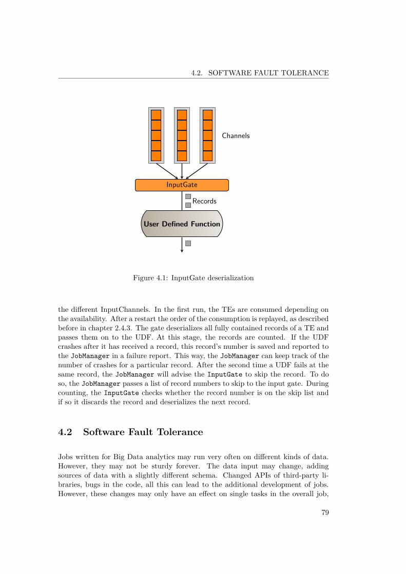
4.2. SOFTWARE FAULT TOLERANCE
InputGate
User Defined Function
Records
Channels
Figure 4.1: InputGate deserialization
the different InputChannels. In the first run, the TEs are consumed depending onthe availability. After a restart the order of the consumption is replayed, as describedbefore in chapter 2.4.3. The gate deserializes all fully contained records of a TE andpasses them on to the UDF. At this stage, the records are counted. If the UDFcrashes after it has received a record, this record’s number is saved and reported tothe JobManager in a failure report. This way, the JobManager can keep track of thenumber of crashes for a particular record. After the second time a UDF fails at thesame record, the JobManager will advise the InputGate to skip the record. To doso, the JobManager passes a list of record numbers to skip to the input gate. Duringcounting, the InputGate checks whether the record number is on the skip list andif so it discards the record and deserializes the next record.
4.2 Software Fault Tolerance
Jobs written for Big Data analytics may run very often on different kinds of data.However, they may not be sturdy forever. The data input may change, addingsources of data with a slightly different schema. Changed APIs of third-party li-braries, bugs in the code, all this can lead to the additional development of jobs.However, these changes may only have an effect on single tasks in the overall job,
79

CHAPTER 4. DATA- AND SOFTWARE-FAULTS
Algorithm 2 Record skipping algorithm1: procedure ReadRecord(target)2: record← deserializeNextRecord()3: num← num+ 14: skipList5: if skipList contains num then6: ▷ do not return record, get the next7: record← deserializeNextRecord()8: num← num+ 19: end if
return record10: end procedure
and may not change any behavior of other tasks. For this, it can be beneficial to usematerialization points between two job runs. Especially if it is unclear what part ofthe data exactly caused an error; it is helpful to start the job with the same data.If the beginning of the job is still unchanged, this could easily be skipped by usingmaterialization points of a previous run and thus start the job partially.
We call this technique memoization of materialization points. This is analogous tothe memoization in programming which caches previous execution results in orderto speed up execution. In memoization, results of function calls are cached andreturned if a call with the same input occurs. The name memoization is comingfrom the Latin term “memorandum" and should not be confused with the similarword memorization as memoization covers a specialized technique in programming.In some programming languages, is called memoization tabling.
4.2.1 Memoization of Intermediate Data
Similiar to the memoization in programming, the written materialization pointsfrom one finished job run could be cached and reused for another run of a jobwith similar parts and the same input. A job which is identical from the input upto a materialization point can start from the materialization point instead of theinput. This can save the recomputation of parts of the job. This technique can bea beneficial tool in the development of a data analytics program. As programmingfaults, updates in third-party libraries, or faulty assumption about the data may askfor changes in parts of a job. In those cases, just single tasks have to be changedwhile the rest of the job and the input data stay the same. Then it is possible touse previous materialization points as the input of parts of the updated job.
In order to achieve the possibility to memoize materialization points two things are
80

4.2. SOFTWARE FAULT TOLERANCE
necessary:
• The system must save materialization points beyond the lifetime of the job.
• The system must identify the job and its changes
The first point, saving materialization points after a job finishes is obvious. However,materialization points are typically written to the local file system, and removed afterthe job has finished. This applies to successful and failed job runs likewise. Thisis done to keep writing the materialization points fast and the usage of disk spacelow. Furthermore, writing materialization points to a local file system means it isnot available once the virtual machine is terminated. To use the materialized dataafter a job run, the mechanism that saves intermediate data has to change. Theintermediate data must be saved to persistent storage and not removed after the jobended. The engine can either achieve that by writing the materialization points toa distributed file system directly or by copying it to persistent storage once a jobended. However, this should not be the solution of a regular job run. Instead ofsaving intermediate data after a job has finished, it should be kept in developmentmode only.
Finding Job Similarities
The second point is far from trivial. Identifying a job as similar would automaticallymean to ensure the input data is identical, the UDFs are identical and which UDFshave changed.
To ensure that the input is identical, we would have to compare the input of the newjob to the input of the job with the memoized materialization points. Even thoughthe basic idea sounds simple, it is unfortunately not. Obviously, the same path ofthe input does not guarantee that it is equal to a previous version of the file or thedirectory. A solution would thus be to compare both inputs directly. That wouldmean to keep not only the intermediate data but also a copy of the input data of thejob to compare against. Fortunately, there are other solutions than just a byte-wisecomparison of data. It is possible to calculate checksums for the data to assure it isunchanged. However, as we are dealing with BigData, checksum calculation mightbe a costly solution.
The same issue applies to the identification of the job. The user sends a job to thesystem as a jar file. It contains one or more class files that implement the job andall necessary classes. In the best-case scenario, the programmer writes each task inan individual file. In this case, it may be possible to compare each class and marka task as updated, if a class differs from the previous job jar file.
81

CHAPTER 4. DATA- AND SOFTWARE-FAULTS
It is possible to execute a simple diff of the two Java class files, but this methodleads to some problems:
• First this does not cover dependencies of classes. As the task is associated witha UDF (i.e., an invokable class), changes of a class that the UDF depends onwould not mark the task to be changed. The dependency analysis of javaclasses is a, ongoing field of research. Tools as classcycle1, Class DependencyAnalyzer2 or Dependency Finder3 work on this field.
• Second, it will not consider external libraries. There may still be third partylibraries that may have changed, and thus change the output of a task.
• Third, the possibility to write inner classes in Java. Writing inner classes inJava will cause changed class files for all declared inner classes of a class even ifonly one inner class changed. This would lead to false-positives when searchingfor changed classes.
• Fourth, even with distinct class files, it can lead to false positives: Changesthat do not change the behavior of a task may mark it as updated. Note thatthe last two issues do not change the correctness of the approach but mayreduce the benefit noticeably.
Given all those stumbling blocks, it is evident that the identification of similaritiesand changes within a job are far from trivial. Therefore, the responsibility to identifychanges and give the info about the reference job is moved to the programmer. Anychanges made must be declared by marking the changed UDF or changed classesthe task’s UDF depends on. If a job is claimed to be a modified version of aprevious job, any task that does not have the “updated" mark and executes thesame class (identified by its name) will be considered to be equal. With the usageof the memoization technique and the indication of a reference job, the system alsoexpects the user to guarantee that the input data is unchanged.
Note that the input of the user makes this fault-tolerance technique violates thetransparency requirement. However, the technique may be useful for upper layersin the programming stack. If an upper layer like PACT for the Nephele frameworkruns the job, it may be able to provide the required information without knowledgeof the user. The development mode might then be useful in the context of tryingdifferent execution plans. The upper layer can change the execution plan withoutlosing the work done before the changes.
1http://classycle.sourceforge.net/index.html2http://www.dependency-analyzer.org/3http://depfind.sourceforge.net/
82

4.2. SOFTWARE FAULT TOLERANCE
Using saved Materialization Points
Once an updated job is sent to the system and the updated tasks are identified,it can reuse all intermediate data from predecessor tasks. The system cannot useany intermediate data that a changed task has produced, as the intermediate datathat the updated task will produce is not equal. Reusing the materialization pointsfrom the reference job is similar to the recovery of the new job considering the firstupdated task as failed. During recovery, the recovery logic searches for the last globalconsistent materialization point upwards the stream and replays it. The failed taskinstance receives its entire input from its predecessors or directly from the foundmaterialization point.
After the engine received an updated job, it will also search for a global consis-tent materialization point. However, in this case, the search only allows completedmaterialization points. If the search finds a suitable materialization point, the cor-responding task will replay. All predecessors of the replaying task will be initiallymarked as finished and thus will not start processing at all.
Note that this approach does not work with partial materialization points as thesystem cannot predict which parts of the input are already present in the material-ization point. As the states of the task are not saved, the new task has no knowledgewhich envelopes have been completely processed by the previous task and must pro-cess all envelopes again, discarding the already written data. Even with a previousconsumption log, the task could replay the input envelopes it has processed, but itcannot ensure that the materialization point contains all resulting data of the lastreceived envelope. Moreover, this would most likely not gain much benefit, as thetasks preceding the partial materialization point would have to be restarted anyway.Given these issues, partial materialization points are not used for the memoization.
4.2.2 Implementation in Nephele
To reuse the recovery logic that is used in case of a failure, there are some tweaksnecessary to the new job. Materialization points are found by the IDs used in theExecutionGraph of the job. The deployment of the new job must use the sameIDs for those parts of that job, that are marked to be identical. Additionally, thematerialization points contain TransferEnvelopes which will be routed using thesource ChannelID stored in the TE.
The system compares the updated Job then to the saved data for the given JobID,i.e., it identifies the updated vertices, and marks all followers as updated too. Duringthe construction of the ExecutionGraph all non-updated vertices are compared,checking whether they execute the same class and whether they have the same
83

CHAPTER 4. DATA- AND SOFTWARE-FAULTS
Updated
Figure 4.2: Given Job
Finished
Updated
Updated
Materialization
Figure 4.3: Reconstructed
number of subtasks and connections. Otherwise the memoized materialization pointscannot be used.
In order to use the recovery logic and materialization points, it is necessary to use theidentical IDs for vertices and connections. This is because materialization points aresets of TransferEnvelopes, which store the source of the data using the ChannelID.Materialization points themselves are files for each vertex named after the VertexID.To reuse the IDs the initial job must save them after it failed. When the user sendsan updated job, the system reuses the IDs for all vertices, which it did not mark asupdated.
As mentioned above, the system marks the updated tasks and their successors asupdated. From the updated tasks a breadth-first search for a completed materializa-tion point is done against the stream. If COMPLETE materialization points exist,all predecessors of the corresponding vertices are switched to the state FINISHED.Figure 4.2 and figure 4.3 show a given updated job example and the reconstructedJob after comparison.
The task that has written the materialization point changes to the state FINISHEDafter it has replayed the materialization point. For any submitted task of a newly
84

4.2. SOFTWARE FAULT TOLERANCE
submitted job, the framework searches for materialization points in case the task isre-submitted during recovery. Therefore, the materialization points for an updatedjob are found automatically.
4.2.3 Evaluation
In order to evaluate the memoization of materialization points, it is interesting tocompare the runtime of a job using memoization vs. the runtime for a completerestart of the job. As the submission of a job using memoization includes readingand applying the job information of a previous run, the setup time is an importantvalue to monitor. It is expectable that the runtime decreases with the use of memo-ization. The decrease is expected to be the smaller the earlier the changes are in theJobGraph. However, the approach itself has an overhead, caused by the rewritingof the ExecutionGraph and the reading of the materialization points. The runtimemeasurement can show whether and when the memoization is profitable.
Optical Character Recognition
The OCR job described in section 3.5.4 serves as test job. It shows the advantage ofmemoization very well because it begins with the most time and resources consumingtask, the OCR. All following tasks are comparably lightweight, especially the index-creating task. Therefore, one would expect that changes of the PDFCreator or theindex-creating task would be considerably faster to recompute using the memoizationapproach. For the job’s input we used pictures of the pages of a PDF Version ofthe King James Bible4. The OCR task parallelizes to 24 instances, and the PDFgenerator parallelizes to 6 instances.
For the test runs one task was marked updated, but the code was left unchanged, tomake the run times comparable. The tests ran with the OCR; the PDFCreator andthe Index task were marked as updated respectively. The test covers two measure-ments: the runtime and the setup time. The runtime is measured after the job hasscheduled until all tasks finished. The setup time is the time between the submissionof the JobGraph and the scheduling of the job, including the reconstruction of thegraph.
The setup times are an average from all runs, with updated tasks and the samenumber of runs without updates. As shown in figure 4.4 the setup time usingthe updated mode is slightly longer than in regular mode. The mean extensionfor the setup amounts to 47 milliseconds, about 8% of the regular runtime. The
4http://www.davince.com/content/blogcategory/14/33/
85

CHAPTER 4. DATA- AND SOFTWARE-FAULTS
0
100
200
300
400
500
600
Avg updated Regular
Setu
p tim
e in
milli
seco
nds
Mode
Setup-Times
Figure 4.4: Setuptimes
0
50000
100000
150000
200000
Index PDF OCR Regular
Runt
ime
in m
illise
cond
s
UpdatedTasks
Run-Times
Figure 4.5: Runtimes for OCR with updated tasks and regular restart
86

4.3. RELATED WORK
difference between the longest updated runtime and the shortest regular runtimeis 84 milliseconds, which is an increase of 15%. This increase is of no consequencecompared to the gain of runtime.
Figure 4.5 shows the average run times for the test runs with the updated tasks andthe regular restarts runtime. The measurements are from 10 runs for each updatedtask and 30 regular restarts. As one can see, depending on the updated task, thedecrease of runtime can be huge. Memoization for the updated Index task leads to aruntime of only 15% of the restarted task. Updates in the PDFCreator task reducethe runtime to 81% and updates in the OCR task still lead to 95% of the restartruntime.
This is because the main time-consuming work is in the OCR and the PDFCreatortask. The Index task is fast, as long as all data is available. Updates in the OCR tasklead almost to a complete restart and thus do not benefit much of the memoizationapproach.
Triangle Enumeration
We also tested a triangle enumeration job written in PACT. This job is used toobserve the runtime behavior in a worst-case scenario. The triangle enumerationjob is a worst-case job because the main time-consuming work is in the last tasksin the pipeline. Updates on the job will therefore only skip the less time-consumingtasks in the pipeline. In this case, it may be possible, that the overhead is higherthan the decrease of runtime. The job is described in detail in section 3.5.1.
As expected, the test runs for the triangle enumeration job did not show the signif-icant runtime decreases as for the OCR job. However, the updated runtimes wherein average still between 85% and 97% of the restart runtime as shown in figure 4.6.
Nevertheless, the gains of memoization can be huge, and as the runtime decreaseoutweighs the increase in setup time it is a useful technique, especially in a job’sdevelopment phase.
4.3 Related Work
MapReduce itself has a record skipping mode. In this mode, the failed task sends thesequence numbers of the records to the master. If the master has seen more than onefailure for a particular record, it will demand the task to skip the record. In contrastto the MapReduce system, our record skipping techniques cover systems that donot require strict input schema and contain more than two steps of execution. As
87

CHAPTER 4. DATA- AND SOFTWARE-FAULTS
0
100000
200000
300000
400000
500000
Select Close Build Regular
Runt
ime
in m
illise
cond
s
UpdatedTasks
Run-Times
Figure 4.6: Runtimes for triangle enumeration with updated tasks and regular restart
described in section 2.2 the data flow is by default not deterministic. It is thereforenot trivially possible to introduce sequence numbers to records as described above.
In “Storm @ Twitter" Toshniwal et al. introduce Storm a real-time resilient dis-tributed stream processing engine[48]. Storm can use an ”at most once" or an “atleast once" semantic using acknowledgement of tuples. Despite the fact that stormis also a nondeterministic data flow, they introduce something similar to a sequencenumber. Each tuple is getting an initial number. After flowing through one task,each record produced from one record, gets a sequence number computed from thesequence number of the source record.
The authors compare their approach with handwritten java code. For comparison,they use storm once with and another time without the message reliability mecha-nism. Although the authors argue that their approach without message reliabilitydoes not have significant overhead to native java code, the numbers show, that themessage reliability in their system adds three times more CPU utilization and needtwo more machines for the same message-passing speed.
Memoization
As briefly mentioned, memoization or functional caching is a well-known technique toavoid re-execution of functions or incremental computation by caching results[49, 50].In contrast to the classic memoization our technique does not cache single results of
88

4.4. SUMMARY
a task’s function evaluation, but the complete output of a task.
Elghandour and Aboulnaga introduc ReStore, a system to reuse intermediate dataof single MapReduce Jobs within a workflow of MapReduce jobs[51]. The imple-mentation is an extension to Pig[8]. It rewrites the MapReduce jobs compiled byPig and stores intermediate data for reuse in similar jobs. Unlike the Pig extensionthe approach described in this thesis is independent from the higher-layer language.
Popa et al. describe DryadInc an incremental computation for append-only datasets. It has two functionalities: either the user has to give a merge function forpreviously and newly computed data, or the system fully automated reuses previousresults for a new computation. The automatic so-called IdenticalComputation isa form of memoization and similar to the approach described in this thesis. Incontrast, it is only based on additional data input to avoid re-execution of thepreviously executed data[52].
Nectar is an approach to manage automatic caching for computations to improvedata center management and resource utilization, which also includes the reuse ofsub-computations, by rewriting programs to be able to use cached data for sub-expressions[53]. As distinguished from this idea, our approach does not considerresource management but runtime optimization.
4.4 Summary
This chapter introduces data fault-tolerance using the record-skipping technique.The main challenge in record skipping is to identify the bad record between sev-eral recovery restarts. This can be a resource consuming issue, considering thenon-deterministic data exchange between the producing task instances and the con-suming task.
The technique described here relies on the consumption logging technique that en-sures a deterministic data stream for each task, on every recovery restart. With thisassurance the identification of a record can simply be done by counting the inputrecords of an individual task and use this count to detect the flawed record detectedby previous faults.
The chapter also covers the idea of memoization of materialization points. Thistechnique enables the user to reuse materialization points of a previous job run, ifonly parts of the job have changed. With the information about the changed tasks,the system can find a suitable materialization point to use. The job is then restartedfrom this materialization point. The predecessors of the materialization point canbe skipped.
89

CHAPTER 4. DATA- AND SOFTWARE-FAULTS
90

CHAPTER 5
Recovery Optimization
Contents5.1 Adaptive Recovery . . . . . . . . . . . . . . . . . . . . . . . 92
5.1.1 Adding vertices during recovery . . . . . . . . . . . . . . . . 935.1.2 Cost Analysis . . . . . . . . . . . . . . . . . . . . . . . . . . 985.1.3 Implementation . . . . . . . . . . . . . . . . . . . . . . . . . 1065.1.4 Evaluation . . . . . . . . . . . . . . . . . . . . . . . . . . . 108
5.2 Offset Logging . . . . . . . . . . . . . . . . . . . . . . . . . 1105.2.1 Channel state . . . . . . . . . . . . . . . . . . . . . . . . . . 1115.2.2 Implementation . . . . . . . . . . . . . . . . . . . . . . . . . 1125.2.3 Evaluation . . . . . . . . . . . . . . . . . . . . . . . . . . . 115
5.3 Related Work . . . . . . . . . . . . . . . . . . . . . . . . . . 1185.4 Summary . . . . . . . . . . . . . . . . . . . . . . . . . . . . 119
As mentioned before, all tasks must be considered stateful, unless the user or upperlayer of the system indicates it differently. The engine has no knowledge of theinternals of the UDF and can therefore not predict the state property of a task.However, if the system gets the information that a task is indeed stateless, it canuse additional optimizations in the recovery process. The engine can scale a statelesstask freely without changing the results, and it does not have to roll it back entirely,as the results of one input record do not depend on the other inputs.
91

CHAPTER 5. RECOVERY OPTIMIZATION
The previously described fault tolerance mechanism, has one major drawback: Sometasks have to redo work that is discarded by their followers. Considering the casewhen the failed task is a successor of a materialization point, it rolls back to it’sinitial state and redoes all work from the first record on. The successors of thefailed task informs the failed task about the data they expect next, and the failedtask throws away any produced output until it reaches data that is unseen by it’sfollowers. During this time, the task is working to produce data, that is not neededand is not able to work on the data that it should have worked on in a failure freecase.
In case of a stateless task, there are opportunities for optimization. The upcomingsections cover two optimization approaches. One is an adaptive recovery process.The idea is to survey the possibility to add additional resources during the recoveryprocess to speed it up. It focuses on additional resources for a failed vertex thatwork on the data that should have been processed by the failed vertex. The secondapproach is to stop the failed task from reprocessing the head of the stream in thefirst place. It is not necessary to reprocess the entire input of a stateless task, asit does not have to reach an internal state again. Due to the n:m relation betweeninput and output records, and the data distribution patterns this approach musttackle the challenge to put the output data into relation to the input data.
5.1 Adaptive Recovery
While the optimization discussed in the previous chapters, allows the system torecover from several failure types, there is still room for an optimization of therecovery time. The main issues with the restart recovery approach is the fact thatother nodes may have to wait for new data while the restarted nodes process theprevious data until they are in the pre failing state again.
As the consumption logging approach reduces the number of restarts drastically therecovery time is reduced already. However, the tasks that do not have to restart maynow wait for new data and do no work at all. As described in chapter 3.2.1 restartscan be prevented because the stream is forced to be identical after a recovery restart.Thus, the tasks succeeding the failed task can keep on running, and just discard thedata portions they have already consumed. Moreover, when a still running taskreceives a data package that it has already seen it informs the predecessor about thenext expected envelope. Doing so, the producer of the envelopes can discard themright after production without sending them over the network if necessary. This waythe data producer still computes the entire stream from the first record on, but onlystarts to send data over the network once it has produced data that has not beenseen by the consumer.
92

5.1. ADAPTIVE RECOVERY
Even though this approach reduces unnecessary network usage, it still includes re-computing output that the consuming tasks have already processed. Furthermore,the consuming tasks, which gave the information about the next expected envelopemay have to idle if all their predecessors had to restart. Additionally, the failed taskis now redoing work it has already done and which is thrown away, and the work itshould be doing is left undone. Both cases slow down the completion of the job.
As described in chapter 3 ephemeral materialization points can be PARTIAL orCOMPLETE. (In a strict sense a materialization point could still be undecided.However, during recovery and the search for a global consistent materialization point,any undecided materialization point is forced and thus immediately changes the stateto PARTIAL.) The adaptive recovery approach described in this chapter only workswith partial materialization points, as it presumes that additional resources can takeup work that the failed task was not yet able to do. With a materialization point inthe state COMPLETE, the failed vertex has at least almost all data processed andneeds to process it again to produce the initial data stream once more.
5.1.1 Adding vertices during recovery
Therefore it seems to be beneficial to allocate additional resources to speed up thejob, that is now slowed down due to the recovery process. However, the benefitsof scaling-out are limited in the context of systems that handle many tasks andcommunicate over the network. Scaling-out a task to speed up the computationat that point can cause a bottleneck somewhere else in the job or cause the newmachines to idle most of the time.
Adding resources to a task is only beneficial if the producing task can offer more datain the same time, otherwise the additional resources only steal hand able work formother workers. Additionally, if the scale-out is reasonable, because the producer canoffer more data at the same speed, the successors of the scaled-out task might notbe able to handle the additional amount of data, and thus become a bottleneck. Infact, there is an implementation of a bottleneck detection for the Nephele systemwhich offers the user the possibility to detect bottlenecks for a job configuration.This enables the user to adapt the degree of parallelization (DoP) for another runof the job. Even if this approach can offer information about the bottlenecks in thesystem, it cannot assume the best DoP for a task itself[54]. Furthermore, addingresources can change the stream, as the output of a task is distributed in a round-robin fashion between all output channels. If the system adds a consumer for a task,the distribution of data changes and a consuming task does not get the same recordsas it would have before the restart of the failed vertex.
This issue was discussed in detail for the Nephele system in Detecting bottlenecks
93

CHAPTER 5. RECOVERY OPTIMIZATION
in parallel DAG-based data flow programs[54]. The authors show an algorithm thatindicates bottlenecks and offers this information to the user. They distinguish be-tween CPU- and I/O-bottlenecks. CPU-bottlenecks are those, where the limitedCPU causes a task to slowly output records and I/O-bottlenecks are those wherethe limit of the communication channels are not capable of processing all records ina time unit that a task tries to send. However, the user still has to adapt the DoPmanually, and the detection algorithm does not give hints about the best DoP. Theuser has to adapt the job with a trial and error method. This is obviously not asolution for the recovery process.
Lohrmann et. al[55] use life scale out in streaming environments to guarantee latencyconstrains. This technique could be adapted for the elimination of bottlenecks atthis point too. However, as mentioned in section 2.5, the optimization of the Nephelesystem itself is out of scope of this work. Thus the adaptive recovery process onlyfocuses on counterbalancing the drawbacks of the recovery process.
When the user has already run the sample runs, detected the bottlenecks of thesystem, and found the sweet spot in degree of parallelization, adding resources isonly sensible as far as they take up the work that would otherwise be neglected duringthe recovery of the failed task. The failed task replays its input and thus processesall input records, even though it discards some of the corresponding output, becausethe output data was already processed by the consuming tasks. During that timeinterval, from the processing of the first record, up to the record that produces thenext portion of new data, the work, that should have been done by the failed taskat this point is postponed. Adding a resource, that does that work, while the failedvertex recovers, is beneficial regardless of the bottleneck issue. That is becausethe added task only consumes and outputs the same amount of data as the nowrecovering task would have done.
As mentioned in section 2.3.1 it is not trivial up to impossible to scale out statefultasks as they may depend on a particular data distribution pattern. Therefore inorder to adapt the job during recovery, the tasks are considered to be stateless forthis recovery optimization approach. Another assumption is that the system recoversfrom partial materialization points. In particular, not all tasks of a job have to bestateless for the adaptive recovery to work properly. As the distribution changes atthe predecessor and the successor of the scaled-out task but not with other tasks, itis only necessary to have those three stateless. If any of the other tasks in the jobis stateful it does not affect the correctness of the approach.
Scaling out a task can be split in two cases: one where the failing task is a directsuccessor of a materialization point and the other where predecessors of the failedtask must be restarted.
94

5.1. ADAPTIVE RECOVERY
Task 1
Channel a
Channel b
Materialization Point b
Materialization Point a
Task 2a
Task 2b
Figure 5.1: Materialization points for each channel
Failing Task Behind Materialization Point
The first scenario is the simpler scenario. In this case it is possible to start a duplicatevertex for the failed vertex itself if it and its successors are stateless. This duplicatevertex receives data from the part of the stream that has not been processed by anyother vertex yet and thus takes up work that should be done by the failed vertex.For this to work the materialization points are no longer written to one file pervertex, but must be split in separate files for each output channel. Figure 5.1 showsthe writing of individual materialization points for each channel, in contrast to thesingle file materialization points shown in figure 3.1.
As described in chapter 3, materialization points contain all data produced by a taskindependently over which channel it was sent. This also means a materializationpoint can only be read for all channels together. Recovering from a materializationpoint is done by reading all contained envelopes one after the other. This is amajor disadvantage for adaptive recovery. For adaptive recovery the added vertexhas to process data that was not yet processed by any other vertex. It cannotprocess other data, as this would run contrary to the consumption logging technique.Processing data that has already been processed by another task, would change thestream and raise the need to somehow rebuild the stream equal to the previousstream. Additionally, trying to adapt the degree of parallelization with one singlematerialization point would necessitate to rewrite the serialized envelopes, as theycontain the routing information.
Providing the duplicate task with new data is not possible in parallel to the reex-ecution of the failed task. Adding another consumer to a producing task spreads
95

CHAPTER 5. RECOVERY OPTIMIZATION
the output data that is not yet written to the materialization point between allconsumers. A vertex that is replayed, stops to send data over the channel directly.Instead all produced data is only written to the materialization point. The sendingof data over the network is suppressed, once the has replay started. The replaymechanism is reading it from disk and sends it to the consuming task. If a task onlyuses one materialization point for all its successors, data for the newly added vertexis written behind the data that was produced until the failure occurred. Followingthis, as reading from the materialization point is done one envelope at a time, thenewly added vertex receives its first portion of data just when the recovery of thefailed vertex has finished. This would not give any benefit to the system and insteadadd another idling vertex.
Thus, the writing of materialization points must be changed from one single materi-alization point for a task to several individual materialization points for each outputchannel of the task. Then it is possible to read data independently for each outputchannel that has to be replayed.
As the writing of materialization points is changed to a materialization point foreach output channel, the reading of materialization points is now also changed to beindividual for each channel. The additional task can receive its data immediately.
Restarting Predecessors of the Failed Task
The other case with predecessors that have not written a materialization point andtherefore must be restarted, is a different issue. In this case it is not possible toduplicate the failed task and keep on with consumption logging. As the predecessorreceives its entire input again to produce the necessary output for the replay, itproduces its entire output again. Using consumption logging the head of the streamcan be ignored as it is equal, to the previous data stream. Adding an additionalvertex to the consumer of the restarted task changes the data distribution. Thishas the consequence that streams are no more identical. Without identical streamsevery task after the materialization point must restart.
Thus, adding vertices while also using consumption logging is only possible for thetasks directly after the materialization point. It would thus be possible to addanother vertex that works on data that the now restarted vertices cannot process,and therefore give input data to the tasks that skip the head of the stream while itis reprocessed. However, the benefit of the scenario is expected to be smaller thana failure of a direct materialization point successor.
If more than one task lays between he failed task and the materialization point,adding additional tasks does not give any benefit to the system. As the additional
96

5.1. ADAPTIVE RECOVERY
Materialization
Figure 5.2: Additional vertex at predecessor
task can only be added as a successor of the materialization point, the predecessorsof the failed task may produce data faster with an additional vertex. But at leastthe failed task has to reprocess the data of the other tasks first to reproduce itsoutput stream and cannot process the data of the additional vertex until then.
Note that adding extra vertices to the direct successor of a partial materializationpoint does not influence the consumption logging. Even though an additional pro-ducer is added to a task it does not change the previously produced stream, as thenew vertex only receives new data that has not yet been processed by any otherproducer. The consumers are not restarted and skip any envelopes of the otherchannels that they have already seen. Any data read from there on is new unseendata and therefore does not change any part of the stream that has already beenprocessed. Any scaling other than the one described here changes the stream anddata distribution and does therefore not allow the usage of consumption logging.
Materialization Point Splitting
If the materialization points are written into different files, they can be read inde-pendently. For every output channel a file is produced once data for this channelarrives, and can be read then. This means in case of a duplicate vertex a successoris added for the replaying vertex. As the replaying vertex is still running it producesdata and eventually writes those data to the materialization point of the outputchannel which is connected to the duplicate vertex. This happens while the failedvertex is receiving its original data from its materialization points.
Usually a task that is writing a materialization point produces data and puts this
97

CHAPTER 5. RECOVERY OPTIMIZATION
data into a buffer, which is wrapped into TransfereEnvelopes. These TEs aredesignated to a particular source channel, which is paired to a particular inputchannel of the consumer. The data is written to the channels in a round-robinfashion. A TE which is ready to be send runs through a processing chain. It startswith the writing of the materialization point, and is then handed over to the nextstep, which sends it to the network and afterwards frees the buffer so it can be filledwith data again. During replay of a materialization point, the second step of thechain is removed. The TE is written to the materialization point and afterwards thebuffer is freed directly.
Splitting the materialization points does not affect this behavior at all, it is just atweak in the writing process. Instead of writing everything to the same destinationfile, each envelope is written to a destination based on its corresponding sourcechannel. Changing the number of output channels adds another option in the round-robin choice and thus spreads any new data between the new number of consumers.However even this newly enabled connection is replayed from disk instead of sendingover the network directly.
5.1.2 Cost Analysis
Making it possible to add vertices to the system during the recovery process can givean opportunity to speed up recovery time. However, it also increases costs. Usingadditional resources in a cloud environment does directly cause additional cost.Setting up an additional node, including starting up a task manager, takes time.Furthermore, adding another node causes additional usage of network bandwidthand could cause a bottleneck.
Due to these issues it is important to consider the cost when deciding whether to scaleout and how many additional nodes should be used. In general, additional verticesare beneficial when the covered vertices must reprocess a considerable amount ofinput but there is still enough input left, so that the startup time does not exceedthe time the duplicate vertex is running, and the duplicate vertex is not idling themajor amount of lease time. Leasing an instance for an entire hour and only usingit to speed some seconds may not be efficient.
However, this would make it necessary to get an idea about the progress of a task,which is not possible in the initial implementation of Nephele. The Nephele enginehas no functionality to give information of the progress of a job. This is mainlybecause it is not a trivial task: A running job consists of black-box user code. It isnot possible to predict the behavior or the running time of such a black box beforeit is running. And even during runtime, the behavior can only be considered for thepart of input that has been processed so far.
98

5.1. ADAPTIVE RECOVERY
Nevertheless, information about the progress of one task are necessary to make asuitable decision regarding the provisioning of extra machines. Therefore in addi-tion to the adaptive recovery mechanism the fault tolerance mechanism includes anapproach of progress estimation in Nephele.
Progress Estimation
Progress estimation is not only suitable to be used from the fault tolerance mecha-nism. It is also a possibility for the user to see unwanted behavior in the system andthus, spot mistakes in the user code, even if they do not cause detectable failures. Aprogrammer of a job might have made false assumptions about the data or the be-havior of third party libraries, that cause an expected long running task to skip overlots of records or -the other way around- work on single records unexpectedly long.Progress estimation itself gives the user of the system the ability to spot failuresearly.
Progress estimation is not trivial in a system with black-box user code and black-boxdata, and unknown data selectivity of tasks. There are too many unknowns for aclear and accurate progress estimation. Before a job is running the system has noclues about an average processing time per record for a task. Furthermore there isno 1:1 relation between input and output records of a task. Even if there was anindicator for the average processing time per record, it would still be impossible tomake assumptions as the number of records that have to be processed is not yetknown.
Because of theses drawbacks, progress estimation in those systems is usually doneusing previous runs of the same job, with either previous productive runs, if the jobis a recurring job, or with sample runs, done with only a part of the actual input.Obviously the first approach does not work for the first (and probably only) runof the job, and is therefore not an option in every scenario. The second approachraises another problem: Finding suitable samples of the input. Choosing sampledata is not as easy as taking the first x MB from the input, as this first part ofthe data might not be representative. Finding good samples is an ongoing researchproblem[56, 57, 58, 59].
To avoid this issue sample-run based progress estimation approaches often expectthe user to come up with a representative portion of data. This is a convenientapproach for the system designer, but expects the user to be able to oversee thecharacteristics of the input data. Considering the context of BigData this is quiteunrealistic, instead the user does most likely give a sample of data that he alreadyused as example for the programming of a job. In terms of fault tolerance this is ahuge problem, as a fault in the user code does usually occurs because the programmer
99

CHAPTER 5. RECOVERY OPTIMIZATION
makes false assumptions about the data. The benefit of seeing unexpected behaviorearly because of a hint in the programming progress is completely lost in this case.
Another issue with samples is to define their size. The minimum size is usually givenin terms of representatives of the productive input. The main question is: Is thesmallest amount of data enough to do a meaningful sample run. The point here is:If the data portion or the intermediate data portions are to small, they might bekept entirely in main memory, and thus give a false assumption about processingspeed. On the other hand, running sample runs with large amounts of data maytake almost as long as a productive job run and not be beneficial. Furthermore, onesingle sample run might not be enough to make an estimation, as complex operatorslike cross join do not increase linearly with input data size. Unfortunately, it is notpossible to see a non-linear increase with just one job run, it takes several runs torecognize this behavior.
In order to be able to make an estimation of the progress with the first run of anunknown job, one must find another solution. A first step to a progress estimationduring the first job run is input-split based progress estimation, which uses theknown size of the input and propagation of progress information in order to makeassumptions of the progress of each individual task.
Before the runtime of a job, the only fix and measurable value is the input of the job.As the system has to handle black box user code, there is no other information left.The input of a Nephele job can either be a single file, or multiple input files. Howeverthe size of the entire input is always known before the job runs. The Nephele systemreads the input for a job in so called splits. A split might be a part of or an entirefile of the input. Each individual task instance of the input task is initially assigneda split of the overall input. Once it has finished processing this split of the input itrequests another split, which is assigned to the task from the remaining splits. Splitassignment is done in a topology aware manner using the topology benefits of theunderlying HDFS system.
This behavior offers great flexibility if some splits are more time consuming to pro-cess, and other splits are faster to handle. If that situation occurs, the faster taskprobably works on more input splits during the job’s runtime. And it can be usedfor a new progress estimation technique during runtime, which we call progressforwarding.
The main idea of progress estimation during runtime is based on the percentage ofinput splits processed. The main assumption is: Once a new split is requested, thealready read splits can be considered to be processed. This is of course a simplifica-tion, as the other tasks might still be working some time on their input splits. Thecalculation of the progress reading the input is pushed through the graph, and givesa hint of the overall progress for an individual task. Once the progress information
100

5.1. ADAPTIVE RECOVERY
50% 25% 25%
33%
Figure 5.3: Estimated progress
has reached the output tasks, this information can be considered to be the progressof the overall job.
This progress information is added to the TransferEnvelopes at the input tasks.Every time an input task requests a new split, it considers all assigned splits to beprocessed and calculates the progress as the percentage of the processed data to theoverall input size. Then it receives its next split. While processing the split, it addsthe calculated progress information to the outgoing data at each output channel. Aconsuming task that receives a TE with progress information takes this informationto calculate its own assumed progress. As every instance of the input tasks addsprogress information to their output, every consumer receives progress informationover each input channel. All progress updates from a tasks input channel are saved,and an average of all received input channel progresses is calculated. The resultingaverage is considered to be the progress of this task.
Imagine a task with three predecessors. Initially all progresses are seen as 0%. Ifit receives a progress information of 25% from one predecessor. The task now has25% of one of its three inputs processed, and its overall progress is estimated to beabout 8,3%. If it receives a 25% progress information of all channels, its progressis estimated as 25%. If it then receives 50% from one of the channels its progresscalculates to 33%. The estimated progress is then added to outgoing data andsent to the consuming task, which also calculates its progress and propagates theinformation further. Figure 5.3 shows this scenario in an execution graph.
Note that because of the reading behavior (A task first reads all available data fromone channel before it chooses the next channel that has data available.) it is possiblethat a task has a progress of 100% at one channel but 0% at the other channels.
101

CHAPTER 5. RECOVERY OPTIMIZATION
Also, taking the progress of all predecessors and calculating the average considersslower paths in the graph into the progress estimation. Furthermore, it may bepossible, that due to calculation of average, the progress is calculated as 0% eventhough data has already been received. These 0% progress events are ignored andnot propagated to the consuming tasks.
The main assumption of this approach is that if the output task receives the infor-mation that they have received a percentage of their input this percentage is equalto the progress of the job. However, it is not safe to translate this informationdirectly to processing time, as the processing time between two records can varydrastically. If the first amount of data does not come through a filtering function,processing time of the first amount of data is notably shorter than for the rest ofthe data. Nevertheless, the progress propagation approach is self-regulating. If thenext progress update is received later or indicates a smaller progress for a similartime interval, the estimated time is adapted.
But independable of the overall runtime of a job, this approach has the benefit, thatit works from the first run, and that it leaves progress information at every singletask in the job. During the adaptive recovery, it is unimportant how long the overalljob runs, but important to have a hint of the considered progress or to be moreaccurate the amount of work that needs still to be done.
Evaluation of Progress Estimation
The evaluation was done on a sample-run-based approach and on the progress for-warding described above. The sample-run-based approach expects the user to comeup with a suitable sample of the input data. For the evaluation we used the first500 Files as a sample. For the OCR job that was about 462,31 MB from the overall2,60 GB of input. During the sample, information about the average runtime ofeach task per record were collected.
To estimate the job runtime the system detects the critical path in the job. A jobpath is a path through the DAG from the input vertex to the output vertex. Onejob can have multiple paths, if it splits the data flow somewhere. For the runtimeestimation it is necessary to consider only the longest running path. The algorithmfor the detection of the critical path using a breadth-first search. The search startsat the jobs output vertices and checks for the vertex with the latest finishing time.Form the specified vertex, all predecessors are checked for the one with the latestfinishing time and so on.
During the runtime of the job only the critical path is considered for estimation. Theruntime is then estimated with the average runtime of the sample run in ratio to the
102

5.1. ADAPTIVE RECOVERY
0
200
400
600
800
1000
0 200 400 600 800 1000
Rem
aini
ng T
ime
in se
cond
s
Runtime of Job
Job Runtime OCR Sample-Run
JobRuntimeCalculated
Figure 5.4: Calculated Job Run time Sample Runs OCR
input data. The input and runtime ratio are expected to be straight proportional.The estimated runtime is update with the actual runtime of a task if it is finished.
Figure 5.4 shows the calculated remaining runtime compared to the actual remainingruntime at particular points of the job runtime for the OCR Task.
For comparison the runtime estimation for a sample run with the ideal data set i.e.the complete input is given in figure 5.5.
Two things are noticeable: First the difference in the estimation, depending on theinput sample. This shows the importance of the quality of the sample. The secondconspicuous thing in the results is the distribution of the estimation points. Oneestimation is done during job start, the next just shortly before the end of the job.This is because the sample run contemplates one pipeline of the critical path andcan therefore only update its estimation if one pipeline is finished. As the OCR jobconsists of one pipeline the estimation is just updated at the end of the runtime.
The deviation of the estimated runtime was about 13% for the sample of about halfof the actual input.
The main benefit of the sample run based approach is that it is suitable for jobsthat contain pipeline breakers. That is why we added tests for sample runs withpipeline breaking jobs.
As the files have roughly the same size, the number of processed records is a good
103

CHAPTER 5. RECOVERY OPTIMIZATION
0
200
400
600
800
1000
0 200 400 600 800 1000
Rem
aini
ng T
ime
in se
cond
s
Runtime of Job
Job Runtime OCR Sample-Run Ideal set
JobRuntimeCalculated
Figure 5.5: Calculated Job Run time Sample Runs OCR Ideal Set
indicator of the progress of a task. In order to compare the calculated progress tothe actual progress we look at the processed records for each calculated percentage.The graph 5.6 shows the calculated progress compared to the actual progress. Thecalculated progress at each task differs only up to 4% from the actual progress.Based on the percentage of the output task we calculated the remaining runtime ofthe job.
Figure 5.7 shows the calculated remaining runtime compared to the actual remainingruntime at particular points of the job runtime. The points of the calculated runtimegraph describe measurements the moment the writer task announces the progress,starting with 5% in 5% increments. The calculated remaining runtime differs onlyup to 23 seconds. The first information about the jobs progress is received 92 secondsafter the job started. Within the first quarter of the job, the system is able to makean estimation about the remaining runtime, which is accurate up to about 5%.
Cost Model
Assuming there is a more or less precise progress estimation at a failing node theadaptive recovery can use this information to decide whether to use a backup node forthe failing node. As mentioned above, adding another node to the job needs startuptime and may add additional network usage. In the specific recovery scenario thenetwork bandwith is only an issue as long as the original and the backup node areboth sending data. With consumption logging and the possibility of a forwarding
104

5.1. ADAPTIVE RECOVERY
0
10 20
30 40
50
60 70
80 90
100
0 10 20 30 40 50 60 70 80 90 100
Perc
enta
ge o
f Rec
ords
pro
gres
sed
Calculatet Percentage of Records progressed
Percentage
ReaderOCRPDF
Writer
Figure 5.6: Progress at tasks
0
50
100
150
200
250
300
100 150 200 250 300 350 400
Rem
aini
ng T
ime
in s
econ
ds
Runtime of Job
Job Runtime
CalculatedJob Runtime
Figure 5.7: Calculated Job Runtime
105

CHAPTER 5. RECOVERY OPTIMIZATION
barrier, the recovering node does not send anything over the network until therecovery is finished. Using a backup node only during that time shutting it downonce the failed node is back at work would not change the bottlenecks of the system.1Therefore, the start up time is the lower bound. If the failed task has only to redowork that is equal to or smaller than to the startup time of a node, it is not beneficialto add another node.
The other question is, where the additional nodes are coming from. In a fixed clusterwith idling nodes this is not an issue. However, in a cloud environment, where thesystem might have to provision another machine and add cost, to the job processingcost, it can be.
Even in an IaaS Cloud environment it is possible to have idling machines available.As the payment is usually done hourly, a task finishing before the payed hour isreached, gives the opportunity to use this extra spare time to speed up the recoveryprocess, and to unprovision it when the time slot ends.
For any other scenario the user has to provide the information about the money heis willing to put into the faster completion of the job. If the cost boundary is notreached, it is possible to provision additional nodes for this task, probably using acost efficient solution like Amazon Spot instances. The system would then only useadditional machines if they are under a specific price at the point of failure.
5.1.3 Implementation
The implementation of the adaptive recovery concept is linked into the recovery logic.The recovery for a failed vertex can duplicate the failed vertex during its restart, ifit is a direct follower of a materialization point. The evaluation of the number ofadditional vertices was based on a configuration value for the number of duplicates.This expects the availability of the number of instances, that was configured. If thesame number of instances is not available, the system just duplicates to the numberof available instances. In the cluster mode of Nephele the available instances area fixed set of nodes that have to be set in the configuration. The Cloud mode ofNephele, that offers support for Amazon EC2, can however lease additional resourcesusing the EC2 API2. In this case it is necessary to differ between two scenarios: Thesystem still has nodes available, that idle but did not extend the lease time yet, andthe system does not have any free instances.
In the first case, the EC2Manager of Nephele has a list of so called FloatingInstances.
1Note that this is of course always with the assumption, that the job is configured in the mostefficient DoP regarding to network and CPU bottlenecks.
2http://docs.aws.amazon.com/AWSEC2/latest/APIReference/Welcome.htm
106

5.1. ADAPTIVE RECOVERY
These instances are allocated instances that idle and are not assigned to any task.It is possible to use these instances for tasks until terminated. Every instance hasa lease period that can be configured by the user. The default is one hour as thisis the charging period for EC2. The instances are used as long as they are assignedto a task. Once the work is finished and an instance is no more assigned to a taskit is converted to a floating instance if the lease period is not yet exceeded. If theinstance is leased for the lease period it is terminated.
If the Cloud manager has floating instances, they can be used for duplication. It isthe perfect opportunity to use the idling computation power for the speed-up of therecovery process. If no idling instance is available at the manager, the Cloud managerhas the possibility to allocate new resources from the EC2 Cloud. Allocating thenew instances causes additional fees to the user. In order to avoid that the instanceidles most of the time, the duplication is only done if the estimated remaining worktime of the failed vertex is longer than the half lease period.
The recovery process checks therefore if the system is running in Cloud mode. If so,it checks if any suitable floating instances are available for the duplication. If not,it checks for the estimated remaining runtime of the failed task. If the remainingruntime is at least half as long as the configured lease period it starts a duplicatevertex. Starting the new vertex automatically triggers the allocation process in theCloud manager. The Cloud manager requests a new instance from the Cloud.
Each duplicate vertex is created in the same way, as a vertex would usually bestarted up in the initial start. It is created and added to the group vertex. Thedifference is that the connections of the vertex have to be set up during starting. Inthe initial start of a job, the execution graph is constructed all at once. It contains agroup vertex for each task, and an execution vertex for each parallel instance of thetask. The connections between those tasks are set up during creation. The duplicatevertex must add those connections during duplication. This consists of two steps:One is to add these connections in the execution graph, to construct the abstractionof those connections and enable the system to iterate through the graph using theedges. The second part is to register the connections to the routing service. Therouting service needs the information about the newly triggered connections to beable to route the data over the network as needed.
During recovery the ExecutionGraph is updated and all necessary edges are addedto the graph. This includes adding the channels to the input and output gates ofthe successors and predecessors. Adding a channel to the OutputGate of the dataproduced, i.e. the task that replays from the materialization point causes any newlyarriving data to be distributed between the new number of channels. The writingto the channels is done in round robin manner, and now includes the new channel.
As the data is written to the materialization point before it is sent over the network,
107

CHAPTER 5. RECOVERY OPTIMIZATION
no data is lost, even though the consuming task is not yet running. As the task nowdistributes the data between all channels, it creates a new materialization point forthe new channel and writes the data into the new files. Once the replay task forthe task is started, it replays all materialization points and the newly duplicatedtask receives its input. The registration at the routing service is updated during thestart of the replay task. The successors of the failed and duplicate task, wait forany channel to provide data. Once the new vertex is started, it sends data to thefollower where it can be read.
Each vertex is only duplicated once. If it fails another time the duplicating algorithmis not triggered again. The same goes for duplicated vertices. A failed duplicatedvertex does not duplicate. This could otherwise lead to a huge growth in resources asan already duplicated vertex has a vertex that takes up work. It does not make senseto duplicate it again. Think of a persistent fault that occurs on the same record overand over again. Duplicating the vertex more than once would not add performanceto the system, instead it might cause bottlenecks. And as a duplicated vertex isjust running for boosting the performance of another vertex it is not beneficial toduplicate it, even in case of a failure.
Once a vertex is duplicated it runs until the job is finished, to avoid additionaloverhead and possible data loss. However, for the sake of recovery performanceboosting, it would be sufficient if the duplicate task is only running as long as ittakes the failed vertex to finish recovery and rollback to its pre-failure state.
5.1.4 Evaluation
For the evaluation the first question to answer is, how beneficial is it to use one ormore duplicates for a failed task, considering a well-balanced job. The job used wasthe OCR-Job described in section 3.5.4. To find the right degree of parallelizationthe job was run with different DoP settings a number of times to compare theruntime. Figure 5.8 shows the results of the experiment, it started with 16 OCRtasks and 4 PDFCreator tasks. The number of PDFCreator tasks was increased byone step by step. It shows the lowest runtime at 16 OCR tasks and 7 PDFCreatortasks. Thus, this degree of parallelization was used for the next evaluations.
For the next step of evaluation, the job was run and a PDFCreator task was killedshortly after it started running. The system was configured to use different numbersof duplicates for the failed vertex. Figure 5.9 show the results for runtime of thesetups.
The results show that adding a duplicate on recovery, reduces the runtime com-pared to the recovery scenario without a duplicate. The average runtime with one
108

5.1. ADAPTIVE RECOVERY
420000
430000
440000
450000
460000
470000
480000
490000
500000
510000
16-4 16-5 16-6 16-7 16-8 16-9 17-7 17-8
Tota
l tim
e in
ms
DOP of OCR - PDF
'Dop-test'
Figure 5.8: DoP Testing
420000
440000
460000
480000
500000
520000
540000
560000
no fail 0 Dup 1 Dup 2 Dup 3 Dup
Tota
l tim
e in
ms
Number of Duplicates
'Dup-cl'
Figure 5.9: Duplicate Testing
109

CHAPTER 5. RECOVERY OPTIMIZATION
duplicate vertex is 92% of the non-duplicate runtime. However, adding more thanone duplicate does not improve the runtime, the runtimes stays at 92% of the run-time without duplicate. That confirms the hypothesis discussed in the beginning ofthe section. As can be seen, adding a duplicate vertex reduces the runtime. Addingmore than one additional vertex does not reduce the runtime of the job further. Themeasurements also show, that the runtime in case of a recovery, is still noticeablylonger then in a fail-free run. The recovery process and the re-execution of the inputof the failed vertex add overhead to the job runtime, even with an additional vertex.
5.2 Offset Logging
Instead of using additional resources to optimize the recovery process further, themost intuitive approach would be to avoid the reprocessing of data that has alreadybeen sent to the consumers. As described before any task has to be considered tobe stateful if not otherwise indicated. The only state to which a task can be rolledback is its initial state, and any restarted task has to be re-executed from the firstrecord, to ensure it reaches the same inner state. Nevertheless, this is unnecessaryfor stateless tasks.
If a task is indicated to be stateless, it could go on to process the data not yet sentto the consumers and thus ignore any previously treated data. This method requiresthe matching of the output to the input.
After a restart of a failed task, the successors of the task can inform the task aboutthe next expected envelope. With consumption logging, the failed task can avoid tosend any data over the network that the successors have already received. Neverthe-less, it still reproduces the data. In order to avoid replicating that data unnecessarily,it would be necessary to know the position in the input stream to start processingto produce the next needed envelope. As there is no 1:1 relation between records orthe in- and output envelopes it is not as easy as skipping the same amount of inputenvelopes. Instead, the processing must restart at the record after the last recordfitting entirely in the previously filled envelope.
This record or a part of it is the first amount of data that was not processed by thefollowing tasks. There are two scenarios to differentiate: The last processed record’soutput could fit entirely in the previously sent envelope, or it did split into severalenvelopes. In the first case, the skipping would be relatively easy if the task keepstrack of the last record processed: As the envelope fills up, it can go on handlingthe record after this, and it is not necessary to think of any order, as no task hasever received the reproduced data.
110

5.2. OFFSET LOGGING
5.2.1 Channel state
If the output data did not fit entirely into one envelope, skipping is not as simple.If the output of a record splits between envelopes, the output channels have a state.The channel keeps the output in the serialization buffer until it is able to write it intoa buffer of an envelope. The recovery process has to reproduce that state. It mustguarantee that the remaining data is in the next envelope that the task sends to thecorresponding consumer. The consuming task’s input channel has already startedthe deserialization with the first bytes that contained in the last envelope. Thedeserialization only works correctly if the missing bytes are the next bytes received.
The state of the channels depends on the record that the task had processed as ithas sent the last envelope. Therefore, this record has to be processed once more.The recovery logic must discard all output bytes that the task has already sent overthe network previously to the crash. It is thus not enough to log the input recordnumber to skip the head of the stream correctly. The log must also contain the offsetof the output that the channel could fit in the last envelope. Note that the recoveryhas to take care of each channel individually. Each of the multiple output channelscould have contained data during the crash. During recovery, the task thus has toreprocess any record, that produced an output which stayed in the channel buffers.The recovery can, however, skip any record in between.
If the log holds all this information, it is possible for a stateless task to skip thepreviously processed data after a restart. This skipping may lead to a significantlyreduced recovery time, as the failed task does not have to reprocess the head ofthe input stream. Furthermore, this offset logging method opens the door for usingephemeral materialization points in stream processing. One main assumption for thematerialization points so far is that the engine does batch processing. The systemgets a finite input. If the engine processes an infinite stream of data, this would havethe consequence that the materialization points grow infinitely. This is, of courseunacceptable.
With the offset logging technique, it is possible to develop a sliding window mate-rialization point. As each task has a translation table of its output envelopes to arecord number, an additional log with translation between record number and inputenvelope would enable a task to push acknowledgments up the stream. A task thatwrites a materialization point could acknowledge all input records which have theiroutput fully represented in the materialization point. This acknowledgment canthen be translated to input records at the next task and so on. A materializationpoint up the stream, which get acknowledgments for an entire envelope, can removeit from the materialization point.
111

CHAPTER 5. RECOVERY OPTIMIZATION
Task1 Task2 Task3 Task4
getExpectedEnvelope#getExpectedEnvelope#
getExpectedEnvelope#
returnExpectedEnvelope#
returnExpectedEnvelope#
returnExpectedEnvelope#
ExpectedEnvelope
Figure 5.10: Expected Envelope Interaction
5.2.2 Implementation
As described above, the offset logging requires a stateless UDF. However, the systemhas a state even with stateless UDFs. For one task, The necessary information tolog is
• The sequence number of the outgoing envelope
• The ChannelID of the log
• The byte offset of a spanning record
• The record offset for multiple output record for one input
• The input record that is currently processed
• The InputGateID for the input
The sequence number of the envelope is provided by the OutputChannelBroker,which creates new envelopes. The byte offset of a record is necessary in case a recordspans over envelopes. If a record does not fit entirely into one envelope it is split.The consumer receives the first part of the record in one envelope and waits for thenext envelope to contain the second part of the record. To create the next expectedenvelope correctly, the recovery must ensure that the next envelope contains exactlythe second part of the record. Therefore, the log has to save the number of bytes thathave already been shipped in the previous envelope. This information is received
112

5.2. OFFSET LOGGING
from the serializer. The Nephele system provides a SpanningRecordSerializerthat takes care of serialization of the record and writes it into the envelope’s buffer.If a record does not fit entirely into the buffer of the envelope the offset is logged,when a new buffer is requested.
The record offset for the number of output records is fetched from the OutputGate,it counts the number of records that are emitted. The InputGate resets the counterevery time it pushes a new record into the UDF. For each log entry, the currentcounter at the output gate is saved. The InputGate provides the information aboutthe currently processed record and the GateID.
A new log entry is created every time the serialization requests a new buffer. Re-questing a new buffer is equivalent to creating a new envelope, as each envelopecontains exactly one buffer. At the creation of a new envelope, all described in-formation about the previously filled envelope are available and can be logged. Todo so a log entry is created as described above. The entry is passed to a writingthread, that has a log file opened for each execution vertex, and appends each newlyincoming entry.
With this information it is possible to set up the failed vertex and its environmentin the same state as it was before the failure without the necessity to re-execute theentire input. Instead the recovery logic is able to skip all input that is not neededfor the creation of the next expected TransferEnvelopes.
As each output channel creates envelopes independently, based on the amount ofdata to transmit, each successor of the failed vertex could have received a differentnumber of envelopes. Consider an input stream with records that produce drasticallydifferent output sizes. An output for one record might have to span over severaloutput envelopes, whereas for another channel the output for several records mayfit in one envelope. The first channel will then have a higher sequence number, butthe output of the second channel depends on input data that comes in the streambefore the big record. Recovering the state of the vertex is thus not as easy as usingthe log entry with the highest sequence number. Instead, the last log entries of alloutput channels have to be checked for the input record number. And the streamcan only be skipped up to the smallest input record number in the logs.
Reading the Log
After the failed vertex has restarted, it tries to find an output log file. If a logfile exists the data is loaded. The vertex, then asks its successors for the sequencenumber of the next envelope it is expecting from the vertex. The successors thenanswer the request with an UnexpectedEnvelopeEvent. This event would usually
113

CHAPTER 5. RECOVERY OPTIMIZATION
User Defined Function
RecordOffset = 3
Discard
R1.1 R1.2 R1.3R1.5
R1.4
R1
Figure 5.11: Record offset
be triggered during restart, to skip the output envelopes, as described above. Withthe offset logging, the event is used to hand the information about the next expectedenvelope to the offset logging functionality. The logger then finds the input recordnumber, which indicates the first record that is needed to recover the previous state.This record is the first one fed to the UDF. To ensure that the output data isdistributed in the same manner as before, the ChannelSelector has to be set tothe channel that received the first output record produced by the input record, inthe first run. Afterwards the channel selector runs in the same manner, as before,which is a round robin selection of output channels.
The recovery of the state is achieved by just running the UDF from the found record.The consumer may have already received parts of the record’s outputs or even theentire output of some records. Therefore, the records have to be processed, but therecovery logic must keep only the parts of output that are necessary to rebuild thestate.
For case that the UDF produces several output records for one input record, theRecordOffsetTotal keeps the information if some of the output records have to beskipped. After the vertex skipped not needed input records the output gate skipsthe number of output records that the log entry saved to be skipped. The outputchannels then receive the output records, and may skip parts of the received outputrecord if it has sent parts of the record to the consumer before failing. Figure 5.11shows the discarding of records for a record offset of 3. The first three records of theoutput for record R1 are discarded, the task starts sending records from the fourthrecord on.
After all channels have finished the recovery according to their log entries, the re-covery is finished and the processing of data continues normally.
114

5.2. OFFSET LOGGING
5.2.3 Evaluation
The evaluation of the offset-logging is based on runtime measuring. It is supposedto show that the logging is functioning correctly, and whether it yields performanceincrease in case of a failure. On the other hand the evaluation has to prove theoverhead of the logging technique in case of a failure free run. This is supposedto answer the question whether it is beneficial to use the offset-logging. Similarto the other evaluations it tries to answer the question: Does the technique gain aruntime reduction in the failure case that is big enough to compensate for possibleruntime increases during non-failure runs? This evaluation is run with a job thatuses integers, to create fixed-size records. This allows to fine tune the position offailure and recovery within the stream.
To be able to test the different scenarios described above the evaluation used a simplejob that processes integers and lists of integers. The job uses a file of random integersas input. The integer values are stored in lists of 2048 integers, and sent to theconsuming vertex. The ListFilter vertex takes an integer list, sorts it and removesevery integer that is bigger than 750000 from the list. This removal of integerscreates output records of different sizes. This is necessary to test the behavior ofthe output channels described above.
The next task takes a list and splits it into single integer records. This coversthe case that one input record produces several output records. Note that thenumber of output records for one input record is not fixed either, as the filteringof the list causes lists with different numbers of output records. The successor ofthe ListSplitting task takes the integer records, doubles the integer and sends theresult as an integer record to the OutputWriter which writes all integers to a file inpersistent storage.
In contrast to previous evaluations, the failure for the evaluations are triggered fromthe tasks. This is necessary to produce the different described scenarios reliably.Instead of killing a task after a number of milliseconds of runtime, the tasks countthe number of records they have received, and if they are marked to fail after aparticular record, the tasks throw a runtime exception. This allows to produceall scenarios that have to be tested. Each marked task only fails once during oneruntime of a job, to allow the recovery logic to recover.
The size of an envelope determines the number of envelopes that are produced fora given input data size and thus the number of offset logs that have to be written.In the job described above that mostly exchanges integer records that have a fixedsize of 8 bytes the size of the envelope also decides, how often records have to besplit between two different envelopes. Any envelope size that is a multiple of 8bytes, eliminates record splitting at channels that exchange pure integer records.
115

CHAPTER 5. RECOVERY OPTIMIZATION
0
100
200
300
400
500
600
No Crash 1000 24600 49200 73800
Tota
l tim
e in
seco
nds
Crash at
Run time for crash before logging
Without loggingWith logging
Figure 5.12: Runtimes for crashes before logging
As described above, the system must replay the state of the channels in case ofsplit records, a lot of split records could therefore increase the recovery runtimenoticeably. Thus, the size of the envelopes is also a factor that the evaluation hasto cover.
Job Runtime
For the comparison, the evaluation runs with two test setups. In the first setup, thesystem crashes directly after writing a log entry. In the second configuration, thesystem crashes just before it writes the log entry. These two setups are supposedto observe the difference in runtime decrease for a recovery for the last processedenvelope and the fast-forward only up to the previous envelope. Both scenarios arecompared with the runtime of the initial roll-back recovery.
Additionally, the evaluation has to cover the overhead of the method. The runtimeof a job run without failure is compared to one with the logging and without. Anincrease in runtime for the logging method indicates the overhead of the offset log-ging. The logging approach aims to be a lightweight solution and the prediction isthat the logging overhead is negligible in comparison.
Figure 5.12 shows the arithmetical mean of job runtimes for the job runs for acrash before logging. The “No crash" bars show the difference in job runtime ifno failure occurs. These bars are, on the one hand, an indicator for the overhead
116

5.2. OFFSET LOGGING
0
100
200
300
400
500
600
No Crash 24600 49200 73800
Tota
l tim
e in
seco
nds
Crash at
Run time for crash before logging
Without loggingWith logging
Figure 5.13: Runtimes for crashes after logging
of the logging technique in general, and a reference value for the increased runtimeduring recovery. As one can see the average runtimes for non-failure runtimes do notdiffer. The overhead for the offset logging is negligibly small. The next bars showthe different runtimes for a fault at ListSplittingTask after the stated number ofrecords. The measurements show that a crash in the earlier stage of the processing,in this case after 1000 records, cannot be faster recovered with the offset logging.However, it also shows that the approach does not add additional runtime. Asexpected the fast-forwarding with offset logging is especially beneficial if the faultoccurs late in the execution. The recovery without offset logging has a constantincrease in recovery time with each step. The recovery time for offset logging isalmost constant, no matter when the failure occurs. The offset logging shows aspeedup of 82% compared to the classic rollback recovery.
Figure 5.13 shows the measurements for a worst-case crash, right before the systemwrites the log entry. As the result of the reprocessing of an entire envelope, theruntime for the offset logging has now increased in comparison to the previous test.However, the runtimes are also constant between the first steps. The offset-loggingruntime for the crash at the last record is slightly smaller; this is because the lastenvelope is only partially filled, and the system does not reprocess a full envelope.Considering the crash at record 73000, the offset logging shows a runtime decreaseof 43% compared to the classic rollback recovery, even though the fault occurredright before the log entry was written.
As mentioned before, the size of the TransferEnvelopes may have a significant
117

CHAPTER 5. RECOVERY OPTIMIZATION
250000
255000
260000
265000
270000
275000
280000
285000
290000
Mode
Run
time
in se
cond
s
No Failure Runtimes
LoggingNo logging
Figure 5.14: No-fault runtimes
impact on the overhead of the logging technique. The smaller the user defines thebuffer size, the more log entries the system has to write. More I/O operationscan slow down the logging and add additional runtime. To see the effect of theTransferEnvelope size, the test runs without a crash run with significantly smallerbuffers of 128 bytes. Figure 5.14 shows the arithmetic mean of 150 executions,including failure bars. The measurements show that the slow down, caused by theoffset logging is about 0.1%. However, the deviation between single runs is muchhigher with offset logging. This is most likely caused by the I/O operations, andinconsistent hardware access time.
5.3 Related Work
There is some related work in the context of elastic scaling, that tries to find thesweet spot in the degree of parallelization. This work is usually placed in the scenariowith changing workload over time and scaling during runtime. Even though theyaim to optimize the DoP during runtime not during failure they head in a similardirection.
As described earlier, Warneke et al. implemented a bottleneck detection algorithmfor parallel data flow system. It is based on measurements of the network throughputand the CPU usage. They differentiate between CPU and Network I/O bottlenecksand adapt the degree of parallelization manually to find the sweet spot with the
118

5.4. SUMMARY
lowest number of bottlenecks. They also show that adding resources beyond thatsweet spot is not beneficial.
There are several approaches for elastic scaling in stream processing environments,where the degree of parallelization is adapted based on the workload. Gedik et al[60]introduce a dynamic scaling of the number of channels depending on the workloadand the availability of resources. They handle stateful tasks using state migration.
Lohrmann et al[61] use elastic scaling and scale out to enforce latency guaranteesin stream processing engines. However, those techniques are run to optimize theengine during runtime, based on the workload. They could be used for optimizationof the engine, which is out of the scope of this thesis. The changing workload, dueto the recovery of a node is described above and does not have to be calculateddynamically.
5.4 Summary
This chapter introduces two methods for recovery optimization in case of statelesstasks. If the system consists of stateless tasks, it is possible to use optimizationtechniques that reduce the job runtime in case of recovery. If all tasks have to beconsidered to be stateful, the fault tolerance technique of ephemeral materializationpoints includes rolling back the task to the last known state and reading all necessaryinput to come back to the state in which the fault occurred. It is not possible tochange the degree of parallelization or to skip input data. This is different forstateless tasks.
The degree of parallelization of a stateless task can be changed without problems.This fact leads to the idea of adaptive recovery. Adding resources during recovery canreduce the runtime. However, the results in section 5.1 show that it is only beneficialto add one additional resource during recovery (considering a well-balanced degreeof parallelization for the tasks).
Another optimization technique is the introduced offset logging. Offset logging en-ables the system to fast-forward the stream during recovery, avoiding the recompu-tation of unneeded records. The reprocessing of the entire input stream is necessaryfor stateful tasks, as the task has to reach the same state again. A stateless taskcan continue processing anywhere in the stream and produce the same output data.It is thus beneficial to skip the head of the stream, if the successors of a failed taskhave already seen the output.
To be able to skip the right amount of input data, it is necessary for the task to knowwhich of its input data is already represented in the data that its successors have
119

CHAPTER 5. RECOVERY OPTIMIZATION
received. The task has to save information about the input records and which outputthey produce. The offset logging mechanism takes care of this. It logs the outgoingtransfer envelopes and the input record that is processed when a new envelope iscreated. This way, the system does not write log entries for every record, but fora transfer envelope that may include several records. A failed task can then askits successors for the next expected envelope and skip an input that is not neededto process the expected data. The evaluation shows that this lightweight loggingsolution offers a great decrease in recovery time.
120

CHAPTER 6
Conclusion
Contents6.1 Recapitulation . . . . . . . . . . . . . . . . . . . . . . . . . 122
6.1.1 Hardware-Faults . . . . . . . . . . . . . . . . . . . . . . . . 1226.1.2 Software- and Data-Faults . . . . . . . . . . . . . . . . . . . 1236.1.3 Recovery Optimization . . . . . . . . . . . . . . . . . . . . . 125
6.2 Future Work . . . . . . . . . . . . . . . . . . . . . . . . . . 1266.3 Discussion . . . . . . . . . . . . . . . . . . . . . . . . . . . . 128
6.3.1 Design decisions . . . . . . . . . . . . . . . . . . . . . . . . 1286.3.2 Fault tolerance . . . . . . . . . . . . . . . . . . . . . . . . . 1286.3.3 Transparency . . . . . . . . . . . . . . . . . . . . . . . . . . 1296.3.4 Cost . . . . . . . . . . . . . . . . . . . . . . . . . . . . . . . 129
6.4 Conclusion . . . . . . . . . . . . . . . . . . . . . . . . . . . 130
This thesis covers fault tolerance mechanisms in parallel data flow execution engines.The main focus of this thesis is to use intermediate data that the system has toproduce during runtime to achieve a fast recovery rollback in case of failure.
Failures are especially common in cloud environments, as they consist of many com-ponents that may fail. Faults lead to the re-execution of jobs, with additional costfor the user and additional stress to the environment for using additional com-puting resources. A fault tolerant data flow system should be able to reduce the
121

CHAPTER 6. CONCLUSION
reprocessing to a minimum to avoid those extra costs. This thesis introduces threemain challenges for the fault tolerance: Covering multiple failure types, low cost,and transparency. The following sections recapitulate the mechanisms, introducesfuture work and discusses how they approach reaches the defined goals.
6.1 Recapitulation
This section recapitulates all described methods for fault tolerance in parallel dataflow systems. The fault tolerance mechanism in this thesis aims to offer a broad faulttolerance with small overhead, and high transparency to the user. Each subsectioncovers a previous chapter and summarizes the idea and findings of the approaches.
6.1.1 Hardware-Faults
The term Hardware-fault stands for faults that are transient. A transient faultoccurs just for an endless period of time. This makes these faults hard to detectbut easy to recover from. A system can recover from a transient fault by restartingthe system on the same or on different hardware. As the fault does not persist overtime, the restart can enable the system to run smoothly afterwards.
In the context of data flow processing, a restart of a component of a system causes theentire running job to restart, because all other components in the system dependdirectly or indirectly on data of the restarted node. In the data flow processingsystem, where the nodes pipeline data between them and not saved to persistentstorage, all data has to be reprocessed once one node has to restart. Unless thesystem runs in an at-least-once semantic any node that has received data from thefailed node has to restart to avoid duplicates. This leads to a rollback propagation,where one failing node causes all other nodes to restart. Obviously, this is notan ideal behavior for fault tolerance. Even though the system might be able torestart a failed job automatically, it is a poor fault tolerance mechanism regardingtransparency and supplementary cost.
Therefore chapter 3 introduces the idea of ephemeral materialization points. Thoseephemeral materialization points take advantage of the intermediate data the tasksin the job produce. They can save the intermediate data to persistent storage, touse it for recovery in case of a failure. The intermediate data serves as input forthe inner task of the job and can thus avoid the restart of the entire job. However,there is a reason why data flow systems usually do not save intermediate data, asit slows down the system and takes up disk space. Saving all intermediate datafor a job is insufficient. The key to economic fault tolerance is to decide where to
122

6.1. RECAPITULATION
save intermediate data, and where to avoid it. This means to create materializationpoints at a spot, where the amount of data is small or at tasks that are importantfor recovery (e.g., for a task that splits the data flow).
One main challenge is to find those spots, without any knowledge of the job beforeit is running. As the tasks of the job are black boxes for the engine, it is not possibleto make assumptions about the behavior before the job is actually running. Insteadof using a sample run to detect the tasks that should materialize data (which wouldadd runtime), the ephemeral materialization points hold the output data in memoryand monitor the task during the production of this output. Once the memory is full,the materialization point decides either to write all data from memory to persistentstorage and materialize all upcoming output or discards the data and does notmaterialize anything else. During materialization and the monitoring phase, thetask still pipelines data to the data consumer. The materialization point writesdata and afterward sends it over the network immediately.
This ephemeral materialization point technique offers a fault tolerance approachthat is fast in failure-free case, as the tasks still pipeline the data and materializationpoints do not occur at all positions in the graph. As the algorithm aims to save dataonly at locations where the intermediate data is small, the approach is also spacesaving compared to another method, where the system would collect all intermediatedata.
Ephemeral materialization points enable the system to recover from hardware fail-ures without restarting the entire job, while being fast and space-saving. The eval-uation shows that the usage of ephemeral materialization points does add runtimeoverhead in a neglectable amount while enabling a fast recovery in case of a failure.
6.1.2 Software- and Data-Faults
After the introduction of a fault tolerance mechanism for Hardware-faults, the nextchapter covered software and Data-faults. Software- and Data-faults are persistentfaults, in contrast to the previously described Hardware-faults. A persistent faultdoes not vanish over time, it occurs every time the job is started in the same config-uration. It is therefore not suitable to just restart the whole or parts of the system,in the manner described before. The restarted job runs into the same fault everytime it is restarted. This only leads to additional runtime, while the system triesseveral restarts, until the job finally fails.
The two types of faults deeply associate with each other. A Data-fault is a caused bya flaw in the data, which causes the user-defined function to fail. These faults occurapparently because the programmer made assumptions about the data. Accordingly,
123

CHAPTER 6. CONCLUSION
the user code does not handle exceptions in the data that do not comply withthose assumptions. This is indeed a bug, which is the definition of a Software-fault.However, the two types of faults appear differently to the system.
A Software-fault is a fault that the system is not able to detect. A Software-faultdoes not crash the UDF or machine and does not lead to an exception. Fromthe viewpoint of the system, a job with a Software-fault runs smoothly and it canthus not mark the job as faulty. The user, however, may detect the fault in the job,based on wrong output data. In contrast to that, the Data-faults do cause exceptionsand are therefore detectable by the system. Nevertheless, the Data-faults are stillpersistent. The system cannot recover from a Data-fault by a simple restart.
If the system wants to avoid the failure caused by a Data-fault, it can only makesure that the UDF does not get the deficient data in its input. If the data containsonly a few flawed data sets, it may be possible to run the job, even though on areduced input. Section 4.1 introduces the record skipping technique. This approachidentifies the record that the UDF processed during a failure. If the UDF fails atthe same record after the restart, the system skips the record on the next restart.This changes the output, and this technique might not be appropriate for any job.It is, however, an input checking, which the programmer of the UDF may haveimplemented the same way if he anticipated the possible flaws in the data. With therecord skipping method, it can be possible to finish a job run that would otherwisefail. As mentioned, it is not a suitable technique for any job, and the user has toexplicitly configure that the system is allowed to use the record skipping method.
For Software-faults, it is impossible to offer classic fault tolerance. As the systemis not aware of the fault, it can naturally not recover from it. Only the user cancorrect the error in the code send an updated job to the system, that does notcontain the error anymore and leads to a fault-free job run, with the correct output.The system is not able to provide fault tolerance in this scenario, but it may speedup the re-execution. Section 4.2 introduces a possibility to re-use materializationpoints of previous job runs, if the user indicates the similarities of two jobs. If theprogrammer updates parts of a previously executed job, and give the informationthat the new job is an updated version, the system may use materialization pointsfrom previous job runs.
This permits to speed up execution time. If the execution engine reuses material-ization point, it is equal to skipping any execution previous to the materializationpoint. The job may not have to execute every task, but the task after the mate-rialization point the system found to be suitable for memoization. This techniquecan also be useful in a nonfailure case, where the job changed programmatically.It might even be helpful for upper layer optimizations if different job versions arecommitted.
124

6.1. RECAPITULATION
The evaluations show that the approach can enable the system to recover fromfaults, that would otherwise cause a fault of the entire job. The overhead of thememoization technique is negligibly small. The overhead of the record skippingapproach however cannot be measured, as the job would not finish without thetechnique.
6.1.3 Recovery Optimization
The introduced ephemeral materialization points offer a fast fault tolerance for tran-sient faults. It is fast in comparison to a complete restart of a job, and it is fasterthan saving all intermediate data. However, it is still slower than a job run with-out failure. This is because the restarted tasks must reprocess all input data, eventhough the successors might have already received the outputs of the head of the in-put stream. This reprocessing is necessary because the system allows stateful tasks.If a UDF has an internal state, it is required to reprocess the entire input to reachthe same inner state again, before processing the next portion of input data.
If a job contains stateless task, it may be possible to speed up the recovery process.Chapter 5 introduces two techniques that can reduce the time the system needs torecover from a failure: Adaptive Recovery and Offset Logging. The former introducesnew resources to the execution, which take up work, that would pile up duringrecovery. The latter keeps track of what parts of the input a task has alreadyprocessed and send to the consumer.
Chapter 5.1 discusses the adaptive recovery technique. Assuming the job consistsof stateless tasks it is possible to add additional resources and spread the work of atask to another task instance. As described before, the recovery always restarts thefailed task (and if necessary, its predecessors that did not materialize) from the firstrecord of the stream. The failed task has to reprocess all its input data even if itssuccessors have already seen the corresponding output. It processes the data, anddiscards every output that the successors have already seen. This is even necessaryif the task is stateless because the task cannot set the output into proportion tothe input, the consuming task may be able to tell the failed task, which output itexpects next, but the task cannot decide which part of the input it can skip fromthis.
Therefore, the failed task redoes previous work, during recovery. At the same time,the new work piles up in the materialization point. Adding additional resourcesduring recovery, that steal the work form the recovering task can speed up the job’srecovery time. If the system adds another task instance, it does work which thefailed task should do but cannot because it is busy recovering. The measurementsshow that the adaptive recovery method is only suitable for one additional vertex. If
125

CHAPTER 6. CONCLUSION
the system adds more than one vertex, it does not speed up recovery more, becauseit exceeds the optimal degree of parallelization.
The recovery logic adds resources if it has an idling resource available. If the user in-dicates the system is allowed to provision additional resources, it provisions resourcesif the estimated work the additional vertex takes at least one lease period. This es-timation is done with a technique called progress forwarding, that is introduced insection 5.1.2.
Even though the adaptive recover technique can reduce the recovery time for state-less tasks, it is dissatisfactory that the failed task has to reprocess data, just todiscard the output afterwards. Section 5.2 introduces a method that aims to handlethis drawback.
Considering the failed task is stateless, it is per se not necessary to redo previouswork. The task does not hold an internal state, and must not reproduce it with thereprocessing of all input data. However, as described above the task cannot set theoutput in relation to the input. If a successor informs the task, that it expects the120th envelope next, the task does not know which input records it can skip.
With the offset logging technique, this becomes possible. It logs the current inputrecord, for every sent output envelope. Additionally, it has to save informationabout the state of the output connections. Even though the task may be stateless,the wrapping environment does have a state. With this information, a task thatrestarts is able to calculate which parts of the input it can skip. Then the restartedtask can jump over the input without reprocessing it.
This technique is a lightweight recovery optimization for stateless tasks. The mea-surements show that the offset logging adds a low overhead to the system. At thesame time it provides a great opportunity for a fast recovery.
6.2 Future Work
The work presented in this thesis provides a lightweight fault tolerance techniquefor pipelined data flow systems. However, there is still room for improvement andfuture work. Two open issues are stateful tasks and stream processing.
Even though the general ephemeral materialization point fault tolerance works forstateful tasks, some key features are not usable for them. The system cannot monitorthem like stateless tasks, it cannot scale unconditionally, and it always has to rollbackentirely to reproduce their internal state. Stateful tasks are a major challenge forfurther optimization of the recovery process.
126

6.2. FUTURE WORK
One solution for stateful tasks is for the upper layer or programmer to provide ad-ditional information about the internals of the task. The PACT layer could provideinformation about the estimated projection or selection ratio; or the type of task(Map, Join, etc.) This can help during the materialization decision process. Infor-mation about the current record could enable the system to use record skipping forstateful tasks.
Another approach to handle stateful tasks could be to change the materializationtechnique in general for those tasks. To avoid rolling back a stateful task to its initialstate, the system would have to save the state of the task, with the materialized data.Unfortunately saving the state of the task is not a trivial thing. As the programmercan do whatever he wants in the UDF Java code, the state could, for example,include files written to disk, and the Nephele engine could not just make a snapshotof the JVM. Thus, writing the state of a stateful task would either mean to make asnapshot of the virtual machine it runs on, or to force the programmer to provide amethod that does the snapshot and includes all necessary information.
The second issue, stream processing, depends on this partial rollback for a statelesstask, if a stream processing job contains one. To provide fault tolerance for streamprocessing, the system must ensure the materialization points do not grow infinitely.With the current ephemeral materialization points, the materialization point fileswould grow endlessly as long as the system receives stream data. Furthermore,any task that restarts would reprocess the entire stream. To adapt the ephemeralmaterialization point technique for stream processing, the materialization pointshave to change from a materialization of the entire output to a sliding window. Amaterialization point should only contain the data, that is necessary to reproduceany unsaved data down the stream. If a succeeding materialization point containsall data that come from a portion of data in the first materialization point, the firstone can discard it.
The first step in this direction is already done with the offset logging. It enables thetask to set output data in ratio to input data. If it writes its output to disk, it couldbe able to acknowledge the input that produced this output. The task receiving theacknowledgment for output, can ack the corresponding input and so on. Anothermaterializing task can then remove acknowledged data from its materialization point.If a job, however, contains a stateful task, it can only work with that sliding windowif it can rollback to a state other than the initial state.
Additionally to that this acknowledgment technique could probably also be used toindicate a flawed job input record, for a record that causes an inner task to fail. Orat least curtail the candidate input records.
127

CHAPTER 6. CONCLUSION
6.3 Discussion
The thesis aims to answer one central question.
“ Given the restrains of parallel data flow systems in IaaS Clouds,how can fault tolerance be achieved in a transparent, fast and space-saving manner for several types of faults? ”
This section discusses how this question was addressed in the thesis, and if theprovided techniques can fulfill the requirements that the initial problem raises. Itstarts with the design decisions that build the basis of the implementations anddiscusses each of the three requirements, fault tolerance, transparency, and cost foreach provided approach in this work.
6.3.1 Design decisions
The goal for the design of the fault tolerance approaches was to avoid changes inthe internals of the general system design wherever possible. If the fault tolerancemechanisms are not enabled, the Nepehele execution engine works in the same wayas it used to before the fault tolerance technique was implemented.
The implementation of the approaches focuses on the fault tolerance aspects. Itdoes not cover optimizations or improvement of the system itself.
6.3.2 Fault tolerance
The requirement of fault tolerance for a system was indicate as the ability of thesystem to react properly to various kinds of failures. That means noticing the failureand recovering from it.
The basic idea of ephemeral materialization points enables the system to notice taskand machine failures and to recover from the failure if it is a transient fault. If thefault is transient, the system can finish the job after the recovery. The ephemeralmaterialization points do not offer recovery for permanent faults. As the recoverywith ephemeral materialization is based on a partial restart, it fails the job finallyat some point if the fault is permanent.
128

6.3. DISCUSSION
The record skipping technique offers an extension to the materialization points,which enables the system to recover from permanent faults if a particular recordcauses it. The job, however, does not run on the entire input if the record skippingtechnique is used.
As discussed before, the memoization technique does not provide classical faulttolerance. In fact, it does not fulfill the requirement, as the system is not able tonotice the faults, that the memoization technique tries to tackle.
6.3.3 Transparency
The transparency requirement was summarized as: Ideally the user does not evennotice the fact that a failure occurred. The entire failure recognition and recoveryshould be as transparent to the user as possible. And the user should be able to runthe same jobs, he used to run on the system before it implemented fault tolerance.
The initial ephemeral materialization points fulfill this requirement. The user runsthe same job on the system with ephemeral materialization points, as he would in thebasic system. It produces the same output data for the same inputs. In a nonfailurecase, the user does not even recognize an additional runtime. In case of a failure,the system detects and recovers from the failure without input from the user. Theentire recovery process is transparent to the user. He recognizes additional runtimeat most.
Memoization and record skipping do not comply to transparency fully. For Memo-ization, the usage of materialization points is transparent to the user, but the userhas to change the job to use the memoization technique. For record skipping theuser does not have to change the job, and the recovery process is transparent to theuser. It runs without interaction or input from the user. However, the job does notrun on the entire input. The system informs the user, about the failure and theoutput may not include all expected output data.
The optimization techniques, which include consumption logging, adaptive recov-ery and offset logging increase the transparency regarding runtime. The lower theadditional runtime for a recovery process, the less recognizable it is to the user.
6.3.4 Cost
The cost requirement includes two central cost factors, disk space, and runtime:The fault tolerance should be achieved with as little additional costs as possible.Especially the runtime increase for saving necessary recovery data and recovery must
129

CHAPTER 6. CONCLUSION
be noticeably shorter than the complete restart of the system. Additionally, it shoulduse as less disk space as possible.
The main focus of the ephemeral materialization point implementation is to reducethe disk space usage and recovery runtime. They are a hybrid option, between thetwo extremes: To write no data to disk, which is fast during nonfailure case, butslow during recovery. Or to write all data to disk, which is slow during nonfailurestart, but has fast recovery time. However, writing all data to the disk can alsobe slower as not writing any data, if the writing overhead exceeds the runtime gainduring recovery.
The optimization techniques reduce the supplementary cost even further. They focuson the runtime optimization and aim to reduce the time to recover. Consumptionlogging reduces the number of restarted nodes, and the offset logging reduces therecovery time for the failed vertex.
The supplementary cost of the adaptive recovery approach depends on the situation.If the system can use spare idle nodes, the approach can decrease the recovery timewithout additional cost. However, if the system has to allocate more resources orallocate them longer as previously planned, the adaptive recovery technique addsmonetary cost for the reduction of runtime cost.
The memoization technique reduces the cost of an updated job run if previous ma-terialization points can be used. At the same time, the system must write thematerialization points to persistent storage which might add monetary cost for therental of the storage space.
The record skipping does not directly reduce cost. The job runs longer with therecord skipping technique, as it has to be partially related several times. However,as the job would fail without the record skipping approach, at least the time andresources of the execution previous to the fault are saved. Nevertheless, the recordskipping technique adds runtime compared to the nonfailure case and does not fulfillthe cost requirement.
6.4 Conclusion
If the system has to handle a transient fault in a job with stateless tasks, it canrecover from it transparently with almost no additional runtime and low disk spaceusage. If the system has to handle permanent faults it may be able to recover fromit, but with drawbacks to the stated optimal requirements. If the job consists ofstateless tasks, the additional runtime can be decreased even further with offsetlogging. This technique also provides the first step towards adaption of ephemeral
130

6.4. CONCLUSION
materialization points to streaming environments.
It is possible to provide fault tolerance for multiple fault types that is transparentat low cost. However, the more advanced the fault tolerance technique is, the morekinds of faults it is trying to cover, and the lower it tries to bring the cost, thedecreasingly it fulfills every requirement. Fault tolerance will always be a tradeoffbetween different competing goals.
131

CHAPTER 6. CONCLUSION
132

APPENDIX A
Supplementary Information
A.1 Tables
property default valuecheckpoint.mode nevercheckpoint.upperbound 1.0checkpoint.lowerbound 0.2checkpoint.useCL truecheckpoint.useDuplicat falsecheckpoint.numberDuplicats 1
A.1.1 Percentages for evaluation from chapter 3.8
Triangle Enumeration
One quarter of runtime
I

APPENDIX A. SUPPLEMENTARY INFORMATION
Build Triads Close Triads Triangle Outputnever 100 100 100dynamic 86 91 71always 204 271 235network 167 212 223
Half of runtimeBuild Triads Close Triads Triangle Output
never 100 100 100dynamic 87 89 60always 224 196 163network 138 164 152
Three quarter of runtimeBuild Triads Close Triads Triangle Output
never 100 100 100dynamic 86 88 59always 225 174 135network 135 113 129
No failurenever 100dynamic 101always 243network 170
TPCH
One quarter of runtimeLineItems Join
never 100 100dynamic 86 73always 136 120network 92 78
Half of runtimeLineItems Join
never 100 100dynamic 87 73always 136 114network 91 81
II

A.2. LIST OF ABBREVIATIONS
Three quarter of runtimeLineItems Join
never 100 100dynamic 81 69always 97 97network 86 75
No failurenever 100dynamic 101always 160network 110
A.2 List of Abbreviations
SQL Structured Query Language
VM virtual machine
UDF User Defined Function
TE TransferEnvelope
IaaS Infrastructure as a Service
DoP Degree of Parallelization
III

APPENDIX A. SUPPLEMENTARY INFORMATION
IV

APPENDIX B
Example Code
public class LineReader extends AbstractFileInputTask {
private RecordWriter <StringPathRecord > output;
@Overridepublic void registerInputOutput () {
this.output = new RecordWriter <StringPathRecord >(this);
}
@Overridepublic void invoke () throws Exception {
final Iterator <FileInputSplit > inputSplits =getFileInputSplits ();
while(inputSplits.hasNext ()) {FileRecord fileRecord;FileInputSplit split = inputSplits.next();fileRecord = FileRecord.fromSplit(split);BufferedReader br = new BufferedReader(new
InputStreamReader(fileRecord.getInputStream ()));
String line = null;int lineNumber =1;while ((line = br.readLine ()) != null) {
System.out.println(line);
V

APPENDIX B. EXAMPLE CODE
this.output.emit(new StringPathRecord(line , lineNumber , fileRecord.getPath ()));
}
br.close ();}
}}
Listing B.1: The LineReader Task
package examples;
import eu.stratosphere.nephele.io.RecordReader;import eu.stratosphere.nephele.io.RecordWriter;import eu.stratosphere.nephele.template.AbstractTask;
public class WordSplit extends AbstractTask {
private RecordReader <StringPathRecord > input;private RecordWriter <StringPathRecord > output;
@Overridepublic void registerInputOutput () {
this.output = new RecordWriter <StringPathRecord >(this);
this.input = new RecordReader <StringPathRecord >(this ,StringPathRecord.class);
}
@Overridepublic void invoke () throws Exception {
while (this.input.hasNext ()) {StringPathRecord record = input.next();String line = record.getString ();String [] words = line.split("␣");for (int i = 0; i < words.length; i++) {
this.output.emit(new StringPathRecord(words[i], record.getLineNumber (),record.getPath ()));
}}
}
}
Listing B.2: WordSplit Task
VI

public class IndexBuilder extends AbstractTask{private Map <String , IndexRecord > hashmap = new HashMap <String ,
IndexRecord >();private RecordReader <StringPathRecord > input;private RecordWriter <IndexRecord > output;
@Overridepublic void invoke () throws Exception {
while (input.hasNext ()) {StringPathRecord record = input.next();insertIntoInvertedIndex(record.getString (),
record.getPath ());}Iterator <String > keyIter = hashmap.keySet ().iterator ()
;while(keyIter.hasNext ()) {
final String key = keyIter.next();final IndexRecord record = hashmap.get(key);this.output.emit(record);
}}
private void insertIntoInvertedIndex(String keyword , Pathdocument) {
IndexRecord record = hashmap.get(keyword);if (record == null) {
record = new IndexRecord ();record.key = keyword;hashmap.put(keyword , record);
}if (! record.documents.contains(document)) {
record.documents.add(document);}
}
@Overridepublic void registerInputOutput () {
this.input = new RecordReader <StringPathRecord >(this ,StringPathRecord.class);
this.output = new RecordWriter <IndexRecord >(this ,newDefaultChannelSelector <IndexRecord >());
}
}
Listing B.3: Index Builder Task
private static Path path;private byte[] buffer = null;
VII

APPENDIX B. EXAMPLE CODE
private class FileRecordInputStream extends InputStream {private final FileRecord fileRecord;private int bytesReadFromStream ;;public FileRecordInputStream(FileRecord fileRecord) {
this.fileRecord = fileRecord;this.bytesReadFromStream = 0;
}
@Overridepublic int read() throws IOException {
if (this.bytesReadFromStream >= this.fileRecord.buffer.length) {
return -1;}return this.fileRecord.buffer[this.
bytesReadFromStream ++];}
@Overridepublic int read(byte[] b, int off , int len) throws
IOException {if (this.bytesReadFromStream >= this.
fileRecord.buffer.length) {return -1;
}len = Math.min(len , (this.fileRecord.buffer.
length - this.bytesReadFromStream));System.arraycopy(this.fileRecord.buffer , this.
bytesReadFromStream , b, off , len);this.bytesReadFromStream += len;return len;
}
@Overridepublic int read(byte[] b) throws IOException {
return read(b, 0, b.length);}
@Overridepublic void reset() {
this.bytesReadFromStream = 0;}
@Overridepublic void close() {
reset();}
@Overridepublic long skip(long n) {
final int bytesToSkip = (int) Math.min(n, (this.fileRecord.buffer.length - this.
VIII

bytesReadFromStream));this.bytesReadFromStream += bytesToSkip;return bytesToSkip;
}
@Overridepublic int available () {
return (this.fileRecord.buffer.length - this.bytesReadFromStream);
}}
private class FileRecordOutputStream extends OutputStream {
private final FileRecord fileRecord;public FileRecordOutputStream(FileRecord fileRecord) {
this.fileRecord = fileRecord;}
@Overridepublic void write(int b) throws IOException {
increaseBuffer (1);this.fileRecord.buffer[this.fileRecord.buffer.
length - 1] = (byte) b;}
@Overridepublic void write(byte[] b) {
write(b, 0, b.length);}
@Overridepublic void write(byte[] b, int off , int len) {
increaseBuffer(len);System.arraycopy(b, off , this.fileRecord.
buffer , this.fileRecord.buffer.length -len , len);
}
private void increaseBuffer(int size) {if (this.fileRecord.buffer == null) {
this.fileRecord.buffer = new byte[size];
} else {byte[] oldBuf = this.fileRecord.buffer
;this.fileRecord.buffer = new byte[
oldBuf.length + size];System.arraycopy(oldBuf , 0, this.
fileRecord.buffer , 0, oldBuf.length);
}}}public static FileRecord fromSplit(FileInputSplit
fileInputSplit) throws IOException {
IX

APPENDIX B. EXAMPLE CODE
if (fileInputSplit.getLength () > SIZE_THRESHOLD) {throw new IOException(fileInputSplit.getPath ()
+ "␣is␣too␣large␣to␣be␣processed␣␣"+ fileInputSplit.getLength () +
"␣<>␣" + SIZE_THRESHOLD);}setPath(fileInputSplit.getPath ());final FileSystem fs = FileSystem.get(fileInputSplit.
getPath ().toUri ());final FSDataInputStream fdis = fs.open(fileInputSplit.
getPath ());final int length = (int) fileInputSplit.getLength ();final FileRecord fileRecord = new FileRecord(length);int totalBytesRead = 0;fdis.seek (0);int bytesRead = fdis.read(fileRecord.buffer ,
totalBytesRead , (int) length - totalBytesRead);while (bytesRead != -1) {
totalBytesRead += bytesRead;bytesRead = fdis.read(fileRecord.buffer ,
totalBytesRead ,(int) Math.min(READ_SIZE ,
length - totalBytesRead));if (( length - totalBytesRead) == 0) {
break;}
}fdis.close ();return fileRecord; }
public static FileRecord fromFile(File file) throwsIOException {
if (!file.exists ()) {throw new IOException("File␣does␣not␣exist");
}if (file.length () > SIZE_THRESHOLD) {
throw new IOException(file + "␣is␣too␣large␣to␣be␣processed");
}final FileInputStream fis = new FileInputStream(file);final FileRecord fileRecord = new FileRecord(file.
length ());int totalBytesRead = 0;int bytesRead;while (true) {
bytesRead = fis.read(fileRecord.buffer ,totalBytesRead , (fileRecord.buffer.length- totalBytesRead));
if (bytesRead == -1) {break;
}totalBytesRead += bytesRead;if (totalBytesRead >= fileRecord.buffer.length
X

) {break;
}}fis.close ();return fileRecord ;}
private FileRecord(int size) {this.buffer = new byte[size];
}
public FileRecord () {}
@Overridepublic void read(DataInput in) throws IOException {
final int bufferSize = in.readInt ();this.buffer = new byte[bufferSize ];in.readFully(this.buffer);
}
@Overridepublic void write(DataOutput out) throws IOException {
out.writeInt(this.buffer.length);out.write(this.buffer);
}
public InputStream getInputStream () {return new FileRecordInputStream(this);
}
public OutputStream getOutputStream () {return new FileRecordOutputStream(this);
}
public byte[] getBuffer () {return this.buffer;
}
public Path getPath () {return path;
}
public static void setPath(Path path) {FileRecord.path = path;
}}
Listing B.4: File Record
XI

APPENDIX B. EXAMPLE CODE
private int lineNumber = 0;private Path path;public StringPathRecord(String string , int lineNumber ,
Path path) {if(string != null){
this.string = string ;}this.setLineNumber(lineNumber);if(path != null){
this.path= path;} }
public StringPathRecord () {}
public String getString () {return string;
}
public void setString(String string) {this.string = string;
}
public int getLineNumber () {return lineNumber;
}
public void setLineNumber(int lineNumber) {this.lineNumber = lineNumber;
}
public Path getPath () {return path;
}
public void setPath(Path path) {this.path = path;
}@Overridepublic void read(DataInput in) throws IOException {
string = StringRecord.readString(in);lineNumber = in.readInt ();path= new Path(StringRecord.readString(in));
}@Overridepublic void write(DataOutput out) throws IOException {
StringRecord.writeString(out , string);out.writeInt(lineNumber);StringRecord.writeString(out , path.toString ())
;}}
Listing B.5: StringPath Record
XII

Bibliography
[1] o. t. P. S. O. The White House, “Fact sheet: President obama’s precisionmedicine initiative,” Jan 2015, https://www.whitehouse.gov/the-press-office/2015/01/30/fact-sheet-president-obama-s-precision-medicine-initiative;last visit 20. November 2015.
[2] M. by Gaillard and S. Pandolfi, “Cern data centre passes the 200-petabytemilestone,” Jul 2017. [Online]. Available: http://cds.cern.ch/record/2276551
[3] P. Cabena, P. Hadjinian, R. Stadler, J. Verhees, and A. Zanasi, DiscoveringData Mining: From Concept to Implementation. Upper Saddle River, NJ,USA: Prentice-Hall, Inc., 1998.
[4] L. Li, W.-Y. Cheng, B. S. Glicksberg, O. Gottesman, R. Tamler, R. Chen,E. P. Bottinger, and J. T. Dudley, “Identification of type 2 diabetes sub-groups through topological analysis of patient similarity,” Science TranslationalMedicine, vol. 7, no. 311, pp. 311ra174–311ra174, 2015.
[5] A. De Mauro, M. Greco, and M. Grimaldi, “What is big data? aconsensual definition and a review of key research topics,” AIP ConferenceProceedings, vol. 1644, no. 1, pp. 97–104, 2015. [Online]. Available:http://scitation.aip.org/content/aip/proceeding/aipcp/10.1063/1.4907823
[6] J. Dean and S. Ghemawat, “Mapreduce: simplified data processing on largeclusters,” Commun. ACM, vol. 51, no. 1, pp. 107–113, 2008.
[7] T. White, Hadoop: the definitive guide. O’Reilly, 2012.
XIII
BIBLIOGRAPHY
[8] A. F. Gates, O. Natkovich, S. Chopra, P. Kamath, S. M. Narayanamurthy,C. Olston, B. Reed, S. Srinivasan, and U. Srivastava, “Building a high-leveldataflow system on top of map-reduce: the pig experience,” Proc. VLDB En-dow., vol. 2, no. 2, pp. 1414–1425, 2009.
[9] C. Olston, B. Reed, S. Utkarsh, R. Kumar, and A. Tomkins, “Pig latin: a not-so-foreign language for data processing,” in SIGMOD Conference, 2008, pp.1099–1110.
[10] A. Thusoo, J. S. Sarma, N. Jain, Z. Shao, P. Chakka, S. Anthony, H. Liu,P. Wyckoff, and R. Murthy, “Hive: a warehousing solution over a map-reduceframework,” Proceedings of the VLDB Endowment, vol. 2, no. 2, pp. 1626–1629,2009.
[11] M. Zaharia, R. S. Xin, P. Wendell, T. Das, M. Armbrust, A. Dave, X. Meng,J. Rosen, S. Venkataraman, M. J. Franklin et al., “Apache spark: A unifiedengine for big data processing,” Communications of the ACM, vol. 59, no. 11,pp. 56–65, 2016.
[12] V. R. Borkar, M. J. Carey, R. Grover, N. Onose, and R. Vernica, “Hyracks:A flexible and extensible foundation for data-intensive computing,” in ICDE,2011, pp. 1151–1162.
[13] M. Isard, M. Budiu, Y. Yu, A. Birrell, and D. Fetterly, “Dryad: distributeddata-parallel programs from sequential building blocks,” in EuroSys ’07: Pro-ceedings of the 2nd ACM SIGOPS/EuroSys European Conference on ComputerSystems 2007. New York, NY, USA: ACM, 2007, pp. 59–72.
[14] D. Warneke and O. Kao, “Nephele: efficient parallel data processing in thecloud,” in MTAGS ’09: Proceedings of the 2nd Workshop on Many-Task Com-puting on Grids and Supercomputers. New York, NY, USA: ACM, 2009, pp.1–10.
[15] M. Giovannozzi, P. Skands, I. Zacharov, P. Jones, A. Harutyunyan, N. Høimyr,E. McIntosh, B. Segal, F. Grey, L. Rivkin et al., “Lhc@ home: A volunteercomputing system for massive numerical simulations of beam dynamics andhigh energy physics events,” in Conf. Proc., vol. 1205201, no. CERN-ATS-2012-159, 2012, p. MOPPD061.
[16] D. P. Anderson, J. Cobb, E. Korpela, M. Lebofsky, and D. Werthimer, “Seti@home: an experiment in public-resource computing,” Communications of theACM, vol. 45, no. 11, pp. 56–61, 2002.
[17] Amazon, “Amazon elastic compute cloud (amazon ec2),” Website, https://aws.amazon.com/ec2/; last visit 16. November 2015.
XIV

BIBLIOGRAPHY
[18] Telekom, “Telekomcloud for business customers,” Website, https://cloud.telekom.de/en/; last visit 31. Oktober 2017.
[19] P. Mell and T. Grance, “The nist definition of cloud computing,” Website,Juli 2009, (Version 15, 10-7-09). Online verfügbar unter http://csrc.nist.gov/groups/SNS/cloud-computing/cloud-def-v15.doc; besucht am 28. September2010.
[20] Amazon, “Amazon ec2 service level agreement,” Website, June 2013, https://aws.amazon.com/ec2/sla/; last visit 16. November 2015.
[21] D. Meisner, B. T. Gold, and T. F. Wenisch, “Powernap: Eliminating serveridle power,” SIGARCH Comput. Archit. News, vol. 37, no. 1, pp. 205–216,Mar. 2009. [Online]. Available: http://doi.acm.org/10.1145/2528521.1508269
[22] L. Liu, H. Wang, X. Liu, X. Jin, W. B. He, Q. B. Wang, andY. Chen, “Greencloud: A new architecture for green data center,”in Proceedings of the 6th International Conference Industry Session onAutonomic Computing and Communications Industry Session, ser. ICAC-INDST ’09. New York, NY, USA: ACM, 2009, pp. 29–38. [Online]. Available:http://doi.acm.org/10.1145/1555312.1555319
[23] P. J. Denning, D. E. Comer, D. Gries, M. C. Mulder, A. Tucker, A. J. Turner,and P. R. Young, “Computing as a discipline,” Computer, vol. 22, no. 2, pp.63–70, Feb 1989.
[24] P. Banerjee, R. Friedrich, C. Bash, P. Goldsack, B. Huberman, J. Manley,C. Patel, P. Ranganathan, and A. Veitch, “Everything as a service: Poweringthe new information economy,” Computer, vol. 44, no. 3, pp. 36–43, 2011.
[25] Microsoft, “Microsoft azure: Cloud computing-plattform und -dienste,” Web-site, https://azure.microsoft.com; last visit 31. Oktober 2017.
[26] U. Rackspace, “Inc.,the rackspace cloud,,” 2010, https://www.rackspace.com;last visit 31. Oktober 2017.
[27] DataPipe, “Gogrid - a datapipe company | datapipe,” Website, https://www.datapipe.com/gogrid; last visit 12. November 2017.
[28] P. Wieder, J. M. Butler, W. Theilmann, and R. Yahyapour, Service level agree-ments for cloud computing. Springer Science & Business Media, 2011.
[29] P. Carbone, A. Katsifodimos, S. Ewen, V. Markl, S. Haridi, and K. Tzoumas,“Apache flink: Stream and batch processing in a single engine,” Bulletin of theIEEE Computer Society Technical Committee on Data Engineering, vol. 36,no. 4, 2015.
XV

BIBLIOGRAPHY
[30] A. Behm, V. R. Borkar, M. J. Carey, R. Grover, C. Li, N. Onose, R. Vernica,A. Deutsch, Y. Papakonstantinou, and V. J. Tsotras, “Asterix: towards a scal-able, semistructured data platform for evolving-world models,” Distributed andParallel Databases, vol. 29, no. 3, pp. 185–216, 2011.
[31] P. Carbone, G. Fóra, S. Ewen, S. Haridi, and K. Tzoumas, “Lightweightasynchronous snapshots for distributed dataflows,” arXiv preprintarXiv:1506.08603, 2015.
[32] R. Hanmer, Patterns for fault tolerant software. John Wiley & Sons, 2013.
[33] P. Jalote, Fault tolerance in distributed systems. Prentice-Hall, Inc., 1994.
[34] J.-C. Laprie, “Dependability: Basic concepts and terminology,” in Dependabil-ity: Basic Concepts and Terminology. Springer, 1992, pp. 3–245.
[35] R. K. Sahoo, M. S. Squillante, A. Sivasubramaniam, and Y. Zhang, “Failuredata analysis of a large-scale heterogeneous server environment,” in DependableSystems and Networks, 2004 International Conference on. IEEE, 2004, pp.772–781.
[36] J. Dean, “Experiences with mapreduce, an abstraction for large-scale compu-tation,” in PACT, vol. 6, 2006, pp. 1–1.
[37] E. N. M. Elnozahy, L. Alvisi, Y.-M. Wang, and D. B. Johnson, “A survey ofrollback-recovery protocols in message-passing systems,” ACM Comput. Surv.,vol. 34, no. 3, pp. 375–408, 2002.
[38] Oracle, “Mxbeans,” Website, https://docs.oracle.com/javase/tutorial/jmx/mbeans/mxbeans.html; last visit 31. Oktober 2017.
[39] J. Cohen, “Graph twiddling in a mapreduce world,” Computing in ScienceEngineering, vol. 11, no. 4, pp. 29–41, july-aug. 2009.
[40] A. Ghazal, R. Bhashyam, and A. Crolotte, “Block optimization in the teradatardbms,” in Database and Expert Systems Applications, ser. Lecture Notes inComputer Science. Springer Berlin / Heidelberg, 2003, vol. 2736, pp. 782–791.
[41] Y.-M. Wang, P.-Y. Chung, I.-J. Lin, and W. K. Fuchs, “Checkpoint space recla-mation for uncoordinated checkpointing in message-passing systems.” IEEETrans. Parallel Distrib. Syst., vol. 6, no. 5, pp. 546–554, 1995.
[42] B. K. Bhargava and S.-R. Lian, “Independent checkpointing and concurrentrollback for recovery in distributed systems - an optimistic approach.” inSymposium on Reliable Distributed Systems, 1988, pp. 3–12. [Online]. Available:http://dblp.uni-trier.de/db/conf/srds/srds88.html#BhargavaL88
XVI

BIBLIOGRAPHY
[43] D. Johnson, “Efficient transparent optimistic rollback recovery for distributedapplication programs,” in Reliable Distributed Systems, 1993. Proceedings., 12thSymposium on, 1993, pp. 86–95.
[44] J.-A. Quiane-Ruiz, C. Pinkel, J. Schad, and J. Dittrich, “Rafting mapreduce:Fast recovery on the raft,” in Data Engineering (ICDE), 2011 IEEE 27th In-ternational Conference on, april 2011, pp. 589–600.
[45] S. Y. Ko, I. Hoque, B. Cho, and I. Gupta, “Making cloud intermediate datafault-tolerant,” in Proceedings of the 1st ACM symposium on Cloud computing,ser. SoCC ’10. New York, NY, USA: ACM, 2010, pp. 181–192. [Online].Available: http://doi.acm.org/10.1145/1807128.1807160
[46] Y. Kwon, M. Balazinska, and A. Greenberg, “Fault-tolerant streamprocessing using a distributed, replicated file system,” Proc. VLDBEndow., vol. 1, pp. 574–585, August 2008. [Online]. Available: http://dx.doi.org/10.1145/1453856.1453920
[47] L. Su and Y. Zhou, “Passive and partially active fault tolerance for massivelyparallel stream processing engines,” IEEE Transactions on Knowledge and DataEngineering, 2017.
[48] A. Toshniwal, S. Taneja, A. Shukla, K. Ramasamy, J. M. Patel, S. Kulkarni,J. Jackson, K. Gade, M. Fu, J. Donham et al., “Storm@ twitter,” in Proceedingsof the 2014 ACM SIGMOD international conference on Management of data.ACM, 2014, pp. 147–156.
[49] D. Michie, “"memo" functions and machine learning,” Nature, vol. 218, no. 5136,pp. 19–22, Apr. 1968. [Online]. Available: http://dx.doi.org/10.1038/218019a0
[50] W. Pugh and T. Teitelbaum, “Incremental computation via function caching,”in Proceedings of the 16th ACM SIGPLAN-SIGACT symposium on Principlesof programming languages, ser. POPL ’89. New York, NY, USA: ACM, 1989,pp. 315–328. [Online]. Available: http://doi.acm.org/10.1145/75277.75305
[51] I. Elghandour and A. Aboulnaga, “Restore: Reusing results of mapreduce jobs,”Proceedings of the VLDB Endowment, vol. 5, no. 6, pp. 586–597, 2012.
[52] L. Popa, M. Budiu, Y. Yu, and M. Isard, “Dryadinc: Reusing work in large-scale computations,” in USENIX workshop on Hot Topics in Cloud Computing,2009.
[53] P. K. Gunda, L. Ravindranath, C. A. Thekkath, Y. Yu, and L. Zhuang, “Nectar:Automatic management of data and computation in datacenters.” in OSDI,vol. 10, 2010, pp. 1–8.
XVII

BIBLIOGRAPHY
[54] D. Battré, M. Hovestadt, B. Lohrmann, A. Stanik, and D. Warneke, “Detectingbottlenecks in parallel dag-based data flow programs,” in Many-Task Computingon Grids and Supercomputers (MTAGS), 2010 IEEE Workshop on. IEEE,2010, pp. 1–10.
[55] B. Lohrmann, P. Janacik, and O. Kao, “Elastic stream processing with latencyguarantees,” in 2015 IEEE 35th International Conference on Distributed Com-puting Systems, June 2015, pp. 399–410.
[56] F. Pan, W. Wang, A. K. H. Tung, and J. Yang, “Finding representative setfrom massive data,” in Fifth IEEE International Conference on Data Mining(ICDM’05), Nov 2005, pp. 8 pp.–.
[57] J. Zhang, G. Chen, and X. Tang, “Extracting representative information toenhance flexible data queries,” IEEE Transactions on Neural Networks andLearning Systems, vol. 23, no. 6, pp. 928–941, June 2012.
[58] V. Leis, B. Radke, A. Gubichev, A. Kemper, and T. Neumann, “Cardinalityestimation done right: Index-based join sampling.” in CIDR, 2017.
[59] B. Liu and H. V. Jagadish, “Datalens: Making a good first impression,”in Proceedings of the 2009 ACM SIGMOD International Conference onManagement of Data, ser. SIGMOD ’09. New York, NY, USA: ACM, 2009, pp.1115–1118. [Online]. Available: http://doi.acm.org/10.1145/1559845.1559997
[60] B. Gedik, S. Schneider, M. Hirzel, and K.-L. Wu, “Elastic scaling for datastream processing,” IEEE Transactions on Parallel and Distributed Systems,vol. 25, no. 6, pp. 1447–1463, 2014.
[61] B. Lohrmann, P. Janacik, and O. Kao, “Elastic stream processing with latencyguarantees,” in Distributed Computing Systems (ICDCS), 2015 IEEE 35th In-ternational Conference on. IEEE, 2015, pp. 399–410.
XVIII
Copyright © 2022 FDOKUMEN