


Bahasa
Halaman
Hukum

Dispersion properties of a one-dimensional aperiodicOmniGuide structure
Volodymyr I. Fesenkoa,b, Vladimir R. Tuza,c, Pedro Pablo Rocha Garciad, andIgor A. Sukhoivanovd
a Institute of Radio Astronomy of NASU, 4, Chervonopraporna St., Kharkiv 61002, UkrainebLaboratory “Photonics”, Kharkiv National University of Radio Electronics, 14, Lenin Av.,
Kharkiv 61166, UkrainecSchool of Radio Physics, Karazin Kharkiv National University, 4, Svobody Sq., Kharkiv
61022, UkrainedDepartamento de Electronica, DICIS, University of Guanajuato, Salamanca, Guanajuato
36885, Mexico
ABSTRACT
We present an analysis of the guided modes of a one-dimensional photonic bandgap waveguide which consistsof a low refractive index guiding layer sandwiched between two Bragg mirrors. The layers in the mirrors areaperiodically arranged according to the Kolakoski K(1, 2) substitutional rules and their parameters are chosen insuch a way that the omnidirectional reflection is achieved. Using the transfer matrix formalism, both the bandgapconditions and dispersion characteristics of the guided modes of such OmniGuide structure are studied.
Keywords: Bragg reflectors, photonic crystals, quasiperiodic crystals, omnidirectional mirrors, dispersion char-acteristics
1. INTRODUCTION
Bragg reflection waveguides are one-dimensional photonic structures, designed to guide light in a core surroundedby cladding of alternating dielectric layers.1,2 The cladding can have different configurations, such as a multilayerstack of periodically and non-periodically3 ordered quarter-wave layers (slab waveguides), coaxial layers withalternating high and low refractive indices (Bragg fibers), arrays of holes in a single-material dielectric film orfiber,4 arrays of dielectric pillars, etc. In any configuration, unlike the conventional high-index guiding waveguidesbased on the total internal reflection, principal characteristics of the Bragg reflection waveguide are determinedby the presence of periodicity in its constituents, that results in the formation of photonic bandgaps in claddingand the light confinement within a low-index core. This photonic bandgap guidance has several attractiveproperties; in particular, since most of the light can be guided in a low-index core, loss and nonlinear effects canpotentially be extremely small. Also, since the Bragg waveguide structures contain several additional degreesof freedom, the mode area, mode profile and dispersion can, to some extent, be tailored. It leads to the factthat the Bragg reflection waveguides find applications in various fields that include integrated optical devices,sensors, and microwave photonics.
As an ideal model, a Bragg reflection waveguide made of low-index layer sandwiched between two identicalsemiinfinite one-dimensional Bragg mirrors can be considered. Such mirrors provide the total reflection withincomplete stopbands and, thus, perfect locking waveguide modes within the core. On the other hand, semiinfiniteconfiguration allows the use of an effective method based on the Bloch wave formulation to analyse and tailor thepropagation characteristics of the waveguide. However, finite extent of the cladding layers in practical structures
Further author information: (Send correspondence to V.I.F.)V.I.F.: E-mail: [email protected].: E-mail: [email protected].: E-mail: [email protected]
Photonic Fiber and Crystal Devices: Advances in Materials and Innovations in Device Applications VIII,edited by Shizhuo Yin, Ruyan Guo, Proc. of SPIE Vol. 9200, 920017 · © 2014 SPIE
CCC code: 0277-786X/14/$18 · doi: 10.1117/12.2060525
Proc. of SPIE Vol. 9200 920017-1
Downloaded From: http://proceedings.spiedigitallibrary.org/ on 09/08/2014 Terms of Use: http://spiedl.org/terms
leads to the leakage of energy from the waveguide through imperfect mirrors and change its dispersion charac-teristics, and, from the theoretical standpoint, invalidates the assumption of the Bloch wave formulation relatedto an infinitely extended periodic medium. Hence becomes important accurate choosing the right configurationof Bragg mirrors to minimize these discrepancies.
In this context, in Refs. 5, 6 a peculiar design of Bragg reflection waveguides, namely “OmniGuide” fibers,was proposed. The OmniGuide fibers comprise a multilayer cladding that exhibits an omnidirectional reflectionin the planar limit. The concept of omnidirectional reflection is related to systems that are able to reflect light atany polarization, any incidence angle, and over a wide range of wavelengths.7,8 Such omnidirectional reflection inthe waveguide cladding results in strong resemblances of OmniGuide fiber features to those ones of the convenienthollow metallic waveguides, confining a set of guided modes almost entirely within the hollow core with similarfield patterns and dispersion characteristics. Because of this strong confinement, the radiation leakage, materialabsorption, and nonlinearities from the cladding layers can be significantly suppressed. Moreover, like hollowmetallic waveguides, in the OmniGuide fibers there is a substantial loss discrimination between a single lowest-lossmode, TE01, and other guided modes which produces effective modal filtering and provides an immunity to thepolarization-mode dispersion from the fiber birefringence. Thereby it is demonstrated that the OmniGuide fibershave the potential to lift the major physical limitations on traditional silica waveguides: losses, nonlinearitiesand polarization-mode dispersion.5,6
Here we propose an extension of the OmniGuide conception. We presume that in the periodical systems onlyone omnidirectional photonic bandgap exists within a period of the reciprocal space, while this limitation does notapply to aperiodic multilayers possessing a much more complex structure in the reciprocal space. Thus, the pres-ence of several omnidirectional photonic bandgaps within a period of the reciprocal space has been theoreticallyand experimentally confirmed for a number of aperiodic (including quasiperiodic) multilayer configurations.9–12
Furthermore in our previous publications13–15 it is revealed that in the particular aperiodic multilayer’s configu-ration based on the Kolakoski generation rules16 several wide omnidirectional reflection bands can be achieved.Our goal in this publication is to study the dispersion characteristics of a planar waveguide system in whichmirrors are made from dielectric layers aperiodically altered according to the mentioned Kolakoski generationrules. The solution for both TE and TM modes is constructed using the transfer matrix formalism developedearlier.17–20
2. PROBLEM STATEMENT AND SOLUTION
2.1 Kolakoski Sequence Generation Rules
Let us briefly recall the Kolakoski self-generating sequence is defined by the property that it equals the sequenceof its run lengths, where a run is a maximal subword consisting of identical letters.21 A one-sided infinite sequence
w = 22︸︷︷︸ 11︸︷︷︸ 2︸︷︷︸ 1︸︷︷︸ 22︸︷︷︸ 1︸︷︷︸ 22︸︷︷︸ 11︸︷︷︸ 2︸︷︷︸ 11︸︷︷︸ . . .
2 2 1 1 2 1 2 2 1 2 . . . = w(1)
over the alphabet A = {1, 2} is called the (classical) Kolakoski sequence.16 In addition the sequence
w′ = 1w = 12211212212211211 . . . (2)
is the other type of the Kolakoski sequence over this alphabet. By analogy with21 the sequence w which is startedfrom digit ‘2’ is named as K(2, 1), while another one w′ which is started from ‘1’ is called K(1, 2).
As an alternative representation, the generation rules of the Kolakoski sequences can be constructed on twosymbols substitution. For example, the K(1, 2) sequence can be obtained from Eq. (2) by starting with theinitiator ‘1’ and iterating two alternating substitutions: w0 : {1→ 1; 2→ 11} and w1 : {1→ 2; 2→ 22}, wherew0 substitutes letters on even positions and w1 letters on odd positions. Notice, in accordance with Ref. 21, thecounting should be started from 0.
Proc. of SPIE Vol. 9200 920017-2
Downloaded From: http://proceedings.spiedigitallibrary.org/ on 09/08/2014 Terms of Use: http://spiedl.org/terms
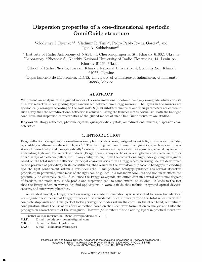
Figure 1. Bragg reflection waveguide with aperiodic mirrors arranged according to the Kolakoski K(1, 2) substitutionalrules at the seventh (σ = 7) generation stage.
2.2 OmniGuide Structure Configuration
Consider a Bragg reflection waveguide made of low-index layer sandwiched between two identical aperiodic one-dimensional mirrors formed by stacking together two different materials Ψ and Υ according to the KolakoskiK(1, 2) generation scheme (2) as it is shown in Fig. 1. The number of generation stage of the sequence is definedas σ. It is further assumed that the letters Ψ and Υ denote two different layers with thicknesses dΨ, dΥ andrefractive indices nΨ, nΥ, respectively. The refractive index profile of the waveguide structure varies only alongz-axis and is invariant in other directions.
The structure under study is infinite along y-axis, so ∂/∂y = 0. We suppose that both mirrors consist of afinite number N of the constitutive layers (σ <∞). The guiding layer has thickness 2dg and refractive index ng.In the chosen configuration, each guiding mode propagates along x-axis with its own phase constant β. In ourinvestigation we analyze the propagation of both TE-waves (s-polarization) with field components ~E = {0, Ey, 0},~H = {Hx, 0, Hz}, and TM-waves (p-polarization) with field components ~E = {Ex, 0, Ez}, ~H = {0, Hy, 0}. Notethat in the case of the practical Bragg reflection waveguides with finite number of layers in the mirrors, the lightpropagation is accompanied by some attenuation (as a result of the energy leakage through imperfect mirrors),which is consistently taken into consideration within our model.
2.3 Transfer Matrix Description and Dispersion Relation
For a TE-polarized wave propagating in the +x-direction, the electric field in layer j can be written in the form
Ey = uj(z) exp[i(βy − ωt)]. (3)
Hereuj(z) = aj exp(ikjz) + bj exp(−ikjz), (4)
kj =
(n2j
ω2
c2− β2
)1/2
, (5)
c is the speed of light in vacuum, and nj can take values ng, nΨ and nΥ related to the core, Ψ and Υ claddinglayers, respectively. For TM polarized light, (3)-(5) hold for the Hy component of the magnetic field. The fieldin layer j can be related to the field in layer j + 1 by the matrix equation[
aj+1
bj+1
]= Tj
[ajbj
], (6)
Proc. of SPIE Vol. 9200 920017-3
Downloaded From: http://proceedings.spiedigitallibrary.org/ on 09/08/2014 Terms of Use: http://spiedl.org/terms
where Tj is the 2×2 transfer matrix determined by applying corresponding boundary conditions at the interfacebetween two neighboring layers. The transfer matrix Tj is different for TE and TM polarized light:
TTEj =
1
2
(1 +kjkj+1
)exp[i(kj − kj+1)zj ]
(1− kj
kj+1
)exp[i(kj + kj+1)zj ](
1− kjkj+1
)exp[i(kj + kj+1)zj ]
(1 +
kjkj+1
)exp[i(kj − kj+1)zj ]
, (7)
TTMj =
1
2
(1 +n2j+1kj
n2jkj+1
)exp[i(kj − kj+1)zj ]
(1− n2
j+1kj
n2jkj+1
)exp[i(kj + kj+1)zj ](
1− n2j+1kj
n2jkj+1
)exp[i(kj + kj+1)zj ]
(1 +
n2j+1kj
n2jkj+1
)exp[i(kj − kj+1)zj ]
. (8)
For the whole stack generated according to the sequence (2) rule, the equation coupling the field amplitudesat the structure input and output is obtained as:[
aNbN
]= TΣ
[a0
b0
]= ( . . .TΥTΨTΨTΥTΥTΨ︸ ︷︷ ︸ )
[a0
b0
]N
(9)
The reflection coefficient of the layer stack is determined by the expression R = |R| exp(iφ) = (b0/a0)|bN=0 =−t21/t22, where tmn are the elements of the transfer matrix TΣ, and φ is the phase of the reflected light.
The field in the core is normalized by setting a0 = 1/2 and b0 = ±1/2, where ± indicates symmetric oranti-symmetric modes, respectively. The field in the outermost layer is related to the field in the core by thematrix equation (9), where, by imposing zero incoming flux, bN = 0, we obtain the dispersion relation22
t21 ± t22 = 0. (10)
Further this equation is solved numerically to obtain the function β versus ω. Remarkably, for a finite number ofcladding layers, the dispersion equation (10) cannot be satisfied for real β. Physically, it is obvious since there isan energy leakage through the outermost layers. Hence the resulting propagation constant is sought in the formβ = β′ + iβ′′.
3. NUMERICAL RESULTS: SOLUTION ANALYSIS
3.1 Omnidirectional Reflection Bands
From our previous investigations13–15 it is revealed that there are indeed multiple bandgaps in the aperiodicdielectric multilayer’s configuration based on the Kolakoski generation rules, but not all of these bandgaps areomnidirectional ones, in which the light reflects regardless of the incident angle and the polarization. Furthermore,besides the materials and structural parameters of the building blocks Ψ and Υ, the number and width of theomnidirectional reflection bands in the Kolakoski structure depends also crucially on the sequence generator σ.Thereby all these key parameters need to be carefully accounted and balanced to achieve sufficient omnidirectionalreflection bands.
As an example in Fig. 2 we demonstrate the bandgaps which are calculated for two particular multilayer’sconfigurations (the bandgaps correspond to the black areas in Fig. 2). These two configurations are obtained forthe same generation stage σ and the refractive indices ratio r = nΥ/nΨ but for different refractive indexes of theconstitutive layers nΨ and nΥ. One can see that while for the first configuration the omnidirectional reflectionband does not exist at all, for the second configuration there are two distinct wide bands where omnidirectionalreflection is achieved. Absence of such a band for the TM polarization in the first configuration is explained bythe fact, that the Brewster condition takes place in the bandgap of the higher incident angles. Region wherethe Brewster condition holds is highlighted in Fig. 2(a) with a red line B. In particular this line specifies thecondition β/k0 = nΨnΥ/
√n2
Ψ + n2Υ. Obviously by handling the refractive indexes of the constitutive layers,
while keeping relationship between them unchanged, it becomes possible to shift the Brewster condition out ofthe band, as is demonstrated in Fig. 2(b).
Thus we achieve the desired goal of finding wide bands of the omnidirectional reflection and define a particularconfiguration of aperiodically arranged layers for the mirrors, suitable for the design of an OmniGuide structure.
Proc. of SPIE Vol. 9200 920017-4
Downloaded From: http://proceedings.spiedigitallibrary.org/ on 09/08/2014 Terms of Use: http://spiedl.org/terms
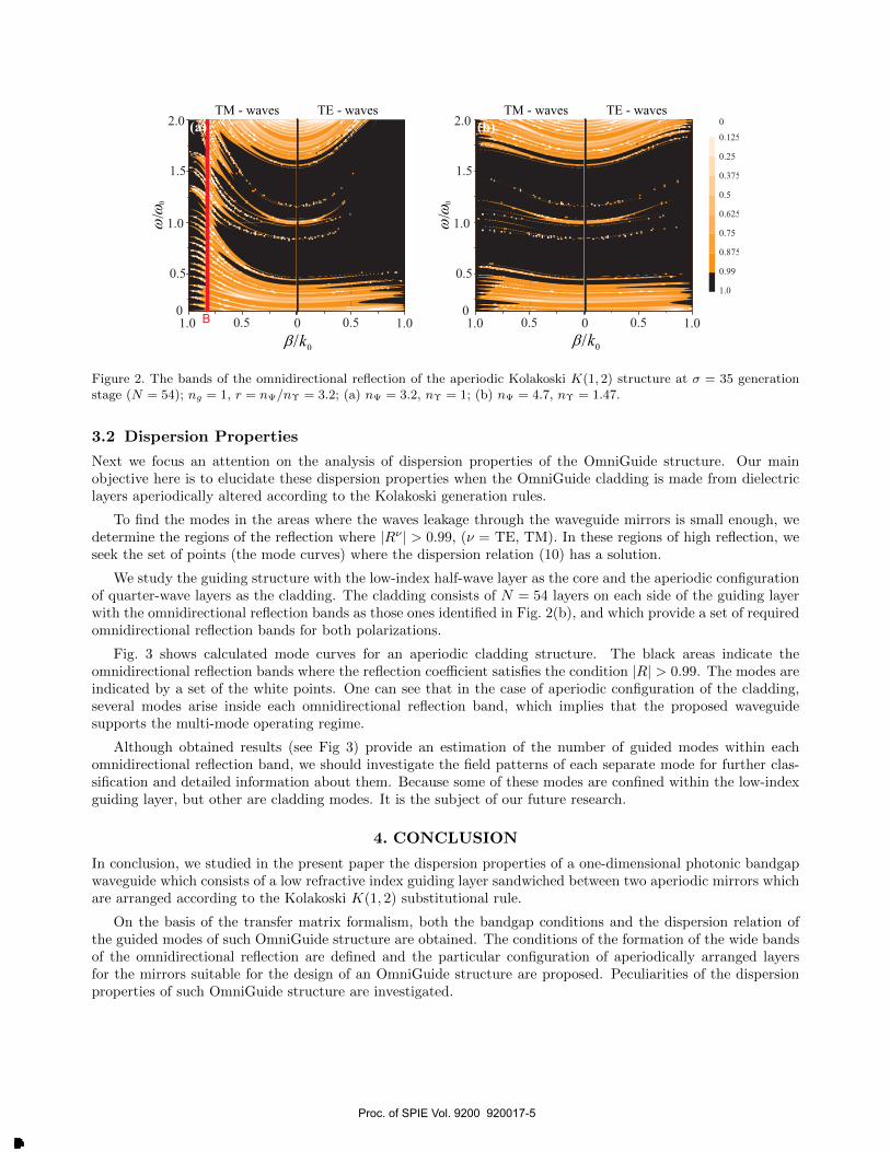
Figure 2. The bands of the omnidirectional reflection of the aperiodic Kolakoski K(1, 2) structure at σ = 35 generationstage (N = 54); ng = 1, r = nΨ/nΥ = 3.2; (a) nΨ = 3.2, nΥ = 1; (b) nΨ = 4.7, nΥ = 1.47.
3.2 Dispersion Properties
Next we focus an attention on the analysis of dispersion properties of the OmniGuide structure. Our mainobjective here is to elucidate these dispersion properties when the OmniGuide cladding is made from dielectriclayers aperiodically altered according to the Kolakoski generation rules.
To find the modes in the areas where the waves leakage through the waveguide mirrors is small enough, wedetermine the regions of the reflection where |Rν | > 0.99, (ν = TE, TM). In these regions of high reflection, weseek the set of points (the mode curves) where the dispersion relation (10) has a solution.
We study the guiding structure with the low-index half-wave layer as the core and the aperiodic configurationof quarter-wave layers as the cladding. The cladding consists of N = 54 layers on each side of the guiding layerwith the omnidirectional reflection bands as those ones identified in Fig. 2(b), and which provide a set of requiredomnidirectional reflection bands for both polarizations.
Fig. 3 shows calculated mode curves for an aperiodic cladding structure. The black areas indicate theomnidirectional reflection bands where the reflection coefficient satisfies the condition |R| > 0.99. The modes areindicated by a set of the white points. One can see that in the case of aperiodic configuration of the cladding,several modes arise inside each omnidirectional reflection band, which implies that the proposed waveguidesupports the multi-mode operating regime.
Although obtained results (see Fig 3) provide an estimation of the number of guided modes within eachomnidirectional reflection band, we should investigate the field patterns of each separate mode for further clas-sification and detailed information about them. Because some of these modes are confined within the low-indexguiding layer, but other are cladding modes. It is the subject of our future research.
4. CONCLUSION
In conclusion, we studied in the present paper the dispersion properties of a one-dimensional photonic bandgapwaveguide which consists of a low refractive index guiding layer sandwiched between two aperiodic mirrors whichare arranged according to the Kolakoski K(1, 2) substitutional rule.
On the basis of the transfer matrix formalism, both the bandgap conditions and the dispersion relation ofthe guided modes of such OmniGuide structure are obtained. The conditions of the formation of the wide bandsof the omnidirectional reflection are defined and the particular configuration of aperiodically arranged layersfor the mirrors suitable for the design of an OmniGuide structure are proposed. Peculiarities of the dispersionproperties of such OmniGuide structure are investigated.
Proc. of SPIE Vol. 9200 920017-5
Downloaded From: http://proceedings.spiedigitallibrary.org/ on 09/08/2014 Terms of Use: http://spiedl.org/terms
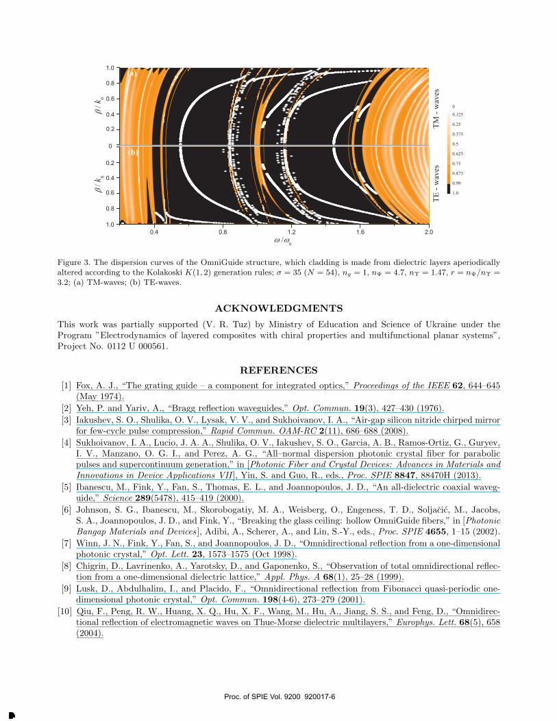
Figure 3. The dispersion curves of the OmniGuide structure, which cladding is made from dielectric layers aperiodicallyaltered according to the Kolakoski K(1, 2) generation rules; σ = 35 (N = 54), ng = 1, nΨ = 4.7, nΥ = 1.47, r = nΨ/nΥ =3.2; (a) TM-waves; (b) TE-waves.
ACKNOWLEDGMENTS
This work was partially supported (V. R. Tuz) by Ministry of Education and Science of Ukraine under theProgram ”Electrodynamics of layered composites with chiral properties and multifunctional planar systems”,Project No. 0112 U 000561.
REFERENCES
[1] Fox, A. J., “The grating guide – a component for integrated optics,” Proceedings of the IEEE 62, 644–645(May 1974).
[2] Yeh, P. and Yariv, A., “Bragg reflection waveguides,” Opt. Commun. 19(3), 427–430 (1976).
[3] Iakushev, S. O., Shulika, O. V., Lysak, V. V., and Sukhoivanov, I. A., “Air-gap silicon nitride chirped mirrorfor few-cycle pulse compression,” Rapid Commun. OAM-RC 2(11), 686–688 (2008).
[4] Sukhoivanov, I. A., Lucio, J. A. A., Shulika, O. V., Iakushev, S. O., Garcia, A. B., Ramos-Ortiz, G., Guryev,I. V., Manzano, O. G. I., and Perez, A. G., “All–normal dispersion photonic crystal fiber for parabolicpulses and supercontinuum generation,” in [Photonic Fiber and Crystal Devices: Advances in Materials andInnovations in Device Applications VII ], Yin, S. and Guo, R., eds., Proc. SPIE 8847, 88470H (2013).
[5] Ibanescu, M., Fink, Y., Fan, S., Thomas, E. L., and Joannopoulos, J. D., “An all-dielectric coaxial waveg-uide,” Science 289(5478), 415–419 (2000).
[6] Johnson, S. G., Ibanescu, M., Skorobogatiy, M. A., Weisberg, O., Engeness, T. D., Soljacic, M., Jacobs,S. A., Joannopoulos, J. D., and Fink, Y., “Breaking the glass ceiling: hollow OmniGuide fibers,” in [PhotonicBangap Materials and Devices ], Adibi, A., Scherer, A., and Lin, S.-Y., eds., Proc. SPIE 4655, 1–15 (2002).
[7] Winn, J. N., Fink, Y., Fan, S., and Joannopoulos, J. D., “Omnidirectional reflection from a one-dimensionalphotonic crystal,” Opt. Lett. 23, 1573–1575 (Oct 1998).
[8] Chigrin, D., Lavrinenko, A., Yarotsky, D., and Gaponenko, S., “Observation of total omnidirectional reflec-tion from a one-dimensional dielectric lattice,” Appl. Phys. A 68(1), 25–28 (1999).
[9] Lusk, D., Abdulhalim, I., and Placido, F., “Omnidirectional reflection from Fibonacci quasi-periodic one-dimensional photonic crystal,” Opt. Commun. 198(4-6), 273–279 (2001).
[10] Qiu, F., Peng, R. W., Huang, X. Q., Hu, X. F., Wang, M., Hu, A., Jiang, S. S., and Feng, D., “Omnidirec-tional reflection of electromagnetic waves on Thue-Morse dielectric multilayers,” Europhys. Lett. 68(5), 658(2004).
Proc. of SPIE Vol. 9200 920017-6
Downloaded From: http://proceedings.spiedigitallibrary.org/ on 09/08/2014 Terms of Use: http://spiedl.org/terms
[11] Barriuso, A., Monzon, J., Sanchez-Soto, L., and Felipe, A., “Comparing omnidirectional reflection fromperiodic and quasiperiodic one-dimensional photonic crystals,” Opt. Express 13, 3913–3920 (May 2005).
[12] Gevorgyan, A., “Optical diodes and omnidirectional reflectors based on one-dimensional quasiperiodic pho-tonic crystals,” Tech. Phys. Lett. 34(1), 22–25 (2008).
[13] Fesenko, V. I., Tuz, V. R., and Sukhoivanov, I. A., “Optical characterization of the aperiodic multilay-ered anisotropic structure based on Kolakoski sequence,” in [Integrated Optics: Physics and Simulations ],Cheben, P., Ctyroky, J., and Molina-Fernandez, I., eds., Proc. SPIE 8781, 87811C (2013).
[14] Fesenko, V. I., Tuz, V. R., and Sukhoivanov, I. A., “Terahertz aperiodic multilayered structure arrangedaccording to the Kolakoski sequence,” in [Terahertz and Mid Infrared Radiation: Detection of Explosives andCBRN (Using Terahertz) ], Pereira, M. F. and Shulika, O., eds., 25–32, Springer Science+Business Media,Dordrecht (2014).
[15] Fesenko, V. I., “Aperiodic birefringent photonic structures based on Kolakoski sequence,” Waves Rand.Complex 24(2), 174–190 (2014).
[16] Kolakoski, W., “Self generating runs, Problem 5304,” Amer. Math. Monthly 72, 674 (1965).
[17] Tuz, V., “Optical properties of a quasiperiodic generalized Fibonacci structure of chiral and material layers,”J. Opt. Soc. Am. B 26(4), 627–632 (2009).
[18] Tuz, V. and Kazanskiy, V., “Electromagnetic scattering by a quasiperiodic generalized multilayer Fibonaccistructure with grates of magnetodielectric bars,” Waves Rand. Complex 19(3), 501–508 (2009).
[19] Tuz, V., “A peculiarity of localized mode transfiguration of a Cantor-like chiral multilayer,” J. Opt. A: PureAppl. Opt. 11(12), 125103 (2009).
[20] Tuz, V. and Batrakov, O., “Localization and polarization transformation of waves by a symmetric andasymmetric modified Fibonacci chiral multilayer,” J. Mod. Opt. 57(21), 2114–2122 (2010).
[21] Sing, B., “Kolakoski sequences - an example of aperiodic order,” J. Non-Cryst. Solids 334, 100–104 (2004).
[22] Nistad, B., Haakestad, M. W., and Skaar, J., “Dispersion properties of planar Bragg waveguides,” Opt.Commun. 265(1), 153 – 160 (2006).
Proc. of SPIE Vol. 9200 920017-7
Downloaded From: http://proceedings.spiedigitallibrary.org/ on 09/08/2014 Terms of Use: http://spiedl.org/terms
Top Related
Copyright © 2022 FDOKUMEN

