


Bahasa
Halaman
Hukum


promoting access to White Rose research papers
White Rose Research Online [email protected]
Universities of Leeds, Sheffield and York http://eprints.whiterose.ac.uk/
This is an author produced version of a paper published in Journal of Composites for Construction. White Rose Research Online URL for this paper: http://eprints.whiterose.ac.uk/42813
Published paper Pilakoutas, K., Neocleous, K., Guadagnini, M. (2002) Design philosophy issues of fiber reinforced polymer reinforced concrete structures, Journal of Composites for Construction, 6 (3), pp. 154-161 http://dx.doi.org/10.1061/(ASCE)1090-0268(2002)6:3(154)

1 Reader, Centre for Cement and Concrete, Department of Civil and Structural Engineering,
University of Sheffield, UK, [email protected]
2 Post-Doctorate Researcher, Centre for Cement and Concrete, Department of Civil and
Structural Engineering, University of Sheffield, UK, [email protected]
3 Post-Doctorate Researcher, Centre for Cement and Concrete, Department of Civil and
Structural Engineering, University of Sheffield, UK, [email protected]
Key words: design philosophy, design guidelines, fibre reinforced polymers, safety, structural
reliability
Design Philosophy Issues of FRP RC Structures
Kypros Pilakoutas1, Kyriacos Neocleous2 and Maurizio Guadagnini3
Abstract: The conventional design philosophy for reinforced concrete (RC) relies heavily on the
ductile properties of steel. These ductile properties are used as a ‘fuse’ and conceal the large
uncertainty in the determination of modes of failure caused by concrete. Current design
guidelines for FRP RC structures have inappropriately adopted the same design philosophy used
for steel RC, leading either to the adoption of large safety factors or reduced structural reliability.
A reliability-based analysis of FRP RC beams shows that the partial safety factors for FRP
reinforcement on their own do not influence the structural safety of over-reinforced concrete
elements. Proposals are made for the modification of the material partial safety factors to achieve
target safety levels.
2
Introduction
The widespread adoption of any new type of reinforcement, such as fiber reinforced polymers
(FRP), requires the development of product specification, testing standards and codes of design
practice, a process that can take many years to be completed.
Though research in this field is very recent, the first generation of design guidelines has already
been developed in Japan, Canada, America and Europe (JSCE 1997, CHBDC 1996, ACI 440
2001, IGDRCS 1999). All of these guidelines are based on modifications of existing codes of
practice for steel reinforced concrete (RC) structures, which, though they have the clear objective
of achieving flexural failures through steel yielding, do not have an identifiable design safety
philosophy (DSP). It should be pointed out, that the codes have different DSP, with the ACI code
relying on material reduction factors, whilst the other codes using partial material safety factors.
In addition, even when these guidelines are used for the design of conventional RC structures:
1. the actual safety, or reliability, levels of the structures are unknown, (even though standards
such as the Eurocode 1 require reliability levels of 10-6)
2. the actual reliability levels vary for different structural elements (depending on the actions
and resistance mechanisms), and
3. the capacity margin between each failure mode is unknown (for example the capacity margin
between flexure and shear, making seismic design codes such as Eurocode 8 to adopt radical
solutions in order to avoid shear failures).
3
The above problems are worse when dealing with FRP RC elements, since the predominant
mode of failure is likely to be dependent on the concrete rather than on the reinforcement.
The first generation design guidelines for FRP RC structures are mainly provided in the form of
modifications to existing steel RC codes of practice, which are predominantly using the limit
state design approach. The modifications consist of basic principles, which are heavily influenced
by the unconventional mechanical properties of FRP reinforcement and empirical equations that
are based on insufficient experimental work on FRP RC elements. Though the brittle linear-
elastic behavior of FRP reinforcement is an influencing factor behind all of the existing design
guidelines, the impact of the change of failure mode is not addressed in detail.
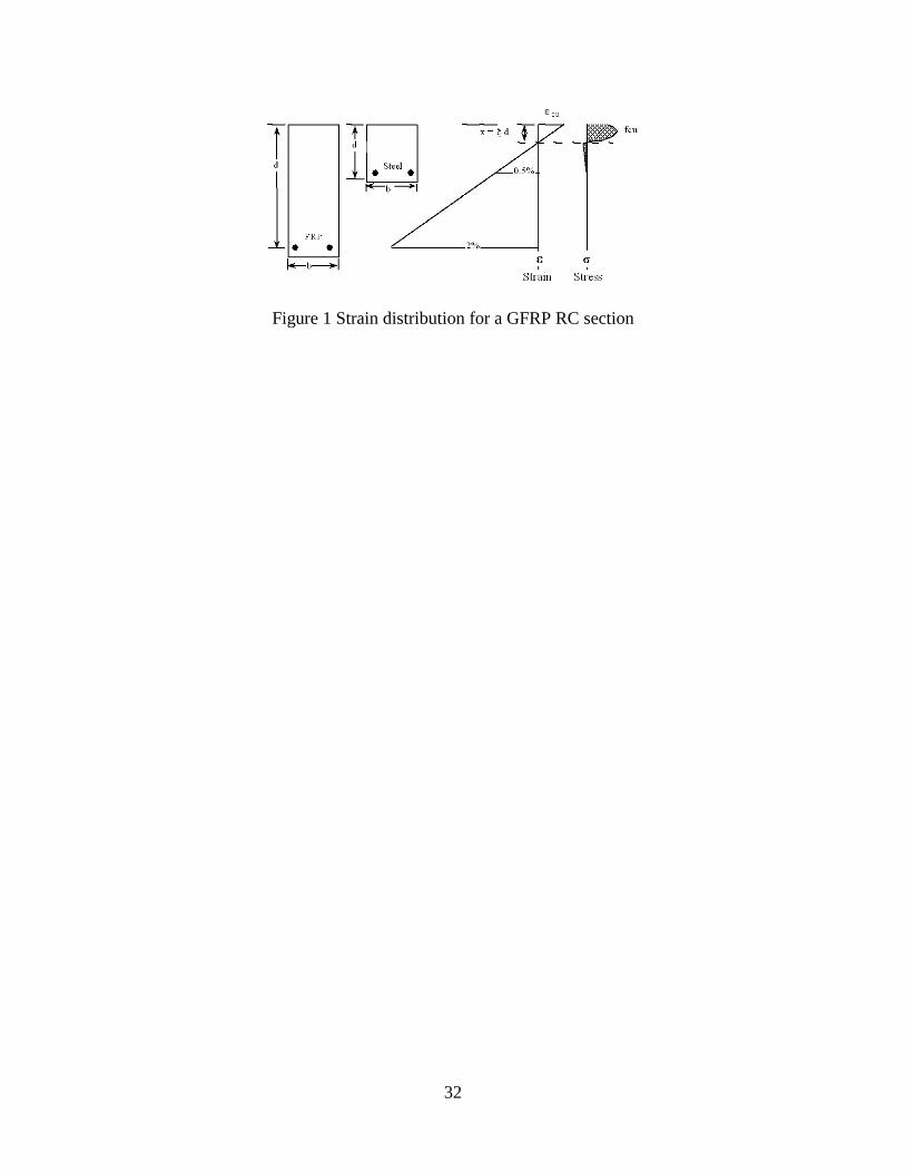
When dealing with FRP reinforcement, the amount of reinforcement to be used has to be
determined by a different approach due to the lower stiffness and the high strength of composite
materials. In fact, for FRP reinforcement, the strength to stiffness ratio is an order of magnitude
greater than that of steel and this affects the distribution of stresses along the section. Hence,
when considering a balanced section, a condition desired for steel RC design, the neutral axis
depth for FRP RC sections would be very close to the compressive end as shown in Fig. 1.
This implies that for such a section a larger amount of the cross-section is subjected to tensile
stresses and the compressive zone is subjected to a greater strain gradient. Hence, for similar
cross sections to that of steel, much larger deflections and less shear strength are expected (Fig.
2).

4
If all of the other modes of failure are avoided, flexural failure can be reached either by crushing
of the concrete in compression or by rupture of the FRP reinforcement in tension. Both modes
are brittle and undesirable. Whichever is the desired mode of flexural failure, this is attained
primarily by the application of specific material partial safety factors for FRP reinforcement
(γFRP) or member strength reduction factors. The application of γFRP implies that there is a target
structural reliability level (Pft). Recent investigations, however, have shown that the application
of specific γFRP would neither lead to the desired mode of flexural failure nor would attain the
target Pft (Neocleous et al.1999).
This paper initially presents and discusses the variety of safety factors currently adopted by the
current first generation design guidelines and then goes on to examine the above issues further
for over-reinforced beams designed to resist uniformly distributed loads in accordance to the
preliminary design guidelines developed in Europe (IGDRCS 1999). The work has been carried
out as part of the European Union sponsored TMR network “ConFibreCrete” and task group 9.3
of the International Federation of Concrete (fib), whose aim is the development of design
guidelines for concrete structures reinforced, prestressed or strengthened with advanced
composites.
The probability of flexural failure occurring due to concrete crushing (Pfc) and the flexural
notional structural reliability level (Pf) of 48 rectangular beam configurations, reinforced with
Eurocrete FRP reinforcement (Eurocrete Project 1997), are determined for a number of γFRP. The
investigation is carried out for two cases: a) simply supported beams reinforced with carbon FRP
5
(CFRP) reinforcement and b) simply supported beams reinforced with glass FRP (GFRP)
reinforcement.
From the results of the above research the paper goes on to identify the DSP problems that need
to be addressed before the emergence of a new generation of design guidelines for FRP RC
structures.
Current Safety factors
The most recent Japanese design guidelines for FRP RC (JSCE 1997), which are based on
modifications of the Japanese steel RC code of practice, provide a set of material partial safety
factors for the FRP reinforcement as indicated in Table 1. These guidelines, however, do not
provide any information regarding the predominant mode of failure that would result from the
application of the proposed partial safety factors, nor do they cover product specification. Hence
the small safety margins given may not adequately cover reinforcement materials which have
large variability in their properties.
The Canadian design guidelines (CHBDC 1996) provide only general information about FRP
reinforcement.
The American design guidelines (ACI 440 2001) are based on modifications of the ACI 318-99
(ACI 318 1999) RC code of practice. These guidelines propose that the predominant mode of
failure is flexural concrete crushing rather than flexural re-bar fracture. Thus, a minimum limit is

6
imposed on the amount of FRP reinforcement in order to attain the desired predominant failure
mode. The guidelines also adopt a conservative approach for the derivation of strength reduction
factors, φ. This is due to the fact that there is very little data regarding the service and long-term
behavior of FRP RC structures. Thus, a φ of 0.7 is recommended for flexure, whereas for shear, it
is recommended that the value of φ be the same as the value adopted by ACI 318-99.
Though the impact of a strength reduction factor is easier to understand than the impact of partial
safety factors, its use can lead to very different levels of safety, depending on the concrete
strength and reinforcement ratio. Furthermore, the use of a member reduction factor does not
help the engineer understand the overall stress levels in the constituent materials, which means
that the level of stress in concrete may be higher than for conventional reinforcement. Since
strength reduction factors are not supposed to be derived on the basis of reliability, they will not
be addressed further in this paper.
In the case of the European design guidelines (Clarke et al. 1996, Eurocrete report 1997), the
recommendations are based on modifications to British and other European RC codes of practice
such as Eurocode 2 (ENV 1991-1 1994, ENV 1992-1-1 1992). These guidelines were published
in the UK as an interim guidance on the design of FRP RC structures by the Institution of
Structural Engineers (IGDRCS 1999). These guidelines include a set of partial safety factors for
the material strength and stiffness (Table 2) that take into consideration both the short and long-
term structural behavior. They do not, however, provide clear indications about the predominant
failure mode that would result from the application of these partial safety factors. The composite

7
action of the reduction factors on the strength and stiffness leads to very conservative results, in
particular when using shear reinforcement.
The initial approach of developing design guidelines such as those described above may seem
reasonable, but it is not entirely appropriate. The conventional steel RC codes of practice assume
that the predominant failure mode is always ductile due to yielding of the flexural reinforcement.
This is not the case, however, for the above FRP RC design guidelines, which seem to accept a
brittle flexural failure due to concrete crushing. Furthermore, the steel RC codes of practice,
which form the basis of these guidelines, have fundamental structural safety uncertainties. These
include the derivation of the partial safety factors, the actual structural reliability levels and the
resistance capacity margins (RCMs) between the various failure modes.
In order to determine the actual structural reliability levels, it is necessary to have accurate
predictive resistance capacity models, a good understanding of the variability of materials and an
accurate assessment procedure. With these concerns in mind, both steel and FRP RC elements
were analyzed in a comprehensive research program at the University of Sheffield (Neocleous,
1999) and some of the results are given below.
Resistance-capacity prediction models
Structural reliability assessment requires the formulation of a model (limit state function) that
represents the structural behavior for the limit state for which the assessment is performed. The
limit state function, G(R, S), is represented in terms of a structural resistance component, R, and

8
an action-effect component, S. Both R and S are modelled by mathematical relationships of
random basic variables, Ri and Si, which represent structural material properties and actions,
respectively. Due to the complexity of the problem, this paper will try and deal only with the
issue of flexural failures, even though work has also been completed on shear and bond failures.
The structural reliability of steel RC beams is assessed in terms of the BS8110 (1997) and
Eurocode 2 (ENV1992-1-1, 1992) codes. Hence, the G(R, S) is formulated using the resistance-
capacity prediction models adopted for the above failure modes by the two codes of practice. The
Eurocode 2 models are elaborated in the appendix and since the BS8110 models are very similar,
they are not given in this paper.
In the case of the FPR RC beams, the structural reliability assessment is performed in terms of
the European design guidelines for FRP RC structures (Clarke et al, 1996). These guidelines
conform to existing European RC codes of practice and thus, the proposed models are based on
the models adopted by these RC codes of practice. The model for the flexural failure mode,
elaborated in Appendix II, is based on the control of strain of the FRP reinforcement and utilizes
the principles of the corresponding Eurocode 2 model.
Statistical data for basic variables
The statistical data used in earlier investigations by the authors are utilized for the statistical
modeling of all random variables (Neocleous et al. 1999, Neocleous 1999). Tables 3 and 4
summarize the statistical data used for the geometric and loading variables. In the case of the

9
material strength of concrete and FRP reinforcement, the adopted statistical data are derived from
the analysis of experimental results provided by manufacturers. A constant standard deviation of
6 N/mm2 is used for the concrete compressive strength and the probability distribution is
truncated at 3.16 standard deviations from the mean value. In the case of CFRP and GFRP
(Eurocrete) reinforcement (Table 5), the strength obtained experimentally in RC beams was
adopted, since existing direct tensile tests fail to simulate the in-service load-transfer mechanisms
for FRP reinforcing bars.
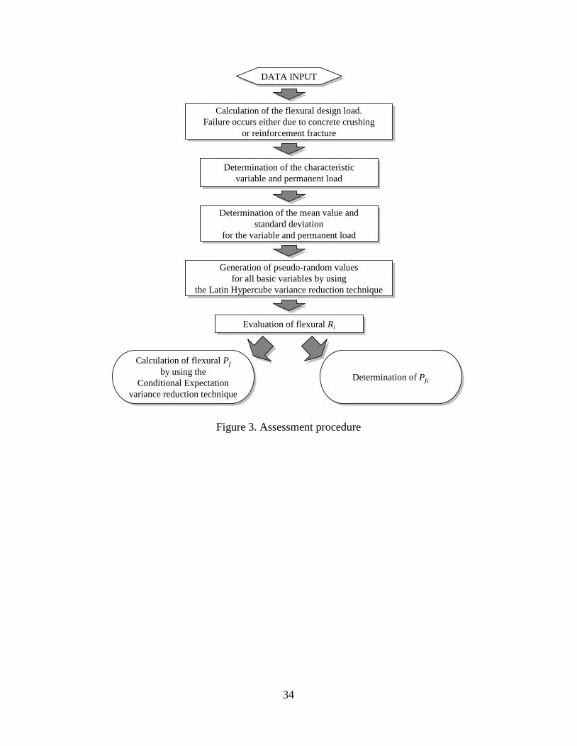
Assessment Procedure
A numerical simulation approach is adopted to determine the Pfc and flexural Pf; the simulations
are performed using MATLAB (MATLAB 1999). The procedure followed in the assessment is
illustrated in Fig. 3, and is further elaborated in Neocleous (1999). It is noted that the resistance-
capacity models adopted by the European design guidelines, are modified accordingly to account
for flexural failure occurring either due to concrete crushing or reinforcement fracture.
The flexural Pf and Pfc are evaluated by equations 1 and 3, respectively.
N
N
1∑== i if
f
PP (1)
)(1)( iiiii GRFGRQPP Qf −−=−>= (2)
N
0035.0εP 1
c∑=
≥= i
fc (3)
10
ANALYSIS OF SIMULATIONS
The flexural design of CFRP RC beams was based on the assumption that a brittle failure would
occur due to concrete crushing. In the case of beams with low reinforcement ratio (ρ) and high
concrete compressive strength (fc), however, it was assumed that a brittle failure due to fracture
of the reinforcement would be possible. This is a consequence of the fact that the actual tensile
strain developed in the reinforcement at the design stage (εFRP) exceeds the design limit (εFRPd)
imposed by the γFRP. It is noted that this was only observed in six of the examined cases of CFRP
RC beams designed using a γFRP of 1.8 (Fig. 4).
In the case of the GFPR RC beams designed using a γFRP of 3.6, it was assumed that brittle failure
would occur due to fracture of the longitudinal reinforcement, due to the low strength of the
reinforcement . Whereas, in the case of GFRP RC beams designed using a γFRP of 1.3, only three
beams had to be designed for fracture of the reinforcement (Fig. 5).
The results obtained for Pfc indicate that the majority of beams would actually fail due to
concrete crushing, as intended at the design stage. In some cases, however, there is a large
probability (up to 0.2 for CFRP RC beams and 0.73 for GFRP RC beams) of failure due to
fracture of the reinforcement. This was observed when: a) the design assumed that failure due to
fracture of the reinforcement would occur, and b) the value of εFRP was relatively close to εFRPd.
In addition, it is observed that the Pfc decreases as fc increases. This can be attributed to the fact
that the tensile strength of FRP reinforcement is further utilized. For instance, in the case of the
CFPR RC beams, Pfc decreases from 0.97 to 0.27 as fc increases from 33 to 50 N/mm2.
11
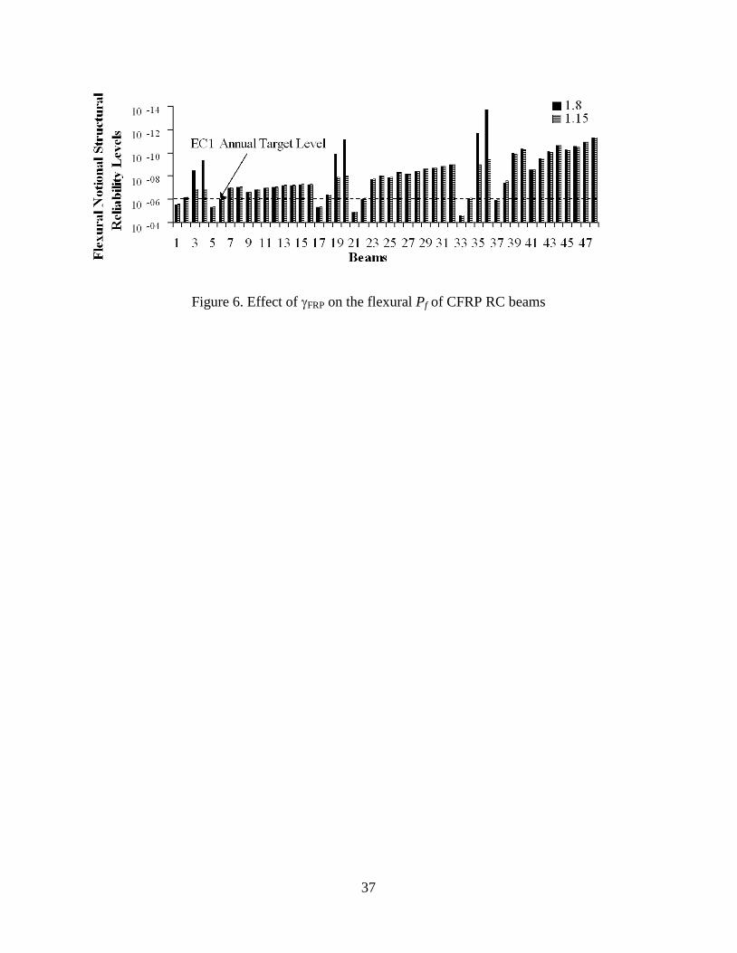
Fig. 6 shows that the flexural Pf is not affected by γFRP, as long as the type of failure assumed at
the design stage is concrete crushing. In such cases, the flexural resistance capacity remains
constant since the εFRP does not change with γFRP. Thus, if concrete crushing is chosen as the
desired mode of flexural failure, it may be seem sensible to discard γFRP and incorporate the
uncertainties relevant to flexural reinforcement in the partial safety factor adopted for fc. As Fig.
7 indicates, the Pf is affected by γFRP if flexural failure occurs due to reinforcement fracture.
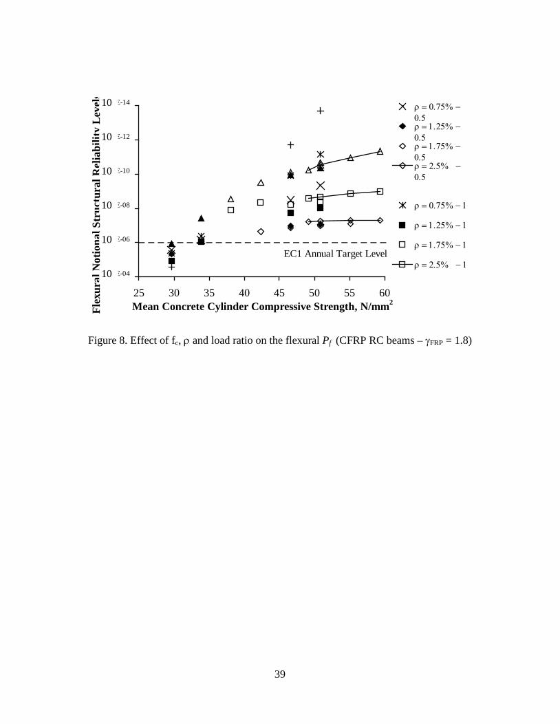
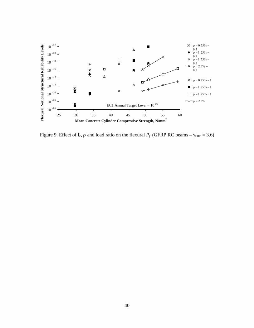
In Fig. 6 and 7, it is also observed that the structural reliability generally satisfies the target value
of 10-6 adopted by Eurocode 1 (ENV 1991-1 1994), however, the figures indicate that the
calculated Pf is highly variable. This is due to the effect of various design parameters as
illustrated in Fig. 8 and 9 for CFRP and GFRP RC beams, respectively. These figures suggest
that the ratio of permanent to variable load greatly influences the flexural Pf. This implies that,
for the same γFRP, the structural reliability varies for different types of structures and hence, in
order to avoid reliability differentiation, it is recommended to use different γFRP (or more
appropriately, load factors) for different types of structures. In addition, Fig. 8 and 9 indicate that
the ratio of ρ and fc influence the Pf of both CFRP and GFPR RC beams. The results of the
assessment show that the effect of these two parameters is greatly affected by the type of flexural
failure assumed at the design stage. If the flexural design assumes reinforcement fracture, the Pf
is influenced by both fc and ρ (Pf increases with ρ, while it decreases as fc increases) (Fig. 9). If
the flexural design assumes concrete crushing, however, the Pf is only affected by fc (Fig. 8). It is
noted that in this case the Pf is more uniform across the range of beam configurations examined.

12
DESIGN RECOMMENDATIONS
Based on the findings of the analysis, design recommendations are proposed for the flexural
(short-term) design of over-reinforced FRP RC beams, reinforced with (Eurocrete) FPR
reinforcement. Since the results show that concrete crushing is the most probable type of flexural
failure, it is recommended that flexural design be carried out to attain concrete crushing. This can
be achieved by ensuring that minimum amounts of flexural reinforcement are provided, which
will also protect the structural elements from large cracks developing as soon as the concrete
tensile stress is exceeded.
Provided that flexural failure occurs due to concrete crushing, it was determined from the
analysis that the use of γFRP to account for the uncertainties in the mechanical characteristics of
the FRP reinforcement is not vital, since the flexural Pf is not affected by γFRP. Based on this
finding, it is proposed that the uncertainties relevant to mechanical characteristics of the flexural
reinforcement should be incorporated into the γm adopted for fc, which would involve the
modification of concrete γm used currently in flexural limit state design.
The mechanical behavior of FRP reinforcement in flexure is not established thoroughly, since
accepted standards for the determination of the mechanical characteristics that take into account
the behavior of FRP bars in concrete are not yet available. In addition, since FRP reinforcement
is primarily intended for use in aggressive environments, its long-term characteristics in concrete
should also be taken into account. It will not be prudent, therefore, to abolish the use of γFPR
based on the existing knowledge. Consequently, it is recommended to adopt the smallest γFRP

13
examined during the assessment of the CFRP and GFRP RC beams. In the case of CFRP
reinforcement, a value of 1.15 is recommended and a γFRP of 1.3 is selected for GFRP
reinforcement. It should be noted that the different γFRP - recommended for Eurocrete CFRP and
GFRP reinforcement - reflect the different material characteristics of the two reinforcements. In
addition, it is noted that these γFRP are recommended for the short-term design of FRP RC beams
and hence, they do not take into account the long-term behavior of FRP reinforcement. A limit is
also imposed on ρ, as shown in equation 4, in order to diminish the possibility of flexural failure
occurring due to reinforcement fracture.
)εEf(f
ε 8) (f 0.81 ρc
kFRP
FRPkkFPR
cckmin
+
+= (4)
Finally, the use of safety factors on the stiffness of the FRP only makes sense if that safety factor
is used just in the determination of deflections and cracking, and not in conjunction with strength
safety factors when determining flexural capacity. It is proposed that the stiffness safety factors
be discarded and the effect of stiffness uncertainty taken into account directly in the equations
dealing with deformations.
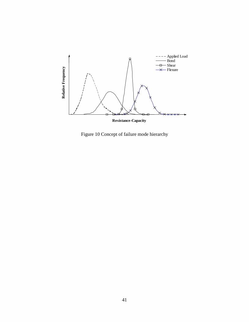
Further research at Sheffield (Neocleous, 1999) has taken into account the effect of other modes
of failure as well, and it has led to the development of a more comprehensive DSP based on
targeted failure mode hierarchy. This approach allows the designer to choose different failure
mode hierarchies, depending on the materials used, by selecting appropriate material safety
factors.

14
CONCLUSIONS
This study has examined the effect of design parameters and γFRP, adopted for FRP
reinforcement, on the flexural behavior of over-reinforced FPR RC beams.
One of the main findings of the assessment is that the desired mode of flexural failure is not
attained by the application of γFRP alone. Thus, in order to attain the desired mode of failure, it is
necessary to apply limits on the design parameters considered by the models adopted to predict
the resistance-capacity.
A minimum amount of reinforcement is proposed, which will ensure flexural failure due to
concrete crushing.
The flexural structural reliability is not uniform due to the effect of various design parameters.
The ratio of permanent to variable load is one of the most influencing parameters and hence, it is
recommended to adopt different load factors for different types of structures.
The use of large values for γFRP for flexural reinforcement is not necessary, if the design is
devised to achieve flexural failure due to concrete crushing. Minimum values for γFRP are
proposed and these values should be extended by further research to take into account the long-
term behavior of FRP reinforcement in concrete.

15
The use of safety factors for the stiffness of FRP is not necessary and the effect of stiffness
uncertainty should be taken into account by the equations dealing with deformations.
A more comprehensive DSP is required that integrates all of the failure modes and takes into
account the properties of different types or reinforcing materials.
ACKNOWLEDGEMENT
The authors wish to acknowledge the European Commission for funding the EU TMR Network
"ConFibreCrete".

16
APPENDIX I. Eurocode 2 (ENV1992-1-1, 1992) models for steel Design Moment Resistance
RC beams
The design rules of Eurocode 2 utilize the simplified stress block approach (Fig. A.1) to
determine the design moment resistance. The following assumptions are made by the design
rules.
1. The strains in the concrete and the reinforcement are directly proportional to their distance
from the neutral axis.
2. The strain in bonded reinforcement is the same as in the surrounding concrete.
3. The concrete tensile strength is ignored.
4. The concrete compressive stresses and the reinforcement stresses are derived from idealized
design stress-strain curves.
5. The concrete compressive strain is limited to 0.002, if the RC section is subjected to pure
longitudinal compression. Otherwise, the strain is limited to 0.0035.
The following algorithm is adopted for the evaluation of the design moment resistance.
Initially, it is assumed that plastic failure would occur and the effective depth of the RC beam is
evaluated from equation A.1. Expressions for the design force in the tensile reinforcement, FSd,
and the design compressive force of concrete, FCd, are afterwards derived (equations A.3 and
A.1.1 respectively).

17
FCd = c
ck
c
ck
γb x f 0.68
γb x 0.8 f 0.85
= (A.1.1)
By considering the force equilibrium, FCd = FSd, x is calculated:
x = sck
cyks
γb f 0.68 γf A
(A.1.2)
Before proceeding to the calculation of the lever arm, z, of the force couple, the same procedure
as in section A.1 is utilized to check if the above value of x corresponds to plastic failure. Thus,
the neutral axis limit and εy are determined from the section strain diagram and the stress-strain
diagram, respectively. If x/d exceeds the neutral axis limit, x is recalculated on the basis that
elastic failure occurs due to concrete crushing. Then the value of εs is derived from the strain
diagram and is used together with the material safety factor to determine FSd. By considering
force equilibrium and substituting in A.1.1, the following expression is obtained:
=xsck
cuss
γb f 0.68
γ)x
xd(ε E A −
(A.1.3)
x is determined by solving the resulting quadratic equation:
0dxx γε E A γb f 0.68 2
cuss
sck =−+ (A.1.4)

18
Then, z is calculated by using the appropriate value of x:
z = d - 0.4 x (A.1.5)
Finally, the design moment of resistance is obtained:
Mu = c
ck
γz x b f 0.68
(A.1.6)
APPENDIX II. Models for Design Moment Resistance of FRP RC beams
The model adopted for the design moment resistance of FRP RC beams is based on the design
rules of Eurocode 2, and hence the same assumptions apply for the current model. The
compression strength of FRP reinforcement is also ignored due to the anisotropic nature of the
reinforcement.
The use of FRP reinforcement in RC construction would generally lead to over-reinforced
sections since the high strength of FRP is not fully utilized. Thus, there is a change in the failure
mode (from ductile to brittle). To accommodate this, the model is modified accordingly and the
design is based on the control of the strain in the FRP reinforcement (ACI 440-98, 1998; JSCE,
1997). The following algorithm is applied for the evaluation of the design moment resistance.
19
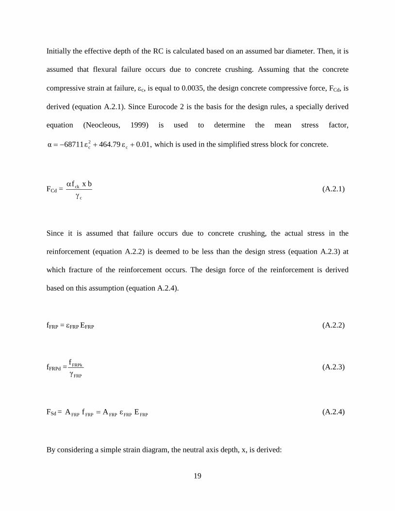
Initially the effective depth of the RC is calculated based on an assumed bar diameter. Then, it is
assumed that flexural failure occurs due to concrete crushing. Assuming that the concrete
compressive strain at failure, εc, is equal to 0.0035, the design concrete compressive force, FCd, is
derived (equation A.2.1). Since Eurocode 2 is the basis for the design rules, a specially derived
equation (Neocleous, 1999) is used to determine the mean stress factor,
0.01ε 464.79ε 68711α c2c ++−= , which is used in the simplified stress block for concrete.
FCd = c
ck b x fγ
α (A.2.1)
Since it is assumed that failure occurs due to concrete crushing, the actual stress in the
reinforcement (equation A.2.2) is deemed to be less than the design stress (equation A.2.3) at
which fracture of the reinforcement occurs. The design force of the reinforcement is derived
based on this assumption (equation A.2.4).
fFRP = εFRP EFRP (A.2.2)
fFRPd =FRP
FRPk
γf (A.2.3)
FSd = FRPFRPFRPFRPFRP E ε Af A = (A.2.4)
By considering a simple strain diagram, the neutral axis depth, x, is derived:

20
x = cFRP
c
εεd ε+
(A.2.5)
Then by considering force equilibrium between FCd and FSd, equations A.2.1, A.2.4 and A.2.5 are
solved simultaneously to determine the actual tensile strain of the reinforcement, εFRP:
FRP FRPFRPc
cFRP
cck
Eε Aγ
b εε
d εf α
=
+
(A.2.6)
By solving the following quadratic equation, the actual reinforcement strain, εFRP, is calculated:
0E A γ
ε d b f αε εε
FRPFRPc
cckFRPc
2FRP =−+ (A.2.7)
Before proceeding into the calculation of the lever arm, z, and design moment resistance, Mu, it
is checked if εFRP has exceeded the design limit, εFRPd, which is defined by equation A.2.8.
εFRPd =FRP
FRPd
Ef (A.2.8)
If εFRPd is exceeded by εFRP, then flexural failure occurs due to fracture of the FRP reinforcement.
In this case, FSd and x are determined from equation A.2.9 and A.2.10 respectively. FCd is also re-
derived (equation A.2.11) by substituting equation A.2.10 to A.2.1. The concrete compressive

21
strain is iteratively reduced until the force equilibrium between FCd (equation A.2.11) and FSd
(equation A.2.9) is satisfied.
FSd = FRPdFRP f A (A.2.9)
x = cFRPd
c
εεd ε+
(A.2.10)
FCd = c
cFRPd
cck
γ
b εε
d εf α
+
(A.2.11)
Using the appropriate value of x, the centroid factor, γ, and the lever arm, z, are then determined
from equation A.2.12.
z = d – γ x where, 0.33ε 17.89ε 1962.6γ c2c ++= (A.2.12)
Finally, the design moment resistance, Mu, is calculated, depending on the mode of flexural
failure. If failure occurs due to concrete crushing, equation A.2.13 is applied. It should be noted
that FCd is determined from equation A.2.1. Otherwise, if failure is due to fracture of the re-bar,
equation A.2.14 is determined by using the appropriate value of FSd.
Mu = FCd z (A.2.13)
Mu = FSd z (A.2.14)

22

23
APPENDIX III. REFERENCES
ACI Committee 318 (1995). Building Code Requirements for Reinforced Concrete, ACI-318-95,
Detroit
ACI Committee 440 (2001). Guide for the Design and Construction of Concrete Reinforced with
FRP Bars, ACI 440.1R-01, ACI, Farmington Hills, MI, USA
British Standards Institution (1985). BS 8110. Structural use of Concrete. Part 1: 1985. Code of
practice for design and construction, BSI
CHBDC - Canadian Highway Bridge Design Code (1996). "Section 16: Fibre Reinforced
Structures", Final Draft
Clarke J. L., O'Regan D. P. and Thirugnanenedran C. (1996). “EUROCRETE Project,
Modification of Design Rules to Incorporate Non-Ferrous Reinforcement”, EUROCRETE
Project, Sir William Halcrow & Partners, London
ENV 1991-1 (1994). “Eurocode 1 – Basis of Design and Actions on Structures – Part 1: Basis of
Design”, European Prestandard, European Committee for Standardisation, 85 pp
ENV 1992-1-1 (1992). Eurocode 2. Design of Concrete Structures, Part 1, General Rules and
Rules for Buildings, European Committee for Standardisation

24
Eurocrete Project (1997). “The Development of Non-ferrous Reinforcement for Concrete
Structures – Final Report”, Prepared by Euro-Projects (LTTC), 109 pp
IGDRCS (1999). “Interim Guidance on the Design of Reinforced Concrete
Structures Using Fibre Composite Reinforcement”, The Institution of Structural Engineers, 116
pp
JSCE (1997). “Recommendation for Design and Construction of Concrete Structures Using
Continuous Fiber Reinforcing Materials”, Research Committee on Continuous Fiber Reinforcing
Materials, Japan Society of Civil Engineers, October 1997, 325 pp
MATLAB (1999). “The Language of Technical Computing”, Version 5.3, Published in the Math
Works Inc. Website: http://www.mathworks.com/products/matlab, 1999
Neocleous K. (1999). “Design and Safety Philosophy for Concrete Structures Reinforced with
Fibre Reinforced Polymers (FRP)”, Ph.D. Thesis, The University of Sheffield, Department of
Civil and Structural Engineering, Sheffield
Neocleous K., Pilakoutas K. and Waldron P. (1999). “Structural Reliability Levels for FRP RC
Structures”, ACI SP-188, Proceedings of the Fourth International Symposium on Fiber
Reinforced Polymers for Reinforced Concrete Structures (FRPRCS-4), Baltimore USA, 31
October – 5 November 1999, pp 65 – 74

25

26
APPENDIX IV. NOTATION
EFRPk characteristic value of elastic modulus of FRP reinforcement
Fi() cumulative distribution function of a variable i
fc concrete compressive strength
fFRPk characteristic value of tensile strength of FRP reinforcement
Gi permanent load evaluated at each simulation cycle, i
N amount of simulation cycles performed
fP mean probability of failure, which corresponds to the notional Pf
Pf notional structural reliability level
Pfc probability of flexural failure occurring due to concrete crushing
Pfi probability of failure evaluated at each simulation cycle
Pft target structural reliability level
Q variable load
Ri resistance-capacity evaluated at each simulation cycle
εc concrete strain
εFRP actual tensile strain developed in the FPR reinforcement at the design stage
εFRPd design limit imposed on the tensile strain of FRP reinforcement by γFRP
γFRP material partial safety factor for FRP reinforcement

27
Table 1 Partial safety factors proposed by JSCE (1997)
(1)
Material Factor γm
Member Factor
γb
(5)
Structural Analysis Factor
γa (6)
Load Factor
γf
(7)
Structural Factor
γi
(8)
Concrete γc (2)
FRP γmf (3)
Steel γs
(4)
Ultimate Limit State
1.3* or 1.5
1.15* * to 1.3
1.0 or
1.05
1.15 to 1.3
1.0
1.0 to 1.2
1.0 to 1.2
Serviceability Limit State 1.0 1.0 1.0 1.0 1.0 1.0 1.0
Fatigue Limit State
1.3* or 1.5
1.15** to 1.3
1.05 1.0 to 1.1
1.0 1.0 1.0 to 1.1
Notes: * 1.3 when characteristic strength of concrete is less than 50 N/mm2
** 1.15 for FRP with carbon or Aramid fibres

28
Table 2 Partial safety factors proposed for FRP RC structures by Clarke et al (1996)
(1)
Material
(2)
Partial Safety Factor, γFRP (Short and Long Term)
(3)
Strength E-Glass reinforced 3.6 Aramid reinforced 2.2 Carbon reinforced 1.8
Stiffness E-Glass reinforced 1.8 Aramid reinforced 1.1 Carbon reinforced 1.1
29
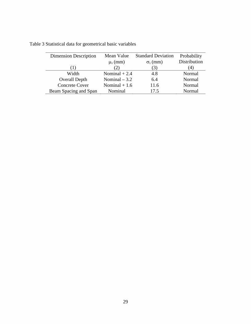
Table 3 Statistical data for geometrical basic variables
Dimension Description
(1)
Mean Value µi (mm)
(2)
Standard Deviation σi (mm)
(3)
Probability Distribution
(4) Width Nominal + 2.4 4.8 Normal
Overall Depth Nominal – 3.2 6.4 Normal Concrete Cover Nominal + 1.6 11.6 Normal
Beam Spacing and Span Nominal 17.5 Normal

30
Table 4 Statistical data for loading
Load Description
(1)
Coefficient of variation covi
(2)
Characteristic ik
(3)
Probability Distribution
(4) Permanent Load G 0.05 µG + 0.082 Normal Variable Load Q 0.4 µQ
. 1.98 Gamma

31
Table 5 Statistical data for CFRP and GFRP reinforcement
Tensile Strength (N/mm2)
Young’s Modulus (N/mm2)
(1)
CFRP (2)
GFRP (3)
CFRP (4)
GFRP (5)
Mean µi 1380 810 115000 45000 Standard Deviation σi 69 40.5 5750 2250
Coefficient of Variation covi 0.05 0.05 0.05 0.05 Minimum imin 1235.1 725 105800 41400 Maximum imax 1524.9 895.1 124200 48600
Characteristic ik 1272.2 746.7 106012.8 41483.3 Probability Distribution Normal Normal Normal Normal
32
Figure 1 Strain distribution for a GFRP RC section

33
Figure 2 Deflection and cracking in FRP RC beams
34
DATA INPUTDATA INPUT
Calculation of the flexural design load.Failure occurs either due to concrete crushing
or reinforcement fracture
Calculation of the flexural design load.Failure occurs either due to concrete crushing
or reinforcement fracture
Determination of the characteristicvariable and permanent load
Determination of the characteristicvariable and permanent load
Determination of the mean value andstandard deviation
for the variable and permanent load
Determination of the mean value andstandard deviation
for the variable and permanent load
Generation of pseudo-random valuesfor all basic variables by using
the Latin Hypercube variance reduction technique
Generation of pseudo-random valuesfor all basic variables by using
the Latin Hypercube variance reduction technique
Evaluation of flexural RiEvaluation of flexural Ri
Calculation of flexural Pfby using the
Conditional Expectationvariance reduction technique
Calculation of flexural Pfby using the
Conditional Expectationvariance reduction technique
Determination of PfcDetermination of Pfc
Figure 3. Assessment procedure

35
Figure 4. Actual tensile strain developed in the CFPR reinforcement at the design stage

36
Figure 5. Actual tensile strain developed in the GFPR reinforcement at the design stage
37
Figure 6. Effect of γFRP on the flexural Pf of CFRP RC beams

38
Figure 7. Effect of γFRP on the flexural Pf of GFRP RC beams
39
EC1 Annual Target Level
11 E-14
11 E-12
11 E-10
11 E-08
11 E-06
11 E-04
25 30 35 40 45 50 55 60 Mean Concrete Cylinder Compressive Strength, N/mm2
ρ = 0.75% −0.5ρ = 1.25% −0.5ρ = 1.75% −0.5ρ = 2.5% −0.5Σεριεσ8
ρ = 0.75% − 1
ρ = 1.25% − 1
ρ = 1.75% − 1
ρ = 2.5% − 1
Flex
ural
Not
iona
l Str
uctu
ral R
elia
bilit
y Le
vels
10
10
10
10
10
10
Figure 8. Effect of fc, ρ and load ratio on the flexural Pf (CFRP RC beams – γFRP = 1.8)
40
EC1 Annual Target Level = 10-06
11 E-22
11 E-20
11 E-18
11 E-16
11 E-14
11 E-12
11 E-10
11 E-08
11 E-06
25 30 35 40 45 50 55 60 Mean Concrete Cylinder Compressive Strength, N/mm2
ρ = 0.75% −0.5ρ = 1.25% −0.5ρ = 1.75% −0.5ρ = 2.5% −0.5Σεριεσ14
ρ = 0.75% − 1
ρ = 1.25% − 1
ρ = 1.75% − 1
ρ = 2.5%
Flex
ural
Not
iona
l Str
uctu
ral R
elia
bilit
y Le
vels
10
10
10
10
10
10
10
10
10
Figure 9. Effect of fc, ρ and load ratio on the flexural Pf (GFRP RC beams – γFRP = 3.6)
41
0%
1%
2%
3%
4%
0 50 100 150 200 250 300 350Resistance-Capacity
Applied LoadBondShearFlexure
Rel
ativ
e Fr
eque
ncy
Figure 10 Concept of failure mode hierarchy

42
d
x 0.8 x N.A.
z
FCd
0.85fck/γc
εs FSd
εc
Strain Diagram
Cross-section
Stress Block
Equivalent Stress Block
b
As
Figure A.1 Simplified stress block used by Eurocode 2
43
List of Captions
Table 1 Partial safety factors proposed by JSCE (1997)
Table 2 Partial safety factors proposed for FRP RC structures by Clarke et al (1996)
Table 3 Statistical data for geometrical basic variables
Table 4 Statistical data for loading
Table 5 Statistical data for CFRP and GFRP reinforcement
Figure 1 Strain distribution for a GFRP RC section
Figure 2 Deflection and cracking in FRP RC beams
Figure 3. Assessment procedure
Figure 4. Actual tensile strain developed in the CFPR reinforcement at the design stage
Figure 5. Actual tensile strain developed in the GFPR reinforcement at the design stage
Figure 6. Effect of γFRP on the flexural Pf of CFRP RC beams
Figure 7. Effect of γFRP on the flexural Pf of GFRP RC beams
Figure 8. Effect of fc, ρ and load ratio on the flexural Pf (CFRP RC beams – γFRP = 1.8)
Figure 9. Effect of fc, ρ and load ratio on the flexural Pf (GFRP RC beams – γFRP = 3.6)
Figure 10 Concept of failure mode hierarchy
Figure A.1 Simplified stress block used by Eurocode 2
Top Related
Copyright © 2022 FDOKUMEN

