


Bahasa
Halaman
Hukum


COURSE MATERIAL III Year B. Tech I- Semester
MECHANICAL ENGINEERING
MALLA REDDY COLLEGE OF ENGINEERING & TECHNOLOGY
DEPARTMENT OF MECHANICAL ENGINEERING
(Autonomous Institution-UGC, Govt. of India) Secunderabad-500100, Telangana State, India.
www.mrcet.ac.in
COMPUTER INTEGRATED MANUFUCTING TECHNOLOGIES
R18A0312

MALLA REDDY COLLEGE OF ENGINEERING & TECHNOLOGY (Autonomous Institution – UGC, Govt. of India)
DEPARTMENT OF MECHANICAL ENGINEERING
CONTENTS
1. Vision, Mission & Quality Policy
2. Pos, PSOs & PEOs
3. Blooms Taxonomy
4. Course Syllabus
5. Lecture Notes (Unit wise)
a. Objectives and outcomes
b. Notes
c. Presentation Material (PPT Slides/ Videos)
d. Industry applications relevant to the concepts covered
e. Question Bank for Assignments
f. Tutorial Questions
6. Previous Question Papers
www.mrcet.ac.in

MALLA REDDY COLLEGE OF ENGINEERING & TECHNOLOGY (Autonomous Institution – UGC, Govt. of India)
VISION
To establish a pedestal for the integral innovation, team spirit, originality and
competence in the students, expose them to face the global challenges and become
technology leaders of Indian vision of modern society.
MISSION
To become a model institution in the fields of Engineering, Technology and
Management.
To impart holistic education to the students to render them as industry ready
engineers.
To ensure synchronization of MRCET ideologies with challenging demands of
International Pioneering Organizations.
QUALITY POLICY
To implement best practices in Teaching and Learning process for both UG and PG
courses meticulously.
To provide state of art infrastructure and expertise to impart quality education.
To groom the students to become intellectually creative and professionally
competitive.
To channelize the activities and tune them in heights of commitment and sincerity,
the requisites to claim the never - ending ladder of SUCCESS year after year.
For more information: www.mrcet.ac.in

MALLA REDDY COLLEGE OF ENGINEERING & TECHNOLOGY (Autonomous Institution – UGC, Govt. of India)
www.mrcet.ac.in Department of Mechanical Engineering
VISION
To become an innovative knowledge center in mechanical engineering through state-of-
the-art teaching-learning and research practices, promoting creative thinking
professionals.
MISSION
The Department of Mechanical Engineering is dedicated for transforming the students
into highly competent Mechanical engineers to meet the needs of the industry, in a
changing and challenging technical environment, by strongly focusing in the
fundamentals of engineering sciences for achieving excellent results in their professional
pursuits.
Quality Policy
To pursuit global Standards of excellence in all our endeavors namely teaching,
research and continuing education and to remain accountable in our core and
support functions, through processes of self-evaluation and continuous
improvement.
To create a midst of excellence for imparting state of art education, industry-
oriented training research in the field of technical education.

MALLA REDDY COLLEGE OF ENGINEERING & TECHNOLOGY (Autonomous Institution – UGC, Govt. of India)
www.mrcet.ac.in Department of Mechanical Engineering
PROGRAM OUTCOMES
Engineering Graduates will be able to:
1. Engineering knowledge: Apply the knowledge of mathematics, science, engineering
fundamentals, and an engineering specialization to the solution of complex engineering
problems.
2. Problem analysis: Identify, formulate, review research literature, and analyze complex
engineering problems reaching substantiated conclusions using first principles of
mathematics, natural sciences, and engineering sciences.
3. Design/development of solutions: Design solutions for complex engineering problems
and design system components or processes that meet the specified needs with
appropriate consideration for the public health and safety, and the cultural, societal, and
environmental considerations.
4. Conduct investigations of complex problems: Use research-based knowledge and
research methods including design of experiments, analysis and interpretation of data,
and synthesis of the information to provide valid conclusions.
5. Modern tool usage: Create, select, and apply appropriate techniques, resources, and
modern engineering and IT tools including prediction and modeling to complex
engineering activities with an understanding of the limitations.
6. The engineer and society: Apply reasoning informed by the contextual knowledge to
assess societal, health, safety, legal and cultural issues and the consequent
responsibilities relevant to the professional engineering practice.
7. Environment and sustainability: Understand the impact of the professional engineering
solutions in societal and environmental contexts, and demonstrate the knowledge of, and
need for sustainable development.
8. Ethics: Apply ethical principles and commit to professional ethics and responsibilities and
norms of the engineering practice.
9. Individual and teamwork: Function effectively as an individual, and as a member or
leader in diverse teams, and in multidisciplinary settings.
10. Communication: Communicate effectively on complex engineering activities with the
engineering community and with society at large, such as, being able to comprehend and
write effective reports and design documentation, make effective presentations, and give
and receive clear instructions.
11. Project management and finance: Demonstrate knowledge and understanding of the
engineering and management principles and apply these to one’s own work, as a member
and leader in a team, to manage projects and in multidisciplinary environments.
MALLA REDDY COLLEGE OF ENGINEERING & TECHNOLOGY (Autonomous Institution – UGC, Govt. of India)
www.mrcet.ac.in Department of Mechanical Engineering
12. Life-long learning: Recognize the need for and have the preparation and ability to
engage in independent and life-long learning in the broadest context of technological
change.
PROGRAM SPECIFIC OUTCOMES (PSOs)
PSO1 Ability to analyze, design and develop Mechanical systems to solve the
Engineering problems by integrating thermal, design and manufacturing Domains.
PSO2 Ability to succeed in competitive examinations or to pursue higher studies or
research.
PSO3 Ability to apply the learned Mechanical Engineering knowledge for the
Development of society and self.
Program Educational Objectives (PEOs)
The Program Educational Objectives of the program offered by the department are broadly
listed below:
PEO1: PREPARATION
To provide sound foundation in mathematical, scientific and engineering fundamentals
necessary to analyze, formulate and solve engineering problems.
PEO2: CORE COMPETANCE
To provide thorough knowledge in Mechanical Engineering subjects including theoretical
knowledge and practical training for preparing physical models pertaining to Thermodynamics,
Hydraulics, Heat and Mass Transfer, Dynamics of Machinery, Jet Propulsion, Automobile
Engineering, Element Analysis, Production Technology, Mechatronics etc.
PEO3: INVENTION, INNOVATION AND CREATIVITY
To make the students to design, experiment, analyze, interpret in the core field with the help of
other inter disciplinary concepts wherever applicable.
PEO4: CAREER DEVELOPMENT
To inculcate the habit of lifelong learning for career development through successful completion
of advanced degrees, professional development courses, industrial training etc.

MALLA REDDY COLLEGE OF ENGINEERING & TECHNOLOGY (Autonomous Institution – UGC, Govt. of India)
www.mrcet.ac.in Department of Mechanical Engineering
PEO5: PROFESSIONALISM
To impart technical knowledge, ethical values for professional development of the student to
solve complex problems and to work in multi-disciplinary ambience, whose solutions lead to
significant societal benefits.

MALLA REDDY COLLEGE OF ENGINEERING & TECHNOLOGY (Autonomous Institution – UGC, Govt. of India)
www.mrcet.ac.in Department of Mechanical Engineering
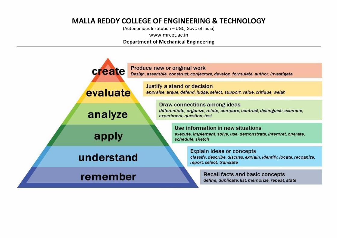
Blooms Taxonomy
Bloom’s Taxonomy is a classification of the different objectives and skills that educators set for
their students (learning objectives). The terminology has been updated to include the following
six levels of learning. These 6 levels can be used to structure the learning objectives, lessons,
and assessments of a course.
1. Remembering: Retrieving, recognizing, and recalling relevant knowledge from long‐ term
memory.
2. Understanding: Constructing meaning from oral, written, and graphic messages through
interpreting, exemplifying, classifying, summarizing, inferring, comparing, and explaining.
3. Applying: Carrying out or using a procedure for executing or implementing.
4. Analyzing: Breaking material into constituent parts, determining how the parts relate to
one another and to an overall structure or purpose through differentiating, organizing, and
attributing.
5. Evaluating: Making judgments based on criteria and standard through checking and
critiquing.
6. Creating: Putting elements together to form a coherent or functional whole; reorganizing
elements into a new pattern or structure through generating, planning, or producing.
MALLA REDDY COLLEGE OF ENGINEERING & TECHNOLOGY (Autonomous Institution – UGC, Govt. of India)
www.mrcet.ac.in Department of Mechanical Engineering

MALLA REDDY COLLEGE OF ENGINEERING &TECHNOLOGY
III Year B. Tech, ME-I Sem
(R18A0312) COMPUTER INTEGRATED MANUFACTURING
TECHNOLOGIES
Course Objectives:
1. Learn about the geometry of metal cutting theory, mechanism of chip formation and
mechanics of orthogonal cutting and merchant’s force diagram.
2. Gain the knowledge and features, working principles and applications of lathe, shaper,
planer, slotter, milling, drilling, and machines.
3. Learn about the ways to reduce the surface roughness by using different Machining
processes.
4. To understand computer aided planning and control and computer monitoring.
5. To understand APT and CNC programming concepts.
6. To know about tooling for CNC machines.
UNIT – I
Metal cutting theory: Elements of cutting process – Geometry of single point tool and angles, chip
formation and types of chips, built up edge and its effects- chip breakers. Mechanics of orthogonal
cutting,cutting forces – cutting speeds, feed, depth of cut, tool life, coolants, machinability. Lathe
Machine: Principle of working, specification of lathe and types of lathes, operations of lathe and
work holding and tool holding devices
UNIT - II
Shaping, slotting and planning machines:-Principles of working – classifications, operations
performed, machining time calculations.Drilling and Boring Machines – Principles of working,
specifications, types, operations performed – tool holding devices – twist drill – Boring machines –
Fine boring machines – Jig Boring machine. Deep hole drilling machine.
UNIT - III
Computer-Aided Programming: General information, APT programming, Examples Apt
programming problems (2D machining only). NC programming on CAD/CAM systems, Introduction
to CAD/CAM software, Automatic Tool Path generation. Tooling for CNC Machines:
Interchangeable tooling system, preset and qualified tools, coolant fed tooling system, modular
featuring, quick change tooling system, automatic head changers.
UNIT – IV
DNC Systems and Adaptive Control: Introduction, type of DNC systems, advantages and
disadvantages of DNC, adaptive control with optimization, Adaptive control with constrains,
Adaptive control of machining processes like turning, grinding. Post Processors for CNC:
Introduction to Post Processors: The necessity of a Post Processor, the general structure of a Post
Processor, the functions of a Post Processor.
UNIT - V
Computer Aided Process Planning: Hybrid CAAP System, Computer Aided Inspection and quality
control, Coordinate Measuring Machine, Limitations of CMM, Computer Aided Testing, Optical
Inspection Methods, Artificial Intelligence and expert system: Artificial Neural Networks, Artificial
Intelligence in CAD, Experts systems and its structures.
L T/P/
D
C
3 0 3

TEXT BOOKS
1. Computer Control of Manufacturing Systems / YoramKoren / McGraw Hill. 1983.
2. CAD/CAM Principles and Applications, P.N.Rao, TMH
3. Manufacturing Technology by P.N.Rao, Volume II, McGraw Hill
4. Production Technology by R.K. Jain and S.C. Gupta, Khanna Publications
REFERENCES
1. CAD / CAM / CIM, Radhakrishnan and Subramanian, New Age
2. Principles of Computer Aided Design and Manufacturing, FaridAmirouche, Pearson
3. Computer Numerical Control Concepts and programming, Warren S Seames, Thomson.
4. Machine Tools – C Elanchezhian and M. Vijayan, Anuradha Publications
5. Workshop Technology – B.S.Raghu Vamshi – Vol II, Dhanpatrai publications
Course Outcomes: 1. Students should be able to understand the function of micro controllers and PLCs.
2. Apply Computer aided process planning, MRP and CNC part programming.
3. Understand the fundamentals of metal cutting, chip formation, cutting forces involved in
orthogonal metal cutting, and different cutting forces will be learned.
4. Analyze the classification of lathe, shaper, planer, slotter, milling, drilling, and
machines.
5. Evaluate the surface finishing operations with abrasive processes such as Grinding and
broaching machines, types and working principle.

UNIT 1
METAL CUTTING THEORY

COURSE OBJECTIVE Learn about the geometry of metal cutting theory, mechanism of chip formation and mechanics of
orthogonal cutting and merchant’s force diagram
COURSE OUTCOME Students should be able to understand the function of micro controllers and PLCs.
UNIT I (SYLLABUS) Metal cutting theory: Elements of cutting process – Geometry of single point tool and angles, chip
formation and types of chips, built up edge and its effects- chip breakers. Mechanics of orthogonal
cutting,cutting forces – cutting speeds, feed, depth of cut, tool life, coolants, machinability. Lathe Machine:
Principle of working, specification of lathe and types of lathes, operations of lathe and work holding and
tool holding devices
Objectives of the unit
Understanding of
CUTTING PROCESS
ORTHOGONAL CUTTING
LATHE MACHINE

Metal Cutting Theory INTRODUCTION- In an industry, metal components are made into different shapes and dimensions using
various metal working processes. Metal working processes are classified into two major groups. They are: Non-cutting shaping or chips less or metal forming process - forging, rolling, pressing, etc. Cutting shaping or metal cutting or chip forming process - turning, drilling, milling, etc
Machining: Term applied to all material-removal processes. Metal cutting: The process in which a thin layer of
excess metal (chip) is removed by a wedge-shaped single-point or multipoint cutting tool with defined geometry
from a work piece, through a process of extensive plastic deformation.
• Machining is an essential process of finishing by which work pieces are produced to the desired
dimensions and surface finish by gradually removing the excess material from the preformed blank in the
form of chips with the help of cutting tool(s) moved past the work surface(s).
• Principle of machining - the fig illustrates A metal rod of irregular shape, size and surface is converted
into a finished product of desired dimension and surface finish by machining by proper relative motions of
the tool-work pair.
Metal Cutting: features
• Closer dimensional accuracy
• Surface texture/finish
• Economical
• Complex shape
• Size
• Material loss (~50%)
• Scarcity of materials
• Special equipment
• Skilled operators
• Time required
• All materials cannot be machined
Essentials of Metal Cutting Operation
• Machine Tool
• Cutting Tool
• Method
• Operator
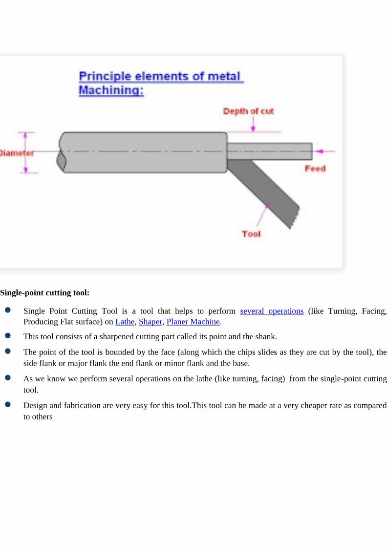
ELEMENTS OF CUTTING PROCESS Principle Elements of Metal Machining:
1: Cutting Speed:
The cutting speed can be defined as the relative surface speed between the tool and the job. It is a relative term
since either the tool or the job or both may be moving during cutting. It is expressed in m/min.
2: Feed:
It may be defined as the relatively small the cutting tool relative to the work piece in a direction which is usually
perpendicular to the cutting speed direction. It is expressed in mm/rev or mm/stroke.
It is more complex element as compare to the cutting speed. It is expressed differently for various operations.
3:Depth of cut:
The depth of cut is the thickness of the layer of the metal remove in one cut or pass measured in a direction
perpendicular to the machine surface. The depth of cut is always perpendicular to the direction feed motion.
Single-point cutting tool:
● Single Point Cutting Tool is a tool that helps to perform several operations (like Turning, Facing,
Producing Flat surface) on Lathe, Shaper, Planer Machine.
● This tool consists of a sharpened cutting part called its point and the shank.
● The point of the tool is bounded by the face (along which the chips slides as they are cut by the tool), the
side flank or major flank the end flank or minor flank and the base.
● As we know we perform several operations on the lathe (like turning, facing) from the single-point cutting
tool.
● Design and fabrication are very easy for this tool.This tool can be made at a very cheaper rate as compared
to others
Single Point Cutting Tool Types
There are only two types of tool:
1. Single and
2. Multi-Point cutting tool.
1. Single Point cutting tool:
● One cutting point or tip is available
● Example: Lathe Machine, Planning Machine tool
2. Multi-Point cutting tool:
● More than One cutting point or tip is available
● Example: Milling cutter, Grinding wheel, drill tool, extra.
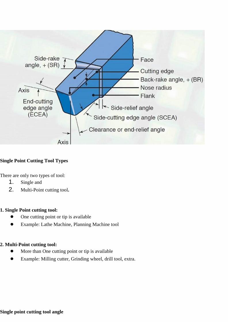
Single point cutting tool angle
Angle:
1. Side Cutting edge angle
2. End cutting edge angle
3. Side relief angle
4. End relief angle
5. Back Rack angle
6. Side rack angle
CHIP FORMATION
Mechanism of chip formation
Machining is a semi-finishing or finishing process essentially done to impart required or stipulated
dimensional and form accuracy and surface finish to enable the product to:
1. Fulfill its basic functional requirements.
2. Provide better or improved performance.
3. Render long service life
Machining is a process of gradual removal of excess material from the preformed blanks in the form of
chips
The form of the chips is an important index of machining because it directly or indirectly indicates:
❖ Nature and behavior of the work material under machining condition.
❖ Specific energy requirement (amount of energy required to remove unit volume of work material) in
machining work.
❖ Nature and degree of interaction at the chip-tool interfaces
The form of machined chips depends mainly upon:
1. Work material.
2. Material and geometry of the cutting tool.
3. Levels of cutting velocity and feed and also to some extent on depth of cut.
4. Machining environment or cutting fluid that affects temperature and friction at the chip-tool and work-tool
interfaces.
• Knowledge of basic mechanism(s) of chip formation helps to understand the characteristics of chips and to
attain favorable chip forms.
Mechanism of chip formation in machining ductile materials
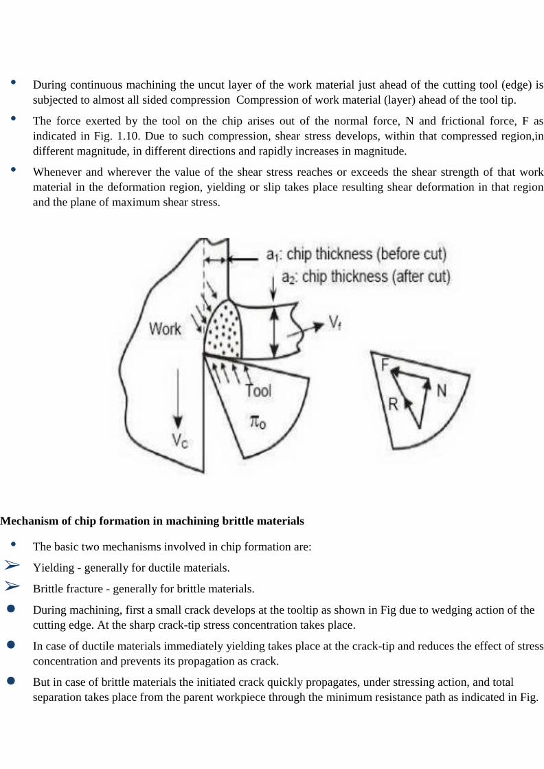
• During continuous machining the uncut layer of the work material just ahead of the cutting tool (edge) is
subjected to almost all sided compression Compression of work material (layer) ahead of the tool tip.
• The force exerted by the tool on the chip arises out of the normal force, N and frictional force, F as
indicated in Fig. 1.10. Due to such compression, shear stress develops, within that compressed region,in
different magnitude, in different directions and rapidly increases in magnitude.
• Whenever and wherever the value of the shear stress reaches or exceeds the shear strength of that work
material in the deformation region, yielding or slip takes place resulting shear deformation in that region
and the plane of maximum shear stress.
Mechanism of chip formation in machining brittle materials
• The basic two mechanisms involved in chip formation are:
➢ Yielding - generally for ductile materials.
➢ Brittle fracture - generally for brittle materials.
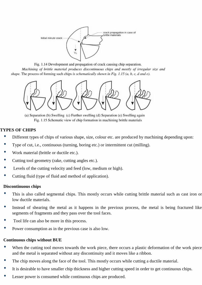
● During machining, first a small crack develops at the tooltip as shown in Fig due to wedging action of the
cutting edge. At the sharp crack-tip stress concentration takes place.
● In case of ductile materials immediately yielding takes place at the crack-tip and reduces the effect of stress
concentration and prevents its propagation as crack.
● But in case of brittle materials the initiated crack quickly propagates, under stressing action, and total
separation takes place from the parent workpiece through the minimum resistance path as indicated in Fig.
TYPES OF CHIPS
• Different types of chips of various shape, size, colour etc. are produced by machining depending upon:
• Type of cut, i.e., continuous (turning, boring etc.) or intermittent cut (milling).
• Work material (brittle or ductile etc.).
• Cutting tool geometry (rake, cutting angles etc.).
• Levels of the cutting velocity and feed (low, medium or high).
• Cutting fluid (type of fluid and method of application).
Discontinuous chips
• This is also called segmental chips. This mostly occurs while cutting brittle material such as cast iron or
low ductile materials.
• Instead of shearing the metal as it happens in the previous process, the metal is being fractured like
segments of fragments and they pass over the tool faces.
• Tool life can also be more in this process.
• Power consumption as in the previous case is also low.
Continuous chips without BUE
• When the cutting tool moves towards the work piece, there occurs a plastic deformation of the work piece
and the metal is separated without any discontinuity and it moves like a ribbon.
• The chip moves along the face of the tool. This mostly occurs while cutting a ductile material.
• It is desirable to have smaller chip thickness and higher cutting speed in order to get continuous chips.
• Lesser power is consumed while continuous chips are produced.
• Total life is also mortised in this process.
Orthogonal Cutting
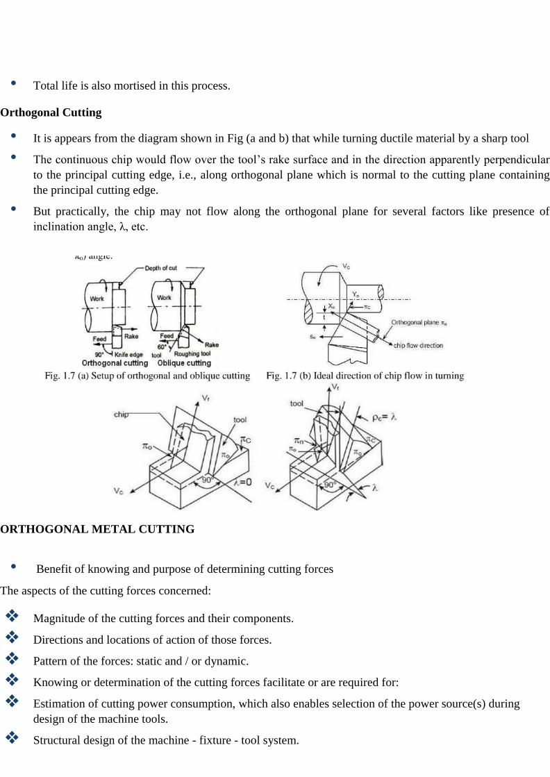
• It is appears from the diagram shown in Fig (a and b) that while turning ductile material by a sharp tool
• The continuous chip would flow over the tool’s rake surface and in the direction apparently perpendicular
to the principal cutting edge, i.e., along orthogonal plane which is normal to the cutting plane containing
the principal cutting edge.
• But practically, the chip may not flow along the orthogonal plane for several factors like presence of
inclination angle, λ, etc.
ORTHOGONAL METAL CUTTING
• Benefit of knowing and purpose of determining cutting forces
The aspects of the cutting forces concerned:
❖ Magnitude of the cutting forces and their components.
❖ Directions and locations of action of those forces.
❖ Pattern of the forces: static and / or dynamic.
❖ Knowing or determination of the cutting forces facilitate or are required for:
❖ Estimation of cutting power consumption, which also enables selection of the power source(s) during
design of the machine tools.
❖ Structural design of the machine - fixture - tool system.
.
Cutting force components and their significances
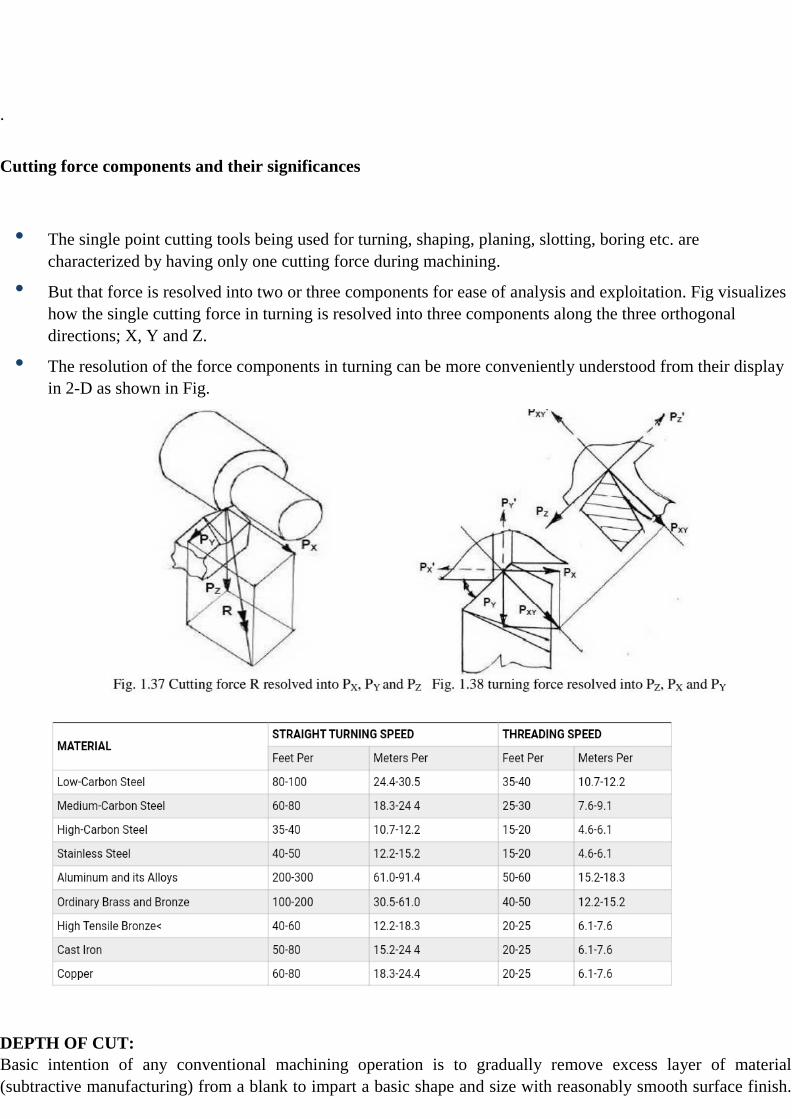
• The single point cutting tools being used for turning, shaping, planing, slotting, boring etc. are
characterized by having only one cutting force during machining.
• But that force is resolved into two or three components for ease of analysis and exploitation. Fig visualizes
how the single cutting force in turning is resolved into three components along the three orthogonal
directions; X, Y and Z.
• The resolution of the force components in turning can be more conveniently understood from their display
in 2-D as shown in Fig.
DEPTH OF CUT:
Basic intention of any conventional machining operation is to gradually remove excess layer of material
(subtractive manufacturing) from a blank to impart a basic shape and size with reasonably smooth surface finish.
For any machining or material removal operation, three relative motions between workpiece and cutting tool are
indispensably necessary, which, in fact, are the primary cutting parameters. The simultaneous action of all three
parameters causes material removal in the form of chip from the workpiece. These three cutting parameters or
relative motions are provided below.
1. Cutting velocity (Vc)—The most important cutting parameter that provides necessary cutting motion. It can be
imparted either on the cutting tool or on workpiece by either rotating it or reciprocating it. In case of either
rotating tool (such as milling, drilling, grinding) or rotating workpiece (such as turning), the peripheral velocity of
cutter or workpiece is considered as the cutting velocity. However, where neither the workpiece nor the tool
rotates, the translation velocity of cutter or workpiece gives the intended cutting velocity.
2. Feed rate (s)—The auxiliary cutting motion is provided by the feed velocity. Usually the direction of feed
velocity is perpendicular to that of the cutting velocity. The primary objective of feed velocity is to remove
material from a large surface. Basically it helps in covering the entire surface of the workpiece by moving either
cutting tool or workpiece.
3. Depth of cut (t)—The tertiary cutting motion that provides necessary depth of material that is required to
remove by machining. It is expressed in mm. It is usually given in the third perpendicular direction (velocity, feed
and depth of cut usually act in mutually perpendicular directions).

Effects of depth of cut (DOC)
Since depth of cut is one of the three main cutting parameters, so its value also affects overall machining
performance and machining economy. Few common effects of DOC are enlisted below; for all effects in detail
read: Effects of depth of cut on machining performance.
● Larger depth of cut indicates higher material removal rate (MRR), as MRR is proportional to the speed,
feed and depth of cut. So productivity of machining can be enhanced by employing larger depth of cut and
consequently machining cost can be reduced.
● Cutting force depends on chip load, which is proportional to depth of cut. Thus larger value of depth of cut
can increase cutting force, which may hamper machining performance and induce vibration.
● Higher depth of cut may also break the cutting tool catastrophically, which is highly undesirable.
● It also influences chip thickness, type of chip produces, shear deformation, etc., which are indication of
machinability.
Selection and value of depth of cut
Since depth of cut value is an important parameter that influences overall machining performance as well as
economy, so an optimum value must be selected judiciously after considering a number of relevant factors.
Usually, in conventional machining operations, depth of cut value varies between 0.1 – 1.0mm. Selection of its
value requires attention on the following characteristics.

● Productivity requirement—Since material removal rate is expressed by the multiplication of cutting
velocity, feed rate and depth of cut, so usage of larger depth of cut results in enhanced MRR. This, in turn,
cuts down machining time and thus improves productivity.
● Quality of cut required—For finish cut, lower depth of cut should be provided; whereas, for rough cut,
larger value can be utilized to shorten machining time.
● Machining operation—Various machining operations have the capability to handle various ranges of depth
of cut. For example, milling operation using a side and face milling cutter can handle a larger depth of cut;
while, its value is limited in knurling operation.
● Workpiece material strength—For machining hard and brittle materials, a lower value of depth of cut is
recommended, otherwise the force may be very high and cutting tool may break.
● Capability of machine tool—Since depth of cut increases cutting force and vibration, so the capability of
machine tool should also be considered.
Coolants
The critical functions of coolant in the machining process include:
● Reducing and removing the heat build-up in the cutting zone and workpiece
● Provides lubrication to reduce friction between the tool and removal of the chips
● Flushes away chips and small abrasive particles from the work area
● Protects against corrosion
The type of machining and materials machined determine the type of coolant to use as well as what the balance of
cooling and lubrication is needed. By altering the mixing ratio or concentration of the coolant, you get a different
balance of cooling and lubrication. A leaner mix provides you better cooling while a more concentrated blend
gives you more lubrication.
Types of Coolants
Coolants are grouped into four main categories and have a variety of different formulations. Selecting coolant
should be based on the overall performance it provides centered around your machining application and materials
used.
Soluble Oils: The most common of all water-soluble cutting fluids and a great option for general purpose
machining. The drawback is that they are prone to microbiological growth of fungus and bacteria if the coolant
sump is not correctly maintained.
Synthetic Fluids: These types of fluids tend to be the cleanest of all cutting fluids because they contain no mineral
oil and reject tramp oil. However, they provide the least lubrication.
Semi-synthetic Fluids: Considered to be the best of both worlds, they have less oil than emulsion-based fluids, a
less stinky smell, and retain much of the same lubricating attributes. This makes them usable for a broader range

of machining.
Straight Oils: These are not water-miscible and have a composition of a mineral or petroleum oil base and contain
lubricants like vegetable oils, fats, and esters. They provide the best lubrication but have the poorest cooling
characteristics.
How Machine Coolant Systems Work
During the machining process, the coolant mixture floods over the work area. This process also washes chips and
particles away from the work area. Coolant collects in a sump at the bottom of the machine. The coolant is
pumped out of the sump and recirculated to the work area.
Both central and single machine coolant systems need to be monitored, maintained, and adjusted. Unfortunately,
small coolant systems tend to use less effective equipment for filtration and oil separation in comparison to central
systems. Small systems are also susceptible to more rapid changes and greater fluctuations in concretion levels.
Therefore, the coolant used in small systems needs to be more tolerant of contamination from metal shavings,
tramp oils, and other materials. Not only does the coolant type play a role in extending the life of your coolant,
but proper coolant management becomes even more critical.
Coolant Concentration
If appropriate concentration levels of coolant are not maintained, several issues can occur. The most common
problem is low concentration. If the concentration of coolant is below the machine coolant supplier’s minimum
ratio, there is a risk of:
● Machine and workpiece corrosion
● Reduction in tool life
● Bacterial growth
On the other hand, if the concentration of coolant is too high, this results in:
● Lesser heat transfer
● Foaming
● Reduced lubrication
● Wasted concentrate
● Formation of residue that shortens tool life
● Staining of machine and machined parts
● Toxicity (skin irritation)
At the start of each day, the coolant should be checked to maintain an acceptable concentration level. Hand
refractometers are a great way to check cutting and grinding fluid concentrations to maintain daily control of
concentration levels. Machine coolant concentrations can change 5% to 20% every day from evaporation,
splashing, misting, and dragout. Keeping a daily log of concentration levels for each machine provides an

understanding of how the system is functioning and how much concentration levels change from day-to-day.
By selecting the right coolant for the type of machine and metals being machined, and by maintaining the
concentration levels, you extend the life of the coolant, the tools, and your machine.
MACHINABILITY
The condition and physical properties of the work material have a direct influence on the machinability of a work
material. The various conditions and characteristics described as "condition of work material," individually and in
combinations, directly influence and determine the machinability. Operating conditions, tool material and
geometry and workpiece requirements exercise indirect effects on machinability and can often be used to
overcome difficult conditions presented by the work material. On the other hand, they can create situations that
increase machining difficulty if they are ignored.
Condition of Work Material
The following eight factors determine the condition of the work material: microstructure, grain size, heat
treatment, chemical composition, fabrication, hardness, yield strength and tensile strength.
Microstructure: The microstructure of a metal refers to its crystal or grain structure as shown through
examination of etched and polished surfaces under a microscope. Metals whose microstructures are similar have
like machining properties. But there can be variations in the microstructure of the same workpiece that will affect
machinability.
Grain Size: Grain size and structure of a metal serve as general indicators of its machinability. A metal with
small undistorted grains tends to cut easily and finish easily. Such a metal is ductile, but it is also "gummy."
Metals of an intermediate grain size represent a compromise that permits both cutting and finishing machinability.
Hardness of a metal must be correlated with grain size and it is generally used as an indicator of machinability.
Heat Treatment: To provide desired properties in metals, they are sometimes put through a series of heating and
cooling operations when in the solid state. A material may be treated to reduce brittleness, remove stress, to obtain
ductility or toughness, to increase strength, to obtain a definite microstructure, to change hardness or to make
other changes that affect machinability.
Chemical Composition: Chemical composition of a metal is a major factor in determining its machinability. The
effects of composition though, are not always clear, because the elements that make up an alloy metal, work both
singly and collectively. Certain generalizations about chemical composition of steels in relation to machinability
can be made, but nonferrous alloys are too numerous and varied to permit such generalizations.
Fabrication: Whether a metal has been hot rolled, cold rolled, cold drawn cast, or forged will affect its grain size,
ductility, strength, hardness, structure-and therefore-its machinability.
The term "wrought" refers to the hammering or forming of materials into premanfactured shapes which are
readily altered into components or products using traditional manufacturing techniques. Wrought metals are
defined as that group of materials, which are mechanically shaped into, bars, billets, rolls, sheets, plates or tubing.
Casting involves pouring molten metal into a mold to arrive at a near component shape that requires minimal, or
in some cases no machining. Molds for these operations are made from sand, plaster, metals and a variety of other
materials.
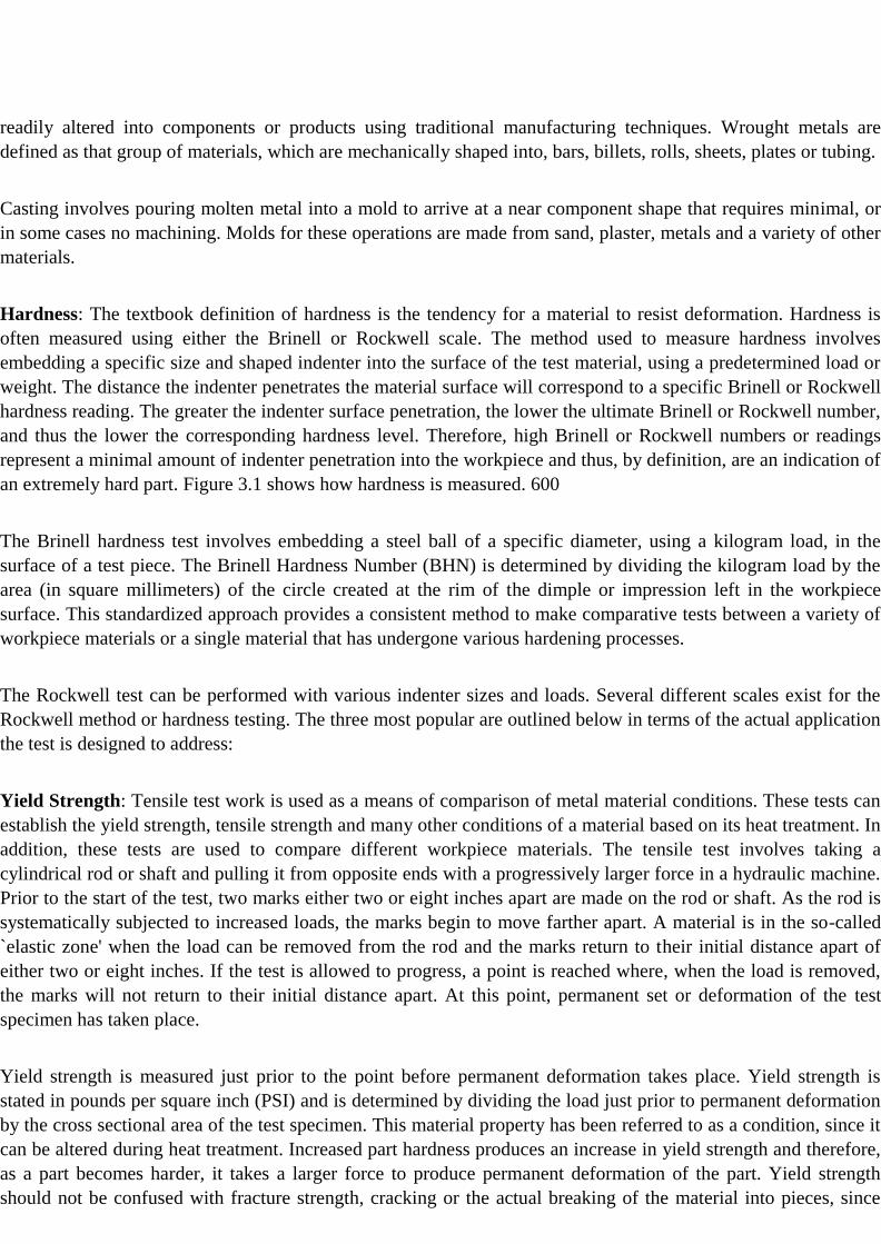
Hardness: The textbook definition of hardness is the tendency for a material to resist deformation. Hardness is
often measured using either the Brinell or Rockwell scale. The method used to measure hardness involves
embedding a specific size and shaped indenter into the surface of the test material, using a predetermined load or
weight. The distance the indenter penetrates the material surface will correspond to a specific Brinell or Rockwell
hardness reading. The greater the indenter surface penetration, the lower the ultimate Brinell or Rockwell number,
and thus the lower the corresponding hardness level. Therefore, high Brinell or Rockwell numbers or readings
represent a minimal amount of indenter penetration into the workpiece and thus, by definition, are an indication of
an extremely hard part. Figure 3.1 shows how hardness is measured. 600
The Brinell hardness test involves embedding a steel ball of a specific diameter, using a kilogram load, in the
surface of a test piece. The Brinell Hardness Number (BHN) is determined by dividing the kilogram load by the
area (in square millimeters) of the circle created at the rim of the dimple or impression left in the workpiece
surface. This standardized approach provides a consistent method to make comparative tests between a variety of
workpiece materials or a single material that has undergone various hardening processes.
The Rockwell test can be performed with various indenter sizes and loads. Several different scales exist for the
Rockwell method or hardness testing. The three most popular are outlined below in terms of the actual application
the test is designed to address:
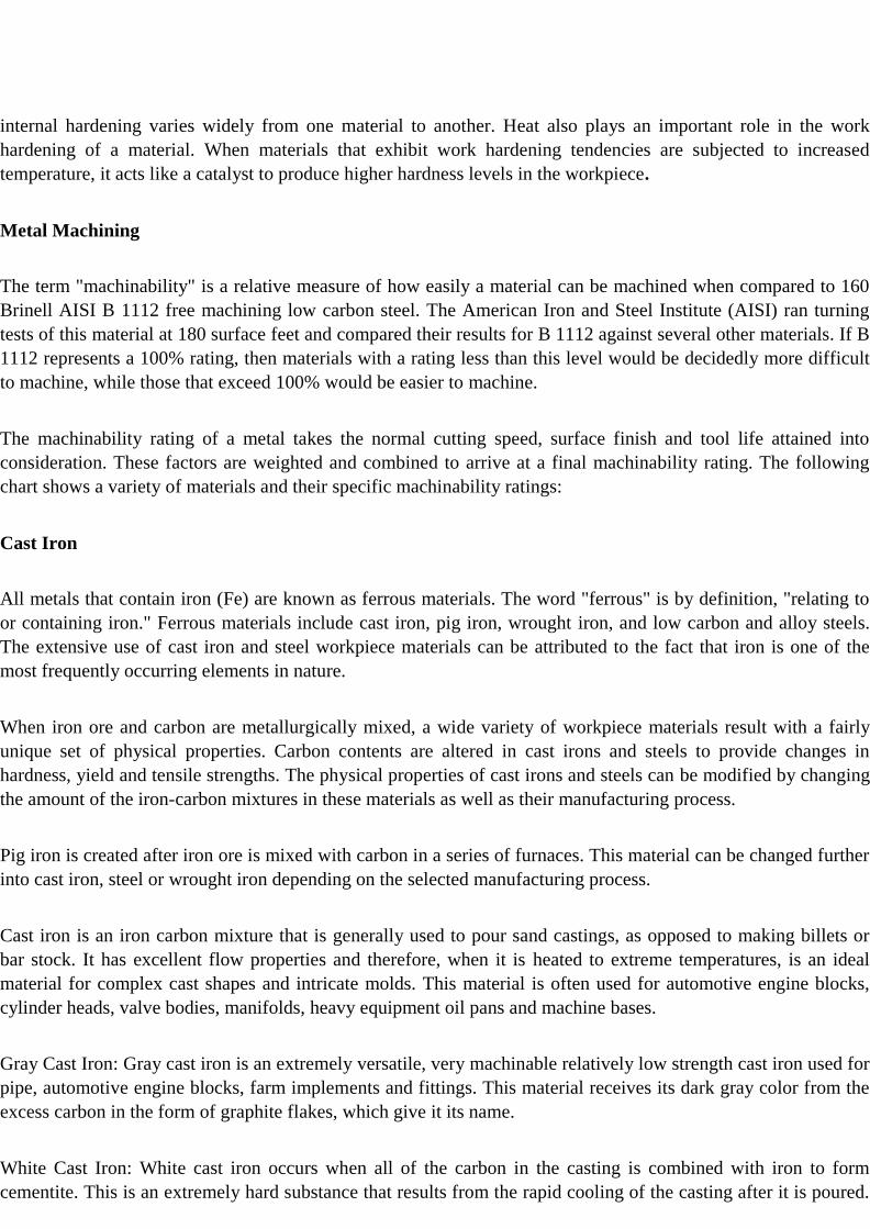
Yield Strength: Tensile test work is used as a means of comparison of metal material conditions. These tests can
establish the yield strength, tensile strength and many other conditions of a material based on its heat treatment. In
addition, these tests are used to compare different workpiece materials. The tensile test involves taking a
cylindrical rod or shaft and pulling it from opposite ends with a progressively larger force in a hydraulic machine.
Prior to the start of the test, two marks either two or eight inches apart are made on the rod or shaft. As the rod is
systematically subjected to increased loads, the marks begin to move farther apart. A material is in the so-called
`elastic zone' when the load can be removed from the rod and the marks return to their initial distance apart of
either two or eight inches. If the test is allowed to progress, a point is reached where, when the load is removed,
the marks will not return to their initial distance apart. At this point, permanent set or deformation of the test
specimen has taken place.
Yield strength is measured just prior to the point before permanent deformation takes place. Yield strength is
stated in pounds per square inch (PSI) and is determined by dividing the load just prior to permanent deformation
by the cross sectional area of the test specimen. This material property has been referred to as a condition, since it
can be altered during heat treatment. Increased part hardness produces an increase in yield strength and therefore,
as a part becomes harder, it takes a larger force to produce permanent deformation of the part. Yield strength
should not be confused with fracture strength, cracking or the actual breaking of the material into pieces, since

these properties are quite different and unrelated to the current subject.
Tensile Strength: The tensile strength of a material increases along with yield strength as it is heat treated to
greater hardness levels. This material condition is also established using a tensile test. Tensile strength (or
ultimate strength) is defined as the maximum load that results during the tensile test, divided by the cross-
sectional area of the test specimen. Therefore, tensile strength, like yield strength, is expressed in PSI. This value
is referred to as a material condition rather than a property, since its level just like yield strength and hardness, can
be altered by heat treatment. Therefore, based on the material selected, distinct tensile and yield strength levels
exist for each hardness reading.
Physical Properties of Work Materials
Physical properties will include those characteristics included in the individual material groups, such as the
modulus of elasticity, thermal conductivity, thermal expansion and work hardening.
Modulus of Elasticity: The modulus of elasticity can be determined during a tensile test in the same manner as
the previously mentioned conditions.
However, unlike hardness, yield or tensile strength, the modulus of elasticity is a fixed material property and,
therefore, is unaffected by heat treatment. This particular property is an indicator of the rate at which a material
will deflect when subjected to an external force. This property is stated in PSI and typical values are several
million PSI for metals.
Hardness is measured by depth of indentations made.
Thermal Conductivity: Materials are frequently labeled as being either heat conductors or insulators. Conductors
tend to transfer heat from a hot or cold object at a high rate, while insulators impede the flow of heat. Thermal
conductivity is a measure of how efficiently a material transfers heat. Therefore, a material that has a
relatively high thermal conductivity would be considered a conductor, while one with a relatively low level
would be regarded as an insulator.
Thermal Expansion: Many materials, especially metals, tend to increase in dimensional size as their
temperature rises. This physical property is referred to as thermal expansion. The rate at which metals
expand varies, depending on the type or alloy of material under consideration. The rate at which metal
expands can be determined using the material's expansion coefficient. The greater the value of this
coefficient, the more a material will expand when subjected to a temperature rise or contract when subjected
to a temperature reduction. For example, a 100- bar of steel which encounters a 100 F rise in temperature
would measure 100.065-.
Work Hardening: Many metals exhibit a physical characteristic that produces dramatic increases in hardness due
to cold work. Cold work involves changing the shape of a metal object by bending, shaping, rolling or forming.
As the metal is shaped, internal stresses develop which act to harden the part. The rate and magnitude of this
internal hardening varies widely from one material to another. Heat also plays an important role in the work
hardening of a material. When materials that exhibit work hardening tendencies are subjected to increased
temperature, it acts like a catalyst to produce higher hardness levels in the workpiece.
Metal Machining
The term "machinability" is a relative measure of how easily a material can be machined when compared to 160
Brinell AISI B 1112 free machining low carbon steel. The American Iron and Steel Institute (AISI) ran turning
tests of this material at 180 surface feet and compared their results for B 1112 against several other materials. If B
1112 represents a 100% rating, then materials with a rating less than this level would be decidedly more difficult
to machine, while those that exceed 100% would be easier to machine.
The machinability rating of a metal takes the normal cutting speed, surface finish and tool life attained into
consideration. These factors are weighted and combined to arrive at a final machinability rating. The following
chart shows a variety of materials and their specific machinability ratings:
Cast Iron
All metals that contain iron (Fe) are known as ferrous materials. The word "ferrous" is by definition, "relating to
or containing iron." Ferrous materials include cast iron, pig iron, wrought iron, and low carbon and alloy steels.
The extensive use of cast iron and steel workpiece materials can be attributed to the fact that iron is one of the
most frequently occurring elements in nature.
When iron ore and carbon are metallurgically mixed, a wide variety of workpiece materials result with a fairly
unique set of physical properties. Carbon contents are altered in cast irons and steels to provide changes in
hardness, yield and tensile strengths. The physical properties of cast irons and steels can be modified by changing
the amount of the iron-carbon mixtures in these materials as well as their manufacturing process.
Pig iron is created after iron ore is mixed with carbon in a series of furnaces. This material can be changed further
into cast iron, steel or wrought iron depending on the selected manufacturing process.
Cast iron is an iron carbon mixture that is generally used to pour sand castings, as opposed to making billets or
bar stock. It has excellent flow properties and therefore, when it is heated to extreme temperatures, is an ideal
material for complex cast shapes and intricate molds. This material is often used for automotive engine blocks,
cylinder heads, valve bodies, manifolds, heavy equipment oil pans and machine bases.
Gray Cast Iron: Gray cast iron is an extremely versatile, very machinable relatively low strength cast iron used for
pipe, automotive engine blocks, farm implements and fittings. This material receives its dark gray color from the
excess carbon in the form of graphite flakes, which give it its name.
White Cast Iron: White cast iron occurs when all of the carbon in the casting is combined with iron to form
cementite. This is an extremely hard substance that results from the rapid cooling of the casting after it is poured.
Since the carbon in this material is transformed into cementite, the resulting color of the material when chipped or
fractured is a silvery white. Thus the name white cast iron. However, white cast iron has almost no ductility, and
therefore when it is subjected to any type of bending or twisting loads, it fractures. The hard brittle white cast iron
surface is desirable in those instances where a material with extreme abrasion resistance is required. Applications
of this material would include plate rolls in a mill or rock crushers.
Yield strength is measured by pulling a test specimen as shown.
Malleable Cast Iron: When white cast iron castings are annealed (softened by heating to a controlled temperature
for a specific length of time), malleable iron castings are formed. Malleable iron castings result when hard, brittle
cementite in white iron castings is transformed into tempered carbon or graphite in the form of rounded nodules
or aggregate. The resulting material is a strong, ductile, tough and very machinable product that is used on a broad
scope of applications.
Nodular Cast Iron: Nodular or "ductile" iron is used to manufacture a wide range of automotive engine
components including cam shafts, crank shafts, bearing caps and cylinder heads. This material is also frequently
used for heavy equipment cast parts as well as heavy machinery faceplates and guides. Nodular iron is strong,
ductile, tough and extremely shock resistant.
Steel
Steel materials are comprised mainly of iron and carbon, often with a modest mixture of alloying elements. The
biggest difference between cast iron materials and steel is the carbon content. Cast iron materials are compositions
of iron and carbon, with a minimum of 1.7 percent carbon to 4.5 percent carbon. Steel has a typical carbon
content of .05 percent to 1.5 percent.
The commercial production of a significant number of steel grades is further evidence of the demand for this
versatile material. Very soft steels are used in drawing applications for automobile fenders, hoods and oil pans,
while premium grade high strength steels are used for cutting tools. Steels are often selected for their electrical
properties or resistance to corrosion. In other applications, non-magnetic steels are selected for wrist watches and
minesweepers.
Plain Carbon Steel: This category of steels includes those materials that are a combination of iron and carbon with
no alloying elements. As the carbon content in these materials is increased, the ductility (ability to stretch or
elongate without breaking) of the material is reduced. Plain carbon steels are numbered in a four-digit code
according to the AISI or SAE system (i.e. 10XX). The last two digits of the code indicate the carbon content of
the material in hundredths of a percentage point. For example, a 10 18 steel has a 0.18-percent carbon content.
Alloy Steels: Plain carbon steels are made up primarily of iron and carbon, while alloy steels include these same
elements with many other elemental additions. The purpose of alloying steel is either to enhance the material's
physical properties or its ultimate manufacturability. The physical property enhancements include improved
toughness, tensile strength, hardenability, (the relative ease with which a higher hardness level can be attained),
ductility and wear resistance. The use of alloying elements can alter the final grain size of a heat-treated steel,
which often results in a lower machinability rating of the final product. The primary types of alloyed steel are:
nickel, chromium, manganese, vanadium, molybdenum, chrome-nickel, chrome-vanadium, chrome-molybdenum,
and nickel-molybdenum.
Tool Steels: This group of high strength steels is often used in the manufacture of cutting tools for metals, wood
and other workpiece materials. In addition, these high-strength materials are used as die and punch materials due
to their extreme hardness and wear resistance after heat treatment. The key to achieving the hardness, strength and
wear-resistance desired for any tool steel is normally through careful heat treatment. These materials are available
in a wide variety of grades with a substantial number of chemical compositions designed to satisfy specific as
well as general application criteria.
Stainless Steels: As the name implies, this group of materials is designed to resist oxidation and other forms of
corrosion, in addition to heat in some instances. These materials tend to have significantly greater corrosion
resistance than their plain or alloy steel counterparts due to the substantial additions of chromium as an alloying
element. Stainless steels are used extensively in the food processing, chemical and petroleum industries to transfer
corrosive liquids between processing and storage facilities. Stainless steels can be cold formed, forged, machined,
welded or extruded. This group of materials can attain relatively high strength levels when compared to plain
carbon and alloy steels. Stainless steels are available in up to 150 different chemical compositions. The wide
selection of these materials is designed to satisfy the broad range of physical properties required by potential
customers and industries. Stainless steels fall into four distinct metallurgical categories. These categories include:
austenitic, ferritic, martensitic, and precipitation hardening.
Nonferrous Metals and Alloys
Nonferrous metals and alloys cover a wide range of materials from the more common metals such as aluminum,
copper, and magnesium, to high-strength high-temperature alloys such as tungsten, tantalum and molybdenum.
Although more expensive than ferrous metals, nonferrous metals and alloys have important applications because
of their numerous properties, such as corrosion resistance, high thermal and electrical conductivity, low density,
and ease of fabrication. Tools.
Judging Machinability
The factors affecting machinability have been explained; four methods used to judge machinability are discussed
below:
Tool Life: Metals that can be cut without rapid tool wear are generally thought of as being quite machinable, and
vice versa. A workpiece material with many small hard inclusions may appear to have the same mechanical
properties as a less abrasive metal. It may require no greater power consumption during cutting. Yet, the
machinability of this material would be lower because its abrasive properties are responsible for rapid wear on the
tool, resulting in higher machining costs.
One problem arising from the use of tool life as a machinability index is its sensitivity to the other machining
variables. Of particular importance is the effect of tool material. Machinability ratings based on tool life cannot be
compared if a high-speed steel tool is used in one case and a sintered carbide tool in another. The superior life of
the carbide tool would cause the machinability of the metal cut with the steel tool to appear unfavorable. Even if
identical types of tool materials are used in evaluating the workpiece materials, meaningless ratings may still
result. For example, cast iron cutting grades of carbide will not hold up when cutting steel because of excessive
cratering, and steel cutting grades of carbide are not hard enough to give sufficient abrasion resistance when
cutting cast iron.
Lathe machine introduction
The Lathe was invented by Jacques de Vaucanson around 1751.
The Lathe Machine is an ancient tool. At the very early stage this machine was developed around 1300 BC at that time there was not developed so many parts expect headstock and Tailstock. But during the industrial revolution Metalworking lathe evolved into heavier machines with thicker, more rigid parts.
Between 19 and 20 centuries the electric motor is replaced line shafting as a power source.
Then in 1950, the servomechanism is applied to control lathe and other machine tools by numeric, Direct numerical control machine.
The Lathe is the most versatile machine tool among all standard of the machine tool.
Nowadays the manually controlled machine exists like a CNC machine and even do with the help of feed mechanism the lathe machine operates manually.
Lathe Machine Definition:
A lathe machine is a machine tool that is used to remove metals from a workpiece to give a desired shape and size.
Lathe Machines are used in metalworking, woodturning, metal spinning, thermal spraying, glass working, and parts reclamation.
The various other operations that you can perform with the help of Lathe Machine can include sanding, cutting, knurling, drilling, and deformation of tools that are employed in creating objects which have symmetry about the axis of rotation.
There are several components of a lathe, later on, I discuss the most important Parts of Lathe with their function. It is also known as the father of all standard machine tools.
The function of Lathe is to remove the metal in the form of chips from a piece of work by mounting the same
rigidly on a machine spindle and revolving at the required speed and the cutting tool is fed against the work either longitudinally or crosswise to make the work to the required shape and size.
Parts of the Lathe Machine and their functions:
1. Headstock 2. Bed 3. Tailstock 4. Carriage 5. Saddle 6. Cross-slide 7. Compound rest 8. Toolpost 9. Apron 10. Lead Screw 11. Feed rod 12. Chuck 13. Main spindle 14. Leg
Head Stock:
Head Stock is situated at the left side of the lathe bed and it is the house of the driving mechanism and electrical mechanism of a Lathe machine tool.
● It holds the job on its spindle nose having external screw threads and internally Morse taper for holding lathe center. And it is rotating at a different speed by cone pulley or all geared drive. There is a hole throughout spindle for handling long bar work.
● Head Stock transmit power from the spindle to the feed rod, lead screw and thread cutting mechanism.
Accessories mounted on headstock spindle: 1. Three jaw chuck 2. Four jaw chuck 3. Lathe center and lathe dog 4. Collect chuck 5. Faceplate 6. Magnetic chuck
A separate speed change gearbox is placed below headstock to reduce the speed in order to have different feed rates for threading and automatic lateral movement of the carriage. The feed rod is used for most turning operation and the lead screw is used for thread cutting operation.

Bed:
It is the base of the lathe machine. It is made of single piece casting of Semi-steel ( Chilled Cast Iron). The bed consists of two heavy metal slides running lengthwise, with ways or ‘V’ formed upon them and rigidly supported with cross girths.
● It is sufficiently rigid and good damping capacity to absorb vibration.
● It prevents the deflection produced by the cutting forces.
● It supports the headstock, tailstock, carriage and other components of the lathe machine.
Tail Stock:
Tail Stock is situated on the right side above the lathe bed.
It is used for:
● Support the long end of the job for holding and minimizes its sagging.
● It holds the tool for performing different operations like drilling, reaming, tapping, etc.
● And it is also used for a small amount of taper for a long job by offsetting the tailstock.

Carriage:
The carriage is used for support, guide and feed the tool against the job when the machining is done.
● It holds moves and controls the cutting tool.
● It gives rigid supports to the tool during operations.
● It transfers power from feed rod to cutting tool through apron mechanism for longitudinal cross-feeding.
● It simplifies the thread cutting operation with the help of lead screw and half nut mechanism.
It is consists of:
1. Saddle
2. Cross-slide
3. Compound rest
4. Toolpost
5. Apron
It provides three movements to the tool:
1. Longitudinal feed-through carriage movement
2. Cross feed-through cross slide movement
3. Angular feed-through top slide movement
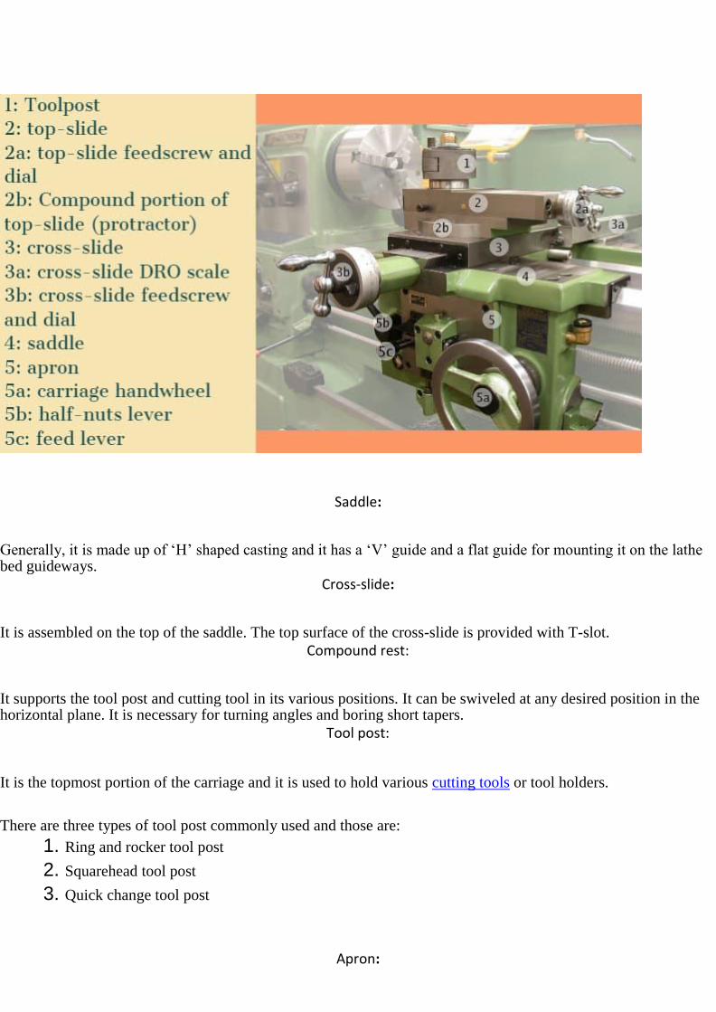
Saddle:
Generally, it is made up of ‘H’ shaped casting and it has a ‘V’ guide and a flat guide for mounting it on the lathe bed guideways.
Cross-slide:
It is assembled on the top of the saddle. The top surface of the cross-slide is provided with T-slot.
Compound rest:
It supports the tool post and cutting tool in its various positions. It can be swiveled at any desired position in the horizontal plane. It is necessary for turning angles and boring short tapers.
Tool post:
It is the topmost portion of the carriage and it is used to hold various cutting tools or tool holders.
There are three types of tool post commonly used and those are:
1. Ring and rocker tool post
2. Squarehead tool post
3. Quick change tool post
Apron:
An apron is a house of the feed mechanism. It is fastened to the saddle and hangover in front of the bed.
Lead screw:
A lead screw is also known as a power screw or a translation screw. It converts rotational motion to linear motion.
Lead Screw is used for Thread Cutting operation in a lathe machine tool.
Feed Rod:
Feed rod is used to move the carriage from the left side to the right side and also from the right side to the left
side.
Chuck:
Chuck is used to holding the workpiece securely.
There are generally 2 types of chucks:
1. 3 jaw self-centering chuck
2. 4 jaw independent chuck
Main Spindle:
The spindle is a hollow cylindrical shaft in which long jobs can pass through it.
It is designed so well that the thrust of the cutting tool does not deflect the spindle.
Leg:
Legs are carrying an entire load of a lathe machine tool and transfer to the ground. The legs are firmly secured to
the floor by the foundation bolt.
Schematic diagram of the lathe machine:

Types of Lathe Machine
Lathe machine tool which is used for removing the excess material from the workpiece to give required shape and
size to the workpiece.
So how many types of Lathe Machine are there? Lathe machine has been categorized into the following types:
● Center or Engine Lathe
● Speed Lathe
● Capstan and Turret Lathe
● Tool Room Lathe
● Bench Lathe
● Automatic Lathe
● Special Purpose and
● CNC Lathe Machine
We are going to study each and every important point of these 8 different types of lathe machines.
Center or Engine Lathe Machine:
Center or Engine Lathe Machine is the most widely used lathe machine and still, it is, in every workshop, this
machine is present.

The operation like Turning, facing, grooving, Knurling, threading and more, such operations are performed on
this type of machine.
Engine lathe machine has all the parts such as bed, Saddle, headstock, and tailstock, etc. The headstock of an
engine lathe is rigid and tailstock is moveable which is further used to support an operation like knurling.
It can easily feed the cutting tool in both directions i.e. longitudinal and lateral directions with the help of feed
mechanisms.
Center Lathe machines are driven by the gear mechanism or pulley mechanism.
It has three types of driven mechanisms, and those are Belt-driven, Motor-driven, Gearhead type.
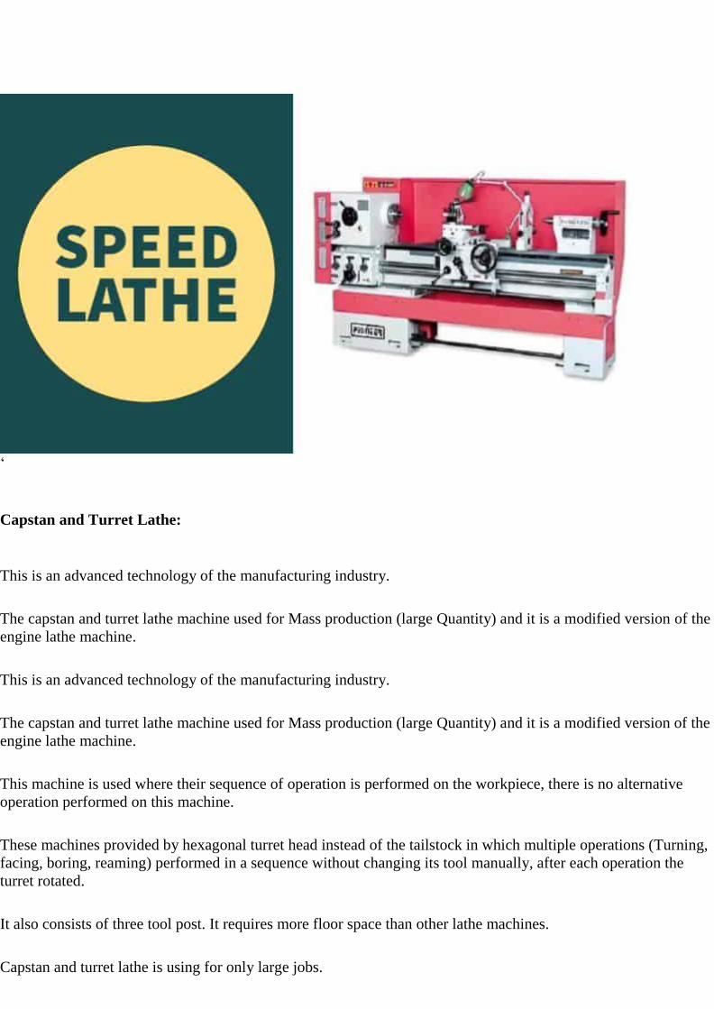
Speed Lathe:
Speed lathe is also called as Wood Lathe.
As the name indicates “Speed” the machine works with high speed. The headstock spindle is rotating at a very
high speed. The parts having like headstock, tailstock, but it’s not having feed mechanism like center or engine
lathe having. The feed we provide is manually operated.
The speed ranges of this machine operated between 1200 to 3600 RPM.
Speed lathe is used for spinning, centering, polishing and machining of wood.
‘
Capstan and Turret Lathe:
This is an advanced technology of the manufacturing industry.
The capstan and turret lathe machine used for Mass production (large Quantity) and it is a modified version of the
engine lathe machine.
This is an advanced technology of the manufacturing industry.
The capstan and turret lathe machine used for Mass production (large Quantity) and it is a modified version of the
engine lathe machine.
This machine is used where their sequence of operation is performed on the workpiece, there is no alternative
operation performed on this machine.
These machines provided by hexagonal turret head instead of the tailstock in which multiple operations (Turning,
facing, boring, reaming) performed in a sequence without changing its tool manually, after each operation the
turret rotated.
It also consists of three tool post. It requires more floor space than other lathe machines.
Capstan and turret lathe is using for only large jobs.
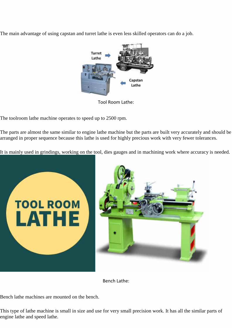
The main advantage of using capstan and turret lathe is even less skilled operators can do a job.
Tool Room Lathe:
The toolroom lathe machine operates to speed up to 2500 rpm.
The parts are almost the same similar to engine lathe machine but the parts are built very accurately and should be
arranged in proper sequence because this lathe is used for highly precious work with very fewer tolerances.
It is mainly used in grindings, working on the tool, dies gauges and in machining work where accuracy is needed.
Bench Lathe:
Bench lathe machines are mounted on the bench.
This type of lathe machine is small in size and use for very small precision work. It has all the similar parts of
engine lathe and speed lathe.
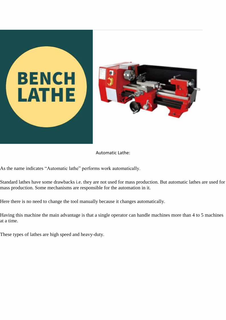
Automatic Lathe:
As the name indicates “Automatic lathe” performs work automatically.
Standard lathes have some drawbacks i.e. they are not used for mass production. But automatic lathes are used for
mass production. Some mechanisms are responsible for the automation in it.
Here there is no need to change the tool manually because it changes automatically.
Having this machine the main advantage is that a single operator can handle machines more than 4 to 5 machines
at a time.
These types of lathes are high speed and heavy-duty.
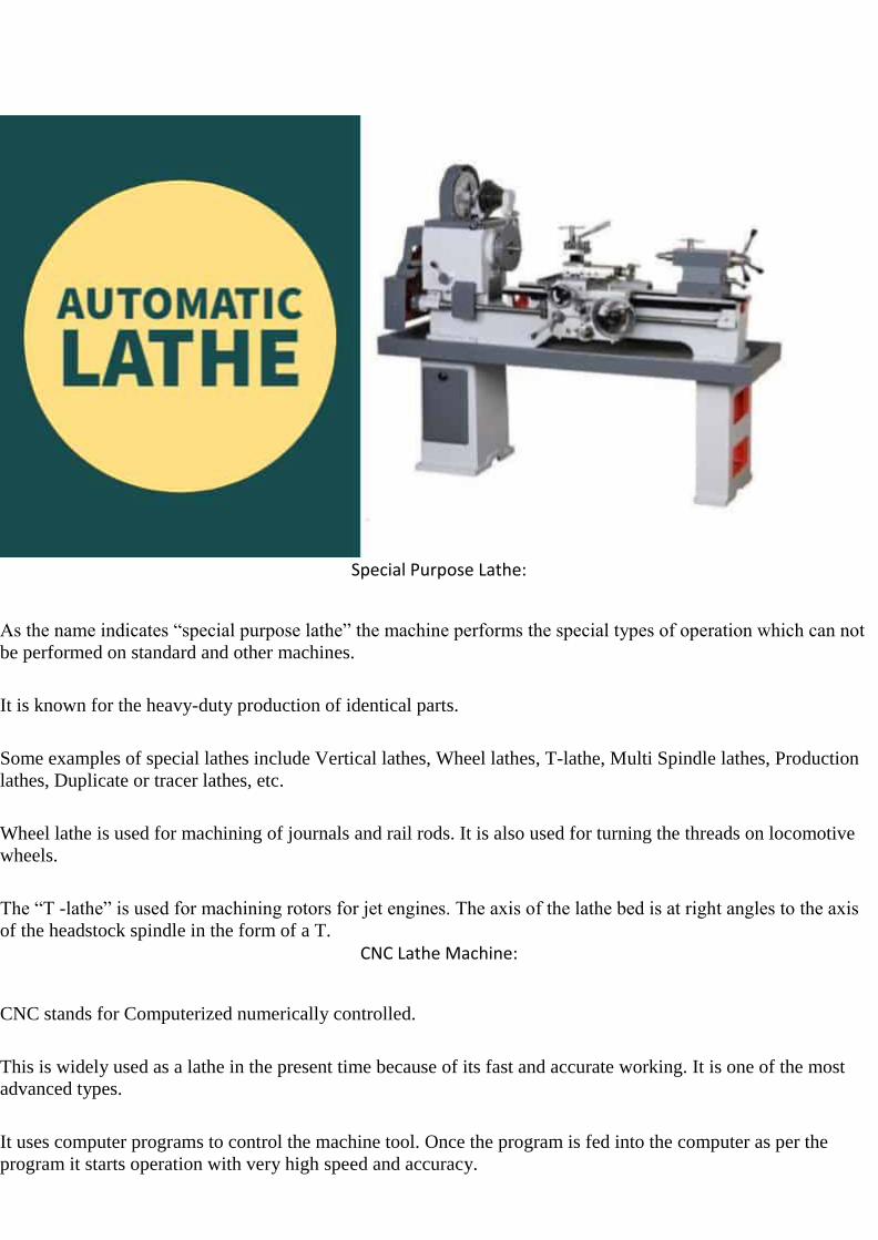
Special Purpose Lathe:
As the name indicates “special purpose lathe” the machine performs the special types of operation which can not
be performed on standard and other machines.
It is known for the heavy-duty production of identical parts.
Some examples of special lathes include Vertical lathes, Wheel lathes, T-lathe, Multi Spindle lathes, Production
lathes, Duplicate or tracer lathes, etc.
Wheel lathe is used for machining of journals and rail rods. It is also used for turning the threads on locomotive
wheels.
The “T -lathe” is used for machining rotors for jet engines. The axis of the lathe bed is at right angles to the axis
of the headstock spindle in the form of a T.
CNC Lathe Machine:
CNC stands for Computerized numerically controlled.
This is widely used as a lathe in the present time because of its fast and accurate working. It is one of the most
advanced types.
It uses computer programs to control the machine tool. Once the program is fed into the computer as per the
program it starts operation with very high speed and accuracy.
Even do preplanned programmed machine is there in which once code is set for the various operations it can starts
operation without changing code in the next time.
A semi-skilled worker can easily operate this after the initial setup is done.
These types of lathes are also used for mass production like capstan and turret but there is no programmed fed
system.
The components manufactured by these lathes are very accurate in dimensional tolerances.
Now discuss the operations performed in a Lathe
A Lathe Machine consists of the following operation:
● Centering
● Facing
● Turning
● Chamfering
● Knurling
● Thread cutting
● Drilling
● Boring
● Reaming
● Spinning
● Tapping
● Parting off
Before continuing any operation in lathe we have to load the job and center it on the head-stock spindle.
In lathe operations, the headstock spindle holds the job and it rotates with the same speed as the spindle. The
carriage holding the tool on the tool post, also the carriage gives the tool post moves longitudinally or crosswise
direction to give the desired feed on the job.
These two motions (longitudinally and crosswise) helps to remove the chips of the metal and giving the proper
shape of the job.
The Lathe is such a versatile machine that it can produce another lathe.
It is tough to mentioned which operations are not performed in a lathe machine tool, though we discuss some
important lathe operations in detail.
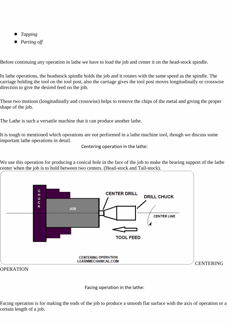
Centering operation in the lathe:
We use this operation for producing a conical hole in the face of the job to make the bearing support of the lathe
center when the job is to hold between two centers. (Head-stock and Tail-stock).
CENTERING
OPERATION
Facing operation in the lathe:
Facing operation is for making the ends of the job to produce a smooth flat surface with the axis of operation or a
certain length of a job.

In this operation,
1. Hold the job on Head-stock spindle using Three or four-jaw chuck.
2. Start the machine on desire RPM to rotate the job.
3. Give a desirable feed on the perpendicular direction of the axis of the job.
FACING
OPERATION
Turning operation in the lathe:
The operation by which we remove the excess material from the workpiece to produce a cone-shaped or a
cylindrical surface.
There are several types of turning operations, those are:
1. Straight turning
2. Shoulder turning
3. Rough turning
4. Finish turning
5. Taper turning
6. Eccentric turning
Straight turning:
This operation is done to produce a cylindrical surface by removing excess material from the workpiece.

It is done in the following ways:
1. Mount the job by suitable job holding device and check the trueness of the job axis with the lathe axis.
2. Hold the cutting tool on the tool post and set the cutting edge at the job axis or slightly above it.
3. Set the spindle as per the desired feed.
4. Give depth of cut as per finish or rough cut.
5. Start the machining.
6. Engage automatic feed to move the carriage with the tool to the desired length, then disengage the feed
and carriage is brought back to its starting.
7. The process is repeated until the job finished.
STRAIGHT
TURNING OPERATION
Shoulder turning:
A shoulder turning is called which has a different diameter to form a step from one diameter to another.
There are four kinds of the shoulder.
1. Square
2. Beveled
3. Radius
4. Undercut

SHOULDER TURNING
Rough turning:
It is a process of removal of excess material from the workpiece in minimum time by applying a high rate of feed
and heavy depth of cut.
the depth of cut is around 2 to 5mm and the rate of feed is 0.3 to 1.5mm/revolution.
Finish turning:
The finish turning operation needs high cutting speed, minimum feed and a very small depth of cut to generate the
smooth surface.
In finish turning the depth of cut is around 0.5 to 1mm and the rate of feed is 0.1 to 0.3 mm/revolution.
ROUGH
TURNING AND FINISH TURNING
Taper turning:

A taper is defined as a uniform decrease or increase in the diameter of a workpiece along with its length.
The operation by which a conical surface of the gradual reduction in diameter from a cylindrical workpiece is
produced is called taper turning.
TAPER TURNING
Taper turning methods:
A tapering form may be done by anyone of the following methods.
1. Taper turning by form tool
2. By swiveling the compound rest
3. Tail-stock set over method
4. By taper turning attachment.
Taper turning by form tool:
It is used to form a short length of taper by using a form tool or broad nose tool.
Any increase in the length of taper will require the use of a wider cutting edge which may destroy the workpiece
due to the vibration and spoil the workpiece.
In this operation, the tool angle must be half of the taper angle.
Taper turning by swiveling the compound rest:

This method is used for turning step and short tapers.
It is done as follows:
1. Set the compound rest by swiveling it from the centerline of the lathe center through an angle equal to a
half taper angle.
2. Clamp the carriage in place.
3. After adjusting and setting the tool, feed is applied by the compound rest’s feed handle to complete the
taper.
Tail-stock set over method:
Set over of tail-stock from its center-line is done equal to half taper.
Job is held between the centers. The length of the workpiece will be long enough. An only a small taper on a long
job is done by this process.
It is used for external taper only.
By taper turning attachment:
It is done in the following ways:
1. The cross slide is first made free from lead screw by hinder screw.
2. The rear end of the cross slide is then tightened with a guide block by a belt.
3. Set the guide bar at an angle to the lathe axis. (Half taper angle)
4. The required depth of cut is given by the compound slide is at a right angle to the lathe axis.
Chamfering operation:
Chamfering is used for beveling the end of a job to remove burrs, to look better, to make a passage of the nut into
the bolt.
This operation is done after thread cutting, knurling, rough turning.

CHAMFERING
Knurling operation:
It is the process of producing a rough surface on the workpiece to provide effective gripping.
Knurling tool is held rigidly on the tool post and pressed against the rotating job so that leaving the exact
facsimile of the tool on the surface of the job.
KNURLING

Thread cutting operation :
It is the operation that is used to produce a helical groove on a cylindrical or conical surface by feeding the tool
longitudinally when the job revolved between the two centers.
Tool setting for thread cutting operation:
The tool should be set exactly to the height of the centerline of the job and at 90 degrees to the job.
Tool setting gauge is used for this purpose.
Feeding during thread cutting operation:
It is done in two ways.
1. The tool may be feed exactly at 90 degrees to the job axis but it does not have good cutting action
because only the front end of the tool does cutting.
2. The tool may be feed at an angle from 27-30 degrees at which the compound rest may be set so that the
complete side of the tool is used for cutting action which gives a better polish on the threads.
Job speed during threading:
The job speed will be 1/3 to 1/4 th of the job speed in turning operation.
Drilling operation:
Drilling is an operation by which we can make holes in a job.
In this operation, the job is rotated at the turning speed on the lathe axis and the drilling tool fitted on the tail-
stock spindle. And the tail-stock is moved towards the job by hand feed.
DRILLING
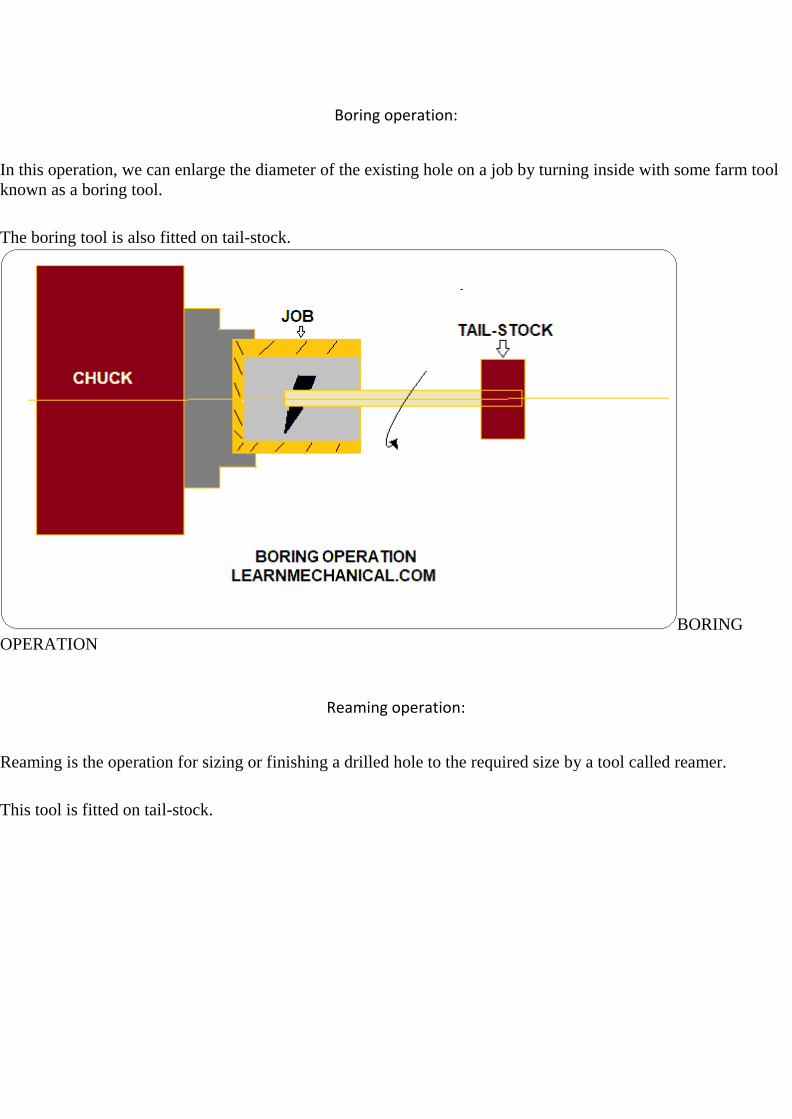
Boring operation:
In this operation, we can enlarge the diameter of the existing hole on a job by turning inside with some farm tool
known as a boring tool.
The boring tool is also fitted on tail-stock.
BORING
OPERATION
Reaming operation:
Reaming is the operation for sizing or finishing a drilled hole to the required size by a tool called reamer.
This tool is fitted on tail-stock.

REAMING OPERATION
Spinning operation:
In this operation, the job of this sheet metal is held between the former and the tail-stock center rotates at high
speed with the former.
the long round nose forming tool rigidly fixed on special tool post presses the job on the periphery of the former.
So the job is taken exactly the shape of the former.
This is a chipless machining process.
Tapping operation:
We use this operation for creating internal threads within a hole by means of a tool called tap.
Three taps are generally used in an internal thread.
1. Taper Tap
2. Second Tap
3. Plug Tap
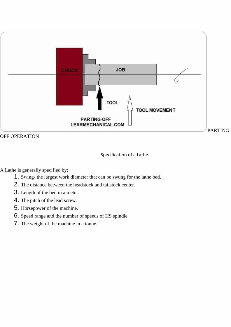
Parting-off operation:
It is the operation of cutting off a bar type job after complete the machining process.
In this operation a bar type job is held on a chuck, rotates at turning speed, a parting off tool is fed into the job
slowly until the tool reaches the center of the job.
PARTING-
OFF OPERATION
Specification of a Lathe:
A Lathe is generally specified by:
1. Swing- the largest work diameter that can be swung for the lathe bed.
2. The distance between the headstock and tailstock center.
3. Length of the bed in a meter.
4. The pitch of the lead screw.
5. Horsepower of the machine.
6. Speed range and the number of speeds of HS spindle.
7. The weight of the machine in a tonne.

UNIT 2 SHAPING, SLOTTING AND
PLANING MACHINES

COURSE OBJECTIVE
Gain the knowledge and features, working principles and applications of lathe, shaper, planer, slotter,
milling, drilling, and machines
COURSE OUTCOME Apply Computer aided process planning, MRP and CNC part programming.

UNIT II (SYLLABUS) Shaping, slotting and planning machines:-Principles of working – classifications, operations performed,
machining time calculations.Drilling and Boring Machines – Principles of working, specifications, types,
operations performed – tool holding devices – twist drill – Boring machines – Fine boring machines – Jig
Boring machine. Deep hole drilling machine.
Objectives of the unit
Understanding of
SHAPING MACHINE OPERATIONS
DRILLING MACHINE OPERATIONS
BORING MACHINE OPERATIONS
DEEP HOLE DRILLING MACHINE
Principle and Working of SHAPER MACHINE
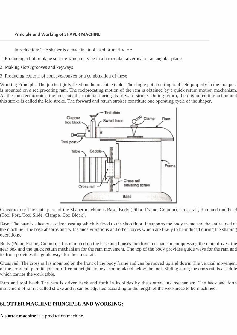
Introduction: The shaper is a machine tool used primarily for:
1. Producing a flat or plane surface which may be in a horizontal, a vertical or an angular plane.
2. Making slots, grooves and keyways
3. Producing contour of concave/convex or a combination of these
Working Principle: The job is rigidly fixed on the machine table. The single point cutting tool held properly in the tool post
is mounted on a reciprocating ram. The reciprocating motion of the ram is obtained by a quick return motion mechanism.
As the ram reciprocates, the tool cuts the material during its forward stroke. During return, there is no cutting action and
this stroke is called the idle stroke. The forward and return strokes constitute one operating cycle of the shaper.
Construction: The main parts of the Shaper machine is Base, Body (Pillar, Frame, Column), Cross rail, Ram and tool head
(Tool Post, Tool Slide, Clamper Box Block).
Base: The base is a heavy cast iron casting which is fixed to the shop floor. It supports the body frame and the entire load of
the machine. The base absorbs and withstands vibrations and other forces which are likely to be induced during the shaping
operations.
Body (Pillar, Frame, Column): It is mounted on the base and houses the drive mechanism compressing the main drives, the
gear box and the quick return mechanism for the ram movement. The top of the body provides guide ways for the ram and
its front provides the guide ways for the cross rail.
Cross rail: The cross rail is mounted on the front of the body frame and can be moved up and down. The vertical movement
of the cross rail permits jobs of different heights to be accommodated below the tool. Sliding along the cross rail is a saddle
which carries the work table.
Ram and tool head: The ram is driven back and forth in its slides by the slotted link mechanism. The back and forth
movement of ram is called stroke and it can be adjusted according to the length of the workpiece to be-machined.
SLOTTER MACHINE PRINCIPLE AND WORKING:
A slotter machine is a production machine.

This is a very old type of the machine and was invented by BRUNEL.
The slotting machine is similar to a verticle shaper. The ram carrying the slotting tool reciprocates in a verticle guide-way
of the machine.
The Slotting Machine can manufacture flat and contour surfaces, slots. and internal grooves.
Slotter Machine Definition:
Slotter machine is defined as a machine tool uses for removing unwanted material chips from the workpiece to make
splines, grooves and more. Here the Ram (Tool attached) moves reciprocating, whereas In shaper the ram moves
horizontally.
This is a reciprocating type of Machine tool. (The Reciprocating type of Machine tools are Shaper, Planner and Slotter
Machine).
We also called this machine is a vertical shaper machine.
It is known mostly for machining internal surfaces.
The tool we use in this is Single Point cutting Tool which is made up of High-Speed Steel.
Schematic Diagram of Slotter Machine:
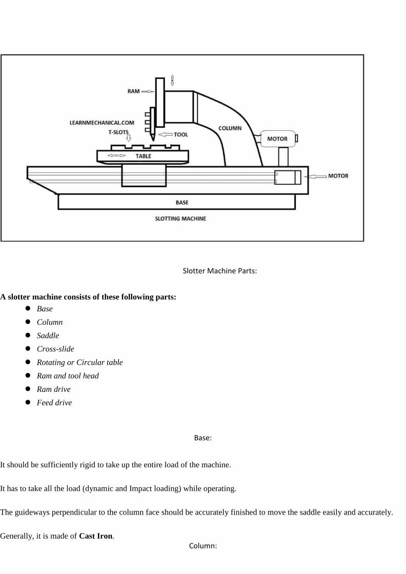
Slotter Machine Parts:
A slotter machine consists of these following parts:
● Base
● Column
● Saddle
● Cross-slide
● Rotating or Circular table
● Ram and tool head
● Ram drive
● Feed drive
Base:
It should be sufficiently rigid to take up the entire load of the machine.
It has to take all the load (dynamic and Impact loading) while operating.
The guideways perpendicular to the column face should be accurately finished to move the saddle easily and accurately.
Generally, it is made of Cast Iron.
Column:
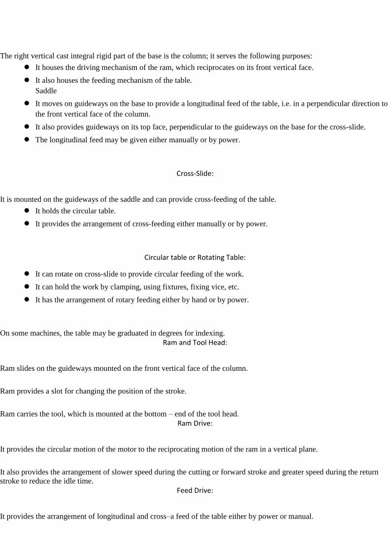
The right vertical cast integral rigid part of the base is the column; it serves the following purposes:
● It houses the driving mechanism of the ram, which reciprocates on its front vertical face.
● It also houses the feeding mechanism of the table.
Saddle
● It moves on guideways on the base to provide a longitudinal feed of the table, i.e. in a perpendicular direction to
the front vertical face of the column.
● It also provides guideways on its top face, perpendicular to the guideways on the base for the cross-slide.
● The longitudinal feed may be given either manually or by power.
Cross-Slide:
It is mounted on the guideways of the saddle and can provide cross-feeding of the table.
● It holds the circular table.
● It provides the arrangement of cross-feeding either manually or by power.
Circular table or Rotating Table:
● It can rotate on cross-slide to provide circular feeding of the work.
● It can hold the work by clamping, using fixtures, fixing vice, etc.
● It has the arrangement of rotary feeding either by hand or by power.
On some machines, the table may be graduated in degrees for indexing.
Ram and Tool Head:
Ram slides on the guideways mounted on the front vertical face of the column.
Ram provides a slot for changing the position of the stroke.
Ram carries the tool, which is mounted at the bottom – end of the tool head.
Ram Drive:
It provides the circular motion of the motor to the reciprocating motion of the ram in a vertical plane.
It also provides the arrangement of slower speed during the cutting or forward stroke and greater speed during the return
stroke to reduce the idle time.
Feed Drive:
It provides the arrangement of longitudinal and cross–a feed of the table either by power or manual.
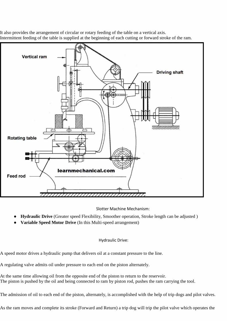
It also provides the arrangement of circular or rotary feeding of the table on a vertical axis.
Intermittent feeding of the table is supplied at the beginning of each cutting or forward stroke of the ram.
Slotter Machine Mechanism:
● Hydraulic Drive (Greater speed Flexibility, Smoother operation, Stroke length can be adjusted )
● Variable Speed Motor Drive (In this Multi-speed arrangement)
Hydraulic Drive:
A speed motor drives a hydraulic pump that delivers oil at a constant pressure to the line.
A regulating valve admits oil under pressure to each end on the piston alternately.
At the same time allowing oil from the opposite end of the piston to return to the reservoir.
The piston is pushed by the oil and being connected to ram by piston rod, pushes the ram carrying the tool.
The admission of oil to each end of the piston, alternately, is accomplished with the help of trip dogs and pilot valves.
As the ram moves and complete its stroke (Forward and Return) a trip dog will trip the pilot valve which operates the

regulating valve.
The regulating valve will admit the oil to the other side of the piston and the motion of the ram will get reversed.
The length of the ram stroke will depend upon the position of trip dogs. The length of the ram stroke can be changed by
unclamping and moving the trip dogs to the desired position.
Variable Speed Motor Drive:
In this type of slotter, speed is obtained by different gears present in the gearbox and the shaft rotates with the help of an
electrical motor.
Basically it is used in modern large slotting machines.
Working Principle of Slotter Machine:
The working of the Slotter machine is similar to the shaper machine do but the main difference between them is the
Shaper machine works horizontally whereas Slotter machines work vertically.
As we have studied all the parts in detail.
Now the ram is connected to the crank and crank connected to the gears. So what happened here is when we increase or
decrease the gear speed, the rotation of crank increases and decreases. And as per these, the ram moves up and down.
We have attached the workpiece into the work table and manually we bring the ram near to the workpiece and according to
the ram we adjust the worktable and then we have to clamp it.
Now we supply the power as per gear the crank rotates and the crank is connected to the ram so ram moves up and down.
During down (ram moves down) the cutting stroke takes place and while moving up or return stroke there is no cut.
If we have to cut at the different sections then manually we give feed to the work table and as per requirement, it cuts.
This is how it works.
Here I would like to add some more points on Work holding device in which work is attached or fixed.
● T bolts and step block
● Clamps
● Vice
● Parallel strips
● Chuck
● Special fixtures for holding
● Adjustable block and more
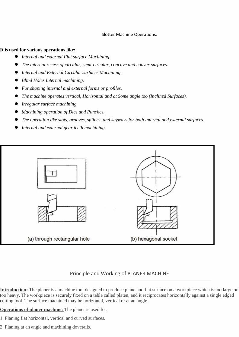
Slotter Machine Operations:
It is used for various operations like:
● Internal and external Flat surface Machining.
● The internal recess of circular, semi-circular, concave and convex surfaces.
● Internal and External Circular surfaces Machining.
● Blind Holes Internal machining.
● For shaping internal and external forms or profiles.
● The machine operates vertical, Horizontal and at Some angle too (Inclined Surfaces).
● Irregular surface machining.
● Machining operation of Dies and Punches.
● The operation like slots, grooves, splines, and keyways for both internal and external surfaces.
● Internal and external gear teeth machining.
Principle and Working of PLANER MACHINE
Introduction: The planer is a machine tool designed to produce plane and flat surface on a workpiece which is too large or
too heavy. The workpiece is securely fixed on a table called platen, and it reciprocates horizontally against a single edged
cutting tool. The surface machined may be horizontal, vertical or at an angle.
Operations of planer machine: The planer is used for:
1. Planing flat horizontal, vertical and curved surfaces.
2. Planing at an angle and machining dovetails.

3. Planing slots and grooves.
The planer are available in different types for doing different types and sizes of job; the most common being the standard
and double housing planer.
Construction: The main parts of the double Housing Planer machine is Bed and table, Housings, Cross rail, , Tool heads,
Driving and feed mechanism.
Bed and table: The bed is a long heavy base and table made of cast iron. Its top surface is flat and machined accurately.
The flat top surface has slots in which the workpiece can be securely clamped. The workpiece needs rigid fixing so that it
does not shift out of its position. The standard clamping devices used on planer machine are: Heavy duty vice, T-holders
and clamps, angle plate, planer jack, step blocks and stop. The table movement may be actuated by a variable speed drive
through a rack and pinion arrangement, or a hydraulic system.
Housings: The housings are the rigid and upright column like castings. These are located near the centre on each side of the
base.
Cross rail: The cross rail is a horizontal member supported on the machined ways of the upright columns. Guide ways are
provided on vertical face of each column and that enables up and vertical movement of the cross rail. The vertical
movement of the cross rail allows to accommodate workpiece of different heights. Since the cross rail is supported at both
the ends, this type of planer machine is rigid in construction.
Tool heads: Generally two tool heads are mounted in the horizontal cross rail and one on each of the vertical housing. Tool
heads may be swiveled so that angular cuts can be made.
Driving and feed mechanism: The tool heads may be fed either by hand or by power in crosswise or vertical direction.
The motor drive is usually at one side of the planer near the centre and drive mechanism is located under the table.
The size of the planer is specified by the maximum length of the stroke, and also by the size of the largest rectangular solid
that can be machined on it.
Principle and Working of DRILLING MACHINE
Introduction: The drilling machine or drill press is one of the most common and useful machine employed in industry for
producing forming and finishing holes in a workpiece. The unit essentially consists of:
1. A spindle which turns the tool (called drill) which can be advanced in the workpiece either automatically or by hand.
2. A work table which holds the workpiece rigidly in position.
Working principle: The rotating edge of the drill exerts a large force on the workpiece and the hole is generated. The
removal of metal in a drilling operation is by shearing and extrusion.
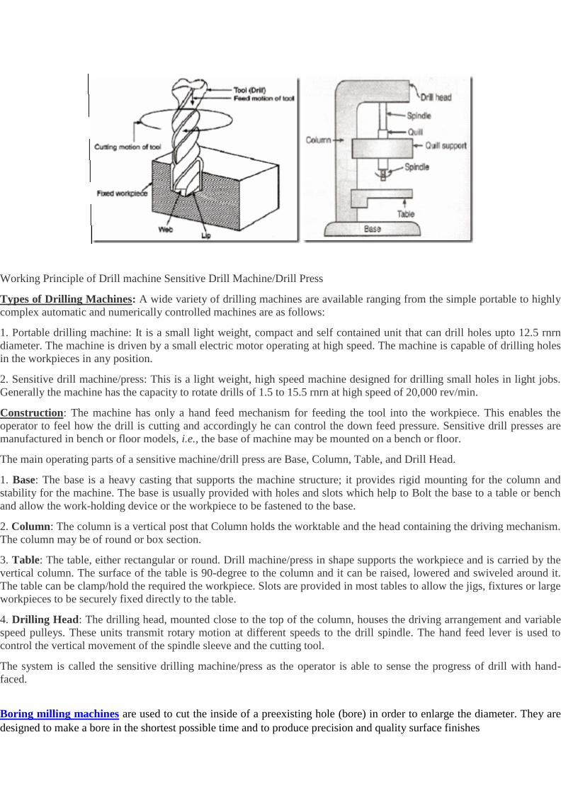
Working Principle of Drill machine Sensitive Drill Machine/Drill Press
Types of Drilling Machines: A wide variety of drilling machines are available ranging from the simple portable to highly
complex automatic and numerically controlled machines are as follows:
1. Portable drilling machine: It is a small light weight, compact and self contained unit that can drill holes upto 12.5 rnrn
diameter. The machine is driven by a small electric motor operating at high speed. The machine is capable of drilling holes
in the workpieces in any position.
2. Sensitive drill machine/press: This is a light weight, high speed machine designed for drilling small holes in light jobs.
Generally the machine has the capacity to rotate drills of 1.5 to 15.5 rnrn at high speed of 20,000 rev/min.
Construction: The machine has only a hand feed mechanism for feeding the tool into the workpiece. This enables the
operator to feel how the drill is cutting and accordingly he can control the down feed pressure. Sensitive drill presses are
manufactured in bench or floor models, i.e., the base of machine may be mounted on a bench or floor.
The main operating parts of a sensitive machine/drill press are Base, Column, Table, and Drill Head.
1. Base: The base is a heavy casting that supports the machine structure; it provides rigid mounting for the column and
stability for the machine. The base is usually provided with holes and slots which help to Bolt the base to a table or bench
and allow the work-holding device or the workpiece to be fastened to the base.
2. Column: The column is a vertical post that Column holds the worktable and the head containing the driving mechanism.
The column may be of round or box section.
3. Table: The table, either rectangular or round. Drill machine/press in shape supports the workpiece and is carried by the
vertical column. The surface of the table is 90-degree to the column and it can be raised, lowered and swiveled around it.
The table can be clamp/hold the required the workpiece. Slots are provided in most tables to allow the jigs, fixtures or large
workpieces to be securely fixed directly to the table.
4. Drilling Head: The drilling head, mounted close to the top of the column, houses the driving arrangement and variable
speed pulleys. These units transmit rotary motion at different speeds to the drill spindle. The hand feed lever is used to
control the vertical movement of the spindle sleeve and the cutting tool.
The system is called the sensitive drilling machine/press as the operator is able to sense the progress of drill with hand-
faced.
Boring milling machines are used to cut the inside of a preexisting hole (bore) in order to enlarge the diameter. They are
designed to make a bore in the shortest possible time and to produce precision and quality surface finishes

.
Boring Machine Design
These machines are available in a wide range of styles and sizes. The power needed to operate these machines can reach up
to 200 horsepower. Boring milling machines are designed with certain considerations in mind.
Types of Boring Milling Machines and Their Uses Boring machines can be general-purpose, but there are many boring machines that are specialized to accomplish other
specified tasks. Here are a few types of boring machines available:
● Cylinder Boring Machines: This equipment is typically used to bore the small engine cylinders of cars.
Cylinders are the central part of piston engines in cars, thus it is important for high precision manufacturing from a
cylinder boring machine.
● Tunnel Boring Machines: As the name implies, this machinery is capable of making a smooth tunnel wall in a
variety of soil and rock. Tunnel boring machines can drill a hole in most natural surfaces, like a mountain or hard
rock. These machines are also known under the moniker “mole”.
● Horizontal Boring Machines: The most common mills used in the industry today. These mills offer safety and
easier use than other mills on the market. Horizontal boring mills are known for being energy and time efficient.
They can improve the quality of your business drastically.
● Vertical Boring Machines: This machine is engineered for larger uniquely shaped surfaces. Although not as
popular as a horizontal boring machine, their specific uses in completing tasks offer many advantages, their
flexibility as an example.
Boring milling machines come in different styles and are used in a variety of different projects. At TOS America, we can
make sure you choose one of our machines that are ideal for your company. Our company specializes in horizontal boring
equipment, as well as vertical boring mills. Our expert staff can assist you in finding the best suited machine for your next
project. Call or email us today with any questions about our products or services.

UNIT 3 COMPUTER AIDED PROGRAMMING

COURSE OBJECTIVE Learn about the ways to reduce the surface roughness by using different Machining
processes COURSE OUTCOME Understand the fundamentals of metal cutting, chip formation, cutting forces involved in
orthogonal metal cutting, and different cutting forces will be learned.

UNIT III (SYLLABUS) Computer-Aided Programming: General information, APT programming, Examples Apt
programming problems (2D machining only). NC programming on CAD/CAM systems,
Introduction to CAD/CAM software, Automatic Tool Path generation. Tooling for CNC
Machines: Interchangeable tooling system, preset and qualified tools, coolant fed tooling
system, modular featuring, quick change tooling system, automatic head changers. Objectives of the unit
Understanding of

Computer aided programming
Introduction to cad cam software:-
Software allows the human user to turn a hardware configuration into a powerful design and
manufacturing system. CAD/CAM software falls into two broad categories, 2-D and 3-D,based on the
number of dimensions are called 2-D representations of 3-D objectsis inherently confusing. Equally problem
has been the inability ofmanufacturing personnel to properly read and interpret complicated 2-
Drepresentations of objects. 3-D software permits the parts to be viewed withthe 3-D planes-height, width,
and depth-visible. The trend in CAD/CAM is toward3-D representation of graphic images. Such
representation approximates the actual shape and appearance of the object to be produced; therefore, they
are easier to read and understand.
CNC milling machines have of course been developed based on conventional millingmachines,
where the tool is moved through the material by operating a hand wheel for each ofthe available axes (X, Y,
Z,). The basis of adding NC (Numerical Control) is very simple:replace the hand wheel by a positioning
motor and add some electronics (the NC controller) tocontrol the position. Nowadays many conversion kits
are available to perform such operation.The first NC controllers were very simple: no user-interface, just an
option to read the toolpositionsto go to from a punched tape. Very soon new controllers were introduced,
includinga simple computer with a special-purpose keyboard and a display. The operator now couldenter the
sequence of movements to make (the NC program) on the controller, which wascalled CNC (Computerized
Numerical Control). In some cases a tape puncher / reader stillwas available for external storage.Next step
was of course to use a PC for external storage, communicating with the CNCcontroller via a serial cable.
This allowed the operator to conveniently sit at his desk to enter anew NC program, while at the same time
the CNC machine was executing a previous job. Donote that for most desktop machines the situation is a bit
different, as here a PC is used forthe CNC controller (much cheaper than a special purpose control
computer).In the situation just described the operator enters the complete NC program on the
computer,using a plain editor like Notepad or a special purpose NC editor. Each movement has to
beseparately entered, like "G0X10Y20Z30" for "Machine in a straight line from the currentposition to
position (10, 20, and 30)". This is of course very labor intensive, and this is where CAMsoftware comes in
to 'automatically' generate NC program files.
In order to manufacture a part, nowadays typically three different software programs
are used (See the illustration above):
▪ First the CAD software to make the design of the part
▪ Next de CAM software to calculate the toolpaths based on the design, compensating for the cutter's
geometry, adding feedrate and spindle commands, etc Third the control software to read the
toolpaths and let the machine actually move along these paths. This subdivision of tasks by three
different programs is the same for both 2D and 3D applications.
APT or Automatically Programmed Tool[1]
is a high-level computer programming language most commonly
used to generate instructions for numerically controlled machine tools. Douglas T. Ross[2]
is considered by
many to be the father of APT: as head of the newly created Computer Applications Group of the
Servomechanisms Laboratory at MIT in 1956, he led its technical effort. APT is a language and system that
makes numerically controlled manufacturing possible. This early language was used widely through the 1970s
and is still a standard internationally.[3]
Derivatives of APT were later developed.
APT is used to program numerically-controlled machine tools to create complex parts using a cutting tool
moving in space. It is used to calculate a path that a tool must follow to generate a desired form. APT is a
special-purpose language and the predecessor to modern CAM systems. It was created and refined during the
late 1950s and early 1960s to simplify the task of calculating geometry points that a tool must traverse in space
to cut the complex parts required in the aerospace industry. It was a direct result of the new numerical control
technology becoming available at that time and the daunting task that a machinist or engineer faced calculating
the movements of the machine for the complex parts for which it was capable. Its development was centered at
the same MIT labs that hosted the Numerical Control and the Milling Machine Projects. APT also was Air
Force sponsored and is notable for being the world's first major cooperative programming venture, combining
government agencies, universities, and a 14-company team organized within the Aircraft Industries
Association [now Aerospace Ind Assoc.].[4]
APT was created before graphical interfaces were available, and so
it relies on text to specify the geometry and toolpaths needed to machine a part. The original version was
created before even FORTRAN was available and was the very first ANSI standard. Later versions were
rewritten in FORTRAN. As a U. S. government funded project APT was placed in the public domain.
APT shares many similarities with other computer programming languages such as FORTRAN. A general-
purpose computer language takes source text and converts the statements to instructions that can be processed
internally by a computer. APT converts source statements into programs for driving numerically-controlled
machine tools. The output from an APT processor may be a CL or "Cutter Location" file which is then run
through a post-processor specific to the desired control - machine pair. The resulting file is then run by the
control of the machine to generate tool motions and other machine actions. Most commonly, this file is in
some form of RS-274 format instructions, commonly known as G-code

PARTNO / APT-1
CLPRNT
UNITS / MM
NOPOST
CUTTER / 20.0
$$ GEOMETRY DEFINITION
SETPT = POINT / 0.0, 0.0, 0.0
STRTPT = POINT / 70,70,0
P1 = POINT / 50, 50, 0
P2 = POINT / 20, -20, 0
C1 = CIRCLE / CENTER, P2, RADIUS, 30
P3 = POINT / -50, -50, 0
P5 = POINT / -30, 30, 0
C2 = CIRCLE / CENTER, P5, RADIUS, 20
P4 = POINT / 50, -20, 0
L1 = LINE / P1, P4
L2 = LINE / P3, PERPTO, L1
L3 = LINE / P3, PARLEL, L1
L4 = LINE / P1, PERPTO, L1
PLAN1 = PLANE / P1, P2, P3
PLAN2 = PLANE / PARLEL, PLAN1, ZSMALL, 16
$$ MOTION COMMANDS

SPINDL / 3000, CW
FEDRAT / 100, 0
FROM / STRTPT
GO/TO, L1, TO, PLAN2, TO, L4
TLLFT, GOFWD / L1, TANTO, C1
GOFWD / C1, TANTO, L2
GOFWD / L2, PAST, L3
GORGT / L3, TANTO, C2
GOFWD / C2, TANTO, L4
GOFWD / L4, PAST, L1
NOPS
GOTO / STRTPT
FINI
Numerical Control(NC) Part Programming Using CAD/CAM
A CAD/CAM system is a computer interactive graphics system equipped with software is accomplish certain
tasks in design and manufacturing and to integrate the design and manufacturing functions. We discuss
('AD/CAM in Chapter 24. One of the important tasks performed on a CAD/CAM system is NC part
programming. In this method of part programming, portions of the procedure usually done by the part
programmer are instead done by the computer. Recall that the two main tasks of the part programmer in
computer assisted programming are (1) defining the part geometry and (2) specifying the tool path. Advanced
CAD/CAM systems automate portions of both of these tasks.
Geometry Definition Using CAD/CAM. A fundamental objective of CAD/CAM is to integrate the design
engineering and manufacturing engineering functions. Certainly one of the important design functions is to
design the individual components of the product. If a CAD/e' AM system is used, a computer graphics model
of each part is developed by the designer and stored in the CAD/CAM data base. That model contains all of the
geometric, dimensional, and material specifications for the part.
When the same CAD/CAM system, or a CAM system that has access to the same CAD data base in which
the part model resides, is used to perform NC part programming, it makes little sense to recreate the geometry
of the part during the programming procedure. Instead, the programmer has the capability to retrieve the part
geometry model from storage and to use that model to construct the appropriate cutter path. The significant
advantage of using CAD/CAM in this way is that it eliminates one of the tirneconsurning steps in
computerassisted part programming: geometry definition. After the part geometry has been retrieved, the usual
procedure is to lahel the geometric elements that will be used during part programming. These labels are the
variable names (symbols) given to the lines, circJe~ and surfaces that comprise the part. Most systems have the
capacity to automatically label the geometry clements of the part and to display tbe labels on the monitor. The
programmer can then refer to those labeled elements during tool path construction.
If the NC programmer does not have access tothe data base, then the geometry of the part must be defined.
This is done by using similar interactive graphics techniques that the product designer would use to design the
part. Points are defined in a coordinate system using the computer graphics system, lines and circles are
defined from the points, surfaces are defined. and so forth, to construct a geometric model of the part. The
advantage of using the interactive graphics system over conventional computerassisted part programming is
that the programmer receives immediate visual verification of the definitions being created. This tends to
improve the speed and accuracy of the geometry definition process
Tool Path Generation Using CAD/CAM. The second task of the NC programmer in computerassisted part
programming is tool path specification, The first step in specifying the tool path is La select the cutting tool for
the operation. Most CADICAM systems have tool libraries that can be called by the programmer to identify
what tools arc available in the tool crib. The programmer must decide which of the available tools is must
appropriate for the operation under consideration and specify it for the tool path. This permits the tool diameter
and other dimensions to be entered automatically for tool offset calculations. If the desired cutting tool is not
available in the library, an appropriate tool can be specified by rhc programmer. It then becomes part of the
library for future use
The next step is tool path definition. There are differences in capabilities of the various CAD/CAM systems,
which result in different approaches fur generating the tool path. The most basic approach involves the use of
the interactive graphics system to enter the motion commands cnebyone.uirnilar to computerassisted part
programming. Individual statements in APT or other part programming language are entered. and the
CAD/CAM system provides an immediate graphic display of the action resulting from the command. thereby
validating the statement.

A moreadvanced approach for generating tool path commands is to use one of the automatic software modules
available on the CAD/CAM system. These modules have been developed to accomplish a number of common
machining cycles for milling, drilling, and turning. They are subroutines in the NC programming package that
can be called and the required parameters given to execute the machining cycle. Several of these modules are
identified in Table 6.13 and Figure 6.25.
When the complete part program has been prepared, the CAD/CAM system can provide an animated
simulation of the program for validation purposes.
Computer Automated Part Programming. In the CAD/CA M approach to NC part programming, several
aspects of the procedure are automated. In the future, it should be possible to automate the complete NC part
programming procedure. We are referring to this fully automated procedure as computerautomated part
programming. Given the geometric model of a part that has been defined during product design, the
computerautomated system would possess sufficient logic and decisionmaking capability to accomplish NC
part programming for the entire part without human assistance.
This can most readily be done for certain NC processes that involve welldefined, relatively simple part
geometries. Examples are pointtopoint operations such as NC drilling and electronic component assembly
machines. In these processes, the program conststs basically of a series of locations in an xy coordinate system
where work is to be performed [e.g .. holes arc to be drilled or components are to be inserted). These locations
are determined by data that are generated during product design. Special algorithms can be developed to
process the design data and generate the NC program fur the particular system. "fe contounag systems will
eventually be capable at a similar level of automation. Automatic programming of this type is closely related to
computer-automated process planning (CAPP), discussed in later pages.

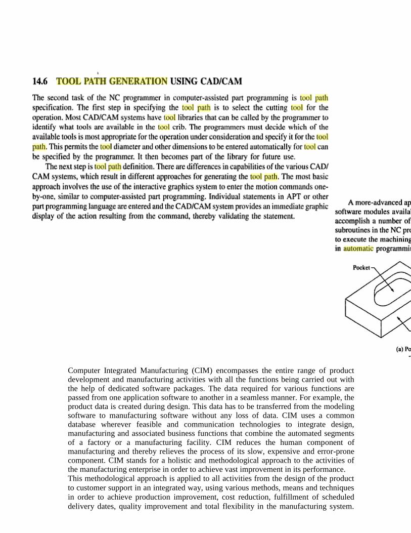
Computer Integrated Manufacturing (CIM) encompasses the entire range of product development and manufacturing activities with all the functions being carried out with the help of dedicated software packages. The data required for various functions are passed from one application software to another in a seamless manner. For example, the product data is created during design. This data has to be transferred from the modeling software to manufacturing software without any loss of data. CIM uses a common database wherever feasible and communication technologies to integrate design, manufacturing and associated business functions that combine the automated segments of a factory or a manufacturing facility. CIM reduces the human component of manufacturing and thereby relieves the process of its slow, expensive and error-prone component. CIM stands for a holistic and methodological approach to the activities of the manufacturing enterprise in order to achieve vast improvement in its performance. This methodological approach is applied to all activities from the design of the product
to customer support in an integrated way, using various methods, means and techniques
in order to achieve production improvement, cost reduction, fulfillment of scheduled
delivery dates, quality improvement and total flexibility in the manufacturing system.

CIM requires all those associated with a company to involve totally in the process of
product development.
CNC Machining
CNC machining is a term commonly used in manufacturing and industrial applications, but exactly what does
the acronym CNC stand for and what is a CNC machine?
The term CNC stands for 'computer numerical control', and the CNC machining definition is that it is a
subtractive manufacturing process which typically employs computerized controls and machine tools to
remove layers of material from a stock piece—known as the blank or workpiece—and produces a custom-
designed part. This process is suitable for a wide range of materials, including metals, plastics, wood, glass,
foam, and composites, and finds application in a variety of industries, such as large CNC machining and CNC
machining aerospace parts. When speaking in terms of the machine itself, the CNC machine definition is that it
represents the actual programmable machine that is capable of autonomously performing the operations of
CNC machining. Note the contrast between the process (CNC machining definition) versus the machine (CNC
machine definition).
Subtractive manufacturing processes, such as CNC machining, are often presented in contrast to additive
manufacturing processes, such as 3D printing, or formative manufacturing processes, such as liquid injection
molding. While subtractive processes remove layers of material from the workpiece to produce custom shapes
and designs, additive processes assemble layers of material to produce the desired form and formative
processes deform and displace stock material into the desired shape. The automated nature of CNC machining
enables the production of high precision and high accuracy, simple parts and the cost-effectiveness when
fulfilling one-off and medium-volume production runs. However, while CNC machining demonstrates certain
advantages over other manufacturing processes, the degree of complexity and intricacy attainable for part
design and the cost-effectiveness of producing complex parts is limited.
While each type of manufacturing process has its advantages and disadvantages, this article focuses on the
CNC machining process, outlining the basics of the process, and the various components and tooling of the
CNC machine (sometimes incorrectly known as a C and C machine). Additionally, this article explores various
mechanical CNC machining operations and presents alternatives to the CNC machining process.
Overview of CNC Machining Process
Evolving from the numerical control (NC) machining process which utilized punched tape cards, CNC
machining is a manufacturing process which utilizes computerized controls to operate and manipulate machine
and cutting tools to shape stock material—e.g., metal, plastic, wood, foam, composite, etc.—into custom parts
and designs. While the CNC machining process offers various capabilities and operations, the fundamental
principles of the process remain largely the same throughout all of them. The basic CNC machining process
includes the following stages:
● Designing the CAD model
● Converting the CAD file to a CNC program
● Preparing the CNC machine
● Executing the machining operation
CAD Model Design
The CNC machining process begins with the creation of a 2D vector or 3D solid part CAD design either in-
house or by a CAD/CAM design service company. Computer-aided design (CAD) software allows designers
and manufacturers to produce a model or rendering of their parts and products along with the necessary
technical specifications, such as dimensions and geometries, for producing the part or product.
Designs for CNC machined parts are restricted by the capabilities (or inabilities) of the CNC machine and
tooling. For example, most CNC machine tooling is cylindrical therefore the part geometries possible via the
CNC machining process are limited as the tooling creates curved corner sections. Additionally, the properties
of the material being machined, tooling design, and workholding capabilities of the machine further restrict the
design possibilities, such as the minimum part thicknesses, maximum part size, and inclusion and complexity
of internal cavities and features.
Once the CAD design is completed, the designer exports it to a CNC-compatible file format, such as STEP or
IGES.
CAD File Conversion
The formatted CAD design file runs through a program, typically computer-aided manufacturing (CAM)
software, to extract the part geometry and generates the digital programming code which will control the CNC
machine and manipulate the tooling to produce the custom-designed part.
CNC machines used several programming languages, including G-code and M-code. The most well-known of
the CNC programming languages, general or geometric code, referred to as G-code, controls when, where, and
how the machine tools move—e.g., when to turn on or off, how fast to travel to a particular location, what
paths to take, etc.—across the workpiece. Miscellaneous function code, referred to as M-code, controls the
auxiliary functions of the machine, such as automating the removal and replacement of the machine cover at
the start and end of production, respectively.
Once the CNC program is generated, the operator loads it to the CNC machine.
Machine Setup
Before the operator runs the CNC program, they must prepare the CNC machine for operation. These
preparations include affixing the workpiece directly into the machine, onto machinery spindles, or into
machine vises or similar workholding devices, and attaching the required tooling, such as drill bits and end
mills, to the proper machine components.
Once the machine is fully set up, the operator can run the CNC program.
Machining Operation Execution
The CNC program acts as instructions for the CNC machine; it submits machine commands dictating the
tooling’s actions and movements to the machine’s integrated computer, which operates and manipulates the
machine tooling. Initiating the program prompts the CNC machine to begin the CNC machining process, and
the program guides the machine throughout the process as it executes the necessary machine operations to
produce a custom-designed part or product.
CNC machining processes can be performed in-house—if the company invests in obtaining and maintaining
their own CNC equipment—or out-sourced to dedicated CNC machining service providers.
Types of CNC Machining Operations
CNC machining is a manufacturing process suitable for a wide variety of industries, including automotive,
aerospace, construction, and agriculture, and able to produce a range of products, such as automobile frames,
surgical equipment, airplane engines, and hand and garden tools. The process encompasses several different
computer-controlled machining operations—including mechanical, chemical, electrical, and thermal
processes—which remove the necessary material from the workpiece to produce a custom-designed part or
product. While chemical, electrical, and thermal machining processes are covered in a later section, this section
explores some of the most common mechanical CNC machining operations including:
● Drilling
● Milling
● Turning
CNC Drilling
Drilling is a machining process which employs multi-point drill bits to produce cylindrical holes in the
workpiece. In CNC drilling, typically the CNC machine feeds the rotating drill bit perpendicularly to the plane
of the workpiece’s surface, which produces vertically-aligned holes with diameters equal to the diameter of the
drill bit employed for the drilling operation. However, angular drilling operations can also be performed
through the use of specialized machine configurations and workholding devices. Operational capabilities of the
drilling process include counterboring, countersinking, reaming, and tapping.
CNC Milling
Milling is a machining process which employs rotating multi-point cutting tools to remove material from the
workpiece. In CNC milling, the CNC machine typically feeds the workpiece to the cutting tool in the same
direction as the cutting tool’s rotation, whereas in manual milling the machine feeds the workpiece in the
opposite direction to the cutting tool’s rotation. Operational capabilities of the milling process include face
milling—cutting shallow, flat surfaces and flat-bottomed cavities into the workpiece—and peripheral
milling—cutting deep cavities, such as slots and threads, into the workpiece.
CNC Turning
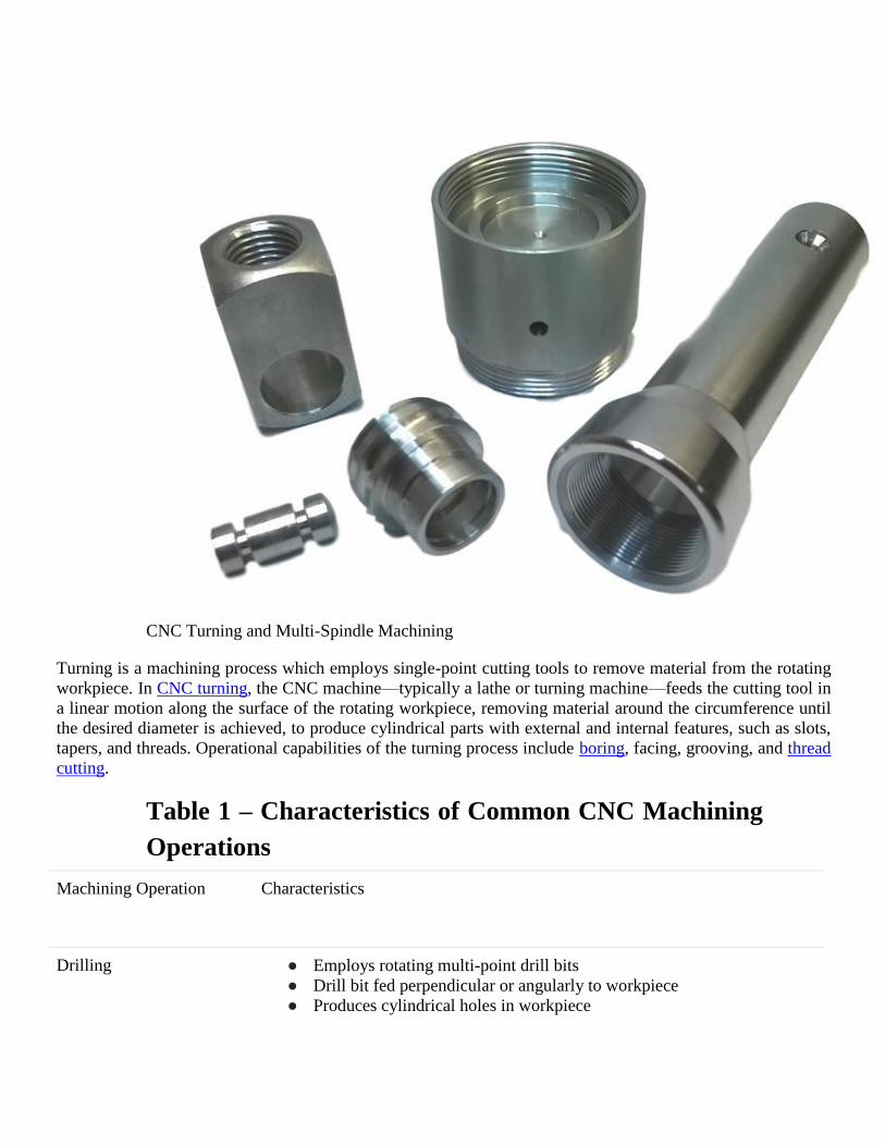
CNC Turning and Multi-Spindle Machining
Turning is a machining process which employs single-point cutting tools to remove material from the rotating
workpiece. In CNC turning, the CNC machine—typically a lathe or turning machine—feeds the cutting tool in
a linear motion along the surface of the rotating workpiece, removing material around the circumference until
the desired diameter is achieved, to produce cylindrical parts with external and internal features, such as slots,
tapers, and threads. Operational capabilities of the turning process include boring, facing, grooving, and thread
cutting.
Table 1 – Characteristics of Common CNC Machining
Operations
Machining Operation Characteristics
Drilling ● Employs rotating multi-point drill bits
● Drill bit fed perpendicular or angularly to workpiece
● Produces cylindrical holes in workpiece
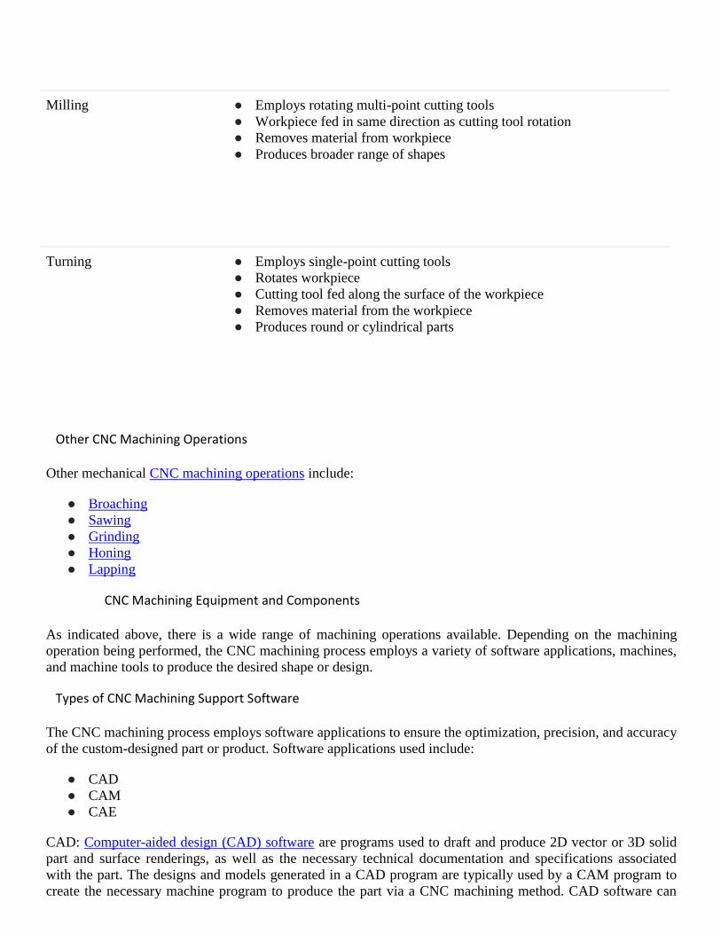
Milling ● Employs rotating multi-point cutting tools
● Workpiece fed in same direction as cutting tool rotation
● Removes material from workpiece
● Produces broader range of shapes
Turning ● Employs single-point cutting tools
● Rotates workpiece
● Cutting tool fed along the surface of the workpiece
● Removes material from the workpiece
● Produces round or cylindrical parts
Other CNC Machining Operations
Other mechanical CNC machining operations include:
● Broaching
● Sawing
● Grinding
● Honing
● Lapping
CNC Machining Equipment and Components
As indicated above, there is a wide range of machining operations available. Depending on the machining
operation being performed, the CNC machining process employs a variety of software applications, machines,
and machine tools to produce the desired shape or design.
Types of CNC Machining Support Software
The CNC machining process employs software applications to ensure the optimization, precision, and accuracy
of the custom-designed part or product. Software applications used include:
● CAD
● CAM
● CAE
CAD: Computer-aided design (CAD) software are programs used to draft and produce 2D vector or 3D solid
part and surface renderings, as well as the necessary technical documentation and specifications associated
with the part. The designs and models generated in a CAD program are typically used by a CAM program to
create the necessary machine program to produce the part via a CNC machining method. CAD software can

also be used to determine and define optimal part properties, evaluate and verify part designs, simulate
products without a prototype, and provide design data to manufacturers and job shops.
CAM: Computer-aided manufacturing (CAM) software are programs used extract the technical information
from the CAD model and generate machine program necessary to run the CNC machine and manipulate the
tooling to produce the custom-designed part. CAM software enables the CNC machine to run without operator
assistance and can help automate finished product evaluation.
CAE: Computer-aided engineering (CAE) software are programs used by engineers during the pre-processing,
analysis, and post-processing phases of the development process. CAE software is used as assistive support
tools in engineering analysis applications, such as design, simulation, planning, manufacturing, diagnosis, and
repair, to help with evaluating and modifying product design. Types of CAE software available include finite
element analysis (FEA), computational fluid dynamics (CFD), and multibody dynamics (MDB) software.
Some software applications have combined all of the aspects of CAD, CAM, and CAE software. This
integrated program, typically referred to as CAD/CAM/CAE software, allows a single software program to
manage the entire fabrication process from design to analysis to production.
What is a CNC Machine?: Types of CNC Machines and Machine Tools
Depending on the machining operation being performed, the CNC machining process employs a variety of
CNC machines and machine tools to produce the custom-designed part or product. While the equipment may
vary in other ways from operation to operation and application to application, the integration of computer
numerical control components and software (as outlined above) remains consistent across all CNC machining
equipment and processes.
CNC Drilling Equipment
Drilling employs rotating drill bits to produce the cylindrical holes in the workpiece. The design of the drill bit
allows for the waste metal—i.e., chips—to fall away from the workpiece. There are several types of drill bits,
each of which is used for a specific application. Types of drill bits available include spotting drills (for
producing shallow or pilot holes), peck drills (for reducing the amount of chips on the workpiece), screw
machine drills (for producing holes without a pilot hole), and chucking reamers (for enlarging previously
produced holes).
Typically the CNC drilling process also utilizes CNC-enabled drill presses, which are specifically designed to
perform the drilling operation. However, the operation can also be performed by turning, tapping, or milling
machines.
CNC Milling Equipment
Milling employs rotating multi-point cutting tools to shape the workpiece. Milling tools are either horizontally
or vertically oriented and include end mills, helical mills, and chamfer mills.
The CNC milling process also utilizes CNC-enabled milling machinery, referred to as mill machines or mills,
which can be horizontally or vertically oriented. Basic mills are capable of three-axis movements, with more
advanced models accommodating additional axes. The types of mills available include hand milling, plain
milling, universal milling, and omniversal milling machines.

CNC Turning Equipment
Turning employs single-point cutting tools to remove material from the rotating workpiece. The design of the
turning tool varies based on the particular application, with tools available for roughing, finishing, facing,
threading, forming, undercutting, parting, and grooving applications.
The CNC turning process also utilizes CNC-enabled lathes or turning machines. The types of lathes available
include turret lathes, engine lathes, and special-purpose lathes.
CNC Machine Models
CNC machines are available in standard and desktop models. Standard CNC machines are the typical industry
standard machines, which can be designated to perform a specific machine operation, such as drill presses, or
perform multiple operations, such as milling and turning machines. Desktop CNC machines are smaller, more
lightweight machines resembling their larger counterparts. Typically the desktop models handle softer
materials, such as foam and plastic, smaller parts, and are suitable for light to moderate production outputs.
The types of desktop CNC machines available include plotter-sized laser cutters and milling machines, and
desktop or benchtop lathes.
Material Considerations
The CNC machining process is suitable for a variety of engineering materials, including:
● Metal (e.g., aluminum, brass, stainless steel, alloy steel, etc.)
● Plastic (e.g., PEEK, PTFE, nylon, etc.)
● Wood
● Foam
● Composites
The optimal material for selection to apply to a CNC manufacturing application is largely dependent on the
particular manufacturing application and its specifications. Most materials can be machined provided that they
can withstand the machining process—i.e., have sufficient hardness, tensile strength, shear strength, and
chemical and temperature resistance.
The workpiece material and its physical properties are used to determine the optimal cutting speed, cutting
feed rate, and depth of cut. Measured in surface feet per minute, the cutting speed refers to how fast the
machine tool cuts into or removes material from the workpiece. The feed rate—measured in inches per
minute—is a measure of how fast the workpiece is fed towards the machine tool, and the cut depth is how deep
the cutting tool cuts into the workpiece. Typically, the workpiece will first undergo an initial phase in which it
is roughly machined to the approximate, custom-designed shape and dimensions, and then undertake a
finishing phase in which it experiences slower feed rates and shallower cut depths to achieve its more precise
and accurate specifications.
Size Considerations
The wide range of capabilities and operations offered by the CNC machining process help it to find application
in a variety of industries, including automotive, aerospace, construction, and agriculture, and enable it to
produce a range of products, such as hydraulic components, screws, and shafts. Despite the versatility and
customizability of the process, the manufacturing of some parts—e.g., large or heavy components—present
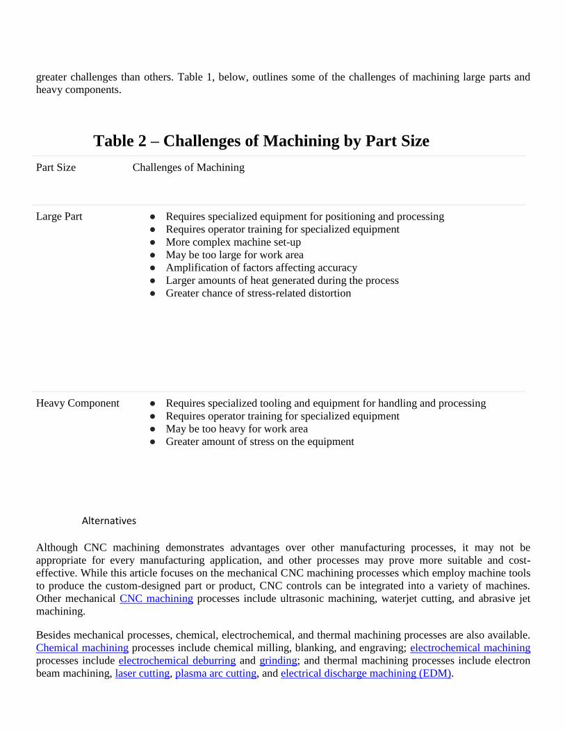
greater challenges than others. Table 1, below, outlines some of the challenges of machining large parts and
heavy components.
Table 2 – Challenges of Machining by Part Size
Part Size Challenges of Machining
Large Part ● Requires specialized equipment for positioning and processing
● Requires operator training for specialized equipment
● More complex machine set-up
● May be too large for work area
● Amplification of factors affecting accuracy
● Larger amounts of heat generated during the process
● Greater chance of stress-related distortion
Heavy Component ● Requires specialized tooling and equipment for handling and processing
● Requires operator training for specialized equipment
● May be too heavy for work area
● Greater amount of stress on the equipment
Alternatives
Although CNC machining demonstrates advantages over other manufacturing processes, it may not be
appropriate for every manufacturing application, and other processes may prove more suitable and cost-
effective. While this article focuses on the mechanical CNC machining processes which employ machine tools
to produce the custom-designed part or product, CNC controls can be integrated into a variety of machines.
Other mechanical CNC machining processes include ultrasonic machining, waterjet cutting, and abrasive jet
machining.
Besides mechanical processes, chemical, electrochemical, and thermal machining processes are also available.
Chemical machining processes include chemical milling, blanking, and engraving; electrochemical machining
processes include electrochemical deburring and grinding; and thermal machining processes include electron
beam machining, laser cutting, plasma arc cutting, and electrical discharge machining (EDM).
INTERCHANGEABLE TOOLING SYSTEMS: A number of clear and powerful trends are impacting the metalworking industry. Customers expect higher
quality but demand lower costs and quicker deliveries. Machine tools are becoming more capable and more
flexible but are, in many cases, considerably more expensive. Lot sizes are becoming smaller. Competition is
coming from around the globe.
In light of these and many other developments, shops and plants of all sizes are rethinking every aspect of their
businesses. The ones that are adopting new strategies that leverage every technical advantage to the fullest are
the ones most likely to succeed in this climate.
PRESET, QUICK-CHANGE AND ADJUSTABLE TOOLING FOR TURNING
MACHINES
Introduction
Ideally, tooling should attach to a machine like the bayonet on the end of a rifle -- quick, sure, and precise.
Preset, quick-change, and adjustable tooling can achieve this ideal to a greater or lesser extent, depending on
the specific application. Use of this tooling can result in cost savings through such things as:
● Reduced labor hours
● Increased machine hours available for production
● Reduced skill and training requirements for shop people
● Improved quality
● Reduced operator error
● Reduced scrap
All this comes at a price, however, and applications should be carefully evaluated to assure that the investment
can pay for itself.
Preset Tooling
The key attribute of preset tooling is that its location in the machine is known with a high degree of precision.
Once such a tool has been attached to a machine, it will produce the desired predetermined dimension without
adjustment. Presetting is done off the machine, and requires that tools have a means of adjustment. In addition,

the method of attaching them to the machine must be repeatable and highly accurate. Presetting is often
employed on end-working tools, but can also be used for cross-working applications.
Preset tooling saves time during setup, as well as when tools are changed during the job’s run, by reducing or
eliminating test cuts, measurements, and adjustments. On screw machines in particular, where the “brass
hammer method” is often used, these adjustments require either substantial skill or substantial time. The
amount of time saved through the use of this tooling has to be balanced against the time required for presetting.
However, even if there is no apparent reduction in labor hours, there will be an increase in the number of hours
available for production on the machine. This is because presetting is part of “external” setup or operating
time. That is, it can be done while the machine continues to make pieces. Whether the benefits of this type of
tooling come in the form of reduced labor or increased uptime, they may be most significant on newer, more
expensive, advanced technology machines which carry a higher machine hour rate.
In this report, preset tooling has been handled separately from “quick-change,” which has been handled
separately from “adjustable,” etc. The purpose of this is to be clear about exactly which benefits are inherent in
each type of tooling. However, in actual practice these types are commonly combined, with examples such as
“preset, quick-change tooling,” or “quick-change, adjustable tooling” coming to mind.
There is a question regarding the feasibility of this tooling on some cam machines, since the end points of tool
slides are not necessarily predictable on a given job, or repeatable from one run to the next. In some cases this
is due to small differences between “identical” cams which are used interchangeably. In addition, on single
spindle machines the high and low points on the lead cam may not be exact, although some presetting systems
can correct for this. These problems can be overcome by purchasing new cams to closer tolerances; but for the
shop with a large inventory of existing cams, this may not be cost effective. Another option is to provide a
means of making a graduated fine adjustment on the machine, either with an adjustable tool holder or with an
integral adjustable slide, although this will reduce the benefits of this tooling somewhat.
Pre-Gaged Tooling
Pre-gaged tooling is a variation of preset tooling, but lacks its ability to be adjusted off the machine. It is made
to close tolerances with only small differences between “identical” tools. Prior to being set up, this type of tool
is gaged and variations from its nominal dimensions are noted. Generally it is used on CNC machines, and
adjustments for these variations are handled by the tool compensation offsets, in many cases without the need
for trial cuts and subsequent adjustments. While not common, this concept can be applied on cam machines as
long as there is a way to make graduated fine adjustments, either within the tool holder system, or on the
machine itself.
Qualified Tooling
Qualified tooling is another variation of preset tooling. All of the components that comprise a qualified tool are
made to close tolerances; and because of this, it will cut very near to the desired dimension. One of the most
common types is the carbide insert/insert tool holder combination. Installed in the machine, any combination
of “identical” inserts and tool holders will generally be located within ?.005” of their nominal dimension. Like
the pre-gaged type above, this tooling is not adjustable; and there must be a way on the machine to compensate
for these small variations, following a trial cut and measurement.
Quick-Change Tooling
The primary characteristic of quick-change tooling is the ease, speed, and convenience it provides in terms of
removal and replacement. In addition, it generally fastens to the machine in a repeatable fashion. The very fact
that it is quick acting allows this tooling to save time both during setup, and when it needs to be changed
during a run.
Unlike quick-change collets, most quick-change tooling can also be preset, pre-gaged, adjusted, etc. With this
combination of qualities it is possible to exchange a new or “renewed” tool with one that needs sharpening,
and have the machine producing again in a moment or two. In some instances it may even make sense to
replace a slightly worn tool in this way, rather than taking time from production for a trial-and-error, on-
machine adjustment.
Adjustable Tooling
Adjustable tooling is capable of shifting the cutting edge (or other functional surfaces) of the tool in one or
more directions so that the desired dimension is produced on the workpiece. The means to do this must be
graduated so that any shift can be made accurately and with predictability. This permits the number of trial
cuts, measurements, and adjustments made during setup or operation to be reduced. Adjustable tooling is often
a more practical alternative for traditional cam-type machines. It is more flexible, and can accommodate the
variations in cams noted earlier in this report. Also, it may be the most practical way to adjust for tool wear in
some situations, or compensate for deflection of the part or tooling. Some tools provide an adjustment to
correct for taper in the workpiece.
Selection/Cost Savings
There are a huge number of variations in machine design, workpieces, tooling design, etc. that make it difficult
to come up with useful generalizations for selecting this kind of tooling. Instead it is recommended that each
shop evaluate its particular situation and select the tooling which offers the greatest cost savings. The first step
is to study what is currently being done to make sure it is really understood by everyone involved. (Members
who have done this note that it can produce surprises.) This is also a good time to note such key selection
factors as the type of machine, its condition, how it is currently tooled, investment in that tooling, machining
requirements for the parts being produced, workpiece material, and lot sizes. Also look at plant personnel,
including the level of their existing skills, ability to implement new concepts, and at what point they will be
retiring and need to be replaced by younger workers.
Next develop accurate and complete costs for several typical parts the way they are currently set up and run on
the machine being studied. Be on the lookout for potential savings, using the list at the beginning of this report
as a guide.
Evaluate the tooling alternatives described in this report, as well as any others available, and select several that
appear promising. Then make realistic estimates of what your costs would be to produce the parts studied
above using each of the alternates you selected. Try to put a dollar figure not only on direct labor savings, but
also on the other benefits mentioned earlier, especially reduced skill and training requirements, reduced scrap,

and having more machine hours available for production. Weigh the purchase cost of each alternate against the
savings in manufacturing costs it can produce to decide which one is best, and whether or not it is a good
investment.
Undoubtedly, it may be difficult to quantify the benefits of things like reduced operator error, or reduced
training requirements. Nevertheless, try to take them into account. Other potential benefits, perhaps even less
tangible, should also be given some weight. One example might be the ability to satisfy a customer's Just-in-
Time requirements. Another example would be taking the skill and art of “brass hammer adjustments” out of
the process, and replacing it with the science of a graduated dial. This is something that may be essential with
the younger, less skilled workforce many companies will depend on in the next few years. Finally there is
significant value in new technology itself, the progressive message it sends to people both in and outside your
plant, and the positive response they can have to it, whether they are customers, potential recruits, or existing
employees who believe in the company they work for and want to make it successful.
Quick change tooling solutions
When people talk about productivity it can often be the metal cutting efficiency which is in focus. However,
machine utilization or time the green light on the machine is on is equally or even more important.
With quick change tooling solution you can really increase your machine utilization by reducing measuring, set-up
and tool changing time.
Productivity factors
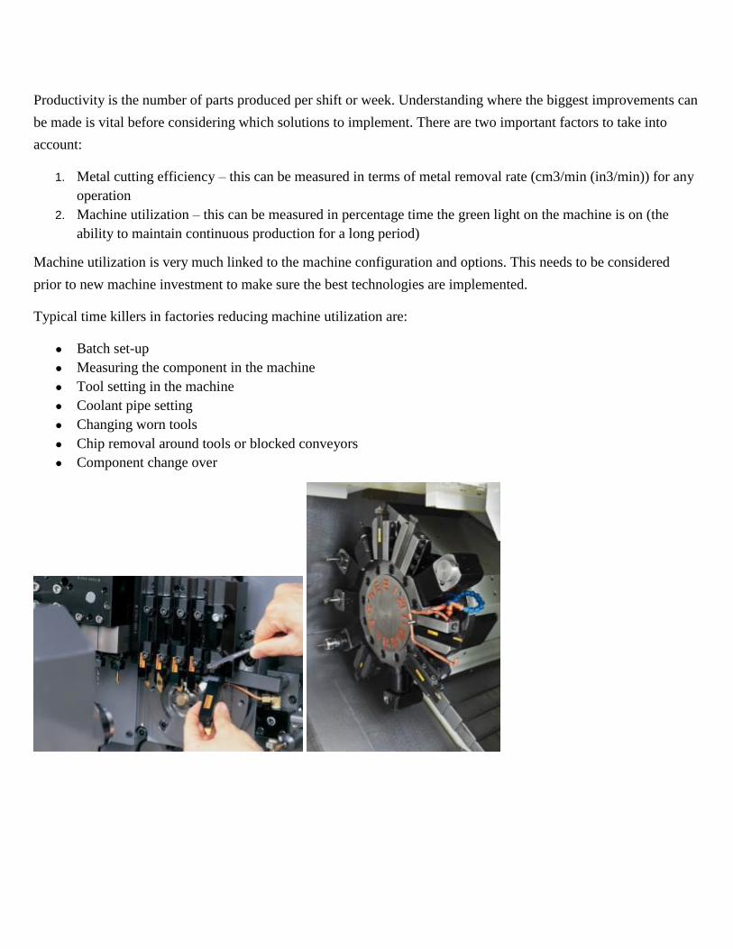
Productivity is the number of parts produced per shift or week. Understanding where the biggest improvements can
be made is vital before considering which solutions to implement. There are two important factors to take into
account:
1. Metal cutting efficiency – this can be measured in terms of metal removal rate (cm3/min (in3/min)) for any
operation
2. Machine utilization – this can be measured in percentage time the green light on the machine is on (the
ability to maintain continuous production for a long period)
Machine utilization is very much linked to the machine configuration and options. This needs to be considered
prior to new machine investment to make sure the best technologies are implemented.
Typical time killers in factories reducing machine utilization are:
● Batch set-up
● Measuring the component in the machine
● Tool setting in the machine
● Coolant pipe setting
● Changing worn tools
● Chip removal around tools or blocked conveyors
● Component change over

How tools are loaded and measured has a huge impact on the machine utilization – the best comparison is motor
racing and minimizing the time the car is in the pit stop and this is why minimizing any machine stoppages is so
important.
Through coolant delivery ensures that the full capabilities of the machine are harnessed with optimized cutting
units to reduce setting and deliver the coolant with maximum impact to provide chip control.
Quick change tooling benefits
CNC lathes and sliding head machines have fast tool indexing but typically have a lower utilization than machining
centres due to the tool change and set-up time. Manual quick change is utilized where there is no automatic tool
change (ATC) in the machine ensuring the green light on the machine is on for longer. The benefits of using quick
change are many.
Reduced batch change over time using tool kits
Changing from one style of tool to another is dramatically reduced.

● Turning tool holders from 5–10 mins down to 30 seconds
● Boring bars takes a little bit longer time than shank tools because of centre height setting and coolant
plumbing
● The advantages with quick change tooling is even more in combination with long boring bars. Boring bars
up to 10×D can be changed with 2 μm (78.7 μinch) accuracy in less than 1 minute
● Driven tools from 5–20 mins down to 30 seconds. Normal driven tools holders are ER or face milling. ER is
limited to end mills with maximum diameter 25 mm (1 inch) which means two separate driven holders.
With Coromant Capto® the same unit covers all applications
Simple CNC machines work with a single tool. Turrets can work with a large number of tools. But if even
more tools are required, then ATC is provided. The tools are stored on a magazine. It allows the machine to
work with a large number of tools without an operator. The main parts of an automatic tool changer are the
base, the gripper arm, the tool holder, the support arm and tool magazines.[2]
Although the ATC increases the
reliability, speed and accuracy, it creates more challenges compared to manual tool change, for example the
tooling used must be easy to centre, be easy for the changer to grab and there should be a simple way to
provide the tool's self-disengagement. Tools used in ATC are secured in toolholders specially designed for this
purpose.[3]
UNIT 4 DNC SYSTEMS AND
ADAPTIVE CONTROL

DNC Systems and Adaptive Control:
DNC Machine [Distributed Numerical Control System]
Direct numerical control (DNC) can be described as a various type of a manufacturing system in which that
multiple NC machine or CNC machines are remotely controlled from a host computer or DNC control of
multiple machines tools by a single computer through a direct connection. It is shown in the diagram below.
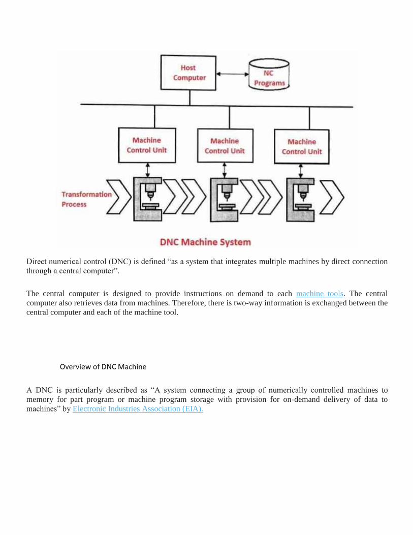
Direct numerical control (DNC) is defined “as a system that integrates multiple machines by direct connection
through a central computer”.
The central computer is designed to provide instructions on demand to each machine tools. The central
computer also retrieves data from machines. Therefore, there is two-way information is exchanged between the
central computer and each of the machine tool.
Overview of DNC Machine
A DNC is particularly described as “A system connecting a group of numerically controlled machines to
memory for part program or machine program storage with provision for on-demand delivery of data to
machines” by Electronic Industries Association (EIA).

Direct Numerical
Control
In DNC, many NC machines are directly controlled by computers, removing enough hardware from a separate
controller of each machine tools. The part-programs are downloaded to machines directly from a computer
memory (thus bypassing tape readers).
The basic DNC system needs following the basic components are the mainframe computers, memory,
communication networks, NC machine tools.
The communication network can be arranged either through connecting the remotely located computer, with
long cables to the individual machine control directly or connecting the mainframe computer with a small
computer at individual operator’s station called as satellite computer.
DNC systems are costly and preferably used in large organizations. The combination of DNC/CNC makes
possible to eliminate the use of the programme as the input media for CNC machines.
DNC downloads computer programs directly into CNC computer memory. This decreases the amount of
communication required between the central computer and each machine tool.
Functions of DNC System
Following are the functions of the DNC machine:
1. For use the central computer for storage and editing programs for all machine tools connected to it.
2. To give the stored programs to the connected machines on demand.
3. For to post-process part programs written in higher-level languages like APT.

4. To combine CAD with CAM by having a common database.
5. To provide a link between a central computer and various plant computers connected through
modems and networks even though the plants may be placed several kilometres away from each
other.
Components Used in DNC Machine
Following are the main components used in CNC machine:
1. Central computer
2. Bulk memory for storing programs
3. Communication network
4. NC machine
Types of DNC system
Following are the main two types of DNC system:
1. Behind the Tape Reader (BTR) system
2. Specialised MCU
1. Behind The Tape Reader (BTR) System
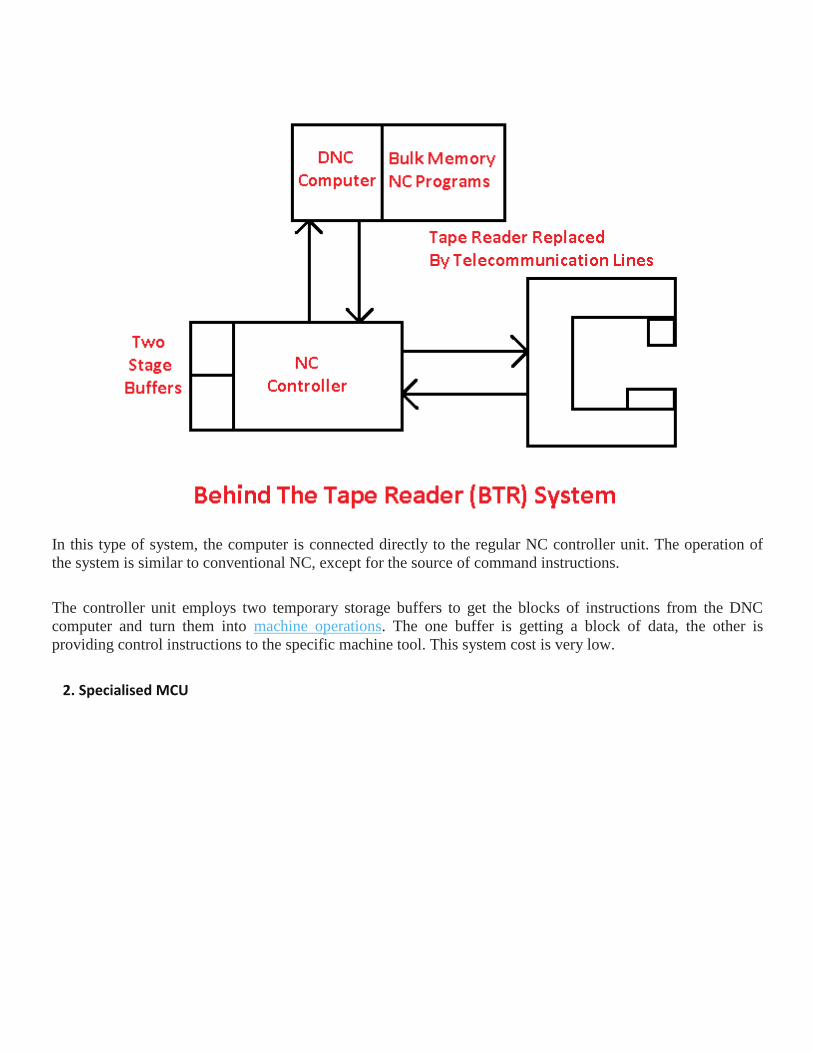
In this type of system, the computer is connected directly to the regular NC controller unit. The operation of
the system is similar to conventional NC, except for the source of command instructions.
The controller unit employs two temporary storage buffers to get the blocks of instructions from the DNC
computer and turn them into machine operations. The one buffer is getting a block of data, the other is
providing control instructions to the specific machine tool. This system cost is very low.
2. Specialised MCU

In specialised MCU system, replace the normal controller unit with the special machine control unit. The
special control unit is created to help communication between machine tools and computers. The specialised
MCU configuration achieves a better balance between the accuracy of interpolation and the faster removal rate
of the metal than is usually possible with the BTR system.
Advantages of DNC System
Following are the advantages of the DNC system:
1. The DNC rejects the use of tape readers, which are absolutely the weakest component of the NC
system.
2. Time-sharing by central control makes it possible to keep close control over the entire machine
shop.
3. The huge memory of DNC allows it to store a large number of part programs for subsequent use. It
also receives the memories of NC control unit.
4. Presence of a central bulk memory allows the same program to be run on different machines at the
same time without duplicating it at individual places.
Disadvantages of DNC System

Following are the disadvantages of the DNC system:
1. DNC uses a central control and in an event of computer failure, the complete activities of the
machine shop would come to a standstill.
2. DNC is expensive and its use is practical in areas where high automation is required.
Adaptive control is the control method used by a controller which must adapt to a controlled system with
parameters which vary, or are initially uncertain. For example, as an aircraft flies, its mass will slowly decrease
as a result of fuel consumption; a control law is needed that adapts itself to such changing conditions. Adaptive
control is different from robust control in that it does not need a priori information about the bounds on these
uncertain or time-varying parameters; robust control guarantees that if the changes are within given bounds the
control law need not be changed, while adaptive control is concerned with control law changing itself.
In general, one should distinguish between:
1. Feedforward adaptive control
2. Feedback adaptive control
as well as between
1. Direct methods
2. Indirect methods
3. Hybrid methods
Direct methods are ones wherein the estimated parameters are those directly used in the adaptive controller. In
contrast, indirect methods are those in which the estimated parameters are used to calculate required controller
parameters.[1]
Hybrid methods rely on both estimation of parameters and direct modification of the control law.
MRAC
MIAC

There are several broad categories of feedback adaptive control (classification can vary):
● Dual adaptive controllers – based on dual control theory
○ Optimal dual controllers – difficult to design
○ Suboptimal dual controllers
● Nondual adaptive controllers
○ Adaptive pole placement
○ Extremum-seeking controllers
○ Iterative learning control
○ Gain scheduling
○ Model reference adaptive controllers (MRACs) – incorporate a reference model defining
desired closed loop performance
■ Gradient optimization MRACs – use local rule for adjusting params when
performance differs from reference. Ex.: "MIT rule".
■ Stability optimized MRACs
○ Model identification adaptive controllers (MIACs) – perform system identification while
the system is running
■ Cautious adaptive controllers – use current SI to modify control law, allowing
for SI uncertainty
■ Certainty equivalent adaptive controllers – take current SI to be the true
system, assume no uncertainty
■ Nonparametric adaptive controllers
■ Parametric adaptive controllers
■ Explicit parameter adaptive controllers
■ Implicit parameter adaptive controllers
○ Multiple models – Use large number of models, which are distributed in the region of
uncertainty, and based on the responses of the plant and the models. One model is
chosen at every instant, which is closest to the plant according to some metric.[2]

Adaptive control with Multiple Models
Some special topics in adaptive control can be introduced as well:
1. Adaptive control based on discrete-time process identification
2. Adaptive control based on the model reference control technique[3]
3. Adaptive control based on continuous-time process models
4. Adaptive control of multivariable processes [4]
5. Adaptive control of nonlinear processes
6. Concurrent learning adaptive control, which relaxes the condition on persistent excitation for
parameter convergence for a class of systems [5][6]
Adaptive control has even been merged with intelligent techniques such as fuzzy and neural networks and the
new terms like fuzzy adaptive control has been generated.
Adaptive control in machining
If you're in the machine tool business, you know that early iterations of CNC adaptive control leave something
to be desired. Most are put into a standalone PLC connected to a machine with intricate wiring that
complicates setup and slows response. The controller's analog-velocity output typically goes to a separate
drive, which in turn controls a velocity loop to the machine — so interjecting adaptive control in these loops
degrades already taxed response time. In addition, feedback loops are not always fully closed — and some
early adaptive controls did not require or allow tuning.
In contrast, new-generation CNC-based adaptive controls leverage the speed and performance of drive-and-
control combinations by using controls, spindle motor, servomotors, and amplifiers to directly monitor load on
the spindle — and optimize cutting feedrates based on these measurements.
Case in point: Adaptive control called iAdaptS from FANUC FA America, Hoffman Estates, Ill., improves
material removal and minimizes cycle time by automatically optimizing cutting feedrate based on actual
spindle load. iAdaptS compensates for variations in material hardness, tool wear, and depth and width of cut.
With this control, users (via G code) set the spindle load per cut; a warning load level, for when load cannot be
kept to an acceptable level (which triggers a warning light, automatic machine safemode, or other function);
and an ultimate alarm setting (to automatically shut the machine down). FANUC's CNC product manager Joe
Donatoni explains, “Adaptive control has been available for some time, but new adaptive controls monitor
spindle cutting load and holds it to a user-defined point by adjusting machine feed override. It's much faster
than an operator looking at a load meter and adjusting feedrate manually.”
In fact, users interact with a graphing feature that displays both the spindle load and feedrate override versus
time. Feedrate control is 100 times finer, to boost responsiveness and accuracy; cycle times are also reduced by
up to 40% because every part is optimized in real-time. A torque override feature allows an operator to
dynamically modify the adaptive-control setpoint during the machining cycle.iAdaptS also keeps roughing
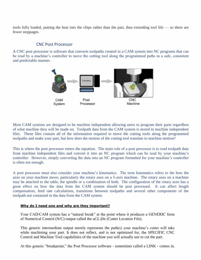
tools fully loaded, putting the heat into the chips rather than the part, thus extending tool life — so there are
fewer stoppages.
CNC Post Processor
A CNC post processor is software that converts toolpaths created in a CAM system into NC programs that can
be read by a machine’s controller to move the cutting tool along the programmed paths in a safe, consistent
and predictable manner.
Most CAM systems are designed to be machine independent allowing users to program their parts regardless
of what machine they will be made on. Toolpath data from the CAM system is stored in machine independent
files. These files contain all of the information required to move the cutting tools along the programmed
toolpaths and make your part, but how does the motion of the cutting tool translate to machine motion?
This is where the post processor enters the equation. The main role of a post processor is to read toolpath data
from machine independent files and convert it into an NC program which can be read by your machine’s
controller. However, simply converting the data into an NC program formatted for your machine’s controller
is often not enough.
A post processor must also consider your machine’s kinematics. The term kinematics refers to the how the
axes on your machine move, particularly the rotary axes on a 5-axis machine. The rotary axes on a machine
may be attached to the table, the spindle or a combination of both. The configuration of the rotary axes has a
great effect on how the data from the CAM system should be post processed. It can affect length
compensation, feed rate calculations, transitions between toolpaths and several other components of the
toolpath not contained in the data from the CAM system.
Why do I need one and why are they important?
Your CAD/CAM system has a “natural break” at the point where it produces a GENERIC form
of Numerical Control (N/C) output called the aCL-file (Cutter Location File).
This generic intermediate output merely represents the path(s) your machine’s cutter will take
while machining your part. It does not reflect, and is not optimized for, the SPECIFIC CNC
Control and Machine Tool capabilities of the machine you will actually use to cut the part.
At this generic “breakpoint,” the Post Processor software - sometimes called a LINK - comes in.

It takes the CL-file and processes it into the specific form of RS-274 NC data required by your
CNC and Machine Tool combination.
The quality of the final RS-274 part program (the extent to which it fully, optimally, and
accurately uses the capabilities of your machine tool) completely depends on the sophistication
and capabilities of the Post Processor software.
A poor Post Processor can mean longer cycle times. It can also produce incorrect NC data which
can scrap parts, damage equipment, or injure personnel. Inaccurate NC data output can lower part
quality and lessen cutting tool life.
In short, without the best Post Processor, you are missing out on the highest part throughput and
part quality. You are also missing out on producing parts at the lowest cost.
General structure of post processor:-
As the tie between CAD/CAM system and manufacturing, post processing is one of the
key technologies in numerical control programmed technologies, it directly influences the result
of using automatic programming system, the reliable operation of the machine and the processing
quality and efficiency of parts. Providing or developing effective post processing programs has
important significance to solve the bottleneck from design to manufacture, increase the
programming efficiency and reliability of machining. The research results can serve as references
to post processing program developing of other types of five axis CNC machines, which also
provide the thought for post processing program developing of other CAD/CAM software.
Overview
The entries in the configuration file fall into five main categories which are described briefly
below.
Global Statements
These determine the descriptive name for the post and its file extensions, whether the
output is in mm or inches, line numbering information, line terminators and default
formatting for numeric fields.
Start of File
This section deals with lines which must be output at the start of every program. This
information usually has the program name, commands for switching on the spindle, moves from
the home position etc.
Tool Moves
This section details how the actual tool moves are output for the machine tool. The tool
moves are sub-divided into two further categories.
Positioning Moves
These moves are used for positioning the tool while it is clear of the workpiece and are
usually
Made at the maximum speed of the machine tool.
Cutting Moves
These are moves made with the tool cutting material and are made at the speeds specified within
ArtCAM when the toolpath was created.
For both types of moves a format can optionally bespecified for the first move in the category
and a different format for all subsequent moves. This is often used when the first move switches
on a modal flag in the control (e.g. G0 to specify positioning moves) and then subsequent
moves do not need this command to be reoutput. See the fanuc.con configuration file for an
example of this behavior.
Toolchanges
If the machine tool is equipped with an automatic toolchanger, or the user wants to allow
manual toolchanges part way through an output file, the TOOLCHANGE statement can be used
to output the appropriate commands. NOTE: Toolchangers are NOT supported by
Mill Wizard.
End Of File
This section deals with lines which must be output at the end of every program. This section
usually contains commands for switching off the spindle, moving the tool back to the home
position etc.

UNIT 5 COMPUTER AIDED PROCESS
PLANNING
Computer-aided process planning
CAPP is a linkage between the CAD and CAM module. It provides for the planning of the process to be used
in producing a designed part. Process planning is concerned with determining the sequence of individual
manufacturing operations needed to produce a given part or product. The resulting operation sequence is
documented on a form typically referred to as a route sheet (also called as process sheet/method sheet)
containing a listing of the production operations and associated machine tools for a work part or assembly.
Process planning in manufacturing also refers to the planning of use of blanks, spare parts, packaging material,
user instructions (manuals) etc.
The term "computer-aided production planning" is used in different contexts on different parts of the
production process; to some extent CAPP overlaps with the term "PIC" (production and inventory control).
Process planning translates design information into the process steps and instructions to efficiently and
effectively manufacture products. As the design process is supported by many computer-aided tools, computer-
aided process planning (CAPP) has evolved to simplify and improve process planning and achieve more
effective use of manufacturing resources.[2]
process planning is of two types as:
1. generative type computer aided process planning.
2. variant type process planning.
Process planning encompasses the activities and functions to prepare a detailed set of plans and instructions to
produce a part. The planning begins with engineering drawings, specifications, parts or material lists and a
forecast of demand. The results of the planning are:
● Routings which specify operations, operation sequences, work centers, standards, tooling and
fixtures. This routing becomes a major input to the manufacturing resource planning system to
define operations for production activity control purposes and define required resources for
capacity requirements planning purposes.
● Process plans which typically provide more detailed, step-by-step work instructions including
dimensions related to individual operations, machining parameters, set-up instructions, and quality
assurance checkpoints.
● Fabrication and assembly drawings to support manufacture (as opposed to engineering drawings to
define the part).
Keneth Crow[3]
stated that "Manual process planning is based on a manufacturing engineer's experience and
knowledge of production facilities, equipment, their capabilities, processes, and tooling. Process planning is
very time-consuming and the results vary based on the person doing the planning".
According to Engelke,[4]
the need for CAPP is greater with an increased number of different types of parts
being manufactured, and with a more complex manufacturing process.
Computer-aided process planning initially evolved as a means to electronically store a process plan once it was
created, retrieve it, modify it for a new part and print the plan. Other capabilities were table-driven cost and
standard estimating systems, for sales representatives to create customer quotations and estimate delivery time.
COMPUTER AIDED QUALITY CONTROL
The quality control (QC) function has traditionally been performed using manual inspection
methods and statistical sampling procedures.
Manual inspection is generally a time-consuming procedure which involves precise, yet
monotonous work. If often requires that parts be removed from the vicinity of the
production machines to a separate inspection area. This causes delays and often
constitutes a bottleneck in the manufacturing schedule.
Inherent in the use of statistical sampling procedures is acknowledgment of the risk that
some defective parts will slip through. Indeed, statistical quality control attempts to
guarantee that a certain expected or average fraction defect rate will be generated during
the production/inspection process. The nature of traditional statistical QC procedures is
that something less than 100% good quality must be tolerated.
There is another aspect of the traditional QC inspection process which detracts from its
usefulness. It is often performed after the fact. The measurements are taken and the
quality is determined after the parts are already made. If the parts are defective, they must
be scrapped or reworked at a cost which is often greater than their original cost to
manufacture.
All of these various factors are driving the quality control function toward what we are calling
computer-aided quality control (CAQC). Other terms that have been applied to describe this
movement are "computer-aided inspection" (CAI) and "computer-aided testing" (CAT).
The objectives of computer-aided quality control are ambitious, yet straight forward. They are:
1. To improve product quality
2. To increase productivity in the inspection process
3. To increase productivity and reduce lead times in manufacturing
The strategy for achieving these objectives is basically to automate the inspection process
through the application of computers combined with advanced sensor technology. Wherever
technically possible and economically feasible, inspection will be done on a 100% basis rather
than sampling.
TERMINOLOGY IN QUALITY CONTROL
✔ Quality in a manufacturing context can be defined as the degree to which a product or its
components conform to certain standards that have been specified by the designer. The
design standards generally relate to the materials, dimensions and tolerances, appearance,
performance, reliability, and any other measurable characteristic of the product.
✔ Quality assurance (QA) is concerned with those activities which will maximize the
probability that the product and its components will be manufactured within the design
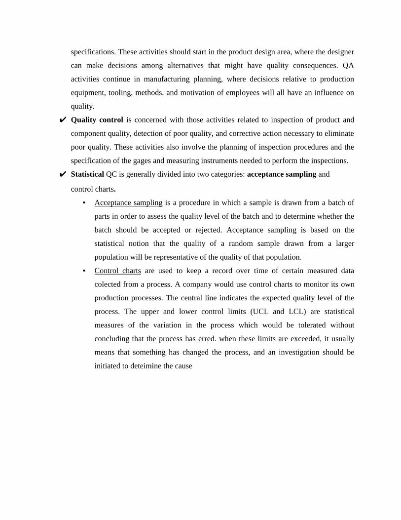
specifications. These activities should start in the product design area, where the designer
can make decisions among alternatives that might have quality consequences. QA
activities continue in manufacturing planning, where decisions relative to production
equipment, tooling, methods, and motivation of employees will all have an influence on
quality.
✔ Quality control is concerned with those activities related to inspection of product and
component quality, detection of poor quality, and corrective action necessary to eliminate
poor quality. These activities also involve the planning of inspection procedures and the
specification of the gages and measuring instruments needed to perform the inspections.
✔ Statistical QC is generally divided into two categories: acceptance sampling and
control charts.
▪ Acceptance sampling is a procedure in which a sample is drawn from a batch of
parts in order to assess the quality level of the batch and to determine whether the
batch should be accepted or rejected. Acceptance sampling is based on the
statistical notion that the quality of a random sample drawn from a larger
population will be representative of the quality of that population.
▪ Control charts are used to keep a record over time of certain measured data
colected from a process. A company would use control charts to monitor its own
production processes. The central line indicates the expected quality level of the
process. The upper and lower control limits (UCL and LCL) are statistical
measures of the variation in the process which would be tolerated without
concluding that the process has erred. when these limits are exceeded, it usually
means that something has changed the process, and an investigation should be
initiated to deteimine the cause
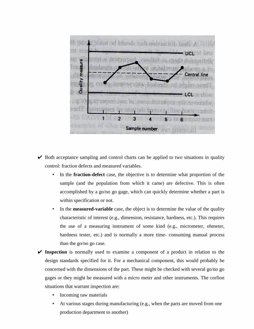
✔ Both acceptance sampling and control charts can be applied to two situations in quality
control: fraction defects and measured variables.
▪ In the fraction-defect case, the objective is to determine what proportion of the
sample (and the population from which it came) are defective. This is often
accomplished by a go/no go gage, which can quickly determine whether a part is
within specification or not.
▪ In the measured-variable case, the object is to determine the value of the quality
characteristic of interest (e.g., dimension, resistance, hardness, etc.). This requires
the use of a measuring instrument of some kind (e.g., micrometer, ohmeter,
hardness tester, etc.) and is normally a more time- consuming manual process
than the go/no go case.
✔ Inspection is normally used to examine a component of a product in relation to the
design standards specified for it. For a mechanical component, this would probably be
concerned with the dimensions of the part. These might be checked with several go/no go
gages or they might be measured with a micro meter and other instruments. The corfion
situations that warrant inspection are:
▪ Incoming raw materials
▪ At various stages during manufacturing (e.g., when the parts are moved from one
production department to another)
▪ At the completion of processing on the parts
▪ Before shipping the final assembled product to the customer
✔ Testing, on the other hand, is normally associated with the functional aspects of the item,
and it is often directed at the final product rather than its components. In this usage,
testing consists of the observation of the final product during operation under actual or
simulated conditions. If the product passes the test, it is deemed suitable for sale. Several
categories of tests used for final product evaluation:
▪ Simple functional tests under normal or simulated normal operating conditions
▪ Functional tests in which the product is tested under extreme (usually adverse
conditions)
▪ Fatigue or wear tests to determine how long the product will function until
Failure.
▪ Overload tests to determine the level of safety factor built into the product
▪ Environmental testing to determine how well the product will perform under
different environments (e.g., humidity, temperature)
THE COMPUTER IN QC
CAI and CAT are performed automatically using the latest computer and sensor technology.
Computer-assisted inspection and testing methods form only part, certainly a major part, of
computer-aided quality control. In our treatment of the subject we shall include the integration of
the quality control function with CAD/CAM as a critical ingredient in the success of CAQC.
The implications of the use of computer-aided quality control are important. The automated
methods of CAQC will result in significant changes from the traditional concepts and methods.
The following list will summarize the important effects likely to result from CAQC.
1. With CAI and CAT, inspection and testing will typically be accom plished on a 100%
basis rather than by the sampling procedures normally used in traditional QC.
2. Inspection during production will be integrated into the manufacturing process rather
than requiring that the parts be taken to some inspection area. This will help to reduce the
elapsed time to complete the parts. On line will have to be accomplished in much less
time than with current manual techniques.
3. The use of noncontact sensors will become much more widely used with computer- aided
inspection. With contact inspection devices, the part must usually be stopped and often
repositioned to allow the inspection device to be applied properly. With noncontact
sensor devices, the part can often be inspected "on the fly." These devices,

CAD/CAM IV B. TECH I SEM (R15)
driven by the high-speed data processing capability of the computer, can complete the inspection in a
small fraction of a second.
4. The on-line noncontact sensors will be utilized as the measurement component of computerized
feedback control systems. These systems will be capable of making adjustments to the process
variables based on analysis of the data collected by the sensors. Data would be plotted. This would not
only allow out of tolerance conditions to be identified, but gradual shifts in the process could also be
uncovered and corrective action taken. By regulating the process in this manner, parts will be made
much closer to the desired nominal dimension rather than merely within tolerance. Quality feedback
control systems will help to reduce scrap losses and improve product quality.
5. With computer-aided inspection technology, it may no longer be necessary to settle for less than
perfection.
6. Robots will be used increasingly in future inspection applications
7. There will also be applications for the computer in quality assurance as well as QC. The CAD/CAM
data base will be used to derive these various quality applications,
8. There will be CAI and CAT take its place, manual inspection activity will be reduced. Quality control
personnel will have to become more computer-wise and technologically sophisticated to operate the
more complex inspection and testing equipment and to manage the information that will result from
these more automated methods.
CONTACT INSPECTION METHODS
The contact methods usually involve the use of coordinate measuring machines (CMM). Most of these
machines today are either controlled by NC or computers. The coordinate measuring machine (CMM) is the
most prominent example of the equipment used for contact inspection of workparts. It consists of a table
which holds the part in a fixed, registered position and a movable head which holds a sensing probe. The
probe can be moved in three directions, corresponding to the x, y, and z coordinates. During operation, the
probe is brought into contact with the part surface to be measured and the three coordinate positions are
indicated to a high level of accuracy.
Today's coordinate measuring machines are computer controlled. The operation of the machine is similar to
an NC machine tool in which the movement of the measuring probe is either tape controlled or computer
controlled. Programs and coordinate data can bedownloaded from a central computer, much in the manner of
direct numerical control. Also similar to DNC is the capability to transmit data from the CMM back up to the
host computer.

Savings in inspection time by using coordinate measuring machines are significant. Typically, between 5 and
10% of the time is required on a CMM com pared to traditional manual inspection methods. Other
advantages include consistency in the inspection process from one part to the next which cannot be matched
by manual inspection, and reductions in production delays to get approval of the first workpiece in a batch.
The coordinate measuring machine is physically located away from the production machine, usually in a
separate area of the shop. Accordingly, the parts must be transported from the production area to the CMM.
In fact, if inspection is required at several different stages of production, several moves will be involved. One
possible approach to overcome this problem is to use inspection probes mounted in the spindle of the
machine tool. These inspection probes are contact sensing devices that operate with the machine tool much
like the coordinate measuring machine.
NONCONTACT INSPECTION METHODS
The noncontact methods are divided into two categories for our purposes:
1. Optical
a. Machine vision
b. Scanning laser beam devices
c. Photogrammetry
2. Non Optical
a. Electric Fiel techniques
b. Radiation techniques
c. Ultrasonic
NONCONTACT INSPECTION METHODS- OPTICAL
The advantages of noncontact inspection are:
1. It usually eliminates the need to reposition the work part.
2. Noncontact inspection is usually much faster than contact inspection.
3. It eliminates mechanical wear encountered with the contacting inspection probe because it eliminates
the probe.
4. It reduces potential danger to people, who must touch a hazardous material if contact inspection is
used.
5. It removes the possibility of damage to the surface of a part which migh result during contact
inspection.
Machine vision
Other names given to these systems include microprocessor-based television and computer vision. The
typical machine vision system consists of a TV camera, a digital computer, and an interface between them
that functions as a preprocessor. The combination of system hardware and software digitizes the picture and
analyzes the image by comparing it with data stored in memory. The data are often in the form of a limited
number of models of the objects which are to be inspected. There are several limitations of machine vision;
The first limitation is concerned with the problem of dividing the picture into picture elements. This is
very similar to the problem encountered in the development of graphics terminals for computer-aided
design.
⮚ A second limitation is that the object in front of the camera must be capable of being divided into areas of
contrasting lightness and darkness.
⮚ Third limitations is on the capability of machine vision systems recognize the object in the viewing area.
Machine vision inspection problems can be divided into two categories:
1. Noncontact gaging of dimensions - Noncontact gaging in machine vision involves the inspection of
part size and other features where it is not necessary to process the image of the entire part out line,
only those portions that must be examined for dimensional accuracy. During setup for an inspection, a
parts-training program is used to view the workpart of interest on a TV monitor. With the image in
fixed position on the screen, the operator manipulates a cursor to define the edges of interest and to
apply an appropriate scale factor to establish the correct units of measure.
2. Inspection based on pattern recognition of object features - It is based on pattern recogition
techniques. In this category, the attributes of the object to be inspected are typically more subjective

and in some respects more complicated than part dimensions. The machine vision pattern recognition
process can be conceptualized as involving a comparison of features (for example, area, perimeter,
and so on) between the object being inspected and the model of the object stored in computer
memory.
Scanning laser beam devices
The scanning laser beam device relies on the measurement of time rather than light, although a light sensor is
required in its operation. The schematic diagram of its operation is pictured in Figure. A laser is used to
project a continuous thin beam of light. A rotating mirror deflects the beam so that it sweeps across the object
to be measured. The light sensor is located at the focal point of the lens system to detect the interruption of
the light beam as it is blocked by the object. The time lapse corresponding to the interruption of the light
beam is meas ured to determine the desired dimension of the part. Typically, a microprocessor is programmed
to make the conversion of the time lapse into a dimensional value and to perform other functions, such as
signaling an automatic parts-rejection mechanism to eject a defective part from the line.
Photogrammetry
Photogrammetry involves the extraction of three-dimensional data from a pair of photographs taken at
different angles. The two photographs can be combined much in the way that a stereoscope uses a pair of
photographs to form a three-dimensional image for the viewer.
In the measurement process used for inspection, the two photographs are read by a device called a mono
comparator to establish coordinates and positions of objects. These data are then computer-analyzed to
extricate the desired information.
The drawback of the conventional photogrammetry technique is the need for photographs, an inconvenient
and time-consuming step in the procedure. An improvement in the technique which is being developed will
delete the photo graphic step. Instead, the images froiri two cameras set up in a stereoscopic configuration
will send visual data directly to a computer for mathematical analysis and real-time extraction of dimensional
data. This arrangement is illustrated in Figure.
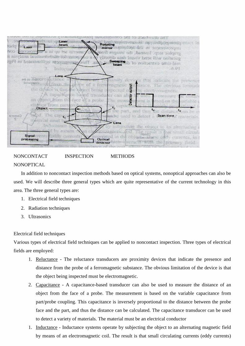
NONCONTACT INSPECTION METHODS
NONOPTICAL
In addition to noncontact inspection methods based on optical systems, nonoptical approaches can also be
used. We will describe three general types which are quite representative of the current technology in this
area. The three general types are:
1. Electrical field techniques
2. Radiation techniques
3. Ultrasonics
Electrical field techniques
Various types of electrical field techniques can be applied to noncontact inspection. Three types of electrical
fields are employed:
1. Reluctance - The reluctance transducers are proximity devices that indicate the presence and
distance from the probe of a ferromagnetic substance. The obvious limitation of the device is that
the object being inspected must be electromagnetic.
2. Capacitance - A capacitance-based transducer can also be used to measure the distance of an
object from the face of a probe. The measurement is based on the variable capacitance from
part/probe coupling. This capacitance is inversely proportional to the distance between the probe
face and the part, and thus the distance can be calculated. The capacitance transducer can be used
to detect a variety of materials. The material must be an electrical conductor
1. Inductance - Inductance systems operate by subjecting the object to an alternating magnetic field
by means of an electromagnetic coil. The result is that small circulating currents (eddy currents)
are generated in the object. These eddy currents, in turn, create their own magnetic field, which
interacts with the primary field. This interaction affects the impedance of the coil, which an be
measured and analyzed to determine certain characteristics about the object
Radiation Techniques
X- ray radiation techniques are employed for purposes of noncontact inspection in the metals and
metalworking industry. The amount of radiation absorbed by a material can be used to measure its thickness
and other quality characteristics. In a typical application in a rolling mill, an X-ray scanning unit measure the
thickness of the plates or strips going through the rolls so that the proper adjustments can be made in the
rollers. X-ray techniques are also used to inspect weld quality in fabricated steel and aluminum pressure
vessels and pipes. In this case the radiation can be used to detect flaws and voids in the weld.
Ultrasonics
Ultrasonics in inspection work involves the use of very high frequency (above 20,000 Hz) sound waves to
indicate quality. A principal application is in nondes tructive testing of materials. Ultrasonic techniques can
also be applied to the problem of determining dimensional features of workparts. One approach, called
acoustical phase monitoring, involves the analysis of sound waves reflected from the surface of an object.
The sound waves are produced by an emitter and directed against the object. Assuming that all else remains
constant, the reflected sound pattern from the object should always be the same. During inspection, the sound
pattern from the part is analyzed by a computer program and compared to the pattern of a standard part, one
that is known to be of acceptable quality. If the pattern of the test part differs significantly from that of the
standard, it is rejected.
COMPUTER-AIDED TESTING
Testing is generally applied to assess the functional performance of a final product. It may also be applied for
major subassemblies of the final product, such as the engines and transmissions of automobiles. Testing may
also be performed on individual components in which some functional aspect of the component must be
examined and cannot be implicitly determined by means of a mechanical inspection. An example of this
might be the case of a brake lining in which the dimensions are correct, but the functional performance must
be determined through a testing procedure.
Computer-aided testing is simply the application of the computer in the testing procedure. There are different
levels of automation which can be found CAT. At the lowest level, the computer would be used simply to
monitor the test and analyze the results, but the testing procedure itself is manually set up, initiated, and
controlled by a human operator. In this case the computer receives the data from a data logger or a data
acquisition system and prepares a report of the test results
Computer-aided test cells are applied in situations where the product is complicated and produced in

significant quantities, Examples include automobile engines, aircraft engines, and electronic integrated
circuits. Advantages of these cells include higher throughput rates, greater consistency in the test procedure,
and less floor space occupied by the automated cell As compared to a manual facility of similar capacity.
\
INTEGRATION OF CAQC WITH CAD/CAM
Although many important benefits result from the use of computer-aided quality control, additional
benefits can be obtained by integrating CAQC with CAD/CAM.
● The design department creates the product definition and the manufacturing department makes use
of and supplements this definition to develop the
manufacturing plan. It is important to add the QC connection to the CAD/CAM framework.
● The quality control department must use the same CAD/CAM data base to perform its function. These
quality standards are all contained in the CAD/CAM data base, available for QC to use.
● One way in which the data base can be used is to develop the NC programs to operate the tape-
controlled or computer-controlled coordinate measuring machines. These programs can be generated
automatically.
● These programs would then be down loaded to the CMM through a DNC link from the central
computer to the controller unit for the CMM. The same sort of downloading process is possible for
some of the noncontact inspection methods.
● Another way in which a common data base is helpful to QC is when engineering changes are made to
the product. It is helpful for any changes to be recorded in a common data file for all departments,
including QC, to use.
● Another area where CAD/CAM benefits the QC function is in computer production monitoring. The
types of production records that are generated during computer monitoring are sometimes useful to
the quality control department in tracing the cause of poor quality in a particular production lot.

Top Related
Copyright © 2022 FDOKUMEN

