


Bahasa
Halaman
Hukum


AccuRange AR550™ Laser Sensor
User’s Manual
For use with AR550™ High Speed Laser Sensor
March 31, 2021
Acuity Laser A product line of Schmitt Industries, Inc.
2765 NW Nicolai St. Portland, OR 97210
www.acuitylaser.com

2 AR550 Operation Manual
Limited Use License Agreement
CAREFULLY READ THE FOLLOWING TERMS AND CONDITIONS BEFORE OPENING THE PACKAGE CONTAINING THE PRODUCT AND THE COMPUTER SOFTWARE LICENSED HEREUNDER. CONNECTING POWER TO THE MICROPROCESSOR CONTROL UNIT INDICATES YOUR ACCEPTANCE OF THESE TERMS AND CONDITIONS. IF YOU DO NOT AGREE WITH THE TERMS AND CONDITIONS, PROMPTLY RETURN THE UNIT WITH POWER SEAL INTACT TO THE DEALER FROM WHOM YOU PURCHASED THE PRODUCT WITHIN FIFTEEN DAYS FROM DATE OF PURCHASE AND YOUR PURCHASE PRICE WILL BE REFUNDED BY THE DEALER. IF THE DEALER FAILS TO REFUND YOUR PURCHASE PRICE, CONTACT SCHMITT INDUSTRIES, INC. IMMEDIATELY AT THE ADDRESS SET OUT BELOW CONCERNING RETURN ARRANGEMENTS.
Schmitt Industries, Inc. provides the hardware and computer software program contained in the microprocessor control unit. Schmitt Industries, Inc. has a valuable proprietary interest in such software and related documentation ("Software) and licenses the use of the Software to you pursuant to the following terms and conditions. You assume responsibility for the selection of the product suited to achieve your intended results, and for the installation, use and results obtained.
License Terms And Conditions
a. You are granted a non-exclusive, perpetual license to use the Software solely on and in conjunction with the product. You agree that the Software title remains with Schmitt Industries, Inc. at all times.
b. You and your employees and agents agree to protect the confidentiality of the Software. You may not distribute, disclose, or otherwise make the Software available to any third party, except for a transferee who agrees to be bound by these license terms and conditions. In the event of termination or expiration of this license for any reason whatsoever, the obligation of confidentiality shall survive.
c. You may not disassemble, decode, translate, copy, reproduce, or modify the Software, except only that a copy may be made for archival or back-up purposes as necessary for use with the product.
d. You agree to maintain all proprietary notices and marks on the Software. e. You may transfer this license if also transferring the product, provided the transferee agrees
to comply with all terms and conditions of this license. Upon such transfer, your license will terminate, and you agree to destroy all copies of the Software in your possession.

AR550 Operation Manual i
Procedures for Obtaining Warranty Service
1. Contact your Acuity distributor or call Schmitt Industries, Inc. to obtain a return merchandise authorization (RMA) number within the
applicable warranty period. Schmitt Industries will not accept any returned product without an RMA number.
2. Ship the product to Schmitt Industries, postage prepaid, together
with your bill of sale or other proof of purchase. your name, address, description of the problem(s). Print the RMA number you have obtained
on the outside of the package.
This device has been tested for electromagnetic emissions and
immunity and has been found to be in compliance with the following directives for class A equipment:
EN 60825-1:2014
This device complies with part 15 of the FCC Rules. Operation is subject to the following two conditions:
(1) This device may not cause harmful interference, and (2) this device must accept any interference received, including
interference that may cause undesired operation. Note: This equipment has been tested and found to comply with the
limits for a Class A digital device, pursuant to part 15 of the FCC rules. These limits are designed to provide reasonable protection against
harmful interference when the equipment is operated in a commercial environment. This equipment generates, uses, and can radiate radio frequency energy and, if not installed and used in accordance with the
instruction manual, may cause harmful interference to radio communications. Operation of this device in a residential area is likely
to cause harmful interference in which case the user will be required to correct the interference at his or her own expense.
This manual copyright © 2021, Schmitt Industries, Inc.
ii AR550 Operation Manual
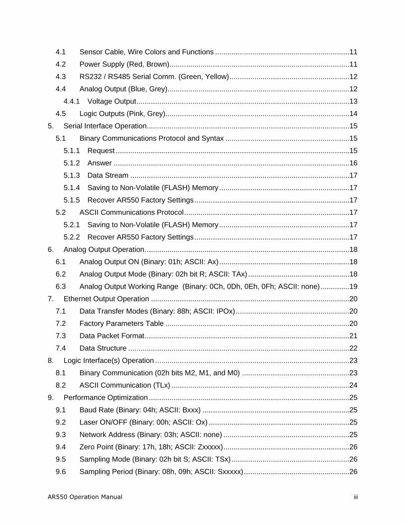
User’s Manual for the
AR550™ Series Laser Sensor Rev. 3.0
Table of Contents
1. Introduction ........................................................................................................................ 1
1.1 General Overview ....................................................................................................... 1
1.2 Definition of Terms ..................................................................................................... 2
1.3 Quick Start Instructions ............................................................................................... 2
1.3.1 Mounting ................................................................................................................. 2
1.3.2 Serial Data Wires .................................................................................................... 3
1.3.3 Analog Output Signals ............................................................................................ 3
2. General Description ............................................................................................................ 4
2.1 Principles of Operation ............................................................................................... 4
2.2 Mechanical Dimensions .............................................................................................. 5
2.3 Installation .................................................................................................................. 5
2.4 Laser Safety ............................................................................................................... 6
2.5 Sensor Maintenance ................................................................................................... 7
2.6 Sensor Service ........................................................................................................... 7
2.7 Sensor Specifications ................................................................................................. 7
3. Installation and Checkout ................................................................................................... 8
3.1 Mounting ..................................................................................................................... 8
3.2 Cabling for sensor unit ................................................................................................ 8
3.2.1 Standalone Cabling ................................................................................................ 8
3.2.2 Serial Connection to a Host Computer .................................................................... 9
3.3 Power On ................................................................................................................... 9
3.3.1 Serial Communications Check ...............................................................................10
3.3.2 Sensor Output Check.............................................................................................10
4. Signal and Power Interface ...............................................................................................11
AR550 Operation Manual iii
4.1 Sensor Cable, Wire Colors and Functions .................................................................11
4.2 Power Supply (Red, Brown) .......................................................................................11
4.3 RS232 / RS485 Serial Comm. (Green, Yellow) ..........................................................12
4.4 Analog Output (Blue, Grey) ........................................................................................12
4.4.1 Voltage Output .......................................................................................................13
4.5 Logic Outputs (Pink, Grey).........................................................................................14
5. Serial Interface Operation ..................................................................................................15
5.1 Binary Communications Protocol and Syntax ............................................................15
5.1.1 Request .................................................................................................................15
5.1.2 Answer ..................................................................................................................16
5.1.3 Data Stream ..........................................................................................................17
5.1.4 Saving to Non-Volatile (FLASH) Memory ...............................................................17
5.1.5 Recover AR550 Factory Settings ...........................................................................17
5.2 ASCII Communications Protocol ................................................................................17
5.2.1 Saving to Non-Volatile (FLASH) Memory ...............................................................17
5.2.2 Recover AR550 Factory Settings ...........................................................................17
6. Analog Output Operation ...................................................................................................18
6.1 Analog Output ON (Binary: 01h; ASCII: Ax) ...............................................................18
6.2 Analog Output Mode (Binary: 02h bit R; ASCII: TAx) .................................................18
6.3 Analog Output Working Range (Binary: 0Ch, 0Dh, 0Eh, 0Fh; ASCII: none) ..............19
7. Ethernet Output Operation ................................................................................................20
7.1 Data Transfer Modes (Binary: 88h; ASCII: IPOx) .......................................................20
7.2 Factory Parameters Table .........................................................................................20
7.3 Data Packet Format ...................................................................................................21
7.4 Data Structure ...........................................................................................................22
8. Logic Interface(s) Operation ..............................................................................................23
8.1 Binary Communication (02h bits M2, M1, and M0) ....................................................23
8.2 ASCII Communication (TLx) ......................................................................................24
9. Performance Optimization .................................................................................................25
9.1 Baud Rate (Binary: 04h; ASCII: Bxxx) .......................................................................25
9.2 Laser ON/OFF (Binary: 00h; ASCII: Ox) ....................................................................25
9.3 Network Address (Binary: 03h; ASCII: none) .............................................................25
9.4 Zero Point (Binary: 17h, 18h; ASCII: Zxxxxx) .............................................................26
9.5 Sampling Mode (Binary: 02h bit S; ASCII: TSx) .........................................................26
9.6 Sampling Period (Binary: 08h, 09h; ASCII: Sxxxxx) ...................................................26
iv AR550 Operation Manual
9.6.1 Output Rate ...........................................................................................................27
9.7 Maximum Integration Time (Binary: 0Ah, 0Bh; ASCII: Exxxx) ...................................27
9.8 Results Lock (Binary: 10h; ASCII: Dxxx) ....................................................................28
9.9 Results Averaging Mode (Binary: 02h bit A; ASCII: TMx) ..........................................28
9.9.1 Averaging Configuration (Binary: 06h; ASCII: Gxxx) .............................................29
10. Demo and Configuration Software .................................................................................30
10.1 Program Setup ..........................................................................................................30
10.2 Connecting to the sensor (RS232/RS485) .................................................................30
10.3 Sensor Operation ......................................................................................................31
10.4 Display and Archiving of Data ....................................................................................32
10.5 Setting and Saving Sensor Parameters .....................................................................33
10.5.1 Setting Parameters ............................................................................................33
10.5.2 Saving Parameters ............................................................................................34
10.5.3 Saving and Writing a Group of Parameters ........................................................34
10.6 Factory Reset ............................................................................................................34
11. Serial Command Quick Reference ................................................................................35
11.1 Binary Communications Reference ............................................................................35
11.2 ASCII Communications Reference ............................................................................38
12. Accessories ...................................................................................................................40
12.1 Protective Enclosure ..................................................................................................40
12.2 Spray Guard ..............................................................................................................41
AR550 Operation Manual 1
1. Introduction
This section is a guide to getting started with the AR550 and this manual. The AR550 has a number of configurable parameters, but many applications can use the sensor in its default factory configuration. This manual contains information
for a variety of AR550 sensor configurations that can be ordered from Acuity. Your specific AR550 model may not have all interfaces and functions described in
this manual.
The recommended order for reading the manual is:
• General Overview – Gives a brief understanding of the sensor operation.
• Operating Guidelines – Provides a few important safety tips.
• Definition of Terms – An aid for proper communication.
• Quick Start Instructions – This should provide the information necessary to connect the sensor and verify its operation, either with a serial terminal program at 9600 baud, or by connecting the current loop or Alarm Output
interface.
• General Description – Gives important laser, operation, mechanical, and
mounting information.
• Installation and Checkout – Tailor the application. Use the other chapters
for reference: Signal and Power Interface – how to hook everything up Serial Interface Operation – modes, formats, bias
Analog Output Operation – current loop, voltage, scaling Alarm Output Operation – alarm settings
Performance Optimization – Sample Rate, Background Elimination, Exposure control AR550 Command Set – explains all commands for customizing the
application
1.1 General Overview
The AR550 is a triangulation sensor that measures distance using a laser beam,
a camera, and a microprocessor. A variety of models are specified, each to allow a different measurement range, communications interface, laser power and environmental options. Models vary in range from 2 to 750 mm. Interface
options include RS232, RS485, 0-10V and Ethernet. Sensors can be optionally ordered with an internal heater or air-cooling jacket.
The accuracy is generally specified with a linearity of about +/- 0.15% of the range.
A variety of configuration settings can be selected via the serial port or
Ethernet interface (available option). The complete list of settings is found in the AR550 Command Set chapter and each setting is discussed in detail in a
specific operation chapter.
The Sample Rate can be specified and the sensor has capability of up to 70,000 samples per second. Several other configurable parameters enhance the
2 AR550 Operation Manual
performance. Sampling may be turned on and off. It can even be triggered using an input signal wire or a serial command.
After making changes to the configuration, it may be viewed, saved in non-volatile memory, and restored. At power-on the sensor uses the most recently
saved configuration settings.
Do not attempt to disassemble the sensor or loosen any screws. Improper disassembly will destroy the optical alignment of the sensor and
necessitate factory repairs.
Do not operate the sensor in areas Where: the sensor case is exposed
to direct sunlight for extended periods or Where: the air temperature is more than 60C (140F) or less than -10°C (-14°F). The optional
internal heater or air-cooling jacket may extend these temperature limits.
Don’t allow fast temperature variations during sensor operation.
Avoid excessive vibration and shocks. The sensor contains securely
mounted but precisely aligned optical components.
Do not operate the sensor if the lens is fogged or dirty.
Do not scratch the lenses on the front face of the sensor. Keep the
lenses clean with expert optical procedures. The lenses are glass with an anti-reflection coating. Avoid the use of organic cleaning solvents.
Do not touch the lenses with bare fingers. The oils are very difficult to remove.
Operate only with DC supply voltages between 9 and 36 volts.
1.2 Definition of Terms
Sensor – The complete AR550 measurement device.
Target – The object of measurement. The relative distance from the sensor to the target is measured by the sensor.
Laser, Laser beam – This bright light is emitted from the sensor, reflected from
the target, and collected by the camera lens. For the AR550, it is visible (Red or Blue) radiation or in some specially ordered configurations,
infrared.
<Range> – The maximum relative distance measurable by the sensor.
Base Distance – The distance from the face of the laser to the start of the measurement window (range).
1.3 Quick Start Instructions
This will get the sensor running in its factory default configuration.
Only one output type (Serial or Analog) is needed to indicate sensor operation.
1.3.1 Mounting
Quick suggestion: Lay the sensor on the floor or a table. It may need to be held in place with a clamp or a weight. Orient the laser so that the laser is
not obstructed. Use a piece of paper such as a business card to insert into the beam to use as a measurement target. The laser should be aimed at a
AR550 Operation Manual 3
target such that the distance from the reference point to the target can be measured.
Mount the sensor in such a way that the case is not twisted or warped. The AR550 can be screwed on using two fastening screws 3.6 /06x7. The
fastening screws are not included in the scope of delivery.
Attach the cable(s) 8-pin connector to the plug(s) on the rear of the sensor.
Connect the red (Supply +) and brown (Ground) wires of the sensor cable
to a 9 to 36 volt DC power supply (or use the power supply if the sensor came with one).
1.3.2 Serial Data Wires
The serial connection is required to set up a unit for operation. If not using the Acuity Connectivity kit which includes a serial cable, the customer must
make their own D-sub 9 serial connector.
1.3.2.1 RS232 serial
Connect the RS232 wires to a 9 pin D-SUB male connector that can be plugged into a COM port of a PC (RS232): Gray (Ground) to pin 5, Green (Transmit) to pin 2, and Yellow (Receive) to pin 3. See section 0.
Use the Demo and Configuration Software (see Section 10) to connect to the sensor via the serial port and get distance measurements.
1.3.2.2 RS485 serial
Connect the RS485 wires to a RS485 adapter connected to a PC COM port Gray (Ground) to pin 5, Green (Data+) to pin 2, and Yellow (Data -) to pin
3. See section 0.
Follow the same instructions for RS232 serial above.
1.3.3 Analog Output Signals
Quick suggestion: connect a DVM (digital voltmeter) to the wires: Gray to Common, Blue to V input. Type QA. The output is 0-10V from 0 to the
maximum range. The meter should read near 0V when a target is placed in the laser beam near 0 mm and 10V near the end of the range.
4 AR550 Operation Manual
2. General Description
The AR550 is an ultra-compact laser diode-based distance measurement sensor with available ranges covering 2 to 750 mm. Consult the AR550 data sheet for exact model range availabilities. The accuracy is generally specified with an
absolute linearity of +/- 0.15% of the span with a resolution of 0.01% of the span for ranges up to the 750 mm model. Linearity will vary depending on sample
averaging, temperature, target stability and surface reflectivity of the target surface. The AR550 laser sensors can be ordered with red or blue laser diodes and a variety of data interfaces. The sensor can be triggered externally and also
has logic outputs to trigger alarms, etc.
2.1 Principles of Operation
The AR550 uses laser triangulation principles to measure distance. The laser beam is projected from the housing’s aperture and shines on a target surface,
where it creates a small spot. From there, the laser light is scattered in all directions for diffuse surfaces (mirrors reflect the light specularly). A collection lens is located behind a window in the sensor. It collects a portion of the
reflected light, which is focused on a CMOS detector array. The linear position of this reflected spot is converted to an electrical signal which is proportional
to the target distance relative to the sensor. The position is processed and communicated via serial, analog, digital or Ethernet interfaces.
AR550 Operation Manual 5
2.2 Mechanical Dimensions
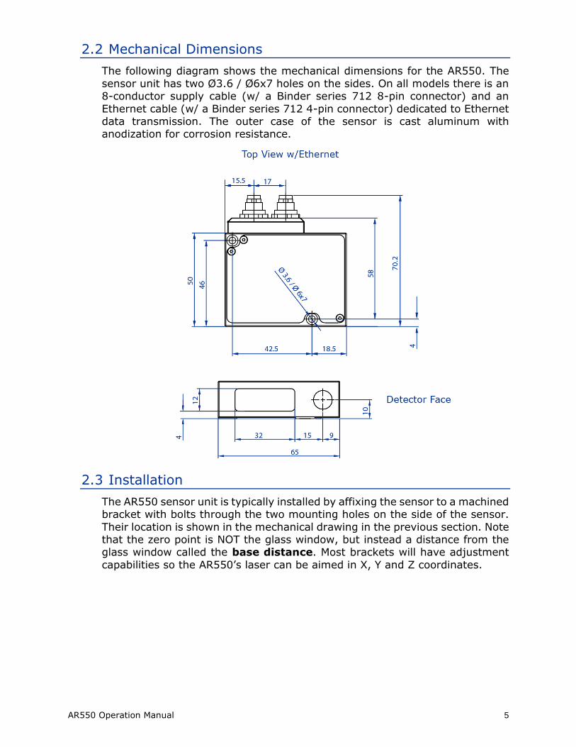
The following diagram shows the mechanical dimensions for the AR550. The
sensor unit has two Ø3.6 / Ø6x7 holes on the sides. On all models there is an 8-conductor supply cable (w/ a Binder series 712 8-pin connector) and an
Ethernet cable (w/ a Binder series 712 4-pin connector) dedicated to Ethernet data transmission. The outer case of the sensor is cast aluminum with anodization for corrosion resistance.
2.3 Installation
The AR550 sensor unit is typically installed by affixing the sensor to a machined bracket with bolts through the two mounting holes on the side of the sensor.
Their location is shown in the mechanical drawing in the previous section. Note that the zero point is NOT the glass window, but instead a distance from the glass window called the base distance. Most brackets will have adjustment
capabilities so the AR550’s laser can be aimed in X, Y and Z coordinates.

6 AR550 Operation Manual
2.4 Laser Safety
Installers of laser sensors should follow precautions set forth by ANSI Z136.1
Standard for the Safe Use of Lasers or by their local safety oversight organization. The AR550 is a class 3R or 3B product under FDA 21CFR.
Red Lasers Blue Lasers
Figure 1 AR550 laser safety labels (all available diodes)

AR550 Operation Manual 7
2.5 Sensor Maintenance
The AR550 sensor and module require little maintenance from the user. The
sensor lens should be kept clean of dust buildup as a part of regular preventative maintenance. Use compressed air to blow dirt off the windows or
use delicate tissue wipes. Do not use any organic cleaning solvents on the sensor. If your sensor does not function according to specifications, contact Schmitt Industries, Inc. Do not attempt to loosen any screws or open the
sensor housing.
2.6 Sensor Service
The AR550 sensor is not user serviceable. Refer all service questions to Schmitt Industries, Inc. Do not attempt to loosen any screws or open the sensor
housing.
2.7 Sensor Specifications
Units in mm unless noted.
Note: Specifications may change with future revisions.
8 AR550 Operation Manual
3. Installation and Checkout
3.1 Mounting
Mount the sensor in such a way that the case not twisted or warped. Do not clamp or squeeze the sensor case excessively. If the case is distorted, the
sensitivity and accuracy of the sensor may be affected.
3.2 Cabling for sensor unit
The AR550 sensor has a multipurpose cable with 8 conductors (included) and an ethernet cable with 4 conductors.
The standard cable is LiYCY (TP) a flexible, overall shielded, PVC twisted-pair data transmission cable for use in flexible and stationary applications under low mechanical stress with free movement without any tensile stress, loads or
forced movements in dry, damp and wet conditions. The twisted pair construction reduces interference (crosstalk) within the cable while the tinned
copper braid shield offers optimum protection from electrical and electromagnetic interference. The AR550 is not suggested for outdoor use.
The standard cable length is 2 m in length. Longer cable lengths are available
upon request. Connection and termination according to the instructions is essential for correct sensor operation. Read the wire descriptions in Section
4.1 for connection information.
Connect the cable’s 8-pin connector (Binder series 712, female) to the plug (Binder series 712, male) on the back cover of the AR550 sensor. Be sure to
tightly secure the connection for full protection from dust and water.
3.2.1 Standalone Cabling
To use the AR550 sensor unit without a serial connection to a host computer, the only connections necessary are the power and ground wires,
the analog output wires, and optionally the alarm output wire connecting to your data display, recording, or control equipment. See Signal and
Power Interface (section 4) for wire connections. In its default configuration, the AR550 should stream measurement distances on power-up.
The alarm output wire can be used to connect to control equipment.

AR550 Operation Manual 9
3.2.2 Serial Connection to a Host Computer
The simplest way to connect the AR550 sensor to a PC for initial
configuration or regular distance measuring is with the use of an Acuity Connectivity Kit. This is a sealed connection box which contains terminal
blocks for each wire lead. It also has an AC power supply and a 2m RS232 serial cable for connection to a PC. Without the Acuity connectivity kit, the user must connect a DB9 plug to the cable using the directions below.
Each AR550 is configured for either RS232 or RS485 serial communications. Please be sure to confirm the serial communication
standard used by the control system you intend to use before ordering. If you have an AR550 with the incorrect standard for your application, a third-party converter will be necessary.
RS232: An AR550 with the RS232 option can be wired directly to a 9-pin D-sub serial connector using the table below.
Wire Color Function Binder 712 pin # DB9 pin #
Gray Ground 5 5
Green TxD 3 2
Yellow RxD 4 3
To connect the AR550 this way to a modern PC, you will likely need a serial
to USB converter. Acuity recommends using a converter that contains an FTDI chip.
RS485: To wire an AR550 with the RS485 option to a 9-pin serial
connector, please refer to the wire functionality chart in section 4 for details.
For testing use the included Demo and Configuration software. Refer to section 10.
3.3 Power On
Connect a power supply to the power and ground lines of the sensor cable. The AR550 can operate with a power supply supplying 9-36 volts. Acuity
recommends a 15 or 24 volt power supply. See Signal and Power Interface (section 4) for wire connections. Only the power and ground need be connected for operation in addition to the serial interface.
When power is applied the laser beam will be emitted from the round sensor window.
10 AR550 Operation Manual
3.3.1 Serial Communications Check
If no information is received over the serial port, check the power supply
and serial wire connections. The sensor may be in a configuration that prevents serial communication, such as being set at the wrong baud rate
or in a polling mode.
Use the Demo and Configuration Software to restore the unit to factory defaults. Otherwise, the 04h command will restore factory defaults to the
device.
3.3.2 Sensor Output Check
If the sensor output value is in error, check that the sensor and target are
stationary and stable and that the laser beam is hitting the target.
The sensor may need to warm up for 5-10 minutes before reaching
full accuracy. Leave it on for a few minutes and re-check the sensor accuracy.

AR550 Operation Manual 11
4. Signal and Power Interface
4.1 Sensor Cable, Wire Colors and Functions
The AR550 sensor includes a multipurpose cable (sensor cable) with solder tail wires. Connection and termination according to the
instructions is essential for correct sensor operation. Read the wire descriptions for connection information.
7 1
2
34
86
5
Figure 2 AR550 cable with 8 conductors (Binder 712, #09-0427-80-08)
The tables below shows the wiring on systems ordered without power
supplies.
Wire Pin Function in All Modes
White 1 Trigger Input
Brown 2 Ground (Power)
Green 3 TxD (Data +)
Yellow 4 RxD (Data -)
Gray 5 Ground (Signal common)
Pink 6 Logic Output (programmable)
Blue 7 Analog output (current loop / voltage)
Red 8 Power, Voltage in
4.2 Power Supply (Red, Brown)
The Brown wire is the Power Supply Common return, also named Ground.
It carries the return current for the power supply.
The Red wire is the Power Supply Input to the sensor. The sensor requires +9 - 36 VDC power and consumes 1.5 – 2 Watts of power (< 250mA
draw) depending on the sensor’s configuration.
Power supplies from 9 VDC to 36 VDC may be used. Higher voltages will
result in excessive current drawn by the over-voltage protection circuitry and may cause permanent damage. Voltages less than 9 VDC may result in inaccurate measurement readings or non-functionality.
12 AR550 Operation Manual
4.3 RS232 / RS485 Serial Comm. (Green, Yellow)
Your sensor is configured with either RS232 or RS485 communications
See Serial Interface Operation (section 5) for information on commands and data. The maximum baud rate is 921.6 KBaud for both RS232 and
RS485.
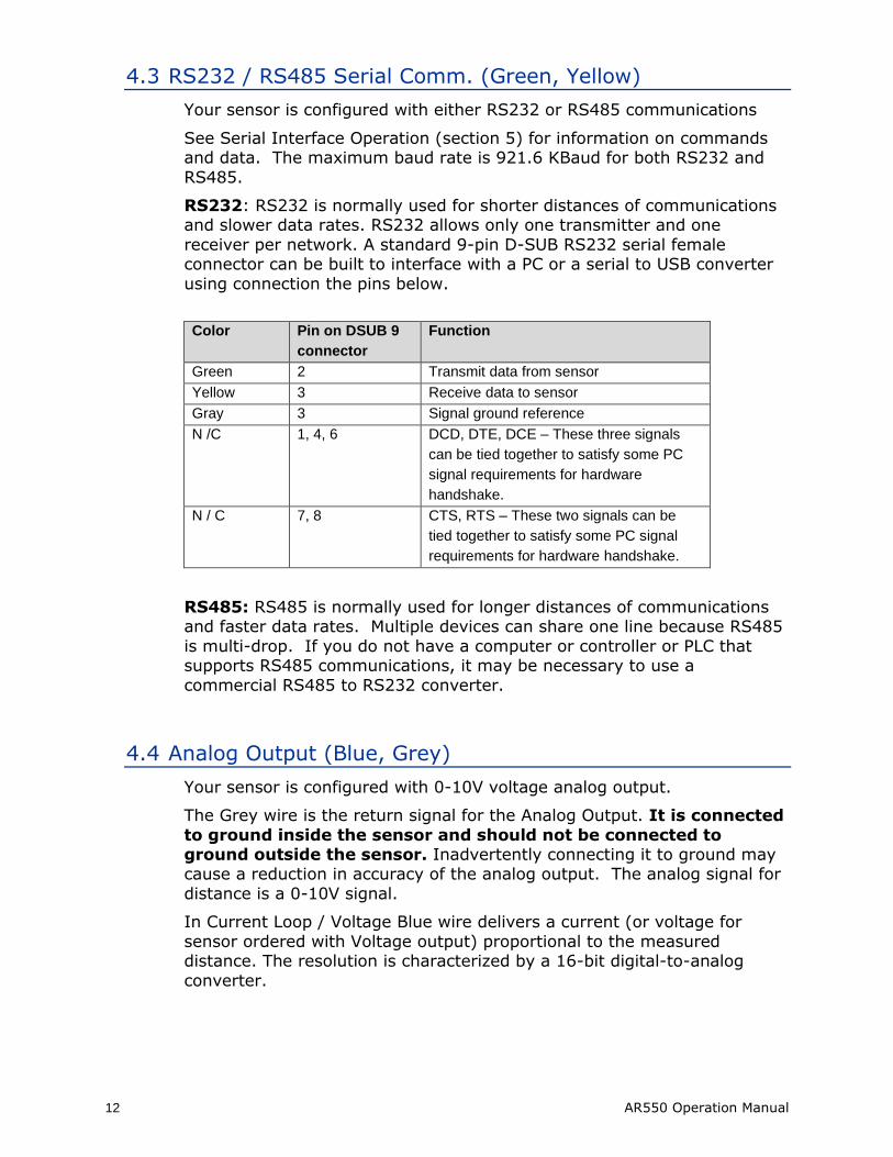
RS232: RS232 is normally used for shorter distances of communications and slower data rates. RS232 allows only one transmitter and one
receiver per network. A standard 9-pin D-SUB RS232 serial female connector can be built to interface with a PC or a serial to USB converter
using connection the pins below.
Color Pin on DSUB 9
connector
Function
Green 2 Transmit data from sensor
Yellow 3 Receive data to sensor
Gray 3 Signal ground reference
N /C 1, 4, 6 DCD, DTE, DCE – These three signals
can be tied together to satisfy some PC
signal requirements for hardware
handshake.
N / C 7, 8 CTS, RTS – These two signals can be
tied together to satisfy some PC signal
requirements for hardware handshake.
RS485: RS485 is normally used for longer distances of communications and faster data rates. Multiple devices can share one line because RS485
is multi-drop. If you do not have a computer or controller or PLC that supports RS485 communications, it may be necessary to use a
commercial RS485 to RS232 converter.
4.4 Analog Output (Blue, Grey)
Your sensor is configured with 0-10V voltage analog output.
The Grey wire is the return signal for the Analog Output. It is connected
to ground inside the sensor and should not be connected to ground outside the sensor. Inadvertently connecting it to ground may cause a reduction in accuracy of the analog output. The analog signal for
distance is a 0-10V signal.
In Current Loop / Voltage Blue wire delivers a current (or voltage for
sensor ordered with Voltage output) proportional to the measured distance. The resolution is characterized by a 16-bit digital-to-analog
converter.

AR550 Operation Manual 13
4.4.1 Voltage Output
The voltage output connection scheme is shown in the. To reduce noise, it
is recommended to install an RC (resistor / capacitor) filter before the measuring instrument. The filter capacitor value is indicated for maximum
sampling frequency of the sensor (9.4 kHz) and this value increases in proportion to the frequency reduction.
Figure 3 Wiring Diagram for Voltage output
14 AR550 Operation Manual
4.5 Logic Outputs (Pink, Grey)
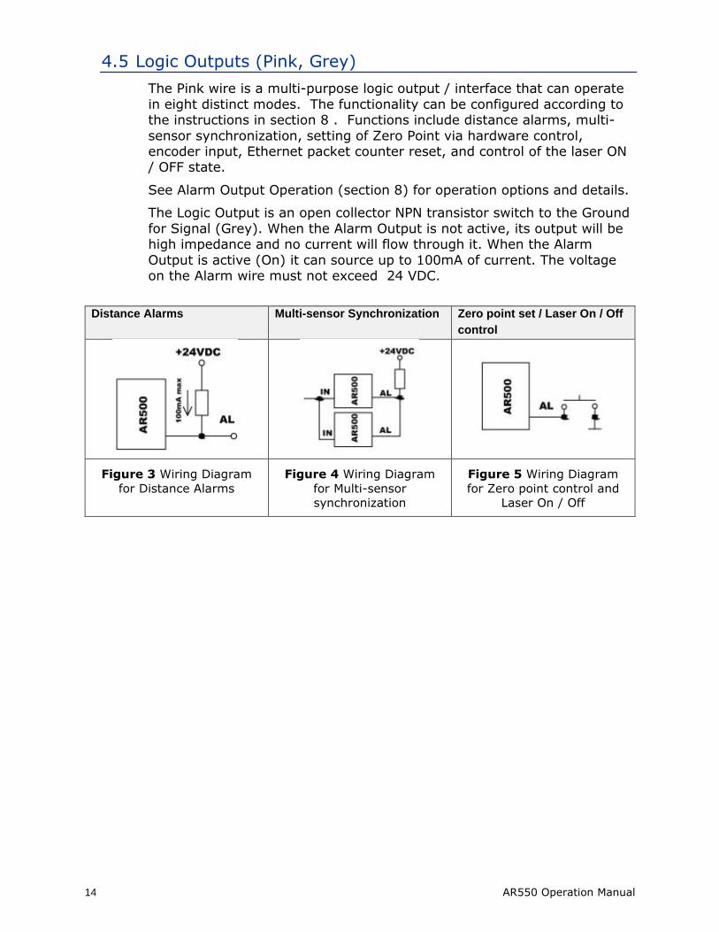
The Pink wire is a multi-purpose logic output / interface that can operate
in eight distinct modes. The functionality can be configured according to the instructions in section 8 . Functions include distance alarms, multi-
sensor synchronization, setting of Zero Point via hardware control, encoder input, Ethernet packet counter reset, and control of the laser ON / OFF state.
See Alarm Output Operation (section 8) for operation options and details.
The Logic Output is an open collector NPN transistor switch to the Ground
for Signal (Grey). When the Alarm Output is not active, its output will be high impedance and no current will flow through it. When the Alarm
Output is active (On) it can source up to 100mA of current. The voltage on the Alarm wire must not exceed 24 VDC.
Distance Alarms Multi-sensor Synchronization Zero point set / Laser On / Off
control
Figure 3 Wiring Diagram
for Distance Alarms
Figure 4 Wiring Diagram
for Multi-sensor
synchronization
Figure 5 Wiring Diagram
for Zero point control and
Laser On / Off
AR550 Operation Manual 15
5. Serial Interface Operation
This section refers to serial communication protocols for both the Sensor and Module versions of the AR550.
5.1 Binary Communications Protocol and Syntax
Serial port communication is required to configure the AR550 for
operation. The easiest way to communicate is by using a PC with an RS232 communication port and a terminal emulation program that uses
hexadecimal binary format. The factory default baud rate is 9600 bits/second.
Through these serial interfaces measurement data can be obtained by two
methods:
By single requests
• Automatic streaming data
• The serial data transmission byte has the following format:
1 start-bit 8 data bits 1 odd bit 1 stop-bit
The communications protocol is formed by communication sessions (commands), which are only initiated by the ‘master’ (PC, controller).
There are two kinds of sessions with such structures:
1. “request”, [“message”] — [“answer”], square brackets include optional
elements
2. “request” — “data stream” — [“request”].
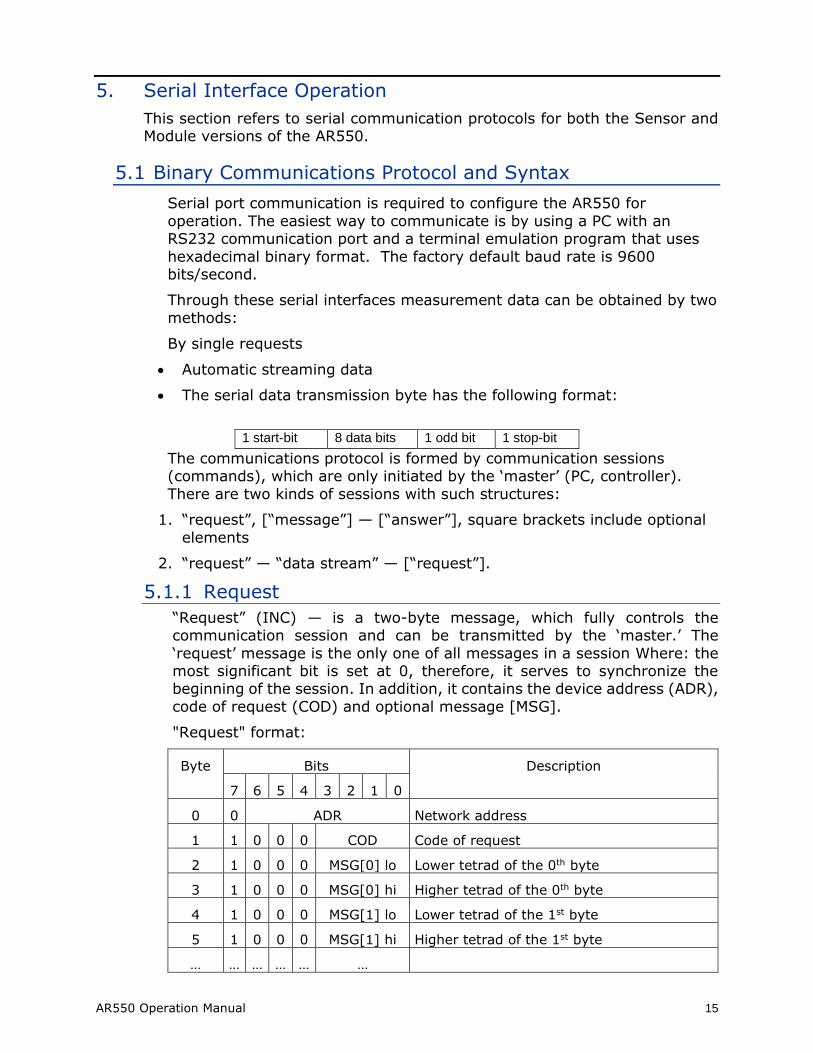
5.1.1 Request
“Request” (INC) — is a two-byte message, which fully controls the communication session and can be transmitted by the ‘master.’ The
‘request’ message is the only one of all messages in a session Where: the most significant bit is set at 0, therefore, it serves to synchronize the beginning of the session. In addition, it contains the device address (ADR),
code of request (COD) and optional message [MSG].
"Request" format:
Byte Bits Description
7 6 5 4 3 2 1 0
0 0 ADR Network address
1 1 0 0 0 COD Code of request
2 1 0 0 0 MSG[0] lo Lower tetrad of the 0th byte
3 1 0 0 0 MSG[0] hi Higher tetrad of the 0th byte
4 1 0 0 0 MSG[1] lo Lower tetrad of the 1st byte
5 1 0 0 0 MSG[1] hi Higher tetrad of the 1st byte
… … … … … …
16 AR550 Operation Manual
5.1.2 Answer
An ‘answer’ is a data burst that can be transmitted by a ‘slave’ during the course of the session.
All messages with an ‘answer’ burst contain 1 in the most significant digit. The data in a message is transferred in nibbles (aka:”tetrads”). When a byte is transmitted, the lower tetrad goes first, and then follows the higher
tetrad. When multi-byte values are transferred, the transmission begins with lower byte.
When ‘answer’ is transmitted, the message contains:
• SB-bit, characterizes the updating of the result. If SB is equal to "1" this means that the sensor has updated the measurement result in the
buffer, if SB is equal to "0" - then non-updated result has been transmitted (subject to sampling period). SB=0 when parameters
transmit;
• Two additional bits of cyclic binary batch counter (CNT). Bit values in the batch counter are identical for all transmissions of one batch. The
value of batch counter is incremented by the sending of each burst and is used for formation (assembly) of batches or bursts as well as for
control of batch losses in receiving data streams.
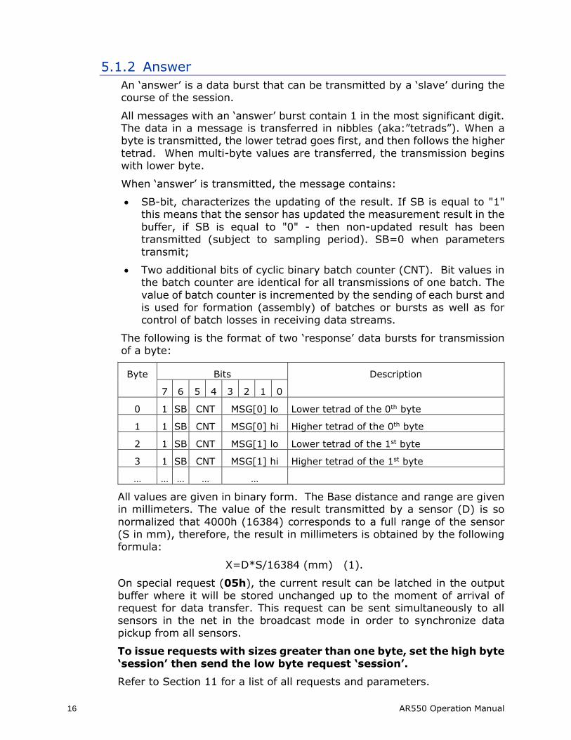
The following is the format of two ‘response’ data bursts for transmission of a byte:
Byte Bits Description
7 6 5 4 3 2 1 0
0 1 SB CNT MSG[0] lo Lower tetrad of the 0th byte
1 1 SB CNT MSG[0] hi Higher tetrad of the 0th byte
2 1 SB CNT MSG[1] lo Lower tetrad of the 1st byte
3 1 SB CNT MSG[1] hi Higher tetrad of the 1st byte
… … … … …
All values are given in binary form. The Base distance and range are given in millimeters. The value of the result transmitted by a sensor (D) is so
normalized that 4000h (16384) corresponds to a full range of the sensor (S in mm), therefore, the result in millimeters is obtained by the following
formula:
X=D*S/16384 (mm) (1).
On special request (05h), the current result can be latched in the output buffer where it will be stored unchanged up to the moment of arrival of request for data transfer. This request can be sent simultaneously to all
sensors in the net in the broadcast mode in order to synchronize data pickup from all sensors.
To issue requests with sizes greater than one byte, set the high byte ‘session’ then send the low byte request ‘session’.
Refer to Section 11 for a list of all requests and parameters.
AR550 Operation Manual 17
5.1.3 Data Stream
‘Data stream’ is an infinite sequence of data bursts or batches transmitted
from ‘slave’ to ‘master’, which can be interrupted by a new request. In transmission of the ‘data stream’ one of the ‘slaves’ fully holds data transfer
channel, therefore, when ‘master’ produces any new request sent to any address, the data streaming process is stopped. Also, there is a special request to stop data streaming.
5.1.4 Saving to Non-Volatile (FLASH) Memory
When adjusting parameter values, all changes are discarded when the AR550 is powered OFF unless a command is made to save these changes
to the FLASH memory.
To save any changes to the FLASH memory, input 0 for binary parameter
04h. This must be done every time a save is desired.
5.1.5 Recover AR550 Factory Settings
To recover all factory settings, input 1 for binary parameter 04h.
5.2 ASCII Communications Protocol
There is now an option to switch the AR550’s output to an ASCII based format that may make the data easier to read for those using only a terminal emulator to operate the laser. The AR550 is set by default to binary output.
The output can be changed to ASCII output using binary parameter 8Ah.
• Value “0” is binary communications.
• Value “1” is ASCII communications.
Once the output is changed ASCII request codes can be entered by typing the code and desired value (when necessary) and pressing enter. In subsequent
chapters, ASCII request codes will be written in the form of [code]x where “x” is the desired value (Example: code Ax determines whether analog output is
on or off. A1 turns analog on, and A0 turns analog off.)
To change the output back to binary, use the ASCII command “PRT”
5.2.1 Saving to Non-Volatile (FLASH) Memory
To save any changes to the FLASH memory, use ASCII command W0.
5.2.2 Recover AR550 Factory Settings
To recover all factory settings, use ASCII command W1.
Note: This will not return the laser to binary communications.
18 AR550 Operation Manual
6. Analog Output Operation
AR550 sensors have a 0–10 V analog output. The analog output uses the same two wires. Please refer to Section 4.4 for connection details.
The analog output is updated with each sample measured. The analog output will
deliver a current which increases linearly from 0 volts at the range beginning point to 10 volts at the range end point.
6.1 Analog Output ON (Binary: 01h; ASCII: Ax)
Default Value: 1 – Analog Output ON
The analog output can be toggled ON / OFF.
The binary parameter (01h) and ASCII command (Ax) use values 1 or 0 for ON and OFF, respectively.
Note: If a sensor is not configured with an analog interface, the value will always be set to 0 despite any attempts to change it.
6.2 Analog Output Mode (Binary: 02h bit R; ASCII: TAx)
Default Value: 0 – Window Mode
The analog output can be operated in two modes, “Window Mode” or “Full
Mode”.
The binary parameter (02h bit R) and ASCII command (TAx) use values
0 or 1 for Window Mode or Full Mode, respectively.
Window Mode – Value: 0 – The entire range of the analog output is scaled within the selected window. Outside the window, the analog output
is "0".
Full Mode – Value: 1 – The entire range of the analog output is scaled
within the selected window. Outside the selected window, the whole range of the analog output is automatically scaled onto the whole operating range of the sensor.

AR550 Operation Manual 19
6.3 Analog Output Working Range (Binary: 0Ch, 0Dh, 0Eh, 0Fh; ASCII: none)
Default Value [Beginning of Range]: 0
Default Value [End of Range]: 16384
Resolution of the analog output can be increased by adjusting the window size and location within the measurement span. The analog signal will be
scaled within this window only. This can only be changed in binary mode.
If the beginning of the range of the analog signal is set at a higher value
than the end value of the range, this will change the direction of rise of the analog signal.
Parameters to set the Beginning of the Analog Range (0V):
0Ch – Value range: 0 to 16384 – Low byte for the beginning of the analog output range.
0Dh – Value range: 0 to 16384 – High byte for the beginning of the analog output range.
Parameters to set the End of the Analog Range (10V):
0Eh – Value range: 0 to 16384 – Low byte for the end of the analog output range.
0Fh – Value range: 0 to 16384 – High byte for the end of the analog output range.

20 AR550 Operation Manual
7. Ethernet Output Operation
Ethernet output is standard on AR550 models. It is the only digital communication method that allows transmission of measurement data at the full 70 kHz sampling rate.
Note 1: The Ethernet interface is used only for the transmission of data from the sensor. Sensor parameters can only be adjusted or set using a
serial connection.
Note 2: Firewall settings can block the receipt of data over Ethernet. If using a hardware or software firewall, please consult its manual or contact
your IT department to remove any blocks on sensor data while maintaining security.
7.1 Data Transfer Modes (Binary: 88h; ASCII: IPOx)
Default Value: 1 – Ethernet transmission ON
The binary parameter (88h) and ASCII command (IPOx) use values 0 or 1 for transmission OFF and ON, respectively.
Transmission OFF – Value: 0 – No data is transmitted over the Ethernet output.
Transmission ON – Value: 1 – Data is transmitted over the Ethernet output in the following manner:
The sensor transmits UDP data packets of 168 measurements. The
measurements are collected with the currently selected Time or Trigger sampling mode (See Section 9.5). Once the internal buffer of 168
measurements is filled, the sensor will transmit a UDP data packet over the network.
Note: The sensor will only send a packet once it has collected 168
measurements. If the buffer is not yet full, the sensor will wait to send the packet until it is full. If more immediate data is
needed for automation purposes at the full 70 kHz speed, the analog output should be used instead.
7.2 Factory Parameters Table
Parameter Name Value
Destination IP Address 255.255.255.255
Gateway IP Address 192.168.0.1
Subnet Mask 255.255.255.255
Source IP Address 192.168.0.3
Interface Condition ON
Data Transfer Method Streaming
Measurements Per Packet 168
AR550 Operation Manual 21
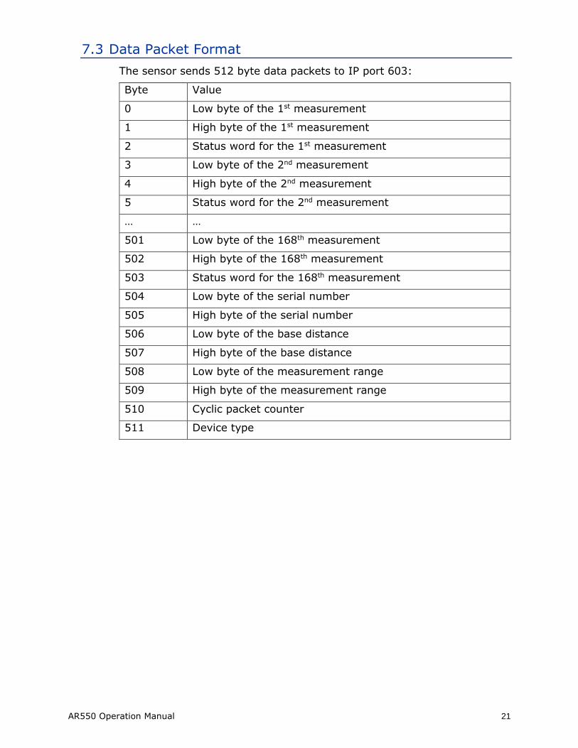
7.3 Data Packet Format
The sensor sends 512 byte data packets to IP port 603:
Byte Value
0 Low byte of the 1st measurement
1 High byte of the 1st measurement
2 Status word for the 1st measurement
3 Low byte of the 2nd measurement
4 High byte of the 2nd measurement
5 Status word for the 2nd measurement
… …
501 Low byte of the 168th measurement
502 High byte of the 168th measurement
503 Status word for the 168th measurement
504 Low byte of the serial number
505 High byte of the serial number
506 Low byte of the base distance
507 High byte of the base distance
508 Low byte of the measurement range
509 High byte of the measurement range
510 Cyclic packet counter
511 Device type
22 AR550 Operation Manual
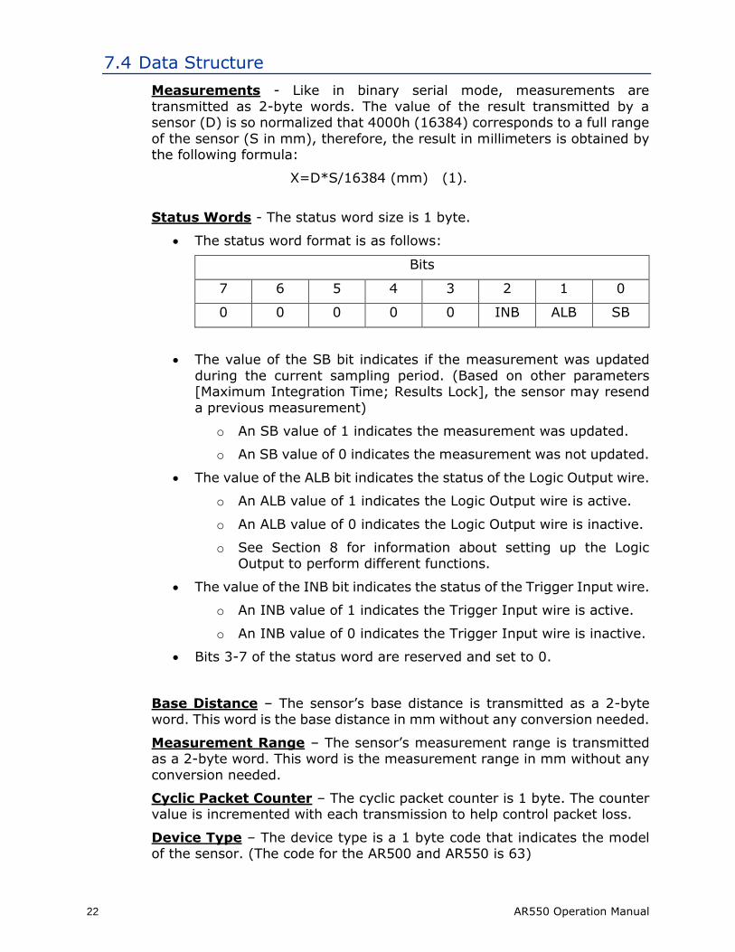
7.4 Data Structure
Measurements - Like in binary serial mode, measurements are
transmitted as 2-byte words. The value of the result transmitted by a sensor (D) is so normalized that 4000h (16384) corresponds to a full range
of the sensor (S in mm), therefore, the result in millimeters is obtained by the following formula:
X=D*S/16384 (mm) (1).
Status Words - The status word size is 1 byte.
• The status word format is as follows:
Bits
7 6 5 4 3 2 1 0
0 0 0 0 0 INB ALB SB
• The value of the SB bit indicates if the measurement was updated
during the current sampling period. (Based on other parameters [Maximum Integration Time; Results Lock], the sensor may resend
a previous measurement)
o An SB value of 1 indicates the measurement was updated.
o An SB value of 0 indicates the measurement was not updated.
• The value of the ALB bit indicates the status of the Logic Output wire.
o An ALB value of 1 indicates the Logic Output wire is active.
o An ALB value of 0 indicates the Logic Output wire is inactive.
o See Section 8 for information about setting up the Logic Output to perform different functions.
• The value of the INB bit indicates the status of the Trigger Input wire.
o An INB value of 1 indicates the Trigger Input wire is active.
o An INB value of 0 indicates the Trigger Input wire is inactive.
• Bits 3-7 of the status word are reserved and set to 0.
Base Distance – The sensor’s base distance is transmitted as a 2-byte word. This word is the base distance in mm without any conversion needed.
Measurement Range – The sensor’s measurement range is transmitted as a 2-byte word. This word is the measurement range in mm without any
conversion needed.
Cyclic Packet Counter – The cyclic packet counter is 1 byte. The counter value is incremented with each transmission to help control packet loss.
Device Type – The device type is a 1 byte code that indicates the model of the sensor. (The code for the AR500 and AR550 is 63)
AR550 Operation Manual 23
8. Logic Interface(s) Operation
All AR550 sensors include a multi-purpose logic line. See the wiring description in section 4.5.
8.1 Binary Communication (02h bits M2, M1, and M0)
Default Value: 000 – Distance Alarm Mode
When the laser is set to binary communication, this line can be set to one of
the eight modes defined by the M bits of parameter 02h
Distance Alarm Mode: To activate this mode from another, set bits M2, M1,
and M0 to 000. The output value is 0 when the measured distance is out of the range or selected window (see Analog Window in section 6.3).
Synchronization Mode: The synchronization mode makes it possible to
synchronize measurement sample times of two and more sensors. Synchronization is achieved by tying together the trigger input lines of multiple
sensors and also the logic output lines of the sensor. Synchronization is a valuable feature for thickness measurements using opposing laser sensors so that measurements are captured at exactly the same instant. There are two
modes:
• ‘Master’ mode:
o Activate this mode by setting bits M2, M1, and M0 to 111. • ‘Slave’ mode:
o Activate this mode by setting bits M2, M1, and M0 to 001.
Hardware Zero Set Mode (Tare function): Activate this mode by setting bits M2, M1, and M0 to 010. When the Logic Interface wire is grounded, the
currently measured distance is assigned as the zero point and subsequent measurements are now relative to this location within the span.
Laser Disable Mode: Activate this mode by setting bits M2, M1, and M0 to
011. When the Logic Interface wire is grounded, the laser is ON. When the switch is removed from ground, the laser is OFF. This controls only the laser
diode and not power to the sensor itself.
Encoder Mode: Activate this mode by setting bits M2, M1, and M0 to 100. In this mode, the Trigger Input (White) and Logic Interface (Pink) wires work as
inputs for a quadrature encoder signal, and if an encoder is connected to these lines, measurements will be synchronized with the encoder.
Input Mode (Ethernet models only): Activate this mode by setting bits M2, M1, and M0 to 101. In this mode, The Logic Interface line state is transmitted in the status word of an Ethernet packet.
Ethernet Packet Counter Reset Mode (Ethernet models only): Activate this mode by setting bits M2, M1, and M0 to 110. In this mode, connecting
the Logic Interface wire to ground will reset the Ethernet packet counter.
24 AR550 Operation Manual
8.2 ASCII Communication (TLx)
Default Value: 0 – Distance Alarm Mode
When the laser is set to ASCII communication, the Logic Interface line can be set to one of four modes using the command TLx:
Distance Alarm Mode: This is the default logic output. To activate this mode from another, use command TL0. The output value is 0 when the measured distance is out of the range or selected window (see Analog Window in section
6.3).
Mutual Synchronization Mode: Activate this mode by using command TL1.
Unlike with binary communication mode, the laser cannot be specifically set as ‘master’ or ‘slave’ in ASCII communication mode, but like in binary
communication mode, synchronization mode makes it possible to synchronize measurement sample times of two and more sensors. Synchronization is achieved by tying together the trigger input lines of multiple sensors and also
the logic output lines of the sensor.
Hardware Zero Set Mode (Tare function): Activate this mode by using
command TL2. When the Logic Interface wire is grounded, the currently measured distance is assigned as the zero point and subsequent measurements are now relative to this location within the span.
Laser Disable Mode: Activate this mode by using command TL3. When the Logic Interface wire is grounded, the laser is ON. When the switch is removed
from ground, the laser is OFF. This controls only the laser diode and not power to the sensor itself.

AR550 Operation Manual 25
9. Performance Optimization This section describes how to configure the AR550 sensor for best use in your particular application.
9.1 Baud Rate (Binary: 04h; ASCII: Bxxx)
Default Value: 4 – 9600 bit/s (baud)
The AR550 automatically begins measuring and outputting distance
measurements to the analog and serial lines when powered-up. The default baud rate is 9600 bit/s.
Users may select among several baud rates that will optimize the sensors’ speed or accuracy performances over a serial connection.
The binary parameter (04h) and ASCII command (Bxxx) can use values from
1 – 192. This specifies the data transfer rate in multiples of 2400. The default value is 4 (9600 bit/s).
9.2 Laser ON/OFF (Binary: 00h; ASCII: Ox)
Default Value: 1 - ON
This serial function toggles the laser ON or OFF. The default setting is ON.
Note that there exists a hardware Logic line which can control the laser’s sate as well. See Laser Disable feature in section 8.
The binary parameter (00h) and ASCII command (Ox) use values 1 or 0 for ON or OFF, respectively.
9.3 Network Address (Binary: 03h; ASCII: none)
Default Value: 1
This parameter defines the network address of the sensor equipped with RS485
interface. The factory default value is 1. This parameter cannot be edited using an ASCII command.
Network data communications protocols assume the presence of a ‘master’ in the network, which can be AR550 set to ‘master’ mode (see section 7.1), a computer, or other information-gathering device, and from 1 to 127 ‘slaves’
(AR550 Series sensors) which support the protocol.
Each ‘slave’ is assigned a unique network identification code – a device
address. The address is used to form requests or inquiries all over the network. Each slave receives inquiries containing its unique address as well as ‘0’ address which is broadcast-oriented and can be used for formation of generic
commands, for example, for simultaneous latching of values of all sensors and for working with only one sensor (with both RS232 port and RS485 port).
Parameter 03h can be assigned values from 1 – 127.
26 AR550 Operation Manual
9.4 Zero Point (Binary: 17h, 18h; ASCII: Zxxxxx)
Default Value: 0
This parameter allows the user to set a zero point within the sensor’s measurement span. The factory default value for the zero point is the
beginning of the measurement span. Note that users can also set the zero point through hardware controls. See Zero Point in section 8.
Binary Parameters:
• 17h – LOW byte of the Zero Point
• 18h – HIGH byte of the Zero Point
ASCII Command:
• Zxxxxx – Where xxxxx is the Zero Point
The above values can be set within a range of 0 to 16384. This is the range of the absolute coordinate system of the AR550 sensor.
9.5 Sampling Mode (Binary: 02h bit S; ASCII: TSx)
Default Value: 0 - Time Sampling
The AR550 has two sampling modes, Time or Trigger Sampling. The factory
default setting is Time Sampling.
The sensor must be in Data Stream Mode. The binary parameter (02h bit S) and the ASCII command (TSx) use the same values.
Time Sampling – Value: 0 – When selected, the sensor automatically transmits the measurement result via serial interface in accordance with
selected sampling period.
Trigger Sampling – Value: 1 – When selected, the sensor transmits the measurement result when an external synchronization input (see section 4.5)
is switched. This takes the division factor set into account. See Sampling Period section 9.6.
9.6 Sampling Period (Binary: 08h, 09h; ASCII: Sxxxxx)
Default Value: 5000
If the Time sampling mode is selected, the ‘sampling period’ parameter determines the time interval over which the sensor will automatically transmit the measurement result. The time interval value is set in increments of 1 μs.
For example, for the parameter value equal to 100, data are transmitted through bit-serial interface with a period of 100 μs.
If the Trigger sampling mode is selected, the ‘sampling period’ parameter determines the division factor for the external synchronization input. For example, for the parameter value equal to 100, data are transmitted through
bit-serial interface when each 100th synchronizing pulse arrives at trigger input of the sensor.
AR550 Operation Manual 27
Binary Parameters:
08h – Low byte for the sampling period.
09h – High byte of sampling period.
ASCII Command:
Sxxxxx – Where xxxxx is the sampling period.
Value ranges:
• In Time sampling mode: 10 to 65535. The time interval in increments
of 1 μs with which sensor automatically communicates of results on streaming request (priority of sampling = 0)
• In Trigger sampling mode: 1 to 65535, divider ratio of trigger input with which sensor automatically communicates of result on streaming request (priority of sampling = 1)
Note 1: It should be noted that the ‘sampling mode’ and ‘sampling period’ parameters control only the transmission of data. The sensor operation
algorithm is built so that measurements are taken at a maximum possible rate determined by the integration time period, the measurement results are sent to buffer and stored therein until a new result arrives. The above-mentioned
parameters determine the method of the read-out of the result from the buffer.
Note 2: If the bit-serial interface is used to receive the result, the time
required for data transmission at a selected data transmission rate should be taken into account in the case Where: small sampling period intervals are used.
If the transmission time exceeds the sampling period, it is this time that will determine the data transmission rate.
9.6.1 Output Rate
The sensor’s output rate (OR) depends on the selected Baud rate (BR) of serial interface and is calculated by the following formula:
OR = 1 / (44/BR+1*10-5) Hz.
For example, for BR=460800 b/s, Output Rate = 9.4 kHz
9.7 Maximum Integration Time (Binary: 0Ah, 0Bh; ASCII: Exxxx)
Default Value: 3200
The intensity of the reflected laser radiation varies with target surface characteristics (color, texture, etc.) and ambient lighting conditions. The
laser’s output power and the integration time (like camera shutter time) of the CMOS detector array are automatically adjusted to achieve maximum
measurement accuracy.
The Maximum Integration Time parameter specifies a maximum allowable integration time limit. If the radiation intensity received by the sensor is so
small that no reasonable result is obtained within the time of integration equal to the limiting value, the sensor transmits a zero value.
28 AR550 Operation Manual
Binary Parameters:
0Ah – Low byte for maximum integration time.
0Bh – High byte for maximum integration time.
ASCII Command:
Exxxx – Where xxxx is the maximum integration time.
Value ranges:
2 to 3200. This value specifies the limiting integration time for the CMOS array
in increments of 1 μs.
The measurement frequency depends on the integration time of the receiving
array. Maximum frequency (9.4 kHz) is achieved for the integration time ≤106 μs (minimum possible integration time is 0.1 μs). As the integration time exceeds 106 μs, the resulting update time increases proportionally.
Increasing this parameter may improve the sensor’s ability to measure to low-reflecting targets at the cost of decreased speed and possible increased effects
of ambient light on measurement accuracy. Decreasing the parameter’s value increases measurement frequency, but may decrease measurement accuracy.
9.8 Results Lock (Binary: 10h; ASCII: Dxxx)
Default Value: 1 – 5ms
If the sensor does not “see” the target surface or if a new measurement cannot
be received, a zero value is transferred. The Results Lock parameter sets a time limit during which the sensor transfers the last valid result instead of a
zero value. The factory default value is 5 ms.
The binary parameter (10h) and the ASCII command (Dxxxx) both use a value range of 0 to 255 . It specifies the time interval in increments of 5 ms.
9.9 Results Averaging Mode (Binary: 02h bit A; ASCII: TMx)
Default Value: 0 – Averaging over a Number of Results
This parameter defines one of the two methods of averaging of measurement results implemented directly in the sensor: Averaging over a Number of Results or Time Averaging. The factory default setting is for Averaging over a
Number of Results.
The binary parameter (02h bit A) and the ASCII command (TMx) both use
two values, 0 or 1, representing one of two modes:
Averaging over a Number of Results – Value: 0 – When selected, a sliding average is calculated and transmitted to the sensor’s outputs
Time averaging – Value: 1 – When selected, the measurement results are averaged over a time interval

AR550 Operation Manual 29
9.9.1 Averaging Configuration (Binary: 06h; ASCII: Gxxx)
Default Value: 1 – No Averaging
Depending on the selected averaging mode (Number or Time), this
parameter controls either the number of results to be averaged or the time for averaging.
Averaging can reduce noise or occasional spikes in the output of the sensor caused by inaccurate readings in dynamic applications.
Averaging over a number of results does not affect the data update in the sensor output buffer. However, in case of Time Averaging, data in the output buffer are updated at a rate equal to the averaging period.
The binary parameter (06h) and the ASCII command (Gxxx) both use a value range of 1 to 127. This is either the number of samples or length of
time (in seconds) depending on the selected averaging mode.
30 AR550 Operation Manual
10. Demo and Configuration Software
The AR550-SP software is intended for making simple serial (or Ethernet,
if ordered) connections to the AR550 for demonstration purposes and configuration of the many sensor parameters. It is also possible to archive
measurement data to a file using this software.
10.1 Program Setup
Start file AR550setup.exe and follow the instructions for the installation wizard.
10.2 Connecting to the sensor (RS232/RS485)
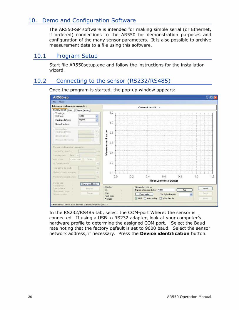
Once the program is started, the pop-up window appears:
In the RS232/RS485 tab, select the СОМ-port Where: the sensor is
connected. If using a USB to RS232 adapter, look at your computer’s hardware profile to determine the assigned COM port. Select the Baud rate noting that the factory default is set to 9600 baud. Select the sensor
network address, if necessary. Press the Device identification button.
AR550 Operation Manual 31
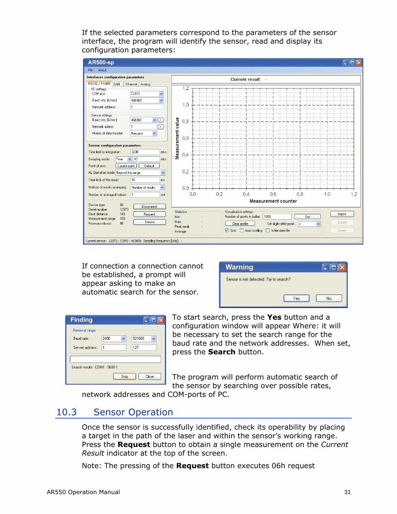
If the selected parameters correspond to the parameters of the sensor interface, the program will identify the sensor, read and display its
configuration parameters:
If connection a connection cannot be established, a prompt will appear asking to make an
automatic search for the sensor.
To start search, press the Yes button and a configuration window will appear Where: it will be necessary to set the search range for the
baud rate and the network addresses. When set, press the Search button.
The program will perform automatic search of the sensor by searching over possible rates,
network addresses and COM-ports of PC.
10.3 Sensor Operation
Once the sensor is successfully identified, check its operability by placing a target in the path of the laser and within the sensor’s working range.
Press the Request button to obtain a single measurement on the Current Result indicator at the top of the screen.
Note: The pressing of the Request button executes 06h request
32 AR550 Operation Manual
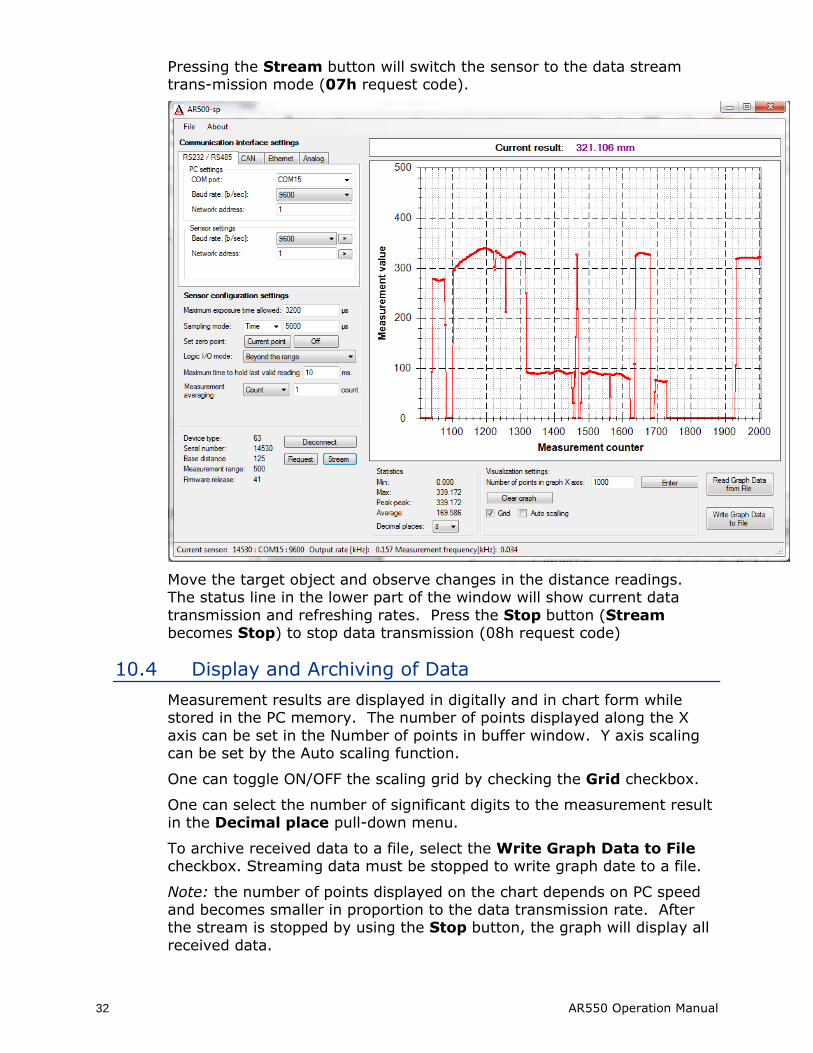
Pressing the Stream button will switch the sensor to the data stream trans-mission mode (07h request code).
Move the target object and observe changes in the distance readings. The status line in the lower part of the window will show current data
transmission and refreshing rates. Press the Stop button (Stream becomes Stop) to stop data transmission (08h request code)
10.4 Display and Archiving of Data
Measurement results are displayed in digitally and in chart form while stored in the PC memory. The number of points displayed along the X
axis can be set in the Number of points in buffer window. Y axis scaling can be set by the Auto scaling function.
One can toggle ON/OFF the scaling grid by checking the Grid checkbox.
One can select the number of significant digits to the measurement result in the Decimal place pull-down menu.
To archive received data to a file, select the Write Graph Data to File checkbox. Streaming data must be stopped to write graph date to a file.
Note: the number of points displayed on the chart depends on PC speed and becomes smaller in proportion to the data transmission rate. After the stream is stopped by using the Stop button, the graph will display all
received data.
AR550 Operation Manual 33
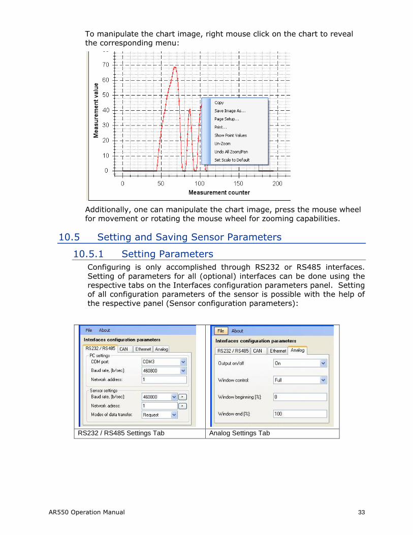
To manipulate the chart image, right mouse click on the chart to reveal the corresponding menu:
Additionally, one can manipulate the chart image, press the mouse wheel for movement or rotating the mouse wheel for zooming capabilities.
10.5 Setting and Saving Sensor Parameters
10.5.1 Setting Parameters
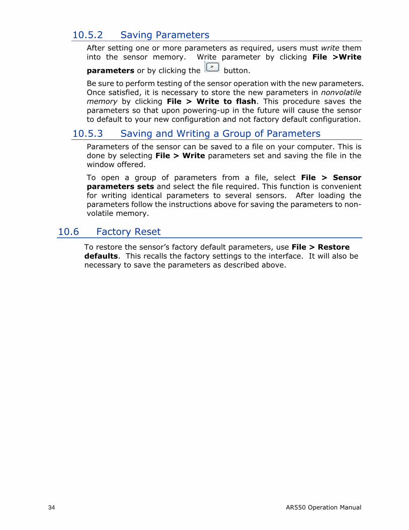
Configuring is only accomplished through RS232 or RS485 interfaces.
Setting of parameters for all (optional) interfaces can be done using the respective tabs on the Interfaces configuration parameters panel. Setting of all configuration parameters of the sensor is possible with the help of
the respective panel (Sensor configuration parameters):
RS232 / RS485 Settings Tab Analog Settings Tab
34 AR550 Operation Manual
10.5.2 Saving Parameters
After setting one or more parameters as required, users must write them
into the sensor memory. Write parameter by clicking File >Write
parameters or by clicking the button.
Be sure to perform testing of the sensor operation with the new parameters.
Once satisfied, it is necessary to store the new parameters in nonvolatile memory by clicking File > Write to flash. This procedure saves the
parameters so that upon powering-up in the future will cause the sensor to default to your new configuration and not factory default configuration.
10.5.3 Saving and Writing a Group of Parameters
Parameters of the sensor can be saved to a file on your computer. This is done by selecting File > Write parameters set and saving the file in the window offered.
To open a group of parameters from a file, select File > Sensor parameters sets and select the file required. This function is convenient
for writing identical parameters to several sensors. After loading the parameters follow the instructions above for saving the parameters to non-volatile memory.
10.6 Factory Reset
To restore the sensor’s factory default parameters, use File > Restore
defaults. This recalls the factory settings to the interface. It will also be necessary to save the parameters as described above.
AR550 Operation Manual 35
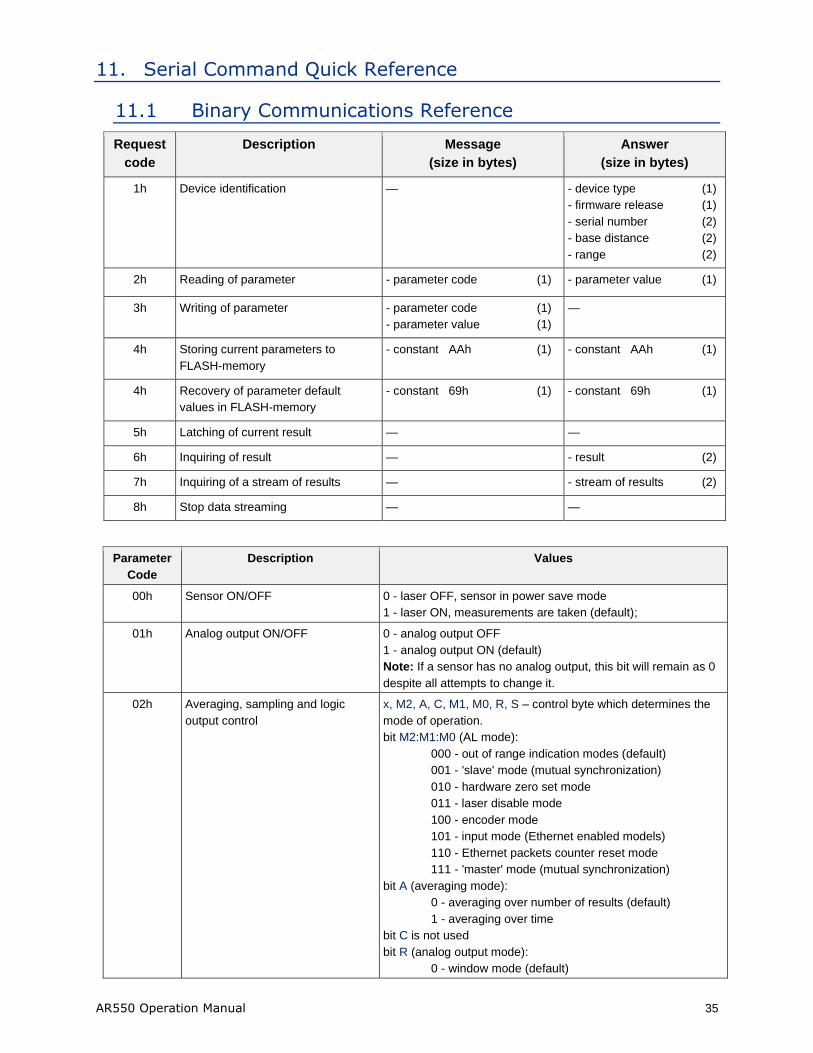
11. Serial Command Quick Reference
11.1 Binary Communications Reference
Request
code
Description Message
(size in bytes)
Answer
(size in bytes)
1h Device identification — - device type (1)
- firmware release (1)
- serial number (2)
- base distance (2)
- range (2)
2h Reading of parameter - parameter code (1) - parameter value (1)
3h Writing of parameter - parameter code (1)
- parameter value (1)
—
4h Storing current parameters to
FLASH-memory
- constant AAh (1) - constant AAh (1)
4h Recovery of parameter default
values in FLASH-memory
- constant 69h (1) - constant 69h (1)
5h Latching of current result — —
6h Inquiring of result — - result (2)
7h Inquiring of a stream of results — - stream of results (2)
8h Stop data streaming — —
Parameter
Code
Description Values
00h Sensor ON/OFF 0 - laser OFF, sensor in power save mode
1 - laser ON, measurements are taken (default);
01h Analog output ON/OFF 0 - analog output OFF
1 - analog output ON (default)
Note: If a sensor has no analog output, this bit will remain as 0
despite all attempts to change it.
02h Averaging, sampling and logic
output control
x, M2, A, C, M1, M0, R, S – control byte which determines the
mode of operation.
bit M2:M1:M0 (AL mode):
000 - out of range indication modes (default)
001 - 'slave' mode (mutual synchronization)
010 - hardware zero set mode
011 - laser disable mode
100 - encoder mode
101 - input mode (Ethernet enabled models)
110 - Ethernet packets counter reset mode
111 - 'master' mode (mutual synchronization)
bit A (averaging mode):
0 - averaging over number of results (default)
1 - averaging over time
bit C is not used
bit R (analog output mode):
0 - window mode (default)
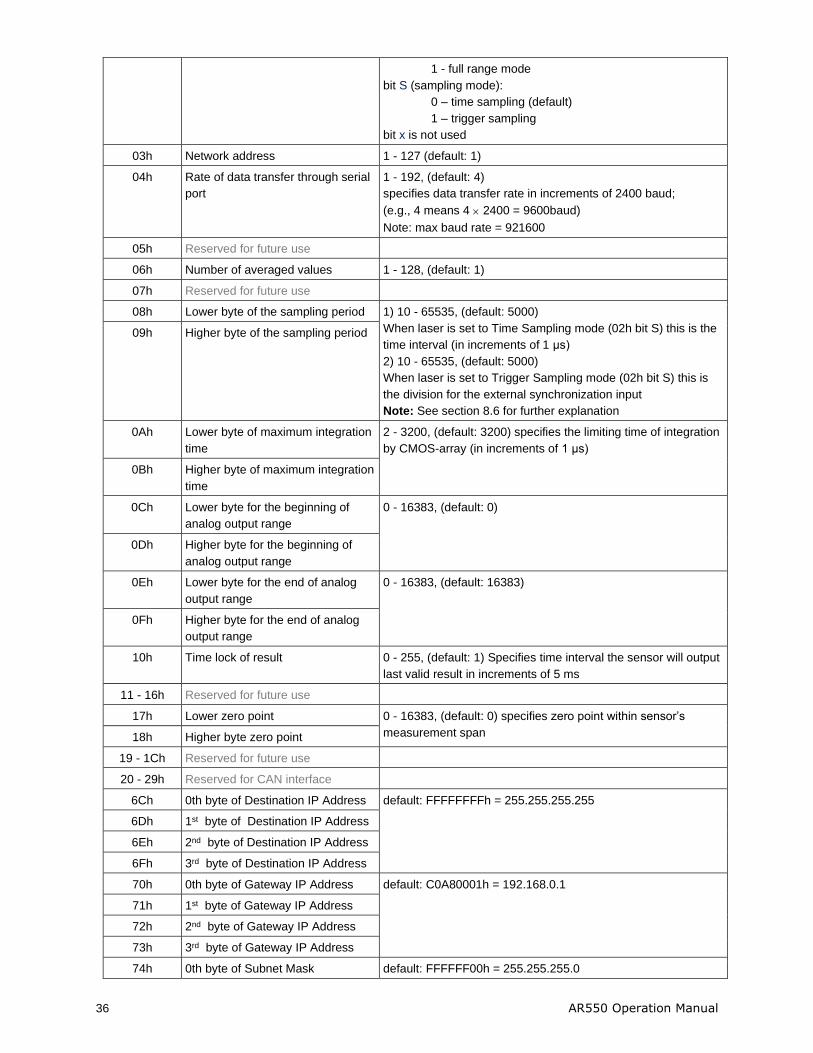
36 AR550 Operation Manual
1 - full range mode
bit S (sampling mode):
0 – time sampling (default)
1 – trigger sampling
bit x is not used
03h Network address 1 - 127 (default: 1)
04h Rate of data transfer through serial
port
1 - 192, (default: 4)
specifies data transfer rate in increments of 2400 baud;
(e.g., 4 means 4 2400 = 9600baud)
Note: max baud rate = 921600
05h Reserved for future use
06h Number of averaged values 1 - 128, (default: 1)
07h Reserved for future use
08h Lower byte of the sampling period 1) 10 - 65535, (default: 5000)
When laser is set to Time Sampling mode (02h bit S) this is the
time interval (in increments of 1 μs)
2) 10 - 65535, (default: 5000)
When laser is set to Trigger Sampling mode (02h bit S) this is
the division for the external synchronization input
Note: See section 8.6 for further explanation
09h Higher byte of the sampling period
0Ah Lower byte of maximum integration
time
2 - 3200, (default: 3200) specifies the limiting time of integration
by CMOS-array (in increments of 1 μs)
0Bh Higher byte of maximum integration
time
0Ch Lower byte for the beginning of
analog output range
0 - 16383, (default: 0)
0Dh Higher byte for the beginning of
analog output range
0Eh Lower byte for the end of analog
output range
0 - 16383, (default: 16383)
0Fh Higher byte for the end of analog
output range
10h Time lock of result 0 - 255, (default: 1) Specifies time interval the sensor will output
last valid result in increments of 5 ms
11 - 16h Reserved for future use
17h Lower zero point 0 - 16383, (default: 0) specifies zero point within sensor’s
measurement span 18h Higher byte zero point
19 - 1Ch Reserved for future use
20 - 29h Reserved for CAN interface
6Ch 0th byte of Destination IP Address default: FFFFFFFFh = 255.255.255.255
6Dh 1st byte of Destination IP Address
6Eh 2nd byte of Destination IP Address
6Fh 3rd byte of Destination IP Address
70h 0th byte of Gateway IP Address default: C0A80001h = 192.168.0.1
71h 1st byte of Gateway IP Address
72h 2nd byte of Gateway IP Address
73h 3rd byte of Gateway IP Address
74h 0th byte of Subnet Mask default: FFFFFF00h = 255.255.255.0
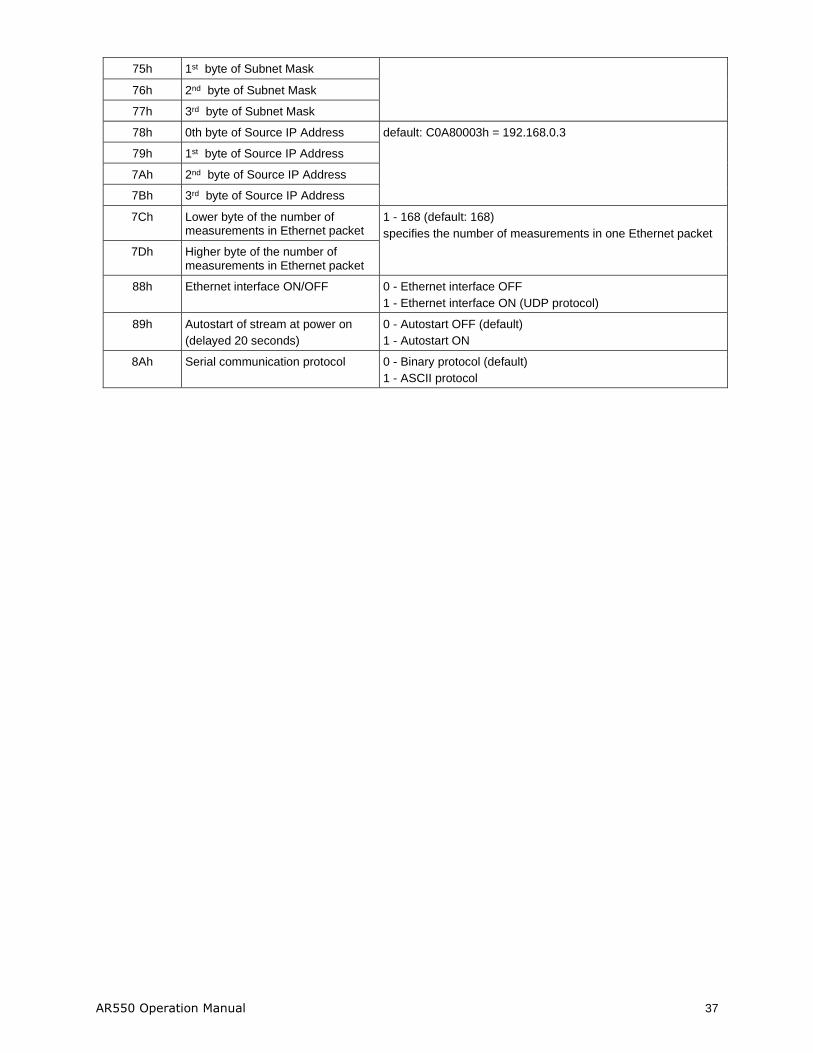
AR550 Operation Manual 37
75h 1st byte of Subnet Mask
76h 2nd byte of Subnet Mask
77h 3rd byte of Subnet Mask
78h 0th byte of Source IP Address default: C0A80003h = 192.168.0.3
79h 1st byte of Source IP Address
7Ah 2nd byte of Source IP Address
7Bh 3rd byte of Source IP Address
7Ch Lower byte of the number of measurements in Ethernet packet
1 - 168 (default: 168)
specifies the number of measurements in one Ethernet packet
7Dh Higher byte of the number of measurements in Ethernet packet
88h Ethernet interface ON/OFF 0 - Ethernet interface OFF
1 - Ethernet interface ON (UDP protocol)
89h Autostart of stream at power on
(delayed 20 seconds)
0 - Autostart OFF (default)
1 - Autostart ON
8Ah Serial communication protocol 0 - Binary protocol (default)
1 - ASCII protocol
38 AR550 Operation Manual
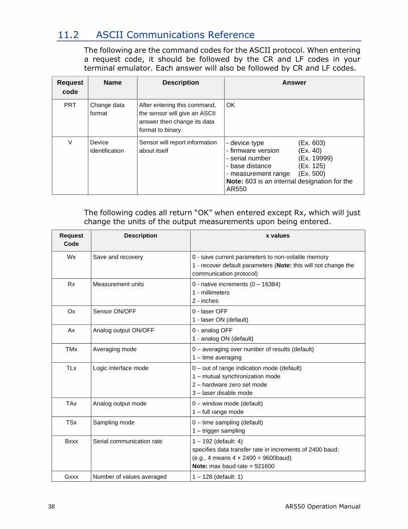
11.2 ASCII Communications Reference
The following are the command codes for the ASCII protocol. When entering
a request code, it should be followed by the CR and LF codes in your terminal emulator. Each answer will also be followed by CR and LF codes.
Request
code
Name Description Answer
PRT Change data
format
After entering this command,
the sensor will give an ASCII
answer then change its data
format to binary.
OK
V Device
Identification
Sensor will report information
about itself
- device type (Ex. 603) - firmware version (Ex. 40) - serial number (Ex. 19999) - base distance (Ex. 125) - measurement range (Ex. 500) Note: 603 is an internal designation for the AR550
The following codes all return “OK” when entered except Rx, which will just change the units of the output measurements upon being entered.
Request
Code
Description x values
Wx Save and recovery 0 - save current parameters to non-volatile memory
1 - recover default parameters (Note: this will not change the
communication protocol)
Rx Measurement units 0 - native increments (0 – 16384)
1 - millimeters
2 - inches
Ox Sensor ON/OFF 0 - laser OFF
1 - laser ON (default)
Ax Analog output ON/OFF 0 - analog OFF
1 - analog ON (default)
TMx Averaging mode 0 – averaging over number of results (default)
1 – time averaging
TLx Logic interface mode 0 – out of range indication mode (default)
1 – mutual synchronization mode
2 – hardware zero set mode
3 – laser disable mode
TAx Analog output mode 0 – window mode (default)
1 – full range mode
TSx Sampling mode 0 – time sampling (default)
1 – trigger sampling
Bxxx Serial communication rate 1 – 192 (default: 4)
specifies data transfer rate in increments of 2400 baud;
(e.g., 4 means 4 × 2400 = 9600baud)
Note: max baud rate = 921600
Gxxx Number of values averaged 1 – 128 (default: 1)
AR550 Operation Manual 39
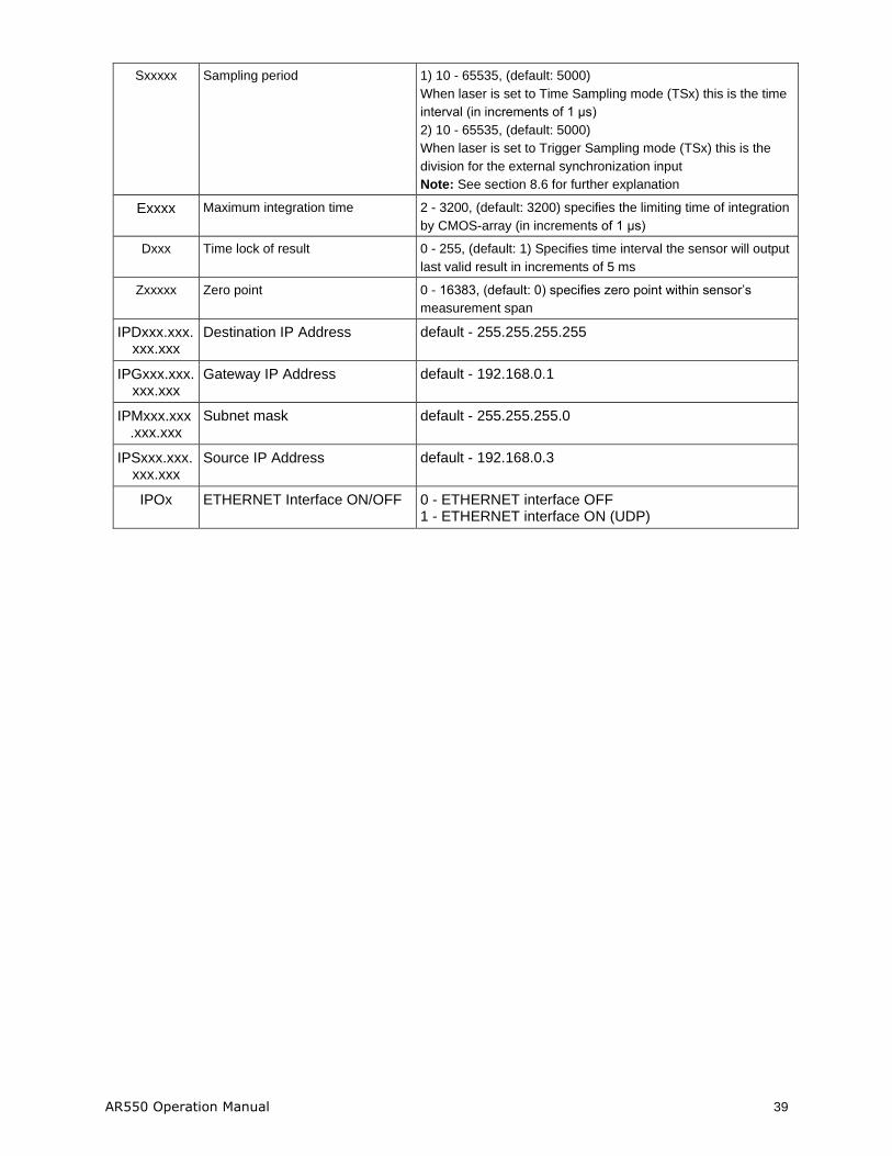
Sxxxxx Sampling period 1) 10 - 65535, (default: 5000)
When laser is set to Time Sampling mode (TSx) this is the time
interval (in increments of 1 μs)
2) 10 - 65535, (default: 5000)
When laser is set to Trigger Sampling mode (TSx) this is the
division for the external synchronization input
Note: See section 8.6 for further explanation
Exxxx Maximum integration time 2 - 3200, (default: 3200) specifies the limiting time of integration
by CMOS-array (in increments of 1 μs)
Dxxx Time lock of result 0 - 255, (default: 1) Specifies time interval the sensor will output
last valid result in increments of 5 ms
Zxxxxx Zero point 0 - 16383, (default: 0) specifies zero point within sensor’s
measurement span
IPDxxx.xxx. xxx.xxx
Destination IP Address default - 255.255.255.255
IPGxxx.xxx. xxx.xxx
Gateway IP Address default - 192.168.0.1
IPMxxx.xxx .xxx.xxx
Subnet mask default - 255.255.255.0
IPSxxx.xxx. xxx.xxx
Source IP Address default - 192.168.0.3
IPOx ETHERNET Interface ON/OFF 0 - ETHERNET interface OFF 1 - ETHERNET interface ON (UDP)
40 AR550 Operation Manual
12. Accessories
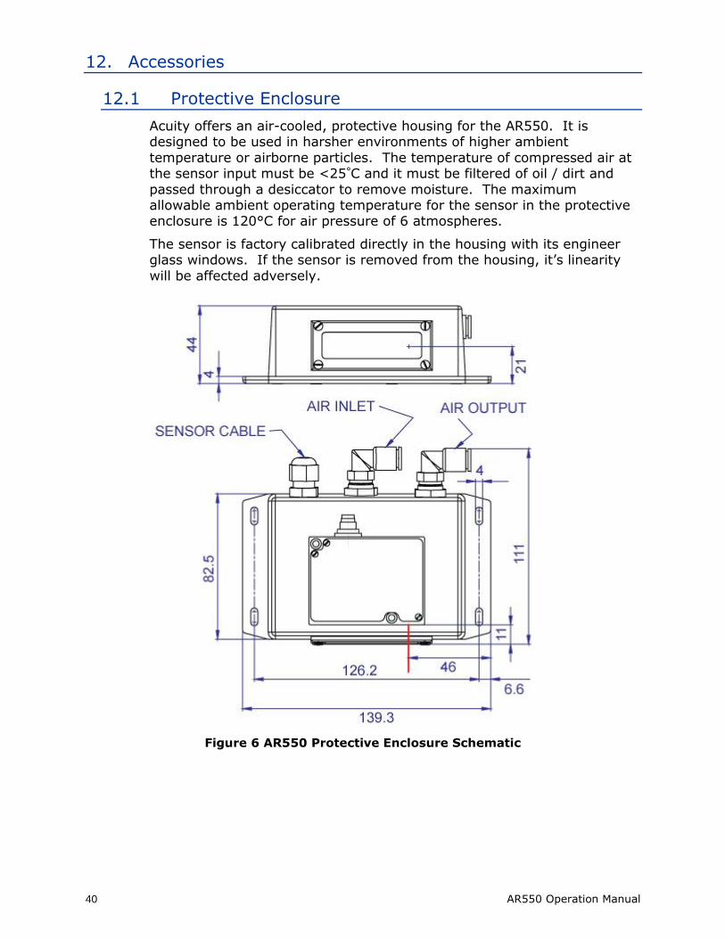
12.1 Protective Enclosure
Acuity offers an air-cooled, protective housing for the AR550. It is designed to be used in harsher environments of higher ambient
temperature or airborne particles. The temperature of compressed air at the sensor input must be <25°C and it must be filtered of oil / dirt and
passed through a desiccator to remove moisture. The maximum allowable ambient operating temperature for the sensor in the protective enclosure is 120°C for air pressure of 6 atmospheres.
The sensor is factory calibrated directly in the housing with its engineer glass windows. If the sensor is removed from the housing, it’s linearity
will be affected adversely.
Figure 6 AR550 Protective Enclosure Schematic
AR550 Operation Manual 41
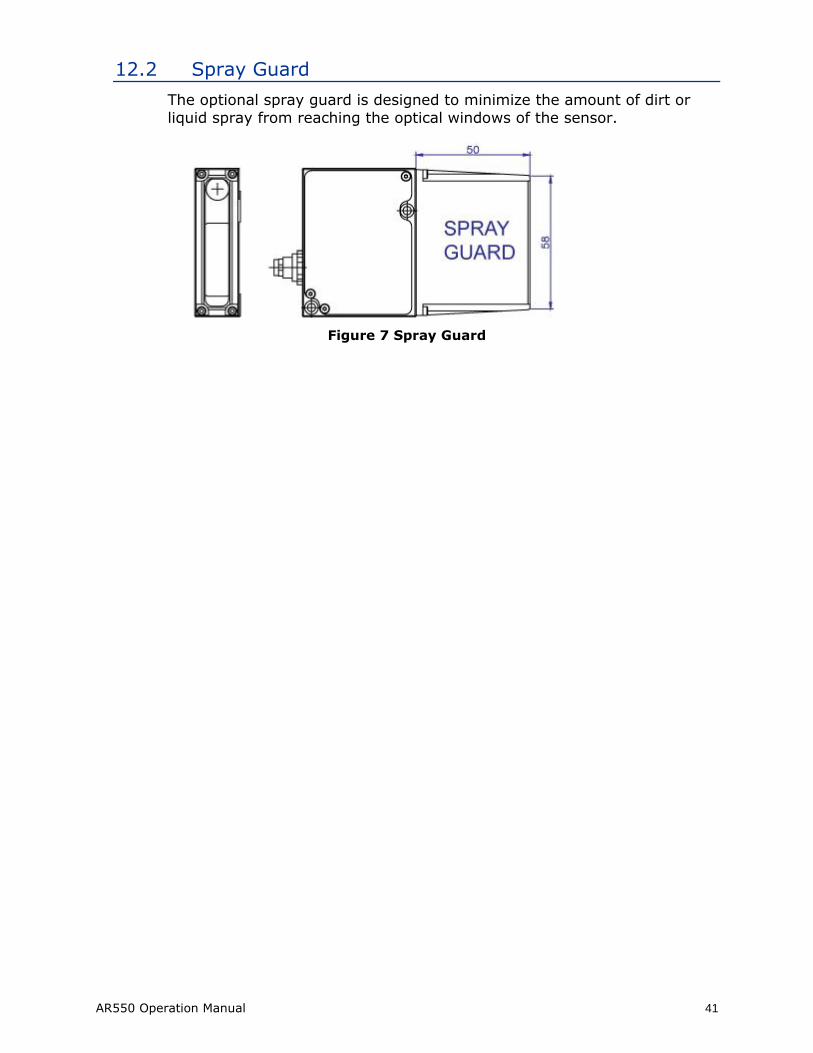
12.2 Spray Guard
The optional spray guard is designed to minimize the amount of dirt or
liquid spray from reaching the optical windows of the sensor.
Figure 7 Spray Guard
Top Related
Copyright © 2022 FDOKUMEN

