


Bahasa
Halaman
Hukum


—OPER ATING INSTRUC TION
Control Panels CP405Control Panels CP408

Operating Instructions 1 CP405, CP408
Contents
Introduction ........................................................................................................................ 2
Before You Start ................................................................................................................ 3
Safety Notices .......................................................................................................................... 3
Markups .................................................................................................................................... 3
Product Overview ..................................................................................................................... 4
Standards and Approvals ................................................................................................. 5
Product Identification............................................................................................................... 5
Technical Specifications ................................................................................................... 6
Environmental Conditions ....................................................................................................... 6
Electromagnetic Compatibility (EMC) ..................................................................................... 7
Durability Information .............................................................................................................. 8
Technical Data ................................................................................................................... 9
Dimensions ...................................................................................................................... 10
Installation Environment ................................................................................................. 12
Installation Procedure ............................................................................................................ 12
Connections ..................................................................................................................... 13
Serial Port ............................................................................................................................... 14
Communication Cables .......................................................................................................... 15
Power Supply, Grounding and Shielding ...................................................................... 16
Battery .............................................................................................................................. 17
Cleaning Faceplates ........................................................................................................ 18
Getting Started ................................................................................................................. 19
Panel Setup ...................................................................................................................... 20

Operating Instructions 2 CP405, CP408
Introduction
The operational guidelines described below is information which relates to the device, place of employ-ment, transportation, storage, assembly, use and maintenance.
The Control Panels have been designed for installation and use in an industrial environment in compli-ance with the 2004/108/EC EMC Directive.
The products have been designed in compliance with:
EN 61000-6-4 EN 55022 Class A
EN 61000-6-2 EN 61000-4-2
EN 61000-4-3
EN 61000-4-4
EN 61000-4-5
EN 61000-4-6
EN 61000-4-8
The installation of these devices into the residential, commercial and light-industrial environments is al-lowed only in the case that special measures are taken in order to get conformity to EN 61000-6-3. The products are in compliance with the Restrictions on Certain Hazardous Substances (RoHS) Directive 2011/65/EC. In compliance with the above regulations the products are CE marked.
This Operating Instruction describes the main features of the CP405 and CP408 Control Panels. The Op-erating Instructions refer to the following models:
Picture Type Description
CP405 (Order No. 1SAP500405R0001)
CP405 Control Panel, TFT graphical display, touch screen, 7”, 800 x 480 pixels
CP408 (Order No. 1SAP500408R0001)
CP408 Control Panel, TFT graphical display, touch screen, 10.1”, 1024 x 600 pixels

Operating Instructions 3 CP405, CP408
Before You Start
Safety Notices
DANGER!
Indicates an imminent risk. It will lead to death or serious injury if not avoided.
WARNING!
Indicates a possible risk. It may lead to death or serious injury if not avoided.
CAUTION!
Indicates a possible risk. It may lead to light or slight injury or material damage if not avoid-ed.
Markups
Enumeration.
Precondition for an operation instruction or a description.
Operation instruction with one step.
1. Operation instruction with several steps.
Result of an operation.
NOTE
Helpful information with background information or an emphasized notice.
TIP
Application tips or other useful information and suggestions.

Operating Instructions 4 CP405, CP408
Product Overview
The Control Panels combine state-of-the-art features and top performance with an outstanding design. They are the ideal choice for all demanding HMI applications including discrete automation and most in-dustrial applications.
These Control Panels have been designed to run the CP400PB Panel Builder 400 software.
CP400PB Panel Builder 400 Runtime included.
Full object dynamics: Control visibility and transparency, move and resize any object on screen. Change properties of basic and complex objects.
Multilanguage applications. Easily create and manage your applications in multiple languages to meet global requirements. Far East languages are supported.
Data display in numerical, text, bar graph, analog gauges and graphic image formats.
Rich set of state-of-the-art HMI features: Data acquisition, alarm handling, scheduler, recipes, users and passwords.
Includes support for a set of communication drivers e.g. AC500/AC500eCo and Motion drives.
Offline and online simulation with CP400PB Panel Builder 400.
Powerful scripting language for automating HMI applications. Script debugging improves efficiency in application development.

Operating Instructions 5 CP405, CP408
Standards and Approvals
The Control Panels have been designed for installation and use in an industrial environment in compli-ance with the 2004/108/EC EMC directive and with the following harmonized standards:
EN 61000-6-4
EN 61000-6-2
In compliance with the above regulations the products are CE marked.
The installation of these devices into residential, commercial and light-industrial environments is allowed only in the case that special measures are taken in order to get conformity to EN 61000-6-3. The products are in compliance with the Restrictions on Certain Hazardous Substances (RoHS) directive 2011/65/EC. In compliance with the above regulations the products are CE marked.
Product Identification
The Control Panel products are identified by a product label. The label reports several information, includ-ing the model name, the part number, the power supply and three barcodes. First code is the version code, second one is the EAN code, third one it the serial number (S.N.).
Example of product label
Information on type plate (example) Description
CP408 Product type
1SAP500408R0001 Product part number
1254100K2GV1401009 Serial number
A0 Version number of the product
Operating Instructions 6 CP405, CP408
Technical Specifications
Parameter Value
Touch screen technology 4 wire analog resistive
Backup battery 3 V 220 mAh lithium manganese dioxide (Li/MnO2) battery type
Fuse Resettable
Serial port RS-232, RS-485, RS-422 (Sub-D 9 female connector)
User memory Flash 8 MB+128 MB for CP405, CP408
Recipe memory Flash or 128 kB battery back-up RAM
Hardware clock Clock/calendar with back-up battery
Accuracy RTC (at 25 °C operating)
+10 s to -5 s per day, which can be calibrated by RTC adjustment in Panel Setup.
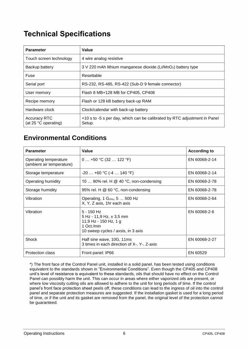
Environmental Conditions
Parameter Value According to
Operating temperature (ambient air temperature)
0 … +50 °C (32 … 122 °F) EN 60068-2-14
Storage temperature -20 … +60 °C (-4 … 140 °F) EN 60068-2-14
Operating humidity 10 … 90% rel. H @ 40 °C, non-condensing EN 60068-2-78
Storage humidity 95% rel. H @ 60 °C, non-condensing EN 60068-2-78
Vibration Operating, 1 Grms, 5 … 500 Hz X, Y, Z axis, 1hr each axis
EN 60068-2-64
Vibration 5 - 150 Hz 5 Hz - 11,9 Hz, ± 3,5 mm 11,9 Hz - 150 Hz, 1 g 1 Oct./min 10 sweep cycles / axsis, in 3 axis
EN 60068-2-6
Shock Half sine wave, 10G, 11ms 3 times in each direction of X-, Y-, Z-axis
EN 60068-2-27
Protection class Front panel: IP66 EN 60529
*) The front face of the Control Panel unit, installed in a solid panel, has been tested using conditions equivalent to the standards shown in ”Environmental Conditions”. Even though the CP405 and CP408 unit’s level of resistance is equivalent to these standards, oils that should have no effect on the Control Panel can possibly harm the unit. This can occur in areas where either vaporized oils are present, or where low viscosity cutting oils are allowed to adhere to the unit for long periods of time. If the control panel’s front face protection sheet peels off, these conditions can lead to the ingress of oil into the control panel and separate protection measures are suggested. If the installation gasket is used for a long period of time, or if the unit and its gasket are removed from the panel, the original level of the protection cannot be guaranteed.

Operating Instructions 7 CP405, CP408
Electromagnetic Compatibility (EMC)
Immunity:
Parameter Value According to
Radiated disturbance test Class A EN 55022
Electrostatic discharge immunity test
8 kV (air electrostatic discharge) 4 kV (contact electrostatic discharge) Performance criterion B
EN 61000-4-2
Radiated, radio-frequency, electromagnetic field im-munity test
80 MHz … 1 GHz, 10 V/m 1.4 GHz … 2 GHz, 3 V/m 2 GHz … 2.7 GHz, 1 V/m Performance criterion A
EN 61000-4-3
Burst immunity test ± 2 kV DC power port ± 1 kV signal line Performance criterion B
EN 61000-4-4
Surge immunity test ± 0.5 kV DC power port (line to earth) ± 0.5 kV DC power port (line to line) ± 1 kV signal line (line to earth) Performance criterion B
EN 61000-4-5
Immunity to conducted disturbances inducted by radio-frequency field
0.15 … 80 MHz, 10 V Performance criterion A
EN 61000-4-6
Power frequency magnetic field immunity test
50 Hz/60 Hz, 30 A/m EN 61000-4-8
Emission:
Parameter Value According to
Conducted (power) 0.15 MHz … 0.5 MHz, 79 dBuV 0.5 MHz … 30 MHz, 73 dBuV
EN 61000-6-4
Conducted (Telecom port) 0.15 MHz … 0.5 MHz, 97 … 87 dBuV 5 MHz … 30 MHz, 87 dBuV
Radiated 30 MHz … 230 MHz, 40 dBuV/m 230 MHz … 1 GHz, 47 dBuV/m

Operating Instructions 8 CP405, CP408
Durability Information
Parameter Value
Backlight life (LED type) 20,000 hr. Time of continuous operation until the brightness of the backlight reaches 50% of the rated value when the surrounding temperature reaches 25 C. 1
Battery lifetime Battery capacity remains 95% after 5 years when not yet used at general environment 20 °C.
Front foil (without directly expose to sunlight or UV ray)
10 years if the surrounding temperature is 25 C
Touch screen (resistive film, analog)
1,000,000 or more of activations
1 Switching off the backlight in case of no use will increase the backlight s lifetime. Extended use in envi-ronments where the surrounding air temperature is 40 °C or higher may degrade backlight quali-ty/reliability/durability.

Operating Instructions 9 CP405, CP408
Technical Data
Model CP405 CP408
Display/backlight WVGA TFT LCD WSVGA TFT LCD
Colors 65,536 65,536
Resolution 800 x 480 1024 x 600
Diagonal (inches) 7’’ 10.1’’
Backlight type LED LED
Backlight brightness 250 cd/m² 250 cd/m²
Viewing angle Wide angle viewing under industrial conditions indoor: vertical: 140° horizontal: 130°
Wide angle viewing under industrial conditions indoor: vertical: 140° horizontal: 130°
Dimming Adjustable by touch panel Adjustable by touch panel
Touch screen 4 wire analog resistive 4 wire analog resistive
User memory flash 8 MB NOR + 128 MB NAND flash 8 MB NOR + 128 MB NAND flash
Recipe memory Yes, flash or 128 kB battery back-up RAM
Yes, flash or 128 kB battery back-up RAM
Serial port RS-232, RS-485, RS422 (DB9 female)
RS-232, RS-485, RS422 (DB9 female)
USB port 1 x USB (type A): Communication to printers and other typical accessories 1 x USB (type B): Port for programming
Battery (built in) Non-chargeable Non-chargeable
Real-time clock Yes Yes
Voltage 24 VDC ± 10% 24 VDC ± 10%
Power consumption 10 W max. 10 W max.
Weight 0.55 kg (1.25 lbs) / net 0.75 kg (1.70 lbs) / gross
1.05 kg (2.35 lbs) / net 1.55 kg (3.45 lbs) / gross

Operating Instructions 10 CP405, CP408
Dimensions
CP405:
Panel Cut-out dimensions: 191.5 x 138 mm (7.54” x 5.43”)
CP408:
Panel Cut-out dimensions: 259.5 x 201.5 mm (10.22” x 7.93”)

Operating Instructions 11 CP405, CP408
Outlet: Cut-out:
Model A B C H L
mm inches mm inches mm inches mm inches mm inches
CP405 203.6 8.02 148.5 5.85 31.1 1.22 138.0 5.43 191.5 7.54
CP408 270.1 10.63 211.9 8.34 37.4 1.47 201.5 7.93 259.5 10.22

Operating Instructions 12 CP405, CP408
Installation Environment
The equipment is not intended for continuous exposure to direct sunlight. This might accelerate the aging process of the front panel film.
The equipment is not intended for installation in contact with corrosive chemical compounds. Check the resistance of the front panel film to a specific compound before installation.
Do not use tools of any kind (screwdrivers etc.) to operate the touch screen of the panel.
In order to meet the front panel protection classifications, proper installation procedure must be followed:
The borders of the cut-out must be flat.
The cut-out for the panel must be of the dimensions indicated in this manual.
Screw up each fixing screw until the plastic bezel corner get in contact with the panel.
The IP66 is only guaranteed if:
Maximum deviation from the plane surface to the cut-out: Ø 0.5 mm
Thickness of the plate the equipment is mounted: 1 mm to 10 mm
Maximum surface roughness where the gasket is applied: Ø 120 µm
Installation Procedure
Panel fixing: Placing the fixing brackets:
CAUTION!
Screw each fixing screw until the bezel corner gets in contact with the panel.

Operating Instructions 13 CP405, CP408
Connections
1 Power supply connector (Terminal)
2 Serial port COM1/ COM3 (9-Pin female)
3 USB port (type A)
4 USB port (type B)

Operating Instructions 14 CP405, CP408
Serial Port
The serial port COM1 / COM3 is used to communicate with the PLC or with another type of controller.
Different electrical standards are available for the signals in the PLC port connector: RS-232, RS-485 and RS422.
The used cable selects the appropriate signals.
NOTE
It is always necessary to use the correct cable type to connect to the PLC. If the proper cable is not used, communication with the PLC will not be possible.
The serial port is software programmable. Make sure you select the appropriate interface in the pro-gramming software.
The serial connector is a DP-9 pin female
NOTE
It is highly recommended to use communication cable for AC500(-eCo) TK407 (Order No. 1SAP500467R0001).
COM1 / COM3 for CP405 / CP408 HMI
Pin Description Pin Description Pin Description
1 RS422_TxD + / RS485 + 4 RS422_RxD + 7 RS232_TxD (COM3)
2 RS232_RxD 5 GND 8 RS232_RxD (COM3)
3 RS232_TxD 6 RS422_TxD - / RS485 - 9 RS422_RxD -
The communication cable must be chosen for the type of device being connected.

Operating Instructions 15 CP405, CP408
Communication Cables
The communication cable must be chosen for the type of device being connected.
Connection to an AC500(-eCo) with the TK407 CP400-AC500(-eCo) RS485/RS232 communication cable
RS485 wiring
Pin AC500-eCo COM1 AC500 COM2
1 FE FE
2 SGND RS232_TxD
3 RS485_RxD/TxD-P RS485_RxD/TxD-P
4 Reserved RS232_RTS
5 SGND SGND
6 + 3.3 V + 5 V
7 Reserved RS232_RxD
8 RS485_RxD/TxD-N RS485_RxD/TxD-N
9 Reserved RS232_CTS
RS232 wiring
Pin AC500 COM2
1 FE
2 RS232_TxD
3 RS485_RxD/TxD-P
4 RS232_RTS
5 SGND
6 + 5 V
7 RS232_RxD
8 RS485_RxD/TxD-N
9 RS232_CTS
Pin CP405 & CP408 COM1 / COM3
1 RS422_TxD-P/RS485_RxD/TxD-P
2 RS232_RxD
3 RS232_TxD
4 RS422_RxD-P
5 GND
6 RS422_TxD-N/RS485_RxD/TxD-N
7 RS232_TxD (COM3)
8 RS232_RxD (COM3)
9 RS422_RxD-N
Pin CP405 & CP408 COM1 / COM3
1 RS422_TxD-P/RS485_RxD/TxD-P
2 RS232_RxD
3 RS232_TxD
4 RS422_RxD-P
5 GND
6 RS422_TxD-N/RS485_RXD/TxD-N
7 RS232_TxD (COM3)
8 RS232_RxD (COM3)
9 RS422_RxD-N

Operating Instructions 16 CP405, CP408
Power Supply, Grounding and Shielding
NOTE
Powered by a low voltage / limited energy power source.
Power supply terminal block
NOTE
Ensure that the power supply has enough power capacity for the operation of the equip-ment.
NOTE
Do not open the rear cover of the panel when power is applied.
The unit must always be grounded to earth. Grounding helps to limit the effects of noise due to electro-magnetic interference on the control system.
1. Do the earth connection by using screw terminal located near the power supply terminal block. A print identify the ground connection.
2. Connect to ground the terminal 3 on the power supply terminal block.
3. The power supply circuit may be floating or grounded. In the latter case, connect to ground the power source common.

Operating Instructions 17 CP405, CP408
Battery
The Control Panels are equipped with a non-chargeable lithium manganese dioxide (Li/MnO2) battery, not user-replaceable.
The battery maintains the hardware real-time clock (date and time).
CP405 / CP408:
NOTE
The battery must not be disposed as unsorted domestic waste.
Dispose the battery according to the local regulations.
NOTE
Capacity of battery can hold for 2 years or more, without connected power supply to HMI, in general environment. The data in the memory may become incorrect under low battery condition.

Operating Instructions 18 CP405, CP408
Cleaning Faceplates
The equipment must be cleaned only with a soft cloth and neutral soap product. Do not use solvents.

Operating Instructions 19 CP405, CP408
Getting Started
The Control Panels (CP405 / CP408) must be programmed with the programming package CP400PB Panel Builder 400.
The Control Panels are programmed via COM1 / COM3 and USB (type B) interface.
To program a Control Panel connect the Control Panel to a PC running CP400PB Panel Builder 400 software package.
The software package CP400PB Panel Builder 400 is a Windows 7/Vista 32- or 64-bit-based application and must be properly installed. Windows 7/Vista 32-/64-bit environment is not included in the software package CP400PB Panel Builder 400 and must already be installed on PC.
CP400PB Panel Builder 400 uses the USB (type B) interface via to communicate with the target device.
The version of the Panel Builder used must be compatible with the CP400PB Panel Builder 400 Runtime version installed on the Control Panel to be programmed. An update of the panel s runtime will be done automatically by downloading a project created with newer CP400PB version.

Operating Instructions 20 CP405, CP408
Panel Setup
The Control Panels provide a system settings tool to allow basic and preliminary settings to the unit.
NOTE
Some of the buttons on the setup screen appear only when they are needed.
After powering up, the target panel will not display the setup screen if “Run AP after Power On” in the General Settings is set to True. The target panel will run the application directly.
The following table describes the function of each button on the setup screen of the target panel.
Property Press the button to …
English display the texts of the screen in the corresponding language.
General set the contrast and brightness of the display.
Touch Panel calibrate the touch panel.
Set Time/Date set the date and time on the real-time clock chip.

Operating Instructions 21 CP405, CP408
H/W Information
display the hardware information of the target panel. The following picture de-scribes the hardware information screen.
Link 1 – Link 4 set the parameters for communication between the target panel and PLC/Controllers.
Copy AP to HMI copy the application to another HMI.
Copy AP to File save the system programs and the application runtime data to a PRP file. The file can be used by the software and compatible target panels.
Copy File copy the file.
Delete File delete the file.
Format Disk C format the built-in flash disk (C:). This operation requires a user level of 8 or high-er.
Boot from File load-and-run the system programs and the application runtime data from a PRP file. The original system programs and runtime data are intact. The loaded system programs and the runtime data will be lost after power off.
Update from File update the system programs and the application runtime data from a PRP file. The original system programs and the application runtime data are replaced by the new ones.
Clear Recorded Data clear the data stored in the battery backed RAM, which include the operation history, alarm history, alarm counts, and the data collected by data loggers. This operation requires a user level of 7 or higher.
Run
start running the application. If login is required, the operator must enter a valid password of any user level before the target panel displays the first screen. The user level of the password you enter becomes the current user level. Any opera-tion that requires a user level higher than the current user level will not work while the application is still running.

3AD
R0
108
67,
1, e
n_U
S
© Copyright 2011 - 2021 ABB.All rights reserved.
—ABB AG Eppelheimer Straße 82 69123 HeidelbergGermany Phone: +49 6221 701 1444Fax: +49 6221 701 1382E-Mail: [email protected]
www.abb.com/plcwww.abb.com/automationbuilder
Note:
We reserve the right to make technical changes or modify
the contents of this document without prior notice.
With regard to purchase orders, the agreed particulars
shall prevail.
ABB AG does not accept any responsibility whatsoever for
potential errors or possible lack of information in this
document.
We reserve all rights in this document and in the subject
matter and illustrations contained therein.
Any reproduction, disclosure to third parties or utilization
of its contents – in whole or in parts – is forbidden without
prior written consent of ABB AG.
Copyright © 2022 FDOKUMEN

