ZL49010/11/20/21/30/31 Wide Dynamic Range DTMF Receiver
19
1 Zarlink Semiconductor Inc. Zarlink, ZL and the Zarlink Semiconductor logo are trademarks of Zarlink Semiconductor Inc. Copyright 2003-2007, Zarlink Semiconductor Inc. All Rights Reserved. Features • Wide dynamic range (50 dB) DTMF Receiver • Call progress (CP) detection via cadence indication • 4-bit synchronous serial data output • Software controlled guard time for ZL490x0 • Internal guard time circuitry for ZL490x1 • Powerdown option (ZL4901x & ZL4903x) • 3.579 MHz crystal or ceramic resonator (ZL4903x and ZL4902x) • External clock input (ZL4901x) • Guarantees non-detection of spurious tones Applications • Integrated telephone answering machine • End-to-end signalling • Fax Machines Description The ZL490xx is a family of high performance DTMF receivers which decode all 16 tone pairs into a 4-bit binary code. These devices incorporate an AGC for wide dynamic range and are suitable for end-to-end signalling. The ZL490x0 provides an early steering (ESt) logic output to indicate the detection of a DTMF signal and requires external software guard time to validate the DTMF digit. The ZL490x1, with preset internal guard times, uses a delay steering (DStD) logic output to indicate the detection of a valid DTMF digit. The 4-bit DTMF binary digit can be clocked out synchronously at the serial data (SD) output. The SD pin is multiplexed with call progress detector output. In the presence of supervisory tones, the call progress detector circuit indicates the cadence (i.e., envelope) of the tone burst. The cadence information can then be processed by an external microcontroller to identify February 2007 Ordering Information ZL49010/11DAA 8 Pin PDIP Tubes ZL49020/21DAA 8 Pin PDIP Tubes ZL49030/31DCA 18 Pin SOIC Tubes ZL49030/31DCB 18 Pin SOIC Tape & Reel ZL49030/31DDA 20 Pin SSOP Tubes ZL49030/31DDB 20 Pin SSOP Tape & Reel ZL49010/11DAA1 8 Pin PDIP* Tubes ZL49020/21DAA1 8 Pin PDIP* Tubes ZL49030/31DCE1 18 Pin SOIC* Tubes, Bake & Drypack ZL49030/31DCF1 18 Pin SOIC* Tape & Reel, Bake & Drypack ZL49030/31DDE1 20 Pin SSOP* Tubes, Bake & Drypack ZL49030/31DDF1 20 Pin SSOP* Tubes, Bake & Drypack *Pb Free Matte Tin -40°C to +85°C ZL49010/11, ZL49020/21, ZL49030/31 Wide Dynamic Range DTMF Receiver Data Sheet Figure 1 - Functional Block Diagram VDD VSS OSC2 1. ZL49010/1 and ZL49030/1 only. 2. ZL49020/1 and ZL49030/1 only. Voltage Bias Circuit AGC Anti- alias Filter High Group Filter Low Group Filter Steering Circuit Digital Detector Algorithm Code Converter and Latch Digital Guard Time 3 Parallel to Serial Converter & Latch Mux Energy Detection Oscillator and Clock Circuit To All Chip Clocks Dial Tone Filter ESt DStD ACK SD 1 2 or 3. ZL490x1 only. PWDN OSC1 (CLK)
-
Upload
khangminh22 -
Category
Documents
-
view
2 -
download
0
Transcript of ZL49010/11/20/21/30/31 Wide Dynamic Range DTMF Receiver

1Zarlink Semiconductor Inc.
Zarlink, ZL and the Zarlink Semiconductor logo are trademarks of Zarlink Semiconductor Inc.Copyright 2003-2007, Zarlink Semiconductor Inc. All Rights Reserved.
Features• Wide dynamic range (50 dB) DTMF Receiver• Call progress (CP) detection via cadence
indication• 4-bit synchronous serial data output• Software controlled guard time for ZL490x0 • Internal guard time circuitry for ZL490x1• Powerdown option (ZL4901x & ZL4903x)• 3.579 MHz crystal or ceramic resonator (ZL4903x
and ZL4902x)• External clock input (ZL4901x)• Guarantees non-detection of spurious tones
Applications• Integrated telephone answering machine• End-to-end signalling• Fax Machines
DescriptionThe ZL490xx is a family of high performance DTMFreceivers which decode all 16 tone pairs into a 4-bitbinary code. These devices incorporate an AGC forwide dynamic range and are suitable for end-to-endsignalling. The ZL490x0 provides an early steering(ESt) logic output to indicate the detection of a DTMF
signal and requires external software guard time tovalidate the DTMF digit. The ZL490x1, with presetinternal guard times, uses a delay steering (DStD)logic output to indicate the detection of a valid DTMFdigit. The 4-bit DTMF binary digit can be clocked outsynchronously at the serial data (SD) output. The SDpin is multiplexed with call progress detector output. Inthe presence of supervisory tones, the call progressdetector circuit indicates the cadence (i.e., envelope)of the tone burst. The cadence information can then beprocessed by an external microcontroller to identify
February 2007
Ordering Information
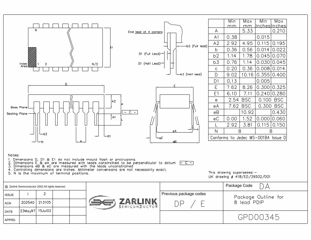
ZL49010/11DAA 8 Pin PDIP TubesZL49020/21DAA 8 Pin PDIP TubesZL49030/31DCA 18 Pin SOIC TubesZL49030/31DCB 18 Pin SOIC Tape & ReelZL49030/31DDA 20 Pin SSOP TubesZL49030/31DDB 20 Pin SSOP Tape & ReelZL49010/11DAA1 8 Pin PDIP* TubesZL49020/21DAA1 8 Pin PDIP* TubesZL49030/31DCE1 18 Pin SOIC* Tubes, Bake & DrypackZL49030/31DCF1 18 Pin SOIC* Tape & Reel,
Bake & Drypack ZL49030/31DDE1 20 Pin SSOP* Tubes, Bake & DrypackZL49030/31DDF1 20 Pin SSOP* Tubes, Bake & Drypack
*Pb Free Matte Tin-40°C to +85°C
ZL49010/11, ZL49020/21, ZL49030/31 Wide Dynamic Range DTMF Receiver
Data Sheet
Figure 1 - Functional Block Diagram
VDD
VSS
OSC2
1. ZL49010/1 and ZL49030/1 only.2. ZL49020/1 and ZL49030/1 only.
VoltageBias Circuit
AGCAnti-aliasFilter
HighGroupFilter
LowGroupFilter
SteeringCircuit
DigitalDetectorAlgorithm
CodeConverter
andLatch
DigitalGuardTime3
Parallel toSerial
Converter& Latch
Mux
EnergyDetection
Oscillatorand
ClockCircuit
To All Chip Clocks
DialToneFilter
ESt
DStD
ACK
SD
1
2
or
3. ZL490x1 only.
PWDN
OSC1(CLK)

ZL49010/11, ZL49020/21, ZL49030/31 Data Sheet
2Zarlink Semiconductor Inc.
specific call progress signals. The ZL4902x and ZL4903x can be used with a crystal or a ceramic resonator withoutadditional components. A power-down option is provided for the ZL4901x and ZL4903x.
Figure 2 - Pin Connections
Pin Description
Pin #Name Description
4903xDD 4903xDC 4902x 4901x3 2 1 1 INPUT DTMF/CP Input. Input signal must be AC coupled via
capacitor.6 4 2 - OSC2 Oscillator Output.7 6 3 3 OSC1
(CLK)Oscillator/Clock Input. This pin can either be driven by:1) an external digital clock with defined input logic
levels. OSC2 should be left open.2) connecting a crystal or ceramic resonator between
OSC1 and OSC2 pins.8 9 4 4 VSS Ground. (0 V)13 11 5 5 SD Serial Data/Call Progress Output. This pin serves the
dual function of being the serial data output when clock pulses are applied after validation of DTMF signal, and also indicates the cadence of call progress input. As DTMF signal lies in the same frequency band as call progress signal, this pin may toggle for DTMF input. The SD pin is at logic low in powerdown state.
14 13 6 6 ACK Acknowledge Pulse Input. After ESt or DStD is high, applying a sequence of four pulses on this pin will then shift out four bits on the SD pin, representing the decoded DTMF digit. The rising edge of the first clock is used to latch the 4-bit data prior to shifting. This pin is pulled down internally. The idle state of the ACK signal should be low.
10
1817161514131211
VDDNCNCESt/DStDNCACKNCSDNC
123456789
NCINPUTPWDNOSC2
NCOSC1
NCNC
VSS
INPUT
PWDN
CLK
VSS
VDD
ACK
SD
INPUT
OSC2
OSC1
VSS
VDD
ESt/
ACK
SD
ZL49010/1 ZL49020/1 ZL49030DC/1DC
8 PIN PLASTIC DIP 18 PIN PLASTIC SOIC
1
2
3
4
8
7
6
5
1
2
3
4
8
7
6
5
12345678910 11
12
2019181716151413
NCNC
INPUTPWDN
NC
NC
OSC1OSC2
VSS
20 PIN SSOP
NCVDDNC
NCACKSDNCNC
ESt/DStDDStDESt/DStD
ZL49030DD/1DD
NC
NC

ZL49010/11, ZL49020/21, ZL49030/31 Data Sheet
3Zarlink Semiconductor Inc.
Change SummaryThe following table summarizes the changes from the July 2006 issue.
16 15 7 7 ESt(ZL490x0)
DStD(ZL490x1)
Early Steering Output. A logic high on ESt indicates that a DTMF signal is present. ESt is at logic low in powerdown state.
Delayed Steering Output. A logic high on DStD indicates that a valid DTMF digit has been detected. DStD is at logic low in powerdown state.
18 18 8 8 VDD Positive Power Supply (5 V Typ.) Performance of the device can be optimized by minimizing noise on the supply rails. Decoupling capacitors across VDD and VSS are therefore recommended.
1,2,5,9, 10,11,12,
15,17,19,20
1,5,7,8,10, 12,14,16,
17
- - NC No Connection. Pin is unconnected internally.
4 3 - 2 PWDN Power Down Input. A logic high on this pin will power down the device to reduce power consumption. This pin is pulled down internally and can be left open if not used. ACK pin should be at logic ’0’ to power down device.
DeviceType 8 Pin 18 Pin 20 Pin PWDN 2 Pin
OSCExtCLK ESt DStD
ZL49010 x x x xZL49011 x x x xZL49020 x x x xZL49021 x x x xZL49030 x x x x x xZL49031 x x x x x x
Table 1 - Summary of ZL490x0/1 Product Family
Page Item Description
2 Figure 2 Added ordering codes to Pin Connection diagram.
2 Pin Description Added 20 pin description to the table.
Pin Description (continued)
Pin #Name Description
4903xDD 4903xDC 4902x 4901x

ZL49010/11, ZL49020/21, ZL49030/31 Data Sheet
4Zarlink Semiconductor Inc.
Functional DescriptionThe ZL490xxs are high performance and low power consumption DTMF receivers. These devices provide widedynamic range DTMF detection and a serial decoded data output. These devices also incorporate an energydetection circuit. An input voiceband signal is applied to the devices via a series decoupling capacitor. Following theunity gain buffering, the signal enters the AGC circuit followed by an anti-aliasing filter. The bandlimited output isrouted to a dial tone filter stage and to the input of the energy detection circuit. A bandsplit filter is then used toseparate the input DTMF signal into high and low group tones. The high group and low group tones are thenverified and decoded by the internal frequency counting and DTMF detection circuitry. Following the detectionstage, the valid DTMF digit is translated to a 4-bit binary code (via an internal look-up ROM). Data bits can then beshifted out serially by applying external clock pulses.
Automatic Gain Control (AGC) Circuit
As the device operates on a single power supply, the input signal is biased internally at approximately VDD/2. Withlarge input signal amplitude (between 0 and approximately -30 dBm for each tone of the composite signal), theAGC is activated to prevent the input signal from being clipped. At low input level, the AGC remains inactive and theinput signal is passed directly to the hardware DTMF detection algorithm and to the energy detection circuit.
Filter and Decoder Section
The signal entering the DTMF detection circuitry is filtered by a notch filter at 350 and 440 Hz for dial tone rejection.The composite dual-tone signal is further split into its individual high and low frequency components by two 6th
order switched capacitor bandpass filters. The high group and low group tones are then smoothed by separateoutput filters and squared by high gain limiting comparators. The resulting squarewave signals are applied to adigital detection circuit where an averaging algorithm is employed to determine the valid DTMF signal. ForZL490x0, upon recognition of a valid frequency from each tone group, the early steering (ESt) output will go high,indicating that a DTMF tone has been detected. Any subsequent loss of DTMF signal condition will cause the EStpin to go low. For ZL490x1, an internal delayed steering counter validates the early steering signal after apredetermined guard time which requires no external components. The delayed steering (DStD) will go high onlywhen the validation period has elapsed. Once the DStD output is high, the subsequent loss of early steering signaldue to DTMF signal dropout will activate the internal counter for a validation of tone absent guard time. The DStDoutput will go low only after this validation period.
Energy Detection
The output signal from the AGC circuit is also applied to the energy detection circuit. The detection circuit consistsof a threshold comparator and an active integrator. When the signal level is above the threshold of the internalcomparator (-35 dBm), the energy detector produces an energy present indication on the SD output. The integratorensure the SD output will remain at high even though the input signal is changing. When the input signal isremoved, the SD output will go low following the integrator decay time. Short decay time enables the signalenvelope (or cadence) to be generated at the SD output. An external microcontroller can monitor this output forspecific call progress signals. Since presence of speech and DTMF signals (above the threshold limit) can causethe SD output to toggle, both ESt (DStD) and SD outputs should be monitored to ensure correct signal identification.As the energy detector is multiplexed with the digital serial data output at the SD pin, the detector output is selectedat all times except during the time between the rising edge of the first pulse and the falling edge of the fourth pulseapplied at the ACK pin.
Serial Data (SD) Output
When a valid DTMF signal burst is present, ESt or DStD will go high. The application of four clock pulses on theACK pin will provide a 4-bit serial binary code representing the decoded DTMF digit on the SD pin output. The risingedge of the first pulse applied on the ACK pin latches and shifts the least significant bit of the decoded digit on theSD pin. The next three pulses on ACK pin will shift the remaining latched bits in a serial format (see Figure 5). If lessthan four pulses are applied to the ACK pin, new data cannot be latched even though ESt/DStD can be valid. Clockpulses should be applied to clock out any remaining data bits to resume normal operation. Any transitions in excess

ZL49010/11, ZL49020/21, ZL49030/31 Data Sheet
5Zarlink Semiconductor Inc.
of four pulses will be ignored until the next rising edge of the ESt/DStD. ACK should idle at logic low. The 4-bitbinary representing all 16 standard DTMF digits are shown in Table 2.
Powerdown Mode (ZL4901x/4903x)
The ZL4901x/4903x devices offer a powerdown function to preserve power consumption when the device is not inuse. A logic high can be applied at the PWDN pin to place the device in powerdown mode. The ACK pin should bekept at logic low to avoid undefined ESt/DStD and SD outputs (see Table 3).
Table 3 - Powerdown Mode
FLOW FHIGH DIGIT b3 b2 b1 b0
697 1209 1 0 0 0 1697 1336 2 0 0 1 0697 1477 3 0 0 1 1770 1209 4 0 1 0 0770 1336 5 0 1 0 1770 1477 6 0 1 1 0852 1209 7 0 1 1 1852 1336 8 1 0 0 0852 1477 9 1 0 0 1941 1336 0 1 0 1 0941 1209 * 1 0 1 1941 1477 # 1 1 0 0697 1633 A 1 1 0 1770 1633 B 1 1 1 0852 1633 C 1 1 1 1941 1633 D 0 0 0 0
0= LOGIC LOW, 1= LOGIC HIGHNote: b0=LSB of decoded DTMF digit and shifted out first.
Table 2 - Serial Decode Bit Table
ACK (input) PWDN (input) ESt/DStD (output) SD (output) ZL4901x/4903x status
low low Refer to Fig. 4 for timing waveforms
Refer to Fig. 4 for timing waveforms
normal operation
low high+ low low powerdown modehigh low low undefined undefinedhigh high undefined undefined undefined
Note: + =enters powerdown mode on the rising edge.

ZL49010/11, ZL49020/21, ZL49030/31 Data Sheet
6Zarlink Semiconductor Inc.
Table 4 - Call Progress Tones
Oscillator
The ZL4902x/4903x can be used in both external clock or two pin oscillator mode. In two pin oscillator mode, theoscillator circuit is completed by connecting either a 3.579 MHz crystal or ceramic resonator across OSC1 andOSC2 pins. It is also possible to configure a number of these devices (4 maximum) employing only a singleoscillator crystal. The OSC2 output of the first device in the chain is connected to the OSC1 input of the next device.Subsequent devices are connected similarly. The oscillator circuit can also be driven by an 3.579 MHz externalclock applied on pin OSC 1. The OSC2 pin should be left open.
For ZL4901x devices, the CLK input is driven directly by an 3.579 MHz external digital clock.
Frequency 1 (Hz) Frequency 2 (Hz) On/Off Description
350 440 continuous North American Dial Tones425 --- continuous European Dial Tones400 --- continuous Far East Dial Tones480 620 0.5s/0.5s North American Line Busy440 --- 0.5s/0.5s Japanese Line Busy480 620 0.25s/0.25s North American Reorder Tones440 480 2.0s/4.0s North American Audible Ringing480 620 0.25s/0.25s North American Reorder Tones

ZL49010/11, ZL49020/21, ZL49030/31 Data Sheet
7Zarlink Semiconductor Inc.
ApplicationsThe circuit shown in Figure 3 illustrates the use of a ZL4902x in a typical receiver application. It requires only acoupling capacitor (C1) and a crystal or ceramic resonator (X1) to complete the circuit.
The ZL490x0 is designed for user who wishes to tailor the guard time for specific applications. When a DTMF signalis present, the ESt pin will go high. An external microcontroller monitors ESt in real time for a period of time set bythe user. A guard time algorithm must be implemented such that DTMF signals not meeting the timing requirementsare rejected. The ZL490x1 uses an internal counter to provide a preset DTMF validation period. It requires noexternal components. The DStD output high indicates that a valid DTMF digit has been detected.
Figure 3 - Application Circuit for ZL4902x
DTMF/CP InputC1
X1
1
2
3
4
8
7
6
5
INPUT
OSC2
OSC1
VSS
VDD
ESt/DStD
ACK
SD
VDD
COMPONENTS LIST:C1 = 0.1 µF ± 10%X1 = Crystal or Resonator (3.579 MHz)
To microprocessor ormicrocontroller
ZL4902x

ZL49010/11, ZL49020/21, ZL49030/31 Data Sheet
8Zarlink Semiconductor Inc.
† Exceeding these values may cause permanent damage. Functional operation under these conditions is not implied.
‡ Typical figures are at 25°C and are for design aid only: not guaranteed and not subject to production testing.
‡ Typical figures are at 25°C and are for design aid only: not guaranteed and not subject to production testing
Absolute Maximum Ratings† - Voltages are with respect to VSS=0V unless otherwise stated.
Parameter Symbol Min. Max. Units
1 DC Power Supply Voltage VDD-VSS 6 V
2 Voltage on any pin (other than supply) VI/O -0.3 6.3 V
3 Current at any pin (other than supply) II/O 10 mA
4 Storage temperature TS -65 150 °C
5 Package power dissipation PD 500 mW
Recommended Operating Conditions - Voltages are with respect to VSS=0V unless otherwise stated
Parameter Sym. Min. Typ.‡ Max. Units Test Conditions
1 Positive Power Supply VDD 4.75 5.0 5.25 V
2 Oscillator Clock Frequency fOSC 3.579 MHz
3 Oscillator Frequency Tolerance ∆fOSC ±0.1 %
4 Operating Temperature Td -40 25 85 °C
DC Electrical Characteristics - Voltages are with respect to VDD=5V±5%,VSS=0V, and temperature -40 to 85°C, unless otherwise stated.
Characteristics Sym. Min. Typ.‡ Max. Units Test Conditions
1 Operating supply current IDD 3 8 mA
2 Standby supply current IDDQ 30 100 µA PWDN=5V, ACK=0VESt/DStD = SD = 0V
3a Input logic 1 VIH 4.0 V
3b Input logic 1(for OSC1 input only)
VIH 3.5 V ZL4902x/ZL4903x
4a Input logic 0 VIL 1.0 V
4b Input logic 0(for OSC1 input only)
VIL 1.5 V ZL4902x/ZL4903x
5 Input impedance (pin 1) RIN 50 kΩ
6 Pull-down Current(PWDN, ACK pins)
IPD 25 µA with internal pull-down resistor of approx. 200kΩ. PWDN/ACK = 5V
7 Output high (source) current IOH 0.4 4.0 mA VOUT=VDD-0.4V
8 Output low (sink) current IOL 1.0 9.0 mA VOUT=VSS+0.4V

ZL49010/11, ZL49020/21, ZL49030/31 Data Sheet
9Zarlink Semiconductor Inc.
‡ Typical figures are at 25 °C and are for design aid only: not guaranteed and not subject to production testing* Test Conditions 1. dBm refers to a reference power of 1 mW delivered into a 600 ohms load.
2. Data sequence consists of all DTMF digits.3. Tone on = 40 ms, tone off = 40 ms.4. Signal condition consists of nominal DTMF frequencies.5. Both tones in composite signal have an equal amplitude.6. Tone pair is deviated by ±1.5%± 2 Hz.7. Bandwidth limited (0-3 kHz) Gaussian noise.8. Precise dial tone frequencies are 350 Hz and 440 Hz (± 2%).9. Referenced to lowest level frequency component in DTMF signal.
10. Referenced to the minimum valid accept level.11. Both tones must be within valid input signal range.12. Internal guard time for ZL490x1 = 20 ms.13. Timing parameters are measured with 70 pF load at SD output. 14. Time duration between PWDN pin changes from ‘1‘ to ‘0‘ and ESt/DStD becomes active.15. Guaranteed by design and characterization. Not subject to production testing.16. Value measured with an applied tone of 450 Hz.
AC Electrical Characteristics - voltages are with respect to VDD=5V±5%, VSS=0V and temperature -40 to +85°C unless otherwise stated.
Characteristics Sym. Min. Typ.‡ Max. Units Test Conditions*1 Valid input signal level
(each tone of composite signal)-502.45
0775
dBmmVRMS
1,2,3,5,6,12
2 Positive twist accept 8 dB 1,2,3,4,11,12,153 Negative twist accept 8 dB 1,2,3,4,11,12,154 Frequency deviation accept ±1.5%± 2Hz 1,2,3,5,125 Frequency deviation reject ±3.5% 1,2,3,5,12,156 Third tone tolerance -16 dB 1,2,3,4,5,127 Noise tolerance -12 dB 7,9,128 Dial tone tolerance +15 dB 8,10,129 Supervisory tones detect level
(Total power)-35 dBm 16
10 Supervisory tones reject level -50 dBm 1611 Energy detector attack time tSA 1.0 6.5 ms 1612 Energy detector decay time tSD 3 25 ms 1613a13b
Powerdown timePowerup time
103050
msmsms
IDDQ ≤ 100µAZL49010/ZL49030ZL49011/ZL49031Note 14
14 Tone present detect time (ESt logic output)
tDP 3 13 20 ms ZL490x0
15 Tone absent detect time (ESt logic output)
tDA 3 15 ms ZL490x0
16 Tone duration accept(DStD logic output)
tREC 40 ms ZL490x1
17 Tone duration reject(DStD logic output)
tREC 20 ms ZL490x1
18 Interdigit pause accept (DStD logic output)
tID 40 ms ZL490x1
19 Interdigit pause reject (DStD logic output)
tDO 20 ms ZL490x1
20 Data shift rate 40-60% duty cycle fACK 1.0 3.0 MHz 13,1521 Propagation delay
(ACK to Data Bit)tPAD 100 140 ns 1MHz fACK,
13,1522 Data hold time (ACK to SD) tDH 30 50 ns 13,15

ZL49010/11, ZL49020/21, ZL49030/31 Data Sheet
10Zarlink Semiconductor Inc.
Figure 4 - Timing Diagram
INPUT
ESt(ZL490x0)
DStD(ZL490x1)
ACK
SD
DTMFTone #n
tDP
tRECtDO
DTMFTone #n + 1
DTMFTone#n + 1
InputSignal
tDA
tREC tID
LSB MSB
b0b1b2b3 b0b1b2b3
tSA tSD
InputSignal
Envelope
LSB MSB
tDOtID
- maximum allowable dropout during valid DTMF signals. ZL490xx).
tRECtRECtDAtDPtSAtSD
- minimum time between valid DTMF signals (ZL49011).- maximum DTMF signal duration not detected as valid (ZL490xx).- minimum DTMF signal duration required for valid recognition (ZL490x1).- time to detect the absence of valid DTMF signals (ZL490x0).- time to detect the presence of valid DTMF signals (ZL490x0).- supervisory tone integrator attack time (ZL490xx).- supervisory tone integrator decay time (ZL490xx).

ZL49010/11, ZL49020/21, ZL49030/31 Data Sheet
11Zarlink Semiconductor Inc.
Figure 5 - ACK to SD Timing
ESt/DStD
ACK
SD
VIH
VIL
VIH
VIL
1/fACK
tPAD tDH
b0 b1 b2 b3
MSB
DTMF EnergyDetect
LSB
DTMF EnergyDetect


www.zarlink.com
Information relating to products and services furnished herein by Zarlink Semiconductor Inc. or its subsidiaries (collectively “Zarlink”) is believed to be reliable.However, Zarlink assumes no liability for errors that may appear in this publication, or for liability otherwise arising from the application or use of any suchinformation, product or service or for any infringement of patents or other intellectual property rights owned by third parties which may result from such application oruse. Neither the supply of such information or purchase of product or service conveys any license, either express or implied, under patents or other intellectualproperty rights owned by Zarlink or licensed from third parties by Zarlink, whatsoever. Purchasers of products are also hereby notified that the use of product incertain ways or in combination with Zarlink, or non-Zarlink furnished goods or services may infringe patents or other intellectual property rights owned by Zarlink.
This publication is issued to provide information only and (unless agreed by Zarlink in writing) may not be used, applied or reproduced for any purpose nor form partof any order or contract nor to be regarded as a representation relating to the products or services concerned. The products, their specifications, services and otherinformation appearing in this publication are subject to change by Zarlink without notice. No warranty or guarantee express or implied is made regarding thecapability, performance or suitability of any product or service. Information concerning possible methods of use is provided as a guide only and does not constituteany guarantee that such methods of use will be satisfactory in a specific piece of equipment. It is the user’s responsibility to fully determine the performance andsuitability of any equipment using such information and to ensure that any publication or data used is up to date and has not been superseded. Manufacturing doesnot necessarily include testing of all functions or parameters. These products are not suitable for use in any medical products whose failure to perform may result insignificant injury or death to the user. All products and materials are sold and services provided subject to Zarlink’s conditions of sale which are available on request.
Purchase of Zarlink’s I2C components conveys a licence under the Philips I2C Patent rights to use these components in and I2C System, provided that the systemconforms to the I2C Standard Specification as defined by Philips.
Zarlink, ZL and the Zarlink Semiconductor logo are trademarks of Zarlink Semiconductor Inc.
Copyright Zarlink Semiconductor Inc. All Rights Reserved.
TECHNICAL DOCUMENTATION - NOT FOR RESALE
For more information about all Zarlink productsvisit our Web Site at


www.zarlink.com
Information relating to products and services furnished herein by Zarlink Semiconductor Inc. or its subsidiaries (collectively “Zarlink”) is believed to be reliable.However, Zarlink assumes no liability for errors that may appear in this publication, or for liability otherwise arising from the application or use of any suchinformation, product or service or for any infringement of patents or other intellectual property rights owned by third parties which may result from such application oruse. Neither the supply of such information or purchase of product or service conveys any license, either express or implied, under patents or other intellectualproperty rights owned by Zarlink or licensed from third parties by Zarlink, whatsoever. Purchasers of products are also hereby notified that the use of product incertain ways or in combination with Zarlink, or non-Zarlink furnished goods or services may infringe patents or other intellectual property rights owned by Zarlink.
This publication is issued to provide information only and (unless agreed by Zarlink in writing) may not be used, applied or reproduced for any purpose nor form partof any order or contract nor to be regarded as a representation relating to the products or services concerned. The products, their specifications, services and otherinformation appearing in this publication are subject to change by Zarlink without notice. No warranty or guarantee express or implied is made regarding thecapability, performance or suitability of any product or service. Information concerning possible methods of use is provided as a guide only and does not constituteany guarantee that such methods of use will be satisfactory in a specific piece of equipment. It is the user’s responsibility to fully determine the performance andsuitability of any equipment using such information and to ensure that any publication or data used is up to date and has not been superseded. Manufacturing doesnot necessarily include testing of all functions or parameters. These products are not suitable for use in any medical products whose failure to perform may result insignificant injury or death to the user. All products and materials are sold and services provided subject to Zarlink’s conditions of sale which are available on request.
Purchase of Zarlink’s I2C components conveys a licence under the Philips I2C Patent rights to use these components in and I2C System, provided that the systemconforms to the I2C Standard Specification as defined by Philips.
Zarlink, ZL, the Zarlink Semiconductor logo and the Legerity logo and combinations thereof, VoiceEdge, VoicePort, SLAC, ISLIC, ISLAC and VoicePath aretrademarks of Zarlink Semiconductor Inc.
TECHNICAL DOCUMENTATION - NOT FOR RESALE
For more information about all Zarlink productsvisit our Web Site at