
Comparative study on a jacket launching operation in South ...
Upload
independentCategory
view
3download
0
Zinc recovery from the water-jacket furnace flue dusts by leaching using the electrowinning return solution.
Ilunga Mutombo a, Bilali wa Ngalu a, Tshikele Mukongo b, KG Tshilomboc and
Kasonde Maweja c *
a. Department of Metallurgical engineering, University of Lubumbashi, Democratic
Republic of the Congo
b. Columbus Stainless, Middleburg, Mpumalanga, Republic of South Africa
c. Council for Scientific and Industrial Research, CSIR / Metals and Metals Processes,
Meiring Naudé road, Scientiapark, POB 395, Pretoria 0001, Republic of South Africa
∗ Corresponding author. Tel: +27 83 365 0952
Email: [email protected]
Abstract
The Zinc containing dusts from the copper matte smelting in water-jacket furnaces at
the Lubumbashi Plants whose composition is given in Table 1 are leachable in
aqueous sulphuric acid solution. Leaching the dusts using a 100 g/l solution of
sulphuric acid does not produce the required 85 g/l zinc minimum level in the solution
submitted to the electrolysis. Return solution from the zinc electrolysis containing 100
g/l H2SO4, 35 g/l Zn++, 10 g/l Fe2(SO4)3 as leaching agent yields a 55 g/l zinc solution.
The electrolysis of the purified solution is controlled by an electrons transfer regime.

This observation was confirmed by the constant cathode overpotential and the
negligible effect of the flow rate on the overall electrolysis cell potential.
Optimum conditions for the zinc electrolysis in a SEC-C.C.S type cell were
determined.
Keywords
Zinc, dusts, recovery, electrowinning return solution, SEC-C.C.S. cell.
1. Introduction
The copper matte smelting in water-jacket furnaces in Lubumbashi plants yields three
separated phases consisting of a matte, a slag and the dusts. The copper sulphide and
the noble metals, i.e. gold and silver, are collected in the matte phase which is further
processed in a Pierce-Smith converter. The slag phase is formed and its composition
optimised to collect the oxide phases. The third phase from the water-jacket furnace,
the dusts, naturally collected all the volatile compounds at the operating temperature
of the furnace, at about 1250°C. The dusts also contain particles resulting from the
wear of the agglomerated concentrate and other additives fed at the top of the furnace
mouth and drawn out of the furnace by the ascending air current. Air is blown at the
bottom of the furnace crucible to burn the combustible coal and to oxidise part of the
iron sulphide contained in the concentrate. The size of the mechanically generated
dusts ranges from 10 to 500 µm. Copper found in the dusts is hence drawn. There is
also the chemically generated dusts due to the volatilisation and oxidation of low-
melting temperature metals i.e. Zn, Pb, Cd, Cd, etc. Their particle size ranges from 0.5
to 2 µm. Chemical dusts particles are zinc, lead, cadmium and germanium rich.
Analysis shows that the chemical dusts formed in the water-jacket furnace contain 10
wt% Cu, 17 wt% Zn and 35 wt% Pb. These are very high metal contents

comparatively to the acceptable limits for an economical extraction from ores and
concentrates. Such fine dusts with high level in heavy metals will also constitute
environmental hazardous if stored as landfill in open areas, where they come into
contact with the air and the rain.
Most metallurgical plants recycle the dusts from furnaces at some points of the
process or separately treat them in a different section.
Zinc recovery from some industrial wastes and dusts has attracted great interest from
researchers as this enables removing heavy metals from potentially hazardous
materials stored as landfill. It also adds to the profitability to the metallurgy process as
Zinc metal can be obtained as by-product with commercial value.
Zeydabadi et al. [1] have extracted Zinc from blast furnace flue dust containing 2.5%
ZnO using sulphuric acid at low concentration followed by a purification process.
They have used LIX 622 and LIX 984 cationic exchangers for liquid-liquid solvent
extraction and obtained electrolyte containing 60 g/l Zn.
Gouvea and Morais [2] recently undertook a study on the recovery of zinc from
industrial residues containing 30 wt% Zn and 26 wt% Cd. The authors optimized the
delicate parameters for the cadmium cementation on zinc as 2h reaction time,
temperature 50°C, pH 1.5 and 20% excess metallic zinc.
The influence of accompanying minerals on the selectivity of zinc extraction was
analysed by T.J. Harvey and W.T. Yen [3]. The authors demonstrated the selectivity
dependence of the mineralogy of the concentrate and its intimate relation to the
presence of both galena and pyrite.
Comparative study of bioleaching and chemical leaching of zinc concentrates and
industrial wastes also attracted the attention of many researchers [4, 5, 6].

A systematic investigation in the integration of bioleaching and chemical leaching as
a cost-effective process to treat zinc sulphides was proposed by Adelso D. De Souza
and his co-workers [7].
Purification of the leaching liquor is the critical step of the hydrometallurgy of zinc as
the electrolysis is rendered inefficient by even low content of some impurities in the
electrolyte. The case of recovering zinc from wastes disposed off as landfill is of
interest as the starting materials contain zinc in lower contents comparatively to iron
and other electropositive metals. Different leaching processes, cementation and
liquid-liquid solvent extraction have been suggested and efforts are currently
intensified in optimising the recovery of zinc from concentrates and industrial wastes
[8, 9, 10, 11].
The present work suggests a hydrometallurgical process for the zinc recovery from
the above mentioned dusts using the return solution from the zinc electrowinning as
lixiviant. The leaching, purification by precipitation and by solvent extraction, the
zinc electrowinning are optimised in laboratory scale.
2. Experimental procedures
The chemical composition of the dusts from the water-jacket furnace is presented in
Table 1.
Table 1: Chemical composition of the dusts from the water-jacket furnace
Compound Zn Cu Pb Ge MgO SiO2 S CaO Cd Co FeO
Wt% 17 10 35 0.14 3.85 3.2 7 6.8 0.89 0.24 2
The hydrometallurgy route is foreseen as possible treatment process for the zinc
extraction from these dusts considering the low sulphur content.

2.1. Leaching
Acid leaching in a slightly oxidizing atmosphere was considered.
The typical reaction is symbolised by Equation (1).
MO+H2SO4→MSO4+H2O (1)
M may represent Zn as well as Cu, Fe, Cd, Co or Ge. The leaching solution will
therefore contain ions whose reduction potentials are higher than the Zn++/Zn.
Elimination of those ions (Cu++, Fe++, Cd++, Co++ and Ge++) from the leaching
solutions is necessary before electrolysis or cementation of zinc.
Sulphuric acid solution at 100g/l was used to dissolve zinc from the dusts. The
acid solution was heated up to 55°C and vigorously stirred at 900 rpm. Dusts were
introduced into the solution containing reactor in the ratio 100g dusts for 700ml
acid solution. 7.2g Fe2(SO4)3 were also added to make the medium slightly
oxidizing. The leaching process took 2h, and the leaching mixture filtered was
analysed by Atomic Absorption Spectrometry.
2.2. Purification
The zinc electrolyte should be free of Cu++, Cd++, Co++ , Ge++ and Sb+++ ions as
these will deposited first and hence reduce the current efficiency during the
electrowinning and deteriorate the properties and zinc metal. Those impurities
make brittle the zinc galvanising shell.
The highest acceptable concentrations of impurities in zinc electrolyte are given in

Table 2. [1, 12]
Table 2: Admissible concentrations of impurities in the zinc electrolysis [1, 12]
Element [mg/l] Element [mg/l]
Mn++ 350 Co++ 1
Fe++ 80 Ni++ 1
Cd++ 12 Ge++ <1
Cu++ 10 Cl- 50
As+++ 1 F- 50
Sb+++ 1
The overpotential for the H2 formation on cobalt metal electrode is lower than the
one for the deposition of zinc metal on the same electrode. This means that zinc
electro- deposition will be rendered very difficult if Co++ ions are present in higher
concentration than an equilibrium limit that may be estimated by the Nernst
equation.
E = E0 +nF
RTLog [M++] (2)
Where E is the actual reduction potential of the couple M++/M, E0 is the standard
potential of the couple in a molar ion concentration at 298K, R is the universal gas
constant, T the temperature of the electrolyte, n is the number of electrons
exchanged per ion, F the Faraday’s number and [M++] the molar concentration of
the ion in the electrolyte.
The detrimental effect of the couple Fe+++/Fe++ on the current efficiency is worth
known.

Iron was removed from the electrolyte by precipitation using a saturated lime
solution at pH 3.4. 1.5 l of filtrate was treated with saturated lime solution. The
pH of the solution was continuously monitored.
The ions Cu++ and Ge++ were removed from the filtrate by solvent extraction using
10% volume LIX 64N in solution in ESCAID 100. This mixture constitutes the
organic phase (OP). The regenerating aqueous solution consisted of 100 g/l
H2SO4. The ratio of (organic phase OP) / (aqueous phase AP) used is 1:1. The
filtrate obtained after precipitation (AP) was mixed to the identical volume of the
organic phase, and stirred for five minutes. The mixture was left for twenty
minutes decantation and separation between AP and OP. The operation was
repeated and the [Cu++] and [Ge++] of the aqueous phase were measured after 6,
12, 18 and 21 extraction cycles. The stirring speed was fixed at 1200 rpm.
Cobalt was eliminated from the electrolyte by cementation using zinc powder, in
presence of antimony in acid solution at temperature comprised between 72 and
82°C. Products formed during cobalt cementation on zinc in zinc sulphate
electrolytes and the optimal conditions of formation are presented in details in the
work by Oluf Bøckman and Terje Østvold [13]. They performed their experiments
at temperatures comprised between 71 and 73°C, at about pH 5. Previous work
[13, 14], observed that Antimony can act as catalyst of cementation of Co++ by
zinc powder. Antimony was added to the solution in three different
concentrations, i.e. 15 mg/l, 20 mg/l and 25 mg/l. Three samples of solution were
taken at 40 minutes interval up to 120 minutes to monitor the remaining [Co++].
Part of the cadmium is removed during this step.
Cadmium was eliminated from the electrolyte following a two-step cementation at
room temperature using zinc powder. The two-step cementation is aimed to

reducing the contact time between the precipitate and the solution to avoid re-
dissolution of the Cd cements.
Cementation at room temperature aimed to finalise the cadmium removal partially
done during the previous step. Samples were taken, filtrated and analysed at 40
minutes interval to monitor the [Cd++].
2.3. Electrowinning
Zinc is one of the latest metals deposited by electrolysis process because of its
negative reduction potential. The electrolysis was conducted in acid solution with
a Pb-1%Ag anode and Al cathode. Millazo [12] reported that in neutral solution
zinc deposited on cathodes is not compact. Millazo also recommends the zinc
electrolysis be conducted under high current density, typically higher than 3
A/dm2. He also suggested that chloride ions in the electrolyte solution may react
with the PbO2 and dissolve the passivating layer on the anode, leading to the
pollution of the cathode metal by Pb. Fluoride ions may dissolve the protective
film of Al 2O3 that prevents zinc from allying with the Al cathode. Hence these
two ions must be kept at low concentration in the electrolyte.
It is well known that zinc deposition on cathode is rendered possible due to the
high overpotential for the hydrogen formation by reduction of H+ on the
aluminium metal [15].
Combined effect of impurities in the electrolyte is detrimental on the electrolysis
current efficiency and the electrocrystallisation of zinc [16, 17, 18, 19].
Tripathy et al. [18] and, Ivanov and Stefanov [19] have explicitly shown the
detrimental effect of Sb(III) when present even at trace levels in the zinc
electrolyte.

Vett and Holtan [in 12] observed that the zinc electrolysis current efficiency was
0.903 for a solution of ZnSO4 containing 0.003g/l Co++. The efficiency was 0.917
for a solution of ZnSO4 containing 0.005g/l Sb+++. However, in a solution
containing the two ions at the above concentrations the zinc electrolysis current
efficiency dropped to 0.76.
Table 2 contains the acceptable concentration limits of impurities for good zinc
electrolysis. Zinc electrolysis is made possible by the high overpotential of
hydrogen formation on the cathode. Everything should be set up to have that
overpotential as high as possible, i.e. the temperature of the electrolyte should not
be higher than 35°C, and the electrolyte must be quasi pure. Additions of
inhibitors such as colloids are necessary, and the current density must be high, ~4
A/dm2. The high current density however has a detrimental effect on the quality of
the deposition as it leads to the formation of fine loose zinc particles. Diverse
techniques such as the forced circulation of the electrolyte in SEC-C.C.S. cells,
and the Periodic Short Circuiting (PSC) method have been shown leading to good
quality of the metal deposited on the cathode and to a good efficiency of the zinc
electrolysis.
Metallurgical challenges surrounding the zinc electrowinning make it a passionate
subject of research in extractive metallurgy of non-ferrous metals.
Electrowinning from ammoniacal, alkaline, nitrate chloride, sulphate, acid
solution are continuously being investigated [16, 17, 18, 19, 20, 21, 22, 23,].
The present work aims to determining the optimal conditions for the complete
cycle of extracting zinc from the water-jacket furnace dusts.

3. Results and discussion
3.1. Leaching
Leaching using a 100 g/l H2SO4 yielded solutions containing only 20 g/l zinc, which
is low for the electrowinning.
Leaching using the return solution from the zinc electrolysis cells in the Kolwezi Zinc
Plant (UZK) containing up to 35 g/l zinc was than envisaged.
The composition of the return solution from the electrowinning cells that was used as
lixiviant in this work is presented in Table 3.
Table 3: Composition of the lixiviant (return solution from the zinc electrowinning)
Element Zn++ Cu++ Cd++ Fe++ Fe+++ Co++ Cl- Mn++ Ni++
Concentration
[g/l]
33 - 35 0.00013 0.00072 0.025 0.025 0.00057 0.017 0.0033 0.00001
The composition of the solution hence obtained after leaching is given in Table 4.
Table 4: Chemical composition of the solution after leaching and filtration
Element Zn++ Cu++ Cd++ Co++ Fe (total) Ge++
[g/l] 55.7 8.89 1.14 0.26 1.65 0.10
The amount of zinc hence dissolved is equal to: m = (55.7 – 35) g/l x 700 ml
= 14.49 g
The total amount of zinc introduced in the leaching reactor is M = 17% x 100g
= 17 g

The zinc leaching efficiency in the above condition is ηleaching = 17
49.14
= 85%
3.2. Purification
Most hydrometallurgical Zinc plants remove iron from leaching liquor by
precipitating ammonium jarosite NH4Fe3(SO4)2(OH)6 at a controlled pH and
temperature [24, 25].
The iron content dropped to 21 mg/l at a pH value of 3.4 when introducing the
saturated lime solution into the leaching solution. This iron content being lower than
the acceptable limit of 80 mg/l, precipitation was assumed complete.
The results of copper and germanium elimination by solvent extraction are presented
in Table 5.
Table 5: Evolution of [Cu++] and [Ge++] in mg/l in the purified solution during solvent extraction
Number of operations
Elements
6 12 18 21
Cu++ 2120 1080 247 123
Ge++ 51 10 5 0.47
The purification by solvent extraction was considered finished after 21 operations
despite having [Cu++] higher than the admissible limit as [Ge++] dropped already
below the acceptable limit at 1 mg/l. The exceeding copper will help for the
solubilisation of the Antimony during the cementation of cobalt by the zinc powder.
The first step of cementation was conducted at 72 to 82°C to remove Cobalt and part
of the cadmium. The residual cobalt content and antimony content are shown Table 6.

Table 6: Evolution of the cobalt content [mg/l] and the residual antimony content [mg/l] as functions of
the cementation time and of the initial antimony content as added before cementation
Reaction time [min]
Initial [Sb] mg/l
40 80 120
[Co++] mg/l 71 67 65.2 15 mg/l
Residual [Sb+++] mg/l 3 0.87 0.31
[Co++] mg/l 41 35 32 20 mg/l
Residual [Sb+++] mg/l 3.7 0.99 0.67
[Co++] mg/l 29 11 0.91
Residual [Sb+++] mg/l 5.7 1.8 0.47
25 mg/l
[Cu++] mg/l 19 5 1.02
The acceptable cobalt content 1 mg/l was achieved after 120 minutes when 25 mg of
antimony powder was added to the solution to purify. It is noticeable that the [Cu++]
in the purified solution was lower than the 10 mg/l limit.
Part of the cadmium contained in the leaching solution was eliminated during this first
step of cementation but its residual level in the solution was still very high (744 mg/l).
This rendered necessary the second step of cementation at room temperature to
decrease [Cd++] below 12 mg/l. The evolution of cadmium content during
cementation at room temperature of the solution is shown in Table 7.
Table 7: Residual Cadmium content after cementation at room temperature

Reaction Time
[min]
0 40 80
[Cd++] mg/l 744 11 0.81
The electrolyte hence purified has the chemical composition shown in Table 8.
Table 8: Composition of purified solution before electrolysis
Element Zn++ Fe (total) Ge++ Co++ Cd++ Sb+++ H2SO4
[M] mg/l 91000 21 0.47 0.91 0.81 0.47 17000
3.3. Electrolysis
The type SEC-C.C.S. electrolysis cell is a 280 ml prism made of glass. The electrolyte
is introduced into the cell via a series of perforated channels that lie parallel to the
base of the prism. A peristaltic pump maintains a forced circulation by injecting and
sucking up the electrolyte parallel to the electrodes through the holes perforated in the
channels placed at the bottom of the cell. Hence the electrolyte sweeps across the
electrodes. The aluminium cathode is placed in between two anodes in Pb-1% Ag.
This arrangement allows the formation of symmetric current lines in the electrolyte.
The distance between anodes and cathode is 3 cm. The circuit of the fluid starts in a 2
litre container heated up to the required temperature by standing it in simmering
water.
The cathodes were cut out of pure aluminium sheets and mechanically polished. The
surface of the cathodes were finally stripped in 65% HNO3, dried and weighed before
the electrolysis. Stripping in nitric solution also eliminated the polishing marks.
The experimental conditions consisted of:
- 1.5 litre of the electrolyte of composition given in Table 8, were introduced to fill
up the all fluid circuit (electrolysis cell, container in simmer water, connecting
flexible, pump)
- Temperature was varied from 30 to 50°C
- Current density (J) was varied from 3 to 9 A/dm2
- Electrolyte flow rate was varied from 60 to 120 l/h
- The electrolysis time was 2 h for all the experiments.
- One variable was changed at a time when the others were kept constant.
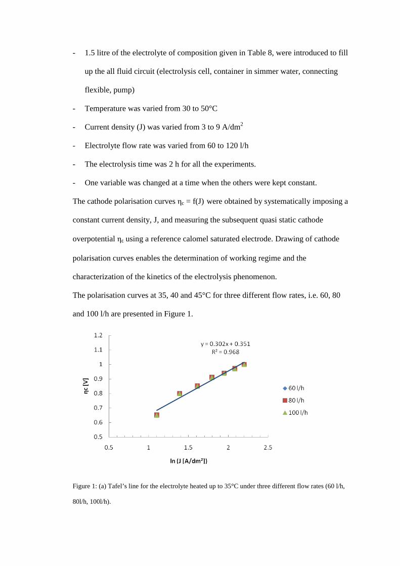
The cathode polarisation curves ηc = f(J) were obtained by systematically imposing a
constant current density, J, and measuring the subsequent quasi static cathode
overpotential ηc using a reference calomel saturated electrode. Drawing of cathode
polarisation curves enables the determination of working regime and the
characterization of the kinetics of the electrolysis phenomenon.
The polarisation curves at 35, 40 and 45°C for three different flow rates, i.e. 60, 80
and 100 l/h are presented in Figure 1.
Figure 1: (a) Tafel’s line for the electrolyte heated up to 35°C under three different flow rates (60 l/h,
80l/h, 100l/h).

Figure 1: (b) Tafel’s line for the electrolyte heated up to 40°C under three different flow rates (60 l/h,
80l/h, 100l/h).
Figure 1: (c) Tafel’s line for the electrolyte heated up to 45°C under three different flow rates (60 l/h,
80l/h, 100l/h).
The absence of the diffusion plateaus in Figure 1(a) throughout to 1(c) suggests that
the electrolysis takes place under a electrons transfer regime. This is also shown by
the insensibility of the cathode overpotential to changes in the electrolyte flow rate at
the three temperatures.

The slopes of the Tafel’s lines and the current densities J0 corresponding to zero volt
overpotential at the cathode for the three electrolyte temperatures are shown in Table
10.
Table 10: Slopes and J0 of the Tafel’s lines for the electrolyte at 35, 40 and 45°C.
Electrolyte temperature 35°C 40°C 45°C
Slope 0.302 0.314 0.389
J0 A/dm² 0.31 0.37 0.77
It is inferred from Figure 1 that increasing the temperature of the electrolyte lowers
the cathode overpotential ηc but increases the slope of the straight line part of the
polarisation curve, hence the increase rate of the cathode overpotential, as the current
density J increases. The extrapolated current densities at zero volt overpotential J0
also suggest that increased electrolyte temperature increases the current density limit
for the transition from an ionic to an electronic conducting mode in the electrolyte.
The effects of the electrolyte temperature on the overall electrolysis potential, the
cathode overpotential, the specific energy consumption and on the current efficiency
were first investigated at 5 A/dm2, 120l/h and 100 mg/l gelatine. The results are
presented in Figure 2.

Figure 2: Effect of the electrolyte temperature on the overall cell potential UA/C, the cathode
overpotential ηc, the specific energy consumption w and the current efficiency Rc.
The electrolysis current efficiency dropped drastically at temperatures higher than
40°C due to a decrease of the hydrogen formation overpotential and an increase of the
conductivity of the electrolyte that leads to a higher current and higher power loss
along the electric wires out of the electrolysis cell. The slight decrease in the overall
electrolysis potential UA/C and the cathode overpotential are dependent on the
increased conductivity of the electrolyte at elevated temperature.
The electrolysis current efficiency decreases with the electrolyte flow rate as shown in
Figure 3. This phenomenon finds its explanation in the competition between
antagonist forces acting on the particulate near the cathode, i.e. the gravitational
interaction and adhesion on the cathode, the drag force and mechanical erosion due to
the hydraulic turbulence and the electrostatic force. Increasing the flow rate increases
the drag force and the cathode erosion. This leads to a decrease of the amount of
metal collected on the cathode after electrolysis. This loss is purely of mechanical
origin. Particles of metal could be collected in the bottom of the cell and in the

channels. Increasing the electrolysis time would lead to complete dissolution of these
zinc particulates by the sulphuric acid contained in the electrolyte.
It is also observed from Figure 3 that the electrolyte flow rate, hence the agitation
does not affect ηc and has negligible effect on the UA/C and on the w. It was noticed
earlier that there was no diffusion plateaus in the cathode polarisation curves and the
electrolysis kinetics was controlled by electrons transfer phenomenon.
Figure 3: Effect of the electrolyte flow rate on the overall cell potential UA/C, the cathode overpotential
ηc, the specific energy consumption w and the current efficiency Rc.
It ressorted from this investigation that the optimum electrolyte flow rate in a SEC-C.C.S
type cell is somwhere between 80 and 100 l/h.
Gelatine was added to the electrolyte to improve the structure and compacity of the cathode
metal by controlling the current density on the cathode surface. Experiments conducted at
35°C, 80 l/h and 5 A/dm² have shown that introducing gelatine into the electrolyte improved
the electrolysis current efficiency. This is due to the fact that gelatine favours the formation
of dense and compact metal, hence less mechanical losses of zinc particulates from the

cathode. Results are illustrated in Figure 4. The structure of the metal formed on the cathode
was dendritic for gelatine contents of 0 and 100 mg/l. Dendrites dissapeared at gelatine
content of 200 mg/l and 400 mg/l. Gelatine helps level the cathode metal by sticking at the
tips of the dendrites. This increases the local electric resistivity ahead of the dendrite and
favours the growth of metal on the slack areas of the cathode. Current efficiency higher than
94% could be achieved in presence of gelatine against 90% without gelatine. Similar
observation was made by A.E. Saba and A.E. Elsherief during continuous electrowinning of
zinc in synthetic sulphuric acid solution [26]. The authors also found that addition of gelatine,
in the range of 50 mg/l improves the quality of electrodeposited zinc. The deposit obtained
becomes continuous and covers the whole electrode surface, with small grain sizes. A
transition from dendritic to boulder type and the marks of dendritic growth dissapear. Copper
and iron, even at low concentrations were found to decrease the current efficiency and
worsen the quality of the electrodeposited zinc.
The effectiveness of additives in improving the current efficiency to above 94%, the quality
of the deposited zinc metal and in developping preferred crystal orientation was also
established by A. Gomes and M.I.da Silva Pereira [27], by A. Recéndiz and his co-workers
[28], and by D.R. Fosnacht and T.J. O’Keefe [29]. The authors also demonstrated the effect
of additives in depressing the deleterious effects of impurities.

Figure 4: Effect of the gelatine on the overall cell potential UA/C, the cathode overpotential ηc, the
specific energy consumption w and the current efficiency Rc.
The effect of the current density J on the overall cell potential, the cathode
overpotential, the specific energy consumption and on the current efficiency were
investigated in the electrolyte maintained at 35°C, 200 mg/l gelatine and 100 l/h flow.
The results are plotted in Figure 5.
Figure 5: Effect of current density on the overall cell potential UA/C, the cathode overpotential ηc,
specific energy consumption w and the current efficiency Rc.
It is inferred from Figure 5 that increasing the electrolysis current density up to 6
A/dm2 results in increased current efficiency Rc. This observation may be explained
by the easy formation of stable nuclei due to a large number of ions discharged in the
cathode. The hydrogen formation overpotential on the aluminium cathode also is high
when the electrolysis current density is high, favouring the discharge of the zinc ions.
Above J = 6 A/dm2 the current efficiency drop drastically due to the Joule’s effect and
the conversion of the electric energy into heat in the electrolyte proportionally to the
square of the electrolysis current. The Joule’s effect in the electrolyte also leads to a
temperature rise that reduces the hydrogen formation overpotential on the cathode.
This effect enhances the undesired formation of hydrogen to the detriment of the zinc
reduction in the cathode.
The overall electrolysis potential UA/C increases when J increases due to the rise in
electrode overpotentials and the resistivity of the electrolyte. The specific energy
consumption is therefore the consequence of the above mentioned phenomenon.
4. Conclusion
The Zinc containing dusts from the copper matte smelting in water-jacket furnaces at
the Lubumbashi Plants whose composition is given in Table 1 are leachable in
aqueous sulphuric acid solution. Dissolved zinc may be recovered from the solution
after purification and electrolysis. The metal recovery in laboratory scale and the
electrolysis current efficiency are high enough to justify the extension of the
experiment to the pilot scale.
Leaching the dusts using a 100 g/l solution of sulphuric acid does not produce the
required 85 g/l zinc minimum level in the solution submitted to the electrolysis.
Return solution from the zinc electrolysis containing 100 g/l H2SO4, 35 g/l Zn++, 10
g/l Fe2(SO4)3 as leaching agent yields a 55 g/l zinc solution. The solution obtained
after purification contains 91 g/l zinc, hence acceptable for electrolysis. In these
conditions, 85% of the zinc content of the dusts was dissolved after 2 hours at 55°C.
Purification of the leaching solution is possible by selective elimination of iron by
precipitation using a saturated lime solution at pH 3.4. Copper and germanium are
removed from the electrolyte by solvent extraction using 10% LIX 64N in ESCAID
100. Finally Cobalt and cadmium levels are reduced to below the acceptable limits for
the zinc electrolysis by cementation in presence of antimony at 72°C for 2 hours and
at room temperature for 40 minutes.
The electrolysis of the purified solution is controlled by an electrons transfer regime.
This observation was confirmed by the constant cathode overpotential and the
negligible effect of the flow rate on the overall electrolysis cell potential.
Optimum conditions for the zinc electrolysis in a SEC-C.C.S type cell were
determined as:
- Current density 5 to 6 A/dm²
- Electrolyte temperature comprised between 35 and 40°C
- Electrolyte flow rate 80 to 100 l/h
- Gelatine level comprised between 100 and 200 mg/l
Zinc electrolysis current efficiency higher than 94% and the specific energy
consumption about 3.5kWh/kg were achieved in the above conditions.
5. References

[1] B. Asadi Zeydabadi, D. Mowla, M.H. Ahariat, J. Fathi Kalajahi, Zinc
recovery from blast furnace flue dust, Hydrometallurgy 47 (1997) 113-125
[2]. Ligiane R. Gouvea, Carlos A. Morais, Recovery of zinc and cadmium from
industrial waste by leaching/cementation, Minerals Engineering 20 (2007)
956-958
[3]. T.J. Harvey, W.T. Yen, The influence of chalcopyrite, galena and pyrite on
the selectivity extraction of zinc from base metal sulphide concentrates,
Minerals Engineering, Vol. 11, No. 1, pp. 1-21, 1998
[4]. C.K. Pani, S. Swain, R.N. Kar, G.R. Chaudhury, L.B. Sukla, V.N. Misra,
Biodissolution of zinc sulphide concentrate in 160 1 4-stage continuous
bioreactor, Minerals Engineering 16 (2003) 1019-1021
[5]. M. Nemati, S.T.L. Harrison, A comparative study on thermophilic and
mesophilic biooxidation of ferrous iron. Minerals Engineering 13 (1999) 19-24
[6]. M.N. Babu, K.K. Sahu, B.D. Pandey, Zinc recovery from sphalerite
concentrate by direct oxidative leaching with ammonium, sodium and
potassium persulphates, Hydrometallurgy 64 (2002) 119-129
[7]. Adelson D. De Souza, Pablo S. Pina, Versiane Albis Leão, Bioleaching and
chemical leaching as an integrated process in the zinc industry, Minerals
Engineering 20 (2007) 591-599.
[8]. M.K. Jha, V. Kumar, R.J. Singh, Review of hydrometallurgical recovery of
zinc from industrial wastes, Resources Conservation & Recycling 23 (2001) 1-
22
[9]. Daniel Dayrell Pereira, Sônia Denise Ferreira Rocha, Marcelo Borges
Mansur, Recovery of zinc sulphate from industrial effluents by liquid-liquid

extraction using D2EHPA (di-2-ethylhexyl phosphoric acid), Separation &
Purification Technology 53 (2007) 89-96
[10]. J. Moghaddam, R. Sarraf-Mamoory, M. Abdollahy, Y. Yamini, Purification
of zinc ammoniacal leaching solution by cementation: Determination of
optimum process conditions with experimental design by Taguchi’s method,
Separation & Purification Technology 51 (2006) 157-164
[11]. A.J.B. Dutra, P.R.P. Paiva, L.M. Tavares, Alkaline leaching of zinc from
electric arc furnace steel dust, Mineral Engineering 19 (2006) 478-485
[12]. G. Millazo, Electrochimie. Applications industrielles, tome 2, Dunod, Paris
1969
[13]. Oluf Bøckman, Terje Østvold, Products formed during cobalt cementation
on zinc in zinc sulphate electrolytes, Hydrometallurgy 54 (2000) 65-78
[14]. Ngoie A Basa, Avant projet de la purification à chaud en continu à l’ usine à
zinc de Kolwezi, Mémoire inedit, Université de Lubumbashi, 1990.
[15]. EK Corneille, Complément de métallurgie des métaux non-ferreux,
Université de Liège, 1971
[16]. C. Rerolle, R. Wiart, Kinetics of Pb and Pb-Ag anodes for zinc
electrowinning-I. Formation of PbSO4 layers at low polarisation,
Electrochemica Acta, 1995, Vol. 40, No. 8, pp. 939-948
[17]. Liana Mureşan, G. Maurin, L. Oniciu, Delia Gaga, Influence of metallic
impurities on zinc electrowinning from sulphate electrolyte, Hydrometallurgy
43 (1996) 345-354
[18]. B.B. Tripathy, S.C. Das, V.N. Misra, Effect of antimony (III) on the
electrocrystallisation of zinc from solutions containing sodium lauryl sulphate
SLS, Hydrometallurgy 69 (2003) 81-88

[19]. Ivan Ivanov, Yavor Stefanov, Electrolysis of zinc from sulphate electrolytes
containing antimony and hydroxyethylated-butine-2-diol-1,4. Part 2:
Deposition on a specpure aluminium cathode, Hydrometallurgy 64 (2002)
111-117
[20]. T. Yoshida, D. Komatsu, N. Shimokawa, H. Minoura, Mechanism of
cathodic electrodeposition of zinc oxide thin films from aqueous nitrate baths,
Thin Solid Films 451-452 (2004) 166-169
[21]. S. Gürmen, M. Emre, A laboratory-scale investigation of alkaline zinc
electrowinning, Minerals Engineering 16 (2003) 559-562
[22]. Zheng Huajun, Gu Zhenghai, Zheng Yunpeng, Electrorefining zinc dross in
ammoniacal ammonium chloride system, Hydrometallurgy 90 (2008) 8-12
[23]. Gábor Csicsovszki, Tamás Kékesi, Tamás I. Török, Selective recovery of
Zn and Fe from spent pickling solutions by the combination of anion exchange
and membrane electrowinning techniques, Hydrometallurgy 77 (2005) 19-28
[24]. F. Elgersma, G.J. Witkamp, G.M. Van Rosmalen, Incorporation of zinc in
continuous jarosite precipitation, Hydrometallurgy 33 (1993) 313-339.
[25]. F. Elgersma, G.J. Witkamp, G.M. Van Rosmalen, Incorporation of zinc in
ferrous sulphate monohydrate, Hydrometallurgy 33 (1993) 301-311.
[26]. A.E. Saba, A.E. Elsherief, Continuous electrowinning of zinc,
Hydrometallurgy 54 (2000) 91-106
[27]. A. Gomes, M.I. da Silva Pereira, Pulsed electrodeposition of Zn in the
presence of surfactants, Electrochemica Acta 51 (2006) 1342-1350
[28]. Alejandro Recéndiz, Ignacio González, José L. Nava, Current efficiency
studies of the zinc electrowinning process on aluminium rotating cylinder

electrode (RCE) in sulphuric acid medium: Influence of different additives,
Electrochemica Acta 52 (2007) 6880-6887
[29]. D.R. Fosnacht, T.J. O’Keefe, The effects of certain impurities and their
interaction on zinc electrowinning, Metal. Trans. B 14 (1983) 645-655
Copyright © 2022 FDOKUMEN