YF - YFA - THE CARBURETOR SHOP
26
-
Upload
khangminh22 -
Category
Documents
-
view
2 -
download
0
Transcript of YF - YFA - THE CARBURETOR SHOP

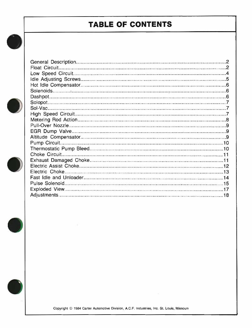
TABLE OF CONTENTS
General Description Float Circuit. Low Speed Circuit. Idle Adjusting Screws Hot Idle Compensator Solenoids ; Dashpot Solopot Sol-Vac High Speed Circuit. Metering Rod Action Pull-Over Nozzle EGR Dump Valve Altitude Compensator. Pump Circuit Thermostatic Pump Bleed Choke Circuit. Exhaust Damaged Choke Electric Assist Choke Electric Choke Fast Idle and Unloader Pulse Solenoid , Exploded View Adjustments
Copyright © 1984 Carter Automotive Division, A.C.F. Industries, Inc. 51. Louis, Missouri
2 2 4 5 6 6 6 7 7 7 8 9 9 9
10 10 11 11 12 13 14 15 17 18
MODEL YF·YFA AIR CLEANER BRACKET
~ VENT TO CHOKE BOWL
PULSE SOLENOI FAST IDLE
\ ADJUSTING IDLE MIXTURE SCREW SCREW
IGENERAL DESCRIPTIONI The YF~nd YFA are the same basic design. The
YF is approximately 51/2" overall height, the YFA is approximately 43~". This lowered height makes it more compatable with the lowered hood lines.
A few of the many advanced design features of the Carter/Carter-Weber YF and YFA carburetors are: • Fewer moving parts-readily accessible and
easy to service. • Compact idle system to provide smooth engine
idle under all driving conditions. • Diaphragm operated metering rod, both vacuum
and mechanically controlled-compensates automatically for added road load requirements.
• Diaphragm-type accelerating pump, both vacuum and mechanically controlled for smoother acceleration and performance.
• Some models feature automatic choke, including the electric assist-type, providing quick cold engine starting and smooth warm-up performance under all climatic conditions. Some late models use an all electric choke.
• Some YFA models are used with the 02 feedback systems, some with a remote mounted anaroid for altitude control.
Five conventional circuits are used in this series carburetor. They are: 1. Float circuit 2. Low speed circuit 3. High speed circuit 4. Accelerating pump circuit 5. Choke circuit
I CIRCUITS I
f::=====::::tT- FLOAT
FLOAT CIRCUIT The purpose of the float circuit is to maintain an
adequate supply of fuel at the proper level in the bowl for use by the low-speed, high-speed, pump and choke circuits.
2
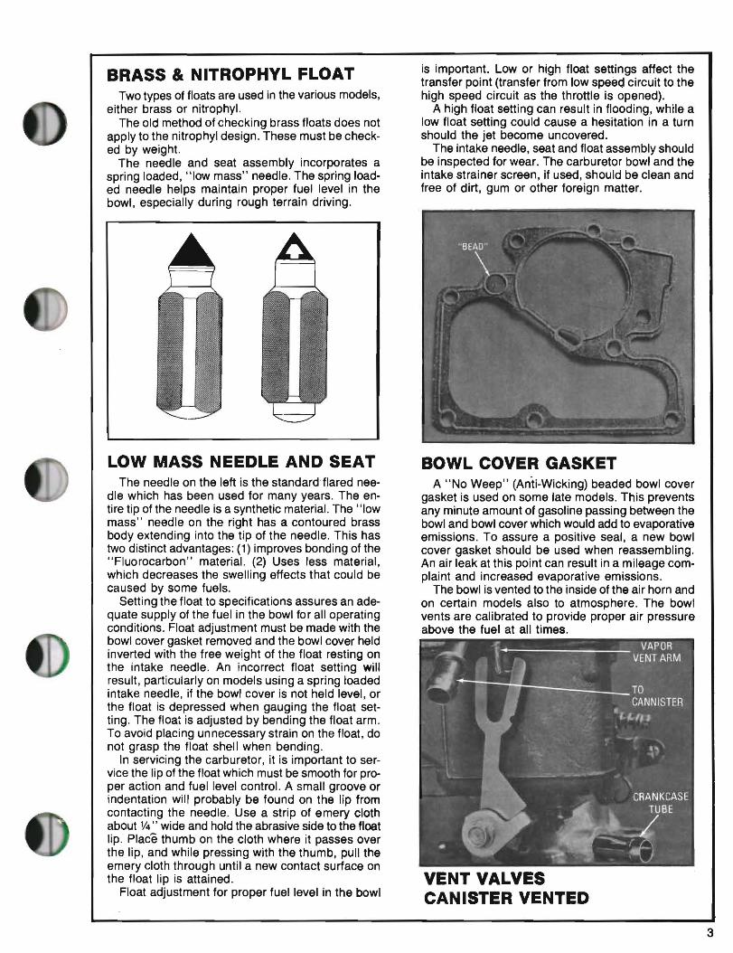
BRASS & NITROPHYL FLOAT Two types of floats are used in the various models,
either brass or nitrophyl. The old method of checking brass floats does not
apply to the nitrophyl design. These must be checked by weight.
The needle and seat assembly incorporates a spring loaded, "low mass" needle. The spring loaded needle helps maintain proper fuel level in the bowl, especially during rough terrain driving.
is important. Low or high float settings affect the transfer point (transfer from low speed circuit to the high speed circuit as the throttle is opened).
A high float setting can result in flooding, while a low float setting could cause a hesitation in a turn should the jet become uncovered.
The intake needle, seat and float assembly should be inspected for wear. The carburetor bowl and the intake strainer screen, if used, should be clean and free of dirt, gum or other foreign matter.
LOW MASS NEEDLE AND SEAT The needle on the left is the standard flared nee
dle which has been used for many years. The entire tip of the needle is a synthetic material. The "low mass" needle on the right has a contoured brass body extending into the tip of the needle. This has two distinct advantages: (1) improves bonding of the "Fluorocarbon" material. (2) Uses less material, which decreases the swelling effects that could be caused by some fuels.
Setting the float to specifications assures an adequate supply of the fuel in the bowl for all operating conditions. Float adjustment must be made with the bowl cover gasket removed and the bowl cover held inverted with the free weight of the float resting on the intake needle. An incorrect float setting will result, particularly on models using a spring loaded intake needle, if the bowl cover is not held level, or the float is depressed when gauging the float setting. The float is adjusted by bending the float arm. To avoid placing unnecessary strain on the float, do not grasp the float shell when bending.
In servicing the carburetor, it is important to service the lip of the float which must be smooth for proper action and fuel level control. A small groove or indentation will probably be found on the lip from contacting the needle. Use a strip of emery cloth about V4" wide and hold the abrasive side to the float lip. Place thumb on the cloth where it passes over the lip, and while pressing with the thumb, pull the emery cloth through until a new contact surface on the float lip is attained.
Float adjustment for proper fuel level in the bowl
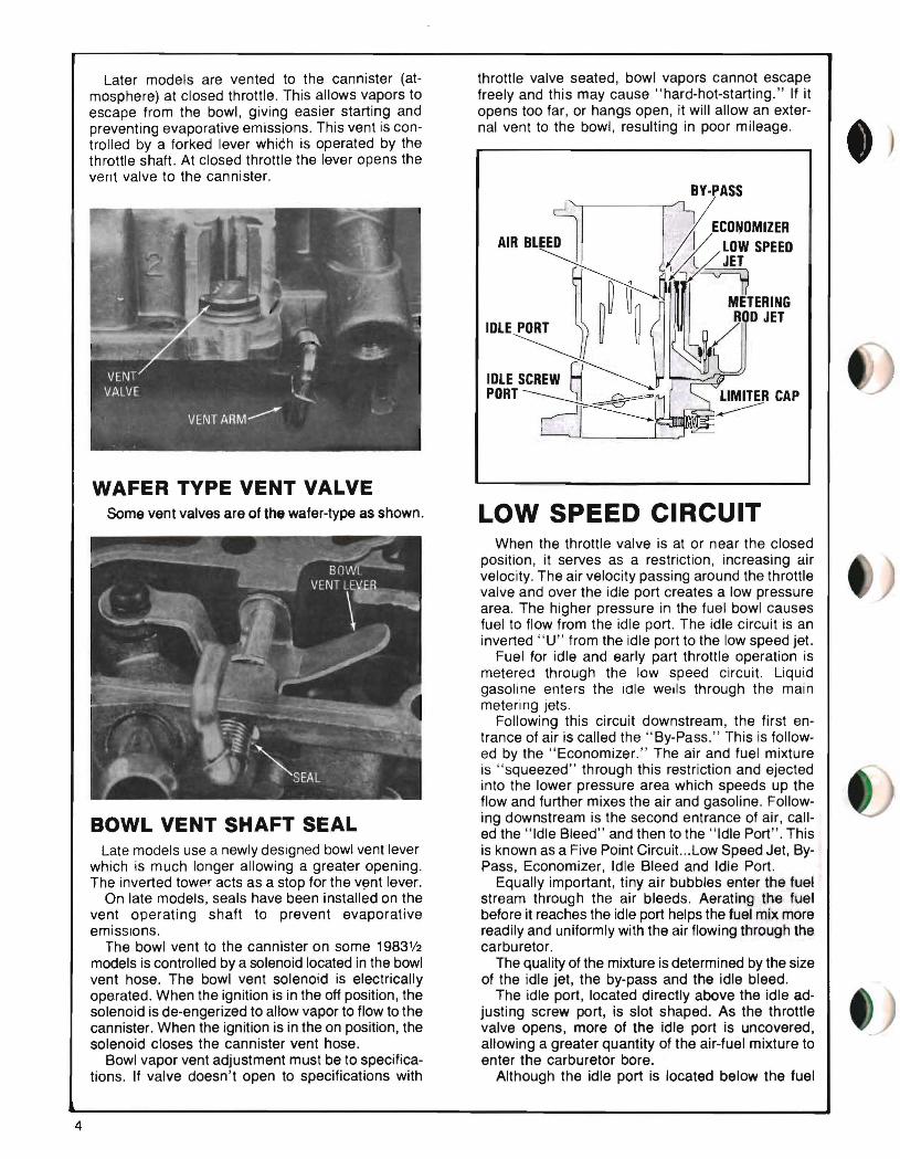
BOWL COVER GASKET A "No Weep" (An'ti-Wicking) beaded bowl cover
gasket is used on some late models. This prevents any minute amount of gasoline passing between the bowl and bowl cover which would add to evaporative emissions. To assure a positive seal, a new bowl cover gasket should be used when reassembling. An air leak at this point can result in a mileage complaint and increased evaporative emissions.
The bowl is vented to the inside of the air horn and on certain models also to atmosphere. The bowl vents are calibrated to provide proper air pressure above the fuel at all times.
VENT VALVES CANISTER VENTED
3
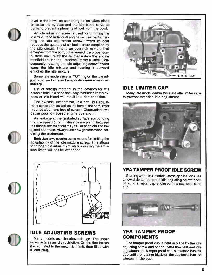
Later models are vented to the cannister (at throttle valve seated, bowl vapors cannot escape mosphere) at closed throttle. This allows vapors to freely and this may cause "hard-hot-starting." If it escape from the bowl, giving easier starting and opens too far, or hangs open, it will allow an exterpreventing evaporative emissions. This vent is con nal vent to the bowl, resulting in poor mileage. trolled by a forked lever which is operated by the throttle shaft. At closed throttle the lever opens the vent valve to the cannister.
BY·PASS
£CONOMIZER AIR BLEED . / V LOW SPEED
~.)I,'~JET . ~ ~ ~fl'- ~TERING IDLE PORT ~ ~ ~OO JET
IOLE~ PORT~ ~RCAP
WAFER TYPE VENT VALVE Some vent valves are of the wafer-type as shown. LOW SPEED CIRCUIT
When the throttle valve is at or near the closed position, it serves as a restriction, increasing air velocity. The air velocity passing around the throttle valve and over the idle port creates a low pressure area. The higher pressure in the fuel bowl causes fuel to flow from the idle port. The idle circuit is an inverted "U" from the idle port to the low speed jet.
Fuel for idle and early part throttle operation is metered through the low speed circuit. Liquid gasoline enters the idle wells through the main metering jets.
Following this circuit downstream, the first entrance of air is called the" By-Pass." This is followed by the" Economizer." The air and fuel mixture is "squeezed" through this restriction and ejected into the lower pressure area which speeds up the flow and further mixes the air and gasoline. Following downstream is the second entrance of air, callBOWL VENT SHAFT SEAL ed the "Idle Bleed" and then to the "Idle Port". This
Late models use a newly designed bowl vent lever is known as a Five Point Circuit... Low Speed Jet, Bywhich is much longer allowing a greater opening. Pass, Economizer, Idle Bleed and Idle Port. The inverted towpr acts as a stop for the v~nt lever. Equally important, tiny air bubbles enter the fuel
On late models, seals have been installed on the stream through the air bleeds. Aerating the fuel vent operating shaft to prevent evaporative before it reaches the idle port helps the fuel mix more emissions. readily and uniformly with the air flowing through the
The bowl vent to the cannister on some 1983'/2 carburetor. models is controlled by a solenoid located in the bowl The quality of the mixture is determined by the size vent hose. The bowl vent solenoid is electrically of the idle jet, the by-pass and the idle bleed. operated. When the ignition is in the off position, the The idle port, located directly above the idle adsolenoid is de-engerized to allow vapor to flow to the justing screw port, is slot shaped. As the throttle cannister. When the ignition is in the on position, the valve opens, more of the idle port is uncovered, solenoid closes the cannister vent hose. allowing a greater quantity of the air-fuel mixture to
Bowl vapor vent adjustment must be to specifica enter the carburetor bore. tions. If valve doesn't open to specifications with Although the idle port is located below the fuel
4
level in the bowl, no siphoning action takes place because the by-pass and the idle bleed serve as vents to prevent siphoning of fuel from the bowl.
An idle adjusting screw is used for trimming the idle mixture to individual engine requirements. Turning the idle adjustment screw toward its seat reduces the quantity of air-fuel mixture supplied by the idle circuit. This is an over-rich mixture that emerges from the port, but is leaned to a proper conbustible mixture by the air that enters the engine manifold around the "cracked" throttle valve. Consequently, rotating the idle adjusting screw inward leans the idle mixture and rotating it outward enriches the idle mixture.
Some late models use an "0" ring on the idle adjusting screw to prevent evaporative emissions or air leakage.
Dirt or foreign material in the ecOnomizer will cause a lean idle condition. Any restriction in the bypass or idle bleed will result in a rich condition.
The by-pass, economizer, idle port, idle adjustment screw port, as well as the bore of the carburetor must be clean and free of carbon. Obstructions will cause poor low speed engine operation.
Air leakage at the gasketed surface surrounding the low speed (idle) mixture passages or between the flange and manifold may cause poor idle and low speed operation. Always use new gaskets when serVicing the carburetor.
Emission laws require some means for limiting the adjustability of the idle mixture screw. This allows for proper idle adjustment while assuring the emission limits will not be exceeded.
IDLE LIMITER CAP Many late model carburetors use idle limiter caps
to prevent over-rich idle adjustment.
YFA TAMPER PROOF IDLE SCREW Starting with 1981 models, some applications use
a new style tamper proof idle adjusting screw incorporating a metal cap enclosed in a stamped steel cup.
IDLE ADJUSTING SCREWS Many models use the above design. The upper
screw acts as an idle restriction. On the flow bench it is adjusted to the mean rich limit, then filled with a lead plug.
YFA TAMPER PROOF COMPONENTS
The tamper proof cup is held in place by the idle adjusting screw and spring. After flow test and idle adjustment the tamper proof cap is inserted into the cup until the retainer blade on the cap locks into the window in the cup.
5
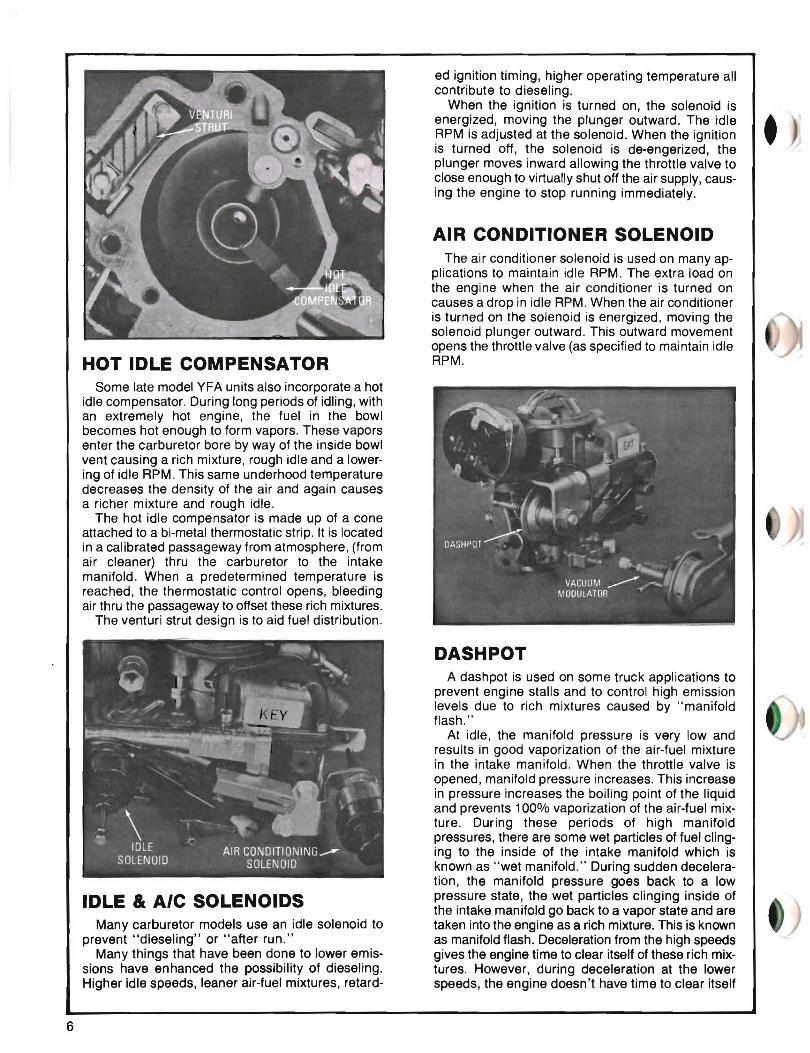
HOT IDLE COMPENSATOR Some late model YFA units also incorporate a hot
idle compensator. During long periods of idling, with an extremely hot engine, the fuel in the bowl becomes hot enough to form vapors. These vapors enter the carburetor bore by way of the inside bowl vent causing a rich mixture, rough idle and a lowering of idle RPM. This same underhood temperature decreases the density of the air and again causes a richer mixture and rough idle.
The hot idle compensator is made up of a cone attached to a bi-metal thermostatic strip. It is located in a calibrated passageway from atmosphere, (from air cleaner) thru the carburetor to the intake manifold. When a predetermined temperature is reached, the thermostatic control opens, bleeding air thru the passageway to offset these rich mixtures.
The venturi strut design is to aid fuel distribution.
IDLE & AIC SOLENOIDS Many carburetor models use an idle solenoid to
prevent "dieseling" or "after run." Many things that have been done to lower emis
sions have enhanced the possibility of dieseling. Higher idle speeds, leaner air-fuel mixtures, retard
ed ignition timing, higher operating temperature all contribute to dieseling.
When the ignition is turned on, the solenoid is energized, moving the plunger outward. The idle • RPM is adjusted at the solenoid. When the ignition • is turned off, the solenoid is de-engerized, the plunger moves inward allowing the throttle valve to close enough to Virtually shut off the air supply, causing the engine to stop running immediately.
AIR CONDITIONER SOLENOID The air conditioner solenoid is used on many ap
plications to maintain idle RPM. The extra load on the engine when the air conditioner is turned on causes a drop in idle RPM. When the air conditioner is turned on the solenoid is energized, moving the solenoid plunger outward. This outward movement opens the throttle valve (as specified to maintain idle RPM.
DASHPOT A dashpot is used on some truck applications to
prevent engine stalls and to control high emission levels due to rich mixtures caused by "manifold flash."
At idle, the manifold pressure is very low and results in good vaporization of the air-fuel mixture in the intake manifold. When the throttle valve is opened, manifold pressure increases. This increase in pressure increases the boiling point of the liquid and prevents 100% vaporization of the air-fuel mixture. During these periods of high manifold pressures, there are some wet particles of fuel clinging to the inside of the intake manifold which is known as "wet manifold." During sudden deceleration, the manifold pressure goes back to a low pressure state, the wet particles clinging inside of the intake manifold go back to a vapor state and are taken into the engine as a rich mixture. This is known as manifold flash. Deceleration from the high speeds gives the engine time to clear itself of these rich mixtures. However, during deceleration at the lower speeds, the engine doesn't have time to clear itself
6
/'"EIBIIIE OFF ADJUSTMENT
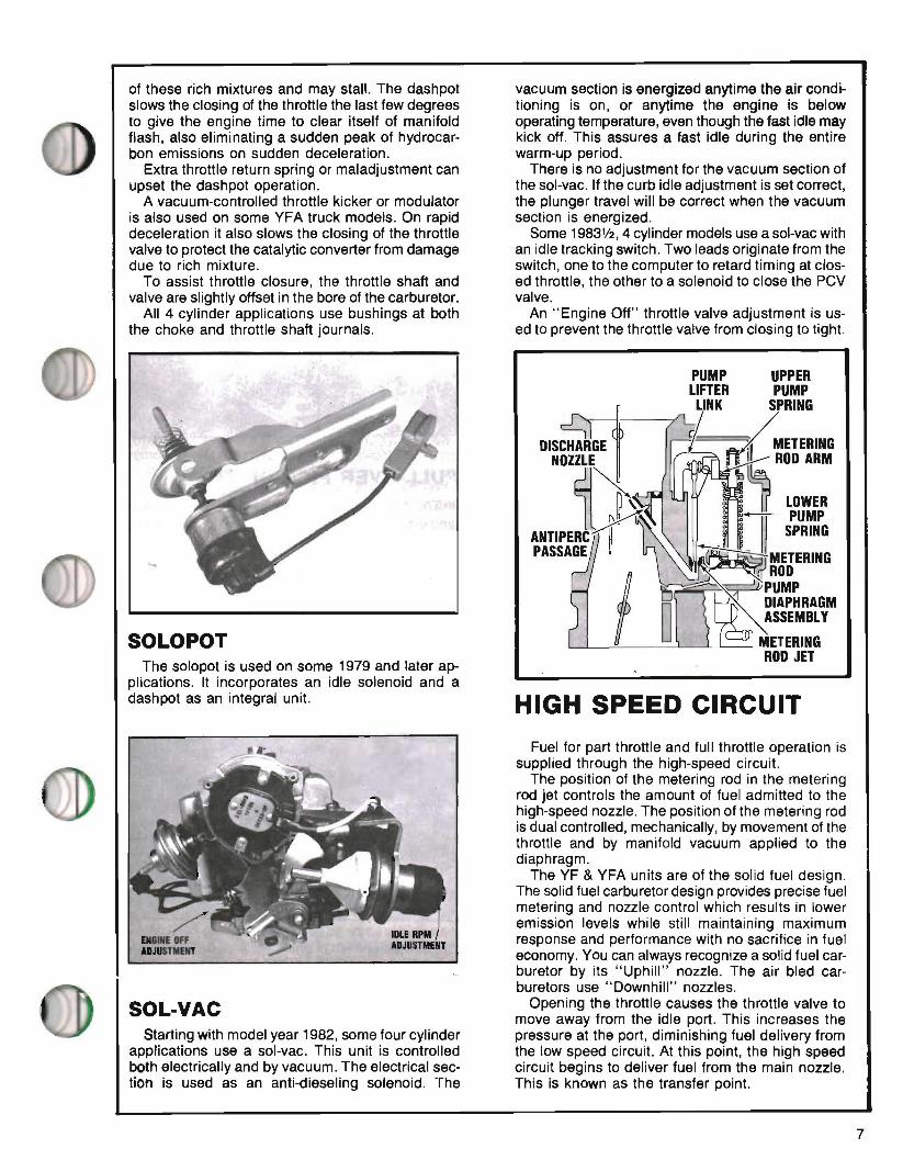
of these rich mixtures and may stall. The dashpot vacuum section is energized anytime the air condislows the closing of the throttle the last few degrees tioning is on, or anytime the engine is below to give the engine time to clear itself of manifold operating temperature, even though the fast idle may flash, also eliminating a sudden peak of hydrocar kick off. This assures a fast idle during the entire bon emissions on sudden deceleration. warm-up period.
Extra throttle return spring or maladjustment can There is no adjustment for the vacuum section of upset the dashpot operation. the sol-vac. If the curb idle adjustment is set correct,
A vacuum-controlled throttle kicker or modulator the plunger travel will be correct when the vacuum is also used on some YFA truck models. On rapid section is energized. deceleration it also slows the closing of the throttle Some 1983112, 4 cylinder models use a sol-vac with valve to protect the catalytic converter from damage an idle tracking switCh. Two leads originate from the due to rich mixture. switch, one to the computer to retard timing at clos
To assist throttle closure, the throttle shaft and ed throttle, the other to a solenoid to close the PCV valve are slightly offset in the bore of the carburetor. valve.
All 4 cylinder applications use bushings at both An "Engine Off" throttle valve adjustment is usthe choke and throttle shaft journals. ed to prevent the throttle valve from closing to tight.
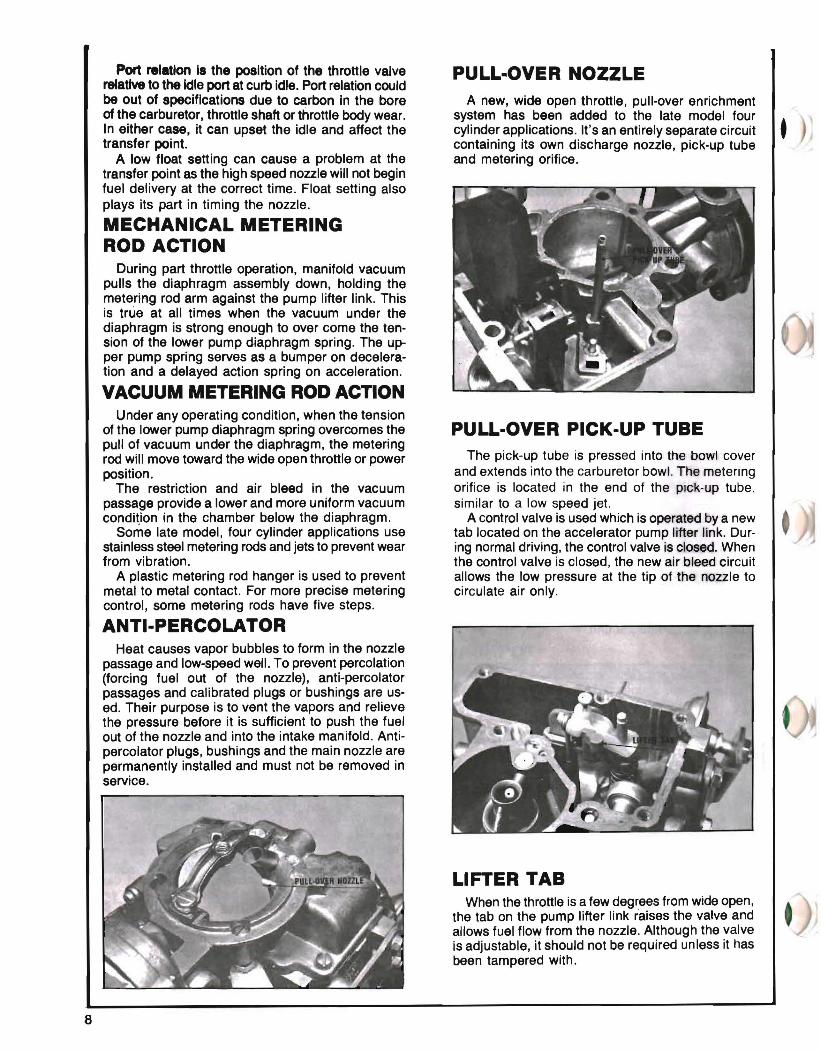
PUMP UPPER LIFTER PUMP I.INK SPRING
~ -{~ETERING NOZZLE ~~OD ARM
~~ • , LOWER
ANTIPER1~~ II :"~~:G PASSAGE I ~ .~ METERING
1~ROD
~~ '~ I)) ~~A~:RAGM ASSEMBLY
L--'-_-"--__L----'--l_---.J METERING ROD JET
The solopot is used on some 1979 and later applications. It incorporates an idle solenoid and a dashpot as an integral unit. HIGH SPEED CIRCUIT
Fuel for part throttle and full throttle operation is supplied through the high-speed circuit.
The position of the metering rod in the metering rod jet controls the amount of fuel admitted to the high-speed nozzle. The position of the metering rod is dual controlled, mechanically, by movement of the throttle and by manifold vacuum applied to the diaphragm.
The YF & YFA units are of the solid fuel design. The solid fuel carburetor design provides precise fuel metering and nozzle control which results in lower emission levels while still maintaining maximum response and performance with no sacrifice in fuel economy. You can always recognize a solid fuel carburetor by its "Uphill" nozzle. The air bled carburetors use "Downhill" nozzles.
Opening the throttle causes the throttle valve to SOL-VAC move away from the idle port. This increases the Starting with model year 1982, some four cylinder pressure at the port, diminishing fuel delivery from
applications use a sol-vac. This unit is controlled the low speed circuit. At this point, the high speed both electrically and by vacuum. The electrical sec circuit begins to deliver fuel from the main nozzle. tion is used as an anti-dieseling solenoid. The This is known as the transfer point.
SOLOPOT
7
Port relation 18 the position of the throttle valve relative to the Idle port at curb idle. Port relation could be out of specifications due to carbon in the bore of the carburetor, throttle shaft or throttle body wear. In either case, it can upset the idle and affect the transfer point.
A low float setting can cause a problem at the transfer point as the high speed nozzle will not begin fuel delivery at the correct time. Float setting also plays its part in timing the nozzle.
MECHANICAL METERING ROD ACTION
During part throttle operation, manifold vacuum pulls the diaphragm assembly down, holding the metering rod arm against the pump lifter link. This is true at all times when the vacuum under the diaphragm is strong enough to over come the tension of the lower pump diaphragm spring. The upper pump spring serves as a bumper on deceleration and a delayed action spring on acceleration.
VACUUM METERING ROD ACTION Under any operating condition, when the tension
of the lower pump diaphragm spring overcomes the pull of vacuum under the diaphragm, the metering rod will move toward the wide open throttle or power position.
The restriction and air bleed in the vacuum passage prOVide a lower and more uniform vacuum condition in the chamber below the diaphragm.
Some late model, four cylinder applications use stainless steel metering rods and jets to prevent wear from vibration.
A plastic metering rod hanger is used to prevent metal to metal contact. For more precise metering control, some metering rods have five steps.
ANTI-PERCOLATOR Heat causes vapor bubbles to form in the nozzle
passage and low-speed well. To prevent percolation (forcing fuel out of the nozzle), anti-percolator passages and calibrated plugs or bushings are used. Their purpose is to vent the vapors and relieve the pressure before it is sufficient to push the fuel out of the nozzle and into the intake manifold. Antipercolator plugs, bushings and the main nozzle are permanently installed and must not be removed in service.
PULL-OVER NOZZLE A new, wide open throttle, pull-over enrichment
system has been added to the late model four cylinder applications. It's an entirely separate circuit t containing its own discharge nozzle, pick-up tube and metering orifice.
PULL-OVER PICK-UP TUBE The pick-up tube is pressed into the bowl cover
and extends into the carburetor bowl. The metering orifice is located in the end of the pick-up tube, similar to a low speed jet.
A control valve is used which is operated by a new tab located on the accelerator pump lifter link. During normal driving, the control valve is closed. When the control valve is closed, the new air bleed circuit allows the low pressure at the tip of the noz.zle to circulate air only.
LIFTER TAB When the throttle is a few degrees from wide open,
the tab on the pump lifter link r'aises the valve and allows fuel flow from the nozzle. Although the valve is adjustable, it should not be required unless it has been tampered with.
8
ALTITUDE
TOP MOUNTED THROTILE VALVE
Later YFA models use a top mounted throttle valve (mounted above the throttle shaft). This gives a smooth surface to the direction of air-fuel flow to prevent puddling of fuel.
On certain models the throttle valve is notched at the idle port to reduce sensitivity, giving smoother transfer to the high speed circuit.
-rJ"'~'.~ • ~ ..ro __ . --( "'" _ .:.:. -.- I ' -=-- ,. ..
. ~ 1
\.~J.'.... 4" Jl' ' ~!f.II\.....
• "EGR" ............ D DUMP VALVE~
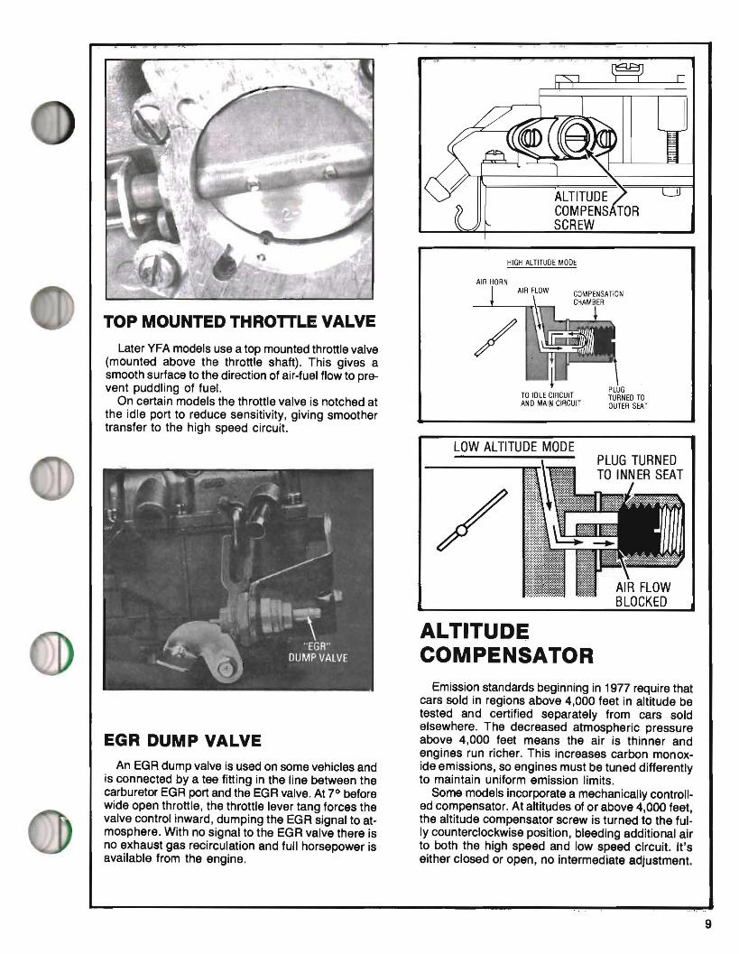
EGR DUMP VALVE An EGR dump valve is used on some vehicles and
is connected by a tee fitting in the line between the carburetor EGR port and the EGR valve. At 7° before wide open throttle, the throttle lever tang forces the valve control inward, dumping the EGR signal to atmosphere. With no signal to the EGR valve there is no exhaust gas recirculation and full horsepower is available from the engine.
COMPENS TOR SCREW
HIGH ALTITUDE MODE
AIR HORN
TO IDLE CIRCUIT PLUG TURNED TO
AND MAIN CIRCUIT OUTER SEAT
LOW ALTITUDE MODE
AIR FLOW BLOCKED
ALTITUDE COMPENSATOR
Emission standards beginning in 1977 require that cars sold in regions above 4,000 feet in altitude be tested and certified separately from cars sold elsewhere. The decreased atmospheric pressure above 4,000 feet means the air is thinner and engines run richer. This increases carbon monoxide emissions, so engines must be tuned differently to maintain uniform emission limits.
Some models incorporate a mechanically controlled compensator. At altitudes of or above 4,000 feet, the altitude compensator screw is turned to the fully counterclockwise position, bleeding additional air to both the high speed and low speed circuit. It's either closed or open, no intermediate adjustment.
9

UPPER PUMP SPRING
PUMP DIAPHRAGM ASSEMBLY
MANIFOLD VACUUM PASSAGE
PUMP JET
PUMP CIRCUIT The accelerating pump circuit provides a
measured amount of fuel, which is necessary to insure smooth engine operation for acceleration at speeds,below approximately half throttle.
Air being lighter than gasoline is immediately available. The mechanical action of the accelerating pump assures gasoline delivery to this additional air flow.
The pump circuit consists of the pump diaphragm, intake and discharge checks, pump jet, duration spring, pump bleed and operating cam and linkage.
Accelerating pump action is controlled both mechanically and by manifold vacuum in the same manner as the metering rod. When the throttle is closed, the diaphragm moves downward and fuel is drawn into the pump fuel chamber. There are three types of intake systems used on YF carburetors: (1) Intake passage. (2) Intake check valve. (3) Intake passage plus an intake check valve. When the diaphragm moves downward, the discharge check is seated. When the throttle is opened, the diaphragm moves upward forcing fuel out through the discharge passage, past the discharge check, and out of the pump jet.
The pump discharges through the main nozzle on models where no pump jet is used. On models with an intake passage, a measured amount of fuel is returned to the bowl through this passage. This calibrates pump delivery to engine requirements. The amount of fuel returned to the bowl varies with the rate of throttle opening. On light acceleration most of the fuel from the pump is returned to the bowl. On fast acceleration more fuel is delivered to the engine, less returned to the bowl.
Carburetors which have only an intake check valve do not discharge fuel back to the bowl. When the
diaphragm moves upward, the intake check, where used, must seat.
If the throttle is opened suddenly, the upper pump spring will be compressed resulting in a smooth pump discharge of longer duration.
Manifold vacuum is applied to the underside of the diaphragm at all times the engine is in operation. When manifold vacuum decreases to the point where the lower pump diaphragm spring overcomes the pull of vacuum, the diaphragm moves upward and a pump discharge results.
The pump jet is pressed into the casting during manufacture and must not be removed in service.
The YFA does not have a drilled pump passage as all models use a flex hose to connect the accelerating pump to the pump jet.
The duration of fuel flow from the pump jet is controlled by the duration spring, the size of the pump jet and fuel bleed.
At higher speeds the air velocity across the tip of the pump jet creates a low pressure area. To prevent pump pUll-over a discharge weight is placed on top of the discharge check ball.
Trouble shooting the pump circuit should include a thorough check of the intake and discharge checks, pump diaphragm, duration spring and all linkage.
If the discharge check is not seating, air will be drawn into the pump circuit during deceleration. If the intake check is not seating, some fuel will be returned to the bowl during acceleration. In either case, a hesitation would result.
THERMOSTATIC PUMP BLEED
Many units use a thermostatically controlled pump circuit to calibrate pump delivery relative to engine temperature. This pump circuit has two bleeds to return fuel back to the bowl. In addition to the constant bleed, a controlled bleed has been added which is opened and closed by a thermostatic pill. When
10
the unit is cold the controlled bleed is closed forcing more fuel thru the pump jet. When a predetermined temperature is reached, the thermostatic pill opens the controlled bleed and returns more fuel to the bowl, less fuel to the pump jet. It all adds up to more fuel from the pump circuit when the engine is cold and requires more fuel, and less fuel after engine warm-up.
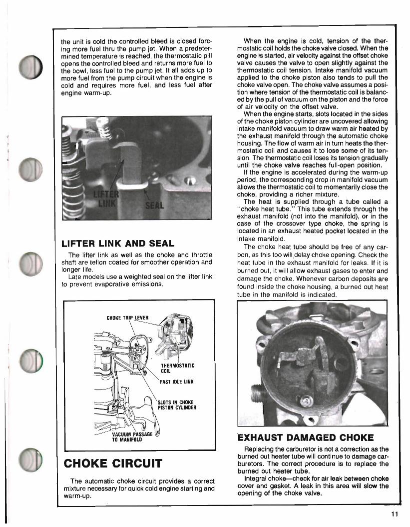
LIFTER LINK AND SEAL The lifter link as well as the choke and throttle
shaft are teflon coated for smoother operation and longer life.
Late models use a weighted seal on the lifter link to prevent evaporative emissions.
CHOKE CIRCUIT The automatic choke circuit provides a correct
mixture necessary for quick cold engine starting and warm-up.
When the engine is cold, tension of the thermostatic coil holds the choke valve closed. When the engine is started, air velocity against the offset choke valve causes the valve to open slightly against the thermostatic coil tension. Intake manifold vacuum applied to the choke piston also tends to pull the choke valve open. The choke valve assumes a position where tension of the thermostatic coil is balanced by the pull of vacuum on the piston and the force of air velocity on the offset valve.
When the engine starts, slots located in the sides of the choke piston cylinder are uncovered allowing intake manifold vacuum to draw warm air heated by the exhaust manifold through the automatic choke housing. The flow of warm air in turn heats the thermostatic coil and causes it to lose some of its tension. The thermostatic coil loses its tension gradually until the choke valve reaches full-open position.
If the engine is accelerated during the warm-up period, the corresponding drop in manifold vacuum allows the thermostatic coil to momentarily close the choke, providing a richer mixture.
The heat is supplied through a tube called a "choke heat tube." This tube extends through the exhaust manifold (not into the manifold), or in the case of the crossover type choke, the spring is located in an exhaust heated pocket located in the intake manifold.
The choke heat tube should be free of any carbon, as this too will1delay choke opening. Check the heat tube in the exhaust manifold for leaks. If it is burned out, it will allow exhaust gases to enter and damage the choke. Whenever carbon deposits are found inside the choke housing, a burned out heat tube in the manifold is indicated.
EXHAUST DAMAGED CHOKE Replacing the carburetor is not a correction as the
burned out heater tube will continue to damage carburetors. The correct procedure is to replace the burned out heater tube.
Integral choke-check for air leak between choke cover and gasket. A leak in this area will slow the opening of the choke valve.
11
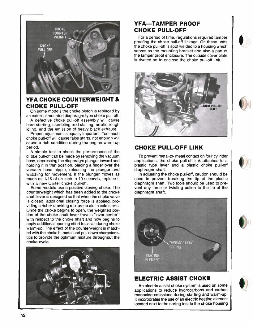
YFA CHOKE COUNTERWEIGHT & CHOKE PULL-OFF
On some models the choke piston is replaced by an external mounted diaphragm type choke pull-off.
A defective choke pull-off assembly will cause hard starting, stumbling and stalling, erratic rough idling, and the emission of heavy black exhaust.
Proper adjustment is equally important. Too much choke pull-off will cause false starts, not enough will cause a rich condition during the engine warm-up period.
A simple test to check the performance of the choke pull-off can be made by removing the vacuum hose, depressing the diaphragm plunger inward and holding it in that position, placing a finger over the vacuum hose nipple, releasing the plunger and watching for movement. If the plunger moves as much as 1/16 of an inch in 10 seconds, replace it with a new Carter choke pull-off.
Some models use a positive closing choke. The counterweight which has been added to the choke shaft lever is designed so that when the choke valve is closed, additional closing force is applied, providing a richer cranking mixture to aid in cold starts. Once the choke begins to open, the weighted portion of the choke shaft lever travels "over-center" with respect to the choke shaft and now begins to apply additional opening effort to assist during choke warm-up. The effect of the counterweight is matched with the choke bi-metal and pull down characteristics to provide the optimum mixture throughout the choke cycle.
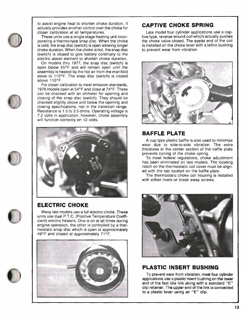
YFA-TAMPER PROOF CHOKE PULL-OFF
For a period of time, regulations required tamper proofing the choke pull-off linkage. On these units the choke pull-off is spot welded to a housing which serves as the mounting bracket and also a part of the tamper proof enclosure. The outside cover plate is riveted on to enclose the choke pull-off Ii nk.
CHOKE PULL-OFF LINK To prevent metal-to- metal contact on four cylinder
applications, the choke pull-off link attaches to a plastic type lever and a plastic choke pull-off diaphragm shaft.
In adjusting the choke pull-off, caution should be used to prevent breaking the tip of the plastic diaphragm shaft. Two tools should be used to prevent any force or twisting action to the tip of the diaphragm shaft.
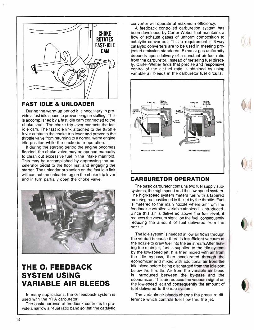
ELECTRIC ASSIST CHOKE An electric assist choke system is used on some
applications to reduce hydrocarbons and carbon monoxide emissions during starting and warm-up. It incorporates the use of an electric heating element located next to the spring inside the choke housing
12
to assist engine heat to shorten choke duration. It actually provides another control over the choke for closer calibration at all temperatures.
These units use a single stage heating unit incorporating a thermo-type snap disc. When the choke is cold, the snap disc (switch) is open allowing longer choke duration. When the choke is hot, the snap disc (switch) is closed to give battery continuity to the electric assist element to shorten choke duration.
On models thru 1977, the snap disc (switch) is open below 55°F and will remain open until the assembly is heated by the hot air from the manifold stove to 110° F. The snap disc (switch) is closed above 110°F.
For closer calibration to meet emission standards, 1978 models open at 54° F and close at 74° F. These can be checked with an ohmeter for opening and closing of the snap disc (switch). They should be checked slightly above and below the opening and closing specifications, not in the transition range. Resistance is 1.5 to 3.5 ohms. Operating voltage is 7.2 volts in application, however, choke assembly will function correctly on 12 volts.
CAPTIVE CHOKE SPRING Late model four cylinder applications use a cap
tive type, reverse wound coil which actually pushes the choke valve closed. The ~yelet end of the coil is installed on the choke lever with a teflon bushing to prevent wear from vibration.
ELECTRIC CHOKE Many late models use a full electric choke. These
units use dual PTC. (Positive Temperature Coefficient) electric heaters. One is on at all times during engine operation, the other is controlled by a thermostatic snap disc which is open at approximately 49°F and closed at approximately 71OF.
BAFFLE PLATE A cup type plastic baffle is also used to minimize
wear due to side-to-side vibration. The extra thickness in the center section of the baffle plate prevents coning of the choke spring.
To meet federal regulations, choke adjustment has been eliminated on late models. The locating notch on the thermostatic coil cover must be aligned with the tab located on the baffle plate.
The thermostatic choke coil housing is installed with either rivets or break away screws.
PLASTIC INSERT BUSHING To prevent wear from vibration, most four cylinder
applications use a plastic insert bushing on the lower end of the fast idle link along with a standard liE" clip retainer. The upper end of the link is connected to a plastic lever using an liE" clip.
13
CHOKE ROTATES
FAST·IDLE CAM
FAST IDLE & UNLOADER During the warm-up period it is necessary to pro
vide a fast idle speed to prevent engine stalling. This is accomplished by a fast idle cam connected to the choke shaft. The choke trip lever contacts the fast idle cam. The fast idle link attached to the throttle lever contacts the choke trip lever and prevents the throttle valve from returning to a normal warm engine idle position while the choke is in operation.
If during the starting period the engine becomes flooded, the choke valve may be opened manually to clean out excessive fuel in the intake manifold. This may be accomplished by depressing the accelerator p'edal to the floor mat and engaging the starter. The unloader projection on the fast idle link will contact the unloader lug on the choke trip lever and in turn partially open the choke valve.
THE 02 FEEDBACK SYSTEM USING VARIABLE AIR BLEEDS
In many applications, the 02 feedback system is used with the YFA carburetor.
The basic purpose of feedback control is to provide a narrow air-fuel ratio band so that the catalytic
converter will operate at maximum efficiency. A feedback controlled carburetion system has
been developed by Carter-Weber that maintains a flow of exhaust gases of uniform composition to catalytic converters. This a requirement if 3-way catalytic converters are to be used in meeting projected emission standards. Exhaust gas uniformity depends upon delivery of a constant air-fuel ratio from the carburetor. Instead of metering fuel directly, Carter-Weber finds that precise and responsive control of the air-fuel ratio is obtained by using variable air bleeds in the carburetor fuel circuits.
.-oM 511'£lD ClACUIT-FttoBACII:
CARBURETOR OPERATION The basic carburetor contains two fuel supply sub
systems, the high-speed and the low-speed system. The high-speed system meters fuel with a tapered metering rod positioned in the jet by the throttle. Fuel is metered to the main nozzle where air from the feedback controlled variable air bleed is introduced. Since this air is delivered above the fuel level, it reduces the vacuum signal on the fuel, consequently reducing the amount of fuel delivered from the nozzle.
The idle system is needed at low air flows through the venturi because there is insufficient vacuum at the nozzle to draw fuel into the air stream.After leaving the main jet, fuel is supplied to the idle system by the low-speed jet. It is then mixed with air f om the idle by-pass, then accelerated through the economizer and mixed with additional air from the idle bleed before being discharged from the idle port below the throttle. Air from the variable air bleed is introduced between the by-pass and the economizer. This air reduces the vacuum signal on the low-speed jet and consequently the amount of fuel delivered to the idle system.
The variable air bleeds change the pressure difference which controls fuel flow thru the jet.
14
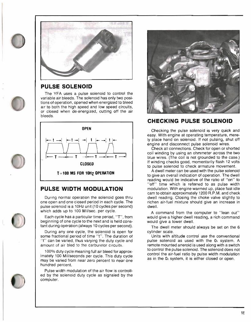
PULSE SOLENOID The YFA uses a pulse solenoid to control the
variable air bleeds. The solenoid has only two positions of operation, opened when energized to bleed air to both the high speed and low speed circuits, or closed when de-energized, cutting off the air bleeds.
OPEN
CLOSED
T=100 MS FOR 10HZ OPERATION
PULSE WIDTH MODULATION During normal operation the solenoid goes thru
one open and one closed period in each cycle. The pulse solenoid is a 10Hz un it (10 cycles per second) which adds up to 100 Mil/sec. per cycle.
Each cycle has a particular time period, "T", from beginning of one cycle to the next and is held constant during operation (always 10 cycles per second).
During anyone cycle, the solenoid is open for some fractional period of time "t". The duration of "t" can be varied, thus varying the duty cycle and amount of air bled to the carburetor circuits.
100% duty cycle meaning full air bleed for approximately 100 Mil/seconds per cycle. This duty cycle may be varied from near zero percent to near one hundred percent.
Pulse width modulation of the air flow is controlled by the solenoid duty cycle as signaled by the computer.
CHECKING PULSE SOLENOID
Checking the pulse solenoid is very quick and easy. With engine at operating temperature, merely place hand on solenoid. If not pulsing, shut off engine and disconnect pulse solenoid wires.
Check all connections. Check for open or shorted coil winding by using an ohmmeter across the two blue wires. (The coil is not grounded to the case.) If winding checks good, momentarily flash 12 volts to pulse solenoid to check armature movement.
A dwell meter can be used with the pulse solenoid to give an overall indication of operation. The dwell reading would be indicative of the ratio of "on" to "off" time which is referred to as pulse width modulation. With engine warmed up, place fast idle cam to obtain approximately 1200 R.P.M. and check dwell reading. Closing the choke valve slightly to richen air-fuel mixture should give an increase in dwell.
A command from the computer to "lean out" would give a higher dwell reading, a rich command would give a lower dwell.
The dwell meter should always be set on the 6 cylinder scale.
Units with altitude control use the conventional pulse solenoid as used with the 02 system. A remote mounted aneroid is used along with a switch to control the pulse solenoid. The solenoid does not control the air-fuel ratio by pulse width modulation as in the 02 system, it is either closed or open.
EXPLODED VIEW
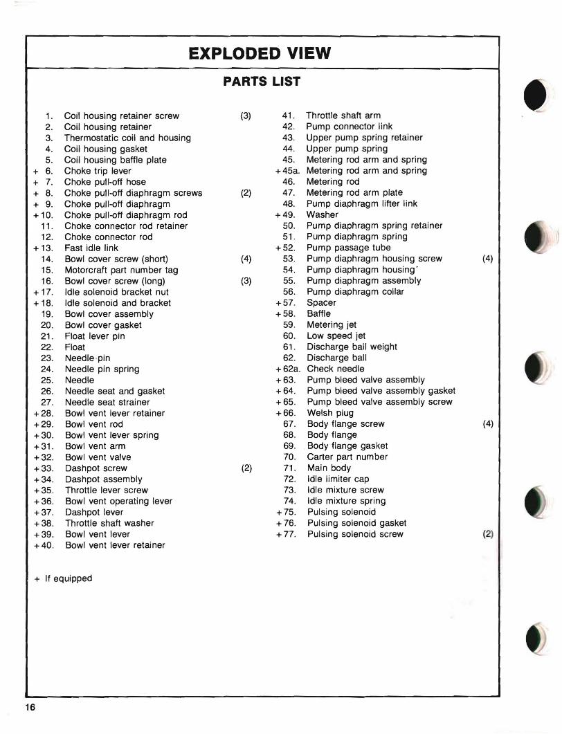
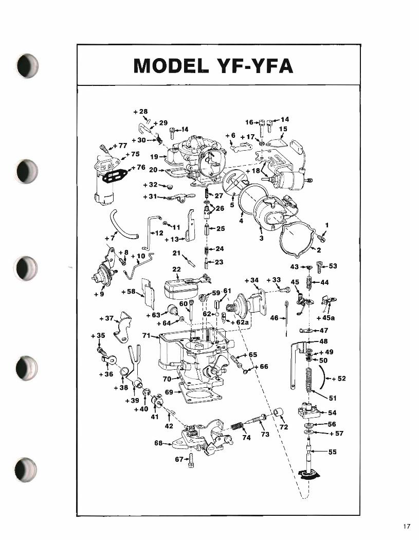
PARTS LIST
1. Coil housing retainer screw (3) 41. Throttle shaft arm 2. Coil housing retainer 42. Pump connector link 3. Thermostatic coil and housing 43. Upper pump spring retainer 4. Coil housing gasket 44. Upper pump spring 5. Coil housing baffle plate 45. Metering rod arm and spring
+ 6. Choke trip lever +45a. Metering rod arm and spring + 7. Choke pull-off hose 46. Metering rod + 8. Choke pull-off diaphragm screws (2) 47. Metering rod arm plate + 9. Choke pull-off diaphragm 48. Pump diaphragm lifter link + 10. Choke pull-off diaphragm rod +49. Washer
11. Choke connector rod retainer 50. Pump diaphragm spring retainer 12. Choke connector rod 51. Pump diaphragm spring
+ 13. Fast idle link +52. Pump passage tube 14. Bowl cover screw (short) (4) 53. Pump diaphragm housing screw (4) 15. Motorcraft part number tag 54. Pump diaphragm housing" 16. Bowl cover screw (long) (3) 55. Pump diaphragm assembly
+ 17. Idle solenoid bracket nut 56. Pump diaphragm collar + 18. Idle solenoid and bracket +57. Spacer
19. Bowl cover assembly +58. Baffle 20. Bowl cover gasket 59. Metering jet 21. Float lever pin 60. Low speed jet 22. Float 61. Discharge ball weight 23. Needle~pin 62. Discharge ball 24. Needle pin spring + 62a. Check needle 25. Needle +63. Pump bleed valve assembly 26. Needle seat and gasket +64. Pump bleed valve assembly gasket 27. Needle seat strainer +65. Pump bleed valve assembly screw
+28. Bowl vent lever retainer +66. Welsh plug +29. Bowl vent rod 67. Body flange screw (4) +30. Bowl vent lever spring 68. Body flange +31. Bowl vent arm 69. .Body flange gasket +32. Bowl vent valve 70. Carter part number +33. Dashpot screw (2) 71. Main body +34. Dashpot assembly 72. Idle limiter cap +35. Throttle lever screw 73. Idle mixture screw +36. Bowl vent operating lever 74. Idle mixture spring +37. Dashpot lever +75. Pulsing solenoid +38. Throttle shaft washer +76. Pulsing solenoid gasket +39. Bowl vent lever +77. Pulsing solenoid screw (2) +40. Bowl vent lever retainer
+ If equipped
16
MODEL YF-YFA
r 23~ ~ 43 L5322 ~ ~-
+58 I 59,61 --~ ~ """ : ff!N :/\ -\ ~
3
+32_~
+31~ 27
Q 5>26 5
~ F12..... ~ 00-2511 +~ +1~:
Cl,+8+ 10 21,-- '-24
Q ~,~~
i 60 If l\-I I ~ I Jl
+ 35 71 I \ \ I
~ ''' 48 ~\65 _+49
1\v I
"2o "" '- '«(,~~\)t 66 -)50_+ 52
+ 36 t 70 "
+38 ~ 69 \ +39 r ~ \ 51I
+40 }:'I'\ \~ ~54 42 ' -~ ~657\72
Q" 74 73 \ \
\ 'n'---55\ \ \ \
\ ~::oiA
\ I \ I
\ I,./
17
ADJUSTMENTS
-..------1(._
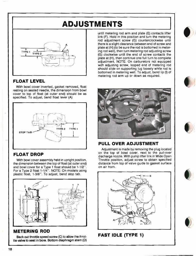
FLOAT LEVEL With bowl cover inverted, gasket removed, float
resting on seated needle, the dimension from bowl cover to top of float (at outer end) should be as specified. To adjust, bend float lever (A)
STOP TAB
FLOAT DROP With bowl cover assembly held in upright position,
the dimension between the top of float (at outer end) and bowl cover for a Type 1 float should be 1-1/2". For a Type 2 float 1-1/4". NOTE: On models using plastic float, 1-3/8". To adjust, bend stop tab.
until metering rod arm and plate (E) contacts lifter link (F). Hold in this position and turn the metering rod adjustment screw (G) counterclockwise until there is a slight clearance between end of screw and plate at (H) (to be sure the rod is bottomed in metering rod well), then turn metering rod adjusting screw (G) clockwise until the end of screw contacts the plate at (H), then continue one full turn to complete adjustment. NOTE: On carburetors not equipped with adjusting screw, looped end of metering rod should slide on supporting lug loosely while rod is bottomed in metering well. To adjust, bend lip (I) of metering rod arm up or down as required.
PULL OVER ADJUSTMENT Adjustment is made by removing the plug located
on the top of bowl cover, next to the pull-over discharge nozzle. With pump lifter link in Wide Open Throttle position, adjust screw to obtain specified distance from top of valve guide to gasket surface on air horn.
G 0
METERING ROD Back out throttle speed screw (C) to allow the throt
tle valve to seat in bore. Bottom diaphragm stem (0)
FAST IDLE (TYPE 1)
18
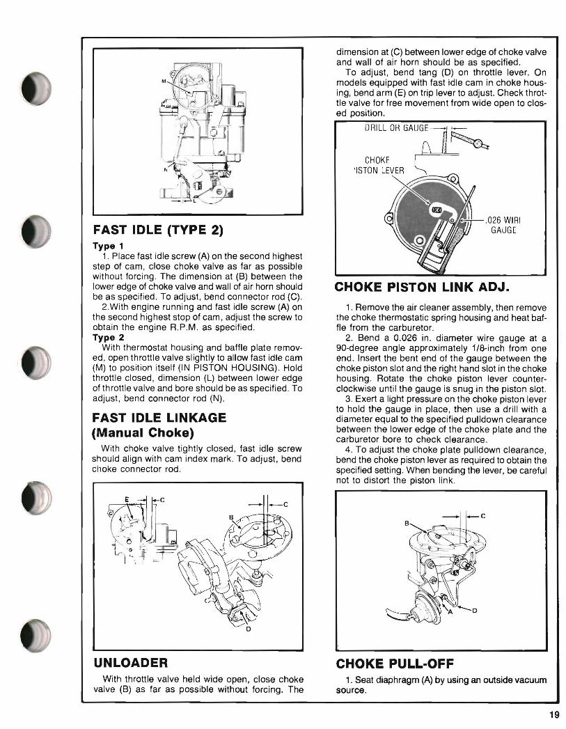
dimension at (C) between lower edge of choke valve and wall of air horn should be as specified.
To adjust, bend tang (0) on throttle lever. On models equipped with fast idle cam in choke housing; bend arm (E) on trip lever to adjust. Check throttle valve for free movement from wide open to closed position.
CHOKE 'ISTON LEVER
.026 WIRI GAUGEFAST IDLE (TYPE 2)
Type 1 1. Place fast idle screw (A) on the second highest
step of cam, close choke valve as far as possible without forcing. The dimension at (B) between the lower edge of choke valve and wall of air horn should be as specified. To adjust, bend connector rod (C).
2With engine running and fast idle screw (A) on 1. Remove the air cleaner assembly, then remove the second highest stop of cam, adjust the screw to the choke thermostatic spring housing and heat bafobtain the engine R.P.M. as specified. fle from the carburetor. Type 2 2. Bend a 0.026 in. diameter wire gauge at a
With thermostat housing and baffle plate remov gO-degree angle approximately its-inch from one ed, open throttle valve slightly to allow fast idle cam end. Insert the bent end of the gauge between the (M) to position itself (IN PISTON HOUSING). Hold choke piston slot and the right hand slot in the choke throttle closed, dimension (L) between lower edge housing. Rotate the choke piston lever counterof throttle valve and bore should be as specified. To clockwise until the gauge is snug in the piston slot. adjust, bend connector rod (N). 3. Exert a light pressure on the choke piston lever
to hold the gauge in place, then use a drill with a FAST IDLE LINKAGE diameter equal to the specified pulldown clearance
between the lower edge of the choke plate and the (Manual Choke) carburetor bore to check clearance.
With choke valve tightly closed, fast idle screw 4. To adjust the choke plate pulldown clearance, should align with cam index mark. To adjust, bend bend the choke piston lever as required to obtain the choke connector rod. specified setting. When bending the lever, be careful
CHOKE PISTON LINK ADJ.
not to distort the piston link.
-_c
UNLOADER CHOKE PULL-OFF With throttle valve held wide open, close choke 1. Seat diaphragm (A) by using an outside vacuum
valve (B) as far as possible without forcing. The source.
19

2. Apply a light closing pressure to choke valve (8) to move the choke valve toward the closed position as far as possible without forcing.
3. The dimension (C) between the lower edge of choke valve and air horn wall should be as listed in in specifications.
4. To adjust, bend rod (D).
AUTOMATIC CHOKE Rotate the thermostatic coil cover against spring
tension until mark of thermostat cover is aligned with specified mark on housing, as listed in specifications.
[1
/' (" ,- 1 ' II~-_.-~\ M~9\~ .
~ . - -~.. _.
I'"'" , ...''..)
I II ALTITUDE , '- COMPENSATOR
SCREW
ALTITUDE COMPENSATOR Where the altitude compensator valve carburetor
is used, the compensator screw should be closed at sea level operation, and opened by turning counterclockwise approximately 2-1/2 turns for altitude operation.
ROTATE HOUSING
W.O.T. VALVE ADJUSTMENT With throttle in wide open position, the dimension
between end o~ operating lever and dump valve body should be 1/8"
D BULLET CONNECTOR
IDLE SPEED & MIXTURE NON EMISSION CARBURETORS
Turn throttle speed screw (A) to slightly open throttle valve. With engine at normal operating temperature, turn mixture screw (D) in or out until engine reaches the highest engine R.P.M. as indicated on tachometer. Turn speed screw (A) to the engine R.P.M. as specified.
EMISSION CARBURETORS Follow idle mixture adjusting procedure as outlin
ed on decal in engine compartment. 1. Check for correct ignition timing.
2. Start engine and allow engine temperature to normalize.
3. Refer to vehicle manufacturer's curb idle speed and procedure for "Propane" adjustment (if reqUired).
4. Curb idle and Propane specs are found on decal located in engine compartment.
IDLE SOLENOID <IF EQUIPPED) When an idle solenoid is used, R.P.M. is adjusted
at the solenoid. Two types are used. Solenoid adjusting screw will be located at "8" or "C" as shown above.
SOL·VAC <IF EQUIPPED) 1. Curb idle adjustment is made with the hex head
screw "8" located on the rear of the solenoid.
2. Engine-off throttle valve adjustment is made with screw "A" as shown above.
•
20
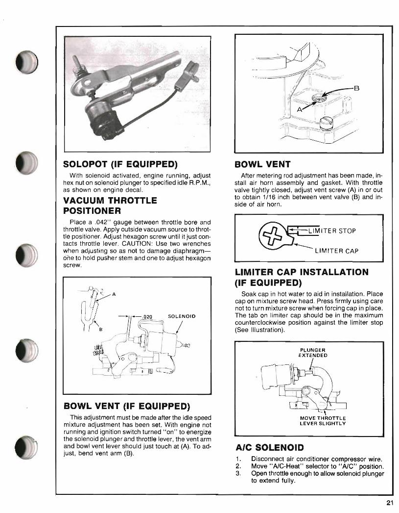
SOLOPOT (IF EQUIPPED) BOWL VENT With solenoid activated, engine running, adjust After metering rod adjustment has been made, in
hex nut on solenoid plunger to specified idle R.P.M., stall air horn assembly and gasket. With throttle as shown on engine decal. valve tightly closed, adjust vent screw (A) in or out
to obtain 1/16 inch between vent valve (8) and inVACUUM THROTTLE side of air horn. POSITIONER
Place a .042" gauge between throttle bore and throttle valve. Apply outside vacuum source to throt ~IMITER STOPtle positioner. Adjust hexagon screw until it just contacts throttle lever. CAUTION: Use two wrenches when adjusting so as not to damage diaphragm LIMITER CAP one to hold pusher stem and one to adjust hexagon screw.
LIMITER CAP INSTALLATION (IF EQUIPPED)
Soak cap in hot water to aid in installation. Place cap on mixture screw head. Press firmly using care not to turn mixture screw when forcing cap in place. The tab on limiter cap should be in the maximum counterclockwise position against the limiter stop (See Illustration).
PLUNGER EXTENDED
I.
BOWL VENT (IF EQUIPPED) ,This adjustment must be made after the idle speed MOVE THROTTLE
LEVER SLIGHTLYmixture adjustment has been set. With engine not running and ignition switch turned "on" to energize the solenoid plunger and throttle lever, the vent arm and bowl vent lever should just touch at (A). To adjust, bend vent arm (8).
1. Disconnect air conditioner compressor wire. 2. Move "AlC-Heat" selector to "AlC" position. 3. Open throttle enough to allow solenoid plunger
to extend fully.
SOLENOID
AIC SOLENOID
21
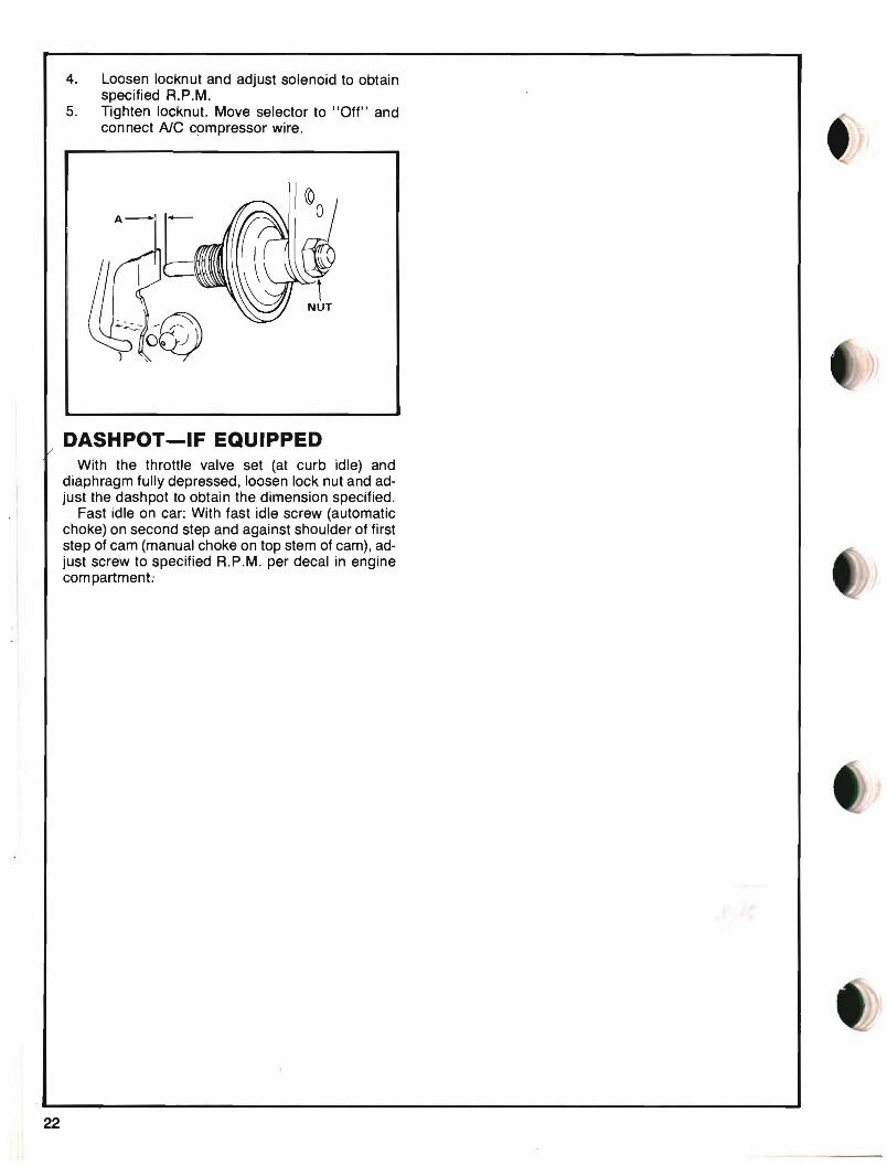
4. Loosen locknut and adjust solenoid to obtain specified R.P.M.
5. Tighten locknut. Move selector to "Off" and connect NC compressor wire.
I~ ,
NUT
DASHPOT-IF EQUIPPED With the throttle valve set (at curb idle) and
diaphragm fully depressed, loosen lock nut and adjust the dashpot to obtain the dimension specified.
Fast idle on car: With fast idle screw (automatic choke) on second step and against shoulder of first step of cam (manual choke on top stem of cam), adjust screw to specified R.P.M. per decal in engine com partment~
22
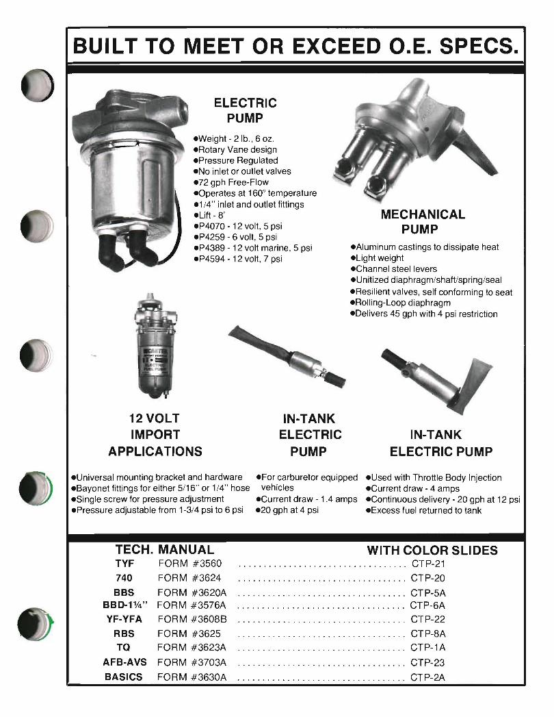
BUILT TO MEET OR EXCEED O.E. SPECS.
ELECTRIC PUMP
eWeight - 2 lb., 6 oz. eRotary Vane design ePressure Regulated eNo inlet or outlet valves e72 gph Free-Flow eOperates at 1600 temperature e1/4" inlet and outlet fittings eLift - 8' MECHANICAL eP4070 - 12 volt, 5 psi PUMP eP4259 - 6 volt, 5 psi eP4389 - 12 volt marine, 5 psi eAluminum castings to dissipate heat eP4594 - 12 volt, 7 psi eLight weight
eChannel steel levers eUnitized diaphragm/shaftlspring/seal eResilient valves, self conforming to seat eRolling-Loop diaphragm eDelivers 45 gph with 4 psi restriction
IN-TANK ELECTRIC PUMP
12 VOLT IN-TANK IMPORT ELECTRIC
APPLICATIONS PUMP
eUniversal mounting bracket and hardware eFor carburetor equipped eUsed with Throttle Body Injection eBayonet fittings for either 5/16" or 114" hose vehicles eCurrent draw - 4 amps eSingle screw for pressure adjustment eCurrent draw - 1.4 amps eContinuous delivery - 20 gph at 12 psi ePressure adjustable from 1-3/4 psi to 6 psi e20 gph at 4 psi eExcess fuel returned to tank
TECH. MANUAL TYF FORM #3560
740 FORM #3624
BBS FORM #3620A BBD-11f4" FORM #3576A
YF-YFA FORM #3608B
RBS FORM #3625
TO FORM #3623A
AFB-AVS FORM #3703A
BASICS FORM #3630A
WITH COLOR SLIDES · CTP-21
· CTP-20
· CTP-5A · CTP-6A
· CTP-22
.................................. CTP-8A
· CTP-1A
· CTP-23
· CTP-2A
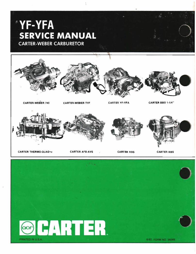
CARTER-WES""e:R 740 CARTER-WEBER TYF CARTER YF-YFA CARTER BBD 1-1/4"
CARTER THERMO-QUADTM CARTER AFB-AVS CARTER RBS CARTER BBS