
XW-111 Wi-Fi Users Manual - ControlByWeb
48
-
Upload
khangminh22 -
Category
Documents
-
view
0 -
download
0
Transcript of XW-111 Wi-Fi Users Manual - ControlByWeb


XW-111™ Wi-Fi Digital Sensor Users Manual
XW-111 User Manual Revisions
Revision Description
1.0 Initial release
1.1 Added Canadian IC declaration
2.0 Split the combined XW-110 and XW-111 user manual into two separate manuals. Added support for Remote Services, Modbus and other features available beginning with firmwarerevision 1.03Added Modbus documentation.Changed to 5-year warranty.
Page 2 Xytronix Research & Design, Inc.

XW-111™ Wi-Fi Digital Sensor Users Manual Introduction
Section 1: IntroductionThe XW-111 is an easy-to-use wireless Wi-Fi digital input monitoring device. The XW-111 monitors and reports the status of switch-closure sensors and alarms. It is ideal for applications where equipment and events must be monitored and Ethernet wiring is not accessible or practical to install.
The XW-111 is powered by an external wall transformer (5VDC), or by two internal AA batteries (installed inside the enclosure). The XW-111 will use the wall transformer and automatically switch to the batteries in the event of a power failure. Only use batteries to provide backup power, or for modes where the HTTP server, ModBus server, and Remote Services are not being used. If the internal web server, ModBus server, or Remote Services is enabled, the XW-111 will need to be powered by an external wall transformer. Some setting configurations consume more power than others, leading to some scenarios where battery operation is not practical. For example, transmitting the status every five seconds could result in depleting the batteries very quickly. Having more features enabled and/or an increased reporting rate leads to lower battery life.
A three-position terminal strip provides connections for up to two switch-closure sensors for the XW-111. No other cables, interfaces, or PC utility programs are needed.
Two modes of Operation:
“Stand-Alone” Mode: The XW-111 is a self-contained device that does not require additional servers or ControlByWeb devices. In this mode the XW-111 products provides real-time input status through a standard web browser or through the CBW Mobile app. In addition, stand-alone mode offers the ability to monitor input status and send out email alerts (which can be converted to text message alerts) whenever an alarm condition occurs.
"Slave" Mode: The XW-111 reports its inputs' status to other ControlByWeb devices. In this mode, the XW-111 is not directly accessible to the user. Instead, input status is transmitted to a server or to another ControlByWeb device, such as the X-600M controller which acts as a "master.” The master device then uses the information provided by the XW-111 as it would from any other sensor.
Provisioning the module:
Access Point Mode: Press the “Access Point” button anytime to enable access point mode. With a PC or smart phone you then connect to and access the internal web server no matter what mode the unit is currently set to. Using the web server, you configure the measurement interval, access port, name, and other setup parameters.
WPS: Alternatively, add the XW-111 to an existing network by pressing the “WPS” (Wi-Fi Protected Setup) button on both the XW-111 and on your access point (i.e., router).
Network Discovery: Using the Android or iOS app, the XW-111 can be used to configure the WiFi network as well as any cloud or network settings.
ControlByWeb Cloud:
The XW-111 can be configured to automatically connect to ControlByWeb.cloud after being connected to a wireless network with internet access. This feature allows internet access to an XW-111 which is installed behind a network router, without the need to setup port forwarding in the router. This also allows easy installation using DHCP without the need to assign a specific IP address. Since the connection from the XW-111 is outgoing, rather than incoming, the local router on the network where the XW-111 resides doesn't need to be configured to forward sockets. This simplifies the installation since the router configuration is not modified.
Xytronix Research & Design, Inc. Page 3

Introduction XW-111™ Wi-Fi Digital Sensor Users Manual
1.1.1 Features
➢ Wireless Wi-Fi 802.11 b/g/n
➢ Two digital inputs
➢ Built-in web server for configuration and remote monitoring
➢ Powered from two “AA” batteries or external DC power adapter
➢ Small data packets provide long battery life
➢ Input status can control relays on other ControlByWeb devices
➢ Send email alarms and weekly status alerts (up to 3 addresses)
➢ Send encrypted emails.
➢ Includes auxiliary protocols including XML, Modbus/TCP and Remote Services
➢ Simple and easy to use
➢ 5-year warranty
1.1.2 Part Numbers and Accessories
Device Description Part Number
XW-111 Wi-Fi digital input monitor with built-in web server XW-111B
Power Supply Wall Transformer, 120VAC in, 5V, 1A out PS5VW1.0-2.5mm
1.1.3 Wireless Communication Notes
Due to the nature of wireless communications, transmission and reception of data cannot be guaranteed. Data may be delayed, have errors, or be lost. Although delays or losses of data are rare with a well constructed network, data can be lost due to interference, noise, reflections, or other environmental conditions. The XW-111 should not be used in situations where failure to transmit or receive data could result in damage to property, equipment, direct, indirect, consequential, or incidental damage, including damage for loss of business profit, business interruption, loss of data, life, and the like.
Page 4 Xytronix Research & Design, Inc.

XW-111™ Wi-Fi Digital Sensor Users Manual Installation and Setup
Section 2: Installation and Setup
2.1 XW-111 Digital Input Connections
The XW-111 can sense the state of up to two switch-closure sensors. Sensors with switch-closure outputs include push buttons, magnetic door alarm switches, micro-switches, or any device which has a relay, switch closure or open collector output. Both sensor inputs share the same GND connection. The XW-111 can be configured for the alarm to be active when the switch is either open or closed. If possible, use switches which are normally open (NO). When the switch contact is open no current flows thru the switch and the longest battery life is achieved. When the switch is closed 17uA flows thru the switch.
The inputs use 3.3Volt logic and work with simple switches and relays. Do not connect the digital inputs to a power source. The inputs will work with cable lengths up to 20-feet and should not be routed near motors or AC wiring. The connections for two switches are shown to the right.
The enclosure can be mounted to a wall or panel with screws (not included). The two screw holes are located underneath the batteries.
2.2 Power / Batteries
The XW-111 is powered from either a 5-volt DC wall transformer or two internal 1.5V “AA” batteries. If the wall adapter is connected, no power is drawn from the batteries. If the external power fails the module automatically switches to the internal batteries. No jumpers or switches are needed. The wall adapter should be used for certain modes with high current demands such as: “Stand-Alone mode” with HTTP server, ModBus or Remote Services enabled, “Slave mode” with high reporting rates, or when “access point” is active.
Install the batteries as shown. Observe the “+” and “-” markings molded in the enclosure underneath the batteries. Both batteries should be replaced at the same time. Do not install the XW-111 inside a freezer or where low temperature conditions would severely diminish the battery capacity.
Xytronix Research & Design, Inc. Page 5
Battery Installation

Installation and Setup XW-111™ Wi-Fi Digital Sensor Users Manual
2.3 Provisioning
After making the sensor connections and providing power, you must provision the XW-111 for use on your wireless network. The goal is to configure the XW-111 such that it can recognize and attach to your Wi-Fi access point. There are two methods for doing this:
1. Access Point Mode
By default, the XW-111 comes up as a wireless access point when powered for the first time. Pressing the XW-111's "Access Point" button at any time also activates the access point mode. It isn't really an access point because it will not provide internet connectivity to your computer or smart phone, but it will appear as an access point, meaning that your computer or smart phone will detect it as an access point and display it as such. When acting as an access point, the XW-111 broadcasts an SSID of “XW111-XXXXXX” where XXXXXX are the last six digits of its MAC address.
With your wireless device (laptop computer or smart phone) scan for, and attach to the XW111 wireless network. Next, access the web server in the XW-111 using a web browser. To access the setup pages, enter the following URL in the address bar of your web browser:
http://192.168.1.2/setup.html
After the page is requested, a password prompt will appear. Enter the username and password. The username is admin and the password is webrelay (password is case sensitive). The next chapter explains each of the setup tabs and screens. Use the WiFi Networks tab for making the proper settings to allow the XW-111 to connect to your access point.
Notes About Access Point Mode:
• Operates at full power and will consume large amounts of energy and drain batteries quickly. It is recommended that you use a wall-transformer to power the unit when operating in access point mode or to configure the XW-111 quickly.
• As an “access point” the XW-111 functions independently of other wireless networks. It broadcasts beacons and services Wi-Fi packet requests. In this mode, your computer or smart-phone is "connected" directly with the XW-111 on a private network and is NOT using another Wi-Fi network. Typically you would use this for configuration and not for normal operation.
• The XW-111 has no hardware “restore defaults” button, to prevent the installer from being locked out, the default username (admin) and password (webrelay) always work in the access point mode, even if the password is changed. If the password has changed via the Password tab, both the new password and the webrelay password will work.
• Only one client (computer or smart-phone) can be connected to XW-111 at a time.
• SSID and password cannot be customized (once again this mode is intended for configuration only).
• Access point is unsecured and open.
Page 6 Xytronix Research & Design, Inc.

XW-111™ Wi-Fi Digital Sensor Users Manual Installation and Setup
2. WPS (Wi-Fi Protected Setup)
The WPS method, provides a simple method for attaching the XW-111 to a wireless network without needing to use any setup pages. Although using this method to connect the XW-111 to the network is simple, you will not be able to access the XW-111 web server unless you know the IP address that was assigned by the DHCP sever (router) or unless mDNS services are available on your device. For this reason, it is recommended that you use this method of configuration only when the XW-111 units have been pre-configured to operate in a non-web-server mode or when you have full access to the DHCP server so you can obtain the IP address that was assigned.
To begin, press the WPS button on your wireless router or access-point. You will generally have about two minutes to connect wireless devices to the network with WPS. Now remove the cover of the XW-111 and press the “WPS” push button. After a few seconds, the XW-111 should register itself with the router or access-point. If WPS fails, the XW-111 will automatically enter the access point mode.
The XW-111 will use DHCP to obtain an IP address after a successful WPS association. Additionally, the connection information is also broadcast using mDNS. If you need to access the XW-111 using its internal web server you will need to obtain the IP address that was assigned to the XW-111 through your DHCP server or router. Alternatively, if using an mDNS capable device, it may be accessed by entering the appropriate URL into the address bar of your web browser:
http://xw-111.local/setup.html
Xytronix Research & Design, Inc. Page 7

Installation and Setup XW-111™ Wi-Fi Digital Sensor Users Manual
2.4 Application Examples
The XW-111 can be configured for many different applications. Applications which require long battery life require careful planning and setup. Several examples are described below:
Storage Shed Door Example
You want to receive an email whenever someone opens the door to your storage shed. The storage shed is within range of a Wi-Fi access point. No AC power is available.
Install a magnetic door switch sensor and connect it to an XW-111. In this application, the XW-111 is workable with batteries because transmissions are infrequent. For best battery life, the magnetic door switch should be wired such that when the door is closed, the switch is open.
First, the XW-111 must be configured to access your Wi-Fi network. If no network profiles have been configured, the XW-111 will automatically enter the access point mode and you can access the XW-111 directly with a computer or smart device with a wireless connection. If the XW-111 has been previously configured for other uses, press the Access Point button. Scan for, and attach to the XW110-XXXXXX wireless network. Access the setup pages with the following URL: http://192.168.1.2/setup.html
For this application, configure the XW-111 in stand-alone mode with the internal web server disabled. Configure the XW-111 to connect to your wireless network. Navigate to the WiFi Networks tab and fill in the appropriate settings for your Wi-Fi network. Obtain the IP address from your network administrator. To increase battery life, disable the HTTP web server and avoid using DHCP. Press the Submit button at the bottom of the page.
Navigate to the Inputs tab. On the Email Alert setting, select Send email when Input On. You may also want to set the Email Deadband option to 5 seconds. This will prevent multiple emails from being sent if the switch opens and closes multiple times as the door is opened. You will receive an email the moment the door is opened, but no more until at least 5 seconds has elapsed and the switch were to close and open again. Change the Module Description text to a descriptive name such as “Storage Shed.” This text may be up to 35 characters long and appears on the Control Page and in email messages when email alerts are enabled. Change the On Status Text to “Door is Open.” Click the Submit button at the bottom of the page.
Navigate to the Email tab and enter the SMTP server settings as well as the username and password (if required). You may need to search online for your email provider's exact settings to use. To provide ongoing assurance that the XW-111 is working, enable the Weekly Status Email option.
Once all the appropriate settings have been applied, click on the Reboot button. The XW-111 will then reboot and begin low-power operation. The XW-111 will no longer broadcast an SSID and the web page will no longer be accessible. If the door is opened, the XW-111 will awaken, connect to your Wi-Fi access point and send an email. Once per week, the XW-111 will send an email with input state and battery information.
Door Bell Example
You want to activate a buzzer to indicate someone has pressed a call button at your warehouse door. The door is within range of a Wi-Fi access point. No AC power is available
The XW-111 is workable with batteries because transmissions are infrequent. Install a WebRelay™ anywhere in your facility and connect it to your Ethernet network. Connect a buzzer to the relay contact. The WebRelay must be accessible from the Wi-Fi network and be assigned a fixed IP address. Your Wi-Fi network must have adequate coverage in the warehouse. Connect the call button to the XW-111 and mount it indoors near the door. For best battery life use a button with normally open contacts (NO).
For this application, configure the XW-111 as a stand-alone device with the internal web server disabled. Configure the XW-111 to connect to your Wi-Fi network as explained in the previous example.
Page 8 Xytronix Research & Design, Inc.

XW-111™ Wi-Fi Digital Sensor Users Manual Installation and Setup
Navigate to the Inputs tab. Set the Remote Relay Options to Send pulse command when input on. With this setting the relay will pulse for three seconds when the button is pressed.
Note: The “Remote command equals input” is not workable in this application because the user may have released the call button by the time the XW-111 has awakened and connected to the Wi-Fi access point.
Upon selecting an action, the remote relay options for specifying the IP address, port, relay number and other options will show. Enter the IP settings for the WebRelay in and press the Submit button at the bottom of the page.
Once all the appropriate settings have been applied, click on the Reboot button, the XW-111 will then reboot and begin low power operation. The XW-111 will no longer broadcast an SSID and the web page will no longer be accessible. When the button is pressed, the XW-111 will awaken and send the command to pulse (activate) the remote relay.
Xytronix Research & Design, Inc. Page 9

Web Server XW-111™ Wi-Fi Digital Sensor Users Manual
Section 3: Web ServerThe internal web server presents two classes of web pages; Setup pages and Control pages. Setup pages are used by an installer to provision and configure the XW-111. The Control page displays measurement and status information for the user.
To access the setup pages, enter the following URL in the address bar of your web browser:
http://192.168.1.2/setup.html
To access the control page, enter the following URL in the address bar of your web browser:
http://192.168.1.2
The internal web server is enabled by default in stand-alone mode and disabled in slave mode. If you wish to access the web server when it is disabled, press and hold the WPS button for 10 seconds. This will temporarily enable the web-server for five minutes or until the unit is rebooted.
Note that if you are accessing the unit as an access point, the above IP address will work even if you have changed the IP address or port in the setup pages. If you are accessing the unit through the network after it has been configured (and the web server remains enabled) you will need to enter the IP address that was assigned to the device.
If the XW-111 has been added to a network using WPS, it will use DHCP and you will need to enter the IP address assigned to it. This can be found in the DHCP server, or by using mDNS. The mDNS name is http://xw-111.local/
3.1 Main Tab
This is the initial page that is displayed when setup.html is entered in the address bar of the browser. It displays model and serial number information, and has navigation tabs which allow access to the configuration and setup settings.
Page 10 Xytronix Research & Design, Inc.

XW-111™ Wi-Fi Digital Sensor Users Manual Web Server
Mode
The XW-111 operates in two fundamental modes: “Stand-alone” and “Slave.” Depending on which mode you select, the menu tabs will change to reflect the mode's settings. Select “Stand-Alone” if using the XW-111 to simply monitor the inputs and provide input status information to users through its built-in web pages, send email alerts, or control a remote relay. Select “Slave” if the XW-111 is used to send data to a master device such as an X-600M™ controller.
The Mode setting will not take effect until the XW-111 is rebooted. To do this click the Reboot button after making a change to the Mode.
► Stand-Alone:
In this mode the XW-111 is self-contained and is used without other master devices. It can be configured to operate in low-power mode and periodically check the inputs and send alarm messages directly to users via email or control remote relays. In stand alone mode it can also be used as a stand-alone web server that users can access at any time to view current input status.
• The web server can be enabled which allows users to access this device directly using a web browser or the CBW Mobile app. Users can view real-time input status. Note: Enabling the web server requires considerably more power and battery operation is not practical.
• The Email tab is visible and the Remote Master tab is suppressed.
► Slave:
In this mode the XW-111 sends the input status to a master device such as an X-600M controller. In this mode the XW-111 sleeps most of the time to conserve power. It periodically awakens, checks the inputs and transmits (pushes) the data to a remote server. The "master" ControlByWeb device uses the XW-111 just like other wired sensors that may be attached.
• In this low power mode the XW-111 sleeps most of the time. It periodically awakens, checks the inputs, connects to a Wi-Fi network and transmits data to the master device.
• Use longer interval for long battery life.
• No emails are supported
• The internal web server is not accessible
• The Email tab is suppressed, and the Remote Master tab is shown
Xytronix Research & Design, Inc. Page 11

Web Server XW-111™ Wi-Fi Digital Sensor Users Manual
Part Number
This is the full model number of the XW-111
Firmware Revision
This is the current product revision of the internal software
Serial Number
This is the serial number of the XW-111. The serial number is also the MAC address of the unit.
Power Supply
This field shows if the XW-111 is currently being powered by batteries or the DC wall transformer. The battery voltage is periodically measured and an estimate is made of the remaining battery life. If the module is powered by the DC wall transformer, the voltage is measured with no load on the battery. The calculations are made for alkaline “AA” batteries with a usable capacity of 2000mAH. When using other types of batteries or in cold conditions, the displayed estimate may be in error. Depending on the activity, the battery life estimate may fluctuate (perhaps even increase) as the load current changes. The battery voltage may recover (increase) when the XW-111 enters low-power sleep mode after a period of high current operation.
Signal Strength
This indicates the current receive Wi-Fi signal strength. The more negative the number, the less signal is being received. -30dBm is a strong signal, and -90dBm is a very weak signal.
Reboot
After showing a confirmation message, this button will send a command to reboot the device.
Restore Defaults
After showing a confirmation message, this button will erase all user settings and return the module to its factory defaults.
Page 12 Xytronix Research & Design, Inc.
XW-111™ Wi-Fi Digital Sensor Users Manual Web Server
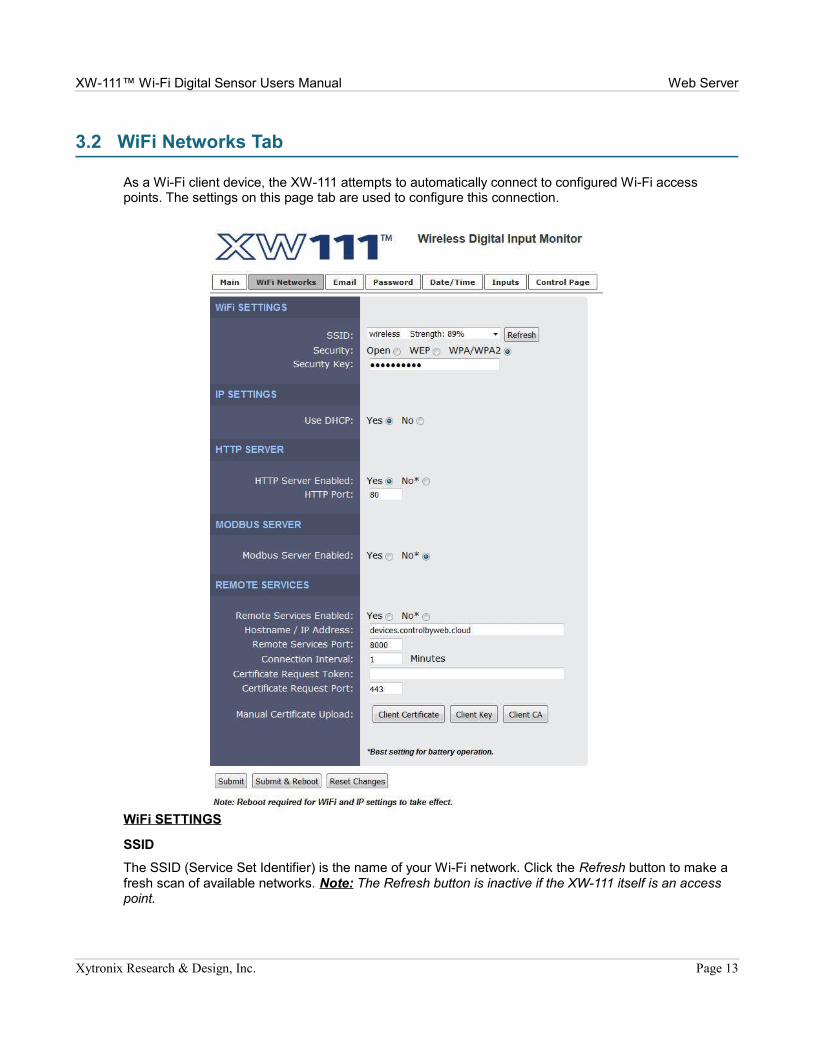
3.2 WiFi Networks Tab
As a Wi-Fi client device, the XW-111 attempts to automatically connect to configured Wi-Fi access points. The settings on this page tab are used to configure this connection.
WiFi SETTINGS
SSID
The SSID (Service Set Identifier) is the name of your Wi-Fi network. Click the Refresh button to make a fresh scan of available networks. Note: The Refresh button is inactive if the XW-111 itself is an access point.
Xytronix Research & Design, Inc. Page 13
Web Server XW-111™ Wi-Fi Digital Sensor Users Manual
Security
Type of authentication used by the access point for connections.
Security Key
Enter the security key or password for the Wi-Fi network that the XW-111 should connect to. (Hidden when not applicable)
IP SETTINGS
Use DHCP
This option allows DHCP to be enabled or disabled. If this option is set to Yes, the XW-111 will wait for an IP address from a DHCP server each time it is powered. The default setting is No (this is recommended for most installations). If DHCP is set to Yes, the Network page must be submitted and the XW-111 must be rebooted before an IP address will be assigned. Once the XW-111 is assigned an IP address by the DHCP, the new IP address can be found through the clients list kept by the DHCP server. For most instances, this is found on the local gateway or router. Alternatively, the device will broadcast its information via mDNS. By not using DHCP, battery life is extended as the device does not expend energy for transmitting requests and receiving responses every time it connects to the Wi-Fi network.
Brief Notes About DHCP: All devices on an IP network require an IP address. This is a unique address that identifies each device on the network. DHCP (Dynamic Host Control Protocol) is a mechanism that automatically assigns an IP address to a computer (or other devices) when it is connected to a network. This eliminates the need to manually enter the IP address. When a computer is connected to the network, another device on the network called a DHCP server detects the presence of the computer and dynamically assigns the IP address to that computer. On many small networks, the DHCP server is built into the router.
DHCP works well for "client" devices such as computers, but is not ideal for servers. This is because servers usually don't initiate communications with other devices, but rather they wait for a request from "clients." To make this request, the client must know the IP address of the server. If a server gets its IP address dynamically, the IP address may not always be the same so client devices may not be able to find the server. For this reason, servers usually use an IP address that is fixed and does not change. The XW-111 is a server and manual IP address assignment is usually recommended.
IP Address
Enter the IP address for the XW-111 in this field. The IP address is specific to the network where the XW-111 will be installed and is obtained from the network administrator. The default setting for this field is 192.168.1.2.
Subnet Mask
The subnet mask defines the size of the local network. This can be obtained from the network administrator. For additional information about sub-netting and IP networking, many tutorials are available on the Internet. The default setting for this field is 255.255.255.0.
Gateway
This specifies the IP address of the gateway router. This can be obtained from the network administrator. The default setting for this field is 192.168.1.1.
DNS Server
The IP address of the DNS server is specified here. When DNS services are required, this is the address that will be used. The default setting for this field is 192.168.1.1. An alternate DNS server is not supported.
Page 14 Xytronix Research & Design, Inc.

XW-111™ Wi-Fi Digital Sensor Users Manual Web Server
HTTP SERVER
HTTP Server Enabled
This option can turn the internal HTTP web server on or off when in stand-alone mode. In slave mode the HTTP web server is automatically disabled. When the web server is on, the XW-111 can be accessed using a web browser or the CBW Mobile app and you can view the current input status. When the web server is off, the input status is obtained when the XW-111 transmits (pushes) the data. For example, you can turn the web server off but get input status information through email alerts. Turning the web server off will allow the device to make use of more power saving features. With the web server turned off, the device will be allowed to disconnect from the Wi-Fi network or at the very least service beacons selectively to save power.
HTTP Port
The TCP port used for HTTP communications with the XW-111 can be customized here. The default setting for this field is 80, which is the standard HTTP port. It is recommended that the port be left unchanged unless the user has an understanding of TCP/IP and ports.
MODBUS SERVER
Modbus Server Enabled
XW-111 can support Modbus/TCP. Modbus is a messaging structure protocol used in industrial manufacturing control and automation. It is an open protocol and offers interoperability with software and devices from other manufacturers. This is enabled by selecting Yes in this field. The default setting for this field is No. (See Section 5.1: Modbus Operation for more information on using XW-111 on a Modbus network.)
Note: Modbus communications are disabled whenever the Control Password is enabled as Modbus does not have support for passwords.
Modbus Port
This specifies the port used for Modbus/TCP communications with XW-111. By default this is set to port 502 which is the standard Modbus port. It can be set within the range of 0 to 65535.
Endianness
32-bit data is treated as two individual 16-bit words using IEEE 754 floating point format. Floating point format is used for reading the battery voltage.
If the Big radio button is set, the XW-111 will use big-endian architecture and the most significant 16-bit word (big end) is sent first. If the Little radio button is selected, then the XW-111 will use little-endian architecture, and the least significant word (little end) is sent first. The default setting is little-endian.
For example, in little-endian format, a 32-bit floating point number represented by '1234 ABCD' is sent as 'ABCD 1234'.
Xytronix Research & Design, Inc. Page 15

Web Server XW-111™ Wi-Fi Digital Sensor Users Manual
REMOTE SERVICES
Remote Services Enabled
This option enables or disables remote services. If Yes is selected, remote services will be enabled as soon as the Submit button is pressed and the XW-111 will immediately attempt to make a connection with a custom remote server (power cycle not required). Once a connection is established, the connection will remain until it is disconnected by the remote server (see Remote Services Notes below). Proper connection with the remote server can be verified by checking the remote server. The default setting for this field is No. If Remote Services is enabled, the default settings will connect to the ControlByWeb.cloud cloud service. Users will need to supply either a token from their account or upload SSL certificates. Most users should leave these settings at their default. (See Remote Services at the end of this section for more information.)
If Remote Services Enabled is set to Yes, the following settings are shown:
Hostname/IP Address
Specify the name or IP address of the remote services' server here. If the IP address is specified, enter it in this format aaa.bbb.ccc.ddd. For numbers that are less than 100, preceding zeros should not be included (for example, enter 80 rather than 080). This field can be up to 40 characters long and has no default setting.
Remote Services Port
Enter the TCP port used for the Remote Services server. This can be set within the range of 0-65535. The default setting for this field is 8000.
Connection String
This text is sent to the remote services' server when the connection is established. This string should include any information required by the server at connection. For example, it may include an ID number, customer number, password, etc. The format is entirely dependent upon the server requirements. This field can be up to 80 characters long. Default text is provided only as an example placeholder. The default text is [<Serial Number>]:ControlByWeb,XW-111.
Connection Interval
This field specifies the periodic interval in which the XW-111 attempts to connect to the remote server, or if XW-111 is already connected, it is the interval in which XW-111 sends the connection string. This field
Page 16 Xytronix Research & Design, Inc.

XW-111™ Wi-Fi Digital Sensor Users Manual Web Server
can be set within the range of 1 to 55 minutes. The default setting for this field is 1 minute.
Version
This field specifies the version of the remote services' protocol to use. Version 1 of the protocol sends the connection string after successfully connecting to the remote server and then periodically per the connection interval specified. Version 2 of the protocol sends the connection string in addition to the MAC address, connection interval, model number and then immediately sends the state.xml file of the device. Version 2 of the protocol requires the remote server to reply to the connection string with a 3 byte packet containing the text “ACK”. If the “ACK” is not received within 10 seconds of sending the connection string, the XW-111 will close the connection. Version 2 continues to send the connection string and the state.xml file periodically per the connection interval specified.
Use SSL Certificate
This option enables encryption of the remote services' connection with the remote services' server as well as authentication of the XW-111 to the server by a client certificate and key. Custom certificates and keys can be loaded into the XW-111 for this purpose. (See Remote Services at the end of this section for more information.)
By default, the XW-111 does not come with any SSL certificates already installed. The certificates will need to be installed either manually by uploading the files or automatically with a token. The SSL certificates must be in the PEM format.
Certificate Request Token
When the XW-111 has a valid Certificate Request Token entered, it will automatically attempt to request and download its Client Certificate, Key, and CA. Once successful, the token will be erased and the XW-111 will stop its requests. (See Remote Services at the end of this section for more information.)
Certificate Request Port
The certificate server is a server that has been configured to deliver the Client Certificate, Key, and CA when requested by the XW-111. For the XW-111 to request a Certificate, Key, and CA from the certificate server, it must have a previously issued Certificate Request Token. This field specifies what port the Certificate Server listens on. The server is found at the same host name as the remote services' server. (See Remote Services at the end of this section for more information.)
Manual Certificate Upload
Client Certificate
A client certificate is used with custom remote services' servers for device authentication. To upload a custom client certificate to the XW-111, click the Browse button, find the PEM formatted certificate file, and select Submit.
Client Key
A client key is used with custom remote services' servers for device authentication. The key that is uploaded must be the correct key associated with the Client Certificate. Care should be taken with where this client key is stored as it is meant only to be known to the XW-111. To upload a custom client key to the XW-111, click the Browse button, find the PEM formatted file, and select Submit.
Client CA
A CA (Certificate Authority) is used by the XW-111 to verify the authenticity of the remote services' server it is connecting to. It is important to note that this CA does not need to be the CA that signed the Client Certificate used by the XW-111. Rather the CA needs to be the one used to sign the certificate used by the remote services server. To upload a custom CA to the XW-111, click the Browse button, find the PEM formatted file, and select Submit.
Remote Services Notes: Remote services initiates an outgoing connection to a server at a remote
Xytronix Research & Design, Inc. Page 17
Web Server XW-111™ Wi-Fi Digital Sensor Users Manual
location. This can be used in an environment where a web server on the Internet provides a custom web page to XW-111 and other ControlByWeb products. Users access the XW-111 through the web server rather than communicating directly with it. This method is sometimes referred to as “web services” and allows programmers to create powerful, custom web pages to multiple devices using the web programming languages of their choice.
Remote services initiates the connection to the external web server (rather than the web server initiating communications to the XW-111). This has two main benefits. First, the web server does not need to know the IP address of XW-111. This means that XW-111 can get its IP address dynamically from a DHCP server, simplifying the installation. Second, since the connection from XW-111 is outgoing, rather than incoming, the local router on the network where XW-111 resides doesn't need to be configured to forward sockets. This simplifies the installation. Since the router configuration is not modified, the risk of compromising security on the local network is eliminated.
In order to allow remote services to operate is a power conscious fashion, remote services will disconnect from the remote services server if it is the only enabled service (modbus and web server are disabled) and external power is not available. If externally powered, remote services will be fully available until external power is lost. However, if remote services is enabled but disconnected due to no external power, it will still connect and push the state.xml if a temperature alarm occurs that has remote services state message enabled. Once the message is sent, remote services will disconnect and low power modes will be resumed. If power is restored, remote services will reconnect to the server and stay connected.
Page 18 Xytronix Research & Design, Inc.

XW-111™ Wi-Fi Digital Sensor Users Manual Web Server
3.3 Email Tab (STAND-ALONE MODE ONLY)
When configured as a Stand-Alone device this tab is visible. When input status alarms occur and an email option is enabled, an email is sent. This page is used to configure the email settings and send notifications to up to three email addresses. The same message is sent to each email address. For email notification to work, the XW-111 must have a properly configured network connection and a SMTP server must be defined. Emails only work if the XW-111 is connected to an access point and can send messages on the internet.
STATUS NOTIFICATION
Email on Low Battery
When the estimated battery life reaches 20%, an email alert is sent. To conserve already meager energy resources, only one low battery message is sent until the estimated battery life goes above 50%.
Weekly Status Email
When checked, the XW-111 will send an email at least once a week with input status and battery information. This provides ongoing assurance the unit is functioning properly. The weekly emails are sent 7-days from the last email that was successfully sent, including alarm or low battery emails. If you are receiving alarm email alerts, the weekly email may never be sent.
Xytronix Research & Design, Inc. Page 19

Web Server XW-111™ Wi-Fi Digital Sensor Users Manual
Email on AC Power Fail
When enabled, the XW-111 will send a status email when it detects loss of the +5V input power source. This feature only works if batteries are installed and power to the access point and internet is still available. Another power-loss email will not be sent until power has been restored for a period of time.
EMAIL SETTINGS
SMTP Server
The SMTP mail server host name. To save energy, DNS lookups are only performed the first time after the settings are submitted, or after a failure to send an email.
SMTP Server Port
The port number of the SMTP mail server. This is generally 25 for non-encrypted SMTP servers. If using SSL/TLS, this port number is generally 465.
SSL
Check this check box if the server and port you have configured is expecting a SSL connection.
User Name
Email user name (if required).
Password
Email password (if required).
Return Email
The email address that will get a notification if the sent email does not send. (Note: Most email providers require the Return Email address to match the address in the User Name field.)
Email 1-3
When an alert occurs an email message is sent to these addresses.
Test Email
Pressing this button will submit any changes to the email settings and trigger an alert email to be sent to the configured email addresses.
The result of the test email will be displayed directly below the Test Email button along with the last message received from the SMTP server, if applicable.
The following are typical responses you may see along with a description of what they mean:
• Error initiating communications: Did not receive the expected HELO from SMTP server. Ensure you are using the proper port and host/IP settings.
• Error with EHLO: Error sending or error receiving proper response to the SMTP EHLO command. Server may be unavailable or port and IP address settings are not correct.
• Error authenticating: Error sending or error receiving proper response to the SMTP AUTH PLAIN command. This may indicate the use of an incorrect username or password.
• Error with FROM field: Error sending or error receiving proper response to the SMTP MAIL FROM command. Ensure the Return Email address has been properly specified.
• Error with RCPT(To) field: Error sending or error receiving proper response to the SMTP RCPT TO command. Ensure the To email addresses are using valid characters and formatted properly.
Page 20 Xytronix Research & Design, Inc.

XW-111™ Wi-Fi Digital Sensor Users Manual Web Server
• Error sending DATA command: Error sending or error receiving proper response to the SMTP DATA command. This error generally indicates a problem with the SMTP server.
• Error sending message body: Error sending or error receiving proper response to sending the content of the email. This error generally indicates a problem with the SMTP server.
• Error resolving DNS: Error resolving the hostname in the SMTP Server field on the setup pages. If this field is an IP address, ensure no numbers are greater than 255, there are four numbers separated by dots, and there are no alphabetic characters. If the SMTP Server field is a host name, ensure the DNS Server on the WiFi Networks tab or DNS server issued via DHCP is valid and has a proper DNS record for the SMTP Server host provided.
• Error establishing connection: Error configuring security on SSL socket or error creating socket.
• Error with SSL handshake: Could not successfully negotiate a cipher or protocol version to use for the SSL connection to the SMTP server. Ensure the configured port is indeed expecting an SSL connection.
• No SMTP server configured: No valid SMTP Server has been specified. Enter the host name or IP address of the SMTP Server you would like to use.
• No To address configured: No recipients of the email alerts has been configured. Enter at least one email address into any of the Email fields.
• Success: The test email was sent successfully.
Note: When the XW-111 is in Access Point mode, your smart-phone or computer connects directly to it and the XW-111 is not connected to the Internet. In this mode, no email messages can be sent and the Test Email button is disabled.
Xytronix Research & Design, Inc. Page 21

Web Server XW-111™ Wi-Fi Digital Sensor Users Manual
3.4 Remote Master Tab (SLAVE MODE ONLY)
When configured as a Slave device this tab is visible. In this low-power mode the XW-111 periodically awakens, makes simple measurements and transmits (pushes) the data to a remote server (usually another ControlByWeb device). These settings are used to specify how the data is to be sent, and to which server. In this mode, no alarms or emails are supported and the web server is disabled.
Master Host/IP
The Hostname or IP address of the server you wish to send (push) data to. To save energy, DNS lookups are only performed the first time after the settings are submitted, or after a failure to send data to the remote master.
Port Number
The TCP port used for communications with the remote server. For pushing data to a Xytronix device, the port number must be 65430.
Push Type
Data is sent to the remote server with one of three HTTP protocols:
XCD Method (Xytronix Compact Data)This method is used to send data to Xytronix devices (ControlByWeb devices) such as the X-600. The CBW method condenses the information into binary data to reduce the amount of energy needed by the XW-111 to transmit the information (see Section 5.2: Xytronix Compact Data (XCD) Format.)
GET MethodThe HTTP GET method is used to send the data to the path specified in the Path field. The Path field is hidden unless the GET or POST methods are selected.
POST MethodThe HTTP POST method is used to send the data to the path specified in the Path field. The Path field is hidden unless the GET or POST methods are selected.
PathThis option appears when either the GET or POST method is selected. This setting
Page 22 Xytronix Research & Design, Inc.

XW-111™ Wi-Fi Digital Sensor Users Manual Web Server
defines the location of a script or page that can accept the data being sent via POST or GET. For example, if the script is located at www.example.com/xw111/logger.php, the path would be xw111/logger.php
With POST or GET requests, the information is sent using key-value pairs. An example of what this request would look like is listed below:
serial=XXXXXXXXXXXX&input1State=0&input2State=1&batteryLife=100
Enable XCD Encryption
If the XCD Method is selected, checking this box will enable the encryption of the XCD communications. If the receiving device has the control page password enabled, you must use encryption and enter the control page password in the Password field.
Password
This password is used to generate the encryption keys used for XCD when encryption is enabled. If encryption is used, this password must be the control page password for the master device.
Periodic Reporting Interval
The XW-111 normally operates in a low power sleep mode. Whenever one of the inputs changes state it awakens and tests the state of the digital inputs. The XW-111 also periodically awakens to check the battery status as well as to update the remote master. Updating the remote master periodically indicates the unit is still functioning correctly and submits the information the same as if an input has changed state.
Xytronix Research & Design, Inc. Page 23

Web Server XW-111™ Wi-Fi Digital Sensor Users Manual
3.5 Password Tab
The XW-111 has separate passwords for the Setup and Control pages. The passwords can be changed on this page. The username (admin) is fixed and cannot be changed.
Setup Password
The Setup Password, which is required to access the setup pages, can be modified by entering a new password. Passwords that are 8 characters or longer (up to 13 characters can be entered in this field) with both alphabetic and numeric characters are recommended. For security purposes, the password will not be displayed as it is entered.
Re-enter Setup Password
When the Setup Password is changed, it must be entered twice. One time in the previous field and a second time in this field. If the password is not entered identically in both fields, the password will not be changed.
CONTROL PAGE
Enable Control Password
The Control Page is normally viewed without entering a password. For security purposes, a password can be enabled. When this field is set to Yes, a password will be required to view the Control page. The default setting for this field is No.
Control Password
The password for the Control page can be modified by entering a new password here. Passwords that are 8 characters or longer (up to 13 characters can be entered in this field) with both alphabetic and numeric characters are recommended. For security purposes, the password will not be displayed as it is entered.
Re-enter Control Password
When the Control Password is changed, it must be entered twice. One time in the previous field and a second time in this field. If the password is not entered identically in both fields, the password will not be changed.
Page 24 Xytronix Research & Design, Inc.

XW-111™ Wi-Fi Digital Sensor Users Manual Web Server
3.6 Date/Time Tab
XW-111 uses the time of day for enabling or disabling emails at specific time periods of the day and week. The time is stored and displayed in 24-hour time format. The XW-111 does not have an event scheduler. If batteries are installed, the time in the XW-111 will be battery backed and will not be lost if the device loses external power. It is recommended to use NTP as it will retrieve the time from the NTP server at power-up and periodically thereafter. This avoids the need to reconfigure the time if the batteries fail, are removed, or if the internal clock drifts over time.
Current Date/Time:
This is the current date and time stored in XW-111. The time is stored and displayed in 24-hour format.
DATE/TIME SETTINGS
Set Time:
This drop-down list offers two options for setting the time: Manually or Sync with NTP server.
The options that follow this field will change based upon how this option is set.
Manually: Requires the user to enter the time and date.
Sync with NTP server: Allows the user to set the clock automatically by using an NTP (Network
Xytronix Research & Design, Inc. Page 25

Web Server XW-111™ Wi-Fi Digital Sensor Users Manual
Time Protocol) server.
MANUAL TIME CONFIGURATION
Date:
The current date is entered by first selecting the correct month and year, using the left and right arrows at the top of the calender. The single arrows(< and >) change the month and the double arrows (<< and >>) change the year. Once the current month and year are displayed, select the correct day, which will then be highlighted.
Time (24-Hour Format):
Enter the time as HH:MM:SS. (HH represents hours in 24-hour format [00-23], MM represents minutes [00-59], SS represents seconds [00-59].)
SYNC WITH NPT SERVER
Server Name/IP Address
This field is used to specify the name or IP address of the NTP server. If a name is specified, a working DNS server address must be entered into the Network settings. If the IP address is specified, it should be entered in the following format aaa.bbb.ccc.ddd where each of the letters represents a number between 0 and 255. This field can be up to 40 characters. There is no default value for this field.
Many NTP Internet servers are available. In addition, many desktop computers will function as an NTP server (both Mac and PC). If a desktop computer is used, firewall settings may need to be adjusted to allow for NTP communications on UDP port 123.Public NTP servers can be found at www.pool.ntp.org. Some of these are listed below.
Page 26 Xytronix Research & Design, Inc.

XW-111™ Wi-Fi Digital Sensor Users Manual Web Server
US Servers (http://www.pool.ntp.org/zone/us):0.us.pool.ntp.org1.us.pool.ntp.org2.us.pool.ntp.org3.us.pool.ntp.org
North America (http://www.pool.ntp.org/zone/north-america):0.north-america.pool.ntp.org1.north-america.pool.ntp.org2.north-america.pool.ntp.org3.north-america.pool.ntp.org
Europe (http://www.pool.ntp.org/zone/europe):0.europe.pool.ntp.org1.europe.pool.ntp.org2.europe.pool.ntp.org3.europe.pool.ntp.org
Australia (http://www.pool.ntp.org/zone/au):0.au.pool.ntp.org1.au.pool.ntp.org2.au.pool.ntp.org3.au.pool.ntp.org
South America (http://www.pool.ntp.org/zone/south-america):0.south-america.pool.ntp.org1.south-america.pool.ntp.org2.south-america.pool.ntp.org3.south-america.pool.ntp.org
Africa (http://www.pool.ntp.org/zone/africa):1.africa.pool.ntp.org1.pool.ntp.org3.pool.ntp.org
Sync With Server
This option allows the user to specify how often the time on the XW-111 will be synchronized with the time server. When the submit button on this page is pressed, the XW-111 will immediately synchronize with the time server. If Daily, Weekly, or Monthly options are selected, the XW-111 will thereafter re-synchronize with the time server at the period interval specified starting at the time of day the settings were submitted. The default value of this setting is Once (the unit will immediately sync with the NTP server, but will not automatically sync again until power cycled).
UTC Offset
Time servers return the current time in Universal Time (GMT). It is common for many servers and data loggers to use GMT as their official time, even when they are not located within the GMT time zone. The default value for this field is -7 (Mountain Standard Time). For convenience, the time can be converted to local standard time by entering the offset here. This manual cannot include the UTC Offset for all parts of the world, but the offset for GMT time and the four major US Time zones are listed here.
GMT Time: 00:00Eastern Standard Time: -5:00Central Standard Time: -6:00Mountain Standard Time: -7:00
Xytronix Research & Design, Inc. Page 27

Web Server XW-111™ Wi-Fi Digital Sensor Users Manual
Pacific Standard Time: -8:00
DAYLIGHT SAVINGS
Daylight Savings Enabled:
In many parts of the United States and in some other countries, the time is shifted forward by one hour during the summer months. This is an effort to conserve energy by making the daylight last longer into the evening hours. If this option is set to Yes, the time on the XW-111 will automatically be shifted forward by one hour between the hours of 12:00 AM – 5:00 AM on the Daylight Savings Start date set below, and it will shift back to standard time between the hours of 12:00 AM – 5:00 AM on the Daylight Savings End date set below. The time change is made at a random time within the previously mentioned, five-hour time frame, in order to prevent several different devices from simultaneously requesting a time and overwhelming the NTP server. The default setting is Yes.
Daylight Savings Start:
This is the date that daylight savings will start. Note that on this date, between the hours of 12:00 AM – 5:00 AM, the current time will be shifted forward by one hour (i.e. the time will jump from 12:02 AM [00:02] to 1:02 AM [01:02]). By default this is set to the 2nd Sunday in March which is the date used in the United States.
Daylight Savings End:
This is the date that daylight savings will end. On this date, between the hours of 12:00 AM – 5:00 AM, the current time will be shifted backward by one hour (i.e. time will jump from 12:02 AM [00:02] to 11:02 PM [23:02] the day before). By default this is set to the 1st Sunday in November which is the date used in the U.S.
Page 28 Xytronix Research & Design, Inc.

XW-111™ Wi-Fi Digital Sensor Users Manual Web Server
3.7 Digital Inputs Tab
This page determines which actions are to be taken when a digital input changes state.
Xytronix Research & Design, Inc. Page 29

Web Server XW-111™ Wi-Fi Digital Sensor Users Manual
Module Description
This text will appear in email messages when email alerts are enabled as well as on the Control Page. This field may be up to 35 characters long.
Control Page Refresh Rate
Number of seconds between updating the control page with the current status of the device.
INPUT 1 & INPUT 2
Description
This text is used to describe the function of the selected input. The text appears to the left of corresponding input status on the Control Page, and in email messages when email alerts are enabled. This field may be up to 24 characters long. Enter a descriptive name such as “Stockroom Door”.
On Status Text
The text in this field specifies the test that will be displayed in the Control Page and in email messages when the input is ON (switch is closed). Up to 15 characters may be entered in this field. Enter a descriptive status such as “Door is Open”
On Status Color
This field specifies the color that will be displayed on the Control Page when the input is considered On. Options are Green, Red, Yellow, Blue and Grey.
Off Status Text
The text in this field specifies the test that will be displayed in the Control Page and in email messages when the input is Off (switch is open). Enter a descriptive status such as “Door is Closed”
Off Status Color
This field specifies the color that will be displayed on the Control Page when the input is considered Off. Options are Green, Red, Yellow, Blue and Grey.
Priority (Only available in Slave mode)
When alert messages are sent in slave mode to an X-600M, this setting determines how the X-600M processes digital events. If Low, the X-600M processes the events with it's normal 3-second scan loop. If High, the X-600M processes the event immediately.
Email Alert
Simple email messages can be sent in response to changes in the digital inputs. This setting is used to specify what conditions, if any, will cause email messages to be sent.
• No email Messages: No email messages will be sent due to input conditions.
• Send email when Input On: Email notifications will be sent when the input is on.
• Send email when Input Off: Email notifications will be sent when the input is off.
• Send email when Input Changes: Email notifications will be sent when the input turns on or off.
Up to three email addresses can be assigned. The same message is sent to each email address. For email notification to work, the XW-111 must have a properly configured network connection and a SMTP server must be defined.
Page 30 Xytronix Research & Design, Inc.

XW-111™ Wi-Fi Digital Sensor Users Manual Web Server
Email Schedule
Email alerts can be sent in response to changes in the digital inputs. For example, an email can be sent whenever a door sensor detects that a door has been opened. However, in this example you may only want an email if the door is opened after office hours. The email schedule allows emails to be enabled or disabled during specific blocks of time and on a daily schedule.
Click on each time block or click and drag to toggle it from red (disabled) to green (enabled) and back. For the Email schedule to work properly you must set the current time (see Section 3.6: Date/Time Tab.)
To disable emails during normal 8:00 to 5:00, Monday to Friday office hours, make the settings shown in the example to the right.
Email Deadband
Number of seconds elapsed between input events before allowing another email to be sent. The max setting is 10 seconds with a resolution of 100ms. With an application using a tilt switch for detecting movement, the switch may open and close multiple times as it is moved. The deadband will allow an email to be sent at the first event from the tilt sensor, but suppress further emails until the Email Deadband period has expired.
A special case may occur if emails are requested when the state changes, the input changes twice or more within the deadband period, and the state of the input is different at the end of the deadband period. In this case, another email with the current state will be sent.
Remote Relay Options (Only available in Stand-alone mode)
Each input can be configured to control the relay contacts of another ControlByWeb™ device (such as WebRelay™) at a remote location. The ‘Remote Relay Options’ setting is used to specify if and how the input affects the remote relay. The options in the drop-down list are described below. Note that in all cases, input changes will only affect the remote relay at the time the input is changed. Once the change has taken place, the state of the input has no effect on the state of the remote relay. In other words, if the input causes the remote relay to go on, a user may turn that remote relay off from the web browser, even if the local input is still on.
Xytronix Research & Design, Inc. Page 31

Web Server XW-111™ Wi-Fi Digital Sensor Users Manual
The input is considered “On” when the switch connected to the input is closed (connected to the Gnd terminal).
• No remote relay control - The input has no effect on the remote relay.• Remote command equals input - When the input switch is closed, a command is sent to the
remote device to set the relay state to on. When the switch is opened, a command is sent to the remote device to set the relay state to off.
• Remote command opposite of input - When the input switch is closed, a command is sent to the remote device to set the relay state to off. When the switch is opened, a command is sent to the remote device to set the relay state to on.
• Send on command when input [on, off] (no off command) - When the input switch is [closed, opened], a command is sent to the remote device to set the relay state to on. When the input switch is [opened, closed], no commands are sent to the remote device.
• Send off command when input [off, on] (no on command) - When the input switch is [opened, closed], a command is sent to the remote device to set the relay state to off. When the input switch is [closed, opened], no commands are sent to the remote device.
• Send pulse command when input [on, off, changes] - When the input switch is [closed, opened, changes], a command is sent to the remote device to pulse the relay.
• Send toggle command when input [on, off, changes] - When the input switch is [closed, opened, changes], a command is sent to the remote device to toggle the relay (change the remote relay to the state opposite of its current state).
If a Remote Relay Option is selected, the following settings are appear:
Hostname / IP Address
Enter the IP address or Host Name of the device on which the remote relay is located. To save energy, DNS lookups are only performed the first time after the settings are submitted, or after a failure to send a remote relay command.
TCP Port
Specify the TCP Port. By default this is set to port 80.
Password
Enter the Control Page password (if applicable) of the device on which the remote relay is located.
Relay#
Specify the number of the relay you would like to control on the device. (Note: To control WebRelay's relay, enter in the number 0.)
Remote Services
The XW-111 can be configured to send messages to other ControlByWeb™ products or servers that are located at a remote location and running the remote services server software. This field specifies the action taken due to an input changing state.
Page 32 Xytronix Research & Design, Inc.

XW-111™ Wi-Fi Digital Sensor Users Manual Control Page
Section 4: Control PageIn Stand-Alone mode, and when the internal HTTP Server is enabled, the digital input status can be monitored by using a web browser, the CBW Mobile app, and/or by sending text commands to an XML status/control page.
4.1 Browser Operation
Once the XW-111 is set up, users can access the Control Page by either clicking the Control Page tab from within the setup pages, or by using a web browser and typing the IP address of the XW-111 into the web browser address bar. For example, using the default IP address, the user would enter http://192.168.1.2. If the IP address is changed from the default, the user must use the new IP address. Note that if any port is used other than the default port 80, the port must also be included in the request. For example, to access the device at port 8000 enter: http://192.168.1.2:8000.
4.1.1 XW-111 Digital Input Display
While the control page is open, the digital input and battery information will update every three seconds.
The Control Page is normally what users see and use, it can be configured to fit your needs. The Inputs tab (Section 3.7: Inputs Tab) has a setting for the device title (Module Description.) Each digital input name can be customized with a 14-character description such as “Front Door” or “Water Alarm.”)
Xytronix Research & Design, Inc. Page 33

Modbus/TCP XW-111™ Wi-Fi Digital Sensor Users Manual
Section 5: Modbus/TCPXW-111 can be controlled and monitored using Modbus/TCP protocol. This provides a standard means of using the XW-111 with devices and software from other manufacturers. This section is not a tutorial on Modbus and it is assumed that the reader is already familiar with Modbus. Detailed Modbus information can be found at http://www.modbus.org.
Note: Modbus communications are disabled whenever the Control Password is enabled. This is because Modbus/TCP does not provide a mechanism for password protection. Make sure the Control Password is disabled (default) and Modbus functionality is enabled on the WiFi Network tab.
The XW-111 functions as a Modbus slave. Host devices, such as PLCs, open a connection with the XW-111 on port 502 (configurable under WiFi Network tab) and then send requests to read sensor values. The XW-111 has no write registers. When the XW-111 receives a command, it will perform the desired function and return a response.
The following sections provide an overview and explanation of Modbus operation.
5.1 XW-111 Modbus Function Code Summary
The XW-111 supports the following function codes:
Code Name Modbus Function
XW-111 Feature XW-111 Start Address
Hexadecimal Decimal
Read Battery Voltage 03 Battery Voltage 0x0010 16
Read Inputs 02 Inputs 1-2 0x0000-0x0001 0-1
Multiple commands may be sent without closing and re-opening the connection, but if no data is transferred for 50 seconds, the connection will time out and close. To keep the connection open, a read request can be sent periodically.
The XW-111 has two TCP sockets available for Modbus/TCP. This allows two connections to be open at one time. Requests for more than two open connections will be rejected.
When errors occur, an error code is returned. Most Modbus client software will interpret this code in a human readable form. The code is comprised of the original function code plus 0x80. For example, an error during the read coils function 0x01 would return 0x81. Each error has a qualifying exception number. The following are the possible exception codes and their meanings:
0x01 - Function code not supported (also when Modbus is disabled in the setup pages).0x02 - Incorrect starting address/quantity of output combination.
Page 34 Xytronix Research & Design, Inc.

XW-111™ Wi-Fi Digital Sensor Users Manual Modbus/TCP
5.2 PLC Device Addressing
There are generally two schemes for accessing Modbus devices. The first is by specifying the Modbus function code, memory type, and address. The second, sometimes called PLC addressing, requires only the address.
Modbus protocol uses four different address ranges for discrete inputs, coils, input registers, and holding registers. The function code determines the address range of the message. The following are common function codes and their respective address ranges.
Code Name Modbus Function
Data Type* PLC Address Mode 485
PLC Address Mode 584/984
Holding Registers (Read only) 03 32 bits 4001-5000 40001-50000
Discrete Inputs (Read only) 02 Discrete 1001-2000 10001-20000
* Data types may be implemented at the discretion of the manufacturer. Address ranges may also over lap. Discrete is a binary or boolean value, 1 or 0.
Function codes, memory types, and addresses can be converted to the PLC addressing equivalent using the table below. To use the table, look up the row corresponding to the Modbus function code. Then take the desired XW-111 feature address and add to it the address offset in the PLC address mode column.
Input Address + PLC Base Address = PLC Address
For example, to read discrete Input 2Input Address 1PLC Base address 1001PLC Address 1002
Programming the PLC to read from 1002 will return the value of Input 2.
Code Name Modbus Function
XW-111 Addresses Data Type PLC Address Mode 485
PLC Address Mode 584/984
Read Holding Registers
03 16 (Battery Voltage) 32-bit float Addr + 4001 Addr + 40001
Read Discrete Inputs 02 0-1 (Inputs 1-2) Discrete Addr + 1001 Addr + 10001
For 32-bit numbers or floats, two registers must be read starting at the desired address, examples of each are given for the applicable functions.
Xytronix Research & Design, Inc. Page 35
Modbus/TCP XW-111™ Wi-Fi Digital Sensor Users Manual
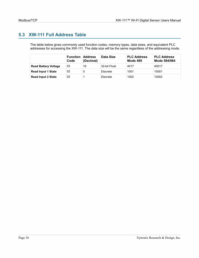
5.3 XW-111 Full Address Table
The table below gives commonly used function codes, memory types, data sizes, and equivalent PLC addresses for accessing the XW-111. The data size will be the same regardless of the addressing mode.
Function Code
Address (Decimal)
Data Size PLC AddressMode 485
PLC AddressMode 584/984
Read Battery Voltage 03 16 32-bit Float 4017 40017
Read Input 1 State 02 0 Discrete 1001 10001
Read Input 2 State 02 1 Discrete 1002 10002
Page 36 Xytronix Research & Design, Inc.

XW-111™ Wi-Fi Digital Sensor Users Manual Modbus/TCP
5.4 Read Holding Registers – Modbus Function Code 03 (0x03)
The Read Holding Registers function is used for the voltage status.
Request32-bit sensor values are read from 16-bit register pairs. Consequently, senors addresses and registers must be even numbers.
Vin Start Addresses
Start Address: 0x0010 (Vin)Input Quantity: 0x0002
Response32-bit floating-point values are returned, either as little-endian or big-endian numbers, depending on the configuration in the WiFi Networks tab.
With little-endian ordering, a voltage reading (0x0010) would return 0x00004040. The least significant word would be 0000 hex and the most significant word would be 4040. This hexadecimal value converts to a voltage reading of 3.0 Volts.
If a voltage reading is not available, a value of 0xFFFFFFFF (NaN) is returned.
ErrorsSensor Read Error Function Code (1 byte): 0x83Exception Codes (1 byte): 0x01 – Function not supported.
0x02 – Incorrect combination of start address and input quantity
Xytronix Research & Design, Inc. Page 37

Modbus/TCP XW-111™ Wi-Fi Digital Sensor Users Manual
5.5 Read Discrete Inputs – Modbus Function Code 02 (0x02)
This function returns the state of the digital inputs.
RequestThe sum of the starting address and the quantity of coils must not be greater than 0x0002. For example, if you want to read 0x0002, both inputs, then the start address must be 0x0000. To read the second input only the start address is 0x0001 with a quantity of 0x0001.
Input Start Addresses
Start Address: 0x0000 (Input 1) to 0x0001 (Input 2)Input Quantity: 0x0001 to 0x0002
ResponseThe inputs states are indicated by bits one and two of the status byte. A 1 indicates that the input is switched high ON. A 0 indicates that the input switched low OFF. Bit zero of the return value will be the state of the coil corresponding to the start address. For example, if a start address of 0x0001 is used, bit zero will be the status of input 2.
When reading all 4 inputs, the following table shows the bit positions.
Discrete Input State Byte
Bit 7 6 5 4 3 2 1 Bit 0
X X x x X X Input 2 Input 1
ErrorsInput Read Error Function Code (1 byte): 0x82Exception Codes (1 byte): 0x01 – Function not supported.
0x02 – Incorrect combination of start address and input quantity
Page 38 Xytronix Research & Design, Inc.

XW-111™ Wi-Fi Digital Sensor Users Manual Xytronix Compact Data (XCD) Format
Section 6: Xytronix Compact Data (XCD) FormatThe XW-111 sends data contained in a TCP/IP packet. To keep the packets small, and conserve battery power, they are not XML/HTTP.
XW-111 Digital Sensor Packet
Function Code MAC Address Salt Interval Battery Input status CRC (4C11DB7)
2 bytes 6 bytes 4 bytes 4 bytes 1 byte 1 byte status 4 bytes
Function Code
Indicates how the packet should be interpreted. If the MSb of the first byte is set, the packet is encrypted. If the 2nd MSb is set, the packet is a salt request. Both the encrypted and salt request bits should not be set at the same time.
Function Description Code
XW-111 Packet 0x0002
MAC Address
The MAC address used by the wireless interface, MSB first. This also matches the serial number of the device.
Salt
Random number requested from the master to be included in the information packet sent back to the master. This salt is included to prevent replay attacks to the master. Only used when using encryption.
Interval
Indicates the period of the transmissions in seconds.
Battery percentage
Indicated the estimated battery life remaining. The MSb, if set, indicates the device is being externally powered.
Input Status
Single byte to indicate the present status of the inputs. The LSb is input 1 with the next bit being input 2.
CRC
The CRC is computed over the entire packet minus the 4 bytes reserved for the CRC result. The CRC is computed using the 0x4C11DB7 polynomial and is included to make sure the packet has not been tempered with. CRC is only present when encryption is used.
Procedure
The XW-111 will send the packet as described above once the interval has expired. The CRC is not included in unencrypted packets and the salt field is not used.
Xytronix Research & Design, Inc. Page 39

Network Discovery XW-111™ Wi-Fi Digital Sensor Users Manual
Section 7: Network DiscoveryXW-111 has implemented a network discovery and provisioning protocol to aid in accessing the device. With this protocol, a user may connect the device to a network without knowing the IP address, search and identify the IP address, query basic information and if not yet configured send the desired network and remote services configurations. This feature can be utilized in the latest versions of the Android and iOS apps.
The network discovery protocol listens for specific requests on UDP port 65431 sent to the IP broadcast address 255.255.255.255. All requests must have the proper header and, when applicable, the correct MAC address. This header is the first 12 bytes of all messages and is simply the string 'ControlByWeb'.
Note: Due to resource constraints, the Network Discovery feature is not available when Modbus is enabled.
Header
C o n t r o l B y W e b
0x43 0x6f 0x6e 0x74 0x72 0x6f 0x6c 0x42 0x79 0x57 0x65 0x62
7.1 Initial Contact
The initial contact request is sent to discover ControlByWeb devices on the network. It is recommended to send this message multiple times in environments where many ControlByWeb devices are present due to potentially lost traffic where collisions occur as UDP does not guarantee deliver of packets.
Request:
Header (12 bytes) ASCII String ControlByWeb
Message ID (1 byte) Initial Contact Request 0x00
Response:
Header (12 bytes) ASCII String ControlByWeb
Message ID (1 byte) Initial Contact Response 0x01
MAC Address (6 bytes) Binary version 0x00 0x0c 0xc8 0x00 0x00 0x00
Device Info (2 bytes) Bit[15-7] Reserved 0b0
Bit 6 – Mode 0b0=Station, 0b1=AP
Bit 5 – Reserved 0b0
Bit 4 – Remote Services Status 0b0=Disconnected, 0b1=Connected
Bit 3 – DHCP Status 0b0=Waiting, 0b1=Success
Bit 2 – Remote Services Enabled 0b0=Disabled, 0b1=Enabled
Bit 1 – DHCP Enabled 0b0=Disabled, 0b1=Enabled
Bit 0 – Configuration Allowed 0b0=Not Allowed, 0b1=Allowed
Model Code (2 bytes) 0x0025=XW-111
IP Address (4 bytes) Network endianness 0xc0 0xa8 0x01 0x02 (192.168.1.2)
Page 40 Xytronix Research & Design, Inc.

XW-111™ Wi-Fi Digital Sensor Users Manual Network Discovery
7.2 Setup Information
The Setup Information request allows the device to receive IP network, remote services and WiFi network configuration data that it should use. Once this request is properly received, the device will apply the settings and reboot. There are two variants of this request, one has message ID 0x03 and the other has message ID 0x06. The only difference in these requests is message ID 0x06 includes fields for WiFi SSID, security and password.
Once the device has received this command or after the user has configured the device through the web-pages, this request will be ignored and will return an error. The only way to re-enable this request, is to reset the device to factory defaults, or re-associate the device to a WiFi network via WPS.
Request:
Header (12 bytes) ASCII String ControlByWeb
Message ID (1 byte) Setup Information request 0x03 -or- 0x06
MAC Address (6 bytes) Binary version 0x00 0x0c 0xc8 0x00 0x00 0x00
DHCP (1 byte) Enable DHCP 0x00=Disabled, 0x01=Enabled
Enable Remote Services (1 byte)
Enable Remote Services 0x00=Disabled, 0x01=Enabled
Token (32 bytes) ASCII String, no null terminator ''xxxxxxxxxxxxxxxxxxxxxxxxxxxxxxxx”
IP Address (4 bytes) Network endianness 0xc0 0xa8 0x01 0x02 (192.168.1.2)
Subnet (4 bytes) Network endianness 0xff 0xff 0xff 0x00 (255.255.255.0)
Gateway (4 bytes) Network endianness 0xc0 0xa8 0x01 0x01 (192.168.1.1)
Primary DNS (4 bytes) Network endianness 0x08 0x08 0x08 0x08 (8.8.8.8)
Alternate DNS (4 bytes) Not used by the XW-110-(Plus) 0x08 0x08 0x04 0x04 (8.8.4.4)
Remote Services Version (1 byte)
Specify protocol version 0x01=1.0, 0x02=2.0
Remote Services port number (1 byte)
Port Remote Services server is listening on (Network Endianness)
0x1f 0x40 (8000)
Remote Services Connection Interval (2 bytes)
Time in minutes between connection attempts and pushing state.xml
0x00 0x01 (1 minute)
Remote Services uses SSL (1 byte)
Only applicable to Remote Services Version 2.0
0x00=No SSL, 0x01=Use SSL
Certificate retrieval port number (2 bytes)
Port used to pass token information to retrieve certificates
0x01 0xbb (443)
Remote Services host Null terminated ASCII string devices.controlbyweb.cloud
Remote Services Connection String
Null terminated ASCII string
WiFi Security option (1 byte) Message ID 0x06 only 0x00=none, 0x01=WEP, 0x02=WPA(2)
SSID Null terminated ASCII string (message ID 0x06 only)
Password Null terminated ASCII string (message ID 0x06 only)
Xytronix Research & Design, Inc. Page 41

Network Discovery XW-111™ Wi-Fi Digital Sensor Users Manual
Successful Response:
Header (12 bytes) ASCII String ControlByWeb
Message ID (1 byte) Setup successful response 0x04
MAC Address (6 bytes) Binary version 0x00 0x0c 0xc8 0x00 0x00 0x00
Error Response:
Header (12 bytes) ASCII String ControlByWeb
Message ID (1 byte) Command not recognized response 0x05
MAC Address (6 bytes) Binary version 0x00 0x0c 0xc8 0x00 0x00 0x00
Page 42 Xytronix Research & Design, Inc.

XW-111™ Wi-Fi Digital Sensor Users Manual Appendix A: Specifications
Appendix A: SpecificationsWireless Specifications
Network Standards:IEEE 802.11b/g/nFrequency Band 2.412 – 2.462 GHzWi-Fi Security Standards Open, WEP, WPA, WPA2Network Settings: DHCP or StaticWireless Range Up to 250ft (typical for Wi-Fi devices) depends on environmentAntenna: Integral chip antenna, 1.9 dBi. RF Output Power (typ) 14dBM (802.11b/g), 12dBM (802.11n)
Operation
Provisioning: Via internal web server (no cables or PC utilities needed)Access Point: Yes, push button activated (setup via web page)WPS: Yes, push button activated (Wi-Fi Protected Setup)Connectivity: Intermittently connected or always connectedXCD Data Packet: TCP, 16 to 34 bytes (See Section 5.2: XCD Format)Remote Server: ControlByWeb's X-600™ or cloud-based serverRemote Relays: Control relays on other ControlByWeb™ productsPolling: state.xml (only when web-server is active)
Power
External: 5VDC ±10%, 500ma max (via DC power wall adapter)DC Jack: 5.5mm barrel x 2.5mm center pin (positive)Internal: Two replaceable 1.5V “AA” cellsPower Consumption: 27-770uA sleep, 59mA active RX, 229mA TX (at +12dBm)Battery Usage: Battery voltage is measured and periodically reported.Battery Life: Battery life is affected by model, mode, reporting interval, security,
DHCP, DNS, battery temperature and other variables.
XW-111: Intermittently connected, 2-min push interval via XCD, with encryption, no DHCP, no DNS: 140,000 transmissions.
XW-111: Always connected, 15-second push interval via XCD, with encryption, no DHCP, no DNS: 200,000 transmissions.
Internal Push Buttons
Button 1: Force access-point modeButton 2: Activate WPS mode
Sensor Inputs
Model XW-111: Two switch closure inputsVin Max = +3.3V, Internal pullup resistor = 200KVin HI = 2.8V (min), Vin LO =1.0V (max)Min pulse width (awake) = 30ms Min pulse width (asleep) = 100msMax cable length 20 ft (6m) (use relay isolation for longer runs)
Configuration
Switch Status Reports: Interval, on state change, or both Report Rate: User configurable
Xytronix Research & Design, Inc. Page 43

Appendix A: Specifications XW-111™ Wi-Fi Digital Sensor Users Manual
Email alerts
Email Alerts: Configurable Encrypted Email Alerts: Yes Switch Status Alerts: Input on, input off, or input change
Environmental
Location: Indoor use or NEMA-4 protected locationUsing Alkaline Batteries: -18ºC to 55ºC (0ºF to 130ºF)Operating Temperature: -40ºC to 65ºC (-40ºF to 150ºF)Storage Temperature: -40ºC to 85ºC (-40ºF to 185ºF)Humidity: 5-95%, non-condensing
Mechanical
Mounting: Wall mountMaterial Polycarbonate plasticSize: 3.16 x 3.04 x 0.93 in. [80 x 77 x 24mm]Weight: 2.4 oz [68g], no batteries
Certifications
FCC ID: 2AE4Z-XWD001FCC 47CFR15 (Class B)IEC CISPR 22, CISPR 24EN55024 ITE Immunity (2010)EN55022 Emissions (2010)IC: 21441-XWD001
Page 44 Xytronix Research & Design, Inc.

XW-111™ Wi-Fi Digital Sensor Users Manual Appendix B: Trademark and Copyright Information
Appendix B: Trademark and Copyright InformationThis document is Copyright ©2015-2017 by Xytronix Research & Design, Inc. All rights reserved.
XW-111™, WebRelay™, ControlByWeb™, and Xytronix Research & Design™ are trademarks of Xytronix Research & Design™, Inc. 2005-2017.
All other trademarks are the property of their respective owners.
All parts of this product and design including but not limited to firmware, hardware design, schematics, PCB layout, concept, graphics, users manual, etc., are property of Xytronix Research & Design, Inc. ©2005-2017. The XW-111™ may not be copied or reverse-engineered.
No part of this manual may be reproduced or transmitted in any form or by any means, electronic or mechanical, including photocopying or scanning, for any purpose other than the personal use by the purchaser of this product. Xytronix Research & Design, Inc., assumes no responsibility for any errors that may appear in this document.
Whereas reasonable effort has been made to make the information in this document as useful and accurate as possible, Xytronix Research & Design, Inc. assumes no responsibility for the application, usefulness, or completeness of the information contained herein. Under no circumstance will Xytronix Research & Design, Inc. be responsible or liable for any damages or losses including direct, indirect, special, incidental, or consequential damages or losses arising from either the use of any information contained within this manual or the use of any products or services referenced in this manual.
Xytronix Research & Design, Inc. reserves the right to change any product’s features, specifications, documentation, warranties, fee schedules, and conditions at any time and without notice.
Xytronix Research & Design, Inc. Page 45

Appendix C: Warranty XW-111™ Wi-Fi Digital Sensor Users Manual
Appendix C: WarrantyThis Xytronix Research & Design, Inc. product is warrantied against defects in material and workmanship for a period of five years from the date of shipment. During the warranty period, Xytronix Research & Design, Inc. will, at its option, either repair or replace products that prove to be defective. This warranty is extended to the original purchaser of the equipment only.
For warranty service or repair, customer must contact Xytronix Research & Design, Inc. technical support ([email protected]) and obtain a Return Authorization number (RA#). Before issuing an RA#, a support technician will work with customer to try to resolve the issue without returning the product. If technician determines that product must be returned for service an RA# will be issued. Next, the product must be properly packaged and returned to Xytronix Research & Design, Inc. with the RA# clearly marked on the package. The purchaser shall prepay all charges for shipping to Xytronix Research & Design, Inc. For warranty repairs of products less than one year old, Xytronix Research & Design, Inc. will pay the shipping charges to return the product to the purchaser as long as the product is shipped within the continental United States. If the product is shipped outside of the continental United States or the product was shipped more than one year earlier, the purchaser shall pay all shipping charges, duties, and taxes.
Limitation
The foregoing warranty shall not apply to defects or damage resulting from improper use or misuse, unauthorized repair, tampering, modification, improper connection, or operation outside the electrical/environmental specifications for the product. Further, the warranty does not cover Acts of God, such as fire, flood, hurricanes, and tornadoes. This warranty does not cover damage to property, equipment, direct, indirect, consequential, or incidental damage (including damage for loss of business profit, business interruption, loss of data, and the like) arising out of the use or misuse of this product.
UNDER NO CIRCUMSTANCES WILL THE LIABILITY OF XYTRONIX RESEARCH & DESIGN, INC. TO THE PURCHASER OR ANY OTHER PARTY EXCEED THE ORIGINAL PURCHASE PRICE OF THE PRODUCT, REGARDLESS OF THE FORM OF THE CLAIM. No other warranty is expressed or implied. Xytronix Research & Design, Inc. specifically disclaims the implied warranties or merchantability and fitness for a particular purpose. Some jurisdictions may not allow the exclusion of limitation of liability for consequential or incidental damage.
Page 46 Xytronix Research & Design, Inc.

XW-111™ Wi-Fi Digital Sensor Users Manual Appendix D: FCC Statement
Appendix D: FCC StatementThis device complies with Part 15 of the FCC Rules. Operation is subject to the following two conditions:
1. This device may not cause harmful interference.2. This device must accept any interference received, including interference that may cause
undesired operation.
Warning
This equipment has been tested and found to comply with the limits for a Class B digital device, pursuant to part 15 of the FCC Rules. These limits are designed to provide reasonable protection against harmful interference in a residential installation. This equipment generates, uses and can radiate radio frequency energy and, if not in-stalled and used in accordance with the instructions, may cause harmful interference to radio communications. However, there is no guarantee that interference will not occur in a particular installation. If this equipment does cause harmful interference to radio or television reception, which can be determined by turning the equipment off and on, the user is encouraged to try to correct the interference by one or more of the following measures:
- Reorient or relocate the receiving antenna.- Increase the separation between the equipment and receiver.- Connect the equipment into a relay on a circuit different from where the receiver is connected.- Consult the dealer or an experienced radio/TV technician for help.
Notice
Changes or modification not expressly approved by the party responsible for compliance could void the user’s authority to operate the equipment.
RF Exposure Information
This equipment complies with the FCC RF radiation exposure limits set forth for an uncontrolled environment. The antennas used with this transmitter must be installed to provide a separation distance of at least 20cm from all persons and must not be located or operating in conjunction with any other antenna or transmitter.
Canadian License-Exempt Radio Apparatus (RSS-GEN)
This device complies with Industry Canada license-exempt RSS standard(s). Operation is subject to the following two conditions: (1) this device may not cause interference, and (2) this device must accept any interference, including interference that may cause undesired operation of the device.
Le présent appareil est conforme aux CNR d'Industrie Canada applicables aux appareils radio exempts de licence. L'exploitation est autorisée aux deux conditions suivantes : (1) l'appareil ne doit pas produire de brouillage, et (2) l'utilisateur de l'appareil doit accepter tout brouillage radioélectrique subi, même si le brouillage est susceptible d'en compromettre le fonctionnement.
Xytronix Research & Design, Inc. Page 47

Appendix E: Mechanical Dimensions XW-111™ Wi-Fi Digital Sensor Users Manual
Appendix E: Mechanical Dimensions
Page 48 Xytronix Research & Design, Inc.