
Wi-Fi solution for a large campus
88
MD. SHAFIQUL ISLAM ID: 082 087 045 1 | Page Wi-Fi Solution for a Large Campus (BUET) Table of Contents Chapter 1: Introduction ................................................................................................................................ 3 1.1 About BASE Technologies Limited ...................................................................................................... 3 1.2 Background of Base Technologies Limited ......................................................................................... 5 1.3 Organizational Structure (Management Team) .................................................................................. 6 1.3.1 Technology Division: .................................................................................................................... 7 1.3.2 Marketing Division: ...................................................................................................................... 7 1.3.3 Communication Division: ............................................................................................................. 7 1.3.4 Finance Division: .......................................................................................................................... 8 1.3.5 Corporate Affairs Division: ........................................................................................................... 8 1.3.6 Human Resource Division: ........................................................................................................... 8 1.3.7 Internal Audit Division: ................................................................................................................ 8 Chapter 2: Executive Summary/Overview .................................................................................................... 9 2.1 Requirement ..................................................................................................................................... 10 2.2 Solution: ............................................................................................................................................ 11 2.3 About Aruba Networks ..................................................................................................................... 12 Chapter 3: Technical Overview.................................................................................................................... 13 3.1 High Level Diagram ........................................................................................................................... 14 3.2 Low Level Diagram: ........................................................................................................................... 15 3.3 Topology Implemented: .................................................................................................................... 16 3.4 Survey Images and Layouts ............................................................................................................... 17 3.5 About OSI Model ............................................................................................................................... 28 Chapter 4: Products Used ........................................................................................................................... 32 4.1 Aruba 7200 Series Mobility Controllers (WLC) ................................................................................. 32 4.1.1 Architected for High Availability ................................................................................................ 33 4.2 Aruba 175 Series Outdoor Access Points .......................................................................................... 34 4.3 Edge-Core Switch (ES3528M-PoE L2 Fast Ethernet Standalone PoE Switch) ................................... 35 4.4 Mikrotik Router BOARD 1100 ........................................................................................................... 37 4.5 Dell PowerEdge T110 II (DHCP Server) ............................................................................................. 38 Chapter 5: Technical Details ....................................................................................................................... 39
Transcript of Wi-Fi solution for a large campus

MD. SHAFIQUL ISLAM ID: 082 087 045
1 | P a g e W i - F i S o l u t i o n f o r a L a r g e C a m p u s ( B U E T )
Table of Contents
Chapter 1: Introduction ................................................................................................................................ 3
1.1 About BASE Technologies Limited ...................................................................................................... 3
1.2 Background of Base Technologies Limited ......................................................................................... 5
1.3 Organizational Structure (Management Team) .................................................................................. 6
1.3.1 Technology Division: .................................................................................................................... 7
1.3.2 Marketing Division: ...................................................................................................................... 7
1.3.3 Communication Division: ............................................................................................................. 7
1.3.4 Finance Division: .......................................................................................................................... 8
1.3.5 Corporate Affairs Division: ........................................................................................................... 8
1.3.6 Human Resource Division: ........................................................................................................... 8
1.3.7 Internal Audit Division: ................................................................................................................ 8
Chapter 2: Executive Summary/Overview .................................................................................................... 9
2.1 Requirement ..................................................................................................................................... 10
2.2 Solution: ............................................................................................................................................ 11
2.3 About Aruba Networks ..................................................................................................................... 12
Chapter 3: Technical Overview .................................................................................................................... 13
3.1 High Level Diagram ........................................................................................................................... 14
3.2 Low Level Diagram: ........................................................................................................................... 15
3.3 Topology Implemented: .................................................................................................................... 16
3.4 Survey Images and Layouts ............................................................................................................... 17
3.5 About OSI Model ............................................................................................................................... 28
Chapter 4: Products Used ........................................................................................................................... 32
4.1 Aruba 7200 Series Mobility Controllers (WLC) ................................................................................. 32
4.1.1 Architected for High Availability ................................................................................................ 33
4.2 Aruba 175 Series Outdoor Access Points .......................................................................................... 34
4.3 Edge-Core Switch (ES3528M-PoE L2 Fast Ethernet Standalone PoE Switch) ................................... 35
4.4 Mikrotik Router BOARD 1100 ........................................................................................................... 37
4.5 Dell PowerEdge T110 II (DHCP Server) ............................................................................................. 38
Chapter 5: Technical Details ....................................................................................................................... 39

MD. SHAFIQUL ISLAM ID: 082 087 045
2 | P a g e W i - F i S o l u t i o n f o r a L a r g e C a m p u s ( B U E T )
5.1 Aruba 7200 Series Mobility Controllers (WLC) ................................................................................. 39
5.1.1 WLC Configuration Screenshot .................................................................................................. 45
5.2 Edge-Core Switch (ES3528M-PoE L2 Fast Ethernet Standalone PoE Switch) ................................... 50
5.3 Mikrotik Router BOARD 1100 ........................................................................................................... 55
Specifications ...................................................................................................................................................................... 56
Description ........................................................................................................................................................................... 57
Description ........................................................................................................................................................................... 57
Example of Source NAT (Masquerading) ....................................................................................................................... 57
Installation ..................................................................................................................................................................................... 60
OSPF Network .................................................................................................................................................................... 61
OSPF_Main Router Setup ................................................................................................................................................ 61
5.4 Huawei Layer 3 switch Configuration ............................................................................................... 62
5.5 Configuration Huawei L2 switch (BUET) ........................................................................................... 72
5.6 Dell PowerEdge T110 II (DHCP Server) ............................................................................................. 75
Chapter 6: My Work Experience (overview) ............................................................................................... 84
Chapter 7: Conclusion ................................................................................................................................. 86
References: ................................................................................................................................................. 87

MD. SHAFIQUL ISLAM ID: 082 087 045
3 | P a g e W i - F i S o l u t i o n f o r a L a r g e C a m p u s ( B U E T )
Chapter 1: Introduction
1.1 About BASE Technologies Limited
BASE Technologies Limited is envisioned to be a leader in the IT and professional services industry. Our Goal is to ensure use
of IT more efficiently to improve operations and profitability, focus on core competencies and achieve business results such as
increased agility, innovation and top-line growth.
Our service offerings include cloud computing, software and platform as a service solutions; system design and
integration;
IT and business process outsourcing; applications software development, cyber security;
Web and application hosting, mission support, technical services and management consulting.
We are here to serve commercial clients, state and local governments. BASE delivers services through three broad
service lines or sectors: Public Sector (PS), Managed Services Sector (MSS) and Business Solutions and Services Sector
(BSS).
BASE Technologies Limited is the partner of following products –
Name BASE Technologies Limited
Address Hosna Center [5th
Floor], 106 Gulshan Avenue,
Dhaka – 1212, Bangladesh.
Telephone +88 02 9885319
Fax +88 02 9863381
E-Mail [email protected]

MD. SHAFIQUL ISLAM ID: 082 087 045
4 | P a g e W i - F i S o l u t i o n f o r a L a r g e C a m p u s ( B U E T )
BASE Group is one of the largest private sector industrial conglomerates in the country. It is engaged in
diverse business areas from Garments, Textiles, Oil & Gas, Paper manufacturing to Technology solutions.
Base tech offered services include Business Process Automation, Managed Services, Maintenance
Services, and Business Process Outsourcing. Base offer services for Telecoms, Banking Financial Services
& Insurances, Government & Defense, Small & Medium Businesses, and Enterprises.
Base provides backup power system to global communication, securing from malicious threats &
increasing productivity. Base offered solutions Include Network Security, Switching, Routing,
Virtualization, Data Centre, Virtualization, Storage, Platform, Unified Communication, IP Telephony,
Contact Centre, IP Surveillance, Audio & Video Collaboration, Battery backup, Rectifier, DC Ventilation
System, Uninterrupted Power Supply.
Supply, Installation and Commissioning of Station Power Equipment Battery and Rectifier is one of the
services of Base Technologies. The work of the company is to ensure the quality and provide the service
for Teletalk 3G. Base Tech will make sure that the Battery and Rectifiers are being correctly installed and
works perfectly without and any disruption. Base Tech previously has also worked with other big
Telecom and Information Technologies companies in Bangladesh such Banglalink Orascom, Robi Axiata,
Summit Communications Ltd, and others.

MD. SHAFIQUL ISLAM ID: 082 087 045
5 | P a g e W i - F i S o l u t i o n f o r a L a r g e C a m p u s ( B U E T )
1.2 Background of Base Technologies Limited BASE Group is one of the successful uprising industrial sectors in Bangladesh. Base started the
company with Base Textiles which later expanded to Garments, Oil & Gas, Paper Manufacturing to
Technology Solutions. The group comprises eight private limited companies of which one company is
under process to be a public limited company. The group currently employs 9,000+ personnel having
operation in Dhaka, Chittagong, Hong Kong, UK and Singapore. It has a business heritage of over 36
years.
Base Technologies Ltd. Initiated in May 2012 with a small yet dynamic team and rapidly
expanding. Envisioned to be a leader in the IT & Professional Services Industry, providing services and
solutions in the field of IT & Telecom services and solutions. It ensures efficient implementation of IT
focus on core competencies; achieve business optimizations, overall increased profitability.
Base Technologies Ltd. solutions & services are delivered through three broad sectors Public
Sector, Managed Services Sector, Business Solutions & Services Sector. Services & Solutions are
delivered over five different industries and meeting clients’ most complex challenges. It has not only
proved to be one of the most successful companies in recent days but has also managed to retain its
reputation throughout time. Base values the skills of an individual, thus also provide career
opportunities.

MD. SHAFIQUL ISLAM ID: 082 087 045
6 | P a g e W i - F i S o l u t i o n f o r a L a r g e C a m p u s ( B U E T )
1.3 Organizational Structure (Management Team)
Md. Hasan Shibli is the Managing Director of BASE Technologies Ltd. Responsible for overall
company vision and management, government relationship and top Corporate Head of the company. He
is the Top Management and Decision Making person in the company.
Md. Jubair Ahmed, Director has expertise: Solution design of Transmission, Data and Access
Network of the Telecom operators. He has extensive knowledge on DWDM, SDH -Transmission,
automation and cost reduction, call-center technology (ACD, IVR, CRM).
Md. Shafiul Islam, Director has expertise on large project management, automation & cost
reduction, has experience on GSM and CDMA Mobile Networks, Managed Services, critical SLA
handling.
Shahriar Husayn, Head of Sales has expertise on specialized skills in B2B technology in IT, ICT,
Mobile, OSS, BSS, IT Security solutions in Telecom Service Provider and Enterprise domain his key skills
include relationship development, Business & Channel Development, Strategic Partnership Building,
Forecasting & Market Analysis, Complex Negotiations & Sales Cycles.
Mohammed Moinoul Hossain Bhuiyan, Head of Technical Department has expertise on Network
& System Security, Risk Assessment, Business Impact Analysis, Data Integrity & Recovery, Disaster
Recovery Planning, Research & Development, Contingency Planning, Cost Benefits Analysis, and Project
Management Expertise.

MD. SHAFIQUL ISLAM ID: 082 087 045
7 | P a g e W i - F i S o l u t i o n f o r a L a r g e C a m p u s ( B U E T )
Kazi Amirul Islam, Head of Supply Chain Management has expertise on Supply Chain
Management & Inventory Management his key skills include extensive knowledge on Finance &
Accounts, Budget and Fund Management of Procurement, Foreign Payment Collection, as per BD Govt.
Rules and Regulations and Internal Audit.
Redwan Al Hameed, Head of Business Development has expertise on design development
process along with technical operation, project management, customer relationship skills has extensive
Knowledge in Fiber Optics, FTTH, GPON and project management.
The brief introduction of the divisions of Base Technologies is as follows:
1.3.1 Technology Division: This division works for enriching and building a strong network of telecommunication service of
Base Technologies. Technology division includes 5 units called Planning unit, Implementing unit,
Operation unit, Network quality & Performance unit and Network advancement unit. All these units are
working by introducing new technology and planning properly to establish a strong network and
implementing those plans in a structural way to successfully operate over the country with great
network quality, impressive performance and advancement of the networks.
1.3.2 Marketing Division: Marketing Division is under the direction of the Chief Executive Officer of the company. This
division works with a purpose to develop and promotion of the available and newly introduced product.
Marketing division does this by identifying the needs of the market by observing it with close attention,
gathering secondary data, various promotional activities by cost effective publicity and advertisement
that can be and can closely reachable to mass people. These are the key operations that are being
operated by Marketing Division. Customer Service is also a part of Marketing Division now days
1.3.3 Communication Division: The objective of this division is to ensure information and public relations activities within the
company and also outside the company.

MD. SHAFIQUL ISLAM ID: 082 087 045
8 | P a g e W i - F i S o l u t i o n f o r a L a r g e C a m p u s ( B U E T )
1.3.4 Finance Division: Finance division supports every department with financial back up. This division ensures that
finance and related management function existing within the company are always linked together and
also supportive to the company’s business objectives.
1.3.5 Corporate Affairs Division: Corporate Affairs Division ensures that the Regulatory and Corporate Affairs function within the
company is always aligned together and supports the business objectives. Ensuring a smooth relation
between company and Government and utilizing regulatory and legal instruments for the company is
also another objective of the Division. This total work is taken place under the supervision of the
Director of Corporate Affairs Division.
1.3.6 Human Resource Division: The departments that HR Division includes are, HR Operations, HR Development, Resourcing and
Employer Branding, Health, Safety and Environment and Administration. HR Division confirms upgraded
business performance and competitive advantage by offering right products and services to add value
and build organizational competences to meet strategic objectives.
1.3.7 Internal Audit Division: Internal Audit Department is to assist management to ensure proper internal control within the
company. It was established in view of the continued growth in operation. Internal Audit is the system of
reviewing the business controls of a corporate entity on behalf of its management

MD. SHAFIQUL ISLAM ID: 082 087 045
9 | P a g e W i - F i S o l u t i o n f o r a L a r g e C a m p u s ( B U E T )
Chapter 2: Executive Summary/Overview
Bangladesh University of Engineering and Technology, abbreviated as BUET, is one of the most prestigious institutions for higher studies in the country. About 5500 students are pursuing undergraduate and postgraduate studies in engineering, architecture, planning and science in this institution. At present, BUET has sixteen teaching departments under five faculties and it has three institutes. Every year the intake of undergraduate students is around 900, while the intake of graduate students in Masters and PhD programs is around 1000. A total of about five hundred teachers are teaching in these departments and institutes. There are additional teaching posts like Dr. Rashid Professor, Professor Emeritus and Supernumerary Professors. The BUET campus is in the heart of Dhaka – the capital city of Bangladesh. It has a compact campus with halls of residence within walking distances of the academic buildings. The physical expansion of the University over the last three decades has been impressive with construction of new academic buildings, auditorium complex, halls of residence, etc. BUET is the oldest institution for the study of Engineering and Architecture in Bangladesh. The history of this institution dates back to the days of Dhaka Survey School which was established at Nalgola, in Old Dhaka in 1876 to train Surveyors for the then Government of Bengal of British India. As the years passed, the Survey School became the Ahsanullah School of Engineering offering three-year diploma courses in Civil, Electrical and Mechanical Engineering. In recognition of the generous financial contribution from the then Nawab of Dhaka, it was named after his father Khawja Ahsanullah. It moved to its present premises in 1912. In 1947, the School was upgraded to Ahsanullah Engineering College as a Faculty of Engineering under the University of Dhaka, offering four-year bachelor’s courses in Civil, Electrical, Mechanical, Chemical and Metallurgical Engineering. In order to create facilities for postgraduate studies and research, Ahsanullah Engineering College was upgraded to the status of a University in 1962 and was named East Pakistan University of Engineering and Technology. After the war of Liberation in 1971, Bangladesh became an independent state and the university was renamed as the Bangladesh University of Engineering and Technology. Till today, it has produced around 25,000 graduates in different branches of engineering and architecture, and has established a good reputation all over the world for the quality of its graduates, many of whom have excelled in their profession in different parts of the globe. It was able to attract students from countries like India, Nepal, Iran, Jordan, Malaysia, Sri Lanka, Pakistan and Palestine. Both Undergraduate and Postgraduate studies and research are now among the primary functions of the University. Eleven departments under five faculties offer Bachelor Degrees, while most of the departments and institutes offer Masters Degrees and some of the departments have Ph.D. programs. In addition to its own research programs, the university undertakes research programs sponsored by outside organizations like European Union, UNO, Commonwealth, UGC, etc. The expertise of the University teachers and the laboratory facilities of the University are also utilized to solve problems and to provide up-to-date engineering and technological knowledge to the various organizations of the country.

MD. SHAFIQUL ISLAM ID: 082 087 045
10 | P a g e W i - F i S o l u t i o n f o r a L a r g e C a m p u s ( B U E T )
2.1 Requirement
Client Requirements:
• Supply, Installation, Configuration, Testing and Commissioning of Wi-Fi Internet Service in the Residential Halls of BUET on Turnkey basis, BUET, Dhaka.
• The Supplier will provide all the facilities required for supply, installation and integration of the proposed work. • The Supplier shall provide free comprehensive maintenance support for the entire system, including services, Spares and other support for 12 months from the date of completion of the work. • Operation and Maintenance Contact for 3 Years. Bidder must have to engage dedicated personnel for the operation and maintenance. • After installation and commissioning bidder must have to provide and operate internet
subscription package as bellow to the students including the following features:
SI Package Name Maximum download Limit Maximum usage time
1 Type A 4 GB 150 Hour/Month
2 Type B 10 GB 200 Hour/Month
• User must be authenticated before accessing the Wi-Fi network using standard mechanism such
as user ID and Password, MAC IP binding etc. Syslog server should be installed to record internet usage log. Any part of unused volume and use time will be elapsed in the next month.
• Non- Academic activated especially adult content should be restricted to save next generation. • Bidder must have to be capable to control user’s bandwidth if required. Bidder must
have to setup an operation, maintenance and monitoring center (Support Centre) within provided space by BUET to run operation, maintenance, monitoring and troubleshooting. Dedicated personnel (at least one of each category) as bellow have to stay at support centre 8 am to 10 pm on normal working day in two shifts (8am to 3 pm and 3 pm to 10 pm).

MD. SHAFIQUL ISLAM ID: 082 087 045
11 | P a g e W i - F i S o l u t i o n f o r a L a r g e C a m p u s ( B U E T )
2.2 Solution: The Access point is connected to POE Access Switch. The POE Access switch is connected to the
Distribution switch. The distribution switch is connected to the core switch. The core switch is in turn
connected to WLAN controller. The WLAN Controller manages light-weight access points in large
quantities by the network administrator or network operations center. The wireless LAN controller is
part of the Data Plane within the Cisco Wireless Model. The main features include:
Interference detection and avoidance: RF power and channel assignment will be adjusted to the
planned network infrastructure.
• Load balancing: Disabled by default, high-speed load balancing can be used to connect a user to
Multiple access points for better coverage and data rates.
• Coverage whole detection and correction: Part of the RF management is the ability to handle
power levels. Power can be increased to cover holes or reduced to protect against cell
overlapping
The Cisco Wireless Controller supports Application Visibility and Control (AVC), the technology
that includes the Network-Based Application Recognition 2 (NBAR-2) engine, Cisco's deep
packet inspection (DPI) capability. The NBAR-2 engine can classify applications, applies quality of
service (QoS) setting to either drop or mark the traffic, and prioritizes business-critical
applications in the network. AVC uses Net Flow Version 9 to export the flows. The 5508 also
supports Bonjour Services Directory to enable Bonjour Services to be advertised and utilized in a
separate Layer 3 network.
Wireless LAN controller has the option of implementing Trusted AP policies. This is a security
feature in the controller that is designed to be used in scenarios where customers have a
parallel autonomous AP network along with the controller. In that scenario, the autonomous AP
can be marked as the trusted AP on the controller, and the user can define policies for these
trusted APs (which should use only WEP or WPA, our own SSID, short preamble, and so on). If
any of these AP fails to meet these policies, the controller raises an alarm to the network
management device (Wireless Control System) that states a trusted AP violated a configured
policy.
APs that are not part of your wireless deployment are called rogue APs. It can be either an
autonomous AP or Lightweight AP that happens to be in the range of authorized APs. Rogue APs
cannot be automatically blocked. This must be done manually. The reason for this is that, when
a rogue AP is found, the finding AP disassociates the clients of the rogue AP, which causes denial
of service to the clients. This can cause legal issues if the AP of the neighbor is detected as a
rogue, and its clients are denied service. Wireless LAN controller supports more than 700
rogues, which includes acknowledged rogues.

MD. SHAFIQUL ISLAM ID: 082 087 045
12 | P a g e W i - F i S o l u t i o n f o r a L a r g e C a m p u s ( B U E T )
2.3 About Aruba Networks
Founded in 2002, Aruba Networks is the leading provider of next-generation access
management, network infrastructure and mobility application solutions for mobile
enterprise networks.
The company’s Mobile Virtual Enterprise (MOVE) architecture unifies these three core areas
into one cohesive and manageable system that strengthens security and dramatically simplifies
bring-your-own-device implementations.
MOVE is software-defined so it easily adapts to the dynamics of mobility. This enables IT to
manage traffic flows on any wired, wireless and remote network and control how devices and
work applications are used – without upgrading or reconfiguring existing networks.
Whether away or at work, MOVE gives users consistent, secure access to the appropriate
corporate resources based on who they are, where they are and what device they’re using.
The result is a rightsized network infrastructure that saves IT time, reduces capital and
operating expenses, speeds-up service delivery, and provides every user with the highest-
quality mobility experience.
Headquartered in Sunnyvale, California, Aruba has offices throughout the Americas, Asia-
Pacific/Japan and Europe/Middle East/Africa regions. Aruba is listed on the NASDAQ and
Russell 2000® Index.
Name Aruba Networks.
Head Quarter Address
1344 Crossman Ave.
Sunnyvale, CA 94089-1113
Telephone Phone: +1-408-227-4500
Fax Fax: +1-408-752-0626
Website: http://www.arubanetworks.com

MD. SHAFIQUL ISLAM ID: 082 087 045
13 | P a g e W i - F i S o l u t i o n f o r a L a r g e C a m p u s ( B U E T )
Chapter 3: Technical Overview
The overall high level diagram consists of the following features:
(i)Offers Hierarchy where each layer has specific role
(ii)Modular topology –building blocks
(iii)Easy to grow , understand and troubleshoot
(iv)Creates small fault domains. Clear demarcations and isolation
(v)Promotes load balancing and redundancy
(vi)Promotes deterministic traffic patterns
(vii) Incorporates balance of both layer 2 and layer 3 technology ,leveraging the strength of both
(viii)Utilizes Layer 3 Routing for load balancing ,fast convergence scalability and control

MD. SHAFIQUL ISLAM ID: 082 087 045
14 | P a g e W i - F i S o l u t i o n f o r a L a r g e C a m p u s ( B U E T )
3.1 High Level Diagram
Figure 1: Proposed Wireless Network Solution Block Diagram for BUET Student's Hall

MD. SHAFIQUL ISLAM ID: 082 087 045
15 | P a g e W i - F i S o l u t i o n f o r a L a r g e C a m p u s ( B U E T )
3.2 Low Level Diagram:
Figure 2: Wireless Solution to the end users

MD. SHAFIQUL ISLAM ID: 082 087 045
16 | P a g e W i - F i S o l u t i o n f o r a L a r g e C a m p u s ( B U E T )
3.3 Topology Implemented:
Figure 3: Network Topology of single Hall Implementation.

MD. SHAFIQUL ISLAM ID: 082 087 045
17 | P a g e W i - F i S o l u t i o n f o r a L a r g e C a m p u s ( B U E T )
3.4 Survey Images and Layouts
Ahsanullah Hall

MD. SHAFIQUL ISLAM ID: 082 087 045
18 | P a g e W i - F i S o l u t i o n f o r a L a r g e C a m p u s ( B U E T )

MD. SHAFIQUL ISLAM ID: 082 087 045
19 | P a g e W i - F i S o l u t i o n f o r a L a r g e C a m p u s ( B U E T )

MD. SHAFIQUL ISLAM ID: 082 087 045
20 | P a g e W i - F i S o l u t i o n f o r a L a r g e C a m p u s ( B U E T )

MD. SHAFIQUL ISLAM ID: 082 087 045
21 | P a g e W i - F i S o l u t i o n f o r a L a r g e C a m p u s ( B U E T )
Kazi Nazrul Islam Hall

MD. SHAFIQUL ISLAM ID: 082 087 045
22 | P a g e W i - F i S o l u t i o n f o r a L a r g e C a m p u s ( B U E T )
Shahid Smrity Hall

MD. SHAFIQUL ISLAM ID: 082 087 045
23 | P a g e W i - F i S o l u t i o n f o r a L a r g e C a m p u s ( B U E T )
Dr. M A Rashid Hall

MD. SHAFIQUL ISLAM ID: 082 087 045
24 | P a g e W i - F i S o l u t i o n f o r a L a r g e C a m p u s ( B U E T )
Shaheed Sarwardi Hall

MD. SHAFIQUL ISLAM ID: 082 087 045
25 | P a g e W i - F i S o l u t i o n f o r a L a r g e C a m p u s ( B U E T )
Chattri Hall

MD. SHAFIQUL ISLAM ID: 082 087 045
26 | P a g e W i - F i S o l u t i o n f o r a L a r g e C a m p u s ( B U E T )
Sher-E-Bangla Hall

MD. SHAFIQUL ISLAM ID: 082 087 045
27 | P a g e W i - F i S o l u t i o n f o r a L a r g e C a m p u s ( B U E T )
Titumir Hall
*Calculation of Access points of each hall and parameters are shown details in
reference [11], [12], [13] and [14]

MD. SHAFIQUL ISLAM ID: 082 087 045
28 | P a g e W i - F i S o l u t i o n f o r a L a r g e C a m p u s ( B U E T )
3.5 About OSI Model
The Open Systems Interconnection model (OSI) is a conceptual model that characterizes and
standardizes the internal functions of a communication system by partitioning it into abstraction
layers. The model is a product of the Interconnection project at the International Organization for
Standardization (ISO), maintained by the identification ISO/IEC 7498-1.
The model group’s communication functions into seven logical layers. A layer serves the layer above
it and is served by the layer below it. For example, a layer that provides error-free communications
across a network provides the path needed by applications above it, while it calls the next lower
layer to send and receive packets that make up the contents of that path. Two instances at one layer
are connected by a horizontal connection on that layer.
There are seven layers in OSI model:
1. Physical Layer
2. Data link Layer
3. Network Layer
4. Transport Layer
5. Session
6. Presentation Layer &
7. Application Layer
PHYSICAL LAYER
The physical layer, the lowest layer of the OSI model, is concerned with the transmission and reception of the unstructured raw bit stream over a physical medium. It describes the electrical/optical, mechanical, and functional interfaces to the physical medium, and carries the signals for all of the higher layers. It provides:
Data encoding: modifies the simple digital signal pattern (1s and 0s) used by the PC to better accommodate the characteristics of the physical medium, and to aid in bit and frame synchronization. It determines:
o What signal state represents a binary 1 o How the receiving station knows when a "bit-time" starts o How the receiving station delimits a frame
Physical medium attachment, accommodating various possibilities in the medium:
o Will an external transceiver (MAU) be used to connect to the medium? o How many pins do the connectors have and what is each pin used for?
Transmission technique: determines whether the encoded bits will be transmitted by baseband (digital) or broadband (analog) signaling.

MD. SHAFIQUL ISLAM ID: 082 087 045
29 | P a g e W i - F i S o l u t i o n f o r a L a r g e C a m p u s ( B U E T )
Physical medium transmission: transmits bits as electrical or optical signals appropriate for the physical medium, and determines:
o What physical medium options can be used o How many volts/db should be used to represent a given signal state, using a given physical
medium
DATA LINK LAYER
The data link layer provides error-free transfer of data frames from one node to another over the physical layer, allowing layers above it to assume virtually error-free transmission over the link. To do this, the data link layer provides:
Link establishment and termination: establishes and terminates the logical link between two nodes.
Frame traffic control: tells the transmitting node to "back-off" when no frame buffers are available.
Frame sequencing: transmits/receives frames sequentially.
Frame acknowledgment: provides/expects frame acknowledgments. Detects and recovers from errors that occur in the physical layer by retransmitting non-acknowledged frames and handling duplicate frame receipt.
Frame delimiting: creates and recognizes frame boundaries.
Frame error checking: checks received frames for integrity.
Media access management: determines when the node "has the right" to use the physical medium.
NETWORK LAYER
The network layer controls the operation of the subnet, deciding which physical path the data should take based on network conditions, priority of service, and other factors. It provides:
Routing: routes frames among networks.
Subnet traffic control: routers (network layer intermediate systems) can instruct a sending station to "throttle back" its frame transmission when the router's buffer fills up.
Frame fragmentation: if it determines that a downstream router's maximum transmission unit (MTU) size is less than the frame size, a router can fragment a frame for transmission and re-assembly at the destination station.
Logical-physical address mapping: translates logical addresses, or names, into physical addresses.
Subnet usage accounting: has accounting functions to keep track of frames forwarded by subnet intermediate systems, to produce billing information.

MD. SHAFIQUL ISLAM ID: 082 087 045
30 | P a g e W i - F i S o l u t i o n f o r a L a r g e C a m p u s ( B U E T )
TRANSPORT LAYER
The transport layer ensures that messages are delivered error-free, in sequence, and with no losses or duplications. It relieves the higher layer protocols from any concern with the transfer of data between them and their peers. The size and complexity of a transport protocol depends on the type of service it can get from the network layer. For a reliable network layer with virtual circuit capability, a minimal transport layer is required. If the network layer is unreliable and/or only supports datagrams, the transport protocol should include extensive error detection and recovery. The transport layer provides:
Message segmentation: accepts a message from the (session) layer above it, splits the message into smaller units (if not already small enough), and passes the smaller units down to the network layer. The transport layer at the destination station reassembles the message.
Message acknowledgment: provides reliable end-to-end message delivery with acknowledgments.
Message traffic control: tells the transmitting station to "back-off" when no message buffers are available.
Session multiplexing: multiplexes several message streams, or sessions onto one logical link and keeps track of which messages belong to which sessions (see session layer).
SESSION LAYER
The session layer allows session establishment between processes running on different stations. It
provides:
Session establishment, maintenance and termination: allows two application processes on
different machines to establish, use and terminate a connection, called a session.
Session support: performs the functions that allow these processes to communicate over the
network, performing security, name recognition, logging, and so on.
PRESENTATION LAYER
The presentation layer formats the data to be presented to the application layer. It can be viewed as the
translator for the network. This layer may translate data from a format used by the application layer into a
common format at the sending station, then translate the common format to a format known to the
application layer at the receiving station.
The presentation layer provides:
Character code translation: for example, ASCII to EBCDIC.
Data conversion: bit order, CR-CR/LF, integer-floating point, and so on.
Data compression: reduces the number of bits that need to be transmitted on the network.
Data encryption: encrypt data for security purposes. For example, password encryption.

MD. SHAFIQUL ISLAM ID: 082 087 045
31 | P a g e W i - F i S o l u t i o n f o r a L a r g e C a m p u s ( B U E T )
APPLICATION LAYER
The application layer serves as the window for users and application processes to access network
services. This layer contains a variety of commonly needed functions:
Resource sharing and device redirection
Remote file access
Remote printer access
Inter-process communication
Network management
Directory services
Electronic messaging (such as mail)
Network virtual terminals

MD. SHAFIQUL ISLAM ID: 082 087 045
32 | P a g e W i - F i S o l u t i o n f o r a L a r g e C a m p u s ( B U E T )
Chapter 4: Products Used
4.1 Aruba 7200 Series Mobility Controllers (WLC)
The Aruba 7200 series Mobility Controller is the next-generation networking platform, optimized for mobile application delivery to ensure the best mobility experience over Wi-Fi. With a new central processor that employs eight cores with four threads each, it’s like having a total of 32 virtual CPUs. As a result, The 7200 series supports 32,000 mobile devices and performs stateful firewall policy enforcement at 40 Gbps – plenty of capacity and speed for BYOD and 802.11ac devices. New levels of visibility are provided by Aruba’s unique AppRF technology, which runs on 7200 series Mobility Controllers. With AppRF, IT can see applications by user, including top web-based applications like Facebook and Box. The 7200 series also manages authentication, encryption, VPN connections, IPv4 and IPv6 Layer 3 services, the Aruba Policy Enforcement Firewall™, Aruba Adaptive Radio Management™, and Aruba RF Protect™ spectrum analysis and wireless intrusion protection. Clustering and centralized management enable the deployment of large networks with hundreds of Mobility Controllers with minimal staff. A master Mobility Controller can manage local Mobility Controllers, while Aruba AirWave™ network management provides enterprise-wide clarity and control through real-time monitoring, historical reporting and troubleshooting.

MD. SHAFIQUL ISLAM ID: 082 087 045
33 | P a g e W i - F i S o l u t i o n f o r a L a r g e C a m p u s ( B U E T )
4.1.1 Architected for High Availability
The 7200 series includes a number of features that make it ideal for deployment in customer locations that require maximum availability: • Redundant power supplies: The 7200 series supports dual, field replaceable redundant power supplies to maintain uninterrupted network operations. • Hot-swappable fan tray with multiple fans: The 7200 series includes a field replaceable fan tray with multiple fans, providing sufficient cooling and rapid time to repair. • Solid state drives for maximum reliability and uptime. • Two dual-media ports: 1000BASE-X or 10/100/1000BASE-T connections for high availability.
Front View
Back view *Details Reference [3] and [4]

MD. SHAFIQUL ISLAM ID: 082 087 045
34 | P a g e W i - F i S o l u t i o n f o r a L a r g e C a m p u s ( B U E T )
4.2 Aruba 175 Series Outdoor Access Points
Multifunctional 175 series outdoor wireless access points (APs) deliver enterprise-grade Wi-Fi to high-density client environments in campuses, storage yards, warehouses, container and transportation facilities, extreme industrial production areas and other harsh environments.
These high-performance 802.11n outdoor APs deliver wireless data rates up to 300 Mbps per radio and ensure peak performance by utilizing channel bonding, block acknowledgement and MIMO radios. Advanced antenna technology also increases RF signal range and reliability. Able to survive in harsh outdoor environments, 175 series APs withstand exposure to high and low temperatures, persistent moisture and precipitation.
*Details Reference [2]
MD. SHAFIQUL ISLAM ID: 082 087 045
35 | P a g e W i - F i S o l u t i o n f o r a L a r g e C a m p u s ( B U E T )
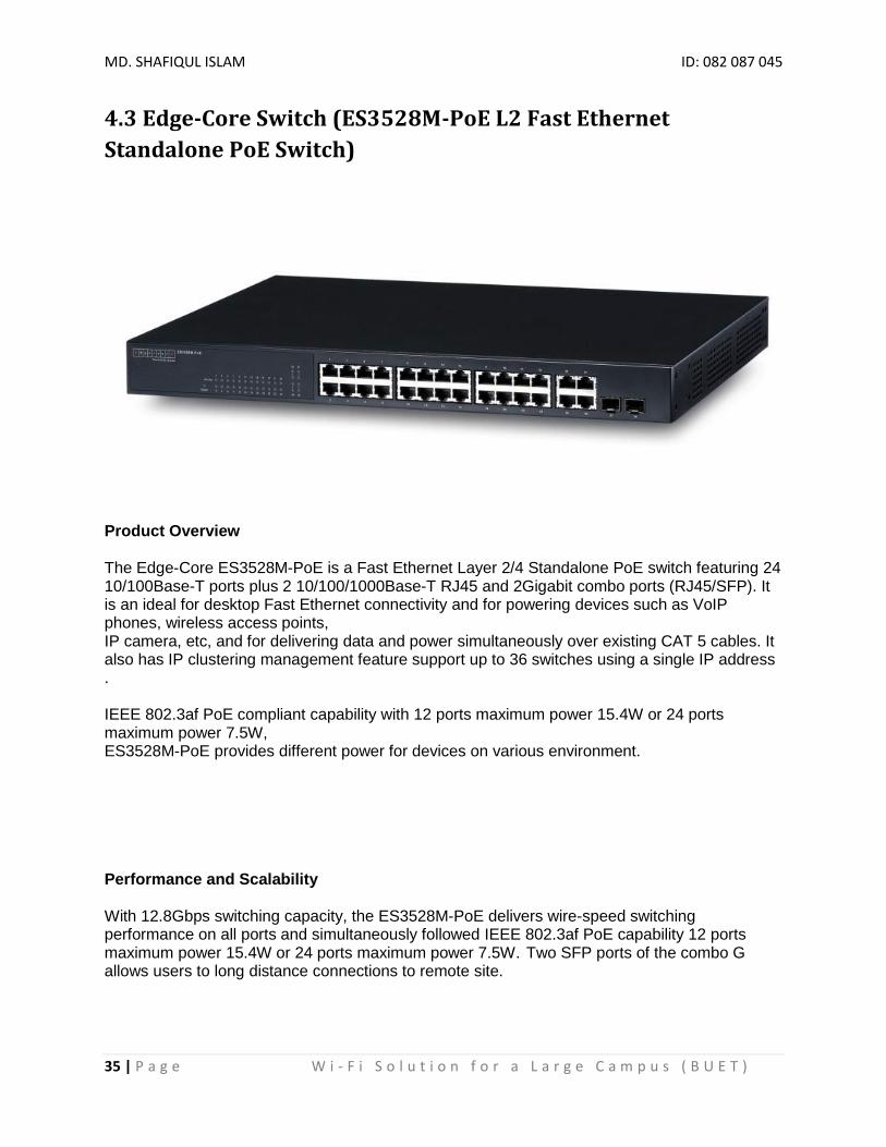
4.3 Edge-Core Switch (ES3528M-PoE L2 Fast Ethernet
Standalone PoE Switch)
Product Overview The Edge-Core ES3528M-PoE is a Fast Ethernet Layer 2/4 Standalone PoE switch featuring 24 10/100Base-T ports plus 2 10/100/1000Base-T RJ45 and 2Gigabit combo ports (RJ45/SFP). It is an ideal for desktop Fast Ethernet connectivity and for powering devices such as VoIP phones, wireless access points, IP camera, etc, and for delivering data and power simultaneously over existing CAT 5 cables. It also has IP clustering management feature support up to 36 switches using a single IP address . IEEE 802.3af PoE compliant capability with 12 ports maximum power 15.4W or 24 ports maximum power 7.5W, ES3528M-PoE provides different power for devices on various environment. Performance and Scalability With 12.8Gbps switching capacity, the ES3528M-PoE delivers wire-speed switching performance on all ports and simultaneously followed IEEE 802.3af PoE capability 12 ports maximum power 15.4W or 24 ports maximum power 7.5W. Two SFP ports of the combo G allows users to long distance connections to remote site.

MD. SHAFIQUL ISLAM ID: 082 087 045
36 | P a g e W i - F i S o l u t i o n f o r a L a r g e C a m p u s ( B U E T )
Continuous Availability IEEE 802.1w Rapid Spanning Tree Protocol provides a loop-free network and redundant links to core networks with rapid convergence to ensure faster recovery from failed links, enhancing overall network stability and reliability. IEEE 802.3ad Link Aggregation Control Protocol (LACP) increases bandwidth by automatically aggregating several physical links together as a logical trunk and provides load balancing and fault tolerance for uplink connection. IGMP snooping prevents flooding of IP multicast traffic and limits bandwidth intensive video traffic to only the subscribers Comprehensive QoS Up to 8 aggregation groups are supported, and up to 8 ports per group. Traffic is prioritized according to 802.1p, DSCP, IP precedence and TCP/UDP port number, L2/3/4 ACL (Access Control List) giving optimal performance to real-time applications such as voice and video. Asymmetric bidirectional rate-limiting, per port or per traffic class, preserves network bandwidth and allowing maximum control of network resources.
Front view
Back view
*Details reference [5] and [6]

MD. SHAFIQUL ISLAM ID: 082 087 045
37 | P a g e W i - F i S o l u t i o n f o r a L a r g e C a m p u s ( B U E T )
4.4 Mikrotik Router BOARD 1100
The RB1100 is a rack mount router with 13 Gigabit Ethernet ports, serial port and PoE support. Two of the ports provide bypass functionality. There are two models, a single core 1066MHz PPC processor (RB1100AH), or with a dual core 1066MHz PPC processor with hardware encryption support (RB1100AHx2). The RB1100 device comes preinstalled with RouterOS and is ready to use. RB1100 is compatible with RouterOS v5 and newer, if your device comes preinstalled with an earlier version, please upgrade before using it: http://wiki.mikrotik.com/wiki/Manual:Upgrading_RouterOS
en the case and install a microSD card into the provided slot, for additional storage
*Details Reference [1] and [7]

MD. SHAFIQUL ISLAM ID: 082 087 045
38 | P a g e W i - F i S o l u t i o n f o r a L a r g e C a m p u s ( B U E T )
4.5 Dell PowerEdge T110 II (DHCP Server)
The Dell™ PowerEdge™ T110 II is an ideal first server for small businesses with the right combination of value, reliability, collaboration and data protection features to improve your business continuity and productivity. The PowerEdge T110 II was designed to meet the needs of your small business environment—customizable with your choice of hard drives for important data, RAID options for added data protection and basic systems management for easy system monitoring. The PowerEdge T110 II provides you with the performance and features you need so you can focus on running your business.
*Details Reference [8], [9] and [10]

MD. SHAFIQUL ISLAM ID: 082 087 045
39 | P a g e W i - F i S o l u t i o n f o r a L a r g e C a m p u s ( B U E T )
Chapter 5: Technical Details
5.1 Aruba 7200 Series Mobility Controllers (WLC)
The Aruba Mobility Controller is the heart of the Aruba dependent access point (AP) WLAN architecture. The mobility controller is responsible for many of the operations that traditionally would be handled by an autonomous AP, and it delivers additional functionality for control, security, operation, and troubleshooting.
Policy configuration: Configuration in the Aruba solution is split between policy and local configurations. Local configuration relates to physical interfaces, IP networking, and VLANs, which are different for each mobility controller. Policy configuration is centered on the operation of APs and users, including AP settings such as the SSID name, encryption, regulatory domain, channel, power, and ARM settings. Policy configuration extends beyond APs and also covers user authentication, firewall policy, mobility domains (IP mobility), IPsec, and system management. The policy is pushed to all locals in the form of profiles, and profiles combine to create the configuration for the dependent APs. Via the CLI
By default, only SSH (Secure SHell) access to the switch (mobility controller) is permitted. 1. From a management system that has network connectivity to the switch, connect to the switch using SSH: ssh admin@<switch IP address> 2.Enter the admin password at the password prompt. 3.Type enable at the > prompt to enter the enable mode. 4.Type the enable password when prompted for a password. Via the Web interface
Once the connectivity to the switch is verified, open a Web browser and enter the switch’s IP address in the navigator bar. The switch can be accessed using http, http://<switch IP Address> or https, https://<switch IP Address>:4343. On power-up, the user is presented with the startup wizard:

MD. SHAFIQUL ISLAM ID: 082 087 045
40 | P a g e W i - F i S o l u t i o n f o r a L a r g e C a m p u s ( B U E T )
Enter System name [Aruba800]: Aruba Enter VLAN 1 interface IP address [172.16.0.254]: Enter VLAN 1 interface subnet mask [255.255.255.0]: Enter IP Default gateway [none]: Enter Switch Role, (master|local) [master]: master Enter Country code (ISO-3166), <ctrl-I> for supported list: US You have chosen Country code US for United States (yes|no)?: yes Enter Password for admin login (up to 32 chars): admin Re-type Password for admin login: admin Enter Password for enable mode (up to 15 chars): enable Re-type Password for enable mode: enable Do you wish to shutdown all the ports (yes|no)? [no]: no Current choices are: System name: Aruba VLAN 1 interface IP address: 172.16.0.254 VLAN 1 interface subnet mask: 255.255.255.0 IP Default gateway: none Switch Role: master Country code: US Ports shutdown: no If you accept the changes the switch will restart! Type <ctrl-P> to go back and change answer for any question. Do you wish to accept the changes (yes|no)yes . . . . . <<<<< Welcome to Aruba Wireless Networks - Aruba 800 >>>>> . . . . (Aruba)

MD. SHAFIQUL ISLAM ID: 082 087 045
41 | P a g e W i - F i S o l u t i o n f o r a L a r g e C a m p u s ( B U E T )
Initial Setup Before starting, please ensure that the Policy Enforcement Firewall module license is enabled on the Aruba mobility controller. Please contact Aruba Networks for licenses and installation information. On power-up, the user is presented with the startup wizard: Enter System name [Aruba800]: Aruba Enter VLAN 1 interface IP address [172.16.0.254]: Enter VLAN 1 interface subnet mask [255.255.255.0]: Enter IP Default gateway [none]: Enter Switch Role, (master|local) [master]: master Enter Country code (ISO-3166), <ctrl-I> for supported list: US You have chosen Country code US for United States (yes|no)?: yes Enter Password for admin login (up to 32 chars): admin Re-type Password for admin login: admin Enter Password for enable mode (up to 15 chars): enable Re-type Password for enable mode: enable Do you wish to shutdown all the ports (yes|no)? [no]: no Current choices are: System name: Aruba VLAN 1 interface IP address: 172.16.0.254 VLAN 1 interface subnet mask: 255.255.255.0 IP Default gateway: none Switch Role: master Country code: US Ports shutdown: no If you accept the changes the switch will restart! Type <ctrl-P> to go back and change answer for any question. Do you wish to accept the changes (yes|no)yes . . . . . <<<<< Welcome to Aruba Wireless Networks - Aruba 800 >>>>> . . . . (Aruba) User:

MD. SHAFIQUL ISLAM ID: 082 087 045
42 | P a g e W i - F i S o l u t i o n f o r a L a r g e C a m p u s ( B U E T )
Assigning an IP to the Mobility Controller 1. Connect to the switch via the CLI. 2. Login with the configured username and password, admin /admin in this example. 3. Type enable at the > prompt. 4. Type the enable password, enable in this example. 5. Type configure terminal at the # prompt. 6. Create the vlan for the voice (vlan 25) using the vlan command: (Aruba) (config) # vlan 25 7. Create the vlan interface. (Aruba) (config) # interface vlan 25 8. Assign the IP address to the interface. (Aruba) (config-subif)# ip address 10.168.10.2 255.255.255.0 9. Create the loopback interface and assign an IP address to the loopback. For more information about the loopback interface refer to the user guide. (Aruba) (config) # interface loopback (Aruba) (config-loop)# ip address 10.168.10.1 Switch IP Address is Modified. Switch should be rebooted now (Aruba) (config-loop)#! (Aruba) (config) #ip default-gateway 10.168.10.10 10. Assign a physical interface to the vlan. In this example, the interface connecting to the network is a trunk interface. Configure the mode on the interface to a trunk mode. (Aruba) (config) # interface fastethernet 1/0 (Aruba) (config-if)# trusted (Aruba) (config-if)# no shutdown (Aruba) (config-if)# switchport mode trunk (Aruba) (config-if)# switchport trunk allowed vlan add 10,25 (Aruba) (config-if)#! (Aruba) (config)# 11. Ping the default gateway from the switch’s console. 12. Ping the switch’s IP address from the management station.
SSID Configuration CLI command configuration APs can be configured using the CLI or the Web interface. Each AP is identified by a unique location code. The APs can either be configured per location with unique settings using the AP’s unique location code or globally using the wildcard location. “0” is used as the wildcard. Example: ap location 0.0.0 will configure all Aruba APs on the WLAN system. Both the Aruba APs and the Spectralink handsets support the 802.11a and the 802.11b/g radios. To apply the SSID to both bands configure the SSID as follows: configure terminal

MD. SHAFIQUL ISLAM ID: 082 087 045
43 | P a g e W i - F i S o l u t i o n f o r a L a r g e C a m p u s ( B U E T )
ap location x.y.z virtual-ap aruba vlan-id 26 opmode wpa2-aes-psk wpa-passphrasethisisthekey dtim-period3 If the voice network needs to exist only in the 802.11a band, configure the virtual AP under the 802.11a settings on the controller. configure terminal ap location x.y.z phy-type a virtual-ap aruba vlan-id 26 opmode wpa2-aes-psk wpa-passphrase thisisthekey dtim-period 3 If the voice network needs to exist only in the 802.11g band , configure the virtual AP under the 802.11a settings on the controller. configure terminal ap location x.y.z phy-type g virtual-ap aruba vlan-id 26 opmode wpa2-aes-psk wpa-passphrase thisisthekey dtim-period 3 To save changes, enter: write mem

MD. SHAFIQUL ISLAM ID: 082 087 045
44 | P a g e W i - F i S o l u t i o n f o r a L a r g e C a m p u s ( B U E T )
AP configuration

MD. SHAFIQUL ISLAM ID: 082 087 045
45 | P a g e W i - F i S o l u t i o n f o r a L a r g e C a m p u s ( B U E T )
5.1.1 WLC Configuration Screenshot

MD. SHAFIQUL ISLAM ID: 082 087 045
46 | P a g e W i - F i S o l u t i o n f o r a L a r g e C a m p u s ( B U E T )

MD. SHAFIQUL ISLAM ID: 082 087 045
47 | P a g e W i - F i S o l u t i o n f o r a L a r g e C a m p u s ( B U E T )

MD. SHAFIQUL ISLAM ID: 082 087 045
48 | P a g e W i - F i S o l u t i o n f o r a L a r g e C a m p u s ( B U E T )

MD. SHAFIQUL ISLAM ID: 082 087 045
49 | P a g e W i - F i S o l u t i o n f o r a L a r g e C a m p u s ( B U E T )
MD. SHAFIQUL ISLAM ID: 082 087 045
50 | P a g e W i - F i S o l u t i o n f o r a L a r g e C a m p u s ( B U E T )
5.2 Edge-Core Switch (ES3528M-PoE L2 Fast Ethernet
Standalone PoE Switch)
For switch configuration we use software name putty. All configuration command is done by in CLI mode.
#config
#vlan database
#vlan 1 media ethernet state active
#config
#vlan database
#vlan 10 media ethernet state active
#config
#vlan database
#vlan 11 media ethernet state active
#config
#vlan database
#vlan 12 media ethernet state active
#config
#vlan database
#vlan 13 media ethernet state active
#config

MD. SHAFIQUL ISLAM ID: 082 087 045
51 | P a g e W i - F i S o l u t i o n f o r a L a r g e C a m p u s ( B U E T )
#vlan database
#vlan 14 media ethernet state active
#config
#vlan database
#vlan 15 media ethernet state active
#config
#vlan database
#vlan 16 media ethernet state active
#config
#vlan database
#vlan 17 media ethernet state active
#config
#vlan database
#vlan 18 media ethernet state active
#config
#vlan database
#vlan 19 media ethernet state active
#config
#vlan database
#vlan 20 media ethernet state active
#config
#vlan database
#vlan 21 media ethernet state active

MD. SHAFIQUL ISLAM ID: 082 087 045
52 | P a g e W i - F i S o l u t i o n f o r a L a r g e C a m p u s ( B U E T )
#config
#vlan database
#vlan 22 media ethernet state active
#config
#vlan database
#vlan 23 media ethernet state active
#config
#vlan database
#vlan 24 media ethernet state active
#config
#vlan database
#vlan 25 media ethernet state active
#config
#vlan database
#vlan 26 media ethernet state active
#config
#vlan database
#vlan 27 media ethernet state active
#config
#vlan database
#vlan 28 media ethernet state active
#config
#vlan database
#vlan 29 media ethernet state active

MD. SHAFIQUL ISLAM ID: 082 087 045
53 | P a g e W i - F i S o l u t i o n f o r a L a r g e C a m p u s ( B U E T )
#config
#vlan database
#vlan 30 media ethernet state active
#config
#vlan database
#vlan 31 media ethernet state active
#config
#vlan database
#vlan 32 media ethernet state active
#config
#vlan database
#vlan 33 media ethernet state active
#config
#vlan database
#vlan 34 media ethernet state active
#config
#vlan database
#vlan 35 media ethernet state active
#config
#vlan database
#vlan 40 media ethernet state active
#config
#vlan database
#vlan 50 media ethernet state active

MD. SHAFIQUL ISLAM ID: 082 087 045
54 | P a g e W i - F i S o l u t i o n f o r a L a r g e C a m p u s ( B U E T )
config
#interface ethernet 1/1
# switchport allowed vlan add 1 untagged
#switchport native vlan 1
# switchport allowed vlan remove 1
config
#interface ethernet 1/2
# switchport allowed vlan add 1 untagged
#switchport native vlan 1
# switchport allowed vlan remove 1
config
#interface ethernet 1/3
# switchport allowed vlan add 1 untagged
#switchport native vlan 1
# switchport allowed vlan remove 1
config
#interface ethernet 1/4
# switchport allowed vlan add 1 untagged
#switchport native vlan 1
# switchport allowed vlan remove 1
Console(config)#interface ethernet 1/10
Console(config-if)#switchport mode trunk
Console(config-if)#switchport allowed vlan add
1,10,11,12,13,14,15,16,17,18,19,20,21,22,23,24,25,26,27,28,29,30,31,32,33,34,35,40,50 tagged
Console(config-if)#exit
Console#copy running-config startup-config

MD. SHAFIQUL ISLAM ID: 082 087 045
55 | P a g e W i - F i S o l u t i o n f o r a L a r g e C a m p u s ( B U E T )
5.3 Mikrotik Router BOARD 1100
Sample Configuration of Mikrotik Router for a Company
How to Configure Interfaces IP Address in Mikrotik
In the current example we use two networks:
The local LAN with network address 192.168.0.0 and 24-bit netmask 255.255.255.0 The router's address is 192.168.0.254 in this network.
The ISP's network with address 10.0.0.0 and 24-bit netmask 255.255.255.0 The router's address is 10.0.0.217 in this network.
[admin@MikroTik] ip address> add address 10.0.0.217/24 interface Public [admin@MikroTik] ip address> add address 192.168.0.254/24 interface Local [admin@MikroTik] ip address> print

MD. SHAFIQUL ISLAM ID: 082 087 045
56 | P a g e W i - F i S o l u t i o n f o r a L a r g e C a m p u s ( B U E T )
How to Configure Default Route in Mikrotik
In the following example the default route (destination 0.0.0.0, netmask 0.0.0.0) will be added.
In this case it is the ISP's gateway 10.0.0.1, which can be reached through the interface Public
[admin@MikroTik] ip route> add gateway=10.0.0.1 [admin@MikroTik] ip route> print
How to Configure NAT
If you want to 'hide' the private LAN 192.168.0.0/24 'behind' one address 10.0.0.217 given to you by the ISP, you should use the source network address translation (masquerading) feature of the MikroTik router. Masquerading is useful, if you want to access the ISP's network and the Internet appearing as all requests coming from the host 10.0.0.217 of the ISP's network. The masquerading will change the source IP address and port of the packets originated from the network 192.168.0.0/24 to the address 10.0.0.217 of the router when the packet is routed through it.
Masquerading conserves the number of global IP addresses required and it lets the whole network use a single IP address in its communication with the world.
To use masquerading, a source NAT rule with action 'masquerade' should be added to the firewall configuration:
[admin@MikroTik] ip firewall nat> add chain=srcnat action=masquerade out-interface=Public [admin@MikroTik] ip firewall nat> print Flags: X - disabled, I - invalid, D - dynamic 0 chain=srcnat out-interface=Public action=masquerade
What is NAT?
Network Address Translation (NAT) is a router facility that replaces source and (or) destination IP addresses of the IP packet as it pass through the router. It is most commonly used to enable multiple hosts on a private network to access the Internet using a single public IP address.
Specifications
Packages required: system License required: Level1 (number of rules limited to 1) , Level3 Submenu level: /ip firewall nat Standards and Technologies: IP, RFC1631, RFC2663 Hardware usage: Increases with the count of rules

MD. SHAFIQUL ISLAM ID: 082 087 045
57 | P a g e W i - F i S o l u t i o n f o r a L a r g e C a m p u s ( B U E T )
Description
Network Address Translation is an Internet standard that allows hosts on local area networks to use one set of IP addresses for internal communications and another set of IP addresses for external communications. A LAN that uses NAT is referred as natted network. For NAT to function, there should be a NAT gateway in each natted network. The NAT gateway (NAT router) performs IP address rewriting on the way a packet travel from/to LAN.
There are two types of NAT:
source NAT or srcnat. This type of NAT is performed on packets that are originated from a natted network. A NAT router replaces the private source address of an IP packet with a new public IP address as it travels through the router. A reverse operation is applied to the reply packets travelling in the other direction.
destination NAT or dstnat. This type of NAT is performed on packets that are destined to the natted network. It is most comonly used to make hosts on a private network to be acceesible from the Internet. A NAT router performing dstnat replaces the destination IP address of an IP packet as it travel through the router towards a private network.
NAT Drawbacks
Hosts behind a NAT-enabled router do not have true end-to-end connectivity. Therefore some Internet protocols might not work in scenarios with NAT. Services that require the initiation of TCP connection from outside the private network or stateless protocols such as UDP, can be disrupted. Moreover, some protocols are inherently incompatible with NAT, a bold example is AH protocol from the IPsec suite.
RouterOS includes a number of so-called NAT helpers, that enable NAT traversal for various protocols.
NAT Applications
Description
In this section some NAT applications and examples of them are discussed.
Basic NAT configuration
Assume we want to create router that:
"hides" the private LAN "behind" one address provides Public IP to the Local server creates 1:1 mapping of network addresses
Example of Source NAT (Masquerading)

MD. SHAFIQUL ISLAM ID: 082 087 045
58 | P a g e W i - F i S o l u t i o n f o r a L a r g e C a m p u s ( B U E T )
If you want to "hide" the private LAN 192.168.0.0/24 "behind" one address 10.5.8.109 given to you by the ISP, you should use the source network address translation (masquerading) feature of the MikroTik router. The masquerading will change the source IP address and port of the packets originated from the network 192.168.0.0/24 to the address 10.5.8.109 of the router when the packet is routed through it.
To use masquerading, a source NAT rule with action 'masquerade' should be added to the firewall configuration:
/ip firewall nat add chain=srcnat action=masquerade out-interface=Public
All outgoing connections from the network 192.168.0.0/24 will have source address 10.5.8.109 of the router and source port above 1024. No access from the Internet will be possible to the Local addresses. If you want to allow connections to the server on the local network, you should use destination Network Address Translation (NAT).
Example of Destination NAT
If you want to link Public IP 10.5.8.200 address to Local one 192.168.0.109, you should use destination address translation feature of the MikroTik router. Also if you want allow Local server to talk with outside with given Public IP you should use source address translation, too
Add Public IP to Public interface:
/ip address add address=10.5.8.200/32 interface=Public
Add rule allowing access to the internal server from external networks:
/ip firewall nat add chain=dstnat dst-address=10.5.8.200 action=dst-nat \ to-addresses=192.168.0.109 Add rule allowing the internal server to talk to the outer networks having its source address translated to 10.5.8.200:
/ip firewall nat add chain=srcnat src-address=192.168.0.109 action=src-nat \to-addresses=10.5.8.200
Example of 1:1 mapping
If you want to link Public IP subnet 11.11.11.0/24 to local one 2.2.2.0/24, you should use destination address translation and source address translation features with action=netmap.
/ip firewall nat add chain=dstnat dst-address=11.11.11.1-11.11.11.254 \ action=netmap to-addresses=2.2.2.1-2.2.2.254 /ip firewall nat add chain=srcnat src-address=2.2.2.1-2.2.2.254 \ action=netmap to-addresses=11.11.11.1-11.11.11.254 STATIC NAT

MD. SHAFIQUL ISLAM ID: 082 087 045
59 | P a g e W i - F i S o l u t i o n f o r a L a r g e C a m p u s ( B U E T )
The server's address is now 192.168.0.4, and we are running web server on it that listens to the
TCP port 80. We want to make it accessible from the Internet at address:port 10.0.0.217:80.
This can be done by means of Static Network Address translation (NAT) at the MikroTik Router.
The Public address:port 10.0.0.217:80 will be translated to the Local address:port
192.168.0.4:80. One destination NAT rule is required for translating the destination address and
port: [admin@MikroTik] ip firewall nat> add chain=dstnat action=dst-nat protocol=tcp dst-
address=10.0.0.217/32
dst-port=80 to-addresses=192.168.0.4 [admin@MikroTik] ip firewall nat> pr Flags: X - disabled, I - invalid, D - dynamic 0 chain=dstnat dst-address=10.0.0.217/32 protocol=tcp dst-port=80 action=dst-nat to-addresses=192.168.0.4 to-ports=0-65535 Port Forwarding This example will show you how to forward port (tcp 5900) to an internal IP using destination
NAT. 69.69.69.69 is the example wan IP, 192.168.1.101 is the desired internal destination.
/ip firewall nat add chain=dstnat dst-address=69.69.69.69 protocol=tcp dst-port=5900 \ action=dst-nat to-addresses=192.168.1.101 to-ports=5900
How to configure DHCP in Mikrotik
Lets say we want to configure DHCP server on ether1 interface to lend addresses from
192.168.0.2 to 192.168.0.254 which belong to the 192.168.0.0/24 network. The gateway and
DNS server is 192.168.0.1.
From /ip dhcp-server menu run setup command and follow instructions:
[admin@MikroTik] ip dhcp-server> setup Select interface to run DHCP server on dhcp server interface: ether1 Select network for DHCP addresses dhcp address space: 192.168.0.0/24 Select gateway for given network gateway for dhcp network: 192.168.0.1 Select pool of ip addresses given out by DHCP server addresses to give out: 192.168.0.2-192.168.0254 Select DNS servers dns servers: 192.168.0.1 Select lease time lease time: 3d [admin@MikroTik] ip dhcp-server>

MD. SHAFIQUL ISLAM ID: 082 087 045
60 | P a g e W i - F i S o l u t i o n f o r a L a r g e C a m p u s ( B U E T )
How to assign IP pool excluding the address:
[admin@MikroTik] ip pool> add name=ip-pool ranges=10.0.0.2-10.0.0.99, 10.0.0.101 , 10.0.0.126
MikroTik RouterOS OSPF Routing Protocol
Document revision 10-Jul-2002 This document applies to the MikroTik RouterOS V2.4 and 2.5
Overview
MikroTik RouterOS implements OSPF Version 2 (RFC 2328). The OSPF protocol is based on the link-state technology. It is also known as the shortest-path-first technology.
OSPF distributes routing information between routers belonging to a single autonomous system (AS). An AS is a group of routers exchanging routing information via a common routing protocol.
Installation
The OSPF feature is included in the “routing” package. The package file routing-2.x.y.npk can be downloaded from MikroTik’s web page www.mikrotik.com. To install the package, please upload it to the router with ftp and reboot. You may check to see if the routing package is installed with the command: [MikroTik] > system package print # NAME VERSION BUILD-TIME UNINSTALL 0 routing 2.4.5 dec/04/2001 14:54:29 no 1 snmp 2.4.5 dec/04/2001 14:54:41 no 2 ppp 2.4.5 dec/04/2001 14:55:36 no 3 pppoe 2.4.5 dec/04/2001 14:56:30 no 4 ssh 2.4.5 dec/04/2001 14:58:22 no 5 pptp 2.4.5 dec/04/2001 14:55:54 no 6 cyclades 2.4.5 dec/04/2001 14:58:39 no 7 framerelay 2.4.5 dec/04/2001 15:07:21 no 8 system 2.4.5 dec/04/2001 14:53:19 no
[MikroTik] >
OSPF Setup
1. Change the general OSPF settings for redistributing connected, static and default routes. Generally, the default route should be distributed only from one router of your area;
2. Add an OSPF area record, if the area is not the backbone area;
Add OSPF network records for each interface you want the OSPF to run on.

MD. SHAFIQUL ISLAM ID: 082 087 045
61 | P a g e W i - F i S o l u t i o n f o r a L a r g e C a m p u s ( B U E T )
OSPF Network
To start the OSPF protocol, you have to define the interfaces on which OSPF runs and the area ID for those interfaces. Use the /routing ospf network add command:
[MikroTik] routing ospf network> add area=local_10 network=10.0.0.0/24 [MikroTik] routing ospf network> print Flags: X - disabled # NETWORK AREA 0 10.0.0.0/24 local_10 [MikroTik] routing ospf network>
Argument description:
area - Area to be associated with the address range. The area name should be from the /routing ospf area list. network - the network address/mask that is associated with the area. The network argument allows defining one or
multiple interfaces to be associated with a specific OSPF area. Only local address of the router should be covered by the network address/mask.
OSPF_Main Router Setup
The IP address configuration of the [OSPF_Main] router is as follows:
[OSPF-Main] interface> /ip address print Flags: X - disabled, I - invalid, D - dynamic # ADDRESS NETWORK BROADCAST INTERFACE 0 10.0.0.214/24 10.0.0.0 10.0.0.255 main_gw 1 10.1.0.2/24 10.1.0.0 10.1.0.255 peer1 2 10.2.0.2/24 10.2.0.0 10.2.0.255 peer2 [OSPF-Main] interface> OSPF settings: [OSPF-Main] > routing ospf print router-id: 0.0.0.0 redistribute-connected: yes redistribute-static: yes redistribute-rip: no distribute-default: if-installed [OSPF-Main] > routing ospf area print Flags: X - disabled 0 name=backbone area-id=0.0.0.0 default-cost=0 stub=no authentication=none 1 name=local_10 area-id=0.0.0.1 default-cost=0 stub=no authentication=none [OSPF-Main] > routing ospf network print Flags: X - disabled # NETWORK AREA 0 10.1.0.0/24 local_10 1 10.2.0.0/24 local_10 [OSPF-Main] >

MD. SHAFIQUL ISLAM ID: 082 087 045
62 | P a g e W i - F i S o l u t i o n f o r a L a r g e C a m p u s ( B U E T )
5.4 Huawei Layer 3 switch Configuration
<BUET_Hall_Core_SW_Pri>
%Mar 16 17:18:01 2014 BUET_Hall_Core_SW_Pri SHELL/5/LOGIN: Console login from aux0
<BUET_Hall_Core_SW_Pri>sys
<BUET_Hall_Core_SW_Pri>system-view
System View: return to User View with Ctrl+Z.
[BUET_Hall_Core_SW_Pri]displ
[BUET_Hall_Core_SW_Pri]display curr
[BUET_Hall_Core_SW_Pri]display current-configuration
sysname BUET_Hall_Core_SW_Pri
super password level 3 simple hall
local-server nas-ip 127.0.0.1 key huawei
domain default enable system
temperature-limit 0 10 70
temperature-limit 1 10 70
poe power max-value 2400
radius scheme system
primary authentication 127.0.0.1 1645
primary accounting 127.0.0.1 1646
user-name-format without-domain
domain system
vlan-assignment-mode integer
access-limit disable
state active
idle-cut disable
self-service-url disable

MD. SHAFIQUL ISLAM ID: 082 087 045
63 | P a g e W i - F i S o l u t i o n f o r a L a r g e C a m p u s ( B U E T )
messenger time disable
local-user huawei
password cipher 7A%Z)9</U<NP\)G'%<OW$1!!
service-type telnet
level 3
stp TC-protection enable
vlan 1
vlan 10
vlan 800
interface Vlan-interface1
ip address 192.168.199.200 255.255.255.0
interface Vlan-interface800
ip address 192.168.100.5 255.255.255.0
interface Aux0/0/0
interface M-Ethernet0/0/0
interface Ethernet1/0/1
broadcast-suppression 20
interface Ethernet1/0/2
broadcast-suppression 20
interface Ethernet1/0/3
broadcast-suppression 20
interface Ethernet1/0/4
broadcast-suppression 20
interface Ethernet1/0/5
broadcast-suppression 20
interface Ethernet1/0/6
broadcast-suppression 20

MD. SHAFIQUL ISLAM ID: 082 087 045
64 | P a g e W i - F i S o l u t i o n f o r a L a r g e C a m p u s ( B U E T )
interface Ethernet1/0/7
broadcast-suppression 20
interface Ethernet1/0/8
interface Ethernet1/0/9
interface Ethernet1/0/10
interface Ethernet1/0/11
interface Ethernet1/0/12
interface Ethernet1/0/13
interface Ethernet1/0/14
interface Ethernet1/0/15
interface Ethernet1/0/16
interface Ethernet1/0/17
interface Ethernet1/0/18
interface Ethernet1/0/19
interface Ethernet1/0/20
interface Ethernet1/0/21
interface Ethernet1/0/22
interface Ethernet1/0/23
description to student hall
port link-type trunk
port trunk permit vlan 1 10 800
interface Ethernet1/0/24
interface Ethernet1/0/25
interface Ethernet1/0/26
interface Ethernet1/0/27
interface Ethernet1/0/28
interface Ethernet1/0/29

MD. SHAFIQUL ISLAM ID: 082 087 045
65 | P a g e W i - F i S o l u t i o n f o r a L a r g e C a m p u s ( B U E T )
interface Ethernet1/0/30
interface Ethernet1/0/31
interface Ethernet1/0/32
interface Ethernet1/0/33
interface Ethernet1/0/34
interface Ethernet1/0/35
interface Ethernet1/0/36
interface Ethernet1/0/37
interface Ethernet1/0/38
interface Ethernet1/0/39
interface Ethernet1/0/40
interface Ethernet1/0/41
interface Ethernet1/0/42
interface Ethernet1/0/43
interface Ethernet1/0/44
interface Ethernet1/0/45
interface Ethernet1/0/46
interface Ethernet1/0/47
interface Ethernet1/0/48
interface GigabitEthernet0/0/1
interface GigabitEthernet0/0/2
description to iictold-s2000-E1/0/1
port link-type trunk
port trunk permit vlan 1 10 800
interface GigabitEthernet0/0/3
interface GigabitEthernet0/0/4
interface GigabitEthernet0/0/5
MD. SHAFIQUL ISLAM ID: 082 087 045
66 | P a g e W i - F i S o l u t i o n f o r a L a r g e C a m p u s ( B U E T )
interface GigabitEthernet0/0/6
interface GigabitEthernet0/0/7
interface GigabitEthernet0/0/8
interface GigabitEthernet0/0/9
interface GigabitEthernet0/0/10
interface GigabitEthernet0/0/11
interface GigabitEthernet0/0/12
interface GigabitEthernet0/0/13
interface GigabitEthernet0/0/14
interface GigabitEthernet0/0/15
interface GigabitEthernet0/0/16
interface NULL0
user-interface aux 0
user-interface vty 0
authentication-mode scheme
set authentication password simple hall
user-interface vty 1 4
authentication-mode scheme
return
primary authentication 127.0.0.1 1645
primary accounting 127.0.0.1 1646
user-name-format without-domain
domain system
vlan-assignment-mode integer
access-limit disable
state active

MD. SHAFIQUL ISLAM ID: 082 087 045
67 | P a g e W i - F i S o l u t i o n f o r a L a r g e C a m p u s ( B U E T )
idle-cut disable
self-service-url disable
messenger time disable
stp TC-protection enable
vlan 1
vlan 10
vlan 11
vlan 12
vlan 13
vlan 14
vlan 15
vlan 16
vlan 17
vlan 18
vlan 19
vlan 20
vlan 21
vlan 22
vlan 23
vlan 24
vlan 25
vlan 26
vlan 27
vlan 28
vlan 29
vlan 30
vlan 31
vlan 32
vlan 33
vlan 34

MD. SHAFIQUL ISLAM ID: 082 087 045
68 | P a g e W i - F i S o l u t i o n f o r a L a r g e C a m p u s ( B U E T )
vlan 35
vlan 40
vlan 50
interface Vlan-interface1
ip address 172.16.215.1 255.255.255.0
interface Vlan-interface10
ip address 172.16.191.1 255.255.255.0
dhcp-server 1
interface Vlan-interface11
ip address 172.16.192.1 255.255.255.0
dhcp-server 1
interface Vlan-interface12
ip address 172.16.193.1 255.255.255.0
dhcp-server 1
interface Vlan-interface13
ip address 172.16.194.1 255.255.255.0
dhcp-server 1
interface Vlan-interface14
ip address 172.16.195.1 255.255.255.0
dhcp-server 1
interface Vlan-interface15
ip address 172.16.196.1 255.255.255.0
dhcp-server 1
interface Vlan-interface16
ip address 172.16.197.1 255.255.255.0
dhcp-server 1
interface Vlan-interface17
ip address 172.16.198.1 255.255.255.0
dhcp-server 1
interface Vlan-interface18

MD. SHAFIQUL ISLAM ID: 082 087 045
69 | P a g e W i - F i S o l u t i o n f o r a L a r g e C a m p u s ( B U E T )
ip address 172.16.199.1 255.255.255.0
dhcp-server 1
interface Vlan-interface19
ip address 172.16.200.1 255.255.255.0
dhcp-server 1
interface Vlan-interface20
ip address 172.16.201.1 255.255.255.0
dhcp-server 1
interface Vlan-interface21
ip address 172.16.202.1 255.255.255.0
dhcp-server 1
interface Vlan-interface22
ip address 172.16.203.1 255.255.255.0
dhcp-server 1
interface Vlan-interface23
ip address 172.16.204.1 255.255.255.0
dhcp-server 1
interface Vlan-interface24
ip address 172.16.205.1 255.255.255.0
dhcp-server 1
interface Vlan-interface25
ip address 172.16.206.1 255.255.255.0
dhcp-server 1
interface Vlan-interface26
ip address 172.16.207.1 255.255.255.0
dhcp-server 1
interface Vlan-interface27
ip address 172.16.208.1 255.255.255.0
dhcp-server 1
interface Vlan-interface28
MD. SHAFIQUL ISLAM ID: 082 087 045
70 | P a g e W i - F i S o l u t i o n f o r a L a r g e C a m p u s ( B U E T )
ip address 172.16.209.1 255.255.255.0
dhcp-server 1
interface Vlan-interface29
ip address 172.16.210.1 255.255.255.0
dhcp-server 1
interface Vlan-interface30
ip address 172.16.211.1 255.255.255.0
dhcp-server 1
interface Vlan-interface31
ip address 172.16.212.1 255.255.255.0
dhcp-server 1
interface Vlan-interface32
ip address 172.16.213.1 255.255.255.0
dhcp-server 1
interface Vlan-interface40
ip address 172.16.214.2 255.255.255.0
interface Vlan-interface50
ip address 172.16.216.1 255.255.255.0
interface Aux0/0/0
interface M-Ethernet0/0/0
interface GigabitEthernet0/0/1
interface GigabitEthernet0/0/2
port access vlan 40
interface GigabitEthernet0/0/3
port access vlan 50
interface GigabitEthernet0/0/4
port link-type trunk
port trunk permit vlan all
interface GigabitEthernet0/0/5
port link-type trunk

MD. SHAFIQUL ISLAM ID: 082 087 045
71 | P a g e W i - F i S o l u t i o n f o r a L a r g e C a m p u s ( B U E T )
port trunk permit vlan all
interface GigabitEthernet0/0/6
interface GigabitEthernet0/0/7
interface GigabitEthernet0/0/8
interface GigabitEthernet0/0/9
interface GigabitEthernet0/0/10
interface GigabitEthernet0/0/11
interface GigabitEthernet0/0/12
interface GigabitEthernet0/0/13
interface GigabitEthernet0/0/14
interface GigabitEthernet0/0/15
interface GigabitEthernet0/0/16
interface NULL0
ip route-static 0.0.0.0 0.0.0.0 172.16.214.1 preference 60
user-interface aux 0
user-interface vty 0 4
Return

MD. SHAFIQUL ISLAM ID: 082 087 045
72 | P a g e W i - F i S o l u t i o n f o r a L a r g e C a m p u s ( B U E T )
5.5 Configuration Huawei L2 switch (BUET)
<Quidway>system-view
[Quidway]display current-configuration configuration
[Quidway]vlan 1
[Quidway-vlan1]quit
[Quidway]vlan 10
[Quidway-vlan 10]quit
[Quidway]vlan11
[Quidway-vlan 11]quit
[Quidway]vlan 12
[Quidway-vlan12]quit
[Quidway]vlan 13
[Quidway-vlan13]quit
[Quidway]vlan 14
[Quidway-vlan14]quit
[Quidway]vlan 15
[Quidway-vlan15]quit
[Quidway]vlan 16
[Quidway-vlan16]quit
[Quidway]vlan 17
[Quidway-vlan17]quit
[Quidway]vlan 18
[Quidway-vlan18]quit
[Quidway]vlan 19
[Quidway-vlan19]quit
[Quidway]vlan 20
[Quidway-vlan20]quit

MD. SHAFIQUL ISLAM ID: 082 087 045
73 | P a g e W i - F i S o l u t i o n f o r a L a r g e C a m p u s ( B U E T )
[Quidway]vlan 21
[Quidway-vlan21]quit
[Quidway]vlan 22
[Quidway-vlan22]quit
[Quidway]vlan 23
[Quidway-vlan23]quit
[Quidway]vlan 24
[Quidway-vlan24]quit
[Quidway]vlan 25
[Quidway-vlan25]quit
[Quidway]vlan 26
[Quidway-vlan26]quit
[Quidway]vlan 27
[Quidway-vlan27]quit
[Quidway]vlan 28
[Quidway-vlan28]quit
[Quidway]vlan 29
[Quidway-vlan29]quit
[Quidway]vlan 30
[Quidway-vlan30]quit
[Quidway]vlan 31
[Quidway-vlan31]quit
[Quidway]vlan 32
[Quidway-vlan32]quit
[Quidway]vlan 33
[Quidway-vlan33]quit
[Quidway]vlan 34
[Quidway-vlan34]quit
[Quidway]vlan 35
[Quidway-vlan35]quit

MD. SHAFIQUL ISLAM ID: 082 087 045
74 | P a g e W i - F i S o l u t i o n f o r a L a r g e C a m p u s ( B U E T )
[Quidway]vlan 40
[Quidway-vlan40]quit
[Quidway]vlan 50
[Quidway-vlan50]quit
[Quidway]interface eth 0/1
[Quidway-Ethernet0/1]port link-type trunk
[Quidway-Ethernet0/1]port trunk permit vlan 1 10 11 12 13 14 15 16 17 18 19 20 21 22 23 24 25 26 27 28 29 30 31
32 33 34 35 40 50
[Quidway]interface eth 0/2
[Quidway-Ethernet0/1]port link-type trunk
[Quidway-Ethernet0/1]port trunk permit vlan 1 10 11 12 13 14 15 16 17 18 19 20 21 22 23 24 25 26 27 28 29 30 31
32 33 34 35 40 50

MD. SHAFIQUL ISLAM ID: 082 087 045
75 | P a g e W i - F i S o l u t i o n f o r a L a r g e C a m p u s ( B U E T )
5.6 Dell PowerEdge T110 II (DHCP Server)
Continuing our series on learning IT basics, today we’re going to show you how to setup DHCP on Windows Server 2008 instead of using it on a router.
Note: this is part of our ongoing series teaching IT administration basics, and might not apply to everybody.
This guide assumes that you have Server 2008 up and running on a machine–if you don’t, you should check out our guide on how to install it. You should also have set a static IP address on the server before continuing.
To get started, fire up the Server Manager, right click on roles, and then select add roles.

MD. SHAFIQUL ISLAM ID: 082 087 045
76 | P a g e W i - F i S o l u t i o n f o r a L a r g e C a m p u s ( B U E T )
You will be prompted with the normal “Before You Begin” screen, and after clicking Next you’ll
be able to choose DHCP Server.

MD. SHAFIQUL ISLAM ID: 082 087 045
77 | P a g e W i - F i S o l u t i o n f o r a L a r g e C a m p u s ( B U E T )
Next you’ll want to select the network connection to bind the DHCP protocol to.

MD. SHAFIQUL ISLAM ID: 082 087 045
78 | P a g e W i - F i S o l u t i o n f o r a L a r g e C a m p u s ( B U E T )
Put in the IP address of your DNS Server, which in this case is the same machine–but be careful
not to put the loopback address (127.0.0.1) as this will be the address your clients will go to for
name resolution.

MD. SHAFIQUL ISLAM ID: 082 087 045
79 | P a g e W i - F i S o l u t i o n f o r a L a r g e C a m p u s ( B U E T )
Click next again to skip the WINS setup, this will bring you to creating a DHCP Scope, where
you can click the Add button.

MD. SHAFIQUL ISLAM ID: 082 087 045
80 | P a g e W i - F i S o l u t i o n f o r a L a r g e C a m p u s ( B U E T )
Now you need to:
Give your scope a name
Enter the first address that you want available to clients to use
Enter the last address that you want available to clients to use
Enter the subnet mask (usually 255.255.255.0)
Enter the IP address of your default gateway (usually your router IP at .1)

MD. SHAFIQUL ISLAM ID: 082 087 045
81 | P a g e W i - F i S o l u t i o n f o r a L a r g e C a m p u s ( B U E T )
Once you have clicked on OK, you can click next 4 times to get to the confirmation screen where
you can finally click install.

MD. SHAFIQUL ISLAM ID: 082 087 045
82 | P a g e W i - F i S o l u t i o n f o r a L a r g e C a m p u s ( B U E T )
Once the installation is complete your DHCP will be functioning, and you can start managing
your DHCP server right away.

MD. SHAFIQUL ISLAM ID: 082 087 045
83 | P a g e W i - F i S o l u t i o n f o r a L a r g e C a m p u s ( B U E T )

MD. SHAFIQUL ISLAM ID: 082 087 045
84 | P a g e W i - F i S o l u t i o n f o r a L a r g e C a m p u s ( B U E T )
Chapter 6: My Work Experience (overview)
I was accepted for internship in Base Technologies Ltd. on 1st February, 2014. At
the beginning of the internship, I was given training sessions. My mentor Mr. Montasir
Mamun taught me networking stuffs. I learned how packets actually travel throughout
the world and how data is shared among end devices. He taught me a lot about
networking. He also taught how to implement Wi-Fi solution for a large campus.
I learned how we can configure different types of switches. How to configure DHCP
server and how DHCP server maintain IP. I also learned about Mikrotik router board.
I studied the network infrastructure of my company and come to know how router is
being configured as well as the switch. The network architecture of my company is
given below.

MD. SHAFIQUL ISLAM ID: 082 087 045
85 | P a g e W i - F i S o l u t i o n f o r a L a r g e C a m p u s ( B U E T )
First when we started survey each of every hall of BUET. We took some pictures of
BUET halls. After taking pictures we measured every hall’s parameter. Then BUET
authority gives us some assumption of Access point’s number. Then we sent the whole
survey report to the ARUBA Networks (USA). Then they gave us actual AP’s number
and the whole calculation. Then we started our work. BUET got their Internet connection
from BTCL (150 mbps line). Then we connected Internet to Bandwidth manager
(mikrotik) and also BUET existing Layer 3 Huawei switch. From layer 3 switch one
connection goes to ARUBA 7210 WL (Wireless controller), another goes to System Log
Server and last one connected to DHCP server. Basically WLC, DHCP server and
Mikrotik Bandwidth manager all these are connected to existing BUET layer 3 switches.
From layer 3 switch connection went to each of every individual Hall’s layer 2 Huawei
switch. And then from layer 2 switch of every individual hall connection went to Edge
Core layer 2 switches. Manually we configure these switches; we created 4 VLAN for 4
Access points and one switch for trunk. We used software which is called PUTTY. In
putty we configure switch manually by CLI mode. We also configure DHCP server by
Graphical mode and web interface. At last we connected Outdoor Access point to edge
core switches. AP din not need any extra power connection because we used edge
core switch which is POE (Power over Ethernet).Beside these kinds of work we did
some other configurations such as NATTING (Network Address Translator), DNS
(Domain Name System) and IP Helper which is work as a relay. IP helper helps layer 3
switches to allocate IP address from DHCP server regularly. DHCP server provides IP’s
to end users from IP range or IP scheme. For configured Mikrotik Router Board we used
a graphical mode or web interface. In WLC first we created a group of AP’s, like for
each hall we created one group and each of groups belong 4 Access Points. Then
register all the new IP’s to each group. We created an AP’s against to Wireless
Controller. And against WLC we created SSID (service set identification) and SSID
created against each of AP’s group. In WLC we could control AP’s signal strength,
Modulation, IP address, configuration, authentication etc.

MD. SHAFIQUL ISLAM ID: 082 087 045
86 | P a g e W i - F i S o l u t i o n f o r a L a r g e C a m p u s ( B U E T )
Chapter 7: Conclusion
Getting a chance to work as an intern in an esteemed IT Solution firm & vendor
company like BASE Technologies LTD was a great experience for me. After working
here, I have learned many things I never knew before. I have gathered a lot of
experiences throughout the entire internship program at the company. There was a
scope for me to observe how to establish a solid Wi-Fi network on an entire campus. In
this report I have explained my practical experiences working for BASE Technologies
Ltd. I have learned so many significant procedures from my supervisors and colleagues
and conducted some tests and did troubleshooting on a regular basis throughout my
entire Internship period. I got to know corporate culture for the very first time and the
discipline that I learned from here will surely help me a lot in my future career. Every
work that I did over here took to me to a new direction and taught me a new lesson.
After working here, I realized that practical learning is the real learning. Handling
different challenges, dealing with various customers, retailers, vendors and client was a
new and great experience for me. Now, I am more confident in decision making than
before. My supervisor and other Colleagues helped me a lot in my working which made
it easy for me to carry on. They taught me how to deal with several problems and take
proper action against them. This Internship program made my view about the working
environment broader and introduced me with Job world and overall I have learned the
requirement of patience, dedication, discipline, decision making power, and team work
and leadership quality. I think I believe this will guide me through my whole working life
in the near future.

MD. SHAFIQUL ISLAM ID: 082 087 045
87 | P a g e W i - F i S o l u t i o n f o r a L a r g e C a m p u s ( B U E T )
References:
1. Router BOARD 1100AH and 1100AHx2 Data sheet [online] Available at:
http://i.mt.lv/routerboard/files/rb1100AHmA.pdf [accessed: May, 24, 2014]
2. 175 series outdoor wireless access points (APs)[online] Available at:
http://www.arubanetworks.com/products/access-points/175-series/ [accessed: May, 24,
2014]
3. Aruba 7200 Series Mobility Controllers [online] Available at:
http://www.arubanetworks.com/products/mobility-controllers/7200-series/ [accessed:
May, 24, 2014]
4. Aruba 7200 Series Mobility controller’s [online] Available at:
http://www.arubanetworks.com/pdf/products/DS_7200Series.pdf [accessed: May, 24,
2014]
5. Layer2 Fast Ethernet Standalone PoE Switches/ data sheet [online] Available at:
http://www.edge-core.com/ProdDtl.asp?sno=297&ES3528M-PoE[accessed: May, 24,
2014]
6. User Manual of Edge Core [online] available at: http://www.edge-
core.com/download.asp?c=B [accessed: May, 24, 2014]
7. Router Boards 1100/data sheet [online] available at:
http://i.mt.lv/routerboard/files/rb1100ug.pdf [accessed: May, 24, 2014]
8. PowerEdge T110 Tower Server [online] available at:
http://www.dell.com/us/business/p/poweredge-t110/pd [accessed: May, 24, 2014]
9. Dell PowerEdge T110 II/ Data sheet [online] available at:
http://www.dell.com/downloads/global/products/pedge/T110_II_Spec_Sheet.pdf
[accessed: May, 24, 2014]
10. Dell PowerEdge Servers Portfolio Guide /data sheet [online] available at:
http://www.dell.com/downloads/global/products/pedge/en/pedge-portfolio-brochure.pdf
[accessed: May, 24, 2014]

MD. SHAFIQUL ISLAM ID: 082 087 045
88 | P a g e W i - F i S o l u t i o n f o r a L a r g e C a m p u s ( B U E T )
11. The Aruba Validated Reference Design (VRD) series is a collection of technology
deployment guides. [Online] available at:
http://www.arubanetworks.com/resources/reference-design-guides/ [accessed:
February, 10, 2014]
12. Aruba Campus Wireless Networks [online] available at:
http://www.arubanetworks.com/wp-content/uploads/CampusVRDV8_20110913.pdf
[accessed: February, 10, 2014]
13. Aruba Reference Architectures [online] available at:
http://www.arubanetworks.com/vrd/CampusWNetworksVRD/wwhelp/wwhimpl/js/html/w
whelp.htm [accessed: February, 10, 2014]
14. Campus Redundancy Models [online] available at:
http://www.arubanetworks.com/wp-content/uploads/CampusRedAppNote_2012-08-
13.pdf [accessed: February, 10, 2014]