XL-AK392-01 Rev A - SAF-HOLLAND
36
XL-AK392-01 Rev A ART SERIES ART Series Air Ride Suspensions ART-500-US ART-500-B ART-500-US-A ART-505-B & -C ART-550-US ART-551-B ART-551-US ART-555-B & -C MAINTENANCE AND PARTS LIST
-
Upload
khangminh22 -
Category
Documents
-
view
1 -
download
0
Transcript of XL-AK392-01 Rev A - SAF-HOLLAND

XL-AK392-01 Rev A
ART SERIES
ART SeriesAir Ride Suspensions
ART-500-US ART-500-BART-500-US-A ART-505-B & -CART-550-US ART-551-BART-551-US ART-555-B & -C
MAINTENANCE AND PARTS LIST

2 XL-AK392-01 Rev A
CONTENTS
PagePage
Introduction ......................................................................................2
Warranty ............................................................................................2
Notes, Cautions, and Warnings ..........................................................2
Model Identification..........................................................................3
Model Nomenclature ........................................................................3
Service Notes.....................................................................................4
Periodic Operation Inspection Checklist ........................................4
Operating Instructions ......................................................................5
Preoperational Checklist ...................................................................6
ART-500-US Suspension Parts List .....................................................7
ART-500-US-A Suspension Parts List ..................................................8
ART-550-US-1, -2, -3 Suspension Parts List .........................................9
ART-551-US-1, -2, -3 Suspension Parts List .......................................10
ART-500-B, ART-500-B-1, ART-551-B-1, -2, -3 Suspension Parts List.11
ART-505-B, ART-505-B-1, ART-555-B-1, -2, -3 Suspension Parts List.12
ART-505-C, ART-505-C-1, ART-555-C-1, -2, -3 Suspension Parts List13
ARTA-5000 Series Parts List.............................................................15
Axle Air Lift Parts Lists.....................................................................15
Air Control Piping and Parts Lists...................................................16
Hand Control Valve..........................................................................18
Service Repair Kits (SRK) ...............................................................19
Component Replacement Instructions ..........................................27
Troubleshooting ..............................................................................31
Contact Information........................................................................36
INTRODUCTIONThis manual provides you information necessary for the care,maintenance, inspection, and safe operation of the SAF-HOLLAND ART Series Truck/Tractor air ride suspensions.
The SAF-HOLLAND ART Series air ride suspension is designedand engineered to provide trouble-free service. In the event of minor breakdown, such as a loss of air in the air springs, thereare safety features designed into the suspension that will allowthe vehicle to be driven CAUTIOUSLY at slow speed, to thenearest service facility.
This suspension uses air drawn from the tractor air system topressurize the air springs.A manual control valve and calibratedair gauge are utilized to control and determine the air pressuresrequired for varying loads.A feature of this suspension is theability to provide a cushioned ride throughout the load range,from empty to fully loaded.
The suspension also provides a traction control feature byreducing the air pressure in the air springs when needed.
WARRANTYRefer to the complete warranty for the country in which theproduct will be used.A copy of the written warranty is includedwith the product as well as on the SAF-HOLLAND Web Site(www.safholland.us)
A warranty certificate may also be ordered by calling 1-888-396-6501.
NOTES, CAUTIONS, AND WARNINGSYou must read and understand all of the safety procedurespresented in this manual before starting any work on the suspension.
Proper tools must be used to perform the maintenance andrepair procedures described in this manual. Many of theseprocedures require special tools.
Failure to use the proper equipment could result in personalinjury and/or damage to the suspension.
Safety glasses must be worn at all times when performingthe procedures covered in this manual.
Throughout this manual, you will notice the terms “NOTE,”“IMPORTANT,”“CAUTION” and “WARNING” followed byimportant product information. So that you may better understand the manual, those terms are as follows:
NOTE: Includes additional information to enableaccurate and easy performance of procedures.
IMPORTANT: Includes additional information that if not followed could lead to hindered product performance.
Used without the safety alert symbol, indicatesa potentially hazardous situation which, if notavoided, may result in property damage.
Indicates a potentially hazardous situationwhich, if not avoided, may result in minor ormoderate injury.
Indicates a potentially hazardous situationwhich, if not avoided, could result in death or serious injury.

XL-AK392-01 Rev A 3
To determine your “ART” model when ordering replacement partsor for service information, compare the frame brackets on theunit to those shown below. (FIGURE 1).
The basic ART-500 Series has a total axle travel of 8-1/2˝.The basicART-550 and ART-551 Series have 10˝ of axle travel.
NOTE: The frame to centerline of pivot dimensions on thevarious models.The shock absorbers and air springsare different for each model.
MODEL IDENTIFICATION
ART-500-BART-551-BART-505-B
ART-500-US ART-555-BART-550-US ART-505-CART-551-US ART-500-US-A ART-555-C
FIGURE 1
FIGURE 2 Serial Number Tag
ART Series Frame Brackets
CONSULT SPECIFICATION FOR CAPACITY AND RECOMMENDED APPLICATION.
MODEL NO.
PART NO.
HHOOLLLLAANNDD UUSSAA,, IINNCC..
PART
NO
. 93
8 00
269
MMAANNUUFFAACCTTUURREEDD UUNNDDEERR OONNEE OORR MMOORREE OOFF TTHHEE FFOOLLLLOOWWIINNGG UU..SS.. PPAATTEENNTTSS::55,,663399,,111100 55,,558888,,666655 44,,559955,,221166 44,,661155,,553399 55,,335544,,00991155,,339933,,009966 55,,008888,,776633 55,,008833,,881122 55,,220033,,558855 55,,447700,,00996655,,220011,,889988 55,,228888,,110000 66,,224411,,226666 55,,992244,,771122 44,,883388,,55778866,,007733,,994466 66,,006622,,557788 66,,111166,,662266 66,,332288,,332222 44,,883388,,55666666,,339988,,223366 44,,887711,,118888
CAPACITY (LBS)
SERIAL NO.
MODEL NOMENCLATURE
Model Number _______________________________
Parts List Number_____________________________
Serial Number ________________________________
In Service Date _______________________________
“A” DimensionSERIES “A” DIMENSION PARTS LIST
ART-500-US 8-3/8˝ Page 7
ART-550-US 11-1/2˝ Page 9
ART-551-US 11-1/2˝ Page 10
ART-500-US-A 8-1/2˝ Page 8
ART-551-B 11-1/2˝ Page 11
ART-500-B 8-1/2˝ Page 11
ART-505-B 8-1/2˝ Page 12
ART-555-B 11-1/2˝ Page 12
ART-505-C 8-1/2˝ Page 14
ART-555-C 11-1/2˝ Page 14
ART-500-US, ART-550-US, ART-551-US - cast frame bracketwith bar pin bushing in frame bracket (all are non-liftablesuspensions); compare the frame brackets on the unit to thoseshown (FIGURE 1).
ART-500-US-A - cast frame bracket with through bolt bushing inframe bracket (all are non-liftable suspensions); compare theframe brackets on the unit to those shown (FIGURE 1).
ART-500-B/-551-B - 8.5˝ (500-B) pivot height (bottom of rail tocenter of bushing), 11.5˝ (551-B). Fabricated frame bracket (allare non-liftable suspensions); compare the frame brackets on theunit to those shown (FIGURE 1).
ART-505-B/-555-B - 8.5˝ (505-B) pivot height (bottom of rail tocenter of bushing), 11.5˝ (555-B). Fabricated frame bracket (allare liftable suspensions, including coil lift spring); compare theframe brackets on the unit to those shown (FIGURE 1).
ART-505-C/-555-C - 8.5˝ (505-C) pivot height (bottom of rail tocenter of bushing), 11.5˝ (555-C). Fabricated frame bracket (allare liftable suspensions, including coil lift spring); compare theframe brackets on the unit to those shown (FIGURE 1).
NOTE: Generally speaking, the higher the dash number (-3),the greater the up travel in the suspension.

4 XL-AK392-01 Rev A
SERVICE NOTES
The service life of component parts will vary from application toapplication, due to the severity of the operation, etc.Thefollowing information is offered as a guideline only to helpprevent extensive repairs and down time.The pre-operationcheck list and periodic inspection list must be followed to obtainmaximum service life from your suspension components.
For any service procedure, failure tochock tires prior to beginning
maintenance could allow vehicle rollaway which, if notavoided, could result in death or serious injury.
Failure to properly support suspensionduring maintenance may allow
suspension to fall which, if not avoided, could result indeath or serious injury.
1.* Front Pivot Connection. Inspect front rubber bushings,delrin liners and rod bolts at 100,000 miles. Excessive playin this area can cause premature tire wear and erratichandling characteristics.A loose bolt will cause the rubberpivot bushing connection to wear out prematurely.
2.* Axle Connections. Inspect rubber wrappers and lowerrubber pads at 100,000 miles. Before installing, inspect axleadapters and beam seats for excessive wear. Replace axleadapters or beam seats, if necessary.Worn or loose parts
50,000 Mile Requirements
1. Check all items listed under First 3,000 Mile Requirements.
2. Block up tractor frame, allowing axle to hang down, andcheck air springs for any signs of chafing or wear.
3. Articulate axle up and down, checking for any signs oflooseness due to worn parts at the front pivot connections.Also, check axle connections for side to side movement ofaxle during articulation, which can be caused by worn parts.(See note below.)
4. Check axle connection welds (beam seat to equalizing beam and axle adapter to axle) visually for sound welds.If beam is cracked, always replace beam.
IMPORTANT: NEVER repair a cracked equalizing beam.DO NOT weld cracks. Secondary weldfailures during use may cause loss of vehicle control.
Failure to replace a crackedequalizing beam could allow weld
failures and loss of vehicle control which, if notavoided, could result in death or serious injury.
5. Check shock absorbers for any signs of leaking hydraulicfluid, broken end connections and worn rubber bushings.
NOTE: If a worn condition exists, Service Repair Kits(SRK) are available. Refer to page 19.
After your SAF-HOLLAND Air Ride Suspension has been inoperation for approximately 3,000 miles, perform requirementslisted.
Torque Chart (Cleaned)SUSPENSION COIL SPRING LIFT
1˝ 680 ft. lbs. 1/2˝ 50 ft. lbs.
1-1/8˝* 600 ft. lbs. 5/8˝ 50 ft. lbs.
1/2˝** 35 ft. lbs. 3/4˝*** 150 ft. lbs.
3/4˝** 35 ft. lbs.
3/4˝ 150 ft. lbs.*bolt requires lower torque when silver-colored Dacromet (extra lubrication) coating ispresent; however, bolts with other coatings typically require higher torque.
**Air Spring Connections Only.
***Lower Cam Pin Coil Spring LIft.Note: 5/8˝ Frame Attachment – 150 ft. lbs.
TORQUE NOTE:Torque specifications are with clean threads.
IMPORTANT:Use of special lubricants with friction modifiers, such as Anti-Seize or Never-Seize, without written approval from SAF-HOLLAND Engineering, will void warranty and could lead to bolt failure or other component issues.
First 3,000 Mile Requirements
1. Check all nuts, bolts and air line fittings for proper torque.Assure metal-to-metal condition exists at axle cap to beamseat connection.
2. With tractor on level surface and air pressure in excess of65 psig, activate hand control valve and check air system for leaks.
3. Check air spring for proper clearance, 1-3/4˝ all around.
PERIODIC OPERATION INSPECTION CHECKLIST
will allow the axle to shift laterally and excessive vehicle roll could occur, causing the vehicle to be unstable. Do notoperate vehicle in this condition.
3. Air Springs. Air springs should provide service in excess of500,000 miles. Do not operate vehicle with the air springs ina deflated or over-extended position. If a suspension airsystem failure should occur, temporary steps can be taken(refer to Troubleshooting section in this manual) to continuecareful operation of vehicle to nearest place of service.Check the air springs periodically for signs of chafing orwear created by interference with other objects. Correctinterference; replace if worn.
4. Shock Absorbers. Shock absorbers should be inspected at50,000 miles or at the first sign of leaking hydraulic fluid.Worn or broken shocks could allow tire hop and poorhandling characteristics.
5. Hand Control Valve. The hand control valve controls the airpressure required in the air springs to maintain proper axleload. Maintain a clean air system; drain air tanks periodically.
6.* Coil Spring Lift. Inspect bolts and bearings at 75,000 - 100,000 miles.
*NOTE: Complete Service Repair Kits (SRKs) available.Refer to page 19.

OPERATING INSTRUCTIONS
XL-AK392-01 Rev A 55
Do not overload the axle or thesuspension or suspension components
damage may occur which, if not avoided, could result invehicle damage and/or death or serious injury.
Maximum ART Series suspension capacity is 20,000 lbs. The ARTair ride suspension is controlled by a manually-operated handvalve, which controls the air pressure in the air springs tosupport the load being carried. Before operation, the tractor airpressure must be in excess of 65 psig to inflate the air springs.
If the loss of air pressure in the suspension air system occurs, anair brake protection valve is provided to automatically maintain a safe air brake pressure of 65 psig.
A minimum and maximum adjusting nut is provided and should beset prior to operation.A minimum of 3 psig must be maintainedto prevent air spring damage. If air pressure is varying duringoperation, it may be necessary to adjust friction disc under valvehandle. Refer to page 18 for instructions.
TABLE 1Air Pressure VS Load Guide*
ART SERIES ART SERIESAXLE NO COIL WITH COIL LOAD SPRING LIFT PSI SPRING LIFT PSI
5,000 14 30
10,000 39 50
13,000 53 70
16,000 66 80
18,000 75 90
20,000 83 100
*NOTE: Table 1 above is to be used only as a guide.
NOTE: The air pressure versus load table is approximate and may vary.The variations will depend uponmaintaining the proper suspension design heightand/or the levelness of the surface on which thevehicle is sitting.To obtain an accurate load readingversus air pressure reading, it is recommended thatthe unit be calibrated over a flat and accurate scale.Holland assumes no responsibility as to the accuracyof loads based on Table 1.
6 XL-AK392-01 Rev A
PRE-OPERATIONAL CHECKLIST
Before the tractor is placed into service, thefollowing items should be inspected carefully.
1. Check for proper attachment of suspension to frame.All fasteners must be properly installed and torqued in accordancewith Holland installation instructions (FIGURE 3).
2. Check axle alignment.Axle must be within 1/8˝ of eachother.Adjusting bushings must be welded securely to framebracket.The 1-1/8˝ bolts at the front pivot connections mustbe torqued per Torque Chart on page 4 (FIGURE 3).
3. Check welding of beam seat to equalizing beam for properwelds (FIGURE 4).
4. Inspect axle connections:axle cap to beam seat must bemetal-to-metal contact front and rear of cap.Tighten U-boltnuts per Torque Chart on page 4 (FIGURE 4).Torque ifnecessary.
5. Visually check welding of axle adapter to axle, 3/8˝ minimumfillet weld, 3/4˝ maximum down from top of axle adapter(FIGURE 4).
FIGURE 3
6. With tractor on level surface, no load, and air pressure inexcess of 65 psig, actuate hand control valve to assure proper air flow to air springs. Check minimum air pressurein suspension system.Air pressure should be at 3 psig. If it is not 3 psig, adjust minimum adjusting nut on hand controlvalve. Refer to page 18.
7. Check air springs:
• Air springs should be of equal firmness when pressurized.
• Check suspension air system for leaks.
• Clearance around air springs should be 1-3/4˝ whenpressurized to 83 psig.
• Ride height (underside of frame to center line of axle)must be within Operating Range of model installed to protect air springs and shock absorbers from over-extension.
• On coil spring lift models: grease cam pin. See note onpage 22.
FIGURE 4
Ride Height ChartMODEL NO. RIDE HEIGHT DIM.
ART-500-B-1, ART-505-B-1With 3-3/8˝ Drop Tube Axle 6˝ - 7-1/2˝
ART-500-B-1, ART-505-B-1, ART-505-C-1 8-1/2˝ - 10˝
ART-500-B, ART-505-B, ART-505-C 9-1/2˝ - 11˝
ART-551-B-1, ART-555-B-1, ART-555-C-1 10-1/2˝ - 11-1/2˝
ART-551-B-2, ART-555-B-2, ART-555-C-2 11-1/2˝ - 13˝
ART-551-B-3, ART-555-B-3, ART-555-C-3 13˝ - 14-1/2˝
NOTE: If any of these items do not pass pre-operationalcheck, contact installer or qualified Holland Service Center.

XL-AK392-01 Rev A 7
ART–500–US SUSPENSION PARTS LIST
FIGURE 5ART–500–US Parts List
ART–500 US Suspension ComponentsITEMNO. DESCRIPTION PART NO. QTY.
1 Air Spring 905 57 006 2
2 Equalizing Beam Assy LH (roadside - includes) 905 15 061 1
2A Rubber Bushing 900 08 005 1
3 Equalizing Beam Assy RH (curbside - includes) 905 15 062 1
3A Rubber Bushing 900 08 005 1
4 Frame Bracket LH * 1
Frame Bracket RH * 1
5 Spacer Washer 900 36 003 4
6 Upper Shock Mount Bracket 905 18 010 2
7 Shock Absorber 900 44 008 2
8 Lock Nut 3/4˝ -10 934 00 492 4
9 H.T. Washer 3/4˝ 936 00 005 4
10 H.T. Hex Hardened Bolt 7/8˝-9 x 5.50˝ 930 03 855 4
11 Lock Nut 7/8˝- 9 934 00 498 4
12 H.T. Washer 7/8˝ 936 00 162 4
13 Regular Hex Nut 1/2˝ - 13 934 00 136 2
14 Lock Washer 1/2˝ 936 00 072 10
ITEMNO. DESCRIPTION PART NO. QTY.
15 Air Spring Mounting Plate 900 31 027 2
16 Air Spring Mounting Bracket 900 18 018 2
17 Hex Hardened Bolt 1/2˝- 13 x 1˝ 930 02 893 8
18 Axle Adapter, 5˝ Dia. Rod 900 01 082 2
19 Axle Cap & Lower Shock Mount Bracket LH ** 1
Axle Cap & Lower Shock Mount Bracket RH ** 1
20 Rubber Wrapper, 5˝ Dia. Rod 900 28 007 2
21 Rubber Pad 900 28 016 2
22 Axle Beam Seat 900 01 006 2
23 1˝– 8 x 9˝ U-Bolt 900 41 878 4
24 1˝– 8 Lock Nut 934 00 502 8
25 1˝ Flat Square Washer 936 00 028 8
26 3/4˝– 16 Regular Hex Nut 934 00 149 2
27 3/4˝ Lock Washer 936 00 077 2
28 Axle Stop 905 44 005 2
29 Replacement Bushing (4 per shock) 905 08 004 8
*For frame bracket replacement, refer to page 27.**For axle cap replacement, refer to page 27.
NOTE: Service Repair Kits (SRKs) are available for servicing the suspension. Refer to page 19.
IMPORTANT: All ART Series models are no longer in production. Parts lists do not necessarily reflect component availability. Suspensioncomponents vary by assembly part number and OEM/Chassis builder specifications. To ensure proper part number identificationbefore placing order, refer to OEM/Chassis builder's specifications or visually check component to be replaced for part number.If part number can not be identified or confirmed please contact SAF-HOLLAND technical service for assistance - 888-396-6501.

8 XL-AK392-01 Rev A
ART–500–US–A SUSPENSION PARTS LIST
FIGURE 6ART–500–US–A Parts List
ART–500–US–A Suspension ComponentsITEMNO. DESCRIPTION PART NO. QTY.
1 Air Spring Assembly 905 57 006 2
2 Equalizing Beam Assy LH (roadside - includes) 905 15 235 1
2A Beam Seat 900 01 006 1
2B Rubber Bushing 900 08 013 1
3 Equalizing Beam Assy RH (curbside - includes) 905 15 236 1
3A Beam Seat 900 01 006 1
3B Rubber Bushing 900 08 013 1
4 Frame Bracket LH * 1
Frame Bracket RH * 1
5 Spacer Washer 900 36 006 4
6 3/4˝–10 x 5.50˝ Hex Head Bolt 930 03 645 2
7 Shock Absorber 900 44 008 2
8 Lock Nut 3/4˝- 10 934 00 492 4
9 Hex Head Bolt 3/4˝-10 x 3.50˝ 930 03 597 2
10 Hex Head Bolt 1-1/4˝-7 x 9.25˝ 930 04 785 2
11 Lock Nut 1-1/4˝- 7 934 00 508 2
12 Alignment Bushing 900 08 012 4
13 Regular Hex Nut 1/2˝- 13 934 00 136 2
ITEMNO. DESCRIPTION PART NO. QTY.
14 Lock Washer 1/2˝ 936 00 072 10
15 Air Spring Mounting Plate 900 31 027 2
16 Air Spring Mounting Bracket 900 31 051 2
17 Hex Head Bolt 1/2˝- 13 x 1˝ 930 02 893 8
18 Axle Adapter, 5˝ Dia. Rod 900 01 082 2
19 Axle Cap & Lower Shock Mount Bracket LH ** 1
Axle Cap & Lower Shock Mount Bracket RH ** 1
20 Rubber Wrapper, 5˝ Dia. Rod 900 28 007 2
21 Rubber Pad 900 28 016 2
22 H.T. Washer 3/4˝ 936 00 005 4
23 1˝– 8 x 9˝ U-Bolt 900 41 878 4
24 1˝– 8 Lock Nut 934 00 502 8
25 1˝ Flat Washer 936 00 028 8
26 3/4˝– 16 Regular Hex Nut 934 00 149 2
27 3/4˝ Lock Washer 936 00 077 2
28 Axle Stop – Upper 905 44 005 2
29 Replacement Bushing (4 per shock) 905 08 004 8
* For frame bracket replacement, refer to page 27.**For axle cap replacement, refer to page 27.
NOTE: Service Repair Kits (SRKs) are available for servicing the suspension. Refer to page 19.
IMPORTANT: All ART Series models are no longer in production. Parts lists do not necessarily reflect component availability. Suspensioncomponents vary by assembly part number and OEM/Chassis builder specifications. To ensure proper part number identificationbefore placing order, refer to OEM/Chassis builder's specifications or visually check component to be replaced for part number.If part number can not be identified or confirmed please contact SAF-HOLLAND technical service for assistance - 888-396-6501.

XL-AK392-01 Rev A 9
ART–550–US–1, –2, –3 SUSPENSION PARTS LIST
FIGURE 7ART–550–US–1, –2, –3 Parts List
ART–550–US–1, –2, –3 Suspension ComponentsITEMNO. DESCRIPTION PART NO. QTY.
1 Air Spring Assembly 905 57 008 2
2 Equalizing Beam Assy LH (roadside - includes) 905 15 067 1
2A Rubber Bushing 900 08 005 1
3 Equalizing Beam Assy RH (curbside - includes) 905 15 068 1
3A Rubber Bushing 900 08 005 1
4 Frame Bracket LH * 1
Frame Bracket RH * 1
5 Spacer Washer 900 36 003 4
6 Upper Shock Mount Bracket LH *** 1
Upper Shock Mount Bracket RH. *** 1
7 Shock Absorber 900 44 012 2
8 Lock Nut 3/4˝- 10 934 00 492 4
9 H.T. Washer 3/4˝ 936 00 005 4
10 Hex Head Bolt 7/8˝- 9 x 5.50˝ 930 03 855 4
11 Lock Nut 7/8˝- 9 934 00 498 4
12 H.T. Washer 7/8˝ 936 00 162 4
13 Regular Hex Nut 1/2˝- 13 934 00 136 2
14 Lock Washer 1/2˝ 936 00 072 10
15 Air Spring Mounting Plate 900 31 027 2
ITEMNO. DESCRIPTION PART NO. QTY.
16 Air Spring Mounting Bracket 900 18 018 2
17 Hex Head Bolt 1/2˝- 13 x 1˝ 930 02 893 8
18 Axle Adapter, 5˝ Dia. Rod 900 01 082 2
19 Axle Connection Cap ** 2
20 Rubber Wrapper 900 28 007 2
21 Rubber Pad 900 28 016 2
22 Axle Beam Seat (-1 Models only) 900 01 008 2
Axle Beam Seat (-2 Models only) 900 01 007 2
Axle Beam Seat (-3 Models only) 900 01 006 2
23 1˝–8 x 12˝ U-Bolt (-1 Models only) 900 41 890 4
1˝–8 x 12˝ U-Bolt (-2 Models only) 900 41 886 4
1˝–8 x 12˝ U-Bolt (-3 Models only) 900 41 878 4
24 1˝– 8 Lock Nut 934 00 502 8
25 1˝ Flat Washer 936 00 028 8
26 3/4˝– 16 Regular Hex Nut 934 00 149 2
27 3/4˝ Lock Washer 936 00 077 2
28 Axle Stop 905 44 006 2
29 Replacement Bushing (4 per shock) 905 08 004 8
30 Lower Shock Mounting Bracket 905 18 027 2* For frame bracket replacement, refer to page 27.**For axle cap replacement, refer to page 27. ***This style bracket has been superseded by a clevis style bracket (P/N 900 18 301). When ordering this style bracket: you must also order one (per bracket)
930 03 597 bolt.
NOTE: Service Repair Kits (SRKs) are available for servicing the suspension. Refer to page 19.
IMPORTANT: All ART Series models are no longer in production. Parts lists do not necessarily reflect component availability. Suspensioncomponents vary by assembly part number and OEM/Chassis builder specifications. To ensure proper part number identificationbefore placing order, refer to OEM/Chassis builder's specifications or visually check component to be replaced for part number.If part number can not be identified or confirmed please contact SAF-HOLLAND technical service for assistance - 888-396-6501.
10 XL-AK392-01 Rev A
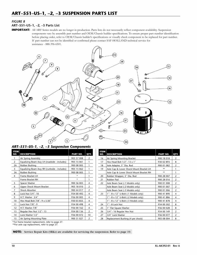
ART–551–US–1, –2, –3 SUSPENSION PARTS LIST
FIGURE 8ART–551–US–1, –2, –3 Parts List
ART–551–US–1, –2, –3 Suspension ComponentsITEMNO. DESCRIPTION PART NO. QTY.
1 Air Spring Assembly 905 57 008 2
2 Equalizing Beam Assy LH (roadside - includes) 905 15 061 1
2A Rubber Bushing 900 08 005 1
3 Equalizing Beam Assy RH (curbside - includes) 905 15 062 1
3A Rubber Bushing 900 08 005 1
4 Frame Bracket LH * 1
Frame Bracket RH * 1
5 Spacer Washer 900 36 003 4
6 Upper Shock Mount Bracket 905 18 010 2
7 Shock Absorber 900 44 017 2
8 Lock Nut 3/4˝- 10 934 00 492 4
9 H.T. Washer 3/4˝ 936 00 005 4
10 Hex Head Bolt 7/8˝- 9 x 5.50˝ 930 03 855 4
11 Lock Nut 7/8˝- 9 934 00 498 4
12 H.T. Washer 7/8˝ 936 00 162 4
13 Regular Hex Nut 1/2˝- 13 934 00 136 2
14 Lock Washer 1/2˝ 936 00 072 10
15 Air Spring Mounting Plate 900 31 027 2
ITEMNO. DESCRIPTION PART NO. QTY.
16 Air Spring Mounting Bracket 900 18 018 2
17 Hex Head Bolt 1/2˝- 13 x 1˝ 930 02 893 8
18 Axle Adapter, 5˝ Dia. Rod 900 01 082 2
19 Axle Cap & Lower Shock Mount Bracket LH ** 1
Axle Cap & Lower Shock Mount Bracket RH ** 1
20 Rubber Wrapper, 5˝ Dia. Rod 900 28 007 2
21 Rubber Pad 900 28 016 2
22 Axle Beam Seat (-1 Models only) 900 01 008 2
Axle Beam Seat (-2 Models only) 900 01 007 2
Axle Beam Seat (-3 Models only) 900 01 006 2
23 1˝– 8 x 12˝ U-Bolt (-1 Models only) 900 41 890 4
1˝– 8 x 12˝ U-Bolt (-2 Models only) 900 41 886 4
1˝– 8 x 12˝ U-Bolt (-3 Models only) 900 41 878 4
24 1˝– 8 Lock Nut 934 00 502 8
25 1˝ Flat Square Washer 936 00 028 8
26 3/4˝– 16 Regular Hex Nut 934 00 149 2
27 3/4˝ Lock Washer 936 00 077 2
28 Replacement Bushing (4 per shock) 905 08 004 8
* For frame bracket replacement, refer to page 27.**For axle cap replacement, refer to page 27.
NOTE: Service Repair Kits (SRKs) are available for servicing the suspension. Refer to page 19.
IMPORTANT: All ART Series models are no longer in production. Parts lists do not necessarily reflect component availability. Suspensioncomponents vary by assembly part number and OEM/Chassis builder specifications. To ensure proper part number identificationbefore placing order, refer to OEM/Chassis builder's specifications or visually check component to be replaced for part number.If part number can not be identified or confirmed please contact SAF-HOLLAND technical service for assistance - 888-396-6501.

XL-AK392-01 Rev A 11
ART–500–B, ART–500–B–1, ART–551–B–1, –2, –3 SUSPENSION PARTS LIST
FIGURE 9ART–500–B, ART–500–B–1, ART–551–B–1, –2, –3 Parts List
ART–500, ART–500–B–1, ART–551–B–1, –2, –3 Suspension Components ITEM ART-500-B ART-500-B-1 ART-551-B-1 ART-551-B-2 ART-551-B-3NO. DESCRIPTION PART NO. PART NO. PART NO. PART NO. PART NO. QTY.1 Air Spring Assembly 905 57 006 905 57 006 905 57 008 905 57 008 905 57 008 22 Equalizing Beam Assembly, LH (includes) 905 15 235 905 15 241 905 15 251 905 15 241 905 15 235 12A Beam Seat 900 01 006 905 01 037 900 01 008 905 01 037 900 01 006 12B Rubber Bushing 900 08 013 900 08 013 900 08 013 900 08 013 900 08 013 13 Equalizing Beam Assembly, RH (includes) 905 15 236 905 15 242 905 15 252 905 15 242 905 15 236 13A Beam Seat 900 01 006 905 01 037 900 01 008 905 01 037 900 01 006 13B Rubber Bushing 900 08 013 900 08 013 900 08 013 900 08 013 900 08 013 14 Inner Sleeve 900 08 037 900 08 037 900 08 037 900 08 037 900 08 037 25 Axle Adapter 5˝ Round 900 01 082 900 01 082 900 01 082 900 01 082 900 01 082 2
Axle Adapter 5˝ Square 900 01 083 900 01 083 900 01 083 900 01 083 900 01 083 26 Rubber Wrapper 5˝ Round 900 28 047 900 28 047 900 28 047 900 28 047 900 28 047 1
Rubber Wrapper 5˝ Square 900 28 073 900 28 073 900 28 073 900 28 073 900 28 073 17 Rubber Pad 900 28 075 900 28 075 900 28 075 900 28 075 900 28 075 28 Axle Cap Assembly LH 5˝ Round without Stops 905 10 061 905 10 061 905 10 061 905 10 061 905 10 061 1
Axle Cap Assembly LH 5˝ Square without Stops 905 10 054 905 10 054 905 10 054 905 10 054 905 10 054 1Axle Cap Assembly LH 5˝ Round with Stops 905 10 063 905 10 063 905 10 063 905 10 063 905 10 063 1Axle Cap Assembly RH 5˝ Round without Stops 905 10 062 905 10 062 905 10 062 905 10 062 905 10 062 1Axle Cap Assembly RH 5˝ Square without Stops 905 10 055 905 10 055 905 10 055 905 10 055 905 10 055 1Axle Cap Assembly RH 5˝ Round with Stops 905 10 064 905 10 064 905 10 064 905 10 064 905 10 064 1
9 U-Bolt 1˝ - 8 x 9˝ Long 5˝ Round 900 41 878 — — — 900 41 878 4U-Bolt 1˝ - 8 x 10˝ Long 5˝ Round — 900 41 882 — 900 41 882 — 4U-Bolt 1˝ - 8 x 12˝ Long 5˝ Round — — 900 41 890 — — 4U-Bolt 1˝ - 8 x 9-1/2˝ Long 5˝ Square 900 41 997 — — — 900 41 997 4U-Bolt 1˝ - 8 x 10⁻¹/2˝ Long 5˝ Square — 900 42 001 — 900 42 001 — 4U-Bolt 1˝ - 8 x 12˝ Long 5˝ Square — — 900 42 007 — — 4
10 Frame Bracket Assembly LH Adjustable with holes 905 18 459 905 18 459 905 18 463 905 18 463 905 18 463 1Frame Bracket Assembly RH Fixed with holes 905 18 460 905 18 460 905 18 464 905 18 464 905 18 464 1
11 Adjusting Bushing 900 01 045 900 01 045 900 01 045 900 01 045 900 01 045 212 Shock Absorber 900 44 162 900 44 162 900 44 162 900 44 017 900 44 017 213 Air Spring & Shock Bracket Assembly LH 905 18 319 905 18 321 905 18 319 905 18 321 905 18 319 1
Air Spring & Shock Bracket Assembly RH 905 18 320 905 18 322 905 18 320 905 18 322 905 18 320 114 Axle Stop Assembly LH 5˝ Round 905 44 241 905 44 243 905 44 243 905 44 245 905 44 247 1
Axle Stop Assembly RH 5˝ Round 905 44 242 905 44 244 905 44 244 905 44 246 905 44 248 115 Spacer Washer 900 36 006 900 36 006 900 36 006 900 36 006 900 36 006 416 Hex Head Bolt 3/4˝ - 10 x 5-1/2˝ 930 03 645 930 03 645 930 03 645 930 03 645 930 03 645 417 Hex Lock Nut 3/4˝ - 10 934 00 492 934 00 492 934 00 492 934 00 492 934 00 492 418 Hex Head Bolt 3/4˝ - 10 x 3-1/2˝ 930 03 597 930 03 597 930 03 597 930 03 597 930 03 597 219 Hex Head Bolt 1-1/8˝ - 7 x 9-1/4˝ 932 00 961 932 00 961 932 00 961 932 00 961 932 00 961 220 Lock Nut 1-1/8˝ - 7 934 00 504 934 00 504 934 00 504 934 00 504 934 00 504 221 Hex Nut 1/2˝ - 13 934 00 136 934 00 136 934 00 136 934 00 136 934 00 136 222 Lock Washer 1/2˝ 936 00 072 936 00 072 936 00 072 936 00 072 936 00 072 823 Hex Head Bolt 1/2˝ - 13 x 1˝ 930 02 893 930 02 893 930 02 893 930 02 893 930 02 893 624 Lock Nut 1˝ - 8 934 00 502 934 00 502 934 00 502 934 00 502 934 00 502 825 Hex Nut 3/4˝ - 16 934 00 149 934 00 149 934 00 149 934 00 149 934 00 149 226 Lock Washer 3/4˝ 936 00 077 936 00 077 936 00 077 936 00 077 936 00 077 227 HT Washer 3/4˝ 936 00 005 936 00 005 936 00 005 936 00 005 936 00 005 228 Replacement Bushing (4 per shock) 905 08 004 905 08 004 905 08 004 905 08 004 905 08 004 8
NOTE: Service Repair Kits (SRKs) of pivot connection and axle connection, refer to page 19.
IMPORTANT: All ART Series models are no longer inproduction. Parts lists do not necessarily reflect componentavailability. For further information regarding parts availability,see entire statement on any other suspension exploded view.

12 XL-AK392-01 Rev A
ART–505–B, ART–505–B–1, ART–555–B–1, –2, –3 SUSPENSION PARTS LIST
FIGURE 10ART–505–B, ART–505–B-1, ART–555–B–1, –2, –3 Parts List
NOTES: The coil spring lift (1˝ dia. lower cam pin) shown is for units produced after September 1, 1977. For units produced priorto this date or conversions refer to pages 22-25. ART 505-C models supersede ART 505-B. Unless specific components onyour installation match illustration above, refer to ART 505-C model for spring lift units.
Grease yoke rod and cam at routine maintenance or every 5,000 miles.
For Service Repair Kits (SRKs) of the coil spring lift, pivot connection & axle connection, refer to page 19.
NOTICE: Parts for these models same as models without Coil Spring Lift except for items listed below.
ART–505–B, ART–505–B–1, ART–555–B–1, –2, –3 Suspension Components
ITEM ART-505-B ART-505-B-1 ART-555-B-1 ART-555-B-2 ART-555-B-3NO. DESCRIPTION PART NO. PART NO. PART NO. PART NO. PART NO. QTY.
2 Equalizing Beam Assembly, LH (includes) 905 15 327 905 15 364 905 15 541 905 15 364 905 15 327 1
2A Beam Seat 900 01 006 905 01 037 900 01 008 905 01 037 900 01 006 1
2B Rubber Bushing 900 08 013 900 08 013 900 08 013 900 08 013 900 08 013 1
3 Equalizing Beam Assembly, RH (includes) 905 15 328 905 15 365 905 15 542 905 15 365 905 15 328 1
3A Beam Seat 900 01 006 905 01 037 900 01 008 905 01 037 900 01 006 1
3B Rubber Bushing 900 08 013 900 08 013 900 08 013 900 08 013 900 08 013 1
10 Frame Bracket Assembly LH Adjustable with holes 905 18 466 905 18 466 905 18 646 905 18 646 905 18 646 1
Frame Bracket Assembly RH Fixed with holes 905 18 467 905 18 467 905 18 647 905 18 647 905 18 647 1
28 Adjusting Lock Nut 939 00 151 939 00 151 939 00 151 939 00 151 939 00 151 2
29 Yoke Grommet 900 44 218 900 44 218 900 44 218 900 44 218 900 44 218 2
30 Yoke Rod 900 06 342 900 06 342 900 06 342 900 06 342 900 06 342 2
31 Bearing Seal (Yoke Rod) 900 44 575 900 44 575 900 44 575 900 44 575 900 44 575 4
32 Inner Sleeve 900 38 222 900 38 222 900 38 222 900 38 222 900 38 222 2
33 Roller Bearing (Yoke Rod) 900 38 220 900 38 220 900 38 220 900 38 220 900 38 220 2
34 Lock Nut 1/2˝ - 13 934 00 541 934 00 541 934 00 541 934 00 541 934 00 541 2
35 Upper Cam Pin 900 44 481 900 44 481 900 44 481 900 44 481 900 44 481 2
36 Lower Cam Pin 905 44 661 905 44 661 905 44 661 905 44 661 905 44 661 2
37 Lower Bearing Seal (Cam) 900 44 574 900 44 574 900 44 574 900 44 574 900 44 574 4
38 Roller Bearing (Cam) 900 38 219 900 38 219 900 38 219 900 38 219 900 38 219 4
39 Lower Bearing Seal (Inner Cam) 900 44 576 900 44 576 900 44 576 900 44 576 900 44 576 2
40 Grease Fitting 938 00 228 938 00 228 938 00 228 938 00 228 938 00 228 4
41 Lock Nut 3/4˝ - 10 934 00 494 934 00 494 934 00 494 934 00 494 934 00 494 2
42 Linkage Assembly 905 44 545 905 44 545 905 44 545 905 44 545 905 44 545 2
43 Hex Head Bolt 5/8˝ - 11 x 2-1/2˝ 930 03 359 930 03 359 930 03 359 930 03 359 930 03 359 2
44 Lock Nut 5/8˝ - 11 934 00 490 934 00 490 934 00 490 934 00 490 934 00 490 2
45 Cam (with bearings) 905 44 701 905 44 701 905 44 701 905 44 701 905 44 701 2
46 Grease Fitting 938 00 229 938 00 229 938 00 229 938 00 229 938 00 229 2
47 Decal 900 44 244 900 44 244 900 44 244 900 44 244 900 44 244 2
IMPORTANT:
All ART Series models are no longer inproduction. Parts lists do not necessarily reflect component availability. Suspensioncomponents vary by assembly part number and OEM/Chassis builder specifications.To ensure proper part number identification before placing order, refer to OEM/Chassis builder'sspecifications or visually check component to bereplaced for part number. If part number can notbe identified or confirmed please contact SAF-HOLLAND technical service for assistance - 888-396-6501.

XL-AK392-01 Rev A 13
ART–505–C, –1, ART–555–C–1, –2, –3 SUSPENSION PARTS LIST
FIGURE 11ART–505–C, -1, ART–555–C–1, –2, –3 Parts List
9
8
14
2521
22
26
17
27
1612
17
28
18
11
10
11
15
20
2b
15
19
6
5
7
2
4
2a
22
23
24
3
13
1
IMPORTANT: All ART Series models are no longer in production. Parts lists do not necessarily reflect component availability. Suspensioncomponents vary by assembly part number and OEM/Chassis builder specifications. To ensure proper part number identificationbefore placing order, refer to OEM/Chassis builder's specifications or visually check component to be replaced for part number.If part number can not be identified or confirmed please contact SAF-HOLLAND technical service for assistance - 888-396-6501.

14 XL-AK392-01 Rev A
ART–505–C, –1, ART–555–C–1, –2, –3 SUSPENSION PARTS LIST
NOTES: The coil spring lift (1˝ dia. lower cam pin) shown is for units produced after September 1, 1977. For units produced priorto this date or conversions refer to pages 22-25.
Grease yoke rod and cam at routine maintenance or every 5,000 miles.
For Service Repair Kits (SRKs) of the coil spring lift, pivot connection & axle connection, refer to page 19.
ART–505–C, –1, ART–555–C–1, –2, –3 Suspension Components
ITEM ART-505-C ART-505-C-1 ART-555-C-1 ART-555-C-2 ART-555-C-3NO. DESCRIPTION PART NO. PART NO. PART NO. PART NO. PART NO. QTY.
1 Air Spring Assembly 905 57 027 905 57 027 905 57 009 905 57 009 905 57 009 2
2 Equalizing Beam Assembly, LH (includes key 2a, 2b, 3) 905 16 335 905 16 337 905 16 341 905 16 337 905 16 335 1
Equalizing Beam Assembly, RH (includes key 2a, 2b, 3) 905 16 336 905 16 338 905 16 342 905 16 338 905 16 336 1
2A Beam Seat 900 01 006 905 01 037 900 01 008 905 01 037 900 01 006 2
2B Rubber Bushing 900 08 139 900 08 139 900 08 139 900 08 139 900 08 139 2
3 Beam Lift Bracket 905 31 040 905 31 040 905 31 040 905 31 040 905 31 040 2
4 Washer 1˝ 939 00 027 939 00 027 939 00 027 939 00 027 939 00 027 8
5 Axle Adapter 900 01 082 900 01 082 900 01 082 900 01 082 900 01 082 2
6 Rubber Wrapper 900 28 047 900 28 047 900 28 047 900 28 047 900 28 047 2
7 Rubber Pad 900 28 083 900 28 083 900 28 083 900 28 083 900 28 083 2
8 Axle Cap Assembly LH - without axle stops 905 10 061 905 10 061 905 10 061 905 10 061 905 10 061 1
Axle Cap Assembly RH - without axle stops 905 10 062 905 10 062 905 10 062 905 10 062 905 10 062 1
Axle Cap Assembly LH - with axle stops 905 10 063 905 10 063 905 10 063 905 10 063 905 10 063 1
Axle Cap Assembly RH - with axle stops 905 10 064 905 10 064 905 10 064 905 10 064 905 10 064 1
9 U-Bolt 1˝ - 8 x 9˝ 900 41 878 - - - 900 41 878 4
U-Bolt 1˝ - 8 x 10.5˝ - 900 42 791 - 900 42 791 - 4
U-Bolt 1˝ - 8 x 12.5˝ - - 900 42 792 - - 4
10 Frame Bracket Assembly LH Adjustable 905 19 995 905 19 995 905 19 993 905 19 993 905 19 993 1
Frame Bracket Assembly RH Fixed 905 19 996 905 19 996 905 19 994 905 19 994 905 19 994 1
11 Adjusting Bushing 900 08 147 900 08 147 900 08 147 900 08 147 900 08 147 2
12 Shock Absorber 900 44 162 900 44 162 900 44 162 900 44 642 900 44 642 2
13 Air Spring & Shock Bracket Assembly LH 905 18 319 905 18 321 905 18 319 905 18 321 905 18 319 1Air Spring & Shock Bracket Assembly RH 905 18 320 905 18 322 905 18 320 905 18 322 905 18 320 1
14 Axle Stop Assembly LH 5˝ Round 905 44 241 905 44 243 905 44 243 905 44 245 905 44 247 1Axle Stop Assembly RH 5˝ Round 905 44 242 905 44 244 905 44 244 905 44 246 905 44 248 1
15 Spacer Washer 900 36 177 900 36 177 900 36 177 900 36 177 900 36 177 416 Hex Head Bolt 3/4˝ - 10 x 5-1/2˝ Gr 5 930 03 645 930 03 645 930 03 645 930 03 645 930 03 645 217 Hex Lock Nut 3/4˝ - 10 Gr B 934 00 492 934 00 492 934 00 492 934 00 492 934 00 492 418 Hex Head Bolt 3/4˝ - 10 x 3-1/2˝ Gr 5 930 03 597 930 03 597 930 03 597 930 03 597 930 03 597 219 Hex Head Bolt 1-1/8˝ - 7 x 9-1/4˝ Gr 8 932 01 055 932 01 055 932 01 055 932 01 055 932 01 055 220 Lock Nut 1-1/8˝ - 7 Gr C 934 00 506 934 00 506 934 00 506 934 00 506 934 00 506 221 Hex Nut 1/2˝ - 13 Gr B 934 00 136 934 00 136 934 00 136 934 00 136 934 00 136 222 Lock Washer 1/2˝ 936 00 072 936 00 072 936 00 072 936 00 072 936 00 072 823 Hex Head Bolt 1/2˝ - 13 x 1˝ Gr 2 930 02 893 930 02 893 930 02 893 930 02 893 930 02 893 624 Lock Nut 1˝ - 8 Gr C 934 00 502 934 00 502 934 00 502 934 00 502 934 00 502 825 Hex Nut 3/4˝ - 16 Gr B 934 00 149 934 00 149 934 00 149 934 00 149 934 00 149 226 Lock Washer 3/4˝ 936 00 077 936 00 077 936 00 077 936 00 077 936 00 077 227 HT Washer 3/4˝ 936 00 005 936 00 005 936 00 005 936 00 005 936 00 005 228 Replacement Bushing (4 per shock) 905 08 004 905 08 004 905 08 004 905 08 004 905 08 004 8

XL-AK392-01 Rev A 15
ARTA–5000 SERIES PARTS LIST
1. Suspension. Refer to Model Identification, page 3.Whenyou identify the model suspension, then refer to thestandard suspension parts list.
2. Axle. Determine Brand, then refer to the Axle Distributor for service.
3. Wheels. Determine Brand, then refer to the Wheel Distributorfor service.
4. Crossmember Kit. Holland Neway CMK-600 for ARTA withor without Coil Spring Lift. Holland Neway CMK-700-1 forARTA with AL-75-B Air Lift.
5. Air Controls (not shown). ACN-5500 with Coil SpringLift;ACN-5600 without Coil Spring Lift;AC-84-M/S-1 with AL-75-B Air Lift.
6. Spring Brakes (24˝). Refer to Spring Brake Distributor for service.
FIGURE 12ARTA–5000 Series Parts List
ALT–40 & ALT–40–L AXLE AIR LIFT PARTS LIST
FIGURE 13ALT–40 & ALT–40–L Parts List
ALT–40 Axle Air LiftALT–40 (Drawing 440 00 004)ITEMNO. DESCRIPTION PART NO. QTY.
1 Air Spring Mounting Bracket Assembly 905 18 368 2
2 Lift Beam 900 44 203 2
3 Hex Nut 1/2˝ - 13 934 00 136 8
4 Lock Washer 1/2˝ 936 00 073 8
5 Air Spring Assembly 905 57 014 2
6 Air Spring Mounting Bracket 900 01 012 2
7 Hex Bolt 3/4˝ - 10 x 6˝ GR 5 930 03 657 2
8 Hex Lock Nut 3/4˝ - 10 GR B 934 00 492 2
ALT–40-L Axle Air LiftALT–40–L (Drawing 440 00 004)ITEMNO. DESCRIPTION PART NO. QTY.
1 Air Spring Mounting Bracket Assembly 905 18 372 2
2 Lift Beam 900 44 203 2
3 Hex Nut 1/2˝ - 13 934 00 136 8
4 Lock Washer 1/2˝ 936 00 073 8
5 Air Spring Assembly 905 57 014 2
6 Air Spring Mounting Bracket 900 01 012 2
7 Hex Bolt 3/4˝ - 10 x 6˝ GR 5 930 03 657 2
8 Hex Lock Nut 3/4˝ - 10 GR B 934 00 492 2

16 XL-AK392-01 Rev A
AL–74–B & AL–75–B AXLE AIR LIFT PARTS LIST
AL–74–B Axle Air Lift (Service Only)Truck/Tractor Application – AL-74-B (Drawing 440 00 005)ITEMNO. DESCRIPTION PART NO. QTY.
1 Hex Nut 1/2˝ - 13 934 00 136 82 Lock Washer 1/2˝ 936 00 072 83 Air Spring Yoke Lift Assembly 905 01 083 14 Yoke Half 900 18 218 45 Air Spring 905 57 028 16 Bracket Assembly 905 18 201 27 3/8˝ H. T. Chain 900 44 111 28 Bolt 1/2˝ - 13 x 1-3/4˝ 939 00 031 49 Lock Nut 1/2˝ - 13 934 00 543 410 Air Spring Mounting Plate 900 31 027 111 Hex Head Cap Screw 5/8˝ - 11 x 2˝ 939 00 039 212 Lock Nut 5/8˝ - 11 934 00 551 2
AL-75-B Axle Air Lift Truck/Tractor Application – AL-75-B (Drawing 440 00 005)ITEMNO. DESCRIPTION PART NO. QTY.
1 Hex Nut 1/2˝ - 13 934 00 136 82 Lock Washer 1/2˝ 936 00 072 83 Air Spring Yoke Lift Assembly 905 01 083 14 Yoke Half 900 18 218 45 Air Spring 905 57 001 16 Bracket Assembly 905 18 201 27 3/8˝ H. T. Chain 900 44 111 28 Bolt 1/2˝ - 13 x 1-3/4˝ 939 00 031 49 Lock Nut 1/2˝ - 13 934 00 543 410 Air Spring Mounting Plate 900 31 027 111 Hex Head Cap Screw 5/8˝ - 11 x 2˝ 939 00 039 212 Lock Nut 5/8˝ - 11 934 00 551 213 Control Link 900 06 283 214 Stabilizer End Bracket 900 31 007 415 Cotter Pin 1/8˝ x 1˝ 938 00 001 416 Yoke Pin 900 44 164 4
FIGURE 14AL–74–B & AL–75–B Parts List
ACN–5500 Air Control Parts ListITEMNO. DESCRIPTION PART NO. QTY.
1 Hand Valve 900 54 082 1
2 Air Brake Protection Valve & Air Filter 900 54 001 1
3 Air Gauge (Non-Illuminated) 900 54 280 1
4 Decal “Operating Instructions” 900 44 021 1
5 Quick Release Valve 900 54 096 1
ACN–5500 AIR CONTROL PIPING AND PARTS LIST
NOTE: All tubing and fittings to be furnished by customer.
For hand control valve information refer to page 18.
Pressure protection valve & air filter maintain safe airbrake pressure & clean air; set to 65 psig at factory.
All piping connections 1/4 N.P.T. 3/8˝ (min.) tubing recommended.
The operating instructions decal is attached so it is visible to the driver.
FIGURE 15ACN–5500 Parts List

XL-AK392-01 Rev A 17
ACN–5600 AIR CONTROL PIPING AND PARTS LIST
ACN–5600 Air Control Parts ListITEMNO. DESCRIPTION PART NO. QTY.
1 Hand Valve 900 54 082 1
2 Air Brake Protection Valve & Air Filter 900 54 001 1
3 Air Gauge (Non-Illuminated) 900 54 280 1
4 Decal “Operating Instructions” 900 44 021 1
NOTE: All tubing and fittings to be furnished by customer.
For hand control valve information refer to page 18.
Pressure protection valve & air filter maintain safe airbrake pressure & clean air; set to 65 psi at factory.
All piping connections 1/4 N.P.T. 3/8˝ (min.) tubing recommended.
The operating instructions decal is attached so it is visible to the driver.
FIGURE 16ACN–5600 Parts List
AC–84–M/S–1 Air Control Kit Parts ListITEMNO. DESCRIPTION MODEL PART NO. QTY.
1 Valve-Manually Operated Selector AC-84-M-1 900 54 088 1
Valve-Solenoid Operated - 12 V.D.C. AC-84-S-1 900 54 074 1
2 Valve-Air Pilot Operated AC-84-M/S-1 900 54 079 2
3 Operating Instructions Decal AC-84-M-1 900 44 233 1
Operating Instructions Decal AC-84-S-1 900 44 234 1
4 No. 10 - 32 x 1/2˝ Machine Screw AC-84-S-1 932 00 724 2
5 No. 10 Lock Washer AC-84-S-1 936 00 442 2
AC–84–M/S–1 AIR CONTROL PIPING AND PARTS LIST (Typical Installation)
NOTE: The “S” denotes Electric Solenoid operated valve.
The “M” denotes Manually operated valve.
FIGURE 17AC–84–M/S–1 Parts List
LOCK, KNOB ONWITH SET SCREW.

18 XL-AK392-01 Rev A
HAND CONTROL VALVE (*Part No. 900 54 082)
General Information
Adjustment Instructions
Maximum Pressure (Range 35 psig to 85 psig) – Loosen loweracorn nut and adjust until desired maximum pressure setting isachieved, then tighten acorn nut securely.
Minimum Pressure (Range 0 psig to 30 psig) – Loosen upperacorn nut and adjust until desired minimum pressure setting isachieved, then tighten acorn nut securely. Do not operate unitwithout air – 3 psig minimum.
Air Piping
Do not pressurize exhaust port. Care should be taken to assureair lines are piped to proper hand valve port.Air pressureinjected into the exhaust port will unseat an internal “U” typeseal causing leakage and malfunction of valve.Valve must bedisassembled to reseat seal.
Hand Valve Handle Tension Adjustment
Remove valve handle by turning out handle bolt.
Using allen wrench, tighten (3) allen head set screws equal amounts until desired tension is obtained.
Replace valve handle and tighten handle bolt securely.
* Part No. 900 54 082 is hand valve and decal.Part No. 900 54 081 is hand valve only.
FIGURE 18
FIGURE 19
FIGURE 20

XL-AK392-01 Rev A 19
SERVICE REPAIR KITS (SRK)
AXLE CONNECTION** COILPIVOT OLD STYLE NEW STYLE SPRING
MODEL CONN. 5” RD. 5” SQ. 5” RD. 5” SQ. LIFT
ART-500-US — SRK-4 — SRK-64 SRK-68 —
ART-500-US-A SRK-12 SRK-4 — SRK-64 SRK-68 —
ART-550-US-1 — — — SRK-128 — —
ART-550-US-2 — — — SRK-66 — —
ART-550-US-3 — SRK-4 — SRK-64 SRK-68 —
ART-551-US-1 — — — ARK-128 — —
ART-551-US-2 — — — SRK-66 — —
ART-551-US-3 — SRK-4 — SRK-64 SRK-68 —
ART-500-B SRK-145 — — SRK-64 SRK-68 —
ART-500-B-1 SRK-145 — — SRK-66 — —
ART-505-B SRK-145 — — SRK-64 SRK-68 *
ART-505-B-1 SRK-145 — — SRK-66 — *
ART-551-B-1 SRK-145 — — SRK-128 — —
ART-551-B-2 SRK-145 — — SRK-66 — —
ART-551-B-3 SRK-145 — — SRK-64 SRK-68 —
ART-555-B-1 SRK-145 — — SRK-128 — *
ART-555-B-2 SRK-145 — — SRK-68 — *
ART-555-B-3 SRK-145 — — SRK-64 SRK-68 *
*Refer to pages 22-25 for Coil Spring Lift Repair Kit.**Refer to page 27 for New Style and Old Style connection definition.
NOTE: These SRK’s will service only one (1) axle.
FIGURE 21

20 XL-AK392-01 Rev A
SERVICE REPAIR KITS (SRK) continued
5˝ Round & Square Axle
SRK-68 Holland part number 481 00 112ITEMNO. DESCRIPTION PART NO. QTY.
1 Wrapper, Rubber 900 28 005 2
2 Wrapper, Rubber 900 28 073 2
3 Pad, Rubber 900 28 083 2
4 U-Bolt 1˝ - 8 x 9.5˝ GR 8 900 41 997 4
5 Nut Hex Lock 1˝ - 8 GR C 934 00 502 8
6 Washer Square for 1˝ (25.4mm) Bolt 936 00 028 8
7 Washer Flat 1˝ 939 00 027 8
8 Literature Instruction XL-AR451 1
Note: Used on Model ART-500-US, ART-500-US-A, ART-550-US-3,
ART-551-US-3, ART-500-B, ART-505-B, ART-551-B-3, ART-555-B-3.
5˝ Round Axle
SRK-128 Holland part number 481 00 181ITEMNO. DESCRIPTION PART NO. QTY.
1 Wrapper Rubber 900 28 047 2
2 Pad Rubber 900 28 083 2
3 U-Bolt 1˝ - 8 x 12.5˝ GR 8 900 42 792 4
4 Nut Hex Lock 1˝ - 8 GR C 934 00 502 8
5 Washer Square for 1˝ (25.4mm) Bolt 936 00 028 8
6 Washer Flat 1˝ 939 00 027 8
7 Literature Instruction XL-AR451 1
Note: Used on Model ART-550-US-1, ART-551-US-1, ART-551-B-1, and
ART-555-B-1.
Pivot Connection
SRK-12 Holland part number 481 00 023ITEMNO. DESCRIPTION PART NO. QTY.
1 Washer Flat 1.141˝ 900 36 177 4
2 Bushing 900 08 139 2
3 Bolt Hex 1.125-7 x 9.53˝ GR 8 932 01 055 2
4 Nut Hex 1.125˝ -7 GR C 934 00 506 2
5 Alignment Block with rust inhibitor 900 08 147 4
Note: Used on Model ART-500-A-US.
PIVOT CONNECTION REPLACEMENT KIT CHARTS
Pivot Connection
SRK-145 Holland part number 481 00 202ITEMNO. DESCRIPTION PART NO. QTY.
Torque Spec Decal XL-AR355-02 1
1 Bolt Hex 1.125˝ - 7 x 9.53˝ GR 8 932 01 055 2
2 Nut Hex 1.125˝ - 7 GR C 934 00 506 2
3 Bushing 900 08 139 2
4 Washer Flat 900 36 177 4
6 ART SRK-145 Literature Instruction XL-AK406 1
7 Decal ART Series Torque Spec’s XL-AK402-01 1
Note: Used on Model ART-500-B, ART- 505-B, ART- 505-C, ART-551-B,
ART-555-B, ART-555-C.
5˝ Round Axle
SRK-4 Holland part number 481 00 008ITEMNO. DESCRIPTION PART NO. QTY.
1 Pad Rubber 900 28 016 2
2 U-Bolt 1˝ - 8 x 9˝ GR 8 900 41 878 4
3 Nut Hex Lock 1˝ - 8 GR C 934 00 502 8
4 Washer Square for 1˝ (25.4mm) Bolt 936 00 028 8
5 Washer Flat 1 939 00 027 8
6 Wrapper Rubber 900 28 007 2
7 Literature Instruction XL-AR451 1
Note: Used on Model ART-500-US, ART-500-US-A, ART-550-US-3.
AXLE CONNECTION REPLACEMENT KIT CHARTS
5˝ Round Axle
SRK-64 Holland part number 481 00 108ITEMNO. DESCRIPTION PART NO. QTY.
1 Wrapper Rubber 900 28 047 2
2 Pad Rubber 900 28 083 2
3 U-Bolt 1˝ - 8 x 9˝ GR 8 900 41 878 4
4 Nut Hex Lock 1˝ - 8 GR C 934 00 502 8
5 Washer Square for 1˝ (25.4mm) Bolt 936 00 028 8
6 Washer Flat 1˝ 939 00 027 8
7 Literature Instruction XL-AR451 1
Note: Used on Model ART-500-US, ART-500-US-A, ART-550-US-3,
ART-551-US-3, , ART-500-B, ART-505-B, ART-551-B-3, ART-555-B-3.
5˝ Round Axle
SRK-66 Holland part number 481 00 110ITEMNO. DESCRIPTION PART NO. QTY.
1 Wrapper Rubber 900 28 047 2
2 Pad Rubber 900 28 083 2
3 U-Bolt 1˝ - 8 x 10.5˝ GR 8 900 42 791 4
4 Nut Hex Lock 1˝ - 8 GR C 934 00 502 8
5 Washer Square for 1˝ (25.4mm) Bolt 936 00 028 8
6 Washer Flat 1˝ 939 00 027 8
7 Literature Instruction XL-AR451 1
Note: Used on Model Used on Model ART-550-US-2, ART-551-US-2,
ART-500-B-1, ART-505-B-1, ART-551-B-2.
AXLE CONNECTION REPLACEMENT KIT CHARTScontinued
XL-AK392-01 Rev A 21
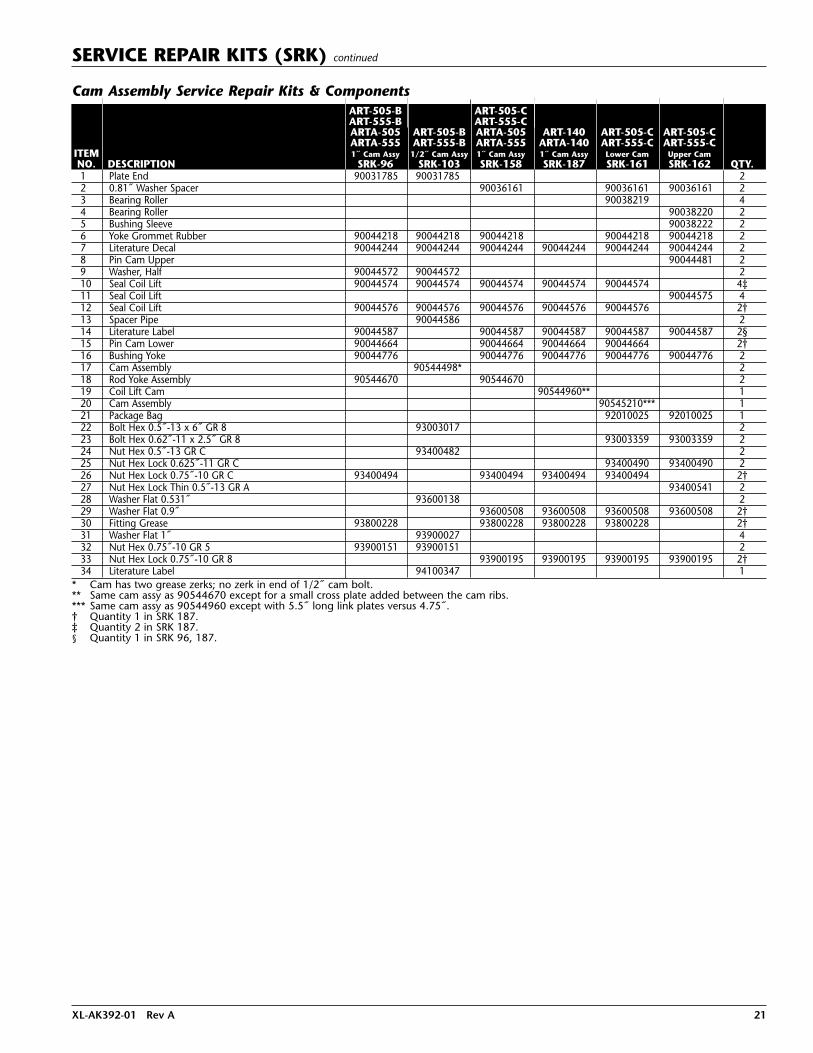
SERVICE REPAIR KITS (SRK) continued
Cam Assembly Service Repair Kits & ComponentsART-505-B ART-505-CART-555-B ART-555-CARTA-505 ART-505-B ARTA-505 ART-140 ART-505-C ART-505-CARTA-555 ART-555-B ARTA-555 ARTA-140 ART-555-C ART-555-C
ITEM 1˝ Cam Assy 1/2˝ Cam Assy 1˝ Cam Assy 1˝ Cam Assy Lower Cam Upper CamNO. DESCRIPTION SRK-96 SRK-103 SRK-158 SRK-187 SRK-161 SRK-162 QTY.1 Plate End 90031785 90031785 22 0.81˝ Washer Spacer 90036161 90036161 90036161 23 Bearing Roller 90038219 44 Bearing Roller 90038220 25 Bushing Sleeve 90038222 26 Yoke Grommet Rubber 90044218 90044218 90044218 90044218 90044218 27 Literature Decal 90044244 90044244 90044244 90044244 90044244 90044244 28 Pin Cam Upper 90044481 29 Washer, Half 90044572 90044572 210 Seal Coil Lift 90044574 90044574 90044574 90044574 90044574 4‡11 Seal Coil Lift 90044575 412 Seal Coil Lift 90044576 90044576 90044576 90044576 90044576 2†13 Spacer Pipe 90044586 214 Literature Label 90044587 90044587 90044587 90044587 90044587 2§15 Pin Cam Lower 90044664 90044664 90044664 90044664 2†16 Bushing Yoke 90044776 90044776 90044776 90044776 90044776 217 Cam Assembly 90544498* 218 Rod Yoke Assembly 90544670 90544670 219 Coil Lift Cam 90544960** 120 Cam Assembly 90545210*** 121 Package Bag 92010025 92010025 122 Bolt Hex 0.5˝-13 x 6˝ GR 8 93003017 223 Bolt Hex 0.62˝-11 x 2.5˝ GR 8 93003359 93003359 224 Nut Hex 0.5˝-13 GR C 93400482 225 Nut Hex Lock 0.625˝-11 GR C 93400490 93400490 226 Nut Hex Lock 0.75˝-10 GR C 93400494 93400494 93400494 93400494 2†27 Nut Hex Lock Thin 0.5˝-13 GR A 93400541 228 Washer Flat 0.531˝ 93600138 229 Washer Flat 0.9˝ 93600508 93600508 93600508 93600508 2†30 Fitting Grease 93800228 93800228 93800228 93800228 2†31 Washer Flat 1˝ 93900027 432 Nut Hex 0.75˝-10 GR 5 93900151 93900151 233 Nut Hex Lock 0.75˝-10 GR 8 93900195 93900195 93900195 93900195 2†34 Literature Label 94100347 1
* Cam has two grease zerks; no zerk in end of 1/2˝ cam bolt.** Same cam assy as 90544670 except for a small cross plate added between the cam ribs. *** Same cam assy as 90544960 except with 5.5˝ long link plates versus 4.75˝. † Quantity 1 in SRK 187. ‡ Quantity 2 in SRK 187. § Quantity 1 in SRK 96, 187.

22 XL-AK392-01 Rev A
SERVICE REPAIR KITS (SRK) continued
ITEM NO. DESCRIPTION PART NO. QTY.
1 Nut Hex 0.75˝ - 10 GR 5 (Adj Lock Nut) 939 00 151 2
2 Yoke Grommet Rubber 900 44 218 2
3* Yoke Rod 900 06 342 -
4* Seal Coil Lift 900 44 575 -
5* Bushing Sleeve 900 38 222 -
6* Roller Bearing 900 38 220 -
7* Nut Hex Lock Thin 0.5˝ – 13 GR A 934 00 541 -
8* Upper Cam Pin 900 44 481 -
9 Lower Cam Pin 900 44 664 2
10 Lower Bearing Seal 900 44 574 4
11* Roller Bearing 900 38 219 -
12 Lower Bearing Seal 900 44 576 2
13 Grease Fitting 938 00 228 2
14 3/4˝- 10 Lock Nut 934 00 494 2
15* Linkage Assembly 905 44 545 -
16* Bolt Hex 0.62˝ - 11 x 2.5˝ GR 8 930 03 359 -
17* Nut Hex Lock 0.625˝ - 11 GR C 934 00 490 -
18* Coil Lift Cam 900 44 674 -
19* Grease Fitting 938 00 229 -
20 Decal 900 44 244 2
21 End Plate 900 31 785 2
22 Washer Half 900 44 572 2
- Literature Label 900 44 587 1
- Installation Instructions 300 00 031 1
Note: Used on Model ART- 505-B, ART-555-B, ARTA-505 and ARTA-555.
*Component of assembly 90544670.
NOTE: One kit per suspension.
Cam AssemblySRK-96
NOTE: Grease yoke rod and cam at routine maintenance or every 5,000 miles. Items 13 & 19.
NOTE: Axle Lift Adjustment - Adjusting tensionbeyond dimension shown will NOTincrease lift, but can cause failures bybottoming coil springs. Do not exceeddimension shown. (Axle up – No Air)
The SRK-96 was released for production as of September 1,1977,on all coil spring lifts,which incorporated a 1˝diameter lower cam pin (item 9).
This Service Repair Kit is also available to convert coilspring lifts produced prior to September 1, 1977. Ifconversion to the SRK-96 is to be performed, contactHolland Technical Service.
FIGURE 22
Refer to replacement instructions for installation, page 29.
SRK-96 Holland part number 481 00 144
*Table items 3-8, 11 and 15-19 come assembled as aYoke Rod Assembly, part number 905 44 670.

XL-AK392-01 Rev A 23
SERVICE REPAIR KITS (SRK) continued
NOTE: One kit per suspension.
Cam AssemblySRK-103(Lower cam pin – 1/2” dia. hex hd. bolt)The SRK-103,which includes the current productiondesign, updated the coil spring lifts producedprior to September 1, 1977.The SRK-103 has a1/2˝ diameter lower cam pin.
If a conversion to a SRK-103 is to be performed,contact Holland Technical Service.
NOTE: Before installing a SRK-103, refer toRemoval Procedure (FIGURE 23).
NOTE: Grease yoke rod and cam at routinemaintenance or every 5,000 miles.Items 3 & 11.
NOTE: Axle Lift Adjustment -Adjusting tensionbeyond dimensionshown will NOTincrease lift, but cancause failures bybottoming coil springs.Do not exceed dimensionshown. (Axle up – No Air)
Removal Procedure
NOTE: Item 13 is welded when assembled.To service,refer to removal procedure.
1. To remove cam assembly, remove 1/2˝ hexhead bolt, Item 21.
2. Using a torch, cut out shaded area asshown. (Do not torch cam body, Item 1).
3. Remove the remaining pieces of innersleeve, Item 12, then the cam assembly.
4. Chisel off the welded washers, Item 13,then install new parts.Refer to replacementinstructions for installation, page 29.
5. Weld new washers, Item 13, after lock nut,Item 23, has been torqued.
FIGURE 23
FIGURE 24
SRK-103 Holland part number 481 00 151ITEM NO. DESCRIPTION PART NO. QTY.
1* Coil Lift Cam 900 44 577 -
2* Yoke Rod 900 06 342 -
3* Grease Fitting 938 00 229 -
4* Roller Bearing 900 38 220 -
5* Linkage Assembly 905 44 545 -
6* Upper Cam Pin 900 44 481 -
7* Inner Sleeve 900 38 222 -
8* Yoke Rod Bearing Seal 900 44 575 -
9* Roller Bearing 900 38 219 -
10* 1/2˝ - 13 Light Thin Lock Nut 934 00 541 -
11* Grease Fitting 938 00 228 -
12 Spacer Pipe 900 44 586 2
13 Washer 939 00 027 4
14 Lower Cam Bearing Inner Seal 900 44 576 2
15 Adjustment Lock Nut 939 00 151 2
16* 5/8˝- 11 x 2-1/2˝ Hex Hd. Screw 930 03 359 -
17* 5/8˝ - 11 Lock Nut 934 00 490 -
18 End Plate 900 31 785 2
19 Yoke Grommet 900 44 218 2
20 Half Washer 900 44 572 2
21 1/2˝ - 13 x 6˝ Hex Hd. Screw 930 03 017 2
22 1/2˝ Washer 936 00 138 2
23 1/2˝ - 13 Lock Nut 934 00 482 2
24 Decal 900 44 244 2
- Installation Instructions 300 00 033 1
Note: Used on Model ART-505-B, ART-555-B.
*Component of assembly 90544498, coil lift cam assembly,
quantity 2 - in SRK-103.
Cam Assembly - 1/2˝
*Table items 1-11 and 16 & 17 come assembled as aYoke Rod Assembly, part number 905 44 498.

24 XL-AK392-01 Rev A
SERVICE REPAIR KITS (SRK) continued
SRK-158 Holland part number 481 00 215ITEMNO. DESCRIPTION PART NO. QTY.
Literature Decal 900 44 244 2
Literature Label 900 44 587 2
1 Rod Yoke Assembly 905 44 670 2
3 Seal Coil Lift 900 44 574 4
4 Seal Coil Lift 900 44 576 2
5 Nut Hex Lock 0.75˝ - 10 GR C 934 00 494 2
8 Nut Hex Lock 0.75˝ - 10 GR 8 939 00 195 2
9 Bushing Yoke 900 44 776 2
10 Washer Flat 0.9˝ 936 00 508 2
11 Yoke Grommet Rubber 900 44 218 2
12 Washer Spacer 0.81˝ 900 36 161 2
13 Pin Cam Lower 900 44 664 2
14 Fitting Grease 938 00 228 2
- Installation Drawing & Instructions 300 00 050 1
- Installation Instructions XL-AK443 1
Note: Used on Model ART-505-C, ART-555-C, ARTA-505, ARTA-555.
CAM ASSEMBLY REPLACEMENT KIT CHARTS continued
Cam Assembly - 1˝ Cam Assembly
SRK-187 Holland part number 481 00 244ITEMNO. DESCRIPTION PART NO. QTY.
1 Coil Lift Cam 905 44 960 1
1-A* Coil Lift Cam 905 44 962 -
1-B* Rod Yoke Assembly 905 06 009 -
1-C* Fitting Grease 938 00 228 -
1-D* Bearing Roller 900 38 220 -
1-E* Link Assembly Coil Lift 905 44 545 -
1-F* Pin Cam Upper 900 44 481 -
1-G* Bushing Sleeve 900 38 222 -
1-H* Seal Coil Lift 900 44 575 -
1-I* Bearing Roller 900 38 219 -
1-J* Nut Hex Lock Thin 0.5˝-13 GR A 934 00 541 -
3 Seal Coil Lift 900 44 574 2
4 Seal Coil Lift 900 44 576 1
5 Nut Hex Lock 0.75˝ - 10 GR C 934 00 494 1
8 Nut Hex Lock Adjustment 0.75˝ - 10 GR 8 939 00 195 1
9 Bushing Yoke 900 44 776 1
10 Washer Flat 0.9˝ 936 00 508 1
11 Literature Decal 900 44 244 1
12 Literature Label 900 44 587 1
13 Pin Cam Lower 900 44 664 1
14 Fitting Grease 938 00 228 1
- Installation Drawing & Instructions 300 00 072 1
- Installation Instructions XL-AK443 1
Note: Used on Model ART-140, and ARTA-140.
*Component of assembly 90544960.

XL-AK392-01 Rev A 25
SERVICE REPAIR KITS (SRK) continued
COIL SPRING LIFT REPLACEMENT KIT CHARTS
Coil Spring Lift
SRK-159 Holland part number 481 00 216ITEMNO. DESCRIPTION PART NO. QTY.
Literature Label 900 44 587 1
1 Spring Coil 900 57 034 1
2 Washer Flat 0.9˝ 936 00 508 1
3 Coil Lift Retainer 905 44 802 1
4 Bushing Yoke 900 44 776 1
5 Nut Hex Lock Adjustment 0.75˝ - 10 GR 8 939 00 195 1
6 Bracket 900 44 777 4
7 Spring Cup Assembly 905 46 434 1
8 Bolt Hex 0.38˝ - 16 x 1.25˝ GR 5 930 02 577 4
9 Nut Hex 0.38˝ - 16 GR B 934 00 128 4
10 Rod Bolt 505 06 001 1
11 Nut Hex Heavy 0.75˝ - 10 GR A 934 00 604 1
12 Bracket 505 44 002 1
13 Washer Flat Narrow 0.75˝ 936 00 156 1
- Installation Drawing & Instructions 300 00 051 1
- Installation Instructions 300 00 060 1
Note: Used on Model ART-505-B, ART-555-B.
Upper Cam Pivot
SRK-162 Holland part number 481 00 219ITEMNO. DESCRIPTION PART NO. QTY.
Decal 900 44 244 2
Decal 900 44 587 2
1 Safety Adjustment Lock Nut 939 00 199 2
2 Bushing Yoke 900 44 776 2
4 Seal Coil Lift 900 44 575 4
5 Bushing Sleeve 900 38 222 2
6 Roller Bearing 900 38 220 2
7 Nut Hex Lock Thin 1/2˝ - 13 GR A 934 00 541 2
8 Upper Cam Pin 900 44 481 2
9 Washer Flat 0.9˝ 936 00 508 2
16 Bolt Hex 0.62˝ - 11 x 2-1/2˝ GR 8 930 03 359 2
17 Nut Hex Lock 0.625˝ - 11 GR C 934 00 490 2
18 Yoke Grommet Rubber 900 44 218 2
19 Washer Spacer 0.81˝ 900 36 161 2
- Installation Drawing & Instructions 300 00 054 1
- Installation Instructions XL-AK443 1
Note: Used on Model ART-505C, ART-555-C.
UPPER CAM PIVOT REPLACEMENT KIT CHARTS
LOWER CAM PIVOT REPLACEMENT KIT CHARTS
Lower Cam Pivot
SRK-161 Holland part number 481 00 218ITEMNO. DESCRIPTION PART NO. QTY.
Literature Decal 900 44 244 2
Literature Label 900 44 587 2
1 Nut Hex Lock Adjustment 0.75˝ - 10 GR 8 939 00 195 2
2 Bushing Yoke 900 44 776 2
3 Washer Flat 0.9˝ 936 00 508 2
10 Seal Coil Lift 900 44 574 4
11 Bearing Roller 900 38 219 4
12 Seal Coil Lift 900 44 576 2
14 Nut Hex Lock 0.75˝ - 10 GR C 934 00 494 2
16 Bolt Hex 0.62˝-11 x 2.5˝ GR 8 930 03 359 2
17 Nut Hex Lock 0.625˝-11 GR C 934 00 490 2
18 Washer Thrust 0.88˝ 900 44 218 2
19 Washer Spacer 0.81˝ 900 36 161 2
20 Pin Cam Lower 900 44 664 2
21 Fitting Grease 938 00 228 2
- Installation Drawing & Instructions 300 00 053 1
- Installation Instructions XL-AK443 1
Note: Used on Model ART-505-C, ART-555-C.
Coil Spring Lift*
SRK-173 Holland part number 481 00 230ITEMNO. DESCRIPTION PART NO. QTY.
1 Spring Coil 900 57 034 1
2 Washer Flat 0.9˝ 936 00 508 1
4 Bushing Yoke 900 44 776 1
5 Nut Hex Lock Adjustment 0.75˝ - 10 GR 8 939 00 195 1
7 Spring Cup Assembly 905 44 800 1
8 Bolt Hex 0.38˝ - 16 x 1.25˝ GR 5 930 02 577 4
9 Nut Hex 0.38˝ - 16 GR B 934 00 128 4
10 Rod Bolt 505 06 001 1
11 Nut Hex Heavy 0.75˝ - 10 GR A 934 00 604 1
12 Bracket 505 44 002 1
13 Washer Flat Narrow 0.75˝ 936 00 156 1
SRK-173 Installation Drawing 941 00 913 1* with installation tool.
Note: Used on Model ART-505-C, ART-555-C.
Coil Spring Lift*
SRK-173-1 Holland part number 481 00 250ITEMNO. DESCRIPTION PART NO. QTY.
1 Spring Coil 900 57 034 1
2 Washer Flat 0.9˝ 936 00 508 1
4 Bushing Yoke 900 44 776 1
5 Nut Hex Lock Adjustment 0.75˝ - 10 GR 8 939 00 195 1
7 Spring Cup Assembly 905 44 800 1
8 Bolt Hex 0.38˝ - 16 x 1.25˝ GR 5 930 02 577 4
9 Nut Hex 0.38˝ - 16 GR B 934 00 128 4
- Installation Drawing & Instructions 941 00 913 1* without installation tool.
Note: Used on Model ART-505-C, ART-555-C.
26 XL-AK392-01 Rev A
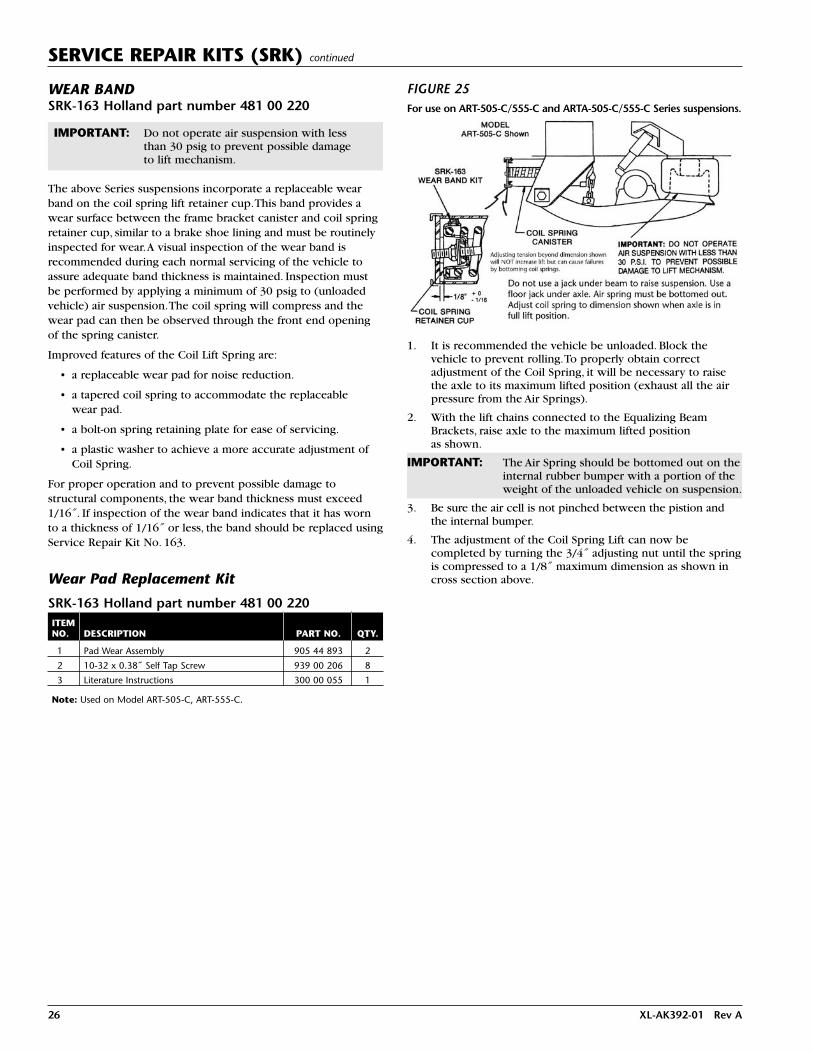
WEAR BANDSRK-163 Holland part number 481 00 220
IMPORTANT: Do not operate air suspension with less than 30 psig to prevent possible damage to lift mechanism.
The above Series suspensions incorporate a replaceable wearband on the coil spring lift retainer cup.This band provides awear surface between the frame bracket canister and coil springretainer cup, similar to a brake shoe lining and must be routinelyinspected for wear.A visual inspection of the wear band isrecommended during each normal servicing of the vehicle toassure adequate band thickness is maintained. Inspection mustbe performed by applying a minimum of 30 psig to (unloadedvehicle) air suspension.The coil spring will compress and thewear pad can then be observed through the front end openingof the spring canister.
Improved features of the Coil Lift Spring are:
• a replaceable wear pad for noise reduction.
• a tapered coil spring to accommodate the replaceable wear pad.
• a bolt-on spring retaining plate for ease of servicing.
• a plastic washer to achieve a more accurate adjustment ofCoil Spring.
For proper operation and to prevent possible damage tostructural components, the wear band thickness must exceed1/16˝. If inspection of the wear band indicates that it has wornto a thickness of 1/16˝ or less, the band should be replaced usingService Repair Kit No. 163.
FIGURE 25
Wear Pad Replacement Kit
SRK-163 Holland part number 481 00 220ITEMNO. DESCRIPTION PART NO. QTY.
1 Pad Wear Assembly 905 44 893 2
2 10-32 x 0.38˝ Self Tap Screw 939 00 206 8
3 Literature Instructions 300 00 055 1
Note: Used on Model ART-505-C, ART-555-C.
SERVICE REPAIR KITS (SRK) continued
1. It is recommended the vehicle be unloaded. Block thevehicle to prevent rolling.To properly obtain correctadjustment of the Coil Spring, it will be necessary to raisethe axle to its maximum lifted position (exhaust all the airpressure from the Air Springs).
2. With the lift chains connected to the Equalizing BeamBrackets, raise axle to the maximum lifted position as shown.
IMPORTANT: The Air Spring should be bottomed out on theinternal rubber bumper with a portion of theweight of the unloaded vehicle on suspension.
3. Be sure the air cell is not pinched between the pistion andthe internal bumper.
4. The adjustment of the Coil Spring Lift can now becompleted by turning the 3/4˝ adjusting nut until the springis compressed to a 1/8˝ maximum dimension as shown incross section above.
For use on ART-505-C/555-C and ARTA-505-C/555-C Series suspensions.

XL-AK392-01 Rev A 27
COMPONENT REPLACEMENT INSTRUCTIONS
ART Frame Bracket Replacement
In the event it becomes necessary to replace cast front framebrackets on Holland models ART-500-US,ART-500-US-A,ART-550-USSeries, or ART-551-US Series, a service repair kit (SRK) using afabricated frame bracket must be specified (FIGURE 26).
These kits are available to replace the frame brackets in pairs or singles, right- or left-hand brackets. However, we recommendthey be replaced as pairs for uniformity. Refer to the selectionchart below for proper SRK requirements.
The frame brackets supplied with these kits will not be pre-drilled, so present frame holes can be used as guides.
8-3/8"11-1/2" 6-1/2"
Axle Cap Replacement
ART–500–USART–500–US–AART–550–US–1, –2 & –3ART–551–US–1, –2 & –3
Axle Cap (New Style vs Old Style)WITHOUT AXLE STOPS WITH AXLE STOPS
MODEL LEFT HAND RT. HAND LEFT HAND RT. HAND
ART–500–US* 905 10 100** 905 10 101** 905 10 102** 905 10 103**
ART–500–US–A 905 10 100** 905 10 101** 905 10 102** 905 10 103**
ART–550–US–1, –2 & –3 900 10 003 900 10 003 905 10 005 905 10 005
ART–551–US–1, –2 & –3* 905 10 074 905 10 075 905 10 076 905 10 077
When converting to this new style cap, you must also order a new style rubberwrapper, part number 900 28 047.
*When ordering new caps for these models, also order a 3/4”–10 x 3 1/2” Hex HeadScrew, part number 930 03 597 and 3/4”–10 Lock Nut, part number 934 00 492, for lower shock absorber connection.
**These are new style caps:905 10 100 Replaces 905 10 001 & 905 10 016905 10 101 Replaces 905 10 002 & 905 10 017905 10 102 Replaces 905 10 014 & 905 10 018905 10 103 Replaces 905 10 015 & 905 10 019.
NEW STYLE OLD STYLE
FIGURE 26
FIGURE 27
28 XL-AK392-01 Rev A
NOTE: Service Repair Kits (SRK) are available for the ARTsuspensions, see page 19. For further information,contact your Holland distributor.
Air Spring Assembly
1. Remove load; tractor with mechanical suspension will maintainproper clearance for removal of air spring. If air suspension is not combined with a mechanical suspension or load isnot removed, then adequate jacks or stand must be used to support tractor frame.
2. If all air is not exhausted from the suspension air system,then exhaust at this time.
IMPORTANT: Do not have anyone in the path of the axlewhen the axle is raised or lowered.
If suspension is a coil spring model,exhausting all air in suspension
system raises the axle immediately which, if notavoided, could result in death or serious injury.
NOTE: To lower axle, apply hydraulic jack (5-ton minimum)between suspension or axle and frame. Push axle downto approximate ride height and insert adequate steelspacer blocks between suspension or axle and frame.Release pressure from hydraulic jack and remove.
3. Disconnect air supply line from top of air spring.
4. Remove fasteners and old air spring assembly.
5. Install new air spring assembly and properly torque fastener.Then reconnect air supply line. See Torque Chart page 4.
6. If suspension is coil spring lift model, build tractor air pressurein excess of 65 psig and apply sufficient air pressure to airsprings to remove spacer blocks. Check for air leaks.
While vehicle air system pressurecapabilities may be in excess of 120
psig, the air spring pressure must not be set above100 psig for normal static vehicle conditions.Operating with static pressure greater than 100 psigmay shorten the life of an air spring.
Shock Absorbers
1. Position tractor frame at approximate suspension rideheight to relieve all tension on shock absorbers.
2. Remove upper and lower shock mounting bolts.
3. Install new shocks and reinstall mounting bolts.
4. Torque fasteners per Torque Chart on page 4.
Axle Connection Pads and Wrappers
When replacing the axle connection rubber pads and wrappers,it is recommended to also replace the U-bolts and nuts with newones. Refer to page 27 for selection of New or Old style parts. Itmay be an advantage to rebuild the front pivot connection at thistime. Refer to page 19 for proper service repair kit (SRK).
1. Exhaust all air from the suspension air system.
IMPORTANT: Do not have anyone in the path of the axlewhen the axle is raised or lowered.
COMPONENT REPLACEMENT INSTRUCTIONS continued
If suspension is a coil spring model,exhausting all air in suspension system
raises the axle immediately which, if not avoided,could result in death or serious injury.
2. Support axle with jacks.Then remove tires and disconnectthe shock absorber and air spring at the lower end.
NOTE: If coil spring lift model,turn adjusting nut on yoke rodto release tension on chain.With tensionreleased, disconnect chain from bracket (FIGURE 28).
3. On coil spring lift models, lower axle to approximate rideheight. Place a jack under each equalizing beam.
ADJUSTINGNUT
DISCONNECTCHAIN FROMBRACKET
FIGURE 28
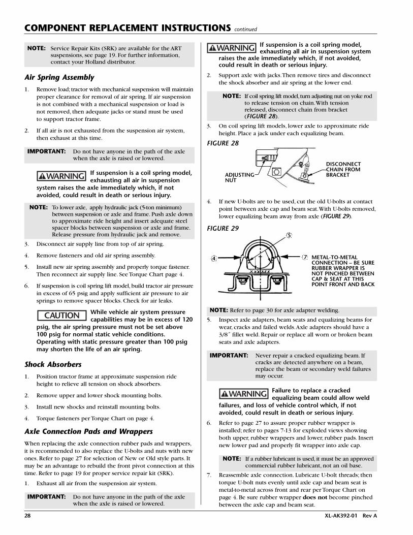
4. If new U-bolts are to be used, cut the old U-bolts at contactpoint between axle cap and beam seat.With U-bolts removed,lower equalizing beam away from axle (FIGURE 29).
NOTE: Refer to page 30 for axle adapter welding.
5. Inspect axle adapters, beam seats and equalizing beams forwear, cracks and failed welds.Axle adapters should have a3/8˝ fillet weld. Repair or replace all worn or broken beamseats and axle adapters.
IMPORTANT: Never repair a cracked equalizing beam. Ifcracks are detected anywhere on a beam,replace the beam or secondary weld failuresmay occur.
Failure to replace a crackedequalizing beam could allow weld
failures, and loss of vehicle control which, if notavoided, could result in death or serious injury.
6. Refer to page 27 to assure proper rubber wrapper isinstalled; refer to pages 7-13 for exploded views showingboth upper, rubber wrappers and lower, rubber pads. Insertnew lower pad and properly fit wrapper into axle cap.
NOTE: If a rubber lubricant is used, it must be an approvedcommercial rubber lubricant, not an oil base.
7. Reassemble axle connection. Lubricate U-bolt threads; thentorque U-bolt nuts evenly until axle cap and beam seat ismetal-to-metal across front and rear per Torque Chart onpage 4. Be sure rubber wrapper does not become pinchedbetween the axle cap and beam seat.
FIGURE 29
METAL-TO-METALCONNECTION – BE SURERUBBER WRAPPER ISNOT PINCHED BETWEENCAP & SEAT AT THISPOINT FRONT AND BACK
4
5
7

XL-AK392-01 Rev A 29
COMPONENT REPLACEMENT INSTRUCTIONS continued
9. Remove jacks and stands.Apply air pressure in excess of 65 psig but not over 100 psig (maximum, allowableoperating pressure) to air suspension system.
Equalizing Beam or Pivot Bushing
NOTE: If replacing the pivot bushing only — you can use a Holland Bushing Service Tool. Purchase Part No.505 44 001 at your Holland Distributor.
NOTE: It may be an advantage to replace the rubber wrappersand pads at this time. If so, see instructions on page 27.Refer to page 19 for proper SRK.
1. Follow the same disassembling procedure for Axle ConnectionPads and Wrappers through Step 3 on page 28.
2. If new U-bolts are to be used, cut the old U-bolts at contactpoint between axle cap and beam seat (FIGURE 31).
3. If not replacing rubber pads and rubber wrappers at thistime and are using a torch to cut U-bolts, do not overheatthe pads and wrappers.
NOTE: Overheated rubber pads or wrappers must bereplaced.
Failure to replace overheatedrubber pads and wrappers could
result in U-bolt failure and separation of axle andsuspension which, if not avoided, could result in deathor serious injury.
4. Remove front pivot bolt and, with U-bolts removed (noticeposition of spacer washers), lower equalizing beam awayfrom axle.
5. Set rubber pads and rubber wrappers aside for reinstalling ifnot using new ones. Inspect all parts to be reused. Repair orreplace all worn and broken parts. Check for sound welds;axle adapters should have a 3/8˝ fillet weld.
IMPORTANT: Never repair a cracked equalizing beam. Ifcracks are detected anywhere on a beam,replace the beam or secondary weld failuresmay occur.
CUT U-BOLTSAT THIS POINT
CHECK WELDS
FRONTPIVOTBOLT
FIGURE 31
Failure to replace a crackedequalizing beam could allow weld
failures, and loss of vehicle control which, if notavoided, could result in death or serious injury.
6. If replacing the pivot bushings only, press out old bushingwith hydraulic press of 5-ton capacity minimum. Clean outbushing receptacle, Lubricate new bushing with approvedlubricant, not oil based. Press new bushing in bushingreceptacle past center.Turn beam over and center bushingin receptacle.
NOTE: If a rubber lubricant is used, it must be an approvedcommercial rubber lubricant, not an oil base.
7. Install new Delrin Liner (FIGURE 32).Some models may notinclude this part.
8. Insert new or rebushed beam into frame bracket. Installspacer washers in same location removed from (frame widthof 34˝ one each side, 33-1/2˝ both to inside or 34-1/2˝ bothto outside). Attach equalizing beam to frame bracket.Torque1-1/8˝ nut per Torque Chart on page 4 (FIGURE 33).
34˝ FRAME WIDTH 34-1/2˝ FRAME WIDTH 33-1/2˝ FRAME WIDTH
FIGURE 33
9. See Steps 7 through 9 of Axle Connection Pads andWrappers instructions, to reassemble axle connection.
Coil Spring Cam Assembly
NOTE: Refer to page 21 for list of Coil Spring SRKs.
NOTE: To assure proper Service Repair Kit has beenselected, refer to pages 22-25.
1. Release air in suspension system.
IMPORTANT: Do not have anyone in the path of the axlewhen the axle is raised or lowered.
If suspension is a coil spring model,exhausting all air in suspension
system raises the axle immediately which, if notavoided, could result in death or serious injury.
FIGURE 30
8. Reinstall air springs and shock absorber and properly torquefasteners. If coil spring lift model, raise axle to complete “up position” and reconnect chain to beam bracket. Readjustadjusting nut to 1/8˝ dimension only as shown (FIGURE 30).If camshafts were removed, reinstall. Reinstall tires.
FIGURE 34
FIGURE 32
DELRIN LINER

30 XL-AK392-01 Rev A
COMPONENT REPLACEMENT INSTRUCTIONS continued
2. With axle in lift position, remove tires.Then place jackunder axle and lift until jack supports vehicle weight.
3. Relieve tension on Yoke Rod by removing adjusting nut from yoke rod.
4. Disconnect chain from beam bracket; then lower axle to approximate ride height.
5. Remove cam assembly and replace necessary parts.
6. Install cam assembly in frame bracket and torque 3/4˝ lowercam pin nut to 150 ft. lbs. torque lubricated.
7. Jack axle up until jack supports vehicle weight.Then reconnectlinkage assembly to beam bracket; torque to 50 ft. lbs. lubricated.
8. Install yoke grommet and adjusting nut.Tighten only enoughto put a slight compression to coil spring.
9. Install tires; then remove jacks.
10. Adjust coil spring lift to 1/8˝, only as shown.
11. Apply and release air pressure with the hand control valveto assure proper lift operation. Readjust if necessary.
12. Grease yoke rod and cam bearings, repeating every 5,000miles minimum.
Axle Adapter Welding Specification
The following welding recommendations are for the fieldinstallation of a Holland air ride axle adapter and should beperformed by a qualified welder.
1. The adapter should be clamped securely in the proper position.
2. The axle tube and adapter must be 70° F minimum and befree from dirt, scale and grease.
3. The electrode or wire selected must conform to one of thefollowing specifications:
a. Electrode AWS E-7018 (Oven-Dried) 5/32˝ Dia.120-190 Amps D.C.+ 135-225 Amps A.C.3/16˝ Dia.170-280 Amps D.C.+ 200-300 Amps A.C.
b.Wire AWS E-70S-3 AWS E-70T-1Gas C-25 CO2 Volts 19-20 21-23 Amps 180-200 200-220 Wire Dia. .045˝ .062˝ Flux Cored
4. Apply welds in the sizes and sequence shown in (FIGURE 35).Fill the crater at the end of the weld, and clean the weldbetween passes.
NOTE: Each weld pass is to be completed in two segments.
FIGURE 35

XL-AK392-01 Rev A 31
TROUBLESHOOTING
Problem
Air Spring Problems
NOTE: If loss of air exists in air suspensionsystem, there is an internal rubberbumper built into the air spring,whichmakes it possible to operate vehicleto a service center.Turn hand valveto deflate position (0 psig or 3 psigminimum pressure setting) andproceed carefully to the nearestservice center.
Do not overload theaxle or the suspension
or suspension component damage mayoccur which, if not avoided, could resultin vehicle damage and/or death orserious injury.
Insufficient air pressure to suspension.
Air leak or damaged line.
Air spring punctured, cut or leaking.
Tires or tire rim rubbing air spring.
Air brake chamber rubbing air cell.
Continual over-extension of air springs.
Possible Remedy
Build tractor air pressure in excess of 65 psig.
Defective brake protection valve; replace.
Check air compressor.
Adjust hand valve to minimum setting of 3 psig. See page 18.
Locate and repair.
Replace with proper air spring.Then check for proper clearance around air spring,1-3/4˝ minimum.
Check inside to inside tire dimension. It may be necessary to reinstall suspension.
Use tire rim back spacers to provide more clearance.
Relocate chamber or clamp ring for more clearance.
Suspension riding too high unloaded; reduce air pressure to 3 psig when empty or bob-tailing.
Shock absorbers and/or connections broken – replace.
Wrong length shock absorbers.
Mislocation of upper shock brackets (Models ART-500, -550 & -551); relocate. Reduceair pressure before disconnecting.
Improper installation or application of suspension, such as improper ride height orcomponent parts. Check and replace if necessary.
continued

32 XL-AK392-01 Rev A
TROUBLESHOOTING continued
Problem
Front Pivot Bushing Worn Prematurely
Alignment bushing(s) not welded.
Front pivot bolt loose.
Excessive lateral axle walk.
Excessive U-Bolt Failures
Axle beam seat(s) not welded.
Insufficient torque (loose axle connection).
Suspension overloaded due to operatingconditions, such as rough terrain.
Repeated Shock Absorber Failures
Over-extending shock absorbers.
Suspension mounted at wrong ride height.
Wrong length or improper replacementshock absorber(s).
Mislocation of upper shock mountbracket(s) (Models ART-500, -550 & -551).
Axle Misaligned
Index aligning blocks not welded.
Front bushing worn. Delrin liner worn or missing.
Insufficient Lifted Tire Clearance
Excessive drive axle spring leaf deflection.
Misadjusted lift mechanism.
Possible Remedy
Weld per installation instructions.
Torque nut per Torque Chart on page 4.
Axle beam seat(s) not welded; weld properly.
Axle connection U-bolts loose; tighten. Follow proper instructions.
Worn axle adapter(s); shim on rear side or replace.
Realign axle and weld beam seat(s) to equalizing beam.
Torque nut (clean and oiled) per Torque Chart on page 4; assure metal-to-metalcondition. See page 28.
Install axle stops.
Reduce air pressure when light or bob-tailing, 3 psig.
Check Specification sheet.
Replace with proper part(s).
Relocate if necessary. Reduce air pressure before disconnecting.
Realign to drive axle and weld to specifications.
Replace worn or missing parts as required.
Add spring leaves as required or relocate overload brackets.
Adjust to specification. Refer to installation instructions.
continued

XL-AK392-01 Rev A 33
TROUBLESHOOTING continued
Problem
Axle Off Tracking
Loose or worn axle connection.
Axle misaligned.
Worn axle adapter.
Alignment bushing(s) not welded or broken.
Possible Remedy
If loose, tighten connection, page 28.Then check axle alignment; realign if necessary.If worn, shim rear side of axle adapter or replace. See page 19 for SRK.
Align axle; then properly weld alignment bushings and tighten pivot connection bolts.
Shim rear side of adapter or replace.
If broken, replace. If not welded properly,weld alignment bushing(s) after axle alignment.

34 XL-AK392-01 Rev A

XL-AK392-01 Rev A 35

36 XL-AK392-01 Rev A
E n g i n e e r i n g Y o u r R o a d t o S u c c e s s
www.safholland.com
SAF-HOLLAND USA, Inc. SAF-HOLLAND Canada Limited SAF-HOLLAND International, Inc.888.396.6501 Fax 800.356.3929 519.537.3494 Fax 800.565.7753 616.396.6501 Fax 616.356.1511
Western Canada604.574.7491 Fax 604.574.0244
Copyright © October 2007-SAF-HOLLAND, Inc. All information contained in this document was correct at time of copyright, and is subject to change without notice. All rights reserved.