SMART Digital XL - Pump Solutions
60
GRUNDFOS DATA BOOKLET SMART Digital XL DIGITAL DOSING from 60 to 200 l/h DDA, DDE Pumps and accessories
-
Upload
khangminh22 -
Category
Documents
-
view
1 -
download
0
Transcript of SMART Digital XL - Pump Solutions

GRUNDFOS DATA BOOKLET
SMART Digital XLDIGITAL DOSING from 60 to 200 l/h
DDA, DDE
Pumps and accessories

Ta
ble
of c
on
ten
ts
2
SMART Digital XL
1. General data 3Performance range . . . . . . . . . . . . . . . . . . . . . . . . . . . . . . . . . . . . . . . . . . . . . . . . . . . . . . . . . . . . . . . . . . . . . . . . . . . . 3
Features at a glance . . . . . . . . . . . . . . . . . . . . . . . . . . . . . . . . . . . . . . . . . . . . . . . . . . . . . . . . . . . . . . . . . . . . . . . . . . . 4
2. Identification 6
3. Functions overview 7Overview of functions. . . . . . . . . . . . . . . . . . . . . . . . . . . . . . . . . . . . . . . . . . . . . . . . . . . . . . . . . . . . . . . . . . . . . . . . . . . 7
Functional description . . . . . . . . . . . . . . . . . . . . . . . . . . . . . . . . . . . . . . . . . . . . . . . . . . . . . . . . . . . . . . . . . . . . . . . . . . 8
4. Functions DDA 9Operating elements DDA . . . . . . . . . . . . . . . . . . . . . . . . . . . . . . . . . . . . . . . . . . . . . . . . . . . . . . . . . . . . . . . . . . . . . . . . 9
Operation modes DDA. . . . . . . . . . . . . . . . . . . . . . . . . . . . . . . . . . . . . . . . . . . . . . . . . . . . . . . . . . . . . . . . . . . . . . . . . 10
Functions DDA. . . . . . . . . . . . . . . . . . . . . . . . . . . . . . . . . . . . . . . . . . . . . . . . . . . . . . . . . . . . . . . . . . . . . . . . . . . . . . . 12
Wiring diagram, DDA . . . . . . . . . . . . . . . . . . . . . . . . . . . . . . . . . . . . . . . . . . . . . . . . . . . . . . . . . . . . . . . . . . . . . . . . . . 17
5. Functions DDE 18Operating elements DDE . . . . . . . . . . . . . . . . . . . . . . . . . . . . . . . . . . . . . . . . . . . . . . . . . . . . . . . . . . . . . . . . . . . . . . . 18
Operation modes DDE. . . . . . . . . . . . . . . . . . . . . . . . . . . . . . . . . . . . . . . . . . . . . . . . . . . . . . . . . . . . . . . . . . . . . . . . . 19
Functions DDE. . . . . . . . . . . . . . . . . . . . . . . . . . . . . . . . . . . . . . . . . . . . . . . . . . . . . . . . . . . . . . . . . . . . . . . . . . . . . . . 20
Wiring diagram, DDE . . . . . . . . . . . . . . . . . . . . . . . . . . . . . . . . . . . . . . . . . . . . . . . . . . . . . . . . . . . . . . . . . . . . . . . . . . 21
6. Construction 22DDA . . . . . . . . . . . . . . . . . . . . . . . . . . . . . . . . . . . . . . . . . . . . . . . . . . . . . . . . . . . . . . . . . . . . . . . . . . . . . . . . . . . . . . . 22
DDE . . . . . . . . . . . . . . . . . . . . . . . . . . . . . . . . . . . . . . . . . . . . . . . . . . . . . . . . . . . . . . . . . . . . . . . . . . . . . . . . . . . . . . . 23
7. Dimensions 24
8. Technical data 25DDA . . . . . . . . . . . . . . . . . . . . . . . . . . . . . . . . . . . . . . . . . . . . . . . . . . . . . . . . . . . . . . . . . . . . . . . . . . . . . . . . . . . . . . . 25
DDE . . . . . . . . . . . . . . . . . . . . . . . . . . . . . . . . . . . . . . . . . . . . . . . . . . . . . . . . . . . . . . . . . . . . . . . . . . . . . . . . . . . . . . . 26
9. Pump selection 27DDA, standard range . . . . . . . . . . . . . . . . . . . . . . . . . . . . . . . . . . . . . . . . . . . . . . . . . . . . . . . . . . . . . . . . . . . . . . . . . . 27
DDE, standard range . . . . . . . . . . . . . . . . . . . . . . . . . . . . . . . . . . . . . . . . . . . . . . . . . . . . . . . . . . . . . . . . . . . . . . . . . . 28
DDA, DDE, non-standard range . . . . . . . . . . . . . . . . . . . . . . . . . . . . . . . . . . . . . . . . . . . . . . . . . . . . . . . . . . . . . . . . . 29
10. Accessories for medium-sized dosing pumps up to 460 l/h 30Accessories overview . . . . . . . . . . . . . . . . . . . . . . . . . . . . . . . . . . . . . . . . . . . . . . . . . . . . . . . . . . . . . . . . . . . . . . . . . 30
Cables and plugs . . . . . . . . . . . . . . . . . . . . . . . . . . . . . . . . . . . . . . . . . . . . . . . . . . . . . . . . . . . . . . . . . . . . . . . . . . . . . 31
Hoses. . . . . . . . . . . . . . . . . . . . . . . . . . . . . . . . . . . . . . . . . . . . . . . . . . . . . . . . . . . . . . . . . . . . . . . . . . . . . . . . . . . . . . 32
Foot valves FV . . . . . . . . . . . . . . . . . . . . . . . . . . . . . . . . . . . . . . . . . . . . . . . . . . . . . . . . . . . . . . . . . . . . . . . . . . . . . . . 33
Rigid suction lances RSL . . . . . . . . . . . . . . . . . . . . . . . . . . . . . . . . . . . . . . . . . . . . . . . . . . . . . . . . . . . . . . . . . . . . . . . 34
Level-control units . . . . . . . . . . . . . . . . . . . . . . . . . . . . . . . . . . . . . . . . . . . . . . . . . . . . . . . . . . . . . . . . . . . . . . . . . . . . 37
Injection units . . . . . . . . . . . . . . . . . . . . . . . . . . . . . . . . . . . . . . . . . . . . . . . . . . . . . . . . . . . . . . . . . . . . . . . . . . . . . . . . 38
Pressure relief valves PRV . . . . . . . . . . . . . . . . . . . . . . . . . . . . . . . . . . . . . . . . . . . . . . . . . . . . . . . . . . . . . . . . . . . . . 39
Pressure loading valves PLV . . . . . . . . . . . . . . . . . . . . . . . . . . . . . . . . . . . . . . . . . . . . . . . . . . . . . . . . . . . . . . . . . . . . 40
Pressure valves PV . . . . . . . . . . . . . . . . . . . . . . . . . . . . . . . . . . . . . . . . . . . . . . . . . . . . . . . . . . . . . . . . . . . . . . . . . . . 41
Pulsation dampers and calibration columns . . . . . . . . . . . . . . . . . . . . . . . . . . . . . . . . . . . . . . . . . . . . . . . . . . . . . . . . 42
Pump connection kits and inlay kits . . . . . . . . . . . . . . . . . . . . . . . . . . . . . . . . . . . . . . . . . . . . . . . . . . . . . . . . . . . . . . . 51
Electric stirrers . . . . . . . . . . . . . . . . . . . . . . . . . . . . . . . . . . . . . . . . . . . . . . . . . . . . . . . . . . . . . . . . . . . . . . . . . . . . . . . 52
Withdrawal devices . . . . . . . . . . . . . . . . . . . . . . . . . . . . . . . . . . . . . . . . . . . . . . . . . . . . . . . . . . . . . . . . . . . . . . . . . . . 54
Adapters. . . . . . . . . . . . . . . . . . . . . . . . . . . . . . . . . . . . . . . . . . . . . . . . . . . . . . . . . . . . . . . . . . . . . . . . . . . . . . . . . . . . 55
Wall or tank mounting assembly for SMART Digital XL DDA/DDE . . . . . . . . . . . . . . . . . . . . . . . . . . . . . . . . . . . . . . . 56
Tank accessories . . . . . . . . . . . . . . . . . . . . . . . . . . . . . . . . . . . . . . . . . . . . . . . . . . . . . . . . . . . . . . . . . . . . . . . . . . . . . 57
11. Pumped liquids 58
12. Grundfos Product Center 59

Ge
ne
ral
da
ta
3
SMART Digital XL 1
1. General data
Performance range
Fig. 1 Performance range
TM
06
73
27
33
16
Q [l/h]
10
7
60 120 200
4
0
P
[bar]
DDA 60-10
DDE 60-10
DDA 120-7
DDE 120-7
DDA 200-4
DDE 200-4

Ge
ne
ral d
ata
4
SMART Digital XL1
Features at a glance
Fig. 2 DDA, DDE
Digital DosingTM
The SMART Digital XL generation DDA and DDE with
powerful PMS (Permanent Magnet Synchronous)
motor brings state-of-the-art technology to perfection.
Combined expert knowledge and the patented
solutions set future standards. Traditional technologies
such as stroke length or stroke frequency adjustment
with asynchronous motor become a thing of the past.
Unique flexibility with only a few variants
The included mounting plate makes the pump more
flexible. Service and pump exchange is easy and fast:
just dismantle the pump from the mounting plate by
removing two screws.
The control cube of the pump can be lifted and turned
into three different positions: front, left or right.
Fig. 3 Modularity of the control cube
A turn-down ratio of 1:800, a wide supply voltage
range (100-240 V, 50/60 Hz), combined connection
sets and other features reduce the models and
variants to a minimum.
Precise and easy setting / usability and interaction
The operator can easily install the pump and set it to
discharge exactly the quantity of dosing liquid required
for the application. In the display of the DDA pump, the
setting of the pump is read out directly, the flow is
shown in ml/h, l/h, or gph.
The click wheel (turn-and-push knob) and the
graphical LC display with plain-text menu in up to 28
languages make commissioning and operation
intuitive. As the LCD is backlit in different colours, the
pump status can be seen from a distance (traffic-light
concept).
Fig. 4 Display DDA
Thanks to a variety of operation modes, signal inputs
and outputs, the pump can easily be integrated into
every process.
Advanced process reliability
An intelligent drive and microprocessor control
ensures that dosing is performed precisely and with
low pulsation, even if the pump is dosing high-viscosity
or degassing liquids. Malfunctions, caused by air
bubbles for example, are detected quickly by the
maintenance-free FlowControl system and then
displayed in the alarm menu.
The AutoFlowAdapt function automatically adjusts the
pump according to the process conditions, suchas
varying backpressure. The integrated flow
measurement makes additional monitoring and control
equipment redundant.
Designed to save costs
In general, the investment for a dosing pump
installation is low compared to its life cycle costs
including the cost of the chemicals. The following
features make the SMART Digital XL DDA and DDE
pumps contribute to low life cycle costs:
� No underdosing or overdosing due to high dosing
accuracy and FlowControl
� Longer maintenance intervals thanks to the
universal chemical resistance of the double
full-PTFE diaphragm
� Reduced energy consumption thanks to
state-of-the-art drive technology.
TM
06
73
28
33
16
TM
06
73
29
33
16
TM
06
73
30
33
16
60.0 l/hManual
60.0 l/h
Operation
Ge
ne
ral
da
ta
5
SMART Digital XL 1
Two application-oriented type ranges
DDA is the high-end pump range for extended flow and
pressure ranges with sensor-based FlowControl and
measurement functions for challenging industrial
applications, such as:
� Drinking water treatment
� Wastewater treatment
� Boiler water treatment
� Cooling water treatment
� Process water treatment
� Chemical industry
� Ultrafiltration process and reverse osmosis
� Food and beverage industry
� Paper and pulp industry.
DDE is the economical pump range with basic
functions including manual operation or control via
PLC for OEM applications, such as:
� Drinking water treatment
� Wastewater treatment
� Boiler water treatment
� Cooling water treatment
� Process water treatment
� Chemical industry
� Ultrafiltration process and reverse osmosis
� Food and beverage industry
� Paper and pulp industry
� Irrigation
� Swimming pool water.

Ide
ntific
atio
n
6
SMART Digital XL2
2. Identification
The type key is used to identify the precise pump and
is not used for configuration purposes.
Example: DDA 60-10 FCM-PVC/V/C-F-31U3U3FG
Type
DDA 60-10 FCM-PVC/V/C-F-31U3U3FG
DDA
DDE
Max. flow [l/h]
DDA 60-10 FCM-PVC/V/C-F-31U3U3FG
Max. pressure [bar]
DDA 60-10 FCM-PVC/V/C-F-31U3U3FG
Control variant
DDA 60-10 FCM-PVC/V/C-F-31U3U3FG
B Basic (only DDE)
ARDDA: Alarm relayDDE: B with pulse mode, analog mode and alarm relay
FCM AR + FlowControl function
Dosing head variant
DDA 60-10 FCM-PVC/V/C-F-31U3U3FG
PVC Polyvinyl chloride
PV PVDF
SS Stainless steel 1.4401
PVC-L PVC + integrated diaphragm leakage detection
PV-L PV + integrated diaphragm leakage detection
SS-L SS + integrated diaphragm leakage detection
Gasket material
DDA 60-10 FCM-PVC/V/C-F-31U3U3FG
E EPDM
V FKM
T PTFE
Valve ball material
DDA 60-10 FCM-PVC/V/C-F-31U3U3FG
C Ceramics
SS Stainless steel 1.4401
Control cube
DDA 60-10 FCM-PVC/V/C-F-31U3U3FG
F Front mounted (change to left or right is possible)
Supply voltage
DDA 60-10 FCM-PVC/V/C-F-31U3U3FG
3 100-240 V 50/60 Hz single phase
Valve type
DDA 60-10 FCM-PVC/V/C-F-31U3U3FG
1 Standard
2 Spring-loaded
Connection, inlet / outlet
DDA 60-10 FCM-PVC/V/C-F-31U3U3FG
U3U3 2x Union nut G 5/4"
2x Hose connector 19/20 mm
2x Hose clamp
2x Pipe connector 25 mm
A7A7 2x Union nut G 5/4"
2x Inlay external thread 3/4" NPT
A1A1 2x Union nut G 5/4" (SS)
2x Inlay internal thread Rp 3/4" (SS)
A3A3 2x Union nut G5/4 (SS)
2x Inlay internal thread 3/4" NPT (SS)
Mains plug
DDA 60-10 FCM-PVC/V/C-F-31U3U3FG
F EU (Schuko)
B USA, Canada
G UK
I Australia, New Zealand, Taiwan
E Switzerland
J Japan
L Argentina
Design / approval
DDA 60-10 FCM-PVC/V/C-F-31U3U3FG
G Grundfos red
A Grundfos green
B Grundfos black
X Neutral / black
C China approval
Special variant
DDA 60-10 FCM-PVC/V/C-F-31U3U3FGC3
Standard
C3 Inspection certificate 3.1 (EN 10204)
Connection, inlet / outlet

Fu
nc
tio
ns
ov
erv
iew
7
SMART Digital XL 3
3. Functions overview
Overview of functions
* DDE-AR: relay 1: alarm; relay 2: low-level signal, stroke signal, pulse input
DDA DDE
Control variant: FCM AR AR B
General
Digital Dosing: Internal stroke speed control and frequency control ● ● ● ●Mounting plate ● ● ● ●
Control panel, see page 9 and 18
Control cube mountable in three positions: front, left, right ● ● ● ●Transparent protective cover for control elements ● ● ● ●Capacity setting in millilitres, litres or US-gallons ● ●Graphical display with background light in four colours for status indication: white, green, yellow, red ● ●LEDs for operation mode, warning and alarm ● ●Plain-text menu in different languages ● ●Turn-and-push knob (click wheel) for easy navigation ● ●Capacity adjusting knob (0.125 - 100 %) ● ●Start/Stop key ● ●100 % key (deaearation) ● ● ●Operation mode key (manual/pulse/analog) ●
Operation modes, see page 10 and 19
Manual speed control ● ● ● ●Pulse control in ml/pulse ● ●Pulse control (1:n) ●Analog control 4-20 mA ●Analog control 0/4-20 mA ● ●Batch control (pulse-based) ● ●Dosing timer cycle ● ●Dosing timer week ● ●Fieldbus control ● ●
Functions, see page 12 and 20
Auto deaeration also during pump standby ● ●FlowControl system with selective fault diagnosis ●Pressure monitoring (min/max) ●Flow measurement ●AutoFlowAdapt ●SlowMode (anti-cavitation) ● ●Calibration mode ● ●Full scaling of analog input ● ●Scaling of maximum analog input ●Service information display ● ●Relay setting: alarm, warning, stroke signal, pump dosing, pulse input* ● ● ●Relay setting (additionally): timer cycle, timer week ● ●
Inputs/outputs, see page 12 and 20
Input for external stop ● ● ●Input for pulse control ● ● ●Input for analog 4-20 mA control ●Input for analog 0/4-20 mA control ● ●Input for low-level signal ● ● ●Input for empty tank signal ● ● ●Output relay (2 relays) ● ● ●Output analog 0/4-20 mA ● ●Input/Output for GENIbus ● ●Input for software update ● ● ● ●Input/Output for CIU (Profibus DP, Modbus, GRM, Ethernet etc.) ● ●
Fu
nc
tion
s o
ve
rvie
w
8
SMART Digital XL3
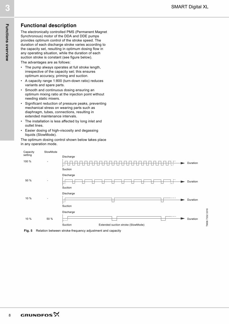
Functional descriptionThe electronically controlled PMS (Permanent Magnet
Synchronous) motor of the DDA and DDE pumps
provides optimum control of the stroke speed. The
duration of each discharge stroke varies according to
the capacity set, resulting in optimum dosing flow in
any operating situation, while the duration of each
suction stroke is constant (see figure below).
The advantages are as follows:
� The pump always operates at full stroke length,
irrespective of the capacity set; this ensures
optimum accuracy, priming and suction.
� A capacity range 1:800 (turn-down ratio) reduces
variants and spare parts.
� Smooth and continuous dosing ensuring an
optimum mixing ratio at the injection point without
needing static mixers.
� Significant reduction of pressure peaks, preventing
mechanical stress on wearing parts such as
diaphragm, tubes, connections, resulting in
extended maintenance intervals.
� The installation is less affected by long inlet and
outlet lines.
� Easier dosing of high-viscosity and degassing
liquids (SlowMode).
The optimum dosing control shown below takes place
in any operation mode.
Fig. 5 Relation between stroke-frequency adjustment and capacity
TM
06
73
32
33
16
100 %
50 %
10 %
Discharge
Discharge
Discharge
Duration
Duration
Duration
Suction
Suction
Suction
Capacity setting
Duration10 %
Discharge
Suction
SlowMode
50 %
Extended suction stroke (SlowMode)
-
-
-
Fu
nc
tio
ns
DD
A
9
SMART Digital XL 4
4. Functions DDA
Operating elements DDA
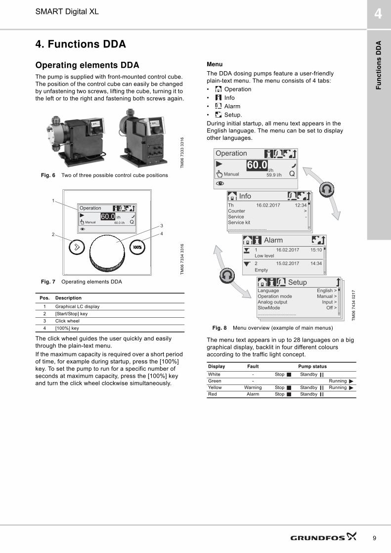
The pump is supplied with front-mounted control cube.
The position of the control cube can easily be changed
by unfastening two screws, lifting the cube, turning it to
the left or to the right and fastening both screws again.
Fig. 6 Two of three possible control cube positions
Fig. 7 Operating elements DDA
The click wheel guides the user quickly and easily
through the plain-text menu.
If the maximum capacity is required over a short period
of time, for example during startup, press the [100%]
key. To set the pump to run for a specific number of
seconds at maximum capacity, press the [100%] key
and turn the click wheel clockwise simultaneously.
Menu
The DDA dosing pumps feature a user-friendly
plain-text menu. The menu consists of 4 tabs:
� Operation
� Info
� Alarm
� Setup.
During initial startup, all menu text appears in the
English language. The menu can be set to display
other languages.
Fig. 8 Menu overview (example of main menus)
The menu text appears in up to 28 languages on a big
graphical display, backlit in four different colours
according to the traffic light concept.
TM
06
73
33
33
16
TM
06
73
34
33
16
Pos. Description
1 Graphical LC display
2 [Start/Stop] key
3 Click wheel
4 [100%] key
60.0 l/hManual
60.0 l/h
Operation
1
2
3
4
TM
06
74
34
02
17
Display Fault Pump status
White - Stop Standby
Green - Running
Yellow Warning Stop Standby Running
Red Alarm Stop Standby
59.9 l/hManuall/h
Operation
60.0
InfoTh 16.02.2017
Counter
Service
Service kit
.............................
12:34
>
-
SetupLanguage
Operation mode
Analog output
SlowMode
.............................
English >
Manual >
Input >
Off >
Alarm
1 16.02.2017 15:10
Low level
2
Empty
15.02.2017 14:34

Fu
nc
tion
s D
DA
10
SMART Digital XL4
Operation modes DDA
Manual control
In this operation mode, the pump constantly
doses the dosing flow set with the click wheel. The
dosing flow is set in l/h or ml/h. The pump
automatically switches between the units. Alternatively,
the display can be reset to US units (gph).
Setting range
* When the SlowMode function is enabled the max. flow is reduced (see page 12).
Pulse control
In this operation mode, the pump doses the set
dosing volume for each incoming (potential-free)
pulse, e.g. from a water meter. There is no direct
relation between pulses and dosing strokes. The pump
automatically calculates the optimum stroke frequency
for dosing the set volume per pulse.
The calculation is based on:
� the frequency of external pulses
� the set dosing volume/pulse.
The quantity to be dosed is set in ml/pulse.
Setting range
The frequency of incoming pulses is multiplied by the
set dosing volume. If the product exceeds the
maximum flow of the pump, a maximum of 65,000
pulses can be stored for later processing with the
pulse memory function, when activated.
Analog 0/4-20 mA control
In this operation mode, the pump doses
according to the external analog signal. The dosing
volume is proportional to the signal input value in mA.
Fig. 9 0/4-20 mA control
With the analog scaling function, the curve can be
individually drawn between two arbitrary points: l1/Q1
and l2/Q2.
Fig. 10 Analog scaling
Pump typeSetting range*
From [l/h] To [l/h]
DDA 60-10 0.075 60
DDA 120-7 0.15 120
DDA 200-4 0.25 200
Pump type Setting range [ml/pulse]
DDA 60-10 0.0111 - 111
DDA 120-7 0.0232 - 232
DDA 200-4 0.0386 - 386
Operation mode Input signal [mA] Dosing flow [%]
4-20≤ 4.1 0
≥ 19.8 100
0-20≤ 0.1 0
≥ 19.8 100
TM
04
15
74
14
10
TM
04
15
75
14
10
0
Q [%]
0 - 20 m
A
4 - 20 m
A
[mA]4 208 12 16
100
80
0
60
40
20
Dosing capacity
Input signal
0
Q [%]
[mA]4 208 12 16
100
80
0
60
40
20
I / Q 1 1
I / Q2 2
I ' / Q '1 1
I ' / Q '2 2
Dosing capacity
Input signal

Fu
nc
tio
ns
DD
A
11
SMART Digital XL 4
Pulse-based batch control
The set quantity is dosed in batches within the
set dosing time (t1). A batch is dosed every time the
pump receives an external pulse. If the pump receives
new pulses before a batch is completed, these pulses
will be ignored. In the event of interrupts such as
external stop or alarm, incoming pulses will also be
ignored. After ending of the interrupts, a new batch will
be dosed with the next incoming pulse.
Fig. 11 Pulse-based batch control
Setting range
* Thanks to the digital motor control, dosing quantities with a resolution of up to 1/8 of the dosing stroke volume can be dosed.
Dosing timer cycle
After a start delay (t2) the set batch volume is
repeatedly dosed in the set cycle time (t3). The dosing
time (t1) can be adjusted. Batch dosing is stopped
during any interrupt, e.g. power supply failure or
external stop while the time continues running in the
background (real-time clock). After ending of the
interrupt, batch dosing proceeds according to the
current status in the timeline.
Fig. 12 Dosing timer cycle
Setting range
The batch volume setting range corresponds to the
pulse-based batch control setting range.
Dosing timer week
The integrated real-time clock features also
batch dosing based on a weekly period. There is a
maximum of 16 procedures per week. Each dosing
procedure consists of:
� Batch volume
� Dosing time
� Start time
� 1 to 7 weekdays (Monday to Sunday).
In case several procedures are overlapping, the
procedure with the highest flow rate has the highest
priority. Batch dosing is stopped during any interrupt,
e.g. power supply failure or external stop, while the
time continues running in the background (real-time
clock). After ending of the interrupt, batch dosing
proceeds according to the current status in the
timeline.
Fig. 13 Dosing timer week (example with 4 procedures)
Setting range
The batch volume setting range corresponds to the
pulse-based batch control setting range.
TM
04
15
78
20
10
Pump typeSetting range
From [ml/batch] To [l/batch] Resolution [ml]*
DDA 60-10 5.56 999 0.694
DDA 120-7 11.6 999 1.45
DDA 200-4 19.3 999 2.41
TM
04
15
77
14
10
Batch volume
Pulse Pulse
t1 t1
Batch volume
t1 t1
t3
t2
TM
04
15
76
14
10
0:00
6:00
12:00
18:00
0:00
3 3 3 3 3 3 3
2 2
1
4 4
1 1 11
Mo Tu We Th Fr Sa Su
Fu
nc
tion
s D
DA
12
SMART Digital XL4
Functions DDA
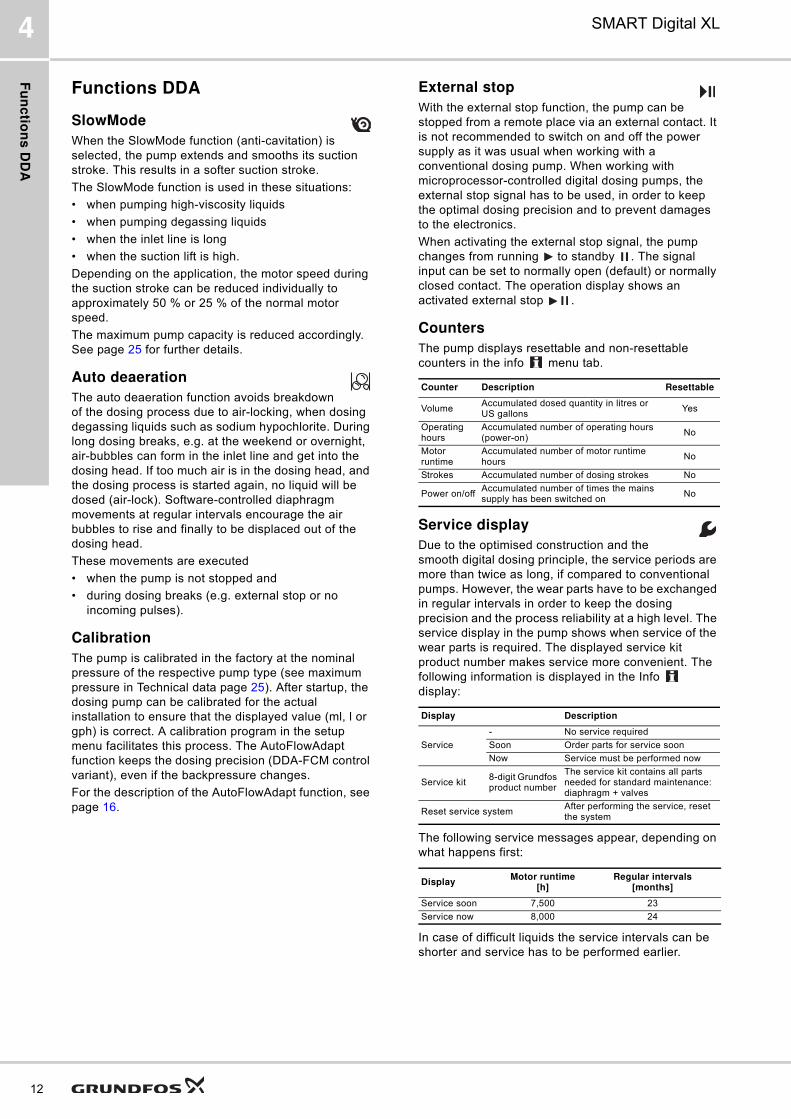
SlowMode
When the SlowMode function (anti-cavitation) is
selected, the pump extends and smooths its suction
stroke. This results in a softer suction stroke.
The SlowMode function is used in these situations:
� when pumping high-viscosity liquids
� when pumping degassing liquids
� when the inlet line is long
� when the suction lift is high.
Depending on the application, the motor speed during
the suction stroke can be reduced individually to
approximately 50 % or 25 % of the normal motor
speed.
The maximum pump capacity is reduced accordingly.
See page 25 for further details.
Auto deaeration
The auto deaeration function avoids breakdown
of the dosing process due to air-locking, when dosing
degassing liquids such as sodium hypochlorite. During
long dosing breaks, e.g. at the weekend or overnight,
air-bubbles can form in the inlet line and get into the
dosing head. If too much air is in the dosing head, and
the dosing process is started again, no liquid will be
dosed (air-lock). Software-controlled diaphragm
movements at regular intervals encourage the air
bubbles to rise and finally to be displaced out of the
dosing head.
These movements are executed
� when the pump is not stopped and
� during dosing breaks (e.g. external stop or no
incoming pulses).
Calibration
The pump is calibrated in the factory at the nominal
pressure of the respective pump type (see maximum
pressure in Technical data page 25). After startup, the
dosing pump can be calibrated for the actual
installation to ensure that the displayed value (ml, l or
gph) is correct. A calibration program in the setup
menu facilitates this process. The AutoFlowAdapt
function keeps the dosing precision (DDA-FCM control
variant), even if the backpressure changes.
For the description of the AutoFlowAdapt function, see
page 16.
External stop
With the external stop function, the pump can be
stopped from a remote place via an external contact. It
is not recommended to switch on and off the power
supply as it was usual when working with a
conventional dosing pump. When working with
microprocessor-controlled digital dosing pumps, the
external stop signal has to be used, in order to keep
the optimal dosing precision and to prevent damages
to the electronics.
When activating the external stop signal, the pump
changes from running to standby . The signal
input can be set to normally open (default) or normally
closed contact. The operation display shows an
activated external stop .
Counters
The pump displays resettable and non-resettable
counters in the info menu tab.
Service display
Due to the optimised construction and the
smooth digital dosing principle, the service periods are
more than twice as long, if compared to conventional
pumps. However, the wear parts have to be exchanged
in regular intervals in order to keep the dosing
precision and the process reliability at a high level. The
service display in the pump shows when service of the
wear parts is required. The displayed service kit
product number makes service more convenient. The
following information is displayed in the Info
display:
The following service messages appear, depending on
what happens first:
In case of difficult liquids the service intervals can be
shorter and service has to be performed earlier.
Counter Description Resettable
VolumeAccumulated dosed quantity in litres or US gallons
Yes
Operating hours
Accumulated number of operating hours (power-on)
No
Motor runtime
Accumulated number of motor runtime hours
No
Strokes Accumulated number of dosing strokes No
Power on/offAccumulated number of times the mains supply has been switched on
No
Display Description
Service
- No service required
Soon Order parts for service soon
Now Service must be performed now
Service kit8-digit Grundfos product number
The service kit contains all parts needed for standard maintenance: diaphragm + valves
Reset service systemAfter performing the service, reset the system
DisplayMotor runtime
[h]Regular intervals
[months]
Service soon 7,500 23
Service now 8,000 24
Fu
nc
tio
ns
DD
A
13
SMART Digital XL 4
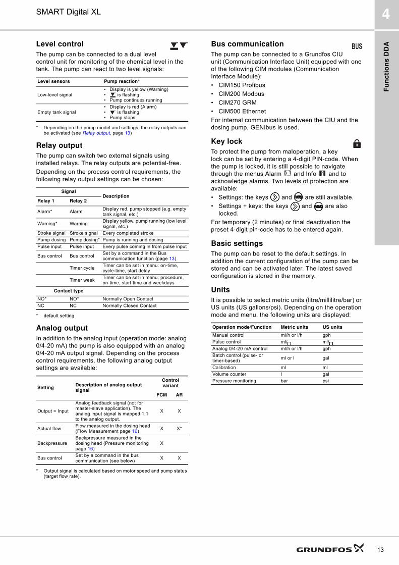
Level control
The pump can be connected to a dual level
control unit for monitoring of the chemical level in the
tank. The pump can react to two level signals:
* Depending on the pump model and settings, the relay outputs can be activated (see Relay output, page 13)
Relay output
The pump can switch two external signals using
installed relays. The relay outputs are potential-free.
Depending on the process control requirements, the
following relay output settings can be chosen:
* default setting
Analog output
In addition to the analog input (operation mode: analog
0/4-20 mA) the pump is also equipped with an analog
0/4-20 mA output signal. Depending on the process
control requirements, the following analog output
settings are available:
* Output signal is calculated based on motor speed and pump status (target flow rate).
Bus communication
The pump can be connected to a Grundfos CIU
unit (Communication Interface Unit) equipped with one
of the following CIM modules (Communication
Interface Module):
� CIM150 Profibus
� CIM200 Modbus
� CIM270 GRM
� CIM500 Ethernet
For internal communication between the CIU and the
dosing pump, GENIbus is used.
Key lock
To protect the pump from maloperation, a key
lock can be set by entering a 4-digit PIN-code. When
the pump is locked, it is still possible to navigate
through the menus Alarm and Info and to
acknowledge alarms. Two levels of protection are
available:
� Settings: the keys and are still available.
� Settings + keys: the keys and are also
locked.
For temporary (2 minutes) or final deactivation the
preset 4-digit pin-code has to be entered again.
Basic settings
The pump can be reset to the default settings. In
addition the current configuration of the pump can be
stored and can be activated later. The latest saved
configuration is stored in the memory.
Units
It is possible to select metric units (litre/millilitre/bar) or
US units (US gallons/psi). Depending on the operation
mode and menu, the following units are displayed:
Level sensors Pump reaction*
Low-level signal� Display is yellow (Warning)� is flashing� Pump continues running
Empty tank signal� Display is red (Alarm)� is flashing� Pump stops
SignalDescription
Relay 1 Relay 2
Alarm* AlarmDisplay red, pump stopped (e.g. empty tank signal, etc.)
Warning* WarningDisplay yellow, pump running (low level signal, etc.)
Stroke signal Stroke signal Every completed stroke
Pump dosing Pump dosing* Pump is running and dosing
Pulse input Pulse input Every pulse coming in from pulse input
Bus control Bus controlSet by a command in the Bus communication function (page 13)
Timer cycleTimer can be set in menu: on-time, cycle-time, start delay
Timer weekTimer can be set in menu: procedure, on-time, start time and weekdays
Contact type
NO* NO* Normally Open Contact
NC NC Normally Closed Contact
SettingDescription of analog output signal
Control variant
FCM AR
Output = Input
Analog feedback signal (not for master-slave application). The analog input signal is mapped 1:1 to the analog output.
X X
Actual flowFlow measured in the dosing head (Flow Measurement page 16)
X X*
BackpressureBackpressure measured in the dosing head (Pressure monitoring page 16)
X
Bus controlSet by a command in the bus communication (see below)
X X
Operation mode/Function Metric units US units
Manual control ml/h or l/h gph
Pulse control ml/ ml/
Analog 0/4-20 mA control ml/h or l/h gph
Batch control (pulse- or timer-based)
ml or l gal
Calibration ml ml
Volume counter l gal
Pressure monitoring bar psi

Fu
nc
tion
s D
DA
14
SMART Digital XL4
Additional display
The additional display function provides further useful
status information, e.g. the target flow rate as well as
the actual flow rate. The value is shown in the
operation display together with the corresponding
symbol.
Fig. 14 Additional display
The following additional information can be selected:
1) Only DDA-FCM control variant
Diaphragm leakage detection (DLD)
Applies to DDA-AR control variant
Pumps with diaphragm leakage detection (DLD) have
a special dosing head with a special diaphragm and a
pressure switch. The pressure switch is fitted and
connected to the pump on delivery.
For pumps with diaphragm leakage detection the
pressure differential between inlet and outlet side must
be at least 2 bar / 29 psi.
Fig. 15 Diaphragm leakage detection
In case of a leak in the working diaphragm:
� Dosing medium (4) penetrates between working
diaphragm (D1) and protective diaphragm (D3) and
is transferred to the pressure switch (1) through the
signal diaphragm (D2).
� On the next discharge stroke the increasing
pressure activates the pressure switch (1).
� The pump indicates an alarm and stops.
The pump provides two relay outputs, which can be
used to trigger an external alarm, for example.
TM
06
74
39
34
16
Settings Description
Default display
Depending on the operation mode:
Actual flow (manual, pulse)1)
Target flow (pulse)
Input current (analog)
Remaining batch volume (batch, timer)
Time until next batch (timer)
Dosed volume Total dosed volume (Counters see page 12)
Actual flow Actually measured flow1)
Backpressure Current backpressure in the dosing head1)
59.9 l/hManual
60.0l/h
Operation
Additional display
TM
06
83
68
311
6
Pos. Components
1 Pressure switch
2 Dosing head
3 Drain opening
4 Dosing medium
D1 Working diaphragm
D2 Signal diaphragm (intermediate layer)
D3 Protective diaphragm
D1 D2 D3
1
3
4
2
Fu
nc
tio
ns
DD
A
15
SMART Digital XL 4
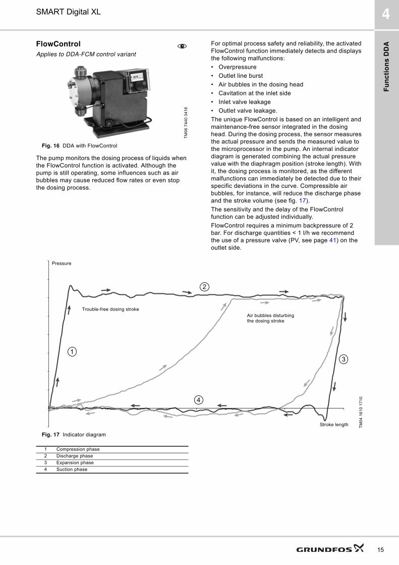
FlowControl
Applies to DDA-FCM control variant
Fig. 16 DDA with FlowControl
The pump monitors the dosing process of liquids when
the FlowControl function is activated. Although the
pump is still operating, some influences such as air
bubbles may cause reduced flow rates or even stop
the dosing process.
For optimal process safety and reliability, the activated
FlowControl function immediately detects and displays
the following malfunctions:
� Overpressure
� Outlet line burst
� Air bubbles in the dosing head
� Cavitation at the inlet side
� Inlet valve leakage
� Outlet valve leakage.
The unique FlowControl is based on an intelligent and
maintenance-free sensor integrated in the dosing
head. During the dosing process, the sensor measures
the actual pressure and sends the measured value to
the microprocessor in the pump. An internal indicator
diagram is generated combining the actual pressure
value with the diaphragm position (stroke length). With
it, the dosing process is monitored, as the different
malfunctions can immediately be detected due to their
specific deviations in the curve. Compressible air
bubbles, for instance, will reduce the discharge phase
and the stroke volume (see fig. 17).
The sensitivity and the delay of the FlowControl
function can be adjusted individually.
FlowControl requires a minimum backpressure of 2
bar. For discharge quantities < 1 l/h we recommend
the use of a pressure valve (PV, see page 41) on the
outlet side.
Fig. 17 Indicator diagram
TM
06
74
40
34
16
TM
04
16
10
17
10
1
2
3
4
Pressure
Stroke length
Trouble-free dosing stroke
Air bubbles disturbing the dosing stroke
1 Compression phase
2 Discharge phase
3 Expansion phase
4 Suction phase

Fu
nc
tion
s D
DA
16
SMART Digital XL4
Pressure monitoringApplies to DDA-FCM control variant
The integrated pressure sensor measures the actual
pressure of the system, which is shown in the display.
A maximum pressure can be set. If the pressure in the
system exceeds the set maximum (e.g. caused by a
closed valve), the pressure monitoring function stops
the dosing process immediately. As soon as the
backpressure falls below the set maximum, the dosing
process is continued. In case the pressure drops below
the minimum limit (e.g. caused by a burst outlet line)
the pump stops and major chemical spills are
prevented.
Pressure setting range
* Can be either set as a warning (pump keeps running) or as an alarm (pump stops)
** The adjustable max. pressure is equivalent to the max. operating pressure plus 1 bar
Flow measurement
Applies to DDA-FCM control variant
The pump can precisely measure and display the
actual dosing flow. Via the analog 0/4-20 mA output,
the actual flow signal can easily be integrated in any
process control system, without needing any additional
measurement equipment.
The Flow measurement function is based on an
indicator diagram as described in FlowControl (page
15). Accumulating the length of each discharge stroke
phase and multiplying it with the stroke frequency
results in the displayed actual flow. Any malfunctions,
such as air bubbles or lower backpressure, will result
in a reduced or increased actual flow rate. When the
AutoFlowAdapt function (page 16) is activated, the
pump compensates these influences by correcting the
stroke speed.
AutoFlowAdaptApplies to DDA-FCM control variant
When activating the AutoFlowAdapt function even
environmental changes will be compensated, so that
the required target flow rate will be achieved. The
integrated AutoFlowAdapt makes additional monitoring
and control devices redundant. The AutoFlowAdapt
function is based on:
� FlowControl: malfunctions are detected
� Pressure monitoring: system pressure changes are
detected
� Flow measurement: deviations in the target flow are
detected.
Examples:
� FlowControl detects air bubbles in the system. Due
to a special motor drive strategy and a certain
speed increase, the pump will try to keep the flow
rate constant. This is especially important when
dosing degassing liquids.
� In general, increasing system pressure reduces the
stroke volume whereas falling system pressure
increases the stroke volume. The AutoFlowAdapt
function compensates this by automatically and
continuously adapting the motor speed. Despite
fluctuating system pressure, dosing accuracy is
maintained.
Pump typeFixed min. pressure
[bar]*Adjustable max. pressure
[bar]**
DDA 60-10 < 2 3 ... 11 (default)
DDA 120-7 < 2 3 ... 8 (default)
DDA 200-4 < 2 3 ... 5 (default)
Fu
nc
tio
ns
DD
A
17
SMART Digital XL 4
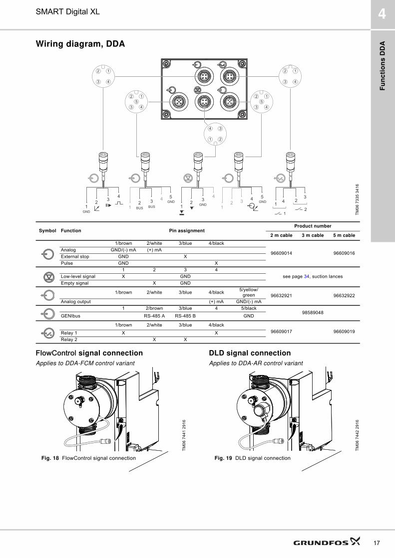
Wiring diagram, DDA
FlowControl signal connection
Applies to DDA-FCM control variant
Fig. 18 FlowControl signal connection
DLD signal connection
Applies to DDA-AR control variant
Fig. 19 DLD signal connection
TM
06
73
35
34
16
21
34 4
4 5322
1
23
412
1
3
2 1
GNDGND
GND
12
3 4
12
3 4
12
5
3 4
34
1 2
12
5
3 4
4 53
1
GND
BUSBUS
Symbol Function Pin assignmentProduct number
2 m cable 3 m cable 5 m cable
1/brown 2/white 3/blue 4/black
96609014 96609016Analog GND/(-) mA (+) mA
External stop GND X
Pulse GND X
1 2 3 4
see page 34, suction lancesLow-level signal X GND
Empty signal X GND
1/brown 2/white 3/blue 4/black5/yellow/
green 96632921 96632922
Analog output (+) mA GND/(-) mA
1 2/brown 3/blue 4 5/black98589048
GENIbus RS-485 A RS-485 B GND
1/brown 2/white 3/blue 4/black
96609017 96609019Relay 1 X X
Relay 2 X X
TM
06
74
41
29
16
TM
06
74
42
29
16

Fu
nc
tion
s D
DE
18
SMART Digital XL5
5. Functions DDE
Operating elements DDE
The pump is supplied with front-mounted control cube.
The position of the control cube can easily be changed
by unfastening two screws, lifting the cube, turning it to
the left or to the right and fastening both screws again.
Fig. 20 Two of three possible control cube positions
Fig. 21 Operating elements DDE
With the capacity adjusting knob the capacity of the
pump can easily be adjusted in % of the maximum
flow. Due to the logarithmic increase of the percent
values, even small dosing capacities can be set
accurately.
LEDs (DDE-B)
The LEDs indicate the following operating statuses
and faults:
● = LED on
❍ = LED flashingEmpty table cell = LED off
Keys and LEDs (DDE-AR)
When pressing and holding down the [100%] key, the
pump doses at 100 % for a certain time. The [100%]
key can be used e.g. for deaeration.
The [Operation mode] key is used to change the
operation mode.
The operation mode LEDs indicate the active
operation mode. Only one operation mode can be
active at a time. Together with the status LEDs, the
operation mode LEDs indicate the following statuses
and faults:
● = LED on
❍ = LED flashingEmpty table cell = LED off
TM
06
73
09
04
17
TM
06
73
20
33
16
Pos. Description
Control variant
B AR
Status LEDs
1Motor blockage (red) ● ●External stop (red) ●
2 Tank level (yellow) ●3 [Operation mode] key ●
Operation mode LEDs (green):
4 Pulse ●5 Manual ● ●6 Analog ●7 Logarithmic scale ● ●8 Capacity adjusting knob ● ●9 [100%] key ●
1 2 3 4 5 6
7
8
9
LED statusPump status Description
● running
❍ standby Capacity adjusted to 0 %
❍ stopMotor blocked or overheated
LED statusPump status Description
● running
❍ standby Capacity adjusted to 0 %
● running
❍ standby No incoming pulses
● running
❍ standby Analog signal < 4.1 mA
❍ ● running Low-level in tank
● ❍ stop Tank empty
● ❍ standby External stop activated
❍ stop Motor blocked or overheated

Fu
nc
tio
ns
DD
E
19
SMART Digital XL 5
Operation modes DDE
Manual control
In this operation mode, the pump doses
constantly the dosing quantity set by the adjusting
knob.
The setting range depends on the pump type:
Setting range
Pulse control
Applies to DDE-AR control variant
In this operation mode, the pump doses the set dosing
volume for each incoming (potential-free) pulse, e.g.
from a water meter. The pump automatically calculates
the optimum stroke frequency for dosing the set
volume per pulse.
The calculation is based on:
� the frequency of external pulses
� the set stroke volume in percent.
The dosing quantity per pulse is set to a value between
0.125 % and 100 % of the stroke volume using the
adjusting knob.
Setting range
The frequency of incoming pulses is multiplied by the
set dosing volume. If the pump receives more pulses
than it can process at the maximum dosing flow, it runs
at the maximum stroke frequency in continuous
operation. Excess pulses will be ignored.
Analog 4-20 mA control
Applies to DDE-AR control variant
In this operation mode, the pump doses according to
the external analog signal. The dosing volume is
proportional to the signal input value in mA. The input
signal must be 4-20 mA.
The maximum dosing volume can be changed via the
capacity adjusting knob.
Example:
Pump typeSetting range
From [l/h] To [l/h]
DDE 60-10 0.075 60
DDE 120-7 0.15 120
DDE 200-4 0.25 200
Pump type Setting range [ml/pulse]
DDE 60-10 0.0070 - 5.56
DDE 120-7 0.0145 - 11.58
DDE 200-4 0.0242 - 19.3
Set capacity[%]
Input signal[mA]
Dosing flow[%]
100≤ 4.1 0
≥ 19.8 100
50≤ 4.1 0
≥ 19.8 50
1≤ 4.1 0
≥ 19.8 1

Fu
nc
tion
s D
DE
20
SMART Digital XL5
Functions DDE
External stop
Applies to DDE-AR control variant
With the external stop function, the pump can be
stopped from a remote place via an external contact. It
is not recommended to switch on and off the power
supply as it was usual when working with a
conventional dosing pump. When working with
microprocessor-controlled digital dosing pumps, the
external stop signal has to be used, in order to keep
the optimal dosing precision and to prevent damages
to the electronics.
When activating the external stop signal, the pump
changes from running to standby . The signal
input can be set to normally open (default) or normally
closed contact.
An activated external stop is indicated by the
respective LED. See Keys and LEDs (DDE-AR) on
page 18.
Level control
Applies to DDE-AR control variant
The pump can be connected to a dual level control unit
for monitoring of the chemical level in the tank. The
pump can react to two level signals:
* Depending on the pump model and settings, the relay outputs can be activated (see Relay output, page 20).
Relay output
Applies to DDE-AR control variant
The pump can switch two external signals using
installed relays. The relay outputs are potential-free.
Depending on the process control requirements, the
following relay output settings can be chosen:
* default setting
Level sensors Pump reaction*
Low-level signal� LED flashes� Pump continues running
Empty tank signal� LED on� Pump stops
SignalDescription
Relay 1 Relay 2
Alarm* Empty tank, motor blocked
Low level* Low level tank
Stroke signal Every completed stroke
Pulse input Every pulse coming in from pulse input
Contact type
NO* NO* Normally Open Contact
NC NC Normally Closed Contact
Fu
nc
tio
ns
DD
E
21
SMART Digital XL 5
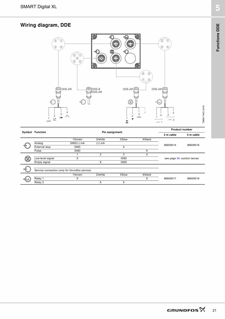
Wiring diagram, DDE
TM
06
74
43
34
16
21
34 4
23
412
1
3
2 1
GND
GND
DDE-AR DDE-BDDE-AR
DDE-AR DDE-AR
12
3 4
12
3 4
34
1 2
12
5
3 4
Symbol Function Pin assignmentProduct number
2 m cable 5 m cable
1/brown 2/white 3/blue 4/black
96609014 96609016Analog GND/(-) mA (+) mA
External stop GND X
Pulse GND X
1 2 3 4
see page 34, suction lancesLow-level signal X GND
Empty signal X GND
Service connection (only for Grundfos service)
1/brown 2/white 3/blue 4/black
96609017 96609019Relay 1 X X
Relay 2 X X

Co
ns
truc
tion
22
SMART Digital XL6
6. Construction
DDA
Fig. 22 Sectional drawing, DDA 60-10
Construction
The DDA pumps are motor-driven diaphragm dosing
pumps consisting of the following main parts:
Dosing head: Patented design with a minimum of
clearance space optimised for degassing liquids. With
integrated deaeration valve for priming and venting
complete with connection for a DN 20 tubing.
DDA-FCM pumps have an integrated pressure sensor
in the dosing head.
Valves: Outlet and inlet valve design for less
clearance space - optimised for degassing liquids.
Spring-loaded valves for higher viscosities are
available as an option.
Connections: Robust and easy-to-use connection
packages for various sizes of hoses or pipes.
Diaphragm: Double full-PTFE diaphragm designed for
long life and universal chemical resistance.
Flange: With separation chamber, safety diaphragm
and drain hole.
Drive unit: Positive return crank with double-stage
belt drive, energy recovery spring for high efficiency
(only 120-7 and 200-4 pump versions), PMS motor, all
mounted in a robust gear housing.
Control cube: Containing operation electronics with
display, keys, click-wheel and protective cover.
Housing: Containing drive unit and power electronics
with robust signal sockets. The housing can be
installed on the mounting plate with two screws.
Material specification
* Pump can be supplied with spring-loaded valves (Material: 2.4610 (Alloy C-4)).
TM
06
75
81
06
17
1
3
5
6
7
8
9
13 14 15 16 17 23 24
25
26
27
28
18 19 20 21 22
10
11
12
Pos. Description Material options
1 PMS motor -
3 Inlet valve, complete* -
5 Dosing head PVC, PVDF, SS 1.4435
6 Safety diaphragm EPDM
7 Dosing head screw SS 1.4301
8 Diaphragm full PTFE
9 Pressure sensor -
10 Dosing head cover SS 1.4301
11 Deaeration valve PVC, PVDF
12 Deaeration valve O-ring EPDM/FKM
13 Outlet valve, complete* -
14 Outlet valve O-ring EPDM, FKM, PTFE
15 Outlet valve ball, DN 20 Ceramic Al2O3 99.5 %, SS 1.4401
16 Outlet valve seat EPDM, FKM, PTFE
17Outlet valve housing and ball cage
PP, PVC, PVDF, SS 1.4435
18 Intermediate ring PPO/PS 20 % gf
19 Pump head flange Aluminium alloy 3.1645
20 Connecting rod 1.4401
21 Gear box PPE/PA 30 % gf
22 Housing PPE/PS 20 % gf
23 Control cube PPE/PS 20 % gf
24 Display cover PC
25 HMI PCB -
26 Click wheel PPE/PS 20 % gf
27 Input/output PCB -
28 Mounting plate PPE/PS 20 % gf
- Energy recovery spring Spring steel EN 10270-1-SH

Co
ns
tru
cti
on
23
SMART Digital XL 6
DDE
Fig. 23 Sectional drawing, DDE 60-10
Construction
The DDE pump is a motor-driven diaphragm dosing
pump consisting of the following main parts:
Dosing head: Patented design with a minimum of
clearance space optimised for degassing liquids. With
integrated deaeration valve for priming and venting
complete with connection for a DN 20 tubing.
Valves: Outlet and inlet valve design for less
clearance space - optimised for degassing liquids.
Spring-loaded valves for higher viscosities are
available as an option.
Connections: Robust and easy-to-use connection
packages for various sizes of hoses or pipes.
Diaphragm: Double full-PTFE diaphragm designed for
long life and universal chemical resistance.
Flange: With separation chamber, safety diaphragm
and drain hole.
Drive unit: Positive return crank with double-stage
belt drive, energy recovery spring for high efficiency
(only 120-7 and 200-4 pump versions), PMS motor, all
mounted in a robust gear housing.
Control cube: Containing keys, LEDs, capacity
adjusting knob and protective cover.
Housing: Containing drive unit, control panel and
electronics with robust signal sockets. The housing
can be installed on the mounting plate with two screws.
Material specification
* Pump can be supplied with spring-loaded valves (Material: 2.4610 (Alloy C-4)).
TM
06
75
85
06
17
1
2
4
5
6
7
11 12 13 1514
23
20
24
25
26
16 17 18 19
8
9
10
21 22
Pos. Description Material options
1 PMS motor -
2 Inlet valve, complete* -
4 Dosing head PVC, PVDF, SS 1.4435
5 Safety diaphragm EPDM
6 Dosing head screw SS 1.4301
7 Diaphragm full PTFE
8 Dosing head cover SS 1.4301
9 Deaeration valve PVC, PVDF
10 Deaeration valve O-ring EPDM/FKM
11 Outlet valve, complete* -
12 Outlet valve O-ring EPDM, FKM, PTFE
13 Outlet valve ball, DN 20 Ceramic Al2O3 99.5 %, SS 1.4401
14Outlet valve housing and ball cage
PP, PVC, PVDF, SS 1.4435
15 Outlet valve seat EPDM, FKM, PTFE
16 Intermediate ring PPO/PS 20 % gf
17 Pump head flange Aluminium alloy 3.1645
18 Connecting rod 1.4401
19 Gear box PPE/PA 30 % gf
20 Housing PPE/PS 20 % gf
21 Control cube PPE/PS 20 % gf
22 Display cover PC
23 HMI PCB -
24 Capacity adjusting knob PPE/PS 20 % gf
25 Input/output PCB -
26 Mounting plate PPE/PS 20 % gf
- Energy recovery spring Spring steel EN 10270-1-SH

Dim
en
sio
ns
24
SMART Digital XL7
7. Dimensions
Fig. 24 DDA and DDE with front-fitted or side-fitted control cube
* Dimension with optional diaphragm leakage detection. Only available for DDA-AR control variant.
TM
06
74
44
34
16
Pump type Pump head materialA
[mm]A1
[mm]A2*
[mm]B
[mm]C
[mm]D
[mm]
DDA 60-10DDE 60-10
PVC/PV 410 374 26 263 112 45
SS 405 364 - 263 112 45
DDA 120-7DDE 120-7
PVC/PV 410 374 26 276.5 97 45
SS 405 364 - 276.5 97 45
DDA 200-4DDE 200-4
PVC/PV 410 374 26 287.5 88 45
SS 405 364 - 287.5 88 45
C
B 283.5
G 5/4"
A1A2
D
A140.5
25
194
183.5
4 x Ø 7 4 x Ø 9187
159
140
29
36
172.513
105
136
180
7
10 Ø 7

Te
ch
nic
al
da
ta
25
SMART Digital XL 8
8. Technical data
DDA
1) The maximum stroke frequency varies depending on calibration2) Data is based on measurements with water3) Maximum suction lift: 1 m, dosing capacity reduced (approx. 30 %)4) Length of inlet line: 1.5 m, length of outlet line: 10 m (at max.
viscosity)
5) FS = Full-scale (maximum actual dosing flow), SP = Setpoint6) For FCM control variant and for pumps with diaphragm leakage
detection the pressure difference must be at least 2 bar / 29 psi.
Data 60-10 120-7 200-4
Mechanical data
Turn-down ratio (setting range) [1:X] 800 800 800
Max. dosing capacity[l/h] 60 120 200
[gph] 15.8 32 52.8
Max. dosing capacity with SlowMode 50 %[l/h] 30 60 100
[gph] 7.9 16 26.4
Max. dosing capacity with SlowMode 25 %[l/h] 15 30 50
[gph] 3.95 8 13.2
Min. dosing capacity[l/h] 0.075 0.15 0.25
[gph] 0.0197 0.04 0.066
Max. operating pressure (backpressure)[bar] 10 7 4
[psi] 145 101 58
Max. stroke frequency1) [strokes/min] 196 188 188
Stroke volume [ml] 5.56 11.58 19.3
Accuracy of repeatability5) [%] 1.5 SP + 0.1 FS5)
Max. suction lift during operation2) [m] 3
Max. suction lift when priming with wet valves2) [m] 1.5
Min. pressure difference between inlet and outlet side[bar] 16)
[psi] 14.56)
Max. inlet pressure, inlet side[bar] 2
[psi] 29
Max. viscosity in SlowMode 25 % with spring-loaded valves3) [mPas] (= cP) 3000 3000 2000
Max. viscosity in SlowMode 50 % with spring-loaded valves3) [mPas] (= cP) 2000 1500 1000
Max. viscosity without SlowMode with spring-loaded valves3) [mPas] (= cP) 1000 1000 500
Max. viscosity without spring-loaded valves3) [mPas] (= cP) 100
Min. internal hose/pipe diameter inlet/outlet side2), 4) [mm] 19
Min. internal hose/pipe diameter inlet/outlet side (high viscosity)4) [mm] 19
Min. / Max. liquid temperature (PVDF, SS) [°C] 0/50
Min. / Max. liquid temperature (PVC) [°C] 0/40
Min. / Max. ambient temperature [°C] 0/45
Min. / Max. storage temperature (PVDF, SS) [°C] -20/70
Min. / Max. storage temperature (PVC) [°C] -20/45
Max. relative humidity (non-condensing) [%] 90
Max. altitude above sea level [m] 2000
Electrical data
Voltage [V] 100-240 V ± 10 %, 50/60 Hz
Length of mains cable [m] 1.5
Max. inrush current for 2 ms (100 V) [A] 35
Max. inrush current for 2 ms (240 V) [A] 70
Max. power consumption P1 [W] 62
Enclosure class IP65, Nema 4X
Electrical safety class I
Pollution degree 2
Signal input
Max. load for level input, pulse input and External stop input 12 V, 5 mA
Min. pulse length [ms] 5
Max. pulse frequency [Hz] 100
Impedance at 0/4-20 mA analog input [Ω] 15
Accuracy of analog input (full-scale value) [%] ± 0.5
Min. resolution of analog input [mA] 0.02
Max. loop resistance in external circuit [Ω] 150
Signal output
Max. resistive load on relay output [A] 0.5
Max. voltage on relay/analog output [V] 30 VDC / 30 VAC
Max. loop resistance in external circuit of the 0/4-20 mA analog output [Ω] 500
Accuracy of analog output (full-scale value) [%] ± 0.5
Min. resolution of analog output [mA] 0.02
Weight/size
Weight (PVC, PVDF) [kg] 6.7 7.9 8.9
Weight (stainless steel) [kg] 7.2 8.3 9.1
Diaphragm diameter [mm] 74 97 117
Sound pressure Max. sound pressure level [dB(A)] 80
Approvals CE, CSA-US, NSF61, EAC, ACS, RCM
Te
ch
nic
al d
ata
26
SMART Digital XL8
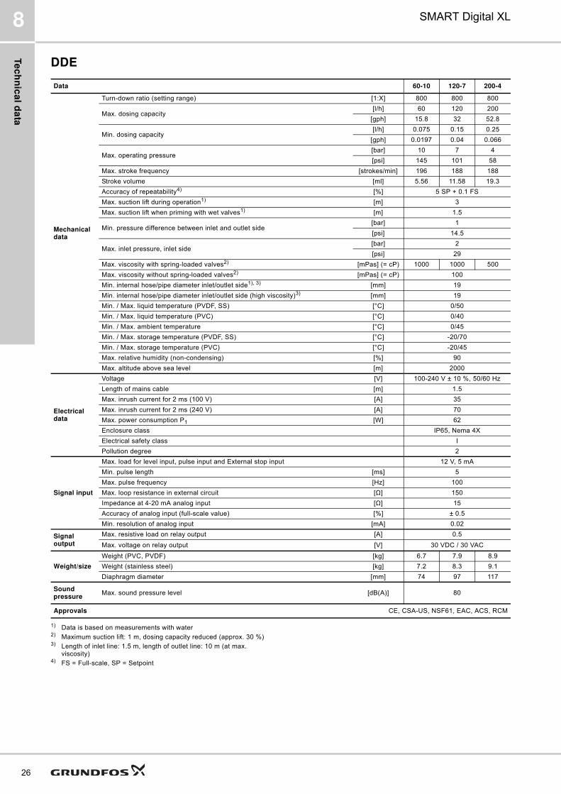
DDE
1) Data is based on measurements with water2) Maximum suction lift: 1 m, dosing capacity reduced (approx. 30 %)3) Length of inlet line: 1.5 m, length of outlet line: 10 m (at max.
viscosity)4) FS = Full-scale, SP = Setpoint
Data 60-10 120-7 200-4
Mechanical data
Turn-down ratio (setting range) [1:X] 800 800 800
Max. dosing capacity[l/h] 60 120 200
[gph] 15.8 32 52.8
Min. dosing capacity[l/h] 0.075 0.15 0.25
[gph] 0.0197 0.04 0.066
Max. operating pressure[bar] 10 7 4
[psi] 145 101 58
Max. stroke frequency [strokes/min] 196 188 188
Stroke volume [ml] 5.56 11.58 19.3
Accuracy of repeatability4) [%] 5 SP + 0.1 FS
Max. suction lift during operation1) [m] 3
Max. suction lift when priming with wet valves1) [m] 1.5
Min. pressure difference between inlet and outlet side[bar] 1
[psi] 14.5
Max. inlet pressure, inlet side[bar] 2
[psi] 29
Max. viscosity with spring-loaded valves2) [mPas] (= cP) 1000 1000 500
Max. viscosity without spring-loaded valves2) [mPas] (= cP) 100
Min. internal hose/pipe diameter inlet/outlet side1), 3) [mm] 19
Min. internal hose/pipe diameter inlet/outlet side (high viscosity)3) [mm] 19
Min. / Max. liquid temperature (PVDF, SS) [°C] 0/50
Min. / Max. liquid temperature (PVC) [°C] 0/40
Min. / Max. ambient temperature [°C] 0/45
Min. / Max. storage temperature (PVDF, SS) [°C] -20/70
Min. / Max. storage temperature (PVC) [°C] -20/45
Max. relative humidity (non-condensing) [%] 90
Max. altitude above sea level [m] 2000
Electrical data
Voltage [V] 100-240 V ± 10 %, 50/60 Hz
Length of mains cable [m] 1.5
Max. inrush current for 2 ms (100 V) [A] 35
Max. inrush current for 2 ms (240 V) [A] 70
Max. power consumption P1 [W] 62
Enclosure class IP65, Nema 4X
Electrical safety class I
Pollution degree 2
Signal input
Max. load for level input, pulse input and External stop input 12 V, 5 mA
Min. pulse length [ms] 5
Max. pulse frequency [Hz] 100
Max. loop resistance in external circuit [Ω] 150
Impedance at 4-20 mA analog input [Ω] 15
Accuracy of analog input (full-scale value) [%] ± 0.5
Min. resolution of analog input [mA] 0.02
Signal output
Max. resistive load on relay output [A] 0.5
Max. voltage on relay output [V] 30 VDC / 30 VAC
Weight/size
Weight (PVC, PVDF) [kg] 6.7 7.9 8.9
Weight (stainless steel) [kg] 7.2 8.3 9.1
Diaphragm diameter [mm] 74 97 117
Sound pressure
Max. sound pressure level [dB(A)] 80
Approvals CE, CSA-US, NSF61, EAC, ACS, RCM
Pu
mp
se
lec
tio
n
27
SMART Digital XL 9
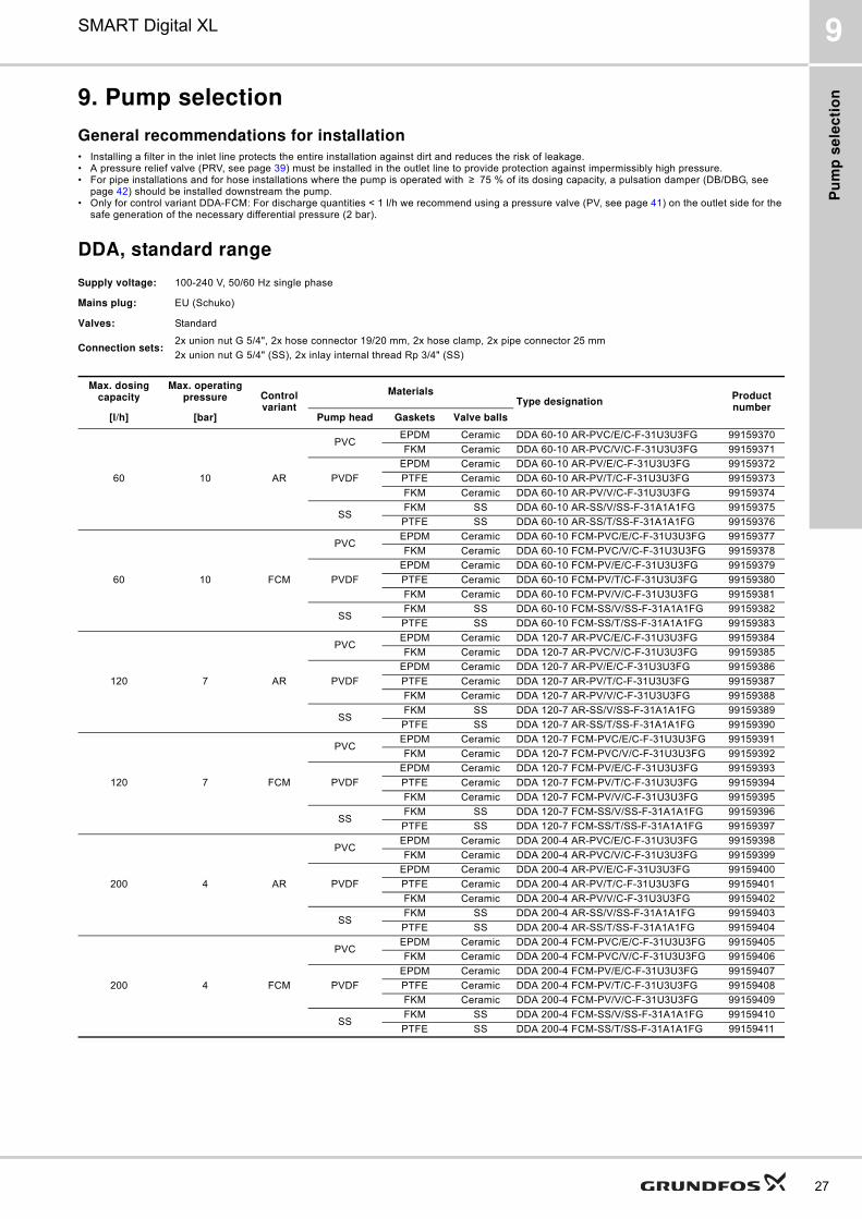
9. Pump selection
General recommendations for installation
� Installing a filter in the inlet line protects the entire installation against dirt and reduces the risk of leakage.� A pressure relief valve (PRV, see page 39) must be installed in the outlet line to provide protection against impermissibly high pressure.� For pipe installations and for hose installations where the pump is operated with ≥ 75 % of its dosing capacity, a pulsation damper (DB/DBG, see
page 42) should be installed downstream the pump.� Only for control variant DDA-FCM: For discharge quantities < 1 l/h we recommend using a pressure valve (PV, see page 41) on the outlet side for the
safe generation of the necessary differential pressure (2 bar).
DDA, standard range
Supply voltage: 100-240 V, 50/60 Hz single phase
Mains plug: EU (Schuko)
Valves: Standard
Connection sets:2x union nut G 5/4", 2x hose connector 19/20 mm, 2x hose clamp, 2x pipe connector 25 mm
2x union nut G 5/4" (SS), 2x inlay internal thread Rp 3/4" (SS)
Max. dosing capacity
Max. operating pressure Control
variant
MaterialsType designation
Product number
[l/h] [bar] Pump head Gaskets Valve balls
60 10 AR
PVCEPDM Ceramic DDA 60-10 AR-PVC/E/C-F-31U3U3FG 99159370
FKM Ceramic DDA 60-10 AR-PVC/V/C-F-31U3U3FG 99159371
PVDF
EPDM Ceramic DDA 60-10 AR-PV/E/C-F-31U3U3FG 99159372
PTFE Ceramic DDA 60-10 AR-PV/T/C-F-31U3U3FG 99159373
FKM Ceramic DDA 60-10 AR-PV/V/C-F-31U3U3FG 99159374
SSFKM SS DDA 60-10 AR-SS/V/SS-F-31A1A1FG 99159375
PTFE SS DDA 60-10 AR-SS/T/SS-F-31A1A1FG 99159376
60 10 FCM
PVCEPDM Ceramic DDA 60-10 FCM-PVC/E/C-F-31U3U3FG 99159377
FKM Ceramic DDA 60-10 FCM-PVC/V/C-F-31U3U3FG 99159378
PVDF
EPDM Ceramic DDA 60-10 FCM-PV/E/C-F-31U3U3FG 99159379
PTFE Ceramic DDA 60-10 FCM-PV/T/C-F-31U3U3FG 99159380
FKM Ceramic DDA 60-10 FCM-PV/V/C-F-31U3U3FG 99159381
SSFKM SS DDA 60-10 FCM-SS/V/SS-F-31A1A1FG 99159382
PTFE SS DDA 60-10 FCM-SS/T/SS-F-31A1A1FG 99159383
120 7 AR
PVCEPDM Ceramic DDA 120-7 AR-PVC/E/C-F-31U3U3FG 99159384
FKM Ceramic DDA 120-7 AR-PVC/V/C-F-31U3U3FG 99159385
PVDF
EPDM Ceramic DDA 120-7 AR-PV/E/C-F-31U3U3FG 99159386
PTFE Ceramic DDA 120-7 AR-PV/T/C-F-31U3U3FG 99159387
FKM Ceramic DDA 120-7 AR-PV/V/C-F-31U3U3FG 99159388
SSFKM SS DDA 120-7 AR-SS/V/SS-F-31A1A1FG 99159389
PTFE SS DDA 120-7 AR-SS/T/SS-F-31A1A1FG 99159390
120 7 FCM
PVCEPDM Ceramic DDA 120-7 FCM-PVC/E/C-F-31U3U3FG 99159391
FKM Ceramic DDA 120-7 FCM-PVC/V/C-F-31U3U3FG 99159392
PVDF
EPDM Ceramic DDA 120-7 FCM-PV/E/C-F-31U3U3FG 99159393
PTFE Ceramic DDA 120-7 FCM-PV/T/C-F-31U3U3FG 99159394
FKM Ceramic DDA 120-7 FCM-PV/V/C-F-31U3U3FG 99159395
SSFKM SS DDA 120-7 FCM-SS/V/SS-F-31A1A1FG 99159396
PTFE SS DDA 120-7 FCM-SS/T/SS-F-31A1A1FG 99159397
200 4 AR
PVCEPDM Ceramic DDA 200-4 AR-PVC/E/C-F-31U3U3FG 99159398
FKM Ceramic DDA 200-4 AR-PVC/V/C-F-31U3U3FG 99159399
PVDF
EPDM Ceramic DDA 200-4 AR-PV/E/C-F-31U3U3FG 99159400
PTFE Ceramic DDA 200-4 AR-PV/T/C-F-31U3U3FG 99159401
FKM Ceramic DDA 200-4 AR-PV/V/C-F-31U3U3FG 99159402
SSFKM SS DDA 200-4 AR-SS/V/SS-F-31A1A1FG 99159403
PTFE SS DDA 200-4 AR-SS/T/SS-F-31A1A1FG 99159404
200 4 FCM
PVCEPDM Ceramic DDA 200-4 FCM-PVC/E/C-F-31U3U3FG 99159405
FKM Ceramic DDA 200-4 FCM-PVC/V/C-F-31U3U3FG 99159406
PVDF
EPDM Ceramic DDA 200-4 FCM-PV/E/C-F-31U3U3FG 99159407
PTFE Ceramic DDA 200-4 FCM-PV/T/C-F-31U3U3FG 99159408
FKM Ceramic DDA 200-4 FCM-PV/V/C-F-31U3U3FG 99159409
SSFKM SS DDA 200-4 FCM-SS/V/SS-F-31A1A1FG 99159410
PTFE SS DDA 200-4 FCM-SS/T/SS-F-31A1A1FG 99159411

Pu
mp
se
lec
tion
28
SMART Digital XL9
DDE, standard range
Supply voltage: 100-240 V, 50/60 Hz single phase
Mains plug: EU (Schuko)
Valves: Standard
Connection sets:2x union nut G 5/4", 2x hose connector 19/20 mm, 2x hose clamp, 2x pipe connector 25 mm
2x union nut G 5/4" (SS), 2x inlay internal thread Rp 3/4" (SS)
Max. dosing capacity
Max. operating pressure Control
variant
MaterialsType designation
Product number
[l/h] [bar] Pump head Gaskets Valve balls
60 10 B
PVCEPDM Ceramic DDE 60-10 B-PVC/E/C-F-31U3U3FG 99159328
FKM Ceramic DDE 60-10 B-PVC/V/C-F-31U3U3FG 99159329
PVDF
EPDM Ceramic DDE 60-10 B-PV/E/C-F-31U3U3FG 99159330
PTFE Ceramic DDE 60-10 B-PV/T/C-F-31U3U3FG 99159331
FKM Ceramic DDE 60-10 B-PV/V/C-F-31U3U3FG 99159332
SSFKM SS DDE 60-10 B-SS/V/SS-F-31A1A1FG 99159333
PTFE SS DDE 60-10 B-SS/T/SS-F-31A1A1FG 99159334
60 10 AR
PVCEPDM Ceramic DDE 60-10 AR-PVC/E/C-F-31U3U3FG 99159335
FKM Ceramic DDE 60-10 AR-PVC/V/C-F-31U3U3FG 99159336
PVDF
EPDM Ceramic DDE 60-10 AR-PV/E/C-F-31U3U3FG 99159337
PTFE Ceramic DDE 60-10 AR-PV/T/C-F-31U3U3FG 99159338
FKM Ceramic DDE 60-10 AR-PV/V/C-F-31U3U3FG 99159339
SSFKM SS DDE 60-10 AR-SS/V/SS-F-31A1A1FG 99159340
PTFE SS DDE 60-10 AR-SS/T/SS-F-31A1A1FG 99159341
120 7 B
PVCEPDM Ceramic DDE 120-7 B-PVC/E/C-F-31U3U3FG 99159342
FKM Ceramic DDE 120-7 B-PVC/V/C-F-31U3U3FG 99159343
PVDF
EPDM Ceramic DDE 120-7 B-PV/E/C-F-31U3U3FG 99159344
PTFE Ceramic DDE 120-7 B-PV/T/C-F-31U3U3FG 99159345
FKM Ceramic DDE 120-7 B-PV/V/C-F-31U3U3FG 99159346
SSFKM SS DDE 120-7 B-SS/V/SS-F-31A1A1FG 99159347
PTFE SS DDE 120-7 B-SS/T/SS-F-31A1A1FG 99159348
120 7 AR
PVCEPDM Ceramic DDE 120-7 AR-PVC/E/C-F-31U3U3FG 99159349
FKM Ceramic DDE 120-7 AR-PVC/V/C-F-31U3U3FG 99159350
PVDF
EPDM Ceramic DDE 120-7 AR-PV/E/C-F-31U3U3FG 99159351
PTFE Ceramic DDE 120-7 AR-PV/T/C-F-31U3U3FG 99159352
FKM Ceramic DDE 120-7 AR-PV/V/C-F-31U3U3FG 99159353
SSFKM SS DDE 120-7 AR-SS/V/SS-F-31A1A1FG 99159354
PTFE SS DDE 120-7 AR-SS/T/SS-F-31A1A1FG 99159355
200 4 B
PVCEPDM Ceramic DDE 200-4 B-PVC/E/C-F-31U3U3FG 99159356
FKM Ceramic DDE 200-4 B-PVC/V/C-F-31U3U3FG 99159357
PVDF
EPDM Ceramic DDE 200-4 B-PV/E/C-F-31U3U3FG 99159358
PTFE Ceramic DDE 200-4 B-PV/T/C-F-31U3U3FG 99159359
FKM Ceramic DDE 200-4 B-PV/V/C-F-31U3U3FG 99159360
SSFKM SS DDE 200-4 B-SS/V/SS-F-31A1A1FG 99159361
PTFE SS DDE 200-4 B-SS/T/SS-F-31A1A1FG 99159362
200 4 AR
PVCEPDM Ceramic DDE 200-4 AR-PVC/E/C-F-31U3U3FG 99159363
FKM Ceramic DDE 200-4 AR-PVC/V/C-F-31U3U3FG 99159364
PVDF
EPDM Ceramic DDE 200-4 AR-PV/E/C-F-31U3U3FG 99159365
PTFE Ceramic DDE 200-4 AR-PV/T/C-F-31U3U3FG 99159366
FKM Ceramic DDE 200-4 AR-PV/V/C-F-31U3U3FG 99159367
SSFKM SS DDE 200-4 AR-SS/V/SS-F-31A1A1FG 99159368
PTFE SS DDE 200-4 AR-SS/T/SS-F-31A1A1FG 99159369

Pu
mp
se
lec
tio
n
29
SMART Digital XL 9
DDA, DDE, non-standard range
The codes used in the following tables are explained in the type key. See page 6.
DDA
DDE
Max. flow - press.
Control variant
DLD function
Materials Control cube
position
Supply voltage
Valve type
Connection inlet / outlet
Mains plug
DesignSpecial variantHead Gaskets Balls
60-10120-7200-4
AR
NO
PVCPV
EVT
C F 312
U3U3A7A7
FBGIEJL
G C3
SSEVT
SS F 312
A1A1A3A3
YES
PVC-LPV-L
EVT
C F 312
U3U3A7A7
SS-LEVT
SS F 312
A1A1A3A3
FCM NO
PVCPV
EVT
C F 312
U3U3A7A7
SSEVT
SS F 312
A1A1A3A3
Max. flow - press.
Control variant
DLD function
Materials Control cube
position
Supply voltage
Valve type
Connection inlet / outlet
Mains plug
DesignSpecial variantHead Gaskets Balls
60-10120-7200-4
BAR
NO
PVCPV
EVT
C F 312
U3U3A7A7
FBGIEJL
G C3
SSEVT
SS F 312
A1A1A3A3

Ac
ce
ss
orie
s fo
r me
diu
m-s
ize
d d
os
ing
pu
mp
s u
p to
46
0 l/h
30
Accessories for dosing pumps10
10. Accessories for medium-sized dosing pumps up to 460 l/h
Grundfos offer a comprehensive range of accessories covering every need when dosing with Grundfos pumps.
Accessories overview
Fig. 25 Dosing pump with accessories
TM
06
83
74
03
17
Foot valves and rigid suction lances, see page 33 and page 34
Electric stirrers, see page 52
Pump connection kits and inlay kits, see page 51
Hoses, see page 32
Injection units, see page 38
Pressure relief valves, pressure loading valves, see page 39
Pulsation dampers,see page 42
Vacuum pump kits, see page 45
Threaded adapters, see page 55
Cables and plugs, see page 31
Wall brackets, see page 57
Pressure valves,see page 41
Withdrawal devices, see page 54

Ac
ce
ss
ori
es
fo
r m
ed
ium
-siz
ed
do
sin
g p
um
ps
up
to
46
0 l
/h
31
Accessories for dosing pumps 10
Cables and plugs
The listed cables and plugs are suitable for the
connection of a pump to external control devices, such
as process controllers, flow meters, start/stop contacts
and level sensors.
Fig. 26 Cable and plug for DDA, DDE, DMX, DMH and
DDI pumps
Technical data
� Cable material: PVC, 0.34 mm2
� Plug size: M 12
TM
01
89
55
09
00
Socket for DDA and DDE
Socket for DMX, DMH and DDI
Application Pins Plug typeCable length
[m]Product number
InputAnalog pulse External stop
4Straight
2 96609014
5 96609016
No cable 96698715
Angled 2 96693246
OutputRelay 1Relay 2
4Straight
2 96609017
5 96609019
No cable 96696198
Angled 2 96698716
Output Analog 5Straight
2 96632921
5 96632922
No cable 96609031
Angled 2 96699697
DDILow-level
Empty tank4 Straight - 96698715
-DMX/
DMH AR
InputLow-level
Empty tank3
Straight with soldered cable
- 96630345
Adapter, flat-roundLow-level
Empty tank4 - 96635010
- DDI
Profibus Y-connector - 96693735
ProfibusTerminating
resistor- 96693737
Input/Output GENIbus 5 Straight 3 98589048
-Mains connection for
DDI/DDA/DDE110-240 VAC 3 Angled - 96698717
4
3
2
5
5
6
Ac
ce
ss
orie
s fo
r me
diu
m-s
ize
d d
os
ing
pu
mp
s u
p to
46
0 l/h
32
Accessories for dosing pumps10
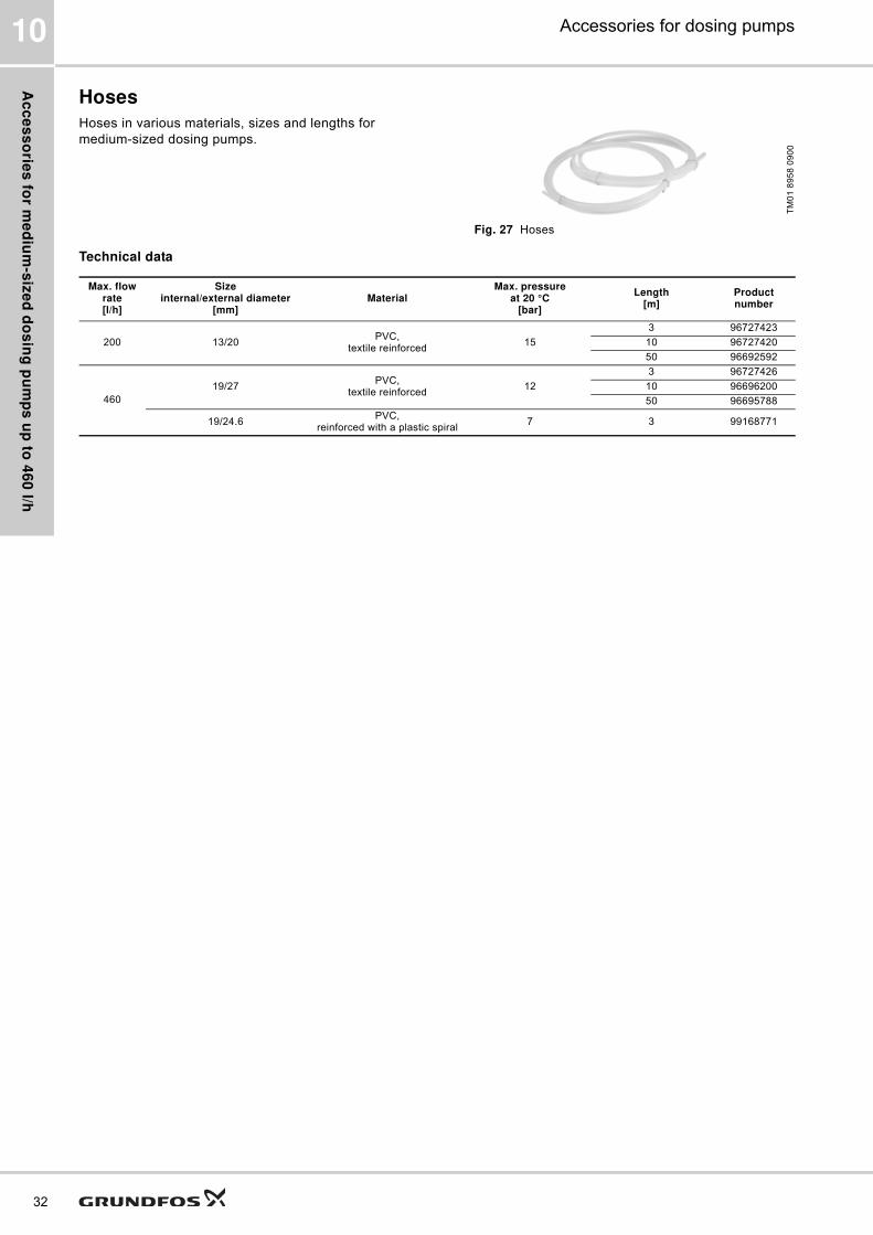
Hoses
Hoses in various materials, sizes and lengths for
medium-sized dosing pumps.
Fig. 27 Hoses
Technical data
TM
01
89
58
09
00
Max. flow rate[l/h]
Sizeinternal/external diameter
[mm]Material
Max. pressureat 20 °C
[bar]
Length[m]
Product number
200 13/20PVC,
textile reinforced15
3 96727423
10 96727420
50 96692592
460
19/27PVC,
textile reinforced12
3 96727426
10 96696200
50 96695788
19/24.6PVC,
reinforced with a plastic spiral7 3 99168771

Ac
ce
ss
ori
es
fo
r m
ed
ium
-siz
ed
do
sin
g p
um
ps
up
to
46
0 l
/h
33
Accessories for dosing pumps 10
Foot valves FV
Foot valves are installed at the lower end of the inlet
hose. They have no level indication.
Foot valves include:
� Strainer (mesh size approx. 0.8 mm)
� Non-return valve
� Hose and pipe connection set:
– for hoses with internal diameter 19 or 20 mm
– for pipes with external diameter 25 mm (PE
includes PVC inlay, PVDF includes PVDF inlay)
� Pipe connection set: threaded, Rp 3/4", internal
thread (stainless steel).
Remark: When using the foot valves with hose
installation, a rigid pipe should be slipped over the
hose to keep the suction line straight and upright in the
tank.
Dimensions
Fig. 28 Foot valves: stainless steel (left), PE/PVDF (right)
Technical data
* Body: SS 1.4571, 1.4435, 1.4305; Ball: SS 1.4401
TM
06
84
27
05
17
TM
06
80
75
45
16
MaterialL
[mm]d
[mm]
PE/PVDF 57 53
SS 57 50
Max. flow rate[l/h]
MaterialsProduct numberBody Gasket Ball
460
PEFKM/EPDM Ceramic 99168633
PTFE Ceramic 99168635
PVDFFKM/EPDM Ceramic 99168636
PTFE Ceramic 99168649
SS* PTFE SS* 99170593
d
L
d
L
Ac
ce
ss
orie
s fo
r me
diu
m-s
ize
d d
os
ing
pu
mp
s u
p to
46
0 l/h
34
Accessories for dosing pumps10
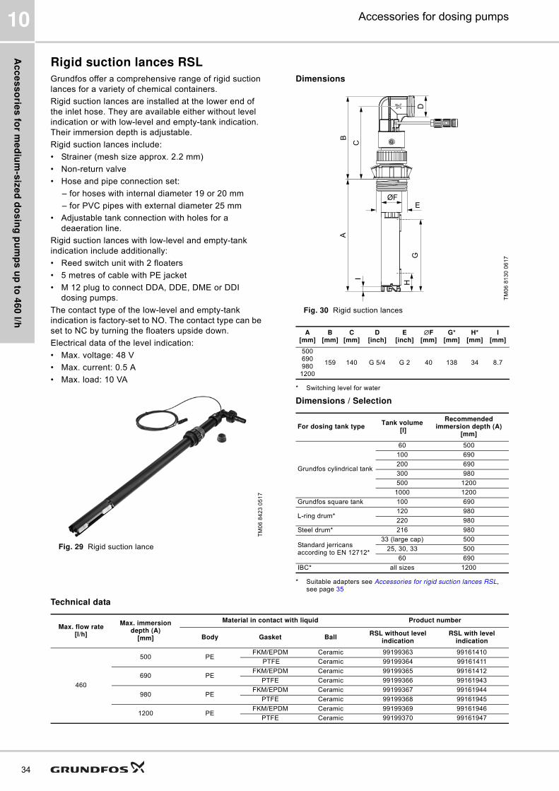
Rigid suction lances RSL
Grundfos offer a comprehensive range of rigid suction
lances for a variety of chemical containers.
Rigid suction lances are installed at the lower end of
the inlet hose. They are available either without level
indication or with low-level and empty-tank indication.
Their immersion depth is adjustable.
Rigid suction lances include:
� Strainer (mesh size approx. 2.2 mm)
� Non-return valve
� Hose and pipe connection set:
– for hoses with internal diameter 19 or 20 mm
– for PVC pipes with external diameter 25 mm
� Adjustable tank connection with holes for a
deaeration line.
Rigid suction lances with low-level and empty-tank
indication include additionally:
� Reed switch unit with 2 floaters
� 5 metres of cable with PE jacket
� M 12 plug to connect DDA, DDE, DME or DDI
dosing pumps.
The contact type of the low-level and empty-tank
indication is factory-set to NO. The contact type can be
set to NC by turning the floaters upside down.
Electrical data of the level indication:
� Max. voltage: 48 V
� Max. current: 0.5 A
� Max. load: 10 VA
Fig. 29 Rigid suction lance
Dimensions
Fig. 30 Rigid suction lances
* Switching level for water
Dimensions / Selection
* Suitable adapters see Accessories for rigid suction lances RSL, see page 35
Technical data
TM
06
84
23
05
17
TM
06
81
30
06
17
A[mm]
B[mm]
C[mm]
D[inch]
E[inch]
∅F[mm]
G*[mm]
H*[mm]
I[mm]
500690980
1200
159 140 G 5/4 G 2 40 138 34 8.7
For dosing tank typeTank volume
[l]
Recommended immersion depth (A)
[mm]
Grundfos cylindrical tank
60 500
100 690
200 690
300 980
500 1200
1000 1200
Grundfos square tank 100 690
L-ring drum*120 980
220 980
Steel drum* 216 980
Standard jerricans according to EN 12712*
33 (large cap) 500
25, 30, 33 500
60 690
IBC* all sizes 1200
D
B
C
A
EØF
GH
I
Max. flow rate[l/h]
Max. immersion depth (A)
[mm]
Material in contact with liquid Product number
Body Gasket BallRSL without level
indicationRSL with level
indication
460
500 PEFKM/EPDM Ceramic 99199363 99161410
PTFE Ceramic 99199364 99161411
690 PEFKM/EPDM Ceramic 99199365 99161412
PTFE Ceramic 99199366 99161943
980 PEFKM/EPDM Ceramic 99199367 99161944
PTFE Ceramic 99199368 99161945
1200 PEFKM/EPDM Ceramic 99199369 99161946
PTFE Ceramic 99199370 99161947

Ac
ce
ss
ori
es
fo
r m
ed
ium
-siz
ed
do
sin
g p
um
ps
up
to
46
0 l
/h
35
Accessories for dosing pumps 10
Accessories for rigid suction lances RSL
Adapters for containers
These adapters allow the installation of standard rigid
suction lances (G 2" thread) on different types of
containers.
Fig. 31 Adapters for containers
Technical data
TM
04
85
06
07
12
Adapter type For container type Remark Product number
TM
04
84
70
05
12
Counter nut for tanks without threaded opening, e.g. 100-litre square tank or 1000-litre cylindrical tank
PVC, grey 98071170
TM
04
84
71
05
12 Containers with 2" NPT threaded opening PVC, grey 98156690
Drums with S 70 x 6 coarse thread (MAUSER 2") PE, blue 98071171
Drums with S 56 x 4 coarse thread (TriSure®) PE, orange 98071172
TM
04
84
73
05
12 Jerricans with medium-sized opening (approx. ∅45 mm), according to EN
12713PE, yellow 98071174
Jerricans with large opening (approx. ∅57 mm), according to EN 12713 PE, brown 98071175
US containers with bung hole of 63 mm (ASTM International) PE, white 98071176
TM
04
84
72
05
12
IBC (Intermediate Bulk Container) with opening of ∅150 mm, S 160 x 7 PE, black 98071177

Ac
ce
ss
orie
s fo
r me
diu
m-s
ize
d d
os
ing
pu
mp
s u
p to
46
0 l/h
36
Accessories for dosing pumps10
Emission protection kits
Gas emitted by liquid in a container can cause bad
odour and corrosion. Emission protection kits help
avoid such problems. Rigid suction lances can be
retrofitted with emission protection kits.
Two variants are available:
� Emission protection kit with snifting valve: no gas
can escape from the container, but air can be drawn
in.
� Emission protection kit for use with filter: gas can
escape from the container and air can be drawn in.
The kit can be connected to a filter by means of a 4/
6 mm hose.
Emission protection kits include:
� Gasket for the tank adapter
� Snifting valve or hose nipple 4/6 mm (hose is not
included)
� Gasket for the cable outlet.
Fig. 32 Emission protection kit
Order data
M 12-plug-to-flat-plug adapter
The adapter allows to connect rigid suction lances or
foot valves with level indication to pumps with a level
input designed for flat plugs (e.g. DMX and DMH with
AR control unit).
Order data
TM
06
83
72
03
17
Position Description
A Gasket for the cable outlet
B Air valve
C Gasket for the tank adapter
Variant Product number
Emission protection kit with snifting valve 98071178
Emission protection kit for use with filter 98071179
A
B
C
AAAAAAAAAAAAAAAAAAAAAAA
BBBBBBBBBBBBBBBBBBBBBBBBBB
CCCCCCCCCCCCCCCCCCCCCCCCCCCCCCCCC
Description Product number
M12-plug-to-flat-plug adapter 96635010
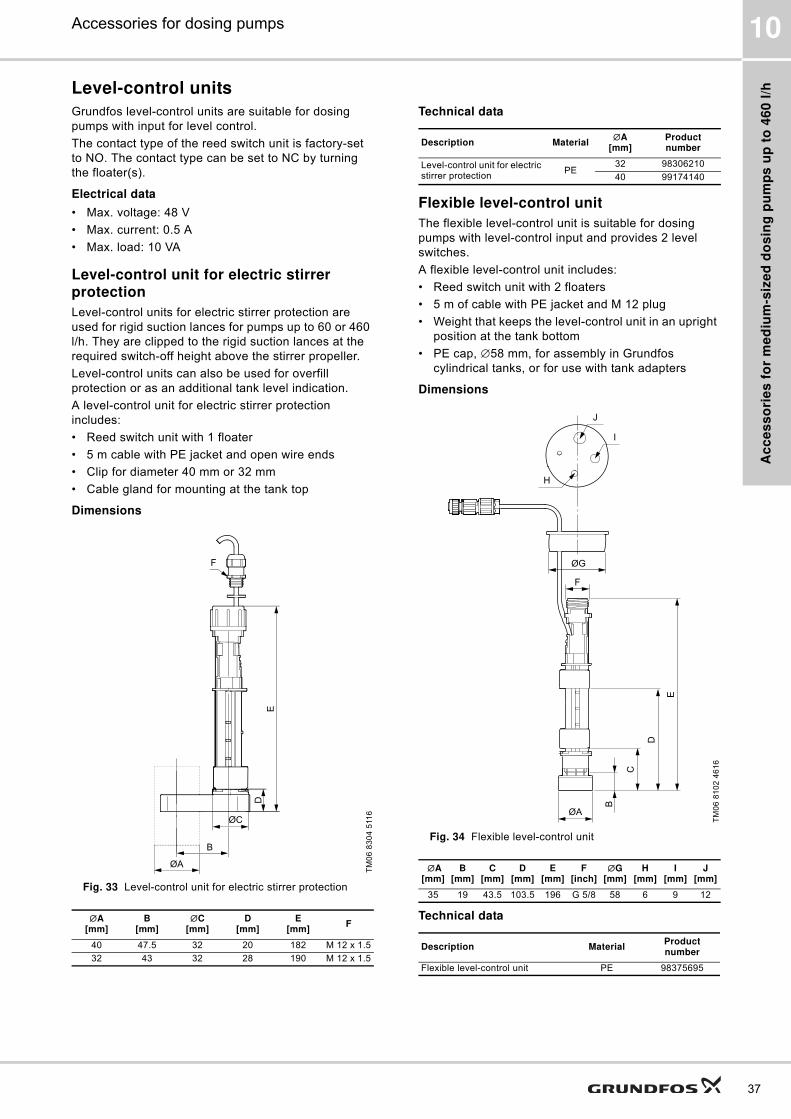
Ac
ce
ss
ori
es
fo
r m
ed
ium
-siz
ed
do
sin
g p
um
ps
up
to
46
0 l
/h
37
Accessories for dosing pumps 10
Level-control units
Grundfos level-control units are suitable for dosing
pumps with input for level control.
The contact type of the reed switch unit is factory-set
to NO. The contact type can be set to NC by turning
the floater(s).
Electrical data
� Max. voltage: 48 V
� Max. current: 0.5 A
� Max. load: 10 VA
Level-control unit for electric stirrer protection
Level-control units for electric stirrer protection are
used for rigid suction lances for pumps up to 60 or 460
l/h. They are clipped to the rigid suction lances at the
required switch-off height above the stirrer propeller.
Level-control units can also be used for overfill
protection or as an additional tank level indication.
A level-control unit for electric stirrer protection
includes:
� Reed switch unit with 1 floater
� 5 m cable with PE jacket and open wire ends
� Clip for diameter 40 mm or 32 mm
� Cable gland for mounting at the tank top
Dimensions
Fig. 33 Level-control unit for electric stirrer protection
Technical data
Flexible level-control unit
The flexible level-control unit is suitable for dosing
pumps with level-control input and provides 2 level
switches.
A flexible level-control unit includes:
� Reed switch unit with 2 floaters
� 5 m of cable with PE jacket and M 12 plug
� Weight that keeps the level-control unit in an upright
position at the tank bottom
� PE cap, ∅58 mm, for assembly in Grundfos
cylindrical tanks, or for use with tank adapters
Dimensions
Fig. 34 Flexible level-control unit
Technical data
TM
06
83
04
511
6
∅A[mm]
B[mm]
∅C[mm]
D[mm]
E[mm]
F
40 47.5 32 20 182 M 12 x 1.5
32 43 32 28 190 M 12 x 1.5
F
E
ØA
B
ØC
D
Description Material∅A
[mm]Product number
Level-control unit for electric stirrer protection
PE32 98306210
40 99174140
TM
06
81
02
46
16
∅A[mm]
B[mm]
C[mm]
D[mm]
E[mm]
F[inch]
∅G[mm]
H[mm]
I[mm]
J[mm]
35 19 43.5 103.5 196 G 5/8 58 6 9 12
Description MaterialProduct number
Flexible level-control unit PE 98375695
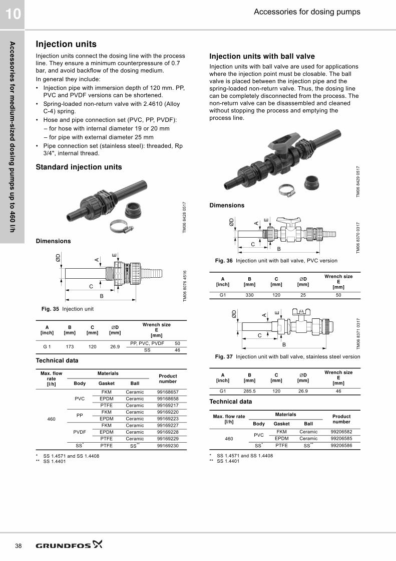
Ac
ce
ss
orie
s fo
r me
diu
m-s
ize
d d
os
ing
pu
mp
s u
p to
46
0 l/h
38
Accessories for dosing pumps10
Injection units
Injection units connect the dosing line with the process
line. They ensure a minimum counterpressure of 0.7
bar, and avoid backflow of the dosing medium.
In general they include:
� Injection pipe with immersion depth of 120 mm. PP,
PVC and PVDF versions can be shortened.
� Spring-loaded non-return valve with 2.4610 (Alloy
C-4) spring.
� Hose and pipe connection set (PVC, PP, PVDF):
– for hose with internal diameter 19 or 20 mm
– for pipe with external diameter 25 mm
� Pipe connection set (stainless steel): threaded, Rp
3/4", internal thread.
Standard injection units
Dimensions
Fig. 35 Injection unit
Technical data
* SS 1.4571 and SS 1.4408** SS 1.4401
Injection units with ball valve
Injection units with ball valve are used for applications
where the injection point must be closable. The ball
valve is placed between the injection pipe and the
spring-loaded non-return valve. Thus, the dosing line
can be completely disconnected from the process. The
non-return valve can be disassembled and cleaned
without stopping the process and emptying the
process line.
Dimensions
Fig. 36 Injection unit with ball valve, PVC version
Fig. 37 Injection unit with ball valve, stainless steel version
Technical data
* SS 1.4571 and SS 1.4408** SS 1.4401
TM
06
84
28
05
17
TM
06
80
76
45
16
A[inch]
B[mm]
C[mm]
∅D[mm]
Wrench sizeE
[mm]
G 1 173 120 26.9PP, PVC, PVDF 50
SS 46
Max. flow rate[l/h]
MaterialsProduct numberBody Gasket Ball
460
PVC
FKM Ceramic 99168657
EPDM Ceramic 99168658
PTFE Ceramic 99169217
PPFKM Ceramic 99169220
EPDM Ceramic 99169223
PVDF
FKM Ceramic 99169227
EPDM Ceramic 99169228
PTFE Ceramic 99169229
SS* PTFE SS** 99169230
B
C
ØD
A
E
TM
06
84
29
05
17
TM
06
83
70
03
17
A[inch]
B[mm]
C[mm]
∅D[mm]
Wrench sizeE
[mm]
G1 330 120 25 50
TM
06
83
71
03
17
A[inch]
B[mm]
C[mm]
∅D[mm]
Wrench sizeE
[mm]
G1 285.5 120 26.9 46
Max. flow rate[l/h]
Materials Product numberBody Gasket Ball
460PVC
FKM Ceramic 99206582
EPDM Ceramic 99206585
SS* PTFE SS** 99206586
BC
ØD
A
E
B
C
ØD
A E

Ac
ce
ss
ori
es
fo
r m
ed
ium
-siz
ed
do
sin
g p
um
ps
up
to
46
0 l
/h
39
Accessories for dosing pumps 10
Pressure relief valves PRV
Pressure relief valves protect the pump and the outlet-
side installations against excessive pressure. All
pressurised dosing installations should include a
pressure relief valve.
Pressure relief valves are installed in the outlet line
near the pump using the 2 in-line connections. The
side connection leads the relief liquid back into the
tank.
� Relief pressure, adjustable from 3 to 10 bar, is
factory-set to 10 bar
� Maximum operating pressure 10 bar
� Hose and pipe connection set (PVC, PP, PVDF):
– for hoses with internal diameter 19 or 20 mm
– for pipes with external diameter 25 mm
� Pipe connection set (stainless steel): threaded, Rp
3/4", internal thread.
Fig. 38 Pressure relief valve
Dimensions
Fig. 39 Pressure relief valve (PP, PVC, PVDF version)
Fig. 40 Pressure relief valve, stainless steel version
Technical data
* SS 1.4571
TM
06
84
21
05
17
TM
06
80
77
45
16
A[mm]
B[mm]
C[mm]
D[mm]
E[mm]
∅F[mm]
G[inch]
H[mm]
I[mm]
168 30 92 6.5 150 85 G 5/4 40 75
G
E
A
B
C
I
HD
ØF
TM
06
82
47
49
16
A[mm]
B[mm]
C[mm]
D∅F
[mm]G
[inch]J
[mm]K
[mm]
167 30 63 M 6 89 Rp 3/4 10 17.5
Max. flow rate[l/h]
Materials Product numberBody Gasket
460
PVCFKM/EPDM 99131032
PTFE 99141139
PP FKM/EPDM 99141197
PVDFFKM/EPDM 99141212
PTFE 99141224
SS* - 99141228
AB
G
C
ØF
DK
G
J

Ac
ce
ss
orie
s fo
r me
diu
m-s
ize
d d
os
ing
pu
mp
s u
p to
46
0 l/h
40
Accessories for dosing pumps10
Pressure loading valves PLV
Pressure loading valves maintain a constant
counterpressure for the dosing pump.
They are used in the following applications:
� Too low counterpressure or no counterpressure at
all
� Fluctuating system pressure with outlet-side
pulsation damper
� To prevent syphoning, when the inlet pressure is
higher than the counterpressure
Pressure loading valves are installed in the outlet line
after the pressure relief valve, and after the pulsation
damper, if fitted.
� Opening pressure, adjustable from 3 to 10 bar, is
factory-set to 3 bar
� Maximum operating pressure: 10 bar
� Hose and pipe connection set (PVC, PP, PVDF):
– for hoses with internal diameter 19 or 20 mm
– for pipes with external diameter 25 mm
� Pipe connection set (stainless steel): threaded, Rp
3/4", internal thread
Pressure loading valves must not be used as shut-off
valves.
Fig. 41 Pressure loading valve
Dimensions
Fig. 42 Pressure loading valve (PP, PVC, PVDF version)
Fig. 43 Pressure loading valve, stainless steel version
Technical data
* SS 1.4571
TM
06
84
22
05
17
TM
06
80
90
45
16
A[mm]
B[mm]
C[mm]
D[mm]
E[mm]
∅F[mm]
G[inch]
H[mm]
168 30 92 6.5 150 85 G 5/4 40
TM
06
82
46
49
16
A[mm]
B[mm]
C[mm]
D∅F
[mm]G
[inch]J
[mm]K
[mm]
167 30 63 M 6 89 Rp 3/4 10 17.5
Max. flow rate[l/h]
Materials Product numberBody Gasket
460
PVCFKM/EPDM 99132186
PTFE 99140593
PP FKM/EPDM 99140610
PVDFFKM/EPDM 99140646
PTFE 99140651
SS* - 99135772
E
B
A
G
C
H
D
ØF
A
B
G
C
ØF
DK
J

Ac
ce
ss
ori
es
fo
r m
ed
ium
-siz
ed
do
sin
g p
um
ps
up
to
46
0 l
/h
41
Accessories for dosing pumps 10
Pressure valves PV
Pressure valves provide a constant counterpressure of
3 bar. They are particularly required for DDA-FCM
pumps at very small flow rates.
Pressure valves are installed either directly on the
pump outlet side, or on the pressure relief valve.
� Loading pressure: 3 bar, not adjustable
� Maximum system pressure: 10 bar
� Spring material: 2.4610 (Alloy C-4)
� No connections included.
Dimensions
Fig. 44 Pressure valve
Technical data
TM
06
84
04
04
17
MaterialA
[mm]B
[inch]
PVCPVDF
94 G 5/4
SS 100 G 5/4
Max. flow rate [l/h]
MaterialProduct numberBody Ball Gaskets
200
PVC CeramicEPDM 99229021
FKM 99229033
PVDF CeramicEPDM 99229018
FKM 99229020
B
A

Ac
ce
ss
orie
s fo
r me
diu
m-s
ize
d d
os
ing
pu
mp
s u
p to
46
0 l/h
42
Accessories for dosing pumps10
Pulsation dampers and calibration columns
Pulsation dampers are used to even out the pulsating
flow and pressure produced by positive displacement
pumps like diaphragm dosing pumps. They can be
installed before and after the pump.
Discharge-side pulsation dampers DB and DBG
Pulsation dampers DB and DBG are especially
designed for installations with long outlet lines with a
small diameter, or with rigid pipes. The pulsation
dampers optimise the dosing accuracy and protect the
pump and the outlet line against pressure surges.
If the counterpressure in the system is low or
fluctuating, the installation of a pressure loading valve
PLV after the pulsation damper may be required to
optimise its function.
Pulsation dampers DB and DBG have an air or
nitrogen cushion inside, which is separated from the
dosing medium by a separating diaphragm. This keeps
the charging pressure stable for a long time and avoids
that air or nitrogen is dissolved in the dosing medium.
For proper operation, the pressure in the air or
nitrogen cushion must be set to approximately 80 % of
the system pressure.
In PVC, PP, and stainless steel pulsation dampers, an
FKM or EPDM bladder is used as separating
diaphragm, in PVDF pulsation dampers a PTFE
bellows is used as separating diaphragm.
Grundfos SMART Digital dosing pumps do not require
a DB or DBG pulsation damper, if the flow rate is
limited to 75 % of the maximum dosing capacity of the
pump. In rigid pipe installations, the flow rate without
pulsation damper should not exceed 50 % of the
maximum dosing capacity of the pump.
Pulsation dampers DBG include a pressure gauge for
easy setting of the correct pressure. Pulsation
dampers DB have no pressure gauge.
Suction-side pulsation dampers CSD with calibration scale
Pulsation dampers CSD help to ensure the accuracy of
dosing pumps, which is highly dependent on proper
suction conditions. In installations with long inlet lines
or inlet lines with a small diameter, the use of a CSD
pulsation damper is recommended.
Pulsation dampers CSD have a transparent PVC
cylinder with a fine volume scale. When combined with
a shut-off valve in the inlet line, they can also be used
for calibration or flow measurement. In installations
without flooded suction, the optional manual vacuum
pump kit simplifies the startup of the dosing pump.
Pulsation dampers CSD can be used for multiple
pumps that are supplied by the same inlet line.
Calibration columns
Calibration columns have a graduated glass cylinder
with a fine scale. A shut-off valve on the lower end can
disconnect them from the inlet-side installation during
normal operation.
One calibration column can be used for multiple pumps
that are supplied by the same inlet line.
Calibration columns must not be used as pulsation
dampers.
Fig. 45 Pulsation dampers CSD, DBG and DB
TM
06
84
49
06
17

Ac
ce
ss
ori
es
fo
r m
ed
ium
-siz
ed
do
sin
g p
um
ps
up
to
46
0 l
/h
43
Accessories for dosing pumps 10
Sizing guide for pulsation dampers DB, DBG, CSD and calibration columns
Look up your pump type in the table. Find the required pulsation damper or calibration column volume in the
respective table column.
* For very low remaining pulsation, a larger damper than mentioned in the sizing guide should be used.
** A smaller damper than mentioned in the sizing guide is sufficient, if a high remaining pulsation is acceptable.
Pump types
Pump stroke volume
[ml]
Required damper volume
Required calibration
column volume
[l]
DB/DBG[l]
CSD[l]
DDC-DDE 6-10 0.81
0.15
0.25 0.25
DDA 7.5-16* 0.74
DDC 9-7 0.84
DDA 12-10 1.45
DDC-DDE 15-4 1.58
DDA 17-7 1.55
DDA 30-4* 3.1
DDI 60-10 6.67
0.5 0.5
DMX 4-10
2.2DMX 8-10
DMX 16-10
DMX 7-10
3.8DMX 14-10
DMX 27-10
DMX 9-10
4.9DMX 18-10
DMX 35-10
DMX 12-10
6.9DMX 26-10
DMX 50-10
DMH 5-10
3.5DMH 13-10
DMH 24-10
DMH 11-10
6.4DMH 24-10
DMH 46-10
DDA/DDE 60-10 5.56
0.3 - 0.35 1.5 2.0
DDA/DDE 120-7 11.58
DDA/DDE 200-4 19.3
DME 60-10** 6.25
DME 150-4 15.6
DDI 150-4 13.9
DMX 17-4
10.4DMX 39-4
DMX 75-4
DMX 25-3
16DMX 60-3
DMX 115-3
DMX 24-8
13.8DMX 52-8
DMX 100-8
DMX 142-8
DMX 67-10
18.5DMX 132-10
DMX 190-10
DMH 21-10
11.3
DMH 43-10
DMH 67-10
DMH 83-10
DMH 100-10
DMX 37-5
22
0.65 - 0.7 3.0 4.0
DMX 82-5
DMX 160-5
DMX 230-5
DMX 95-8
27.8DMX 199-8
DMX 280-8
DMX 60-3
36DMX 130-3
DMX 255-3
DMX 380-3
DMX 152-6
44.6DMX 321-6
DMX 460-6
DMH 50-10
31.6
DMH 102-10
DMH 143-10
DMH 175-10
DMH 213-10
DMH 291-10
Pump types
Pump stroke volume
[ml]
Required damper volume
Required calibration
column volume
[l]
DB/DBG[l]
CSD[l]
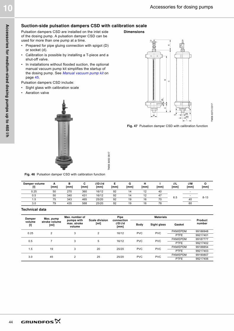
Ac
ce
ss
orie
s fo
r me
diu
m-s
ize
d d
os
ing
pu
mp
s u
p to
46
0 l/h
44
Accessories for dosing pumps10
Suction-side pulsation dampers CSD with calibration scale
Pulsation dampers CSD are installed on the inlet side
of the dosing pump. A pulsation damper CSD can be
used for more than one pump at a time.
� Prepared for pipe gluing connection with spigot (D)
or socket (d).
� Calibration is possible by installing a T-piece and a
shut-off valve.
� In installations without flooded suction, the optional
manual vacuum pump kit simplifies the startup of
the dosing pump. See Manual vacuum pump kit on
page 45.
Pulsation dampers CSD include:
� Sight glass with calibration scale
� Aeration valve
Fig. 46 Pulsation damper CSD with calibration function
Dimensions
Fig. 47 Pulsation damper CSD with calibration function
Technical data
TM
06
84
50
06
17
TM
06
83
73
03
17
I
ØD
Ød
G
HAB
CE
M
ØL
O
Damper volume[l]
A[mm]
B[mm]
C[mm]
∅D/∅d[mm]
E[mm]
G[mm]
H[mm]
I[mm]
∅L[mm]
∅M[mm]
O[mm]
0.25 50 270 360 16/12 92 14 12 40
6.5
-
8-130.5 50 340 431 16/12 92 14 12 47 -
1.5 75 343 465 25/20 92 19 16 70 40
3.0 79 435 568 25/20 92 19 16 78 60
Damper volume
[l]
Max. pump stroke volume
[ml]
Max. number of pumps with max. stroke
volume
Scale division[ml]
Pipe connection
∅D/∅d [mm]
MaterialsProduct numberBody Sight glass Gasket
0.25 2 3 2 16/12 PVC PVCFKM/EPDM 99186948
PTFE 99217401
0.5 7 3 5 16/12 PVC PVCFKM/EPDM 99187777
PTFE 99217402
1.5 19 3 20 25/20 PVC PVCFKM/EPDM 99188854
PTFE 99217403
3.0 45 2 25 25/20 PVC PVCFKM/EPDM 99190807
PTFE 99217406
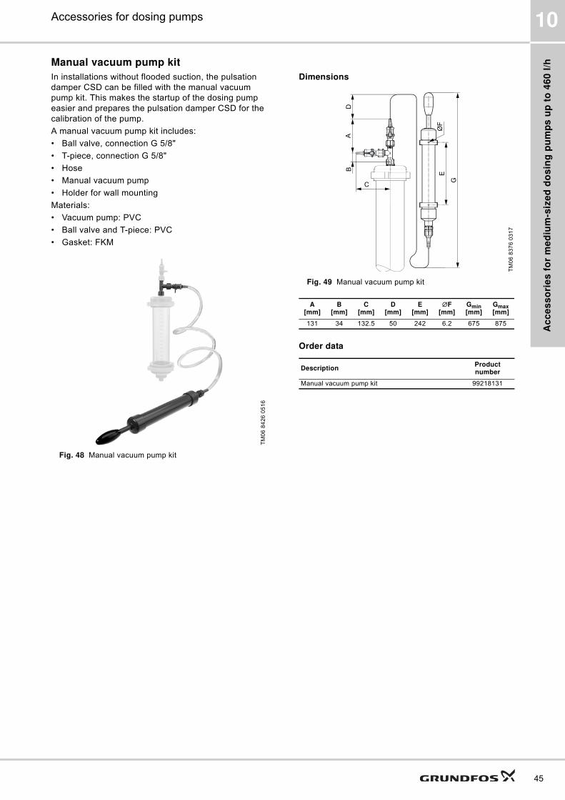
Ac
ce
ss
ori
es
fo
r m
ed
ium
-siz
ed
do
sin
g p
um
ps
up
to
46
0 l
/h
45
Accessories for dosing pumps 10
Manual vacuum pump kit
In installations without flooded suction, the pulsation
damper CSD can be filled with the manual vacuum
pump kit. This makes the startup of the dosing pump
easier and prepares the pulsation damper CSD for the
calibration of the pump.
A manual vacuum pump kit includes:
� Ball valve, connection G 5/8"
� T-piece, connection G 5/8"
� Hose
� Manual vacuum pump
� Holder for wall mounting
Materials:
� Vacuum pump: PVC
� Ball valve and T-piece: PVC
� Gasket: FKM
Fig. 48 Manual vacuum pump kit
Dimensions
Fig. 49 Manual vacuum pump kit
Order data
TM
06
84
26
05
16
TM
06
83
76
03
17
A[mm]
B[mm]
C[mm]
D[mm]
E[mm]
∅F[mm]
Gmin[mm]
Gmax[mm]
131 34 132.5 50 242 6.2 675 875
DescriptionProduct number
Manual vacuum pump kit 99218131
AB
C
G
EØ
F
D

Ac
ce
ss
orie
s fo
r me
diu
m-s
ize
d d
os
ing
pu
mp
s u
p to
46
0 l/h
46
Accessories for dosing pumps10
Calibration columns
Calibration columns are intended for flow
measurement or calibration of dosing pumps. They
must be isolated from the pipework during normal
operation.
The volume in the calibration column can supply the
largest suitable pump for approximately 30 seconds.
Calibration columns include:
� Glass cylinder with acrylic outer shield
� Aeration valve on top
� Shut-off valve on the bottom
In installations without flooded suction, the optional
manual vacuum pump kit simplifies the startup of the
dosing pump. See Manual vacuum pump kit on page
45.
Calibration columns must not be used as pulsation
dampers.
Dimensions
Fig. 50 Calibration columns
Technical data
TM
06
84
05
05
17
Ød
AB
ØD
ØC
min. H
max. H
EØF
Volume[l]
BodyA
[mm]B
[mm]∅C
[mm]∅D
[mm]E
[mm]∅F
[mm]Hmin - Hmax
[mm]
0.25PVDF 478 184
12 50.8 M 10 12 50-154SS 460 140
0.5PVDF 517 184
12 69.85 M 10 12 61-165SS 498 140
2.0PVDF 675 188
12 101.6 M 10 12 78-182SS 657 148
4.0PVDF 795 188
12 132 M 10 12 92-196SS 777 148
Volume[l]
Max. pump stroke volume
[ml]
Scale division[ml]
Pipe connection∅d
Material Product number
[mm] [inch] Body Gasket
0.25 2 2
16 - PVDF FKM 99224280
- G 1/2SS FKM 99224303
SS EPDM 99224304
0.5 7 5
16 - PVDF FKM 99224305
- G 1/2SS FKM 99224307
SS EPDM 99224308
2.0 19 20
25 - PVDF FKM 99224309
- G 1SS FKM 99224310
SS EPDM 99224311
4.0 45 25
25 - PVDF FKM 99224312
- G 1SS FKM 99224313
SS EPDM 99224314

Ac
ce
ss
ori
es
fo
r m
ed
ium
-siz
ed
do
sin
g p
um
ps
up
to
46
0 l
/h
47
Accessories for dosing pumps 10
Vacuum pump kit for calibration columns
In installations without flooded suction, the calibration
column can be filled with the vacuum pump kit. This
makes the startup of the dosing pump easier and
prepares the calibration column for pump calibration.
A vacuum pump kit for calibration columns includes:
� Ball valve, connection G 5/8"
� T-piece, connection G 5/8"
� Hose
� Manual vacuum pump
� Holder for wall mounting
Materials:
� Vacuum pump: PVC
� Ball valve and T-piece: PVDF
� Gasket: FKM
Dimensions
Fig. 51 Vacuum pump kit
Order data
TM
06
84
12
05
17
Dimension Unit Value
Amin-max [mm] 700-875
B [mm] 242
∅C [mm] 6.1
∅D [mm] 12
E [inch] G 5/8
F [mm] 206
G [mm] 51
H [mm] 206
∅I [mm] 12
∅J [mm] 12
K [mm] 40
DescriptionProduct number
Vacuum pump kit for calibration columns 99226934
FE
GH
ØI
ØJ
ØD
A m
in
A m
ax
B
ØC
K

Ac
ce
ss
orie
s fo
r me
diu
m-s
ize
d d
os
ing
pu
mp
s u
p to
46
0 l/h
48
Accessories for dosing pumps10
Discharge-side pulsation dampers DB and DBG
Pulsation dampers DB and DBG have a separating
diaphragm and are intended for the outlet side of the
dosing pump. We recommend using one pump per
pulsation damper.
� Pre-load pressure: 2.7 bar.
Pulsation dampers DB and DBG include:
� Material for wall mounting
� PVC versions are prepared for pipe gluing
connection with spigot (D) or socket (d).
� PVDF and PP versions are prepared for pipe
welding connection with spigot (D) or socket (d).
� Pulsation dampers DBG include a pressure gauge.
Fig. 52 Pulsation damper DBG with separating diaphragm
and pressure gauge
Dimensions
Fig. 53 Pulsation damper DBG, PVC version
Fig. 54 Pulsation damper DB, stainless steel version
* SS 1.4404
TM
06
84
24
05
17
TM
06
82
84
50
16
TM
06
84
52
06
17
A2
A3
A1
B
min. H
max. H
EØF
ØD1
ØD
Ød
ØD2
G
A2
A1
ØD1min. H
max. H
EØF
Nominal damper volume
[l]
Actual damper volume
[l]
MaterialPipe
connection[mm]
A1[mm]
A2[mm]
A3[mm]
D1[mm]
D2[mm]
Hmin - Hmax[mm]
Ginternal thread[inch]
F[mm]
B[mm]
E
Body ∅ D ∅ d
0.15
0.15 PVDF 16 12 205 12 14 70 53 53-127
-
12 129 M 10
0.18
PVC16 12 161 12 14 80 - 67-171
PP
SS* - - 118 14 - 70 - 64-168 G 1/2
0.35
0.3 PVDF 25 20 267 20 25 84 63 58-175 -
0.36
PVC25 20 203 20 25 90 - 71-175 -
PP
SS* - - 161 16- - 85 - 67-171 G 3/4
0.650.65
PVC25 20 263 20 25 100 - 78-152 -
PP
SS* - - 205 20 - 90 84 67-171 G 3/4
0.7 PVDF 25 20 138 20 25 125 84 67-171 -

Ac
ce
ss
ori
es
fo
r m
ed
ium
-siz
ed
do
sin
g p
um
ps
up
to
46
0 l
/h
49
Accessories for dosing pumps 10
Technical data
* SS 1.4404
Nominal damper-volume
[l]
Max. pump stroke volume
[ml]
Pipe connection
Max. operating pressure
[bar]
Material Product number
∅D/∅d[mm]
Ginternal thread[inch]
Body GasketType DB
(without pressure gauge)
Type DBG(with pressure
gauge)
0.15 7
16/12 - 10
PVCFKM 99202642 99202679
EPDM 99202653 99202680
PPFKM 99202654 99202681
EPDM 99202657 99202682
- G 1/2 180 SS* FKM 99202660 99202684
EPDM 99202661 99202685
16/12 20 PVDF PTFE 99202658 99202683
0.35 19
25/20 - 10
PVCFKM 99202662 99202687
EPDM 99202663 99202688
PPFKM 99202664 99202689
EPDM 99202665 99202690
- G 1/2 130 SS* FKM 99202667 99202692
EPDM 99202669 99202693
0.3 19 25/20 20 PVDF PTFE 99202666 99202691
0.65 45
25/20 - 10
PVCFKM 99202670 99202694
EPDM 99202671 99202695
PPFKM 99202672 99202696
EPDM 99202673 99202697
- G 3/4 50 SS* FKM 99202675 99202699
EPDM 99202676 99202700
0.7 45 25/20 16 PVDF PTFE 99202674 99202698
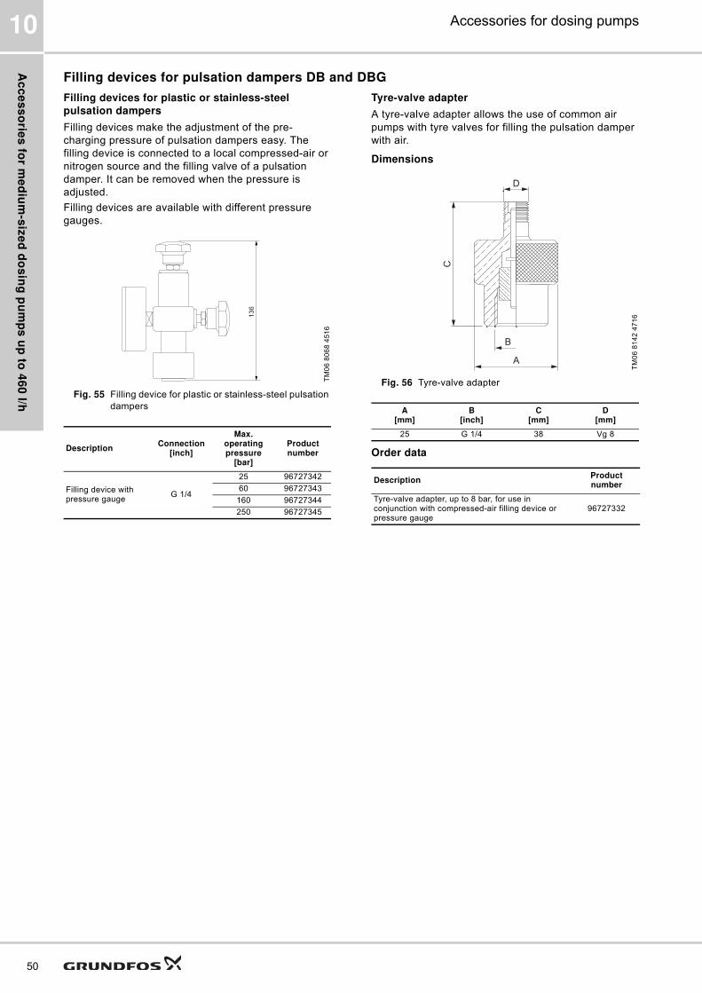
Ac
ce
ss
orie
s fo
r me
diu
m-s
ize
d d
os
ing
pu
mp
s u
p to
46
0 l/h
50
Accessories for dosing pumps10
Filling devices for pulsation dampers DB and DBG
Filling devices for plastic or stainless-steel
pulsation dampers
Filling devices make the adjustment of the pre-
charging pressure of pulsation dampers easy. The
filling device is connected to a local compressed-air or
nitrogen source and the filling valve of a pulsation
damper. It can be removed when the pressure is
adjusted.
Filling devices are available with different pressure
gauges.
Fig. 55 Filling device for plastic or stainless-steel pulsation
dampers
Tyre-valve adapter
A tyre-valve adapter allows the use of common air
pumps with tyre valves for filling the pulsation damper
with air.
Dimensions
Fig. 56 Tyre-valve adapter
Order data
TM
06
80
68
45
16
DescriptionConnection
[inch]
Max. operating pressure
[bar]
Product number
Filling device with pressure gauge
G 1/4
25 96727342
60 96727343
160 96727344
250 96727345
13
6
TM
06
81
42
47
16
A[mm]
B[inch]
C[mm]
D[mm]
25 G 1/4 38 Vg 8
DescriptionProduct number
Tyre-valve adapter, up to 8 bar, for use in conjunction with compressed-air filling device or pressure gauge
96727332
A
B
C
D
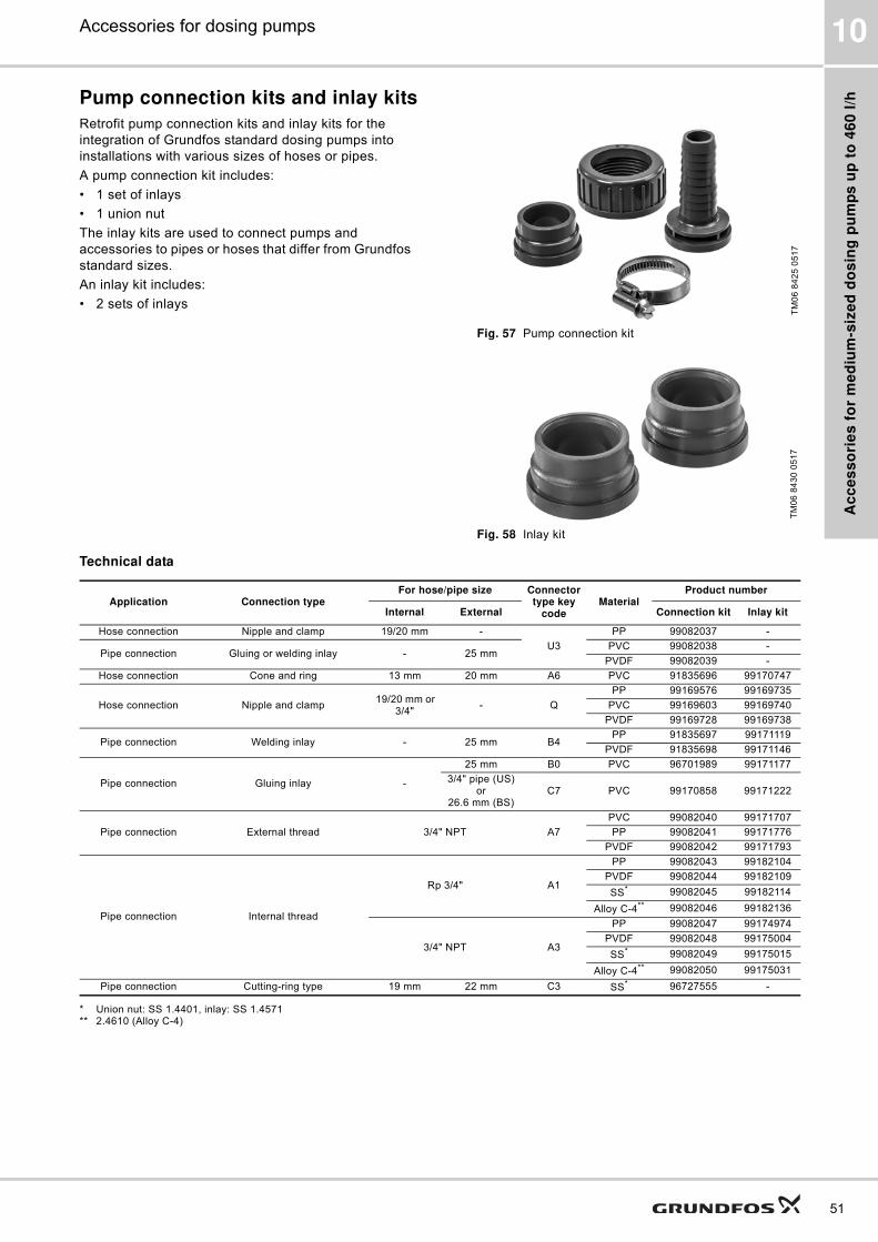
Ac
ce
ss
ori
es
fo
r m
ed
ium
-siz
ed
do
sin
g p
um
ps
up
to
46
0 l
/h
51
Accessories for dosing pumps 10
Pump connection kits and inlay kits
Retrofit pump connection kits and inlay kits for the
integration of Grundfos standard dosing pumps into
installations with various sizes of hoses or pipes.
A pump connection kit includes:
� 1 set of inlays
� 1 union nut
The inlay kits are used to connect pumps and
accessories to pipes or hoses that differ from Grundfos
standard sizes.
An inlay kit includes:
� 2 sets of inlays
Fig. 57 Pump connection kit
Fig. 58 Inlay kit
Technical data
* Union nut: SS 1.4401, inlay: SS 1.4571** 2.4610 (Alloy C-4)
TM
06
84
25
05
17
TM
06
84
30
05
17
Application Connection typeFor hose/pipe size Connector
type key code
MaterialProduct number
Internal External Connection kit Inlay kit
Hose connection Nipple and clamp 19/20 mm -
U3
PP 99082037 -
Pipe connection Gluing or welding inlay - 25 mmPVC 99082038 -
PVDF 99082039 -
Hose connection Cone and ring 13 mm 20 mm A6 PVC 91835696 99170747
Hose connection Nipple and clamp 19/20 mm or
3/4"- Q
PP 99169576 99169735
PVC 99169603 99169740
PVDF 99169728 99169738
Pipe connection Welding inlay - 25 mm B4PP 91835697 99171119
PVDF 91835698 99171146
Pipe connection Gluing inlay -
25 mm B0 PVC 96701989 99171177
3/4" pipe (US) or
26.6 mm (BS)C7 PVC 99170858 99171222
Pipe connection External thread 3/4" NPT A7
PVC 99082040 99171707
PP 99082041 99171776
PVDF 99082042 99171793
Pipe connection Internal thread
Rp 3/4" A1
PP 99082043 99182104
PVDF 99082044 99182109
SS* 99082045 99182114
Alloy C-4** 99082046 99182136
3/4" NPT A3
PP 99082047 99174974
PVDF 99082048 99175004
SS* 99082049 99175015
Alloy C-4** 99082050 99175031
Pipe connection Cutting-ring type 19 mm 22 mm C3 SS* 96727555 -
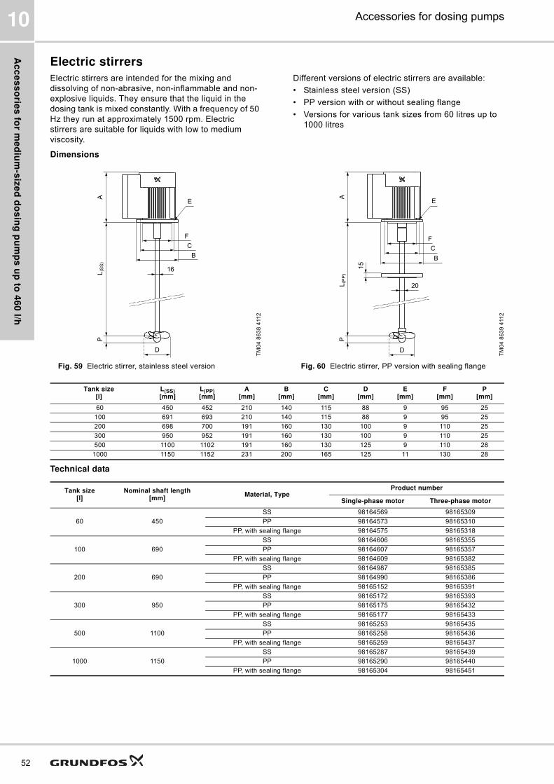
Ac
ce
ss
orie
s fo
r me
diu
m-s
ize
d d
os
ing
pu
mp
s u
p to
46
0 l/h
52
Accessories for dosing pumps10
Electric stirrers
Electric stirrers are intended for the mixing and
dissolving of non-abrasive, non-inflammable and non-
explosive liquids. They ensure that the liquid in the
dosing tank is mixed constantly. With a frequency of 50
Hz they run at approximately 1500 rpm. Electric
stirrers are suitable for liquids with low to medium
viscosity.
Different versions of electric stirrers are available:
� Stainless steel version (SS)
� PP version with or without sealing flange
� Versions for various tank sizes from 60 litres up to
1000 litres
Dimensions
Fig. 59 Electric stirrer, stainless steel version Fig. 60 Electric stirrer, PP version with sealing flange
Technical data
TM
04
86
38
411
2
16
D
AL
(SS
)P
B
C
F
E
TM
04
86
39
411
2
20
D
PL
(PP
)A
15
F
C
B
E
Tank size[l]
L(SS)[mm]
L(PP)[mm]
A[mm]
B[mm]
C[mm]
D[mm]
E[mm]
F[mm]
P[mm]
60 450 452 210 140 115 88 9 95 25
100 691 693 210 140 115 88 9 95 25
200 698 700 191 160 130 100 9 110 25
300 950 952 191 160 130 100 9 110 25
500 1100 1102 191 160 130 125 9 110 28
1000 1150 1152 231 200 165 125 11 130 28
Tank size[l]
Nominal shaft length[mm]
Material, TypeProduct number
Single-phase motor Three-phase motor
60 450
SS 98164569 98165309
PP 98164573 98165310
PP, with sealing flange 98164575 98165318
100 690
SS 98164606 98165355
PP 98164607 98165357
PP, with sealing flange 98164609 98165382
200 690
SS 98164987 98165385
PP 98164990 98165386
PP, with sealing flange 98165152 98165391
300 950
SS 98165172 98165393
PP 98165175 98165432
PP, with sealing flange 98165177 98165433
500 1100
SS 98165253 98165435
PP 98165258 98165436
PP, with sealing flange 98165259 98165437
1000 1150
SS 98165287 98165439
PP 98165290 98165440
PP, with sealing flange 98165304 98165451

Ac
ce
ss
ori
es
fo
r m
ed
ium
-siz
ed
do
sin
g p
um
ps
up
to
46
0 l
/h
53
Accessories for dosing pumps 10
Motor data of electric stirrers
Tank size[l]
Power rating[kW]
Motor phasesVoltage
[V]Frequency
[Hz]Enclosure
classInsulation
class
60100
0.091 220-240 50/60
IP65
F
3 220-240 / 380-420 (440-480) 50/60 (60)
200300500
0.251 220-230 50
IP553 220-240 / 380-415 50/60
1000 0.551 220-230 50
3 220-240 / 380-415 50/60

Ac
ce
ss
orie
s fo
r me
diu
m-s
ize
d d
os
ing
pu
mp
s u
p to
46
0 l/h
54
Accessories for dosing pumps10
Withdrawal devices
A withdrawal device is designed for installation in the
drain opening of a Grundfos tank. Hose or pipe
connection kits are included.
� Hose connection kit up to 60 l/h: 4/6 mm, 6/9 mm, 6/
12 mm and 9/12 mm
� Hose and pipe connection kit up to 460 l/h:
– for hoses with internal diameter 19 or 20 mm
– for pipes with external diameter 25 mm
Dimensions
Fig. 61 Withdrawal device, G 5/4"
Technical data
TM
06
84
14
05
17
G
A
F
B
C
E
D
Max. flow[l/h]
A[mm]
B[mm]
C[inch]
D[mm]
E[mm]
F[mm]
G[inch]
60 14314 G 3/4 41
27 75 G 5/8
460 151 30 87 G 5/4
Max. flow[l/h]
DescriptionMaterial Product
numberBody Gasket
60Withdrawal device with ball valve with through-bolt for connection to the dosing tank
PVCFKM 99226879
EPDM 99226880
460Withdrawal device with ball valve with through-bolt for connection to the dosing tank
PVCFKM 99226881
EPDM 99226893

Ac
ce
ss
ori
es
fo
r m
ed
ium
-siz
ed
do
sin
g p
um
ps
up
to
46
0 l
/h
55
Accessories for dosing pumps 10
Adapters
Threaded adapters
Union nut adapters
A union nut adapter allows the direct assembly of a pressure loading valve PLV or a pressure relief valve PRV on the
pump outlet valve.
Elbow adapter
An elbow adapter can be installed, if the space on the inlet side of the pump is confined.
Application example
TypeThreaded connection size Materials Product
numberInternal thread External thread Body Gaskets
DN 20 → DN 10
TM
06
84
16
05
17
G 5/4" G 3/4"
PP FKM/EPDM 99227512
PVCFKM/EPDM 99227511
PTFE 99228197
PVDFFKM/EPDM 99227829
PTFE 99227533
DN 32 → DN 20
TM
06
84
17
05
17
G 2" G 5/4"
PP FKM/EPDM 99227945
PVCFKM/EPDM 99227943
PTFE 99227960
PVDFFKM/EPDM 99227953
PTFE 99227948
TypeThreaded connection size
Body material Product numberInternal thread Internal thread
TM
06
84
18
05
17 G 5/4" G 5/4"
PP 99228667
PVC 99228665
PVDF 99228669
TypeThreaded connection size
Body material Product numberInternal and external thread
TM
06
81
29
47
16
G 5/4" PVC 99168768
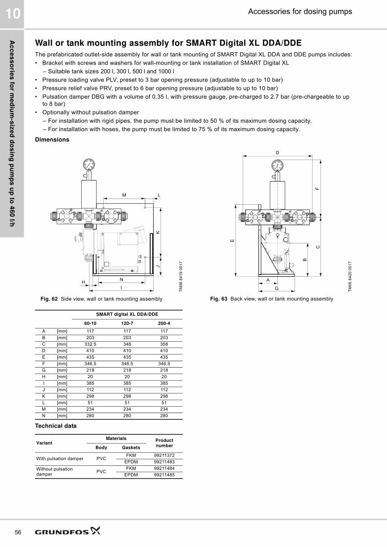
Ac
ce
ss
orie
s fo
r me
diu
m-s
ize
d d
os
ing
pu
mp
s u
p to
46
0 l/h
56
Accessories for dosing pumps10
Wall or tank mounting assembly for SMART Digital XL DDA/DDE
The prefabricated outlet-side assembly for wall or tank mounting of SMART Digital XL DDA and DDE pumps includes:
� Bracket with screws and washers for wall-mounting or tank installation of SMART Digital XL
– Suitable tank sizes 200 l, 300 l, 500 l and 1000 l
� Pressure loading valve PLV, preset to 3 bar opening pressure (adjustable to up to 10 bar)
� Pressure relief valve PRV, preset to 6 bar opening pressure (adjustable to up to 10 bar)
� Pulsation damper DBG with a volume of 0.35 l, with pressure gauge, pre-charged to 2.7 bar (pre-chargeable to up
to 8 bar)
� Optionally without pulsation damper
– For installation with rigid pipes, the pump must be limited to 50 % of its maximum dosing capacity.
– For installation with hoses, the pump must be limited to 75 % of its maximum dosing capacity.
Dimensions
Fig. 62 Side view, wall or tank mounting assembly Fig. 63 Back view, wall or tank mounting assembly
Technical data
TM
06
84
19
05
17
M L
KJ
I
HN
TM
06
84
20
05
17
D
FC
E
A
G
B
SMART digital XL DDA/DDE
60-10 120-7 200-4
A [mm] 117 117 117
B [mm] 203 203 203
C [mm] 332.5 348 358
D [mm] 410 410 410
E [mm] 435 435 435
F [mm] 346.5 346.5 346.5
G [mm] 218 218 218
H [mm] 20 20 20
I [mm] 385 385 385
J [mm] 112 112 112
K [mm] 298 298 298
L [mm] 51 51 51
M [mm] 234 234 234
N [mm] 280 280 280
VariantMaterials Product
numberBody Gaskets
With pulsation damper PVCFKM 99211372
EPDM 99211483
Without pulsation damper
PVCFKM 99211484
EPDM 99211485
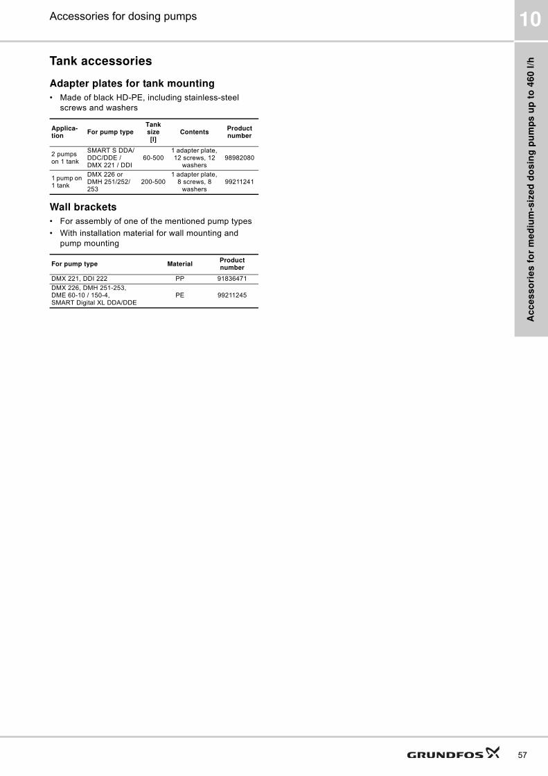
Ac
ce
ss
ori
es
fo
r m
ed
ium
-siz
ed
do
sin
g p
um
ps
up
to
46
0 l
/h
57
Accessories for dosing pumps 10
Tank accessories
Adapter plates for tank mounting
� Made of black HD-PE, including stainless-steel
screws and washers
Wall brackets
� For assembly of one of the mentioned pump types
� With installation material for wall mounting and
pump mounting
Applica-tion
For pump typeTank size[l]
ContentsProduct number
2 pumps on 1 tank
SMART S DDA/DDC/DDE / DMX 221 / DDI
60-5001 adapter plate, 12 screws, 12
washers98982080
1 pump on 1 tank
DMX 226 or DMH 251/252/253
200-5001 adapter plate,
8 screws, 8 washers
99211241
For pump type MaterialProduct number
DMX 221, DDI 222 PP 91836471
DMX 226, DMH 251-253,DME 60-10 / 150-4, SMART Digital XL DDA/DDE
PE 99211245
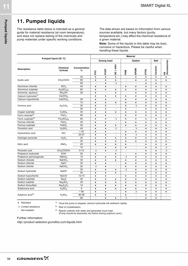
Pu
mp
ed
liqu
ids
58
SMART Digital XL11
11. Pumped liquids
The resistance table below is intended as a general
guide for material resistance (at room temperature),
and does not replace testing of the chemicals and
pump materials under specific working conditions.
The data shown are based on information from various
sources available, but many factors (purity,
temperature etc.) may affect the chemical resistance of
a given material.
Note: Some of the liquids in this table may be toxic,
corrosive or hazardous. Please be careful when
handling these liquids.
Further information:
http://product-selection.grundfos.com/liquids.html
Pumped liquid (20 °C)Material
Dosing head Gasket Ball
PE
(Ac
ce
ss
ori
es
)
DescriptionChemical formula
Concentration %
PV
C
PV
DF
SS
1.4
40
1
FK
M
EP
DM
PT
FE
Ce
ram
ic
Acetic acid CH3COOH
25 ● ● ● - ● ● ● ●60 ● ● ● - ● ● ● ●85 - ● ❍ - - ● ● -
Aluminium chloride AlCl3 40 ● ● - ● ● ● ● ●Aluminium sulphate Al2(SO4)3 60 ● ● ● ● ● ● ● ●Ammonia, aqueous NH4OH 28 ● - ● - ● ● ● ●Calcium hydroxide1) Ca(OH)2 ● ● ● ● ● ● ● ●Calcium hypochlorite Ca(OCl)2 20 ● ● - ● ● ● ● ●
Chromic acid H2CrO4
10 ● ● ● ● ● ● ● ●30 ● ● - ● ❍ ● ● ●50 ● ● - ● - ● ● ●
Copper sulphate CuSO4 30 ● ● ● ● ● ● ● ●Ferric chloride2) FeCl3 60 ● ● - ● ● ● ● ●Ferric sulphate2) Fe2(SO4)3 60 ● ● ❍ ● ● ● ● ●Ferrous chloride FeCl2 40 ● ● - ● ● ● ● ●Ferrous sulphate FeSO4 50 ● ● ● ● ● ● ● ●Fluosilicic acid H2SiF6 40 ● ● ❍ - ❍ ● ● ●
Hydrochloric acid HCl< 25 ● ● - ● ● ● ● ●
25-37 ● ● - ● ❍ ● ● ●Hydrogen peroxide H2O2 30 ● ● ● ● ● ● ● ●
Nitric acid HNO3
30 ● ● ● ● ● ● ● ●40 ● ● ● ● - ● ● ●70 - ● ● ● - ● ● ❍
Peracetic acid CH3COOOH 5-15 ❍ ● ❍ - - ● ● ❍Potassium hydroxide KOH 50 ● - ● - ● ● ● ●Potassium permanganate KMnO4 10 ● ● ● ❍ ● ● ● ●Sodium chlorate NaClO3 30 ● ● ● ● ● ● ● ●Sodium chloride NaCl 30 ● ● - ● ● ● ● ●Sodium chlorite NaClO2 20 ❍ ● - ● ● ● ● ●
Sodium hydroxide NaOH30 ● ● ● ❍ ● ● ● ●50 ● ● ● - ● ● ● ●
Sodium hypochlorite NaClO 12-15 ● ● - ● ● ● ● ●Sodium sulphide Na2S 30 ● ● ● ● ● ● ● ●Sodium sulphite Na2SO3 20 ● ● ● ● ● ● ● ●Sodium thiosulfate Na2S2O3 10 ● ● ● ● ● ● ● ●Sulphurous acid H2SO3 6 ● ● ● ● ● ● ● ●
Sulphuric acid3) H2SO4
< 80 ● ● - ● ❍ ● ● ●80-96 ● ● - ● - ● ● -
98 - ● ● ❍ - ● ● -
● Resistant 1) Once the pump is stopped, calcium hydroxide will sediment rapidly.
❍ Limited resistance 2) Risk of crystallisation.
- Not resistant 3) Reacts violently with water and generates much heat. (Pump should be absolutely dry before dosing sulphuric acid.)
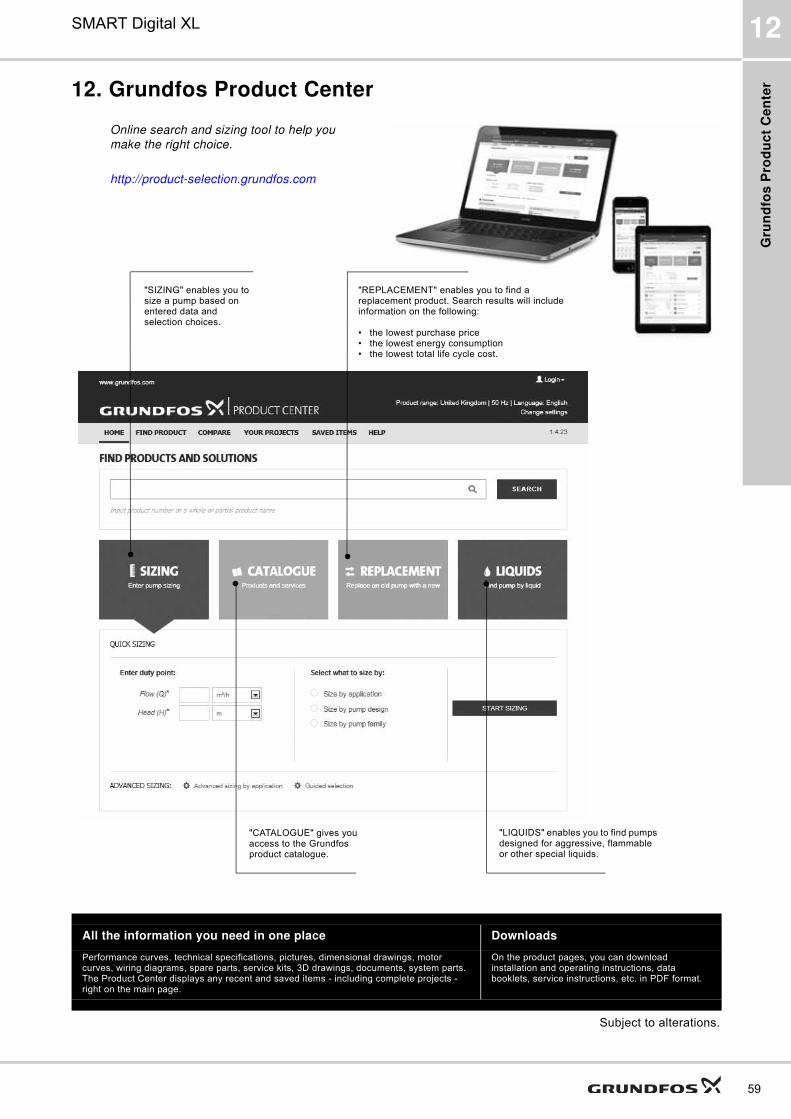
Gru
nd
fos
Pro
du
ct
Ce
nte
r
59
SMART Digital XL 12
12. Grundfos Product Center
Subject to alterations.
All the information you need in one place Downloads
Performance curves, technical specifications, pictures, dimensional drawings, motor curves, wiring diagrams, spare parts, service kits, 3D drawings, documents, system parts. The Product Center displays any recent and saved items - including complete projects - right on the main page.
On the product pages, you can download installation and operating instructions, data booklets, service instructions, etc. in PDF format.
"SIZING" enables you to size a pump based on entered data and selection choices.
Online search and sizing tool to help you
make the right choice.
http://product-selection.grundfos.com
"REPLACEMENT" enables you to find a replacement product. Search results will include information on the following:
� the lowest purchase price� the lowest energy consumption� the lowest total life cycle cost.
"CATALOGUE" gives you access to the Grundfos product catalogue.
"LIQUIDS" enables you to find pumps designed for aggressive, flammable or other special liquids.

GRUNDFOS A/S DK-8850 Bjerringbro . DenmarkTelephone: +45 87 50 14 00www.grundfos.com
99021865 0417
ECM: 1207552 Th
e n
am
e G
run
dfo
s,
the
Gru
nd
fos lo
go
, a
nd
be
th
ink
in
no
va
te a
re r
eg
iste
red
tra
de
ma
rks o
wn
ed
by G
run
dfo
s H
old
ing
A/S
or
Gru
nd
fos A
/S,
De
nm
ark
. A
ll r
igh
ts r
ese
rve
d w
orl
dw
ide
.©
Co
pyri
gh
t G
run
dfo
s H
old
ing
A/S