XCP Busbar Trunking Systems - BTicino
120
LEGRAND BP 30076 87002 Limoges Cedex France www.legrand.com XCP Busbar Trunking Systems Installation and user manual LE12461AA-01GF-20W40
-
Upload
khangminh22 -
Category
Documents
-
view
2 -
download
0
Transcript of XCP Busbar Trunking Systems - BTicino

LEGRANDBP 30076
87002 Limoges Cedex Francewww.legrand.com
XCP Busbar Trunking Systems
Installation and user manual LE12
461A
A-0
1GF-
20W
40

2
XCP Busbar Trunking Systems
EN ENGLISH 3

XCP Busbar Trunking Systems
Inst
alla
tion
and
user
man
ual
3
The information in this installation manual offers general descriptions and takes into account the general technical features of the products discussed, with the object of guiding the user through the installation of the XCP busbar.Therefore, product reliability for specific user applications cannot rely on this manual to ensure suitability or reliability of the busbar.Each user must assess the specific risks and test the product based on their own specific application. Neither Legrand, nor any of its subsidiaries or controlled companies shall be held responsible for the improper use of the information contained in this document.For any suggestions of any kind regarding this manual, please contact Legrand directly.The user hereby agrees not to reproduce this manual in full or in part for commercial use, or for any other use that is not strictly personal.The reproduction of this manual is also prohibited, on any supports whatsoever, including multimedia or internet publication, without the explicit written consent of Legrand.The publication of any types of hyperlinks to this manual or part thereof is also strictly prohibited.The user of this manual agrees to use it exactly as it is written, and always at their own risk.Only the manufacturer has the authority of intervening on individual components for replacement and repair purposes, in order to ensure the compliance of those described in this document.The instructions of this manual must always be followed, to ensure correct installation of the components within the system.Failure to comply with such instructions can cause injury or damage to system components and equipment.
Safety instructionsThis product should be installed in compliance with installation rules, preferably by a qualified electrician. Incorrect installation and/or incorrect use can lead to risk of electric shock or fire.Before carrying out the installation, read the instructions and take account of the product's specific mounting location.Do not open up, dismantle, alter or modify the device except where specifically required to do so by the instructions. All Legrand products must be opened and repaired exclusively by personnel trained and approved by Legrand. Any unauthorised opening or repair completely cancels all liabilities and the rights to replacement and guarantees.Use only Legrand brand accessories.
General information

4
Index
1. Introduction 6
1.1 Safety Information 6
1.1.1 Important Information 6
1.2 Safety tips 7
1.3 Purpose of the document 7
1.4 Product overview 8
1.4.1 Straight elements 8
1.4.2 Additional elements 8
1.4.3 Angle components 8
1.4.4 Tap-off boxes 9
1.4.5 Connection interfaces 9
1.4.6 Fixing supports 9
1.5 System concept 10
1.6 Certifications 12
1.6.1 Company approval certifications 12
1.6.2 The certificates 14
2. Material preparation and arrangement 16
2.1 Equipment and Tools 16
2.1.1 Introduction 16
2.1.2 Lifting and handling equipment 16
2.1.3 Supports for positioning and installing 16
2.2 Storage 17
2.3 Weight table 18
2.4 Handling and lifting 20
2.5 Missing or damaged components 23
2.6 Product type identification 24
3. Installation 26
3.1 Checks before installation 26
3.1.1 Visual / electric checks 26
3.1.2 General rules for installing supports 26
3.1.3 Fixing accessories 27
3.2 Installation of wall supports 35
3.2.1 Installation sizes, distances and positioning logics 35
3.3 Detailed instructions for vertical installation 37
3.3.1 Charging definition in brackets with springs 38
3.3.2 Wall and floor drilling 40
3.3.2.1 Floor bracket with/without springs 41
3.3.2.2 Wall bracket with springs and anti-seismic bracket 42
3.3.2.3 Standard bracket 47
3.3.3 Attaching the brackets to the busbars 50
3.3.3.1 Floor bracket with springs 50
3.3.3.2 Floor bracket without springs 52
3.3.3.3 Wall bracket with springs 54
3.3.3.4 Anti-seismic bracket 56
3.3.4 Busbar mounting in line 58

XCP Busbar Trunking Systems
Inst
alla
tion
and
user
man
ual
5
3.3.4.1 Floor bracket with/without springs 58
3.3.4.2 Wall bracket with springs and anti-seismic bracket 59
3.3.4.3 Standard bracket 60
3.3.5 Joint installation 61
3.3.6 Fire barrier installation 67
3.4 Product installation 68
3.4.1 Operating instructions on how to design riser mains 68
3.4.2 Panel end cap installation 69
3.4.3 ATR elements 86
3.4.4 End caps 87
3.4.5 Box installation 89
3.4.6 Assembly instruction Plug-In box 63A-125/160A 94
3.4.7 Assembly instruction Plug-In box 250A 97
3.4.8 Assembly instruction Plug-In box 630A 100
3.4.9 Busbar post-installation checks 109
4. Starting-up 110
4.1 Busbar pre-energising checks 110
4.1.1 Electrical safety tests 110
4.2 Electric checks 110
4.2.1 Conductors 110
4.2.2 Tap-off boxes 110
4.3 Filling the check form 111
4.3.1 Busduct record form for inspections and controls 111
4.3.2 Inspections after installation 111
5. Verification 112
5.1 Definition of the check sequence 112
5.1.1 Busduct periodic inspections are to be carried out yearly 112
5.1.2 Tap-off boxes annual periodic inspections 112
5.1.3 Annual periodic inspections carried out one year after energizing and every other following year 113
5.1.4 Inspections after installation and yearly 114
5.1.5 Feeder element 115
5.1.6 Dihedral elbow 116
5.1.7 Flat elbow 117
5.1.8 Troubleshooting table 118
6. Disposal 118

6
1.1 Safety Information1.1.1 Important Information
Here above general information concerning with signalling to take into account for all operative phases of the installationThis symbology and these messages are used all through the manual in order to highlight any potential dangerous situations or to arouse attention to procedures
The addition of symbol to a “Danger” or “Warning” safety label indicates that an electrical hazard exists which will result in personal injury if the instructions are not followed.
This is safety alert symbol. It is used to alert you to potential personal injury hazards. Obey all safety messages that follow this symbol to avoid possible injury or death.
DANGERDANGER indicates a hazardous situation which, if not avoided, will result in death or serious injury.
WARNINGWARNING indicates a hazardous situation which, if not avoided, could result in death or serious injury.
CAUTIONCAUTION indicates a hazardous situation which, if not avoided, could result in minor or moderate injury.
NOTICENOTICE is used to address practices not related to physical injury.
PLEASE NOTEElectrical equipment should be installed, operated, serviced, and verified only by qualified personnel.No responsibility is assumed by Legrand for any consequences arising out of the use of this material.A qualified person is one who has skills and knowledge related to the construction and operation of electrical equipment and its installation, and has received safety training to recognize and avoid the hazards involved.
1. Introduction

XCP Busbar Trunking Systems
Inst
alla
tion
and
user
man
ual
7
1.2 Safety tips
WARNING
HAZARD OF CRUSHING AND FRACTURES• Wear personal protective equipment when handling and installing the products (long sleeved jacket, trousers, gloves,
safety shoes, helmet, and safety glasses).• Only personnel who have been trained in safety regulations may work on construction sites to install busbar trunking
systems.• Work with extreme caution and follow the instructions provided in the manual.
Failure to follow these instructions can result in death, serious injury, or equipment damage.
1.3 Purpose of the documentThe present manual contains all the information necessary for the installation of Legrand XCP busbar trunking system (Xtra Compact busbar).
It contains the rules and procedures to be taken into account during the different phases involved in the whole process related to the realization of the plant and its final power up.
In particular all preliminary requirements, specific installation procedures and overall recommendations are explained along the present manual.
Topics exposed can be divided into different sections:• check of the equipment and of all the tools necessary for plant assembly• check of all the material availability and its correct identification (both as an individual component and inside the whole
system)• pre-installation checks on connections among different components• detailed operative installation procedures
Also checks to be carried out after installation and before to power up (“putting into service”) are exposed in this manual
A final part related to the periodic checking of the plant during its life is also illustrated (with the definition of the types and frequency of the checks to be performed)
This manual is addressed to trained technical personnel

8
1.4 Product overview
1.4.1 Straight elementsSupplied with its pre-installed monobloc.
Feeder elements:- standard length: 3 m- special length: from 0,7 m to 3 m
Distribution elements with tap-off outlets:- standard length: 3 m- standard tap-off sockets: spaced at 850 mm intervals on both sides
1.4.2 Additional elementsSupplied with its pre-installed monobloc.Elements able to meet any installation requirement.
Elements with S120 fire barrierElements with phase balancingElements with thermal expansion device
1.4.3 Angle componentsSupplied with its pre-installed monobloc.Elements able to meet any change of directionwith standard or special solutions.
ElbowsDouble elbowsSpecial T, X elements
1. Introduction
Fire barrierEI120
N 1 2 3
N 1 2 3
N 1 2 3
N 1 2 3

XCP Busbar Trunking Systems
Inst
alla
tion
and
user
man
ual
9
1.4.4 Tap-off boxesElements used for connectingand energizing electric loads.
Plug-in tap-off boxes from 63 A up to 630 A:(can be installed with busbar energized)- with 3P fuse holders- with switch disconnector and fuse holder- for MCCB circuit breakers
Bolted tap-off boxes from 125 A to 1250 A:- with switch disconnector and fuse holder- for MCCB circuit breakers
1.4.5 Connection interfacesElements used for connecting the busbar to the electric board or transformer.
Solutions for Legrand XL³ cabinets andLegrand cast resin transformersUniversal solutions
1.4.6 Fixing supportsElements used for fixing the busbar to thestructure of the building.
Options for horizontal installationsOptions for vertical installationsOptions for special applications(seismic areas, naval environment)

10
1. Introduction
1.5 System conceptGroup synergy allows for immediate integration between busbar trunking systems, cast resin transformers and Legrand XL³ cabinets. Cast resin transformers can be made to order with a pre-installed interface connection for the busbar trunking systems.
MV ENCLOSURES AIR CIRCUIT BREAKERS
LV CABINETS
BUSBAR TRUNKING SYSTEM
LV SIDE
HV/LV CAST RESIN TRANSFORMERS

XCP Busbar Trunking Systems
Inst
alla
tion
and
user
man
ual
11
The cabinets XL3 can be fitted by the panelbuilder with a XCP standard board connection.Thanks to a reinforcement kit it is possible to quickly and easily install any kind of board connection to the roof or bottom of the cabinet. The safety and the performance of the Legrand system are guaranteed by the system approval certification, obtained following stringent tests carried out in the most important international labs.
AIR CIRCUIT BREAKERS
LIGHTING BUSBARS
CABLE TRAYS
TRUNKING SYSTEMS
MINIATURE CIRCUIT BREAKERS
UPSMOULDED CASE CIRCUIT BREAKERS

12
1. Introduction
1.6 Certifications 1.6.1 Company approval certificationsTHE QUALITY MANAGEMENT SYSTEMLegrand has always considered Quality, one of the strategic points of its policy, and therefore implements a strict Quality Management System.The efficacy of the procedures devised and the level of organisation required for their implementation, have enabled the company to obtain the approval certification of its Quality Management System in accordance with the latest edition of the UNI EN ISO 9001 standard. All company processes, from Marketing to Product Development, Manufacturing, Sale and Technical Support, contribute to meeting the requirements for obtaining and keeping such Approval Certification. The certifying body used is Bureau Veritas. With its presence in over 140 countries, and over 100 years of experience in approval certification, Bureau Veritas is highly recognised by over 30 accreditation bodies, and is today among the world leaders in the field.
ACCREDITATION OF TEST LABORATORYThe test labs have a fundamental role in ensuring the Company Quality, both in terms of development, and as a complement to the design stage, as well as in ensuring that the product complies with the standards (type tests).The suitability and reliability of the BTicino/Legrand Test Room is guaranteed by the approvals obtained with ACAE (Associazione per la Certificazione delle Apparecchiature Elettriche ed Elettroniche - Association for the Certification of Electric and Electronic Equipment) in accordance with LOVAG procedures, onthe basis of IEC EN 17025 standard.The test laboratory is where some of the main type tests required for obtaining product approval certification are carried out.With the support of the BTicino* test laboratory, and of prestigious international labs, Legrand products undergo:• overtemperature limits tests;• dielectric properties tests;• protection circuit efficiency tests;• aerial and surface insulation distance tests;• mechanical operation tests;• busbar trunking system electric characteristics tests;• construction strength tests;• thermal cycling test;• crushing resistance tests.Moreover, in order to ensure maximum product quality, and in addition to the requirements of the product approval certification, BTicino* test laboratory also carries out electromagnetic compatibility measurements on all lines.

XCP Busbar Trunking Systems
Inst
alla
tion
and
user
man
ual
13
CERTIFICATION AND QUALIFICATION MARKSOnce compliance with IEC 61439-6 product standard has been confirmed, the various product lines may be further marked and approved for special applications.The compliance of a product to the specific standards can be certified by the manufacturer declaration and the application of the “CE” symbol, or through the concession of a mark by an appointed third-party body that ascertains its compliance. In the case of manufacturer declaration, the responsibility for compliance with the standards lies with the manufacturer itself;If a quality mark is granted by a third-party body, this body will only do so subject to the approval of the manufacturer and the prototype, through type tests, and subsequently following tests on the products sold on the market, which must comply with the requirements of the tests carried out on the prototypes themselves.The same range of products can therefore be granted several quality or conformity marks.
LOVAG CERTIFICATESLOVAG is the Low Voltage Agreement Group, which is a Mutual Agreement Group of Certification Bodies founded in 1991, which has achieved a high level of competence in testing and certification of low voltage equipment.LOVAG’s main purpose as an Agreement Group shall be for the mutual recognition of test reports and/or certificates of conformity by its signatories.
Membership LOVAG presently has five signatories (Certification Bodies) to the Agreement: ACAE (Italy), Applus+ Laboratories (Spain), ASEFA (France), IMQ (Italy), and SGS Belgium NV -
Division SGS CEBEC (Belgium) and employs more than 30 Testing Laboratories.
Certificates LOVAG Certificates are issued by the LOVAG Certification Bodies using verification reports and certificates in a common and recognisable format in the market. They are recognised and accepted in the European Economic Area and elsewhere in the world.
LOVAG Instructions LOVAG uses common Instructions for verification by Testing, Comparison or Assessment of the International and Standards covered by the Agreement and signatories to the Agreement abide by these when verifying for LOVAG Certification.
Qualifications All signatory bodies to the Agreement are accredited to ISO IEC 17065 by accreditors being members of IAF, the International Accreditation Forum. They are located in a member country of the EU and their laboratories are accredited and/or assessed to EN ISO/IEC 17025.
For further information contact your local certification body or the Secretariat of LOVAG by e-mail or by fax from the list below.
LOVAG Certification Bodies and LOVAG Secretariat:
ACAE Via Tito Livio 5 I-24123 Bergamo ITALY Fax: + 39 035 453 4662 e-mail: [email protected] Web : www.acaecert.it
ASEFA 33 Av du General Leclerc F-92260 Fontenay-aux-roses FRANCE e-mail: [email protected] Web: www.asefa-cert.com
Applus+ Laboratories Campus UAB E-08193 Bellaterra (Barcelona) SPAIN Fax: + 34 93 567 20 01 e-mail: [email protected] Web: www.applus.corp.com
SGS Belgium N.V. Division SGS CEBEC Business Riverside Park Av Internationalelaan, 55 B-1070-Brussels BELGIUM Fax: + 32 2 556 00 36 e-mail: [email protected] Web: www.cebec.sgs.com
IMQ S.p.A. Via Quintiliano 43 20138 Milano ITALY Fax: +39 0250991510 e-mail : [email protected] Web: www.imq.it
LOVAG Secretariat
at ETICS aisbl Rue des Deux Églises, 29 B-1000-Brussels - BELGIUM e-mail: [email protected] Web: www.lovag.net

14
1. Introduction
1.6.2 The certificatesThe Super-Compact line has been given Type- Approval Certifications by the most prestigious Electro-technical agencies:• Certificate of Compliance with Standard: IEC 61439-6• GOST Type-Approval (Russia) In order to obtain these
recognitions, the XCP range has• undergone the following type tests, as confirmation of
their quality:• EI 120 Fire Barrier Test• IEC 60331-1 / CEI EN 50362 - Fire Resisting Test

XCP Busbar Trunking Systems
Inst
alla
tion
and
user
man
ual
15

16
2.1 Equipment and Tools2.1.1 IntroductionHere below the tools, equipment and materials necessary you need to have before to start the installation of Zucchini XCP Busbar Trunking System.
2.1.2 Lifting and handling equipment
2.1.3 Supports for positioning and installing
Crane or forklift truck capable of lifting 1.5 tons (minimum). In function of the plant and the typology of components.
Two slings for handling thecomponents.
Drilling machine capable of drilling through concrete.
Set of �at or ring spanners (8...24 mm).
Socket wrench with sockets (8...24 mm).
Set of screwdrivers.
Carpenters square.
Insulation tester (Megohmmeter 1000 Vdc)
Measuring tape (metric).
Levelling instrument (spirit level).
Torque wrench only for periodic check inspection or when an element is placed for the second time.
2. Material preparation and arrangement

XCP Busbar Trunking Systems
Inst
alla
tion
and
user
man
ual
17
2.2 StorageBelow are the instructions to follow for a correct storage of the materials.Failure to comply with the indications supplied may cause damage to the materials, and make the product warranties void.Store the material in a dry place, protected from weather conditions such as rain and humidity, to prevent the formation of condensation inside the busbars.Also ensure that the busbars are protected from smoke, water, soil, mud, dust, or dirt in general. Position the material in a way that prevents a physical damage to it. It is recommended that the material is stored indoor, in a dry location. In case of storing the busbars outside for short-medium periods, ensure that it is appropriately protected, to avoid accidental infiltration of water, which will result in them being damaged.The material can be transported and stored at a temperature between -25°C and +55°C.Handling operations must be carried out implementing all the necessary precautions to ensure the integrity of the materials. The manufacturer shall not be held responsible for any material damage caused by failure to ensure appropriate protection.
Material handling

18
2. Material preparation and arrangement
2.3 Weight table
SINGLE BAR
DOUBLE BAR
TRIPLE BAR
XCP-S Aluminum
PE v
ersi
on
Wei
ght
In [A
] 630
In [A
] 800
In [A
] 100
0
In [A
] 125
0
In [A
] 160
0
In [A
] 200
0
In [A
] 250
0
In [A
] 320
0
In [A
] 400
0
In [A
] 500
0
XCP 3C AL
(PE 1) [kg/m] 13.3 14.2 14.5 16.6 19.8 23.6 29.9 35.9 42.9 58.8
(PE 2) [kg/m] 16.6 17.5 17.8 21.0 24.6 30.1 37.9 45.4 53.4 71.8
(PE 3) [kg/m] 14.3 15.3 15.5 18.0 21.4 25.5 32.5 39.0 46.4 63.0
XCP 4C AL
(PE 1) [kg/m] 14.3 15.6 16.0 18.6 22.5 27.4 34.1 41.5 50.4 68.6
(PE 2) [kg/m] 17.6 18.9 19.3 22.9 27.3 33.9 42.1 51.0 61.0 81.7
(PE 3) [kg/m] 15.4 16.7 17.1 20.0 24.1 29.2 36.7 44.6 54.0 72.9
XCP 5C AL
(PE 1) [kg/m] 15.3 17.0 17.6 20.5 25.2 31.1 38.3 47.1 58.0 78.5
(PE 2) [kg/m] 18.6 20.3 20.9 24.9 30.0 37.6 46.3 56.6 68.6 91.6
(PE 3) [kg/m] 16.4 18.0 18.7 22.0 26.7 33.0 40.9 50.2 61.5 82.8
XCP 2N AL
(PE 1) [kg/m] 15.3 17.0 17.6 20.5 25.2 31.1 38.3 47.1 58.0 78.5
(PE 2) [kg/m] 18.6 20.3 20.9 24.9 30.0 37.6 46.3 56.6 68.6 91.6
(PE 3) [kg/m] 16.4 18.0 18.7 22.0 26.7 33.0 40.9 50.2 61.5 82.8
SINGLE BAR
DOUBLE BAR
TRIPLE BAR
XCP-S Copper
PE v
ersi
on
Wei
ght
In [A
] 800
In [A
] 100
0
In [A
] 125
0
In [A
] 160
0
In [A
] 200
0
In [A
] 250
0
In [A
] 320
0
In [A
] 400
0
In [A
] 500
0
In [A
] 630
0
XCP-S 4C Cu
(PE 1) [kg/m] 21.2 23.8 26.9 33.5 42.5 51.0 63.0 80.9 114.9 155.2
(PE 2) [kg/m] 24.5 27.1 30.2 37.8 47.6 57.7 71.0 90.4 125.4 168.3
(PE 3) [kg/m] 22.3 24.9 28.0 34.9 44.2 53.2 65.6 84.0 118.4 159.5
XCP-S 3C Cu
(PE 1) [kg/m] 18.7 20.6 22.9 28.0 35.0 42.2 51.9 65.8 91.6 126.8
(PE 2) [kg/m] 22.0 23.9 26.2 32.4 40.2 48.8 59.9 75.3 102.1 139.9
(PE 3) [kg/m] 19.7 21.7 23.9 29.5 36.7 44.4 54.5 68.9 95.1 131.0
XCP-S 5C Cu
(PE 1) [kg/m] 23.7 27.1 31.0 38.9 49.9 59.9 74.1 96.0 138.1 183.5
(PE 2) [kg/m] 27.1 30.4 34.4 43.3 55.1 66.5 82.1 105.5 148.6 196.6
(PE 3) [kg/m] 24.8 28.1 32.1 40.3 51.6 62.0 76.7 99.1 141.6 187.8
XCP-S 2N Cu
(PE 1) [kg/m] 23.7 27.1 31.0 38.9 49.9 59.9 74.1 96.0 138.1 183.5
(PE 2) [kg/m] 27.1 30.4 34.4 43.3 55.1 66.5 82.1 105.5 148.6 196.6
(PE 3) [kg/m] 24.8 28.1 32.1 40.3 51.6 62.0 76.7 99.1 141.6 187.8

XCP Busbar Trunking Systems
Inst
alla
tion
and
user
man
ual
19
SINGLE BAR
DOUBLE BAR
TRIPLE BAR
XCP-HP Aluminum
PE v
ersi
on
Wei
ght
In [A
] 630
In [A
] 800
In [A
] 100
0
In [A
] 125
0
In [A
] 160
0
In [A
] 200
0
In [A
] 250
0
In [A
] 320
0
In [A
] 400
0
In [A
] 500
0
XCP-HP 4C AL
(PE 1) [kg/m] 11.3 11.3 13.0 14.6 18.9 22.4 26.7 35.0 41.1 61.7
(PE 2) [kg/m] 14.6 14.6 16.3 17.9 24.1 28.1 35.5 45.2 52.4 78.7
(PE 3) [kg/m] 12.3 12.3 14.1 15.7 20.6 24.3 29.6 38.3 44.8 67.2
XCP-HP 3C AL
(PE 1) [kg/m] 9.7 9.7 11.0 12.2 15.5 18.2 21.6 27.9 32.5 50.4
(PE 2) [kg/m] 13.0 13.0 14.3 15.5 20.7 23.9 30.4 38.2 43.9 67.4
(PE 3) [kg/m] 10.8 10.8 12.1 13.3 17.2 20.0 24.5 31.2 36.2 55.9
XCP-HP 5C AL
(PE 1) [kg/m] 17.5 17.5 19.7 21.7 22.4 26.7 31.8 42.0 49.7 73.0
(PE 2) [kg/m] 20.8 20.8 23.0 25.0 27.5 32.4 40.6 52.3 61.0 90.0
(PE 3) [kg/m] 21.0 18.6 20.8 22.7 24.0 28.5 34.7 45.4 53.3 78.5
XCP-HP 2N AL
(PE 1) [kg/m] 17.5 17.5 19.7 21.7 22.4 26.7 31.8 42.0 49.7 73.0
(PE 2) [kg/m] 20.8 20.8 23.0 25.0 27.5 32.4 40.6 52.3 61.0 90.0
(PE 3) [kg/m] 21.0 18.6 20.8 22.7 24.0 28.5 34.7 45.4 53.3 78.5
SINGLE BAR
DOUBLE BAR
TRIPLE BAR
XCP-HP Copper
PE v
ersi
on
Wei
ght
In [A
] 800
In [A
] 100
0
In [A
] 125
0
In [A
] 160
0
In [A
] 200
0
In [A
] 250
0
In [A
] 320
0
In [A
] 400
0
In [A
] 500
0
In [A
] 630
0
XCP-HP 4C Cu
(PE 1) [kg/m] 16.4 22.2 24.8 27.7 44.7 55.3 63.3 85.5 117.0 150.0
(PE 2) [kg/m] 19.7 25.5 28.1 32.1 49.0 66.7 72.0 95.8 128.3 165.5
(PE 3) [kg/m] 17.5 23.2 25.9 29.1 46.1 59.0 66.1 89.1 120.9 155.0
XCP-HP 3C Cu
(PE 1) [kg/m] 18.7 22.9 24.9 28.0 41.6 52.2 60.3 78.6 103.2 126.2
(PE 2) [kg/m] 22.0 26.2 28.2 32.4 45.9 63.5 69.0 88.9 114.5 141.6
(PE 3) [kg/m] 19.7 23.9 25.9 29.5 43.0 55.8 63.1 82.2 107.1 130.5
XCP-HP 5C Cu
(PE 1) [kg/m] 23.8 31.1 34.5 39.0 59.9 74.3 88.2 117.3 157.4 189.7
(PE 2) [kg/m] 27.2 34.5 37.8 43.4 64.3 85.6 96.9 127.6 168.8 205.1
(PE 3) [kg/m] 24.9 32.2 35.5 40.4 61.3 78.0 91.1 120.8 161.4 193.9
XCP-HP 2N Cu
(PE 1) [kg/m] 23.8 31.1 34.5 39.0 59.9 74.3 88.2 117.3 157.4 189.7
(PE 2) [kg/m] 27.2 34.5 37.8 43.4 64.3 85.6 96.9 127.6 168.8 205.1
(PE 3) [kg/m] 24.9 32.2 35.5 40.4 61.3 78.0 91.1 120.8 161.4 193.9

20
2. Material preparation and arrangement
2.4 Handling and lifting
WARNINGAll lifting operations refer to a single component.

XCP Busbar Trunking Systems
Inst
alla
tion
and
user
man
ual
21
Fig. 1Do not lift
the busbars from their ends.
Fig. 3Do not use
belts or other systems to lift
the busbars in unbalanced
positions. Fig. 3
Fig. 1
Fig. 2
Fig. 2Do not use
belts or other systems to lift them
to the junction windows.

22
2. Material preparation and arrangement
Fig. 6When lifting not
linear shape path components, pay
particular attention to their own centre
of gravity. Use equipment that
will not damage surfaces.
Fig. 5Correct way of
lifting the busbars.
Fig. 6
Fig. 4
Fig. 5
Fig. 4Handle the busbars
with due care and attention. Do not
subject busbars to torsions, dents, violent impact, or
sharp movements that may damage
their internal components.

XCP Busbar Trunking Systems
Inst
alla
tion
and
user
man
ual
23
2.5 Missing or damaged components
GOOD RECEPTIONUpon receipt of the goods check the following:1) integrity of the packaging, and the goods, if delivered in a see-through package.2) consistency of the material with the delivery note and the packing list, if supplied.3) consistency of the material with the order acknowledgement details.In case of any disclaims, please inform us in writing following the instructions found in the notifications section.
NOTIFICATIONSIn case of any disclaim, please forward your official complaint to a Legrand referent.
When notifying that a wrong item has been received, please indicate the item code no. found on the packaging, and the item code no. found on the part (if possible include a photo of the labels).

24
2.6 Product type identificationBefore beginning installation, you must compare the plan which you received from the design office project al layout of the building. For custom-made products based on specific projects, check the system drawing to ensure that the components match.
2. Material preparation and arrangement
WARNINGIn case of several straight components with standard length of 3 m, these will all have the same generic common label.

XCP Busbar Trunking Systems
Inst
alla
tion
and
user
man
ual
25
(*) Optional �eld
Brand
Year and week of production
Insulation voltage
Frequency
Standard reference
Short circuit current
Degree of protection
Conductors material
Type of busduct
Rated Current
Item Code
Item Description
MarkingElement dimensions (*)
Data matrixwith Serial number of piece
Con�guration
Reference line (*)
Item position (*)
Internal project Name (*)
Order con�rmation number (*)
Position in the order con�rmation (*)
Address
Bar code EAN12
Details of the adhesive label found on each
component.
QR code containing all the identification datas of the specific piece with relative electrical response datas to tests.
Code Descrizione Estesa EN
ZU-64281304P XCP-S AL 1250A HORI. ELB.+FLG. END T1
ZU-64287124P XCP-S AL 1250A STR.LENG INVER.FASI L.1,2MT
ZU-64280404P XCP-S AL 1250A VERTICAL ELB. RH STD
ZU-64280104P XCP-S AL 1250A FEEDER ELE. L=3M
ZU-64280154P XCP-S AL 1250A FEEDER ELE. L=2501-2999
ZU-64280404P XCP-S AL 1250A VERTICAL ELB. RH STD
ZU-64281334P XCP-S AL 1250A HORI. ELB.+FLG. END T4

26
WARNINGWhere not differently specified, dimensions indicated in the manual are to be intended in millimeters (mm).
3.1 Checks before installation3.1.1 Visual / electric checksBefore the installation, all material should be inspected for damage.When installing the busbars comply with the following:
1 Do not position the busbars near pipes containing liquids.2 For the installation only use bracketing systems supplied by Legrand, and follow the instructions found in the catalogue
or enclosed with the item.3 Only use accessories supplied by Legrand.4 Check that the operating voltage coincides with that indicated on the product plate.5 Check that the system operating current does not exceed the product rated current, downgrade it if required.6 Check if the busbar capacity must be downgraded (for example due to high ambient temperature, presence of
harmonics, etc.)7 Do not install the standard product in particular environments (high concentration of chlorine, explosive atmosphere, etc.).8 For outdoor installations, protect the busbar with a protection canopy. The IP55 protection degree can be affected by
unsuitably protected outdoor installation.
3.1.2 General rules for installing supportsHazard of improper installation
Before installation: be sure to have well the layout plan
During installation: be sure to consider correct separation distances between the supports. These have to be levelled, so to guarantee final levelling also for path components.Be sure that all supports are able to sustain the weights of the path components.Failure to follow these instructions can result in injury or equipment damage.
IntroductionCorrect installation of supports is fundamental to realize a proper installation of path components.Here below, a list of rules to take into account during installation of supports and path components.
General Installation rules for supportsFollow these general rules for installing supports:• All path components have to be correctly sustained• To get advantage in installation, be sure to use more than one support for each path component• The supporting capacity of the support must be at least the weight of the path component plus 90 kg, in accordance
with IEC 61439-6.• Use different support for components at the terminal ends of the path.
3. Installation
Edgewise horizontal installation: Flatwise horizontal installation:

XCP Busbar Trunking Systems
Inst
alla
tion
and
user
man
ual
27
3.1.3 Fixing accessories
30 Nm
30 Nm
• Be sure to not sustain weight of end components by transformers or switchboards.• Sustain vertical branches near to the elbow angle.• Be sure to support Elbows and “Z” units one at a time.• Even if supports have to installed near to joint blocks, it has never to be put exactly under a joint block.• Keep the right distance from tap-offs ..mm(show picture)

28
1500/2000
1500/2000
110
15
M10
190
hole 9x20
A
40
40
15
M10
A
210
4013
0
40
hole 9x20
Rating XCP-S
A (mm)
Al Cu
630 210 -
800 210 210
1.000 210 210
1.250 250 210
1.600 280 250
2.000 300 280
2.500 460 380
3.200 520 460
4.000 560 520
5.000 670 560
6.300 - 670
Rating XCP-HP
A (mm)
Al Cu
630 210 -
800 210 210
1.000 210 210
1.250 210 210
1.600 280 250
2.000 300 250
2.500 460 300
3.200 520 460
4.000 560 520
5.000 820 560
6.300 - 760
3. Installation

XCP Busbar Trunking Systems
Inst
alla
tion
and
user
man
ual
29
Rating XCP-S
A (mm)
Al Cu
630 190 -
800 190 190
1.000 190 190
1.250 315 190
1.600 315 315
2.000 315 315
2.500 430 350
3.200 490 430
4.000 530 490
5.000 640 530
6.300 - 640
RatingXCP-HP
A (mm)
Al Cu
630 190 -
800 190 190
1.000 190 190
1.250 190 190
1.600 315 315
2.000 315 315
2.500 430 315
3.200 490 430
4.000 530 490
5.000 790 530
6.300 - 730
1500/2000
1500/2000
110
15
M10
190
hole 9x20
A
40
40
15M10
A
210
4013
0
40
hole 9x20

30
3. Installation
Supports for Edgewise InstallationFor edgewise installations, the maximum recommended distance between supports is 2000 mm.
1500 / 2000
750
750
1500 / 2000
Supports Flatwise InstallationFor flatwise installations, the maximum recommended distance between supports is 2000 mm. In addition,a support must be placed at a maximum distance of 750 mm from the joint block axis.
1500 / 2000
750
750
1500 / 2000

XCP Busbar Trunking Systems
Inst
alla
tion
and
user
man
ual
31
Consult always the general installation rules, before installing any type of support (see page 26)
Horizontal SupportsThe function of horizontal supports is to correctly install path components horizontally and also adjust them along the length. Supports also have the function to absorb path componenets movements.
Types of Horizontal Supports
• Attached to the ceiling using 2x2 m threaded M10 rods (NOT provided within the busbar).• Provide support for edgewise path components from the bottom.
• Attached to the ceiling.• Provide support for flatwise path components from the bottom.• Supports are NOT provided within the busbar.

32
3. Installation
• Attached to the wall.• Provide support for edgewise path components from the bottom.• Supports are NOT provided within the busbar.
• Attached to the wall.• Provide support for flatwise path components from the bottom.• Supports are NOT provided within the busbar.• Fixe the bar on the wall support.

XCP Busbar Trunking Systems
Inst
alla
tion
and
user
man
ual
33
WARNINGAll the dihedral angle components must be supported at the point of the change of direction.
Use dedicated supports for components at the terminal ends of the path.Be aware to have enough space to connect cables by customer.
Supports for flatwise elbows componentsElbows components must have a support installed across the elbow angle.

34
3. Installation
Supports for edgewise elbow components with a vertical branchFollow these rules to support edgewise elbows with a vertical branch.
Supports for T componentsT components must have a support installed across the T-joint.Diagonal supports are not supplied.

XCP Busbar Trunking Systems
Inst
alla
tion
and
user
man
ual
35
Minimum installationdistance when
there are several adjacent lines.
Minimum installationdistance when
there are several overlapped lines.
3.2 Installation of wall supports3.2.1 Installation sizes, distances and positioning logicsBelow are some precautions that may be useful to avoid problems during the assembly, which we recommend should be taken into account during the design.
Minimum distances from the structureThe minimum distance from the walls, to avoid problems during edgewise installation of the busbar, is 300 mm.The variables that must be taken into account for correct assembly are:• position of the bolt for tightening the Monobloc; the minimum required distance is 100 mm;• sizes of the distribution element (box) selected for the collection of power (at least 300 mm);• any brackets and their assembly; • accessibility to the screws for the installation of the brackets and the closing of the junctions;• any material required for the actual installation in order to compensate for wall imperfections.In case of rising mains installation, if the system does not require fire barriers, the bracket supporting can be directly secured to the wall. Otherwise, allow for a spacing support between the bracket and the wall, to ensure that the back of the busbar remains at a distance of 100 mm from the wall, therefore ensuring enough space for the positioning of the fire barriers.
Minimum distance of the wall / ceiling elements
100
Wall
Wall
Wall
100
300
80
Ceiling
300
60
Ceiling
100
100
80
100
300
Ceiling
300
100
Ceiling
Wall
Wall
Wall
100
Wall
Wall
300
300
*
Ceiling
Wall
300
300
Ceiling
Wall
Ceiling* When there is a tap-off box
installed abovethe busbar, check theoverall dimension of
the open cover of thetap-off unit used in the specific section.
When there are tap-off units along the busbars, the minimum distances depend on the dimensions of the tap-offs selected.

36
3. Installation
Fixing for installation in seismic environments in horizontalEvery 2 anti-seismic brackets with bracket (Type B), use one standard bracket.
Standard bracket
B
B
A
B
B
E
E
1500
A con mensola e molle
B con mensola B with anti-seismicshelf
C con molle
D solo sta�a
E for naval applications
Edgewise element.
Standard bracket
B
B
A
B
B
E
E
1500
Fixing for naval installationFor naval installations always use a type E bracket.
A con mensola e molle
B con mensola
C con molle
D solo sta�a
E for naval applications
B antisismica
Edgewise element.

XCP Busbar Trunking Systems
Inst
alla
tion
and
user
man
ual
37
3.3 Detailed instructions for vertical installation
40 mm
wall bracketwith springs
standardbracket
anti-seismicbracket
�oor bracketwith springs
�oor bracketwithout springs
When installing a vertical busbar, strictly follow the instructions below:3.3.1 Definition of spring charging3.3.2 Wall and floor drilling3.3.3 Attaching the brackets to the busbars3.3.4 Busbar mounting in line

38
3. Installation
3.3.1 Charging definition in brackets with springsDepending on the capacity of the busbar, the quantity and the type of brackets being installed, check that the selected distance (D) is the same or less than the maximum distance (Dmax) between two subsequent brackets with springs.
XCP-S 4C Al
In (A) D max Kit
Springs
630 11 4
800 10 4
1000 10 4
1250 9 4
1600 10 6
2000 9 6
2500 12 8
3200 11 12
4000 10 12
5000 8 12
XCP-S 4C Cu
In (A) D max Kit
Springs
800 9 4
1000 8 4
1250 7 4
1600 6 4
2000 6 6
2500 9 8
3200 7 8
4000 7 12
5000 5 12
6300 4 12
For 5C version multiply Dmax by 0.9 For 3C version multiply Dmax by 1.1
XCP-HP 4C Al
In (A) D max Kit
Springs
630 10 4
800 10 4
1000 10 4
1250 9 4
1600 7 4
2000 9 6
2500 11 8
3200 11 12
4000 10 12
5000 8 12
XCP-HP 4C Cu
In (A) D max Kit
Springs
800 9 4
1000 7 4
1250 7 4
1600 6 4
2000 6 6
2500 5 6
3200 6 8
4000 6 12
5000 5 12
6300 4 12
For 5C version multiply Dmax by 0.85 For 3C version multiply Dmax by 1.1

XCP Busbar Trunking Systems
Inst
alla
tion
and
user
man
ual
39
If D≤Dmax, calculate the spring H CHARGING value:
HH
H = 130 − (Wb ∙ D + Wacc)
(3 ∙ n)
Where:• Wb: busbar linear weight [kg/m]• D: actual distance between two brackets with springs [m]• Wacc: sum of the weights of all the accessories connected between two brackets with springs (boxes, cables, etc.) [kg]• n: total number of springs in the brackets (see previous table)• H: charging [mm]. CAUTION: H should be between 105 and 130 mm
Calculation example:
TYPE OF BUSBAR: S-4C-Cu (Pe2)In [A]: 800Dmax [m]: 9D [m]: 7BUSBAR [kg/m]: 23,3BOX WEIGHT 1 [kg]: 18BOX WEIGHT 2 [kg]: 12
TYPE OF BUSBAR: S-5C-AI (Pe1)In [A]: 2000Dmax [m]: 9X0,9=8,1D [m]: 6BUSBAR [kg/m]: 29,6BOX WEIGHT 1 [kg]: 18BOX WEIGHT 2 [kg]: 12

40
3.3.2 Wall and floor drillingDrill the required floor and wall holes for fixing all the brackets
wall bracket with springs
standard bracket
anti-seismic bracket
�oor bracket with springs
�oor bracket without springs
Below are the procedures for drilling the holes for each type of bracket.
3. Installation

XCP Busbar Trunking Systems
Inst
alla
tion
and
user
man
ual
41
3.3.2.1 Floor bracket with/without springsThe bottom supports (dashed shapes) are not included with the brackets, but are available to order.
Screw
Lower support (not included)
Bracket
Spring
Floor bracket with springs (type C) Floor bracket without springs (type D)
Screw
Lower support (not included)
Bracket
Screw
Lower support (not included)
Bracket
Spring
Floor bracket with springs (type C) Floor bracket without springs (type D)
Screw
Lower support (not included)
Bracket
2) Drill the floor at the marked
positions.
1) On the floor, mark the holes of the bottom
supports at the point where the busbar must be
secured.

42
3.3.2.2 Wall bracket with springs and anti-seismic bracket
Wall bracket with springs (type A) Anti-seismic wall bracket (type B)
Screw
Shelf
Bracket
Spring Bracket
Shelf
Screw
1500
1500
Type B
Type B
Type A
WARNINGDo not position the bracket nearby branching, joining ports and tap offs.
Wall bracket with springs (type A) Anti-seismic wall bracket (type B)
Screw
Shelf
Bracket
Spring Bracket
Shelf
Screw
1500
1500
Type B
Type B
Type A
3. Installation
1) Set the bracket position on the
busbar.

XCP Busbar Trunking Systems
Inst
alla
tion
and
user
man
ual
43
In case of anti-seismic busbars (Type B), fit one bracket every 1.5 m along the busbar.Fit one bracket with springs (Type A) every two anti-seismic brackets (Type B).
Wall bracket with springs (type A) Anti-seismic wall bracket (type B)
Screw
Shelf
Bracket
Spring Bracket
Shelf
Screw
1500
1500
Type B
Type B
Type A
Wall bracket with springs (type A) Anti-seismic wall bracket (type B)
T
2) Place the bracket on the
busbar at the fixing position and mark the
upper side of the shelf.

44
WARNINGThe measurement must be from the busbar cap and not the bars.
Wall bracket with springs (type A) Anti-seismic wall bracket (type B)
T
3) Measure the distance T from
the mark just made to the
bottom cap of the component.
3. Installation

XCP Busbar Trunking Systems
Inst
alla
tion
and
user
man
ual
45
Z
19
T
Z
270
Check that the hole marks are aligned with the busbar.
Adjoining busbar already installed
Type A Type B
4) On the wall, mark the position
Z of the two upper holes of the shelves
(indicated in the magnified view),
calculated as follows:Z= T-19+270
(measurements in millimeters).

46
WARNINGThe Z value must be measured from the upper cap of the already installed adjoining busbar.
140 140
140
Wall bracket with springs (type A)
Anti-seismic bracket (type B)
163
163
163
163
140
140
163
140
140
5) On the wall, mark the
positions of the bottom holes of
the shelves, in accordance with
the values below.
6) Drill the holes at the marked
positions.Check that the hole marks are
aligned with the busbar.
3. Installation

XCP Busbar Trunking Systems
Inst
alla
tion
and
user
man
ual
47
3.3.2.3 Standard bracketThe bottom support (dashed shape) is not supplied.
Tie rod
Support (not supplied)
Bracket
W
Tie rod
Support (not supplied)
Bracket
W
Tie rod
Support (not supplied)
Bracket
W
1) Set the bracket position on the
busbar.
WARNING
Do not position the
bracket nearby branching and
joining ports.
2) Place the bracket on the
busbar and mark its upper side.
3) Measure the distance W from
the mark just made to the
bottom cap of the busbar.
WARNING
The measure-ment must be
from the busbar cap and not the
bars.

48
4) On the wall, mark the
position U for fixing the
bottom support, calculated as
follows:U= W+270-40-X(measurements in millimeters).
WARNING
The U value must be measured
from the upper cap of the
already installed adjoining
busbar.
U
270
40
X
U
Adjoining busbar already installed.
Check that the hole marks are aligned with the busbar.
W
U
X
3. Installation

XCP Busbar Trunking Systems
Inst
alla
tion
and
user
man
ual
49
5) Drill the wall and fix the
bottom bracket support.
6) Attach the bracket to the
bottom support.

50
3.3.3 Attaching the brackets to the busbars3.3.3.1 Floor bracket with springs
1) Mark the four bracket holes on
the busbar in accordance with
the following values:
P=X+Y+H-270-19 (measurements in millimeters).
P
19
50
65
270
Y
X
P
P
ø 9
H
2) Drill the busbar at
the four marks just made:
HOLE ø = 9mm.
3. Installation

XCP Busbar Trunking Systems
Inst
alla
tion
and
user
man
ual
51
3) Screw the bracket to the busbar with a
torque of 24 Nm.
4) Tighten the nuts, bringing
the spring to the CHARGING
distance H as previously
defined (page 38).
24 Nm
13
H
In case of need, contact Legrand technical service.

52
3.3.3.2 Floor bracket without springs
1) Mark the four bracket holes on
the busbar in accordance with
the following values:
Q=X+Y+69-270(measurements in millimeters).
Q
270
X
Q
Y
69
Q
ø 9
2) Drill the busbar at
the four marks just made:
HOLE ø = 9mm.
3. Installation

XCP Busbar Trunking Systems
Inst
alla
tion
and
user
man
ual
53
3) Screw the bracket to the busbar with a
torque of 24 Nm.
24 Nm
13

54
3.3.3.3 Wall bracket with springs1) Mark the four
bracket holes on the busbar,
calculated as follows Y=T+H-19
(measurements in millimeters).
Y
Y
19
50
65
T
H
Yø 9
2) Drill the busbar at the
marks just made:
HOLE ø = 9mm.
3. Installation

XCP Busbar Trunking Systems
Inst
alla
tion
and
user
man
ual
55
3) Screw the brackets to the
busbar with a torque of 24 Nm.
24 Nm
13
H
4) Tighten the nuts, bringing the spring to
the CHARGING distance H as
previously defined (page 35).

56
3.3.3.4 Anti-seismic bracket
Y
Yø 9
Y
65
T
69
1) Mark the four bracket holes on
the busbar, calculated as
follows:Y=T+69.
(measurements in millimeters).
2) Drill the busbar at the
marks just made:
HOLE ø = 9mm.
3. Installation

XCP Busbar Trunking Systems
Inst
alla
tion
and
user
man
ual
57
3) Screw the brackets to the busbar
with a torque of 24 Nm.
24 Nm
13

58
3.3.4 Busbar mounting in line 3.3.4.1 Floor bracket with/without springs
1) Join the two components
following the instructions
below.
2) Match the bracket with the holes previously
drilled on the floor and fasten with the screws.
Component to be fastened
Component already fastened to the wall
Floor bracket with springs (type C) Floor bracket without springs (type D)
Floor bracket with springs (type C) Floor bracket without springs (type D)
13
Component to be fastened
Component already fastened to the wall
Component to be fastened
Component already fastened to the wall
Floor bracket with springs (type C) Floor bracket without springs (type D)
Floor bracket with springs (type C) Floor bracket without springs (type D)
13
Component to be fastened
Component already fastened to the wall
3) For brackets with springs, unscrew the spring nuts.
WARNINGThe nut must be fully unscrewed, therefore releasing the springs.
3. Installation

XCP Busbar Trunking Systems
Inst
alla
tion
and
user
man
ual
59
1) Join the two components
following the instructions
below.
3.3.4.2 Wall bracket with springs and anti-seismic bracket
Component to be fastened
Component already fastened to the wall
Wall bracket with springs (type A) Anti-seismic bracket (type B)
13
2) Match the the bracket with the holes previously
drilled on the wall and fix with the
screws
3) For brackets with springs, unscrew the spring nuts
WARNINGThe nut must be fully unscrewed, therefore releasing the springs.

60
3.3.4.3 Standard bracket1) Using the
screws supplied, attach the bracket to the one already
attached to the support.
2) Tighten the screw with a
torque of 16 Nm.
17
16 Nm
3. Installation

XCP Busbar Trunking Systems
Inst
alla
tion
and
user
man
ual
61
3.3.5 Joint installation
19
Mandatory:Don't remove
19
Mandatory:Don't remove
WARNINGRemove residues with mild reagents not corroding or creating abrasion on surface treatment (zinc, tin, silver coating) or on contact surface (copper).

62
~ 30
270
DANGERThe following operations must be carried out with the voltage disconnected.
3. Installation

XCP Busbar Trunking Systems
Inst
alla
tion
and
user
man
ual
63
25 Nm
19
IP55
13
85 Nm

64
IP55
In case of multi-bolt busbars, follow the sequence below
3. Installation

XCP Busbar Trunking Systems
Inst
alla
tion
and
user
man
ual
65
UP-SIDE LINE
PE : Protective earth conductorL : Fishplate
PEL
DANGERHazard of short circuit• It is mandatory to correctly align all path components, joint blocks and PE conductors .• It is mandatory to correctly position, between the fishplates, all path components conductors and the metallic side of
the PE conductor between the fishplates.Failure to follow these instructions will result in death or serious injury.
The continuity of the PE conductors is established by the enclosure of the path component. You must check the correct position of the components, joint blocks, and PE conductors and the continuity of the PE conductors through the joint block:
UP-SIDE LINE
PE : Protective earth conductorL : Fishplate
PEL

66
DANGER LOSS OF IP55 PROTECTION RATINGThe path components must be correctly aligned.Failure to follow these instructions can result in equipment damage.
The alignment must be checked on both sides of the path components:
Check alignment on the side of the path components
Check the alignment on the loop of the path components:
1000
= =
3. Installation

XCP Busbar Trunking Systems
Inst
alla
tion
and
user
man
ual
67
Fire barrier sizes.Dimension H
changeswith the rating; itis specified in the
technical information.
3.3.6 Fire barrier installation Fire barrier elements S120 (EN 1366-3, DIN 4102-09)
Fire barrier
211
130
H +
81
S120
≥ 200
No �re barrier
Al: 630 Cu:1000
Al: 630 Cu:1000 ≥ 200 ≥ 200
No �re barrier No �re barrier
Fire barrier
211
130
H +
81
S120
≥ 200
No �re barrier
Al: 630 Cu:1000
Al: 630 Cu:1000 ≥ 200 ≥ 200
No �re barrier No �re barrier
B
h
h +
82
h +
82
h
L
B
In order to ensure the maximum resistance class, for some ratings it is also necessary to fit at the factory an internal fire barrier following the indications on the table.It is therefore necessary to indicate at the order stage what elements will cross fire resistant walls or ceilings.
The external fire barrier can be used on any trunking component in compliance with the operating instructions specified in figures 1 and 2.
USE OF INTERNAL OR EXTERNAL BARRIER
Al Cu
XCP-S
Rating (A) Internal External In (A) Internal External
630-800 √ √ 800-1000 √ √
1000-2000 – √ 1250-2000 – √
2500-4000 – √ 2500-5000 – √
5000 √ √ 6300 √ √
XCP-HP
630-2000 – √ 800 √ √
2500-4000 – √ 1000-2500 – √
5000 √ √ 3200-5000 – √
– – – 6300 √ √
Fig. 1 Fig. 2
XCP-S XCP-HP
Al Cu Al Cu
B 200 205
L 630 1000 630 1000

68
3.4 Product installation3.4.1 Operating instructions on how to design riser mains1) Use an RH end feed unit (without
monobloc).The RH misaligned feed units (without monobloc) are used at the departure of the riser mains lines, allow the busbar to be installed 40 mm away from the wall. In order to position the tap-off boxes correctly as shown in the figure, the neutral conductor of the riser main must be on the left side of the element
2) The tap-off boxes can be installed in the tap-off outlets (Plug-in type) and on the junction of elements (Bolt-on type)
3) Use elements with tap-off outlets where necessary, distribute the power using plug-in boxes
4) Use EI120 fire barrier kit for each compartment floor, where specifically requested
5) At the end of the riser mains, position the IP55 end cover
A) At the lowest point, use a fixed bracket (without spring) to avoid pressure on the cable connection box or low voltage switch board
B) Use a standard suspension bracket to hang the busbar every 2 metres of riser mains
C) Use one or more suspension brackets for the vertical elements, according to the weight of the whole riser mains
3. Installation
40 mm
5
4
C
B
3
2
1
A
NL1
L2L3

XCP Busbar Trunking Systems
Inst
alla
tion
and
user
man
ual
69
Ø 9
850
600
1
2
3
3.4.2 Panel end cap installation

70
N 1 23
3. Installation
Power supply

XCP Busbar Trunking Systems
Inst
alla
tion
and
user
man
ual
71

72
Wall
300
300
*
Ceiling
Wall
300
300
Ceiling
Wall
Ceiling
When there are tap-off units along the busbars, the minimum distances depend on the dimensions of the tap-offs selected.
* When there is a tap-off box
installed abovethe busbar, check theoverall dimension of
the open cover of thetap-off unit used in the specific section.
3. Installation
130
222
195
105
52.5
80
50
55
270
240
7550
78.5351.5
5043050
590
4016
5
280
295
Metal T1 overall dimension

XCP Busbar Trunking Systems
Inst
alla
tion
and
user
man
ual
73
146114
70
282
260
130
105
360
390
75105
4020
5
400
495
78.5471.5
5055050
750
Metal T1overall dimension

74
370
390
160
140
270
250
160
140
545
5027
5
460
670 80
55 775
1040
3. Installation
Metal T1overall dimension

XCP Busbar Trunking Systems
Inst
alla
tion
and
user
man
ual
75
222
195
105
130
52.5
55
80
50
50 75
7016
5
280
295
78.5351.5
5043075
590
Metal T2overall dimension

76
146114
70
282
260
130
105
360
390
75105
7020
5
400
495
78.5471.5
5055075
750
3. Installation
Metal T2overall dimension

XCP Busbar Trunking Systems
Inst
alla
tion
and
user
man
ual
77
370
390
160
140
270
250
160
140
545
7527
5
460
670 80
75 775
1040
Metal T2overall dimension

78
222
195
130
105
7555
50
80
52.5
50
7016
5
280
295
430 50
78.5351.5
2516
5
3. Installation
Metal T3overall dimension

XCP Busbar Trunking Systems
Inst
alla
tion
and
user
man
ual
79
105
130
146114
260
282
75105
360
390
495
7020
5
400 78.5471.5
50550
2520
5
Metal T3 overall dimension

80
250
270
140
160
140
160
370
390
670 80
775
2527
5
545
460
7027
53. Installation
Metal T3 overall dimension

XCP Busbar Trunking Systems
Inst
alla
tion
and
user
man
ual
81
100340
115 440
605
250
7016
5
275
ISO 50:1ISO 40:2ISO 25:6ISO 21:9ISO 16:14FAIRLEADS
ISO 50:2ISO 40:3ISO 25:6ISO 21:10ISO 16:14FAIRLEADS
100340
45 440
605
250
275
165
34
7070
85
26
110
150
87
2072
Fiberglass plastic T2overall dimension

82
350
175
375
45 640
535 105
810
ISO 50:2ISO 40:3ISO 25:7ISO 21:13ISO 16:17FAIRLEADS
74
138
90
28.5
180 25
ISO 50:1ISO 40:2ISO 25:9ISO 21:12ISO 16:20FAIRLEADS
95
7012144
350
7017
5
375
105535115 640
810
3. Installation
Fiberglass plastic T3overall dimension

XCP Busbar Trunking Systems
Inst
alla
tion
and
user
man
ual
83
Type 3 (from 125A to 630A)
90
340
260
54087
33
575
540
120453335
180
60
575
130
260
50
33
Cable input(F x G)
Type 4 (from 125A to 1250A)
B
A
C
E
B
I A
E
HM
L
C
D
B
F
G
A
Cable input
Cable input 180x130
Type 4 (from 125 A to 1250 A)
Type Rating (A) A B C D E F G H I L M
4A
125
365 630 270 115 630 290 180 287 59 520 50250
400
4B 630 400 750 280 115 675 290 180 297 74 640 64
4C
800
450 1050 300 115 745 380 210 317 74 940 641000
1250

84
G
F
C
D
B
H
A
I L
A
C
B
E
H - Usable internal spaceL - Metal internal plate
Cable input (F x G)
Type 5 - from 125 A to 1250 A
3. Installation
Type Rating (A) A B C D E F G H I L
5A
125
365 630 270 115 630 290 180 465 142 260250
400
5B 630 400 750 280 115 675 290 180 585 227 295
5C
800
450 1050 300 115 745 380 210 885 254 5451000
1250

XCP Busbar Trunking Systems
Inst
alla
tion
and
user
man
ual
85
Not all boxes can be installed in any position.
The following figures show where the various Plug-in/Bolt-on boxes may be installed on elements with standard setup.
The numbers indicate the type of box:T1/T2/T3: type of tap-off boxM: metal tap-off boxP: fiberglass plastic tap-off
Different combination of boxes in straight elements of XCP:
T1MT2M
T1PT2P
T1MT2M
T1PT2P
T1MT2M
T1PT2P
T3M T3P
T1MT2M
T1PT2P
T3M T3P
T1MT2M
T1PT2P T1M
T2MT1PT2PT3M T3P
T1MT2M
T1PT2P
T3M T3PT1MT2M
T1PT2P
T1MT2M
T1PT2P
T3M T3P
T1MT2M
T1PT2P
T3M T3P
T1MT2M
T1PT2P
T3M T3P
T.O. BOX BOLT ON
T.O. BOX BOLT ON
T1MT2M
T1PT2P
T3M T3P
T1MT2M
T1PT2P
T3M T3P
T1MT2M
T1PT2P
T3M T3PT1MT2M
T1PT2P
T1MT2M
T1PT2P
T3M T3PT1MT2M
T1PT2P
T1MT2M
T1PT2P
T1MT2M
T1PT2P
T3M T3PT1MT2M
T1PT2P
T1MT2M
T1PT2P
T3M T3P
T1MT2M
T1PT2P
T3M T3P

86
3.4.3 ATR elementsATR are elements used for connection to electric boards or transformers, si-milar in everything to straight elements.These elements may be used for con-nection to both cast resin and oil tran-sformers, and offer the advantage that the connection interfaces may be in-stalled directly on the vertical section of the transformer terminals, minimi-sing the time required for the connec-tion of the busbar trunking system to the transformer. Each element is desi-gned based on precise connection specifications supplied by the customer.
ATR dimensional dataAlthough designed ad-hoc, ATR elements are still subjected to construc-tion limits. Below are the summarizing tables indicating these values.
ATR Simple
Type 1 Type 2
Horizontal elbow ATR
Type 1 Type 3
Type 2 Type 4
Vertical elbow ATR
Type 1 Type 1
3. Installation
INTERAXES (mm)Al Cu
In (A) A B C D H A B C D H 630 75 165 165 165 130 - - - - - 800 110 165 165 165 130 75 165 165 165 1301000 110 165 165 165 130 110 165 165 165 1301250 120 165 165 165 130 110 165 165 165 1301600 155 205 205 205 170 150 205 205 205 1702000 205 255 255 255 220 160 205 205 205 1702500 150 205 205 205 380 200 255 255 255 2203200 180 235 235 235 440 150 205 205 205 3804000 205 255 255 255 480 180 235 235 235 4405000 210 255 255 255 590 200 255 255 255 4806300 - - - - - 210 255 255 255 590

XCP Busbar Trunking Systems
Inst
alla
tion
and
user
man
ual
87
3.4.4 End caps

88
3. Installation

XCP Busbar Trunking Systems
Inst
alla
tion
and
user
man
ual
89
3.4.5 Box installationPlug in tap-off box

90
1 2 3
3. Installation

XCP Busbar Trunking Systems
Inst
alla
tion
and
user
man
ual
91

92
8 Nm13M8
15 Nm17M10
3. Installation

XCP Busbar Trunking Systems
Inst
alla
tion
and
user
man
ual
93

94
3.4.6 Assembly instruction Plug-In box 63A-125/160A
DANGERThe following operations must be carried out with the voltage disconnected.
3. Installation
1/4
OPENCLOSE
Iso63 MAX 2Iso40 MAX 3Iso32 MAX 6
Iso32 MAX 1Iso25 MAX 5
195
105
240
102,
5
50
A
B

XCP Busbar Trunking Systems
Inst
alla
tion
and
user
man
ual
95
PZ 2
63 A
2 Nm
PH 2
CH 4
125 - 160 A
4 Nm
3 Nm
PH 2
CH 8
2 Nm
NL1
L2L3
PEFE
XCP XCM XCP
OPEN CLOSE
XCM
C D
E

96
35 m
m ø 6 mm
35 m
m ø 6 mm
Option for line maintenance
F
G
I
H
1/4
3. Installation

XCP Busbar Trunking Systems
Inst
alla
tion
and
user
man
ual
97
1/4
OPENCLOSE
Iso63 MAX 3Iso32 MAX 6
Iso50 MAX 4Iso40 MAX 5
260
105
360
75
73
A
B
3.4.7 Assembly instruction Plug-In box 250A
DANGER The following operations must be carried out with the voltage disconnected.

98
3. Installation
CH 4
250 A
4 Nm
XCP XCM
OPEN
XCMXCP
CLOSE
NL1
L2L3
C D
E
PEFE
3 Nm
PH 2
CH 8
2 Nm

XCP Busbar Trunking Systems
Inst
alla
tion
and
user
man
ual
99
35 m
m ø 6 mm
1/4
F
G H
I
35 m
m ø 6 mm
Option for line maintenance

100
3.4.8 Assembly instruction Plug-In box 630A
DANGER The following operations must be carried out with the voltage disconnected.
3. Installation
1/4
Iso63 MAX 3Iso40 MAX 6
250
140
Iso63 MAX 4Iso50 MAX 5
370
140
OPENCLOSE
A
B

XCP Busbar Trunking Systems
Inst
alla
tion
and
user
man
ual
101
CH 8
CH 8
630 A
25 Nm
NL1
L2L3
PEFE
C D
E
3 Nm
PH 2

102
1/4
XCP XCM
OPEN
XCMXCP
CLOSE
F
G
CH 8
CH 8
2 Nm
3. Installation

XCP Busbar Trunking Systems
Inst
alla
tion
and
user
man
ual
103
35 m
m
ø 6 mm
H
I
35 m
m ø 6 mm
Option for line maintenance

104
19
N 1 23
N 1 23
NN
N
N 1 23
N
N 1 23
N
270
N
Bolt on tap-off box
3. Installation

XCP Busbar Trunking Systems
Inst
alla
tion
and
user
man
ual
105
x4
x2
13
10
13
x2
19
85 Nm

106
x2
15
x4
8
3. Installation

XCP Busbar Trunking Systems
Inst
alla
tion
and
user
man
ual
107
x2
x2 15
25 Nm13x10
8
x4x4
108
x8
13
25 Nm N
L1
L2
L3
125A
x4
10
10 Nm
250A400A
x12
13
25 Nm
x4
17
25 Nm
N
L1
L2
L3
630A
x16
13
25 Nm
x4
19
85 Nm
N
L1
L2
L3
800A1000A
x1
17
25 Nm
x3
24
100 Nm
x16
13
25 Nm
N
L1
L2
L3
1250A
x8
19
85 Nm
x16
13
25 Nm
N
L1
L2
L3
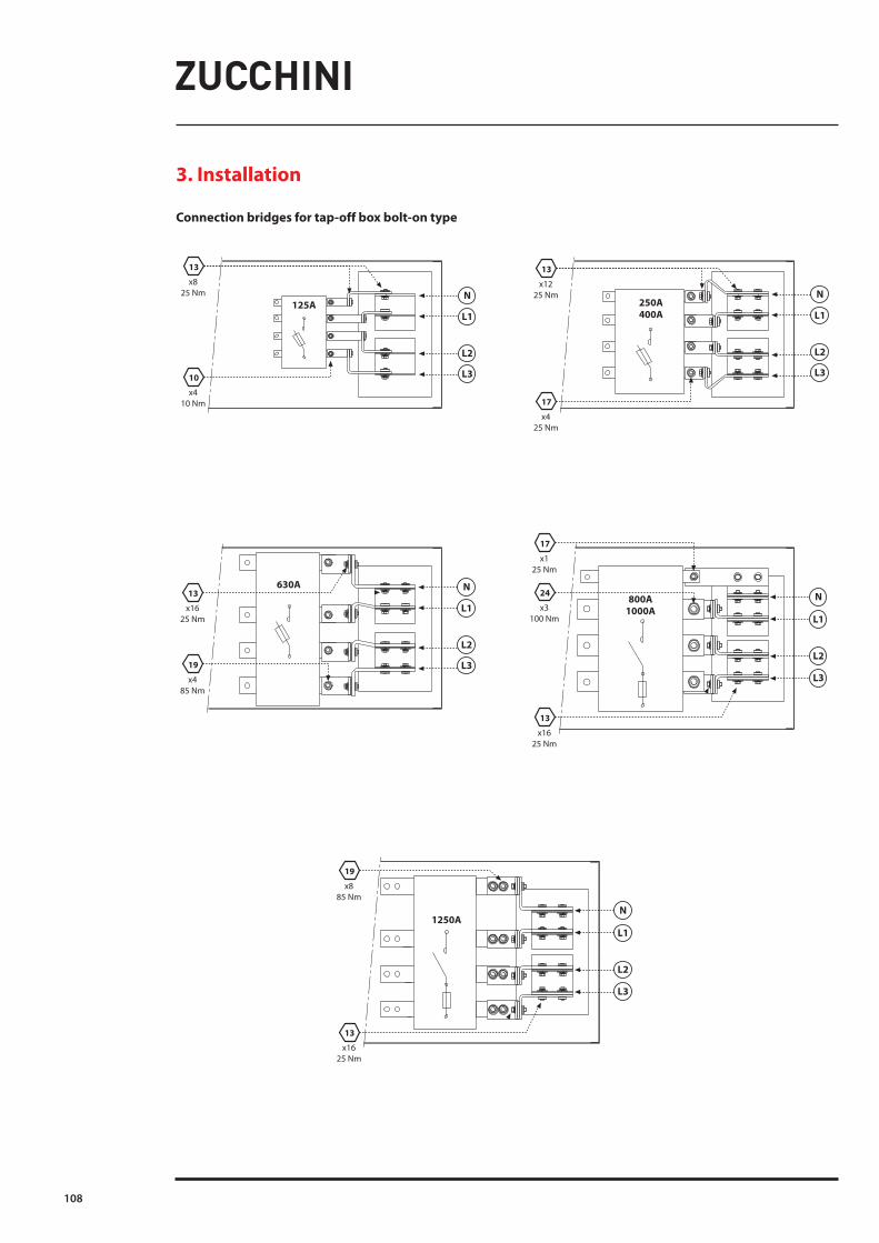
Connection bridges for tap-off box bolt-on type
3. Installation

XCP Busbar Trunking Systems
Inst
alla
tion
and
user
man
ual
109
3.4.9 Busbar post-installation checks Bus duct inspections after installationAfter installation, following inspections have to be carried out before running the plant:
Bus duct installationCheck if elements are correctly aligned. If not, align them correctly.
JUNCTIONSOpen a random sample (10%) of mechanical junctions and verify that:1 the block has been installed in the correct direction and that the mechanical guides (pins and slots) correctly correspond. If
not, remove the block and mount it again correctly, after checking it is sound. Otherwise wholly replace it.2 plastics are sound, in particular that there are neither slits nor chips, and that there is neither dust nor grime. If the
insulating parts are damaged, wholly replace the monobloc. If there are dust or grime, clean them off.3 the block is correctly centred with the bars of the element. If not, centre it after having checked it is undamaged.4 the torque moment of the self-breaking bolts is correct (80-90 Nm), use a calibrated torque wrench. During the
measurement the line has to be at ambient temperature. If the torque moment is lower than the specified value, re-establish it.
SWITCHBOARD CONNECTIONOn switchboard connections verify that:1 the air distances between bars with different potentials are over 40 mm wide. If it is not the case, contact Eng. Dept.
Zucchini Brand to evaluate the employment of correct insulating material.2 the torque moment of connecting screws is correct (required values: 85 Nm for M12, 100 Nm for M14, 120 Nm for M16,
170 Nm for M18, 25 Nm for M8 and 50 Nm for M10).
The above-mentioned inspections have to be carried out by personnel with a proper technical background and with controlling function/responsibility in the installation activities.
Tap-off boxes inspections after installationThese inspections always have to be carried out with a non-energized plant and after having earthed the phases after the tap-off box, in order to unload possible static discharges in the downstream circuit (with an insulated device).
BOLT-ONCarry out the same inspections planned for junctions. Verify the correct torque moment of the screws joining the mechanical junction and the collector bars. If necessary, retighten the connecting screws.

110
4.1 Busbar pre-energising checks4.1.1 Electrical safety testsCarry out all tests described in the applicable technical installation norms, as the insulating test between phases neutral and to earth at 1000 V with a minimum value of 1MΩ, for every line stretch.If the insulating value is lower than 1MΩ, it is necessary to verify the plant completely, starting from the insulating parts of each monobloc. If the insulation is still inadequate, divide the plant in two parts and verify the single stretch to identify the element with low insulation. Continue the splitting, if the insulation keeps being inadequate.If insulation test is made to every piece the value minimal is 100MΩ.
4.2 Electric checks4.2.1 ConductorsThermal testsAfter having path the plant at the maximal working current, and having let it work for at least 6 hours, carry out a thermal test. Stick labels on the hottest parts and mark them with progressive numbers to identify the element. Carry out the thermal test again on the labels. Fill the attached form with the measured values, together with ambient temperature and working current (forms for thermal tests at pages 115-117).Thermal tests can be carried out with contact temperature sensors, with optical pyrometers or thermal cameras.
4.2.2 Tap-off boxesPlug-inVerify the contact resistance between the clamp before the protective device and the relative bar in the upstream outlet. If resistance is higher than 100μΩ, the tap-off box could have been mounted not correctly. Take off the tap-off box, verify the plug-block and the outlet of the element. If the outlet is broken and the contacts have entered the bulb, replace the box and mark the outlet as out of service. Insert a new box in another outlet and do not use the broken one again.N.B. Never use an outlet when problems have occurred during the installation of the tap-off box, or when the tap-off box is replaced because out of service.
Thermal testsCarry out a thermal test on the cover near the lock, using contact temperature sensors, optical pyrometers or thermal cameras. The test has to be carried out with tap-off boxes running at working current for at least 6 hours. Fill in the attached form together with ambient temperature and working current.
4. Starting-up

XCP Busbar Trunking Systems
Inst
alla
tion
and
user
man
ual
111
4.3 Filling the check form4.3.1 Busduct record form for inspections and controls
PLANTCLIENTCONFIRMATION OF ORDER N.MANUFACTURING YEARINSTALLATION YEARINSTALLING COMPANY
4.3.2 Inspections after installation
PERSON IN CHARGE OF INSPECTIONSCOMPANY (if different from installing company)INSPECTION DATESIGNATURE
Element alignment YES NO
JunctionsChecked junctions (quantity)Total junctions (quantity)Correct installation YES NO Soundness of insulating parts YES NO Correct centring YES NO Correct coupling clamp (85 Nm) - write value
Connection to switchboardCorrect air distance between barsCorrect coupling clamp
Tests on electrical safetyInsulating resistance between L1 and neutral (L1-N)Insulating resistance between L2 and neutral (L2-N)Insulating resistance between L3 and neutral (L3-N)Insulating resistance between L1 and L2 (L1-L2)Insulating resistance between L2 and L3 (L2-L3)Insulating resistance between L3 and L1 (L3-L1)Insulating resistance between L1 and earth (L1-PE)Insulating resistance between L2 and earth (L2-PE)Insulating resistance between L3 and earth (L3-PE)Insulating resistance between neutral and earth (N-PE)Test voltage
NoteN.B. Write the measured value of the insulating resistance
Thermal testsFill in the attached table, with reference to the inspected element.As per the measurement point and the plate present on the measurement side, fill in the relative box with the measured temperature value.

112
5. Verification
5.1 Definition of the check sequence5.1.1 Busduct periodic inspections are to be carried out yearlyTHERMAL TESTSIn order to performe inspections over installations, it is raccomanded to de-energise the busbar. After having path the plant at the maximal working current for at least 6 hours, carry out a thermal test, taking in particular consideration the points where labels had been sticked on during installation. Fill in the attached form with the measured values, together with ambient temperature and working current (form for thermal tests at pages 115-117). If the measured temperature (DT) is higher than 55 K or is 15 K higher than the temperature measured during installation, get in contact with Customer Care. This thermal test should be carried out with contact temperature sensors, optical pyrometers or thermal cameras.
JUNCTIONSIt is recomanded to open a random sample (10%) of the mechanical junctions, and for every junction verify that:1 plastics are sound, in particular there are no slits, and plastic colour has not changed. If it is not the case, wholly
replace the monobloc.2 there are no water, scale-marks or foreign materials (dust, grime, etc.) on the protective flanges of the mechanical
junctions. In case they are found, also verify the bars near the block. Dry possible wet parts with hot air at a temperature not higher than 80 °C and remove residues with mild reagents (e.g. trichloroethene) not corroding or creating abrasion on surface treatment (zinc, tin, silver coating) or on contact surface (copper).
3 blocks correctly adhere on bars (use a 0.05mm thickness gauge), i.e. conducting parts fully make contact.4 the torque moment of the self-breaking bolts with a torque wrench calibrated at 85 Nm. During the measurement the
line has to be at ambient temperature. If the torque moment is lower than the required value (85Nm), re-establish it.5 insulation test at 1000V, with minimum value of 1MΩ, for every separated line stretch. The insulation test has to be
carried out between phases, between phases and neutral, and between every single phase and the casing. If results are unsuccessful, identify the stretch and in case replace it or carry out further tests.
If insulation test is made to every piece the value minimal is 100MΩ.In case the inspections carried out have negative results, extend the inspections on all junctions and get in contact with Customer Care.
5.1.2 Tap-off boxes annual periodic inspectionsCarry out a thermal test on the cover near the lock, using contact temperature sensors, optical pyrometers or thermal cameras. The test has to be carried out with tap-off boxes running at working current for at least 6 hours.Fill in the attached form together with ambient temperature and working current. If the measured relative temperature (DT) is higher than 55 K or is 15 K higher than the temperature measured during installation, get in contact with Customer Care.
Verify if joining screws are correctly tightened.

XCP Busbar Trunking Systems
Inst
alla
tion
and
user
man
ual
113
5.1.3 Annual periodic inspections carried out one year after energizing and every other following year
PERSON IN CHARGE OF INSPECTIONSCOMPANY (if different from installing company)INSPECTION DATESIGNATURE
JunctionsChecked junctions (quantity)Total junctions (quantity)Soundness of insulating parts YES NO Absence of water, scale and dust in flanges YES NO Correct centring YES NO Correct coupling clamp (85 Nm) - write value
Connection to switchboardCorrect air distance between barsCorrect coupling clampTests on electrical safetyInsulating resistance between L1 and neutral (L1-N)Insulating resistance between L2 and neutral (L2-N)Insulating resistance between L3 and neutral (L3-N)Insulating resistance between L1 and L2 (L1-L2)Insulating resistance between L2 and L3 (L2-L3)Insulating resistance between L3 and L1 (L3-L1)Insulating resistance between L1 and earth (L1-PE)Insulating resistance between L2 and earth (L2-PE)Insulating resistance between L3 and earth (L3-PE)Insulating resistance between neutral and earth (N-PE)
NoteN.B. Write the measured value of the insulating resistance
Thermal testsFill in the attached table, with reference to the inspected element.As per the measurement point and the plate present on the meausurement side, fill in the relative box with the measured temperature value.

114
5. Verification
5.1.4 Inspections after installation and yearly
PERSON IN CHARGE OF INSPECTIONSCOMPANY (if different from installing company)INSPECTION DATESIGNATURE
Correct coupling clamp of connecting screws
Thermal testsTap-off box n. Measured T Ambient T Dt IbTap-off box n. Measured T Ambient T Dt IbTap-off box n. Measured T Ambient T Dt IbTap-off box n. Measured T Ambient T Dt IbTap-off box n. Measured T Ambient T Dt IbTap-off box n. Measured T Ambient T Dt IbTap-off box n. Measured T Ambient T Dt IbTap-off box n. Measured T Ambient T Dt IbTap-off box n. Measured T Ambient T Dt IbTap-off box n. Measured T Ambient T Dt IbTap-off box n. Measured T Ambient T Dt IbTap-off box n. Measured T Ambient T Dt Ib
Dt = Tmeasured - TambientIb = working current

XCP Busbar Trunking Systems
Inst
alla
tion
and
user
man
ual
115
5.1.5 Feeder element
ELEMENT IDENTIFICATIONPERSON IN CHARGE OF INSPECTIONSCOMPANY (if different from installing company)INSPECTION DATESIGNATURE
N.B. Stick on the element a label with a progressive number for identification.
RATED CURRENT In (A)
AL Cu
N 1 2 3
N 1 23
AN
CN
AF
BF
CF
BN
Dim.(mm)
CN Ta (°C) I. (A)POS. BNANCFBFAFDim.(mm)

116
5.1.6 Dihedral elbow
ELEMENT IDENTIFICATIONPERSON IN CHARGE OF INSPECTIONSCOMPANY (if different from installing company)INSPECTION DATESIGNATURE
N.B. Stick on the element a label with a progressive number for identification.
CN Ta (°C) I. (A)POS. BNANCFBFAFDim.(mm) A Dim.(mm) B
RATED CURRENT In (A)
AL Cu
N 1 23
N 1 23
CFB
A
AF
BF
CN
AN
BN
5. Verification

XCP Busbar Trunking Systems
Inst
alla
tion
and
user
man
ual
117
5.1.7 Flat elbow
ELEMENT IDENTIFICATIONPERSON IN CHARGE OF INSPECTIONSCOMPANY (if different from installing company)INSPECTION DATESIGNATURE
N.B. Stick on the element a label with a progressive number for identification.
CF
BF
BN
AFAN
CN
N 1 23
N 1 23
Dim.(mm)B
Dim.(mm)A
CN Ta (°C) I. (A)POS. BNANCFBFAFDim.(mm) A Dim.(mm) B
RATED CURRENT In (A)
AL Cu

118
5.1.8 Troubleshooting table
Problem’s signals Where? Causes:Solutions:
Materials are damaged: Materials are ok:
Abnormal heat on: Monoblock or along busbar plant or elbow
Couple loosingNut not broken
Request spare parts Strength the torque
Wrong mountingMonoblock tooth wrong
Change way to mounting
Burnished point on: casing or insulating broken insulatingoverload on the line
request spare parts
Low insulating measure
apply “half plant” technique, to find out:
mechanical damagewater inside broken insulating
request spare parts
Mccb break on panel board, on feed unit, on TOB:
apply “half plant” technique, to find out:
- electrical overload- bad electrical contact- short circuit on load- short circuit inside
TOB- broken MCCB- wrong mounting
MCCB- too much hot
environment- water inside
request spare parts
6. Disposal
For the identification of the materials and the disposal instructions visit www.bticino.com/disposal.
5. Verification

XCP Busbar Trunking Systems
Inst
alla
tion
and
user
man
ual
119

Installer stamp
Legrand reserves at any time the right to modify the contents of this booklet and to communicate, in any form and modality, the changes brought to the same.
Legrand:LEGRANDPro and Consumer ServiceBP 30076 - 87002LIMOGES CEDEX FRANCEwww.legrand.com