xArm 7 DoF Robotic Arm - User Manual - RobotShop
248
1
-
Upload
khangminh22 -
Category
Documents
-
view
0 -
download
0
Transcript of xArm 7 DoF Robotic Arm - User Manual - RobotShop

1

2
Table
Table ................................................................................................. 2
Preface ..................................................................................................... 6
User Manual Information .................................................................. 6
Product Information .......................................................................... 6
Main Contents of the Manual ............................................................ 7
Terms and Definitions ....................................................................... 8
xArm Motion Parameters ................................................................. 12
Unit Definition ................................................................................. 13
Additional Information .................................................................... 13
Safety Precautions .......................................................................... 14
xArm User Manual-Hardware Section .................................................... 22
1. Hardware Installation Manual ......................................................... 22
1.1. The Hardware Composition of xArm ..................................... 22
1.2. Robot Installation ................................................................. 26
1.3. Power Supply for the Robotic Arm ........................................ 35
2. Electrical Interface ........................................................................... 38
2.1. AC Control Box ..................................................................... 38
2.2. DC Control Box ..................................................................... 40
2.3. End-Effector I/O ................................................................... 43
2.4. Control Box Electrical IO ....................................................... 49

3
2.5. Communication Interface ..................................................... 61
2.6. Ethernet TCP/IP..................................................................... 61
3. End-Effector ..................................................................................... 64
3.1. Gripper ................................................................................. 64
3.2. Vacuum Gripper ................................................................... 68
xArm User Manual-Software Section ..................................................... 71
1. xArm Studio ....................................................................................... 71
1.1 Hardware Preparation ............................................................... 72
1.2 Connect to the Robotic Arm ....................................................... 73
1.3 xArm Studio Homepage ............................................................ 81
1.4 Robotic Arm Setting .................................................................. 83
1.5 Live Control ............................................................................ 137
1.6 Blockly Graphical Programming ............................................. 150
1.7 Python IDE ............................................................................. 175
1.8 Recording .............................................................................. 177
2. xArm Motion Analysis ....................................................................... 180
2.1 Robotic Arm Motion Mode and State Analysis ........................ 181
2.2. Motion of the Robotic Arm ...................................................... 188
2.3. xArm5 Motion Characteristics ................................................ 203
2.4. Singularity .............................................................................. 204
3. Typical Examples ............................................................................. 207
3.1. The Use of xArm Vacuum Gripper ........................................... 207

4
3.2. The Use of xArm Gripper ......................................................... 208
3.3. The Use of the Digital IO ......................................................... 209
3.4. Cyclic Motion Count ................................................................ 210
Appendix ............................................................................................. 212
Appendix1-Error Reporting and Handling ........................................... 212
1.1 Joints Error Message and Error Handling ................................. 212
1.2 Control Box Error Code and Error Handling ............................ 215
1.3 Gripper Error Code & Error Handling ...................................... 219
1.4 Python SDK Error Code & Error Handling ................................. 221
Appendix2-Technical Specifications .................................................... 223
1.1 xArm5/6/7 Common Specifications ....................................... 223
1.2 xArm 5 Specifications ............................................................. 225
1.3 xArm 6 Specifications ............................................................. 225
1.4 xArm 7 Specifications ............................................................. 226
Appendix3-FAQ.................................................................................... 228
Appendix4-The xArm Software/Firmware Update Method. ................. 229
Appendix5- Maintenance and Inspection ............................................ 238
Appendix6- Repair ............................................................................... 239
Appendix7-Product Information .......................................................... 241
1.1 Product Mark ...................................................................... 241
1.2 Applied Standards .............................................................. 242
1.3 EMC .................................................................................... 242

5
1.4 Use Environment ................................................................ 243
1.5 Transport, Storage and Handling ....................................... 244
1.6 Power box placement height ............................................. 244
1.7 Power Connection .............................................................. 244
1.8 Special Consumables. ........................................................ 245
1.9 Stop Categories .................................................................. 245
1.10 Stopping Time and Stopping Distance ............................... 245
1.11 Maximum Speed ................................................................. 246
1.12 Maximum Payload .............................................................. 246
1.13 Specifications ..................................................................... 247

6
Preface
User Manual Information
Translated Version V1.6.9.
Apply to Model: XI1300 XI1301 XI1302 XI1303 XI1304 XI1305
Product Information
Package contains:
1. Robotic Arm x 1
2. Control Box x 1
3. Power cable for the Control Box x 1
4. Power cable for the Robotic Arm x 1
5. Communication cable for the Robotic Arm x 1
6. Ethernet Cable x1
7. Robotic Arm end effector adapter cable x1
1 2 3

7
Main Contents of the Manual
xArm User Manual Hardware Section
(1) xArm hardware installation
(2) Electrical interface
(3) xArm end-effector
xArm User Manual Software Section
(1) xArm Studio instructions
(2) xArm motion analysis
(3) Typical examples
Appendix
(1) xArm error reporting and handling
(2) xArm technical specifications
(3) FAQ
(4) The xArm software/firmware update method
(5) Maintenance and Inspection
(6) After-sales service
5 4 6

8
Terms and Definitions
The following terms and definitions apply to this manual.
Control Box The control box, core part of the robotic arm, is the integration of
the robotic arm control system.
End Effector
The end effector, installed on the front end of the wrist of the
robotic arm, is used to install special tools (such as grippers,
vacuum gripper, etc.), which can directly perform work tasks.
Enable Robotic Arm Power on the robotic arm and turn on the motor of the robotic
arm. After the robotic arm is enabled, it can start to move
normally. TCP Tool center point.
TCP Motion TCP motion is the Cartesian space motion, with target position in
Cartesian space coordinate and the end follows the specified
trajectory (arc, line, etc.).
TCP Payload
(End Payload)
The payload weight refers to the actual (end tool +other object)
weight in Kg; the X / Y / Z-axis indicates the position of the center
of mass of the TCP relative to the default tool coordinate
system,with unit of mm.
TCP Offset
(Tool Center Point
Offset)
Set the relative offset between the default tool coordinate system
at flange center and the actual tool coordinate system, with
distance unit of mm.
Roll / Pitch / Yaw sequentially rotates around the X / Y / Z of the
selected coordinate system (base coordinate system).
The following describes the roll/pitch/yaw orientation
representation of B relative to A:
For example, the coordinate system B and a known reference
coordinate system A are first superposed. First rotate B around
AX by γ, then around AY by β, and finally around AZ by α.
Each rotation is around a fixed axis of the reference coordinate
system A. This method is called the XYZ fixed angle coordinate
system, and sometimes they are defined as the roll angle, pitch
angle, and yaw angle.
The above description is shown in the following figure:

9
Roll/Pitch/Yaw
The equivalent rotation matrix is:
( ) ( ) ( ) ( ) XYZXYZ
A
B RRRR =,,
Note: γ corresponds to roll; β corresponds to pitch; α corresponds
to yaw.

10
Axis-Angle
Rx / Ry / Rz representation also, using 3 values to represent the
pose (but not three rotation angles), which is the product of a
three-dimensional rotation vector [x, y, z] and a rotation angle[phi
(scalar)].
The characteristics of the axis angle:
Assume the rotation axis is [x , y, z], and the rotation angle is phi.
Then the representation of the axial angle:
[Rx, Ry, Rz] = [x * phi, y * phi, z * phi]
Note:
1. [x, y, z] is a unit vector, and phi is a non-negative value.
2. The vector length (modulus) of [Rx, Ry, Rz] can be used to
estimate the rotation angle, and the vector direction is the rotation
direction.
3. If you want to express reverse rotation, invert the rotation axis
vector [x, y, z], and the value of phi remains unchanged.
4. Using phi and [x, y, z] can also derive the attitude representation
as unit quaternion q = [cos (phi / 2), sin (phi / 2) * x, sin (phi / 2) *
y, sin (phi / 2) * z].
For example:
The vector of the rotation axis represented by the base coordinate
system is [1, 0, 0], and the rotation angle is 180 degrees (π), then
the axis angle representation of this pose is [π, 0, 0].
The rotation axis is [0.707, 0.707, 0] and the rotation angle is 90
degrees (π / 2), then the axis angle posture is [0.707 * (π / 2), 0.707
* (π / 2), 0].
The Base Coordinate
System
(please refer to the
figure 1)
The base coordinate system is a Cartesian coordinate system
based on the mounting base of the robotic arm and used to
describe the motion of the robotic arm.
(front and back: X axis, left and right: Y axis, up and down: Z axis)
Tool Coordinate
System
(please refer to the
Consists of tool center point and coordinate orientation. If the TCP
offset is not set, the default tool coordinate system is located at
flange center.
For tool coordinate system based motion: The tool center point is

11
figure 1) taken as the zero point, and the trajectory of the robotic arm refers
to the tool coordinate system.
User Coordinate
System
(please refer to the
figure 1)
The user coordinate system can be defined as any other reference
coordinate system rather than the robot base.
Manual Mode In this mode, the robotic arm will enter the ‘zero gravity’ mode,
since the gravity is compensated, the user can guide the robotic
arm position directly by hand.
Teach Sensitivity
Teach sensitivity range is from 1 to 5 level. The larger the set
value, the higher the teach sensitivity level, and the less the force
required to drag the joint in the manual mode.
Collision Sensitivity
The collision sensitivity range is from 0 to 5 level. When it is set to
0, it means that collision detection is not enabled. The larger the
set value, the higher the collision sensitivity level, and the smaller
the force required to trigger the collision protection response of
the robotic arm.
GPIO
General-purpose input and output.
For the input, you can check the potential of the pin by reading a
register;
For the output, you can write a certain register to make this pin
output high or low potential;
Safety Boundary
When this mode is activated, the boundary range of the cartesian
space of the robotic arm can be limited. If the tool center point
(TCP) exceeds the set safety boundary, the robotic arm will stop
moving. Reduced Mode
When this mode is activated, the maximum linear velocity of the
Cartesian motion of the robotic arm, the maximum joint speed,
and the range of the joint motion will be limited.
Figure 1

12
xArm Motion Parameters
The parameters of the robotic arm are shown in Table 1.1 and Table 1.2.
Table 1.1 working range of each joint of the robotic arm
Table 1.2 range of various motion parameters of the robotic arm
Note:
1. In the TCP motion (Cartesian space motion) commands (set_position () function
of the SDK), If a motion command involves both position transformation and
attitude transformation, the attitude rotation speed is generally calculated
automatically by the system. In this situation, the specified speed parameter is the
maximum linear speed, range from: 0 ~ 1000mm / s.
2. When the expected TCP motion only changes the attitude (roll, pitch, yaw), with
Robotic Arm xArm 5 xArm 6 xArm 7
Maximum
Speed
180°/s 180°/s 180°/s
Working
Range
1st Axis ±360° ±360° ±360°
2st Axis -118°~120° -118°~120° -118°~120°
3st Axis -225°~11° -225°~11° ±360°
4st Axis -97°~180° ±360° -11°~225°
5st Axis ±360° -97°~180° ±360°
6st Axis None ±360° -97°~180°
7st Axis None None ±360°
TCP Motion Joint Motion
Speed 0~1000mm/s 0~180°/s
Acceleration 0~50000mm/s2 0~1145°/s2
Jerk 0~10000mm/s3 0~28647°/s3

13
position (x, y, z) remains unchanged, the specified speed is the attitude rotation
speed, so the range 0 to 1000 corresponds to 0 to 180 ° / s.
Unit Definition
The Python / Blockly examples and the units standard in the
communication protocol are shown in Table 1.3.
Table 1.3. Default units in Python / Blockly example and Communication
Protocol
Parameter Python-SDK Blockly Communication
Protocol X(Y/Z) millimeter(mm) millimeter(mm) millimeter(mm)
Roll(Pitch/Yaw) degree(°) degree(°) radian(rad)
J1(J2 /J3/J4/J5/J6/J7) degree(°) degree(°) radian(rad)
TCP Speed mm/s mm/s mm/s
TCP Acceleration mm/s² mm/s² mm/s²
TCP Jerk mm/s³ mm/s³ mm/s³
Joint Speed °/s °/s rad/s
Joint Acceleration °/s² °/s² rad/s²
Joint Jerk °/s³ °/s³ rad/s³
Additional Information
For xArm Studio software download and xArm developer manual,
please refer to the UFACTORY official website.
(https://store-ufactory-cc.myshopify.com/pages/download-xarm)

14
Safety Precautions
Introduction
This chapter contains essential safety information, integrators and users
of xArm must follow the instructions and pay special attention to the
content with warning signs. Due to the complexity of the robotic arm
system and its degree of danger, please ensure you fully understand the
content of this manual and strictly adhere to the instructions. When
using SDK (Python/ROS/C++) and graphical interface (xArm Studio),
please read the relevant interface instructions demonstrated in this
operation manual.
UFACTORY devotes to providing reliable and safety information, but
these contents do not constitute warranties by UFACTORY. UFACTORY
will not have or accept any liability, obligation, or responsibility
whatsoever for any loss, destruction, or damage arising from or in
respect of any use or misuse of xArm.
Validity and Responsibility
The information does not cover how to design, install, and operate a
complete robotic arm application, nor does it cover all peripheral
equipment that can influence the safety of the complete system. The
complete system must be designed and installed under the safety

15
requirements outlined in the standards and regulations of the country
where the robotic arm installed.
The integrators of the xArm are responsible for the compliance of
applicable safety laws and regulations in the country, to prevent any
hazards in the operating environment.
Safety precautions include but are not limited to:
Making a risk assessment for the complete system. Make sure to
have a safe distance between people and xArm when interacting
with the xArm.
Interfacing other machines and additional safety devices if defined
by the risk assessment.
For software programming, please read the interface
documentations carefully and set up the appropriate safety
functions in the software.
Specifying instructions for use to prevent unnecessary property
damage or personal injury caused by improper operation.
Limitations on Liability Exceptions
Any information given in this manual regarding safety must not be
construed as a warranty by UFACTORY that the xArm will not cause injury

16
or damage even if all safety instructions are complied with.
Safety Alarms in this Manual
DANGER:
This indicates an imminently hazardous
electrical situation, which if not avoided, could
result in death or serious damage to the device.
WARNING:
This indicates a potentially hazardous situation
which, if not avoided, could result in death or
serious damage to the device.
HIGH TEMPERATURE
This indicates a potential hot surface, which if
touched, could result in personal injury.
NOTICE
If not avoided, could result in personal injury or
damage to the equipment.
CAUTION:
If not avoided, could result in personal injury or
damage to the equipment.

17
Safety Precautions
Overview
This section contains some general warnings and cautions on
installation and application planning for the robotic arm. To prevent
damage to the machine and associated equipment, users need to learn
all the relevant content and fully understand the safety precautions. We
do not control or guarantee the relevance or completeness of such
information in this manual, for which users should conduct self-
assessment of their specific problems.
General Alarms and Cautions
1. Make sure to use the correct installation settings
in this manual for the robotic arm and all the
electrical equipment.
2. Please follow the instructions in this manual,
installation, and commissioning needs to be
performed by professionals in accordance with
the installation standards.
3. Make sure the robotic arm and tool are properly
and securely bolted in place.
4. The integrity of the device and system must be
checked before each use (e.g. the operational

18
safety and the possible damage of the robotic
arm and other device systems).
5. Preliminary testing and inspection for both
robotic arm and peripheral protection system
before production is essential.
6. The operator must be trained to guarantee a
correct operation procedure when using
SDK(Python/ROS/C++) and graphical interface
xArm Studio.
7. A complete safety assessment must be recorded
each time the robotic arm is re-installed and
debugged.
8. When the robotic arm is in an accident or
abnormal operation, the emergency stop switch
needs to be pressed down to stop the
movement, and the posture of the robotic arm
will slightly brake and fall.
9. The xArm joint module has brakes inside, which
will remain manipulator’s pose when a power
outage occurs.
10. When the robotic arm is in operation, make sure
no people or other equipment are in the working
area.
11. When releasing the brakes of xArm, please take
protective measures to prevent the robotic arm
or operator from damage or injury.

19
12. When connecting the xArm with other
machinery, it may increase risk and result in
dangerous consequences. Make sure a
consistent and complete safety assessment is
conducted for the installation system.
1. The robotic arm and Control Box will generate
heat during operation. Do not handle or touch
the robotic arm and Control Box while in
operation or immediately after the operation.
2. Never stick fingers to the connector of the end-
effector.
1. Make sure the robotic arm’s joints and tools are
installed properly and safely, and check the
status for all circuits.
2. Make sure that there is enough space for the
manipulator to move freely.
3. Make sure that there is no obstacle in the robotic
arm’s working space.
4. The Control Box must be placed outside the
working range of the robotic arm to ensure the
emergency stop button can be pressed once an
emergency occurs.
5. If the robotic arm is in operation and needs an
emergency stop, make sure the restart/reset
motions will not collide with any obstacle.
6. Do not modify the robotic arm(or Control Box).

20
Any modification may lead to unpredictable
danger to the integrators. The authorized
restructuring needs to be in accordance with the
latest version of all relevant service manuals. If
the robotic arm is modified or altered in any
way, UFACTORY (Shenzhen) Technology Co., Ltd.
disclaims all liability.
7. Users need to check the collision protection and
water-proof measures before any
transportation.
When the xArm cooperates with other machinery, a
comprehensive safety assessment of the entire
collaboration system should be performed. It is
recommended that any equipment that may cause
mechanical damage to xArm be placed outside the
working range during application planning.
Operator Safety
In the operation of the robotic arm system, we must ensure the safety of
the operators first, with the general precautions listed in the table
below. Please take appropriate measures to ensure the safety of
operators.
1. Each operator who uses the robotic arm system
should read the product user manual carefully.
Users should fully understand the standardized

21
operating procedures with the robotic arm, and the
solution to the robotic arm running error.
2. When the device is running, even if the robotic arm
seems to stop, the robotic arm may be waiting for
the signal and in the upcoming action status. Even
in such a state, it should be considered as the
robotic arm is in action.
3. A line should be drawn to mark the range of motion
of the robotic arm to let the operator acknowledge
the robotic arm, including its end tools (such as
gripper and suction cup, etc) operating range.
4. Check the robotic arm regularly to prevent
loosening of the bolts that may cause undesirable
consequences.
5. Be careful when the robotic arm is running too fast.
6. Be careful about dropping items that can be caused
by accidental power off or unstable clamping of the
robotic arm.

22
xArm User Manual-Hardware Section
1. Hardware Installation Manual
1.1. The Hardware Composition of xArm
1.1.1. Hardware Composition
The composition of robotic arm hardware includes:
• Robotic Arm(Figure 2-1)
• Control Box (Figure 2-2)
• Robotic Arm Signal Cable (Figure 2-3)
• Robotic Arm Power Supply Cable (Figure 2-4)
• Control Box Power Supply Cable (Figure 2-5)
Figure 2-1 Figure 2-2

23
The xArm robotic arm system consists of a base and rotary joints, and
each joint represents a degree of freedom. From the bottom to the top,
in order, Joint 1, Joint 2, Joint 3, etc. The last joint is known as the tool
side and can be used to connect end-effector (e.g. gripper, vacuum
gripper, etc).
Refer to technical specifications for joint Figures(See appendix-2).
1.1.2. Emergency Stop Button
By pressing the emergency stop button of the Control Box, a command
will be sent to the Control Box for software deceleration to stop all
activities of the robotic arm and clear all the cached commands in the
Control Box; the power supply for the robotic arm will be removed
within 300ms. The emergency stop should not be used as a risk
reduction measure. When an emergency occurs during the operation of
the robotic arm, users need to press the emergency stop, and the
Figure 2-5 Figure 2-4 Figure 2-3

24
posture of the robotic arm will slightly brake and fall. The emergency
stop button is shown below:
Emergency Stop: press the emergency stop button to power off the
xArm, and the power indicator will go out.
Power-on: when the button is rotated in the direction indicated by the
arrow, the button is pulled up, the xArm power indicator lights up, and
the arm is powered.
Note:
After pressing the emergency stop button, the following operations
should be performed to re-start the xArm:
1. Power up the xArm (Turn the emergency stop button in the direction
of the arrow)
2. Enable the xArm (enable the servo motor)
xArm Studio:enable the robotic arm:click the button: [Enable
Robot]
Python-SDK:enable the robotic arm: motion_enable (true)

25
1.1.3. Three-Position Enabling Switches
The three-position enabling switches is composed of three switches and
an emergency stop button. The specific functions are shown in the
following table:
First-position
switch
Second-position
switch
Third-position
switch Emergency stop
Stops the motion
of the robotic arm Yes No Yes Yes
Program
execution
Pause
The buffered
motion
command is not
cleared.
The robotic arm
resumes motion.
Pause
The buffered
motion command
is not cleared.
Stop
The buffered
motion command
is cleared.
The robotic arm
status Pause Resuming motion Pause Stop
The power supply
of the robotic arm On On On Off

26
1.1.4. Control Box Description
Control Box Buttons and
Indicator
Parameter Name Function
ROBOT power indicator ROBOT PWR The light is on, indicating that the
xArm is powered on.
Control Box power status
indicator
STATE The light flashes, indicating that the
control box is powered on.
Network port indicator LAN The light is on, indicating that the
xArm is communicating normally.
Emergency stop button EMERGENCY STOP Press the button to power off the
xArm;
Rotate the button, the ROBOT power
indicator of the xArm lights up.
1.2. Robot Installation
1.2.1. Safety Guidelines for the Robot Environment
1. Make sure the arm is properly and safely installed
in place. The mounting surface must be
shockproof and sturdy.
2. To install the arm body, check that the bolts are

27
tight.
3. The robotic arm should be installed on a sturdy
surface that is sufficient to withstand at least 10
times the full torsion of the base joint and at least
5 times the weight of the arm.
1. The robotic arm and its hardware composition
must not be in direct contact with the liquid, and
should not be placed in a humid environment for
a long time.
2. A safety assessment is required each time
installed.
3. When connecting or disconnecting the arm cable,
make sure that the external AC is disconnected.
To avoid any electric shock hazard, do not
connect or disconnect the robotic arm cable when
the robotic arm is connecting with external AC.
1.2.2. Robot Installation
1. Brief installation steps:
a. Define a robotic arm workspace
b. Fix the robotic arm base
c. Connect the robotic arm with the Control Box
d. Connect the Control Box with cable

28
e. Install end-effector
1.2.2.1. Define a Robotic Arm Workspace
The robotic arm workspace refers to the area within the extension of the
links. The figure below shows the dimensions and working range of the
robotic arm. When installing the robotic arm, make sure the range of
motion of the robotic arm is taken into account, so as not to bump into
the surrounding people and equipment (the end-effector not included in
the working range).

29
Working space of xArm7 (unit: mm)
Note : The following working range diagrams are only for safety
assessment.

30
Working space of xArm5 and xArm6 (unit: mm)
Note : The following working range diagrams are only for safety
assessment.

31
1.2.2.2. Robot Installation
The robotic arm has five M5 bolts provided and can be mounted through
five ∅5.5 holes in the base of the robotic arm. It is recommended to
tighten these bolts with a torque of 20N·m.
Robot Base Mounting (unit: mm)

32
1.2.2.3. Robotic Arm is Connected to the Control Box
Plug the connector of the Robotic Arm Power Supply Cable and the
Robotic Arm Signal Cable into the interface of the Robotic Arm. The
connector is a foolproof design. Please do not unplug and plug it
violently;
Plug the Robotic Arm Power Supply Cable and the Robotic Arm Signal
Cable into the Control Box;
Plug the Control Box Power Cable into the AC (110V-240V) interface on
the Control Box and the other end into the socket (as shown in Figure
below).
1.2.2.4. Control Box Networking
Plug the Network Cable into the interface marked LAN on the Control
Box, and plug the other end of the Network Cable into the computer.

33
1.2.2.5. End-effector Installation
The End-effector flange has 6 M6 threaded holes and one Ф6
positioning hole, where the end-effector of two different sizes can be
mounted. If the effector does not have a positioning hole, the
orientation of the end-effector must be documented in a file format, to
avoid errors and unexpected results when re-installing the end-effector.
The end-effector flange referenced ISO 9409-1-50-4-M6 standard.

34
Mechanical dimensions of end-effector flange (unit: mm)
Drawing of tool I/O
1. Make sure the tool is properly and safely bolted in
place.
2. If the end-effector does not have a locating hole,

35
the orientation of the end-effector must be
archived as a file.
3. Make sure that the tool is safely constructed such
that it cannot create a hazardous situation by
dropping a part unexpectedly.
4. Pay attention to the operation specifications of
sharp end-effector tools.
5. If the installed end-effector exceeds the robotic
arm mounting surface at the zero position of the
robotic arm, a safety assessment is required for the
zero return operation.
1.3. Power Supply for the Robotic Arm
1.3.1. Preparation before Power On
• Ensure the power cable and the communication wire are properly
connected between the Control Box and the robotic arm.
• Ensure the network cable or RS-485 cable is properly connected.
• Ensure the power cable for the Control Box is properly connected.
• Ensure the xArm will not hit any personnel or equipment within
the working range.

36
1.3.2. Power On
1. Turn on the OFF/ON button and ensure the indicator lights are lit.
2. Press the power button, when the status indicator(CONTROLLER)
lights up, the control box is turned on.
3. Rotate the emergency stop button in the direction indicated by the
arrow and is pulled up, at which point the xArm power indicator
(ROBOT PWR) lights up.
4. Use the xArm Studio / SDK command to complete the operation of
enabling the robotic arm. (enable the servo motor)
1.3.3. Shut Down the Robotic Arm System
1. Shutdown Sequence
(1) Press the EMERGENCY STOP button to power off the robotic arm.

37
(2) Ensure the power indicator light is off.
2. Shutdown the control box
(1) Press the power button(PWR) of the control box for about 5s
to turn off the status light.
(2) Turn off the power supply of the control box. (the power switch
takes about 5 seconds to turn off the power of the control box. If
users like to restart the power right after turning off the power
supply, they need to press the power button manually.)
Unplugging the power cord directly from the wall outlet
to shut down the system may result in damage to the file
system of the control box, which may result in robotic
arm malfunction.

38
2. Electrical Interface
2.1. AC Control Box
2.1.1. Connect the Control Box to the Robotic Arm
1. The robotic arm power supply cable connects the power port of the
robotic arm and the ROBOT power port of the control box.
2. The robotic arm signal cable is connected to the signal interface of
the robotic arm and the ROBOT signal interface of the control box.

39
2.1.2. Power Connection
There is a standard IEC plug at the end of the control box’s main cable.
Connect a local dedicated main outlet or cable to the IEC plug. The
control box is powered by 100V-240V AC (the input frequency is 47-
63HZ) and its internal switching power supply converts 100V-240V AC
into 12V, 24V DC, which supplies power to the load of the control box
and the robotic arm.
Therefore, it is necessary to check whether the connection between the
robotic arm and the control box is secured before use. The hardware
protection and software protection of the control box can ensure the
safety of use largely. The emergency stop button of the control box
allows the user to cut off the power of the robotic arm in the shortest
time possible and protect the safety of both personnel and the
equipment.
To power on the robotic arm, the control box must be connected to the
power supply. In this process, the corresponding IEC C19 wire must be
used.
Connect to the standard IEC C20 plug of the Control Box to complete the
process, see the figure below.

40
2.1.3. Definition of the Robotic Arm Industrial
Connector
6-Pin Industrial Connector (Robot Communication )
Industrial connector wire sequence Functional definition
1 GND
2 485-A Arm
3 485-B Arm
4 GND
5 485-A Tool
6 485-B Tool
2.2. DC Control Box
2.2.1. External Interfaces of Control Box
Except that the DC Control Box is connected to different power sources,
the other electrical interface specifications and functions are the same

41
as the AC Control Box.
2.2.2. Definition of Industrial Connector
4-Pin Industrial Connector (External 24V Power )
Industrial connector wire sequence Functional definition
1 24V
2 GND
3 Null
4 Null

42
2.2.3. Specification of External Power
Input
Rated voltage 24V-28V
Rated power 400W
Rated current 17A
2.2.4. Electrical Alarms and Cautions
Always follow the warnings and cautions below when designing and
installing a robotic arm application. These warnings and cautions are
also subject to the implementation of maintenance work.
1. Never connect a safety signal to a non-safety PLC.
Failure to follow this warning may result in serious
injury or death due to an invalid safety stop function.
1. Make sure that all the non-waterproof equipment
is kept dry. If water enters the product, turn off the
power supply, and contact your supplier.
2. Use only the original cable of the robotic arm. Do
not use the robotic arm in applications where the
cable needs to be bent. If you need a longer cable
or flexible cable, please contact your supplier.
3. All GND connectors mentioned in this manual are
only suitable for powering and transmitting

43
signals.
4. Be careful when installing the interface cable to
the I/O of the robotic arm.
1. Interfering signals above the level specified in the
IEC standard will cause abnormal behaviour of the
robotic arm. Extremely high signal levels or
excessive exposure can cause permanent damage
to the robotic arm. UFACTORY (Shenzhen)
Technology Co., Ltd. is not responsible for any loss
caused by EMC problems.
2. The length of the I/O cable that used to connect
the Control Box with other mechanical and plant
equipment must not exceed 30 meters unless it is
feasible after the extension testing.
1. When wiring the electrical interface of the Control
Box, the Control Box must be powered off.
2.3. End-Effector I/O
At the tool side of the robotic arm, there is an avionic socket 12-pin
female industrial connector. This connector provides power and control
signals for the grippers and sensors used on a particular robotic arm
tool. Please refer to the figure below:

44
There are 12 pins inside the cable with different colors, each color
represents different functions, please refer to the following table:
Pin sequence Color Signal
1 Brown +24V(Power)
2 Blue +24V(Power)
3 White 0V (GND)
4 Green 0V (GND)
5 Pink User 485-A
6 Yellow User 485-B
7 Black Tool Output 0 (TO0)
8 Grey Tool Output 1 (TO1)
9 Red Tool Input 0 (TI0)
10 Purple Tool Input 1 (TI1)
11 Orange Analog input 0 (AI0)
12 Light Green Analog input 1 (AI1)

45
The electrical specifications are as follows:
Parameter Min. Value Typical Value Max. Value Unit
Supply Voltage in 24V Mode - 24 30 V
Supply Current * - - 1800 mA
Note: * It is strongly recommended to use a protection diode for inductive loads.
Make sure that the connecting tool and the gripper do
not cause any danger when the power is cut, such as
dropping of the work-piece from the tool.
2.3.1. Digital Output
The digital output is implemented in the form of NPN with an open
collector(OC). When the digital output is activated, the corresponding
connector will be driven to GND. When the digital output is disabled, the
corresponding connector will be open (open collector/open drain). The
electrical specifications are as follows:
Parameter Min Typical Max Unit
Open-circuit Voltage -0.5 - 30 V
Voltage when sinking 50mA - 0.05 0.20 V
Sink Current 0 - 100 mA
Current through GND 0 - 100 mA
There is no current protection on the digital output of
the tool, which can cause permanent damage if the

46
2.3.1.1. Tool Digital Output Usage
The following example illustrates how to use the digital output. As the
internal output is an open collector, the resistor should be connected to
the power supply according to the load. The size and power of the
resistor depend on the specific use.
Note: It is highly recommended to use a protection diode for inductive
loads as shown below.
2.3.2. Digital Input
The digital input is already equipped with a pull-down resistor. This
means that the reading of the floating input is always low. The electrical
specifications are as follows:
Parameter Min Typical Max Unit
specified value exceeded.

47
Input Voltage -0.5 - 30 V
Logic Low Voltage - - 1.0 V
Logic High Voltage 1.6 - - V
Input Resistance - 47k - Ω
2.3.2.1. Tool Digital Input Usage
The following figure shows the connection with the simple switch.
2.3.3. Tool Analog Input
The tool analog input is a non-differential input. The electrical
specifications are as follows:
Parameter Min Typical Max Unit
Input Voltage in Voltage Mode -0.5 - 3.3 V
Resolution - 12 - Bit
Input Current in Current Mode - - - mA
Pull-down Resistors in the 4mA to 20mA Current
Range
- - 165 Ω
Resolution - 12 - Bit
1. In the current/voltage mode, the analog input does
not provide over-voltage protection. Exceeding the
limits in the electrical code may result in permanent
damage to the input port.
2. In current mode, the pull-down resistance depends
on the range of the input current.

48
2.3.3.1. Non-differential Analog Input
The following figures show how the analog sensor can be connected to
a non-differential output.
Voltage mode
Current mode
2.3.3.2. Differential Analog Input
The following figures show how the analog sensor is connected to the
differential output. Connect the negative output to GND (0V), and it can
work like a non-differential sensor.
Voltage Mode

49
Current Mode
2.4. Control Box Electrical IO
This chapter explains how to connect devices to the electrical I/O outside
of the control box.
The I/Os are extremely flexible and can be used in many different
devices, including pneumatic relays, PLCs, and emergency stop buttons.
The figure below shows the electrical interface layout inside the control
box.
2.4.1. General Specifications for all Digital I/O
This section describes the electrical specifications for the following 24V
digital I/Os for the Control Box.

50
• Dedicated safety I/O.
• Configurable I/O.
For the specific configuration functions of IO, see the following table:
Configurable Function CI0-CI7
(Configurable Input)
DI0-DIO7
(Digital Input) General Input Yes Yes
Stop Moving Yes No
Safeguard Reset Yes No
Offline Task Yes Yes
Manual Mode Yes Yes
Reduced Mode Yes No
Enable Robot Yes Yes
Configurable Function CO0-CO7
(Configurable Output)
DO0-DO7
(Digital Output) General Output Yes Yes
Motion Stopped Yes Yes
Robot Moving Yes Yes
Error Yes Yes
Warning Yes Yes
Collision Yes Yes
Manual Mode Yes Yes
Reduced Mode Yes Yes
Offline Task Running Yes Yes
Robot Enabled Yes Yes
Emergency Stop is Pressed Yes Yes
It is very important to install xArm according to the electrical
specifications.
All the I/O must comply with the specifications. The digital I/O can be
powered by a internal 24V power supply or by an external power supply
by configuring the power junction box. In the following figure, PWR is

51
the internal 24V power output. The lower terminal (24V-IN) is the 24V
input external power input for I/O. The default configuration is to use
internal power, see below.
If larger current is needed, connect the external power supply as shown
below.
The electrical specifications for the internal and external power supplies
are as follows.
Terminal Parameter Min. Value Typical Value Max. Value Unit
Built-in 24V Power Supply
[PWR - GND] Voltage 23 24 30 V
[PWR - GND] Current 0 - 1.8 A
External 24V Input Requirement
[24V - 0V] Voltage 20 24 30 V
[24V - 0V] Current 0 - 3 A
The digital I/O electrical specifications are as follows.
Terminal Parameter Min. Value Typical Value Max. Value Unit
Digital Output

52
[COx] Current* 0 - 100 mA
[COx] Voltage Goes
Down
0 - 0.5 V
[COx] Open Drain
Current
0 - 0.1 mA
[COx] Function - NPN(OC) - Type
Digital Input
[EIx/SIx/CIx/RIx] Voltage 0 - 30 V
[EIx/SIx/CIx/RIx] OFF Area 15 - 30 V
[EIx/SIx/CIx/RIx] ON Area 0 - 5 V
[EIx/SIx/CIx/RIx] Current(0-0.5) 3 - 8 mA
[EIx/SIx/CIx/RIx] Function - - - Type
Note: ** For resistive or inductive loads up to 1H.
2.4.2. Dedicated Safety I/O
This section describes the dedicated safety inputs and their
configurations of the safety I/O. Please follow the universal
specifications in Section 2.4.1.
Safety devices and equipment must be installed to comply with the
safety instructions and risk assessment (see Chapter 1).
All safety I/Os exist in pairs (redundancy) and must be kept in two
separate branches. A single I/O failure should not result in the loss of
There is no current protection on the digital output of
the Control Box. If the specified values exceeded,
permanent damage may result.

53
safety features. There are two fixed safety inputs:
• The robotic arm emergency stop input is only used for the emergency
stop of the device.
• The protective stop input is used for all types of safety protection.
The functional differences are as follows.
Emergency Stop Protective Stop
Stops the motion of the robotic
arm
Yes Yes
Program execution Stop Suspend
The power supply of the robotic
arm
Off On
Reset Manual Auto or manual
Usage frequency Not frequent No more than once per run
cycle Need re-initiation Only releasing the brake No
2.4.2.1. Default Safety Configuration
The robotic arm has been configured by default and can be operated
without any additional safety equipment, as the figure below. If there is
a problem with the robotic arm, please check the following figure for the
correct connection.

54
2.4.2.2. Connect to the Emergency Stop Button
In most applications, one or more additional emergency stop buttons
are required. The figure below shows how to connect one or more
emergency stop buttons.
2.4.2.3. Share Emergency Stop with other Machines
When a robotic arm is used with other machines, it requires to set up a
common emergency stop circuit in most of the time. The following figure
shows that two robotic arms share an emergency stop button (the
connection method shown in the figure below also applies to multiple
robotic arms sharing an emergency stop button).

55
2.4.2.4. Automatically Recoverable Protective Stop
The door switch is an example of a basic protective stop device. When
the door is open, the robotic arm stops. See the figure below.
This configuration is only for applications where the operator is unable
to close the door from behind. Configurable I/O can be used to set the
reset button outside the door, as to reactivate the movement of the
robotic arm. Another example of an automatic recovery is the use of a
safety pad or a safety laser scanner, see the figure below.
2.4.2.5. Protective Stop with Reset Button
If you use a protective interface to interact with the light curtain, you
need to reset from outside the safety zone. The reset button must be a
two-channel button. In the example shown below, the I/O of the reset
configuration is “CI0”.(the corresponding configuration must also be

56
done in xArmStudio)
How to realize the protection reset function with reset button:
1. Configure "CI0" as the safeguard reset in xArm Studio. The specific steps
are as follows:
Enter "Settings" - "I/O" - "Input" - Configure CI0 as safeguard reset -"Save".

57
2. If xArm needs to resume motion, connect SI0 and SI1 to GND, and
trigger the motion of xArm by connecting CI0 to GND; if xArm needs to
pause the motion, disconnect SI0 and SI1 from GND.
Note:
DI0-DI7 are not equipped with the following three functions: stop moving,
safeguard reset, and reduced mode.
2.4.3. General Digital I/O Function
2.4.3.1. Configurable Output
The digital output is implemented in the form of NPN. When the digital
output is enabled, the corresponding connector will be driven to GND.
When the digital output is disabled, the corresponding connector will be
open (OC/OD).
Users must follow the electrical specifications set in section 2.4.1
‘universal specification’.
The following example shows how to use the digital output, as the
internal output is an open-drain (OD) output, so you need to connect the
resistor to the power supply according to the load. The resistance and
power of the resistor depend on the specific use.

58
Note: It is highly recommended to use a protection diode for inductive
loads as shown below.
2.4.3.2. Configurable Input
The digital input is implemented in the form of a weak pull-up resistor.
This means that the reading of the floating input is always high.
Users must follow the electrical specifications set in the 2.4.1 ‘universal
specification’. This example shows how a simple button is connected to
a digital input.

59
2.4.3.3. Communicate with other Machines or PLCs
If general GND (0V) is established and the machine uses open-drain
output technology, digital I/O and other can be used device
communication, see the figure below.
2.4.4. General Analog I/O
This type of interface can be used to set or measure voltage (0-10V)
going into or out of other devices.
For the highest accuracy, the following instructions are recommended:
• Use the GND terminal closest to this I/O.
• The device and Control box use the same ground (GND). The analog

60
I/O is not isolated from the control box.
• Use shielded cables or twisted pairs. Connect the shield to the
“GND” terminal on the “Power” section.
Terminal Parameter Min. Value Typical Value Max. Value Unit
Analog Input under Voltage Mode
[AIx - AG] Voltage 0 - 10 V
[AIx - AG] Resistance - 10k - Ω
[AIx - AG] Resolution - 12 12 bit
Analog Output under Voltage Mode
[AOx - AG] Voltage 0 - 10 V
[AOx - AG] Current 0 - 20 mA
[AOx - AG] Resistance - 100k - Ω
[AOx - AG] Resolution - 12 - bit
2.4.4.1. Analog Output
The following example shows how to use the analog speed control input
to control the conveyor belt.(Connect to AO0 or AO1)
2.4.4.2. Analog Input
The following example shows how to connect an analog

61
sensor.(Connect to AI0 or AI1)
2.5. Communication Interface
The Control Box provides Ethernet interface, as shown in the figure
below.
2.6. Ethernet TCP/IP
The control box provides a gigabit Ethernet interface.

62
Ethernet connection steps:
• The control box and the computer are connected via Ethernet. One
end of the network cable is connected to the network interface of the
control box, and the other end is connected to the computer or LAN
network interface. If the connection is successful, the network port
indicator blinks frequently.
The default network segment IP address of the control box is
192.168.1.*(2~254). For a specific IP address, please check the control
box label. When communicating with the robotic arm, the IP address of
the computer should be in the same network segment with the IP
address of the control box.
Note:
To connect with Ethernet, please check if the computer's IP address is

63
192.168.1.*, check if the network proxy is enabled, and check if the
robotic arm’s IP address conflicts with that of other devices in the LAN.
Please change the computer IP address to the same network segment
and close the computer's network proxy. To test whether the computer
can communicate with the robotic arm, open the command terminal
and input ‘ping 192.168.1.* (the IP address of the robotic arm)’. If the
ping is working, the communication between the computer and the
robotic arm is successful.

64
3. End-Effector
3.1. Gripper
The gripper is the end-effector of the robotic arm, which can grasp objects
dynamically.
The value range of the gripper opening and closing is: -10 to 850. The
larger the value, the greater the stroke of the gripper, meaning the
smaller the value, the smaller the stroke of the gripper. If the clamping is
not tight, a negative value can be set until it is tightened.
The speed of the gripper should be in 1000-5000. If a speed less than 1000
was set, the gripper may not work. The speed of the gripper opening
needs to be greater than or equal to the speed of the gripper closing.

65
3.1.1. Gripper Installation
Installation of gripper:
1. Move the robotic arm to a safe position. Avoid collision with the robotic
arm mounting surface or other equipment;
2. Power off the robotic arm by pressing the emergency stop button on
the control box;
3. Fix the gripper on the end of the robotic arm with 2 M6 bolts;
4. Connect the robotic arm and the gripper with the gripper connection
cable;
Note:
1. When wiring the gripper connection cable, be sure to power off the
robotic arm, to set the emergency stop button in the pressed state, and

66
to ensure that power indicator of the robotic arm is off, as to avoid
robotic arm failure caused by hot-plugging;
2. Due to limited length of the gripper connection cable, the gripper
connector and the tool/end effector connector must be on the same
side;
3. When connecting the gripper and the robotic arm, be sure to align the
positioning holes at the ends of the gripper and the robotic arm. The
male pins of the connecting cable are relatively thin, please be careful
to avoid bending the male pins during disassembly.
3.1.2. The Flow of Gripper Movement
1. Enable the gripper.
2. Send out a position for clamping.
3. The current range of value: -10 ~ 850.

67
3.1.3. Precautions
1. When the robotic arm is in the zero position, the
gripper will exceed the installation surface. Please
adjust the robotic arm to a posture suitable for
installing the gripper during installation.
2.When a robotic arm equipped with a gripper is used
for trajectory planning, it is necessary to perform a
safety assessment on whether to return to the zero-
point or whether the operation can be performed and to
avoid collisions.
The gripper of the robotic arm in the zero position will exceed the
mounting surface.
Note:
For detailed instructions on the xArm gripper, please refer to the xArm
gripper user manual, download link:

68
https://www.ufactory.cc/pages/download-xarm
3.2. Vacuum Gripper
The vacuum gripper can dynamically suck the smooth plane object with
payload ≤5kg. The vacuum gripper is equipped with 5 suction cups,
which can be partially selected for use according to the size of the object
surface, and the unused suction cup needs to be sealed.
Note:
If the surface of the object is not smooth, there will be air leakage from
the suction cup which makes the object fail to be sucked up firmly.
Indicator status: When the vacuum gripper is powered on, the power
supply indicator near the vacuum gripper is constantly red. When the
vacuum gripper is on, the IO status indicator is constantly green.

69
3.2.1. Vacuum Gripper Installation
Installation of vacuum gripper:
1. Move the robotic arm to a safe position. Avoid collision with the robotic
arm mounting surface or other equipment;
2. Power off the robotic arm by pressing the emergency stop button on
the control box;
3. Fix the vacuum gripper on the end of the robotic arm with 2 M6 bolts;
4. Connect the robotic arm and the vacuum gripper with the vacuum
gripper connection cable.
Note:
1. When turning on the vacuum gripper connection cable, be sure to
power off the robotic arm, to set the emergency stop button in the
pressed state, and to ensure that power indicator of the robotic arm is
off, as to avoid robotic arm failure caused by hot-plugging;
2. Due to the length limitation of the vacuum gripper connection cable,
the vacuum gripper interface and the tool IO interface must be in the
same direction;
3. When connecting the vacuum gripper and the robotic arm, be sure to

70
align the positioning holes on the two ends of the interface. The male
pins of the connecting cable are relatively thin to avoid bending the
male pins during disassembly.
3.2.2. Turn On/Off Vacuum Gripper
Example:
Blockly:
Python-SDK:
arm.set_vacuum_gripper(True, wait=False) #Turn on vacuum gripper
arm.set_vacuum_gripper(False, wait=False) #Turn off vacuum gripper
Note:
1. Python-SDK and xArm Studio provide wrapped functions that can be
called to turn on/off the vacuum gripper.
xArm Studio-Blockly Command-End Effector-Vacuum Gripper.
2. For detailed instructions on the xArm vacuum gripper, please refer to
the xArm vacuum gripper user manual, download link:
https://www.ufactory.cc/pages/download-xarm

71
xArm User Manual-Software Section
1. xArm Studio
xArm Studio is a graphical user application for controlling the robotic
arm. With this application, you can set parameters, move the robotic
arm in live control, and create a motion trajectory by simply drag and
drop the code blocks of Blockly. xArm Studio allows users to plan the
motion trajectory for the robotic arm without programming skills.
Note:
1) Installation systems supported by the xArm Studio client: Windows, Mac, Linux
(Ubuntu16.04)
2) On Windows(Mac/Linux) computers, iPad, Android tablets and Raspberry Pi 4B,
you can access xArm Studio through a browser.
xArm Stuidio is now compatible with browsers:
Google Chrome/ Firefox / Safari /Microsoft Edge (Chromium kernel)

72
1.1 Hardware Preparation
Before using xArm Studio, you must ensure that the hardware is
installed correctly and all the protective measures for the workplace
environment have been implemented.
1. The robotic arm is fixed on the plane; protective measures are in
place within the range of motion.
2. Check if the connection between the control box and the robotic arm,
power supply, and network cable is stable.
3. Check if the main power of the control box is on. If the ON/OFF light is
on it means power is on.
73
4. Check if the control box is turned on, if the status indicator of the
control box is on, it means the control box is turned on.
5. Check if the network is connected. If the network indicator in the
middle of the control box flashes frequently, it means the network
communication is normal.
6. Check if the robotic arm is powered and the emergency stop button is
disabled. If the power indicator of the robotic arm lights up, it means
the power is on.
1.2 Connect to the Robotic Arm
1.2.1 The Robotic Arm Network Settings
There are four ways of network settings for the robotic arm. You can
choose the appropriate network setting method according to your
scenario:
(1) The control box is directly connected to the PC.
Note: Recommended connection method.

74
(2) The control box, PC and router are connected by Ethernet cable.
(3) PC and router are connected by wireless network, and control box an
d router are connected by Ethernet cable.
Note: It is not recommended because of the delay and packet loss of
wireless connection.

75
(4) The control box, PC and network switch are connected by Ethernet
cable.
1.2.2 IP Configuration
Before connecting the robotic arm with xArm Studio (communication
with the robotic arm), make sure that the IP address of the computer and

76
the IP address of the control box are on the same network segment.
When the control box is shipped from the factory, the default IP address
is 192.168.1.xxx (The factory IP address of the device has been marked
on the side of the control box). Therefore, to successfully communicate
with the control box, the IPV4 network segment on the computer must
be between 192.168.1.1-192.168.1.255 (cannot be the same as the IP
address tail number of the control box).
IP Setting
Network and Sharing Center → Ethernet → Properties → IPV4
Step1: Open the “Network and Sharing Center”
Step2: Open the “Ethernet”

77
Step3: Open the “Properties”
Step4: Open the “IPV4”

78
Step5:
Then check whether the computer IP is within 192.168.1.1-192.168.1.255
(the tail number should be 1 to 255, and can not be the same as the IP
address of the control box). If not, please modify the computer's IP.
Step6:
1.2.3 Connect to the Robotic Arm
There are the following two ways to communicate with the robotic arm.
1. If you access xArm Studio software, you can communicate with the
robotic arm through the following steps:
(1) Download xArm Studio

79
xArm Studio download address:
https://store-ufactory-cc.myshopify.com/pages/download-xarm
(2) Install xArm Studio software
(3) Open the xArm Studio software, and enter the IP address of the
control box in the search box (the default IP address of the device has
been marked on the side of the control box)
2. If you use a browser to access xArm Studio, you can communicate with
the robot through the following steps:
(1) Open the browser
(2) Enter in the search bar: the IP address of the control box: 18333
For example, if the IP address of the control box is 192.168.1.135,
enter 192.168.1.135:18333 in the search bar to access xArm Studio.

80
1.2.4 Return to the Search Interface
PC: Click 【Tool】 - 【Search】 to return to the search interface.

81
1.3 xArm Studio Homepage
1.3.1 xArm Studio Homepage Parameters
The homepage displays the number of axes currently connected to the
robotic arm, Controller IP, Robot State, TCP Payload, Collision Sensitivity,
Robot-Mounting, and Motion Enable.
Robot State:
【Error】 indicating that the robotic arm has not been enabled, or the
robot is in error state. Click the blue【Enable Robot】button to
enable it.
【Normal】 indicating that the robotic arm is ready, and【Enable

82
Robot】becomes 【Robot Enabled】.
1.3.2 5 Main Functional Modules of xArm Studio
xArm Studio mainly consists of 5 main functional modules:
Live Control: Gives the ability to control the position of the
xArm and adjust its posture.
Blockly: A graphical programming tool that allows users
to achieve programming for the control of the robotic
arm , I/O, or end-effector by simply drag and drop the
code blocks.
Python IDE: Python integrated development environment
that uses the xArm-Python-SDK API directly and has ability
to view the Python code generated by the Blockly project.
Recording: To record the trajectory of the robotic arm in
manual mode, the maximum recording time is 5 minutes.
Settings: Set the parameters of the robotic arm, upgrade
the system software, etc.
1.3.3 Toolbar
Window: To adjust its size, you can make a selection in the 【Window】
drop-down menu or adjust the size by dragging the border of
the window.

83
Language: Switch language in the upper right corner of the toolbar -
【Language】 may switch between Simplified Chinese /
English.
Tool: 【Tools】 - 【Search】 to return to the interface of ‘search the
robotic arm’.
【Tools】 - 【Check for Updates】 to check the software updates.
Help: 【Help】Use the drop-down window to download the manuals of
the robotic arm, contact technical support, open forums, and visit
GitHub.
1.4 Robotic Arm Setting
Click the 【Settings】button on the home page to enter the robotic arm
setting interface. Set the desired parameters according to the actual
situation.

84
1.4.1 Motion Settings
1.4.1.1 Linear Motion
Acceleration: The acceleration of linear motion. The larger the value, the
less time it takes to reach the set speed. It is recommended
to be set within 20 times the maximum speed value for a
smooth trajectory.
Position step: Set the step length for fine cartesian position( X/Y/Z)
adjustment in Live-control.
Attitude step: Set the step length for fine adjustment of TCP orientation
in Live-control.

85
1.4.1.2 Joint Motion
Acceleration: The acceleration of joint motion. The larger the value, the
less time it takes to reach the set speed. The range is
recommended to be within 20 times the maximum
operating speed [20*180°/s].
Joint step: Set the step length for fine adjustment of single joint rotation
in Live-control.
1.4.1.3 Sensitivity Setting
Collision sensitivity:
• When the deviation of the torque detected by the joint exceeds a
certain normal range during the movement of the robotic arm, the
robotic arm will automatically stop to prevent the robotic arm or the
operator from being injured. The collision sensitivity range is 0 to 5
levels. When it is set to 0, it means that collision detection is not
enabled. The larger the value is set, the higher the collision sensitivity
level is, and the smaller the additional torque required for the robotic

86
arm to trigger collision protection. If the load or installation direction
is not set accurately, it may cause false alarms. During certain high
loads or high speed movements, if you confirm that the load or
installation direction is set accurately, you can try to lower the
collision sensitivity, but it is not recommended to lower it to less than
3.
Teach sensitivity:
• The level of Teach sensitivity is from 1 to 5. The higher the set value,
the smaller the force required to drag the joint in manual mode.
1.4.1.4 Initial Position
Setting the Initial Position of the robotic arm can help the user to return
the robotic arm to a relatively safe position when planning the motion
trajectory.
Steps for setting the initial position:
1. Click【Settings】button on the homepage.
2. Enter 【Motion】,then click the 【Set】 button next to the
Initial Position.
3. Set the initial position of the xArm in Live-control.
【Confirm】: Save the changes.
【Cancel】: Cancel the changes.

87
1.4.2 End Effector
When the end effector provided in the option is installed at the end
of the xArm, select the corresponding end effector.

88
The end effectors currently supported by xArm are: xArm Gripper, xArm
vacuum Gripper, xArm BIO Gripper, Robotiq-2F-85 Gripper, Robotiq-2F-
140 Gripper.
Take the xArm Gripper as an example.
xArm Gripper
Note:
1. The opening and closing speed of the gripper can be adjusted.
2. The self-collision prevention model of the gripper can be turned on by
clicking the button.
3. The gripper firmware version can be get by clicking the button [Get

89
Version].
4. When "TCP payload compensation" is turned on, the default TCP
payload will be changed to the TCP payload parameter of the gripper.
When installing other end effectors (not officially provided) at the
end of the robotic arm, please choose 【other】.
1. You can choose a 3D model (cylinder/cuboid) that can wrap the end
effector and use it as the self-collision prevention model of the end
effector.

90
When no end effector is installed at the end of the robotic arm, select
[No End Effector]
1.4.3 TCP Settings
Set TCP Payload and TCP Offset according to the actual situation.
【TCP Payload】

91
The load weight refers to the actual mass (end-effector + object ) in
Kg; X/Y/Z-axis represents the position of the centre of gravity of
payload in mm, this position is expressed in default TCP coordinate
located at flange center(Frame B in the above figure) . If there is
virtually no load at the end, both TCP payload and centre of gravity
must be set to 0.
【TCP Offset】
Setting the Tool Coordinate Offset with respect to the initial tool
frame located at the center of the flange (Frame B in the
above figure) . The position coordinates X, Y, and Z determine the
position of TCP, while Roll, Pitch, and Yaw determine the orientation.
When the specified value is zero, TCP coincides with the centre point of
the tool output flange.

92
1.4.3.1 TCP Payload
On this page, the current payload of the robotic arm can be set and the
additional TCP payload data can be recorded. The additional TCP
payload data can be referenced during Blockly programming.
【Set as default】
Set the payload data to the payload of the current robotic arm and
display the current payload at the top, which is used for controlling the
entire robotic arm and is related to the normal use of manual mode
and collision detection.
【New】: Create new payload data.
【Select】: Select the payload data to be deleted in the next step.

93
【Delete】: Delete the selected payload data. Note: the current default
payload data cannot be deleted.
【Save】: Save for the newly added payload record, setting the default
payload, and deleting the payload record.
【Cancel】: Cancel saving the newly added payload record, setting the
default payload, or deleting the payload record.
Create New TCP Payload
There are two ways to create a new TCP payload:
Manual input or Automatic identification. Manually inputting can be
selected if the weight of the payload and the approximate center of
gravity of the payload are known. The center of gravity of the payload is
set based on the initial tool coordinates (the coordinates of point B
shown in the above figure).
The current robotic arm must be mounted on a steady floor if automatic
identification is selected. The robotic arm needs to run a series of action
commands to calculate the parameters of TCP payload. In addition, it is
important to ensure the safety of equipment and personnel near the
robotic arm.
Note: Once the name of the new payload has been determined, it

94
cannot be changed.
1.4.3.2 TCP Offset
On this page, the current offset of the robotic arm can be set and the
additional TCP offset data can be recorded. The additional TCP offset
data can be referenced during Blockly programming.
【Set as default】: Set the offset data to the offset of the current robotic
arm and display the current offset at the top.
【New】: Create a new offset record.
When creating a new TCP offset, there are two ways to set the new TCP
offset parameters, as shown in the figure below:

95
1) Manual Input
When the TCP offset parameter of the end effector is known, you can
choose to manually input its TCP offset parameter.
2) Teaching TCP
When the TCP offset parameter of the end effector is unknown, click the
[Teach and Acquire] button to obtain the TCP offset parameters by
teaching 5 points.
【Select】: Select the offset data to be deleted in the next step.
【Delete】: Delete the selected offset data.
Note: the current default offset data cannot be deleted.
【Save】: Save for the newly added offset record, setting the default
offset, and deleting the offset record.
【Cancel】: Cancel saving the newly added offset record, setting the
default offset, and deleting the offset record.

96
1.4.4 I/O Settings
The control box of the robotic arm is equipped with 8 digital input and
output signals, which can be set in the Blockly project and SDK only
when IO is set to General Input / Output, otherwise the custom setting
will not take effect.
1.4.4.1 Input
The following functions (if configured), can be triggered by low-level
input signals.
【General Input】The user can use the IO freely in Blockly or SDK
program only when the controller input is set as a general

97
input, otherwise it will cause a function conflict. For
example, if CI 0 is configured as an offline task, CI 0
should not be used in any program.
【Stop Moving】 Trigger IO, the robotic arm stops moving.
【Safeguard Reset】Trigger IO to resume the motion of the robotic arm
in the protection stop state. Should work with
SI, refer to 2.4.2.5.Protective Stop with Reset
Button
【Offline Task】 Offline Task can add multiple Blockly to be triggered
through I/O. As shown in the figure above, CI0 is set as
Offline Task and a Blockly project is added. Click
【Add】 to add a Blockly project, and click 【 】 to
delete the project.
【Manual Mode】When set as Manual Mode, the robotic arm can be
dragged freely when the input signal remains low
level.
【Reduced Mode】The IO is triggered and the robotic arm enters the
reduced mode.
【Enable Robot】Enable the robotic arm by triggering IO.
【Save】Save the changes.

98
【Cancel】Discard the changes.
Note:
DI0-DI7 are not equipped with the following three functions: stop moving,
safeguard reset, and reduced mode.
1.4.4.2 Output
The below functions can be configured for each output.
【General Output】The user can use the IO freely in Blockly or SDK
program only when the controller output is set as
general output, otherwise it will cause function
conflict. For example, if CO 0 is configured as motion
stopped, CO 0 should not be used in any program.

99
【Motion Stopped】The system enters an emergency stop state and
outputs a high signal.
The actions that conform to the emergency stop are:
• When the Emergency Stop button of the control box is pressed, the
power supply of the robotic arm is cut off.
• Enter emergency stop via CI.
• Stop button of xArm Studio and Emergency stop code block of
Blockly.
• Emergency stop API of SDK.
【Robot Moving】When the robotic arm is moving, the output is high.
【Error】When the robotic arm reports an error, the output is high.
【Warning】When the robotic arm issues a warning, the output is high.
【Collision】When the robotic arm reports an error of collision, the
output is high.
【Manual mode】 When the Manual Mode is turned on, the output is high.
【Offline task running】When the robotic arm is running the offline
projects, the output is high.
【Reduced Mode】When the reduced mode is turned on, the output is
high.

100
【Robot Enabled】When the robot is enabled, the output is high.
【Emergency Stop is Pressed】When the emergency stop button on the
robotic arm control box is pressed, the output is
high.
1.4.4.3 IO Commissioning
In this interface, the IO input status and IO output status of the control
box can be monitored, and the IO output status of the control box can be
controlled by clicking the button.

101
1.4.5 Safety Settings
1.4.5.1 Safety Boundary
Safety Boundary
When this mode is turned on, the working range of the robotic arm in
Cartesian space can be limited. If the tool center point (TCP) of the
robotic arm exceeds the set safety boundary, the robotic arm will stop
moving. The user can then adjust the robotic arm back into the
restricted space.

102
1.4.5.2 Reduced Mode
Reduced Mode
When this mode is turned on, the maximum linear speed, maximum
joint speed, and joint range of the robotic arm in Cartesian space will
be limited.

103
1.4.6 Mounting
Setting the mounting direction of the robotic arm is mainly to inform the
control box of the current relationship between the actual mounting
direction of the robotic arm and the direction of gravity. If the mounting
direction of the robotic arm is set incorrectly, the robotic arm will not be
able to accurately recognize the direction of gravity, which will cause
the robotic arm to frequently trigger a collision warning and stop
motion, and will also result in uncontrolled motion of the robotic arm
after entering manual mode.
xArm with SN of XF1300/XI1300/XS1300 and later versions, the built-in
IMU of the robot arm will detect the direction of gravity. When the
deviation between the installation direction you set and the installation

104
direction detected by the IMU exceeds 10°, the software will pop-up
prompts.
【Floor (0 °, 0 °)】
The default method is horizontal installation, and the horizontally
mounted robotic arm does not need a tilt angle and a rotation angle.
【Ceiling (180 °, 0 °)】
For ceiling-mount, users simply need to set the mounting method as
ceiling, and it is not necessary to set the angle of rotation.
【WallUp (90 °, 180 °)】
Indicates that the robotic arm is wall-mounted and the end of the
robotic arm is facing up.
【WallDown (90 °, 0 °)】
Indicates that the robotic arm is wall-mounted and the end of the
robotic arm is facing down.
【Customized】
Mount at other angles. For mounting at a certain angle. It is
necessary to set the tilt angle and the rotation angle according to the
actual situation.
How to determine the tilt angle and rotation angle?

105
The initial position of the robotic arm:
On the horizontal plane, when the user is facing the robotic arm side,
the initial position is on the left-hand side of the user in a downward
direction.
Tilt angle: The initial position of the robotic arm and the base of the
robotic arm to be mounted should be in a tilt angle, which
ranges from 0 to 180°.
Rotation angle: The initial position of the robotic arm and the end
direction of the robotic arm to be mounted should be used
as the rotation angle.
The method of determining the rotation angle ± direction:
Hold it with your right hand and point your thumb in the direction of the
robotic arm which is vertically mounted. The direction where your four
fingers point is the positive direction and vice versa.
The range of rotation angle : ±180°

106
Make sure the robotic arm is properly placed according
to the actual use.
Must be mounted on a sturdy, shock-resistant surface
to avoid the risk of rollover of the robotic arm.
1.4.7 Timed Tasks
Timed tasks can schedule the offline task to run at a specific time or
within a time range in the future, without the need for an I/O triggering
signal. When using this function, please ensure the safety of the
equipment and personnel around the robotic arm within the timed
range.

107
【Timing Task】: The robotic arm will run the added tasks during the
timing range within the set effective time according to
the system time of the control box.
【Periodic Task】: The robotic arm will periodically run the added tasks
during the timing range within the set effective time
according to the system time of the control box.
【Calibration】: Calibrate the system time of the control box according
to the time of the connected computer.
【New】: Create a new task project, under which the user can 【Add】
several Blockly and Python tasks.
【Select】: Select the tasks to【Cancel】.
【Inactivated】: Inactive projects will not take effect during the effective
time.
【Activated】: Activated projects will take effect within the effective
time, and the robotic arm will automatically run the tasks

108
within the set time.
【Expired】: The set time for the project has expired
【 】: Delete the tasks added under the project.
1.4.8 Coordinate System
In this interface, the user can set the coordinate offset to customize the
user coordinate system. X, Y, Z are coordinate values that are offset

109
relative to the base coordinate system. Roll, Pitch, Yaw represents the
angular values of orientation relative to the base coordinate system.
After this offset setting, user coordinate system becomes the world
origin instead of robot base.
【New】: Create a new user coordinate offset.
When creating a new base coordinate offset, there are two ways to set
the new base coordinate offset parameters, as shown in the figure
below:
1) Manual Input
When the base coordinate offset parameter is known, you can choose
to manually input its base coordinate offset parameter.
2) Teaching UCS
When the base coordinate offset parameter is unknown, click the [Teach
and Acquire] button to obtain the base coordinate offset parameters by

110
teaching 4 points.
【Select】: Select the data to be deleted.
【Set as Default】: Set the offset data as the default offset.
【Default】: The data is the default current base coordinate offset.
【Cancel】: Cancel the selection.
【Save】: Save the modified data.
【Discard】: Discard the modified data.
Example:
When expressed in coordinate system A:
B is (207,0,112,180,0,0) , DAC = 1000mm , if user want to set the world reference
coordinate system to C, just express the position and orientation of user
coordinate system C in coordinate system A.
As figure shown, the offset of the base coordinate system should be
(1000,0,0,0,0,180).
Former TCP coordinates of B (207,0,112,180,0,0) in base coordinate system, after
user coordinate system offset setting:
Becomes: B ’(793,0,112,180,0,180)

111
1.4.9 Advanced Settings
1.4.9.1. Advanced Parameters
If you want to modify the joint jerk and TCP jerk of the robotic arm, you
can modify time here.
Note:
1. The jerk affects the acceleration performance of the robotic arm. In
general, we do not recommend modifying this parameter.
2. If the robotic arm is not enabled, the jerk cannot be modified.
3. If an error warning occurs on the robotic arm, the jerk cannot be
modified.

112
4. When the robotic arm is moving, the jerk can not be modified.
1.4.9.2. Assistive Features
【Orientation Control】
xArm supports adjusting the rotation of the robot arm through the axis-
angle and R/P/Y. Generally, it is recommended to use the axis-angle
since the axis-angle control is more intuitive. The choice here
determines the TCP control mode of the xArm Studio Live Control page.
The left side of the figure below is the axis-angle control, the button is
displayed as Rx/Ry/Rz; the right side is the R/P/Y control, and the
button is displayed as R/P/Y.

113
【Quick Copy】
After turning on this button, the TCP coordinates and joint angle
values of the xArm can be copied on the real-time control interface.
【Run Package Blockly Project】
Run Package Blockly Project can avoid the Blockly program from
being affected by the network communication between the client and
the control box during the running process, which improves the running
speed of the program.
Note: After turning on this button, the Blockly program will not be
interrupted after closing the client terminal and will continue to run, so
please do a security assessment before using this function.
【Quick access button】

114
After opening this button, the 【Quick setting】 interface will
pop up. In this interface, you can quickly adjust the value of each
parameter.
【Quick access switch】
After enabling quick access, you can quickly adjust parameters
through the【Quick access button】in any interface of xArm Studio.
【Quick access】
You can select the parameters you want to access quickly, and the
selected parameters will be displayed on the quick setting interface.

115
1.4.9.3. Advanced Tools

116
PID Parameters Settings
Steps for changing PID parameter:
1. Select PID-PARAMETERS-1 (or PID-PARAMETERS-2).
2. Then click [Save].
In the following cases, the PID parameters cannot be modified:
1. If the robotic arm is not enabled, the PID parameters cannot be
modified.
2. If an error warning occurs on the robotic arm, the PID parameters
cannot be modified.

117
3. When the robotic arm is moving, PID parameters cannot be modified.
The following situation can be improved by modifying the PID
parameter:
1. If the robotic arm shakes heavily executing motions with payload.
Note:
1. Changing The PID parameter can only be performed if UFACTORY
technical support recommends changing the PID parameters. (contact
technical support: [email protected])
2. After changing the PID parameters, it may cause the robotic arm to
shake or increase safety risk. Please be sure to perform a safety
assessment after changing the PID parameter.

118
Friction Identification

119
When the robotic arm needs friction identification, please input the SN of
the robotic arm base for friction identification.
The following situation can be improved by modifying the friction
identification:
1. If manual mode or collision detection performance is far from
satisfying.
Note: Before friction identification, please read the software tips carefully
and strictly follow the software guidelines for friction identification.
Advanced Logic

120
Clear the IO output when the robot is stopped
After turning on 【Clear IO output when the robot is stopped】 if the
robotic arm receives a stop command, 【Controller Digital Output】or
【Tool Digital Output】will be set to the invalid state. Otherwise, the
【Controller Digital Output】 or【Tool Digital Output】will not be affected
by the stop command.
Collision Rebound
When this mode is turned on, the robotic arm will rebound backward
for a certain distance after it collides with an obstacle. If collision
sensitivity is not zero, when this mode is turned off, the robotic arm
will stay at the position where collision is detected.
Self-collision detection

121
When the mode is turned on, it will prevent the xArm from causing self-
collision.
Joint Tools
1. Joint Status
In this interface, you can get the joint current value and joint voltage value
of the robotic arm.
The range of the joint voltage value of the robotic arm is: [0, 50V]
The range of the joint current value of the robotic arm is: [0, 35A]
Note: When using the above functions, the joint firmware version≥ 2.7.0.

122
2. Unlock Joints
Click【lock】 to unlock a single joint. The unlocked joint does not have
any force to provide and thence external force support is needed. At this
time, the joint can be dragged by hand to rotate. After confirming the
position, please re-lock all the joints manually.
Note:
1. Please ensure to hold the robotic arm by hand when unlocking the
joint to prevent it from falling down due to the inadequate provision of
force, and take measures to protect the surrounding environment and

123
peripheral facilities.
2. The operation of the unlocking joint is mainly used to adjust the
posture of the robotic arm to a relatively safe position when the error is
reported by the robotic arm. Attention should be paid to adjusting the
joint into the range manually when it exceeds the range of the joint.
3. In the "simulated robotic arm mode", clicking the unlock joint button
will also unlock the real joints of the robotic arm.
When releasing the joint brakes,
someone must support the robot's
posture to prevent the robotic arm
from falling without external force and
damage the robotic arm and
surrounding equipment.
After the release of the joint brake and
manually dragging the robotic arm,
please always pay attention to the
degree of joint rotation to avoid
exceeding the rotation range of the
robot joint and damage the internal
structure of the robotic arm.

124
3. Joint Debug
The user can obtain the following information of the robotic arm by
clicking the corresponding button: communication status, joint status,
and PID parameters. And you can clear the multi-turn error of the robotic
arm and modify the speed threshold of the robotic arm.
Note: This function should be completed under the guidance of technical
support.
(please contact the technical support by the email: [email protected])

125
Configuration File
1. Click the 【Export Configuration】button to export the parameters of
the robotic arm as a configuration file.
The robotic arm parameters that can be exported mainly include: motion
parameters, TCP offset, TCP payload, IO settings, safety boundary,
installation methods, coordinate systems, and advanced parameters.
2. Click the 【Import Configuration】button to import the configuration

126
file containing the parameters of the robotic arm.
3. Click the 【Factory Reset】button, and the robotic arm will restore the
factory settings mode.
Note:
(1) When multiple robotic arms need to share a set of configuration
parameters, click the 【 Export Configuration 】 button to export the
configuration file of a robotic arm that has been set. Then click the
【Import Configuration】button to import the configuration file to other
robotic arms.
(2) When the control box fails and needs to be repaired, you can export
and save the configuration file of the robotic arm to prevent the original
data from being lost or changed during the repair process.
(3) The parameters of the robotic arm will change after the factory reset.
Please export the configuration file of the robotic arm before the factory
reset.

127
Change Password
The user password of the Advanced Tools can be modified in the page
shown above.
Note: Please keep the new password properly. If the password is lost, you
will need to contact UFACTORY to reset the password.
1.4.10 System Settings
System Settings mainly include Check Update, System Information,
Network Settings, and Log.
Check Update
Software updates for xArm Studio, and firmware updates for the

128
robotic arm.
System Information
Display the IP address of the connected robotic arm, the firmware
version of the arm, and the xArm Studio software version.
Network Settings
Display the IP address of the robotic arm, subnet mask, broadcast
address, and default gateway. The DNS address can be modified and
added.
Log
Display or Download the error log of the robotic arm.

129
1.4.10.1 System Information
On the page of System Information, the control box can be rebooted or
the joint can be operated, the degree of freedom(number of axis) of the
current robotic arm, IP address, firmware version, SN address, and
software version of the robotic arm can be checked.
Control Box shutdown / Reboot:

130
Access to Control Box Shutdown
Access to [Settings]-[System Settings]-[System Information]
Shutdown / Reboot
The control box can be shut down or restarted. Note that the shutdown /
reboot button does not turn off the power supply and the main power
supply to the robotic arm.
【Shutdown】
Click this button, the page will go back to the【Search the IP Address
of the Control Box】 page, and the control box will shut down. This
operation is equivalent to long pressing the Power button of the
control box, and the shutdown process takes 2 to 3 seconds.
【Reboot】
Click this button, the control box of the robotic arm will restart. After
the restart action is completed, the pop-up window will close and the
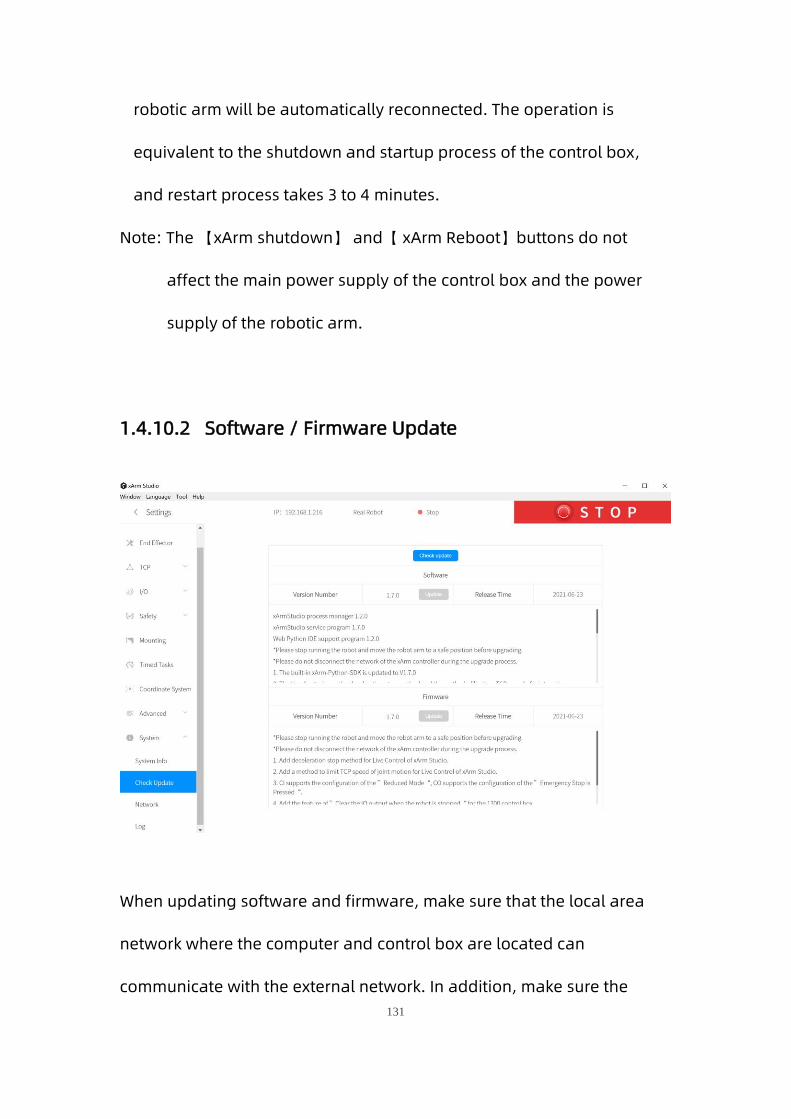
131
robotic arm will be automatically reconnected. The operation is
equivalent to the shutdown and startup process of the control box,
and restart process takes 3 to 4 minutes.
Note: The 【xArm shutdown】 and【 xArm Reboot】buttons do not
affect the main power supply of the control box and the power
supply of the robotic arm.
1.4.10.2 Software / Firmware Update
When updating software and firmware, make sure that the local area
network where the computer and control box are located can
communicate with the external network. In addition, make sure the

132
control box can communicate with external internet.
: Click this button to check whether the control box is
connected to the Internet.
Note:
Note: For detailed steps on updating xArm Studio and xArm firmware,
please refer to Appendix 4-xArm Software/Firmware Update Method.
1.4.10.3 Network Settings
The IP address, subnet mask, broadcast address, and default gateway
of the control box of the robotic arm are displayed on this page. You can

133
change the IP address of the control box and add DNS.
Note:
If you change the IP address, be sure to mark it on the control box. If you
forget or lose the modified IP address, you can use the following
method to reset the IP.
Reset IP
Steps to reset IP:
1. Press the emergency stop button and turn off the power of the control
box.
2. Connect RI0 to GND with a cable.
3. Turn on the power of the control box. After hearing the sound of
"beep", it means that the IP address of the control box has been reset
successfully. The reset IP is 192.168.1.111.
4. Please unplug the cable connecting RI0 and GND and wait for the
control box to start up (60 seconds).

134
5. Enter 192.168.1.111 in the xArm Studio search box, connect the
robotic arm.
6. If you need to modify the IP, just modify the IP in [Settings] → [System
Settings] → [Network Settings].(For example: the modified IP is
192.168.1.135)

135
7. Restart the control box, enter your modified IP in the xArm Studio
search box, and connect the robotic arm.

136
Note:
1. If you need to reset the IP, the xArm firmware version must be ≥
V1.5.0.
2. If you do not unplug the cable connecting RI0 and GND, the next time
you restart the control box, no matter what IP address you modify, the IP
address of the control box will be automatically changed to
192.168.1.111, so after modifying the IP, Be sure to unplug the cable
connecting RI0 and GND.
1.4.10.4 Log
The error log of the control box, servo error log and end effector error
log can be checked.
Click the 【Download】button to download the error log.

137
1.5 Live Control
1.5.1 Status Bar
The "unconnected robotic arm" indicates that the robotic arm is not
connected. Please reconnect the robotic arm on the homepage. If it is
not connected, please check if the robotic arm is normally turned on and
check if the network connection is normal.
The “Simulate Robot” indicates that the robotic arm is connected and
is currently in simulation mode. In this mode only, the joint motion of the
simulated robotic arm can be controlled by the live control panel.

138
The “Real Robot” indicates that the robotic arm is connected. It is
currently a real robotic arm, and all control functions on the live control
panel are available.
1.5.2 Emergency Stop
Click on the emergency stop button to immediately stop the current
motion and clear all cached commands.
Note:
The “STOP” button in xArm Studio is different from the one on the
control box.
1. The “STOP” button in xArm Studio allows the robotic arm to
stop the current motion and clear all cache commands
immediately. It is a software stop, and the power is still on.
2. The Emergency STOP button on the control box: Send out a stop
command to cut off the power supply of the robotic arm, and thence
the posture of the robotic arm will slightly brake and fall.

139
1.5.3 Real Robot/ Simulation Robot
【Real Robot】
It can control the motion of the real robotic arm in the interface of
xArm Studio, and the virtual robotic arm will reflect the position and
posture of the real robotic arm in real-time.
【Simulation Robot】
It can control the motion of the virtual robotic arm in the interface of
xArm Studio.
Note: A robotic arm can only be in one mode (Real Robot
Mode/Simulation Robot Mode).
【 】: It can reload the entire software control interface and refresh
the model posture.
1.5.4 Manual Mode
By turning on the Manual Mode, the joint can be driven freely by hand.
Turn on the joint manual mode, you can manually drag the robot
links to reach the target position, making it easier to record the robot's
motion trajectory, thereby reducing the development workload. When
danger occurs, you can also use the manual mode to manually drag
the robot away from the danger zone.
Drag sensitivity can be set in 【Settings】-【Motion Settings】-

140
【Teach sensitivity】.
Note:
1. Before opening the manual mode, you must ensure that the
installation method of the robotic arm and the payload setting of
the robotic arm are consistent with the actual situation, otherwise
it will be dangerous.
2. The serial number of robotic arm and the control box need to be
matched before Manual Mode can be turned on. The SN of the
control box can be checked in 【Settings】-【System
Information】.
3. The SN address of the robotic arm can be checked next to the
power signal interface of the base.
1.5.5 Joint Motion
The robotic arm consists of joint modules. The position of the end-
effector is controlled by coordinating the rotation angle of each joint.
The joint motion reaches the target point with the fastest path, the end
trajectory is not a straight line, and the speed unit is °/s. After the target
point is set, the corresponding poses are unique for TCP and the joints
along the trajectory.

141
You can copy the joint angle value of the robotic arm by clicking
this button.
The progress bar represents the range of joints, the text
represents the current joint and its degree.
Operation mode:
Click 【+】 or【-】 for the step angles, users can set the step angle in
【Settings】 -【Motion Settings】 -【Joint Motion】 -【Joint Step 】.
Press-and-hold【+】or【-】for continuous joint motion in a positive or
negative direction, which will stop when the mouse is released.
To confirm the direction of joint rotation, please refer the figure below:
xArm 5 xArm 6 xArm 7

142
1.5.6 Linear Motion
1.5.6.1 Introduction
Users can control the motion of the robotic arm based on the base
coordinate system and TCP coordinate system. The trajectory of tool
center point in the Cartesian space is a straight line. Each joint performs
a more complex movement to keep the tool in a straight path. The TCP
path is unique once the target point is confirmed, and the corresponding
posture in the execution process is random.
X, Y, and Z control the position of TCP in base or tool coordinate system,
in the unit of mm. While Roll/Pitch/Yaw controls the TCP orientation in
the unit of degree.
Linear motion and arc linear motion belong to the Cartesian space
trajectory planning, which needs to be solved by inverse kinematics.
Therefore, there may be no solution, multiple solutions, and
approximated solutions; and due to the nonlinear relationship between
the joint space and Cartesian space, the joint motion may exceed its
maximum speed and acceleration limits.

143
1.5.6.2 TCP Coordinate System
A: Base coordinate system B: Tool coordinate system
The default TCP coordinate system is defined at the centre point of the
end flange of the robotic arm, and it is the result of rotating [180°, 0°, 0°]
around the X/Y/Z-axis of the base coordinate system in order. The
spatial orientation of the TCP coordinate system changes according to
the changes of the joint angles.
Roll/Pitch/Yaw respectively rotates around X/Y/Z of the base
coordinate system, and the final TCP orientation is the result of the
three rotations in exact order. The robotic arm will always choose the
shortest way to reach target orientation. In particular, it is important
to strictly control the magnitude of the deflection angle between the
two points to control the direction of rotation, and if necessary, insert
a third point between the two points. As shown in figure 6.4, if a

144
deflection is needed from position point A to point B, the robotic arm
moves in the direction of α angle. If the robotic arm needs to be
moved in the direction of the β angle, a new position between the
angles of β should be inserted, and the angle that formed by the
inserted point and A should be smaller than α.
The +180° and -180°points of the Roll/Pitch/Yaw are coinciding in
the space, and the valid range is ±180°, so it is possible to have
both ±180° when the robotic arm is reporting the position.
Roll angle, pitch angle, and yaw angle (RPY). The RPY rotation
matrix (X, Y', Z" rotation) is determined by the following formula:
R rpy (γ, β, α) = R Z (α) · R Y (β) · R X (γ)

145
A: base coordinates B: TCP coordinates(if no offset)
1. You must check the TCP offset before recording
the Cartesian position.
1.5.7 Operation Mode
1.5.7.1 xArm 6 (xArm 7) Operation Interface

146
【 】
It can switch the control functions between the base coordinate
system and the tool coordinate system.
【Position/Attitude Real-time Display】
X / Y / Z represents the coordinates of the tool center point (TCP)
position of the robotic arm under the base coordinate offset.
Roll/Pitch/Yaw under the Attitude indicates the angle value rotated
under the base coordinate offset, which is a description of the azimuth
obtained by rotating three times around the selected coordinate
system in a certain order.
【Real-time Position Control】
X/Y/Z controls the X/Y/Z-axis of the selected coordinate system
respectively. Click for step motion and long press for continuous
motion.
【Real-time Attitude Control】
Roll/Pitch/Yaw controls the Roll/Pitch/Yaw of the selected coordinate

147
system respectively. Click for step motion and long press for
continuous motion.
The step can be set by clicking【Settings】 -【Motion Settings】 -【Line
Motion】 -【Attitude Step】 on the homepage.
Note: When the real-time control base coordinate system/tool
coordinate system is switched, if the coordinate system offset is not
[0,0,0,0,0,0], the "user coordinate system" will be displayed, as shown in
the figure below.
1.5.7.2 xArm 5 Operation Interface

148
【Aligning】
After clicking this button, the tool flange will be adjusted to a
horizontal attitude, that is, pitch and roll will be adjusted to the fixed
values of 0 ° and 180 °.
1.5.8 Zero Position, Initial Position
【ZERO POSITION】
Indicates all joint angles values are zero.
Long press the button of Zero Position to return the robotic arm to the
posture of Zero Position. This button blaks collision detection.
User can click【Settings】—【Motion Settings】—【Initial Position】on
the homepage to set the Initial Position.
Click【ZERO POSITION】【INITIAL POSITION】for step motion, long press
them for continuous motion.

149
If the end-effector is installed in the robotic arm, make
sure to assess whether the robotic arm will hit the
obstacles or the fixed surface of the robotic arm when
it returns to the zero pose.
The robotic arm should be back to the zero pose
before packaging.
1.5.9 Speed Setting
It is used to adjust the motion speed of the live control interface of xArm.
(Note that the maximum speed of the live control interface is not the
actual maximum motion speed of the robotic arm. If you want the
program to run at high speed, you can add a speed command in the
Blockly motion program).
Joint Operating Speed
The range is 1°/s ~ 180°/s. When the robotic arm is in operation, the
actual maximum speed will be influenced by the payload, speed, and
the pose, and the maximum speed would not be an absolutely
reachable value.
Note: the speed at which the joint runs between each command is not

150
continuous, and the robotic arm will have a brief pause between joint
command.
TCP Operating Speed
The Cartesian speed range is from 1mm/s to 1000mm/s. The actual
maximum speed is also affected by the payload, speed, and posture
of the robotic arm. If the set speed is close to the limit speed, the
robotic arm will slow down or cause an error mechanism. When a
command involves displacement and rotation, at the same time, the
time required for the displacement motion and the rotational motion
depends on the one that takes more time, but in principle, it is better
to separate the displacement from the rotation command.
1.6 Blockly Graphical Programming
Blockly is a graphical programming tool that can be programmed to
control the robotic arm by dragging and dropping code blocks without
the need to write the code manually.

151
1.6.1 Interface Overview
【 】Click to create a new folder.
【 】Can be converted to Python code and can be used in
the xArm-Python-SDK library.
【My Project— “xxx”】 Click to expand to display all created items, the
currently open item "xxx" is displayed when it folds.
【Import Project】 Click to import the Blockly project from the local drive.

152
【Download All】Click to download all projects.
【 】Click this button, and the 3D simulation model of the robotic
arm in the real-time control interface will pop up (as shown in the figure
below). When running the program, you can observe the motion posture
of the robotic arm in real time.
Note: When the robotic arm is in the simulation mode, you can also run
the Blockly motion program to observe the motion of the virtual robotic
arm.

153
1.6.2 Blockly Workspace
Drag the code block into the action panel, the code execution is top-
down, users can drag and drop the code block with the blocks attached
from behind together.
【 】Return to the default size and code block at centered position
【 】Zoom in on the code block.
【 】Zoom out on the code block.

154
1.6.2.1 The Right Click Mouse Event in the Workspace
Right-click on the blank workspace of the non-code block, the function is
mainly for all code blocks:
【Undo】: Undo the previous operation.
【Redo】: Restore the last undo operation.
【Collapse Blocks】: Collapse all code blocks.
【Expand Blocks】: Display all collapsed commands.
【Delete 30 Blocks】: Delete all code blocks.

155
1.6.2.2 The Right Click Mouse Event of the Code Block
Right-click in the code block, the function of each module pop up:
【Duplicate】: Copy all code blocks of the current workspace, copy/cut
shortcuts with the keyboard and paste them into other files.
【Add Comment】: Users can add a description to the code block, which
is identified by the symbol . Click to open/close the
description pop-up window, as shown in the following
figure.
【External input】: The location for setting the text box is displayed at
the far right.
【Internal Input】: The location for the setting of the text box to be
displayed in the default middle position.
【Collapse Block】: Folds the code block of the current workspace.

156
【Disable Block】: Stop the execution of the running command of the
current code block. The opposite is 【Enable Block】.
【Delete 82 Blocks】: Delete the current code block selected by the
mouse click.
【Help】: Jump to the Help Page of the corresponding code block.
1.6.2.3 Move/Wait/Edit
For some common functions of the motion commands, click【move】
and the robotic arm will move to the current position; click【edit】, Then
the robotic arm will move to the current position and open the live
control interface; Wait (true/false), indicating whether to wait for the
execution of a command before sending the next one.
1.6.3 Blockly Code Block
Setting: Used to set the running speed, acceleration, collision sensitivity,
load, etc. of the robotic arm.
Motion: Common motion commands including linear motion, joint
motion, linear motion with arc, sleep time, zero point, and
emergency stop.
Application: You can import Blockly other projects.
GPIO: External input signal triggered event (suitable for plc).

157
End-Effector: Contains common commands to control the end-effector,
such as gripper, vacuum gripper.
Logic: Contains commonly used logic commands.
Loop: Contains common loop commands such as multiple loops, infinite
loops, and breaking loops.
Math: Contains commands for mathematical operations.
Advanced: Includes location notes and message reminders.
1.6.4 Setting
【Set TCP speed()mm/s】
Set the speed of the linear motion in mm/s.
【Set TCP acceleration()mm/s²】

158
Set the acceleration of the linear motion in mm/s2.
【Set joint speed()°/s】
Set the speed of joint movement in °/s.
【Set joint acceleration()°/s²】
Set the acceleration of joint motion in °/s2.The default speed and
acceleration values in the code block are the speed and acceleration
values set currently, which can be modified manually.
【Set tcp load()weight()XYZ】
Set the load of the current project, refer Settings-TCP Payload from
the drop-down list.
【Set tcp offset()X Y Z R P Y】
Set the end offset of the current project, reference Settings-TCP Offset
from the drop-down list.
【Set world offset()X Y Z Roll Pitch Yaw】
Set the base coordinate offset of the current project. The drop-down
list refers to the data of the Setting-Base Coordinate Offset.
【Counter reset】
This command resets the counter in the control box to 0
【Counter plus】
Each time the command is run, the counter of the control box will be
incremented by 1. It can be used to calculate the number of times the

159
program actually cycles.
1.6.5 Motion
【sleep()s】
After receiving this command, the robotic arm will stop moving for the
set time, and then continue to execute the following commands. It is
mainly used in motion programs that need to do the continuous
motion. It is used to buffer more motion commands for successful
continuous motion calcutation.
【motion()】
With this command, operators can set the state of the robotic arm

160
(movement, pause, stop). It is used to control the state of the robotic
arm. It is mainly used in condition-triggered programs.
【emergency stop】
The robotic arm immediately stops moving and clears the command
cache.
【zero position】
The robotic arm returns to a posture where the joint value are 0.
【move joint J1() J2() J3 () J4() J5() J6() J7() Radius()
Wait(true/false) ,[move] , [edit]】
Set each joint value for the joint movement, with the unit of degree.
【move(arc) line X() Y()Z() Roll() Pitch() Yaw() Radius() Wait(true/false)
[move] [edit]】
Set the Cartesian coordinate target value of the linear motion and the
TCP rotation angle in mm and °.
【move (front/back/left/right) (true/false)() mm 】
Indicates that the robotic arm makes relative linear motion
forward/backward/left/right based on the current position, in mm
【move tool line X() Y()Z() Roll() Pitch() Yaw() Radius() Wait(true/false) 】
This command is a relative motion relative to TCP coordinates.
【move circle position 1 to position 2】
From current position, the whole circle is determined by current

161
position and position1 and positon2, “center angle” specifies how
much of the circle to execute.
【center angle (°) () 】
Indicates the degree of the circle. When it is set to 360, a whole circle
can be completed, and it can be greater than or less than 360; (Note:
To achieve smooth track motion, you need to set Wait = false).
【move joint [variable] J1() J2() J3 () J4() J5() J6() J7() Wait(true/false)】
The command passes through the joint motion and supports variable
values.
【move (arc) line [variable] X() Y() Z() Roll() Pitch() Yaw() Radius()
Wait(true/false) 】
The command passes through the Cartesian motion and supports
variable values.

162
1.6.6 GPIO(Control Box and End tool interface)
The IO interface is made up of a control box interface and an end tool
interface, which can be used to acquire, set, and monitor IO interface
operations. The control box has 8 digital input interfaces, 8 digital
output interfaces, 2 analog input interfaces, and 2 analog output
interfaces. The end tool has 2 digital input interfaces and 2 digital
output interfaces. 2 analog input interfaces. The control box digital IO is
low-level-triggered. The end tool digital IO is high-level-triggered.
【get I/O 】
Acquire the I/O interface data of the code block.
【set I/O 】

163
Set the I/O interface of the code block, click 【Set】 to run the
command.
【set I/O when(X, Y, Z, tolerance)】
When the robotic arm reaches the specified position (the area of the
sphere specified with the trigger position point (X, Y, Z) as the center
(the radius of the sphere is the tolerance radius)), IO is triggered. This
command can be used to trigger IO at a specific location.
X, Y, Z represent the coordinate value of the specified position to be
reached by the robot arm, with the unit of mm.
The digital IO is triggered as soon as the system detects that the TCP
position enters a spherical area centered at (X,Y,Z) with the specified
radius. If the tolerance radius is not set, when the robotic arm passes the
specified point at a speed other than 0, it may miss the trigger because it
cannot be accurately detected.
【when digital I/O is (High/Low) do 】
Executes the commands contained in this code block when the
condition is met.
【 when the analog IO value satisfies the set condition do】
When the monitored analog IO value meets the condition, the
commands contained in the code block will be executed, and the

164
condition are =, ≠, >, ≥, <, ≤.
IO trigger logic of xArm Studio:
1. xArm Studio obtains the IO state every 100ms, and uses the IO state
value obtained for the first time as the initial value.
2. Compare the IO state obtained the second time with the IO state
obtained last time. If the IO state changes, a callback meeting the
condition is triggered.
1.6.7 End Effector

165
【set xarm gripper Pos () Speed () Wait (true / false)[move][edit]】
Set the position and the opening and closing speed of the gripper.
【set bio gripper Speed () Wait (true / false)[move][edit]】
Set the opening and closing speed of the gripper.
【set robotiq gripper Pos () Speed () Wait (true / false)[move][edit]】
Set the position of robotiq gripper, opening and closing speed, and
the strength of the gripping object.
【initialize gripper】
Enable gripper.
【object is (picked/release) 】
Detect whether the vacuum gripper has picked (released) the object.
If it is detected that the vacuum gripper has picked (released) the
object, then jump out of this command and execute the next
command. If the timeout period is exceeded, the vacuum gripper has
not yet picked (released) the object, it will also jump out of the
command and execute the next command.
【get xarm vacuum gripper state】
Obtain whether the vacuum gripper picks the object or not. When the

166
vacuum gripper state is 1, it indicates that the object is picked
successfully; when the vacuum gripper state is 0, it indicates that the
object fails to be picked.
【set xarm vacuum gripper (ON/OFF) object detection (true/false) [set]】
Set the vacuum gripper to be on and off.
[object detection] = true: detect whether the object is picked, if not, it will
jump out of the entire program.
[object detection] = false: do not detect whether the object is picked.
1.6.8 Application
【Run Trajectory (path) Times [1] 】
Users can import the trajectory recording file and set the times of
executions.
【Import other APP】
Users can import Blockly of other projects.

167
1.6.9 Logic
【wait ()】
Wait for the next command to be sent, with the unit of seconds.
【if (Condition 1) Run (Command 1)】
If Condition 1 is true, then Command 1 will be run. Otherwise, it will
be skipped.
The setting method of the if/else sentence:
1. Click the setting button on the command block , then the
command block will pop up a selection box, as shown below:
2. At this point, drag the [else] code block to the bottom of the [if] code

168
block, and combine the two code blocks, as shown below:
3. Click the setting button , the selection box is retracted, if /else
sentence setting is completed, as shown below:
1.6.10 Loop
【forever】
The command contained in the loop will be executed in infinite loop.
【repeat() times do】
The command contained in the loop will be executed X times.
【repeat while/until do】

169
When the condition is not met, it jumps out of the loop.
【break】
Terminate the loop.
1.6.11 Math
You can use the above code block to do some complex operations such
as addition, subtraction, multiplication, and division, exponential
operations.

170
1.6.12 Text
【remark】
Remark the code block, which serves as an indicator and can change
the color.
【message type】
Types available are: (information/success/warning/error), duration
indicates the time interval the message is displayed, the unit is in
second; the message indicates the content of the prompt message.
【string printing[]】
Users can print the entered string below and set the font and the
color.

171
【variable printing】
Users can print the added variable and set the font and the color.
【Date】
The date and time on which the command was run can be output.
1.6.13 Variable
【Create variable】
New variables can be added. After adding a variable, there are three
commands by default (set the value of the variable, change the value
of the variable by adding or subtracting, variable).
【Rename variable】
Rename the variable.
【Delete variable】
Delete the variable.

172
1.6.14 Function
【to (do something)】
Users can define a new function without a return value.
【to (do something) return []】
Users can define a new function with a return value.
【if [] return []】
Conditional judgment sentence that can only be placed in the built-in
function.
Note:
1. The defined function should be placed in front of the main programs.

173
1.6.15 Set & Edit Motion Coordinates
Long press 【Move】 button to move the robotic arm to the position of
the current command.
Click 【edit】to pop up the live control interface to re-edit the motion
coordinates of the current command.

174
Click 【Save】to save the changes and close the pop-up window.
Click【Cancel】 to cancel the changes and close the pop-up window.
Note: In the command, there are sequential points such as A / B / C /
D. Etc. If the user clicks 【move】 to skip point B from point A to
point C, a safety assessment must be carried out to avoid damage
to peripheral facilities
Due to the complexity of Cartesian commands, Cartesian spatial
trajectory planning needs to be solved by inverse kinematics. Therefore,
there may be no solution, multiple solutions, approximate solutions.
When the solution of the Cartesian command from point A to point B is
not ideal, insert a third joint command between the two points if
necessary.

175
1.6.16 Path Planning Guidelines
If the robotic arm is collided during the movement,
resulting in stopping, the robotic arm will report an
error at this time, and the error must be cleared
before it can be used normally. Be sure to do a
safety assessment before moving again to prevent
collisions.
When the robotic arm is in certain positions, there
may be a situation where the linear motion is
unsolvable. At this time, the route needs to be re-
planned. For details, please refer to "xArm
Kinematics-Linear Motion".
1.7 Python IDE
Python IDE is a Python development integration environment that can
directly use xArm-Python-SDK API and check the Blockly projects
converted into Python code.

176
【 】Create a new project.
【 】Create a new file.
【 】Create a new folder.
【 】Rename.
【 】Delete the file.
【 】Run the file.
1.7.1 Create a New Project
On this page, all current project files are displayed, including Blockly
projects converted into Python code.
【 】Import projects.
【 】Export projects.

177
【 】
Display the current open project and the time it was created.
【 】Delete projects.
【Open】Open the projects and display them in the edit box.
Note: , The project folder is not
available, please create a new project by yourself.
Control Box Command Caching Mechanism:
The current control box can cache 2048 commands. If more than 2048
commands need to be sent, user have to control the cached number and
control the volume. When awaiting commands of the control box exceed
the maximum buffer amount (2048), a warning code will be returned.
The warning code is decimal 11, and the command will be discarded.
The commands issued should not exceed 256 command caches.
It is recommended to keep the number of cached/sent commands under
256 all the time.
1.8 Recording
The position of the joint is obtained and recorded by 250HZ to record the
motion trajectory of the robotic arm in free driving, and the maximum

178
recording time is 5 minutes. The playback will completely repeat the
motion trajectory during recording, and the playback speed of the
trajectory can be set (x1, x2, x4). A recorded trajectory can be imported
into Blockly projects.
【 】Pop-up live control panel.
【 】Create a new recording file.
【 】Manual Mode will be turned on accordingly by clicking on the
button, and the robotic arm can be dragged directly for
trajectory recording. When starting recording, be sure to pay
attention to the load state of the robotic arm, so as to avoid

179
the big difference between the actual load and the set load of
the robotic arm, resulting in its self-motion.
【 】Display recording time.
【 】Stop recording.
【Times】Set playback times.
【Speed】Set playback speed.
【 】Download the file.
【 】Delete the file.
【Import Project】Import recorded trajectory.
【Download All】Download all current files.

180
2. xArm Motion Analysis
In this section, we mainly use Python / Blockly examples to explain a few
typical motions in the list below.
Motion Joint
Motion
Linear
Motion
Arc linear
motion
Circular
Motion
xArm5
Motion
About Python-SDK:
For all interfaces with is_radian, the default value of is_radian is the
value at the time of instantiation.
That is, the value of “ is_radian” set when xArmAPI () is created.
Here are three examples to illustrate:
1. arm = xArmAPI('192.168.1.226',)
2. arm = xArmAPI('192.168.1.226', is_radian=False)
3. arm = xArmAPI('192.168.1.226', is_radian=True)
When the xArmAPI() interface is created in method 1, the default value of is_radian is False, the unit
is °;
When the xArmAPI() interface is created in method 2, is_radian = False, the unit is °;
When the xArmAPI() interface is created in method 3, is_radian = True, the unit is rad ;
About Blockly:

181
All units for angles use degrees (°).
2.1 Robotic Arm Motion Mode and State Analysis
2.1.1 The Motion Mode of the Robotic Arm
Motions of the robotic arm: joint motion, linear motion, linear circular
motion, circular motion, servoj motion and servo_cartesian motion.
The following motions are in position mode (Please refer to 【Robot
Movement & Status Analysis】):
Joint Motion: to achieve the point-to-point motion of joint space
(unit: degree/radian), the speed between each command is
discontinuous.
Linear Motion: to achieve linear motion between Cartesian
coordinates (unit: mm), the speed between each instruction is
discontinuous.
Arc Linear Motion: to achieve linear motion between Cartesian
coordinates (unit : mm), inserting an arc between two straight lines
for a smooth transition, and the speed between each command is
continuous.
Circular Motion: Circular motion calculates the trajectory of the

182
spatial circle according to the three-point coordinates, the three-
point coordinates are starting point, parameter 1 and parameter 2.
The following motion modes are in servoj mode:
Servoj motion: move to the given joint position with the fastest
speed (180°/s) and acceleration (unit: degree/radian). This
command has no buffer, only execute the latest received target
point, and the user needs to enter the servoj mode to use. In servoj
mode, the maximum receiving frequency of the control box is 250Hz
(the maximum receiving frequency of the version before 1.4.0 is
100Hz). If the frequency of sending commands exceeds 250Hz, the
redundant commands will be lost. The xArm-Python-SDK interface
function we provide also reserves the speed, acceleration and time
settings, but they will not work at present. The suggested way of
use: If you want to plan your track, you can use this command to
issue a smoothed track point with interpolation at a certain
frequency (preferably 100Hz or 200 Hz), similar to the position servo
control command. (Note: this execution is similar to the step
response, for safety considerations, do not give a distant target
position at once). Using this mode requires detailed position
planning for each axis and motion estimation of the robotic arm,
which is difficult to develop.

183
Servo_cartesian motion: move to the given cartesian position with
the fastest speed (1m/s) and acceleration (unit: mm). This command
has no buffer, only execute the latest received target point, and the
user needs to enter the servoj mode to use. In servoj mode, the
maximum receiving frequency of the control box is 250Hz (the
maximum receiving frequency of the version before 1.4.0 is 100Hz).
If the frequency of sending commands exceeds 250Hz, the
redundant commands will be lost. The xArm-Python-SDK interface
function we provide also reserves the speed, acceleration and time
settings, but they will not work at present. The suggested way of
use: If you want to plan your track, you can use this command to
issue a smoothed track point with interpolation at a certain
frequency (preferably 100Hz or 200 Hz), similar to the position servo
control command. (Note: this execution is similar to the step
response, for safety considerations, do not give a distant target
position at once). It is recommended that the frequency of user
issuing commands be controlled within the range of 30Hz-250Hz. If
the frequency is lower than 30Hz, the motion of the robotic arm may
be discontinuous. Using this mode requires planning the fine
position of each axis and predicting the motion behavior of the
robotic arm, which is difficult to develop.

184
Operators who design the robotic arm motion path
must be qualified with the following conditions:
1. The operator should have a strong sense of
security consciousness, and sufficient knowledge
on robotic arm operations.
2. The operator should have in-depth knowledge
on the robotic arm and understands the joint
motion mode and the linear motion mode.
3. The operator should have safety knowledge on
emergencies.
4. When planning the path for the robotic arm, the
risk assessment must be done and the operator
should be cautious.
2.1.2 Analysis of Robotic Arm Movement Mode
4 motion modes of the control box: (Python SDK: set_mode ())
Mode 0: Position control mode.
In this mode, the robotic arm can execute a series of motion
commands (joint motion, linear motion, circular motion, etc.)
automatically planned by the control box, which is also the
mode that the control box enters by default after startup.
Mode 1: Servoj mode.

185
In this mode, the robotic arm can accept joint position
commands sent at a fixed high frequency like 100Hz (Note: not
a Cartesian commands). The robotic arm responds
immediately after receiving each commands and executes at
the maximum speed. If the user can complete the planning of
the motion trajectory with smooth speed and acceleration and
map it to the joint space, the servoj mode can replace the
planning of the control box, and let xArm execute the user's
own or third-party (such as ROS Moveit!) planning algorithm.
Do not use this mode if users cannot implement trajectory
planning and inverse kinematics by themselves.
Mode 2: Joint teaching mode.
In this mode, the robotic arm will enter the zero gravity mode,
and the user can freely drag the links of the robotic arm to
complete the teaching function. If the drag teaching is
completed, switch back to mode 0.
*Note for safe use: Before turning on the joint teaching mode, be sure to
confirm that the installation direction of the robotic arm and the TCP
load are set correctly, otherwise the arm may not be able to remain
stationary due to inaccurate gravity compensation!*

186
Mode 4: Cartesian teaching mode,(not yet available).
2.1.3 Analysis of the Motion Status of the Robotic Arm
3 states that the control box can set: (Python SDK: set_state () )
State 0: Start motion.
Can be understood as ready for motion or stand-by. In this
state, the robotic arm can normally respond to and execute
motion commands. If the robotic arm recovers from an error,
power outage, or stop state (state 4), remember to set the
state to 0 before continuing to send motion commands.
Otherwise the commands sent will be discarded.
State 3: Paused state.
Pause the currently executing motion and resume the motion
at the interruption by setting state 0 again.
State 4: Stop state.
Terminates the current motion and clears the cached
subsequent commands. Need to set state 0 to continue the
motion.
4 states that the control box can get: (Python SDK: get_state ())

187
State 1: In motion.
The robotic arm is executing motion commands and is not
stationary.
State 2: Standby.
The control box is already in motion ready state, but no motion
commands are cached for execution.
State 3: Pausing.
The robotic arm is set to pause state, and the motion
commands buffer may not be empty.
State 4: Stopping.
This state is the state entered by default upon power-on.
Stop and on commands can be executed until state is set to 0.
State 5: System reset.
The user just enters the state after the mode switch or changes
some settings (such as TCP offset, sensitivity, etc.). The above
operations will terminate the ongoing movement of the robotic
arm and clear the cache commands, which is the same as the
STOP state.

188
2.2. Motion of the Robotic Arm
2.2.1. Joint Motion
To achieve point-to-point motion in joint space (unit: degree), the speed
is not continuous between each command.
Blockly example:
【Set joint speed() °/s】: Set the speed of joint movement in °/s.
【Set joint acceleration() °/s²】: Set the acceleration of joint motion
in °/s2.
【move joint J1() J2() J3 () J4() J5() J6() J7() ,Radius()】: Set each joint
angle for the joint movement, the unit is °.
【Wait (true / false)】: indicates whether to wait for the execution of this
command before sending the next command.
【Move】: The robotic arm will move to the current position.
【Edit】: Open the live control interface and adjust the coordinates of

189
the current point.
The motion trajectory of the robotic arm in the above example is as
follows:
Python example:
arm.set_servo_angle(angle=[0.0, 7.0, -71.2, 0.0, 0.0, 0.0], speed=8, mvacc=1145, wait=True)
arm.set_servo_angle(angle=[0.0, 7.0, -51.2, 0.0, 0.0, 0.0], speed=8, mvacc=1145, wait=True)
arm.set_servo_angle(angle=[0.0, 7.0, -91.2, 0.0, 0.0, 0.0], speed=8, mvacc=1145, wait=True)
The interface set_servo_angle is described in Table 2.1:
Table 2.1 Description of set_servo_angle
set_servo_angle
description set joint angle for joint motion
parameter
servo_id
joint ID, 1-7, None or 8 means all joints:
a) 1- (Number of axes) Joint number of the robotic arm
E.g. : arm.set_servo_angle (servo_id = 1, angle = 45, is_radian =
False)
b) None (8) represents all joints
E.g. : arm.set_servo_angle (angle = [30, -45, 0, 0, 0, 0, 0], is_radian =
False)
angle
angle Joint angle or list of joint angles (the unit of the default joint
angle is is_radian = False, degrees (°))
a) If servo_id is 1- (joint number)
E.g. : arm.set_servo_angle (servo_id = 1, angle = 45, is_radian =
False)

190
b) If servo_id is None or 8,
E.g. : arm.set_servo_angle (angle = [30,45,0,0,0,0,0], is_radian =
False)
speed
joint speed (the default unit is ° / s):
Unit: if is_radian = True, the unit is rad / s; if is_radian = False, the
unit is ° / s;
mvacc
joint acceleration (default unit is ° / s2)
Unit: if is_radian = True, the unit is rad / s2; if is_radian = False, the
unit is ° / s2;
is_radian
roll / pitch / yaw Whether it is measured in radian (default is_radian
= False)
If is_radian = True, the unit of roll / pitch / yaw is radian;
If is_radian = False, the unit of roll / pitch / yaw is degree (°);
wait
If wait = True, wait for the current commands to finish before
sending the next commands;
If wait = False, send the next commands directly;
mvtime 0,reserved;
Note:
1. If the joint angle is to be set in radian, then is_radian = True;
ex: code = arm.set_servo_angle (servo_id = 1, angle = 1.57, is_radian = True)
2. To wait for the robotic arm to complete the current commands before
returning, wait = True;
ex: code = arm.set_servo_angle (servo_id = 1, angle = 45, is_radian = False, wait
= True)
Continuous Joint Motion
Inserting an arc transition between two joint motion commands is a way to plan
the continuous joint motion of the robotic arm.

191
Blockly:
The motion trajectory of the robotic arm in the above example is as
follows:
Key parameter description
Radius = 60
Radius =60 in the "move joint" command refers to setting the radius of
the transition arc R = 60mm, which is used to achieve a smooth
transition of the arc in a joint motion.
The parameters of Radius can be set as Radius> 0, Radius = 0, Radius = -
1, different parameters correspond to different trajectories.

192
(1) Radius> 0. For example, setting Radius = 60, the turning trajectory is
as shown in the arc in the figure below, which can achieve a smooth
turning effect.
Note: The radius of the arc is smaller than DAB and DBC.
(2) Radius = 0. There is no arc transition at the turn, it will be a sharp turn
with no deceleration, as shown in the figure below.
(3) Radius <0. There is no arc transition at the turn, this speed will not be
continuous between this and next motion, as shown in the figure below,
speed will decelerate to 0 at point B before moving to C.
Note: Radius <0 cannot realize continuous motion. If you need to plan a
continuous motion of the robotic arm, please make sure Radius>0.
Wait = false

193
The wait in the "move joint" command indicates whether it is necessary
to wait for the execution of this command before sending the next
command.
Note: If you need to plan for speed continuous motion, make sure wait =
false, to buffer the commands to be blended.
2.2.2. Linear Motion and Arc Linear Motion
2.2.2.1. Linear Motion
Characteristics of Linear Motion
The concept of linear motion
• Straight linear motion between Cartesian coordinates (unit: mm),
the speed is not continuous between each command.
• Users can control the motion of the robotic arm based on the base
coordinate system and TCP coordinate system. The trajectory of
tool center point in the Cartesian space is a straight line. Each joint
performs a more complex movement to keep the tool in a straight
path. The TCP path is unique once the target point is confirmed,
and the corresponding posture in the execution process is
random. X, Y, and Z control the position of TCP in base or tool
coordinate system, in the unit of mm. While Roll/Pitch/Yaw

194
controls the TCP orientation in the unit of degree.
• Linear motion and circular linear motion belong to the Cartesian
space trajectory planning, which needs to be solved by inverse
kinematics. Therefore, there may be no solution, multiple
solutions, and approximated solutions; and due to the nonlinear
relationship between the joint space and Cartesian space, the
joint motion may exceed its maximum speed and acceleration
limits.
Blockly example:
【Set TCP speed()mm/s】: Set the speed of the linear motion in
mm/s.
【Set TCP acceleration()mm/s²】: Set the acceleration of the linear
motion in mm/s2.
【move(arc) line X() Y()Z() Roll() Pitch() Yaw() Radius() Wait(true/false)
【move】【edit】】: Indicates the Cartesian coordinate value of the
linear motion and the TCP rotation angle in mm and °.
Note: Cartesian motion is TCP straight-line motion.

195
Python example:
arm.set_tcp_jerk(2000)
arm.set_position(x=205.0, y=100.0, z=110.4, roll=180.0, pitch=0.5, yaw=0.0, speed=100, radius=-
1.0, wait=True)
arm.set_position(x=205.0, y=120.0, z=110.4, roll=180.0, pitch=0.5, yaw=0.0, speed=100, radius=-
1.0, wait=True)
arm.set_position(x=205.0, y=140.0, z=110.4, roll=180.0, pitch=0.5, yaw=0.0, speed=100, radius=-
1.0, wait=True)
arm.reset()
The interface set_position() is described in Table 2.2:
Table 2.2 set_position description
set_position
Description Sets the Cartesian coordinate value of the linear motion
Parameter
x coordinate x, (unit: mm)
y coordinate y, (unit: mm)
z coordinate z, (unit: mm)
roll
attitude roll(default unit is °):
Unit: if is_radian = True, the unit is rad; if is_radian = False, the unit
is °;
pitch
attitude pitch (default unit is °):
Unit: if is_radian = True, the unit is rad; if is_radian = False, the
unit is °;
yaw
attitude yaw (default unit is °):
Unit: if is_radian = True, the unit is rad; if is_radian = False, the
unit is °);
radius radius: if it is a linear motion, radius <0 / radius = None;

196
if it is arc linear motion(blended), radius> 0;
is_radian
if is_radian = True, the unit of roll / pitch / yaw is rad;
if is_radian = False, the unit of roll / pitch / yaw is °;
speed TCP motion speed (mm / s, rad / s);
mvacc TCP motion acceleration (mm / s2, rad / s2);
mvtime 0, reserved;
relative if relative = True, it is relative motion; if relative = True, it is not
relative motion;
wait
if wait = True, wait for the current commands to finish before
sending the next commands;
if wait = False, send the next commands directly;
Note: If it is xArm5, roll and pitch must be set to roll = ± 180 ° and pitch = 0 °.
2.2.2.2. Arc Linear Motion
Characteristics of Arc Linear Motion:
Arc linear motion (Lineb), inserting arc transitions between two straight
lines, is a way to plan the continuous movement of the robotic arm. The
following figure is a simple example of continuous motion using a
circular arc linear motion planning robotic arm.
Note: When the xArm firmware version≥1.6.0, if you need to plan Lineb
motion, you need to adjust the TCP speed below 200mm/s for
debugging, otherwise there will be a high security risk.
Blockly:

197
Key parameter description
Radius = 5
Radius = 5 in the "move (arc) line" command refers to setting the radius
of the transition arc between two straight lines R = 5mm, which is used
to achieve a smooth transition of the arc in a straight motion.
The parameters of Radius can be set as Radius> 0, Radius = 0, Radius = -
1, different parameters correspond to different trajectories.
(4) Radius> 0. For example, setting Radius = 5, the turning trajectory is as
shown in the black arc in the figure below, which can achieve a smooth
turning effect.
Note: The radius of the arc is smaller than DAB and DBC.
(5) Radius = 0. There is no arc transition at the turn, it will be a sharp turn

198
with no deceleration, as shown in the figure below.
Note: If the motion of the robotic arm is a reciprocating linear motion, you
need to set radius=0. If the radius>0, the robotic arm may report a motion
planning error.
(6) Radius <0. There is no arc transition at the turn, this speed will not be
continuous between this and next motion, as shown in the figure below,
speed will decelerate to 0 at point B before moving to C.
Note: Radius <0 cannot realize continuous motion. If you need to plan a
continuous movement of the robotic arm, please make sure Radius≥0.
Wait = false
The wait in the "move (arc) line" command indicates whether it is
necessary to wait for the execution of this command before sending the
next command.
Note: If you need to plan for speed continuous motion, make sure wait =
false, to buffer the commands to be blended.

199
Python example:
arm.reset(wait=True)
arm.set_pause_time(0.5)
while True:
arm.set_position(x=400, y=-100, z=250, roll=180, pitch=0, yaw=0, radius=50,speed=200,
wait=False)
arm.set_position(x=400, y=100, z=250, roll=180, pitch=0, yaw=0, radius=50,speed=200, wait=False)
arm.set_position(x=300, y=0, z=250, roll=-180, pitch=0, yaw=0, radius=50,speed=200, wait=False)
set_position interface: refer to Table 2.2.
The set_pause_time interface is described in Table 2.3:
Table 2.3 set_pause_time description
set_pause_time
Description Set the robotic arm pause time
Parameter
sltime pause time, unit: second (s);
wait whether to wait, default is False;
2.2.3. Circular and Arc Motion
The circular motion calculates the trajectory of the spatial circle
according to the coordinates of three points, which are (starting point,
pose 1, pose 2).
The calculation method of three-point drawing circle:
Use the current point as the starting point, and then set two position
points. Three points define a circle. Make sure these three points are not

200
in a common line.
Set the center angle:
1. If 0< center angle (°) <360 ° or center angle (°) > 360 °, the motion path
of the robotic arm is a circular arc of the corresponding degree;
center angle = 60°, the motion trajectory of the robotic arm is:
2. The center angle (°) = 360 °, the movement track of the robotic arm is a
complete circle;
3. If you want to draw multiple circles continuously(for example, draw
10 circles continuously), set center angles equal to 3600°;
Blockly example:
【move circle position 1 to position 2】: From current position, the whole

201
circle is determined by current position
and position1 and positon2, “center
angle” specifies how much of the
circle to execute.
Note: (1) The starting point, pose 1 and pose 2 determine the three reference points of a
complete circle. If the motion path of the robotic arm is a circular arc, then pose 1 and pose 2 are
not necessarily end points or passing points;
(2) If you want the robot arm to change its posture during the movement, set the roll, pitch, and
yaw of pose 2 to the desired posture when completing the trajectory;
【center angle (°) () 】: Indicates the degree of the circle. When it is set
to 360, a whole circle can be completed, and it can
be greater than or less than 360;
Note: To achieve smooth motion, you need to set Wait = false.
Example explanation:
In this example, the central angle is set to 3600°, which means that the
robotic arm can draw ten circles at a time, and the robotic arm still stays
at the starting point after drawing a circle.
Judgment of the direction of the robotic arm motion
In the above example, the starting point, pose 1 and pose 2 are:
A (300,0,400,180,0,0) B (350,50,400,180,0,0) C (350,-50,400,180,0,0)
The robotic arm draws a circle in a clockwise direction, and The
trajectory of the robotic arm is as follows:

202
If the positions of point B and C are swapped, point B is (350,-
50,400,180,0,0), point C is (350,50,400,180,0,0), the robotic arm will
draw a circle in a counterclockwise direction. The trajectory of the
robotic arm is as follows:
Python example:
arm.set_servo_angle(angle=[0.0, -45.0, 0.0, 0.0, -45.0, 0.0], speed=20, mvacc=500, wait=True)
arm.set_position(*[300.0, 0.0, 400.0, 0.0, -90.0, 180.0], speed=300, mvacc=2000, radius=-1.0,
wait=True)
move_circle([350.0, 50.0, 400.0, 180.0, -90.0, 0.0], [350.0, -50.0, 400.0, 180.0, -90.0, 0.0], 1000.0,
speed=300, mvacc=2000, wait=True)
set_servo_angle interface: see Table 2.1.
set_position interface: see Table 2.2.
The move_circle interface is described in Table 2.4:
Table 2.4 move_circle description
move_circle
Description This motion calculates the trajectory of a space circle based on three-point
coordinates. The three-point coordinates are (current starting point, pose 1,
pose 2)

203
Parameter
pose1 Cartesian coordinates
[x(mm), y(mm), z(mm), roll(rad or °), pitch(rad or °), yaw(rad or °)];
pose2 Cartesian coordinates
[x(mm), y(mm), z(mm), roll(rad or °), pitch(rad or °), yaw(rad or °)];
percent Percentage of arc moved
is_radian
If is_radian = True, the unit of roll / pitch / yaw is rad;
If is_radian = False, the unit of roll / pitch / yaw is °;
speed TCP motion speed (mm / s, rad / s);
mvacc TCP motion acceleration (mm / s2, rad / s2);
mvtime 0, reserved;
wait
If wait = True, wait for the current commands to be sent before
sending the next commands;
If wait = False, send the next commands directly;
2.3. xArm5 Motion Characteristics
Cartesian space
The movement of xArm5 is relatively special. Due to the structural
limitation, the actual flexible degrees of freedom of linear and
circular motions in Cartesian space is 4, which is [x, y, z, yaw],
similar to a SCARA manipulator with four degrees of freedom.
Before starting Cartesian control, it is necessary to ensure that the
end flange surface of xArm5 and the base are completely parallel.
If mounted on horizontal plane, the roll and pitch should be [± 180
degrees, 0 degrees], otherwise the trajectory is likely to have no

204
solution.
Joint space
In joint space, the robotic arm has 5 degrees of freedom to control
and can switch to joint commands when different orientations are
required at the end. Then use the joint command again to return
the flange and the base to a horizontal attitude, and you can switch
back to Cartesian control. A quick way to set a cartesian
controllable attitude is: Just set the angle of J4 equal to-(J2 angle +
J3 angle).
2.4. Singularity
1.Concept
Singularities occur when the axes of any two joints of a robotic arm
are on the same straight line. At the singularity point, the robot's
degrees of freedom will be degraded, which will cause the angular
velocity of some joints to be too fast, leading to loss of control. A
common situation is that when the wrist joint (the penultimate one)
is at or near the axis of the first joint, singularity point will also
appear (see Figure 2.1), so the robotic arm should try to avoid
passing directly the central area near the base, which is likely to

205
cause 1st Joint speed too high.
Figure 2.1 xArm6 singularity
2.Characteristics
The characteristic of the singularity is that the planning movement
cannot be performed correctly. Coordinate-based planned
movements cannot be explicitly translated into joint motions of
each axis. When the robot performs motion planning (linear,
circular, etc., excluding joint movements) near the singularity point,
it will stop to avoid high instantaneous speed of the joint when it
passes the singularity point. Therefore, try to avoid the singularity
point or pass the singularity point through joint motion.
3.Processing method for singularity point

206
Case 1: Singularity encountered during robot teaching
a) Switch the robot coordinate system to a joint coordinate
system, and pass the singularity point through joint
motion.
Case 2: Singularities encountered while the program is running
a) When encountering a singularity point while running the
program, you can modify the position and attitude of the
robot and re-plan the path to the target point.
Note:
It is important to consider the cylindrical volume directly above and
directly below the base of the robotic arm when a mounting place for
the robotic arm is chosen. Moving the wrist joint(second last joint) close
to the cylindrical volume should be avoided if possible, because it
causes the joints to move fast even though the robotic arm is moving
slowly, causing the robot to work ineffificiently and making it diffificult
to conduct a risk assessment.

207
3. Typical Examples
3.1. The Use of xArm Vacuum Gripper
The download address of the Blockly program:
The use of xArm vacuum gripper.blockly
The role of this program: execute this program to control the vacuum
gripper to suck the target object at the specified position, and then place
the target object at the target position.

208
Explanation of main commands:
【object is (picked/release) 】
Detect whether the vacuum gripper has picked (released) the object,
if it is detected that the vacuum gripper has picked (released) the
object, then jump out of this command and execute the next
command. If the timeout period is exceeded, the vacuum gripper has
not yet picked (released) the object, it will also jump out of the
command and execute the next command.
【set xarm vacuum gripper (ON/OFF) object detection (true/false)
[set]】:
Set the vacuum gripper to be on and off.
[object detection] = true: detect whether the object is sucked, if not, it
will jump out of the entire program.
[object detection] = false: do not detect whether the object is sucked.
3.2. The Use of xArm Gripper
The download address of the Blockly program:
The use of xArm gripper.blockly

209
The role of this program: execute this program to control the gripper to
grip the target object at the specified position, and then place the target
object at the target position.
3.3. The Use of the Digital IO
The download address of the Blockly program:
The use of the digital IO.blockly
The role of this program: If you need to use digital IO to control the
motion of the robotic arm, you can trigger the digital IO to perform the
corresponding motion.

210
Note:
2. The defined function should be placed in front of the main programs,
as shown in the figure above.
3.4. Cyclic Motion Count
The download address of the Blockly program: Cyclic Motion
Count.blockly
Counter counts:
Cyclic motion count: By adding 【Counter plus】, each time the
command is run, the counter of the Control Box will be incremented by
1. It can be used to calculate the number of times the program cycles.
【Counter reset】: This command resets the counter in the Control Box to

211
0.
Variable ++ i class count:
1. wait = true
When wait = true, the counting effect of the ++ i class and the counter
counting are consistent.
2. wait = false
When wait = false, the ++ i class count and the count counter are
inconsistent. Because wait = false, the commands will be sent
continuously until the control box buffer is full (According to the above
example, the number of cycles of the robotic arm is 10 times. When wait

212
= false, the ++ i class count will take into account all commands already
sent to the robotic arm, regardless of whether the robotic arm has
completed 10 cycles.), the counter count is a count made by the
firmware through position detection, and it is a count of the actual
number of cycles of the robotic arm.
Note: If the robotic arm needs to count the cyclic motion, it is
recommended to use the counter for counting.
Appendix
Appendix1-Error Reporting and Handling
1.1 Joints Error Message and Error Handling
Error processing method: Re-power on, the steps are as follows:
1. Turn the emergency stop button on the control box
2. Enable the robotic arm

213
xArm Studio enable method: Click the guide button of the error pop-
up window.
xArm-Python-SDK enable method: Refer to Error Handling Mode.
xArm-ROS-library: Users can view related documents at
https://github.com/xArm-Developer/xarm_ros
https://github.com/xArm-Developer/xarm_ros2
If the problem remains unsolved after power on/off for multiple
times, please contact UFACTORY team for support.
Software Error Code Error Handling
S0
Joint Communication Error
Please restart the xArm with the Emergency Stop Button on the Control
Box. If multiple reboots do not work, please contact technical support.
S10
Abnormal Current Detection
Please restart the xArm with the Emergency Stop Button on the xArm
Control Box.
S11 Joint Overcurrent
Please restart the xArm with the Emergency Stop Button on the xArm
Control Box. S12
Joint Overspeed
Please restart the xArm with the Emergency Stop Button on the xArm
Control Box.
S14
Position Command Overlimit
Please restart the xArm with the Emergency Stop Button on the xArm
Control Box.

214
S15
Joints Overheat
If the robot arm is running for a long time, please stop running and
restart the xArm after it cools down.
S16
Encoder Initialization Error
Please ensure that no external force pushes the robot arm to move when
it's powered on. Please restart the xArm with the Emergency Stop Button
on the Control Box.
S17
Single-turn Encoder Error
Please restart the xArm with the Emergency Stop Button on the Control
Box.
S18
Multi-turn Encoder Error
Please click "Clear Error", then push the power switch of the Control Box
to OFF, wait 5 seconds and then power on again.
S19 Low Battery Voltage
Please contact technical support.
S20 Driver IC Hardware Error
Please re-enable the robot.
S21
Driver IC Initialization Error
Please restart the xArm with the Emergency Stop Button on the xArm
Control Box.
S22
Encoder Configuration Error
Please contact technical support.
S23
Large Motor Position Deviation
Please check whether the xArm movement is blocked, whether the
payload exceeds the rated payload of xArm, and whether the
acceleration value is too large.
S26 Joint N Positive Overrun
Please check if the angle value of the joint N is too large.
S27
Joint N Negative Overrun
Please check if the angle value of the joint N is too large, if so, please
click Clear Error and manually unlock the joint and rotate the joint to the
allowed range of motion.
S28 Joint Commands Error
The xArm is not enabled, please click Enable Robot.
S33 Drive Overloaded
Please make sure the payload is within the rated load.

215
S34 Motor Overload
Please make sure the payload is within the rated load.
S35
Motor Type Error
Please restart the xArm with the Emergency Stop Button on the xArm
Control Box.
S36
Driver Type Error
Please restart the xArm with the Emergency Stop Button on the xArm
Control Box.
S39 Joint Overvoltage
Please reduce the acceleration value in the Motion Settings.
S40
Joint Undervoltage
Please reduce the acceleration value in the Motion Settings.
Please check if the control box emergency stop switch is released.
S49
EEPROM Read and Write Error
Please restart the xArm with the Emergency Stop Button on the xArm
Control Box.
S52
Initialization of Motor Angle Error
Please restart the xArm with the Emergency Stop Button on the xArm
Control Box.
For alarm codes that are not listed in the above table: Power on again. If the problem remains
unsolved after power on/off for multiple times, please contact technical support.
1.2 Control Box Error Code and Error Handling
1.2.1 Control Box Error Code
If there is an error in the hardware of the robotic arm/the software of the
Control Box/in sending commands, an error or warning will be issued.
This error/warning signal will be fed back when the user sends any

216
command; that is, the feedback is passive and not actively reported.
After the above error occurs, the robotic arm will stop working
immediately and discard the Control Box cache command. Users need to
clear these errors manually to allow normal operation. Please re-adjust
the motion planning of the robotic arm according to the reported error
message.
Software Error
Code
Error Handling
C1
The Emergency Stop Button on the Control Box is Pushed in to Stop
please release the Emergency Stop Button, and then click "Enable Robot"
C2 The Emergency IO of the Control Box is triggered
Please ground the 2 EIs of the Control Box, and then click "Enable Robot".
C3
The Emergency Stop Button of the Three-state Switch is pressed
Please release the Emergency Stop Button of the Three-state Switch, and
then click "Enable Robot".
C11-C17 Power on again.
C19
Gripper Communication Error
Please check if the Gripper is installed or the baud rate setting is correct, or
restart the xArm with the Emergency Stop Button on the xArm Control Box.
C21 Kinematic Error
Please re-plan the path.
C22
Self-collision Error, Please Re-plan the Path.
If the robotic arm continues to report self-collision errors, please go to the
"live control" interface to turn on the "manual mode" and drag the robotic
arm back to the normal position.
C23
Joints Angle Exceed Limit
Please go to the "Live Control" page and press the "ZERO POSITION" button
to let the robot back to the zero position.
C24
Speed Exceeds Limit
Please check if the xArm is at singularity point, or reduce the speed and
acceleration values.

217
C25
Planning Error
Please re-plan the path or reduce the speed.
C26
Linux RT Error
Please contact technical support.
C27
Command Reply Error
Please retry, or restart the xArm with the Emergency Stop Button on the
Control Box. If multiple reboots are not working, please contact technical
support.
C28
End Module Communication Error
Please restart the xArm with the Emergency Stop Button on the xArm Control
Box.
C29
Other Errors
Please contact technical support.
C30 Feedback Speed Exceeds Limit
Please contact technical support.
C31
Abnormal current in the robotic arm
1. Check whether the robotic arm collides.
2. Check whether the mass and center of mass set at "Settings"-"TCP
Settings"-"TCP Payload" match the actual payload.
3. Check whether the mounting direction set at "Settings"-"Mounting"
matches the actual situation.
4. Check whether the TCP payload parameters set in your program match the
actual payload.
5. Reduce the motion speed of the robotic arm.
6. Go to "Settings"-"Motion"-"Sensitivity Settings" to lower the collision
sensitivity.
C32
Three-point Drawing Circle Calculation Error
please reset the arc command.
C33
Controller IO Error
If the error occurs repeatedly, please contact technical support.
C34
Recording Timeout
The track recording duration exceeds the maximum duration limit of 5
minutes. It is recommended to re-record.
C35 Safety Boundary Limit
The xArm reaches the safety boundary. Please let the xArm work within the

218
safety boundary.
C36
The number of delay commands exceeds the limit
1. Please check whether there are too many position detection or IO delay
commands.
2. Increase the tolerance of the position detection command.
C37
Abnormal Motion in Manual Mode
Please check whether the TCP payload setting of the robotic arm and the
installation method of the robotic arm match the actual settings.
C38
Abnormal Joint Angle
Please stop the xArm by pressing the Emergency Stop Button on the Control
Box.
C39 Control Box Power Board Master and Slave IC Communication Error
Please contact technical support.
C110 Robot Arm Base Board Communication Error.
Please contact technical support.
C111 Control Box External 485 Device Communication Error
Please contact technical support.
For alarm codes that are not listed in the above table: Power on again. If the problem remains
unsolved after power on/off for multiple times, please contact technical support.
1.2.2 Control Box Error Code
The error does not affect the normal operation of the robotic arm, but it
may affect the user's program operation. Once the warning occurs, the
arm will set the warning flag and return it together in the command
reply. Otherwise, no other operations will be performed. The robotic arm
will still operate normally.
Error code Description Error Handling
11 Buffer overflow Control the volume of command
cache

219
12 Command parameter abnormal Check sent command
13 Unknown Command Check sent command
14 Command no solution Check sent command
1.3 Gripper Error Code & Error Handling
The user can re-power on the robotic arm as an error handling, the
steps are as follows (all the following steps are needed):
1. Re-powering the robotic arm via the emergency stop button on the
control box.
2. Enable the robotic arm.
a. xArm Studio enable method: Click the guide button of the error
pop-up window or the ‘STOP’ red button in the upper right corner.
b. xArm-Python-SDK enable method: Refer to Error Handling
Method.
c. xArm_ROS library:
ROS https://github.com/xArm-Developer/xarm_ros
ROS2 https://github.com/xArm-Developer/xarm_ros2
3. Re-enable the gripper.

220
If the problem remains unsolved after power on/off multiple times,
please contact UFACTORY team for support.
Software Error Code Error Handling
G9
Gripper Current Detection Error
Please restart the xArm with the Emergency Stop Button on the xArm
Control Box.
G11 Gripper Current Overlimit
Please click “OK” to re-enable the Gripper.
G12 Gripper Speed Overlimit
Please click “OK” to re-enable the Gripper.
G14 Gripper Position Command Overlimit
Please click “OK” to re-enable the Gripper.
G15 Gripper EEPROM Read and Write Error
Please click “OK” to re-enable the Gripper.
G20 Gripper Driver IC Hardware Error
Please click “OK” to re-enable the Gripper.
G21 Gripper Driver IC Initialization Error
Please click “OK” to re-enable the Gripper.
G23
Gripper Large Motor Position Deviation
Please check if the movement of the Gripper is blocked, if not, please
click “OK” to re-enable the Gripper.
G25 Gripper Command Over Software Limit
Please check if the gripper command is set beyond the software limit.
G26 Gripper Feedback Position Software Limit
Please contact technical support.
G33 Gripper Drive Overloaded
Please contact technical support.
G34 Gripper Motor Overload
Please contact technical support.
G36 Gripper Driver Type Error
Please click “OK” to re-enable the Gripper.

221
For alarm codes that are not listed in the above table: enable the robotic arm and gripper. If
the problem remains unsolved after power on/off for multiple times, please contact technical
support.
1.4 Python SDK Error Code & Error Handling
Software Error Code Error Handling
A-9 Emergency Stop
A-8 The TCP position command is out of the robot arm's motion range.
Please adjust the TCP position command.
A-2 xArm is not ready.
Please check whether the robot is enabled and the state is set correctly.
A-1 xArm is disconnect or not connect.
Please check the network.
A1 There are errors that have not been cleared.
Please clear the errors and try again.
A2 There are warnings that have not been cleared.
Please clear the warnings and try again.
A3 Get response timeout.
Please check the firmware version and the network.
A4 TCP reply length error.
Please check the network.
A5 TCP reply number error.
Please check the network.
A6 TCP protocol flag error.
Please check the network.
A7 The TCP reply command does not match the sending command.
Please check the network.
A8 Send command error.
Please check the network.
A9
xArm is not ready.
Please check whether the errors have been cleared, whether the robot
arm has been enabled, and whether the robot arm status is set correctly.

222
A11 Other error.
Please contact technical support.
A12 Parameter error.
A20 Tool IO ID error.
A22 The end tool Modbus baud rate is incorrect.
A23 The end tool Modbus reply length error.
A31 Trajectory read/write failed.
A32 Trajectory read/write timeout.
A33 Playback trajectory timeout.
A41 Vacuum gripper wait timeout.
A100 Waiting for completion timeout.
A101 Too many failures to detect the status of the end effector.
A102 There are errors in the end effector
A103 The end effector is not enabled
For alarm codes that are not listed in the above table: enable the robotic arm and gripper. If
the problem remains unsolved after power on/off for multiple times, please contact technical
support.
xArm-Python-SDK Error Handling:
When designing the robotic arm motion path with the Python library, if
the robotic arm error (see Appendix for Alarm information) occurs, then
it needs to be cleared manually. After clearing the error, the robotic arm
should be motion enabled.
Python library error clearing steps: (Please check GitHub for details on
the following interfaces)
a. error clearing: clean_error()
b. Re-enable the robotic arm: motion_enable(true)
c. Set the motion state: set_state(0)

223
Appendix2-Technical Specifications
1.1 xArm5/6/7 Common Specifications
xArm
Cartesian Range
X ±700mm
Y ±700mm
Z -400mm~951.5mm
Roll/Yaw/Pitch ± 180°
Maximum Joint Speed 180°/s
Reach 700mm
Repeatability ±0.1mm
Max Speed of End-effector 1m/s
*Ambient Temperature Range 0-50 °C*
Power Consumption Min 8.4 W, Typical 200W, Max 500W
Input Power Supply 24 V DC, 16.5 A
ISO Class Cleanroom 5
Robotic Arm Mounting Any
Programming xArm Studio/Python/C++/ROS
Robotic Arm Communication Protocol Modbus-TCP
End-effector I/O Interface
2 Digital inputs, 2 Digital outputs,
2 Analog inputs
End-effector Communication Protocol Modbus-RTU
Footprint Ø 126 mm
Materials Aluminium, Carbon Fiber
End Tool Flange DIN ISO 9409-1-A50/63(M5*6)
Control Box
AC Control Box DC Control Box
Input 100-240VAC 50/60Hz 24VDC
Output 24VDC 20.8A 24VDC 16.5A
Control Box Communication Protocol Modbus TCP
Control Box Communication Model Ethernet
Control Box I/O Interface 8*CI+8*DI(Digital In)
8*CO+8*DO(Digital Out)
8*CI(Digital In)
8*CO(Digital Out)

224
2*AI(Analog In)
2*AO(Analog Out)
1*RS-485 Master
1*RS-485 Slave
2*AI(Analog In)
2*AO(Analog Out)
Weight 3.9kg 1.6kg
Dimension(L*W*H) 285*135*101mm 180*145*68mm
xArm accessories parameters:
Gripper
Nominal Supply Voltage 24V DC
Absolute Maximum Supply Voltage 28V DC
Quiescent Power (Minimum Power
Consumption)
1.5W
Peak Current 1.5A
Working Range 84mm
Maximum Clamping Force 30N
Weight (g) 802g
Communication Mode RS-485
Communication Protocol Modbus RTU
Programmable Gripping Parameters Position, Speed
Feedback Position
Vacuum Gripper
Rated Supply Voltage 24V DC
Absolute Maximum Supply Voltage 28V DC
Quiescent Current(mA) 30mA
Peak Current(mA) 400mA
Vacuum 78%
Vacuum Flow (L/min) > 5.6L/min
Weight (g) 610 g
Dimensions (L*W*H) 122.5 * 91.6 * 75mm
Payload (kg) ≤5kg
Noise Level (30cm away) < 60dB
Communication Mode Digital IO
State Indicator Power, Working State
Feedback Air Pressure (Low or Normal)
Notes:
1. The ambient temperature of xArm is 0-50 °C, please reduce the temperature if continuous
high-speed operation is needed.

225
1.2 xArm 5 Specifications
Joint Range
1,5 ±360°
2 -118°~120°
3 -225°~11°
4 -97°~180°
Payload 3kg
Degrees of Freedom 5
Weight(robotic arm only) 11.2kg
Robot Joints
Robot Zero Attitude
Joint Rotating Direction
1.3 xArm 6 Specifications
Joint Range 1,4,6 ±360°
2 -118°~120°

226
3 -225°~11°
5 -97°~180°
Payload 5kg
Degrees of Freedom 6
Repeatability ±0.1mm
Weight(robotic arm only) 12.2kg
Robot Joints
Robot Zero Attitude
Joint Rotating Direction
1.4 xArm 7 Specifications
Joint Range
1,3,5,7 ±360°
2 -118°~120°
4 -11°~225°
6 -97°~180°
Payload 3.5kg
Degrees of Freedom 7

227
Weight(robotic arm only) 13.7kg
Robot Joints
Robot Zero Attitude
Joint Rotating Direction

228
Appendix3-FAQ
1. Guide for xArm Studio displaying “Sever is not ready”
2. Guide to use the Vacuum Gripper
3. Guide to download the log file on the xArm Studio
4. Solve the problem that all joints of the xArm are at '0' in the gazebo
5. The Method of the IP Configuration
6. How to use PLC to control xArm
7. Guide to control xArm by tablet
8. Kinematic and Dynamic Parameters of xArm Series
9. The Proper Way to Power DC Control Box
10. How to get the joint current/torque data of the xArm robot
11. Guide to Update the xArm Studio and xArm Firmware
12. What should I do if I have a problem with xArm?
13. Guide to install the xArm Camera Module
14. Guide to use the Robotiq Gripper on xArm
15. Guide to run xArm at the maximum speed

229
Appendix4-The xArm Software/Firmware
Update Method.
There are five ways of network settings for the robotic arm, you can
choose the corresponding update method according to the different
methods of the robotic arm network setting.
Notes
1) It is recommended to update the xArm firmware and xArm Studio at
the same time.
2) After updating, please download the latest "xArm User Manual" and
"xArm Developer Manual" from the official website to learn about the
latest features of xArm.
The download link: https://store-ufactory-
cc.myshopify.com/pages/download-xarm
3) Although the compatibility with the old version of the SDK was fully
considered when developing the xArm software, we still recommend:
If you use xArm-Python-SDK (xArm-C++ SDK or xArm ROS), after

230
updating the xArm to the latest firmware, you need to obtain the latest
xArm-Python-SDK (xArm-C++ SDK or xArm ROS) from GitHub.
The download link: https://github.com/xArm-Developer
1. When you use the following network setting methods, please
use xarm-tool-gui tool to update xArm Studio and xArm firmware
online.
The control box is directly connected to the PC(The PC is connected to the Internet)
The method for the online update using the xarm-tool-gui tool is as
follows:
1) Tool download
Download address of xarm-tool-gui tool, xArm Studio and xArm
Firmware installation package:
xArm-Tool-GUI
Since your PC connected to the xArm control box can access the Internet,

231
you can directly download the above installation package to your PC.
2) After decompressing the installation package, run the xarm-tool-gui
program that matches your PC's operating system, select the type of
robotic arm, and enter the IP address of the xArm control box, then click
"Connect".
3) After successful connection, click the [Check Update] button, then click
the [Install Online] in the Firmware installation box (xArm Studio
installation box), and finally click the [Install] button in the pop-up box;

232
4) After the installation is completed, the console of the xarm-tool-gui
will display "Install firmware success" (or "Install Studio success").
Finally, click "Reboot Control Box" and wait for the control box to reboot,
the reboot usually takes about 2-3 minutes.

233
2. When you use the following network setting methods, please
use xarm-tool-gui tool to update xArm Studio and xArm firmware
offline.
The control box is directly connected to the PC(The PC is not connected to the Internet)

234
The offline update method using the xarm-tool-gui tool is as follows:
Tool download
Download address of xarm-tool-gui tool, xArm Studio, and xArm
Firmware installation package:
xArm-Tool-GUI
Since your PC connected to the xArm control box cannot access the
Internet, please download the above installation package using a USB
drive, copy it to the PC connected to the xArm control box.
After decompressing the installation package, run the xarm-tool-gui
program that matches your PC's operating system, select the type of
robotic arm, and enter the IP address of the xArm control box, then click
"Connect".
After successful connection, click the [Install Offline] in the Firmware
installation box (xArmStudio installation box), then load the
corresponding "firmware" or "xArm Studio" compressed package in the

235
folder.
Click the [Install] button.
After the installation is completed, the console of the xarm-tool-gui will
display "Install firmware success" (or "Install Studio success"). Finally,
click "Reboot Control Box" and wait for the control box to reboot, the
reboot usually takes about 2-3 minutes.
3. When you use the following network setting methods, please use
xArm Studio to update the xArm Studio and xArm firmware online.
The method of online update using xArm Studio is as follows:

236
(1)The control box, PC and router are connected by ethernet cable
The control box, PC and network switch are connected by ethernet cable

237
(3)PC and router are connected by wireless network, and control box and router are connected by ethernet
Cable.
Click [Settings] on the xArm Studio homepage, enter [System Settings] →
[Check Update], click "Update".
Wait for the system to prompt to restart, and then click "Restart", the
restart usually takes about 2-3 minutes, please be patient.

238
4. Precautions
If there is no IO module on the side of your control box (the IO module is
shown in the figure below) and cannot be updated online by xArm
Studio, please contact technical support ([email protected]) to
provide a dedicated xarm-tool-gui installation package.
Appendix5- Maintenance and Inspection
1. Long-term placement
If the robotic arm is not used for a long time (≥6 months), you need to
power on the robotic arm for 6 hours every 6 months to charge the built-
in battery of the robotic arm.
When powering on the robotic arm, please release the emergency stop
button on the control box, and the robotic arm does not need to be
enabled.

239
2.Clean
After the robotic arm is used for a long time, there may be dirt or grease
on the carbon fiber shell (in rare cases, a small amount of grease can be
seen at the joints, which will not affect the normal use or life of the
joints). You can use 95% alcohol or 70% isopropanol to wipe the carbon
fiber surface for cleaning.
Note:
When cleaning the carbon fiber surface, be careful not to let the liquid
penetrate the joints.
Appendix6- Repair
1. Repair work must only be done by UFACTORY.
After repair work, checks must be done to ensure the required safety
level. Checks
must adhere to valid national or regional work safety regulations. The
correct functioning of all safety functions shall also be tested.
2. After-sales policy:
For the detailed after-sales policy of the product, see the official
website:
https://store-ufactory-cc.myshopify.com/pages/warranty-returns

240
3. The general process of after-sales service is:
(1) Contact UFACTORY technical support ([email protected]) to
confirm whether the product needs to repair and which part should be
sent back to UFACTORY.
(2) After the bill of lading on UPS, we will send the invoice and label to
you by mail. You need to make an appointment with the local UPS and
then send the product to us.
(3) UFACTORY will check the product warranty status according to the
after-sales policy.
(4) Generally, the process takes around 1-2 weeks except for shipment.
Note:
1. Please keep the original packaging materials of the product. When
you need to send the product back to get repaired, please pack the
product with the original box to protect the product during the
transportation.
2. If you need to send the control box to get repaired, please export and
save the configuration file of the robotic arm to prevent the original data
from being lost or changed during the repair process (Please refer to the

241
section 1.4.9.2 Advanced Tool-Configuration File).
Appendix7-Product Information
1.1 Product Mark
Robotic Arm
Control Box

242
1.2 Applied Standards
The xArm 6 robot is certified and tested by SGS, and has passed the EU
CE certification. The product meets the relevant requirements of the EU
CE directive:
• MD 2006/42/EC
• EMC 2004/108/EC
• EN ISO 10218-1:2011
• EN 60204-1:2018
• EN ISO 12100:2010
• EN 61000-6-2:2005
• EN 61000-6-4:2007+A1:2011
1.3 EMC
• IEC 61000-6-2:2005
• IEC 61000-6-4/A1:2010
• EN 61000-6-2:2005 [2004/108/EC]
• EN 61000-6-4/A1:2011 [2004/108/EC]
Electromagnetic compatibility (EMC)
Part 6-2: Generic standards - Immunity for industrial environments
Part 6-4: Generic standards - Emission standard for industrial
environments
These standards define requirements for the electrical and
electromagnetic disturbances. Conforming to these standards ensures
that the xArm robots perform well in industrial environments and that
they do not disturb other equipment.

243
• EN 61000-6-4:2019
• EN 61000-6-2:2019
Electrical equipment for measurement, control and laboratory use - EMC
requirements
Part 3-1: Immunity requirements for safety-related systems and for
equipment intended to perform safety-related functions (functional
safety) - General industrial applications.
This standard defines extended EMC immunity requirements for safety-
related functions. Conforming to this standard ensures that the safety
functions of xArm robots provide safety even if other equipment exceeds
the EMC emission limits defined in the IEC 61000 standards.
1.4 Use Environment
• Low humidity (25%-85% non-condensing)
• Altitude: <2000m
• Ambient temperature: 0°C ~ 50°C
• Avoid direct sunlight (indoor use)
• No corrosive gas or liquid.
• No flammable materials.
• No oil mists.
• No salt sprays.
• No dust or metal powder.
• No mechanical shock, vibration.
• No electromagnetic noise.
• No radioactive materials.

244
1.5 Transport, Storage and Handling
• Move the robot to the zero position by xArm Studio, then put the
xArm robot and Control Box in the original packaging.
• Transport the robot in the original packaging.
• Lift both tubes of the robot arm at the same time when moving it
from the packaging to the installation place. Hold the robot in
place until all mounting bolts are securely tightened at the base
of the robot.
• The controller box shall be lifted by the handle.
• Save the packaging material in a dry place, you may need to pack
down and move the robot in the future.
1.6 Power box placement height
The control box should be placed at a height of 0.6m to 1.5m
1.7 Power Connection
The power cut-off method of this product is a plug/socket connection, so
when using this product, it is recommended to equip with a suitable
switching device with sufficient breaking capacity (such as an air switch;
insulation voltage: 400V AC; rated current: 10A)

245
1.8 Special Consumables.
Fuse specifications:15A 250V 5×20mm Time-Lag glass body cartridge
fuse
1.9 Stop Categories
A Stop Category 1 and a Stop Category 2 decelerates the robot with
drive power on, which enables the robot to stop without deviating from
its current path.
Safety Input Description
Emergency Stop Button of the Control Box Performs a Stop Category 1
Emergency Input of the Control Box Performs a Stop Category 1.
Emergency Stop Button of the Three-Position Enabling
Device
Performs a Stop Category 1.
Three-Position Enabling Device Performs a Stop Category 2.
Safeguard Stop by CI of Control Box Performs a Stop Category 2.
1.10 Stopping Time and Stopping Distance
Stop Category 1 stopping distances and times.
The table below includes the stopping distances and times measured
when a Stop Category 1 is triggered. These measurements correspond to
the following configuration of the robot:
• Extension: 100% (the robot arm is fully extended horizontally).

246
• Speed: 100% (the general speed of the robot is set to 100% and
the movement is performed at a joint speed of 180 °/s).
• Payload: maximum payload handled by the robot attached to the
TCP (5 kg).
The test on the Joint 1 was carried out by performing a horizontal
movement, the axis of rotation was perpendicular to the ground.
During the tests for Joint 2 and 3 the robot followed a vertical trajectory,
i.e. the axes of rotation were parallel to the ground, and the stop was
performed while the robot was moving downwards.
Stopping Distance (rad) Stopping time (ms)
Joint 1 0.62 521
Joint 2 1.12 885
Joint 3 0.67 577
1.11 Maximum Speed
Mode Typical Scenarios Maximum Speed
Teaching mode Live Control Page of xArm Studio 250 mm/s
Automatic mode Blockly/ IDE of xArm Studio 1000 mm/s
1.12 Maximum Payload
The maximum allowed payload of the robot arm depends on the center
of gravity offset. The center of gravity offset is defined as the distance

247
between the center of the tool output flange and the center of gravity.
1.13 Specifications
Robotic Arm Model XI1300
Joint Range
1,4,6 ±360°
2 -118°~120°
3 -225°~11°
5 -97°~180°
Payload 5kg
Maximum Reach 700mm
Degrees of Freedom 6
Repeatability ±0.1mm
Maximum Joint Speed 180°/s
Weight (robotic arm only) 12.2kg
Footprint Ø 126 mm
Maximum Power 500W

248
Rated Voltage 24VDC
Control Box Model AC1300
Size 285*135*101mm
I/O Ports 8*CI 8*DI 8*CO 8*DO 2*AI 2*AO 2*RS-485
Communication Protocol Modbus TCP
Weight 3.9kg
Operating Temperature 0-50ºC
Humidity 25%-85% (non-condensing)
Short Circuit Rating 50A
Input 1PHASE AC 100-240V 47~63HZ 550Wmax
Manufacturer:UFactory Technology Co.,Ltd
Address: 2F, Building M-6, Ma Que Ling Industrial Zone, Nanshan District, Shenzhen,
Guangdong, China
Website: www.ufactory.cc