
X-431 ADAS PRO Calibration Tool Operation Guideline
186
PREFACE X-431 ADAS PRO CALIBRATION APPROACH HOW TO CALIBRATE ABOUT ADAS X-431 ADAS PRO Calibration Tool Operation Guideline II www.cnlaunch.com +86 755 8455 7891 Copyright Information Copyright © 2019 by LAUNCH TECH. CO., LTD. All rights reserved. No part of this publication may be reproduced, stored in a retrieval system, or transmitted in any form or by any means, electronic, mechanical, photocopying, recording or otherwise, without the prior written permission of LAUNCH. Neither LAUNCH nor its affiliates shall be liable to the purchaser of this unit or third parties for damages, losses, costs, or expenses incurred by purchaser or third parties as a result of: Accident, misuse, or abuse of this unit, or unauthorized modifications, repairs, or alterations to this unit, or failure to strictly comply with LAUNCH operating and maintenance instructions. LAUNCH shall not be liable for any damages or problems arising from the use of any options or any consumable products other than those designated as Original LAUNCH Products or LAUNCH Approved Products by LAUNCH. All information, specifications and illustrations in this manual are based on the latest information available at the time of printing. LAUNCH reserves the right to make changes at any time without prior written or oral notice. Trademark Information LAUNCH is a registered trademark of LAUNCH TECH CO., LTD. (LAUNCH) in China and other countries. All other LAUNCH trademarks, service marks, domain names, logos, and company names referred to in this manual are either trademarks, registered trademarks, service marks, domain names, logos, company names of or are otherwise the property of LAUNCH or its affiliates. In countries where any of the LAUNCH trademarks, service marks, domain names, logos and company names are not registered, LAUNCH claims other rights associated with unregistered trademarks, service marks, domain names, logos, and company names. Other products or company names referred to in this manual may be trademarks of their respective owners. You may not use any trademark, service mark, domain name, logo, or company name of LAUNCH or any third party without permission from the owner of the applicable trademark, service mark, domain name, logo, or company name. You may contact LAUNCH by visiting the website at www.cnlaunch.com, or writing to LAUNCH TECH. CO., LTD., Launch Industrial Park, North of Wuhe Avenue, Banxuegang, Bantian, Longgang, Shenzhen, Guangdong, P.R.China, to request written permission to use Materials on this manual for purposes or for all other questions relating to this manual.
-
Upload
khangminh22 -
Category
Documents
-
view
1 -
download
0
Transcript of X-431 ADAS PRO Calibration Tool Operation Guideline

PREFA
CE
X-431 AD
AS PR
OC
ALIB
RATIO
N
APPR
OA
CH
HO
W TO
CA
LIBR
ATEA
BO
UT A
DA
S
X-431 ADAS PRO Calibration Tool Operation Guideline
II www.cnlaunch.com +86 755 8455 7891
Copyright InformationCopyright © 2019 by LAUNCH TECH. CO., LTD. All rights reserved. No part of this publication may be reproduced, stored in a retrieval system, or transmitted in any form or by any means, electronic, mechanical, photocopying, recording or otherwise, without the prior written permission of LAUNCH.
Neither LAUNCH nor its affiliates shall be liable to the purchaser of this unit or third parties for damages, losses, costs, or expenses incurred by purchaser or third parties as a result of: Accident, misuse, or abuse of this unit, or unauthorized modifications, repairs, or alterations to this unit, or failure to strictly comply with LAUNCH operating and maintenance instructions. LAUNCH shall not be liable for any damages or problems arising from the use of any options or any consumable products other than those designated as Original LAUNCH Products or LAUNCH Approved Products by LAUNCH.
All information, specifications and illustrations in this manual are based on the latest information available at the time of printing. LAUNCH reserves the right to make changes at any time without prior written or oral notice.
Trademark InformationLAUNCH is a registered trademark of LAUNCH TECH CO., LTD. (LAUNCH) in China and other countries. All other LAUNCH trademarks, service marks, domain names, logos, and company names referred to in this manual are either trademarks, registered trademarks, service marks, domain names, logos, company names of or are otherwise the property of LAUNCH or its affiliates. In countries where any of the LAUNCH trademarks, service marks, domain names, logos and company names are not registered, LAUNCH claims other rights associated with unregistered trademarks, service marks, domain names, logos, and company names. Other products or company names referred to in this manual may be trademarks of their respective owners. You may not use any trademark, service mark, domain name, logo, or company name of LAUNCH or any third party without permission from the owner of the applicable trademark, service mark, domain name, logo, or company name. You may contact LAUNCH by visiting the website at www.cnlaunch.com, or writing to LAUNCH TECH. CO., LTD., Launch Industrial Park, North of Wuhe Avenue, Banxuegang, Bantian, Longgang, Shenzhen, Guangdong, P.R.China, to request written permission to use Materials on this manual for purposes or for all other questions relating to this manual.

PREF
AC
EX-
431
AD
AS
PRO
CA
LIB
RAT
ION
A
PPR
OA
CH
HO
W T
O C
ALI
BR
ATE
AB
OU
T A
DA
S
X-431 ADAS PRO Calibration Tool Operation Guideline
IIIwww.cnlaunch.com +86 755 8455 7891
Safety PrecautionsThe X-431 ADAS PRO calibration tool is exclusively intended for use on a vehicle. To avoid personal injury, property damage, or accidental damage to the product, read all of the information in this section before using the product:• To operate the X-431 ADAS PRO calibration tool properly, user must have knowledge of automotive
technology and is therefore aware of the sources of danger and risks in the repair shop and on vehicles.• All notes given in the individual sections of the operating instructions apply. In principle it is required to
follow the steps and safety precautions stated below.• Furthermore, pay attention to all general instructions from labor inspectorates, trade associations and
vehicle manufacturers as well as all laws, legal ordinances and instructions which have to be commonly obeyed by a repair shop.
The safety messages herein cover situations LAUNCH is aware of. LAUNCH cannot know, evaluate or advise you as to all of the possible hazards. You must be certain that any conditions or service procedure encountered do not jeopardize your personal safety.
On Using X-431 ADAS PRO Calibration Tool In order to avoid incorrect handling and injury to the user or destruction of the X-431 ADAS PRO calibration tool arising from this, pay attention to the following:• Only assemble the X-431 ADAS PRO calibration tool according to the operating instructions.• Protect the X-431 ADAS PRO calibration tool from water and strong impacts.• Protect the X-431 ADAS PRO calibration tool from long periods of exposure to solar radiation.• The light source should ensure that there is no reflected spot on the calibration panel.• In the field of view of the camera, there should be no direct light source into the camera, otherwise the
camera will reduce the exposure so that the captured calibration pattern becomes darker, adversely affecting the calibration.
• The light source should ensure uniform illumination distribution in the calibration workstation.• Do a regular check and service for the X-431 ADAS PRO calibration tool.
On Using Vehicle• When working on the vehicle, please carefully read the following information:• Make sure the vehicle is parked with all wheels on an even floor surface. • The park position should also be engaged in automatic vehicles.• Always attach the wheel clamp to the rim flange or tire to prevent it from scratching surfaces or damage
to wheel rims.• Before calibrating, make sure the vehicle system is working properly and no trouble codes are stored in
ECU memories. • After a calibration is completely performed, remember to unplug the VCI device from the vehicle’s
diagnostic socket.
On Using Laser ModuleThere is a risk of injury through dazzling the eyes when working with the laser. Therefore regard the following:• Do not direct the laser beam towards persons, doors or windows.• Never look directly into the laser beam because it may cause damage to/destruction of the retina.• Ensure the calibration room is properly illuminated.• While moving the laser module, hold it tightly to protect it from falling down on the floor.• While installing a laser module, please make sure it is firmly and securely attached.• Only use a straight screwdriver to adjust the laser beam radius.

PREFA
CE
X-431 AD
AS PR
OC
ALIB
RATIO
N
APPR
OA
CH
HO
W TO
CA
LIBR
ATEA
BO
UT A
DA
S
X-431 ADAS PRO Calibration Tool Operation Guideline
IV www.cnlaunch.com +86 755 8455 7891
Table of Contents
1 About ADAS ................................................................................................................................................1
2 Knowledge of X-431 ADAS PRO Calibration Tool ..................................................................................42.1 Key Functions & Advantage ......................................................................................................................42.2 Components & Controls .........................................................................................................................11
2.2.1 Base support ................................................................................................................................. 122.2.2 Beam lifter ..................................................................................................................................... 132.2.3 Calibration panel & cross member ................................................................................................ 142.2.4 Laser module ................................................................................................................................. 162.2.5 3 points wheel alignment clamp .................................................................................................... 182.2.6 Radar kit ........................................................................................................................................ 20
2.3 Installing the ADAS Calibration Tool ....................................................................................................... 212.3.1 Installing the beam lifter on the base support ................................................................................ 212.3.2 Installing the cross member & calibration frame ........................................................................... 222.3.3 Installing the radar kit .................................................................................................................... 262.3.4 Installing the calibration reference pattern .................................................................................... 272.3.5 Attaching the wheel clamps to the vehicle’s tires .......................................................................... 27
2.4 Activate the Software Calibration Function ............................................................................................ 28
3 Calibration Approach .............................................................................................................................. 303.1 Workstation requirements ....................................................................................................................... 303.2 Calibration Principle................................................................................................................................ 32
3.2.1 Calibrating the camera-based ADAS ............................................................................................. 323.2.2 Calibrating the radar-based ADAS ................................................................................................ 35
4 How to Calibrate? .................................................................................................................................... 374.1 VOLKSWAGON ...................................................................................................................................... 37
4.1.1 Calibrating the front camera .......................................................................................................... 374.1.2 Calibrating the radar sensor .......................................................................................................... 46
4.2 OPEL ...................................................................................................................................................... 584.2.1 Calibrating the front camera .......................................................................................................... 58
4.3 FIAT ........................................................................................................................................................ 624.3.1 Calibrating the front camera .......................................................................................................... 62
4.4 MAZDA ................................................................................................................................................... 694.4.1 Calibrating the front camera (Using LAC01-10) ............................................................................ 694.4.2 Calibrating the front camera (Using LAC01-16) ............................................................................ 754.4.3 Calibrating the radar sensor .......................................................................................................... 81
4.5 GM .......................................................................................................................................................... 854.5.1 Calibrating the front camera .......................................................................................................... 854.5.2 Calibrating the radar sensor .......................................................................................................... 88
4.6 LEXUS .................................................................................................................................................... 924.6.1 Calibrating the front camera .......................................................................................................... 92
4.7 MERCEDES BENZ............................................................................................................................... 1024.7.1 Calibrating the front (multifunction) camera ................................................................................ 1024.7.2 Calibrating the rear camera ......................................................................................................... 108

PREF
AC
EX-
431
AD
AS
PRO
CA
LIB
RAT
ION
A
PPR
OA
CH
HO
W T
O C
ALI
BR
ATE
AB
OU
T A
DA
S
X-431 ADAS PRO Calibration Tool Operation Guideline
Vwww.cnlaunch.com +86 755 8455 7891
4.7.3 Calibrating the 360o all-view camera ...........................................................................................1164.8 RENAULT ............................................................................................................................................. 121
4.8.1 Calibrating the front camera ........................................................................................................ 1214.9 PORSCHE ............................................................................................................................................ 127
4.9.1 Calibrating the front camera ........................................................................................................ 1274.10 VOLVO ............................................................................................................................................... 133
4.10.1 Calibrating the front camera & radar ......................................................................................... 1334.11 BMW ................................................................................................................................................... 141
4.11.1 Calibrating the front camera ...................................................................................................... 1414.11.2 Calibrating the 360o all-view camera ........................................................................................ 1444.11.3 Calibrating the radar sensor ...................................................................................................... 148
4.12 AUDI ................................................................................................................................................... 1524.12.1 Calibrating the front camera ...................................................................................................... 1524.12.2 Calibrating the rear camera ....................................................................................................... 1634.12.3 Calibrating the radar sensor ...................................................................................................... 171

PREF
AC
EX-
431
AD
AS
PRO
CA
LIB
RAT
ION
A
PPR
OA
CH
HO
W T
O C
ALI
BR
ATE
AB
OU
T A
DA
S
X-431 ADAS PRO Calibration Tool Operation Guideline
1www.cnlaunch.com +86 755 8455 7891
1 About ADAS
Advanced Driver Assistance Systems (ADAS) are electronic components in vehicles, which include a wide range of safety features for vehicles such as autonomous emergency braking (AEB), lane departure warning (LDW), lane keep assist, blind spot elimination, night vision cameras and adaptive lighting.
3D Surround View
Rear View Camera
Rear Cross Traffic
Blind Spot Detection
Lane Departure Warning
Intelligent Headlamp Control
Traffic Sign Recognition
Forward Collision Warning
Intelligent Speed Control
Pedestrian Detection
Most road accidents occurred due to the human error. Advanced Driver Assist Systems are developed to automate, adapt and enhance vehicle systems for safety and better driving. The automated system provided by ADAS to the vehicle is proven to reduce road fatalities, by offering technologies that alert the driver to potential problems or by implementing safeguards and taking over control of the vehicle.
SAFETY FEATURESPASSIVE FEATURE
Alert for potential problem
ACTIVE FEATURE
Avoid collision by control
LDW LANE
DEPARTUREWARNING
LANEKEEPINGASSIST

PREFA
CE
X-431 AD
AS PR
OC
ALIB
RATIO
N
APPR
OA
CH
HO
W TO
CA
LIBR
ATEA
BO
UT A
DA
S
X-431 ADAS PRO Calibration Tool Operation Guideline
2 www.cnlaunch.com +86 755 8455 7891
ACC ADAPTIVE
CRUISECONTROL
COLLISIONAVOIDANCE
SYSTEM
RCW REAR
COLLISIONWARNING
PARKINGASSIST
BSD BLINDSPOT
DETECTION
BLIND SPOT
INTERVENTION
AVM AROUND
VIEWMONITORING
AUTOMATICPARKING
NVS NIGHTVISION
SYSTEM
NIGHTVISIONASSIST
HUD HEAD-UPDISPLAY
ATTENTIONASSIST
Initially only found on premium segment, the number of modern mid-class and compact vehicles equipped with Advanced Driver Assist Systems is growing at a rapid rate. The cameras and sensors used by these systems have to be precisely calibrated and adjusted. Incorrect calibration resulting from windscreen replacement or wheel alignment can cause the system to deliver incorrect results or even fail completely, resulting in a serious accident or even a fatality.In light of this, Launch has developed the X-431 ADAS PRO calibration tool. As a comprehensive and flexible calibration tool, it enables you to effectively and accurately calibrate a wide range of camera-based & radar-based driver assistance systems, e.g. the front camera for the lane departure warning system, the radar sensor for the ACC (Adaptive Cruise Control) or the camera for adaptive headlights. Repair and service shops do not require a fully equipped wheel alignment station or a leveled workshop ground or platform lift in order to work with X-431 ADAS PRO calibration tool.There are two main components to the X-431 ADAS PRO calibration tool:• CalibrationTool – It is designed to calibrate the position of the vehicle sensor and target. It mainly consists
of calibration frame (calibration panel available in packages or individual), cross member, wheel clamp, laser module and radar kit etc.

PREF
AC
EX-
431
AD
AS
PRO
CA
LIB
RAT
ION
A
PPR
OA
CH
HO
W T
O C
ALI
BR
ATE
AB
OU
T A
DA
S
X-431 ADAS PRO Calibration Tool Operation Guideline
3www.cnlaunch.com +86 755 8455 7891
• DiagnosticTool (sold separately) – The calibration tool can be exclusively operated in conjunction with a Launch’s diagnostic tool. Diagnostic tools from other manufacturers will not be supported.The following diagnostic tools made by LAUNCH can work together with the calibration tool (More new products featuring this module will come soon in the future without prior notice):
X-431 PRO3
X-431 PAD III
X-431 PAD II

PREFA
CE
X-431 AD
AS PR
OC
ALIB
RATIO
N
APPR
OA
CH
HO
W TO
CA
LIBR
ATEA
BO
UT A
DA
S
X-431ADASPROCalibrationToolOperationGuideline X-431ADASPROCalibrationToolOperationGuideline
4 5www.cnlaunch.com +86 755 8455 7891 www.cnlaunch.com +86 755 8455 7891
2 Knowledge of X-431 ADAS PRO Calibration Tool
2.1 Key Functions & Advantage
1. Ease of use
User-friendly diagnostic software guides you through all the necessary steps, from correct ADAS tool positioning to the calibration procedure as such.
2. Wide vehicle coverage
The currently available vehicle brands are as follows:
EUROPEAN AMERICAN ASIAN
MERCEDES-BENZ / BMW / AUDI / VOLKSWAGON / MINI / JAGUAR / VOLVO / FIAT / SEAT / SKODA / SMART / RENAULT / PEUGEOT / LAND ROVER / OPEL / CITROEN
GM / FORD / CHRYSLER
TOYOTA / LEXUS / HONDA / ACURA / KIA / HYUNDAI / NISSAN / INFINITI / SUBARU / SUZUKI / MITSUBISHI / DAIHATSU
Due to continuous development, more vehicle manufacturer-specific calibration panels will be individually available for the X-431 ADAS PRO, further extending its coverage.
3. A flexible and modular system can be tailored to individual workshop requirements
Thanks to its “Modular” architecture, X-431 ADAS PRO solution allows you to create the best combination of calibration panels based on your professional needs.Various calibration panel packages and kits are available individually or as a package to meet different workshop requirements. Each package is available separately and can be ordered using the part numbers shown below:
For detailed part number on each calibration panel, refer to the Spare Parts Manual of X-431 ADAS PRO calibration tool.

PREF
AC
EX-
431
AD
AS
PRO
CA
LIB
RAT
ION
A
PPR
OA
CH
HO
W T
O C
ALI
BR
ATE
AB
OU
T A
DA
S
X-431ADASPROCalibrationToolOperationGuideline X-431ADASPROCalibrationToolOperationGuideline
4 5www.cnlaunch.com +86 755 8455 7891 www.cnlaunch.com +86 755 8455 7891
1. FRONT CAMERA PANELS KIT (301250002)
MERCEDES-FC(LAC01-01)
HONDA-FC 01(LAC01-03)
HONDA-FC 02(LAC01-04-L) (LAC01-04-R)
TOYOTA-FC(LAC01-06)
NISSAN-FC 01(LAC01-07)
NISSAN-FC 02(LAC01-08)
HYUNDAI/KIA-FC(LAC01-09)
MAZDA-FC 01(LAC01-10)
ALFA GIULIA-FC(LAC01-11)
MAZDA-FC 02(LAC01-16)
2. REAR CAMERA & AVM PANELS KIT (ASIAN) (301250023)
HONDA-AVM(LAC04-01)
(LAC04-02)
NISSAN-AVM(LAC04-11)
HYUNDAI-AVM(LAC04-12-01) (LAC04-12-02)

PREFA
CE
X-431 AD
AS PR
OC
ALIB
RATIO
N
APPR
OA
CH
HO
W TO
CA
LIBR
ATEA
BO
UT A
DA
S
X-431ADASPROCalibrationToolOperationGuideline X-431ADASPROCalibrationToolOperationGuideline
6 7www.cnlaunch.com +86 755 8455 7891 www.cnlaunch.com +86 755 8455 7891
3. REAR CAMERA & AVM PANELS KIT (AMERICAN) (301250024)
CADILAC -AVM(LAC04-06)
FORD -AVM(LAC04-07)
4. REAR CAMERA & AVM PANELS KIT (EUROPEAN) (301250025)
MERCEDES-RC(LAC02-02)
VW-RC(LAC02-03)
MERCEDES-RFK(LAC04-08-01)
(LAC04-08-02)
RENAULT-AVM(LAC04-10-01) (LAC04-10-02)
VW-AVM(LAC04-04)
5. HONDA FRONT CAMERA SINGLE TARGET KIT (LAC01-17) (301250020)
6. CORNER RADAR REFLECTOR KIT (LAC05-03) (301250022)

PREF
AC
EX-
431
AD
AS
PRO
CA
LIB
RAT
ION
A
PPR
OA
CH
HO
W T
O C
ALI
BR
ATE
AB
OU
T A
DA
S
X-431ADASPROCalibrationToolOperationGuideline X-431ADASPROCalibrationToolOperationGuideline
6 7www.cnlaunch.com +86 755 8455 7891 www.cnlaunch.com +86 755 8455 7891
7. RENAULT/SMART FRONT CAMERA SINGLE TARGET KIT (LAC01-12) (301250015)
8. DAIHATSU FRONT CAMERA SINGLE TARGET KIT (LAC01-14) (301250017)
9. SUBARU FRONT CAMERA SINGLE TARGET KIT (LAC01-15) (301250018)

PREFA
CE
X-431 AD
AS PR
OC
ALIB
RATIO
N
APPR
OA
CH
HO
W TO
CA
LIBR
ATEA
BO
UT A
DA
S
X-431ADASPROCalibrationToolOperationGuideline X-431ADASPROCalibrationToolOperationGuideline
8 9www.cnlaunch.com +86 755 8455 7891 www.cnlaunch.com +86 755 8455 7891
4. Compatible with camera- & radar-based driver assist systems
The systems supported include:
Adaptive Cruise Control
Lane Departure Warning
Night Vision System
Blind Spot Detection
Lidar Radar
Millemeter Wave Radar
Front/Rear Camera
Mirror Camera
Night Vision
All-round Camera
The sensors to be calibrated include:
Front: Lidar Radar / Millemeter Wave Radar / Front Camera / Night Vision Camera
Side: Side Camera / All-round Camera
Rear: Rear Camera / Radar

PREF
AC
EX-
431
AD
AS
PRO
CA
LIB
RAT
ION
A
PPR
OA
CH
HO
W T
O C
ALI
BR
ATE
AB
OU
T A
DA
S
X-431ADASPROCalibrationToolOperationGuideline X-431ADASPROCalibrationToolOperationGuideline
8 9www.cnlaunch.com +86 755 8455 7891 www.cnlaunch.com +86 755 8455 7891
FRO
NT
SID
ER
EA
RFR
ON
T
• Lidar Radar
• Millemeter Wave Radar
• Mirror Camera
• All-around Camera
• Rear Camera
• Radar
• Front Camera
• Night Vision Camera
5. Provides accurate calibration results
Enables effective calibration with no need for a fully-equipped axle alignment station or platform lift and achieves precise calibration result.

PREFA
CE
X-431 AD
AS PR
OC
ALIB
RATIO
N
APPR
OA
CH
HO
W TO
CA
LIBR
ATEA
BO
UT A
DA
S
X-431ADASPROCalibrationToolOperationGuideline X-431ADASPROCalibrationToolOperationGuideline
10 11www.cnlaunch.com +86 755 8455 7891 www.cnlaunch.com +86 755 8455 7891
6. Rapidly change calibration pattern
The calibration pattern available is simple to install and can be rapidly switched to different vehicle.

PREF
AC
EX-
431
AD
AS
PRO
CA
LIB
RAT
ION
A
PPR
OA
CH
HO
W T
O C
ALI
BR
ATE
AB
OU
T A
DA
S
X-431ADASPROCalibrationToolOperationGuideline X-431ADASPROCalibrationToolOperationGuideline
10 11www.cnlaunch.com +86 755 8455 7891 www.cnlaunch.com +86 755 8455 7891
2.2 Components & Controls The X-431 ADAS PRO calibration tool mainly includes the following items and components:
Fig. 2-1 (This figure is fictitious and only for illustrative purpose. It is subject to change due to product improvements)
No. Description
A
Base Support To firmly fasten the beam lifter to balance the cross member and calibration frame installed on the lifter. Equipped with four rolling casters, it also provides the ability to move the tool anytime and anywhere.See Chapter 2.2.1 for details.

PREFA
CE
X-431 AD
AS PR
OC
ALIB
RATIO
N
APPR
OA
CH
HO
W TO
CA
LIBR
ATEA
BO
UT A
DA
S
X-431ADASPROCalibrationToolOperationGuideline X-431ADASPROCalibrationToolOperationGuideline
12 13www.cnlaunch.com +86 755 8455 7891 www.cnlaunch.com +86 755 8455 7891
B
Cross MemberIt is installed on the beam lifter and supports the calibration frame. To obtain more accurate result, ensure the cross member is centrally mounted on the the beam lifter. See Chapter 2.2.3 for details.
C
Calibration FrameHere you will need different calibration patterns depending on the car manufacturer. These are optionally available.See Chapter 2.2.3 for details.
D
Radar KitThere are three main components to the standard radar kit: radar reflector, magnetic laser and attachment bracket. A corner reflector is also required if necessary.See Chapter 2.2.6 for details.
*Note:RadarkitisrequiredonlywhencalibratingRadar-basedADAS.
E
3 Points Wheel Alignment ClampIt can be adjusted to best fit with the vehicle’s tire. A laser module so that the vehicle is placed centred in front/rear of and in parallel with the calibration tool.See Chapter 2.2.5 for details.
F
Beam LifterConnected to the AC outlet, it sits in the center of the base support and controls the height of the calibration frame. A scale ruler is also available on it for reading the height of the calibration frame.See Chapter 2.2.2 for details.
2.2.1 Base support
Fig. 2-2 Base Support
No. Description
1Mounting holeFor securing the beam lifter.

PREF
AC
EX-
431
AD
AS
PRO
CA
LIB
RAT
ION
A
PPR
OA
CH
HO
W T
O C
ALI
BR
ATE
AB
OU
T A
DA
S
X-431ADASPROCalibrationToolOperationGuideline X-431ADASPROCalibrationToolOperationGuideline
12 13www.cnlaunch.com +86 755 8455 7891 www.cnlaunch.com +86 755 8455 7891
2Adjustment screwsUse the adjustment screws to balance the level gauge of the base support.
3Rolling casterAllows you to move the tool from one place to another place.
2.2.2 Beam lifter
Fig. 2-3 Beam Lifter
No. Description
1Upper coverIt should be removed firstly before disassembling and installing all other components of the beam lifter. A rocker switch (11) and a tuning knob (10) are available on it.
2HandleFor moving and holding the beam lifter easier.

PREFA
CE
X-431 AD
AS PR
OC
ALIB
RATIO
N
APPR
OA
CH
HO
W TO
CA
LIBR
ATEA
BO
UT A
DA
S
X-431ADASPROCalibrationToolOperationGuideline X-431ADASPROCalibrationToolOperationGuideline
14 15www.cnlaunch.com +86 755 8455 7891 www.cnlaunch.com +86 755 8455 7891
3
Slider
For lifting the cross member up or dropping it along the lifter.
*Note:Therearetwosliderspre-installedoneachguiderail.Topreventthebeamlifterfromshaking,youarestronglysuggestedtousethecross-linkingbracket3tolocktheslidersatthe
sametime.
4 Mounting holes
5BearingNever collide it abruptly when installing the beam lifter. Doing so may cause damage to it.
6 Cross-linking bracket 1
7 Cross-linking bracket 2
8Cross-linking bracket 3A scale indicator is installed on the bracket for indicating the scale on the beam lifter.
9 Feed screw nut
10Tuning knobControls the ascending/descending speed of the slider (3).
11Rocker switchIt has total 3 control levels: Up, Stop and Down.
2.2.3 Calibration panel & cross member
Fig. 2-4 Calibration frame & cross member (Front view)
No. Description
1Calibration patternThe pattern varies from vehicle to vehicle. The default standard calibration pattern is VAG Type 1(Front).

PREF
AC
EX-
431
AD
AS
PRO
CA
LIB
RAT
ION
A
PPR
OA
CH
HO
W T
O C
ALI
BR
ATE
AB
OU
T A
DA
S
X-431ADASPROCalibrationToolOperationGuideline X-431ADASPROCalibrationToolOperationGuideline
14 15www.cnlaunch.com +86 755 8455 7891 www.cnlaunch.com +86 755 8455 7891
2
Laser moduleThe actual value can be projected onto the scale of the 3 points wheel alignment clamp with the help of the laser.
*Note:Thislasermodulefeaturesthesamefunctionsasthatinstalledonthewheelclamp.
3 Cover plate of cross member
4 Right laser position ruler
5 Cross member
6 Left laser position ruler
Fig. 2-4 Calibration frame & cross member (Rear view)
No. Description
7 Level gauge
8
Laser range finderMeasures the distance. To ensure it works normally, you need to install the battery into the battery compartment. See “operation tips” for details.
*Note:Pleasetakeoutthebatteryifyoudon’tusethemeterforalongtime.
9 Handle
10
Laser module holderFor supporting and fixing the laser module.
*Note:Toobtainaccuratecalibrationresult,pleasemakesurethatthelasermodulesareevenlydistributedandinstalledonthebothendsofthecrossmember.
11 Fixed bracket for calibration frame
12 Calibration frame

PREFA
CE
X-431 AD
AS PR
OC
ALIB
RATIO
N
APPR
OA
CH
HO
W TO
CA
LIBR
ATEA
BO
UT A
DA
S
X-431ADASPROCalibrationToolOperationGuideline X-431ADASPROCalibrationToolOperationGuideline
16 17www.cnlaunch.com +86 755 8455 7891 www.cnlaunch.com +86 755 8455 7891
Operation tips on laser ranger finder
• MEAS: If the meter is OFF, press it to power on meter and laser. Press it again, the measurement begins and the measurement result will be displayed on the screen promptly.
• CLR: 1) Long press this button will power off. This meter will automatically power off without operation for
3 minutes.2) Cancel the last instruction or clear the display.
• It is forbidden to place the meter into water, plase use the soft and damp cloth to clean it. Do not use corrosion or volatilization to clearn it.
• When measuring no reflected or dark surface, it will increase the measuring time.• If the surface of the object is liquid or clear transparent substance, it will make mistake.• If the object has very strong reflected light, the laser may reflected, and it will make error.
2.2.4 Laser module
Total four laser modules are included the X-431 ADAS PRO calibration tool. 2 laser modules mounted on the cross member are available separately, and other 2 laser modules integrated with the rulers are working on the wheel clamps. This chapter provides a basic description of the cross member laser module.
Fig. 2-5 Laser module
No. Description
1
Output of the laser beamOutput for laser beam.Use the laser beam to read the actual value at the position ruler of the cross member and at wheel clamp.
2Mounting boltUse this to secure the laser module on the cross member.

PREF
AC
EX-
431
AD
AS
PRO
CA
LIB
RAT
ION
A
PPR
OA
CH
HO
W T
O C
ALI
BR
ATE
AB
OU
T A
DA
S
X-431ADASPROCalibrationToolOperationGuideline X-431ADASPROCalibrationToolOperationGuideline
16 17www.cnlaunch.com +86 755 8455 7891 www.cnlaunch.com +86 755 8455 7891
3SwitchSwitch the laser on and off.
4Battery compartment cover3 type AA batteries can be inserted into the battery compartment.
Battery installation & replacement
1. Loosen the screw of the battery compartment cover, and then push it along the indicator to remove it.
2. Follow the correct installation direction/battery polarities to install the new batteries.
Fig. 2-6
3. Restore the battery compartment cover and use the screw to fasten it.
Adjust the radius of laser beam
If the beam radius output from the laser is found too big, proceed the following steps to adjust it:
1. Switch on the laser beam with the switch.
2. Use the straight screwdriver (not included) to adjust the laser beam radius as desired.
CAUTION:Laserradiationmaycausedamageto/destructionoftheretina.Neverlookdirectlyintothelaserbeam.
*Note:Toavoidtheintuitivedistinction,youaresuggestedtokeepthebeamradiusofthelasermodulesassameaspossible.

PREFA
CE
X-431 AD
AS PR
OC
ALIB
RATIO
N
APPR
OA
CH
HO
W TO
CA
LIBR
ATEA
BO
UT A
DA
S
X-431ADASPROCalibrationToolOperationGuideline X-431ADASPROCalibrationToolOperationGuideline
18 19www.cnlaunch.com +86 755 8455 7891 www.cnlaunch.com +86 755 8455 7891
2.2.5 3 points wheel alignment clamp
Fig. 2-7 3 points wheel alignment clamp
No. Description
1Attachment brackets for vehicle tireAttach it to the vehicle’s tire.
2 Level gauge
3 Handle
4 Mounting slot for wheel clamp laser
5Adjustment screwTurning it can slide all attachment brackets in (out) simultaneously.
6Set screwTo fasten/loosen the wheel clamp laser.
7Cable pull switchUse the finger to pull it, the attachment bracket can be adjusted to desired position or detached from the wheel clamp.
8Position rulerShows the scale value projected from the laser module on the cross member.
9Output of laser beamWhen the laser module is ON, the laser will cast a laser beam on the position ruler on the cross member.
10
Laser moduleIntegrated with the wheel clamp position ruler. Regarding the installation method and steps, it is different from the laser module on the cross member. For battery replacement and laser beam radius adjustment, please refer to Chapter 2.2.4.

PREF
AC
EX-
431
AD
AS
PRO
CA
LIB
RAT
ION
A
PPR
OA
CH
HO
W T
O C
ALI
BR
ATE
AB
OU
T A
DA
S
X-431ADASPROCalibrationToolOperationGuideline X-431ADASPROCalibrationToolOperationGuideline
18 19www.cnlaunch.com +86 755 8455 7891 www.cnlaunch.com +86 755 8455 7891
1. Install the attachment bracket on the wheel clamp
1). Take out the attachment brackets from the package box.2). Follow the instructions in Fig. 2-8 to insert the attachment brackets into the wheel clamp
respectively, ensuring the left and right attachment brackets are installed into the same depth.
*Note:Toinserttheattachmentbracketstothebottomoftheslot,justpullthecablepullswitchandthenpushituntilitreachestothebottom.
Fig. 2-8
3). After properly installing, hold the handle of the wheel clamp and store it, making sure that the attachment brackets firmly sit on the ground.
2. Install the laser module on the wheel clamp
If the laser module is ON, the actual value can be projected onto the scale of the cross member with the help of the laser beam.
1). Loosen the set screw.2). Align one end of the exclusive laser module with the mounting slot of the wheel clamp, and then
insert it into the mounting slot, making sure that the battery compartment cover side facing down.3). Use the set screw to tighten it and follow Fig. 2-9a to lay it aside.
Fig. 2-9a () Fig. 2-9b ()
*Note:
Preventthelasermoduleonthewheelclampfromcontactingwiththegroundwhenstoringthewheelclamp.Doingsomaydestroytheinstallationofthelasermoduleandcausecalibrationerror.

PREFA
CE
X-431 AD
AS PR
OC
ALIB
RATIO
N
APPR
OA
CH
HO
W TO
CA
LIBR
ATEA
BO
UT A
DA
S
X-431ADASPROCalibrationToolOperationGuideline X-431ADASPROCalibrationToolOperationGuideline
20 21www.cnlaunch.com +86 755 8455 7891 www.cnlaunch.com +86 755 8455 7891
2.2.6 Radar kit
There are two main components to the radar kit: radar reflector and magnetic laser.
Fig. 2-10 Radar reflector
Fig. 2-11 Magnetic laser
*Note:Whilecalibratingtheradar-basedADAS,themagneticlaserisnotnecessaryforallvehicles.Dependingonvehiclemanufacturer,modelandyearofmanufacture,itonlyappliestotheradarsensorwhichmustbecalibratedwiththemagneticlaser.
Fig. 2-13 Radar Kit

PREF
AC
EX-
431
AD
AS
PRO
CA
LIB
RAT
ION
A
PPR
OA
CH
HO
W T
O C
ALI
BR
ATE
AB
OU
T A
DA
S
X-431ADASPROCalibrationToolOperationGuideline X-431ADASPROCalibrationToolOperationGuideline
20 21www.cnlaunch.com +86 755 8455 7891 www.cnlaunch.com +86 755 8455 7891
No. Description
1 Angular Adjustment Plate
2Attachment Position 1, 2 and 3The attachment position varies from vehicle to vehicle.
3*Output of laser beamUse the laser beam to read the actual value at the scale of the magnetic laser.
4*
Battery Compartment CoverInsert three AA batteries here.Proceed as follows to replace the batteries:
1. Loosen the screw of the battery compartment cover, and then push it along the OPEN indicator to remove it.
2. Take out the batteries individually and follow the correct installation direction/battery polarities to install the new batteries.
3. Reassemble it in reverse order.
5*Tuning Lever (Magnet base)Switch the electromagnet on and off.
6*ElectromagnetSwitch the electromagnet on so that it can firmly attach on the radar reflector. To detach it, turn the lever off.
7SwitchSwitch the laser on and off.
*Note:Items3~6aremainpartsofthemagneticlaser.
2.3 Installing the ADAS Calibration Tool
2.3.1 Installing the beam lifter on the base support
Follow the steps mentioned below to proceed:
1. Use the set screws to fix the base support (Rotate the screws until the carrier foot cups firmly stand on the ground) to prevent it from sliding.
*Note:Theheavytoolmaydropdownandcauseinjuries,remembertoalwaysinstallthebeamlifterwiththeaidofasecondpersonorusesuitableaidasnecessary.
2. Take out the beam lifter from the package box, gently attach it on the base support, with the mounting holes on the beam lifter aligning with ones on the base support. Use the screws to lock it on the base support.
3. Insert one end of the power adaptor into the DC-IN port of the beam lifter, and the other end to the AC outlet.

PREFA
CE
X-431 AD
AS PR
OC
ALIB
RATIO
N
APPR
OA
CH
HO
W TO
CA
LIBR
ATEA
BO
UT A
DA
S
X-431ADASPROCalibrationToolOperationGuideline X-431ADASPROCalibrationToolOperationGuideline
22 23www.cnlaunch.com +86 755 8455 7891 www.cnlaunch.com +86 755 8455 7891
DC-IN Port
Fig. 2-14
2.3.2 Installing the cross member & calibration frame
While installing the cross member and calibration frame, please prepare the following items:
Cross member
Laser modules (x 2)
Calibration frame
Follow the steps mentioned below to proceed:

PREF
AC
EX-
431
AD
AS
PRO
CA
LIB
RAT
ION
A
PPR
OA
CH
HO
W T
O C
ALI
BR
ATE
AB
OU
T A
DA
S
X-431ADASPROCalibrationToolOperationGuideline X-431ADASPROCalibrationToolOperationGuideline
22 23www.cnlaunch.com +86 755 8455 7891 www.cnlaunch.com +86 755 8455 7891
1. Secure the cross member on the beam lifter: There are two scales (the distance between them indicates the width of cross-linking bracket 2) marked
on the cross-member and next to them are 4 floating screws pre-installed in the sliding rail 1 & 4 respectively. See Fig. 2-15.
2 pre-installed calibration frame holders
(For docking the calibration frame)
2 pre-installed laser module bases
(For docking the laser modules)
4 pre-installed floating screws
(For locking the cross member on the beam lifter)
The distance between the marking indicates the width of cross-linking
bracket 2
Fig. 2-15
When the cross member is centrally located on the beam lifter, align the mounting holes on the cross-linking bracket 2 with the floating screws on the cross member, and then use the dedicated screws to fasten the cross member on the beam lifter.
*Note:Ifathickfilmiscoveredonthecrossmember,pleaseremoveitfromthecrossmemberwheninstalling.

PREFA
CE
X-431 AD
AS PR
OC
ALIB
RATIO
N
APPR
OA
CH
HO
W TO
CA
LIBR
ATEA
BO
UT A
DA
S
X-431ADASPROCalibrationToolOperationGuideline X-431ADASPROCalibrationToolOperationGuideline
24 25www.cnlaunch.com +86 755 8455 7891 www.cnlaunch.com +86 755 8455 7891
Fig. 2-16
2. Install the calibration frame:
Hold the handles to lift the calibration frame up, and insert it into the calibration frame holder at the same time until it reaches to the bottom. See Fig. 2-17. Use the set screws to fix it.
Fig. 2-17

PREF
AC
EX-
431
AD
AS
PRO
CA
LIB
RAT
ION
A
PPR
OA
CH
HO
W T
O C
ALI
BR
ATE
AB
OU
T A
DA
S
X-431ADASPROCalibrationToolOperationGuideline X-431ADASPROCalibrationToolOperationGuideline
24 25www.cnlaunch.com +86 755 8455 7891 www.cnlaunch.com +86 755 8455 7891
Fig. 2-18
CAUTION:Thecalibrationframeisheavyandmaydropwheninstallingandmaycauseinjuries.Youarestronglysuggestedtoaskasecondpersontoinstallittogether.
3. Mount the laser modules on the cross member:
Mount the two laser modules on the support base respectively ensuring the output of laser beam aimed the ruler of the wheel clamp, and then use the set screws to fasten it.
Fig. 2-19
PREFA
CE
X-431 AD
AS PR
OC
ALIB
RATIO
N
APPR
OA
CH
HO
W TO
CA
LIBR
ATEA
BO
UT A
DA
S
X-431ADASPROCalibrationToolOperationGuideline X-431ADASPROCalibrationToolOperationGuideline
26 27www.cnlaunch.com +86 755 8455 7891 www.cnlaunch.com +86 755 8455 7891
2.3.3 Installing the radar kit
To calibrate the radar-based ADAS system, a radar kit is required.
*Note:Whilecalibratingthefrontcamera,NEVERkeeptheradarkithangingonthecrossmember.
Case 1
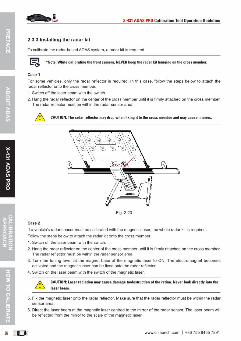
For some vehicles, only the radar reflector is required. In this case, follow the steps below to attach the radar reflector onto the cross member.1. Switch off the laser beam with the switch.2. Hang the radar reflector on the center of the cross member until it is firmly attached on the cross member.
The radar reflector must be within the radar sensor area.
CAUTION:Theradarreflectormaydropwhenfixingittothecrossmemberandmaycauseinjuries.
Fig. 2-20
Case 2
If a vehicle’s radar sensor must be calibrated with the magnetic laser, the whole radar kit is required.Follow the steps below to attach the radar kit onto the cross member.1. Switch off the laser beam with the switch.2. Hang the radar reflector on the center of the cross member until it is firmly attached on the cross member.
The radar reflector must be within the radar sensor area.3. Turn the tuning lever at the magnet base of the magnetic laser to ON. The electromagnet becomes
activated and the magnetic laser can be fixed onto the radar reflector.4. Switch on the laser beam with the switch of the magnetic laser.
CAUTION:Laserradiationmaycausedamageto/destructionoftheretina.Neverlookdirectlyintothelaserbeam.
5. Fix the magnetic laser onto the radar reflector. Make sure that the radar reflector must be within the radar sensor area.
6. Direct the laser beam at the magnetic laser centred to the mirror of the radar sensor. The laser beam will be reflected from the mirror to the scale of the magnetic laser.

PREF
AC
EX-
431
AD
AS
PRO
CA
LIB
RAT
ION
A
PPR
OA
CH
HO
W T
O C
ALI
BR
ATE
AB
OU
T A
DA
S
X-431ADASPROCalibrationToolOperationGuideline X-431ADASPROCalibrationToolOperationGuideline
26 27www.cnlaunch.com +86 755 8455 7891 www.cnlaunch.com +86 755 8455 7891
7. Shift the magnetic laser slowly so that the horizontal and vertical level gauge bubbles are centred.
2.3.4 Installing the calibration reference pattern
Before calibrating, you need to install the vehicle-specific calibration pattern. Follow the steps below to proceed.
1. There are two mounting holes on each of calibration panels for front camera. Align the calibration pattern with the top horizontal holes of calibration frame.
Fig. 2-21
2. Use the screws to fasten it on the calibration panel.
2.3.5 Attaching the wheel clamps to the vehicle’s tires
Total 2 wheel clamps (left & right) are available for the wheel clamp. While attaching it onto the vehicle’s tire, please pay attention to the installation direction.
1). Hold the handle to install the wheel clamp on the tire. Use the adjustment screw to slowly slide out the turning rod (making sure that the lasers installed on the wheel clamp aim the rulers on both sides of the cross member) until it fits the tire’s size and the level gauge bubble is centred.
2). Tighten the adjustment screw so that the wheel clamp can tightly secure on the vehicle’s tire. See Fig. 2-22.
Fig. 2-22
PREFA
CE
X-431 AD
AS PR
OC
ALIB
RATIO
N
APPR
OA
CH
HO
W TO
CA
LIBR
ATEA
BO
UT A
DA
S
X-431ADASPROCalibrationToolOperationGuideline X-431ADASPROCalibrationToolOperationGuideline
28 29www.cnlaunch.com +86 755 8455 7891 www.cnlaunch.com +86 755 8455 7891
2.4 Activate the Software Calibration Function By default, the calibration feature of the pre-installed diagnostic software of LAUNCH scanners is disabled. To ensure normal use of the calibration function of the diagnostic software, you need to activate the pin card to unlock the calibration function on the LAUNCH scanner (sold separately) first.
Follow the steps below to activate it. Here we take X-431 PAD II for example to demonstrate how to activate the ADAS function.
*Note:DifferentLAUNCHscannershavedifferentaccessestotheADASfunction.Fordetails,pleaserefertotheusermanualofindividualscanner.
1. Press the [POWER] button on the diagnostic tool to turn it on.2. Tap the application icon on the home screen to launch it. 3. Log in the system, a screen similar to the following figure appears:
Fig. 2-23
*Note:Alternatively,useralsocandirectlyactivateADASbytapping->“Profile”->“ActivateADAS”.
Fig. 2-24
4. Tap “ADAS” under the “Automotive” tab. If the ADAS is not activated, the following prompt window displays.

PREF
AC
EX-
431
AD
AS
PRO
CA
LIB
RAT
ION
A
PPR
OA
CH
HO
W T
O C
ALI
BR
ATE
AB
OU
T A
DA
S
X-431ADASPROCalibrationToolOperationGuideline X-431ADASPROCalibrationToolOperationGuideline
28 29www.cnlaunch.com +86 755 8455 7891 www.cnlaunch.com +86 755 8455 7891
Fig. 2-25
5. Tap “Activate” to enter the ADAS activation screen.
Fig. 2-26
6. Scratch or scrap the designated area on the included Activation Card to reveal the password, and input the 24-digit password to activate it.
7. Now the ADAS function becomes accessible and is ready for use.

PREFA
CE
X-431 AD
AS PR
OC
ALIB
RATIO
N
APPR
OA
CH
HO
W TO
CA
LIBR
ATEA
BO
UT A
DA
S
X-431ADASPROCalibrationToolOperationGuideline X-431ADASPROCalibrationToolOperationGuideline
30 31www.cnlaunch.com +86 755 8455 7891 www.cnlaunch.com +86 755 8455 7891
3 Calibration Approach
3.1 Workstation requirementsTo make you work smoothly and calibrate accurately, please make sure the following conditions are met:
1. Workstation size
DistanceA = about 2.8m (the width of the cross member)DistanceB = about 1m (from the cross member to the wall)DistanceC = at least 0.5m (from the edge of the cross member to other obstacles)DistanceD = varies from vehicle to vehicle, about 1.5m is strongly recommended (from the calibration panel to the vehicle)DistanceE = reserved for about 1m (from the calibration panel to other obstacles)DistanceF = at least 0.5m (a lane for technician to walk through)
Fig. 3-1
2. Workstation ground
Make sure the vehicle is parked with all wheels on an even floor surface.

PREF
AC
EX-
431
AD
AS
PRO
CA
LIB
RAT
ION
A
PPR
OA
CH
HO
W T
O C
ALI
BR
ATE
AB
OU
T A
DA
S
X-431ADASPROCalibrationToolOperationGuideline X-431ADASPROCalibrationToolOperationGuideline
30 31www.cnlaunch.com +86 755 8455 7891 www.cnlaunch.com +86 755 8455 7891
Correct:
Fig. 3-2
Wrong:
Fig. 3-3
Fig. 3-4
Fig. 3-5
3. Lighting system:
• The lighting system around the calibration workstation should be a non-frequency flash source, including but not limited to: LED light source, industrial lighting complying with international standards, dual light source in opposite phase.
• In the field of view of the camera, there should be no direct light source into the camera, otherwise the

PREFA
CE
X-431 AD
AS PR
OC
ALIB
RATIO
N
APPR
OA
CH
HO
W TO
CA
LIBR
ATEA
BO
UT A
DA
S
X-431ADASPROCalibrationToolOperationGuideline X-431ADASPROCalibrationToolOperationGuideline
32 33www.cnlaunch.com +86 755 8455 7891 www.cnlaunch.com +86 755 8455 7891
camera will reduce the exposure so that the captured calibration pattern becomes darker, adversely affecting the calibration.
• The light source should ensure that there is no reflected spot on the calibration panel.• The light source should ensure uniform illumination distribution in the calibration workstation.• The brightness of the light should not be changed, and ensure that there will be no other changing light
source around the workstation, such as a driving vehicle with lights ON, etc.
3.2 Calibration PrincipleThe calibration operation should be performed strictly following the on-screen instructions on the diagnostic tool. For some vehicle models, calibration pattern and calibration tool are not mandatory. But for some camera-based ADAS, the calibration can not be done without the help of calibration tool and calibration pattern. In this case, for the positioning of the calibration tool and vehicle, it is necessary for the user to manually finish it. Here we take the front camera for example to demonstrate how to place the calibration tool and vehicle.
3.2.1 Calibrating the camera-based ADAS
3.2.1.1 Placing the calibration panel centred in front of the vehicleIn this step, we just need to make sure that the left (CL) and right (CR) scale of the cross member projected from the wheel clamp laser show the same values.
Fig. 3-6
1. Attach one wheel clamp on the left rear wheel.
*Note:Youarestronglyrecommendedtoinstallthewheelclampontherearwheelsincethefartherdistance(betweenthecalibrationpanelandwheelclamp)makesthecalibrationmoreaccurate.

PREF
AC
EX-
431
AD
AS
PRO
CA
LIB
RAT
ION
A
PPR
OA
CH
HO
W T
O C
ALI
BR
ATE
AB
OU
T A
DA
S
X-431ADASPROCalibrationToolOperationGuideline X-431ADASPROCalibrationToolOperationGuideline
32 33www.cnlaunch.com +86 755 8455 7891 www.cnlaunch.com +86 755 8455 7891
2. Align the scale of the wheel clamp at a right angle. Ensure that the level gauge bubbles of both wheel clamps are centred.
3. Switch on the laser beam of the laser module with the switch.
CAUTION:Laserradiationmaycausedamageto/destructionoftheretina.Neverlookdirectlyintothelaserbeam.
4. Align the laser module by setting a desired height on the scale of the cross member.
*Note:Ifthelaserbeamofthewheelclamppositionsatagreatervalueonthecrossmember,slightlypushthecalibrationframerightwards.
Fig. 3-7
5. Perform steps 3-4 for the second laser module of wheel clamp.6. By moving the calibration frame laterally, place the panel in a way that the left and right scale of
the cross member projected from the wheel clamp laser show the same values. Now the calibration panel is placed centred in front of the vehicle.
Fig. 3-8

PREFA
CE
X-431 AD
AS PR
OC
ALIB
RATIO
N
APPR
OA
CH
HO
W TO
CA
LIBR
ATEA
BO
UT A
DA
S
X-431ADASPROCalibrationToolOperationGuideline X-431ADASPROCalibrationToolOperationGuideline
34 35www.cnlaunch.com +86 755 8455 7891 www.cnlaunch.com +86 755 8455 7891
3.2.1.2 Placing the calibration panel in parallel with the vehicleIn this step, we just need to make sure that the left (WL) and right (WR) scale of the wheel clamp reflected from the laser modules on the cross member show the same values.
Fig. 3-9
1. Switch on the laser beam of the laser module with the switch.2. Align the laser beam of the laser module on the cross member with the scale of the wheel clamp. The
laser beam will be projected onto the scale of the wheel clamp.3. Perform step 1-2 with the second laser beam.4. By axially turning the calibration frame, place the frame in a way that the left and right scale of the
wheel clamp reflected from the laser modules on the cross member show the same values.
Fig. 3-10
Now the calibration panel is placed in parallel with the vehicle.

PREF
AC
EX-
431
AD
AS
PRO
CA
LIB
RAT
ION
A
PPR
OA
CH
HO
W T
O C
ALI
BR
ATE
AB
OU
T A
DA
S
X-431ADASPROCalibrationToolOperationGuideline X-431ADASPROCalibrationToolOperationGuideline
34 35www.cnlaunch.com +86 755 8455 7891 www.cnlaunch.com +86 755 8455 7891
Fig. 3-11
3.2.2 Calibrating the radar-based ADASX-431 ADAS PRO calibration system provides a Radar expansion kit for the calibration of the radar-based Advanced Driver Assist Systems (ADAS). Compatible with the systems used by VAG and on certain ADAS-equipped Mercedes-Benz models, it extends the capability of the X-431 ADAS PRO calibration tool beyond just camera-based systems.Before proceeding this step, please make sure the following conditions must be met:• Place the X-431 ADAS PRO calibration panel in front of the vehicle.• Ensure the vehicle is stopped on even surface.• Level gauge bubble of radar reflector is centred. Depending on vehicle manufacturer, model and year of manufacture, the radar sensor can be calibrated directly (without magnetic laser) or must be calibrated with the magnetic laser.
3.2.2.1 Calibrating the radar sensor with magnetic laser
1. Attach the radar reflector to the cross member.
CAUTION:Theradarreflectormaydropwhenattachingittothecrossmemberandmaycuaseinjuries.Youarestronglysuggestedtoaskasecondpersontoattachtheradarreflectortothecrossmember.
2. Turn the tuning lever at the magnet base of the magnetic laser to ON. The electromagnet becomes activated and the magnetic laser can be fixed onto the radar reflector.
3. Switch on the laser beam with the switch of the magnetic laser.
CAUTION:Laserradiationmaycausedamageto/destructionoftheretina.Neverlookdirectlyintothelaserbeam.

X-431ADASPROCalibrationToolOperationGuideline X-431ADASPROCalibrationToolOperationGuideline
36 37www.cnlaunch.com +86 755 8455 7891 www.cnlaunch.com +86 755 8455 7891
PREFA
CE
X-431 AD
AS PR
OC
ALIB
RATIO
N
APPR
OA
CH
HO
W TO
CA
LIBR
ATEA
BO
UT A
DA
S
X-431ADASPROCalibrationToolOperationGuideline X-431ADASPROCalibrationToolOperationGuideline
36 37www.cnlaunch.com +86 755 8455 7891 www.cnlaunch.com +86 755 8455 7891
4. Fix the magnetic laser onto the radar reflector. Make sure that the radar reflector must be within the radar sensor area.
5. Direct the laser beam at the magnetic laser centred to the mirror of the radar sensor. The laser beam will be reflected from the mirror to the scale of the magnetic laser.
4. Shift the magnetic laser slowly so that the horizontal and vertical level gauge bubbles are centred. 5. Observe the on-screen prompt information and instructions to calibrate the radar sensor.6. After calibrating the radar sensor, switch off the laser beam on the magnetic laser.
3.2.2.2 Calibrating the radar sensor without magnetic laser
1. Attach the radar reflector to the cross member.
CAUTION:Theradar reflectormaydropwhenattaching it to thecrossmemberandmaycuaseinjuries.Youarestronglysuggestedtoaskasecondpersontoattachtheradarreflectortothecrossmember.
2. Follow the instructions on the screen to calibrate the radar sensor.

PREF
AC
EX-
431
AD
AS
PRO
CA
LIB
RAT
ION
A
PPR
OA
CH
HO
W T
O C
ALI
BR
ATE
AB
OU
T A
DA
S
X-431ADASPROCalibrationToolOperationGuideline X-431ADASPROCalibrationToolOperationGuideline
36 37www.cnlaunch.com +86 755 8455 7891 www.cnlaunch.com +86 755 8455 7891
X-431ADASPROCalibrationToolOperationGuideline X-431ADASPROCalibrationToolOperationGuideline
36 37www.cnlaunch.com +86 755 8455 7891 www.cnlaunch.com +86 755 8455 7891
4 How to Calibrate?
4.1 VOLKSWAGON
4.1.1 Calibrating the front cameraThis chapter describes a general operation procedure of front camera calibration on 5G/BA/BX-GOLF 2013> 2018.
4.1.1.1 Why to calibrate?1). The following diagnostic trouble codes are found on the vehicle (No or incorrect basic setting/adaption):
B201000 - No basic setting. C110A54 - Camera not calibrated or incorrectly calibrated. B201100 - Wrong basic setting.
2). The following repairs and replacements are made on the vehicle: Front camera has been replaced. The windshield has been removed, installed or replaced. Chassis structure has been changed/adjusted. One of the vehicle level sensors of the wheel damping electronics or the level control has been
replaced.
4.1.1.2 Operation Notes
Make sure the following conditions are met:
On vehicle & diagnostic tool
• Use the VOLKSWAGON (VW) diagnostic software version 28.55 or above to perform the calibration. • Only the calibration-related fault trouble codes are found on the vehicle, all other fault memory records
must have been cleared.• Make sure that the VCI device has been plugged into the vehicle’s DLC.• Turn on the ignition.• Park the unloaded vehicle along with the four wheels on a horizontal surface.
• All vehicle doors must be closed.• Wheel pressure is set to the standard value.• Turn off the headlamp.
On calibration tool
• Camera view is free and clean.• The front wheel is at straight ahead position, and the steering angle sensor is set to zero.• Use the LAC01-02 (standard) calibration pattern.
PREFA
CE
X-431 AD
AS PR
OC
ALIB
RATIO
N
APPR
OA
CH
HO
W TO
CA
LIBR
ATEA
BO
UT A
DA
S
X-431ADASPROCalibrationToolOperationGuideline X-431ADASPROCalibrationToolOperationGuideline
38 39www.cnlaunch.com +86 755 8455 7891 www.cnlaunch.com +86 755 8455 7891
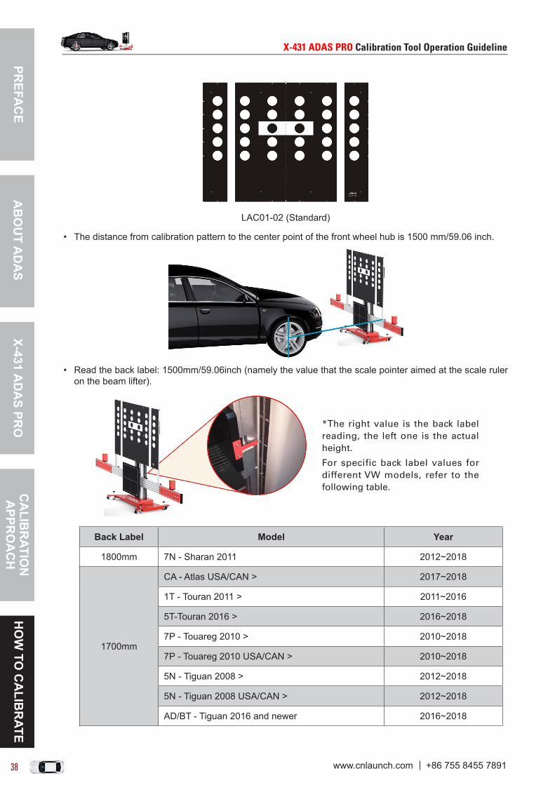
LAC01-02 (Standard)
• The distance from calibration pattern to the center point of the front wheel hub is 1500 mm/59.06 inch.
• Read the back label: 1500mm/59.06inch (namely the value that the scale pointer aimed at the scale ruler on the beam lifter).
*The right value is the back label reading, the left one is the actual height.
For specific back label values for different VW models, refer to the following table.
Back Label Model Year
1800mm 7N - Sharan 2011 2012~2018
1700mm
CA - Atlas USA/CAN > 2017~2018
1T - Touran 2011 > 2011~2016
5T-Touran 2016 > 2016~2018
7P - Touareg 2010 > 2010~2018
7P - Touareg 2010 USA/CAN > 2010~2018
5N - Tiguan 2008 > 2012~2018
5N - Tiguan 2008 USA/CAN > 2012~2018
AD/BT - Tiguan 2016 and newer 2016~2018
PREF
AC
EX-
431
AD
AS
PRO
CA
LIB
RAT
ION
A
PPR
OA
CH
HO
W T
O C
ALI
BR
ATE
AB
OU
T A
DA
S
X-431ADASPROCalibrationToolOperationGuideline X-431ADASPROCalibrationToolOperationGuideline
38 39www.cnlaunch.com +86 755 8455 7891 www.cnlaunch.com +86 755 8455 7891
1500mm
35 - Passat CC 2009 > 2011~2018
35 - Passat CC 2009 USA/CAN > 2012~2018
36 - Passat 2011 > 2011~2015
3G - Passat 2015 > 2015~2018
3D - Phaeton 2003 > 2011~2017
A3 - Passat 2011 > 2016~2018
A3 - Passat/New Midsize Sedan 2011 USA/CAN > 2016~2018
5G / BA / BE / BX - Golf 2013 > 2013~2018
AU/BE/BX - Golf 2013 USA/CAN > 2013~2018
AM - Golf Sportsvan 2014 > 2014~2018
3H7 - Arteon 2017 and newer 2017~2018
• ADAS calibration pattern is placed in parallel in front of the vehicle.• ADAS calibration pattern is placed in the center of the front of the vehicle.
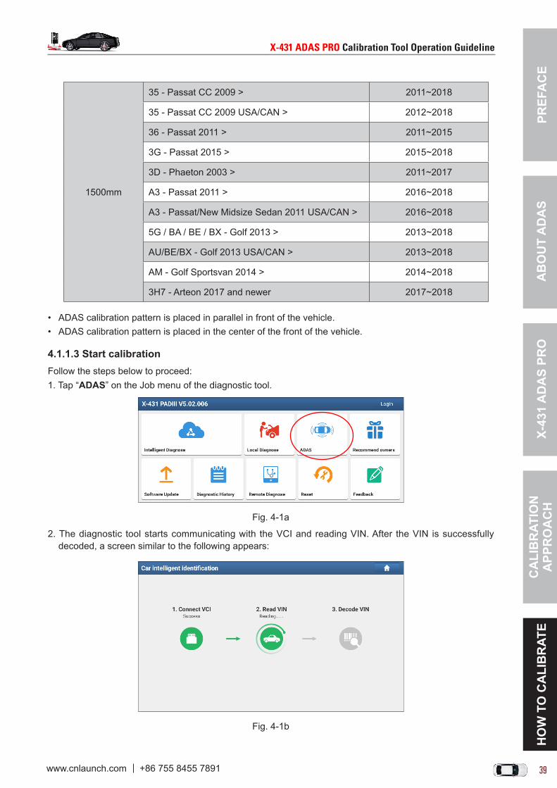
4.1.1.3 Start calibrationFollow the steps below to proceed:1. Tap “ADAS” on the Job menu of the diagnostic tool.
Fig. 4-1a
2. The diagnostic tool starts communicating with the VCI and reading VIN. After the VIN is successfully decoded, a screen similar to the following appears:
Fig. 4-1b

PREFA
CE
X-431 AD
AS PR
OC
ALIB
RATIO
N
APPR
OA
CH
HO
W TO
CA
LIBR
ATEA
BO
UT A
DA
S
X-431ADASPROCalibrationToolOperationGuideline X-431ADASPROCalibrationToolOperationGuideline
40 41www.cnlaunch.com +86 755 8455 7891 www.cnlaunch.com +86 755 8455 7891
Fig. 4-1c
3. Select “5G/BA/BX/BQ - Golf 2013 >”.
Fig. 4-1d (Select 2018 (J))
Fig. 4-1e (Select Sedan)

PREF
AC
EX-
431
AD
AS
PRO
CA
LIB
RAT
ION
A
PPR
OA
CH
HO
W T
O C
ALI
BR
ATE
AB
OU
T A
DA
S
X-431ADASPROCalibrationToolOperationGuideline X-431ADASPROCalibrationToolOperationGuideline
40 41www.cnlaunch.com +86 755 8455 7891 www.cnlaunch.com +86 755 8455 7891
Fig. 4-1f (Tap All engines codes)
4. Double check your selections and tap “Confirm” to go to the next step.
Fig. 4-1g
5. Select the system to be calibrated.
Fig. 4-1h (Select A5 Front Sensors Driver Assistance System)

PREFA
CE
X-431 AD
AS PR
OC
ALIB
RATIO
N
APPR
OA
CH
HO
W TO
CA
LIBR
ATEA
BO
UT A
DA
S
X-431ADASPROCalibrationToolOperationGuideline X-431ADASPROCalibrationToolOperationGuideline
42 43www.cnlaunch.com +86 755 8455 7891 www.cnlaunch.com +86 755 8455 7891
Fig. 4-1i (Select 00A5 - Calibration)
6. Check if the following preparations have been made or not. • The vehicle stands on a horizontal ground.• Chassis/wheel damping electronic control system is normal.• Front camera has been properly installed.
If yes, tap “Complete/Continue” to continue.
Fig. 4-1j
7. Swipe the screen from the bottom to carefully read the calibration reasons and all calibration conditions. After reading, tap “Complete/Continue”.
Fig. 4-1k

PREF
AC
EX-
431
AD
AS
PRO
CA
LIB
RAT
ION
A
PPR
OA
CH
HO
W T
O C
ALI
BR
ATE
AB
OU
T A
DA
S
X-431ADASPROCalibrationToolOperationGuideline X-431ADASPROCalibrationToolOperationGuideline
42 43www.cnlaunch.com +86 755 8455 7891 www.cnlaunch.com +86 755 8455 7891
8. The following dialog box displays on the screen. Before calibrating, make sure that all DTCs that are not related to the calibration have been erased. If yes, tap “Yes” to go to the next step.
Fig. 4-1l (Tap Yes)
Fig. 4-1m (Tap Complete/Continue)
Fig. 4-1n (Select )
9. Select “-2- (Replacement of windshield, replacement of control module, customer complaints)” to start the calibration.

PREFA
CE
X-431 AD
AS PR
OC
ALIB
RATIO
N
APPR
OA
CH
HO
W TO
CA
LIBR
ATEA
BO
UT A
DA
S
X-431ADASPROCalibrationToolOperationGuideline X-431ADASPROCalibrationToolOperationGuideline
44 45www.cnlaunch.com +86 755 8455 7891 www.cnlaunch.com +86 755 8455 7891
CAUTION:Makesuretochoosethecorrectcalibrationreason.Awrongselectionmayleadtoaconsequentialdamageandfailureofthefrontcameraforthedriverassistancesystems-R242.
*Note:ThesefouroptionshavethesimilaroperationproceduresexceptforOption1and3withonemorestep.Determineifthereisaneedtomakecalibrationandperformitifnecessary.Otherwiseexitthecalibrationapplication.
10. Tap “Complete/Continue”, follow the on-screen instruction to enter the distances between the tire contact surface and the Left Front (Right Front & Left Rear & Right Rear) wheel housing edge respectively(*please enter the values in millimeter). After inputting, tap “OK”, the following screen displays.
Fig. 4-1o
11. Follow the on-screen prompt information to set the calibration tool and vehicle.
Fig. 4-1p
12. Tap “Complete/Continue” until the following screen displays.

PREF
AC
EX-
431
AD
AS
PRO
CA
LIB
RAT
ION
A
PPR
OA
CH
HO
W T
O C
ALI
BR
ATE
AB
OU
T A
DA
S
X-431ADASPROCalibrationToolOperationGuideline X-431ADASPROCalibrationToolOperationGuideline
44 45www.cnlaunch.com +86 755 8455 7891 www.cnlaunch.com +86 755 8455 7891
Fig. 4-1q
13. Switch the ignition OFF, tap “Complete/Continue” to continue.
Fig. 4-1r
14. Leave the ignition OFF. When the progress reaches to 100%, tap “Complete/Continue”.
Fig. 4-1s
15. Switch the ignition ON again. Tap “Complete/Continue” to read the parameters of the front camera.

PREFA
CE
X-431 AD
AS PR
OC
ALIB
RATIO
N
APPR
OA
CH
HO
W TO
CA
LIBR
ATEA
BO
UT A
DA
S
X-431ADASPROCalibrationToolOperationGuideline X-431ADASPROCalibrationToolOperationGuideline
46 47www.cnlaunch.com +86 755 8455 7891 www.cnlaunch.com +86 755 8455 7891
Fig. 4-1t
16. Now the calibration is successfully finished. Tap “Complete/Continue” to confirm and end the whole calibration session.
4.1.2 Calibrating the radar sensorThis chapter describes a general operation procedure of radar sensor calibration on 5G/BA/BX-GOLF 2013> 2018.
It also applies to the following models:
Model (Series) Year
16 - Jetta 2011> 2014~2017
3D - Phaeton 2003> 2003~2007
3G - Passat 2015> 2015~2018
3H7 - Arteon 2017> 2017~2018
5T-Touran 2016> 2016~2018
6C - Polo 2014> 2014~2018
5G / BA / BE / BX - GOLF 2013> 2013~2018
7P - Touareg 2010> 2010~2018
A3 - Passat 2011> 2015~2018
AD/BT - Tiguan 2016> 2016~2018
AM - Golf Sportsvan 2014> 2014~2018
16 - Jetta 2011 USA/CANADA> 2015~2017
3D - Phaeton 2003 USA/CANADA> 2004~2006
A3 - Passat 2011 USA/CANADA> 2015~2018
AU/BE/BX - Golf 2013 USA/CANADA> 2013~2018
CA - Atlas USA/CANADA> 2017~2018
7P - Touareg 2010 USA/CANADA> 2010~2018
4.2.2.1 Why to calibrate?1). The following diagnostic trouble codes are found on the vehicle:
C110300 ACC(Adaptive Cruise Control) sensor - incorrect adjustment.

PREF
AC
EX-
431
AD
AS
PRO
CA
LIB
RAT
ION
A
PPR
OA
CH
HO
W T
O C
ALI
BR
ATE
AB
OU
T A
DA
S
X-431ADASPROCalibrationToolOperationGuideline X-431ADASPROCalibrationToolOperationGuideline
46 47www.cnlaunch.com +86 755 8455 7891 www.cnlaunch.com +86 755 8455 7891
C110B54 ACC(Adaptive Cruise Control) sensor - no basic setting.
2). The following repairs and replacements are made on the vehicle: Vertical misalignment angle greater than -1.0° to +1.0°. Rear axle toe was adjusted. The distance regulation control module -J428- has been removed and installed. The front bumper was removed and installed. There is damage on the front bumper.
4.2.2.2 Operation Notes
Make sure the following conditions are met:
Necessary tools
• X-431 ADAS PRO calibration tool.• Use the LAC05-01 radar magnetic laser.
LAC05-01
• Use the LAC05-02 radar reflector.
LAC05-02
On vehicle & diagnostic tool
• Use the VOLKSWAGON (VW) diagnostic software version 28.55 or above to perform the calibration. • Make sure that the VCI device has been plugged into the vehicle’s DLC. • Turn on the ignition.• Place the 3 point wheel alignment clamp on the rear wheel and locate the radar reflector LAC05-01 to
Position 2. The distance between the LAC05-01 and the radar sensor is 120 ± 2 cm or 47.244 ± 0.787 inch.

PREFA
CE
X-431 AD
AS PR
OC
ALIB
RATIO
N
APPR
OA
CH
HO
W TO
CA
LIBR
ATEA
BO
UT A
DA
S
X-431ADASPROCalibrationToolOperationGuideline X-431ADASPROCalibrationToolOperationGuideline
48 49www.cnlaunch.com +86 755 8455 7891 www.cnlaunch.com +86 755 8455 7891
Radar reflector
• Place the calibration tool horizontally to the center of the vehicle.• Attach the LAC05-02 radar magnet laser to the center of the LAC05-01 radar reflector. Use the rocker
switch to adjust the height of the cross member so that the laser beam is at the center of the radar sensor. If the radar sensor has a mirror, the laser beam hits the center of the mirror. Adjust the radar positioning bolt so that the reflection points falls onto the center of the LAC05-02 scale ruler.
Attention
• Before placing the adjustment tool on the adjustment stud, if the stud is dirty, please clean it and apply the lubricate oil to it to prevent it from being damaged
• The ACC sensor and distance regulation control module -J428 are both mounted in a whole housing. The entire unit must be replaced when the sensor/control module is damaged.
• Before performing ACC sensor adjustment, use the diagnostic tool to retrieve the DTC. Troubleshoot all DTCs unrelated to the calibration.
• Make sure the calibration tool is not moved, especially when the calibration is being performed. Any movement of the calibration tool will result in an inaccurate setting of the ACC sensor.
• Please ensure that never apply too much pressure on the ACC sensor while adjusting the adjustment studs.
4.2.2.3 Start calibrationFollow the steps below to proceed:1. Tap “ADAS” on the Job menu of the diagnostic tool.
Fig. 4-2a
2. The diagnostic tool starts communicating with the VCI and reading VIN. After the VIN is successfully decoded, a screen similar to the following appears:

PREF
AC
EX-
431
AD
AS
PRO
CA
LIB
RAT
ION
A
PPR
OA
CH
HO
W T
O C
ALI
BR
ATE
AB
OU
T A
DA
S
X-431ADASPROCalibrationToolOperationGuideline X-431ADASPROCalibrationToolOperationGuideline
48 49www.cnlaunch.com +86 755 8455 7891 www.cnlaunch.com +86 755 8455 7891
Fig. 4-2b
Fig. 4-2c
3. Select “5G/BA/BE/BX/BQ-Golf 2013>”.
Fig. 4-2d (Select 2018 (J))

PREFA
CE
X-431 AD
AS PR
OC
ALIB
RATIO
N
APPR
OA
CH
HO
W TO
CA
LIBR
ATEA
BO
UT A
DA
S
X-431ADASPROCalibrationToolOperationGuideline X-431ADASPROCalibrationToolOperationGuideline
50 51www.cnlaunch.com +86 755 8455 7891 www.cnlaunch.com +86 755 8455 7891
Fig. 4-2e (Select Sedan)
Fig. 4-2f
4. Double check your selections and tap “Confirm” to go to the next step.
Fig. 4-2g
5. Select “13 Adaptive Cruise Control” from the system selection list.

PREF
AC
EX-
431
AD
AS
PRO
CA
LIB
RAT
ION
A
PPR
OA
CH
HO
W T
O C
ALI
BR
ATE
AB
OU
T A
DA
S
X-431ADASPROCalibrationToolOperationGuideline X-431ADASPROCalibrationToolOperationGuideline
50 51www.cnlaunch.com +86 755 8455 7891 www.cnlaunch.com +86 755 8455 7891
Fig. 4-2h (Select 13 Adaptive Cruise Control)
Fig. 4-2i (Tap 0013 - Calibration)
6. Next we will calibrate the vehicle distance control. Carefully check the test requirements and necessary tools, tap “Complete/Continue” to continue.
Fig. 4-2j
7. Double confirm all calibration conditions are well prepared, then tap “Complete/Continue”.

PREFA
CE
X-431 AD
AS PR
OC
ALIB
RATIO
N
APPR
OA
CH
HO
W TO
CA
LIBR
ATEA
BO
UT A
DA
S
X-431ADASPROCalibrationToolOperationGuideline X-431ADASPROCalibrationToolOperationGuideline
52 53www.cnlaunch.com +86 755 8455 7891 www.cnlaunch.com +86 755 8455 7891
Fig. 4-2k
8. Now switch the engine OFF and then turn the ignition ON, tap “Complete/Continue”.
Fig. 4-2l
9. The screen displays whether to calibrate the distance regulation control module (J428) now. Tap “Yes” to go to the next step.
Fig. 4-2m
10. Attach the angular adjustment plate of radar reflector with attachment Position 2 on the cross member. Tap “Complete/Continue” to start the measurement.

PREF
AC
EX-
431
AD
AS
PRO
CA
LIB
RAT
ION
A
PPR
OA
CH
HO
W T
O C
ALI
BR
ATE
AB
OU
T A
DA
S
X-431ADASPROCalibrationToolOperationGuideline X-431ADASPROCalibrationToolOperationGuideline
52 53www.cnlaunch.com +86 755 8455 7891 www.cnlaunch.com +86 755 8455 7891
Fig. 4-2n (Tap Complete/Continue)
Fig. 4-2o (Tap Complete/Continue)
11. Attach the angular adjustment plate of radar reflector with attachment Position 1 on the cross member. Tap “Complete/Continue” to start the measurement.

PREFA
CE
X-431 AD
AS PR
OC
ALIB
RATIO
N
APPR
OA
CH
HO
W TO
CA
LIBR
ATEA
BO
UT A
DA
S
X-431ADASPROCalibrationToolOperationGuideline X-431ADASPROCalibrationToolOperationGuideline
54 55www.cnlaunch.com +86 755 8455 7891 www.cnlaunch.com +86 755 8455 7891
Fig. 4-2p (Tap Complete/Continue)
Fig. 4-2q (Tap Complete/Continue)
12. Readjust the angular adjustment plate of radar reflector with attachment Position 2 on the cross member. Tap “Complete/Continue” to start the measurement.

PREF
AC
EX-
431
AD
AS
PRO
CA
LIB
RAT
ION
A
PPR
OA
CH
HO
W T
O C
ALI
BR
ATE
AB
OU
T A
DA
S
X-431ADASPROCalibrationToolOperationGuideline X-431ADASPROCalibrationToolOperationGuideline
54 55www.cnlaunch.com +86 755 8455 7891 www.cnlaunch.com +86 755 8455 7891
Fig. 4-2r (Tap Complete/Continue)
Fig. 4-2s (Tap Complete/Continue)
13. Attach the angular adjustment plate of radar reflector with attachment Position 3 on the cross member. Tap “Complete/Continue” to start the measurement.

PREFA
CE
X-431 AD
AS PR
OC
ALIB
RATIO
N
APPR
OA
CH
HO
W TO
CA
LIBR
ATEA
BO
UT A
DA
S
X-431ADASPROCalibrationToolOperationGuideline X-431ADASPROCalibrationToolOperationGuideline
56 57www.cnlaunch.com +86 755 8455 7891 www.cnlaunch.com +86 755 8455 7891
Fig. 4-2t (Tap Complete/Continue)
Fig. 4-2u (Tap Complete/Continue)
14. According to the measurement result, follow the on-screen prompts to adjust the two bolts. Tap “Complete/Continue” to continue.
Fig. 4-2v
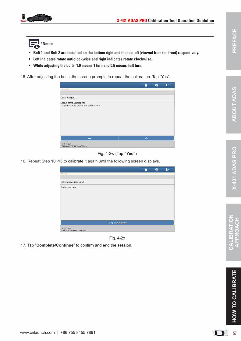
PREF
AC
EX-
431
AD
AS
PRO
CA
LIB
RAT
ION
A
PPR
OA
CH
HO
W T
O C
ALI
BR
ATE
AB
OU
T A
DA
S
X-431ADASPROCalibrationToolOperationGuideline X-431ADASPROCalibrationToolOperationGuideline
56 57www.cnlaunch.com +86 755 8455 7891 www.cnlaunch.com +86 755 8455 7891
*Notes:
• Bolt1andBolt2areinstalledonthebottomrightandthetopleft(viewedfromthefront)respectively.
• Leftindicatesrotateanticlockwiseandrightindicatesrotateclockwise.
• Whileadjustingthebolts,1.0means1turnand0.5meanshalfturn.
15. After adjusting the bolts, the screen prompts to repeat the calibration. Tap “Yes”.
Fig. 4-2w (Tap “Yes”)
16. Repeat Step 10~13 to calibrate it again until the following screen displays.
Fig. 4-2x
17. Tap “Complete/Continue” to confirm and end the session.
PREFA
CE
X-431 AD
AS PR
OC
ALIB
RATIO
N
APPR
OA
CH
HO
W TO
CA
LIBR
ATEA
BO
UT A
DA
S
X-431ADASPROCalibrationToolOperationGuideline X-431ADASPROCalibrationToolOperationGuideline
58 59www.cnlaunch.com +86 755 8455 7891 www.cnlaunch.com +86 755 8455 7891
4.2 OPEL
4.2.1 Calibrating the front cameraThis chapter describes a general operation procedure of front camera calibration on OPEL Zafira-C i.
4.2.1.1 Why to calibrate?
The following repairs and replacements are made on the vehicle: The vehicle parts associated with the frontview camera module have been repaired or replaced. The intelligent headlamp control/forward collision warning/lane departure warning featured by the
frontview camera module malfunctions.
4.2.1.2 Operation Notes
Make sure the following conditions are met:• Use the OPEL diagnostic software version 42.03 or above to perform the calibration. • All DTC memory records related to the calibration must have been cleared.• Make sure that the VCI device has been plugged into the vehicle’s DLC.• Turn the ignition switch ON.• Performing the learn procedure will delete the learned values. Once the procedure has been started, it
must be completed to its end.• The following conditions are necessary/helpful during the learn procedure:
• The vehicle speed is greater than 60km/h (38mph)• Drive the vehicle on a straight road with many stationary objects at the side of the road.• Drive the vehicle during daytime and good weather conditions are required.• Avoid lane change.
• The learn procedure will take approximate 5 minutes during which the lane departure warning indicator will illuminate AMBER. When the indicator changes to GREEN, it means the procedure is completed.
4.2.1.3 Start calibrationFollow the steps below to proceed:1. Tap “ADAS” on the Job menu of the diagnostic tool.
Fig. 4-3a
2. The diagnostic tool starts communicating with the VCI and reading VIN.

PREF
AC
EX-
431
AD
AS
PRO
CA
LIB
RAT
ION
A
PPR
OA
CH
HO
W T
O C
ALI
BR
ATE
AB
OU
T A
DA
S
X-431ADASPROCalibrationToolOperationGuideline X-431ADASPROCalibrationToolOperationGuideline
58 59www.cnlaunch.com +86 755 8455 7891 www.cnlaunch.com +86 755 8455 7891
Fig. 4-3b
2. After the VIN is successfully decoded, the system will automatically navigate to the ADAS module selection screen.
Fig. 4-3c
3. Tap “FCM(Frontview Camera Module)” to select the type of the front camera. Here we choose “Magna (UFL)” equipped on the current vehicle.
Fig. 4-3d
*Note:Incasethatafterselectingthedesiredfrontcamera,butthesoftwaredoesnotsupportit.Thisisbecausethefrontcameradoesnotfeaturethecalibrationfunction.
4. Tap “Frontview Camera Learn”.

PREFA
CE
X-431 AD
AS PR
OC
ALIB
RATIO
N
APPR
OA
CH
HO
W TO
CA
LIBR
ATEA
BO
UT A
DA
S
X-431ADASPROCalibrationToolOperationGuideline X-431ADASPROCalibrationToolOperationGuideline
60 61www.cnlaunch.com +86 755 8455 7891 www.cnlaunch.com +86 755 8455 7891
Fig. 4-3e
5. Carefully read the calibration operation requirements and confirm whether all calibration conditions are met or not. If yes, tap “OK”.
Fig. 4-3f (Tap OK)
6. Tap “Learn” to start the front camera learn procedure. As you keep driving the vehicle on the straight road, the learn progress starts changing.
Fig. 4-3g

PREF
AC
EX-
431
AD
AS
PRO
CA
LIB
RAT
ION
A
PPR
OA
CH
HO
W T
O C
ALI
BR
ATE
AB
OU
T A
DA
S
X-431ADASPROCalibrationToolOperationGuideline X-431ADASPROCalibrationToolOperationGuideline
60 61www.cnlaunch.com +86 755 8455 7891 www.cnlaunch.com +86 755 8455 7891
Fig. 4-3h (Progress reaches to 12%)
If the lane departure occurs during the learn process, the Lane Departure Warning indicator will illuminate light yellow.
7. When the progress reaches to 100% and the Lane Departure Warning indicator changes to GREEN, it indicates the learn procedure has been successfully finished. Tap “Release Control” to release the learning control over the vehicle.
Fig. 4-3i

PREFA
CE
X-431 AD
AS PR
OC
ALIB
RATIO
N
APPR
OA
CH
HO
W TO
CA
LIBR
ATEA
BO
UT A
DA
S
X-431ADASPROCalibrationToolOperationGuideline X-431ADASPROCalibrationToolOperationGuideline
62 63www.cnlaunch.com +86 755 8455 7891 www.cnlaunch.com +86 755 8455 7891
4.3 FIAT
4.3.1 Calibrating the front cameraThis chapter describes a general operation procedure of front camera calibration on FIAT DUCATO 2014.
4.3.1.1 Why to calibrate?1). The calibration is required only in case of missing calibration of the ECU (Electronic Control Unit) or
sensor adjustment required.
2). The following repairs and replacements are made on the vehicle: Front camera has been replaced. The windshield has been removed, installed or replaced. Chassis structure has been changed/adjusted. The trouble codes that prompt for calibration are present on the diagnostic tool.
4.3.1.2 Operation Notes
Make sure the following conditions are met:
On vehicle & diagnostic tool
• Use the FIAT diagnostic software version 35.00 or above to perform the calibration. • The module has no DTC (Diagnostic Trouble Code) except for the DTC related to the calibration.• Make sure that the VCI device has been plugged into the vehicle’s DLC.• All vehicle doors must be closed.• Park the unloaded vehicle along with the four wheels on an even ground.
• Vehicle storage area is illuminated adequately.• Axle geometry must be OK.• Ensure that vehicle has enough battery voltage.• The vehicle chassis does not reach the ground.• Wheel pressure is set to the standard value.• Turn on the ignition.• Turn off the headlamp.
On calibration tool
• Camera view is free and clean.• The front wheel is at straight ahead position, and the steering angle sensor is set to zero.• Use the LAC01-09 calibration pattern.

PREF
AC
EX-
431
AD
AS
PRO
CA
LIB
RAT
ION
A
PPR
OA
CH
HO
W T
O C
ALI
BR
ATE
AB
OU
T A
DA
S
X-431ADASPROCalibrationToolOperationGuideline X-431ADASPROCalibrationToolOperationGuideline
62 63www.cnlaunch.com +86 755 8455 7891 www.cnlaunch.com +86 755 8455 7891
LAC01-09
• The distance from calibration pattern to the front edge (license plate) of the vehicle is 50 cm/19.69 inch.
• Set the desired height of the calibration frame (back label): 168.5 cm (± 1cm)/66.34 (± 0.4inch) inch (namely the value that the scale pointer aimed at the scale ruler on the beam lifter).
*The right value is the calibration height required (the distance from the center of the calibration frame to the ground), the left one is the actual height.
• ADAS calibration pattern is placed in parallel in front of the vehicle.• ADAS calibration pattern is placed in the center of the front of the vehicle.
4.3.1.3 Start calibrationFollow the steps below to proceed:1. Tap “Local Diagnose” on the Job menu of the diagnostic tool.
Fig. 4-4a

PREFA
CE
X-431 AD
AS PR
OC
ALIB
RATIO
N
APPR
OA
CH
HO
W TO
CA
LIBR
ATEA
BO
UT A
DA
S
X-431ADASPROCalibrationToolOperationGuideline X-431ADASPROCalibrationToolOperationGuideline
64 65www.cnlaunch.com +86 755 8455 7891 www.cnlaunch.com +86 755 8455 7891
2. Tap “FIAT” and select the diagnostic software version.
Fig. 4-4b (Select FIAT)
Fig. 4-4c (Tap OK)
3. On the function selection screen, select “ADAS Calibration”.
Fig. 4-4d (Select ADAS Calibration)

PREF
AC
EX-
431
AD
AS
PRO
CA
LIB
RAT
ION
A
PPR
OA
CH
HO
W T
O C
ALI
BR
ATE
AB
OU
T A
DA
S
X-431ADASPROCalibrationToolOperationGuideline X-431ADASPROCalibrationToolOperationGuideline
64 65www.cnlaunch.com +86 755 8455 7891 www.cnlaunch.com +86 755 8455 7891
Fig. 4-4e (Select DUCATO)
Fig. 4-4f (Select 2014)
4. Select “Service Single Pole Calibration” and tap “Continue” to go to the next step.
Fig. 4-4g
5. The screen prompts in which situations the calibration is required.

PREFA
CE
X-431 AD
AS PR
OC
ALIB
RATIO
N
APPR
OA
CH
HO
W TO
CA
LIBR
ATEA
BO
UT A
DA
S
X-431ADASPROCalibrationToolOperationGuideline X-431ADASPROCalibrationToolOperationGuideline
66 67www.cnlaunch.com +86 755 8455 7891 www.cnlaunch.com +86 755 8455 7891
Fig. 4-4h (Tap Continue)
Fig. 4-4i (Tap Continue)
6. Read the on-screen prompt information and double check whether all conditions of the calibration are met or not. If yes, tap “Continue”.
Fig. 4-4j (Tap Continue)

PREF
AC
EX-
431
AD
AS
PRO
CA
LIB
RAT
ION
A
PPR
OA
CH
HO
W T
O C
ALI
BR
ATE
AB
OU
T A
DA
S
X-431ADASPROCalibrationToolOperationGuideline X-431ADASPROCalibrationToolOperationGuideline
66 67www.cnlaunch.com +86 755 8455 7891 www.cnlaunch.com +86 755 8455 7891
Fig. 4-4k (Tap Continue)
7. The system starts calibrating. The calibration includes two parts which will be separately completed with two steps.
Fig. 4-4l (Waiting...)
Fig. 4-4m (Tap OK)
8. The system starts calibrating the second part.

PREFA
CE
X-431 AD
AS PR
OC
ALIB
RATIO
N
APPR
OA
CH
HO
W TO
CA
LIBR
ATEA
BO
UT A
DA
S
X-431ADASPROCalibrationToolOperationGuideline X-431ADASPROCalibrationToolOperationGuideline
68 69www.cnlaunch.com +86 755 8455 7891 www.cnlaunch.com +86 755 8455 7891
Fig. 4-4m (Waiting...)
Fig. 4-4n (Tap OK)
9. Now the calibration of front camera is successfully finished.
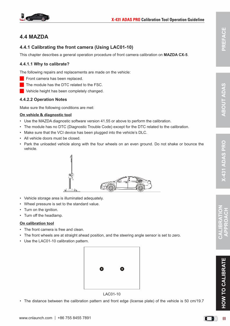
PREF
AC
EX-
431
AD
AS
PRO
CA
LIB
RAT
ION
A
PPR
OA
CH
HO
W T
O C
ALI
BR
ATE
AB
OU
T A
DA
S
X-431ADASPROCalibrationToolOperationGuideline X-431ADASPROCalibrationToolOperationGuideline
68 69www.cnlaunch.com +86 755 8455 7891 www.cnlaunch.com +86 755 8455 7891
4.4 MAZDA
4.4.1 Calibrating the front camera (Using LAC01-10)This chapter describes a general operation procedure of front camera calibration on MAZDA CX-5.
4.4.1.1 Why to calibrate?
The following repairs and replacements are made on the vehicle: Front camera has been replaced. The module has the DTC related to the FSC. Vehicle height has been completely changed.
4.4.2.2 Operation Notes
Make sure the following conditions are met:
On vehicle & diagnostic tool
• Use the MAZDA diagnostic software version 41.55 or above to perform the calibration. • The module has no DTC (Diagnostic Trouble Code) except for the DTC related to the calibration.• Make sure that the VCI device has been plugged into the vehicle’s DLC.• All vehicle doors must be closed.• Park the unloaded vehicle along with the four wheels on an even ground. Do not shake or bounce the
vehicle.
• Vehicle storage area is illuminated adequately.• Wheel pressure is set to the standard value.• Turn on the ignition.• Turn off the headlamp.
On calibration tool
• The front camera is free and clean.• The front wheels are at straight ahead position, and the steering angle sensor is set to zero.• Use the LAC01-10 calibration pattern.
LAC01-10
• The distance between the calibration pattern and front edge (license plate) of the vehicle is 50 cm/19.7
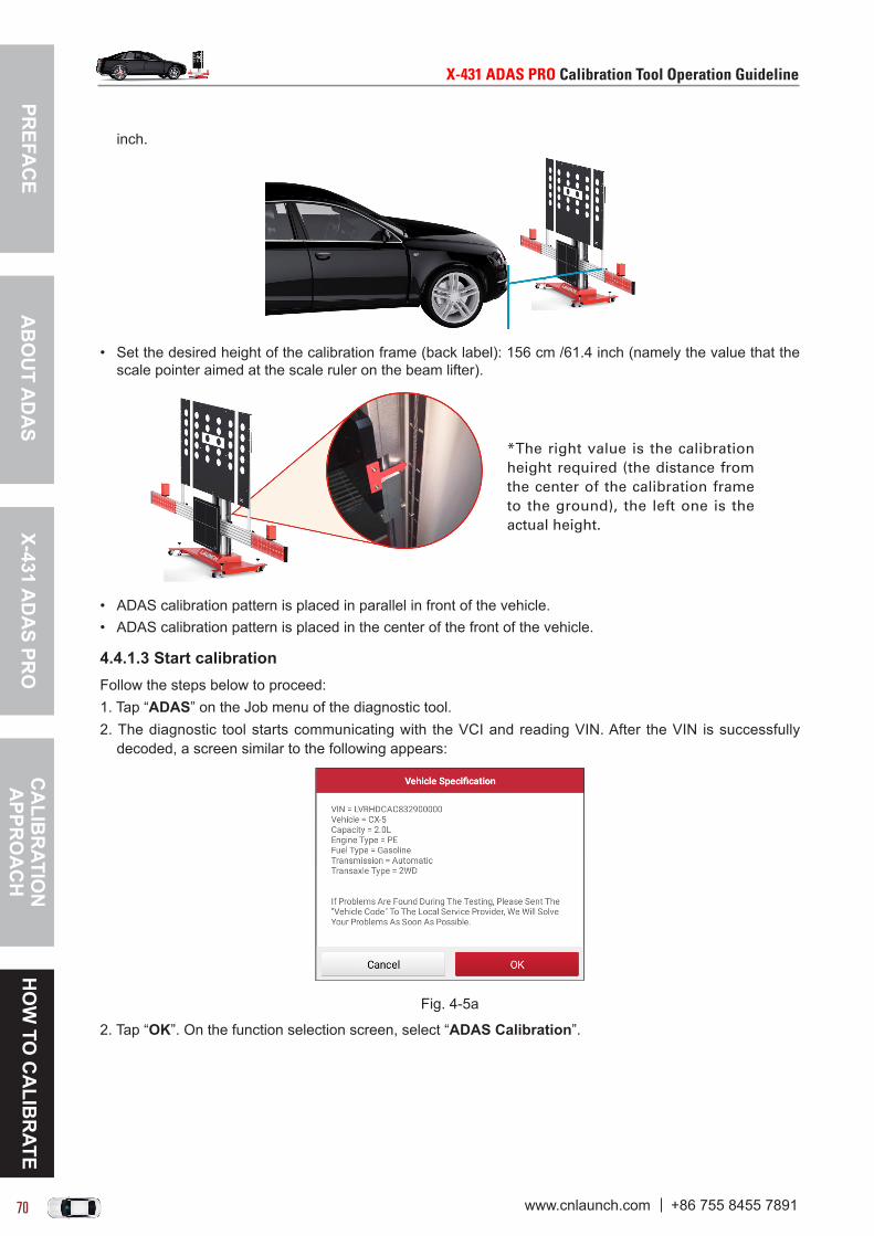
PREFA
CE
X-431 AD
AS PR
OC
ALIB
RATIO
N
APPR
OA
CH
HO
W TO
CA
LIBR
ATEA
BO
UT A
DA
S
X-431ADASPROCalibrationToolOperationGuideline X-431ADASPROCalibrationToolOperationGuideline
70 71www.cnlaunch.com +86 755 8455 7891 www.cnlaunch.com +86 755 8455 7891
inch.
• Set the desired height of the calibration frame (back label): 156 cm /61.4 inch (namely the value that the scale pointer aimed at the scale ruler on the beam lifter).
*The right value is the calibration height required (the distance from the center of the calibration frame to the ground), the left one is the actual height.
• ADAS calibration pattern is placed in parallel in front of the vehicle.• ADAS calibration pattern is placed in the center of the front of the vehicle.
4.4.1.3 Start calibrationFollow the steps below to proceed:1. Tap “ADAS” on the Job menu of the diagnostic tool.2. The diagnostic tool starts communicating with the VCI and reading VIN. After the VIN is successfully
decoded, a screen similar to the following appears:
Fig. 4-5a
2. Tap “OK”. On the function selection screen, select “ADAS Calibration”.

PREF
AC
EX-
431
AD
AS
PRO
CA
LIB
RAT
ION
A
PPR
OA
CH
HO
W T
O C
ALI
BR
ATE
AB
OU
T A
DA
S
X-431ADASPROCalibrationToolOperationGuideline X-431ADASPROCalibrationToolOperationGuideline
70 71www.cnlaunch.com +86 755 8455 7891 www.cnlaunch.com +86 755 8455 7891
Fig. 4-5b (Select ADAS Calibration)
3. Select “FSC (Forward Sensing Camera) Aiming”.
Fig. 4-5c (Select FSC Aiming)
4. Carefully read the calibration operation requirements and check if all calibration conditions are met or not.
Fig. 4-5d (Tap Yes)

PREFA
CE
X-431 AD
AS PR
OC
ALIB
RATIO
N
APPR
OA
CH
HO
W TO
CA
LIBR
ATEA
BO
UT A
DA
S
X-431ADASPROCalibrationToolOperationGuideline X-431ADASPROCalibrationToolOperationGuideline
72 73www.cnlaunch.com +86 755 8455 7891 www.cnlaunch.com +86 755 8455 7891
Fig. 4-5e (Tap OK)
5. If yes, tap “OK”. A dialog box prompting to input value manually appears:
Fig. 4-5f
6. Tap “OK” to select the desired measurement unit.
Fig. 4-5g
6. Follow the on-screen instructions to measure the distance of the required option (swipe the screen from the bottom to scroll the hidden options), tap the desired option, input the measured value in the pop-up window.

PREF
AC
EX-
431
AD
AS
PRO
CA
LIB
RAT
ION
A
PPR
OA
CH
HO
W T
O C
ALI
BR
ATE
AB
OU
T A
DA
S
X-431ADASPROCalibrationToolOperationGuideline X-431ADASPROCalibrationToolOperationGuideline
72 73www.cnlaunch.com +86 755 8455 7891 www.cnlaunch.com +86 755 8455 7891
Fig. 4-5h (Tap to input)
Fig. 4-5i
7. After inputting, check if all values are correct or not. If yes, tap “Continue”.
Fig. 4-5j (Tap Continue)
8. Double confirm all the preparations are made before starting the calibration.
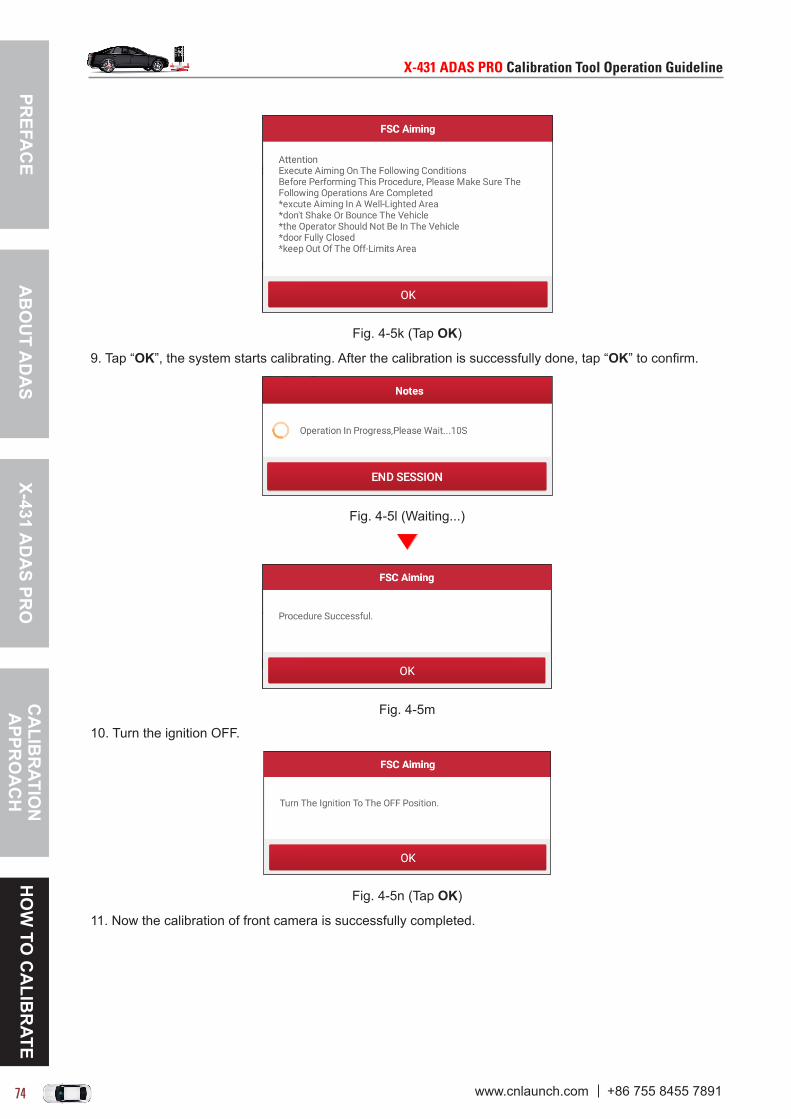
PREFA
CE
X-431 AD
AS PR
OC
ALIB
RATIO
N
APPR
OA
CH
HO
W TO
CA
LIBR
ATEA
BO
UT A
DA
S
X-431ADASPROCalibrationToolOperationGuideline X-431ADASPROCalibrationToolOperationGuideline
74 75www.cnlaunch.com +86 755 8455 7891 www.cnlaunch.com +86 755 8455 7891
Fig. 4-5k (Tap OK)
9. Tap “OK”, the system starts calibrating. After the calibration is successfully done, tap “OK” to confirm.
Fig. 4-5l (Waiting...)
Fig. 4-5m
10. Turn the ignition OFF.
Fig. 4-5n (Tap OK)
11. Now the calibration of front camera is successfully completed.

PREF
AC
EX-
431
AD
AS
PRO
CA
LIB
RAT
ION
A
PPR
OA
CH
HO
W T
O C
ALI
BR
ATE
AB
OU
T A
DA
S
X-431ADASPROCalibrationToolOperationGuideline X-431ADASPROCalibrationToolOperationGuideline
74 75www.cnlaunch.com +86 755 8455 7891 www.cnlaunch.com +86 755 8455 7891
4.4.2 Calibrating the front camera (Using LAC01-16)This chapter describes a general operation procedure of front camera calibration on MAZDA CX-5.
4.4.2.1 Why to calibrate?
The following repairs and replacements are made on the vehicle: Front camera has been replaced. The module has the DTC related to the FSC. Vehicle height has been completely changed.
4.4.2.2 Operation Notes
Make sure the following conditions are met:
On vehicle & diagnostic tool
• Use the MAZDA diagnostic software version 41.55 or above to perform the calibration. • The module has no DTC (Diagnostic Trouble Code) except for the DTC related to the calibration.• Make sure that the VCI device has been plugged into the vehicle’s DLC.• All vehicle doors must be closed.• Park the unloaded vehicle along with the four wheels on an even ground. Do not shake or bounce the
vehicle.
• Vehicle storage area is illuminated adequately.• Wheel pressure is set to the standard value.• Turn on the ignition.• Turn off the headlamp.
On calibration tool
• The front camera is free and clean.• The front wheels are at straight ahead position, and the steering angle sensor is set to zero.• Use the LAC01-16 calibration pattern.
LAC01-16
• The distance between the calibration pattern and front edge (license plate) of the vehicle is 160 cm/63 inch.

PREFA
CE
X-431 AD
AS PR
OC
ALIB
RATIO
N
APPR
OA
CH
HO
W TO
CA
LIBR
ATEA
BO
UT A
DA
S
X-431ADASPROCalibrationToolOperationGuideline X-431ADASPROCalibrationToolOperationGuideline
76 77www.cnlaunch.com +86 755 8455 7891 www.cnlaunch.com +86 755 8455 7891
• Set the desired height of the calibration frame (back label): 169 cm /66.5 inch (namely the value that the scale pointer aimed at the scale ruler on the beam lifter).
*The right value is the calibration height required (the distance from the center of the calibration frame to the ground), the left one is the actual height.
• ADAS calibration pattern is placed in parallel in front of the vehicle.• ADAS calibration pattern is placed in the center of the front of the vehicle.
4.4.2.3 Start calibrationFollow the steps below to proceed:1. Tap “ADAS” on the Job menu of the diagnostic tool.2. The diagnostic tool starts communicating with the VCI and reading VIN. After the VIN is successfully
decoded, a screen similar to the following appears:
Fig. 4-6a
2. Tap “OK”. On the function selection screen, select “ADAS Calibration”.
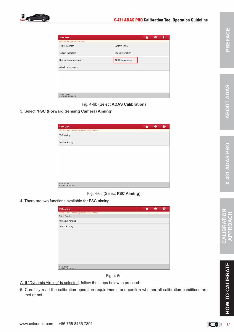
PREF
AC
EX-
431
AD
AS
PRO
CA
LIB
RAT
ION
A
PPR
OA
CH
HO
W T
O C
ALI
BR
ATE
AB
OU
T A
DA
S
X-431ADASPROCalibrationToolOperationGuideline X-431ADASPROCalibrationToolOperationGuideline
76 77www.cnlaunch.com +86 755 8455 7891 www.cnlaunch.com +86 755 8455 7891
Fig. 4-6b (Select ADAS Calibration)
3. Select “FSC (Forward Sensing Camera) Aiming”.
Fig. 4-6c (Select FSC Aiming)
4. There are two functions available for FSC aiming.
Fig. 4-6d
A. If “Dynamic Aiming” is selected, follow the steps below to proceed:
5. Carefully read the calibration operation requirements and confirm whether all calibration conditions are met or not.

PREFA
CE
X-431 AD
AS PR
OC
ALIB
RATIO
N
APPR
OA
CH
HO
W TO
CA
LIBR
ATEA
BO
UT A
DA
S
X-431ADASPROCalibrationToolOperationGuideline X-431ADASPROCalibrationToolOperationGuideline
78 79www.cnlaunch.com +86 755 8455 7891 www.cnlaunch.com +86 755 8455 7891
Fig. 4-6e (Tap Yes)
Fig. 4-6f (Tap OK)
6. Tap “OK”, the system starts calibrating. After the calibration is successfully done, tap “OK” to confirm.
Fig. 4-6g (Waiting...)

PREF
AC
EX-
431
AD
AS
PRO
CA
LIB
RAT
ION
A
PPR
OA
CH
HO
W T
O C
ALI
BR
ATE
AB
OU
T A
DA
S
X-431ADASPROCalibrationToolOperationGuideline X-431ADASPROCalibrationToolOperationGuideline
78 79www.cnlaunch.com +86 755 8455 7891 www.cnlaunch.com +86 755 8455 7891
Fig. 4-6h (Tap OK)
7. Tap “OK” to confirm.
Fig. 4-6i (Tap OK)
8. Turn the ignition OFF.
Fig. 4-6j (Tap OK)
9. Now the calibration of front camera is successfully completed.
B. If “Static Aiming” is selected, follow the steps below to proceed:
5. Carefully read the calibration operation requirements and confirm whether all calibration conditions are met or not.
Fig. 4-6k (Tap Yes)

PREFA
CE
X-431 AD
AS PR
OC
ALIB
RATIO
N
APPR
OA
CH
HO
W TO
CA
LIBR
ATEA
BO
UT A
DA
S
X-431ADASPROCalibrationToolOperationGuideline X-431ADASPROCalibrationToolOperationGuideline
80 81www.cnlaunch.com +86 755 8455 7891 www.cnlaunch.com +86 755 8455 7891
Fig. 4-6l (Tap OK)
6. Tap “OK”. If the ignition switch is not ON, a pop-up window similar to the following appears.
Fig. 4-6m
7. Turn the ignition switch ON and input the measured distance from the calibration pattern to the front wheel center in millimeter.
Fig. 4-6n
8. Tap “OK” to start calibrating until it is successfully performed.
Fig. 4-6o (Waiting...)

PREF
AC
EX-
431
AD
AS
PRO
CA
LIB
RAT
ION
A
PPR
OA
CH
HO
W T
O C
ALI
BR
ATE
AB
OU
T A
DA
S
X-431ADASPROCalibrationToolOperationGuideline X-431ADASPROCalibrationToolOperationGuideline
80 81www.cnlaunch.com +86 755 8455 7891 www.cnlaunch.com +86 755 8455 7891
Fig. 4-6p (Tap OK)
9. Tap “OK” and then turn the ignition switch OFF.
Fig. 4-6q (Tap OK)
10. Now the calibration of front camera is successfully completed.
4.4.3 Calibrating the radar sensor
4.4.3.1 Operation Notes• The following work area (size: 4m width x 8m length) in front of the vehicle has no obstacles.
• Use the LAC05-03 triangular radar corner reflector. The triangular corner reflector is parallel with the front axle and occupies the middle of the vehicle.
• The distance between the triangular corner reflector and the front (license plate position) of the vehicle is 500cm / 197inch. The height of the triangular corner reflector remains 71cm / 28inch.

PREFA
CE
X-431 AD
AS PR
OC
ALIB
RATIO
N
APPR
OA
CH
HO
W TO
CA
LIBR
ATEA
BO
UT A
DA
S
X-431ADASPROCalibrationToolOperationGuideline X-431ADASPROCalibrationToolOperationGuideline
82 83www.cnlaunch.com +86 755 8455 7891 www.cnlaunch.com +86 755 8455 7891
4.4.3.2 Start CalibrationFollow the steps below to proceed:1. Tap “ADAS” on the Job menu of the diagnostic tool. The diagnostic tool starts communicating with the
VCI and reading VIN. After the VIN is successfully decoded, a screen similar to the following appears:
Fig. 4-7a
2. Tap “OK”. On the function selection screen, select “ADAS Calibration”.
Fig. 4-7b (Select ADAS Calibration)
3. Select “Reader Aiming”.

PREF
AC
EX-
431
AD
AS
PRO
CA
LIB
RAT
ION
A
PPR
OA
CH
HO
W T
O C
ALI
BR
ATE
AB
OU
T A
DA
S
X-431ADASPROCalibrationToolOperationGuideline X-431ADASPROCalibrationToolOperationGuideline
82 83www.cnlaunch.com +86 755 8455 7891 www.cnlaunch.com +86 755 8455 7891
Fig. 4-7c (Select Reader Aiming)
4. Carefully read the calibration operation requirements and confirm whether all calibration conditions are met or not.
Fig. 4-7d
5. Tap “OK” and set the ignition switch to ON.
Fig. 4-7e
6. Tap “OK”, the system starts calibrating. After the calibration is successfully done, tap “OK” to confirm.
Fig. 4-7f (Waiting...)

PREFA
CE
X-431 AD
AS PR
OC
ALIB
RATIO
N
APPR
OA
CH
HO
W TO
CA
LIBR
ATEA
BO
UT A
DA
S
X-431ADASPROCalibrationToolOperationGuideline X-431ADASPROCalibrationToolOperationGuideline
84 85www.cnlaunch.com +86 755 8455 7891 www.cnlaunch.com +86 755 8455 7891
Fig. 4-7g (Tap OK)
7. Tap “OK” and turn the ignition switch OFF.

PREF
AC
EX-
431
AD
AS
PRO
CA
LIB
RAT
ION
A
PPR
OA
CH
HO
W T
O C
ALI
BR
ATE
AB
OU
T A
DA
S
X-431ADASPROCalibrationToolOperationGuideline X-431ADASPROCalibrationToolOperationGuideline
84 85www.cnlaunch.com +86 755 8455 7891 www.cnlaunch.com +86 755 8455 7891
4.5 GM
4.5.1 Calibrating the front cameraThis chapter describes a general operation procedure of front camera calibration on Chevrolet Suburban 2017.
4.5.1.1 Why to calibrate?
The following repairs and replacements are made on the vehicle: The vehicle parts associated with the frontview camera module have been repaired or replaced. The intelligent headlamp control/forward collision warning/lane departure warning featured by the
frontview camera module malfunctions.
4.5.1.2 Operation Notes
Make sure the following conditions are met:• Use the GM diagnostic software version 47.20 or above to perform the calibration. • All DTC memory records related to the calibration must have been cleared.• Make sure that the VCI device has been plugged into the vehicle’s DLC.• Turn the ignition switch ON.• Performing the learn procedure will delete the learned values. Once the procedure has been started, it
must be completed to its end.• The following conditions are necessary/helpful during the learn procedure:
• The vehicle speed is greater than 60km/h (38mph)• Drive the vehicle on a straight road with many stationary objects at the side of the road.• Drive the vehicle during daytime and good weather conditions are required.• Avoid lane change.
• The learn procedure will take approximate 5 minutes during which the lane departure warning indicator will illuminate AMBER. When the indicator changes to GREEN, it means the procedure is completed.
4.5.1.3 Start calibrationFollow the steps below to proceed:1. Tap “ADAS” on the Job menu of the diagnostic tool.
Fig. 4-8a
2. The diagnostic tool starts communicating with the VCI and reading VIN.

PREFA
CE
X-431 AD
AS PR
OC
ALIB
RATIO
N
APPR
OA
CH
HO
W TO
CA
LIBR
ATEA
BO
UT A
DA
S
X-431ADASPROCalibrationToolOperationGuideline X-431ADASPROCalibrationToolOperationGuideline
86 87www.cnlaunch.com +86 755 8455 7891 www.cnlaunch.com +86 755 8455 7891
Fig. 4-8b
2. After the VIN is successfully decoded, the system will automatically navigate to the ADAS module calibration selection screen. Select “FCM(Frontview Camera Module)”.
Fig. 4-8c
2. Tap “Special Functions”.
Fig. 4-8d
3. Tap “Front Camera Learn”.

PREF
AC
EX-
431
AD
AS
PRO
CA
LIB
RAT
ION
A
PPR
OA
CH
HO
W T
O C
ALI
BR
ATE
AB
OU
T A
DA
S
X-431ADASPROCalibrationToolOperationGuideline X-431ADASPROCalibrationToolOperationGuideline
86 87www.cnlaunch.com +86 755 8455 7891 www.cnlaunch.com +86 755 8455 7891
Fig. 4-8e
4. Carefully read the calibration operation requirements and confirm whether all calibration conditions are met or not. If yes, tap “OK”.
Fig. 4-8f (Tap OK)
5. Tap “Learn” to start the front camera learning procedure until it is successfully finished.
Fig. 4-8g

PREFA
CE
X-431 AD
AS PR
OC
ALIB
RATIO
N
APPR
OA
CH
HO
W TO
CA
LIBR
ATEA
BO
UT A
DA
S
X-431ADASPROCalibrationToolOperationGuideline X-431ADASPROCalibrationToolOperationGuideline
88 89www.cnlaunch.com +86 755 8455 7891 www.cnlaunch.com +86 755 8455 7891
4.5.2 Calibrating the radar sensorThis chapter describes a general operation procedure of front camera calibration on Chevrolet Cruze 2016.
4.5.2.1 Why to calibrate?The vehicle parts associated with the radar sensor have been repaired or replaced.
4.5.2.2 Operation NotesMake sure the following conditions are met:• Use the GM diagnostic software version 47.20 or above to perform the calibration. • All DTC memory records related to the calibration must have been cleared.• Make sure that the VCI device has been plugged into the vehicle’s DLC.• Performing the learn procedure will delete the learned values. Once the procedure has been started, it
must be completed to its end.• The following conditions are necessary/helpful during the learn procedure:
• Engine must be running.• The vehicle speed is greater than 56km/h (35mph)• Drive the vehicle on a straight road with many stationary objects at the side of the road.• Drive the vehicle during daytime and good weather conditions are required.• Avoid extreme acceleration or deceleration.• Do not exit the current operation or tap any other buttons until the calibration is complete.• Follow one or multiple vehicles. Keeping a distance 30~50m (100~165ft) away from the vehicle ahead
is the most effective for reducing the calibration time.• Drive the vehicle within the above conditions for 10~30 minutes or until the calibration is complete. During
the calibration process, the driver information display will show the “Service Drive Assist” message, which will turn off when the calibration is complete.
4.5.2.3 Start calibrationFollow the steps below to proceed:1. Tap “ADAS” on the Job menu of the diagnostic tool.
Fig. 4-9a
2. The diagnostic tool starts communicating with the VCI and reading VIN.

PREF
AC
EX-
431
AD
AS
PRO
CA
LIB
RAT
ION
A
PPR
OA
CH
HO
W T
O C
ALI
BR
ATE
AB
OU
T A
DA
S
X-431ADASPROCalibrationToolOperationGuideline X-431ADASPROCalibrationToolOperationGuideline
88 89www.cnlaunch.com +86 755 8455 7891 www.cnlaunch.com +86 755 8455 7891
Fig. 4-9b
2. After the VIN is successfully decoded, the system will automatically navigate to the ADAS module calibration selection screen. Select “LRRSM(Long Range Radar Sensor Module)”.
Fig. 4-9c
2. Tap “Special Functions”.
Fig. 4-9d
3. Tap “Long Range Radar Sensor Module Learn”.

PREFA
CE
X-431 AD
AS PR
OC
ALIB
RATIO
N
APPR
OA
CH
HO
W TO
CA
LIBR
ATEA
BO
UT A
DA
S
X-431ADASPROCalibrationToolOperationGuideline X-431ADASPROCalibrationToolOperationGuideline
90 91www.cnlaunch.com +86 755 8455 7891 www.cnlaunch.com +86 755 8455 7891
Fig. 4-9e
4. Carefully read the calibration operation requirements and confirm whether all calibration conditions are met or not. If yes, tap “OK”.
Fig. 4-9f (Tap OK)
5. Tap “Learn” to start the front camera learning procedure until it is successfully finished.
Fig. 4-9g (Tap Learn)

PREF
AC
EX-
431
AD
AS
PRO
CA
LIB
RAT
ION
A
PPR
OA
CH
HO
W T
O C
ALI
BR
ATE
AB
OU
T A
DA
S
X-431ADASPROCalibrationToolOperationGuideline X-431ADASPROCalibrationToolOperationGuideline
90 91www.cnlaunch.com +86 755 8455 7891 www.cnlaunch.com +86 755 8455 7891
Fig. 4-9h

PREFA
CE
X-431 AD
AS PR
OC
ALIB
RATIO
N
APPR
OA
CH
HO
W TO
CA
LIBR
ATEA
BO
UT A
DA
S
X-431ADASPROCalibrationToolOperationGuideline X-431ADASPROCalibrationToolOperationGuideline
92 93www.cnlaunch.com +86 755 8455 7891 www.cnlaunch.com +86 755 8455 7891
4.6 LEXUS
4.6.1 Calibrating the front cameraThis chapter describes a general operation procedure of front camera calibration on LEXUS RX200t 2016.
4.6.1.1 Why to calibrate?1). The following diagnostic trouble codes are found on the vehicle (No or incorrect basic setting/adaption):
C1AA8 - Incorrect axial clearance of the front camera module. C1AA9 - Beam axle of the front camera module not adjusted.
2). The following repairs and replacements are made on the vehicle: Front camera has been replaced. The windshield has been removed, installed or replaced. Chassis structure has been changed/adjusted. One of the vehicle level sensors of the wheel damping electronics or the level control has been replaced.
4.6.1.2 Operation Notes
Make sure the following conditions are met:
On vehicle & diagnostic tool
• Use the LEXUS diagnostic software version 49.20 or above to perform the calibration. • All fault trouble codes irrelevant to the calibration must have been cleared.• Make sure that the VCI device has been plugged into the vehicle’s DLC.• Turn on the ignition.• Park the unloaded vehicle along with the four wheels on a horizontal surface.
• All vehicle doors must be closed.• Wheel pressure is set to the standard value.• Turn off the headlamp.
On calibration tool
• Camera view is free and clean.• The front wheel is at straight ahead position, and the steering angle sensor is set to zero.• Use the LAC01-06 calibration pattern.

PREF
AC
EX-
431
AD
AS
PRO
CA
LIB
RAT
ION
A
PPR
OA
CH
HO
W T
O C
ALI
BR
ATE
AB
OU
T A
DA
S
X-431ADASPROCalibrationToolOperationGuideline X-431ADASPROCalibrationToolOperationGuideline
92 93www.cnlaunch.com +86 755 8455 7891 www.cnlaunch.com +86 755 8455 7891
LAC01-06
• The distance from calibration pattern to the center point of the front wheel hub is 3000 mm/118.11 inch.
• Read the back label: 1350 mm/53.15 inch (namely the value that the scale pointer aimed at the scale ruler on the beam lifter).
*The right value is the back label reading, the left one is the actual height.
• ADAS calibration pattern is placed in parallel in front of the vehicle.• ADAS calibration pattern is placed in the center of the front of the vehicle.
4.6.1.3 Start calibrationFollow the steps below to proceed:1. Tap “ADAS” on the Job menu of the diagnostic tool.
Fig. 4-10a
2. The diagnostic tool starts communicating with the VCI and reading VIN (Alternatively, user also can
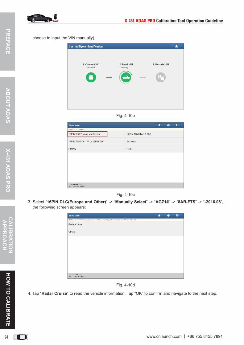
PREFA
CE
X-431 AD
AS PR
OC
ALIB
RATIO
N
APPR
OA
CH
HO
W TO
CA
LIBR
ATEA
BO
UT A
DA
S
X-431ADASPROCalibrationToolOperationGuideline X-431ADASPROCalibrationToolOperationGuideline
94 95www.cnlaunch.com +86 755 8455 7891 www.cnlaunch.com +86 755 8455 7891
choose to input the VIN manually).
Fig. 4-10b
Fig. 4-10c
3. Select “16PIN DLC(Europe and Other)” -> “Manually Select” -> “AGZ1#” -> “8AR-FTS” -> “-2016.08”, the following screen appears:
Fig. 4-10d
4. Tap “Radar Cruise” to read the vehicle information. Tap “OK” to confirm and navigate to the next step.

PREF
AC
EX-
431
AD
AS
PRO
CA
LIB
RAT
ION
A
PPR
OA
CH
HO
W T
O C
ALI
BR
ATE
AB
OU
T A
DA
S
X-431ADASPROCalibrationToolOperationGuideline X-431ADASPROCalibrationToolOperationGuideline
94 95www.cnlaunch.com +86 755 8455 7891 www.cnlaunch.com +86 755 8455 7891
Fig. 4-10e
4. Tap “Front Recognition Camera” to enter the function selection screen.
Fig. 4-10f
5. Tap “Special Function”, the following screen appears.
Fig. 4-10g
In process of “Recognition Camera Axis Adjust”, the system will scan the information of the recognition camera and target position, so you need to create it firstly.
Hereby, “Recognition Camera / Target Position Memory” is used to make the ECU memory save the following information before executing “Recognition Camera Axis Adjust”:• Position information of recognition camera• Position information of the target• Vehicle information

PREFA
CE
X-431 AD
AS PR
OC
ALIB
RATIO
N
APPR
OA
CH
HO
W TO
CA
LIBR
ATEA
BO
UT A
DA
S
X-431ADASPROCalibrationToolOperationGuideline X-431ADASPROCalibrationToolOperationGuideline
96 97www.cnlaunch.com +86 755 8455 7891 www.cnlaunch.com +86 755 8455 7891
6. Select “Recognition Camera/Target Position Memory”. Carefully read the on-screen tips to proceed until the following dialog box displays.
Fig. 4-10h
7. Make sure that the vehicle is stopped and the engine/power switch is ON (Engine OFF/Ready OFF) before proceeding to the next step. Tap “OK”.
Fig. 4-10i
Swipe the screen from the bottom to display all hidden items. Total 12 items are required to enter.
8. Tap “Input” to enter the corresponding values according to the Automotive Repair Manual. After inputting, tap “Next”, a dialog box similar to the following appears.
Fig. 4-10j
9. Now the Recognition Camera/Target Position Memory operation is complete. Keep the vehicle as it is to perform the Recognition Camera Axis Adjust.
*Note:Ifturningengine/powerswitchOFF,anerrormayoccurintheprocessofRecognitionCameraAxisAdjust.Inthatcase,itisnecessaryforyoutoredothisfunctionfrominputtingvalues.
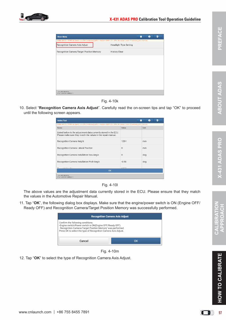
PREF
AC
EX-
431
AD
AS
PRO
CA
LIB
RAT
ION
A
PPR
OA
CH
HO
W T
O C
ALI
BR
ATE
AB
OU
T A
DA
S
X-431ADASPROCalibrationToolOperationGuideline X-431ADASPROCalibrationToolOperationGuideline
96 97www.cnlaunch.com +86 755 8455 7891 www.cnlaunch.com +86 755 8455 7891
Fig. 4-10k
10. Select “Recognition Camera Axis Adjust”. Carefully read the on-screen tips and tap “OK” to proceed until the following screen appears.
Fig. 4-10l
The above values are the adjustment data currently stored in the ECU. Please ensure that they match the values in the Automotive Repair Manual.
11. Tap “OK”, the following dialog box displays. Make sure that the engine/power switch is ON (Engine OFF/Ready OFF) and Recognition Camera/Target Position Memory was successfully performed.
Fig. 4-10m
12. Tap “OK” to select the type of Recognition Camera Axis Adjust.

PREFA
CE
X-431 AD
AS PR
OC
ALIB
RATIO
N
APPR
OA
CH
HO
W TO
CA
LIBR
ATEA
BO
UT A
DA
S
X-431ADASPROCalibrationToolOperationGuideline X-431ADASPROCalibrationToolOperationGuideline
98 99www.cnlaunch.com +86 755 8455 7891 www.cnlaunch.com +86 755 8455 7891
Fig. 4-10n
A. If selecting “One time recognition”, proceed as follows:13. Select “One time recognition”, the following dialog box appears.
Fig. 4-10o
14. Set the target at position 1 as instructed in the Automotive Repair Manual and tap “OK”.
Fig. 4-10p
15. Now the recognition camera axis adjust is complete. Next is to set the headlight type. Make sure that the vehicle is stopped and the engine/power switch is ON(Engine OFF/Ready OFF).
Fig. 4-10q
16. Tap “OK” to select the desired headlight type and follow the instruction to proceed until all steps are finished.
*Note: Alternatively,useralsocanconfigure theheadlight type in“HeadlightTypeSetting” indiagnosticmenuasindicatedFig.4-8g.

PREF
AC
EX-
431
AD
AS
PRO
CA
LIB
RAT
ION
A
PPR
OA
CH
HO
W T
O C
ALI
BR
ATE
AB
OU
T A
DA
S
X-431ADASPROCalibrationToolOperationGuideline X-431ADASPROCalibrationToolOperationGuideline
98 99www.cnlaunch.com +86 755 8455 7891 www.cnlaunch.com +86 755 8455 7891
Fig. 4-10r
B. If selecting “Sequential recognition”, proceed as follows:13. Select “Sequential recognition”, the following dialog box appears.
Fig. 4-10s
14. Set the target at position 1 (Center) as instructed in the Automotive Repair Manual and tap “OK”. The system starts adjusting automatically, and the screen displays as below:
Fig. 4-10t
15. After processing, set the target at position 2 (Left) as instructed in the Automotive Repair Manual and tap “OK” within 180s.
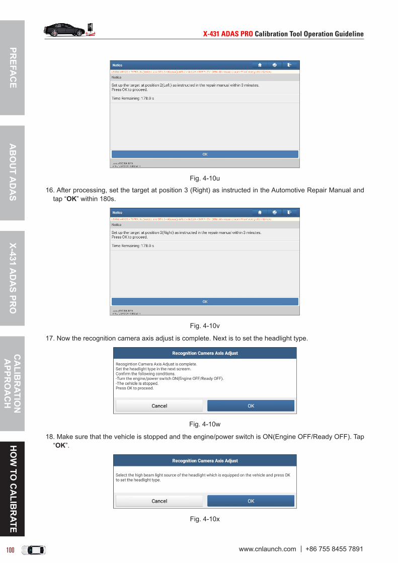
PREFA
CE
X-431 AD
AS PR
OC
ALIB
RATIO
N
APPR
OA
CH
HO
W TO
CA
LIBR
ATEA
BO
UT A
DA
S
X-431ADASPROCalibrationToolOperationGuideline X-431ADASPROCalibrationToolOperationGuideline
100 101www.cnlaunch.com +86 755 8455 7891 www.cnlaunch.com +86 755 8455 7891
Fig. 4-10u
16. After processing, set the target at position 3 (Right) as instructed in the Automotive Repair Manual and tap “OK” within 180s.
Fig. 4-10v
17. Now the recognition camera axis adjust is complete. Next is to set the headlight type.
Fig. 4-10w
18. Make sure that the vehicle is stopped and the engine/power switch is ON(Engine OFF/Ready OFF). Tap “OK”.
Fig. 4-10x

PREF
AC
EX-
431
AD
AS
PRO
CA
LIB
RAT
ION
A
PPR
OA
CH
HO
W T
O C
ALI
BR
ATE
AB
OU
T A
DA
S
X-431ADASPROCalibrationToolOperationGuideline X-431ADASPROCalibrationToolOperationGuideline
100 101www.cnlaunch.com +86 755 8455 7891 www.cnlaunch.com +86 755 8455 7891
19. Select the desired headlight type and follow the instruction to proceed until all steps are finished.
*Note: Alternatively,useralsocanconfigure theheadlight type in“HeadlightTypeSetting” indiagnosticmenuasindicatedFig.4-10g.
Fig. 4-10y

PREFA
CE
X-431 AD
AS PR
OC
ALIB
RATIO
N
APPR
OA
CH
HO
W TO
CA
LIBR
ATEA
BO
UT A
DA
S
X-431ADASPROCalibrationToolOperationGuideline X-431ADASPROCalibrationToolOperationGuideline
102 103www.cnlaunch.com +86 755 8455 7891 www.cnlaunch.com +86 755 8455 7891
4.7 MERCEDES BENZ
4.7.1 Calibrating the front (multifunction) cameraThis chapter describes a general operation procedure of front camera calibration on MERCEDES BENZ E200 2012.It also applies to the following vehicle models:
Model (Series) Chassis No.
CL 216
SLK SLK 172
C 204/205
GLK 204
CLS 218
E 207/212/213/238
ML/GLE/GL/GLS 166
A 176
SL 231
B 246
CLA 117
GLE 292
GLA 156
AMG 190
S 221/222/217
GLC 253
4.7.1.1 Why to calibrate?1). The following diagnostic trouble codes are found on the vehicle:
A28600 - Control unit not calibrated. B228600 - Control unit not calibrated.
2). The following repairs and replacements are made on the vehicle: Front camera has been replaced. The windshield has been removed, installed or replaced. Chassis structure has been changed/adjusted. One of the vehicle level sensors has been replaced.
4.7.1.2 Operation Notes
Make sure the following conditions are met:
On vehicle & diagnostic tool
• Use the MERCEDES BENZ diagnostic software version 49.20 or above to perform the calibration. • Make sure that the VCI device has been plugged into the vehicle’s DLC.• Turn on the ignition.• Park the unloaded vehicle along with the four wheels on a horizontal surface.

PREF
AC
EX-
431
AD
AS
PRO
CA
LIB
RAT
ION
A
PPR
OA
CH
HO
W T
O C
ALI
BR
ATE
AB
OU
T A
DA
S
X-431ADASPROCalibrationToolOperationGuideline X-431ADASPROCalibrationToolOperationGuideline
102 103www.cnlaunch.com +86 755 8455 7891 www.cnlaunch.com +86 755 8455 7891
• All vehicle doors must be closed.• Wheel pressure is set to the standard value.• Turn off the headlamp. • The vehicle is on the normal level.• Adjust the steering wheel to the straight ahead position.
On calibration tool
• Camera view is free and clean.• The front wheel is at straight ahead position, and the steering angle sensor is set to zero.• Use the LAC01-01 calibration pattern.
LAC01-01
• The distance from calibration pattern to the front edge of the vehicle license plate is 0 mm/0 inch.• The height of the calibration pattern from the ground is 1275 mm/50.2 inch.• Read the back label: 1595 mm/62.8 inch (namely the value that the scale pointer aimed at the scale ruler
on the beam lifter).
*The right value is the back label reading, the left one is the actual height.
• ADAS calibration pattern is placed in parallel in front of the vehicle.• ADAS calibration pattern is placed in the center of the front of the vehicle.
4.7.1.3 Start calibrationFollow the steps below to proceed:1. Tap “ADAS” on the Job menu of the diagnostic tool.

PREFA
CE
X-431 AD
AS PR
OC
ALIB
RATIO
N
APPR
OA
CH
HO
W TO
CA
LIBR
ATEA
BO
UT A
DA
S
X-431ADASPROCalibrationToolOperationGuideline X-431ADASPROCalibrationToolOperationGuideline
104 105www.cnlaunch.com +86 755 8455 7891 www.cnlaunch.com +86 755 8455 7891
Fig. 4-11a
2. The diagnostic tool starts communicating with the VCI and decoding VIN.
Fig. 4-11b
3. After the VIN is successfully decoded, the screen display as follows:
Fig. 4-11c
4. Select “MFK - Multifunction camera(A40/11)”. If the ignition switch is OFF, please turn it ON. The system will navigate to the function selection screen.

PREF
AC
EX-
431
AD
AS
PRO
CA
LIB
RAT
ION
A
PPR
OA
CH
HO
W T
O C
ALI
BR
ATE
AB
OU
T A
DA
S
X-431ADASPROCalibrationToolOperationGuideline X-431ADASPROCalibrationToolOperationGuideline
104 105www.cnlaunch.com +86 755 8455 7891 www.cnlaunch.com +86 755 8455 7891
Fig. 4-11d (Select “Special Function”)
Fig. 4-11e
5. Tap “Teach-in Processes - Calibration”, a dialog box appears on the screen.
Fig. 4-11f
6. Make sure the component A40/11 multifunction camera is fastened correctly. Tap “OK” to go to the next step.
Fig. 4-11g
7. Before performing calibration, it is essential to erase the diagnostic trouble fault. Tap “Yes” to start erasing

PREFA
CE
X-431 AD
AS PR
OC
ALIB
RATIO
N
APPR
OA
CH
HO
W TO
CA
LIBR
ATEA
BO
UT A
DA
S
X-431ADASPROCalibrationToolOperationGuideline X-431ADASPROCalibrationToolOperationGuideline
106 107www.cnlaunch.com +86 755 8455 7891 www.cnlaunch.com +86 755 8455 7891
the fault codes.
Fig. 4-11h
8. After the fault codes are erased, the screen will guide you through detailed calibration guidelines. Swipe the screen from the bottom to view the hidden content.
Fig. 4-11i
9. After reading all operation guidelines, tap “OK”, the following dialog box will pop up on the screen.
Fig. 4-11j
9. Tap “Yes” to start calibration. Be patient to wait until the calibration is successfully completed.
Fig. 4-11k

PREF
AC
EX-
431
AD
AS
PRO
CA
LIB
RAT
ION
A
PPR
OA
CH
HO
W T
O C
ALI
BR
ATE
AB
OU
T A
DA
S
X-431ADASPROCalibrationToolOperationGuideline X-431ADASPROCalibrationToolOperationGuideline
106 107www.cnlaunch.com +86 755 8455 7891 www.cnlaunch.com +86 755 8455 7891
Fig. 4-11l
Fig. 4-11m (Calibration OK)

PREFA
CE
X-431 AD
AS PR
OC
ALIB
RATIO
N
APPR
OA
CH
HO
W TO
CA
LIBR
ATEA
BO
UT A
DA
S
X-431ADASPROCalibrationToolOperationGuideline X-431ADASPROCalibrationToolOperationGuideline
108 109www.cnlaunch.com +86 755 8455 7891 www.cnlaunch.com +86 755 8455 7891
4.7.2 Calibrating the rear cameraThis chapter describes a general operation procedure of front camera calibration on MERCEDES BENZ C 200 2010.It also applies to the following vehicle models:
Model (Series) Chassis No.
CL 216
SLK SLK 172
C 204/205
GLK 204
CLS 218
E 207/212/213/238
ML/GLE/GL/GLS 164/166
A 176
SL 231
B 246
CLA 117
GLE 292
GLA 156
S 221
4.7.2.1 Why to calibrate?The rear camera has been replaced.
4.7.2.2 Operation Notes
Make sure the following conditions are met:
On vehicle & diagnostic tool
• Use the MERCEDES BENZ diagnostic software version 49.20 or above to perform the calibration. • Make sure that the VCI device has been plugged into the vehicle’s DLC.• The function “Reversing camera AUTOMATICALLY ON” in the “System/Settings” menu must be activated
in Audio or CMNAND.• The steering angle sensor must be calibrated.• Park the unloaded vehicle along with the four wheels on a horizontal surface.• The vehicle is at the normal level and must be unloaded.• Ensure that there are no persons or objects in the vehicle.• Ensure that no persons or objects are located at the rear of the vehicle.• Correct the tire pressure and set it to the standard value.• The steering wheel is in the straight ahead position.• All vehicle doors must be closed.• The trunk lid or the lift gate should be closed.• Ensure that the workshop is adequately illuminated.• Use the LAC02-02 calibration pattern to perform the rear camera calibration.

PREF
AC
EX-
431
AD
AS
PRO
CA
LIB
RAT
ION
A
PPR
OA
CH
HO
W T
O C
ALI
BR
ATE
AB
OU
T A
DA
S
X-431ADASPROCalibrationToolOperationGuideline X-431ADASPROCalibrationToolOperationGuideline
108 109www.cnlaunch.com +86 755 8455 7891 www.cnlaunch.com +86 755 8455 7891
LAC02-02
On calibration tool
• Set a distance of 1300mm/51.18inch between the calibration pattern and the vehicle’s rear wheel (The two rear wheels are parallel with the calibration pattern).
• Attach the calibration pattern LAC02-02 on the calibration frame.• ADAS calibration pattern is placed in parallel in front of the vehicle.• ADAS calibration pattern is placed in the center of the front of the vehicle.
4.7.2.3 Start calibrationFollow the steps below to proceed:1. Tap “ADAS” on the Job menu of the diagnostic tool.
Fig. 4-12a
2. The diagnostic tool starts communicating with the VCI and decoding VIN.
Fig. 4-12b
3. After the VIN is successfully decoded, the screen display as follows:

PREFA
CE
X-431 AD
AS PR
OC
ALIB
RATIO
N
APPR
OA
CH
HO
W TO
CA
LIBR
ATEA
BO
UT A
DA
S
X-431ADASPROCalibrationToolOperationGuideline X-431ADASPROCalibrationToolOperationGuideline
110 111www.cnlaunch.com +86 755 8455 7891 www.cnlaunch.com +86 755 8455 7891
Fig. 4-12c
4. Select “RFK - Backup Camera”. If the ignition switch is OFF, please turn it ON. The system will navigate to the function selection screen.
Fig. 4-12d (Select “Special Function”)
Fig. 4-12e (Tap “Teach-in Processes”)

PREF
AC
EX-
431
AD
AS
PRO
CA
LIB
RAT
ION
A
PPR
OA
CH
HO
W T
O C
ALI
BR
ATE
AB
OU
T A
DA
S
X-431ADASPROCalibrationToolOperationGuideline X-431ADASPROCalibrationToolOperationGuideline
110 111www.cnlaunch.com +86 755 8455 7891 www.cnlaunch.com +86 755 8455 7891
Fig. 4-12f
5. Tap “Calibration of Steering Angle Sensor”, the following dialog box appears on the screen.
Fig. 4-12g (Tap “Yes” to abort it)
Before calibrating the reversing camera, the steering angle needs to be calibrated firstly. Additionally, the calibration pattern LAC02-02 is essential to calibrate the reversing camera.
6. Tap “No” to continue.
Fig. 4-12h
7. Tap “OK” to start calibrating the steering angle sensor.

PREFA
CE
X-431 AD
AS PR
OC
ALIB
RATIO
N
APPR
OA
CH
HO
W TO
CA
LIBR
ATEA
BO
UT A
DA
S
X-431ADASPROCalibrationToolOperationGuideline X-431ADASPROCalibrationToolOperationGuideline
112 113www.cnlaunch.com +86 755 8455 7891 www.cnlaunch.com +86 755 8455 7891
Fig. 4-12i
8. Follow the on-screen prompts to turn the steering wheel to full LEFT lock, and tap “OK”.
Fig. 4-12j
9. Then turn the steering wheel to full RIGHT lock, and tap “OK”.
Fig. 4-12k
10. Next is to calibrate the steering angle sensor by moving the steering wheel to center position (straight-ahead travel). Tap “OK” to start.
Fig. 4-12l
11. Switch off the combustion engine and tap “OK”. Now the calibration of steering angle sensor is successfully finished.
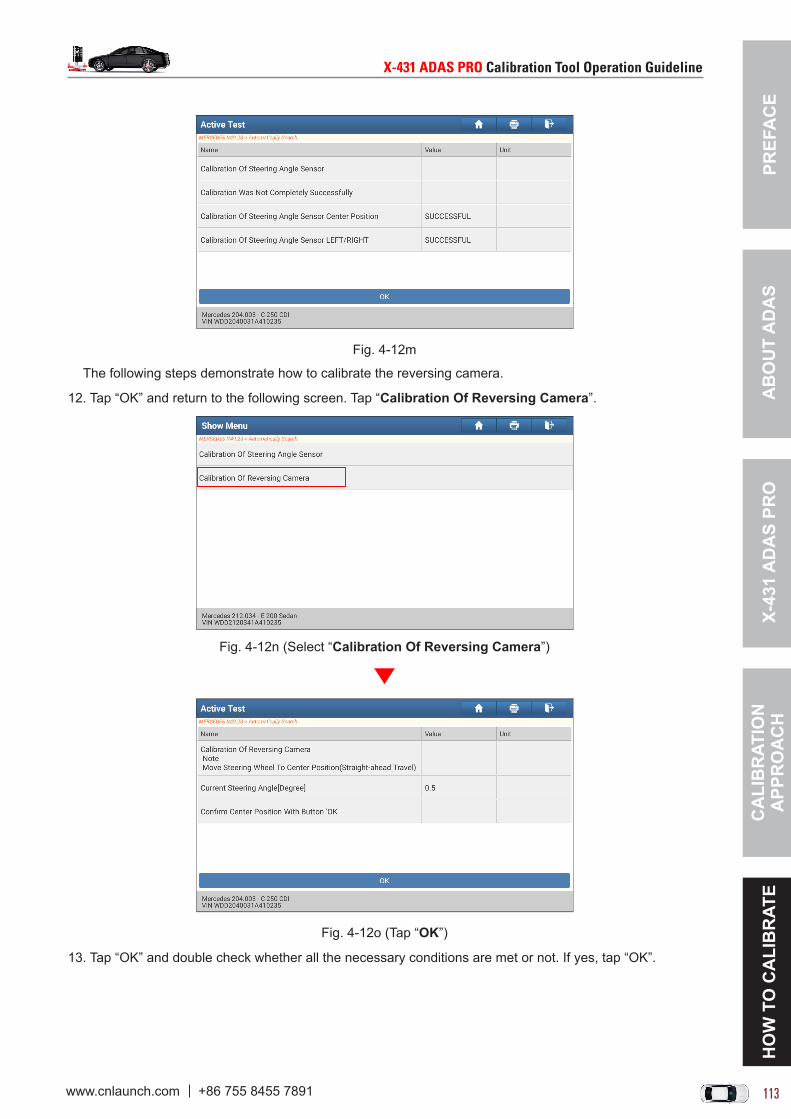
PREF
AC
EX-
431
AD
AS
PRO
CA
LIB
RAT
ION
A
PPR
OA
CH
HO
W T
O C
ALI
BR
ATE
AB
OU
T A
DA
S
X-431ADASPROCalibrationToolOperationGuideline X-431ADASPROCalibrationToolOperationGuideline
112 113www.cnlaunch.com +86 755 8455 7891 www.cnlaunch.com +86 755 8455 7891
Fig. 4-12m
The following steps demonstrate how to calibrate the reversing camera.
12. Tap “OK” and return to the following screen. Tap “Calibration Of Reversing Camera”.
Fig. 4-12n (Select “Calibration Of Reversing Camera”)
Fig. 4-12o (Tap “OK”)
13. Tap “OK” and double check whether all the necessary conditions are met or not. If yes, tap “OK”.
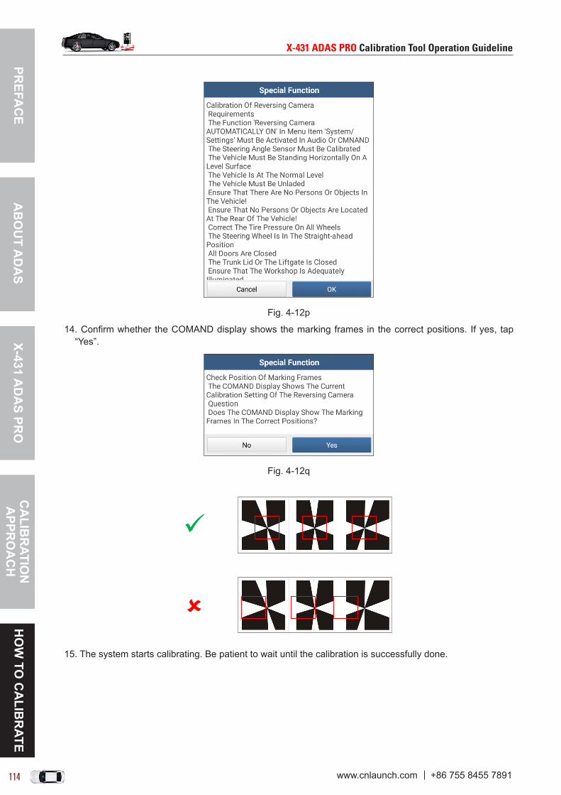
PREFA
CE
X-431 AD
AS PR
OC
ALIB
RATIO
N
APPR
OA
CH
HO
W TO
CA
LIBR
ATEA
BO
UT A
DA
S
X-431ADASPROCalibrationToolOperationGuideline X-431ADASPROCalibrationToolOperationGuideline
114 115www.cnlaunch.com +86 755 8455 7891 www.cnlaunch.com +86 755 8455 7891
Fig. 4-12p
14. Confirm whether the COMAND display shows the marking frames in the correct positions. If yes, tap “Yes”.
Fig. 4-12q
15. The system starts calibrating. Be patient to wait until the calibration is successfully done.

PREF
AC
EX-
431
AD
AS
PRO
CA
LIB
RAT
ION
A
PPR
OA
CH
HO
W T
O C
ALI
BR
ATE
AB
OU
T A
DA
S
X-431ADASPROCalibrationToolOperationGuideline X-431ADASPROCalibrationToolOperationGuideline
114 115www.cnlaunch.com +86 755 8455 7891 www.cnlaunch.com +86 755 8455 7891
Fig. 4-12r
Fig. 4-12s (Calibration OK)

PREFA
CE
X-431 AD
AS PR
OC
ALIB
RATIO
N
APPR
OA
CH
HO
W TO
CA
LIBR
ATEA
BO
UT A
DA
S
X-431ADASPROCalibrationToolOperationGuideline X-431ADASPROCalibrationToolOperationGuideline
116 117www.cnlaunch.com +86 755 8455 7891 www.cnlaunch.com +86 755 8455 7891
4.7.3 Calibrating the 360o all-view cameraThis chapter describes a general operation procedure of front camera calibration on MERCEDES BENZ C 200 2010.It also applies to the following vehicle models:
Model (Series) Chassis No.
C 204/205
GLK 204
CLS 218
E 207/212/213/238
ML/GLE/GL/GLS 166
GLE 292
GLA 156
AMG 190
S 222/217
GLC 253
4.7.3.1 Why to calibrate? One or more of 360o camera(s) has(have) been replaced . Failed to view the image or the screen appears blank.
4.7.3.2 Operation Notes
Make sure the following conditions are met:
On vehicle & diagnostic tool
• Use the MERCEDES BENZ diagnostic software version 49.20 or above to perform the calibration. • Make sure that the VCI device has been plugged into the vehicle’s DLC.• Clean the lenses of all 360o cameras.• Folding in/out of outside mirrors.• The outside mirrors must be engaged in the drive position.• All vehicle doors must be closed.• When performing calibration, keep driving the vehicle on a flat road in a good weather condition. Poor
weather conditions and visibility (e.g. rain or fog) can impair or prevent the calibration.• The vehicle speed must be between 5 and 30km/h (3 to 20Mph). • Drive the vehicle in such a way that the “Vehicle speed” and “Steering angle” in the COMAND display are
displayed in GREEN. • When the calibration comes to an end, a symbol of “green tick” will be shown in the COMAND display.
4.7.3.3 Start calibrationFollow the steps below to proceed:1. Tap “ADAS” on the Job menu of the diagnostic tool.

PREF
AC
EX-
431
AD
AS
PRO
CA
LIB
RAT
ION
A
PPR
OA
CH
HO
W T
O C
ALI
BR
ATE
AB
OU
T A
DA
S
X-431ADASPROCalibrationToolOperationGuideline X-431ADASPROCalibrationToolOperationGuideline
116 117www.cnlaunch.com +86 755 8455 7891 www.cnlaunch.com +86 755 8455 7891
Fig. 4-13a
2. The diagnostic tool starts communicating with the VCI and decoding VIN.
Fig. 4-13b
3. After the VIN is successfully decoded, the screen display as follows:
Fig. 4-13c
4. Select “360 Degree Camera - 360 Degree camera(N148)”. If the ignition switch is OFF, please turn it ON. The system will navigate to the function selection screen.
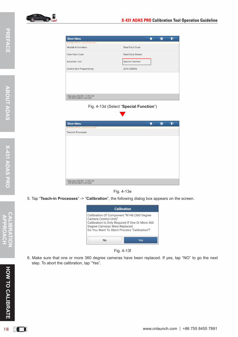
PREFA
CE
X-431 AD
AS PR
OC
ALIB
RATIO
N
APPR
OA
CH
HO
W TO
CA
LIBR
ATEA
BO
UT A
DA
S
X-431ADASPROCalibrationToolOperationGuideline X-431ADASPROCalibrationToolOperationGuideline
118 119www.cnlaunch.com +86 755 8455 7891 www.cnlaunch.com +86 755 8455 7891
Fig. 4-13d (Select “Special Function”)
Fig. 4-13e
5. Tap “Teach-in Processes” -> “Calibration”, the following dialog box appears on the screen.
Fig. 4-13f
6. Make sure that one or more 360 degree cameras have been replaced. If yes, tap “NO” to go the next step. To abort the calibration, tap “Yes”.

PREF
AC
EX-
431
AD
AS
PRO
CA
LIB
RAT
ION
A
PPR
OA
CH
HO
W T
O C
ALI
BR
ATE
AB
OU
T A
DA
S
X-431ADASPROCalibrationToolOperationGuideline X-431ADASPROCalibrationToolOperationGuideline
118 119www.cnlaunch.com +86 755 8455 7891 www.cnlaunch.com +86 755 8455 7891
Fig. 4-13g
7. Swipe the screen from the bottom to carefully read all operation guidelines. After reading, tap “OK” to navigate to the camera selection screen.
Fig. 4-13h
These 5 cameras feature the similar calibration steps. He we take “Calibration of 360 Degree Camera At Front End” for example to demonstrate how to calibrate the 360 degree camera.
8. Tap “Calibration of 360 Degree Camera At Front End”, the following dialog box appears.
Fig. 4-13i
9. Tap “Yes” to start calibration.

PREFA
CE
X-431 AD
AS PR
OC
ALIB
RATIO
N
APPR
OA
CH
HO
W TO
CA
LIBR
ATEA
BO
UT A
DA
S
X-431ADASPROCalibrationToolOperationGuideline X-431ADASPROCalibrationToolOperationGuideline
120 121www.cnlaunch.com +86 755 8455 7891 www.cnlaunch.com +86 755 8455 7891
Fig. 4-13j (Calibration OK)
10. When the values of “Vehicle speed” and “Steering angle” change into “GREEN”, tap “OK” to confirm and end the session.

PREF
AC
EX-
431
AD
AS
PRO
CA
LIB
RAT
ION
A
PPR
OA
CH
HO
W T
O C
ALI
BR
ATE
AB
OU
T A
DA
S
X-431ADASPROCalibrationToolOperationGuideline X-431ADASPROCalibrationToolOperationGuideline
120 121www.cnlaunch.com +86 755 8455 7891 www.cnlaunch.com +86 755 8455 7891
4.8 RENAULT
4.8.1 Calibrating the front cameraThis chapter describes a general operation procedure of front camera calibration on RENAULT KADJAR.It also applies to the following vehicle models:
Model (Series) Year
MEGANE IV SEDAN As of 2017
MEGANE IV As of 2016
KADJAR As of 2016
ESPACE V As of 2016
KOLEOS II As of 2017
KOLEOS II CN As of 2017
4.8.1.1 Why to calibrate?1). The diagnostic fault memory is found on the vehicle:
Front camera not calibrated or incorrectly calibrated.
2). The following repairs and replacements are made on the vehicle: Front camera has been replaced. The windshield has been removed, installed or replaced. One of the vehicle level sensors has been replaced.
4.8.1.2 Operation Notes
Make sure the following conditions are met:
On vehicle & diagnostic tool
• Use the RENAULT diagnostic software version 42.85 or above to perform the calibration. • Make sure that the VCI device has been plugged into the vehicle’s DLC.• Turn on the ignition.• Park the unloaded vehicle along with the four wheels on a horizontal surface.
• All vehicle doors must be closed.• Wheel pressure is set to the standard value.• The vehicle battery is fully charged. • The trunk is unloaded.• The Lane Change Warning system switch is ON.• Make sure that no persons are located in the vehicle in process of calibration.
On calibration tool
• Camera view is free and clean.

PREFA
CE
X-431 AD
AS PR
OC
ALIB
RATIO
N
APPR
OA
CH
HO
W TO
CA
LIBR
ATEA
BO
UT A
DA
S
X-431ADASPROCalibrationToolOperationGuideline X-431ADASPROCalibrationToolOperationGuideline
122 123www.cnlaunch.com +86 755 8455 7891 www.cnlaunch.com +86 755 8455 7891
• The front wheel is at straight ahead position, and the steering angle sensor is set to zero.• Use the LAC01-12 calibration pattern and attach it on the calibration frame.
LAC01-12
• The distance from calibration pattern to the center of the front wheel hubs is 3000 mm (±50mm)/118.11 inch (±1.968 inch).
• The height of the calibration pattern from the ground is 1740 mm/68.504 inch.• Read the back label: 2000 mm/78.74 inch (namely the value that the scale pointer aimed at the scale
ruler on the beam lifter).
*The right value is the back label reading, the left one is the actual height.
• ADAS calibration pattern is placed in parallel in front of the vehicle.• ADAS calibration pattern is placed in the center of the front of the vehicle.
4.8.1.3 Start calibrationFollow the steps below to proceed:1. Tap “ADAS” on the Job menu of the diagnostic tool.

PREF
AC
EX-
431
AD
AS
PRO
CA
LIB
RAT
ION
A
PPR
OA
CH
HO
W T
O C
ALI
BR
ATE
AB
OU
T A
DA
S
X-431ADASPROCalibrationToolOperationGuideline X-431ADASPROCalibrationToolOperationGuideline
122 123www.cnlaunch.com +86 755 8455 7891 www.cnlaunch.com +86 755 8455 7891
Fig. 4-14a
2. The diagnostic tool starts communicating with the VCI and decoding VIN.
Fig. 4-14b
3. After the VIN is successfully decoded, the screen display as follows(Alternatively, it can be accessed by manually selecting “Local Diagnosis” -> “RENAULT” -> “ADAS Calibration” -> “KADJAR”):
Fig. 4-14c
4. Select “Front Camera”, the system navigates to the function selection screen.

PREFA
CE
X-431 AD
AS PR
OC
ALIB
RATIO
N
APPR
OA
CH
HO
W TO
CA
LIBR
ATEA
BO
UT A
DA
S
X-431ADASPROCalibrationToolOperationGuideline X-431ADASPROCalibrationToolOperationGuideline
124 125www.cnlaunch.com +86 755 8455 7891 www.cnlaunch.com +86 755 8455 7891
Fig. 4-14d
5. Tap “Special Function” to navigate to the following calibration menu screen.
Fig. 4-14e
5. Tap “Front Camera Calibration”, a dialog box appears on the screen.
Fig. 4-14f
6. Make sure that the ADAS calibration tool is well-prepared and the calibration pattern LAC01-12 has been installed on the calibration frame. Tap “OK” to carefully read all operation tips.

PREF
AC
EX-
431
AD
AS
PRO
CA
LIB
RAT
ION
A
PPR
OA
CH
HO
W T
O C
ALI
BR
ATE
AB
OU
T A
DA
S
X-431ADASPROCalibrationToolOperationGuideline X-431ADASPROCalibrationToolOperationGuideline
124 125www.cnlaunch.com +86 755 8455 7891 www.cnlaunch.com +86 755 8455 7891
Fig. 4-14g
7. Swipe the screen from the bottom to view the hidden content. After ensuring that all conditions are met, tap “OK”. The following screen displays:
Fig. 4-14h
8. Since the following parameters of front camera are very important to perform the calibration, it is necessary to check whether these parameters satisfy the specified values.
Yaw Angle: between -27° and 27° Roll Angle: between -0.05° and 0.05° Pitch Angle: between -3° and 3°
A). If these parameters are within the standard range, tap “OK” to start the calibration. If successful, the following message box appears.
Fig. 4-14i (Calibration OK)

PREFA
CE
X-431 AD
AS PR
OC
ALIB
RATIO
N
APPR
OA
CH
HO
W TO
CA
LIBR
ATEA
BO
UT A
DA
S
X-431ADASPROCalibrationToolOperationGuideline X-431ADASPROCalibrationToolOperationGuideline
126 127www.cnlaunch.com +86 755 8455 7891 www.cnlaunch.com +86 755 8455 7891
Tap “OK” to confirm and end the session.B). If these parameters are out of the standard range, tap “OK”. A message box prompting calibration failure will pop up on the screen. Tap “OK” to confirm and exit.
Fig. 4-14j (Tap “OK”)
Fig. 4-14k

PREF
AC
EX-
431
AD
AS
PRO
CA
LIB
RAT
ION
A
PPR
OA
CH
HO
W T
O C
ALI
BR
ATE
AB
OU
T A
DA
S
X-431ADASPROCalibrationToolOperationGuideline X-431ADASPROCalibrationToolOperationGuideline
126 127www.cnlaunch.com +86 755 8455 7891 www.cnlaunch.com +86 755 8455 7891
4.9 PORSCHE
4.9.1 Calibrating the front cameraThis chapter describes a general operation procedure of front camera calibration on Porsche Cayenne 92A 2016.
4.9.1.1 Why to calibrate?1). The following diagnostic trouble codes are found on the vehicle (No or incorrect basic setting/adaption):
B201000 C1106F0 C110A76
2). The following repairs and replacements are made on the vehicle: Front camera has been replaced. The windshield has been removed, installed or replaced. Chassis structure has been changed/adjusted. The level sensor has been replaced.
4.9.1.2 Operation Notes
Make sure the following conditions are met:
On vehicle & diagnostic tool
• Use the PORSCHE diagnostic software version 23.40 or above to perform the calibration. • Make sure that the VCI device has been plugged into the vehicle’s DLC.• Turn on the ignition.• Park the unloaded vehicle along with the four wheels on a horizontal surface.
• All vehicle doors must be closed.• Axle geometry must be OK.• Wheel pressure is set to the standard value.• The vehicle was bottomed out several times.• The vehicle battery voltage is sufficient (Please connect to the battery charger if necessary). • Select Comfort mode and then activate Jack mode (vehicles with Pneumatic suspension.)• Turn off the headlamp.
On calibration tool
• Camera view is free and clean.• The front wheel is at straight ahead position, and the steering angle sensor is set to zero.• Use the LAC01-12 calibration pattern and attach it on the calibration frame.

PREFA
CE
X-431 AD
AS PR
OC
ALIB
RATIO
N
APPR
OA
CH
HO
W TO
CA
LIBR
ATEA
BO
UT A
DA
S
X-431ADASPROCalibrationToolOperationGuideline X-431ADASPROCalibrationToolOperationGuideline
128 129www.cnlaunch.com +86 755 8455 7891 www.cnlaunch.com +86 755 8455 7891
LAC01-02 (Standard)
• The distance from calibration pattern to the center of the front wheel hubs is 150cm (±2.5cm).
• Read the back label: 1360cm (±1cm) (namely the value that the scale pointer aimed at the scale ruler on the beam lifter).
*The right value is the back label reading, the left one is the actual height.
Below formulates the back labels for other PORSCHE models:
Standard back label Model Year
150cm
Panamera 970 2010~2016
911_991 2012~2019
Boxster/Cayman_981 2013~2019
170cmCayenne 92A 2011~2016
Macan 2014~2019
• ADAS calibration pattern is placed in parallel in front of the vehicle.• ADAS calibration pattern is placed in the center of the front of the vehicle.• Make sure that the level gauge bubbles on the calibration tool are centred.
4.9.1.3 Start calibrationFollow the steps below to proceed:

PREF
AC
EX-
431
AD
AS
PRO
CA
LIB
RAT
ION
A
PPR
OA
CH
HO
W T
O C
ALI
BR
ATE
AB
OU
T A
DA
S
X-431ADASPROCalibrationToolOperationGuideline X-431ADASPROCalibrationToolOperationGuideline
128 129www.cnlaunch.com +86 755 8455 7891 www.cnlaunch.com +86 755 8455 7891
1. Tap “ADAS” on the Job menu of the diagnostic tool.
Fig. 4-15a
2. The diagnostic tool starts communicating with the VCI and decoding VIN.
Fig. 4-15b
3. After the VIN is successfully decoded, the screen display as follows:
Fig. 4-15c
4. Select “Pre-calibration Camera”, the system navigates to the function selection screen.

PREFA
CE
X-431 AD
AS PR
OC
ALIB
RATIO
N
APPR
OA
CH
HO
W TO
CA
LIBR
ATEA
BO
UT A
DA
S
X-431ADASPROCalibrationToolOperationGuideline X-431ADASPROCalibrationToolOperationGuideline
130 131www.cnlaunch.com +86 755 8455 7891 www.cnlaunch.com +86 755 8455 7891
Fig. 4-15d
5. Tap “Pre-calibration Camera”, a dialog box appears on the screen.
Fig. 4-15e
6. Tap “OK” to carefully read all operation tips.
Fig. 4-15f
7. Swipe the screen from the bottom to view the hidden content. After ensuring that all conditions are met, tap “OK”. The following screen displays:

PREF
AC
EX-
431
AD
AS
PRO
CA
LIB
RAT
ION
A
PPR
OA
CH
HO
W T
O C
ALI
BR
ATE
AB
OU
T A
DA
S
X-431ADASPROCalibrationToolOperationGuideline X-431ADASPROCalibrationToolOperationGuideline
130 131www.cnlaunch.com +86 755 8455 7891 www.cnlaunch.com +86 755 8455 7891
Fig. 4-15g
8. Tap “OK” to confirm and enter the following screen.
Fig. 4-15h
9. Read the on-screen tips to measure the height from the tire contact surface (ground) to the bottom edge of the fend at each wheel (Front Right, Rear Right, Rear Left and Front Left) (*Note: The value is between 400mm and 1100mm). Tap “OK”.
Fig. 4-15i
10. Tap the desired option to input the measured value. After inputting, tap “Next” to confirm the values you entered.

PREFA
CE
X-431 AD
AS PR
OC
ALIB
RATIO
N
APPR
OA
CH
HO
W TO
CA
LIBR
ATEA
BO
UT A
DA
S
X-431ADASPROCalibrationToolOperationGuideline X-431ADASPROCalibrationToolOperationGuideline
132 133www.cnlaunch.com +86 755 8455 7891 www.cnlaunch.com +86 755 8455 7891
Fig. 4-15j
11. If all values are correct, tap “Next”, a prompt message box will appear on the screen.
Fig. 4-15k
12. Tap “OK” to start the calibration. If the status displays “Calibration Successful”, it indicates that the calibration is successfully completed. If “Calibration Failed” shows, check all the necessary requirements for the calibration and correct the positioning of the ADAS tool and the vehicle.
Fig. 4-15l
13. Tap “OK” to end the calibration session. Turn the ignition switch OFF and wait for at least 10 seconds, and then switch the ignition on again. Use the diagnostic tool to scan the vehicle and double check whether the previous calibration-related fault memory exists or not.

PREF
AC
EX-
431
AD
AS
PRO
CA
LIB
RAT
ION
A
PPR
OA
CH
HO
W T
O C
ALI
BR
ATE
AB
OU
T A
DA
S
X-431ADASPROCalibrationToolOperationGuideline X-431ADASPROCalibrationToolOperationGuideline
132 133www.cnlaunch.com +86 755 8455 7891 www.cnlaunch.com +86 755 8455 7891
4.10 VOLVO
4.10.1 Calibrating the front camera & radarThis chapter describes a general operation procedure of front camera calibration on VOLVO S60 2015.
4.10.1.1 Why to calibrate?1). The following diagnostic trouble codes are found on the vehicle (No or incorrect basic setting/adaption):
FSM-C100154 Vision system camera - system programming failures - missing calibration. FSM-U030055 Internal control module software incompatibility - System programming failures - Not
configured.
2). The following repairs and replacements are made on the vehicle: When replacing with new forward facing radar, the radar must be calibrated. When replacing forward sensing camera, the camera must be calibrated. When replacing forward sensing module (FSM) or downloading software, both the camera and radar
must be calibrated.
4.10.1.2 Operation Notes
Make sure the following conditions are met:
On vehicle & diagnostic tool
• Use the VOLVO diagnostic software version 44.10 or above to perform the calibration. • Make sure that the VCI device has been plugged into the vehicle’s DLC.• Keep the engine OFF. Turn the ignition switch ON (press the START button for about 4~5 seconds until
the dashboard light illuminates).
4.10.1.3 Calibration ProcedureThe following operation flowchart allows you to get familiar with the calibration operation steps.
Choose “Special Function”
Choose “Calibration of Radar and Camera”
Select “Read off Diagnostic Trouble Codes”
Perform “Activate Calibrations”
Follow the on-screen instructions to calibrate
Confirm the calibration result and erase the DTC
Read the DTC again to check erased or not
*This step is used to confirm whether the calibration-related DTC exists or not.
*The option to be calibrated depends on the existing DTC.
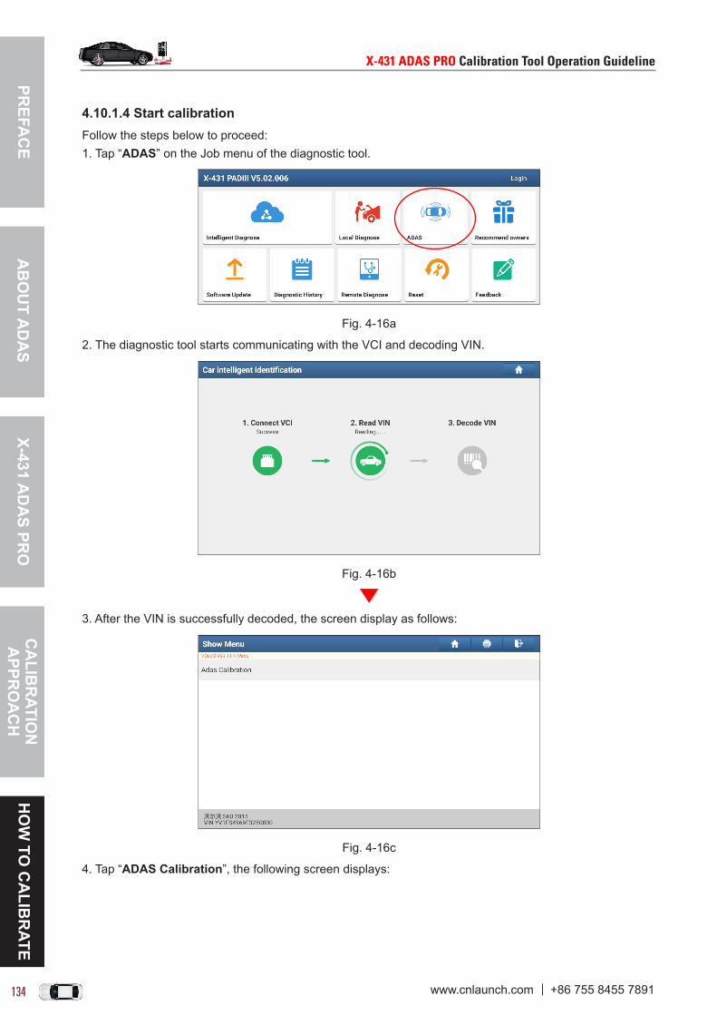
PREFA
CE
X-431 AD
AS PR
OC
ALIB
RATIO
N
APPR
OA
CH
HO
W TO
CA
LIBR
ATEA
BO
UT A
DA
S
X-431ADASPROCalibrationToolOperationGuideline X-431ADASPROCalibrationToolOperationGuideline
134 135www.cnlaunch.com +86 755 8455 7891 www.cnlaunch.com +86 755 8455 7891
4.10.1.4 Start calibrationFollow the steps below to proceed:1. Tap “ADAS” on the Job menu of the diagnostic tool.
Fig. 4-16a
2. The diagnostic tool starts communicating with the VCI and decoding VIN.
Fig. 4-16b
3. After the VIN is successfully decoded, the screen display as follows:
Fig. 4-16c
4. Tap “ADAS Calibration”, the following screen displays:

PREF
AC
EX-
431
AD
AS
PRO
CA
LIB
RAT
ION
A
PPR
OA
CH
HO
W T
O C
ALI
BR
ATE
AB
OU
T A
DA
S
X-431ADASPROCalibrationToolOperationGuideline X-431ADASPROCalibrationToolOperationGuideline
134 135www.cnlaunch.com +86 755 8455 7891 www.cnlaunch.com +86 755 8455 7891
Fig. 4-16d
5. Select “S60(11-)”, the system navigates to the function selection screen.
Fig. 4-16e
6. Tap “Special Function”, the following screen appears:
Fig. 4-16f
7. Tap “Calibration of Radar and Camera”, a dialog box appears on the screen.
*Note:Nocalibrationpatternisrequiredforthecalibrationoftheforward-sensingradarandcamera.Thecalibrationcanbedonejustbystartingtherespectivecalibrationprocedure(dependingontheretrievedDTCs)andthendrivingthevehicle.
Whendrivingthevehicle,theradarmeasuresstationaryobjectsalongtheroad,e.g.guardrails,signsorsimilar,andadjustselectronically.Thecamerasearchesforloadlines,roadedges,pavementsorsimilarshapeswhichmeetsapointonthehorizon.

PREFA
CE
X-431 AD
AS PR
OC
ALIB
RATIO
N
APPR
OA
CH
HO
W TO
CA
LIBR
ATEA
BO
UT A
DA
S
X-431ADASPROCalibrationToolOperationGuideline X-431ADASPROCalibrationToolOperationGuideline
136 137www.cnlaunch.com +86 755 8455 7891 www.cnlaunch.com +86 755 8455 7891
Fig. 4-16g
8. Swipe the screen from the bottom to scroll the operation tips. After reading, tap “OK”. Next we will read the diagnostic trouble codes first, and then determine whether to perform the calibration or not.
Fig. 4-16h
9. Tap “Read off Diagnostic Trouble Codes(DTCs)”, a prompt message will pop up on the screen.
• If the DTC U030055 is found, the radar needs to be calibrated.• If the DTC C100154 is retrieved, the camera needs to be calibrated.• If the DTC U030055 and DTC C100154 are both found, calibrations of the radar and camera should be
performed at the same time.
*Note:IftheDTCsareeasedbeforethecalibration,theDTCU030055andDTCC100154disappearbutthetextmessageremainsintheDriverInformationModule(DIM),whichwillappearinthenextdriv-ingcycle.Ifbothradarandcameraneedtobecalibrated,thetextmessagestoredinDriverInforma-tionModule(DIM)willgooutwhentheyhavebeensuccessfullycalibrated.

PREF
AC
EX-
431
AD
AS
PRO
CA
LIB
RAT
ION
A
PPR
OA
CH
HO
W T
O C
ALI
BR
ATE
AB
OU
T A
DA
S
X-431ADASPROCalibrationToolOperationGuideline X-431ADASPROCalibrationToolOperationGuideline
136 137www.cnlaunch.com +86 755 8455 7891 www.cnlaunch.com +86 755 8455 7891
Fig. 4-16i
10. Tap “OK” start scanning the vehicle. If the DTCs are retrieved, a screen similar to the following will appear.
Fig. 4-16j
11. According to the DTC type, return to the following special function item selection screen.
Fig. 4-16k
12. Tap “Activate Calibrations”, the following prompt message box pops up.

PREFA
CE
X-431 AD
AS PR
OC
ALIB
RATIO
N
APPR
OA
CH
HO
W TO
CA
LIBR
ATEA
BO
UT A
DA
S
X-431ADASPROCalibrationToolOperationGuideline X-431ADASPROCalibrationToolOperationGuideline
138 139www.cnlaunch.com +86 755 8455 7891 www.cnlaunch.com +86 755 8455 7891
Fig. 4-16l
Swipe the screen from the bottom to check all calibration steps and conditions and strictly follow these instructions to proceed.
13. After reading, tap “OK”, a dialog box appears on the screen.
Fig. 4-16m
14. Tap “OK” to enter the calibration option selection screen.
Fig. 4-16n

PREF
AC
EX-
431
AD
AS
PRO
CA
LIB
RAT
ION
A
PPR
OA
CH
HO
W T
O C
ALI
BR
ATE
AB
OU
T A
DA
S
X-431ADASPROCalibrationToolOperationGuideline X-431ADASPROCalibrationToolOperationGuideline
138 139www.cnlaunch.com +86 755 8455 7891 www.cnlaunch.com +86 755 8455 7891
*Note:IfDTCU030055andDTCC100154arebothfound,calibrationsoftheradarandcamerashouldbeperformedatthesametime.Inthiscase,weshouldactivatetherespectivecalibrationprocedurefirstandthendrivethevehicleaccordingtothecalibrationconditions.
15. Choose “Calibration of Camera”, the following message box appears.
Fig. 4-16o
16. Tap “OK”. Choose “Calibration of Radar” to activate the radar calibration procedure.
Fig. 4-16p
17. Start driving the vehicle on the road. Forward sensing radar and camera will calibrate itself in the following conditions:• Vehicle speed keeps constant at least above 60km/h (preferably above 80km/h). The lower the speed
maintains, the longer the calibration takes.• Keep driving straight ahead on flat roads without hills as possible, since winding road takes longer
calibration time. • No vehicle drives in front of your vehicle within approximate 10 car length.• Driving in lanes closest to stationary objects, e.g. guard rails, signs (especially those visible road
markings on both sides of the road), etc. The calibration time depends on how often the above conditions are met during the same drive cycle.
Generally it may be about 5~15 minutes or longer. If no enough targets are detected, the camera’s calibration cycle will be cancelled automatically after 30 minutes and a new 30-minute cycle resumes automatically. If the vehicle restarts before the calibration is complete, the calibration starts from the beginning.
Fig. 4-16q

PREFA
CE
X-431 AD
AS PR
OC
ALIB
RATIO
N
APPR
OA
CH
HO
W TO
CA
LIBR
ATEA
BO
UT A
DA
S
X-431ADASPROCalibrationToolOperationGuideline X-431ADASPROCalibrationToolOperationGuideline
140 141www.cnlaunch.com +86 755 8455 7891 www.cnlaunch.com +86 755 8455 7891
18. After finishing the driving operation, tap “Has Calibration Been Successful?” to clear the previous DTCs.
Fig. 4-16r
19. Tap “OK”. Turn the ignition OFF for over 10 seconds and then ON again. Next is to retrieve the DTCs again in order to check if the calibration is successful or not.
Fig. 4-16s
20. Tap “OK” to read the DTCs again. If the DTCs are completely erased, the screen displays as follows:
Fig. 4-16t
21. Exit the calibration session and the calibrations of camera and radar are OK now.

PREF
AC
EX-
431
AD
AS
PRO
CA
LIB
RAT
ION
A
PPR
OA
CH
HO
W T
O C
ALI
BR
ATE
AB
OU
T A
DA
S
X-431ADASPROCalibrationToolOperationGuideline X-431ADASPROCalibrationToolOperationGuideline
140 141www.cnlaunch.com +86 755 8455 7891 www.cnlaunch.com +86 755 8455 7891
4.11 BMW
4.11.1 Calibrating the front cameraThis chapter describes a general operation procedure of front camera calibration on BMW 730Li 2005.
4.11.1.1 Why to calibrate?
The following repairs and replacements are made on the vehicle: Repair was made on lane departure warning device. Repair was made on auxiliary high beam lamp.
4.11.1.2 Operation Notes
Make sure the following conditions are met:
On vehicle & diagnostic tool
• Use the BMW diagnostic software version 50.20 or above to perform the calibration. • Make sure that the VCI device has been plugged into the vehicle’s DLC.• Turn on the ignition.• Park the unloaded vehicle along with the four wheels on a horizontal surface.• Wheel pressure is set to the standard value.• Adjust the steering wheel to the straight ahead position.• Keep the steering wheel unmoved.
4.11.1.3 Start calibrationFollow the steps below to proceed:1. Tap “ADAS” on the Job menu of the diagnostic tool.
Fig. 4-17a
2. The diagnostic tool starts communicating with the VCI and decoding VIN.
Fig. 4-17b

PREFA
CE
X-431 AD
AS PR
OC
ALIB
RATIO
N
APPR
OA
CH
HO
W TO
CA
LIBR
ATEA
BO
UT A
DA
S
X-431ADASPROCalibrationToolOperationGuideline X-431ADASPROCalibrationToolOperationGuideline
142 143www.cnlaunch.com +86 755 8455 7891 www.cnlaunch.com +86 755 8455 7891
3. After the VIN is successfully decoded, the screen display as follows:
Fig. 4-17c
4. Select “ADAS Calibration”, the system navigates to the function selection screen.
Fig. 4-17d
5. Tap “Calibration of Camera-based Driver Support Systems”, the following screen displays.
Fig. 4-17e
6. Tap “[2] Perform calibration of camera-based driver support systems”, a dialog box appears on the screen.

PREF
AC
EX-
431
AD
AS
PRO
CA
LIB
RAT
ION
A
PPR
OA
CH
HO
W T
O C
ALI
BR
ATE
AB
OU
T A
DA
S
X-431ADASPROCalibrationToolOperationGuideline X-431ADASPROCalibrationToolOperationGuideline
142 143www.cnlaunch.com +86 755 8455 7891 www.cnlaunch.com +86 755 8455 7891
Fig. 4-17f
7. Tap “Yes”, the following pop-up dialog box appears on the screen.
*Note: Once you choose to start the calibration, you have to do the following steps correctly. Termination of the normal calibration session can cause a defect in the camera or vehicle.
Fig. 4-17g
8. Tap “Yes” to check whether the following conditions are prepared or not:• Turn the ignition switch ON.• Connect the battery charger.• Clean lens in the front camera.
9. If yes, tap “OK” to start the calibration.
*Note: In process of the calibration, keep moving in front of the camera within the specified test interval. Walk back and forth in front of the vehicle if necessary.A movement must be provoked in front of the camera, otherwise the camera will not be calibrated.
Fig. 4-17h
10. Keep moving in front of the camera within the specified test interval until the following message box pops up on the screen.

PREFA
CE
X-431 AD
AS PR
OC
ALIB
RATIO
N
APPR
OA
CH
HO
W TO
CA
LIBR
ATEA
BO
UT A
DA
S
X-431ADASPROCalibrationToolOperationGuideline X-431ADASPROCalibrationToolOperationGuideline
144 145www.cnlaunch.com +86 755 8455 7891 www.cnlaunch.com +86 755 8455 7891
Fig. 4-17i
11. Drive the vehicle at 70km/h for 5 minutes. The system will teach itself while driving. If the calibration is successful, a pop-up message box appears as follows.
Fig. 4-17j (Calibration OK)
12. Tap “OK” to confirm and end the session.
4.11.2 Calibrating the 360o all-view cameraThis chapter describes a general operation procedure of all-view camera calibration on BMW 730Li 2005.
4.11.2.1 Why to calibrate? The reversing camera has been replaced and installed. Repair work has been made on the vehicle body. Adjustment of the tailgate has ever been made.
4.11.2.2 Operation Notes
Make sure the following conditions are met:
On vehicle & diagnostic tool
• Use the BMW diagnostic software version 50.20 or above to perform the calibration. • Make sure that the VCI device has been plugged into the vehicle’s DLC.• Vehicle stands level on the headlight aiming station.• Correct tire pressure (See label on the vehicle).• Vehicle is free of load.• Rear seat bench is unoccupied.• Do not swap seats during calibration.• The steering wheel stays in straight-ahead position.• Do not move the steering wheel.
4.11.2.3 Start calibrationFollow the steps below to proceed:1. Tap “ADAS” on the Job menu of the diagnostic tool.

PREF
AC
EX-
431
AD
AS
PRO
CA
LIB
RAT
ION
A
PPR
OA
CH
HO
W T
O C
ALI
BR
ATE
AB
OU
T A
DA
S
X-431ADASPROCalibrationToolOperationGuideline X-431ADASPROCalibrationToolOperationGuideline
144 145www.cnlaunch.com +86 755 8455 7891 www.cnlaunch.com +86 755 8455 7891
Fig. 4-18a
2. The diagnostic tool starts communicating with the VCI and decoding VIN.
Fig. 4-18b
3. After the VIN is successfully decoded, the screen display as follows:
Fig. 4-18c
4. Select “ADAS Calibration”, the system navigates to the function selection screen.

PREFA
CE
X-431 AD
AS PR
OC
ALIB
RATIO
N
APPR
OA
CH
HO
W TO
CA
LIBR
ATEA
BO
UT A
DA
S
X-431ADASPROCalibrationToolOperationGuideline X-431ADASPROCalibrationToolOperationGuideline
146 147www.cnlaunch.com +86 755 8455 7891 www.cnlaunch.com +86 755 8455 7891
Fig. 4-18d
5. Tap “Calibration And Teaching System For All-Round Vision Camera”, the following screen displays.
Fig. 4-18e
6. Swipe the screen from the bottom to carefully check all calibration conditions and guidelines. After checking, tap “OK” to continue.
Fig. 4-18f
7. The system prompts you if one of the all-round vision cameras was replaced, it must be re-adapted. Tap “OK” to confirm which cameras are installed and whether to perform the adaptation function.

PREF
AC
EX-
431
AD
AS
PRO
CA
LIB
RAT
ION
A
PPR
OA
CH
HO
W T
O C
ALI
BR
ATE
AB
OU
T A
DA
S
X-431ADASPROCalibrationToolOperationGuideline X-431ADASPROCalibrationToolOperationGuideline
146 147www.cnlaunch.com +86 755 8455 7891 www.cnlaunch.com +86 755 8455 7891
Fig. 4-18g
8. Tap “OK” to start the calibration. The whole adaptation of the installed cameras may take up to 5 minutes.
Fig. 4-18h
9. After all installed cameras were successfully calibrated and taught, the following dialog box appears.
Fig. 4-18i
10. Tap “OK” to confirm and go to the next step.
Fig. 4-18j
11. Tap “OK”. Next the automatic calibration operation will run in the background and the system will be calibrated automatically while driving.

PREFA
CE
X-431 AD
AS PR
OC
ALIB
RATIO
N
APPR
OA
CH
HO
W TO
CA
LIBR
ATEA
BO
UT A
DA
S
X-431ADASPROCalibrationToolOperationGuideline X-431ADASPROCalibrationToolOperationGuideline
148 149www.cnlaunch.com +86 755 8455 7891 www.cnlaunch.com +86 755 8455 7891
Fig. 4-18k (Calibration OK)
12. Tap “OK” to confirm and end the calibration session.
4.11.3 Calibrating the radar sensorThis chapter describes a general operation procedure of all-view camera calibration on BMW 730Li 2005.
4.11.3.1 Why to calibrate? The wheel suspension geometry changed. Front/lock carrier disassembled. The radar sensor becomes loose. Exterior force attack through rear-end crashes within the vehicle front.
4.11.3.2 Operation Notes
Make sure the following conditions are met:
Necessary tools
• X-431 ADAS PRO calibration tool.• Use the LAC05-02 radar reflector.
LAC05-02
On vehicle & diagnostic tool
• Use the BMW diagnostic software version 50.20 or above to perform the calibration. • Make sure that the VCI device has been plugged into the vehicle’s DLC.• No faults in the ECUs of the systems: Adaptive cruise control, Rear axle tire slip angle control and Ride
height leveling.• Connect to the battery charger.• Make sure the tire inflation pressure is OK.• Turn the ignition switch ON.• Axle geometry must be OK.• Front wheels are in straight-ahead position.• All vehicle doors must be closed.• Attach the LAC05-02 angular plate with Position 2 on the cross member. The distance from the LAC05-

PREF
AC
EX-
431
AD
AS
PRO
CA
LIB
RAT
ION
A
PPR
OA
CH
HO
W T
O C
ALI
BR
ATE
AB
OU
T A
DA
S
X-431ADASPROCalibrationToolOperationGuideline X-431ADASPROCalibrationToolOperationGuideline
148 149www.cnlaunch.com +86 755 8455 7891 www.cnlaunch.com +86 755 8455 7891
02 radar reflector to the radar sensor is 1200mm.• ADAS calibration pattern is placed in parallel in front of the vehicle.• ADAS calibration pattern is placed in the center of the front of the vehicle.
4.11.3.3 Start calibrationFollow the steps below to proceed:1. Tap “ADAS” on the Job menu of the diagnostic tool.
Fig. 4-19a
2. The diagnostic tool starts communicating with the VCI and decoding VIN.
Fig. 4-19b
3. After the VIN is successfully decoded, the screen display as follows:
Fig. 4-19c
4. Select “ADAS Calibration”, the system navigates to the function selection screen.

PREFA
CE
X-431 AD
AS PR
OC
ALIB
RATIO
N
APPR
OA
CH
HO
W TO
CA
LIBR
ATEA
BO
UT A
DA
S
X-431ADASPROCalibrationToolOperationGuideline X-431ADASPROCalibrationToolOperationGuideline
150 151www.cnlaunch.com +86 755 8455 7891 www.cnlaunch.com +86 755 8455 7891
Fig. 4-19d
5. Tap “Calibration The Radar Sensor”, the following screen displays.
Fig. 4-19e (Tap “OK”)

PREF
AC
EX-
431
AD
AS
PRO
CA
LIB
RAT
ION
A
PPR
OA
CH
HO
W T
O C
ALI
BR
ATE
AB
OU
T A
DA
S
X-431ADASPROCalibrationToolOperationGuideline X-431ADASPROCalibrationToolOperationGuideline
150 151www.cnlaunch.com +86 755 8455 7891 www.cnlaunch.com +86 755 8455 7891
Fig. 4-19f
6. Swipe the screen from the bottom to carefully check all calibration conditions and guidelines. After checking, tap “OK” to start the calibration.
Fig. 4-19g
Fig. 4-19h
7. Tap “OK”. The system saves the calibration until the following message box appears.
Fig. 4-19i
8. Tap “OK” to confirm and end the calibration session.

PREFA
CE
X-431 AD
AS PR
OC
ALIB
RATIO
N
APPR
OA
CH
HO
W TO
CA
LIBR
ATEA
BO
UT A
DA
S
X-431ADASPROCalibrationToolOperationGuideline X-431ADASPROCalibrationToolOperationGuideline
152 153www.cnlaunch.com +86 755 8455 7891 www.cnlaunch.com +86 755 8455 7891
4.12 AUDI
4.12.1 Calibrating the front cameraThis chapter describes a general operation procedure of front camera calibration on AUDI Q 5 USA/Canada 2017.
4.12.1.1 Why to calibrate?1). The following diagnostic trouble codes are found on the vehicle (No or incorrect basic setting/adaption):
B201000 - No basic setting C110A54 - No basic setting B201100 - Wrong basic setting
2). The following repairs and replacements are made on the vehicle: Front camera has been replaced. The windshield has been removed, installed or replaced. Chassis structure has been changed/adjusted. One of the vehicle level sensors of the wheel damping electronics or the level control has been
replaced.
4.12.1.2 Operation Notes
Make sure the following conditions are met:
On vehicle & diagnostic tool
• Use the AUDI diagnostic software version 28.50 or above to perform the calibration. • Only the calibration-related fault trouble codes are found on the vehicle, all other fault memory records
must have been cleared.• Make sure that the VCI device has been plugged into the vehicle’s DLC.• Turn on the ignition.• Park the unloaded vehicle along with the four wheels on a horizontal surface.
• All vehicle doors must be closed.• Wheel pressure is set to the standard value.• Turn off the headlamp.
On calibration tool
• Camera view is free and clean.• The front wheel is at straight ahead position, and the steering angle sensor is set to zero.• Use the LAC01-02 (standard) calibration pattern.

PREF
AC
EX-
431
AD
AS
PRO
CA
LIB
RAT
ION
A
PPR
OA
CH
HO
W T
O C
ALI
BR
ATE
AB
OU
T A
DA
S
X-431ADASPROCalibrationToolOperationGuideline X-431ADASPROCalibrationToolOperationGuideline
152 153www.cnlaunch.com +86 755 8455 7891 www.cnlaunch.com +86 755 8455 7891
LAC01-02 (Standard)
• The distance from calibration pattern to the center point of the front wheel hub is 1500 mm/59.06 inch.
• Read the back label: 1700 mm/66.93 inch (namely the value that the scale pointer aimed at the scale ruler on the beam lifter).
*The right value is the back label reading, the left one is the actual height.
For specific back label values for different AUDI models, refer to the following table.
1500mm 1700mm
AUDI A3 2013> 2013~2018 AUDI Q2 2017> 2017~2018
AUDI A3 USA /CANADA 2013> 2014~2018 AUDI Q3 2012> 2012~2018
AUDI A4 2016> 2016~2018 AUDI Q3 USA /CANADA 2012> 2014~2018
AUDI A4 USA /CANADA 2016> 2016~2018 AUDI Q5 2017> 2017~2018
AUDI A5 2017> 2017~2018 AUDI Q5 USA /CANADA 2017> 2017~2018
AUDI A6 2011> 2011~2018 AUDI Q7 2016> 2016~2018
AUDI A6 USA /CANADA 2011> 2011~2018 AUDI Q7 USA /CANADA 2016> 2015~2018
AUDI A7 2011> 2011~2018
AUDI A7 USA /CANADA 2011> 2011~2018

PREFA
CE
X-431 AD
AS PR
OC
ALIB
RATIO
N
APPR
OA
CH
HO
W TO
CA
LIBR
ATEA
BO
UT A
DA
S
X-431ADASPROCalibrationToolOperationGuideline X-431ADASPROCalibrationToolOperationGuideline
154 155www.cnlaunch.com +86 755 8455 7891 www.cnlaunch.com +86 755 8455 7891
AUDI A8 2010> 2010~2018
AUDI A8 USA /CANADA 2010> 2010~2018
AUDI A5 USA /CANADA 2016> 2017~2018
AUDI TT 2015> 2015~2018
AUDI TT USA /CANADA 2015> 2015~2018
• ADAS calibration pattern is placed in parallel in front of the vehicle.• ADAS calibration pattern is placed in the center of the front of the vehicle.
4.12.1.3 Start calibrationFollow the steps below to proceed:1. Tap “ADAS” on the Job menu of the diagnostic tool.
Fig. 4-20a
2. The diagnostic tool starts communicating with the VCI and reading VIN. After the VIN is successfully decoded, a screen similar to the following appears:
Fig. 4-20b

PREF
AC
EX-
431
AD
AS
PRO
CA
LIB
RAT
ION
A
PPR
OA
CH
HO
W T
O C
ALI
BR
ATE
AB
OU
T A
DA
S
X-431ADASPROCalibrationToolOperationGuideline X-431ADASPROCalibrationToolOperationGuideline
154 155www.cnlaunch.com +86 755 8455 7891 www.cnlaunch.com +86 755 8455 7891
Fig. 4-20c
3. Select “Audi Q5 Usa/Cdn 2017>”.
Fig. 4-20d (Select 2018 (J))
Fig. 4-20e (Select SUV)

PREFA
CE
X-431 AD
AS PR
OC
ALIB
RATIO
N
APPR
OA
CH
HO
W TO
CA
LIBR
ATEA
BO
UT A
DA
S
X-431ADASPROCalibrationToolOperationGuideline X-431ADASPROCalibrationToolOperationGuideline
156 157www.cnlaunch.com +86 755 8455 7891 www.cnlaunch.com +86 755 8455 7891
Fig. 4-20f (Select Engine - Dfva 2.0l Tdi/140kw)
4. Double check your selections and tap “Confirm” to go to the next step.
Fig. 4-20g
5. Select the system to be calibrated.
Fig. 4-20h (Select A5 Front Sensors Driver Assistance System)

PREF
AC
EX-
431
AD
AS
PRO
CA
LIB
RAT
ION
A
PPR
OA
CH
HO
W T
O C
ALI
BR
ATE
AB
OU
T A
DA
S
X-431ADASPROCalibrationToolOperationGuideline X-431ADASPROCalibrationToolOperationGuideline
156 157www.cnlaunch.com +86 755 8455 7891 www.cnlaunch.com +86 755 8455 7891
Fig. 4-20i (Select A5 - Front Camera)
Fig. 4-20j (Select A5 - Calibrate Control Module)
6. Check if the following steps have been done or not. • The vehicle stands on a horizontal ground.• Chassis/wheel damping electronic control system is normal.• Front camera has been properly installed.
If yes, tap “Complete/Continue” to continue.
Fig. 4-20k
7. Swipe the screen to carefully read all calibration conditions and tips. After reading, tap “Complete/Continue”.

PREFA
CE
X-431 AD
AS PR
OC
ALIB
RATIO
N
APPR
OA
CH
HO
W TO
CA
LIBR
ATEA
BO
UT A
DA
S
X-431ADASPROCalibrationToolOperationGuideline X-431ADASPROCalibrationToolOperationGuideline
158 159www.cnlaunch.com +86 755 8455 7891 www.cnlaunch.com +86 755 8455 7891
Fig. 4-20l
8. The following dialog box displays on the screen. Before calibrating, make sure that all DTCs that are not related to the calibration have been erased. If yes, tap “Yes” to go to the next step.
Fig. 4-20m (Tap Yes)
Fig. 4-20n (Tap Yes)

PREF
AC
EX-
431
AD
AS
PRO
CA
LIB
RAT
ION
A
PPR
OA
CH
HO
W T
O C
ALI
BR
ATE
AB
OU
T A
DA
S
X-431ADASPROCalibrationToolOperationGuideline X-431ADASPROCalibrationToolOperationGuideline
158 159www.cnlaunch.com +86 755 8455 7891 www.cnlaunch.com +86 755 8455 7891
Fig. 4-20o
9. Select “74 - Suspension Control” to choose how to set the vehicle level system to normal level.
Fig. 4-20p (Select -2-)
10. Tap “-2- (Vehicle has level control system and should be set to normal level automatically)”. Set the drive select function of the vehicle to COMFORT to set the suspension system to normal level and lock it.
Fig. 4-20q
11 Tap “Complete/Continue”, follow the on-screen instruction to finish the startup, evaluate chassis status and level control system, and enter the wheel housing edge values (*please enter the values in millimeter).

PREFA
CE
X-431 AD
AS PR
OC
ALIB
RATIO
N
APPR
OA
CH
HO
W TO
CA
LIBR
ATEA
BO
UT A
DA
S
X-431ADASPROCalibrationToolOperationGuideline X-431ADASPROCalibrationToolOperationGuideline
160 161www.cnlaunch.com +86 755 8455 7891 www.cnlaunch.com +86 755 8455 7891
Fig. 4-20r
12. Double check whether all values are correct or not. Tap “Yes” to write the adaption values into the driver assistance systems.
Fig. 4-20s
13. Tap “Complete/Continue” to set the calibration mode, start calibration and read calibration values.
Fig. 4-20t
14. Tap “Complete/Continue” to inquire the level control system and select the type of chassis control of the vehicle.

PREF
AC
EX-
431
AD
AS
PRO
CA
LIB
RAT
ION
A
PPR
OA
CH
HO
W T
O C
ALI
BR
ATE
AB
OU
T A
DA
S
X-431ADASPROCalibrationToolOperationGuideline X-431ADASPROCalibrationToolOperationGuideline
160 161www.cnlaunch.com +86 755 8455 7891 www.cnlaunch.com +86 755 8455 7891
Fig. 4-20u
15. Select “74 - Suspension Control” to reset the level control system to normal control mode and activate the level control system of the suspension system.
Fig. 4-20v
16. Tap “Complete/Continue” to finish the calibration of front camera. Next the diagnostic tool will clear the previously existed diagnostic trouble codes.
Fig. 4-20w
17. Tap “Complete/Continue” to wait the diagnostic tool to automatically erase the DTCs related to the calibration.
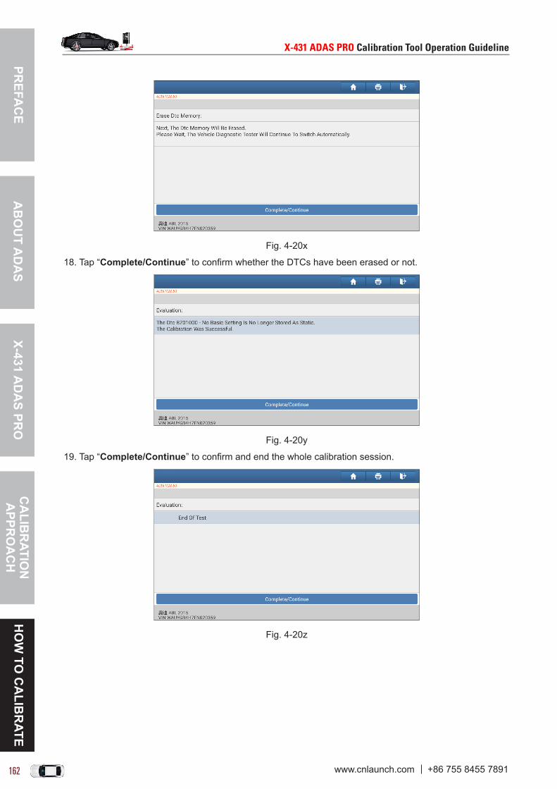
PREFA
CE
X-431 AD
AS PR
OC
ALIB
RATIO
N
APPR
OA
CH
HO
W TO
CA
LIBR
ATEA
BO
UT A
DA
S
X-431ADASPROCalibrationToolOperationGuideline X-431ADASPROCalibrationToolOperationGuideline
162 163www.cnlaunch.com +86 755 8455 7891 www.cnlaunch.com +86 755 8455 7891
Fig. 4-20x
18. Tap “Complete/Continue” to confirm whether the DTCs have been erased or not.
Fig. 4-20y
19. Tap “Complete/Continue” to confirm and end the whole calibration session.
Fig. 4-20z

PREF
AC
EX-
431
AD
AS
PRO
CA
LIB
RAT
ION
A
PPR
OA
CH
HO
W T
O C
ALI
BR
ATE
AB
OU
T A
DA
S
X-431ADASPROCalibrationToolOperationGuideline X-431ADASPROCalibrationToolOperationGuideline
162 163www.cnlaunch.com +86 755 8455 7891 www.cnlaunch.com +86 755 8455 7891
4.12.2 Calibrating the rear cameraThis chapter describes a general operation procedure of rear camera calibration on AUDI A4 USA/Canada 2016 (Model Year 2018).
4.12.2.1 Why to calibrate?1). The following diagnostic trouble code is found on the vehicle:
B201000 - Rear view system has not been calibrated.
2). The following repairs and replacements are made on the vehicle: The backup camera R189 has been removed and installed. The backup camera system control unit J772 has been replaced. After the accident repair has been done on the rear body or the trunk lid. After Four-wheel alignment. After repair work has been made on the front or rear axle.
4.12.2.2 Operation Notes
Make sure the following conditions are met:
On vehicle & diagnostic tool
• Use the AUDI diagnostic software version 28.50 or above to perform the calibration. • Make sure that there should be no direct light reflecting on the calibration pattern. Reflecting light affects
the image recognition of the camera and calibration failure becomes possible.• Make sure that the VCI device has been plugged into the vehicle’s DLC.• Turn on the ignition.• The backup camera has been activated (Backup camera image can be seen).• The vehicle is in good condition and no one is allowed to sit in the vehicle.• Fuel tank is full.• Maintain the standard wheel pressure.
On calibration tool
• Use the LAC02-03 calibration pattern.
LAC02-03
• Ruler or tape measure is necessary.• Calibration tool setting: The calibration pattern is parallel to the axis of the rear wheel of the vehicle and
is centred. The distance from the edge of the LAC02-03 to the center of the rear wheel is 1500 ± 10 mm or 59.055 ± 0.394 inch. For Phaeton, it is 1700±10 mm or 66.929 ± 0.394 inch.

PREFA
CE
X-431 AD
AS PR
OC
ALIB
RATIO
N
APPR
OA
CH
HO
W TO
CA
LIBR
ATEA
BO
UT A
DA
S
X-431ADASPROCalibrationToolOperationGuideline X-431ADASPROCalibrationToolOperationGuideline
164 165www.cnlaunch.com +86 755 8455 7891 www.cnlaunch.com +86 755 8455 7891
4.12.2.3 Start calibrationFollow the steps below to proceed:1. Choose “AUDI” on the diagnostic software selection screen.
Fig. 4-21a
2. Tap “OK” to enter the following diagnostic menu screen.

PREF
AC
EX-
431
AD
AS
PRO
CA
LIB
RAT
ION
A
PPR
OA
CH
HO
W T
O C
ALI
BR
ATE
AB
OU
T A
DA
S
X-431ADASPROCalibrationToolOperationGuideline X-431ADASPROCalibrationToolOperationGuideline
164 165www.cnlaunch.com +86 755 8455 7891 www.cnlaunch.com +86 755 8455 7891
Fig. 4-21b
3. Choose “Guided Functions” to enter vehicle model selection screen.
Fig. 4-21c
3. Select “Audi A4 Usa/Cdn 2016>”.
Fig. 4-21d (Select 2018 (J))

PREFA
CE
X-431 AD
AS PR
OC
ALIB
RATIO
N
APPR
OA
CH
HO
W TO
CA
LIBR
ATEA
BO
UT A
DA
S
X-431ADASPROCalibrationToolOperationGuideline X-431ADASPROCalibrationToolOperationGuideline
166 167www.cnlaunch.com +86 755 8455 7891 www.cnlaunch.com +86 755 8455 7891
Fig. 4-21e (Select Sedan)
Fig. 4-21f (Select Engine - Dfva 2.0l/140kw)
4. Double check your selections and tap “Confirm” to go to the next step.
Fig. 4-21g
5. Select “System Selection” from the Guided functions list.

PREF
AC
EX-
431
AD
AS
PRO
CA
LIB
RAT
ION
A
PPR
OA
CH
HO
W T
O C
ALI
BR
ATE
AB
OU
T A
DA
S
X-431ADASPROCalibrationToolOperationGuideline X-431ADASPROCalibrationToolOperationGuideline
166 167www.cnlaunch.com +86 755 8455 7891 www.cnlaunch.com +86 755 8455 7891
Fig. 4-21h (Select System Selection)
Fig. 4-21i (Select 6C Camera System Rear View)
Fig. 4-21j (Select 6c - Rear View Camera System)

PREFA
CE
X-431 AD
AS PR
OC
ALIB
RATIO
N
APPR
OA
CH
HO
W TO
CA
LIBR
ATEA
BO
UT A
DA
S
X-431ADASPROCalibrationToolOperationGuideline X-431ADASPROCalibrationToolOperationGuideline
168 169www.cnlaunch.com +86 755 8455 7891 www.cnlaunch.com +86 755 8455 7891
Fig. 4-21k (Select 6c - Calibration)
6. Swipe the screen from the bottom to scroll and carefully read all instructions and notes on calibration operation. Tap “Complete/Continue” to continue.
Fig. 4-21l
7. Input the measured height distance of the calibration pattern to the floor in millimeter (for example: 80), and tap “OK” to confirm.
Fig. 4-21m
8. Input the measured distance of the calibration pattern to the rear axle in millimeter (for example: 1300), and tap “OK” to confirm.

PREF
AC
EX-
431
AD
AS
PRO
CA
LIB
RAT
ION
A
PPR
OA
CH
HO
W T
O C
ALI
BR
ATE
AB
OU
T A
DA
S
X-431ADASPROCalibrationToolOperationGuideline X-431ADASPROCalibrationToolOperationGuideline
168 169www.cnlaunch.com +86 755 8455 7891 www.cnlaunch.com +86 755 8455 7891
Fig. 4-21n
9. Double check whether it is a A4 long version or not. If yes, tap “Yes”.
Fig. 4-21o
10. Enter the measured ground clearance of the camera lens perpendicular to the ground in millimter (for example: 865mm), and tap “OK” to confirm.
Fig. 4-21p
11. The rear view camera system starts calibrating. Follow the on-screen instructions until the calibration is successfully finished.

PREFA
CE
X-431 AD
AS PR
OC
ALIB
RATIO
N
APPR
OA
CH
HO
W TO
CA
LIBR
ATEA
BO
UT A
DA
S
X-431ADASPROCalibrationToolOperationGuideline X-431ADASPROCalibrationToolOperationGuideline
170 171www.cnlaunch.com +86 755 8455 7891 www.cnlaunch.com +86 755 8455 7891
Fig. 4-21q
Fig. 4-21r

PREF
AC
EX-
431
AD
AS
PRO
CA
LIB
RAT
ION
A
PPR
OA
CH
HO
W T
O C
ALI
BR
ATE
AB
OU
T A
DA
S
X-431ADASPROCalibrationToolOperationGuideline X-431ADASPROCalibrationToolOperationGuideline
170 171www.cnlaunch.com +86 755 8455 7891 www.cnlaunch.com +86 755 8455 7891
4.12.3 Calibrating the radar sensorThis chapter describes a general operation procedure of radar sensor calibration on AUDI Q5 USA/Canada 2017 (Model Year 2018).
4.12.3.1 Why to calibrate?1). The following diagnostic trouble codes are found on the vehicle:
C110300 ACC(Adaptive Cruise Control) sensor - incorrect adjustment. C110B54 ACC(Adaptive Cruise Control) sensor - no basic setting.
2). The following repairs and replacements are made on the vehicle: Vertical misalignment angle is greater than -1.0° to +1.0°. Rear axle toe was adjusted. The distance regulation control module -J429- and the distance regulation control module 2 -J850- have
been removed and installed. The front bumper was removed and installed. There is damage to the front bumper.
4.12.3.2 Operation Notes
Make sure the following conditions are met:
Necessary tools
• X-431 ADAS PRO calibration tool.• Use the LAC05-01 radar magnetic laser.
LAC05-01
• Use the LAC05-02 radar reflector.
LAC05-02
On vehicle & diagnostic tool
• Use the AUDI diagnostic software version 28.50 or above to perform the calibration.
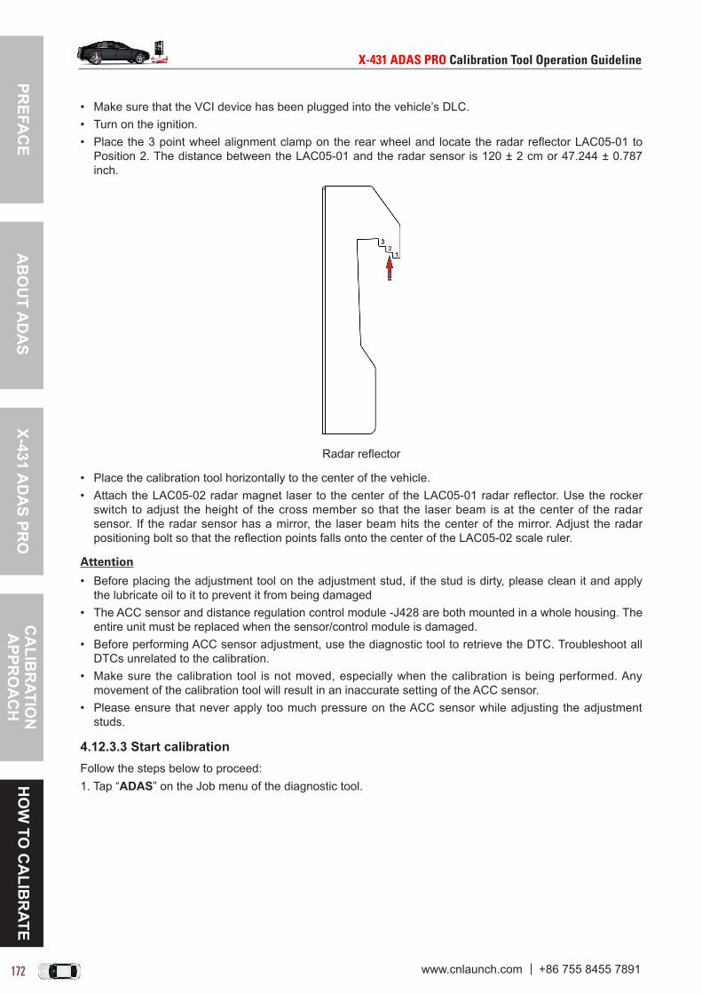
PREFA
CE
X-431 AD
AS PR
OC
ALIB
RATIO
N
APPR
OA
CH
HO
W TO
CA
LIBR
ATEA
BO
UT A
DA
S
X-431ADASPROCalibrationToolOperationGuideline X-431ADASPROCalibrationToolOperationGuideline
172 173www.cnlaunch.com +86 755 8455 7891 www.cnlaunch.com +86 755 8455 7891
• Make sure that the VCI device has been plugged into the vehicle’s DLC. • Turn on the ignition.• Place the 3 point wheel alignment clamp on the rear wheel and locate the radar reflector LAC05-01 to
Position 2. The distance between the LAC05-01 and the radar sensor is 120 ± 2 cm or 47.244 ± 0.787 inch.
Radar reflector
• Place the calibration tool horizontally to the center of the vehicle.• Attach the LAC05-02 radar magnet laser to the center of the LAC05-01 radar reflector. Use the rocker
switch to adjust the height of the cross member so that the laser beam is at the center of the radar sensor. If the radar sensor has a mirror, the laser beam hits the center of the mirror. Adjust the radar positioning bolt so that the reflection points falls onto the center of the LAC05-02 scale ruler.
Attention
• Before placing the adjustment tool on the adjustment stud, if the stud is dirty, please clean it and apply the lubricate oil to it to prevent it from being damaged
• The ACC sensor and distance regulation control module -J428 are both mounted in a whole housing. The entire unit must be replaced when the sensor/control module is damaged.
• Before performing ACC sensor adjustment, use the diagnostic tool to retrieve the DTC. Troubleshoot all DTCs unrelated to the calibration.
• Make sure the calibration tool is not moved, especially when the calibration is being performed. Any movement of the calibration tool will result in an inaccurate setting of the ACC sensor.
• Please ensure that never apply too much pressure on the ACC sensor while adjusting the adjustment studs.
4.12.3.3 Start calibrationFollow the steps below to proceed:1. Tap “ADAS” on the Job menu of the diagnostic tool.

PREF
AC
EX-
431
AD
AS
PRO
CA
LIB
RAT
ION
A
PPR
OA
CH
HO
W T
O C
ALI
BR
ATE
AB
OU
T A
DA
S
X-431ADASPROCalibrationToolOperationGuideline X-431ADASPROCalibrationToolOperationGuideline
172 173www.cnlaunch.com +86 755 8455 7891 www.cnlaunch.com +86 755 8455 7891
Fig. 4-22a
2. The diagnostic tool starts communicating with the VCI and reading VIN. After the VIN is successfully decoded, a screen similar to the following appears:
Fig. 4-22b
Fig. 4-22c
3. Select “Audi Q5 Usa/Cdn 2017”.
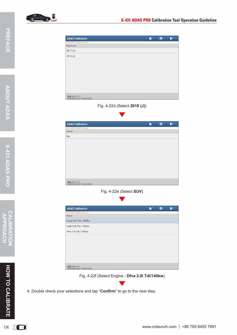
PREFA
CE
X-431 AD
AS PR
OC
ALIB
RATIO
N
APPR
OA
CH
HO
W TO
CA
LIBR
ATEA
BO
UT A
DA
S
X-431ADASPROCalibrationToolOperationGuideline X-431ADASPROCalibrationToolOperationGuideline
174 175www.cnlaunch.com +86 755 8455 7891 www.cnlaunch.com +86 755 8455 7891
Fig. 4-22d (Select 2018 (J))
Fig. 4-22e (Select SUV)
Fig. 4-22f (Select Engine - Dfva 2.0l Tdi/140kw)
4. Double check your selections and tap “Confirm” to go to the next step.
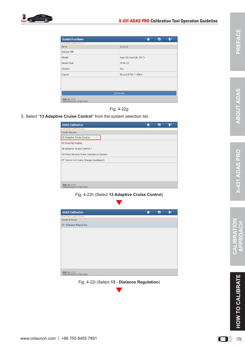
PREF
AC
EX-
431
AD
AS
PRO
CA
LIB
RAT
ION
A
PPR
OA
CH
HO
W T
O C
ALI
BR
ATE
AB
OU
T A
DA
S
X-431ADASPROCalibrationToolOperationGuideline X-431ADASPROCalibrationToolOperationGuideline
174 175www.cnlaunch.com +86 755 8455 7891 www.cnlaunch.com +86 755 8455 7891
Fig. 4-22g
5. Select “13 Adaptive Cruise Control” from the system selection list.
Fig. 4-22h (Select 13 Adaptive Cruise Control)
Fig. 4-22i (Select 13 - Distance Regulation)

PREFA
CE
X-431 AD
AS PR
OC
ALIB
RATIO
N
APPR
OA
CH
HO
W TO
CA
LIBR
ATEA
BO
UT A
DA
S
X-431ADASPROCalibrationToolOperationGuideline X-431ADASPROCalibrationToolOperationGuideline
176 177www.cnlaunch.com +86 755 8455 7891 www.cnlaunch.com +86 755 8455 7891
Fig. 4-22j (Select 13/8B-Adjustment(Rg.44))
6. Check all necessary steps on the screen, tap “Complete/Continue” to carefully read all calibration instructions and notes.
Fig. 4-22k
7. After reading, tap “Complete/Continue” until it navigates to the following screen.
Fig. 4-22l
8. Tap “Yes” to go to the next step. While proceeding the following steps, please strictly follow the test and adjustment requirements and the safety provisions of repair manual(if applicable).

PREF
AC
EX-
431
AD
AS
PRO
CA
LIB
RAT
ION
A
PPR
OA
CH
HO
W T
O C
ALI
BR
ATE
AB
OU
T A
DA
S
X-431ADASPROCalibrationToolOperationGuideline X-431ADASPROCalibrationToolOperationGuideline
176 177www.cnlaunch.com +86 755 8455 7891 www.cnlaunch.com +86 755 8455 7891
Fig. 4-22l
9. Tap “Complete/Continue”, the system starting reading diagnostic trouble codes. After retrieving, the screen displays the diagnostic result.
Fig. 4-22m
10. Swipe the screen from the bottom to carefully check all notes. Tap “1 (Re-adjust Distance Regulation Control Module -J428- or Distance Regulation Control Module 2 -J850-)” to continue.
Fig. 4-22n
11. Select the desired control module to be calibrated. Tap “1” (Distance Regulation Control Module -J428- (Component Location On Right Side in Driving Direction)) to start calibration.
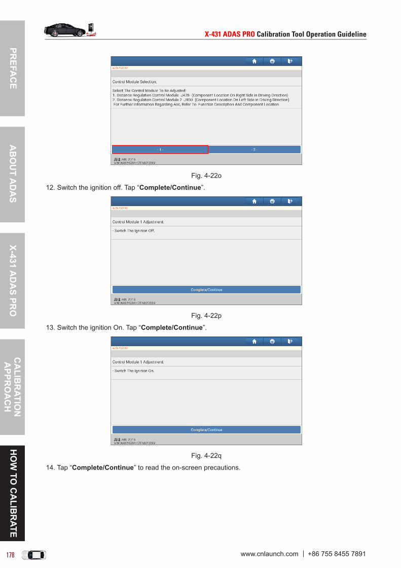
PREFA
CE
X-431 AD
AS PR
OC
ALIB
RATIO
N
APPR
OA
CH
HO
W TO
CA
LIBR
ATEA
BO
UT A
DA
S
X-431ADASPROCalibrationToolOperationGuideline X-431ADASPROCalibrationToolOperationGuideline
178 179www.cnlaunch.com +86 755 8455 7891 www.cnlaunch.com +86 755 8455 7891
Fig. 4-22o
12. Switch the ignition off. Tap “Complete/Continue”.
Fig. 4-22p
13. Switch the ignition On. Tap “Complete/Continue”.
Fig. 4-22q
14. Tap “Complete/Continue” to read the on-screen precautions.

PREF
AC
EX-
431
AD
AS
PRO
CA
LIB
RAT
ION
A
PPR
OA
CH
HO
W T
O C
ALI
BR
ATE
AB
OU
T A
DA
S
X-431ADASPROCalibrationToolOperationGuideline X-431ADASPROCalibrationToolOperationGuideline
178 179www.cnlaunch.com +86 755 8455 7891 www.cnlaunch.com +86 755 8455 7891
Notes:
• Make sure the calibration tool is not moved, especially when the calibration is being performed. Any movement of the calibration tool will result in an inaccurate setting of the ACC sensor.
• Please ensure that never apply too much pressure on the ACC sensor while adjusting the adjustment studs.
Fig. 4-22r
15. Tap “Complete/Continue”. Attach the angular adjustment plate of radar reflector with attachment Position 2 on the cross member. Tap “Complete/Continue” to start the measurement.

PREFA
CE
X-431 AD
AS PR
OC
ALIB
RATIO
N
APPR
OA
CH
HO
W TO
CA
LIBR
ATEA
BO
UT A
DA
S
X-431ADASPROCalibrationToolOperationGuideline X-431ADASPROCalibrationToolOperationGuideline
180 181www.cnlaunch.com +86 755 8455 7891 www.cnlaunch.com +86 755 8455 7891
Fig. 4-22s
16. After measuring the attachment position 2, attach the angular adjustment plate of radar reflector with attachment Position 1 on the cross member. Tap “Complete/Continue” to continue.
Fig. 4-22t
17. According to the measurement result, follow the on-screen prompts to adjust the two adjustment studs. Tap “Complete/Continue” to continue.

PREF
AC
EX-
431
AD
AS
PRO
CA
LIB
RAT
ION
A
PPR
OA
CH
HO
W T
O C
ALI
BR
ATE
AB
OU
T A
DA
S
X-431ADASPROCalibrationToolOperationGuideline X-431ADASPROCalibrationToolOperationGuideline
180 181www.cnlaunch.com +86 755 8455 7891 www.cnlaunch.com +86 755 8455 7891
Fig. 4-22u
18. After the adjustment is successfully made, next the system will clear the diagnostic trouble codes.
Fig. 4-22v (Tap “Complete/Continue”)
Fig. 4-22w (Tap “Complete/Continue”)
19. Now the Distance Regulation Control Module -J428- was adjusted and the diagnostic trouble codes are successfully erased.

PREFA
CE
X-431 AD
AS PR
OC
ALIB
RATIO
N
APPR
OA
CH
HO
W TO
CA
LIBR
ATEA
BO
UT A
DA
S
X-431ADASPROCalibrationToolOperationGuideline X-431ADASPROCalibrationToolOperationGuideline
182 PBwww.cnlaunch.com +86 755 8455 7891 www.cnlaunch.com +86 755 8455 7891
Fig. 4-22x
20. Tap “1” (Adjust Other Control Module) to select the other control module.
Fig. 4-22y
21. Tap “2” (Distance Regulation Control Module 2 -J850- (Component Location on Left Side in Driving Direction)) to select the other control module, and repeat Steps 11~19 to finish the calibration.