WR161100NA Weather-Rite TT Manual .book
207
NOT FOR RESIDENTIAL USE Weather-Rite 1100 Seven Mile Road NW Comstock Park, MI 49321 Telephone: +1.612.338.1401 Fax: +1.616.784.0435 www.weather-rite.com Installer Please take the time to read and understand these instructions prior to any installation. Installer must give a copy of this manual to the owner. Owner Keep this manual in a safe place in order to provide your service technician with necessary information. © 2019 Specified Air Solutions WARNING FOR YOUR SAFETY If you smell gas: 1. Open windows. 2. DO NOT try to light any appliance. 3. DO NOT use electrical switches. 4. DO NOT use any telephone in your building. 5. Extinguish any open flame. 6. Leave the building. 7. Immediately call your local fuel supplier after leaving the building. Follow the fuel supplier’s instructions. 8. If you cannot reach your fuel supplier, call the Fire Department. Fire Hazard Keep all flammable objects, liquids and vapors the minimum required clear- ances to combustibles away from equipment. Some objects will catch fire or explode when placed close to equipment. Failure to follow these instructions can result in death, injury or property damage. TT-Series Direct, Gas Fired, Industrial Air Handler Installation, Operation & Service Manual TT112 TT115 TT118 TT212 TT215 TT218 TT221 TT224 TT230 TT233 TT236 P/N WR161100NA Rev D 07/19
-
Upload
khangminh22 -
Category
Documents
-
view
0 -
download
0
Transcript of WR161100NA Weather-Rite TT Manual .book

NOT FOR RESIDENTIAL USEWeather-Rite 1100 Seven Mile Road NWComstock Park, MI 49321Telephone: +1.612.338.1401Fax: +1.616.784.0435
www.weather-rite.com
�������
������ ���������������������� ����� �������������������� � ��� ����� ����� ���������� ��������� ��� ������� ������ ���������������������� ��
��������� ����� ��!���"����!������ ��!���� ������� ����������������� ������!� �"�������������������� ��������� ����� ��!������ ���������� �������������������������� ���� ��������� � ��� ���� ����
Installer
Please take the time to read and understand
these instructions prior to any installation.
Installer must give a copy of this manual to the owner.
Owner
Keep this manual in a safe place in order to provide
your service technician with necessary information.
© 2019 Specified Air Solutions
WARNING
FOR YOUR SAFETYIf you smell gas: 1. Open windows. 2. DO NOT try to light any appliance. 3. DO NOT use electrical switches. 4. DO NOT use any telephone in your building. 5. Extinguish any open flame. 6. Leave the building. 7. Immediately call your local fuel supplier after leaving the building. Follow the fuel supplier’s instructions. 8. If you cannot reach your fuel supplier, call the Fire Department.
Fire Hazard
Keep all flammable objects, liquids and vapors the minimum required clear-ances to combustibles away from equipment.
Some objects will catch fire or explode when placed close to equipment.
Failure to follow these instructions can result in death, injury or property damage.
TT-SeriesDirect, Gas Fired,
Industrial Air HandlerInstallation, Operation &
Service ManualTT112TT115TT118TT212TT215TT218
TT221TT224TT230TT233TT236
P/N WR161100NA Rev D 07/19

Conçus pour les applications non-résidentiellesWeather-Rite1100 Seven Mile Road NWComstock Park, MI 49321Téléphone: +1.612.338.1401Fax: +1.616.784.0435Numéro sans fraís: 800.589.3691
www.weather-rite.com
���������
��� ���� ����� �� �������� ������������� ���� �������������� ��� �� ���������������� ���� ���� ������ ������������� �������!�����"�������������"��� ������"�#$
��� ���� ��%���&�� ���� %���� ��� ��%�����������"������� �� ���������� ������� �������������� %����'������������������"( ���� �����$�������� ����� ������������� ���� ��%������� ���� ���� �� ������ ���� ���� �������)�� �� �������� ��������� $
��� ���� ����������������� ��������������� �����������������
��������������������������������� �����������������������
������������� �����������
*����� ���
��� ������������ ��������� �������������������� ��������������������������
������� ���������
© 2018 Specified Air Solutions
AVERTISSEMENT
POUR VOTRE SECURITESi vous sentez une odeur de gaz:
1. Ouvrir les fenêtres.2. N’essayer pas d’allumer un appareil.3. N’utiliser pas d’interrupteurs électriques.4. N’utiliser pas de téléphone dans votre bâtiment.5. Eteindre flamme nue.6. Quitter le bâtiment.7. Après avoir quitté le bâtiment, appelez immédiatement votre fournisseur local de gaz. Suivre les instructions du fournisseur de gaz.8. Si vous ne pouvez pas joindre votre fournisseur de gaz, appeler le service d’incendie.
Risque d’incendie
Garder tous les objets, liquides ou vapeurs inflammables à la distance minimale de l’unité de chauffage requise avec les matériaux combustibles.
Certains objets prendront feu ou exploseront s’ils sont placés à proximité de l’unité de chauffage.
Le non respect de ces instructions peut entraîner la mort, des blessures corporelles ou des dommages matériels.
TT-SeriesL’appareil de traitment de l’air àcombustion directe, au gaz pour
les applications industriellesManuel d'installation,
d'opération, et d'entretien
TT112TT115TT118TT212TT215TT218
TT221TT224TT230TT233TT236
P/N WR161100NA Rev C 04/18

© 2019 Specified Air Solutions
Specified Air Solutions.
TABLE OF CONTENTSSECTION 1: Air Handler Safety.............................................. 1
1.1 Description of Operation............................................... 1
1.2 Inspection and Setup ................................................... 1
1.3 Safety Labels and Their Placement ............................. 2
1.4 California Proposition 65 .............................................. 2
1.5 Label Placement .......................................................... 2
SECTION 2: Installer Responsibility .....................................82.1 Corrosive Chemicals.................................................... 8
2.2 Required Equipment .................................................... 8
SECTION 3: Critical Considerations ................................... 103.1 Required Clearances to Combustibles....................... 10
3.2 Purge of Supply Duct ................................................. 10
3.3 Hardware ................................................................... 10
SECTION 4: National Standards and Applicable Codes ... 114.1 Fuel Codes................................................................. 11
4.2 Installation Codes ...................................................... 11
4.3 Aircraft Hangars ......................................................... 11
4.4 Parking Structures and Repair Garages .................... 11
4.5 Electrical .................................................................... 11
4.6 Venting....................................................................... 11
4.7 High Altitude .............................................................. 11
SECTION 5: Specifications .................................................. 12SECTION 6: Lifting an Air Handler ...................................... 27
6.1 Lifting an Air Handler ................................................. 27
SECTION 7: Air Handler Assembly...................................... 30SECTION 8: VIBRATION ISOLATION ................................... 33
8.1 Pad Isolator for Curb-Mounted Air Handler................ 33
8.2 Neoprene or Spring Isolators for Hanging-Mounted
Air Handler................................................................. 35
8.3 Neoprene or Spring Isolators for Pad-Mounted Air
Handlers.................................................................................. 39
SECTION 9: Roof Curb ......................................................... 479.1 Roof Curb Assembly and Installation......................... 47
9.2 Air Handler Mounting to Roof Curb............................ 49
SECTION 10: Upright Stand ................................................. 5010.1 Upright Stand ........................................................... 50
10.2 Upright Stand Installation......................................... 50
10.3 Attaching Air Handler to Stand................................. 50
SECTION 11: Vertical mounting Legs ................................. 5511.1 Attaching Legs to Air Handler ................................... 55
11.2 Attaching Legs to Slab.............................................. 55
SECTION 12: Filter Section .................................................. 5712.1 Filter Section Installation - Horizontal Air Handlers ..58
12.2 Filter Section Installation - Upright Air Handlers ...... 59
SECTION 13: Inlet Hoods ..................................................... 6013.1 Inlet Hood Installation (Models TT112 - TT215) ....... 61
13.2 Inlet Hood Assembly (Models TT218 and TT221) ... 62
13.3 Inlet Hood Installation (Models TT224 and TT230) .63
13.4 Inlet Hood Installation (Models TT233 and TT236) .67
SECTION 14: Service Platform............................................. 68
SECTION 15: Dampers ......................................................... 7015.1 Discharge Damper Installation................................. 70
15.2 Inlet Damper Installation.......................................... 71
SECTION 16: Discharge plenum and Discharge Louvers. 7316.1 Four-Way Discharge Plenum Installation ................. 73
16.2 Double Deflection Discharge Louver Installation ......74
SECTION 17: Duct Considerations .................................... 7517.1 Inlet Air Duct............................................................. 76
17.2 Return Air Duct......................................................... 76
17.3 Discharge Duct Work ............................................... 76
SECTION 18: Gas Piping...................................................... 7718.1 Gas Manifolds.......................................................... 77
18.2 Gas Piping and Pressures ....................................... 77
18.3 Gas Manifold Venting............................................... 78
18.4 Gas Piping ............................................................... 83
18.5 Pressure Test Ports.................................................. 83
18.6 Line Pressure Test - Leak Testing............................ 84
SECTION 19: Electrical......................................................... 8519.1 Wiring and Electrical Connections ........................... 85
19.2 Remote Panel .......................................................... 85
19.3 Motor Current Draw ................................................. 85
19.4 Control Current Draw ............................................... 85
19.5 Safety Systems........................................................ 86
SECTION 20: Sequence of Operation ................................. 8720.1 Air Handler Configuration ........................................ 87
20.2 Remote Panel Options............................................. 88
20.3 Basic Sequence of Operation.................................. 90
20.4 Flame Control .......................................................... 90
20.5 Air Volume Control Options ..................................... 99
20.6 Night Setback Options............................................101
20.7 Other Control Options............................................ 102
SECTION 21: Temperature Controls ................................. 10421.1 System Overview For All Series............................. 104
SECTION 22: Direct Fired Burner ...................................... 10822.1 Direct Fired Burner Ignition.................................... 109
22.2 Direct Fired Burner Flame Proving (Flame Rod) ....110
22.3 Direct Fired Burner Flame Proving
(Ultra Violet Scanner) ............................................. 111
SECTION 23: Direct fired process air heaters...................11223.1 Direct Fired Process Air Heater Models..................113
23.2 Installer's Responsibilities ......................................113
23.3 Installer's Responsibility for Process Heaters
Connected to Paint Booths .....................................114
23.4 WEATHER-RITE™ Control Packages .....................115
SECTION 24: Start-up Procedures .................................... 12224.1 Installation of Recirculating Air Handler................. 123
24.2 Mechanical ............................................................ 123
24.3 Electrical ................................................................ 124
24.4 Airflow .................................................................... 124
24.5 Gas Piping and Initial Pressure Settings................ 127
Printed in U.S.A.

24.6 Safety Shut Off Valve Check ..................................131
24.7 Air Volume Control .................................................131
SECTION 25: Maintenance .................................................13325.1 General ..................................................................134
25.2 Unit Exterior ...........................................................134
25.3 Blower Section .......................................................135
25.4 Motor and Drive Components ................................137
25.5 Supply Blower ........................................................138
25.6 Manifold and Controls ............................................138
25.7 Burner ....................................................................139
SECTION 26: Replacement Parts.......................................14126.1 Replacement Blower Components.........................141
26.2 Damper Components.............................................147
26.3 Burner Components...............................................148
26.4 Manifold Components ...........................................149
26.5 Combustion Components ......................................149
26.6 Electrical Components ...........................................151
26.7 Miscellaneous Mechanical Components................154
SECTION 27: Troubleshooting ...........................................15627.1 Initial Checks ..........................................................157
27.2 Supply Fan..............................................................157
27.3 Burner.....................................................................158
27.4 Temperature Controls .............................................159
27.5 Series 14 - Preliminary Circuit Analysis ..................159
27.6 Series 44 - Preliminary Circuit Analysis ..................164
27.7 Series 94 - Preliminary Circuit Analysis ..................168
27.8 Series MP - Trouble Shooting .................................172
27.9 Flame® Safeguard...................................................186
27.10 WEATHER-RITE™ TT-Series Start-Up Procedure.191
SECTION 28: The WEATHER-RITE™ TT-Series Warranty.195
SECTION 1: AIR HANDLER SAFETY
1 of 198
SECTION 1: AIR HANDLER SAFETYYour Safety Is Important To Us!
This symbol is used throughout
the manual to notify you of
possible fire, electrical or burn
hazards. Please pay special
attention when reading and
following the warnings in these
sections. Installation, service and,
at a minimum, annual inspection of air handlers must
be done by a contractor qualified in the installation
and service of gas-fired heating equipment.
Read this manual carefully before installation,
operation or service of this equipment.
This air handler is designed for heating non-
residential indoor spaces. Do not install in residential
spaces. These instructions, the layout drawing, local
codes and ordinances and applicable standards that
apply to gas piping (where applicable), electrical
wiring, ventilation, etc., must be thoroughly
understood before proceeding with the installation.
Protective gear is to be worn during installation,
operation and service. Thin sheet metal parts have
sharp edges. To prevent injury, the use of work
gloves is recommended.
Before installation, check that the local distribution
conditions, nature of gas and pressure and
adjustment of the appliance are compatible.
This equipment must be applied and operated under
the general concepts of reasonable use and installed
using the best building practices.
This appliance is not intended for use by persons
(including children) with reduced physical, sensory or
mental capabilities, or lack of experience and
knowledge, unless they have been given supervision
or instruction concerning the use of the appliance by
a person responsible for their safety.
Children should be supervised to ensure that they do
not play with the appliance.
For additional copies of the Installation, Operation
and Service Manual, please contact Weather-Rite
LLC.
Gas-fired appliances are not designed for use in
atmospheres containing flammable vapors or dust or
atmospheres containing chlorinated or halogenated
hydrocarbons. Recirculated room air may be
hazardous if containing flammable solids, liquids,
and gases; explosive materials; and/or substances
which may become toxic when exposed to heat (i.e.
refrigerants, aerosols, etc.).
1.1 Description of Operation
This air handler is a direct gas-fired applianc8e. It is
designed for indoor or outdoor installation with fresh
outdoor air delivered to the burner. Air handlers are
designed to operate in temperatures as low as -40 °F
(-40 °C). The air handler is factory-tested to fire with
natural gas or LPG (check the air handler's rating
plate for information on the appropriate type of fuel).
The burner will operate to maintain the selected
discharge air temperature or room/space air
temperature, depending on the selected options. See Page 104, Section 21.
The air handler may be provided with several
different controls and options to meet various
application requirements. Be sure to read this entire
manual before installation and start-up.
1.2 Inspection and Setup
The air handler is shipped in multiple sections based
on the configuration selected. The air handler was
inspected and operated prior to shipment.
Immediately upon receipt of the air handler, check
the fuel and electrical characteristics of the air
handler and verify that they match the fuel and
electrical supply available. Verify that the
specifications on the air handler rating plate match
the order. Check the air handler for any damage that
may have occurred during shipment. If any damage
is found, file a claim with the transporting agency. Do
not refuse shipment. Check the installation location
to ensure proper clearances to combustibles. See Page 10, Section 3.1.
Any small options which do not come attached to the
air handler (i.e. remote panel or disconnect) will be
found inside the air handler.
Larger accessories (i.e. legs, stand, filter section,
inlet hood) may either ship with the air handler or
separately. Check the bill of lading for information.
If the air handler must be temporarily stored, (i.e. job
site is not ready for installation of the air handler), the
air handler should be set on 4" x 4" (10 cm x 10 cm)
pieces of timber on the ground in a protected area.
Cover the air handler to protect it from the
environment.

TT-SERIES INSTALLATION, OPERATION AND SERVICE MANUAL
2 of 198
1.3 Safety Labels and Their Placement
Product safety signs or labels should be replaced by
product user if they are no longer legible. Please
contact Weather-Rite LLC or your WEATHER-RITE™
independent distributor to obtain replacement signs
or labels. See Page 2, Figure 1 through Page 6, Figure 8.
1.4 California Proposition 65
In accordance with California Proposition 65
requirements, a warning label must be placed in a
highly visible location on the outside of the
equipment. (i.e. near equipment's serial plate). See
label placement drawing on Page 2, Figure 1 through Page 3, Figure 2 for label location. Avoid placing
label on areas with extreme heat, cold, corrosive
chemicals or other elements. To order additional
labels, please contact Weather-Rite LLC or your
WEATHER-RITE™ independent distributor.
1.5 Label Placement
FIGURE 1: TT-112-TT221 Horizontal
3
1
2
4 5
11
6
810 9
713
1312
14
14
Item Part Number Description1 91070002 Danger - Severe Injury
2 Ref Logo
3 91070001 Danger - Electric Shock
4 91070004 Warning - Fire
5 91070006 Warning - Burn
6 91070005 Warning - Fall
7 19162 Rotation
8 19030 Recommended Entry
9 91010427 Vent Outdoors
10 14302333 Installation Manual Enclosed
11 14302372 Burner Access
12 14302389 Sight Port
13 14302390 Test
14 P-001720 Fan Bearing Lubrication

SECTION 1: AIR HANDLER SAFETY
3 of 198
FIGURE 2: TT224-TT236 Horizontal
FIGURE 3: TT112- 221 Upright
13 12
11
7
13 6
2
4 5
10
8 9
1414
Item Part Number Description1 91070002 Danger - Severe Injury
2 Ref Logo
3 91070001 Danger - Electric Shock
4 91070004 Warning - Fire
5 91070006 Warning - Burn
6 91070005 Warning - Fall
7 19162 Rotation
8 19030 Recommended Entry
9 91010427 Vent Outdoors
10 14302333 Installation Manual Enclosed
11 14302372 Burner Access
12 14302389 Sight Port
13 14302390 Test
14 P-001720 Fan Bearing Lubrication
6
3
2
1010
8
9
4
1311 12
1
7
Item Part Number Description1 91070002 Danger - Severe Injury
2 Ref Logo
3 91070001 Danger - Electric Shock
4 91070004 Warning - Fire
5 91070006 Warning - Burn
6 91070005 Warning - Fall
7 19162 Rotation
8 19030 Recommended Entry
9 91010427 Vent Outdoors
10 14302333 Installation Manual Enclosed
11 14302372 Burner Access
12 14302389 Sight Port
13 14302390 Test
14 P-001720 Fan Bearing Lubrication

TT-SERIES INSTALLATION, OPERATION AND SERVICE MANUAL
4 of 198
FIGURE 4: TT224-TT236 Upright
7
1
6 3
2
1010
9
8
11
4 5
12
13
Item Part Number Description1 91070002 Danger - Severe Injury
2 Ref Logo
3 91070001 Danger - Electric Shock
4 91070004 Warning - Fire
5 91070006 Warning - Burn
6 91070005 Warning - Fall
7 19162 Rotation
8 19030 Recommended Entry
9 91010427 Vent Outdoors
10 14302333 Installation Manual Enclosed
11 14302372 Burner Access
12 14302389 Sight Port
13 14302390 Test
14 P-001720 Fan Bearing Lubrication

SECTION 1: AIR HANDLER SAFETY
5 of 198
FIGURE 5: TT118 Upright
FIGURE 6: TT118 Horizontal
7
1
10
9
8
11
2
1
36
4 5
12
13
Item Part Number Description1 91070002 Danger - Severe Injury
2 Ref Logo
3 91070001 Danger - Electric Shock
4 91070004 Warning - Fire
5 91070006 Warning - Burn
6 91070005 Warning - Fall
7 19162 Rotation
8 19030 Recommended Entry
9 91010427 Vent Outdoors
10 14302333 Installation Manual Enclosed
11 14302372 Burner Access
12 14302389 Sight Port
13 14302390 Test
14 P-001720 Fan Bearing Lubrication
2
13 13 12
11
7
1
3 6
1098
1 4 5
Item Part Number Description1 91070002 Danger - Severe Injury
2 Ref Logo
3 91070001 Danger - Electric Shock
4 91070004 Warning - Fire
5 91070006 Warning - Burn
6 91070005 Warning - Fall
7 19162 Rotation
8 19030 Recommended Entry
9 91010427 Vent Outdoors
10 14302333 Installation Manual Enclosed
11 14302372 Burner Access
12 14302389 Sight Port
13 14302390 Test
14 P-001720 Fan Bearing Lubrication
TT-SERIES INSTALLATION, OPERATION AND SERVICE MANUAL
6 of 198
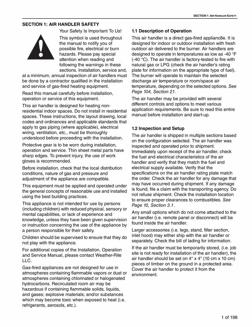
FIGURE 7: 2" NPT or Smaller Gas Train Control Panel Interior
FIGURE 8: 2.5" NPT or Larger Gas Train Control Panel Interior
Exterior Interior
22
213
2
6
23 2410
Item Part Number Description3 91070001 Danger - Electric Shock
6 91070005 Warning - Fall
10 14302333 Installation Manual Enclosed
21 Ref Serial Data Plate
22 Ref Electrical Schematic
23 91070016 California Proposition 65
24 Ref Agency Approval - ETL (optional)
25 Ref Agency Approval - ULC (optional)
3 6
Exterior
10
22
242321
Interior
Item Part Number Description3 91070001 Danger - Electric Shock
6 91070005 Warning - Fall
10 14302333 Installation Manual Enclosed
21 Ref Serial Data Plate
22 Ref Electrical Schematic
23 91070016 California Proposition 65
24 Ref Agency Approval - ETL (optional)
25 Ref Agency Aprroval - ULC (optional)

SECTION 1: AIR HANDLER SAFETY
7 of 198
FIGURE 9: Remote Panel
FIGURE 10: Aux Control Panel
Item Part Number Description3 91070001 Danger - Electric Shock
20a 91070032 Danger - Electric Shock
20b 910700033 Danger - Electric Shock
Item Part Number Description3 91070001 Danger - Electric Shock
20a 91070032 Danger - Electric Shock
20b 910700033 Danger - Electric Shock
TT-SERIES INSTALLATION, OPERATION AND SERVICE MANUAL
8 of 198
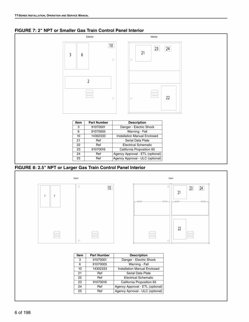
SECTION 2: INSTALLER RESPONSIBILITY
The installer is responsible for the following:
• To install and commission the air handler, as well
as the gas and electrical supplies, in accordance
with applicable specifications and codes.
Weather-Rite LLC recommends the installer
contact a local building inspector or Fire Marshal
for guidance.
• To use the information given in a layout drawing
and in the manual together with the cited codes
and regulations to perform the installation.
• To install the heater in accordance with the
clearances to combustibles.
• To furnish all needed materials not furnished as
standard equipment.
• To plan location of supports.
• To provide access to air handler for servicing.
• To provide the owner with a copy of this
Installation, Operation and Service Manual.
• To never use heater as support for a ladder or
other access equipment and never hang or
suspend anything from heater.
• To ensure there is adequate air circulation around
the air handler and to supply air for combustion,
ventilation and distribution in accordance with
local codes.
• To assemble or install any accessories or
associated duct work using best building
practices.
• To properly size supports and hanging materials.
• To ensure heater is placed in an approved
application.
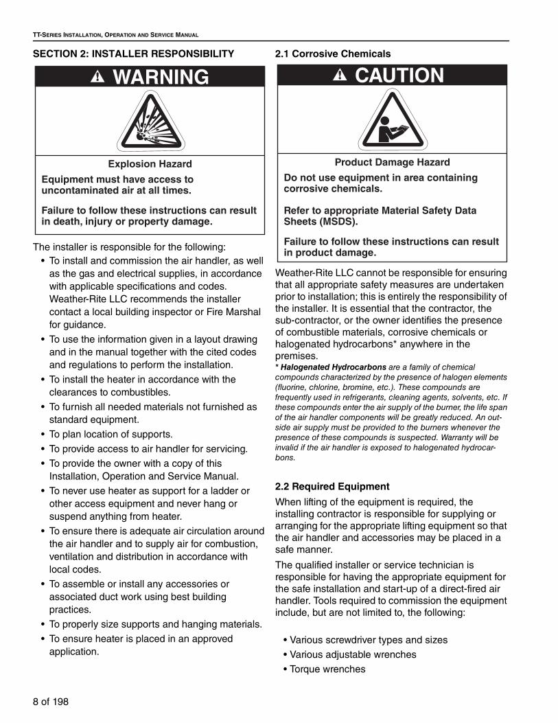
2.1 Corrosive Chemicals
Weather-Rite LLC cannot be responsible for ensuring
that all appropriate safety measures are undertaken
prior to installation; this is entirely the responsibility of
the installer. It is essential that the contractor, the
sub-contractor, or the owner identifies the presence
of combustible materials, corrosive chemicals or
halogenated hydrocarbons* anywhere in the
premises.* Halogenated Hydrocarbons are a family of chemical compounds characterized by the presence of halogen elements (fluorine, chlorine, bromine, etc.). These compounds are frequently used in refrigerants, cleaning agents, solvents, etc. If these compounds enter the air supply of the burner, the life span of the air handler components will be greatly reduced. An out-side air supply must be provided to the burners whenever the presence of these compounds is suspected. Warranty will be invalid if the air handler is exposed to halogenated hydrocar-bons.
2.2 Required Equipment
When lifting of the equipment is required, the
installing contractor is responsible for supplying or
arranging for the appropriate lifting equipment so that
the air handler and accessories may be placed in a
safe manner.
The qualified installer or service technician is
responsible for having the appropriate equipment for
the safe installation and start-up of a direct-fired air
handler. Tools required to commission the equipment
include, but are not limited to, the following:
• Various screwdriver types and sizes
• Various adjustable wrenches
• Torque wrenches
WARNING
Explosion Hazard
Equipment must have access to uncontaminated air at all times.
Failure to follow these instructions can result in death, injury or property damage.
CAUTION
Product Damage Hazard
Do not use equipment in area containing corrosive chemicals.
Refer to appropriate Material Safety Data Sheets (MSDS).
Failure to follow these instructions can result in product damage.

SECTION 2: INSTALLER RESPONSIBILITY
9 of 198
• Pipe wrenches sized appropriately for the gas
train components
• Drill motor and various drills
• U-tube manometer or Magnehelic® gauge (0 to
1.0" w.c.)
• U-tube manometer or gas pressure gauge (0 to
5# and 0 to 30" w.c.)
• Volt meter
• Clamp style ammeter
• Belt tension gauge
• Paintable latex caulk (silicone caulk is not to be
used)

TT-SERIES INSTALLATION, OPERATION AND SERVICE MANUAL
10 of 198
SECTION 3: CRITICAL CONSIDERATIONS
3.1 Required Clearances to Combustibles
Clearances are the required distances that
combustible objects must be away from the air
handler to prevent fire hazards. Combustibles are
materials that may catch on fire and include common
items such as wood, paper, rubber, fabric, etc.
Maintain clearances to combustibles at all times for safety.
Check the clearances on each air handler being
installed to make sure the product is suitable for your
application and the clearances are maintained.
Minimum clearances for all models are as follows:
• 18" (45.7 cm) Above the top of the equipment
• 18" (45.7 cm) Along the sides of the equipment
• 18" (45.7 cm) Under the floor of the equipment
(when suspended)
Read and follow the safety guidelines below:
• Locate the air handler so that the air intakes are
not too close to any exhaust fan outlets (refer to
applicable codes for minimum distance to exhaust
fan outlets), gasoline storage, propane tanks or
other contaminants that could potentially cause
dangerous situations.
• Keep gasolines or other combustible materials
including flammable objects, liquids, dust or
vapors away from this air handler or any other
appliance.
• Maintain clearances from heat sensitive material,
equipment and workstations.
Clearances to combustibles do not denote
clearances for accessibility. Minimum clearance
for access is 48" (122 cm). Minimum clearance for
accessibility applies to the control enclosure,
blower access panel and filter access panel
(when equipped).
The stated clearances to combustibles represent
a surface temperature of 90 °F (50 °C) above
room temperature (90 °F [50 °C] plus ambient
temperature). Building materials with a low heat
tolerance (i.e. plastics, vinyl siding, canvas, tri-ply,
etc.) may be subject to degradation at lower
temperatures. It is the installer's responsibility to
assure that adjacent materials are protected from
degradation. Maintain clearances from heat
sensitive material, equipment and work stations.
• Maintain clearances from vehicles parked below
the air handler. See Page 11, Section 4.4.
3.2 Purge of Supply Duct
If this heating unit is to be installed indoors, and its
outdoor air supply ducted from outdoors, ANSI
Standards Z83.4/CSA 3.7, Z83.18 and Z83.25/CSA
3.19 require that all supply duct shall be purged a
minimum of four times prior to any ignition attempt. If
the volume of the outdoor air supply duct exceeds
the heating unit's ability to complete the required four
air changes prior to ignition, you must contact the
factory to purchase an extended purge card of the
appropriate duration to meet this requirement.
3.3 Hardware
Unless otherwise specified, all hardware must be
torqued to settings from Page 10, Table 1.
Table 1: Recommended Torque Settings
WARNING
Fire Hazard
Keep all flammable objects, liquids and vapors the minimum required clearances to combustibles away from equipment.
Some objects will catch fire or explode when placed close to equipment.
Failure to follow these instructions can result in death, injury or property damage.
Bolt HeadGrade Marking
Nut GradeMarking
Bolt Size Grade 2 Grade 510-24 27 in•lb 42 in•lb
1/4-20 65 in•lb 101 in•lb
5/16-18 11 ft•lb 17 ft•lb
3/8-16 19 ft•lb 30 ft•lb

SECTION 4: NATIONAL STANDARDS AND APPLICABLE CODES
11 of 198
SECTION 4: NATIONAL STANDARDS AND APPLICABLE CODESAll appliances must be installed in accordance with
the latest revision of the applicable standards and
national codes. This also refers to the electric, gas
and venting installation.
4.1 Fuel Codes
The type of gas appearing on the nameplate
must be the type of gas used. Installation must
comply with national and local codes and
requirements of the local gas company.
United States: Refer to NFPA 54/ANSI Z223.1 -
latest revision, National Fuel Gas Code.
Canada: Refer to CSA B149.1- latest revision,
Natural Gas and Propane Installation Code.
4.2 Installation Codes
Installations must be made in accordance with
NFPA 90A - latest revision, Standard for the
Installation of Air-Conditioning and Ventilation
Systems.
4.3 Aircraft Hangars
Installation in aircraft hangars must be in
accordance with the following codes:
United States: Refer to Standard on Aircraft
Hangars, NFPA 409 - latest revision.
Canada: Refer to Natural Gas and Propane
Installation Code, Standard CSA B14 - latest
revision.
4.4 Parking Structures and Repair Garages
Installation in garages must be in accordance
with the following codes:
United States: Refer to Standard for Parking
Structures, NFPA 88A - latest revision or the
Code for Motor Fuel Dispensing Facilities and
Repair Garages, NFPA 30A - latest revision.
Canada: Refer to Natural Gas and Propane
Installation Code, Standard CSA B149.1 - latest
revision.
4.5 Electrical
Electrical connection to air handler must be in
accordance with the following codes:
United States: Refer to National Electrical
Code®, NFPA 70 - latest revision. Wiring must
conform to the most current National Electrical
Code®, local ordinances, and any special
diagrams furnished.
Canada: Refer to Canadian Electrical Code,
CSA C22.1 Part 1 - latest revision.
4.6 Venting
This air handler must be vented in accordance
with the requirements within this manual and
with the following codes and any state,
provincial or local codes which may apply:
United States: Refer to NFPA 54/ANSI Z223.1-
latest revision, National Fuel Gas Code.
Canada: Refer to CSA B149.1 - latest revision,
Natural Gas and Propane Installation Code.
4.7 High Altitude
These air handlers are approved for installations
up to 2000' (609.6 m) (US), 4500' (1371.6 m)
(Canada) without modification. Consult factory if
US installation is above 2000' or Canadian
installation is above 4500’(1371.6 m).

TT-SERIES INSTALLATION, OPERATION AND SERVICE MANUAL
12 of 198
SECTION 5: SPECIFICATIONSDimension and estimated weight tables apply to both
upright and horizontal air handlers of the same
model.
The maximum total static pressure is listed by model
in Page 24, Table 27. To calculate the available
external static pressure (ESP), calculate the internal
static pressure (ISP) with the use of Page 75, Table 32 and then subtract that value from the TSP. If more
external static pressure is required, this needs to be
requested with the order as required motor
horsepower (HP) may increase from the
specifications given.
The legend below is a list of abbreviations used in
this section and applies to Page 12, Figure 11
through Page 23, Figure 22.
Table 2: Legend
FIGURE 11: Horizontal Model Dimensions (Models TT112 and TT115)
Table 3: Cabinet Dimensions (Models TT112 and TT115)
Table 4: Filters (Permanent, Polyester or Pleated)
RA = Return Air BD = Bottom Discharge
OA = Outside Air ED = End Discharge
CE = Control Enclosure AD2 = Filter Access Door
AD1 = Unit Access Panel TD = Top Discharge
SD = Side Discharge
Model A B C D E F G H J K L M N P Q R S T V W X Y Z*
TT112in
cm28.0
71.1
36.0
91.4
58.0
147.3
13.4
34.0
15.6
39.6
24.0
61.0
15.0
38.1
5.0
12.7
17.2
43.7
16.0
40.6
10.2
25.9
1.0
2.5
26.0
66.0
34.0
86.4
48.0
121.9
5.0
12.7
19.5
49.5
7.0
17.8
8.0
20.3
1.0
2.5
18.5
47.0
33.0
83.8
2.0
5.1
TT115in
cm28.0
71.1
36.0
91.4
58.0
147.3
15.9
40.4
18.6
47.2
24.0
61.0
15.0
38.1
5.0
12.7
17.2
43.7
16.0
40.6
8.9
22.6
1.0
2.5
26.0
66.0
34.0
86.4
48.0
121.9
5.0
12.7
19.5
49.5
8.3
21.1
8.0
20.3
3.8
9.7
18.5
47.0
33.0
83.8
2.0
5.1
SIDEVIEW N
V
SR
T D G F QK
C
A D
WX
V
M
PLANVIEW N N
S
B E
L
BD RA
H
P
AD2
AD2AD1
CE
Y
OA
OA
ED
ED
BD
RA
J
MOTORIZEDDISCHARGE
DAMPER (OPTIONAL)BURNER / BLOWER SECTION FILTER SECTION
(OPTIONAL)
MOTORIZEDINLET DAMPER
(OPTIONAL)
INLET HOODWITH BIRDSCREEN
(OPTIONAL)
Z Z
NOTE: *'Z' dimension reflects curb angle for
horizontal orientation. (Optional)
Model QuantitySize
in cm
TT1123
3
2 x 20 x 20
2 x 16 x 20
5.08 x 50.8 x 50.8
5.08 x 40.6 x 50.8
TT1153
3
2 x 20 x 20
2 x 16 x 20
5.08 x 50.8 x 50.8
5.08 x 40.6 x 50.8

SECTION 5: SPECIFICATIONS
13 of 198
FIGURE 12: Upright Model Dimensions (Models TT112 and TT115)
Table 5: Estimated Shipping Weights (Models TT112 and TT115)
Table 6: Estimated Shipping Weights - Motors
SIDEVIEW N
ENDVIEW
EB
L
SD
RA
N
HAD1
AD2
PN
V
F
C
G
K
D
T
S
R
DA X
W
S
V
M
CE
J
Y
SD
RA
TD TD
OA OA
MOT
ORIZ
EDDI
SCHA
RGE
DAM
PER
(OPT
IONA
L)
BURN
ER /
BLOW
ERSE
CTIO
NFI
LTER
SEC
TION
(OPT
IONA
L)
MOT
ORIZ
EDIN
LET
DAM
PER
(OPT
IONA
L)
ModelBurner/Blower Section
Filter Section
Inlet Hood
WeatherizingDischarge/
Inlet Damper
Roof Curb
Legs StandService Platform
Four-Way Discharge
Plenum
Double Deflection Discharge Louvers
Burner/Blower
Filter Section
TT112lbkg
400
181.4
63
28.6
30
13.6
75
34.0
40
18.1
75
34.0
98
44.5
70
31.8
125
56.7
400
181.4
80
36.3
70
31.8
TT115lbkg
525
238.1
63
28.6
30
13.6
75
34.0
40
18.1
75
34.0
98
44.5
70
31.8
125
56.7
400
181.4
80
36.3
70
31.8
SizeHP kW
.75
.561
.751.5 1.1
2 1.5
3 2.2
5 3.7
7.5 5.6
10 7.5
15 11.2
20 14.9
25 18.6
30 22.4
40 30.0
50 37.0
60 44.7
75 55.9
Standardlbkg
3515.9
3515.9
4520.4
4520.4
7031.8
8538.6
13059.0
15570.3
22099.8
275124.7
300136.1
360163.3
500226.8
550249.5
800362.9
950430.9
2-Speedlbkg
7031.8
8538.6
12556.7
15068.0
18583.9
21597.5
270122.5
310140.6
405183.7
455206.4
525238.1
570258.5
700317.5
760344.7
N/A N/A

TT-SERIES INSTALLATION, OPERATION AND SERVICE MANUAL
14 of 198
FIGURE 13: Horizontal Model Dimensions (Model TT118)
Table 7: Cabinet Dimensions (Model TT118)
Table 8: Filters (Permanent, Polyester, or Pleated)
CE
BB
Y
VT NUPQ
R K
N
U
S
N
KM
P
XL
AD2
J
AD1
AD1AD1
H
G
FE
D
C
A
B
EE
S
DD
BD RA
AD1 AD1
MOTORIZEDDISCHARGE
DAMPER (OPTIONAL)BLOWER SECTION FILTER / BURNER
SECTION
MOTORIZEDINLET DAMPER
(OPTIONAL)
INLET HOODWITH BIRDSCREEN
(OPTIONAL)
SIDEVIEW
PLANVIEW OA
OA
ED
ED
BDRA
N
NOTE: *'S' dimension reflects curb angle for
horizontal orientation. (Optional)
Model A B C D E F G H J K L M N P Q R S* T U V X Y BB DD EE
TT118in
cm17.0
43.2
26.0
66.0
60.0
152.4
19.1
48.5
21.9
55.6
50.0
127
16.2
41.1
33.0
83.8
58.0
147.3
19.5
49.5
18.0
45.7
30.0
76.2
8.0
20.3
18.9
48.0
10.4
26.4
10.3
26.2
2.0
5.1
12.0
30.5
45.0
114.3
1.9
4.8
0.8
2.0
28.0
71.1
38.0
96.5
5.0
12.7
10.0
25.4
Model QuantitySize
in cm
TT118 6 2 x 20 x 25 5.08 x 50.8 x 63.5

SECTION 5: SPECIFICATIONS
15 of 198
FIGURE 14: Upright Model Dimensions (Model TT118)
Table 9: Estimated Shipping Weights (Models TT118)
Table 10: Estimated Shipping Weights - Motors
N
K
R
V
T
PU
U
Q
K
N N
M
P X
L
G
CE
N
Y
SIDEVIEW
ENDVIEW
J
H
DDF
B A
C
E D
AD1
AD1 AD1
SD
RA
AD1
AD1RA
SD
TD
OA OA
TD
MOT
ORIZ
EDDI
SCHA
RGE
DAM
PER
(OPT
IONA
L)BL
OWER
SEC
TION
FILT
ER /
BURN
ERSE
CTIO
N
MOT
ORIZ
EDIN
LET
DAM
PER
(OPT
IONA
L)
ModelBurner/Blower Section
Inlet Hood
WeatherizingDischarge/
Inlet Damper
Roof CurbLegs Stand
Serivce Platform
Four-Way Discharge
Plenum
Double Deflection Discharge Louvers
Burner/Blower
Filter Section
TT118lbkg
700
317.5
55
24.9
75
34.0
70
31.8N/A
100
45.4
70
31.8
140
63.5
400
181.4
80
36.3
70
31.8
SizeHP kW
.75
.561
.751.5 1.1
2 1.5
3 2.2
5 3.7
7.5 5.6
10 7.5
15 11.2
20 14.9
25 18.6
30 22.4
40 30.0
50 37.0
60 44.7
75 55.9
Standardlb 35 35 45 45 70 85 130 155 220 275 300 360 500 550 800 950
kg 15.9 15.9 20.4 20.4 31.8 38.6 59.0 70.3 99.8 124.7 136.1 163.3 226.8 249.5 362.9 430.9
2-Speedlb 70 85 125 150 185 215 270 310 405 455 525 570 700 760
N/A N/Akg 31.8 38.6 56.7 68.0 83.9 97.5 122.5 140.6 183.7 206.4 238.1 258.5 317.5 344.7

TT-SERIES INSTALLATION, OPERATION AND SERVICE MANUAL
16 of 198
FIGURE 15: Horizontal Model Dimensions (Models TT212 - TT221)
Table 11: Cabinet Dimensions (Models TT212 - TT221)
Table 12: Filters (Permanent, Polyester or Pleated)
Model A B C D E F G H J K L M N P Q R S T U* V W X Y Z AA BB
TT212in
cm28.0
71.1
60.0
152.4
58.0
147.3
13.4
34.0
15.6
39.6
24.0
61.0
15.0
38.1
5.0
12.7
50.0
127
16.0
40.6
8.9
22.6
1.0
2.54
26.0
66.0
58.0
147.3
48.0
121.9
5.0
12.7
19.5
49.5
7.0
17.8
2.0
5.1
50.0
127
1.0
2.54
11.0
27.9
18.5
47.0
33.0
83.8
16.9
42.9
8.0
20.3
TT215in
cm28.0
71.1
72.0
182.9
58.0
147.3
15.9
40.4
18.6
47.2
28.0
71.1
15.0
38.1
7.0
17.8
58.0
147.3
16.0
40.6
11.9
30.2
1.0
2.54
26.0
66.0
70.0
177.8
48.0
121.9
5.0
12.7
19.5
49.5
8.3
21.1
2.0
5.1
50.0
127
3.8
9.65
11.0
27.9
18.5
47.0
33.0
83.8
16.9
42.9
8.0
20.3
TT218in
cm36.0
91.4
72.0
182.9
62.0
157.5
18.9
48.0
21.9
55.6
24.0
61.0
15.0
38.1
7.0
17.8
58.0
147.3
14.0
35.6
7.0
17.8
6.0
15.2
33.0
83.8
69.0
175.3
72.0
182.9
6.0
15.2
26.0
66.0
10.5
26.7
2.0
5.1
58.0
147.3
10.5
26.7
14.3
36.3
20.0
50.8
33.0
83.8
16.9
42.9
8.0
20.3
TT221in
cm42.0
106.7
100.0
254
72.0
182.9
24.8
63.0
22.8
57.9
26.0
66.0
20.0
50.8
10.1
25.4
80.0
203.2
14.0
35.6
15.5
39.4
1.0
2.54
38.0
96.5
96.0
243.8
72.0
182.9
6.0
15.2
33.0
83.8
11.3
28.7
2.0
5.1
76.0
193.4
4.8
12.2
23.5
59.7
20.0
50.8
33.0
83.8
16.9
42.9
8.0
20.3
Q
N
U
SR
T D G FK
C
AD
WY
U
BB
S
M
P
AD2
AD2
CE
RABD
AD1
Z
AA
E
E
X
L
BV J
H
SIDEVIEW
PLANVIEW OA
OA
ED
ED
BDRA
MOTORIZEDDISCHARGE
DAMPER (OPTIONAL)BURNER / BLOWER SECTION FILTER SECTION
(OPTIONAL)
MOTORIZEDINLET DAMPER
(OPTIONAL)
INLET HOODWITH BIRDSCREEN
(OPTIONAL)
BB
NOTE: *'U' dimension reflects curb angle for
horizontal orientation. (Optional)
NOTE: Model TT221 has 1.5" (3.91cm) mounting
channel above curb angle.
Model QuantitySize
in cm
TT212 9 2 x 20 x 20 5.08 x 50.8 x 50.8
TT2154
4
2 x 20 x 25
2 x 16 x 25
5.08 x 50.8 x 63.5
5.08 x 40.6 x 63.5
TT2158
8
2 x 20 x 20
2 x 16 x 25
5.08 x 50.8 x 50.8
5.08 x 40.6 x 63.5
TT221 16 2 x 20 x 25 5.08 x 50.8 x 63.5
SECTION 5: SPECIFICATIONS
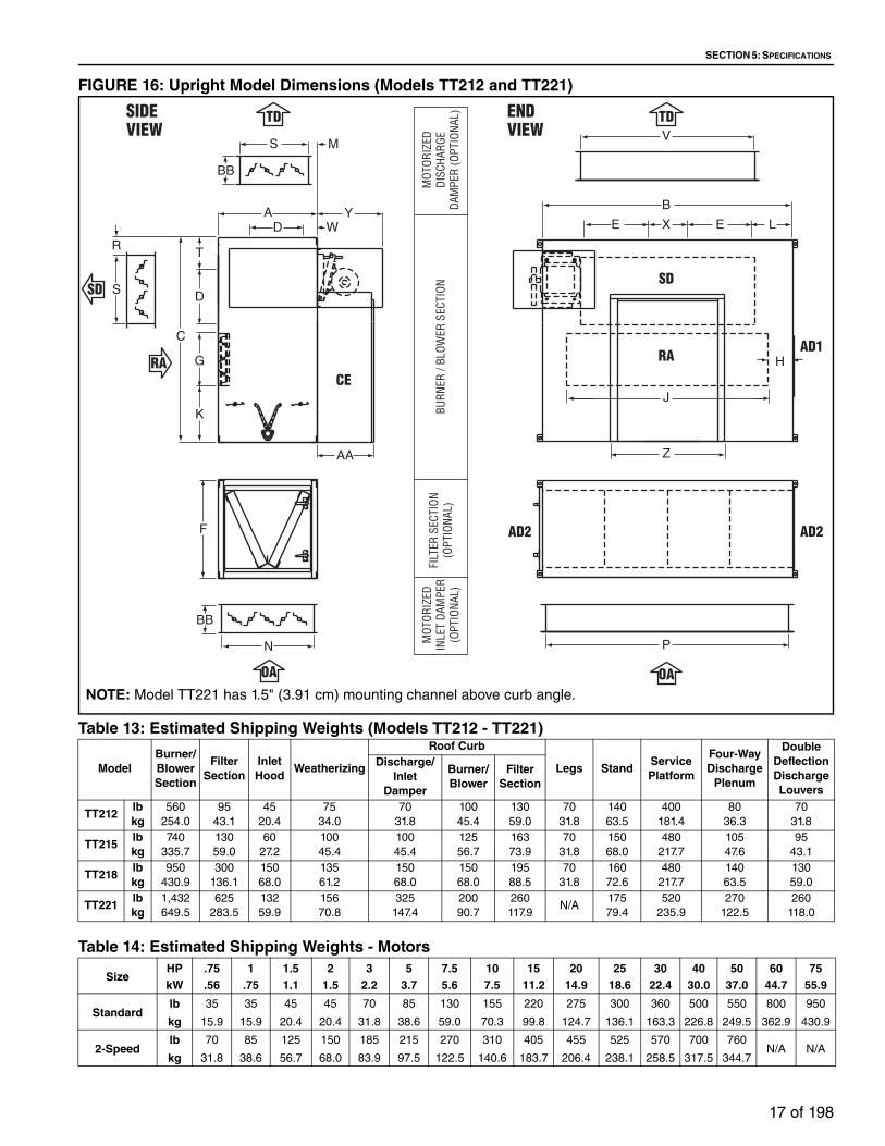
17 of 198
FIGURE 16: Upright Model Dimensions (Models TT212 and TT221)
Table 13: Estimated Shipping Weights (Models TT212 - TT221)
Table 14: Estimated Shipping Weights - Motors
ModelBurner/Blower Section
Filter Section
Inlet Hood
Weatherizing
Roof Curb
Legs StandService Platform
Four-Way Discharge
Plenum
Double Deflection DischargeLouvers
Discharge/ Inlet
Damper
Burner/Blower
Filter Section
TT212lbkg
560
254.0
95
43.1
45
20.4
75
34.0
70
31.8
100
45.4
130
59.0
70
31.8
140
63.5
400
181.4
80
36.3
70
31.8
TT215lbkg
740
335.7
130
59.0
60
27.2
100
45.4
100
45.4
125
56.7
163
73.9
70
31.8
150
68.0
480
217.7
105
47.6
95
43.1
TT218lbkg
950
430.9
300
136.1
150
68.0
135
61.2
150
68.0
150
68.0
195
88.5
70
31.8
160
72.6
480
217.7
140
63.5
130
59.0
TT221lbkg
1,432
649.5
625
283.5
132
59.9
156
70.8
325
147.4
200
90.7
260
117.9N/A
175
79.4
520
235.9
270
122.5
260
118.0
N
BB
F
C
G
K
D
T
S
R
D
A Y
W
S
BB
M
CE
AA
P
Z
AD1RA
SD
E EX L
B
J
H
V
AD2 AD2
SIDEVIEW
ENDVIEW
OA OA
RA
SD
TD TD
MOT
ORIZ
EDDI
SCHA
RGE
DAM
PER
(OPT
IONA
L)BU
RNER
/ BL
OWER
SEC
TION
FILT
ER S
ECTI
ON(O
PTIO
NAL)
MOT
ORIZ
EDIN
LET
DAM
PER
(OPT
IONA
L)
NOTE: Model TT221 has 1.5" (3.91 cm) mounting channel above curb angle.
SizeHP kW
.75
.561
.751.5 1.1
2 1.5
3 2.2
5 3.7
7.5 5.6
10 7.5
15 11.2
20 14.9
25 18.6
30 22.4
40 30.0
50 37.0
60 44.7
75 55.9
Standardlb 35 35 45 45 70 85 130 155 220 275 300 360 500 550 800 950
kg 15.9 15.9 20.4 20.4 31.8 38.6 59.0 70.3 99.8 124.7 136.1 163.3 226.8 249.5 362.9 430.9
2-Speedlb 70 85 125 150 185 215 270 310 405 455 525 570 700 760
N/A N/Akg 31.8 38.6 56.7 68.0 83.9 97.5 122.5 140.6 183.7 206.4 238.1 258.5 317.5 344.7

TT-SERIES INSTALLATION, OPERATION AND SERVICE MANUAL
18 of 198
FIGURE 17: Horizontal Model Dimensions (Models TT224 and TT230)
Table 15: Cabinet Dimensions (Models TT224 and TT230)
Table 16: Filters (Permanent, Polyester or Pleated)
Model A B C D E F G H J K L M N P Q R S T U V W X Y Z*
TT224in
cm55.0
139.7
110.0
279.4
5.0
12.7
35.0
88.9
90.0
228.6
10.0
25.4
20.0
50.8
31.0
78.7
100.0
254
55.0
139.7
10.0
25.4
100.0
254
51.0
129.5
106.0
269.2
26.0
66.0
.75
1.9
3.0
7.6
8.0
20.3
3.0
7.6
116.0
294.6
122.0
309.9
6.0
15.2
60.0
152.4
2.0
5.1
TT230in
cm60.0
152.4
145.0
368.3
5.0
12.7
40.0
101.6
115.0
292.1
10.0
25.4
25.0
63.5
31.0
78.7
135.0
342.9
55.0
139.7
15.0
38.1
100.0
254
55.0
139.7
140.0
355.6
26.0
66.0
.75
1.9
3.0
7.6
5.0
12.7
4.0
10.2
151.0
383.5
157.0
398.8
6.0
15.2
60.0
152.4
2.0
5.1
A
E
D
FQ
B P
N
E J
HCE
F
R
R S
L
X
AD1C AD2
AD2
D
K
G
M
Y
D
U
T
T
SIDEVIEW
PLANVIEW OA
OA
ED
ED
BD RA
MOTORIZEDDISCHARGE
DAMPER (OPTIONAL)BURNER / BLOWER SECTION FILTER SECTION
(OPTIONAL)
MOTORIZEDINLET DAMPER
(OPTIONAL)
INLET HOODWITH BIRDSCREEN
(OPTIONAL)
ZZU
NOTE: *’Z’ dimension reflects curb angle for
horizontal orientation. (Optional)
Model QuantitySize
in cm
TT22418
12
2 x 20 x 20
2 x 20 x 25
5.08 x 50.8 x 50.8
5.08 x 50.8 x 63.5
TT2306
30
2 x 20 x 25
2 x 20 x 25
5.08 x 50.8 x 63.5
5.08 x 50.8 x 63.5

SECTION 5: SPECIFICATIONS
19 of 198
FIGURE 18: Upright Model Dimensions (Models TT224 - TT230)
Table 17: Estimated Shipping Weights (Models TT224 - TT230)
Table 18: Estimated Shipping Weights - Motors
ModelBurner/Blower Section
Filter Section
Inlet Hood
WeatherizingDischarge/
Inlet Damper
Roof Curb
Legs StandService Platform
Four-Way Discharge
Plenum
Double Deflection Discharge Louvers
Burner/Blower
Filter Section
TT224lbkg
2,975
1,349.4
980
444.5
182
82.6
200
90.7
470
213.2
300
136.1
450
204.1N/A
300
136.1
575
260.8
385
174.6
375
170.1
TT230lbkg
4,300
1,950.4
1,140
517.1
281
127.5
300
136.1
100
45.4
375
170.1
488
221.4N/A
425
192.8
650
294.8
410
186.0
400
181.4
SizeHP kW
.75
.561
.751.5 1.1
2 1.5
3 2.2
5 3.7
7.5 5.6
10 7.5
15 11.2
20 14.9
25 18.6
30 22.4
40 30.0
50 37.0
60 44.7
75 55.9
Standardlb 35 35 45 45 70 85 130 155 220 275 300 360 500 550 800 950
kg 15.9 15.9 20.4 20.4 31.8 38.6 59.0 70.3 99.8 124.7 136.1 163.3 226.8 249.5 362.9 430.9
2-Speedlb 70 85 125 150 185 215 270 310 405 455 525 570 700 760
N/A N/Akg 31.8 38.6 56.7 68.0 83.9 97.5 122.5 140.6 183.7 206.4 238.1 258.5 317.5 344.7
N
U
Q
M
G
K D
T
D
D
F
T
A
W
VS
P
AD2AD2
AD1
CEJ
C
E
E
B
L
H
SD
RA
SIDEVIEW
ENDVIEW
OA OA
RA
SD
TD TD
MOT
ORIZ
EDDI
SCHA
RGE
DAM
PER
(OPT
IONA
L)BU
RNER
/ BL
OWER
SEC
TION
FILT
ER S
ECTI
ON(O
PTIO
NAL)
MOT
ORIZ
EDIN
LET
DAM
PER
(OPT
IONA
L)
MOU
NTIN
GCH
ANNE
L(O
PTIO
NAL)
F

TT-SERIES INSTALLATION, OPERATION AND SERVICE MANUAL
20 of 198
FIGURE 19: Non-Recirculating Horizontal Model Dimensions (Models TT233 and TT236)
Table 19: Cabinet Dimensions (Models TT233 and TT236)
Table 20: Filters (Permanent, Polyester or Pleated)
Model A B C D E F G H J K L M N P Q R S V W Z*
TT224in
cm133.0
337.8
160.0
406.4
31.0
78.7
0.8
2.0
3.0
7.6
6.0
15.2
43.0
109.2
10.0
25.4
72.0
182.9
17.0
43.2
10.0
25.4
110.0
279.4
67.0
170.2
155.0
393.7
4.0
10.2
26.0
66.0
60.0
152.4
166.0
421.6
172.0
436.9
2.0
5.1
TT230in
cm133.0
337.8
180.0
457.2
31.0
78.7
0.8
2.0
3.0
7.6
6.0
15.2
43.0
109.2
10.0
25.4
72.0
182.9
22.0
55.9
25.0
63.5
110.0
279.4
67.0
170.2
175.0
444.5
4.0
10.2
26.0
66.0
60.0
152.4
186.0
472.4
192.0
487.7
2.0
5.1
AD1
CE
SZQ HRM
GF
J
F
NG G
A A
H
K
L
B
C
AD2
AD2
P
FED
BD
SIDEVIEW
PLANVIEW OA
OA
ED
ED
BD
MOTORIZEDDISCHARGE
DAMPER (OPTIONAL)BURNER / BLOWER SECTION FILTER SECTION
(OPTIONAL)
MOTORIZEDINLET DAMPER
(OPTIONAL)
INLET HOODWITH BIRDSCREEN
(OPTIONAL)
ZQ
NOTE: *’Z’ dimension reflects curb angle for
horizontal orientation. (Optional)
Model QuantitySize
in cm
TT224 56 2 x 20 x 20 5.08 x 50.8 x 50.8
TT236 63 2 x 20 x 20 5.08 x 50.8 x 50.8

SECTION 5: SPECIFICATIONS
21 of 198
FIGURE 20: Non-Recirculating Upright Model Dimensions (Models TT233 and TT236)
Table 21: Estimated Shipping Weights (Models TT233 and TT236)
Table 22: Estimated Shipping Weights - Motors
W
CE
AD2 AD2
AD1
VD
P
B
L
A
AKC
Q
H
R
G
M
F
G
G F
J
H
SD
SIDEVIEW
ENDVIEW
OA OA
SD
TDTD
MOT
ORIZ
EDDI
SCHA
RGE
DAM
PER
(OPT
IONA
L)BU
RNER
/ BL
OWER
SEC
TION
FILT
ER S
ECTI
ON(O
PTIO
NAL)
MOT
ORIZ
EDIN
LET
DAM
PER
(OPT
IONA
L)
MOU
NTIN
GCH
ANNE
L(O
PTIO
NAL)
N
ModelBurner/Blower Section
Filter Section
Inlet Hood
WeatherizingDischarge/
Inlet Damper
Roof Curb
Legs StandService Platform
Four-Way Discharge
Head
Double Deflection Discharge Louvers
Burner/Blower
Filter Section
TT224lbkg
5,600
2,540.1
1,300
589.7
365
165.6
325
147.4
690
313.0
500
226.8
650
294.8N/A
700
317.5
700
317.5
510
231.3
500
226.8
TT230lbkg
5,900
2,676.2
1,430
648.6
400
181.4
325
147.4
690
313.0
500
226.8
650
294.8N/A
700
317.5
700
317.5
510
231.3
500
226.8
SizeHP kW
.75
.561
.751.5 1.1
2 1.5
3 2.2
5 3.7
7.5 5.6
10 7.5
15 11.2
20 14.9
25 18.6
30 22.4
40 30.0
50 37.0
60 44.7
75 55.9
Standardlb 35 35 45 45 70 85 130 155 220 275 300 360 500 550 800 950
kg 15.9 15.9 20.4 20.4 31.8 38.6 59.0 70.3 99.8 124.7 136.1 163.3 226.8 249.5 362.9 430.9
2-Speedlb 70 85 125 150 185 215 270 310 405 455 525 570 700 760
N/A N/Akg 31.8 38.6 56.7 68.0 83.9 97.5 122.5 140.6 183.7 206.4 238.1 258.5 317.5 344.7
TT-SERIES INSTALLATION, OPERATION AND SERVICE MANUAL
22 of 198
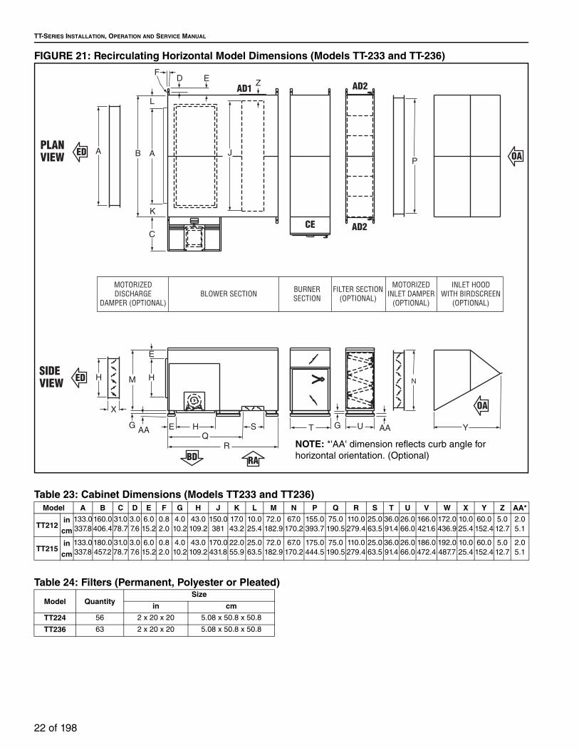
FIGURE 21: Recirculating Horizontal Model Dimensions (Models TT-233 and TT-236)
Table 23: Cabinet Dimensions (Models TT233 and TT236)
Table 24: Filters (Permanent, Polyester or Pleated)
Model A B C D E F G H J K L M N P Q R S T U V W X Y Z AA*
TT212in
cm
133.0
337.8
160.0
406.4
31.0
78.7
3.0
7.6
6.0
15.2
0.8
2.0
4.0
10.2
43.0
109.2
150.0
381
17.0
43.2
10.0
25.4
72.0
182.9
67.0
170.2
155.0
393.7
75.0
190.5
110.0
279.4
25.0
63.5
36.0
91.4
26.0
66.0
166.0
421.6
172.0
436.9
10.0
25.4
60.0
152.4
5.0
12.7
2.0
5.1
TT215in
cm
133.0
337.8
180.0
457.2
31.0
78.7
3.0
7.6
6.0
15.2
0.8
2.0
4.0
10.2
43.0
109.2
170.0
431.8
22.0
55.9
25.0
63.5
72.0
182.9
67.0
170.2
175.0
444.5
75.0
190.5
110.0
279.4
25.0
63.5
36.0
91.4
26.0
66.0
186.0
472.4
192.0
487.7
10.0
25.4
60.0
152.4
5.0
12.7
2.0
5.1
Y
AD2
AD2AD1
CE
AAUT
R
SQ
HE
M H
E
H
AA
X
N
PJ
Z
B A
L
K
C
A
EDF
SIDEVIEW
PLANVIEW OA
OA
ED
ED
BD RA
MOTORIZEDDISCHARGE
DAMPER (OPTIONAL)BLOWER SECTION BURNER
SECTIONFILTER SECTION
(OPTIONAL)
MOTORIZEDINLET DAMPER
(OPTIONAL)
INLET HOODWITH BIRDSCREEN
(OPTIONAL)
GG
NOTE: *'AA' dimension reflects curb angle for
horizontal orientation. (Optional)
Model QuantitySize
in cm
TT224 56 2 x 20 x 20 5.08 x 50.8 x 50.8
TT236 63 2 x 20 x 20 5.08 x 50.8 x 50.8

SECTION 5: SPECIFICATIONS
23 of 198
FIGURE 22: Recirculating Upright Model Dimensions (Models TT233 and TT236)
Table 25: Estimated Shipping Weights (Models TT233 and TT236)
Table 26: Estimated Shipping Weights - Motors
W
CE
AD2 AD2
AD1
VF
P
J
Z
AB
L
A
KC
G
X
N
U
T
HQ
S
R
E
H
H E
M
X
RA
SD
SIDEVIEW
ENDVIEW
OA OA
RA
SD
TD TD
MOT
ORIZ
EDDI
SCHA
RGE
DAM
PER
(OPT
IONA
L)BU
RNER
SEC
TION
BLOW
ER S
ECTI
ONFI
LTER
SEC
TION
(OPT
IONA
L)
MOT
ORIZ
EDIN
LET
DAM
PER
(OPT
IONA
L)
MOU
NTIN
GCH
ANNE
L(O
PTIO
NAL)
ModelBurner/Blower Section
Filter Section
Inltet Hood
WeatherizingDischarge/
Inlet Damper
Roof Curb
Legs StandService Platform
Four-Way Discharge
Plenum
Double Deflection Discharge Louvers
Burner/Blower
Fiter Section
Recirculating
TT224lbkg
5,600
2,540.1
1,300
589.7
365
165.6
325
147.4
690
313.0
500
226.8
650
294.8N/A
700
317.5
700
317.5
510
231.3
500
226.8
TT230lbkg
5,900
2,676.2
1,430
648.6
400
181.4
325
147.4
690
313.0
500
226.8
650
294.8N/A
700
317.5
700
317.5
510
231.3
500
226.8
SizeHP kW
.75
.561
.751.5 1.1
2 1.5
3 2.2
5 3.7
7.5 5.6
10 7.5
15 11.2
20 14.9
25 18.6
30 22.4
40 30.0
50 37.0
60 44.7
75 55.9
Standardlb 35 35 45 45 70 85 130 155 220 275 300 360 500 550 800 950
kg 15.9 15.9 20.4 20.4 31.8 38.6 59.0 70.3 99.8 124.7 136.1 163.3 226.8 249.5 362.9 430.9
2-Speedlb 70 85 125 150 185 215 270 310 405 455 525 570 700 760
N/A N/Akg 31.8 38.6 56.7 68.0 83.9 97.5 122.5 140.6 183.7 206.4 238.1 258.5 317.5 344.7

TT-SERIES INSTALLATION, OPERATION AND SERVICE MANUAL
24 of 198
Table 27: Blower Motor Horsepower Selection
Mo
del
TT
112
AIRFLOW
CFM m3/h
Outlet Velocity
fpm m/s
Percent-age of
Capacity
Total Static Pressure.50 in wc / 1.25 mbar
.75 in wc /1.87 mbar
1.00 in wc /2.49 mbar
1.25 in wc /3.11 mbar
1.50 in wc /3.74 mbar
1.75 in wc /4.36 mbar
2.00 in wc /4.98 mbar
2.25 in wc5.6 mbar
2.50 in wc6.23 mbar
RPM BHP RPM BHP RPM BHP RPM BHP RPM BHP RPM BHP RPM BHP RPM BHP RPM BHP1,600 2,718 1,111 5.64 0 603 0.231,800 3,058 1,250 6.35 20 609 0.27 737 0.382,000 3,398 1,388 7.05 30 617 0.33 741 0.43 850 0.552,200 3,738 1,527 7.76 40 627 0.38 746 0.50 852 0.62 951 0.762,400 4,078 1,666 8.46 50 641 0.44 754 0.57 858 0.71 953 0.84 1041 0.992,600 4,417 1,805 9.17 60 656 0.52 764 0.65 864 0.80 956 0.94 1043 1.10 1125 1.242,800 4,757 1,944 9.88 70 673 0.60 775 0.75 872 0.90 962 1.06 1047 1.21 1127 1.37 1203 1.543,200 5,437 2,222 11.29 80 712 0.80 805 0.96 894 1.13 970 1.17 1058 1.48 1135 1.66 1208 1.83 1278 2.03 1345 2.223,600 6,116 2,500 12.70 90 759 1.06 841 1.22 922 1.40 1001 1.59 1077 1.78 1149 1.98 1219 2.18 1286 2.38 1350 2.584,000 6,796 2,777 14.11 100 808 1.37 881 1.54 956 1.73 1029 1.94 1100 2.14 1169 2.36 1235 2.57 1300 2.80 1362 3.00
Mo
del
TT
115
AIRFLOW
CFM m3/h
Outlet Velocity
fpm m/s
Percent-age of
Capacity
Total Static Pressure.50 in wc / 1.25 mbar
.75 in wc /1.87 mbar
1.00 in wc /2.49 mbar
1.25 in wc /3.11 mbar
1.50 in wc /3.74 mbar
1.75 in wc /4.36 mbar
2.00 in wc /4.98 mbar
2.25 in wc5.6 mbar
2.50 in wc6.23 mbar
RPM BHP RPM BHP RPM BHP RPM BHP RPM BHP RPM BHP RPM BHP RPM BHP RPM BHP2,250 2,823 1,119 5.68 20 497 0.312,500 4,248 1,243 6.31 30 501 0.36 608 0.503,000 5,097 1,492 7.58 40 513 0.47 613 0.63 702 0.813,500 5,947 1,741 8.84 50 528 0.62 623 0.81 708 0.99 786 1.19 860 1.404,000 6,796 1,990 10.11 60 548 0.82 637 1.00 720 1.22 793 1.43 863 1.66 928 1.89 993 2.144,500 7,646 2,238 11.37 70 574 1.07 654 1.27 732 1.49 805 1.73 872 1.96 935 2.22 995 2.47 1053 2.73 1110 3.005,000 8,495 2,487 12.63 80 607 1.37 675 1.57 748 1.80 819 2.00 884 2.32 945 2.58 1003 2.86 1058 3.13 1112 3.425,500 9,345 2,736 13.90 90 645 1.74 703 1.94 767 2.18 833 2.45 897 2.73 957 3.00 1014 3.30 1068 3.60 1119 3.906,000 10,194 2,985 15.16 100 686 2.18 734 2.38 791 2.62 851 2.90 913 3.20 971 3.50 1027 3.81 1079 4.13 1130 4.44
Mo
del
TT
118
AIRFLOW
CFM m3/h
Outlet Velocity
fpm m/s
Percent-age of
Capacity
Total Static Pressure.50 in wc / 1.25 mbar
.75 in wc /1.87 mbar
1.00 in wc /2.49 mbar
1.25 in wc /3.11 mbar
1.50 in wc /3.74 mbar
1.75 in wc /4.36 mbar
2.00 in wc /4.98 mbar
2.25 in wc5.6 mbar
2.50 in wc6.23 mbar
RPM BHP RPM BHP RPM BHP RPM BHP RPM BHP RPM BHP RPM BHP RPM BHP RPM BHP5,000 8,495 1,742 8.85 0 463 0.99 544 1.28 617 1.57 685 1.87 746 2.17 803 2.495,500 9,345 1,916 9.73 10 476 1.18 554 1.50 625 1.81 690 2.14 750 2.47 806 2.81 860 3.15 910 3.506,000 10,194 2,090 10.62 20 490 1.41 564 1.75 633 2.09 696 2.44 755 2.80 810 3.15 862 3.52 913 3.89 960 4.276,500 11,044 2,264 11.50 30 504 1.67 576 2.04 642 2.41 704 2.77 762 3.15 816 3.53 867 3.92 917 4.33 963 4.737,000 11,893 2,439 12.39 40 521 1.96 590 2.35 653 2.74 713 3.14 769 3.54 823 3.96 872 4.37 921 4.79 967 5.217,500 12,743 2,613 13.27 50 538 2.29 603 2.71 666 3.12 724 3.54 779 3.98 830 4.41 880 4.85 926 5.29 972 5.748,000 13,592 2,787 14.16 60 557 2.66 619 3.10 678 3.54 735 4.00 788 4.45 839 4.91 887 5.37 934 5.83 978 6.318,500 14,442 2,961 15.04 70 576 3.08 636 3.53 693 4.01 747 4.48 799 4.96 848 5.44 896 5.93 941 6.42 985 6.929,000 15,291 3,135 15.93 80 596 3.53 653 4.02 708 4.52 761 5.00 810 5.52 859 6.03 905 6.54 950 7.06 993 7.509,500 16,141 3,310 16.81 90 616 4.04 671 4.55 724 5.00 774 5.60 823 6.13 870 6.67 916 7.21 959 7.74 1001 8.29
10,000 16,990 3,484 17.70 100 638 4.60 690 5.14 741 5.68 789 6.22 837 6.78 883 7.34 926 7.91 970 8.47 1011 9.04
Mo
del
TT
212
AIRFLOW
CFM m3/h
Outlet Velocity
fpm m/s
Percent-age of
Capacity
Total Static Pressure.50 in wc / 1.25 mbar
.75 in wc /1.87 mbar
1.00 in wc /2.49 mbar
1.25 in wc /3.11 mbar
1.50 in wc /3.74 mbar
1.75 in wc /4.36 mbar
2.00 in wc /4.98 mbar
2.25 in wc5.6 mbar
2.50 in wc6.23 mbar
RPM BHP RPM BHP RPM BHP RPM BHP RPM BHP RPM BHP RPM BHP RPM BHP RPM BHP3,600 6,116 1,250 6.35 20 609 0.554,000 6,796 1,388 7.05 30 617 0.64 741 0.874,400 7,476 1,527 7.76 40 627 0.76 746 1.00 852 1.244,800 8,155 1,666 8.46 50 641 0.87 754 1.15 858 1.41 953 1.695,200 8,835 1,805 9.17 60 656 1.03 763 1.31 864 1.59 956 1.895,600 9,514 1,944 9.88 70 673 1.20 775 1.49 872 1.79 962 2.10 1047 2.426,400 10,874 2,222 11.29 80 712 1.60 805 1.92 894 2.25 978 2.60 1058 2.95 1135 3.31 1208 3.677,200 12,233 2,500 12.70 90 759 2.11 841 2.45 922 2.81 1001 3.19 1077 3.57 1149 3.97 1219 4.37 1286 4.77 1250 5.188,000 13,592 2,777 14.11 100 808 2.74 881 3.09 956 3.47 1029 3.87 1100 4.29 1169 4.72 1235 5.45 1300 5.59 1362 6.05

SECTION 5: SPECIFICATIONS
25 of 198
Mo
del
TT
215
AIRFLOW
CFM m3/h
Outlet Velocity
fpm m/s
Percent-age of
Capacity
Total Static Pressure.50 in wc / 1.25 mbar
.75 in wc /1.87 mbar
1.00 in wc /2.49 mbar
1.25 in wc /3.11 mbar
1.50 in wc /3.74 mbar
1.75 in wc /4.36 mbar
2.00 in wc /4.98 mbar
2.25 in wc5.6 mbar
2.50 in wc6.23 mbar
RPM BHP RPM BHP RPM BHP RPM BHP RPM BHP RPM BHP RPM BHP RPM BHP RPM BHP5,000 8,495 1,244 6.32 0 501 0.726,000 10,194 1,492 7.58 15 513 0.95 613 1.287,000 11,893 1,741 8.85 30 528 1.26 624 1.61 708 1.998,000 13,592 1,990 10.11 40 548 1.64 637 2.03 720 2.45 793 2.87 863 3.329,000 15,291 2,238 11.37 55 574 2.12 654 2.53 732 2.98 805 3.45 872 3.94 935 4.42 995 4.94
10,000 16,990 2,487 12.63 70 607 2.73 675 3.14 748 3.61 819 4.13 884 4.64 945 5.17 1003 5.72 1058 6.27 1112 6.8411,000 18,689 2,736 13.90 85 645 3.47 703 3.88 767 4.37 833 4.90 897 5.45 957 6.02 1014 6.60 1068 7.20 1119 7.8012,000 20,388 2,985 15.16 100 686 4.37 734 4.78 791 5.25 851 5.80 913 6.38 971 6.99 1027 7.62 1079 8.25 1130 8.89
Mo
del
TT
218
AIRFLOW
CFM m3/h
Outlet Velocity
fpm m/s
Percent-age of
Capacity
Total Static Pressure.50 in wc / 1.25 mbar
.75 in wc /1.87 mbar
1.00 in wc /2.49 mbar
1.25 in wc /3.11 mbar
1.50 in wc /3.74 mbar
1.75 in wc /4.36 mbar
2.00 in wc /4.98 mbar
2.25 in wc5.6 mbar
2.50 in wc6.23 mbar
RPM BHP RPM BHP RPM BHP RPM BHP RPM BHP RPM BHP RPM BHP RPM BHP RPM BHP9,000 15,291 1,071 5.44 0 453 1.64 537 2.16 612 2.69
10,000 16,990 1,745 8.86 10 463 1.97 544 2.55 617 3.13 685 3.7311,000 18,689 1,920 9.75 20 476 2.37 554 3.00 625 3.63 690 4.27 750 4.9412,000 20,388 2,094 10.64 30 489 2.83 564 3.50 633 4.19 696 4.88 755 5.59 810 6.31 863 7.0413,000 22,087 2,269 11.53 40 504 3.34 576 4.06 642 4.80 704 5.55 762 6.31 816 7.07 867 7.85 917 8.6414,000 23,786 2,443 12.41 50 521 3.92 590 4.71 653 5.49 713 6.29 769 7.09 823 7.91 872 8.74 921 9.57 970 10.4215,000 25,485 2,618 13.30 60 538 4.59 603 5.41 666 6.26 724 7.10 779 7.95 830 8.82 880 9.70 926 10.55 973 11.3916,000 27,184 2,792 14.18 70 557 5.33 619 6.20 678 7.09 735 7.99 788 8.90 839 9.81 887 10.66 934 11.61 975 12.5517,000 28,883 2,967 15.07 80 576 6.15 636 7.08 693 8.02 747 8.97 799 9.93 848 10.87 896 11.82 941 12.77 985 13.8218,000 30,582 3,141 15.96 90 596 7.07 653 8.04 708 9.03 761 10.03 810 10.97 859 12.03 905 13.08 950 14.03 993 15.1620,000 33,980 3,490 17.73 100 638 9.19 690 10.27 741 11.29 789 12.45 837 13.50 883 14.66 926 15.72 970 16.88 1011 18.04
Mo
del
TT
221
AIRFLOW
CFM m3/h
Outlet Velocity
fpm m/s
Percent-age of
Capacity
Total Static Pressure.50 in wc / 1.25 mbar
.75 in wc /1.87 mbar
1.00 in wc /2.49 mbar
1.25 in wc /3.11 mbar
1.50 in wc /3.74 mbar
1.75 in wc /4.36 mbar
2.00 in wc /4.98 mbar
2.25 in wc5.6 mbar
2.50 in wc6.23 mbar
RPM BHP RPM BHP RPM BHP RPM BHP RPM BHP RPM BHP RPM BHP RPM BHP RPM BHP10,000 16,990 1,278 6.49 0 382 1.53 458 2.0612,000 20,388 1,534 7.79 10 397 2.11 466 2.72 531 3.3514,000 23,786 1,790 9.09 20 415 2.85 480 3.54 540 4.26 595 4.99 648 5.7516,000 27,184 2,046 10.39 30 436 3.77 497 4.56 554 5.36 606 6.17 655 7.01 703 7.85 748 8.7218,000 30,582 2,301 11.69 40 460 4.91 516 5.78 570 6.67 619 7.57 667 8.49 711 9.41 754 10.35 795 11.29 837 12.2320,000 33,980 2,557 12.99 50 487 6.30 538 7.24 589 8.22 636 9.21 682 10.22 724 11.18 765 12.24 805 13.19 843 14.2422,000 37,378 2,813 14.29 60 517 7.97 563 8.98 610 10.03 654 11.08 697 12.13 739 13.29 779 14.35 817 15.51 853 16.6724,000 40,776 3,069 15.59 70 548 9.94 590 10.97 633 12.13 675 13.29 716 14.45 755 15.61 793 16.88 830 18.04 866 19.3126,000 44,174 3,324 16.89 80 619 13.29 658 14.56 697 15.72 736 16.99 774 18.36 810 19.62 846 20.89 881 22.2628,000 47,572 3,580 18.19 90 686 17.30 722 18.67 759 19.94 794 21.31 829 22.68 864 24.16 897 25.5330,000 50,970 3,836 19.49 100 714 20.57 749 21.94 783 23.32 817 24.79 850 26.16 883 27.64 915 29.22
Mo
del
TT
224
AIRFLOW
CFM m3/h
Outlet Velocity
fpm m/s
Percent-age of
Capacity
Total Static Pressure.50 in wc / 1.25 mbar
.75 in wc /1.87 mbar
1.00 in wc /2.49 mbar
1.25 in wc /3.11 mbar
1.50 in wc /3.74 mbar
1.75 in wc /4.36 mbar
2.00 in wc /4.98 mbar
2.25 in wc5.6 mbar
2.50 in wc6.23 mbar
RPM BHP RPM BHP RPM BHP RPM BHP RPM BHP RPM BHP RPM BHP RPM BHP RPM BHP25,000 42,475 1,862 9.46 0 327 4.94 376 6.16 420 7.46 463 8.84 503 10.3227,000 45,873 2,011 10.22 10 338 5.79 384 7.09 426 8.45 467 9.89 506 11.39 544 12.98 580 14.6629,000 49,271 2,160 10.97 20 348 6.75 392 8.13 434 9.56 473 10.97 511 12.55 546 14.24 581 15.93 616 17.7231,000 52,669 2,309 11.73 30 359 7.83 402 9.31 442 10.76 480 12.34 516 13.93 551 15.61 584 17.41 617 19.20 650 21.1033,000 56,067 2,459 12.49 40 370 9.03 413 10.55 452 12.13 487 13.72 522 15.44 556 17.20 588 18.99 620 20.89 651 22.7935,000 59,465 2,608 13.25 50 423 11.92 461 13.61 496 15.30 530 17.09 593 18.88 593 20.68 624 22.68 654 24.5837,000 62,863 2,757 14.01 60 435 13.50 471 15.30 505 17.09 538 18.88 599 20.68 599 22.58 629 24.58 658 26.5939,000 66,261 2,906 14.76 70 481 17.09 515 18.99 546 20.78 606 22.79 606 24.69 635 26.69 663 28.8041,000 69,659 3,055 15.52 80 492 19.10 524 20.99 555 23.00 614 24.90 614 27.01 641 29.01 669 31.2343,000 73,057 3,204 16.28 90 535 23.21 565 25.21 622 27.32 622 29.43 649 31.54 675 33.7645,000 76,455 3,353 17.03 100 545 25.64 575 27.75 631 29.86 631 32.07 657 34.29 683 36.50

TT-SERIES INSTALLATION, OPERATION AND SERVICE MANUAL
26 of 198
Mo
del
TT
230
AIRFLOW
CFM m3/h
Outlet Velocity
fpm m/s
Percent-age of
Capacity
Total Static Pressure.50 in wc / 1.25 mbar
.75 in wc /1.87 mbar
1.00 in wc /2.49 mbar
1.25 in wc /3.11 mbar
1.50 in wc /3.74 mbar
1.75 in wc /4.36 mbar
2.00 in wc /4.98 mbar
2.25 in wc5.6 mbar
2.50 in wc6.23 mbar
RPM BHP RPM BHP RPM BHP RPM BHP RPM BHP RPM BHP RPM BHP RPM BHP RPM BHP30,000 50,970 1,612 8.19 0 252 4.86 298 6.35 339 8.0033,000 56,067 1,774 9.01 10 260 5.82 302 7.40 341 9.09 379 10.8736,000 61,164 1,935 9.83 20 267 6.93 307 8.61 345 10.38 381 12.24 415 14.2439,000 66,261 2,096 10.65 30 276 8.20 314 9.98 350 11.82 384 13.72 417 15.83 448 18.0442,000 71,358 2,258 11.47 40 285 9.62 322 11.50 357 13.40 388 15.51 420 17.62 450 19.94 479 22.26 507 24.7945,000 76,455 2,419 12.29 50 330 13.19 363 15.30 395 17.48 424 19.62 453 21.94 481 24.37 509 29.60 536 29.6448,000 81,553 2,580 13.11 60 339 15.19 370 17.41 401 19.62 429 21.94 457 24.27 484 26.80 511 29.33 537 32.0751,000 86,650 2,741 13.92 70 379 19.62 407 21.94 436 24.41 462 26.80 488 29.43 514 32.07 539 34.8254,000 91,747 2,903 14.75 80 387 22.16 415 24.58 442 27.11 468 29.69 493 32.28 518 35.03 542 37.7757,000 96,844 3,064 15.57 90 423 27.43 449 30.07 475 32.71 499 35.47 522 38.19 545 41.0460,000 101,941 3,225 16.38 100 431 30.49 457 33.23 481 36.08 505 38.82 529 41.76 550 44.63
Mo
del
TT
233
AIRFLOW
CFM m3/h
Outlet Velocity
fpm m/s
Percent-age of
Capacity
Total Static Pressure.50 in wc / 1.25 mbar
.75 in wc /1.87 mbar
1.00 in wc /2.49 mbar
1.25 in wc /3.11 mbar
1.50 in wc /3.74 mbar
1.75 in wc /4.36 mbar
2.00 in wc /4.98 mbar
2.25 in wc5.6 mbar
2.50 in wc6.23 mbar
RPM BHP RPM BHP RPM BHP RPM BHP RPM BHP RPM BHP RPM BHP RPM BHP RPM BHP40,000 67,960 1,659 8.43 0 239 7.36 276 9.20 312 11.1543,000 73,057 1,784 9.06 8 246 8.53 282 10.50 315 12.45 347 14.6646,000 78,155 1,908 9.69 16 252 9.84 287 11.92 320 14.03 350 16.29 380 20.3649,000 83,252 2,033 10.33 25 258 11.29 293 13.50 324 15.72 353 18.07 382 20.5052,000 88,349 2,157 10.96 33 300 15.19 329 17.62 358 19.94 385 22.47 411 25.1455,000 93,446 2,282 11.59 41 306 17.09 335 19.62 363 22.16 389 24.77 415 27.44 440 30.2358,000 98,543 2,406 12.22 50 342 21.83 342 21.84 368 24.48 394 27.11 419 29.95 442 32.80 466 35.7661,000 103,640 2,531 12.86 58 348 24.27 373 27.01 399 29.85 423 32.60 446 35.55 468 38.62 492 41.6764,000 108,737 2,655 13.49 66 354 26.80 380 29.79 404 32.71 427 35.55 450 38.64 473 41.67 494 44.9167,000 113,834 2,780 14.12 75 361 29.65 386 32.71 410 35.76 433 38.82 455 41.88 476 45.05 497 48.3270,000 118,931 2,904 14.75 83 392 35.76 416 39.05 438 42.20 460 45.37 481 48.68 501 51.9173,000 124,028 3,029 15.39 91 400 39.21 422 42.52 444 45.79 465 49.17 485 52.43 505 55.9275,000 127,426 3,112 15.81 100 426 44.94 448 48.32 468 51.81 488 55.18 509 67.20
Mo
del
TT
236
AIRFLOW
CFM m3/h
Outlet Velocity
fpm m/s
Percent-age of
Capacity
Total Static Pressure.50 in wc / 1.25 mbar
.75 in wc /1.87 mbar
1.00 in wc /2.49 mbar
1.25 in wc /3.11 mbar
1.50 in wc /3.74 mbar
1.75 in wc /4.36 mbar
2.00 in wc /4.98 mbar
2.25 in wc5.6 mbar
2.50 in wc6.23 mbar
RPM BHP RPM BHP RPM BHP RPM BHP RPM BHP RPM BHP RPM BHP RPM BHP RPM BHP50,000 84,951 1,953 9.92 0 244 10.76 274 12.98 303 11.15 330 17.51 358 20.0253,000 90,048 2,070 10.52 8 250 12.24 281 14.66 308 12.45 334 19.38 360 21.89 385 24.5556,000 95,145 2,187 11.11 16 256 13.93 287 16.35 313 14.03 339 21.31 364 23.96 387 26.6559,000 100,242 2,304 11.70 25 293 18.36 320 15.72 344 23.55 368 26.16 391 28.97 414 31.8362,000 105,339 2,421 12.30 33 299 20.41 326 17.62 349 28.85 372 28.65 394 31.48 417 34.41 438 37.4665,000 110,436 2,539 12.90 41 332 19.62 356 28.44 378 31.23 399 34.18 420 37.14 441 40.30 462 43.5368,000 115,533 2,656 13.49 50 339 21.84 362 31.12 383 34.08 404 37.14 424 40.22 444 43.36 464 46.6371,000 120,630 2,773 14.09 58 345 24.27 367 34.08 389 37.14 409 40.29 429 43.46 448 46.63 468 50.0274,000 125,727 2,890 14.68 66 351 33.87 373 37.14 395 40.42 415 43.57 435 46.84 454 50.24 472 53.5977,000 130,824 3,007 15.28 75 381 40.41 401 43.78 421 47.16 440 50.60 458 54.02 476 57.4980,000 135,921 3,124 15.87 83 387 43.89 407 47.48 426 50.96 445 54.51 463 58.04 481 61.5183,000 141,018 3,242 16.47 91 394 47.69 414 51.38 433 54.97 452 58.67 468 62.30 486 65.9485,000 144,416 3,320 16.87 100 398 50.29 418 54.02 437 57.85 455 61.50 473 65.20 490 69.01
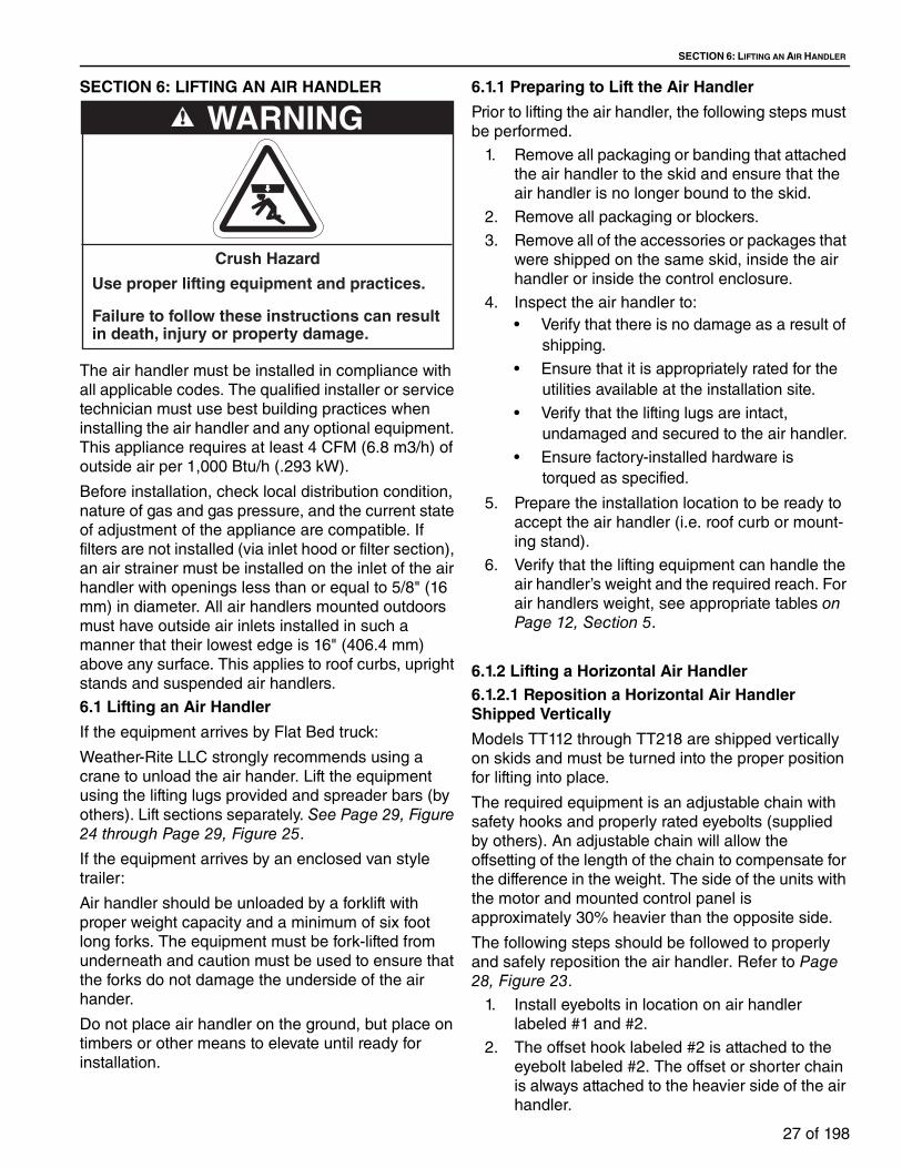
SECTION 6: LIFTING AN AIR HANDLER
27 of 198
SECTION 6: LIFTING AN AIR HANDLER
The air handler must be installed in compliance with
all applicable codes. The qualified installer or service
technician must use best building practices when
installing the air handler and any optional equipment.
This appliance requires at least 4 CFM (6.8 m3/h) of
outside air per 1,000 Btu/h (.293 kW).
Before installation, check local distribution condition,
nature of gas and gas pressure, and the current state
of adjustment of the appliance are compatible. If
filters are not installed (via inlet hood or filter section),
an air strainer must be installed on the inlet of the air
handler with openings less than or equal to 5/8" (16
mm) in diameter. All air handlers mounted outdoors
must have outside air inlets installed in such a
manner that their lowest edge is 16" (406.4 mm)
above any surface. This applies to roof curbs, upright
stands and suspended air handlers.
6.1 Lifting an Air Handler
If the equipment arrives by Flat Bed truck:
Weather-Rite LLC strongly recommends using a
crane to unload the air hander. Lift the equipment
using the lifting lugs provided and spreader bars (by
others). Lift sections separately. See Page 29, Figure 24 through Page 29, Figure 25.
If the equipment arrives by an enclosed van style
trailer:
Air handler should be unloaded by a forklift with
proper weight capacity and a minimum of six foot
long forks. The equipment must be fork-lifted from
underneath and caution must be used to ensure that
the forks do not damage the underside of the air
hander.
Do not place air handler on the ground, but place on
timbers or other means to elevate until ready for
installation.
6.1.1 Preparing to Lift the Air Handler
Prior to lifting the air handler, the following steps must
be performed.
1. Remove all packaging or banding that attached
the air handler to the skid and ensure that the
air handler is no longer bound to the skid.
2. Remove all packaging or blockers.
3. Remove all of the accessories or packages that
were shipped on the same skid, inside the air
handler or inside the control enclosure.
4. Inspect the air handler to:
• Verify that there is no damage as a result of
shipping.
• Ensure that it is appropriately rated for the
utilities available at the installation site.
• Verify that the lifting lugs are intact,
undamaged and secured to the air handler.
• Ensure factory-installed hardware is
torqued as specified.
5. Prepare the installation location to be ready to
accept the air handler (i.e. roof curb or mount-
ing stand).
6. Verify that the lifting equipment can handle the
air handler’s weight and the required reach. For
air handlers weight, see appropriate tables on Page 12, Section 5.
6.1.2 Lifting a Horizontal Air Handler6.1.2.1 Reposition a Horizontal Air Handler Shipped Vertically
Models TT112 through TT218 are shipped vertically
on skids and must be turned into the proper position
for lifting into place.
The required equipment is an adjustable chain with
safety hooks and properly rated eyebolts (supplied
by others). An adjustable chain will allow the
offsetting of the length of the chain to compensate for
the difference in the weight. The side of the units with
the motor and mounted control panel is
approximately 30% heavier than the opposite side.
The following steps should be followed to properly
and safely reposition the air handler. Refer to Page 28, Figure 23.
1. Install eyebolts in location on air handler
labeled #1 and #2.
2. The offset hook labeled #2 is attached to the
eyebolt labeled #2. The offset or shorter chain
is always attached to the heavier side of the air
handler.
WARNING
Crush Hazard
Use proper lifting equipment and practices.
Failure to follow these instructions can result in death, injury or property damage.
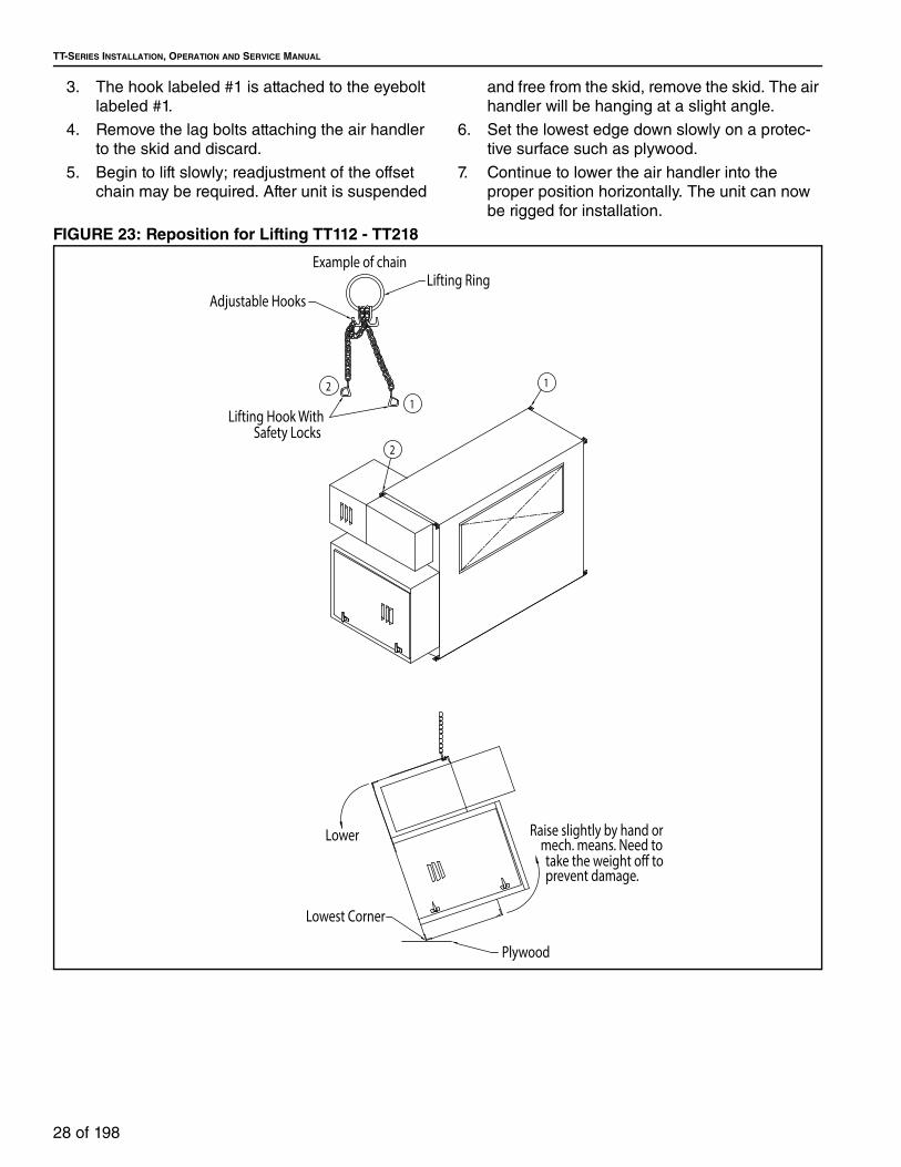
TT-SERIES INSTALLATION, OPERATION AND SERVICE MANUAL
28 of 198
3. The hook labeled #1 is attached to the eyebolt
labeled #1.
4. Remove the lag bolts attaching the air handler
to the skid and discard.
5. Begin to lift slowly; readjustment of the offset
chain may be required. After unit is suspended
and free from the skid, remove the skid. The air
handler will be hanging at a slight angle.
6. Set the lowest edge down slowly on a protec-
tive surface such as plywood.
7. Continue to lower the air handler into the
proper position horizontally. The unit can now
be rigged for installation.
FIGURE 23: Reposition for Lifting TT112 - TT218
2
1
Example of chainLifting Ring
Adjustable Hooks
Lifting Hook WithSafety Locks
1
2
Lowest Corner
Lower
prevent damage.
Plywood
take the weight off tomech. means. Need to
Raise slightly by hand or

SECTION 6: LIFTING AN AIR HANDLER
29 of 198
6.1.3 Lifting an Upright Air Handler
Lift the air handler into place using all four 0.75"
(1.9 cm) diameter lifting lugs on the unit base. Use
spreader bars to ensure that the lifting cables clear
the sides of the air handler. See Page 29, Figure 25.
Use caution as the load may be unbalanced. The air
handler must be kept level during the lift to prevent
tipping, twisting or falling. If lifted improperly, product
damage may occur.
If the air handler is shipped as two pieces, lift the two
pieces separately and then assemble. See Page 30, Section 7 for assembly instructions. Refer to the
applicable portions of Page 50, Section 10 through Page 55, Section 11 for assembly and mounting
instructions for specific accessories.
FIGURE 24: Lifting a Horizontal Air Handler
FIGURE 25: Lifting an Upright Air Handler
EYE-BOLT
NUT
WASHER
(HARDWARE SUPPLIED BY OTHERS)
EYE-BOLT
NUT
WASHER
(HARDWARE SUPPLIED BY OTHERS)

TT-SERIES INSTALLATION, OPERATION AND SERVICE MANUAL
30 of 198
SECTION 7: AIR HANDLER ASSEMBLYAll air handlers, except the TT118 and the
recirculating TT233-TT236, have the blower and
burner shipped as one piece. No field assembly is
required. For TT118 and recirculating models TT233-
TT236 field assembly will be required.
To assemble, use the supplied hardware and bolt the
blower section to the burner section through pre-
drilled holes. Supplied hardware must be torqued to
recommended specifications on Page 10, Table 1.
For details, See Page 31, Figure 27.
On outdoor models, caulk (provided by others) the
sides, roof and bottom seams between the section
splits. Once caulk has been applied to outdoor
models TT233-TT236 (pitched roof is standard), the
provided roof seam cover should be screwed over
the caulked seam every 12" (30.5 cm) with the
provided screws. For outdoor model TT118, roof
seam cover is not required (unless pitched roof
option supplied). See Page 30, Table 28 for quantity
of screws required.
Table 28: Roof Seam Cover Drill Screws
FIGURE 26: Air Handler Assembly - Horizontal/Upright (Model TT118)
ModelQuantity of Drill Screws per
Section for Seam CoverTT233 & TT236 14
TYPICAL FOR ALL CONNECTIONS
BOLTFLAT WASHER
FLAT WASHERLOCK WASHER
NUT
BLOWER SECTION
FILTER/BURNER SECTION
Model Quantity of Nuts, Bolts, Flat/Lock Washers
118
BURNER/FILTERSECTION
BLOWERSECTION
HORIZONTAL UPRIGHT
14 Sets

SECTION 7: AIR HANDLER ASSEMBLY
31 of 198
FIGURE 27: Air Handler Assembly - Recirculating Horizontal (Models TT233 and TT236)
TYPICAL FOR ALL CONNECTIONS
BOLTFLAT WASHER
FLAT WASHERLOCK WASHERNUT
TYPICAL ROOF SEAM DETAIL
CAULK END OF SEAM & AT INTERSECTIONS
SEAM STRIP
PITCHED ROOF (REF)
INSTALL DRILL SCREWS APPROX. 1" FROM EACH ENDTO SECURE SEAM STRIP TO ROOF CONNECTING FLANGES
BLOWER SECTION
BURNER SECTION
ModelQuantity of 1/2" Nuts,
Bolts, Flat/Lock WashersTT233 14 sets
TT236 14 sets

TT-SERIES INSTALLATION, OPERATION AND SERVICE MANUAL
32 of 198
FIGURE 28: Air Handler Assembly - Recirculating Upright (Models TT233 and TT236)
LOCK WASHERFLAT WASHER
FLAT WASHER
BLOWERSECTION
BURNERSECTION
TYPICAL FOR ALL CONNECTIONS
NUT
BOLT
Model Quantity of 1/2" Nuts, Bolts, Flat/Lock Washers
TT233 14 sets
TT236 14 sets

SECTION 8: VIBRATION ISOLATION
33 of 198
SECTION 8: VIBRATION ISOLATIONVibration isolation isolates the support / mounting structure / building from vibrations that the air handler
equipment may generate. The type of isolation is determined by the application and or specifications of the
equipment on order. The factory will select the appropriate sizing for the isolators.
There are three different types of vibration isolators available - Pad, Neoprene or Spring. Pad isolators are
typically used for curb-mounted units. Neoprene and Spring can be used for suspension via hanger rod or
pad mounted installation. Neoprene style is normally selected when noise and vibration are to be
considered. Spring style is normally selected when only vibration is considered.
8.1 Pad Isolator for Curb-Mounted Air Handler
The pad supplied is 2" (5.1 cm) wide by 15" (38.1 cm) long. See Page 33, Figure 29. This is a resilient cross
ribbed neoprene pad with a high deflection rate. Alternatively raised ribs provide effective isolation in both
high and low load ranges. The equipment can be properly isolated with use these strips placed on a
standard factory-supplied curb.
FIGURE 29: Pad Isolator
8.1.1 Installation Instructions for Pad Isolator for Curb-Mounted Air Handlers1. Lay strips on the top surface of the curb. See Page 34, Figure 30.
2. Hold in place with tape, such as masking or duct.
3. Trim as needed to cover the perimeter of the curb.
4. Lift and place the air handler on top of curb.

TT-SERIES INSTALLATION, OPERATION AND SERVICE MANUAL
34 of 198
FIGURE 30: Pad Isolator Installation
Unit
Waffle Pad Isolator
2" (5.08 cm) x 2" (5.08 cm)
Curb Angle
Curb
C-Channel
(Check Unit Dimensions
For More Detail)
2” Duct Flange or Case

SECTION 8: VIBRATION ISOLATION
35 of 198
8.2 Neoprene or Spring Isolators for Hanging-Mounted Air Handler
The hanger style isolator, available in neoprene or
spring, and is used to suspend the air handler from
any overhead support. (i.e. hanger rod) It is supplied
with a rectangular steel housing which incorporates
the neoprene element or spring. See Page 35, Figure 31. The design permits either the housing to be
bolted directly to the ceiling or support structure or to
be suspended from hanger rods (sized and supplied
by the installer along with all hardware).
FIGURE 31: Hanging Isolator Variations
All hardware, which include nuts, washers and
hanger rods are to be supplied by the installer.
1. Equipment should be hung at its proper eleva-
tion by using temporary fixtures that can be
removed after vibration isolators are installed
and adjusted.
2. Isolators may be fastened directly to the struc-
ture or inserted in the hanger rods. See Page 35, Figure 32. For best results, isolators should
be located at or near the ceiling.
3. Install isolators.
4. Turn nut on lower rod assembly clockwise on
complete turn on each isolator. Repeat this
procedure until temporary hanging fixtures are
loose and load of the equipment is suspended
completely on the vibration isolators. See Page 37, Figure 34.
5. Remove temporary hanger fixtures and level
equipment by taking additional turns on the
lower isolator rod nut clockwise to raise, coun-
terclockwise to lower, as required.
NOTE: It is recommended on models TT112-TT218,
that the hanger rod pass through the upper support
flange and attach to the lower support flange. See Page 36, Figure 33. It is recommended on model
TT221, that the hanger rod pass through the upper
support tube and attach to the lower support tube,
See Page 37, Figure 34. It is recommended on
models TT224-TT236, that the hanger rod pass
through the upper and lower flange of the structural
base and attach to the lower flange. See Page 38, Figure 35.
FIGURE 32: Hanger Isolator
NEOPRENE SPRING
ROOF STRUCTURE

TT-SERIES INSTALLATION, OPERATION AND SERVICE MANUAL
36 of 198
FIGURE 33: Hanger Rods’ Installation instructions (Model TT112-TT218)
LOCK WASHER
(HARDWARE BY OTHERS)NUT
FLAT WASHER

SECTION 8: VIBRATION ISOLATION
37 of 198
FIGURE 34: Hanger Rods’ Installation (Model TT221)
FLAT WASHERLOCK WASHERNUT
(HARDWARE BY OTHERS)

TT-SERIES INSTALLATION, OPERATION AND SERVICE MANUAL
38 of 198
FIGURE 35: Hanger Rods’ Installation Instructions (Model TT224-TT236)
NUTLOCK WASHERFLAT WASHER
(HARDWARE BY OTHERS)

SECTION 8: VIBRATION ISOLATION
39 of 198
8.3 Neoprene or Spring Isolators for Pad-Mounted Air Handlers
The pad style isolator, which is available in either a
neoprene version or spring version, is used to
support the air handler from a base pad or structural
frame.
8.3.1 Neoprene Mount Isolator
The neoprene mount isolator is a single piece
structure in a rectangular steel housing designed to
be bolted directly to the bottom support base of the
air handler equipment and the pad or base it rests
on. See Page 39, Figure 36. Neoprene style is
normally selected when the equipment requires up to
½" (12.7 mm) of static deflection.
FIGURE 36: Pad Mounting of Neoprene Isolator
8.3.1.1 Installation Instructions for Neoprene Mount Isolator
All hardware required to mount the isolator to the
structure is to be supplied by the installer.
1. Install blockers under the air handler equip-
ment to allow the isolator to be slid into place.
2. Place the isolator between the structure and
support base of the air handler.
3. Bolt the base of the isolator securely to the
structure.
4. Secure equipment with an adjusting bolt pass-
ing through the base of the air handler and
screw it into the isolator. See Page 40, Figure 37.

TT-SERIES INSTALLATION, OPERATION AND SERVICE MANUAL
40 of 198
FIGURE 37: Pad Mounting Installation Instructions for Neoprene Isolator (Models TT112-TT218)

SECTION 8: VIBRATION ISOLATION
41 of 198
FIGURE 38: Pad Mounting Installation Instructions for Neoprene Isolator (Model TT221)

TT-SERIES INSTALLATION, OPERATION AND SERVICE MANUAL
42 of 198
FIGURE 39: Pad Mounting Installation Instructions for Neoprene Isolator (Models TT224-TT236)

SECTION 8: VIBRATION ISOLATION
43 of 198
8.3.2 Spring Mount Isolator
The spring mount isolator includes a rectangular
steel housing which incorporates the spring and load
tensioning adjustment bolt. It is equipped with
neoprene stabilizers to provide lateral control without
binding. See Page 43, Figure 40. Spring style is
normally selected when the equipment requires up to
1" (25.4 cm) in deflection.
FIGURE 40: Pad Mounting of Spring Isolator
8.3.2.1 Installation Instructions for Spring Mount Isolator
All hardware required to mount the isolator to the
structure is to be supplied by the installer.
1. Place the spring mount between the structure
and support base of the air handler. The spring
mount housing serves as the blocking during
erection.
2. Bolt the base of the isolator securely to the
structure.
3. Secure equipment with adjustment bolt pass-
ing through the base of the air handler.
4. Adjust the isolator to ensure the spring pres-
sure plate is a minimum ¼" (6.35 mm) above
the lower housing and no more than ½" (12.7
mm) above the lower housing. See Page 44, Figure 41.
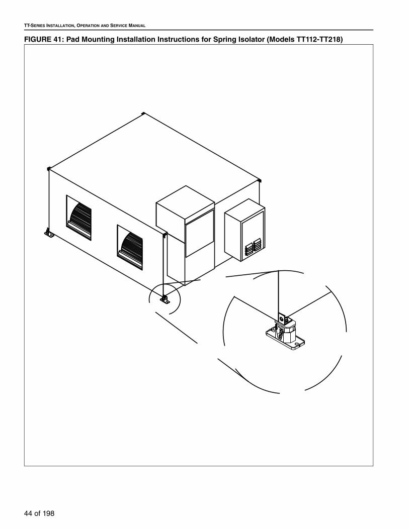
TT-SERIES INSTALLATION, OPERATION AND SERVICE MANUAL
44 of 198
FIGURE 41: Pad Mounting Installation Instructions for Spring Isolator (Models TT112-TT218)

SECTION 8: VIBRATION ISOLATION
45 of 198
FIGURE 42: Pad Mounting Installation Instructions for Spring Isolator (Model TT221)

TT-SERIES INSTALLATION, OPERATION AND SERVICE MANUAL
46 of 198
FIGURE 43: Pad Mounting Installation Instructions for Spring Isolator (Model TT224-TT236)

SECTION 9: ROOF CURB
47 of 198
SECTION 9: ROOF CURB
Roof curbs support roof mounted horizontal air
handlers and accessory sections, roof curbs are
available in 24" (61.0 cm).
Roof curbs are shipped knocked down and require
field assembly. Note: Before installation, verify that
you have the correct roof curb and that all required
components are present. If any are missing, contact
your WEATHER-RITE™ independent representative.
9.1 Roof Curb Assembly and Installation
Assemble roof curb according to the assembly
drawing on Page 48, Figure 44. Supplied hardware
must be torqued to recommended specifications on Page 10, Table 1.
Place the curb on the roof in the position in which it
will be installed. Check that the diagonal
measurements are within 1/8"(3 mm) of each other.
To ensure a weatherproof seal between the air
handler and the curb, the curb must be level with no
twist from end to end. Shim level as required and
secure curb to roof deck using best building
practices. The curb is self-flashing. Install roofing
material as required.
NOTE: Check the installation location to ensure
proper clearances to combustibles and clearance for
access. See Page 10, Section 3.1.
Crush Hazard
Use proper lifting equipment and practices.
Falling Hazard
Use proper safety equipment and prac-tices to avoid falling.
Severe Injury Hazard
Use proper lifting practices and equip-ment.
Equipment and accessories are heavy.
Cut/Pinch Hazard
Wear protective gear during installation, operation and service.
Edges are sharp.
WARNING
Failure to follow these instructions can result in death, injury or property damage.
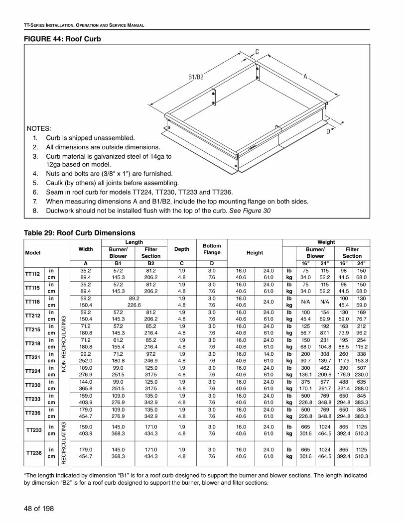
TT-SERIES INSTALLATION, OPERATION AND SERVICE MANUAL
48 of 198
FIGURE 44: Roof Curb
Table 29: Roof Curb Dimensions
*The length indicated by dimension “B1” is for a roof curb designed to support the burner and blower sections. The length indicated
by dimension “B2” is for a roof curb designed to support the burner, blower and filter sections.
C
B1/B2 A
DNOTES:
1. Curb is shipped unassembled.
2. All dimensions are outside dimensions.
3. Curb material is galvanized steel of 14ga to
12ga based on model.
4. Nuts and bolts are (3/8" x 1") are furnished.
5. Caulk (by others) all joints before assembling.
6. Seam in roof curb for models TT224, TT230, TT233 and TT236.
7. When measuring dimensions A and B1/B2, include the top mounting flange on both sides.
8. Ductwork should not be installed flush with the top of the curb. See Figure 30
ModelWidth
LengthDepth
Bottom Flange Height
WeightBurner/Blower
Filter Section
Burner/Blower
Filter Section
A B1 B2 C D 16" 24" 16" 24"
TT112in
cm
NO
N-R
EC
IRC
UL
AT
ING
35.2
89.4
57.2
145.3
81.2
206.2
1.9
4.8
3.0
7.6
16.0
40.6
24.0
61.0
lbkg
75
34.0
115
52.2
98
44.5
150
68.0
TT115in
cm35.2
89.4
57.2
145.3
81.2
206.2
1.9
4.8
3.0
7.6
16.0
40.6
24.0
61.0
lbkg
75
34.0
115
52.2
98
44.5
150
68.0
TT118in
cm59.2
150.4
89.2
226.6
1.9
4.8
3.0
7.6
16.0
40.624.0
lbkg
N/A N/A100
45.4
130
59.0
TT212in
cm59.2
150.4
57.2
145.3
81.2
206.2
1.9
4.8
3.0
7.6
16.0
40.6
24.0
61.0
lbkg
100
45.4
154
69.9
130
59.0
169
76.7
TT215in
cm71.2
180.8
57.2
145.3
85.2
216.4
1.9
4.8
3.0
7.6
16.0
40.6
24.0
61.0
lbkg
125
56.7
192
87.1
163
73.9
212
96.2
TT218in
cm71.2
180.8
61.2
155.4
85.2
216.4
1.9
4.8
3.0
7.6
16.0
40.6
24.0
61.0
lbkg
150
68.0
231
104.8
195
88.5
254
115.2
TT221in
cm99.2
252.0
71.2
180.8
97.2
246.9
1.9
4.8
3.0
7.6
16.0
40.6
14.0
61.0
lbkg
200
90.7
308
139.7
260
117.9
338
153.3
TT224in
cm109.0
276.9
99.0
251.5
125.0
317.5
1.9
4.8
3.0
7.6
16.0
40.6
24.0
61.0
lbkg
300
136.1
462
209.6
390
176.9
507
230.0
TT230in
cm144.0
365.8
99.0
251.5
125.0
317.5
1.9
4.8
3.0
7.6
16.0
40.6
24.0
61.0
lbkg
375
170.1
577
261.7
488
221.4
635
288.0
TT233in
cm159.0
403.9
109.0
276.9
135.0
342.9
1.9
4.8
3.0
7.6
16.0
40.6
24.0
61.0
lbkg
500
226.8
769
348.8
650
294.8
845
383.3
TT236in
cm179.0
454.7
109.0
276.9
135.0
342.9
1.9
4.8
3.0
7.6
16.0
40.6
24.0
61.0
lbkg
500
226.8
769
348.8
650
294.8
845
383.3
TT233in
cm
RE
CIR
CU
LAT
ING
159.0
403.9
145.0
368.3
171.0
434.3
1.9
4.8
3.0
7.6
16.0
40.6
24.0
61.0
lbkg
665
301.6
1024
464.5
865
392.4
1125
510.3
TT236in
cm179.0
454.7
145.0
368.3
171.0
434.3
1.9
4.8
3.0
7.6
16.0
40.6
24.0
61.0
lbkg
665
301.6
1024
464.5
865
392.4
1125
510.3

SECTION 9: ROOF CURB
49 of 198
9.2 Air Handler Mounting to Roof Curb
After the curb has been installed, the air handler may
be placed on the curb. There must be a 1/8" (.3 cm) x
2" (5.1 cm) neoprene closed cell, adhesive-back
gasket (supplied by others) between the top of the
curb and the base surface of the air handler to
prevent moisture from leaking into the building from
either driving rains or melting snow.
The installer is responsible for tying the air handler to
the curb per all applicable codes. See Page 49, Figure 45 for details.
FIGURE 45: Installation of Legs
WEATHER-RITE UNIT
BOLT LEGS TO THE SECTIONTHRU THE LIFTING LUGS.1/2" 13NC X 1.5" BOLTS.
DRILL SCREW MOUNTINS LEGTO UNDERSIDE OF SECTION.
AMODEL
28.000 TT 112, 115, 212, 215
36.00042.000
TT 218TT 221
30.000 TT 11836.000
B
36.00036.000
36.000
DIMENSIONS
6.000
10.250
"A"
SECTION A-A
LAG BOLT HOLES FOR FLOOR MOUNTING.
WEATHER-RITE UNIT
DRILL SCREW LEGS INTO SIDE OF CABINET.
DRILL SCREW CROSSMEMBER TO LEGS.
"B"
9.500
1.500 (TYP)
9.000
6.0002.500
9.500
4.334
4.019
AA
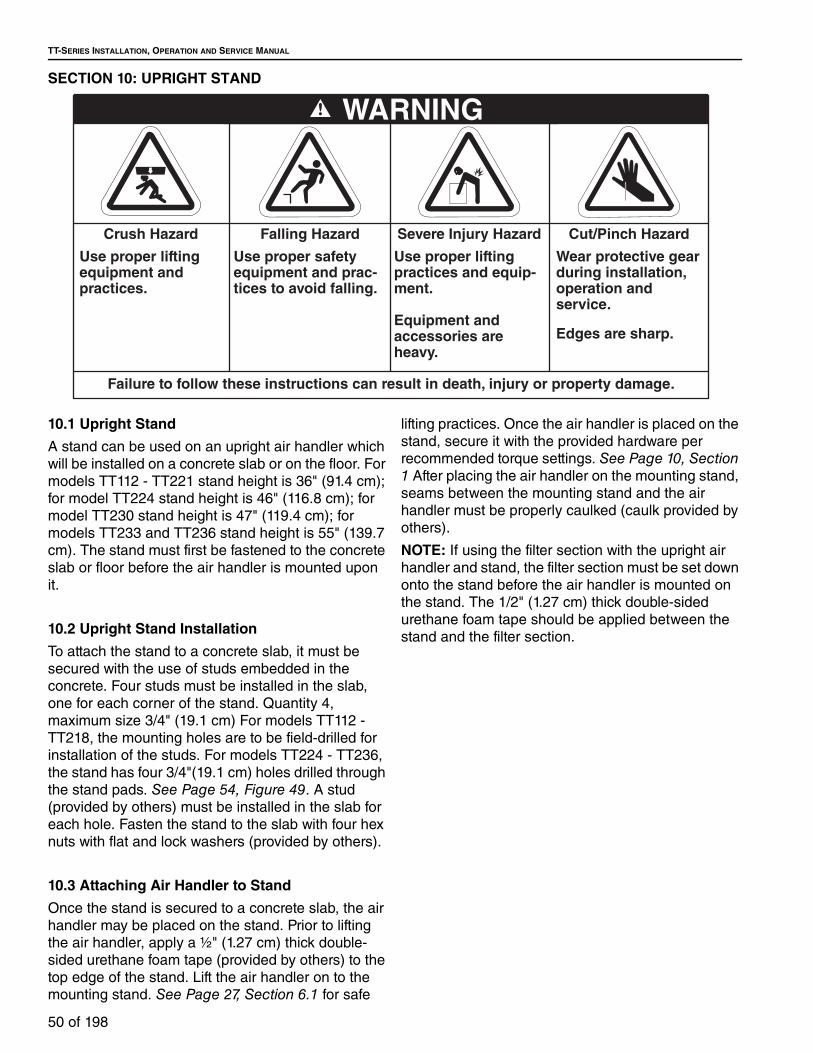
TT-SERIES INSTALLATION, OPERATION AND SERVICE MANUAL
50 of 198
SECTION 10: UPRIGHT STAND
10.1 Upright Stand
A stand can be used on an upright air handler which
will be installed on a concrete slab or on the floor. For
models TT112 - TT221 stand height is 36" (91.4 cm);
for model TT224 stand height is 46" (116.8 cm); for
model TT230 stand height is 47" (119.4 cm); for
models TT233 and TT236 stand height is 55" (139.7
cm). The stand must first be fastened to the concrete
slab or floor before the air handler is mounted upon
it.
10.2 Upright Stand Installation
To attach the stand to a concrete slab, it must be
secured with the use of studs embedded in the
concrete. Four studs must be installed in the slab,
one for each corner of the stand. Quantity 4,
maximum size 3/4" (19.1 cm) For models TT112 -
TT218, the mounting holes are to be field-drilled for
installation of the studs. For models TT224 - TT236,
the stand has four 3/4"(19.1 cm) holes drilled through
the stand pads. See Page 54, Figure 49. A stud
(provided by others) must be installed in the slab for
each hole. Fasten the stand to the slab with four hex
nuts with flat and lock washers (provided by others).
10.3 Attaching Air Handler to Stand
Once the stand is secured to a concrete slab, the air
handler may be placed on the stand. Prior to lifting
the air handler, apply a ½" (1.27 cm) thick double-
sided urethane foam tape (provided by others) to the
top edge of the stand. Lift the air handler on to the
mounting stand. See Page 27, Section 6.1 for safe
lifting practices. Once the air handler is placed on the
stand, secure it with the provided hardware per
recommended torque settings. See Page 10, Section 1 After placing the air handler on the mounting stand,
seams between the mounting stand and the air
handler must be properly caulked (caulk provided by
others).
NOTE: If using the filter section with the upright air
handler and stand, the filter section must be set down
onto the stand before the air handler is mounted on
the stand. The 1/2" (1.27 cm) thick double-sided
urethane foam tape should be applied between the
stand and the filter section.
Crush Hazard
Use proper lifting equipment and practices.
Falling Hazard
Use proper safety equipment and prac-tices to avoid falling.
Severe Injury Hazard
Use proper lifting practices and equip-ment.
Equipment and accessories are heavy.
Cut/Pinch Hazard
Wear protective gear during installation, operation and service.
Edges are sharp.
WARNING
Failure to follow these instructions can result in death, injury or property damage.

SECTION 10: UPRIGHT STAND
51 of 198
FIGURE 46: Upright Stand Detail
Model A B C Weight
TT112 &TT115
in cm
36.0 91.4
36.0 91.4
28.0 71.1
lb kg
125 56.7
TT118in
cm36.0 91.4
60.0 152.4
30.0 76.2
lb kg
140 63.5
TT212in
cm36.0 91.4
60.0 152.4
28.0 71.1
lb kg
140 63.5
TT215in
cm36.0 91.4
72.0 182.9
28.0 71.1
lb kg
150 68.0
TT218in
cm36.0 91.4
72.0 182.9
36.0 91.4
lb kg
160 72.6
TT221in
cm36.0 91.4
100.0 254.0
42.0 106.7
lb kg
175 79.4
TT224in
cm46.0
116.8110.0 279.4
55.0 139.7
lb kg
300 136.1
TT230in
cm47.0
119.4145.0 368.3
60.0 152.4
lb kg
425 192.8
TT233in
cm55.0
139.7160.0 406.4
72.0 182.9
lb kg
700 317.5
TT236in
cm55.0
139.7180.0 457.2
72.0 182.9
lb kg
700 317.5
C
A
B

TT-SERIES INSTALLATION, OPERATION AND SERVICE MANUAL
52 of 198
FIGURE 47: Attaching Air Handler to Mounting Stand (TT112-TT221)
Quantity of 1/2" Nuts, Bolts, Flat/Lock Washers
115118212215
112
Model
4
444
221 4218
44
Connecting Point(TYP Both Sides)
TYPICAL FOR ALL CONNECTIONS
BOLTFLAT WASHER
FLAT WASHERLOCK WASHERNUT

SECTION 10: UPRIGHT STAND
53 of 198
FIGURE 48: Attaching Air Handler to Mounting Stand (TT224-TT236)
Connecting Point(TYP Both Sides)
17178
236
230233
8224
Model Quantity of 1/2" Nuts, Bolts, Flat/Lock Washers
TYPICAL FOR ALL CONNECTIONS
BOLTFLAT WASHER
FLAT WASHERLOCK WASHERNUT

TT-SERIES INSTALLATION, OPERATION AND SERVICE MANUAL
54 of 198
FIGURE 49: Stand Mounting Hole Detail for Floor/Slab (Models TT221-TT236)
B
AShort Sides of
Air Handler
Long Sides of Air Handler
Model A B
TT221(in)
(cm)43.5
110.5
101.5
257.8
TT224(in)
(cm)53.5
135.9
113.0
287.0
TT230(in)
(cm)58.5
148.6
151
383.5
TT233(in)
(cm)70.5
179.1
166
421.6
TT236(in)
(cm)70.5
179.1
186
472.4

SECTION 11: VERTICAL MOUNTING LEGS
55 of 198
SECTION 11: VERTICAL MOUNTING LEGS
Legs can be used when mounting an air handler on a
concrete slab or directly on the floor. Legs are
available for models TT112 - TT221 in the upright
configuration.They cannot be used if the optional
inlet damper is supplied. See Page 55, Figure 50.
11.1 Attaching Legs to Air Handler
Legs must first be fastened to the air handler before
attaching them to the concrete slab or floor. To attach
the 36" (91.4 cm) legs to the air handler, the air
handler must first be lifted using the provided lifting
lugs. See Page 27, Figure 6 for safe lifting practices.
The legs can now be mounted one at a time to each
outside corner by utilizing hardware listed on Page 56, Figure 51 and supplied with the legs. Place the
leg on the outside corner and attach with the
previously listed hardware. Each bolt location must
have hardware installed. Once the legs are mounted
in place, cross members must be attached. See
Page 56, Figure .
NOTE: If using a filter section with upright air handler
and mounting legs, the mounting legs must be
attached to the filter section using the same
techniques listed previously. The ½" (1.27 cm) thick
double-sided urethane foam tape should be applied
between the air handler and the filter section.
11.2 Attaching Legs to Slab
To attach the legs to a concrete slab, or floor, the
base of each leg is equipped with two ¾" holes.
Studs (provided by others) must be installed in the
concrete slab, or floor.
The air handler may now be placed down over the
slab studs. The legs should then be bolted down
using nuts, lock and flat washers.
FIGURE 50: Mounting Leg Dimensions (TT112 - TT218)
Crush Hazard
Use proper lifting equipment and practices.
Falling Hazard
Use proper safety equipment and prac-tices to avoid falling.
Severe Injury Hazard
Use proper lifting practices and equip-ment.
Equipment and accessories are heavy.
Cut/Pinch Hazard
Wear protective gear during installation, operation and service.
Edges are sharp.
WARNING
Failure to follow these instructions can result in death, injury or property damage.
A
BC
Model A B CHardware
Qty.Weight
TT112 &TT115
in cm
36.0
91.4
9.5
24.1
26.0
66.028.0
lb kg
70
31.8
TT118in
cm
36.0
91.4
9.5
24.1
30.0
76.2 28.0lb kg
70
31.8
TT212 &TT215
in cm
36.0
91.4
9.5
24.1
26.0
66.028.0
lb kg
70
31.8
TT218in
cm
36.0
91.4
9.5
24.1
33.0
83.828.0
lb kg
70
31.8

TT-SERIES INSTALLATION, OPERATION AND SERVICE MANUAL
56 of 198
FIGURE 51: Mounting Legs Installation Instructions
WEATHER-RITE UNIT
BOLT LEGS TO THE SECTIONTHRU THE LIFTING LUGS.1/2" 13NC X 1.5" BOLTS.
DRILL SCREW MOUNTINS LEGTO UNDERSIDE OF SECTION.
AMODEL
28.000 TT 112, 115, 212, 215
36.00042.000
TT 218TT 221
30.000 TT 11836.000
B
36.00036.000
36.000
DIMENSIONS
6.000
10.250
"A"
SECTION A-A
LAG BOLT HOLES FOR FLOOR MOUNTING.
WEATHER-RITE UNIT
DRILL SCREW LEGS INTO SIDE OF CABINET.
DRILL SCREW CROSSMEMBER TO LEGS.
"B"
9.500
1.500 (TYP)
9.000
6.0002.500
9.500
4.334
4.019
AA

SECTION 12: FILTER SECTION
57 of 198
SECTION 12: FILTER SECTION
All filter sections are shipped assembled. The TT118 filter section is an integral part of the burner section.
NOTE: Check to be sure that all required components are present. If any are missing, contact your
WEATHER-RITE™ independent distributor.
Crush Hazard
Use proper lifting equipment and practices.
Falling Hazard
Use proper safety equipment and prac-tices to avoid falling.
Severe Injury Hazard
Use proper lifting practices and equip-ment.
Equipment and accessories are heavy.
Cut/Pinch Hazard
Wear protective gear during installation, operation and service.
Edges are sharp.
WARNING
Failure to follow these instructions can result in death, injury or property damage.

TT-SERIES INSTALLATION, OPERATION AND SERVICE MANUAL
58 of 198
12.1 Filter Section Installation - Horizontal Air Handlers
For installation directly onto the inlet of the air handler, use the supplied hardware and bolt the filter section to
the air handler through the pre-drilled holes. Supplied hardware must be torqued to recommended
specifications on Page 10, Table 1. On outdoor models, caulk (provided by others) both mating surfaces, roof
and bottom seams between the section splits. Once caulk has been applied to outdoor models TT224-
TT236 (pitched roof is standard), provided roof seam cover should be screwed over the caulked seam every
12" (30.5 cm) with the provided screws. See Page 30, Table 28 for quantity of screws required. Verify that the
factory installed filters are properly placed and filter access door is secured in the closed position. For details
See Page 58, Figure 52.
FIGURE 52: Filter Section Installation on Horizontal Air Handler
TYPICAL FOR ALL CONNECTIONS(Amount of hardware varies per unit size)
BOLT
FLAT WASHER
FLAT WASHERLOCK WASHER
NUT
Hardware Size
1/4"1/4"
1/2"1/4"
1/2"1/2"
Model
218
224-230233-236
112-115118-215
221
ModelQuantity of 1/4" Nuts, Bolts,
Flat/Lock WashersTT112 & TT115
6 sets
TT118 N/A
TT212 8 sets
TT215 &TT218
14 sets
ModelQuantity of 1/2" Nuts, Bolts,
Flat/Lock WashersTT221 6 sets
TT224 6 sets
TT230 14 sets
TT233 14 sets
TT236 14 sets
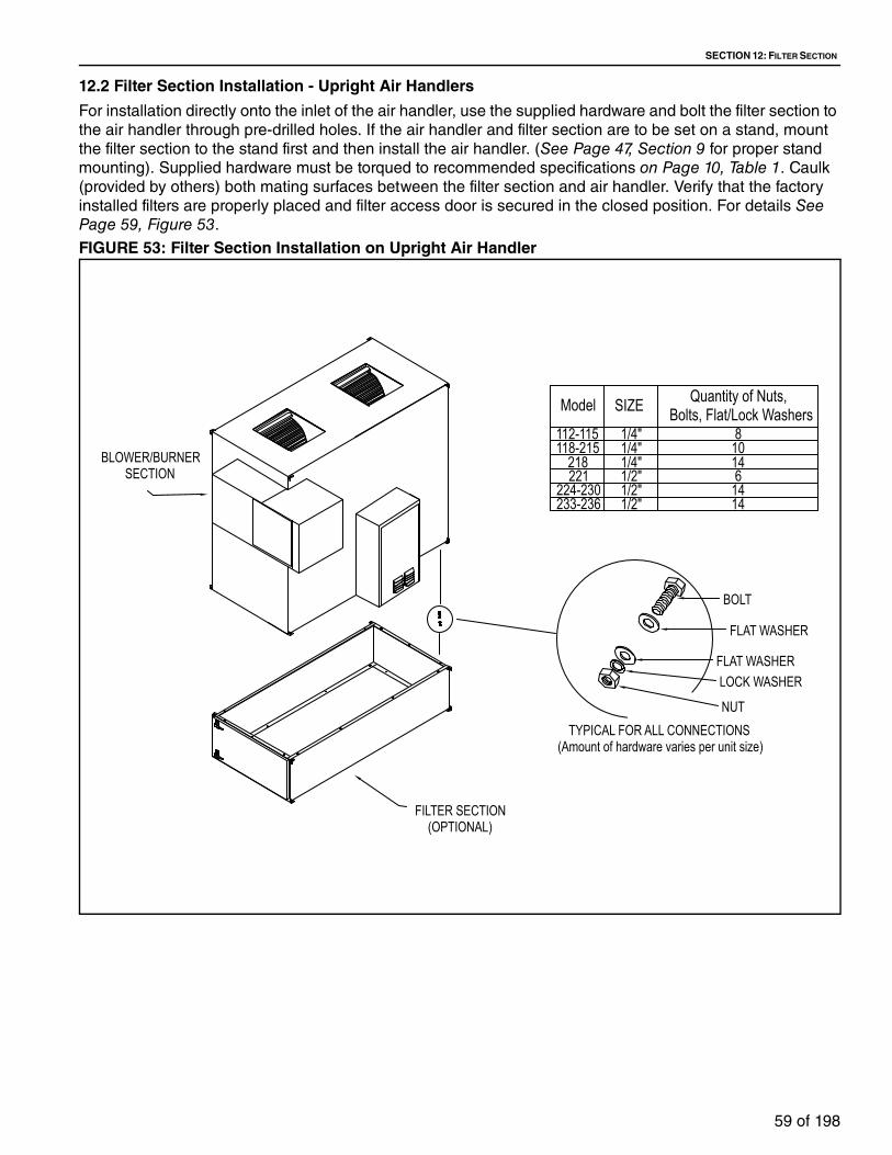
SECTION 12: FILTER SECTION
59 of 198
12.2 Filter Section Installation - Upright Air Handlers
For installation directly onto the inlet of the air handler, use the supplied hardware and bolt the filter section to
the air handler through pre-drilled holes. If the air handler and filter section are to be set on a stand, mount
the filter section to the stand first and then install the air handler. (See Page 47, Section 9 for proper stand
mounting). Supplied hardware must be torqued to recommended specifications on Page 10, Table 1. Caulk
(provided by others) both mating surfaces between the filter section and air handler. Verify that the factory
installed filters are properly placed and filter access door is secured in the closed position. For details See Page 59, Figure 53.
FIGURE 53: Filter Section Installation on Upright Air Handler
TYPICAL FOR ALL CONNECTIONS(Amount of hardware varies per unit size)
BOLT
FLAT WASHER
FLAT WASHERLOCK WASHER
NUT
BLOWER/BURNERSECTION
FILTER SECTION(OPTIONAL)
221218
224-230233-236
112-115118-215
Model Quantity of Nuts, Bolts, Flat/Lock WashersSIZE
1/2"1/4"
1/2"1/2"
1/4"1/4"
614
1414
108

TT-SERIES INSTALLATION, OPERATION AND SERVICE MANUAL
60 of 198
SECTION 13: INLET HOODS
Inlet hoods are available with permanent filters or bird screen mounted on the inlet face.
For models TT112 - TT215, inlet hoods are shipped as one piece. For models TT218 and TT221 the inlet
hood is shipped in two pieces. For models TT224 and TT230, inlet hoods are shipped as five pieces. For
models TT233 and TT236 are shipped in two sections.
The inlet hood may be installed either onto the inlet of the air handler or to an outside wall. After installing an
inlet hood, all hardware must be tightened with a torque wrench to recommended specifications on Page 10, Table 1. In addition, all seams must be caulked (supplied by others).
NOTE: Bird screen ships loose for field installation on the face of the inlet hood as the final step of assembly.
See pages 61, 62 and 64 for installation details.
Crush Hazard
Use proper lifting equipment and practices.
Falling Hazard
Use proper safety equipment and prac-tices to avoid falling.
Severe Injury Hazard
Use proper lifting practices and equip-ment.
Equipment and accessories are heavy.
Cut/Pinch Hazard
Wear protective gear during installation, operation and service.
Edges are sharp.
WARNING
Failure to follow these instructions can result in death, injury or property damage.

SECTION 13: INLET HOODS
61 of 198
13.1 Inlet Hood Installation (Models TT112 - TT215)
Inlet hoods for models TT112 - TT215 are shipped in one piece. To install the inlet hood on the cabinet of the
air handler, use the supplied hardware. See Page 61, Figure 54.
To install the inlet hood on an exterior wall, drill holes every 8" (20.3 cm) in the flanges of the inlet hood and
mount with lag bolts (supplied by others). Caulking is required on both mating surfaces.
FIGURE 54: Inlet Hood Installation to Air Handler (Models TT112 - TT215)
FLAT WASHER
TYPICAL FOR ALL CONNECTIONSNUT
LOCK WASHER
FLAT WASHER
BOLT
Bird screen attaches toface of inlet hood.

TT-SERIES INSTALLATION, OPERATION AND SERVICE MANUAL
62 of 198
13.2 Inlet Hood Assembly (Models TT218 and TT221)
Inlet hoods for standard TT218 and TT221 are shipped in two pieces. To install the inlet hood on the cabinet
of the air handler, use the supplied hardware. See Page 62, Figure 55.
To install the inlet hood on an exterior wall, drill holes every 8" (20.3 cm) in the flanges of the inlet hood and
mount with lag bolts (supplied by others). Caulking is required on both mating surfaces.
FIGURE 55: Inlet Hood Assembly and Installation to Air Handler (Models TT218 and TT221)
FLAT WASHER
TYPICAL FOR ALL CONNECTIONSNUT
LOCK WASHER
FLAT WASHER
BOLT
Bird screen attaches toface of inlet hood.
ModelQuantity of 1/2" Nuts, Bolts,
Flat/Lock WashersTT221 10 sets
ModelQuantity of 1/4" Nuts, Bolts,
Flat/Lock WashersTT218 18 sets

SECTION 13: INLET HOODS
63 of 198
13.3 Inlet Hood Installation (Models TT224 and TT230)
Inlet hoods for standard TT224 and TT230 are shipped in five pieces. To install the inlet hood on the cabinet
of the air handler, use the supplied hardware. See Page 63, Step 13.3.1.
To install the inlet hood on an exterior wall, drill holes every 8" (20.3 cm) in the flanges of the inlet hood and
mount with lag bolts (supplied by others). Caulking is required on all mating surfaces.
Step 13.3.1
Drill Screws
Step 1: Use supplied drill screws to
fasten two large pieces together.

TT-SERIES INSTALLATION, OPERATION AND SERVICE MANUAL
64 of 198
Step 13.3.2
Step 13.3.3
Lock Washerand Washer
Washer
1/2" Nut
1/2" Bolt
Caulk mating surfaces
Birdscreen attached toface of inlet hood.
ModelQuantity of 1/2" Nuts,
Bolts, Flat/Lock WashersTT224TT230
8 sets
10 sets
Step 1: Attach assembly
made on Page 63, Step 13.3.1 to inlet section of
air handler using
supplied hardware.
Drill Screws
Caulk mating surfaces
Step 1: Use supplied drill
screws to fasten the smaller
two pieces together.

SECTION 13: INLET HOODS
65 of 198
Step 13.3.4
Drill Screws
Caulk mating surfaces
Step 1: Use supplied drill screws to attach assembly made on Page 64, Step 13.3.3 to the larger section
of the inlet hood that was attached to the air handler on Page 64, Step 13.3.2.

TT-SERIES INSTALLATION, OPERATION AND SERVICE MANUAL
66 of 198
Step 13.3.5
Step 13.3.6
NOTE: This view shown with half of the hood hidden to show support.
Drill Screws
Step 1: Drill screw factory supplied hood support channel through side of support and side flanges of
inlet hood.
NOTE: This view shown with half of the hood hidden to show support.
Step 1: Drill screw factory supplied hood support to bottom flange at base of unit.

SECTION 13: INLET HOODS
67 of 198
13.4 Inlet Hood Installation (Models TT233 and TT236)
Inlet hoods for standard TT233 - TT236 are shipped in two sections. To install the inlet hood on the cabinet
of the air handler, use the supplied hardware. See Page 67, Figure 56.
To install the inlet hood sections on an exterior wall, drill holes every 8" (20.3 cm) in the flanges of the inlet
hood and mount with lag bolts (supplied by others).
FIGURE 56: Inlet Hood Installation to Air Handler (Models TT233 and TT236)
Final assembly of inlet hood is not complete until bird
screen, which shipped loose with the air handler, is
installed. See pages 61, 62 and 64.
Caulk mating surfaces
ModelQuantity of 1/2" Nuts, Bolts,
Flat/Lock Washers
TT233in
cm16 sets
TT236in
cm20 sets

TT-SERIES INSTALLATION, OPERATION AND SERVICE MANUAL
68 of 198
SECTION 14: SERVICE PLATFORM
All service platforms are shipped assembled and attached. Upright air handlers supplied with both a stand
and a service platform will have the service platform factory-mounted as an integral part of the stand.
Service platform for all standard horizontal units (models TT112 - TT236) are bolted or welded to the burner/
blower section depending on the application. For recirculating models TT233 and TT236, please refer to
submittal drawings for specific details.
See Page 69, Figure 57 for layout and dimensions.
Crush Hazard
Use proper lifting equipment and practices.
Falling Hazard
Use proper safety equipment and prac-tices to avoid falling.
Severe Injury Hazard
Use proper lifting practices and equip-ment.
Equipment and accessories are heavy.
Cut/Pinch Hazard
Wear protective gear during installation, operation and service.
Edges are sharp.
WARNING
Failure to follow these instructions can result in death, injury or property damage.

SECTION 14: SERVICE PLATFORM
69 of 198
FIGURE 57: Service Platform
Table 30: Service Platform
NOTE: Service platform will be located on the same side as the control panel. *Dimension "B" only applies to
service platforms on upright units. For horizontal units, dimension "B" can be determined by adding the
length of the units sections together. OSHA approved ladder and stairs by others.
Model A B* C Weight
TT112 &TT115
in cm
48.0
121.9
36.0
91.4
42.0
106.7
lb kg
400
181.4
TT118 & TT212
in cm
48.0
121.9
60.0
152.4
42.0
106.7
lb kg
400
181.4
TT215 & TT218
in cm
48.0
121.9
72.0
182.9
42.0
106.7
lb kg
480
217.7
TT221in
cm48.0
121.1
100.0
254.0
42.0
106.7
lb kg
520
235.9
TT224in
cm72.0
182.9
55.0
139.7
42.0
106.7
lb kg
300
136.1
TT230in
cm72.0
182.9
60.0
152.4
42.0
106.7
lb kg
425
192.8
TT233 & TT236
in cm
72.0
182.9
72.0
182.9
42.0
106.7
lb kg
700
317.5
Upright Unit / Models TT224 through TT236
Upright Unit /Models TT112 through TT221
Horizontal Unit / All Models
C
B
A
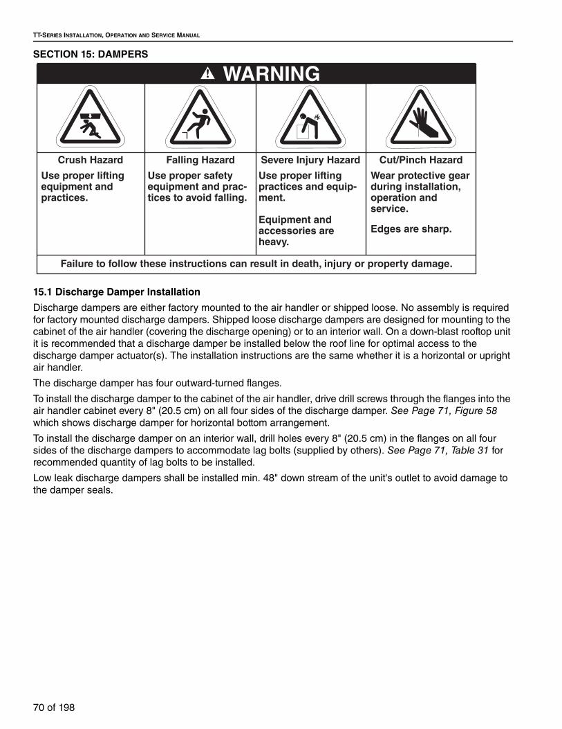
TT-SERIES INSTALLATION, OPERATION AND SERVICE MANUAL
70 of 198
SECTION 15: DAMPERS
15.1 Discharge Damper Installation
Discharge dampers are either factory mounted to the air handler or shipped loose. No assembly is required
for factory mounted discharge dampers. Shipped loose discharge dampers are designed for mounting to the
cabinet of the air handler (covering the discharge opening) or to an interior wall. On a down-blast rooftop unit
it is recommended that a discharge damper be installed below the roof line for optimal access to the
discharge damper actuator(s). The installation instructions are the same whether it is a horizontal or upright
air handler.
The discharge damper has four outward-turned flanges.
To install the discharge damper to the cabinet of the air handler, drive drill screws through the flanges into the
air handler cabinet every 8" (20.5 cm) on all four sides of the discharge damper. See Page 71, Figure 58
which shows discharge damper for horizontal bottom arrangement.
To install the discharge damper on an interior wall, drill holes every 8" (20.5 cm) in the flanges on all four
sides of the discharge dampers to accommodate lag bolts (supplied by others). See Page 71, Table 31 for
recommended quantity of lag bolts to be installed.
Low leak discharge dampers shall be installed min. 48" down stream of the unit's outlet to avoid damage to
the damper seals.
Crush Hazard
Use proper lifting equipment and practices.
Falling Hazard
Use proper safety equipment and prac-tices to avoid falling.
Severe Injury Hazard
Use proper lifting practices and equip-ment.
Equipment and accessories are heavy.
Cut/Pinch Hazard
Wear protective gear during installation, operation and service.
Edges are sharp.
WARNING
Failure to follow these instructions can result in death, injury or property damage.

SECTION 15: DAMPERS
71 of 198
FIGURE 58: Discharge Damper
Table 31: Lag Bolts
15.2 Inlet Damper Installation
Inlet dampers are either factory mounted to the air handler or shipped loose. No assembly is required for
factory mounted inlet dampers. Shipped loose inlet dampers are designed for mounting to the face of the air
handler (covering the inlet opening) or to an exterior wall. The installation instructions are the same whether
it is a horizontal or upright air handler.
The inlet damper has four outward-turned flanges.
To install the inlet damper to the face of the air handler, drive drill screws through the flanges into the air
handler cabinet every 8" (20.5 cm) on all four sides of the inlet damper for models TT112 - TT218. For model
TT221 - TT236 use bolts. See Page 72, Figure 59 for details.
To install the inlet damper on an exterior wall, drill holes every 8" (20.3 cm) in the flanges on all four sides of
the inlet dampers to accommodate lag bolts (supplied by others). See Page 71, Table 31 for recommended
quantity of lag bolts to be installed.
DRILL SCREWS(SUPPLIED BY OTHERS)
Quantity of 1/4" Drill ScrewsModel
112-115118-212 10
8
221215-218
233-236224-230
12141414
Model Quantity of Lag Bolts RecommendedTT112 & TT115 18
TT118 & TT212 20
TT215 & TT218 20
TT221 28
TT224 32
TT230 34
TT233 36
TT236 52

TT-SERIES INSTALLATION, OPERATION AND SERVICE MANUAL
72 of 198
FIGURE 59: Inlet Damper
Drill Screws or Lag Bolts (supplied by others)

SECTION 16: DISCHARGE PLENUM AND DISCHARGE LOUVERS
73 of 198
SECTION 16: DISCHARGE PLENUM AND DISCHARGE LOUVERS
16.1 Four-Way Discharge Plenum Installation
All discharge heads are shipped assembled. The discharge head is designed for mounting to the cabinet of
the air handler (covering the discharge opening) or to supply duct (duct by contractor). The discharge head
has four outward-turned flanges. To install discharge head to the cabinet of the air handler or supply duct,
drive sheet metal screws or pop rivets (supplied by others) through the flanges into the air handler or supply
cabinet every 8" (20.5 cm) on all four sides of the discharge head. In this type of installation, the discharge
head must be field-supported.
See Page 73, Figure 60 for layout and dimensions.
FIGURE 60: Four-Way Discharge Plenum
Crush Hazard
Use proper lifting equipment and practices.
Falling Hazard
Use proper safety equipment and prac-tices to avoid falling.
Severe Injury Hazard
Use proper lifting practices and equip-ment.
Equipment and accessories are heavy.
Cut/Pinch Hazard
Wear protective gear during installation, operation and service.
Edges are sharp.
WARNING
Failure to follow these instructions can result in death, injury or property damage.
B
A
C
Model A B C Weight
TT112 - TT118
in cm
19.5
49.5
26.0
66.0
24.0
61.0
lb kg
80
36.3
TT212in
cm
19.5
49.5
50.0
127.0
24.0
61.0
lb kg
80
36.3
TT215in
cm
19.5
49.5
50.0
127.0
24.0
61.0
lb kg
105
47.6
TT218in
cm
26.0
66.0
58.0
147.3
24.0
61.0
lb kg
140
63.5
TT221in
cm
33.0
83.8
76.0
193.0
24.0
61.0
lb kg
270
122.5
TT224in
cm
35.0
88.9
90.0
228.6
24.0
61.0
lb kg
385
174.6
TT230in
cm
40.0
101.6
115.0
292.1
24.0
61.0
lb kg
410
186.0
TT233 & TT236
in cm
43.0
109.2
133.0
337.8
24.0
61.0
lb kg
510
231.3

TT-SERIES INSTALLATION, OPERATION AND SERVICE MANUAL
74 of 198
16.2 Double Deflection Discharge Louver Installation
All discharge louvers are shipped assembled. The discharge louvers are designed for mounting to the
cabinet of the air handler (covering the discharge opening) or to an interior wall. To install the discharge
louvers to the cabinet of the air handler, drive sheet metal screws or pop rivets (supplied by others) through
the flanges into the air handler cabinet every 8" (20.3 cm) on all four sides of the discharge louvers. In this
type of installation, the discharge louvers must be field-supported.
To install the discharge louvers on an interior wall, drill holes every 8" (20.3 cm) in the flanges on all four
sides of the discharge louvers to accommodate lag bolts (supplied by others). See Page 71, Table 31 for
recommended quantity of lag bolts to be installed. In this type of installation, the discharge louvers are self-
supporting; no other support is needed in a standard installation.
See Page 74, Figure 61 for layout and dimensions.
FIGURE 61: Double Deflection Discharge Louvers
B
A
C
Model A B C Weight
TT112 - TT118
in cm
19.5
49.5
26.0
66.0
24.0
61.0
lb kg
70
31.8
TT212in
cm
19.5
49.5
50.0
127.0
24.0
61.0
lb kg
70
31.8
TT215in
cm
19.5
49.5
50.0
127.0
24.0
61.0
lb kg
95
43.1
TT218in
cm
26.0
66.0
58.0
147.3
24.0
61.0
lb kg
130
59.0
TT221in
cm
33.0
83.8
76.0
193.0
24.0
61.0
lb kg
260
118.0
TT224in
cm
35.0
88.9
90.0
228.6
24.0
61.0
lb kg
375
170.1
TT230in
cm
40.0
101.6
115.0
292.1
24.0
61.0
lb kg
400
181.4
TT233 & TT236
in cm
43.0
109.2
133.0
337.8
24.0
61.0
lb kg
500
226.8

SECTION 17: DUCT CONSIDERATIONS
75 of 198
SECTION 17: DUCT CONSIDERATIONS
The air handler has been designed to operate at the
specific air volume and external static pressure that
was ordered. This static pressure is generated by any
additional components that are added to the heater
(i.e. inlet hood, filter section, dampers, ductwork,
discharge heads, etc). Additional static pressure
beyond that ordered will affect the performance of the
air handler and lessen the air volume that can be
delivered. See Page 75, Table 32 for static pressure
drop of air handler components.
Table 32: Internal Static Pressures (ISP)
Proper engineering methods need to be employed
when calculating duct and component static pressure
(i.e. 2009 ASHRAE Handbook - Fundamentals,
Chapter 21).
The system ductwork must comply with Sheet Metal
and Air Conditioning Contractors Nationals
Association (SMACNA) or any other recognized
standards.
As a general rule, all discharge ducts should have a
straight run of at least 3 hydraulic duct diameters
after the air handler before adding any fittings,
elbows, restrictions, etc. Return ducts should have
the same straight run before attaching to the unit.
Hydraulic duct diameter for round ducts (in inches):
Dh = d
Dh: hydraulic diameter
d: round duct inside diameter
Hydraulic duct diameter for rectangular ducts:
Dh = (2*H*W)/(H+W)
Dh: hydraulic diameter
H: rectangular duct height
W: rectangular duct width
The air handler is not designed to support the weight
of ductwork. Ductwork must be constructed in a
fashion that is self-supporting. Ductwork should be
straight, elbows should be minimal and any
transitions should be smooth. Ductwork fittings (i.e.
elbows, transitions, etc.) should be located a
minimum of 4' (1.2 m) from the connection. Refer to
SMACNA guidelines for further information.
Depending on the options ordered with the air
handler, flanges (either external or internal) may be
provided to facilitate connection of ductwork. In
cases where flanges are not provided, flat surfaces
on the exterior skin of the air handler are provided to
facilitate connection of ductwork.
Neither the flanges nor exterior skin of the air handler
are capable of supporting the load of the ductwork.
Ductwork support must come from the structure itself
that the air handler is servicing. On horizontal runs, it
is recommended that ductwork be supported every 6'
(1.8 m) for ductwork that has a cross section of 10 ft2
(0.9 m2) or less and every 4' (1.2 m) for ductwork
which has a cross section of greater than 10 ft2 (0.9
m2). On vertical runs, it is recommended that
ductwork be supported every 10' (3.0 m). On both
cases, supporting members should be sized to carry
the weight load.
Cut/Pinch Hazard
Wear protective gear during installation, operation and service.
Edges are sharp.
Falling Hazard
Use proper safety equipment and prac-tices to avoid falling.
WARNING
Failure to follow these instructions can result in death, injury or property damage.
A. Blower D. Inlet HoodB. V-Bank or Flat Offset Filters E. Inlet DamperC. Discharge Damper
NOTE: Burner has constant ISP = .40” w.c.
STAT
IC P
RESS
URE
(in w
c)
PERCENT OF CFM RANGE

TT-SERIES INSTALLATION, OPERATION AND SERVICE MANUAL
76 of 198
17.1 Inlet Air Duct
Inlet duct work height and width must be no smaller
than the air handler inlet height and width and supply
only uncontaminated air to the air handler. See Page 12, Figure 11 through Page 23, Figure 22 for inlet
dimensions.
17.2 Return Air Duct
Return air duct work height and width must be no
smaller than the air handler return air opening height
and width. See Page 12, Figure 11 through Page 23, Figure 22 for return air dimensions.
17.3 Discharge Duct Work
Discharge duct work sizes should be determined by
the application requirements of the system. Units
with twin blowers must have a common discharge
duct.
Table 33: Minimum Discharge Duct Connection Size
Model Height Width
TT112 - TT118(in)
(cm)19.5
49.5
26
66.0
TT212 & TT215(in)
(cm)19.5
49.5
50
127.0
TT218(in)
(cm)26
66.0
58
147.3
TT221(in)
(cm)33
83.8
76
193.0
TT224(in)
(cm)35
88.9
90
228.6
TT230(in)
(cm)40
101.6
115
292.1
TT233 & TT236(in)
(cm)43
104.2
133
337.8

SECTION 18: GAS PIPING
77 of 198
SECTION 18: GAS PIPING18.1 Gas Manifolds
All gas piping to the air handler must comply with:
United States: Refer to NFPA 54/ANSI Z223.1 - latest
revision, National Fuel Gas Code.
Canada: Refer to CSA B149.1 - latest revision,
Natural Gas and Propane Installation Code.
The air handlers are available with three different
types of gas manifolds:
• American National Standards Institute (ANSI)
compliant manifold: (See Page 78, Figure 62
through Page 79, Figure 63.)
• Factory Mutual (FM)-compliant manifold: (See Page 79, Figure 64 through Page 80, Figure 65.)
• XL Insurance (former IRI)-compliant manifold: (8
through Page 81, Figure 68.)
18.2 Gas Piping and Pressures
The air handler is equipped with a gas manifold
suitable for connection to supply pressure of up to:
• 28 in wc or 1 psi. maximum for the less than 1
million BTU capacity gas train. See Page 78, Figure 62.
• 5 psi maximum for 1 million BTU and over
capacity gas trains. See Page 79, Figure 63
through Page 81, Figure 68.
When gas supply exceeds the above-listed maximum
gas pressures, an additional high pressure gas
regulator will be required to assure that the correct
gas pressure is supplied to the gas train. Pressure
should be measured between the high pressure gas
regulator and safety shut off valve. Minimum gas
pressure as indicated on data plate must be mea-
sured with the burner operating in high fire.
Table 34: Gas Train Capacities
MBH Manifold Size Inlet Gas Pressure
Minimum Maximum Up to 999 1"
7" wc1 PSI
1000 - 16501.25"
5 PSI
1" 12" wc
1651 - 24991.5" 7" wc
1.25" 12" wc
2500 - 30002" 7" wc
1.5" 12" wc
3001 - 40002.5" 8" wc
2" 12" wc
4001 - 5000
3" 8" wc
2.5" 12" wc
2" 21" wc
5001 - 60003" 12" wc
2.5" 21" wc
6001 - 8000 3" 12" wc
8001 - 9000 3" 21" wc
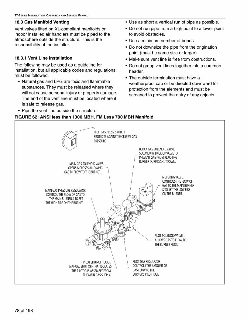
TT-SERIES INSTALLATION, OPERATION AND SERVICE MANUAL
78 of 198
18.3 Gas Manifold Venting
Vent valves fitted on XL-compliant manifolds on
indoor installed air handlers must be piped to the
atmosphere outside the structure. This is the
responsibility of the installer.
18.3.1 Vent Line Installation
The following may be used as a guideline for
installation, but all applicable codes and regulations
must be followed.
• Natural gas and LPG are toxic and flammable
substances. They must be released where they
will not cause personal injury or property damage.
The end of the vent line must be located where it
is safe to release gas.
• Pipe the vent line outside the structure.
• Use as short a vertical run of pipe as possible.
• Do not run pipe from a high point to a lower point
to avoid obstacles.
• Use a minimum number of bends.
• Do not downsize the pipe from the origination
point (must be same size or larger).
• Make sure vent line is free from obstructions.
• Do not group vent lines together into a common
header.
• The outside termination must have a
weatherproof cap or be directed downward for
protection from the elements and must be
screened to prevent the entry of any objects.
FIGURE 62: ANSI less than 1000 MBH, FM Less 700 MBH Manifold
PILOT GAS REGULATORCONTROLS THE AMOUNT OFGAS FLOW TO THE BURNER'S PILOT TUBE.
BLOCK GAS SOLENOID VALVE.SECONDARY BACK-UP VALVE TOPREVENT GAS FROM REACHINGBURNER DURING SHUTDOWN.
MAIN GAS PRESSURE REGULATORCONTROL THE FLOW OF GAS TO
THE MAIN BURNER & TO SETTHE HIGH FIRE ON THE BURNER
PILOT SHUT-OFF COCKMANUAL SHUT OFF THAT ISOLATES
THE PILOT GAS ASSEMBLY FROM THE MAIN GAS SUPPLY.
MAIN GAS SOLENOID VALVE.OPENS & CLOSES ALLOWING
GAS TO FLOW TO THE BURNER.
PILOT SOLENOID VALVE.ALLOWS GAS TO FLOW TOTHE BURNER PILOT.
METERING VALVE.CONTROLS THE FLOW OFGAS TO THE MAIN BURNER& TO SET THE LOW FIREON THE BURNER.
HIGH GAS PRESS. SWITCHPROTECTS AGAINST EXCESSIVE GASPRESSURE

SECTION 18: GAS PIPING
79 of 198
FIGURE 63: ANSI Manifold 1000 - 5000 MBH - 1"-2" NPT
FIGURE 64: ANSI Manifold Above 3000 MBH - 2 ½" to 3" NPT
PILOT GAS REGULATORCONTROLS THE AMOUNT OFGAS FLOW TO THE BURNER'S PILOT TUBE.
MAIN GAS SOLENOID VALVE.OPENS & CLOSES ALLOWING
GAS TO FLOW TO THE BURNER.
PILOT SHUT-OFF COCKMANUAL SHUT OFF THAT ISOLATES
THE PILOT GAS ASSEMBLY FROM THE MAIN GAS SUPPLY.
PILOT SOLENOID VALVE.ALLOWS GAS TO FLOW TOTHE BURNER PILOT.
BLOCK GAS SOLENOID VALVE.SECONDARY BACK-UP VALVE TOPREVENT GAS FROM REACHINGBURNER DURING SHUTDOWN.
METERING VALVE.CONTROLS THE FLOW OFGAS TO THE MAIN BURNER& TO SET THE HIGH & LOW FIRE ON THE BURNER.
HIGH GAS PRESS. SWITCHPROTECTS AGAINST EXCESSIVE GASPRESSURE
MAXIT
ROL
Selectra
Honeywell
FLUID POWER GAS VALVE
FLUID POWER GAS VALVEHoneywell
MAXIT
ROL
Selectra
PILOT GAS REGULATORCONTROLS THE AMOUNT OFGAS FLOW TO THE BURNER'S PILOT TUBE.
PILOT SOLENOID VALVE.ALLOWS GAS TO FLOW TOTHE BURNER PILOT.
METERING VALVE.CONTROLS THE FLOW OFGAS TO THE MAIN BURNER& TO SET THE LOW FIREON THE BURNER.
BLOCK GAS MOTORIZED ACTUATORSECONDARY BACK-UP.OPENS AND CLOSES VALVE.
MAIN GAS MOTORIZED ACTUATOR.OPENS & CLOSES VALVE ALLOWINGGAS TO FLOW TO THE BURNER.
MOTORIZED BLOCKVALVE BODY.
SECONDARY BACK-UPVALVE TO PREVENT GAS
FROM REACHING THEBURNER DURING
SHUTDOWN.
PILOT SHUT-OFF COCKMANUAL SHUT OFF THAT ISOLATES THE PILOT GAS ASSEMBLY FROM THE MAIN GAS SUPPLY.
MAIN GAS VALVE BODYOPENS & CLOSES ALLOWING
GAS TO FLOW TO THE BURNER.
SHUT-OFF COCK.MANUAL SHUT OFF THAT ISOLATES THE GAS TRAIN ASSEMBLY FROM THE BURNER.
HIGH GAS PRESS. SWITCHPROTECTS AGAINST EXCESSIVE GASPRESSURE
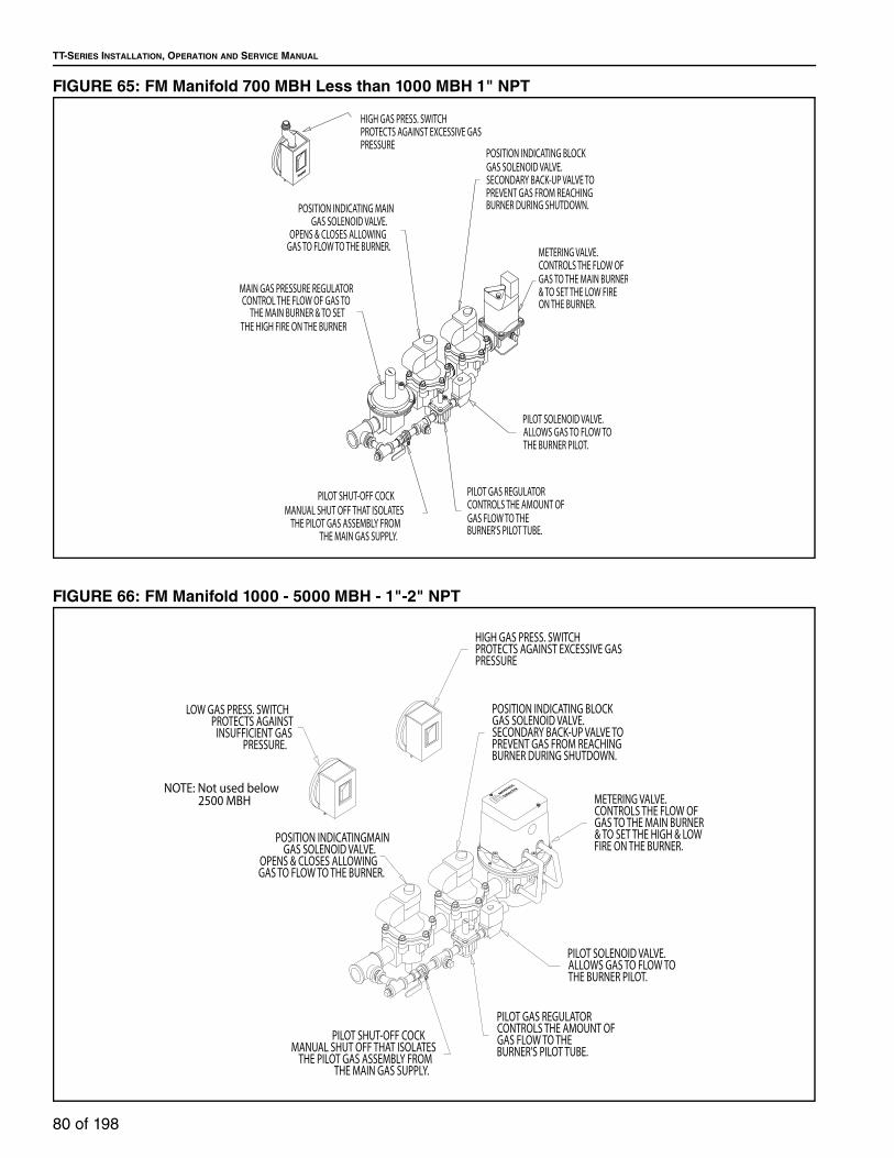
TT-SERIES INSTALLATION, OPERATION AND SERVICE MANUAL
80 of 198
FIGURE 65: FM Manifold 700 MBH Less than 1000 MBH 1" NPT
FIGURE 66: FM Manifold 1000 - 5000 MBH - 1"-2" NPT
PILOT GAS REGULATORCONTROLS THE AMOUNT OFGAS FLOW TO THE BURNER'S PILOT TUBE.
POSITION INDICATING BLOCKGAS SOLENOID VALVE.SECONDARY BACK-UP VALVE TOPREVENT GAS FROM REACHINGBURNER DURING SHUTDOWN.
MAIN GAS PRESSURE REGULATORCONTROL THE FLOW OF GAS TO
THE MAIN BURNER & TO SETTHE HIGH FIRE ON THE BURNER
PILOT SHUT-OFF COCKMANUAL SHUT OFF THAT ISOLATES
THE PILOT GAS ASSEMBLY FROM THE MAIN GAS SUPPLY.
POSITION INDICATING MAINGAS SOLENOID VALVE.
OPENS & CLOSES ALLOWINGGAS TO FLOW TO THE BURNER.
PILOT SOLENOID VALVE.ALLOWS GAS TO FLOW TOTHE BURNER PILOT.
METERING VALVE.CONTROLS THE FLOW OFGAS TO THE MAIN BURNER& TO SET THE LOW FIREON THE BURNER.
HIGH GAS PRESS. SWITCHPROTECTS AGAINST EXCESSIVE GASPRESSURE
Honeywell
PILOT GAS REGULATORCONTROLS THE AMOUNT OFGAS FLOW TO THE BURNER'S PILOT TUBE.
POSITION INDICATINGMAIN GAS SOLENOID VALVE.
OPENS & CLOSES ALLOWINGGAS TO FLOW TO THE BURNER.
PILOT SHUT-OFF COCKMANUAL SHUT OFF THAT ISOLATES
THE PILOT GAS ASSEMBLY FROM THE MAIN GAS SUPPLY.
PILOT SOLENOID VALVE.ALLOWS GAS TO FLOW TOTHE BURNER PILOT.
POSITION INDICATING BLOCKGAS SOLENOID VALVE.SECONDARY BACK-UP VALVE TOPREVENT GAS FROM REACHINGBURNER DURING SHUTDOWN.
METERING VALVE.CONTROLS THE FLOW OFGAS TO THE MAIN BURNER& TO SET THE HIGH & LOW FIRE ON THE BURNER.
LOW GAS PRESS. SWITCHPROTECTS AGAINST
INSUFFICIENT GAS PRESSURE.
HIGH GAS PRESS. SWITCHPROTECTS AGAINST EXCESSIVE GASPRESSURE
Selectra
MAXIT
ROLNOTE: Not used below 2500 MBH

SECTION 18: GAS PIPING
81 of 198
FIGURE 67: FM Manifold above 3000 MBH 2 ½" to 3" NPT
FIGURE 68: XL Manifold Less than 1000 MBH - 1" NPT
Honeywell
FLUID POWER GAS VALVE
FLUID POWER GAS VALVEHoneywell
MAXIT
ROL
Selectra
PILOT GAS REGULATORCONTROLS THE AMOUNT OFGAS FLOW TO THE BURNER'S PILOT TUBE.
PILOT SOLENOID VALVE.ALLOWS GAS TO FLOW TOTHE BURNER PILOT.
METERING VALVE.CONTROLS THE FLOW OFGAS TO THE MAIN BURNER& TO SET THE LOW FIREON THE BURNER.
BLOCK GAS MOTORIZED ACTUATORSECONDARY BACK-UP.OPENS AND CLOSES VALVE.
MAIN GAS MOTORIZED ACTUATOR.OPENS & CLOSES VALVE ALLOWINGGAS TO FLOW TO THE BURNER.
MOTORIZED BLOCKVALVE BODY.
SECONDARY BACK-UPVALVE TO PREVENT GAS
FROM REACHING THEBURNER DURING
SHUTDOWN.
PILOT SHUT-OFF COCKMANUAL SHUT OFF THAT ISOLATES THE PILOT GAS ASSEMBLY FROM THE MAIN GAS SUPPLY.
MAIN GAS VALVE BODYOPENS & CLOSES ALLOWING
GAS TO FLOW TO THE BURNER.
SHUT-OFF COCK.MANUAL SHUT OFF THAT ISOLATES THE GAS TRAIN ASSEMBLY FROM THE BURNER.
LOW GAS PRESS. SWITCHPROTECTS AGAINST
INSUFFICIENT GAS PRESSURE.
HIGH GAS PRESS. SWITCHPROTECTS AGAINST EXCESSIVE GASPRESSURE
PILOT GAS REGULATORCONTROLS THE AMOUNT OFGAS FLOW TO THE BURNER'S PILOT TUBE.
POSITION INDICATING BLOCKGAS SOLENOID VALVE.SECONDARY BACK-UP VALVE TOPREVENT GAS FROM REACHINGBURNER DURING SHUTDOWN.
MAIN GAS PRESSURE REGULATORCONTROL THE FLOW OF GAS TO
THE MAIN BURNER & TO SETTHE HIGH FIRE ON THE BURNER
PILOT SHUT-OFF COCKMANUAL SHUT OFF THAT ISOLATES
THE PILOT GAS ASSEMBLY FROM THE MAIN GAS SUPPLY.
POSITION INDICATING MAINGAS SOLENOID VALVE.
OPENS & CLOSES ALLOWINGGAS TO FLOW TO THE BURNER.
PILOT SOLENOID VALVE.ALLOWS GAS TO FLOW TOTHE BURNER PILOT.
METERING VALVE.CONTROLS THE FLOW OFGAS TO THE MAIN BURNER& TO SET THE LOW FIREON THE BURNER.
HIGH GAS PRESS. SWITCHPROTECTS AGAINST EXCESSIVE GASPRESSURE
LOW GAS PRESS. SWITCHPROTECTS AGAINST
INSUFFICIENT GAS PRESSURE.

TT-SERIES INSTALLATION, OPERATION AND SERVICE MANUAL
82 of 198
FIGURE 69: XL Manifold 1000 - 5000 MBH 1" - 2" NPT
PILOT GAS REGULATORCONTROLS THE AMOUNT OFGAS FLOW TO THE BURNER'S PILOT TUBE.
POSITION INDICATINGMAIN GAS SOLENOID VALVE.
OPENS & CLOSES ALLOWINGGAS TO FLOW TO THE BURNER.
PILOT SHUT-OFF COCKMANUAL SHUT OFF THAT ISOLATES
THE PILOT GAS ASSEMBLY FROM THE MAIN GAS SUPPLY.
PILOT SOLENOID VALVE.ALLOWS GAS TO FLOW TOTHE BURNER PILOT.
POSITION INDICATING BLOCKGAS SOLENOID VALVE.SECONDARY BACK-UP VALVE TOPREVENT GAS FROM REACHINGBURNER DURING SHUTDOWN.
METERING VALVE.CONTROLS THE FLOW OFGAS TO THE MAIN BURNER& TO SET THE HIGH & LOW FIRE ON THE BURNER.
HIGH GAS PRESS. SWITCHPROTECTS AGAINST EXCESSIVE GASPRESSURE
LOW GAS PRESS. SWITCHPROTECTS AGAINST
INSUFFICIENT GAS PRESSURE.
VENT VALVE.
VENTS GAS THAT IS TRAPPEDIN THE MANIFOLD BETWEEN
THE MAIN & BLOCK VALVES, ONSHUTDOWN, TO THE OUTDOORS.
Selectra
MAXIT
ROL

SECTION 18: GAS PIPING
83 of 198
FIGURE 70: XL Manifold above 3000 MBH 2 ½" - 3" NPT
18.4 Gas Piping
The gas manifold extends through the side of the
control cabinet. The factory piping terminates with a
female pipe connection. The manual main gas
shutoff valve is shipped loose for field installation. Be
sure that the fuel supply pipe connected at this point
is large enough to ensure the proper gas flow and
line pressure at the inlet of the air handler.
The piping must comply with:
United States: Refer to NFPA 54/ANSI Z223.1 - latest
revision, National Fuel Gas Code.
Canada: Refer to CSA B149.1 - latest revision,
Natural Gas and Propane Installation Code.
Gas supply piping must conform to best building
practices and local codes. During installation of the
gas piping, be sure that no piping restricts
accessibility to the air handler or its removable
access panels and/or access doors. Lockable
manual shut-off valve must be added by the installer
in compliance with Occupational Safety and Health
Administration (OSHA) regulations.
18.5 Pressure Test Ports
There are 3/8"(9.5 mm) and 1/8"(3.2 mm) pressure
test ports located on the air handler equipment. The
test ports are available to measure the manifold inlet
gas pressure and the burner gas pressure during
burner setup.
18.5.1 Manifold Inlet Gas Pressure 3/8" NPT
The pressure test port for measuring manifold inlet
pressure is located on the pilot tee which is located
on the manifold inlet tee. Refer to the unit rating plate
for the acceptable inlet gas pressure. See Page 84, Figure 71.
Honeywell
FLUID POWER GAS VALVE
FLUID POWER GAS VALVEHoneywell
MAXIT
ROL
Selectra
PILOT GAS REGULATORCONTROLS THE AMOUNT OFGAS FLOW TO THE BURNER'S PILOT TUBE.
PILOT SOLENOID VALVE.ALLOWS GAS TO FLOW TOTHE BURNER PILOT.
METERING VALVE.CONTROLS THE FLOW OFGAS TO THE MAIN BURNER& TO SET THE LOW FIREON THE BURNER.
BLOCK GAS MOTORIZED ACTUATORSECONDARY BACK-UP.OPENS AND CLOSES VALVE.
MAIN GAS MOTORIZED ACTUATOR.OPENS & CLOSES VALVE ALLOWINGGAS TO FLOW TO THE BURNER.
MOTORIZED BLOCKVALVE BODY.
SECONDARY BACK-UPVALVE TO PREVENT GAS
FROM REACHING THEBURNER DURING
SHUTDOWN.
PILOT SHUT-OFF COCKMANUAL SHUT OFF THAT ISOLATES THE PILOT GAS ASSEMBLY FROM THE MAIN GAS SUPPLY.
MAIN GAS VALVE BODYOPENS & CLOSES ALLOWING
GAS TO FLOW TO THE BURNER.
SHUT-OFF COCK.MANUAL SHUT OFF THAT ISOLATES THE GAS TRAIN ASSEMBLY FROM THE BURNER.
VENT VALVE.VENTS GAS THAT
IS TRAPPED IN THEMANIFOLD BETWEENTHE MAIN & BLOCK
VALVES, ON SHUTDOWN,TO THE OUTDOORS.
LOW GAS PRESS. SWITCHPROTECTS AGAINSTINSUFFICIENT GAS
PRESSURE.
HIGH GAS PRESS. SWITCHPROTECTS AGAINST EXCESSIVE GASPRESSURE

TT-SERIES INSTALLATION, OPERATION AND SERVICE MANUAL
84 of 198
FIGURE 71: Gas Pressure Taps (Manifold)
18.5.2 Burner Gas Pressure - 1/8" NPT
A pressure tap is used to measure negative airflow at
the burner and to set high fire gas pressure. The
pressure tap is located on an elbow between the
modulating valve and the burner. See Page 84, Figure 72.
FIGURE 72: Burner Gas Pressure Tap
18.6 Line Pressure Test - Leak Testing
The air handler and its individual shut-off valve must
be disconnected from the gas supply piping systems
during any pressure testing of that system at test
pressures in excess of 28 in wc (69.7 mbar). The air
handler must be isolated from the gas supply piping
system by closing its individual manual gas valve
(shipped loose for field installation) that is to be
located immediately upstream of the pilot tee.

SECTION 19: ELECTRICAL
85 of 198
SECTION 19: ELECTRICAL
Each air handler is equipped with a wiring diagram
which will vary depending on the type of controls and
options supplied.
NOTE: Spark testing or shorting of the control wires
by any means will render the transformers
inoperative.
19.1 Wiring and Electrical Connections
All electrical wiring and connections, including
electrical grounding, must comply with;
United States: Refer to National Electrical Code®,
NFPA 70 - latest revision. Wiring must conform to the
most current National Electrical Code®, local
ordinances, and any special diagrams furnished.
Canada: Refer to Canadian Electrical Code, CSA
C22.1 Part 1 - latest revision.
Check rating plate on air handler for supply voltage
and current requirements.
If any of the original control wire supplied with the air
handler must be replaced, replace it with type THHN
221 °F (105 °C), 600 V, 16 gauge wire or equivalent.
For all other wires, replace with the equivalent size
and type of wire that was originally provided with the
air handler.
19.2 Remote Panel
The remote panel must be wired as shown on the
electrical schematic.
All power supply and motor wiring must be type
THWN - or equivalent, minimum with a 167 °F
(75 °C) temperature rise. For wire gauge sizes, See Page 85, Table 35.
19.2.1 Remote Panel Mounting Distance
If the inter connection wiring between the remote
panel and the air handler control enclosure is run in a
single conduit, the wire run can be as long as 100'
(30 m). If the interconnection wiring between remote
panel and the air handler control enclosure is run in
two conduits (separating the shielded cable and the
120v power supply for the remote panel), the wire run
can be as long as 200' (60 m) For longer wire runs,
consult the factory. Care should be used to avoid
running the interconnect wiring near large industrial
loads or high voltage wire runs as that may further
limit the length of the interconnect wire run.
Table 35: Control Voltage Wiring For All Control Systems
NOTE: Wiring for temperature controls must be run in
shielded cable as indicated on the wiring diagram.
19.2.2 Low Voltage Control Wiring
Low voltage (24V - AC/DC) control wiring in excess of
100' (30.5 m) in length should be in its own separate
conduit run to prevent interference.
19.3 Motor Current Draw
For current requirements of the motor, see rating
plate located on the blower motor. Current draw may
be adjusted downard by reducing blower rotations
per minute (RPM) or by increasing external static
pressure.
19.4 Control Current Draw
The maximum current draw for an air handler’s
controls and accessories is 4.5 A.
DANGER
Electrical Shock Hazard
Disconnect electric before service.
More than one disconnect switch may be required to disconnect electric from equipment.
Equipment must be properly grounded.
Failure to follow these instructions can result in death or electrical shock.
VOLTS WIRE GAUGE WIRE FEET120 18 150 (45 m)
120 16 250 (75 m)
120 14 350 (106 m)

TT-SERIES INSTALLATION, OPERATION AND SERVICE MANUAL
86 of 198
19.5 Safety Systems
Safety systems are required for proper performance
of the air handler. The air handler shall not be
permitted to operate with any safety system disabled.
If a fault is found in any of the safety systems, then
the system shall be repaired only by a contractor
qualified in the installation and service of gas fired
heating equipment, using only components that are
sold and supplied by Weather-Rite LLC. See Page 86, Figure 36 for a brief description of each safety
device, its location and its switching voltage.
Table 36: Safety Systems
19.5.1 Manual Reset High Temperature Limit Switch
If for any reason, the temperature of the air at the
discharge of the blower reaches the limit set point of
160 °F (71.1 °C), the high temperature limit switch will
open the circuit to the burner system and discontinue
all burner functions. Events that could result in
excessive discharge air temperatures includes
defective burner modulation system or a surge in gas
pressure reaching the burner. Restarting the burner
can only be accomplished after the limit has cooled
down and the reset button on the switch has been
depressed. This switch is located in the air handler
control enclosure.
19.5.2 Airflow Pressure Switches
The low airflow velocity pressure switch monitors the
airflow (differential pressure) across the burner.
When the airflow across the burner reaches the
proper velocity (volume) for combustion, the switch
closes. When the switch closes, it permits the flame
safeguard relay to begin ignition. This switch is
factory set at 0.2 in w.c. The high velocity pressure
switch will open if the airflow across the burner
exceeds its maximum allowable limit. When the
switch opens, it shuts down the flame safeguard
relay. This switch is factory set at 1.0" wc The
pressure switch is a safety device, which can be field-
adjusted.
19.5.3 Gas Pressure Switches
The high gas pressure switch is standard on all
models. The low gas pressure switch is standard on
certain models. (ANSI and FM compliant gas trains
above 2,500 MBH and XL compliant gas trains above
400 MBH) and are also available as an option on the
others.
The function of the gas pressure switches is to
protect against either a lack of gas or an excessive
pressure in the system.
On the low gas pressure switch side, this switch
opens its internal switch which shuts the burner down
and prevents its operation due to insufficient gas
pressure.
On the high gas pressure side, its internal switch will
open, shutting down the burner due to excessive gas
pressure passing through the gas train.
The settings of the gas pressure switches are field
adjustable. The one monitoring the incoming gas
pressure is the low gas pressure switch. The low gas
pressure switch must be set to 2" wc to
accommodate the surge drop when the valves of the
gas train open.
The high gas pressure switch must be set to 8" wc to
accommodate the surge increase when the gas train
valve opens.
If either switch senses a pressure which is lower (low
gas pressure switch) or higher (high gas pressure
switch) than its set point, then the switch will open
and lock out, shutting the burner down. The switch
will have to be reset manually, once the condition has
been corrected.
19.5.4 Flame Control
This device will check for both pilot flame and main
flame within the burner. When a flame signal from the
pilot flame is available, it will allow the main gas valve
to open. If a pilot flame is not present, the electrical
signal cannot be sent and the pilot gas valve will
close. The relay is equipped with a trial for ignition. If
ignition does not occur, the flame safeguard relay will
try to relight or lockout (depending on model used),
and must be manually reset. (See Troubleshooting
Guide - Page 156, Section 27).
Safety Controls Location Voltage
Manual Reset High-Temp
Limit (All Models)
Air Handler
Control
Enclosure
120V
Pressure Switches (All
Models)
Air Handler
Control
Enclosure
120V
Flame Control (All Models) 120V

SECTION 20: SEQUENCE OF OPERATION
87 of 198
SECTION 20: SEQUENCE OF OPERATION 20.1 Air Handler Configuration
Based on the air handler application, the air handler
may be configured in any of the following styles to
achieve the described functionality. These
configurations are available on all air handlers. For a
comparison of these configurations, see Page 87, Table 37 on Page 89, Figure 74. For Volumatic
Recirculating style air handlers, a carbon dioxide
sensor must be installed limiting the building carbon
dioxide concentration to 5000 ppm. This sensor is
field supplied.
Table 37: Configuration Chart
DANGER
Electrical Shock Hazard
Disconnect electric before service.
More than one disconnect switch may be required to disconnect electric from equipment.
Equipment must be properly grounded.
Failure to follow these instructions can result in death or electrical shock.
WARNING
Carbon Monoxide Hazard
Do not recirculate air from the heated space over burner.
Air supply to burner must be from outside.
Failure to follow these instructions can result in death or injury.
Heater Configuration
Air FlowAir
VolumeControl
Make Up Air
(MUA)100% Outside Air Constant -
Volumatic
Recirculating
Adjustable ratio of 20%
outside air and 80%
return air to 100%
outside air and 0%
return air.
Constant
Manual or Auto
building pressure
control of outside /
return air ratio
Volumatic w/
VFD100% Outside Air
Variable
20%-100%
Manual or Auto
building pressure
control of air vol-
ume

TT-SERIES INSTALLATION, OPERATION AND SERVICE MANUAL
88 of 198
20.1.1 Make-Up Air (MUA) Style
The MUA style air handler has a constant speed
blower that is designed to deliver a constant volume
of air to the heated space. This style air handler
supplies 100% outside air to the heated space and is
not capable of supplying return air.
20.1.2 Volumatic Recirculating
The VR style air handler has a constant speed
blower that is designed to deliver a constant volume
of air to the heated space. The standard control is
manual, with options available to allow for a building
pressure sensor is used to detect and control the
differential pressure between the outside and the
heated space. The total volume of air delivered by
the air handler may at times consist of 0% to 80%
return air.
20.1.3 Volumatic with VFD
The Volumatic with VFD style air handler uses
modulating discharge dampers to control outside air
delivered to the space (this style air handler does not
return any air from the building). Proper air velocity /
pressure drop over the burner is maintained by
automatic modulating profile dampers. This style is
available in two versions - Two Position Volumatic
and Full Volumatic. The Two Position Volumatic
delivers 100% of the outside air and to a pre-selected
second value of airflow (operator determined) down
to 25% of the full CFM rating of the air handler. Full
Volumatic allows full control of air flow from 100%
down to 25% of the full CFM rating of the air handler
or any where in between.
20.1.4 Autocycle Air Control
The Autocycle Air Control adjusts the positioning of
the discharge damper to control the volume of air
discharged into the facility. The Autocycle includes
up to 12 pre-set positions adjusted by potentiometers
mounted on the printed circuit board.
Each pre-set position is controlled by an exhaust
fan interlock requiring two wires per interlock. The
installer must connect the two wires between the
printed circuit board on the make-up air unit and the
auxiliary contacts of the exhaust fans. the exhaust
fan starters must include auxiliary contacts.
FIGURE 73: Air Handler Configurations
20.2 Remote Panel Options
The remote panel should be mounted in the
conditioned space in a convenient location for
controlling the air handler. Do not locate a remote
panel which contains temperature sensing controls in
an area that is directly affected by this air handler or
another heat source as it may interfere with the
operation of the air handler.
20.2.1 8.3LS Remote Panel Discharge Air Tem-perature Control (DAT)
The 8.3LS Remote Panel includes Summer/Off/
Winter switch and blower, burner, and flame failure
indicators in a NEMA 1 style enclosure and
discharge temperature set point.
Blower Indicator: Indicates the air handler is
supplying power to the main fan motor via the motor
controls.
Burner Indicator: Indicates that the air handler has
supplied power to open the main fuel shut off valve.
Discharge Air
100%Outside Air
25%-100%Volume Motorized
ProfileDamper
Discharge Air
100%Outside Air
Variable0%-80%
Return Air
MotorizedProfile
Damper
Variable20%-100%Outside Air
Discharge Air
Volumatic with VFD
Make-Up Air (MUA)
Volumatic Recirculating

SECTION 20: SEQUENCE OF OPERATION
89 of 198
Flame Failure Indicator: The burner control module
has experienced a fault and will need to be reset. The
burner control module must be reset at the air
handler. Refer to the Maintenance and Trouble
Shooting sections of this manual to determine the
cause of the fault.
Summer/Off/Winter Switch:
Summer position: The blower will operate without the
burner for summer ventilation.
Winter position: The blower and burner will operate
as needed to maintain airflow and temperature.
FIGURE 74: 8.3LS Remote Panel DAT
20.2.2 8.3 Remote Panel Discharge Air Tempera-ture Control with Room Over-Ride (DATRO)
The 8.3LS Remote Panel includes Summer/Off/
Winter switch and blower, burner, and flame failure
indicators in a NEMA 1 style enclosure and
discharge temperature set point with a space sensing
thermostat which provides space temperature control
by raising the discharge air temperature to a pre-
selected point.
Blower Indicator: Indicates the air handler is
supplying power to the main fan motor via the motor
controls.
Burner Indicator: Indicates that the air handler has
supplied power to open the main fuel shut off valve.
Flame Failure Indicator: The burner control module
has experienced a fault and will need to be reset. The
burner control module must be reset at the air
handler. Refer to the Maintenance and Trouble
Shooting sections of this manual to determine the
cause of the fault.
Summer/Off/Winter Switch:
Summer position: The blower will operate without the
burner for summer ventilation.
Winter position: The blower and burner will operate
as needed for the application to maintain airflow and
temperature.
FIGURE 75: 8.3 Remote Panel DATRO
20.2.3 8.3LS Remote Panel Room Temperature Control (RMTC)
The 8.3LS Remote Panel includes Summer/Off/
Winter switch and blower, burner, and flame failure
indicators in a NEMA 1 style enclosure and space
temperature control.
Blower Indicator: Indicates the air handler is
supplying power to the main fan motor via the motor
controls.
Burner Indicator: Indicates that the air handler has
supplied power to open the main fuel shut off valve.
Flame Failure Indicator: The burner control module
has experienced a fault and will need to be reset. The
burner control module must be reset at the air
handler. Refer to the Maintenance and Trouble
Shooting sections of this manual to determine the
cause of the fault.
Summer/Off/Winter Switch:
Summer position: The blower will operate without the
burner for summer ventilation.
Winter position: The blower and burner will operate
as needed to maintain airflow and temperature.

TT-SERIES INSTALLATION, OPERATION AND SERVICE MANUAL
90 of 198
FIGURE 76: 8.3LS Remote Panel RMTC
20.2.4 DDC - Ready Option
The DDC-ready option provides inputs to receive
control signals from a customer determined control
system and outputs to provide sequence status to the
same. A 24VAC transformer is provided by Weather-
Rite's control panel for use by the customer's DDC
system to command "Unit Start" and "Heat Start"
signals (by means of DDC dry contact) back to the
air handler control panel.
The air handler provides 24VAC signals to the
customer's DDC for monitoring the following status:
Unit Running
Heat Running (Gas Valves "On")
Flame Failure
On all air handlers, the burner modulation will be
controlled 0-10VDC or 4-20MA signal from the
customer's DDC. Temperature monitoring and
modulation valve adjustment are completed by the
customer supplied control system. For volumatic
recirculating and volumatic w/VFD style air handlers,
the control system can also control the modulating
dampers.
20.3 Basic Sequence of Operation
The following is an overview of the sequence of
operation. Depending on the application and options
supplied with the air handler, this can vary greatly.
Thoroughly review all documentation for the air
handler, including the electrical print, to familiarize
and understand the actual sequence of operation.
Summer (Blower Only)
With power supplied to the air handler and the
Summer/Off/Winter switch on the remote panel in the
SUMMER position, power is supplied to the blower
motor starter coil, allowing the blower motor to start.
The burner circuit is NOT energized.
Winter (Blower & Burner)
With power supplied to the air handler and the
Summer/Off/Winter switch on the remote panel in the
WINTER position, power is supplied to the blower
motor starter coil, allowing the blower motor to start.
Auxiliary contacts on the blower starter close,
powering the flame relay through the high limit, and
low- and high-gas pressure switches (if provided).
When airflow is proven by the burner airflow
switches, the burner firing circuit is powered up. After
the pilot flame or main flame is proven by the flame
detector, the main and blocking valves are opened
and the ignition transformer is de-energized. The
temperature control system is powered separately
and controls the flow of the fuel to maintain space /
discharge set point temperature through the
temperature control amplifier which controls the
modulating valve.
20.4 Flame Control
The main function of a flame safeguard device is to
prevent the flow of fuel into the burner in the event of
either a flame failure during a running cycle or an
ignition failure during an attempt to fire. The
secondary function of a flame safeguard is to cycle
the entire burner system. Flame safeguards are used
with rectification type flame detectors, which provide
a small pulsating direct current when a suitable flame
is present. The current is amplified and used in the
electronic network of the flame safeguard. If the
flame rod signal is insufficient to hold in the electronic
network, the flame safeguard device quickly and
safely shuts down the burner system. It also triggers
the LED for alarm and the remote alarm light.
Three types of flame safeguard devices are used on
this equipment. They are the Fireye® MicroM, Fireye®
M4RT1 and the Honeywell® RM7897. The Fireye®
MicroM and the Honeywell® RM7897 are versatile in
that it can be coupled to a UV Scanner detector or a
flame rod style detector. Its construction is modular,
so that by changing amplifiers and programmers its
function is varied. The Fireye® M4RT1 is similar, but
only accepts flame rod detectors and its functions are
controlled by the removal or installation of jumpers.
All three flame safeguards can be used in all agency

SECTION 20: SEQUENCE OF OPERATION
91 of 198
compliance requirements (ANSI, CSA, FM and XL).
20.4.1 Fireye® MicroM Flame Safeguard
This control is located in the center of the main
control panel.
FIGURE 77: Fireye Components MicroM Family
The cover of this control is red and it has a reset
button extending out from it. It consists of three
components, which are:
1. The MEC120 chassis contains the main hard-
ware. It also contains a fuse to protect itself
from external shorts or overloads.
FIGURE 78: Fireye Chassis MEC120
2. The MEP100 and MEP 230-programmer mod-
ule determines the operational characteristics
of the control. It also has mounted on its exte-
rior, five (5) lights which indicate the operating
status of the control.
3. The MERT4 (flame rod) rectifier/amplifier mod-
ule provides the flame scanning capability and
the flame failure response time. On its exterior
are test jacks, which permit flame signal mea-
surement during operation.
FIGURE 79: Fireye Rectifier/Amplifier MERT4
The functions of the indicator lights, which are
located on the programmer module, are as follows.
They are listed in the order you will find them on the
flame safeguard. This is also the order in which they
will occur in the sequence. The indicators are
actually a red colored light emitting diode or LED, this
is how they will be referred to from now on.
1. Operating Control - This indicator is on when
power is present at terminals #1 and #7 of the
flame safeguard.
2. Air Flow - This indicator comes on at the same
time as the one above. This is because the
actual circuit is not used and is jumped out. It
can be used as a troubleshooting guide, that
power is present to terminals #6 and #8 in the
flame safeguard.
3. PTFI - This acronym stands for Pilot Trial For
Ignition. This indicator is on only during the trial
for ignition period. It indicates that terminal #3
(pilot valve) and terminal #4 (ignition module),
in the flame safeguard, have been turned on.

TT-SERIES INSTALLATION, OPERATION AND SERVICE MANUAL
92 of 198
4. Flame On - This indicator comes on after the
flame safeguard has proven out the flame sig-
nal. It also shows that the main valves have
been activated in the equipment. On the safe-
guard control, terminal #5 is powered up.
5. Alarm - This indicates that a safety lockout has
occurred, whether by loss of flame signal or
failure to ignite.
FIGURE 80: Fireye LED Display MicroM
20.4.1.1 Fireye® MicroM Flame Safeguard Opera-tion (ANSI, FM < 2.5MBH and XL < 1MBH)
The following will describe the internal operation of
the flame safeguard control (that is equipped with a
MEP100 programmer & MERT4 amplifier) and the
external functions that will take place. We will just
trace the electromechanical steps and not the
electronic network.
• All interlocks, control relays and safety limits are
closed. Power is supplied to terminals #1 and #7
of the flame safeguard.
• The Operating Control LED illuminates.
• The electronic network is now powered up which
illuminates the Air Flow LED.
NOTE: The airflow circuit of the safeguard control is
not used and is jumped. This is why the Air Flow LED
illuminates with the Operating Control LED.
• Following a short time delay period (purge cycle)
of 2 to 5 seconds. The electronic network closes a
contact that powers up terminal #3 and terminal
#4 in the safeguard control.
• Terminal #3 powers up the equipment's pilot gas
solenoid valve which opens allowing gas to flow.
• Terminal #4 powers up the ignition module
creating the spark at the burner.
• This lasts for 10 seconds. This cycle is called trial
for ignition. During this time period, the PTFI LED
is illuminated.
• When the flame sensor detects a pilot flame, the
signal is sent back to the safeguard control. The
electronic network illuminates the FLAME LED.
• It closes a contact, which powers up terminal #5
in the control. This terminal powers up the main
gas valves allowing the main burner to come on.
• At the same time the electronic network opens a
contact which removes power from terminal #4.
This shuts off the power to the ignition module,
which stops the spark at the burner. The
safeguard control at this point monitors the flame.
NOTE: If a pilot flame is not detected during the 10
second trial for ignition, the pilot gas solenoid valve
and the ignition module are turned off. A safety
lockout occurs which shuts down the electronic
network. The only LED that will be illuminated at this
time will be the OPERATING CONTROL. 30 seconds
after the lockout occurs, the alarm circuit is powered
up, illuminating the ALARM LED. Manual reset is
now required. Wait 10 seconds before resetting the
control to allow the lockout switch to cool down.
NOTE: If the flame signal is lost while the burner is
on, the ignition module will be turned back on. A 10-
second re-light trial for ignition is started. The PTFI
LED will illuminate during this time.If a flame signal is
detected, the main gas valves will turn back on and
the ignition module will turn off. If a flame is not
detected during this re-light trial, the pilot gas
solenoid valve and ignition module will shut off. A
safety lockout occurs which shuts down the
electronic network. The only LED that will be
illuminated at this time will be the OPERATING
CONTROL. Thirty seconds after the alarm lockout
happens the alarm circuit is powered up, illuminating
the ALARM LED. Manual reset is now required. Wait
10 seconds before resetting the control to allow the
lockout switch to cool down.
20.4.1.2 Fireye® MicroM Flame Safeguard (FM ≥ 2.5MBH and XL ≥ 1MBH)
If the equipment is ordered with a FM compliant
Manifold equal or over 2.5 M BTU or XL compliant
equal to or over 1 M BTU, certain sequences must be

SECTION 20: SEQUENCE OF OPERATION
93 of 198
provided in the flame safeguard control. There is a
specified time for pre-purge, trial for ignition, and non
recycle.
FIGURE 81: Fireye MEP 230 Programmer
1. Timed pre-purgeThis must be a separate purge from the rest of
the system. The trial for ignition must be
delayed by 7 seconds while the blower in the
unit is running. This is to guarantee that there
are no combustible gases or vapors present in
the air stream during burner ignition and light
off.
2. Trial for ignitionThe length of time must be fixed at 10 seconds.
This is to prevent the ignition module from con-
tinuing activating the spark electrode if a haz-
ardous malfunction takes place.
3. Non recycleThis feature prevents the flame safeguard con-
trol from trying to re-light the burner if it should
fail during the ignition cycle or firing cycle.
Instead it goes directly to a lockout condition
and the flame safeguard will need to be manu-
ally reset.
To accomplish these requirements the MEP100
programmer is replaced with a MEP230 programmer.
This programmer has the same LED displays as the
MEP100, same fuse for protection, but on its face it
has eight dipswitches (digital input programming
switch). These switches must first be set before the
control is installed.
NOTE: The dipswitch settings become permanently
stored within the programmer's eeprom memory after
8 hours of continuous electrical operation.
To set the dipswitches for their appropriate setting
use the following procedure.
NOTE: READ OVER THE FOLLOWING SECTIONS
COMPLETELY BEFORE ATTEMPTING TO SET
THE DIPSWITCHES OR MOVING THE CLEAR
PLASTIC WINDOW.
PURGE TIMING• Locate dipswitches #1 through #5.
• Switch #2 is the one for 7 seconds timing. Move
this switch to the right, which is the ON position.
• The remaining switches (#1 & #3 through #5)
must remain to the left in the OFF position.
Purge Timing is now set, if all five switches are left in
the off position, the control will lockout right after
power is supplied to the flame safeguard control.
TRIAL FOR IGNITION• Locate dipswitches #6 and #7.
• Switch #6 must remain to the left in the OFF
position.
• Switch #7 is the one for 10 seconds timing. Move
this switch to the right, which is the ON position.
Trial for Ignition timing is now set, if both switches are
left in the off position the control will automatically
supply a timing of less than 5 seconds
(approximately 3 to 4 seconds). If both switches are
in the on position the control will go directly to lockout
once prepurge is completed.
RECYCLE/NON RECYCLE OPERATION
• Locate dipswitch #8.
• Move this switch to the right, which is the ON
position.
The non recycle feature is now set, if the switch is left
in the off position the safeguard control will try for a
relight if the burner should fail during a firing cycle.
20.4.1.3 Fireye® MicroM Flame Safeguard Opera-tion (FM ≥ 2.5MBH and XL ≥ 1MBH)
The following will describe the internal operation of a
flame safeguard control (that is equipped with a
MP230 programmer) and the external functions that
will take place. We will just trace the
electromechanical steps and not the electronic

TT-SERIES INSTALLATION, OPERATION AND SERVICE MANUAL
94 of 198
network.
• All interlocks, control relays and safety limits are
closed. Power is supplied to terminals #1 and #7
of the flame safeguard.
• The Operating Control LED illuminates.
• The electronic network is now powered up which
illuminates the Air Flow LED.
NOTE: The airflow circuit of the safeguard control is
not used and is jumped. This is why the Air Flow LED
illuminates with the Operating Control LED.
• Following a time delay period (purge cycle) 7
seconds. The electronic network closes a contact
that powers up terminal #3 and terminal #4 in the
safeguard control.
• Terminal #3 powers up the equipment's pilot gas
solenoid valve which opens allowing gas to flow.
• Terminal #4 powers up the ignition module
creating the spark at the burner.
• This lasts for 10 seconds. This cycle is called trial
for ignition. During this time period, the PTFI LED
is illuminated.
• When the flame sensor detects a pilot flame, the
signal is sent back to the safeguard control. The
electronic network illuminates the FLAME LED.
• It closes an internal contact, which powers up
terminal #5 in the control. This terminal powers up
the main gas valves allowing the main burner to
come on.
• At the same time that the contact in step b closes,
the electronic network opens a contact, which
powers terminal #4. This shuts off the power to
the ignition module, which stops the spark at the
burner. The safeguard control at this point
monitors the flame.
NOTE: If a pilot flame is not detected during the 10
second trial for ignition, the pilot gas solenoid valve
and the ignition module are turned off. A safety
lockout occurs which shuts down the electronic
network. The only LED that will be illuminated at this
time will be the OPERATING CONTROL. 30 seconds
after the lockout has activated, the alarm circuit is
powered up, illuminating the ALARM LED. Manual
reset is now required. Wait 10 seconds before
resetting the control to allow the lockout switch to
cool down.
NOTE: If the flame signal is lost while the burner is
on, the pilot and main gas valves will be turned off. A
safety lockout occurs which shuts down the
electronic network. The only LED that will be
illuminated at this time will be the OPERATING
CONTROL. Thirty seconds after the lockout has
activated, the alarm circuit is powered up,
illuminating the ALARM LED. Manual reset is now
required. Wait 10 seconds before resetting the control
to allow the lockout switch to cool down.
20.4.2 Fireye® M4RT1 Flame Safeguard
This control is located in the center of the main
control panel. To reset this flame relay, power to it must be shut off and turned back on.
FIGURE 82: Fireye M4RT1
This is an exposed circuit board one piece control. It
contains a fuse to protect itself from external shorts
or overloads and on its exterior it has five lights which
indicate the operating status of the control.
The functions of the indicator lights, which are
located on the programmer module, are as follows.
They are listed in the order you will find them on the
flame safeguard and is also the order in which they
will occur in the sequence. The indicators are
actually a red colored light emitting diode or LED, this
is how they will be referred to from now on.
1. Operating Control - This indicator is on when
power is present at terminals #1 and #7 of the
flame safeguard.
2. Air Flow - This indicator comes on at the same
time as the one above. This is because the
actual circuit is not used and is jumped out. It
can be used as a troubleshooting guide, that
power is present to terminals #6 and #8 in the
flame safeguard.
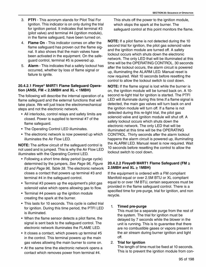
SECTION 20: SEQUENCE OF OPERATION
95 of 198
3. PTFI - This acronym stands for Pilot Trial For
Ignition. This indicator is on only during the trial
for ignition period. It indicates that terminal #3
(pilot valve) and terminal #4 (ignition module),
in the flame safeguard, have been turned on.
4. Flame On - This indicator comes on after the
flame safeguard has proven out the flame sig-
nal. It also shows that the main valves have
been activated in the equipment. On the safe-
guard control, terminal #5 is powered up.
5. Alarm - This indicates that a safety lockout has
occurred, whether by loss of flame signal or
failure to ignite.
20.4.2.1 Fireye® M4RT1 Flame Safeguard Opera-tion (ANSI, FM < 2.5MBH and XL < 1MBH)
The following will describe the internal operation of a
flame safeguard and the external functions that will
take place. We will just trace the electromechanical
steps and not the electronic network.
• All interlocks, control relays and safety limits are
closed. Power is supplied to terminal #7 of the
flame safeguard.
• The Operating Control LED illuminates.
• The electronic network is now powered up which
illuminates the Air Flow LED.
NOTE: The airflow circuit of the safeguard control is
not used and is jumped. This is why the Air Flow LED
illuminates with the Operating Control LED.
• Following a short time delay period (purge cycle)
determined by the jumpers, See Page 96, Figure 83 and Page 96, Table 38. The electronic network
closes a contact that powers up terminal #3 and
terminal #4 in the safeguard control.
• Terminal #3 powers up the equipment's pilot gas
solenoid valve which opens allowing gas to flow.
• Terminal #4 powers up the ignition module
creating the spark at the burner.
• This lasts for 10 seconds. This cycle is called trial
for ignition. During this time period, the PTFI LED
is illuminated.
• When the flame sensor detects a pilot flame, the
signal is sent back to the safeguard control. The
electronic network illuminates the FLAME LED.
• It closes a contact, which powers up terminal #5
in the control. This terminal powers up the main
gas valves allowing the main burner to come on.
• At the same time the electronic network opens a
contact which removes power from terminal #4.
This shuts off the power to the ignition module,
which stops the spark at the burner. The
safeguard control at this point monitors the flame.
NOTE: If a pilot flame is not detected during the 10
second trial for ignition, the pilot gas solenoid valve
and the ignition module are turned off. A safety
lockout occurs which shuts down the electronic
network. The only LED that will be illuminated at this
time will be the OPERATING CONTROL. 30 seconds
after the lockout occurs, the alarm circuit is powered
up, illuminating the ALARM LED. Manual reset is
now required. Wait 10 seconds before resetting the
control to allow the lockout switch to cool down.
NOTE: If the flame signal is lost while the burner is
on, the ignition module will be turned back on. A 10-
second re-light trial for ignition is started. The PTFI
LED will illuminate during this time.If a flame signal is
detected, the main gas valves will turn back on and
the ignition module will turn off. If a flame is not
detected during this re-light trial, the pilot gas
solenoid valve and ignition module will shut off. A
safety lockout occurs which shuts down the
electronic network. The only LED that will be
illuminated at this time will be the OPERATING
CONTROL. Thirty seconds after the alarm lockout
happens the alarm circuit is powered up, illuminating
the ALARM LED. Manual reset is now required. Wait
10 seconds before resetting the control to allow the
lockout switch to cool down.
20.4.2.2 Fireye® M4RT1 Flame Safeguard (FM ≥ 2.5MBH and XL ≥ 1MBH)
If the equipment is ordered with a FM compliant
Manifold equal or over 2.5M BTU or XL compliant
equal to or over 1M BTU, certain sequences must be
provided in the flame safeguard control. There is a
specified time for pre-purge, trial for ignition, and non
recycle.
1. Timed pre-purgeThis must be a separate purge from the rest of
the system. The trial for ignition must be
delayed by 7 seconds while the blower in the
unit is running. This is to guarantee that there
are no combustible gases or vapors present in
the air stream during burner ignition and light
off.
2. Trial for ignitionThe length of time must be fixed at 10 seconds.
This is to prevent the ignition module from con-

TT-SERIES INSTALLATION, OPERATION AND SERVICE MANUAL
96 of 198
tinuing activating the spark electrode if a haz-
ardous malfunction takes place.
3. Non recycleThis feature prevents the flame safeguard con-
trol from trying to re-light the burner if it should
fail during the ignition cycle or firing cycle.
Instead it goes directly to a lockout condition
and the flame safeguard will need to be manu-
ally reset.
The M4RT1 has a series of 8 jumpers that are used
to configure the Purge timing, Pilot Trial for Ignition
(PTFI) timing, and recycle or non-recycle operation.
See Page 96, Figure 83.
Purge Timing
• Jumpers JP1 through JP5 are used to select the
purge timing for the M4RT1. The available purge
timing selections are 5, 7, 30, 60, and 240
seconds and any additive combination of those
times. Selecting two or more purge timing
jumpers will result in a purge time period equal to
the sum of the jumpers selected. Selection of a
purge time is accomplished by cutting or not
installing the associated jumper. The factory set,
default purge time of 5 seconds (JP1 not installed)
is always selected. See Page 96, Table 38 lists all
available purge times and how to select those by
cutting jumpers JP2 through JP5.
FIGURE 83: Jumper Locations
Table 38: Jumper Settings
Pilot Trial for Ignition• Jumpers JP6 and JP7 are used by the factory
only to select the PTFI for the M4RT1. The factory
set, default PTFI time is 10 seconds (JP6
installed, JP7 not installed). The PTFI time may
only be set by the factory.
Recycle/Non-recycle Operation• Jumper JP8 is used to select either Recycle or
Non-Recycle operation of the M4RT1. The factory
set, default is Recycle operation (JP8 installed).
To select Non-Recycle operation, cut jumper JP8.
20.4.2.3 Fireye® M4RT1 Flame Safeguard Opera-tion (FM ≥ 2.5MBH and XL ≥ 1MBH)
The following will describe the internal operation of a
flame safeguard control (that has had its jumpers
changed to comply with the agency requirements)
and the external functions that will take place. Refer
to the drawing below to follow the steps. We will just
trace the electromechanical steps and not the
electronic network.
Purge Time (seconds) JP2 JPS JP4 JP55 Installed Installed Installed Installed
12 Cut Installed Installed Installed
35 Installed Cut Installed Installed
42 Cut Cut Installed Installed
65 Installed Installed Cut Installed

SECTION 20: SEQUENCE OF OPERATION
97 of 198
• All interlocks, control relays and safety limits are
closed. Power is supplied to terminal #7 of the
flame safeguard.
• The Operating Control LED illuminates.
• The electronic network is now powered up which
illuminates the Air Flow LED.
NOTE: The airflow circuit of the safeguard control is
not used and is jumped. This is why the Air Flow LED
illuminates with the Operating Control LED.
• Following a time delay period (purge cycle) 7
seconds. The electronic network closes a contact
that powers up terminal #3 and terminal #4 in the
safeguard control.
• Terminal #3 powers up the equipment's pilot gas
solenoid valve which opens allowing gas to flow.
• Terminal #4 powers up the ignition module
creating the spark at the burner.
• This lasts for 10 seconds. This cycle is called trial
for ignition. During this time period, the PTFI LED
is illuminated.
• When the flame sensor detects a pilot flame, the
signal is sent back to the safeguard control. The
electronic network illuminates the FLAME LED.
• It closes an internal contact, which powers up
terminal #5 in the control. This terminal powers up
the main gas valves allowing the main burner to
come on.
• At the same time that the contact in step b closes,
the electronic network opens a contact, which
powers terminal #4. This shuts off the power to
the ignition module, which stops the spark at the
burner. The safeguard control at this point
monitors the flame.
NOTE: If a pilot flame is not detected during the 10
second trial for ignition, the pilot gas solenoid valve
and the ignition module are turned off. A safety
lockout occurs which shuts down the electronic
network. The only LED that will be illuminated at this
time will be the OPERATING CONTROL. 30 seconds
after the lockout has activated, the alarm circuit is
powered up, illuminating the ALARM LED. Manual
reset is now required. Wait 10 seconds before
resetting the control to allow the lockout switch to
cool down.
NOTE: If the flame signal is lost while the burner is
on, the pilot and main gas valves will be turned off. A
safety lockout occurs which shuts down the
electronic network. The only LED that will be
illuminated at this time will be the OPERATING
CONTROL. Thirty seconds after the lockout has
activated, the alarm circuit is powered up,
illuminating the ALARM LED. Manual reset is now
required. Wait 10 seconds before resetting the control
to allow the lockout switch to cool down.
FIGURE 84: Honeywell RM7897
20.4.3 Honeywell RM7897 Flame Safeguard
The color of this control is blue and it has a reset
button extending out from it. It consists of three
components, which are:
1. The RM7897 chassis contains the main hard-
ware. It also has mounted on its exterior, five
(5) lights which indicate the operating status of
the control.
2. The ST7800 Purge Timer Card which deter-
mines the pre-purge time for the control -
default is 7 seconds.
3. The R7847 (flame rod) or R7849 (ultraviolet)
rectifier/amplifier module provides the flame
scanning capability and the flame failure
response time. On its exterior are test jacks,
which permit flame signal measurement during
operation.
The functions of the indicator lights, which are
located on the main chassis, are as follows. They are
listed in the order you will find them on the flame
safeguard. This is also the order in which they will
occur in the sequence.
1. Power - this indicator is on when power is
present at terminal #5 of the flame safeguard.
BURNER CONTROL
BURNER FLAME CONTROL
FLAME AMPLIFIER+-
- Negative + Positive
5.0 VDC

TT-SERIES INSTALLATION, OPERATION AND SERVICE MANUAL
98 of 198
2. Pilot - this indicator comes on when power is
present at terminals #8 and #10 of the flame
safeguard. It indicates that the pilot circuit has
been turned on.
3. Flame - this indicates that a flame signal has
been proven.
4. Main - this indicator comes on after the flame
safeguard has proven out the flame signal. It
also shows that the main valves have been
activated in the equipment. On the safeguard
control, terminal #9 is powered up.
5. Alarm - this indicates that a safety lockout has
occurred, whether by loss of flame signal or
failure to ignite.
20.4.3.1 Honeywell RM7897 Flame Safeguard Operation (ANSI, FM < 2.5MBH and XL < 1MBH)
The following will describe the internal operation of
the flame safeguard and the external functions that
will take place. We will just trace the
electromechanical steps and not the electronic
network.
• Initiate
• The flame safeguard enters the INITIATE
sequence when the relay module is initially
powered. The INITIATE sequence lasts for ten
seconds.
• Standby
• The flame safeguard is ready to start an operating
sequence when the operating control input,
Terminal #6 receives power.
• Normal Start-Up Pre-purge
• The flame safeguard provides PREPURGE
timing, with the ST7800 Purge Timer card, for
seven with power applied to Terminal #6.
• Ignition Trials
Pilot Flame Establishing Period (PFEP):
A. When the PFEP begins:
1. The pilot valve and ignition
transformer, terminals 8 and 10 are
energized.
2. Flame must be proven by the end
of the ten second PFEP to allow the
sequence to continue. If a flame is not
proven by the end of PFEP, a safety
shutdown occurs.
Main Flame Establishing Period (MFEP):
After PFEP, and with the presence of flame,
the main fuel valve, terminal 9, is powered. If
a flameout occurs, the flame safeguard
recycles within 0.8 or 3 seconds, depending
on the Flame Failure Response Time (FFRT)
of the amplifier.
• Run
The flame safeguard is now in RUN and remains
in RUN until the controller input, terminal 6,
opens, indicating that the demand is satisfied or a
limit has opened.
20.4.3.2 Honeywell RM7897 Flame Safeguard (FM ≥ 2.5MBH and XL ≥ 1MBH)
If the equipment is ordered with a FM compliant
Manifold equal or over 2.5 M BTU or XL compliant
equal to or over 1 M BTU, certain sequences must be
provided in the flame safeguard control. The
safeguard control must be converted to non recycle
on flame lockout. This is accomplished by configuring
the on board jumpers located on the back side of the
flame safeguard control.
FIGURE 85: Honeywell Safeguard Jumpers
Table 39: Site-Configuration Honeywell Safeguard Jumpers
Jumpers
The relay module has three site-configurable jumper
Jumper Number 7897JR1 Intact
JR2 Remove
JR3 Intact
JR1
JR2
JR3
Selectable Configuration Jumpers

SECTION 20: SEQUENCE OF OPERATION
99 of 198
options; See Page 98, Figure 85 and Page 98, Table 39. If necessary, clip the site-configurable jumpers
with side cutters and remove the resistors from the
relay module.
IMPORTANT
Clipping and removing a jumper after 200 hours of
operation causes a non-resettable Fault 110. The
relay module must then be replaced.
The following will describe the internal operation of
the flame safeguard and the external functions that
will take place. We will just trace the
electromechanical steps and not the electronic
network.
• Initiate
• The flame safeguard enters the INITIATE
sequence when the relay module is initially
powered. The INITIATE sequence lasts for ten
seconds.
• Standby
• The flame safeguard is ready to start an operating
sequence when the operating control input,
Terminal #6 receives power.
• Normal Start-Up Pre-purge
• The flame safeguard provides PREPURGE
timing, with the ST7800 Purge Timer card, for
seven with power applied to Terminal #6.
• Ignition Trials
Pilot Flame Establishing Period (PFEP):
A. When the PFEP begins:
1. The pilot valve and ignition
transformer, terminals 8 and 10 are
energized.
2. Flame must be proven by the end
of the ten second PFEP to allow the
sequence to continue. If a flame is not
proven by the end of PFEP, a safety
shutdown occurs.
Main Flame Establishing Period (MFEP):
After PFEP, and with the presence of flame,
the main fuel valve, terminal 9, is powered. If
a flameout occurs, the flame safeguard
recycles within 0.8 or 3 seconds, depending
on the Flame Failure Response Time (FFRT)
of the amplifier.
Run
The flame safeguard is now in RUN and remains in
RUN until the controller input, terminal 6, opens,
indicating that the demand is satisfied or a limit has
opened.
20.5 Air Volume Control Options20.5.1 Volumatic Dampers
This is a control option for varying the total delivered
air volume down to 20% of the air handler's
maximum airflow capacity. It is used when the space
demands for make-up air are not at a constant value
due to exhaust fan cycling or environmental changes.
The standard Volumatic control option allows the air
handler's discharge damper to modulate, which in
turns delivers the required airflow.
Methods of control for this option are by a manual
damper position controller (standard with this option),
Space Pressure controller which senses the space
pressure and makes volume changes as required.
The minimum air position is preset from the factory
and may be readjusted in the field by the use of the
minimum air damper positioner, located on the air
handlers control panel. It is adjusted to prevent the
air handler from going below the minimum airflow
required for proper combustion. The profile damper
motor which maintains the proper air pressure drop
across the burner is electrically interlocked with the
discharge damper (master/slave operation). As the
discharge damper opens, the profile damper opens
proportionally to maintain the proper pressure drop
across the burner. As the discharge damper closes,
the profile damper closes.
20.5.2 Volumatic Variable Frequency Drive
This is a control option for varying the total delivered
air volume down to 25% of the air handler's
maximum airflow capacity. It is used when the space
demands for make-up air are not at a constant value
due to exhaust fan cycling or environmental changes.
The VFD control option allows the air handler's
blower vary its speed, which in turns delivers the
required airflow.
Methods of control for this option are by a Keypad
(standard with this option) or Space Pressure
controller which senses the space pressure and
makes volume changes as required.
The minimum air position is preset from the factory
and may be readjusted in the field by the use of the
VFD's Keypad. It is adjusted to prevent the air
handler from going below the minimum airflow
required for proper combustion. The profile damper
motor which maintains the proper air pressure drop
across the burner is electrically interlocked with VFD
TT-SERIES INSTALLATION, OPERATION AND SERVICE MANUAL
100 of 198
(master/slave operation). As the VFD speeds the
blower up, the profile damper opens proportionally to
maintain the proper pressure drop across the burner.
As the VFD slows the blower down, the profile
damper closes.
20.5.3 Two Position Volumatic
This control package allows the unit to deliver two Air
Volume requirements, one at 100% of the unit's
required capacity, the other to be set between 25% -
100% of capacity. The method of control for this
system is an interlock contact provided by others, or
by contacts that is dictated by the sequence of
operation.
High Air Volume Position
When switched to the High Air Volume position, the
discharge damper opens fully (100%). The burner
profile motor adjusts the burner profile blades to
attain proper pressure drop across the burner.
Low Air Volume Position
When switched to the Low Air Volume position, the
discharge damper opens to a setting of between
25% -100% open. This position is to be manually
preset by the Minimum Air Potentiometer which is
located in the air handler's control panel. The burner
profile motor closes the burner profile blades to
provide the correct pressure drop across the burner
for proper burner combustion. As the profile motor
closes, its motor end switch opens, putting the
Maximum Fire Potentiometer (located in the air
handler's control panel) into the circuit. The
Maximum Fire Potentiometer reduces the maximum
firing rate of the burner in the low Air Volume position
preventing the burner from over-firing.
20.5.4 Two Speed Volumatic
This control package, through the use of a two-speed
blower motor allows the unit to deliver two Air Volume
requirements. One at 100% of unit's required
capacity, the other determined by the speed of the
blower motor. The method of control for this system is
an interlock contact provided by others, or by
contacts that is dictated by the sequence of
operation.
High Air Volume Operation
When switched to the high speed position, the unit
will deliver 100% of its designed airflow. The burner
profile motor opens the burner profile blades to attain
proper pressure drop across the burner.
Low Air Volume Operation
When switched to the low speed position, the blower
motor switches to low speed providing low Air
Volume operation. The burner profile motor closes
the burner profile blades to provide the correct
pressure drop across the burner for proper burner
combustion. As the profile motor closes, its motor
end switch opens, putting the Maximum Fire
Potentiometer (located in the air handler's control
panel) into the circuit. The Maximum Fire
Potentiometer reduces the maximum firing rate of the
burner in the low Air Volume position preventing the
burner from over-firing.
20.5.5 Volumatic/Recirculating
This option has modulating inlet (optional),
modulating return air dampers and modulating
burner profile blades. The Volumatic/Recirculation
system is similar to the Volumatic package but varies
the mixture of recirculated air back into the unit, while
still maintaining a constant supply Air Volume. The
inlet damper can only be closed down to a minimum
of 20% of the maximum capacity of the air handler
unit, to maintain proper combustion. This system is
used when the total volume of air supplied must be
kept constant in order to properly distribute the air
throughout the building.
Methods of control for this option are by a manual
damper position controller (standard with this option)
or Space Pressure controller which senses the space
pressure and makes volume changes as required.
The minimum air position is preset from the factory
and maybe readjusted in the field by the use of the
minimum air damper positioner, located on the air
handlers control panel. It is adjusted to prevent the
air handler from going below the minimum airflow
required for proper combustion. The profile damper
motor which maintains the proper air pressure drop
across the burner is electrically interlocked with
either the optional inlet damper or the return air
damper (master/slave operation). If equipped with
the optional inlet damper, as the inlet damper opens,
the profile damper opens proportionally to maintain
the proper pressure drop across the burner. As the
inlet closes, the profile damper closes. If not
equipped with an inlet damper, as the return air
damper opens, the profile damper closes
proportionally to maintain the pressure drop across
the burner. As the return as damper closes, the
profile damper opens.

SECTION 20: SEQUENCE OF OPERATION
101 of 198
20.5.6 Space Pressure Controller With Minimum Air
This option uses a building pressure sensor (for DDC
controls) or differential pressure switch [photohelic
optional] (for conventional relay logic controls) to
monitor differential pressure between the outside of
the space (typically outside the structure) and the
heated space. The air handler will ensure proper air
delivery by using a discharge damper, inlet/
recirculating dampers or VFD to modify the airflow
when a pressure change is required. The pressure
drop across the burner is maintained by the
motorized profile dampers which are set up
electrically as a Master/Slave. Most installations
require a set point of 0.01 in wc to 0.02 in wc to
achieve adequate pressure control in the building.
20.5.7 Electronic Space Pressure Control
This is a solid state controller that monitors the space
serviced by the air handler and a reference point
(usually outside the structure) for pressure
differential. It maintains the selected pressure set
point by varying the output of airflow from the handler
using various options.
20.6 Night Setback Options20.6.1 Night Setback with Occupied/Unoccupied Switch
This option provides manual control of occupied and
unoccupied cycles, operated by an occupied/
unoccupied switch. It includes a line voltage room
thermostat (shipped loose) and an occupied/
unoccupied switch (mounted on remote panel).
During the unoccupied cycle, the air handler remains
off until the room thermostat calls for heat. At that
time, the air handler goes to a standard daytime
sequence until the thermostat is satisfied.
20.6.2 Night Setback with Electro-Mechanical Time Clock
This option provides automatic control of occupied and unoccupied cycles, operated by an electromechanical time clock. It includes a seven-day electro-mechanical time clock (shipped loose). The time clock can be set for different on and off times any of the days during the seven-day period. During the unoccupied cycle, the air handler remains off until the room thermostat calls for heat. At that time, the air handler goes to a standard daytime sequence until the thermostat is satisfied.
20.6.3 Night Setback with Electronic Time Clock
This option provides automatic control of occupied and unoccupied cycles, operated by an electric time clock. It includes a seven-day electronic time clock (mounted on the remote panel). The time clock can be set for different on and off times any of the days during the seven-day period. During the unoccupied cycle, the air handler remains off until the room thermostat calls for heat. At that time, the air handler goes to a standard daytime sequence until the thermostat is satisfied.

TT-SERIES INSTALLATION, OPERATION AND SERVICE MANUAL
102 of 198
20.7 Other Control Options20.7.1 Exhaust Fan Interlock - Exhaust Fan Starts Air Handler
This option provides an interlock between an exhaust
fan and an air handler. It includes a break in the
control circuitry to which wiring from an auxiliary set
of contacts on the starter of an exhaust fan can be
connected.
20.7.1.1 Exhaust Fan Interlock - Air Handler Starts Exhaust Fan
This option provides an interlock between an exhaust
fan and an air handler. It includes wiring from an
auxiliary set of contacts on the air handlers blower
motor starter to start the exhaust fan.
20.7.2 Burner On/Off Outdoor Thermostat
This option de-energizes the burner circuit when the
outside air temperature meets or exceeds the
thermostat's set point. It includes a thermostat and
outside air sensor. The range of thermostat is 25 -
100 °F (-3.9 - 37.8 °C).
20.7.3 Low Limit Control - (With Thermostat Timer and Relay)
This option shuts down the air handler when the
discharge temperature falls below the controller's set
point. It includes a solid-state controller with timer
and a thermistor-type discharge air temperature
probe. The temperature range of the controller is 30 -
75 °F (-1.1 - 17.9 °C) and the timer range of the
controller is 1-10 minutes. The controller is typically
set for 35 °F (1.7 °C) and a 5-minute time delay in
order to allow a warm-up period for the air handler
when first being energized.
NOTE: The low limit control is recommended where
freeze protection is needed in the event of burner
shutdown.
20.7.4 Unit Mounted On/Off Switch
This option provides manual on and off operation of
the air handler. It includes a single-pole, single-throw
(SPST) toggle switch (mounted in the air handler's
control panel).
20.7.5 Post-Purge Timer and Relay
This option allows the supply fan on the equipment to
run for a timed period (adjustable 1 to 100 minutes)
after burner shutdown. It includes timer (mounted on
air handler).
20.7.6 Pre-Purge Timer and Relay
This option allows the supply fan on the equipment to
run for a timed period (adjustable 0.1 to 15 minutes)
before allowing the burner to fire and run. It includes
timer (mounted on air handler).
20.7.7 Clogged Filter Switch with Indicator Light
This option monitors the differential pressure drop
across the filters and, when it meets or exceeds the
set point, illuminates a light mounted on the remote
panel. It includes a pressure differential switch
(mounted on the air handler) and an indicator light
(mounted on the remote panel).
20.7.8 Audible Alarm for Flame Failure
This option sounds an alarm upon burner failure. It
includes an alarm device (mounted on the air
handler's control panel).
20.7.9 Ultra Violet Flame Supervision
This option includes a Ultra Violet scanner mounted
on the burner in lieu of a flame rod with the
appropriate amplifier in the flame safeguard.
20.7.10 Unit Mounted Discharge Sensor
In this option the discharge temperature sensor is
mounted in the blower's housing and is wired directly
back to the air handler's control panel.
20.7.11 Circuit Analyzer Indicators (Watchman)
This, depending on the options ordered, option
consists of up to eleven indicators. The indicator
lights can either be mounted in the air handler's
control panel or on the remote panel option to aid in
troubleshooting the air handler.
20.7.12 Service Receptacle Powered by Others
This option provides a service receptacle. It includes
ground-fault interrupter (GFI) receptacle (mounted on
the air handler). Power to the receptacle is supplied
by the installer.
20.7.13 Service Receptacle with a 7 Amp Power Source from Air Handler

SECTION 20: SEQUENCE OF OPERATION
103 of 198
This option provides a service receptacle. It includes
ground-fault interrupter (GFI) receptacle (mounted on
the air handler). Power to the receptacle is supplied
by a 7A power source from the air handler itself.
20.7.14 UL-Listed Flame Control Panel
This option provides for the air handler's control
panel to be built to Underwriters Laboratories (UL)
standards. It includes an UL label on the control
panel.
20.7.15 Filter Gauge
The air filter gauge (unit mounted) measures
pressure drop across the filter for the purpose of
determining whether or not the filter is operating
within its design range of effective utilization.
20.7.16 Carbon Dioxide Detector
All air handlers that recirculate air from the heated
space require the use of a room carbon dioxide
sensor which is set to maintain a CO2 concentration
below 5,000 ppm. (Shipped loose for field
installation)
20.7.17 Carbon Monoxide Detector
This is a ship loose sensor that monitors the CO
levels in the space. It can either sound an alarm and/
or control the function of the air handler in the event
its threshold set point is exceeded.
20.7.18 Proof of Closure Valve
This is a calibrated valve that is tied into the control
system of the burner. It does not allow the burner to
begin the ignition cycle if it is not in the closed
position.
20.7.19 Electronic Space Pressure Control
This is a solid state controller that monitors the space
serviced by the air handler and a reference point
(usually outside the structure) for pressure
differential. It maintains the selected pressure set
point by varying the output of airflow from the handler
using various options.

TT-SERIES INSTALLATION, OPERATION AND SERVICE MANUAL
104 of 198
SECTION 21: TEMPERATURE CONTROLS
The standard temperature controls supplied with the
air handler are manufactured by Maxitrol Company®.
The type of controls are identified by a "series" type
The ones used on Weather-Rite LLC equipment are;
Series 14, 44, 94 and "M".
21.1 System Overview For All Series
In describing the operation of the temperature control
system it will be reduced to its basic level.
• When a set point is selected on the dial, a
resistance value (ohms) is determined. This value
is sent to the amplifier.
• The discharge sensor monitoring the temperature
sends its resistance value to the amplifier.
• The amplifier then converts these resistance
values to a voltage signal that its internal
components can work with. The amplifier's goal is
to have a balanced system. It does this by
generating a modulating D.C. voltage signal to the
metering valve.
The voltage signal generated by the amplifier has a
range of 0 to 30 volts D.C. Between 0 to 5 volts is
considered to be low fire while above 17 volts is
considered high fire. The voltage signal between 5
and 17 volts is the modulation portion of the
temperature control system. The metering valve will
respond to this signal by either increasing or
decreasing the gas flow to the burner. For more
detailed information, refer to the manufacturer's
literature supplied with the air handler.
The temperature control system components are
factory calibrated to a base resistance so that
component replacement will not upset the system
calibration. If the temperature control system should
require field calibration, refer to the provided
temperature control amplifier product information
sheet.
21.1.1 System Components For Series 14• Temperature Selectors
These are non-temperature-sensing controls,
which are used to select the supply air
temperature desired during heating operation. It is
generally located on the cover of the remote panel
and is field wired back to the amplifier.
• Discharge SensorThis is a thermistor sensor mounted in a mixing or
averaging tube. It monitors the temperature of the
air being delivered into the discharge duct.
Resistance decreases as its temperature
increases. The sensor is located such that the
averaging tube protrudes into the discharge duct.
NOTE: This is a field-installed device and location
is critical. Make sure this sensor in mounted in the
area of ductwork that has the most amount of air
moving through it. Recommended distance from
air handler is 6 to 16 feet.
• AmplifierThis is a solid state control that receives its input
signal from the temperature selectors and
discharge sensor. From this it produces the
control voltage signal that is sent to the metering
valve to control the discharge temperature of the
unit. The amplifier is powered by a 24 volts AC
step down transformer.
DANGER
Electrical Shock Hazard
Disconnect electric before service.
More than one disconnect switch may be required to disconnect electric from equipment.
Equipment must be properly grounded.
Failure to follow these instructions can result in death or electrical shock.
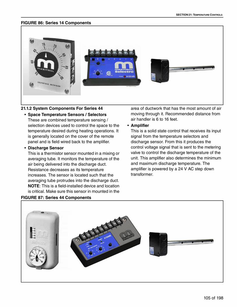
SECTION 21: TEMPERATURE CONTROLS
105 of 198
FIGURE 86: Series 14 Components
21.1.2 System Components For Series 44• Space Temperature Sensors / Selectors
These are combined temperature sensing /
selection devices used to control the space to the
temperature desired during heating operations. It
is generally located on the cover of the remote
panel and is field wired back to the amplifier.
• Discharge SensorThis is a thermistor sensor mounted in a mixing or
averaging tube. It monitors the temperature of the
air being delivered into the discharge duct.
Resistance decreases as its temperature
increases. The sensor is located such that the
averaging tube protrudes into the discharge duct.
NOTE: This is a field-installed device and location
is critical. Make sure this sensor in mounted in the
area of ductwork that has the most amount of air
moving through it. Recommended distance from
air handler is 6 to 16 feet.
• AmplifierThis is a solid state control that receives its input
signal from the temperature selectors and
discharge sensor. From this it produces the
control voltage signal that is sent to the metering
valve to control the discharge temperature of the
unit. This amplifier also determines the minimum
and maximum discharge temperature. The
amplifier is powered by a 24 V AC step down
transformer.
FIGURE 87: Series 44 Components

TT-SERIES INSTALLATION, OPERATION AND SERVICE MANUAL
106 of 198
21.1.3 System Components For Series 94• Dual Temperature Selectors with LED Display
These are non-temperature-sensing controls
which set the temperature required in the spray
cycle and in the dry cycle, while displaying the
actual average temperature in the discharge duct.
It is generally located on the cover of the remote
panel and connects to the amplifier via a ribbon
cable.
• Discharge SensorThis is a Platinum Positive Coefficient RTD sensor
mounted in a mixing or averaging tube. It monitors
the temperature of the air being delivered into the
discharge duct. Platinum is the material that the
sensor is made out of. Positive coefficient means
that its resistance increases as its temperature
increases. RTD is an acronym for Resistance
Temperature Detector. As its name implies, the
sensor is located such that the averaging tube
protrudes into the discharge duct.
NOTE: This is a field-installed device and location
is critical. Make sure this sensor in mounted in the
area of ductwork that has the most amount of air
moving through it. Recommended distance from
air handler is 6 to 16 feet.
• AmplifierThis is a solid state control that receives its input
signal from the temperature selectors and
discharge sensor. From this it produces the
control voltage signal that is sent to the metering
valve to control the discharge temperature of the
unit. The amplifier is supplied with 24 volts AC
and is located inside the remote control panel.
Besides signaling the valve, the amplifier also
sends a signal to the LED display (located
between the temperature selectors). This signal
is used to illuminate the LED; displaying the
average temperature the discharge sensor is
seeing.
FIGURE 88: Series 94 Components
21.1.4 System Components For Series MP2 And MP2+
• Programmable Temperature Selector with LED DisplayThese are non-temperature-sensing controls
which set the temperature required in the spray
cycle and in the dry cycle, while displaying the
actual average temperature in the discharge duct.
It is generally located on the cover of the remote
panel and connects to the amplifier via a ribbon
cable.
• Discharge SensorThis is a Platinum Positive Coefficient RTD sensor
mounted in a mixing or averaging tube. It monitors
the temperature of the air being delivered into the
discharge duct. Platinum is the material that the
sensor is made out of. Positive coefficient means

SECTION 21: TEMPERATURE CONTROLS
107 of 198
that its resistance increases as its temperature
increases. RTD is an acronym for Resistance
Temperature Detector. As its name implies, the
sensor is located such that the averaging tube
protrudes into the discharge duct.
NOTE: This is a field-installed device and location
is critical. Make sure this sensor in mounted in the
area of ductwork that has the most amount of air
moving through it. Recommended distance from
air handler is 6 to 16 feet.
• AmplifierThis is a solid state control that receives its input
signal from the temperature selectors and
discharge sensor. From this it produces the
control voltage signal that is sent to the metering
valve to control the discharge temperature of the
unit. The amplifier is supplied with 24 volts AC
and is located inside the remote control panel.
Besides signaling the valve, the amplifier also
sends a signal to the LED display (located
between the temperature selectors). This signal is
used to illuminate the LED; displaying the average
temperature the discharge sensor is seeing. The
amplifier for the MP2+ system (designated
AMO2+) allows for up to 8 separate programs to
be entered and stored while the standard MP2
amplifier only allows one program to be entered.
• Auxiliary Multifunctional Timer Control (optional)Any of the eight processes can be timed. The
conclusion of a timed Process will immediately
proceed into the next Process. If the last Process
of the program is timed, it will proceed to the
selected start position after timing out. The
controller features two Timers (Timer 1 and Timer
2) that accumulate the hours of operation for each
Process. Each Process has a Timer 1 and a Timer
2. Timer 1 logs the hours of operation for a
Process. It also has a programmable alarm setting
to notify the user when the desired accumulated
hours for the Process have been reached. Timer 2
logs the hours of operation for a Process.
FIGURE 89: Series MP Components

TT-SERIES INSTALLATION, OPERATION AND SERVICE MANUAL
108 of 198
SECTION 22: DIRECT FIRED BURNER
The burner used by Weather-Rite is manufactured by Midco International®, Inc., Model HMA-2A. The HMA-
2A is used for natural gas and propane (LP). The burner combines the two main ingredients needed for
proper combustion air (oxygen) and fuel (gas whether natural or manufactured). In this burner raw gas is
delivered to the burner ports at low pressure. The air passing across the burner is maintained between 2,500
and 3,200 feet per minute. The arrangement and shape of the air holes in the baffles surrounding the burner
provide the amount of air required for proper combustion for all of the firing rates.
WARNING
Failure to follow these instructions can result in death, electric shock, injury or property damage.
Burn Hazard
Allow heater to cool before service.
Tubing may still be hot after operation.
Explosion Hazard
Leak test all compo-nents of gas piping before operation.
Gas can leak if piping is not installed properly.
Do not high pressure test gas piping with equipment connected.
DANGER
Electrical Shock Hazard
Disconnect electric before service.
More than one disconnect switch may be required to disconnect electric from heater.
Heater must be connected to a properly grounded electrical source.
Carbon Monoxide Hazard
Heaters installed unvented must be interlocked with sufficient building exhaust.
Heaters must be installed according to the installation manual.

SECTION 22: DIRECT FIRED BURNER
109 of 198
FIGURE 90: Midco HMA-2A Burner
22.1 Direct Fired Burner Ignition
The burner that is used in the Weather-Rite LLC unit
is equipped with a pilot assembly. The pilot assembly
consists of a pilot gas tube, spark electrode or rod
and either a flame rod with grounding assembly or
UV scanner. For proper ignition the spark rod must
be adjusted correctly. A high voltage arc is generated
between the spark rod and the pilot gas tube. The
gas flowing out the ports in the pilot gas tube is
ignited by this arc. The arc will be a brilliant electric
blue in color. See Page 109, Figure 90.
The gas supplied to the pilot gas tube should be 3 1/
2" wc for natural gas and between 9 to 11" wc for
propane or LP. The difference between the two fuels
is that a restricting orifice is installed in the propane
or LP pilot gas tube. The pilot assembly can be used
on propane or LP without an orifice, if this is the case
then the pressure for LP is 2.0"w.c. Ignition will take
place with the introduction of gas to the pilot gas
tube. The pilot flame will be mostly blue in color with
streaks of yellow. The flame size will be roughly 2" in
diameter. The flame must be steady and consistent
in size.

TT-SERIES INSTALLATION, OPERATION AND SERVICE MANUAL
110 of 198
22.2 Direct Fired Burner Flame Proving (Flame Rod)
The flame rod in the burner is constructed of a
material that produces a signal when heated. This
signal is measured as a direct current micro amp.
The path of the signal is from the flame rod to the
burner. From the burner, which is mechanically
grounded to the unit casing, the signal continues to
the grounded side of the flame rectification module in
the flame safeguard control. The signal continues out
of the module to the flame rod where it completes the
loop.
The length the flame rod extends into the burner is
determined by the insulator surrounding the rod. This
insulator must not be exposed more than 1/8" into
the burner and not recessed more than 1/8". At this
setting the flame rod will be enveloped by the pilot or
main flame. It will be glowing bright red along at least
50% of its length. See Page 109, Figure 90.
FIGURE 91: Spark Rod Dimensions
NOTE: For the flame rod to produce this signal its
position in relation to the grounding rod, pilot and
main flame is critical.
The flame rectification module of the flame safeguard
control converts this signal to a D.C. voltage. This
voltage is the value that is used to monitor the pilot
and the main flame of the burner.
For the flame safeguard control to recognize this
signal the value of the voltage must be between 5 to
10 volts D.C. and it must be steady. This signal is
measured at the flame relay, on the rectification
module's test jacks; S1 (colored red) and S2 (colored
black).
Upon receiving the correct signal, the flame relay will
accept this as proof that the burner is functioning
correctly and will proceed with its functions.
B
C
E
D
A
WARNING: the ignition system on the air handler generates between 6,000 to 10,000 volts.
A B C D E
in 2.940 0.125 0.125 1.881 0.633
cm 7.468 0.318 0.318 4.778 1.608

SECTION 22: DIRECT FIRED BURNER
111 of 198
22.3 Direct Fired Burner Flame Proving (Ultra Violet Scanner)
The UV tube is made of quartz and is filled with a gas
that ionizes when struck by UV radiation from the
flame. In the absence of UV radiation, the gas acts
as an insulator between two electrodes which are
mounted inside the tube. These electrodes are
energized continuously by a high voltage. During
combustion, UV radiation ionizes the gas, causing
current pulses to flow between the electrodes. These
current pulses result in a flame signal which is
transmitted to the amplifier in the control where it is
processed to energize or hold in the flame relay.
FIGURE 92: Ultra Violet Sensor
The flame rectification module of the flame safeguard
control converts this signal to a D.C. voltage. This
voltage is the value that is used to monitor the pilot
and the main flame of the burner. For the flame
safeguard control to recognize this signal the value of
the voltage must be between 5 to
10 volts D.C. and it must be steady. This signal is
measured at the flame relay, on the rectification
module's test jacks; S1 (colored red) and S2 (colored
black). Upon receiving the correct signal, the flame
relay will accept this as proof that the burner is
functioning correctly and will proceed with its
functions.
FIGURE 93: Ultra Violet Scanner Mounting

TT-SERIES INSTALLATION, OPERATION AND SERVICE MANUAL
112 of 198
SECTION 23: DIRECT FIRED PROCESS AIR HEATERS
This section applies to direct gas-fired process air
heaters of the recirculating or non-recirculating type.
During the process heating cycle (bake or cure)
excess Carbon Monoxide is produced and all entry
into the controlled space is prohibited. Exhaust
systems must be provided for proper operation and
no entry is allowed into the space during the high
temperature or baking cycle. This equipment is to
provide process heating to non-occupied spaces and
may also include operation as a non-recirculating
ventilation air heater. This heater may or may not be
used in a paint booth application.
The intent of this section is to supply the required
information concerning installation and operation of
Electrical Shock Hazard
Disconnect electric before service.
More than one disconnect switch may be required to disconnect electric from equipment.
Equipment must be properly grounded.
Severe Injury Hazard
Do not enter equipment while in operation.
Equipment may start automatically.
Do not operate with door open.
Installation, operation and service must be done by a trained technician only.
DANGER
Failure to follow these instructions can result in death, electrical shock or injury.
Explosion Hazard
Leak test all compo-nents of equipment gas piping before operation.
Gas can leak if piping is not installed properly.
Do not high pressure test gas piping with equipmentconnected.
Carbon MonoxideHazard
Do not recirculate air from the heated space over burner.
Air supply to burner must be from outside.
Falling Hazard
Use proper safety equipment and practices to avoid falling.
Do not use any part of equipment as support.
Burn Hazard
Allow equipment to cool before service.
Internal components of equipment may still be hot after operation.
WARNING
Failure to follow these instructions can result in death, injury or property damage.

SECTION 23: DIRECT FIRED PROCESS AIR HEATERS
113 of 198
the process air heater in compliance with:
United States: Refer to NFPA 86 - latest revision,
Ovens and Furnaces /ANSI Z83.25 - latest revision,
Direct Gas-Fired Process Air Heaters.
Canada: Refer to CSA 3.19 - latest revision, Direct
Gas-Fired Process Air Heaters.
23.1 Direct Fired Process Air Heater Models• 100% Outside Air - Ventilating and Baking Cycle
Mode
• 100% Outside Air - Ventilating with Reduced
Airflow for Bake Cycle Mode
• 100% Outside Air - Ventilating with Recirculation
for Baking Cycle Model (80% Recirculated Air
after the burner and 20% Outside Air)
• 100% Outside Air - Ventilating with Recirculation
for Baking Cycle Model (90% Recirculated Air
across the burner and 10% Outside Air)
Other terms may be used to describe the bake cycle
mode such as; Cure or Cure Time Cycle, Dry or
Drying Cycle, and Flash Kick Cycle. Ventilation air
and the term outside air are also used
interchangeably.
All process heaters come equipped with two High
Limit discharge controllers, one for the ventilation
cycle - maximum 160 °F (71 °C) (automatic reset)
and one for the bake cycle mode - maximum 300 °F
(149 °C) (manual reset). The discharge temperature
controller limits the temperature to a maximum
250 °F (121 °C).
23.2 Installer's Responsibilities1. All access opening(s) to the heated space,
served by the Process Heater that can be used
by personnel to enter the space, must have
door interlock switch or switches to shut down
the Process Heater if entry is attempted during
the bake cycle.
2. On recirculation Process Heaters, the return air
duct from the served space must have filters
installed to prevent particulate matter from
entering the heater. If not supplied by the Pro-
cess Heater, then the installer must supply
them. These filters must be approved by the
authority having jurisdiction of the installation.
3. The return air duct system must be installed
with doors, panels or other means for access to
facilitate inspection, maintenance, cleaning
and access to fire protection devices.
4. Instructions must be provided to require peri-
odic inspection and cleaning of the recircula-
tion air duct. The installer must supply this
information.
5. The gas piping installer must locate a manual
emergency gas shutoff valve in an appropriate
location that allows access to shut off the flow
of gas to the Process Heater in case of an
emergency.
6. If a post purge (cool-down) cycle is not sup-
plied with the Process Heater, then the installer
must supply a timing circuit that allows 100%
ventilation air of the space to cool the products
down and purge any airborne contaminants.
See Page 113, Figure 94
FIGURE 94: Cool Down Cycle Circuit
7. It is also suggested that the following Burn
Hazard Warning be installed at all access
opening(s) to the heated space, served by the
Process Heater, that can be used by personnel
to enter the space. If additional burn hazard
warnings are needed, contact Weather-Rite
-f
-
-
A
B
TO MAIN POWER
f f
f
f
f
f f
f
FUSE F2 FUSE F3
120 V
CONTROL TRANSFORMER
COOL DOWN
TIMER COIL*HEATER
RUN CONTACT
BAKE CYCLE
AUXILARY CONTACT
SUMMER/OFF/WINTER SWITCH*
1
1
15
16
17
3
4
13
5
15
COOL DOWN TIMER CONTACT
SUPPLY FAN OVERLOADS
SUPPLY FAN CONTACTOR COIL
SUPPLY FAN AUXILIARY CONTACT
SUPPLY FAN AIR FLOW SWITCH
VOLUME AIR FLOW SWITCH
TERMINAL LOCATED ON MAIN PANEL
TERMINAL LOCATED ON REMOTE STATION
FIELD WIRING
KEY;
WIN.SUM.
OFF
135
FUSE F1
2
2

TT-SERIES INSTALLATION, OPERATION AND SERVICE MANUAL
114 of 198
LLC or WEATHER-RITE™ independent distrib-
utor.
FIGURE 95: Burn Hazard
8. The space serviced by the Process Heater,
during the bake cycle mode must have its light-
ing turned off. If not supplied by the process
heater, then the installer must electrically inter-
lock the facility lights with the bake cycle. See Page 113, Figure 94.
FIGURE 96: Lighting Interlock Circuit
9. Process Heaters in the baking cycle mode
require a minimum of 200 CFM of ventilation
air per 1000 CFH of fuel gas for proper com-
bustion. If the Process Heater does not come
equipped with the features to meet this require-
ment, then the installer must provide the
method to accomplish it.
NOTE: Process Heaters supplied by Weather-Rite
LLC are available with the options required to satisfy
this requirement.
A. Reduced Airflow Process Heaters
• Variable Frequency Drive control of the Process
Heater's airflow comes with either:
• Manual or motorized burner profile dampers
• Process Heaters that deliver up to and including
20,000 CFM may be supplied with manual burner
profile dampers. These models are limited to a
CFM reduction of 50% of the maximum ventilating
air capacity of that particular model.
• Process Heaters supplied with motorized burner
profile dampers, may be reduced to a CFM
reduction of 20% of the maximum ventilating air
capacity of that particular model.
B. Discharge Damper control of the Process Heater's
airflow comes with either:
• Manual or motorized profile dampers
• Process Heaters that deliver up to and including
20,000 CFM may be supplied with manual burner
profile dampers. These models are limited to a
CFM reduction of 50% of the maximum ventilating
air capacity of that particular model.
• Process Heaters supplied with motorized burner
profile dampers, may be reduced to a CFM
reduction of 20% of the maximum ventilating air
capacity of that particular model.
C. 90/10 Recirculation Process Heaters
• The installer must ensure that the Outside Air
Damper, when supplied by Weather-Rite LLC, is
set to provide proper airflow for combustion and to
make sure the recirculation air is properly diluted
during the bake cycle mode. This is accomplished
by ensuring the bypass feature of the ventilating
air damper is not blocked by the installation or that
the minimum position control of the ventilating air
damper is functioning properly.
23.3 Installer's Responsibility for Process Heaters Connected to Paint Booths
1. If the exhaust control system is not supplied by
the Process Heater, then the installer must
electrically interlock the exhaust system with
the heater. See Page 115, Figure 97.
WARNING
Burn Hazard
Allow equipment to cool before service.
Internal components of equipment may still be hot after operation.
Failure to follow these instructions can result in injury.
TO MAIN POWER
f f
fFUSE F2
FUSE F1
120 V
CONTROL TRANSFORMER
LIGHTING CONTACTOR COIL
TERMINAL LOCATED ON MAIN PANEL
TERMINAL LOCATED ON REMOTE STATION
FIELD WIRING
BAKE CYCLE MODE
ACTIVATION RELAY CONTACT
1
1
f
f
LIGHT SWITCH
KEY;
f
OFF ON
f2 2
FUSE F3
-
-
-
C1

SECTION 23: DIRECT FIRED PROCESS AIR HEATERS
115 of 198
FIGURE 97: Exhaust Interlock Circuit
2. If a purge cycle between ventilation cycle mode
and the bake cycle mode is not supplied with
the Process Heater, then the installer must
supply a purge timer that delays the bake cycle
from operating for a minimum of 3 minutes or
at least 4 air changes of the space. See Page 115, Figure 98.
FIGURE 98: Purge Circuit
3. The space serviced by the Process Heater,
during the purging cycle and bake cycle mode
must have all spray equipment turned off. If not
supplied by the Process Heater, then the
installer must electrically interlock the spray
equipment with the Process Heater. See Page 115, Figure 99.
FIGURE 99: Spray Equipment Interlock Circuit
23.4 WEATHER-RITE™ Control Packages
Various control packages are available to
complement the process heaters. These control
packages interlock with the exhaust systems, lighting
circuits, spraying equipment. These packages ensure
purging of the space (3 minutes minimum with
adjustability to lengthen if process requires) takes
place before the bake cycle is initialized and also
supplies a cool-down cycle (operator adjustable) for
after the bake cycle. All packages are available with
optional exhaust system variable frequency drive.
23.4.1 : WRP- 1 Remote Control Station - 100% Ventilation Air
1. Description:
• NEMA1 hinged control panel.
• Summer-Off-Winter switch.
• Three system indicating lights; Blower, Burner
and Flame Failure.
• Maxitrol "M" Series temperature set point with
digital temperature indicator.
• Booth Lighting On/Off Switch, fusing and contactor (supply power for lights by others).
f
A
B
1
-
-
-
THE N/O AUXILIARY CONTACT OF A
PROCESS’ EXHAUST FAN(S)
SHOULD BE CONNECTED BETWEEN
TERMINALS #1 AND #1 UNLESS THE
PROCESS HEATER IS DIRECTLY
CONNECTED TO THE SYSTEM
TO MAIN POWER
f f
fFUSE F2 FUSE F3
CONTROL TRANSFORMER
SUMMER/OFF/WINTER SWITCH*
SUPPLY FAN OVERLOADS
WIRE TO EXH. FAN CIRCUIT
EXHAUST FAN AIR FLOW SWITCH
NOTE: REMOVE JUMPER WIRE BETWEEN 17 & 17
IF EXHAUST AIR FLOW SWITCH IS USED
SUPPLY FAN CONTACTOR COIL
SUPPLY FAN AUXILIARY CONTACT
17
3
4
SUPPLY FAN AIR FLOW SWITCH
VOLUME AIR FLOW SWITCH
KEY;
TERMINAL LOCATED ON MAIN PANEL
TERMINAL LOCATED ON REMOTE STATION
FIELD WIRING
13
5
16
17
f f
f
f f f
2
f
f
f
ff
f 14 14
1513
OFF
WIN.SUM.
5
120 V
FUSE F1
KEY;
2 fSUM.
A
B
OFFWIN.
2
TO MAIN POWER
f
FUSE F2
FUSE F1
FUSE F3
120 V
CONTROL TRANSFORMER
PURE TIMER
TERMINAL LOCATED ON MAIN PANEL
TERMINAL LOCATED ON REMOTE PANEL
FIELD WIRING
BAKE CYCLE
START CONTACT14
5
5
1
1
ff
f
f
13
5
SUMMER/OFF/WINTER SWITCH*
f f
f
f
BAKE CYCLE
ACTIVATION RELAY
-f
-
-
*
KEY;KEY;-
-
-
f
TO MAIN POWERFUSE F2
FUSE F1
FUSE F3
120 V
CONTROL TRANSFORMER
SUMMER/OFF/WINTER SWITCH*
SUPPLY FAN OVERLOADS
SUPPLY FAN CONTACTOR COIL 2
SPRAY AIR SUPPLY SOLENOID
TERMINAL LOCATED ON MAIN PANEL
TERMINAL LOCATED ON REMOTE STATION
FIELD WIRING
fff13
5
SUPPLY FAN AUXILIARY CONTACT
SUPPLY FAN AIR FLOW SWITCH
VOLUME AIR FLOW SWITCH
BAKE CYCLE
AUXILIARY CONTACT
3
f f 4
16
17
14
14
13
A
B5
f f
f
1
1
WIN.
OFF
SUM.
f
f
f
f

TT-SERIES INSTALLATION, OPERATION AND SERVICE MANUAL
116 of 198
2.Operation:
• Switch in "Summer" position for fan only or
"Winter" position for fan and burner.
• Process Heater's discharge damper (if
equipped) opens to 100% open position.
• Exhaust fan starts and after a timed delay, the
supply fan comes on In the winter position,
temperature based on paint temperature set
point.
FIGURE 100: WRP-1
23.4.2 WRP- 2 Remote Control Station - 100% Ventilation Air / Reduced Airflow Dry Cycle
1. Description:
• NEMA1 hinged control panel.
• Summer-Off-Winter switch.
• Three system indicating lights; Blower, Burner
and Flame Failure.
• Spray gun interlock.
• Dry Purge Timer and Cool-Down timer.
• Mechanical Dry timer (0-60 minutes).
• Maxitrol "M" Series temperature set point with
digital temperature indicator.
• Booth Lighting On/Off Switch, fusing and
contactor (supply power for lights by others).
2.Operation - Paint Mode:
• Switch in "Summer" position for fan only or
"Winter" position for fan and burner.
• Process Heater's discharge damper opens to
100% open position.
• Exhaust fan starts and after a timed delay, the
supply fan comes on.
• In the winter position, temperature based on
paint temperature set point.
• Booth lights operated by on/off switch.
3.Operation - Dry Mode:
• Activate switch to either "Summer" or "Winter"
position.
• Turn Dry Cycle Start Timer to desired time
(activates the Dry cycle).
• Spray gun solenoid and booth lights are shut
off.
• Purge timer is activated, purging booth with
100% ventilation air (operating as if in paint
mode).
• Process Heater's discharge damper re-
positions to 50% airflow position, exhaust fan
operates at 50% airflow.
• Temperature based on dry temperature set
point.
• When dry cycle is completed, cool-down cycle
is activated. Booth lights remain off.
• During cool-down cycle, the process heater
and exhaust fan revert to 100% ventilation air
(operating as if in paint mode).
• Process Heater and exhaust fan shut down
after cool-down cycle.
FIGURE 101: WRP-2
BLOWER
BURNER
FLAME FAILURE SUMMER OFF WINTER
OFF ON
LIGHTS
TEMP CONTROLLER
PGM
MAXITROL
ENT
BLOWER
BURNER
FLAME FAILURE SUMMER OFF WINTER
OFF ON
LIGHTS
TEMP CONTROLLER
PGM
MAXITROL
ENT
20
5
3540
2530
45
50
55
60HOLD 0
15
10
DRY CYCLE START

SECTION 23: DIRECT FIRED PROCESS AIR HEATERS
117 of 198
23.4.3 WRP - 3 Remote Control Station - 100% Ventilation Air / Reduced Airflow Dry Cycle - VFD Exhaust
1. Description:
• NEMA1 hinged control panel.
• Summer-Off-Winter switch.
• Three system indicating lights; Blower, Burner
and Flame Failure.
• Spray gun interlock.
• Dry Purge Timer and Cool-Down timer.
• Mechanical Dry timer (0-60 minutes).
• Maxitrol "M" Series temperature set point with
digital temperature indicator.
• Booth Lighting On/Off Switch, fusing and
contactor (supply power for lights by others).
• Manual balancing pot for adjusting exhaust fan
speed in the paint mode.
• Booth pressure gauge (Dwyer 4" Magnehelic®),
monitors booth pressure.
2.Operation - Paint Mode:
• Switch in "Summer" position for fan only or
"Winter" position for fan and burner.
• Process Heater's discharge damper opens to
100% open position.
• Exhaust fan starts and after a timed delay, the
supply fan comes on.
• In the winter position, temperature based on
paint temperature set point.
• Booth lights operated by on/off switch.
• Booth balancing pot provides fine tune
adjustment of exhaust fan speed to maintain
booth pressure.
3.Operation - Dry Mode:
• Activate switch to either "Summer" or "Winter"
position.
• Turn Dry Cycle Start Timer to desired time
(activates the dry cycle).
• Spray gun solenoid and booth lights are shut
off.
• Purge timer is activated, purging booth with
100% ventilation air (operating as if in paint
mode).
• Process Heater's discharge damper re-
positions to 50% airflow position, exhaust fan
operates at 50% airflow.
• Temperature based on Dry temperature set
point.
• When Dry cycle is completed, cool-down cycle
is activated. Booth lights remain off.
• During cool-down cycle, the Process Heater
and exhaust fan revert to 100% ventilation air
(operating as if in paint mode).
• Process Heater and exhaust fan shut down
after cool-down cycle
FIGURE 102: WRP-3
23.4.4 WRP - 3R Remote Control Station - 100% Ventilation Air and 90/10 Recirculating Cure Sys-tem - VFD Exhaust
1. Description:
• NEMA1 hinged control panel.
• Summer-Off-Winter switch.
• Three system indicating lights; Blower, Burner
and Flame Failure.
• Spray gun interlock.
• Dry Purge Timer and Cool-Down timer.
• Mechanical Dry timer (0-60 minutes).
• Maxitrol "M" Series temperature set point with
digital temperature indicator.
• Booth Lighting On/Off Switch, fusing and
contactor (supply power for lights by others).
• Manual balancing pot for adjusting exhaust fan
speed in the paint mode.
BOOTH BALANCING POTBOOTH PRESSURE
BURNER
BLOWER
FLAME FAILURE SUMMER OFF WINTER
OFF ON
LIGHTS
TEMP CONTROLLER
PGM
MAXITROL
ENT
20
5
3540
2530
45
50
55
60HOLD 0
15
10
DRY CYCLE START
YOU CAN'T SEE IT!
IS SO DAMN SMALL THAT
SIGNIFICANCE BECAUSE IT
INFORMATION OF NO
THIS APPARENTLY SOME
MAGNEHELIC
1"
0
1"

TT-SERIES INSTALLATION, OPERATION AND SERVICE MANUAL
118 of 198
• Booth pressure gauge (Dwyer 4" Magnehelic®),
monitors booth pressure.
2.Operation - Paint Mode:
• Switch in "Summer" position for fan only or
"Winter" position for fan and burner.
• Process Heater ventilation air damper opens to
100% open position.
• Exhaust fan starts and after a timed delay, the
supply fan comes on.
• In the winter position, temperature based on
paint temperature set point.
• Booth lights operated by on/off switch.
• Booth balancing pot provides fine tune
adjustment of exhaust fan speed to maintain
booth pressure.
3.Operation - Dry Mode:
• Activate switch to either "Summer" or "Winter"
position.
• Turn Dry Cycle Start Timer to desired time
(activates the Dry cycle).
• Spray gun solenoid and booth lights are shut
off.
• Purge timer is activated, purging booth with
100% ventilation air (operating as if in paint
mode).
• After purge cycle, Process Heater's dampers
re-position to 10% ventilation air & 90 % return
air for Dry cycle. Exhaust fan speed reduces
down to 10% airflow.
• Temperature based on Dry temperature set
point.
• When Dry cycle is completed, cool-down cycle
is activated. Booth lights remain off.
• During cool-down cycle, the Process Heater
and exhaust fan revert to 100% ventilation air
(operating as if in paint mode).
• Process Heater and exhaust fan shut down
after cool-down cycle.
FIGURE 103: WRP-3R
23.4.5 WRP- 4 Remote Control Station - 100% Ventilation Air / Reduced Airflow Dry Cycle - Auto Balance
1. Description:
• NEMA1 hinged control panel.
• Summer-Off-Winter switch.
• Three system indicating lights; Blower, Burner
and Flame Failure.
• Spray gun interlock.
• Dry Purge Timer and Cool-Down timer.
• Mechanical Dry timer (0-60 minutes).
• Maxitrol "M" Series temperature set point with
digital temperature indicator.
• Booth Lighting On/Off Switch, fusing and
contactor (supply power for lights by others).
• Booth pressure gauge controller (Dwyer 4"
Photohelic®), monitors and automatically
adjusts exhaust fans to maintain booth
pressure.
2.Operation - Paint Mode:
• Switch in "Summer" position for fan only or
"Winter" position for fan and burner.
• Process Heater discharge damper opens to
100% open position.
• Exhaust fan starts and after a timed delay, the
supply fan comes on.
BOOTH BALANCING POTBOOTH PRESSURE
BURNER
BLOWER
FLAME FAILURE SUMMER OFF WINTER
OFF ON
LIGHTS
TEMP CONTROLLER
PGM
MAXITROL
ENT
20
5
3540
2530
45
50
55
60HOLD 0
15
10
DRY CYCLE START
YOU CAN'T SEE IT!
IS SO DAMN SMALL THAT
SIGNIFICANCE BECAUSE IT
INFORMATION OF NO
THIS APPARENTLY SOME
MAGNEHELIC
1"
0
1"

SECTION 23: DIRECT FIRED PROCESS AIR HEATERS
119 of 198
• In the winter position, temperature based on
paint temperature set point.
• Booth lights operated by on/off switch.
3.Operation - Dry Mode:
• Activate switch to either "Summer" or "Winter"
position.
• Turn Dry Cycle Start Timer to desired time
(activates the Dry cycle).
• Spray gun solenoid and booth lights are shut
off.
• Purge timer is activated, purging booth with
100% ventilation air (operating as if in paint
mode).
• "Process Heater's discharge damper re-
positions to 50% airflow position, exhaust fan
automatically adjusts airflow to maintain the
pressure setting of the pressure controller.
• Temperature based on Dry temperature set
point.
• When Dry cycle is completed, cool-down cycle
is activated. Booth lights remain off.
• During cool-down, Process Heater and the
exhaust fan revert to 100% airflow position
(operating as if in paint mode).
• Process Heater and exhaust fan shut down
after cool-down cycle.
FIGURE 104: WRP-4
23.4.6 WRP- 4R Remote Control Station 90/10 Recirculating Cure System - Auto Balance
1. Description:
• NEMA1 hinged control panel
• Summer-Off-Winter switch
• Three (3) system indicating lights; Blower,
Burner and Flame Failure
• Spray gun interlock
• Dry Purge Timer and Cool-Down timer
• Mechanical Dry timer (0-60 minutes)
• Maxitrol "M" Series temperature set point with
digital temperature indicator
• Booth Lighting On/Off Switch, fusing and
contactor (supply power for lights by others)
• Booth pressure gauge controller (Dwyer 4"
Photohelic), monitors and automatically adjusts
exhaust fans to maintain booth pressure
2.Operation - Paint Mode:
• Switch in "Summer" position for fan only or
"Winter" position for fan and burner
• Process Heater's dampers opens to 100%
ventilation position
• Exhaust fan starts and after a timed delay, the
supply fan comes on
• In the winter position, temperature based on
paint temperature set point
• Booth lights operated by on/off switch
• Dry mode:
• Activate switch to either "Summer" or "Winter"
position
• Turn Dry Cycle Start Timer to desired time
(activates the Dry cycle)
• Spray gun solenoid and booth lights are shut
off
• Purge timer is activated, purging booth with
100% ventilation air (operating as if in paint
mode)
• Process Heater's dampers re-positions to 10%
ventilation air and 90% return air, exhaust fan
automatically adjusts airflow to maintain the
pressure setting of the pressure controller.
• Temperature based on Dry temperature set
point
• When Dry cycle is completed, cool-down cycle
is activated. Booth lights remain off.
BOOTH PRESSURE
BURNER
BLOWER
FLAME FAILURE SUMMER OFF WINTER
OFF ON
LIGHTS
TEMP CONTROLLER
PGM
MAXITROL
ENT
20
5
3540
2530
45
50
55
60HOLD 0
15
10
DRY CYCLE START
PHOTOHELIC
1"
4
1"
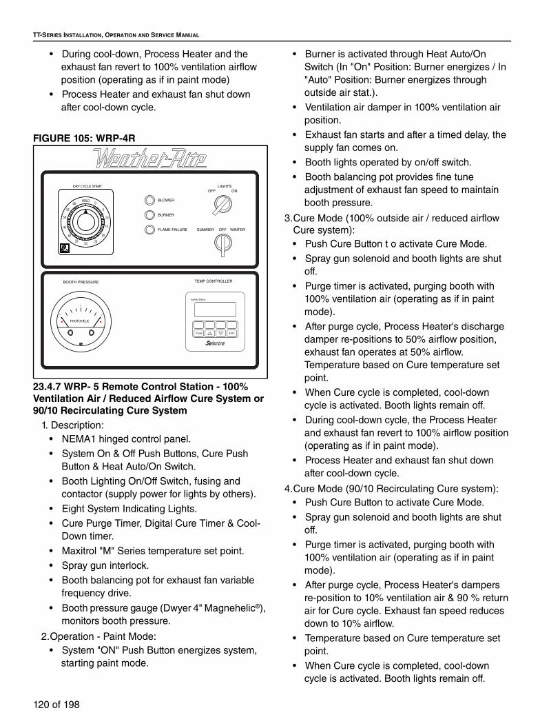
TT-SERIES INSTALLATION, OPERATION AND SERVICE MANUAL
120 of 198
• During cool-down, Process Heater and the
exhaust fan revert to 100% ventilation airflow
position (operating as if in paint mode)
• Process Heater and exhaust fan shut down
after cool-down cycle.
FIGURE 105: WRP-4R
23.4.7 WRP- 5 Remote Control Station - 100% Ventilation Air / Reduced Airflow Cure System or 90/10 Recirculating Cure System
1. Description:
• NEMA1 hinged control panel.
• System On & Off Push Buttons, Cure Push
Button & Heat Auto/On Switch.
• Booth Lighting On/Off Switch, fusing and
contactor (supply power for lights by others).
• Eight System Indicating Lights.
• Cure Purge Timer, Digital Cure Timer & Cool-
Down timer.
• Maxitrol "M" Series temperature set point.
• Spray gun interlock.
• Booth balancing pot for exhaust fan variable
frequency drive.
• Booth pressure gauge (Dwyer 4" Magnehelic®),
monitors booth pressure.
2.Operation - Paint Mode:
• System "ON" Push Button energizes system,
starting paint mode.
• Burner is activated through Heat Auto/On
Switch (In "On" Position: Burner energizes / In
"Auto" Position: Burner energizes through
outside air stat.).
• Ventilation air damper in 100% ventilation air
position.
• Exhaust fan starts and after a timed delay, the
supply fan comes on.
• Booth lights operated by on/off switch.
• Booth balancing pot provides fine tune
adjustment of exhaust fan speed to maintain
booth pressure.
3.Cure Mode (100% outside air / reduced airflow
Cure system):
• Push Cure Button t o activate Cure Mode.
• Spray gun solenoid and booth lights are shut
off.
• Purge timer is activated, purging booth with
100% ventilation air (operating as if in paint
mode).
• After purge cycle, Process Heater's discharge
damper re-positions to 50% airflow position,
exhaust fan operates at 50% airflow.
Temperature based on Cure temperature set
point.
• When Cure cycle is completed, cool-down
cycle is activated. Booth lights remain off.
• During cool-down cycle, the Process Heater
and exhaust fan revert to 100% airflow position
(operating as if in paint mode).
• Process Heater and exhaust fan shut down
after cool-down cycle.
4.Cure Mode (90/10 Recirculating Cure system):
• Push Cure Button to activate Cure Mode.
• Spray gun solenoid and booth lights are shut
off.
• Purge timer is activated, purging booth with
100% ventilation air (operating as if in paint
mode).
• After purge cycle, Process Heater's dampers
re-position to 10% ventilation air & 90 % return
air for Cure cycle. Exhaust fan speed reduces
down to 10% airflow.
• Temperature based on Cure temperature set
point.
• When Cure cycle is completed, cool-down
cycle is activated. Booth lights remain off.
BOOTH PRESSURE
BURNER
BLOWER
FLAME FAILURE SUMMER OFF WINTER
OFF ON
LIGHTS
TEMP CONTROLLER
PGM
MAXITROL
ENT
20
5
3540
2530
45
50
55
60HOLD 0
15
10
DRY CYCLE START
PHOTOHELIC
1"
4
1"

SECTION 23: DIRECT FIRED PROCESS AIR HEATERS
121 of 198
• During cool-down cycle, the Process Heater
and exhaust fan revert to 100% ventilation air
(operating as if in paint mode).
• Process Heater and exhaust fan shut down
after cool-down cycle.
FIGURE 106: WRP-5
SYSTEM OFF
CUTE ONCUTE
PURGE
PAINT
SYSTEM ONHEATING MODE
BOOTH LIGHT
BOOTH PRESSURE
OFF
AUTO ON HEAT ON
HEAT FAIL
CHANGE PIT FILTER
ON
COOL-DOWN
G
R
Y
B
A
Y
W
G A
R
R
TEMP CONTROLLER
PGM
MAXITROL
ENT
YOU CAN'T SEE IT!
IS SO DAMN SMALL THAT
SIGNIFICANCE BECAUSE IT
INFORMATION OF NO
THIS APPARENTLY SOME
MAGNEHELIC
1"
0
1"I N C R E A S E
PAINT
DE C R E A S E I N C R E A S E
CURE
DE C R E A S E
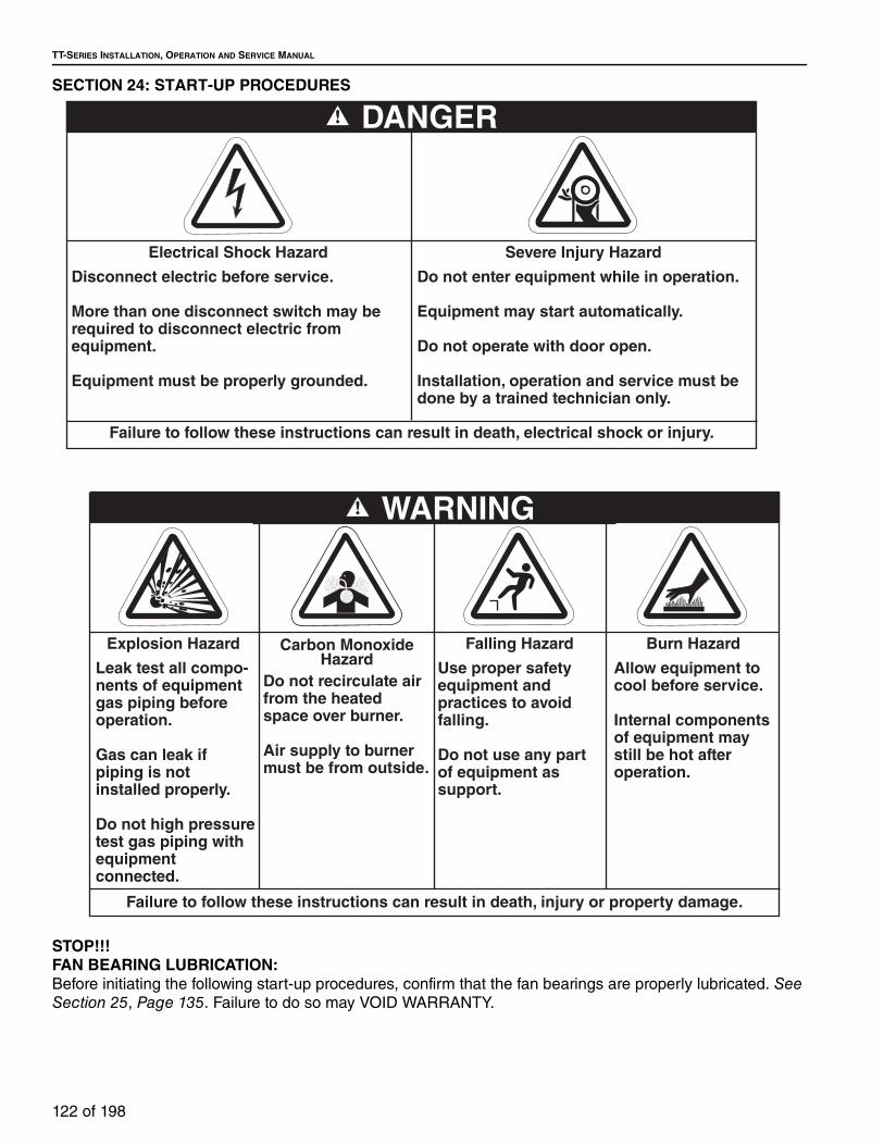
TT-SERIES INSTALLATION, OPERATION AND SERVICE MANUAL
122 of 198
SECTION 24: START-UP PROCEDURES
STOP!!!FAN BEARING LUBRICATION:Before initiating the following start-up procedures, confirm that the fan bearings are properly lubricated. See Section 25, Page 135. Failure to do so may VOID WARRANTY.
Electrical Shock Hazard
Disconnect electric before service.
More than one disconnect switch may be required to disconnect electric from equipment.
Equipment must be properly grounded.
Severe Injury Hazard
Do not enter equipment while in operation.
Equipment may start automatically.
Do not operate with door open.
Installation, operation and service must be done by a trained technician only.
DANGER
Failure to follow these instructions can result in death, electrical shock or injury.
Explosion Hazard
Leak test all compo-nents of equipment gas piping before operation.
Gas can leak if piping is not installed properly.
Do not high pressure test gas piping with equipmentconnected.
Carbon MonoxideHazard
Do not recirculate air from the heated space over burner.
Air supply to burner must be from outside.
Falling Hazard
Use proper safety equipment and practices to avoid falling.
Do not use any part of equipment as support.
Burn Hazard
Allow equipment to cool before service.
Internal components of equipment may still be hot after operation.
WARNING
Failure to follow these instructions can result in death, injury or property damage.

SECTION 24: START-UP PROCEDURES
123 of 198
Installation Code and Annual Inspections: All installation and service of WEATHER-RITE™
equipment must be performed by a contractor
qualified in the installation and service of equipment
sold and supplied by Weather-Rite LLC and conform
to all requirements set forth in the WEATHER-RITE™
manuals and all applicable governmental authorities
pertaining to the installation, service, operation and
labeling of the equipment.
To help facilitate optimum performance and safety,
Weather-Rite LLC recommends that a qualified
contractor conduct, at a minimum, annual
inspections of your WEATHER-RITE™ equipment
and perform service where necessary, using only
replacement parts sold and supplied by Weather-Rite
LLC.
Check installation site to ensure all codes and
engineering specifications are correct. This section of
the manual is intended to be used as an instructional
guide to the commissioning of the direct fired air
handler. Fill out the attached start up sheet (located
at the back of the manual) as each step of the
procedure is performed. This procedure should be
completed by the commissioning contractor and
returned to Weather-Rite LLC. If the document is not
returned, the manufacturing date will be used as the
warranty start date.
24.1 Installation of Recirculating Air Handler
Every direct-fired air handler which recirculates room
air (AM style) must utilize either a control system
which limits temperature rise in proportion to the
amount of outdoor air, or a room carbon dioxide
sensor, installed per the manufacturer's
recommendations. The normally closed contacts of
this sensor must be wired in as per the air handler's
wiring diagram, maintaining the room concentration
of CO2 below 5,000 ppm.
24.2 Mechanical
Refer to appliance rating plate for minimum outside
air requirements during recirculation operation.
Before installation, check that the local distribution
condition, nature of gas and pressure, and the
current state of adjustment of the appliance are
compatible.
If filters are not installed (via inlet hood or filter
section), an air strainer must be installed on the inlet
of the air handler with openings less than or equal to
5/8" (16 mm) in diameter.
Air inlets must be installed with the lowest edge 16"
(406.4 mm) above any surface. This applies to roof
curbs, upright stands and suspended air handlers.
24.2.1 Sheave Alignment
Sheaves are factory aligned. On all air handlers, check sheave alignment as follows:
1. A string to the vertical surface next to the
blower shaft bearing. (See Page 123, Figure 107)
2. Wrap the string around the blower sheave and
across both sheave surfaces as shown.
3. Adjust until all four contact points touch the
sheave surfaces. "IN" or "OUT" adjustment of
the motor sheave and/or motor adjustment
may be required.
4. Pull the string away from the motor sheave and
then move it slowly back towards the sheave,
making sure the string remains straight while
touching all contact points.
5. Remove string before turning air handler on.
NOTE: Allowances must be made for motor sheaves
which are wider than the blower sheaves.
FIGURE 107: Sheave Alignment
24.2.2 Belt Tension• Belt tension should be checked with a belt-tension
gauge when one is available. Follow the belt
tension gauge instructions.
• When a tension gauge is not available, measure
the belt span of the belts. (See Page 124, Figure 108.)
• Allow for 1/64" (.04 cm) of deflection for each inch
of center distance length for the charted pounds
of force. Check the table below for proper
deflection force.
• EXAMPLE: A 40" (101.6 cm) shaft center
distance would dictate 40"/64" or 5/8" (1.59
cm) of deflection. With a standard B-type
Correct Alignment
Incorrect Alignment

TT-SERIES INSTALLATION, OPERATION AND SERVICE MANUAL
124 of 198
V-belt and a motor sheave measuring
between 5.8" (1.59 cm) and 8.6" (21.84 cm),
the belt will have proper tension if a 5/8"
deflection can be achieved with a minimum of
6-3/8 inch lbs. and a maximum of 8-3/4 inch
lbs. of pressure as measured with a belt
tensioning gauge.
FIGURE 108: Belt Tension
Table 40: Deflection Force of V-Belts (in lbs)
NOTE: If drive belts squeal during start-up, increase belt tension to the highest allowed value. Re-check tension during each inspection.
24.2.3 Air Temperature Sensing
The supply air sensing probe is either shipped loose
for field installation or factory mounted.
24.3 Electrical1. Check motor starter for proper overload set-
tings. The overload setting should match the
full load amps (FLA) + 10% of motor.
2. Verify correct blower.
3. Measure the supply voltage with the air handler
off and then on. For a system that is powered
with three phase power, measure the voltage of
each phase.
4. While the blower is running and the burner is
off, measure the total system current draw with
an ammeter. Measure the system current draw
again after the burner adjustments are made
and with the burner and blower both on.
5. If applicable, compare all variable frequency
drive (VFD) programming parameters with
specifications provided on electrical drawing.
24.4 Airflow
The air flow switches are factory calibrated safety
devices for burner air flow. If an air flow switch does
not close, the problem may not be the air flow switch.
It could be an indication of an air flow problem
(incorrect blower rotation, duct restrictions, etc.).
24.4.1 Differential Pressure
In order to verify proper airflow across the burner, the
differential pressure across the profile plate needs to
be measured. Attach a manometer to the pressure
test ports located inside of the control enclosure. See Page 124, Figure 109. Measure the differential
pressure with a manometer with the burner off and
the air handler running at full airflow. This reading
must be 0.55 +/- 0.1 in wc (1.37 +/- 0.25 mbar).
FIGURE 109: Differential Test Ports
Note: On the older model Air Handlers, these
pressure ports were located on either side of the
burner access panel for horizontal configuration or
above and below burner access panel on vertical
configuration.
Belt Cross-Section
Motor Sheave Dimension Range
(inches) - (cm)
TYPE BTYPE B-X (High H.P.)
Min. Max. Min. Max.
B
3.4 - 4.2 4 5 1/2 5 3/4 8
4.4 - 5.6 5 1/8 7 1/8 6 1/2 9 1/8
5.8 - 8.6 6 3/8 8 3/4 7 3/8 10 1/8
Belt Span

SECTION 24: START-UP PROCEDURES
125 of 198
24.4.1.1 Differential Pressure Adjustment Manual Profiles
To adjust the differential pressure that was measured
in the step above, use the profile damper adjustment
quadrants located above and below the burner
access panel for horizontal configuration or on either
side of the burner access panel on vertical
configuration. To increase the differential pressure,
turn the quadrant towards the centerline of the
burner. To decrease the differential pressure, turn the
quadrants towards the parallel of airflow path. Both
quadrants must be at the same setting, but opposing,
for proper airflow distribution across the burner. Make
any adjustments in small increments and recheck
pressure drop after each adjustment. See Page 124, Figure 109.
FIGURE 110: Profile Quadrant Adjustment
24.4.1.2 Differential Pressure Adjustment Motor-ized Profiles
To adjust the differential pressure that was measured
on Page 124, Section 24.4.1 the profile blade
assemblies must be adjusted individually to achieve
the desired pressure. DO NOT disturb the
relationship of the damper motor to the shaft or any
linkage adjustments. Loosen the setscrew nearest
the linkage end of the profile blade and turn the blade
on the shaft in the direction necessary to correct the
pressure, make changes in small increments. Each
profile assembly is done individually and equally,
tighten setscrews securely when done. Turn the air
leaving edge of blade toward the burner to increase
pressure and away from burner to decrease
pressure. Check pressure over the full operating
range of the unit when done. See Page 124, Figure 109
FIGURE 111: Motorized Profile Adjustment
24.4.2 Burner Gas Flow (Temperature Rise)
The gas flow must be adjusted to give the design
temperature rise above outside air. Refer to the air
handler's rating plate for the temperature rise it was
ordered for. To determine the proper gas flow the
following steps need to be completed.
24.4.2.1 Burner Gas Flow - Maxitrol® Series 14/44 Temperature Control System
• Measure the outside air temperature.
• Disconnect one of the discharge sensor wires
from terminal 3 on the Maxitrol 1014 or 1044
amplifier. The air handler will now run at high fire.
• Start the air handler in the winter mode.
• After the burner has ignited and run for 30
seconds, measure the discharge temperature.
• Subtract the outside air temperature from the
discharge temperature; the difference is the
temperature rise.
• If the value is lower than required, increase the
gas flow. If the value is higher than required,
decrease the gas flow. For adjustments See Page 127, Section 24.5.

TT-SERIES INSTALLATION, OPERATION AND SERVICE MANUAL
126 of 198
NOTE: Open the burner observation port and
examine the burner flame. The flame should be a
brilliant blue with short (approx. 1" to 2") yellow
finger tips. If there is too much yellow in the flame
then the air pressure drop, or velocity across the
burner, needs to be increased. This is
accomplished by closing the profile blades. If
there is hardly any yellow in the flame or the
burner sounds like a blowtorch, then you would
decrease the air pressure drop across the burner
by opening the profile blades. This can also be
checked by using a pressure gauge across the
burner and measuring the pressure drop. The
pressure reading should be 0.55 +/- 0.1 In W.C.
(1.37 +/- 0.25 mbar). Performance of the burner
must always be verified by a visual observation.
• Shut the air handler off.
• Locate terminal #1 on the amplifier. Disconnect
the wire that is on that terminal.
• Turn the air handler on in the winter mode. The
unit will now stay in low fire. Low fire should be 1"-
1-1/2" deep and run full length across the burner
(no gaps), if the flame is too high then turn low fire
down. If the flame does not cover the entire length
of the burner then increase the low fire. Observe
the flame; its appearance will be the same as high
fire except for the flame length. For adjustments
See See Page 127, Section 24.5.
• Shut the air handler down.
• Reconnect the wires back to terminals #1 & #3 on
the amplifier.
• Turn the equipment back on in the winter mode.
Vary the temperature selector between the lowest
setting and the highest setting. Visually check the
burner during this operation. The appearance of
the flame will remain the same, brilliant blue with
short yellow finger tips.
24.4.2.2 Burner Gas Flow - Maxitrol® Series 94 and MP2 Temperature Control System
• Measure the outside air temperature.
• Locate the wires connected to terminals (Series
94-#10 & 12, Series MP-#SP1 & SP2) on the
amplifier. Swap their location on the amplifier.
• Start the air handler in the winter mode.
• Set the dry temperature (Series 94) or the second
stage temperature setting (Series MP) to at least
100° over the ambient temperature.
• After the burner has ignited and run for 30
seconds, measure the discharge temperature.
• Subtract the outside air temperature from the
discharge temperature; the difference is the
temperature rise.
• If the value is lower than required, increase the
gas flow. If the value is higher than required,
decrease the gas flow. For adjustments See Page 127, Section 24.5.
NOTE: Open the burner observation port and
examine the burner flame. The flame should be a
brilliant blue with short (approx. 1" 2") yellow
finger tips. If there is too much yellow in the flame
then the air pressure drop, or velocity across the
burner, needs to be increased. This is
accomplished by closing the profile blades. If
there is hardly any yellow in the flame or the
burner sounds like a blowtorch, then you would
decrease the air pressure drop across the burner
by opening the profile blades. This can also be
checked by using a pressure gauge across the
burner and measuring the pressure drop. The
pressure reading should be 0.55 +/- 0.1 In W.C.
(1.37 +/- 0.25 mbar). Performance of the burner
must always be verified by a visual observation.
• Shut the air handler off.
• Go to the amplifier and locate terminal #1.
Disconnect the wire that is on that terminal.
• Turn the air handler on in the winter mode. The
unit will now stay in low fire.
• Low fire should be 1-1 1/2" deep and run full
length across the burner (no gaps). If the flame is
too high then turn low fire down. If the flame does
not cover the entire length of the burner then
increase the low fire. Observe the flame; its
appearance will be the same as high fire except
for the flame length. For proper adjustments see
See Page 127, Section 24.5.
• Shut the air handler down.
• Reconnect the wire back to terminal #1 on the
amplifier.
• Turn the equipment back on in the winter mode.
Vary the spray temperature selector (Series 94) or
first stage temperature setting (Series MP)
between the lowest setting and the highest
setting. Visually check the burner during this
operation. The appearance of the flame will
remain the same, brilliant blue with short yellow

SECTION 24: START-UP PROCEDURES
127 of 198
finger tips.
24.5 Gas Piping and Initial Pressure Settings1. Perform a pressure test on all gas supply lines
to the air handler per applicable codes.
Make sure to isolate all gas controls before pressure testing the system.
2. Verify supply pressure does not exceed maxi-
mum rated gas pressure as stated on the rating
plate.
3. Set the supply gas pressure at the step down
regulator (normally outside of the enclosure if
one is installed) according to the name plate
rating inlet gas pressure specifications.
4. Only after performing steps 1-3 above, verify
pilot pressure.
• Place a u-tube manometer or gas pressure
gauge on the tee at the downstream side of
the pilot pressure regulator. See Page 128, Section 112.
• Open the main gas valve and close the gas
valve downstream of the MR valve.
• Start the air handler in the winter mode and
adjust the pilot pressure regulator to 3.5 in
W.C. for natural gas or 9 to 11 in W.C. for LPG.
• Verify that the burner flame control has a
flame signal of 5.0 to 10VDC.
5. Adjust air handler high fire gas pressure.
• Force the burner into high fire. See Page 140, Table 42 or See Page 125, Section 24.4.2.1
through Page 126, Section 24.4.2.2. for the
specific amplifier and action required to place
it into high fire mode.
• Open both manual gas valves at the air
handler.
• Begin by removing high fire adjustment cap,
see Page 129, Figure 113, and rotating the
regulator adjustment screw. A clockwise
rotation increases manifold pressure.
• For air handlers equipped with less than 1
MBH gas trains, the high fire gas pressure is
set by adjusting the regulator upstream of the
M611 valve. See Page 131, Figure 115.
• Reconnect any wires that were used for
adjustment.
6. Low Fire Adjustment
• NOTE: High fire gas pressure must be set
BEFORE adjusting low fire. There are three
critical items to consider before adjusting low
fire:
A. Low fire adjustment does not regulate gas
pressure.
B. If the low fire adjustment screw is set to
maximum, high fire regulation problems will
occur.
C. The burner control system must be forced
into low fire. See Page 151, Table 42 or See
Page 136, Section 24.4.2.1 through Page 137,
Section 24.4.2.2. for the specific amplifier and
action required to place it into low fire mode.
• Low fire is set at the MR212 valve using the
adjustment screw under the low fire.
Adjustment cap screw (loosen locking screw
before adjustment), see Page 129, Figure 113
or on the M611 valve using the brass adjusting
screw on the front side, see Page 128, Figure 112. Rotate the adjustment screw until there is
a continuous blue ribbon across the entire
burner. A counter clockwise rotation increases
the flame size. Low fire temperature rise must
not exceed 12 °F (7 °C). Tighten locking screw
when finished.
• Reconnect any wires that were removed for
adjustment.
7. Once gas pressure and high/low fire adjust-
ments are made, the gas setup is completed.
All taps and instruments must be removed
and all caps and plugs must be replaced.

TT-SERIES INSTALLATION, OPERATION AND SERVICE MANUAL
128 of 198
FIGURE 112: Pilot Pressure Tap
PILOT GAS REGULATORCONTROLS THE AMOUNT OFGAS FLOW TO THE BURNER'S PILOT TUBE.
PILOT SHUT-OFF COCKMANUAL SHUT OFF THAT ISOLATES
THE PILOT GAS ASSEMBLY FROM THE MAIN GAS SUPPLY.
PILOT PRESSURE TAP.
PILOT SOLENOID VALVE.ALLOWS GAS TO FLOW TOTHE BURNER PILOT.

SECTION 24: START-UP PROCEDURES
129 of 198
FIGURE 113: Maxitrol MR212 Valve
T N E V
R
2A04
112
A06
R
Low Fire Adjustment
(loosen locking screw
before adjustment)
High Fire Adjustment
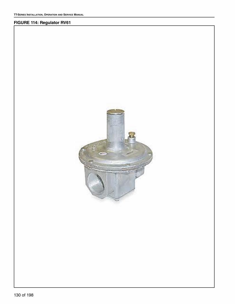
TT-SERIES INSTALLATION, OPERATION AND SERVICE MANUAL
130 of 198
FIGURE 114: Regulator RV61

SECTION 24: START-UP PROCEDURES
131 of 198
FIGURE 115: Maxitrol M611 Valve
24.6 Safety Shut Off Valve Check
After the initial start up and gas pressure adjustment,
verify gas soundness of each SSOV (Safety Shut Off
Valve). This check must be repeated after the first
100 hours of operation.
24.7 Air Volume Control24.7.1 Volumatic Dampers
• Air handler can be running in either the summer
or winter mode of operation.
• Set the damper position controller to highest
airflow requirement. Discharge dampers will drive
to full open position.
• Pressure drop across burner should remain stable
during all settings of the damper position
controller.
• Set the damper position controller for lowest
airflow position (discharge damper will drive to its
minimum position) and take air pressure drop
readings across burner profiles.
• If below recommended setting, decrease the
profile linkage range of travel without altering the
full airflow position. If above setting, increase the
profile linkage range. See Page 125, Section 24.4.2.1.
• Recheck air pressure drops across burner on high
and low airflow settings.
• Minimum air damper position controller is factory
set and should not be adjusted unless specifically
directed to do so by the factory.
24.7.2 Volumatic Variable Frequency Drive• Air handler can be running in either the summer
or winter mode of operation.
• Set the VFD to highest airflow requirement.
• Pressure drop across burner should remain stable
during all settings of the damper position
controller.
• Set the VFD for lowest airflow position and take
air pressure drop readings across burner profiles.
• If below recommended setting, decrease the
profile linkage range of travel without altering the
full airflow position. If above setting, increase the
profile linkage range. See Page 125, Section 24.4.2.1.
Low Fire Adjustment
(under cap)
Gas Inlet
Gas Outlet

TT-SERIES INSTALLATION, OPERATION AND SERVICE MANUAL
132 of 198
• Recheck air pressure drops across burner on high
and low airflow settings.
• Minimum motor speed is factory set and should
not be adjusted unless specifically directed to do
so by the factory.
24.7.3 Two Position Volumatic• Air handler can be running in either the summer
or winter mode of operation.
• Close interlock for high airflow. Discharge
dampers will drive to full open position.
• Pressure drop across burner should remain
stable.
• Open interlock for high airflow, discharge damper
will drive to its minimum position determined by
the air handler mounted damper position
controller. This controller determines what the
airflow will be delivered; it must be set so air
handler does not go below the minimum setting
for the burner air pressure drop.
• Take air pressure drop reading across burner
profiles.
• If below recommended setting, decrease the
profile linkage range of travel without altering the
full airflow position. If above setting, increase the
profile linkage range. See Page 125, Section 24.4.2.1.
• Recheck air pressure drops across burner on high
and low airflow settings.
• The air handler is supplied with a reduced
maximum fire potentiometer which prevents the
burner from over firing while in its reduced airflow
operation. Adjusting this potentiometer controls
the burner efficiency and performance at low
airflow. Turning this potentiometer counter
clockwise increases burner output clockwise
decreases the output. Set this potentiometer to
meet the design temperature rise at the low
airflow setting. See Page 125, Section 24.4.2.1.
24.7.4 Two Speed Volumatic• Air handler can be running in either the summer
or winter mode of operation.
• Close interlock for high speed.
• Pressure drop across burner should remain
stable.
• Open interlock for high speed.
• Take air pressure drop across burner profiles.
• If below recommended setting, decrease the
profile linkage range of travel without altering the
high speed position. If above setting, increase the
profile linkage range. See Page 126, Section 24.4.2.2.
• Recheck air pressure drops across burner on high
and low speed settings.
• The air handler is supplied with a reduced
maximum fire potentiometer which prevents the
burner from over firing while in its low speed
operation. Adjusting this potentiometer controls
the burner efficiency and performance at low
airflow. Turning this potentiometer counter
clockwise increases burner output clockwise
decreases the output. Set this potentiometer to
meet the design temperature rise at the low speed
setting. See Page 125, Section 24.4.2.
24.7.5 Volumatic/Recirculating• Air handler can be running in either the summer
or winter mode of operation.
• Set the damper position controller to highest
outside airflow requirement. Inlet dampers (if
equipped) will drive to full open position, return air
dampers will drive to the full closed position.
• Pressure drop across burner should remain stable
during all settings of the damper position
controller.
• Set the damper position controller for lowest
outside airflow position. Inlet damper (if equipped)
will drive to its minimum position, return air
dampers will drive to the full open position and
verify the air pressure drop across burner profiles.
• If below recommended setting, decrease the
profile linkage range of travel without altering the
full airflow position. If above setting, increase the
profile linkage range. See Page 125, Section 24.4.2.1.
• Recheck air pressure drops across burner on high
and low outside airflow settings.
• Minimum air damper position controller is factory
set and should not be adjusted unless specifically
directed to do so by the factory.
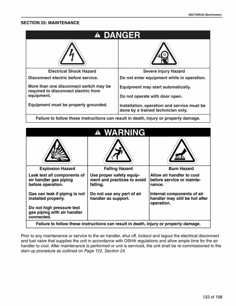
SECTION 25: MAINTENANCE
133 of 198
SECTION 25: MAINTENANCE
Prior to any maintenance or service to the air handler, shut off, lockout and tagout the electrical disconnect
and fuel valve that supplies the unit in accordance with OSHA regulations and allow ample time for the air
handler to cool. After maintenance is performed or unit is serviced, the unit shall be re-commissioned to the
start-up procedure as outlined on Page 122, Section 24.
DANGER
Failure to follow these instructions can result in death, injury or property damage.
Severe Injury Hazard
Do not enter equipment while in operation.
Equipment may start automatically.
Do not operate with door open.
Installation, operation and service must be done by a trained technician only.
Electrical Shock Hazard
Disconnect electric before service.
More than one disconnect switch may be required to disconnect electric from equipment.
Equipment must be properly grounded.
TT-SERIES INSTALLATION, OPERATION AND SERVICE MANUAL
134 of 198
Installation Code and Annual Inspections: All installation and service of WEATHER-RITE™
equipment must be performed by a contractor
qualified in the installation and service of equipment
sold and supplied by Weather-Rite LLC and conform
to all requirements set forth in the WEATHER-RITE™
manuals and all applicable governmental authorities
pertaining to the installation, service, operation and
labeling of the equipment.
To help facilitate optimum performance and safety,
Weather-Rite LLC recommends that a qualified
contractor conduct, at a minimum, annual
inspections of your WEATHER-RITE™ equipment
and perform service where necessary, using only
replacement parts sold and supplied by Weather-Rite
LLC.
25.1 General
25.2 Unit Exterior
First 8 Hours of Operation Check belts and adjust as required (See Page 123, Section 24.2.2). Though
belts were properly adjusted at the factory, they will stretch after the first few
hours of operation.
First 100 Hours of Operation
Re-check belt tension and adjust if necessary.
Annual Fall Start-Up Follow entire start-up procedure at this time and check control settings and
operation.
Cabinet Exterior After installation, touch up scratches. Periodic painting should be done there-
after as required. The caulk around weather enclosures and over field joints
should be inspected annually. Re-apply caulk as needed to maintain integrity.
Warning labels and logo labels should be legible and accurate. Please con-
tact Weather-Rite LLC or WEATHER-RITE™ independent distributor if you
need replacement warning labels or logo labels.
See Page 2, Figure 1.5 through Page 3, Section 3.
Unit Location Verify that no flammable objects, liquids or vapors are present near the air
handler.
Do not hang anything from or place anything on the air handler.
Keep the area under and around the air handler free of all objects.
See Page 10, Section 3 for Clearances to Combustibles.

SECTION 25: MAINTENANCE
135 of 198
25.3 Blower SectionBlower Wheel Inspect blower wheel and clean as necessary. A small build up of dust can
cause a significant decrease in blower performance. Check for excessive
vibration, repair as required. Critical labels are located on or near the blower
housing. Contact Weather-Rite LLC or WEATHER-RITE™ independent distrib-
utor if you need replacement labels. See Page 3, Figure 3.
Drive Belts and Sheaves Check for belt ride in the groove. In multiple groove drives, belt ride should be
uniform. Check groove wear area for wear. Side wall of groove should be
straight, not dished out. Bottom of groove should show no signs of belt con-
tact.
Sheave alignment, set screw torque and belt tension should be checked after
8, 24, and 100 hours of operation after initial start-up. Visually inspect belts
and sheaves for excessive wear. If belts have a slick, glazed look, the belts
are slipping. Check drive capacity and belt tension.
Never replace only one belt in a used set, as used belts will elongate.
Replace the entire set if replacement is necessary.
See Page 134, Section 25.2 and Page 123, Section 24.2.2.
Blower Bearing Lubrication
The blowers use pillow block and flange bearings; they should be re-lubri-
cated based on lubrication chart. The recommended lubricant is Shell Alvania
#2 or S3 grease. To re-lubricate the blower flange/pillow block bearings, be
sure that the grease fittings on the bearing housing (or air handler cabinet wall
in the case of extended grease lines) are clean. Apply the recommended
grease to the fitting with a low-pressure grease gun and add slowly while the
shaft is spun by hand. Do not over-grease. Over-greasing will reduce the ser-
vice life of the bearings. Consult the blower manufacturer for grease capacity
recommendations as capacities vary by model.
TT-SERIES INSTALLATION, OPERATION AND SERVICE MANUAL
136 of 198
Motors Inspection:1. Inspect motor every 3 months or 500 hours of operation, which ever
occurs first. Keep the motor clean and vent openings clear.
Lubrication:1. Motors with grease fittings must be lubricated based on the table below.
2. A high grade ball or roller bearing grease must be used. Recommended
grease for standard service is Mobil Polyrex™ EM (Exxon Mobil). Other
compatible greases include ChevronTexaco Polystar®, ChevronTexaco
Rykon® Premium 2, Pennzoil® Pen 2 and ChevronTexaco SRI.
3. Motors without grease fittings are sealed for life and do not require re-
lubrication.
Instructions for LubricatingBefore greasing, be sure fittings are clean and free from dirt. Remove grease relief plug or plate and, using a low-pressure grease gun, pump in the required grease. Do not over-grease. Relubrication intervals are specified in the table above. After relubricating, allow motor to run for 10 minutes before replacing relief hardware.
NOTE: In general it is not recommended to mix greases of different brands. The mixing of different types of thickeners may destroy the composition and physical properties of the grease. In the event that a different grease is required by the end user, the following steps can be taken. Using the instruc-tions for lubrication, open grease outlet and purge the system as much as possible of the old or unwanted grease. Repeat this same operation after 1 week of service. Consult Weather-Rite LLC or the motor manufacturer for fur-ther recommendations on grease compatibility.
Table 41: Motor Lubrication Intervals
Note: These intervals are based on severe duty. Over lubricating bearings could result in reduced motor life.
NEMA Frame Size (Motor HP) Rated at 1800 RPM (Hrs)
Up to 210 (3 - 5 HP) 6,000
Over 210 to 280 (7.5 - 20 HP) 4,750
Over 280 to 360 (25 - 50 HP) 3,700

SECTION 25: MAINTENANCE
137 of 198
25.4 Motor and Drive Components
FIGURE 116: Supply Blowers
Gain access to the blower and motor by removing the belt guard or weather-proof cover. First, release tension on the belts by adjusting the motor base closer to the blower pulley. Remove the belts.
To remove the motor pulley, first loosen the adjustment set screws and count the number of turns to fully close the pulley (this number will be required to reinstall the pulleys to the previous adjustment). Open the adjustable sheaves to gain access to the shaft set screws. Loosen the set screw(s) that hold it to the motor shaft and pull away from the motor.
To remove the blower pulley, remove the bolts from the bushing and insert into the previously unused threaded holes of the bushing. Carefully press the blower pulley off the bushing, tightening the bolts evenly. Loosen the Allen Head setscrew (located on top of the keyway) and slide the pulley bushing off the shaft.
To remove the motor, first remove any guards and/or covers around motor and then remove motor pulley as described above. Disconnect the motor power wiring and conduit at the junction box in the side of the motor. Support the motor so that it will be secure when disconnected from the adjustable base. Remove the bolts that hold the motor to the adjustable base. The motor may now be removed.
CUTOFF
SCROLL
SHAFT
WHEEL
DRIVEN PULLEY BUSHING
MOTOR
BELT
DRIVE PULLEY
FLANGE BEARING
FLANGE BEARING
~
~
~

TT-SERIES INSTALLATION, OPERATION AND SERVICE MANUAL
138 of 198
25.5 Supply Blower
25.6 Manifold and Controls
The supply air is handled by DWDI (double width, double inlet) blower wheel(s) mounted on either a solid or tubular shaft. The blower wheel(s) are attached to this shaft via two setscrews or two clamps (tubular shaft style) (one on each side of the wheel). The clamp style is secured in placed by two 3/8 socket head screws. These screws should be checked on startup for tight-ness. If loose, they will need to be equally tighten.
Two styles of bearings are used on the air handlers. The driven end (motor side) bearings are a flange block style. The bearing on the side opposite the motor is also a flange style on TT112 - TT221, on TT224 - TT236 this is a pil-low block style. All of the bearings are equipped with eccentric locking collars. These bearings should be checked for tightness before startup. To re tighten if necessary, you must rotate the collar in the direction the shaft turns. Loosen the setscrew that locks the collar to the shaft. Use a punch with a hammer to give the collar a hard strike to set the collar then tighten the setscrew down again.
Below find label for proper bearing load lubrication guidelines. Label can also be found on the unit, please refer to section 1.5 for label location.
Manifold Periodically check fuel control assembly, and internal and external piping for leaks. Relief vent lines to outdoors on fuel controls should be checked to ensure against blockage caused by insects or any other substance. Clean as required.
All gas piping to the air handler must comply with the National Fuel Gas Code - NFPA54, latest edition and all local codes. Verify gas soundness of each SSOV (Safety Shut Off Valve). This test must be repeated after the first 100 hours of operation.
See Page 78, Figure 62 through Page 81, Figure 68.
Air Flow Switch An annual check of the tubes attached to the air flow switch should be made to ensure against blockage caused by insects or any other substance. Clean as required.
See Page 124, Section 24.4.
Electric Components Check to see there is no physical damage on any of the electric components
and verify all electrical connections are secure. Ensure equipment is properly
grounded.
See Page 124, Section 24.3 and Page 151, Section 26.6.
Temperature Sensors Calibrate space, outdoor air, and discharge air sensors as required.
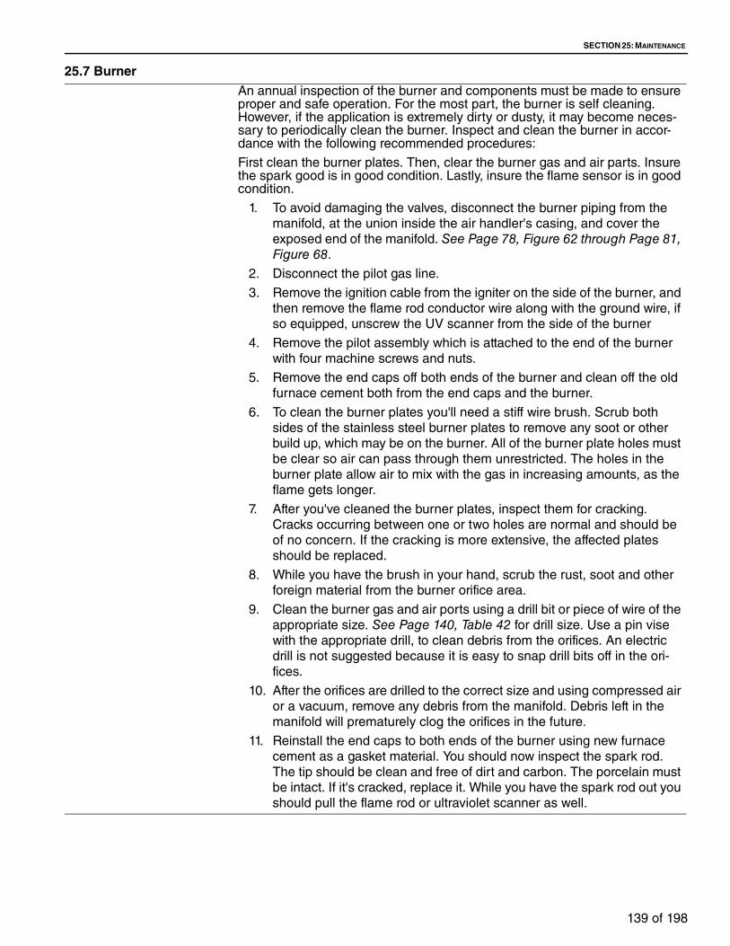
SECTION 25: MAINTENANCE
139 of 198
25.7 BurnerAn annual inspection of the burner and components must be made to ensure proper and safe operation. For the most part, the burner is self cleaning. However, if the application is extremely dirty or dusty, it may become neces-sary to periodically clean the burner. Inspect and clean the burner in accor-dance with the following recommended procedures:
First clean the burner plates. Then, clear the burner gas and air parts. Insure the spark good is in good condition. Lastly, insure the flame sensor is in good condition.
1. To avoid damaging the valves, disconnect the burner piping from the
manifold, at the union inside the air handler's casing, and cover the
exposed end of the manifold. See Page 78, Figure 62 through Page 81, Figure 68.
2. Disconnect the pilot gas line.
3. Remove the ignition cable from the igniter on the side of the burner, and
then remove the flame rod conductor wire along with the ground wire, if
so equipped, unscrew the UV scanner from the side of the burner
4. Remove the pilot assembly which is attached to the end of the burner
with four machine screws and nuts.
5. Remove the end caps off both ends of the burner and clean off the old
furnace cement both from the end caps and the burner.
6. To clean the burner plates you'll need a stiff wire brush. Scrub both
sides of the stainless steel burner plates to remove any soot or other
build up, which may be on the burner. All of the burner plate holes must
be clear so air can pass through them unrestricted. The holes in the
burner plate allow air to mix with the gas in increasing amounts, as the
flame gets longer.
7. After you've cleaned the burner plates, inspect them for cracking.
Cracks occurring between one or two holes are normal and should be
of no concern. If the cracking is more extensive, the affected plates
should be replaced.
8. While you have the brush in your hand, scrub the rust, soot and other
foreign material from the burner orifice area.
9. Clean the burner gas and air ports using a drill bit or piece of wire of the
appropriate size. See Page 140, Table 42 for drill size. Use a pin vise
with the appropriate drill, to clean debris from the orifices. An electric
drill is not suggested because it is easy to snap drill bits off in the ori-
fices.
10. After the orifices are drilled to the correct size and using compressed air
or a vacuum, remove any debris from the manifold. Debris left in the
manifold will prematurely clog the orifices in the future.
11. Reinstall the end caps to both ends of the burner using new furnace
cement as a gasket material. You should now inspect the spark rod.
The tip should be clean and free of dirt and carbon. The porcelain must
be intact. If it's cracked, replace it. While you have the spark rod out you
should pull the flame rod or ultraviolet scanner as well.

TT-SERIES INSTALLATION, OPERATION AND SERVICE MANUAL
140 of 198
Table 42: Burner Orifice Sizes
12. If your flame sensor is a scanner, clean the lens with a clean damp soft
rag. A flame rod's metal rod should be clean and free of dirt and carbon.
Like the spark rod igniter, the porcelain on the flame rod must be intact
as well. Replace it if it's cracked. Reinstall the spark rod to the proper
setting See Page 110, Figure . Reinstall the flame sensor; if it is a flame
rod ensure the correct positioning see Page 111, Figure 93.
13. Reinstall the pilot assembly and connect appropriate cables and con-
ductors and pilot gas line.
Model Fuel Gas Port Drill Size Air Port Drill SizeHMA-2A Natural Gas/Propane 1/8" 42
Dampers Check linkage when applicable and tighten set screws as required. All moving parts of dampers should be cleaned and then thoroughly lubricated with light molybdenum oil in aerosol can.
Dampers furnished with stainless steel side seals should also have the seals lubricated generously. Dampers should then be manually operated several times until linkages and blades operate freely.
Reconnect linkages and check dampers for proper operation.
See Page 70, Section 15.
Filters Filters should be checked for dirt restriction on a monthly basis (or as required).
Replace filters with filters of equal specification when they appear dirty.
See Page 57, Section 12 for filter section filters. See Page 60, Section 13 for inlet hood filters.
Evaporative / Cooling If applicable, refer to separate maintenance literature.
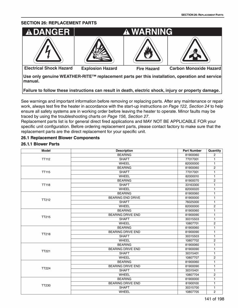
SECTION 26: REPLACEMENT PARTS
141 of 198
SECTION 26: REPLACEMENT PARTS
See warnings and important information before removing or replacing parts. After any maintenance or repair
work, always test fire the heater in accordance with the start-up instructions on Page 122, Section 24 to help
ensure all safety systems are in working order before leaving the heater to operate. Minor faults may be
traced by using the troubleshooting charts on Page 156, Section 27.
Replacement parts list is for general direct fired applications and MAY NOT BE APPLICABLE FOR your
specific unit configuration. Before ordering replacement parts, please contact factory to make sure that the
replacement parts are the direct replacement for your specific unit.
26.1 Replacement Blower Components26.1.1 Blower Parts
Carbon Monoxide Hazard
WARNING
Use only genuine WEATHER-RITE™ replacement parts per this installation, operation and service manual.
Failure to follow these instructions can result in death, electric shock, injury or property damage.
Explosion Hazard
DANGER
Electrical Shock Hazard Fire Hazard
Model Description Part Number Quantity
TT112
BEARING 81900060 2
SHAFT 77017001 1
WHEEL 82000000 1
TT115
BEARING 81900060 2
SHAFT 77017001 1
WHEEL 82000010 1
TT118
BEARING 81900070 2
SHAFT 33163300 1
WHEEL 82000020 1
TT212
BEARING 81900060 1
BEARING END DRIVE 81900000 1
SHAFT 76025000 1
WHEEL 82000000 2
TT215
BEARING 81900060 1
BEARING DRIVE END 81900090 1
SHAFT 30315503 1
WHEEL 10807701 2
TT218
BEARING 81900060 1
BEARING DRIVE END 81900090 1
SHAFT 30315503 1
WHEEL 10807702 2
TT221
BEARING 81900060 1
BEARING DRIVE END 81900090 1
SHAFT 30315401 1
WHEEL 10807707 2
TT224
BEARING 81900060 1
BEARING DRIVE END 81900090 1
SHAFT 30315401 1
WHEEL 10807704 2
TT230
BEARING 81900000 1
BEARING DRIVE END 81900100 1
SHAFT 30315700 1
WHEEL 10807705 2

TT-SERIES INSTALLATION, OPERATION AND SERVICE MANUAL
142 of 198
26.1.2 Bushing, Fixed Pulley
Model Description Part Number Quantity
TT233
BEARING 81900000 1
BEARING DRIVE END 81900110 1
SHAFT 30315702 1
WHEEL 82000073 2
TT236
BEARING 81900000 1
BEARING DRIVE END 81900116 1
SHAFT 30315900 1
WHEEL 82000083 2
Description Size (in) Part NumberSD 7/8 82200580
SD 1 3/16 14153100
SD 1 7/16 82200590
SD 1 1/2 82200595
SD 1 5/8 82200610
SD 1 15/16 14142800
SD158 1 5/8 82200600
SD178 1 7/8 82200620
SDS 1 1/4 82200470
SDS11116 1 11/16 82200520
SDS112 1 1/2 82200550
SDS11516 1 15/16 82200540
SDS1316 13/16 82200480
SDS138 1 3/8 82200490
SDS158 1 5/8 82200510
SDS1716 1 7/16 82200500
SF 1.438 1 7/16 14130500
SF 1.688 1 11/16 14263800
SF 2.938 2 15/16 82200900
SF11116 1 11/16 82200830
SF11516 1 15/16 82200840
SF158 1 5/8 82200850
SF21116 2 11/16 14173900
SF218 2 1/8 82201000
SF2316 2 3/16 82200860
SF238 2 3/8 14071000
SF2716 2 7/16 82200870
SF278 2 7/8 82200880
SH .75 3/4 14220000
SH 1.188 1 3/16 82200420
SH 1.688 1 11/16 82210700
SH138 1 3/8 82200430
SH158 1 5/8 82200450
SH1716 1 7/16 82200440
SK 1.375 1 3/8 82200670
SK 2.188 2 3/16 82200740
SK 2.438 2 7/16 82200750
SK 2.688 2 11/16 82200760
SK11116 1 11/16 82200700
SK112 1 1/2 82201030
SK11516 1 15/16 82200720
SK118 1 1/8 82201020
SK1316 1 3/16 82200660
SK158 1 5/8 82200690
SK1716 1 7/16 82200680
SK178 1 7/8 82200710
SK218 2 1/8 82200730
SK238 2 3/8 82201010

SECTION 26: REPLACEMENT PARTS
143 of 198
26.1.3 Fixed PulleyDescription Part Number
1B X 11.0 1-3/16 82105120
1B X 11.0 PD SDS 14093210
1B X 12.4 1-3/16 82105140
1B X 12.4 PD SDS 14189300
1B X 13.6 1-3/16 82105150
1B X 13.6 PD SDS 82105160
1B X 16.0 PD SDS 82100270
1B X 18.4 PD SK 82100280
1B X 20.0 PD SK 82100290
1B x 3.4 PD 1-3/16 14129000
1B X 3.6 PD SH 14228902
1B X 4.0 PD 1-3/16 14106400
1B X 4.2 PD SH 14228903
1B X 4.6 PD 1-3/16 14118900
1B X 40 SH 14087110
1B X 5.0 PD 5/8 14087100
1B X 5.2 PD SDS 14110800
1B X 5.6 1.18 14120400
1B X 5.8 1-3/16 82100110
1B X 6.0 SDS 14120410
1B X 6.2 PD SDS 14228904
1B X 6.8 1-3/16 82105060
1B X 7.4 1-3/16 82105070
1B X 7.4 PD SDS 82100180
1B X 8.6 1-3/16 82105080
1B X 9.4 PD SDS 82100220
2B X 11.0 PD SK 82100560
2B X 12.4 PD SK 82100570
2B X 13.6 PD SK 82100580
2B X 15.4 PD SK 82100590
2B X 16.0 PD SK 82100600
2B X 18.4 PD SK 82100610
2B X 20.0 PD SF 82100620
2B X 23.0 2.125 14143000
2B X 25.0 SF 82100630
2B X 3.4 PD SH 14228901
2B X 4.2 PD SH 82100360
2B X 4.4 PD SH 82100370
2B X 4.6 PD SDS 82100380
2B X 4.8 PD SDS 82100390
2B X 5.2 PD SDS 82100410
2B X 5.4 PD SDS 82100420
2B X 5.6 PD SDS 82100430
2B X 5.8 PD SDS 82100440
2B X 6.0 PD SDS 82100450
2B X 6.2 PD SDS 82100460
2B X 6.4 PD SDS 82100470
2B X 6.6 PD SDS 82100480
2B X 6.8 PD SDS 82100490
2B X 7.0 PD SK 82100500
2B X 7.4 PD SK 82100510
2B X 8.0 PD SK 82100520
2B X 8.6 PD SK 82100530
2B X 9.4 PD SK 82100550
3B X 5.2 PD SD 82100740
3B X 11.0 PD SK 82100890
3B X 12.4 PD SK 82100900
3B X 13.6 PD SK 82100910
3B X 15.4 PD SK 82100920
3B X 16.0 PD SK 82100930
3B X 18.4 PD SK 82100940
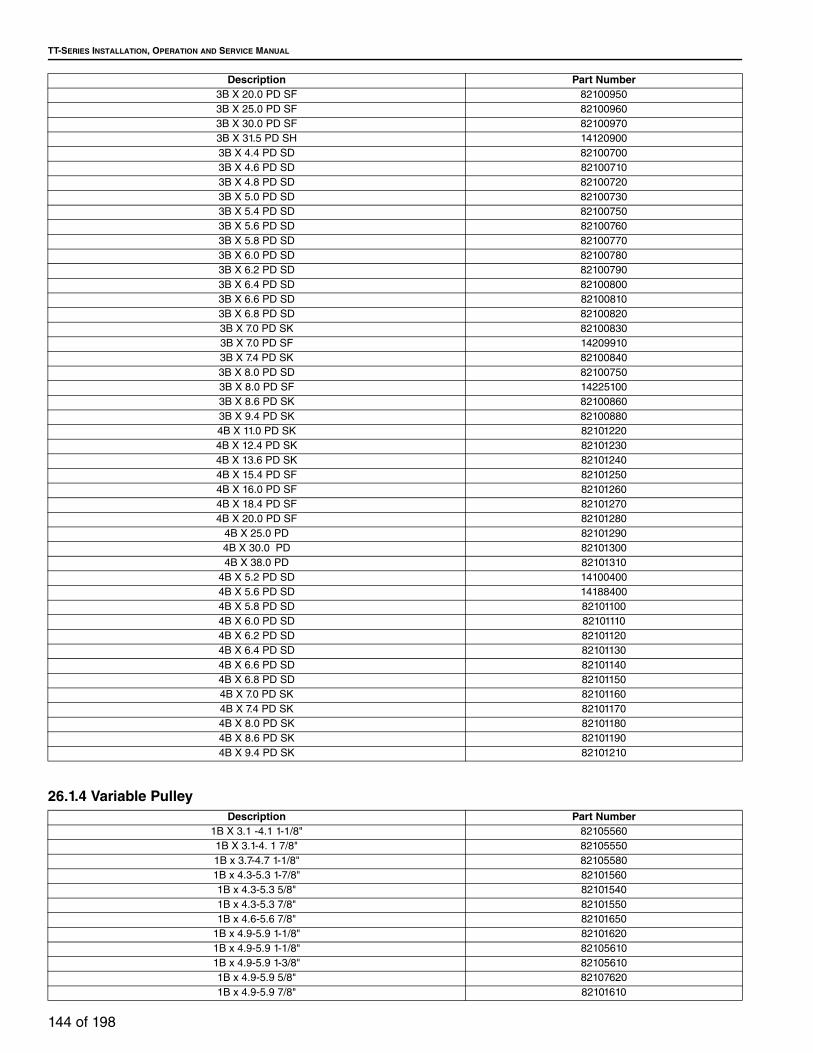
TT-SERIES INSTALLATION, OPERATION AND SERVICE MANUAL
144 of 198
26.1.4 Variable Pulley
Description Part Number3B X 20.0 PD SF 82100950
3B X 25.0 PD SF 82100960
3B X 30.0 PD SF 82100970
3B X 31.5 PD SH 14120900
3B X 4.4 PD SD 82100700
3B X 4.6 PD SD 82100710
3B X 4.8 PD SD 82100720
3B X 5.0 PD SD 82100730
3B X 5.4 PD SD 82100750
3B X 5.6 PD SD 82100760
3B X 5.8 PD SD 82100770
3B X 6.0 PD SD 82100780
3B X 6.2 PD SD 82100790
3B X 6.4 PD SD 82100800
3B X 6.6 PD SD 82100810
3B X 6.8 PD SD 82100820
3B X 7.0 PD SK 82100830
3B X 7.0 PD SF 14209910
3B X 7.4 PD SK 82100840
3B X 8.0 PD SD 82100750
3B X 8.0 PD SF 14225100
3B X 8.6 PD SK 82100860
3B X 9.4 PD SK 82100880
4B X 11.0 PD SK 82101220
4B X 12.4 PD SK 82101230
4B X 13.6 PD SK 82101240
4B X 15.4 PD SF 82101250
4B X 16.0 PD SF 82101260
4B X 18.4 PD SF 82101270
4B X 20.0 PD SF 82101280
4B X 25.0 PD 82101290
4B X 30.0 PD 82101300
4B X 38.0 PD 82101310
4B X 5.2 PD SD 14100400
4B X 5.6 PD SD 14188400
4B X 5.8 PD SD 82101100
4B X 6.0 PD SD 82101110
4B X 6.2 PD SD 82101120
4B X 6.4 PD SD 82101130
4B X 6.6 PD SD 82101140
4B X 6.8 PD SD 82101150
4B X 7.0 PD SK 82101160
4B X 7.4 PD SK 82101170
4B X 8.0 PD SK 82101180
4B X 8.6 PD SK 82101190
4B X 9.4 PD SK 82101210
Description Part Number1B X 3.1 -4.1 1-1/8" 82105560
1B X 3.1-4. 1 7/8" 82105550
1B x 3.7-4.7 1-1/8" 82105580
1B x 4.3-5.3 1-7/8" 82101560
1B x 4.3-5.3 5/8" 82101540
1B x 4.3-5.3 7/8" 82101550
1B x 4.6-5.6 7/8" 82101650
1B x 4.9-5.9 1-1/8" 82101620
1B x 4.9-5.9 1-1/8" 82105610
1B x 4.9-5.9 1-3/8" 82105610
1B x 4.9-5.9 5/8" 82107620
1B x 4.9-5.9 7/8" 82101610
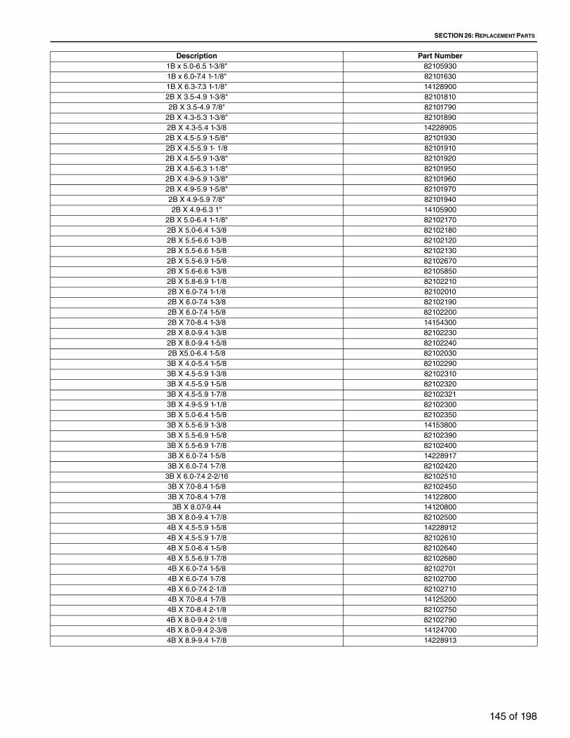
SECTION 26: REPLACEMENT PARTS
145 of 198
Description Part Number1B x 5.0-6.5 1-3/8" 82105930
1B x 6.0-7.4 1-1/8" 82101630
1B X 6.3-7.3 1-1/8" 14128900
2B X 3.5-4.9 1-3/8" 82101810
2B X 3.5-4.9 7/8" 82101790
2B X 4.3-5.3 1-3/8" 82101890
2B X 4.3-5.4 1-3/8 14228905
2B X 4.5-5.9 1-5/8" 82101930
2B X 4.5-5.9 1- 1/8 82101910
2B X 4.5-5.9 1-3/8" 82101920
2B X 4.5-6.3 1-1/8" 82101950
2B X 4.9-5.9 1-3/8" 82101960
2B X 4.9-5.9 1-5/8" 82101970
2B X 4.9-5.9 7/8" 82101940
2B X 4.9-6.3 1" 14105900
2B X 5.0-6.4 1-1/8" 82102170
2B X 5.0-6.4 1-3/8 82102180
2B X 5.5-6.6 1-3/8 82102120
2B X 5.5-6.6 1-5/8 82102130
2B X 5.5-6.9 1-5/8 82102670
2B X 5.6-6.6 1-3/8 82105850
2B X 5.8-6.9 1-1/8 82102210
2B X 6.0-7.4 1-1/8 82102010
2B X 6.0-7.4 1-3/8 82102190
2B X 6.0-7.4 1-5/8 82102200
2B X 7.0-8.4 1-3/8 14154300
2B X 8.0-9.4 1-3/8 82102230
2B X 8.0-9.4 1-5/8 82102240
2B X5.0-6.4 1-5/8 82102030
3B X 4.0-5.4 1-5/8 82102290
3B X 4.5-5.9 1-3/8 82102310
3B X 4.5-5.9 1-5/8 82102320
3B X 4.5-5.9 1-7/8 82102321
3B X 4.9-5.9 1-1/8 82102300
3B X 5.0-6.4 1-5/8 82102350
3B X 5.5-6.9 1-3/8 14153800
3B X 5.5-6.9 1-5/8 82102390
3B X 5.5-6.9 1-7/8 82102400
3B X 6.0-7.4 1-5/8 14228917
3B X 6.0-7.4 1-7/8 82102420
3B X 6.0-7.4 2-2/16 82102510
3B X 7.0-8.4 1-5/8 82102450
3B X 7.0-8.4 1-7/8 14122800
3B X 8.07-9.44 14120800
3B X 8.0-9.4 1-7/8 82102500
4B X 4.5-5.9 1-5/8 14228912
4B X 4.5-5.9 1-7/8 82102610
4B X 5.0-6.4 1-5/8 82102640
4B X 5.5-6.9 1-7/8 82102680
4B X 6.0-7.4 1-5/8 82102701
4B X 6.0-7.4 1-7/8 82102700
4B X 6.0-7.4 2-1/8 82102710
4B X 7.0-8.4 1-7/8 14125200
4B X 7.0-8.4 2-1/8 82102750
4B X 8.0-9.4 2-1/8 82102790
4B X 8.0-9.4 2-3/8 14124700
4B X 8.9-9.4 1-7/8 14228913

TT-SERIES INSTALLATION, OPERATION AND SERVICE MANUAL
146 of 198
26.1.5 BeltsDescription Part Number
B-036 33689436
B-040 33689440
B-041 33689441
B-042 33689402
B-043 33689443
B-044 33689444
B-045 33689445
B-046 33689446
B-047 33689447
B-048 33689448
B-050 33689450
B-052 33689452
B-053 33689453
B-054 33689454
B-057 33689457
B-058 33689458
B-060 33689460
B-062 33689462
B-063 33689463
B-064 33689464
B-065 33689465
B-066 33689466
B-067 33689467
B-068 33689468
B-069 33689469
B-070 33689470
B-071 33689471
B-072 33689472
B-073 33689473
B-074 33689474
B-075 33689475
B-076 33689476
B-077 33689477
B-078 33689478
B-079 33689479
B-080 33689480
B-081 33689481
B-082 33689482
B-083 33689483
B-084 33689484
B-085 33689485
B-086 33689486
B-088 33689488
B-089 33689489
B-090 33689490
B-091 33689491
B-092 33689492
B-093 33689493
B-094 33689494
B-095 33689495
B-096 33689496
B-097 33689497
B-099 33689499
B-100 33689400
B-101 33689401
B-103 33689403
B-104 33689404
B-105 33689405
B-108 33689408
B-112 33689412
B-115 33689415

SECTION 26: REPLACEMENT PARTS
147 of 198
26.2 Damper Components26.2.1 Actuators
Description Part NumberB-120 33689420
B-128 33689428
B-150 33689411
B-154 33689413
BX-49 33689549
BX-50 33689550
BX-51 33689551
BX-52 33689552
BX-62 33689562
BX-64 33689564
BX-65 33689565
BX-67 33689567
BX-70 33689570
BX-72 33689572
BX-76 33689576
BX-77 33689577
BX-78 33689578
BX-80 33689580
BX-81 33689581
BX-82 33689582
BX-83 33689583
BX-84 33689584
BX-85 33689585
BX-86 33689586
BX-87 33689587
BX-88 33689588
BX-90 33689590
BX-93 33689593
BX-95 33689595
BX-96 33689596
BX-97 33689597
BX-98 33689598
BX-99 33689599
BX-100 33689500
BX-103 33689501
BX-105 33689505
BX-108 33689508
BX-113 33689513
BX-116 33689516
BX-117 33689517
BX-120 33689520
BX-128 33689528
BX-133 33689533
Description Part Number2 POSITION SPRING RETURN - 120 V 83400010
2 POSITION 120V 133# 2-SPDT 14266201
24V 2SPDT 0-10VDC 16022700
24V NO SW 0-10VDC 14219300
24V NO SW FLOATING 14266500
24V NO SW 0-10VDC 14266600
24V NO SW FLOATING 14266800
24V NO SW 0-10VDC 14266900
24V - PRGMABLE 14266304
24V WITH SW - PRGMAB 14266303
24V NO SW 0-10 VDC 14266300
24V NO SW 0-10VDC 14267100
24V NO SW FLOATING 14267000

TT-SERIES INSTALLATION, OPERATION AND SERVICE MANUAL
148 of 198
26.2.2 Actuators Accessories
26.3 Burner Components
Note: For Complete Natural Gas or LP Burner Assemblies - Contact Factory
Description Part NumberMODULATING FOOT MOUNT WITH END SWITCH 83400051
24V NO SW SPRING RETURN 14321500
24V WITH SW ZERO SPAN SPRING RETURN 14321501
24V NO SW ZERO SPAN SPRING RETURN 14321502
20V WITH SW SPRING RETURN 14321510
120V WITH SW SPRING RETURN 14321511
120V WITH SW SPRING RETURN 14321512
24V NO SW SPRING RETURN 14321520
24V NO SW ZERO SPAN SPRING RETURN 14321521
24V NO SW ZERO SPAN SPRING RETURN 14321522
Description Part NumberSHORT CRANK ARM 81100051
DES FOR NM 1SPDT 14283701
CRANK/ARM ADP KIT FOR SM MOTORS 14286201
CRANK ARM KIT 16025200
CRANKARM ADAPT/NM 14286200
MOUNT/BRACK/NM 14300802
MOUNT SM/GM/MOTOR 14300801
CRANKARMW/BRACKET AF/NF 14300800
ACTUATOR POSITIONER - PANEL MOUNT 14297900
DES FOR SM/GM2SPDT 14283702
DES FOR SM/GM 1SPDT 14283700
DES/NM MOTORS/2SPDT 14283703
CRANKARM (FOR FOOT MOUNT ACTUATORS) 14160800
COVER TRANSFORMER 120VOLT TO 24VOLT 11136204
ACTUATOR POSITIONER - PANEL MOUNT 14321550
AUXILIARY SWITCH PACKAGE 14321551
FOOT MOUNT KIT (DIRECT DRIVE ACTUATOR) 14321560
Description Part NumberELECTRODE, FLAME ROD 14123203
ELECTRODE, SPARK ROD 14123204
PILOT ASSEMBLY/FLAME ROD/NAT GAS 14108433
PILOT ASSEMBLY/W-UV ADAPTER/NAT GAS 14108431
REMOTE FLAME ROD ASSEMBLY 14153220
REMOTE UV ADAPTER ASSEMBLY 14153221
PILOT LP ORFICE 14281221
BURNER SECTION (NAT GAS) - 6" (15.3CM) STRAIGHT 14107720
BURNER SECTION (NAT GAS) - 12" (30.5CM) STRAIGHT 14107620
BURNER SECTION (NAT GAS) - 12" (30.5CM) TEE 14108020
BURNER SECTION (NAT GAS) - 6" (15.3CM) STRAIGHT W/BACK FEED 14107820
BURNER SECTION (NAT GAS) - 12" (30.5CM) STRAIGHT W/BACK FEED 14107821
BURNER SECTION (LP) - 6" (15.3CM) STRAIGHT Contact Factory
BURNER SECTION (LP) - 12" (30.5CM) STRAIGHT Contact Factory
BURNER SECTION (LP) - 12" (30.5CM) TEE Contact Factory
BURNER SECTION (LP) - 6" (15.3CM) STRAIGHT W/BACK FEED Contact Factory
BURNER SECTION (LP) - 12" (30.5CM) STRAIGHT W/BACK FEED Contact Factory

SECTION 26: REPLACEMENT PARTS
149 of 198
26.4 Manifold Components
26.5 Combustion Components26.5.1 Combustion Components
Description Part NumberSOLENOID VALVE - 3/8" (PILOT) 14036400
SOLENOID VALVE - 1" 82500031
SOLENOID VALVE - 1.25" 82500040
SOLENOID VALVE - 1.5" 10762900
SOLENOID VALVE - 2" 82500060
Description Part NumberSOLENOID VALVE - POSITION INDICATION - 1" 82500032
SOLENOID VALVE - POSITION INDICATION - 1.25" 82500041
SOLENOID VALVE - POSITION INDICATION - 1.5" 82500051
SOLENOID VALVE - POSITION INDICATION - 2" 82500061
SOLENOID VENT VALVE - 3/4" 82500280
SOLENOID VENT VALVE - 1" 82500110
SOLENOID VENT VALVE - 1.25" 82500120
SOLENOID VENT VALVE - 1.5" 11056500
ON/OFF MOTORIZED ACTUATOR - 83400001
MOTORIZED PROOF OF CLOSURE ACTUATOR - 83400301
MOTORIZED PROOF OF CLOSURE VALVE BODY - 1" 82585171
MOTORIZED PROOF OF CLOSURE VALVE BODY - 1.25" 82585301
MOTORIZED PROOF OF CLOSURE VALVE BODY - 1.5" 82585291
MOTORIZED PROOF OF CLOSURE VALVE BODY - 2" 82585261
MOTORIZED PROOF OF CLOSURE VALVE BODY - 2.5" 82585361
MOTORIZED VALVE BODY - 1" 82580171
MOTORIZED VALVE BODY - 1.25" 82580181
MOTORIZED VALVE BODY - 1.5" 82580191
MOTORIZED VALVE BODY - 2" 82580201
MOTORIZED VALVE BODY - 2.5" 82580211
MOTORIZED VALVE BODY - 3" 82580221
PILOT REGULATOR - 325-3 X 3/8 14036300
MAIN REGULATOR LESS THAN 1 MBH - x 1" 82600030
MANUAL SHUT OFF VALVE - 3/8" 82580260
MANUAL SHUT OFF VALVE - 1" 82580010
MANUAL SHUT OFF VALVE - 1.25" 82580020
MANUAL SHUT OFF VALVE - 1.5" 82580030
MANUAL SHUT OFF VALVE - 2" 82580040
MANUAL SHUT OFF VALVE - 2.5" 82580050
MANUAL SHUT OFF VALVE - 3" 82580060
MODULATING VALVE LESS THAN 1 MBH - x1" 82600320
MODULATING VALVE - x 1" 10885900
MODULATING VALVE - x 1 1/4 " 82600240
MODULATING VALVE - x 1 1/2 " 82600260
MODULATING VALVE - x 2" 82600270
MODULATING VALVE - x 2 1/2 " 82600360
MODULATING VALVE - x 3" 82600290
REPLACEMENT MR212 MODULATING HEAD AND PLUNGER 11018200
Description Part NumberIGNITION TRANSFORMER 83000001
HIGH LIMIT 83200023
SUPPLY AIRFLOW SWITCH 83100001
VOLUME AIRFLOW SWITCH 83100001
LOW GAS PRESSURE SWITCH 83100023

TT-SERIES INSTALLATION, OPERATION AND SERVICE MANUAL
150 of 198
HIGH GAS PRESSURE SWITCH 83100070
IGNITION CABLE (PER FOOT) 81400400
IGNITION CABLE BOOT 81150420
IGNITION CABLE SNAP FITTING 81150440
FIREYE ULTRA VIOLET SCANNER 83500022
HONEYWELL ULTRA VIOLET SCANNER 15159701
PILOT OFF TIMER 14197700

SECTION 26: REPLACEMENT PARTS
151 of 198
26.5.2 Flame Safeguards
26.6 Electrical Components26.6.1 Motor Protectors
Description Part NumberFLAME SAFEGUARD RELAY MODULE 15159600
FLAME RELAY SUB-BASE 15160001
AMPLIFIER - FLAME ROD 15159802
AMPLIFIER - ULTRAVIOLET 15159801
PURGE TIMER 7 SEC 15159701
FLAME SAFEGUARD RELAY MODULE 14169810
FLAME RELAY SUB-BASE 83500010
PROGRAMMER - RECYCLE 14170010
PROGRAMMER - NON-RECYCLE 14170011
AMPLIFIER - FLAME ROD 14169911
AMPLIFIER - ULTRAVIOLET 14169910
FLAME SAFEGUARD 800-001-00
REPLACEMENT FUSE FOR MEC120 CHASSIS 14204901
REPLACEMENT FUSE FOR M4RT1 CHASSIS 14204902
Description Part NumberRotary - .63-1 AMPS 14320505
Rotary - 1-1.6 AMPS 14320506‘
Rotary - 1.6-2.5 AMPS 14320507
Rotary - 2.5-4 AMPS 14320508
Rotary - 4-6.3 AMPS 14320510
Rotary - 6-10 AMPS 14320514
Rotary - 9-14 AMPS 14320516
Rotary - 13-18 AMPS 14320520
Rotary - 17-23 AMPS 14320521
Rotary - 20-25 AMPS 14320522
Rotary - 24-32 AMPS 14320532
Toggle - .63-1 AMPS 14320205
Toggle - 1-1.6 AMPS 14320206
Toggle - 1.6-2.5 AMPS 14320207
Toggle - 2.5-4 AMPS 14320208
Toggle - 4-6.3 AMPS 14320210
Toggle - 6-10 AMPS 14320214
Toggle - 9-14 AMPS 14320216
Toggle - 13-18 AMPS 14320220
Toggle - 17-23 AMPS 14320221
Toggle - 20-25 AMPS 14320222
Toggle - 24-32 AMPS 14320232
Toggle - 25-40 AMPS 14320340
Toggle - 45-63 AMPS 14320363
AUX CONTACT SIDE MOUNT 14320400
AUX CONTACT FRONT MOUNT 14320401

TT-SERIES INSTALLATION, OPERATION AND SERVICE MANUAL
152 of 198
26.6.2 Contactors
26.6.3 Overloads
26.6.4 Temperature Controls
Description Part Number18 AMPS 14320703
25 AMPS 14320704
32 AMPS 14320705
40 AMPS 14320706
50 AMPS 14320707
65 AMPS 14320708
80 AMPS 14320709
115 AMPS 14320710
150 AMPS 14320711
Description Part Number.4-.63 AMPS 14320801
.63-1 AMPS 14320802
1-1.6 AMPS 14320803
1.6-2.5 AMPS 14320804
2.5-4 AMPS 14320805
4-6 AMPS 14320806
5.5-8 AMPS 14320807
7-10 AMPS 14320808
3-13 AMPS 14320809
12-18 AMPS 14320810
16-24 AMPS 14320811
23-32 AMPS 14320812
30-40 AMPS 14320813
37-50 AMPS 14320814
48-65 AMPS 14320815
55-70 AMPS 14320816
63-80 AMPS 14320817
80-104 AMPS 14320818
95-120 AMPS 14320819
110-140 AMPS 14320820
Description Part NumberROOM OVER-RIDE THERMOSTAT (OPTIONAL) 83200052
NIGHT THERMOSTAT (OPTIONAL) 83200052
BURNER ON/OFF OUTDOOR THERMOSTAT (OPTIONAL) 83200002
BURNER ON/OFF OUTDOOR THERMOSTAT (OPTIONAL) 83200001
DISCHARGE - SERIES 14 - 55-90 DEGREE 10948400
AMPLIFIER - SERIES 14 10938310
DISCHARGE SENSOR - SERIES 14 83200140
ROOM CONTROL - SERIES 44 - 55-90 DEGREE 11069300
AMPLIFIER - SERIES 44 10948000
AMPLIFIER - SERIES 44 LOW FIRE START 14258101
DISCHARGE SENSOR - SERIES 44 11069200
DISCHARGE - SERIES 94 DUAL SETPOINT - 60-90/80-180 DEGREE 14177901
AMPLIFIER - SERIES 94 14177500
DISCHARGE SENSOR - SERIES 94 14177600
MP2 SYSTEM (INCLUDES CONTROLLER AND AMPLIFIER) 14177502
MP2+ SYSTEM (INCLUDES CONTROLLER AND AMPLIFIER) 14177503
DISCHARGE SENSOR - SERIES MP2 14319411
TIMING BOARD - (OPTIONAL) 14177550
SIGNAL CONDITIONER 14174900
MAXIMUM FIRE POTENTIOMETER 14020000

SECTION 26: REPLACEMENT PARTS
153 of 198
26.6.5 Miscellaneous Electrical ComponentsDescription Part Number
CLOGGED FILTER PRESSURE SWITCH 8024206082 83100006
INDICATOR LIGHT - NEON - AMBER - 120 VAC 14297311
INDICATOR LIGHT - NEON - GREEN - 120 VAC 14297313
INDICATOR LIGHT - NEON - RED - 120 VAC 14297310
INDICATOR LIGHT - NEON - WHITE - 120 VAC 14297312
INDICATOR LIGHT LENSE (22.5MM) - AMBER 14183400
INDICATOR LIGHT LENSE (22.5MM) - RED 14183401
INDICATOR LIGHT LENSE (22.5MM) - GREEN 14183402
INDICATOR LIGHT LENSE (22.5MM) - YELLOW 14183403
INDICATOR LIGHT LENSE (22.5MM) - WHITE 14183404
INDICATOR LIGHT LENSE (22.5MM) - BLUE 14183405
Description Part NumberIndicator Light Unit (22.5mm) Incandescent 120 VAC 14183500
Indicator Light Unit (22.5mm) LED 120 VAC Red 14183503
Indicator Light Unit (22.5mm) LED 120 VAC Green 14183504
Indicator Light Unit (22.5mm) LED 120 VAC Yellow 14183505
Indicator Light Unit (22.5mm) LED 120 VAC Blue 14183506
Indicator Light Unit (22.5mm) LED 120 VAC White 14183507
Indicator Light Unit (22.5mm) LED 120 VAC Orange 14183508
Indicator Light Unit (22.5mm) LED 24 VAC/VDC 14183510
Low Limit (TT112 - TT 221) TCF313 w/10FT Sensor 14016902
Low Limit (TT224 - TT 236) TCF313 w/20FT Sensor 14016903
Minimum Air Pot 81600240
Pushbutton Switch (22.5mm) Operator - Blue 14178305
Pushbutton Switch (22.5mm) Operator - Yellow 14178306
Pushbutton Switch (22.5mm) Operator - Green 14178307
Pushbutton Switch (22.5mm) Operator - Red 14178308
Pushbutton Switch (22.5mm) Operator - Red / Mushroom Head 14178309
Selector Switch (22.5mm) 3 Position - Center Off 14135700
Selector Switch (22.5mm) 2 Position 14135800
Contact Block (22.5mm) Normally Open 14132601
Contact Block (22.5mm) Normally Closed 14132602
Process Electro/Mechanical Timer ACP #J-INM2W1/60MD6R - Range 0 to 60 Minutes 14020703
Process Purge/Cooldown Timer ERDM429 14084804
Relay - 4PDT 120 VAC w/Socket (10 A) 14132300
Relay - DPDT 120 VAC w/Socket (3 A) 14163900
Relay - DPDT 120 VAC w/Socket (10 A) 14163901
Relay - DPDT 24 VAC w/Socket (3 A) 14236800
Relay - DPDT 24 VDC w/Socket (3 A) 14236801
Time Clock 24HR PARAGON #4005-00S 14024100
Time Clock 7DAY Eelectro/Mechanical PARAGON 7008-00 10957200
Time Clock 7DAY Electronic GRASSLIN #FM1D20E-120 14182103
Toggle Switch - 3PDT ON/ON 14217303
Toggle Switch - DPDT-ON/OFF 14217304
Toggle Switch - DPDT-ON/OFF 14217301
Toggle Switch - DPDT-ON/OFF/ON 14217302
Toggle Switch - SPDT-ON/OFF 14217300
Transformer - 120-24V, 40VA 83000020
Transformer - 208|230|460 x 115, 500VA With Fuse Block 80300108
Transformer - 600|575 x 120/240|115/230, 500VA With Fuse Block 80300119
VFD Potentiometer - 10K Ohm - 534-1-1-103 15112100
VFD Potentiometer Knob - 91F2246 15045301
Day/Night Switch - Operator 14135800
Day/Night Switch - Contact Block 14132606
Summer/Off/Winter Switch - Operator 14135700
Summer/Off/Winter Switch - Contact Block (2 Req'd) 14132601
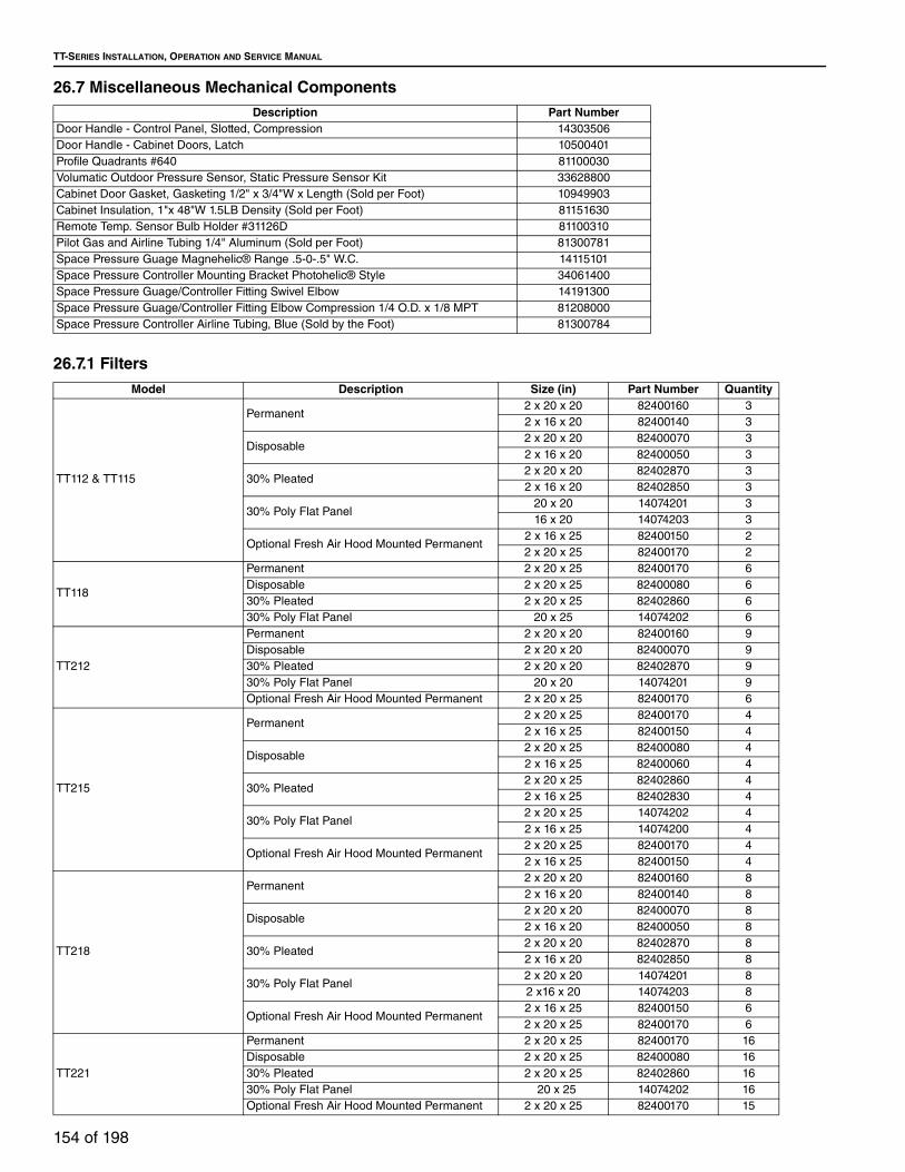
TT-SERIES INSTALLATION, OPERATION AND SERVICE MANUAL
154 of 198
26.7 Miscellaneous Mechanical Components
26.7.1 Filters
Description Part NumberDoor Handle - Control Panel, Slotted, Compression 14303506
Door Handle - Cabinet Doors, Latch 10500401
Profile Quadrants #640 81100030
Volumatic Outdoor Pressure Sensor, Static Pressure Sensor Kit 33628800
Cabinet Door Gasket, Gasketing 1/2" x 3/4"W x Length (Sold per Foot) 10949903
Cabinet Insulation, 1"x 48"W 1.5LB Density (Sold per Foot) 81151630
Remote Temp. Sensor Bulb Holder #31126D 81100310
Pilot Gas and Airline Tubing 1/4" Aluminum (Sold per Foot) 81300781
Space Pressure Guage Magnehelic® Range .5-0-.5" W.C. 14115101
Space Pressure Controller Mounting Bracket Photohelic® Style 34061400
Space Pressure Guage/Controller Fitting Swivel Elbow 14191300
Space Pressure Guage/Controller Fitting Elbow Compression 1/4 O.D. x 1/8 MPT 81208000
Space Pressure Controller Airline Tubing, Blue (Sold by the Foot) 81300784
Model Description Size (in) Part Number Quantity
TT112 & TT115
Permanent 2 x 20 x 20 82400160 3
2 x 16 x 20 82400140 3
Disposable2 x 20 x 20 82400070 3
2 x 16 x 20 82400050 3
30% Pleated2 x 20 x 20 82402870 3
2 x 16 x 20 82402850 3
30% Poly Flat Panel 20 x 20 14074201 3
16 x 20 14074203 3
Optional Fresh Air Hood Mounted Permanent 2 x 16 x 25 82400150 2
2 x 20 x 25 82400170 2
TT118
Permanent 2 x 20 x 25 82400170 6
Disposable 2 x 20 x 25 82400080 6
30% Pleated 2 x 20 x 25 82402860 6
30% Poly Flat Panel 20 x 25 14074202 6
TT212
Permanent 2 x 20 x 20 82400160 9
Disposable 2 x 20 x 20 82400070 9
30% Pleated 2 x 20 x 20 82402870 9
30% Poly Flat Panel 20 x 20 14074201 9
Optional Fresh Air Hood Mounted Permanent 2 x 20 x 25 82400170 6
TT215
Permanent 2 x 20 x 25 82400170 4
2 x 16 x 25 82400150 4
Disposable2 x 20 x 25 82400080 4
2 x 16 x 25 82400060 4
30% Pleated2 x 20 x 25 82402860 4
2 x 16 x 25 82402830 4
30% Poly Flat Panel 2 x 20 x 25 14074202 4
2 x 16 x 25 14074200 4
Optional Fresh Air Hood Mounted Permanent 2 x 20 x 25 82400170 4
2 x 16 x 25 82400150 4
TT218
Permanent 2 x 20 x 20 82400160 8
2 x 16 x 20 82400140 8
Disposable2 x 20 x 20 82400070 8
2 x 16 x 20 82400050 8
30% Pleated2 x 20 x 20 82402870 8
2 x 16 x 20 82402850 8
30% Poly Flat Panel 2 x 20 x 20 14074201 8
2 x16 x 20 14074203 8
Optional Fresh Air Hood Mounted Permanent 2 x 16 x 25 82400150 6
2 x 20 x 25 82400170 6
TT221
Permanent 2 x 20 x 25 82400170 16
Disposable 2 x 20 x 25 82400080 16
30% Pleated 2 x 20 x 25 82402860 16
30% Poly Flat Panel 20 x 25 14074202 16
Optional Fresh Air Hood Mounted Permanent 2 x 20 x 25 82400170 15

SECTION 26: REPLACEMENT PARTS
155 of 198
TT224
Permanent 2 x 20 x 20 82400160 18
2 x 20 x 25 82400170 12
Disposable2 x 20 x 20 82400070 18
2 x 20 x 25 82400080 12
30% Pleated2 x 20 x 20 82402870 18
2 x 20 x 25 82402860 12
30% Poly Flat Panel 20 x 20 14074201 18
20 x 25 14074202 12
Optional Fresh Air Hood Mounted Permanent 2 x 20 x 20 82400160 18
2 x 20 x 25 82400170 12
Model Description Size (in) Part Number Quantity
TT230
Permanent 2 x 20 x 20 82400160 6
2 x 20 x 25 82400170 30
Disposable2 x 20 x 20 82400070 6
2 x 20 x 25 82400080 30
30% Pleated2 x 20 x 20 82402870 6
2 x 20 x 25 82402860 30
30% Poly Flat Panel 20 x 20 14074201 6
20 x 25 14074202 30
TT233
Permanent 2 x 20 x 20 82400160 56
Disposable 2 x 20 x 20 82400070 56
30% Pleated 2 x 20 x 20 82402870 56
30% Poly Flat Panel 20 x 20 14074201 56
TT236
Permanent 2 x 20 x 20 82400160 63
Disposable 2 x 20 x 20 82400070 63
30% Pleated 2 x 20 x 20 82402870 63
30% Poly Flat Panel 20 x 20 14074201 63

TT-SERIES INSTALLATION, OPERATION AND SERVICE MANUAL
156 of 198
SECTION 27: TROUBLESHOOTING
Electrical Shock Hazard
Disconnect electric before service.
More than one disconnect switch may be required to disconnect electric from equipment.
Equipment must be properly grounded.
Severe Injury Hazard
Do not enter equipment while in operation.
Equipment may start automatically.
Do not operate with door open.
Installation, operation and service must be done by a trained technician only.
DANGER
Failure to follow these instructions can result in death, electrical shock or injury.
Falling Hazard
Use proper safety equipment and practices to avoid falling.
Do not use any part of equipment as support.
WARNING
Failure to follow these instructions can result in death, injury or property damage.
Burn Hazard
Allow equipment to cool before service.
Internal compo-nents of equipment may still be hot after operation.
Explosion Hazard
Turn off gas supply to equipment before service.
Fire Hazard
Keep all flammable objects, liquids and vapors the minimum required clearances to combustibles away from equipment.
Some objects will catch fire or explode when placed close to equipment.
Cut/Pinch Hazard
Wear protective gear during installation, operation and service.
Edges are sharp.

SECTION 27: TROUBLESHOOTING
157 of 198
The following is divided into two basic categories - fan problems and burner problems. In some cases, they
interrelate. In order to use this effectively, you should familiarize yourself with both categories.
27.1 Initial Checks
When encountering any abnormal operation or fault conditions of the equipment, all troubleshooting should
start with the following initial checks. If a problem is discovered in these initial checks, it must be corrected
before moving on in the trouble shooting.
1. Compare voltage and phase of supply power on site with rating plate information.
2. Review wiring between remote panel and control panel. Do the electrical connections match the sup-
plied wiring diagram?
3. Compare gas type and supply pressure on site with rating plate information.
4. Check for proper blower rotation - on air handler and any exhaust blowers.
• Blowers powered with a three phase motor can be reversed by swapping any two incoming power
legs. For blowers powered by a single phase motor, refer to the motor rating plate for reversing
instructions.
27.2 Supply FanPROBLEM POSSIBLE CAUSE SOLUTIONBlower motor does not run Damper limit switch not closed or inoperative. Repair or replace switch.
Motor thermal over-loads tripped. For tripped condition-reset.
Fuses blown or missing. Replace.
External power source lacking. Have incoming power lines checked.
Motor inoperative. Repair or replace.
Blower motor runs, but fans
do not supply enough
make-up air
Belts broken or loose. Readjust or replace.
Intake filters dirty. Replace or clean.
Obstruction in intake. Check dampers for proper opera-
tion. Clear all intake passages of
obstructions.
Fan wheel loose on shaft. Reposition and tighten.
Access doors and panels not closed. Close.
Excessive discharge resistance from:
Dirty filters in discharge.
External dampers.
Clean filters and/or readjust
dampers.
Excessive fan noise Fan bearing Replace.
Fan sheave loose on shaft. Tighten.
Belts not adjusted. Readjust.
Fan wheel loose on shaft. Reposition and retighten.
Fan wheel rubbing. Loosen setscrews. Reposition wheel
and tighten.
Fan wheel dirty. Clean.
Loose duct. Tighten or reinforce.
Foreign article in fan or duct. Remove.

TT-SERIES INSTALLATION, OPERATION AND SERVICE MANUAL
158 of 198
27.3 BurnerPROBLEM POSSIBLE CAUSE SOLUTIONFlame control does not try
for ignition
Auxiliary contact "M1" not closed? Properly mount contact or replace
Replace switch
High temp limit switch tripped? Manually reset or replace
Low airflow pressure switch contacts not made? Check blower operation
Reconnect tubes to pressure switch
Clean pressure test tubes
Check filters/duct work for restric-
tions
High airflow pressure switch contacts are open? Check blower FLA and compare to
data plate.
Cabinet pressure too high, check
system setup and for restrictions
down stream of blower.
Optional: Mild weather stat, dial set to low Set dial higher
Replace stat
High gas pressure switch Manual reset
Verify gas pressure
Optional: Low gas pressure switch Manual reset
Verify gas pressure
Flame control defect Replace
Burner Lockout
Failure to ignite pilot or main flame.
Flame control failure.
Reset the flame control module at
the unit and proceed to the next
step, observing the unit to indicate
at which step lockout condition
occures.
No PILOT flame No spark Check wiring from burner control to
ignition transformer
Check high tension wire to spark
plug
Replace ignition transformer
No gas Open manual gas shut off valves
Check wiring from burner control to
pilot gas valve
Verify inlet gas pressure
Adjust pilot gas pressure
Replace pilot gas valve
Check burner pilot opening for
obstruction
Pilot flame does not stay lit Improper pilot gas pressure Adjust pilot gas pressure
UV flame scanner dirty Clean UV scanner

SECTION 27: TROUBLESHOOTING
159 of 198
Burner (continued)
27.4 Temperature Controls
If temperature control problems occur and are not
remedied in the troubleshooting procedure, refer to
the trouble shooting table for the unit specific
temperature control amplifier.
1. For units with the Maxitrol series 14 tempera-
ture controls, refer to the Field Service Check
List for Series 14. Series 14 are supplied on
units equipped with DAT and DATRO style
remote panels.
2. For units with the Maxitrol series 44 tempera-
ture controls, refer to the Field Service Check
List for Series 44. Series 44 are supplied on
units equipped with RMTC remote panels.
3. For units with the Maxitrol series 94 tempera-
ture controls, refer to the Field Service Check
List for Series 94. Series 94 are supplied on
units equipped with WRP style remote panels.
4. For units with the Maxitrol series MP tempera-
ture controls, refer to the Field Service Check
List for Series MP. Series MP are supplied on
units equipped with WRP remote panels.
If problems persist after performing the
troubleshooting procedure and the temperature
control troubleshooting procedure contact the factory.
27.5 Series 14 - Preliminary Circuit Analysis
For ease in troubleshooting, it is advisable to wire the
system as follows (this differs from the normal
connection).
• The Discharge Air Sensor is disconnected and
replaced with a 10,000 ohm, 1/2 watt test resistor
(terminals 3 and 4). If inlet air sensor is being
used, disconnect and replace with a jumper. On
units where the Remote Temperature Selector is
located a considerable distance from the heater, it
may be advantageous to connect the selector at
the heater location.
1. Connect a DC volt meter (capable of reading 0-
24 V DC) on the Modulator or Modulator-Regu-
lator Valve terminals. Set the temperature to
the minimum dial setting. The DC voltage
should read 0 volts. The DC voltage should
gradually increase to at least 20 volts as you
slowly rotate the dial to the maximum dial set-
ting. If these voltages are obtained, the valve
function can now be checked out.
2. The operation of the Valve with regard to volt-
age is as follows: from 0 volts to approximately
5 volts, the modulating valve should be on
bypass flow with the heater operating on low or
minimum fire. From approximately 5 volts to 15
volts DC, the valve should be performing its
modulating function, and the heater should be
firing at a modulated flow rate between low and
high fire, depending upon the voltage. Above
approximately 15 volts DC, the Valve should be
delivering full flow to the heater and the unit
should be on full fire. If the DC voltage is
obtained on the Valve terminals, but the heater
does not respond as described, the problem
can be isolated to the valve itself or to the gas
control manifold of the heater.
3. In the event proper voltages are obtained, and
the Valve responds correctly to these DC volt-
ages, the problem could well be in the wiring
leading to the Discharge Air Sensor or the Dis-
charge Air Sensor itself.
4. If the proper voltages are not obtained when
wired as instructed, the problem can be iso-
lated to the electronics and this may once
again be reviewed in the check list.
PROBLEM POSSIBLE CAUSE SOLUTIONNo main flame Manual shut off valve closed Open manual shut off valve
Safety Shut Off Valve not operating. Is there
positive gas pressure downstream of SSOV?
Check wiring from burner control to
SSOV
Verify inlet gas pressure
Replace SSOV
Minimum gas supply pressure Verify minimum gas supply pressure as
per data plate is available
Burner openings obstructed Remove obstruction
Clean burner orifice holes
Improper burner low fire adjustment on modu-
lating valve
Adjust low fire as per the relevant Max-
itrol temperature control instructions.

TT-SERIES INSTALLATION, OPERATION AND SERVICE MANUAL
160 of 198
5. After test, remove the test resistor and recon-
nect the Discharge Air Sensor to terminals 3
and 4. If Remote Temperature Selector has
been moved return it to its original position.
27.5.1 Series 14 - Low Fire Start Time Adjustment1. On the "L" suffix amplifiers, the low fire start
duration is adjustable from approximately 0-30
seconds, and begins timing after the amplifier
has been energized.
2. High fire is delayed, and the M/MR valve
remains in the low fire setting position during
the delay time period.
3. Use a small screwdriver to adjust the time
delay potentiometer.
• Turn clockwise (+) to increase low fire start
duration, and counter-clockwise (-) to
decrease low fire start duration.
27.5.2 Series 14 - Sensitivity Adjustment• The sensitivity control will allow the user to control
the response of the system. Caution should be
exercised in the use of this adjustment. Under
normal usage the pointer should be located on
the mark on the label.
• If hunting is encountered (rapid oscillation),
rotating the sensitivity control counter-clockwise
will dampen the oscillation - stabilizing the flame.
• DO NOT adjust unless necessary, because
decreasing the sensitivity will increase the
temperature "DROOP" of the system.
27.5.3 Series 14 - Temperature Calibration
NOTE: The components of this system are
individually calibrated and are not part of a matched
set. It is necessary to place an accurate temperature
measuring device as near the discharge air sensor
as possible. Set the remote temperature selector at
least 10° above outside air temperatures.
1. Calibrating at the remote temperature selector:
• If measured temperature is below set
temperature, rotate the calibration
potentiometer clockwise until the correct
temperature is obtained.
• If the temperature is above the set point the
potentiometer should be turned counter-
clockwise.
• Proceed slowly with the above steps so as
to allow the temperature measuring
instrument to catch up with the change in
temperature.
2. Calibrating at the Amplifier:
• Adjust calibration potentiometer until
temperature reads the same as the set
temperature.
• If the temperature is below the set point,
then rotate calibration potentiometer
clockwise.
• If the temperature is above the set point,
rotate the potentiometer counter-clockwise.
• Proceed slowly with the above steps so as
to allow the temperature measuring
instrument to catch up with the change in
temperature.

SECTION 27: TROUBLESHOOTING
161 of 198

TT-SERIES INSTALLATION, OPERATION AND SERVICE MANUAL
162 of 198
27.5.4 Series 14 - Field Service Checklist
SYMPTOM POSSIBLE CAUSE
A. No Gas Flow 1. Modulating valve improperly installed.
B. Continuous Low Fire (electronics problem). 2. Short circuit or no voltage to the amplifi er.3. Open circuit in TD114. Remote Temperature Selector circuit or wiring.4. Short circuit in TS114, Discharge Air Sensor circuit or wiring.5. Faulty amplifi er.
C. Continuous Low Fire (electronics ok) 6. Short circuit or open circuit in Modulator Coil.7. Plunger missing, jammed or improperly installed.
D. Incorrect Minimum Fire Erratic or Pulsating Flame. 8. Incorrect by-pass metering valve adjustment.9. Excessive negative burner pressure.
E. Continuous High Fire (electronics problem). 10. Short circuit in TD114 Remote Temperature Selector circuit or wiring.11. Open circuit in TS114/TS10765. Discharge or Inlet Air Sensor Circuit or wiring.12. Jumper not connected across amplifi er terminals 2 and 3.
F. Continuous High Fire (electronics ok). 13. Foreign object holding valve open.14. Plunger jammed.
G. Incorrect Maximum Fire. 15. Inlet pressure too low.16. Incorrect outlet pressure adjustment of Pressure Regulator.
H. Erratic or Pulsating Flame. 17. Hunting18. Erratic air patterns or improper TS114 location.19. Wiring is run next to high voltage switching circuits causing induced voltages.20. Faulty Amplifi er or erratic voltage supply.
I. Incorrect Discharge Air Temperature 21. Inlet Air Sensor is used.22. Incorrect Wiring.23. System out of calibration.24. Improper TS114 location.25. Room Override Thermostat circuit closed.
J. Burned out Transformer. 26. Short circuit in modulator coil.27. Short circuit between amplifi er and modulator valve.
K. Discharge Air Temperature too Low when T115 is Opera-tive
28. Too low an Override Temperature setting.29. Burner capacity may be insufficient.

SECTION 27: TROUBLESHOOTING
163 of 198
FIELD TEST REMEDY
1. Arrow on side of Valve should point in direction of gas fl ow. 1. Install properly.
2. Check for 24VAC at amplifi er terminals 7 & 8.3. Inspect for loose or broken wires between amplifi er terminals 1 & 2, and TD114 terminals 1 & 2, and TD114 terminals 1 & 3.4. Connect test resistor as described in Preliminary Circuit Analysis, in Max-itrol product information sheet. Follow procedure outlined.5. Check items 2, 3, and 4.
2. Prove the power source.3. Tighten connections or replace wiring.4. If modulating voltages are obtained, Check TS114 circuit for shorts. Replace TS114 if necessary.5. If items 2, 3, and 4 check out and modulating voltages are still not obtained, amplifi er may be assumed faulty. Replace.
6. Measure resistance across modulator terminals with connecting wires detached.7. Inspect. Plunger should be installed per diagrams in Maxitrol information sheet and operate freely in solenoid sleeve.
6. Replace modulator head if not approximately 45-55 ohms for M611 Valve and 60-80 ohms for MR212 Valve.7. Clean or replace plunger if necessary. Install per Maxitrol product information sheet.
8. See valve adjustments in Section 19.5.9. Measure manifold pressure as outlined in Section 19.4.
8. Adjust to proper minimum fi re.9. If reading is greater than 1.0 in wc negative pressure, check for clogged fi lters or other inlet air restrictions. Consult factory for other solutions.
10. Inspect for shorts at or between Amplifi er terminals 1 & 2 or TD114 termi-nals 1 & 3.11. Check TS114/TS10765 for open internal circuit. Connect test resistor as described in Preliminary Circuit Analysis, in Maxitrol product information sheet. Follow procedure outlined.12. Inspect
10. Correct wiring if shorts exist.11. If modulating voltages are obtained, check TS114/TS10765 for open circuits. Replace TS114/TS10765.12. Correct the wiring.
13. Remove button plate and inspect valve and seat.14. Inspect. Plunger should be smooth, clean, and operate freely in solenoid sleeve.
13. Clean seat. Clean valve or replace if necessary.14. Clean, or if necessary, replace plunger.
15. Read pressure at inlet to modulating valve using a manometer with unit operating at full fi re. Pressure should be equal to the sum of outlet pressure setting plus pressure drop of the valve (see Maxitrol capacity chart).16. Read manifold pressure using manometer and compare with recommen-dation of equipment manufacturer.
15. Increase inlet pressure if possible.16. See valve adjustments in Section 19.5.
17. Adjust sensitivity control counter-clockwise.18. Connect test resistor as described in Preliminary Circuit Analysis, in Maxitrol product information sheet. Turn TD114 selector dial so heater goes through its entire modulating range.19. Temporarily wire each of TD114, TS114, and MR212 externally and ob-serve heater/equipment operation.20. With test resistor connected (per item #18) and TD114 locally connected (per item #19), turn TD114 selector dial through entire modulating range. Ob-serve D.C. voltage across modulator terminals.
17. If fl ame stabilizes, adjust sensitivity control to maintain an even fl ame.18. If the fl ame is steady throughout the entire modulating range, the TS114 must be moved.19. If smooth operation results, isolate effected wiring from source of induced voltage.20. If erratic or unstable DC voltages are obtained throughout the modulating range, the amplifi er may be assumed faulty. Replace. If erratic operation is noted only over a small range of 2 or 3 volts, the volt-age source may contain surges. Consult factory.
21. Inlet Air Sensor changes 1°, for each 3.5°, 5°, or 8° outside temperature change from 60° (pre-determined - turndown varies with model used).22. Check wiring diagrams per maxitrol product.*23. Sensed temperature (thermometer next to TS114) does not correspond to TD114 setting.24. Sensed temperature (thermometer next to TS114) does not represent average discharge air temperature.25. Remove Override Thermostat lead from terminal 2 of TD114.*information sheet
21. Sensed temperature will vary from TD114 dial settings. This is intentional.22. Correct wiring.23. See calibration procedure.24. Move TS114 to location where average representative temperature can be sensed.25. TD114 dial setting, then check thermostat setting and/or check wir-ing for shorts.
26. Measure resistance across modulator terminals with red lead wires disconnected.27. Inspect wiring.
26. Replace modulator head if less than 40 ohms.27. Correct wiring if short is found.
28. Check “Override Temperature Selector” of TD114.29. Check for high fi re (Maximum manifold pressure specifi ed for heater).
28. Reset to correct temperature.29. If on high fi re, control can do no more. Heater unable to furnish ad-ditional heat to raise temperature.

TT-SERIES INSTALLATION, OPERATION AND SERVICE MANUAL
164 of 198
27.6 Series 44 - Preliminary Circuit Analysis
This Preliminary Circuit Analysis will provide
identification of faulty components, improper wiring or
calibration, and other difficulties.
NOTE: All voltages and resistance readings are
approximate.
1. Disconnect the room temperature control from
terminals #4 & #5 of the amplifier.
2. Connect a 2K Ohm resistor in series with a 10K
Ohm potentiometer to terminals #4 & #5 of the
amplifier and install a jumper between
terminals #1 & #3 of the amplifier.
3. Connect a DC voltmeter to amplifier terminals
#6 & #7.
4. Turn the Test-Potentiometer to minimum
resistance (2,000 ohms).
5. The DC voltage should read 0 volts.
6. Turn the Test-Potentiometer slowly to maxi-
mum resistance (12,000 ohms).
7. The DC voltage should gradually increase to at
least 18 volts.
8. If proper voltages are observed continue on
with step #9.
If proper voltages are not observed, the problem is
identified with the Amplifier, the 24-volt AC power
supply, or the circuit connected to terminals #6 & #7.
9. Turn power OFF, remove the discharge sensor
from the amplifier, and relocate the jumper to
terminals #2 & #3 of the amplifier. Relocate the
resistor and test potentiometer to terminals #1
& #5 of the amplifier, turn power ON.
10. Turn Test-Potentiometer to minimum
resistance, the voltage should be 0 volts.
11. Turn Test-Potentiometer slowly to maximum
resistance, the DC voltage should gradually
increase to at least 18 volts.
12. If proper voltages are observed in all of the
above steps, the amplifier is satisfactory.
If proper voltages are not observed, continue testing
to identify the difficulty. Faults may be identified with
the amplifier, the 24 V power supply, or the circuit
connected to terminals #6 & #7.
Observe burner flames and/or burner pressure as
Test- Potentiometer is turned through full range.
NOTE: From 0-5 volts, heater should be at by-pass
or low, 5-15 volts, heater should respond with various
input rates; beyond 15 volts, heater is at maximum
input.
If proper operation is observed, continue procedure
to check operation of sensing and selecting
components. If proper operation is not observed, see
Field Service Checklist to test M or MR valves and
connecting wiring.
13. With proper voltages observed thus far and
modulator responding correctly, wire the sys-
tem as in steps #1 & #2, except have discharge
air monitor connected in place of jumper. Set
MIN temperature selector at least 10 °F above
outdoor temperature. Set MAX temperature
selector at mid-range. Heater is now under
control by the discharge air monitor.
14. Turn Test-Potentiometer to maximum resis-
tance, delivered air temperature should be per
MAX temperature setting.
15. Turn Test-Potentiometer to minimum resis-
tance, delivered air temperature should be per
MIN temperature setting.
If proper delivered air temperatures are observed,
the problem is identified with the space temperature
sensing and/or temperature selecting components
and circuits.
If proper delivered air temperatures are not
observed, check calibration.
16. 16.After test, remove all test equipment and
reconnect all components.
27.6.1 Series 44 - Low Fire Start Time Adjustment1. On the "L" suffix amplifiers, the low fire start
duration is adjustable from approximately 0-30
seconds, and begins timing after the amplifier
has been energized.
2. High fire is delayed, and the M/MR valve
remains in the low fire setting position during
the delay time period.
3. 3.Use a small screwdriver to adjust the time
delay potentiometer.
• Turn clockwise (+) to increase low fire start
duration, and counter-clockwise (-) to
decrease low fire start duration.
27.6.2 Series 44 -Sensitivity Adjustment• The sensitivity control will allow the user to control
the response of the system. Caution should be
exercised in the use of this adjustment. Under
normal usage the pointer should be located on
the mark of the label.

SECTION 27: TROUBLESHOOTING
165 of 198
• If hunting is encountered (rapid oscillation),
rotating the sensitivity control counterclockwise
may dampen the oscillation, stabilizing the flame.
• DO NOT adjust unless necessary, because
decreasing the sensitivity will increase the
temperature "DROOP" of the system.
27.6.3 Series 44 -Temperature Calibration
NOTE: All electronic components are pre-calibrated
to a base resistance. This permits field replacement
without upsetting system calibration.
27.6.3.1 Minimum Discharge Air Temperature1. Install a thermometer or other temperature
measuring device at a point adjacent to the tip
of the Discharge Air Monitor.
2. Connect a wire jumper between terminals #4
and #5. Be sure minimum temperature setting
is at least ten degrees higher than outdoor
temperature.
3. Turn the calibrating potentiometer until the
reading of the thermometer adjacent to the
Discharge Air Monitor agrees with the mini-
mum setting of the Discharge Air Temperature
Selector.
• Clockwise rotation increases.
4. Remove jumper.
27.6.3.2 Maximum Discharge Air Temperature1. Install a thermometer or other temperature
measuring device at a point adjacent to the tip
of the Discharge Air Monitor.
2. Disconnect wires from terminals #4 & #5. Con-
nect 12K resistor across terminals #4 & #5.
3. Turn the calibrating potentiometer (B), until the
reading of the thermometer adjacent to the
Discharge Air Monitor agrees with the maxi-
mum setting of the Discharge Air Temperature
Selector.
• Clockwise rotation increases temperature
Be sure temperature setting does not
exceed the design temperature rise of the
air handler.
4. Remove resistor and reconnect wires.
27.6.3.3 Space Temperature1. Install a thermometer or other temperature
measuring device at a point adjacent to the
Discharge Air Temperature Selector. Set the
Discharge Air Temperature Selector for the
desired room temperature. Because of the
large space being heated, wait at least one half
hour to make certain adjustment is needed.
2. If the temperature reading is different from the
temperature setting, turn (C) clockwise for an
increase in space temperature and counter-
clockwise for a decrease in temperature. Each
increment on adjustment C is approximately
2.5 degrees.
3. After an adjustment has been made, give the
room temperature at least one half hour to set-
tle out before rechecking.

TT-SERIES INSTALLATION, OPERATION AND SERVICE MANUAL
166 of 198
27.6.4 Series 44 - Field Service Checklist
SYMPTOM POSSIBLE CAUSE
A. No gas fl ow. 1. Valve improperly installed.
B. Continuous low fi re (electronics ok). 2. Open circuit in modulator coil.3. Plunger missing, jammed or improperly installed.4. Ruptured main or balancing diaphragm.
C. Continuous Low Fire (electronics problem) 5. No voltage to the amplifi er.6. Short in modulator coil circuit.7. Short in TS144 circuit.8. Faulty amplifi er.
D. Incorrect Low Fire 9. Incorrect by-pass metering valve adjustment.10. Excessive negative burner pressure.
E. Continuous Minimum Discharge Air Temperature 11. Faulty amplifi er.12. Short in T244 or TS244/TD244 circuit13. Incorrect space temperature calibration.
F. Incorrect Max. or Min. Discharge Air Temperature. 14. Improper TS144 location.15. Incorrect discharge air temperature calibrations
G. Continuous High Fire (electronics ok) 16. Foreign material holding valve open.17. Plunger jammed.
H. Continuous High Fire. (electronics problem) 18. Open circuit in TS144
I. Incorrect High Fire 19. Inlet pressure too low.20. Incorrect outlet pressure adjustment.
J. Continuous Maximum Discharge Air Temperature 21. Faulty amplifi er.22. Open circuit in T244 to TS244/TD24423. Incorrect space temperature calibration.
K. Burned out Transformer. No Voltage to Amplifi er 24. Short in modulator coil circuit.
L. Incorrect Space Temperature. 25. Incorrect maximum discharge air temperature setting (A1044).26. Incorrect minimum discharge air temperature setting (A1044).27. Insufficient burner capacity.28. Incorrect space temperature calibration.
*Control circuits external to the Series 44 can cause burner malfunction. Always check manual valve to be certain gas is on, and check limit control for normal operation.

SECTION 27: TROUBLESHOOTING
167 of 198
FIELD TEST REMEDY
1. Arrow on side of valve should point in direction of gas fl ow. 1. Install properly.
2. Remove wires connected to amplifi er terminals 6 & 7 and mea-sure resistance. MR212 (60-80 ohms), M611 (45-55 ohms).3. Inspect - plunger should be installed per Maxitrol product infor-mation sheet and operate freely in solenoid sleeve.4. Disassemble valve for inspection of internal parts.
2. If proper resistance values are not observed, replace modulator head or repair wiring.3. Clean or replace plunger if necessary and install per Maxitrol product infor-mation sheet.4. Replace diaphragm if ruptured.
5. Check for 24VAC at amplifi er terminals 8 & 9.6. Measure resistance per item 2.7. Remove wires connected to amplifi er terminals 1, 2, & 3. Mea-sure resistance across wires 1 & 3, then 2 & 3. Meter should read greater than 2500 ohms.8. Follow procedures outlined in “PRELIMINARY CIRCUIT ANALY-SIS” (Sections I & II) in Maxitrol product information sheet.
5. Provide 24VAC to amplifi er. Refer to item 24.6. If proper resistance values are not observed, replace modulator head or repair wiring.7. If readings are incorrect, replace the TS144 or repair wiring.8. If power source and modulator coil check out (items 5 & 6) but proper modu-lating voltages cannot be obtained, then amplifi er may be assumed at fault. Install replacement amplifi er.
9. See Valve Adjustments - Section 19.5.10. Measure manifold pressure as outlined in Section 19.4.
9. Adjust to proper low fi re.10. If greater than 1.0 in wc negative pressure, check equipment for clogged fi lters & other inlet air restrictions. For other solutions, consult factory.
11. Follow procedures outlined in “PRELIMINARY CIRCUIT ANALY-SIS” (sections I & II), in Maxitrol product information sheet.12. Remove wires connected to amplifi er terminals 4 & 5. Set T244 or TD244 to maximum setting. Measure resistance across wires. Meter should read 6000 ohms +/- 1000 (T244). If TS244/TD244 are used, meter should read 4500 ohms +/- 1000 (TS244) and 2100 ohms +/- 150 (TD244).13. Follow procedures outlined in “PRELIMINARY CIRCUIT ANALY-SIS” (Sections IV), in Maxitrol product information sheet.
11. If amplifi er is proven at fault, install replacement amplifi er.12. If reading is incorrect, replace the T244, TS244/TD244 or repair wiring.13. If proper action is obtained, fi rst check item 12. Recalibrate if necessary See section 19.7.
14. Compare sensed temperature reading at TS144 with average discharge air temperature.15. Follow procedures outlined in “PRELIMINARY CIRCUIT ANALY-SIS” (Sections IV), in Maxitrol product information sheet.
14. Move TS144 to location where average temperature can be sensed.15. If proper temperatures are not observed, refer to temperature calibration procedures, in Maxitrol product information sheet.
16. Remove button Plate and inspect valve and seat17. Inspect - plunger should be smooth and clean and operate freely in solenoid sleeve.
16. Clean, replace valve and/or seat if necessary.17. Clean, or if necessary, replace plunger.
18. Measure resistance per item 7. 18. If readings are incorrect, replace the TS144 or repair wiring.
19. Read inlet pressure at valve, using a manometer with heater operating at full fi re. Pressure should be at least equal to the sum of: outlet pressure setting and pressure drop of the valve (See Max-itrol Capacity Chart Bulletin) plus 1.0 in wc.20. Read outlet pressure using manometer and compare with recommendation of equipment manufacturer.
19. Increase inlet pressure if possible or change to larger valve. Consult factory about possibility of using special spring to reduce pressure drop on selected installations.20. See valve adjustments in section 19.5.
21. Follow procedure outlined in “PRELIMINARY CIRCUIT ANALY-SIS” (Sections I & II), in Maxitrol product information sheet.22. Measure resistance per item 12.23. Follow procedures outlined in “PRELIMINARY CIRCUIT ANALYSIS: (Section IV), in Maxitrol product information sheet.
21. If amplifi er is proven at fault, install replacement amplifi er.22. If reading is incorrect, replace the T244, TS244/TD244 or repair wiring.23. If proper action is obtained, fi rst check item 22. Recalibrate if necessary. Refer to Temperature Calibration Proceedures in Maxitrol product information sheet
24. Measure resistance per item 2. 24. If proper resistances are not observed, replace modulator head or repair wiring.
25. Check to see if heater is delivering air at maximum discharge air setting.26. Check to see if heater is delivering air at maximum discharge air setting.27. Check to see if heater is operating at high fi re.28. Place thermometer next to T244 or TS244. Compare space temperature reading with T244 or TD244 dial setting.
25. If desired temperature is not reached, increase maximum discharge air temperature setting.26. If desired space temperature is not reached, decrease minimum discharge air temperature setting.27. If desired space temperature is not reached with heater at high fi re, it may be undersized. Consult manufacturer.28. If temperature reading is incorrect, check items 25, 26, & 27, then recalibrate if necessary.

TT-SERIES INSTALLATION, OPERATION AND SERVICE MANUAL
168 of 198
27.7 Series 94 - Preliminary Circuit Analysis
In order to diagnose the cause of problems in this
system it is necessary to determine certain values. It
is helpful to have a volt/ohm multimeter.
Modulation Function: If sensed temperature
(controller display) is less than minimum dial setting
temperature, perform Step 1 below; otherwise
continue on to Step 2.
Temperature Sensor Function: Perform the entire
"Modulation Function" analysis, implementing Step 1.
(Step 1 isolates the sensor function from the
system).
1. Disconnect the sensor wires to terminals
(amplifier - 8 and 9, amplifier/selector - 1 and
2) and replace with supplied test resistor or
with other means to obtain a resistance value
falling within the temperature range to be
tested, referencing temperature table below.*
2. Connect a DC volt meter to terminals 3 and 4,
or at the M/MR valve terminals. Do not discon-
nect existing wiring.
3. Rotate temperature dial knob to maximum set-
ting - the DC volts should read at least 17.5 V
DC. Rotate temperature dial knob to minimum
setting - the DC volts should read no more than
2.0 V DC. DC voltage should gradually
increase as the dial temperature setting is
slowly rotated up to and past the controller's
digital display temperature.
Table 43: Resistance/Temperature Table
Approximate controller display temperature with 1100 to 1800 ohms resistance across terminals (amplifier - 8 and 9, amplifier/selector - 1 and 2).
27.7.1 Series 94 - Temperature Calibration
Occasionally the set point that is indicated on the
dial does not match the LED display. This is usually a
indication that calibration is required. To calibrate the
set-point controls, follow the steps listed below. The
LED display is to be considered master, during these
steps.
27.7.1.1 Calibration of Spray Temperature Selector
NOTE: Calibration can not be done if room
temperature is 90 °F or higher.
1. Place the Summer/Off/Winter switch in the
Winter position.
2. Loosen the setscrew that holds the knob to the
shaft of the selector.
3. Rotate the knob, taking care not to move the
shaft, in the direction needed to align the dial
setting to the LED display.
4. Tighten down the setscrew.
• Calibration is now complete.
27.7.1.2 Calibration of Dry Temperature Selector1. Activate the dry cycle.
2. Place the Summer/Off/Winter switch in the
Winter position.
3. Loosen the setscrew that holds the knob to the
shaft of the selector.
4. Rotate the knob, taking care not to move the
shaft, in the direction needed to align the dial
setting to the LED display.
5. Tighten down the setscrew.
• Calibration is now complete.
R (ohms) T (degrees)1,100 78 °F (25 °C)
1,200 125 °F (50 °C)
1,300 172 °F (80 °C)
1,400 220 °F (100 °C)
1,500 270 °F (130 °C)
1,600 15 °F (160 °C)
1,700 365 °F (185 °C)
1,800 410 °F (210 °C)

SECTION 27: TROUBLESHOOTING
169 of 198

TT-SERIES INSTALLATION, OPERATION AND SERVICE MANUAL
170 of 198
27.7.2 Series 94 - Field Service Checklist
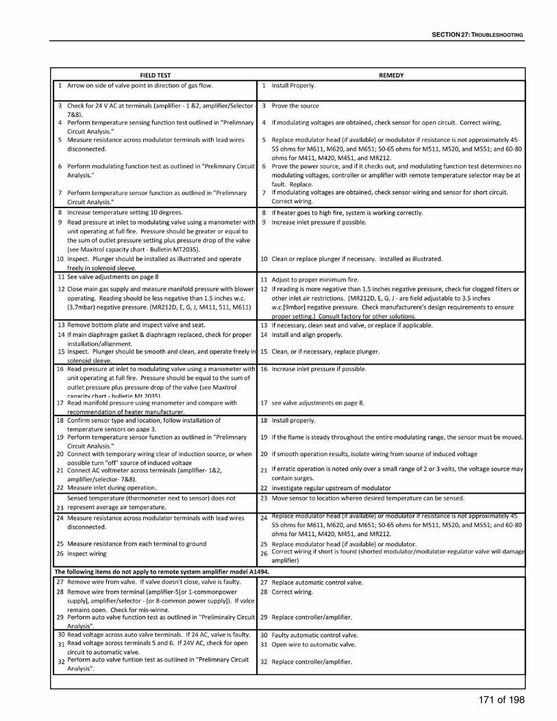
SECTION 27: TROUBLESHOOTING
171 of 198

TT-SERIES INSTALLATION, OPERATION AND SERVICE MANUAL
172 of 198
27.8 Series MP - Trouble Shooting
The MP2 and MP2+ have built in diagnostics; refer to the following programming guides for setup and
troubleshooting information.
Thoroughly read entire MP Section to guarantee proper usage of MP2 or MP2+ system. MP2+ system
requires initial programming before accessing process menu. See Page 181, Section 27.8.5
27.8.1 Series MP2 User Information and Programming GuideTable 44: Process Menu
27.8.1.1 Operation Menu
Process Set Point1 A maximum of 8 Process Set Points are available with a temperature range of 60 °F (15 °C) to 240 °F (115 °C).
2 The Process Set Point is displayed as "SP."
3 Process Set Points not being used can be turned to an "Off" setting.
Process Times
Note: TM02
required.
Any of the 8 Processes can be timed. Each timed Process has a range of 00:00:01 to 23:59:59. The conclusion of a timed Pro-
cess will immediately proceed into the next Process. If the last Process of the program is timed, it will proceed to the selected
start position (see Looping Mode) after timing out. The letter "T" will be displayed indicating a timed Process. Press the up or
down arrows on the TDM02 to scroll between the screens showing the Process Set Point and the sensed temperature AND the
sensed temperature with the time remaining in the Process (hh:mm:ss).
Soft Start The Soft Start feature controls the initial rate of voltage change to the modulator.
Soft Start operates when switching from a lower Process temperature to a higher Process
temperature. It is designed to slow the initial input rate to the burner. This feature is avail-
able in three settings: slow, medium, and fast and may be turned off. "Ss" (slow), "Sm"
(medium) or "Sf" (fast) is displayed during the time the Soft Start is active. This feature is
comprehensive to all Set Points.
NOTE: Global Setting for MP2+ system.
Max Valve VDC This feature limits the maximum voltage applied to the modulator. It has a setting
range of 7 to 25 VDC. This feature is comprehensive to all Set Points.
NOTE: Global Setting for MP2+ system.
Max Ramp VDC This feature limits the maximum voltage applied to the modulator while operating in the
Ramping mode. It has a setting range of 5 to 24 VDC. This setting cannot exceed the max-
imum voltage output setting. This feature is comprehensive to all Set Points.
Total Bandwidth
This feature determines the amount of temp. change required to drive the modulator from
the minimum fire setting to the maximum fire setting and vice versa. This feature is used to
eliminate pulsating or hunting due to an oversensitive application. Increase the Bandwidth
if a pulsating or hunting condition exists for an extended period of time after a Set Point
change. The feature has a range of 5 °F (2.8 °C) to 15 °F (8.3 °C). Total Bandwidth is com-
prehensive to all Set Points.
NOTE: Global Setting for MP2+ system.
Offset Temp This feature is used to maintain a desired temperature in an area not being directly sensed
by the [MP2 or MP2+] system. The average difference between the [MP2 or MP2+]
sensed discharged temperature and the desired space temperature must be known. This
is the Offset. The Offset will set the [MP2 or MP2+] sensed discharged air needed to pro-
duce the desired space temperature. Decrease (-) the Offset to maintain and control
space temperature lower than [MP2 or MP2+] discharged temperature. Increase (+) the
Offset to maintain and control space temperature higher than [MP2 or MP2+] discharged
temperature. The space temperature will be displayed as the Process Set Point.

SECTION 27: TROUBLESHOOTING
173 of 198
The feature has a range of -10 °F (-5.6 °C) to +10 °F (5.6 °C) and is available for each pro-
cess.
Ramping This feature is used to step the input rate when changing from one Process Set Point to
another. It is available for each Process. The Ramping Rate determines the amount of
temperature change per hour in one-minute steps. It has a range of 60 Deg/hr to 900 Deg/
hr. The change can be positive or negative.
This feature can be used with Max Ramp VDC and Soft Start to smooth the stepping. (Soft
Start only works when Process Temperature increases.)
"Ramp" is displayed to indicate the Ramping feature is active.
Timers The controller features two Timers (Timer 1 and Timer 2) that accumulate the hours of
operation for each Process. Each Process has a Timer 1 and a Timer 2. The TM02 is
required.
Timer 1 Timer 1 logs the hours of operation for a Process. It will log up 999 hours at which time it
will automatically reset to zero. The hours can be user reset to zero at any time. It also has
a programmable alarm setting to notify the user (by flashing a character in the lower right
hand corner of the display) when the desired accumulated hours for the Process have
been reached. It has a setting range of 1 to 999 hours. The feature is useful in maintaining
maintenance requirements.
Timer 2 Timer 2 logs the hours of operation for a Process. It will log up 999 hours at which time it
will automatically reset to zero. The hours can be user reset to zero at any time. The fea-
ture is useful in maintaining maintenance requirements.
Example
1. Program Offset to -5° F
2. Program Process Set Point (desired space temperature) to 75° F.
3. Therefore discharge air temperature = 80° F.
(Required [MP2 or MP2+] discharge air temperature to maintain desired space
temperature.)
4. The [MP2 or MP2+] discharged air temp. is 80° F. The displayed Process Set Point
is 75° F.
80° F -5° F 75° F
ExampleProcess 1 = 75° F
Process 2 = 125° F
Process 2 Ramp Rate = 600 Deg/hr or 10 Deg/min
1. The control switches from Process 1 to Process 2.
2. The controller will immediately raise the temperature 10° and will hold it at the new set point.
85 °F (75° F + 10 °F) until 1 minute has passed.
3. It will continue to raise it 10° each subsequent minute until it meets Process 2.
4. It will take 5 steps (10 °F each) and 4 minutes to go from 75 °F to 125 °F.

TT-SERIES INSTALLATION, OPERATION AND SERVICE MANUAL
174 of 198
27.8.1.2 Operation Menu
Max Proc Temp This feature limits the maximum temperature for each Process. It has a range of 60 °F
(15 °C) to 240 °F (115 °C). It does not allow the Process Set Point to be set in excess of
the Maximum Process Temperature setting.
NOTE: Global Setting for MP2+ system.
Min Proc Temp This feature limits the minimum temperature for all Processes. It has a range of 60 °F
(15 °C) to 240°F (115 °C). It does not allow any Process Set Point to be set below the Min-
imum Process Temperature setting.
NOTE: Global Setting for MP2+ system.
Calibration This feature is used to fine-tune a particular application. Calibration shifts the Bandwidth
range up or down from the factory set mean. Each application is different with variances in
burners and appliances. It can be necessary to change the midpoint of the modulation
range to have the Process Temperature and the actual sensed temperature match.
For sensed temperatures consistently displaying lower than the Set Point, increase (+)
Calibration by number of degrees off. For sensed temperatures consistently displaying
higher than the Set Point, decrease (-) Calibration by number of degrees off. It is available
for each Process and has a range of -10 °F (-5.6 °C) to +10° F (5.6 °C).
Monitor The Monitor feature is a useful tool when setting up or troubleshooting the MP2 system.
The following will appear on the display when Monitor is in the "On" position:

SECTION 27: TROUBLESHOOTING
175 of 198
27.8.1.3 Menus
Looping Mode (TM02 applications only)
The looping mode feature is used to select the controllers default position on startup and
after the last process of a program is completed.
NOTE: Global Setting for MP2+ system.
NOTE: For MP2+ system, On "Power up" the controller defaults to the last program in use
prior to removal of power. After last manual process of a program or after last timed pro-
cess of a program expires, the controller defaults to the first process of the same program.
F/C Mode This feature sets the control to operate in either the Fahrenheit (F) or Celsius (C) mode.
NOTE: Changing between Fahrenheit and Celsius will reset the control to factory default
settings.
NOTE: Global Setting for MP2+ system.
Software Version
Displays the version of software utilized by the controller.
Program Indication Output
See MP2 or MP2+ Select Information
Selecting "READY"Power up:"READY" is displayed. Requires a momentary switch closure
to move the controller to the first process.
After last, manual process of a program:After momentary switch closure to move out of the last process,
controller defaults to the "READY" position.
After last, timed process of a program expires:Controller defaults to the "READY" position.
Selecting "First Process"Power up:Controller begins operating in the First Process of the program.
After last, manual process of a program:After momentary switch closure to move out of the last process,
controller defaults to the First Process.
After last, timed process of a program expires:Controller defaults to the First Process.
Init
ial M
enu
(f
or
MP
2+
syste
m o
nly
) Programs Program Set (1-8), Process Menu, Operation Menu,
Diagnostic Menu
Global Settings Operation Menu, Diagnostic Menu
Pro
cess
Men
u Process Temperatures Temp Set Point Process #(1 - 8)
Off, 60 °F (15 °C) to 240 °F (115 °C)
Process Time
NOTE: TM02 required
Time Process #(1 - 8) ??Hours, Minutes, Seconds
Manual, 00:00:01 to 23:59:59

TT-SERIES INSTALLATION, OPERATION AND SERVICE MANUAL
176 of 198
27.8.1.4 Programming the MP System
Table 45: Programming Buttons
Op
erat
ion
Men
uSoft Start Off, Slow, Medium, Fast
Max Valve VDC 7 to 25 VDC
Max Ramp VDC 5 to 24 VDC
Total Bandwidth 5 °F(2.8 °C) to 15 °F (8.3 °C)
Offset Temp Offset Temp Process #(1 - 8) -10 °F(-5.6 °C) to +
10 °F(5.6 °C)
Ramping Ramping Process #(1 - 8) Off, 60 Deg/hr to 900 Deg/
hr
Timers Timer Process #(1 - 8)
Timer 1 View Hours, Clear Hours, Set Alarm Hours
Set Alarm 0 hrs to 999 hrs
Timer 2 View Hours, Clear Hours
Dia
gn
ost
ic M
enu
Max Proc Temp Max Temp Process #(1 - 8) 60 °F(15 °C) to 240 °F
(115 °C)
Min Proc Temp 60 °F(15 °C) to 240 °F(115 °C)
Calibration Calibration Process #(1 - 8) -10 °F(-5.6 °C) to +
10 °F(5.6 °C)
Monitor On, Off
Looping Mode Ready, First Process
F/C ModeSoftware Version
Buttons DescriptionPress once to initially enter programming mode.
Press once during programming to return to the previous screen.
Press, hold for 5 seconds and release to EXIT programming mode.
Press either to scroll or advance through menus.
Press either to change current value.
Press once to enter into the selected menu or programming mode.
Press once to store programmed setting.
PGM
ENT

SECTION 27: TROUBLESHOOTING
177 of 198
Table 46: Screen Indicators
27.8.2 Series MP2 Select User Information
27.8.2.1 Program Indication Output
Terminal #8 is used to indicate the controller is operating within a Program. The following voltage will be
measured across the #8 terminals.
Press and release once to switch to the next Process or to move the controller from the
"READY" position to the First Process.
Press twice or hold for 10 seconds to
abort a timed process.
Display Description**STORED** Will appear on the screen to confirm entry accepted
T Indicates a timed process
M Indicates a manual process
Controller in hte "READY" position 0 VDC
Controller operating in any of the 8 processes making up a Program 24 VDC 2W max

TT-SERIES INSTALLATION, OPERATION AND SERVICE MANUAL
178 of 198
27.8.3 Series MP2+ Select User Information
The initial programming has a maximum of 8 programs available. Each program has a maximum of 8
processes set points. The program and process set point in use is displayed as P(1-8) S#(1-8). Programs
utilize global settings.
On global settings, multiple programmable menu settings common to all programs (global) to speed
programming and insure consistent heater operation, program to program.
Operation Menu Global Settings include Soft Start, Max Valve VDC and Total Bandwidth.
Diagnostic Menu Global Settings include Max Proc Temp, Min Proc Temp, Looping Mode, F/C Mode and
Software Version. NOTE: In Looping Mode On "Power up" the controller defaults to the last program in use
prior to removal of power. After last manual process of a program or after last timed process of a program
expires, the controller defaults to the first process of the same program.
27.8.3.1 Program Indication Output
Terminal #9 is used to indicate the controller is operating within a Program. The following voltage will be
measured across the #9 terminals:
27.8.4 Series MP Programming Guide27.8.4.1 MP2 System
To enter the Process, Operation and Diagnostics Menus Press once.
Table 47: Process Menu Programming
Table 48: Operation Menu programming
Controller in the "READY" position 0 VDC
Controller operating in any of the 8 processes making up a Program 24 VDC 2W max
1 Scroll to the Processes Menu, press .
Process Temperatures2 Scroll to Temperatures, press .
3 Temp Set Point Process #, scroll to Set Point #, press .
4Set Point Temp Process #, XX° F, set Process Temperature value (OFF, 60 °F (15 °C) to 240 °F
(115 °C), press .
5 **Stored** will flash 4 times to confirm entry.
6 Repeat steps 2 - 5 for Set Points #(2-8).
NOTE: Process #1 CAN NOT be OFF. For unused Process Temperature Set Points, press down arrow
until "Off" is displayed. Set Points #(2-8) are factory set to "Off."
Process Times (TM02 required)2 Scroll to Times, press . Each Process can be either Timed or Manual.
3 Time Process #, scroll to Set Point #, press . MANUAL will be the default.
4 Scroll to Seconds, Minutes, or Hours, press .
a. Set Seconds, Minutes or Hours values with , press .
b. **Stored** will flash 4 times to confirm entry.
c. Repeat steps 4 - 4b for each time segment.
d. Default setting or when programmed to 00:00:00.
5 Repeat steps 2 - 4 for Set Points #(2-8)
1 Scroll to the Processes Menu, press .
Soft Start (Global Setting for MP2+ system)
2 Scroll to Soft Start, press .
3 Soft Start, scroll to Off, Slow, Medium or Fast, press .
4 **Stored** will flash 4 times to confirm entry.
PGM
ENT
ENT
ENT
ENT
ENT
ENT
ENT
ENT
ENT
ENT
ENT
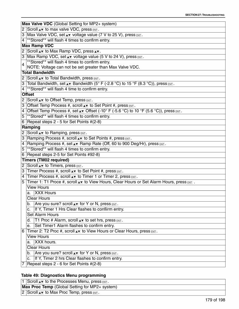
SECTION 27: TROUBLESHOOTING
179 of 198
Table 49: Diagnostics Menu programming
Max Valve VDC (Global Setting for MP2+ system)
2 Scroll to max valve VDC, press .
3 Max Valve VDC, set voltage value (7 V to 25 V), press .
4 **Stored** will flash 4 times to confirm entry.
Max Ramp VDC2 Scroll to Max Ramp VDC, press .
3 Max Ramp VDC, set voltage value (5 V to 24 V), press .
4**Stored** will flash 4 times to confirm entry.
NOTE: Voltage can not be set greater than Max Valve VDC.
Total Bandwidth2 Scroll to Total Bandwidth, press .
3 Total Bandwidth, set Bandwidth (5° F (-2.8 °C) to 15 °F (8.3 °C)), press .
4 **Stored** will flash 4 time to confirm entry.
Offset2 Scroll to Offset Temp, press .
3 Offset Temp Process #, scroll to Set Point #, press .
4 Offset Temp Process #, set Offset (-10° F (-5.6 °C) to 10 °F (5.6 °C)), press .
5 **Stored** will flash 4 times to confirm entry.
6 Repeat steps 2 - 5 for Set Points #(2-8)
Ramping2 Scroll to Ramping, press .
3 Ramping Process #, scroll to Set Points #, press .
4 Ramping Process #, set Ramp Rate (Off, 60 to 900 Deg/Hr), press .
5 **Stored** will flash 4 times to confirm entry.
6 Repeat steps 2-5 for Set Points #92-8)
Timers (TM02 required)2 Scroll to Timers, press .
3 Timer Process #, scroll to Set Point #, press .
4 Timer Process #, scroll to Timer 1 or Timer 2, press .
5 Timer 1: T1 Proce #, scroll to View Hours, Clear Hours or Set Alarm Hours, press .
View Hours
a. XXX Hours
Clear Hours
b. Are you sure? scroll for Y or N, press .
c. If Y, Timer 1 Hrs Clear flashes to confiirm entry.
Set Alarm Hours
d. T1 Proc # Alarm, scroll to set hrs, press .
e. Set Timer1 Alarm flashes to confirm entry.
6 Timer 2: T2 Proc #, scroll to View Hours or Clear Hours, press .
View Hours
a. XXX hours.
Clear Hours
b. Are you sure? scroll for Y or N, press .
c. If Y, Timer 2 hrs Clear flashes to confirm entry.
7 Repeat steps 2 - 6 for Set Points #(2-8)
ENT
ENT
ENT
ENT
ENT
ENT
ENT
ENT
ENT
ENT
ENT
ENT
ENT
ENT
ENT
ENT
ENT
ENT
ENT
1 Scroll to the Processes Menu, press .
Max Proc Temp (Global Setting for MP2+ system)
2 Scroll to Max Proc Temp, press .
ENT
ENT

TT-SERIES INSTALLATION, OPERATION AND SERVICE MANUAL
180 of 198
27.8.4.2 MP2+ System
Initial Menu programming, press once. Programs appears, press or scroll to Global Settings and
press .
Programs selected:
• Scroll to desired Program #, press .
• After program loads, scroll to Process menu, Operational menu or Diagnostic Menu and press .
• Proceed to selected Menu to continue programming.
Global Settings selected:
• Scroll to Operational menu or Diagnostic Menu, press .
• Process to selected Menu to continue programming.
For Process Menu programming See Page 178, Table 47. For Operation Menu programming, See Page 178, Table 48
For Diagnostic Menu programming, See Page 179, Table 49.
3 Maximum Temp Process #, scrol to Set Points #, press .
4 Max T Proc #, set Temp value (60 °F (15 °C) to 240 °F (115 °C), press .
5 **Stored** will flash 4 times to confirm entry.
6 Repeat steps 2 - 5 for Set Points #(2-8)
Min Proc Temp (Global Setting for MP2+ system)
2 Scroll to Min Proc Temp, press .
3 Min Proc Temp, set Temp value (60 °F (15 °C) to 240 °F (115 °C)), press .
4 **Stored** will flash 4 times to confirm entry.
Calibration2 Scroll to Calibration, press .
3 calibration Process #, scroll to Set Point #, press .
4 Cal Proc #, set Temp value (-10 °F (-5.6 °C) to 10 °F (5.6 °C)), press .
5 **Stored** will flash 4 times to confirm entry.
6 Repeat steps 2 - 5 for Set Points #(2-8)
Monitor2 Scroll to Monitor, press .
3 Monitor, set On or Off, press .
4 Either monitor mode on or Off will flash 3 times to confirm entry.
Looping (Global Setting for MP2+ system)
2 Scroll to Monitor, press .
3 Scroll to READY or FIRST PROCESS, press .
4 **Stored** will flash 4 times to confirm entry.
F/C Mode (Global setting for MP2+ system)
2 Scroll to F/C Mode, press .
3 F/C MODE, scroll to either Fahrenheit or Celsius, press .
4 **Stored** will flash 4 times to confirm entry.
NOTE: Changing between F and C will cause the MP2 system to reset to factory defaults.
Software Version (Global Setting for MP2+ system)
2 Scroll to Menu Software Version, press .
3 Software Version information will appear.
ENT
ENT
ENT
ENT
ENT
ENT
ENT
ENT
ENT
ENT
ENT
ENT
ENT
ENT
PGM ENT
ENT
ENT
ENT
ENT

SECTION 27: TROUBLESHOOTING
181 of 198
27.8.5 Series MP Operation27.8.5.1 MP2 Process Control System
27.8.5.2 MP2 Process Control System w/ TM02 Multifunctional Timer ControlSwitching to the Next Programmed Process:
27.8.5.3 MP2+ Multiple Program Processes Temperature Controller
27.8.5.4 MP2+ Multiple Program Process Temperature Controller w/ TM02 Multifunctional Timer Control
Push and release Button 1 on dial face (See Page 176, Table 45 (programming buttons) )
or momentarily latch (make) a set of contacts wired to the TB1 terminal (i.e. typically
accomplished by a momentary ON (normally open) switch) to proceed to the next Pro-
cess. Pushing and releasing Button 1 or momentary latching of TB1 during the last Pro-
cess of a program will cause the MP2 System to return to Process 1. Multiple contacts
used to switch Processes are to be wired in parallel.
Aborting a Process
Same as switching to next Process, push and release Button 1 or momentarily latch TB1.
Timed Processes
Nothing is required. The MP2 system will immediately proceed to the next programmed
process after timing out.
NOTE: If the last Process of a program is timed, it will proceed either to the "READY" posi-
tion or to the First Process. By selecting the First Process in the LOOPING Mode menu,
the MP2 can be programmed into a continuous program loop (See Page 179, Table 49
(diagnostic menu)).
Untimed (Manual) Processes
An untimed Process will remain in the Process indefinitely until Button 1 is pushed and
released or TB1 is momentarily latched. Pushing and releasing Button 1 or the momentary
latching of the TB1 will cause the MP2 System to proceed to the next Process. If the last
Process of a program is untimed, pushing and releasing Button 1 or the momentary latch-
ing of TB1 will cause the MP2 system to proceed to the selected program start position.
Multiple contacts used to switch untimed Processes are to be wired in parallel.
Aborting a Timed Process
Push and release Button 1 or momentarily latch TB1 twice within a 10 second period or
latch and hold continuously for 10 seconds.
Switching to Another Program
Switching to another program can only be accomplished by entering the Initial Program-
ming Menu and selecting "Program Set #".
Switching to Next Programmed Process
Push and release Button 1 on dial face (See Page 176, Table 45 (programming buttons))
or momentarily latch (make) a set of contacts wired to the TB1 terminal (i.e. typically
accomplished by a momentary ON (normally open) switch) to proceed to the next Pro-
cess. Pushing and releasing Button 1 or momentary latching of TB1 during the last Pro-
cess of a program will cause the MP2 System to return to Process 1. Multiple contacts
used to switch Processes are to be wired in parallel.
Aborting a Process
Same as switching to next Process, push and release Button 1 or momentarily latch TB1.
Switching to Another Program
Switching to another program can only be accomplished by entering the Initial Program-
ming Menu and selecting "Program Set #".
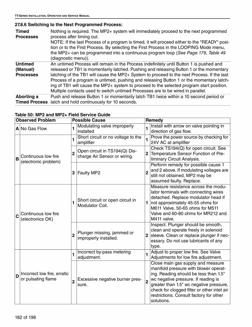
TT-SERIES INSTALLATION, OPERATION AND SERVICE MANUAL
182 of 198
27.8.6 Switching to the Next Programmed Process:
Table 50: MP2 and MP2+ Field Service Guide
Timed Processes
Nothing is required. The MP2+ system will immediately proceed to the next programmed
process after timing out.
NOTE: If the last Process of a program is timed, it will proceed either to the "READY" posi-
tion or to the First Process. By selecting the First Process in the LOOPING Mode menu,
the MP2+ can be programmed into a continuous program loop (See Page 179, Table 49
(diagnostic menu)).
Untimed (Manual) Processes
An untimed Process will remain in the Process indefinitely until Button 1 is pushed and
released or TB1 is momentarily latched. Pushing and releasing Button 1 or the momentary
latching of the TB1 will cause the MP2+ System to proceed to the next Process. If the last
Process of a program is untimed, pushing and releasing Button 1 or the momentary latch-
ing of TB1 will cause the MP2+ system to proceed to the selected program start position.
Multiple contacts used to switch untimed Processes are to be wired in parallel.
Aborting a Timed Process
Push and release Button 1 or momentarily latch TB1 twice within a 10 second period or
latch and hold continuously for 10 seconds.
Observed Problem Possible Cause Remedy
A No Gas Flow 1 Modulating valve improperly
installed1 Install with arrow on valve pointing in
direction of gas flow.
BContinuous low fire
(electronic problem)
1Short circuit or no voltage to the
amplifier1
Prove the power source by checking for
24V AC at amplifier
2 Open circuit in TS194(Q) Dis-
charge Air Sensor or wiring.2
Check TS194(Q) for open circuit. See
Temperature Sensor Function of Pre-
liminary Circuit Analysis.
3 Faulty MP2 2
Perform remedy for possible cause 1
and 2 above. If modulating voltages are
still not obtained, MP2 may be
assumed faulty. Replace.
C Continuous low fire
(electronics OK)
1 Short circuit or open circuit in
Modulator Coil. 1
Measure resistance across the modu-
lator terminals with connecting wires
detached. Replace modulator head if
not approximately 45-55 ohms for
M611 Valve, 50-65 ohms for M511
Valve and 60-80 ohms for MR212 and
M411 valve.
2 Plunger missing, jammed or
improperly installed.2
Inspect. Plunger should be smooth,
clean and operate freely in solenoid
sleeve. Clean or replace plunger if nec-
essary. Do not use lubricants of any
type.
D Incorrect low fire, erratic
or pulsating flame
1 Incorrect by-pass metering
adjustment.1 Adjust to proper low fire. See Valve
Adjustments for low fire adjustment.
2 Excessive negative burner pres-
sure.2
Close main gas supply and measure
manifold pressure with blower operat-
ing. Reading should be less than 1.5"
wc negative pressure. If reading is
greater than 1.5" wc negative pressure,
check for clogged filter or other inlet air
restrictions. Consult factory for other
solutions.

SECTION 27: TROUBLESHOOTING
183 of 198
EContinuous high fire
(electronic problem)
1Short circuit in TS194(Q) Dis-
charge Air Sensor circuit or wir-
ing.
1Check TS194(Q) for internal short cir-
cuit. See Temperature Sensor Function
of Preliminary Circuit Analysis.
2 Faulty MP2 2
Perform remedy for possible cause 1
and 2 above. If modulating voltages are
still not obtained, MP2 may be
assumed faulty. Replace.
FContinuous high fire
(electronics OK)
1Foreign object holding valve
open.1
Remove bottom plate and inspect valve
and seat.
2 Plunger jammed. 2
Inspect. Plunger should be smooth,
clean and operate freely in solenoid
sleeve. Clean or replace plunger if nec-
essary. Do not use lubricants of any
type.
G Incorrect high fire
1 Inlet pressure too low. 1
Read pressure at inlet to modulating
valve using a manometer with unit
operating at full fire. Pressure should
be equal to the sum of outlet pressure
setting plus pressure drop of the valve.
See Maxitrol's Capacity Chart, M-
MR.MT.EN.
2 Incorrect outlet pressure adjust-
ment of Pressure Regulator.2
Read manifold pressure using manom-
eter and compare with recommenda-
tion of equipment manufacturer. See
Valve Adjustments for high fire adjust-
ment.

TT-SERIES INSTALLATION, OPERATION AND SERVICE MANUAL
184 of 198
Observed Problem Possible Cause Remedy
H
1 Hunting 1
Increase bandwith setting. See Opera-
tion Menu programming in MP2(+)
User's Programming Guide. If flame
stabilizes, reduce bandwith to the mini-
mum setting where a stable flame can
be maintained.
2Erratic air patterns or improper
TS194(Q) location.2
Connect test resistor as described in
step 2 of Preliminary Circuit Analysis.
Set point temperature to process tem-
perature being displayed. If the flame is
steady, the TS194(Q) should be
removed.
3Wiring is run next to high voltage
switching circuits causing
induced voltages.
3
Temporarily wire MP2, TS194(Q) and
modulating gas valve externally and
observe heater/equipment operation. If
smooth operating results, isolate
effected wiring from source of induced
voltage.
4 Faulty amplifier or erratic voltage
supply.4
With DC voltmeter connected (per item
2 above) and locally connected (per
item 3 above), observe DC voltage
across modulator terminals. If erratic or
unstable DC voltages are obtained, the
MP2 may be faulty. Replace. If erratic
operation continues after replacement,
consult Maxitrol Company.
I Incorrect discharge air
temperature
1 Incorrect wiring 1Check wiring diagrams in MP2(+)
Installation Guide and correct if neces-
sary.
2 System out of calibration 2
If sensed temperature (thermometer
next to TS194(Q)) does not correspond
to MP2 setting. See Calibration Proce-
dure in MP2(+) User's/Programming
Guide.
3 Improper TS194(Q) location 3
Is sensed temperature does not repre-
sent average discharge at temperature,
move TS194(Q) to location where aver-
age representative temperature can be
sensed.
J Burned out transformer
1 Short circuit in modulator coil 1
Measure resistance across the modu-
lator terminals with connecting wires
detached. Replace modulator head if
less than 40 ohms.
2 Short circuit between amplifier
and modulator valve.2
Inspect wiring. Correct wiring if short is
found using the wiring diagrams in
MP2(+) Installation Guide.
KProcess temperature
display reads "Low"1
Discharge air temperature too
low.1
Raise discharge air temperature to
greater that 60 °F.

SECTION 27: TROUBLESHOOTING
185 of 198
L Control inoperable; Dis-
play reads "Ready…"
1 Bad cable connection between
dial and amplifier.1
Remove power. Disconnect and recon-
nect cable securely. Restore power. If
"Ready…" remains, replace or consult
Maxitrol Company.
2Dial cable disconnected and
reconnected with system pow-
ered.
2Remove and restore power. If
"Ready…" remains, replace or consult
Maxitrol Company.
3 Incorrect cable 3Insure cable type is correct. Replace
with correct cable if necessary.
4 Loss of program. 4Perform remedy for possible cause 1
and 3 above. If "Ready…" remains,
replace or consult Maxitrol Company.
M Control resets
1Momentary switch wiring is run
next to high voltage switching cir-
cuits causing induced voltages.
1
Temporarily wire momentary switch
externally or disconnect external
momentary switch wiring and use inte-
gral switch only. If proper operation
results, isolate effected wiring from
source of induced voltage or use inte-
gral switch only.
2 Momentary loss of power 2Prove the power source by checking for
24V AC at amplifier

TT-SERIES INSTALLATION, OPERATION AND SERVICE MANUAL
186 of 198
27.9 Flame® Safeguard
27.9.1 Fireye® MicroM
FIGURE 117: Fireye® Micro M Service Guide Page 1
LOCKOUTMESSAGE
OPCTRL
INTRLCK PTFI FLAME
LINE FREQUENCY NOISE ● ❍ ❍ ●
FLAME FAIL - PTF1 ❍ ● ● ●
FAULT UNKNOWN ● ● ● ●
AMPLIFIER COUNT FAIL ❍ ❍ ❍ ❍
FLAME FAIL MTFI ❍ ❍ ● ●
FALSE FLAME IDLE ❍ ● ❍ ❍
INTRLCK OPEN ● ● ● ❍
INTRLCK CLOSED ❍ ● ● ❍
CHASSIS OPTO ● ● ❍ ●
FLAME FAIL-AUTO ❍ ● ❍ ●
CHECK CHASSIS ❍ ❍ ❍ ●
CHECKPROGRAMMER
❍ ❍ ● ❍
CHECK AMPLIFIER ● ❍ ❍ ❍
AMPLIFIER AUTO CHECK ● ❍ ● ❍
CHECK BLOWN FUSE ● ❍ ● ●
CHECK SCANNER ● ● ❍ ❍

SECTION 27: TROUBLESHOOTING
187 of 198
FIGURE 118: Fireye® Micro M Service Guide Page 2
TROU
BLES
HOOT
ING
TIPS
1.Ve
rify
that
ther
e is
a s
olid
ear
th g
roun
d w
ire b
roug
ht to
the
pane
l tha
t the
Fire
ye b
ase
is m
ount
ed to
.2.
In a
rect
ifica
tion
syst
em, v
erify
that
term
inal
S1
is s
olid
ly e
arth
gro
unde
d, a
nd c
onfir
m th
at th
e fla
me
rod
is a
ligne
d so
it d
oesn
’t dr
oop
near
the
igni
tion
spar
k.3.
Confi
rm th
at th
ere
is n
o m
easu
rabl
e vo
ltage
pre
sent
bet
wee
n th
e gr
ound
scr
ew a
nd te
rmin
al 2
(neu
tral).
4.Co
nfirm
that
the
120
volt
AC s
uppl
y ha
s its
neu
tral l
eg e
arth
gro
unde
d at
the
supp
ly, (
float
ing
isol
atio
n tra
nsfo
rmer
s ca
n c
ause
pro
b-le
ms)
.5.
Confi
rm th
at th
e ig
nitio
n tra
nsfo
rmer
’s s
econ
dary
win
ding
is s
olid
ly e
arth
gro
unde
d. T
he g
roun
ding
met
hod
is u
sual
ly th
roug
h th
e tra
nsfo
rmer
cas
e. D
irt, p
aint
, loo
se m
ount
ing
hard
war
e, e
tc.,
can
all b
e fa
ctor
s.6.
Ther
e m
ay b
e a
prob
lem
with
tran
sien
ts in
the
mai
n po
wer
sup
ply.
If y
ou th
ink
this
may
be
the
prob
lem
, you
may
wan
t to
run
a gr
ound
w
ire d
irect
ly fr
om th
e pi
lot a
ssem
bly
back
to th
e el
ectri
cal p
anel
whe
re th
e Fi
reye
con
trol i
s m
ount
ed.
Mic
roM
Fus
e
10 a
mps
Fire
ye P
art N
umbe
r: 23
-197
o
rW
ickm
ann
Part
Num
ber:
378-
2100
-0-4
1(o
r Wic
kman
n ol
der P
art N
umbe
r: 19
373-
071-
K)

TT-SERIES INSTALLATION, OPERATION AND SERVICE MANUAL
188 of 198
27.9.2 Fireye® M4RT1
The Fireye® M4RT1 is a self contained version of the
MicroM flame safeguard. It is only used on flame rod
applications and does not have separate
programming boards or flame signal amplifiers. Refer
to Page 186, and Page 187, Figure 117 and Figure 118 and use the same service guide that the MicroM
uses, except ignore the sections concerning
replacing programming and amplifier boards, but
instead where ever replacement is needed, the entire
flame safeguard must be replaced.
27.9.3 Honeywell RM7897
Run/Test Switch
The Run/Test Switch is located on the top side of the
relay module. The Run/Test Switch allows the burner
sequence to be altered as follows:
• In the measured PREPURGE sequence, the Run/
Test Switch, placed in the TEST position, causes
the PREPURGE timing to stop.
• In the Pilot Flame Establishing Period, the Run/
Test Switch, placed in the TEST position, stops
the timer during the first eight seconds of a ten-
second PFEP selection. It also allows for pilot
turn-down test and other burner adjustments. This
activates a fifteen-second flameout timer that
permits pilot flame adjustment without nuisance
safety shutdowns.
IMPORTANT
When the relay module is switched to the TEST
mode, it stops and holds at the next Run/Test Switch
point in the operating sequence. Make sure that the
Run/Test Switch is in the RUN position before leaving
the installation.
The POWER LED provides fault identification when
the flame safeguard control locks out on an alarm.
Fault identification is a series of fast- and slow-
blinking LED lights. The fast blinks identify the tens
portion of the fault code (three fast blinks is 30), while
the slow blinks identify the units portion of the fault
code (two slow blinks is 2). Three fast blinks followed
by two slow blinks would be fault code 32. This
identifies a running interlock on during STANDBY.
The LED code repeats as long as the fault exists. To
clear the fault, press the RESET button, (See Page 188, Table 51 for Blinking Fault Code List.).
Table 51: Honeywell Blinking Fault Code ListFault Code System Failure Recommended TroubleshootingCode 1-1
*Low AC Line
Voltage*
Low AC Line detected. 1. Check the relay module and display module connections.
2. Reset and sequence the Relay Module.
3. Check the 7800 power supply and make sure that frequency and voltage meet specifications.
4. Check the backup power supply, as appropriate.Code 1-2
*AC Quality
Problem*
Excessive noise or
device running on slow,
fast, or AC line dropout
detected.
Code 2-1
*Unexpected
Flame Signal*
Flame sensed when no
flame is expected during
STANDBY or PURGE.
1. Check that flame is not present in the combustion chamber; correct any errors.
2. Make sure that the flame amplifier and flame detector are compatible.
3. Check the wiring and correct any errors.
4. Remove the flame amplifier and inspect its connections. Reseat the amplifier.
5. Reset and sequence the relay module.
6. If the code reappears, replace the flame amplifier and/or the flame detector.
7. If the fault persists, replace the relay module.
Code 2-2
*Flame Signal
Absent*
No-flame time present
at the end of the PIlot
Flame Establishing
Period; lost during the
Main Flame Establishing
Period or during RUN.
1. Measure the flame signal. If one exists, verify that it meets specifications.
2. Make sure that the flame amplifier and flame detector are compatible.
3. Inspect the main fuel valve(s) and valve connection(s).
4. Verify that the fuel pressure is sufficient to supply fuel to the combustion chamber. Inspect the
connections to the fuel pressure switches. Make sure they are functioning properly.
5. Inspect the Airflow Switch and make sure that it is functioning properly.
6. Check the flame detector sighting position; reset and recycle. Measure the flame signal
strength. Verify that it meets specifications. If not, refer to the flame detector and/or flame
amplifier checkout procedures in the installation instructions.
7. Replace the flame amplifier and/or the flame detector, if necessary.
8. If the fault persists, replace the relay module.
Code 2-3
*Flame Signal
Overrange*
Flame signal value is
too high to be valid.
1. Make sure the flame detector and flame amplifier are compatible.
2. Remove the flame amplifier and inspect its connections. Reset the flame amplifier.
3. Reset and sequence the relay module.
4. Check the flame detector sighting position; reset and recycle. Measure flame strength. Verify
that it meets specifications. If not, refer to the flame detectorand/or flame amplifier checkout
procedures in the installation instructions.
5. If the code reappears, replace the flame amplifier and/or the flame detector.
6. If the fault persists, replace the relay module.

SECTION 27: TROUBLESHOOTING
189 of 198
Code 3-1
*Running/
Interlock Switch
Problem*
Running or Lockout
Interlock fault during
Prepurge.
1. Check wiring; correct any errors.
2. Inspect the fan; make sure there is no air intake blockage and that it is supplying air.
3. Make sure the Lockout Interlock switches are functioning properly and the contacts are free
from contaminants.
4. Reset and sequence the relay module to Prepurge (place the TEST/RUN Switch in the TEST
position, if available). Measure the voltage between terminal 7 and G (ground); 120 Vac
should be present. Switch TEST/RUN back to RUN.
5. If steps 1 through 4 are correct and the fault persists, replace the relay module.
Code 3-2
*Running/
Interlock On
During
Standby*
Lockout Interlock
powered at improper
point in sequence or On
in Standby.
1. Check wiring to make sure that the Lockout Interlocks are connected properlybetween termi-
nals 6 and 7. Correct any errors.
2. Reset and sequence the relay module.
3. If the fault persists, measure the voltage between terminal 6 and G (ground),then between ter-
minal 7 and G. If there is 120 Vac at terminal 6 when the controller is off, the controller switch
may be bad or is jumpered.
4. If steps 1 through 3 are correct and there is 120 Vac at terminal 7 when the controller is closed
and the fault persists, check for a welded or jumpered Running Interlock or Airflow Switch. Cor-
rect any errors.
5. If steps 1 through 4 are correct and the fault persists, replace the relay module.
Code 3-3
*VPS in
Improper State*
VPS (Valve Proving
Switch) in wrong state
during VPS Test.
1. Check wiring, making sure upstream valve is connected to terminal 9 and downstream valve is
connected to terminal 17.
2. Conduct Valve Seat leakage test using a manometer.
3. Reset and sequence the relay module; if fault repeats, test VPS (connected to terminal 16) is
functioning properly; replace if necessary.
4. Reset and sequence the relay module.
5. If fault persists, replace the relay module.
Code 4-1
*Purge Card
Problem*
No purge card or the
purge card timing has
changed from the
original configuration.
1. Make sure the purge card is seated properly.
2. Inspect the purge card and the connector on the relay module for any damage or contami-
nants.
3. Reset and sequence the relay module.
4. If the fault code reappears, replace the purge card.
5. Reset and sequence the relay module.
6. If the fault code persists, replace the relay module.
Code 4-2
*Wiring
Problem/
Internal Fault*
Pilot (ignition) valve
terminal, main valve,
ignition or Main Valve 2
was on when it should
be off. Electrical Shock Hazard; Fire or Explosion Hazard.Can cause severe injury, death or property damage.Remove system power and turn off power supply.
1. Remove system power and turn off fuel supply.
2. Check wiring; correct any errors.
3. inspect Pilot Fuel Valve(s), both places, and connections.
4. Reset and sequence the relay module.
5. If the fault persists, replace the relay module.
Code 4-3
*Flame
Amplifier
Problem*
Flame not sensed, or
sensed when it should
be on or off.
1. Check wiring; correct any errors.
2. Make sure the flame amplifier and flame detector are compatible.
3. Remove the flame amplifier and inspect the connections. Reseat the amplifier.
4. Reset and sequence the relay module.
5. If the code reappears, replace the flame amplifier and/or the flame detector.
6. If the fault persists, replace the relay module.
Code 4-4
*Configuration
Jumper Problem*
The configuration
jumpers differ from the
sample taken at startup.
1. Inspect the jumper connections. Make sure the clipped jumpers were completely removed.
2. Reset and sequence the relay module.
3. If the fault persists, replace the relay module.
Code 5-1
*Preignition
Interlock*
Preignition Interlock
fault.
1. Check wiring and correct any errors.
2. Check Preignition Interlock switches to assure proper functioning.
3. Check fuel valve operation.
4. Reset and sequence the relay module; monitor the Preignition Interlock status.
5. If the fault persists, replace the relay module.
Code 5-2
*High Fire Sw.
or Low Fire
Sw.*
Either High Fire Switch
or Low Fire Switch
failure.
1. Check wiring and correct any errors.
2. Reset and sequence the relay module.
3. Use manual motor potentiometer to drive the motor open and closed. Verify at motor switch
that the end switches are operating properly. Use RUN/TEST switch if manual potentiometer is
not available.
4. Reset and sequence the relay module.
5. If the fault persists, replace the relay module.
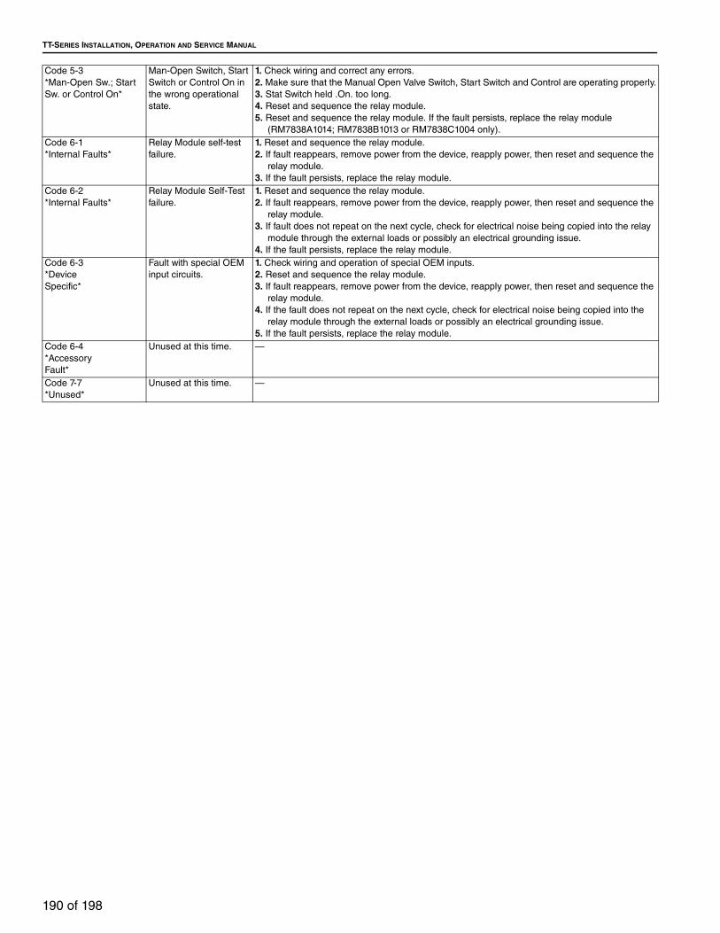
TT-SERIES INSTALLATION, OPERATION AND SERVICE MANUAL
190 of 198
Code 5-3
*Man-Open Sw.; Start
Sw. or Control On*
Man-Open Switch, Start
Switch or Control On in
the wrong operational
state.
1. Check wiring and correct any errors.
2. Make sure that the Manual Open Valve Switch, Start Switch and Control are operating properly.
3. Stat Switch held .On. too long.
4. Reset and sequence the relay module.
5. Reset and sequence the relay module. If the fault persists, replace the relay module
(RM7838A1014; RM7838B1013 or RM7838C1004 only).
Code 6-1
*Internal Faults*
Relay Module self-test
failure.
1. Reset and sequence the relay module.
2. If fault reappears, remove power from the device, reapply power, then reset and sequence the
relay module.
3. If the fault persists, replace the relay module.
Code 6-2
*Internal Faults*
Relay Module Self-Test
failure.
1. Reset and sequence the relay module.
2. If fault reappears, remove power from the device, reapply power, then reset and sequence the
relay module.
3. If fault does not repeat on the next cycle, check for electrical noise being copied into the relay
module through the external loads or possibly an electrical grounding issue.
4. If the fault persists, replace the relay module.
Code 6-3
*Device
Specific*
Fault with special OEM
input circuits.
1. Check wiring and operation of special OEM inputs.
2. Reset and sequence the relay module.
3. If fault reappears, remove power from the device, reapply power, then reset and sequence the
relay module.
4. If the fault does not repeat on the next cycle, check for electrical noise being copied into the
relay module through the external loads or possibly an electrical grounding issue.
5. If the fault persists, replace the relay module.
Code 6-4
*Accessory
Fault*
Unused at this time. —
Code 7-7
*Unused*
Unused at this time. —
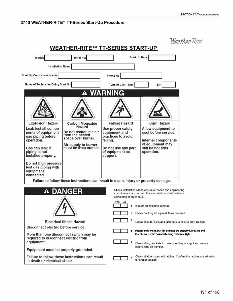
SECTION 27: TROUBLESHOOTING
191 of 198
27.10 WEATHER-RITE™ TT-Series Start-Up Procedure

TT-SERIES INSTALLATION, OPERATION AND SERVICE MANUAL
192 of 198
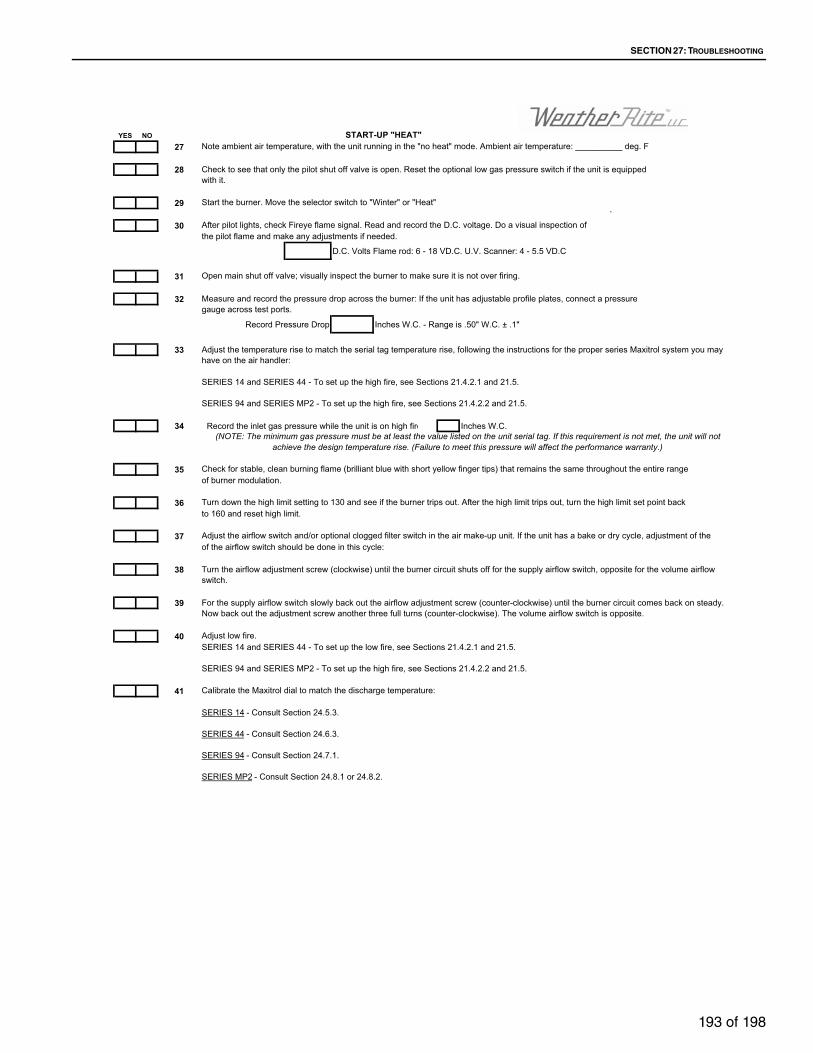
SECTION 27: TROUBLESHOOTING
193 of 198
YES NO
27
28
29`
30
D.C. Volts Flame rod: 6 - 18 VD.C. U.V. Scanner: 4 - 5.5 VD.C
31
32
Record Pressure Drop Inches W.C. - Range is .50" W.C. ± .1"
33
34 Record the inlet gas pressure while the unit is on high fire Inches W.C.
35
36
37
38
39
40
41
SERIES MP2 - Consult Section 24.8.1 or 24.8.2.
SERIES 94 - Consult Section 24.7.1.
Check for stable, clean burning flame (brilliant blue with short yellow finger tips) that remains the same throughout the entire range of burner modulation.
Turn down the high limit setting to 130 and see if the burner trips out. After the high limit trips out, turn the high limit set point back
SERIES 94 and SERIES MP2 - To set up the high fire, see Sections 21.4.2.2 and 21.5.
SERIES 44 - Consult Section 24.6.3.
to 160 and reset high limit.
Adjust the airflow switch and/or optional clogged filter switch in the air make-up unit. If the unit has a bake or dry cycle, adjustment of theof the airflow switch should be done in this cycle:
(NOTE: The minimum gas pressure must be at least the value listed on the unit serial tag. If this requirement is not met, the unit will not achieve the design temperature rise. (Failure to meet this pressure will affect the performance warranty.)
SERIES 14 - Consult Section 24.5.3.
Adjust low fire.SERIES 14 and SERIES 44 - To set up the low fire, see Sections 21.4.2.1 and 21.5.
Open main shut off valve; visually inspect the burner to make sure it is not over firing.
SERIES 14 and SERIES 44 - To set up the high fire, see Sections 21.4.2.1 and 21.5.
SERIES 94 and SERIES MP2 - To set up the high fire, see Sections 21.4.2.2 and 21.5.
Turn the airflow adjustment screw (clockwise) until the burner circuit shuts off for the supply airflow switch, opposite for the volume airflow switch.
For the supply airflow switch slowly back out the airflow adjustment screw (counter-clockwise) until the burner circuit comes back on steady. Now back out the adjustment screw another three full turns (counter-clockwise). The volume airflow switch is opposite.
Calibrate the Maxitrol dial to match the discharge temperature:
Note ambient air temperature, with the unit running in the "no heat" mode. Ambient air temperature: __________ deg. F
Start the burner. Move the selector switch to "Winter" or "Heat"
After pilot lights, check Fireye flame signal. Read and record the D.C. voltage. Do a visual inspection of the pilot flame and make any adjustments if needed.
START-UP "HEAT"
Adjust the temperature rise to match the serial tag temperature rise, following the instructions for the proper series Maxitrol system you may have on the air handler:
Check to see that only the pilot shut off valve is open. Reset the optional low gas pressure switch if the unit is equipped with it.
Measure and record the pressure drop across the burner: If the unit has adjustable profile plates, connect a pressure gauge across test ports.

TT-SERIES INSTALLATION, OPERATION AND SERVICE MANUAL
194 of 198
42
YES NO
If no, explain:
If no, explain:
If no, explain:
If no, explain:
If no, explain:
If no, explain:
43
If no, explain:
If no, explain:
44
If no, explain:
If no, explain:
Date Date
Operation of the temperature control in the dry cycle? (if applicable)
Personnel Training Review:
Proper maintenance and replacement of filters?
Location and operation of safety devices and location of reset buttons?
The customer knows where to purchase replacement filters and service parts?
Open Items Responsible Party Expected Completion Date
Maintenance:
The customer has been made aware of the equipment warranty?
Customer Signature
Operation of the balancing gauge to maintain positive pressure?
Location and operation of safety disconnect switch? (Use lockout/tag out procedures)
The above start-Up checklist has been completely and accurately filled out and reviewed with the customer
Name and position of individuals trained:Name: Position:
Documentation:The customer has a copy of the operations and maintenance manual?
The customer has a copy of this Start-Up checklist?
Operation of the temperature control? (Including "heat" minimum temp. rise?)
The following items should be completed during final walk through with the customer.
It is important that everyone concerned with the operation and maintenance of the equipment be trained in the safety procedures contained in the operation and maintenance manuals. Has everyone been trained on:
Factory Representative

SECTION 28: THE WEATHER-RITE™ TT-SERIES WARRANTY
195 of 198
SECTION 28: THE WEATHER-RITE™ TT-SERIES WARRANTYWEATHER-RITE LLC WILL PAY FOR:Within 24 months from date of purchase by buyer or 27 months from date of shipment by Weather-Rite LLC (whichever occurs first), replacement parts will be provided free of charge for any part of the product which fails due to a manufacturing or material defect.
Weather-Rite LLC will require the part in question to be returned to the factory. Weather-Rite LLC will, at its sole discretion, repair or replace after determining the nature of the defect and disposition of part in question.
WEATHER-RITE™ Replacement Parts are warranted for the later of 12 months from date of shipment from Weather-Rite LLC or the remaining WEATHER-RITE™ TT-Series warranty.
WEATHER-RITE LLC WILL NOT PAY FOR:Service trips, service calls and labor charges.
Shipment of replacement parts.
Claims where the total price of the goods have not been paid.
Damage due to:
• Improper installation, operation or maintenance.
• Misuse, abuse, neglect, or modification of the
WEATHER-RITE™ TT-Series in any way.
• Use of the WEATHER-RITE™ TT-Series for other
than its intended purpose.
• Incorrect gas or electrical supply, accident, fire,
floods, acts of God, war, terrorism, or other casualty.
• Improper service, use of replacement parts or
accessories not specified by Weather-Rite LLC.
• Failure to install or maintain the
WEATHER-RITE™ TT-Series as directed in the
Installation, Operation and Service Manual.
• Relocation of the WEATHER-RITE™ TT-Series after
initial installation
• Use of the WEATHER-RITE™ TT-Series in a
corrosive atmosphere containing contaminants.
• Use of the WEATHER-RITE™ TT-Series in the
vicinity of a combustible or explosive material.
• Any defect in the WEATHER-RITE™ TT-Series
arising from a drawing, design, or specification
supplied by or on behalf of the consumer.
• Damage incurred during shipment. Claim must be
filed with carrier.
WARRANTY IS VOID IF:The WEATHER-RITE™ TT-Series is not installed by an contractor qualified in the installation and service of gas fired heating equipment.
You cannot prove original purchase date and required annual maintenance history.
The data plate and/or serial number are removed, defaced, modified or altered in any way.
The ownership of the WEATHER-RITE™ TT-Series is moved or transferred. This warranty is non-transferable.
Weather-Rite LLC is not permitted to inspect the damaged equipment and/or component parts.
READ YOUR INSTALLATION, OPERATION AND SERVICE MANUAL.If you have questions about your equipment, contact your installing professional. Should you need Replacement Parts or have additional questions, call or write:
Weather-Rite LLC
616 North 5th Street
Minneapolis, MN 55401-1236
Telephone: +1.612.338.1401
Fax: +1.612.338.6783
Toll Free: 800.589.3691
www.weather-rite.com
Weather-Rite LLC's liability, and your exclusive remedy, under this warranty or any implied warranty (including the implied warranties of merchantability and fitness for a particular purpose) is limited to providing replacement parts during the term of this warranty. Some jurisdictions do not allow limitations on how long an implied warranty lasts, so this limitation may not apply to you. There are no rights, warranties or conditions, expressed or implied, statutory or otherwise, other than those contained in this warranty.
Weather-Rite LLC shall in no event be responsible for incidental or consequential damages or incur liability for damages in excess of the amount paid by you for the WEATHER-RITE™ TT-Series. Some jurisdictions do not allow the exclusion or limitation of incidental or consequential damages, so this limitation or exclusion may not apply to you. This warranty gives you specific legal rights, and you may also have other rights which vary from jurisdiction to jurisdiction.
Weather-Rite LLC shall not be responsible for failure to perform under the terms of this warranty if caused by circumstances out of its control, including but not limited to war, fire, flood, strike, government or court orders, acts of God, terrorism, unavailability of supplies, parts or power. No person is authorized to assume for Weather-Rite LLC any other warranty, obligation or liability.
LIMITATIONS ON AUTHORITY OF REPRESENTATIVES:No representative of Weather-Rite LLC, other than an Executive Officer, has authority to change or extend these provisions. Changes or extensions shall be binding only if confirmed in writing by Weather-Rite LLC's duly authorized Executive Officer.

TT-SERIES INSTALLATION, OPERATION AND SERVICE MANUAL
196 of 198

SECTION 28: THE WEATHER-RITE™ TT-SERIES WARRANTY
197 of 198
8 Specified Air Solutions

TT-SERIES INSTALLATION, OPERATION AND SERVICE MANUAL
198 of 198
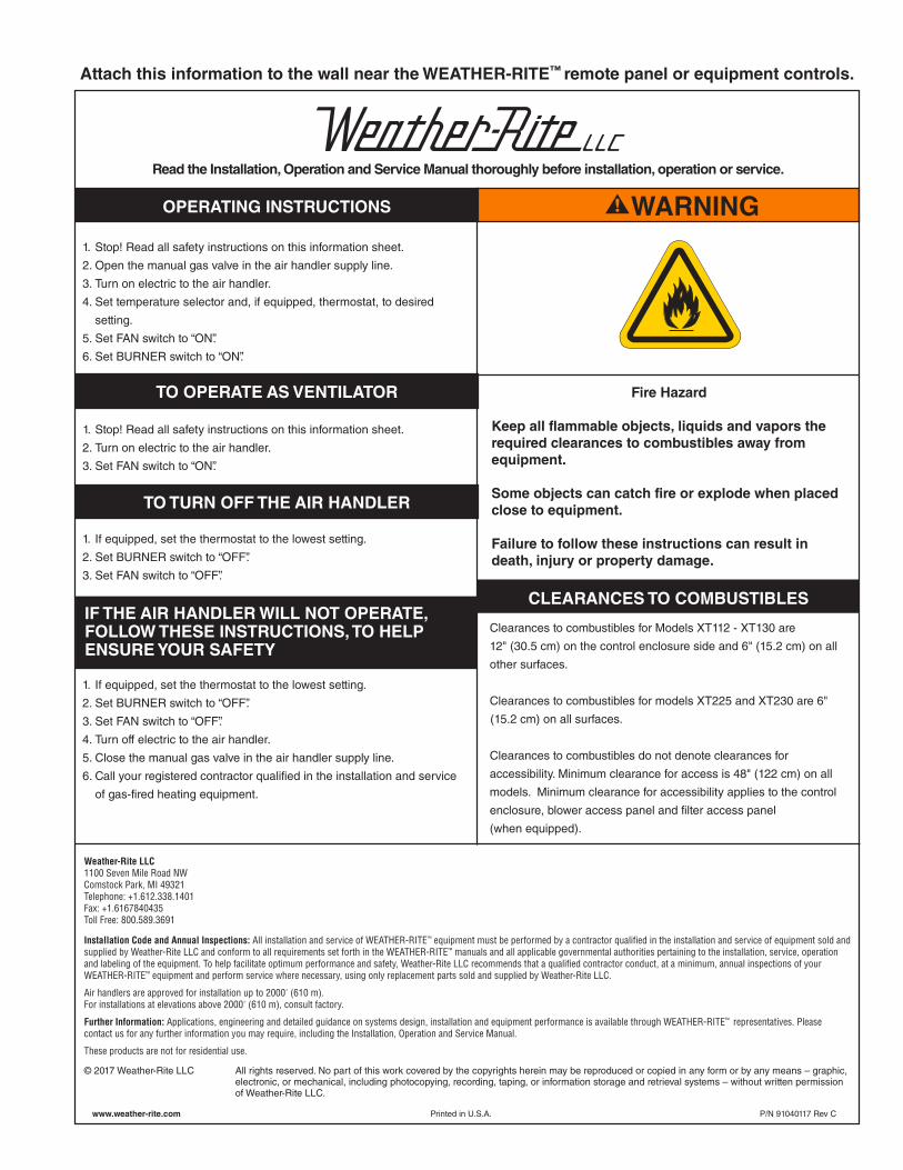
SECTION 28: THE WEATHER-RITE™ TT-SERIES WARRANTY
199 of 198
WARNING
Read the Installation, Operation and Service Manual thoroughly before installation, operation or service.
OPERATING INSTRUCTIONS
1. Stop! Read all safety instructions on this information sheet.
2. Open the manual gas valve in the air handler supply line.
3. Turn on electric to the air handler.
4. Set temperature selector and, if equipped, thermostat, to desired
setting.
5. Set FAN switch to “ON”.
6. Set BURNER switch to “ON”.
1. Stop! Read all safety instructions on this information sheet.
2. Turn on electric to the air handler.
3. Set FAN switch to “ON”.
1. If equipped, set the thermostat to the lowest setting.
2. Set BURNER switch to “OFF”.
3. Set FAN switch to “OFF”.
1. If equipped, set the thermostat to the lowest setting.
2. Set BURNER switch to “OFF”.
3. Set FAN switch to “OFF”.
4. Turn off electric to the air handler.
5. Close the manual gas valve in the air handler supply line.
6. Call your registered contractor qualified in the installation and service
of gas-fired heating equipment.
Fire Hazard
Keep all flammable objects, liquids and vapors the
required clearances to combustibles away from
equipment.
Some objects can catch fire or explode when placed
close to equipment.
Failure to follow these instructions can result in
death, injury or property damage.
Installation Code and Annual Inspections: All installation and service of WEATHER-RITE™ equipment must be performed by a contractor qualified in the installation and service of equipment sold and supplied by Weather-Rite LLC and conform to all requirements set forth in the WEATHER-RITE™ manuals and all applicable governmental authorities pertaining to the installation, service, operation and labeling of the equipment. To help facilitate optimum performance and safety, Weather-Rite LLC recommends that a qualified contractor conduct, at a minimum, annual inspections of your WEATHER-RITE™ equipment and perform service where necessary, using only replacement parts sold and supplied by Weather-Rite LLC.
Air handlers are approved for installation up to 2000' (610 m).For installations at elevations above 2000' (610 m), consult factory.
Further Information: Applications, engineering and detailed guidance on systems design, installation and equipment performance is available through WEATHER-RITE™ representatives. Please contact us for any further information you may require, including the Installation, Operation and Service Manual.
These products are not for residential use.
© 2017 Weather-Rite LLC All rights reserved. No part of this work covered by the copyrights herein may be reproduced or copied in any form or by any means – graphic, electronic, or mechanical, including photocopying, recording, taping, or information storage and retrieval systems – without written permission of Weather-Rite LLC.
Weather-Rite LLC1100 Seven Mile Road NWComstock Park, MI 49321Telephone: +1.612.338.1401Fax: +1.6167840435Toll Free: 800.589.3691
CLEARANCES TO COMBUSTIBLES
Clearances to combustibles for Models XT112 - XT130 are
12" (30.5 cm) on the control enclosure side and 6" (15.2 cm) on all
other surfaces.
Clearances to combustibles for models XT225 and XT230 are 6"
(15.2 cm) on all surfaces.
Clearances to combustibles do not denote clearances for
accessibility. Minimum clearance for access is 48" (122 cm) on all
models. Minimum clearance for accessibility applies to the control
enclosure, blower access panel and filter access panel
(when equipped).
TO OPERATE AS VENTILATOR
TO TURN OFF THE AIR HANDLER
IF THE AIR HANDLER WILL NOT OPERATE,FOLLOW THESE INSTRUCTIONS, TO HELPENSURE YOUR SAFETY
www.weather-rite.com Printed in U.S.A. P/N 91040117 Rev C
Attach this information to the wall near the WEATHER-RITE™ remote panel or equipment controls.

TT-SERIES INSTALLATION, OPERATION AND SERVICE MANUAL
200 of 198

SECTION 28: THE WEATHER-RITE™ TT-SERIES WARRANTY
201 of 198