WO 2008/080047 A2
39
(12) INTERNATIONAL APPLICATION PUBLISHED UNDER THE PATENT COOPERATION TREATY (PCT) (19) World Intellectual Property Organization International Bureau (43) International Publication Date (10) International Publication Number 3 July 2008 (03.07.2008) PCT WO 2008/080047 A2 (51) International Patent Classification: (74) Agents: MAYO, Michael, C. et al; Baxter International B03C 1/28 (2006.01) Inc., One Baxter Parkway, Deerfield, IL 60015 (US). (21) International Application Number: (81) Designated States (unless otherwise indicated, for every PCT/US2007/088527 kind of national protection available): AE, AG, AL, AM, (22) International Filing Date: AT, AU, AZ, BA, BB, BG, BH, BR, BW, BY, BZ, CA, CH, 21 December 2007 (21.12.2007) CN, CO, CR, CU, CZ, DE, DK, DM, DO, DZ, EC, EE, EG, ES, FI, GB, GD, GE, GH, GM, GT, HN, HR, HU, ID, IL, (25) Filing Language: English IN, IS, JP, KE, KG, KM, KN, KP, KR, KZ, LA, LC, LK, LR, LS, LT, LU, LY, MA, MD, ME, MG, MK, MN, MW, (26) Publication Language: English MX, MY, MZ, NA, NG, NI, NO, NZ, OM, PG, PH, PL, PT, RO, RS, RU, SC, SD, SE, SG, SK, SL, SM, SV, SY, (30) Priority Data: TJ, TM, TN, TR, TT, TZ, UA, UG, US, UZ, VC, VN, ZA, 60/871,781 23 December 2006 (23 .12.2006) US ZM, ZW (71) Applicants (for all designated States except US): BAX¬ TER INTERNATIONAL INC. [ /US]; One Baxter (84) Designated States (unless otherwise indicated, for every Parkway, Deerfield, IL 60015 (US). BAXTER HEALTH¬ kind of regionalprotection available): ARIPO (BW, GH, CARE S.A. [-/CH]; Hertistrasse 2, CH-8304 Wallisellen GM, KE, LS, MW, MZ, NA, SD, SL, SZ, TZ, UG, ZM, (CH). ZW), Eurasian (AM, AZ, BY, KG, KZ, MD, RU, TJ, TM), European (AT, BE, BG, CH, CY, CZ, DE, DK, EE, ES, FI, (72) Inventors; and FR, GB, GR, HU, IE, IS, IT, LT, LU, LV,MC, MT, NL, PL, (75) Inventors/Applicants (for US only): KIPP, James, E. PT, RO, SE, SI, SK, TR), OAPI (BF, BJ, CF, CG, CI, CM, [US/US]; 609 Hermosa Avenue, Wauconda, IL 60084 GA, GN, GQ, GW, ML, MR, NE, SN, TD, TG). (US). WONG, Joseph, Chung Tak [US/US]; 36141 N. Birdlewood Avenue, Gurnee, IL 60031 (US). WERLING, Published: Jane, O. [US/US]; 940 Northridge Avenue, Arlington — without international search report and to be republished Heights, IL 60005 (US). upon receipt of that report (54) Title: MAGNETIC SEPARATION OF FINE PARTICLES FROM COMPOSITIONS (57) Abstract: The disclosure describes apparatuses and methods of use thai may be used to remove material with magnetic proper- ties from compositions, particularly pharmaceutical compositions. The apparatuses provide a conduit or column in which a magnetic field exists and through which a composition flows. Magnetic material in the composition is substantially reduced after flowing through the conduit or column.
-
Upload
khangminh22 -
Category
Documents
-
view
1 -
download
0
Transcript of WO 2008/080047 A2

(12) INTERNATIONAL APPLICATION PUBLISHED UNDER THE PATENT COOPERATION TREATY (PCT)
(19) World Intellectual Property OrganizationInternational Bureau
(43) International Publication Date (10) International Publication Number3 July 2008 (03.07.2008) PCT WO 2008/080047 A2
(51) International Patent Classification: (74) Agents: MAYO, Michael, C. et al; Baxter InternationalB03C 1/28 (2006.01) Inc., One Baxter Parkway, Deerfield, IL 60015 (US).
(21) International Application Number: (81) Designated States (unless otherwise indicated, for everyPCT/US2007/088527 kind of national protection available): AE, AG, AL, AM,
(22) International Filing Date: AT,AU, AZ, BA, BB, BG, BH, BR, BW, BY,BZ, CA, CH,
2 1 December 2007 (21.12.2007) CN, CO, CR, CU, CZ, DE, DK, DM, DO, DZ, EC, EE, EG,ES, FI, GB, GD, GE, GH, GM, GT, HN, HR, HU, ID, IL,
(25) Filing Language: English IN, IS, JP, KE, KG, KM, KN, KP, KR, KZ, LA, LC, LK,LR, LS, LT, LU, LY, MA, MD, ME, MG, MK, MN, MW,
(26) Publication Language: English MX, MY, MZ, NA, NG, NI, NO, NZ, OM, PG, PH, PL,PT, RO, RS, RU, SC, SD, SE, SG, SK, SL, SM, SV, SY,
(30) Priority Data: TJ, TM, TN, TR, TT, TZ, UA, UG, US, UZ, VC, VN, ZA,60/871,781 23 December 2006 (23 .12.2006) US ZM, ZW
(71) Applicants (for all designated States except US): BAX¬TER INTERNATIONAL INC. [ /US]; One Baxter (84) Designated States (unless otherwise indicated, for every
Parkway, Deerfield, IL 60015 (US). BAXTER HEALTH¬ kind of regional protection available): ARIPO (BW, GH,
CARE S.A. [-/CH]; Hertistrasse 2, CH-8304 Wallisellen GM, KE, LS, MW, MZ, NA, SD, SL, SZ, TZ, UG, ZM,
(CH). ZW), Eurasian (AM, AZ, BY, KG, KZ, MD, RU, TJ, TM),European (AT,BE, BG, CH, CY, CZ, DE, DK, EE, ES, FI,
(72) Inventors; and FR, GB, GR, HU, IE, IS, IT, LT,LU, LV,MC, MT, NL, PL,(75) Inventors/Applicants (for US only): KIPP, James, E. PT, RO, SE, SI, SK, TR), OAPI (BF, BJ, CF, CG, CI, CM,
[US/US]; 609 Hermosa Avenue, Wauconda, IL 60084 GA, GN, GQ, GW, ML, MR, NE, SN, TD, TG).(US). WONG, Joseph, Chung Tak [US/US]; 36141 N.Birdlewood Avenue, Gurnee, IL 60031 (US). WERLING, Published:Jane, O. [US/US]; 940 Northridge Avenue, Arlington — without international search report and to be republishedHeights, IL 60005 (US). upon receipt of that report
(54) Title: MAGNETIC SEPARATION OF FINE PARTICLES FROM COMPOSITIONS
(57) Abstract: The disclosure describes apparatuses and methods of use thai may be used to remove material with magnetic proper-ties from compositions, particularly pharmaceutical compositions. The apparatuses provide a conduit or column in which a magneticfield exists and through which a composition flows. Magnetic material in the composition is substantially reduced after flowingthrough the conduit or column.

MAGNETIC SEPAVRATION O F FINE PARTICLES FROM COMPOSITIONS
DESCRIPTION
FIELD OF THE DISCLOSURE
[0001] fhe disclosure relates to compositions, apparatuses and systems for use in the
removal of magnetic material from compositions, particularly pharmaceutical compositions
BACKGROUND
[0002| Many applications require the separation of particles from a composition. Filtration
is a widely used method to remove particulate matter. In one commonly used version of this
method, a membrane is inserted into the flow of the preparation and particles are unable to
pass through the pores of the membrane due to their size. The filtration membrane may also
include materials such that the particles absorb to the membrane. The composition with
reduced amounts of particles is collected as the filtrate. However, filtration may not be
desirable in situations where small particles are present and membranes with very small pore
sizes are required because an unacceplably large increase in mechanically applied pressure
may be necessary to maintain the flow rate. In addition, filtration may be difficult where the
initial viscosity of the solution is high or where the one or more of the components of the
composition is not compatible with the membrane. Also, filtration may be completely
impossible in situations where the active agent is itself in the form of particles in suspension.
In these cases, filtration may remove the active agent particles as well as undesirable
particles.
[0003 1 An alternative method of separating particles takes advantage of their magnetic
properties. Generally, if a magnetic field is applied to a solution containing material with
magnetic properties, then that material will be drawn to the source of the magnetic field and
will be separated from the solution. The use of magnetic fields to separate components from
solution has been exploited in applications where it is necessary to purify a particular
component from a solution. For example, an antibody may be linked to a magnetic particle
and the antibody-particle complex mixed with blood. The antibody will interact with its
corresponding antigen in the solution. When a magnetic field is applied, the antibody-
ant igcn-magnetic particle complex can be separated from the blood.

[0004| Material \\ tth magnetic properties may also arise during the production of a
composition. For example during the production of pharmaceutical co positions one source
of mela! particles comes from the metal used in devices such as reaction \essels. stirrers,
homogenuers. grinders and ball milling apparatus. The presence o f these particles e\en at
\ery low levels is undesirable and the use o f magnetic fields presents one method to remove
them and achieve the required purity for the composition. These metal particles may arise
from metals such as allotropes of iron (e.g., ferrite austenite, martensite), alloys of iron and
carbon (such as stainless steel, with or without added elements such as nickel, cobalt
molybdenum, chromium or vanadium), lanthanides (such as gadolinium, europium, and
dysprosium), or paramagnetic materials such as aluminum, titanium, and their alloys.
Ceramic materials may also be magnetic. Magnetic ceramics may be generated by mixing
metal oxides (e.g., ZnO, FeO, MnO, N)O, BaO, or SrO) with Fe2O These ceramics find use
in permanent magnets, computer memory, and in telecommunications
[0005J Stainless steel is defined as a ferrous alloy with a minimum of 10.5% chromium
content. The presence of chromium results in a higher resistance to rust and corrosion. The
magnetic properties of stainless steel vary depending on the elemental composition of the
steel. Alloys with relatively low concentrations of nickel or manganese are ferromagnetic. In
these alloys, a martensite crystalline structure predominates and the steel will respond
strongly to magnetic fields. Steel alloys with higher concentrations of nickel or manganese
assume a stabilized austenite crystalline configuration. The austen ϊ tic steels are generally
considered non-magnetic but in fact are paramagnetic and will respond to strong magnetic
fields (on the order of 1 TESLA). Pure titanium or aluminum are paramagnetic and are
expected to respond to strong magnetic fields.
[00061 U.S. Published Patent Application No. 2003/010861 3 by Weitschies et al, which is
herein incorporated by reference, describes a device for the magnetic separation of
pharmaceutical preparations. The device consists of a separation space in which a magnetic
field prevails and which has an inlet and an outlet. However, the device is intended to be
used only as an attachment filter for infusion and injection instruments or to be integrated
into such instruments. There remains a need for apparatuses, systems and methods for using
them which are able to separate magnetic material and which are more easily adapted into
processes for formulating compositions.

SUMMARY
[0007] The disclosure ides for apparatuses, systems and methods to substantial!)
remove magnetic material from compositions, particularly pharmaceutical compositions.
[0008] in one embodiment, the disclosure provides for a conduit through which a
composition passes or is maintained. The conduit passes adjacent lo an arrangement of
magnets and the composition is subject to a magnetic Held that substantially removes
material with magnetic properties.
[Θ009J In one embodiment, an arrangement of magnets is formed from magnets that are
arranged in at least one double Halbach array. The conduit passes through a space between
the halves of the array substantially removing material with magnetic properties from a
composition that flows through the conduit
[0010] In another embodiment, a column contains magnetic beads. A composition passes
through the column, and material with magnetic properties is substantially removed.
[001 1] The disclosure also provides for systems that incorporate the apparatuses of the
disclosure as well as methods for using the apparatuses.
BRIEF DESCRIPTION O F THE DRAWINGS
[00121 s - i -a a n I show cross-sectional views of apparatuses according to the
disclosure
(0013] Fig. 2 shows a cross-sectional view of an apparatus according to the disclosure.
[0014] Figs. 3a and 3b show schematics of two possible arrangements of magnets
according to the disclosure.
[0015] Figs 4a to 4e show schematics of the possible orientations of the magnetic fields of
split ring magnets according the disclosure
[0016] Fig. 5 is a schematic showing an arrangement of magnets that form a Halbach
array
[0017] Figs. 6a and 6b are schematics showing an arrangement of magnets that form a
double Halbach array, in an (a) aligned or (b) opposed arrangement according to the
disclosure.

(0018| Fig. 7 is a schematic showing an arrangement o f ring magnets that form a double
Halbach aligned array
[0019] Fig. 8 shows magnetic field lines and flux as determined by finite element analysis
of the arrangement of magnets shown in Fig. 7 .
(002Oj Figs. 9a and 9b are schematics showing an arrangement of magnets forming
multiple double Halbach arrays according to the disclosure.
(0021) Figs. 10a (double Halbach aligned), 1Oh (double Halbach opposed) and 10c
(diametrically oriented array elements as shown in Fig 3a using whole magnets) show
magnetic field lines and flux as determined from finite element analysis o f arrangements o f
magnets according to the disclosure.
[0022] Fig 11 shows a cross-sectional view of an embodiment of an apparatus according
to the disclosure.
[0023J Figs. 12a and 12b show a side view of an embodiment of an apparatus according to
the disclosure.
J0024] Fig. 13 is a graph showing a plot of magnetic field strength across the inner
diameter of a split ring magnet in which the magnetic fields are diametric and antipodal
(south-to-south).
[0025J Fig. 14 shows an embodiment of a system for removing magnetic material from a
composition according to the disclosure
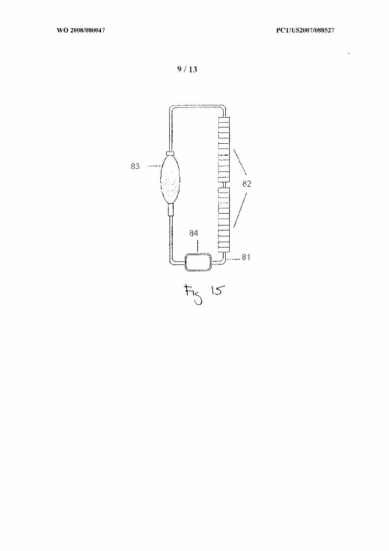
[0026] Figure 15 show s another embodiment of a system for removing magnetic material
from a composition according to the disclosure.
[0027| Fig. 16 is a graph showing the ability of several embodiments according to the
disclosure to remove magnetic material from a composition.
[0028J Fig 17 is a graph showing the residual iron in a composition treated to remove
magnetic material from a composition using embodiments of the disclosure.
[0029] Fig 18 is a graph showing the ability of several disclosed embodiments to remove
magnetic material from a composition at different flow rates and with different numbers of
passages.

[0030] Fig. 19 is a photograph showing the absorption of magnetic material to tubing as
described in the disclosure.
[0031] Fig. 20 is a graph showing the separation of magnetic material as described in
Example 4
DESCRIPTION O F THE PREFERRED EMBODIMENTS
[0032 J As required, detailed embodiments of the present disclosure are disclosed herein;
however, it is to he understood that the disclosed embodiments are merely exemplary of the
disclosure, which may be embodied in various forms. Therefore, specific details disclosed
herein are not to be interpreted as limiting, but merely as a basis for the claims and as a
representative basis for teaching one skilled in the art to variously employ the present
disclosure in virtually any appropriate manner.
J0033J This disclosure concerns apparatuses and systems for the separation or removal of
ferromagnetic, ferrimagnetic, paramagnetic, or superparamagnetic particulate material from
compositions that are in the form of a fluid or solid. The fluid may be either a solution or a
fluid containing dispersed particles. The composition may be solid such as a finely divided
powder that can be passed through the apparatuses of the disclosure using a stream of carrier
gas. The present disclosure can be used in numerous applications where it is desirable to
remove material that is responsive to magnetic fields, including magnetic material of a very
small size. These applications include petroleum products, pharmaceutical compositions,
magnetic recording media, food products and drinking water purification. In one
embodiment, the apparatuses and methods of the disclosure are used with pharmaceutical
compositions.
[0034] The present disclosure can also be used in any industrial process in which magnetic
particles are intentionally added as a catalyst or manufacturing aid that needs to be removed
at the end of the manufacturing process. In biotechnology, for example, the disclosure is
applicable to situations where desired biochεmicats or biologicals including cells or tissue
should be separated from other components during or at the end of a process (e.g.,
fermentation). For example, magnetic beads coated with molecules (e.g., antibodies) that
specifically interact with the desired product are added, the interaction occurs, and the
magnetic beads with the attached desired product are removed. The final product is detached

from the beads which can then be recycled. This is exemplified in US Patent 4,628 037
which is herein incorporated by reference Another example is in I 1S Patent 5,9 16 741 which
is also herein incorporated by reference. This latSer patent discloses a cell-separation method
combining lhe techniques o f immunoaffinily separation and continuous flow centrifugal
separation for selective separation of a nucleated heterogeneous cell population from a
heterogeneous cell mixture. The heterogeneous cell mixture is intimately contacted to
promote binding thereto by particles having attached a substance that actively binds to a
specific desired type of cell out of the cell mixture. The particles are selected so that the
sedimentation velocity of the particle/cell conjugate differs sufficiently from those of other
cells in the cell mixture to allow its separation by means of a continuous flow cell separator.
The method rapidly processes large volumes o f cell mixture with the high accuracy expected
of immunoaffmity separation and can be used to separate, for example, various types of
leukocytes from whole blood, bone marrow concentrate, or a peripheral blood stem cell
concentrate; or precursors of lymphokine activated killer cells, tumor infiltrating lymphocyte
cells, or activated kilter monocytes from lymphocyte or monocyte cell concentrates or from a
tissue cell preparation. In this case, the present disclosure can be used as an alternative
separation method to immunoaffmity purification and separation techniques.
[0035| In general, the apparatuses provide for a separation zone to which a magnetic field
is applied and through which a composition passes or is maintained. The apparatuses
include an arrangement of magnets that produce a magnetic field of sufficient force to
remove magnetic material such that the treated composition is rendered substantially free of
magnetic material or at least within required limits. The apparatuses described here are
capable of being physically integrated into systems used to make compositions such that the
separation of magnetic material becomes an easily accomplished step in the process of the
commercial production of compositions. Alternatively, the apparatuses of the disclosure may
be used separately from the other processes during production of compositions.
10036] The apparatuses and methods disclosed here are capable of removing material with
magnetic properties including material with ferromagnetic, ferrimagnetic, paramagnetic and
superparamagnetic properties. In one embodiment, the composition is a pharmaceutical
composition, and the active agent or agents of the composition are generally non-magnetic or
diamagnetic, whether the active agent forms a homogeneous solution or is in the form of

dispersed particles in suspension. In this embodiment, undesirable magnetic materia! is
removed and the acth e agent is substantially iciainccl in the composition I an alternative
embodiment, the active agent may have magnetic properties and the apparatuses are used to
separate out the active agent from other components of the composition.
[0037 1 It is generally noted that the disclosure can be especially efficient in reniov ing
smaller particles from a composition that includes different sizes of particles to be removed.
[0038] In one embodiment, the apparatuses may separate particles of stainless steel or
other metals that may originate from the machinery used during the production of
pharmaceutical compositions, including particles that originate from alloys of stainless steel
that are generally considered non-magnetic. Although not wishing to be bound by theory,
these alloys may be non-magnetic on a large scale but the smaller magnetic particles that
originate from abrasive processes may have magnetic properties. On a large scale, there may
be no net magnetization because randomly oriented magnetic domains within the molecular
structure of the steel cancel each other. However, particles may have a single isolated domain
or a small collection of domains and have net magnetic properties. Domain sizes vary
considerably from a few nm to over 10 microns, depending on the type of material and how it
was processed (Fourlaris G; Maylin MG; Gladman T Magnetic domain imaging and
mechanical/magnetic property characterization of a 2507 type duplex austcnitic-fcrritic
stainless steel. Materials Science Forum, 1999, VoI 318-320, pp 823-828). In addition,
abrasive stress is known to cause a transition from an austenilic crystalline form found in
many stainless steels to a martensitic form. The latter form has ferromagnetic properties and
responds to magnetic fields. Furt hermore austenite is paramagnetic and responds to very
strong magnetic fields.
[0039J Magnets formed from a number of elements can be used for the disclosed magnetic
separations depending on the nature of the material to be separated. The removal of small
particles by magnetic attraction is enhanced by the use of magnets with very strong magnetic
fields. In this case, the rare earth composite neodymiurn-iron-boron (NdFeB) typically is an
advantageous choice. NdFeB has the highest residual magnetic flux density (Br) and
resistance to demagnetization (also called coercivity [Hc]) of any magnet formula. The
maximum flux density at the surface of NdFeB is approximately 10,000 gauss ( 1 Tesla)

Samarium Cobalt (SmCo) s another preferred material. The magnets may be bar-shaped,
hoiscshoc-shapcd or ring-shaped, for example
[00401 Fig. I shows one embodiment of an apparatus that can achieve the separation of
magnetic material. The apparatus has a conduit 2 1 with an interior volume 22 that carries a
composition, such as a pharmaceutical composition. The conduit 2 1 passes through a zone 24
containing a magnetic field. The magnetic field is generated by an arrangement 25 of at least
one magnet. In this and other embodiments, the conduit passes through a gap 26 in the
arrangement of magnets where lhe magnetic field prevails.
[0041) The removal o f magnetic material is achieved when the composition containing the
magnetic material passes through the conduit and the magnetic particles are drawn to the
interior surface of the conduit by the magnetic field. As shown in Fig. 2 the conduit 4 1 with
interior volume 42 may have properties of its interior surface or features on its internal
surface 44 (such as a matrix 43) that impede, retain or trap the particles 47 when they are
attracted to the internal surface of the conduit 4 1 by the magnetic field produced by the
arrangement of magnets 45. When provided, a matrix feature may consist of elastomeric,
tacky or fibrous material. Fig 19 illustrates this aspect of the present disclosure. A
composition containing magnetic material was passed through silicone tubing and subjected
to a magnetic field. The magnetic field and composition were removed and the tubing
examined. Dark bands representing magnetic material can be seen as being retained on the
inside surface of the tubing. The bands are separated by 0.5 inch, which corresponds to the
width of each magnetic element in the array of magnets used in this particular embodiment.
In this embodiment, the magnetic material absorbs most obviously by visual inspection to the
tubing in periodic regions of high magnetic field gradient. These regions are predicted by
finite-element analysis (Figure 10c) and occur near the magnet junctions where field lines
emanate and where line spacing changes most with increasing distance from the gap into the
central space of the magnet array.
J0042] The conduit, for example, may be non-magnetic tubing that is compatible with
pharmaceutical compositions. The conduit may be adapted such that it can be integrated into
a system for production of a pharmaceutical composition. For example, one end of the
conduit may be adapted to receive the pharmaceutical composition from a previous step in
processing and the second end may be adapted to re-circulate the pharmaceutical composition

through the first end of the conduit to repeat the magnetic separation step or to the next step
in processing of the pharmaceutical composition. The effluent contains no magnetic particles.
or a quantity o f magnetic particles significantly lower than that in the initial composition.
Alternatively, the apparatus may be separate from the other components of the production
system.
[0043] [n the embodiment shown in Fig. Ia, a conduit passes through a separation /one
where a magnetic field is formed by a single magnet. The magnetic field may be orientated
in the same orientation as the flow of the composition or it may be orientated transversely to
the flow or at any angle between these orientations.
[00441 h i - ' b. representing another embodiment of this disclosure, the conduit 3 1with
interior volume 32 passes through the separation zone 34 which is formed by more than one
magnet 35 separated with optional spacers 33, formed from non-magnetic or ferromagnetic
material, that are inserted between each magnet 35. The conduit passes through a gap 36 in
the arrangement of magnets. In a further embodiment of this segmented design, spacers are
not inserted between segments, and thus the magnets are in direct contact with each other.
The magnetic field orientation of each magnet may be parallel or perpendicular to the
direction of flow of the composition or may be orientated at some angle between these two
positions. For the purposes of this disclosure the orientation of a magnetic field is shown in
various drawings by an arrow with the arrowhead pointing in the direction of North.
[0045] For example, in one embodiment o f an array of magnets (Fig. 3a), the field of each
magnet runs transversely and perpendicular to the direction of flow of the composition
("diametric orientation"). The field orientation may also run parallel to the direction of flow
("axial orientation") fn Fig 3a, the diametric orientation of each successive segment runs in
the opposite direction ("antipodal"). The magnetic orientation of each element in the array
also may be axial, or parallel to the major axis as shown in Figure 3b. In these examples the
magnetic field vectors of each magnet are aligned in the same direction, although it is to be
emphasized that any magnet in the array may be arranged such that its magnetic field may
assume any orientation with respect to other magnets in the array.
10046] In a further embodiment, the magnetic field results from a series of ring magnets
such that each split pair comprises one segment. Each half of the pair may have any
magnetic field orientation. Fig. 4 illustrates possible orientations. In Fig 4 a the field of

each half is diametric and both fields are aligned Io point in the same direction. In this
configuration, Άwhole magnet (unsplit) ith diametric magnetization may also be used
instead of a split pair. In Fig 4b, the field of each half is diametric, but both vectors point in
opposite directions, and antipodal (the North pole of one half abuts the North pole of the
other half). In Fig. 4c, the fields are diametric and antipodal, but are oriented so that the
South pole of one half-element abuts the South pole o f the other half. Fig 4d shows a split
element pair, in which the field vectors are axially oriented and run in the same direction (X -
South, • = North). As with the configuration in Fig. 4a, a whole magnet (i.e. unsplit) that is
magnetized in the axial direction may be used instead of the split pair. Figure 4e shows a
split element pair in which the axial fields run in opposite directions.
100471 I one embodiment, the composition flows through a conduit that passes through a
gap in a series of magnets in which the magnetization vectors of the magnets are arranged
according to a modification of a simple Halbach array. In a Flalbach array, a series of
permanent magnets is arranged such that the magnetic field on one side of the array is
augmented while reducing the field to very low values on the other side, ϊn a typical Halbach
array of block magnets, the magnetization direction of each magnet in the series is rotated a
specified angle in either a clockwise or counterclockwise direction. Fig. 5 illustrates an
example of this concept in which each successive magnetic element in the array is rotated 90
degrees. The result of this arrangement is that the magnetic field lies predominantly along
only along one face of the array.
[0048] In another embodiment utilizing a split ring design, each half of the array comprises
a series of complete magnetic circuits (a double Halbach design). In Fig. 6a, the double
Halbach, aligned array, every other split ring pair is diametrically aligned, whereas the other
elements that separate the diametric elements are axial and antipodal. In a further
embodiment, the diametrically aligned split pairs may be fused into whole magnets that are
diametrically magnetized. The axial split ring elements serve to direct the field of a
neighboring diametric element along the axial direction and through the adjoining diametric
element into the space between the halves of the array, resulting in a weaker magnetic field
on the exterior of the array and a stronger magnetic field in the space between the the arrays.
In the embodiment shown in Fig. 6a, the split axial pair is antipodal. This configuration
results in a series of complete magnetic circuits through both halves of the array.

. π -
[0049] In a further embodiment ("double l ϊ albacn, opposed"), the axial split elements are
aligned and the alternating diametric elements are antipodal (see Fig. 6b). In a >et further
embodiment each axial split element pair in this design may be fused into a whole magnet
with axial magnetization. The diametric elements alternate in series between antipodal (N to
N) and antipodal (S to S) configurations. As in the double Halbach aligned arrangement, this
arrangement also directs the field Io the space between the halves of the array, but in an
antipodal fashion, such that the field is compressed in the space between the two halves of the
array (that is, the field density is higher). This configuration results in magnetic circuits that
are restricted to each half of the array
[0050] As shown in Fig 7 another embodiment shows a split ring array configuration
("double Halbach aligned") where the magnets are stacked. The diametrically magnetized
elements may either be split pairs or whole magnets that are diametrically magnetized. The
magnetization polarity is designated by N or S . The array may consist of any number of
magnets with the repeated magnetization pattern illustrated in Fig. 7. The alternating
magnets may have any dimension. For example, alternating thin elements alternate between
thicker elements as shown in Fig. 7. In the double Halbach designs, the magnetic field is
almost entirely focused in tight zones within the vertical central bore of the array. This is
illustrated in Figure 8, generated by performing a finite-element analysis (using Vizimag,
version 3.1, by J . Beeteson, 2005) on the array shown in Fig. 7.
[0051] Figs. 9a and 9b show two embodiments of double Halbach arrangements that were
experimentally tested in the Examples. Each array was composed of twenty elements. This
double Halbach arrangement may be thought of as a composite of two Halbach arrays, each
comprised of a series of half magnets, or combinations of split pair elements (antipodal) and
whole magnets. In the first embodiment (the Halbach Aligned design), the magnetization
vectors for the stack of ring magnets are oriented as shown in Fig. 9a. The magnetization for
the segments (whole magnets) labeled "1" is diametric (transverse), and perpendicular to the
major (long) axis of the array. In the segments labeled "2", the magnets are split and vectors
on both halves of each segment are anti-parallel to each other and parallel to the major axis.
The field directions are reversed for every other axial element pair.
[0052] In a further embodiment (the Halbach opposed design), the magnetization vectors
for the array are oriented as shown in Fig. 9b. The magnetization for both halves of the

scgmcnts labeled "1" is diametric (transverse) antipodal (oriented in opposite directions),
and petpendicular to the major (long) axis of the array The field vectors for both halves are
pointed directly at each other. In the segments labeled 2". the vectors on both halves of each
segment are antipodal and diametric (perpendicular to the major axis). Unlike the
configuration of segments "1", the field vectors for each half o f the split pair arc antipodal
and directed away from each other. Elements labeled "3" are whole magnets that are axially
magnetized. This direction is reversed for every other axial clement.
[0053 1 As shown in Figs. 10a and 10b, a finite element analysis in two dimensions was
performed on each array configuration in Fig. 9. The 2-dimensional analysis is a mapping of
Reid lines on a plane that bisects each array. This bisecting plane contains the central aiτay
axis and is perpendicular to the cleavage planes between split elements. The arrays in Figures
10a and 10b comprise series of split ring magnets, whereas the configuration shown in Figure
10c consists of a series of whole ring magnets that are transversely (diametrically)
magnetized. This configuration (Fig 1Oc) is built by normally stacking ring magnets on top
of one another. Because the opposite poles attract each other, it is not necessary to apply
mechanical force to maintain the magnets in close proximity.
[0054] Areas with a stronger magnetic field are represented by closer line spacing. As
shown, the double Halbach array opposed (Fig. 10b) generates higher field strengths and flux
densities in the space encompassed by the array than the double Halbach aligned array (Fig.
10a) and the unsplit ring design (Fig. 10c). Magnetic gradients (changes in field strength per
unit distance) were calculated to be somewhat similar in the two Halbach designs. The
attractive force between two magnetic dipoles is proportional to the product of the field
strength, density, and magnetic moment of the particle. This is expressed in the
F - I P fdB Bequation: µ \ dt
[0055] Fµ is the magnetic force between two dipoles. χ is the magnetic susceptibility p is
the particle density, µo is the magnetic permeability of free space, dB/dl is the magnetic field
gradient along a direction perpendicular to the field lines, and \B \ is the field strength at the
particle position. Therefore, at similar magnetic gradients, higher field strengths should
result in larger forces between the magnetic particles and the walls of the magnet array.

[0056] Compared with the Halbach opposed design (Fig. 10b), the whole magnet array
configuration (Fig. 10c) and the Halbach aligned design (Figure 10a) show a more diffuse
field in the central space within the array. Weaker magnetic gradients correspond to these
regions in these latter two arrangements.
[0057| In Fig. 11, a further embodiment according to the disclosure is shown. In this
embodiment, a column 5 1 containing one or more magnetic beads 52 is provided, with each
bead possessing a high surface field strength (> 1,000 gauss). The maximum surface field
strength typically can be much less than that associated with ring magnets that are
substantially larger than these magnetic beads. An initial composition, a fraction of which
consists of ferromagnetic or paramagnetic particles, is passed through the column 51.
Ferromagnetic or paramagnetic particles are attracted Io the surfaces o f the magnetic beads
52 within the column thereby separating the magnetized particles from the composition. The
effluent dispersion contains no magnetic particles, or a reduced quantity of magnetic particles
significantly less than that in the initial dispersion. The column may be inserted into devices
used to process compositions or it may form an apparatus that may be used independently.
[00581 yet further embodiment is shown in Fig. 12a. A conduit 60 is subject to a
magnetic Field where the conduit is adjacent to or in contact with the external surface of an
arrangement 6 1 of one or more magnets. The arrangement of magnets may consist of one
piece of magnetic material or a series of magnetic segments, which may be in direct contact
with each other, or separated by metallic or non-metallic spacers. The arrangement consists
of magnetic material of high surface field strength (>l,000 gauss). The conduit may, for
example, be non-magnetic tubing. The conduit may assume a number of different
arrangements with respect to the external surface of the arrangement of magnets. In the
embodiment shown in Fig 12a, the initial particle dispersion is directed through the conduit
wound in a helix adjacent to or in contact with the outer surface of the solid magnetic
arrangement 6 1 as shown in Fig. 12a. In an alternative embodiment shown in Fig. 12b, the
conduit 62 is adjacent an arrangement of magnets in the form of a tube 63. In both
embodiments, the ferromagnetic or paramagnetic particles are attracted to the inner surface of
the non-magnetic tubing closest to the magnetic cylinder thereby separating the magnetized
particles from the initial particle dispersion.
EXAMPLE 1

J0059| Fins Example describes purification of pharmaceutical solid in a liquid process
stream. Three magnetic array separators were tested each of the follow ing types:
(a) Whole magnet array (diametric alternating antipodal segments)
(b) Double Halbach array aligned
(c) Double Halbach array opposed.
[0060| Each magnetic element (split or whole ring magnet), was fabricated from
neodymium-tron-boron (NdFeB) alloy (DuraMagnetics, Sylvania. OH). The magnetic field
strength of a whole magnet was measured on its outside surface using a DC magnetometer
(AlphaLab Inc.), and was found to have a maximum field strength of approximately 5,000
gauss (0.5 tesla). Finite element analysis estimated field strengths as high as 5,700 gauss for
each magnet, and strong gradients near the inner surface o f the central bore of the ring
magnet (see Fig. 13) near the junction of the two half elements. The outer diameter of the
ring was 1-inch, the inner diameter (of the center hole) was 1A inch (6.35mm), and the
thickness was V inch (12 7mm).
[0061] Systems as shown in Fig. 14 and Fig. 15 were used to separate magnetic material
consisted of two 20-magnet arrays combined in series, vertically arranged, and collincar.
Two setups were used, one for single-pass studies (Fig. 14), and another for multiple passes
through the array (Fig. 15). The system using a syringe pump is shown in Figure 14
Silicone tubing 7 1 (153 cm Tygon Sanitary Silicone Tubing, Formulation 3350, Saint-Gobain
Performance Plastics) with an outer diameter of 1/4 inch (6.35mm) and wall thickness of 1/32
inch (0.79 mm) was passed through the bore of two magnetic arrays 72, connecting the two in
series. The tubing 7 1 extending from the bottom of the array was connected to a syringe
pump 70, and the other end was inserted into a beaker 73 to collect the effluent. Fresh tubing
was used in each experiment. A 1% (w/v) composition of drug in a liquid vehicle was
prepared by precipitation of the drug, followed by homogenization to reduce drug particle
sizes. The drug particles were diamagnetic. The volume-weighted mean drug particle size
was 0.485,and particles at the 99 l percentile were less than < 1.71 µm. The composition also
contained particles that were either ferromagnetic (e.g., steel), paramagnetic (e.g., titanium,
aluminum), or a combination thereof.

[0062] The syringe pump 70 {sec Fig. 14) was equipped with a 60-cc syringe, filled with
10 niL of the composition. An aliquot of unprocessed starting material was saved as a
control. In one set o f experiments, the suspension was passed through the magnetic array in
one pass and was not rccirculatcd. The pump was started at a specified ilow rate and 10 ml
of cluent was collected.
10063( To recirculate the composition through the magnetic arrays (5 passes), a system
using a peristaltic pump was used (see Fig. 15). A composition was passed through tubing
8 1, through the bore of two magnetic arrays 82 and then to an addition funnel 83. Under the
action of the pump 84 the suspension was recirculated through the arrays 82. Sixteen trials
were conducted (8 single pass studies, and 8 multiple pass studies), under conditions shown
in Table 1. A run through the same length of tubing, in the absence of the magnetic array
was carried out as a control ("NO ARRAY").
[0064] Drug particle size populations were determined by static laser diffraction (Horiba
LA-920). The method is described in the following article: J . Wong, P Papadopoulos, J .
Werling, C . Rebbeck, M. Doty, J . Kipp, J . Konkel and D. Neuberger," Itraconazole
Suspension for Intravenous Injection: Determination of the Real Component of Complete
Refractive Index for Particle Sizing by Static Light Scattering," PDA J . Pharm Sci. Technol.,
60, 302-313 (2006) and D. Neuberger and J. Wong, "Suspension for Intravenous Injection:
Image Analysis of Scanning Electron Micrographs of Particles to Determine Size and
Volume," PDA J. Pharm. Sci. Technol., 59, 187-1 99 (2005). Measurements were obtained
using five milliliters o f each collected sample. The remaining five milliliters of each sample
were centrifuged at 10,000 RCF for 1 hour (Beckman Coulter, Allegra 64R Centrifuge
with C1015 Rotor)and the centrifuge tubes were visually examined for separation of dense,
dark metal particles. These samples were resuspended and analyzed for iron content by
emission spectroscopy(Perkin-Elmer Aanalyst I M 600 Atomic Absorption Spectrometer with
THGA Graphite Furnace). Table 2 shows the iron content (in ppb) of each sample. The data
are plotted in Fig. 16. Figure 16 is a plot of residual iron versus that in the control
(unprocessed) suspension.
TABLE 1

TABLE 2
* Average of two runs.** Possible outlier

[0065| Fig. 16 indicates that ail magnet arrays reduced iron particle content. The double
Halbach opposed design showed surprisingly superior capability in removing iron from a
particle stream. The efficiencies of the whole magnet design (whole magnet diametric) and
the double Halbach aligned design were similar. The double Halbach opposed design
showed significantly better particle removal capability at the higher flo rate (50 niLmi πJ.
The cumulative effect of five passes through the array enhanced this difference (see Figure
16).
EXAMPLE 2
[0066] The effect of higher flow rate on particle removal was examined in this Example.
The system shown in Figure 15 was used. Silicone tubing (153 cm, 1A inch (6.35mm) outer
diameter, with wall thickness of 1/32 inch (0.794 mm)) was used, and was replaced for each
experiment. A segment of the tubing was threaded through the peristaltic pump. A solid
suspension that contained non-magnetic drug particles (meaπ=0.5Gό µm and 99% less than
2.46 µm) and also contained iron impurities was passed once through each array at 100
cc/min. Test samples are listed in Table 3.
TABLE 3
[0067] The results are presented in Fig. 17. As in Example 1 the Halbach opposed array
demonstrated superior removal capability at higher flow rate
EXAMPLE 3
(0068J This Example examined the effect of multiple passes on particle separation (double
Halbach opposed). A 1% (w/v) pharmaceutical suspension with metal particles was passed
once, 10 times, and 100 times, through the double Halbach opposed array at a flow rate of
either 100 or 300 cc/min. The experimental setup in Fig. 15 was used. Results, plotted in
Fig. 18, indicate that multiple passes improved magnetic particle removal.
EXAMPLE 4

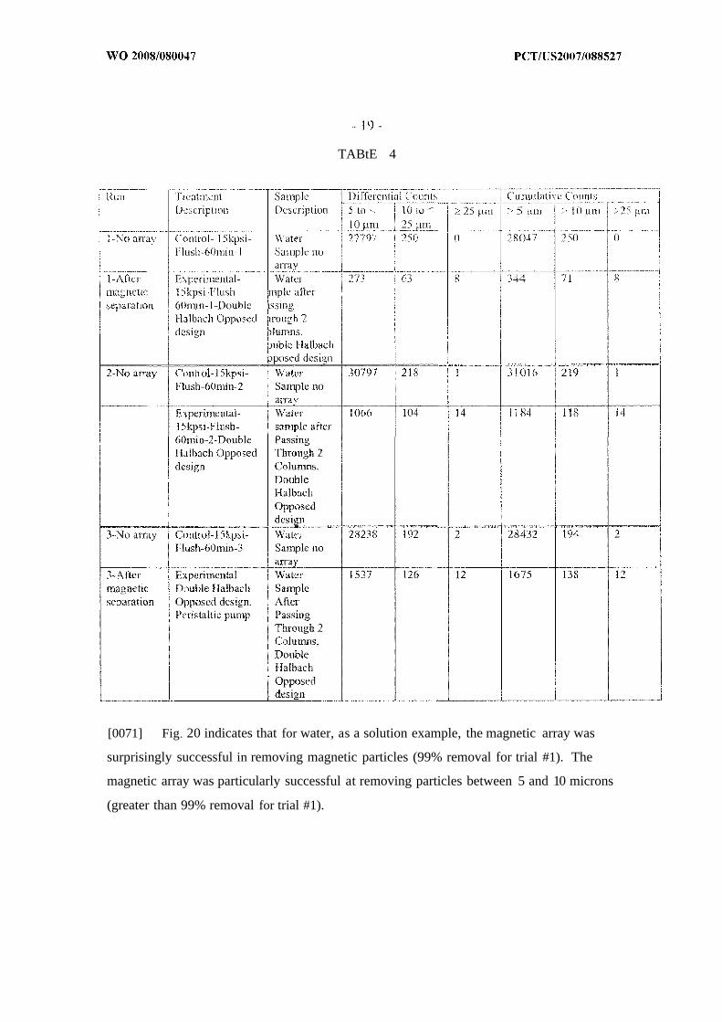
J0069) In this Example, water was used to wash a system that is used to manufacture
pharmaceutical compositions. This Example also indicates lhc efficiency o f this invention
for removing magnetic material from solutions. The water was Hushed through the system
and a sample of the flushed water examined for the presence o f magnetic material. In
Control experiments, no magnetic array was included in the s\ stern and in Experimental
samples a magnetic array was included as indicated in Table 4 .
[0070] Water was flushed through the system at 15000 psi for 60 minutes or pumped using
a peristaltic pump. A sample o f the flushed or pumped water was removed and magnetic
particle size populations were determined by static laser diffraction. In Table 4, results of
magnetic particle numbers and sizes are shown both as differential and cumulative counts are
shown for three separate experiments.
TABtE 4
[0071] Fig 20 indicates that for water, as a solution example, the magnetic array was
surprisingly successful in removing magnetic particles (99% removal for trial #1). The
magnetic array was particularly successful at removing particles between 5 and 10 microns
(greater than 99% removal for trial #1).

[0072 1 It will be understood that the embodiments of the present disclosure which have
been described are illustrative of some of the applications of the principles of the present
disclosure. Numerous modifications may be made by those skilled in the art without
departing from the true spirit and scope of the disclosure. Various features which arc
described herein can be used in any combination and are not limited to procure combinations
that are specifically outlined herein.

CLAtIVlS
1. An apparatus for removing material wiih magnetic piopcitiet> hotn a
composition comprising:
a conduit wherein said conduit has first and second ends and wherein said
conduit defines an interior volume;
an magnetic arrangement of at least one permanent magnet that defines a
space, and said conduit lies at least partially within said space such that a magnetic field is
generated wjthm at least a portion of said interior volume; and
wherein said composition flows through said conduit and is subject to said
magnetic field.
2. The apparatus of claim 1 wherein said magnetic field is generated by one
magnet
3 . The apparatus of claim I wherein said magnetic field is generated by a
plurality of magnets.
4 . The apparatus of claim 1 wherein said magnetic field is approximately parallel
to said flow of said composition.
5. The apparatus of claim 1 wherein said magnetic field is approximately
perpendicular to said flow of said composition.
6 . The apparatus of claim 3 wherein the respective magnetic fields of at least two
of said plurality of magnets are arranged in the same orientation.
7. The apparatus of claim 3 wherein the respective magnetic fields of said
plurality of magnets are arranged in the same orientation.
8. The apparatus of claim 3 wherein said plurality of magnets comprises bar,
block, horseshoe or ring magnets.
9 . The apparatus of claim 3 wherein said plurality of magnets are ring magnets.
10. The apparatus of claim 9 wherein said ring magnets are split in halves.

11. The apparatus of claim 9 wherein a combination o f whole ring magnets and
ring magnets that arc split in halves arc used
12. The apparatus of claim 11 wherein the orientation of the magnetic field of said
whole ring magnets are selected from the group consisting of: perpendicular to said flow of
said composition and parallel to said flow of said composition
13. The apparatus of claim 11 wherein the orientation of the magnetic field of said
halves of each ring magnet are selected from the group consisting of: aligned and
perpendicular to said flow of said composition; antipodal and perpendicular to said How o f
said composition with North poles abutting; antipodal and perpendicular to said flow of said
composition with South poles abutting: aligned and parallel to said flow of said composition;
and antipodal and parallel to said flow of said composition.
14. The apparatus of claim 3 wherein said plurality of magnets forms at least one
double Halbach array
15. The apparatus of claim 12 wherein said at least one double Halbach array is in
an aligned configuration
16. The apparatus of claim 12 wherein said at least one double Halhach array is in
an opposed configuration.
17. The apparatus of claim 1 wherein said composition is pharmaceutical
composition containing an active agent.
18. The apparatus of claim 15 wherein said pharmaceutical composition is a
homogeneous solution of an active agent.
19. The apparatus of claim 15 wherein said pharmaceutical composition contains
dispersed particles of an active agent.
20. The apparatus of claim 17 wherein said dispersed particles of said active agent
are diamagnetic.
21. The apparatus of claim 1 wherein material with magnetic properties is
ferromagnetic or ferrimagnetic
22. The apparatus of claim 1 wherein material with magnetic properties is
paramagnetic.

23. The apparatus of claim 1wherein material with magnetic properties is in the
form of particles of es than about 100 urn in diameter.
24. The apparatus of claim 1 wherein material with magnetic properties is derived
from equipment used in the production of said composition.
25. The apparatus of claim 1 wherein said material with magnetic properties is
aulensitic.
26. The apparatus of claim 1 wherein said material with magnetic properties is
martensitic.
27. The apparatus of claim 1 wherein material with magnetic properties is in the
form ofparticles composed of steel.
28. The apparatus of claim 1 wherein the interior surface of said conduit retains
said magnetic material when said magnetic material contacts said interior surface.
29. The apparatus of claim 3 wherein said conduit is situated adjacent to an
external surface of said magnetic arrangement.
30. The apparatus of claim 1 wherein said conduit forms a helical path adjacent to
the external surface of said magnetic arrangement.
31. The apparatus of claim 1 wherein said composition thai flows through said
conduit includes undesirable particles responsive to the magnetic field and said conduit
volume excludes other components other than said magnetic particles that are responsive to
said magnetic field.
32. An apparatus for removing material with magnetic properties from a
composition, comprising:
a conduit wherein said conduit has first and second ends and wherein said
conduit defines an interior volume;
an arrangement of magnets selected from the group consisting split and whole
ring magnets, such that said arrangement forms at least one double Halbach opposed array
magnetic field; and

said conduit lies at least partially within the space between formed by said
double Halbacli oppo d array and said composition h subject to iύd magnetic field
33. Λn apparatus for removing material ith magnetic properties from a
composition, comprising.
a column wherein said column has first and second open ends and wherein
said conduit defines an interior volume;
an arrangement o f beads of permanent magnets such that a magnetic field is
generated within at least a portion of said interior volume; and
said composition flows through said column and through said magnetic field.
34. A system for removing material with magnetic properties properties from a
composition comprising:
at least one device used to produce a composition;
a conduit, said conduit having first and second ends, one end of said conduit
being adapted to receive said composition from said device; and
an arrangement of at least one magnet such that a magnetic field is generated
within at least a portion of said interior volume of said conduit, whereby material with
magnetic properties is removed from said composition.
35. A method to produce a composition substantially free of material with
magnetic properties comprising the steps of:
a) providing a composition containing material with magnetic properties;
b) passing said composition through a conduit;
c) herein at least a portion of said conduit is exposed to a magnetic field
generated by an arrangement of at least one permanent magnet; and
d) collecting said pharmaceutical composition after passage through said
conduit
36. The process of claim 32 wherein said magnetic fieid is provided by an
aiτangement of magnets that forms at least one double Halbach array.

37. Ilie proces of claim 32 herei said magnetic field is provided by an
arrangement o f magnets that forms at least one double Halbach array in an opposed
configuration
38. The process of claim 32 wherein said magnetic field is provided by an
arrangement of magnets that forms at least one double Halbach array in an aligned
configuration.
39. The process of claim 32 wherein said pharmaceutical composition is a
homogeneous solution of an active agent
40. The process of claim 32 wherein said pharmaceutical composition contains
dispersed particles of an active agent.
41. The process of claim 32 wherein said dispersed particles of said active agent
are diamagnetic.
42. An apparatus for removing material with magnetic properties from a
composition, comprising:
a conduit wherein said conduit has first and second ends and wherein said
conduit defines an interior volume;
an arrangement of permanent magnets that generates a magnetic field; and
said conduit is adjacent to or in contact with the external surface of said
arrangement of magnets and said composition is subject to said magnetic field.
43. The apparatus of claim 39 wherein said conduit forms a helical path adjacent
to the external surface of said arrangement of magnets.