WO 2014/018491 A2
123
(12) INTERNATIONAL APPLICATION PUBLISHED UNDER THE PATENT COOPERATION TREATY (PCT) (19) World Intellectual Property Organization International Bureau (10) International Publication Number (43) International Publication Date 30 January 2014 (30.01.2014) WO 2014/018491 A2 PO PCT (51) International Patent Classification: (74) Agent: NEUGEBOREN, Craig; Neugeboren O' Dowd F28F 7/00 (2006.01) G06F 1/20 (2006.01) PC, 1227 Spruce Street, Suite 200, Boulder, CO 80302 H05K3/00 (2006.01) H05K 7/20 (2006.01) (US). (21) International Application Number: (81) Designated States (unless otherwise indicated, for every PCT/US20 13/05 1600 kind of national protection available): AE, AG, AL, AM, AO, AT, AU, AZ, BA, BB, BG, BH, BN, BR, BW, BY, (22) International Filing Date: BZ, CA, CH, CL, CN, CO, CR, CU, CZ, DE, DK, DM, 23 July 20 13 (23.07.2013) DO, DZ, EC, EE, EG, ES, FI, GB, GD, GE, GH, GM, GT, (25) Filing Language: English HN, HR, HU, ID, IL, IN, IS, JP, KE, KG, KN, KP, KR, KZ, LA, LC, LK, LR, LS, LT, LU, LY, MA, MD, ME, (26) Publication Language: English MG, MK, MN, MW, MX, MY, MZ, NA, NG, NI, NO, NZ, (30) Priority Data: OM, PA, PE, PG, PH, PL, PT, QA, RO, RS, RU, RW, SC, 13/559,739 27 July 2012 (27.07.2012) US SD, SE, SG, SK, SL, SM, ST, SV, SY, TH, TJ, TM, TN, TR, TT, TZ, UA, UG, US, UZ, VC, VN, ZA, ZM, ZW. (71) Applicant: OUTLAST TECHNOLOGIES, LLC [US/US]; 83 1 Pine Ridge Road, Golden, CO 80403 (US). (84) Designated States (unless otherwise indicated, for every kind of regional protection available): ARIPO (BW, GH, (72) Inventors: HARTMANN, Mark; 585 Deer Trail Road, GM, KE, LR, LS, MW, MZ, NA, RW, SD, SL, SZ, TZ, Boulder, CO 80302 (US). RODA, Greg; 125 Breckenridge UG, ZM, ZW), Eurasian (AM, AZ, BY, KG, KZ, RU, TJ, Trail, Broomfield, CO 80020 (US). TM), European (AL, AT, BE, BG, CH, CY, CZ, DE, DK, EE, ES, FI, FR, GB, GR, HR, HU, IE, IS, IT, LT, LU, LV, MC, MK, MT, NL, NO, PL, PT, RO, RS, SE, SI, SK, SM, [Continued on next page] = (54) Title: SYSTEMS, STRUCTURES AND MATERIALS FOR ELECTRONIC DEVICE COOLING (57) Abstract: An electronic device having one or more components that gen erate heat during operation includes a structure for temperature management and heat dissipation. The structure for temperature management and heat dis sipation comprises a heat transfer substrate having a surface that is in thermal communication with the ambient environment and a temperature management material in physical contact with at least a portion of the one or more com ponents of the electronic device and at least a portion of the heat transfer sub strate. The temperature management material comprises a polymeric phase change material having a latent heat of at least 5 Joules per gram and a trans - ition temperature between 0°C and 100°C, and a thermal conductive filler.
-
Upload
khangminh22 -
Category
Documents
-
view
0 -
download
0
Transcript of WO 2014/018491 A2

(12) INTERNATIONAL APPLICATION PUBLISHED UNDER THE PATENT COOPERATION TREATY (PCT)
(19) World Intellectual PropertyOrganization
International Bureau(10) International Publication Number
(43) International Publication Date30 January 2014 (30.01.2014)
WO 2014/018491 A2P O PCT
(51) International Patent Classification: (74) Agent: NEUGEBOREN, Craig; Neugeboren O' DowdF28F 7/00 (2006.01) G06F 1/20 (2006.01) PC, 1227 Spruce Street, Suite 200, Boulder, CO 80302H05K3/00 (2006.01) H05K 7/20 (2006.01) (US).
(21) International Application Number: (81) Designated States (unless otherwise indicated, for everyPCT/US20 13/05 1600 kind of national protection available): AE, AG, AL, AM,
AO, AT, AU, AZ, BA, BB, BG, BH, BN, BR, BW, BY,(22) International Filing Date: BZ, CA, CH, CL, CN, CO, CR, CU, CZ, DE, DK, DM,
23 July 20 13 (23.07.2013) DO, DZ, EC, EE, EG, ES, FI, GB, GD, GE, GH, GM, GT,
(25) Filing Language: English HN, HR, HU, ID, IL, IN, IS, JP, KE, KG, KN, KP, KR,KZ, LA, LC, LK, LR, LS, LT, LU, LY, MA, MD, ME,
(26) Publication Language: English MG, MK, MN, MW, MX, MY, MZ, NA, NG, NI, NO, NZ,
(30) Priority Data: OM, PA, PE, PG, PH, PL, PT, QA, RO, RS, RU, RW, SC,
13/559,739 27 July 2012 (27.07.2012) US SD, SE, SG, SK, SL, SM, ST, SV, SY, TH, TJ, TM, TN,TR, TT, TZ, UA, UG, US, UZ, VC, VN, ZA, ZM, ZW.
(71) Applicant: OUTLAST TECHNOLOGIES, LLC[US/US]; 83 1 Pine Ridge Road, Golden, CO 80403 (US). (84) Designated States (unless otherwise indicated, for every
kind of regional protection available): ARIPO (BW, GH,(72) Inventors: HARTMANN, Mark; 585 Deer Trail Road, GM, KE, LR, LS, MW, MZ, NA, RW, SD, SL, SZ, TZ,
Boulder, CO 80302 (US). RODA, Greg; 125 Breckenridge UG, ZM, ZW), Eurasian (AM, AZ, BY, KG, KZ, RU, TJ,Trail, Broomfield, CO 80020 (US). TM), European (AL, AT, BE, BG, CH, CY, CZ, DE, DK,
EE, ES, FI, FR, GB, GR, HR, HU, IE, IS, IT, LT, LU, LV,MC, MK, MT, NL, NO, PL, PT, RO, RS, SE, SI, SK, SM,
[Continued on nextpage]
= (54) Title: SYSTEMS, STRUCTURES AND MATERIALS FOR ELECTRONIC DEVICE COOLING
(57) Abstract: An electronic device having one or more components that generate heat during operation includes a structure for temperature managementand heat dissipation. The structure for temperature management and heat dissipation comprises a heat transfer substrate having a surface that is in thermalcommunication with the ambient environment and a temperature managementmaterial in physical contact with at least a portion of the one or more components of the electronic device and at least a portion of the heat transfer substrate. The temperature management material comprises a polymeric phasechange material having a latent heat of at least 5 Joules per gram and a trans -ition temperature between 0°C and 100°C, and a thermal conductive filler.

TR), OAPI (BF, BJ, CF, CG, CI, CM, GA, GN, GQ, GW, PublishedKM, ML, MR, NE, SN, TD, TG). without international search report and to be republished
upon receipt of that report (Rule 48.2(g))

SYSTEMS, STRUCTURES AND MATERIALS FOR ELECTRONIC DEVICE COOLING
FIELD OF THE INVENTION
[0001] In general, the present invention relates to systems, structures and compositions used
to enhance the performance of electronic devices and components by increasing the cooling
efficiency and capacity of the devices and components.
BACKGROUND OF THE INVENTION
[0002] Electronic devices, and in particular personal electronic devices such as smart phones,
tablets, and laptop computers, have gone through major evolutions in the past decade. The
devices themselves have become smaller and smaller, while at the same time, utilizing more
and more processing power, advanced communications electronics, and fewer moving parts.
For example, and most particular to aspects of the present invention, the small size of modern
personal electronics has demanded that mechanical cooling systems, such as fans and other
air handling devices, be removed and replaced with passive cooling systems. However, the
higher processing power and demands of modern electronic devices only adds to the heat
generated by these devices. The temperatures generated by such devices have been reported
widely in the news and have even led to user injuries and device damage. The use and
development of smaller, faster, more powerful computer chips and electronic components in
mobile phones, computers, laptops, tablets, etc. has caused a dramatic increase in the power,
run time and heat generation in these components. The increased power and heat generation
must be controlled to prevent overheating and damage to the components. This overheating
also causes hotspots and hot areas on the surface of the device thereby causing discomfort or
injury to the human user and therefore there is a need to manage this heat. This heat control
is done by either removing the heat by various means or "throttling" back the power and
speed of the components to reduce the generated heat. Reducing the speed and power of the
components is not preferable since this creates inefficiencies, prolonged wait times for

results, reduced download speeds, etc. Therefore materials are needed to both absorb or store
this generated heat and subsequently rapidly remove or conduct heat away from the
components. This is made more difficult by the shrinking of the component and total device
area, all leading to a larger heat flux per unit area.
[0003] More notable is the fact that when the operating temperature of these devices increase,
the performance of the device drops, either purposely by design, or naturally because of the
inherent characteristics of solid state electronics. Many devices have built in safe modes that
completely shut down the processors and other heat generating components if the operating
temperature gets too high.
[0004] Electronic heat dissipation techniques require that the heat be moved away from the
operating electronic components and to the ambient environment. Without the benefit of fans
and other mechanical cooling systems, the generated heat is merely transmitted by
conduction to the exterior surface of the device or some other substrate. Thus, most devices
become warm or hot to the touch during operation as heat exchangers are utilized to move the
heat from the electronics to the device case. These prior methods rely solely on thermal
conduction techniques to move the heat from one point to another.
[0005] The use of phase change materials (PCMs) in various industries to store and release
heat is known. For example, the use of various forms and compositions of PCMs (micro
encapsulated or raw), their methods of manufacture and applications thereof have been
widely disclosed. PCMs have been used widely in the textile and fabrics industries but have
not been effectively utilized or disclosed in the electronics fields, particularly when utilized to
effect heat storage and removal. The use of PCMs in the electronics industries has thus far
been limited to mixing micro-encapsulated PCMs into an epoxy or otherwise mixing waxes
and gels. No one has been able to figure out how to effectively take these materials, form
them, lock them into place in a complicated and sensitive electronic assembly, maintain high

latent heats with thermal conductivity while conforming to the confines of an enclosed
electronic device or other processor confined within a sealed or other casing.
[0006] Thermal management materials (TMM), thermal interface materials (TIMs), heat
management materials, heat spreaders, etc. all have key functions in an electronics package,
i.e. to dissipate heat in order to allow higher processing speeds. More specifically, thermal
interface materials and heat sinks bring the heat generating electronics components (i.e.
chips, transistors, semiconductors, integrated circuits (ICs), discrete devices, batteries, etc.)
into good thermal contact with the heat removal hardware.
SUMMARY OF THE INVENTION
[0007] Exemplary embodiments are summarized below. These and other embodiments are
more fully described in the Detailed Description section. It is to be understood, however, that
there is no intention to limit the invention to the forms described in this Summary of the
Invention or in the Detailed Description. One skilled in the art can recognize that there are
numerous modifications, equivalents and alternative constructions that fall within the spirit
and scope of the invention as expressed in the claims.
[0008] In one embodiment according to the present invention an electronic device with one
or more components that generate heat during operation includes a structure for temperature
management and heat dissipation. The structure for temperature management and heat
dissipation comprises a heat transfer substrate having a surface that is in thermal
communication with the ambient environment and a temperature management material in
physical contact with at least a portion of the one or more components of the electronic
device and at least a portion of the heat transfer substrate. The temperature management
material comprises a polymeric phase change material having a latent heat of at least 5 Joules

per gram and a transition temperature between 0°C and 100°C, and a thermal conductive
filler.
[0009] In another or the same embodiment the heat transfer substrate may be a printed circuit
board and the one or more components of the electronic device may be mounted to the
printed circuit board. In another or the same embodiment, the electronic device may further
comprise a second substrate in thermal communication with the heat transfer substrate. In
another or the same embodiment, the heat transfer substrate may be an exterior surface of the
electronic device and/or a display of the electronic device.
[0010] In other or the above-mentioned embodiments, the thermal conductive filler may be a
form of carbon, graphene, alumina, or a boron compound. In other or the above-mentioned
embodiments, the structure for temperature management and heat control may further
comprise a fusible material.
[0011] In another or one of the above-mentioned embodiments, the thermally conductive
filler may comprise between 5% and 95% of the temperature management material. In
another embodiment, the thermally conductive filler may have a purity that is greater than
95%.
[0012] In another or one of the above-mentioned embodiments the structure for temperature
management and heat control may further comprise a fire resistant additive. In yet another or
one of the above-mentioned embodiments, the electronic device may further comprise a
housing containing the one or more electronic components and the structure for temperature
management and heat dissipation.
[0013] A personal computing device according to the present invention, such as a cell phone,
PDA, tablet or laptop computer, comprises a housing, a printed circuit board, one or more
components attached to the printed circuit board that generate heat during operation of the
electronic device, and a structure for temperature management and heat dissipation. The

structure for temperature management and heat dissipation comprises a heat transfer substrate
having a surface that is in thermal communication with the printed circuit board and a surface
that is in thermal communication with the ambient environment and a temperature
management material in physical contact with at least a portion of the one or more
components of the electronic device and at least a portion of the heat transfer substrate.
[0014] According to one embodiment of the present invention the temperature management
material comprises a polymeric phase change material having a latent heat of at least 5 Joules
per gram and a transition temperature between 0°C and 100°C, and a thermal conductive
filler.
[0015] According to the present invention, a method of constructing such a personal
computing device comprises applying the temperature management material over at least a
portion of one or more heat generating components attached to a printed circuit board of the
device, enclosing the printed circuit board, the one or more components, and the structure for
temperature management and heat dissipation with the housing; and curing the temperature
management material. In some embodiments, the temperature management material may
substantially fill any voids within the housing.
[0016] Many additional aspects and embodiments are described herein as would be
recognized by one of ordinary skill in the art.
BRIEF DESCRIPTION OF THE DRAWINGS
[0017] Various objects and advantages and a more complete understanding of the present
invention are apparent and more readily appreciated by reference to the following Detailed
Description and to the appended claims when taken in conjunction with the accompanying
Drawings wherein:
[0018] Figure 1 shows a high level diagram of a typical mobile phone;

[0019] Figure 2 shows a high level diagram of a typical portable computer;
[0020] Figures 3A - 3C show the circuit board of a device in accordance with aspects of the
present invention;
[0021] Figures 4A - 4B show high level diagrams of a circuit board and related structures in
accordance with aspects of the present invention;
[0022] Figures 5A - 5C show cross sections of several of the embodiments from Figures 4A
- 4C;
[0023] Figures 6A - 6C show details of the embodiments of Figure 5A - 5C;
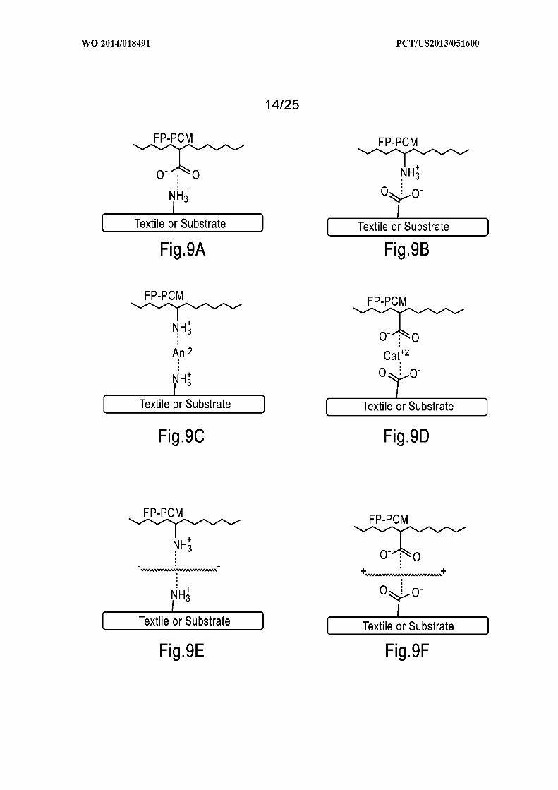
[0024] Figures 7 - 10D show various embodiments of functional polymeric PCMs;
[0025] Figure 11 shows one embodiment of the precisely branched polymers compared with
randomly distributed polymers;
[0026] Figure 12 is a graph depicting the peak melting point of various copolymers;
[0027] Figure 13 is a graph depicting the heat of crystallization of various copolymers;
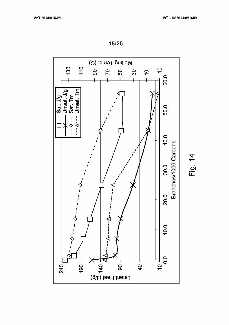
[0028] Figure 14 is a graph depicting the latent heat and melting point of various copolymers;
[0029] Figures 15A and 15B show details of a microcapsule as used in connection with
various aspects of the present invention;
[0030] Figures 16A - 16C show various layering embodiments that may be used in
connection with aspects of the present invention;
[0031] Figures 17 and 18 show additional embodiments of applying aspects of the present
invention to a substrate;
[0032] Figures 19 and 20 show additional embodiments of applying aspects of the present
invention to a substrate;
[0033] Figure 2 1 shows a graph depicting processor temperature in relation to PCM
transition temperature and standard power over time;

[0034] Figure 22 shows another graph depicting processor temperature in relation to PCM
transition temperature and transient temperature over time; and
[0035] Figure 23 shows the graphed results of one embodiment of the present invention.
[0036] Other embodiments and aspects are disclosed herein, including various figures and
process descriptions described and illustrated throughout the specification.
DETAILED DESCRIPTION
[0037] Throughout this specification references are made to the use of various materials,
combinations, chemical formulations and other aspects that may be used in various
combinations to form one or more materials, end products, or compositions in accordance
with aspects of the present invention. It should be understood, to one of skill in the art that
each of the lists of materials, examples, and other embodiments are included herein in order
to teach one of skill in the art that they may be combined into various alternative
embodiments, without requiring specific claim permutations of these individual features. The
claims as presented herein, as well as any potential future amendments to those claims, may
include one or more combinations of these materials, ranges and other alternatives without
departing from the spirit and scope of the invention described herein. In particular it is
contemplated that one of skill in the art would recognize and find adequate support in the
written description for any combination of the features disclosed herein, whether described in
a single example or embodiment, or described in different sections of the written description.
[0038] It should be clearly understood that by providing examples of specific compositions
and methods in the later part of this description, applicant does not intend to limit the scope
of the claims to any of those specific composition. To the contrary, it is anticipated that any
combination of the functional groups, polymeric phase change materials, and articles
described herein may be utilized to achieve the novel aspects of the present invention. The

claims are not intended to be limited to any of the specific compounds described in this
disclosure or any disclosure incorporated herein.
[0039] It is known that good thermal management materials should have high thermal
conductivity, high specific heat capacity, high latent heat capacity, high polytropic heat
capacity, low coefficient of thermal expansion, low air content, good gap-filling, good
surface wetting and adhesion, good rheology, etc.
[0040] Thermal conductivity, or the rate of heat transfer across a material and expressed as
watts per meter kelvin (WV(m-K)) or W-m_ -K_ , is controlled by the flow of free electrons or
crystal lattice vibrations (phonons). In metals, conductivity is primarily due to free electrons,
whereas for nonmetals it is mainly due to phonon transport. Thermal conductivity can vary
dependent on type of materials, temperature, material phase, impurities, etc. For instance the
change in thermal conductivity that occurs when ice (thermal conductivity of 2.18 W/(m »K)
at 0 °C) melts into liquid water (thermal conductivity of 0.58 W/(m »K) at 0 °C). Another
example is for pure crystalline substances can exhibit different thermal conductivities along
different crystal axes, due to differences in phonon coupling along a given crystal axis. The
thermal conductivity of plastics depends strongly on the degree of crystallinity in polymers
(Anisotropicity of crystalline polymers). This is mostly due to phonon transport (flowing
lattice vibrational energy) that is efficient along the crystalline axis but reduced substantially
in amorphous areas or by various scattering processes in the other directions.
Definitions
[0041] The following definitions apply to various elements described with respect to various
aspects of the invention. These definitions may likewise be expanded upon herein.
[0042] As used herein, the term "monodisperse" refers to being substantially uniform with
respect to a set of properties. Thus, for example, a set of microcapsules that are monodisperse

can refer to such microcapsules that have a narrow distribution of sizes around a mode of the
distribution of sizes, such as a mean of the distribution of sizes. A further example is a set of
polymer molecules with similar molecular weights.
[0043] As used herein, the term "latent heat" refers to an amount of heat absorbed or released
by a material as it undergoes a transition between two states. Thus, for example, a latent heat
can refer to an amount of heat that is absorbed or released as a material undergoes a transition
between a liquid state and a crystalline solid state, a liquid state and a gaseous state, a
crystalline solid state and a gaseous state, two crystalline solid states or crystalline state and
amorphous state or any combination thereof.
[0044] As used herein, the term "transition temperature" refers to an approximate
temperature at which a material undergoes a transition between two states. Thus, for example,
a transition temperature can refer to a temperature at which a material undergoes a transition
between a liquid state and a crystalline solid state, a liquid state and a gaseous state, a
crystalline solid state and a gaseous state, two crystalline solid states or crystalline state and
amorphous state. A temperature at which an amorphous material undergoes a transition
between a glassy state and a rubbery state may also be referred to as a "glass transition
temperature" of the material or combination thereof.
[0045] As used herein, the term "phase change material" refers to a material that has the
capability of absorbing or releasing heat to adjust heat transfer at or within a temperature
stabilizing range. A temperature stabilizing range can include a specific transition
temperature or a range of transition temperatures. This allows for the adjustment of heat
transfer or thermal conductivity within this transition range. In some instances, a phase
change material can be capable of inhibiting heat transfer during a period of time when the
phase change material is absorbing or releasing heat, typically as the phase change material
undergoes a transition between two states. This action is typically transient and will occur
until a latent heat of the phase change material is absorbed or released during a heating or
cooling process. Heat can be stored or removed from a phase change material, and the phase
change material typically can be effectively recharged by a source emitting or absorbing it.
For certain implementations, a phase change material can be a mixture of two or more
materials. By selecting two or more different materials and forming a mixture, a temperature
stabilizing range can be adjusted for any desired application. The resulting mixture can
exhibit two or more different transition temperatures or a single modified transition
temperature when incorporated in the articles described herein.
[0046] As used herein, the term "polymer" refers to a material that includes a set of
macromolecules. Macromolecules included in a polymer can be the same or can differ from
one another in some fashion. A macromolecule can have any of a variety of skeletal
structures, and can include one or more types of monomeric units. In particular, a
macromolecule can have a skeletal structure that is linear or non-linear. Examples of non
linear skeletal structures include branched skeletal structures, such those that are star
branched, comb branched, or dendritic branched, and network skeletal structures. A
macromolecule included in a homopolymer typically includes one type of monomeric unit,
while a macromolecule included in a copolymer typically includes two or more types of
monomeric units. Examples of copolymers include statistical copolymers, random
copolymers, alternating copolymers, periodic copolymers, block copolymers, radial
copolymers, and graft copolymers. In some instances, a reactivity and a functionality of a
polymer can be altered by addition of a set of functional groups, such as acid anhydride
groups, amino groups and their salts, N-substituted amino groups, amide groups, carbonyl
groups, carboxy groups and their salts, cyclohexyl epoxy groups, epoxy groups, glycidyl
groups, hydroxy groups, isocyanate groups, urea groups, aldehyde groups, ester groups, ether
groups, alkenyl groups, alkynyl groups, thiol groups, disulfide groups, silyl or silane groups,

groups based on glyoxals, groups based on aziridines, groups based on active methylene
compounds or other b-dicarbonyl compounds (e.g., 2,4-pentandione, malonic acid,
acetylacetone, ethylacetone acetate, malonamide, acetoacetamide and its methyl analogues,
ethyl acetoacetate, and isopropyl acetoacetate), halo groups, hydrides, or other polar or H
bonding groups and combinations thereof. Such functional groups can be added at various
places along the polymer, such as randomly or regularly dispersed along the polymer, at ends
of the polymer, on the side, end or any position on the crystallizable side chains, attached as
separate dangling side groups of the polymer, or attached directly to a backbone of the
polymer. Also, a polymer can be capable of cross-linking, entanglement, network formation,
ionic bonding, covalant bonding or hydrogen bonding in order to increase its mechanical
strength or its resistance to degradation under ambient or processing conditions. As can be
appreciated, a polymer can be provided in a variety of forms having different molecular
weights, since a molecular weight of the polymer can be dependent upon processing
conditions used for forming the polymer. Accordingly, a polymer can be referred to as having
a specific molecular weight or a range of molecular weights. As used herein with reference to
a polymer, the term "molecular weight" can refer to a number average molecular weight, a
weight average molecular weight, or a melt index of the polymer.
[0047] Examples of polymers (including those polymers used for crosslinkers and binders)
include polyhydroxyalkonates, polyamides, polyamines, polyimides, polyacrylics (e.g.,
polyacrylamide, polyacrylonitrile, and esters of methacrylic acid and acrylic acid),
polycarbonates (e.g., polybisphenol A carbonate and polypropylene carbonate), polydienes
(e.g., polybutadiene, polyisoprene, and polynorbornene), polyepoxides (e.g. bisphenol A,
bisphenol F, multifunctional glycidyl based epoxies either crosslinked or uncrosslinked with
amines, acids, alcohols, etc.), polyesters (e.g., polycaprolactone, polyethylene adipate,
polybutylene adipate, polypropylene succinate, polyesters based on terephthalic acid, and

polyesters based on phthalic acid), polyethers (e.g., polyethylene glycol or polyethylene
oxide, polybutylene glycol, polypropylene oxide, polyoxymethylene or paraformaldehyde,
polytetramethylene ether or polytetrahydrofuran, and polyepichlorohydrin),
polyfluorocarbons, formaldehyde polymers (e.g., urea-formaldehyde, melamine-
formaldehyde, and phenol formaldehyde), natural polymers (e.g., polysaccharides, such as
cellulose, chitan, chitosan, and starch; lignins; proteins; and waxes), polyolefins (e.g.,
polyethylene, polypropylene, polybutylene, polybutene, and polyoctene), polyphenylenes,
silicon-containing polymers (e.g., polydimethyl siloxane, polyalkyl siloxanes and
polycarbomethyl silane), polyurethanes, polyvinyls (e.g., polyvinyl butyral, polyvinyl
alcohol, esters and ethers of polyvinyl alcohol, polyvinyl acetate, polystyrene,
polymethylstyrene, polyvinyl chloride, polyvinyl pryrrolidone, polymethyl vinyl ether,
polyethyl vinyl ether, and polyvinyl methyl ketone), polyacetals, polyarylates, alkyd-based
polymers (e.g., polymers based on glyceride oil), copolymers (e.g., polyethylene-co-vinyl
acetate and polyethylene-co-acrylic acid, styrene-butadiene, or any combination of the
above), and mixtures thereof. The term polymer is meant to be construed to include any
substances that become available after the filing of this application and that exhibit the
general polymeric properties described above.
[0048] As used herein, the term "chemical bond" and its grammatical variations refer to a
coupling of two or more atoms based on an attractive interaction, such that those atoms can
form a stable structure. Examples of chemical bonds include covalent bonds and ionic bonds.
Other examples of chemical bonds include hydrogen bonds and attractive interactions
between carboxy groups and amine groups.
[0049] As used herein, the term "covalent bond" means a form of chemical bonding that is
characterized by the sharing of pairs of electrons between atoms, or between atoms and other
covalent bonds. Attraction-to-repulsion stability that forms between atoms when they share

electrons is known as covalent bonding. Covalent bonding includes many kinds of
interactions, including σ-bonding, π-bonding, metal-metal bonding, agostic interactions, and
three-center two-electron bonds.
[0050] As used herein, the term "ionic bond" or "electrovalent bond" means a bond formed
through electrostatic attraction between oppositely charged ions. For example, between a
positively charged cation and a negatively charged anion. Ionic bonds can be formed
between a metal such Na, Fe, Ag, etc. and a nonmetal, or between two metals, or between
two non-metals such as ammonia and acids. Ionic compounds can conduct electricity when
molten, in a solid or in solution.
[0051] As used herein, the term "molecular group" and obvious variations thereof, refers to a
set of atoms that form a portion of a molecule. In some instances, a group can include two or
more atoms that are chemically bonded to one another to form a portion of a molecule. A
group can be neutral on the one hand or charged on the other, e.g., monovalent or polyvalent
(e.g., bivalent) to allow chemical bonding to a set of additional groups of a molecule. For
example, a monovalent group can be envisioned as a molecule with a set of hydride groups
removed to allow chemical bonding to another group of a molecule. A group can be neutral,
positively charged, or negatively charged. For example, a positively charged group can be
envisioned as a neutral group with one or more protons (i.e., H+) added, and a negatively
charged group can be envisioned as a neutral group with one or more protons removed. A
group that exhibits a characteristic reactivity or other set of properties can be referred to as a
functional group, reactive function or reactive functional groups. Examples of reactive
functional groups include those such as acid anhydride groups, amino groups, N-substituted
amino groups and their salts, amide groups, carbonyl groups, carboxy groups and their salts,
cyclohexyl epoxy groups, epoxy groups, glycidyl groups, hydroxy groups, isocyanate groups,
urea groups, aldehyde groups, ester groups, ether groups, alkenyl groups, alkynyl groups,

thiol groups, disulfide groups, silyl or silane groups, groups based on glyoxals, groups based
on aziridines, groups based on active methylene compounds or other b-dicarbonyl
compounds (e.g., 2,4-pentandione, malonic acid, acetylacetone, ethylacetone acetate,
malonamide, acetoacetamide and its methyl analogues, ethyl acetoacetate, and isopropyl
acetoacetate), halo groups, hydrides, or other polar or H bonding groups and combinations
thereof.
[0052] As used herein the term "Melt flow index" or MFI is a measure of the ease of flow of
the melt of a polymer. In academic terms the melt flow is defined as the mass of polymer, in
grams, flowing in ten minutes through a capillary of a specific diameter and length by a
pressure applied via prescribed alternative gravimetric weights for alternative prescribed
temperatures. The method is described in the similar standards ASTM D1238 and ISO 1133.
[0053] Molecular Weight Polydispersity - A polydispersity index (PDI), is a measure of the
distribution of molecular mass in a given polymer sample. The PDI calculated is the weight
average molecular weight divided by the number average molecular weight. It indicates the
distribution of individual molecular masses in a batch of polymers. The PDI has a value equal
to or greater than 1, but as the polymer chains approach uniform chain length, the PDI
approaches unity (1). For some natural polymers PDI is almost taken as unity. The PDI from
polymerization is often denoted as:
PDI = / .
[0054] Mn is more sensitive to molecules of low molecular mass, while Mw is more sensitive
to molecules of high molecular mass. A polymer material is denoted by the term
polydisperse if its chain lengths vary over a wide range of molecular masses.
[0055] Stereochemistry - Stereochemistry involves the study of the relative spatial
arrangement of atoms within molecules. One branch of stereochemistry is the study of chiral
molecules. Stereochemistry is also known as 3D chemistry. Examples, explanations,
descriptions and definitions of various stereochemical nomenclature and naming regimes can
be found in chapter 6 "Stereochemistry" in "Modern Physical Organic Chemistry" by
Anslyn and Dougherty, ©2005, University Science Books.
[0056] Polymer stereochemistry descriptions of atactic, syndiotactic, isotactic, cis- and trans-,
R- and S-, L-, D- and Meso- will be used.
[0057] Polymerization - Polymerization is a process of reacting monomer molecules together
in a chemical reaction to form three-dimensional networks or polymer chains. Many forms
of polymerization and different systems exist to categorize them are known in the art.
[0058] Rheology and Viscosity - Rheology is the characterization of the flow of matter while
viscosity is the measure of resistance to flow or deformation. Viscosity can be measured by
various means and characterized as a melt flow index (MFI) or centipoise (cps), usually at a
given temperature or shear rate.
[0059] As used herein, the term "thermal conductivity" ("k" and also denoted as λ or κ), is
the property of a material's ability to conduct heat and is measured in W/m-K. Thermal
conductivity is defined as the quantity of heat (Q) transmitted through a unit thickness (L) in
a direction normal to a surface of unit area (A) due to a unit temperature gradient (AT) under
steady state conditions and when the heat transfer is dependent only on the temperature
gradient. In equation form this becomes the following:
Thermal Conductivity = heat x distance / (area x temperature gradient)
λ = Q x L / (A x AT)
[0060] Generally in low conducting materials k < 0.1 W/m-K. In good conducting materials
k = 0.1-10 W/m-K. In highly conducting material k>10 W/m-K. In accordance with aspects
of the present invention the thermal management and heat dissipation material preferably has

a k value of > 0.5 W/m-K. In another embodiment k >1.0 W/m-K and it yet another
embodiment k is >10 W/m-K.
[0061] As used herein, the term "heat dissipation" refers to the movement or spreading of
heat from a high temperature environment to a low temperature environment, e.g. moving
heat from a warm processor or other heat producing electronic component to cooler ambient
air. Methods to dissipate heat can be accomplished by using high thermal conductivity
materials such as metallic or ceramic heat spreaders, heat spreader plates, heat sinks, heat
pipes, heat exchangers, loop pipes, liquid cold pipes, heat fins, fans, circulating coolants or a
combination thereof. Further examples are products such as those supplied by Thermo Cool
Corp., Thermacore Inc., etc.
General Structure of Electronic Devices
[0062] Aspects of the inventions disclosed herein may be used in connection with a wide
variety of electronic device and any other device that generates heat to the detriment of the
performance of the processors and other operating circuits (memory, video chips, telecom
chips, etc.). While reference is made herein to such common devices as cell phone, PDAs,
smart-phones, tablets, laptop computers and other generally portable devices, the same
features may be incorporated into virtually any electronic device that requires cooling during
operation. For example, electronics used in automotive components, aircraft components,
guidance systems and GPS devices incorporated into civilian and military equipment and
other vehicles may benefit from aspects of the present invention such as engine control units
(ECU), airbag modules, body controllers, door modules, cruise control modules, instrument
panels, climate control modules, anti-lock braking modules (ABS), transmission controllers,
and power distribution modules. Aspects of the present invention can also be incorporated
into the casings of electronics or other structural components. In the end, any device that

relies on the performance characteristics of an electronic processor or other electronic circuit
can benefit from the increased or more stable performance characteristics resulting from
utilizing aspects of the present invention.
[0063] In general, aspects of the invention relate to incorporating a material, coating, or layer
of a phase change material containing substance onto, over or otherwise near the heat
producing components of an electronic device so that heat is pulled away from those
components and stored and/or dissipated through some form of heat transfer substrate to the
ambient environment. Described below are various embodiments of the devices that can
utilize such a substance and structure and different embodiments of such a composition as
used in these devices.
[0064] Figure 1 shows a general representation of a cell phone 100 that includes a front panel
102, including common features such as a keyboard and screen. A rear panel 104 engages
with the front panel 102 and encloses, among other components, a printed circuit board
(PCB) 106 that includes operating electronics. While the PCB 106 has many different pieces
of electronics, connectors and other features, the primary components referred to in this
disclosure are those that generally generate heat, such as battery 108, transmitter/receiver or
other communications chip 110, and processor 112. Most electronics devices have at least
one of these components or some other element that generates heat during operation and for
which there is a need to reduce the buildup of that heat during operation. By referring to one
or another specific types of device in this disclosure, it is not intended to limit the scope of
the claims herein as the claims are applicable to virtually any electronic device known or
unknown that suffers from the same heat related problems.
[0065] Figure 2 is a generalized diagram showing the main components and features of a
laptop computer 200 with a similar detail as that of Figure 1. Computer 200 includes a lower
panel 202, an upper panel 204, an internal panel 206 and an electronics section 208 that

includes, among other components, a processor 210, a system board 212, memory 214, a
storage device such as a hard drive 216 and a battery 218. Many of the components within
the computer 200 generate heat during operation and there is also a need in these devices to
reduce the buildup of that heat.
[0066] Figure 3A shows a more detailed diagram of the electronic component circuit board
300 of a representative cell phone. While circuit board 300 includes many circuits and other
components, reference will primarily be made herein to those that regularly produce heat
during operation, such as transceiver or communication module 302, wireless communication
module 304, power supply module 306 battery 308, graphics driver 310, and processor 312.
Each of these components is one that will generate heat during operation and that also will
suffer a degradation in performance as their temperature rises. With reference to Figure 3B,
the same cell phone circuit board 300 is shown with the same components 302, 304, 306,
308, 310 and 312 covered in a temperature management material 350 according to one of
various aspects of the present invention. In Figure 3B, temperature management material 350
is shown in a first configuration dispersed and coated over only those portions of circuit
board 300 that contain heat generating components, leaving the other components of the
circuit board exposed as they would be normally. In Figure 3C, temperature management
material 350 is shown in a second configuration dispersed and coated over substantially the
entire surface of circuit board 300 without segregating the heat generating components from
the non-heat generating components.
[0067] With reference to Figure 4A and 4B several perspective views of a printed circuit
board 400 are shown, illustrating various options and embodiments for incorporating a
temperature management material into the structure of the circuit boards. For example, in
Figure 4A, printed circuit board 400 includes several heat generating components 402, 404
and 406 such as processors, graphic chips and telecommunication chips as described above.

PCB 400 includes a backing or other outer surface 412 that protects and also conducts heat
away from the operable components within the device. Regions of temperature management
material are dispersed on the PCB components at 450a and 450b and are generally dispersed
to only cover those elements that contribute to the generation of heat and for which it is
desired to reduce the effects of the heat on the operable components. Because of the
composition of the temperature management material 450a and 450b (discussed in more
detail below), heat is both stored and more rapidly and efficiently moved away from the
electronic components and to an ambient environment. In an alternate embodiment, the
temperature management material has an increased surface area and volume that is in direct
contact with the outer casing, thus providing a larger thermal transfer area in order to rapidly
pull heat away from the operable components and dissipate that heat to the outside
environment or to a heat transfer substrate.
[0068] Figure 4B shows another embodiment where there is no or little discrimination as to
where the temperature management material 460 is dispersed on the PCB 400 such that both
heat generating components and non-heat generating components are covered or otherwise
coating with the temperature management material 460. While this embodiment necessarily
uses a greater amount of the temperature management material, it is easier to form and
manufacture since less precision is needed to disperse the material 460. Other advantages are
also realized from the use of a greater amount of temperature management material such as
impact resistance and water resistance. These are discussed in further detail below.
[0069] While Figures 4A and 4B are shown with the outer device casing 412 shown opposite
the face of the PCB 400 that includes the temperature management material 450a, 450b
and/or 460, it is contemplated that one or more of the PCB components (or just the heat
generating components) may be placed on the opposite side of the PCB such 400 that the
temperature management material is in direct contact with the outer casing 412, thereby
increasing the thermal conductivity between the temperature regulating material and the outer
casing 412.
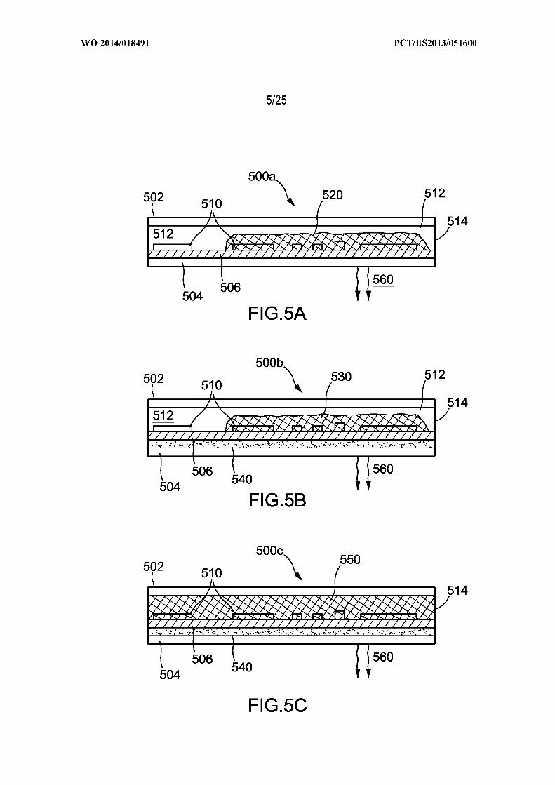
[0070] Figures 5A - 5C illustrate various cross-sectional embodiments of an electronic device
constructed in accordance with aspects of the present invention. First with reference to
Figure 5A, an electronic device 500a is shown with the major components in cross section.
Device 500a includes a top display surface 502, a back surface 504 and a printed circuit
board 506. Mounted on the printed circuit board 506 are one or more electronic components
510, some of which generate heat while in operation. As is customary in many electronic
devices, a seal or other gasket type device 514 is located along the periphery of the device. In
many known devices, heat generated by one or more of the electronic components 510 is
dissipated via heat transfer or conduction by transferring to the back surface 504 and then to
the environment as shown by reference number 560. In prior devices, electronic components
510 may be coupled with known heat transfer components, substrates, or other mechanical
heat sinks to better move the heat from the components themselves to the outer environment
at 560. In the embodiment of Figure 5A and in conjunction with aspects of the present
invention, temperature management material 520 is dispersed or otherwise coated or attached
to the specific components 510 on PCB 506 that generate heat. The composition of the
temperature management material 520 provides a mechanism to both store the heat generated
by the components 510 and also to more quickly and efficiently move that heat away from
the components and to the ambient environment at 560.
[0071] Figure 5B shows another embodiment an electronic device 500b shown with the
major components in cross section. Similar to the embodiment in Figure 5A, device 500b
includes a top display surface 502, a back surface 504 and a printed circuit board 506.
Mounted on the printed circuit board 506 are one or more electronic components 510, some
of which generate heat while in operation. A seal or other gasket type device 514 is located

along the periphery of the device. Heat generated by one or more of the electronic
components 510 is dissipated via heat transfer or conduction by transferring to the back
surface 504 and then to the environment as shown by reference number 560. In the
embodiment of Figure 5B and in conjunction with aspects of the present invention,
temperature management material 520 is dispersed or otherwise coated or attached to the
specific components 510 on PCB 506 that generate heat. In addition, in the embodiment of
Figure 5B, a second temperature management material 540 is dispersed between the PCB and
the back surface 504. The temperature management material 540 may be the same or a
different composition or blend as the first temperature management material 520 as described
in more detail in the sections that follow.
[0072] Figure 5C shows another embodiment an electronic device 500c shown with the
major components in cross section. Similar to the embodiments in Figures 5A and 5B,
device 500c includes a top display surface 502, a back surface 504 and a printed circuit board
506. Mounted on the printed circuit board 506 are one or more electronic components 510,
some of which generate heat while in operation. A seal or other gasket type device 514 is
located along the periphery of the device. Heat generated by one or more of the electronic
components 510 is dissipated via heat transfer or conduction by transferring to the back
surface 504 and then to the environment as shown by reference number 560. In the
embodiment of Figure 5C and in conjunction with aspects of the present invention,
temperature management material 550 completely fills the gaps left within the device that are
typically found between the components on PCB 506 and either of the top or bottom surfaces.
In this embodiment, all component surfaces are in contact with the temperature management
material. In addition, in the embodiment of Figure 5C, a second temperature management
material 540 is dispersed between the PCB and the back surface 504. The temperature

management material 540 may be the same or a different composition or blend as the first
temperature management material 550 as described in more detail in the sections that follow.
[0073] Figures 6A - 6C show various embodiments of a temperature management material
used in the above-mentioned examples of devices and the various components that may be
used to form that material. In Figure 6A a uniform mixture of a PCM 602 and a thermal
conductive filler 604 is shown as forming the temperature management material 600. In the
example of Figure 6A the PCM 602 is a microencapsulated PCM (mCAP) but can also be a
raw or otherwise unencapsulated PCM such as a pPCM (polymeric PCM) or a FP-PCM
(functional polymeric PCM). However the phase change material is incorporated into the
temperature management material 600, in the example of Figure 6A, the temperature
management material is a uniform substance with some level of homogeneity to the material.
There are no specific layers within the example of Figure 6A.
[0074] With reference to Figure 6B, a temperature management material 620 is shown that
includes several layers. A layer 622 is formed from a thermal conductive filler, a layer 624 is
formed from a first phase change material, and a layer 626 is formed from a second phase
change material. The layers 624 and 626 may each be any of an mPCM, pPCM, or FP-PCM
or the layers 624 and 626 may be combinations or blends of one or more of these types of
phase change materials. In addition, each of layer 624 and 626 can utilize any of the PCM
materials discussed herein in various combinations that may be necessary to fit a specific
temperature control scenario. For example, certain electronics applications may generate
more heat, or have a steeper heating curve profile and thus warrant the use of PCMs that have
higher latent heat values or higher PCM loading requirements in order to effectively manage
the temperature changes that occur in those devices. Other applications may have more
subtle temperature change profiles and not demand PCMs with such large latent heat values
and can thus utilize lower loading amounts.

[0075] With reference to Figure 6C, another temperature management material 640 is shown
that also includes several layers. A layer 642 is formed from a thermal conductive filler, a
layer 644 is formed from a first phase change material, and a layer 646 is formed from a
second phase change material. As with the example of Figure 6B, the layers 644 and 646
may each be any of an mPCM, pPCM, or FP-PCM or the layers 644 and 646 may be
combinations or blends of one or more of these types of phase change materials. In addition,
each of layer 644 and 646 can utilize any of the PCM materials discussed herein in various
combinations that may be necessary to fit a specific temperature control scenario. In the
embodiment and example of Figure 6C, layer 644 is shown utilizing microcapsules 645.
These microcapsules may be within a polymeric binder 647 (with or without its own PCM
and latent heat qualities).
[0076] Figures 16A - 16C show other layering options that may be utilized in constructing
the structure for temperature management and heat dissipation. As exemplified in Figures
16A - 16C, any combination of these different layers are also possible. In Figures 16A - 16C
each of LI through L8 represent different layers on a substrate or electronic components 800
or different regions within a discrete portion of a layer 810 and 815. It should be understood
that many different combinations of these layers are possible and it is not intended to limit the
invention to any of the physical structures depicted by FIGS. 16A - 16C. These are merely
representative of several of the possibilities.

Use of PCMs and Thermal Management Materials
[0077] The sections above describe various compositions and other materials that may be
used in connection with the electronic structures and devices that may benefit from the
temperature control and thermal management aspects of the present invention. However, by
referring to any of the specific structural embodiments or any of the precise and specific
chemical compositions (above or further in this disclosure), it is not intended to limit the
scope of the claims to any one in particular. To the contrary, the specification is arranged
such that one of skill in the art could combine one or more of the structures and electronic
devices described herein with one or more of the chemical compositions described herein in
order to create a device that worked for a specific purpose.
[0078] The compositions and other PCM materials described herein can be used in
conjunction with various electronics and electrical articles such as conductors, heat sinks,
semiconductors, transistors, integrated circuits, batteries, wiring, switches, capacitors,
resistors, diodes, boards, coverings, motors, engines, etc. Further details of these structures
are described in conjunction with Figures 1-6.
[0079] While the above description of phase change technology and the different types of
chemicals and other materials useful in temperature regulation is generally applicable and
relevant to aspects and embodiments of the present invention, there are other aspects and
unique features that find particular relevance in electronics applications and promoting more
efficient cooling in those electronics.
Thermal Management Materials (TMM) for Electronics Temperature Control
[0080] PCMs are very advantageous for use as thermal management materials in electronics
in that the high crystallinity allows for a combination of good thermal conductivity, high
latent heat capacity and energy absorption all leading to improved heat management, lower
heat buildup, fewer problems and faster processor speeds.
[0081] Air is a very poor thermal conductor and therefore air spaces or air gaps anywhere
within the TMM is not preferred. Air gaps such as between the electronic components and
thermal management materials, cracks or voids within the TMM, voids or gaps between
particles and the TMM composite or matrix material, etc. are all problematic for good
thermal conductivity. For instance, attaching a heat sink or TMM to a semiconductor
package requires that two solid surfaces be brought together into intimate contact.
Unfortunately, no matter how well prepared, solid surfaces are never really flat or smooth
enough to permit intimate contact. All surfaces have a certain roughness due to microscopic
hills and valleys. Superimposed on this surface roughness is a macroscopic non-planarity in
the form of a concave, convex or twisted shape. As two such surfaces are brought together,
only the hills of the surfaces come into physical contact. The valleys are separated and form
air-filled gaps. When two typical electronic component surfaces are brought together, less
than one percent of the surfaces may make physical contact with the remainder (99%) of the
surfaces separated by a layer of interstitial air. Some heat is conducted through the physical
contact points, but much more has to transfer through the air gaps. Since air is a poor
conductor of heat, it should be replaced by a more conductive material to increase the joint
conductivity and thus improve heat flow across the thermal interface. The thermal
management materials should have good rheological characteristics and surface wetting to
have good "gap-filling" properties, i.e. the ability to flow, wetout and fill gaps, crevices,
cracks, etc. to reduce air gaps and improve thermal movement. These TMM flow properties

can be formulated into the material through the use of additives or designed into the TMM
molecules. These materials described below are broadly referred to as thermal conductive
fillers.
[0082] TMMs should also have good adhesive, tack or bonding properties to prevent the
loose of contact between the TMM and the electronic components when the end device is
dropped, damaged, impacted or exposed to high or low temperatures.
[0083] Current electronics thermal management materials have many disadvantages such as
poor latent heat properties, poor heat sink properties in the appropriate temperature range,
poor gap/void filling properties, poor rheology, etc.
[0084] Figures 2 1 and 22 show graphs that illustrate the benefits of using aspects of the
present invention in connection with electronics and the ability to moderate the buildup of
heat within an electronic device. Temperature profiles and power profiles of a standard
processor and a processor utilizing aspects of the present invention incorporating a PCM are
shown in Figures 2 1 and 22. The PCM transition temperature is also shown for reference.
Figure 2 1 shows the results for a standard power measurement and Figure 22 shows the
results for a transient power measurement.
[0085] As described in general terms above and in the definition section, the term "phase
change material" refers to a material that has the capability of absorbing or releasing heat to
adjust heat transfer at or within a temperature stabilizing range. A temperature stabilizing
range can include a specific transition temperature or a range of transition temperatures. In
some instances, a phase change material can be capable of inhibiting heat transfer during a
period of time when the phase change material is absorbing or releasing heat, typically as the
phase change material undergoes a transition between two states. This action is typically
transient and will occur until a latent heat of the phase change material is absorbed or
released during a heating or cooling process. Heat can be stored or removed from a phase

change material, and the phase change material typically can be effectively recharged by a
source of heat or cold. For certain implementations, a phase change material can be a mixture
of two or more materials. By selecting two or more different materials and forming a mixture,
a temperature stabilizing range can be adjusted for any desired application. The resulting
mixture can exhibit two or more different transition temperatures or a single modified
transition temperature when incorporated in the articles described herein.
[0086] PCMs that can be used include various organic and inorganic substances. Organic
PCMs may be preferred for the embodiments disclosed herein. Examples of phase change
materials include hydrocarbons (e.g., straight-chain alkanes or paraffinic hydrocarbons,
branched-chain alkanes, unsaturated hydrocarbons, halogenated hydrocarbons, and alicyclic
hydrocarbons), alkanes, alkenes, alkynes, arenes, hydrated salts (e.g., calcium chloride
hexahydrate, calcium bromide hexahydrate, magnesium nitrate hexahydrate, lithium nitrate
trihydrate, potassium fluoride tetrahydrate, ammonium alum, magnesium chloride
hexahydrate, sodium carbonate decahydrate, disodium phosphate dodecahydrate, sodium
sulfate decahydrate, and sodium acetate trihydrate), waxes, oils, water, fatty acids (caproic
acid, caprylic acid, lauric acid, myristic acid, palmitic acid, stearic acid, arachidic acid,
behenic acid, lignoceric acid and cerotic acid, etc.), fatty acid esters (methyl caprylate, methyl
caprate, methyl laurate, methyl myristate, methyl palmitate, methyl stearate, methyl
arachidate, methyl behenate, methyl lignocerate, etc.), fatty alcohols (capryl alcohol, lauryl
alcohol, myristyl alcohol, cetyl alcohol, stearyl alcohol, arachidyl alcohol, behenyl alcohol,
lignoceryl alcohol, ceryl alcohol, montanyl alcohol, myricyl alcohol, and geddyl alcohol,
etc.), dibasic acids, dibasic esters, 1-halides, primary alcohols, secondary alcohols, tertiary
alcohols, aromatic compounds, clathrates, semi-clathrates, gas clathrates, anhydrides (e.g.,
stearic anhydride), ethylene carbonate, methyl esters, polyhydric alcohols (e.g., 2,2-dimethyl-
1,3 -propanediol, 2-hydroxymethyl-2-methyl-l,3-propanediol, ethylene glycol, polyethylene

glycol, pentaerythritol, dipentaerythritol, pentaglycerine, tetramethylol ethane, neopentyl
glycol, tetramethylol propane, 2-amino-2-methyl-l,3-propanediol,
monoaminopentaerythritol, diaminopentaerythritol, and tris(hydroxymethyl)acetic acid),
sugar alcohols (erythritol, D-mannitol, galactitol, xylitol, D-sorbitol), polymers (e.g.,
polyethylene, polyethylene glycol, polyethylene oxide, polypropylene, polypropylene glycol,
polytetramethylene glycol, polypropylene malonate, polyneopentyl glycol sebacate,
polypentane glutarate, polyvinyl myristate, polyvinyl stearate, polyvinyl laurate,
polyhexadecyl methacrylate, polyoctadecyl methacrylate, polyesters produced by
polycondensation of glycols (or their derivatives) with diacids (or their derivatives), and
copolymers, such as polyacrylate or poly(meth)acrylate with alkyl hydrocarbon side chain or
with polyethylene glycol side chain and copolymers including polyethylene, polyethylene
glycol, polyethylene oxide, polypropylene, polypropylene glycol, or polytetramethylene
glycol), metals, and mixtures thereof. Any combination of natural alcohols, natural fatty
acids, sugars, celluloses and natural glycols can be combined to yield PCMs. General
formulas such as the following, where m or n can be 0-100:
[0087] Polymerized alcohols such as polyvinyl alcohol, polyglycerols (mol. wt. of 100-
10,000) or multifunctional alcohols esterified with various fatty acids.
[0088] Paraffinic PCMs may be a paraffinic hydrocarbons, that is, hydrocarbons represented
by the formula CnHn + 2, where n can range from about 10 to about 44 carbon atoms. PCMs
useful in the invention include paraffinic hydrocarbons having 13 to 30 carbon atoms. For
example, the melting point of a homologous series of paraffin hydrocarbons is directly related
to the number of carbon atoms as shown in the following table:

No. of MeltingCarbon Point
Paraffmic Hydrocarbon Atoms (° C.)
n-Octacosane 28 6 1.4n-Heptacosane 27 59.0n-Hexacosane 2 6 56.4n-Pentacosane 25 53 .7n-Tetracosane 24 50.9n-Tricosane 23 47.6n-Docosane 22 44.4n-Heneicosane 21 40.5n-Eicosane 20 36.8n-Nonadecane 19 32. 1n-Octadecane 18 28.2n-Heptadecane 17 22.0n-Hexadecane 16 18.2n-Pentadecane 15 10.0n-Tetradecane 14 5.9n-Tridecane 13 - 5.5
Use of Polymeric Phase Change Materials (pPCMs) and Functional Polymeric Phase ChangeMaterials (fpPCMs) as TMMs
Reactive Functional Groups
[0089] Examples of suitable reactive functional groups include functional groups such as
acid anhydride groups, amino groups, N-substituted amino groups and their salts, amide
groups, imine groups, imide groups, azide groups, azo groups, amine-fromaldehyde groups,
carbonyl groups, carboxy groups and their salts, cyclohexyl epoxy groups, epoxy groups,
glycidyl groups, hydroxy groups, isocyanate groups, cyanate groups, urea groups, aldehyde
groups, ketone groups, ester groups, ether groups, alkenyl groups, alkynyl groups, thiol
groups, disulfide groups, silyl or silane groups, halogenated leaving groups, peroxide groups,
salt groups, groups based on glyoxals, groups based on aziridines, groups based on active
methylene compounds or other b-dicarbonyl compounds (e.g., 2,4-pentandione, malonic acid,
acetylacetone, ethylacetone acetate, malonamide, acetoacetamide and its methyl analogues,
ethyl acetoacetate, and isopropyl acetoacetate), halo groups, hydrides, or other polar or H
bonding groups and combinations thereof.
[0090] Further details of the variety of examples of reactive functions and functional groups
that may be used in accordance with one or more aspects of the present invention can be
found in commonly owned and co-pending patent application Nos. 12/174,607 and
12/174,609, the details of which have been incorporated by reference into this disclosure. It
should be clearly understood that by providing examples of specific compositions and
methods in the later part of this description, applicant does not intend to limit the scope of the
claims to any of those specific composition. To the contrary, it is anticipated that any
combination of the functional groups, polymeric phase change materials, and articles
described herein may be utilized to achieve the novel aspects of the present invention. The
claims are not intended to be limited to any of the specific compounds described in this
disclosure or any disclosure incorporated herein.
Polymeric Phase Change Materials and Reactivity
[0091] Several publications referenced herein deal with polymeric PCMs (P-PCM), which
present an intermediate case between the solid-liquid PCMs and the solid-solid PCMs. P-
PCMs are solid both prior to phase change and after it. The difference is in their degree of
structure. At lower temperatures, that degree is greater than that at the elevated temperature,
so that at a temperature of phase change, P-PCM converts from the more structured form into
its less structured one. Typically, in the more structures form, some sections of the polymer
are better aligned and more closely compacted. The better aligned sections resemble
crystallites. Therefore, the phase change on heating P-PCM is also referred to as change from
a more crystallized form to a less crystallized form. Differently put, at the elevated
temperatures (above the transition temperature), P-PCMs are essentially amorphous. At the
lower temperatures (below the transition temperature) they have a degree of crystallinity.
Similarly, the changes on heat absorption and on heat release could be referred to as
decrystallization and recrystallization, respectively. The related enthalpy could also be
referred to as enthalpy of decrystallization.
[0092] Typically, P-PCMs have sections that are capable of being better aligned and more
closely compacted. Such sections could be referred to as crystallizable sections. In some
embodiments, the functional polymeric PCM described herein in accordance with various
aspects of the present invention comprises at least one such crystallizable section. According
to an embodiment of the invention, the polymer comprises a backbone and side chains.
Preferably, the side chains form a crystallizable section.
Functional Polymeric Phase Change Materials (FP-PCMs)
[0093] As used here, the term "reactive function" means a chemical group (or a moiety)
capable of reacting with another chemical group to form a covalent or an electrovalent bond,
examples of which are given above. Preferably, such reaction is doable at relatively low
temperatures, e.g. below 200°C, more preferably below 100°C, and at conditions suitable to
handle delicate substrates, e.g. electronic components or other delicate substrates. As used
herein the term "carrying a function" and obvious variations of this term, means having a
function bound to it, e.g. covalently or electrovalently.
[0094] The reactive function could be placed on (carried on or covalently bound or
electrovalently bonded to) any part of the FP-PCM molecule, e.g. on a side chain, along the
backbone chain or on at least one of the ends of the backbone chain or side chain. According

to various embodiments of the invention, the FP-PCM comprises multiple reactive functions
and those functions are spread at substantially regular intervals, stereospecifically (i.e.
isotactic, syndiotactic, or atactic, etc.) or randomly along the molecule, e.g. along the
backbone chain. Any combination of these is also possible.
[0095] The molecular weight of an FP-PCM is preferably of at least 500 Daltons, more
preferably at least 2000 Daltons. Preferably the weight of the crystallizable section forms at
least 20%, more preferably at least 50%, and most preferably at least 70% of the total weight
of the FP-PCM.
[0096] The molecular weight can be monodisperse or polydisperse where all the polymer
molecules are the same molecular weight or different molecular weights as defined by the
polydispersity. Mn is the number average molecular w , Mw is weight average molecular wt.
and the molecular wt. polydispersity (Pd) is defined by Mn/Mw. A Pd of 1.0 means all
polymer molecules are monodisperse and have the same molecular weight. Aspects of a
composition constructed in accordance with the present invention have a Pd of between 1.0-
100 and preferably between 1.0-10.0, most preferably between 1.0-5.0.
[0097] Aspects of the present invention include utilizing a PCM with a single phase change
temperature or multiple such temperatures. According to one embodiment, a FP-PCM has at
least one phase change temperature in the range between -10°C and 300°C, preferably
between 10°C and 100°C and a phase change enthalpy of at least 25 J/g. In some instances, a
phase change material can have a latent heat that is at least about 1 Joule per gram, at least
about 5 Joules per gram (J/g), at least about 10 J/g, at least about 20 J/g, at least about 30 J/g,
at least about 40 J/g, at least about 50 J/g, at least about 60 J/g, at least about 70 J/g, at least
about 80 J/g, at least about 90 J/g, or at least about 100 J/g. Thus, for example, the phase
change material can have a latent heat from about 5 J/g to about 400 J/g, 10 J/g to about 100,
J/g, 20 J/g to about 100 J/g, from about 60 J/g to about 400 J/g, from about 80 J/g to about
400 J/g, or from about 100 J/g to about 400 J/g.
[0098] The phase change at each of the temperatures has its own enthalpy, so that according
to some of the embodiments, the composition used has a single phase change enthalpy and,
according to other embodiments, multiple such enthalpies. As used herein, the term "overall
phase change enthalpy" refers to the enthalpy of phase change in the case of a structure with
a single phase change temperature and to the combined enthalpies in case of multiple phase
change temperatures. According to an embodiment of the invention, the composition has an
overall phase change enthalpy of at least 2.0 Joules/gram (J/g) or 10 J/m2.
[0099] An FP-PCM used in accordance with various aspects of the present invention can
have a designed stereospecificty. The FP-PCM can be atactic, isotactic or syndiotactic. The
FP-PCM can be L-, D- or Meso-.
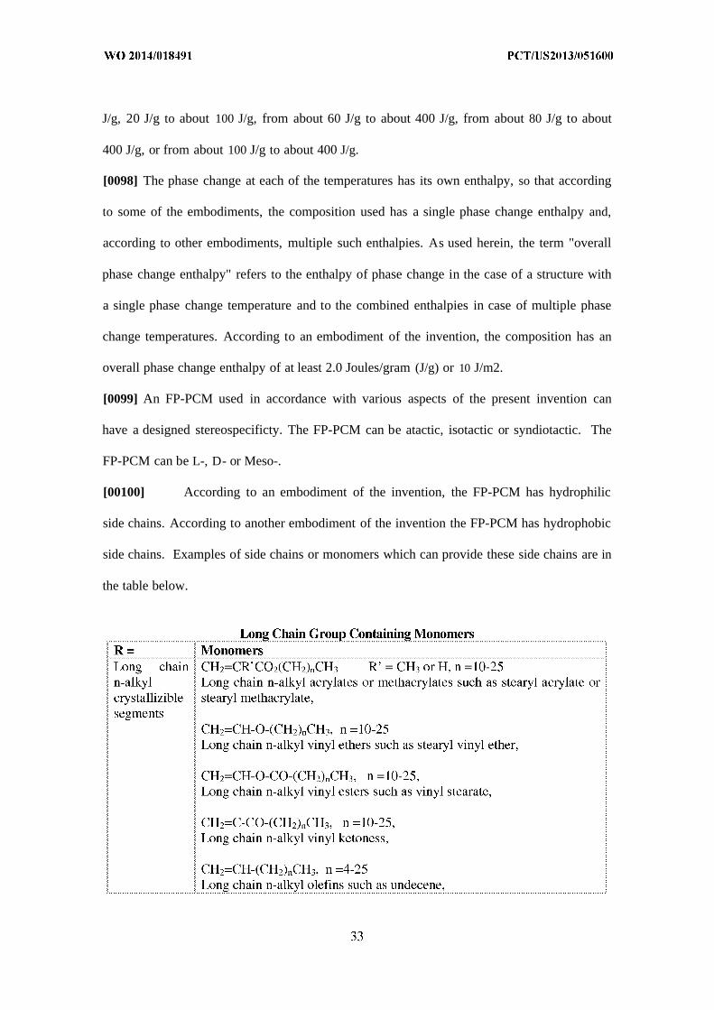
[00100] According to an embodiment of the invention, the FP-PCM has hydrophilic
side chains. According to another embodiment of the invention the FP-PCM has hydrophobic
side chains. Examples of side chains or monomers which can provide these side chains are in
the table below.

i or any unsaturate po ymer za e y roxy unct ona monomer
[00101] In addition other crystallizable sections of P-PCMs are contemplated,
including radicals of fatty acids, radicals of long-chain dicarboxylic acids, radicals of fatty
alcohols, radicals of dialcohols, polyester-polycarboxylic or as previously described.
[00102] While each of the FP-PCM molecules carries at least one reactive function,
large FP-PCM molecules may carry multiple reactive functions. According to an embodiment
an FP-PCM carries at least one reactive function per 10,000 Daltons of the molecular weight
and preferably two reactive functions.
[00103] In various embodiments, the functions are shown along the backbone, but that
is only one option. As indicated above, the functions could also be placed at the end(s) of the
backbone, on the side chains and any combination of those. Each FP-PCM may have a single
or multiple reactive functions. FP-PCM may also carry multiple reactive functions of a
similar chemical nature or a combination of reactive functions of different chemical nature.
[00104] As indicated, the reactive function of the FP-PCM should be capable of
forming covalent or electrovalent bonds with various articles, compounds and other
molecules, commonly referred to here as base materials or substrates. Examples of reactive

functions capable of forming covalent bonds are acid anhydride groups, amino groups, N-
substituted amino groups and their salts, amide groups, imine groups, imide groups, azide
groups, azo groups, amine-fromaldehyde groups, carbonyl groups, carboxy groups and their
salts, cyclohexyl epoxy groups, epoxy groups, glycidyl groups, hydroxy groups, isocyanate
groups, cyanate groups urea groups, aldehyde groups, ketone groups, ester groups, ether
groups, alkenyl groups, alkynyl groups, thiol groups, disulfide groups, silyl or silane groups,
halogenated leaving groups, peroxide groups, salt groups, groups based on glyoxals, groups
based on aziridines, groups based on active methylene compounds or other b-dicarbonyl
compounds (e.g., 2,4-pentandione, malonic acid, acetylacetone, ethylacetone acetate,
malonamide, acetoacetamide and its methyl analogues, ethyl acetoacetate, and isopropyl
acetoacetate), halo groups, hydrides, or other polar or H bonding groups and combinations
thereof. FP-PCMs capable of forming covalent bonds are disclosed in commonly assigned
US Patent Application No. 12/174,607, the teaching of which is incorporated herein by
reference in its entirety. Examples of reactive functions capable of forming electrovalent
bonds are acid functions, basic functions, positively charged complexes and negatively
charged complexes. FP-PCM capable of forming electrovalent bonds such as disclosed in
commonly assigned US Patent Application No. 12/174,609, the teaching of which is
incorporated herein by reference in its entirety. For example, the following are examples of
suitable reactive functional groups:
[00105] According to one embodiment, the FP-PCM may carry reactive functions as
its end group or groups. Examples of such FP-PCMs are α,ω-diglycidyl polyesters, α,ω-
diglycidyl ethers, α,ω-diisocyanates, α,ω-diureas, α,ω-dialkenes, a-glycidyl polyesters, a-
glycidyl ethers, a-ureas and a-isocyanates. (See e.g. the structures depicted in Figures 7-10
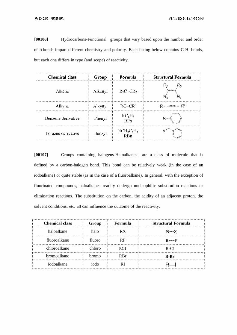
[00106] Hydrocarbons-Functional groups that vary based upon the number and order
of π bonds impart different chemistry and polarity. Each listing below contains C-H bonds,
but each one differs in type (and scope) of reactivity.
[00107] Groups containing halogens-Haloalkanes are a class of molecule that is
defined by a carbon-halogen bond. This bond can be relatively weak (in the case of an
iodoalkane) or quite stable (as in the case of a fluoroalkane). In general, with the exception of
fluorinated compounds, haloalkanes readily undergo nucleophilic substitution reactions or
elimination reactions. The substitution on the carbon, the acidity of an adjacent proton, the
solvent conditions, etc. all can influence the outcome of the reactivity.
Chemical class Group Formula Structural Formula
haloalkane halo RX
fluoroalkane fluoro RF R~~~F
chloroalkane chloro RC1 R-C!
bromoalkane bromo RBr R-Br
iodoalkane iodo RI R—l
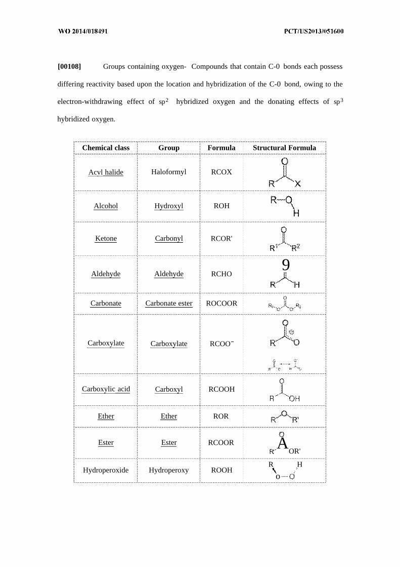
[00108] Groups containing oxygen- Compounds that contain C-0 bonds each possess
differing reactivity based upon the location and hybridization of the C-0 bond, owing to the
electron-withdrawing effect of sp2 hybridized oxygen and the donating effects of sp3
hybridized oxygen.
Chemical class Group Formula Structural Formula
Acvl halide Haloformyl RCOX
Alcohol Hydroxyl ROH
Ketone Carbonyl RCOR'
Aldehyde Aldehyde RCHO9
Carbonate Carbonate ester ROCOOR
Carboxylate Carboxylate RCOO
Carboxylic acid Carboxyl RCOOH
Ether Ether ROR
Ester Ester RCOOR AOR'
R HHydroperoxide Hydroperoxy ROOH
o

Chemical class Group Formula Structural Formula
Peroxide Peroxv ROOR
[00109] Groups containing nitrogen- Compounds that contain Nitrogen in this
category may contain C-0 bonds, such as amides.
Chemical class Group Formula Structural Formula
Amide Carboxamide RCONRz
.... ..
Primary amine RNH2 RΠ
Secondary amine R2NH
Amines
Tertiary amine R N
R
4° ammonium ion R4N+
Primary ketimine RC(=NH)R
Imine SecondaryRC(=NR)R
ketimine
Primary aldimine RC(=NH)H


Chemical class Group Formula Structural Formula
i ¾ > }i
4f ¾Pyridine Pyridyl RC5H4N —derivative
i }
[00110] Groups containing phosphorus and sulfur- Compounds that contain sulfur and
phosphorus exhibit unique chemistry due to their varying polarity and ability to form more
bonds than nitrogen and oxygen, their lighter analogues on the periodic table.
StructuralChemical class Group Formula
Formula
PPhosphine Phosphino R P
Phosphodiester Phosphate HOPO(OR) 2
Phosphonic acid Phosphono RP(=0)(OH) 2
Phosphate Phosphate ROP(=0)(OH)
Sulfide orRSR s
thioether FT
Sulfone Sulfonyl RSO2R'... ... ... .
Sulfonic acid Sulfo RSO3HΡ
R
Sulfoxide Sulfinvl RSOR

[00111] Other chemical classes include Organosilanes, Siloxides, Silyl halides, Silyl
hydrides, Hydrosilylation, Silenes, Siloles, and Hypercoordinated silicon.
[00112] According to another embodiment, the functional polymeric phase change
material may also be chemically bound to the substrate. Binding may be one of covalent
binding, electrovalent binding, direct binding, or binding via a connecting compound.
According to another embodiment, binding is such as the one resulting from a reaction
between a reactive function of the FP-PCM and a reactive function of the substrate,
preferably the binding is a result of such reaction. The substrate can be selected from the
group consisting of plastic or polymeric layers such as plastic films, plastic sheets, laminates
or combinations of above, metals, composites, other polymers, carbons, ceramics, glass,
fiberglass or other known materials used in the construction of electronics.
[00113] The FP-PCM can be implemented as a coating, laminate, infusion, treatment
or ingredient in a coating, laminate, infusion, treatment that is formed adjacent to, on or
within the substrate using any suitable coating, laminating, infusion, etc. technique. During
use, the FP-PCM can be positioned so that it is adjacent to an internal compartment, thus
serving as an inner coating. It is also contemplated that the FP-PCM can be positioned so that
it is exposed to an outside environment, thus serving as an outer coating. The FP-PCM covers
at least a portion of the substrate. Depending on characteristics of the substrate or a specific
coating technique that is used, the FP-PCM can penetrate below the top surface and permeate

at least a portion of the substrate. While two layers are described, it is contemplated that the
article can include more or less layers for other implementations. In particular, it is
contemplated that a third layer can be included so as to cover at least a portion of a bottom
surface of the substrate. Such a third layer can be implemented in a similar fashion as the FP-
PCM or can be implemented in another fashion to provide different functionality, such as
water repellency, stain resistance, stiffness, impact resistance, etc.
[00114] In one embodiment, the FP-PCM may be blended with a binder which may
also contain a set of microcapsules that are dispersed in the binder. The binder can be any
suitable material that serves as a matrix within which the FP-PCM and possibly also the
microcapsules are dispersed, thus offering a degree of protection to the FP-PCM and
microcapsules against ambient or processing conditions or against abrasion or wear during
use. For example, the binder can be a polymer or any other suitable medium used in certain
coating, laminating, or adhesion techniques. For certain implementations, the binder is
desirably a polymer having a glass transition temperature ranging from about -110° C to
about 100° C, more preferably from about
-110° C to about 40° C. While a polymer that is water soluble or water dispersible can be
particularly desirable, a polymer that is water insoluble or slightly water soluble can also be
used as the binder for certain implementations.
[00115] The selection of the binder can be dependent upon various considerations,
such as its affinity for the FP-PCM, PCM and/or microcapsules or the substrate, its ability to
modify heat transfer, its breathability, its flexibility, its softness, its water absorbency, its
coating-forming ability, its resistance to degradation under ambient or processing conditions,
and its mechanical strength. In particular, for certain implementations, the binder can be
selected so as to include a set of functional groups, acid anhydride groups, amino groups, N-
substituted amino groups and their salts, amide groups, imine groups, imide groups, azide
groups, azo groups, amine-fromaldehyde groups, carbonyl groups, carboxy groups and their
salts, cyclohexyl epoxy groups, epoxy groups, glycidyl groups, hydroxy groups, isocyanate
groups, cyanate groups urea groups, aldehyde groups, ketone groups, ester groups, ether
groups, alkenyl groups, alkynyl groups, thiol groups, disulfide groups, silyl or silane groups,
halogenated leaving groups, peroxide groups, salt groups, groups based on glyoxals, groups
based on aziridines, groups based on active methylene compounds or other b-dicarbonyl
compounds (e.g., 2,4-pentandione, malonic acid, acetylacetone, ethylacetone acetate,
malonamide, acetoacetamide and its methyl analogues, ethyl acetoacetate, and isopropyl
acetoacetate), halo groups, hydrides, or other polar or H bonding groups and combinations
thereof.
[00116] These functional groups can allow chemical bonding to a complementary set
of functional groups included in either of, or any of, the FP-PCM, the PCM, the thermal
conductive particles, the microcapsules and the substrate, thereby enhancing durability of the
article during processing or during use. Thus, for example, the binder can be a polymer that
includes a set of epoxy groups, which can chemically bond to a set of carboxy groups
included in the FP-PCM, PCM, the thermal conductive particles, and/or the microcapsules.
As another example, the binder can be a polymer that includes a set of isocyanate groups or a
set of amino groups, which can chemically bond with those carboxy groups included in the
FP-PCM, PCM, the thermal conductive particles, microcapsules, or substrate.
[00117] In some instances, a set of catalysts can be added when forming the coating
composition. Such catalysts can facilitate chemical bonding between complementary
functional groups, such as between those included in the binder and those included in the
microcapsules. Examples of materials that can be used as catalysts include boron salts,
hypophosphite salts (e.g., ammonium hypophosphite and sodium hypophosphite), phosphate
salts, tin salts (e.g., salts of Sn+2 or Sn 4 , such as dibutyl tin dilaurate and dibutyl tin

diacetate), and zinc salts (e.g., salts of Zn ) . A desirable amount of a tin salt or a zinc salt
that is added to the coating composition can range from about 0.001 to about 1.0 percent by
dry weight, such as from about 0.01 to about 0.1 percent by dry weight. A desirable amount
of a boron salt or a phosphate salt that is added to the coating composition can range from
about 0.1 to about 5 percent by dry weight, such as from about 1 to about 3 percent by dry
weight. Other examples of materials that can be used as catalysts include alkylated metals,
metal salts, metal halides, and metal oxides, where suitable metals include Li, Be, Na, Mg, K,
Ca, Rb, Sr, Ti, V, Mn, Fe, Co Ni, Cu Zn Ga, Ge As, Se, Al, Y, Zr, Nb, Mo, Ru, Rh, Pd, Ag,
Cd, In, Sn, Sb, Te, Cs, Ba, La, Hf, Ta, W, Re, Os, Ir, Pt, Au, Hg, Tl, Pb, Bi, Po, A Ra, Ac,
Ce, Nd, Pm, Sm, Eu, Gd, Tb, Dy, Ho, Er, Tm, Yb, Lu, Th, Pa, U, Pu, etc.. These metals and
their compounds can be used singly or blended. Organic acids and bases, such as those based
on sulfur (e.g., sulfuric), nitrogen (e.g., nitric), phosphorous (e.g., phosphoric), or halides
(e.g., F, CI, Br, and I), can also be used as catalyst. Further examples of materials that can be
used as catalysts include acids such as citric acid, itaconic acid, lactic acid, fumaric acid, and
formic acid.
[00118] Bonds between substrate, functional phase change material, binder, PCM, the
thermal conductive particles, and/or microcapsules are, according to various embodiments,
covalent, electrovalent or various combinations of those. Binding could be direct or indirect,
e.g. via a connecting compound. According to some embodiments, the connecting compound
is selected from a group consisting of functional polymeric phase change material and
microcapsules. According to another or the same embodiment, the functional polymeric
phase change material may form a binder for at least a portion of a second PCM.
[00119] According to another embodiment, the reactive function of the FP-PCM can
be converted into another reactive function, which is more suitable for reacting with
particular substrates.

[00120] According to another embodiment, the reactive function of the FP-PCM could
be of various chemical nature. For example, reactive functions capable of reacting and
forming covalent or electrovalent bonds with reactive functions of various substrates, e.g.
metals, plastics, other electronic components and thermal interface materials.
[00121] According to another embodiment of the invention, the reactive function can
be any of the following: 1) glycidyl or epoxy such as from glycidyl methacrylate or glycidyl
vinyl ether; 2) anhydride such as from maleic anhydride or itaconic anhydride; 3) isocyanate
such as from isocyanato methacrylate, TMI® from Cytec Ind. or blocked isocyanates such as
2-(0-[l'-methylproplyideneamino]carboxyamino)ethyl methacrylate; 4) amino or amine-
formaldehyde such as from N-methylolacrylamide; and 5) silane such as from
methacryloxypropyltriethoxysilane. Such reactive functions can react with OH functional
groups of cellulosic based materials; with hydroxyl or carboxyl groups of polyester based
materials and with amide functional groups of nylon functional resins.
[00122] According to still another embodiment of the invention, the reactive function
may be a double bond, capable of binding to another double bond, providing a cross-linking
point, a polymerization point, etc. The above described reactions, linking or crosslinking
reactions can be triggered by any energy such as light, UV, IR, heat, thermal, plasma, sound,
microwave, radiowave, pressure, x-ray, gamma, or any form of radiation or energy. They can
be triggered by chemical reactions such as by the use of free radical, anionic or cationic
catalysts or initiators.
[00123] The reactive function of the FP-PCM can assume a positive charge and bind
electrovalently with a negative charge on the substrate. According to another embodiment,
the reactive function can assume a negative charge and bind electrovalently with a positive
charge on the substrate. According to another embodiment, the reactive functions of both the
substrate and the FP-PCM and/or microcapsule may be negatively charged and binding is via

a multivalent cation, which acts as a cross-linker. According to still another embodiment, the
reactive functions of both the substrate and the FP-PCM and/or microcapsule may be
positively charged and binding is via a multivalent anion, which acts as a cross-linker. The
cross-linking multivalent cation, anion or both could be organic or inorganic.
Examples of FP-PCM Structures
[00124] Figures 7-10D are schematic drawings of FP-PCMs used in accordance with
various aspects of the present invention. Both are composed of a backbone chain and side
chains. The FP-PCM in Figure 7 represent long chain alkyl polyacrylate or polymethacrylate,
and 7A-7C where 7A is long chain alkyl vinyl esters, 7B is long chain vinyl ethers and 7C is
long chain alkyl olefins.
[00125] Figures 8A and 8B represent long chain glycol polyacrylates or
polymethacrylates, where 8A is long chain glycol vinyl esters and 8B is long chain glycol
vinyl ethers.
[00126] In Figures 7 and 8, R represents one or more of the reactive functions(s)
described above. In those figures, the functions are drawn along the backbone, but that is only
one option. As indicated above, the functions could also be placed at the end(s) of the
backbone, on the side chains and any combination of those. Each FP-PCM may have a single
or multiple reactive functions. FP-PCM may also carry multiple reactive functions of a
similar chemical nature or a combination of reactive functions of different chemical nature.
The length of the side chains may vary in different embodiments as shown by the variable
chain length n.
[00127] With reference to Figures 9A - 9F, Figure 9A drawing depicts an acidic or
low pH carboxyl functional FP-PCM ionically interacting with a basic or high pH amino
functional substrate. Figure 9B depicts basic or high pH amino functional FP-PCM ionically
interacting with an acidic or low pH carboxyl functional substrate. Figure 9C depicts basic or
high pH amino functional FP-PCM and a basic or high pH amino functional substrate being
neutralized and ionically bound or "crosslinked" with an anion such as an amine. Figure 9D
depicts an acidic or low pH carboxyl functional FP-PCM and an acidic or low pH carboxyl
functional substrate being neutralized and ionically bound or "crosslinked" with a cation such
as a metal salt. Figure 9E depicts basic or high pH amino functional FP-PCM and a basic or
high pH amino functional substrate being neutralized and ionically bound or "crosslinked"
with negatively charged organic compound such as dicarboxy functional polymer or
dicarboxy functional FP-PCM. Figure 9F depicts an acidic or low pH carboxyl functional
FP-PCM and an acidic or low pH carboxyl functional substrate being neutralized and
ionically bound or "crosslinked" with positively charged organic compound such as diamine
functional polymer or diamine functional FP-PCM.
[00128] With reference to Figures 10A - 10D, Figure 10A depicts a covalent ether
bond from the reaction of an FP-PCM epoxy and hydroxyl on a cellulose substrate. Figure
10B depicts a covalent urea bond from the reaction of an FP-PCM isocyanate and amine from
another material. Figure IOC depicts a covalent urethane bond from the reaction of an FP-
PCM isocyanate on the end of a side chain and hydroxyl from a cellulose substrate. Figure
10D depicts a covalent urea and urethane bonds from the reaction of amine function, FP-
PCMs, multifunctional isocyanate crosslinker/binder, and hydroxyl from a cellulose
substrate.
Use of Precisely Branched FP-PCMs
[00129] In addition to the above disclosure concerning functional polymeric phase
change material application and the use with various substrates, the disclosure below focuses
on how using a more precisely branched polymer can give more precise and repeatable

control of a copolymer addition. It is contemplated that each of the embodiments shown in
Figures 7-10 may be modified to utilize the precisely branched polymers disclosed and
discussed below. One of skill in the art would readily recognize how to incorporate the
precisely branched polymers into the examples above and into variations of the above
examples.
[00130] Standard polymerizations do not give precise and repeatable control of the
comonomer addition because the catalysts generally add co-monomers in a random fashion.
As discussed above, many polymers currently available commercially have random monomer
incorporation. Current catalysts and polymerization technologies produce polymers with
"drifting copolymer" structures where polymer chains in the product have a wide range of
compositions of the comonomers. Due to the randomness of this comonomer addition, less
control can be exerted over the thermal properties of the copolymer such as
melt/crystallization temperature and the amount of crystallization. The amount of
crystallization can be expressed as a percentage crystallinity, latent heat, heat of fusion or
Joules per gram.
[00131] Precise branching control as discussed below allows for greater latent heat
content at a given melt temperature versus random comonomer incorporation which requires
more comonomer to give the same melt temperature, leading to lower percentage crystallinity
and lower latent heat.
[00132] With general reference to Figures 11-13, various graphs are shown that
illustrate the difference in both melt temperature and latent heat. In Figures 11-13 the
precisely branched polymers are labeled as ADMET. In the various embodiments, figures
and examples, ADMET stands for Acyclic Diene Metathesis Polymerization and generally
represents polymers with precisely placed methyl branches.

[00133] It is well known in the industry, that for polyolefin polymers the melting
temperature and latent heat are controlled by the longest carbon segments in the polyolefin
backbone. For instance in polyethylene random copolymers, the distribution of ethylene
sequences vary. In the case of polyethylene copolymers, thick crystal lamella can be formed
from the longer ethylene sequences which will result in higher melting temperatures. The
shorter ethylene sequences and/or branches will not be incorporated into these crystallites or
lamella resulting in lowered heats of fusion or Joules per gram.
[00134] In accordance with one embodiment and example, a precisely branched
polyethylene material having equal ethylene sequences yields the following features: a faster
decrease in melting temperature at lower branch content; better control of the melting
temperature; and an overall higher amount of ethylene sequences incorporated into the
lamella or crystallite, yielding higher latent heats.
[00135] Therefore, aspects of the invention and the use of these precisely controlled
copolymers yields materials with phase change materials exhibiting enhanced temperature
regulating, heat absorbing, and heat releasing properties. In order to obtain a preferred PCM
with melting temperatures suitable for use in electronics applications and as described below.
In yet another embodiment, and a latent heat of fusion of >25 Joules per gram in one
embodiment, > 5 Joules per gram in another embodiment, and between 5 and 150 Joules per
gram in yet another embodiment, a PCM in one example has a structure with one or more of
the following features:
The overall polymer molecular weight (n) is between 100 - 10,000,000, between
1000-1,000,000 or between 10,000 - 500,000 in various embodiments.
With the molecular weight distribution expressed as polydispersity or
Pd=Mn/Mw, it is between 1-20, between 1-10, or between 1-3 in various
embodiments.

The ethylene length between branches is between 5-500,000, between 10-400,000,
or between 10-20 in various embodiments.
[00136] The length described above can be expressed in a number of ways such as
number of m units in diagram 1 below, branches per 1000 carbons (branches/ 1000 C), mole
% branches or weight % branches. The PCM structure also has the following characteristics
in one or more embodiments:
The number of m units is between 0-500,000, between 0-200,000 or between 5-
15,000 in different embodiments.
There are between 200-0, between 100-5 or between 100-0 branches per 1000
carbons (branches/ 1000 C) in different embodiments.
The mole % of the branches is 0-50% or between -30% in different embodiments.
The weight percentage of the branches is between 0-50% or between 10-30% in
different embodiments.
[00137] In some embodiments it is preferred that the branches are methyl branches
from propylene as the comonomer and that propylene is 0-30 mole % of the polymer. In
another embodiment, propylene is 0-39 weight % of the polymer
Diagram 1
[00138] In diagram 1 above, illustrating one embodiment, Rl may be any of CH3,
C2H5, CnH2n+l, OCH3, OC2H5, or any functional group, polar group, halogen group, their

normal, branched or mixed group. In certain embodiments Rl is selected from either CH3 or
OCH3. In diagram 1, R2= H, CH3 and in certain specific embodiments, R2 is limited to H.
[00139] In diagram 1, R3= H, CH3 or some concentration of a selected functional
group, polar group or halogen group. In certain embodiments, R3 is limited to CH3 or to one
or more concentrations of a functional group
[00140] In diagram 1, R4 and R5 are polymer end groups and can be H, CH3 or any
functional group, polar group or halogen group, salt, metal, catalyst end, crosslinking group,
another polymer chain to form copolymers (block, graft, etc.). In some embodiments, R4, R5
can be the same or different. In certain embodiments, R4 and R5 are limited to H, CH3 or
any functional group.
[00141] In accordance with other aspects Rl, R2, R3, R4, and R5 can have some
degree of stereocontrol or stereochemistry associated with them. For example:
Rl, R2, R3 may be atactic, isotactic or syndiotactic.
Rl, R2, R3 may also be controlled for chirality to yield L-and D-chiral homo and
copolymers (or another way of stating is R- and S- polymers).
[00142] Different polymer architectures based on the stereochemistry of the polymer
chain can lead to various crystalline complexes. For example, syndiotactic homo- and
copolymers can complex with isotactic homo- and copolymers. Polymers of opposite
chirality can be mixed to form a racemic stereocomplex. In one embodiment, a certain
amount of isotactic L-polymer can be mixed with an amount of isotactic D-polymer to yield a
racemic stereocomplex with thermal and physical properties different than the L- or D-chiral
homopolymers. (A polymer stereocomplex is defined as a stereoselective interaction between
two complementing stereoregular polymers, that interlock and form a new composite,
demonstrating altered physical and thermal properties different than the parent polymers.)

[00143] These syndiotactic, isotactic or L- and D-chiral segments can be in different
polymer chains (homopolymer segments) or in the same polymer (stereoblock copolymers
segments). The syndiotactic, isotactic or L- and D-chiral segments can make up anywhere
between 1-100% of the polymer or copolymer as well as various intermediate percentage
ranges.
[00144] The syndiotactic, isotactic or L- and D-chiral segments can be mixed in a
ration between 9:1 and 1:9 to give complete or partial stereocomplex formation and
subsequent thermal and physical property adjustment. Other crystalline complexes may also
be utilized such as complexes between different polymers such as polyamides and polyesters,
cationic/anionic, polyethers/polyacids, and triple helixes.
[00145] R3, R4, R5 can be any functional group, polar group or halogen group, salt,
metal, catalyst end, crosslinking group, or any of the following functional groups: acid
anhydride groups, amino groups, N-substituted amino groups and their salts, amide groups,
imine groups, imide groups, azide groups, azo groups, amine-fromaldehyde groups, carbonyl
groups, carboxy groups and their salts, cyclohexyl epoxy groups, epoxy groups, glycidyl
groups, hydroxy groups, isocyanate groups, cyanate groups urea groups, aldehyde groups,
ketone groups, ester groups, ether groups, alkenyl groups, alkynyl groups, thiol groups,
disulfide groups, silyl or silane groups, halogenated leaving groups, peroxide groups, salt
groups, groups based on glyoxals, groups based on aziridines, groups based on active
methylene compounds or other b-dicarbonyl compounds (e.g., 2,4-pentandione, malonic acid,
acetylacetone, ethylacetone acetate, malonamide, acetoacetamide and its methyl analogues,
ethyl acetoacetate, and isopropyl acetoacetate), halo groups, hydrides, or other polar or H
bonding groups and combinations thereof.

[00146] The crosslinking groups discussed above may also include the ability to
reversibly or irreversibly change the crosslink by thermal, sonic, photon, pressure, or
chemical (water, solvents, ions, etc.) energy.
[00147] Various other methods of functionalization are described shown in the
following references, the details of which are incorporated by reference into the present
application: Synthesis of Functional Polylefins using Metallocenes: A Comprehensive
Review; Atiqullah M., et.al.; Polymer Reviews, 50:178-230, 2010; Comprehensive
Organometallic Chemistry III: 11.20-Polymerization of Alkenes; Elsevier Ltd.; Fujita T.,
Makio H.; Vol. 11, 691-734, 2007; Functionalized Ethylene Copolymers and Materials via
Olefin Metathesis Polymerization; Baughman, T., Univ. of Florida Dissertation, 2006.
[00148] In accordance with another aspect, the polymer may have a certain degree of
unstaturation or include double and triple bonded atoms in the polymer. For instance, alkene
or alkyne bonds. This unsaturation (not all valence electrons are "saturated" or reacted to
other atoms) can be incorporated and controlled by the monomers used in the polymerization
(isoprene, butadiene, a-olefins, etc.), hydride elimination (β-hydride elimination, etc.),
various polymerization mechanisms (ring-opening metathesis polymerization (ROMP),
acyclic diene metathesis (ADMET described herein, etc.) or controlled
hydrogenation/dehydrogenation. For instance, as shown in Diagram 2 and Figure 14,
examples of making the invention by ADMET polymerization and subsequent hydrogenation
are shown. Figure 14 shows the effect of unsaturation on the thermal properties.
Diagram 2

[00149] As can be seen, unsaturation causes a lower melting temperature and also
slighly lower latent heat of fusion, but by controlling the level of unsaturation, one can also
control the thermal properties. In some embodiments the unsaturation is 0-99 mole %. In
other embodiments the unsaturation is 0-15 mole %. In various other embodiments, various
intermediate ranges of mole % are utilized.
[00150] The isomeric orientation of the double bond can also have an effect on the
properties of the unsaturated polymer. The cis/trans orientation of the double bond can also
be controlled by the hydrogenation catalyst or the hydrogenation process conditions such as
time, temperature, pressure, etc.
[00151] The isomer ratio, unsaturation and double bond orientation will vary
depending on the comonomer composition, comonomer distribution and polymerization
conditions. One goal of a composition in accordance with an aspect of the present invention
is to maximize latent heat in the preferred temperature range.
[00152] Copolymer segments used in connection with aspects of the present invention
can be copolymers or blended with any of the other polymers/copolymers disclosed herein.
In addition, copolymer segments used in connection with aspects of the present invention can
be high melt or low melt.
Use of Nucleating Agents
[00153] In order to improve the crystallinity of the PCM, pPCM and/or fpPCM and
therefore the latent heat and thermal conductivity of these materials, nucleating agents can
also be added. Nucleating agents can effect improved crystal growth, crystallization speed,
crystal shape and size, amount of crystallization and number of crystallites of the materials.

[00154] Furthermore, the particle size of the nucleating agent and the mixing of these
are important factors in ensuring optimal performance of the additives. Features of a good
melt insensitive nucleating agent may be selected from one or more of the following:
• It contains both an organic group and a polar group
• It is well dispersed
• It is insoluble or can become insoluble in the polymer
• It has an epitaxial match with the PCM crystal
• The physical or chemical nature of nucleating agents can be diverse. A nucleating
agent can be:
o An impurity, i.e. catalyst residue
o An organic compound like benzoic acid, hydrocarbons or fatty acid based
materials
o An inorganic compound such as mineral or pigment
o A foreign polymer crystal, i.e. polyethylene for octadecane, etc.
o A diluent, i.e. a material that lowers the Tg or improves the chain mobility
leading to improved chain packing.
[00155] Additional nucleating agents that may be utilized include those described in
US Patent No. 7569630 β-Crystalline Polypropylene to Chemtura Corp., US Patent No.
7879933 Blending Nucleating Agents Composition and Methods to Milliken & Company,
and Hyperform® products from Milliken & Company. Other examples are aliphatic
hydrocarbons, aromatic hydrocarbons, alcohols, fatty acids, fatty acid salts, fatty acid esters,
fatty amides, fatty amines, fatty alcohols, N-Phenyl-N'-stearylurea, zinc glycerolate, benzoic
acid, salts and esters of benzoic acid, benzoic acid derivatives, Na benzoate, Li benzoate, Al
hydroxy -4-tert.- butyl benzoate, phosphate esters, phosphate ester salts, sodium 2,2'-
methylene-bis-(4,6-di-tert-butylphyenyl)phosphate, dibenzylidene sorbitol, derivatives of
dibenzylidene sorbitol, linear or branched polyphenyls, salts of hydrogen phthalate, 1, 2-
cyclohexanedicarboxylic acid and the mono or di neutralized salt (i.e. Na, K, Al, B, Ti, n,

Ca, Li, Mg, etc.), cetyl alcohol, stearyl alcohol, eicosanol, myristic acid, palmitic acid,
behenic acid, stearic acid amide, ethylenebisoleic acid amide, methylolbehenic acid amide, 1-
octacosanol, 1-heptacosanol, 1-hexacosanol, 1-pentacosanol, 1-tetracosanol, 1-tricosanol, 1-
docosanol, 1-heneicosanol, 1-eicosanol, 1-nonadecanol, 1-octadecanol, 1-heptadecanol, 1-
hexadecanol, 1-pentadecanol, 1-tetradecanol, 1-tridecanol, tridecylamine, tetradecylamine,
pentadecylamine, hexadecylamine, heptadecylamine, octadecylamine, nonadecylamine,
eicocylamine, heneicocylamine, dococylamine, tricocylamine, tetracocylamine,
pentacocylamine, hexacocylamine, heptacocylamine and octacocylamine, etc. Minerals such
as talc, kaolin, calcium carbonate, Ti0 2, salts, NaCl, and Na carbonate may also be used as
nucleating agents. These compounds may be used singly or in combination of two or more
thereof.
Microcapsules and Other Containment and/or Absorbing Structures for Phase ChangeMaterials
[00156] PCM can be contained in microcapsules or some other containment structure
or particulate. Containment structures other than microcapsules are capable of carrying
functional groups, either as a natural part of their structure or from their modified
manufacturing. For instance, PCMs can be absorbed and stabilized into any number of
particles including silica (fumed or precipitated), graphite, graphene, carbon nanoparticles,
carbon or activated carbon, zeolites, organoclays, montmorillonite, bentonite, clay, talc, and
vermiculite. Paraffin or hydrophobic PCMs can also be absorbed in any number of polymers,
especially crosslinked polymers, similar to how a plasticizer will absorb into plastics. For
instance PCM can be absorbed into any polyolefin and polyolefin copolymer such as
polyethylene, polypropylene, salts of polyolefins and their copolymers, poly(meth)acrylates,
salts of poly(meth)acrylates, polyvinyls, aliphatic polyesters, rubbers, copolymers (i.e.
Kraton® copolymers, Elvaloy®) and mixtures, etc. PCMs based on glycols can be absorbed
into any hydrophilic polymers such as polyvinyl alcohol, substituted cellulose (CMC, HMC,
etc.) etc.
[00157] PCMs, pPCMs, fpPCMs can also be contained, absorbed or infused on any
particle or fiber including the below described thermal conductive fillers, reinforcing
materials, FR addtives, etc. These containment or absorbing particle can be any shape such as
round, spherical, cylindrical, fiber, sheet, flake, powder, whiskers, tubular, platelets, foams,
meshes, agglomerates of these shapes or any other irregular shape. Depending on the
application, a single shape or mixture of shapes may be advantageous to provide the optimum
packing and arrangement for particle contact. These containment or absorbing particle can be
any size but are preferably O.lnm to 100mm.
[00158] Other materials which can absorb or contain PCMs such as standard
superabsorbant polymers based on cross-linked sodium polyacrylate. Other materials are also
used to make a superabsorbent polymer, such as polyacrylamide copolymer, ethylene maleic
anhydride copolymer, cross-linked carboxy-methyl-cellulose, polyvinyl alcohol copolymers,
cross-linked polyethylene oxide, and starch grafted copolymer of polyacrylonitrile to name a
few.
[00159] Microcapsules are implemented to contain a phase change material, which
serves to absorb or release heat to reduce or eliminate heat transfer. In particular, the
microcapsules are formed as shells that define internal compartments within which the phase
change material is positioned. The shells can be formed of any suitable material that serves to
contain the phase change material, thus offering a degree of protection to the phase change
material against ambient or processing conditions or against loss or leakage during use. For
example, the shells can be formed of a polymer or any other suitable encapsulation material.
[00160] The selection of a material forming the microcapsule shells can be dependent
upon various considerations, such as its affinity for other materials in the TMM, affinity or

adhesion to electronic components, its reactivity or lack of reactivity with the phase change
material, TMM materials or electrical components, its resistance to degradation under
ambient or processing conditions, and its mechanical strength. In particular, for certain
implementations, a material forming the shells can be selected so as to include a set of
functional groups, acid anhydride groups, amino groups, N-substituted amino groups and
their salts, amide groups, imine groups, imide groups, azide groups, azo groups, amine-
fromaldehyde groups, carbonyl groups, carboxy groups and their salts, cyclohexyl epoxy
groups, epoxy groups, glycidyl groups, hydroxy groups, isocyanate groups, cyanate groups
urea groups, aldehyde groups, ketone groups, ester groups, ether groups, alkenyl groups,
alkynyl groups, thiol groups, disulfide groups, silyl or silane groups, halogenated leaving
groups, peroxide groups, salt groups, groups based on glyoxals, groups based on aziridines,
groups based on active methylene compounds or other b-dicarbonyl compounds (e.g., 2,4-
pentandione, malonic acid, acetylacetone, ethylacetone acetate, malonamide, acetoacetamide
and its methyl analogues, ethyl acetoacetate, and isopropyl acetoacetate), halo groups,
hydrides, or other polar or H bonding groups and combinations thereof. At least some of
these functional groups can be exposed on outer surfaces of the shells and can allow chemical
bonding to a complementary set of functional groups included in either of, or both, the
substrates or other TMM materials, thereby enhancing durability or adhesion. In such
fashion, at least some of the microcapsules can be chemically bonded to other PCMs,
pPCMs, fpPCMs or fillers. Thus, for example, a material forming the shells can include a set
of carboxy groups, which can chemically bond to a set of hydroxy groups. As another
example, those carboxy groups included in the shells can chemically bond to a set of amino
groups.
[00161] Examples of polymers that can be used to form the shells include those listed
under the "polymers" definition, including those with carboxy groups, such as polymers

including monomelic units based on acrylic acid or methacrylic acid. For certain
implementations, the shells can be formed of a polymer that includes from about 1 to about
100 molar percent of monomelic units that include carboxy groups, such as from about 20 to
about 80 molar percent, from about 25 to about 60 molar percent, or from about 40 to about
50 molar percent of the monomeric units. In some instances, it can be desirable to adjust a
molar percentage of the monomeric units based on sizes of the microcapsules. For example,
as a size of an individual one of the microcapsules decreases, an outer surface area of that
microcapsule also typically decreases. Thus, to maintain a desired amount of exposed
functional groups for chemical bonding, it can be desirable to increase the molar percentage
of the monomeric units as the size of that microcapsule decreases. As another example, as a
size of an individual one of the microcapsules increases, a weight of that microcapsule also
typically increases. Thus, to account for the increasing weight, it can be desirable to increase
the molar percentage of the monomeric units as the size of that microcapsule increases. Table
1 provides examples of ranges of the molar percentages as a function of the sizes of the
microcapsules. Referring to Table 1, the microcapsules are assumed to be spherical for ease
of presentation. Similar considerations and molar percentages can also apply to polymers
with other types of functional groups.
TABLE 1
Surface Molar percent ofRadius - r area - 4 r2 monomeric units with
(urn) (urn2) carboxy groups
0.5 3 50-601 13 45-552 50 40-503 113 40-504 201 55 314 5 56 4 2 0 07 616 30^08 804 25-35
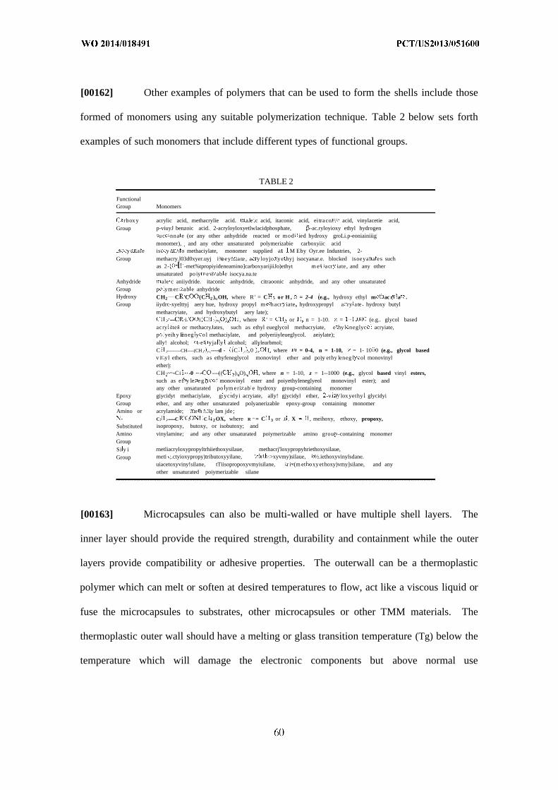
[00162] Other examples of polymers that can be used to form the shells include those
formed of monomers using any suitable polymerization technique. Table 2 below sets forth
examples of such monomers that include different types of functional groups.
TABLE 2
FunctionalGroup Monomers
rbox y acrylic acid, methacrylie acid. aJe c acid, itaconic acid, ei traco acid, vinylacetie acid,Group p-viuyJ benzoic acid. 2-acryloyloxyetlwlacidphosphate, -ac.ryloyioxy ethyl hydrogen
u c nna e (or any other anhydride reacted or mod ied hydroxy groLi.p-eoniainiiigmonomer), and any other unsaturated polymerizabie carboxyiic acid
y a e is y o methaciylate, monomer supplied M Eby Oyr.ee Industries, 2-Group methacry.l03d0xyer.uyj i¾oey ar.e , a y loyjo y e hyj isocyanar.e. blocked isoeya a es such
as 2- -[ -met%tpropiyideneamino]carboxyarijiiJo)ethyt m e i acr iate , and any otherunsaturated po iy evi ab e isocya.na.te
Anhydride ale c aniiydride. itaconic anhydride, citraoonic anhydride, and any other unsaturatedGroup p ym er ab e anhydrideHydroxy CH2 C 'C (C 2 ) OH, where R ' = C or H , = 2-4 (e.g., hydroxy ethyl m ac r a .Group iiydrc-xyelttyj aery hue, hydroxy propyl m h acr iate hydroxypropyl a ry ate hydroxy butyl
methacryiate, and hydroxybutyl aery late);----- ,i i , where ' = or n = 1-10. = (e.g.. glycol based
acry te or methacryJates, such as ethyl eueglycol methacryiate, e hy l neglyc acryiate,p yeih y Een eg y o l methaciylate, and polyeriiyleueglycol. aeiylate);ally! alcohol; -e i yja y alcohol; allylearbmol;C --------CH----(CH ----d - iC 0 I, where = 0-4, n = 1-10, = 1- 10 0 (e.g., glycol basedv i yl ethers, such as ethyfeneglycol monovinyl ether and po)y ethy leneg l ol monovinylether):CH -Ci . -0 - ----(( - )i O), , where n = 1-10, z = 1--1000 (e.g., glycol based vinyl esters,such as ef y le. eg l monovinyl ester and poiyethyleneglyeol monovinyl ester); andany other unsaturated po ym eri ab e hydroxy group-containing monomer
Epoxy giycidyt methaciylate, g yc dyi acryiate, ally! gjycidyl ether, -v lox yethy glycidyiGroup ether, and any other unsaturated polyanerizable epoxy-group containing monomerAmino or acrylamide; e h y lam jde;
- C: --------C : C -i 2OX, where R " = C 3 or .E , X , meihoxy, ethoxy, propoxy,Substituted isopropoxy, butoxy, or isobutoxy; andAmino vinylamine; and any other unsaturated poiymerizable amino grou -containing monomerGroupSi y i rnetliacryloxypropyltrhiiethoxysilaue, methacrj'loxypropyhriethoxysilaue,
Group meti ;.ctyioxypropy)tributoxyyilane, >xyvmy)silaue, ½.iethoxyvinylsdane.uiacetoxyviny!silane, tTiisopropoxyvmyisilane, r i (m et oxy ethoxy)vmy]silane, and anyother unsaturated poiymerizable silane
[00163] Microcapsules can also be multi-walled or have multiple shell layers. The
inner layer should provide the required strength, durability and containment while the outer
layers provide compatibility or adhesive properties. The outerwall can be a thermoplastic
polymer which can melt or soften at desired temperatures to flow, act like a viscous liquid or
fuse the microcapsules to substrates, other microcapsules or other TMM materials. The
thermoplastic outer wall should have a melting or glass transition temperature (Tg) below the
temperature which will damage the electronic components but above normal use

temperatures. The outerwall can be made of any polymer that melts, softens or flows such as
polyolefins, rubbers, polyvinyls, poly(meth)acrylates, polyurethanes, etc. or copolymers.
[00164] Microcapsules can have the same shape or different shapes, and can have the
same size or different sizes. In some instances, the microcapsules can be substantially
spheroidal or spherical, and can have sizes ranging from about O.lnm to about 1,000 microns,
such as from about O.lnm to about 500 microns, from about O.lnm to about 100 microns,
from about 1 to about 15 microns. For certain implementations, it can be desirable that a
substantial fraction, such as at least 50 percent, or at least 80 percent of the microcapsules
have sizes within a specified range, such as from about 1 to about 15 microns. It can also be
desirable that the microcapsules are monodisperse with respect to either of, both, their shapes
and sizes.
[00165] Microcapsules can be of a durable, breakable, or controlled release type. It
can be advantageous to have the microcapsule core material permanently contained to
prevent leakage or loss of core material during use or processing. It may also be
advantageous to have the core material released thru either fast (breakable) or slow
(controlled release) means. For instance, when microcapsules are added to composites, and
the composites are cured at higher temperatures, small voids can be formed between the
composite and microcapsule shell wall due to variables such as differential expansion
between microcapsule and composite, incompatibility between microcapsule and composite
or shape distortion, etc. Release of core material and allowing it to flow into and fill these
voids allows for greatly improved thermal conductivity. This is shown in Figures 15A-15B.
Selection of a PCM Transition Temp.
[00166] The selection of a PCM is typically dependent upon the transition temperature
that is desired for a particular application that is going to include the PCM. The transition
temperature is the temperature or range of temperatures at which the PCM experiences a
phase change from solid to liquid or liquid to solid. For example, a PCM having a transition
temperature near normal body temperature or around 60°C can be desirable for electronics
applications to prevent user injury and protect overheating components. A phase change
material according to some embodiments of the invention can have a transition temperature
in the range of about -5 °C. to about 150 °C. In one embodiment, the transition temperature is
about 6 °C. to about 90 °C. In another embodiment, the transition temperature is about 30 °C.
to about 70 °C. In another embodiment, the PCM has a transition temperature of about 40 °C.
to about 60 °C.
[00167] The transition temperature can be expanded or narrowed by modifying the
purity of the PCM, molecular structure, blending of PCMs, blending of mPCM, blending of
polymeric PCMs and any mixtures thereof.
[00168] In addition, the temperature control is dependent on the absorption and release
of energy by changing phases, preferably by absorbing energy and melting or
releasing/dissipating heat by solidifying or crystallization. These melting (Tm) and
crystallization (Tp) temperatures for a single PCM material are preferably not widely spread
("supercooling"). This difference can be defined as the difference between peak melting
temperature and peak crystallization temperature as measured by a DSC, i.e. ∆Τ (°C) = Tm-
Tc. Preferably this ∆Τ is <15 °C, preferably <10 °C, more preferably <5° C.
Mixing and Layering of PCM Transition Temperatures
[00169] In some embodiments, it may be advantageous to have multiple or broad
transition temperatures. If a single narrow transition temperature is used, this can cause
thermal/energy buildup before the transition temperature is reached. Once the transition
temperature is reached, then energy will be absorbed until the latent energy is consumed and
the temperature will then continue to increase. Broad or multiple transition temperatures

allow for temperature regulation and thermal absorption as soon the temperature starts to
increase, thereby alleviating any thermal/energy buildup. Multiple or broad transition
temperatures can also more efficiently help "bleed-off or conduct heat away from a
component by overlapping or staggering thermal absorptions. For instance a TMM contains
PCMl which absorbs at 35-40°C and PCM2 which absorbs at 38-45°C. PCMl will start
absorbing and controlling temperature until a majority of the latent heat is used, at which time
PCM2 will start to absorb and conduct energy from PCMl thereby rejuvenating PCMl and
allowing it to keep functioning. This broadening or mixing of transition temps can be done
by combining all materials or layering them as depicted in the various figures.
Selection of Latent Heat Values
[00170] The selection of the phase change material can be dependent upon a latent heat
of the phase change material. A latent heat of the phase change material typically correlates
with its ability to absorb and release energy/heat or modify the heat transfer properties of the
article. In some instances, the phase change material can have a latent heat that is at least
about 20 J/g, such as at least about 40 J/g, at least about 50 J/g, at least about 70 J/g, at least
about 80 J/g, at least about 90 J/g, or at least about 100 J/g. Thus, for example, the phase
change material can have a latent heat ranging from about 20 J/g to about 400 J/g, such as
from about 60 J/g to about 400 J/g, from about 80 J/g to about 400 J/g, or from about 100 J/g
to about 400 J/g.
TMM Rheology, Viscosity, Crosslinking and Physical Properties of the PCM
[00171] The rheology (i.e. viscosity or flow properties) of the TMM is important for
many different processes of the electronics manufacturing and use applications. Variables
such as general application of the TMM into the electronics either by spray, flow, coating,
pressure adhesive or extrusion is controlled by the rheology. The application must balance

rheology to achieve sufficient gap fill and reduction of air spaces for good thermal
conductivity versus maintaining the structure and stability of the TMM on a specific
component or within a specific area of the electronic, i.e. the material cannot further flow or
migrate away from its desired position.
[00172] TMM with phase change and/or polymeric properties are advantageous in
solving the above problems since they can be formulated to be solid at low temperatures and
deformable or flowable at phase change or higher temperatures. The phase change
temperature can be lower, equal to or higher than the normal operating temperature of the
electronic component. These TMM embodiments are also advantageous over greases or
waxes in that improved physical properties such as tensile, elongation, flexibility, toughness
can be improved.
[00173] Rheology, viscosity and flow of the TMM can be controlled by many different
variables. These can include the characteristics of the pPCM/fpPCM such as type of
polymer, the polymer structure, the polymer mol. w , polymer branching (i.e. number of
branches, length of branches, types of branches, etc.), polymer functionality (i.e. type and
amount), copolymers, compatibility with other polymers, crosslinking of the polymer, type of
crosslinking, entanglement of the polymer, compatibility with additives, etc.
[00174] The polymer glass transition temperature (Tg, temperature at which a polymer
changes from a glassy state to a rubbery state) can be controlled to allow for flow at or below
operating temperatures. The Tg can be between -20°C and 150°C, preferably between 15°C
and 90°C.
[00175] The polymer mol. wt. can be controlled to provide low or high viscosity with
higher mol. wt. polymers providing low viscosity or no flow. The molecular weight of
pPCM/fpPCM is preferably of at least 500 Daltons, more preferably at least 2000 Daltons.

[00176] The polymer branching can be controlled to provide for chain entanglement
and rheology control. The polymer chain can have any number and length of chains. The
polymer preferably has 0-1000 branches. The branches are at least 50 daltons. The branches
can be in any configuration such as random, comb, etc. The branches can be in a
stereospecific configuration.
[00177] The polymer can be a copolymer or block copolymer in which there are
"hard" segments and "soft" segments. The hard segments can be due to high Tg moieties or
crystallizible moieties, whereas the soft segments can be due to low Tg moieties or
amorphous segments. The hard segments can interact and create a crosslink, entanglement or
interaction that creates a degree of fixation or high viscosity. The soft segment can be free to
flow or rearrange due to heat or pressure.
[00178] In one embodiment, the weight of the crystallizable section forms at least
20%, more preferably at least 50%, and most preferably at least 70% of the total weight of
the pPCM/fpPCM.
[00179] They type and amount of functionality can also effect the rheology, flow
properties and setting of the TMM. For instance, the TMM can be applied to the electronic
component then fully cured and crosslinked through any of the previously described
functionality, reactions or crosslinking mechanisms
[00180] The functionality can be also be mixed to give different crosslinking reactions
and different kinetics of the crosslinking reactions. As example, epoxy and amines can
quickly cure at room temperature to provide for a fast set, tack free time, and use. This
partial cure allows for slight flow or gap fill either over time or as the TMM warms up from
electronic use - at this time, a second set of crosslinking reactions can occur to fully crosslink
and fully set the TMM. These second set of crosslinking reactions can be triggered either by
oxidation, heat, UV etc. such as oxygen radical crosslinking of unsaturated groups, N-
methylol ether crosslinking with hydroxyl or carboxyl, or UV initiated free radical reaction
with unsaturated moieties.
[00181] The different crosslinking reactions and kinetics can be controlled by the use
of different catalysts or initiators that react at different temperatures. For instance, two
different free radical (FR) initiators (peroxide, azo, etc.) with different decomposition
temperatures can be combined with a polymer containing various unsaturated groups. The
first FR initiator can decompose at application temperatures creating a partial cure,
crosslinking or set while allowing for some flow and gap fill. The second FR initiator can
then decompose and react to further react at higher temperatures.
[00182] These various temperatures of reaction, application or use can also be
controlled by external environments. For instance, room temperature crosslinking reactions
can be controlled by preparing, shipping/storing and applying the TMM at lower than room
temperature or at freezing temperatures, then allowing the reaction to proceed as the
electronic parts are assembled. Likewise, crosslinking reactions can be controlled by the
addition of heat, light or other forms of energy.
[00183] Rheology, viscosity, flow and gap fill can also be controlled by the use of
reversible reactions or crosslinks. These are sometimes referred to as "self-healing" systems.
For instance, the TMM can contain ionic crosslinks based Zn+2 carboxyl salts or S-S disulfide
bonds that can easily break, allow flow and recombine.
[00184] Examples of reversible reactions are hydrolysis of ester bonds, breaking and
recombination of the urethane bond into hydroxyl and isocyanate, breaking and
recombination of the urea bond into amine and isocyanate, Diels-Alder reaction based
crosslinks, ionic bonds based on metals, metal coordination or organic salts, hydrogen
bonding, metal coordination, hydrophobic forces, van der Waals forces, pi-pi interactions and
electrostatic effects.

[00185] The above described phase changes or chemical associations can also be used
as reversible crosslinks, i.e. the melting and recrystallization of polymer crystalline segments.
Associations of hydrophobic/hydrophilic sections of copolymers or block copolymers.
Copolymers or block copolymers with different Tg segments, hard/soft segments, etc.
[00186] Rheology, viscosity, flow and gap fill can also be controlled by the use or
addition of rheology control agents, thickeners, etc. These materials are such things as silica,
carbon particles, talc, ZnO, Calcium carbonate, partially crosslinked or gelled polymers, etc.
The following described particles and fillers can also be used a rheology control or viscosity
agents.
Fillers and Additives - Thermal Conductive Fillers
[00187] Aspects of the present invention pertain to using a thermal conductive filler in
combination with the various phase change materials described herein. As described above,
Thermal Conductivity, k (also denoted as λ or κ), is the property of a material's ability to
conduct heat is measured in W/m-K.
[00188] Thermal conductivity is defined as the quantity of heat (Q) transmitted
through a unit thickness (L) in a direction normal to a surface of unit area (A) due to a unit
temperature gradient (AT) under steady state conditions and when the heat transfer is
dependent only on the temperature gradient.
[00189] The TMM described herein can also have various conductive additives and
fillers to improve the various properties. Materials to enhance the thermal conductivity can
be added such as forms of carbon (graphene, graphite (synthetic or natural, expanded or
exfoliated, etc), graphite oxide, diamond (synthetic or natural), diamond aerogel, carbon
fibers, carbon nanotubes (CNT or single walled (SWCNT)), multiwalled (MWCNT)),
fullerenes (buckyballs), loonsdaleite, carbine, glassy carbon and amorphous carbon. Other
thermal conductive particles can include metals, metal salts, metal carbides, metal oxides,

metal nitrides, metal sulfate derivatives, metal phosphate derivatives, boron nitride (cubic and
hexagonal), boron carbide, boron oxide, alumina, Al, Al oxide, AI2O 3 , Al nitride, Ag, Au,
metallized glass, Sn, n, ZnO, Cu, Mg, MgO, wollastonite, silica (fused, fumed, precipitated,
coated, colloidal, agglomerated), silicon carbide (SiC), silicone, silica coated particles and
alloys (silica coated Al nitride), sapphire, quartz, polyhedral oligomeric silsesquioxane
(POSS), Fe, Fe oxides, Pt, Pb, Ni, Ti, Ti oxides, Cr, Bi, In, Ga, Ge, Ce, La, W, WC, Li, Be,
Be oxides, Ca, Rb, Sr, Cs, Ba, Fr, Ra, Sc, V, Mn, Co, As, Se, Y, Zr, Zr oxides Nb, Mo, Tc,
Ru, Rh, Cd, In, Sb, Te, Hf, Ta, Re, Os, Ir, Hg, TI, Po, Rf, Db, Sg, Bh, Hs, Mt, Ds, Rg, Pr, Nd,
Pm, Sm, Eu, Gd, Tb, Dy, Ho, Er, Tm, Yb, Lu, Ac, Th, Pa, U, Np, Pu, Am, Cm, Bk, Cf, Es,
Fm, Md, No, Lr, etc. and their blends, solders, eutectics and alloys.
[00190] Low melting or fusible materials and fillers can also be included for
enhancement of rheology, gap fill, and conductivity (electrical and thermal). These may
comprise Ga, In, Sn, or any alloy and oxide thereof. The low melting metal may optionally
further comprise Ag, Bi, Cd, Cu, Pb, Zn, or a combination thereof. Examples of suitable low
melting metals, alloys and their oxides include Ga, In-Ga alloys, In-Ag alloys, In-Bi alloys,
In-Sn alloys, Bi-Sn alloys, Pb-Sn alloys, In-Pb alloys, In-Pb-Ag alloys, In-Bi-Sn alloys, Sn-
In-Zn alloys, Sn-Bi-Zn alloys, Sn-In-Ag alloys, Sn-Ag-Bi alloys, Sn-Bi-Cu-Ag alloys, Sn-
Ag-Cu-Sb alloys, Sn-Ag-Cu alloys, Sn-Ag alloys, Sn-Ag-Cu-Zn alloys, and combinations
thereof. The low melting metal can have a melting point of up to 250°C, alternatively up to
225 °C. The low melting metal can have a melting point of at least 50 °C, alternatively at
least 150 °C. The low melting metal can be a eutectic alloy, a non-eutectic alloy, an oxide, or
a pure metal. Low melting metals are commercially available. The low melting metal may
comprise at least about 0.1 up to about 20% of the weight of the TMM. These alloys, oxides
or metals can also be separate layers or segregated portions of the TMM.

[00191] The thermal conductive fillers work most efficiently if they are in close
contact or touching other thermally conductive or crystalline materials in order to facilitate a
direct conductive pathway. Therefore the concentration, impurities, crystallinity, shape, size,
compatibility and distribution of the fillers and other thermal materials is important.
[00192] The fillers can be 5-95% of the TMM. The amount of filler will depend on
many factors such as compatibility, effect on rheology, etc. The particle can be any shape
such as round, spherical, cylindrical, fiber, sheet, flake, powder, whiskers, tubular, platelets,
foams, meshes, agglomerates of these shapes or any other irregular shape. Depending on the
application, a single shape or mixture of shapes may be advantageous to provide the optimum
packing and arrangement for particle contact.
[00193] The particle can have any aspect ratio, from 1 for perfectly spherical particles
to an infinite aspect ratio for nanomaterials. The particle size can be from 0.1 nanometer to 1
mm. The size and distribution of the particle will depend on the application such as
nanometer sized particles allow for good dispersion, compatibility with good gap fill whereas
large particles allow for lower concentration but provide for higher occurrence of contact
between the particles for good thermal conductivity. Depending on the application, a single
particle size or narrow particle size distribution may be advantageous for rheology
optimization, whereas a mixture of particle sizes allows for most efficient packing
distribution curve. For instance smaller average particles can fill the interstitial spaces
between larger average particles to produce the optimum packing theory distribution curve
which provides for efficient thermal transfer.
[00194] The particles can be of a monomolecular thickness, layer or size, such as the
individual platelets or layers which make up bigger particles. As an example, graphene is
one-atom-thick planar sheets of sp -bonded carbon atoms that are densely packed in a
honeycomb crystal lattice. Graphene sheets stack to form graphite.
[00195] Thermal conductivity can be improved by using materials that will align or
orient themselves to connect and provide a pathway from the electronic component to the
cooler surface. For instance the use of fibers, whiskers, flakes or sheets can be used such that
the materials when applied will align or pack along their longitudinal axis. Further examples
is using fibers, flakes or sheets that have a length equal or greater than the TMM thickness so
that the one end of the fiber, flake or sheet is touching the electronic component and the other
end reaches to the surface or contacts the cooler surface, heat sink or heat spreader providing
a constant unbroken single particle pathway. These types of fillers can also provide strength
and reinforcement to the TMM to improve the tensile, adhesive or cohesive properties.
[00196] In order to provide optimum thermal conductivity, the fillers should have
maximum purity with reduced included elemental materials. Purities greater than 95%,
preferably >99% and most preferably >99. 99999%. Higher purities also lead to higher
material crystallinity with >50% crystallinity, preferably >90% and most preferably >99%
crystalline. Reduced elemental impurities also means lower radioactive emissions with
radioactive particle emissions lower than 0.001 counts/cm -hr, (i.e. positively charged alpha
particle (a), a positively or negatively charged beta particle (β), a photon or gamma particle,
(γ), or a neutron and neutrinos).
[00197] In order to improve filler or particle compatibility with the TMM, electronic
components or matrix material, it can be advantageous to surface treat the particle. This can
also improve the rheology, viscosity and flow characteristics of the TMM. Surface treated
particles can have improved compatibility with the binder, polymers or matrix material of the
TMM which allows for complete coverage or surface wetting of the particle and therefore
less air space or voids around the particle providing for improved thermal conductivity.
Particle surface treatments can be by reaction with coupling agents, oxidation, acid, base,
flame, functionalizing, etc. plasma oxidation, plasma sulfonation, ozone treatments in the

presence or absence of ultraviolet light, alkaline surface hydrolysis, silanation, silanization
and plasma ammonia treatment.
[00198] Coupling or surface treating agents can be any functional material such as FP-
PCMs, FP-PCM with salt functionality, nonionic molecules with hydrophilic or hydrophobic
moieties (i.e. aliphatic ethoxylates, alkyl ethoxylates, alkylphenoxy ethoxylates and their
branched analogues), anionic or cationic molecules or polymers such as those containing
carboxyl groups, containing amine neutralized carboxy groups, containing amine groups, acid
neutralized amine groups etc. anhydrides and unsaturated polymeric acids or their salts and
analogues (i.e. maleinized polybutadiene, maleinized or acid functional polyolefins,
maleinized or acid functional poly (meth)acrylates, maleinized or acid functional polyesters,
including metal or amine salts), alkoxysilanes, alkoxy-functional oligosiloxanes, alkylthiols,
fatty acids, fatty acid metal salts, fatty acid amine salts, fatty amines, fatty amine salts,
titanates, titanate coupling agents, zirconates, zirconate coupling agents, aluminates,
aluminate coupling agents or mixtures thereof. Coupling agents such as those supplied by
Kenrich Petrochemicals, Inc., Capaute Chemical, or Tyzor™ products from Dupont Inc.,
Dynasylan® silanes and organofunctional silanes from Evonik Degussa GmbH Germany,
Dow Corning® "Z" silanes or Xiameter® "OFS" silanes from Dow Corning Corp.
[00199] Treating agents and treating methods are known in the art, see for example,
U.S. Pat. No. 6,169,142 (col. 4, line 42 to col. 5, line 2). The TIM may comprise at least
about 0.05% of a treating agent. The TIM may comprise up to about 10%, alternatively up to
about 5%, alternatively up to about 0.5%, of a treating agent. The treating agent can be an
alkoxysilane having the formula: R5 Si(OR )(4_ ), where x is 1, 2, or 3; alternatively x is 3. R5
is a substituted or unsubstituted monovalent hydrocarbon group of at least about 1 carbon
atom, alternatively at least about 8 carbon atoms. R5 has up to about 50 carbon atoms,
alternatively up to about 30 carbon atoms, alternatively up to about 18 carbon atoms. R5 is
exemplified by alkyl groups such as hexyl, octyl, dodecyl, tetradecyl, hexadecyl, and
octadecyl; and aromatic groups such as benzyl and phenylethyl. R5 can be saturated or
unsaturated, branched or unbranched, and unsubstituted. R5 can be saturated, unbranched, and
unsubstituted.
[00200] R6 is an unsubstituted, saturated hydrocarbon group of at least about 1 carbon
atom. R6 may have up to about 4 carbon atoms, alternatively up to about 2 carbon atoms. The
treating agent is exemplified by hexyltrimethoxysilane, octyltriethoxysilane,
decyltrimethoxysilane, dodecyltrimethyoxysilane, tetradecyltrimethoxysilane,
phenylethyltrimethoxysilane, octadecyltrimethoxysilane, octadecyltriethoxysilane, a
combination thereof, and others.
[00201] Alkoxy-functional oligosiloxanes can also be used as treatment agents.
Alkoxy-functional oligosiloxanes and methods for their preparation are known in the art, see
for example, EP 1 101 167 A2. For example, suitable alkoxy-functional oligosiloxanes
include those of the formula (R6 0 )aSi(OSi R 2R ).sub.4-a. In this formula, a is 1, 2 or 3,
alternatively a is 3. Each R6 can be an alkyl group. Each R7 is can be independently selected
from unsaturated monovalent hydrocarbon groups of about 1 to about 10 carbon atoms. Each
R8 can be an unsaturated monovalent hydrocarbon group having at least about 11 carbon
atoms.
[00202] Treatment agents for alumina or passivated aluminum nitride could include
alkoxysilyl functional alkylmethyl polysiloxanes (e.g., partial hydrolysis condensate of
R bR cSi(O )(4_b-c) or cohydrolysis condensates or mixtures), similar materials where the
hydrolyzable group would be silazane, acyloxy or oximo. In all of these, a group tethered to
Si, such as R9 in the formula above, is a long chain unsaturated monovalent hydrocarbon or
monovalent aromatic-functional hydrocarbon. R is a monovalent hydrocarbon group, and
R is a monovalent hydrocarbon group of about 1 to about 4 carbon atoms. In the formula

above, b is 1, 2, or 3 and c is 0, 1, or 2, with the proviso that b+c is 1, 2, or 3. One skilled in
the art could optimize a specific treatment to aid dispersion of the filler without undue
experimentation.
[00203] Other specific examples of treating agents such as organo-functional silanes
have the following typical molecular structure: X-CH2CH2CH2Si(OR) _nR'n where n = 0, 1,
2. Many combinations are possible, but these are characterized by the fact that they contain
two different types of reactive groups. The OR groups are hydrolyzable groups such as
methoxy, ethoxy or acetoxy groups. The group X is an organo-functional group, such as
epoxy, amino, methacryloxy (shown below), or sulfide The presence of some Si-alkyl
groups ensures low surface tension and good wetting properties. A typical example for
sulfido-silanes: (OR) Si-(CH2) 3-S -(CH2)3Si(OR) 3 where x = 2 to 8.
Amino-sUaneY-Aminopropyltrietftoxysilane ny tr met oxys ane
M h acryloxy-silane Epoxy-silaneγ-Methacryloxypropyltrimethoxysilarie γ -Glycidoxypropyltrimethoxysilaiie
Use of Fire Resistant Additives
[00204] In order to provide a margin of safety for the electronic components, a fire
retarder (FR) can be added to prevent combustion if the components overheat. Materials

such as Magnesium hydroxide, Al hydroxide, expanded graphite, ammonium polyphosphate,
phosphate salts, polyphosphate salts, wherein the polyphosphate can be any mol. wt. or
degree of polymerization, pentaerythritol, treated montmorillonite, halogenated compounds,
ammonium bromide, chlorinated or brominated alkanes and polymers, antimony oxide,
antimony trioxide, red phosphorous, magnesia cements, magnesium oxysulphate, magnesium
phosphate, magnesium sulphate, boron compounds, borates, boric acid, silicon and silica
compounds, melamine and melamine compounds, sol-gels, sodium carbonate, sodium
silicate, tetrakis(hydroxymethyl)phosphonium salts, halocarbons, including chlorendic acid
derivates, halogenated phosphorus compounds including tri-o-cresyl phosphate, tris(2,3-
dibromopropyl)phosphate (TRIS), bis(2,3-dibromopropyl)phosphate, tris(l-aziridinyl)-
phosphine oxide (TEPA), phosphoramides, triphenyl phosphate (TPP), resorcinol
diphosphate (RDP), bisphenol-a-disphosphate (BPA-DP), organic phosphine oxides,
halogenated epoxy resin (tetrabromobisphenol A), etc. including their blends or mixtures.
[00205] Another example is to have the FR material as part of the microcapsule shell.
For instance, melamine or melamine compounds provide excellent microcapsule shells and
also provide good FR properties. Sol-gels can also be used as mPCM shells or secondary
shells to give additional FR protection. Any shell material, shell polymer or secondary shell
layer can also incorporate any of the above FR additives to infer improved FR properties to
the TMM.
Use of Electrically Conducting and Static Charging/Discharging Materials and Polymers.
[00206] In certain embodiments of the invention, it may also be advantageous to
include materials designed to control electrical energy or static energy. This electrical energy
can either be conducted, discharged, dissipated, stored or other means of moving this energy.
Metallic materials, such as previously described above, can include any metal, alloy, oxide,
etc. These can also be in any shape or size as previously outlined. Many of the previously

described thermal conductors can also be used as electrical conductors. Organic or organic
doped materials can also be included in the TMM package. These materials can include the
general polymer structures shown below:
Chemical structures of some conductive polymers.From top left clockwise: polyacetylene; polyphenylene vinylene;
polypyrrole (X = NH) and polythiophene (X = S);and polyaniline (X = NH/N) and polyphenylene sulfide (X = S)
[00207] These and other general classes of conducting polymers can be broken down
as in the below table:

Polyanilines (PANI)
Double bonds in main Poly(acetylene)schain (PAC)Aromatic and Double Poly(p-phenyleneBonds vinylene) (PPV)
[00208] More specifically, various materials, polymers and monomers can be further
broken down into more specific charge or radiation conducting materials. The various
combinations and mixtures of materials using below example materials is infinite and the
below examples are not complete or inclusive. Infinite combinations can produce various
polymers, copolymers, mixtures, etc. that can have electrically conducting and static
dissipating properties. These polymers can be doped with any combination of the infinite
number of salts or metallic salts to enhance the conductivity:
[00209] Photosensitizing and charge transport compounds such as 1,1,4,4-Tetraphenyl-
1,3 butadiene, 4-[2- [5-[4-(Diethylamino)phenyl] -4,5-dihydro- 1-phenyl- 1H -pyrazol-3-
yl]ethenyl ]-N,N -diethylaniline, 5,12-Bis(phenylethynyl)naphthacene, 9,10-
Bis(phenylethynyl)anthracene, 9, lO-Di-p-tolylanthracene, 9,10-Phenanthrenequinone,
Benzo[ ']perylene, Coronene, Julolidine, Pentaphene-78, Perylene-66, Phenanthrene,
Phenanthridine, Phenazine, Phenothiazine, Pyrazole-72, Quinacridonequinone, Quinolin-65,
Thioxanthone-64, Triphenylene, Violanthrone-79, [4-[Bis(2-hydroxyethyl)amino]phenyl]-
1,1,2-ethylenetricarbonitrile.
[00210] Light Emitters, Dopants, electron & hole transporting materials such as: 5,12-
Dihydro-5, 12-dimethylquino[2,3-b]acridine-7, 14-dione, 8-Hydroxyquinoline zinc,
Anthracene, Benz[b]anthracene, Coumarin 6, Dichlorotris(l,10-phenanthroline)ruthenium(II)
hydrate, Lithium tetra(2-methyl-8-hydroxyquinolinato)boron, Perylene, Platinum
octaethylporphyrin, Rubrene, Tris(2,2'-bipyridyl)dichlororuthenium(II) hexahydrate,
Tris(2,2'-bipyridyl-d8)ruthenium(II) hexafluorophosphate, Tris(benzoylacetonato)

mono(phenanthroline)europium(III) , Tris(dibenzoylmethane) mono( 1,10-
phenanthroline)europium(lll) , Tris(dibenzoylme thane) mono(5 -amino- 1,10-
phenanthroline)europium (111), Tris-(8-hydroxyquinoline)aluminum, Tris[l-
phenylisoquinoline-C2,N]iridium(III), Tris[2-(4,6-difluorophenyl)pyridinato-
C2,N]iridium(III), Tris[2-(benzo[b]thiophen-2-yl)pyridinato-C3,N]iridium(III), Tris[2-
phenylpyridinato-C2,N]iridium(III), Metal and salt dopants.
[00211] Light Emitting Polymers such as: Cyano-Polyphenylene vinylene (CN-PPV)
Polymers including: Poly(2,5-di(hexyloxy)cyanoterephthalylidene), Poly(2,5-
di(octyloxy)cyanoterephthalylidene), Poly(2,5-di(3,7-
dimethyloctyloxy)cyanoterephthalylidene), Poly(5-(2-ethylhexyloxy)-2-methoxy-
cyanoterephthalylidene), Poly(5-(3,7-dimethyloctyloxy)-2-methoxy-
cyanoterephthalylidene) .
[00212] Nitrogen-Containing Polymers including: Poly(2,5 pyridine) and Poly(3,5
pyridine).
[00213] Poly(fluorenylene ethynylene) (PFE) Polymers including: Poly(9,9-
dioctylfluorenyl-2,7-yleneethynylene), Poly[9,9-di(3',7'-dimethyloctyl)fluoren-2,7-
yleneethynylene], Poly[9,9-di(2'-ethylhexyl)fluoren-2,7-yleneethynylene], Poly[9,9-
didodecylfluroenyl-2,7-yleneethylnylene].
[00214] Poly(phenylene ethynylene) (PPE) Polymers including: Poly(2,5-di(3',7'-
dimethyloctyl)phenylene- 1,4-ethynylene) , Poly(2,5 -dicyclohexylphenylene- 1,4-ethynylene) ,
Poly(2,5-di(2'-ethylhexyl)- 1,4-ethynylene), Poly(2,5-didodecylphenylene- 1,4-ethynylene),
and Poly(2,5-dioctylphenylene-l ,4-ethynylene).
[00215] Polyfluorene (PFO) Polymers and Co-Polymers including: Poly(9,9-di-n-
dodecylfluorenyl-2,7-diyl), Poly(9,9-di-n-hexylfluorenyl-2,7-diyl), Poly(9,9-di-n-
octylfluorenyl-2,7-diyl), Poly(9,9-n-dihexyl-2,7-fluorene-alt-9-phenyl-3,6-carbazole),

Poly[(9,9-di-n-octylfluorenyl-2,7-diyl)-alt-(benzo[2,l,3]thiadiazol-4,8-diyl)], Poly[(9,9-
dihexylfluoren-2,7-diyl)-alt-(2,5-dimethyl-l,4-phenylene)], Poly[(9,9-dihexylfluoren-2,7-
diyl)-co-(9-ethylcarbazol-2,7-diyl)], Poly[(9,9-dihexylfluoren-2,7-diyl)-co-(anthracen-9,10-
diyl)], Poly[(9,9-dioctylfluorenyl-2,7-diyl)-co-bithiophene], Poly[9,9-bis-(2-ethylhexyl)-9H-
fluorene-2,7-diyl].
[00216] Polyfluorene-Vinylene (PFV) Co-Polymers including: Poly((9,9-dihexyl-9H-
fluorene-2,7-vinylene)-co-(l-methoxy-4-(2-ethylhexyloxy)-2,5-phenylenevinylene)),
Poly(9,9-di-(2-ethylhexyl)-9H-fluorene-2,7-vinylene), Poly(9,9-di-n-hexylfluorenyl-2,7-
vinylene), Poly[(9,9-di-(2-ethylhexyl)-9H-fluorene-2,7-vinylene)-co-(l-methoxy-4-(2-
ethylhexyloxy)-2,5-phenylenevinylene)], and Poly[9-(2-ethylhexyl)-3,6-carbazolevinylene-
alt-2,6-naphthalenevinylene].
[00217] Polyphenylene Vinylene (PPV) Polymers and Co-Polymers including: Poly(l-
methoxy-4-(3-propyloxy-heptaisobutyl-PSS)-2,5-phenylenevinylene)-co-(l-methoxy-4-(2-
ethylhexyloxy)-2,5-phenylenevinylene) (60:40), Poly(l-methoxy-4-(0-disperse Red l))-2,5-
phenylenevinylene, Poly(2,5-bis(l,4,7,10-tetraoxaundecyl)-l,4-phenylenevinylene),
Poly(2,5-dihexyloxy-l,4-phenylenevinylene), Poly(2,5-dioctyl-l,4-phenylenevinylene),
Poly(2,6-naphthalenevinylene), Poly(p-xylene tetrahydrothiophenium chloride), Poly[(m-
phenylenevinylene)-alt-(2,5-dibutoxy-p-phenylenevinylene)], Poly[(m-phenylenevinylene)-
alt-(2,5-dihexyloxy-p-phenylenevinylene)], Poly[(m-phenylenevinylene)-alt-(2-methoxy-5-
(2-ethylhexyloxy)-p-phenylenevinylene)], Poly[(m-phenylenevinylene)-alt-(2-methoxy-5-
octyloxy-p-phenylenevinylene)], Poly[(m-phenylenevinylene)-co-(2,5-dioctoxy-p-
phenylenevinylene)], Poly[(o-phenylenevinylene)-alt-(2-methoxy-5-(2-ethylhexyloxy)-p-
phenylenevinylene)], Poly[(p-phenylenevinylene)-alt-(2-methoxy-5-(2-ethylhexyloxy)-p-
phenylenevinylene)], Poly[1-methoxy-4-(3-propyloxy-heptaisobutyl-PS S)-2 ,5-
phenylenevinylene], Poly[l-methoxy-4-(3-propyloxy-heptaisobutyl-PSS)-2,5-

phenylenevinylene]-co-[l-methoxy-4-(2-ethylhexyloxy)-2, 5-phenylenevinylene] (30:70),
Poly[2,5-bis(3',7'-dimethyloctyloxy)-l,4-phenylenevinylene], Poly[2,5-bisoctyloxy)-l,4-
phenylenevinylene] , Poly [2-(2 ' ,5'-bis(2"-ethylhexyloxy )phenyl) -1,4-phenylenevinylene] ,
Poly[2-methoxy-5-(2-ethylhexyloxy)-l,4-phenylenevinylene], Poly[2-methoxy-5-(3',7'-
dimethyloctyloxy)-l,4-phenylenevinylene], Poly[5-methoxy-2-(3-sulfopropoxy)- 1,4-
phenylenevinylene] potassium salt, Poly[tris(2,5-bis(hexyloxy)-l,4-phenylenevinylene)-alt-
(1,3-phenylenevinylene)], and Poly{ [2-[2',5'-bis(2"-ethylhexyloxy)phenyl]-l,4-
phenylenevinylene]-co-[2-methoxy-5-(2 '-ethylhexyloxy)- 1,4-phenylenevinylene] }.
[00218] Polythiophene Polymers and Co-Polymers (regioregular or regiorandom
stearic configurations) including: Poly(3-(2-methoxyethoxy)ethoxymethylthiophene-2,5-
diyl), Poly(3,4-ethylenedioxythiophene), Poly(3-butylthiophene-2,5-diyl), Poly(3-cyclohexyl-
4-methylthiophene-2,5-diyl), Poly(3-cyclohexylthiophene-2,5-diyl), Poly(3-
decyloxythiophene-2,5-diyl), Poly(3-decylthiophene-2,5-diyl), Poly(3-dodecylthiophene-2,5-
diyl), Poly(3-hexylthiophene-2,5-diyl), Poly(3-octylthiophene-2,5-diyl), Poly(3-
octylthiophene-2,5-diyl-co-3-decyloxythiophene-2,5-diyl), Poly(thiophene-2,5-diyl), bromine
terminated, Poly[(2,5-didecyloxy-l,4-phenylene)-alt-(2,5-thienylene)].
[00219] Water-Soluble light emitting polymers including: Poly(2,5-bis(3-
sulfonatopropoxy)- 1,4-phenylene, disodium salt-alt- 1,4-phenylene), Poly[(2,5-bis(2-(N,N-
diethylammonium bromide)ethoxy)- 1,4-phenylene)-alt- 1,4-phenylene], Poly[5-methoxy-2-
(3-sulfopropoxy)-l,4-phenylenevinylene] potassium salt, Poly{[2,5-bis(2-(N,N-
diethylamino)ethoxy)- 1,4-phenylene] -alt- 1,4-phenylene }
[00220] Polymer Hole Transport and Host Materials including Polyvinyl polymers
such as: Poly(l-vinylnaphthalene), Poly(2-vinylcarbazole), Poly(2-vinylnaphthalene), Poly(9-
vinylcarbazole), and Poly(N-ethyl-2-vinylcarbazole).
[00221] Conducting polymers, copolymers and monomers including Polyacetylenes
such as Poly[l,2-bis(ethylthio)acetylene], Poly(phenylene sulfides), Polyanilines, copolymers
and Polyaniline Dopants including Camphor- 10-sulfonic acid (β),
Dinonylnaphthalenesulfonic acid, Dodecylbenzenesulfonic acid, Polyaniline (emeraldine
base, emeraldine salt, leucoemeraldine base, nigraniline, or pemigraniline), o-ethoxyaniline,
ortho & meta mono- and di-substituted anilines, ortho or meto-aminoacetophenone, and m-
toluidine.
[00222] Polypyrroles and Pyrrole Monomers including: lH-Pyrrole-1 -propanoic acid,
3,4-Ethylenedioxypyrrole-2,5-dicarboxylic acid, 3,4-Ethylenedioxypyrrole, 3,4-
Propylenedioxypyrrole, 4-(3-Pyrrolyl)butyric acid, Diethyl l-benzyl-3,4-
ethylenedioxypyrrole-2,5-dicarboxylate, and Polypyrrole (conductive, doped or undoped).
[00223] Polythiophenes and Thiophene Monomers including: 3,4-
Ethylenedioxythiophene, Poly(3,4-ethylenedioxythiophene), bis-poly(ethyleneglycol), lauryl
terminated, Poly(3,4-ethylenedioxythiophene), tetramethacrylate end-capped, Poly(3,4-
ethylenedioxythiophene)-block-poly(ethylene glycol), Poly(3,4-ethylenedioxythiophene)-
poly(styrenesulfonate) , Poly(3 ,4-ethylenedioxythiophene), Poly(thiophene-3 -[2-(2-
methoxyethoxy)ethoxy]-2,5-diyl).
[00224] Sulfonated versions of Polyfluorenes, Poly(o-aminophenols) (POAP),
Polytetrathiafulvalenes, Polynapththalenes, Poly (para-phenylene vinylene)s, natural or
Biological Melanin pigment polymers.
[00225] Organic Photovoltaic materials including: Conducting Materials such as
5,5""'-Dihexyl-2,2':5',2":5",2"':5"',2"":5"",2""'-sexithiophene, Copper(II)
1,2,3,4,8,9,10,1 l,15,16,17,18,22,23,24,25-hexadecafluoro-29H,31H-phthalocyanine,
Copper(II) phthalocyanine, Fullerene-C6o, Fullerene-Cs4, Pentacene, Perylene-3,4,9,10-
tetracarboxylic dianhydride, Perylene, Poly(3-dodecylthiophene-2,5-diyl), Poly(3-
hexylthiophene-2,5-diyl) regioregular, Poly(3-octylthiophene-2,5-diyl) regioregular, Poly[2-
methoxy-5-(3',7'-dimethyloctyloxy)-l,4-phenylenevinylene], Tris[4-(5-
dicyanomethylidenemethyl-2-thienyl)phenyl]amine, [5,6]-Fullerene-C7o, [6,6]-
Pentadeuterophenyl C6 1 butyric acid methyl ester, [6,6]-Phenyl C6 1 butyric acid methyl ester,
[6,6]-Phenyl C7 1 butyric acid methyl ester, [6,6]-Phenyl C butyric acid methyl ester, [6,6]-
Thienyl C6 1 butyric acid methyl ester, [6.6] Diphenyl C62 bis(butyric acid methyl ester), and
a-Sexithiophene.
[00226] Dyes including l,3-Bis[4-(dimethylamino)phenyl]-2,4-
dihydroxycyclobutenediylium dihydroxide, bis(inner salt), 7-Methylbenzo[a]pyrene, 9,10-
Dihydrobenzo[a]pyrene-7(8H)-one, Benzo[e]pyrene, Coumarin 102, Coumarin 153,
Coumarin 30, Coumarin 480 D, Coumarin 6, Merocyanine 540 and Pyrene.
[00227] Particles and their doped, undoped, various crystal forms, and mixtures with
metals including: Titanium oxide, Titanium dioxide, Titanium 14 oxides and dioxides, and
Zinc oxide.
[00228] Organic Semi-conductors including n-Type Oligomers and Polymers such as
1,4,5,8-Naphthalenetetracarboxylic dianhydride , 2,3,5,6-Tetrafluoro-7,7,8,8-
tetracyanoquinodimethane, 5,10,15,20-Tetrakis(pentafluorophenyl)-21H,23H-porphine
palladium (II), 7,7,8,8-Tetracyanoquinodimethane, Copper (II)
1,2,3,4,8,9,10,1 l,15,16,17,18,22,23,24,25-hexadecafluoro-29H,31H-phthalocyanine,
Fullerene-C6o, Fullerene-Cs4, N,N'-Dioctyl-3,4,9,10-perylenedicarboximide, N,N'-Dipentyl-
3,4,9, 10-perylenedicarboximide, N,N'-Diphenyl-3,4,9,10-perylenedicarboximide, Ν ,Ν '-
Bis(2,5-di-tert-butylphenyl)-3,4,9,10-perylenedicarboximide, Perylene-3,4,9,10-
tetracarboxylic dianhydride, [5,6]-Fullerene-C7o, [6,6]-Phenyl C6i butyric acid methyl ester,
[6,6]-Phenyl C7 1 butyric acid methyl ester, [6,6]-Phenyl C butyric acid methyl ester, [6,6]-
Phenyl-C i butyric acid butyl ester, [6,6]-Phenyl-C i butyric acid octyl ester, [6,6]-Thienyl

C6i butyric acid methyl ester, [6.6] Diphenyl C62 bis(butyric acid methyl ester), Poly(2,5-
di(hexyloxy)cyanoterephthalylidene) , Poly(2 ,5-di(octyloxy)cyanoterephthalylidene) ,
Poly(2,5-di(3,7-dimethyloctyloxy)cyanoterephthalylidene), Poly(5-(2-ethylhexyloxy)-2-
methoxy-cyanoterephthalylidene), Poly(5-(3,7-dimethyloctyloxy)-2-methoxy-
cyanoterephthalylidene), Poly(benzimidazobenzophenanthroline), Poly[( 1,4-
divinylenephenylene)(2,4,6-triisopropylphenylborane)], and Poly[(2,5-didecyloxy-l,4-
phenylene) (2,4,6-triisopropylphenylborane)], diphenyl terminated.
[00229] p-Type Oligomers and Polymers including: 13,6-N-
Sulfinylacetamidopentacene, 2,2':5',2":5",2"'-Quaterthiophene, 3,3"'-Didodecyl-
2,2':5',2":5",2"'-quaterthiophene, 3,3"'-Dihexyl-2,2':5',2":5",2"'-quaterthiophene, 5,5""'-
Dihexyl-2,2':5',2":5",2"':5"',2"":5"",2""'-sexithiophene, 5,5'-Di(4-biphenylyl)-2,2'-
bithiophene, 5,5'-Dihexyl-2,2'-bithiophene, 6,13-Dihydro-6,13-methanopentacene-15-one,
Benz[b]anthracene, Benz[b]anthracene, Bis(ethylenedithio)tetrathiafulvalene, Copper(II)
phthalocyanine, Coronene purified by sublimation, Dibenzotetrathiafulvalene, Pentacene,
Pentacene-N-sulfinyl-n-butylcarbamate adduct, Pentacene-N-sulfinyl-tert-butylcarbamate,
Platinum octaethylporphyrin, Rubrene, Tetrathiafulvalene, Tris[4-(5-
dicyanomethylidenemethyl-2-thienyl)phenyl] amine, a-Sexithiophene, Poly(3-
dodecylthiophene-2,5-diyl) regiorandom or regioregular, Poly(3-hexylthiophene-2,5-diyl)
regiorandom or regioregular, Poly(3-octylthiophene-2,5-diyl) regiorandom or regioregular,
Poly[(9,9-di-n-octylfluorenyl-2,7-diyl)-alt-(benzo[2,l,3]thiadiazol-4,8-diyl)], Poly[(9,9-
dioctylfluorenyl-2,7-diyl)-co-bithiophene], Poly[2-methoxy-5-(2-ethylhexyloxy)-l,4-
phenylenevinylene], Poly[2-methoxy-5-(3',7'-dimethyloctyloxy)-l,4-phenylenevinylene]
Use of Other Additives

[00230] Suitable antioxidants are known in the art and are commercially available.
Suitable antioxidants include phenolic antioxidants and combinations of phenolic
antioxidants with stabilizers. Phenolic antioxidants include fully sterically hindered phenols
and partially hindered phenols. Stabilizers include organophosphorous derivatives such as
trivalent organophosphorous compound, phosphites, phosphonates, and a combination
thereof; thiosynergists such as organosulfur compounds including sulfides,
dialkyldithiocarbamate, dithiodipropionates, and a combination thereof; and sterically
hindered amines such as tetramethyl-piperidine derivatives. Suitable antioxidants and
stabilizers are disclosed in Zweifel, Hans, "Effect of Stabilization of Polypropylene During
Processing and Its Influence on Long-Term Behavior under Thermal Stress," Polymer
Durability, Ciba-Geigy AG, Additives Division, CH-4002, Basel, Switzerland, American
Chemical Society, vol. 25, pp. 375-396, 1996. Suitable antioxidants are supplied by BASF
Corp. under the Irgafos® and Irganox® tradenames. Antioxidants supplied by Chemtura
Corp. under the Naugalube® and Naugard® tradenames. Stabilizers and antioxidants
supplied by Nanjing Union Rubber and Chemicals Co., Ltd.
[00231] Suitable phenolic antioxidants include vitamin E, IRGANOX B225 and
IRGANOX 1010 from BASF Corp., IRGANOX 1010 comprises pentaerythriol tetrakis(3-
(3,5-di-t-butyl-4-hydroxyphenyl)propionate).
[00232] Reaction catalyst inhibitors are known in the art and commercially available,
see for example, U.S. Pat. No. 5,929,164 (col. 1, line 65 to col. 3, line 65). Inhibitors can be
a phosphine, a diphosphine, an amine, a diamine, a triamine, an organic sulfide, an alkenyl-
functional compound, an alkynyl-functional compound, a hydroxy-functional compound, a
combination thereof, or any other transition metal catalyst poison.
[00233] Suitable phosphines include trialkyl phosphines and triaryl phosphines such as
triphenyl phosphine. Suitable diphosphines include tetraphenylethylene diphosphine. Suitable

amines include n-butyl amine and triethanolamine. Suitable diamines include
tetramethylenediamine. Suitable organic sulfides include ethyl phenyl sulfide. Suitable
alkenyl-functional compounds can be organic, organosilicones, or organosilanes. Suitable
alkenyl-functional compounds include vinylsiloxanes and vinylsilanes. Suitable alkynyl
functional compounds can be organic, such as acetylene, propyne, 1-butyne, 1-pentyne, 4,4-
dimethyl-l-pentyne, 1-hexyne, 5-methyl- 1-hexyne, and 1-decyne.
Methods of Manufacture of the PCM and TMM - Structure for Temperature Managementand Heat Dissipation
[00234] The TMM can be prepared by any convenient means such as mixing all
components together at higher temperatures, preferably higher than the phase change
temperature of the PCM/pPCM/fpPCM. The TMM can be manufactured by addition of
ingredients in a certain order to facilitate specific reactions or interactions such as the
pretreatment of the fillers and particles with coupling agents or silanes. The TMM can be
mixed at low, room temperature or higher temperatures. The TMM can be prepared in
mixing vessels, reactors, extruders or the like.
Application Forms
[00235] The FP-PCM, P-PCM, mPCM, PCM, additives and finished TMM can be
implemented as a coating, laminate, infusion, treatment, gums, gels, film, sheets, greases,
waxes or ingredient in a coating, laminate, infusion, treatment, caulks, gums, gels, film,
sheets, tapes, greases, waxes that is formed adjacent to, on or within the electronic
components and materials using any suitable coating, laminating, layering, infusion, etc.
technique. Application techniques and forms can include spray coating, air atomized
spraying, airless atomized spraying, electrostatic spraying, slot die coating, contact slot
coating, curtain coating, knife coating, roller coating, kiss coating, transfer coating, foam

coating, brushing, screenprinting, padding, dipping or immersion, saturating, printing,
pressure or gravity feed nozzles/guns, hot melt applicators, pump guns, manually operated
guns, syringes, needle guns, various shape and size nozzles, molding, overmolding, injection
molding, RIM, prepeg, Resin infusion process such as resin transfer molding (RTM), vacuum
infusion process (VIP) and vacuum assisted RTM ( VARTM), pultrusion, extrusion, plasma,
etc. The TMM can be applied to release sheets or other temporary substrate surface for
packaging/shipment then subsequently transferred to the electronic components, i.e. indirect
transfer processes.
[00236] The TMM can also be constructed to be the chip or board substrates, or
depending on the properties of the pPCM/fpPCM it can be the whole or part of the structural
part of the component body or casing for electronic component to facilitate improved
conductivity and temperature regulation/control. For example, the outside housing or casing
of a cellphone or computer tablet. As described below, multiple layers of different materials
can be manufactured together to provide various levels of temperature control, facilitate
improved thermal conductive pathways to the outside environment and allow for acceptable
user properties.
[00237] The application process can be run cold, warm, hot or at room temperature, i.e.
above or below room temperature, i.e. -100°C to 400°C. Curing, crosslinking, drying or
further reactions of the TMM or various layers to either cause bonding between or within the
layers, or to facilitate the application of additional layers can be accomplished by any energy
source. Examples are thermal, heat, light, UV, IR, radiation, solar, induction, pressure, sonic
or sound waves, x-ray, radio waves, gamma waves, microwave, laser, e-beam, plasma, etc.
[00238] During use or application, the TMM can be positioned so that it is adjacent to
an internal component, thus serving to control the temperature of internal electronic
components. It is also contemplated that the TMM can be positioned so that it is exposed to

an outside environment, thus serving to facilitate temperature to the outside, protect internal
components from the outside environment or protect users from internal overheating. The
TMM covers at least a portion of the substrate or electronic component. Depending on
characteristics of the substrate or electronic component or a specific coating technique that is
used, the TMM can penetrate below the top surface and permeate at least a portion of the
substrate or electronic component. While two layers are described, it is contemplated that the
article can include more or less layers for other implementations. In particular, it is
contemplated that a third layer can be included so as to cover at least a portion of a bottom
surface of the substrate. Such a third layer can be implemented in a similar fashion as the
TMM or can be implemented in another fashion to provide different functionality, such as
water repellency, stain resistance, stiffness, impact resistance, etc. The TMM can be applied
to provide a continuous coating, encapsulant or complete coverage, or the TMM be used in a
discontinuous pattern.
[00239] As shown in FIG. 17 and FIG. 18, the TMM 904 is formed in a crisscross
pattern. This crisscross pattern comprises a first set of spaced apart regions (e.g., coating
strips) that intersect a second set of spaced apart regions (e.g., coating strips) at an angle. In
the present embodiment, the strips of the first set are generally parallel and evenly spaced
from one another, and the strips of the second set are also generally parallel and evenly
spaced from one another. The strips of the first and second set intersect at a right angle to
create regions of discontinuity (e.g., 912, 912', and 912") that are generally diamond- shaped
or square-shaped (i.e., as seen from the top view of FIG. 17) and are distributed across the
surface 906. If desired, the spacing, width, or intersection angle of the strips may be varied to
adjust the spacing, shapes, or sizes (i.e., largest linear dimension measured from the top view
of FIG. 17) of the regions of discontinuity. Depending on the particular characteristics
desired for the electronic article 900 or method of applying the TMM 904, the thickness of
the strips may be generally uniform or may vary across a portion or portions of the coating
904. In the present embodiment, the thickness of the strips may be up to about 20 meters
(e.g., from about 0.1 mm to about 20 meters), and, typically, the thickness of the coating
strips may be up to about 200 mm (e.g., from about 0.1 mm to about 200 mm) to provide
desired TMM properties.
[00240] In the embodiment shown in FIG. 17 and FIG. 18, the regions of discontinuity
are separated from one another and expose a remaining portion of the surface 906 that is not
covered by the coating 904. Alternatively or in conjunction, these regions of discontinuity
may serve as passageways or openings to facilitate improved thermal conductivity or
transport air, heat, pressure or other materials into or out of the electronic components.
[00241] It should be recognized that the coating 904 may, in general, be formed in a
variety continuous, discontinuous, regular or irregular patterns and with regions of
discontinuity having a variety of shapes and sizes. By way of example and not limitation, the
coating 904 may be formed in a honeycomb pattern (e.g., with hexagonal regions of
discontinuity), a grid pattern (e.g., with square-shaped or rectangular regions of
discontinuity), a random pattern (e.g., with regions of discontinuity distributed randomly),
and so forth. In general, the regions of discontinuity may be distributed across the surface 906
at intervals that are regularly spaced or not regularly spaced. The regions of continuity or
discontinuity may be formed with a variety regular or irregular shapes such as, by way of
example and not limitation, circular, half-circular, nubbin, domed, diamond-shaped,
hexagonal, multilobal, octagonal, oval, pentagonal, rectangular, square-shaped, star-shaped,
trapezoidal, triangular, wedge-shaped, pyramidal, conical, cylindrical and so forth. If desired,
one or more regions of discontinuity may be shaped as logos, letters, or numbers. In the
present embodiment, the regions of discontinuity may have sizes up to about 100 mm (e.g.,
from about 0.1 mm up to about 100 mm) and will typically have sizes ranging from about 1

mm to about 10 mm. In general, the regions of discontinuity may have the same or different
shapes or sizes.
[00242] For example, Figures 19 and 20 show a substrate 1000 with the TMM 1012
formed in a dotted pattern. The dots 1012, 1012' and 1012"of TMM create regions of
discontinuity and are distributed across the surface 1006.
[00243] The TMM, components or substrates can also be the same or different layers
of the ingredients themselves. For instance, the layers can be a combination or mixture of
TMM, fire retardants, thermal conductors, heat spreaders, etc. The layers can be individual
or combination of ingredients such as PCM, mPCM, pPCM, fpPCM, binders, thermal
conductors, heat spreaders, additives, etc. The layers can be the same, mixtures of or
different transition temperatures, latent heats, thermal conductivities, etc. For example a first
substrate or layer can be a film or sheet of FP-PCM, a second substrate or layer are
microcapsules (or another containment structure) with same or different transition
temperature or another FP-PCM bonded to the first layer, a third layer may be a separate
layer bonded to the second layer which enhances thermal conductivity.
Example of Polymeric PCM Putty for Electronics Temperature Regulation
[00244] DSC was measured on a Perkin-Elmer Diamond DSC with a heating rate of
5°C/min. per ISO 11357 Plastics (DSC) Part 3. Thermal Conductivity and Specific Heat
were measured on a Netzsch Instruments LFA 447 Nanoflash and DSC 404C respectively.
Thermal conductivity was run per ASTM E-1461.
[00245] Preparation of polystearyl methacrylate polymeric PCM. In a flask equipped
with a stirrer, condenser, nitrogen, purge and temperature controller was reacted:

2 SR324 Stearyl Sartomer Company 94.0
methacrylate
3 Glycidyl Dow Chemical 6.0
methacrylate
4 Di-t-amyl peroxide Sigma-Aldrich Corp. 2.7
5 Di-t-amyl peroxide Sigma-Aldrich Corp. 0.5
[00246] # 1 was added to the flask and heated to 152° C. under nitrogen. #2, #3 and #4
were combined and added slowly to reaction flask over 3.5 hours. This was let react an
additional 1.0 hours, #5 added, let react for 1.5 hours then cooled to yield a 69.7% solution of
polystearyl methacrylate-co-glycidyl methacrylate with a melt point of 31.1°C and 83.8 J/g
latent heat.
[00247] The above solution was dried to 100% solids. 35.0 grams of this polymer was
heated to 55°C and mixed with 65.0 grams of spray dried Docosane (C22) containing
microcapsules (Microtek Laboratories, Inc.). Once the microcapsules were dispersed evenly,
5.0 grams of graphite powder (Ecophit EG15 supplied by SGL Group) was blended in to
yield a putty for electronics control with the following properties and DSC. Figure 23 shows
the graphed results of this example.

Density (g/m ) 0.98
[00248] It should be clearly understood that by providing examples of specific
compositions, applicant does not intend to limit the scope of the claims to any of these
specific composition. To the contrary, it is anticipated that any combination of the functional
groups, polymeric phase change materials, and articles described herein may be utilized to
achieve the novel aspects of the present invention. The claims are not intended to be limited
to any of the specific compounds described in this disclosure, any disclosure incorporated
herein or the example given above.
[00249] While the present invention has been described with reference to the specific
embodiments thereof, it should be understood by those skilled in the art that various changes
may be made and equivalents may be substituted without departing from the true spirit and
scope of the invention as defined by the appended claims. In addition, many modifications
may be made to adapt a particular situation, material, composition of matter, method, process
step or steps, to the objective, spirit and scope of the present invention. All such
modifications are intended to be within the scope of the claims appended hereto. In
particular, while the methods disclosed herein have been described with reference to
particular steps performed in a particular order, it will be understood that these steps may be
combined, sub-divided, or re-ordered to form an equivalent method without departing from
the teachings of the present invention. Accordingly, unless specifically indicated herein, the
order and grouping of the steps is not a limitation of the present invention.

WHAT IS CLAIMED IS:
1. An electronic device, wherein one or more components of the electronic device
generate heat during operation, the electronic device including structure for
temperature management and heat dissipation, the structure for temperature
management and heat dissipation comprising:
a heat transfer substrate having a surface that is in thermal communication
with the ambient environment;
a temperature management material in physical contact with at least a portion
of the one or more components of the electronic device and at least a portion of
the heat transfer substrate;
the temperature management material comprising,
a polymeric phase change material having a latent heat of at least 5
Joules per gram and a transition temperature between 0°C and 100°C; and
a thermal conductive filler.
2. The electronic device of claim 1, wherein the heat transfer substrate is a printed
circuit board and wherein the one or more components of the electronic device are
mounted to the printed circuit board.
3. The electronic device of claim 1 or 2, further comprising a second substrate in thermal
communication with the heat transfer substrate.
4. The electronic device of any of claims 1-3, wherein the heat transfer substrate is an
exterior surface of the electronic device.
5. The electronic device of any of the proceeding claims, wherein the heat transfer
substrate is a display of the electronic device.
6. The electronic device of any of the proceeding claims, wherein the thermal
conductive filler is a form of carbon.
7. The electronic device of claim 6, wherein the thermal conductive filler is graphene.
8. The electronic device of any of claims 1 to 5, wherein the thermal conductive filler is
a form of alumina.
9. The electronic device of any of claims 1 to 5, wherein the thermal conductive filler is
a boron compound.
10. The electronic device of any of the proceeding claims, wherein the structure for
temperature management and heat control further comprises a fusible material.

11. The electronic device of any of the proceeding claims, wherein the thermally
conductive filler comprises between 5% and 95% of the temperature management
material.
12. The electronic device of any of the proceeding claims, wherein the thermally
conductive filler has a purity that is greater than 95%.
13. The electronic device of any of the proceeding claims, wherein the structure for
temperature management and heat control further comprises a fire resistant additive.
14. The electronic device of any of the proceeding claims, further comprising a housing
containing the one or more electronic components and the structure for temperature
management and heat dissipation.
15. A personal computing device, comprising:
a housing;
a printed circuit board;
one or more components attached to the printed circuit board that generate
heat during operation of the electronic device;
structure for temperature management and heat dissipation, the structure for
temperature management and heat dissipation comprising:
a heat transfer substrate having a surface that is in thermal communication
with the printed circuit board and a surface that is in thermal communication
with the ambient environment;
a temperature management material in physical contact with at least a
portion of the one or more components of the electronic device and at least a
portion of the heat transfer substrate;
the temperature management material comprising,
a polymeric phase change material having a latent heat of at least 5
Joules per gram and a transition temperature between 0°C and 100°C; and
a thermal conductive filler.
16. The personal computing device of claim 15, wherein the device is a phone.
17. The personal computing device of claim 15, wherein the device is a tablet computer.
18. The personal computing device of claim 15, wherein the device is a laptop computer.
19. A method of constructing a personal computing device, the personal computing
device comprising a housing, a printed circuit board, one or more components
attached to the printed circuit board that generate heat during operation of the
electronic device, and structure for temperature management and heat dissipation, the

structure for temperature management and heat dissipation comprising a heat transfer
substrate having a surface that is in thermal communication with the printed circuit
board and a surface that is in thermal communication with the ambient environment, a
temperature management material in physical contact with at least a portion of the one
or more components of the electronic device and at least a portion of the heat transfer
substrate, the temperature management material comprising, a polymeric phase
change material having a latent heat of at least 5 Joules per gram and a transition
temperature between 0°C and 100°C, and a thermal conductive filler, the method
comprising:
applying the temperature management material over at least a portion
of the one or more components attached to the printed circuit board;
enclosing the printed circuit board, the one or more components, and
the structure for temperature management and heat dissipation with the
housing;
curing the temperature management material.
20. The method of claim 19, wherein the temperature management material substantially
fills any voids within the housing.
21. An electronic device, wherein one or more components of the electronic device
generate heat during operation, the electronic device including structure for
temperature management and heat dissipation, the structure for temperature
management and heat dissipation comprising:
a heat transfer substrate having a surface that is in thermal communication
with an ambient environment;
a temperature management material in physical contact with at least a portion
of the one or more components of the electronic device and at least a portion of
the heat transfer substrate;
the temperature management material comprising,
a mixture of two or more crosslinked polymeric latent heat storage
materials, the mixture having two different transition temperatures between
0°C and 100°C; and
a thermal conductive filler.
22. A personal computing device, comprising:
a housing;
a printed circuit board;
one or more components attached to the printed circuit board that generate
heat during operation of the electronic device;
structure for temperature management and heat dissipation, the structure for
temperature management and heat dissipation comprising:
a heat transfer substrate having a surface that is in thermal
communication with the printed circuit board and a surface that is in thermal
communication with an ambient environment;
a temperature management material in physical contact with at least a
portion of the one or more components of the electronic device and at least a
portion of the heat transfer substrate;
the temperature management material comprising,
a mixture of two or more polymeric latent heat storage
materials, the mixture having two different transition temperatures
between 0°C and 100°C; and
a thermal conductive filler.
23. A method of constructing a personal computing device, the personal computing
device comprising a housing, a printed circuit board, one or more components
attached to the printed circuit board that generate heat during operation of the
electronic device, and a structure for temperature management and heat dissipation,
the structure for temperature management and heat dissipation comprising a heat
transfer substrate having a surface that is in thermal communication with the printed
circuit board and a surface that is in thermal communication with an ambient
environment, a mixture of two or more temperature management materials, the
mixture in physical contact with at least a portion of the one or more components of
the electronic device and at least a portion of the heat transfer substrate, at least one of
the two temperature management materials comprising, a functional polymeric latent
heat storage material, carrying at least one function, having a latent heat of at least 5
Joules per gram and a transition temperature between 0°C and 100°C, and a thermal
conductive filler, the method comprising:
applying the mixture over at least a portion of the one or more
components attached to the printed circuit board;
enclosing the printed circuit board, the one or more components, and
the structure for temperature management and heat dissipation with the
housing;
curing the mixture.

24. An electronic device, wherein one or more components of the electronic device
generate heat during operation, the electronic device including structure for
temperature management and heat dissipation, the structure for temperature
management and heat dissipation comprising:
a heat transfer substrate having a surface that is in thermal communication
with an ambient environment;
a mixture of two or more temperature management materials, the mixture in
physical contact with at least a portion of the one or more components of the
electronic device and at least a portion of the heat transfer substrate;
at least one of the temperature management materials comprising,
a crosslinked polymeric latent heat storage material having a latent
heat of at least 5 Joules per gram and a transition temperature between 0°C
and 100°C and carrying at least one function; and
a thermal conductive filler.