WM, Husqvarna, 555, 556, 560 XP, 560 XPG, 2021-04, CHAIN ...
68
Workshop manual 555, 556, 560 XP, 560 XPG English 1540 - 003 - 27.04.2021
-
Upload
khangminh22 -
Category
Documents
-
view
3 -
download
0
Transcript of WM, Husqvarna, 555, 556, 560 XP, 560 XPG, 2021-04, CHAIN ...

Workshop manual
555, 556, 560 XP, 560 XPGEnglish
1540 - 003 - 27.04.2021
Contents
1 Introduction1.1 Document description............................................ 31.2 Target group...........................................................31.3 Revisions................................................................31.4 Safety..................................................................... 31.5 Servicing tools........................................................3
2 Safety2.1 Safety definitions....................................................42.2 General safety instructions.....................................42.3 Special safety instructions......................................42.4 Symbols on the product......................................... 42.5 Cutting equipment safety....................................... 5
3 Prepare and do servicing on the product3.1 Maintenance schedule........................................... 6
4 Servicing data4.1 Servicing data........................................................ 7
5 Servicing tools5.1 Servicing tools........................................................9
6 Function overview6.1 Type plate and product serial number..................126.2 Fuel...................................................................... 12
7 Repair instructions7.1 Product overview for repair instructions............... 137.2 To clean and examine the product parts..............157.3 Chain brake..........................................................157.4 Chain catcher....................................................... 197.5 Muffler.................................................................. 197.6 Start/stop switch...................................................207.7 Handles................................................................ 217.8 Starter.................................................................. 257.9 Ignition system..................................................... 287.10 Flywheel............................................................. 307.11 Centrifugal clutch............................................... 327.12 Lubrication system............................................. 347.13 Air filter............................................................... 347.14 Carburetor.......................................................... 357.15 Fuel tank............................................................ 417.16 Vibration damping system..................................457.17 Generator........................................................... 457.18 Cylinder and piston............................................ 477.19 Crankshaft and crankcase................................. 517.20 Guide bar bolts...................................................567.21 Thermostat and heating element....................... 577.22 To repair a damaged thread...............................59
8 Troubleshooting8.1 Troubleshooting................................................... 608.2 To troubleshoot the heating element in thefront handle................................................................ 608.3 To troubleshoot the heating element in therear handle................................................................. 608.4 To troubleshoot the generator..............................608.5 To troubleshoot the start/stop switch................... 608.6 To troubleshoot the heating element andthermostat.................................................................. 608.7 Troubleshooting diagram..................................... 618.8 Engine running issue............................................628.9 Engine running issue............................................638.10 Ignition System Diagnostic Flow Chart.............. 64
9 Technical data9.1 Technical data......................................................65
2 1540 - 003 - 27.04.2021

1 Introduction1.1 Document descriptionThis manual gives a full description of how to domaintenance and repair on the product. It also givessafety instructions that the personnel must obey.
1.2 Target groupThis manual is for personnel with a general knowledgeof how to do repair and do servicing. All personnel thatdo repair or do servicing on the product must read andunderstand the manual.
1.3 RevisionsChanges to the product can cause changes to themaintenance work and spare parts. Separateinformation is sent out for each change.
Read the manual together with all received informationabout changes to maintenance and spare parts for theproduct.
1.4 SafetyWARNING: All personnel that repair or doservicing on the product must read andunderstand the safety instructions in thisworkshop manual.
1.5 Servicing toolsThe manual gives information about necessary servicingtools. Always use original tools from Husqvarna.
1540 - 003 - 27.04.2021 Introduction - 3
2 Safety2.1 Safety definitionsWarnings, cautions and notes are used to point outspecially important parts of the manual.
WARNING: Used if there is a risk of injury ordeath for the operator or bystanders if theinstructions in the manual are not obeyed.
CAUTION: Used if there is a risk of damage tothe product, other materials or the adjacent areaif the instructions in the manual are not obeyed.
Note: Used to give more information that is necessary ina given situation.
2.2 General safety instructionsWARNING: Read the warning instructions thatfollow before you use the product.
The service center that repairs the product must havesafety devices that obey local regulations. Warnings andcautions are used to point out specially important partsof the workshop manual.
2.3 Special safety instructions• Do not use accessories that are not approved by the
manufacturer. Do not do changes that are notapproved by the manufacturer. This can cause injuryor death to the operator or other persons.
• Always use original spare parts and accessories.• Use approved hearing protection. Noise from the
product can result in permanent hearing loss.• Be careful with the fuel. The fluid and its fumes are
poisonous, can cause skin damage and is veryflammable.
• The guide bar, saw chain, chain brake and clutchcover must be attached correctly before you start theproduct. If not, the clutch can become loose andcause injury.
• Adjust the saw chain before you use the product.Make sure that the saw chain does not move at idlespeed.
• Not sufficient lubrication of the saw chain can resultin the saw chain breaking. This can cause injury ordeath to the operator or other persons.
• After operation, do not touch the muffler until thetemperature of the muffler has decreased. Risk ofburn injuries.
• Use safety glasses when you do maintenance onsprings that have tension. Make sure that the springin the starter pulley does not eject and cause injury.
• Wear protective gloves when you replace thecrankshaft bearings. The crankcase halves are hot,risk of burn injuries.
• Make sure that the chain brake is engaged whenyou remove the pressure spring on the chain brake.If the chain brake is not engaged, the pressurespring can eject and cause injury.
• After repair, examine the chain brake before you usethe product. Obey the instructions in the chain brakechapter.
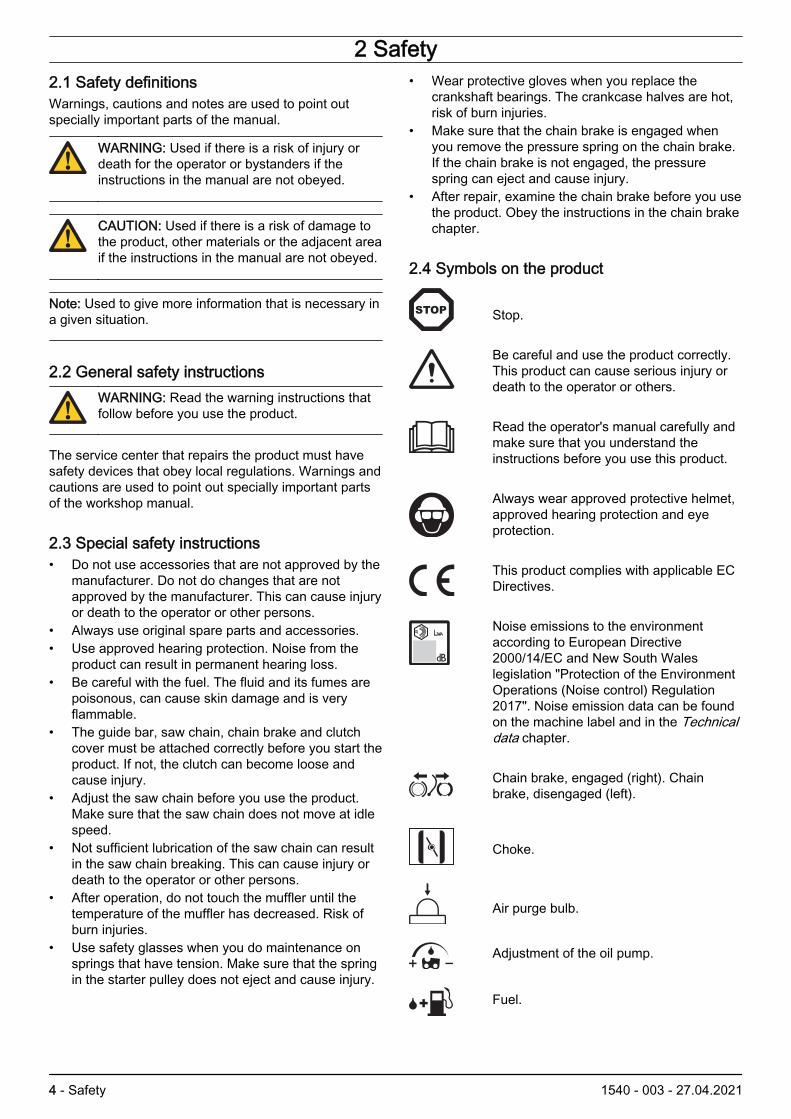
2.4 Symbols on the product
Stop.
Be careful and use the product correctly.This product can cause serious injury ordeath to the operator or others.
Read the operator's manual carefully andmake sure that you understand theinstructions before you use this product.
Always wear approved protective helmet,approved hearing protection and eyeprotection.
This product complies with applicable ECDirectives.
Noise emissions to the environmentaccording to European Directive2000/14/EC and New South Waleslegislation "Protection of the EnvironmentOperations (Noise control) Regulation2017". Noise emission data can be foundon the machine label and in the Technicaldata chapter.
Chain brake, engaged (right). Chainbrake, disengaged (left).
Choke.
Air purge bulb.
Adjustment of the oil pump.
Fuel.
4 - Safety 1540 - 003 - 27.04.2021

Chain oil.
If your product has this symbol it hasheated handles.
yyyywwxxxx The rating plate shows se-rial number xxxx. yyyy isthe production year andww is the production week.
Note: Other symbols/decals on the product refer tocertification requirements for some markets.
2.5 Cutting equipment safetyWARNING: Always remove the cuttingequipment before you do repairs or do servicingon the product.
WARNING: Do not install the cutting equipmentuntil the product is assembled.
1540 - 003 - 27.04.2021 Safety - 5

3 Prepare and do servicing on the product
3.1 Maintenance scheduleMaintenance Before
operation After 40 h After 100h
Clean the external surfaces. After each operation.
Clean the muffler, exhaust pipe and engine from dirt and unwanted lubricant. After each operation.
Make sure that the saw chain does not move at idle speed. X
Do a check of the stop switch. X
Do a check of the chain brake. X
Do a check of the chain drive sprocket. X
Sharpen the saw chain. X
Do a check of the tension of the saw chain. X
Do a check of the chain catcher. X
Turn the guide bar, do a check of the lubrication hole and clean the groove in theguide bar. X
Make sure that the guide bar and saw chain are sufficiently lubricated. X
Do a check of the throttle trigger lockout and the throttle trigger. X
Examine the engine, the fuel tank and the fuel lines for leaks. X
Tighten nuts and screws. X
Do a check of the engine oil level. Fill with oil if it is necessary. X
Examine the starter and the starter rope for wear and damage. X
Clean the air filter. Replace the air filter if it is necessary. X
Examine the vibration damping units for wear and damage. X
Examine the spark plug. X
Lubricate the needle bearing for the clutch drum. X
Clean the cooling system. Make sure to clean the flywheel fins. X
Clean the external surface of the carburetor and the area around it. X
Remove burrs from the edges of the guide bar. X
Clean the spark arrester screen. Replace the spark arrester screen if it is neces-sary. X
Clean the inner surface of the fuel tank. X
Clean the inner surface of the chain oil tank. X
Examine the fuel filter for contamination and the fuel hose for damage. Replacethe parts if it is necessary. X
Examine the spark plug. Replace the spark plug if it is necessary. X
Do a check of all cables and connections. X
Do a check of the clutch assembly and the clutch drum for wear. Replace theparts if it is necessary. X
Do a check of the brake band. X
Clean the external parts of the carburetor. X
6 - Prepare and do servicing on theproduct
1540 - 003 - 27.04.2021

4 Servicing data4.1 Servicing data● Lubricate with grease.
■ Lubricate with two-stroke oil.
▲ Lubricate with chain oil.
1,5 – 2 Nm T20
5 – 6 Nm T27
8 – 10 Nm T27
4 – 5 Nm T27
18 – 20 Nm 16mm12 – 14 Nm 13mm
1 – 2 Nm
14 – 16 Nm T27
16 – 20 Nm T27
1 – 2 Nm
1 – 2 Nm
11 – 13 Nm 13mm
1 – 3 Nm
25 Nm
1540 - 003 - 27.04.2021 Servicing data - 7

5 – 6 Nm T27
3,5 – 4 Nm T27
5 – 6 Nm T27
6 – 8 Nm T27
7 – 9 Nm T27
6 – 8 Nm T27
22 – 25 Nm 13mm
9 – 11 Nm T27
3 – 4 Nm 4mm
7 – 9 Nm T27
3 – 4 Nm T27
3 – 4 Nm T27
2 – 3 Nm T27
1 – 2 Nm
3 – 4 Nm T27
8 – 10 Nm T27
3 – 4 Nm T27
9 – 11 Nm T27
8 - Servicing data 1540 - 003 - 27.04.2021

5 Servicing tools
5.1 Servicing tools
0.3
1 2 3 4
5 6 7 8
9 10 11 12
13 14 15
17 18 19 20
16
1540 - 003 - 27.04.2021 Servicing tools - 9
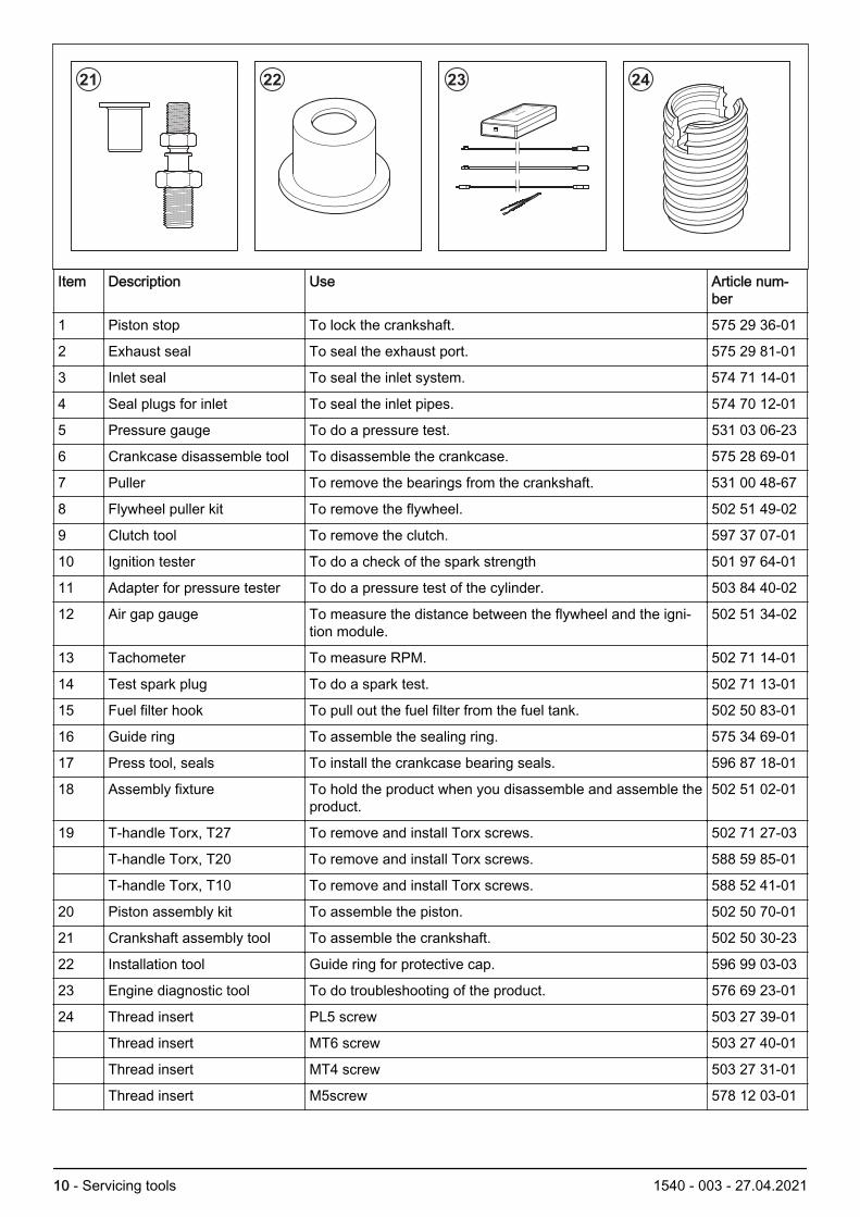
21 22 23 24
Item Description Use Article num-ber
1 Piston stop To lock the crankshaft. 575 29 36-01
2 Exhaust seal To seal the exhaust port. 575 29 81-01
3 Inlet seal To seal the inlet system. 574 71 14-01
4 Seal plugs for inlet To seal the inlet pipes. 574 70 12-01
5 Pressure gauge To do a pressure test. 531 03 06-23
6 Crankcase disassemble tool To disassemble the crankcase. 575 28 69-01
7 Puller To remove the bearings from the crankshaft. 531 00 48-67
8 Flywheel puller kit To remove the flywheel. 502 51 49-02
9 Clutch tool To remove the clutch. 597 37 07-01
10 Ignition tester To do a check of the spark strength 501 97 64-01
11 Adapter for pressure tester To do a pressure test of the cylinder. 503 84 40-02
12 Air gap gauge To measure the distance between the flywheel and the igni-tion module.
502 51 34-02
13 Tachometer To measure RPM. 502 71 14-01
14 Test spark plug To do a spark test. 502 71 13-01
15 Fuel filter hook To pull out the fuel filter from the fuel tank. 502 50 83-01
16 Guide ring To assemble the sealing ring. 575 34 69-01
17 Press tool, seals To install the crankcase bearing seals. 596 87 18-01
18 Assembly fixture To hold the product when you disassemble and assemble theproduct.
502 51 02-01
19 T-handle Torx, T27 To remove and install Torx screws. 502 71 27-03
T-handle Torx, T20 To remove and install Torx screws. 588 59 85-01
T-handle Torx, T10 To remove and install Torx screws. 588 52 41-01
20 Piston assembly kit To assemble the piston. 502 50 70-01
21 Crankshaft assembly tool To assemble the crankshaft. 502 50 30-23
22 Installation tool Guide ring for protective cap. 596 99 03-03
23 Engine diagnostic tool To do troubleshooting of the product. 576 69 23-01
24 Thread insert PL5 screw 503 27 39-01
Thread insert MT6 screw 503 27 40-01
Thread insert MT4 screw 503 27 31-01
Thread insert M5screw 578 12 03-01
10 - Servicing tools 1540 - 003 - 27.04.2021

Item Description Use Article num-ber
Thread insert M5 screw 582 52 60-01
1540 - 003 - 27.04.2021 Servicing tools - 11

6 Function overview6.1 Type plate and product serial numberThe product serial number is given on the type plate.Supply the model name and the article number whenyou send an order for spare parts.
6.2 FuelThis product has a two-stroke engine.
CAUTION: Incorrect type of fuel can result inengine damage. Use a mixture of gasoline andtwo-stroke oil.
6.2.1 Premixed fuelUse Husqvarna premixed alkylate fuel of a good quality,for best performance and extension of the engine life.This fuel contains less harmful chemicals compared toregular fuel, which decreases harmful exhaust fumes.The quantity of remains after combustion is lower withthis fuel, which keeps the components of the enginemore clean.
6.2.2 To mix fuel
6.2.2.1 Gasoline
CAUTION: Do not use gasoline with an octanegrade less than 90 RON/87 AKI. Use of a loweroctane grade can cause engine knocking, whichcauses engine damages.
We recommend that you use gasoline of a higher octanegrade for work with continuously high rpm. Limbing is anexample of such work.
Use good quality unleaded gasoline with a maximum of10% ethanol contents.
6.2.2.2 Two-stroke oil
CAUTION: Do not use two-stroke oil for water-cooled outboard engines, also referred to asoutboard oil. Do not use oil for four-strokeengines.
For best results and performance use Husqvarna two-stroke oil.
If Husqvarna two-stroke oil is not available, use a two-stroke oil of good quality for aircooled engines. Speak toyour servicing dealer to select the correct oil.
6.2.2.3 To mix gasoline and two-stroke oil
Gasoline, liter Two-stroke oil, liter
2% (1:50)
5 0.10
10 0.20
15 0.30
20 0.40
12 - Function overview 1540 - 003 - 27.04.2021

7 Repair instructions
7.1 Product overview for repair instructions
6
1
2
5
3
19
16
12
13
14
15
11
4
17
18
7
9
8
10
1540 - 003 - 27.04.2021 Repair instructions - 13

22
20 21
23
25
24
26
1. Front handguard2. Front handle3. Muffler4. Cylinder cover5. Air filter6. Starter unit7. Start/stop switch8. Throttle trigger lockout9. Rear handle
10. Throttle trigger11. Fuel tank12. Carburetor13. Cylinder and piston14. Lubrication system15. Heated handle switch16. Centrifugal clutch and clutch drum17. Guide bar bolts18. Chain catcher
14 - Repair instructions 1540 - 003 - 27.04.2021

19. Clutch cover20. Generator21. Thermostat and heating element22. Ignition system23. Flywheel24. Crankcase25. Crankshaft26. Vibration damping system
7.2 To clean and examine the product parts• Clean and examine all parts fully. You find more
instructions in the chapter for each part if specialtools or procedures are necessary.
• Replace damaged or defective parts.
• Always use original spare parts.
7.3 Chain brake
7.3.1 To disassemble the chain brakeWARNING: Use approved eye protection. Therecoil spring can eject and cause injuries.
1. Loosen the 2 nuts on the clutch cover and removethe clutch cover.
2. Remove the 2 screws and remove the fronthandguard.
1540 - 003 - 27.04.2021 Repair instructions - 15

3. Carefully tighten the clutch housing in a vise. Usethe handguard to release the chain brake.
4. Remove the 3 screws (A) and carefully remove thechain brake cover (B) in front of the chain brakespring (C).
B
A
C
5. Hold one hand above the chain brake spring. Usethe other hand to push a small screwdriver inbetween the rear section of the chain brake springand the clutch cover. Carefully push the screwdriveragainst the chain brake spring until the chain brakespring releases onto the screwdriver shaft.
6. Remove the screw (D), the chain tensioner cover(E), the adjustment screw (F), the shaft (G), thewasher (H) and the O-ring (J). Remove the screw(K) and the chain guide (L).
F
H
G
D
E
J
K
L
7. Remove the saw dust guard (M), the knee joint (N)and the brake band assembly (P) from the clutchcover.
P
N
M
16 - Repair instructions 1540 - 003 - 27.04.2021

7.3.2 To clean and examine the chain brake1. Carefully clean and examine all parts of the chain
brake. Replace damaged parts.
2. Measure the thickness of the brake band. Thethickness of the brake band must be minimum 0.6mm at the most worn point.
3. Lubricate the knee joint with grease.
7.3.3 To assemble the chain brake1. Attach the knee joint to the brake band and tighten
to the correct torque. Refer to Servicing data onpage 7.
2. Attach the knee joint (N), the brake band assembly(P) and the saw dust guard (M) to the clutch cover.
P
N
M
3. Attach the chain guide (L) and the screw (K). Attachthe O-ring (J), the washer (H), the shaft (G), theadjustment screw (F), the chain tensioner (E) andthe screw (D).
F
H
G
D
E
J
K
L
4. Lubricate the recess for the chain brake spring (Q)with grease.
Q
1540 - 003 - 27.04.2021 Repair instructions - 17

5. Put the clutch cover in a vise. Compress the chainbrake spring with a wide screwdriver and push itdown with your thumb.
WARNING: Use approved eye protection.The chain brake spring can eject and causeinjury.
6. Attach the cover (B) above the chain brake spring(C). Tighten the 3 screws (A) to the correct torque.Refer to Servicing data on page 7.
B
A
C
7. Use the front handguard to tighten the chain brakespring. Connect the front handguard to the chainbrake mechanism and turn clockwise to release thechain brake.
8. Turn the chain tensioner counterclockwise as muchas you can.
9. Attach the guide bar, the saw chain and the clutchcover.
10. When the chain brake is assembled, you must do afunction test of the chain brake. Refer to To do afunction test of the chain brake on page 18.
7.3.4 To do a function test of the chain brake1. Hold the product with 2 hands above a stump or
other stable surface.
WARNING: The engine must be off.
2. Release the front handle. The guide bar tip falls ontothe stump.
HL
Guide bar length, L Height, H
15 inch 30-40 cm
3. Make sure that the chain brake engages when theguide bar tip hits the stump.
18 - Repair instructions 1540 - 003 - 27.04.2021

7.4 Chain catcher
7.4.1 To replace the chain catcherWARNING: You must always replace a wornchain catcher. Always use original spare parts.
1. Remove the clutch cover.
2. Remove the screw and the chain catcher.
3. Replace the chain catcher.
4. Attach the clutch cover.
7.5 Muffler
7.5.1 To disassemble the mufflerWARNING: Do not touch a hot muffler. Risk ofburn injuries.
1. Remove the cylinder cover.
2. Remove the 2 crankcase screws (A) and the 2cylinder screws (B).
B
A
3. Remove the muffler (C), the gasket (D) and the heatdeflector (E).
G
F
E
D
C
4. Remove the screw (F) and pull out the sparkarrester screen (G).
7.5.2 To clean and examine the muffler1. Clean all components. Clean the contact surfaces of
the gasket, the heat deflector and the cylinder.
2. Examine the spark arrester for damage.
3. Examine the muffler and the muffler holder fordamage.
4. Examine the gasket for damage.
5. Replace all damaged parts.
1540 - 003 - 27.04.2021 Repair instructions - 19

7.5.3 To assemble the muffler1. Attach the spark arrester screen (A) with the screw
(B).
A
B
2. Put the 2 cylinder screws (C) through the muffler(D).
C
G
F
E
D
3. Put the gasket (E) and the heat deflector (F) on the2 cylinder screws (C).
4. Attach the 2 cylinder screws (C) to the cylinder.
5. Install the 2 crankcase screws (G) in the crankcasea minimum of 2 turns, but do not tighten fully.
6. Tighten the 2 cylinder screws (C) to the correcttorque. Refer to Servicing data on page 7.
7. Tighten the 2 crankcase screws (G) to the correcttorque. Refer to Servicing data on page 7.
8. Attach the cylinder cover.
7.6 Start/stop switch
7.6.1 To remove and install the start/stop switch1. Remove the cylinder cover.
2. Remove the air filter.
3. Remove the air filter holder assembly. Refer to Todisassemble the carburetor on page 40.
4. Remove the rubber seal (A) from the start/stopswitch (C).
5. Remove the screw (B) and the start/stop switch.
A
C
B
6. Install in the opposite sequence.
20 - Repair instructions 1540 - 003 - 27.04.2021

7.6.2 To do a function test of the start/stop switch1. Clean the surfaces where you will measure the
resistance.
2. Connect a multimeter to the blue cable and thecylinder to measure the resistance. The resistancemust not be higher than 0.5 Ω.
Note: The start/stop switch must be in the ONposition to give the correct indication. The start/stopswitch is in the ON position when you hold thebutton down.
7.7 Handles
7.7.1 To remove and install the front handle1. Loosen the screw in the vibration damping system.
2. Remove the 2 screws.
3. Remove the front handle from the product.
4. Install in the opposite sequence.
1540 - 003 - 27.04.2021 Repair instructions - 21

7.7.2 To remove and install the heated front handle1. Remove the 2 screws and the cover for the heated
front handle.
2. Remove the switch (A) from the contact plate (B).Disconnect the wire (C) from the connection plate.Disconnect the handle wire (D) from the contactplate. Remove the contact plate (B). Disconnect thestator wire (E) and the carburetor wire (F) from thewire (G). Disconnect the ground cable (H) from theheated front handle.
A
B
C
D
E
F
G
H
3. Remove the 2 screws.
4. Remove the 2 screws.
22 - Repair instructions 1540 - 003 - 27.04.2021

5. Remove the heated front handle from the product.
6. Install in the opposite sequence.
7.7.3 To remove and install the heated rear handle1. Remove the heated front handle, refer to To remove
and install the heated front handle on page 22.
2. Remove the chain brake, refer to To disassemblethe chain brake on page 15.
3. Remove the cylinder cover.
4. Remove the air filter.
5. Remove the air filter holder and the carburetor, referto To remove and install the carburetor on page 36.
6. Remove the chain catcher.
7. Loosen the screw to the vibration damping system.
8. Loosen the deflection limiter.
1540 - 003 - 27.04.2021 Repair instructions - 23

9. Lift the saw carefully and pull down the hosesthrough and the throttle wire down through thecarburetor bottom plate. Make sure that youunderstand how the cables are attached.
10. Remove the screw and pull out the heated rearhandle and pull out the cables.
11. Install in the opposite sequence.
24 - Repair instructions 1540 - 003 - 27.04.2021

7.7.4 To disassemble and assemble the rearhandle1. Remove the screw and the handle cover. If the
product has heated handles, refer to To remove andinstall the heated rear handle on page 23.
2. Use a flat screwdriver to push out and remove thethrottle trigger lockout.
3. Remove the pin that holds the throttle trigger.
4. Remove the throttle wire and the throttle trigger.
5. Assemble in the opposite sequence.
7.7.5 To clean and examine the handle and throttletrigger1. Carefully clean and examine all parts.
2. Replace parts that are damaged. Always useoriginal spare parts.
3. Make sure that the spring in the throttle trigger is notdamaged and keeps all its tension.
7.8 Starter
7.8.1 To disassemble the starter unitWARNING: Use approved eye protection. Therecoil spring can eject and cause injuries.
1. Loosen the 4 screws (A).
A
B
C
2. Remove the starter (B) and the cooling air conductor(C).
1540 - 003 - 27.04.2021 Repair instructions - 25

3. Pull out the starter rope approximately 30 cm/12 in.and put it into the notch in the starter pulley.
4. Let the starter pulley rotate slowly counterclockwiseto release the tension of the recoil spring.
5. Remove the screw and washer (D).
D
E
G
H
F
6. Remove the starter pulley (E).
7. Remove the 2 screws (F).
8. Remove the spring cassette (G) and the recoilspring (H).
7.8.2 To clean and examine the starter unit1. Clean all components.
2. Examine the starter rope. Replace the starter rope ifit is damaged.
3. Examine the starter pulley. Replace damaged parts.
4. Make sure that the starter pawls on the flywheel arenot damaged, attached correctly and move freely.
5. Examine the starter springs and replace the startersprings if they are damaged.
6. Lubricate the starter pawls and springs.
7. Lubricate the recoil spring.
26 - Repair instructions 1540 - 003 - 27.04.2021

7.8.3 To assemble the starter unitWARNING: Use approved eye protection. Therecoil spring can eject and cause injuries.
1. Put a new recoil spring (B) in the starter housing (A).Attach the spring cassette (C) to the starter housing.Tighten the 2 screws (D) to the correct torque. Referto Servicing data on page 7.
C
B
D
A
2. Push the end of the starter rope into the hole in thestarter pulley. Use a pointed pliers to pull out thestarter rope from the starter pulley. Make a knot atthe end of the starter rope.
3. Pull the starter rope through the hole in the starterhousing.
4. Pull the starter rope through the starter rope handleand make a knot.
5. Put the starter pulley in the starter housing andtighten the screw.
6. Pull the starter rope up into the notch in the starterpulley. Use your thumb and turn the starter pulley 3turns clockwise to wind the starter rope on thestarter pulley. Make sure that you can turn thestarter pulley ½ turn more when you pull out thestarter rope fully.
1540 - 003 - 27.04.2021 Repair instructions - 27

7. Pull the starter rope to make it straight, remove yourthumb and let the starter rope wind up.
8. Attach the cooling air conductor (E) and the starterunit (F) on the crankcase. Pull the starter rope lightlyto make sure that the starter pulley is attachedcorrectly against the crankcase. Tighten the 4screws (G) to the correct torque. Refer to Servicingdata on page 7.
G
F
E
7.9 Ignition system
7.9.1 To do a spark test1. Remove the spark plug from the cylinder.
2. Connect the spark plug to the spark plug cap.
3. Make sure that the stop switch on the throttle handleis in the start position.
4. Hold the spark plug against the cylinder and pull thestarter rope handle. If the ignition operates correctly,you will see a spark between the electrodes on thespark plug.
WARNING: To prevent the risk of fire, donot hold the spark plug near the spark plughole.
5. If no spark occurs, remove the spark plug andconnect the ignition tester (A) to the spark plug cap(B). Refer to Servicing tools on page 9.
A
C
B
D
6. Connect the ground cable (C) to 1 of the cooling finson the cylinder.
7. Use the knob (D) to adjust the distance between the2 electrodes to 6 mm.
Note: One mark on the scale is 1 mm.
8. Pull the starter rope handle.
9. Do 1 of the steps that follow.a) If a spark occurs between the electrodes on the
ignition tester, replace the spark plug.b) If there is no spark between the electrodes on
the ignition tester, replace the ignition module.Refer to To remove the ignition system on page29.
7.9.2 To examine the spark plugCAUTION: Use resistor spark plugs to preventproblems during operation and permanentdamage to the ignition system. Only use sparkplugs recommended by Husqvarna, refer to theoperator's manual.
• Examine the spark plug if the engine is low onpower, is not easy to start or does not operatecorrectly at idle speed.
• To decrease the risk of unwanted material on thespark plug electrodes, obey these instructions:a) Make sure that the idle speed is correctly
adjusted.b) Make sure that the fuel mixture is correct.c) Make sure that the air filter is clean.
28 - Repair instructions 1540 - 003 - 27.04.2021

• If the spark plug is dirty, clean it and make sure thatthe electrode gap is correct, refer to Technical dataon page 65.
• Replace the spark plug if it is necessary.
7.9.3 To remove the ignition system1. Remove the cylinder cover.
2. Disconnect the spark plug cap from the spark plug.
3. Remove the starter unit. Refer to To disassemblethe starter unit on page 25.
4. Remove the spark plug cable from the cooling airconductor.
5. Remove the cooling air conductor.
6. Pull out the spark plug cable.
7. Remove the 2 screws and the ignition module.
8. Disconnect the ignition module.
1540 - 003 - 27.04.2021 Repair instructions - 29

7.9.4 To install the ignition system1. Connect the ignition module.
2. Install the ignition module and the 2 screws.
3. Put the spark plug cable through the crankcase.Make sure that the spark plug cable is in the correctposition on the crankcase.
4. Install the cooling air conductor.
5. Attach the spark plug cable to the cooling airconductor.
6. Put an air gap gauge between the ignition moduleand the flywheel. Tighten the screw to the correcttorque. Refer to Servicing data on page 7.
7. Connect the spark plug cap to the spark plug.
8. Install the cylinder cover.
7.10 Flywheel
7.10.1 To remove the flywheel1. Remove the cylinder cover.
2. Remove the starter unit and cooling air conductor.Refer to To disassemble the starter unit on page 25.
3. Clean around the spark plug.
30 - Repair instructions 1540 - 003 - 27.04.2021

4. Remove the spark plug and put a piston stop in thespark plug hole.
5. Loosen but do not remove the screws that hold theignition module.
6. Remove the flywheel nut (A).
B
C
D
E
A
7. Remove the screws (B), starter pawls (C), springs(D) and washers (E).
8. Put the flywheel puller tool (F) in the center of theflywheel. Attach the screws (G) in the holes for thestarter pawls. Refer to Servicing tools on page 9.
F
G
9. Attach the socket of the flywheel puller tool (H) onthe crankshaft.
10. Use a wrench (J) to lock the outer socket of theflywheel puller tool. Use a socket wrench (K) totighten the screw in the center of the flywheel pullertool until the flywheel comes off.
K
J
Note: If the flywheel does not come off, hit lightlywith a hammer on the screw to the flywheel. At thesame time lift the tool handle slightly to tilt theproduct.
7.10.2 To install the flywheel1. Clean the crankshaft.
2. Put the flywheel on the crankshaft. Turn the flywheeluntil the key goes into the key slot on the crankshaft.
3. Attach the flywheel nut (A) and tighten it to thecorrect torque, refer to Servicing tools on page 9.
B
C
D
E
A
4. Install the 2 screws (B), the starter 2 pawls (C), the 2springs (D), and the 2 washers (E).
1540 - 003 - 27.04.2021 Repair instructions - 31

5. Make sure that you install the 2 springs in thecorrect position, as shown in the illustration.
6. Put the air gap gauge between the flywheel and theignition module. Refer to Servicing tools on page 9.
7. Tighten the 2 screws that hold the ignition module tothe correct torque. Refer to Servicing data on page7.
8. Remove the air gap gauge.
9. Install the cooling air conductor and the starter unit.
10. Install the spark plug and connect the spark plug capto the spark plug.
11. Install the cylinder cover.
7.11 Centrifugal clutch
7.11.1 To disassemble the centrifugal clutchMake sure that the chain brake is disengaged beforeyou disassemble the centrifugal clutch.
1. Remove the cylinder cover.
2. Remove the clutch cover.
3. Clean around the spark plug.
4. Remove the spark plug and put a piston stop in thespark plug hole.
5. Attach the clutch tool to the centrifugal clutch. Referto Servicing tools on page 9. Use a socket wrench toloosen the centrifugal clutch.
32 - Repair instructions 1540 - 003 - 27.04.2021

6. Remove the clutch (A), the clutch drum (B), thebearing (C), the bearing (D) and the worm gear (E).
A
BC
DE
7. Put the centrifugal clutch in a vise.
8. Carefully remove the clutch shoe springs from theside that does not have text.
9. Assemble in the opposite sequence.
7.11.2 To clean and examine the centrifugal clutch1. Clean and examine the clutch shoe springs (A), the
clutch hub (B) and the clutch shoes (C) carefully.Replace damaged parts. Always use original spareparts.
BA
C
2. Measure the diameter of the clutch shoes across thefull clutch hub. Replace the clutch if the thickness isless than 65 mm.
Min. 65 mm
1540 - 003 - 27.04.2021 Repair instructions - 33
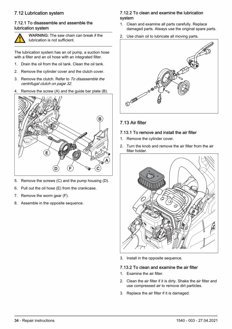
7.12 Lubrication system
7.12.1 To disassemble and assemble thelubrication system
WARNING: The saw chain can break if thelubrication is not sufficient.
The lubrication system has an oil pump, a suction hosewith a filter and an oil hose with an integrated filter.
1. Drain the oil from the oil tank. Clean the oil tank.
2. Remove the cylinder cover and the clutch cover.
3. Remove the clutch. Refer to To disassemble thecentrifugal clutch on page 32.
4. Remove the screw (A) and the guide bar plate (B).
B
A
CFD
E
5. Remove the screws (C) and the pump housing (D).
6. Pull out the oil hose (E) from the crankcase.
7. Remove the worm gear (F).
8. Assemble in the opposite sequence.
7.12.2 To clean and examine the lubricationsystem1. Clean and examine all parts carefully. Replace
damaged parts. Always use the original spare parts.
2. Use chain oil to lubricate all moving parts.
7.13 Air filter
7.13.1 To remove and install the air filter1. Remove the cylinder cover.
2. Turn the knob and remove the air filter from the airfilter holder.
3. Install in the opposite sequence.
7.13.2 To clean and examine the air filter1. Examine the air filter.
2. Clean the air filter if it is dirty. Shake the air filter anduse compressed air to remove dirt particles.
3. Replace the air filter if it is damaged.
34 - Repair instructions 1540 - 003 - 27.04.2021

7.14 Carburetor
7.14.1 Carburetor designWARNING: The fuel used in the product has thefollowing hazardous properties: The fluid and itsvapour are poisonous, can cause skin irritationand are highly inflammable.
The figures accompanying this description do notcorrespond with the carburettor on the product. Theyshow only the principle of design and function.
The carburettor is based on three sub-systems:
• Pump unit.• Metering unit.• Mixing unit.
In the pump unit (A), fuel is pumped from the fuel tank tothe carburettor’s metering unit. One side of the pumpdiaphragm is connected to the crankcase and pulses intime with the pressure changes in the crankcase. Withthe help of inlet and outlet valve in diaphragm, the fuel istransfered through a filter screen to inlet needle.
A
The fuel control unit is attached to the metering unit (B).Here the correct quantity of fuel is adjusted for the actualspeed and power output.
B
The mixing unit (C) houses the choke, the throttle valveand the diffuser jets. Here air is mixed with the fuel to
give a fuel/air mixture that can be ignited by the ignitionspark.
C
7.14.2 Carburetor functionThe carburetor operates differently in the followingmodes:
• Cold start mode• Idling mode• Part throttle mode• Full throttle mode
In cold start mode the choke valve (H) is completelyshut. This increases the vacuum in the carburettor andfuel is easier to suck from all the diffuser jets (D), (E),and (F). The throttle valve (I) is partly open. The airthrottle valve (J) is closed.
H
J
I
D
G
FE
In idling mode, the throttle valves (I) and (J) are closedand the choke valve (H) is open.
1540 - 003 - 27.04.2021 Repair instructions - 35

Air is sucked in through an aperture in the throttle valveand a small amount of fuel is supplied through thediffuser jet (D).
H
J
D
I
In part throttle mode, the throttle valve (I) is partly openand the choke valve (H) is fully open. Fuel is suppliedthrough the diffuser jets (D) and (E). The air throttlevalve (J) starts to open.
H
J
I
D
E
In the full throttle mode both valves are open and fuel issupplied through all four diffuser jets (D, E, F and G).The air throttle valve (J) is fully open.
F
H
J
I
D
E
7.14.3 To remove and install the carburetor1. Remove the cylinder cover.
2. Remove the spark plug and the spark plug cap.
3. Turn the knob and remove the air filter from the airfilter holder.
4. Push the air filter holder and the carburetor slightlyforward to get access to the screws with the Torxtool. Remove the 2 screws.
5. Lift the electrical wires from the air filter holder.
6. Disconnect the air filter holder from the rubber partson the sides.
36 - Repair instructions 1540 - 003 - 27.04.2021

7. Remove the air filter holder.
8. Remove the return hose (A) and the suction hose(B) from the air purge bulb.
C
BA
D
9. Remove the cable connector (C) from theconnection clamp (D).
Note: Make a note of the position of the return hoseand the wires on the air filter holder.
10. Remove the connection clamp (D) from the bracketon the carburetor and remove the air filter holder.
11. Disconnect the throttle wire (E).
F
E
12. Remove the fuel hose (F).
13. Remove the 2 screws and the bracket.
14. Disconnect the thermostat wires. Disconnect thegenerator wires. Remove the heating elements.
1540 - 003 - 27.04.2021 Repair instructions - 37

15. Push down the lever to release the carburetor.
16. Remove the carburetor.
17. Disconnect the cable connectors.
18. Install in the opposite sequence.
38 - Repair instructions 1540 - 003 - 27.04.2021

7.14.4 Carburetor components
A
B
D
E
F
C
G
J
I
H
K
RS
L
M
Q
P
O
N
1540 - 003 - 27.04.2021 Repair instructions - 39

7.14.5 To disassemble the carburetor1. Remove the carburetor. Refer to To remove and
install the carburetor on page 36.
2. Remove the 4 screws (A) from the metering cover(B).
3. Remove the gasket (C), the metering diaphragm (D),the control diaphragm (E) and the gasket (F).
4. Remove the screw (G), the needle valve (J), themetering lever (H), the metering lever pin (I) and thespring (K).
5. Remove the 2 screws (L).
6. Remove the air filter holder assembly (M).
7. Remove the screw (N) and the fuel pump cover (O).
8. Remove the gasket (P), the boost diaphragm (Q)and the pump diaphragm (R).
9. Remove the fuel screen (S).
7.14.6 To clean and examine the carburetor1. Clean all parts in clean gasoline. Use compressed
air to dry the gasoline. Point the air through allchannels in the carburetor housing and make surethat the channels are not blocked.
2. Make sure that there is no play on the throttle valveand the shafts of the choke valve.
3. Examine all parts for damage and wear. Replace theparts that show sign of damage.
4. Use the Engine Diagnostic Tool to examine theAutoTune™ unit. Refer to Servicing tools on page 9.
7.14.7 To assemble the carburetorCAUTION: Assemble the carburetor in a cleanenvironment. Contamination can cause damageto the product.
Note: When you replace the carburetor, a firmwaredownload is necessary on the new carburetor. With thefirmware installed, the carburetor must be approved onthe test “autotest” in the CST before use. Refer to theCST for instructions.
1. Lubricate the shaft bearings with two-stroke oil.
2. Attach the fuel screen (S). Use the handle of a smallscrewdriver.
3. Assemble the pump diaphragm (R), the boostdiaphragm (Q), the gasket (P) and the fuel pumpcover (O) to the carburetor with the screw (N).
4. Attach the 2 screws (L) to the air filter holderassembly (M).
5. Assemble the needle valve (J) and the meteringlever (H), the metering lever pin (I) and the spring(K). Tighten the screw (G).
6. Measure the distance between the metering lever(H) and the gasket surface of the carburetorhousing. Refer to Servicing tools on page 9. Thedistance must be 0.55 mm. If it is more or less than0.55 mm, adjust the distance. Refer to To adjust themetering lever on page 41.
7. Assemble the gasket (C), the metering diaphragm(D), the control diaphragm (E), and the gasket (F) onthe carburetor housing. Make sure that youassemble the parts in the correct sequence.
8. Attach the metering cover (B) to the carburetorhousing.
9. Do a pressure test of the carburetor. Refer to To doa pressure test of the carburetor on page 41.
10. On 555 and 556: Attach the 4 screws and washers(A) and tighten the screws.
11. On 560 XP and 560 XPG: Assemble the heatingelement on the carburetor. Attach the 4 screws andwashers (A) and tighten the screws.
40 - Repair instructions 1540 - 003 - 27.04.2021

7.14.8 To adjust the metering leverThe distance between the metering lever and the gasketsurface of the carburetor housing must be 0.55 mm.Adjust the distance if it is more or less than 0.55 mm.
• Move the end of the metering lever down (A) todecrease the distance. Move the end of the meteringlever up (B) to increase the distance.
BA
7.14.9 To do a pressure test of the carburetor1. Remove the carburetor. Refer to To remove and
install the carburetor on page 36.
2. Make sure that the carburetor is correctlyassembled. Refer to To assemble the carburetor onpage 40.
3. Connect the pressure tester to the fuel inlet on thecarburetor. Increase the pressure to 50kPa. Refer to Servicing tools on page 9.
4. Lower the carburetor in a container with gasoline tofind leaks.
5. Make sure that there are no leaks.
7.14.10 Troubleshooting leakageFault Cause
Leakage in the diffuser jets The needlevalve
Leakage in the impulse pipe The pump gas-ket
Leakage in the ventilation hole on themetering unit
The controlgasket
7.14.11 Adjustment of the unitNote: The product adjusts the tune automatically and willbe fully adjusted after some minutes of standardoperation.
The high speed part is adjusted during loaded operation,such as cutting and felling.
The idle part is adjusted when you operate the productat idle speed.
7.15 Fuel tank
7.15.1 To remove and install the fuel tank1. Drain the fuel tank.
2. Remove the chain brake system. Refer to Todisassemble the chain brake on page 15.
3. Remove the cylinder cover.
4. Remove the spark plug cap and the spark plug.
5. Remove the air filter. Refer to To remove and installthe air filter on page 34.
6. Remove the air filter holder and the carburetor.Refer to To remove and install the carburetor onpage 36.
7. Remove the screw and the chain catcher.
8. Remove the front handle. Refer to Handles on page21.
1540 - 003 - 27.04.2021 Repair instructions - 41

9. Remove the screw of the vibration damping system.
A
10. Loosen the deflection limiter.
11. Remove the fuel hose and disconnect the wires fromthe heated handles. Refer to To remove and installthe heated rear handle on page 23.
12. Remove the tank unit.
CAUTION: Be careful not to cause damageto the hoses when you remove the tank unit.
13. Install in the opposite sequence.
42 - Repair instructions 1540 - 003 - 27.04.2021

7.15.2 To replace the fuel filter1. Remove the fuel tank cap.
2. Use a fuel filter hook to pull out the fuel hose and thefuel filter. Refer to Servicing tools on page 9
3. Remove the fuel filter.
4. Attach a new fuel filter.
5. Install the fuel tank cap.
7.15.3 To replace the fuel hose1. Remove the fuel tank. Refer to To remove and
install the fuel tank on page 41.
2. Remove the fuel tank cap.
3. Use a fuel filter hook to pull out the fuel hose and thefuel filter. Refer to Servicing tools on page 9.
4. Remove the fuel filter.
5. Pull out and remove the fuel hose from the fuel tankas the illustration shows.
1540 - 003 - 27.04.2021 Repair instructions - 43

6. Attach the new fuel hose to the fuel tank as theillustration shows.
7. Attach the fuel filter to the new fuel hose.
8. Install the fuel tank cap.
9. Install the fuel tank in the opposite sequence. Referto To remove and install the fuel tank on page 41.
7.15.4 To replace the air purge bulb1. Remove the cylinder cover and the air filter.
2. Remove the suction hose (A) and the return hose(B) from the air purge bulb.
3. Push the snap locks to remove the air purge bulbfrom the air filter holder.
A
B
4. Replace the air purge bulb.
5. Install in the opposite sequence.
7.15.5 Air pressure in the fuel tankThe two-way tank valve has a controlled openingpressure in the two directions. The controlled openingprevents positive pressure or vacuum in the fuel tank,and fuel leakage. Positive pressure, vacuum and fuelleakage decreases engine performance.
7.15.5.1 To do a pressure test of the fuel tank1. Remove the fuel tank cap and drain the fuel tank.
2. Pull out and remove the fuel hose.
3. Connect the pressure tester to the tank valve (A).
A
4. Do a test of the negative pressure in the fuel tank.a) Use the pressure tester in vacuum mode to
decrease the pressure in the fuel tank.b) The pressure must be between 0.10–0.45 bar.
5. Do a test of the positive pressure in the fuel tank.a) Use the pressure tester in pressure mode
increase the pressure in the fuel tank.b) The pressure must stop at max. 0.07 bar.
6. Install the fuel tank cap.
44 - Repair instructions 1540 - 003 - 27.04.2021

7.16 Vibration damping system
7.16.1 To disassemble and assemble the vibrationdamping system1. Use a Torx to remove the vibration damping unit
from the cylinder.
2. Remove the chain catcher to get access to thevibration damping unit.
3. Remove the screw to get access to the vibrationdamping unit. Use a Torx to remove the vibrationdamping unit.
4. Assemble in the opposite sequence.
7.17 Generator
7.17.1 To remove the generator1. Remove the fuel tank. Refer to To remove and
install the fuel tank on page 41.
2. Remove the starter unit. Refer to To disassemblethe starter unit on page 25.
3. Remove the flywheel. Refer to To remove theflywheel on page 30.
4. Remove the 2 screws.
5. Remove the generator and the wires.
7.17.2 To install the generator1. Pull the cables through the hole in the crankcase.
2. Attach the generator to the crankcase. Tighten thescrews to the correct torque. Refer to Servicing dataon page 7.
3. Install the flywheel.
4. Install the starter unit.
1540 - 003 - 27.04.2021 Repair instructions - 45

5. Install the cables.
A
E
DB
B
C
a) Attach the cable (A) between the generator andthe heating element.
b) Attach the cable (B) between the generator andthe carburetor.
c) Attach the cable (C) between the rear handleand the carburetor.
d) Attach the cable (D) between the heatingelement and the carburetor.
e) Attach the cable (E) between the heatingelement and the rear handle.
6. Pull up the hoses through the carburetor bottomplate. Pull up the throttle wire through the carburetorbottom plate.
7. Put the product on the fuel tank.
8. Attach the deflection limiter.
9. Tighten the 2 screws in the front vibration dampingunit.
10. Tighten the 2 screws (A) in the rear vibrationdamping unit.
A
11. Attach the heated front handle to the product. Referto To remove and install the heated front handle onpage 22.
46 - Repair instructions 1540 - 003 - 27.04.2021

12. Install the air filter holder and the carburetor. Referto To remove and install the carburetor on page 36.
13. Install the air filter.
14. Install the chain brake system.
15. Install the spark plug and the spark plug cable.
16. Install the cylinder cover.
7.17.3 Product overview of the generator cables
7.18 Cylinder and piston
7.18.1 To remove the cylinder and piston1. Remove the cylinder cover.
2. Remove the spark plug cap.
3. Remove the carburetor.
4. Remove the muffler and the heat deflector.
5. Remove the 4 screws and lift the cylinder. Removethe sleeves for the 4 screws.
CAUTION: Make sure that the piston doesnot move. The guide pin can cause damageto the piston if it falls.
6. Remove the cylinder base gasket.
CAUTION: Make sure that no dirt orunwanted particles go into the crankcase.
7. Put a cover on the crankcase opening.
1540 - 003 - 27.04.2021 Repair instructions - 47

8. Use pliers to remove the snap ring from the pin.Keep your thumb adjacent to the snap ring to makesure that the snap ring do not eject.
9. Carefully remove the snap ring (B) for the piston pin(C). Make sure that you do not cause damage to thegroove.
A
C
D
B
10. Push out the piston pin (C) and lift off the piston.
11. Remove the needle bearing (A). Replace the needlebearing if it is damaged or worn.
12. Remove the piston ring (D).
7.18.2 To clean the cylinder and piston1. Clean the piston crown.
2. Clean the top of the cylinder bore.
3. Clean the cylinder exhaust port.
4. Clean the bottom of the cylinder and the bottom ofthe crankcase. Remove all gasket particles and dirtparticles.
5. Use a screwdriver to remove dirt particles from thecooling fins.
7.18.3 To examine the cylinder1. Make sure that the surface layer of the cylinder is
not worn, especially in the top end of the cylinder.
2. Make sure that the cylinder does not have scoremarks.
48 - Repair instructions 1540 - 003 - 27.04.2021

7.18.4 To examine the inlet manifold1. Remove the 4 screws and remove the inlet manifold
from the cylinder.
2. Remove the flange and support sleeve from the inletmanifold.
3. Examine the parts for damage. Replace damagedparts.
7.18.5 To examine the piston
1. Make sure that the piston pin bearing is notdamaged.
2. Make sure that the piston pin does not havedamages on the running surface for the bearing.
3. Make sure that the piston ring can move freely in thegroove.
4. Put the piston ring in the cylinder and measure thering gap with a feeler gauge. The space must not bemore than 1 mm.
7.18.6 Piston damagesScore marks on the piston
Incorrect carburetor setting. Too high speed.
Too low octane fuel.
The fuel has a too low octane grade.
Carbon build-up
Incorrect carburetor setting. Too low speed.
Too much or incorrect oil in the fuel.
1540 - 003 - 27.04.2021 Repair instructions - 49

7.18.7 To examine the piston rings1. Examine the piston rings for damage.
2. Replace damaged piston rings.
7.18.8 To install the cylinder and piston1. Attach the flange to the inlet manifold. Attach the
inlet pipe to the cylinder. Tighten the screws to thecorrect torque. Refer to Servicing data on page 7.
2. Lubricate the needle bearing (A) and put it into theconnecting rod. Make sure the bearing moves freelyin the connecting rod.
A
C
D
B
3. Attach the piston. The arrow at the piston top mustbe turned to the exhaust port. Push in the piston pin(C) and attach the snap ring (B).
Note: Always use a new snap ring.
4. Lubricate the piston and piston ring (D).
5. Carefully attach the piston ring on the piston. Makesure that you do not cause damage to the piston ringor the piston.
6. Put a new cylinder base gasket (E) on thecrankcase.
Note: Make sure that the gasket is new and does nothave signs of damage or wear.
7. Attach the support plate (F) from the pistonassembly kit.
8. Use a clamp (G) from the piston assembly kit tocompress the piston ring and carefully push thepiston into the cylinder opening. Make sure that the4 sleeves (H) are in the correct position and attachthe cylinder (J) to the crankcase. Tighten the screw(K). Tighten the screw (L). Tighten the screw (M).Tighten the screw (N). Refer to Servicing data onpage 7 for the correct torque.
E
F
G
J
K H
FG
N
LM
Note: When you operate the product, the torque ofthe screws (K), (L), (M) and (N) decreases.
50 - Repair instructions 1540 - 003 - 27.04.2021
9. Assemble the remaining parts in the oppositesequence to how they were disassembled.
7.18.9 To do a pressure test of the cylinder1. Remove the cylinder cover.
2. Remove the air filter.
3. Remove the air filter holder and the carburetor.Refer to To remove and install the carburetor onpage 36.
4. Remove the spark plug.
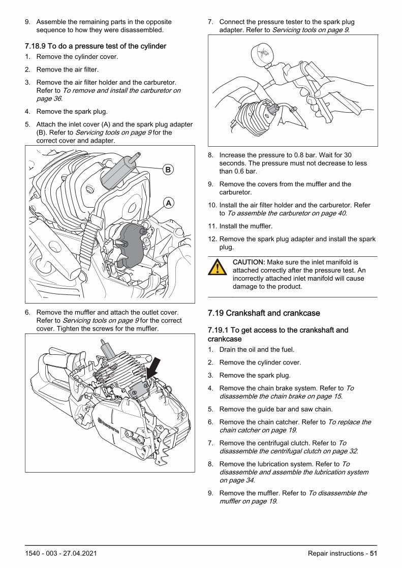
5. Attach the inlet cover (A) and the spark plug adapter(B). Refer to Servicing tools on page 9 for thecorrect cover and adapter.
A
B
6. Remove the muffler and attach the outlet cover.Refer to Servicing tools on page 9 for the correctcover. Tighten the screws for the muffler.
7. Connect the pressure tester to the spark plugadapter. Refer to Servicing tools on page 9.
8. Increase the pressure to 0.8 bar. Wait for 30seconds. The pressure must not decrease to lessthan 0.6 bar.
9. Remove the covers from the muffler and thecarburetor.
10. Install the air filter holder and the carburetor. Referto To assemble the carburetor on page 40.
11. Install the muffler.
12. Remove the spark plug adapter and install the sparkplug.
CAUTION: Make sure the inlet manifold isattached correctly after the pressure test. Anincorrectly attached inlet manifold will causedamage to the product.
7.19 Crankshaft and crankcase
7.19.1 To get access to the crankshaft andcrankcase1. Drain the oil and the fuel.
2. Remove the cylinder cover.
3. Remove the spark plug.
4. Remove the chain brake system. Refer to Todisassemble the chain brake on page 15.
5. Remove the guide bar and saw chain.
6. Remove the chain catcher. Refer to To replace thechain catcher on page 19.
7. Remove the centrifugal clutch. Refer to Todisassemble the centrifugal clutch on page 32.
8. Remove the lubrication system. Refer to Todisassemble and assemble the lubrication systemon page 34.
9. Remove the muffler. Refer to To disassemble themuffler on page 19.
1540 - 003 - 27.04.2021 Repair instructions - 51

10. Remove the starter. Refer to To disassemble thestarter unit on page 25.
11. Remove the air filter and the air filter holder. Refer to To remove and install the air filter on page 34.Remove the start/stop switch. Refer to To removeand install the start/stop switch on page 20.
12. Remove the carburetor. Refer to To remove andinstall the carburetor on page 36.
13. Remove the ignition module. Refer to To remove theignition system on page 29.
14. Remove the flywheel. Refer to To remove theflywheel on page 30.
15. Remove the fuel tank. Refer to To remove andinstall the fuel tank on page 41.
16. Remove the handle and throttle trigger. RefertoHandles on page 21.
17. Disconnect the wires.
18. For 560 XP and 560 XPG: Remove the generator.Refer to To remove the generator on page 45.
19. Remove the cylinder and the piston. Refer to Toremove the cylinder and piston on page 47.
Note: Make sure that no dirt or object can come intothe bearings.
7.19.2 To replace the seal ringsNote: Hold the outer part of the bearing when youreplace the seal ring. Make sure that the bearing doesnot move.
1. To replace the seal ring on the flywheel side.a) Remove the starter unit. Refer to To
disassemble the starter unit on page 25.b) Remove the flywheel. Refer to To remove the
flywheel on page 30.
2. To replace the seal ring on the clutch side.a) Remove the centrifugal clutch. Refer to To
disassemble the centrifugal clutch on page 32.b) Remove the oil pump. Refer to To disassemble
and assemble the lubrication system on page34.
3. Use a screwdriver to remove the seal ring.
4. Attach the guide ring (A) on the crankshaft axle.
A
B
5. Lubricate the new seal ring (B) with two-stroke oil.
6. Put the seal ring on the guide ring.
52 - Repair instructions 1540 - 003 - 27.04.2021

7. Use the press tool to push the new seal ring to thecorrect position. Refer to Servicing tools on page 9
8. Remove the seal ring tool and the guide ring.
9. Install in the opposite sequence.
7.19.3 To disassemble the crankshaft and thecrankcase1. Remove the 3 screws (A) and remove the carburetor
bottom plate.
2. Remove the oil tank cap assembly (B).
3. Remove the 6 screws (C).
4. Remove the deflection limiter (D).
A
D
C
B
5. Remove the crankcase on the flywheel side from thecrankshaft. Use the crankcase disassemble tool.Refer to Servicing tools on page 9.
1540 - 003 - 27.04.2021 Repair instructions - 53

6. Remove the crankcase half on the clutch side fromthe crankshaft. Use the crankcase disassemble tool.Refer to Servicing tools on page 9.
7. If the crankcase bearing is attached to thecrankshaft, use a puller tool to remove thecrankcase bearing.
7.19.4 To install the protective washerNote: Install a new protective washer when you replacethe seal ring.
1. Put the protective washer (A) on the crankshaft.
2. Push down the protective washer (A) in the directionof the bearing.
3. Put the installation tool (B) on the crankshaft.
4. Put the nut (C) on the crankshaft. Tighten the nut tothe correct torque.
A
B
C
5. Visually examine that the protective washer is in thecorrect position. Make sure that the protectivewasher is fully attached to the inner ring of the framebearing.
2 Nm
6. Remove the nut and the installation tool.
54 - Repair instructions 1540 - 003 - 27.04.2021
7.19.5 To clean and examine the crankshaft andcrankcase
CAUTION: Make sure that dirt and unwantedparticles do not go into the crankcase and intothe bearings.
Clean all components and remove gasket particles fromthe mating surfaces of the crankcase halves.
1. Make sure that the crankpin bearing does not haveradial play. Axial play is permitted.
2. Make sure that the crankpin bearing is not worn orhas discoloration on the sides.
3. Make sure that the bearing surfaces in the small endof the connecting rod are not worn or havediscoloration.
4. Make sure that the crankpin bearing is attachedcorrectly and does not have radial play. Make surethe crankpin bearing is lubricated.
5. Make sure that the crankcase has no cracks.
7.19.6 To install the crankcase bearingsWARNING: Use protective gloves. Thecrankcase halves are hot.
1. Increase the temperature of the crankcase halves toapproximately 200ºC.
2. Put the bearing in the crankcase halves.
3. Use the press tool to push the bearings into thecrankcase halves. Refer to Servicing tools on page9.
4. Let the crankcase halves become cool.
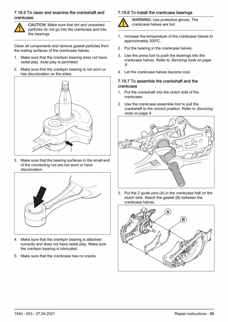
7.19.7 To assemble the crankshaft and thecrankcase1. Put the crankshaft into the clutch side of the
crankcase.
2. Use the crankcase assemble tool to pull thecrankshaft to the correct position. Refer to Servicingtools on page 9.
3. Put the 2 guide pins (A) in the crankcase half on theclutch side. Attach the gasket (B) between thecrankcase halves.
A
B
1540 - 003 - 27.04.2021 Repair instructions - 55

4. Use the crankcase assemble tool to push thecrankcase to the correct position. Refer to Servicingtools on page 9.
5. Attach the 6 screws (C). Tighten them in turn to thecorrect torque. Refer to Servicing data on page 7.
x4
C
D
CAUTION: Make sure that the crankshaftrotates freely.
6. Carefully cut off the gasket along the cylinderinterface. Make sure that you do not cause damageto the crankcase surface.
7. Assemble the carburetor bottom plate to thecrankcase and tighten the 4 screws (D) to thecorrect torque. Refer to Servicing data on page 7.
8. Install the oil tank cap assembly
9. Assemble the remaining parts as given in To getaccess to the crankshaft and crankcase on page 51.
7.20 Guide bar bolts
7.20.1 To remove the guide bar bolts1. Drain the oil tank.
2. Remove the clutch cover.
3. Remove the guide bar and saw chain.
4. Hit the guide bar bolts until they fall into the oil tank.
5. Remove the guide bar bolts from the oil tank.
56 - Repair instructions 1540 - 003 - 27.04.2021

7.20.2 To install the guide bar bolts1. Attach a steel wire to the thread of a guide bar bolt.
2. Put the steel wire through the oil tank and throughthe hole for the guide bar bolt.
3. Pull the steel wire to pull out the guide bar bolt.
4. Make sure that the square head of the guide bar boltis correctly attached in the oil tank.
5. Put 2 spacers on each guide bar bolt.
6. Attach a nut to each guide bar bolt and tighten thenuts until the guide bar bolts are tightly attached tothe crankcase.
Note: Fill the tank with chain oil before you operate theproduct.
7.21 Thermostat and heating element
7.21.1 To remove and install the thermostat andheating elementThe models 560 XP and 560 XPG has a thermostat andheating element.
1. Drain the fuel from the fuel tank.
2. Remove the cylinder cover.
3. Remove the spark plug cap and the spark plug.
4. Remove the air filter.
5. Remove the air filter holder. Refer to To remove andinstall the carburetor on page 36.
6. Remove the 2 screws and the cover for the heatedhandle.
1540 - 003 - 27.04.2021 Repair instructions - 57

7. Remove the switch (A) from the connection plate(B). Disconnect the wire (C) from the connectionplate. Disconnect the handle wire (D) from theconnection plate. Remove the connection plate (B).Disconnect the stator wire (E) and the carburetorwire (F) from the wire (G). Disconnect the groundcable (H) from the handle.
A
B
C
D
E
F
G
H
8. Disconnect the wires and pull out the wires from thehandle. Be careful when you pull the wire throughthe handle.
9. Pull the wire up through the carburetor bottom plate.
10. Remove the 2 screws and the bracket.
58 - Repair instructions 1540 - 003 - 27.04.2021

11. Disconnect the thermostat wires. Disconnect thegenerator wires. Remove the heating elements.
12. Install in the opposite sequence.
7.22 To repair a damaged threadA damaged thread can be repaired with a thread insert.
Note: For aluminum threads, use helicoil and metricscrews. Refer to the manufacturer’s manual for moreinformation.
1. Use the applicable drill bit to make a new hole thatremoves the damaged threads.
Note:
If you have a MT6 screw, use a 7.1 mm diameterdrill bit.
If you have a MT4 screw, use a 5.1 mm diameterdrill bit.
If you have a PL5 screw, use a 6.1 mm diameter drillbit.
2. Attach the thread insert with the sharp part of thethread insert first.
PL MT
5 4 & 6
3. Attach the thread insert with an applicable screwand wrench.
1540 - 003 - 27.04.2021 Repair instructions - 59

8 Troubleshooting8.1 TroubleshootingYou can do the troubleshooting procedure with mostcomponents attached to the product. Tools necessaryfor the troubleshooting procedure is:
• Ammeter• Ohmmeter• Cooling spray
The most common fault is oxidisation of the heatingelement contacts in the rear handle and the switchcontact.
F
C1
A1
G
A
C
E
H
B
D D1
B1
8.2 To troubleshoot the heating element in thefront handle1. Measure the resistance between point (E) and (F).
The resistance for heating element must be 3.0-4.0Ω.
2. Replace the front handle if the resistance is lessthan 3.0 Ω or more than 4,0 Ω.
8.3 To troubleshoot the heating element in therear handle1. Disconnect the cable connection at (B1) and (D1).
2. Clean the contacts (B1) and (D1).
3. Measure the resistance between point (B1) and(D1). The resistance for heating element must be0,8-1,0 Ω.
4. Replace the heating element if the resistance is lessthan 0.8 Ω or more than 1,0 Ω.
8.4 To troubleshoot the generator1. Measure the resistance in the generator between
point (A1) and (G). The resistance for generatormust be 0.5 Ω.
2. Replace the generator if the resistance is more than0.5 Ω.
8.5 To troubleshoot the start/stop switch1. Disconnect one of the wires to the switch and
connect the ohmmeter between the points (A1) and(F).
2. The ohmmeter must show more than 1000 Ω withthe start/stop switch in the OFF position. Replacethe start/stop switch if the resistance is less than1000 Ω.
3. The ohmmeter must show more than 0.1 Ω with thestart/stop switch in the ON position. Replace thestart/stop switch if the resistance is less than 0.1 Ω.
8.6 To troubleshoot the heating element andthermostat1. Disconnect the earth cable (H).
2. Measure with the ohmmeter between (H) and (C1).
3. The ohmmeter must show 0.0 Ω at an airtemperature of 15 C° or more. Replace the heatingelement and thermostat if the resistance is less ormore than 0.0 Ω.
Note: You must replace the heating element andthermostat at the same time.
4. Cool the thermostat with a cooling spray. Theohmmeter must show 8.0 Ω. Replace the heatingelement and thermostat if the resistance is less ormore than 8.0 Ω.
Note: You must replace the heating element andthermostat at the same time.
60 - Troubleshooting 1540 - 003 - 27.04.2021

8.7 Troubleshooting diagram
Starter rope
does not retract
Start rope stuck
No
resistance when
pulling the rope
Impossible to
activate choke/
start switch
Defect
starter housing
Perform “Cleaning and inspec-
tion” of starter housing
(see separate instr.)
Sticking starter
housing
Defect hook/pawl in
starter housing
Stop lever/start
switch
incorrect mounted
Engine will not
Flywheel is loose
Choke valve
incorrect position
Change part or entire
starter if needed.
Change part or entire
starter if needed.
Change part if needed.
Change part if needed.
Change part if needed.
Piston ring is stuck
Change part if needed.
Tighten/change if
needed.
Change part if needed.
Defect starter housing
Check air gap between
flywheel and ignition module
Check main bearings
Check cylinder and piston
Perform “Cleaning and inspec-
tion” of starter housing
(see separate instr.)
Check the key on flywheel and
make sure that the flywheel is
tightened with the correct torque
Check piston ring function
Check installation of stop lever/
start switch
Check position of choke valve
Correct if needed
Correct choke valve/
replace
carburettor
rotate
1540 - 003 - 27.04.2021 Troubleshooting - 61

8.8 Engine running issue
Does the
engine
start ?
Clean the engine (cylinder fins, fly wheel area etc) before start of troubleshooting.
Confirm that the fuel is of correct quality and not to old. Purge the fuel system 10 times.
Connect to CST.
Run Auto Test, check for error codes. Error code might give a hint of the problem
Change decompression
valve
Starting issue
No
Yes
Troubleshooting
ended
No
1 Check the spark plug and replace if necessary.
2 Perform the “Spark Plug Test”. (see “Spark Plug Test” instr.)
3. Confirm stop switch functionality.
4. Measure the distance between flywheel and ignition
module.
5. Perform the “Ignition System Diagnostic”. (see “Ignition
System Diagnostic” instr.)
1. Check fuel filter.
2. Check fuel houses for leakage by pressure test.
3. Check if impulse hose is blocked or leaks.
4. Check carburettor for leakage by pressure test. (see
separate instr.)
5. Check fuel filter in the carburettor.
Does the
engine
start ?
Does the
engine
start ?
No
No
Yes
Yes
Yes
Yes
If product has an decompression valve,
check that the deco valve deactivate correct.
Check if the system deliveries a spark
Yes
Confirm fuel system.
-Wet spark plug?
-Purge bulb function ok ?
No
Leakage test of engine
Use leakage spray to check:
1. Cylinder gasket
2. Intake system
3. Cylinder
4. Crankcase gaskets
5. Crankcase
Perform a visual inspection of interface between
carburettor and intake rubber for leakage.
No
No
Does the
engine
start ?
Yes
Issue still remains?
Contact your Husqvarna
Local Sales Company for
advice.
Yes
62 - Troubleshooting 1540 - 003 - 27.04.2021

8.9 Engine running issue
Idle
High speed
Acceleration
Retardation
Air supply
1. Confirm that the air filter is clean.
2. Check the spark arrestor (if equipped).
3. Confirm that muffler is not blocked.Product OK
Problem solved
Fuel system
1. Check fuel filter.
2. Check fuel hoses (including impulse hose) for
leakage by pressure test.
3. Check tank venting functionality.
Product OK
Spark plug/Ignition module
1. Check spark plug and spark plug cap.
2. Check cables and connectors for wear.
3. Check torque on ignition coil screws.
4. Check the ground wire.
Leakage
1. Check function of decompression valve (if
equipped).
2. Check mounting/interface intake rubber and
carburettor.
3. Check cylinder base.
4. Check intake system.
5. Check cylinder.
6. Check gaskets on crankshaft.
7. Check crank case.
Carburettor
1. Check leakage by pressure test (positive
pressure on fuel inlet and negative pressure
on purge outlet).
2 Check throttle shaft and valve function.
3. Check filter screen for dirt.
4. Check metering lever for wear and height.
Product OK
Product OK
Clean the engine (cylinder fins, fly wheel area etc) before start of troubleshooting.
Confirm that the fuel is of correct quality and not to old. Purge the fuel system 10 times.
Connect to CST.
Run Auto Test, check for error codes. Error code might give a hint of the problem
Product OK
Issue still remains?
Contact your
Husqvarna Local Sales
Company for advice.
Check for carbon build up
in exhaust port and
scavenging channel.
Yes
YesNo
No
Yes
Yes
No
No
No
No
Yes
Product OKYes
1540 - 003 - 27.04.2021 Troubleshooting - 63

8.10 Ignition System Diagnostic Flow Chart
Install new, properly gapped, manufacturer specified spark plug. Stop switch must be in run position.
Perform Spark Test (See separate instructions).
Is a spark weak or is there
no spark?
Disconnect stop wire from ignition
module and re-test.
Repair damaged stop wire or stop
switch.
Remove ignition module mount-ing bolts, clean
connections, set air gap and re-test.
Is a strong blue spark
Replace the
ignition module.
Remove spark tester. Run unit.
Does engine start and run
properly?
End Test
Inspect flywheel key and key way for sheared key.
Is flywheel key way
damaged?
Problem is not in ignition system.
Perform cylinder compression test.
Verify fuel system.
Replace damaged components.
Perform visual inspection of unit. Inspect spark plug wire, boot connections.
Repair/replace any problem items.
NO
NO
YES
YES
NO
YES
NO SPARK
WEAK SPARK
NO
NO
YES
YES
Inspect black wire for damage. Measure black wire between
core and end of the wire, should show below 1.0 OHM
Is the wire damaged ?
YES
NO
Replace the
ignition module.
present?
Is a strong blue spark present?
Is a strong blue spark present?
64 - Troubleshooting 1540 - 003 - 27.04.2021

9 Technical data
9.1 Technical dataHusqvarna 555 Husqvarna 556 Husqvarna 560 XP
Engine
Cylinder displacement, cm3 59.8 59.8 59.8
Idle speed, rpm 2800 2800 2800
Maximum engine poweracc. to ISO 8893, kW/hp @rpm
3.1/4.2 @ 9600 3.1/4.2 @ 9600 3.5/4.8 @ 9600
Ignition system1
Spark plug NGK CMR6H NGK CMR6H NGK CMR6H
Electrode gap, mm 0.5 0.5 0.5
Fuel and lubrication system
Fuel tank capacity, liter/cm3 0.65/650 0.65/650 0.65/650
Oil tank capacity, liter/cm3 0.33/330 0.35/350 0.33/330
Type of oil pump Adjustable Adjustable Adjustable
Weight
Weight, kg 5.9 6.0 5.9
Noise emissions2
Sound power level, meas-ured dB(A) 116 116 116
Sound power level, guaran-teed LWA dB(A) 118 118 118
Sound levels3
Equivalent sound pressurelevel at the operator’s ear,dB(A)
106 106 106
Equivalent vibration levels, a hveq4
Front handle, m/s2 3.2 3.2 4.4
Rear handle, m/s2 5.0 5.0 5.3
Saw chain/guide bar
Type of drive sprocket/number of teeth Rim/7 Rim/7 Rim/7
Saw chain speed at 133%of maximum engine powerspeed, m/s.
28.3 28.3 28.3
1 Always use the recommended spark plug type! Use of the wrong spark plug can damage the piston/cylinder.2 Noise emissions in the environment measured as sound power (LWA) in conformity with EC directive
2000/14/EC.3 Equivalent sound pressure level, according to ISO 22868, is calculated as the time-weighted energy total for dif-
ferent sound pressure levels under various working conditions. Typical statistical dispersion for equivalent soundpressure level is a standard deviation of 1 dB (A).
4 Equivalent vibration level, according to ISO 22867, is calculated as the time-weighted energy total for vibrationlevels under various working conditions. Reported data for equivalent vibration level has a typical statistical dis-persion (standard deviation) of 1 m/s2.
1540 - 003 - 27.04.2021 Technical data - 65

Husqvarna 560 XPG Husqvarna 562 XP Husqvarna 562 XPG
Engine
Cylinder displacement, cm3 59.8 59.8 59.8
Idle speed, rpm 2800 2800 2800
Maximum engine poweracc. to ISO 8893, kW/hp @rpm
3.5/4.8 @ 9600 3.5/4.8 @ 9600 3.5/4.8 @ 9600
Ignition system5
Spark plug NGK CMR6H NGK CMR6H NGK CMR6H
Electrode gap, mm 0.5 0.5 0.5
Fuel and lubrication system
Fuel tank capacity, liter/cm3 0.65/650 0.65/650 0.65/650
Oil tank capacity, liter/cm3 0.33/330 0.33/330 0.33/330
Type of oil pump Adjustable Adjustable Adjustable
Weight
Weight, kg 6.1 6.1 6.3
Noise emissions6
Sound power level, meas-ured dB(A) 116 116 116
Sound power level, guaran-teed LWA dB(A) 118 118 118
Sound levels7
Equivalent sound pressurelevel at the operator’s ear,dB(A)
106 106 106
Equivalent vibration levels, a hveq8
Front handle, m/s2 4.4 3.2 3.2
Rear handle, m/s2 5.3 5.0 5.0
Saw chain/guide bar
Type of drive sprocket/number of teeth Rim/7 Rim/7 Rim/7
Saw chain speed at 133%of maximum engine powerspeed, m/s.
28.3 28.3 28.3
5 Always use the recommended spark plug type! Use of the wrong spark plug can damage the piston/cylinder.6 Noise emissions in the environment measured as sound power (LWA) in conformity with EC directive
2000/14/EC.7 Equivalent sound pressure level, according to ISO 22868, is calculated as the time-weighted energy total for dif-
ferent sound pressure levels under various working conditions. Typical statistical dispersion for equivalent soundpressure level is a standard deviation of 1 dB (A).
8 Equivalent vibration level, according to ISO 22867, is calculated as the time-weighted energy total for vibrationlevels under various working conditions. Reported data for equivalent vibration level has a typical statistical dis-persion (standard deviation) of 1 m/s2.
66 - Technical data 1540 - 003 - 27.04.2021

1540 - 003 - 27.04.2021 Technical data - 67

1142464-26
2021-04-30