WizFi210 Programmers' Guide - OpenHacks
87
WizFi210 Programmers’ Guide (Version 1.3) WizFi220 operates same as described in this documents ©2013 WIZnet Co., Ltd. All Rights Reserved. ☞ For more information, visit our website at http://www.wiznet.co.kr
-
Upload
khangminh22 -
Category
Documents
-
view
6 -
download
0
Transcript of WizFi210 Programmers' Guide - OpenHacks

WizFi210 Programmers’ Guide
(Version 1.3)
WizFi220 operates same as described in this documents
©2013 WIZnet Co., Ltd. All Rights Reserved.
☞ For more information, visit our website at http://www.wiznet.co.kr

WizFi210 Programmers’ Guide (WIZnet Co., Ltd.)
Certification Information
CE for Class B ITE INFORMATION TO THE USER Hereby, WIZnet. Declares that these WizFi210 and WizFi220 are in compliance with the essential requirements and other relevant provisions of directive 1999/5/EC. WARNING: These are the class B products. In a domestic environment this product may cause radio interference in which case the user may be required to take adequate measures.
FCC for Class B ITE INFORMATION TO THE USER These equipments have been tested and found to comply with the limits for a Class B digital device, pursuant to part 15 of the FCC Rules. These limits are designed to provide reasonable protection against harmful interference in a residential installation. This equipment generates, uses and can radiate radio frequency energy and, if not installed and used in accordance with the instructions, may cause harmful interference to radio communications. However, there is no Guarantee that interference will not occur in a particular installation. If this equipment does cause harmful interference to radio or television reception, which can be determined by turning the equipment off and on, the user is encouraged to try to correct the interference by one more of the following measures: - Reorient or relocate the receiving antenna. - Increase the separation between the equipment and receiver. - Connect the equipment into an outlet on a circuit different from that to which the receiver is connected. - Consult the dealer or an experienced radio/TV technician for help. WARNING: These equipments may generate or use radio frequency energy. Changes or modifications to this equipment may cause harmful interference unless the modifications are expressly approved in the instruction manual. The user could lose the authority to operate this equipment if an unauthorized change or modification is made.
TELEC
KCC for Class B ITE INFORMATION TO THE USER 이 기기는 가정용(B급) 으로 전자파 적합등록을 한 기기로서 주거지역에서는 물론 모든 지역에서 사용할 수 있습니다. - Trade Name or Applicant : WIZnet Co., Ltd. - Equipment Name : Wireless LAN Module - Model Number : WizFi210 / WizFi220 - Manufacturer / Country of Origin : WIZnet, Co., Ltd. / KOREA - Certification Number : KCC-CRM-WWW-WIZFI210 / KCC-CRM-WWW-WIZFI220 WARNING: 해당 무선설비는 운용 중 전파혼신의 가능성이 있으므로 인명안전과 관련된 서비스는 할 수 없습니다.
Equipment : Wireless Module Model : WizFi210 UFL antenna type, WizFi210 Chip antenna type Made in Korea
010-100040

WizFi210 Programmers’ Guide (WIZnet Co., Ltd.)
Document Revision History
Date Revision Changes
2011-03-24 V1.0 Official Release
2011-05-24 V1.01 Changed Power Consumption and RF Output Power Added Auto Reconnect AT Command(AT+XAR) Added Certification Information
2011-09-05 V1.10
Changed Evaluation Board Changed GPIO number(HW Trigger, Button) Changed AT+XEHT Command Added Limited AP Feature Added WizFi220 Specs
2012-01-11 V1.11
Added UART baud rate(460800, 921600bps) Added EXT_nRESET description Added FAQ Added AT+DHCPSRVR Command Added Product contents
2012-10-24 V1.12
Added AT+WAUTO Option(2 for Limited AP mode) Added FAQ(Reducing the disassociation event) Removed unused AT Commands Removed some features for customizing f/w
2013-03-08 V1.13 Added AT+XRESET Command Added max/min power value of AT+WP command
2013-03-12 V1.14 Added explanation of AT+XRESET Command Added FAQ
2013-05-06 V1.2 Divided two documents, Datasheet for Hardware Engineer and Programmers’ guide for Software Engineer. More detail information included in datasheet.
2013-10-08 V1.3 Added AT+WSEC Command Added AT+TCERTDEL Command
Information in this document is belived to be accurate and reliable. However, WIZnet does
not give any representations or warranties, expressed or implied, as to the accuracy or
completeness of such information and shall have no liability for the consequences of use of
such information.
WIZnet reserves the right to make changes to information published in this document,
including without limitation specifictions and product descriptions, at any time and without

WizFi210 Programmers’ Guide (WIZnet Co., Ltd.)
notice. This document supersedes and replaces all information supplied prior to the
publication hereof.

WizFi210 Programmers’ Guide (WIZnet Co., Ltd.)
<Contents>
1. Overview ...................................................................................................................... 1-1 2. AT Command Set ......................................................................................................... 2-1
2.1. AT command category and description .................................................................... 2-3 2.1.1. Basic commands ............................................................................................... 2-3 2.1.2. UART / Adapter interface configuration ............................................................ 2-3 2.1.3. Profile management .......................................................................................... 2-5 2.1.4. WiFi interface .................................................................................................... 2-5 2.1.5. WiFi security .................................................................................................... 2-10 2.1.6. Wireless configuration ..................................................................................... 2-13 2.1.7. Network interface ............................................................................................ 2-15 2.1.8. Connection management ................................................................................ 2-17 2.1.9. Battery check .................................................................................................. 2-23 2.1.10. Power state management ........................................................................... 2-24 2.1.11. Auto connection .............................................................................................. 2-24 2.1.12. Provisioning ................................................................................................. 2-26 2.1.13. Miscellaneous .............................................................................................. 2-26 2.1.14. Network Connection Manager(NCM) .......................................................... 2-31 2.1.15. Summary of commands supported by firmware version ............................. 2-33
3. Communication Interface ........................................................................................... 3-37 3.1. UART ...................................................................................................................... 3-37 3.2. SPI .......................................................................................................................... 3-37
3.2.1. Pin connections for SPI ................................................................................... 3-37 3.2.2. SPI interface details ........................................................................................ 3-38 3.2.3. Host Wake-Up Signal Handling....................................................................... 3-39 3.2.4. SPI data handling ............................................................................................ 3-39 3.2.5. SPI Interface Parameters ................................................................................ 3-40
4. Command mode & Data mode .................................................................................. 4-42 4.1. AT command mode ................................................................................................ 4-42 4.2. Data mode .............................................................................................................. 4-42 4.3. Data communication in AT command mode ........................................................... 4-42
4.3.1. Data Handling ................................................................................................. 4-42
4.3.2. Escape Sequences ......................................................................................... 4-43 5. Using multi sockets .................................................................................................... 5-47
5.1. Associate with AP. .................................................................................................. 5-47 5.1.1. TCP Client multi-connections .......................................................................... 5-47 5.1.2. TCP Server multi-connections ........................................................................ 5-49
6. Operation Mode ......................................................................................................... 6-50 6.1. Station Mode .......................................................................................................... 6-50 6.2. Limited AP Mode .................................................................................................... 6-50
7. Using Factory default provisioning ............................................................................. 7-52 7.1. Factory default #1 : <Limited AP & Web configuration> ........................................ 7-52
7.1.1. Changing mode to <Limited AP & Web mode> .............................................. 7-52 7.1.2. Connect to the WizFi210 (Limited AP) ............................................................ 7-53 7.1.3. Connect to the Web server ............................................................................. 7-54
7.2. Factory default #2 : <Ad-hoc Configuration> ......................................................... 7-56 7.2.1. Changing mode to <ad hoc & Configuration-Tool mode> ............................ 7-56 7.2.2. Connecting to the WizFi210 with ad-hoc mode .............................................. 7-56
8. Transmitting and Receiving HTML Data .................................................................... 8-58 8.1. Operating as HTTP Client using WizFi210 functions ............................................. 8-58
8.1.1. Communicating with Web Server using normal HTTP ................................... 8-58 8.1.2. Communicating with Secure Web Server using HTTPS ................................. 8-59
8.2. Emulating HTTP Server or HTTP Client ................................................................ 8-61 8.2.1. Emulating HTTP Server .................................................................................. 8-62 8.2.2. Emulating HTTP Client.................................................................................... 8-62

WizFi210 Programmers’ Guide (WIZnet Co., Ltd.)
8.3. Making and Testing the environment for HTTP Server .......................................... 8-64 8.3.1. Configuring the Environment for Web Server Test.......................................... 8-64 8.3.2. HTTP Protocol for Web Server Test ................................................................ 8-65 8.3.3. Example of AT commands for configuring HTTP Server ................................ 8-66
9. Using Enterprise Security .......................................................................................... 9-68 9.1. EAP-TLS ................................................................................................................ 9-68
9.1.1. Connect to RADIUS Server using WizFi210 ................................................... 9-68 10. Examples ................................................................................................................. 10-70
10.1. Station Mode, TCP Client and Auto Connection .................................................. 10-70 10.1.1. Example 1 of commands sequence .......................................................... 10-70 10.1.2. Example 2 of commands sequence .......................................................... 10-72 10.1.3. exchanging data with a peer system ......................................................... 10-72 10.1.4. Closing TCP connection ............................................................................ 10-72
10.2. Station Mode, UDP socket and Auto Connection ................................................. 10-73 10.3. Station Mode and Multi sockets ........................................................................... 10-74
10.3.1. Example of commands sequence ............................................................. 10-74 10.3.2. Exchanging data with a peer system......................................................... 10-75 10.3.3. Closing TCP connection and UDP socket ................................................. 10-75
10.4. Limited AP, TCP Server and Auto Connection ..................................................... 10-76 10.4.1. Example of commands sequence ............................................................. 10-76 10.4.2. Exchanging data with a peer system......................................................... 10-77 10.4.3. Closing TCP connection and UDP socket ................................................. 10-77
10.5. Limited AP and Multi sockets ............................................................................... 10-78 10.5.1. Example of commands sequence ............................................................. 10-78 10.5.2. Exchanging data with a peer system......................................................... 10-79 10.5.3. Closing TCP connection and UDP socket ................................................. 10-79

WizFi210 Programmers’ Guide (WIZnet Co., Ltd.)
<Table> TABLE 1 LIST OF RESPONSE FOR AT COMMANDS ................................................................................................. 2-2
TABLE 2 BASIC COMMANDS.................................................................................................................................................. 2-3
TABLE 3 UART/ADAPTER INTERFACE COMMANDS ................................................................................................ 2-4
TABLE 4 LIST OF COMMANDS FOR PROFILE MANAGEMENT........................................................................... 2-5
TABLE 5 LIST OF COMMANDS FOR WIFI INTERFACE ............................................................................................ 2-9
TABLE 6 LIST OF COMMANDS FOR WIFI SECURITY ............................................................................................ 2-13
TABLE 7 LIST OF COMMANDS FOR WIRELESS(RF) CONFIGURATION ..................................................... 2-15
TABLE 8 LIST OF COMMANDS FOR NETWORK INTERFACE ........................................................................... 2-17
TABLE 9 LIST OF COMMANDS FOR CONNECTION MANAGEMENT ............................................................ 2-22
TABLE 10 LIST OF COMMANDS FOR BATTERY CHECK ..................................................................................... 2-23
TABLE 11 LIST OF COMMANDS FOR POWER STATE MANAGEMENT ........................................................ 2-24
TABLE 12 LIST OF COMMANDS FOR AUTO CONNECTION .............................................................................. 2-26
TABLE 13 LIST OF COMMANDS FOR PROVISIONING.......................................................................................... 2-26
TABLE 14 LIST OF COMMANDS FOR MISCELLANEOUS .................................................................................... 2-30
TABLE 15 LIST OF COMMANDS FOR NETWORK CONNECTION MANAGER .......................................... 2-32
TABLE 16 AT COMMAND LIST ............................................................................................................................................. 2-36
TABLE 17 PIN DESCRIPTION OF SPI INTERFACE .................................................................................................. 3-38
TABLE 18 TIMING INFORMATION OF SPI INTERFACE ......................................................................................... 3-39
TABLE 19 BYTE STUFFING FOR SPECIAL DATA OF SPI..................................................................................... 3-40
TABLE 20 ESCAPE SEQUENCE FOR SENDING DATA IN COMMAND MODE .......................................... 4-44
TABLE 21 ESCAPE SEQUENCE FOR RECEIVING DATA IN COMMAND MODE ...................................... 4-46

WizFi210 Programmers’ Guide (WIZnet Co., Ltd.)
<Figure> FIGURE 1 PIN CONNECTION FOR SPI BETWEEN HOST AND WIZFI210 .................................................. 3-37
FIGURE 2 TIMING DIAGRAM OF SPI INTERFACE ................................................................................................... 3-38
FIGURE 3 COMMANDS SET FOR ASSOCIATING WITH AP WHEN USING MULTI SOCKETS ......... 5-47
FIGURE 4 COMMAND SEQUENCE AND RESPONSE FOR TCP CLIENT MULTI SOCKETS .............. 5-48
FIGURE 5 COMMANDS SEQUENCE FOR USING TCP SERVER SOCKETS ............................................. 5-49
FIGURE 6 EXAMPLE OF USING COMMANDS FOR STATION MODE ............................................................ 6-50
FIGURE 7 EXAMPLE OF USING COMMANDS FOR LIMITED AP MODE ...................................................... 6-51
FIGURE 8 BUTTON CORRESPONDING TO THAT PIN IN WIZFI210 EVALUATION BOARD .............. 7-52
FIGURE 9 EXAMPLE OF USING AT COMMAND INSTEAD OF HARDWARE PIN ..................................... 7-52
FIGURE 10 EXAMPLE OF APS LIST ................................................................................................................................ 7-53
FIGURE 11 EXAMPLE OF EXECUTING IPCONFIG ON DOS COMMAND LINE ........................................ 7-53
FIGURE 12 EXAMPLE OF CONNECTING TO WEB SERVER ON WIZFI210 ............................................... 7-54
FIGURE 13 WEB PAGE FOR CONFIGURATION ON WIZFI210 .......................................................................... 7-55
FIGURE 14 CERTIFICATE INFORMATION VIEW ON TWITTER.COM ............................................................ 8-60
FIGURE 15 NETWORK ENVIRONMENT FOR TESTING WEB SERVER ON WIZFI210 ......................... 8-64
FIGURE 16 CONNECTION FLOW FOR TEST ............................................................................................................. 8-65
FIGURE 17 EXAMPLE OF COMMANDS FOR WEB SERVER ON WIZFI210 ............................................... 8-66
FIGURE 18 EXAMPLE OF RECEIVED DATA FROM WEB BROWSER ........................................................... 8-67
FIGURE 19 EXAMPLE OF ESCAPE SEQUENCE FOR TRANSMITTING DATA ......................................... 8-67
FIGURE 20 AT COMMAND FOR CLOSE THE TCP CONNECTION .................................................................. 8-67
FIGURE 21 EXAMPLE OF COMMANDS FOR USING EAP-TLS ......................................................................... 9-69
FIGURE 22 EXAMPLE OF COMMANDS FOR STATION MODE AND AUTO CONNECTION .............. 10-71
FIGURE 23 EXAMPLE OF COMMANDS FOR STATION MODE AND AUTO CONNECTION .............. 10-72
FIGURE 24 EXAMPLE OF COMMANDS FOR STATION MODE AND MULTI SOCKETS ...................... 10-74
FIGURE 25 EXAMPLE OF EXCHANGING DATA IN MULTI SOCKETS MODE .......................................... 10-75
FIGURE 26 EXAMPLE OF COMMANDS FOR CLOSING SOCKETS.............................................................. 10-75
FIGURE 27 EXAMPLE OF COMMANDS FOR LIMITED AP MODE AND AUTO CONNECTION ........ 10-76
FIGURE 28 EXAMPLE OF COMMANDS FOR LIMITED AP MODE AND AUTO CONNECTION ........ 10-78
WizFi210 Programmers’ Guide (WIZnet Co., Ltd.) 1-1
1. Overview This document provides programmers with all command and explanation about WizFi210
control.
Basically programmers can control WizFi210 with commands set, known as AT command - the
character string format.
In this document, we describe what AT command are used, how each command operates and
how programmers have to handle those commands to get the response as expected.
2. AT Command Set This section provides a list of WizFi210 AT commands and their effects. Parameters are
generally in ASCII characters, e.g. ATEn with n=1 means series of ASCII characters ‘A’, ‘T’, ‘E’,
and ‘1’. The mandatory parameters are denoted by < > and optional parameters by [ ]. If a
parameter is mandatory, any associated sub-parameters are also mandatory; sub-parameters of
an optional parameter are optional. Parameters must always be provided in the order given in
the command description. When an optional parameter is not supplied, the comma delimiters
must still be included in the command. Every command starts with the characters “AT”; any
other initial characters will cause an error return.
In the most cases, valid commands return the characters OK. Invalid inputs return ERROR:
INVALID INPUT.
Some commands are not supported according to the firmware version on WizFi210.
When user issues an AT command, “Carriage Return(0x0D)” must follows the AT command
to inform its termination.
The possible responses sent by WizFi210 to the serial host are described below.
If you send “AT” string and Line Feed to WizFi210, AT \r (0x61 0x74 0x0d)
You can get the following data.
AT\r (0x61 0x74 0x0d)1 + \r\n[OK]\r\n (0x0d 0x0a 0x5b 0x4f 0x4b 0x5d 0x0d 0x0a)
1 This is echo back of what I sent to WizFi210 from it.

WizFi210 Programmers’ Guide (WIZnet Co., Ltd.) 1-2
ASCII
CHAR Response ASCII STRING Meaning
0 S2W_SUCCESS [OK] Command Request Success.
1 S2W_FAILURE [ERROR] Command Request Failed.
2 S2W_EINVAL [ERROR: INVALID INPUT] Invalid Command or Option or
Parameter.
3 S2W_SOCK_FAIL [ERROR: SOCKET
FAILURE] Socket Operation Failed.
4 S2W_ENOCID [ERROR: NO CID]
All allowed CID’s in use, so
there was no CID to assign to
the new connection.
5 S2W_EBADCID [ERROR: INVALID CID] Invalid Connection Identifier.
6 S2W_ENOTSUP [ERROR: NOT
SUPPORTED]
Operation or Feature not
supported.
7 S2W_CON_SUCCESS [CONNECT <CID> <info>]
TCP/IP connection successful.
<CID> = the new CID in
hexadecimal format.
8 S2W_ECIDCLOSE [DISCONNECT <CID>]
TCP/IP connection with the
given CID is closed. This
response is sent to the host
when a connection is closed
either by the remote device or
by the serial host.
9 S2W_LINK_LOST [DISASSOCIATED] Not associated to a wireless
network.
A S2W_DISASSO_EVT [Disassociation Event] Wireless network association
lost.
Table 1 List of response for AT commands

WizFi210 Programmers’ Guide (WIZnet Co., Ltd.) 1-3
2.1. AT command category and description 2.1.1. Basic commands
This category is for basic commands
Command Category Description
AT
Format AT
Meaning This command is to check whether WizFi210 is in command mode
Response [OK]
ATE
Format ATEn
Meaning n=0 (Input echo disable) ex)ATE0
n=1 (Input echo enable) ex)ATE1
Response [OK]
ATV
Format ATVn
Meaning n=0 (ASCII reply disable) ex) ATV0
n=1 (ASCII reply enable) ex) ATV1
Response [OK]
Table 2 Basic commands
2.1.2. UART / Adapter interface configuration This category is for commands related to UART setting.
Command Category Description
ATB
Format ATB<baudrate>[[,2<bitsperchar>]3[,<parity>][,<stopbits>]]
Description <baudrate> : 9600, 19200, 38400, 57600, 115200, 230400, 460800,
921600
<bitsperchar> : 5, 6, 7, or 8
<parity> : n = no parity
e = even parity
o = odd parity
<stopbits> : 1, 2 or 1.5(in case of a 5-bit character)
※ UART parameters are immediately reset to values provided.
ex) ATB=9600,8,n,1
Response [OK]
AT&K Format AT&Kn
2 No space is allowed between Parameter, comma(,), and next parameter 3 The parameter, which is surrounded by [ ], can be skipped.

WizFi210 Programmers’ Guide (WIZnet Co., Ltd.) 1-4
Description n=0 (SW Flow ctrl disable) ex) AT&K0
n=1 (SW Flow ctrl enable) ex) AT&K1
Response [OK]
AT&R Format AT&Rn
Description n=0 (HW Flow ctrl disable) ex) AT&R0
n=1 (HW Flow ctrl enable) ex) AT&R1
Response [OK]
ATS Format ATSn,p
Description n=0 to 5
p=(timeout value)
n meaning unit range default
0 Network connection Timeout 10ms 1~65535 1000
1 Auto Associate Timeout 10ms 0~65535 500
2 TCP connection Timeout 10ms 0~65535 500
3 Association Retry Count NA NA NA
4 Nagle Algorithm Wait Time 10ms 0~65535 10
5 Scan Time 1ms 0~65535 20
Response [OK]
ATIn Format ATIn
Description This command provides version information of WizFi210.
ex)ATI0 or ATI2
n Meaning
0 OEM Identification
1 Hardware version
2 Software version
Response
Command ATI0 ATI1 ATI2
Response WIZnet
[OK]
GS1011
[OK]
WizFi210
1.1.0.5(W)
[OK]
Table 3 UART/Adapter interface commands
WizFi210 Programmers’ Guide (WIZnet Co., Ltd.) 1-5
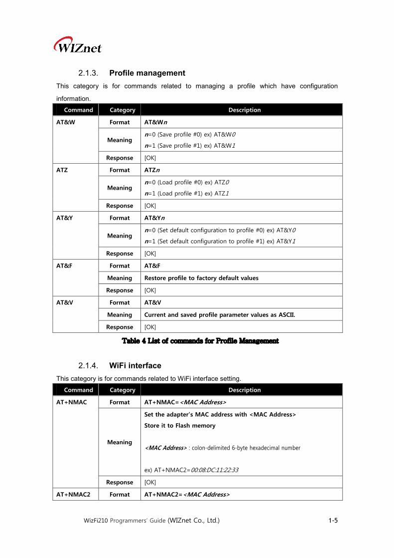
2.1.3. Profile management This category is for commands related to managing a profile which have configuration
information.
Command Category Description
AT&W Format AT&Wn
Meaning n=0 (Save profile #0) ex) AT&W0
n=1 (Save profile #1) ex) AT&W1
Response [OK]
ATZ Format ATZn
Meaning n=0 (Load profile #0) ex) ATZ0
n=1 (Load profile #1) ex) ATZ1
Response [OK]
AT&Y Format AT&Yn
Meaning n=0 (Set default configuration to profile #0) ex) AT&Y0
n=1 (Set default configuration to profile #1) ex) AT&Y1
Response [OK]
AT&F Format AT&F
Meaning Restore profile to factory default values
Response [OK]
AT&V Format AT&V
Meaning Current and saved profile parameter values as ASCII.
Response [OK]
Table 4 List of commands for Profile Management
2.1.4. WiFi interface This category is for commands related to WiFi interface setting.
Command Category Description
AT+NMAC Format AT+NMAC=<MAC Address>
Meaning
Set the adapter’s MAC address with <MAC Address>
Store it to Flash memory
<MAC Address> : colon-delimited 6-byte hexadecimal number
ex) AT+NMAC2=00:08:DC:11:22:33
Response [OK]
AT+NMAC2 Format AT+NMAC2=<MAC Address>
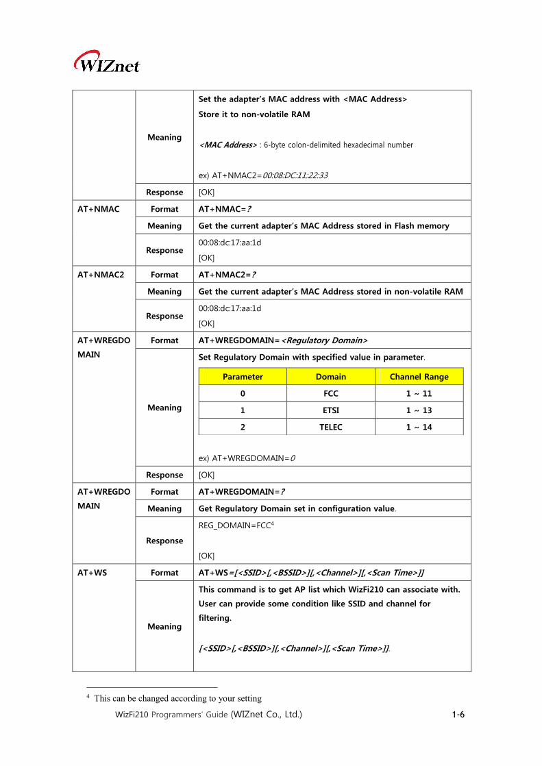
WizFi210 Programmers’ Guide (WIZnet Co., Ltd.) 1-6
Meaning
Set the adapter’s MAC address with <MAC Address>
Store it to non-volatile RAM
<MAC Address> : 6-byte colon-delimited hexadecimal number
ex) AT+NMAC2=00:08:DC:11:22:33
Response [OK]
AT+NMAC Format AT+NMAC=?
Meaning Get the current adapter’s MAC Address stored in Flash memory
Response 00:08:dc:17:aa:1d
[OK]
AT+NMAC2 Format AT+NMAC2=?
Meaning Get the current adapter’s MAC Address stored in non-volatile RAM
Response 00:08:dc:17:aa:1d
[OK]
AT+WREGDO
MAIN
Format AT+WREGDOMAIN=<Regulatory Domain>
Meaning
Set Regulatory Domain with specified value in parameter.
ex) AT+WREGDOMAIN=0
Parameter Domain Channel Range
0 FCC 1 ~ 11
1 ETSI 1 ~ 13
2 TELEC 1 ~ 14
Response [OK]
AT+WREGDO
MAIN
Format AT+WREGDOMAIN=?
Meaning Get Regulatory Domain set in configuration value.
Response
REG_DOMAIN=FCC4
[OK]
AT+WS Format AT+WS=[<SSID>[,<BSSID>][,<Channel>][,<Scan Time>]]
Meaning
This command is to get AP list which WizFi210 can associate with.
User can provide some condition like SSID and channel for
filtering.
[<SSID>[,<BSSID>][,<Channel>][,<Scan Time>]].
4 This can be changed according to your setting

WizFi210 Programmers’ Guide (WIZnet Co., Ltd.) 1-7
The response for this command has the format like below.
<SSID>,<BSSID>,<Channel>,<RSSI>,<Mode>,<Security>
ex) AT+WS
ex) AT+WS=,,5
Response
BSSID SSID Channel Type RSSI Security
00:0a:79:c7:f3:1b, swpark , 01, INFRA , -81 , WEP
02:17:c3:b2:35:0d, , 01, INFRA , -79 , WPA2-PERSONAL
cc:b2:55:d2:21:bc, JeongGW , 01, INFRA , -36 , WPA2-PERSONAL
00:26:66:7b:9d:b0, Wiznet_Kaizen , 01, INFRA , -44 , WPA2-PERSONAL
00:40:5a:c4:6f:a1, 3PA-W , 02, INFRA , -38 , WPA2-PERSONAL
00:08:9f:09:d1:d8, Danal_ENT_AP_03 , 03, INFRA , -85 , WPA2-PERSONAL
10:6f:3f:25:c3:8c, BUFF_SJCHUN , 04, INFRA , -78 , WPA2-PERSONAL
No.Of AP Found:7
[OK]
AT+WM Format AT+WM=n
Meaning
n=0 (infrastructure / Station)
n=1 (ad hoc)
n=2 (limited AP)
Response [OK]
AT+WA Format AT+WA=<SSID>[,[<BSSID>][,<Ch>]]
Meaning
This command make WizFi210 associate to an AP specified with
parameters. SSID among parameters should not be omitted at
least.
<SSID> : the SSID of AP WizFi210 will associate with
<BSSID> : the BSSID of AP WizFi210 will associate with. Option
<Ch> : the Channel of AP WizFi210 will associate with. Option
ex) AT_WA=WizFiDemoAP
Response
IP SubNet Gateway
192.168.3.123: 255.255.255.0: 192.168.3.1
[OK]
AT+WD Format AT+WD
Meaning
This command makes WizFi210 disassociate from the current AP
ex) AT+WD
Response [OK]

WizFi210 Programmers’ Guide (WIZnet Co., Ltd.) 1-8
ATH Format ATH
Meaning
This command makes WizFi210 disassociate from the current AP
ex) ATH
Response [OK]
AT+WWPS Format AT+WWPS=<METHOD>[,PIN]
Meaning
This command make WizFi210 startup itself with the stored
provision information.
<METHOD>
METHOD Meaning
1 Set to Limited AP mode with default setting
2 Set to Ad hoc mode with default setting
<PIN> : PIN value which WizFi210 needs in Limited AP mode
Response
AT+NSTAT Format AT+NSTAT=?
Meaning Get Current wireless and network status.
Response
MAC=00:08:dc:17:aa:1d
WSTATE=CONNECTED MODE=AP
BSSID=00:23:69:c8:f4:f5 SSID="WizFiDemoAP" CHANNEL=11
SECURITY=WPA2-PERSONAL RSSI=-48
IP addr=192.168.3.123 SubNet=255.255.255.0 Gateway=192.168.3.1
DNS1=168.126.63.1 DNS2=168.126.63.2
RxCount=10 TxCount=1245
[OK]
AT+WSTATU
S
Format AT+WSTATUS
Meaning Get current Wireless status
Response
MODE:0 CHANNEL:11 SSID:"WizFiDemoAP"
BSSID:00:23:69:c8:f4:f5 SECURITY:WPA2-PERSONAL
[OK]
AT+WRSSI Format AT+WRSSI=?
Meaning Get current RSSI value as ASCII
Response
-53
[OK]
AT+WRATE Format AT+WRATE=?

WizFi210 Programmers’ Guide (WIZnet Co., Ltd.) 1-9
Meaning Get current transmit rate as ASCII
Response
11
[OK]
AT+WRETRY Format AT+WRETRY=<retrycount>
Meaning
Set 802.11 TX retry count with <retrycount>
<retrycount> : Retry Count
ex) AT+WRETRY=5
Response [OK]
AT+WST
Format AT+WST=<Min scan time>,<Max scan time>
Meaning
Set the minimum and maximum scan time per channel
<Min scan time> : the minimum scan time per channel
<Max scan time> : the maximum scan time per channel. The Max
scan time should be always greater than or equal to Min scan time.
Both parameters are in milliseconds.
The allowed range of Min and Max scan time is 5 to 16000
Response [OK]
AT+WST
Format AT+WST=?
Meaning
To view the scan time.
This command returns the min and max scan time in milliseconds to
the serial interface.
By default, minimum and maximum scans time are set to 150
milliseconds
Response
MinScanTime=150
MaxScanTime=150
[OK]
AT+APCLIEN
TINFO
Format AT+APCLIENTINFO=?
Meaning Get the information about the clients associated to the adapter
when it act as a Limited AP.
Response
No.Of Stations Connected=1
No MacAddr IP
1 00:08:DC:00:00:00 192.168.13.101
[OK]
Table 5 List of commands for WiFi interface

WizFi210 Programmers’ Guide (WIZnet Co., Ltd.) 1-10
2.1.5. WiFi security This category is for commands related to WiFi security
Command Category Description
AT+WAUTH Format AT+WAUTH=n
Meaning
Set Authentication Mode
n=0 (None)
n=1 (Open)
n=2 (Shared with WEP)
If WizFi210 will be used as Limited AP, you must put this command
with parameter ‘1’
ex) AT+WAUTH=1
Response [OK]
AT+WSEC
Format AT+WSEC=n
Meaning
Supported a strict security configuration
n = 0 ( Auto security )
n = 1 ( Open security )
n = 2 ( WEP security )
n = 4 ( WPA-PSK security )
n = 8 ( WPA2-PSK security )
n = 16 ( WPA2 Enterprise )
n = 64 ( WPA2-AES + TKIP security )
ex) AT+WSEC=8
Response [OK]
AT+WWEP Format AT+WWEPn=<key>
Meaning
When AP, which WizFi210 will associate with, is using WEP
Security, this command transfer WEP key to WizFi210.
But when WizFi210 operates as Limited AP, it uses KEY, which
transferred, as its own key.
n=1 to 4 (Key index)
<key> : (Key value in ASCII)
ex) AT+WWEP1=1234567890

WizFi210 Programmers’ Guide (WIZnet Co., Ltd.) 1-11
Response [OK]
AT+WWPA Format AT+WWPA=<passphrase>
Meaning
When AP, which WizFi210 will associate with, is using WPA
Security, this command transfer WPA passphrase to WizFi210.
But When WizFi210 operates as Limited AP, this command is not
meaningless, as WizFi210 doesn’t support WPA Security.
<passphrase> : (passphrase value in ASCII)
ex) AT+WWPA=12345678
Response [OK]
AT+WPAPSK Format AT+WPAPSK=<SSID>,<passphrase>
Meaning
When AP, which WizFi210 will associate with, is using WPA2PSK
Security, this command transfer SSID and passphrase to WizFi210.
But When WizFi210 operates as Limited AP, this command is not
meaningless, as WizFi210 doesn’t support WPA2PSK Security.
<SSID> : AP’s SSID
<passphrase> : Key value for associating to AP
ex)AT+WPAPSK=WizFiDemoAP,12345678
Response [OK]
AT+WPSK Format AT+WPSK=<PSK>
Meaning
When AP, which WizFi210 will associate with, is using WPA2(Pre
Shared Key) Security, this command transfer Pre Shared Key to
WizFi210.
But When WizFi210 operates as Limited AP, this command is not
meaningless, as WizFi210 doesn’t support this security.
<PSK> : Pre Shared Key
ex)AT+WPSK=00010203040506070809000102 (?)
Response [OK]
AT+WEAPCO
NF Format
AT+ WEAPCONF=<Outer Authentication>,<Inner
Authentication>,<user name>, <password>
Meaning
This is a command for setting EAP Security mode
<Outer Authentication>

WizFi210 Programmers’ Guide (WIZnet Co., Ltd.) 1-12
Mode Value(in ASCII)
EAP-FAST 43
EAP-TLS 13
EAP-TTLS 21
EAP-PEAP 25
<Inner Authentication>
Mode Value(in ASCII)
EAP-MSCHAP 26
EAP-GTC 6
<user name> : User Name
<password> : Password
ex) AT+WEAPCONF=43,26,guest,1234
Response [OK]
AT+WEAP
Format
AT+WEAP=<Type>,<Format>,<Size>,0
[OK]5 <= Response from WizFi210
<ESC>W <data of size above>
Meaning
This is a command to set which certificate WizFi210 will use.
You can use only one of three type and more than two types with
multiple of this command having different parameter.
<Type>
Type Value(in ASCII)
CA certificate 0
Client certificate 1
Private Key 2
<Format>
0 : Binary, 1: Hex
<Size> : size of the file to be transferred
ex) AT+WEAP=2,0,100,0<ESC>6W<….data….>7
ex) AT+WEAP=0,0,100,0<ESC>W<…data…>
AT+WEAP=1,0,200,0<ESC>W<…data…>
AT+WEAP=2,0,150,0<ESC>W<…data…>
Response [OK]
5 After receiving this reply, user has to send data following escape sequence 6 <ESC> means ESC Char in ASCII Table, its value is 0x1B in HEX code. 7 <…data…> means real data of 100 bytes to transfer, as its size field has 100.

WizFi210 Programmers’ Guide (WIZnet Co., Ltd.) 1-13
AT+TCERTAD
D Format
AT+TCERTADD=<Name>,<Format>,<Size>,<Location>
[OK]8 <= Response from WizFi210
<ESC>W<Certificate data in binary>
Meaning
The Command to configure the certificate for SSL/HTTPS
connection
This command enables the adapter to receive the certificate for
SSL/HTTPS connection. It stores the certificate in flash or ram depends
on the parameter.
<Name> : Name of the certificate
<Format> :
0 : Binary, 1 : Hex
<Size> : Size of the file to be transferred
<Location>
0 : Flash, 1 : Ram
Response [OK]
AT+TCERTDE
L Format
AT+TCERTDEL=<certificate name>
[OK]
Meaning
This command deletes the SSL/HTTPS/EAP-TLS certificate stored in
flash/ram by name.
In the case of EAP-TLS certificate names are:
- TLS_CA
- TLS_CLIENT
- TLS_KEY
Response [OK]
Table 6 List of commands for WiFi Security
2.1.6. Wireless configuration This category is for commands related to configure RF signal of WizFi210/220
Command Category Description
AT+WRXACT
IVE
Format AT+WRXACTIVE=n
Meaning
n=0 (802.11 radio disable)
n=1 (802.11 radio enable)
ex) AT+WRXACTIVE=1
Response [OK]
8 After receiving this reply, user has to send data following escape sequence
WizFi210 Programmers’ Guide (WIZnet Co., Ltd.) 1-14
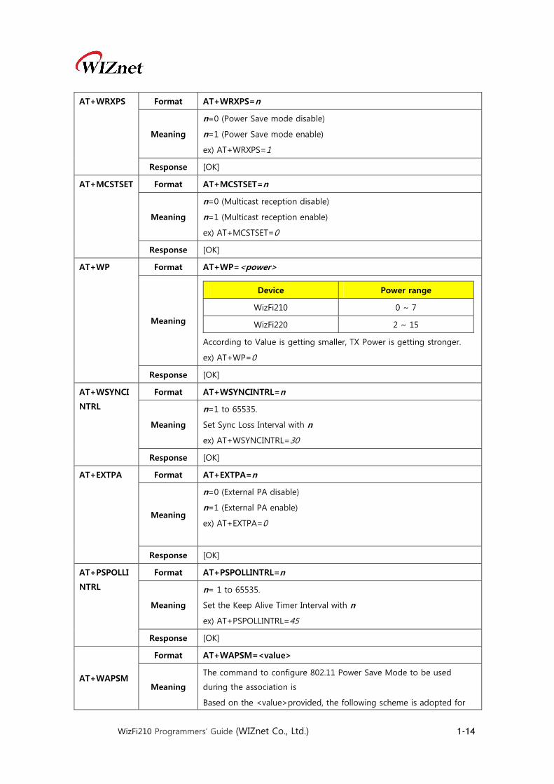
AT+WRXPS Format AT+WRXPS=n
Meaning
n=0 (Power Save mode disable)
n=1 (Power Save mode enable)
ex) AT+WRXPS=1
Response [OK]
AT+MCSTSET Format AT+MCSTSET=n
Meaning
n=0 (Multicast reception disable)
n=1 (Multicast reception enable)
ex) AT+MCSTSET=0
Response [OK]
AT+WP Format AT+WP=<power>
Meaning
According to Value is getting smaller, TX Power is getting stronger.
ex) AT+WP=0
Device Power range
WizFi210 0 ~ 7
WizFi220 2 ~ 15
Response [OK]
AT+WSYNCI
NTRL
Format AT+WSYNCINTRL=n
Meaning
n=1 to 65535.
Set Sync Loss Interval with n
ex) AT+WSYNCINTRL=30
Response [OK]
AT+EXTPA Format AT+EXTPA=n
Meaning
n=0 (External PA disable)
n=1 (External PA enable)
ex) AT+EXTPA=0
Response [OK]
AT+PSPOLLI
NTRL
Format AT+PSPOLLINTRL=n
Meaning
n= 1 to 65535.
Set the Keep Alive Timer Interval with n
ex) AT+PSPOLLINTRL=45
Response [OK]
AT+WAPSM
Format AT+WAPSM=<value>
Meaning
The command to configure 802.11 Power Save Mode to be used
during the association is
Based on the <value>provided, the following scheme is adopted for
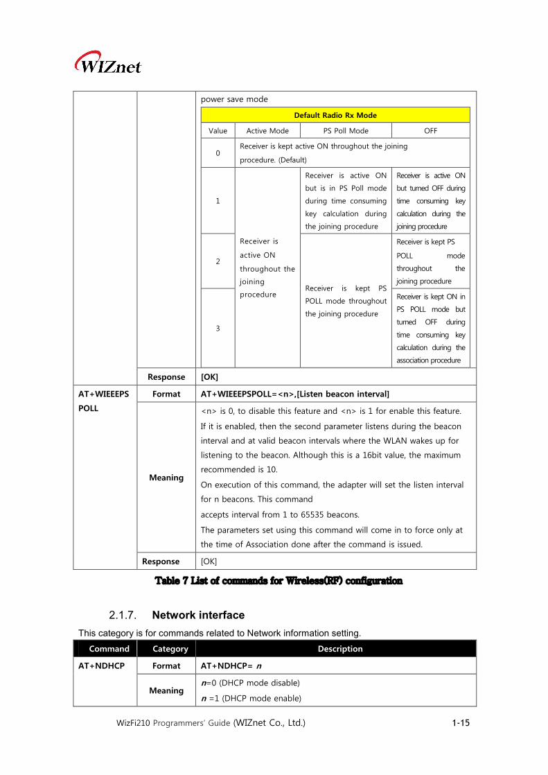
WizFi210 Programmers’ Guide (WIZnet Co., Ltd.) 1-15
power save mode
Default Radio Rx Mode
Value Active Mode PS Poll Mode OFF
0 Receiver is kept active ON throughout the joining
procedure. (Default)
1
Receiver is
active ON
throughout the
joining
procedure
Receiver is active ON
but is in PS Poll mode
during time consuming
key calculation during
the joining procedure
Receiver is active ON
but turned OFF during
time consuming key
calculation during the
joining procedure
2
Receiver is kept PS
POLL mode throughout
the joining procedure
Receiver is kept PS
POLL mode
throughout the
joining procedure
3
Receiver is kept ON in
PS POLL mode but
turned OFF during
time consuming key
calculation during the
association procedure
Response [OK]
AT+WIEEEPS
POLL
Format AT+WIEEEPSPOLL=<n>,[Listen beacon interval]
Meaning
<n> is 0, to disable this feature and <n> is 1 for enable this feature.
If it is enabled, then the second parameter listens during the beacon
interval and at valid beacon intervals where the WLAN wakes up for
listening to the beacon. Although this is a 16bit value, the maximum
recommended is 10.
On execution of this command, the adapter will set the listen interval
for n beacons. This command
accepts interval from 1 to 65535 beacons.
The parameters set using this command will come in to force only at
the time of Association done after the command is issued.
Response [OK]
Table 7 List of commands for Wireless(RF) configuration
2.1.7. Network interface This category is for commands related to Network information setting.
Command Category Description
AT+NDHCP Format AT+NDHCP= n
Meaning n=0 (DHCP mode disable)
n =1 (DHCP mode enable)

WizFi210 Programmers’ Guide (WIZnet Co., Ltd.) 1-16
If DHCP mode is disabled, Users have to use “AT+NSET=…” command
to set the adapter’s static network information.
Response [OK]
AT+DHCPSR
VR
Format AT+DHCPSRVR= n
Meaning
n =0 (DHCP Server disable)
n =1 (DHCP Server enable)
Prior to start the DHCP server, the adapter should be configured with
a valid static ip address using “AT+NSET=…”
Response [OK]
AT+NSET Format AT+NSET=<Src Address>,<Net-mask>,<Gateway>
Meaning
<Src Address>,<Net-mask>,<Gateway>
Set static network information; overrides previous values.
ex) AT+NSET=192.168.3.100,255.255.255.0,192.168.3.1
Response [OK]
AT+DNSLOO
KUP
Format AT+DNSLOOKUP=<URL>,[<retry>,[<timeout=S>]
Meaning
<URL>,[<retry>,[<timeout=S>]
Query DNS server for address of hostname URL
Ex) AT+DNSLOOKUP=google.com
Response [OK]
AT+DNSSET Format AT+DNSSET=<DNS1 IP>,[<DNS2 IP>]
Meaning
<DNS1 IP>,[<DNS2 IP>]
Set the DNS server addresses to be used.
Ex) AT+DNSSET=192.168.3.1
Response [OK]
AT+STOREN
WCONN
Format AT+STORENWCONN
Meaning Store network connection parameters prior to transition to Standby
Response [OK]
AT+RESTORE
NWCONN
Format AT+RESTORENWCONN
Meaning Restore network connection parameters after wake from Standby.
Response [OK]
AT+NARP
Format AT+NARP=?
Meaning
The interface get the ARP entries present in the adapter’s network
stack and send to the serial interface in the following format
MACaddress<space>:<space>IP address
The Macaddress format is xx:xx:xx:xx:xx:xx and the IP address format is
xxx.xxx.xxx.xxx

WizFi210 Programmers’ Guide (WIZnet Co., Ltd.) 1-17
Response 00:26:66:7b:9d:b1 : 192.168.12.1
[OK]
AT+NARPCH
ACHEEN
Format AT+NARPCHACHEEN=<Enable>
Meaning
The adapter support caching of the ARP entries(max 8)in its
nonvolatile memory and available across standby wakeup cycle.
<Enable> : 1 to start the caching and 0 to stop the caching.
Response [OK]
AT+NARPCH
ACHEDEL
Format AT+NARPCHACHEDEL
Meaning No Parameter
Delete ARP entries
Response [OK]
Table 8 List of commands for Network interface
2.1.8. Connection management This category is for commands related to handling TCP and UDP socket.
Command Category Description
AT+NCTCP Format AT+NCTCP=<Dest Address>,<Port>
Meaning
Create TCP Client socket and make it try to connect to Destination
with Dest Address and Port
<Dest Address> : Server’s IP address
<Port> : Server’s Listen port number
ex) AT+NCTCP=192.168.3.200,5000
Response [OK]
AT+NCUDP Format AT+NCUDP=<Dest Address>,<Port> [<,Src.Port>]
Meaning
Open an UDP Socket with destination address and port number.
Use this command whenever you already know peer’s IP address
and port number.
You can specify source port optionally if you want this socket has a
specific port number.
<Dest Address> : Peer’s IP address
<Port> : Peer’s port number
[<,Src.Port>] : Local port number
ex) AT+NCUDP=192.168.3.200,5000
Response

WizFi210 Programmers’ Guide (WIZnet Co., Ltd.) 1-18
AT+NSTCP Format AT+NSTCP=<Port>
Meaning
Create a TCP server socket and Listen for peer system to connect.
If a connection is established with this server socket, you will get
another <CID> for communication with the peer system.
<Port> : Local Listen port number
ex) AT+NSTCP=5000
Response
AT+NSUDP Format AT+NSUDP=<Port>
Meaning
Open an UDP Socket with source port. You can use this command
for application which many unknown devices send UDP data to
your already known socket first.
<Port> : Local port number
ex) AT+NSUDP=5000
Response
AT+CID Format AT+CID=?
Meaning Get the current connection status with CID
Response
In case of
some
Connections
CID TYPE MODE LOCAL PORT REMOTE PORT REMOTE IP
0 TCP CLIENT 52388 35001 192.168. 3.105
[OK]
In case of
no
Connection
No valid Cids
[OK]
AT+NCLOSE Format AT+NCLOSE=<CID>
Meaning
Close a connection having a specified CID
<CID> : Connection ID, 0 ~ F
ex) AT+NCLOSE=1
Response [OK]
AT+NCLOSE
ALL
Format AT+NCLOSEALL
Meaning Close all connections
Response [OK]

WizFi210 Programmers’ Guide (WIZnet Co., Ltd.) 1-19
AT+SETSOCK
OPT
Format AT+SETSOCKOPT=<CID>,<Type>,<Parameter>,<Value>,<Length>
Meaning Set a Socket option having a specified CID
Response [OK]
AT+SSLOPEN Format AT+SSLOPEN=<cid>,<certificate name> (*)
Meaning
Open a SSL Connection
<cid> : Connection ID
<certificate name> : Certificate Name
Response [OK]
AT+SSLCLOS
E
Format AT+SSLCLOSE=<cid> (*)
Meaning
Close a SSL Connection
<cid> : Connection ID
Response [OK]
AT+HTTPCO
NF
Format AT+HTTPCONF=<Param>,<Value> (*)
Meaning
Set a specific parameter of configuration information for HTTP
Client with <Value>.
<Param>
value Meaning
2 HTTP_HEADER_AUTHORIZATION
3 HTTP_HEADER_CONNECTION
4 HTTP_HEADER_CONTENT_ENCODING
5 HTTP_HEADER_CONTENT_LENGTH
6 HTTP_HEADER_CONTENT_RANGE
7 HTTP_HEADER_CONTENT_TYPE
8 HTTP_HEADER_DATE
9 HTTP_HEADER_EXPIRES
10 HTTP_HEADER_FROM
11 HTTP_HEADER_HOST
12 HTTP_HEADER_IF_MODIFIED_SINCE
13 HTTP_HEADER_LAST_MODIFIED
14 HTTP_HEADER_LOCATION
15 HTTP_HEADER_PRAGMA
16 HTTP_HEADER_RANGE

WizFi210 Programmers’ Guide (WIZnet Co., Ltd.) 1-20
17 HTTP_HEADER_REFERER
18 HTTP_HEADER_SERVER
19 HTTP_HEADER_TRANSFER_ENCODING
20 HTTP_HEADER_USER_AGENT
21 HTTP_HEADER_WWW_AUTHENTICATE
23 HTTP_HEADER_REQUEST_URL
<Value> : a string value for a corresponding parameter above.
ex)AT+HTTPCONF=20,User-Agent: Mozilla/5.0\r
Response [OK]
AT+HTTPCO
NFDEL
Format AT+HTTPCONFDEL=<Param>
Meaning
Remove an http client configuration.
Upon reception of this command the adapter removes the HTTP
configuration specified by the param.
The ‘param’ is the HTTP header and is one of the following:
<Param>
value Meaning
2 HTTP_HEADER_AUTHORIZATION
3 HTTP_HEADER_CONNECTION
4 HTTP_HEADER_CONTENT_ENCODING
5 HTTP_HEADER_CONTENT_LENGTH
6 HTTP_HEADER_CONTENT_RANGE
7 HTTP_HEADER_CONTENT_TYPE
8 HTTP_HEADER_DATE
9 HTTP_HEADER_EXPIRES
10 HTTP_HEADER_FROM
11 HTTP_HEADER_HOST
12 HTTP_HEADER_IF_MODIFIED_SINCE
13 HTTP_HEADER_LAST_MODIFIED
14 HTTP_HEADER_LOCATION
15 HTTP_HEADER_PRAGMA
16 HTTP_HEADER_RANGE
17 HTTP_HEADER_REFERER
18 HTTP_HEADER_SERVER
19 HTTP_HEADER_TRANSFER_ENCODING
20 HTTP_HEADER_USER_AGENT

WizFi210 Programmers’ Guide (WIZnet Co., Ltd.) 1-21
21 HTTP_HEADER_WWW_AUTHENTICATE
23 HTTP_HEADER_REQUEST_URL
Response [OK]
AT+HTTPOPE
N Format
AT+HTTPOPEN=<host>[,<Port Number>,<SSL Flag>,<certificate
name>,<proxy>] (*)
Meaning
Open an HTTP Client connection. This command opens an HTTP
Client socket on WizFi210 and tries to connect to the server
specified by the host name or IP address in <host> field.
<host> : Domain name or IP address of the Server
<Port Number> : a port number on which the Server is listening
In default, 80 for HTTP and 443 for HTTPS
<SSL Flag>
Value Meaning
0 SSL Disabled(Default)
1 SSL Enabled
<certificate name>
The name of CA Certificate to be used in SSL enabled.
CA Certificate should be provided to WizFi210 in advance.
<proxy>
0 : not using a proxy server
1: using a proxy server
Response 0 (Connected Socket’s CID)
[OK]
AT+HTTPSEN
D Format
AT+HTTPSEND=<cid>,<Type>,<Timeout>,<Page>,[<Size of
content>]
<ESC>H<Contents> (*)
Meaning
Send GET/POST HTTP data on the HTTP client connection to peer
system.
<cid> : CID for the HTTP Client socket
<Type>
Value Meaning
1 HTTP_METHOD_GET
3 HTTP_METHOD_POST
<Timeout> : Timeout value in seconds
<Page> : The page or script name being accessed

WizFi210 Programmers’ Guide (WIZnet Co., Ltd.) 1-22
<Size of content> : Actual contents size, this can be omitted in
case of GET
ex)AT+HTTPSEND=0,1,10,/
Response Response data in escaped sequence format from HTTP(S) Server
AT+HTTPCLO
SE
Format AT+HTTPCLOSE=<cid> (*)
Meaning
Close the HTTP client connection.
<cid> : CID for the HTTP Client socket
ex)AT+HTTPCLOSE=0
Response [OK]
AT+NRAW Format AT+NRAW=n
Meaning
Enable / Disable Raw Ethernet support.
n=0
n=1
n=2
Response [OK]
AT+UNSOLIC
ITEDTX Format
AT+UNSOLICITEDTX=<Frame Control>,<Sequence
Cntrl>,<Channel>,<Rate>,<WmmInfo>, <Receiver Mac>,<Bssid of
AP>,<Frame Length>
Meaning Unsolicited data transmission.
Response [OK]
Table 9 List of commands for Connection Management
(*) is specialized functions for HTTP Client/SSL, not the part of standard firmware. If you
want these functions, we can use the WizFi210 firmware for Enterprise.
WizFi210 Programmers’ Guide (WIZnet Co., Ltd.) 1-23
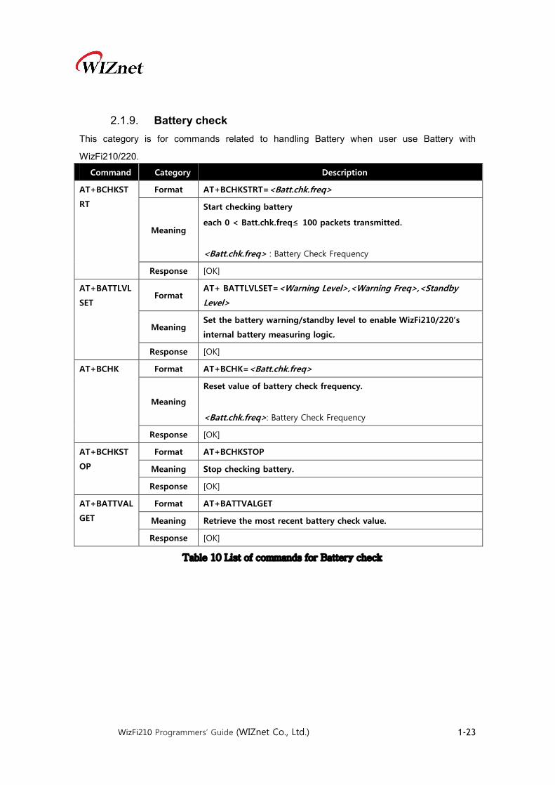
2.1.9. Battery check This category is for commands related to handling Battery when user use Battery with
WizFi210/220.
Command Category Description
AT+BCHKST
RT
Format AT+BCHKSTRT=<Batt.chk.freq>
Meaning
Start checking battery
each 0 < Batt.chk.freq≤ 100 packets transmitted.
<Batt.chk.freq> : Battery Check Frequency
Response [OK]
AT+BATTLVL
SET Format
AT+ BATTLVLSET=<Warning Level>,<Warning Freq>,<Standby
Level>
Meaning Set the battery warning/standby level to enable WizFi210/220’s
internal battery measuring logic.
Response [OK]
AT+BCHK Format AT+BCHK=<Batt.chk.freq>
Meaning
Reset value of battery check frequency.
<Batt.chk.freq>: Battery Check Frequency
Response [OK]
AT+BCHKST
OP
Format AT+BCHKSTOP
Meaning Stop checking battery.
Response [OK]
AT+BATTVAL
GET
Format AT+BATTVALGET
Meaning Retrieve the most recent battery check value.
Response [OK]
Table 10 List of commands for Battery check
WizFi210 Programmers’ Guide (WIZnet Co., Ltd.) 1-24
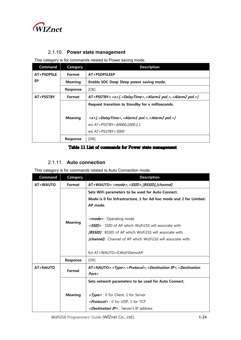
2.1.10. Power state management This category is for commands related to Power saving mode.
Command Category Description
AT+PSDPSLE
EP
Format AT+PSDPSLEEP
Meaning Enable SOC Deep Sleep power saving mode.
Response [OK]
AT+PSSTBY Format AT+PSSTBY=<x>[,<DelayTime>,<Alarm1 pol.>,<Alarm2 pol.>]
Meaning
Request transition to Standby for x milliseconds.
<x>[,<DelayTime>,<Alarm1 pol.>,<Alarm2 pol.>]
ex) AT+PSSTBY=60000,1000,1,1
ex) AT+PSSTBY=5000
Response [OK]
Table 11 List of commands for Power state management
2.1.11. Auto connection This category is for commands related to Auto Connection mode.
Command Category Description
AT+WAUTO Format AT+WAUTO=<mode>,<SSID>,[BSSID],[channel]
Meaning
Sets WiFi parameters to be used for Auto Connect.
Mode is 0 for Infrastructure, 1 for Ad-hoc mode and 2 for Limited-
AP mode.
<mode> : Operating mode
<SSID> : SSID of AP which WizFi210 will associate with
[BSSID] : BSSID of AP which WizFi210 will associate with.
[channel] : Channel of AP which WizFi210 will associate with.
Ex) AT+WAUTO=0,WizFiDemoAP
Response [OK]
AT+NAUTO Format
AT+NAUTO=<Type>,<Protocol>,<Destination IP>,<Destination
Port>
Meaning
Sets network parameters to be used for Auto Connect.
<Type> : 0 for Client, 1 for Server
<Protocol> : 0 for UDP, 1 for TCP
<Destination IP> : Server’s IP address

WizFi210 Programmers’ Guide (WIZnet Co., Ltd.) 1-25
<Destination Port> : Server’s Listen port num or Local port num
ex) AT+NAUTO=0,1,192.168.3.101,5000 (TCP/Client)
ex) AT+NAUTO=1,1, ,5001 (TCP/Server)
ex) AT+NAUTO=0,0,192.168.3.101,5002(UDP, Port is 5002)
Response [OK]
ATC Format ATCn
Meaning
After next reboot or next “AT” command, this will be affected.
n=0 (Auto Connect is disable)
n=1 (Auto Connect is enable)
Response [OK]
ATA Format ATA
Meaning Start Auto Connect, including association.
Response [OK]
ATA2 Format ATA2
Meaning Start Auto Connect using existing association.
Response [OK]
ATO Format ATO
Meaning
Return to a previous Auto Connect session, returns an error if no
such session exists.
We use this command normally when using data mode for
exchanging data.
You already exchanged data on a previous Auto Connect session in
Data mode, and you exited9 out AT command mode shortly in
order to execute any AT command without terminating that
session. After execution, You use this command to return into Data
mode.
Response No Response. Just change to Data mode
AT+XAR Format AT+XAR=n
Meaning
Auto reconnect interval.
n=0 (disable)
n=5 to 3600 (interval, seconds)
9 In order to exit from Data mode to AT command mode, you have to write +++(0x2B 0x2B 0x2B)
without any followed char during more than 2 seconds.
WizFi210 Programmers’ Guide (WIZnet Co., Ltd.) 1-26
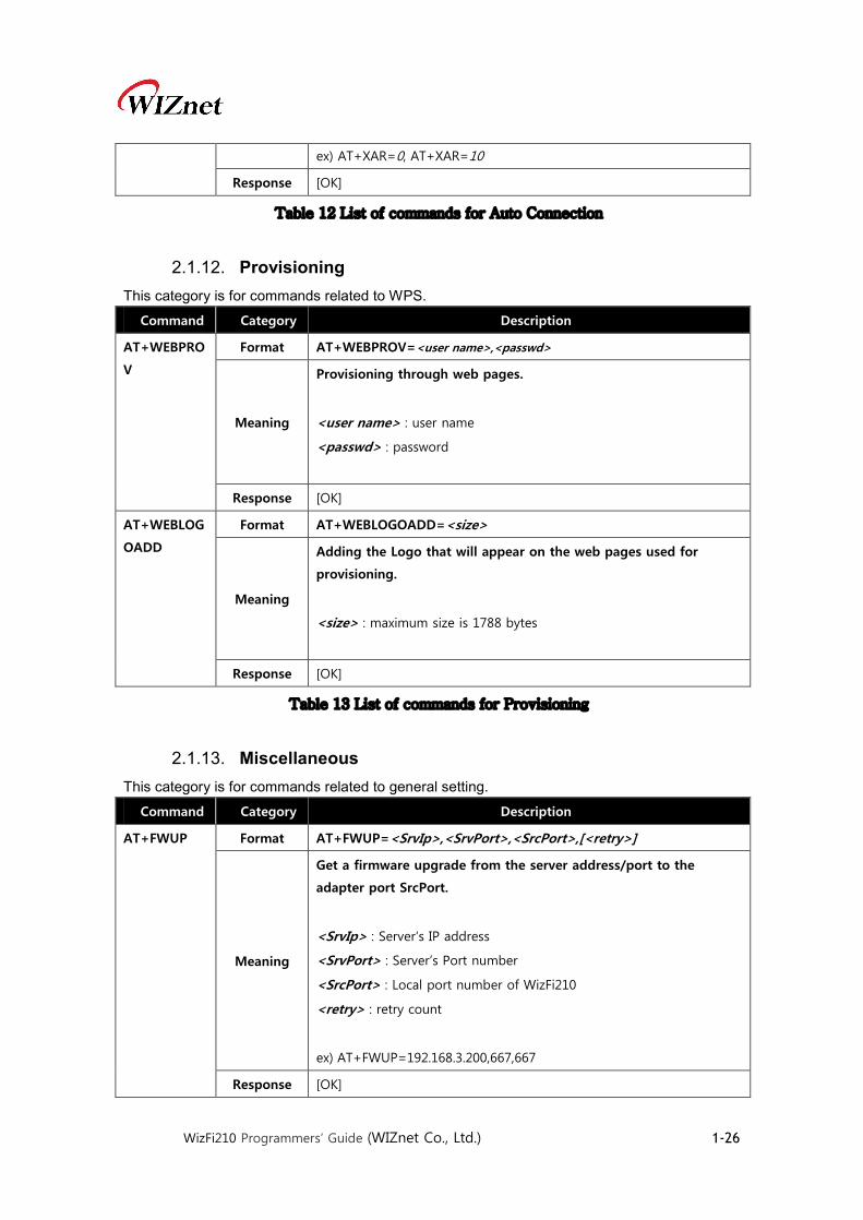
ex) AT+XAR=0, AT+XAR=10
Response [OK]
Table 12 List of commands for Auto Connection
2.1.12. Provisioning This category is for commands related to WPS.
Command Category Description
AT+WEBPRO
V
Format AT+WEBPROV=<user name>,<passwd>
Meaning
Provisioning through web pages.
<user name> : user name
<passwd> : password
Response [OK]
AT+WEBLOG
OADD
Format AT+WEBLOGOADD=<size>
Meaning
Adding the Logo that will appear on the web pages used for
provisioning.
<size> : maximum size is 1788 bytes
Response [OK]
Table 13 List of commands for Provisioning
2.1.13. Miscellaneous This category is for commands related to general setting.
Command Category Description
AT+FWUP Format AT+FWUP=<SrvIp>,<SrvPort>,<SrcPort>,[<retry>]
Meaning
Get a firmware upgrade from the server address/port to the
adapter port SrcPort.
<SrvIp> : Server‘s IP address
<SrvPort> : Server’s Port number
<SrcPort> : Local port number of WizFi210
<retry> : retry count
ex) AT+FWUP=192.168.3.200,667,667
Response [OK]

WizFi210 Programmers’ Guide (WIZnet Co., Ltd.) 1-27
AT+SETTIME Format AT+SETTIME=<dd/mm/yyyy>,<HH:MM:SS>
Meaning
Set the adaptor system time.
<dd/mm/yyyy> : Date
<HH:MM:SS> : Time
ex) AT+SETTIME=11/04/2013,09:00:00
Response [OK]
AT+GETTIME Format AT+ GETTIME=?
Meaning
Upon reception of this command the adaptor sends the current
system time in milliseconds since
epoch(1970) to the serial interface. The time format comes on the
serial interface as follows:
Response [OK]
AT+DGPIO Format AT+DGPIO=<GPIO-NO>,<SET/RESET(0/1)>
Meaning
Set or reset (high/low) a GPIO pin
<GPIO-NO> : GPIO number
<SET/RESET(0/1)> : GPIO value to set
ex) AT+DGPIO=31,0
Response [OK]
AT+XGPIO Format AT+XGPIO=<GPIO-NO>
Meaning Get a GPIO pin status(high/low).
Response GPIO-No is High or GPIO-No is Low.
AT+PING Format
AT+PING=<IP>,[[Trails],[<Interval>],[<Len>],[<TOS>],[<TTL>],[<PA
YLOAD>]]
Meaning
PING the IP address provided. Trails = 0 will ping until <Esc> C is
issued.
<IP> : Target’s IP address
<Trails> : Option
<Interval> : Option
<Len> : Option
<TOS> : Option
<TTL> : Option
<PAYLOAD> : Option
Ex) AT+PING=192.168.3.1,5

WizFi210 Programmers’ Guide (WIZnet Co., Ltd.) 1-28
Response
Pinging for 192.168.3.1 with 56 bytes of data
[OK]
Reply from 192.168.3.1: bytes=56 time=17 ms TTL 30
Reply from 192.168.3.1: bytes=56 time=4 ms TTL 30
Reply from 192.168.3.1: bytes=56 time=2 ms TTL 30
Reply from 192.168.3.1: bytes=56 time=2 ms TTL 30
Reply from 192.168.3.1: bytes=56 time=3 ms TTL 30
Ping Statistics for 192.168.3.1:
Packets: Sent = 5, Received = 5, Lost = 0 percent
Approximate round trip times in milliseconds
Minimum = 2ms, Maximum = 17ms, Average = 5ms
AT+TRACER
OUTE Format
AT+TRACEROUTE=<IP>,[[<Interval>],[<MaxHops>],[<MinHops>],[
<TOS>]]
Meaning
Trace the route to the IP address provided.
<IP> : Target’s IP address
<Interval> : Option
<MaxHops> : Option
<MinHops> : Option
<TOS> : Option
Ex) AT+TRACEROUTE=74.125.155.103
Response
Tracing Route to 74.125.235.145 over a max hops 30
[OK]
1 3 ms 3 ms 2 ms 192.168.3.1
2 4 ms 4 ms 3 ms 222.98.173.254
3 5 ms 4 ms 3 ms 121.190.34.69
4 * * * Request timed out
5 3 ms 3 ms 7 ms 112.189.127.21
6 5 ms 4 ms 5 ms 125.130.13.233
7 38 ms 10 ms 7 ms 112.174.15.133
8 5 ms 5 ms 5 ms 112.174.81.102
9 5 ms 5 ms 4 ms 112.174.83.50
10 101 ms 73 ms 71 ms 72.14.195.22

WizFi210 Programmers’ Guide (WIZnet Co., Ltd.) 1-29
11 71 ms 90 ms 72 ms 209.85.255.80
12 91 ms 113 ms 93 ms 209.85.249.195
13 74 ms 73 ms 73 ms 209.85.241.129
14 74 ms 77 ms 77 ms 74.125.235.145
Trace Complete
AT+BDATA Format AT+BDATA=n
Meaning
This command is to set whether Data is handled in Bulk mode.
n=1 (Bulk Data mode is enable)
n=0 (Bulk Data mode is disable)
Response [OK]
AT+XDUM Format AT+XDUM=n
Meaning
This command is to set whether Notification from WizFi210
regarding of some event become enable.
n=1 (Notification Message is disable)
n =0 (Notification Message is enable)
Response [OK]
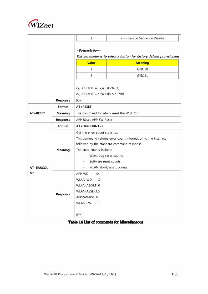
AT+XEHT Format
AT+XEHT=<HW Trigger GPIO>,<ActiveReverse>,<SW Trigger
Disable>,<ButtonAction>
Meaning
This command is to set Hardware Trigger handling transition of
between command mode and data mode.
<HW Trigger GPIO>
Value Meaning
0 Disable HW Trigger
1 GPIO10
2 GPIO29
<ActiveReverse>
Value Meaning
0 Change to Active Low
1 Change to Active High
<SW Trigger Disable>
Value Meaning
0 +++ Escape Sequence Enable
WizFi210 Programmers’ Guide (WIZnet Co., Ltd.) 1-30
1 +++ Escape Sequence Disable
<ButtonAction>
This parameter is to select a button for factory default provisioning
Value Meaning
1 GPIO10
3 GPIO21
ex) AT+XEHT=2,1,0,3 (Default)
ex) AT+XEHT=1,0,0,1 (in old EVB)
Response [OK]
AT+RESET
Format AT+RESET
Meaning The command forcefully reset the WizFi210
Response APP Reset-APP SW Reset
AT+ERRCOU
NT
Format AT+ERRCOUNT=?
Meaning
Get the error count statistics.
This command returns error count information to the interface
followed by the standard command response
The error counts include:
- Watchdog reset counts
- Software reset counts
- WLAN abort/assert counts
Response
APP-WD :0
WLAN-WD :0
WLAN-ABORT :0
WLAN-ASSERT:0
APP-SW-RST :0
WLAN-SW-RST:0
[OK]
Table 14 List of commands for Miscellaneous

WizFi210 Programmers’ Guide (WIZnet Co., Ltd.) 1-31
2.1.14. Network Connection Manager(NCM) The WizFi210 supports network connection manager which manage L2, L3 and L4 level
connection automatically.
Command Category Description
AT+NCMAUT
O
Format AT+NCMAUTO=<Mode>.<Start/Stop>,[Level]
Meaning
This command start the NCM by connecting to the AP(if the mode
configured as station) or create a limited AP(if the mode configured as
limited AP) with the pre-configured parameters.
<Mode> : 0 is for station mode and 1 is for limited AP mode
<Start/Stop> : 1 is for start the NCM and 0 is for stop the NCM
<Level> : 0 is for L2+L3 Connection and 1 is for L2+L3+L4
connection
Once it connected any of the L2,L3 and L4 disconnection triggers the
NCM and it starts do the L2,L3 and L4 re-connection.
Response [OK]
AT+NCMAUT
OCONF
Format AT+NCMAUTOCONF=<ConfID>,<Value>
Meaning
The NCM use some configurable parameters for its state machine.
<ConfId>:The id corresponding to the NCM Configuration parameters.
ConfId Meaning
0 CPU Wait Period
(1 to 65355 msec, default is 1000msec)
1 Power Save Period(not supported)
(1 to 65355 msec, default is 1000 msec)
2 Know channel scan period
(1 to 65355 msec, default is 1000 msec)
3 Specific channels scan period(not supported)
(1 to 65355 msec, default is 1000 msec)
4 All Channel scan Period
(1 to 65355 msec, default is 1000)
5 All Channel scan Period
(1 to 65355 msec, default is 1000)
8 Known channel scan retry count
(1 to 65355, default is 10)
9 Specific channels scan retry count(not
supported) (1 to 65355, default is 10)
10 All Channel scan retry count
(1 to 65355, default is 10)

WizFi210 Programmers’ Guide (WIZnet Co., Ltd.) 1-32
11 L3 Connect retry count
(1 to 65355, default is 100)
Response [OK]
AT+APCONF
Format AT+APCONF=<Enable>
Meaning
The NCM AP parameters can be configured using the auto connect
commands specified in section 2.1.5 and 2.1.11. However, these
commands are used for both station and Limited AP mode. To
distinguish the parameters for Limited AP mode, WizFi210 provides a
command:
AT+APCONF=<Enable>
Enable: 1 if for limited AP mode and 0 is for station mode, with default
value as 0.
Once it enabled, the parameters configured using commands goes to
limited AP.
Response [OK]
Table 15 List of commands for Network Connection Manager

WizFi210 Programmers’ Guide (WIZnet Co., Ltd.) 1-33
2.1.15. Summary of commands supported by firmware version WizFi210 has some limitation of system resources like computing power and memory, so
WizFi210 supply some kind of firmware and hardware according to the main function.
WizFi210 has four firmware categories like Standard UART, Standard SPI, Enterprise UART and
Enterprise SPI. The Enterprise version can be supported on specific hardware version. Use can
check the version of firmware and hardware using ATI2 command.
Now, we summarize those information here.
AT command
Standard version Enterprise version
H/W Rev 1.00 H/W Rev 1.01
UART
V1.1.0.x(W)
SPI
V1.1.0.x(SPI)
UART
V1.2.0.x
(S2WEAP)
SPI
V1.2.0.x
(S2WEAP-SPI)
AT+WA ○ ○ ○ ○
AT+NARP X X ○ ○
AT+NARPCHACHEEN X X ○ ○
AT+NARPCHACHEDEL X X ○ ○
AT+NDHCP ○ ○ ○ ○
AT+NSTAT ○ ○ ○ ○
AT+CID ○ ○ ○ ○
AT+DNS ○ ○ ○ ○
AT+DHCPSRVR ○ ○ ○ ○
AT+PSSTBY ○ ○ ○ ○
AT+NCLOSEALL ○ ○ ○ ○
AT+NCLOSE ○ ○ ○ ○
AT+WRXACTIVE ○ ○ ○ ○
AT+WRETRY ○ ○ ○ ○
AT+NAUTO ○ ○ ○ ○
AT+NCTCP ○ ○ ○ ○
AT+SSLOPEN X X ○ ○
AT+SSLCLOSE X X ○ ○
AT+NCUDP ○ ○ ○ ○
AT+NSTCP ○ ○ ○ ○
AT+NSUDP ○ ○ ○ ○

WizFi210 Programmers’ Guide (WIZnet Co., Ltd.) 1-34
AT+SETSOCKOPT ○ ○ ○ ○
AT+NMAC2 ○ ○ ○ ○
AT+NMAC ○ ○ ○ ○
AT+WSYNCINTRL ○ ○ ○ ○
AT+WSTATUS ○ ○ ○ ○
AT+WST X X ○ ○
AT+WSEC ○ ○ ○ ○
AT+WS ○ ○ ○ ○
AT+WAUTH ○ ○ ○ ○
AT+WAUTO ○ ○ ○ ○
AT+WRATE ○ ○ ○ ○
AT+WRSSI ○ ○ ○ ○
AT+NSET ○ ○ ○ ○
AT+WWPA ○ ○ ○ ○
AT+WWEP ○ ○ ○ ○
AT+WEAPCONF X X ○ ○
AT+WEAP X X ○ ○
AT+WM ○ ○ ○ ○
AT+WRXPS ○ ○ ○ ○
AT+WP ○ ○ ○ ○
AT+WD ○ ○ ○ ○
AT+WAPSM X X ○ ○
AT+HTTPSEND X X ○ ○
AT+HTTPOPEN X X ○ ○
AT+HTTPCLOSE X X ○ ○
AT+HTTPCONF X X ○ ○
AT+HTTPCONFDEL X X ○ ○
AT+TCERTADD X X ○ ○
AT+TCERTDEL X X ○ ○
ATB ○ X ○ X
AT&K ○ X ○ X
AT&R ○ X ○ X
AT&F ○ ○ ○ ○
AT&V ○ ○ ○ ○
AT&W ○ ○ ○ ○
AT&Y ○ ○ ○ ○

WizFi210 Programmers’ Guide (WIZnet Co., Ltd.) 1-35
ATA2 ○ ○ ○ ○
ATA ○ ○ ○ ○
ATC ○ ○ ○ ○
ATH ○ ○ ○ ○
ATI ○ ○ ○ ○
ATO ○ ○ ○ ○
ATS ○ ○ ○ ○
ATE ○ ○ ○ ○
ATV ○ ○ ○ ○
ATZ ○ ○ ○ ○
AT+PSDPSLEEP ○ ○ ○ ○
AT+STORENWCONN ○ ○ ○ ○
AT+RESTORENWCONN ○ ○ ○ ○
AT+WPAPSK ○ ○ ○ ○
AT+WPSK ○ ○ ○ ○
AT+VER ○ ○ ○ ○
AT+DNSLOOKUP ○ ○ ○ ○
AT+DNSSET ○ ○ ○ ○
AT+MCSTSET ○ ○ ○ ○
AT+BCHKSTRT ○ ○ ○ ○
AT+BATTVALGET ○ ○ ○ ○
AT+BCHK ○ ○ ○ ○
AT+BCHKSTOP ○ ○ ○ ○
AT+BATTLVLSET ○ ○ ○ ○
AT+TRACEROUTE ○ ○ X X
AT+ERRCOUNT ○ ○ ○ ○
AT+SETTIME ○ ○ ○ ○
AT+GETTIME ○ ○ ○ ○
AT+DGPIO ○ ○ ○ ○
AT+WWPS ○ ○ X X
AT+BDATA ○ ○ ○ ○
AT+EXTPA ○ ○ ○ ○
AT+PSPOLLINTRL ○ ○ ○ ○
AT+UNSOLICITEDTX ○ ○ ○ ○
AT+SPICONF X ○ X ○
AT+WREGDOMAIN ○ ○ ○ ○
WizFi210 Programmers’ Guide (WIZnet Co., Ltd.) 1-36
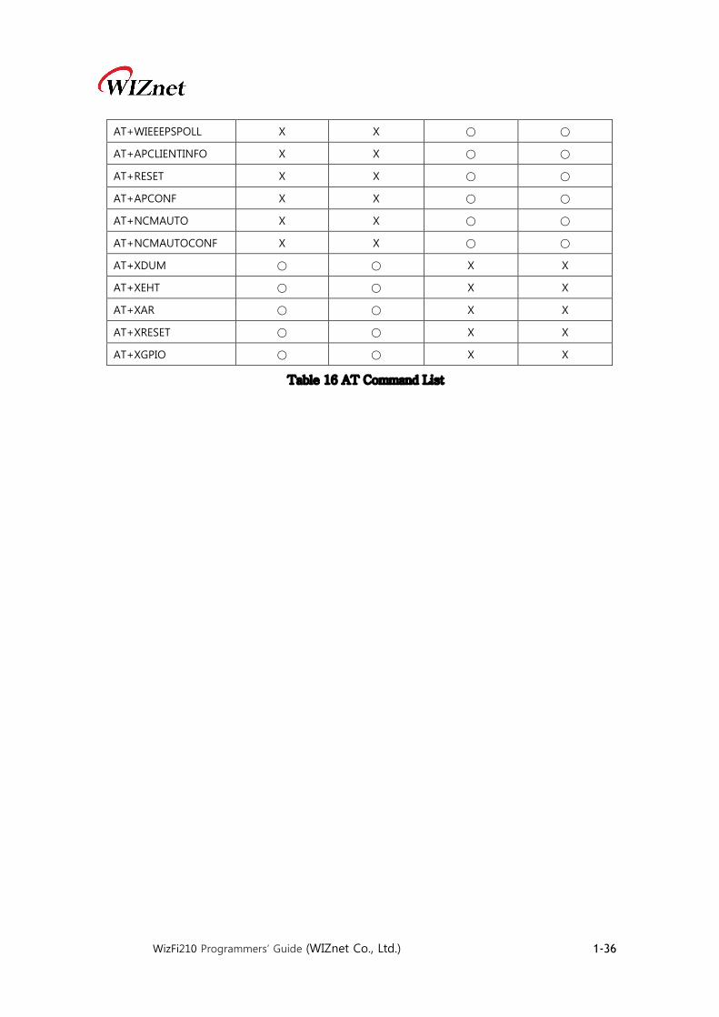
AT+WIEEEPSPOLL X X ○ ○
AT+APCLIENTINFO X X ○ ○
AT+RESET X X ○ ○
AT+APCONF X X ○ ○
AT+NCMAUTO X X ○ ○
AT+NCMAUTOCONF X X ○ ○
AT+XDUM ○ ○ X X
AT+XEHT ○ ○ X X
AT+XAR ○ ○ X X
AT+XRESET ○ ○ X X
AT+XGPIO ○ ○ X X
Table 16 AT Command List

WizFi210 Programmers’ Guide (WIZnet Co., Ltd.) 1-37
3. Communication Interface 3.1. UART
WizFi210 provides UART interface, which can communicate with a host processor and be used
for updating WizFi210’s firmware. When using WizFi210 via UART, we don’t need some special
operation for that. All of things users have to do is to follow Chapter 4 and later.
3.2. SPI WizFi210 provides alternative communication interface, SPI. When using SPI, WizFi210
requests some additional operation like byte stuffing. So, programmers using SPI interface have
to do handle it in their code. This 3.2 SPI section explains how for WizFi210 to operate in SPI
mode and how for users to handle in their code.
3.2.1. Pin connections for SPI As shown below picture, Pin connection for SPI is the same as any normal SPI device’s except
for connecting WizFi210’s pin number 23(GPIO19) to a GPIO pin of host processor. This pin’s
direction is from WizFi210 to host processor.
Figure 1 Pin connection for SPI between Host and WizFi210

WizFi210 Programmers’ Guide (WIZnet Co., Ltd.) 1-38
Table 17 Pin description of SPI interface
3.2.2. SPI interface details In case of SPI interface, additional task is required to handle SPI data transfer and SPI Interface
of WizFi210 follows as below.
Ø Only Motorola mode is supported
Ø Only 8 bit SPI data word size is supported
Ø By default SPI Mode#0 is selected (CPOL =0 and CPH=0)
Motorola SPI Format with CPL=0, CPH=0 is like Figure 2 below
Figure 2 Timing diagram of SPI interface
Note: In case of continuous back-to-back transmissions, the Chip Select (CS) signal must be
pulsed HIGH between each byte (8 bit) transfer.
Host App (SPI Master) WizFi210 (SPI Slave) Remarks
MSPI_MISO SSPI_MISO (27) SPI Master In/Slave Out
MSPI_CLK SSPI_CLK (28) SPI Clock
MSPI_CS SSPI_CS (29) SPI Chip Select
MSPI_MOSI SSPI_MOSI (30) SPI Master Out/Slave In
Allocate your GPIO GPIO#19 (23) Host wake-up signal
GND GND Common ground
WizFi210 Programmers’ Guide (WIZnet Co., Ltd.) 1-39
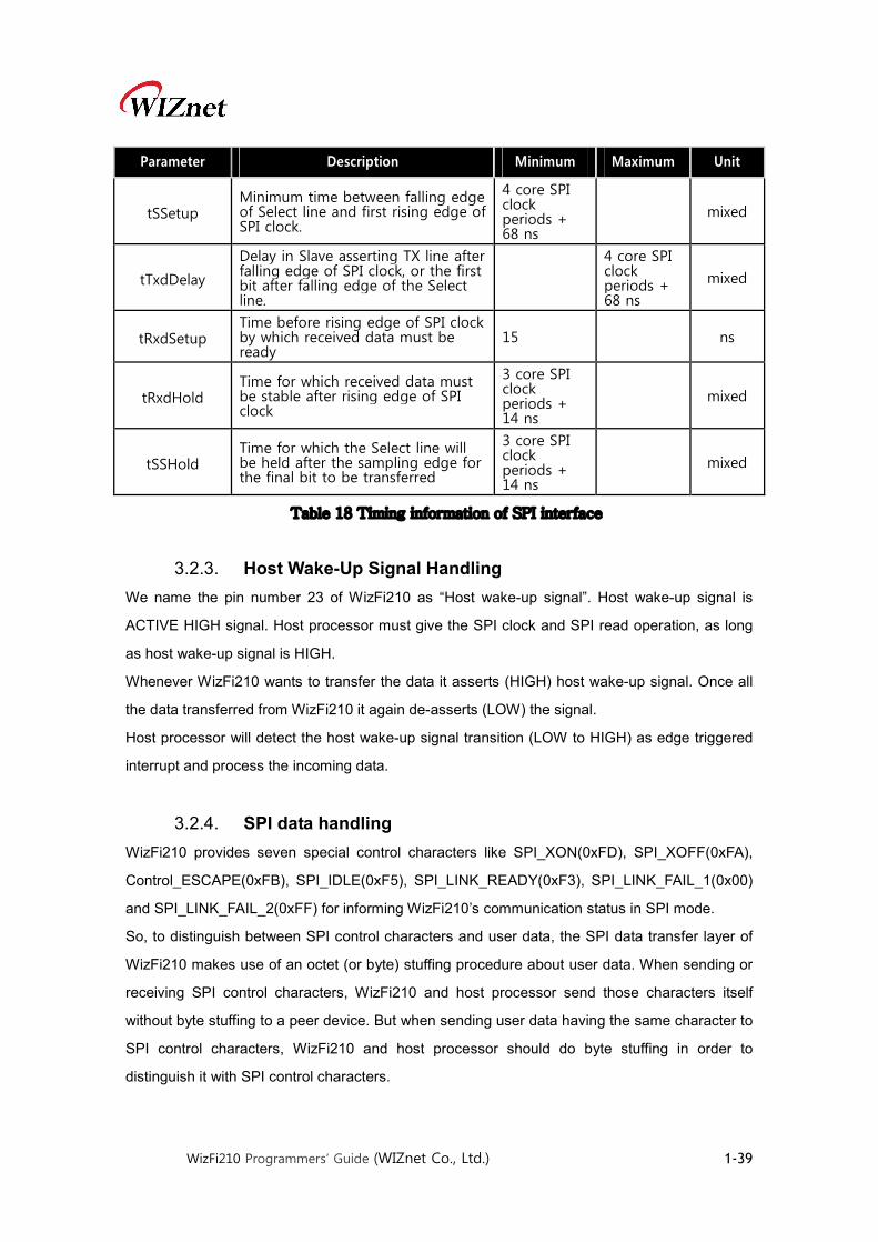
Parameter Description Minimum Maximum Unit
tSSetup Minimum time between falling edge of Select line and first rising edge of SPI clock.
4 core SPI clock periods + 68 ns
mixed
tTxdDelay
Delay in Slave asserting TX line after falling edge of SPI clock, or the first bit after falling edge of the Select line.
4 core SPI clock periods + 68 ns
mixed
tRxdSetup Time before rising edge of SPI clock by which received data must be ready
15 ns
tRxdHold Time for which received data must be stable after rising edge of SPI clock
3 core SPI clock periods + 14 ns
mixed
tSSHold Time for which the Select line will be held after the sampling edge for the final bit to be transferred
3 core SPI clock periods + 14 ns
mixed
Table 18 Timing information of SPI interface
3.2.3. Host Wake-Up Signal Handling We name the pin number 23 of WizFi210 as “Host wake-up signal”. Host wake-up signal is
ACTIVE HIGH signal. Host processor must give the SPI clock and SPI read operation, as long
as host wake-up signal is HIGH.
Whenever WizFi210 wants to transfer the data it asserts (HIGH) host wake-up signal. Once all
the data transferred from WizFi210 it again de-asserts (LOW) the signal.
Host processor will detect the host wake-up signal transition (LOW to HIGH) as edge triggered
interrupt and process the incoming data.
3.2.4. SPI data handling WizFi210 provides seven special control characters like SPI_XON(0xFD), SPI_XOFF(0xFA),
Control_ESCAPE(0xFB), SPI_IDLE(0xF5), SPI_LINK_READY(0xF3), SPI_LINK_FAIL_1(0x00)
and SPI_LINK_FAIL_2(0xFF) for informing WizFi210’s communication status in SPI mode.
So, to distinguish between SPI control characters and user data, the SPI data transfer layer of
WizFi210 makes use of an octet (or byte) stuffing procedure about user data. When sending or
receiving SPI control characters, WizFi210 and host processor send those characters itself
without byte stuffing to a peer device. But when sending user data having the same character to
SPI control characters, WizFi210 and host processor should do byte stuffing in order to
distinguish it with SPI control characters.

WizFi210 Programmers’ Guide (WIZnet Co., Ltd.) 1-40
The scheme of byte stuffing is to add a prefix byte(the Control Escape octet) and change a real
data byte. The Control Escape octet is defined as binary 11111011 (hexadecimal 0xFB), most
significant bit first.
Each special control character is replaced by a two octet sequence consisting of the Control
Escape octet followed by the original octet exclusive-or (XOR) with hexadecimal 0x20.
Receiving implementations must correctly process all Control Escape sequences.
Escaped data is transmitted on the link as follows:
Pattern Encoded as Description
0xFD 0xFB 0xDD SPI_XON
0xFA 0xFB 0xDA SPI_XOFF
0xFB 0xFB 0xDB Control ESCAPE
0xF5 0xFB 0xD5 SPI _IDLE
0xF3 0xFB 0xD3 SPI_LINK_READY
0x00 0xFB 0x20 SPI_LINK_FAIL_1(ALL ZERO)
0xFF 0xFB 0xDF SPI_LINK_FAIL_2(ALL ONE)
Table 19 Byte stuffing for special data of SPI
One dedicated GPIO signal known as host wake-up is available for data ready indication from
Slave WizFi210 to Master Host processor. Master host processor must provide clock as long as
host wake-up signal is active. Host processor can make use of GPIO interrupt (edge triggered
low-to-high transition) to receive the data from WizFi210.
Since SPI data transfer works in full duplex mode, special fill character (SPI _IDLE) will be
transmitted during idle period (if there is no more data to transmit). These idle fill pattern shall be
dropped at receiving end.
3.2.5. SPI Interface Parameters The command to set the SPI clock phase and clock polarity parameter is as follows:
AT+SPICONF=<clockpolarity>, <clockphase>
If clock polarity is 0, then inactive state of serial clock is low.
If clock polarity is 1, then inactive state of serial clock is high.
If clock phase is 0, then data is captured on the first toggling edge of the serial clock (clock
phase zero), after the falling edge of slave select signal.
If clock phase is 1, then data is captured on the second edge of the serial clock (clock phase

WizFi210 Programmers’ Guide (WIZnet Co., Ltd.) 1-41
180), after the falling edge of slave select signal. Default is clock polarity 0 and clock phase 0.
The new SPI parameters take effect after node reset/restart. However, they are stored in RAM
and will be lost when power is lost unless they are saved to a profile using AT&W. The profile
used in that command must also be set as the power-on profile using AT&Y.
This command returns the standard command response to the serial interface with the new SPI
configuration

WizFi210 Programmers’ Guide (WIZnet Co., Ltd.) 1-42
4. Command mode & Data mode 4.1. AT command mode
AT command mode is default communication mode between WizFi210 and user’s system.
WizFi210 treats all received data from user as AT command. If all received data follows correct
command format, WizFi210 returns a reply to user’s system.
Transition from AT command mode to Data mode is done by Auto Connection command.
After executing auto connection commands like ATA, ATA2 and ATO, and TCP connection with
the peer system is established, or UDP socket is open, then WizFi210 becomes Data mode.
Transition from Data mode to AT command mode can be done by two method. One is using
SW escape sequence(it is +++) or HW Trigger and the other is to close the established Auto
Connection session.
Using SW escape sequence is not to close the established Auto Connection session, It just only
to transit its mode to AT command mode in order to execute some AT command.
4.2. Data mode In Data mode, except the case that Notification Message is enabled using AT+XDUM=0, user
has to handle all received data as just data, and must write data that transfers to the peer
system, on serial interface.
4.3. Data communication in AT command mode Transition between AT command mode and Data mode can make some confusion and
problem because of data carried with SW trigger characters, +++. In addition, there is a
restriction – only one socket(TCP or UDP) can be used in Data mode.
If user wants to use multi sockets concurrently or handle data robustly, user has to use the
method of “Data communication in AT command mode”
4.3.1. Data Handling In AT Command mode, data transfers are managed using various escape sequences. Each
escape sequence starts with the ASCII character <ESC> (0x1B). The encoding of data and
related commands are described below. This encoding is used for both transmitted and received
data.

WizFi210 Programmers’ Guide (WIZnet Co., Ltd.) 1-43
The network destination, or destination source, for a given data packet is established by means
of a Connection Identifier, and represented as a single hexadecimal number. Data is transferred
on a per CID basis. Data is normally buffered until the end-of-data escape sequence is received.
However, if the amount of data exceeds the size of the data buffer, the data received, thus far, is
sent immediately. The data buffer size depends on the implementation, but is usually one MTU.
4.3.2.Escape Sequences
4.3.2.1. Sending data using Escape Sequence Escape Sequence Description
<Esc>S<CID><data>10<Esc>E This escape sequence selects the specified Connection ID as
the current connection. Use this sequence to send data to a
TCP server, TCP client or UDP socket in WizFi210/220.
Example:
To send user data (e.g. Hello) on CID 1, the format will be:
<Esc>S1Hello<Esc>E
<Esc>Z<CID><data length><data> To improve data transfer speed, user can use this bulk data
transfer. This sequence is used to send data on TCP client,
TCP server or UDP socket in WizFi210/220.
<data length> is always 4 bytes, and last <ESC> and ‘E’
character is omitted because user will receive data up to
specified byte count at <data length>
Example:
To send user data (e.g. Hello) on CID 1, the format will be:
<Esc>Z10005Hello
<Esc>U<CID><IP
Address>:<port>:<data><Esc>E
When this command is used, the remote address and
remote port is transmitted.
WizFi210 expects to receive the following data sequence
from Host:
<Esc>U<CID><IP Address>:<port>:<data><Esc>E
10 If you have some <ESC>(0x1B in Hex) in your data to send, you have to add to it with one more
<ESC>. So We recommend you use Bulk data transfer mode.

WizFi210 Programmers’ Guide (WIZnet Co., Ltd.) 1-44
Example:
When WizFi210 sends data (e.g. Hello) on CID 0 with
destination IP(192.168.1.1) and destination port number(52),
the format will be:
<Esc>U0192.168.1.1:52:Hello<Esc>E
Table 20 Escape Sequence for sending data in command mode

WizFi210 Programmers’ Guide (WIZnet Co., Ltd.) 1-45
4.3.2.2. Receiving data using Escape Sequence Escape Sequence Description
<Esc>S<CID><data>11<Esc>E WizFi210/220 send data in this escape sequence to user
whenever Bulk data option is disable and a TCP socket is
involved.
Example:
When you receive data thru CID 1 TCP socket from peer
system, user will receive from WizFi210/220 as below.
<Esc>S1Hello<Esc>E
<Esc>Z<CID><data length><data> To improve data transfer speed, user can use this bulk data
transfer. This sequence is used to receive data on TCP client
or TCP server
<data length> is always 4 bytes, and last <ESC> and ‘E’
character is omitted because user will receive data up to
specified byte count in <data length>
Example:
When you receive data thru CID 1 TCP socket from peer
system, user will receive from WizFi210/220 as below.
<Esc>Z10005Hello
<Esc>U<CID><IP
Address>:<port>:<data><Esc>E
When this command is used, the remote address and
remote port is transmitted.
When WizFi210 received data thru an UDP socket, it send it
to host with below format.
<Esc>U<CID><IP Address>:<port>:<data><Esc>E
Example:
When WizFi210 receive data (e.g. Hello) thru CID 0,
WizFi210/220 transfer it to host as below
<Esc>U0192.168.1.1:52:Hello<Esc>E
<Esc>y<CID><IP Address>
<port>\t<data length><data>
When this command is used, the remote address and
remote port is transmitted.
11 As there may be some <ESC> in data to receive, you have to preprocess <ESC><ESC>. So We
recommend you use Bulk data transfer mode.

WizFi210 Programmers’ Guide (WIZnet Co., Ltd.) 1-46
When WizFi210 received data thru an UDP socket under
BULK mode, it send it to host with below format.
<Esc>y<CID><IP Address> <port>\t<data>
Example:
When WizFi210 receive data (e.g. Hello) thru CID 0,
WizFi210/220 transfer it to host as below
<Esc>y0192.168.1.1 52\t0005Hello
<Esc>O “OK”: This sequence is sent to the serial host by the
WizFi210/220 upon successful completion of the commands.
<Esc>F “FAILURE”: This sequence is sent to the host by the
WizFi210/220 Adapter if an command failed.
Table 21 Escape Sequence for receiving data in command mode
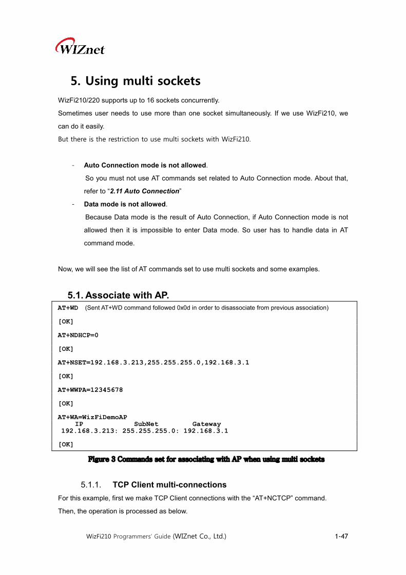
WizFi210 Programmers’ Guide (WIZnet Co., Ltd.) 1-47
5. Using multi sockets WizFi210/220 supports up to 16 sockets concurrently.
Sometimes user needs to use more than one socket simultaneously. If we use WizFi210, we
can do it easily.
But there is the restriction to use multi sockets with WizFi210.
- Auto Connection mode is not allowed.
So you must not use AT commands set related to Auto Connection mode. About that,
refer to “2.11 Auto Connection”
- Data mode is not allowed.
Because Data mode is the result of Auto Connection, if Auto Connection mode is not
allowed then it is impossible to enter Data mode. So user has to handle data in AT
command mode.
Now, we will see the list of AT commands set to use multi sockets and some examples.
5.1. Associate with AP.
Figure 3 Commands set for associating with AP when using multi sockets
5.1.1. TCP Client multi-connections For this example, first we make TCP Client connections with the “AT+NCTCP” command.
Then, the operation is processed as below.
AT+WD (Sent AT+WD command followed 0x0d in order to disassociate from previous association) [OK] AT+NDHCP=0 [OK] AT+NSET=192.168.3.213,255.255.255.0,192.168.3.1 [OK] AT+WWPA=12345678 [OK] AT+WA=WizFiDemoAP IP SubNet Gateway 192.168.3.213: 255.255.255.0: 192.168.3.1 [OK]
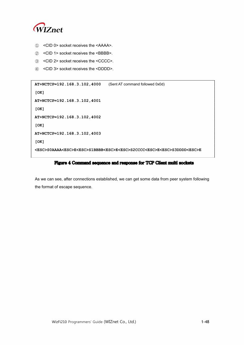
WizFi210 Programmers’ Guide (WIZnet Co., Ltd.) 1-48
① <CID 0> socket receives the <AAAA>.
② <CID 1> socket receives the <BBBB>.
③ <CID 2> socket receives the <CCCC>.
④ <CID 3> socket receives the <DDDD>.
Figure 4 Command sequence and response for TCP Client multi sockets
As we can see, after connections established, we can get some data from peer system following
the format of escape sequence.
AT+NCTCP=192.168.3.102,4000 (Sent AT command followed 0x0d) [OK] AT+NCTCP=192.168.3.102,4001 [OK] AT+NCTCP=192.168.3.102,4002 [OK] AT+NCTCP=192.168.3.102,4003 [OK] <ESC>S0AAAA<ESC>E<ESC>S1BBBB<ESC>E<ESC>S2CCCC<ESC>E<ESC>S3DDDD<ESC>E

WizFi210 Programmers’ Guide (WIZnet Co., Ltd.) 1-49
5.1.2. TCP Server multi-connections For this example, first we make TCP Server connections with the [AT+NSTCP] command.
Then, the operation is processed as below.
① <CID 6> socket receives the <SSSSS>.
② <CID 7> socket receives the <TTTTT>.
Figure 5 Commands sequence for using TCP Server sockets
AT+NSTCP=5001 (Sent AT command followed 0x0d) [OK] AT+NSTCP=5002 [OK] [CONNECT 4 6 192.168.3.102 1744] [CONNECT 5 7 192.168.3.102 1751] <ESC>S6SSSSS<ESC>E<ESC>S7TTTTT<ESC>E
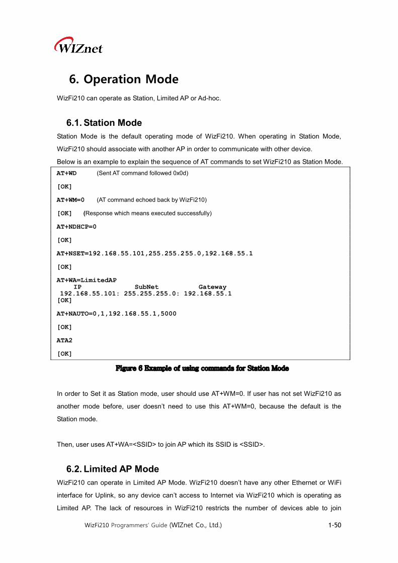
WizFi210 Programmers’ Guide (WIZnet Co., Ltd.) 1-50
6. Operation Mode WizFi210 can operate as Station, Limited AP or Ad-hoc.
6.1. Station Mode Station Mode is the default operating mode of WizFi210. When operating in Station Mode,
WizFi210 should associate with another AP in order to communicate with other device.
Below is an example to explain the sequence of AT commands to set WizFi210 as Station Mode.
Figure 6 Example of using commands for Station Mode
In order to Set it as Station mode, user should use AT+WM=0. If user has not set WizFi210 as
another mode before, user doesn’t need to use this AT+WM=0, because the default is the
Station mode.
Then, user uses AT+WA=<SSID> to join AP which its SSID is <SSID>.
6.2. Limited AP Mode WizFi210 can operate in Limited AP Mode. WizFi210 doesn’t have any other Ethernet or WiFi
interface for Uplink, so any device can’t access to Internet via WizFi210 which is operating as
Limited AP. The lack of resources in WizFi210 restricts the number of devices able to join
AT+WD (Sent AT command followed 0x0d) [OK] AT+WM=0 (AT command echoed back by WizFi210) [OK] (Response which means executed successfully) AT+NDHCP=0 [OK] AT+NSET=192.168.55.101,255.255.255.0,192.168.55.1 [OK] AT+WA=LimitedAP IP SubNet Gateway 192.168.55.101: 255.255.255.0: 192.168.55.1 [OK] AT+NAUTO=0,1,192.168.55.1,5000 [OK] ATA2 [OK]

WizFi210 Programmers’ Guide (WIZnet Co., Ltd.) 1-51
WizFi210.
However, Limited AP Mode of WizFi210 is useful when the mobile device, that having WiFi
capability, directly connects to WizFi210 and communicate with it without any other Access
Point.
Below is an example to explain the sequence of AT commands to set WizFi210/220 as Limited
AP Mode.
Figure 7 Example of using commands for Limited AP Mode
In order to set it as Limited AP mode, we should use AT+WM=2.
AT+WA=<SSID>… has WizFi210/220 configure itself with parameter values, not join AP
having <SSID>
And if we need to allocate IP address to devices joined WizFi210 dynamically, we should use
AT+DHCPSRVR=1 to enable DHCP Server inside WizFi210.
AT+WD (Sent AT command followed 0x0d) [OK] AT+WM=2 (AT command echoed back by WizFi210) [OK] (Response which means executed successfully) AT+WAUTH=0 [OK] AT+NDHCP=0 [OK] AT+NSET=192.168.55.1,255.255.255.0,192.168.55.1 [OK] AT+DHCPSRVR=1 [OK] AT+WA=LimitedAP,,8, IP SubNet Gateway 192.168.55.1: 255.255.255.0: 192.168.55.1 [OK] AT+NAUTO=1,1,,5000 [OK] ATA2 [OK]
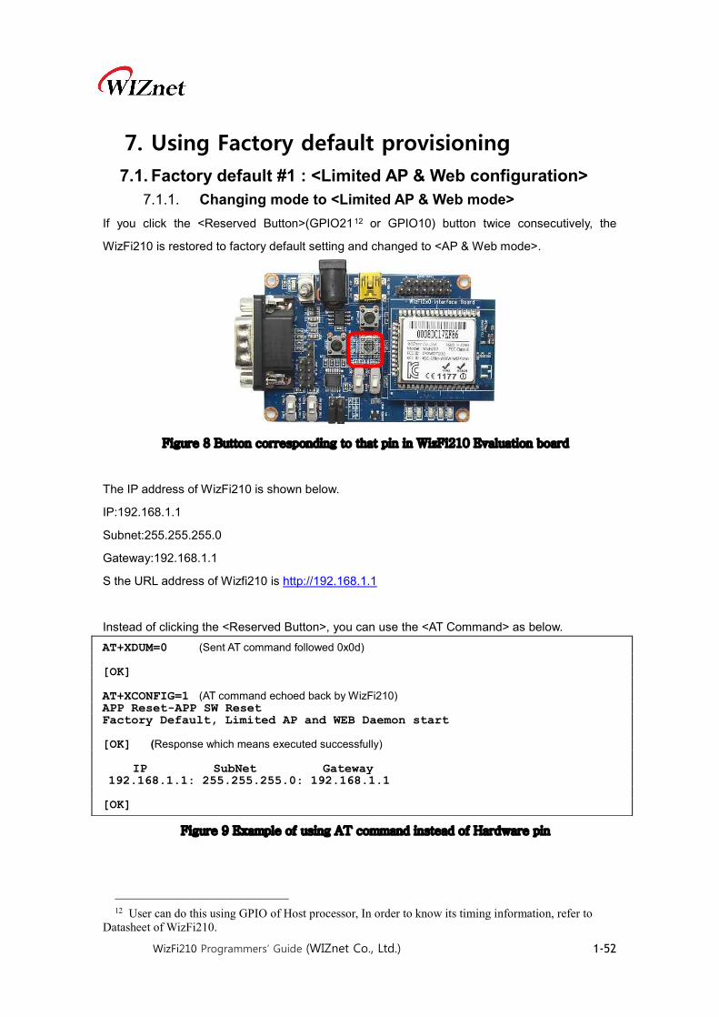
WizFi210 Programmers’ Guide (WIZnet Co., Ltd.) 1-52
7. Using Factory default provisioning 7.1. Factory default #1 : <Limited AP & Web configuration>
7.1.1. Changing mode to <Limited AP & Web mode> If you click the <Reserved Button>(GPIO2112 or GPIO10) button twice consecutively, the
WizFi210 is restored to factory default setting and changed to <AP & Web mode>.
Figure 8 Button corresponding to that pin in WizFi210 Evaluation board
The IP address of WizFi210 is shown below.
IP:192.168.1.1
Subnet:255.255.255.0
Gateway:192.168.1.1
S the URL address of Wizfi210 is http://192.168.1.1
Instead of clicking the <Reserved Button>, you can use the <AT Command> as below.
Figure 9 Example of using AT command instead of Hardware pin
12 User can do this using GPIO of Host processor, In order to know its timing information, refer to
Datasheet of WizFi210.
AT+XDUM=0 (Sent AT command followed 0x0d) [OK] AT+XCONFIG=1 (AT command echoed back by WizFi210) APP Reset-APP SW Reset Factory Default, Limited AP and WEB Daemon start [OK] (Response which means executed successfully) IP SubNet Gateway 192.168.1.1: 255.255.255.0: 192.168.1.1 [OK]

WizFi210 Programmers’ Guide (WIZnet Co., Ltd.) 1-53
7.1.2. Connect to the WizFi210 (Limited AP) If you scan the AP on your PC, you can see <WizFiAPXXXXXX> in the AP list.
The MAC address of WizFi210 is attached to the position of <XXXXXX>.
Now, do connect your PC to the WizFi210.
Figure 10 Example of APs list
In Limited AP mode, WizFi210 has the DHCP server, so you don’t need use the <static IP
address>.
You can verify the IP address of your PC on DOS command console writing “ipconfig”.
Figure 11 Example of executing ipconfig on Dos command line

WizFi210 Programmers’ Guide (WIZnet Co., Ltd.) 1-54
7.1.3. Connect to the Web server This web server is implemented in WizFi210. So, you don’t need any effort to handle user’s
HTTP request at your host processor. WizFi210 provides a web page for setting WizFi210.
Users can connect to the web server, the default ID and Password are admin and admin
respectively.
Figure 12 Example of connecting to Web Server on WizFi210
Then you can see the default web page on WizFi210 and you can configure the WizFi210 at the
web browser via WiFi, if you need.
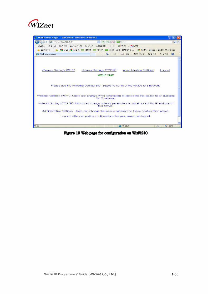
WizFi210 Programmers’ Guide (WIZnet Co., Ltd.) 1-55
Figure 13 Web page for configuration on WizFi210
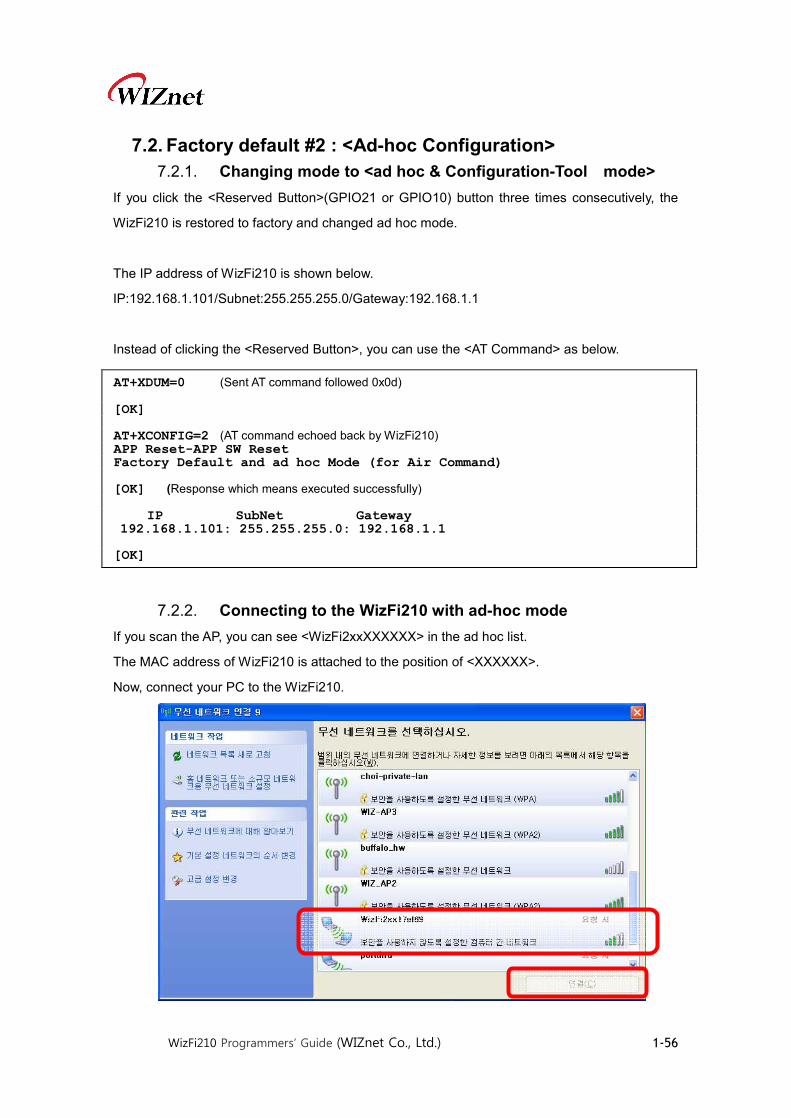
WizFi210 Programmers’ Guide (WIZnet Co., Ltd.) 1-56
7.2. Factory default #2 : <Ad-hoc Configuration> 7.2.1. Changing mode to <ad hoc & Configuration-Tool mode>
If you click the <Reserved Button>(GPIO21 or GPIO10) button three times consecutively, the
WizFi210 is restored to factory and changed ad hoc mode.
The IP address of WizFi210 is shown below.
IP:192.168.1.101/Subnet:255.255.255.0/Gateway:192.168.1.1
Instead of clicking the <Reserved Button>, you can use the <AT Command> as below.
7.2.2. Connecting to the WizFi210 with ad-hoc mode If you scan the AP, you can see <WizFi2xxXXXXXX> in the ad hoc list.
The MAC address of WizFi210 is attached to the position of <XXXXXX>.
Now, connect your PC to the WizFi210.
AT+XDUM=0 (Sent AT command followed 0x0d) [OK] AT+XCONFIG=2 (AT command echoed back by WizFi210) APP Reset-APP SW Reset Factory Default and ad hoc Mode (for Air Command) [OK] (Response which means executed successfully) IP SubNet Gateway 192.168.1.101: 255.255.255.0: 192.168.1.1 [OK]
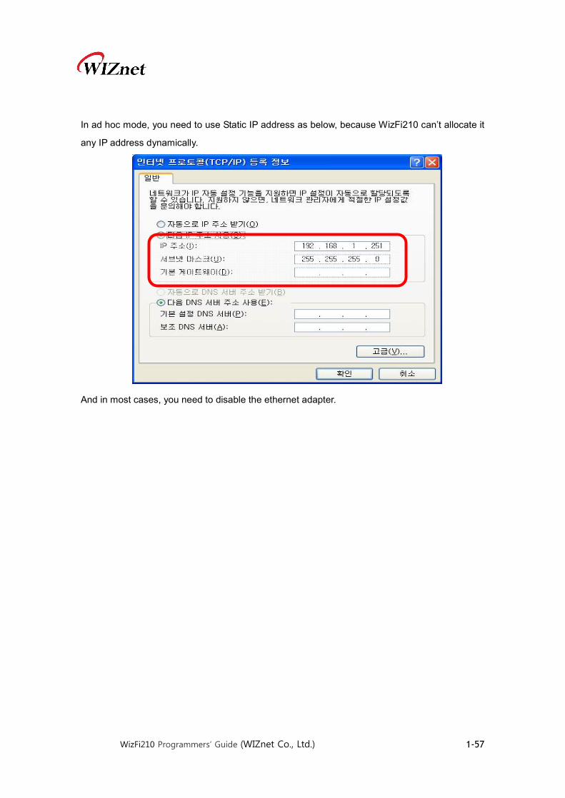
WizFi210 Programmers’ Guide (WIZnet Co., Ltd.) 1-57
In ad hoc mode, you need to use Static IP address as below, because WizFi210 can’t allocate it
any IP address dynamically.
And in most cases, you need to disable the ethernet adapter.

WizFi210 Programmers’ Guide (WIZnet Co., Ltd.) 1-58
8. Transmitting and Receiving HTML Data There are two method to transmit and receive HTML data. One is using WizFi210 with built-in
capabilities, and the other is to have users’ host processor parse received HTML data and make
HTML data to send to the peer system under the condition which WizFi210 just operates as
communication device, we call this mode “Emulating”.
You can see two sections to describe how to implement and use these two methods.
8.1. Operating as HTTP Client using WizFi210 functions As described above, WizFi210 has capabilities to support HTTP Client. If you want to make
WizFi210 operate as HTTP Server, you can just implement it with emulation of HTTP Server.
When using these capabilities, users don’t need to make any HTTP request data to
communicate with peer’s Web server, all users have to do is give some AT commands like
“AT+HTTPCOPEN”, “AT+HTTPCCLOSE” and so on.
And there are two modes to connect to any Web Server. One is the normal HTTP Client function
and the other is the secure HTTP Client function as named HTTPS Client.
WizFi210 supports both of options with the same command but the difference is whether a
corresponding option flag is set or not and in order to use HTTPS Client, users should do
something like registering Certificate, in advance.
8.1.1. Communicating with Web Server using normal HTTP Now, we explain how to communicate with a normal Web Server, www.wiznet.co.kr, with a
simple example.
Getting HTML Data In order to connect to a HTTP server and get some HTML Data, users have to do as follow.
① Do some configuration you need using “AT+HTTPCONF” command.

WizFi210 Programmers’ Guide (WIZnet Co., Ltd.) 1-59
② Then, connect to that HTTP server you want using “AT+HTTPOPEN” command.
③ Next, send a query data to get HTML data to that HTTP server using “AT+HTTPSEND”
command.
8.1.2. Communicating with Secure Web Server using HTTPS Now, we explain how to communicate with a Secured Web Server, m.twitter.com, with a simple
example.
Normally, When registering our own tweet or getting mentions from others on twitter.com, we
need a secure session known as HTTPS. In order to do this, we need something to do as below.
① Certificate from the Secured Web Server, like twitter.com
② A secure TCP/IP Session, this means TLS(SSL) function is supported.
As an example, we will describe how to connect to twitter.com and register user’s own tweet on
it, step by step.
Getting Twitter Certificate You have to get twitter certificate using a Web browser in your PC, as WizFi210 doesn’t operate
as a real Web browser. You can do this in the same way that you connect to other secure Web
13 80 is the default port number of normal HTTP server, not HTTPS server. 14 If this value is ‘0’, then it makes WizFi210 use the standard HTTP protocol, not HTTPS protocol 15 The CID number of a socket connected to mobile.twitter.com
AT+HTTPCONF=20,User-Agent: Mozilla/5.0 [OK] AT+HTTPCONF=3,close [OK] AT+HTTPCONF=11,www.wiznet.co.kr [OK] (Response which means executed successfully)
AT+HTTPOPEN=www.wiznet.co.kr,8013,014 IP:118.129.166.160015 (Response from WizFi210) [OK] (Response from WizFi210)
AT+HTTPSEND=0,1,10,/ <ESC>H0...... (Data from WizFi210 to Host processor) [DISCONNECT 0] (Notification message from WizFi210)

WizFi210 Programmers’ Guide (WIZnet Co., Ltd.) 1-60
server.
① Using a web browser, connect to https://twitter.com
After a connection, if you click an image of lock at the beginning of URL address field,
you can see the certificate information of Twitter.com.
Figure 14 Certificate information view on Twitter.com
② Click “Connection” Tab and then click “Certificate information” link to save
Certificate into a file.
③ After a dialog box was shown, Click Next
④ Select “DER encoded binary X.509(.CER)” combo box and click the Next button.
⑤ Then, give the location and file name to it and click the Next button.
⑥ Finally, click “Finish” button.
Registering Certificate to WizFi210 inside Before using a TLS(SSL) session, users should register the Certificate of the secure Web server,
which WizFi210 will connect to, to WizFi210 inside.
The command to use for registering Certificate is “AT+TCERTADD”.

WizFi210 Programmers’ Guide (WIZnet Co., Ltd.) 1-61
Getting HTML Data In order to connect to a HTTPS server and get some HTML Data, users have to do as follow.
① First, set WizFi210 with current time information using “AT+SETTIME” command.
② Then, do some configuration you need using “AT+HTTPCONF” command.
③ Then, connect to a HTTPS server you want using “AT+HTTPOPEN” command.
④ Next, send a query data to get HTML data to a HTTPS server using
“AT+HTTPSEND” command.
8.2. Emulating HTTP Server or HTTP Client
If users want to use their system with WizFi210 as HTTP Server or customize their system’s
interaction to peer’s web server, they can emulate HTTP server or HTTP client on their host
16 The CID number of a socket connected to mobile.twitter.com
AT+TCERTADD=twitter-cert.cer,0,1664,0 <ESC>W<data in certificate> [OK] (Response which means executed successfully)
AT+SETTIME=10/04/2013,16:38:00 [OK] (Response which means executed successfully)
AT+HTTPCONF=20,User-Agent: Mozilla/5.0 [OK] AT+HTTPCONF=3,close [OK] AT+HTTPCONF=11,mobile.twitter.com [OK] (Response which means executed successfully)
AT+HTTPOPEN=mobile.twitter.com,443,1 IP:199.59.148.212016 (Response from WizFi210) [OK] (Response from WizFi210)
AT+HTTPSEND=0,1,10,/signup <ESC>H0...... (Data from WizFi210 to Host processor) [DISCONNECT 0] (Notification message from WizFi210)

WizFi210 Programmers’ Guide (WIZnet Co., Ltd.) 1-62
processor, not WizFi210 itself.
8.2.1. Emulating HTTP Server
In order to emulate HTTP Server on users’ host processor, they need a HTML Parser and HTML
Page data.
WizFi210 just operates as a communication device, and users’ host processor should process
all of things of a real HTTP Server. In this circumstance, users’ host processor have WizFi210
open and listen a socket with 80 or other port number like 8080. Then if any client connects to
the WizFi210’s listen port, WizFi210 informs host processor it with a corresponding CID and
bypasses all data from that client system to host processor.
To emulate HTTP Server, users’ application operating on host processor should parse received
data to get and/or extract proper information from those, and make a proper response and send
back to WizFi210 in order to reply to that client system.
How to make a HTML parser and HTML pages and how to operate under corresponding rule is
up to you and your systems’ requirement.
You can see an example regarding to a HTML Parser and HTML Pages in
WizFi210_Standard_Library.zip on WIZnet web site(www.wiznet.co.kr).
8.2.2. Emulating HTTP Client In order to emulate HTTP Client on users’ host processor, they need a HTML Parser and HTML
Page data.
WizFi210 just operates as a communication device, and users’ host processor should process
all of things which a real Web browser does. In this circumstance, users’ host processor have
WizFi210 connect to a Web server which users want to connect with “AT+NCTCP” command.
Then if WizFi210 connected to the specified Web server, WizFi210 informs host processor with
a corresponding CID.
To emulate HTTP Client like any web browser, users’ application operating on host processor
should make and send a HTML page containing any users’ request. Then Web server send its
response to WizFi210. WizFi210 will bypass those data with escape sequence. Then users’

WizFi210 Programmers’ Guide (WIZnet Co., Ltd.) 1-63
application can process it according to its intention, like extracting some information. After all
data is finished, Web server will close its current connection.

WizFi210 Programmers’ Guide (WIZnet Co., Ltd.) 1-64
8.3. Making and Testing the environment for HTTP Server 8.3.1. Configuring the Environment for Web Server Test
In the case of Web Server using WizFi210, You must constitute environment as bellows
1. Associate WizFi210 with AP
2. Associate PC with AP
3. View Web Page on PC
Figure 15 Network environment for testing Web server on WizFi210
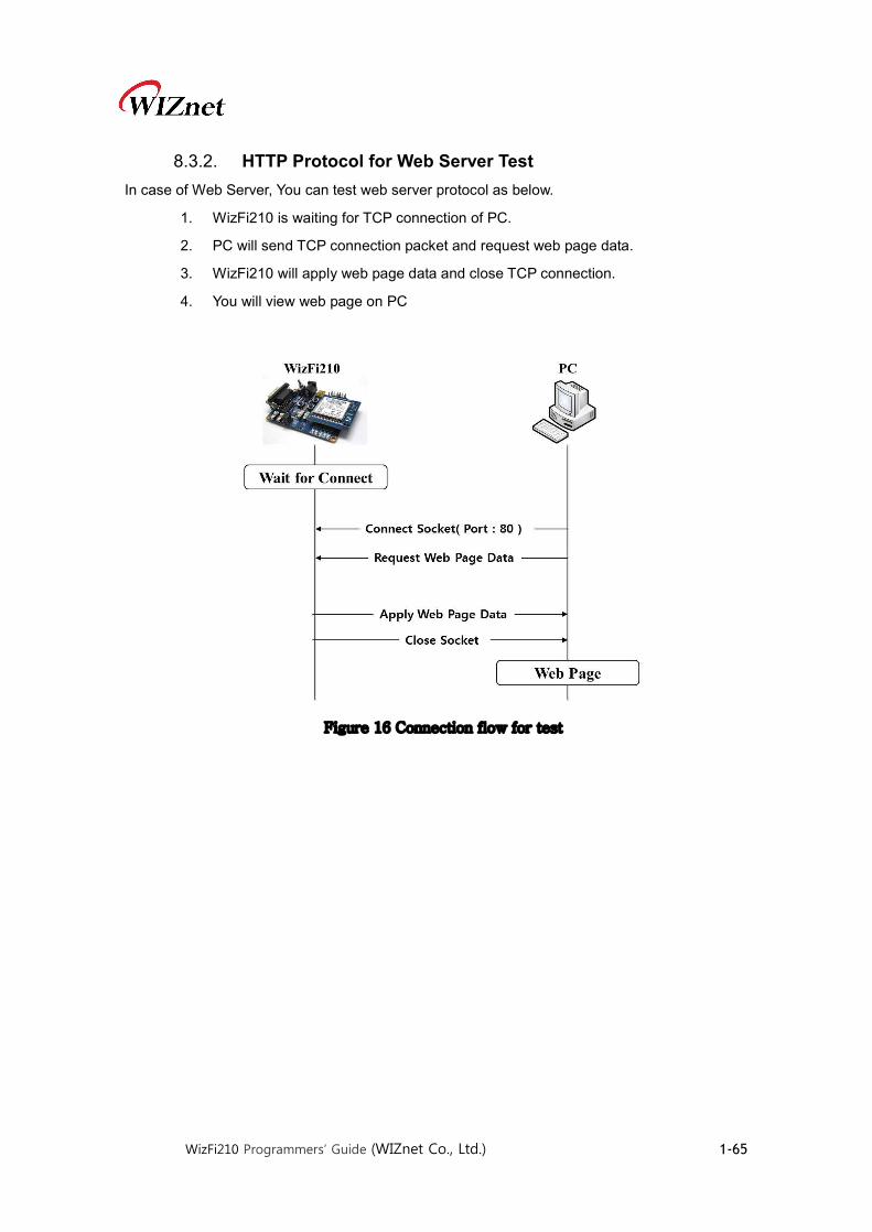
WizFi210 Programmers’ Guide (WIZnet Co., Ltd.) 1-65
8.3.2. HTTP Protocol for Web Server Test In case of Web Server, You can test web server protocol as below.
1. WizFi210 is waiting for TCP connection of PC.
2. PC will send TCP connection packet and request web page data.
3. WizFi210 will apply web page data and close TCP connection.
4. You will view web page on PC
Figure 16 Connection flow for test
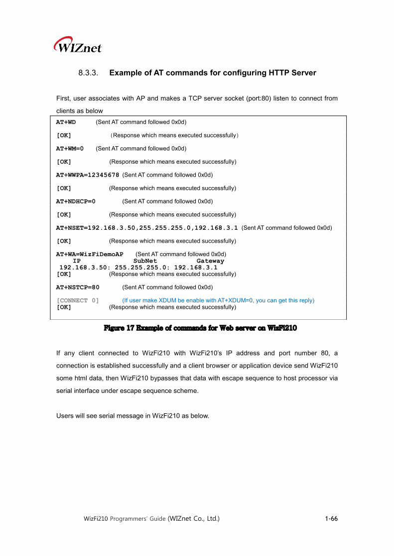
WizFi210 Programmers’ Guide (WIZnet Co., Ltd.) 1-66
8.3.3. Example of AT commands for configuring HTTP Server
First, user associates with AP and makes a TCP server socket (port:80) listen to connect from
clients as below
Figure 17 Example of commands for Web server on WizFi210
If any client connected to WizFi210 with WizFi210’s IP address and port number 80, a
connection is established successfully and a client browser or application device send WizFi210
some html data, then WizFi210 bypasses that data with escape sequence to host processor via
serial interface under escape sequence scheme.
Users will see serial message in WizFi210 as below.
AT+WD (Sent AT command followed 0x0d) [OK] (Response which means executed successfully) AT+WM=0 (Sent AT command followed 0x0d) [OK] (Response which means executed successfully) AT+WWPA=12345678 (Sent AT command followed 0x0d) [OK] (Response which means executed successfully) AT+NDHCP=0 (Sent AT command followed 0x0d) [OK] (Response which means executed successfully) AT+NSET=192.168.3.50,255.255.255.0,192.168.3.1 (Sent AT command followed 0x0d) [OK] (Response which means executed successfully) AT+WA=WizFiDemoAP (Sent AT command followed 0x0d) IP SubNet Gateway 192.168.3.50: 255.255.255.0: 192.168.3.1 [OK] (Response which means executed successfully) AT+NSTCP=80 (Sent AT command followed 0x0d) [CONNECT 0] (If user make XDUM be enable with AT+XDUM=0, you can get this reply) [OK] (Response which means executed successfully)

WizFi210 Programmers’ Guide (WIZnet Co., Ltd.) 1-67
Figure 18 Example of received data from web browser
Users can send HTML data to clients using WizFi210’s escape sequence like below.
Figure 19 Example of Escape sequence for transmitting data
Close TCP connection with PC.
Figure 20 AT command for close the TCP connection
17 Escape sequence for handling data in AT command mode. This means data will follow 18 Escape sequence for handling data in AT command mode. This follows the end of data. 19 Escape sequence for handling data in AT command mode. This means data will follow 20 Escape sequence for handling data in AT command mode. This follows the end of data.
[CONNECT 0 1 192.168.3.114 3609] (This is a notification message from WizFi210) <ESC>S117GET /HTTP/1.1\r\n Host: 192.168.3.50\r\n Connection: keep-alive\r\n User-Agent: Mozilla/5.0 (Windows NT 6.1)AppleWebKit/536.5 (KHTML, like Gecko) Chrome/19.0.1084.56 Safari/536.6\r\n Accept: text/html,application/xhtml+xml,application/xml;q=0.9,*/*;q=0.8\r\n Accept-Encoding: gzip,deflate,sdch\r\n Accept-Language: ko-KR,ko;q=0.8,en-US;q=0.6,en=q=0.4\r\n Accept-Charset: windows-949,utf-8;q=0.7,*;q=0.3<ESC>E18
<ESC>S119<HTML> <TABLE width=”600” style=”table-layout:fixed” border=1> <TR><img src=”http://wiznet.co.kr/Sub_Modules/images/kr/sub/Overview_01.gif”></TD></TR> <TR><img src=”http://wiznet.co.kr/Admin_Root/UpLoad_Files/ProductImgs/Dtl_1138_20111005131932.jpg”></TR> <TR><TD height=”50” width=”100” align=center valign=middle><img src=”http://wiznet.co.kr/Sub_Modules/images/en/sub2/comm/logo.gif”></TD> <TD><a href=”http://wiznet.co.kr”>http://wiznet.co.kr</a></TD></TR> <TR> <TD height= “50” width=”100” align=center valign=middle><imag src=”http://shop....en/images/common/Top_Logo01.gif”></TD> <TD><a href=”http://shop.wiznettechnology.com”>http://shop.wiznettechnology.com</a></TD></TR> <TABLE> </HTML><ESC>E20
AT+NCLOSE=1 (Sent AT command followed 0x0d) [OK] (Response which means executed successfully)

WizFi210 Programmers’ Guide (WIZnet Co., Ltd.) 1-68
9. Using Enterprise Security 9.1. EAP-TLS
In regard to Enterprise mode of WizFi210, Please refer to an Application note in details. This
section only introduces WizFi210 can handle the enterprise mode.
9.1.1. Connect to RADIUS Server using WizFi210
- Click Start, click Run, type cmd, and then click OK
- Convert certificate file into the binary file.
u type openssl.exe pkcs12 –in Client_Cert.pfx –out Client_Cert.pem -nodes and then
type Import Password, 12345678
u type openssl.exe x509 –outform der –in Client_Cert.pem –out Client_Cert.der
u type openssl.exe rsa –outform der –in Client_Cert.pem –out Client_Cert.key
- If type command to WizFi210 as below, you will succeed to connect RADIUS Server.

WizFi210 Programmers’ Guide (WIZnet Co., Ltd.) 1-69
Figure 21 Example of commands for using EAP-TLS

WizFi210 Programmers’ Guide (WIZnet Co., Ltd.) 1-70
10. Examples Now, we show many examples of AT commands set for handling WizFi210 according to usage
of WizFi210 and its network configuration.
If user uses WizFi210 with UART firmware, he can use these examples without any modification.
Otherwise, if they use it with SPI interface, then he has to add byte stuffing function to UART AT
commands and responses. For it, refer to “3.2 SPI” section.
10.1. Station Mode, TCP Client and Auto Connection This is the popular example that user handles WizFi210 for their application.
WizFi210 operates as a WiFi Station to associate with another AP to communicate with a peer
system, After associating with AP, it makes a TCP client socket and connect to a server socket
on the peer system.
10.1.1. Example 1 of commands sequence
Using “AT+WAUTO”, “AT+NAUTO” and “ATA”

WizFi210 Programmers’ Guide (WIZnet Co., Ltd.) 1-71
Figure 22 Example of commands for Station Mode and Auto connection
AT (Sent AT command followed 0x0d) AT (AT command echoed back by WizFi210) [OK] (Response which means executed successfully) ATE0 (Sent AT command followed 0x0d, this make echo back be disable) ATE0 (AT command echoed back by WizFi210) [OK] (Response which means executed successfully) AT+WD (AT command making disassociation from previous AP association) [OK] (Response) AT+NDHCP=1 (AT command making DHCP mode be enable) [OK] (Response) AT+WWPA=12345678 (AT command setting WiFi security) [OK] (Response) AT+WAUTO=0,WizFiDemoAP (AT command setting WiFi association information) [OK] (Response) AT+NAUTO=0,1,192.168.3.105,5000 (AT command setting TCP/UDP Socket information) [OK] (Response) ATA (AT command executing Auto Connection including AP association and Socket connection) IP SubNet Gateway (Response) 192.168.3.104: 255.255.255.0: 192.168.3.1 (Response with IP addr) [OK] (Response) <= At this point, association is done and TCP connection is established.

WizFi210 Programmers’ Guide (WIZnet Co., Ltd.) 1-72
10.1.2. Example 2 of commands sequence
Using “AT+WA”, “AT+NAUTO” and “ATA2”
Figure 23 Example of commands for Station Mode and Auto connection
10.1.3. exchanging data with a peer system After ATA or ATA2, you can send data just by writing on serial interface, and treat all from serial
interface as pure data.
10.1.4. Closing TCP connection In order to disconnect the TCP connection, you have to transit to AT command mode first using
SW escape characters (+++)or HW trigger(GPIO10 or GPIO29, depending on your setting with
AT+XEHT command).
After transition to AT command mode, you can disconnect by using AT+NCLOSE=<CID> or
AT+NCLOSEALL, also can disassociate from AP using AT+WD command.
AT (Sent AT command followed 0x0d) AT (AT command echoed back by WizFi210) [OK] (Response which means executed successfully) ATE0 (Sent AT command followed 0x0d, this make echo back be disable) ATE0 (AT command echoed back by WizFi210) [OK] (Response which means executed successfully) AT+WD (AT command making disassociation from previous AP association) [OK] (Response) AT+NDHCP=1 (AT command making DHCP mode be enable) [OK] (Response) AT+WWPA=12345678 (AT command setting WiFi security) [OK] (Response) AT+WA=WizFiDemoAP (AT command setting WiFi association information) IP SubNet Gateway (Response) 192.168.3.104: 255.255.255.0: 192.168.3.1 (Response with IP addr) [OK] (Response) <= At this point, association is done. AT+NAUTO=0,1,192.168.3.105,5000 (AT command setting TCP/UDP Socket information) [OK] (Response) ATA2 (AT command executing Auto Connection except association as association already done) [OK] (Response) <= At this point, TCP connection is established.

WizFi210 Programmers’ Guide (WIZnet Co., Ltd.) 1-73
10.2. Station Mode, UDP socket and Auto Connection This is the same exactly with 10.1 except using an UDP socket.
To make an UDP socket, you have to use AT+NAUTO=<type>,0,<Dest IP>,<Dest port>
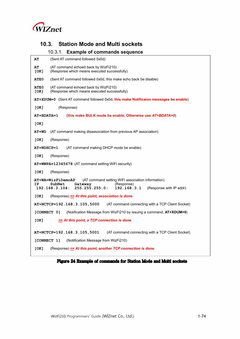
WizFi210 Programmers’ Guide (WIZnet Co., Ltd.) 1-74
10.3. Station Mode and Multi sockets 10.3.1. Example of commands sequence
Figure 24 Example of commands for Station Mode and Multi sockets
AT (Sent AT command followed 0x0d) AT (AT command echoed back by WizFi210) [OK] (Response which means executed successfully) ATE0 (Sent AT command followed 0x0d, this make echo back be disable) ATE0 (AT command echoed back by WizFi210) [OK] (Response which means executed successfully) AT+XDUM=0 (Sent AT command followed 0x0d, this make Notificaion messages be enable) [OK] (Response) AT+BDATA=1 (this make BULK mode be enable, Otherwise use AT+BDATA=0) [OK] AT+WD (AT command making disassociation from previous AP association) [OK] (Response) AT+NDHCP=1 (AT command making DHCP mode be enable) [OK] (Response) AT+WWPA=12345678 (AT command setting WiFi security) [OK] (Response) AT+WA=WizFiDemoAP (AT command setting WiFi association information) IP SubNet Gateway (Response) 192.168.3.104: 255.255.255.0: 192.168.3.1 (Response with IP addr) [OK] (Response) <= At this point, association is done. AT+NCTCP=192.168.3.105,5000 (AT command connecting with a TCP Client Socket) [CONNECT 0] (Notification Message from WizFi210 by issuing a command, AT+XDUM=0) [OK] <= At this point, a TCP connection is done. AT+NCTCP=192.168.3.105,5001 (AT command connecting with a TCP Client Socket) [CONNECT 1] (Notification Message from WizFi210) [OK] (Response) <= At this point, another TCP connection is done.
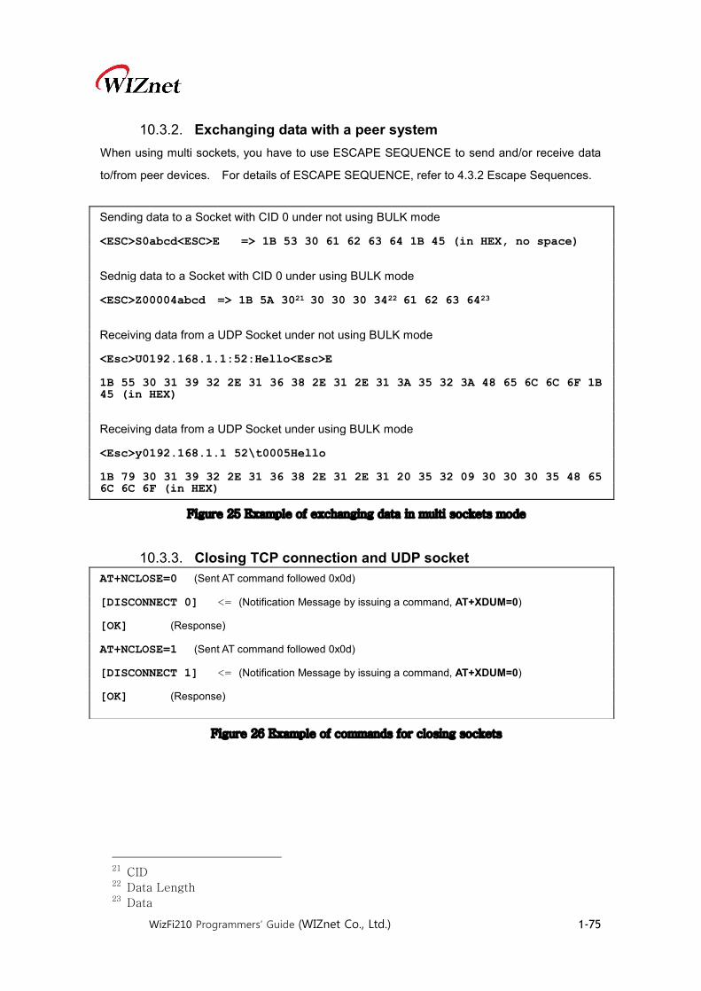
WizFi210 Programmers’ Guide (WIZnet Co., Ltd.) 1-75
10.3.2. Exchanging data with a peer system When using multi sockets, you have to use ESCAPE SEQUENCE to send and/or receive data
to/from peer devices. For details of ESCAPE SEQUENCE, refer to 4.3.2 Escape Sequences.
Figure 25 Example of exchanging data in multi sockets mode
10.3.3. Closing TCP connection and UDP socket
Figure 26 Example of commands for closing sockets
21 CID 22 Data Length 23 Data
Sending data to a Socket with CID 0 under not using BULK mode <ESC>S0abcd<ESC>E => 1B 53 30 61 62 63 64 1B 45 (in HEX, no space) Sednig data to a Socket with CID 0 under using BULK mode <ESC>Z00004abcd => 1B 5A 3021 30 30 30 3422 61 62 63 6423 Receiving data from a UDP Socket under not using BULK mode <Esc>U0192.168.1.1:52:Hello<Esc>E 1B 55 30 31 39 32 2E 31 36 38 2E 31 2E 31 3A 35 32 3A 48 65 6C 6C 6F 1B 45 (in HEX) Receiving data from a UDP Socket under using BULK mode <Esc>y0192.168.1.1 52\t0005Hello 1B 79 30 31 39 32 2E 31 36 38 2E 31 2E 31 20 35 32 09 30 30 30 35 48 65 6C 6C 6F (in HEX)
AT+NCLOSE=0 (Sent AT command followed 0x0d) [DISCONNECT 0] <= (Notification Message by issuing a command, AT+XDUM=0) [OK] (Response) AT+NCLOSE=1 (Sent AT command followed 0x0d) [DISCONNECT 1] <= (Notification Message by issuing a command, AT+XDUM=0) [OK] (Response)

WizFi210 Programmers’ Guide (WIZnet Co., Ltd.) 1-76
10.4. Limited AP, TCP Server and Auto Connection 10.4.1. Example of commands sequence
Figure 27 Example of commands for Limited AP Mode and Auto Connection
AT (Sent AT command followed 0x0d) AT (AT command echoed back by WizFi210) [OK] (Response which means executed successfully) ATE0 (Sent AT command followed 0x0d, this make echo back be disable) ATE0 (AT command echoed back by WizFi210) [OK] (Response which means executed successfully) AT+XDUM=0 (Sent AT command followed 0x0d, this make Notificaion messages be enable) [OK] (Response) AT+BDATA=1 (this make BULK mode be enable, Otherwise use AT+BDATA=0) [OK] AT+WD (AT command making disassociation from previous AP association) [OK] (Response) AT+WM=2 (AT command making WizFi210 Operating Mode as LimitedAP mode) [OK] (Response) AT+WAUTH=1 (AT command making WizFi210 Operating Mode as LimitedAP mode) [OK] AT+WWEP1=1234567890 (AT command setting WiFi security. LimitedAP mode supports only WEP) [OK] (Response) AT+NSET=192.168.55.1,255.255.255.0,192.168.55.1 (AT command setting the network information of WizFi210 itself , You have to use this always when you use LimitedAP mode) [OK] (Response) AT+WA=LimitedAP (AT command setting WiFi association information) IP SubNet Gateway (Response) 192.168.55.1: 255.255.255.0: 192.168.55.1 (Response with IP addr) [OK] (Response) <= At this point, AP is started. AT+NAUTO=0,1,192.168.3.105,5000 (AT command setting TCP/UDP Socket information) [OK] (Response) ATA2 (AT command executing Auto Connection except association as association already done) [OK] (Response) <= At this point, TCP connection is established.

WizFi210 Programmers’ Guide (WIZnet Co., Ltd.) 1-77
10.4.2. Exchanging data with a peer system Exchanging data with its peer system is the same to 10.1.3. Refer to it.
10.4.3. Closing TCP connection and UDP socket Closing TCP connections and UDP sockets is the same to 10.1.4. Refer to it.
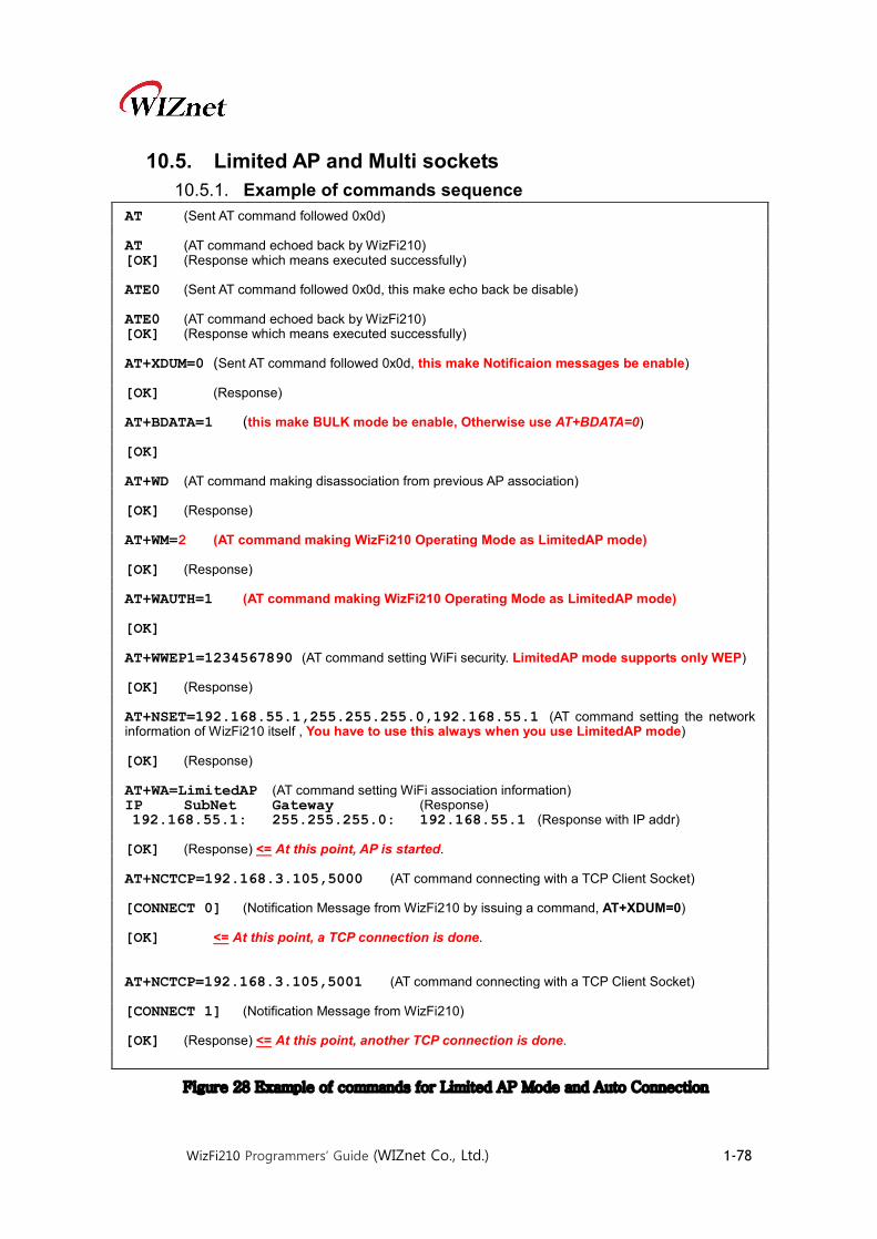
WizFi210 Programmers’ Guide (WIZnet Co., Ltd.) 1-78
10.5. Limited AP and Multi sockets 10.5.1. Example of commands sequence
Figure 28 Example of commands for Limited AP Mode and Auto Connection
AT (Sent AT command followed 0x0d) AT (AT command echoed back by WizFi210) [OK] (Response which means executed successfully) ATE0 (Sent AT command followed 0x0d, this make echo back be disable) ATE0 (AT command echoed back by WizFi210) [OK] (Response which means executed successfully) AT+XDUM=0 (Sent AT command followed 0x0d, this make Notificaion messages be enable) [OK] (Response) AT+BDATA=1 (this make BULK mode be enable, Otherwise use AT+BDATA=0) [OK] AT+WD (AT command making disassociation from previous AP association) [OK] (Response) AT+WM=2 (AT command making WizFi210 Operating Mode as LimitedAP mode) [OK] (Response) AT+WAUTH=1 (AT command making WizFi210 Operating Mode as LimitedAP mode) [OK] AT+WWEP1=1234567890 (AT command setting WiFi security. LimitedAP mode supports only WEP) [OK] (Response) AT+NSET=192.168.55.1,255.255.255.0,192.168.55.1 (AT command setting the network information of WizFi210 itself , You have to use this always when you use LimitedAP mode) [OK] (Response) AT+WA=LimitedAP (AT command setting WiFi association information) IP SubNet Gateway (Response) 192.168.55.1: 255.255.255.0: 192.168.55.1 (Response with IP addr) [OK] (Response) <= At this point, AP is started. AT+NCTCP=192.168.3.105,5000 (AT command connecting with a TCP Client Socket) [CONNECT 0] (Notification Message from WizFi210 by issuing a command, AT+XDUM=0) [OK] <= At this point, a TCP connection is done. AT+NCTCP=192.168.3.105,5001 (AT command connecting with a TCP Client Socket) [CONNECT 1] (Notification Message from WizFi210) [OK] (Response) <= At this point, another TCP connection is done.

WizFi210 Programmers’ Guide (WIZnet Co., Ltd.) 1-79
10.5.2. Exchanging data with a peer system Exchanging data with its peer system is the same to 10.3.2. Refer to it.
10.5.3. Closing TCP connection and UDP socket Closing TCP connections and UDP sockets are the same to 10.3.3. Refer to it.