SyncSort for z/VSE v3.7 Programmers Guide - support ...
602
performance Programmer's Guide Release 3. 7 SyncSort for z/ VSE PROVEN All rights reserved. This document contains proprietary and confidential material, and is only for use by licensees of the SyncSort for z/VSE proprietary software system. SyncSort is a registered trademark of Syncsort Incorporated SI-0328-G 070809
-
Upload
khangminh22 -
Category
Documents
-
view
3 -
download
0
Transcript of SyncSort for z/VSE v3.7 Programmers Guide - support ...
performance
Programmer's GuideRelease 3. 7
SyncSort for z/ VSE
P R O V E N
All rights reserved. This document containsproprietary and confidential material, and isonly for use by licensees of the SyncSort for z/VSE proprietary software system.
SyncSort is a registered trademark of Syncsort Incorporated
SI-0328-G
070809

© Syncsort Incorporated, 2009
All rights reserved. This document contains proprietary and confidential material,and is only for use by licensees of the SyncSort proprietary software system.This publication may not be reproduced in whole or in part, in any form, exceptwith written permission from Syncsort Incorporated.
SyncSort is a trademark of Syncsort Incorporated. All other company and productnames used herein may be the trademarks of their respective companies.

Table of Contents
Summary of Changes . . . . . . . . . . . . . . . . . . . . . . . . . . . . . . . . . . . . . . . . . . . . . . . . . . . . . vPerformance Improvements . . . . . . . . . . . . . . . . . . . . . . . . . . . . . . . . . . . . . vData Utility Features. . . . . . . . . . . . . . . . . . . . . . . . . . . . . . . . . . . . . . . . . . . vOperating System . . . . . . . . . . . . . . . . . . . . . . . . . . . . . . . . . . . . . . . . . . . . . viMessages. . . . . . . . . . . . . . . . . . . . . . . . . . . . . . . . . . . . . . . . . . . . . . . . . . . . . vi
Chapter 1. Introduction . . . . . . . . . . . . . . . . . . . . . . . . . . . . . . . . . . . . . . . . . . . . . . 1.1An Introduction to SyncSort for z/VSE. . . . . . . . . . . . . . . . . . . . . . . . . . . . 1.1SyncSort’s Basic Functions . . . . . . . . . . . . . . . . . . . . . . . . . . . . . . . . . . . . . 1.1SyncSort’s Data Utility and SortWriter Features . . . . . . . . . . . . . . . . . . . 1.2Join Processing Sequence . . . . . . . . . . . . . . . . . . . . . . . . . . . . . . . . . . . . . . 1.5Sample SortWriter Report. . . . . . . . . . . . . . . . . . . . . . . . . . . . . . . . . . . . . . 1.6SyncSort’s Operational Features. . . . . . . . . . . . . . . . . . . . . . . . . . . . . . . . . 1.7Structure of the Programmer’s Guide. . . . . . . . . . . . . . . . . . . . . . . . . . . . . 1.7Related Reading . . . . . . . . . . . . . . . . . . . . . . . . . . . . . . . . . . . . . . . . . . . . . . 1.9
Chapter 2. SyncSort Control Statements . . . . . . . . . . . . . . . . . . . . . . . . . . . . . . . 2.1Control Statement Summary Chart . . . . . . . . . . . . . . . . . . . . . . . . . . . . . . 2.3Data Utility Processing Sequence. . . . . . . . . . . . . . . . . . . . . . . . . . . . . . . 2.17Maximum Record Length Allowed . . . . . . . . . . . . . . . . . . . . . . . . . . . . . . 2.23Control Statement Examples . . . . . . . . . . . . . . . . . . . . . . . . . . . . . . . . . . 2.25Rules for Control Statements . . . . . . . . . . . . . . . . . . . . . . . . . . . . . . . . . . 2.25ALTSEQ Control Statement . . . . . . . . . . . . . . . . . . . . . . . . . . . . . . . . . . . 2.30ANALYZE Control Statement . . . . . . . . . . . . . . . . . . . . . . . . . . . . . . . . . . 2.32DUPKEYS Control Statement . . . . . . . . . . . . . . . . . . . . . . . . . . . . . . . . . 2.33
Table of Contents i

END Control Statement. . . . . . . . . . . . . . . . . . . . . . . . . . . . . . . . . . . . . . 2.38INCLUDE/OMIT Control Statement . . . . . . . . . . . . . . . . . . . . . . . . . . . 2.39INPFIL Control Statement . . . . . . . . . . . . . . . . . . . . . . . . . . . . . . . . . . . 2.64INREC Control Statement . . . . . . . . . . . . . . . . . . . . . . . . . . . . . . . . . . . . 2.83JOIN Control Statement . . . . . . . . . . . . . . . . . . . . . . . . . . . . . . . . . . . . . 2.86JOINKEYS Control Statement . . . . . . . . . . . . . . . . . . . . . . . . . . . . . . . . 2.88MERGE Control Statement . . . . . . . . . . . . . . . . . . . . . . . . . . . . . . . . . . . 2.95MODS Control Statement . . . . . . . . . . . . . . . . . . . . . . . . . . . . . . . . . . . 2.110OMIT Control Statement . . . . . . . . . . . . . . . . . . . . . . . . . . . . . . . . . . . . 2.113OPTION Control Statement . . . . . . . . . . . . . . . . . . . . . . . . . . . . . . . . . 2.114OUTFIL Control Statement. . . . . . . . . . . . . . . . . . . . . . . . . . . . . . . . . . 2.141OUTREC Control Statement . . . . . . . . . . . . . . . . . . . . . . . . . . . . . . . . . 2.174RECORD Control Statement . . . . . . . . . . . . . . . . . . . . . . . . . . . . . . . . . 2.219REFORMAT Control Statement . . . . . . . . . . . . . . . . . . . . . . . . . . . . . . 2.224SORT Control Statement . . . . . . . . . . . . . . . . . . . . . . . . . . . . . . . . . . . . 2.227SUM Control Statement. . . . . . . . . . . . . . . . . . . . . . . . . . . . . . . . . . . . . 2.246XDUPFIL Control Statement . . . . . . . . . . . . . . . . . . . . . . . . . . . . . . . . 2.249XSUMFIL Control Statement . . . . . . . . . . . . . . . . . . . . . . . . . . . . . . . . 2.250
Chapter 3. Using the SyncSort Dictionary Feature . . . . . . . . . . . . . . . . . . . . . . 3.1The Dictionary Feature . . . . . . . . . . . . . . . . . . . . . . . . . . . . . . . . . . . . . . . 3.1Dictionary Statement Format . . . . . . . . . . . . . . . . . . . . . . . . . . . . . . . . . . 3.8The Constant_name Statement: Rules and Syntax . . . . . . . . . . . . . . . . 3.11The Field_name Statement: Rules and Syntax . . . . . . . . . . . . . . . . . . . 3.13The Operator Statement: Rules and Syntax. . . . . . . . . . . . . . . . . . . . . . 3.21Using Dictionary_names in SyncSort Control Statements . . . . . . . . . . 3.26Error Handling for Dictionary Statements . . . . . . . . . . . . . . . . . . . . . . . 3.28
Chapter 4. How to Use SyncSort Data Utility Features . . . . . . . . . . . . . . . . . . . 4.1Introduction . . . . . . . . . . . . . . . . . . . . . . . . . . . . . . . . . . . . . . . . . . . . . . . . 4.1Sample Data Utility Applications . . . . . . . . . . . . . . . . . . . . . . . . . . . . . . . 4.2Selecting Input Records . . . . . . . . . . . . . . . . . . . . . . . . . . . . . . . . . . . . . . 4.2Selecting Relevant Fields from the Input Records . . . . . . . . . . . . . . . . . . 4.7Combining Records within a File . . . . . . . . . . . . . . . . . . . . . . . . . . . . . . 4.13Making Output Records Printable and Easy to Read . . . . . . . . . . . . . . 4.16Dividing a Report into Sections . . . . . . . . . . . . . . . . . . . . . . . . . . . . . . . 4.33Writing Headers and Trailers for a Report . . . . . . . . . . . . . . . . . . . . . . 4.36Totaling and Subtotaling Data . . . . . . . . . . . . . . . . . . . . . . . . . . . . . . . . 4.46Counting Data Records . . . . . . . . . . . . . . . . . . . . . . . . . . . . . . . . . . . . . . 4.53Creating Multiple Output Files . . . . . . . . . . . . . . . . . . . . . . . . . . . . . . . 4.57
Chapter 5. Job Control Language and Sample Control Statement Streams . 5.1Six Job Control Statements That May Be Needed for the Sort/Merge . . 5.1Symbolic Filenames and Symbolic Unit Names for Job Control . . . . . . . 5.5Setting up Disk Work File Statements . . . . . . . . . . . . . . . . . . . . . . . . . . . 5.5Calculating the Amount of Disk Work Space . . . . . . . . . . . . . . . . . . . . . . 5.8Setting up Multiple SORTOUT Files . . . . . . . . . . . . . . . . . . . . . . . . . . . . 5.8Sample JCL/Control Statement Streams . . . . . . . . . . . . . . . . . . . . . . . . . 5.8
SyncSort for z/VSE 3.7 Programmer’s Guideii
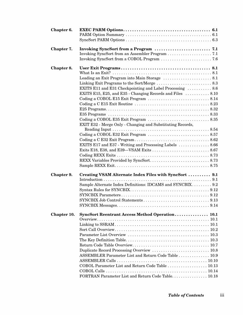
Chapter 6. EXEC PARM Options . . . . . . . . . . . . . . . . . . . . . . . . . . . . . . . . . . . . . . . 6.1PARM Option Summary . . . . . . . . . . . . . . . . . . . . . . . . . . . . . . . . . . . . . . . 6.1SyncSort PARM Options . . . . . . . . . . . . . . . . . . . . . . . . . . . . . . . . . . . . . . . 6.3
Chapter 7. Invoking SyncSort from a Program . . . . . . . . . . . . . . . . . . . . . . . . . 7.1Invoking SyncSort from an Assembler Program . . . . . . . . . . . . . . . . . . . . 7.1Invoking SyncSort from a COBOL Program . . . . . . . . . . . . . . . . . . . . . . . 7.6
Chapter 8. User Exit Programs . . . . . . . . . . . . . . . . . . . . . . . . . . . . . . . . . . . . . . . . 8.1What Is an Exit? . . . . . . . . . . . . . . . . . . . . . . . . . . . . . . . . . . . . . . . . . . . . . 8.1Loading an Exit Program into Main Storage . . . . . . . . . . . . . . . . . . . . . . 8.1Linking Exit Programs to the Sort/Merge . . . . . . . . . . . . . . . . . . . . . . . . . 8.3EXITS E11 and E31 Checkpointing and Label Processing . . . . . . . . . . . 8.6EXITS E15, E25, and E35 - Changing Records and Files . . . . . . . . . . . 8.10Coding a COBOL E15 Exit Program . . . . . . . . . . . . . . . . . . . . . . . . . . . . 8.14Coding a C E15 Exit Routine . . . . . . . . . . . . . . . . . . . . . . . . . . . . . . . . . . 8.23E25 Programs. . . . . . . . . . . . . . . . . . . . . . . . . . . . . . . . . . . . . . . . . . . . . . . 8.32E35 Programs . . . . . . . . . . . . . . . . . . . . . . . . . . . . . . . . . . . . . . . . . . . . . . 8.33Coding a COBOL E35 Exit Program . . . . . . . . . . . . . . . . . . . . . . . . . . . . 8.35EXIT E32 - Merge Only - Changing and Substituting Records,
Reading Input . . . . . . . . . . . . . . . . . . . . . . . . . . . . . . . . . . . . . . . . . . . . 8.54Coding a COBOL E32 Exit Program . . . . . . . . . . . . . . . . . . . . . . . . . . . . 8.57Coding a C E32 Exit Program. . . . . . . . . . . . . . . . . . . . . . . . . . . . . . . . . . 8.62EXITS E17 and E37 - Writing and Processing Labels . . . . . . . . . . . . . . 8.66Exits E18, E38, and E39—VSAM Exits . . . . . . . . . . . . . . . . . . . . . . . . . . 8.67Coding REXX Exits . . . . . . . . . . . . . . . . . . . . . . . . . . . . . . . . . . . . . . . . . . 8.73REXX Variables Provided by SyncSort. . . . . . . . . . . . . . . . . . . . . . . . . . . 8.73Sample REXX Exit. . . . . . . . . . . . . . . . . . . . . . . . . . . . . . . . . . . . . . . . . . . 8.75
Chapter 9. Creating VSAM Alternate Index Files with SyncSort . . . . . . . . . . 9.1Introduction . . . . . . . . . . . . . . . . . . . . . . . . . . . . . . . . . . . . . . . . . . . . . . . . . 9.1Sample Alternate Index Definitions: IDCAMS and SYNCBIX. . . . . . . . . 9.2Syntax Rules for SYNCBIX. . . . . . . . . . . . . . . . . . . . . . . . . . . . . . . . . . . . 9.12SYNCBIX Parameters . . . . . . . . . . . . . . . . . . . . . . . . . . . . . . . . . . . . . . . . 9.12SYNCBIX Job Control Statements . . . . . . . . . . . . . . . . . . . . . . . . . . . . . . 9.13SYNCBIX Messages. . . . . . . . . . . . . . . . . . . . . . . . . . . . . . . . . . . . . . . . . . 9.14
Chapter 10. SyncSort Reentrant Access Method Operation . . . . . . . . . . . . . . . 10.1Overview. . . . . . . . . . . . . . . . . . . . . . . . . . . . . . . . . . . . . . . . . . . . . . . . . . . 10.1Linking to SSRAM . . . . . . . . . . . . . . . . . . . . . . . . . . . . . . . . . . . . . . . . . . . 10.1Sort Call Overview. . . . . . . . . . . . . . . . . . . . . . . . . . . . . . . . . . . . . . . . . . . 10.2Parameter List Overview . . . . . . . . . . . . . . . . . . . . . . . . . . . . . . . . . . . . . 10.3The Key Definition Table. . . . . . . . . . . . . . . . . . . . . . . . . . . . . . . . . . . . . . 10.3Return Code Table Overview. . . . . . . . . . . . . . . . . . . . . . . . . . . . . . . . . . . 10.7Duplicate Record Processing Overview . . . . . . . . . . . . . . . . . . . . . . . . . . 10.8ASSEMBLER Parameter List and Return Code Table . . . . . . . . . . . . . . 10.9ASSEMBLER Calls . . . . . . . . . . . . . . . . . . . . . . . . . . . . . . . . . . . . . . . . . 10.10COBOL Parameter List and Return Code Table . . . . . . . . . . . . . . . . . . 10.13COBOL Calls . . . . . . . . . . . . . . . . . . . . . . . . . . . . . . . . . . . . . . . . . . . . . . 10.14FORTRAN Parameter List and Return Code Table. . . . . . . . . . . . . . . . 10.18
Table of Contents iii
FORTRAN Calls . . . . . . . . . . . . . . . . . . . . . . . . . . . . . . . . . . . . . . . . . . . 10.19PL/I Parameter List and Return Code Table . . . . . . . . . . . . . . . . . . . . 10.22PL/I Calls . . . . . . . . . . . . . . . . . . . . . . . . . . . . . . . . . . . . . . . . . . . . . . . . 10.23
Chapter 11. The SYNCHSTO Utility Program . . . . . . . . . . . . . . . . . . . . . . . . . . . 11.1What is SYNCHSTO?. . . . . . . . . . . . . . . . . . . . . . . . . . . . . . . . . . . . . . . . 11.1Control Parameters for SYNCHSTO. . . . . . . . . . . . . . . . . . . . . . . . . . . . 11.2Job Control Language . . . . . . . . . . . . . . . . . . . . . . . . . . . . . . . . . . . . . . . 11.5Sample SYNCHSTO Output . . . . . . . . . . . . . . . . . . . . . . . . . . . . . . . . . . 11.6
Chapter 12. Messages . . . . . . . . . . . . . . . . . . . . . . . . . . . . . . . . . . . . . . . . . . . . . . . . . 12.1SyncSort for z/VSE Messages . . . . . . . . . . . . . . . . . . . . . . . . . . . . . . . . . 12.1Common SyncSort Errors . . . . . . . . . . . . . . . . . . . . . . . . . . . . . . . . . . . 12.29SSRAM Messages . . . . . . . . . . . . . . . . . . . . . . . . . . . . . . . . . . . . . . . . . . 12.30SYNCBIX Messages . . . . . . . . . . . . . . . . . . . . . . . . . . . . . . . . . . . . . . . . 12.35SYNCHSTO Messages . . . . . . . . . . . . . . . . . . . . . . . . . . . . . . . . . . . . . . 12.37
Appendix A. Devices and Software Supported by SyncSort. . . . . . . . . . . . . . . . A.1Devices Supported by SyncSort . . . . . . . . . . . . . . . . . . . . . . . . . . . . . . . . A.1Proprietary Software Packages Compatible with SyncSort . . . . . . . . . . . A.1
Appendix B. Helpful Formulas for SyncSort Programs. . . . . . . . . . . . . . . . . . . . B.1Calculating How Much Disk Workfile Space Is Needed for a Job . . . . . B.1Minimum Storage Needed to Run a Sort or Merge . . . . . . . . . . . . . . . . . B.1
Appendix C. VSE/VSAM Space Management for SAM Files . . . . . . . . . . . . . . . . C.1Introduction . . . . . . . . . . . . . . . . . . . . . . . . . . . . . . . . . . . . . . . . . . . . . . . . C.1SAM ESDS Files . . . . . . . . . . . . . . . . . . . . . . . . . . . . . . . . . . . . . . . . . . . . C.1VSAM-Managed SORTIN Files . . . . . . . . . . . . . . . . . . . . . . . . . . . . . . . . C.2VSAM-Managed SORTWK Files . . . . . . . . . . . . . . . . . . . . . . . . . . . . . . . C.3JCL Requirements for VSAM-Managed SORTWK Files . . . . . . . . . . . . C.4Sample JCL/Control Streams . . . . . . . . . . . . . . . . . . . . . . . . . . . . . . . . . . C.5VSAM-Managed SORTOUT Files . . . . . . . . . . . . . . . . . . . . . . . . . . . . . . C.7JCL Requirements for VSAM-Managed SORTOUT Files . . . . . . . . . . . C.8Setting Up a JCL/Control Stream for Sorts with VSAM-Managed Files C.8
Index . . . . . . . . . . . . . . . . . . . . . . . . . . . . . . . . . . . . . . . . . . . . . . . . . . . . . . . . . . . . . . . . . . I.1
SyncSort for z/VSE 3.7 Programmer’s Guideiv
SyncSort for z/VSE Release 3.7 Summary of Changes
Performance Improvements
SyncSort for z/VSE performance has been improved by the following.
• Improved elapsed time for sort applications that use the Virtual Sortwork feature ofthe SyncSort Dynamic Storage Manager (DSM) due to improved I/O techniques.
• Improved elapsed time for sort applications that do not use the SyncSort DSM due tomore efficient buffer utilization for Sortwork I/O.
• Elapsed time improvements for applications using VSAM files as input to SyncSort.
Data Utility Features
The SyncSort for z/VSE data utility features have been enhanced by the following:
DUPKEYS Control Statement
• The new ALLDUPS parameter specifies that only records with duplicate SORT/MERGE fields are retained.
• The new FIRSTDUP parameter specifies that only the first record of those withduplicate SORT/MERGE fields is retained.
• The new LASTDUP parameter specifies that only the last record of those withduplicate SORT/MERGE fields is retained.
• The NODUPS parameter specifies that only records with unique SORT/MERGE fieldsare retained.
INPFIL/OUTFIL Control Statements
• The new BUILD parameter is identical to the OUTREC parameter of the OUTFILcontrol statement.
Summary of Changes v

• The new IFTHEN parameter uses conditional logic which enables you to reformatrecords based on specific criteria.
• The new IFOUTLEN parameter overrides the maximum record length, which isautomatically set by the IFTHEN parameter.
• The new OVERLAY parameter enables you to change particular columns within arecord, and add fields to the end of a record, without rebuilding the entire record.
• The SECTIONS parameter now supports non-contiguous data fields to be used as thebreak control field.
INREC/OUTREC Control Statements
• The new IFTHEN, IFOUTLEN, and OVERLAY parameters can be used to conditionallyreformat records or reformat only selected portions of records.
• The new RESTART subparameter of the SEQNUM parameter can be used to restartthe sequence numbering.
JOINKEYS Control Statement
• Data formats of CH, FI, PD, and ZD are now supported in addition to BI.
Other Features
• Support for UFF and SFF data formats in the INCLUDE/OMIT, MERGE, OUTREC,and SORT parameters has been added.
• Support for additional data formats in SSRAM applications has been added.
Operating System
SyncSort for z/VSE Release 3.7 supports z/VSE 4.2.
Messages
• Now message SHS118A indicates that the input file to SYNCHSTO is empty.
• Message WER127A now applies to the BUILD and OVERLAY parameters in addition to the INREC, OUTREC, and REFORMAT parameters.
• Message WER128A now applies to the BUILD, OVERLAY, and REFORMAT parameters in addition to the INREC and OUTREC parameters.
SyncSort for z/VSE 3.7 Programmer’s Guidevi
• Message WER129A now applies to the IFTHEN parameter in addition to the INCLUDE and OMIT parameters.
• Message WER130A now applies to the IFTHEN parameter in addition to the INCLUDE and OMIT parameters.
• Message WER132A now applies to the IFTHEN parameter in addition to the INCLUDE and OMIT parameters.
• Message WER133A now applies to the BUILD parameter in addition to the INREC, OUTREC, and REFORMAT parameters.
• New message WER157A indicates that the IFOUTLEN parameter has a specified length greater than the RECORD control statement’s maximum record length.
• Message WER191A now indicates that the number of JOINKEYS fields specified on two JOINKEYS control statements are not equal.
• New message WER205A indicates that one or more of the corresponding fields on two JOINKEYS control statements are in incompatible formats.
Summary of Changes vii

SyncSort for z/VSE 3.7 Programmer’s Guideviii

Chapter 1. Introduction
An Introduction to SyncSort for z/VSE
SyncSort for z/VSE is a high performance sort/merge/copy program for IBM System/370, System/390, and z/Architecture machines running under VSE/ESA, z/VSE, and MVT/VSE(Software Pursuits).
SyncSort for z/VSE is designed to conserve system resources and provide significant perfor-mance benefits.
SyncSort for z/VSE can be initiated by job control language or invoked from a programwritten in COBOL, PL/1, or Assembler language. Eleven types of user exit routines can bespecified for additional programming flexibility.
SyncSort’s Basic Functions
SyncSort for z/VSE has three basic functions:
1. Sorting - rearranging data set records to produce a specific sequence
2. Merging - combining up to 32 presequenced data sets into one data set that has thesame sequence
3. Copying - reproducing a data set without going through the sorting process
Chapter 1. Introduction 1.1
Sorting
A sort is the ordering of a data set of unspecified sequence into specific sequential form. Forexample, a sort can arrange records in numeric or alphabetic order.
Up to 32 files can be sorted at one time, and a number of different devices can be used forinput, output, and work files.
The sort logically consists of four phases that perform the following functions:
• The control statements and job control information are read and analyzed, and theoperational parameters for the sort are established.
• The input data is read into virtual storage and sorted.
• If necessary, intermediate results are written to temporary storage devices.
• The sorting process completes, and the sorted data is written to the specified outputdevice(s).
Merging
A merge is used to combine files where data in each file is in sequential order. The mergecombines up to 32 files into one output file.
A merge has only two phases that perform the following functions:
• The control statements and job control information are read and analyzed, and theoperational parameters for the merge are established.
• The files are merged and the sorted data is written to the specified output device(s).
Copying
A copy reproduces a file, bypassing the sorting process. A copy has only two phases thatperform the following functions:
• The control statements and job control information are read and analyzed, and theoperational parameters for the copy are established.
• The file is copied to the specified output device(s).
SyncSort’s Data Utility and SortWriter Features
SyncSort for z/VSE is designed to improve programmer productivity by reducing the timethe programmer/analyst must spend designing, testing, and debugging applications. With
SyncSort for z/VSE 3.7 Programmer’s Guide1.2
SyncSort’s extensive Data Utility and SortWriter features, data processing applicationspreviously requiring several steps can be accomplished in a single execution.
SyncSort’s Data Utility features include a multiple output facility, a full range of reportwriting capabilities, and record selection and record reformatting facilities. These optionsallow the user to design sort/merge/copy applications that can accomplish a host of relatedtasks.
Processing Multiple Input Files
The multiple input facility (INPFIL) allows multiple input files to be processed by just onepass of the sort. Each of these files can have unique specifications that determine whichrecords are to be included and how the records are to be formatted. Moreover, all these filescan originate from one input device, or each file can originate from a different device.
Generating Multiple Output Files
The multiple output facility (OUTFIL) allows multiple output files to be generated withjust one pass of the sort. Each of these files can have unique specifications that determinewhich records are to be included, how the records are to be formatted, and which reportcapabilities are to be used. Moreover, all these files can be written to the same outputdevice, or each can be written to a different device.
Creating Reports
SyncSort’s SortWriter feature (OUTFIL) allows the user to design comprehensive reportseasily and efficiently. SortWriter options allow output data to be flexibly formatted withheaders and trailers that can include data fields. Totals, subtotals, record counts, and sub-counts can be produced at report, page, and section levels. Output record fields can berealigned, the records can be padded with blanks, characters, and binary zeros, andnumeric data can be converted and edited. Automatic pagination, page numbering, anddating are also provided.
Selecting Records, Reformatting Records and Summing Fields
Record selection, reformatting, and summing are other important SyncSort for z/VSE DataUtility features. Record selection via the INCLUDE/OMIT feature permits certain recordsto be included in or omitted from an input data set based on comparisons between two datafields or between a data field and a constant.
Record reformatting after input and/or before output, provided by the INREC/OUTRECcapability, allows the user to delete or repeat portions of records, insert spaces, charactersand binary zeros, realign fields, convert numeric data to its printable format, convert fixed-length records to variable-length records or vice-versa, and convert data to its printablehexadecimal format. The ability to delete irrelevant data fields before sorting via INRECcan provide important performance benefits.
Chapter 1. Introduction 1.3

The AVG, MAX, MIN, and SUM features allow deletion of records with equal sort controlfields and optional replacement of specified numeric fields in the retained record with theaverage, maximum, minimum, or sum of the field for all records with the same controlfield. The deleted records can be written to a separate data set.
Join Facility
The join facility of SyncSort for z/VSE provides the capability to join records from twosource files. Each record from the first file with a given value in one or more fields (the joinkey) is joined to each record from the second file that has an identical value in its join key.The joined records are passed to the sort/copy process. The power of this facility isenhanced by the ability to eliminate records from either or both files and to control the dis-position of paired and unpaired records resulting from the join operation.
SyncSort for z/VSE 3.7 Programmer’s Guide1.4

Join Processing Sequence
Join processing replaces the reading of the input data set (SORTIN) during a more tradi-tional SORT or COPY. The records created by joining and reformatting are inserted intothe SORT/COPY process immediately prior to record selection by the INCLUDE/OMIT con-trol statement. Note that the specifications in all of the other control statements after joinprocessing refer to the positions of the fields in the reformatted join records. See Figure 1below.
Figure 1. One-Step Join Processing Sequence
Chapter 1. Introduction 1.5
Sample SortWriter Report
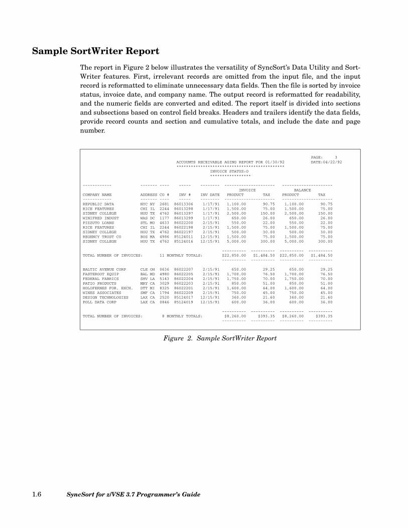
The report in Figure 2 below illustrates the versatility of SyncSort’s Data Utility and Sort-Writer features. First, irrelevant records are omitted from the input file, and the inputrecord is reformatted to eliminate unnecessary data fields. Then the file is sorted by invoicestatus, invoice date, and company name. The output record is reformatted for readability,and the numeric fields are converted and edited. The report itself is divided into sectionsand subsections based on control field breaks. Headers and trailers identify the data fields,provide record counts and section and cumulative totals, and include the date and pagenumber.
PAGE: 3ACCOUNTS RECEIVABLE AGING REPORT FOR 01/30/92 DATE:04/22/92*********************************************
INVOICE STATUS:O*****************
------------ ------- ---- ----- -------- --------------------- ---------------------INVOICE BALANCE
COMPANY NAME ADDRESS CO # INV # INV DATE PRODUCT TAX PRODUCT TAX------------ ------- ---- ----- -------- --------------------- ---------------------REPUBLIC DATA NYC NY 2681 86013306 1/17/91 1,100.00 90.75 1,100.00 90.75RICE FEATURES CHI IL 2244 86013298 1/17/91 1,500.00 75.00 1,500.00 75.00SIDNEY COLLEGE HOU TX 4762 86013297 1/17/91 2,500.00 150.00 2,500.00 150.00WINIFRED INDUST WAS DC 1177 86013299 1/17/91 650.00 26.00 650.00 26.00PIZZUTO LOANS STL MO 4633 86022200 2/15/91 550.00 22.00 550.00 22.00RICE FEATURES CHI IL 2244 86022198 2/15/91 1,500.00 75.00 1,500.00 75.00SIDNEY COLLEGE HOU TX 4762 86022197 2/15/91 500.00 30.00 500.00 30.00REGENCY TRUST CO BOS MA 4986 85124011 12/15/91 1,500.00 75.00 1,500.00 75.00SIDNEY COLLEGE HOU TX 4762 85124016 12/15/91 5,000.00 300.00 5,000.00 300.00
---------- ---------- ---------- ----------TOTAL NUMBER OF INVOICES: 11 MONTHLY TOTALS: $22,850.00 $1,484.50 $22,850.00 $1,484.50
---------- ---------- ---------- ----------
BALTIC AVENUE CORP CLE OH 0636 86022207 2/15/91 650.00 29.25 650.00 29.25FASTEROOT EQUIP BAL MD 4980 86022205 2/15/91 1,700.00 76.50 1,700.00 76.50FEDERAL FABRICS SHV LA 5143 86022204 2/15/91 1,750.00 70.00 1,750.00 70.00PATIO PRODUCTS MRY CA 3029 86022203 2/15/91 850.00 51.00 850.00 51.00HOLOFERNES FOR. EXCH. DTT MI 8325 86022201 2/15/91 1,600.00 64.00 1,600.00 64.00WINES ASSOCIATES SMF CA 1794 86022209 2/15/91 750.00 45.00 750.00 45.00DESIGN TECHNOLOGIES LAX CA 2520 85124017 12/15/91 360.00 21.60 360.00 21.60POLL DATA CORP LAX CA 0846 85124019 12/15/91 600.00 36.00 600.00 36.00
---------- ---------- ---------- ----------TOTAL NUMBER OF INVOICES: 8 MONTHLY TOTALS: $8,260.00 $393.35 $8,260.00 $393.35
---------- ---------- ---------- ----------
Figure 2. Sample SortWriter Report
SyncSort for z/VSE 3.7 Programmer’s Guide1.6
SyncSort’s Operational Features
SyncSort for z/VSE has many operational features that contribute to its flexibility andfunctionality.
• SyncSort for z/VSE interfaces with the VSE/VSAM Space Management for SAMfeature to permit VSAM space management of input, output, and sort work files. Thiscapability simplifies JCL requirements and facilitates automatic secondary sort workallocation.
• SyncSort for z/VSE can be installed in the SVA. However, on VSE/ESA and z/VSEsystems, most of the SVA can be saved by activating SyncSort for z/VSE’s VirtualLibrary and Virtual Sortwork features at installation time.
• Default values can be dynamically modified at execution time via the PARMEXITfeature, allowing main storage allocations to reflect observed or anticipated VS pagingactivity.
• SyncSort for z/VSE interfaces with many disk space management packages. Thiscapability provides many benefits, including automatic release of unused output diskspace and automatic secondary sort work allocation.
Other operational features include support for input files on different devices (e.g., disk,tape, and card readers), support for mixed device types for disk sort work space, automaticincore sorting, support for ASCII tape input and output files, and support for spanned vari-able-length records.
SyncSort’s SYNCBIX feature is a high performance replacement for the BLDINDEX pro-cess performed by Access Methods Services (IDCAMS). The SYNCBIX feature interfaceswith SyncSort for z/VSE to allow efficient reading of the base cluster, fast extracting of therecord pointer information, primary and alternate keys, and high performance sorting ofthese records.
Structure of the Programmer’s Guide
The SyncSort for z/VSE Programmer’s Guide is a reference manual designed for use byapplications programmers when sorting, merging, or copying sequential data sets withSyncSort. This manual is self-contained and assumes only a basic working knowledge ofthe operating system and its job control language. It should not be necessary to refer to anyother manual to produce a functioning, efficient sort.
This manual is organized into the following chapters:
SyncSort Control Statements describes the coding and use of the ALTSEQ, ANALYZE,DUPKEYS, END, INCLUDE/OMIT, INPFIL, INREC, JOIN, JOINKEYS, MERGE, MODS,OMIT, OPTION, OUTFIL, OUTREC, RECORD, REFORMAT, SORT, SUM, XDUPFIL,and XSUMFIL statements. The discussion of a particular control statement includes these
Chapter 1. Introduction 1.7
topics: the statement’s coding format, the versatility provided by the various parameters(many of them unique to SyncSort), the interaction between this control statement andother statements, and simple examples.
Using the SyncSort Dictionary Feature describes how to use a dictionary_name to rep-resent most fields or constants recognized in SyncSort control statements.
How to Use SyncSort’s Data Utility Features explains and illustrates the Data Utilityfeatures and SortWriter using a series of sample applications. Each application is self-con-tained and provides both the required JCL and the control statements necessary to accom-plish tasks such as record and field selection, report writing, and multiple output filegeneration.
Job Control Language and Sample JCL/Control Statement Streams analyzesSyncSort’s job control requirements and describes the job control statements that may beneeded. Two methods for setting up disk work file statements are described. Sample JCL/control statement streams illustrate typical SyncSort applications and can be used asmodels.
EXEC PARM Options describes the parameters that can be passed to SyncSort with thePARM option on the JCL //EXEC statement.
Invoking SyncSort from a Program explains how to invoke SyncSort for z/VSE fromprograms written in Assembler, COBOL, and PL/1 and provides examples of invoked sorts.
User Exit Programs describes the different types of exits that can be written to performvarious tasks at different stages of the sort/merge. Each exit point is fully documentedtogether with the tasks that are appropriate at that point. Exits for VSAM files are alsodiscussed.
Creating VSAM Alternate Index Files with SyncSort describes SyncSort’s SYNCBIXfeature, a high performance replacement for the BLDINDEX process performed by AccessMethods Services (IDCAMS).
SyncSort Reentrant Access Method Operation describes the interface between aninvoking program and SyncSort, which allows a program to invoke up to 16 concurrentsorts.
The SYNCHSTO Utility Program describes a separate program that determines infor-mation about variable-length record files, which then can be used to run more efficientsorts of those files.
Messages documents all of the error and informational messages generated by theSyncSort program. Errors that occur most frequently are explained in detail along withsuggestions for correcting them.
SyncSort for z/VSE 3.7 Programmer’s Guide1.8
Related Reading
SyncSort for z/VSE Installation Guide
This manual explains how to install and maintain SyncSort.
Exploiting SyncSort for z/VSE: JOIN
This booklet demonstrates how to use SyncSort’s JOIN feature through the use of sampleapplications.
Exploiting SyncSort: SortWriter Data Utilities Guide
This booklet explains how to use SyncSort’s Data Utility features, with special emphasis onreport writing. Comprehensive sample applications illustrate how the control statementsproduce formatted reports.
Chapter 1. Introduction 1.9

SyncSort for z/VSE 3.7 Programmer’s Guide1.10
Chapter 2. SyncSort Control Statements
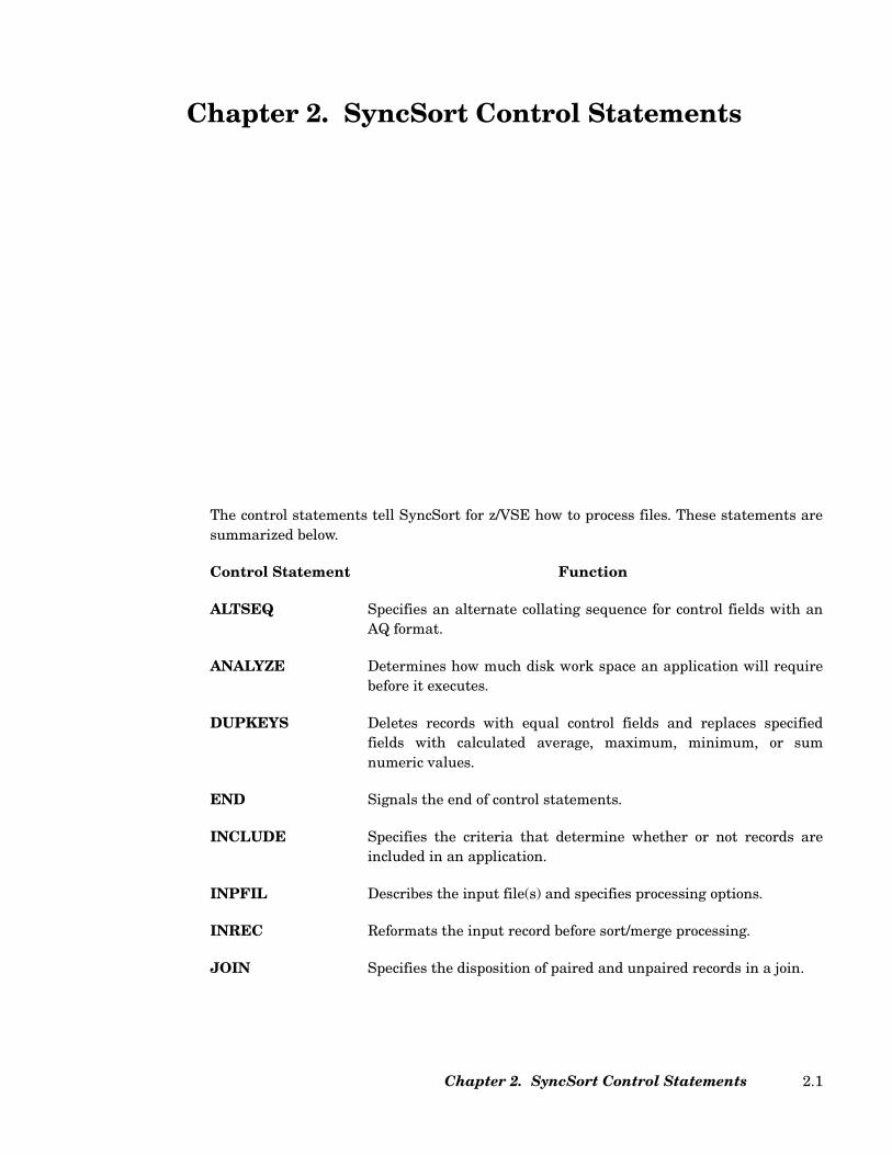
The control statements tell SyncSort for z/VSE how to process files. These statements aresummarized below.
Control Statement Function
ALTSEQ Specifies an alternate collating sequence for control fields with anAQ format.
ANALYZE Determines how much disk work space an application will requirebefore it executes.
DUPKEYS Deletes records with equal control fields and replaces specifiedfields with calculated average, maximum, minimum, or sumnumeric values.
END Signals the end of control statements.
INCLUDE Specifies the criteria that determine whether or not records areincluded in an application.
INPFIL Describes the input file(s) and specifies processing options.
INREC Reformats the input record before sort/merge processing.
JOIN Specifies the disposition of paired and unpaired records in a join.
Chapter 2. SyncSort Control Statements 2.1
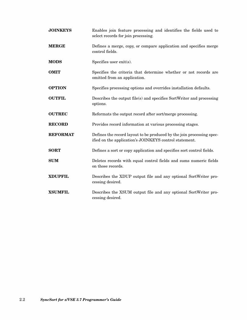
JOINKEYS Enables join feature processing and identifies the fields used toselect records for join processing.
MERGE Defines a merge, copy, or compare application and specifies mergecontrol fields.
MODS Specifies user exit(s).
OMIT Specifies the criteria that determine whether or not records areomitted from an application.
OPTION Specifies processing options and overrides installation defaults.
OUTFIL Describes the output file(s) and specifies SortWriter and processingoptions.
OUTREC Reformats the output record after sort/merge processing.
RECORD Provides record information at various processing stages.
REFORMAT Defines the record layout to be produced by the join processing spec-ified on the application’s JOINKEYS control statement.
SORT Defines a sort or copy application and specifies sort control fields.
SUM Deletes records with equal control fields and sums numeric fieldson those records.
XDUPFIL Describes the XDUP output file and any optional SortWriter pro-cessing desired.
XSUMFIL Describes the XSUM output file and any optional SortWriter pro-cessing desired.
SyncSort for z/VSE 3.7 Programmer’s Guide2.2
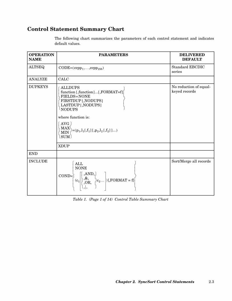
Control Statement Summary Chart
The following chart summarizes the parameters of each control statement and indicatesdefault values.
OPERATION NAME
PARAMETERS DELIVEREDDEFAULT
ALTSEQ Standard EBCDIC series
ANALYZE CALC
DUPKEYS
where function is:
No reduction of equal-keyed records
XDUP
END
INCLUDE Sort/Merge all records
Table 1. (Page 1 of 14) Control Table Summary Chart
CODE= ccpp1,…,ccpp256( )
ALLDUPSfunction ,function[ ]... ,FORMAT=f[ ]FIELDS=NONEFIRSTDUP ,NODUPS[ ]LASTDUP ,NODUPS[ ]NODUPS
AVGMAXMINSUM
= p1,l1 ,f1[ ] ,p2,l2 ,f2[ ][ ]...( )
COND=
ALLNONE
(c1
,AND,,&,,OR,, ,
c2… )[,FORMAT = f]
Chapter 2. SyncSort Control Statements 2.3
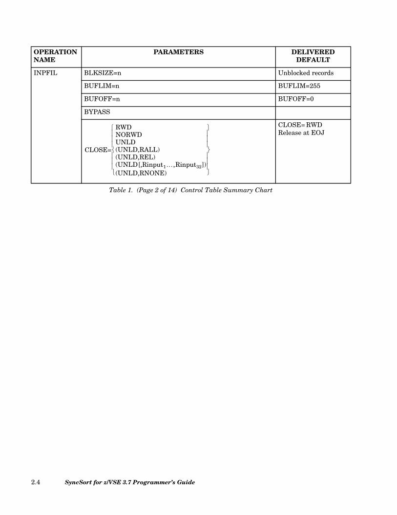
INPFIL BLKSIZE=n Unblocked records
BUFLIM=n BUFLIM=255
BUFOFF=n BUFOFF=0
BYPASS
CLOSE= RWDRelease at EOJ
OPERATION NAME
PARAMETERS DELIVEREDDEFAULT
Table 1. (Page 2 of 14) Control Table Summary Chart
CLOSE=
RWDNORWDUNLD(UNLD,RALL)(UNLD,REL)(UNLD[,Rinput1…,Rinput32])(UNLD,RNONE)
SyncSort for z/VSE 3.7 Programmer’s Guide2.4

INPFIL CONVERT
CRDSIZE=n CRDSIZE=80
DATA=E
EXIT
FTOV
INPUT Accepted but ignored
Record unchanged
L4FILL = NONE
NOCHAIN
OPEN = RWD
PRESEQ Accepted but ignored
SKIPBYTE Accepted but ignored
SKIPREC=0
OPERATION NAME
PARAMETERS DELIVEREDDEFAULT
Table 1. (Page 3 of 14) Control Table Summary Chart
DATA= EA
FILES=1n(1,2,…,32)
FNAMES=filenamefilename1[,filename2][,filename3]…( )
INCLUDEOMIT
=(…)
INRECBUILD
OVERLAYIFTHEN
…( )=
LRECL=nnn(lmax[,lmin])
L4FILL =NONEX'nn'C'c'
OPEN= RWDNORWD
SKIPRECSTARTEC
=n
Chapter 2. SyncSort Control Statements 2.5

INPFIL SPAN Unspanned records
SYSIPT
TOL Only if VSAM input
VLFILL=b
VLLONG=NO
VLTRIM=b
VOLUME=1
VSAM (Optional if managed-SAM)
VTOF
INREC Input records unchanged
JOIN UNPAIRED
F1
F2
ONLY
OPERATION NAME
PARAMETERS DELIVEREDDEFAULT
Table 1. (Page 4 of 14) Control Table Summary Chart
STOPAFTENDREC
=n
VLLONG = YESNO
VOLUME=nn1,...,n32( )
FIELDSBUILD
OVERLAYIFTHEN
…( )=
SyncSort for z/VSE 3.7 Programmer’s Guide2.6

JOINKEYS
FIELDS=(p1,l1,f1,o1[,p2,l2,f2,o2,...[,p64,l64,f64o64]])
FORMAT = f FORMAT = BI
BLKSIZE=n
BUFLIM=n BUFLIM = 255
BUFOFF=0
BYPASS
CLOSE=RWD
CRDSIZE=80
DATA=E
OPEN=RWD
OPERATION NAME
PARAMETERS DELIVEREDDEFAULT
Table 1. (Page 5 of 14) Control Table Summary Chart
FILE= F1F2
LRECL =nnn(l1[,l4])
TYPE= FV
BUFOFF= n
CLOSE=RWDNORWDUNLD
CRDSIZE= n
DATA= EA
ENDRECSTOPAFT
=n
INCLUDEOMIT
=(...)
OPEN= RWDNORWD
Chapter 2. SyncSort Control Statements 2.7
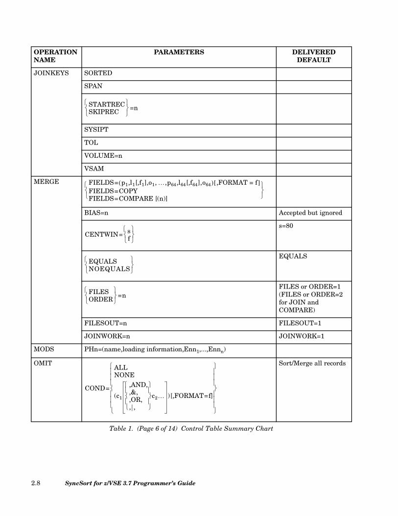
JOINKEYS SORTED
SPAN
SYSIPT
TOL
VOLUME=n
VSAM
MERGE
BIAS=n Accepted but ignored
s=80
EQUALS
FILES or ORDER=1(FILES or ORDER=2 for JOIN and COMPARE)
FILESOUT=n FILESOUT=1
JOINWORK=n JOINWORK=1
MODS PHn=(name,loading information,Enn1,...,Ennn)
OMIT Sort/Merge all records
OPERATION NAME
PARAMETERS DELIVEREDDEFAULT
Table 1. (Page 6 of 14) Control Table Summary Chart
STARTRECSKIPREC
=n
FIELDS= p1,l1[,f1],o1, …,p64,l64[,f64],o64( ) ,FORMAT = f[ ]FIELDS=COPYFIELDS=COMPARE [(n)]
CENTWIN= sf
EQUALSNOEQUALS
FILESORDER
=n
COND=
ALLNONE
(c1
,AND,,&,,OR,, ,
c2… )[,FORMAT=f]
SyncSort for z/VSE 3.7 Programmer’s Guide2.8

OPTION
CALCAREA
s=80
NOCHALT
CMP=CPD
CMPINOM=CLC
DATE=STD
DEVIN=nn DEVIN=49
DEVOUT=nn DEVIN=49
DIAG
NOEQUALS-SortEQUALS-Merge
NOERASE
OPERATION NAME
PARAMETERS DELIVEREDDEFAULT
Table 1. (Page 7 of 14) Control Table Summary Chart
ADDROUT= AD
CENTWIN= sf
CHALTNOCHALT
CMP= CLCCPD
CMPINOM= CLCCPD
DATE =
ADATEEDATEIDATESTD
DEVWK=n(n1,…,n3)NO
DUMPNODUMP
EQUALSNOEQUALS
ERASENOERASE
Chapter 2. SyncSort Control Statements 2.9

OPTION FILNM=(output1,...,output32,input1,...,input32,cccc) SORTOUT/SORTOFx/SORTOxx/SORTINx/SORTIxx/SORTWKx
GVSRANY=32K
GVSRLOW=128K
Respect l4
INCOR=OFF Incore sort if possible
Default symbolic unit numbers
KEYLEN=n KEYLEN=0
LABEL=(output1,...,output32,input1,...,input32,work) Standard labels
No LOCALE process-ing
NOINC Incore sort if possible
NOTPMK Tape marks written
RC0, continue process-ing
NRECS=n Output all records
RC0, continue process-ing
OPERATION NAME
PARAMETERS DELIVEREDDEFAULT
Table 1. (Page 8 of 14) Control Table Summary Chart
GVSRANY=nnKnM
GVSRLOW=nnKnM
IGNRL4NOIGNRL4NOVLSHRTVLSHRT
JOINWK=joinwork(joinwork1,…,joinwork9)
LOCALE=CURRENTnameNONE
NRECOUT=RC0RC4RC16
OVFLO=RC0RC4RC16
SyncSort for z/VSE 3.7 Programmer’s Guide2.10
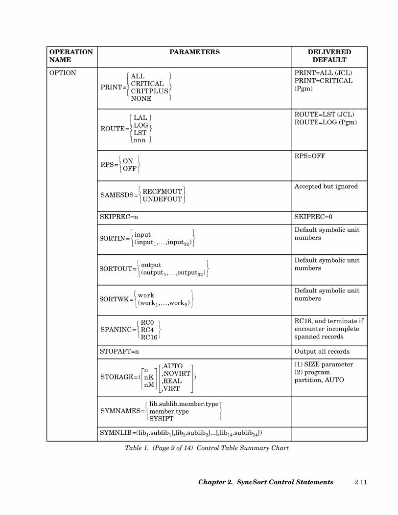
OPTION PRINT=ALL (JCL)PRINT=CRITICAL(Pgm)
ROUTE=LST (JCL)ROUTE=LOG (Pgm)
RPS=OFF
Accepted but ignored
SKIPREC=n SKIPREC=0
Default symbolic unit numbers
Default symbolic unit numbers
Default symbolic unit numbers
RC16, and terminate if encounter incomplete spanned records
STOPAFT=n Output all records
(1) SIZE parameter(2) programpartition, AUTO
SYMNLIB=(lib1.sublib1[,lib2.sublib2]...[,lib14.sublib14])
OPERATION NAME
PARAMETERS DELIVEREDDEFAULT
Table 1. (Page 9 of 14) Control Table Summary Chart
PRINT=
ALLCRITICALCRITPLUSNONE
ROUTE=
LALLOGLSTnnn
RPS= ONOFF
SAMESDS= RECFMOUTUNDEFOUT
SORTIN=input(input1,…,input32)
SORTOUT=output(output1,…,output32)
SORTWK=work(work1,…,work9)
SPANINC=RC0RC4RC16
STORAGE= (nnKnM
,AUTO,NOVIRT,REAL,VIRT
)
SYMNAMES=lib.sublib.member.typemember.typeSYSIPT
Chapter 2. SyncSort Control Statements 2.11

OPTION
TP Accepted but ignored
VERIFY Accepted but ignored
VSCORE=4096K
VSCORET=8192K
WORKNM=work WORKNM=SORTWKx
Standard labels
XDUPNM=filename XDUPNM=SORTXDP
XDUPOUT=nnn Default symbolic unit number
Standard labels
XSUMNM=filename XSUMNM=SORTXSM
XSUMOUT=nnn Default symbolic unit number
No conversion of ZD SUM results to print-able number
OPERATION NAME
PARAMETERS DELIVEREDDEFAULT
Table 1. (Page 10 of 14) Control Table Summary Chart
SYMNOUT=
LALLOGLSTNONE
VSCORE=nnKnM
VSCORET=nnKnM
XDUPLAB= SU
XSUMLAB= SU
NZDPRINTZDPRINT
SyncSort for z/VSE 3.7 Programmer’s Guide2.12
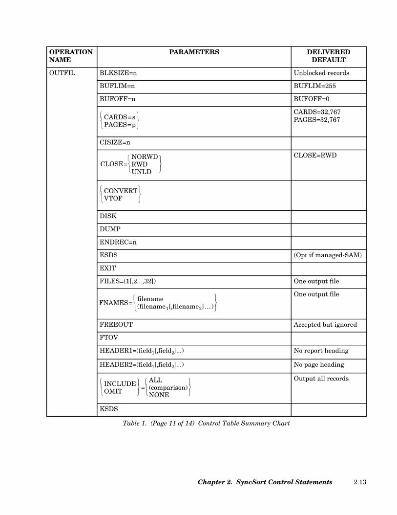
OUTFIL BLKSIZE=n Unblocked records
BUFLIM=n BUFLIM=255
BUFOFF=n BUFOFF=0
CARDS=32,767PAGES=32,767
CISIZE=n
CLOSE=RWD
DISK
DUMP
ENDREC=n
ESDS (Opt if managed-SAM)
EXIT
FILES=(1[,2...,32]) One output file
One output file
FREEOUT Accepted but ignored
FTOV
HEADER1=(field1[,field2]...) No report heading
HEADER2=(field1[,field2]...) No page heading
Output all records
KSDS
OPERATION NAME
PARAMETERS DELIVEREDDEFAULT
Table 1. (Page 11 of 14) Control Table Summary Chart
CARDS=sPAGES=p
CLOSE=NORWDRWDUNLD
CONVERTVTOF
FNAMES=filename(filename1[,filename2]…)
INCLUDEOMIT
=ALL(comparison)NONE
Chapter 2. SyncSort Control Statements 2.13
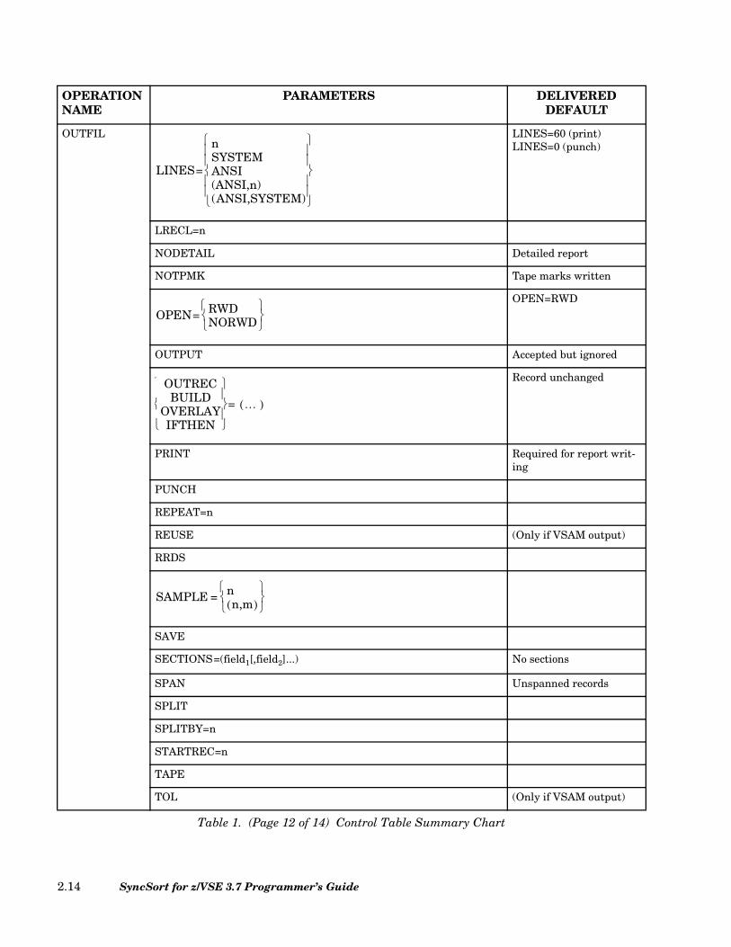
OUTFIL LINES=60 (print)LINES=0 (punch)
LRECL=n
NODETAIL Detailed report
NOTPMK Tape marks written
OPEN=RWD
OUTPUT Accepted but ignored
Record unchanged
PRINT Required for report writ-ing
PUNCH
REPEAT=n
REUSE (Only if VSAM output)
RRDS
SAVE
SECTIONS=(field1[,field2]...) No sections
SPAN Unspanned records
SPLIT
SPLITBY=n
STARTREC=n
TAPE
TOL (Only if VSAM output)
OPERATION NAME
PARAMETERS DELIVEREDDEFAULT
Table 1. (Page 12 of 14) Control Table Summary Chart
LINES=
nSYSTEMANSI(ANSI,n)(ANSI,SYSTEM)
OPEN= RWDNORWD
OUTRECBUILD
OVERLAYIFTHEN
…( )=
SAMPLE = nn,m( )
SyncSort for z/VSE 3.7 Programmer’s Guide2.14
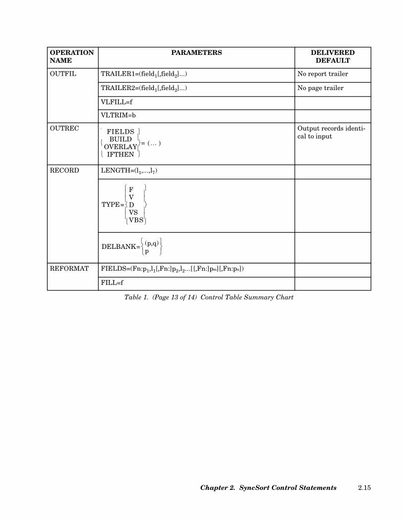
OUTFIL TRAILER1=(field1[,field2]...) No report trailer
TRAILER2=(field1[,field2]...) No page trailer
VLFILL=f
VLTRIM=b
OUTREC Output records identi-cal to input
RECORD LENGTH=(l1,...,l7)
REFORMAT FIELDS=(Fn:p1,l1[,Fn:]p2,l2...[[,Fn:]pm][,Fn:pn])
FILL=f
OPERATION NAME
PARAMETERS DELIVEREDDEFAULT
Table 1. (Page 13 of 14) Control Table Summary Chart
FIELDSBUILD
OVERLAYIFTHEN
…( )=
TYPE=
FVDVSVBS
DELBANK= (p,q)p
Chapter 2. SyncSort Control Statements 2.15

SORT
BIAS=n Accepted but ignored
s=80
NOEQUALS
ERASEWK NOERASE
FILES=n FILES=1FILES=2 (for JOIN)
FILESOUT=n FILESOUT=1
JOINWORK=1
Sort Capacity
WORK=DA
SUM No summing of fields; no reduction of equal-keyed records
XSUM Records deleted by SUM processing are not written to a file
XDUPFIL Same as OUTFIL except EXIT, FILES=, and FNAMES= Same as OUTFIL
XSUMFIL Same as OUTFIL except EXIT, FILES=, and FNAMES= Same as OUTFIL
OPERATION NAME
PARAMETERS DELIVEREDDEFAULT
Table 1. (Page 14 of 14) Control Table Summary Chart
FIELDS=(p1,l1[,f1],o1,…,p64,l64[,f64],o64)[,FORMAT=f]FIELDS=COPY
CENTWIN= sf
CHKPTCKPT
EQUALSNOEQUALS
JOINWORK= n
SIZE= nE1
WORK=DAn(n,s)
FIELDS=(p1,l1[,f1][,p2,l2[,f2]]...) ,FORMAT=f[ ]FIELDS=NONE
SyncSort for z/VSE 3.7 Programmer’s Guide2.16

Data Utility Processing Sequence
Figure 3 on page 2.18 presents the sequence in which SyncSort control statements andparameters are processed. It includes those statements and parameters that modify theinput file (e.g., INPFIL, INCLUDE/OMIT), reposition record fields (e.g., INREC,OUTREC),and create reports (e.g., OUTFIL).
When specifying record fields on any of these SyncSort control statements or parameters,refer to the record as it appears at that stage of SyncSort processing. For example, whenspecifying SORT fields, be sure to take into account any repositioning of fields that may bedue to INREC processing.
The figure also illustrates the steps in processing where several record length parametersare used to describe the records. lmin and lmax are parameters of INPFIL LRECL; l1, l2, l3, l4,and l5 are parameters of RECORD LENGTH.
Chapter 2. SyncSort Control Statements 2.17

Figure 3. Data Utility Processing Sequence
Multiple Input File ProcessingINPFIL Control Statements
(see Figure 4)
User Exit to Read/Insert/Delete/Reformat Input RecordsE15 exit
Record SelectionINCLUDE/OMIT Control Statement
Field SelectionINREC Control Statement
Record SortingSORT Control Statement
Combining/Eliminating Duplicate RecordsSUM Control Statement
Printable and Easy-to-Read Output andFixed-to-Variable or Variable-to-Fixed Length Format Conversion
OUTREC Control Statement
User Exit to Insert/Delete/Reformat/Write Output RecordsE35 exit
Multiple Output and Report FormattingOUTFIL Control Statement(s)
(see Figure 5)
. . . .
. . . .
lmax,
lmin
lmax,
lmin
l1
l2,
l4,l5
InputFile 1
InputFile n
OutputFile 1
OutputFile n
l3
SyncSort for z/VSE 3.7 Programmer’s Guide2.18
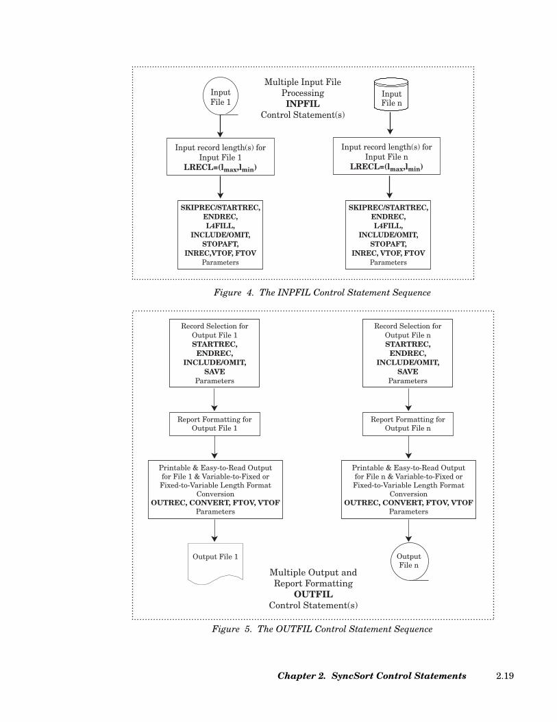
Figure 4. The INPFIL Control Statement Sequence
Figure 5. The OUTFIL Control Statement Sequence
Multiple Input FileProcessingINPFIL
Control Statement(s)
Input record length(s) forInput File 1
LRECL=(lmax,lmin)
InputFile 1
SKIPREC/STARTREC,ENDREC,L4FILL,
INCLUDE/OMIT,STOPAFT,
INREC,VTOF, FTOVParameters
InputFile n
Input record length(s) forInput File n
LRECL=(lmax,lmin)
SKIPREC/STARTREC,ENDREC,L4FILL,
INCLUDE/OMIT,STOPAFT,
INREC, VTOF, FTOVParameters
Record Selection forOutput File 1STARTREC,
ENDREC,INCLUDE/OMIT,
SAVEParameters
Report Formatting forOutput File 1
Printable & Easy-to-Read Outputfor File 1 & Variable-to-Fixed or Fixed-to-Variable Length Format
ConversionOUTREC, CONVERT, FTOV, VTOF
Parameters
Output File 1
Record Selection forOutput File nSTARTREC,
ENDREC,INCLUDE/OMIT,
SAVEParameters
Report Formatting forOutput File n
Output File n
Printable & Easy-to-Read Outputfor File n & Variable-to-Fixed or Fixed-to-Variable Length Format
ConversionOUTREC, CONVERT, FTOV, VTOF
Parameters
Multiple Output andReport Formatting
OUTFILControl Statement(s)
Chapter 2. SyncSort Control Statements 2.19

Data Utility Processing Sequence
1. The INPFIL control statement describes the input file(s) and details certain processingoptions. In a JOIN application, the JOINKEYS control statements are used instead ofthe INPFIL control statement to describe the input files for JOIN and to detail certainprocessing applications.
2. The INCLUDE/OMIT control statement selects records from an input file based oncomparisons testing the contents of one or more fields within the record.
3. The INREC control statement reformats the input records by adding, deleting, orreformatting fields before the records are sorted or merged.
4. The SORT control statement defines the application as a sort. It can also define a copyapplication.
5. The SUM control statement deletes records with equal control fields and optionallysums specified numeric fields on those records. Alternatively, the DUPKEYS controlstatement may be used, which includes all functions of the SUM control statement andmore.
6. The OUTREC control statement reformats the output records by:
• Deleting or repeating segments of the input records
• Inserting character strings between data fields
• Inserting binary zeros
• Converting numeric data to printable format or to another numeric format
• Performing arithmetic operations and minimum and maximum functions withnumeric fields and constants
• Converting data to printable hexadecimal format
• Changing the order of or completely redesigning the original input records
• Selecting, realigning, and reordering data fields
7. The OUTFIL control statement describes the output file(s) and:
• Creates multiple output files
• Uses the SortWriter facility
SyncSort for z/VSE 3.7 Programmer’s Guide2.20
• Reformats records after E35 processing
• Converts a variable-length record input file to a fixed-length record output file or afixed-length record input file to a variable-length record output.
INPFIL Processing Sequence
1. The INPFIL control statement is the initial function of SyncSort. Its specific processingvaries, depending on parameters specified on INPFIL. If EXIT is specified, SyncSortgets the input records from an E15/E32 user exit routine and all other INPFILparameters are ignored. If not, SyncSort processes each of the INPFIL parameters insequence as depicted in Figure 4 on page 2.19.
2. If the SKIPREC, STARTREC, and ENDREC parameters are specified, SyncSortprocesses the functions as follows:
• SKIPREC - skips a specified number of records per input file before the file issorted, merged, or copied.
• STARTREC - specifies the first record that will be processed for this input file.
• ENDREC - specifies the last record that will be processed for this input file.
3. If the INCLUDE/OMIT parameter is specified, SyncSort performs processing of theINCLUDE/OMIT function by selecting from an input file based on comparison of thecontents of one or more fields within the record.
4. If the STOPAFT parameter is specified, SyncSort performs processing of the STOPAFTfunction by ceasing to pass the records to the SORT/MERGE when the specifiednumber of records has been reached.
5. If the INREC, BUILD, OVERLAY, or IFTHEN parameter is specified, SyncSortperforms processing of that function by reformatting the input records of the input file.
6. If the VTOF parameter is specified, variable-length records will be converted to fixed-length records. If the FTOV parameter is specified, fixed-length records will beconverted to variable-length records.
OUTFIL Processing Sequence
1. The OUTFIL control statement is the final function of SyncSort. Its specific processingvaries, depending on parameters specified on OUTFIL. SyncSort processes each of theOUTFIL parameters in sequence as depicted in Figure 5 on page 2.19.
2. If the STARTREC and ENDREC parameters are specified, SyncSort processes thefunctions as follows:
• STARTREC - specifies the first sorted record that is generated to the output file.
Chapter 2. SyncSort Control Statements 2.21
• ENDREC - specifies the last sorted record that is generated to the output file.
3. If the INCLUDE/OMIT parameter is specified, SyncSort performs processing of theINCLUDE/OMIT function by excluding records from an output file based oncomparison of the contents of one or more fields within the record.
4. If the SAVE parameter is specified, SyncSort will include all the records that are notincluded in another OUTFIL group in the data sets for this group. SAVE retains all theinput records that are not included in the other groups and would otherwise be lost.
If the OUTREC, BUILD, OVERLAY, or IFTHEN parameter is specified, SyncSort performsprocessing of that function by reformatting the output records of the output file.
If the CONVERT or VTOF parameter is specified, variable-length records will be convertedto fixed-length records. If the FTOV parameter is specified, fixed-length records will be con-verted to variable-length.
SyncSort for z/VSE 3.7 Programmer’s Guide2.22
Maximum Record Length Allowed
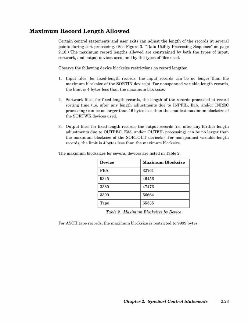
Certain control statements and user exits can adjust the length of the records at severalpoints during sort processing. (See Figure 3. “Data Utility Processing Sequence” on page2.18.) The maximum record lengths allowed are constrained by both the types of input,sortwork, and output devices used, and by the types of files used.
Observe the following device blocksize restrictions on record lengths:
1. Input files: for fixed-length records, the input records can be no longer than themaximum blocksize of the SORTIN device(s). For nonspanned variable-length records,the limit is 4 bytes less than the maximum blocksize.
2. Sortwork files: for fixed-length records, the length of the records processed at recordsorting time (i.e. after any length adjustments due to INPFIL, E15, and/or INRECprocessing) can be no larger than 16 bytes less than the smallest maximum blocksize ofthe SORTWK devices used.
3. Output files: for fixed-length records, the output records (i.e. after any further lengthadjustments due to OUTREC, E35, and/or OUTFIL processing) can be no larger thanthe maximum blocksize of the SORTOUT device(s). For nonspanned variable-lengthrecords, the limit is 4 bytes less than the maximum blocksize.
The maximum blocksizes for several devices are listed in Table 2.
For ASCII tape records, the maximum blocksize is restricted to 9999 bytes.
Device Maximum Blocksize
FBA 32761
9345 46456
3380 47476
3390 56664
Tape 65535
Table 2. Maximum Blocksizes by Device
Chapter 2. SyncSort Control Statements 2.23

Also, observe the device and file type restrictions on the maximum size of fixed-length andvariable-length records shown in Table 3.
Device/File TypeMaximum Record Length
Fixed-Length Variable-Length
FBA sequential disk 32761 32757
CKD sequential disk max. blocksize (max blocksize - 4) c
65535b
VSAM 32761c
65535a32765c
32767a
SAM ESDS 32761 32757c
65535b
Tape 65535 65531c
65535b
a with SPANNED in DEFINE CLUSTER statementb with SPAN on sort’s OUTFIL control statementc unspanned records
Table 3. Maximum Record Lengths by Device and File Type
SyncSort for z/VSE 3.7 Programmer’s Guide2.24

Control Statement Examples
Simple examples illustrating the syntax of each of the SyncSort for z/VSE control state-ments are included in this chapter. More complex applications are presented in “Chapter 4.How to Use SyncSort Data Utility Features”. These applications demonstrate how the INP-FIL, INCLUDE/OMIT, INREC, OUTREC, SUM, and OUTFIL control statements can beused to accomplish a variety of tasks, such as selecting input records, selecting input fields,combining records, reformatting output records, writing reports, and creating multiple out-put.
Rules for Control Statements
The following rules apply to SyncSort for z/VSE control statements.
Specifying Control Statements
• Control statements can be in any order, except for the END statement which, ifspecified, must be last.
• The control statement name can begin in column 2 through column 71. If labels areused, the control statement name can begin in column 3 through 71.
• The control statement name must be the first field of the first card image of thestatement. It cannot be continued on a continuation card image.
• The control statement name must be preceded and followed by at least one blank.
• Each control statement, except for INPFIL/OUTFIL, can be specified only once for aparticular application.
• Each application can include up to 255 card images (including continuation cardimages).
• Specify the OPTION control statement as the first card image if you want to overridethe PRINT and ROUTE defaults prior to all processing or if you want to use SyncSort’sdictionary feature.
Specifying Parameters
• Parameters can take three forms:
– Parameter
– Parameter=value, Parameter=(value) or Parameter(value)
– Parameter=(value1,value2,...,valuen) or Parameter(value1,value2,...,valuen)
Chapter 2. SyncSort Control Statements 2.25

Note: Multiple values must be enclosed in parentheses.
• Parameters can be in any order, but the first parameter must begin on the first cardimage of a control statement.
• Parameters must be separated from each other by commas.
• The parameter(s) must be preceded and followed by at least one blank. A blankseparates the parameter(s) from the control statement name and also indicates the endof the control statement.
• If the parameter(s) end in column 71, column 72 must contain a blank to signal the endof the control statement.
• With the exception of a literal string, a parameter value cannot exceed eightalphanumeric characters.
• With the exception of a literal string, blanks are not permitted within parameters, andblanks, commas, equals signs, and parentheses are not permitted within parametervalues. Parentheses within literal strings must be balanced.
Specifying Field Positions, Lengths, and Formats
• Control statements reference fields by position (p) and length (l).
• The first byte of every fixed-length record is position 1, the second byte position 2, andso on.
• Bytes 1 through 4 of variable-length records are reserved for the Record DescriptorWord (RDW). For these records, the first byte of the data portion is position 5.
• Some control statements support bit-level processing. This means a binary control fieldcan begin and end on any bit of any byte. For example, a position value of 7.4 designatesa field beginning on the fifth bit of the seventh byte (the 8 bits in each byte arenumbered 0 through 7). A length value of 7.4 designates a field seven bytes, four bitslong.
• When proper processing depends on data format, the format of the field must bespecified.
• The format of the field must be appropriate to the task. For example, only numericfields can be SUMmed.
• When all the fields have the same format, the format value can be specified just oncethrough the FORMAT=f subparameter. The FORMAT=f subparameter cannot be usedwhen the INCLUDE/OMIT parameter is specified on the OUTFIL control statement.
SyncSort for z/VSE 3.7 Programmer’s Guide2.26

Specifying Comments
• Identify a comment card image by placing an asterisk (*) in column 1. Comments canextend through column 71.
• A comment card image can be inserted between a control statement and itscontinuation.
• To add a comment to a control statement card image, leave one or more blanks after thelast parameter and follow with the comment, which can extend through column 71.Continue a comment that follows a control statement by coding an asterisk (*) incolumn 1 of the next card image.
Specifying Continuation Card Images
Control statements cannot extend beyond column 71, but they can be continued. To con-tinue a control statement:
• Break after a parameter-comma combination or a complete parameter value beforecolumn 72. Begin the continuation on the next card image anywhere between columns2 and 71. No continuation character is required.
--or--
• When the control statement extends through column 71 and cannot be broken at a parameter-comma combination:
• If the control statement does not contain a literal string that would extend beyondcolumn 71, place a continuation character in column 72 and continue the statementon the next card image anywhere between columns 2 and 16.
• If the control statement does contain a literal string that would extend beyondcolumn 71, place a continuation character in column 72 and begin the continuationof the literal string in column 16 of the next card image.
The following examples illustrate how card images can be continued.
In Figure 6, no continuation character is required. The control statement is interruptedafter a complete parameter value before column 72.
COL. 72 ↓
SORT FIELDS=(1,10,A,20,5,A,45,7,A),FORMAT=CH,FILESOUT=2, WORK=3
Figure 6. Continuing a Control Statement Without Specifying a Continuation Character
Chapter 2. SyncSort Control Statements 2.27
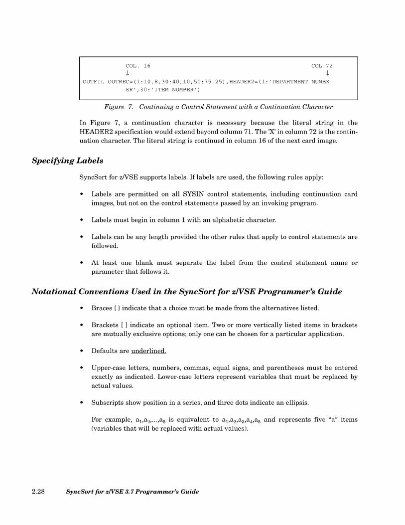
In Figure 7, a continuation character is necessary because the literal string in theHEADER2 specification would extend beyond column 71. The 'X' in column 72 is the contin-uation character. The literal string is continued in column 16 of the next card image.
Specifying Labels
SyncSort for z/VSE supports labels. If labels are used, the following rules apply:
• Labels are permitted on all SYSIN control statements, including continuation cardimages, but not on the control statements passed by an invoking program.
• Labels must begin in column 1 with an alphabetic character.
• Labels can be any length provided the other rules that apply to control statements arefollowed.
• At least one blank must separate the label from the control statement name orparameter that follows it.
Notational Conventions Used in the SyncSort for z/VSE Programmer’s Guide
• Braces { } indicate that a choice must be made from the alternatives listed.
• Brackets [ ] indicate an optional item. Two or more vertically listed items in bracketsare mutually exclusive options; only one can be chosen for a particular application.
• Defaults are underlined.
• Upper-case letters, numbers, commas, equal signs, and parentheses must be enteredexactly as indicated. Lower-case letters represent variables that must be replaced byactual values.
• Subscripts show position in a series, and three dots indicate an ellipsis.
For example, a1,a2,...,a5 is equivalent to a1,a2,a3,a4,a5 and represents five “a” items(variables that will be replaced with actual values).
COL. 16 COL.72
↓ ↓ OUTFIL OUTREC=(1:10,8,30:40,10,50:75,25),HEADER2=(1:'DEPARTMENT NUMBX
ER',30:'ITEM NUMBER')
Figure 7. Continuing a Control Statement with a Continuation Character
SyncSort for z/VSE 3.7 Programmer’s Guide2.28
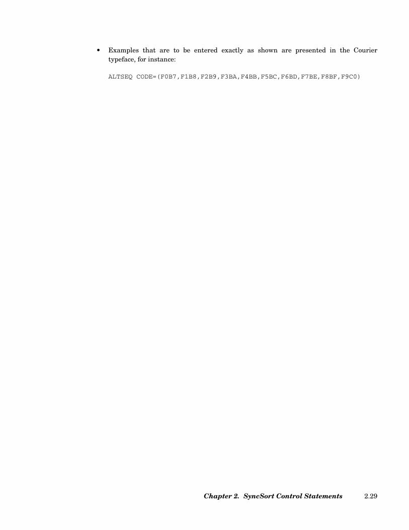
• Examples that are to be entered exactly as shown are presented in the Couriertypeface, for instance:
ALTSEQ CODE=(F0B7,F1B8,F2B9,F3BA,F4BB,F5BC,F6BD,F7BE,F8BF,F9C0)
Chapter 2. SyncSort Control Statements 2.29
ALTSEQ
ALTSEQ Control Statement
The ALTSEQ control statement constructs an alternate collating sequence for all controlfields for which the format code AQ has been specified on the SORT/MERGE orINCLUDE/OMIT statement. If an alternate collating sequence has been provided by instal-lation default, AQ fields collate against this sequence, modified by the ALTSEQ controlstatement. If a default alternate sequence has not been provided, AQ fields collate againstthe standard EBCDIC sequence, modified by an ALTSEQ statement. AQ can be specifiedfor one or more control fields so that those control fields all use the same alternate collatingsequence.
ALTSEQ Control Statement Format
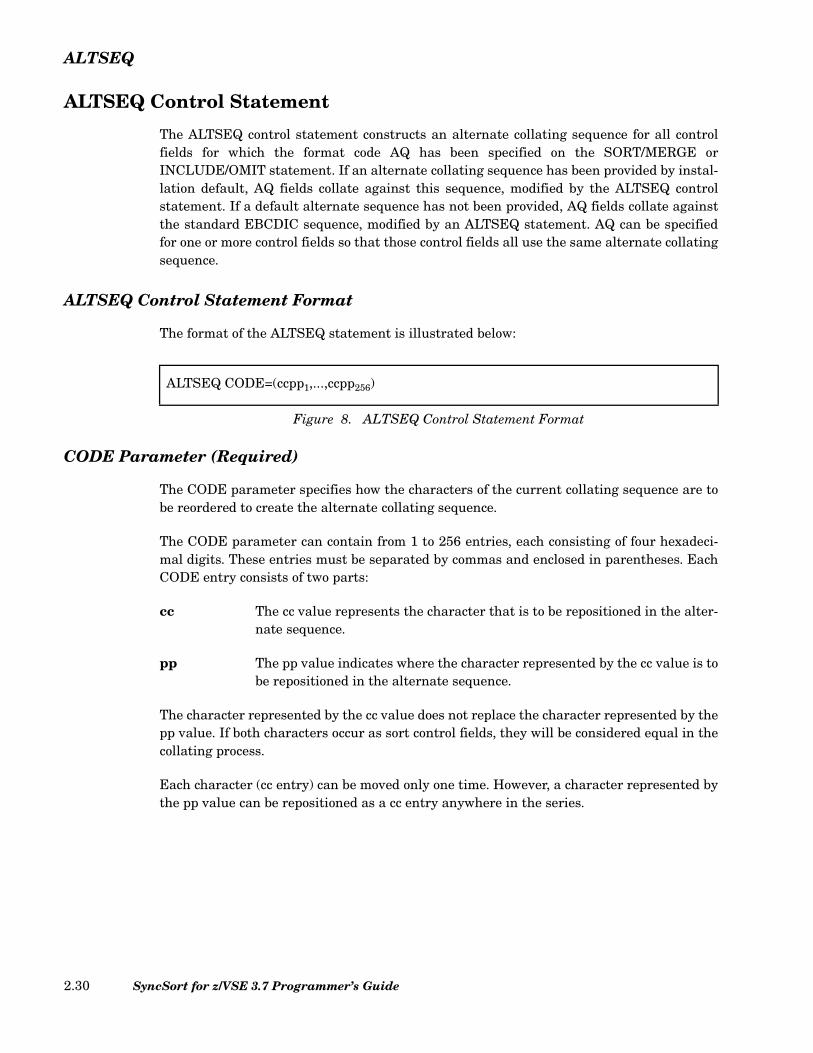
The format of the ALTSEQ statement is illustrated below:
CODE Parameter (Required)
The CODE parameter specifies how the characters of the current collating sequence are tobe reordered to create the alternate collating sequence.
The CODE parameter can contain from 1 to 256 entries, each consisting of four hexadeci-mal digits. These entries must be separated by commas and enclosed in parentheses. EachCODE entry consists of two parts:
cc The cc value represents the character that is to be repositioned in the alter-nate sequence.
pp The pp value indicates where the character represented by the cc value is tobe repositioned in the alternate sequence.
The character represented by the cc value does not replace the character represented by thepp value. If both characters occur as sort control fields, they will be considered equal in thecollating process.
Each character (cc entry) can be moved only one time. However, a character represented bythe pp value can be repositioned as a cc entry anywhere in the series.
ALTSEQ CODE=(ccpp1,...,ccpp256)
Figure 8. ALTSEQ Control Statement Format
SyncSort for z/VSE 3.7 Programmer’s Guide2.30

ALTSEQ
Sample ALTSEQ Control Statements
The ALTSEQ statement in Figure 9 shows that the numbers 0 through 9 are to collatebefore the uppercase alphabet.
This ALTSEQ statement in Figure 10 specifies that the number 0 is to collate as equal to ablank (X'40').
ALTSEQ CODE=(F0B7,F1B8,F2B9,F3BA,F4BB,F5BC,F6BD,F7BE,F8BF,F9C0)
Figure 9. Sample ALTSEQ Control Statement
ALTSEQ CODE=(F040)
Figure 10. Sample ALTSEQ Control Statement
Chapter 2. SyncSort Control Statements 2.31
ANALYZE
ANALYZE Control Statement
The ANALYZE control statement determines how much disk work space a sort will requirebefore it executes.
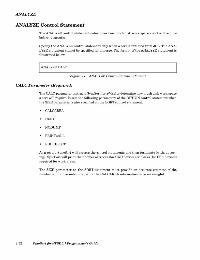
Specify the ANALYZE control statement only when a sort is initiated from JCL. The ANA-LYZE statement cannot be specified for a merge. The format of the ANALYZE statement isillustrated below.
CALC Parameter (Required)
The CALC parameter instructs SyncSort for z/VSE to determine how much disk work spacea sort will require. It sets the following parameters of the OPTION control statement whenthe SIZE parameter is also specified on the SORT control statement:
• CALCAREA
• DIAG
• NODUMP
• PRINT=ALL
• ROUTE=LST
As a result, SyncSort will process the control statements and then terminate (without sort-ing). SyncSort will print the number of tracks (for CKD devices) or blocks (for FBA devices)required for work areas.
The SIZE parameter on the SORT statement must provide an accurate estimate of thenumber of input records in order for the CALCAREA information to be meaningful.
ANALYZE CALC
Figure 11. ANALYZE Control Statement Format
SyncSort for z/VSE 3.7 Programmer’s Guide2.32

DUPKEYS
DUPKEYS Control Statement
The DUPKEYS control statement deletes all records with duplicate SORT/MERGE controlfields and optionally replaces specified numeric fields in the retained record with calculatedaverage, calculated sum, minimum, or maximum values from all records with equal controlfields. The deleted records can optionally be written to a separate output file.
The DUPKEYS control statement cannot be used along with a SUM control statement, orwhen FIELDS=COPY is specified on the SORT or MERGE control statement, or whenFIELDS=COMPARE is specified on the MERGE control statement.
If you need to add AVG, MAX, or MIN functionality to an existing application with a SUMcontrol statement, you must move the SUM specification to the DUPKEYS statement, andremove the SUM statement. If you used XSUM, then specify XDUP on the DUPKEYSstatement, and define a SORTXDP output file instead of the SORTXSM file.
The format of the DUPKEYS control statement is illustrated below.
Arithmetic functions, FIELDS=NONE, ALLDUPS, FIRSTDUP, LASTDUP and NODUPSare all mutually exclusive parameters, except that NODUPS can be specified along withFIRSTDUP or LASTDUP.
If FIELDS=NONE is specified, all records with duplicate control fields are simply deleted.If arithmetic functions are desired then the AVG, MAX, MIN, or SUM parameter must beused, along with the optional FORMAT parameter. The AVG, MAX, MIN, or SUM parame-ter specifies the position, length, and (optionally) the format of one or more numeric fieldsfor the arithmetic function.
When the FORMAT parameter is specified, an individual AVG, MAX, MIN, or SUM fieldmay omit a format value; in this case, the value specified by the FORMAT parameter isused for that field.
where function is:
Figure 12. DUPKEYS Control Statement Format
DUPKEYS
ALLDUPSfunction ,function[ ]... ,FORMAT=f[ ]FIELDS=NONEFIRSTDUP ,NODUPS[ ]LASTDUP ,NODUPS[ ]NODUPS
,XDUP[ ]
AVGMAXMINSUM
= p1,l1 ,f1[ ] ,p2,l2 ,f2[ ][ ]...( )
Chapter 2. SyncSort Control Statements 2.33

Control Statements: DUPKEYS
Each field specified in the AVG, MAX, MIN, and SUM parameters is identified by its posi-tion (p), length (l), and format (f).
p The position value indicates the first byte of the field relative to the beginning ofthe input record after INREC and/or E15 processing, if specified, have completed.The field must begin on a byte boundary.
l The length value indicates the length of the field. The length must be an integralnumber of bytes. Refer to Table 4 for the permissible lengths.
f The optional format value indicates the data format. Table 4 displays the valid for-mats. If the format value is omitted, then the value in the FORMAT parameter isused.
ALLDUPS Parameter (Optional)
The ALLDUPS parameter specifies that only records with SORT/MERGE fields that occurmore than once are retained.
AVG Parameter (Optional)
Use the AVG parameter to specify numeric fields to retain the average value among allrecords of the same control fields. Multiple fields separated by commas may be specified inthe same parameter. Multiple AVG parameters may be specified on the same DUPKEYScontrol statement.
• Adding AVG fields to an existing sort application may result in an increase in theamount of SORTWORK space required. This occurs because AVG postpones allDUPKEYS processing until phase 3.
FORMATCODE
PERMISSIBLE LENGTH
SUM Fields MIN or MAXFields AVG Fields *
BI 2, 4, or 8 bytes 1 to 256 bytes 2, 4, or 8 bytes
FI 2, 4, or 8 bytes 2, 4, or 8 bytes 2, 4, or 8 bytes
FL 4, 8, or 16 bytes 4, 8, or 16 bytes 4, 8, or 16 bytes
PD 1 to 16 bytes 1 to 16 bytes 1 to 10 bytes
ZD 1 to 31 bytes 1 to 31 bytes 1 to 18 bytes
* 8-byte BI, FI and 16-byte FL AVG fields require an ESA-mode VSE machine.
Table 4. Allowed DUPKEYS Field Lengths
SyncSort for z/VSE 3.7 Programmer’s Guide2.34
Control Statements: DUPKEYS
• BI, FI, PD, and ZD AVG fields contain average values truncated to integers. Forexample, the average value of (1,1,1,1,0) is 0 and the average value of (-1,-1,-1,0) is also0.
FIELDS Parameter (Optional)
The only valid value for FIELDS is NONE. Specify FIELDS=NONE only if no arithmeticfunctions are desired. The sorted data will be reduced to one record per sort key value.
FIRSTDUP Parameter (Optional)
The FIRSTDUP parameter specifies that only the first record of those with SORT/MERGEfields that occur more than once is retained. If the NODUPS parameter is also specified, allrecords with SORT/MERGE fields that occur exactly once are also retained.
FORMAT Parameter (Optional)
Use the FORMAT parameter to specify the default field format for fields specified in theAVG, MAX, MIN, and SUM parameters. If any field in the AVG, MAX, MIN, or SUMparameter does not include the format value (f), then this default format value applies tothat field.
LASTDUP Parameter (Optional)
The LASTDUP parameter specifies that only the last record of those with SORT/MERGEfields occurring more than once is retained. If the NODUPS parameter is also specified, allrecords with SORT/MERGE fields occurring exactly once are also retained.
MAX Parameter (Optional)
Use the MAX parameter to specify numeric fields to retain the maximum value among allrecords with the same control fields. Multiple fields separated by commas may be specifiedin the same parameter. Multiple MAX parameters may be specified on the same DUPKEYScontrol statement.
MIN Parameter (Optional)
Use the MIN parameter to specify numeric fields to retain the minimum value among allrecords with the same control fields. Multiple fields separated by commas may be specifiedin the same parameter. Multiple MIN parameters may be specified on the same DUPKEYScontrol statement.
NODUPS Parameter (Optional)
The NODUPS parameter specifies that only records with SORT/MERGE fields that occurexactly once are retained.
Chapter 2. SyncSort Control Statements 2.35
Control Statements: DUPKEYS
SUM Parameter (Optional)
Use the SUM parameter to specify numeric fields to contain the summed value among allrecords with the same control fields. Multiple fields separated by commas may be specifiedin the same parameter. Multiple SUM parameters may be specified on the same DUPKEYScontrol statement.
XDUP Parameter (Optional)
Specify the XDUP parameter if you want the records deleted by DUPKEYS processing to bewritten to a file named SORTXDP (this name may be changed by the XDUPNM parameterin the OPTION statement). These records will be written to SORTXDP at the time of DUPKEYS processing. These records will not undergo OUTREC, E35, and OUTFIL pro-cessing as such processing occurs after DUPKEYS processing.
When the XDUP parameter is specified, at least one additional parameter also must bespecified.
Characteristics of the SORTXDP file, such as BLKSIZE, can be specified with the XDUP-FIL control statement. The default is unblocked output.
The SORTXDP file will be sequenced in the same order as the SORTOUT file.
Note that XDUP may increase system resource requirements:
• Adding XDUP to an existing sort application may result in an increase in the amount ofSORTWORK space required. This occurs because XDUP delays all DUPKEYSprocessing until phase 3.
• XDUP may require additional storage. Do not specify a VSCORE value less than 512Kon the OPTION control statement.
Rules for Specifying DUPKEYS
• When using arithmetic functions or FIELDS=NONE, if EQUALS is in effect, the recordthat is retained is the first record read for that sort key. If NOEQUALS is in effect, therecord that is retained is arbitrarily determined by SyncSort.
• An AVG, MAX, MIN, or SUM field cannot include any or part of a SORT or MERGEcontrol field, nor the first four bytes of a variable-length record that contains theRecord Descriptor Word.
• AVG, MAX, MIN, and SUM fields cannot overlap each other.
• If arithmetic overflow occurs during the summing or averaging of two records, thoserecords are not summed or averaged and neither record is deleted. All other DUPKEYSfunctions are also suspended between those two records. AVG, MAX, MIN, and SUM
SyncSort for z/VSE 3.7 Programmer’s Guide2.36
Control Statements: DUPKEYS
arithmetic restarts when a subsequent set of records with equal control fields can besummed or averaged without overflow. To avoid arithmetic overflow with SUM, use theINREC control statement to insert binary zeros (or X'F0's if ZD) immediately before theSUM field.
• Refer to “OVFLO Parameter (Optional)” on page 2.131 for other options for overflowprocessing.
Sample DUPKEYS Control Statement
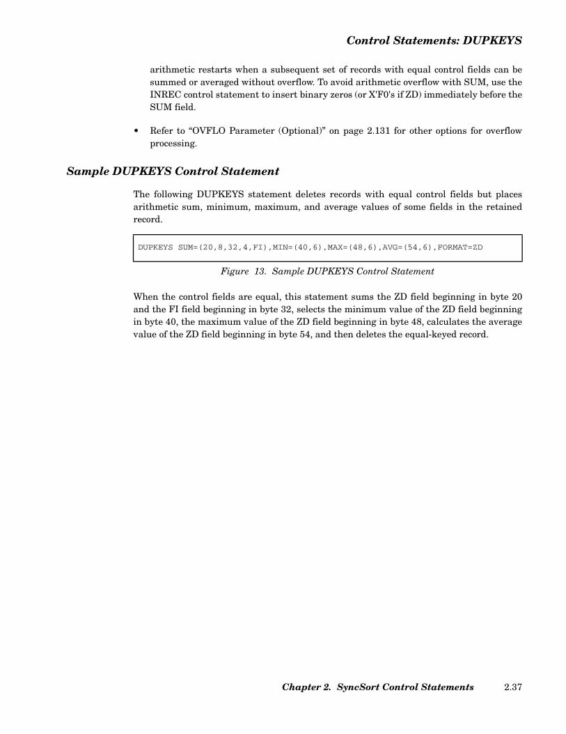
The following DUPKEYS statement deletes records with equal control fields but placesarithmetic sum, minimum, maximum, and average values of some fields in the retainedrecord.
When the control fields are equal, this statement sums the ZD field beginning in byte 20and the FI field beginning in byte 32, selects the minimum value of the ZD field beginningin byte 40, the maximum value of the ZD field beginning in byte 48, calculates the averagevalue of the ZD field beginning in byte 54, and then deletes the equal-keyed record.
DUPKEYS SUM=(20,8,32,4,FI),MIN=(40,6),MAX=(48,6),AVG=(54,6),FORMAT=ZD
Figure 13. Sample DUPKEYS Control Statement
Chapter 2. SyncSort Control Statements 2.37
END
END Control Statement
If present, the END control statement must be the last control statement. The END controlstatement is required only with card input.
The END statement has no parameters, but can contain comments if the comments arepreceded by at least one blank.
When SORTIN is a card (SYSIPT) file, the card file must follow immediately after the ENDcontrol statement. A /* (end-of-data) card must follow the last SORTIN card.
SyncSort for z/VSE 3.7 Programmer’s Guide2.38
INCLUDE/OMIT
INCLUDE/OMIT Control Statement
The INCLUDE/OMIT control statement selects records from an input file based on compar-isons testing the contents of one or more fields within the record. A field can be compared toa constant or to another field within the record. A binary field may enter into comparisonsthat involve testing the individual bits in the field; and substrings, including wildcards,may be specified. Only one INCLUDE/OMIT control statement can be specified for anapplication, either as an INCLUDE or as an OMIT statement.
If you specify an INCLUDE or an OMIT statement, do not use the DELBLANK parameteron the RECORD statement.
LOCALE-Based Comparison Processing
SyncSort supports alternate sets of collating rules based on a specified national language.The alternate collating applies to INCLUDE/OMIT (as well as to INPFIL INCLUDE/OMITand OUTFIL INCLUDE/OMIT) comparison processing as well as to SORT/MERGE pro-cessing. A LOCALE defines single and multi-character collating rules for a cultural envi-ronment.
LOCALE-based INCLUDE/OMIT processing applies only to character (CH) fields andcharacter or hexadecimal constants compared to character fields. When LOCALE is active,a CH to BI (or BI to CH) comparison is not allowed. The illegal comparison will causeSyncSort to terminate with an error message.
For more information on LOCALE-based processing, see “LOCALE Parameter (Optional)”on page 2.128.
INCLUDE/OMIT Control Statement Format
The format of the INCLUDE/OMIT statement follows.
Chapter 2. SyncSort Control Statements 2.39
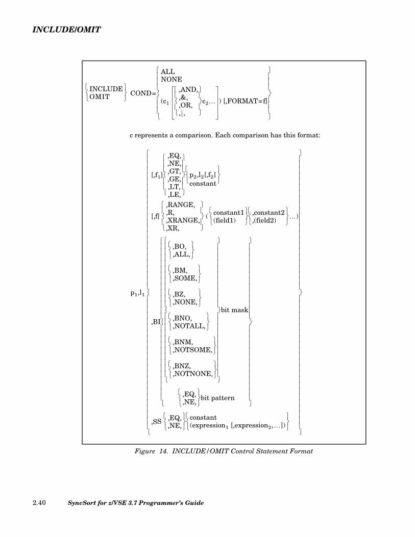
INCLUDE/OMIT
c represents a comparison. Each comparison has this format:
Figure 14. INCLUDE/OMIT Control Statement Format
INCLUDEOMIT
COND=
ALLNONE
(c1
,AND,,&,,OR,, ,
c2… ) [,FORMAT=f]
p1,l1
[,f1]
,EQ,,NE,,GT,,GE,,LT,,LE,
p2,l2[,f2]constant
[,f]
,RANGE,,R,,XRANGE,,XR,
( constant1(field1)
,constant2
,(field2)
…)
,BI
,BO,,ALL,
,BM,,SOME,
,BZ,,NONE,
,BNO,,NOTALL,
,BNM,,NOTSOME,
,BNZ,,NOTNONE,
bit mask
,EQ,,NE,
bit pattern
,SS ,EQ,,NE,
constant
(expression1 [,expression2,…])
SyncSort for z/VSE 3.7 Programmer’s Guide2.40
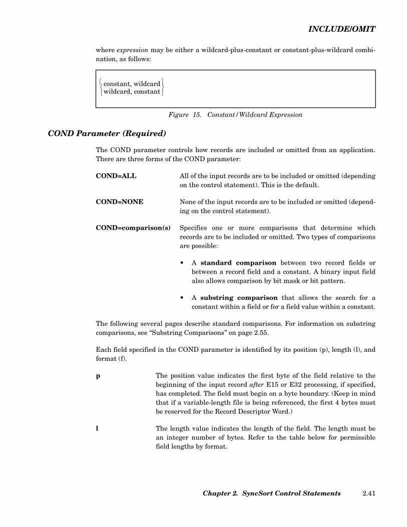
INCLUDE/OMIT
where expression may be either a wildcard-plus-constant or constant-plus-wildcard combi-nation, as follows:
COND Parameter (Required)
The COND parameter controls how records are included or omitted from an application.There are three forms of the COND parameter:
COND=ALL All of the input records are to be included or omitted (dependingon the control statement). This is the default.
COND=NONE None of the input records are to be included or omitted (depend-ing on the control statement).
COND=comparison(s) Specifies one or more comparisons that determine whichrecords are to be included or omitted. Two types of comparisonsare possible:
• A standard comparison between two record fields orbetween a record field and a constant. A binary input fieldalso allows comparison by bit mask or bit pattern.
• A substring comparison that allows the search for aconstant within a field or for a field value within a constant.
The following several pages describe standard comparisons. For information on substringcomparisons, see “Substring Comparisons” on page 2.55.
Each field specified in the COND parameter is identified by its position (p), length (l), andformat (f).
p The position value indicates the first byte of the field relative to thebeginning of the input record after E15 or E32 processing, if specified,has completed. The field must begin on a byte boundary. (Keep in mindthat if a variable-length file is being referenced, the first 4 bytes mustbe reserved for the Record Descriptor Word.)
l The length value indicates the length of the field. The length must bean integer number of bytes. Refer to the table below for permissiblefield lengths by format.
Figure 15. Constant/Wildcard Expression
constant, wildcardwildcard, constant
Chapter 2. SyncSort Control Statements 2.41
INCLUDE/OMIT
f The format value indicates the format type of the field. The supportedformats for standard comparisons are all those indicated in Table 5 onpage 2.43 except for SS. If all data fields have the same format, theFORMAT=f subparameter can be specified instead of the individual fvalues. If both are specified, the individual f values will be used. (Notethat the f values must be specified for each compare field.)
R/RANGE This keyword indicates that a condition is true for a specified range ofvalues. One or more pairs of range values can be specified.
XR/XRANGE This keyword indicates that a condition is true outside a specified rangeof values. One or more pairs of range values can be specified.
constant1 This constant specifies the starting value. This value must be less thanthe ending value of constant2 or field2.
constant2 This constant specifies the ending value. This value must be greaterthan the starting value of constant1 or field1.
field1 This first field contains the starting value to be compared. This valuemust be less than the ending value of constant2 or field2. It has threevariables (p1[, l1, f1]). p1 is the position of the field relative to the begin-ning of the record. l1 is the optional length value indicating the lengthof the field. If omitted, it will use the length defined in field 1 (l). f1 isthe optional format type of the field. If omitted, it will use the formatdefined in field 1 (l).
field2 This second field contains the ending value to be compared. This valuemust be greater than the starting value of constant1 or field1. It hasthree variables (p2[, l2, f2]). p2 is the position of the field relative to thebeginning of the record. l2 is the optional length value indicating thelength of the field. If omitted, it will use the length defined in field 1 (l).f2 is the optional format type of the field. If omitted, it will use the for-mat defined in field 1 (l).
Notes:
1) A constant will be padded or truncated to the length of the field towhich it is compared.
2) Left and right parentheses are mandatory for field1 and field2.
SyncSort for z/VSE 3.7 Programmer’s Guide2.42

INCLUDE/OMIT
For definitions of the field formats in the above table, see Table 7 on page 2.47. The follow-ing table shows the full-date data formats:
Data Format Acceptable FieldLength (Bytes)
AC 1 to 256
AQ 1 to 256
ASL 1 to 256
AST 1 to 256
BI 1 to 256
CH 1 to 256
CLO / OL 1 to 256
CSF / FS 1 to 16
CSL / LS 2 to 256
CST / TS 2 to 256
CTO / OT 1 to 256
FI 1 to 256
PD 1 to 255
PD0 2-8
SFF 1 to 44
UFF 1 to 44
Y2B 1
Y2C / Y2Z 2
Y2D 1
Y2P 2
Y2S 2
ZD 1 to 256
SS 1 to 32767
Table 5. Formats and Lengths of Include/Omit Fields
Chapter 2. SyncSort Control Statements 2.43
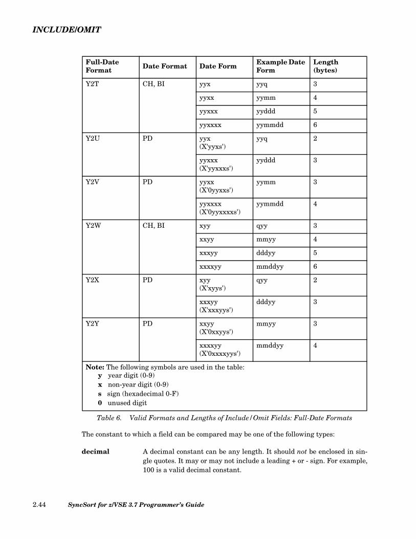
INCLUDE/OMIT
The constant to which a field can be compared may be one of the following types:
decimal A decimal constant can be any length. It should not be enclosed in sin-gle quotes. It may or may not include a leading + or - sign. For example,100 is a valid decimal constant.
Full-DateFormat Date Format Date Form Example Date
Form Length (bytes)
Y2T CH, BI yyx yyq 3
yyxx yymm 4
yyxxx yyddd 5
yyxxxx yymmdd 6
Y2U PD yyx(X'yyxs')
yyq 2
yyxxx(X'yyxxxs')
yyddd 3
Y2V PD yyxx(X'0yyxxs')
yymm 3
yyxxxx(X'0yyxxxxs')
yymmdd 4
Y2W CH, BI xyy qyy 3
xxyy mmyy 4
xxxyy dddyy 5
xxxxyy mmddyy 6
Y2X PD xyy(X'xyys')
qyy 2
xxxyy(X'xxxyys')
dddyy 3
Y2Y PD xxyy(X'0xxyys')
mmyy 3
xxxxyy(X'0xxxxyys')
mmddyy 4
Note: The following symbols are used in the table:y year digit (0-9)x non-year digit (0-9)s sign (hexadecimal 0-F)0 unused digit
Table 6. Valid Formats and Lengths of Include/Omit Fields: Full-Date Formats
SyncSort for z/VSE 3.7 Programmer’s Guide2.44

INCLUDE/OMIT
hexadecimal A hexadecimal constant should be preceded by an X and specified inpairs of valid hexadecimal values that must be enclosed in singlequotes: X'hh...hh'. For example, X'ACBF05' is a valid hexadecimal con-stant. If a hexadecimal constant is compared to a CH field andLOCALE is in effect, the hexadecimal constant is governed by theLOCALE rules.
character A character constant should be preceded by a C and enclosed in singlequotes: C'literal'. For example, C'SALES' is a valid character constant.
To include an apostrophe in a character constant, specify it as two apos-trophes; for example, C'D''AGOSTINO'. If a character constant must becontinued on a second card image, place a continuation character in col-umn 72 and then begin the continuation of the constant in column 16 ofthe next card image. If a character constant is compared to a CH fieldand LOCALE is in effect, the character constant is governed by theLOCALE rules.
Y constant A Y constant should be preceded by a Y and enclosed in single quotes:Y'yyx...x', where yy is a 2-digit year value. For example, Y'991225' is avalid Y constant. A Y constant may only be used with date data for-mats.
There are two methods in which the bit level characteristics of a binary input field can beused to include or omit records. One is to compare the binary field to a bit mask; the otheris to compare the binary field to a bit pattern.
bit mask A bit mask is a string of bits specified in terms of either hexadecimal orbinary digits. The bit mask indicates which bits in the input field are tobe tested. Each bit in the mask whose value is 1 (ON) is tested againstthe corresponding bit in the input field. If the value of a mask bit is 0(OFF), the corresponding bit in the input field is ignored.
The hexadecimal format of a bit mask is X'hh...hh,' where each 'hh' rep-resents any pair of hexadecimal digits.
The binary format of a bit mask is B'bbbbbbbb...bbbbbbbb', where each'bbbbbbbb' represents 8 bits or a byte. Each bit is 1 or 0. The number ofbits in a binary bit mask must be a multiple of 8. The maximum lengthof a binary bit mask is 256 bytes (2048 bits).
A bit mask is truncated or padded on the right to the byte length of thebinary field. The pad character is X'00' or B'00000000'.
bit pattern The binary format of a bit pattern is B'bbbbbbbb...bbbbbbbb', whereeach 'bbbbbbbb' represents 8 bits or a byte. Each bit is 1, 0, or period (.).If the value of a bit in the bit pattern is 1 or 0, the corresponding bit in
Chapter 2. SyncSort Control Statements 2.45
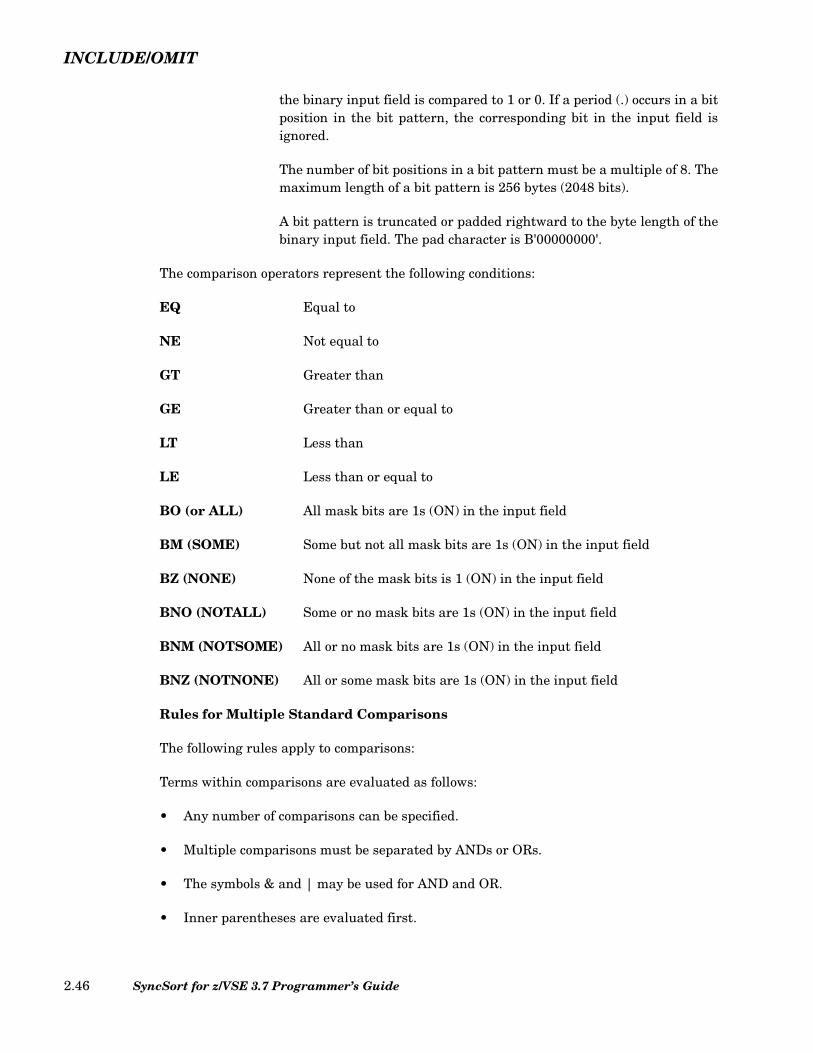
INCLUDE/OMIT
the binary input field is compared to 1 or 0. If a period (.) occurs in a bitposition in the bit pattern, the corresponding bit in the input field isignored.
The number of bit positions in a bit pattern must be a multiple of 8. Themaximum length of a bit pattern is 256 bytes (2048 bits).
A bit pattern is truncated or padded rightward to the byte length of thebinary input field. The pad character is B'00000000'.
The comparison operators represent the following conditions:
EQ Equal to
NE Not equal to
GT Greater than
GE Greater than or equal to
LT Less than
LE Less than or equal to
BO (or ALL) All mask bits are 1s (ON) in the input field
BM (SOME) Some but not all mask bits are 1s (ON) in the input field
BZ (NONE) None of the mask bits is 1 (ON) in the input field
BNO (NOTALL) Some or no mask bits are 1s (ON) in the input field
BNM (NOTSOME) All or no mask bits are 1s (ON) in the input field
BNZ (NOTNONE) All or some mask bits are 1s (ON) in the input field
Rules for Multiple Standard Comparisons
The following rules apply to comparisons:
Terms within comparisons are evaluated as follows:
• Any number of comparisons can be specified.
• Multiple comparisons must be separated by ANDs or ORs.
• The symbols & and | may be used for AND and OR.
• Inner parentheses are evaluated first.
SyncSort for z/VSE 3.7 Programmer’s Guide2.46
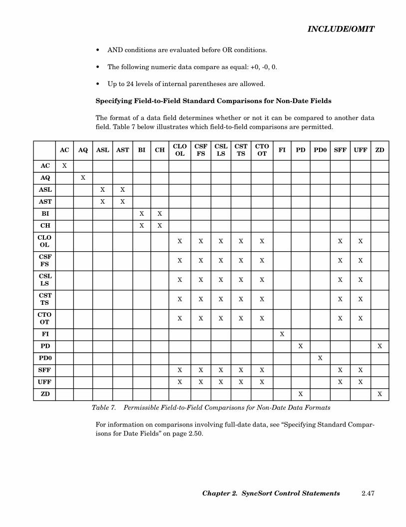
INCLUDE/OMIT
A
A
A
A
B
C
CO
CF
CL
CT
CO
P
P
S
U
Z
• AND conditions are evaluated before OR conditions.
• The following numeric data compare as equal: +0, -0, 0.
• Up to 24 levels of internal parentheses are allowed.
Specifying Field-to-Field Standard Comparisons for Non-Date Fields
The format of a data field determines whether or not it can be compared to another datafield. Table 7 below illustrates which field-to-field comparisons are permitted.
For information on comparisons involving full-date data, see “Specifying Standard Compar-isons for Date Fields” on page 2.50.
AC AQ ASL AST BI CH CLOOL
CSFFS
CSLLS
CSTTS
CTOOT FI PD PD0 SFF UFF ZD
C X
Q X
SL X X
ST X X
I X X
H X X
LOL X X X X X X X
SFS X X X X X X X
SLS X X X X X X X
STS X X X X X X X
TOT X X X X X X X
FI X
D X X
D0 X
FF X X X X X X X
FF X X X X X X X
D X X
Table 7. Permissible Field-to-Field Comparisons for Non-Date Data Formats
Chapter 2. SyncSort Control Statements 2.47
INCLUDE/OMIT
Padding of Compared Fields
When two fields are compared, the shorter field is padded to the length of the longer field.Padding takes place as follows:
• The padding characters are blanks when the shorter field is in character format;otherwise, they are zeros of the shorter field’s own format.
• Padding is on the right if the shorter field is in BI, CH, or PD0 formats. Padding is onthe left for all other formats.
Specifying Field-to-Constant Standard Comparisons for Non-Date Fields
The format of a data field determines the type of constant to which it can be compared.Table 8 below illustrates which field-to-constant comparisons are permitted.
SyncSort for z/VSE 3.7 Programmer’s Guide2.48

INCLUDE/OMIT
Table 8 above does not include full-date formats. For information on comparisons involvingfull-date formats, see “Specifying Standard Comparisons for Date Fields” below.
A constant will be padded or truncated to the length of the field with which it is compared.Decimal constants are padded or truncated on the left; hexadecimal, binary, and characterconstants are padded on the right. The padding characters are:
Format Decimal Hexadecimal Character Binary(bit pattern)
AC X X
AQ X X
ASL X
AST X
BI X X X X
CH X X
CLO / OL X
CSF / FS X
CSL / LS X
CST / TS X
CTO / OT X
FI X
PD X
PD0 X
SFF X
SS X X
UFF X
Y2B X
Y2C / Y2Z X
Y2D X
Y2P X
Y2S X
ZD X
Table 8. Permissible Field-to-Constant Comparisons
Chapter 2. SyncSort Control Statements 2.49

INCLUDE/OMIT
Binary string B'00000000'
EBCDIC Character string X'40'
ASCII Character string X'20'
Hexadecimal string X'00'
Decimal fields Zeros of proper format. Decimal constants for all Y2 for-mats are padded or truncated to two decimal digits rep-resenting a year. The year constant will then haveCENTWIN processing applied to it for comparison to aY2 field. The constants for PD0 comparison should notinclude the first digit and trailing sign of the PD0 datathat will be ignored. Thus, a PD0 field of n bytes will becompared to a constant of n-1 bytes.
Specifying Standard Comparisons for Date Fields
The date data formats work with the CENTWIN run-time parameter or installation optionto define a 2-digit year value that is to be treated as a 4-digit year. CENTWIN defines asliding or fixed 100-year window that determines the century to which 2-digit year databelongs when processed by INCLUDE/OMIT and other control statements.
The date data formats that can be used with INCLUDE/OMIT and OUTFILINCLUDE/OMIT control statements are of two types, 2-digit year formats and full-date for-mats, as follows:
• The 2-digit year formats are Y2B, Y2C, Y2D, Y2P, Y2S, and Y2Z.
• The full-date formats are Y2T, Y2U, Y2V, Y2W, Y2X, and Y2Y.
Date data format fields in a record can be compared to a constant or to another field in therecord. For field-to-field comparisons, date data format fields can only be compared to otherdate data format fields.
Any of the comparison operators (EQ, NE, GE, LT, and LE) can be used.
The date data formats and CENTWIN ensure that century evaluation is applied toINCLUDE/OMIT comparison conditions involving 2-digit year data. For example, withoutCENTWIN processing, an INCLUDE/OMIT comparison would treat the year 01 as “lessthan” the year 98. With CENTWIN processing, the 01 field could be recognized as a twenty-first century date (2001), which would be treated as “greater than” 98 (1998).
For details on the CENTWIN option, see “CENTWIN Parameter (Optional)” on page 2.101.For details on the date data formats, see “CENTWIN (Century Window) Processing withSORT: 2-Digit Year Formats” on page 2.235 and “CENTWIN (Century Window) Processingwith SORT: Full-Date Formats” on page 2.240. For examples of INCLUDE statements not
SyncSort for z/VSE 3.7 Programmer’s Guide2.50

INCLUDE/OMIT
involving date data, see “Sample INCLUDE/OMIT Control Statements without Date Data”on page 2.57. For examples of INCLUDE statements involving date data, see “SampleINCLUDE/OMIT Control Statements with Date Data” on page 2.60.
Table 9 summarizes the valid field-to-field comparisons for 2-digit year data formats:
For full-date formats, two types of comparisons are available:
Field-to-field Compares ZD, PD, and BI date fields.
Field-to-constant Compares a date field to a Y date constant.
The sequencing of date and non-date characters is the same as for an ascending sort.
A full-date data field is comprised of a year field plus additional date components. You cancompare a full-date data field to another full-date data field or to a Y date constant. In bothcases, the compared elements must have the same number of non-year (x) digits.
Thus, you can compare a field of the form P'xxxxyy' to a field of the form Z'xxxxyy' orP'yyxxxx' but not Z'xxyy'. Similarly, you can compare a full-date data field of the formC'yyxxx' or P'xxxyy' to a Y date constant of the form Y'yyxxx' but not Y'yyxx'.
Note that the position of the year components need not be the same for the items beingcompared. Although compared date constants must be in the form yyxx... (two-digit year,month, day -- with month and day optional), the full-date formats take care of this inter-nally.
CH and ZD formats are represented by X'FdFd...sd', and PD formats are represented byX'dd...ds', where “d” is a decimal digit (0-9) and “s” is a sign (0-F). For dates, the sign is notrelevant and can be ignored.
Table 6 on page 2.44 indicates the full-date formats that can be used with character (CH),binary (BI), or packed decimal (PD) data. Note the recognized non-date values:
• Character or binary (Y2T and Y2W full-date formats)C'0...0' (CH zeros)C'9...9' (CH nines)
Y2B Y2C/Y2Z Y2D Y2P Y2S
Y2B X
Y2C/Y2Z X X X
Y2D X X X
Y2P X X X
Y2S X
Table 9. Valid Comparisons with 2-Digit Year Formats
Chapter 2. SyncSort Control Statements 2.51
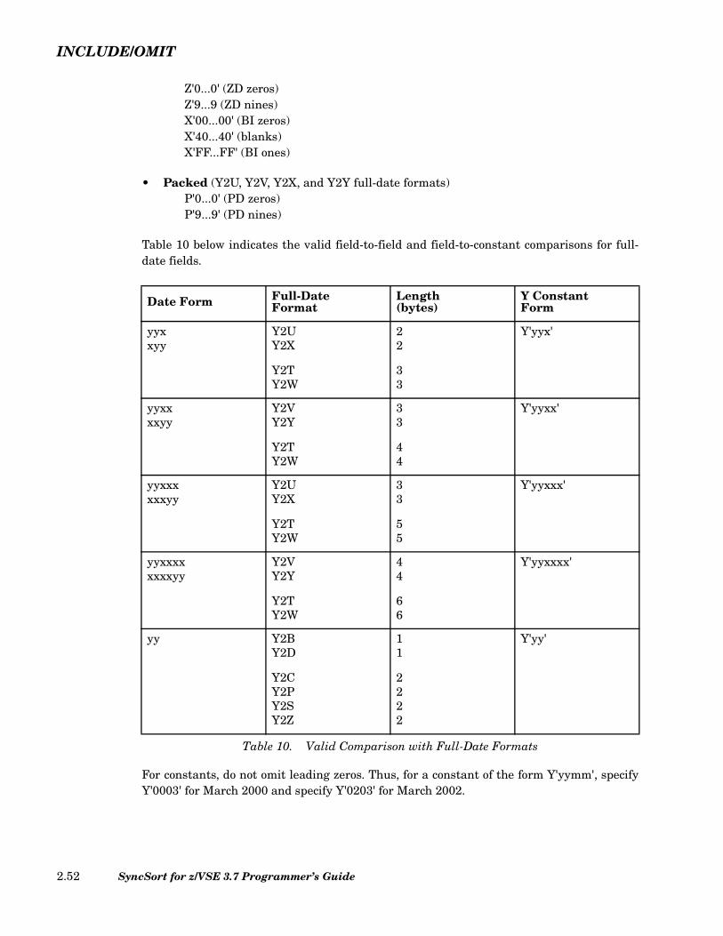
INCLUDE/OMIT
Z'0...0' (ZD zeros)Z'9...9 (ZD nines)X'00...00' (BI zeros)X'40...40' (blanks)X'FF...FF' (BI ones)
• Packed (Y2U, Y2V, Y2X, and Y2Y full-date formats)P'0...0' (PD zeros)P'9...9' (PD nines)
Table 10 below indicates the valid field-to-field and field-to-constant comparisons for full-date fields.
For constants, do not omit leading zeros. Thus, for a constant of the form Y'yymm', specifyY'0003' for March 2000 and specify Y'0203' for March 2002.
Date Form Full-DateFormat
Length(bytes)
Y ConstantForm
yyxxyy
Y2UY2X
Y2TY2W
22
33
Y'yyx'
yyxxxxyy
Y2VY2Y
Y2TY2W
33
44
Y'yyxx'
yyxxxxxxyy
Y2UY2X
Y2TY2W
33
55
Y'yyxxx'
yyxxxxxxxxyy
Y2VY2Y
Y2TY2W
44
66
Y'yyxxxx'
yy Y2BY2D
Y2CY2PY2SY2Z
11
2222
Y'yy'
Table 10. Valid Comparison with Full-Date Formats
SyncSort for z/VSE 3.7 Programmer’s Guide2.52

INCLUDE/OMIT
Y constants can also specify non-date values, as shown in Table 11:
Current Date Constant Specification
You can compare fields to the date of a SyncSort run or the date of the run with an offset inaddition to decimal fields and binary, character, and hexadecimal strings. Thus, records canmore easily be included or omitted based on whether their dates are equal to, less than, orgreater than the run date or the run date with an offset.
The format of a current date constant is illustrated below.
where:
• ‘current date constant’ is in the form of one of the &DATEx, &DATEx(c), &DATExP, orY'DATEx' parameters where x is 1, 2, 3, or 4 and depends on date comparisoncompatibility.
• ‘+’ indicates a date after the current date, and ‘-’ indicates a date before the currentdate.
• ‘nnnn’ can have a maximum of 15 digits with the leftmost zeros truncated. When the xin &DATEx, &DATEx(c), &DATExP, or Y'DATEx' is 1, 3, or 4, ‘nnnn’ can be from 0-9999 and represents offset days. When the x in &DATEx, &DATEx(c), &DATExP, orY'DATEx' is 2, ‘nnnn’ can be from 0-999 and represents offset months.
Y ConstantForm
Non-DateCharacter Full-Date Format
Y'0...0' CH, ZD, PDzeros
Y2T, Y2U, Y2V,Y2W, Y2X, Y2Y
Y'9...9' CH, ZD, PDnines
Y'LOW' BI zeros Y2T, Y2W, Y2S
Y'BLANKS' Blanks
Y'HIGH' BI ones
Table 11. Y Constant and Non-Date Characters
Figure 16. Current Date Constant Format
current date constant +-
nnnn
Chapter 2. SyncSort Control Statements 2.53

INCLUDE/OMIT
The forms of current date constants available for standard comparisons are:
• &DATEx and &DATEx(c) represent the current date as a character string(C'string') to which a field can be compared.
• &DATExP represents the current date as a decimal number (+n) to which a fieldcan be compared.
• Y'DATEx' represents the current date with a Y constant (Y'string') to which a fieldcan be compared.
The following table shows the current date constants and the format produced by each. Thec character in &DATEx(c) represents a non-blank separator character, except open andclose parentheses.
Full-Date Format Constant Specifications
Constants used for full-date comparisons should have the same number of digits in the con-stant as in the full-date field that has been specified. Leading zeros must be specified whenneeded. The constant is constructed from two items; the first is a 2-digit year and the sec-ond is a value representing the months or days that comprise the remainder of the full date
Current Date Constant Generated Constant
&DATE1 C'yyyymmdd'
&DATE1(c) C'yyyycmmcdd'
&DATE1P +yyyymmdd
&DATE2 C'yyyymm'
&DATE2(c) C'yyyycmm'
&DATE2P +yyyymm
&DATE3 C'yyyyddd'
&DATE3(c) C'yyyycddd'
&DATE3P +yyyyddd
&DATE4 C'yyyy-mm-dd-hh.mm.ss'
Y'DATE1' Y'yymmdd'
Y'DATE2' Y'yymm'
Y'DATE3' Y'yyddd'
Table 12. Current Date Constant Formats
SyncSort for z/VSE 3.7 Programmer’s Guide2.54
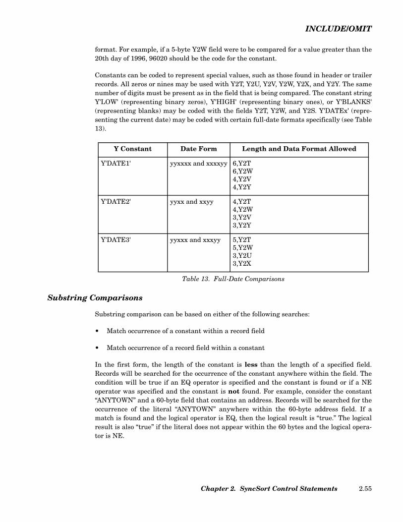
INCLUDE/OMIT
format. For example, if a 5-byte Y2W field were to be compared for a value greater than the20th day of 1996, 96020 should be the code for the constant.
Constants can be coded to represent special values, such as those found in header or trailerrecords. All zeros or nines may be used with Y2T, Y2U, Y2V, Y2W, Y2X, and Y2Y. The samenumber of digits must be present as in the field that is being compared. The constant stringY'LOW' (representing binary zeros), Y'HIGH' (representing binary ones), or Y'BLANKS'(representing blanks) may be coded with the fields Y2T, Y2W, and Y2S. Y'DATEx' (repre-senting the current date) may be coded with certain full-date formats specifically (see Table13).
Table 13. Full-Date Comparisons
Substring Comparisons
Substring comparison can be based on either of the following searches:
• Match occurrence of a constant within a record field
• Match occurrence of a record field within a constant
In the first form, the length of the constant is less than the length of a specified field.Records will be searched for the occurrence of the constant anywhere within the field. Thecondition will be true if an EQ operator is specified and the constant is found or if a NEoperator was specified and the constant is not found. For example, consider the constant“ANYTOWN” and a 60-byte field that contains an address. Records will be searched for theoccurrence of the literal “ANYTOWN” anywhere within the 60-byte address field. If amatch is found and the logical operator is EQ, then the logical result is “true.” The logicalresult is also “true” if the literal does not appear within the 60 bytes and the logical opera-tor is NE.
Y Constant Date Form Length and Data Format Allowed
Y'DATE1' yyxxxx and xxxxyy 6,Y2T6,Y2W4,Y2V4,Y2Y
Y'DATE2' yyxx and xxyy 4,Y2T4,Y2W3,Y2V3,Y2Y
Y'DATE3' yyxxx and xxxyy 5,Y2T5,Y2W3,Y2U3,Y2X
Chapter 2. SyncSort Control Statements 2.55

INCLUDE/OMIT
In the second form, the length of a constant is greater than the length of a specified field.Records will be searched for an occurrence of the field within the constant. For example, theconstant 'A02,A05,A06,A09', which is composed of substrings separated by commas, can becompared against the contents of a 3-byte field within the record. If the 3-byte fieldmatches any 3-byte character string in the constant, the logical result is “true” if the logicaloperator is EQ.
The character used to separate elements of the constant should be a character that does notappear in the field being compared. The comparison is then equivalent to a standard com-parison with ORed conditions. That is, the condition is true if 'A02' OR 'A05' OR 'A06' OR'A09' is found in the field being compared. The substring comparison is a much more com-pact expression than multiple OR conditions in a standard comparison.
For both forms of substring comparisons, constants can be from 1 to 256 bytes in length,while fields in the record can be from 1 to 32767 bytes in length. Constants can be in eithercharacter or hexadecimal format. (Refer to the description of constants just after Table 6 onpage 2.44.) For a sample INCLUDE control statement with substring comparisons, see“Sample INCLUDE/OMIT Control Statements without Date Data” on page 2.57.
Wildcards can be used with substring comparisons to search a string pattern anywherewithin a field.
• The length value (l) can be a wildcard (*). This means the entire record, beginning fromthe starting position (p), is searched for the specified substring.
Note: For variable-length records, you can specify a position (p) that exceeds the mini-mum record length (l4). This excludes all records shorter than l4.
• The constant to which a field is compared can be in either character format(C'AIRLINE') or hexadecimal format (X'0DFF').
Note: If two or more short constants are specified one after the other and separated bya comma without any wildcard characters, then the constants will be concatenated andtreated as one long constant. For example, C'AIR',X'81',C'LAND',X'82' will be combinedto produce a 9-byte constant C'AIRaLANDb'.
• A wildcard can be either an asterisk (*) or percent sign (%). An asterisk (*) representszero or more characters, and a percent sign (%) represents exactly one character.
• Ordinarily, if the length of a constant is greater than the length of a specified field,SyncSort will signify an error. This is not the case with substring comparisons.
For sample INCLUDE control statements with substring wildcards, see “SampleINCLUDE/OMIT Control Statements without Date Data” below.
SyncSort for z/VSE 3.7 Programmer’s Guide2.56
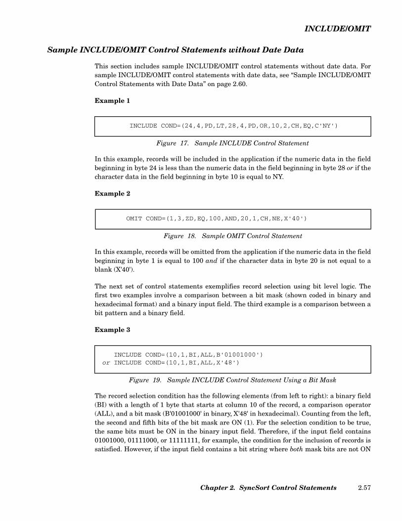
INCLUDE/OMIT
Sample INCLUDE/OMIT Control Statements without Date Data
This section includes sample INCLUDE/OMIT control statements without date data. Forsample INCLUDE/OMIT control statements with date data, see “Sample INCLUDE/OMITControl Statements with Date Data” on page 2.60.
Example 1
In this example, records will be included in the application if the numeric data in the fieldbeginning in byte 24 is less than the numeric data in the field beginning in byte 28 or if thecharacter data in the field beginning in byte 10 is equal to NY.
Example 2
In this example, records will be omitted from the application if the numeric data in the fieldbeginning in byte 1 is equal to 100 and if the character data in byte 20 is not equal to ablank (X'40').
The next set of control statements exemplifies record selection using bit level logic. Thefirst two examples involve a comparison between a bit mask (shown coded in binary andhexadecimal format) and a binary input field. The third example is a comparison between abit pattern and a binary field.
Example 3
The record selection condition has the following elements (from left to right): a binary field(BI) with a length of 1 byte that starts at column 10 of the record, a comparison operator(ALL), and a bit mask (B'01001000' in binary, X'48' in hexadecimal). Counting from the left,the second and fifth bits of the bit mask are ON (1). For the selection condition to be true,the same bits must be ON in the binary input field. Therefore, if the input field contains01001000, 01111000, or 11111111, for example, the condition for the inclusion of records issatisfied. However, if the input field contains a bit string where both mask bits are not ON
INCLUDE COND=(24,4,PD,LT,28,4,PD,OR,10,2,CH,EQ,C'NY')
Figure 17. Sample INCLUDE Control Statement
OMIT COND=(1,3,ZD,EQ,100,AND,20,1,CH,NE,X'40')
Figure 18. Sample OMIT Control Statement
INCLUDE COND=(10,1,BI,ALL,B'01001000') or INCLUDE COND=(10,1,BI,ALL,X'48')
Figure 19. Sample INCLUDE Control Statement Using a Bit Mask
Chapter 2. SyncSort Control Statements 2.57
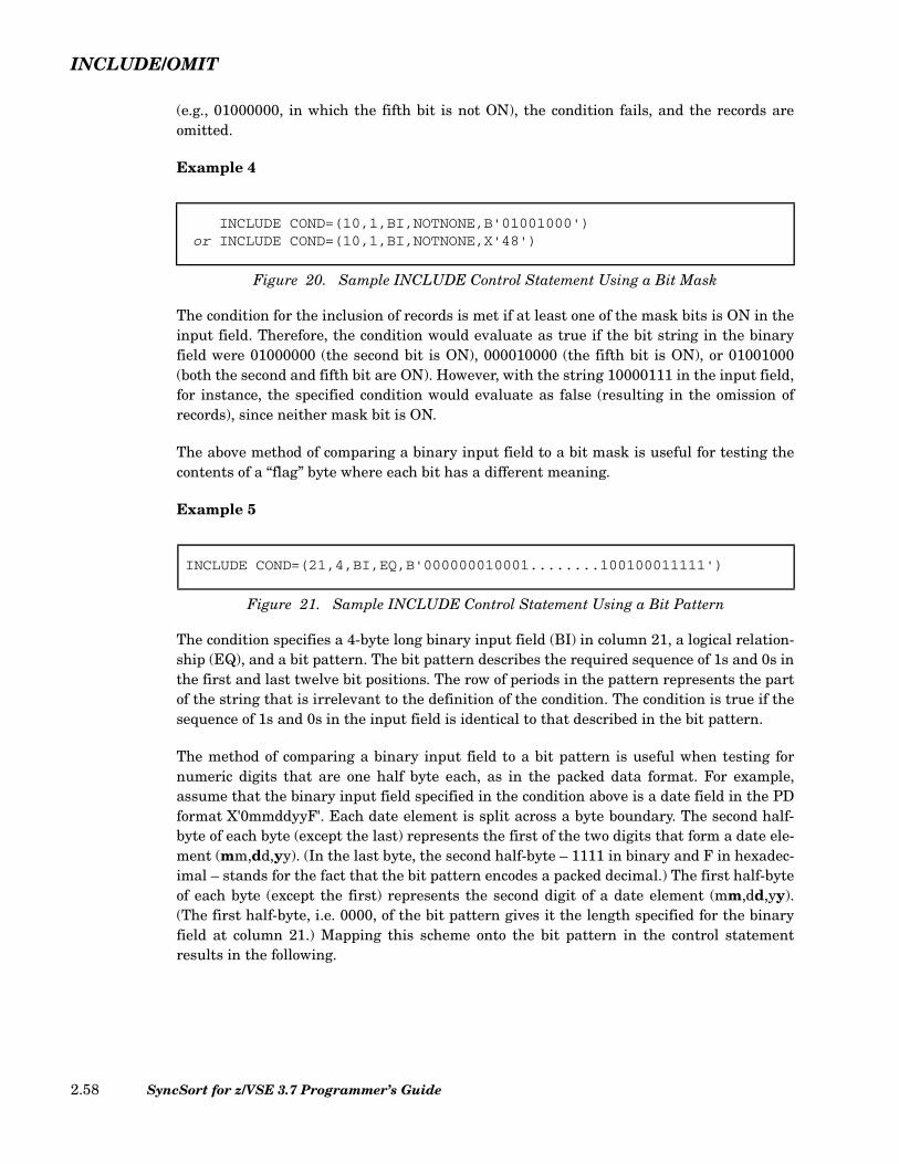
INCLUDE/OMIT
(e.g., 01000000, in which the fifth bit is not ON), the condition fails, and the records areomitted.
Example 4
The condition for the inclusion of records is met if at least one of the mask bits is ON in theinput field. Therefore, the condition would evaluate as true if the bit string in the binaryfield were 01000000 (the second bit is ON), 000010000 (the fifth bit is ON), or 01001000(both the second and fifth bit are ON). However, with the string 10000111 in the input field,for instance, the specified condition would evaluate as false (resulting in the omission ofrecords), since neither mask bit is ON.
The above method of comparing a binary input field to a bit mask is useful for testing thecontents of a “flag” byte where each bit has a different meaning.
Example 5
The condition specifies a 4-byte long binary input field (BI) in column 21, a logical relation-ship (EQ), and a bit pattern. The bit pattern describes the required sequence of 1s and 0s inthe first and last twelve bit positions. The row of periods in the pattern represents the partof the string that is irrelevant to the definition of the condition. The condition is true if thesequence of 1s and 0s in the input field is identical to that described in the bit pattern.
The method of comparing a binary input field to a bit pattern is useful when testing fornumeric digits that are one half byte each, as in the packed data format. For example,assume that the binary input field specified in the condition above is a date field in the PDformat X'0mmddyyF'. Each date element is split across a byte boundary. The second half-byte of each byte (except the last) represents the first of the two digits that form a date ele-ment (mm,dd,yy). (In the last byte, the second half-byte – 1111 in binary and F in hexadec-imal – stands for the fact that the bit pattern encodes a packed decimal.) The first half-byteof each byte (except the first) represents the second digit of a date element (mm,dd,yy).(The first half-byte, i.e. 0000, of the bit pattern gives it the length specified for the binaryfield at column 21.) Mapping this scheme onto the bit pattern in the control statementresults in the following.
INCLUDE COND=(10,1,BI,NOTNONE,B'01001000') or INCLUDE COND=(10,1,BI,NOTNONE,X'48')
Figure 20. Sample INCLUDE Control Statement Using a Bit Mask
INCLUDE COND=(21,4,BI,EQ,B'000000010001........100100011111')
Figure 21. Sample INCLUDE Control Statement Using a Bit Pattern
SyncSort for z/VSE 3.7 Programmer’s Guide2.58
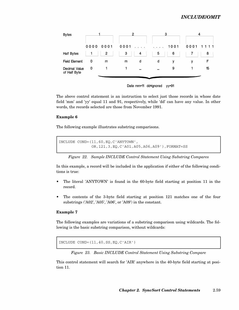
INCLUDE/OMIT
The above control statement is an instruction to select just those records in whose datefield 'mm' and 'yy' equal 11 and 91, respectively, while 'dd' can have any value. In otherwords, the records selected are those from November 1991.
Example 6
The following example illustrates substring comparisons.
In this example, a record will be included in the application if either of the following condi-tions is true:
• The literal 'ANYTOWN' is found in the 60-byte field starting at position 11 in therecord.
• The contents of the 3-byte field starting at position 121 matches one of the foursubstrings ('A02', 'A05', 'A06', or 'A09') in the constant.
Example 7
The following examples are variations of a substring comparison using wildcards. The fol-lowing is the basic substring comparison, without wildcards:
This control statement will search for 'AIR' anywhere in the 40-byte field starting at posi-tion 11.
INCLUDE COND=(11,60,EQ,C'ANYTOWN',OR,121,3,EQ,C'A01,A05,A06,A09'),FORMAT=SS
Figure 22. Sample INCLUDE Control Statement Using Substring Compares
INCLUDE COND=(11,40,SS,EQ,C'AIR')
Figure 23. Basic INCLUDE Control Statement Using Substring Compare
Chapter 2. SyncSort Control Statements 2.59

INCLUDE/OMIT
Consider the following variation with the wildcard (*):
This control statement will search the 40-byte field for a string beginning with 'AIR' fol-lowed by any single character, multiple characters, or nothing and ending with 'FLIGHT'.The following variation uses the wildcard (%):
This control statement will search the 40-byte field for a string beginning with 'AIR' fol-lowed by any five characters and ending with 'FLIGHT'.
The last variation uses a wildcard for the length (l) specification:
This control statement will search the record starting from position 100 to the maximumrecord length (L4 - 100 + 1). It searches for a string beginning with 'AIR' followed by anysingle character, multiple characters, or nothing and ending with 'FLIGHT'. All recordsshorter than 100 bytes will not be searched.
Sample INCLUDE/OMIT Control Statements with Date Data
Example 1
The following example illustrates an INCLUDE comparison based on CENTWIN process-ing.
In this example, only records whose data is from the years greater than 1996 will beincluded in the application. If the CENTWIN parameter were set to 1980, representing acentury window of 1980 to 2079, the records would be processed in the following manner:
INCLUDE COND=(11,40,SS,EQ,(C'AIR',*,C'FLIGHT'))
Figure 24. INCLUDE Control Statement Using Wildcard *
INCLUDE COND=(11,40,SS,EQ,(C'AIR',%%%%%,C'FLIGHT'))
Figure 25. INCLUDE Control Statement Using Wildcard (%)
INCLUDE COND=(100,*,SS,EQ,(C'AIR',*,C'FLIGHT'))
Figure 26. INCLUDE Control Statement Using Wildcard (*) for Length
INCLUDE COND=(20,2,Y2C,GT,96)
Figure 27. INCLUDE Control Statement with Y2C Format
SyncSort for z/VSE 3.7 Programmer’s Guide2.60

INCLUDE/OMIT
Contents ofPosition 20 and 21 Record Disposition
84 Omitted - represents 1984
99 Included - represents 1999
37 Included - represents 2037
Example 2
The following control statement selects records if the date field (20,6) of the form C'mmddyy' is Jan. 1, 1997 through Dec. 31, 2001. Records with a none-date value ofC'999999' are omitted. The previously set century window is 1980-2079 (CENTWIN=1980).
Table 6 on page 2.44 indicates that the 6-byte Y2W format is appropriate for a CH inputfield of the form C'mmddyy'. The OMIT control statement compares the 6-byte field start-ing in byte 20 to three different 6-byte character constants.
The following sample table indicates the include/omit status of input records:
Example 3
The following control statement selects records if the date field (20,3) of the form P'yyddd'(X'yyddds') is between January 1, 1992 and December 31, 2007. Records with non-datevalue P'00000' are also selected.
The previously set century windows is 1980-2079 (CENTWIN=1980).
MERGE FIELDS=COPYOMIT FORMAT=Y2W, * Uses Y2W full-date format.
COND=((20,6,GT,Y'011231'),OR, * Keeps records with dates(20,6,LT,Y'970101'),OR, * between Jan. 1, 1997(20,6,EQ,Y'9')) * and Dec. 31, 2001.
Figure 28. OMIT Control Statement with Y2W Format
SORTIN Input(C'mmddyy')
Record Disposition Date Represented (yyyy/mm/dd)
021545 Omit 2045/02/15 999999 Omit non-date 091899 Include 1999/09/18 062184 Omit 1984/06/21 070400 Include 2000/07/04
Chapter 2. SyncSort Control Statements 2.61
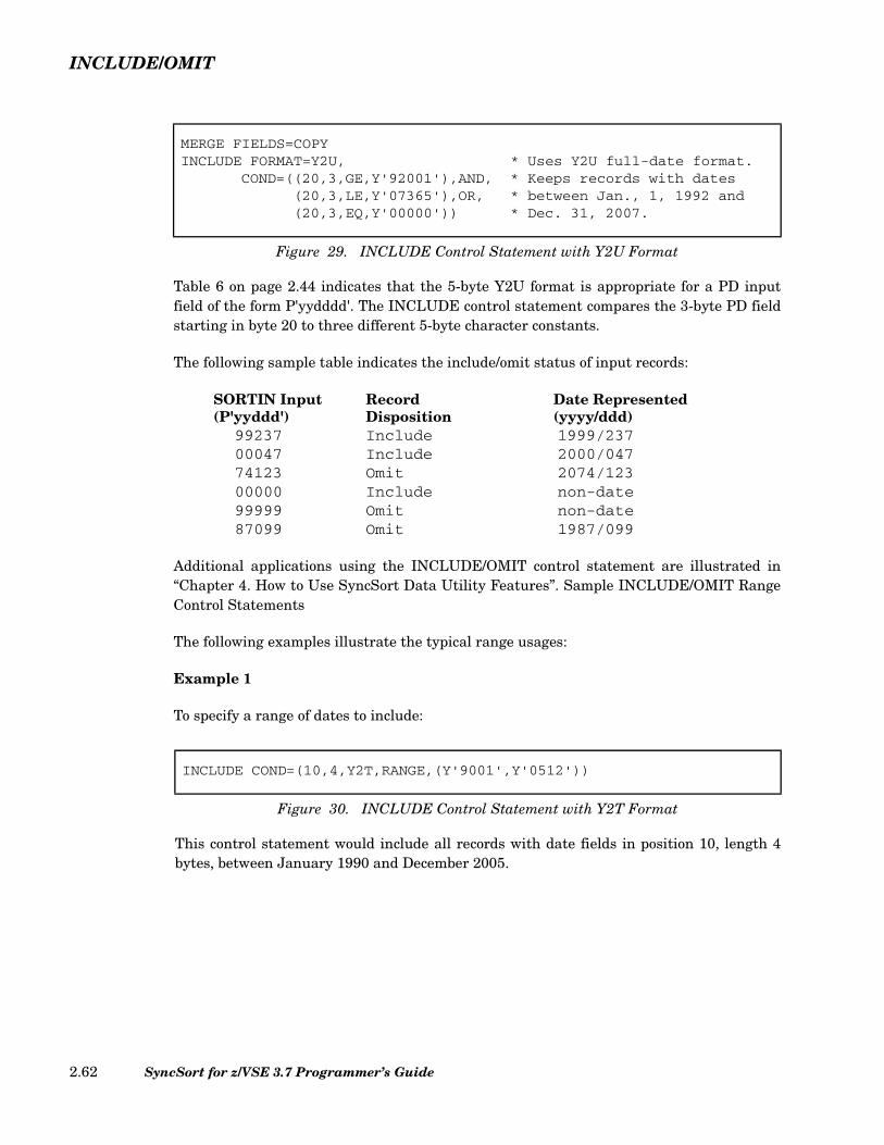
INCLUDE/OMIT
Table 6 on page 2.44 indicates that the 5-byte Y2U format is appropriate for a PD inputfield of the form P'yydddd'. The INCLUDE control statement compares the 3-byte PD fieldstarting in byte 20 to three different 5-byte character constants.
The following sample table indicates the include/omit status of input records:
Additional applications using the INCLUDE/OMIT control statement are illustrated in“Chapter 4. How to Use SyncSort Data Utility Features”. Sample INCLUDE/OMIT RangeControl Statements
The following examples illustrate the typical range usages:
Example 1
To specify a range of dates to include:
MERGE FIELDS=COPYINCLUDE FORMAT=Y2U, * Uses Y2U full-date format.
COND=((20,3,GE,Y'92001'),AND, * Keeps records with dates(20,3,LE,Y'07365'),OR, * between Jan., 1, 1992 and(20,3,EQ,Y'00000')) * Dec. 31, 2007.
Figure 29. INCLUDE Control Statement with Y2U Format
SORTIN Input(P'yyddd')
Record Disposition
Date Represented(yyyy/ddd)
99237 Include 1999/237 00047 Include 2000/047 74123 Omit 2074/123 00000 Include non-date 99999 Omit non-date 87099 Omit 1987/099
INCLUDE COND=(10,4,Y2T,RANGE,(Y'9001',Y'0512'))
Figure 30. INCLUDE Control Statement with Y2T Format
This control statement would include all records with date fields in position 10, length 4bytes, between January 1990 and December 2005.
SyncSort for z/VSE 3.7 Programmer’s Guide2.62

INCLUDE/OMIT
Example 2
To specify a range of dates to exclude:
Example 3
To specify a range of values to include:
This control statement would include all records for an occurrence of the character field inposition 10, length 8 bytes, within the constants between '00001000' and '00005000'.
INCLUDE COND=(10,4,Y2T,RANGE,((50),(60)))
Figure 31. INCLUDE Control Statement with Y2T Format
If field (50,4,Y2T) contains Y'9001' and field (60,4,Y2T) contains Y'0512', then this controlstatement would include all records with date fields in position 10, length 4 bytes, betweenJanuary 1990 and December 2005.
INCLUDE COND=(10,4,Y2T,RANGE,(Y'9001',Y'9012',Y'9501',Y'9512'))
Figure 32. INCLUDE Control Statement with Y2T Format
This control statement would include all records with date fields in position 10, length 4bytes, between January 1990 and December 1990 or between January 1995 and December1995.
INCLUDE COND=(10,4,Y2T,XRANGE,(Y'9001',Y'0512'))
Figure 33. INCLUDE Control Statement with Y2T Format
This control statement would exclude all records with date fields in position 10, length 4bytes, between January 1990 and December 2005.
INCLUDE COND=(10,8,CH,RANGE,(C'00001000',C'00005000'))
INCLUDE COND=((10,8,CH,GE,C'00001000'),&,(10,8,CH,LE,C'00005000'))
Figure 34. INCLUDE Control Statement with RANGE
Chapter 2. SyncSort Control Statements 2.63

INPFIL
INPFIL Control Statement
The INPFIL control statement describes the input file(s) and details certain processingoptions. The format of the INPFIL control statement is illustrated below:
Figure 35. (Page 1 of 2) INPFIL Control Statement Format
INPFIL ,BLKSIZE=n[ ] ,BUFLIM=255n
,NOCHAIN
,BUFOFF=0n
,BYPASS[ ]
,CLOSE=
RWDNORWD
( UNLD
,RALL,REL,Rinput1,…,Rinput32
,RNONE
)
,CONVERT[ ]
,CRDSIZE= 80n
------
,DATA= EA----
,EXIT[ ] ,FILES=1n1,2,…,32( )
,FNAMES=filenamefilename1 ,filename2[ ] ,filename3[ ]…( )
,FTOV[ ]
, INCLUDEOMIT
= …( ) ,INPUT[ ]
INREC ,BUILD,OVERLAY ,
field1[,field2 ]…( )=
IFTHEN, subparm( ) ,IFTHEN = subparm( )[ ]…( ) ,IFOUTLEN = n[ ]=
,LRECL=nnn(lmax[,lmin])
,L4FILL=NONEX'nn'C'c'
,NOCHAIN[ ] ,OPEN=RWDNORWD
,PRESEQ[ ]
,SKIPBYTE[ ] , SKIPRECSTARTREC
=n ,SPAN[ ] , STOPAFTENDREC
= n
SyncSort for z/VSE 3.7 Programmer’s Guide2.64

INPFIL
For more information on the INPFIL processing sequence, see “INPFIL ProcessingSequence” on page 2.21.
BLKSIZE Parameter (Optional)
The BLKSIZE parameter specifies the blocksize of the input records. For multifile input,use the largest blocksize.
If the BLKSIZE parameter is omitted (either by leaving it out of the INPFIL statement oromitting the INPFIL statement itself), SyncSort will assume that the records areunblocked.
The BLKSIZE parameter is not required for VSAM input.
Follow these guidelines in specifying the BLKSIZE value:
fixed-length EBCDIC records BLKSIZE must be a multiple of the fixed recordlength (l1).
variable-length EBCDIC records BLKSIZE must be greater than or equal to thelength of the longest record (l1, which includes theRecord Descriptor Word) plus 4 bytes (for the BlockDescriptor Word).
fixed-length ASCII records BLKSIZE must be a multiple of the fixed recordlength (l1) plus the BUFOFF value, if specified.
variable-length ASCII records BLKSIZE must be greater than or equal to thelength of the longest record (l1, which includes theRecord Descriptor Word) plus the BUFOFF value, ifspecified.
See Table 2 on page 2.23 for the maximum BLKSIZE values allowed for different inputdevices.
Figure 35. (Page 2 of 2) INPFIL Control Statement Format
,SYSIPT[ ] ,TOL[ ] ,VLFILL=b[ ] ,VLLONG=YESNO
,VLTRIM=b[ ] ,VOLUME=n(n1,…,n32)
,VSAM[ ] ,VTOF[ ]
Chapter 2. SyncSort Control Statements 2.65

INPFIL
BUFLIM/NOCHAIN Parameter (Optional)
The BUFLIM parameter places an upper limit of' 'n' on the number of input buffersSyncSort can create. Specify n as a decimal number between 1 and 255. The delivereddefault is 255. For multifile input, this is a global option that can be specified in oneINPFIL statement.
The NOCHAIN parameter can be specified only for tape input cases and is equivalent toBUFLIM=2. NOCHAIN prevents chaining from taking place in a double buffer tape case.NOCHAIN is ignored if it is specified for input from other devices.
Note: In the vast majority of cases, SyncSort for z/VSE needs no external assistance inchoosing the number of buffers. Therefore, avoid specifying this parameter, as inappropri-ate use may degrade performance.
BUFOFF Parameter (Optional)
The BUFOFF parameter can be specified for ASCII input to indicate the block prefix size ofvariable-length ASCII records. The 'n' value can be any number from 0 to 99. The default is0.
Omit the BUFOFF parameter for fixed-length ASCII records, or specify BUFOFF=0.
Specify the BUFOFF parameter only when TYPE=D is specified on the RECORD controlstatement or DATA=A is specified on the INPFIL control statement.
When the BUFOFF parameter is specified, the BLKSIZE value must include the BUFOFFvalue.
BUILD Parameter (Optional)
The BUILD parameter is identical to the INREC parameter of the INPFIL Control State-ment. See “INREC Parameter (Optional)” on page 2.72 for a description of this parameter.
BYPASS Parameter (Optional)
The BYPASS parameter can be specified to instruct SyncSort not to terminate abnormallywhen certain errors are encountered.
The BYPASS parameter functions as follows:
• For non-VSAM files, with fixed-length records or variable-length records, BYPASSinstructs SyncSort to skip input data blocks that have been misread by the system.
• For all files with variable-length records, BYPASS instructs SyncSort to skip recordsthat are greater than or less than the lengths specified on the RECORD statement.
SyncSort for z/VSE 3.7 Programmer’s Guide2.66
INPFIL
If BYPASS is not specified and either of the above situations occurs, the application willterminate abnormally with a detailed error message.
Because this parameter instructs SyncSort to skip erroneous input records, do not specifyBYPASS if all the input records must appear in the output file.
If the BYPASS parameter is specified in conjunction with either an E18 or E38 exit, it willbe ignored for fixed-length records.
Because the BYPASS parameter reduces performance, specify this option only when neces-sary.
CLOSE Parameter (Optional)
Specified for tape input files only, the CLOSE parameter indicates what action should betaken at the end of the file(s).
CLOSE=RWD, the default, indicates that all tape input volumes should be rewound at theend of the file(s). CLOSE=NORWD indicates that the input volumes should not be rewoundat the end of the file(s).
CLOSE=UNLD indicates that all input volumes should be rewound and unloaded at theend of the file(s). The Release option associated with CLOSE=UNLD is designed to assistinstallations that lack tape management systems and may degrade performance whenspecified in conjunction with a tape manager. The RNONE subparameter, the default withCLOSE=UNLD, indicates that the tape drives should not be released until the end of thejob. The other subparameters permit the release of all (RALL) or specific assigned tapedrives (Rinput1,...,Rinput32) after their use for input. When the Release option is specified,the UNLD and Release specifications must be enclosed in parentheses.
CLOSE=(UNLD,REL) indicates that the input tape drives assigned to this INPFIL controlstatement are to be released after their use.
The following example illustrates the CLOSE parameter:
In this example, the tape drives assigned to the SORTIN logical device are released afterthe input phase. A SORTIN device is needed for SORTOUT to be released.
CONVERT Parameter
CONVERT is equivalent to VTOF. See “VTOF Parameter (Optional)” on page 2.76.
CLOSE=(UNLD,REL)
Figure 36. Sample CLOSE Parameter
Chapter 2. SyncSort Control Statements 2.67

INPFIL
CRDSIZE Parameter (Optional)
The CRDSIZE parameter specifies the decimal number of bytes of data per physical inputcard. The delivered default is 80.
When LRECL is a factor of CRDSIZE, “blocked” card input is possible. For example, ifCRDSIZE=80, multiple-record card input is possible if LRECL=40, 20, 10, etc. Thus, everydata card contains two 40-byte records (or four 20-byte records, etc.). Since short blocks arenot permitted, the /* card must appear in columns 1-2 of the last card after full cards ofdata. A short data card can be padded with identifiable “dummy” records, which then areexcluded by the INCLUDE/OMIT control statement.
CRDSIZE removes any possible ambiguity with multi-record card input and multifile,mixed device type input. For example, to sort an 80-column card and 400-byte blocked tapeinput consisting of 40-byte logical records, use the following control statements:
In this example, the logical records are 40 bytes long. The input consists of both cards andtape. Each card contains two records. The blocksize of the tape input is 400. Note that theCRDSIZE parameter is necessary in this case only if the CRDSIZE default of 80 has beenchanged.
DATA=E/A Parameter (Optional)
The DATA parameter specifies either EBCDIC or ASCII input. DATA=E specifies EBCDICinput, and DATA=A specifies ASCII tape input. If this parameter is omitted, EBCDICinput is assumed unless TYPE=D is specified on the RECORD control statement to indi-cate variable-length ASCII input. Mixing ASCII and EBCDIC files on the INPFIL state-ments is not supported.
If DATA=A is specified, the following restrictions apply:
• Only the AC, AST, or ASL format codes can be specified on the SORT and MERGEcontrol statements.
• The INCLUDE/OMIT, SUM, and ALTSEQ control statements cannot be specified.
• The INREC and OUTREC control statements are permitted, but the followingparameters cannot be specified: ZD, PD, BI, or FI formats and Mm, EDIT, SIGNS,LENGTH, and HEX. If the nX parameter is specified, ASCII blanks (X'20') will beinserted instead of EBCDIC blanks (X'40'). Specifying an nC'literal string' on anINREC/OUTREC control statement results in the insertion of the ASCIIrepresentation of the character string.
RECORD TYPE=F,LENGTH=40INPFIL CRDSIZE=80,BLKSIZE=400
Figure 37. Sample INPFIL Control Statement Illustrating CRDSIZE Parameter
SyncSort for z/VSE 3.7 Programmer’s Guide2.68
INPFIL
• The following parameters cannot be specified on the INPFIL control statement:CRDSIZE, SPAN, SYSIPT, TOL, and VSAM.
• The following parameters cannot be specified on the OUTFIL control statement:CARDS, DISK, ESDS, HEADER1, HEADER2, INCLUDE, KSDS, LINES, LRECL,NODETAIL, OMIT, PAGES, PRINT, PUNCH, REUSE, RRDS, SECTIONS, SPAN,TOL, TRAILER1, and TRAILER2.
• If the OUTREC parameter is specified on the OUTFIL control statement, the followingsubparameters cannot be specified: ZD, PD, BI, or FI formats and Mm, EDIT, SIGNS,LENGTH, and HEX. Specifying an nC'literal string' on an INREC/OUTREC controlstatement results in the insertion of the ASCII representation of the character string.
• The value of the BLKSIZE parameter on the INPFIL and OUTFIL control statementscannot exceed 9,999 bytes.
• TYPE=D must be specified on the RECORD control statement for variable-lengthrecords.
• The DELBLANK parameter cannot be specified on the RECORD control statement.
• The KEYLEN and ADDROUT parameters cannot be specified on the OPTION controlstatement. The CMP parameter can be specified on the OPTION statement, but will beignored.
• The date data formats Y2B, Y2C, Y2D, Y2P, Y2S, and Y2Z are changed into 4-digitcharacter (EBCDIC) format by OUTREC data conversion processing. If DATA=A hasbeen specified on the INPFIL statement, the above date data formats will be convertedinto 4-digit ASCII character formats.
When TYPE=D is specified on the RECORD control statement, the above restrictions applyeven if the DATA=A parameter is not specified on the INPFIL control statement.
ENDREC Parameter (Optional)
The ENDREC parameter specifies the last record from the input file.
The record count is done before INPFIL INCLUDE/OMIT processing, if specified, takesplace. (For example, if the first 100 records are to be deleted by INCLUDE/OMIT, the nextrecord is still counted as record number 101. If ENDREC=90, then no records will bepassed to the sort/merge.) For ENDREC=n, the n value can be 1 through 2,147,483,647.
The ENDREC parameter is incompatible with the STOPAFT parameter on the same INPFIL statement.
Chapter 2. SyncSort Control Statements 2.69
INPFIL
EXIT Parameter (Optional)
The EXIT parameter indicates that an E15 or E32 exit will provide all the input to thesort/merge. Write the E15 or E32 exit routine so that it reads the input data and passes onerecord at a time to the sort/merge. Include label processing, volume positioning, and fileopening and closing information. Also, specify exit E15 or exit E32 in the MODS controlstatement.
If the EXIT parameter is specified, all other INPFIL parameters are checked for syntax butignored.
FILES Parameter (Optional)
The FILES parameter connects the INPFIL statement with one or more input files. Thedefault is FILES=1.
By using FILES=(1,2,...,32), data sets that have all their parameters in common may bespecified by one INPFIL. If any one parameter differs, a separate INPFIL must be used.
Note: FNAMES and FILES are mutually exclusive parameters. Specifying both parame-ters on the same INPFIL statement will cause a syntax error. If neither parameter is usedand only one INPFIL statement is specified, then that INPFIL statement applies to allinput files.
FNAMES Parameter (Optional)
The FNAMES parameter connects the INPFIL statement with one or more input files. Thename(s) used to specify the input file(s) can be up to seven characters long, and a corre-sponding DLBL/TLBL statement must be present. The filenames specified with theFNAMES parameter must be either the default filenames (SORTIN1, SORTIN2, ...) or afilename specified using the FILNM parameter of the OPTION statement.
When two or more input files have identical parameters on the INPFIL statement, writethe specifications only once as illustrated below:
Note: FNAMES and FILES are mutually exclusive parameters. Specifying both parame-ters on the same INPFIL statement will cause a syntax error. If neither parameter is usedand only one INPFIL statement is specified, then that INPFIL statement applies to allinput files.
FNAMES=(filename1,filename2,...,filename32)
Figure 38. Sample FNAMES Parameter
SyncSort for z/VSE 3.7 Programmer’s Guide2.70
INPFIL
FTOV Parameter (Optional)
The FTOV parameter converts fixed-length input records to variable-length output records.FTOV can be used both with and without the INREC parameter. When FTOV is used withthe INREC parameter, the variable-length record is created from the specified fields of thefixed-length record. When FTOV is not used with the INREC parameter, the variable-length record is created from the whole fixed-length record.
Note: FTOV cannot be used with CONVERT or VTOF. VLTRIM can be used with theFTOV parameter to delete pad bytes at the end of a record.
The LENGTH parameter on the RECORD control statement specifies the variable-lengthoutput record to be produced by FTOV. l1 specifies the maximum variable-length outputrecord to be produced. l4 specifies the minimum variable-length output record to be pro-duced.
The following control parameters may not be specified when INPFIL FTOV is used:
• INPFIL EXIT
• RECORD TYPE F,D
• MERGE FIELDS=COMPARE
• INPFIL VTOF, CONVERT
FTOV, no INREC Parameter
When FTOV is used without the INREC parameter, the variable-length record is createdfrom the fixed-length record.
FTOV, with INREC Parameter
When FTOV is used with the INREC parameter, the variable-length record is created fromthe specified fields of the fixed-length record. The maximum record length is the maximumof the reformatted input records plus 4.
The TYPE parameter on the RECORD control statement must have a variable-lengthrecord format (for example, VB or VBS).
The LENGTH parameter on the RECORD control statement must be given an LRECL thatcan contain the largest and smallest variable-length records to be produced by INPFIL.
IFOUTLEN Parameter (Optional)
The IFOUTLEN parameter overrides the maximum record length, which is automaticallyset by the IFTHEN parameter, and changes it to a specified value. The IFOUTLEN param-eter may only be used in conjunction with the IFTHEN parameter.
Chapter 2. SyncSort Control Statements 2.71

INPFIL
The IFOUTLEN parameter automatically makes the following changes to the record tomatch the new length. A record longer than n is truncated to n. A fixed-length recordshorter than n is padded with blanks to reach a length of n. The length n must not be largerthan the length l1 specified in the LENGTH parameter on the RECORD control statement.
IFTHEN Parameter (Optional)
The IFTHEN parameter uses conditional logic which enables you to reformat records basedon specified criteria. Multiple IFTHEN parameters may be specified within the same con-trol statement and are processed sequentially. See “IFTHEN Parameter (Optional)” onpage 2.205 for a complete description of this parameter.
INCLUDE/OMIT Parameter (Optional)
The INCLUDE/OMIT parameter selects records from an input file based on comparisons ofthe contents of one or more fields within the record. See “INCLUDE/OMIT Control State-ment Format” on page 2.39.
INPUT Parameter (Optional)
The INPUT parameter is ignored by SyncSort for z/VSE.
INREC Parameter (Optional)
The INREC parameter reformats the input records. See “INREC Control Statement For-mat” on page 2.83 for a complete description of this parameter’s functions.
Note: The LENGTH parameter on the RECORD statement functions differently for fixed-length records than it does for variable-length records. For fixed-length records, LENGTHindicates the record length of the output records produced by INPFIL.
The length of the reformatted input record should match the length specified in theLENGTH parameter on the RECORD statement. If the reformatted input record is lessthan the length on the RECORD statement, SyncSort automatically pads the output recordwith blanks on the right to achieve the desired length.
For variable-length records, LENGTH indicates the maximum and minimum record lengthof the logical records produced by INPFIL INREC. l1 specifies the maximum variable-length output record to be produced. l4 specifies the minimum variable-length outputrecord to be produced. This length should take into account any modifications made by anINREC, or FTOV. See “LRECL Parameter (Optional)” section below for a complete descrip-tion of how to specify an input record length for each file.
SyncSort for z/VSE 3.7 Programmer’s Guide2.72

INPFIL
LRECL Parameter (Optional)
The LRECL parameter specifies an input record length before INPFIL INREC processing,which may differ from the length specified in the LENGTH parameter on the RECORDstatement (see Figure 3 on page 2.18). It is, therefore, possible to have one record length forthe sort/merge and another record length for the input record. For variable-length records,lmax is the maximum input record length, and lmin is the minimum input record length.
Use the INREC control statement to reformat the input records.
When multiple INPFIL statements are used, LRECL parameters may be used on some orall of the INPFIL statements. When LRECL is omitted, the record length values for thatfile are those specified by the LENGTH parameter of the RECORD statement.
When INREC, FTOV, or VTOF is specified on any INPFIL statement, the LRECL parame-ter is required on all INPFIL statements.
L4FILL Parameter (Optional)
INPFIL L4FILL=X'hh' (or C'c') causes variable-length input records shorter than l4 (beforeINREC processing) to be padded with hex byte “hh” (or character “c”) to a length of l4.IGNRL4 is ignored for this file.
INPFIL L4FILL pads the records before any reformatting of records is done by the INRECparameter of the INPFIL control statement, or by the INREC control statement. WhenINPFIL INREC reformats the input records, the records are padded up to the minimumrecord length specified by the LRECL lmin parameter on INPFIL (the length before INPFILINREC reformatting). Otherwise, the l4 value specified on the RECORD control statement(or calculated by SyncSort), which is the length before any reformatting by the INREC con-trol statement, is used. (See Figure 4 on page 2.19 and Figure 5 on page 2.19.)
When L4FILL=NONE is specified, no padding is done. This overrides any L4FILL installa-tion default set by SYNCMAC.
When L4FILL is not specified on an INPFIL statement, padding will be done only if
- L4FILL has been specified as a default by SYNCMAC; and
- IGNRL4 has not been specified on the OPTION control statement.
When INPFIL L4FILL is used without FILES=f, the L4FILL specification applies to allinput files.
L4FILL is not used to pad short variable-length input records that are to be converted tofixed-length records by VTOF or CONVERT; in these cases, specify the VLFILL parameter.
Chapter 2. SyncSort Control Statements 2.73
INPFIL
OPEN Parameter (Optional)
Specified for tape input files only, the OPEN parameter indicates what action should betaken when the file is opened.
OPEN=RWD, the default, indicates that the first volume of each tape input file should berewound when the file is opened. OPEN=NORWD indicates that the first volume of eachinput file should not be rewound when the file is opened. This parameter is ignored if theinput files are on direct access devices.
OVERLAY Parameter (Optional)
The OVERLAY parameter enables you to change particular columns within a record, andadd fields to the end of a record, without rebuilding the entire record. When using theOVERLAY parameter you only need to specify the columns you want to change; the rest ofthe input record remains unchanged. See “OVERLAY Parameter (Optional)” on page 2.209for a complete description of this parameter.
PRESEQ Parameter (Optional)
The PRESEQ parameter is ignored by SyncSort for z/VSE.
SKIPBYTE Parameter (Optional)
The SKIPBYTE parameter is ignored by SyncSort for z/VSE.
SKIPREC Parameter (Optional)
The SKIPREC parameter instructs SyncSort to skip a decimal number of 'n' records perinput file before the file is sorted, merged, or copied. The input bypasses the skippedrecords before INCLUDE/OMIT and INREC processing, if specified, takes place. ForSKIPREC=n, the n value can be 0 through 2,147,483,647.
The SKIPREC parameter is incompatible with the STARTREC parameter on the sameINPFIL statement.
SPAN Parameter (Optional)
The SPAN parameter instructs SyncSort to examine the input file(s) for spanned records.
If TYPE=VS or TYPE=VBS is specified on the RECORD control statement, the SPANparameter need not be specified.
SyncSort for z/VSE 3.7 Programmer’s Guide2.74

INPFIL
STARTREC Parameter (Optional)
The STARTREC parameter specifies the first record that will be processed from the inputfile. The 'n'th record will be the first record eligible for the sort/merge, while the first n-1records are skipped. The record count is done before INPFIL INCLUDE/OMIT processing,if specified, takes place. For STARTREC=n, the n value can be 1 through 2,147,483,647.
The STARTREC parameter is incompatible with the SKIPREC parameter on the sameINPFIL statement.
STOPAFT Parameter (Optional)
The STOPAFT parameter specifies the number of records in a file for output to thesort/merge. These will be the first 'n' records after INCLUDE/OMIT, SKIPREC, andSTARTREC processing. For STOPAFT=n, the n value can be 0 through 2,147,483,647.
The STOPAFT parameter is incompatible with the ENDREC parameter on the sameINPFIL statement.
SYSIPT Parameter (Optional)
The SYSIPT parameter specifies that the input should be read from a card reader. Cardinput can be read with or without specific file assignments. Use the SYSIPT parameterinstead of an E15 exit program for increased efficiency.
Note: SYSIPT must be assigned either to an IBM-supported card reader or to SYSRDRsimulated input (diskette). The SYSIPT parameter cannot be used for card image input ontape or disk.
TOL Parameter (Optional)
The TOL parameter indicates that a warning code is to be accepted when a VSAM input fileis opened. If the TOL parameter is not specified, the warning return code is recognized asan error, an error message is generated, and SyncSort for z/VSE terminates.
VLFILL Parameter (Optional)
The VLFILL parameter is used in conjunction with VTOF to specify a fill byte to be usedfor any short record. By default, spaces will be used.
VLLONG Parameter (Optional)
The VLLONG parameter specifies that SyncSort is to truncate long variable-length inputrecords. A long record is one whose length is greater than the LENGTH=parameter speci-fied in the RECORD control statement. VLLONG=YES indicates that SyncSort truncateslong variable-length input records. VLLONG=NO indicates that SyncSort will terminate ifa long variable-length input record is encountered. This is the default.
Chapter 2. SyncSort Control Statements 2.75

INPFIL
VLTRIM Parameter (Optional)
The VLTRIM parameter defines a byte to be deleted from the end of a variable-lengthrecord. All prior occurrences of this byte will also be deleted until a byte that is not equal tothe trim byte is found. The resulting records are decreased in record length. However, VLTRIM will not delete the first data byte, the Record Descriptor Word (RDW), or a databyte less than or equal to the minimum record length.
For the VLTRIM parameter, specify a byte b to be deleted from the end of the record. b canbe specified as either a character or hexadecimal value. Specify either C'x' where x is a sin-gle EBCDIC character or X'hh' where hh represents a hexadecimal digit pair (00-FF).
Note: VLTRIM is ignored if the FTOV parameter is not used.
VOLUME Parameter (Optional)
Specified for unlabeled or nonstandard labeled tape input files only, the VOLUME parame-ter indicates the number of volumes for each input file. The default is one volume for eachinput file. This parameter is ignored for disk input files.
For multifile input, the format of the VOLUME parameter is VOLUME=(n1,...,n32), where nrepresents the number of volumes in each file. Specify the n values in the same order as theinput files are specified in the SORTIN portion of the job control stream. If the FILES orFNAMES parameter is specified, only the VOLUME=n parameter is supported.
SyncSort’s installation procedure allows the user to choose IBM SM-483 compatibility forthis parameter. (See the VOLUME parameter of SYNCMAC in the SyncSort for z/VSEInstallation Guide for instructions.) With SM-483 compatibility for standard labeled files,SyncSort will process whichever is less: the user’s actual number of volumes or the numberspecified in the VOLUME parameter. Without this change, processing of standard labeledfiles is compatible with IBM’s 5743 and 5746 programs; i.e., the VOLUME parameter isignored.
VSAM Parameter (Optional)
The VSAM parameter specifies VSAM access for VSAM managed SAM input files and isnot required with VSAM input. If this parameter is not specified, SyncSort assumes SAMaccess for VSAM managed SAM.
Note: For improved performance when all input files are VSAM, specify the VSAM param-eter.
VTOF Parameter (Optional)
The VTOF parameter converts variable-length records to fixed-length records. VTOF canbe used either with or without the INREC parameter. When VTOF is used with the INRECparameter, the fixed-length record is created from the specified fields of the variable-length
SyncSort for z/VSE 3.7 Programmer’s Guide2.76
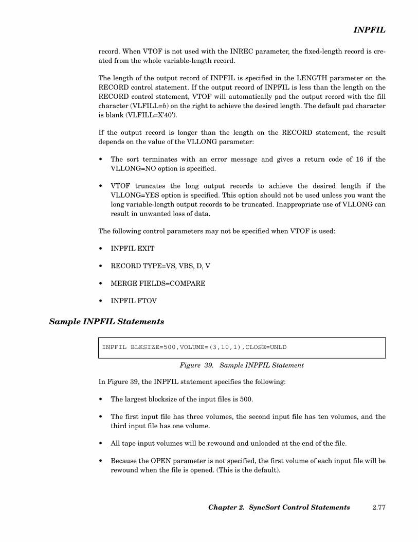
INPFIL
record. When VTOF is not used with the INREC parameter, the fixed-length record is cre-ated from the whole variable-length record.
The length of the output record of INPFIL is specified in the LENGTH parameter on theRECORD control statement. If the output record of INPFIL is less than the length on theRECORD control statement, VTOF will automatically pad the output record with the fillcharacter (VLFILL=b) on the right to achieve the desired length. The default pad characteris blank (VLFILL=X'40').
If the output record is longer than the length on the RECORD statement, the resultdepends on the value of the VLLONG parameter:
• The sort terminates with an error message and gives a return code of 16 if theVLLONG=NO option is specified.
• VTOF truncates the long output records to achieve the desired length if theVLLONG=YES option is specified. This option should not be used unless you want thelong variable-length output records to be truncated. Inappropriate use of VLLONG canresult in unwanted loss of data.
The following control parameters may not be specified when VTOF is used:
• INPFIL EXIT
• RECORD TYPE=VS, VBS, D, V
• MERGE FIELDS=COMPARE
• INPFIL FTOV
Sample INPFIL Statements
In Figure 39, the INPFIL statement specifies the following:
• The largest blocksize of the input files is 500.
• The first input file has three volumes, the second input file has ten volumes, and thethird input file has one volume.
• All tape input volumes will be rewound and unloaded at the end of the file.
• Because the OPEN parameter is not specified, the first volume of each input file will berewound when the file is opened. (This is the default).
INPFIL BLKSIZE=500,VOLUME=(3,10,1),CLOSE=UNLD
Figure 39. Sample INPFIL Statement
Chapter 2. SyncSort Control Statements 2.77
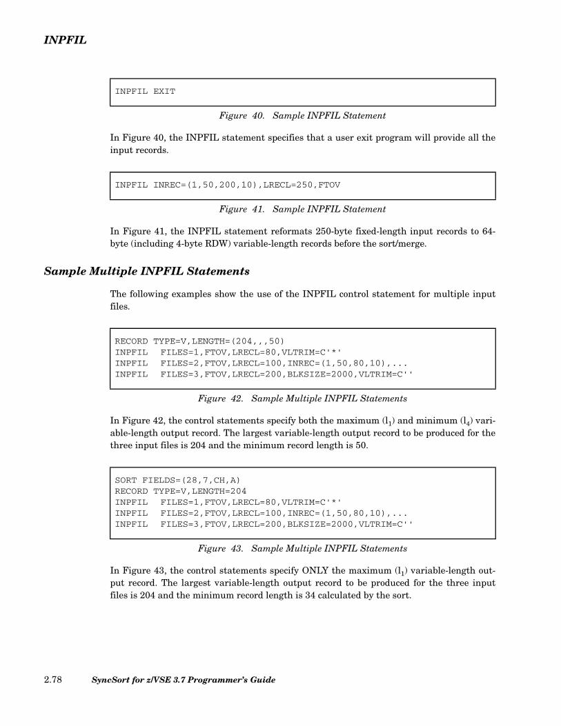
INPFIL
In Figure 40, the INPFIL statement specifies that a user exit program will provide all theinput records.
In Figure 41, the INPFIL statement reformats 250-byte fixed-length input records to 64-byte (including 4-byte RDW) variable-length records before the sort/merge.
Sample Multiple INPFIL Statements
The following examples show the use of the INPFIL control statement for multiple inputfiles.
In Figure 42, the control statements specify both the maximum (l1) and minimum (l4) vari-able-length output record. The largest variable-length output record to be produced for thethree input files is 204 and the minimum record length is 50.
In Figure 43, the control statements specify ONLY the maximum (l1) variable-length out-put record. The largest variable-length output record to be produced for the three inputfiles is 204 and the minimum record length is 34 calculated by the sort.
INPFIL EXIT
Figure 40. Sample INPFIL Statement
INPFIL INREC=(1,50,200,10),LRECL=250,FTOV
Figure 41. Sample INPFIL Statement
RECORD TYPE=V,LENGTH=(204,,,50)INPFIL FILES=1,FTOV,LRECL=80,VLTRIM=C'*'INPFIL FILES=2,FTOV,LRECL=100,INREC=(1,50,80,10),...INPFIL FILES=3,FTOV,LRECL=200,BLKSIZE=2000,VLTRIM=C''
Figure 42. Sample Multiple INPFIL Statements
SORT FIELDS=(28,7,CH,A)RECORD TYPE=V,LENGTH=204INPFIL FILES=1,FTOV,LRECL=80,VLTRIM=C'*'INPFIL FILES=2,FTOV,LRECL=100,INREC=(1,50,80,10),...INPFIL FILES=3,FTOV,LRECL=200,BLKSIZE=2000,VLTRIM=C''
Figure 43. Sample Multiple INPFIL Statements
SyncSort for z/VSE 3.7 Programmer’s Guide2.78

INPFIL
In Figure 44, the INPFIL FILES=1 statement specifies the following:
• The largest blocksize of the input file is 1604.
• The maximum record length of the logical records is 160, and 80 bytes is the minimum.
• The number of records to read from this file is 100.
• The input record will be reformatted based on the specified fields.
• The output maximum record length of the logical records is 1200, and 80 is theminimum.
The INPFIL FILES=2 statement specifies the following:
• The largest blocksize of the input file is 12004.
• The maximum record length of the logical records is 1200, and 80 is the minimum.
• The number of records to read from this file is 150.
• The input record will be reformatted based on the specified fields.
• The output maximum record length of the logical records is 1200, and 80 is theminimum.
In Figure 45, the INPFIL FILES=1 statement specifies the following:
• The largest blocksize of the input file is 800.
• The record length of the logical records is 80.
RECORD TYPE=V,LENGTH=(1200,,,80)INPFIL FILES=1,LRECL=(160,80),STOPAFT=100,
INREC=(1,26,5,7,34),BLKSIZE=1604INPFIL FILES=2,STOPAFT=150,LRECL=(1200,80),
INREC=(1,26,9,7,34),BLKSIZE=12004
Figure 44. Sample Multiple INPFIL Statements
RECORD TYPE=F,LENGTH=80INPFIL BLKSIZE=800,FILES=1,STOPAFT=150,
LRECL=80,INREC=(1,70)INPFIL BLKSIZE=9387,FILES=2,
LRECL=63,INREC=(1,60),SKIPREC=100
Figure 45. Sample Multiple INPFIL Statements
Chapter 2. SyncSort Control Statements 2.79

INPFIL
• The number of records to read from this file is 150.
• The first 70 bytes contain original data, and the last 10 bytes are blanks.
• The output record length is 80.
The INPFIL FILES=2 statement specifies the following:
• The largest blocksize of the input file is 9387.
• The record length of the logical records is 63.
• The number of records to be skipped is 100.
• The first 60 bytes contain original data, and the last 20 bytes are blanks.
• The output record length is 80.
In Figure 46, the INPFIL FILES=1 statement specifies the following:
• The largest blocksize of the input file is 800.
• The record length of the logical records is 80.
• The number of records to be skipped is 100.
• The number of records to read from this file is 200.
• The output record length is 80.
The INPFIL FILES=2 statement specifies the following:
• The largest blocksize of the input file is 800.
• The record length of the logical records is 80.
• The number of records to read from this file is 100.
• The output record length is 80.
RECORD TYPE=F,LENGTH=80INPFIL FILES=1,BLKSIZE=800,STOPAFT=200,SKIPREC=100INPFIL FILES=2,BLKSIZE=800,STOPAFT=100INPFIL FILES=3,BLKSIZE=800OUTFIL BLKSIZE=800OPTION PRINT=ALL,ROUTE=LST,STOPAFT=500
Figure 46. Sample Multiple INPFIL Statements
SyncSort for z/VSE 3.7 Programmer’s Guide2.80

INPFIL
The INPFIL FILES=3 statement specifies the following:
• The largest blocksize of the input file is 800.
• The record length of the logical records is 80.
• The number of records to read from this file is 200.
• The output record length is 80.
The OPTION STOPAFT parameter limits the number of records for the sort as follows:
• 200 records of SORTIN1 are accepted for processing.
• 100 records of SORTIN2 are accepted for processing.
• 200 records of SORTIN3 are accepted for processing (calculated 500-200-100=200).
In Figure 47, the control statements specify both the maximum (l1) and minimum (l4) vari-able-length output records. The largest variable-length output record to be produced for thethree input files is 204 and the minimum record length is 50.
In Figure 48, the control statements specify ONLY the maximum (l1) variable-length out-put record. The largest variable-length output record to be produced for the three inputfiles is 204; the minimum record length of 34 is calculated by the sort.
RECORD TYPE=V,LENGTH=(204,,,50)INPFIL FILES=1,FTOV,LRECL=80,VLTRIM=C'*'INPFIL FILES=2,FTOV,LRECL=100,INREC=(1,50,80,10)INPFIL FILES=3,FTOV,LRECL=200,BLKSIZE=2000,VLTRIM=C''
Figure 47. Sample Multiple INPFIL Statements
SORT FIELDS=(28,7,CH,A)RECORD TYPE=V,LENGTH=204INPFIL FILES=1,FTOV,LRECL=80,VLTRIM=C'*'INPFIL FILES=2,FTOV,LRECL=100,INREC=(1,50,80,10)INPFIL FILES=3,FTOV,LRECL=200,BLKSIZE=2000,VLTRIM=C''
Figure 48. Sample Multiple INPFIL Statements
SORT FIELDS=(30,7,CH,A)RECORD TYPE=V,LENGTH=(83,,,53)INPFIL FILES=(1,3)BLKSIZE=9387INPFIL FILES=2,BLKSIZE=9387,LRECL=(63,58),INREC=(1,34,20X,40)
Figure 49. Sample Multiple INPFIL Statements
Chapter 2. SyncSort Control Statements 2.81
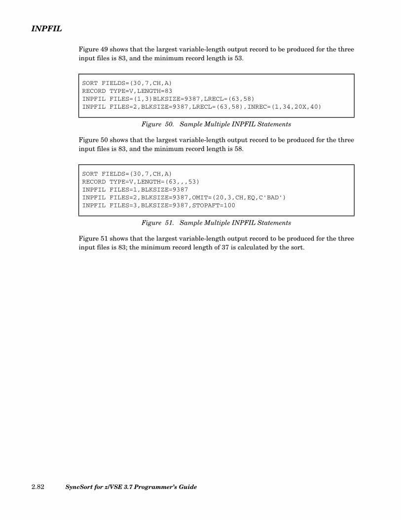
INPFIL
Figure 49 shows that the largest variable-length output record to be produced for the threeinput files is 83, and the minimum record length is 53.
Figure 50 shows that the largest variable-length output record to be produced for the threeinput files is 83, and the minimum record length is 58.
Figure 51 shows that the largest variable-length output record to be produced for the threeinput files is 83; the minimum record length of 37 is calculated by the sort.
SORT FIELDS=(30,7,CH,A)RECORD TYPE=V,LENGTH=83INPFIL FILES=(1,3)BLKSIZE=9387,LRECL=(63,58)INPFIL FILES=2,BLKSIZE=9387,LRECL=(63,58),INREC=(1,34,20X,40)
Figure 50. Sample Multiple INPFIL Statements
SORT FIELDS=(30,7,CH,A)RECORD TYPE=V,LENGTH=(63,,,53)INPFIL FILES=1,BLKSIZE=9387INPFIL FILES=2,BLKSIZE=9387,OMIT=(20,3,CH,EQ,C'BAD')INPFIL FILES=3,BLKSIZE=9387,STOPAFT=100
Figure 51. Sample Multiple INPFIL Statements
SyncSort for z/VSE 3.7 Programmer’s Guide2.82
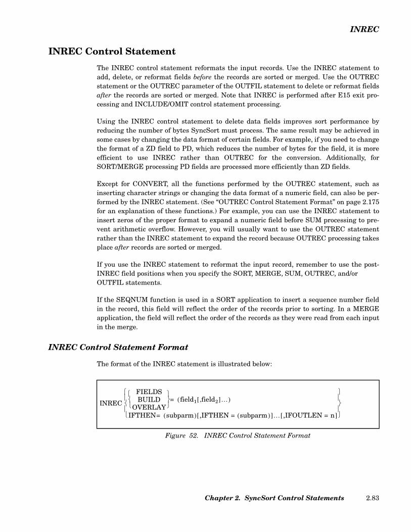
INREC
INREC Control Statement
The INREC control statement reformats the input records. Use the INREC statement toadd, delete, or reformat fields before the records are sorted or merged. Use the OUTRECstatement or the OUTREC parameter of the OUTFIL statement to delete or reformat fieldsafter the records are sorted or merged. Note that INREC is performed after E15 exit pro-cessing and INCLUDE/OMIT control statement processing.
Using the INREC control statement to delete data fields improves sort performance byreducing the number of bytes SyncSort must process. The same result may be achieved insome cases by changing the data format of certain fields. For example, if you need to changethe format of a ZD field to PD, which reduces the number of bytes for the field, it is moreefficient to use INREC rather than OUTREC for the conversion. Additionally, forSORT/MERGE processing PD fields are processed more efficiently than ZD fields.
Except for CONVERT, all the functions performed by the OUTREC statement, such asinserting character strings or changing the data format of a numeric field, can also be per-formed by the INREC statement. (See “OUTREC Control Statement Format” on page 2.175for an explanation of these functions.) For example, you can use the INREC statement toinsert zeros of the proper format to expand a numeric field before SUM processing to pre-vent arithmetic overflow. However, you will usually want to use the OUTREC statementrather than the INREC statement to expand the record because OUTREC processing takesplace after records are sorted or merged.
If you use the INREC statement to reformat the input record, remember to use the post-INREC field positions when you specify the SORT, MERGE, SUM, OUTREC, and/or OUTFIL statements.
If the SEQNUM function is used in a SORT application to insert a sequence number fieldin the record, this field will reflect the order of the records prior to sorting. In a MERGEapplication, the field will reflect the order of the records as they were read from each inputin the merge.
INREC Control Statement Format
The format of the INREC statement is illustrated below:
Figure 52. INREC Control Statement Format
INREC
FIELDSBUILD
OVERLAY
field1 field2,[ ]…( )=
IFTHEN subparm( )= ,IFTHEN = subparm( )[ ]… ,IFOUTLEN = n[ ]
Chapter 2. SyncSort Control Statements 2.83

INREC
FIELDS/BUILD Parameter
The FIELDS parameter specifies the data fields to be included in the application. BUILD isan alias for FIELDS. See “OUTREC Control Statement Format” on page 2.175 for a com-plete description of these parameters.
IFOUTLEN Parameter (Optional)
The IFOUTLEN parameter overrides the maximum record length, which is automaticallyset by the IFTHEN parameter, and changes it to a specified value. The IFOUTLEN param-eter may only be used in conjunction with the IFTHEN parameter.
The IFOUTLEN parameter automatically makes the following changes to the record tomatch the new length. A record longer than n is truncated to n. A fixed-length recordshorter than n is padded with blanks to reach a length of n.
IFTHEN Parameter (Optional)
The IFTHEN parameter uses conditional logic which enables you to reformat records basedon specified criteria. Multiple IFTHEN parameters may be specified within the same con-trol statement and are processed sequentially. See “IFTHEN Parameter (Optional)” onpage 2.205 for a complete description of this parameter.
OVERLAY Parameter (Optional)
The OVERLAY parameter enables you to change particular columns within a record, andadd fields to the end of a record, without rebuilding the entire record. When using theOVERLAY parameter you only need to specify the columns you want to change; the rest ofthe input record remains unchanged. See “OVERLAY Parameter (Optional)” on page 2.209for a complete description of this parameter.
Sample INREC Control Statement
This INREC statement specifies three data fields from an 80-byte record:
• The first field begins in byte 1 of the input record and is 20 bytes long.
• The second field begins in byte 40 of the input record and is a 15-byte ZD field. The dataformat is to be converted to PD. Since the input field contains 15 decimal digits, theconverted PD output field created by SyncSort will be 8 bytes long.
• The third field begins in byte 60 of the input record and is 5 bytes long.
INREC FIELDS=(1:1,20,21:40,15,ZD,PD,29:60,5)
Figure 53. Sample INREC Control Statement
SyncSort for z/VSE 3.7 Programmer’s Guide2.84
INREC
These three fields have been positioned to begin in bytes 1, 21, and 29, as indicated by theircolumn prefixes.
The reformatted input record is now just 33 bytes long.
For comprehensive examples that illustrate the INREC control statement, see “Chapter 4.How to Use SyncSort Data Utility Features”.
Chapter 2. SyncSort Control Statements 2.85
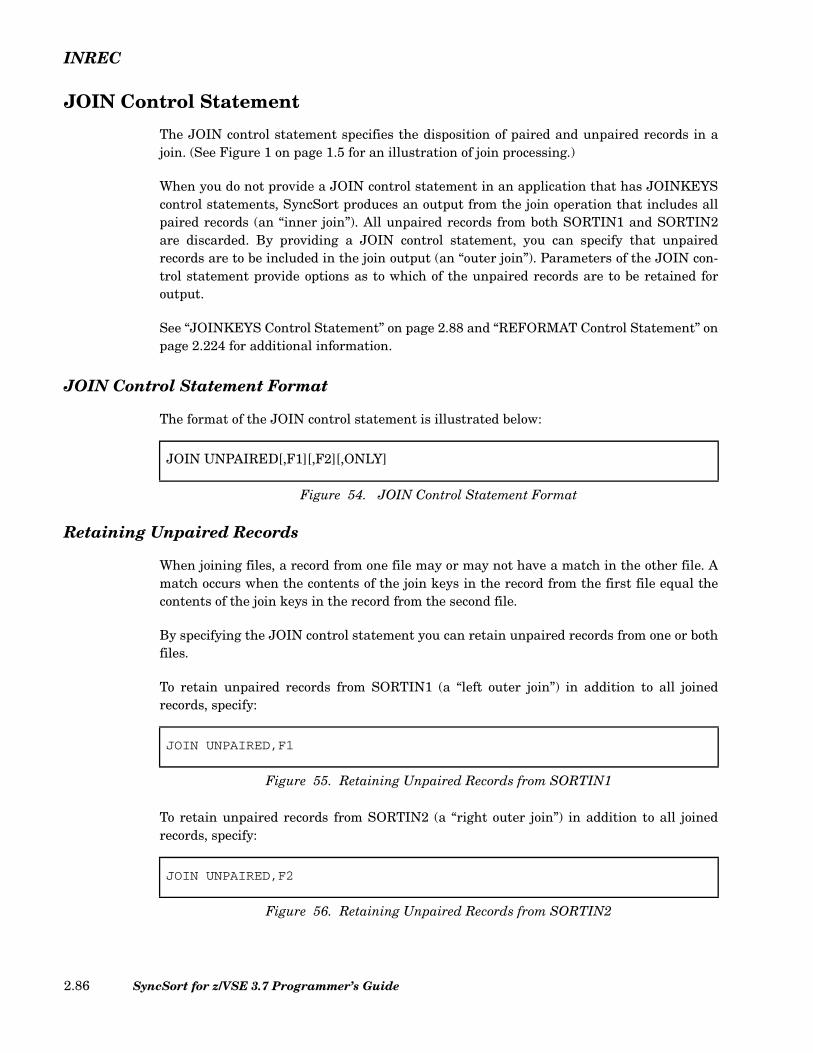
INREC
JOIN Control Statement
The JOIN control statement specifies the disposition of paired and unpaired records in ajoin. (See Figure 1 on page 1.5 for an illustration of join processing.)
When you do not provide a JOIN control statement in an application that has JOINKEYScontrol statements, SyncSort produces an output from the join operation that includes allpaired records (an “inner join”). All unpaired records from both SORTIN1 and SORTIN2are discarded. By providing a JOIN control statement, you can specify that unpairedrecords are to be included in the join output (an “outer join”). Parameters of the JOIN con-trol statement provide options as to which of the unpaired records are to be retained foroutput.
See “JOINKEYS Control Statement” on page 2.88 and “REFORMAT Control Statement” onpage 2.224 for additional information.
JOIN Control Statement Format
The format of the JOIN control statement is illustrated below:
Retaining Unpaired Records
When joining files, a record from one file may or may not have a match in the other file. Amatch occurs when the contents of the join keys in the record from the first file equal thecontents of the join keys in the record from the second file.
By specifying the JOIN control statement you can retain unpaired records from one or bothfiles.
To retain unpaired records from SORTIN1 (a “left outer join”) in addition to all joinedrecords, specify:
To retain unpaired records from SORTIN2 (a “right outer join”) in addition to all joinedrecords, specify:
JOIN UNPAIRED[,F1][,F2][,ONLY]
Figure 54. JOIN Control Statement Format
JOIN UNPAIRED,F1
Figure 55. Retaining Unpaired Records from SORTIN1
JOIN UNPAIRED,F2
Figure 56. Retaining Unpaired Records from SORTIN2
SyncSort for z/VSE 3.7 Programmer’s Guide2.86
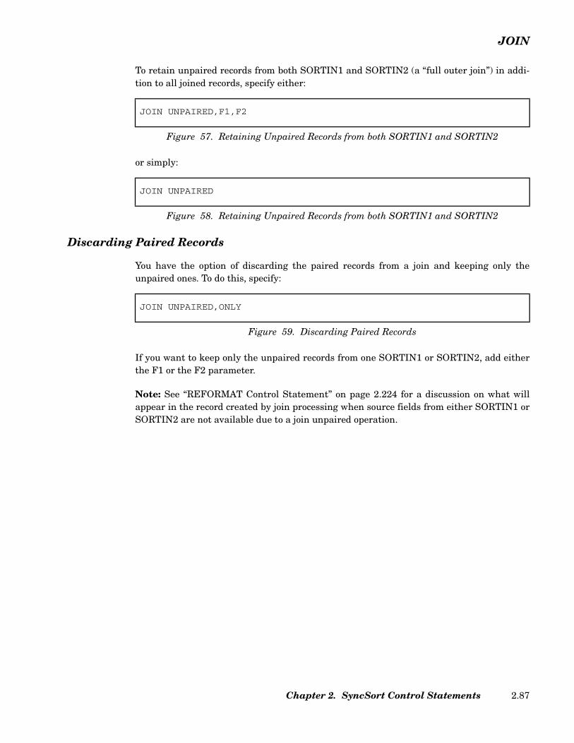
JOIN
To retain unpaired records from both SORTIN1 and SORTIN2 (a “full outer join”) in addi-tion to all joined records, specify either:
or simply:
Discarding Paired Records
You have the option of discarding the paired records from a join and keeping only theunpaired ones. To do this, specify:
If you want to keep only the unpaired records from one SORTIN1 or SORTIN2, add eitherthe F1 or the F2 parameter.
Note: See “REFORMAT Control Statement” on page 2.224 for a discussion on what willappear in the record created by join processing when source fields from either SORTIN1 orSORTIN2 are not available due to a join unpaired operation.
JOIN UNPAIRED,F1,F2
Figure 57. Retaining Unpaired Records from both SORTIN1 and SORTIN2
JOIN UNPAIRED
Figure 58. Retaining Unpaired Records from both SORTIN1 and SORTIN2
JOIN UNPAIRED,ONLY
Figure 59. Discarding Paired Records
Chapter 2. SyncSort Control Statements 2.87

JOINKEYS
JOINKEYS Control Statement
Use the JOINKEYS statement to enable join feature processing and to identify the fieldsused to select records for join processing. (See Figure 1 on page 1.5 for an illustration of joinprocessing.)
The join feature joins records from two input files that are specified on the SORTIN1 andSORTIN2 label statements. By default, when the JOINKEYS fields from m records inSORTIN1 match the JOINKEYS fields from n records in SORTIN2, all combinations of therecords are joined using the REFORMAT control statement, producing m*n records asinput to subsequent SyncSort processing. (This is called an “inner join.”)
See “REFORMAT Control Statement” on page 2.224 for a description of how a record is con-structed from two records that have been selected as a match.
If the optional JOIN UNPAIRED control statement is specified, the unmatched recordsfrom the SORTIN1 and/or SORTIN2 files will also be REFORMATted and included in theinput to SyncSort without being joined. (Including the unmatched records from SORTIN1is called a “left outer join,” and including all unmatched records is called a “full outer join.”)Optionally, only these unmatched records will become input to SyncSort. See “JOIN Con-trol Statement” on page 2.86 and “REFORMAT Control Statement” on page 2.224 for fur-ther details on their specifications.
The input files do not need to be presorted or have the same record type.
Two JOINKEYS control statements are required - one for each of the two files used in thejoin. Do not specify an INPFIL control statement when JOINKEYS control statements areused.
When JOINKEYS control statements are used, the RECORD control statement is ignoredand can be omitted. The actual record type and length will be determined by the REFORMAT statement or the input files.
The JOINKEYS control statement cannot be used with any exits (except for E35).
SyncSort for z/VSE 3.7 Programmer’s Guide2.88

JOINKEYS
JOINKEYS Control Statement Format
The format of the JOINKEYS control statement is illustrated below:
FILE Parameter (Required)
The FILE parameter connects the JOINKEYS control statement with the input file to beread. The specification of F1 connects the JOINKEYS control statement with the SORTIN1label statement. The specification of the F2 connects the JOINKEYS control statementwith the SORTIN2 label statement.
FIELDS Parameter (Required)
The FIELDS parameter is required. It describes the fields to be used to match records fromthe two files, SORTIN1 and SORTIN2.
The number of JOINKEYS fields must be the same for both files, although their startingpositions need not be the same.
These fields can be in any of CH, BI, FI, PD, or ZD formats. If not explicitly specified, thedefault format is binary (BI).
Figure 60. JOINKEYS Control Statement Format
JOINKEYS FILE= F1F2
,FIELDS= p1,l1,f1 o, 1 p, 2,l2,f2 o, 2… p64,l64,f64 o, 64[ ][ ]( ),
FORMAT=f,[ ]
LRECL=nnnl1 ,l4[ ]( )
,TYPE= FV
,BLKSIZE=n[ ]
,BUFLIM=255n
,BUFOFF= 0n---
,BYPASS[ ]
,CLOSE=RWDNORWDUNLD
,CRDSIZE=80n
,DATA= EA----
, ENDRECSTOPAFT
=n , INCLUDEOMIT
= …( ) ,OPEN=RWDNORWD
,SORTED[ ] ,SPAN[ ] , STARTRECSKIPREC
=n ,SYSIPT[ ] ,TOL[ ]
,VOLUME=n[ ][,VSAM]
Chapter 2. SyncSort Control Statements 2.89
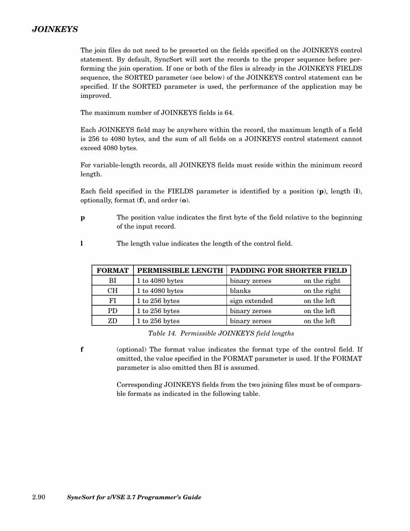
JOINKEYS
The join files do not need to be presorted on the fields specified on the JOINKEYS controlstatement. By default, SyncSort will sort the records to the proper sequence before per-forming the join operation. If one or both of the files is already in the JOINKEYS FIELDSsequence, the SORTED parameter (see below) of the JOINKEYS control statement can bespecified. If the SORTED parameter is used, the performance of the application may beimproved.
The maximum number of JOINKEYS fields is 64.
Each JOINKEYS field may be anywhere within the record, the maximum length of a fieldis 256 to 4080 bytes, and the sum of all fields on a JOINKEYS control statement cannotexceed 4080 bytes.
For variable-length records, all JOINKEYS fields must reside within the minimum recordlength.
Each field specified in the FIELDS parameter is identified by a position (p), length (l),optionally, format (f), and order (o).
p The position value indicates the first byte of the field relative to the beginningof the input record.
l The length value indicates the length of the control field.
Table 14. Permissible JOINKEYS field lengths
f (optional) The format value indicates the format type of the control field. Ifomitted, the value specified in the FORMAT parameter is used. If the FORMATparameter is also omitted then BI is assumed.
Corresponding JOINKEYS fields from the two joining files must be of compara-ble formats as indicated in the following table.
FORMAT PERMISSIBLE LENGTH PADDING FOR SHORTER FIELDBI 1 to 4080 bytes binary zeroes on the rightCH 1 to 4080 bytes blanks on the rightFI 1 to 256 bytes sign extended on the leftPD 1 to 256 bytes binary zeroes on the leftZD 1 to 256 bytes binary zeroes on the left
SyncSort for z/VSE 3.7 Programmer’s Guide2.90
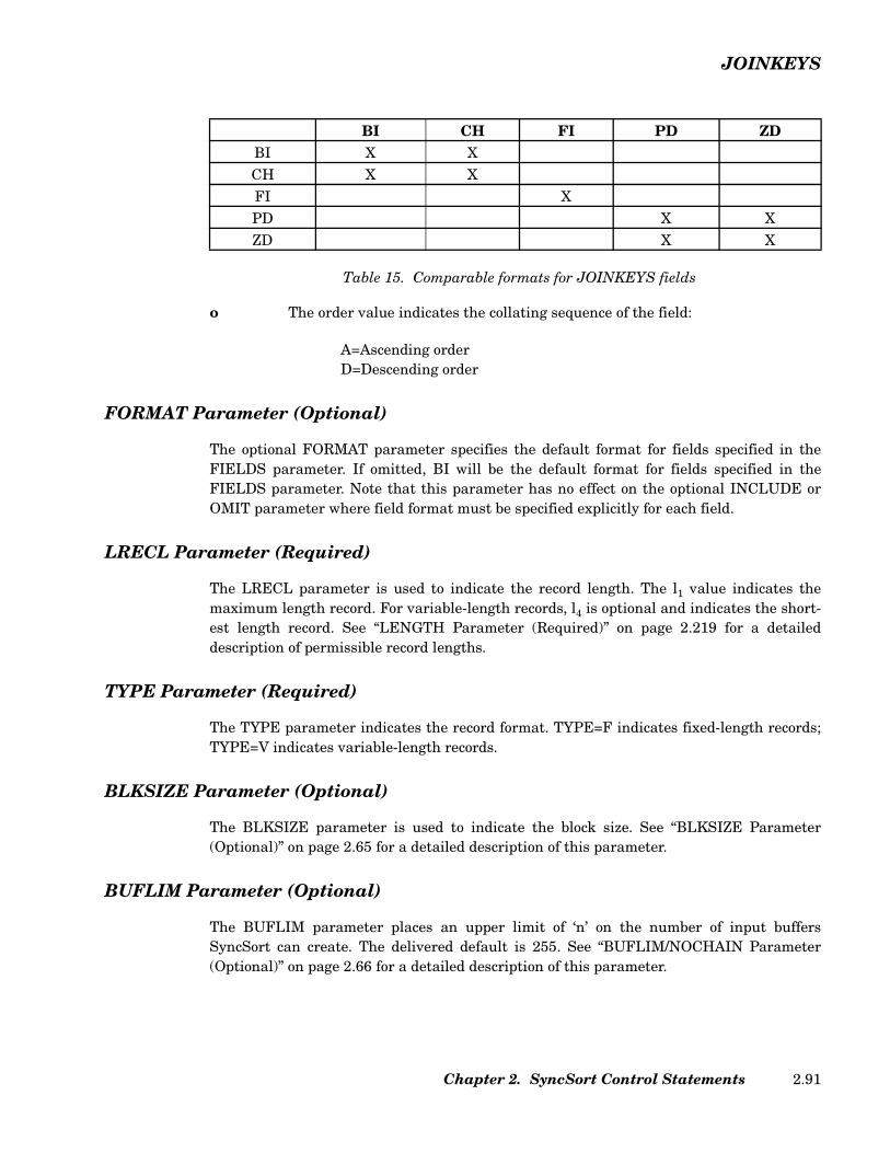
JOINKEYS
Table 15. Comparable formats for JOINKEYS fields
o The order value indicates the collating sequence of the field:
A=Ascending orderD=Descending order
FORMAT Parameter (Optional)
The optional FORMAT parameter specifies the default format for fields specified in theFIELDS parameter. If omitted, BI will be the default format for fields specified in theFIELDS parameter. Note that this parameter has no effect on the optional INCLUDE orOMIT parameter where field format must be specified explicitly for each field.
LRECL Parameter (Required)
The LRECL parameter is used to indicate the record length. The l1 value indicates themaximum length record. For variable-length records, l4 is optional and indicates the short-est length record. See “LENGTH Parameter (Required)” on page 2.219 for a detaileddescription of permissible record lengths.
TYPE Parameter (Required)
The TYPE parameter indicates the record format. TYPE=F indicates fixed-length records;TYPE=V indicates variable-length records.
BLKSIZE Parameter (Optional)
The BLKSIZE parameter is used to indicate the block size. See “BLKSIZE Parameter(Optional)” on page 2.65 for a detailed description of this parameter.
BUFLIM Parameter (Optional)
The BUFLIM parameter places an upper limit of ‘n’ on the number of input buffersSyncSort can create. The delivered default is 255. See “BUFLIM/NOCHAIN Parameter(Optional)” on page 2.66 for a detailed description of this parameter.
BI CH FI PD ZDBI X XCH X XFI XPD X XZD X X
Chapter 2. SyncSort Control Statements 2.91

JOINKEYS
BUFOFF Parameter (Optional)
The BUFOFF parameter can be specified for ASCII input to indicate the block prefix size ofvariable-length ASCII records. The delivered default is 0. See “BUFOFF Parameter(Optional)” on page 2.66 for a detailed description of this parameter.
BYPASS Parameter (Optional)
The BYPASS parameter can be specified for all non-VSAM files to instruct SyncSort not toterminate abnormally when certain errors are encountered. See “BYPASS Parameter(Optional)” on page 2.66 for a detailed description of this parameter.
CLOSE Parameter (Optional)
Specified for tape input files only, the CLOSE parameter indicates what action should betaken at the end of file. The delivered default is RWD. See “CLOSE Parameter (Optional)”on page 2.67 for a detailed description of this parameter.
Note: The (REL, RNONE, RALL, and Rnnn) options on the CLOSE parameter are notsupported on the JOINKEYS control statement.
CRDSIZE Parameter (Optional)
The CRDSIZE parameter specifies the decimal number of bytes of data per physical inputcard. The delivered default is 80. See “CRDSIZE Parameter (Optional)” on page 2.68 for adetailed description of this parameter.
DATA Parameter (Optional)
The DATA parameter specifies either EBCDIC or ASCII input. The delivered default isEBCDIC. See “DATA=E/A Parameter (Optional)” on page 2.68 for a detailed description ofthis parameter.
ENDREC Parameter (Optional)
The ENDREC parameter specifies the last record that will be processed from the input file.See “ENDREC Parameter (Optional)” on page 2.69 for a detailed description of this param-eter.
INCLUDE/OMIT Parameter (Optional)
The INCLUDE/OMIT parameter selects from the input file based on comparisons of thecontents of one or more fields within the record. See “INCLUDE/OMIT Control Statement”on page 2.39 for a detailed description of this parameter.
SyncSort for z/VSE 3.7 Programmer’s Guide2.92
JOINKEYS
OPEN Parameter (Optional)
Specified for tape input files only, the OPEN parameter indicates what action should betaken when the file is opened. The delivered default is RWD. See “OPEN Parameter(Optional)” on page 2.74 for a detailed description of this parameter.
SKIPREC Parameter (Optional)
The SKIPREC parameter instructs SyncSort to skip a decimal number of records per inputfile. See “SKIPREC Parameter (Optional)” on page 2.74 for a detailed description of thisparameter.
SORTED Parameter (Optional)
By default, SyncSort will presume that the records in the file are not presequenced in theJOINKEYS FIELDS specified. If both files are already collated in the proper sequence(sorted with the first field being the major field and the subsequent fields being progres-sively less significant fields), the SORTED parameter can be specified to improve the appli-cation’s performance.
If sorting is skipped for a pre-sorted file, SyncSort will sequence check that file according toits JOINKEYS fields. If the sequence check fails, SyncSort will issue a critical error mes-sage containing the file name.
SPAN Parameter (Optional)
The SPAN parameter instructs SyncSort to examine the input file for spanned records. See“SPAN Parameter (Optional)” on page 2.74 for a detailed description of this parameter.
STARTREC Parameter (Optional)
The STARTREC parameter specifies the first record that will be processed from the inputfile. See “STARTREC Parameter (Optional)” on page 2.75 for a detailed description of thisparameter.
STOPAFT Parameter (Optional)
The STOPAFT parameter specifies the number of records in a file for output. See“STOPAFT Parameter (Optional)” on page 2.75 for a detailed description of this parameter.
SYSIPT Parameter (Optional)
The SYSIPT parameter specifies that the input should be read from a card reader. See“SYSIPT Parameter (Optional)” on page 2.75 for a detailed description of this parameter.
Chapter 2. SyncSort Control Statements 2.93
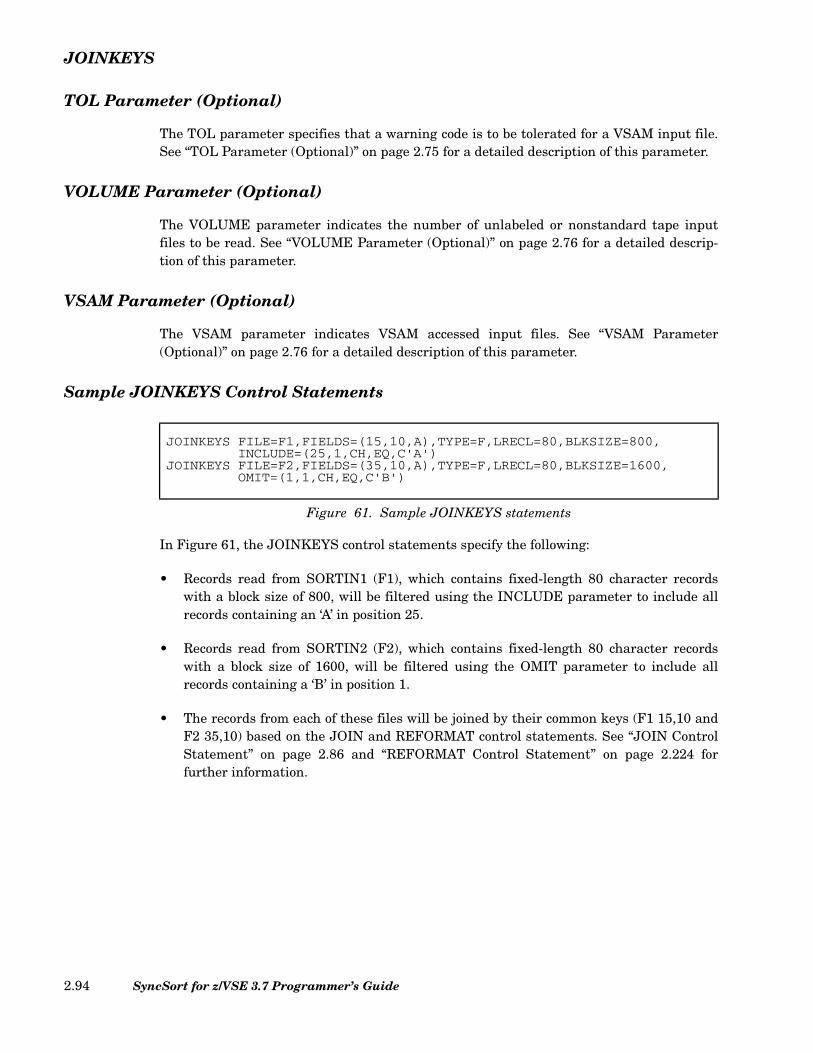
JOINKEYS
TOL Parameter (Optional)
The TOL parameter specifies that a warning code is to be tolerated for a VSAM input file.See “TOL Parameter (Optional)” on page 2.75 for a detailed description of this parameter.
VOLUME Parameter (Optional)
The VOLUME parameter indicates the number of unlabeled or nonstandard tape inputfiles to be read. See “VOLUME Parameter (Optional)” on page 2.76 for a detailed descrip-tion of this parameter.
VSAM Parameter (Optional)
The VSAM parameter indicates VSAM accessed input files. See “VSAM Parameter(Optional)” on page 2.76 for a detailed description of this parameter.
Sample JOINKEYS Control Statements
In Figure 61, the JOINKEYS control statements specify the following:
• Records read from SORTIN1 (F1), which contains fixed-length 80 character recordswith a block size of 800, will be filtered using the INCLUDE parameter to include allrecords containing an ‘A’ in position 25.
• Records read from SORTIN2 (F2), which contains fixed-length 80 character recordswith a block size of 1600, will be filtered using the OMIT parameter to include allrecords containing a ‘B’ in position 1.
• The records from each of these files will be joined by their common keys (F1 15,10 andF2 35,10) based on the JOIN and REFORMAT control statements. See “JOIN ControlStatement” on page 2.86 and “REFORMAT Control Statement” on page 2.224 forfurther information.
JOINKEYS FILE=F1,FIELDS=(15,10,A),TYPE=F,LRECL=80,BLKSIZE=800,INCLUDE=(25,1,CH,EQ,C'A')
JOINKEYS FILE=F2,FIELDS=(35,10,A),TYPE=F,LRECL=80,BLKSIZE=1600,OMIT=(1,1,CH,EQ,C'B')
Figure 61. Sample JOINKEYS statements
SyncSort for z/VSE 3.7 Programmer’s Guide2.94
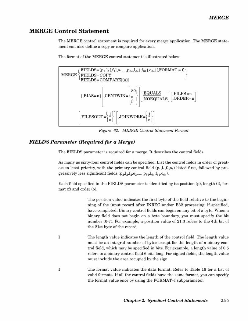
MERGE
MERGE Control Statement
The MERGE control statement is required for every merge application. The MERGE state-ment can also define a copy or compare application.
The format of the MERGE control statement is illustrated below:
FIELDS Parameter (Required for a Merge)
The FIELDS parameter is required for a merge. It describes the control fields.
As many as sixty-four control fields can be specified. List the control fields in order of great-est to least priority, with the primary control field (p1,l1,f1,o1) listed first, followed by pro-gressively less significant fields (p2,l2,f2,o2,..., p64,l64,f64,o64).
Each field specified in the FIELDS parameter is identified by its position (p), length (l), for-mat (f) and order (o).
The position value indicates the first byte of the field relative to the begin-ning of the input record after INREC and/or E32 processing, if specified,have completed. Binary control fields can begin on any bit of a byte. When abinary field does not begin on a byte boundary, you must specify the bitnumber (0-7). For example, a position value of 21.3 refers to the 4th bit ofthe 21st byte of the record.
l The length value indicates the length of the control field. The length valuemust be an integral number of bytes except for the length of a binary con-trol field, which may be specified in bits. For example, a length value of 0.5refers to a binary control field 6 bits long. For signed fields, the length valuemust include the area occupied by the sign.
f The format value indicates the data format. Refer to Table 16 for a list ofvalid formats. If all the control fields have the same format, you can specifythe format value once by using the FORMAT=f subparameter.
Figure 62. MERGE Control Statement Format
MERGEFIELDS=(p1,l1[,f1],o1... ,p64,l64 ,f64[ ],o64)[,FORMAT = f]FIELDS=COPYFIELDS=COMPARE[(n)]
,BIAS=n[ ] ,CENTWIN=80sf
,EQUALS,NOEQUALS
,FILES=n,ORDER=n
,FILESOUT=1n
,JOINWORK=1n
Chapter 2. SyncSort Control Statements 2.95

MERGE
o The order value indicates how the field is to be collated. A indicates Ascend-ing order. D indicates Descending order.
Valid Formats for Control Fields
The following table lists the valid formats for merge control fields.
Code Data Format Acceptable field length in bytes
AC EBCDIC characters are translated to their ASCII equivalents before sorting.
1 to 256
AQ Character. Sorts records according to an alternate sequence specified either in the ALTSEQ control statement or as an installation default.
1 to 256
ASL Leading separate sign. An ASCII + or - precedes a numeric field. One digit per byte.
2 to 256
AST Trailing separate sign. An ASCII + or - trails a numeric field. One digit per byte.
2 to 256
BI Binary. Unsigned. 1 bit to 4092
CH Character. Unsigned. Characters are collated according to the EBCDIC collating sequence unless LOCALE has been used to chose an alternate set of collating rules based on a specific national language. LOCALE can be set on the OPTION statement or as an installation default.
1 to 4092
CLO or OL
Leading overpunch sign. Hexadecimal F,C,E or A in the first 4 bits of your field indicates a positive number. Hexadecimal D or B in the first 4 bits indicates a negative number. One digit per byte. CMP=CLC is forced.
1 to 256
CSF or FS
Floating sign format. An optional leading sign may be specified imme-diately to the left of the digits. If the sign is a -, the number treated as negative. For other characters, the number is treated as positive. Char-acters to the left of the sign are ignored.
1 to 16
CSL or LS
Leading separate sign. An EBCDIC + or - precedes a numeric field. One digit per byte. CMP=CLC is forced.
2 to 256
CST or TS
Trailing separate sign. An EBCDIC + or - follows a numeric field. One digit per byte. CMP=CLC is forced.
2 to 256
FI Fixed point. Signed. 1 to 256
FL Signed floating point. Normalized. 2 to 16
PD Packed decimal. Signed. 1 to 256
Table 16. (Page 1 of 3) Format Code Chart
SyncSort for z/VSE 3.7 Programmer’s Guide2.96

MERGE
PD0 Packed decimal. 2-8-byte packed decimal data with the first digit and trailing sign ignored. The remaining bytes are treated as packed deci-mal digits. Typically PD0 is used with century window processing and Y2P format; Y2P processes the year, while PD0 processes month and day.
2-8
SFF Signed free format. Decimal digits (0-9) are extracted from right to left to form a number value. A character of - or ) found within the field will cause the value to be treated as a negative number. All other non-deci-mal digit values in the field are ignored.
1 to 44
UFF Unsigned free format. Decimal digits (0-9) are extracted from right to left to form a number value. All non-decimal digit values in the field are ignored.
1 to 44
Y2B Binary. 2-digit, 1-byte binary year data treated as a 4-digit year by CENTWIN (century window) processing.
1
Y2C Character. 2-digit character year data treated as a 4-digit year by CENTWIN (century window) processing. Processing is identical to Y2Z fields.
2
Y2D Packed decimal. 2-digit, 1-byte packed decimal year data treated as a 4-digit year by CENTWIN (century window) processing.
1
Y2P Packed decimal. 2-digit, 2-byte packed decimal year data. Of the four packed digits contained in the 2 bytes, the first digit and trailing sign are ignored; the two inner digits are treated as a 4-digit year by CENTWIN processing.
2
Y2S Character or zoned decimal. 2-digit, 2-byte valid numeric data treated as a 4-digit year by CENTWIN (century window) processing, as for Y2C and Y2Z. However, certain data is not treated as year data. Data with binary zeros (X'00') or a blank (X'40') in the first byte will be col-lated before valid numeric year data for ascending order (after year data for descending order). Data with all binary ones (X'FF') in the first byte will be collated after valid numeric year data for ascending order (before year data for descending order). Zones are ignored, as for Y2C and Y2Z, except for data where the first byte begins with X'00', X'40' or X'FF'.
2
Y2TY2UY2VY2WY2XY2Y
Full-date formats. Enable sorting or merging a variety of date fields. The formats can process dates ending or starting with year digits and non-date data commonly used with the dates. Two-digit years are interpreted according to the CENTWIN setting. In most cases, for CH, ZD, and PD date fields the full-date data formats are easier to use than the 2-digit year formats. For details on these formats see Table 17 on page 2.99.
Code Data Format Acceptable field length in bytes
Table 16. (Page 2 of 3) Format Code Chart
Chapter 2. SyncSort Control Statements 2.97
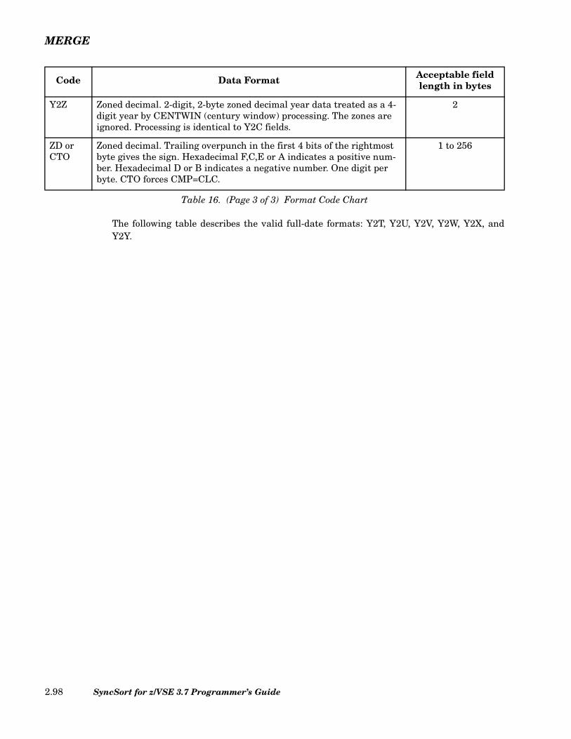
MERGE
The following table describes the valid full-date formats: Y2T, Y2U, Y2V, Y2W, Y2X, andY2Y.
Y2Z Zoned decimal. 2-digit, 2-byte zoned decimal year data treated as a 4-digit year by CENTWIN (century window) processing. The zones are ignored. Processing is identical to Y2C fields.
2
ZD or CTO
Zoned decimal. Trailing overpunch in the first 4 bits of the rightmost byte gives the sign. Hexadecimal F,C,E or A indicates a positive num-ber. Hexadecimal D or B indicates a negative number. One digit per byte. CTO forces CMP=CLC.
1 to 256
Code Data Format Acceptable field length in bytes
Table 16. (Page 3 of 3) Format Code Chart
SyncSort for z/VSE 3.7 Programmer’s Guide2.98
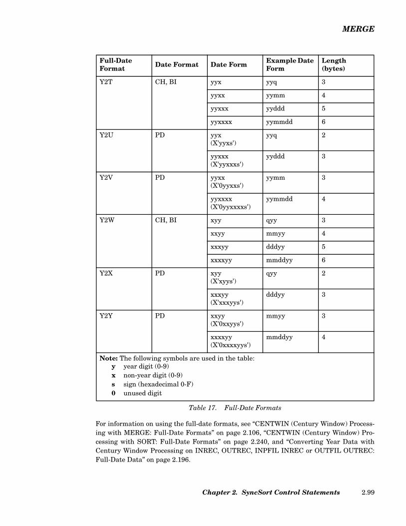
MERGE
For information on using the full-date formats, see “CENTWIN (Century Window) Process-ing with MERGE: Full-Date Formats” on page 2.106, “CENTWIN (Century Window) Pro-cessing with SORT: Full-Date Formats” on page 2.240, and “Converting Year Data withCentury Window Processing on INREC, OUTREC, INPFIL INREC or OUTFIL OUTREC:Full-Date Data” on page 2.196.
Full-Date Format Date Format Date Form Example Date
Form Length (bytes)
Y2T CH, BI yyx yyq 3
yyxx yymm 4
yyxxx yyddd 5
yyxxxx yymmdd 6
Y2U PD yyx(X'yyxs')
yyq 2
yyxxx(X'yyxxxs')
yyddd 3
Y2V PD yyxx(X'0yyxxs')
yymm 3
yyxxxx(X'0yyxxxxs')
yymmdd 4
Y2W CH, BI xyy qyy 3
xxyy mmyy 4
xxxyy dddyy 5
xxxxyy mmddyy 6
Y2X PD xyy(X'xyys')
qyy 2
xxxyy(X'xxxyys')
dddyy 3
Y2Y PD xxyy(X'0xxyys')
mmyy 3
xxxxyy(X'0xxxxyys')
mmddyy 4
Note: The following symbols are used in the table:y year digit (0-9)x non-year digit (0-9)s sign (hexadecimal 0-F)0 unused digit
Table 17. Full-Date Formats
Chapter 2. SyncSort Control Statements 2.99
MERGE
For information on the 2-digit year formats (Y2B, Y2C, Y2D, Y2P, Y2S, and Y2Z) plus therelated data format PD0), see “CENTWIN (Century Window) Processing with SORT: 2-Digit Year Formats” on page 2.235 and “Converting Year Data with Century Window Pro-cessing on INREC, OUTREC, INPFIL INREC or OUTFIL OUTREC: 2-Digit Year Data” onpage 2.194.
Rules for Specifying Control Fields
• The sum of the lengths of all control fields cannot exceed 4092 bytes. When theEQUALS option is specified, the sum of the lengths cannot exceed 4088 bytes.
• Control fields can be in contiguous or noncontiguous locations in the record.
• Remember that for variable-length records, the first 4 bytes are reserved for the RecordDescriptor Word, so the first byte of the data portion of the record is byte 5.
Comparing PD and ZD Control Fields
When you specify CMP=CPD, SyncSort uses the Compare Decimal (CP) instructions for thecomparison, which means that ZD data fields are packed first then compared. This methodhas performance advantages. However, invalid PD data may cause a Data Exception abendand program termination. Moreover, the integrity of ZD fields is only guaranteed when thefields contain valid ZD data. Since the zone bits (the left most 4 bits of each byte) are lostduring PACKing, UNPKing the field only restores valid ZD data to its original state. Forexample, blanks are transformed into ZD zeros and alphabetic character data that packs toa valid PD field is converted into valid ZD data.
When CMP=CLC is in effect, SyncSort does not perform data validation and the integrity ofthe output is maintained.
FIELDS=COPY (Required for a Copy)
Use FIELDS=COPY to copy input file(s). Other control statements such asINCLUDE/OMIT, INREC, OUTREC and OUTFIL and user exit routines can be specified inconjunction with a copy application, allowing you to edit and reformat the file(s) withoutmerging them.
The SUM control statement cannot be specified with FIELDS=COPY.
FIELDS=COMPARE (Required for a Compare)
Use FIELDS=COMPARE[(n)] to determine if two files are identical. When the COMPAREfeature is specified, SyncSort compares the files record for record, byte for byte, and thesorting process is bypassed.
SyncSort for z/VSE 3.7 Programmer’s Guide2.100
MERGE
The value specified for 'n' indicates how many unequal pairs of record SyncSort should flagbefore terminating the job. The diagnostic information provided distinguishes among threecases:
• Fully identical files.
• Files of different sizes where the smaller file consists of the larger file’s first n records,in the same order.
• Files with different records. In this case, dumps are produced that identify the first pairof unequal records or as many pairs of unequal records as the 'n' value specifies.
The SUM control statement cannot be used with FIELDS=COMPARE.
BIAS Parameter (Optional)
The BIAS parameter is ignored.
CENTWIN Parameter (Optional)
The CENTWIN option defines a sliding or fixed 100-year window that determines the cen-tury to which 2-digit year data belongs when processed by SORT, MERGE, INCLUDE,INREC, OMIT, OUTREC, or OUTFIL OUTREC control statements.
There are two types of date data formats: 2-digit year and full-date:
• For details on CENTWIN processing and the 2-digit year formats with the MERGEcontrol statement, see “CENTWIN (Century Window) Processing with MERGE: 2-DigitYear Formats” on page 2.102. For similar information for the SORT control statement,see “CENTWIN (Century Window) Processing with SORT: 2-Digit Year Formats” onpage 2.235.
For information on using INCLUDE/OMIT with 2-digit year formats, see “SpecifyingStandard Comparisons for Date Fields” on page 2.50.
For information on using the 2-digit year formats for OUTREC processing, see “Con-verting Year Data with Century Window Processing on INREC, OUTREC, INPFILINREC or OUTFIL OUTREC: 2-Digit Year Data” on page 2.194 and “Sample OUTRECControl Statements with CENTWIN Processing: 2-Digit Year Formats” on page 2.213.
• For details on CENTWIN processing and the full-date formats with the MERGE controlstatement, see “CENTWIN (Century Window) Processing with MERGE: Full-DateFormats” on page 2.106. For similar information for the SORT control statement, see“CENTWIN (Century Window) Processing with SORT: Full-Date Formats” on page2.240.
Chapter 2. SyncSort Control Statements 2.101

MERGE
For information on using INCLUDE/OMIT with full-date formats, see “Specifying Stan-dard Comparisons for Date Fields” on page 2.50 and “Sample INCLUDE/OMIT ControlStatements with Date Data” on page 2.60.
For information on using the full-date data formats for OUTREC processing, see “Con-verting Year Data with Century Window Processing on INREC, OUTREC, INPFILINREC or OUTFIL OUTREC: Full-Date Data” on page 2.196.
EQUALS/NOEQUALS Parameter (Optional)
The EQUALS parameter insures that equal-keyed records are merged in the order of theirrespective files. Equal-keyed records from the first input file are written before those fromthe second input file, etc. The NOEQUALS parameter specifies that equal-keyed recordsfrom different files be written in random order. EQUALS is the default.
The order of equal-keyed records within each input file is always preserved during a mergewhether or not the EQUALS parameter is specified.
When the EQUALS parameter is used with the SUM or DUPKEYS control statement, thefirst of the equally-keyed records is retained with the sum; all other records are deletedafter the specified field(s) have been summed.
FILES/ORDER Parameter (Optional)
The FILES parameter or the ORDER parameter specifies the number of input files to bemerged. The 'n' value can be any number from 1 to 32. NOTE: When using the JOIN pro-cess or the COMPARE process, two input files are assumed.
FILESOUT Parameter (Optional)
The FILESOUT parameter specifies the number of output files and is required when creat-ing multiple output files. The 'n' value can be any number from 1 to 32. If the FILESOUTparameter is not specified, one output file is assumed.
JOINWORK Parameter (Optional)
The JOINWORK parameter specifies the number of sortwork files that the join process willuse. The ‘n’ value can be any number from 1 to 9. If the join process is used and JOIN-WORK is not specified, JOINWORK=1 is assumed
CENTWIN (Century Window) Processing with MERGE: 2-Digit Year Formats
The CENTWIN run-time or installation option acts on 2-digit year data that spans centu-ries. CENTWIN treats 2-digit year data as a 4-digit year and sequences the data accordingto the 4-digit representation.
SyncSort for z/VSE 3.7 Programmer’s Guide2.102
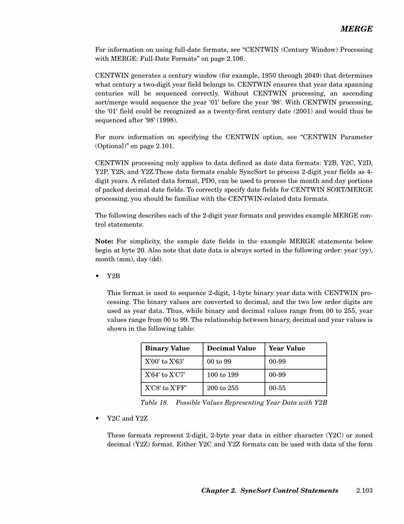
MERGE
For information on using full-date formats, see “CENTWIN (Century Window) Processingwith MERGE: Full-Date Formats” on page 2.106.
CENTWIN generates a century window (for example, 1950 through 2049) that determineswhat century a two-digit year field belongs to. CENTWIN ensures that year data spanningcenturies will be sequenced correctly. Without CENTWIN processing, an ascendingsort/merge would sequence the year '01' before the year '98'. With CENTWIN processing,the '01' field could be recognized as a twenty-first century date (2001) and would thus besequenced after '98' (1998).
For more information on specifying the CENTWIN option, see “CENTWIN Parameter(Optional)” on page 2.101.
CENTWIN processing only applies to data defined as date data formats: Y2B, Y2C, Y2D,Y2P, Y2S, and Y2Z.These data formats enable SyncSort to process 2-digit year fields as 4-digit years. A related data format, PD0, can be used to process the month and day portionsof packed decimal date fields. To correctly specify date fields for CENTWIN SORT/MERGEprocessing, you should be familiar with the CENTWIN-related data formats.
The following describes each of the 2-digit year formats and provides example MERGE con-trol statements:
Note: For simplicity, the sample date fields in the example MERGE statements belowbegin at byte 20. Also note that date data is always sorted in the following order: year (yy),month (mm), day (dd).
• Y2B
This format is used to sequence 2-digit, 1-byte binary year data with CENTWIN pro-cessing. The binary values are converted to decimal, and the two low order digits areused as year data. Thus, while binary and decimal values range from 00 to 255, yearvalues range from 00 to 99. The relationship between binary, decimal and year values isshown in the following table:
• Y2C and Y2Z
These formats represent 2-digit, 2-byte year data in either character (Y2C) or zoneddecimal (Y2Z) format. Either Y2C and Y2Z formats can be used with data of the form
Binary Value Decimal Value Year Value
X'00' to X'63' 00 to 99 00-99
X'64' to X'C7' 100 to 199 00-99
X'C8' to X'FF' 200 to 255 00-55
Table 18. Possible Values Representing Year Data with Y2B
Chapter 2. SyncSort Control Statements 2.103
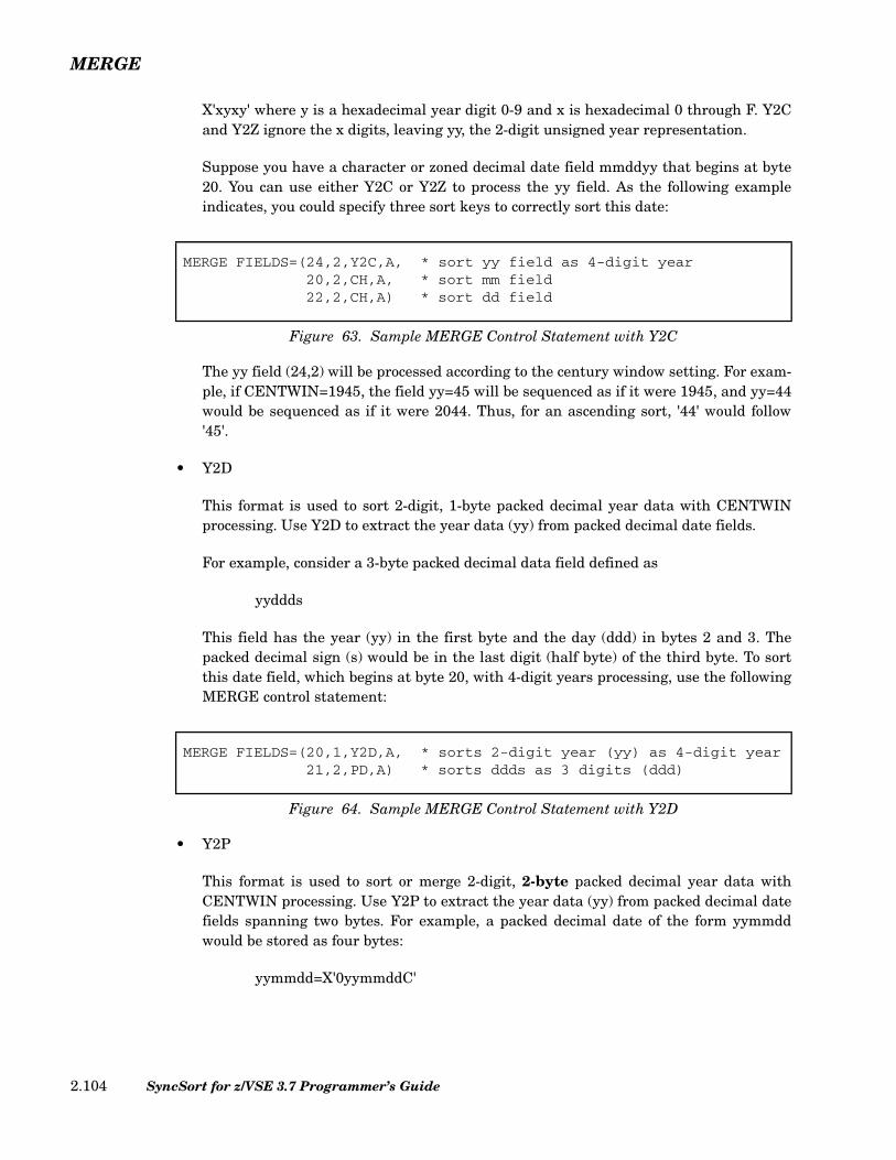
MERGE
X'xyxy' where y is a hexadecimal year digit 0-9 and x is hexadecimal 0 through F. Y2Cand Y2Z ignore the x digits, leaving yy, the 2-digit unsigned year representation.
Suppose you have a character or zoned decimal date field mmddyy that begins at byte20. You can use either Y2C or Y2Z to process the yy field. As the following exampleindicates, you could specify three sort keys to correctly sort this date:
The yy field (24,2) will be processed according to the century window setting. For exam-ple, if CENTWIN=1945, the field yy=45 will be sequenced as if it were 1945, and yy=44would be sequenced as if it were 2044. Thus, for an ascending sort, '44' would follow'45'.
• Y2D
This format is used to sort 2-digit, 1-byte packed decimal year data with CENTWINprocessing. Use Y2D to extract the year data (yy) from packed decimal date fields.
For example, consider a 3-byte packed decimal data field defined as
yyddds
This field has the year (yy) in the first byte and the day (ddd) in bytes 2 and 3. Thepacked decimal sign (s) would be in the last digit (half byte) of the third byte. To sortthis date field, which begins at byte 20, with 4-digit years processing, use the followingMERGE control statement:
• Y2P
This format is used to sort or merge 2-digit, 2-byte packed decimal year data withCENTWIN processing. Use Y2P to extract the year data (yy) from packed decimal datefields spanning two bytes. For example, a packed decimal date of the form yymmddwould be stored as four bytes:
yymmdd=X'0yymmddC'
MERGE FIELDS=(24,2,Y2C,A, * sort yy field as 4-digit year20,2,CH,A, * sort mm field22,2,CH,A) * sort dd field
Figure 63. Sample MERGE Control Statement with Y2C
MERGE FIELDS=(20,1,Y2D,A, * sorts 2-digit year (yy) as 4-digit year21,2,PD,A) * sorts ddds as 3 digits (ddd)
Figure 64. Sample MERGE Control Statement with Y2D
SyncSort for z/VSE 3.7 Programmer’s Guide2.104
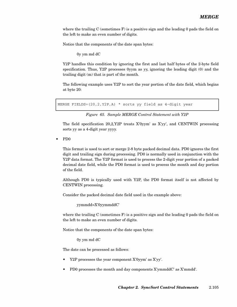
MERGE
where the trailing C (sometimes F) is a positive sign and the leading 0 pads the field onthe left to make an even number of digits.
Notice that the components of the date span bytes:
0y ym md dC
Y2P handles this condition by ignoring the first and last half bytes of the 2-byte fieldspecification. Thus, Y2P processes 0yym as yy, ignoring the leading digit (0) and thetrailing digit (m) that is part of the month.
The following example uses Y2P to sort the year portion of the date field, which beginsat byte 20:
The field specification 20,2,Y2P treats X'0yym' as X'yy', and CENTWIN processingsorts yy as a 4-digit year yyyy.
• PD0
This format is used to sort or merge 2-8 byte packed decimal data. PD0 ignores the firstdigit and trailing sign during processing. PD0 is normally used in conjunction with theY2P data format. The Y2P format is used to process the 2-digit year portion of a packeddecimal date field, while the PD0 format is used to process the month and day portionof the field.
Although PD0 is typically used with Y2P, the PD0 format itself is not affected byCENTWIN processing.
Consider the packed decimal date field used in the example above:
yymmdd=X'0yymmddC'
where the trailing C (sometimes F) is a positive sign and the leading 0 pads the field onthe left to make an even number of digits.
Notice that the components of the date span bytes:
0y ym md dC
The date can be processed as follows:
• Y2P processes the year component X'0yym' as X'yy'.
• PD0 processes the month and day components X'ymmddC' as X'mmdd'.
MERGE FIELDS=(20,2,Y2P,A) * sorts yy field as 4-digit year
Figure 65. Sample MERGE Control Statement with Y2P
Chapter 2. SyncSort Control Statements 2.105
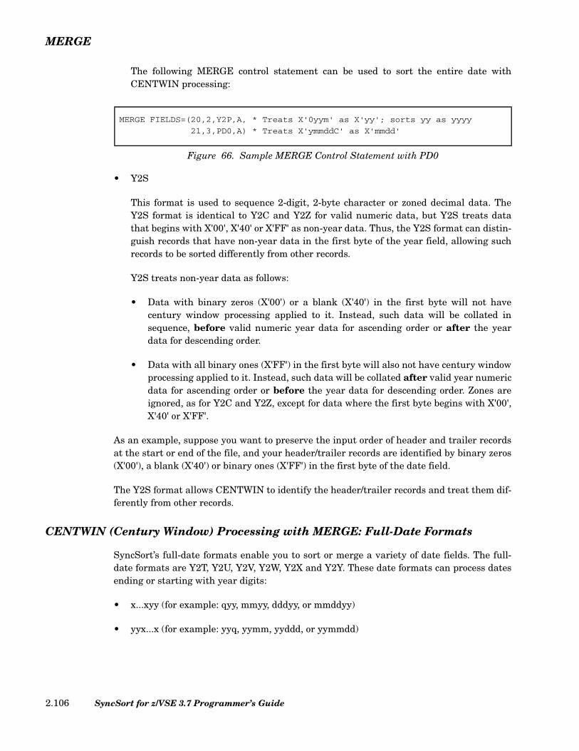
MERGE
The following MERGE control statement can be used to sort the entire date withCENTWIN processing:
• Y2S
This format is used to sequence 2-digit, 2-byte character or zoned decimal data. TheY2S format is identical to Y2C and Y2Z for valid numeric data, but Y2S treats datathat begins with X'00', X'40' or X'FF' as non-year data. Thus, the Y2S format can distin-guish records that have non-year data in the first byte of the year field, allowing suchrecords to be sorted differently from other records.
Y2S treats non-year data as follows:
• Data with binary zeros (X'00') or a blank (X'40') in the first byte will not havecentury window processing applied to it. Instead, such data will be collated insequence, before valid numeric year data for ascending order or after the yeardata for descending order.
• Data with all binary ones (X'FF') in the first byte will also not have century windowprocessing applied to it. Instead, such data will be collated after valid year numericdata for ascending order or before the year data for descending order. Zones areignored, as for Y2C and Y2Z, except for data where the first byte begins with X'00',X'40' or X'FF'.
As an example, suppose you want to preserve the input order of header and trailer recordsat the start or end of the file, and your header/trailer records are identified by binary zeros(X'00'), a blank (X'40') or binary ones (X'FF') in the first byte of the date field.
The Y2S format allows CENTWIN to identify the header/trailer records and treat them dif-ferently from other records.
CENTWIN (Century Window) Processing with MERGE: Full-Date Formats
SyncSort’s full-date formats enable you to sort or merge a variety of date fields. The full-date formats are Y2T, Y2U, Y2V, Y2W, Y2X and Y2Y. These date formats can process datesending or starting with year digits:
• x...xyy (for example: qyy, mmyy, dddyy, or mmddyy)
• yyx...x (for example: yyq, yymm, yyddd, or yymmdd)
MERGE FIELDS=(20,2,Y2P,A, * Treats X'0yym' as X'yy'; sorts yy as yyyy
21,3,PD0,A) * Treats X'ymmddC' as X'mmdd'
Figure 66. Sample MERGE Control Statement with PD0
SyncSort for z/VSE 3.7 Programmer’s Guide2.106

MERGE
The full-date formats also process non-date data commonly used with the dates. SyncSortinterprets two-digit years (yy) according to the century window specified by the CENTWINoption. CENTWIN processing does not apply to non-date data.
In most cases, for CH, ZD, and PD date fields the full-date data formats are easier to usethan the 2-digit year formats. The 2-digit year formats can be more difficult because youmust divide the date into its components. This requires care, particularly for PD dates,where date components (q, dd, mm, or yy) may span bytes or occupy only part of a byte. Thefull-date formats, on the other hand, process such dates automatically. For information onthe 2-digit year formats (Y2B, Y2C, Y2D, Y2P, Y2S, and Y2Z), see Table 16 on page 2.96 and“CENTWIN (Century Window) Processing with MERGE: 2-Digit Year Formats” on page2.102.
The following two examples illustrate how you might use Table 16 on page 2.96 to developSORT control statements:
• Suppose you have a packed decimal (PD) date field of the form mmyy. To sort this fieldcorrectly, you would use the Y2Y 3-byte format from the table. Thus, if the date fieldstarts in position 30, you would specify the following SORT control statement to sortthe date in descending order:
Any PD fields of all PD zeros or all PD nines will be processed automatically as non-date data.
• Suppose you have a character (CH) date field of the form yymmdd. To sort this fieldcorrectly, you would use the Y2T 6-byte format from the table. Thus, if the field startsin byte 40, you would specify the following SORT control statement to sort in ascendingorder:
Any CH zeros, CH nines, BI zeros, blanks and BI ones will be processed automaticallyas non-date data.
Collating Sequence with Full-Date Formats
For full-date formats, the yy component is always sorted first (treated as primary key). Thisis so even when the yy is physically at the rightmost end of the field, as for Y2W, Y2X, andY2Y. For example, a 6-byte Y2W field, has the form xxxxyy. This is collated with the yy asthe primary key and xxxx as the secondary key. Because SyncSort automatically collates
SORT FIELDS=(30,3,Y2Y,D)
Figure 67. Sample SORT Control Statement with Y2Y
SORT FIELDS=(40,6,Y2T,A)
Figure 68. Sample SORT Control Statement with Y2T
Chapter 2. SyncSort Control Statements 2.107

MERGE
the year character first, you don’t have to deal with yy manually, for example by using PD0and Y2D.
It is important to understand that the xxxx component of a full-date format must bedesigned to collate as a unit. Suppose you have the 6-byte Y2T field yyxxxx. If you collatethis field in ascending order, then yy collates first (the primary key) with xxxx collating sec-ond (secondary key). Consider two possibilities:
• If yyxxxx is actually yymmdd, you will be sorting first by year, then month, then day.
• If yyxxxx is actually yyddmm, you will be sorting by year, then day, then month. Inmost cases, sorting in this way would not be what you intended.
To correctly collate a date, the date components must be in an order suitable for collating.For example mmddyy and yymmdd will collate correctly, but ddmmyy or yyddmm will not.For date forms that will not collate correctly, you must use one of the 2-digit year formats(Y2B, Y2C, Y2D, Y2P, Y2S, and Y2Z).
Table 16 on page 2.96 indicates the full-date formats that can be used with character (CH),binary (BI) or packed decimal (PD) data. Note the recognized non-date values:
• Character or binary (Y2T and Y2W full-date formats)C'0...0' (CH zeros)C'9...9' (CH nines)Z'0...0' (ZD zeros)Z'9...9 (ZD nines)X'00...00' (BI zeros)X'40...40' (blanks)X'FF...FF' (BI ones)
• Packed (Y2U, Y2V, Y2X and Y2Y full-date formats)P'0...0' (PD zeros)P'9...9' (PD nines)
The following table shows the order for ascending collation when using full-date formatswith the CENTWIN option:
SyncSort for z/VSE 3.7 Programmer’s Guide2.108

MERGE
For a descending sort, the collation order is reversed.
Other date formats (non-full-date), with the exception of Y2S, do not process non-date data;their sort sequence for ascending sorts is simply lower century dates then higher centurydates.
Sample MERGE Control Statements
This sample MERGE statement specifies three merge control fields:
• The first, or primary, control field begins in byte 1, is 5 bytes long, is in characterformat and is to be merged in ascending order.
• The second control field begins in byte 10, is 2 bytes long, is in packed decimal formatand is to be merged in descending order.
• The third control field begins in the third bit of byte 30, is 4 bytes long, is in binaryformat and is to be merged in ascending order.
This MERGE statement specifies a copy operation.
Full-Date Format Data Format Ascending Sort Sequence
Y2TY2W
CH, BI BI zerosBlanksCH/ZD zerosLower century dates (e.g. 1980)Higher century dates (e.g. 2010)CH/ZD ninesBI ones
Y2UY2VY2XY2Y
PD PD zerosLower century dates (e.g. 1980)Higher century dates (e.g. 2010)PD nines
Table 19. Collation Order for Full-Date Formats
MERGE FIELDS=(1,5,CH,A,10,2,PD,D,30.2,4,BI,A)
Figure 69. Sample MERGE Control Statement
MERGE FIELDS=COPY
Figure 70. Sample MERGE Control Statement
Chapter 2. SyncSort Control Statements 2.109
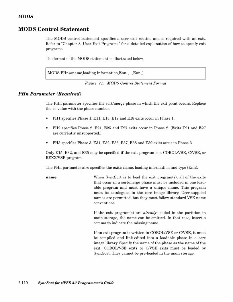
MODS
MODS Control Statement
The MODS control statement specifies a user exit routine and is required with an exit.Refer to “Chapter 8. User Exit Programs” for a detailed explanation of how to specify exitprograms.
The format of the MODS statement is illustrated below.
PHn Parameter (Required)
The PHn parameter specifies the sort/merge phase in which the exit point occurs. Replacethe 'n' value with the phase number.
• PH1 specifies Phase 1. E11, E15, E17 and E18 exits occur in Phase 1.
• PH2 specifies Phase 2. E21, E25 and E27 exits occur in Phase 2. (Exits E21 and E27are currently unsupported.)
• PH3 specifies Phase 3. E31, E32, E35, E37, E38 and E39 exits occur in Phase 3.
Only E15, E32, and E35 may be specified if the exit program is a COBOL/VSE, C/VSE, orREXX/VSE program.
The PHn parameter also specifies the exit’s name, loading information and type (Enn).
name When SyncSort is to load the exit program(s), all of the exitsthat occur in a sort/merge phase must be included in one load-able program and must have a unique name. This programmust be catalogued in the core image library. User-suppliednames are permitted, but they must follow standard VSE nameconventions.
If the exit program(s) are already loaded in the partition inmain storage, the name can be omitted. In that case, insert acomma to indicate the missing name.
If an exit program is written in COBOL/VSE or C/VSE, it mustbe compiled and link-edited into a loadable phase in a coreimage library. Specify the name of the phase as the name of theexit. COBOL/VSE exits or C/VSE exits must be loaded bySyncSort. They cannot be pre-loaded in the main storage.
MODS PHn=(name,loading information,Enn1,...,Ennn)
Figure 71. MODS Control Statement Format
SyncSort for z/VSE 3.7 Programmer’s Guide2.110
MODS
Note that COBOL/VSE and C/VSE exits require activation ofSyncSort LOCALE and COBOL/C Exit Facility as described inthe SyncSort for z/VSE Installation Guide.
If the exit program is written in REXX/VSE, it must be cata-logued in one of the libraries in the PROC search chain. Specifythe name of the REXX/VSE exit here. SyncSort does not sup-port a compiled REXX/VSE exit.
loading information When SyncSort is to load the exit program(s), loading informa-tion must be supplied in one of the following ways:
• If the exit program is a compiled COBOL/VSE program,specify the word COBOL here.
Note that COBOL/VSE requires additional GETVIS storagefor run-time library loading. Allow at least 500K of GETVISwhen executing SyncSort with the COBOL/VSE user exit.
• If the exit program is a compiled C/VSE program, specify Chere.
Note that C/VSE requires additional GETVIS storage forrun-time library loading. Allow at least 4 MB of GETVISwhen executing SyncSort with the C/VSE user exit.
• If the exit program is a REXX/VSE program, specify theword EXEC or REXX here.
• If none of the above conditions apply, do the following:
– Specify the length of the program(s) as a decimal num-ber of bytes. The letter 'L' must precede the number, forinstance, L2500. This method of specifying loadinginformation is preferred because it allows SyncSort toload the program(s) into the optimal location within thepartition. However, the program(s) must be either self-relocating or a relocating loader must be present in thesystem in order to use this method.
– Specify the absolute loading address of the program asa decimal number. This must be a virtual address ifSyncSort is running in virtual mode and a real addressif SyncSort is running in real mode. To use space mostefficiently, place the program(s) at the highest addresswithin the sort/merge partition. This method of supply-ing loading information must be used if the program(s)cannot be relocated.
Chapter 2. SyncSort Control Statements 2.111
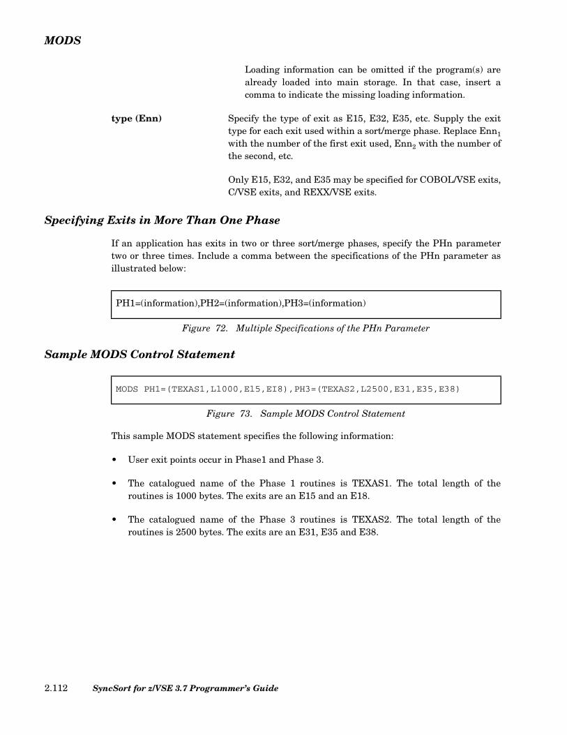
MODS
Loading information can be omitted if the program(s) arealready loaded into main storage. In that case, insert acomma to indicate the missing loading information.
type (Enn) Specify the type of exit as E15, E32, E35, etc. Supply the exittype for each exit used within a sort/merge phase. Replace Enn1
with the number of the first exit used, Enn2 with the number ofthe second, etc.
Only E15, E32, and E35 may be specified for COBOL/VSE exits,C/VSE exits, and REXX/VSE exits.
Specifying Exits in More Than One Phase
If an application has exits in two or three sort/merge phases, specify the PHn parametertwo or three times. Include a comma between the specifications of the PHn parameter asillustrated below:
Sample MODS Control Statement
This sample MODS statement specifies the following information:
• User exit points occur in Phase1 and Phase 3.
• The catalogued name of the Phase 1 routines is TEXAS1. The total length of theroutines is 1000 bytes. The exits are an E15 and an E18.
• The catalogued name of the Phase 3 routines is TEXAS2. The total length of theroutines is 2500 bytes. The exits are an E31, E35 and E38.
PH1=(information),PH2=(information),PH3=(information)
Figure 72. Multiple Specifications of the PHn Parameter
MODS PH1=(TEXAS1,Ll000,El5,EI8),PH3=(TEXAS2,L2500,E31,E35,E38)
Figure 73. Sample MODS Control Statement
SyncSort for z/VSE 3.7 Programmer’s Guide2.112
OMIT
OMIT Control Statement
Refer to “INCLUDE/OMIT Control Statement” on page 2.39 for an explanation of the OMITcontrol statement.
Chapter 2. SyncSort Control Statements 2.113

OPTION
OPTION Control Statement
The OPTION control statement specifies options for the application.
The format of the OPTION control statement is illustrated in Figure 74, below. Delivereddefaults are underlined, but may have been changed when SyncSort for z/VSE wasinstalled.
[,FILNM=(output1,...,output32,input1,...,input32,cccc)]
Figure 74. (Page 1 of 2) OPTION Control Statement Format
OPTION
ADDROUT
ADDROUT= AD
,CALCAREA[ ] ,CENTWIN=
80sf
,CHALT,NOCHALT
,CMP=CLCCPD
,CMPINOM= CLCCPD-------------
,DATE=
ADATEEDATEIDATESTD
,DEVIN=nn[ ] ,DEVOUT=nn[ ] ,DEVWK=n(n1,…,n3)NO
,DIAG[ ]
,DUMP,NODUMP
,EQUALS,NOEQUALS
,ERASE,NOERASE
,GVSRANY=nnKnM
,GVSRLOW=nnKnM
,IGNRL4,NOIGNRL4,NOVLSHRT,VLSHRT
[,INCOR=OFF]
,JOINWK=jwork,JOINWK=(jwork1,…,jwork9) ,KEYLEN=n[ ]
,LABEL=(output1,…,output32,input1,…,input32,work)[ ]
,LOCALE=CURRENTnameNONE
,NOINC[ ] ,NOTPMK[ ] ,NRECOUT=RC0RC4RC16
,NRECS=n[ ] ,OVFLO=RC0RC4RC16
,PRINT=
ALLCRITICALCRITPLUSNONE
SyncSort for z/VSE 3.7 Programmer’s Guide2.114
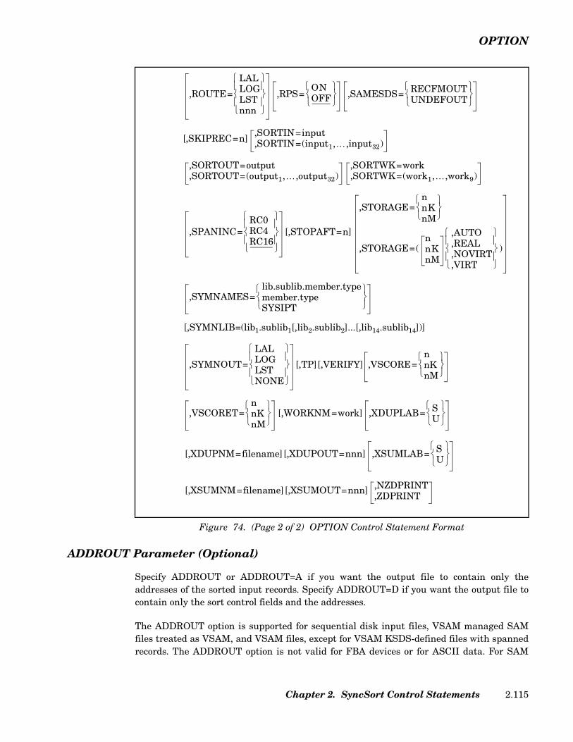
OPTION
ADDROUT Parameter (Optional)
Specify ADDROUT or ADDROUT=A if you want the output file to contain only theaddresses of the sorted input records. Specify ADDROUT=D if you want the output file tocontain only the sort control fields and the addresses.
The ADDROUT option is supported for sequential disk input files, VSAM managed SAMfiles treated as VSAM, and VSAM files, except for VSAM KSDS-defined files with spannedrecords. The ADDROUT option is not valid for FBA devices or for ASCII data. For SAM
[,SYMNLIB=(lib1.sublib1[,lib2.sublib2]...[,lib14.sublib14])]
Figure 74. (Page 2 of 2) OPTION Control Statement Format
,ROUTE=
LALLOGLSTnnn
,RPS=ONOFF
,SAMESDS= RECFMOUTUNDEFOUT
[,SKIPREC=n],SORTIN=input,SORTIN=(input1,…,input32)
,SORTOUT=output,SORTOUT=(output1,…,output32)
,SORTWK=work,SORTWK=(work1,…,work9)
,SPANINC=RC0RC4RC16
[,STOPAFT=n]
,STORAGE=nnKnM
,STORAGE=(nnKnM
,AUTO,REAL,NOVIRT,VIRT
)
,SYMNAMES=lib.sublib.member.typemember.typeSYSIPT
,SYMNOUT=
LALLOGLSTNONE
[,TP][,VERIFY] ,VSCORE=nnKnM
,VSCORET=nnKnM
[,WORKNM=work] ,XDUPLAB= SU
[,XDUPNM=filename][,XDUPOUT=nnn] ,XSUMLAB= SU
[,XSUMNM=filename][,XSUMOUT=nnn] ,NZDPRINT,ZDPRINT
Chapter 2. SyncSort Control Statements 2.115
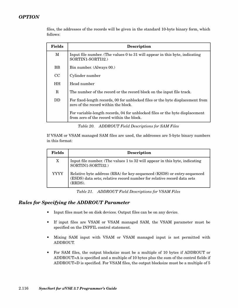
OPTION
files, the addresses of the records will be given in the standard 10-byte binary form, whichfollows:
If VSAM or VSAM managed SAM files are used, the addresses are 5-byte binary numbersin this format:
Rules for Specifying the ADDROUT Parameter
• Input files must be on disk devices. Output files can be on any device.
• If input files are VSAM or VSAM managed SAM, the VSAM parameter must bespecified on the INPFIL control statement.
• Mixing SAM input with VSAM or VSAM managed input is not permitted withADDROUT.
• For SAM files, the output blocksize must be a multiple of 10 bytes if ADDROUT orADDROUT=A is specified and a multiple of 10 bytes plus the sum of the control fields ifADDROUT=D is specified. For VSAM files, the output blocksize must be a multiple of 5
Fields Description
M Input file number. (The values 0 to 31 will appear in this byte, indicating SORTIN1-SORTI32.)
BB Bin number. (Always 00.)
CC Cylinder number
HH Head number
R The number of the record or the record block on the input file track.
DD For fixed-length records, 00 for unblocked files or the byte displacement from zero of the record within the block.
For variable-length records, 04 for unblocked files or the byte displacement from zero of the record within the block.
Table 20. ADDROUT Field Descriptions for SAM Files
Fields Description
X Input file number. (The values 1 to 32 will appear in this byte, indicating SORTIN1-SORTI32.)
YYYY Relative byte address (RBA) for key-sequenced (KSDS) or entry-sequenced (ESDS) data sets; relative record number for relative record data sets (RRDS).
Table 21. ADDROUT Field Descriptions for VSAM Files
SyncSort for z/VSE 3.7 Programmer’s Guide2.116
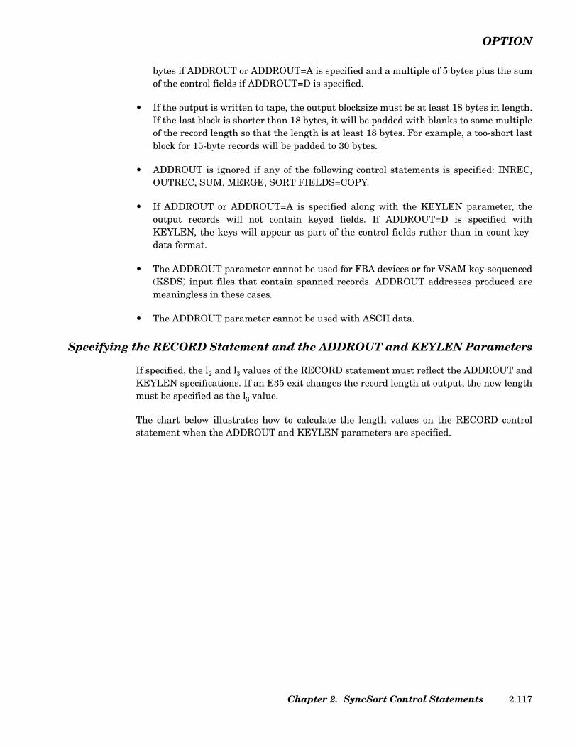
OPTION
bytes if ADDROUT or ADDROUT=A is specified and a multiple of 5 bytes plus the sumof the control fields if ADDROUT=D is specified.
• If the output is written to tape, the output blocksize must be at least 18 bytes in length.If the last block is shorter than 18 bytes, it will be padded with blanks to some multipleof the record length so that the length is at least 18 bytes. For example, a too-short lastblock for 15-byte records will be padded to 30 bytes.
• ADDROUT is ignored if any of the following control statements is specified: INREC,OUTREC, SUM, MERGE, SORT FIELDS=COPY.
• If ADDROUT or ADDROUT=A is specified along with the KEYLEN parameter, theoutput records will not contain keyed fields. If ADDROUT=D is specified withKEYLEN, the keys will appear as part of the control fields rather than in count-key-data format.
• The ADDROUT parameter cannot be used for FBA devices or for VSAM key-sequenced(KSDS) input files that contain spanned records. ADDROUT addresses produced aremeaningless in these cases.
• The ADDROUT parameter cannot be used with ASCII data.
Specifying the RECORD Statement and the ADDROUT and KEYLEN Parameters
If specified, the l2 and l3 values of the RECORD statement must reflect the ADDROUT andKEYLEN specifications. If an E35 exit changes the record length at output, the new lengthmust be specified as the l3 value.
The chart below illustrates how to calculate the length values on the RECORD controlstatement when the ADDROUT and KEYLEN parameters are specified.
Chapter 2. SyncSort Control Statements 2.117
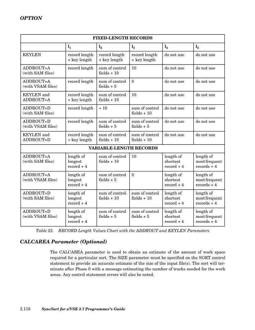
OPTION
CALCAREA Parameter (Optional)
The CALCAREA parameter is used to obtain an estimate of the amount of work spacerequired for a particular sort. The SIZE parameter must be specified on the SORT controlstatement to provide an accurate estimate of the size of the input file(s). The sort will ter-minate after Phase 0 with a message estimating the number of tracks needed for the workareas. Any control statement errors will also be noted.
FIXED-LENGTH RECORDS
l1 l2 l3 l4 l5
KEYLEN record length + key length
record length + key length
record length + key length
do not use do not use
ADDROUT=A(with SAM files)
record length sum of control fields + 10
10 do not use do not use
ADDROUT=A(with VSAM files)
record length sum of control fields + 5
5 do not use do not use
KEYLEN andADDROUT=A
record length + key length
sum of control fields + 10
10 do not use do not use
ADDROUT=D(with SAM files)
record length + 10 sum of control fields + 10
do not use do not use
ADDROUT=D(with VSAM files)
record length sum of control fields + 5
sum of control fields + 5
do not use do not use
KEYLEN andADDROUT=D
record length + key length
sum of control fields + 10
sum of control fields + 10
do not use do not use
VARIABLE-LENGTH RECORDS
ADDROUT=A(with SAM files)
length of longest record + 4
sum of control fields + 10
10 length of shortest record + 4
length of most frequent records + 4
ADDROUT=A(with VSAM files)
length of longest record + 4
sum of control fields + 5
5 length of shortest record + 4
length of most frequent records + 4
ADDROUT=D(with SAM files)
length of longest record + 4
sum of control fields + 10
sum of control fields + 10
length of shortest record + 4
length of most frequent records + 4
ADDROUT=D(with VSAM files)
length of longest record + 4
sum of control fields + 5
sum of control fields + 5
length of shortest record + 4
length of most frequent records + 4
Table 22. RECORD Length Values Chart with the ADDROUT and KEYLEN Parameters
SyncSort for z/VSE 3.7 Programmer’s Guide2.118
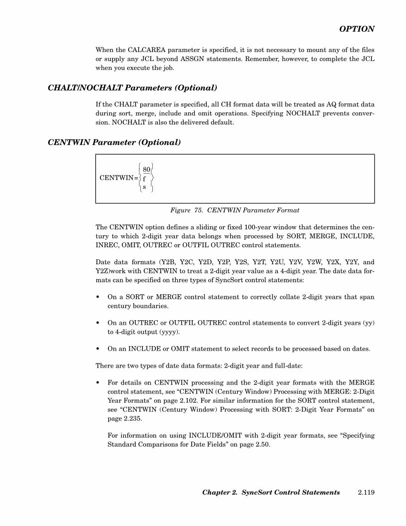
OPTION
When the CALCAREA parameter is specified, it is not necessary to mount any of the filesor supply any JCL beyond ASSGN statements. Remember, however, to complete the JCLwhen you execute the job.
CHALT/NOCHALT Parameters (Optional)
If the CHALT parameter is specified, all CH format data will be treated as AQ format dataduring sort, merge, include and omit operations. Specifying NOCHALT prevents conver-sion. NOCHALT is also the delivered default.
CENTWIN Parameter (Optional)
The CENTWIN option defines a sliding or fixed 100-year window that determines the cen-tury to which 2-digit year data belongs when processed by SORT, MERGE, INCLUDE,INREC, OMIT, OUTREC or OUTFIL OUTREC control statements.
Date data formats (Y2B, Y2C, Y2D, Y2P, Y2S, Y2T, Y2U, Y2V, Y2W, Y2X, Y2Y, andY2Z)work with CENTWIN to treat a 2-digit year value as a 4-digit year. The date data for-mats can be specified on three types of SyncSort control statements:
• On a SORT or MERGE control statement to correctly collate 2-digit years that spancentury boundaries.
• On an OUTREC or OUTFIL OUTREC control statements to convert 2-digit years (yy)to 4-digit output (yyyy).
• On an INCLUDE or OMIT statement to select records to be processed based on dates.
There are two types of date data formats: 2-digit year and full-date:
• For details on CENTWIN processing and the 2-digit year formats with the MERGEcontrol statement, see “CENTWIN (Century Window) Processing with MERGE: 2-DigitYear Formats” on page 2.102. For similar information for the SORT control statement,see “CENTWIN (Century Window) Processing with SORT: 2-Digit Year Formats” onpage 2.235.
For information on using INCLUDE/OMIT with 2-digit year formats, see “SpecifyingStandard Comparisons for Date Fields” on page 2.50.
Figure 75. CENTWIN Parameter Format
CENTWIN=80fs
Chapter 2. SyncSort Control Statements 2.119

OPTION
For information on using the 2-digit year formats for OUTREC processing, see “Con-verting Year Data with Century Window Processing on INREC, OUTREC, INPFILINREC or OUTFIL OUTREC: 2-Digit Year Data” on page 2.194 and “Sample OUTRECControl Statements with CENTWIN Processing: 2-Digit Year Formats” on page 2.213.
• For details on CENTWIN processing and the full-date formats with the MERGE controlstatement, see “CENTWIN (Century Window) Processing with MERGE: Full-DateFormats” on page 2.106. For similar information for the SORT control statement, see“CENTWIN (Century Window) Processing with SORT: Full-Date Formats” on page2.240.
For information on using INCLUDE/OMIT with full-date formats, see “Specifying Stan-dard Comparisons for Date Fields” on page 2.50 and “Sample INCLUDE/OMIT ControlStatements with Date Data” on page 2.60.
For information on using the full-date data formats for OUTREC processing, see “Con-verting Year Data with Century Window Processing on INREC, OUTREC, INPFILINREC or OUTFIL OUTREC: Full-Date Data” on page 2.196.
CENTWIN ensures that year data spanning centuries will be sequenced correctly. WithoutCENTWIN processing, an ascending sort/merge would sequence the year '01' before theyear '98'. With CENTWIN processing, the '01' field could be recognized as a twenty-firstcentury date (2001) and would thus be sequenced after '98' (1998) for an ascending sort.
The CENTWIN option generates either a sliding or fixed century window, depending onwhich form of CENTWIN is used: CENTWIN=s or CENTWIN=f.
• CENTWIN=s specifies a sliding century window that automatically advances as thecurrent year changes.
The variable s is a number 0 through 100. This value is subtracted from the currentyear to set a century-window starting point. For example, in 1996 CENTWIN=20 wouldcreate the century window 1976 through 2075. Ten years later in 2006, the centurystarting year would slide to 1986 (2006 minus 20=1986) and the century window wouldbe 1986 through 2085.
The CENTWIN default is s=80, which represents 80 years prior to the current year asthe starting year of a century window.
• CENTWIN=f specifies a fixed century window. The variable f is a four-digit year (yyyy)between 1000 and 3000.
For example, CENTWIN=1976 establishes a fixed starting year 1976 for the centurywindow 1976 through 2075. This window will not change as the current year changes.
The century window defined by CENTWIN controls processing of year-data. If a 2-digityear field has a value less than the last 2 digits of the century window start year, the year
SyncSort for z/VSE 3.7 Programmer’s Guide2.120

OPTION
field will be treated as a year in the century following the year of the century window. Allother 2-digit years will be treated as in the same century as the century window start year.
For example, consider the century window 1950 through 2049. The 2-digit year fields wouldbe processed as follows:
Two-digit Field Processed as Year01 200149 204950 195099 1999
An ascending sort of the above sample data would produce output data in the followingsequence:
Two-digit Field Processed as Year50 195099 199901 200149 2049
CMP=CLC/CMP=CPD Parameter (Optional)
The CMP parameter specifies how PD and ZD collation fields will be compared.
When you specify CMP=CPD, SyncSort uses the Compare Decimal (CP) instructions for thecomparison, which means that ZD data fields are packed first then compared. This methodhas performance advantages. However, invalid PD data may cause a Data Exception abendand program termination. Moreover, the integrity of ZD fields is only guaranteed when thefields contain valid ZD data. Since the zone bits (the left most 4 bits of each byte) are lostduring PACKing, UNPKing the field only restores valid ZD data to its original state. Forexample, blanks are transformed into ZD zeros and alphabetic character data that packs toa valid PD field is converted into valid ZD data.
When CMP=CLC is in effect, SynsSort does not perform data validation and the integrity ofthe output is maintained.
Before specifying this parameter, find out whether the default setting (CMP=CPD) hasbeen changed at installation time.
CMPINOM=CLC/CMPINOM=CPD Parameter (Optional)
The CMPINOM parameter is similar to the CMP parameter, but affects the processing ofthe INCLUDE/OMIT statement or OUTFIL INCLUDE/OMIT statement.
CMPINOM specifies the type of INCLUDE/OMIT comparison operation that will be usedwhen comparing packed and zoned decimal fields.
Chapter 2. SyncSort Control Statements 2.121

OPTION
DATE Parameter (Optional)
The DATE parameter specifies the format of the current system date generated by the&DATE parameter (see “HEADER1/HEADER2 Parameters (Optional)” on page 2.149 and“TRAILER1/TRAILER2 Parameters (Optional)” on page 2.164. The date format may be setas follows: ADATE signifies American date format (mm/dd/yy); EDATE signifies Europeandate format (dd/mm/yy); IDATE signifies ISO date format (yy/mm/dd); STD signifies gener-ated system date format. In the absence of any user provided formatting information, thestandard default format, STD will appear as the date format.
DEVIN/DEVOUT Parameters (Optional)
The DEVIN/DEVOUT parameters identify the system’s tape input and output devices.Each tape device is represented by 'nn', a two-digit code. Use Table 23 below to determinethe correct value to substitute for 'nn'. If the device is not manufactured by IBM, use theIBM model number, which corresponds to the device’s transfer rate and density. Accuratespecification of tape input/output devices may improve sort performance. The DEVIN andDEVOUT parameters are usually specified at installation time.
SyncSort for z/VSE 3.7 Programmer’s Guide2.122

OPTION
DEVWK Parameter (Optional)
The DEVWK parameter overrides the default disk device types in SYNCMAC. All devicetypes specified must match device types used for SORTWK.
You may specify up to three device types, but you may not specify both FBA and CKDdevices (for example, models 3380 and 3370) in the same DEVWK parameter.
Specifying SORTWK device types can improve the performance of small sorts. However, donot specify multiple SORTWK device types needlessly since this may have a negativeimpact on performance.
When specifying device types, you may use a two- or three-digit 'n' value to represent thedevice type, or you may use a four-digit IBM model number. See Table 24 below for the 'n'values corresponding to particular model numbers.
To override the default in SYNCMAC and have SyncSort identify the SORTWK devicetypes directly, specify DEVWK=NO.
nnVALUES
IBMMODEL NO. TRACKS
DENSITY
BPI KB/S
3233343536373838394041424243444546474748495051
3420-33420-33420-33420-53420-53420-53420-73430
3420-73420-73420-43420-63422
3420-83410(1-2)
3410-23410-33430
3410-38809348034903590
9 77977997799999999991818128
1600800556
1600800556
16006250800556
6250625062506250800
1600800
16001600160038K38K----
1206041.7
20010069.5
320312.5160111.2470780780
12502040408080
20(160)150030009000
Table 23. DEVIN and DEVOUT Values
Chapter 2. SyncSort Control Statements 2.123

OPTION
Note: If your device is not listed, use the value corresponding to the equivalent IBM modelnumber or the actual four-digit model number.
DIAG Parameter (Optional)
Specify the DIAG parameter to produce a listing of diagnostic messages for each SyncSortphase. If the application terminates successfully, additional PDUMPS will be provided.
DUMP/NODUMP Parameter (Optional)
Specify the DUMP parameter to produce a dump if the application terminates before theend of the sort or merge. Specify NODUMP if you do not want a dump. NODUMP is thedefault if the program terminates prematurely in Phase 0 and DUMP is the default if theprogram terminates prematurely in Phases 1, 2, or 3.
EQUALS/NOEQUALS Parameter (Optional)
Specify the EQUALS parameter to preserve the original order of records with equal controlfields. These records are written in the same order in which they are read. SpecifyNOEQUALS if the original record order need not be preserved. The defaults areNOEQUALS for a sort and EQUALS for a merge.
When EQUALS is used with the SUM control statement, the first of the equal-keyedrecords is retained with the sum; all other records are deleted after the specified field(s)have been summed.
The EQUALS and NOEQUALS parameters can also be specified on the SORT and MERGEcontrol statements.
ERASE Parameter (Optional)
Specify ERASE to erase the contents of the work files opened by the sort. (If an incore sortis performed, no files are erased.)
n VALUE IBM MODEL NO.
08 3380
09 3310, 3370, 9332, 9335, 9336
138 3390
139 9345
Table 24. DEVWK Values
SyncSort for z/VSE 3.7 Programmer’s Guide2.124

OPTION
FILNM Parameter (Optional)
Specify the FILNM parameter to direct SyncSort for z/VSE to use filenames other than thedefault names of SORTOUT, SORTOFx, SORTOxx, SORTINx, SORTIxx and SORTWKx.The alternate filenames must also be used in the TLBL/DLBL job control statements. If theFILNM parameter is not specified, the default names must be used.
Observe the following rules when specifying the FILNM parameter:
• The alternate filename can contain up to seven alphanumeric characters. The firstcharacter must be a letter.
• If user-supplied filenames are used with some default filenames, the FILNM parametercan be specified. Insert a comma to indicate when a default filename is being used. Or,write out the default filename(s).
The default names for multiple SORTIN files are: SORTIN1, SORTIN2,SORTIN3,...,SORTIN9, SORTI10,...,SORTI32.
The default names for multiple SORTOUT files are: SORTOUT, SORTOF2,SORTOF3,...,SORTOF9, SORTO10,...SORTO32.
The default names for multiple SORTWK files are: SORTWK1, SORTWK2,SORTWK3,...,SORTWK9. For SORTWK files, only the first four characters ('SORT') can bechanged by specifying the FILNM parameter.
The format of the FILNM parameter is illustrated below.
Insert commas to represent files for which alternate filenames are not specified. TheFILESOUT parameter of the SORT or MERGE control statement determines the numberof commas SyncSort for z/VSE expects before finding the filename of the first input file.
If cccc is specified to change the prefix of the sort work files and fewer than nine input filesare input to the sort/merge, you must insert commas to represent any files that are notnamed. It is not necessary to insert commas to represent unused input filenames if cccc isnot specified and nine or more input files are used.
An example of the FILNM parameter is illustrated below.
FILNM=(output1,...,output32,input1,...,input32,cccc)
Figure 76. FILNM Format
FILNM=(OUT78,,,,IN78,,,,,,SYNC)
Figure 77. Sample FILNM Parameter
Chapter 2. SyncSort Control Statements 2.125

OPTION
This example specifies one output file (OUT78), four input files (SORTIN1, SORTIN2,SORTIN3 and IN78). The sort work files will be named SYNCWKx.
If additional default input filenames were to be used after IN78 and the SORTWK prefixwas not to be changed, it would not be necessary to code commas for the additional inputfilenames. SyncSort would reference them as SORTIN5, SORTIN6, etc.
GVSRANY Parameter
This parameter instructs SyncSort to reserve at least the specified amount of 31-bitGETVIS storage for the system to use. The default is 32K.
GVSRLOW Parameter
This parameter instructs SyncSort to reserve at least the specified amount of 24-bitGETVIS storage for the system to use. The default is 128K.
INCOR=OFF Parameter (Optional)
The INCOR=OFF parameter instructs SyncSort for z/VSE not to perform an incore sort.
IGNRL4/NOIGNRL4/VLSHRT/NOVLSHRT Parameter (Optional)
The IGNRL4 parameter indicates that SyncSort for z/VSE should not check that the vari-able-length input record is at least as large as the value of l4 specified by the user on theRECORD statement (or computed by the sort if the l4 value was not specified). SpecifyingNOIGNRL4 will override IGNRL4. NOIGNRL4 is the default. The VLSHRT parameter isequivalent to the IGNRL4 parameter. The NOVLSHRT parameter is equivalent toNOIGNRL4 parameter. Note that only one of these parameters can be issued on anOPTION statement.
Figure 78. GVSRANY Parameter Format
GVSRANY=nnKnM
Figure 79. GVSRLOW Parameter Format
GVSRLOW=nnKnM
SyncSort for z/VSE 3.7 Programmer’s Guide2.126
OPTION
IGNRL4 overrides any default L4FILL set by SYNCMAC; no L4FILL padding will be done.However, the IGNRL4 parameter can be overridden on a per file basis by the INPFILL4FILL parameter, which will allow padding for those specific files.
JOINWK Parameter (Optional)
See “SORTOUT, SORTIN, SORTWK, and JOINWK Parameters (Optional)” on page 2.133for a description of this parameter.
KEYLEN Parameter (Optional)
The KEYLEN parameter indicates that keys precede the input records and all or part ofthese keys are to be used as control fields and/or the keys are to be included in the outputrecord. The 'n' value represents the number of bytes in the key field.
If the input records have keys and the KEYLEN parameter is not specified, SyncSort willnot read the keys and it will not be possible to sort on these keys nor to have them writtento the output file.
The KEYLEN parameter is supported only for SAM files on CKD disk devices.
Rules for Specifying the KEYLEN Parameter
• Input and output files must be on CKD direct access devices unless the ADDROUTparameter is also specified. If ADDROUT is specified, output can be on any device type,but the keys will not be written in count-key-data format. The keys will be included inthe output record if all or part of the key is specified as a control field.
• Keys are treated as the first n bytes of the input records. Replace n with the number ofbytes of the key field.
• Every record must have one key.
• Keys may extend up to 255 bytes, but all keys must be the same length.
• Key fields must be included in the length values of the RECORD statement. The l1
value must be specified; l2 to l5 may be calculated by default. Refer to Table 22 on page2.118 under the ADDROUT parameter to determine how to calculate these values.
• Input records must be fixed-length and unblocked. If the input records are variable-length and/or blocked, write an E15 exit routine to unblock them and/or restructurethem to fixed-length so that the KEYLEN parameter can be used.
• If the BLKSIZE parameter is specified on the INPFIL and OUTFIL statements, theBLKSIZE value must be the length of one record plus the length of the key. If theseparameters are not specified, the correct value will be calculated by default.
Chapter 2. SyncSort Control Statements 2.127
OPTION
• Key length must be taken into account when specifying the positions of control fields.
• The entire key, or part of it, can be used as a sort/merge control field.
LABEL Parameter (Optional)
The LABEL parameter specifies what types of labels the files have:
S - Standard labels (the default)
N - Nonstandard labels
U - Unlabeled
The files must be described in order (output, input, work) with the output files and theinput files listed in sequence. Output files and input files can have different types of labelsbut work files must all have the same label type. Since all disk files must be labeled, U isignored if specified and the default (S) is used instead.
An 'S' designation can be omitted for a standard labeled file within a series, but a commamust be inserted to represent the missing specification. If the files at the end of the seriesall have standard labels, it is not necessary to insert commas for them. Simply close theparenthesis after the last N or U value; for example, LABEL=(S,N,N,U).
Be sure that the number of specifications, either explicit or by default, equals the totalnumber of output, input and work files.
If any information is added to a standard label, it is no longer considered standard andmust be coded as 'N'. Any files with 'N' labels must be opened and closed by an exit programdesigned to process labels. (Refer to “Chapter 8. User Exit Programs”.) Standard labeledand unlabeled files will be processed by SyncSort.
LOCALE Parameter (Optional)
LOCALE controls cultural environment processing, allowing you to choose an alternate setof collating rules based on a specified national language.
Figure 80. LOCALE Parameter Format
LOCALE=NONECURRENTname
SyncSort for z/VSE 3.7 Programmer’s Guide2.128
OPTION
For SORT/MERGE processing, the alternate collating applies to character (CH) fields. ForINCLUDE/OMIT comparison processing, the alternate collating applies to character fieldsand to character constants and hexadecimal constants compared to character fields.
SyncSort employs the callable services of IBM’s Language Environment for VSE (LE/VSE)to collate data in a way that conforms to the language and conventions of a selectedLOCALE. A LOCALE defines single and multi-character collating rules for a cultural envi-ronment. Numerous pre-defined LOCALEs are available.
NONE, the default setting for LOCALE, results in normal EBCDIC collating.
CURRENT directs SyncSort to use the LOCALE active when SyncSort begins.
name is the name of a supplied or user-defined LOCALE that is to be active duringSyncSort processing. A LOCALE name may be up to 32 characters and is not case sensitive.The LOCALE active just before SyncSort processing begins will be restored when SyncSortprocessing completes.
Notes:
1. Make sure the LIBDEF chain gives SyncSort access to the library that contains theloadable LOCALE routines. For the IBM supplied LOCALEs, these are the dynamicallyloadable routines in the IBM LE/VSE library. For more information, see the IBMpublication LE/VSE Customization Guide.
2. If LOCALE processing is used for fields specified in a SORT or MERGE controlstatement with variable-length records, then SyncSort will terminate if a variable-length input record does not contain all SORT/MERGE control fields.
3. Although LOCALE processing can improve performance compared to external collatingroutines, it should be used only when necessary. LOCALE processing can significantlydegrade SORT/MERGE and INCLUDE/OMIT performance compared to normalcollating.
4. LOCALE processing requires additional GETVIS storage to support the use of the IBMLE/VSE facilities. For those jobs that use LOCALE, a total partition size of at least 5Mbytes is recommended to accommodate the storage needs of LE/VSE.
5. LOCALE cannot be used with CHALT, VLSHRT, or IGNRL4.
6. LOCALE processing of fields may greatly expand the size of a field.
Chapter 2. SyncSort Control Statements 2.129

OPTION
NOERASE Parameter (Optional)
The NOERASE parameter is ignored.
NOINC Parameter (Optional)
The NOINC parameter instructs SyncSort not to perform an incore sort and is equivalentto INCOR=OFF.
NOTPMK Parameter (Optional)
The NOTPMK parameter specifies that a tape mark not be written before the first record ofeach volume of an unlabeled tape output file. The default is to write tape marks on eachvolume of an unlabeled tape output file. The NOTPMK parameter can also be specified onthe OUTFIL control statement.
This parameter is ignored for disk files or labeled tape files.
NRECS Parameter (Optional)
The NRECS parameter specifies the number of records to be sorted or merged. These willbe the first 'n' records after E15, INCLUDE/OMIT, and SKIPREC processing, if specified,have completed.
The NRECS parameter is identical to the STOPAFT parameter.
NRECOUT Parameter (Optional)
The NRECOUT parameter overrides the NRECOUT installation option. The NRECOUToption indicates how SyncSort will proceed when it does not write any output records.
RC0 issues a return code of 0 and continues processing.
RC4 issues a return code of 4 and continues processing.
RC16 issues a return code of 16 and terminates processing.
If more than one return code is generated by SyncSort, the highest is issued.
NRECOUT is ignored when OUTFIL EXIT is indicated.
Figure 81. NRECOUT Parameter Format
NRECOUT=RC0RC4RC16
SyncSort for z/VSE 3.7 Programmer’s Guide2.130

OPTION
OVFLO Parameter (Optional)
The OVFLO parameter overrides the OVFLO installation option. OVFLO indicates howSyncSort will proceed when BI, FI, PD, or ZD fields overflow during DUPKEYS or SUMprocessing.
RC0 causes SyncSort to continue processing if overflow is encountered and to issue mes-sage WER207 with return code 0. DUPKEYS or SUM processing continues. The record pairthat caused the overflow condition is not summed and the records are not deleted.
RC4 is identical to RC0 except that SyncSort issues return code 4.
RC16 causes SyncSort to terminate when an overflow condition is encountered and to issuemessage WER207 with return code 16.
If more than one return code is generated by SyncSort, the highest is issued.
PRINT Parameter (Optional)
The PRINT parameter determines which sort/merge messages are displayed.
PRINT/PRINT=ALL All sort/merge messages are displayed, including end of phase,end of SyncSort program and error messages.
PRINT=NONE No messages are printed on the printer. Critical messages, how-ever, appear on the console.
PRINT=CRITICAL Only critical messages (A-level severity) are displayed. Thesemessages will appear on the printer and/or console and willindicate premature termination of the SyncSort program.
PRINT=CRITPLUS Displays the same messages as CRITICAL, plus the WER227and WER228 messages.
PRINT=ALL is the default for a JCL-initiated sort/merge. PRINT=CRITICAL is the defaultfor an invoked sort/merge.
Specify the OPTION statement as the first control statement if you wantPRINT=CRITICAL, PRINT=CRITPLUS, or PRINT=NONE to suppress the printing of con-trol card images.
Figure 82. OVFLO Parameter Format
OVFLO=RC0RC4RC16
Chapter 2. SyncSort Control Statements 2.131

OPTION
ROUTE Parameter (Optional)
The ROUTE parameter directs the routing of messages. ROUTE=LST directs all messagesto the printer (SYSLST). If the JCL has assigned a console to the application, critical mes-sages will also appear on the console. ROUTE=LOG directs all messages to the console(SYSLOG). ROUTE=LAL directs all messages both to the printer and to the console. Thedefault is ROUTE=LST for a JCL-initiated application, and ROUTE=LOG for a program-invoked application.
ROUTE=nnn directs all messages to the disk device whose logical unit is specified by nnn,which can be any value from 000 to 221. ROUTE=nnn is accepted only when SyncSort isinvoked by another program. If ROUTE=nnn is specified for a JCL-initiated sort/merge, itis ignored and the default (ROUTE=LST) is used. Specifying ROUTE=nnn allows the userto separate SyncSort’s messages from the report being produced by the invoking program.
When ROUTE=nnn is specified, the following statements must be included in the JCL ofthe program that is invoking the sort/merge.
The 'nnn' specified in the EXTENT statement must correspond to the logical unit numberspecified in the ROUTE=nnn parameter.
RPS Parameter (Optional)
The RPS parameter determines whether SyncSort for z/VSE uses rotational position sens-ing, an operating system facility that frees the channel during part of an I/O operation. IfRPS is active on the system, RPS=ON causes SyncSort to utilize the feature and RPS=OFFcauses SyncSort to ignore the feature. RPS=OFF is the default.
The use of RPS can enhance system performance by improving throughput.
SAMESDS Parameter (Optional)
The SAMESDS parameter is ignored.
SKIPREC Parameter (Optional)
The SKIPREC parameter instructs SyncSort to skip a decimal number of 'n' records beforethe input file is sorted or copied. The input bypasses the skipped records before E15 andINCLUDE/OMIT processing, if specified, take place.
The SKIPREC parameter can be specified for a merge only when FIELDS=COPY is speci-fied.
// DLBL SYSLST,'file-id'...// EXTENT SYSnnn,...
Figure 83. JCL Statements for the ROUTE=nnn Parameter
SyncSort for z/VSE 3.7 Programmer’s Guide2.132

OPTION
For SKIPREC=n, the maximum value of n is 2G-1 (2147483647).
SORTOUT, SORTIN, SORTWK, and JOINWK Parameters (Optional)
The SORTOUT, SORTIN, SORTWK, and JOINWK parameters override the default sym-bolic unit numbers that SyncSort uses to logically connect the sort/merge program withinput, output, and work devices. The symbolic user-supplied numbers assigned in the JCLASSGN and EXTENT statements must be specified in the SORTIN, SORTOUT, SORTWK,and JOINWK parameters. However, if the standard default numbers are used, theseparameters can be omitted.
Symbolic numbers can be selected from SYSnumbers SYS001 to SYS254. Specify only thenumeric part of the SYSnumber. Leading zeros can be omitted.
The following example illustrates how the SORTOUT, SORTIN, SORTWK, and JOINWKparameters can be specified.
This example assumes that SyncSort is reading input and writing output (see Table 45 onpage 5.4) and that FILES=3, WORK=3, and JOINWORK=2 have been specified. Thisexample illustrates the following:
• SYS011 has been assigned to the output file, overriding the default value of SYS001.
• SYS016 has been assigned to the first input file, overriding the default of SYS002. Thesecond and third input files represented by commas default to SYS003 and SYS004.
• The default values for SORTWK begin with O+I+1 where O is the number of outputfiles and I is the number of input files. The first two sort work files, represented bycommas, default to SYS005 and SYS006. SYS010 has been assigned to the third sortwork file, overriding the default of SYS007.
• The default values of JOINWK begin with N+I+W+1 where N is the number of outputfiles, I is the number of input files and W is the number of sortwork files. SYS012 hasbeen assigned to the first sort joinwork file, overriding the default SYS008.
If a direct access work file with multi-extents is being used and DA has been coded in theDLBL statement, it is not necessary to supply symbolic unit numbers for all the extents.Simply provide a single number for the first extent and SyncSort will access all the extents.
SORTOUT=11,SORTIN=(16,,),SORTWK=(,,10),JOINWK=(12)
Figure 84. Sample SORTOUT, SORTIN, SORTWK, and JOINWK Parameters
Chapter 2. SyncSort Control Statements 2.133

OPTION
SPANINC Parameter (Optional)
The SPANINC parameter overrides the SPANINC installation option. SPANINC indicateshow SyncSort responds when one or more incomplete spanned records are encountered in avariable spanned input data set.
RC0 causes SyncSort to delete incomplete spanned records it encounters and issue messageWER217 with return code 0. Processing continues for complete records.
RC4 is identical to RC0 except that SyncSort issues return code 4.
RC16 causes SyncSort to terminate when incomplete spanned records are encountered andissue message WER217 with return code 16.
If more than one return code is generated by SyncSort, the highest is issued.
SyncSort terminates with return code 16 if a spanned record cannot be assembled, as whensegment length is less than 4 bytes. In such cases, SPANINC is not relevant.
STOPAFT Parameter (Optional)
The STOPAFT parameter specifies the number of records to be sorted or copied. These willbe the first 'n' records after E15, INCLUDE/OMIT, and SKIPREC processing, if specified,have completed.
The STOPAFT parameter can be specified for a merge only when FIELDS=COPY is speci-fied.
For STOPAFT=n, the maximum value of n is 2G-1 (2147483647).
Figure 85. SPANINC Parameter Format
SPANINC=RC0RC4RC16
SyncSort for z/VSE 3.7 Programmer’s Guide2.134

OPTION
STORAGE Parameter (Optional)
The STORAGE parameter specifies the amount of main storage to be used and indicateswhether SyncSort can perform private CCW translation.
If the SIZE parameter is specified on the EXEC statement and the STORAGE parameter isspecified on the OPTION statement, SyncSort uses the lower figure.
If the figure specified for the STORAGE parameter is larger than the partition size inwhich the sort/merge is to operate, SyncSort will use whatever space is available within thepartition.
In addition to the above rules, the VSCORE parameter (after DSMVSE adjustment)—aninternal default that can be changed at installation time—specifies an absolute upperbound to the main storage the sort will be allowed to run in. (See “VSCORE Parameter(Optional)” on page 2.137.)
SyncSort can execute from the GETVIS area. If you want to load SyncSort into the GETVISarea, specify the SIZE parameter on the invoking program’s EXEC statement, issue theGETVIS macro, and use the STORAGE=n or STORAGE=nK parameter to specify anequivalent amount of storage.
STORAGE=n STORAGE=nKSTORAGE=nM
Define the amount of main storage as a decimalnumber of bytes, K bytes (K=1024), or M bytes(M=1024x1024).
STORAGE=(n,VIRT)STORAGE=(nK,VIRT)STORAGE=(nM,VIRT)
Instruct SyncSort not to perform private CCWtranslations.
STORAGE=(n,NOVIRT)STORAGE=(nK,NOVIRT)STORAGE=(nM,NOVIRT)
Allow SyncSort to perform a private CCW translationaccording to the real storage allocated to a partition;equivalent to STORAGE=(,REAL).
STORAGE=(,REAL) Instructs SyncSort to perform a private CCWtranslation according to the real storage allocated to apartition. The translation will be done based on theuser’s real storage definition specified by the ALLOCRor SETPFIX command.
STORAGE=(,AUTO) Instructs SyncSort to perform a private CCWtranslation according to what SyncSort considersoptimal based on both the operating system and sortperformance.
Table 25. Storage Parameter Options
Chapter 2. SyncSort Control Statements 2.135

OPTION
SYMNAMES Parameter (Optional)
The presence of the SYMNAMES parameter indicates that the SyncSort dictionary featureis to be used to map symbolic names in control statements to proper position, length, andformat values or constants. See “Chapter 3. Using the SyncSort Dictionary Feature” forinformation on using a SyncSort dictionary.
If this parameter is used, the OPTION control statement must be placed first, before allother SyncSort control statements.
The SYMNAMES parameter specifies where the dictionary statements are located. It mayinclude a complete library name, sublibrary name, member name, and member type for alibrary member that contains the dictionary statements. Alternatively, SYMNAMES mayinclude just the member name and the member type. In that case, SyncSort will find thelibrary member by using the library search chain supplied by the SYMNLIB parameter.
Dictionary statements may also be supplied along with SyncSort control statements byspecifying SYMNAMES=SYSIPT. In this case, place the dictionary statements immediatelyafter the OPTION control statement (but before all other non-dictionary SyncSort controlstatements). Use a statement that starts with /* in column 1 and 2 to indicate the end ofthe dictionary statements. SYMNAMES=SYSIPT is not valid when SyncSort is invokedfrom within a program.
SYMNLIB Parameter (Optional)
The SYMNLIB parameter specifies a set of library.sublibrary pairs that constitute a librarysearch chain used in library searches when the SYMNAMES parameter only specifies amember name and member type. As many as fourteen library/sublibrary pairs may be spec-ified. See “Chapter 3. Using the SyncSort Dictionary Feature” for information on using aSyncSort dictionary.
The SYMNLIB parameter overrides the installation default value of SYMNLIB.
SYMNOUT Parameter (Optional)
The SYMNOUT parameter specifies where the dictionary listing is to be printed. The list-ing contains the original dictionary statements and the content of the SyncSort dictionaryderived from them. The listing should be reviewed and verified during initial setup or aftera change was made to a dictionary.
• SYMNOUT=LST directs the listing to the printer (SYSLST).
• SYMNOUT=LOG directs the listing to the console (SYSLOG).
• SYMNOUT=LAL sends the listing to both the printer and the console.
• SYMNOUT=NONE suppresses the listing.
SyncSort for z/VSE 3.7 Programmer’s Guide2.136

OPTION
In all cases, critical error messages from SyncSort dictionary processing will also appear atthe console. See “Chapter 3. Using the SyncSort Dictionary Feature” for information onusing a SyncSort dictionary.
The SYMNOUT parameter overrides the installation default value of SYMNOUT.
TP Parameter (Optional)
The TP parameter is ignored.
VERIFY Parameter (Optional)
The VERIFY parameter is ignored.
VSCORE Parameter (Optional)
The VSCORE parameter is an internal default parameter that establishes the upper boundof virtual storage below the 16-megabyte line in which SyncSort will run. Refer to theSyncSort for z/VSE Installation Guide for this default value and for instructions on how tochange it permanently.
If you want to change the VSCORE value for a single job, specify the VSCORE parameteron the OPTION statement to override the default setting. Specify the amount of main stor-age to be used as an upper limit as a decimal number of n, nK (K=1024) bytes, or nM bytes.
VSCORET Parameter (Optional)
VSCORET sets the maximum amount of storage below and above the 16-megabyte virtualstorage line that SyncSort can use when it is running in a partition that has above the 16-megabyte line virtual storage.
The optional VSCORET parameter is used to override the installation default value ofVSCORET. Refer to the SyncSort for z/VSE Installation Guide for instructions on how tochange the installation default value.
If the value specified for VSCORET is less than the value of VSCORE, SyncSort will auto-matically raise it to that of VSCORE.
WORKNM Parameter (Optional)
The WORKNM parameter changes the four-character prefix of all SORTWK names fromthe default value, SORT. For example, if WORKNM=SYNC is specified, all sort work fileswill be named SYNCWKx instead of SORTWKx.
Note: For a JOIN application, the WORKNM parameter will also change the four characterprefix of all the JOINWORK files in the same way.
Chapter 2. SyncSort Control Statements 2.137
OPTION
XDUPLAB Parameter (Optional)
The XDUPLAB parameter specifies the label type for the XDUP output file:
S Standard labels (the default)
U Unlabeled
XDUPNM Parameter (Optional)
The XDUPNM parameter overrides the default filename for the XDUP output file, whichcontains records deleted by DUPKEYS processing. This alternate filename must also beused in the DLBL/TLBL job control statements.
An alternate filename can consist of up to seven alphanumeric characters and the firstcharacter must be a letter. The delivered default filename for XDUP output is SORTXDP.
XDUPOUT Parameter (Optional)
The XDUPOUT parameter overrides the default symbolic logic unit number that SyncSortuses to connect the sort/merge program to the device on which the XDUP output will bewritten. This alternate symbolic logic unit must also be used in the ASSIGN and EXTENTjob control statements for the XDUP output file.
The alternate symbolic logic unit number must be a number from 1 to 254 that representsSYSnumbers SYS001 to SYS254. The available SYSnumbers are limited by the number oflogical units generated in your VSE Supervisor. Specify only the numeric part of the SYS-number. Leading zeros can be omitted.
The delivered default symbolic logic unit number for XDUP output is N+I+W+1, where N isthe number of output files not including XDUP output, I is the number of input files, and Wis the number of sort work files.
For example, if a sort job has one output file, one input file, one sort work file, and specifiesthe XDUP parameter in the DUPKEYS statement, then the default symbolic logic unitnumbers for the output file, input file, sort work file, and the XDUP output file, areSYS001, SYS002, SYS003, and SYS004, respectively.
XSUMLAB Parameter (Optional)
The XSUMLAB parameter specifies the label type for the XSUM output file:
S Standard labels (the default)
U Unlabeled
SyncSort for z/VSE 3.7 Programmer’s Guide2.138

OPTION
XSUMNM Parameter (Optional)
The XSUMNM parameter overrides the default filename for the XSUM output file, whichcontains records deleted by SUM processing. This alternate filename must also be used inthe DLBL/TLBL job control statements.
An alternate filename can consist of up to seven alphanumeric characters and the firstcharacter must be a letter. The delivered default filename for XSUM output is SORTXSM.
XSUMOUT Parameter (Optional)
The XSUMOUT parameter overrides the default symbolic logic unit number that SyncSortuses to connect the sort/merge program to the device on which the XSUM output will bewritten. This alternate symbolic logic unit must also be used in the ASSIGN and EXTENTjob control statements for the XSUM output file.
The alternate symbolic logic unit number must be a number from 1 to 254 that representsSYSnumbers SYS001 to SYS254. The available SYSnumbers are limited by the number oflogical units generated in your VSE Supervisor. Specify only the numeric part of the SYS-number. Leading zeros can be omitted.
The delivered default symbolic logic unit number for XSUM output is N+I+W+1, where N isthe number of output files not including XSUM output, I is the number of input files, and Wis the number of sort work files.
For example, if a sort job has one output file, one input file, one sort work file, and specifiesthe XSUM parameter in the SUM statement, then the default symbolic logic unit numbersfor the output file, input file, sort work file, and the XSUM output file, are SYS001,SYS002, SYS003, and SYS004, respectively.
ZDPRINT/NZDPRINT Parameter (Optional)
This option specifies if positive ZD summation results from the SUM or DUPKEYS controlstatement are to be converted to printable numbers. ZDPRINT enables conversion to print-able format. NZDPRINT, the default, prevents the conversion.
This option determines whether the sign byte of a positive ZD field summed by the SUM orDUPKEYS control statement will be converted to a printable format. More precisely, theoption specifies whether the zone of the last digit should be changed from a hexadecimal Cto a hexadecimal F.
Figure 86. ZDPRINT/NZDPRINT Parameter Format
ZDPRINTNZDPRINT
Chapter 2. SyncSort Control Statements 2.139
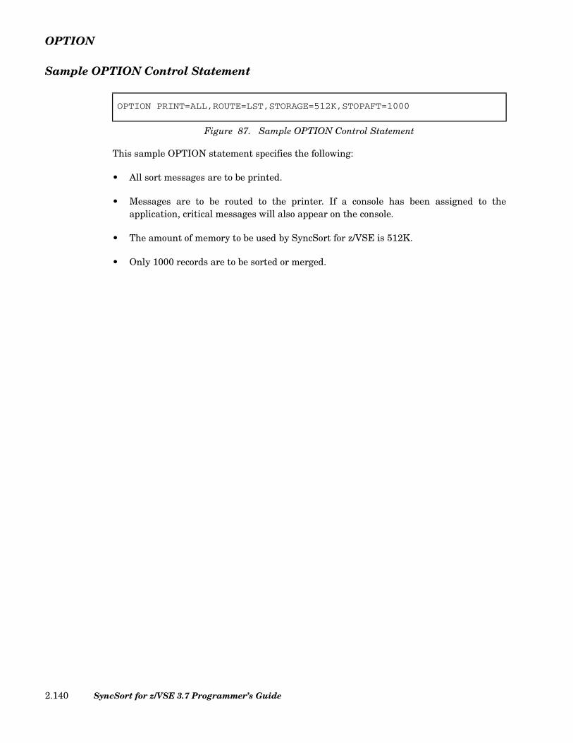
OPTION
Sample OPTION Control Statement
This sample OPTION statement specifies the following:
• All sort messages are to be printed.
• Messages are to be routed to the printer. If a console has been assigned to theapplication, critical messages will also appear on the console.
• The amount of memory to be used by SyncSort for z/VSE is 512K.
• Only 1000 records are to be sorted or merged.
OPTION PRINT=ALL,ROUTE=LST,STORAGE=512K,STOPAFT=1000
Figure 87. Sample OPTION Control Statement
SyncSort for z/VSE 3.7 Programmer’s Guide2.140

OUTFIL
OUTFIL Control Statement
The OUTFIL control statement describes the output file or files. It is required to accom-plish the following tasks:
• Create multiple output files
• Use the SortWriter facility
• Reformat records after E35 processing
• Convert variable-length records to fixed-length, or fixed-length records to variable-length.
The OUTFIL parameters associated with each of these tasks are listed below:
• Creating multiple output files: FILES, INCLUDE/OMIT, OUTREC
• Using the SortWriter facility: HEADER1, HEADER2, LINES, TRAILER1, TRAILER2,SECTIONS, NODETAIL
• Reformatting records: OUTREC, CONVERT, FTOV, VTOF, BUILD, IFTHEN,IFOUTLEN, OVERLAY
In addition, the OUTFIL statement is required with VSAM output, in which case theESDS, KSDS or RRDS parameter must be specified.
The format for the OUTFIL statement is illustrated below.
[,DISK] [,DUMP] [,ENDREC=n] [,ESDS] [,EXIT]
[,HEADER1=(field1[,field2]...)] [,HEADER2=(field1[,field2]...)]
Figure 88. (Page 1 of 2) OUTFIL Control Statement Format
OUTFIL BLKSIZE=n[ ] ,BUFLIM=255n
,BUFOFF= 04---
,CARDS=c
,PAGES=p
[,CISIZE=n] ,CLOSE=RWDNORWDUNLD
CONVERT,VTOF,
,FILES=1n---
(1,2,…,32)
,FNAMES=filename(filename1[,filename2]…)
[,FREEOUT] ,FTOV[ ]
Chapter 2. SyncSort Control Statements 2.141
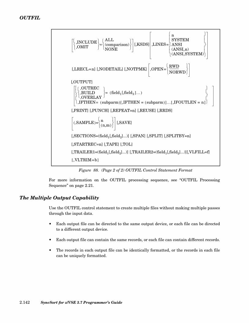
OUTFIL
For more information on the OUTFIL processing sequence, see “OUTFIL ProcessingSequence” on page 2.21.
The Multiple Output Capability
Use the OUTFIL control statement to create multiple files without making multiple passesthrough the input data.
• Each output file can be directed to the same output device, or each file can be directedto a different output device.
• Each output file can contain the same records, or each file can contain different records.
• The records in each output file can be identically formatted, or the records in each filecan be uniquely formatted.
[,PRINT] [,PUNCH] [,REPEAT=n] [,REUSE] [,RRDS]
[,SECTIONS=(field1[,field2]...)] [,SPAN] [,SPLIT] [,SPLITBY=n]
[,STARTREC=n] [,TAPE] [,TOL]
[,TRAILER1=(field1[,field2]...)] [,TRAILER2=(field1[,field2]...)][,VLFILL=f]
Figure 88. (Page 2 of 2) OUTFIL Control Statement Format
,INCLUDE,OMIT
=ALL(comparison)NONE
[,KSDS] ,LINES=
nSYSTEMANSI(ANSI,n)(ANSI,SYSTEM)
[,LRECL=n] [,NODETAIL] [,NOTPMK] ,OPEN=RWDNORWD
[,OUTPUT] OUTREC ,BUILD,OVERLAY ,
field1[,field2 ]…( )=
IFTHEN, subparm( )= ,IFTHEN = subparm( )[ ]… ,IFOUTLEN = n[ ]
SAMPLE,( )= nn,m( )
[,SAVE]
,VLTRIM=b[ ]
SyncSort for z/VSE 3.7 Programmer’s Guide2.142

OUTFIL
The SortWriter Capability
The SortWriter capability of OUTFIL can produce completely formatted reports. The reportwriting features, which can be specified differently for each output file, can accomplishthese tasks:
• Arrange the report into pages.
• Divide the report into sections.
• Format headers and trailers for sections, pages and the complete report.
• Convert and edit numeric data.
• Provide TOTAL and SUBTOTAL capabilities for data fields in a specific part of areport. Provide MIN, MAX, AVERAGE, SUBMIN, SUBMAX and SUBAVG capabilitiesfor data fields in a specific part of a report.
• Provide COUNT and SUBCOUNT capabilities for records in a specific part of a report.
Once formatted, output files can be assigned to any tape, disk, or unit record device for sub-sequent printing.
BLKSIZE Parameter (Optional)
The BLKSIZE parameter specifies the blocksize of the output records.
If the BLKSIZE parameter is omitted, either by leaving it out of the OUTFIL statement oromitting the OUTFIL statement itself, SyncSort will generate unblocked records.
Do not specify the BLKSIZE parameter for VSAM output.
Follow these guidelines in specifying the BLKSIZE value:
fixed-length EBCDIC and ASCII records: BLKSIZE must be a multiple of the fixed record length (l3).
variable-length EBCDIC records: BLKSIZE must be greater than or equal to the length of thelongest record (l3, which includes the Record Descriptor Word)plus 4 bytes (for the Block Descriptor Word).
variable-length ASCII records: BLKSIZE must be greater than or equal to the length of thelongest record (l3, which includes the Record Descriptor Word)plus the BUFOFF value, if specified.
Chapter 2. SyncSort Control Statements 2.143

OUTFIL
The l3 value represents the maximum output record length after E35 and OUTREC pro-cessing.
See Table 2 on page 2.23 for the maximum BLKSIZE values allowed for different outputdevices.
BUFLIM Parameter (Optional)
The BUFLIM parameter places an upper limit of 'n' on the number of output buffersSyncSort can create. Specify n as a decimal number between 1 and 255. The delivereddefault is 255.
In the vast majority of cases, SyncSort for z/VSE needs no external assistance in choosingthe number of buffers. Therefore, avoid specifying this parameter because using it inappro-priately may seriously degrade performance.
BUFOFF Parameter (Optional)
The BUFOFF parameter can be specified when TYPE=D is specified on the RECORD con-trol statement to indicate variable-length ASCII data. For variable-length ASCII data, the'n' value can be 0 or 4. If the BUFOFF parameter is not specified, it defaults to 0. For fixed-length ASCII data, this parameter should either be omitted or, if specified, the n valuemust be 0.
For variable-length data only, when BUFOFF=4 is specified, the 4-digit ASCII blocksize isinserted at the beginning of each block.
When BUFOFF=n is specified, the BLKSIZE value must include the BUFOFF value.
BUILD Parameter (Optional)
The BUILD parameter is identical to the OUTREC parameter of the OUTFIL ControlStatement. See “OUTREC Parameter (Optional)” on page 2.158 for a description of thisparameter.
CARDS/PAGES Parameter (Optional)
The CARDS parameter sets an upper bound, 'c', on the number of cards to be punched. ThePAGES parameter sets an upper bound, 'p', on the number of logical pages (not physicalpages) to be printed. Specify only one of these two parameters. The choice must reflect thetype of device to which the output file has been assigned.
The value specified for CARDS cannot exceed 16,777,215. The delivered default values of32,767 are assigned only if the PRINT or PUNCH parameters are explicitly specified in theOUTFIL control statement. Specifying 0 for either the CARDS or PAGES parameter causesthe sort/merge to terminate abnormally if there is any output.
SyncSort for z/VSE 3.7 Programmer’s Guide2.144

OUTFIL
To use the PAGES parameter to limit the number of physical pages printed, define the log-ical page using LINES=n with an 'n' value no greater than the line capacity of the paperused.
CISIZE Parameter (Optional)
The CISIZE parameter can be used to override the default control interval size selected byVSAM for implicitly-defined VSAM-managed SAM output files. For other types of outputfiles, this parameter is ignored.
Specify n as a decimal number between 512 and 32768. The actual control interval size ofthe file created by VSAM will be rounded up to be a multiple of 512 (or 2048), which islarger than the record length (for unblocked files) or the blocksize (for blocked files).
CLOSE Parameter (Optional)
Specified for tape output files only, the CLOSE parameter indicates what action should betaken at end of file.
CLOSE=RWD, the default, specifies that all tape output volumes be rewound at end of file.CLOSE=NORWD specifies that output volumes should not be rewound. CLOSE=UNLDspecifies that all output volumes be rewound and unloaded.
The CLOSE parameter is ignored if the output files are on direct access devices.
CONVERT/VTOF Parameter (Optional)
The CONVERT parameter is used to convert variable-length records to fixed-length. Inorder to use CONVERT, OUTREC, BUILD, OVERLAY, or IFTHEN must also be specifiedas an OUTFIL parameter. In addition, the following control parameters may not be speci-fied when CONVERT is used:
• OPTION ADDROUT
• RECORD TYPE=VS, VBS, F or D
• OUTFIL SPAN or EXIT
• MERGE FIELDS=COMPARE
• INPFIL DATA=A
The record length and padding characters of the resulting fixed-length output are deter-mined by the OUTREC (or BUILD, OVERLAY, or IFTHEN) parameter and the pres-ence/absence of the LRECL parameter on the OUTFIL control statement. The followingrules are followed:
Chapter 2. SyncSort Control Statements 2.145
OUTFIL
• If LRECL=n is specified, the output record length is n. Otherwise, the output recordlength is the sum of the field lengths in the OUTREC parameter list.
• Data records that are shorter than the sum of the field lengths in the OUTRECparameter list are padded to that length with binary zeros; report header and trailerrecords are padded with blanks. If this length is less than the length specified by theLRECL parameter, additional padding of records is done with blank characters.
When CONVERT is used, all OUTREC fields specifying a position value must also specify alength value.
Bytes 1 through 4 of the input record contain the RDW of the record. This field does notneed to be copied into the OUTRECed output record when using CONVERT.
DISK Parameter (Optional)
The DISK parameter specifies that the output file be stored on a disk device. The DISKparameter is required if report writing parameters are specified and the output file(s) areto be directed to a disk device.
DUMP Parameter (Optional)
The DUMP parameter specifies that SYSLST output be printed in both character andhexadecimal format.
ENDREC Parameter (Optional)
The ENDREC parameter specifies the last record that will be processed for this output file.The “n”th record sorted will be the last record eligible to be written to the output file. ForENDREC=n, the maximum value of n is 2G-1 (2147483647).
The count of sorted records is done before OUTFIL INCLUDE/OMIT processing, if speci-fied, takes place. (For example, if the first 100 sorted records are to be deleted byINCLUDE/OMIT, the next sorted record is still counted as record number 101. IfENDREC=90, then NO records would be written to the output file.)
If STARTREC is also specified for this output file, the ENDREC value must be greater thanor equal to the STARTREC value.
ESDS Parameter (Optional)
Specify the ESDS parameter when the VSAM output data set is to be entry-sequenced.(Entry-sequenced data sets are the VSAM equivalent of SAM data sets.) This parameter isrequired when creating an entry-sequenced data set. Do not specify the BLKSIZE parame-ter for an ESDS data set.
SyncSort for z/VSE 3.7 Programmer’s Guide2.146
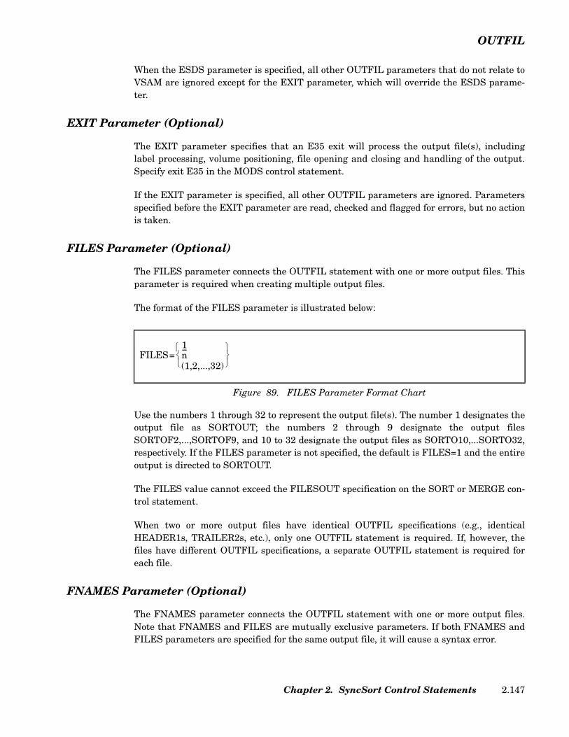
OUTFIL
When the ESDS parameter is specified, all other OUTFIL parameters that do not relate toVSAM are ignored except for the EXIT parameter, which will override the ESDS parame-ter.
EXIT Parameter (Optional)
The EXIT parameter specifies that an E35 exit will process the output file(s), includinglabel processing, volume positioning, file opening and closing and handling of the output.Specify exit E35 in the MODS control statement.
If the EXIT parameter is specified, all other OUTFIL parameters are ignored. Parametersspecified before the EXIT parameter are read, checked and flagged for errors, but no actionis taken.
FILES Parameter (Optional)
The FILES parameter connects the OUTFIL statement with one or more output files. Thisparameter is required when creating multiple output files.
The format of the FILES parameter is illustrated below:
Use the numbers 1 through 32 to represent the output file(s). The number 1 designates theoutput file as SORTOUT; the numbers 2 through 9 designate the output filesSORTOF2,...,SORTOF9, and 10 to 32 designate the output files as SORTO10,...SORTO32,respectively. If the FILES parameter is not specified, the default is FILES=1 and the entireoutput is directed to SORTOUT.
The FILES value cannot exceed the FILESOUT specification on the SORT or MERGE con-trol statement.
When two or more output files have identical OUTFIL specifications (e.g., identicalHEADER1s, TRAILER2s, etc.), only one OUTFIL statement is required. If, however, thefiles have different OUTFIL specifications, a separate OUTFIL statement is required foreach file.
FNAMES Parameter (Optional)
The FNAMES parameter connects the OUTFIL statement with one or more output files.Note that FNAMES and FILES are mutually exclusive parameters. If both FNAMES andFILES parameters are specified for the same output file, it will cause a syntax error.
Figure 89. FILES Parameter Format Chart
FILES=1n---
(1,2,...,32)
Chapter 2. SyncSort Control Statements 2.147

OUTFIL
The format of the FNAMES parameter is illustrated below:
Use FNAMES to specify a filename for an output file. The name can be up to 7 characterslong. A DLBL/TLBL statement must be present for this filename. The file names specifiedwith the FNAMES parameter must be either the default filenames (SORTOUT,SORTOF2,...) or a filename specified using the FILNM parameter of the OPTION state-ment.
FREEOUT Parameter (Optional)
The FREEOUT parameter is ignored.
FTOV Parameter (Optional)
The FTOV parameter converts fixed-length input records to variable-length output records.FTOV can be used either with or without the OUTREC parameter. When FTOV is usedwith the OUTREC parameter, the variable-length record is created from the specified fieldsof the fixed-length record. When FTOV is not used with the OUTREC parameter, the vari-able-length record is created from the whole fixed-length record. The maximum recordlength is passed from INPFIL.
FTOV can be used with the VLTRIM parameter to delete pad bytes from the end of arecord.
The output record format produced by OUTFIL FTOV depends on the BLKSIZE parameterexcept for VSAM output.
When the BLKSIZE parameter is not specified for the OUTFIL FTOV, SyncSort will gener-ate unblocked output records.
The TYPE for the RECORD control statement must have a fixed-length record format (forexample, TYPE=F). In addition, the following control parameters may not be specifiedwhen OUTFIL FTOV is used:
• OUTFIL EXIT
• RECORD TYPE=V, D, VS, VBS
• MERGE FIELDS=COMPARE
• OUTFIL VTOF, CONVERT
Figure 90. FNAMES Parameter Format Chart
FNAMES=filenamefilename1 filename2 … filename32,,,( )
SyncSort for z/VSE 3.7 Programmer’s Guide2.148

OUTFIL
Note: FTOV cannot be used with CONVERT or VTOF. If the input record is variable-length, FTOV, if specified, will be ignored. FTOV can be used with the VLTRIM parameterto delete pad bytes at the end of a record.
FTOV With BLKSIZE Parameter
When the BLKSIZE parameter is specified for the OUTFIL FTOV, SyncSort will generatean output record format of VB or VBS. Make sure the BLKSIZE specified is big enough tocontain the largest variable-length output record to be produced.
Note: Do not specify the BLKSIZE parameter for VSAM output.
FTOV With OUTREC Parameter
When FTOV is used with the OUTREC parameter, the variable-length record is createdfrom the specified fields of the fixed-length record. The maximum record length is the refor-matted OUTREC record length plus 4.
HEADER1/HEADER2 Parameters (Optional)
The SortWriter facility provides three types of headers:
• HEADER1, the report header
• HEADER2, the page header
• HEADER3, the section header
HEADER1 and HEADER2 are parameters of the OUTFIL control statement; HEADER3 isa subparameter of OUTFIL’s SECTIONS parameter. Refer to “SPLIT Parameter(Optional)” on page 2.161 for an explanation of how to specify HEADER3.
The three types of headers function independently of each other. Each serves a differentpurpose:
• HEADER1 provides a header or a possible title page for the entire report. It appearsonly once at the beginning of the report on its own page.
• HEADER2 provides a page header or a running head for each page defined by theLINES parameter. It appears at the beginning or top of each page.
• HEADER3 provides a section header that appears at the beginning of each specifiedsection and, optionally, at the top of each page (or directly below any HEADER2).
Figure 91 illustrates the format for HEADERs. The field entries represent the subparame-ters that can be specified for each HEADER.
Chapter 2. SyncSort Control Statements 2.149

OUTFIL
Figure 92 illustrates and defines the available subparameters. Each subparameter consti-tutes a separate field of the HEADER.
c: Use the c: subparameter to define the column in which the specifiedfield should begin.
n Used in conjunction with the X, 'literal string', and / subparameters,the n value defines the number (1-255) of repetitions for each entry.
X Use the X subparameter to define the number of spaces. It must becoded to the immediate right of the n value, if specified. For morethan 255 spaces, two or more nX values should be specified.
[C]'literal string' Use the C'literal string' or 'literal string' subparameter to define aliteral string. Specify the number of repetitions by coding n immedi-ately before it.
/ Use the / subparameter to indicate the end of a line, force a carriagereturn and separate text lines of a header. Multiple slashes (coded // ... / or n/) can be used to specify leading, trailing or embeddedblank lines. At the beginning or end of a header, n/ produces n blanklines. Within a header, n/ produces n-1 blank lines.
p,l Use the p,l subparameter to include a field (or fields) within arecord in the header. For a HEADER1, the field(s) will be extracted
HEADER1=(field1[,field2] ...)HEADER2=(field1[,field2] ...)HEADER3=(field1[,field2] ...)
Figure 91. HEADER Parameter Format Chart
Figure 92. HEADER Subparameters Format Chart
[c]
[n] X[n] C'literal string'[n] 'literal string'[n] /p,l&DATE=(abcd)DATE=(abcd)&DATENS=(abc)DATENS=(abc)&TIME=(nnc)TIME=(nnc)&TIMENS=(nn)TIMENS=(nn)&PAGEPAGE
SyncSort for z/VSE 3.7 Programmer’s Guide2.150
OUTFIL
from the first record in a file; for a HEADER2, the field(s) will beextracted from the first record on a page; for a HEADER3, thefield(s) will be extracted from the first record in a section. p is thestarting position of the field in the record; l is the length in bytes (1-255) of the field. Any number of fields can be specified. (Contiguousfields within a record can be specified with a single p,l entry, buttheir combined length cannot exceed 255 bytes.) The specifiedfield(s) must be a character or alphanumeric string or a number inzoned decimal format, and the field cannot be converted or edited.
If any variable-length record contains only a portion of the bytes ina specified field, those bytes will be included in the header andblanks will be substituted for the missing bytes.
&DATE=(abcd) The &DATE or DATE subparameter specifies the current gener-ated system date and requires 8 bytes. abcd indicates that youarrange the year, month and day in any order. d is the separatorcharacter. Use M to denote month, D to denote day, and Y to denotethe last two characters of the year. You can specify 4 as an alterna-tive to Y if you want the year expressed in four digits (1996 asopposed to 96).
For example, if the current date is 4/24/96 and &DATE=(DMY.), theoutput date is 24.04.96. With the same example, if &DATE=(4MD-),the output date is 1996-04-24.
The date format represented by &DATE may also be set by theDATE parameter on the OPTION statement as follows: ADATE sig-nifies American date format (mm/dd/yy); EDATE signifies Euro-pean date format (dd/mm/yy); IDATE signifies ISO date format(yy/mm/dd). If omitted, system generated date (STD) is the default.
&DATENS=(abc) Specify &DATENS or DATENS when no separator is desired.
&TIME=(nnc) The &TIME or TIME subparameter specifies the current step starttime, which is the time that the current execution of SyncSortbegan.
nn can be either 12 or 24. 24 specifies twenty-four hour clock withthe format hhcmmcss and requires 8 bytes. 12 specifies twelve hourclock with the format hhcmmcss xx. xx can be either am or pm. cdenotes the separation character. When nn=12, &TIME requires 11bytes.
&TIMENS=(nn) Specify &TIMENS or TIMENS when no separator is desired.
Chapter 2. SyncSort Control Statements 2.151
OUTFIL
&PAGE The &PAGE or PAGE subparameter sequentially numbers logicalpages of the output report and requires 6 bytes. It produces a 6-digit sequential page number, right-justified with leading zerossuppressed. &PAGE is ignored for HEADER1.
Rules for Specifying HEADER Subparameters
Observe the following guidelines when you specify HEADER subparameters:
• Separate subparameters with commas, except for /, where commas are optional.
• Enclose literals in single quotes.
• Specify blank fields of n bytes as nX.
• Short headings (i.e., headings specified with fewer blanks than the logical record length(LRECL) of the output record) are automatically padded on the right with blanks.
• If a heading exceeds the logical record length (LRECL) of the output record, specify theLRECL parameter to expand the output record length so that the output record lengthis at least as long as the longest header. (See “LRECL Parameter (Optional)” on page2.157.)
IFOUTLEN Parameter (Optional)
The IFOUTLEN parameter overrides the maximum record length, which is automaticallyset by the IFTHEN parameter, and changes it to a specified value. The IFOUTLEN param-eter may only be used in conjunction with the IFTHEN parameter.
The IFOUTLEN parameter automatically makes the following changes to the record tomatch the new length. A record longer than n is truncated to n. A fixed-length recordshorter than n is padded with blanks to reach a length of n. For fixed-length blocked outputrecords, the blocksize must be a multiple of n.
IFTHEN Parameter (Optional)
The IFTHEN parameter uses conditional logic which enables you to reformat records basedon specified criteria. Multiple IFTHEN parameters may be specified within the same con-trol statement and are processed sequentially. See “IFTHEN Parameter (Optional)” onpage 2.205 for a complete description of this parameter.
INCLUDE/OMIT Parameter (Optional)
Specify the INCLUDE or OMIT parameter to indicate which records are to be included inor omitted from each output file. These parameters let you create multiple output files thatcontain different records. The default is to include all sorted or merged records in the out-put file. The format for the INCLUDE/OMIT parameter is illustrated below:
SyncSort for z/VSE 3.7 Programmer’s Guide2.152
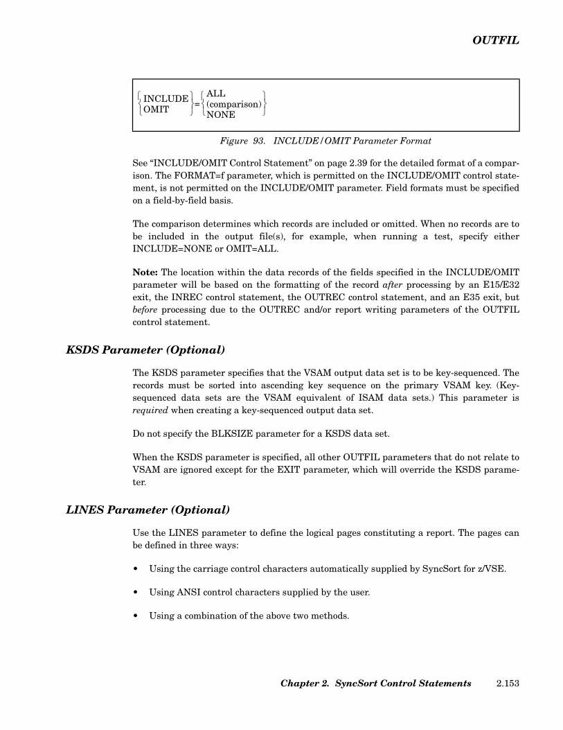
OUTFIL
See “INCLUDE/OMIT Control Statement” on page 2.39 for the detailed format of a compar-ison. The FORMAT=f parameter, which is permitted on the INCLUDE/OMIT control state-ment, is not permitted on the INCLUDE/OMIT parameter. Field formats must be specifiedon a field-by-field basis.
The comparison determines which records are included or omitted. When no records are tobe included in the output file(s), for example, when running a test, specify eitherINCLUDE=NONE or OMIT=ALL.
Note: The location within the data records of the fields specified in the INCLUDE/OMITparameter will be based on the formatting of the record after processing by an E15/E32exit, the INREC control statement, the OUTREC control statement, and an E35 exit, butbefore processing due to the OUTREC and/or report writing parameters of the OUTFILcontrol statement.
KSDS Parameter (Optional)
The KSDS parameter specifies that the VSAM output data set is to be key-sequenced. Therecords must be sorted into ascending key sequence on the primary VSAM key. (Key-sequenced data sets are the VSAM equivalent of ISAM data sets.) This parameter isrequired when creating a key-sequenced output data set.
Do not specify the BLKSIZE parameter for a KSDS data set.
When the KSDS parameter is specified, all other OUTFIL parameters that do not relate toVSAM are ignored except for the EXIT parameter, which will override the KSDS parame-ter.
LINES Parameter (Optional)
Use the LINES parameter to define the logical pages constituting a report. The pages canbe defined in three ways:
• Using the carriage control characters automatically supplied by SyncSort for z/VSE.
• Using ANSI control characters supplied by the user.
• Using a combination of the above two methods.
Figure 93. INCLUDE/OMIT Parameter Format
INCLUDEOMIT
=ALL(comparison)NONE
Chapter 2. SyncSort Control Statements 2.153

OUTFIL
Regardless of which method is selected, the number of lines defining a logical page must beequal to or greater than the total number of lines, including blank lines, required for allHEADER2, HEADER3, TRAILER2 and TRAILER3 entries plus at least one record.
The format of the LINES parameter is illustrated below:
LINES=n
If LINES=n is specified, paging is automatic and carriage control characters are added tothe beginning of each record by SyncSort. Specify 'n' as a value from 0 to 255. If the outputfile is assigned to a printer, the default is LINES=60. If the output file is assigned to a cardpunch, the default is LINES=0. LINES=0 is allowed only if the output file is assigned to acard punch. This specification generates all HEADER1 and HEADER2 cards exactly oncebefore all output records.
When LINES=n is specified, the output record length is increased by 1.
The LINES=n specification works in conjunction with any HEADERs and TRAILERs youhave specified as follows:
• HEADER1, if specified, prints as a preface to the report. Its page is not numbered.
• An automatic page break will occur after HEADER1. Every nth line after thecompletion of HEADER1 will signal the start of a new page.
• A HEADER2 entry, if present, will be the first line(s) on each page, followed by anyHEADER3 entries that might be triggered either by control breaks or by PAGEHEADspecifications in the SECTIONS parameter. HEADER2 is part of the logical page.
• A HEADER3 entry, if present, is part of a section of the report. It prints as a header forthe separate report sections. HEADER3s will appear in major to minor order accordingto the order in which they are specified.
• If PAGEHEAD is specified, HEADER3 will print immediately below HEADER2, ifspecified, or at the top of the page if a HEADER2 is not specified. A HEADER3 will notprint near the end of a page if there is not sufficient room on that page for at least onedata record and a TRAILER2, if specified.
Figure 94. LINES Parameter Format Chart
,LINES=
nSYSTEMANSI(ANSI,n)(ANSI,SYSTEM)
SyncSort for z/VSE 3.7 Programmer’s Guide2.154
OUTFIL
• A TRAILER3 entry, if present, is part of a section of the report. It prints as a conclusionor summary for the separate report sections. TRAILER3s will appear in major to minororder according to the order in which they are specified.
• A TRAILER2 entry, if present, will be the last line(s) on the logical page, preceded byany TRAILER3s triggered by coincidentally occurring control breaks. TRAILER2 ispart of the logical page.
• TRAILER1 will be the last page of the entire report. Its page is not numbered.
Therefore, when LINES=n is specified, all HEADER2, HEADER3, TRAILER2 andTRAILER3 entries will be included as part of 'n' (the total number of lines in a logical page)and will print as described above.
LINES=SYSTEM
LINES=SYSTEM is similar to LINES=n. If LINES=SYSTEM is specified, the VSE systemdefined default for the number of lines per page for SYSLST will be used as 'n'.
LINES=ANSI
If LINES=ANSI is specified, user-provided ANSI control characters define the logicalpages. The first byte of each output record (including HEADER and TRAILER records)must contain an ANSI control character (inserted, for example, by an E35 program) that isvalid for the specified output device type. For example, inserting '0' in byte 1 of the outputrecords produces double spaced records.
The ANSI control characters that can be used with the LINES=ANSI specification are sum-marized in Table 26 on page 2.157.
If printed output is requested, the ANSI control characters do not print as part of the out-put record. If, however, the report is routed to a disk or tape device, the control charactersare included in the output data.
The LINES=ANSI specification works in conjunction with any HEADERs or TRAILERsyou have specified. If you specify HEADER2, the ANSI specification affects this header asfollows:
• After HEADER1 is output, the first logical page begins with the first line of HEADER2.
• A logical page ends when data with a '1' in the first byte is encountered. Because '1' isnot a valid control character for a card punch, output punched using LINES=ANSIalways consists of exactly one logical page and always punches HEADER2 only oncebefore all data records.
• If the output file is assigned to a printer, a data record beginning with a '1' is delayeduntil after TRAILER2 and HEADER2, if specified, are output. When record printingresumes, this delayed record will be modified to have a control character '+', which
Chapter 2. SyncSort Control Statements 2.155

OUTFIL
causes it to print over the last line of HEADER2. To prevent the data record fromprinting over a text line of HEADER2, the HEADER2 should end with at least oneblank line, specified by a slash (/).
• To print HEADER2 at the top of a new physical page, the HEADER2’s first line shouldbegin with a '1'.
• Because you are in complete control of the paging with LINES=ANSI, you can permitHEADER2 to appear between variable numbers of printed records.
LINES=(ANSI,n)
If LINES=(ANSI,n) is specified, ANSI control characters govern vertical control, and the 'n'specification provides additional automatic paging. Added flexibility is provided becausethe user can elect to double or triple space the output and still use automatic paging.
When SyncSort encounters a data record with a '1' in the first byte, SyncSort begins a newlogical page. If no data record begins with a '1' but the next data record would cause thenumber of lines on the page to exceed 'n', SyncSort treats that record as if it began with a '1'and begins a new page.
Refer to the LINES=ANSI discussion for information on using a HEADER2 with ANSI con-trol characters.
LINES=(ANSI,SYSTEM)
LINES=(ANSI,SYSTEM) is similar to LINES=(ANSI,n). If LINES=(ANSI,SYSTEM) isspecified, the VSE system defined default for the number of lines per page for SYSLST willbe used as 'n'.
Valid ANSI Control Characters
The following table lists the ANSI control characters accepted by SyncSort.
SyncSort for z/VSE 3.7 Programmer’s Guide2.156
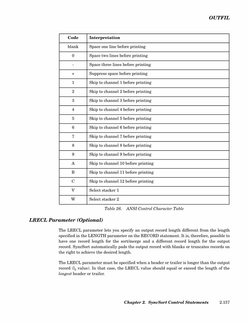
OUTFIL
LRECL Parameter (Optional)
The LRECL parameter lets you specify an output record length different from the lengthspecified in the LENGTH parameter on the RECORD statement. It is, therefore, possible tohave one record length for the sort/merge and a different record length for the outputrecord. SyncSort automatically pads the output record with blanks or truncates records onthe right to achieve the desired length.
The LRECL parameter must be specified when a header or trailer is longer than the outputrecord (l3 value). In that case, the LRECL value should equal or exceed the length of thelongest header or trailer.
Code Interpretation
blank Space one line before printing
0 Space two lines before printing
- Space three lines before printing
+ Suppress space before printing
1 Skip to channel 1 before printing
2 Skip to channel 2 before printing
3 Skip to channel 3 before printing
4 Skip to channel 4 before printing
5 Skip to channel 5 before printing
6 Skip to channel 6 before printing
7 Skip to channel 7 before printing
8 Skip to channel 8 before printing
9 Skip to channel 9 before printing
A Skip to channel 10 before printing
B Skip to channel 11 before printing
C Skip to channel 12 before printing
V Select stacker 1
W Select stacker 2
Table 26. ANSI Control Character Table
Chapter 2. SyncSort Control Statements 2.157

OUTFIL
NODETAIL Parameter (Optional)
The NODETAIL parameter instructs the SortWriter facility to generate an output reportconsisting only of header and trailer entries. Data records are not included in the outputreport when this parameter is specified.
Thus, for example, it is possible to generate a report with section trailers containing totalsand record counts without printing any data records.
NOTPMK Parameter (Optional)
The NOTPMK parameter specifies that a tape mark not be written before the first record ofeach volume of an unlabeled tape output file. The default is to write tape marks on eachvolume of an unlabeled tape output file. The NOTPMK parameter can also be specified onthe OPTION control statement.
This parameter is ignored for disk files or labeled tape files.
OPEN Parameter (Optional)
Specified for tape output files only, the OPEN parameter indicates what action should betaken when the file is opened.
OPEN=RWD, the default, specifies that the first volume of the output file be rewound whenthe file is opened. OPEN=NORWD specifies that the first volume should not be rewoundbefore data is written. The default is OPEN=RWD.
The OPEN parameter is ignored if the output files are on direct access devices.
OUTPUT Parameter (Optional)
The OUTPUT parameter is ignored by SyncSort for z/VSE.
OUTREC Parameter (Optional)
The OUTREC parameter indicates how the records are to be formatted in each output file.This parameter lets you create multiple output files that contain differently formattedrecords.
When the records in multiple output files are formatted and edited identically, it is moreefficient to specify a single OUTREC control statement rather than several OUTRECparameters.
The OUTREC parameter reformats the records that are to be included in the output file(s)after E35 processing, if specified. If no additional reformatting is required, omit thisparameter.
SyncSort for z/VSE 3.7 Programmer’s Guide2.158
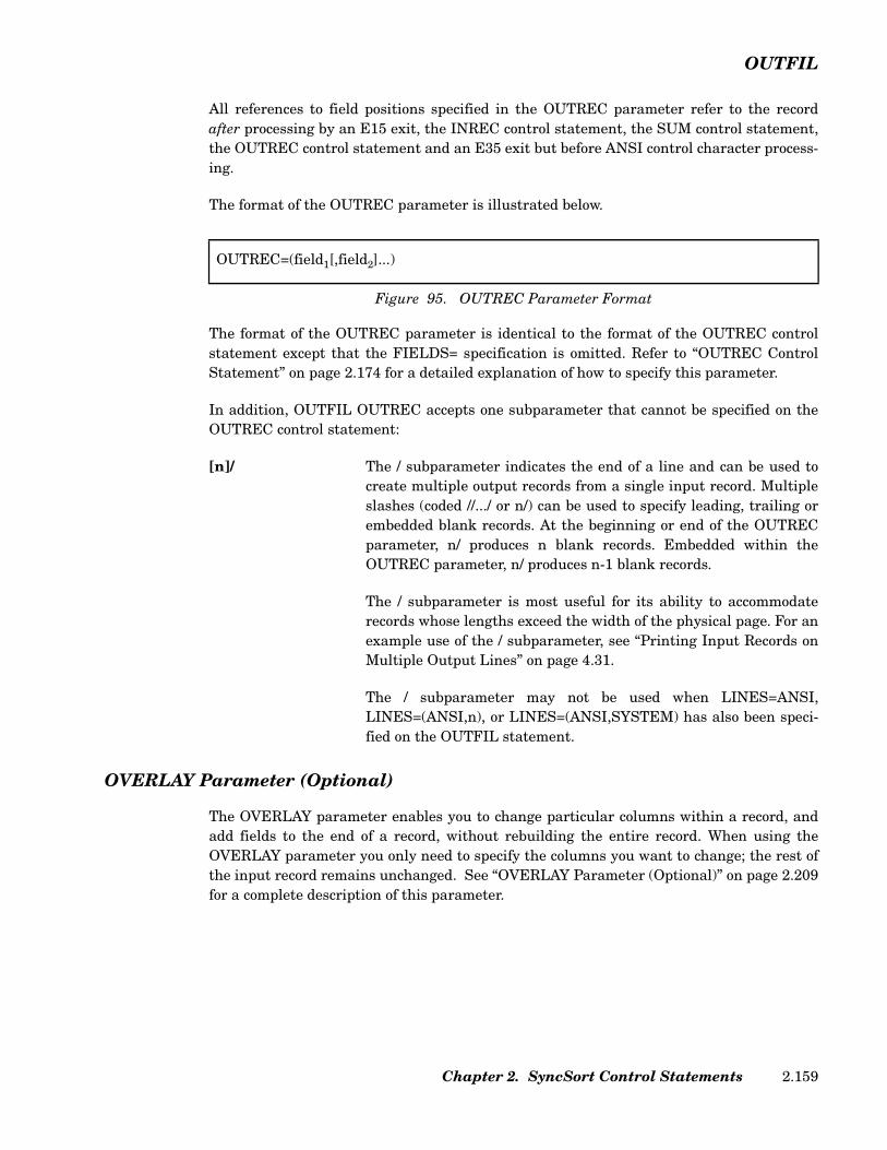
OUTFIL
All references to field positions specified in the OUTREC parameter refer to the recordafter processing by an E15 exit, the INREC control statement, the SUM control statement,the OUTREC control statement and an E35 exit but before ANSI control character process-ing.
The format of the OUTREC parameter is illustrated below.
The format of the OUTREC parameter is identical to the format of the OUTREC controlstatement except that the FIELDS= specification is omitted. Refer to “OUTREC ControlStatement” on page 2.174 for a detailed explanation of how to specify this parameter.
In addition, OUTFIL OUTREC accepts one subparameter that cannot be specified on theOUTREC control statement:
[n]/ The / subparameter indicates the end of a line and can be used tocreate multiple output records from a single input record. Multipleslashes (coded //.../ or n/) can be used to specify leading, trailing orembedded blank records. At the beginning or end of the OUTRECparameter, n/ produces n blank records. Embedded within theOUTREC parameter, n/ produces n-1 blank records.
The / subparameter is most useful for its ability to accommodaterecords whose lengths exceed the width of the physical page. For anexample use of the / subparameter, see “Printing Input Records onMultiple Output Lines” on page 4.31.
The / subparameter may not be used when LINES=ANSI,LINES=(ANSI,n), or LINES=(ANSI,SYSTEM) has also been speci-fied on the OUTFIL statement.
OVERLAY Parameter (Optional)
The OVERLAY parameter enables you to change particular columns within a record, andadd fields to the end of a record, without rebuilding the entire record. When using theOVERLAY parameter you only need to specify the columns you want to change; the rest ofthe input record remains unchanged. See “OVERLAY Parameter (Optional)” on page 2.209for a complete description of this parameter.
OUTREC=(field1[,field2]...)
Figure 95. OUTREC Parameter Format
Chapter 2. SyncSort Control Statements 2.159

OUTFIL
PRINT Parameter (Optional)
Use the PRINT parameter to specify that the output file be written to a printer. If reportwriting parameters are specified and another output device type is not specified, PRINT isthe default. If report writing parameters are not specified and the output is to be printed,the PRINT parameter must be specified.
When the output file is to be printed, the SYSnumber for this file (usually SYS001 forSORTOUT) must be assigned to a printer. Do not specify a DLBL or TLBL statement forthe printer output file.
PUNCH Parameter (Optional)
Use the PUNCH parameter to specify that the output file be written to a card punch. Thisparameter is required if the output is to be directed to a card punch.
The SYSnumber for this file (usually SYS001 for SORTOUT) must be assigned to a punch.Do not specify a DLBL or TLBL statement for the punch output file.
REPEAT Parameter (Optional)
The REPEAT=n parameter writes each output record multiple times. n specifies the num-ber of times each OUTFIL output record is written. The minimum value for n is 2.
REPEAT can be used with the OUTFIL OUTREC multiline feature (designated by a / inthe OUTREC specification). When this is done, each line will be written n times defined bythe OUTREC specifications. All occurrences of the first line will be written followed by allthe occurrences of the second, and so on.
The REPEAT parameter cannot be used with LINES, HEADER1, TRAILER1, HEADER2,TRAILER2, SECTIONS, and NODETAIL.
REUSE Parameter (Optional)
Use the REUSE parameter to specify that the output be written over an existing VSAMdata set. The VSAM cluster must have been defined (DEFINE CLUSTER) with the REUSEoption; otherwise, an error will occur.
The REUSE parameter is ignored for non-VSAM files.
RRDS Parameter (Optional)
Specify the RRDS parameter when the VSAM output data set is to be a relative record dataset. (A relative record VSAM data set is essentially a string of fixed-length slots, each ofwhich has a relative record number. This number starts at one and continues up to themaximum number of records that can be stored in the file.) This parameter is requiredwhen creating a relative record data set.
SyncSort for z/VSE 3.7 Programmer’s Guide2.160

OUTFIL
Do not specify the BLKSIZE parameter for an RRDS data set.
When the RRDS parameter is specified, all other OUTFIL parameters that do not relate toVSAM are ignored except for the EXIT parameter, which will override the RRDS parame-ter.
SAMPLE Parameter (Optional)
The SAMPLE=n and SAMPLE=(n,m) parameters allow the selection of a sample of recordsfrom an OUTFIL group. A specific interval and number of records in that interval can bespecified. The sample process will take place within the range of records specified by STARTREC or ENDREC if they are specified. SAMPLE=n and SAMPLE=(n,m) are mutu-ally exclusive.
The sample consists of the first m records in every nth interval. n specifies the interval size.The minimum value for n is 2 (sample every other record).
m specifies the number of records to be processed in each interval. The minimum value form is 1(process the first record in each interval). If m is not specified, 1 is used for m. If m isspecified, it must be less than n.
SAVE Parameter (Optional)
Use the SAVE parameter to include all the records that are not included in anotherOUTFIL group in the data sets for this group. SAVE retains all the input records that arenot included in the other groups and would otherwise be lost.
SPLIT Parameter (Optional)
The SPLIT parameter of the OUTFIL control statement causes output records to be distrib-uted in rotation among files in an OUTFIL group.
In the normal case, when the SPLIT parameter is not used, the output record files in thegroup will contain the same records. SPLIT distributes the output records. The followingOUTFIL control statement will distribute records among three output files:
For the above example, the first record will be written to the SORTOF1 data set, the sec-ond, to SORTOF2, the third, to SORTOF3. The fourth record will be written to SORTOF1again, and so on in round-robin fashion.
OUTFIL FILES=(01,02,03), SPLIT
Figure 96. Sample OUTFIL Control Statement with SPLIT
Chapter 2. SyncSort Control Statements 2.161

OUTFIL
The OUTFIL control statement can contain an INCLUDE/OMIT and an OUTREC parame-ter, in which case the selected and reformatted subset of records will be distributed amongthe output files.
Note that the SPLIT parameter cannot be used with any report writing (SortWriter) func-tions. Specifically, report writing parameters (HEADERn, TRAILERn, SECTIONS, LINES,NODETAIL) cannot be specified on the OUTFIL control statement that defines the outputgroup.
SPLIT and SPLITBY=n are mutually exclusive. SPLITBY=1 is equivalent to SPLIT.
SECTIONS Parameter (Optional)
The SECTIONS parameter allows the output report to be divided into sections.
The format of the SECTIONS parameter is illustrated below.
The SECTIONS parameter identifies the control field(s) that determine, or control, sectionbreaks. More than one control field can be specified to subdivide a report within sections.However, if more than one control field is specified, the specifications must be made inmajor to minor order. A major control field break causes all minor control fields to break atthe same time.
Each control field is identified by its position (p) and length (l).
p The position value indicates the first byte of the field relative tothe beginning of the record after processing by an E15/E32 exit,the INREC statement, the OUTREC statement and an E35exit, if specified, but before processing by the OUTREC parame-ter and other report writing parameters of the OUTFIL state-ment, if specified.
l The length value indicates the length of the field. The lengthmust be an integral number of bytes, with a maximum value of256.
Multiple p,l pairs of non-contiguous fields can be specified to form a control field for aSECTIONS break.
For each control field, at least one of the following subparameters must be specified: SKIP,HEADER3 or TRAILER3. The SECTIONS subparameters are described below.
SECTIONS=(field1[,field2]...)Each field is specified as follows:
p,l[,p,l],subparameter[,subparameter]
Figure 97. SECTIONS Parameter Format Chart
SyncSort for z/VSE 3.7 Programmer’s Guide2.162
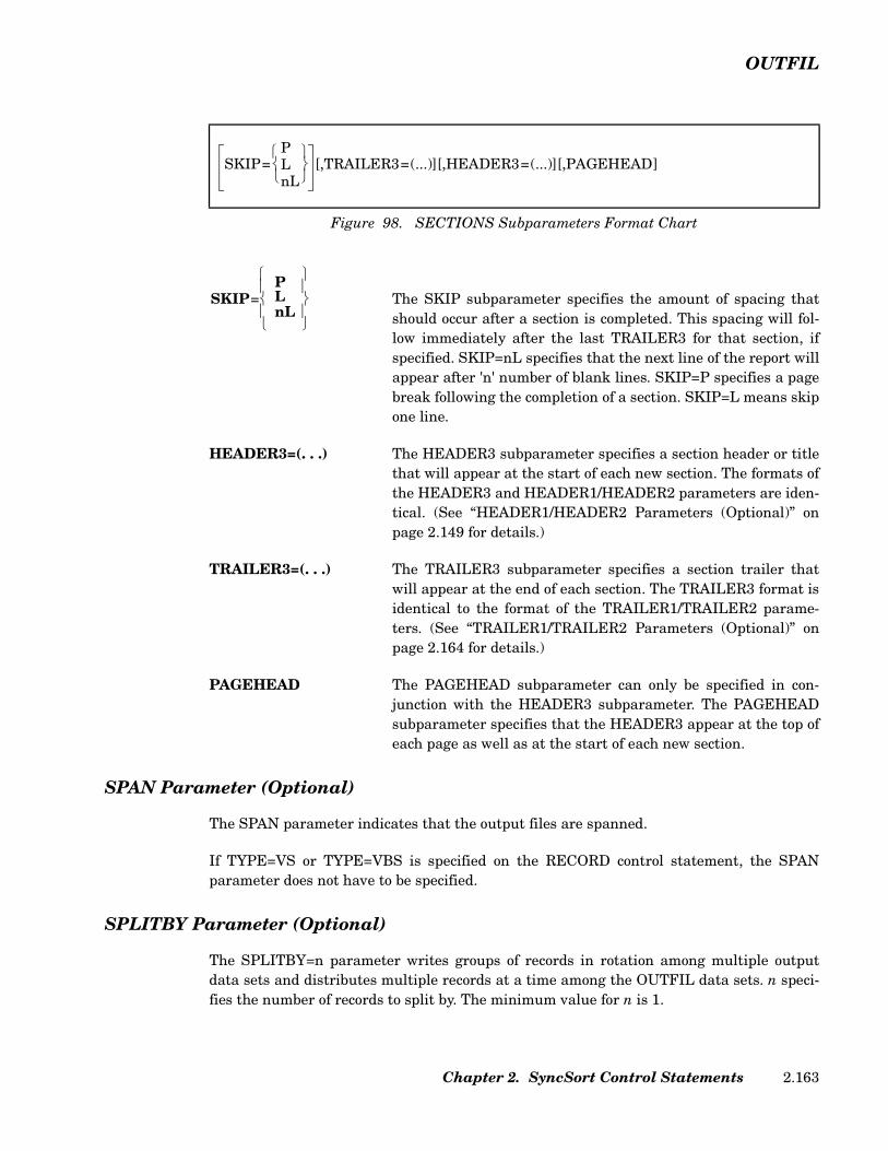
OUTFIL
The SKIP subparameter specifies the amount of spacing thatshould occur after a section is completed. This spacing will fol-low immediately after the last TRAILER3 for that section, ifspecified. SKIP=nL specifies that the next line of the report willappear after 'n' number of blank lines. SKIP=P specifies a pagebreak following the completion of a section. SKIP=L means skipone line.
HEADER3=(. . .) The HEADER3 subparameter specifies a section header or titlethat will appear at the start of each new section. The formats ofthe HEADER3 and HEADER1/HEADER2 parameters are iden-tical. (See “HEADER1/HEADER2 Parameters (Optional)” onpage 2.149 for details.)
TRAILER3=(. . .) The TRAILER3 subparameter specifies a section trailer thatwill appear at the end of each section. The TRAILER3 format isidentical to the format of the TRAILER1/TRAILER2 parame-ters. (See “TRAILER1/TRAILER2 Parameters (Optional)” onpage 2.164 for details.)
PAGEHEAD The PAGEHEAD subparameter can only be specified in con-junction with the HEADER3 subparameter. The PAGEHEADsubparameter specifies that the HEADER3 appear at the top ofeach page as well as at the start of each new section.
SPAN Parameter (Optional)
The SPAN parameter indicates that the output files are spanned.
If TYPE=VS or TYPE=VBS is specified on the RECORD control statement, the SPANparameter does not have to be specified.
SPLITBY Parameter (Optional)
The SPLITBY=n parameter writes groups of records in rotation among multiple outputdata sets and distributes multiple records at a time among the OUTFIL data sets. n speci-fies the number of records to split by. The minimum value for n is 1.
Figure 98. SECTIONS Subparameters Format Chart
SKIP=PLnL
[,TRAILER3=(...)][,HEADER3=(...)][,PAGEHEAD]
SKIP=PLnL
Chapter 2. SyncSort Control Statements 2.163

OUTFIL
The SPLITBY parameter is similar to SPLIT, but SPLITBY can be used to rotate by a spec-ified number of records rather than by one record, for example, records 1-10 to the firstOUTFIL data set, records 11-20 to the second OUTFIL data set, and so on.
For example, if SPLITBY=10 is specified for an OUTFIL group with three data sets:
• The first OUTFIL data set in the group receives records 1-10, 31-40, and so on.
• The second OUTFIL data set in the group receives records 11-20, 41-50, and so on.
• The third OUTFIL data set in the group receives records 21-30, 51-60, and so on.
SPLIT and SPLITBY=n are mutually exclusive. SPLITBY=1 is equivalent to SPLIT.
Note that the SPLIT parameter cannot be used with any report writing (SortWriter) func-tions. Specifically, report writing parameters (HEADERn, TRAILERn, SECTIONS, LINES,NODETAIL) cannot be specified on the OUTFIL control statement that defines the outputgroup.
STARTREC Parameter (Optional)
The STARTREC parameter specifies the first record that will be processed for this outputfile. The “n”th sorted record will be the first record eligible to be written to the output file;the first n-1 records are skipped. For STARTREC=n, the maximum value of n is 2G-1(2147483647).
The count of sorted records is done before OUTFIL INCLUDE/OMIT processing, if speci-fied, takes place.
TAPE Parameter (Optional)
Use the TAPE parameter to specify that the output file be stored on a tape device. TheTAPE parameter is required if report writing parameters are specified and the outputfile(s) are to be directed to a tape device.
TOL Parameter (Optional)
The TOL parameter specifies that a warning code be accepted when a VSAM output file isopened. If the TOL parameter is not specified, the warning return code is recognized as anerror, an error message is generated, and SyncSort for z/VSE terminates.
TRAILER1/TRAILER2 Parameters (Optional)
The SortWriter facility provides three types of trailers:
• TRAILER1, the report trailer
SyncSort for z/VSE 3.7 Programmer’s Guide2.164
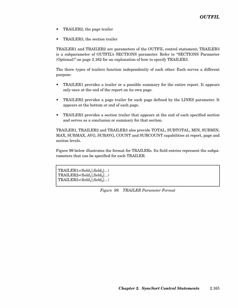
OUTFIL
• TRAlLER2, the page trailer
• TRAILER3, the section trailer
TRAILER1 and TRAILER2 are parameters of the OUTFIL control statement; TRAILER3is a subparameter of OUTFIL’s SECTIONS parameter. Refer to “SECTIONS Parameter(Optional)” on page 2.162 for an explanation of how to specify TRAILER3.
The three types of trailers function independently of each other. Each serves a differentpurpose:
• TRAILER1 provides a trailer or a possible summary for the entire report. It appearsonly once at the end of the report on its own page.
• TRAILER2 provides a page trailer for each page defined by the LINES parameter. Itappears at the bottom or end of each page.
• TRAILER3 provides a section trailer that appears at the end of each specified sectionand serves as a conclusion or summary for that section.
TRAILER1, TRAILER2 and TRAILER3 also provide TOTAL, SUBTOTAL, MIN, SUBMIN,MAX, SUBMAX, AVG, SUBAVG, COUNT and SUBCOUNT capabilities at report, page andsection levels.
Figure 99 below illustrates the format for TRAILERs. Its field entries represent the subpa-rameters that can be specified for each TRAILER.
TRAILER1=(field1[,field2]...) TRAILER2=(field1[,field2]...) TRAILER3=(field1[,field2]...)
Figure 99. TRAILER Parameter Format
Chapter 2. SyncSort Control Statements 2.165
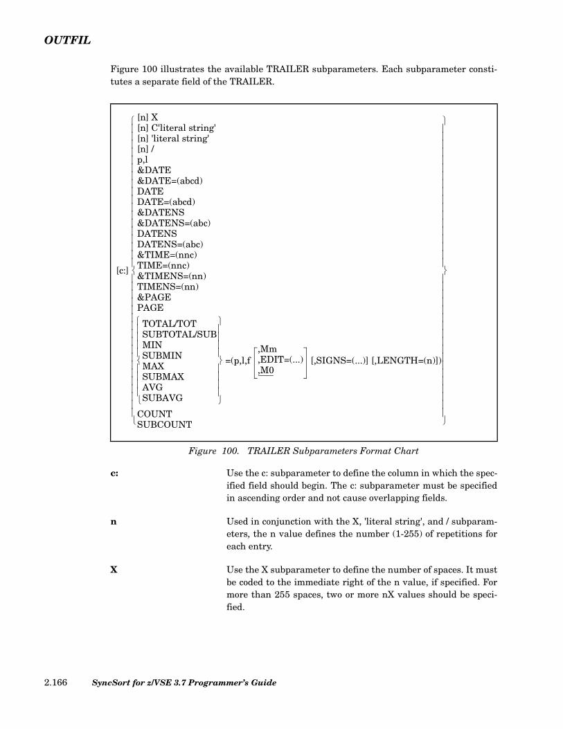
OUTFIL
Figure 100 illustrates the available TRAILER subparameters. Each subparameter consti-tutes a separate field of the TRAILER.
c: Use the c: subparameter to define the column in which the spec-ified field should begin. The c: subparameter must be specifiedin ascending order and not cause overlapping fields.
n Used in conjunction with the X, 'literal string', and / subparam-eters, the n value defines the number (1-255) of repetitions foreach entry.
X Use the X subparameter to define the number of spaces. It mustbe coded to the immediate right of the n value, if specified. Formore than 255 spaces, two or more nX values should be speci-fied.
Figure 100. TRAILER Subparameters Format Chart
[c:]
[n] X[n] C'literal string'[n] 'literal string'[n] /p,l&DATE&DATE=(abcd)DATEDATE=(abcd)&DATENS&DATENS=(abc)DATENSDATENS=(abc)&TIME=(nnc)TIME=(nnc)&TIMENS=(nn)TIMENS=(nn)&PAGEPAGE
TOTAL/TOTSUBTOTAL/SUBMINSUBMINMAXSUBMAXAVGSUBAVG
=(p,l,f ,Mm,EDIT=(...),M0
[,SIGNS=(...)] [,LENGTH=(n)])
COUNTSUBCOUNT
SyncSort for z/VSE 3.7 Programmer’s Guide2.166
OUTFIL
[C]'literal string' Use the C'literal string' or 'literal string' subparameter to definea literal string. Specify the number of repetitions by specifyingn immediately before it.
/ Use the / subparameter to indicate the end of a line, force a car-riage return and separate text lines of a trailer. Multipleslashes (coded / /... / or n/) can be used to specify leading, trail-ing or embedded blank lines. At the beginning or ending of atrailer, n/ produces n blank lines. Within a trailer, n/ producesn-1 blank lines.
p,l Use the p,l subparameter to include a field or field(s) within arecord in the trailer. For a TRAILER1, the field(s) will beextracted from the last record in a file; for a TRAILER2, thefield(s) will be extracted from the last record on a page; for aTRAILER3, the field(s) will be extracted from the last record ina section. p is the starting position of the field in the record; l isthe length in bytes (1-255) of the field. Any number of fields canbe specified. (Contiguous fields within a record may be specifiedwith a single p,l entry, but their combined length may notexceed 255 bytes.) The specified field(s) must be a character oralphanumeric string or a number in zoned decimal format, andthe field cannot be converted or edited.
If any variable-length record contains only a portion of thebytes in a specified field, those bytes will be included in thetrailer and blanks will be substituted for the missing bytes.
&DATE=(abcd) The &DATE or DATE subparameter specifies the current gen-erated system date and requires 8 bytes. abcd indicates thatyou arrange the year, month and day in any order. d is the sep-arator character. Use M to denote month, D to denote day, andY to denote the last two characters of the year. You can specify4 as an alternative to Y if you want the year expressed in fourdigits (1996 as opposed to 96).
For example, if the current date is 4/24/96 and&DATE=(DMY.), the output date is 24.04.96. With the sameexample, if &DATE=(4MD-), the output date is 1996-04-24.
The date format represented by &DATE may also be set by theDATE parameter on the OPTION statement as follows: ADATEsignifies American date format (mm/dd/yy); EDATE signifiesEuropean date format (dd/mm/yy); IDATE signifies ISO dateformat (yy/mm/dd). If omitted, system generated date (STD) isthe default.
Chapter 2. SyncSort Control Statements 2.167
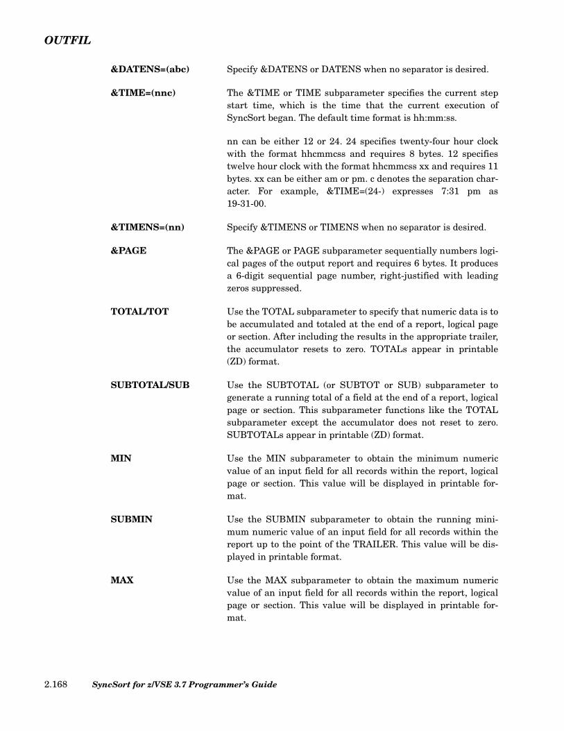
OUTFIL
&DATENS=(abc) Specify &DATENS or DATENS when no separator is desired.
&TIME=(nnc) The &TIME or TIME subparameter specifies the current stepstart time, which is the time that the current execution ofSyncSort began. The default time format is hh:mm:ss.
nn can be either 12 or 24. 24 specifies twenty-four hour clockwith the format hhcmmcss and requires 8 bytes. 12 specifiestwelve hour clock with the format hhcmmcss xx and requires 11bytes. xx can be either am or pm. c denotes the separation char-acter. For example, &TIME=(24-) expresses 7:31 pm as19-31-00.
&TIMENS=(nn) Specify &TIMENS or TIMENS when no separator is desired.
&PAGE The &PAGE or PAGE subparameter sequentially numbers logi-cal pages of the output report and requires 6 bytes. It producesa 6-digit sequential page number, right-justified with leadingzeros suppressed.
TOTAL/TOT Use the TOTAL subparameter to specify that numeric data is tobe accumulated and totaled at the end of a report, logical pageor section. After including the results in the appropriate trailer,the accumulator resets to zero. TOTALs appear in printable(ZD) format.
SUBTOTAL/SUB Use the SUBTOTAL (or SUBTOT or SUB) subparameter togenerate a running total of a field at the end of a report, logicalpage or section. This subparameter functions like the TOTALsubparameter except the accumulator does not reset to zero.SUBTOTALs appear in printable (ZD) format.
MIN Use the MIN subparameter to obtain the minimum numericvalue of an input field for all records within the report, logicalpage or section. This value will be displayed in printable for-mat.
SUBMIN Use the SUBMIN subparameter to obtain the running mini-mum numeric value of an input field for all records within thereport up to the point of the TRAILER. This value will be dis-played in printable format.
MAX Use the MAX subparameter to obtain the maximum numericvalue of an input field for all records within the report, logicalpage or section. This value will be displayed in printable for-mat.
SyncSort for z/VSE 3.7 Programmer’s Guide2.168

OUTFIL
SUBMAX Use the SUBMAX subparameter to obtain the running maxi-mum numeric value of an input field for all records within thereport up to the point of the TRAILER. This value will be dis-played in printable format.
AVG Use the AVG subparameter to obtain the average numericvalue of an input field for all records within the report, logicalpage or section. This value will be displayed in printable for-mat.
SUBAVG Use the SUBAVG subparameter to obtain the running averagenumeric value of an input field for all records within the reportup to the point of the TRAILER. This value will be displayed inprintable format.
p Use the p subparameter to indicate the position of the first byteof the field to be totaled.
l Use the l subparameter to indicate the length of the field to betotaled.
f Use the f subparameter to indicate the format of the field to betotaled. Replace f with BI, FI, PD or ZD.
Mm Use the Mm subparameter to indicate that one of the 26SyncSort-supplied masks (M0-M25) be used to format thetotaled field. Replace m with the mask number. (For details,refer to “Mm Subparameter (Editing Masks)” on page 2.202.)
EDIT=(pattern) Use the EDIT=(pattern) subparameter to indicate that a user-provided editing mask be used to format the totaled field. (Fordetails, refer to “EDIT Subparameter” on page 2.200.)
SIGNS=(...) Use the SIGNS subparameter to specify leading and/or trailingsigns that will appear before or after the edited number. (Fordetails, refer to “SIGNS Subparameter” on page 2.204.)
LENGTH=(n) Use the LENGTH subparameter to alter the length of a totaledfield determined by the edit pattern and the internal field for-mat. (For details, see “LENGTH=n Subparameter” on page2.201.)
COUNT Use the COUNT subparameter to obtain a count of the numberof records in either the entire report or a specific part of thereport. In a TRAILER1, this field will contain a count of thetotal number of data records in the report. In a TRAILER2, itwill contain a count of the number of data records on each page.In a TRAILER3, it will contain a count of the number of data
Chapter 2. SyncSort Control Statements 2.169

OUTFIL
records in each section. This number will be a right-justified,8-digit field with leading zeros suppressed. The maximum valueis 99999999.
SUBCOUNT Use the SUBCOUNT subparameter to obtain a running countof the number of records in either the entire report or a specificpart of the report. In a TRAILER1, this field will contain a run-ning count of the total number of data records in the report. In aTRAILER2, it will contain a running count of the number ofdata records on each page. In a TRAILER3, it will contain arunning count of the number of data records in each section.This number will be a right-justified, 8 digit field with leadingzeros suppressed. The maximum value is 99999999.
Rules for Specifying TRAILER Subparameters
Observe the following guidelines when you specify TRAILER subparameters:
• Separate fields with commas, except for /, where commas are optional.
• Enclose literals in single quotes.
• Specify blank fields of n bytes as nX.
• If a SyncSort editing mask is used for totaled or subtotaled data, either by specificationor by default, the length of the generated pattern will be determined by the maximumpermissible length supported for that data format, regardless of the actual length of thefield being totaled or subtotaled. Use the LENGTH subparameter to override thelength of the pattern.
• Short trailers (i.e., trailers specified with fewer blanks than the logical record length(LRECL) of the output record) are automatically padded on the right with blanks.
• If a trailer exceeds the logical record length (LRECL) of the output record, specify theLRECL parameter to expand the output record length so that the output record lengthis at least as long as the longest trailer. (See “LRECL Parameter (Optional)” on page2.157.)
VLFILL Parameter (Optional)
The VLFILL parameter is used in conjunction with VTOF to specify a fill byte to be usedfor any short record. By default, spaces will be used. In order to use the VLFILL parameter,OUTREC, BUILD, OVERLAY, or IFTHEN must also be specified as an OUTFIL parameter.
SyncSort for z/VSE 3.7 Programmer’s Guide2.170

OUTFIL
VLTRIM Parameter (Optional)
The VLTRIM parameter defines a byte to be deleted from the end of a variable-lengthrecord. All prior occurrences of this byte will also be deleted until a byte that is not equal tothe trim byte is found. The resulting records are decreased in record length. However,VLTRIM will not delete the first data byte, the Record Descriptor Word (RDW), or the ANSIcarriage control character.
For the VLTRIM parameter, specify a byte b to be deleted from the end of the record. b canbe specified as either a character or hexadecimal value. Specify either C'x' where x is asingle EBCDIC character, or X'hh' where hh represents a hexadecimal digit pair (00-FF).
Note: VLTRIM is ignored if used with fixed-length output records.
VTOF Parameter (Optional)
The VTOF parameter is identical to the CONVERT parameter. See “CONVERT/VTOFParameter (Optional)” on page 2.145 for a description of these parameters.
Sample OUTFIL Control Statements
The following example uses the IFOUTLEN and OVERLAY parameters to lengthen therecords.
This OUTFIL control statement refers to an 80-byte record. The OVERLAY parameter sub-tracts the Payments field (13,4,PD) from the Balance Due field (9,4,PD). This updated Bal-ance Due amount is entered in a new, displayable field at the end of the record. Blanks arefilled in after the Balance Due amount to increase the output LRECL to 100 bytes.
The following example uses the IFOUTLEN and OVERLAY parameters to shorten therecords.
This OUTFIL control statement refers to an 100-byte record. The OVERLAY parametersubtracts the Payments field (13,4,PD) from the Balance Due field (9,4,PD). This updatedBalance Due amount is entered at columns 51-54. The output LRECL is truncated to 80bytes.
OUTFIL BLKSIZE=800,LRECL=80,IFOUTLEN=100,
OVERLAY=(9:9,4,PD,SUB,13,4,PD,PD,LENGTH=4,81:9,4,PD)
Figure 101. Sample IFOUTLEN and OVERLAY parameters
OUTFIL BLKSIZE=800,LRECL=100,IFOUTLEN=80,
OVERLAY=(9:9,4,PD,SUB,13,4,PD,PD,LENGTH=4,51:9,4,PD)
Figure 102. Sample IFOUTLEN and OVERLAY parameters
Chapter 2. SyncSort Control Statements 2.171
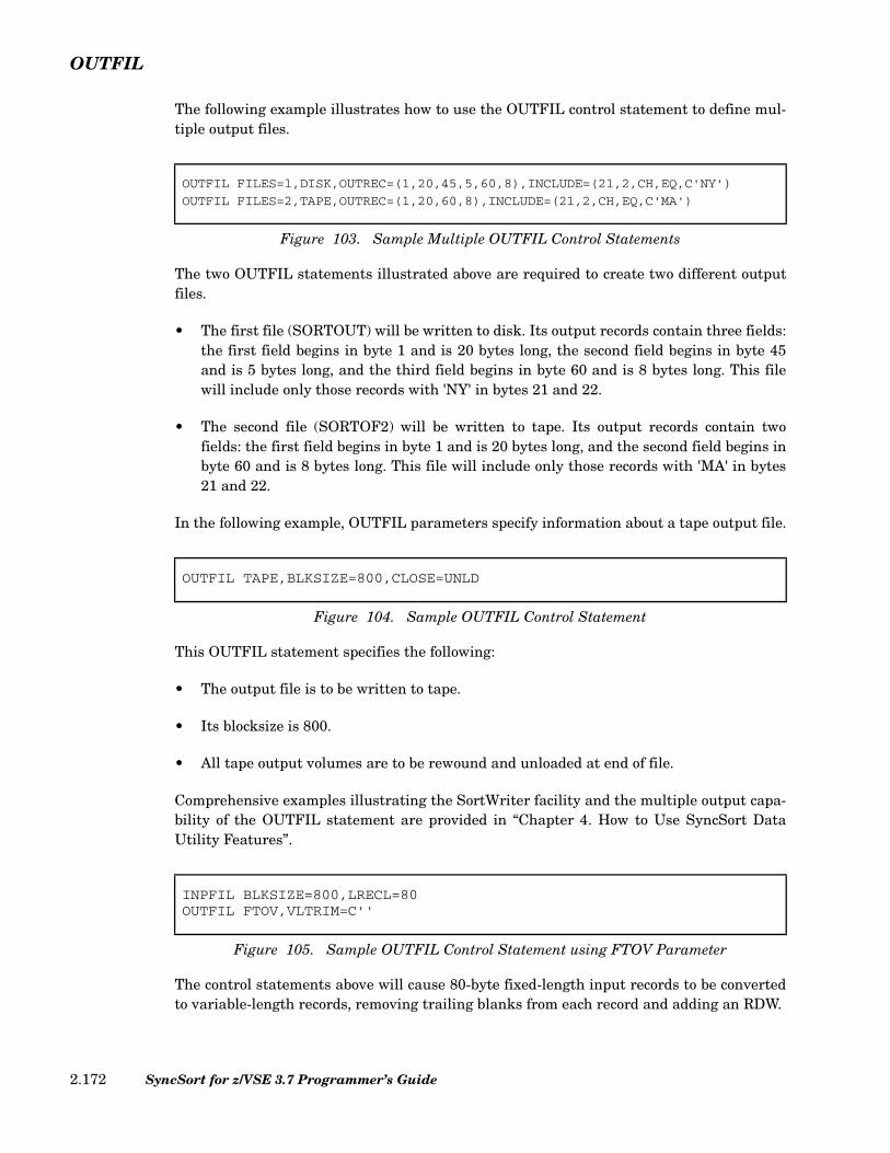
OUTFIL
The following example illustrates how to use the OUTFIL control statement to define mul-tiple output files.
The two OUTFIL statements illustrated above are required to create two different outputfiles.
• The first file (SORTOUT) will be written to disk. Its output records contain three fields:the first field begins in byte 1 and is 20 bytes long, the second field begins in byte 45and is 5 bytes long, and the third field begins in byte 60 and is 8 bytes long. This filewill include only those records with 'NY' in bytes 21 and 22.
• The second file (SORTOF2) will be written to tape. Its output records contain twofields: the first field begins in byte 1 and is 20 bytes long, and the second field begins inbyte 60 and is 8 bytes long. This file will include only those records with 'MA' in bytes21 and 22.
In the following example, OUTFIL parameters specify information about a tape output file.
This OUTFIL statement specifies the following:
• The output file is to be written to tape.
• Its blocksize is 800.
• All tape output volumes are to be rewound and unloaded at end of file.
Comprehensive examples illustrating the SortWriter facility and the multiple output capa-bility of the OUTFIL statement are provided in “Chapter 4. How to Use SyncSort DataUtility Features”.
The control statements above will cause 80-byte fixed-length input records to be convertedto variable-length records, removing trailing blanks from each record and adding an RDW.
OUTFIL FILES=l,DISK,OUTREC=(1,20,45,5,60,8),INCLUDE=(21,2,CH,EQ,C'NY')
OUTFIL FILES=2,TAPE,OUTREC=(1,20,60,8),INCLUDE=(21,2,CH,EQ,C'MA')
Figure 103. Sample Multiple OUTFIL Control Statements
OUTFIL TAPE,BLKSIZE=800,CLOSE=UNLD
Figure 104. Sample OUTFIL Control Statement
INPFIL BLKSIZE=800,LRECL=80OUTFIL FTOV,VLTRIM=C''
Figure 105. Sample OUTFIL Control Statement using FTOV Parameter
SyncSort for z/VSE 3.7 Programmer’s Guide2.172

OUTFIL
The control statements above will cause the 240-byte fixed-length input records to be con-verted to variable-length records by using 60 bytes from each input record, removing trail-ing blanks, and adding an RDW.
INPFIL BLKSIZE=2400,LRECL=240OUTFIL OUTREC=(1,50,200,10),FTOV,VLTRIM=C''
Figure 106. Sample Multiple OUTFIL Control Statement using FTOV With OUTREC Parameter
Chapter 2. SyncSort Control Statements 2.173

OUTREC
OUTREC Control Statement
The OUTREC control statement reformats the output records. Use the OUTREC statementto accomplish the following tasks:
• Delete or repeat segments of the input records.
• Insert character strings between data fields.
• Insert binary zeros.
• Insert record sequence number or date/time of job run.
• Convert numeric data to printable format or to another numeric format.
• Perform arithmetic operations (multiply, divide, add, subtract) and minimum andmaximum functions with numeric fields and constants. This “horizontal arithmetic”ability complements the “vertical arithmetic” already available with SUM and OUTFILTOTAL, MIN, MAX, and AVG.
• Convert binary data to printable hexadecimal format, or vice versa.
• Change the order of, or completely redesign, the original input records.
• Select, realign, and reorder data fields.
• Translate the case (upper, lower) of EBCDIC letters.
• Translate characters based on a translation table.
• The BUILD, IFTHEN, IFOUTLEN, and OVERLAY parameters can be used toconditionally reformat records or reformat only selected portions of records.
The OUTREC parameter of the OUTFIL control statement can also be used to accomplishany of the above tasks.
OUTREC control statement processing takes place after the records have been sorted ormerged but before E35 processing, if specified. OUTREC parameter processing takes placeafter E35 processing.
Consider these guidelines when deciding whether to use the INREC statement, theOUTREC statement or the OUTREC parameter of the OUTFIL control statement:
• Use the INREC statement to delete irrelevant data fields, reformat numeric fields to ashorter length or combine numeric fields with arithmetic operations and functions.Reducing the size of the input records before they are sorted or merged usuallyimproves performance.
SyncSort for z/VSE 3.7 Programmer’s Guide2.174

OUTREC
• Use either the OUTREC statement or the OUTREC parameter of the OUTFILstatement to expand the data record, create new numeric fields, realign data fields,convert and edit numeric data, and change from variable-length format to fixed-lengthformat when you are creating one output file.
• Use the OUTREC statement when you are creating multiple output files with the sameoutput record.
• Use the OUTREC parameter of the OUTFIL statement when you are creating multipleoutput files with different output records.
• Use the OUTREC parameter of the OUTFIL statement when an E35 exit processes therecords.
• Use the OUTREC parameter of the OUTFIL statement when you specify the TOTALand/or SUBTOTAL subparameters of the TRAILER parameter so that the data fieldbeing totaled can easily be aligned with the total in the trailer.
OUTREC Control Statement Format
The format for the OUTREC control statement is illustrated below.
FIELDS/BUILD Parameter
The FIELDS parameter specifies fields that are to be included in the output record. BUILDis an alias for FIELDS. Fields can be data fields or spaces, hexadecimal digits, literalstrings or binary zeros.
The field parameters can be specified as follows:
Figure 107. OUTREC Control Statement Format
OUTREC
FIELDSBUILDOVERLAY
field1 field2,[ ]…( )=
IFTHEN subparm( )= ,IFTHEN = subparm( )[ ]… ,IFOUTLEN = n[ ]
c:[ ]
p,l [,subparm][n] X[n] X'hhhh...hh'[n] C'literal string'[n] Z
SEQNUM,l,f [,START= 1n---
] [,INCR = 1i---
] ,RESTART = p,h( )[ ]
run-time constant
Chapter 2. SyncSort Control Statements 2.175
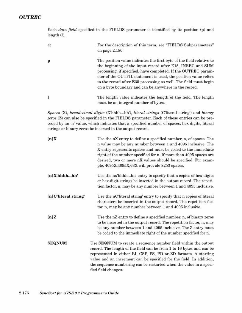
OUTREC
Each data field specified in the FIELDS parameter is identified by its position (p) andlength (l).
c: For the description of this term, see “FIELDS Subparameters”on page 2.180.
p The position value indicates the first byte of the field relative tothe beginning of the input record after E15, INREC and SUMprocessing, if specified, have completed. If the OUTREC param-eter of the OUTFIL statement is used, the position value refersto the record after E35 processing as well. The field must beginon a byte boundary and can be anywhere in the record.
l The length value indicates the length of the field. The lengthmust be an integral number of bytes.
Spaces (X), hexadecimal digits (X'hhhh...hh'), literal strings (C'literal string') and binaryzeros (Z) can also be specified in the FIELDS parameter. Each of these entries can be pre-ceded by an 'n' value, which indicates that a specified number of spaces, hex digits, literalstrings or binary zeros be inserted in the output record.
[n]X Use the nX entry to define a specified number, n, of spaces. Then value may be any number between 1 and 4095 inclusive. TheX entry represents spaces and must be coded to the immediateright of the number specified for n. If more than 4095 spaces aredesired, two or more nX values should be specified. For exam-ple, 4095X,4095X,63X will provide 8253 spaces.
[n]X'hhhh...hh' Use the nx'hhhh...hh' entry to specify that n copies of hex-digitsor hex-digit strings be inserted in the output record. The repeti-tion factor, n, may be any number between 1 and 4095 inclusive.
[n]C'literal string' Use the nC'literal string' entry to specify that n copies of literalcharacters be inserted in the output record. The repetition fac-tor, n, may be any number between 1 and 4095 inclusive.
[n]Z Use the nZ entry to define a specified number, n, of binary zerosto be inserted in the output record. The repetition factor, n, maybe any number between 1 and 4095 inclusive. The Z entry mustbe coded to the immediate right of the number specified for n.
SEQNUM Use SEQNUM to create a sequence number field within the outputrecord. The length of the field can be from 1 to 16 bytes and can berepresented in either BI, CSF, FS, PD or ZD formats. A startingvalue and an increment can be specified for the field. In addition,the sequence numbering can be restarted when the value in a speci-fied field changes.
SyncSort for z/VSE 3.7 Programmer’s Guide2.176
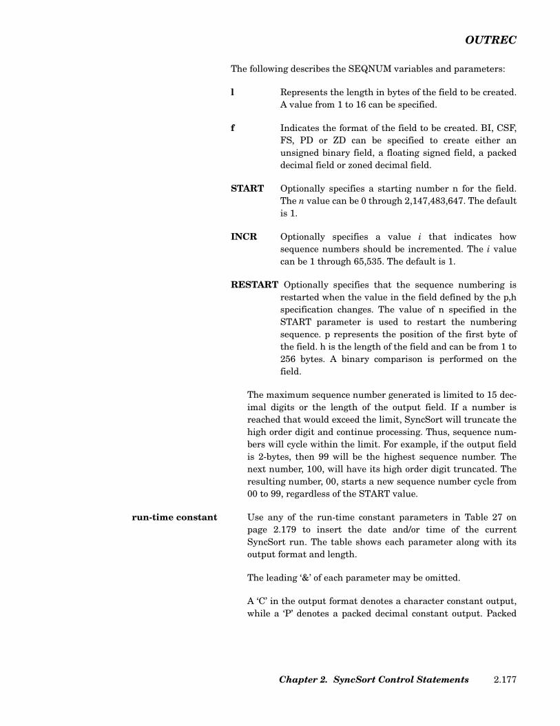
OUTREC
The following describes the SEQNUM variables and parameters:
l Represents the length in bytes of the field to be created.A value from 1 to 16 can be specified.
f Indicates the format of the field to be created. BI, CSF,FS, PD or ZD can be specified to create either anunsigned binary field, a floating signed field, a packeddecimal field or zoned decimal field.
START Optionally specifies a starting number n for the field.The n value can be 0 through 2,147,483,647. The defaultis 1.
INCR Optionally specifies a value i that indicates howsequence numbers should be incremented. The i valuecan be 1 through 65,535. The default is 1.
RESTART Optionally specifies that the sequence numbering isrestarted when the value in the field defined by the p,hspecification changes. The value of n specified in theSTART parameter is used to restart the numberingsequence. p represents the position of the first byte ofthe field. h is the length of the field and can be from 1 to256 bytes. A binary comparison is performed on thefield.
The maximum sequence number generated is limited to 15 dec-imal digits or the length of the output field. If a number isreached that would exceed the limit, SyncSort will truncate thehigh order digit and continue processing. Thus, sequence num-bers will cycle within the limit. For example, if the output fieldis 2-bytes, then 99 will be the highest sequence number. Thenext number, 100, will have its high order digit truncated. Theresulting number, 00, starts a new sequence number cycle from00 to 99, regardless of the START value.
run-time constant Use any of the run-time constant parameters in Table 27 onpage 2.179 to insert the date and/or time of the currentSyncSort run. The table shows each parameter along with itsoutput format and length.
The leading ‘&’ of each parameter may be omitted.
A ‘C’ in the output format denotes a character constant output,while a ‘P’ denotes a packed decimal constant output. Packed
Chapter 2. SyncSort Control Statements 2.177
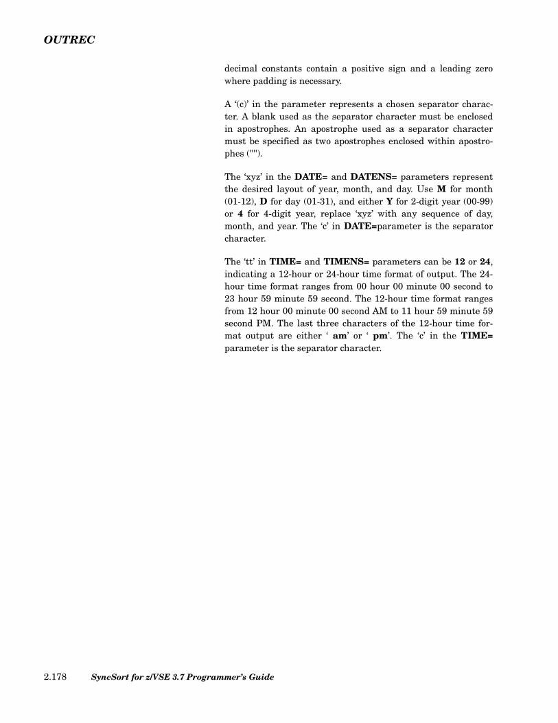
OUTREC
decimal constants contain a positive sign and a leading zerowhere padding is necessary.
A ‘(c)’ in the parameter represents a chosen separator charac-ter. A blank used as the separator character must be enclosedin apostrophes. An apostrophe used as a separator charactermust be specified as two apostrophes enclosed within apostro-phes ('''').
The ‘xyz’ in the DATE= and DATENS= parameters representthe desired layout of year, month, and day. Use M for month(01-12), D for day (01-31), and either Y for 2-digit year (00-99)or 4 for 4-digit year, replace ‘xyz’ with any sequence of day,month, and year. The ‘c’ in DATE=parameter is the separatorcharacter.
The ‘tt’ in TIME= and TIMENS= parameters can be 12 or 24,indicating a 12-hour or 24-hour time format of output. The 24-hour time format ranges from 00 hour 00 minute 00 second to23 hour 59 minute 59 second. The 12-hour time format rangesfrom 12 hour 00 minute 00 second AM to 11 hour 59 minute 59second PM. The last three characters of the 12-hour time for-mat output are either ‘ am’ or ‘ pm’. The ‘c’ in the TIME=parameter is the separator character.
SyncSort for z/VSE 3.7 Programmer’s Guide2.178

OUTREC
Parameter Output Length (Bytes)
&DATE C'mm/dd/yy' 8
&DATE1 C'yyyymmdd' 8
&DATE1(c) C'yyyycmmcdd' 10
&DATE1P P'yyyymmdd' 5
&DATE2 C'yyyymm' 6
&DATE2(c) C'yyyycmm' 7
&DATE2P P'yyyymm' 4
&DATE3 C'yyyyddd' 7
&DATE3(c) C'yyyycddd' 8
&DATE3P P'yyyyddd' 4
&DATE4 C'yyyy-mm-dd-hh.mm.ss'
19
&DATE=(xyzc) (see description above table)
8 or 10
&DATENS=(xyz) (see description above table)
6 or 8
&TIME C'hh:mm:ss' 8
&TIME1 C'hhmmss' 6
&TIME1(c) C'hhcmmcss' 8
&TIME1P P'hhmmss' 4
&TIME2 C'hhmm' 4
&TIME2(c) C'hhcmm' 5
&TIME2P P'hhmm' 3
&TIME3 C'hh' 2
&TIME3P P'hh' 2
&TIME=(ttc) C'hhcmmcss am' 8 or 11
&TIMENS=(tt) C'hhmmss am' 6 or 9
Table 27. Run-Time Constants
Chapter 2. SyncSort Control Statements 2.179

OUTREC
Specifying the FIELDS Parameter for Variable-Length Records
Observe these rules when you specify the FIELDS parameter for variable-length records:
• Remember to specify 4 bytes for the Record Descriptor Word. You can include the 4bytes in the length value of the first field if the first field in the original data record isalso the first field specified in the FIELDS parameter.
• At least one byte from the fixed portion of the input records must be specified in theFIELDS parameter.
• To include any portion of the variable part of the input records, specify a position valuewithout a length value as the last entry. Make sure the position value does not exceedthe minimum input record length. Do not specify any other subparameters after theposition value unless HEX conversion is also specified. (Refer to “FIELDSSubparameters” on page 2.180 for an explanation of HEX conversion.)
• The nX entry cannot be used to insert spaces before the first field if variable-lengthrecords are being used because the Record Descriptor Word must be accounted for.
• The contents of the Record Descriptor Word will be automatically revised by the sort.
FIELDS Subparameters
Use the FIELDS subparameters to accomplish these tasks:
• Specify the column in which a field should begin.
• Specify halfword, fullword or doubleword alignment.
• Convert a numeric field to a printable format with editing capabilities.
• Convert numeric data to another numeric data format.
• Convert a field to its printable hexadecimal representation.
• Change an input field to a replacement constant if the input field equals a specifiedsearch constant.
• Provide minimum and maximum functions and arithmetic operations (add, subtract,multiply, divide) with numeric fields and constants.
Figure 108 illustrates how the FIELDS subparameters should be specified and describestheir functions. More detailed descriptions of the EDIT, LENGTH, Mm, and SIGNS subpa-rameters follow this figure in the section “How to Convert Numeric Data” on page 2.192.
SyncSort for z/VSE 3.7 Programmer’s Guide2.180

OUTREC
The following describes the c: subparameter:
c: Use the c: subparameter to define the column in which the field should begin.SyncSort will add the appropriate number of blanks to achieve the properalignment. The c: subparameter must be specified in ascending order and not causeoverlapping fields. This subparameter can be specified for all types of fields.
The term expression represents the following syntax:
The following describes the elements of expression:
p,l,fi This specifies the position, length and format of an input field. (Seethe description of fi, below, for details.)
+n This represents a positive numerical constant of up to 15 decimaldigits. The + sign must be specified.
-n This represents a negative numerical constant of up to 15 decimaldigits. The - sign must be specified.
expression An expression defines a numeric value. The simplest forms of anexpression consist of a numeric data input field defined either byp,l,fi or a constant defined by +n or -n. Expressions can also be cre-ated by connecting these simple expressions with operators, asshown in the last line of the above syntax chart. Parentheses may
Figure 108. Fields Subparameters Format
Figure 109. Syntax for expression
[c:]
expression
,fo
,M0MmEDIT=(pattern)
[,SIGNS=(s1s2s3s4)][,LENGTH=n]
p,l ,a,CHANGE=(change-parms)[,NOMATCH=(nomatch-parms)]
p[,l] ,HEX,TRAN= …
p,l,fi
+n-n[(]"expression1"[, "operator" , "expression2"][)]
Chapter 2. SyncSort Control Statements 2.181
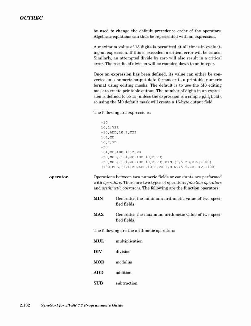
OUTREC
be used to change the default precedence order of the operators.Algebraic equations can thus be represented with an expression.
A maximum value of 15 digits is permitted at all times in evaluat-ing an expression. If this is exceeded, a critical error will be issued.Similarly, an attempted divide by zero will also result in a criticalerror. The results of division will be rounded down to an integer.
Once an expression has been defined, its value can either be con-verted to a numeric output data format or to a printable numericformat using editing masks. The default is to use the M0 editingmask to create printable output. The number of digits in an expres-sion is defined to be 15 (unless the expression is a simple p,l,fi field),so using the M0 default mask will create a 16-byte output field.
The following are expressions:
+10
10,2,Y2Z
+10,ADD,10,2,Y2Z
1,4,ZD
10,2,PD
+30
1,4,ZD,ADD,10,2,PD
+30,MUL,(1,4,ZD,ADD,10,2,PD)
+30,MUL,(1,4,ZD,ADD,10,2,PD),MIN,(5,5,ZD,DIV,+100)
(+30,MUL,(1,4,ZD,ADD,10,2,PD)),MIN,(5,5,ZD,DIV,+100)
operator Operations between two numeric fields or constants are performedwith operators. There are two types of operators: function operatorsand arithmetic operators. The following are the function operators:
MIN Generates the minimum arithmetic value of two speci-fied fields.
MAX Generates the maximum arithmetic value of two speci-fied fields.
The following are the arithmetic operators:
MUL multiplication
DIV division
MOD modulus
ADD addition
SUB subtraction
SyncSort for z/VSE 3.7 Programmer’s Guide2.182

OUTREC
The following rules of arithmetic precedence apply in computing an“expression”:
• Conditions within parentheses are evaluated first, frominnermost to outermost parentheses.
• The arithmetic functions of minimum and maximum (MIN andMAX) are performed before the arithmetic operators (MUL,DIV, MOD, ADD, SUB). Within the arithmetic operators,multiplication (MUL), division (DIV), and modulus (MOD) areperformed before addition (ADD) and subtraction (SUB).Operations within the same precedence level are performedfrom left to right.
The result of the DIV operation is truncated (rounded down) to aninteger. The MOD operation produces an integer remainder withthe sign of the dividend.
fi Use this parameter together with p,l to define the input format of anumeric field that is part or all of an expression. The expressionwill then be converted to either another numeric data format or to aprintable format. In such cases, indicate the format of the data fieldthat is to be converted by replacing fi with BI, FI, PD, ZD, CSF/FS,PD0, one of the SMF formats (DT1, DT2, DT3, TM1, TM2, TM3,and TM4), or one of the year data formats (Y2B, Y2C, Y2D, Y2P,Y2S, Y2Z, Y2T, Y2U, Y2V, Y2W, Y2X, Y2Y).
Also use this parameter when a 2-digit packed decimal year value isto be expanded to a 4-digit packed decimal value. In such casesreplace fi with Y2ID or Y2IP. The Y2ID and Y2IP formats cannot beused to form complex arithmetic expressions and do not allow thespecification of mask (Mm), EDIT, SIGNS or LENGTH. Y2DP andY2PP can be used as synonyms for Y2ID and Y2IP respectively.
An l value indicating the length of the field must be specified inaccordance with the following allowable values:
for BI ... 1-4 inclusivefor CSF/FS ... 1-16 inclusive (15 digit limit)
Chapter 2. SyncSort Control Statements 2.183
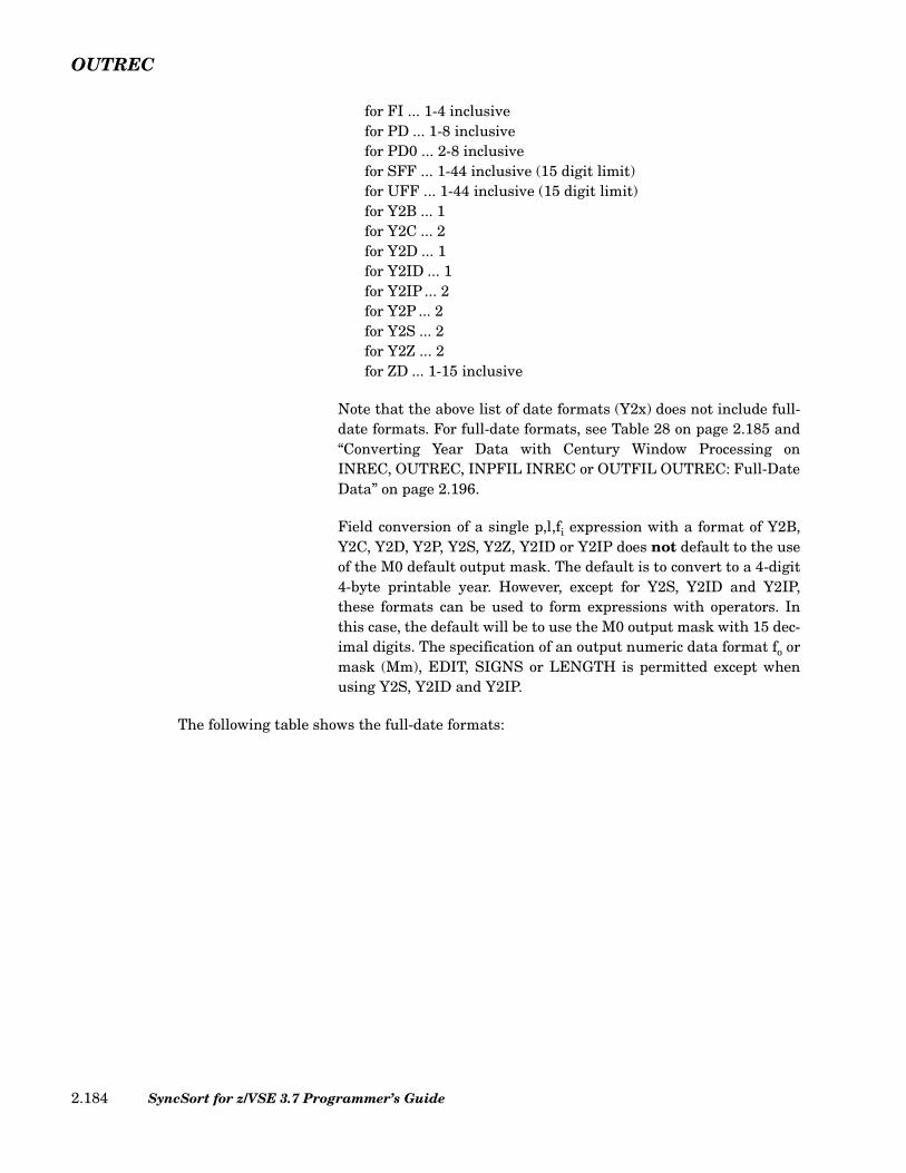
OUTREC
for FI ... 1-4 inclusivefor PD ... 1-8 inclusivefor PD0 ... 2-8 inclusivefor SFF ... 1-44 inclusive (15 digit limit)for UFF ... 1-44 inclusive (15 digit limit)for Y2B ... 1for Y2C ... 2for Y2D ... 1for Y2ID ... 1for Y2IP ... 2for Y2P ... 2for Y2S ... 2for Y2Z ... 2for ZD ... 1-15 inclusive
Note that the above list of date formats (Y2x) does not include full-date formats. For full-date formats, see Table 28 on page 2.185 and“Converting Year Data with Century Window Processing onINREC, OUTREC, INPFIL INREC or OUTFIL OUTREC: Full-DateData” on page 2.196.
Field conversion of a single p,l,fi expression with a format of Y2B,Y2C, Y2D, Y2P, Y2S, Y2Z, Y2ID or Y2IP does not default to the useof the M0 default output mask. The default is to convert to a 4-digit4-byte printable year. However, except for Y2S, Y2ID and Y2IP,these formats can be used to form expressions with operators. Inthis case, the default will be to use the M0 output mask with 15 dec-imal digits. The specification of an output numeric data format fo ormask (Mm), EDIT, SIGNS or LENGTH is permitted except whenusing Y2S, Y2ID and Y2IP.
The following table shows the full-date formats:
SyncSort for z/VSE 3.7 Programmer’s Guide2.184

OUTREC
fo Use this parameter to define the output numeric data format of anexpression. When fo is specified, mask (Mm), EDIT, and SIGNScannot be specified. Indicate the desired format of the output fieldby replacing fo with BI, CSF/FS, FI, PD or ZD.
Full-Date Format Date Format Date Form Example Date
Form Length (bytes)
Y2T CH, BI yyx yyq 3
yyxx yymm 4
yyxxx yyddd 5
yyxxxx yymmdd 6
Y2U PD yyx(X'yyxs')
yyq 2
yyxxx(X'yyxxxs')
yyddd 3
Y2V PD yyxx(X'0yyxxs')
yymm 3
yyxxxx(X'0yyxxxxs')
yymmdd 4
Y2W CH, BI xyy qyy 3
xxyy mmyy 4
xxxyy dddyy 5
xxxxyy mmddyy 6
Y2X PD xyy(X'xyys')
qyy 2
xxxyy(X'xxxyys')
dddyy 3
Y2Y PD xxyy(X'0xxyys')
mmyy 3
xxxxyy(X'0xxxxyys')
mmddyy 4
Note: The following symbols are used in the table:y year digit (0-9)x non-year digit (0-9)s sign (hexadecimal 0-F)0 unused digit q any digit
Table 28. Full-Date Formats
Chapter 2. SyncSort Control Statements 2.185
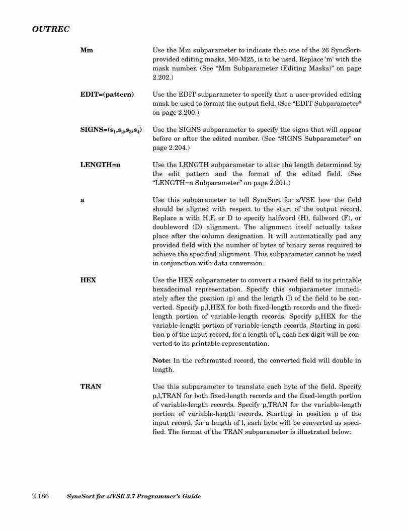
OUTREC
Mm Use the Mm subparameter to indicate that one of the 26 SyncSort-provided editing masks, M0-M25, is to be used. Replace 'm' with themask number. (See “Mm Subparameter (Editing Masks)” on page2.202.)
EDIT=(pattern) Use the EDIT subparameter to specify that a user-provided editingmask be used to format the output field. (See “EDIT Subparameter”on page 2.200.)
SIGNS=(s1,s2,s3,s4) Use the SIGNS subparameter to specify the signs that will appearbefore or after the edited number. (See “SIGNS Subparameter” onpage 2.204.)
LENGTH=n Use the LENGTH subparameter to alter the length determined bythe edit pattern and the format of the edited field. (See“LENGTH=n Subparameter” on page 2.201.)
a Use this subparameter to tell SyncSort for z/VSE how the fieldshould be aligned with respect to the start of the output record.Replace a with H,F, or D to specify halfword (H), fullword (F), ordoubleword (D) alignment. The alignment itself actually takesplace after the column designation. It will automatically pad anyprovided field with the number of bytes of binary zeros required toachieve the specified alignment. This subparameter cannot be usedin conjunction with data conversion.
HEX Use the HEX subparameter to convert a record field to its printablehexadecimal representation. Specify this subparameter immedi-ately after the position (p) and the length (l) of the field to be con-verted. Specify p,l,HEX for both fixed-length records and the fixed-length portion of variable-length records. Specify p,HEX for thevariable-length portion of variable-length records. Starting in posi-tion p of the input record, for a length of l, each hex digit will be con-verted to its printable representation.
Note: In the reformatted record, the converted field will double inlength.
TRAN Use this subparameter to translate each byte of the field. Specifyp,l,TRAN for both fixed-length records and the fixed-length portionof variable-length records. Specify p,TRAN for the variable-lengthportion of variable-length records. Starting in position p of theinput record, for a length of l, each byte will be converted as speci-fied. The format of the TRAN subparameter is illustrated below:
SyncSort for z/VSE 3.7 Programmer’s Guide2.186

OUTREC
LTOU Instruct SyncSort to translate EBCDIC letters inthe specified field from lower case to upper case.
UTOL Instruct SyncSort to translate EBCDIC letters inthe specified field from upper case to lower case.
CTOX Instruct SyncSort to convert each byte in the speci-fied field into 2-byte printable HEX digits.(p,l,TRAN=CTOX is equivalent to p,l,HEX)
XTOC Instruct SyncSort to convert each 2-byte HEX digitsin the specified field into 1-byte binary value. Thefield length must be an even number of bytes long.HEX digits are EBCDIC characters ‘0’ through ‘9’,‘A’ through ‘F’, or ‘a’ through ‘f ’. Non-HEX charac-ters are treated as ‘0’.
ALTSEQ Instruct SyncSort to translate each byte in the spec-ified field based on the ALTSEQ table in effect.
xxyy... Instruct SyncSort to translate each byte in the spec-ified field that matches xx into yy. xx and yy areboth HEX representations of a byte value. Up to 256pairs of xxyy may be specified. Do not specify acomma (,) between pairs of xxyy.
C'cp...' Instruct SyncSort to translate each byte in the spec-ified field that matches character c into character p.Up to 256 pairs of cp may be specified. Do not spec-ify a comma (,) between pairs of cp.
Figure 110. TRAN Subparameters format
TRAN=
LTOUUTOLCTOXXTOCALTSEQxxyy…X'xxyy...'C'cp...'
Chapter 2. SyncSort Control Statements 2.187

OUTREC
The following example illustrates the use of the TRAN subparameter:
In the above example, the OUTREC control statement reformats the output record to con-tain the first four bytes of the input record, followed by nine bytes of the input record withlower case characters converted to upper case, followed by 16 bytes of input at column 21with any ‘(‘ , ’)’, ‘-’, or ‘#’ characters converted to slashes (‘/’), and followed by 20 bytes ofinput at column 37 with bytes of value X'00' and X'FF' changed to character ‘*’ (X'5C') andall ‘$’ signs changed to character ‘_’.
CHANGE The CHANGE subparameter changes an input field to a replace-ment value in the reformatted output record if the input field equalsa search constant. The input field remains unchanged on the inputside.
Multiple search-replacement paired values, with different data for-mats, can be specified on a CHANGE subparameter. Note the fol-lowing rules for mixing data formats:
• Search constants are character, hexadecimal, or binary strings.Multiple search constants on a CHANGE subparameter can bea mixture of character and hexadecimal formats. Binary searchconstants cannot be mixed with search constants of otherformats; thus, if one search constant on a CHANGEsubparameter is binary, all other search constants on thatsubparameter must also be binary.
• Replacement values are either character or hexadecimal stringconstants or a field from the input record. Multiple replacementconstants on a CHANGE subparameter can be a mixture ofcharacter and hexadecimal string constants and fields from theinput record.
• The constants of a search-replacement pair can be of differentdata format. For example, a hexadecimal or binary searchconstant could be paired with a character replacementconstant, or a character search constant could be paired with ahexadecimal replacement constant. Thus, you could change ahexadecimal or binary input field to a character output field, oryou could change a character input field to a hexadecimaloutput field.
OUTREC FIELDS=(1,4,5,9,TRAN=LTOU21,16,TRAN=C'(/)/-/#/',37,20,TRAN=(X'005CFF5C',C'$_'))
Figure 111. Sample Use of the TRAN Subparameter
SyncSort for z/VSE 3.7 Programmer’s Guide2.188

OUTREC
The subparameters for CHANGE are specified by the following syn-tax:
The following describes the elements of the CHANGE subparame-ter:
p,l The normal SyncSort position-length designationthat specifies the input field. When this fieldmatches a search constant, the field will be changedin the output to a replacement constant.
For character or hexadecimal search constants, theinput field can be 1 to 64 bytes long. For binarysearch constants, the input field must be one byte.
o The length of the output replacement field. Permis-sible length is 1 to 64 bytes.
srch The search constant to which the input field is com-pared. Permissible formats are character string(C'x...x'), hexadecimal string (X'x...x'), or a binarybyte (B'bbbbbbbb'). When the search constantmatches the input field, the input field will bechanged to an output replacement constant.
If one of the search constants is binary in a set ofsearch-replacement pairs on a CHANGE subparam-eter, then all the search constants on that CHANGEsubparameter must be binary. (For additional infor-mation on using binary fields in INCLUDE/OMITprocessing, see “INCLUDE/OMIT Control State-ment” on page 2.39.)
If the search constant is longer than the length (l) ofthe input field, the constant will be truncated tolength l. If the search constant is shorter than l, theconstant will be padded on the right to length l.Character strings are padded with blanks (X'40', orX'20' if INPFIL DATA=A was specified). Hexadeci-mal strings are padded with zeros (X'00'). Binarystrings are neither truncated nor padded since onlyone-byte strings are permissible.
o,srch1,repl1[,srch2,repl2...,srchn,repln]
Figure 112. Syntax for change-parms
Chapter 2. SyncSort Control Statements 2.189
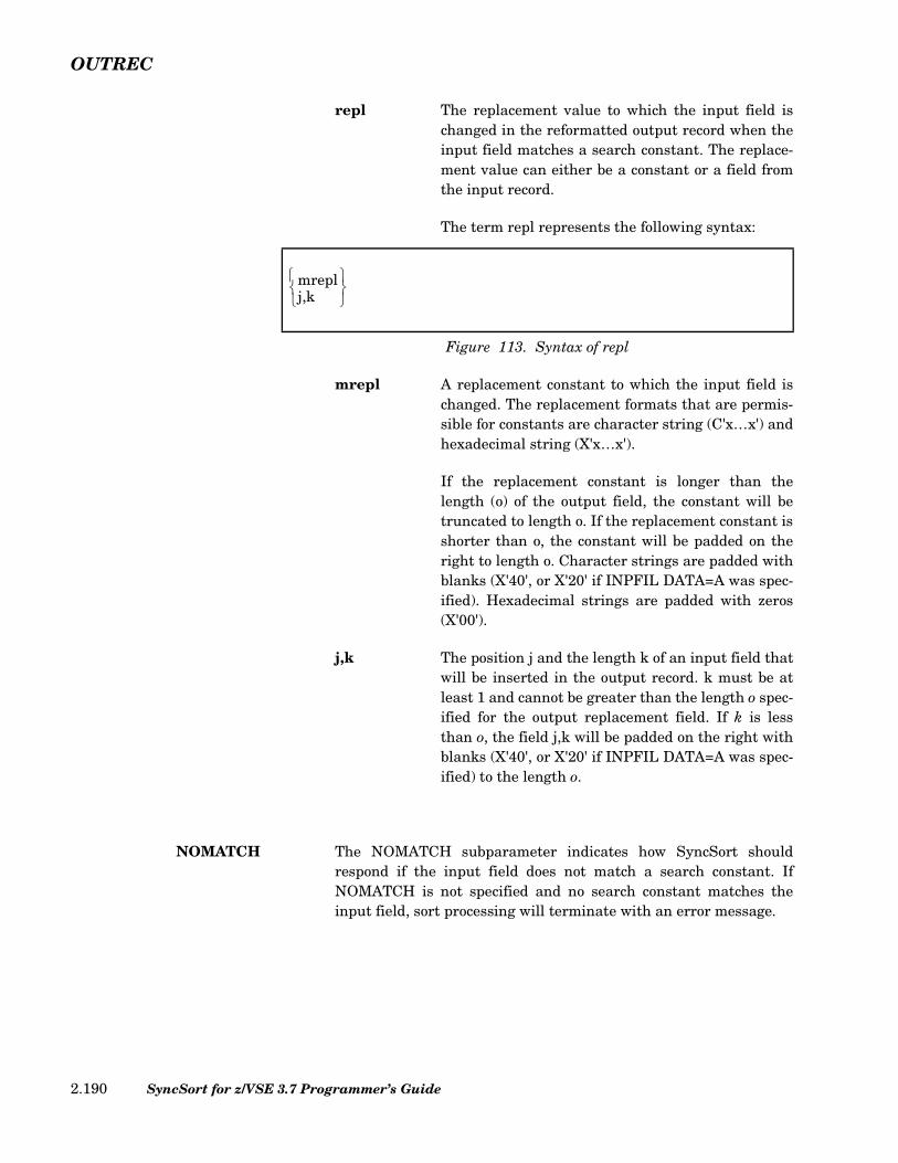
OUTREC
repl The replacement value to which the input field ischanged in the reformatted output record when theinput field matches a search constant. The replace-ment value can either be a constant or a field fromthe input record.
The term repl represents the following syntax:
mrepl A replacement constant to which the input field ischanged. The replacement formats that are permis-sible for constants are character string (C'x…x') andhexadecimal string (X'x…x').
If the replacement constant is longer than thelength (o) of the output field, the constant will betruncated to length o. If the replacement constant isshorter than o, the constant will be padded on theright to length o. Character strings are padded withblanks (X'40', or X'20' if INPFIL DATA=A was spec-ified). Hexadecimal strings are padded with zeros(X'00').
j,k The position j and the length k of an input field thatwill be inserted in the output record. k must be atleast 1 and cannot be greater than the length o spec-ified for the output replacement field. If k is lessthan o, the field j,k will be padded on the right withblanks (X'40', or X'20' if INPFIL DATA=A was spec-ified) to the length o.
NOMATCH The NOMATCH subparameter indicates how SyncSort shouldrespond if the input field does not match a search constant. IfNOMATCH is not specified and no search constant matches theinput field, sort processing will terminate with an error message.
Figure 113. Syntax of repl
mreplj,k
SyncSort for z/VSE 3.7 Programmer’s Guide2.190

OUTREC
The subparameters for NOMATCH are specified by the followingsyntax:
The following describes the elements of the NOMATCH subparame-ter:
nmrepl A replacement constant to which the input field ischanged in the reformatted output record when theinput field (p,l) fails to match a search constant. Fordetails, see the description of the repl variableabove.
r,n The position (r) and length (n) of an input field thatwill be inserted in the output record when theCHANGE input field (p,l) fails to match a searchconstant.
n must be at least 1. If n is greater than the length(o) specified for the output replacement field, theoutput field r,n will be truncated on the right tolength o. If n is less than o, the field r,n will bepadded on the right with blanks (X'40', or X'20' ifINPFIL DATA=A was specified) to the length o.
The following example illustrates the use of the CHANGE subparameter:
In the above example, the OUTREC parameter contains two CHANGE subparameters. Thefirst CHANGE subparameter changes the input field 16,2 to a state name in the reformat-ted output record when the input field matches a state code. If the state code is XX, posi-
Figure 114. Syntax for nomatch-parms
OUTREC FIELDS=(16,2,CHANGE=(13,C'NJ',C'NEW JERSEY',
C'NY',C'NEW YORK',C'PA',C'PENNSYLVANIA',C'XX',50,13),
NOMATCH=(C'NOT SUPPORTED'),8X,24,1,
CHANGE=(10,B'1.......',C'EAST COAST',B'0.......',C'WEST COAST'))
Figure 115. Sample OUTREC Parameter with CHANGE Subparameter
nmreplr,n
Chapter 2. SyncSort Control Statements 2.191

OUTREC
tions 50 through 62 of the input record will be placed in the output record. If no matchesare found, the output field will be 'NOT SUPPORTED'. The second change subparameterchanges the one-byte input field 24,1 to 'EAST COAST' or 'WEST COAST' in the reformat-ted output record, depending on the binary contents of the input field.
The following example illustrates a situation that can arise when using binary search con-stants. In such cases, more than one search constant may match an input field:
Note that in the above example, the input field X'06' would match both binary search con-stants. In such cases, the first search constant is used, thus the output would be the charac-ter string 'SHARE'. If the input field were X'02', the output would be the character string'UNIQUE'.
How to Convert Numeric Data
One of the most important functions of OUTREC processing is to convert a numeric datafield or an expression to either an output numeric data format or a printable format withediting capabilities.
OUTREC processing can also expand a packed decimal 2-digit year to a packed decimal 4-digit year. In such cases, Y2ID or Y2IP formats are used to convert from a 2-digit to a 4-digit year while maintaining a packed format. For details on converting year data, see“Converting Year Data with Century Window Processing on INREC, OUTREC, INPFILINREC or OUTFIL OUTREC: 2-Digit Year Data” on page 2.194.
When a single numeric field defined by p,l,fi is to be converted, the format and length of thefield determines the length of the output field, as illustrated in the chart below.
OUTREC FIELDS=(24,1,CHANGE=(6,B'.....11.',C'SHARE',
B'......1.',C'UNIQUE'))
Figure 116. CHANGE Subparameter with Binary Search Constants
SyncSort for z/VSE 3.7 Programmer’s Guide2.192
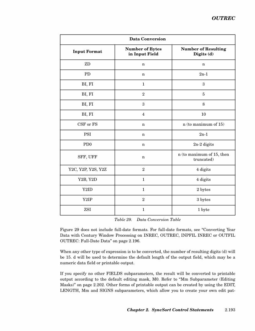
OUTREC
Figure 29 does not include full-date formats. For full-date formats, see “Converting YearData with Century Window Processing on INREC, OUTREC, INPFIL INREC or OUTFILOUTREC: Full-Date Data” on page 2.196.
When any other type of expression is to be converted, the number of resulting digits (d) willbe 15. d will be used to determine the default length of the output field, which may be anumeric data field or printable output.
If you specify no other FIELDS subparameters, the result will be converted to printableoutput according to the default editing mask, M0. Refer to “Mm Subparameter (EditingMasks)” on page 2.202. Other forms of printable output can be created by using the EDIT,LENGTH, Mm and SIGNS subparameters, which allow you to create your own edit pat-
Data Conversion
Input Format Number of Bytesin Input Field
Number of ResultingDigits (d)
ZD n n
PD n 2n-1
BI, FI 1 3
BI, FI 2 5
BI, FI 3 8
BI, FI 4 10
CSF or FS n n (to maximum of 15)
PSI n 2n-1
PD0 n 2n-2 digits
SFF, UFF n n (to maximum of 15, then truncated)
Y2C, Y2P, Y2S, Y2Z 2 4 digits
Y2B, Y2D 1 4 digits
Y2ID 1 2 bytes
Y2IP 2 3 bytes
ZSI 1 1 byte
Table 29. Data Conversion Table
Chapter 2. SyncSort Control Statements 2.193

OUTREC
terns, or by using one of the 26 SyncSort-supplied editing masks, which are appropriate formany editing operations.
To convert to a numeric data field, simply specify an output format of BI, CSF/FS, FI, PD orZD. The default output field length is determined by the following table, where d in the sec-ond column represents the number of digits in the input.
These lengths can be overridden by specifying the LENGTH parameter.
The following six sections describe the data conversion capabilities:
• Converting Year Data with Century Window Processing on INREC, OUTREC, INPFILINREC, or OUTFIL OUTREC: 2-Digit Year Data
• Converting Year Data with Century Window Processing on INREC, OUTREC, INPFILINREC, or OUTFIL OUTREC: Full-Date Data
• The EDIT Subparameter
• The LENGTH=n Subparameter
• The Mm Subparameter (Editing Masks)
• The SIGNS Subparameter
Converting Year Data with Century Window Processing on INREC, OUTREC, INPFIL INREC or OUTFIL OUTREC: 2-Digit Year Data
This section describes 2-digit year data. For information on converting full-date year data,see “Converting Year Data with Century Window Processing on INREC, OUTREC, INPFILINREC or OUTFIL OUTREC: Full-Date Data” on page 2.196.
A 2-digit year field, (as specified by the Y2B, Y2C, Y2D, Y2ID, Y2IP, Y2P, Y2S, and Y2Z for-mats) can be converted on output to a 4-digit year:
Output Format Default
Output Length(bytes)
BI 4
CSF or FS 4
FI 4
PD d/2 + 1
ZD d
Table 30. Output Length of Output Formats
SyncSort for z/VSE 3.7 Programmer’s Guide2.194

OUTREC
• The Y2C and Y2Z formats specify 2-digit year data that is in displayable (zoneddecimal) format. The 2-digit year data will be expanded to a 4-digit field containing theappropriate century value.
• The Y2B format specifies 2-digit, 1-byte binary year data that will be converted to a 4-digit, displayable character format with the appropriate century value. For informationon the range of binary values representing year data with Y2B, see Table 18 on page2.103.
• The Y2D and Y2P formats specify 2-digit year values in packed decimal format. Theprocessing applied to these fields will create a 4-digit year value converted to adisplayable character format. (For a description of Y2D and Y2P formats, see Table 18on page 2.103.)
• The Y2ID and Y2IP formats take as input the same 2-digit packed decimal year data asY2D and Y2P formats but produce a 4-digit year output that remains in packed decimalformat.
• The Y2S format is equivalent to Y2C and Y2Z for valid numeric year data. All threeformats will convert such data to a 4-digit year with the appropriate century value.Y2S, however, provides additional functionality. For data with binary zeros (X'00'), ablank (X'40') or binary ones (X'FF') in the first byte, typically to identify header/trailerrecords, Y2S will expand the data to 4-bytes, padded in the first two bytes with thesame character as found in the first byte of the input field. The fourth byte of theoutput field is copied unchanged from the second byte of the input field.
The following symbolic representation shows the treatment of the three types of data:
SORTIN Input OUTREC Output00ab 000000ab40ab 404040abFFab FFFFFFab
• The date data formats Y2B, Y2C, Y2D, Y2P, Y2S, and Y2Z are changed into 4 digitcharacter (EBCDIC) format by OUTREC data conversion processing. If DATA=A hasbeen specified on the INPFIL statement then the above date data formats will beconverted into 4 digit ASCII character formats.
For information on using the date formats for SORT/MERGE field specifications, see“CENTWIN (Century Window) Processing with SORT: 2-Digit Year Formats” on page2.235.
There are other data formats (PD0, PSI and ZSI) that do not convert to 2-digit format:
• The PD0 format is typically used to process the month and day portion of packeddecimal data, is not affected by CENTWIN processing and will not convert 2-digit yeardata to 4-digit years.
Chapter 2. SyncSort Control Statements 2.195

OUTREC
Note: On an OUTREC statement, PZ is an acceptable synonym for PD0.
• The PSI format is used to process 1-8 byte packed decimal data. PSI ignores the trailingsign during processing. PSI is normally used in conjunction with the Y2D data format.The Y2D format is used to process the 2-digit year portion of a packed decimal datafield, while the PSI format is used to process the day portion of the field.
Although PSI is typically used with Y2D, the PSI format itself is not affected byCENTWIN processing.
Consider the packed decimal date field:
yyddd=X'yydddC'
where the trailing C (sometimes F) is a positive sign. This field has the year (yy) in thefirst byte and the day (ddd) in bytes 2 and 3. The packed decimal sign would be in thelast digit (half byte) of the third byte.
The date can be processed as follows: Y2D processes the year component (X'yy'), whilePSI processes the day components (X'dddC').
• The ZSI format is used to process 1-15 byte zoned decimal data. ZSI ignores the trailingsign during processing. ZSI is normally used in conjunction with the Y2Z data format.The Y2Z format is used to process the 2-digit year portion of a zoned decimal data field,while the ZSI format is used to process the day portion of the field.
Although ZSI is typically used with Y2Z, the ZSI format itself is not affected byCENTWIN processing.
Consider the zoned decimal date field:
yymmdd=X'xyxyxmxmxdxd'
where y, m and d are hexadecimal digits 0-9, and x is hexadecimal 0-F.
The date can be processed as follows: Y2Z processes the year component (X'xyxy'). ZSIprocesses the day components (X'xmxmxdxd)'.
For more information on using the date formats for OUTREC processing, see “SampleOUTREC Control Statements with CENTWIN Processing: 2-Digit Year Formats” on page2.213.
Converting Year Data with Century Window Processing on INREC, OUTREC, INPFIL INREC or OUTFIL OUTREC: Full-Date Data
You can use full-date formats with INREC/OUTREC, INPFIL INREC, and OUTFIL OUT-REC to simplify conversion of date fields to printable or packed decimal format. Such con-
SyncSort for z/VSE 3.7 Programmer’s Guide2.196
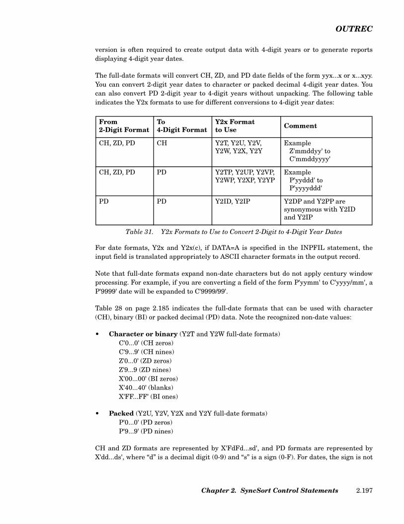
OUTREC
version is often required to create output data with 4-digit years or to generate reportsdisplaying 4-digit year dates.
The full-date formats will convert CH, ZD, and PD date fields of the form yyx...x or x...xyy.You can convert 2-digit year dates to character or packed decimal 4-digit year dates. Youcan also convert PD 2-digit year to 4-digit years without unpacking. The following tableindicates the Y2x formats to use for different conversions to 4-digit year dates:
For date formats, Y2x and Y2x(c), if DATA=A is specified in the INPFIL statement, theinput field is translated appropriately to ASCII character formats in the output record.
Note that full-date formats expand non-date characters but do not apply century windowprocessing. For example, if you are converting a field of the form P'yymm' to C'yyyy/mm', aP'9999' date will be expanded to C'9999/99'.
Table 28 on page 2.185 indicates the full-date formats that can be used with character(CH), binary (BI) or packed decimal (PD) data. Note the recognized non-date values:
• Character or binary (Y2T and Y2W full-date formats)C'0...0' (CH zeros)C'9...9' (CH nines)Z'0...0' (ZD zeros)Z'9...9 (ZD nines)X'00...00' (BI zeros)X'40...40' (blanks)X'FF...FF' (BI ones)
• Packed (Y2U, Y2V, Y2X and Y2Y full-date formats)P'0...0' (PD zeros)P'9...9' (PD nines)
CH and ZD formats are represented by X'FdFd...sd', and PD formats are represented byX'dd...ds', where “d” is a decimal digit (0-9) and “s” is a sign (0-F). For dates, the sign is not
From2-Digit Format
To4-Digit Format
Y2x Formatto Use Comment
CH, ZD, PD CH Y2T, Y2U, Y2V,Y2W, Y2X, Y2Y
ExampleZ'mmddyy' toC'mmddyyyy'
CH, ZD, PD PD Y2TP, Y2UP, Y2VP,Y2WP, Y2XP, Y2YP
ExampleP'yyddd' toP'yyyyddd'
PD PD Y2ID, Y2IP Y2DP and Y2PP aresynonymous with Y2IDand Y2IP
Table 31. Y2x Formats to Use to Convert 2-Digit to 4-Digit Year Dates
Chapter 2. SyncSort Control Statements 2.197
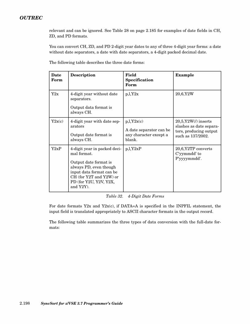
OUTREC
relevant and can be ignored. See Table 28 on page 2.185 for examples of date fields in CH,ZD, and PD formats.
You can convert CH, ZD, and PD 2-digit year dates to any of three 4-digit year forms: a datewithout date separators, a date with date separators, a 4-digit packed decimal date.
The following table describes the three date forms:
For date formats Y2x and Y2x(c), if DATA=A is specified in the INPFIL statement, theinput field is translated appropriately to ASCII character formats in the output record.
The following table summarizes the three types of data conversion with the full-date for-mats:
DateForm
Description FieldSpecificationForm
Example
Y2x 4-digit year without date separators.
Output data format is always CH.
p,l,Y2x 20,6,Y2W
Y2x(c) 4-digit year with date sep-arators
Output date format is always CH.
p,l,Y2x(c)
A date separator can be any character except a blank.
20,5,Y2W(/) inserts slashes as date separa-tors, producing output such as 137/2002.
Y2xP 4-digit year in packed deci-mal format.
Output date format is always PD, even though input data format can be CH (for Y2T and Y2W) or PD (for Y2U, Y2V, Y2X, and Y2Y).
p,l,Y2xP 20,6,Y2TP converts C'yymmdd' to P'yyyymmdd'.
Table 32. 4-Digit Date Forms
SyncSort for z/VSE 3.7 Programmer’s Guide2.198
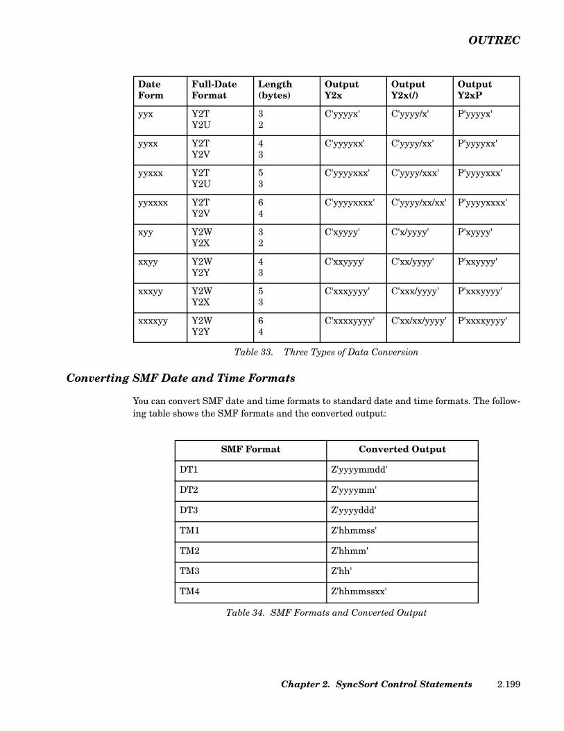
OUTREC
Converting SMF Date and Time Formats
You can convert SMF date and time formats to standard date and time formats. The follow-ing table shows the SMF formats and the converted output:
DateForm
Full-DateFormat
Length(bytes)
OutputY2x
OutputY2x(/)
OutputY2xP
yyx Y2TY2U
32
C'yyyyx' C'yyyy/x' P'yyyyx'
yyxx Y2TY2V
43
C'yyyyxx' C'yyyy/xx' P'yyyyxx'
yyxxx Y2TY2U
53
C'yyyyxxx' C'yyyy/xxx' P'yyyyxxx'
yyxxxx Y2TY2V
64
C'yyyyxxxx' C'yyyy/xx/xx' P'yyyyxxxx'
xyy Y2WY2X
32
C'xyyyy' C'x/yyyy' P'xyyyy'
xxyy Y2WY2Y
43
C'xxyyyy' C'xx/yyyy' P'xxyyyy'
xxxyy Y2WY2X
53
C'xxxyyyy' C'xxx/yyyy' P'xxxyyyy'
xxxxyy Y2WY2Y
64
C'xxxxyyyy' C'xx/xx/yyyy' P'xxxxyyyy'
Table 33. Three Types of Data Conversion
SMF Format Converted Output
DT1 Z'yyyymmdd'
DT2 Z'yyyymm'
DT3 Z'yyyyddd'
TM1 Z'hhmmss'
TM2 Z'hhmm'
TM3 Z'hh'
TM4 Z'hhmmssxx'
Table 34. SMF Formats and Converted Output
Chapter 2. SyncSort Control Statements 2.199
OUTREC
For DTn, the source is the 4-byte packed SMF date value (P'cyyddd'). For TMn, the sourceis a 4-byte binary SMF time value.
The c in the date source P'cyyddd' represents the century. It is converted as follows: 0 isconverted to 19, 1 is converted to 20, and 2 or greater is converted to 21.
The converted output is a zoned decimal field, where each character in the table representsa single byte. For TM4, xx represents hundredths of a second.
The SyncSort predefined edit masks (M0-M26) or specified edit patterns can be used to editthe converted date and time. The default mask is M11.
Note: A data exception or an inaccurate ZD date can occur if an SMF date is not valid. Aninaccurate ZD time can occur if an SMF time is not valid. SMF dates and times areprocessed as positive values.
EDIT Subparameter
The EDIT subparameter lets you create your own edit patterns for converted numeric data.An edit pattern can consist of:
• Significant digit selectors.
• Leading insignificant digit selectors.
• Sign replacement characters.
• Any other characters to be printed in the actual output.
The edit pattern can be up to 22 characters in length, with a maximum of 15 leading insig-nificant and/or significant digits.
The characters used to represent significant or insignificant digit selectors are determinedby the keyword EDIT. If EDIT is specified, the letter I represents leading insignificant dig-its, which will print as blanks if the digits are zeros, and the letter T represents significantdigits (digits that will print in their true form, even as leading zeros).
The keyword EDIT can be specified with replacements for the letters I and/or T. Any print-able character can be used as a replacement character. This replacement makes availableto the user a pattern that encompasses all printable characters. Figure 117 illustrates theconcept of replacing the insignificant and significant digit selectors I and T with other char-acters.
SyncSort for z/VSE 3.7 Programmer’s Guide2.200

OUTREC
When a blank, quotation mark or unbalanced parenthesis appears within an EDIT pattern,the pattern must be enclosed within single quotation marks. Balanced parentheses neednot be enclosed within quotation marks. A single quotation mark within the pattern (e.g.,an apostrophe) must be specified as a double quotation mark. All other characters areprinted as specified in the edit pattern with the following exceptions:
• Any character specified after the first leading insignificant digit selector and before thefirst significant digit selector will print as a blank, unless a previously selected digitwas non-zero.
• Any character specified after the last significant digit selector will print as a blank ifthe edited number is positive.
• Any character or character string specified before the first leading insignificant digitselector, including a leading sign character, will print to the immediate left of the firstsignificant digit. The appropriate number of leading blanks will be supplied, assuringthat the total number of characters in the printed field corresponds to the total numberof characters in the edit pattern.
• Any leading insignificant digit selector specified after the first significant digit selectorwill be treated as a significant digit selector.
• The sign replacement character appearing as the first and/or last character of thepattern is replaced as per the SIGNS subparameter.
LENGTH=n Subparameter
Use the LENGTH=n subparameter to alter the default length determined by the edit pat-tern and the format of the field. If LENGTH=n is not specified, the length is equal to thenumber of characters specified in the edit pattern. If LENGTH=n is specified, the edit pat-tern will either be truncated or padded with blanks on the left so that the length of the pat-tern equals the 'n' value.
The maximum value that can be specified for 'n' is 22.
• When an output data format fo is used, the default length is 4 for BI and FI formats,and is determined by the number of digits in the input expression for CFS/FS, PD andZD formats. (The number of digits is 15 for any input expression other than a singlep,l,fi field.) If LENGTH=n is specified, the output data will either be truncated on the
EDxy=where: x = insignificant digit selector
y = significant digit selector
Figure 117. Replacing Digit Selector Characters
Chapter 2. SyncSort Control Statements 2.201

OUTREC
left or padded on the left with zeros (or blanks for CSF/FS) of the appropriate format toa length of n.
The following are the maximum values that can be specified for n when an output data for-mat fo is used:
Mm Subparameter (Editing Masks)
SyncSort for z/VSE provides editing masks to simplify the more common editing opera-tions. If neither Mm nor EDIT is specified in the OUTREC control statement, the defaultmask, M0, is used.
Where applicable (in most European countries), the default may be set via the SYNCMACparameter at installation time, to interchange decimal commas and periods in the SyncSortsupplied editing masks: M2, M3, M4, and M5.
Output Format Maximum Value of n
BI 4
FI 4
CSF 16
FS 16
PD 8
ZD 15
Table 35. Maximum Values of LENGTH=n for Output Data
Figure 118. EMASK Format
EMASK= YN
SyncSort for z/VSE 3.7 Programmer’s Guide2.202

OUTREC
Mask Pattern Signs Length
DefaultMask (M0) IIII...IITS (,,' ',-) d+1
M1 TTTTT...TTTS (,,' ',-) d+1
M2 I,III,...,IIT.TTS (,,' ',-) d+1 + [ d/3 ]
M3 I,III,...IIT.TTCR d+2 + [ d/3 ]
M4 SI,III,...,IIT.TT (+,-) d+1 + [ d/3 ]
M5 SIII,...,IIT.TTS (' ',(,' ',)) d+2 + [ d/3 ]
M6 III-TTT-TTTT 12
M7 TTT-TT-TTTT 11
M8 IT:TT:TT 8
M9 TT/TT/TT 8
M10 IIIIIIIIIIIIIIT d
M11 TTTTTTTTTTTTTTT d
M12 SIII,..,III,IIT (' ',-) d+1 + [ [d-1]/3 ]
M13 SIII.III.III.III.IIT (' ',-) d+1 + [ [d-1]/3 ]
M14 SIII III III III IITS (' ',(,' ',)) d+2 + [ [d-1]/3 ]
M15 III III III III IITS (,,' ',-) d+1 + [ [d-1]/3 ]
M16 SIII III III III IIT (' ',-) d+1 + [ [d-1]/3 ]
M17 SIII'III'III'III'IIT (' ',-) d+1 + [ [d-1]/3 ]
M18 SI,III,III,III,IIT.TT (' ',-) d+1 + [ d/3 ]
M19 SI.III.III.III.IIT,TT (' ',-) d+1 + [ d/3 ]
M20 SI III III III IIT,TTS (' ',(,' ',)) d+2 + [ d/3 ]
M21 I III III III IIT,TTS (,,' ',-) d+1 + [ d/3 ]
M22 SI III III III IIT,TT (' ',-) d+1 + [ d/3 ]
M23 SI'III'III'III'IIT.TT (' ',-) d+1 + [ d/3 ]
M24 SI'III'III'III'IIT,TT (' ',-) d+1 + [ d/3 ]
M25 SIIIIIIIIIIIIIIT (' ',-) d+1
M26 STTTTTTTTTTTTTTT (+,-) d+1
Table 36. Editing Masks
Chapter 2. SyncSort Control Statements 2.203

OUTREC
Note: The letter 'd' represents the number of resulting digits after data conversion. Thebrackets indicate that only the integer part of this division should be retained.
Table 36, above, illustrates the following:
• Edit pattern
• Leading or trailing signs, where appropriate
• Length
The edit patterns use the same symbolic letters used in the EDIT subparameter. Leadinginsignificant digits are represented by the letter I; significant digits are represented by theletter T. Leading or trailing sign replacement characters are represented by the letter S.All other characters print as they appear in the pattern.
The SIGNS illustrated for each mask follow the format requirements of the SIGNS subpa-rameter. You can specify the SIGNS subparameter to selectively override the signs for aparticular mask. For example, if you specify mask M4 and also specify SIGNS=(' '), a lead-ing blank will print instead of a plus sign if the number is positive. However, a leadingminus sign will print if the number is negative because the leading negative sign specifiedin the editing mask has not been overridden.
The lengths in the table represent the length, in bytes, of the mask. The lengths of masksM0 - M5 and M10-M26 are determined, in part, by the number of digits (d).
SIGNS Subparameter
The SIGNS subparameter specifies the sign(s) that will appear before or after the editednumber.
The sign replacement character, normally 'S', has special meaning if it appears as the firstor last character in an edit pattern. In these positions, the sign replacement character willbe replaced, as appropriate, by the characters specified by the SIGNS subparameter.
The format of the SIGNS subparameter is illustrated below.
where:
s1=leading positive sign indicator
s2=leading negative sign indicator
SIGNS=(s1,s2,s3,s4)
Figure 119. SIGNS Subparameter Format
SyncSort for z/VSE 3.7 Programmer’s Guide2.204
OUTREC
s3=trailing positive sign indicator
s4=trailing negative sign indicator
Because the SIGNS subparameter contains four positional values, commas must be used toindicate embedded, unspecified values. Each of the four values can contain one, and onlyone, character; specified characters must be separated by commas.
A blank, comma, quotation mark and unbalanced parenthesis used as a SIGNS charactermust be enclosed within single quotation marks. A single quotation mark used as a SIGNScharacter must be specified as a double quotation mark and enclosed within single quota-tion marks.
When the SIGNS subparameter is specified, the letter 'S' is normally used as the signreplacement character in the user-supplied edit pattern. The user can change the last letterof the keyword SIGNS in order to specify another character as the sign replacement charac-ter. For example, if the user specifies SIGNX instead of SIGNS, the letter 'X' becomes thesign replacement character in the user-provided edit pattern.
If the user specifies a sign replacement character in the edit pattern but does not specify avalue in the corresponding position in the SIGNS parameter, a blank will be assumed. Forexample, if the user specifies the following:
EDIT=(IITT.TTS),SIGNS=(,,,-)
then a trailing minus sign will print if the number is negative and a trailing blank willprint if the number is positive.
The SIGNS subparameter can also be used to override the sign values in SyncSort-providedediting masks.
IFOUTLEN Parameter (Optional)
The IFOUTLEN parameter overrides the maximum record length, which is automaticallyset by the IFTHEN parameter, and changes it to a specified value. The IFOUTLEN param-eter may only be used in conjunction with the IFTHEN parameter.
The IFOUTLEN parameter automatically makes the following changes to the record tomatch the new length. A record longer than n is truncated to n. A fixed-length recordshorter than n is padded with blanks to reach a length of n.
IFTHEN Parameter (Optional)
The IFTHEN parameter uses conditional logic which enables you to reformat records basedon specified criteria. Multiple IFTHEN parameters may be specified within the same con-trol statement and are processed sequentially.
Chapter 2. SyncSort Control Statements 2.205
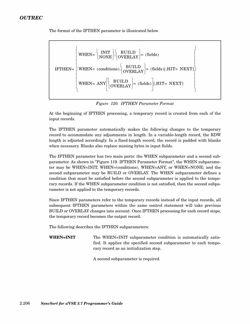
OUTREC
The format of the IFTHEN parameter is illustrated below.
At the beginning of IFTHEN processing, a temporary record is created from each of theinput records.
The IFTHEN parameter automatically makes the following changes to the temporaryrecord to accommodate any adjustments in length. In a variable-length record, the RDWlength is adjusted accordingly. In a fixed-length record, the record is padded with blankswhen necessary. Blanks also replace missing bytes in input fields.
The IFTHEN parameter has two main parts: the WHEN subparameter and a second sub-parameter. As shown in "Figure 119. IFTHEN Parameter Format", the WHEN subparame-ter may be WHEN=INIT, WHEN=(conditions), WHEN=ANY, or WHEN=NONE; and thesecond subparameter may be BUILD or OVERLAY. The WHEN subparameter defines acondition that must be satisfied before the second subparameter is applied to the tempo-rary records. If the WHEN subparameter condition is not satisfied, then the second subpa-rameter is not applied to the temporary records.
Since IFTHEN parameters refer to the temporary records instead of the input records, allsubsequent IFTHEN parameters within the same control statement will take previousBUILD or OVERLAY changes into account. Once IFTHEN processing for each record stops,the temporary record becomes the output record.
The following describes the IFTHEN subparameters:
WHEN=INIT The WHEN=INIT subparameter condition is automatically satis-fied. It applies the specified second subparameter to each tempo-rary record as an initialization step.
A second subparameter is required.
Figure 120. IFTHEN Parameter Format
IFTHEN
WHEN INITNONE
BUILD
OVERLAY
fields( )=,=
WHEN conditions( ) BUILDOVERLAY
fields( ) HIT NEXT=,[ ]=,=
WHEN ANY BUILDOVERLAY
fields( )= HIT NEXT=,[ ]=
=
SyncSort for z/VSE 3.7 Programmer’s Guide2.206

OUTREC
WHEN=(conditions) The WHEN=(conditions) subparameter condition is satisfied if atemporary record meets the specified conditions. It applies the spec-ified second subparameter to each temporary record that meets thespecified conditions.
conditions The conditions must be formulated into a comparisonor logical expression that can be evaluated to true or false.
For a complete description of comparisons and logical expressions,see “COND Parameter (Required)” on page 2.41. However, the fol-lowing cannot be used in WHEN=(conditions):
• FORMAT=f
A second subparameter is required. The HIT=NEXT subparameter isoptional.
WHEN=ANY The WHEN=ANY subparameter condition is satisfied if one or moreof its associated WHEN=(conditions) subparameter conditions havebeen satisfied. Its associated WHEN=(conditions) subparametersare those that precede it but no other WHEN=ANY subparameter.If the WHEN=ANY subparameter condition is satisfied, it appliesthe specified second subparameter to the temporary record.
A second subparameter is optional. If it is not used, IFTHEN pro-cessing simply stops if the WHEN=ANY subparameter condition issatisfied unless the optional HIT=NEXT subparameter has beenspecified.
WHEN=NONE The WHEN=NONE subparameter condition is satisfied if none ofthe preceding WHEN=(conditions) subparameter conditions is sat-isfied or if there are no WHEN=(conditions) subparameters. If theWHEN=NONE subparameter condition is satisfied, it applies thespecified second subparameter to the temporary record.
A second subparameter is required.
The IFTHEN parameters must be specified such that the WHEN subparameters are in thefollowing order:
• WHEN=INIT
• WHEN=(conditions) and WHEN=ANY
Chapter 2. SyncSort Control Statements 2.207
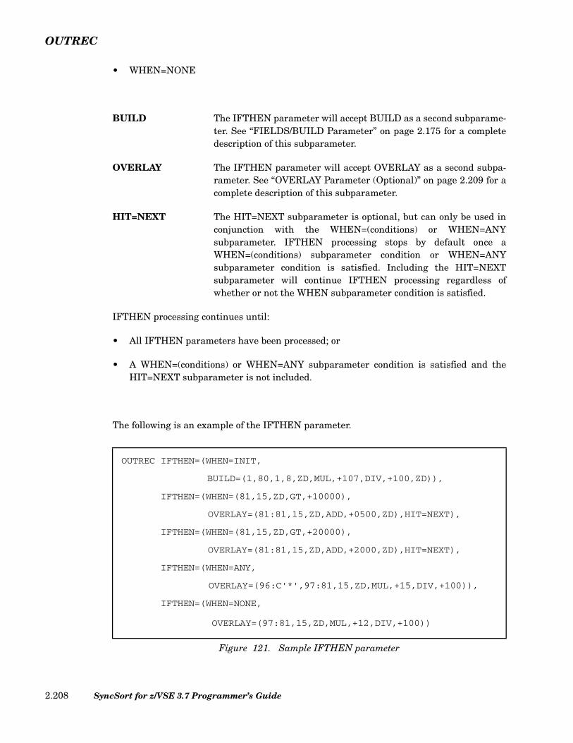
OUTREC
• WHEN=NONE
BUILD The IFTHEN parameter will accept BUILD as a second subparame-ter. See “FIELDS/BUILD Parameter” on page 2.175 for a completedescription of this subparameter.
OVERLAY The IFTHEN parameter will accept OVERLAY as a second subpa-rameter. See “OVERLAY Parameter (Optional)” on page 2.209 for acomplete description of this subparameter.
HIT=NEXT The HIT=NEXT subparameter is optional, but can only be used inconjunction with the WHEN=(conditions) or WHEN=ANYsubparameter. IFTHEN processing stops by default once aWHEN=(conditions) subparameter condition or WHEN=ANYsubparameter condition is satisfied. Including the HIT=NEXTsubparameter will continue IFTHEN processing regardless ofwhether or not the WHEN subparameter condition is satisfied.
IFTHEN processing continues until:
• All IFTHEN parameters have been processed; or
• A WHEN=(conditions) or WHEN=ANY subparameter condition is satisfied and theHIT=NEXT subparameter is not included.
The following is an example of the IFTHEN parameter.
OUTREC IFTHEN=(WHEN=INIT,
BUILD=(1,80,1,8,ZD,MUL,+107,DIV,+100,ZD)),
IFTHEN=(WHEN=(81,15,ZD,GT,+10000),
OVERLAY=(81:81,15,ZD,ADD,+0500,ZD),HIT=NEXT),
IFTHEN=(WHEN=(81,15,ZD,GT,+20000),
OVERLAY=(81:81,15,ZD,ADD,+2000,ZD),HIT=NEXT),
IFTHEN=(WHEN=ANY,
OVERLAY=(96:C'*',97:81,15,ZD,MUL,+15,DIV,+100)),
IFTHEN=(WHEN=NONE,
OVERLAY=(97:81,15,ZD,MUL,+12,DIV,+100))
Figure 121. Sample IFTHEN parameter
SyncSort for z/VSE 3.7 Programmer’s Guide2.208
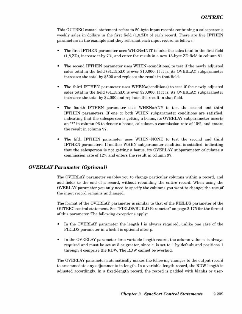
OUTREC
This OUTREC control statement refers to 80-byte input records containing a salesperson'sweekly sales in dollars in the first field (1,8,ZD) of each record. There are five IFTHENparameters in the example and they reformat each input record as follows:
• The first IFTHEN parameter uses WHEN=INIT to take the sales total in the first field(1,8,ZD), increase it by 7%, and enter the result in a new 15-byte ZD field in column 81.
• The second IFTHEN parameter uses WHEN=(conditions) to test if the newly adjustedsales total in the field (81,15,ZD) is over $10,000. If it is, its OVERLAY subparameterincreases the total by $500 and replaces the result in that field.
• The third IFTHEN parameter uses WHEN=(conditions) to test if the newly adjustedsales total in the field (81,15,ZD) is over $20,000. If it is, its OVERLAY subparameterincreases the total by $2,000 and replaces the result in that field.
• The fourth IFTHEN parameter uses WHEN=ANY to test the second and thirdIFTHEN parameters. If one or both WHEN subparameter conditions are satisfied,indicating that the salesperson is getting a bonus, its OVERLAY subparameter insertsan "*" in column 96 to denote a bonus, calculates a commission rate of 15%, and entersthe result in column 97.
• The fifth IFTHEN parameter uses WHEN=NONE to test the second and thirdIFTHEN parameters. If neither WHEN subparameter condition is satisfied, indicatingthat the salesperson is not getting a bonus, its OVERLAY subparameter calculates acommission rate of 12% and enters the result in column 97.
OVERLAY Parameter (Optional)
The OVERLAY parameter enables you to change particular columns within a record, andadd fields to the end of a record, without rebuilding the entire record. When using theOVERLAY parameter you only need to specify the columns you want to change; the rest ofthe input record remains unchanged.
The format of the OVERLAY parameter is similar to that of the FIELDS parameter of theOUTREC control statement. See “FIELDS/BUILD Parameter” on page 2.175 for the formatof this parameter. The following exceptions apply:
• In the OVERLAY parameter the length l is always required, unlike one case of theFIELDS parameter in which l is optional after p.
• In the OVERLAY parameter for a variable-length record, the column value c: is alwaysrequired and must be set at 5 or greater, since c: is set to 1 by default and positions 1through 4 comprise the RDW. The RDW cannot be overlaid.
The OVERLAY parameter automatically makes the following changes to the output recordto accommodate any adjustments in length. In a variable-length record, the RDW length isadjusted accordingly. In a fixed-length record, the record is padded with blanks or user-
Chapter 2. SyncSort Control Statements 2.209
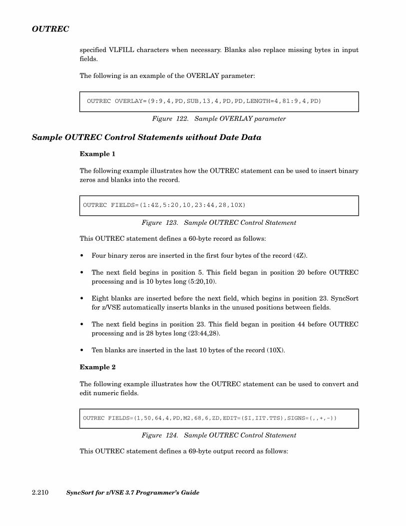
OUTREC
specified VLFILL characters when necessary. Blanks also replace missing bytes in inputfields.
The following is an example of the OVERLAY parameter:
Sample OUTREC Control Statements without Date Data
Example 1
The following example illustrates how the OUTREC statement can be used to insert binaryzeros and blanks into the record.
This OUTREC statement defines a 60-byte record as follows:
• Four binary zeros are inserted in the first four bytes of the record (4Z).
• The next field begins in position 5. This field began in position 20 before OUTRECprocessing and is 10 bytes long (5:20,10).
• Eight blanks are inserted before the next field, which begins in position 23. SyncSortfor z/VSE automatically inserts blanks in the unused positions between fields.
• The next field begins in position 23. This field began in position 44 before OUTRECprocessing and is 28 bytes long (23:44,28).
• Ten blanks are inserted in the last 10 bytes of the record (10X).
Example 2
The following example illustrates how the OUTREC statement can be used to convert andedit numeric fields.
This OUTREC statement defines a 69-byte output record as follows:
OUTREC OVERLAY=(9:9,4,PD,SUB,13,4,PD,PD,LENGTH=4,81:9,4,PD)
Figure 122. Sample OVERLAY parameter
OUTREC FIELDS=(1:4Z,5:20,10,23:44,28,10X)
Figure 123. Sample OUTREC Control Statement
OUTREC FIELDS=(1,50,64,4,PD,M2,68,6,ZD,EDIT=($I,IIT.TTS),SIGNS=(,,+,-))
Figure 124. Sample OUTREC Control Statement
SyncSort for z/VSE 3.7 Programmer’s Guide2.210

OUTREC
• The first field begins in position 1. This field began in position 1 before OUTRECprocessing and is 50 bytes long. (1,50)
• The next field begins in position 51. This packed decimal field began in position 64before OUTREC processing and is 4 bytes long. After being converted and edited byediting mask M2, the resulting field will be 9 bytes long. However, the number of digitsthat will actually print will depend on the number of leading zeros, if any, because thismask specifies that only three digits must print whether or not they are leading zeros.Moreover, this mask specifies that a minus sign print after the number if it is negativeand a blank print after the number if it is positive. (64,4,PD,M2)
• The last field begins in position 60. This zoned decimal field began in position 68 beforeOUTREC processing and is 6 bytes long. The EDIT and SIGNS subparameters specifya 10-byte field because 4 additional bytes are needed for the dollar sign, the comma, thedecimal point and the trailing plus or minus sign. Note that if the first three digits areleading zeros, they will be suppressed. (68,6,ZD,EDIT=($I,IIT.TTS),SIGNS=(,,+, -))
Example 3
This example uses the OUTREC statement to convert numeric data from one format toanother.
This OUTREC statement defines a 14-byte output record as follows:
• The first field (20,10,ZD,PD) begins in position 1. This field was a 10-byte ZD field thatbegan in position 20 before OUTREC processing. It will be converted to a 6-byte PDfield in the output record, because 6 bytes are required to contain 10 decimal digits as aPD field.
• The next field (11,4,FI,ZD) begins in position 7. This field was a 4-byte FI field thatbegan in position 11 before OUTREC processing. It will be converted to an 8-byte ZDfield in the output record. Normally 10 ZD bytes would be required to contain the 10decimal digits that may be represented by a 4-byte FI field, but the LENGTH=8parameter overrode the output length. If there are more than 8 decimal digits in any ofthe 11,4,FI fields, those digits will be truncated on the left in the output record.
Note that ZD output is not the same as printable output using editing masks. Highorder zeros will appear as zeros in a ZD field, while they appear as blanks when usingthe default M0 mask, as well as most other masks. The sign indicator in a ZD field isplaced in the first 4 bits of the rightmost byte, and not as a separate printable sign.
OUTREC FIELDS=(20,10,ZD,PD,11,4,FI,ZD,LENGTH=8)
Figure 125. Sample OUTREC Control Statement
Chapter 2. SyncSort Control Statements 2.211
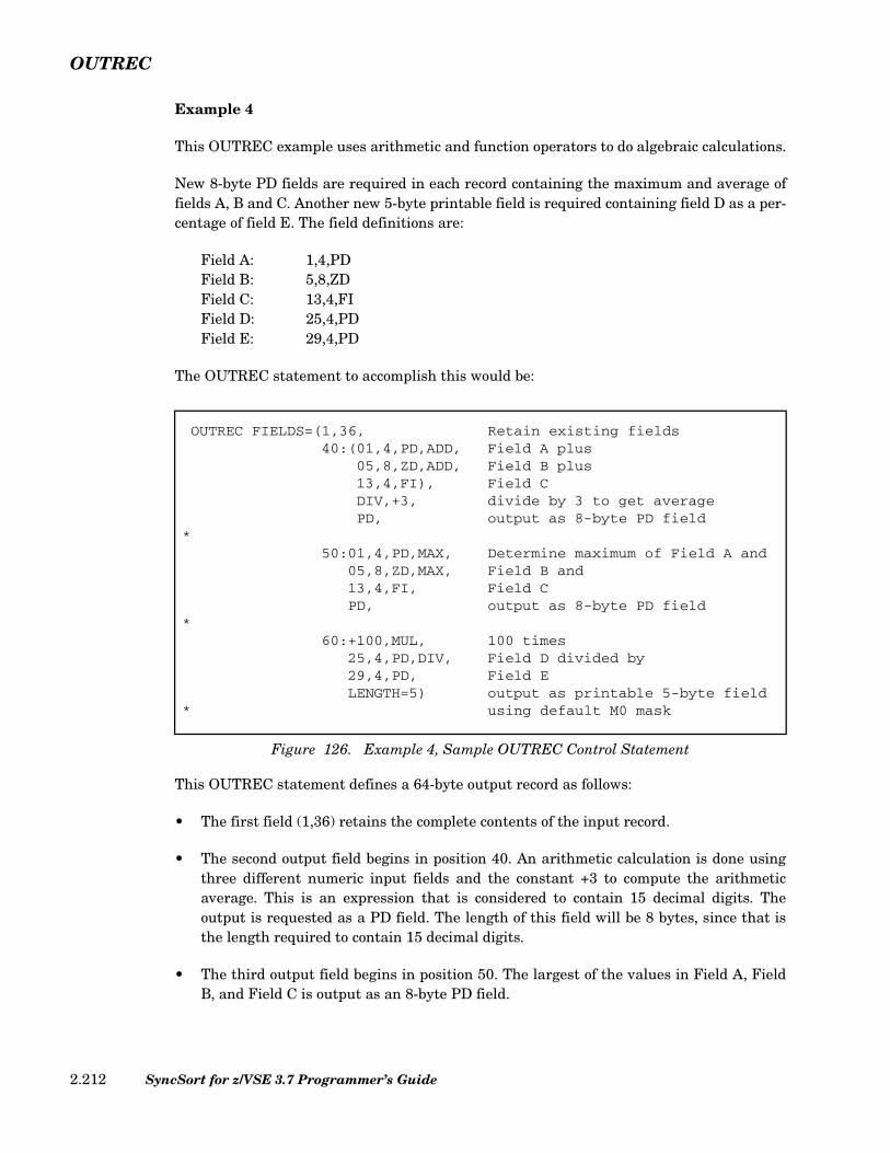
OUTREC
Example 4
This OUTREC example uses arithmetic and function operators to do algebraic calculations.
New 8-byte PD fields are required in each record containing the maximum and average offields A, B and C. Another new 5-byte printable field is required containing field D as a per-centage of field E. The field definitions are:
Field A: 1,4,PDField B: 5,8,ZDField C: 13,4,FIField D: 25,4,PDField E: 29,4,PD
The OUTREC statement to accomplish this would be:
This OUTREC statement defines a 64-byte output record as follows:
• The first field (1,36) retains the complete contents of the input record.
• The second output field begins in position 40. An arithmetic calculation is done usingthree different numeric input fields and the constant +3 to compute the arithmeticaverage. This is an expression that is considered to contain 15 decimal digits. Theoutput is requested as a PD field. The length of this field will be 8 bytes, since that isthe length required to contain 15 decimal digits.
• The third output field begins in position 50. The largest of the values in Field A, FieldB, and Field C is output as an 8-byte PD field.
OUTREC FIELDS=(1,36, Retain existing fields40:(01,4,PD,ADD, Field A plus
05,8,ZD,ADD, Field B plus13,4,FI), Field CDIV,+3, divide by 3 to get averagePD, output as 8-byte PD field
*50:01,4,PD,MAX, Determine maximum of Field A and
05,8,ZD,MAX, Field B and13,4,FI, Field CPD, output as 8-byte PD field
*60:+100,MUL, 100 times
25,4,PD,DIV, Field D divided by29,4,PD, Field ELENGTH=5) output as printable 5-byte field
* using default M0 mask
Figure 126. Example 4, Sample OUTREC Control Statement
SyncSort for z/VSE 3.7 Programmer’s Guide2.212
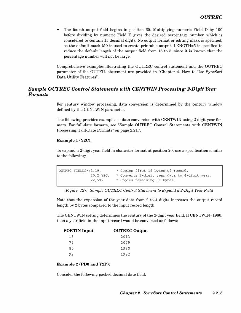
OUTREC
• The fourth output field begins in position 60. Multiplying numeric Field D by 100before dividing by numeric Field E gives the desired percentage number, which isconsidered to contain 15 decimal digits. No output format or editing mask is specified,so the default mask M0 is used to create printable output. LENGTH=5 is specified toreduce the default length of the output field from 16 to 5, since it is known that thepercentage number will not be large.
Comprehensive examples illustrating the OUTREC control statement and the OUTRECparameter of the OUTFIL statement are provided in “Chapter 4. How to Use SyncSortData Utility Features”.
Sample OUTREC Control Statements with CENTWIN Processing: 2-Digit Year Formats
For century window processing, data conversion is determined by the century windowdefined by the CENTWIN parameter.
The following provides examples of data conversion with CENTWIN using 2-digit year for-mats. For full-date formats, see “Sample OUTREC Control Statements with CENTWINProcessing: Full-Date Formats” on page 2.217.
Example 1 (Y2C):
To expand a 2-digit year field in character format at position 20, use a specification similarto the following:
Note that the expansion of the year data from 2 to 4 digits increases the output recordlength by 2 bytes compared to the input record length.
The CENTWIN setting determines the century of the 2-digit year field. If CENTWIN=1980,then a year field in the input record would be converted as follows:
SORTIN Input OUTREC Output13 2013
79 2079
80 1980
92 1992
Example 2 (PD0 and Y2P):
Consider the following packed decimal date field:
OUTREC FIELDS=(1,19, * Copies first 19 bytes of record.
20,2,Y2C, * Converts 2-digit year data to 4-digit year.
22,59) * Copies remaining 59 bytes.
Figure 127. Sample OUTREC Control Statement to Expand a 2-Digit Year Field
Chapter 2. SyncSort Control Statements 2.213
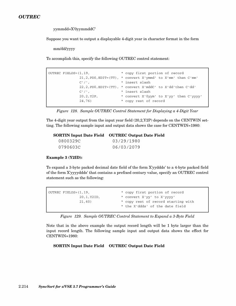
OUTREC
yymmdd=X'0yymmddC'
Suppose you want to output a displayable 4-digit year in character format in the form
mm/dd/yyyy
To accomplish this, specify the following OUTREC control statement:
The 4-digit year output from the input year field (20,2,Y2P) depends on the CENTWIN set-ting. The following sample input and output data shows the case for CENTWIN=1980:
SORTIN Input Date Field OUTREC Output Date Field0800329C 03/29/1980
0790603C 06/03/2079
Example 3 (Y2ID):
To expand a 3-byte packed decimal date field of the form X'yyddds' to a 4-byte packed fieldof the form X'yyyyddds' that contains a prefixed century value, specify an OUTREC controlstatement such as the following:
Note that in the above example the output record length will be 1 byte larger than theinput record length. The following sample input and output data shows the effect forCENTWIN=1980:
SORTIN Input Date Field OUTREC Output Date Field
OUTREC FIELDS=(1,19, * copy first portion of record
21,2,PD0,EDIT=(TT), * convert X'ymmd' to X'mm' then C'mm'
C'/', * insert slash
22,2,PD0,EDIT=(TT), * convert X'mddC' to X'dd'then C'dd'
C'/', * insert slash
20,2,Y2P, * convert X'0yym' to X'yy' then C'yyyy'
24,76) * copy rest of record
Figure 128. Sample OUTREC Control Statement for Displaying a 4-Digit Year
OUTREC FIELDS=(1,19, * copy first portion of record
20,1,Y2ID, * convert X'yy' to X'yyyy'
21,60) * copy rest of record starting with
* the X'ddds' of the date field
Figure 129. Sample OUTREC Control Statement to Expand a 3-Byte Field
SyncSort for z/VSE 3.7 Programmer’s Guide2.214

OUTREC
X'79' X'2079'
X'80' X'1980'
Example 4 (Y2IP):
To expand a 4-byte packed decimal date field of the form X'0yymmdds' to a 5-byte field ofthe form X'0yyyymmdds' that contains a prefixed century value, specify an OUTREC con-trol statement such as the following:
As with Y2ID conversion, the output record length will be 1 byte larger than the inputlength. The following sample input and output data shows the effect for CENTWIN=1980:
SORTIN Input Date Field OUTREC Output Date FieldX'0791' X'020791'
X'0800' X'019800'
Example 5 (Y2D and PSI):
To convert a 3-byte packed decimal date field of the form X'yyddds' to a 8-byte characterfield of the form C'yyyy/ddd' that contains a prefixed century value, specify an OUTRECcontrol statement such as the following:
The output record length will be 5 bytes larger than the input length. The following sampleinput and output data shows the effect for CENTWIN=1980:
SORTIN Input Date Field OUTREC Output Date Field
OUTREC FIELDS=(1,19, * copy first portion of record
20,2,Y2IP, * convert X'0yym' to X'0yyyym'
22,59) * copy rest of record starting with
* the X'mdds' of the date field
Figure 130. Sample OUTREC Control Statement to Expand a 4-Byte Field
OUTREC FIELDS=(1,19, * copy first portion of record20,1,Y2D, * convert X'yy' to C'yyyy'C'/', * insert slash (/)21,2,PSI, * convert X'ddds' to C'ddd'23,58) * copy rest of record
Figure 131. Sample OUTREC Control Statement to Convert a 3-Byte Field
Chapter 2. SyncSort Control Statements 2.215

OUTREC
X'79124C' 2079/124
X'80022C' 1980/022
Example 6 (Y2Z and ZSI):
To convert a 6-byte zoned decimal date field of the form X'FyFyFmFmFdFd' to a 10-bytecharacter field of the form C'yyyy/mm/dd' that contains a prefixed century value, specify anOUTREC control statement such as the following:
The output record length will be 4 bytes larger than the input length. The following sampleinput and output data shows the effect for CENTWIN=1980:
SORTIN Input Date Field OUTREC Output Date FieldX'F7F9F1F1F1F7' 2079/11/17
X'F8F0F0F2F0F5' 1980/02/05
Example 7 (Y2S)
Consider a 2-byte character or zoned decimal field that may contain either valid numericyear data or characters that identify the record as a header or trailer. Header records in theexample are identified by zeros (X'00') or a blank (X'40') in the first byte of the year field,while trailer records are identified by binary ones (X'FF') in the first byte of the field. TheY2S format will treat the valid year data normally, in the same way as the Y2C or Y2Z for-mats would treat the data, but the year fields of header and trailer records will be con-verted to a 4-digit form padded on the left with data identical to the data in the first byte ofthe input field.
Typically this type of conversion is needed when a Y2S SORT or MERGE field is used tocollate the records so that header/trailer records in the output remain at the start or end ofthe file. An OUTREC statement such as the following could be used.
OUTREC FIELDS=(1,19, * copy first portion of record20,2,Y2Z, * convert X'FyFy to C'yyyy'C'/', * insert slash (/)22,2,ZSI, * convert X'FmFm' to C'mm'C'/', * insert slash (/)24,2,ZSI, * convert X'FdFd' to C'dd'26,55) * copy rest of record
Figure 132. Sample OUTREC Control Statement to Convert a 6-Byte Field
SyncSort for z/VSE 3.7 Programmer’s Guide2.216
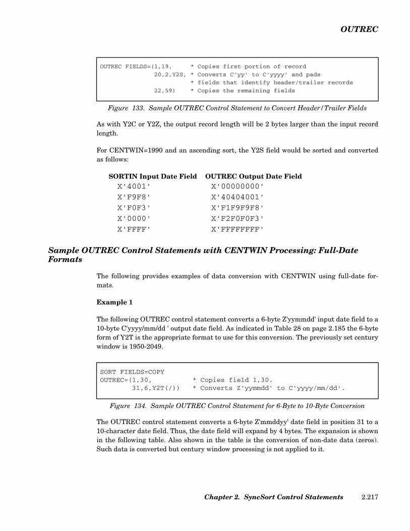
OUTREC
As with Y2C or Y2Z, the output record length will be 2 bytes larger than the input recordlength.
For CENTWIN=1990 and an ascending sort, the Y2S field would be sorted and convertedas follows:
SORTIN Input Date Field OUTREC Output Date FieldX'4001' X'00000000'
X'F9F8' X'40404001'
X'F0F3' X'F1F9F9F8'
X'0000' X'F2F0F0F3'
X'FFFF' X'FFFFFFFF'
Sample OUTREC Control Statements with CENTWIN Processing: Full-Date Formats
The following provides examples of data conversion with CENTWIN using full-date for-mats.
Example 1
The following OUTREC control statement converts a 6-byte Z'yymmdd' input date field to a10-byte C'yyyy/mm/dd ' output date field. As indicated in Table 28 on page 2.185 the 6-byteform of Y2T is the appropriate format to use for this conversion. The previously set centurywindow is 1950-2049.
The OUTREC control statement converts a 6-byte Z'mmddyy' date field in position 31 to a10-character date field. Thus, the date field will expand by 4 bytes. The expansion is shownin the following table. Also shown in the table is the conversion of non-date data (zeros).Such data is converted but century window processing is not applied to it.
OUTREC FIELDS=(1,19, * Copies first portion of record
20,2,Y2S, * Converts C'yy' to C'yyyy' and pads
* fields that identify header/trailer records
22,59) * Copies the remaining fields
Figure 133. Sample OUTREC Control Statement to Convert Header/Trailer Fields
SORT FIELDS=COPYOUTREC=(1,30, * Copies field 1,30.
31,6,Y2T(/)) * Converts Z'yymmdd' to C'yyyy/mm/dd'.
Figure 134. Sample OUTREC Control Statement for 6-Byte to 10-Byte Conversion
Chapter 2. SyncSort Control Statements 2.217

OUTREC
SORTIN Input SORTOUT Output (Z'yymmdd') (C'yyyy/mm/dd')740514 1974/05/14
101121 2010/11/21
500803 1950/08/03
000000 0000/00/00
Example 2
The following OUTREC control statement converts a 3-byte P'yyddd' packed decimal datefield to a 4-byte P'yyyyddd' packed decimal date field. As indicated in Table 28 on page2.185 the Y2UP format is appropriate for this conversion. The previously set century win-dow is 1970-2069.
The packed decimal input format is retained in the output data, as indicated in the follow-ing table:
SORTIN Input SORTOUT Output (P'yyddd') (P'yyyyddd')P'60347' P'2060347'
P'99002' P'1999002'
P'70143' P'1970143'
P'99999' P'9999999'
P'69113' P'2069113'
P'84175' P'1984175'
SORT FIELDS=COPYOUTREC=(20,3,Y2UP) * Converts 3-byte P'yyddd' to 4-byte
* P'yyyyddd'.
Figure 135. Sample OUTREC Control Statement for 3-Byte to 4-Byte Conversion
SyncSort for z/VSE 3.7 Programmer’s Guide2.218

RECORD
RECORD Control Statement
The RECORD control statement provides record length and format information. TheRECORD statement can also be used to delete certain records before sort/merge processingThe RECORD control statement is required unless the JOINKEYS control statement isused.
The format of the RECORD control statement is illustrated below.
LENGTH Parameter (Required)
The LENGTH parameter specifies the length of the record at various points during the pro-cessing of the application. These points are illustrated in Figure 3 on page 2.18.
The number of length values can vary from 1 to 7. Only the l1 value is required. If l1 is theonly value used, parentheses are optional. If l1 and additional length values are used, theyall must be enclosed in parentheses.
The length values are positionally dependent. An extra comma must indicate a missing lvalue between any two that are specified. Commas need not follow the final l value speci-fied. For example, if LENGTH=(l1,,,l4) is specified, the omitted values are understood to bel2 ,l3, l5, l6, and l7.
If the KEYLEN or ADDROUT parameter is specified on the OPTION control statement,refer to Table 22 on page 2.118 for information on calculating RECORD length values.
The l1,...,l7 variables specify the following:
l1 The maximum record length of the logical records at input tothe sort/merge, after any length change from INPFIL INRECcontrol statement(s) but before E15 processing. (See Figure 3on page 2.18.) For variable-length records, this is the length ofthe longest logical record plus the 4-byte Record DescriptorWord. The 4-byte RDW must be included, even if the input is aVSAM file. For tape input, 18 bytes is the minimum recordlength that is permitted.
l2 The maximum length of the logical records after INPFILINREC E15 processing. Do not specify an l2 value to reflect a
Figure 136. RECORD Control Statement Format
RECORD LENGTH=(l1,...,l7), TYPE=
FVDVSVBS
,DELBLANK=(p,q),DELBLANK=p
Chapter 2. SyncSort Control Statements 2.219

RECORD
length change due to the INREC control statement; the post-INREC length is calculated automatically. However, it is neces-sary to specify an l2 value if an E15 exit has altered the recordlength. If an l2 value is specified, it must be the length afterINPFIL INREC and/or E15 have altered the record length.
l3 The maximum length of the logical records after OUTREC orE35 processing. If the record length has not changed from the l2
value, either as specified or as defaulted, you may omit the l3
value. It is not necessary to specify an l3 value to reflect a lengthchange due to the OUTREC statement or the OUTREC parame-ter on the OUTFIL statement; the post-OUTREC length is cal-culated automatically. However, it is necessary to specify an l3
value if an E35 exit has altered the record length and the sort iswriting the output file.
l4 The minimum length of the variable-length logical records plusthe 4-byte Record Descriptor Word. This length should take intoaccount any modifications made by an E15 exit program and/oran INPFIL INREC statement, but not an INREC control state-ment; the post-INREC length is calculated automatically. Anomitted l4 value defaults to the number of bytes needed to con-tain all of the control fields specified on the INCLUDE/OMIT,INREC, MERGE, OUTREC, SORT, SUM and/or OUTFIL state-ments.
The l4 value is not used for a merge, but if it is specified,SyncSort will check record lengths.
l5 The most frequent record length of the variable-length records.This length should take into account any modifications made byan E15 exit program and/or an INPFIL INREC statement, butnot an INREC control statement; the post-INREC length is cal-culated automatically. Specify this length value to optimize thesize of the segment, i.e., the fixed-length block reserved to con-tain variable-length records when they are placed on intermedi-ate storage devices.
The l5 value is not used for a merge. If specified, it will beignored.
l6 The average work space required by each variable-lengthrecord. The VL5L6L7 PARM or the SYNCHSTO utility programcan be used to calculate this value.
SyncSort for z/VSE 3.7 Programmer’s Guide2.220
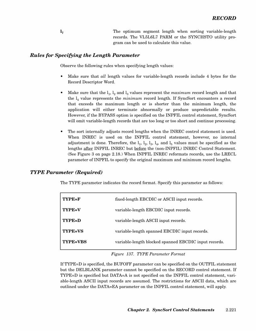
RECORD
l7 The optimum segment length when sorting variable-lengthrecords. The VL5L6L7 PARM or the SYNCHSTO utility pro-gram can be used to calculate this value.
Rules for Specifying the Length Parameter
Observe the following rules when specifying length values:
• Make sure that all length values for variable-length records include 4 bytes for theRecord Descriptor Word.
• Make sure that the l1, l2 and l3 values represent the maximum record length and thatthe l4 value represents the minimum record length. If SyncSort encounters a recordthat exceeds the maximum length or is shorter than the minimum length, theapplication will either terminate abnormally or produce unpredictable results.However, if the BYPASS option is specified on the INPFIL control statement, SyncSortwill omit variable-length records that are too long or too short and continue processing.
• The sort internally adjusts record lengths when the INREC control statement is used.When INREC is used on the INPFIL control statement, however, no internaladjustment is done. Therefore, the l1, l2, l3, l4, and l5 values must be specified as thelengths after INPFIL INREC but before the (non-INPFIL) INREC Control Statement.(See Figure 3 on page 2.18.) When INPFIL INREC reformats records, use the LRECLparameter of INPFIL to specify the original maximum and minimum record lengths.
TYPE Parameter (Required)
The TYPE parameter indicates the record format. Specify this parameter as follows:
If TYPE=D is specified, the BUFOFF parameter can be specified on the OUTFIL statementbut the DELBLANK parameter cannot be specified on the RECORD control statement. IfTYPE=D is specified but DATA=A is not specified on the INPFIL control statement, vari-able-length ASCII input records are assumed. The restrictions for ASCII data, which areoutlined under the DATA=EA parameter on the INPFIL control statement, will apply.
TYPE=F fixed-length EBCDIC or ASCII input records.
TYPE=V variable-length EBCDIC input records.
TYPE=D variable-length ASCII input records.
TYPE=VS variable-length spanned EBCDIC input records.
TYPE=VBS variable-length blocked spanned EBCDIC input records.
Figure 137. TYPE Parameter Format
Chapter 2. SyncSort Control Statements 2.221

RECORD
If TYPE=VS or TYPE=VBS is specified, SyncSort insures that all output files are alsospanned.
Only one type of record can be specified for an application.
Note: when FTOV or VTOF is used on the INPFIL control statement to reformat the inputrecords before sorting, the TYPE parameter must specify the format of the records afterthe format conversion is done.
DELBLANK Parameter (Optional)
The DELBLANK parameter allows certain records to be deleted before sort/merge process-ing. This parameter cannot be used if either an INCLUDE statement or an OMIT state-ment is specified. The DELBLANK parameter also cannot be specified when DATA=A isspecified on the INPFIL control statement or TYPE=D is specified on the RECORD controlstatement.
The DELBLANK parameter can be specified in two formats.
When DELBLANK=(p,q) is specified, p specifies the position of q. The q value representsany EBCDIC value except a left or right-hand parenthesis, a comma or a blank. SyncSortfor z/VSE omits any record with the specified q value in the p position.
If DELBLANK=p is specified, SyncSort for z/VSE omits any record that has a blank in thep position.
For variable-length records, remember to add 4 bytes for the Record Descriptor Word whenspecifying the p value.
All references to field positions within the data record refer to the record after processingby an E15 exit, if specified. The p position must be located within the first 4092 bytes of thelogical record.
Sample RECORD Control Statement
This sample RECORD statement defines the record as follows:
• The file contains variable-length records.
• The l1 or longest input record to the sort will be 104 bytes. (This includes the 4-byteRecord Descriptor Word.) This is the only required length value.
RECORD TYPE=V,LENGTH=(104,,,84,104),DELBLANK=(5,X)
Figure 138. Sample RECORD Control Statement
SyncSort for z/VSE 3.7 Programmer’s Guide2.222
RECORD
• The l2 value is omitted because INREC and/or E15 processing did not alter the recordlength. A comma indicates the omitted l2 value.
• The l3 value is omitted because OUTREC and/or E35 processing did not alter the recordlength. A comma indicates the omitted l3 value.
• The l4 value indicates that the minimum record length is 84 bytes.
• The l5 value indicates that the most frequent record length is 104 bytes.
• The DELBLANK parameter specifies that any record with an X in byte 5 be omitted.
Chapter 2. SyncSort Control Statements 2.223
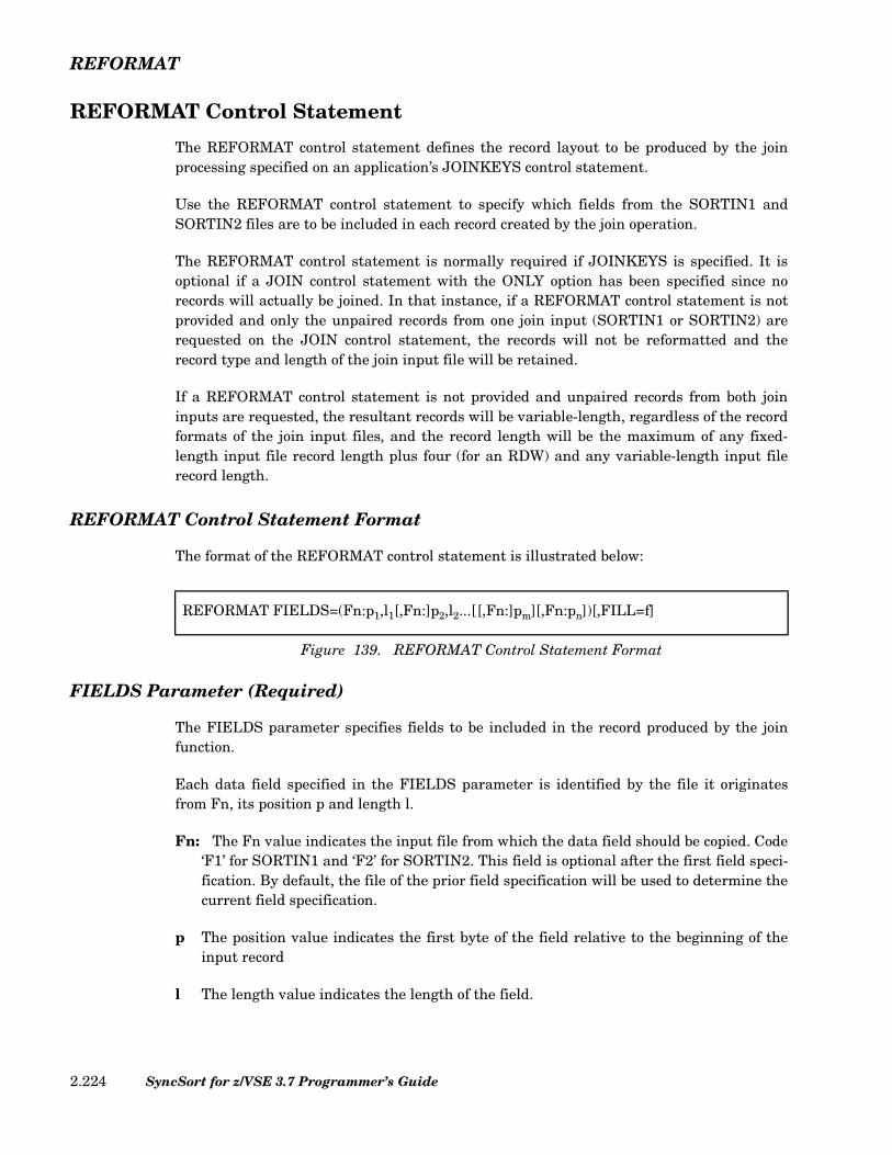
REFORMAT
REFORMAT Control Statement
The REFORMAT control statement defines the record layout to be produced by the joinprocessing specified on an application’s JOINKEYS control statement.
Use the REFORMAT control statement to specify which fields from the SORTIN1 andSORTIN2 files are to be included in each record created by the join operation.
The REFORMAT control statement is normally required if JOINKEYS is specified. It isoptional if a JOIN control statement with the ONLY option has been specified since norecords will actually be joined. In that instance, if a REFORMAT control statement is notprovided and only the unpaired records from one join input (SORTIN1 or SORTIN2) arerequested on the JOIN control statement, the records will not be reformatted and therecord type and length of the join input file will be retained.
If a REFORMAT control statement is not provided and unpaired records from both joininputs are requested, the resultant records will be variable-length, regardless of the recordformats of the join input files, and the record length will be the maximum of any fixed-length input file record length plus four (for an RDW) and any variable-length input filerecord length.
REFORMAT Control Statement Format
The format of the REFORMAT control statement is illustrated below:
FIELDS Parameter (Required)
The FIELDS parameter specifies fields to be included in the record produced by the joinfunction.
Each data field specified in the FIELDS parameter is identified by the file it originatesfrom Fn, its position p and length l.
Fn: The Fn value indicates the input file from which the data field should be copied. Code‘F1’ for SORTIN1 and ‘F2’ for SORTIN2. This field is optional after the first field speci-fication. By default, the file of the prior field specification will be used to determine thecurrent field specification.
p The position value indicates the first byte of the field relative to the beginning of theinput record
l The length value indicates the length of the field.
REFORMAT FIELDS=(Fn:p1,l1[,Fn:]p2,l2...[[,Fn:]pm][,Fn:pn])[,FILL=f]
Figure 139. REFORMAT Control Statement Format
SyncSort for z/VSE 3.7 Programmer’s Guide2.224

REFORMAT
Specifying the FIELDS Parameter for Variable-Length Records
If the REFORMAT control statement only defines p,l fields, then the output of the join willbe a fixed-length record. If a variable-length record format is desired when one or bothinput files are variable-length, then the first p,l REFORMAT field must be l,4 (from eitherSORTINn input file) to define the RDW. This p,l specification of l,4 must reference an Fnthat is a variable-length file. The variable portion of the record must then be specified asthe last REFORMAT field by coding a position p without a length l. If both files are vari-able-length, then the variable portion from each of the variable-length input files may bespecified once at the end of the REFORMAT statement. For example:
FILL Parameter (Optional)
The FILL parameter defines a fill byte to be used for any missing p,l field bytes. f specifiesthe fill byte. f can be specified as either a character or hexadecimal value. Specify either C'c'where c is a single EBCDIC character, or X'hh' where hh represents a hexadecimal digitpair (00-FF).
The need for a fill byte can arise from two conditions:
• A portion or an entire p,l field specification is missing due to a short variable-lengthrecord.
• A JOIN UNPAIRED was used and the REFORMAT FIELDS specification requiresa field from the file that is not being used to generate the current joined record.
For example, an application contains the following JOIN and REFORMAT control state-ments:
REFORMAT FIELDS=(F1:1,4,F1:10,10,F2:25,3,F1:40,F2:50)
Figure 140. Sample REFORMAT Control Statement
JOIN UNPAIRED,F1REFORMAT FIELDS=(F1:10,10,F2:12,5),FILL=C'0'
Figure 141. Sample JOIN and REFORMAT Control Statements
Chapter 2. SyncSort Control Statements 2.225

REFORMAT
If a record is found in SORTIN1 that does not match a record in SORTIN2, the unpairedrecord will be included in the join output and would look as follows:
The default FILL character is blank. Binary zeros will be used instead of the FILL charac-ter for the first four bytes of a variable-length record requiring FILL processing. This indi-cates that a record was not present for the REFORMAT due to JOIN UNPAIRED.
POSITION VALUE
1-10 Contents of the SORTIN1 record positions 10 through 19.
11-15 Filled with 0’s since SORTIN2 does not participate in building this record.
Figure 142. Sample Output of Unmatched SORTIN1/SORTIN2 Records
SyncSort for z/VSE 3.7 Programmer’s Guide2.226
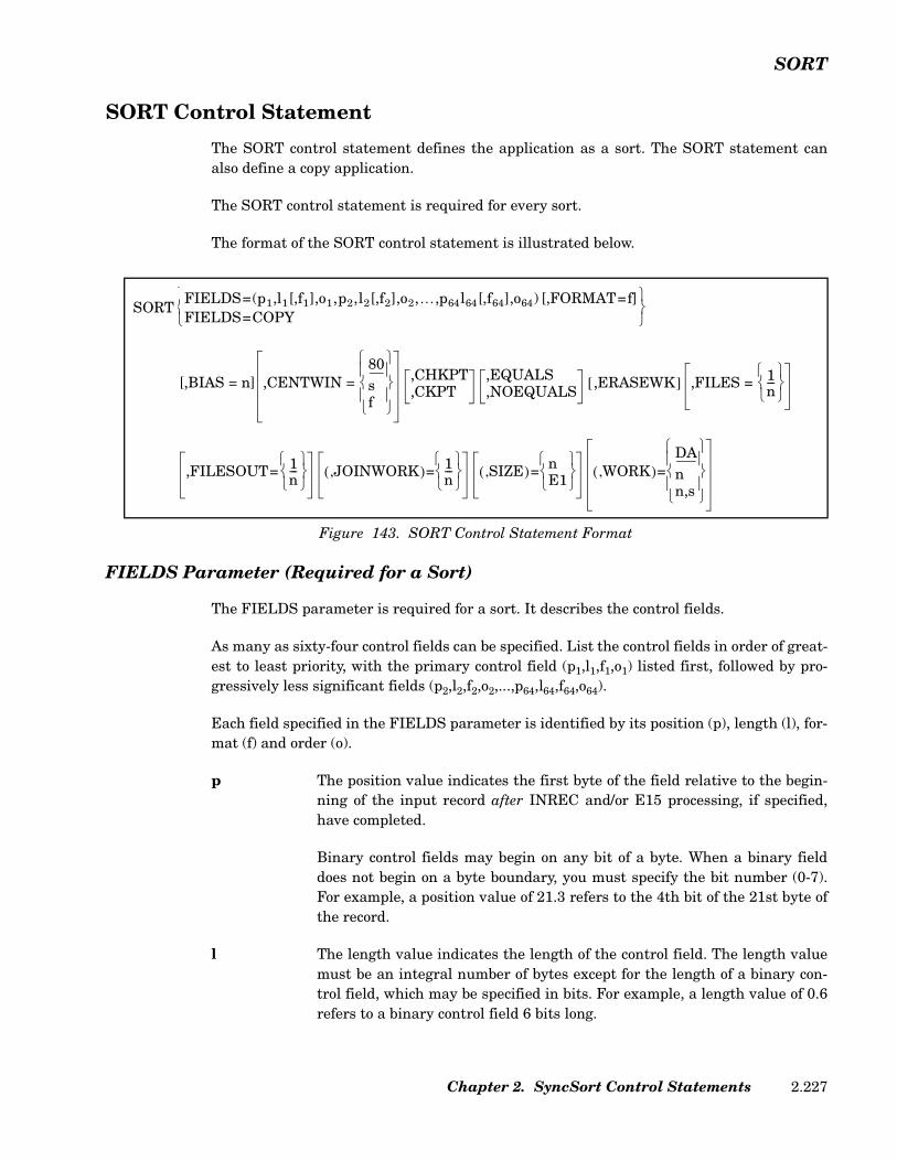
SORT
SORT Control Statement
The SORT control statement defines the application as a sort. The SORT statement canalso define a copy application.
The SORT control statement is required for every sort.
The format of the SORT control statement is illustrated below.
FIELDS Parameter (Required for a Sort)
The FIELDS parameter is required for a sort. It describes the control fields.
As many as sixty-four control fields can be specified. List the control fields in order of great-est to least priority, with the primary control field (p1,l1,f1,o1) listed first, followed by pro-gressively less significant fields (p2,l2,f2,o2,...,p64,l64,f64,o64).
Each field specified in the FIELDS parameter is identified by its position (p), length (l), for-mat (f) and order (o).
p The position value indicates the first byte of the field relative to the begin-ning of the input record after INREC and/or E15 processing, if specified,have completed.
Binary control fields may begin on any bit of a byte. When a binary fielddoes not begin on a byte boundary, you must specify the bit number (0-7).For example, a position value of 21.3 refers to the 4th bit of the 21st byte ofthe record.
l The length value indicates the length of the control field. The length valuemust be an integral number of bytes except for the length of a binary con-trol field, which may be specified in bits. For example, a length value of 0.6refers to a binary control field 6 bits long.
Figure 143. SORT Control Statement Format
SORTFIELDS=(p1,l1[,f1],o1,p2,l2[,f2],o2,…,p64l64[,f64],o64) [,FORMAT=f]FIELDS=COPY
[,BIAS = n] ,CENTWIN = 80sf
,CHKPT,CKPT
,EQUALS,NOEQUALS
,ERASEWK[ ] ,FILES = 1n---
,FILESOUT= 1n---
JOINWORK,( )= 1n---
SIZE,( )= nE1
WORK,( )=DAnn,s
Chapter 2. SyncSort Control Statements 2.227
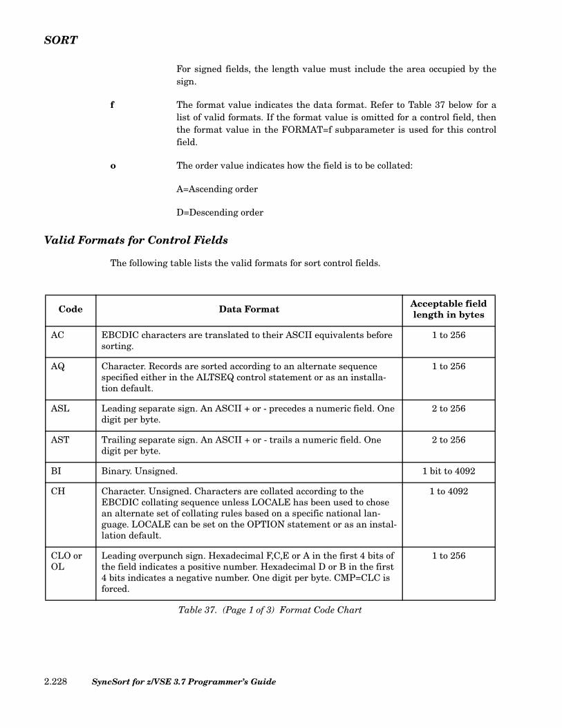
SORT
For signed fields, the length value must include the area occupied by thesign.
f The format value indicates the data format. Refer to Table 37 below for alist of valid formats. If the format value is omitted for a control field, thenthe format value in the FORMAT=f subparameter is used for this controlfield.
o The order value indicates how the field is to be collated:
A=Ascending order
D=Descending order
Valid Formats for Control Fields
The following table lists the valid formats for sort control fields.
Code Data Format Acceptable field length in bytes
AC EBCDIC characters are translated to their ASCII equivalents before sorting.
1 to 256
AQ Character. Records are sorted according to an alternate sequence specified either in the ALTSEQ control statement or as an installa-tion default.
1 to 256
ASL Leading separate sign. An ASCII + or - precedes a numeric field. One digit per byte.
2 to 256
AST Trailing separate sign. An ASCII + or - trails a numeric field. One digit per byte.
2 to 256
BI Binary. Unsigned. 1 bit to 4092
CH Character. Unsigned. Characters are collated according to the EBCDIC collating sequence unless LOCALE has been used to chose an alternate set of collating rules based on a specific national lan-guage. LOCALE can be set on the OPTION statement or as an instal-lation default.
1 to 4092
CLO or OL
Leading overpunch sign. Hexadecimal F,C,E or A in the first 4 bits of the field indicates a positive number. Hexadecimal D or B in the first 4 bits indicates a negative number. One digit per byte. CMP=CLC is forced.
1 to 256
Table 37. (Page 1 of 3) Format Code Chart
SyncSort for z/VSE 3.7 Programmer’s Guide2.228

SORT
CSF or FS
Floating sign format. An optional leading sign may be specified imme-diately to the left of the digits. If the sign is a -, the number is treated as negative. For other characters, the number is treated as positive. Characters to the left of the sign are ignored.
1 to 16
CSL or LS
Leading separate sign. An EBCDIC + or - precedes a numeric field. One digit per byte. CMP=CLC is forced.
2 to 256
CST or TS
Trailing separate sign. An EBCDIC + or - follows a numeric field. One digit per byte. CMP=CLC is forced.
2 to 256
FI Fixed point. Signed. 1 to 256
FL Signed floating point. Normalized. 2 to 16
PD Packed decimal. Signed. 1 to 256
PD0 Packed decimal. 2-8-byte packed decimal data with the first digit and trailing sign ignored. The remaining bytes are treated as packed deci-mal digits. Typically PD0 is used with century window processing and Y2P format; Y2P processes the year, while PD0 processes month and day.
2-8
SFF Signed free format. Decimal digits (0-9) are extracted from right to left to form a number value. A character of - or ) found within the field will cause the value to be treated as a negative number. All other non-decimal digit values in the field are ignored.
1 to 44
UFF Unsigned free format. Decimal digits (0-9) are extracted from right to left to form a number value. All non-decimal digit values in the field are ignored.
1 to 44
Y2B Binary. 2-digit, 1-byte binary year data treated as a 4-digit year by CENTWIN (century window) processing.
1
Y2C Character. 2-digit character year data treated as a 4-digit year by CENTWIN (century window) processing. Processing is identical to Y2Z fields.
2
Y2D Packed decimal. 2-digit, 1-byte packed decimal year data treated as a 4-digit year by CENTWIN (century window) processing.
1
Y2P Packed decimal. 2-digit, 2-byte packed decimal year data. Of the four packed digits contained in the 2 bytes, the first digit and trailing sign are ignored; the two inner digits are treated as a 4-digit year by CENTWIN processing.
2
Code Data Format Acceptable field length in bytes
Table 37. (Page 2 of 3) Format Code Chart
Chapter 2. SyncSort Control Statements 2.229

SORT
The table below describes the valid full-date formats: Y2T, Y2U, Y2V, Y2W, Y2X, and Y2Y.
Y2S Character or zoned decimal. 2-digit, 2-byte valid numeric data treated as a 4-digit year by CENTWIN (century window) processing, as for Y2C and Y2Z. However, certain data is not treated as year data. Data with binary zeros (X'00') or a blank (X'40') in the first byte will be col-lated before valid numeric year data for ascending order (after year data for descending order). Data with all binary ones (X'FF') in the first byte will be collated after valid numeric year data for ascending order (before year data for descending order). Zones are ignored, as for Y2C and Y2Z, except for data where the first byte begins with X'00', X'40' or X'FF'.
2
Y2TY2UY2VY2WY2XY2Y
Full-date formats. Enable sorting or merging a variety of date fields. The formats can process dates ending or starting with year digits and non-date data commonly used with the dates. Two-digit years are interpreted according to the CENTWIN setting. In most cases, for CH, ZD, and PD dates fields the full-date data formats are easier to use than the 2-digit year formats. For a description of these formats see Table 38 on page 2.231.
Y2Z Zoned decimal.2-digit, 2-byte zoned decimal year data treated as a 4-digit year by CENTWIN (century window) processing. The zones are ignored. Processing is identical to Y2C fields.
2
ZD or CTO
Zoned decimal. Trailing overpunch in the first 4 bits of the rightmost byte gives the sign. Hexadecimal F,C,E or A indicates a positive num-ber. Hexadecimal D or B indicates a negative number. One digit per byte. CTO forces CMP=CLC.
1 to 256
Code Data Format Acceptable field length in bytes
Table 37. (Page 3 of 3) Format Code Chart
SyncSort for z/VSE 3.7 Programmer’s Guide2.230
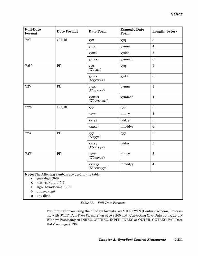
SORT
For information on using the full-date formats, see “CENTWIN (Century Window) Process-ing with SORT: Full-Date Formats” on page 2.240 and “Converting Year Data with CenturyWindow Processing on INREC, OUTREC, INPFIL INREC or OUTFIL OUTREC: Full-DateData” on page 2.196.
Full-Date Format Date Format Date Form Example Date
Form Length (bytes)
Y2T CH, BI yyx yyq 3
yyxx yymm 4
yyxxx yyddd 5
yyxxxx yymmdd 6
Y2U PD yyx(X'yyxs')
yyq 2
yyxxx(X'yyxxxs')
yyddd 3
Y2V PD yyxx(X'0yyxxs')
yymm 3
yyxxxx(X'0yyxxxxs')
yymmdd 4
Y2W CH, BI xyy qyy 3
xxyy mmyy 4
xxxyy dddyy 5
xxxxyy mmddyy 6
Y2X PD xyy(X'xyys')
qyy 2
xxxyy(X'xxxyys')
dddyy 3
Y2Y PD xxyy(X'0xxyys')
mmyy 3
xxxxyy(X'0xxxxyys')
mmddyy 4
Note: The following symbols are used in the table:y year digit (0-9)x non-year digit (0-9)s sign (hexadecimal 0-F)0 unused digitq any digit
Table 38. Full-Date Formats
Chapter 2. SyncSort Control Statements 2.231

SORT
For information on the 2-digit year formats (Y2B, Y2C, Y2D, Y2P, Y2S, and Y2Z) plus therelated data format PD0) see “CENTWIN (Century Window) Processing with SORT: 2-Digit Year Formats” on page 2.235 and “Converting Year Data with Century Window Pro-cessing on INREC, OUTREC, INPFIL INREC or OUTFIL OUTREC: 2-Digit Year Data” onpage 2.194.
Rules for Specifying Control Fields
• The sum of the lengths of all control fields cannot exceed 4092 bytes. When theEQUALS option is specified, the sum of their lengths cannot exceed 4088 bytes.
• Control fields can be in contiguous or noncontiguous locations in the record.
• Remember that the first 4 bytes of variable-length records are reserved for the RecordDescriptor Word, so the first byte of the data portion of the record is byte 5.
Comparing PD and ZD Control Fields
When you specify CMP=CPD, SyncSort may use the Compare Decimal (CP) instructions forthe comparison, which means that ZD data fields are packed first then compared. Thismethod provides performance advantages. However, invalid PD data may cause a DataException abend and program termination. Moreover, the integrity of ZD fields is onlyguaranteed when the fields contain valid ZD data. Since the zone bits (the left most 4 bitsof each byte) are lost during PACKing, UNPKing the field only restores valid ZD data to itsoriginal state. For example, blanks are transferred into ZD zeros and alphabetic characterdata that packs to a valid PD field is converted into valid ZD data.
When CMP=CLC is in effect, SyncSort does not perform data validation and the integrity ofthe output is maintained.
FIELDS=COPY (Required for a Copy)
Use FIELDS=COPY to copy input file(s). Other control statements such asINCLUDE/OMIT, INREC, OUTREC and OUTFIL and user exit routines can be specified inconjunction with a copy application, allowing you to edit and reformat the file(s) withoutsorting them.
The SUM control statement, and the CONVERT parameter of the OUTFIL control state-ment, cannot be specified with FIELDS=COPY.
BIAS Parameter (Optional)
The BIAS parameter is ignored.
SyncSort for z/VSE 3.7 Programmer’s Guide2.232

SORT
CENTWIN Parameter (Optional)
The CENTWIN option defines a sliding or fixed 100-year window that determines the cen-tury to which 2-digit year data belongs when processed by SORT, MERGE, INCLUDE,INREC, OMIT, OUTREC or OUTFIL OUTREC control statements.
There are two types of date data formats: 2-digit year and full-date:
• For details on CENTWIN processing and the 2-digit year data formats with the SORTcontrol statement, see “CENTWIN (Century Window) Processing with SORT: 2-DigitYear Formats” on page 2.235.
For information on using INCLUDE/OMIT with 2-digit year formats, see “SpecifyingStandard Comparisons for Date Fields” on page 2.50.
For information on using the 2-digit year formats for OUTREC processing, see “Con-verting Year Data with Century Window Processing on INREC, OUTREC, INPFILINREC or OUTFIL OUTREC: 2-Digit Year Data” on page 2.194 and “Sample OUTRECControl Statements with CENTWIN Processing: 2-Digit Year Formats” on page 2.213.
• For details on CENTWIN processing and the full-date formats with the SORT controlstatement, see “CENTWIN (Century Window) Processing with SORT: Full-DateFormats” on page 2.240.
For information on using INCLUDE/OMIT with full-date formats, see “Specifying Stan-dard Comparisons for Date Fields” on page 2.50 and “Sample INCLUDE/OMIT ControlStatements with Date Data” on page 2.60.
For information on using the full-date formats for OUTREC processing, see “Convert-ing Year Data with Century Window Processing on INREC, OUTREC, INPFIL INRECor OUTFIL OUTREC: Full-Date Data” on page 2.196.
CKPT/CHKPT Parameter (Optional)
This parameter instructs SyncSort to take a single checkpoint during a sort. SORTWK filesmust be saved in order to restart the sort.
When the CKPT parameter is specified, a SYS000 direct access device or a 2400/3400 seriestape device must be assigned as a checkpoint file. (See Table 45 on page 5.4.) This file musthave standard labels and must be given the filename SORTCKP in the TLBL/DLBL state-ment.
Use standard restart procedures to restart the sort from the checkpoint. Refer to the appro-priate System Management Guide for detailed instructions.
Because taking a checkpoint does cause some performance degradation, specify this param-eter only for sorts that take a long time to complete.
Chapter 2. SyncSort Control Statements 2.233
SORT
EQUALS/NOEQUALS Parameter (Optional)
The EQUALS parameter preserves the original order of records with equal control fields.These records are written in the same order in which they were read. The NOEQUALSparameter specifies that equal-keyed records be written in random order. NOEQUALS isthe default.
When EQUALS is used with the SUM or DUPKEYS control statement, the first of theequally-keyed records is retained with the sum; all other records are deleted after the spec-ified field(s) have been summed.
ERASEWK Parameter (Optional)
The ERASEWK parameter specifies that the contents of the work files opened by the sortare to be erased at the end of the sort. (If an incore sort is performed, no files are erased.)
FILES Parameter (Optional)
The FILES parameter specifies the number of input files to be sorted. The 'n' value may beany number from 1 to 32. If the FILES parameter is not specified, one input file is assumed.Note: When using with the JOIN process, one output file is assumed.
FILESOUT Parameter (Optional)
The FILESOUT parameter specifies the number of output files and is required when creat-ing multiple output files. The 'n' value may be any number from 1 to 32. If the FILESOUTparameter is not specified, one output file is assumed.
JOINWORK Parameter (Optional)
The JOINWORK parameter specifies the maximum number of sortwork files that the joinprocess will use. The ‘n’ value can be any number from 1 to 9. If the join process is used andJOINWORK is not specified, one sortwork file is assumed.
SIZE Parameter (Optional)
The SIZE parameter specifies the total number of records in the input file(s). Replace 'n'with an accurate estimate of the number of records. Because sort performance is notaffected by the SIZE parameter, this parameter is used primarily in conjunction with theANALYZE control statement and the CALCAREA parameter on the OPTION statement.These features determine the amount of sort work space required for a particular applica-tion.
SIZE=E1 can be used to call a Parmexit to override SyncSort defaults for a particular sort.A default can be specified at installation time to call a Parmexit for every sort, providingthe ability to vary certain parameters on the basis of internal criteria, e.g., adjusting
SyncSort for z/VSE 3.7 Programmer’s Guide2.234

SORT
storage requirements according to the time of day. For information on Parmexits, see theSyncSort for z/VSE Installation Guide.
WORK Parameter (Optional)
The WORK parameter specifies the total number of disk files to be used for sort work.
WORK=DA is equivalent to WORK=1; SyncSort will determine whether the sort work fileis a DA file, an SD file or a VSAM-managed SAM file. If multiple extents are used for sortwork files and the JCL statements follow Method 1, in which one DLBL statement precedesall EXTENT statements (see “Chapter 5. Job Control Language and Sample Control State-ment Streams”), WORK=DA must be specified on the SORT control statement.
For an incore sort, specify WORK=0. In any event, SyncSort may perform an incore sort if itis more efficient.
For sequential disk files, replace 'n' with the number of sort work files SyncSort should usefor primary space. Specify WORK=(n,s) only in conjunction with Disk Space Managementpackages. Replace 's' with the number of secondary work packs SyncSort can access withinthe DSM pool, overriding the default set at installation time. For multiple sortwork files,performance can be enhanced by assigning the files to separate devices. See “Setting upDisk Work File Statements” on page 5.5.
Note: If OPTWORK=m has been specified as an installation parameter, with m>n, the sortmay improve performance by using more than ‘n’ work files. See the SyncSort for z/VSEInstallation Guide for details.
CENTWIN (Century Window) Processing with SORT: 2-Digit Year Formats
The CENTWIN run-time or installation option acts on 2-digit year data that spans centu-ries. CENTWIN treats 2-digit year data as a 4-digit year and sequences the data accordingto the 4-digit representation.
For information on using full-date data, see “CENTWIN (Century Window) Processing withSORT: Full-Date Formats” on page 2.240.
CENTWIN generates a century window (for example, 1950 through 2049) that determineswhat century a two-digit year field belongs to. CENTWIN ensures that year data spanningcenturies will be sequenced correctly. Without CENTWIN processing, an ascendingsort/merge would sequence the year '01' before the year '98'. With CENTWIN processing,the '01' field could be recognized as a twenty-first century date (2001) and would thus besequenced after '98' (1998).
For more information on specifying the CENTWIN option, see “CENTWIN Parameter(Optional)” on page 2.119.
Chapter 2. SyncSort Control Statements 2.235

SORT
CENTWIN processing applies to data defined as 2-digit year formats: Y2B, Y2C, Y2D, Y2P,Y2S, and Y2Z. These data formats enable SyncSort to process 2-digit year fields as 4-digityears. A related data format, PD0, can be used to process the month and day portions ofpacked decimal date fields. To correctly specify date fields for CENTWIN SORT/MERGEprocessing, you should be familiar with the CENTWIN-related data formats.
The following describes each of the date formats and provides example SORT control state-ments:
Note: For simplicity, the sample date fields in the example SORT statements below beginat byte 20. Also note that date data is always sorted in the following order: year (yy), month(mm), day (dd).
• Y2B
This format is used to sequence 2-digit, 1-byte binary year data with CENTWIN pro-cessing. The binary values are converted to decimal, and the two low order digits areused as year data. Thus, while binary and decimal values range from 00 to 255, yearvalues range from 00 to 99. The relationship between binary, decimal and year values isshown in the following table:
• Y2C and Y2Z
These formats represent 2-digit, 2-byte year data in either character (Y2C) or zoneddecimal (Y2Z) format. Either Y2C and Y2Z formats can be used with data of the form
X'xyxy'
where y is a hexadecimal year digit 0-9 and x is hexadecimal 0 through F. Y2C and Y2Zignore the x digits, leaving yy, the 2-digit unsigned year representation.
Suppose you have a character or zoned decimal date field mmddyy that begins at byte20. You can use either Y2C or Y2Z to process the yy field. As the following example indi-cates, you could specify three sort keys to correctly sort this date:
Binary Value Decimal Value Year Value
X'00' to X'63' 00 to 99 00-99
X'64' to X'C7' 100 to 199 00-99
X'C8' to X'FF' 200 to 255 00-55
Table 39. Possible Values Representing Year Data with Y2B
SyncSort for z/VSE 3.7 Programmer’s Guide2.236

SORT
The yy field (24,2) will be processed according to the century window setting. For exam-ple, if CENTWIN=1945, the field yy=45 will be sequenced as if it were 1945, and yy=44would be sequenced as if it were 2044. Thus, for an ascending sort, '44' would follow'45'.
• Y2D
This format is used to sort 2-digit, 1-byte packed decimal year data with CENTWINprocessing. Use Y2D to extract the year data (yy) from packed decimal date fields.
For example, consider a 3-byte packed decimal data field defined as
yyddds
This field has the year (yy) in the first byte and the day (ddd) in bytes 2 and 3. Thepacked decimal sign (s) would be in the last digit (half byte) of the third byte. To sortthis date field, which begins at byte 20, with 4-digit years processing, use the followingSORT control statement:
• Y2P
This format is used to sort or merge 2-digit, 2-byte packed decimal year data withCENTWIN processing. Use Y2P to extract the year data (yy) from packed decimal datefields spanning two bytes. For example, a packed decimal date of the form yymmddwould be stored as four bytes:
yymmdd=X'0yymmddC'
where the trailing C (sometimes F) is a positive sign and the leading 0 pads the field onthe left to make an even number of digits.
Notice that the components of the date span bytes:
0y ym md dC
SORT FIELDS=(24,2,Y2C,A, * sort yy field as 4-digit year20,2,CH,A, * sort mm field22,2,CH,A) * sort dd field
Figure 144. Sample SORT Control Statement using Y2C
SORT FIELDS=(20,1,Y2D,A, * sorts 2-digit year (yy) as 4-digit year21,2,PD,A) * sorts ddds as 3 digits (ddd)
Figure 145. Sample SORT Control Statement using Y2D
Chapter 2. SyncSort Control Statements 2.237
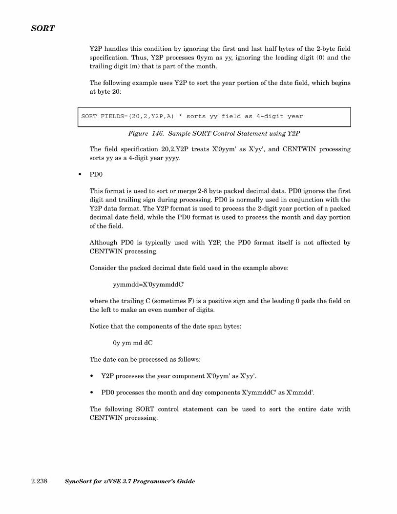
SORT
Y2P handles this condition by ignoring the first and last half bytes of the 2-byte fieldspecification. Thus, Y2P processes 0yym as yy, ignoring the leading digit (0) and thetrailing digit (m) that is part of the month.
The following example uses Y2P to sort the year portion of the date field, which beginsat byte 20:
The field specification 20,2,Y2P treats X'0yym' as X'yy', and CENTWIN processingsorts yy as a 4-digit year yyyy.
• PD0
This format is used to sort or merge 2-8 byte packed decimal data. PD0 ignores the firstdigit and trailing sign during processing. PD0 is normally used in conjunction with theY2P data format. The Y2P format is used to process the 2-digit year portion of a packeddecimal date field, while the PD0 format is used to process the month and day portionof the field.
Although PD0 is typically used with Y2P, the PD0 format itself is not affected byCENTWIN processing.
Consider the packed decimal date field used in the example above:
yymmdd=X'0yymmddC'
where the trailing C (sometimes F) is a positive sign and the leading 0 pads the field onthe left to make an even number of digits.
Notice that the components of the date span bytes:
0y ym md dC
The date can be processed as follows:
• Y2P processes the year component X'0yym' as X'yy'.
• PD0 processes the month and day components X'ymmddC' as X'mmdd'.
The following SORT control statement can be used to sort the entire date withCENTWIN processing:
SORT FIELDS=(20,2,Y2P,A) * sorts yy field as 4-digit year
Figure 146. Sample SORT Control Statement using Y2P
SyncSort for z/VSE 3.7 Programmer’s Guide2.238

SORT
• Y2S
This format is used to sequence 2-digit, 2-byte character or zoned decimal data. TheY2S format is identical to Y2C and Y2Z for valid numeric data, but Y2S treats datathat begins with X'00', X'40' or X'FF' as non-year data. Thus, the Y2S format can distin-guish records that have non-year data in the first byte of the year field, allowing suchrecords to be sorted differently from other records.
Y2S treats non-year data as follows:
• Data with binary zeros (X'00') or a blank (X'40') in the first byte will not havecentury window processing applied to it. Instead, such data will be collated insequence, before valid numeric year data for ascending order or after the yeardata for descending order.
• Data with all binary ones (X'FF') in the first byte will also not have century windowprocessing applied to it. Instead, such data will be collated after valid year numericdata for ascending order or before the year data for descending order. Zones areignored, as for Y2C and Y2Z, except for data where the first byte begins with X'00',X'40' or X'FF'.
As an example, suppose you want to preserve the input order of header and trailer recordsat the start or end of the file, and your header/trailer records are identified by binary zeros(X'00'), a blank (X'40') or binary ones (X'FF') in the first byte of the date field.
The Y2S format allows CENTWIN to identify the header/trailer records and treat them dif-ferently from other records. Presuming the year data begins in column 20, you would usethe following sort key specification:
The yy field (20,2) will be processed according to the century window setting. ForCENTWIN=1945, data with header and trailer records would be sorted as follows:
SORTIN Input Record Order after SortingX'F9F6' X'0000'
X'4001' X'4000'
X'F4F4' X'4001'
SORT FIELDS=(20,2,Y2P,A, * Treats X'0yym' as X'yy'; sorts yy as yyyy21,3,PD0,A) * Treats X'ymmddC' as X'mmdd'
Figure 147. Sample SORT Control Statement using PD0
SORT FIELDS=(20,2,Y2S,A) * Sorts yy field as 4-digit year
Figure 148. Sample SORT Control Statement using Y2S
Chapter 2. SyncSort Control Statements 2.239

SORT
X'4000' X'F5F1'
X'0000' X'F9F6'
X'F5F1' X'F4F4'
X'FF03' X'FF03'
Note that if the above data were sorted as Y2C or Y2Z format, the output order would bedifferent because the records starting with X'00', X'40' and X'FF' would be interpreted asnumeric years. For example, suppose the fields in the above list were defined as Y2Z andsorted with EQUALS:
The data would be processed as follows:
SORTIN Input Record Order after SortingX'F9F6' X'F5F1'
X'4001' X'F9F6'
X'F4F4' X'FF03' (invalid numeric data)
X'4000' X'4000' (invalid numeric data)
X'0000' X'0000' (invalid numeric data)
X'F5F1' X'4001' (invalid numeric data)
X'FF03' X'F4F4'
The header and trailer records are sequenced as year data according to the CENTWIN set-ting (CENTWIN=1945), and the header and trailer records lose their position at the startand end of the file.
CENTWIN (Century Window) Processing with SORT: Full-Date Formats
SyncSort’s full-date formats enable you to sort or merge a variety of date fields. The full-date formats are Y2T, Y2U, Y2V, Y2W, Y2X and Y2Y. These date formats can process datesending or starting with year digits:
• x...xyy (for example: qyy, mmyy, dddyy, or mmddyy)
• yyx...x (for example: yyq, yymm, yyddd, or yymmdd)
The full-date formats also process non-date data commonly used with the dates. SyncSortinterprets two-digit years (yy) according to the century window specified by the CENTWINoption. CENTWIN processing does not apply to non-date data.
In most cases, for CH, ZD, and PD date fields the full-date formats are easier to use thanthe 2-digit year formats. The 2-digit formats can be more difficult because you must dividethe date into its components. This requires care, particularly for PD dates, where date com-ponents (q, dd, mm, or yy) may span bytes or occupy only part of a byte. The full-date for-
SORT FIELDS=(20,2,Y2Z,A),EQUALS
Figure 149. Sample SORT Control Statement using Y2Z
SyncSort for z/VSE 3.7 Programmer’s Guide2.240
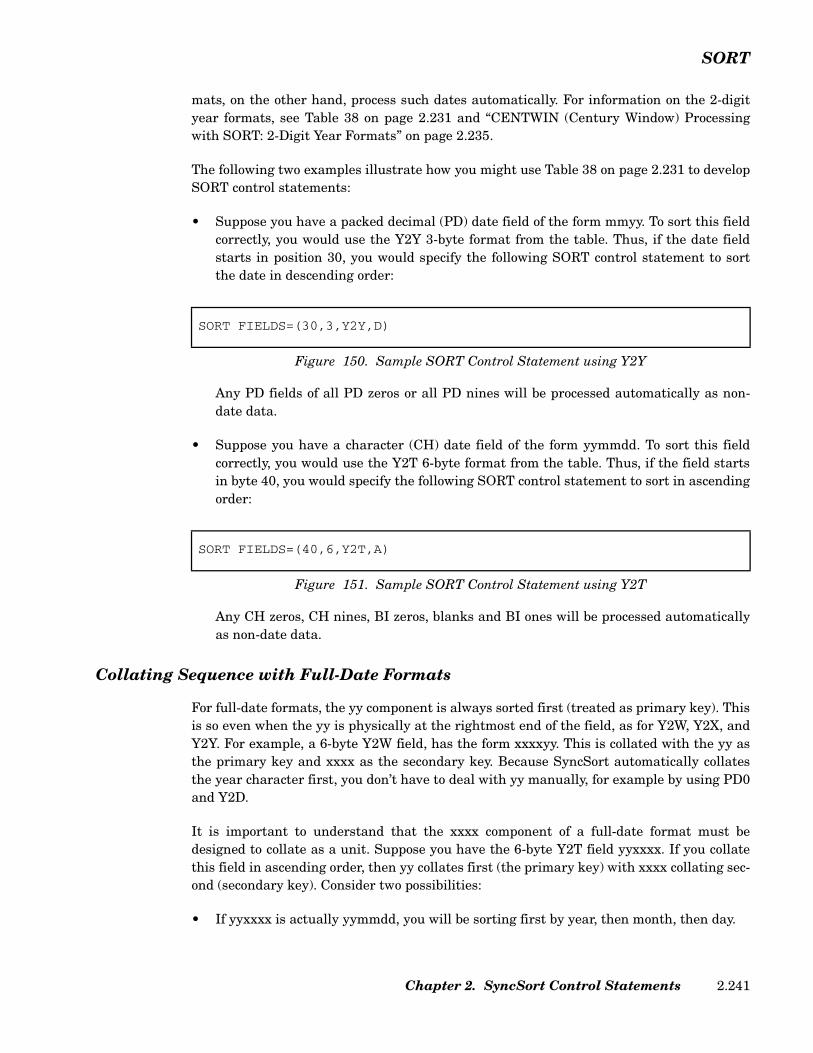
SORT
mats, on the other hand, process such dates automatically. For information on the 2-digityear formats, see Table 38 on page 2.231 and “CENTWIN (Century Window) Processingwith SORT: 2-Digit Year Formats” on page 2.235.
The following two examples illustrate how you might use Table 38 on page 2.231 to developSORT control statements:
• Suppose you have a packed decimal (PD) date field of the form mmyy. To sort this fieldcorrectly, you would use the Y2Y 3-byte format from the table. Thus, if the date fieldstarts in position 30, you would specify the following SORT control statement to sortthe date in descending order:
Any PD fields of all PD zeros or all PD nines will be processed automatically as non-date data.
• Suppose you have a character (CH) date field of the form yymmdd. To sort this fieldcorrectly, you would use the Y2T 6-byte format from the table. Thus, if the field startsin byte 40, you would specify the following SORT control statement to sort in ascendingorder:
Any CH zeros, CH nines, BI zeros, blanks and BI ones will be processed automaticallyas non-date data.
Collating Sequence with Full-Date Formats
For full-date formats, the yy component is always sorted first (treated as primary key). Thisis so even when the yy is physically at the rightmost end of the field, as for Y2W, Y2X, andY2Y. For example, a 6-byte Y2W field, has the form xxxxyy. This is collated with the yy asthe primary key and xxxx as the secondary key. Because SyncSort automatically collatesthe year character first, you don’t have to deal with yy manually, for example by using PD0and Y2D.
It is important to understand that the xxxx component of a full-date format must bedesigned to collate as a unit. Suppose you have the 6-byte Y2T field yyxxxx. If you collatethis field in ascending order, then yy collates first (the primary key) with xxxx collating sec-ond (secondary key). Consider two possibilities:
• If yyxxxx is actually yymmdd, you will be sorting first by year, then month, then day.
SORT FIELDS=(30,3,Y2Y,D)
Figure 150. Sample SORT Control Statement using Y2Y
SORT FIELDS=(40,6,Y2T,A)
Figure 151. Sample SORT Control Statement using Y2T
Chapter 2. SyncSort Control Statements 2.241

SORT
• If yyxxxx is actually yyddmm, you will be sorting by year, then day, then month. Inmost cases, sorting in this way would not be what you intended.
To correctly collate a date, the date components must be in an order suitable for collating.For example mmddyy and yymmdd will collate correctly, but ddmmyy or yyddmm will not.For date forms that will not collate correctly, you must use one of the 2-digit year formats(Y2B, Y2C, Y2D, Y2P, Y2S, and Y2Z).
Table 38 on page 2.231 indicates the full-date formats that can be used with character(CH), binary (BI) or packed decimal (PD) data. Note the recognized non-date values:
• Character or binary (Y2T and Y2W full-date formats)C'0...0' (CH zeros)C'9...9' (CH nines)Z'0...0' (ZD zeros)Z'9...9 (ZD nines)X'00...00' (BI zeros)X'40...40' (blanks)X'FF...FF' (BI ones)
• Packed (Y2U, Y2V, Y2X and Y2Y full-date formats)P'0...0' (PD zeros)P'9...9' (PD nines)
The following table shows the order for ascending collation when using full-date formatswith the CENTWIN option:
For a descending sort, the collation order is reversed.
Other date formats (non-full-date), with the exception of Y2S, do not process non-date data;their sort sequence for ascending sorts is simply lower century dates then higher centurydates.
Full-Date Format Data Format Ascending Sort Sequence
Y2TY2W
CH, BI BI zerosBlanksCH/ZD zerosLower century dates (e.g. 1980)Higher century dates (e.g. 2010)CH/ZD ninesBI ones
Y2UY2VY2XY2Y
PD PD zerosLower century dates (e.g. 1980)Higher century dates (e.g. 2010)PD nines
Table 40. Collation Order for Full-Date Formats
SyncSort for z/VSE 3.7 Programmer’s Guide2.242

SORT
Sample SORT Control Statements with CENTWIN: Full-Date Formats
The following examples illustrate the use of full-date formats with the SORT control state-ment.
• Example 1 (Y2W)
The following SORT control statement sorts a C'mmddyy' date field in ascending order,with the previously set fixed century window 1984-2083:
Table 38 on page 2.231 indicates that the 6-byte Y2W form is appropriate for a CHinput field of the form xxxxyy. As shown in the following table, the output will be col-lated as C'yyyymmdd', with the non-date data (zeros) appearing correctly at the begin-ning of the sorted output.
• Example 2 (Y2T)
The following SORT control statement sorts a Z'yyddd' date field in descending order,with the previously set fixed century window 1921-2020:
Table 38 on page 2.231 indicates that the 5-byte Y2T form is appropriate for a ZD inputfield of the form yyddd. As shown in the following table, the output will be collated as
SORT FIELDS=(10,6,Y2W,A) * Sort C'mmddyy' in ascending order,* with Y2W and previously set* century window 1984-2083.
Figure 152. Sample SORT Control Statement using Y2W
SORTIN Input (mmddyy)
Record Order after Sorting (mmddyy)
Actual Date after Sorting (yyyy/mm/dd)
021783 000000 non-date data
092206 070484 1984/07/04
081395 081395 1995/08/13
110210 092206 2006/09/22
000000 110210 2010/11/02
070484 043060 2060/04/30
043060 021783 2083/02/17
SORT FIELDS=(20,5,Y2T,D) * Sort Z'yyddd' in descending order* with Y2T and previously set* century window 1921-2020.
Figure 153. Sample SORT Control Statement using Y2T
Chapter 2. SyncSort Control Statements 2.243

SORT
Z'yyyyddd', with non-date data (nines and zeros) appearing correctly at the beginningand end of the sorted output.
• Example 3 (Y2Y)
The following SORT control statement sorts a P'mmddyy' (X'0mmddyys') in ascendingorder, with the previously set fixed century window 1921-2020:
Table 38 on page 2.231 indicates that the 4-byte Y2Y field is appropriate for a PD inputfield of the form xxxxyy. As shown in the following table, the output will be collated asP'yyyymmdd', with the non-date data (zeros and nines) appearing correctly at thebeginning and end of the sorted output. Note that the first two columns are in hexadec-imal.
SORTIN Input (mmddd)
Record Order after Sorting (mmddd)
Actual Date after Sorting (yyyy/ddd)
00000 99999 non-date data
50237 20153 2020/153
99999 20047 2020/047
20047 01223 2001/223
94001 94001 1994/001
01223 50237 1950/237
20153 21148 1921/148
21148 00000 non-date data
SORT FIELDS=(26,4,Y2Y,A) * Sort P'mmddyy' in ascending order,* with Y2Y and previously set* century window 1921-2020.
Figure 154. Sample SORT Control Statement using Y2Y
SORTIN Input (mmddyy)
Record Order after Sorting (mmddyy)
Actual Date after Sorting (yyyy/mm/dd)
0999999C 0000000C non-date data 0102250C 0080321C 1921/08/03 0032120C 0102250C 1950/10/22 0010194C 0010194C 1994/01/01 0000000C 0111501C 2001/11/15 0111501C 0032120C 2020/03/21 0080321C 0999999C non-date data
SyncSort for z/VSE 3.7 Programmer’s Guide2.244
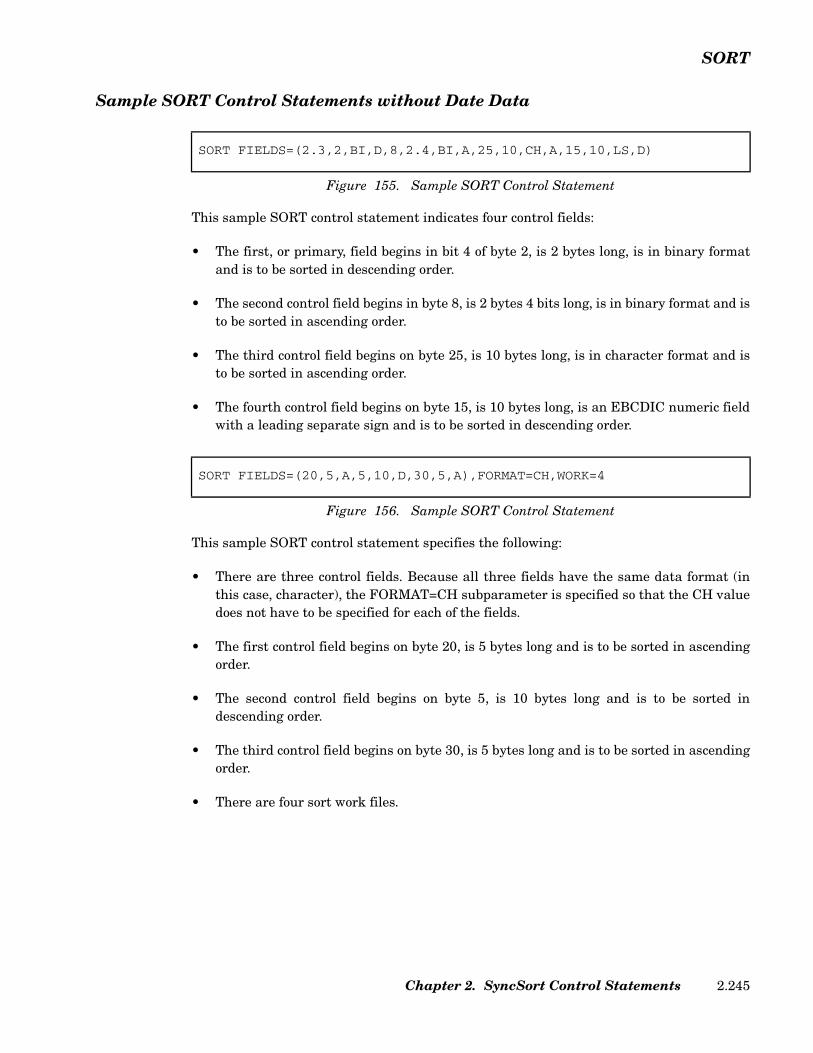
SORT
Sample SORT Control Statements without Date Data
This sample SORT control statement indicates four control fields:
• The first, or primary, field begins in bit 4 of byte 2, is 2 bytes long, is in binary formatand is to be sorted in descending order.
• The second control field begins in byte 8, is 2 bytes 4 bits long, is in binary format and isto be sorted in ascending order.
• The third control field begins on byte 25, is 10 bytes long, is in character format and isto be sorted in ascending order.
• The fourth control field begins on byte 15, is 10 bytes long, is an EBCDIC numeric fieldwith a leading separate sign and is to be sorted in descending order.
This sample SORT control statement specifies the following:
• There are three control fields. Because all three fields have the same data format (inthis case, character), the FORMAT=CH subparameter is specified so that the CH valuedoes not have to be specified for each of the fields.
• The first control field begins on byte 20, is 5 bytes long and is to be sorted in ascendingorder.
• The second control field begins on byte 5, is 10 bytes long and is to be sorted indescending order.
• The third control field begins on byte 30, is 5 bytes long and is to be sorted in ascendingorder.
• There are four sort work files.
SORT FIELDS=(2.3,2,BI,D,8,2.4,BI,A,25,10,CH,A,15,10,LS,D)
Figure 155. Sample SORT Control Statement
SORT FIELDS=(20,5,A,5,10,D,30,5,A),FORMAT=CH,WORK=4
Figure 156. Sample SORT Control Statement
Chapter 2. SyncSort Control Statements 2.245

SUM
SUM Control Statement
The SUM control statement deletes records with equal control fields and optionally sumsspecified numeric fields on those records. Equal keyed records are processed pair by pair. Ifnumeric fields are to be summed, the data in the sum fields is added, the sum is placed inone of the records, and the other record is deleted. Provided arithmetic overflow does notoccur, the SUM statement produces only one record per sort key in the output data set.
The SUM control statement cannot be used when FIELDS=COPY is specified on the SORTor MERGE control statement, or when FIELDS=COMPARE is specified on the MERGEcontrol statement.
The format of the SUM control statement is illustrated below.
FIELDS Parameter (Required)
The FIELDS parameter defines the numeric fields to be summed when the control fields oftwo or more records are equal. Specify FIELDS=NONE or FIELDS=(NONE) to reduce thesorted data to one record per sort key without summing any numeric fields.
Each field specified in the FIELDS parameter is identified by its position (p), length (l) andformat (f).
p The position value indicates the first byte of the field relative to thebeginning of the input record after INREC and/or E15 processing, ifspecified, have completed. The field must begin on a byte boundary.
l The length value indicates the length of the field. The length mustbe an integral number of bytes. Refer to Table 41 on page 2.247 forthe permissible lengths.
f The format value indicates the data format. Fields with BI, FI, FL,PD and ZD formats can be summed. If all the sum fields have thesame format, you can specify the format value once by using theFORMAT=f subparameter.
Figure 157. SUM Control Statement Format
SUM FIELDS= (p1,l1[,f1][,p2,l2[,f2]]…)[,FORMAT=f ]FIELDS=NONE
[,XSUM]
SyncSort for z/VSE 3.7 Programmer’s Guide2.246
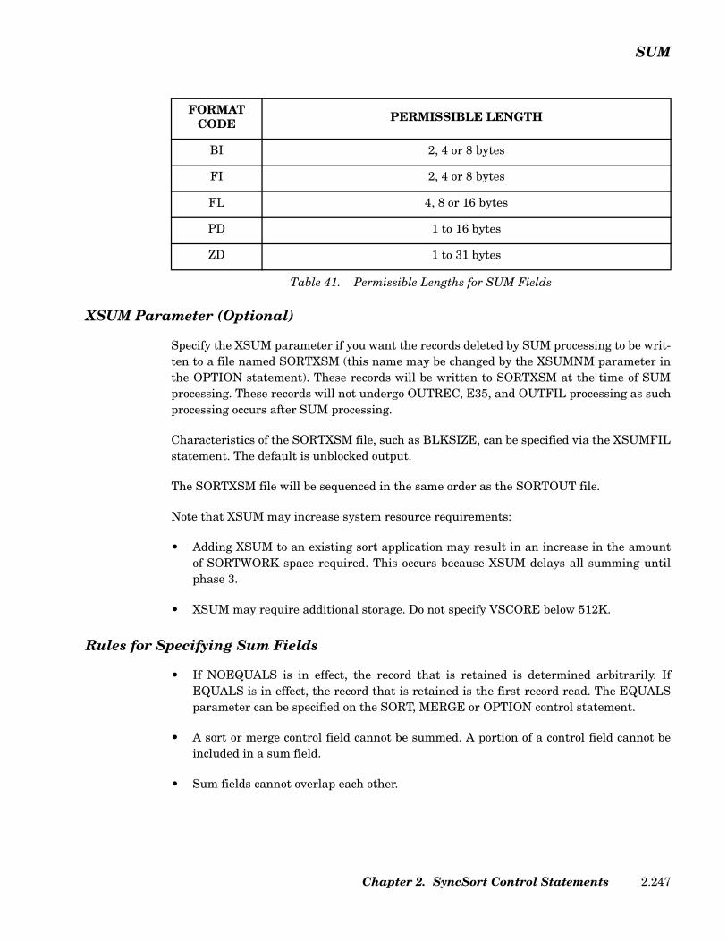
SUM
XSUM Parameter (Optional)
Specify the XSUM parameter if you want the records deleted by SUM processing to be writ-ten to a file named SORTXSM (this name may be changed by the XSUMNM parameter inthe OPTION statement). These records will be written to SORTXSM at the time of SUMprocessing. These records will not undergo OUTREC, E35, and OUTFIL processing as suchprocessing occurs after SUM processing.
Characteristics of the SORTXSM file, such as BLKSIZE, can be specified via the XSUMFILstatement. The default is unblocked output.
The SORTXSM file will be sequenced in the same order as the SORTOUT file.
Note that XSUM may increase system resource requirements:
• Adding XSUM to an existing sort application may result in an increase in the amountof SORTWORK space required. This occurs because XSUM delays all summing untilphase 3.
• XSUM may require additional storage. Do not specify VSCORE below 512K.
Rules for Specifying Sum Fields
• If NOEQUALS is in effect, the record that is retained is determined arbitrarily. IfEQUALS is in effect, the record that is retained is the first record read. The EQUALSparameter can be specified on the SORT, MERGE or OPTION control statement.
• A sort or merge control field cannot be summed. A portion of a control field cannot beincluded in a sum field.
• Sum fields cannot overlap each other.
FORMAT CODE PERMISSIBLE LENGTH
BI 2, 4 or 8 bytes
FI 2, 4 or 8 bytes
FL 4, 8 or 16 bytes
PD 1 to 16 bytes
ZD 1 to 31 bytes
Table 41. Permissible Lengths for SUM Fields
Chapter 2. SyncSort Control Statements 2.247

SUM
• Non-sum fields remain unchanged and are retained from the record that contains thesum.
• If arithmetic overflow occurs during the summing of two records, those records are notsummed and neither record is deleted. However, the sum process continues so thatsubsequent pairs of records with equal control fields can be summed, provided they donot cause overflow. To avoid arithmetic overflow, use the INREC statement to insertbinary zeros, or X'F0’s if the field is in ZD format, immediately before the sum field.
• Remember that the first 4 bytes of variable-length records are reserved for the RecordDescriptor Word, so the first byte of the data portion of the record is byte 5.
Sample SUM Control Statements
The following SUM statement deletes equal-keyed records without summing numericfields.
Records with equal control fields will be deleted so that only one record is retained.
The following SUM statement sums two numeric fields on records with equal control fields.
When the control fields are equal, this SUM statement sums the numeric data in the fieldsbeginning in bytes 20 and 32. Because both fields are in packed decimal format, the FOR-MAT=PD subparameter is used so that the PD value does not have to be specified for eachfield.
Comprehensive examples illustrating the SUM control statement are provided in “Chapter4. How to Use SyncSort Data Utility Features”.
SUM FIELDS=NONE
Figure 158. Sample SUM Control Statement
SUM FIELDS=(20,4,32,4),FORMAT=PD
Figure 159. Sample SUM Control Statement
SyncSort for z/VSE 3.7 Programmer’s Guide2.248

XDUPFIL
XDUPFIL Control Statement
The XDUPFIL control statement describes the XDUP (records deleted by DUPKEYS pro-cessing) output file. It is required when XDUP is specified in the DUPKEYS statement andyou want any of the following:
• To specify an output blocksize
• VSAM output
• To reformat output records
• To use other parameters available in the XDUPFIL statement
The format and the parameters for the XDUPFIL statement are identical to the OUTFILstatement, except that the following parameters are not supported:
• EXIT
• FILES=
• FNAMES=
Refer to the “OUTFIL Control Statement” on page 2.141 for an explanation of the parame-ters that may be specified in an XDUPFIL statement.
Chapter 2. SyncSort Control Statements 2.249
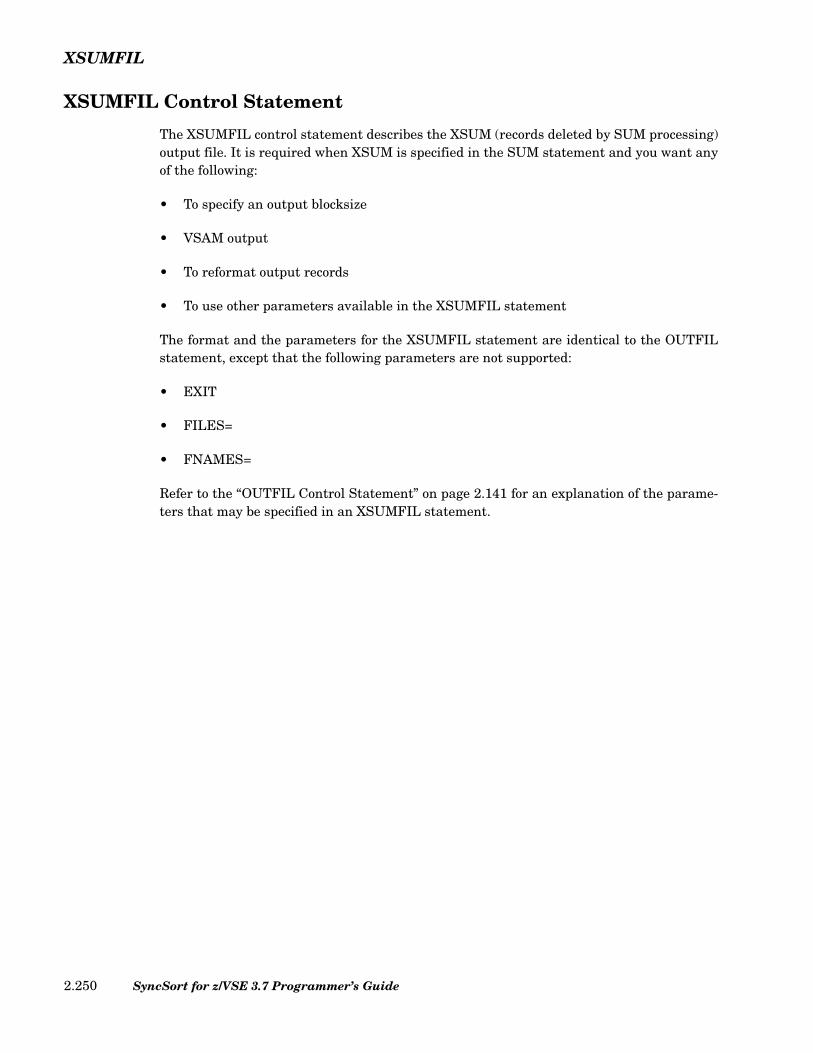
XSUMFIL
XSUMFIL Control Statement
The XSUMFIL control statement describes the XSUM (records deleted by SUM processing)output file. It is required when XSUM is specified in the SUM statement and you want anyof the following:
• To specify an output blocksize
• VSAM output
• To reformat output records
• To use other parameters available in the XSUMFIL statement
The format and the parameters for the XSUMFIL statement are identical to the OUTFILstatement, except that the following parameters are not supported:
• EXIT
• FILES=
• FNAMES=
Refer to the “OUTFIL Control Statement” on page 2.141 for an explanation of the parame-ters that may be specified in an XSUMFIL statement.
SyncSort for z/VSE 3.7 Programmer’s Guide2.250
Chapter 3. Using the SyncSort Dictionary Feature
The Dictionary Feature
The SyncSort Dictionary Feature allows you to create symbolic ‘dictionary_names’ for fre-quently used fields or constants and use these dictionary_names in SyncSort control state-ments.
Using the Dictionary Feature has many benefits:
• Easier coding of sort control statements speeds development of sort applications andimproves accuracy.
• More readable and understandable sort control statements facilitate debugging andadaptation to changes in the future.
• Reduction or elimination of changes to sort control statements when record layouts oruser parameters change saves time and reduces errors.
To use the SyncSort Dictionary Feature, do the following:
• Build a dictionary using the dictionary statements. A dictionary statement creates adictionary_name and associates it with a field specification (position, length, format) ora constant value.
• Activate the Dictionary Feature using the SYMNAMES parameter on the OPTIONcontrol statement. This parameter tells SyncSort the name and location of thedictionary to use.
Chapter 3. Using the SyncSort Dictionary Feature 3.1
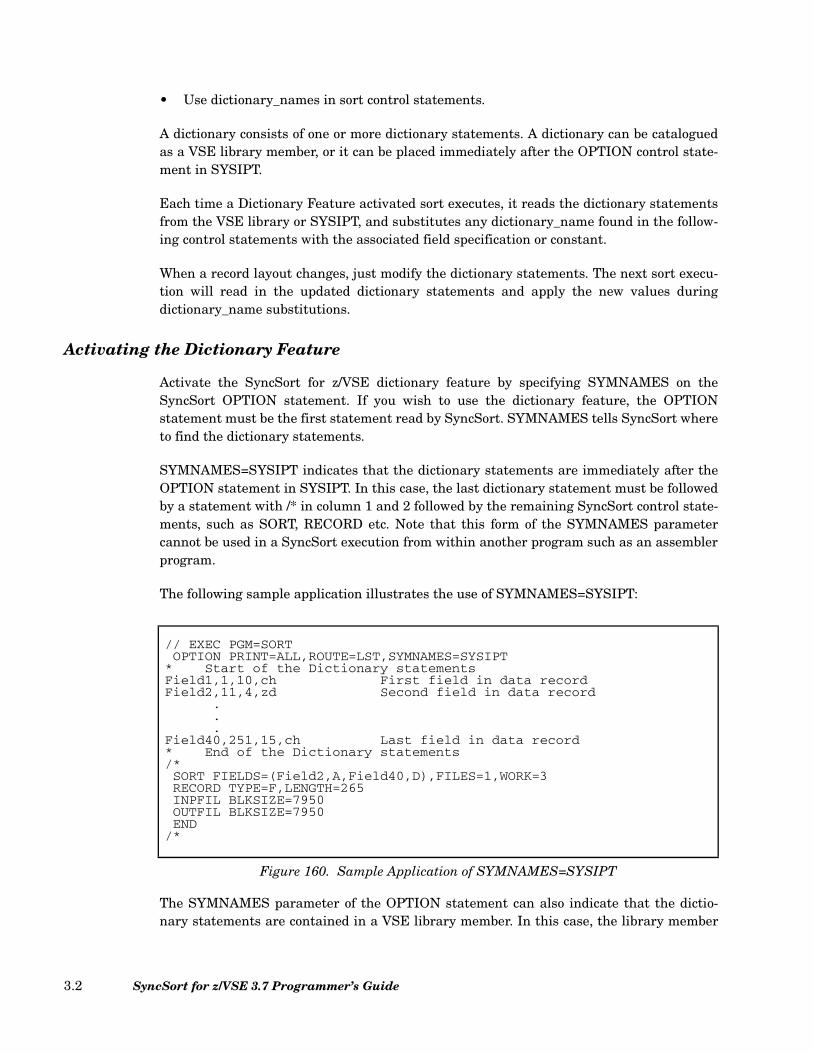
• Use dictionary_names in sort control statements.
A dictionary consists of one or more dictionary statements. A dictionary can be cataloguedas a VSE library member, or it can be placed immediately after the OPTION control state-ment in SYSIPT.
Each time a Dictionary Feature activated sort executes, it reads the dictionary statementsfrom the VSE library or SYSIPT, and substitutes any dictionary_name found in the follow-ing control statements with the associated field specification or constant.
When a record layout changes, just modify the dictionary statements. The next sort execu-tion will read in the updated dictionary statements and apply the new values duringdictionary_name substitutions.
Activating the Dictionary Feature
Activate the SyncSort for z/VSE dictionary feature by specifying SYMNAMES on theSyncSort OPTION statement. If you wish to use the dictionary feature, the OPTIONstatement must be the first statement read by SyncSort. SYMNAMES tells SyncSort whereto find the dictionary statements.
SYMNAMES=SYSIPT indicates that the dictionary statements are immediately after theOPTION statement in SYSIPT. In this case, the last dictionary statement must be followedby a statement with /* in column 1 and 2 followed by the remaining SyncSort control state-ments, such as SORT, RECORD etc. Note that this form of the SYMNAMES parametercannot be used in a SyncSort execution from within another program such as an assemblerprogram.
The following sample application illustrates the use of SYMNAMES=SYSIPT:
The SYMNAMES parameter of the OPTION statement can also indicate that the dictio-nary statements are contained in a VSE library member. In this case, the library member
// EXEC PGM=SORTOPTION PRINT=ALL,ROUTE=LST,SYMNAMES=SYSIPT
* Start of the Dictionary statementsField1,1,10,ch First field in data recordField2,11,4,zd Second field in data record
.
.
.Field40,251,15,ch Last field in data record* End of the Dictionary statements/*SORT FIELDS=(Field2,A,Field40,D),FILES=1,WORK=3RECORD TYPE=F,LENGTH=265INPFIL BLKSIZE=7950OUTFIL BLKSIZE=7950END
/*
Figure 160. Sample Application of SYMNAMES=SYSIPT
SyncSort for z/VSE 3.7 Programmer’s Guide3.2

must consist of fixed-length, 80 byte records. When SYMNAMES is used to specify a VSElibrary member, SYMNAMES has two possible formats.
• SYMNAMES=library.sublib.member.type tells SyncSort all the information that itneeds to find the dictionary statements. In this case, SyncSort will read the dictionarystatements from the library member: member.type in the VSE library: library.sublib,as shown in the following example:
The library member DATAREC.CARDS in the above example might contain dictionarystatements such as the following:
• SYMNAMES=member.type specifies only the member.type information. In this case,SyncSort will read the data dictionary statements from library member member.typein the first VSE library that SyncSort finds contains member.type. The libraries thatSyncSort searches for member.type are specified by the SYMNLIB installation defaultor by the SYMNLIB parameter of the OPTION statement.
The SYMNLIB parameter specifies a list of 1 to 14 VSE libraries that should besearched for the library member specified by SYMNAMES=member.type. The followingshows the format for SYMNLIB:
SyncSort will attempt to find the member specified by SYMNAMES=member.type firstin lib1.sublib1. If it is not found, SyncSort checks each lib.sublib in turn.
// EXEC PGM=SORTOPTION PRINT=ALL,ROUTE=LST,SYMNAMES=(MAINLIB.MYSUB.DATAREC.CARDS)SORT FIELDS=(Field2,A,Field40,D),FILES=1,WORK=3RECORD TYPE=F,LENGTH=265INPFIL BLKSIZE=7950OUTFIL BLKSIZE=7950END
/*
Figure 161. Sample SYMNAMES=library.sublib.member.type
Field1,1,10,ch First field in data recordField2,11,4,zd Second field in data record
.
.
.Field40,251,15,ch Last field in data record
Figure 162. Sample Dictionary Statements
SYMNLIB=(lib1.sublib1 [,lib2.sublib2]...[,lib14.sublib14])
Figure 163. SYMNLIB Format
Chapter 3. Using the SyncSort Dictionary Feature 3.3

The following sample application uses SYMNAMES with SYMNLIB:
The library member DATAREC.CARDS in the above example might contain dictionarystatements such as the following:
An additional statement is allowed within dictionary statements to enable embedding orconcatenating dictionary sources. This is the SYMNAMES statement. The SYMNAMESstatement has the same function as the SYMNAMES parameter on the OPTION state-ment. Either SYMNAMES=library.sublib.member.type or SYMNAMES=member.type maybe specified. (SYMNAMES=SYSIPT may not be specified on the SYMNAMES statement.)The SYMNAMES statement may start with 0, 1 or more blanks followed by SYMNAMES=and the required library member information. Continuation of the SYMNAMES statementis not allowed. The maximum nesting level allowed using the SYMNAMES statement is 15.
// EXEC PGM=SORT
OPTION SYMNAMES=DATAREC.CARDS,SYMNLIB=(TESTLIB.TSTSUB.MAINLIB.MYSUB)
SORT FIELDS=(Field2,A,Field40,D),FILES=1,WORK=3
RECORD TYPE=F,LENGTH=265
INPFIL BLKSIZE=7950
OUTFIL BLKSIZE=7950
END
/*
Figure 164. Sample Application of SYMNAMES with SYMNLIB
Field1,1,10,ch First field in data recordField2,11,4,zd Second field in data record
.
.
.Field40,251,15,ch Last field in data record
Figure 165. Sample Dictionary Statements
SyncSort for z/VSE 3.7 Programmer’s Guide3.4
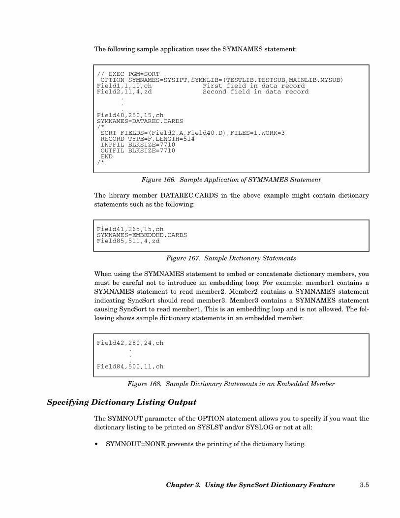
The following sample application uses the SYMNAMES statement:
The library member DATAREC.CARDS in the above example might contain dictionarystatements such as the following:
When using the SYMNAMES statement to embed or concatenate dictionary members, youmust be careful not to introduce an embedding loop. For example: member1 contains aSYMNAMES statement to read member2. Member2 contains a SYMNAMES statementindicating SyncSort should read member3. Member3 contains a SYMNAMES statementcausing SyncSort to read member1. This is an embedding loop and is not allowed. The fol-lowing shows sample dictionary statements in an embedded member:
Specifying Dictionary Listing Output
The SYMNOUT parameter of the OPTION statement allows you to specify if you want thedictionary listing to be printed on SYSLST and/or SYSLOG or not at all:
• SYMNOUT=NONE prevents the printing of the dictionary listing.
// EXEC PGM=SORTOPTION SYMNAMES=SYSIPT,SYMNLIB=(TESTLIB.TESTSUB,MAINLIB.MYSUB)
Field1,1,10,ch First field in data recordField2,11,4,zd Second field in data record
.
.
.Field40,250,15,chSYMNAMES=DATAREC.CARDS/*SORT FIELDS=(Field2,A,Field40,D),FILES=1,WORK=3RECORD TYPE=F,LENGTH=514INPFIL BLKSIZE=7710OUTFIL BLKSIZE=7710END
/*
Figure 166. Sample Application of SYMNAMES Statement
Field41,265,15,chSYMNAMES=EMBEDDED.CARDSField85,511,4,zd
Figure 167. Sample Dictionary Statements
Field42,280,24,ch...
Field84,500,11,ch
Figure 168. Sample Dictionary Statements in an Embedded Member
Chapter 3. Using the SyncSort Dictionary Feature 3.5
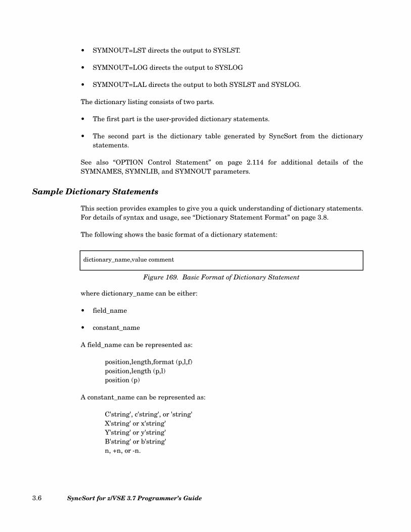
• SYMNOUT=LST directs the output to SYSLST.
• SYMNOUT=LOG directs the output to SYSLOG
• SYMNOUT=LAL directs the output to both SYSLST and SYSLOG.
The dictionary listing consists of two parts.
• The first part is the user-provided dictionary statements.
• The second part is the dictionary table generated by SyncSort from the dictionarystatements.
See also “OPTION Control Statement” on page 2.114 for additional details of theSYMNAMES, SYMNLIB, and SYMNOUT parameters.
Sample Dictionary Statements
This section provides examples to give you a quick understanding of dictionary statements.For details of syntax and usage, see “Dictionary Statement Format” on page 3.8.
The following shows the basic format of a dictionary statement:
where dictionary_name can be either:
• field_name
• constant_name
A field_name can be represented as:
position,length,format (p,l,f)position,length (p,l)position (p)
A constant_name can be represented as:
C'string', c'string', or 'string'X'string' or x'string'Y'string' or y'string'B'string' or b'string'n, +n, or -n.
dictionary_name,value comment
Figure 169. Basic Format of Dictionary Statement
SyncSort for z/VSE 3.7 Programmer’s Guide3.6
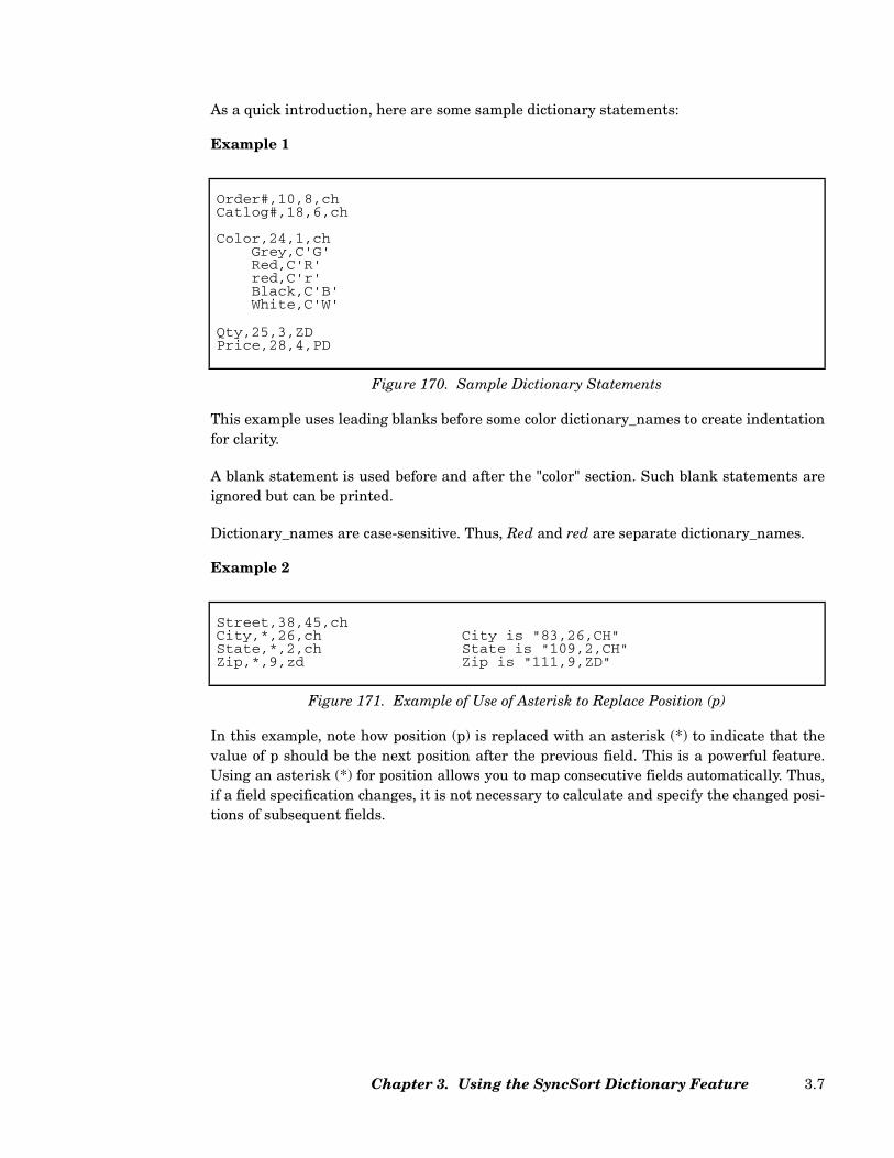
As a quick introduction, here are some sample dictionary statements:
Example 1
This example uses leading blanks before some color dictionary_names to create indentationfor clarity.
A blank statement is used before and after the "color" section. Such blank statements areignored but can be printed.
Dictionary_names are case-sensitive. Thus, Red and red are separate dictionary_names.
Example 2
In this example, note how position (p) is replaced with an asterisk (*) to indicate that thevalue of p should be the next position after the previous field. This is a powerful feature.Using an asterisk (*) for position allows you to map consecutive fields automatically. Thus,if a field specification changes, it is not necessary to calculate and specify the changed posi-tions of subsequent fields.
Order#,10,8,chCatlog#,18,6,ch
Color,24,1,chGrey,C'G'Red,C'R'red,C'r'Black,C'B'White,C'W'
Qty,25,3,ZDPrice,28,4,PD
Figure 170. Sample Dictionary Statements
Street,38,45,chCity,*,26,ch City is "83,26,CH"State,*,2,ch State is "109,2,CH"Zip,*,9,zd Zip is "111,9,ZD"
Figure 171. Example of Use of Asterisk to Replace Position (p)
Chapter 3. Using the SyncSort Dictionary Feature 3.7

Example 3
In this example, the SKIP operator advances the next position by n bytes. Since the posi-tion of the next field is specified with an asterisk (*), the position will be calculated auto-matically.
Other operators, in addition to SKIP, are POSITION and ALIGN. POSITION,q or POSI-TION,dictionary_name resets the next position. ALIGN,H aligns the next position on ahalfword, while ALIGN,F aligns it on a fullword and ALIGN,D aligns it on a doubleword.
Example 4
In this example, an equal sign (=) is used instead of p,l, or f. The equal sign assigns the pre-vious position,length or format to the equal sign, mapping one field onto another.
Although field_names and constant_names can usually be specified in any order, using theasterisk (*) or equal sign (=) forces a dependency on field order.
Note the use of comments in the above examples. As for SyncSort control statements, ablank after the value indicates the beginning of a comment. You can also use commentstatements, which begin with an asterisk (*) in column 1.
Dictionary Statement Format
There are three basic types of dictionary statements:
• The constant_name statement
• The field_name statement
• The operator statement
These types of dictionary statements are described below in separate sections.
Name,5,40,chSKIP,20Phone#,*,11,ch Phone# is "65,11,CH"
Figure 172. Example of Use of SKIP Operator
Date_of_Birth,10,6,Y2T A 6-byte field in yymmdd formatDOB_YY,=,2,Y2C Mapping byte 1,2 of Date_of_BirthDOB_MM,*,=,ZD Mapping byte 3,4 of Date_of_BirthDOB_DD,*,=,= Mapping byte 5,6 of Date_of_Birth
Figure 173. Example of Use of Equal Sign to Replace p,l, or f
SyncSort for z/VSE 3.7 Programmer’s Guide3.8
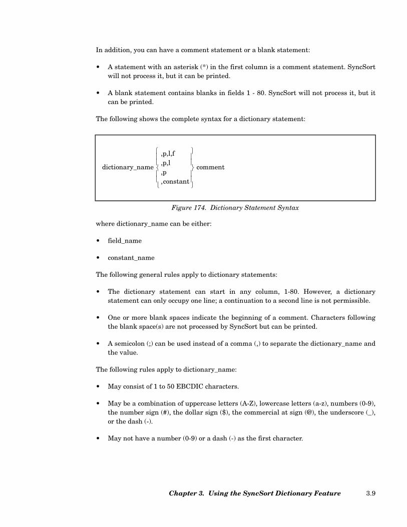
In addition, you can have a comment statement or a blank statement:
• A statement with an asterisk (*) in the first column is a comment statement. SyncSortwill not process it, but it can be printed.
• A blank statement contains blanks in fields 1 - 80. SyncSort will not process it, but itcan be printed.
The following shows the complete syntax for a dictionary statement:
where dictionary_name can be either:
• field_name
• constant_name
The following general rules apply to dictionary statements:
• The dictionary statement can start in any column, 1-80. However, a dictionarystatement can only occupy one line; a continuation to a second line is not permissible.
• One or more blank spaces indicate the beginning of a comment. Characters followingthe blank space(s) are not processed by SyncSort but can be printed.
• A semicolon (;) can be used instead of a comma (,) to separate the dictionary_name andthe value.
The following rules apply to dictionary_name:
• May consist of 1 to 50 EBCDIC characters.
• May be a combination of uppercase letters (A-Z), lowercase letters (a-z), numbers (0-9),the number sign (#), the dollar sign ($), the commercial at sign (@), the underscore (_),or the dash (-).
• May not have a number (0-9) or a dash (-) as the first character.
Figure 174. Dictionary Statement Syntax
dictionary_name
,p,l,f,p,l,p,constant
comment
Chapter 3. Using the SyncSort Dictionary Feature 3.9

• Are case-sensitive; for example, 'Address', 'ADDRESS', and 'address' are treated asdifferent fields.
• Cannot be a SyncSort reserved word. The following table lists the SyncSort reservedwords:
All SyncSort reserved words are in uppercase. Thus, mixed case and lowercase forms ofSyncSort reserved words are permissible as a dictionary_name. Similarly, dictionarystatement operators such as POSITION, SKIP and ALIGN are in uppercase, thusmixed and lowercase forms of these words are permissible as a dictionary_name. Forexample, position, Skip, and align are all acceptable as a dictionary_name.
Some permissible dictionary_names:
cust_nameADDR2
AACADDALIGNALLANDAQASLASTAVGBICHCLOCOMPARECOPYCOUNTCSFCSLCSTCTODD1D2DATEDATE1DATE1PDATE2
DATE2PDATE3DATE3PDATE4DATENSDC1DC2DC3DE1DE2DE3DIVDT1DT2DT3EFFIFLFSHHEXLSMAXMINMODMUL
M00 through M99NONENUMOLOROTPAGEPAGEHEADPDPD0PDCPDFPOSITIONPSIPZSEQNUMSFFSKIPSSSUBSUBCOUNTTC1TC2TC3TC4TE1TE2
TE3TE4TIMETIME1TIME1PTIME2TIME2PTIME3TIME3PTIMENSTM1TM2TM3TM4TSUFFVALCNTVLENXY2x*Y2xx*ZZDZDCZDFZSI
* x represents any character
Table 42. SyncSort Reserved Words
SyncSort for z/VSE 3.7 Programmer’s Guide3.10

FAX#num Primary-SSN
The following are not permissible dictionary names:
100_Addr (begins with a number)NUM (a reserved word)ALIGN (an operator)
The following sections describe the three types of dictionary statements in detail:
• “The Constant_name Statement: Rules and Syntax” on page 3.11
• “The Field_name Statement: Rules and Syntax” on page 3.13
• “The Operator Statement: Rules and Syntax” on page 3.21
The Constant_name Statement: Rules and Syntax
The value of a constant may be a decimal number, a character string, a hexadecimal string,or a bit string.
A constant_name representing a specific value can be used for headings, titles, compari-sons, etc. However, take care that the SyncSort control statement specifies the correct dataformat. For example, consider the the dictionary_name CONSR, defined by the followingdictionary statement:
Since CONSR is a binary field, it can be specified as such on the SyncSort control state-ment:
If you specified CH as the data format, the control statement would be invalid.
The rules for fields specified in a control statement always apply to a field specified as adictionary_name since internally SyncSort substitutes the actual field specification.
CONSR,B'00000010'
Figure 175. Example of constant_name in Dictionary Statement
INCLUDE COND=(14,1,BI,EQ,CONSR)
Figure 176. Example of constant_name in Control Statement
Chapter 3. Using the SyncSort Dictionary Feature 3.11
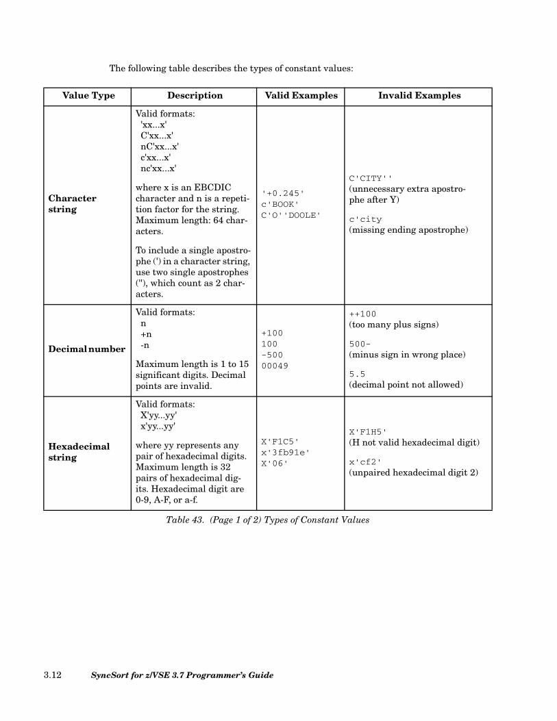
The following table describes the types of constant values:
Value Type Description Valid Examples Invalid Examples
Character string
Valid formats:'xx...x'C'xx...x'nC'xx...x'c'xx...x'nc'xx...x'
where x is an EBCDIC character and n is a repeti-tion factor for the string. Maximum length: 64 char-acters.
To include a single apostro-phe (') in a character string, use two single apostrophes (''), which count as 2 char-acters.
'+0.245'c'BOOK'C'O''DOOLE'
C'CITY''(unnecessary extra apostro-phe after Y)
c'city(missing ending apostrophe)
Decimal number
Valid formats:n+n-n
Maximum length is 1 to 15 significant digits. Decimal points are invalid.
+100100-50000049
++100(too many plus signs)
500-(minus sign in wrong place)
5.5(decimal point not allowed)
Hexadecimal string
Valid formats:X'yy...yy'x'yy...yy'
where yy represents any pair of hexadecimal digits. Maximum length is 32 pairs of hexadecimal dig-its. Hexadecimal digit are 0-9, A-F, or a-f.
X'F1C5'x'3fb91e'X'06'
X'F1H5'(H not valid hexadecimal digit)
x'cf2'(unpaired hexadecimal digit 2)
Table 43. (Page 1 of 2) Types of Constant Values
SyncSort for z/VSE 3.7 Programmer’s Guide3.12
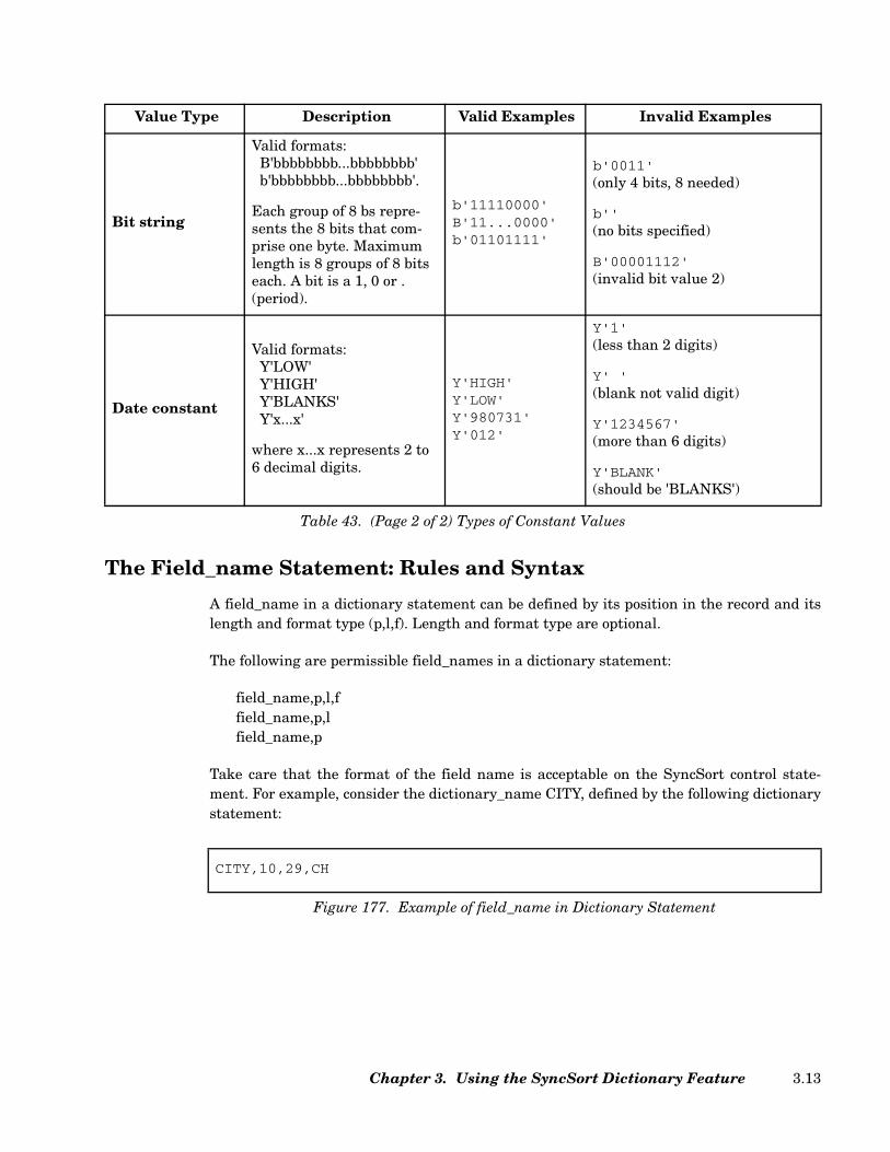
The Field_name Statement: Rules and Syntax
A field_name in a dictionary statement can be defined by its position in the record and itslength and format type (p,l,f). Length and format type are optional.
The following are permissible field_names in a dictionary statement:
field_name,p,l,ffield_name,p,lfield_name,p
Take care that the format of the field name is acceptable on the SyncSort control state-ment. For example, consider the dictionary_name CITY, defined by the following dictionarystatement:
Bit string
Valid formats:B'bbbbbbbb...bbbbbbbb'b'bbbbbbbb...bbbbbbbb'.
Each group of 8 bs repre-sents the 8 bits that com-prise one byte. Maximum length is 8 groups of 8 bits each. A bit is a 1, 0 or . (period).
b'11110000'B'11...0000'b'01101111'
b'0011'(only 4 bits, 8 needed)
b''(no bits specified)
B'00001112'(invalid bit value 2)
Date constant
Valid formats:Y'LOW'Y'HIGH'Y'BLANKS'Y'x...x'
where x...x represents 2 to 6 decimal digits.
Y'HIGH'Y'LOW'Y'980731'Y'012'
Y'1'(less than 2 digits)
Y' '(blank not valid digit)
Y'1234567'(more than 6 digits)
Y'BLANK'(should be 'BLANKS')
Value Type Description Valid Examples Invalid Examples
Table 43. (Page 2 of 2) Types of Constant Values
CITY,10,29,CH
Figure 177. Example of field_name in Dictionary Statement
Chapter 3. Using the SyncSort Dictionary Feature 3.13
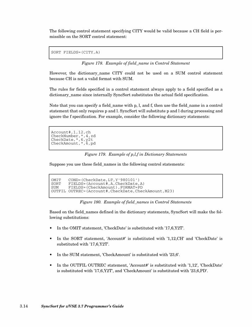
The following control statement specifying CITY would be valid because a CH field is per-missible on the SORT control statement:
However, the dictionary_name CITY could not be used on a SUM control statementbecause CH is not a valid format with SUM.
The rules for fields specified in a control statement always apply to a field specified as adictionary_name since internally SyncSort substitutes the actual field specification.
Note that you can specify a field_name with p, l, and f, then use the field_name in a controlstatement that only requires p and l. SyncSort will substitute p and l during processing andignore the f specification. For example, consider the following dictionary statements:
Suppose you use these field_names in the following control statements:
Based on the field_names defined in the dictionary statements, SyncSort will make the fol-lowing substitutions:
• In the OMIT statement, 'CheckDate' is substituted with '17,6,Y2T'.
• In the SORT statement, 'Account#' is substituted with '1,12,CH' and 'CheckDate' issubstituted with '17,6,Y2T'.
• In the SUM statement, 'CheckAmount' is substituted with '23,6'.
• In the OUTFIL OUTREC statement, 'Account#' is substituted with '1,12', 'CheckDate'is substituted with '17,6,Y2T', and 'CheckAmount' is substituted with '23,6,PD'.
SORT FIELDS=(CITY,A)
Figure 178. Example of field_name in Control Statement
Account#,1,12,chCheckNumber,*,4,zdCheckDate,*,6,y2tCheckAmount,*,6,pd
Figure 179. Example of p,l,f in Dictionary Statements
OMIT COND=(CheckDate,LT,Y'980101')SORT FIELDS=(Account#,A,CheckDate,A)SUM FIELDS=(CheckAmount),FORMAT=PDOUTFIL OUTREC=(Account#,CheckDate,CheckAmount,M23)
Figure 180. Example of field_names in Control Statements
SyncSort for z/VSE 3.7 Programmer’s Guide3.14

Here are the resulting control statements:
The following three subsections describe the rules for specifying position (p), length (l) andformat (f) in field_name dictionary statements.
Specifying Position (p) in Field_name Dictionary Statements
The following are the rules for specifying position (p) in field_name dictionary statements:
• p can be a number from 1 to 65532 whenever p,l or p,l and f are used. However, ifposition (p) is used alone (for example, CITY,20), the p can not be more than 15significant digits.
Note that any value of p greater than 65532 may cause a syntax error when it is pro-cessed as a position.
• Alternately, p can be in the form of m.n for specifying a bit position, where m is anumber from 1 to 65532 and n is a number between 0 and 7. Note that m.0 isequivalent to m.
• p can be an asterisk (*), which indicates that the next position should be assigned to p.Since l represents length, the next position is set to p + l each time the field_name forp,l,f or p,l is read. If the next position has not yet been determined, as when theasterisk is used in the first field_name, then p defaults to 1 (one).
The dictionary table, which can be printed on request, displays the actual positionsassigned to p when the asterisk is used for p. For example, consider the followingOPTION statement:
OMIT COND=(17,6,Y2T,LT,Y'980101')SORT FIELDS=(1,12,CH,A,17,6,Y2T,A)SUM FIELDS=(23,6),FORMAT=PDOUTFIL OUTREC=(1,12,17,6,Y2T,23,6,PD,M23)
Figure 181. Example of p,l in Control Statements
OPTION SYMNAMES=PARTS.LAYOUT
Figure 182. Sample OPTION Statement
Chapter 3. Using the SyncSort Dictionary Feature 3.15
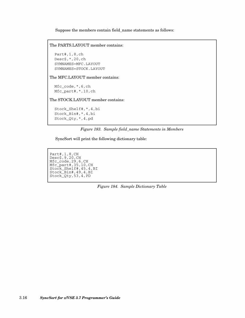
Suppose the members contain field_name statements as follows:
SyncSort will print the following dictionary table:
The PARTS.LAYOUT member contains:
Part#,1,8,chDesc$,*,20,chSYMNAMES=MFC.LAYOUTSYMNAMES=STOCK.LAYOUT
The MFC.LAYOUT member contains:
Mfc_code,*,6,chMfc_part#,*,10,ch
The STOCK.LAYOUT member contains:
Stock_Shelf#,*,4,biStock_Bin#,*,4,biStock_Qty,*,4,pd
Figure 183. Sample field_name Statements in Members
Part#,1,8,CHDesc$,9,20,CHMfc_code,29,6,CHMfc_part#,35,10,CHStock_Shelf#,45,4,BIStock_Bin#,49,4,BIStock_Qty,53,4,PD
Figure 184. Sample Dictionary Table
SyncSort for z/VSE 3.7 Programmer’s Guide3.16

Note that using the asterisk (*) for position (p) enables you to:
• Map consecutive record fields without having to calculate their actual positions.
• Map new fields inserted between other fields without having to modify the p valuesof existing or inserted fields.
• Map contiguous fields in concatenated field name sets.
Field_names from all three field_name sets in the above example could be used inSyncSort control statements as follows:
• The equal sign (=) can be used instead of p to indicate that the previous position shouldbe assigned to p. If the previous position has not yet been determined, an error messagewill be issued. Each time the field_name for p,l,f (or p,l) is read, the previous position isset to p.
Note that the value of the previous position can also be modified by a POSITION opera-tor statement. See “Using POSITION in Operator Statements” on page 3.22.
If the dictionary table is printed, it will display the actual positions that result from the= specification. For example, consider the following dictionary statements:
OUTFIL FNAME=ORDER,INCLUDE=(Stock_Qty,LT,100),OUTREC=(Part#,10X,Mfc_code,5X,Mfc_part#)
OUTFIL FNAME=INTEL,INCLUDE=(Mfc_code,EQ,C'INTEL'),OUTREC=(Part#,10X,Stock_Shelf#,LENGTH=6,
8X,Stock_Bin#,LENGTH=6,8X,Stock_Qty,LENGTH=8)
Figure 185. Sample field_names in Control Statements
POSITION,40Payment_type,=,1,Bi@cash$,B'......00'@check,B'......01'@credt,B'......1.'Teller,*,20,ChCheck#,=,4,ZdCCard#,=,12,Zd
Figure 186. Sample Dictionary Statements
Chapter 3. Using the SyncSort Dictionary Feature 3.17
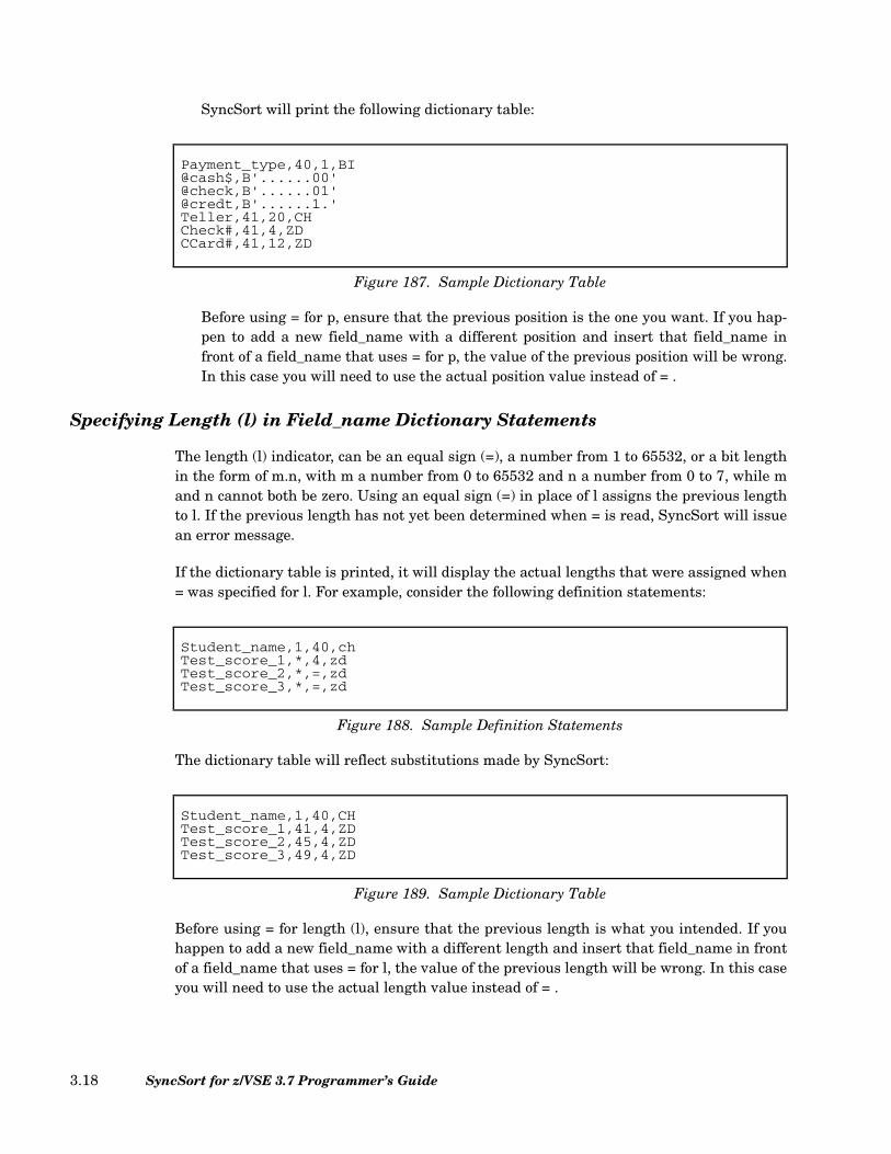
SyncSort will print the following dictionary table:
Before using = for p, ensure that the previous position is the one you want. If you hap-pen to add a new field_name with a different position and insert that field_name infront of a field_name that uses = for p, the value of the previous position will be wrong.In this case you will need to use the actual position value instead of = .
Specifying Length (l) in Field_name Dictionary Statements
The length (l) indicator, can be an equal sign (=), a number from 1 to 65532, or a bit lengthin the form of m.n, with m a number from 0 to 65532 and n a number from 0 to 7, while mand n cannot both be zero. Using an equal sign (=) in place of l assigns the previous lengthto l. If the previous length has not yet been determined when = is read, SyncSort will issuean error message.
If the dictionary table is printed, it will display the actual lengths that were assigned when= was specified for l. For example, consider the following definition statements:
The dictionary table will reflect substitutions made by SyncSort:
Before using = for length (l), ensure that the previous length is what you intended. If youhappen to add a new field_name with a different length and insert that field_name in frontof a field_name that uses = for l, the value of the previous length will be wrong. In this caseyou will need to use the actual length value instead of = .
Payment_type,40,1,BI@cash$,B'......00'@check,B'......01'@credt,B'......1.'Teller,41,20,CHCheck#,41,4,ZDCCard#,41,12,ZD
Figure 187. Sample Dictionary Table
Student_name,1,40,chTest_score_1,*,4,zdTest_score_2,*,=,zdTest_score_3,*,=,zd
Figure 188. Sample Definition Statements
Student_name,1,40,CHTest_score_1,41,4,ZDTest_score_2,45,4,ZDTest_score_3,49,4,ZD
Figure 189. Sample Dictionary Table
SyncSort for z/VSE 3.7 Programmer’s Guide3.18

Specifying Format (f) in Field_name Dictionary Statements
The format (f) indicator, can be an equal sign (=) or a specific format. The following formatsare permissible:
AC, AQ, ASL, AST, BI, CH, CLO, CSF, CSL, CST, CTO, FI, FL, FS, LS, OL, OT, PD,PD0, PSI, SS, TS, Y2B, Y2C, Y2D, Y2DP, Y2ID, Y2IP, Y2P, Y2PP, Y2S, Y2T, Y2TP,Y2U, Y2UP, Y2V, Y2VP, Y2W, Y2WP, Y2X, Y2XP, Y2Y, Y2YP, Y2Z, ZD, ZSI
Formats can be specified using uppercase, lowercase, or mixed case letters.
When either p or l is specified in the bit form (m.n) and the bit number is not zero (n≠0),then the only valid format is BI.
As with p and l, an equal sign (=) indicates that the previous format should be assigned to f.If the previous format has not yet been determined when an = sign is used for f, SyncSortissues an error message.
If the dictionary table is printed, it will display the actual formats SyncSort substituted for=. For example, consider the following dictionary statement:
After processing, the substitutions will be reflected in the dictionary table:
Before using = for f, ensure that the previous format is what you intend. If you happen toadd a new field_name with a different format and insert that field_name in front of afield_name that uses = for f, the value of previous format will be wrong. In this case youwill need to change the = to the actual format.
Student_name,1,40,chTest_score_1,*,4,zdTest_score_2,*,=,=Test_score_3,*,=,=
Figure 190. Sample Dictionary Statement
Student_name,1,40,CHTest_score_1,41,4,ZDTest_score_2,45,4,ZDTest_score_3,49,4,ZD
Figure 191. Sample Dictionary Table
Chapter 3. Using the SyncSort Dictionary Feature 3.19
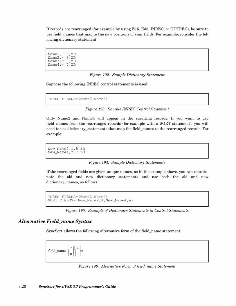
If records are rearranged (for example by using E15, E35, INREC, or OUTREC), be sure touse field_names that map to the new positions of your fields. For example, consider the fol-lowing dictionary statement:
Suppose the following INREC control statements is used:
Only Name2 and Name4 will appear in the resulting records. If you want to usefield_names from the rearranged records (for example with a SORT statement), you willneed to use dictionary_statements that map the field_names to the rearranged records. Forexample:
If the rearranged fields are given unique names, as in the example above, you can concate-nate the old and new dictionary statements and use both the old and newdictionary_names, as follows:
Alternative Field_name Syntax
SyncSort allows the following alternative form of the field_name statement:
Name1,1,5,ZDName2,*,8,ZDName3,*,3,ZDName4,*,7,ZD
Figure 192. Sample Dictionary Statement
INREC FIELDS=(Name2,Name4)
Figure 193. Sample INREC Control Statement
New_Name2,1,8,ZDNew_Name4,*,7,ZD
Figure 194. Sample Dictionary Statements
INREC FIELDS=(Name2,Name4)SORT FIELDS=(New_Name2,A,New_Name4,A)
Figure 195. Example of Dictionary Statements in Control Statements
Figure 196. Alternative Form of field_name Statement
field_name, *
= +
-
n
SyncSort for z/VSE 3.7 Programmer’s Guide3.20

where n is a number from 1 to 65532.
This syntax form is useful for defining a field_name for record length to be used in theRECORD control statement. For example:
You would then use rec_len in the RECORD control statement, as follows:
The Operator Statement: Rules and Syntax
The Operator Statement controls the position of fields you are mapping. Following is theformat of an operator statement:
where operator represents:
POSITION Specifies a starting position.
SKIP Skips unwanted positions.
ALIGN Aligns fields on boundaries.
Syntax rules for the operator statement are the same as for the other types of dictionarystatement. However, one rule applies specifically to the operator statement: To be treatedas an operator statement, the operator must be all uppercase. The following are permissi-ble operator statements:
field_name1,1,10,CH....
field_namen,*,10,CHrec_len,*-1
Figure 197. Sample Dictionary Statements
RECORD TYPE=F,LENGTH=rec_len
Figure 198. Example of field_name in RECORD Control Statement
operator,value comment
Figure 199. Operator Statement Format
Chapter 3. Using the SyncSort Dictionary Feature 3.21
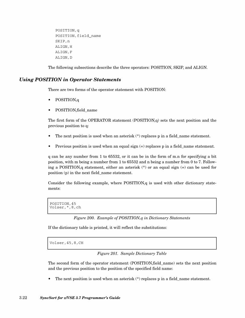
POSITION,q
POSITION,field_name
SKIP,n
ALIGN,H
ALIGN,F
ALIGN,D
The following subsections describe the three operators: POSITION, SKIP, and ALIGN.
Using POSITION in Operator Statements
There are two forms of the operator statement with POSITION:
• POSITION,q
• POSITION,field_name
The first form of the OPERATOR statement (POSITION,q) sets the next position and theprevious position to q:
• The next position is used when an asterisk (*) replaces p in a field_name statement.
• Previous position is used when an equal sign (=) replaces p in a field_name statement.
q can be any number from 1 to 65532, or it can be in the form of m.n for specifying a bitposition, with m being a number from 1 to 65532 and n being a number from 0 to 7. Follow-ing a POSITION,q statement, either an asterisk (*) or an equal sign (=) can be used forposition (p) in the next field_name statement.
Consider the following example, where POSITION,q is used with other dictionary state-ments:
If the dictionary table is printed, it will reflect the substitutions:
The second form of the operator statement (POSITION,field_name) sets the next positionand the previous position to the position of the specified field name:
• The next position is used when an asterisk (*) replaces p in a field_name statement.
POSITION,45Volser,*,8,ch
Figure 200. Example of POSITION,q in Dictionary Statements
Volser,45,8,CH
Figure 201. Sample Dictionary Table
SyncSort for z/VSE 3.7 Programmer’s Guide3.22

• The previous position is used when an equal sign (=) replaces p in a a field_namestatement.
Following a POSITION,field_name statement, either an * or an = can be used for p in thenext field_name statement.
The field_name used with the POSITION operator can be any previously definedfield_name. As a result, POSITION,field_name functions like the assembler ORG instruc-tion, allowing you to map different fields onto the same area. Consider the following exam-ple, where POSITION,field_name is used with other dictionary_statements:
SyncSort will print the following dictionary table:
Using SKIP in Operator Statements
The operator statement has the following form with SKIP:
where n can be any number from 1 to 65532, or it can be in the form of u.v for specifying abit length, with u being a number from 0 to 65532 and v being a number from 0 to 7 (whileu and v cannot both be zero).
SKIP,n increases the next position by n bytes. As described above, the next position is usedwhen an asterisk (*) replaces p in a field_name statement.
Filename,1,8,chFiletype,*,8,chFilemode,*,2,chPOSITION,FilenameFilespec,*,18,=
Figure 202. Example of POSITION,field_name in Dictionary Statements
Filename,1,8,CHFiletype,9,8,CHFilemode,17,2,CHFilespec,1,18,CH
Figure 203. Sample Dictionary Table
SKIP,n
Figure 204. SKIP Format in Operator Statement
Chapter 3. Using the SyncSort Dictionary Feature 3.23
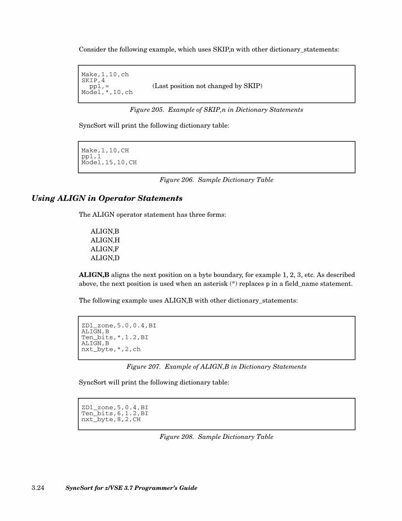
Consider the following example, which uses SKIP,n with other dictionary_statements:
SyncSort will print the following dictionary table:
Using ALIGN in Operator Statements
The ALIGN operator statement has three forms:
ALIGN,BALIGN,HALIGN,FALIGN,D
ALIGN,B aligns the next position on a byte boundary, for example 1, 2, 3, etc. As describedabove, the next position is used when an asterisk (*) replaces p in a field_name statement.
The following example uses ALIGN,B with other dictionary_statements:
SyncSort will print the following dictionary table:
Make,1,10,chSKIP,4
pp1,= (Last position not changed by SKIP)Model,*,10,ch
Figure 205. Example of SKIP,n in Dictionary Statements
Make,1,10,CHpp1,1Model,15,10,CH
Figure 206. Sample Dictionary Table
ZD1_zone,5.0,0.4,BIALIGN,BTen_bits,*,1.2,BIALIGN,Bnxt_byte,*,2,ch
Figure 207. Example of ALIGN,B in Dictionary Statements
ZD1_zone,5,0.4,BITen_bits,6,1.2,BInxt_byte,8,2,CH
Figure 208. Sample Dictionary Table
SyncSort for z/VSE 3.7 Programmer’s Guide3.24
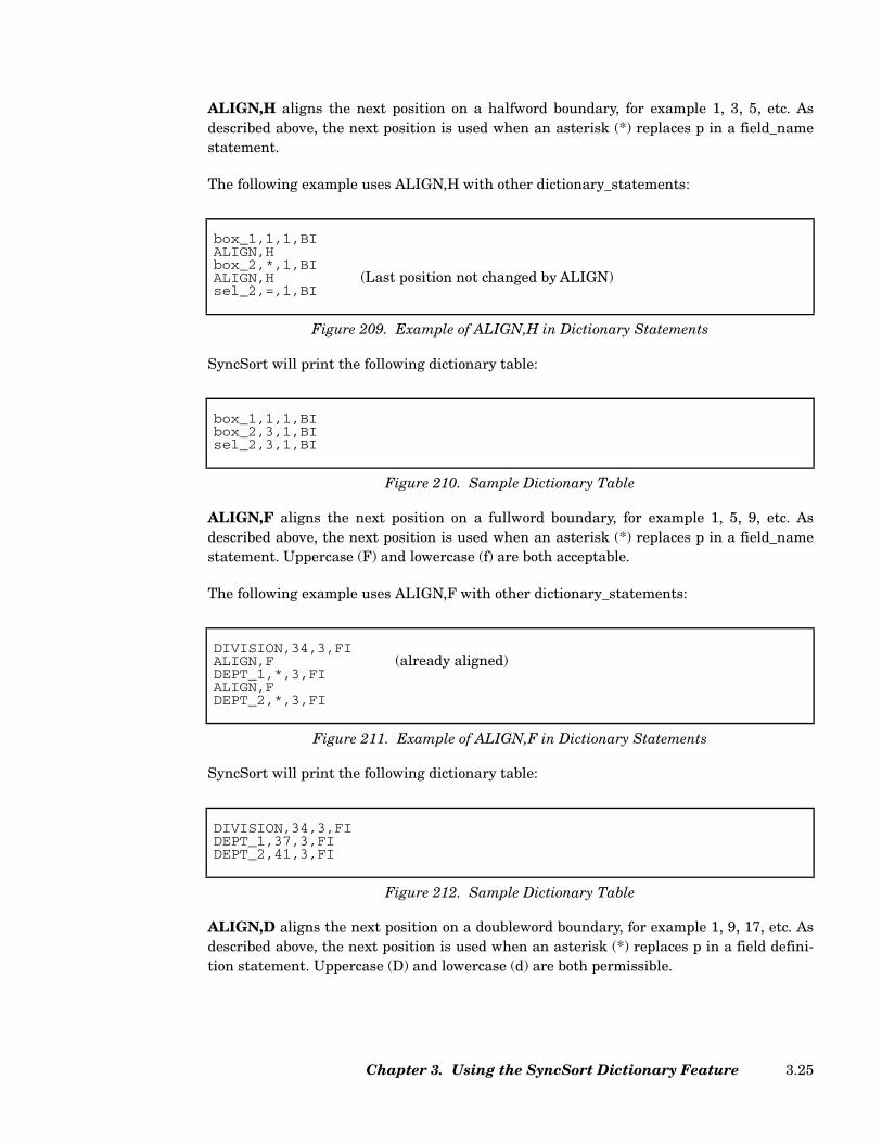
ALIGN,H aligns the next position on a halfword boundary, for example 1, 3, 5, etc. Asdescribed above, the next position is used when an asterisk (*) replaces p in a field_namestatement.
The following example uses ALIGN,H with other dictionary_statements:
SyncSort will print the following dictionary table:
ALIGN,F aligns the next position on a fullword boundary, for example 1, 5, 9, etc. Asdescribed above, the next position is used when an asterisk (*) replaces p in a field_namestatement. Uppercase (F) and lowercase (f) are both acceptable.
The following example uses ALIGN,F with other dictionary_statements:
SyncSort will print the following dictionary table:
ALIGN,D aligns the next position on a doubleword boundary, for example 1, 9, 17, etc. Asdescribed above, the next position is used when an asterisk (*) replaces p in a field defini-tion statement. Uppercase (D) and lowercase (d) are both permissible.
box_1,1,1,BIALIGN,Hbox_2,*,1,BIALIGN,H (Last position not changed by ALIGN)sel_2,=,1,BI
Figure 209. Example of ALIGN,H in Dictionary Statements
box_1,1,1,BIbox_2,3,1,BIsel_2,3,1,BI
Figure 210. Sample Dictionary Table
DIVISION,34,3,FIALIGN,F (already aligned)DEPT_1,*,3,FIALIGN,FDEPT_2,*,3,FI
Figure 211. Example of ALIGN,F in Dictionary Statements
DIVISION,34,3,FIDEPT_1,37,3,FIDEPT_2,41,3,FI
Figure 212. Sample Dictionary Table
Chapter 3. Using the SyncSort Dictionary Feature 3.25

The following example uses ALIGN,D with other dictionary statements:
SyncSort will print the following dictionary table:
Using Dictionary_names in SyncSort Control Statements
Field_names can be used in the following SyncSort control statements:
DUPKEYSINCLUDEINPFILINRECJOINKEYSMERGEOMITOUTFILOUTRECREFORMATSORTSUMXDUPFILXSUMFIL
You can use a field_name wherever you would specify a position, length, and format (p,l,f orp,l or p). In addition, a special form of field_name can be used with the LENGTH parameterof the RECORD statement. (See “Alternative Field_name Syntax” on page 3.20.)
Account#,42,8,chALIGN,DBalance,*,8,csL
Figure 213. Example of ALIGN,D in Dictionary Statements
Account#,42,8,CHBalance,57,8,CSL
Figure 214. Sample Dictionary Table
SyncSort for z/VSE 3.7 Programmer’s Guide3.26
Constant_names can be used in the following control statements:
INCLUDEINPFILINRECJOINKEYSOMITOUTFILOUTRECXDUPFILXSUMFIL
You can use a constant_name wherever you would specify a constant (X'nn...',B'bbbb,...',C'ccc...', Y'xx...'), that is:
• A constant compared to a field in the data record (INCLUDE/OMIT)
• A constant inserted into a data record (INREC/OUTREC, OUTFIL, XSUMFIL).
• A constant used in a HEADERn/TRAILERn parameter, where n=1, 2, or 3 (OUTFIL,XSUMFIL).
When substituting field_names in control statements, SyncSort checks the context in whicheach field_name appears and determines which field specification is appropriate: p,l,f oronly p,l. A field_name substitution results in position and length (p,l) under the followingconditions:
• There is a separate FORMAT=parameter present in the control statement.
• A format is explicitly specified for the field; that is, the field_name is followed by aformat specification.
• The field_name appears in HEADERn/TRAILERn (where n=1, 2, or 3) in anOUTFIL/XSUMFIL statement but outside a TOTAL/SUBTOTAL/MIN/MAX/AVGsubparameter.
• The field_name appears in an INREC/OUTREC statement or in the OUTREC parm ofan OUTFIL/XSUMFIL statement, with the following exceptions:
• The field_name is followed by an EDIT mask (Mnn), EDIT=parameter,SIGN=parameter, or LENGTH=parameter.
• The field_name is enclosed in parentheses.
• The field_name is an operand of an arithmetic operation (ADD/SUB/MUL/DIV/MOD/MIN/MAX).
Chapter 3. Using the SyncSort Dictionary Feature 3.27
• The field_name is a Y2x field and it is not followed by H, F, D, HEX, orCHANGE=parameter.
Note that you cannot use a dictionary_name for any of the following:
• EDIT parameter
• DATE parameter
• Replacement length in CHANGE=parameter
Error Handling for Dictionary Statements
SyncSort will scan each dictionary statement for errors. When the first error is detected, anerror message is printed. If appropriate, a marker will print just below the Dictionarystatement, near the error. SyncSort stops scanning at the first error, then resumes with thenext Dictionary statement.
Once an error has been detected, positions calculated with the use of an asterisk (*) for p orwith the POSITION,field_name statement in subsequent dictionary statements will not bechecked for errors. If an error is detected in any Dictionary statement, SyncSort terminatesprocessing after all Dictionary statements are scanned.
If SyncSort detects an error in a control statement while substitution is taking place, itmay respond in either of the following ways:
• Print the statement that was in error, followed by a corresponding error message andmarker (if appropriate), then continue with the next statement and terminate when allsubstitutions have been completed.
• Stop the substitution for the statement in error and continue processing, lettingsubsequent processing handle the error. If this occurs, the original field or constantname rather than the substituted value may be displayed in a translated statement.
If the substitution process is successful, SyncSort will substitute values for field_names orconstant_names wherever they are allowed. If substituted values prove invalid for a partic-ular statement or operand, it will be detected after the substitution has been performed,making it easier to determine the source of the error.
SyncSort for z/VSE 3.7 Programmer’s Guide3.28
Chapter 4. How to Use SyncSort Data Utility Features
Introduction
This chapter assumes that you already know how to sort records and are ready to useSyncSort’s Data Utility features for any or all of the following:
• Selecting only those input records and data fields that are needed for an application.
• Eliminating duplicate records.
• Consolidating records into a single record that contains the AVG, MAX, MIN, or SUMof any numeric data fields.
• Making output data printable and easy to read.
• Writing a multi-sectioned report complete with headers and trailers.
• Generating several output files and reports with a single pass of the sort.
The following examples show how you can accomplish these tasks with SyncSort. Eachexample is self-contained and provides coding instructions for both the required JCL andthe necessary control statements. Use them as starting points for your own applications.
For examples of the JOIN facility, you may refer to Syncsort’s booklet, Exploiting SyncSortfor z/VSE: JOIN.
Chapter 4. How to Use SyncSort Data Utility Features 4.1

Sample Data Utility Applications
The following chart lists applications that demonstrate SyncSort’s features.
Selecting Input Records
When only certain records from an input file are needed for an application, SyncSort allowsyou to set up one or more logical conditions for including only those records. Alternately,you may specify conditions for omitting records from an application. Each condition isbased on a comparison between two record fields or between a record field and a constant.
Feature Application Page
Selecting Input Records Including Relevant Records Omitting Irrelevant Records
4.44.5
Selecting Relevant Fields from the Input Records
Selecting a Number of Fields from Longer Records Eliminating Irrelevant Data Field(s) Selecting Fields from Variable-Length Records
4.84.94.11
Combining Records within a File
Combining Records and Placing AVG, MAX, MIN, or SUM Values in Retained Records
Eliminating Duplicate Records 4.144.15
Making Output Records Print-able and Easy to Read
Reordering the Positions of Record Fields Inserting Blanks and Repositioning Record Fields Inserting Binary Zeros Converting Unprintable Data to Readable Form Converting Unprintable Data to Hexadecimal Format Converting and Editing Unprintable Data Putting a Data Field in Standard Format Printing Input Records
4.184.204.224.234.254.274.294.34
Dividing a Report into Sections Dividing Output into Sections 4.34
Writing Headers and Trailers for a Report
Writing a Title Page for a Report Writing a Page Header Writing a Section Header Using a Header to Eliminate Duplication Information within
a SectionWriting a Report Trailer or Summary Writing a Page Trailer
4.384.404.41
4.424.444.45
Totaling and Subtotaling Data Totaling Data at the End of a Report Subtotaling Data at the End of a Page Totaling Data at the End of a Section
4.474.494.50
Counting Data Records Obtaining a Count of Data Records Obtaining a Cumulative, or Running, Count of Data Records
4.534.54
Creating Multiple Output Files Generating Several Output Files with Different Information Writing Identical Output Files to Different Devices
4.584.60
Table 44. Index to Data Utility Applications
SyncSort for z/VSE 3.7 Programmer’s Guide4.2
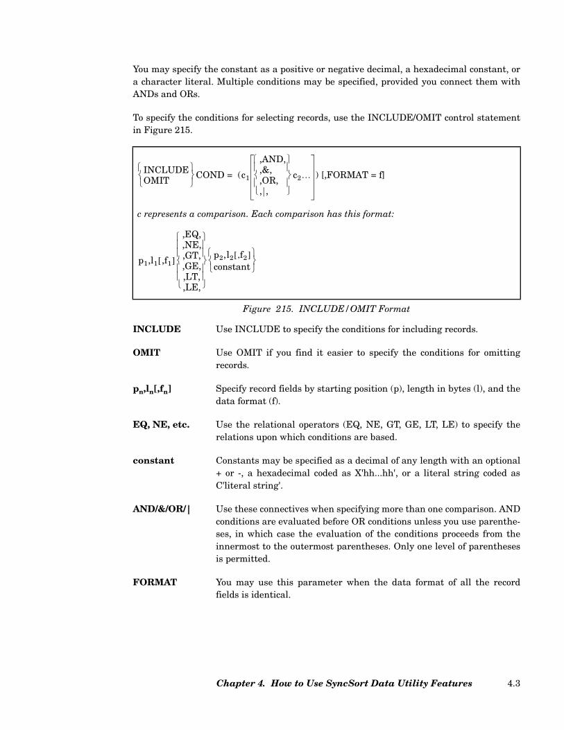
You may specify the constant as a positive or negative decimal, a hexadecimal constant, ora character literal. Multiple conditions may be specified, provided you connect them withANDs and ORs.
To specify the conditions for selecting records, use the INCLUDE/OMIT control statementin Figure 215.
INCLUDE Use INCLUDE to specify the conditions for including records.
OMIT Use OMIT if you find it easier to specify the conditions for omittingrecords.
pn,ln[,fn] Specify record fields by starting position (p), length in bytes (l), and thedata format (f).
EQ, NE, etc. Use the relational operators (EQ, NE, GT, GE, LT, LE) to specify therelations upon which conditions are based.
constant Constants may be specified as a decimal of any length with an optional+ or -, a hexadecimal coded as X'hh...hh', or a literal string coded asC'literal string'.
AND/&/OR/| Use these connectives when specifying more than one comparison. ANDconditions are evaluated before OR conditions unless you use parenthe-ses, in which case the evaluation of the conditions proceeds from theinnermost to the outermost parentheses. Only one level of parenthesesis permitted.
FORMAT You may use this parameter when the data format of all the recordfields is identical.
c represents a comparison. Each comparison has this format:
Figure 215. INCLUDE/OMIT Format
INCLUDEOMIT
COND = (c1
,AND,,&,,OR,, ,
c2… ) [,FORMAT = f]
p1,l1 ,f1[ ]
,EQ,,NE,,GT,,GE,,LT,,LE,
p2,l2 f2,[ ]constant
Chapter 4. How to Use SyncSort Data Utility Features 4.3
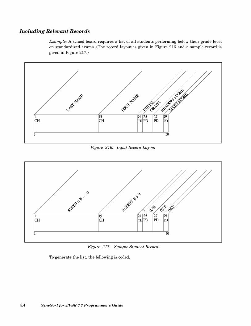
Including Relevant Records
Example: A school board requires a list of all students performing below their grade levelon standardized exams. (The record layout is given in Figure 216 and a sample record isgiven in Figure 217.)
To generate the list, the following is coded.
Figure 216. Input Record Layout
Figure 217. Sample Student Record
SyncSort for z/VSE 3.7 Programmer’s Guide4.4

Explanation: In this application, two comparisons are necessary to identify the recordsneeded for the list: the Grade field (25,2) has to be compared to the student’s Reading Scorefield (27,2) and to the Mathematics Score field (29,2). All numeric fields on the studentrecords are in packed-decimal (PD) format.
The two-clause INCLUDE statement (see Figure 218) guarantees the selection of theneeded records from the file. The first clause (29,2,LT,25,2) guarantees that records withMath Scores less than the Grade field are INCLUDED. The second clause (27,2,LT,25,2)guarantees that records with Reading Scores less than the Grade field are alsoINCLUDED. The OR connecting the two clauses guarantees that if either or both of thescores are less than the Grade field, the record is selected. Finally, since all the fields are inpacked-decimal format (PD), FORMAT=PD is specified.
The sample record shown above will be INCLUDED because the student’s Math Score(047F) is lower than the Grade level (050F).
Omitting Irrelevant Records
Example: Records that have an Invoice Status Code of F (fully paid) are to be omitted inpreparing a list of only those customers with outstanding payments. (The input record lay-out is given in Figure 219 and a sample input record is given in Figure 220.)
// JOB SUBLEV Signals the Start of Job
// ASSGN SYS001,SYSLST Assigns Logical Unit to Printer
// ASSGN SYS002,X'181' Assigns Logical Unit to Tape
// TLBL SORTIN1,'STUDENTS' Contains Input Tape File
Information
// ASSGN SYS003,X'251' Assigns Logical Unit to SORTWK Device
// DLBL SORTWK1 Contains SORTWK File Information
// EXTENT SYS003 Defines Direct Access Area for SORTWK
// EXEC SORT Signals Beginning of Sort Program
RECORD TYPE=F,LENGTH=30 Describes Input Records
INCLUDE COND=(29,2,LT,25,2,OR,27,2,LT,25,2),FORMAT=PD Selects Records
SORT FIELDS=(1,14,CH,A) Sorts Records
Figure 218. JCL and Required Control Statements
Chapter 4. How to Use SyncSort Data Utility Features 4.5
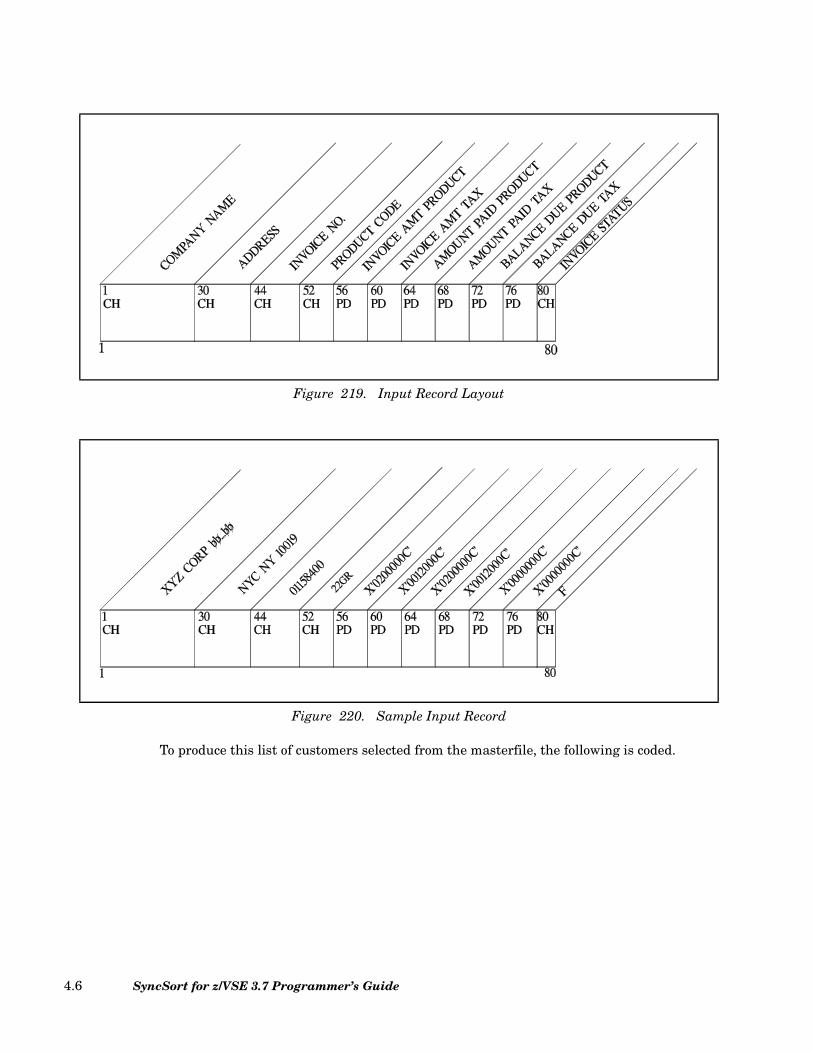
To produce this list of customers selected from the masterfile, the following is coded.
Figure 219. Input Record Layout
Figure 220. Sample Input Record
SyncSort for z/VSE 3.7 Programmer’s Guide4.6

Explanation: In this application, a simple comparison is necessary to identify those master-file records that are not needed: the Invoice Status Code field (80,1,CH) has to be comparedto the constant 'F'.
The OMIT statement’s condition, 80,1,CH,EQ,C'F' (see Figure 221) guarantees that invoicerecords, like the sample record shown above, with the Invoice Status Code 'F' are omittedfrom the sort.
Selecting Relevant Fields from the Input Records
Input records often contain some information that is not relevant to a specific application.For example, records in a personnel masterfile might, in addition to addresses, include sal-aries and other confidential information that is not required for preparing a mailing list.
SyncSort’s Data Utility features allow you to select only those record fields that containnecessary data and to eliminate those that do not. More important, SyncSort enables you todo this editing before the records are sorted. As a result, the sort has fewer bytes to handleand processing is more efficient.
To select relevant record fields, use the INREC statement as described below:
For the complete format of the INREC control statement, see “INREC Control Statement”on page 2.83.
// JOB OUTPAY Signals the Start of Job
// ASSGN SYS001,SYSLST Assigns Logical Unit to Printer
// ASSGN SYS002,X'181' Assigns Logical Unit to Tape
// TLBL SORTIN1,'NEWINV' Contains Input Tape File
Information
// ASSGN SYS003,X'251' Assigns Logical Unit to SORTWK
Device
// DLBL SORTWK1 Contains SORTWK File Information
// EXTENT SYS003 Defines Direct Access Area for
SORTWK
// EXEC SORT Signals Beginning of Sort Program
RECORD TYPE=F,LENGTH=80 Describes Input Records
OMIT COND=(80,1,CH,EQ,C'F') Omits Records
SORT FIELDS=(1,29,CH,A) Sorts Records
Figure 221. JCL and Required Control Statements
INREC FIELDS=(p1,l1[,p2,l2,...,pn,ln])
Figure 222. Basic INREC Statement Format
Chapter 4. How to Use SyncSort Data Utility Features 4.7

p,l Specify the beginning position and length in bytes of the input record’s rele-vant fields. When specifying contiguous fields, or fields that directly followone another, you can simply indicate the starting position of the first fieldtogether with the combined length of the fields that are contiguous.
Selecting a Number of Fields from Longer Records
Example: A school wants to rank the entire student body by grade point index. This appli-cation simply requires selecting the two relevant fields out of all the fields in the studentrecords, and then sorting on the Grade Point Index field. (The Input Record layout is givenin Figure 223.)
To include only the relevant fields and generate the ranked list of students, the following iscoded.
Figure 223. Input Record Layout
SyncSort for z/VSE 3.7 Programmer’s Guide4.8
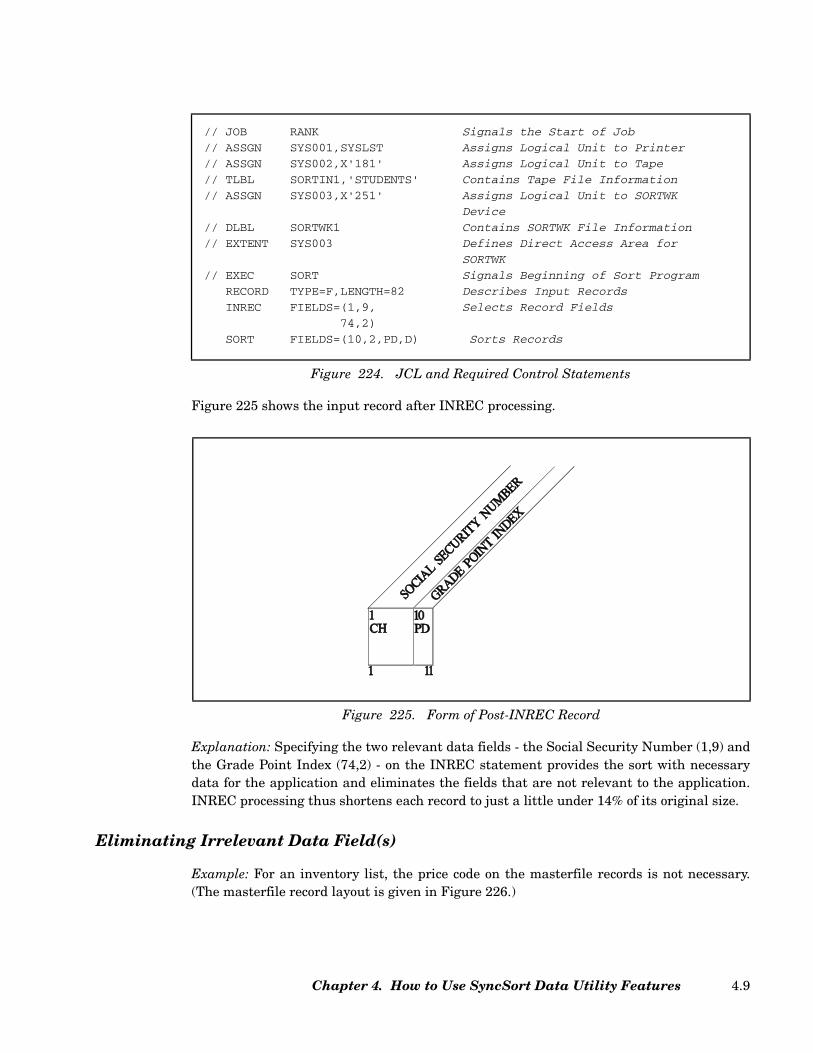
Figure 225 shows the input record after INREC processing.
Explanation: Specifying the two relevant data fields - the Social Security Number (1,9) andthe Grade Point Index (74,2) - on the INREC statement provides the sort with necessarydata for the application and eliminates the fields that are not relevant to the application.INREC processing thus shortens each record to just a little under 14% of its original size.
Eliminating Irrelevant Data Field(s)
Example: For an inventory list, the price code on the masterfile records is not necessary.(The masterfile record layout is given in Figure 226.)
// JOB RANK Signals the Start of Job
// ASSGN SYS001,SYSLST Assigns Logical Unit to Printer
// ASSGN SYS002,X'181' Assigns Logical Unit to Tape
// TLBL SORTIN1,'STUDENTS' Contains Tape File Information
// ASSGN SYS003,X'251' Assigns Logical Unit to SORTWK
Device
// DLBL SORTWK1 Contains SORTWK File Information
// EXTENT SYS003 Defines Direct Access Area for
SORTWK
// EXEC SORT Signals Beginning of Sort Program
RECORD TYPE=F,LENGTH=82 Describes Input Records
INREC FIELDS=(1,9, Selects Record Fields
74,2)
SORT FIELDS=(10,2,PD,D) Sorts Records
Figure 224. JCL and Required Control Statements
Figure 225. Form of Post-INREC Record
Chapter 4. How to Use SyncSort Data Utility Features 4.9

To eliminate the Price Code field and generate the inventory list, the following is coded.
Figure 228 shows the input record after INREC processing.
Figure 226. INPUT Record Layout
// JOB INVENTR Signals the Start of Job
// ASSGN SYS001,SYSLST Assigns Logical Unit to Printer
// ASSGN SYS002,X'181' Assigns Logical Unit to Tape
// TLBL SORTIN1,'WAREHSE' Contains Input Tape File Information
// ASSGN SYS003,X'251' Assigns Logical Unit to SORTWK Device
// DLBL SORTWK1 Contains SORTWK File Information
// EXTENT SYS003 Defines Direct Access Area for SORTWK
// EXEC SORT Signals Beginning of Sort Program
RECORD TYPE=F,LENGTH=21 Describes Input Records
INREC FIELDS=(1,17, Selects Record Fields
19,3)
SORT FIELDS=(1,5,CH,A) Sorts Records
.
Figure 227. JCL and Required Control Statements
SyncSort for z/VSE 3.7 Programmer’s Guide4.10
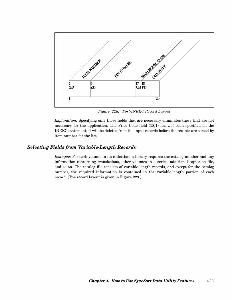
Explanation: Specifying only those fields that are necessary eliminates those that are notnecessary for the application. The Price Code field (18,1) has not been specified on theINREC statement; it will be deleted from the input records before the records are sorted byitem number for the list.
Selecting Fields from Variable-Length Records
Example: For each volume in its collection, a library requires the catalog number and anyinformation concerning translations, other volumes in a series, additional copies on file,and so on. The catalog file consists of variable-length records, and except for the catalognumber, the required information is contained in the variable-length portion of eachrecord. (The record layout is given in Figure 229.)
Figure 228. Post-INREC Record Layout
Chapter 4. How to Use SyncSort Data Utility Features 4.11

To include only the relevant fields on the input records and to generate this list, the follow-ing is coded.
Figure 231 shows the input record after INREC processing.
Figure 229. Sample Record Layout
// JOB LISTCAT Signals the Start of Job
// ASSGN SYS001,SYSLST Assigns Logical Unit to Printer
// ASSGN SYS002,X'181' Assigns Logical Unit to Tape
// TLBL SORTIN1,'CATALOG' Contains Input Tape File Information
// ASSGN SYS003,X'251' Assigns Logical Unit to SORTWK Device
// DLBL SORTWK1 Contains SORTWK File Information
// EXTENT SYS003 Defines Direct Access Area for SORTWK
// EXEC SORT Signals Beginning of Sort Program
RECORD TYPE=V,LENGTH=119 Describes Input Records
INREC FIELDS=(1,14, Selects Record Fields
98)
SORT FIELDS=(5,10,ZD,A) Sorts Records
Figure 230. JCL and Required Control Statements
SyncSort for z/VSE 3.7 Programmer’s Guide4.12

Explanation: When selecting fields on variable-length records, you must observe these tworestrictions: (1) The position of the RDW cannot be affected; and (2) at least one byte fromthe fixed-length portion of the record, in addition to the RDW, must be specified. On theabove INREC statement, the first 14 bytes of each record-the 4-byte RDW and the fixed-length Catalog Number field-are retained unchanged. The next field, which contains moreinformation as required, is indicated only by position (98) since it is of variable-length. Thiscauses the entire variable-length portion of the record (beginning with byte 98) to beincluded after the initial 14 bytes of the post INREC record. SyncSort automaticallyadjusts the RDW to reflect the new record length.
Combining Records within a File
Sometimes you may want to shorten a file by consolidating records that have some infor-mation in common. For example, a company’s invoice file may contain more than one recordfor any customer to whom multiple invoices have been issued. In some applications it mightthen be feasible to consolidate such records, that is, to combine records with identical Cus-tomer Name and Address fields into a single record containing the sum of that customer’scharges and payments.
The SUM control statement allows you to combine records in this way. It is coded as fol-lows.
Figure 231. Form of Post-INREC Record
Figure 232. SUM Control Statement Format
SUM
FIELDS = (p1,l1 ,f1[ ]…,pn,ln ,fn[ ])
FIELDS = NONE(NONE)
[,XSUM] [,FORMAT = f]
Chapter 4. How to Use SyncSort Data Utility Features 4.13

pn,ln,fn Specify the starting position (p), the length in bytes (l), and the data format(f) for each field for which you desire the sum to appear on the combined,cumulative record.
Note: Make sure that none of these fields has been specified on the SORTstatement.
FORMAT Use this parameter to specify the default format for any field without “f ”specified.
NONE Use this parameter, with or without parentheses, to eliminate all but one oftwo or more records that have identical information in the fields specifiedon the SORT statement.
XSUM Use this parameter to direct the sort to save all records eliminated by SUMprocessing in a separate output file.
Combining Records and Summing Numeric Data Fields
Example: For an inventory list, a company requires a single record for each product, indi-cating its item number, warehouse code, and the total quantity in stock. (Figure 233 givesthe sample record layout.)
To combine those inventory records with identical item numbers and warehouse codes andto produce the required list, the following is coded.
Figure 233. Input Record Layout
SyncSort for z/VSE 3.7 Programmer’s Guide4.14
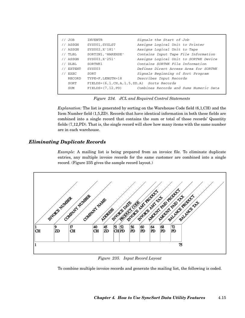
Explanation: The list is generated by sorting on the Warehouse Code field (6,1,CH) and theItem Number field (1,5,ZD). Records that have identical information in both these fields arecombined into a single record that contains the sum or total of those records’ Quantityfields (7,12,PD). That is, the single record will show how many items with the same numberare in each warehouse.
Eliminating Duplicate Records
Example: A mailing list is being prepared from an invoice file. To eliminate duplicateentries, any multiple invoice records for the same customer are combined into a singlerecord. (Figure 235 gives the sample record layout.)
To combine multiple invoice records and generate the mailing list, the following is coded.
// JOB INVENTR Signals the Start of Job
// ASSGN SYS001,SYSLST Assigns Logical Unit to Printer
// ASSGN SYS002,X'181' Assigns Logical Unit to Tape
// TLBL SORTIN1,'WAREHSE' Contains Input Tape File Information
// ASSGN SYS003,X'251' Assigns Logical Unit to SORTWK Device
// DLBL SORTWK1 Contains SORTWK File Information
// EXTENT SYS003 Defines Direct Access Area for SORTWK
// EXEC SORT Signals Beginning of Sort Program
RECORD TYPE=F,LENGTH=18 Describes Input Records
SORT FIELDS=(6,1,CH,A,1,5,ZD,A) Sorts Records
SUM FIELDS=(7,12,PD) Combines Records and Sums Numeric Data
Figure 234. JCL and Required Control Statements
Figure 235. Input Record Layout
Chapter 4. How to Use SyncSort Data Utility Features 4.15

Explanation: To prepare the customer mailing list, the only information required from theinvoice records is located in the Company Name field (17,23) and the Address field (40,5),which are selected by the INREC statement. Sorting these records in ascending order bycompany name generates an alphabetical list. Then, because the file contains a record forevery transaction, the SUM statement is used to avoid duplicate listings of customers whohave had more than one transaction. Note that because none of the fields contains numericdata to be summed, the FIELDS=NONE parameter is used.
Making Output Records Printable and Easy to Read
Because data is usually stored in a compact format, it can be difficult, if not impossible, toread when printed. For example, on a typical input record, there will be no blank spacebetween fields, numeric data will sometimes be lost in leading and trailing zeros, and somedata will be in unprintable format.
After processing, you will probably want to edit this data so that it is easy to read. This isbound to entail one or more of the following tasks:
• reordering the position of record fields
• inserting blanks between fields
• inserting binary zeros
• converting numeric data from unprintable to printable format
• converting data to printable hexadecimal format
• using masks or edit patterns to insert dollar signs, decimal points, slashes, and thelike.
// JOB MAILIST Signals the Start of Job
// ASSGN SYS001,SYSLST Assigns Logical Unit to Printer
// ASSGN SYS002,X'181' Assigns Logical Unit to Tape
// TLBL SORTIN1,'MASTINV' Contains Input Tape File Information
// ASSGN SYS003,X'251' Assigns Logical Unit to SORTWK Device
// DLBL SORTWK1 Contains SORTWK File Information
// EXTENT SYS003 Defines Direct Access Area for SORTWK
// EXEC SORT Signals Beginning of Sort Program
RECORD TYPE=F,LENGTH=75 Describes Input Records
INREC FIELDS=(17,28) Selects Relevant Fields
SORT FIELDS=(1,23,CH,A) Sorts Records, Reference is to
Post-INREC Record
SUM FIELDS=NONE Eliminates Duplicate Records
Figure 236. JCL and Required Control Statements
SyncSort for z/VSE 3.7 Programmer’s Guide4.16
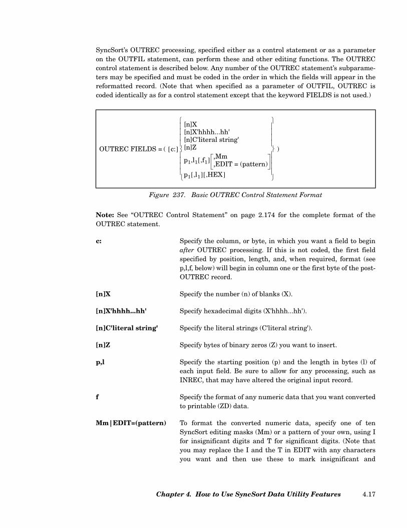
SyncSort’s OUTREC processing, specified either as a control statement or as a parameteron the OUTFIL statement, can perform these and other editing functions. The OUTRECcontrol statement is described below. Any number of the OUTREC statement’s subparame-ters may be specified and must be coded in the order in which the fields will appear in thereformatted record. (Note that when specified as a parameter of OUTFIL, OUTREC iscoded identically as for a control statement except that the keyword FIELDS is not used.)
Note: See “OUTREC Control Statement” on page 2.174 for the complete format of theOUTREC statement.
c: Specify the column, or byte, in which you want a field to beginafter OUTREC processing. If this is not coded, the first fieldspecified by position, length, and, when required, format (seep,l,f, below) will begin in column one or the first byte of the post-OUTREC record.
[n]X Specify the number (n) of blanks (X).
[n]X'hhhh...hh' Specify hexadecimal digits (X'hhhh...hh').
[n]C'literal string' Specify the literal strings (C'literal string').
[n]Z Specify bytes of binary zeros (Z) you want to insert.
p,l Specify the starting position (p) and the length in bytes (l) ofeach input field. Be sure to allow for any processing, such asINREC, that may have altered the original input record.
f Specify the format of any numeric data that you want convertedto printable (ZD) data.
Mm|EDIT=(pattern) To format the converted numeric data, specify one of tenSyncSort editing masks (Mm) or a pattern of your own, using Ifor insignificant digits and T for significant digits. (Note thatyou may replace the I and the T in EDIT with any charactersyou want and then use these to mark insignificant and
Figure 237. Basic OUTREC Control Statement Format
OUTREC FIELDS = ( c:[ ]
[n]X[n]X'hhhh...hh'[n]C'literal string'[n]Z
p1 l1 f1,[ ] ,Mm,EDIT = (pattern)
,
p1 l1,[ ] HEX,[ ]
)
Chapter 4. How to Use SyncSort Data Utility Features 4.17
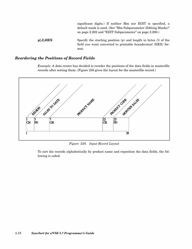
significant digits.) If neither Mm nor EDIT is specified, adefault mask is used. (See “Mm Subparameter (Editing Masks)”on page 2.202 and “EDIT Subparameter” on page 2.200.)
p[,l],HEX Specify the starting position (p) and length in bytes (l) of thefield you want converted to printable hexadecimal (HEX) for-mat.
Reordering the Positions of Record Fields
Example: A data center has decided to reorder the positions of the data fields in masterfilerecords after sorting them. (Figure 238 gives the layout for the masterfile record.)
To sort the records alphabetically by product name and reposition the data fields, the fol-lowing is coded.
Figure 238. Input Record Layout
SyncSort for z/VSE 3.7 Programmer’s Guide4.18

Figure 240 shows the output record after OUTREC processing.
Explanation: After the records are sorted alphabetically by product name (7,15,CH),OUTREC processing moves the Product Code field (22,3) to the first byte of the record, theProduct Name field (7,15) to the fourth byte, the Region field (1,2) to the nineteenth byte,the Month’s Sales field (25,4) to the twenty-first byte, and the Sales to Data field (3,4) tothe twenty-fifth byte.
// JOB SORTPRD Signals the Start of Job
// ASSGN SYS001,SYSLST Assigns Logical Unit to Printer
// ASSGN SYS002,X'181' Assigns Logical Unit to Tape
// TLBL SORTIN1,'MASTPRD' Contains Input Tape File Information
// ASSGN SYS003,X'251' Assigns Logical Unit to SORTWK Device
// DLBL SORTWK1 Contains SORTWK File Information
// EXTENT SYS003 Defines Direct Access Area for SORTWK
// EXEC SORT Signals Beginning of Sort Program
RECORD TYPE=F,LENGTH=28 Describes Input Records
SORT FIELDS=(7,15,CH,A) Sorts Records
OUTREC FIELDS=(22,3, Repositions Fields on Output Records
7,15,
1,2,
25,4,
3,4)
Figure 239. JCL and Required Control Statements
Figure 240. Post-OUTREC Record Layout
Chapter 4. How to Use SyncSort Data Utility Features 4.19
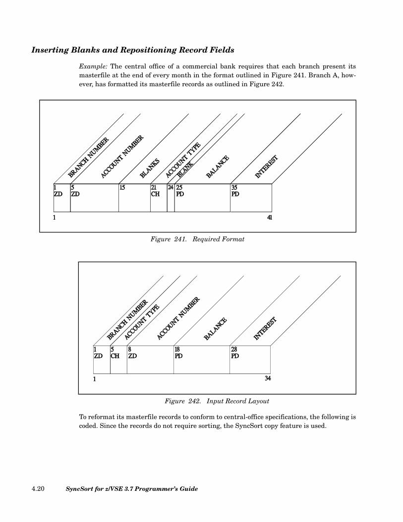
Inserting Blanks and Repositioning Record Fields
Example: The central office of a commercial bank requires that each branch present itsmasterfile at the end of every month in the format outlined in Figure 241. Branch A, how-ever, has formatted its masterfile records as outlined in Figure 242.
To reformat its masterfile records to conform to central-office specifications, the following iscoded. Since the records do not require sorting, the SyncSort copy feature is used.
Figure 241. Required Format
Figure 242. Input Record Layout
SyncSort for z/VSE 3.7 Programmer’s Guide4.20
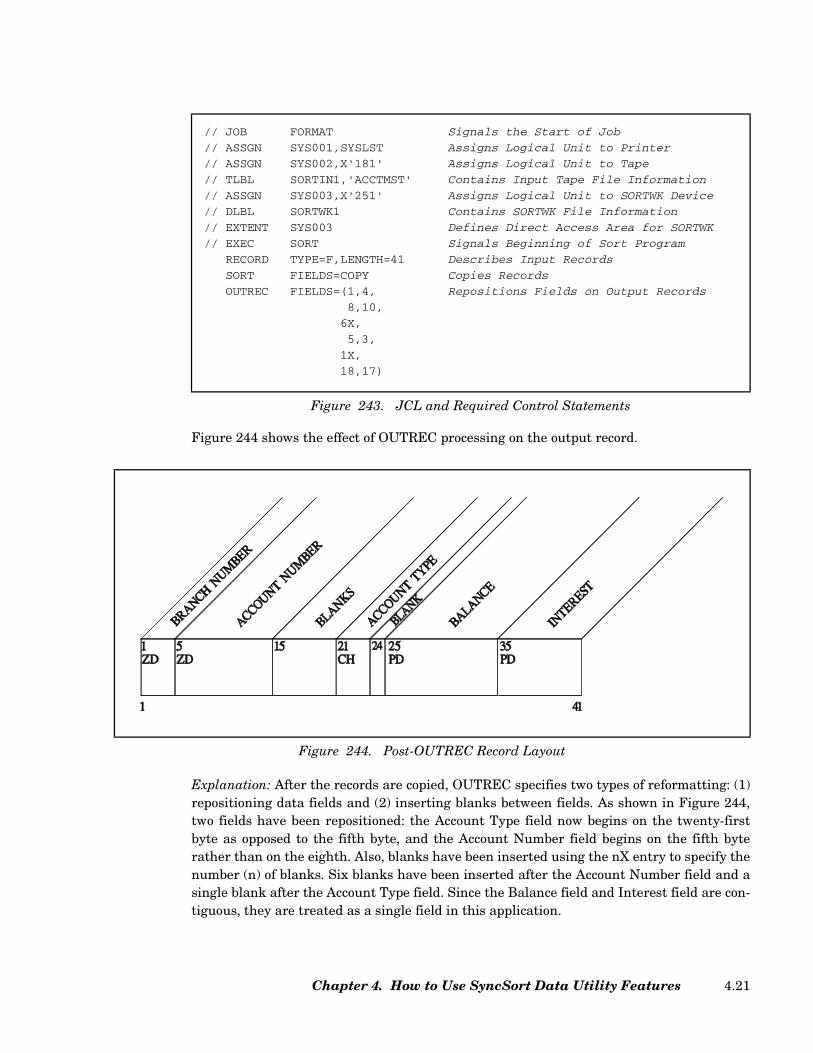
Figure 244 shows the effect of OUTREC processing on the output record.
Explanation: After the records are copied, OUTREC specifies two types of reformatting: (1)repositioning data fields and (2) inserting blanks between fields. As shown in Figure 244,two fields have been repositioned: the Account Type field now begins on the twenty-firstbyte as opposed to the fifth byte, and the Account Number field begins on the fifth byterather than on the eighth. Also, blanks have been inserted using the nX entry to specify thenumber (n) of blanks. Six blanks have been inserted after the Account Number field and asingle blank after the Account Type field. Since the Balance field and Interest field are con-tiguous, they are treated as a single field in this application.
// JOB FORMAT Signals the Start of Job
// ASSGN SYS001,SYSLST Assigns Logical Unit to Printer
// ASSGN SYS002,X'181' Assigns Logical Unit to Tape
// TLBL SORTIN1,'ACCTMST' Contains Input Tape File Information
// ASSGN SYS003,X'251' Assigns Logical Unit to SORTWK Device
// DLBL SORTWK1 Contains SORTWK File Information
// EXTENT SYS003 Defines Direct Access Area for SORTWK
// EXEC SORT Signals Beginning of Sort Program
RECORD TYPE=F,LENGTH=41 Describes Input Records
SORT FIELDS=COPY Copies Records
OUTREC FIELDS=(1,4, Repositions Fields on Output Records
8,10,
6X,
5,3,
1X,
18,17)
Figure 243. JCL and Required Control Statements
Figure 244. Post-OUTREC Record Layout
Chapter 4. How to Use SyncSort Data Utility Features 4.21

Inserting Binary Zeros
Example: A manufacturing firm has decided to expand its product line. However, becausethe Item Number field on its inventory records is too small, the records must be reformat-ted to allow for more columns for the new products. The Item Number is kept in packed-decimal, PD, format, and the firm wants to add 4 bytes to the current 2 byte field. The newbytes are to precede the current two bytes. Figure 245 gives the input record layout.
To copy the records and insert the 4 bytes of binary zeros, the following is coded.
Figure 245. Input Record Layout
// JOB COLUMNS Signals the Start of Job
// ASSGN SYS001,SYSLST Assigns Logical Unit to Printer
// ASSGN SYS002,X'181' Assigns Logical Unit to Tape
// TLBL SORTIN1,'INVREC' Contains Input Tape File Information
// ASSGN SYS003,X'251' Assigns Logical Unit to SORTWK Device
// DLBL SORTWK1 Contains SORTWK File Information
// EXTENT SYS003 Defines Direct Access Area for SORTWK
// EXEC SORT Signals Beginning of Sort Program
RECORD TYPE=F,LENGTH=76 Decsribes Input Records
SORT FIELDS=COPY Copies Records
OUTREC FIELDS=(1,20, Inserts Binary Zeros and
4Z, Reformats Records
25:21,56)
Figure 246. JCL and Required Control Statements
SyncSort for z/VSE 3.7 Programmer’s Guide4.22
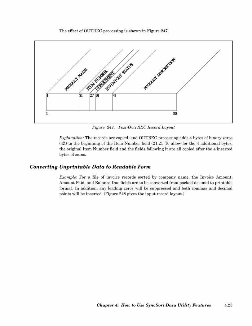
The effect of OUTREC processing is shown in Figure 247.
Explanation: The records are copied, and OUTREC processing adds 4 bytes of binary zeros(4Z) to the beginning of the Item Number field (21,2). To allow for the 4 additional bytes,the original Item Number field and the fields following it are all copied after the 4 insertedbytes of zeros.
Converting Unprintable Data to Readable Form
Example: For a file of invoice records sorted by company name, the Invoice Amount,Amount Paid, and Balance Due fields are to be converted from packed-decimal to printableformat. In addition, any leading zeros will be suppressed and both commas and decimalpoints will be inserted. (Figure 248 gives the input record layout.)
Figure 247. Post-OUTREC Record Layout
Chapter 4. How to Use SyncSort Data Utility Features 4.23

To sort the records, convert the three fields of packed-decimal data, and insert the commasand decimal points, the following is coded.
Figure 248. Input Record Layout
// JOB INVOICE Signals the Start of Job
// ASSGN SYS001,SYSLST Assigns Logical Unit to Printer
// ASSGN SYS002,X'181' Assigns Logical Unit to Tape
// TLBL SORTIN1,'NEWINV' Contains Input Tape File Information
// ASSGN SYS003,X'251' Assigns Logical Unit to SORTWK Device
// DLBL SORTWK1 Contains SORTWK File Information
// EXTENT SYS003 Defines Direct Access Area for SORTWK
// EXEC SORT Signals Beginning of Sort Program
RECORD TYPE=F,LENGTH=35 Describes Input Records
SORT FIELDS=(1,23,CH,A) Sorts Records
OUTREC FIELDS=(17:1,23, Repositions Record Fields and
52:24,4,PD,M2, Converts Data
74:28,4,PD,M2,
96:32,4,PD,M2)
Figure 249. JCL and Required Control Statements
SyncSort for z/VSE 3.7 Programmer’s Guide4.24
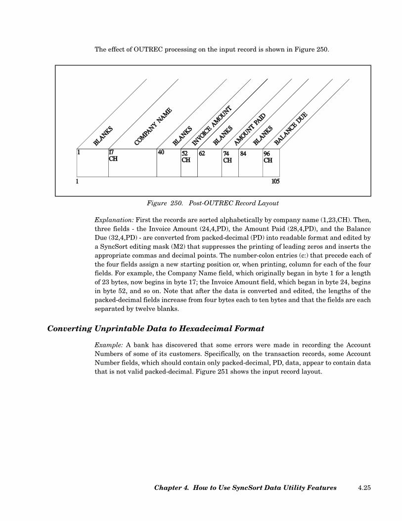
The effect of OUTREC processing on the input record is shown in Figure 250.
Explanation: First the records are sorted alphabetically by company name (1,23,CH). Then,three fields - the Invoice Amount (24,4,PD), the Amount Paid (28,4,PD), and the BalanceDue (32,4,PD) - are converted from packed-decimal (PD) into readable format and edited bya SyncSort editing mask (M2) that suppresses the printing of leading zeros and inserts theappropriate commas and decimal points. The number-colon entries (c:) that precede each ofthe four fields assign a new starting position or, when printing, column for each of the fourfields. For example, the Company Name field, which originally began in byte 1 for a lengthof 23 bytes, now begins in byte 17; the Invoice Amount field, which began in byte 24, beginsin byte 52, and so on. Note that after the data is converted and edited, the lengths of thepacked-decimal fields increase from four bytes each to ten bytes and that the fields are eachseparated by twelve blanks.
Converting Unprintable Data to Hexadecimal Format
Example: A bank has discovered that some errors were made in recording the AccountNumbers of some of its customers. Specifically, on the transaction records, some AccountNumber fields, which should contain only packed-decimal, PD, data, appear to contain datathat is not valid packed-decimal. Figure 251 shows the input record layout.
Figure 250. Post-OUTREC Record Layout
Chapter 4. How to Use SyncSort Data Utility Features 4.25

In order to find the invalid data, the following is coded.
Figure 251. Sample Input Record Layout
// JOB ACCTNO Signals the Start of Job
// ASSGN SYS001,SYSLST Assigns Logical Unit to Printer
// ASSGN SYS002,X'181' Assigns Logical Unit to Tape
// TLBL SORTIN1,'CUSTNO' Contains Input Tape File Information
// ASSGN SYS003,X'251' Assigns Logical Unit to SORTWK Device
// DLBL SORTWK1 Contains SORTWK File Information
// EXTENT SYS003 Defines Direct Access Area for SORTWK
// EXEC SORT Signals Beginning of Sort Program
RECORD TYPE=F,LENGTH=79 Describes Input Records
SORT FIELDS=COPY Copies Records
OUTREC FIELDS=(1,30, Reformats Output Records and
36:31,12,HEX) Converts Data
Figure 252. JCL and Required Control Statements
SyncSort for z/VSE 3.7 Programmer’s Guide4.26

The effect of OUTREC processing on the input record is shown in Figure 253.
Explanation: The records are copied, and OUTREC processing reformats the output recordto contain the Customer Name field (1,30) followed in column 36 by the Account Numberfield converted to hexadecimal format (31,12,HEX). Blanks are automatically inserted inthe unspecified columns (31,5). Note that converting the Account Number data to printablehexadecimal expands the original 12-byte field to 24 bytes. The bank can now read theAccount Number field in hexadecimal format to determine which records contain invaliddata.
Converting and Editing Unprintable Data
Example: For an Outstanding Payments report, the packed-decimal Amount Due field on acompany’s invoice records is converted to printable format and edited with a floating dollarsign, commas, and a decimal point. In addition, to make the output easy to read, ten blanksare inserted between the Company Name field and the Amount Due field. (Figure 254 givesthe input record layout.)
Figure 253. Post-OUTREC Record Layout
Chapter 4. How to Use SyncSort Data Utility Features 4.27

To sort the records and accomplish the conversion and editing, the following is coded.
Figure 254. Input Record Layout
// JOB PAYMENT Signals the Start of Job
// ASSGN SYS001,SYSLST Assigns Logical Unit to Printer
// ASSGN SYS002,X'181' Assigns Logical Unit to Tape
// TLBL SORTIN1,'INVOICE' Contains Input Tape File Information
// ASSGN SYS003,X'251' Assigns Logical Unit to SORTWK Device
// DLBL SORTWK1 Contains SORTWK File Information
// EXTENT SYS003 Defines Direct Access Area for SORTWK
// EXEC SORT Signals Beginning of Sort Program
RECORD TYPE=F,LENGTH=27 Describes Input Records
SORT FIELDS=(1,23,CH,A) Sorts Records
OUTREC FIELDS=(1,23, Converts and Edits Data, Inserts Blanks
10X,
24,4,PD,EDIT=($II,IIT.TT))
Figure 255. JCL and Required Control Statements
SyncSort for z/VSE 3.7 Programmer’s Guide4.28

Figure 256 shows the effect of OUTREC processing on the input record.
Explanation: First the records are sorted alphabetically by Company Name (1,23,CH).Next, OUTREC processing inserts 10 blanks (10X) between the Company Name field (1,23)and the Balance Due field (24,4,PD). OUTREC processing also converts this packed-deci-mal field to printable format and edits it with the user-provided pattern specified on theEDIT subparameter, EDIT=($II,IIT.TT). This pattern provides for a floating dollar sign aswell as the appropriate comma and decimal point. The Is indicate that leading zeros shouldnot be printed and the Ts indicate that zeros in those positions should be printed. Note thatthis conversion and editing of the data cause the length of the Balance Due field to increasefrom its original length of four bytes to ten bytes.
Putting a Data Field in Standard Format
Example: The date field on insurance-policy records is stored in zoned-decimal format butwithout slashes separating the month, day, and year. After the records are sorted, theseslashes will be inserted and the date will appear in the standard mm/dd/yy format. (Figure257 gives the input record layout.)
Figure 256. Post-OUTREC Record Layout
Chapter 4. How to Use SyncSort Data Utility Features 4.29

To sort the records and format the date field with the required slashes, the following iscoded.
Figure 257. Input Record Layout
// JOB SORTDT Signals the Start of Job
// ASSGN SYS001,SYSLST Assigns Logical Unit to Printer
// ASSGN SYS002,X'181' Assigns Logical Unit to Tape
// TLBL SORTIN1,'NEWPLCY' Contains Input Tape File Information
// ASSGN SYS003,X'251' Assigns Logical Unit to SORTWK
Device
// DLBL SORTWK1 Contains SORTWK File Information
// EXTENT SYS003 Defines Direct Access Area for
SORTWK
// EXEC SORT Signals Beginning of Sort Program
RECORD TYPE=F,LENGTH=37 Describes Input Records
SORT FIELDS=(1,23,CH,A) Sorts Records
OUTREC FIELDS=(1:1,23, Edits Data and Repositions
30:24,6,ZD,M9, Record Fields
45:30,8)
Figure 258. JCL and Required Control Statements
SyncSort for z/VSE 3.7 Programmer’s Guide4.30
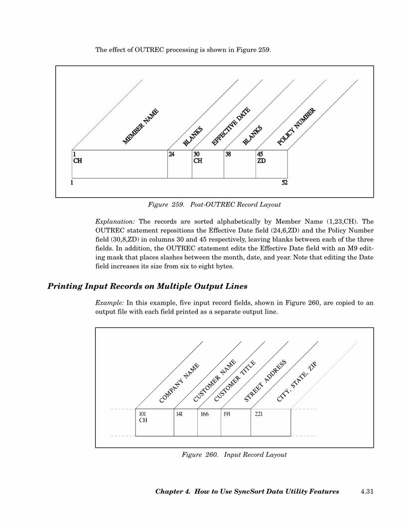
The effect of OUTREC processing is shown in Figure 259.
Explanation: The records are sorted alphabetically by Member Name (1,23,CH). TheOUTREC statement repositions the Effective Date field (24,6,ZD) and the Policy Numberfield (30,8,ZD) in columns 30 and 45 respectively, leaving blanks between each of the threefields. In addition, the OUTREC statement edits the Effective Date field with an M9 edit-ing mask that places slashes between the month, date, and year. Note that editing the Datefield increases its size from six to eight bytes.
Printing Input Records on Multiple Output Lines
Example: In this example, five input record fields, shown in Figure 260, are copied to anoutput file with each field printed as a separate output line.
Figure 259. Post-OUTREC Record Layout
Figure 260. Input Record Layout
Chapter 4. How to Use SyncSort Data Utility Features 4.31

Multiple output lines are created by specifying a newline character, i.e. / (slash), in theOUTREC parameter of an OUTFIL control statement. As shown in Figure 261, the newlinecharacter follows the specification of each input field’s starting position and length.
Once SyncSort has printed the data in the COMPANY NAME field, it starts a new outputline, prints on it the data in the next field, CUSTOMER NAME, starts a new line, and soforth. After printing the contents of the last field (CITY, STATE AND ZIP), SyncSort cre-ates two new lines (2/).
Figure 262 provides an excerpt from the output file where the input record is formatted onmultiple lines. A blank line appears in the second and third set of multiline output becausethe corresponding input record fields (i.e. CUSTOMER TITLE and CUSTOMER NAME)were blank.
// JOB SORTDT Signals the Start of Job
// ASSGN SYS001,SYSLST Assigns Logical Unit to Printer
// ASSGN SYS002,X'181' Assigns Logical Unit to Tape
// TLBL SORTIN1,'NEWPLCY' Contains Input Tape File Information
// ASSGN SYS003,X'251' Assigns Logical Unit to SORTWK
Device
// DLBL SORTWK1 Contains SORTWK File Information
// EXTENT SYS003 Defines Direct Access Area for
SORTWK
// EXEC SORT Signals Beginning of Sort Program
SORT FIELDS=(101,40,CH,A) Sorts Records
RECORD TYPE=F,LENGTH=300 Record Length
OUTFIL HEADER2=('CUSTOMER ADDRESS LIST',3/), Prints a Page
Header
OUTREC=(101,40,/, Prints the Data in the
Field and Starts a
New Output Line
141,25,/, As Above
166,25,/, As Above
191,30,/, As Above
266,35,2/) As Above but Starts
2 New Output Lines
Figure 261. JCL and Control Statements for Multiline Output
SyncSort for z/VSE 3.7 Programmer’s Guide4.32
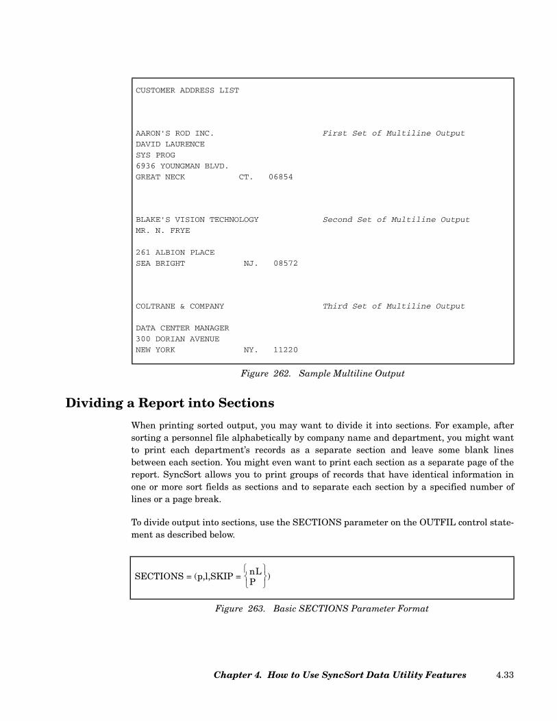
Dividing a Report into Sections
When printing sorted output, you may want to divide it into sections. For example, aftersorting a personnel file alphabetically by company name and department, you might wantto print each department’s records as a separate section and leave some blank linesbetween each section. You might even want to print each section as a separate page of thereport. SyncSort allows you to print groups of records that have identical information inone or more sort fields as sections and to separate each section by a specified number oflines or a page break.
To divide output into sections, use the SECTIONS parameter on the OUTFIL control state-ment as described below.
CUSTOMER ADDRESS LIST
AARON'S ROD INC. First Set of Multiline Output
DAVID LAURENCE
SYS PROG
6936 YOUNGMAN BLVD.
GREAT NECK CT. 06854
BLAKE'S VISION TECHNOLOGY Second Set of Multiline Output
MR. N. FRYE
261 ALBION PLACE
SEA BRIGHT NJ. 08572
COLTRANE & COMPANY Third Set of Multiline Output
DATA CENTER MANAGER
300 DORIAN AVENUE
NEW YORK NY. 11220
Figure 262. Sample Multiline Output
Figure 263. Basic SECTIONS Parameter Format
SECTIONS = (p,l,SKIP = nLP
)
Chapter 4. How to Use SyncSort Data Utility Features 4.33
Note: See “SECTIONS Parameter (Optional)” on page 2.162 for the complete syntax of theSECTIONS parameter.
p,l Specify the starting position and the length in bytes of the field thatyou have chosen to determine section breaks. (Note: Typically, thisfield is one on which the data has been sorted.) A section break willoccur every time the data in this sort field changes.
When specifying the fields that control section breaks, keep the fol-lowing in mind:
• Give the position and length of the field as it appears after anyprocessing by an E15 or E32 exit, the INREC control statement,the OUTREC control statement, and an E35 exit, but beforeprocessing due to the OUTREC and/or other OUTFILparameters.
• You may specify more than one field in order to subdivide thereport within sections. Specify the major control field first,followed (in major to minor order) by the control fields that willgenerate breaks within a major section.
SKIP=nL Specifies the number of lines (nL) that should be skipped betweeneach section. Spacing occurs after the last section trailer(TRAILER3) in the section.
SKIP=P Specifies a page break (P). Spacing occurs after the last sectiontrailer (TRAILER3) in the section.
Dividing Output into Sections
Example: A personnel roster is to be divided into sections by Department. (Figure 264 pre-sents the layout for the input record.)
SyncSort for z/VSE 3.7 Programmer’s Guide4.34
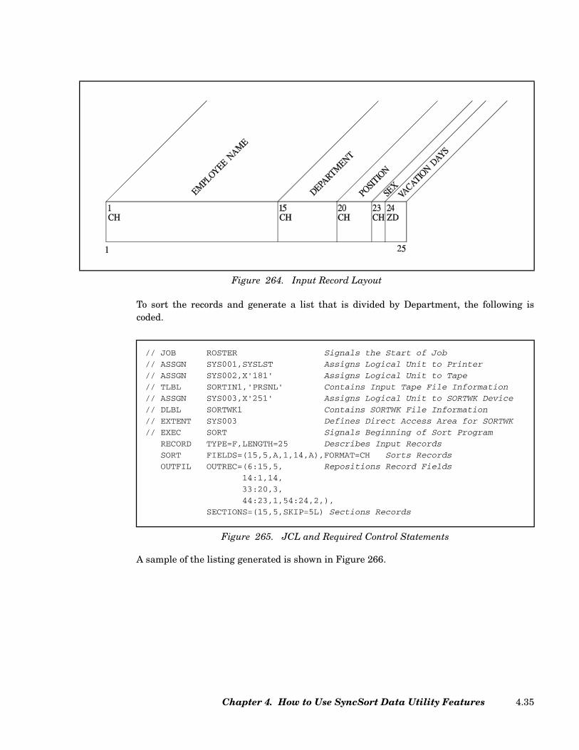
To sort the records and generate a list that is divided by Department, the following iscoded.
A sample of the listing generated is shown in Figure 266.
Figure 264. Input Record Layout
// JOB ROSTER Signals the Start of Job
// ASSGN SYS001,SYSLST Assigns Logical Unit to Printer
// ASSGN SYS002,X'181' Assigns Logical Unit to Tape
// TLBL SORTIN1,'PRSNL' Contains Input Tape File Information
// ASSGN SYS003,X'251' Assigns Logical Unit to SORTWK Device
// DLBL SORTWK1 Contains SORTWK File Information
// EXTENT SYS003 Defines Direct Access Area for SORTWK
// EXEC SORT Signals Beginning of Sort Program
RECORD TYPE=F,LENGTH=25 Describes Input Records
SORT FIELDS=(15,5,A,1,14,A),FORMAT=CH Sorts Records
OUTFIL OUTREC=(6:15,5, Repositions Record Fields
14:1,14,
33:20,3,
44:23,1,54:24,2,),
SECTIONS=(15,5,SKIP=5L) Sections Records
Figure 265. JCL and Required Control Statements
Chapter 4. How to Use SyncSort Data Utility Features 4.35

Explanation: After the records are sorted alphabetically by Department (15,5) andEmployee Name (1,14), they are divided into sections by department. That is, every timethere is a change in the Department field (15,5 in the input record) the printer skips 5 lines(5L) before printing the next record. (Note, in the Sample Output above, the five-line breakthat occurs between ACCTG and PRSNL.) The OUTREC parameter is used to repositionthe record fields and to leave blanks between them.
Writing Headers and Trailers for a Report
Headers are used to provide report, page, and section headings such as titles, page num-bers, the current date, labels for each column of data, and the like. Similarly, trailers areused for report, page, and section summaries. You can use them, for example, to providetotals for columns of numeric data (see “Totaling and Subtotaling Data” on page 4.46) or toindicate the end of a section with, for example, a string of asterisks or to provide a list ofabbreviations used in the report.
ACCTG BELL PAT SUP F 03
ACCTG EMERY PAUL CLK M 04
ACCTG JONES MARK CLK M 01
ACCTG NORTH NANCY MGR F 02
ACCTG OWEN JERRY CLK M 03
ACCTG TWAIN JOAN SEC F 05
ACCTG WEST DONNA CLK F 03
PRSNL SMITHE JON CLK M 00
PRSNL TOWERS LINDA CLK F 02
PRSNL VREES GEORGE CLK M 02
PRSNL WU JANE SUP F 05
PRSNL YOUNG RUSS MGR M 03
Figure 266. Sample Output
SyncSort for z/VSE 3.7 Programmer’s Guide4.36

To generate Headers and/or Trailers, code the OUTFIL statement as described below:
Note: See “HEADER1/HEADER2 Parameters (Optional)” on page 2.149 and “TRAILER1/TRAILER2 Parameters (Optional)” on page 2.164 for complete formats of HEADER andTRAILER parameters.
HEADERn Use a HEADER1 for a title page, a HEADER2 for a pageheader, a HEADER3 for a section header. Note: HEADER3must be specified as a subparameter of the SECTIONSparameter.
TRAILERn Specify a TRAILER1 for a report trailer, a TRAILER2 for apage trailer, a TRAILER3 for a section trailer. Note:TRAILER3 must be specified as a subparameter of theSECTIONS parameter.
c: Specify the column in which you want the entry to beginprinting.
n Specify the number of times you want the blank (X), charac-ter data ('literal string'), or forward spacing (/) repeated.
p,l Specify the starting position (p) and the length in bytes (l) ofthe data-record field(s) that you want to include in either aheader or trailer. For a HEADER1, the field(s) will beextracted from the first data record in the report; for aHEADER2, from the first data record on the page; for aHEADER3, from the first data record in the section. For aTRAILER1, the field(s) will be extracted from the last datarecord in the report; for a TRAILER2, from the last datarecord on a page; for a TRAILER3, from the last data recordin the section.
Figure 267. Basic HEADER and TRAILER Parameter Formats
HEADERTRAILER
1
23
=([c:]
[n]X[n]C'literal string'[n]'literal string'[n]/p,l[&DATE][DATE][DATE(abcd)][&TIME][TIME][TIME(nnc)][&PAGE]
,...)
Chapter 4. How to Use SyncSort Data Utility Features 4.37

&DATE=(abcd) The &DATE or DATE subparameter specifies the currentgenerated system date and requires 8 bytes. abcd indicatesthat you arrange the year, month, and day in any order. c isthe separator character. Use M to denote month, D todenote day, and Y to denote the last two characters of theyear. You can specify 4 as an alternative to Y if you wantthe year expressed in four digits (2006 as opposed to 06).
For example, if the current date is 4/24/06 and&DATE=(DMY.), the output date is 24.04.06. With thesame example, if &DATE=(4MD-), the output date is 2006-04-24.
&TIME=(nnc) The &TIME subparameter specifies the current step starttime, which is the time that the current execution of SyncSort began. The default time format is hh:mm:ss.
nn can be either 12 or 24. 24 specifies twenty-four hourclock with the format hhcmmcss and requires 8 bytes. 12specifies twelve hour clock with the format hhcmmcss xxand requires 11 bytes. xx can be either am or pm. c denotesthe separation character. For example, &TIME=(24-)expresses 7:31 pm as 19-31-00.
&PAGE Specify this parameter if you want the logical pages to benumbered sequentially. Page numbers appear in a six-byteformat that is right justified with leading zeros suppressed.
Note: If any specified HEADER or TRAILER exceeds the length of the post-OUTRECrecord, be sure to code the LRECL parameter on the OUTFIL statement to match thelength of the longest header or trailer. If this length is unknown, you may specifyLRECL=132.
Writing a Title Page for a Report
Example: Marketing wants a title page for its monthly departmental sales report. Thethree-line title will begin on line 16 and three blank lines will separate each line of the title.The three lines will start printing in columns 49, 59, and 63, respectively.
To print this title page, the following is coded.
SyncSort for z/VSE 3.7 Programmer’s Guide4.38

Figure 269 shows the header that is generated by the above HEADER1 parameter:
Explanation: The HEADER1 parameter produces a header that will print on a separatepage, with no page number, at the beginning of the report. The first number-slash (n/)entry, 15/, causes the printer to skip 15 lines before printing. The following number-colonentry (c:), 49:, specifies the column in which the literal string 'D E P A R T M E N T A L S A L E S' begins to print. Note that the literal string printsexactly as it is entered between the single quotes, with a space between each letter and adouble space between the words.
The next entry, 4/, causes the printer to skip 3 more blank lines before starting to print theliteral string 'F E B R U A R Y' in column 59.
Finally, three more lines are left blank (4/) and the literal string '2 0 0 0' begins printing incolumn 63.
// JOB DSRPT Signals the Start of Job
// ASSGN SYS001,SYSLST Assigns Logical Unit to Printer
// ASSGN SYS002,X'181' Assigns Logical Unit to Tape
// TLBL SORTIN1,'SALES' Contains Input Tape File Information
// ASSGN SYS003,X'251' Assigns Logical Unit to SORTWK Device
// DLBL SORTWK1 Contains SORTWK File Information
// EXTENT SYS003 Defines Direct Access Area for SORTWK
// EXEC SORT Signals Beginning of Sort Program
RECORD TYPE=F,LENGTH=80 Describes Input Records
SORT FIELDS=(1,15,CH,A) Sorts Records
.
.
.
OUTFIL HEADER1=(15/,49:'D E P A R T M E N T A L S A L E S',
4/,59:'F E B R U A R Y',
4/,63:'2 0 0 0'), Generates Title Page
.
.
.
Figure 268. JCL and Required Control Statements
D E P A R T M E N T A L S A L E S
F E B R U A R Y
2 0 0 0
Figure 269. Sample HEADER1
Chapter 4. How to Use SyncSort Data Utility Features 4.39
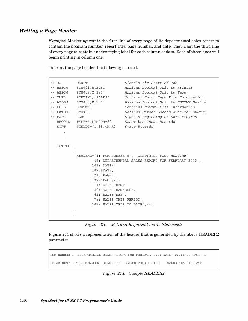
Writing a Page Header
Example: Marketing wants the first line of every page of its departmental sales report tocontain the program number, report title, page number, and date. They want the third lineof every page to contain an identifying label for each column of data. Each of these lines willbegin printing in column one.
To print the page header, the following is coded.
Figure 271 shows a representation of the header that is generated by the above HEADER2parameter.
// JOB DSRPT Signals the Start of Job
// ASSGN SYS001,SYSLST Assigns Logical Unit to Printer
// ASSGN SYS002,X'181' Assigns Logical Unit to Tape
// TLBL SORTIN1,'SALES' Contains Input Tape File Information
// ASSGN SYS003,X'251' Assigns Logical Unit to SORTWK Device
// DLBL SORTWK1 Contains SORTWK File Information
// EXTENT SYS003 Defines Direct Access Area for SORTWK
// EXEC SORT Signals Beginning of Sort Program
RECORD TYPE=F,LENGTH=80 Describes Input Records
SORT FIELDS=(1,15,CH,A) Sorts Records
.
.
.
OUTFIL .
.
HEADER2=(1:'PGM NUMBER 5', Generates Page Heading
46:'DEPARTMENTAL SALES REPORT FOR FEBRUARY 2000',
101:'DATE:',
107:&DATE,
121:'PAGE:',
127:&PAGE,//,
1:'DEPARTMENT',
40:'SALES MANAGER',
61:'SALES REP',
78:'SALES THIS PERIOD',
103:'SALES YEAR TO DATE',//),
.
.
Figure 270. JCL and Required Control Statements
PGM NUMBER 5 DEPARTMENTAL SALES REPORT FOR FEBRUARY 2000 DATE: 02/01/00 PAGE: 1
DEPARTMENT SALES MANAGER SALES REP SALES THIS PERIOD SALES YEAR TO DATE
Figure 271. Sample HEADER2
SyncSort for z/VSE 3.7 Programmer’s Guide4.40
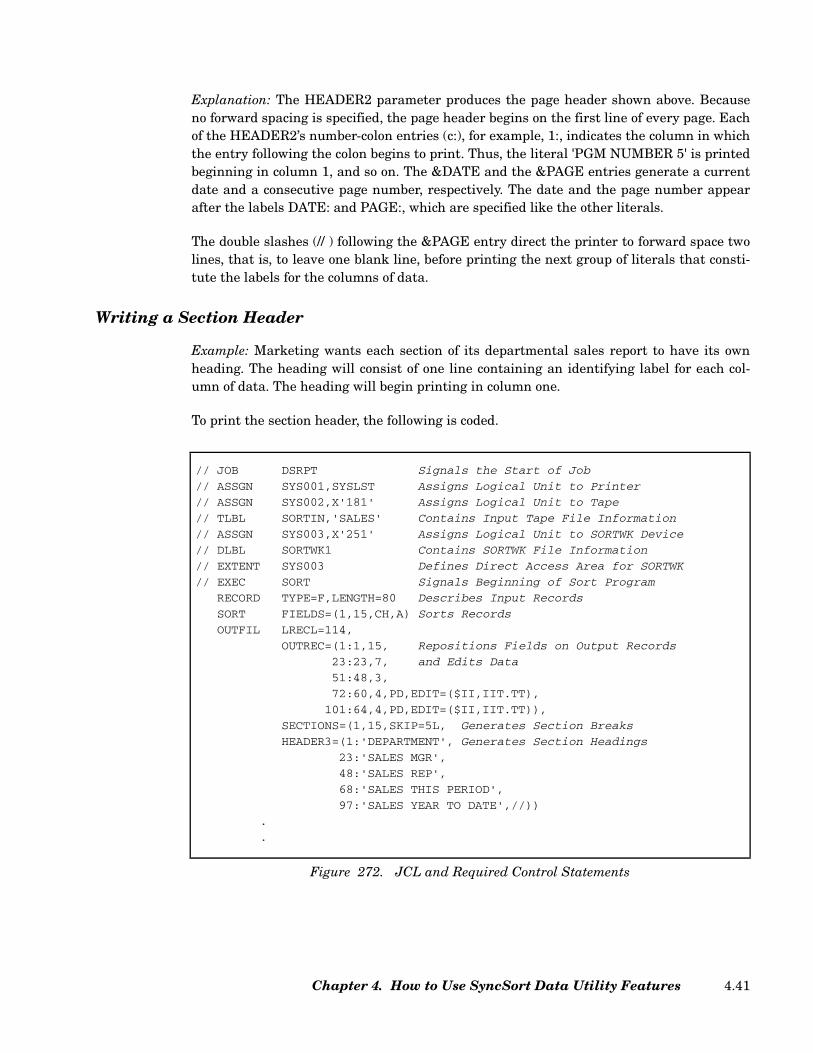
Explanation: The HEADER2 parameter produces the page header shown above. Becauseno forward spacing is specified, the page header begins on the first line of every page. Eachof the HEADER2’s number-colon entries (c:), for example, 1:, indicates the column in whichthe entry following the colon begins to print. Thus, the literal 'PGM NUMBER 5' is printedbeginning in column 1, and so on. The &DATE and the &PAGE entries generate a currentdate and a consecutive page number, respectively. The date and the page number appearafter the labels DATE: and PAGE:, which are specified like the other literals.
The double slashes (// ) following the &PAGE entry direct the printer to forward space twolines, that is, to leave one blank line, before printing the next group of literals that consti-tute the labels for the columns of data.
Writing a Section Header
Example: Marketing wants each section of its departmental sales report to have its ownheading. The heading will consist of one line containing an identifying label for each col-umn of data. The heading will begin printing in column one.
To print the section header, the following is coded.
// JOB DSRPT Signals the Start of Job
// ASSGN SYS001,SYSLST Assigns Logical Unit to Printer
// ASSGN SYS002,X'181' Assigns Logical Unit to Tape
// TLBL SORTIN,'SALES' Contains Input Tape File Information
// ASSGN SYS003,X'251' Assigns Logical Unit to SORTWK Device
// DLBL SORTWK1 Contains SORTWK File Information
// EXTENT SYS003 Defines Direct Access Area for SORTWK
// EXEC SORT Signals Beginning of Sort Program
RECORD TYPE=F,LENGTH=80 Describes Input Records
SORT FIELDS=(1,15,CH,A) Sorts Records
OUTFIL LRECL=114,
OUTREC=(1:1,15, Repositions Fields on Output Records
23:23,7, and Edits Data
51:48,3,
72:60,4,PD,EDIT=($II,IIT.TT),
101:64,4,PD,EDIT=($II,IIT.TT)),
SECTIONS=(1,15,SKIP=5L, Generates Section Breaks
HEADER3=(1:'DEPARTMENT', Generates Section Headings
23:'SALES MGR',
48:'SALES REP',
68:'SALES THIS PERIOD',
97:'SALES YEAR TO DATE',//))
.
.
Figure 272. JCL and Required Control Statements
Chapter 4. How to Use SyncSort Data Utility Features 4.41

Figure 273 shows the header that is generated by the above HEADER3 subparameter.
Explanation: The HEADER3 subparameter on the SECTIONS parameter generates aheader that prints at the beginning of each section. Its primary purpose here is to providelabels for the columns of data that appear in each section. Each of the number-colon entries(c:) specifies the column in which the entry following it should begin to print. Thus, the lit-eral string 'DEPARTMENT' begins to print in column 1, the literal string 'SALES MGR'begins to print in column 23, and so on. Blanks are automatically inserted in the spacebetween the columns that are specified. LRECL=114 has been specified on the OUTFILstatement so that the length of the output record will equal that of the header. Note that ifthe HEADER3 in this example were used in conjunction with the preceding HEADER2example, there would be no need to specify the labels for the columns of data in theHEADER2.
Using a Header to Eliminate Duplicate Information within a Section
Example: Rather than repeat the department name and sales manager, which are identicalfor every record included in a section of the departmental sales report, marketing wantsthis information to appear only once — within the section headers of the report. Therefore,the section header’s first two entries (Department and Sales Manager) will be drawndirectly from the first data record in each section.
To print the section header with the input data fields, the following is coded.
DEPARTMENT SALES MGR SALES REP SALES THIS PERIOD SALES YEAR TO DATE
OVER COUNTER CASEY 075 $14,000.00 $27,000.00
OVER COUNTER CASEY 093 13,550.00 32,000.00
OVER COUNTER CASEY 084 11,755.00 24,850.00
OVER COUNTER CASEY 090 12,250.00 25,000.00
OVER COUNTER CASEY 095 13,075.00 26,180.00
DEPARTMENT SALES MGR SALES REP SALES THIS PERIOD SALES YEAR TO DATE
SURGICAL KILDARE 003 $11,750.00 $25,320.00
SURGICAL KILDARE 007 14,300.00 24,900.00
SURGICAL KILDARE 009 11,110.00 30,850.00
SURGICAL KILDARE 004 13,375.00 27,505.00
. . . . .
. . . . .
. . . . .
Figure 273. Sample Sections with HEADER3
SyncSort for z/VSE 3.7 Programmer’s Guide4.42

Figure 275 shows the header that is generated by the above HEADER3 subparameter.
// JOB DSRPT Signals the Start of Job
// ASSGN SYS001,SYSLST Assigns Logical Unit to Printer
// ASSGN SYS002,X'181' Assigns Logical Unit to Tape
// TLBL SORTIN1,'SALES' Contains Input Tape File Information
// ASSGN SYS003,X'251' Assigns Logical Unit to SORTWK Device
// TLBL SORTWK1 Contains SORTWK File Information
// EXTENT SYS003 Defines Direct Access Area for SORTWK
// EXEC SORT Signals Beginning of Sort Program
RECORD TYPE=F,LENGTH=80 Describes Input Records
SORT FIELDS=(1,15,CH,A) Sorts Records
OUTFIL LRECL=114,
OUTREC=(51:48,3, Repositions Fields on Output Records
72:60,4,PD,EDIT=($II,IIT.TT), and Edits Data
101:64,4,PD,EDIT=($II,IIT.TT)),
SECTIONS=(1,15,SKIP=5L, Generates Section Breaks
HEADER3=(1:1,15, Generates Section Headings
23:23,7,
48:'SALES REP',
68:'SALES THIS PERIOD',
97:'SALES YEAR TO DATE'//))
Figure 274. JCL and Required Control Statements
OVER COUNTER CASEY SALES REP SALES THIS PERIOD SALES YEAR TO DATE
075 $14,000.00 $27,000.00
093 $13,550.00 $32,000.00
084 $11,755.00 $24,850.00
090 $12,250.00 $25,000.00
095 $13,075.00 $26,180.00
SURGICAL KILDARE SALES REP SALES THIS PERIOD SALES YEAR TO DATE
003 $11,750.00 $25,320.00
007 $14,300.00 $24,900.00
009 $11,110.00 $30,850.00
004 $13,375.00 $27,505.00
. . .
. . .
. . .
Figure 275. Sample Sections with HEADER3 Including Data from Input Record
Chapter 4. How to Use SyncSort Data Utility Features 4.43
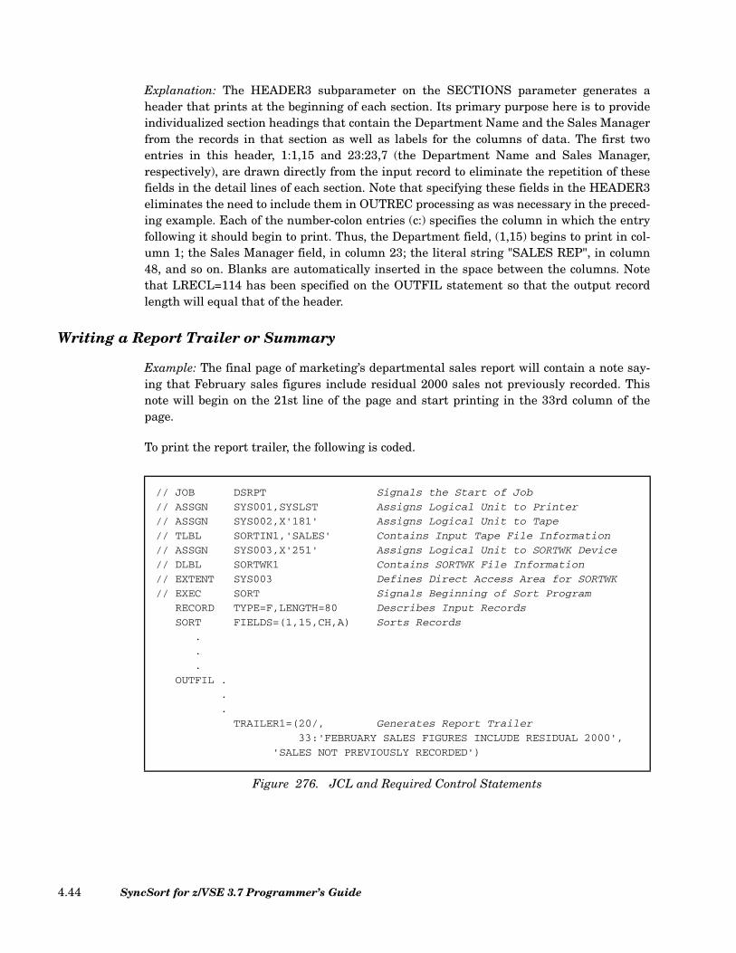
Explanation: The HEADER3 subparameter on the SECTIONS parameter generates aheader that prints at the beginning of each section. Its primary purpose here is to provideindividualized section headings that contain the Department Name and the Sales Managerfrom the records in that section as well as labels for the columns of data. The first twoentries in this header, 1:1,15 and 23:23,7 (the Department Name and Sales Manager,respectively), are drawn directly from the input record to eliminate the repetition of thesefields in the detail lines of each section. Note that specifying these fields in the HEADER3eliminates the need to include them in OUTREC processing as was necessary in the preced-ing example. Each of the number-colon entries (c:) specifies the column in which the entryfollowing it should begin to print. Thus, the Department field, (1,15) begins to print in col-umn 1; the Sales Manager field, in column 23; the literal string "SALES REP", in column48, and so on. Blanks are automatically inserted in the space between the columns. Notethat LRECL=114 has been specified on the OUTFIL statement so that the output recordlength will equal that of the header.
Writing a Report Trailer or Summary
Example: The final page of marketing’s departmental sales report will contain a note say-ing that February sales figures include residual 2000 sales not previously recorded. Thisnote will begin on the 21st line of the page and start printing in the 33rd column of thepage.
To print the report trailer, the following is coded.
// JOB DSRPT Signals the Start of Job
// ASSGN SYS001,SYSLST Assigns Logical Unit to Printer
// ASSGN SYS002,X'181' Assigns Logical Unit to Tape
// TLBL SORTIN1,'SALES' Contains Input Tape File Information
// ASSGN SYS003,X'251' Assigns Logical Unit to SORTWK Device
// DLBL SORTWK1 Contains SORTWK File Information
// EXTENT SYS003 Defines Direct Access Area for SORTWK
// EXEC SORT Signals Beginning of Sort Program
RECORD TYPE=F,LENGTH=80 Describes Input Records
SORT FIELDS=(1,15,CH,A) Sorts Records
.
.
.
OUTFIL .
.
.
TRAILER1=(20/, Generates Report Trailer
33:'FEBRUARY SALES FIGURES INCLUDE RESIDUAL 2000',
'SALES NOT PREVIOUSLY RECORDED')
Figure 276. JCL and Required Control Statements
SyncSort for z/VSE 3.7 Programmer’s Guide4.44
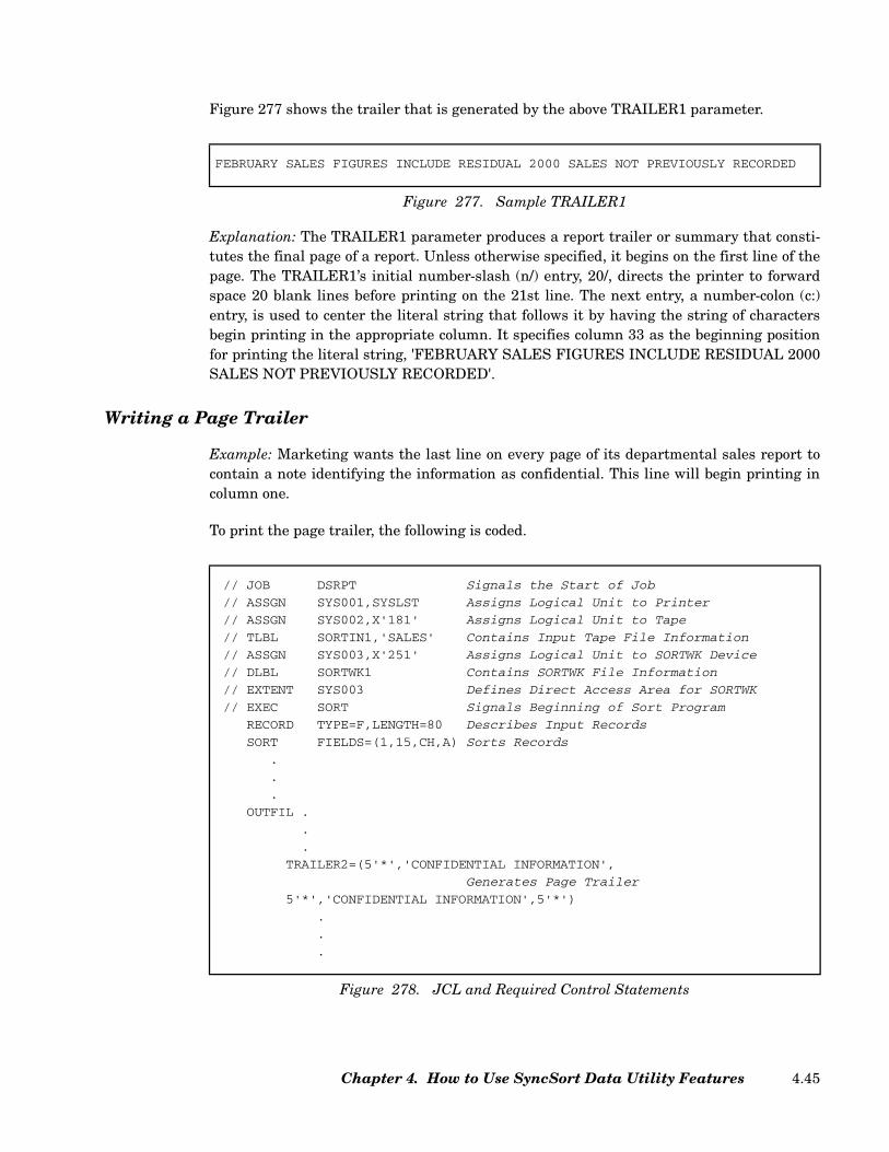
Figure 277 shows the trailer that is generated by the above TRAILER1 parameter.
Explanation: The TRAILER1 parameter produces a report trailer or summary that consti-tutes the final page of a report. Unless otherwise specified, it begins on the first line of thepage. The TRAILER1’s initial number-slash (n/) entry, 20/, directs the printer to forwardspace 20 blank lines before printing on the 21st line. The next entry, a number-colon (c:)entry, is used to center the literal string that follows it by having the string of charactersbegin printing in the appropriate column. It specifies column 33 as the beginning positionfor printing the literal string, 'FEBRUARY SALES FIGURES INCLUDE RESIDUAL 2000SALES NOT PREVIOUSLY RECORDED'.
Writing a Page Trailer
Example: Marketing wants the last line on every page of its departmental sales report tocontain a note identifying the information as confidential. This line will begin printing incolumn one.
To print the page trailer, the following is coded.
FEBRUARY SALES FIGURES INCLUDE RESIDUAL 2000 SALES NOT PREVIOUSLY RECORDED
Figure 277. Sample TRAILER1
// JOB DSRPT Signals the Start of Job
// ASSGN SYS001,SYSLST Assigns Logical Unit to Printer
// ASSGN SYS002,X'181' Assigns Logical Unit to Tape
// TLBL SORTIN1,'SALES' Contains Input Tape File Information
// ASSGN SYS003,X'251' Assigns Logical Unit to SORTWK Device
// DLBL SORTWK1 Contains SORTWK File Information
// EXTENT SYS003 Defines Direct Access Area for SORTWK
// EXEC SORT Signals Beginning of Sort Program
RECORD TYPE=F,LENGTH=80 Describes Input Records
SORT FIELDS=(1,15,CH,A) Sorts Records
.
.
.
OUTFIL .
.
.
TRAILER2=(5'*','CONFIDENTIAL INFORMATION',
Generates Page Trailer
5'*','CONFIDENTIAL INFORMATION',5'*')
.
.
.
Figure 278. JCL and Required Control Statements
Chapter 4. How to Use SyncSort Data Utility Features 4.45

Figure 279 shows the trailer that is generated by the above TRAILER2 parameter.
Explanation: The TRAILER2 coded above provides a trailer that appears at the bottom ofevery logical page. The first entry, 5'*', a literal enclosed in single quotes (in this case anasterisk) and a repetition factor (5), specifies that 5 asterisks should be printed. Because nocolumn was specified, the trailer begins in column one. The next entry, 'CONFIDENTIALINFORMATION', specifies that the literal string enclosed in the single quotes shoulddirectly follow the asterisks. Note that the literal string is printed exactly as it is codedwithin the quotation marks. The trailer’s other entries specify the printing of another fiveasterisks followed by the literal string 'CONFIDENTIAL INFORMATION' and finallyanother five asterisks.
Totaling and Subtotaling Data
Writing a summary or trailer for a report will sometimes involve providing totals for col-umns of figures. For example, you would probably want a trailer for an inventory report tocontain the total number of items on hand. The OUTFIL statement allows you to writetrailers that contain both totals and subtotals. Moreover, you can total data at the end of areport, at the end of a page, and also at the end of a section.
The TOTAL and SUBTOTAL entries of OUTFIL’s TRAILER parameters and subparame-ter are described below.
c: Specify the column in which you want the entry to beginprinting.
TRAILERn Specify a TRAILER1 for a report trailer, a TRAILER2 for apage trailer, a TRAILER3 for a section trailer. NOTE: Spec-ify a TRAILER3 only as a subparameter of the SECTIONSparameter.
TOTAL/TOT Use this parameter if you want the numeric data that youspecify totaled at the end of a report, page, or section.
SUBTOTAL/SUB Use this parameter if you want a running total of thenumeric data you specify.
*****CONFIDENTIAL INFORMATION*****CONFIDENTIAL INFORMATION*****
Figure 279. Sample TRAILER3
Figure 280. TRAILER Format for TOTALS and SUBTOTALS
TRAILER123
= ([c:] TOTALSUBTOTAL
= (p,l,f ,Mm,EDIT = (pattern)
,SIGNS = (...)[ ] ,LENGTH = (n)[ ]...)
SyncSort for z/VSE 3.7 Programmer’s Guide4.46
p Specify the beginning position of the numeric field on theinput record.
Note: This position should reflect any changes in the recorddue to any processing other than OUTFIL processing.
l Specify the length of the numeric field that you wanttotaled.
f Specify the format of the numeric data.
Mm Specify one of ten SyncSort editing masks to format thetotal. (See “Mm Subparameter (Editing Masks)” on page2.202.)
Note: If neither Mm nor EDIT is specified, a default editmask is used.
EDIT=(pattern) Specify your own editing mask or pattern to format thetotal. (See “EDIT Subparameter” on page 2.200.)
SIGNS=(...) Specify leading and/or trailing sign indicators to be usedwith the edit pattern or SyncSort mask.
LENGTH=(n) Specify the length of the edited total to alter the defaultlength of an edit pattern or SyncSort mask.
Note: If any specified TRAILER exceeds the length of the post-OUTREC record, be sure tocode the LRECL parameter on the OUTFIL statement to match the length of the longestheader or trailer. If this length is unknown, you may specify LRECL=132.
Totaling Data at the End of a Report
Example: The departmental sales report’s final page will be a summary containing both thetotal for the sales this period and the total for the sales to date. The trailer will begin on the21st line of the page and each total will have an identifying label.
To print the report trailer, the following is coded.
Chapter 4. How to Use SyncSort Data Utility Features 4.47
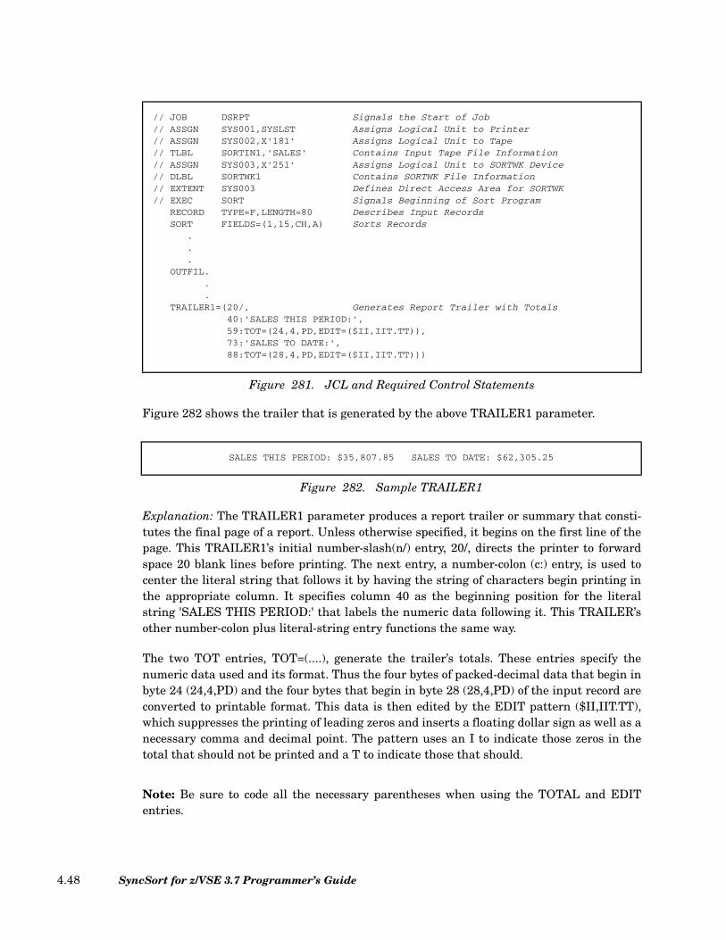
Figure 282 shows the trailer that is generated by the above TRAILER1 parameter.
Explanation: The TRAILER1 parameter produces a report trailer or summary that consti-tutes the final page of a report. Unless otherwise specified, it begins on the first line of thepage. This TRAILER1’s initial number-slash(n/) entry, 20/, directs the printer to forwardspace 20 blank lines before printing. The next entry, a number-colon (c:) entry, is used tocenter the literal string that follows it by having the string of characters begin printing inthe appropriate column. It specifies column 40 as the beginning position for the literalstring 'SALES THIS PERIOD:' that labels the numeric data following it. This TRAILER’sother number-colon plus literal-string entry functions the same way.
The two TOT entries, TOT=(....), generate the trailer’s totals. These entries specify thenumeric data used and its format. Thus the four bytes of packed-decimal data that begin inbyte 24 (24,4,PD) and the four bytes that begin in byte 28 (28,4,PD) of the input record areconverted to printable format. This data is then edited by the EDIT pattern ($II,IIT.TT),which suppresses the printing of leading zeros and inserts a floating dollar sign as well as anecessary comma and decimal point. The pattern uses an I to indicate those zeros in thetotal that should not be printed and a T to indicate those that should.
Note: Be sure to code all the necessary parentheses when using the TOTAL and EDITentries.
// JOB DSRPT Signals the Start of Job// ASSGN SYS001,SYSLST Assigns Logical Unit to Printer// ASSGN SYS002,X'181' Assigns Logical Unit to Tape// TLBL SORTIN1,'SALES' Contains Input Tape File Information// ASSGN SYS003,X'251' Assigns Logical Unit to SORTWK Device// DLBL SORTWK1 Contains SORTWK File Information// EXTENT SYS003 Defines Direct Access Area for SORTWK// EXEC SORT Signals Beginning of Sort Program
RECORD TYPE=F,LENGTH=80 Describes Input RecordsSORT FIELDS=(1,15,CH,A) Sorts Records
.
.
.OUTFIL.
.
.TRAILER1=(20/, Generates Report Trailer with Totals
40:'SALES THIS PERIOD:',59:TOT=(24,4,PD,EDIT=($II,IIT.TT)),73:'SALES TO DATE:',88:TOT=(28,4,PD,EDIT=($II,IIT.TT)))
Figure 281. JCL and Required Control Statements
SALES THIS PERIOD: $35,807.85 SALES TO DATE: $62,305.25
Figure 282. Sample TRAILER1
SyncSort for z/VSE 3.7 Programmer’s Guide4.48

Subtotaling Data at the End of a Page
Example: The page trailer for a report listing invoices is to contain the totals for theAmount Paid and the Balance Due fields of the invoice records printed up to and includingthat page. These totals will appear directly below the columns of figures and be separatedfrom them by strings of hyphens. An identifying label, TOTALS:, will appear on the sameline as the totals and will begin in column 40.
To generate the trailer, the following is coded.
// JOB INVLST Signals the Start of Job
// ASSGN SYS001,SYSLST Assigns Logical Unit to Printer
// ASSGN SYS002,X'181' Assigns Logical Unit to Tape
// TLBL SORTIN1,'INVOICE' Contains Input Tape File Information
// ASSGN SYS003,X'251' Assigns Logical Unit to SORTWK Device
// DLBL SORTWK1 Contains SORTWK File Information
// EXTENT SYS003 Defines Direct Access Area for SORTWK
// EXEC SORT Signals Beginning of Sort Program
RECORD TYPE=F,LENGTH=155 Describes Input Records
SORT FIELDS=(9,23,A,36,2,A,32,4,A),FORMAT=CH Sorts Records
.
.
.
OUTFIL.
.
.
TRAILER2=(65:10'-',86:10'-',/, Generates Page Trailer
40:'TOTALS:', with Running Totals
65:SUB=(46,4,PD,EDIT=($II,IIT.TT)),
86:SUB=(54,4,PD,EDIT=($II,IIT.TT)))
Figure 283. JCL and Required Control Statements
Chapter 4. How to Use SyncSort Data Utility Features 4.49

Figure 284 shows the trailer that is produced.
Explanation: The above TRAILER2 provides for totaling the figures in the Amount Paidfield (46,4,PD) and the Amount Due field (54,4,PD) on the invoice records. Because theSUB (SUBTOTAL) entry is specified, the totals that appear at the bottom of each page rep-resent running totals, that is, the totals for all the records that have been printed up to andincluding that page. The TRAILER2 also generates the identifying label TOTALS:(40:'TOTALS:') and strings of hyphens at the bottoms of the columns to be totaled (65:10'-',86:10'-').
The totaled data for each field is converted to printable format and, after being edited,begins printing in the columns specified with the two number colon entries (c:), 65: and 86:.The data is edited by the EDIT pattern, ($II,IIT.TT), which suppresses the printing of lead-ing zeros and inserts a floating dollar sign as well as the necessary comma and decimalpoint. The pattern uses an I to indicate the zeros in the total that should not be printed anda T to indicate those that should.
Totaling Data at the End of a Section
Example: The section trailer for an accounts receivable report sectioned by month is to con-tain the totals for the Amount Paid and the Balance Due columns of each section. Thesetotals will appear directly below the columns of figures and be separated from them bystrings of hyphens. An identifying label, TOTALS:, will appear on the same line as thetotals and will begin in column 40.
To generate the trailer, the following is coded.
. . . . .
. . . . .
. . . . .MERLINS TRUST CO 82124054 12/15/92 0.00 1,500.00MEWER COLLEGE 83013324 1/17/92 0.00 1,500.00NORTHEAST INDUST 83013303 1/17/92 200.00 200.00PARK PLACE CORP 83022211 2/15/92 0.00 650.00PATIO PRODUCTS 83022203 2/15/92 0.00 850.00PINES ASSOCIATES 83022587 2/15/92 0.00 750.00POLL DATA CORP 82124019 12/15/92 0.00 600.00PRIESTLEY METALS 83022201 2/15/92 0.00 1,600.00REGENCY TRUST CO 82124011 12/15/92 0.00 1,500.00REPUBLIC DATA 83013306 1/17/92 0.00 1,100.00RIBBIT TECHNOLOGIES 82124020 12/15/92 0.00 360.00RICE FEATURES 82124015 12/15/92 750.00 750.00RICE FEATURES 83013298 1/17/92 0.00 1,500.00RICE FEATURES 83022198 2/15/92 0.00 1,500.00ROBINS NEST CORP 83013353 1/17/92 0.00 900.00SIDNEY COLLEGE 82124016 12/15/92 0.00 5,000.00SIDNEY COLLEGE 83013297 1/17/92 0.00 2,500.00
---------- ----------TOTALS: $6,150.00 $66,475.00
Figure 284. TRAILER2 with SUBTOTAL
SyncSort for z/VSE 3.7 Programmer’s Guide4.50
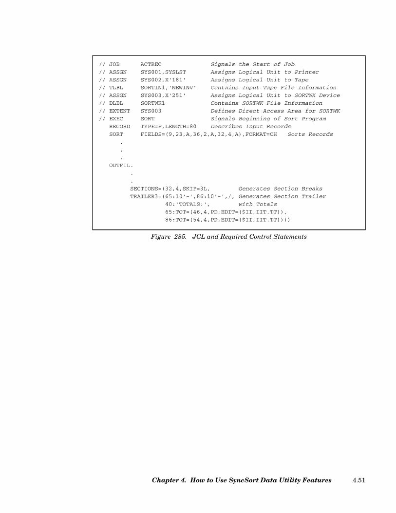
// JOB ACTREC Signals the Start of Job
// ASSGN SYS001,SYSLST Assigns Logical Unit to Printer
// ASSGN SYS002,X'181' Assigns Logical Unit to Tape
// TLBL SORTIN1,'NEWINV' Contains Input Tape File Information
// ASSGN SYS003,X'251' Assigns Logical Unit to SORTWK Device
// DLBL SORTWK1 Contains SORTWK File Information
// EXTENT SYS003 Defines Direct Access Area for SORTWK
// EXEC SORT Signals Beginning of Sort Program
RECORD TYPE=F,LENGTH=80 Describes Input Records
SORT FIELDS=(9,23,A,36,2,A,32,4,A),FORMAT=CH Sorts Records
.
.
.
OUTFIL.
.
.
SECTIONS=(32,4,SKIP=3L, Generates Section Breaks
TRAILER3=(65:10'-',86:10'-',/, Generates Section Trailer
40:'TOTALS:', with Totals
65:TOT=(46,4,PD,EDIT=($II,IIT.TT)),
86:TOT=(54,4,PD,EDIT=($II,IIT.TT))))
Figure 285. JCL and Required Control Statements
Chapter 4. How to Use SyncSort Data Utility Features 4.51

Figure 286 shows the section trailer, with totals, that is produced.
Explanation: In addition to generating strings of hyphens at the bottom of the columns tobe totaled (65:10'-',86:10'-') and the identifying label TOTALS: on the line below(40:'TOTALS:'), the TRAILER3 provides for totaling the figures in the Amount Paid field(46,4,PD) and the Amount Due field (54,4,PD) on the invoice records. Note that because theTOT (TOTAL) entry is specified, the totals that appear at the end of each section representthe totals only for the records that are included in that section.
The totaled data for each field is converted to printable format and, after being edited,begins printing in the columns specified with the two number colon entries (c:), 65: and 86:.The data is edited by the EDIT pattern, ($II,IIT.TT), which suppresses the printing of lead-ing zeros and inserts a floating dollar sign as well as the necessary comma and decimalpoint. The pattern uses an I to indicate the zeros in the total that should not be printed anda T to indicate those that should.
. . . . .
. . . . .
. . . . .
WINIFRED INDUST 82124013 12/15/91 300.00 350.00
-------- ---------
TOTALS: $2,600.00 $19,770.00
ARLINE FRAGRANCES 83013304 1/17/92 0.00 7,500.00
CHARACTER DATA 83013343 1/17/92 0.00 1,100.00
COUNTRY INDUSTRIAL 83013557 1/17/92 0.00 950.00
DUNHAM INDUST INC 83013302 1/17/92 0.00 850.00
ECHO LABS INC 83013300 1/17/92 0.00 550.00
ESS SECURITIES 83013311 1/17/92 0.00 550.00
EVERMORE INDUST 83013556 1/17/92 2,000.00 3,000.00
GOODEY FOODS 83013356 1/17/92 0.00 600.00
GROSS BOOKS CO 83013264 1/17/92 0.00 2,500.00
HARVEY MOTORS CO 83013301 1/17/92 2,000.00 3,000.00
KALABRA CORPORATION 83013555 1/17/92 0.00 1,500.00
MEWER COLLEGE 83013324 1/17/92 0.00 1,500.00
NORTHEAST INDUST 83013303 1/17/92 200.00 200.00
REPUBLIC DATA 83013306 1/17/92 0.00 1,100.00
RICE FEATURES 83013298 1/17/92 0.00 1,500.00
ROBINS NEST CORP 83013353 1/17/92 0.00 900.00
SIDNEY COLLEGE 83013297 1/17/92 0.00 2,500.00
SOUTHWEST INDUST 83013503 1/17/92 200.00 200.00
SPENSERS INDUST 83013989 1/17/92 0.00 650.00
UNITED INTERESTS INC 83013309 1/17/92 0.00 1,500.00
WINIFRED INDUST 83013299 1/17/92 0.00 650.00
-------- ---------
TOTALS: $4,400.00 $32,800.00
Figure 286. TRAILER3 with TOTAL
SyncSort for z/VSE 3.7 Programmer’s Guide4.52

Counting Data Records
Trailers in a report will sometimes require you to obtain a record count or a count for a par-ticular type of item in a specific part of a report. The OUTFIL statement allows you to writetrailers that contain such a count as well as cumulative, or running, counts of records.Moreover, you can obtain these counts at the end of a report, at the end of a page, and atthe end of a section.
The COUNT and SUBCOUNT entries of OUTFIL’s TRAILER parameters and subparame-ter are described below.
TRAILERn Specify TRAILER1 for a report trailer, TRAILER2 for a pagetrailer, TRAILER3 for a section trailer.
Note: Specify TRAILER3 only as a subparameter of the SECTIONSparameter.
COUNT Use this entry in TRAILER1 for the total number of output datarecords in the entire report; in a TRAILER2 for the total number ofoutput data records on a page; in a TRAILER3 for the total numberof output data records in a section. This number will be a right-jus-tified, eight-byte field with leading zeros suppressed. The maximumvalue is 99999999.
SUBCOUNT Use this entry in a TRAILER1 if you want a count of the outputdata records in the entire report; in a TRAILER2 if you want acumulative, or running, count of output data records on a givenpage and all pages that precede it; in a TRAILER3 if you want acumulative, or running, count of output data records in that sectionand all sections that precede it. This number will be a right-justi-fied, eight-character field with leading zeros suppressed. The maxi-mum value is 99999999.
Note: You can use the COUNT and SUBCOUNT entries in conjunction with all otherTRAILER entries.
Obtaining a Count of Data Records
Example: Marketing wants a count of the total number of customers with outstanding pay-ments included in the summary of its outstanding invoices report.
Figure 287. TRAILER Format for COUNT and SUBCOUNT
TRAILER 123
= ([c:] COUNTSUBCOUNT
…)
Chapter 4. How to Use SyncSort Data Utility Features 4.53
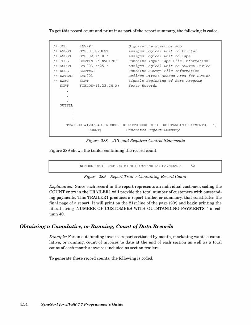
To get this record count and print it as part of the report summary, the following is coded.
Figure 289 shows the trailer containing the record count.
Explanation: Since each record in the report represents an individual customer, coding theCOUNT entry in the TRAILER1 will provide the total number of customers with outstand-ing payments. This TRAILER1 produces a report trailer, or summary, that constitutes thefinal page of a report. It will print on the 21st line of the page (20/) and begin printing theliteral string 'NUMBER OF CUSTOMERS WITH OUTSTANDING PAYMENTS: ' in col-umn 40.
Obtaining a Cumulative, or Running, Count of Data Records
Example: For an outstanding invoices report sectioned by month, marketing wants a cumu-lative, or running, count of invoices to date at the end of each section as well as a totalcount of each month’s invoices included as section trailers.
To generate these record counts, the following is coded.
// JOB INVRPT Signals the Start of Job
// ASSGN SYS001,SYSLST Assigns Logical Unit to Printer
// ASSGN SYS002,X'181' Assigns Logical Unit to Tape
// TLBL SORTIN1,'INVOICE' Contains Input Tape File Information
// ASSGN SYS003,X'251' Assigns Logical Unit to SORTWK Device
// DLBL SORTWK1 Contains SORTWK File Information
// EXTENT SYS003 Defines Direct Access Area for SORTWK
// EXEC SORT Signals Beginning of Sort Program
SORT FIELDS=(1,23,CH,A) Sorts Records
.
.
.
OUTFIL
.
.
.
TRAILER1=(20/,40:'NUMBER OF CUSTOMERS WITH OUTSTANDING PAYMENTS: ',
COUNT) Generates Report Summary
Figure 288. JCL and Required Control Statements
NUMBER OF CUSTOMERS WITH OUTSTANDING PAYMENTS: 52
Figure 289. Report Trailer Containing Record Count
SyncSort for z/VSE 3.7 Programmer’s Guide4.54

// JOB INVRPT Signals the Start of Job// ASSGN SYS001,SYSLST Assigns Logical Unit to Printer// ASSGN SYS002,X'181' Assigns Logical Unit to Tape// TLBL SORTIN1,'INVOICE' Contains Input Tape File Information// ASSGN SYS003,X'251' Assigns Logical Unit to SORTWK Device// DLBL SORTWK1 Contains SORTWK File Information// EXTENT SYS003 Defines Direct Access Area for SORTWK// EXEC SORT Signals Beginning of Sort Program
SORT FIELDS=(28,2,ZD,A, Sorts Records24,2,ZD,A,1,23,ZD,A)
.
.
.OUTFIL.
.
.SECTIONS=(24,6,SKIP=1L, Generates Sections with RecordTRAILER3=(/, Count & Cumulative Record Subcount
95:'MONTH''S NUMBER OF INVOICES: ',COUNT,/,95:'NUMBER OF INVOICES TO DATE: ',SUBCOUNT))
Figure 290. JCL and Required Control Statements
Chapter 4. How to Use SyncSort Data Utility Features 4.55

Figure 291 shows the trailers containing the counts of records.
Explanation: The trailer’s first / entry causes the printer to leave one blank line after thedata records and before printing the trailer. The second / entry indicates the end of thetrailer’s first line. The identical number-colon entries (95:) set the starting positions of theliteral strings that follow them: 'MONTH' 'S NUMBER OF INVOICES: ' and 'NUMBER OF
. . . .
. . . .
. . . .RIBBIT TECHNOLOGIES 12/15/91 360.00 21.60RICE FEATURES 12/15/91 750.00 75.00SIDNEY COLLEGE 12/15/91 5,000.00 300.00SNAP FEATURES 12/15/91 750.00 75.00WEBB BROS CORP 12/15/91 600.00 36.00WELLINGTON IMPORTS 12/15/91 750.00 45.00WINIFRED INDUST 12/15/91 350.00 26.00
MONTH'S NUMBER OF INVOICES: 17NUMBER OF INVOICES TO DATE: 17
ARLINE FRAGRANCES 1/17/92 7,500.00 618.75CHARACTER DATA 1/17/92 1,100.00 50.75COUNTRY INDUSTRIAL 1/17/92 850.00 0.00DUNHAM INDUST CO 1/17/92 850.00 0.00ECHO LABS INC 1/17/92 550.00 22.00ESS SECURITIES 1/17/92 550.00 22.00EVERMORE INDUST 1/17/92 3,000.00 225.00GOODEY FOODS 1/17/92 600.00 30.00GROSS BOOKS CO 1/17/92 2,500.00 150.00HARVEY MOTORS CO 1/17/92 3,000.00 225.00KALABRA CORP 1/17/92 1,500.00 90.00NORTHEAST INDUST 1/17/92 200.00 20.00PULER COLLEGE 1/17/92 1,500.00 75.00REPUBLIC DATA 1/17/92 1,100.00 90.75RICE FEATURES 1/17/92 1,500.00 75.00ROBINS NEST CORP 1/17/92 900.00 54.00SIDNEY COLLEGE 1/17/92 2,500.00 150.00SOUTHWEST INDUST 1/17/92 200.00 20.00SPENSERS INDUST 1/17/92 650.00 26.00UNITED INTERESTS 1/17/92 1,500.00 90.00WINIFRED INDUST 1/17/92 650.00 26.00
MONTH'S NUMBER OF INVOICES: 21NUMBER OF INVOICES TO DATE: 38
BALTIC AVENUE CORP 2/15/92 650.00 29.25BATHO PRODUCTS 2/15/92 850.00 51.00CARRINGTON OIL 2/15/92 1,600.00 64.00CDR TRUST INC 2/15/92 1,500.00 75.00ECHO LABS INC 2/15/92 550.00 22.00ESS SECURITIES 2/15/92 550.00 22.00FASTEROOT EQUIP 2/15/92 1,700.00 76.50FEDERAL FABRICS 2/15/92 1,750.00 70.00
. . . .
. . . .
. . . .
Figure 291. TRAILER3 Containing Record Counts and Cumulative Record Counts
SyncSort for z/VSE 3.7 Programmer’s Guide4.56

INVOICES TO DATE: '.(Note that the apostrophe in MONTH'S is doubled because a singleapostrophe would signal the end of a literal string.) Finally, because each data record inthis report represents an invoice, the TRAILER3’s COUNT entry generates a count of eachmonth’s invoices and the SUBCOUNT entry generates a cumulative, or running, count ofthe invoices. The leading zeros in these 8-byte fields are suppressed.
Creating Multiple Output Files
Data centers often use the same masterfile for different purposes. Assume, for example,that you wanted to produce two reports using a masterfile of cash-receipt records. Onereport was to present the total cash receipts for the current month; the second, for the yearto date. This would typically entail running a separate sort for each report. SortWriter’smultiple-output feature, however, enables you to produce both reports with a single pass ofthe sort. In addition, you can specify the same or different devices to receive the separateoutput files.
To generate multiple output files, code the OUTFIL statement as described below.
Note: See “OUTFIL Control Statement” on page 2.141 for the complete format of theOUTFIL statement.
FILES Use this parameter to connect an OUTFIL statement with one or moreoutput files. (NOTE: FILES and the FILESOUT parameter on theSORT statement must coincide.) These numbers correspond to the out-put files defined in the JCL. The number 1 designates SORTOUT as theoutput file; the numbers 2 through 9 designate the output filesSORTOF2 through SORTOF9; the numbers 10 through 32 designatethe output files SORTO10 through SORTO32, respectively. If theFILES parameter is not specified, the entire output is directed toSORTOUT; the default is FILES=1.
INCLUDE Use this parameter to indicate which records you wish included in eachoutput file. The default is to INCLUDE ALL records. To override thedefault, specify one or more logical conditions under which records areto be included or omitted. You may also override the default by specify-ing OMIT=ALL or INCLUDE=NONE. (See “OUTFIL Control State-ment” on page 2.141 for the detailed format of comparisons.)
Figure 292. Multiple Output Parameters Format on OUTFIL
OUTFIL FILES = 1n(1,2,...,32)
,INCLUDE
,OMIT
=ALL(comparison)NONE
,TAPE[ ] ,DISK[ ] ,PRINT[ ] ,PUNCH[ ] ,OUTREC = field ,field[ ] ...( )[ ]
Chapter 4. How to Use SyncSort Data Utility Features 4.57
OMIT Use this parameter to indicate which records you wish omitted fromeach output file. The default is to OMIT=NONE records. To overridethe default, specify one or more logical conditions under which recordsare to be included or omitted. You may also override the default byspecifying OMIT=ALL or INCLUDE=NONE. (See “INCLUDE/OMITControl Statement” on page 2.39 for the detailed format of compari-sons.)
TAPE Use this parameter to specify that the output file(s) is (are) to be storedon a tape device.
DISK Use this parameter to specify that the output file(s) is (are) to be storedon a disk device.
PRINT Use this parameter, the default, to specify that the output file(s) is (are)to be written to a printer.
PUNCH Use this parameter to specify that the output file(s) is (are) to be writ-ten to a card punch.
OUTREC Use the OUTREC parameter to reformat the output file. When specify-ing the beginning positions of data fields, remember to take intoaccount any changes due to processing by an E15/E32 exit, the INRECcontrol statement, the OUTREC control statement, and/or an E35 exit.(See “OUTREC Control Statement” on page 2.174 for the detailed for-mat of OUTREC fields.)
Generating Several Output Files with Different Information
Example: Marketing wants three output files of customer records. The first will contain alist of U.S. and European customers. The second will contain a list of U.S. customers only,and the third will contain a list of European customers only.
To generate the three separate files, the following is coded.
SyncSort for z/VSE 3.7 Programmer’s Guide4.58

Explanation: Creating the three requested output files requires specifying a SORTOUTand two SORTOFx data sets in the JCL as well as three separate OUTFIL statements.Each of the OUTFIL statements is connected by a FILES parameter to one of the outputfiles defined in the JCL. Specifying 1 on the FILES parameter connects its OUTFIL state-ment with the output file defined by SORTOUT on the JCL. Likewise, specifying 2 connectsits OUTFIL statement with the output file defined by SORTOF2, and so on.
The first output file (SORTOUT) in this example will contain the records from the input file(INCLUDE=ALL). The second output file will include the records that contain thecharacter string 'USA' starting in byte 67, (INCLUDE=(67,3,CH,EQ,C'USA')), whichindicates that these records are for USA customers. And similarly, the third output file willinclude only those records that contain the character string 'EUR' beginning in byte 67,which indicates that these records are for European customers. Note that because eachdata set is being written to tape, the TAPE parameter is specified on each OUTFILstatement and because three output files are being written, the FILESOUT parameter iscoded as FILESOUT=3 on the SORT control statement.
// JOB CUSTRCD Signals the Start of Job
// ASSGN SYS001,X'180' Assigns Logical Unit to Tape
// TLBL SORTOUT Contains Output Tape File Information
// ASSGN SYS002,X'181' Assigns Logical Unit to Tape
// TLBL SORTOF2 Contains Output Tape File Information
// ASSGN SYS003,X'182' Assigns Logical Unit to Tape
// TLBL SORTOF3 Contains Output Tape File Information
// ASSGN SYS004,X'251' Assigns Logical Unit to Disk
// DLBL SORTIN1,'CUSTMRS' Contains Input Disk File Information
// EXTENT SYS004 Defines Direct Access Area for Input
// ASSGN SYS005,X'253' Assigns Logical Unit to SORTWK Device
// DLBL SORTWK1 Contains SORTWK File Information
// EXTENT SYS005 Defines Direct Access Area for SORTWK
// EXEC SORT Signals Beginning of Sort Program
RECORD TYPE=F,LENGTH=80 Describes Input Records
SORT FIELDS=(10,15,CH,A),FILESOUT=3 Sorts Records
OUTFIL FILES=1, Outfil Statement for SORTOUT
INCLUDE=ALL, Including All Records
TAPE
OUTFIL FILES=2, Outfil Statement for SORTOF2
INCLUDE=(67,3,CH,EQ,C'USA'), Including Only USA Records
TAPE
OUTFIL FILES=3, Outfil Statement for SORTOF3
INCLUDE=(67,3,CH,EQ,C'EUR'), Including Only European Records
TAPE
Figure 293. JCL and Required Control Statements
Chapter 4. How to Use SyncSort Data Utility Features 4.59
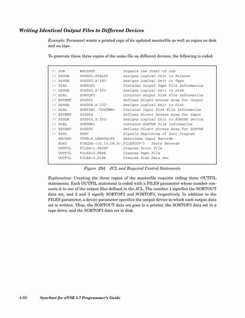
Writing Identical Output Files to Different Devices
Example: Personnel wants a printed copy of its updated masterfile as well as copies on diskand on tape.
To generate these three copies of the same file on different devices, the following is coded.
Explanation: Creating the three copies of the masterfile requires coding three OUTFILstatements. Each OUTFIL statement is coded with a FILES parameter whose number con-nects it to one of the output files defined in the JCL. The number 1 signifies the SORTOUTdata set, and 2 and 3 signify SORTOF2 and SORTOF3, respectively. In addition to theFILES parameter, a device parameter specifies the output device to which each output dataset is written. Thus, the SORTOUT data set goes to a printer, the SORTOF2 data set to atape drive, and the SORTOF3 data set to disk.
// JOB MULTOUT Signals the Start of Job
// ASSGN SYS001,SYSLST Assigns Logical Unit to Printer
// ASSGN SYS002,X'181' Assigns Logical Unit to Tape
// TLBL SORTOF2 Contains Output Tape File Information
// ASSGN SYS003,X'251' Assigns Logical Unit to Disk
// DLBL SORTOF3 Contains Output Disk File Information
// EXTENT SYS003 Defines Direct Access Area for Output
// ASSGN SYS004,X'252' Assigns Logical Unit to Disk
// DLBL SORTIN1,'CUSTMRS' Contains Input Disk File Information
// EXTENT SYS004 Defines Direct Access Area for Input
// ASSGN SYS005,X'253' Assigns Logical Unit to SORTWK Device
// DLBL SORTWK1 Contains SORTWK File Information
// EXTENT SYS005 Defines Direct Access Area for SORTWK
// EXEC SORT Signals Beginning of Sort Program
RECORD TYPE=F,LENGTH=80 Describes Input Records
SORT FIELDS=(10,15,CH,A),FILESOUT=3 Sorts Records
OUTFIL FILES=1,PRINT Creates Print File
OUTFIL FILES=2,TAPE Creates Tape File
OUTFIL FILES=3,DISK Creates Disk Data Set
Figure 294. JCL and Required Control Statements
SyncSort for z/VSE 3.7 Programmer’s Guide4.60

Chapter 5. Job Control Language and Sample Control Statement Streams
Six Job Control Statements That May Be Needed for the Sort/Merge
Job control language for SyncSort for z/VSE follows the standard conventions for VSE/ESAand z/VSE. Here are six job control statements that may be needed for sorting or merging,and the format they should follow. For detailed JCL information, refer to the appropriateversion of System Control Statements.
Brackets in the following examples indicate optional parameters; braces show that onechoice must be made. Capital letters mean the capitalized word itself must appear. Capital-ized words in brackets and braces, however, may be omitted if not chosen.
JOB
As the first card image in the job stream, the JOB statement signals the start of the job.
ASSGN
The ASSGN statement assigns symbolic unit names to the input, output, and work devicesthat will be used for the sort/merge. (See Table 45 on page 5.4.) It connects the sort/mergeprogram to the devices by referring the sort/merge devices to the logical unit block, the log-
// JOB jobname
Figure 295. JOB Job Control Statement Format
Chapter 5. Job Control Language and Sample Control Statement Streams 5.1

ical unit block to the physical unit block, and finally, the physical unit block secures thedevices specified. Because it must work with the system’s logical unit block, this statementis often described as “assigning a logical name to a physical device.”
It is not necessary to move all input files to the same type of device before sorting; inputmay be drawn from card, disk, or tape files in a single sort/merge. When different diskdrives are used for SORTWK files, the characteristics of the smaller device do not constrainthe way the larger device is used; the full track is utilized for each device.
An ASSGN statement is needed for every input, output, and work device used unless thesystem has already been set up with permanent symbolic unit names for the sort/mergeprogram. In that case, this statement may be omitted.
TLBL/DLBL
These statements contain tape or DASD file information. A TLBL statement must be pro-vided for every tape file with standard labels. A DLBL statement is necessary for everydisk file. The format of the TLBL statement is given below in Figure 297.
A DLBL statement would take the form below in Figure 298.
Filenames can be user-supplied or the pre-chosen, "default" names, i.e., SORTIN1,SORTOUT, and SORTWK for input, output, and work filenames, respectively, can beselected. If user-supplied names are used, they must be specified in the FILNM orWORKNM parameter of the OPTION control statement. Up to 32 input files can be usedfor a sort or merge. Appropriate numbers can be attached to a single filename (for example,OWNAME1, OWNAME2,. . .,) or a unique name can be used for each file.
Note: The names may not be over seven characters long and the first character must be aletter.
The TLBL and DLBL statements may have continuation statements.
// ASSGN SYSxxx,X'nnn' or // ASSGN SYSxxx,cuu
Figure 296. ASSGN Job Control Statement Format
// TLBL filename [,'file-id'] [,date]
Figure 297. TLBL Job Control Statement Format
// DLBL filename [,'file-id'] [,date] [,code]
Figure 298. DLBL Job Control Statement Format
SyncSort for z/VSE 3.7 Programmer’s Guide5.2
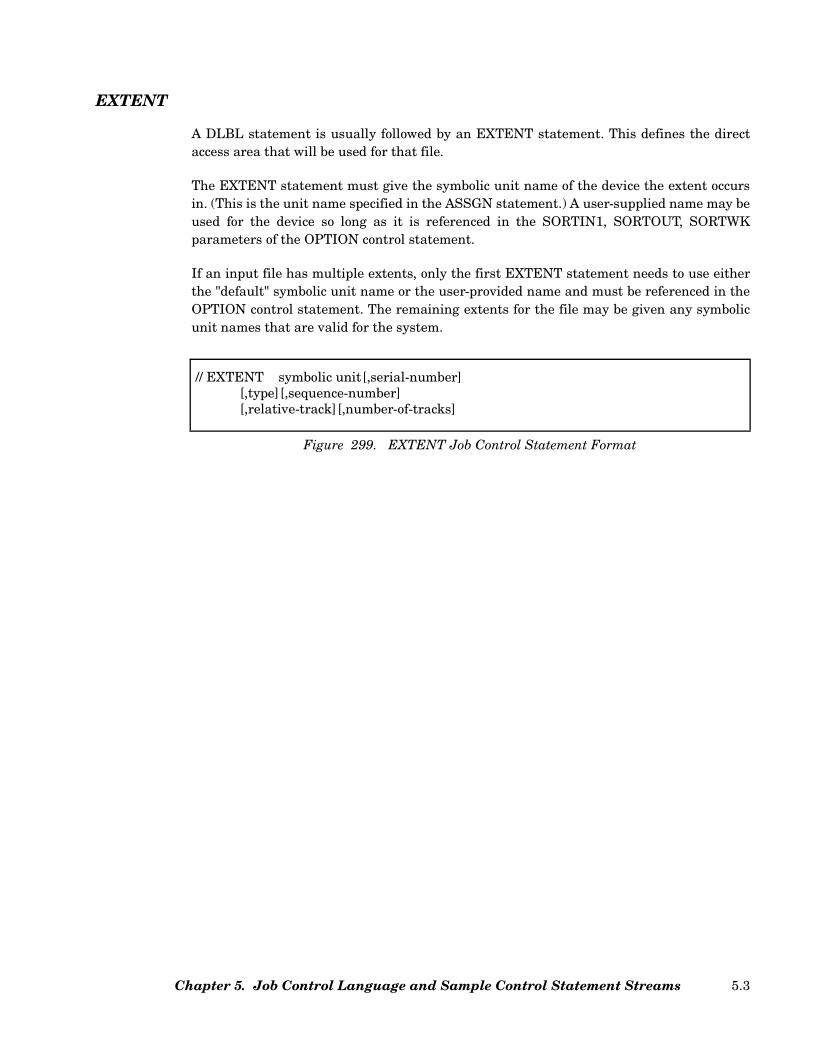
EXTENT
A DLBL statement is usually followed by an EXTENT statement. This defines the directaccess area that will be used for that file.
The EXTENT statement must give the symbolic unit name of the device the extent occursin. (This is the unit name specified in the ASSGN statement.) A user-supplied name may beused for the device so long as it is referenced in the SORTIN1, SORTOUT, SORTWKparameters of the OPTION control statement.
If an input file has multiple extents, only the first EXTENT statement needs to use eitherthe "default" symbolic unit name or the user-provided name and must be referenced in theOPTION control statement. The remaining extents for the file may be given any symbolicunit names that are valid for the system.
// EXTENT symbolic unit[,serial-number][,type][,sequence-number][,relative-track][,number-of-tracks]
Figure 299. EXTENT Job Control Statement Format
Chapter 5. Job Control Language and Sample Control Statement Streams 5.3
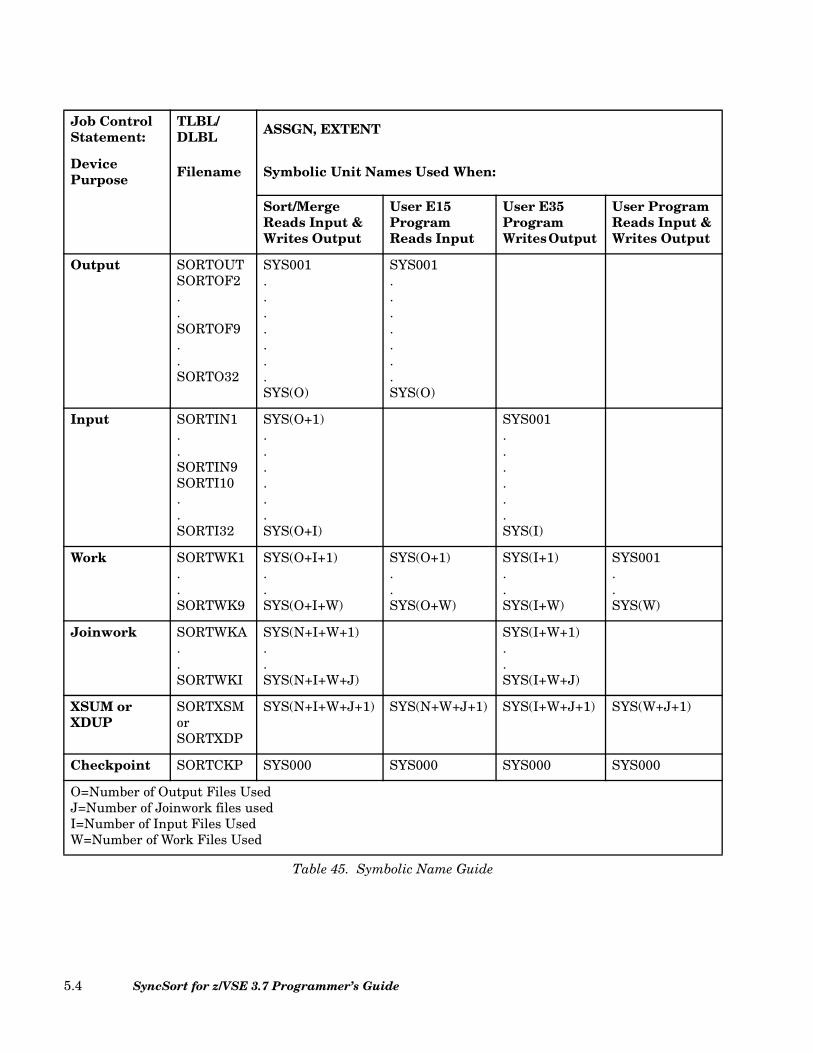
Job Control Statement:
TLBL/DLBL ASSGN, EXTENT
Device Purpose Filename Symbolic Unit Names Used When:
Sort/Merge Reads Input & Writes Output
User E15Program Reads Input
User E35Program Writes Output
User Program Reads Input & Writes Output
Output SORTOUTSORTOF2 . . SORTOF9. . SORTO32
SYS001 . . . . . . .SYS(O)
SYS001 . . . . . . . SYS(O)
Input SORTIN1 . . SORTIN9SORTI10 . . SORTI32
SYS(O+1)......SYS(O+I)
SYS001 ......SYS(I)
Work SORTWK1..SORTWK9
SYS(O+I+1) ..SYS(O+I+W)
SYS(O+1)..SYS(O+W)
SYS(I+1) ..SYS(I+W)
SYS001..SYS(W)
Joinwork SORTWKA..SORTWKI
SYS(N+I+W+1)..SYS(N+I+W+J)
SYS(I+W+1) ..SYS(I+W+J)
XSUM or XDUP
SORTXSM or SORTXDP
SYS(N+I+W+J+1) SYS(N+W+J+1) SYS(I+W+J+1) SYS(W+J+1)
Checkpoint SORTCKP SYS000 SYS000 SYS000 SYS000
O=Number of Output Files UsedJ=Number of Joinwork files usedI=Number of Input Files UsedW=Number of Work Files Used
Table 45. Symbolic Name Guide
SyncSort for z/VSE 3.7 Programmer’s Guide5.4
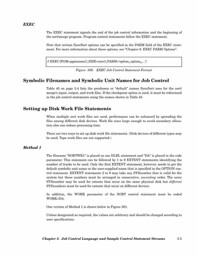
EXEC
The EXEC statement signals the end of the job control information and the beginning ofthe sort/merge program. Program control statements follow the EXEC statement.
Note that certain SyncSort options can be specified in the PARM field of the EXEC state-ment. For more information about these options, see “Chapter 6. EXEC PARM Options”.
Symbolic Filenames and Symbolic Unit Names for Job Control
Table 45 on page 5.4 lists the prechosen or “default” names SyncSort uses for the sort/merge’s input, output, and work files. If the checkpoint option is used, it must be referencedin the job control statements using the names shown in Table 45.
Setting up Disk Work File Statements
When multiple sort work files are used, performance can be enhanced by spreading thefiles among different disk devices. Work file sizes large enough to avoid secondary alloca-tion also can reduce processing time.
There are two ways to set up disk work file statements. (Disk devices of different types maybe used. Tape work files are not supported.)
Method 1
The filename "SORTWK1" is placed on one DLBL statement and "DA" is placed in the codeparameter. This statement can be followed by 1 to 9 EXTENT statements identifying thenumber of tracks to be used. Only the first EXTENT statement, however, needs to get thedefault symbolic unit name or the user-supplied name that is specified in the OPTION con-trol statement. EXTENT statements 2 to 9 may take any SYSnumber that is valid for thesystem but these numbers must be arranged in consecutive, ascending order. The sameSYSnumber may be used for extents that occur on the same physical disk but differentSYSnumbers must be used for extents that occur on different devices.
In addition, the WORK parameter of the SORT control statement must be codedWORK=DA.
One version of Method 1 is shown below in Figure 301.
Unless designated as required, the values are arbitrary and should be changed according touser specifications.
// EXEC[PGM=pgmname][,SIZE=size][,PARM='option1,option2,...']
Figure 300. EXEC Job Control Statement Format
Chapter 5. Job Control Language and Sample Control Statement Streams 5.5

Notes:
1-3 The ASSGN statements assign symbolic unit names SYS003, SYS004, andSYS005 to three disk work files, each of which resides on a disk device. Thevariables in the X'nnn' parameter should be replaced with the address of eachof the three devices.
4 The DLBL statement uses the required filename SORTWK1, places a comma toindicate a missing file-id, codes a zero to show no retention date, and places therequired (for this method) DA in the code parameter to indicate a direct accessfile.
5-10 There are six EXTENT statements that describe six extents. The first two arelocated on device SYS003, the next area is found on SYS004, and the last threeare on the disk assigned the name SYS005.
vvvvvv represents the volume serial number of the volume, and should bereplaced by the actual number. If this number is less than 6 digits, the systemwill pad it on the left with zeros.
The 1 that appears in the type parameter in all the EXTENT statements speci-fies a data area.
The next parameter indicates the sequence number of the extents within thismulti-extent file. The number of the first extent is 0, and this number is incre-mented by 1 on each following extent. The numbers may range from 0 to 255.
aaaaa represents the number of the track (relative to zero) where the extent isto begin. It should be replaced by the actual number, and may be from 1 to 5digits long.
zzzzz gives the number of tracks the extent will use. It should be replaced bythe actual number, and may be from 1 to 5 digits long.
// ASSGN SYS003,X'nnn' 1// ASSGN SYS004,X'nnn' 2// ASSGN SYS005,X'nnn' 3// DLBL SORTWK1,,0,DA 4// EXTENT SYS003,vvvvvv,l,0,aaaaa,zzzzz 5// EXTENT SYS003,vvvvvv,l,l,aaaaa,zzzzz 6// EXTENT SYS004,vvvvvv,1,2,aaaaa,zzzzz 7// EXTENT SYS005,vvvvvv,1,3,aaaaa,zzzzz 8// EXTENT SYS005,vvvvvv,1,4,aaaaa,zzzzz 9// EXTENT SYS005,vvvvvv,1,5,aaaaa,zzzzz 10
Figure 301. Disk Work File JCL Method 1
SyncSort for z/VSE 3.7 Programmer’s Guide5.6

Method 2
Using the filenames SORTWK1 to SORTWK9, one DLBL statement is required for each SDwork file.
The symbolic unit names for the work files must be either user-created and referenced inthe SORTWK parameter of the OPTION control statement, or the default names shown inTable 45 on page 5.4.
An example of Method 2 is given in Figure 302.
Notes:
1 The ASSGN statement assigns the symbolic unit name SYS003 to the firstwork file. The file resides on a device at address X'nnn'.
2 The first DLBL statement uses the required filename SORTWK1 for the firstwork file. The file-id is 'WORK AREA A', there is to be no retention date, andthe code is sequential disk (the SD designation). This last parameter could havebeen left out and received by default, as in the last DLBL statement in thisexample.
3 The EXTENT statement defines an area to be used for the SORTWK1 work fileto which the symbolic name SYS003 has been assigned. vvvvvv represents thevolume serial number; 1 indicates a data area; 0 shows a sequence number ofzero; aaaaa represents the number of the track where the extent begins (rela-tive to zero); and zzzzz represents the number of tracks used by the extent.
// ASSGN SYS003,X'nnn' 1// DLBL SORTWK1,'WORK AREA A',0,SD 2// EXTENT SYS003,vvvvvv,1,0,aaaaa,zzzzz 3// ASSGN SYS004,X'nnn' 4// DLBL SORTWK2,'WORK AREA B',0,SD 5// EXTENT SYS004,vvvvvv,1,0,aaaaa,zzzzz 6// ASSGN SYS005,X'nnn' 7// DLBL SORTWK3,'WORK AREA C',0,SD 8// EXTENT SYS005,vvvvvv,1,0,aaaaa,zzzzz 9// ASSGN SYS006,X'nnn' 10// DLBL SORTWK4,'WORK AREA D',0,SD 11// EXTENT SYS006,vvvvvv,1,0,aaaaa,zzzzz 12// ASSGN SYS007,X'nnn' 13// DLBL SORTWK5,'WORK AREA E',0,SD 14// EXTENT SYS007,vvvvvv,1,0,aaaaa,zzzzz 15// ASSGN SYS008,X'nnn' 16// DLBL SORTWK6,'WORK AREA F',0 17// EXTENT SYS008,vvvvvv,1,0,aaaaa,zzzzz 18
Figure 302. Disk Work File JCL Method 2
Chapter 5. Job Control Language and Sample Control Statement Streams 5.7
4-18 The instructions for statements 4-18 are the same as for statements 1-3, exceptthat the SYSnumber is incremented by one for each work file.
Unlike Method 1, where the sequence number is always incremented by one for eachextent, the sequence number in Method 2 EXTENT statements is always 0.
Calculating the Amount of Disk Work Space
As a general rule, 15 to 20 percent more disk work space should be planned for than thetotal input file size. If INREC or an E15 shorten or lengthen the input records, the diskwork space required is also reduced or increased.
Whenever the initial allocation of SORTWK space is exhausted, SyncSort can request morework space. This space will be generated by a Disk Space Management package, if present,or may be supplied through operator communication.
Setting up Multiple SORTOUT Files
The multiple SORTOUT feature enables the user to specify a maximum of thirty-twoSORTOUT files. The default names for the multiple SORTOUT files are SORTOUT,SORTOF2,...,SORTOF9, SORTO10,...SORTO32.
The DLBL and/or TLBL statements for filenames SORTOFx and SORTOxx are used todefine the data sets used, in addition to SORTOUT, to receive sorted output. These valuesmay be overridden by the FILNM parameter on the OPTION statement. SORTOFx andSORTOxx may be assigned to any disk, tape or unit record device.
The logical SYSnumbers default to SYS001,...,SYS032. These values may be overridden bythe SORTOUT parameter on the OPTION statement. The number of output files is speci-fied in the FILESOUT parameter on the SORT control statement.
Sample JCL/Control Statement Streams
One of the ways to initiate the sort/merge is by using job control language streams. Thissection illustrates sample JCL/control statement streams that you can use as models foryour own applications.
Appendix C. “VSE/VSAM Space Management for SAM Files” explains how to set up jobcontrol language streams for VSAM managed SAM files. Information describing each lineof JCL is provided.
A Standard-Labeled Tape Input and Output Sort
Figure 303 shows a sort with one tape input file, one tape output file, and a single extentdisk work file. The default names have been used for the input, output and work files. The
SyncSort for z/VSE 3.7 Programmer’s Guide5.8
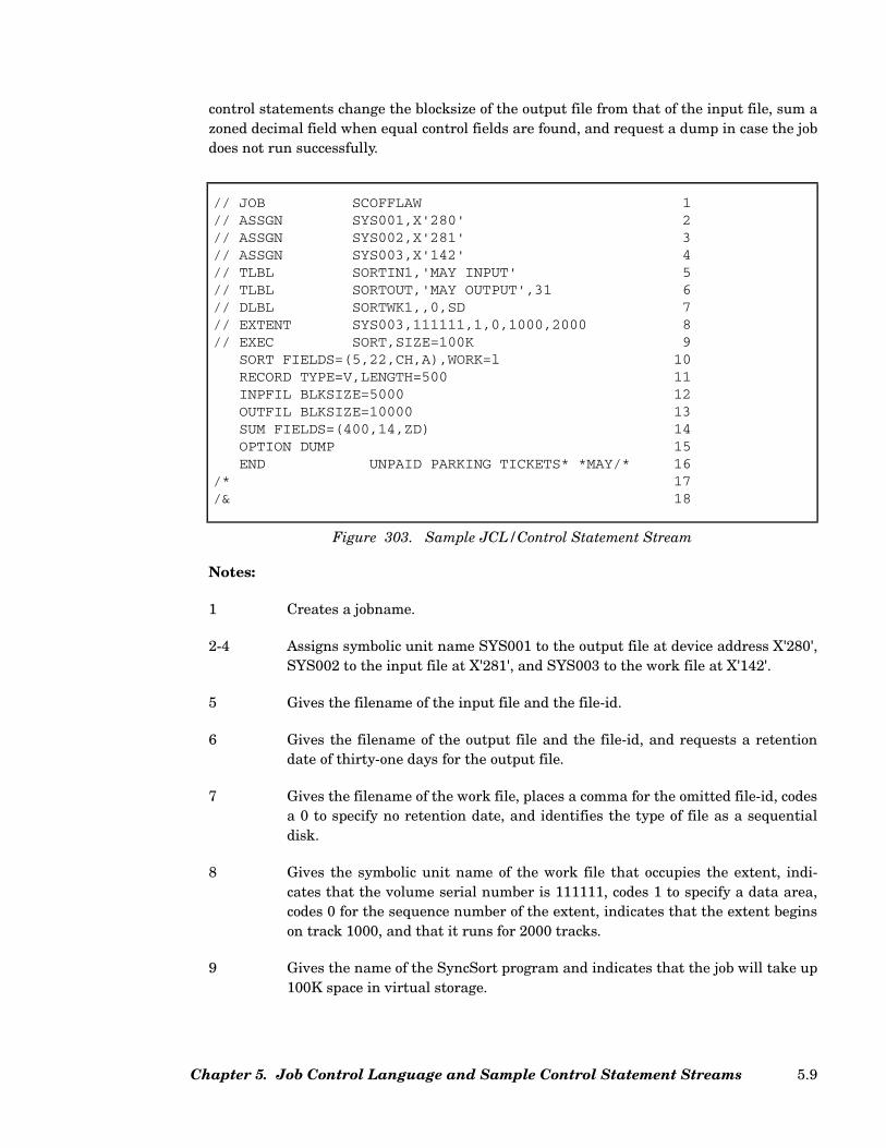
control statements change the blocksize of the output file from that of the input file, sum azoned decimal field when equal control fields are found, and request a dump in case the jobdoes not run successfully.
Notes:
1 Creates a jobname.
2-4 Assigns symbolic unit name SYS001 to the output file at device address X'280',SYS002 to the input file at X'281', and SYS003 to the work file at X'142'.
5 Gives the filename of the input file and the file-id.
6 Gives the filename of the output file and the file-id, and requests a retentiondate of thirty-one days for the output file.
7 Gives the filename of the work file, places a comma for the omitted file-id, codesa 0 to specify no retention date, and identifies the type of file as a sequentialdisk.
8 Gives the symbolic unit name of the work file that occupies the extent, indi-cates that the volume serial number is 111111, codes 1 to specify a data area,codes 0 for the sequence number of the extent, indicates that the extent beginson track 1000, and that it runs for 2000 tracks.
9 Gives the name of the SyncSort program and indicates that the job will take up100K space in virtual storage.
// JOB SCOFFLAW 1// ASSGN SYS001,X'280' 2// ASSGN SYS002,X'281' 3// ASSGN SYS003,X'142' 4// TLBL SORTIN1,'MAY INPUT' 5// TLBL SORTOUT,'MAY OUTPUT',31 6// DLBL SORTWK1,,0,SD 7// EXTENT SYS003,111111,1,0,1000,2000 8// EXEC SORT,SIZE=100K 9
SORT FIELDS=(5,22,CH,A),WORK=l 10RECORD TYPE=V,LENGTH=500 11INPFIL BLKSIZE=5000 12OUTFIL BLKSIZE=10000 13SUM FIELDS=(400,14,ZD) 14OPTION DUMP 15END UNPAID PARKING TICKETS* *MAY/* 16
/* 17/& 18
Figure 303. Sample JCL/Control Statement Stream
Chapter 5. Job Control Language and Sample Control Statement Streams 5.9
10 The SORT control statement shows that one field is to be sorted on. It begins onbyte 5 of the record, has a length of 22 bytes, consists of character data, and isto be sorted in ascending sequence. There is to be one work file.
11 The RECORD statement shows that variable-length records are being sortedand that the maximum record length is 500 bytes.
12 The INPFIL statement shows that the blocksize of the records in the input fileis 5000 bytes.
13 The OUTFIL statement shows that the blocksize of the records in the outputfile is 10,000 bytes.
14 The SUM statement requests that when two records with equal control fieldsare found, SyncSort is to sum a certain portion of the two records, place thetotal in one record, and delete the other record. The field to be summed beginson byte 400 of the record, is 14 bytes long, and has a zoned decimal format.
15 In case the job is not completed, a dump is to be processed.
16 The END statement tells SyncSort that the control statements for the job arenow complete. The rest of the card image is a comment.
17 A standard job card image indicating the end of the JCL/control stream.
18 A standard job control statement indicating the end of the job stream.
An Unlabeled Tape Input and Output Sort
Figure 304 shows a sort with four unlabeled input tape volumes, five disk work files, andan unlabeled output tape file. In this case, by using the special INCLUDE feature, the sorthas been used to build an output file containing unique information.
SyncSort for z/VSE 3.7 Programmer’s Guide5.10
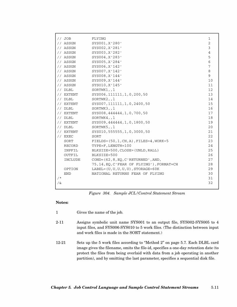
Notes:
1 Gives the name of the job.
2-11 Assigns symbolic unit name SYS001 to an output file, SYS002-SYS005 to 4input files, and SYS006-SYS010 to 5 work files. (The distinction between inputand work files is made in the SORT statement.)
12-21 Sets up the 5 work files according to “Method 2” on page 5.7. Each DLBL cardimage gives the filename, omits the file-id, specifies a one-day retention date (toprotect the files from being overlaid with data from a job operating in anotherpartition), and by omitting the last parameter, specifies a sequential disk file.
// JOB FLYING 1// ASSGN SYS001,X'280' 2// ASSGN SYS002,X'281' 3// ASSGN SYS003,X'282' 4// ASSGN SYS004,X'283' 5// ASSGN SYS005,X'284' 6// ASSGN SYS006,X'142' 7// ASSGN SYS007,X'142' 8// ASSGN SYS008,X'144' 9// ASSGN SYS009,X'144' 10// ASSGN SYSO10,X'145' 11// DLBL SORTWK1,,l 12// EXTENT SYS006,111111,1,0,200,50 13// DLBL SORTWK2,,l 14// EXTENT SYS007,111111,1,0,2400,50 15// DLBL SORTWK3,,l 16// EXTENT SYS008,444444,1,0,700,50 17// DLBL SORTWK4,,l 18// EXTENT SYS009,444444,1,0,1800,50 19// DLBL SORTWK5,,l 20// EXTENT SYS010,555555,1,0,3000,50 21// EXEC SORT 22
SORT FIELDS=(50,1,CH,A),FILES=4,WORK=5 23RECORD TYPE=F,LENGTH=100 24INPFIL BLKSIZE=500,CLOSE=(UNLD,RALL) 25OUTFIL BLKSIZE=500 26INCLUDE COND=(62,8,EQ,C'RETURNED',AND, 27
75,14,EQ,C'FEAR OF FLYING'),FORMAT=CH 28OPTION LABEL=(U,U,U,U,U),STORAGE=60K 29END NATIONAL RETURNS FEAR OF FLYING 30
/* 31/& 32
Figure 304. Sample JCL/Control Statement Stream
Chapter 5. Job Control Language and Sample Control Statement Streams 5.11
The EXTENT statements give the symbolic unit names of the files. They notethat SYS006 and SYS007 are on volume 111111, SYS008 and SYS009 on vol-ume 444444, and SYS010 on volume 555555. The 1 on each card image specifiesa data area, and the 0 gives the required sequence number for sequential diskfiles. A beginning track number has been specified for each extent, and eachextent will take 50 tracks.
22 Gives the SyncSort program name.
23 The SORT statement identifies one control field. It starts on byte 50 of therecord, is 1 byte long, has character format, and is to be sorted in ascendingsequence.
The FILES parameter gives four as the number of input files, and the WORKparameter gives five as the number of work files.
24 The RECORD statement shows fixed-length records that are 100 bytes long.
25-26 The INPFIL and OUTFIL statements specify a blocksize of 500 bytes. All fourinput tape volumes will be rewound, unloaded, and released at end-of-file. TheRelease option should only be used in the absence of a tape management sys-tem.
27-28 The INCLUDE statement tells the sort to select any record with 'RETURNED'in bytes 62-69 and 'FEAR OF FLYING' in bytes 75-88, and write them to theoutput file. Records that do not meet these requirements are not to be included.At the end of this sort, the programmer will have complete data on the returnsof a book sold on consignment throughout the country. A report may be printedat a later time.
29 The OPTION statement shows that the output and four input files are unla-beled, and that SyncSort may use 60K in main storage.
30 The END control statement gives a comment.
31-32 The standard job control end card images.
A Disk Input and Output Sort
Figure 305 shows a sort with disk input, disk output and two disk work devices. The objectof this sort is to create a paycheck file from the input payroll data. Later, paychecks will beprinted from this output disk. The OUTREC feature has been used to select the pay,department, and name fields from the input record for the new, shortened output records.
SyncSort for z/VSE 3.7 Programmer’s Guide5.12
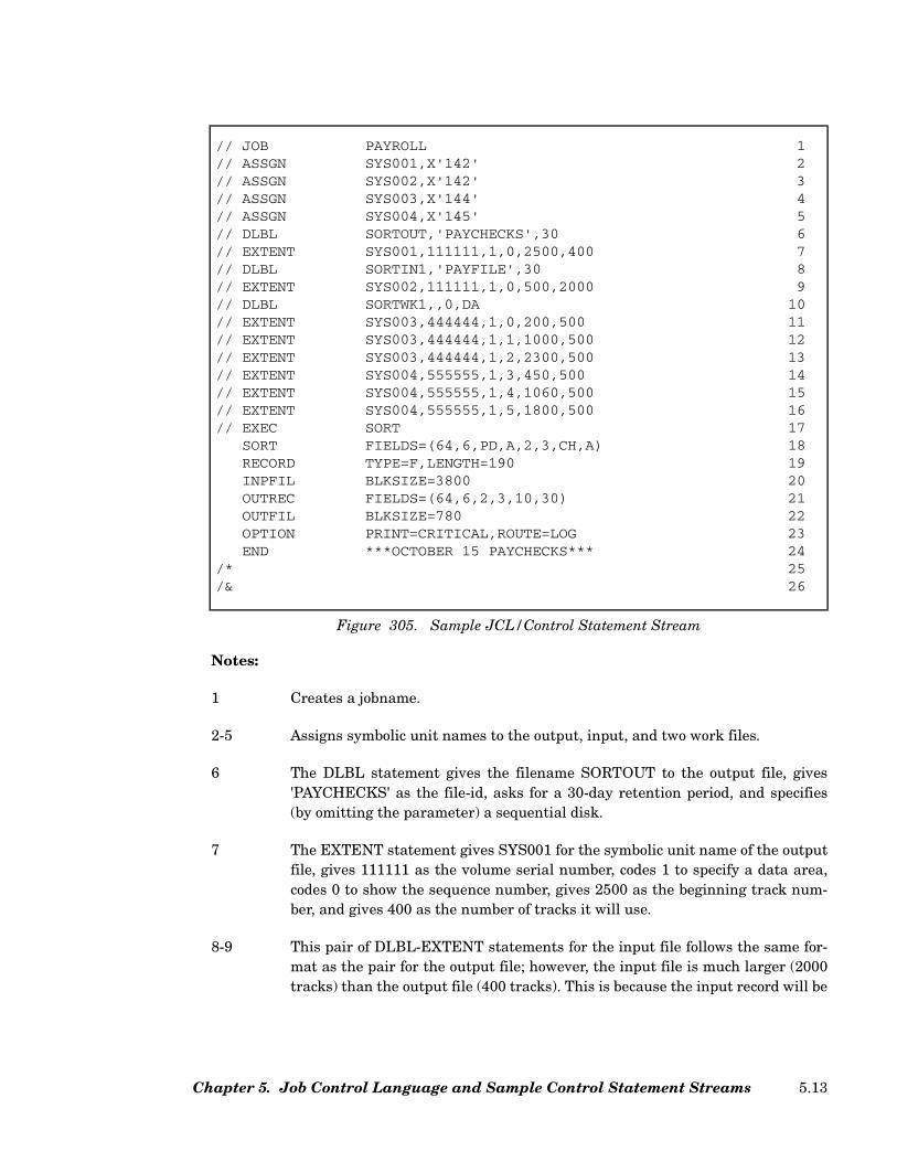
Notes:
1 Creates a jobname.
2-5 Assigns symbolic unit names to the output, input, and two work files.
6 The DLBL statement gives the filename SORTOUT to the output file, gives'PAYCHECKS' as the file-id, asks for a 30-day retention period, and specifies(by omitting the parameter) a sequential disk.
7 The EXTENT statement gives SYS001 for the symbolic unit name of the outputfile, gives 111111 as the volume serial number, codes 1 to specify a data area,codes 0 to show the sequence number, gives 2500 as the beginning track num-ber, and gives 400 as the number of tracks it will use.
8-9 This pair of DLBL-EXTENT statements for the input file follows the same for-mat as the pair for the output file; however, the input file is much larger (2000tracks) than the output file (400 tracks). This is because the input record will be
// JOB PAYROLL 1// ASSGN SYS001,X'142' 2// ASSGN SYS002,X'142' 3// ASSGN SYS003,X'144' 4// ASSGN SYS004,X'145' 5// DLBL SORTOUT,'PAYCHECKS',30 6// EXTENT SYS001,111111,1,0,2500,400 7// DLBL SORTIN1,'PAYFILE',30 8// EXTENT SYS002,111111,1,0,500,2000 9// DLBL SORTWK1,,0,DA 10// EXTENT SYS003,444444,1,0,200,500 11// EXTENT SYS003,444444,1,1,1000,500 12// EXTENT SYS003,444444,1,2,2300,500 13// EXTENT SYS004,555555,1,3,450,500 14// EXTENT SYS004,555555,1,4,1060,500 15// EXTENT SYS004,555555,1,5,1800,500 16// EXEC SORT 17
SORT FIELDS=(64,6,PD,A,2,3,CH,A) 18RECORD TYPE=F,LENGTH=190 19INPFIL BLKSIZE=3800 20OUTREC FIELDS=(64,6,2,3,10,30) 21OUTFIL BLKSIZE=780 22OPTION PRINT=CRITICAL,ROUTE=LOG 23END ***OCTOBER 15 PAYCHECKS*** 24
/* 25/& 26
Figure 305. Sample JCL/Control Statement Stream
Chapter 5. Job Control Language and Sample Control Statement Streams 5.13

reformatted on the OUTREC statement so that at the end of the sort, when itbecomes output, it will be 151 bytes shorter.
10 This DLBL statement gives the filename for the work file as SORTWK1, omitsa file-id, specifies no retention date, and codes DA to indicate a direct accessfile.
11-16 The EXTENT statements give the locations and lengths of the six extents of thework file described on the DLBL statement (item 10). The sequence number isincremented by one for each extent.
17 The EXEC statement gives SORT as the SyncSort program name.
18 The SORT statement shows two control fields. The first, or major field, startson byte 64 of the input record, is 6 bytes long, has packed decimal format, and isto be sorted according to ascending sequence. The second, or lesser field, beginson byte 2 of the record, is 3 bytes long, has character data, and is to be sortedaccording to ascending sequence.
19 The RECORD statement codes an F for fixed-length records and indicates thatthe length of the input record is 190 bytes. This is the l1 value. The l2 and l3 val-ues will be calculated by the sort and the correct values will be used when it istime to change the length of the record for the output file.
20 The INPFIL statement gives the blocksize of the input file as 3800 bytes. Thisis twenty records to a block.
21 The OUTREC statement shows how the input record is to be reconstructed toform the output record. The FIELDS parameter shows that three fields will bepicked up. The first starts on byte 64 of the input record and is 6 bytes long.The second starts on byte 2 of the input record and is 3 bytes long. The thirdstarts on byte 10 of the input record and is 30 bytes long. These are the pay,department number, and employee name fields, respectively, that will later bereproduced on paychecks. They will now run consecutively from byte 1 throughbyte 39 of the output record, and will be edited with spacing later when theyare printed.
22 The OUTFIL statement gives the blocksize of the output file as 780 bytes.Although this is still twenty records to a block, the output file blocksize is con-siderably shorter than that of the input file.
23 The OPTION statement requests that only critical messages be issued and thatthey appear on the console.
24 The END statement indicates the end of the control statements. A comment isgiven.
25-26 The standard job control end statement.
SyncSort for z/VSE 3.7 Programmer’s Guide5.14
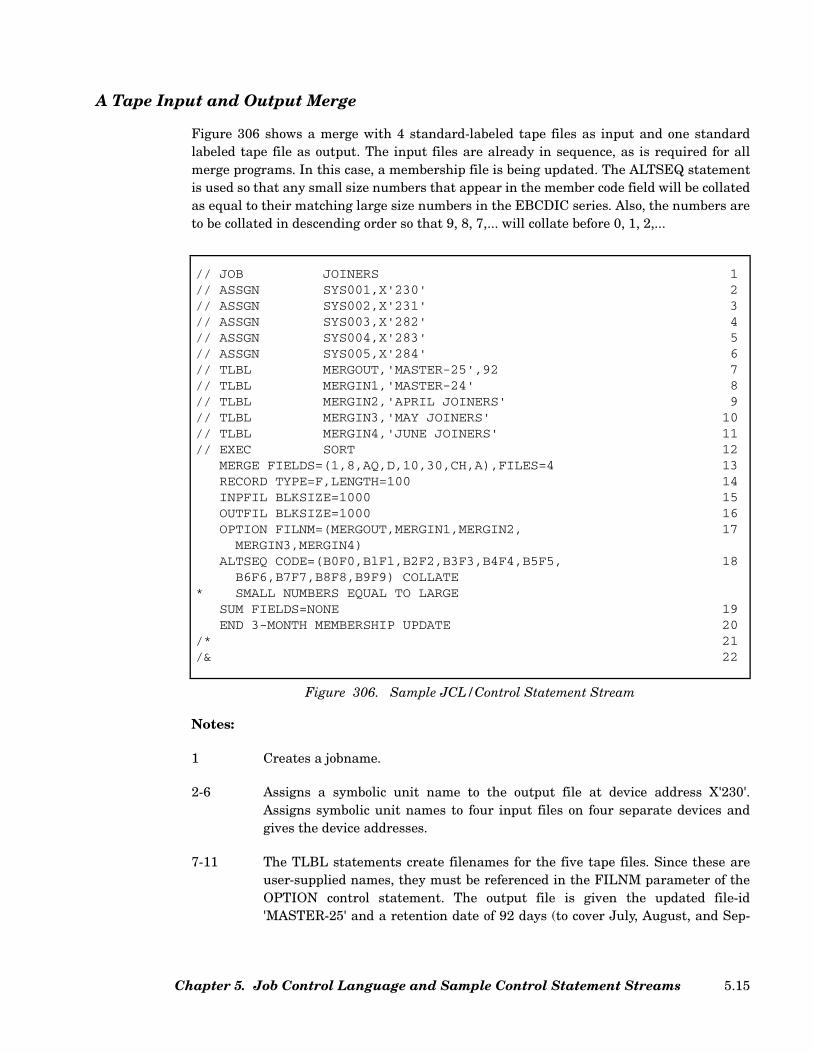
A Tape Input and Output Merge
Figure 306 shows a merge with 4 standard-labeled tape files as input and one standardlabeled tape file as output. The input files are already in sequence, as is required for allmerge programs. In this case, a membership file is being updated. The ALTSEQ statementis used so that any small size numbers that appear in the member code field will be collatedas equal to their matching large size numbers in the EBCDIC series. Also, the numbers areto be collated in descending order so that 9, 8, 7,... will collate before 0, 1, 2,...
Notes:
1 Creates a jobname.
2-6 Assigns a symbolic unit name to the output file at device address X'230'.Assigns symbolic unit names to four input files on four separate devices andgives the device addresses.
7-11 The TLBL statements create filenames for the five tape files. Since these areuser-supplied names, they must be referenced in the FILNM parameter of theOPTION control statement. The output file is given the updated file-id'MASTER-25' and a retention date of 92 days (to cover July, August, and Sep-
// JOB JOINERS 1// ASSGN SYS001,X'230' 2// ASSGN SYS002,X'231' 3// ASSGN SYS003,X'282' 4// ASSGN SYS004,X'283' 5// ASSGN SYS005,X'284' 6// TLBL MERGOUT,'MASTER-25',92 7// TLBL MERGIN1,'MASTER-24' 8// TLBL MERGIN2,'APRIL JOINERS' 9// TLBL MERGIN3,'MAY JOINERS' 10// TLBL MERGIN4,'JUNE JOINERS' 11// EXEC SORT 12
MERGE FIELDS=(1,8,AQ,D,10,30,CH,A),FILES=4 13RECORD TYPE=F,LENGTH=100 14INPFIL BLKSIZE=1000 15OUTFIL BLKSIZE=1000 16OPTION FILNM=(MERGOUT,MERGIN1,MERGIN2, 17
MERGIN3,MERGIN4)ALTSEQ CODE=(B0F0,BlFl,B2F2,B3F3,B4F4,B5F5, 18
B6F6,B7F7,B8F8,B9F9) COLLATE* SMALL NUMBERS EQUAL TO LARGE
SUM FIELDS=NONE 19END 3-MONTH MEMBERSHIP UPDATE 20
/* 21/& 22
Figure 306. Sample JCL/Control Statement Stream
Chapter 5. Job Control Language and Sample Control Statement Streams 5.15

tember) is requested. The MERGIN1 file is the old master and MERGIN2,MERGIN3, and MERGIN4 contain new data.
12 The EXEC statement gives SyncSort’s program name and signals that the sort/merge control statements are about to begin.
13 The MERGE statement shows there are two control fields on which the mergewill be based. The first control field starts on byte 1 of the record, is 8 byteslong, is to be merged according to an alternate collating sequence (this will besupplied in the ALTSEQ statement), and the sequence is to be referenced indescending order. The second control field starts on byte 10 of the record, is 30bytes long, has character format data, and is to be merged according to ascend-ing order. The FILES parameter specifies four input files.
14 The RECORD statement notes that the TYPE of records are fixed-length, andthat their LENGTH is 100 bytes.
15-16 The INPFIL and OUTFIL statements both show a blocksize of 1000 bytes.
17 Since MERGOUT/MERGIN filenames were substituted for the defaultSORTOUT/SORTIN filenames, the user-supplied names must be referencedhere in the FILNM parameter.
18 The ALTSEQ statement gives the alternate collating sequence that will be usedfor the first control field. In this case, the nine pairs of hex numbers specify thatthe small numbers represented in the EBCDIC series by B0-B9 are to be col-lated as identical to the large numbers represented by F0-F9. This statementincludes a comment.
19 The SUM statement guarantees that the output membership file will have onlyone record per sort control key. Assuming the sort key identifies the member,this would mean that the updated membership file will mention each memberexactly once. Since EQUALS is the default for a merge, when equal-keyedrecords are encountered, it is the record from the earliest input file that isretained; i.e., records from the old master file, then the April joiners, then theMay joiners, and finally, the June joiners. The EQUALS default ensures thatthe updated master membership file identifies the member’s earliest successfulapplication for membership.
20 The END control statement indicates the end of the control statements andincludes a comment.
21-22 Standard job control end statement.
SyncSort for z/VSE 3.7 Programmer’s Guide5.16

A Sort Using Card Input
In Figure 307 and Figure 308, the SYSIPT parameter has been issued so that cards may beused as direct input to the sort. No work files are used for this sort. This is because thenumber of records is small enough to be sorted incore, and data can go directly to the out-put phase without ever needing to be written out to an intermediate work device. Anapproximate guide for determining whether a job is small enough to be sorted completelyincore is:
Total bytes of input data + output BLKSIZE + 20K ≤ Sort program’s storage.
The input in the following examples consists of the 200 report cards with the highest aver-ages for one high school semester. They will be sorted by class and student names so thatthe disk output can later be printed as "The Dean’s List." Either example will produce thesame results.
Note: Some older programs use E15 programs to read card input. Since SyncSort supportsdirect reading of card input, these programs should be converted to use SYSIPT forincreased efficiency.
// JOB TOPGRADE 1// ASSGN SYS001,X'142' 2// DLBL SORTOUT,'DEAN'S LIST' 3// EXTENT SYS001,111111,1,0,100,4 4// ASSGN SYS002,SYSIPT 4A// EXEC SORT 5
SORT FIELDS=(79,2,CH,A,2,20,CH,A),WORK=0 6RECORD TYPE=F,LENGTH=80 7
* NO INPFIL STATEMENT 8OUTFIL BLKSIZE=1600 9END 10Report Card 1 11...Report Card 200 12
/* 13/& 14
Figure 307. Sample JCL/Control Statement Stream
Chapter 5. Job Control Language and Sample Control Statement Streams 5.17
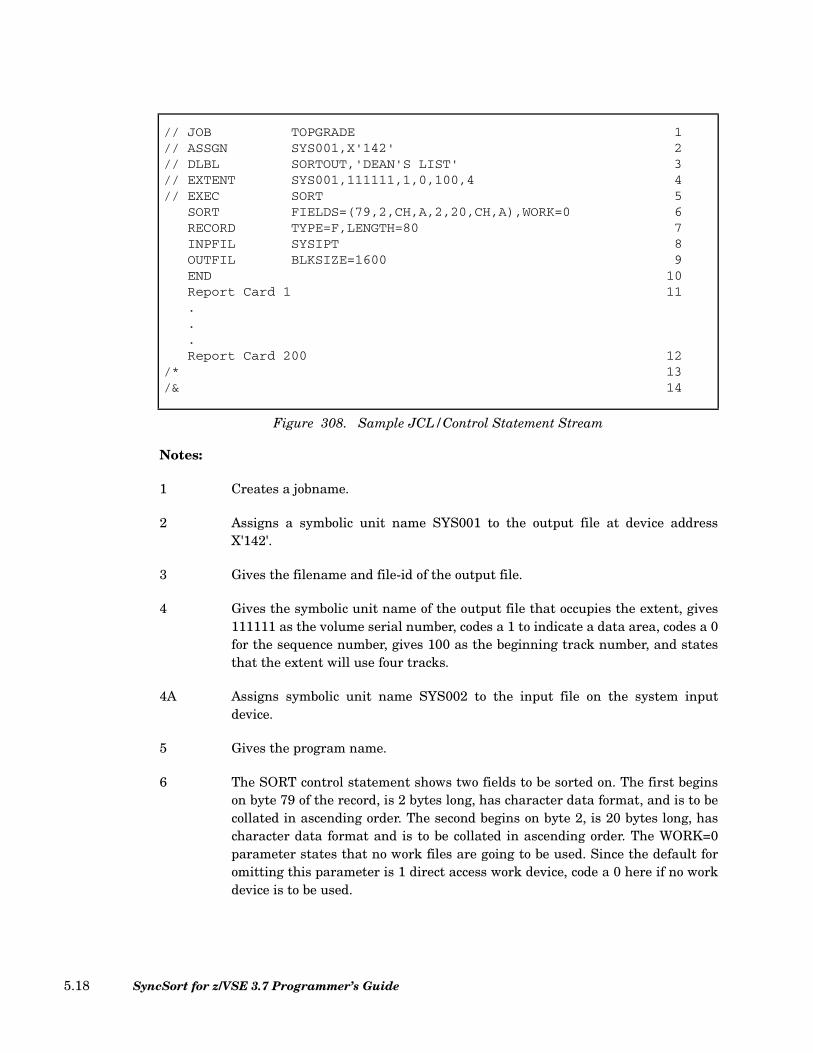
Notes:
1 Creates a jobname.
2 Assigns a symbolic unit name SYS001 to the output file at device addressX'142'.
3 Gives the filename and file-id of the output file.
4 Gives the symbolic unit name of the output file that occupies the extent, gives111111 as the volume serial number, codes a 1 to indicate a data area, codes a 0for the sequence number, gives 100 as the beginning track number, and statesthat the extent will use four tracks.
4A Assigns symbolic unit name SYS002 to the input file on the system inputdevice.
5 Gives the program name.
6 The SORT control statement shows two fields to be sorted on. The first beginson byte 79 of the record, is 2 bytes long, has character data format, and is to becollated in ascending order. The second begins on byte 2, is 20 bytes long, hascharacter data format and is to be collated in ascending order. The WORK=0parameter states that no work files are going to be used. Since the default foromitting this parameter is 1 direct access work device, code a 0 here if no workdevice is to be used.
// JOB TOPGRADE 1// ASSGN SYS001,X'142' 2// DLBL SORTOUT,'DEAN'S LIST' 3// EXTENT SYS001,111111,1,0,100,4 4// EXEC SORT 5
SORT FIELDS=(79,2,CH,A,2,20,CH,A),WORK=0 6RECORD TYPE=F,LENGTH=80 7INPFIL SYSIPT 8OUTFIL BLKSIZE=1600 9END 10Report Card 1 11...Report Card 200 12
/* 13/& 14
Figure 308. Sample JCL/Control Statement Stream
SyncSort for z/VSE 3.7 Programmer’s Guide5.18
7 The RECORD statement shows that fixed-length, 80-byte records are beingused.
8 The INPFIL statement is not required when SYSIPT is assigned to SYS002.
9 The OUTFIL statement indicates that the blocksize of the output file is to be1600 bytes.
10 The END statement signals the end of the control statements and is requiredwith card input.
11-12 The 200 input cards are inserted here.
13 The standard job control end card signals the end of the input.
14 The standard job control end card signals the end of the program.
A Disk Input and Output JOIN
Figure 309 shows a JOIN application with one fixed-length and one variable-length diskinput file. The records in these two files are filtered based on INCLUDE parameters andthen reformatted into variable-length output records to a disk file.
Chapter 5. Job Control Language and Sample Control Statement Streams 5.19

Notes:
1 Creates a job name.
2-7 Assigns symbolic unit names to the output, input, one sort work, and two joinwork files.
8-9 Gives DLBL and EXTENT information for the SORTOUT disk file ‘YTD.COMBINED’.
// JOB JOIN 1// ASSGN SYS001,250 2// ASSGN SYS002,251 3// ASSGN SYS003,252 4// ASSGN SYS004,253 5// ASSGN SYS005,253 6// ASSGN SYS006,253 7// DLBL SORTOUT,'YTD.COMBINED',30 8// EXTENT SYS001,111111,1,0,2500,100 9// DLBL SORTIN1,'YTD.OLD',30 10// EXTENT SYS002,222222,1,0,2500,100 11// DLBL SORTIN2,'YTD.NEW',30 12// EXTENT SYS003,333333,1,0,2500,100 13// DLBL SORTWK1,'SORT.WORK.1',0 14// EXTENT SYS002,222222,1,0,2500,100 15// DLBL SORTWKA,'SORT.WORK.A',0 16// EXTENT SYS005,222222,1,0,2600,100 17// DLBL SORTWKB,'SORT.WORK.B',0 18// EXTENT SYS006,222222,1,0,2700,100 19// EXEC SORT 20JOINKEYS FILE=F1,FIELDS=(13,6,A),TYPE=F,LRECL=80, 21
BLKSIZE=2400,INCLUDE=(19,2,CH,EQ,C' C') 22JOINKEYS FILE=F2,FIELDS=(5,6,A),TYPE=V,LRECL=200, 23
BLKSIZE=1700,INCLUDE=(11,10,ZD,GE,100000) 24REFORMAT FIELDS=(F2:1,4, 25
F2:1,6, 26F2:5,6, 27F2:74,6, 28F2:11,10, 29F2:23,20, 30F2:21) 31
SORT FIELDS=(5,6,BI,A) ,EQUALS,JOINWORK=2 32OUTFIL BLKSIZE=1700 33END 34
/* 35/& 36
Figure 309. A disk input and output JOIN
SyncSort for z/VSE 3.7 Programmer’s Guide5.20

10-11 Gives DLBL and EXTENT information for the SORTIN1 disk file ‘YTD.OLD’.
12-13 Gives DLBL and EXTENT information for the SORTIN2 disk file ‘YTD.NEW’.
14-15 Gives DLBL and EXTENT information for the SORTWK1 sort work disk file.
16-19 Gives DLBL and EXTENT information for SORTWKA and SORTWKB for theinternal join work disk files.
20 The EXEC statement gives SORT as the SyncSort program name.
21-22 The JOINKEYS control statement is used to define the join key, record format,record length, and block size for file F1, or SORTIN2. The INCLUDE parame-ter is used to include all records with a ‘C’ in positions 19-20.
23-24 The JOINKEYS control statement is used to define the join key, record format,record length, and block size for file F2, or SORTIN2. The INCLUDE parame-ter is used to include all records that have a ZD value greater than 100000 inpositions 11-20.
25-31 The REFORMAT control statement is used to combine data fields from both F1and F2 based on the positions and lengths specified. Since the JOIN controlstatement is not specified, all equally-keyed records based on the keys specifiedin the JOINKEYS control statements will be kept and all unequally keyedrecords will be discarded. The reformatted output record will be variable-lengthbecause statement 25 copies the RDW from F2 and statement 31 copies theposition (p) without the length (l) from F2.
32 The SORT control statement shows that all reformatted records coming out ofthe internal join sort will be sorted on the binary field starting in position 5 fora length of 6 in ascending sequence. The EQUALS parameter indicates that allequally keyed records will have their original order preserved through theentire sort process. JOINWORK=2 indicates that two join work files,SORTWKA and SORTWKB, will be used for the join sorting process. Since noWORK parameter is present, the default of one sort work is used, SORTWK1.
33 The OUTFIL control statement indicates the output disk block size forSORTOUT.
34 The END control statement indicates the end of the sort control statements.
35-36 The standard job control statements indicate the end of the job stream.
VSAM Input and Output
Figure 310 is a sample JCL/control statement stream that can be used to run an actual jobwith VSAM input and output files. This example illustrates the manner in which a jobstream should be set up to facilitate the sorting of an entry-sequenced data set.
Chapter 5. Job Control Language and Sample Control Statement Streams 5.21

Notes:
1 Creates a jobname.
2-6 Assigns I/O disk devices for input, output and work files.
7-8 Specifies a VSAM disk file as output. The file should have been defined (by aDEFINE CLUSTER) earlier.
9-10 Specifies a VSAM disk file as input.
11-16 Specifies work files on disk.
17 Specifies the SIZE parameter to restrict the amount of virtual storage used bySyncSort. There must be sufficient virtual storage left in the partition forVSAM use.
18 The OPTION statement indicates the following:
• All sort/merge messages are to be printed.
// JOB SORTTEST 1// ASSGN SYS001,X'250' OUTPUT FILE 2// ASSGN SYS002,X'251' INPUT FILE 3// ASSGN SYS003,X'252' SORT WORK 4// ASSGN SYS004,X'253' SORT WORK 5// ASSGN SYS005,X'254' SORT WORK 6// DLBL SORTOUT,'SORTOUT',,VSAM 7// EXTENT SYS001,PACKI 8// DLBL SORTIN1,'SORTIN1',,VSAM 9// EXTENT SYS002,PACK2 10// DLBL SORTWK1,,0 11// EXTENT SYS003,PACK3,1,0,4769,70 12// DLBL SORTWK2,,0 13// EXTENT SYS004,PACK4,1,0,4839,70 14// DLBL SORTWK3,,0 15// EXTENT SYS005,PACK,1,0,4909,70 16// EXEC SYNCSORT,SIZE=100K 17
OPTION PRINT=ALL,ROUTE=LST 18SORT FIELDS=(11,4,BI,A),FILES=1,WORK=3 19RECORD TYPE=F,LENGTH=(0063,,0063) 20INPFIL VSAM,TOL 21OUTFIL ESDS,TOL 22END 23
/* 24/& 25
Figure 310. Sample JCL/Control Statement Stream
SyncSort for z/VSE 3.7 Programmer’s Guide5.22
• Messages are to be routed to SYSLST.
19 The SORT statement specifies the sort control field and one input file and threesort work files.
20 The RECORD statement specifies record information for an entry-sequenceddata set. Fixed-length records are to be sorted. The input and output recordlengths are 63 bytes.
21 The INPFIL statement specifies that the input file is VSAM and a warningcode will be accepted when opening the VSAM input file.
22 The OUTFIL statement specifies that the output file is entry-sequenced and awarning code will be tolerated when opening a VSAM output data set.
23 The END statement signals the end of the control statements.
24-25 The standard job control end statements.
Using the FIELDS=COPY Parameter
The FIELDS=COPY parameter, when coupled with SyncSort’s I/O techniques, may be usedas a high performance file editing tool. By using this facility, the user may avoid writingfile edit programs. Certain control statements can be input in a predetermined sequence toaccomplish the desired file edit.
Figure 311 and the related record layout in Figure 312 show how to perform the file edit. Inthis example, the FIELDS=COPY parameter of the MERGE control statement is used inconjunction with the INCLUDE/OMIT and INREC/OUTREC control statements. Fordetailed descriptions, refer to “INCLUDE/OMIT Control Statement” on page 2.39, “INRECControl Statement” on page 2.83, and “OUTREC Control Statement” on page 2.174.
In this example, certain data concerning exployees in a fictitious department 44 are to beextracted from a master file and placed on an edited file.
Chapter 5. Job Control Language and Sample Control Statement Streams 5.23
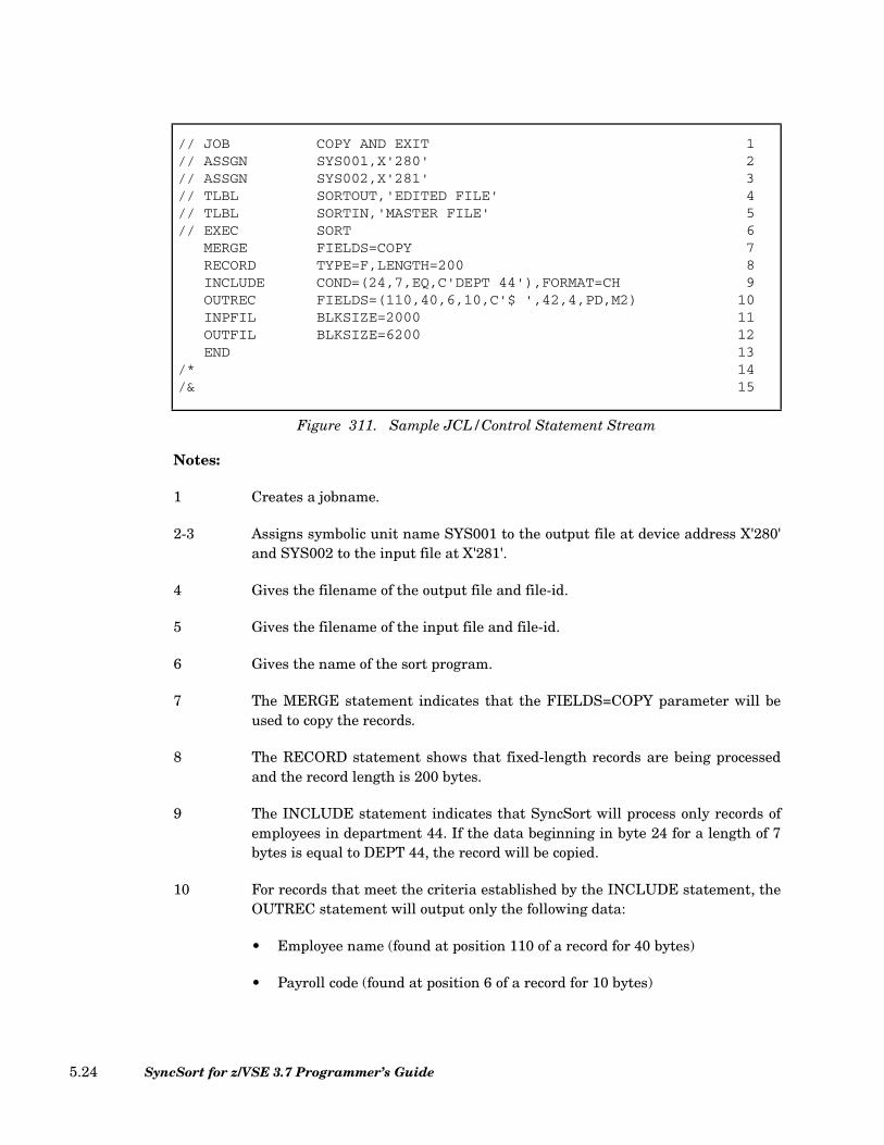
Notes:
1 Creates a jobname.
2-3 Assigns symbolic unit name SYS001 to the output file at device address X'280'and SYS002 to the input file at X'281'.
4 Gives the filename of the output file and file-id.
5 Gives the filename of the input file and file-id.
6 Gives the name of the sort program.
7 The MERGE statement indicates that the FIELDS=COPY parameter will beused to copy the records.
8 The RECORD statement shows that fixed-length records are being processedand the record length is 200 bytes.
9 The INCLUDE statement indicates that SyncSort will process only records ofemployees in department 44. If the data beginning in byte 24 for a length of 7bytes is equal to DEPT 44, the record will be copied.
10 For records that meet the criteria established by the INCLUDE statement, theOUTREC statement will output only the following data:
• Employee name (found at position 110 of a record for 40 bytes)
• Payroll code (found at position 6 of a record for 10 bytes)
// JOB COPY AND EXIT 1// ASSGN SYS001,X'280' 2// ASSGN SYS002,X'281' 3// TLBL SORTOUT,'EDITED FILE' 4// TLBL SORTIN,'MASTER FILE' 5// EXEC SORT 6
MERGE FIELDS=COPY 7RECORD TYPE=F,LENGTH=200 8INCLUDE COND=(24,7,EQ,C'DEPT 44'),FORMAT=CH 9OUTREC FIELDS=(110,40,6,10,C'$ ',42,4,PD,M2) 10INPFIL BLKSIZE=2000 11OUTFIL BLKSIZE=6200 12END 13
/* 14/& 15
Figure 311. Sample JCL/Control Statement Stream
SyncSort for z/VSE 3.7 Programmer’s Guide5.24

• Payroll amount (the 4 byte PD field found at position 42 is converted toprintable format and edited with SyncSort editing mask M2. Leading zeroswill be suppressed and a minus sign will be included if the number isnegative. A dollar sign and a blank will precede the number: $ II,IIT.TTS).
The output records will be 62 characters in length.
11 The INPFIL statement gives the blocksize of the input file as 2000 bytes.
12 The OUTFIL statement gives the blocksize of the output file as 6200 bytes.
13 The END statement indicates the end of the control statements.
14-15 The standard job control end statements.
Chapter 5. Job Control Language and Sample Control Statement Streams 5.25
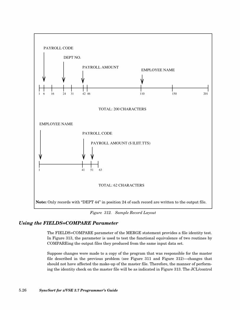
Using the FIELDS=COMPARE Parameter
The FIELDS=COMPARE parameter of the MERGE statement provides a file identity test.In Figure 313, the parameter is used to test the functional equivalence of two routines byCOMPAREing the output files they produced from the same input data set.
Suppose changes were made to a copy of the program that was responsible for the masterfile described in the previous problem (see Figure 311 and Figure 312)—changes thatshould not have affected the make-up of the master file. Therefore, the manner of perform-ing the identity check on the master file will be as indicated in Figure 313. The JCL/control
Note: Only records with “DEPT 44” in position 24 of each record are written to the output file.
Figure 312. Sample Record Layout
1 6 16 24 31 42 46 110 150 201
PAYROLL CODE
DEPT NO.
PAYROLL AMOUNTEMPLOYEE NAME
TOTAL: 200 CHARACTERS
1 41 51 63
EMPLOYEE NAME
PAYROLL CODE
PAYROLL AMOUNT ($ II,IIT.TTS)
TOTAL: 62 CHARACTERS
SyncSort for z/VSE 3.7 Programmer’s Guide5.26
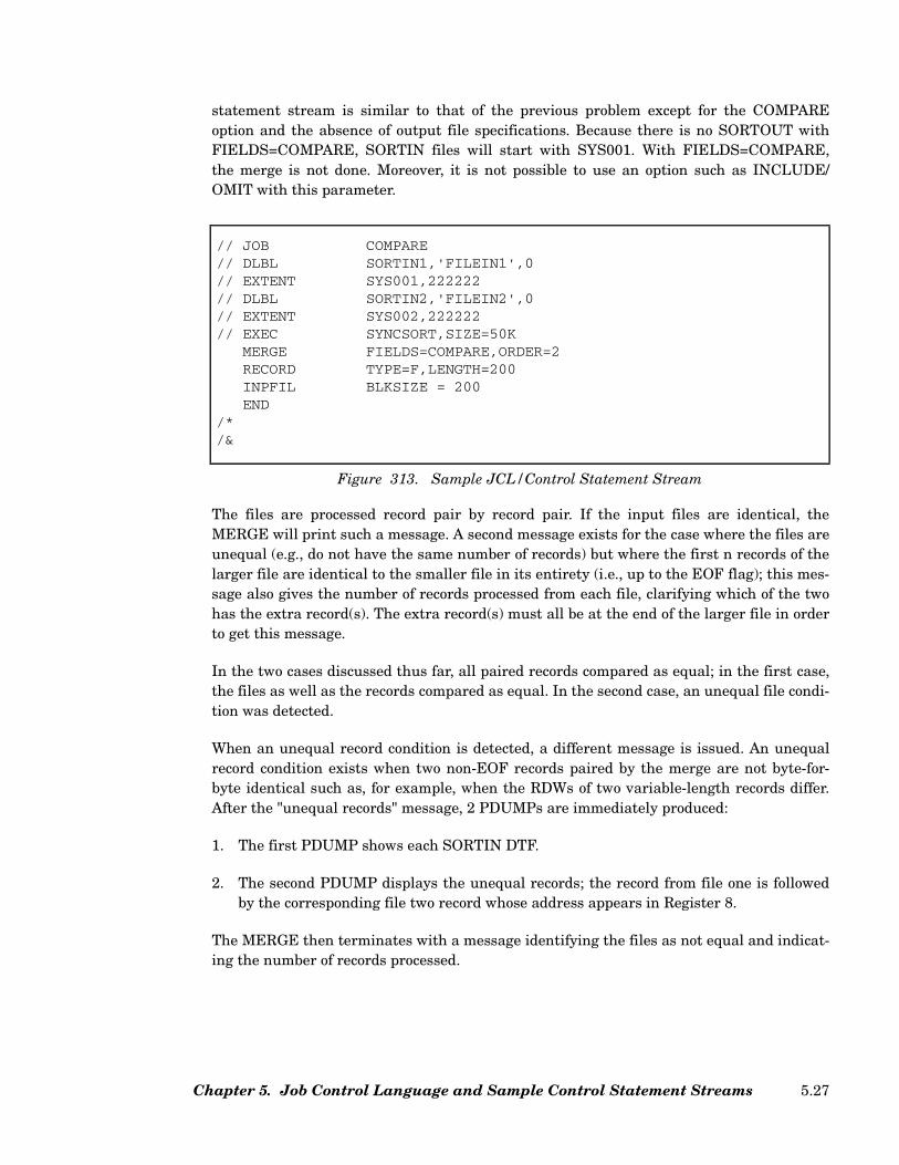
statement stream is similar to that of the previous problem except for the COMPAREoption and the absence of output file specifications. Because there is no SORTOUT withFIELDS=COMPARE, SORTIN files will start with SYS001. With FIELDS=COMPARE,the merge is not done. Moreover, it is not possible to use an option such as INCLUDE/OMIT with this parameter.
The files are processed record pair by record pair. If the input files are identical, theMERGE will print such a message. A second message exists for the case where the files areunequal (e.g., do not have the same number of records) but where the first n records of thelarger file are identical to the smaller file in its entirety (i.e., up to the EOF flag); this mes-sage also gives the number of records processed from each file, clarifying which of the twohas the extra record(s). The extra record(s) must all be at the end of the larger file in orderto get this message.
In the two cases discussed thus far, all paired records compared as equal; in the first case,the files as well as the records compared as equal. In the second case, an unequal file condi-tion was detected.
When an unequal record condition is detected, a different message is issued. An unequalrecord condition exists when two non-EOF records paired by the merge are not byte-for-byte identical such as, for example, when the RDWs of two variable-length records differ.After the "unequal records" message, 2 PDUMPs are immediately produced:
1. The first PDUMP shows each SORTIN DTF.
2. The second PDUMP displays the unequal records; the record from file one is followedby the corresponding file two record whose address appears in Register 8.
The MERGE then terminates with a message identifying the files as not equal and indicat-ing the number of records processed.
// JOB COMPARE// DLBL SORTIN1,'FILEIN1',0// EXTENT SYS001,222222// DLBL SORTIN2,'FILEIN2',0// EXTENT SYS002,222222// EXEC SYNCSORT,SIZE=50K
MERGE FIELDS=COMPARE,ORDER=2RECORD TYPE=F,LENGTH=200INPFIL BLKSIZE = 200END
/*/&
Figure 313. Sample JCL/Control Statement Stream
Chapter 5. Job Control Language and Sample Control Statement Streams 5.27
All these messages are directed to SYSLST and no provision is made for SYSLST’s beingassigned to tape or disk. "A" messages generated by the FIELDS=COMPARE parameter donot appear on the console.
SyncSort for z/VSE 3.7 Programmer’s Guide5.28
Chapter 6. EXEC PARM Options
EXEC PARM options can be specified to provide processing information for JCL-initiatedand program-invoked applications. EXEC PARM options override both installation defaults(set by SYNCMAC) and parameters specified on the OPTION control statement. They canbe useful when a parameter change is needed for one instance of the sort without changingthe installation defaults for all sorts, or without recompiling a program that invokes thesort.
Specify the PARM options in the EXEC statement as follows:
The maximum number of characters that can be specified in one PARM string is 100. Tospecify more than 100 characters, up to two additional PARM strings may be used on theEXEC statement.
Note: Since other program products also may be using the EXEC PARM, SyncSort will notperform its normal syntax validation on the PARM options. If SyncSort does not recognizea PARM option, the option will be ignored.
PARM Option Summary
The available SyncSort PARM options are summarized in Table 46.
// EXEC programname,...,PARM='option1,option2,...,optionn'
Figure 314. PARM Options in EXEC Statement
Chapter 6. EXEC PARM Options 6.1
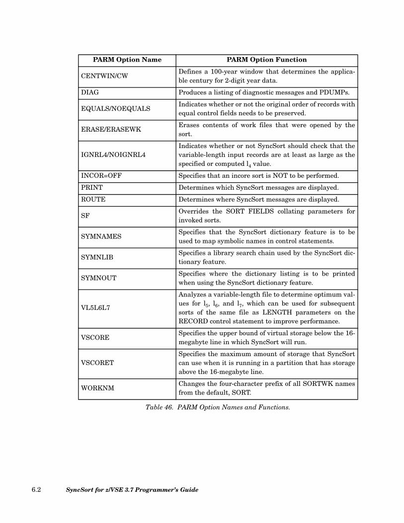
Table 46. PARM Option Names and Functions.
PARM Option Name PARM Option Function
CENTWIN/CWDefines a 100-year window that determines the applica-ble century for 2-digit year data.
DIAG Produces a listing of diagnostic messages and PDUMPs.
EQUALS/NOEQUALSIndicates whether or not the original order of records withequal control fields needs to be preserved.
ERASE/ERASEWKErases contents of work files that were opened by thesort.
IGNRL4/NOIGNRL4Indicates whether or not SyncSort should check that thevariable-length input records are at least as large as thespecified or computed l4 value.
INCOR=OFF Specifies that an incore sort is NOT to be performed.
PRINT Determines which SyncSort messages are displayed.
ROUTE Determines where SyncSort messages are displayed.
SFOverrides the SORT FIELDS collating parameters forinvoked sorts.
SYMNAMESSpecifies that the SyncSort dictionary feature is to beused to map symbolic names in control statements.
SYMNLIBSpecifies a library search chain used by the SyncSort dic-tionary feature.
SYMNOUTSpecifies where the dictionary listing is to be printedwhen using the SyncSort dictionary feature.
VL5L6L7
Analyzes a variable-length file to determine optimum val-ues for l5, l6, and l7, which can be used for subsequentsorts of the same file as LENGTH parameters on theRECORD control statement to improve performance.
VSCORESpecifies the upper bound of virtual storage below the 16-megabyte line in which SyncSort will run.
VSCORETSpecifies the maximum amount of storage that SyncSortcan use when it is running in a partition that has storageabove the 16-megabyte line.
WORKNMChanges the four-character prefix of all SORTWK namesfrom the default, SORT.
SyncSort for z/VSE 3.7 Programmer’s Guide6.2
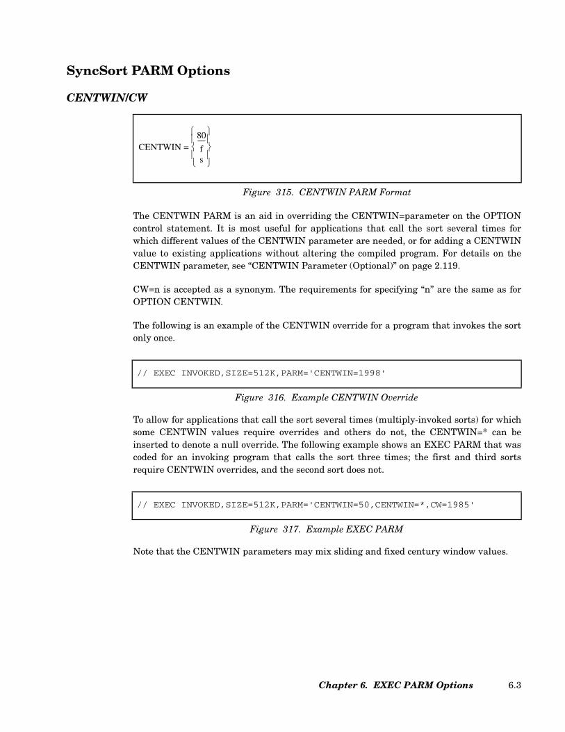
SyncSort PARM Options
CENTWIN/CW
The CENTWIN PARM is an aid in overriding the CENTWIN=parameter on the OPTIONcontrol statement. It is most useful for applications that call the sort several times forwhich different values of the CENTWIN parameter are needed, or for adding a CENTWINvalue to existing applications without altering the compiled program. For details on theCENTWIN parameter, see “CENTWIN Parameter (Optional)” on page 2.119.
CW=n is accepted as a synonym. The requirements for specifying “n” are the same as forOPTION CENTWIN.
The following is an example of the CENTWIN override for a program that invokes the sortonly once.
To allow for applications that call the sort several times (multiply-invoked sorts) for whichsome CENTWIN values require overrides and others do not, the CENTWIN=* can beinserted to denote a null override. The following example shows an EXEC PARM that wascoded for an invoking program that calls the sort three times; the first and third sortsrequire CENTWIN overrides, and the second sort does not.
Note that the CENTWIN parameters may mix sliding and fixed century window values.
Figure 315. CENTWIN PARM Format
CENTWIN = 80
fs
// EXEC INVOKED,SIZE=512K,PARM='CENTWIN=1998'
Figure 316. Example CENTWIN Override
// EXEC INVOKED,SIZE=512K,PARM='CENTWIN=50,CENTWIN=*,CW=1985'
Figure 317. Example EXEC PARM
Chapter 6. EXEC PARM Options 6.3

DIAG
The DIAG PARM causes a listing of diagnostic messages and PDUMPs to be produced.
EQUALS/NOEQUALS
The EQUALS and NOEQUALS PARMs determine if the original order of records withequal control fields needs to be preserved. These PARMs use the same rules as theEQUALS and NOEQUALS parameters of the OPTION control statement. See“EQUALS/NOEQUALS Parameter (Optional)” on page 2.102.
ERASE/ERASEWK
ERASE or ERASEWK causes contents of the work files opened by the sort to be erased atthe end of the sort. This PARM is equal to the ERASEWK parameter of the SORT controlstatement. See “ERASEWK Parameter (Optional)” on page 2.234.
IGNRL4/NOIGNRL4
The IGNRL4 and NOIGNRL4 PARMs determine if the sort checks that each variable-length input record is at least as large as the specified or computed l4 value. These PARMsuse the same rules as the IGNRL4 and NOIGNRL4 parameters of the OPTION controlstatement. See “IGNRL4/NOIGNRL4/VLSHRT/NOVLSHRT Parameter (Optional)” onpage 2.126.
DIAG
Figure 318. DIAG PARM Format
EQUALSNOEQUALS
Figure 319. EQUALS/NOEQUALS PARMs Format
ERASEERASEWK
Figure 320. ERASE/ERASEWK PARMs Format
IGNRL4NOIGNRL4
Figure 321. IGNRL4/NOIGNRL4 PARMs Format
SyncSort for z/VSE 3.7 Programmer’s Guide6.4
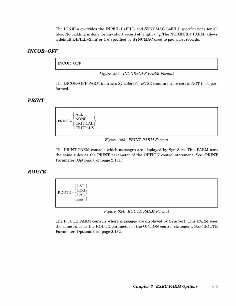
The IGNRL4 overrides the INPFIL L4FILL and SYNCMAC L4FILL specifications for allfiles. No padding is done for any short record of length < l4. The NOIGNRL4 PARM, allowsa default L4FILL=X'nn' or C'c' specified by SYNCMAC used to pad short records.
INCOR=OFF
The INCOR=OFF PARM instructs SyncSort for z/VSE that an incore sort is NOT to be per-formed.
The PRINT PARM controls which messages are displayed by SyncSort. This PARM usesthe same rules as the PRINT parameter of the OPTION control statement. See “PRINTParameter (Optional)” on page 2.131.
ROUTE
The ROUTE PARM controls where messages are displayed by SyncSort. This PARM usesthe same rules as the ROUTE parameter of the OPTION control statement. See “ROUTEParameter (Optional)” on page 2.132.
INCOR=OFF
Figure 322. INCOR=OFF PARM Format
Figure 323. PRINT PARM Format
PRINT =
ALLNONECRITICALCRITPLUS
Figure 324. ROUTE PARM Format
ROUTE =
LSTLOGLALnnn
Chapter 6. EXEC PARM Options 6.5
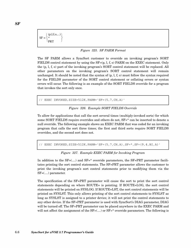
SF
The SF PARM allows a SyncSort customer to override an invoking program’s SORTFIELDS control statement by using the SF=(p, l, f, o) PARM on the EXEC statement. Onlythe (p, l, f, o) part of the invoking program’s SORT control statement will be replaced. Allother parameters on the invoking program’s SORT control statement will remainunchanged. It should be noted that the syntax of (p, l, f, o) must follow the syntax requiredfor the FIELDS parameter of the SORT control statement or collating errors or syntaxerrors will occur. The following is an example of the SORT FIELDS override for a programthat invokes the sort only once.
To allow for applications that call the sort several times (multiply-invoked sorts) for whichsome SORT FIELDS require overrides and others do not, SF=* can be inserted to denote anull override. The following example shows an EXEC PARM that was coded for an invokingprogram that calls the sort three times; the first and third sorts require SORT FIELDSoverrides, and the second sort does not.
In addition to the SF=(....) and SF=* override parameters, the SF=PRT parameter facili-tates printing the sort control statements. The SF=PRT parameter allows the customer toprint the invoking program’s sort control statements prior to modifying them via theSF=(....) parameter.
The specification of the SF=PRT parameter will cause the sort to print the sort controlstatements depending on where ROUTE= is pointing. If ROUTE=LOG, the sort controlstatements will be printed on SYSLOG. If ROUTE=LST, the sort control statements will beprinted on SYSLST. This only allows printing of the sort control statements to SYSLST aslong as SYSLST is assigned to a printer device; it will not print the control statements toany other device. If the SF=PRT parameter is used with SyncSort’s DIAG parameter, DIAGwill be turned off. The SF=PRT parameter can be placed anywhere in the EXEC PARM andwill not affect the assignment of the SF=(....) or SF=* override parameters. The following is
Figure 325. SF PARM Format
SF = (p,l,f,o,...)*PRT
// EXEC INVOKED,SIZE=512K,PARM='SF=(5,7,CH,A)'
Figure 326. Example SORT FIELDS Override
// EXEC INVOKED,SIZE=512K,PARM='SF=(5,7,CH,A),SF=*,SF=(9,4,BI,A)'
Figure 327. Example EXEC PARM for Invoking Program
SyncSort for z/VSE 3.7 Programmer’s Guide6.6
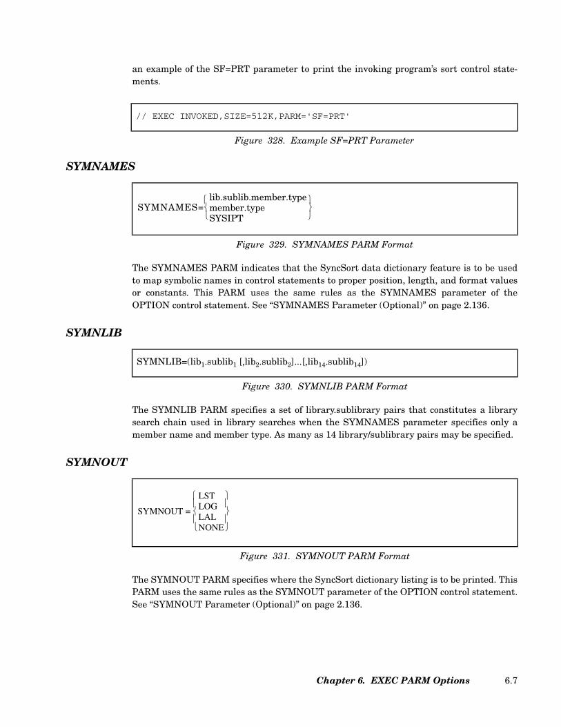
an example of the SF=PRT parameter to print the invoking program’s sort control state-ments.
SYMNAMES
The SYMNAMES PARM indicates that the SyncSort data dictionary feature is to be usedto map symbolic names in control statements to proper position, length, and format valuesor constants. This PARM uses the same rules as the SYMNAMES parameter of theOPTION control statement. See “SYMNAMES Parameter (Optional)” on page 2.136.
SYMNLIB
The SYMNLIB PARM specifies a set of library.sublibrary pairs that constitutes a librarysearch chain used in library searches when the SYMNAMES parameter specifies only amember name and member type. As many as 14 library/sublibrary pairs may be specified.
SYMNOUT
The SYMNOUT PARM specifies where the SyncSort dictionary listing is to be printed. ThisPARM uses the same rules as the SYMNOUT parameter of the OPTION control statement.See “SYMNOUT Parameter (Optional)” on page 2.136.
// EXEC INVOKED,SIZE=512K,PARM='SF=PRT'
Figure 328. Example SF=PRT Parameter
Figure 329. SYMNAMES PARM Format
SYMNAMES=lib.sublib.member.typemember.typeSYSIPT
SYMNLIB=(lib1.sublib1 [,lib2.sublib2]...[,lib14.sublib14])
Figure 330. SYMNLIB PARM Format
Figure 331. SYMNOUT PARM Format
SYMNOUT =
LSTLOGLALNONE
Chapter 6. EXEC PARM Options 6.7
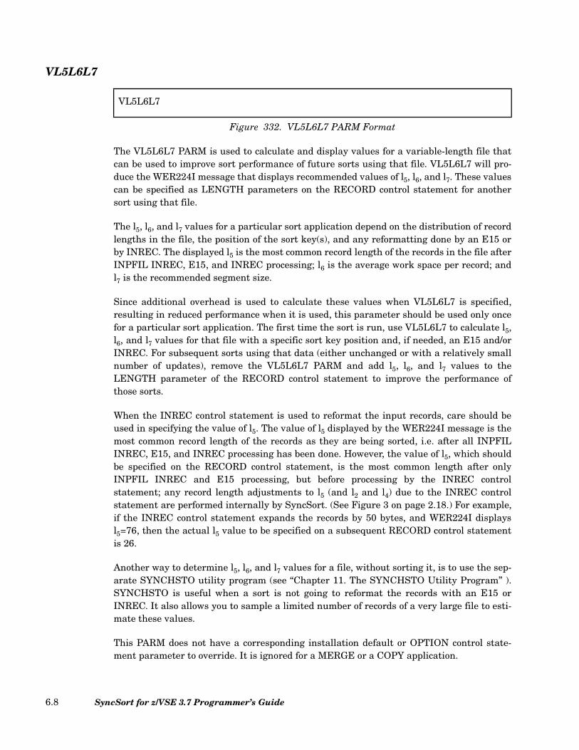
VL5L6L7
The VL5L6L7 PARM is used to calculate and display values for a variable-length file thatcan be used to improve sort performance of future sorts using that file. VL5L6L7 will pro-duce the WER224I message that displays recommended values of l5, l6, and l7. These valuescan be specified as LENGTH parameters on the RECORD control statement for anothersort using that file.
The l5, l6, and l7 values for a particular sort application depend on the distribution of recordlengths in the file, the position of the sort key(s), and any reformatting done by an E15 orby INREC. The displayed l5 is the most common record length of the records in the file afterINPFIL INREC, E15, and INREC processing; l6 is the average work space per record; andl7 is the recommended segment size.
Since additional overhead is used to calculate these values when VL5L6L7 is specified,resulting in reduced performance when it is used, this parameter should be used only oncefor a particular sort application. The first time the sort is run, use VL5L6L7 to calculate l5,l6, and l7 values for that file with a specific sort key position and, if needed, an E15 and/orINREC. For subsequent sorts using that data (either unchanged or with a relatively smallnumber of updates), remove the VL5L6L7 PARM and add l5, l6, and l7 values to theLENGTH parameter of the RECORD control statement to improve the performance ofthose sorts.
When the INREC control statement is used to reformat the input records, care should beused in specifying the value of l5. The value of l5 displayed by the WER224I message is themost common record length of the records as they are being sorted, i.e. after all INPFILINREC, E15, and INREC processing has been done. However, the value of l5, which shouldbe specified on the RECORD control statement, is the most common length after onlyINPFIL INREC and E15 processing, but before processing by the INREC controlstatement; any record length adjustments to l5 (and l2 and l4) due to the INREC controlstatement are performed internally by SyncSort. (See Figure 3 on page 2.18.) For example,if the INREC control statement expands the records by 50 bytes, and WER224I displaysl5=76, then the actual l5 value to be specified on a subsequent RECORD control statementis 26.
Another way to determine l5, l6, and l7 values for a file, without sorting it, is to use the sep-arate SYNCHSTO utility program (see “Chapter 11. The SYNCHSTO Utility Program” ).SYNCHSTO is useful when a sort is not going to reformat the records with an E15 orINREC. It also allows you to sample a limited number of records of a very large file to esti-mate these values.
This PARM does not have a corresponding installation default or OPTION control state-ment parameter to override. It is ignored for a MERGE or a COPY application.
VL5L6L7
Figure 332. VL5L6L7 PARM Format
SyncSort for z/VSE 3.7 Programmer’s Guide6.8

VSCORE
The VSCORE PARM establishes the upper bound of virtual storage below the 16-megabyteline in which SyncSort will run, specified as a decimal number of n, nK (K=1024), or nM(M=1024x1024) bytes.
VSCORET
The VSCORET PARM sets the maximum amount of storage that SyncSort can use when itis running in a partition that has storage above the 16-megabyte line, specified as a deci-mal number of n, nK (K=1024), or nM (M=1024x1024) bytes. If the specified value ofVSCORET is less than the specified or default value of VSCORE, SyncSort automaticallyraises the value of VSCORET to the VSCORE value.
WORKNM
The WORKNM PARM changes the four-character prefix of all SORTWK names from thedefault, SORT. For example, if WORKNM=SYNC is specified, all sort work files will benamed SYNCWKx instead of SORTWKx.
Figure 333. VSCORE PARM Format
VSCORE = nnKnM
Figure 334. VSCORET PARM Format
VSCORET = nnKnM
WORKNM=work
Figure 335. WORKNM PARM Format
Chapter 6. EXEC PARM Options 6.9

SyncSort for z/VSE 3.7 Programmer’s Guide6.10
Chapter 7. Invoking SyncSort from a Program
Another way to initiate the sort/merge is to have it loaded by an executing program. Thisprogram may be written in a number of languages including Assembler, COBOL, and PL/1.The coding necessary to invoke the sort/merge from an Assembler and from a COBOL pro-gram is given in this chapter.
When the sort/merge is invoked from a program, you can direct messages to a specific logi-cal unit. This feature is explained in “OPTION Control Statement” on page 2.114 and“ROUTE Parameter (Optional)” on page 2.132.
Invoking SyncSort from an Assembler Program
When an Assembler program is used and SyncSort is to be called somewhere within thatprogram, use the LOAD or CALL macro to establish linkage. (SyncSort will not execute asa subtask, so the FETCH and ATTACH macros cannot be used.) If the LOAD or CALLmacro is used, SyncSort should be loaded on a doubleword boundary at the end of the pro-gram. To insure proper linkage, registers 13, 14, 15, and 1 must contain the following infor-mation:
Register 13 Must contain the address of an 18-word save area where SyncSort can storethe contents of the user’s registers when the sort/merge gains control.When the sort/merge program is over, these registers will be automaticallyrestored to the user.
Register 14 Must contain the address of the instruction in the invoking program towhich SyncSort is to return control when it finishes the sort/merge.
Chapter 7. Invoking SyncSort from a Program 7.1
Register 15 Must contain the address of SyncSort’s entry point.
Register 1 Must contain the address of a variable-length parameter list of address con-stants.
Addressing and Residence Modes For Invoking Programs
SyncSort may be invoked from an Assembler program located above or below 16 MB of vir-tual storage and may execute in either 24-bit or 31-bit addressing mode.
SyncSort will process the invoking parameter list in the addressing mode that is currentwhen it receives control, and it will return control to the invoking program in that samemode.
• If SyncSort receives control in 24-bit mode, it treats all addresses as 24-bit addresses.SyncSort will ignore the high order byte of these addresses, and all user exits pre-loaded by the invoking program must be located below 16 MB of virtual storage andmust be able to execute in AMODE 24.
• If SyncSort receives control in 31-bit mode, it treats all addresses as 31-bit addresses,and these addresses may be located either above or below 16 MB of virtual storage. Ifthe addresses reside below 16 MB of virtual storage, the invoking program mustprovide "clean" 24-bit addresses, that is, bits 1 through 7 must be 0. SyncSort ignoresthe high order bit (bit 0) unless it is part of the address of a user exit.
When user exit addresses are included in the parameter list, bit 0 of the address signals theaddressing mode of the exit. When the bit is set to 0, SyncSort calls the user exit inAMODE 24. When the bit is set to 1, SyncSort calls the user exit in AMODE 31.
When it loads a user exit, SyncSort always calls the exit in the AMODE assigned by thelinkage editor, and provides "clean" 24-bit addresses in the parameter list. All addressesreturned by the user exit must be valid 31-bit addresses for AMODE 31 exits and valid 24-bit addresses for AMODE 24 exits.
A user exit may return to SyncSort in any addressing mode.
The Parameter List of Address Constants
An Assembler program that invokes the sort/merge must include a 10-word or an 18-wordparameter address constant list. These address constants will point to the images ofSyncSort control statements, to a halfword set aside for a return code, and to three-branchtables for exit programs.
The first 10 parameters in the parameter list are obligatory and must be coded in the cor-rect sequence, with A(0) coded for any control statement image or branch table entry notused. The final 8 parameters (address constants for ALTSEQ through REFORMAT) are
SyncSort for z/VSE 3.7 Programmer’s Guide7.2

optional. The sequence of these last 8 addresses is not important and unused parameterscan be omitted.
The Control Statement Images
The actual control statement images must use DC instructions and follow these specificrules:
1. Each control statement image must be delimited at the beginning by the constant Cfollowed immediately by a single quote.
2. The operator (SORT, RECORD, etc.) must immediately follow the single quote.
3. The operator must be followed by exactly one blank.
4. The operator and parameters of the control statement images must be coded exactly asthe control statements described in “Chapter 2. SyncSort Control Statements”.
5. The last parameter is followed by exactly one blank and then a final delimiting singlequote.
6. The parameter for the INPFIL control statement image addresses may specify morethan one control statement image to accommodate multiple input files. If more thanone INPFIL control statement image is to be specified, each subsequent specificationshould immediately follow the final blank of the prior specification. A parameter listcontaining multiple INPFIL control statement images is illustrated in Figure 339 onpage 7.7.
LINKLIST DC A(LSORT) * ADDRESS OF SORT CONTROL STATEMENT IMAGE
DC A(LREC) * ADDRESS OF RECORD CONTROL STATEMENT IMAGE
DC A(LINPFIL) * ADDRESS OF INPFIL CONTROL STATEMENT IMAGE
DC A(LOUTFIL) * ADDRESS OF OUTFIL CONTROL STATEMENT IMAGE
DC A(LOPTION) * ADDRESS OF OPTION CONTROL STATEMENT IMAGE
DC A(LMODS) * ADDRESS OF MODS CONTROL STATEMENT IMAGE
DC A(PHASE1) * ADDRESS OF PHASE 1 BRANCH TABLE
DC A(PHASE2) * ADDRESS OF PHASE 2 BRANCH TABLE
DC A(PHASE3) * ADDRESS OF PHASE 3 BRANCH TABLE
DC A(RETCODE) * ADDRESS OF HALFWORD FOR RETURN CODE
DC A(LALTSEQ) * ADDRESS OF ALTSEQ CONTROL STATEMENT IMAGE
DC A(LOUTREC) * ADDRESS OF OUTREC CONTROL STATEMENT IMAGE
DC A(LSUM) * ADDRESS OF SUM CONTROL STATEMENT IMAGE
DC A(LINCOM) * ADDRESS OF INCLUDE/OMIT CONTROL STATEMENT IMAGE
DC A(LANALYZE) * ADDRESS OF ANALYZE CONTROL STATEMENT IMAGE
DC A(LINREC) * ADDRESS OF INREC CONTROL STATEMENT IMAGE
DC A(LJOIN) * ADDRESS OF JOIN CONTROL STATEMENT IMAGE
DC A(LREFORMAT) * ADDRESS OF REFORMAT CONTROL STATEMENT IMAGE
Figure 336. Sample Parameter List of Address Constants
Chapter 7. Invoking SyncSort from a Program 7.3
7. The parameter for the OUTFIL/XSUMFIL/XDUPFIL control statement imageaddresses may specify more than one control statement image to accommodatemultiple output files. If more than one OUTFIL control statement image is to bespecified, each subsequent specification should immediately follow the final blank ofthe prior specification. A parameter list containing multiple OUTFIL/XSUMFIL/XDUPFIL control statement images is illustrated in Figure 339 on page 7.7.
8. If both the INREC and the OUTREC control statement images are specified, eachcontrol statement image address may be specified separately. Or, the parameter foreither the INREC control statement image address or the OUTREC control statementimage address may be used to specify both control statement images. In this case, thesecond control statement image should immediately follow the final blank of the firstspecification.
9. The parameter for the SUM control statement image may be used to specify theDUPKEYS control statement image.
10. In a JOIN application, the parameter for the INPFIL control statement image would beused to specify the JOINKEYS control statement image.
11. To continue a control image, place a single quote with no embedded blank after the lastcharacter on the first card image. The successive card image should code a DCinstruction in columns 10 and 11, a C' in columns 16 and 17, start the continuation incolumn 18, and leave exactly one blank followed by a single quote after the lastparameter.
12. Embedded blanks are not allowed on control statement images, except within literalstrings.
13. Comments are not allowed on the control statement images.
An example of a coded parameter list using the addresses from the sample parameter list ofaddress constants is given in Figure 337 on page 7.5.
The Return Code Parameter
The return code address constant points to a halfword that must be set up somewhere inthe user’s program. After a successful run of the sort/merge program, SyncSort will store a0 in this halfword. If the sort/merge was not successful, SyncSort will place a 16 in thishalfword.
An example of a coded return code parameter is given in Figure 337 on page 7.5.
SyncSort for z/VSE 3.7 Programmer’s Guide7.4
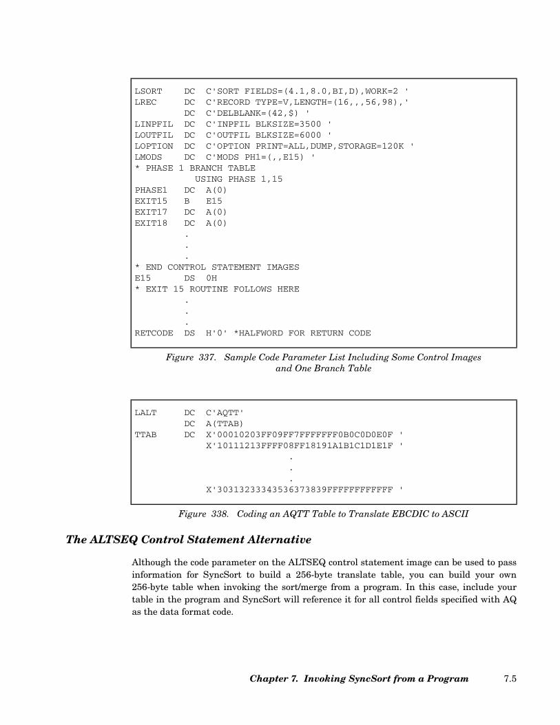
The ALTSEQ Control Statement Alternative
Although the code parameter on the ALTSEQ control statement image can be used to passinformation for SyncSort to build a 256-byte translate table, you can build your own256-byte table when invoking the sort/merge from a program. In this case, include yourtable in the program and SyncSort will reference it for all control fields specified with AQas the data format code.
LSORT DC C'SORT FIELDS=(4.1,8.0,BI,D),WORK=2 'LREC DC C'RECORD TYPE=V,LENGTH=(16,,,56,98),'
DC C'DELBLANK=(42,$) 'LINPFIL DC C'INPFIL BLKSIZE=3500 'LOUTFIL DC C'OUTFIL BLKSIZE=6000 'LOPTION DC C'OPTION PRINT=ALL,DUMP,STORAGE=120K 'LMODS DC C'MODS PH1=(,,E15) '* PHASE 1 BRANCH TABLE
USING PHASE 1,15PHASE1 DC A(0)EXIT15 B E15EXIT17 DC A(0)EXIT18 DC A(0)
.
.
.* END CONTROL STATEMENT IMAGESE15 DS 0H* EXIT 15 ROUTINE FOLLOWS HERE
.
.
.RETCODE DS H'0' *HALFWORD FOR RETURN CODE
Figure 337. Sample Code Parameter List Including Some Control Imagesand One Branch Table
LALT DC C'AQTT'DC A(TTAB)
TTAB DC X'00010203FF09FF7FFFFFFF0B0C0D0E0F 'X'10111213FFFF08FF18191A1B1C1D1E1F '
.
.
.X'30313233343536373839FFFFFFFFFFFF '
Figure 338. Coding an AQTT Table to Translate EBCDIC to ASCII
Chapter 7. Invoking SyncSort from a Program 7.5
To create a translate table, follow these steps:
1. In place of the ALTSEQ address constant, specify the address of a fullword alignedlocation containing C'AQTT' in the parameter address list.
2. Program a constant C with the value 'AQTT'.
3. Immediately following this entry, place the address of the table.
4. Construct a 256-byte hexadecimal translate table.
An example of the coding necessary for the AQTT table is given in Figure 338 on page 7.5.Note that the entire table is not given.
A Sample Assembler Program Invoking SyncSort
Figure 339 on page 7.7 illustrates how to invoke the sort/merge from an Assembler Pro-gram. When SyncSort is invoked from a program, it will return control to the user’s pro-gram upon completion, giving a code to indicate either a successful or an unsuccessful sort/merge program. For this reason, the sample program in Figure 339 on page 7.7 includes aprocess for a successful sort as well as a process for an unsuccessful sort. It checks the sort’sreturn code with a compare instruction and either branches to or falls into the routine toprocess the results of the sort.
Invoking SyncSort from a COBOL Program
The COBOL programming language includes a sort feature so that the COBOL program-mer has complete opportunity to access the SyncSort program. The COBOL program mustinclude an SD (Sort-File-Description) in the File Section and a SORT statement in the Pro-cedure Division. Control fields, called sort-keys in COBOL, are defined in the SD and, asspecified in the SORT verb, sort-keys are either sorted in ascending or descending orderaccording to the EBCDIC collating sequence for COBOL characters. (Consult AmericanNational Standard COBOL texts for complete details.)
A Sample COBOL Program Invoking SyncSort
The program in Figure 342 on page 7.9 was designed to produce three output reports from asingle pass of the master file. By using the SyncSort sort/merge program together with theCOBOL sort feature, three distinct records are created from one master record, sorted andlater written out on the appropriate reports.
SyncSort for z/VSE 3.7 Programmer’s Guide7.6

*LOAD SORT,ESTABLISH LINKAGE,BRANCH AND LINK
LOAD SORT,SENTRY *LOAD SORT AT SENTRYLR R15,R1 *LOAD ADDRESS OF SENTRYLA R1,PADLIST *LOAD ADDRESS OF PARAMETER ADDRESS LISTLA R13,REGSAVE *LOAD ADDRESS OF REGISTER SAVE AREABALR R14,R15 *LINK TO R15 WITH A RETURN TO R14
*SORT RETURNS CONTROL AT COMBACK, RETURN CODE IS CHECKED
COMBACK CLC RETCODE(2),=H'0'*COMPARE FOR SUCCESSFUL SORTBNE BADSORT *NO GOOD, GO TO ERROR ROUTINE
PROCESS DS 0H.. *PROCESS ROUTINE FOR SUCCESSFUL SORT.
PADLIST DC A(SORT1) *SORT CONTROL IMAGE ADDRESSDC A(REC1) *RECORD CONTROL IMAGE ADDRESSDC A(INPUT1) *INPFIL CONTROL IMAGE ADDRESSDC A(OUTPT1) *OUTFIL CONTROL IMAGES ADDRESSDC A(OPT1) *OPTION CONTROL IMAGE ADDRESSDC A(0) *MODS CONTROL IMAGE (UNUSED) ADDRESSDC A(0) *PHASE 1 BRANCH TABLE (UNUSED) ADDRESSDC A(0) *PHASE 2 BRANCH TABLE (UNUSED) ADDRESSDC A(0) *PHASE 3 BRANCH TABLE (UNUSED) ADDRESSDC A(RETCODE) *RETURN CODE HALFWORD ADDRESSDC A(0) *ALTSEQ CONTROL IMAGE (UNUSED) ADDRESSDC A(INREC1) *INREC CONTROL IMAGE ADDRESSDC A(SUM1) *SUM CONTROL IMAGE ADDRESSDC A(OMIT1) *OMIT CONTROL IMAGE ADDRESSDC A(OUTREC1) *OUTREC CONTROL IMAGE ADDRESS
*THE PARAMETER ADDRESS LIST IS GIVEN ABOVE, THE PARAMETERS ARE REFERENCED*BELOW
SORT1 DC C'SORT FIELDS=(24,8,BI,A),WORK=3,FILESOUT=2,FILES=2 'REC1 DC C'RECORD TYPE=F,LENGTH=148 'INPUT1 DC C'INPFIL BLKSIZE=1480,FILES=1 '
DC C'INPFIL BLKSIZE=2960,FILES=2 'OUTPT1 DC C'OUTFIL BLKSIZE=2500,FILES=1 '
DC C'OUTFIL BLKSIZE=5000,FILES=2 'DC C'XSUMFIL BLKSIZE=2200 '
OPT1 DC C'OPTION STORAGE=100K 'INREC1 DC C'INREC FIELDS=(1,100,139,10) 'SUM1 DC C'SUM FIELDS=(96,4,PD),XSUM 'OMIT1 DC C'OMIT COND=(71,5,ZD,GT,5000) 'OUTREC1 DC C'OUTREC FIELDS=(1,8,5X,9,10,5X,19,4,5X,23,88) '
REGSAVE DC 18F'0' *REGISTER SAVE AREA OF 18 FULLWORDSRETCODE DC H'0' *HALFWORD FOR RETURN CODE
LTORGBADSORT DS 0H
.
. *ROUTINE FOR UNSUCCESSFUL SORT
.SENTRY DC D'0' *SYNCSORT ENTRY POINT
END
Figure 339. Assembler Program Invoking SyncSort
Chapter 7. Invoking SyncSort from a Program 7.7
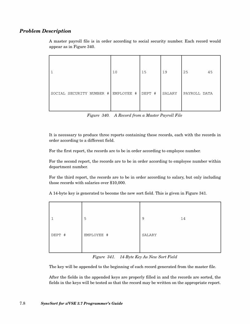
Problem Description
A master payroll file is in order according to social security number. Each record wouldappear as in Figure 340.
It is necessary to produce three reports containing these records, each with the records inorder according to a different field.
For the first report, the records are to be in order according to employee number.
For the second report, the records are to be in order according to employee number withindepartment number.
For the third report, the records are to be in order according to salary, but only includingthose records with salaries over $10,000.
A 14-byte key is generated to become the new sort field. This is given in Figure 341.
The key will be appended to the beginning of each record generated from the master file.
After the fields in the appended keys are properly filled in and the records are sorted, thefields in the keys will be tested so that the record may be written on the appropriate report.
1 10 15 19 25 45
SOCIAL SECURITY NUMBER # EMPLOYEE # DEPT # SALARY PAYROLL DATA
Figure 340. A Record from a Master Payroll File
1 5 9 14
DEPT # EMPLOYEE # SALARY
Figure 341. 14-Byte Key As New Sort Field
SyncSort for z/VSE 3.7 Programmer’s Guide7.8

The appended key will not be picked up, so only the original record will appear in thereports.
IDENTIFICATION DIVISIONPROGRAM-ID. REPGENAUTHOR. SYNCSORT INCORPORATEDENVIRONMENT DIVISION.CONFIGURATION SECTION.SOURCE COMPUTER. IBM-370-158.OBJECT COMPUTER. IBM-370-158.INPUT-OUTPUT SECTION.FILE-CONTROL.
SELECT EMP-MASTER ASSIGN TO SYS007-UR-2540R-S.SELECT REP-MASTER ASSIGN TO SYS009-UT-2400-S-SORTOUT.SELECT SORT-FILE ASSIGN TO SYS001-UT-3330-S-SORTWK1.
DATA DIVISION.FILE SECTION.SD SORT-FILE
SORT-OPTION IS WORK-OPTIONDATA RECORD IS REP-REC.
01 REP-REC.05 GEN-KEY PIC X(14).05 REC PIC X(45).
FD EMP-MASTERDATA RECORD IS EMPLOYEE.
01 EMPLOYEE.05 $$ PIC X(9).05 EMP PIC 9999.05 DEPT PIC 9999.05 MONEY PIC 9(6).
88 REC-OK VALUE 10001 THRU 999999.05 NAME PIC X(20).05 FILLER PIC X(37).
FD REP-FILELABEL RECORDS ARE STANDARDDATA RECORD IS REPORT-REC.
01 REPORT-REC.05 REP-CODE PIC X(14).05 REP-RECD PIC X(45).
WORKING STORAGE SECTION01 WORK-OPTION PIC X(20) VALUE 'OPTION SORTWK=003'.01 WORK-RECORD
05 WORK-KEY PIC X(14) VALUE SPACE.05 WORK-REC PIC X(45) VALUE SPACE
01 SORT-KEY.05 S-DEPT PIC 9(4) VALUE ZERO.05 S-EMP PIC 9(4) VALUE ZERO.05 S-SAL PIC 9(6) VALUE ZERO.
Figure 342. Invoking SyncSort from a COBOL Program
Chapter 7. Invoking SyncSort from a Program 7.9
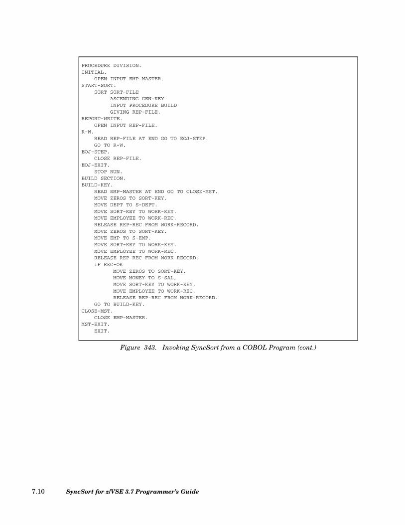
PROCEDURE DIVISION.INITIAL.
OPEN INPUT EMP-MASTER.START-SORT.
SORT SORT-FILEASCENDING GEN-KEYINPUT PROCEDURE BUILDGIVING REP-FILE.
REPORT-WRITE.OPEN INPUT REP-FILE.
R-W.READ REP-FILE AT END GO TO EOJ-STEP.GO TO R-W.
EOJ-STEP.CLOSE REP-FILE.
EOJ-EXIT.STOP RUN.
BUILD SECTION.BUILD-KEY.
READ EMP-MASTER AT END GO TO CLOSE-MST.MOVE ZEROS TO SORT-KEY.MOVE DEPT TO S-DEPT.MOVE SORT-KEY TO WORK-KEY.MOVE EMPLOYEE TO WORK-REC.RELEASE REP-REC FROM WORK-RECORD.MOVE ZEROS TO SORT-KEY.MOVE EMP TO S-EMP.MOVE SORT-KEY TO WORK-KEY.MOVE EMPLOYEE TO WORK-REC.RELEASE REP-REC FROM WORK-RECORD.IF REC-OK
MOVE ZEROS TO SORT-KEY,MOVE MONEY TO S-SAL,MOVE SORT-KEY TO WORK-KEY,MOVE EMPLOYEE TO WORK-REC,RELEASE REP-REC FROM WORK-RECORD.
GO TO BUILD-KEY.CLOSE-MST.
CLOSE EMP-MASTER.MST-EXIT.
EXIT.
Figure 343. Invoking SyncSort from a COBOL Program (cont.)
SyncSort for z/VSE 3.7 Programmer’s Guide7.10

Chapter 8. User Exit Programs
What Is an Exit?
User-supplied routines are known as exits. Different types of exits can be written to do avariety of tasks at different stages of the sort/merge. The point in the sort/merge at whichan exit program takes control to do a specific task is also known as an exit, and this pointhas the same exit number as the program that is entered to do the task.
The number of an exit provides certain information: the first digit in the exit number indi-cates whether the exit occurs in Phase 1, 2, or 3 of the sort/merge. The second digit refers tothe type of task(s) the exit can perform.
Table 47 on page 8.2 lists all available exits. It also illustrates in which phase each exitoccurs and provides an overall view of the tasks that can be performed by each exit.
Loading an Exit Program into Main Storage
There are two ways to get exit programs into main storage: (1) place them in the core imagelibrary and have the sort/merge load them; (2) place them in main storage and tell the sort/merge where they are to be found.
When SyncSort Loads a User-Supplied Program
Group all exit routines that occur in a particular phase of the sort/merge together and cata-logue each group under a unique name in the core image library. The group name(s), load-ing information, and names of the exits being included are supplied on the MODS control
Chapter 8. User Exit Programs 8.1

statement. This informs SyncSort when to get the exit programs, where to find them, andhow much space to set aside.
SyncSort can load the exits (routines) whether the sort is initiated by JCL or by anotherprogram.
TASKS PHASE 1 PHASE 2 PHASE 3
E11 E15 E17 E18 E21 E25 E27 E31 E32 E35 E37 E38 E39
Checkpoint *
Process labels * * * * *
Open files * *
Close files * * * * *
Read sort input *
Count input records *
Insert records * *
Delete records * * *
Lengthen and shorten records
* *
Alter noncontrol fields of records
* * * *
Read merge input *
Sum records * * *
Substitute records (merge only)
*
Suppress sequence checking
*
Write output *
Process read errors * *
Process direct access write errors
*
Provide VSAM pass-words
* * *
Table 47. Exit Task Chart
SyncSort for z/VSE 3.7 Programmer’s Guide8.2
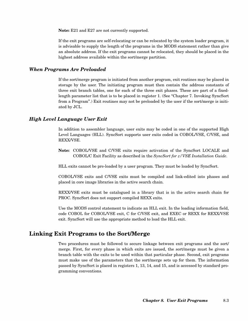
Note: E21 and E27 are not currently supported.
If the exit programs are self-relocating or can be relocated by the system loader program, itis advisable to supply the length of the programs in the MODS statement rather than givean absolute address. If the exit programs cannot be relocated, they should be placed in thehighest address available within the sort/merge partition.
When Programs Are Preloaded
If the sort/merge program is initiated from another program, exit routines may be placed instorage by the user. The initiating program must then contain the address constants ofthree exit branch tables, one for each of the three exit phases. These are part of a fixed-length parameter list that is to be placed in register 1. (See “Chapter 7. Invoking SyncSortfrom a Program”.) Exit routines may not be preloaded by the user if the sort/merge is initi-ated by JCL.
High Level Language User Exit
In addition to assembler language, user exits may be coded in one of the supported HighLevel Languages (HLL). SyncSort supports user exits coded in COBOL/VSE, C/VSE, andREXX/VSE.
Note: COBOL/VSE and C/VSE exits require activation of the SyncSort LOCALE andCOBOL/C Exit Facility as described in the SyncSort for z/VSE Installation Guide.
HLL exits cannot be pre-loaded by a user program. They must be loaded by SyncSort.
COBOL/VSE exits and C/VSE exits must be compiled and link-edited into phases andplaced in core image libraries in the active search chain.
REXX/VSE exits must be catalogued in a library that is in the active search chain forPROC. SyncSort does not support compiled REXX exits.
Use the MODS control statement to indicate an HLL exit. In the loading information field,code COBOL for COBOL/VSE exit, C for C/VSE exit, and EXEC or REXX for REXX/VSEexit. SyncSort will use the appropriate method to load the HLL exit.
Linking Exit Programs to the Sort/Merge
Two procedures must be followed to secure linkage between exit programs and the sort/merge. First, for every phase in which exits are issued, the sort/merge must be given abranch table with the exits to be used within that particular phase. Second, exit programsmust make use of the parameters that the sort/merge sets up for them. The informationpassed by SyncSort is placed in registers 1, 13, 14, and 15, and is accessed by standard pro-gramming conventions.
Chapter 8. User Exit Programs 8.3

The Branch Table
All exit routines for a particular phase must be placed together in ascending numericalsequence and loaded as a single module. Immediately preceding this module must be abranch table that lists every branch (including those not supported) in the phase in ascend-ing numerical sequence.
The format for each of the three branch tables is given in Figure 344, Figure 345 and Fig-ure 346, respectively.
Code a 4-byte branch instruction for every exit used, and code 4 bytes of zeros for every exitnot used. An example of a coded Phase 3 branch table is Figure 347.
USING PHASE1,15PHASE1 B E11
B E15B E17B E18
Figure 344. PHASE1 Branch Table Format
USING PHASE2,15PHASE2 DC A(0) *E21 NOT SUPPORTED
B E25DC A(0) *E27 NOT SUPPORTED
Figure 345. PHASE2 Branch Table Format
USING PHASE3,15PHASE3 B E31
B E32B E35B E37B E38B E39
Figure 346. PHASE3 Branch Table Format
SyncSort for z/VSE 3.7 Programmer’s Guide8.4
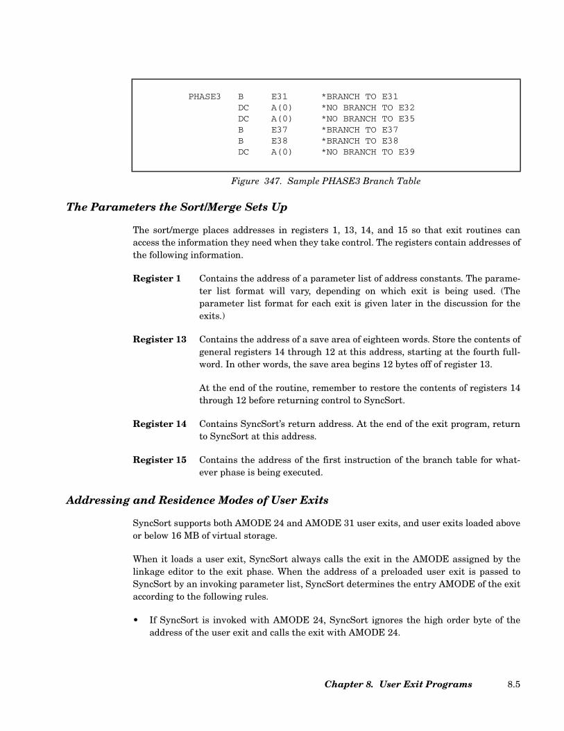
The Parameters the Sort/Merge Sets Up
The sort/merge places addresses in registers 1, 13, 14, and 15 so that exit routines canaccess the information they need when they take control. The registers contain addresses ofthe following information.
Register 1 Contains the address of a parameter list of address constants. The parame-ter list format will vary, depending on which exit is being used. (Theparameter list format for each exit is given later in the discussion for theexits.)
Register 13 Contains the address of a save area of eighteen words. Store the contents ofgeneral registers 14 through 12 at this address, starting at the fourth full-word. In other words, the save area begins 12 bytes off of register 13.
At the end of the routine, remember to restore the contents of registers 14through 12 before returning control to SyncSort.
Register 14 Contains SyncSort’s return address. At the end of the exit program, returnto SyncSort at this address.
Register 15 Contains the address of the first instruction of the branch table for what-ever phase is being executed.
Addressing and Residence Modes of User Exits
SyncSort supports both AMODE 24 and AMODE 31 user exits, and user exits loaded aboveor below 16 MB of virtual storage.
When it loads a user exit, SyncSort always calls the exit in the AMODE assigned by thelinkage editor to the exit phase. When the address of a preloaded user exit is passed toSyncSort by an invoking parameter list, SyncSort determines the entry AMODE of the exitaccording to the following rules.
• If SyncSort is invoked with AMODE 24, SyncSort ignores the high order byte of theaddress of the user exit and calls the exit with AMODE 24.
PHASE3 B E31 *BRANCH TO E31DC A(0) *NO BRANCH TO E32DC A(0) *NO BRANCH TO E35B E37 *BRANCH TO E37B E38 *BRANCH TO E38DC A(0) *NO BRANCH TO E39
Figure 347. Sample PHASE3 Branch Table
Chapter 8. User Exit Programs 8.5

• If SyncSort is invoked with AMODE 31, SyncSort uses the high order bit of the userexit address to determine the AMODE of the exit. If the high order bit is set to 1, theexit will be called with AMODE 31. If the high order bit is set to 0, the exit will becalled with AMODE 24.
An exit entered with 24-bit addressing mode can only pass 24-bit addresses back toSyncSort. An exit entered with 31-bit addressing mode can only pass 31-bit addresses backto SyncSort, and bits 1 through 7 must be set to 0 in addresses below 16 MB of virtualstorage.
A user exit may return to SyncSort in any addressing mode.
EXITS E11 and E31 Checkpointing and Label Processing
These exits are used for opening and closing files, initialization or termination processing,and the processing of labels. E31 is additionally used for checkpointing. Since the only timethe opening and closing of files would be done by the user is while assuming the responsi-bility for processing labels, the opening and closing of files will be treated in this section,along with label processing.
Note: Label processing must be done whenever the user’s files have nonstandard or userstandard labels. The LABEL parameter of the OPTION control statement must be speci-fied whenever label processing is done.
Exits E15, E32, and E35 may also be used to process labels and should do so if EXIT hasbeen specified in the INPFIL or OUTFIL control statements. In addition, final trailerlabels (those on the last input and output volumes) should be processed by E17 and E37,respectively.
Parameter and Entry Lists
For each of these exits, SyncSort will place the address of a parameter list of full wordaddresses in register 1. The information passed in these parameter lists will vary accordingto the point the user has reached in the sort/merge. An exit is approached many times dur-ing the SyncSort program and there is an opportunity to enter at each of these times; theseopportunities are called entries and do various things. Table 48 and Table 49 on page 8.7show the parameter to which each word points and the entry lists for each of the exits,respectively, showing what is done at the various entry points of each exit.
SyncSort for z/VSE 3.7 Programmer’s Guide8.6
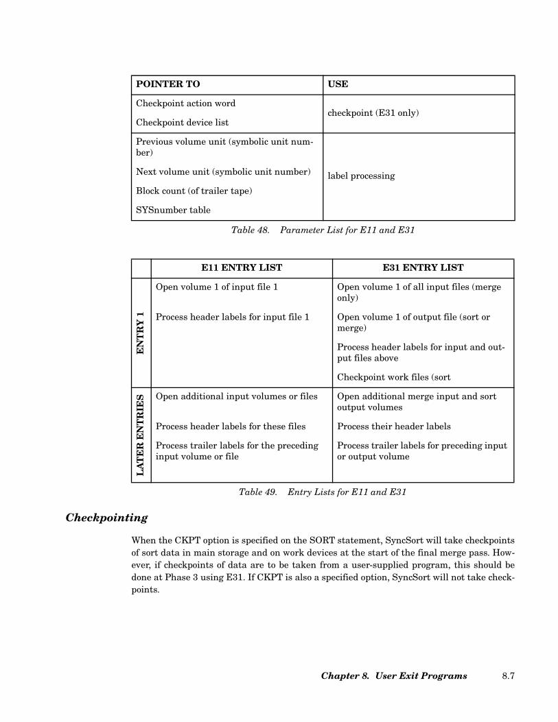
Checkpointing
When the CKPT option is specified on the SORT statement, SyncSort will take checkpointsof sort data in main storage and on work devices at the start of the final merge pass. How-ever, if checkpoints of data are to be taken from a user-supplied program, this should bedone at Phase 3 using E31. If CKPT is also a specified option, SyncSort will not take check-points.
POINTER TO USE
Checkpoint action word
Checkpoint device list checkpoint (E31 only)
Previous volume unit (symbolic unit num-ber)
Next volume unit (symbolic unit number)
Block count (of trailer tape)
SYSnumber table
label processing
Table 48. Parameter List for E11 and E31
E11 ENTRY LIST E31 ENTRY LIST
EN
TR
Y 1
Open volume 1 of input file 1 Open volume 1 of all input files (merge only)
Process header labels for input file 1 Open volume 1 of output file (sort or merge)
Process header labels for input and out-put files above
Checkpoint work files (sort
LA
TE
R E
NT
RIE
S Open additional input volumes or files Open additional merge input and sort
output volumes
Process header labels for these files Process their header labels
Process trailer labels for the preceding input volume or file
Process trailer labels for preceding input or output volume
Table 49. Entry Lists for E11 and E31
Chapter 8. User Exit Programs 8.7

E11 Programs
Since sorting has not yet begun at this phase, it is not necessary to pass any informationfrom the exit routine to the sort through parameters.
E31 Programs
At this exit it is possible to checkpoint both user devices and sort work files. Since only onemerge occurs in Phase 3, only one checkpoint is taken. This occurs at Entry 1 when the exitroutine first gets control.
The only parameter that applies to an E31 checkpoint program is the Checkpoint devicelist, which is the second parameter in the list. The device list for disk files is given below inFigure 348.
The 2-byte Count area contains the total number of devices to be checkpointed. The Unitcode is the numeric portion of the symbolic unit name of the device, and the Bin numberis always 0. (All numbers will be in the low-order bytes.) There will be only one count areaat the start of the checkpoint device list, but a unit code and bin number will be given forevery device checkpointed.
Label Processing
Nonstandard and user standard labels are not processed by the sort/merge program. Diskand tape files with these types of labels will need to have label processing routines writtenfor headers, and the tape files will need routines for trailers as well. Since sort file labelsare not processed in Phase 2, only E11 and E31 routines will be used, and if it is necessaryto write a header label on the output file, exit 31 must be used. (Exit 37 must be used towrite the trailer label on the last volume of the output file.) For exits E11 and E31, the lastfour words of the parameter list are relevant. (They are: 3. Previous volume (symbolic)unit (number), 4. Next volume (symbolic) unit (number), 5. Block count (of trailer tape),and 6. SYSnumber table.) The Previous volume unit points to the numeric portion ofthe symbolic unit name of the volume just processed. This is contained in a halfword in thelow-order bytes. The Next volume unit points to the numeric portion of the symbolic unitname of the volume to be processed next. This is also in a halfword in the low-order bytes.
CHECKPOINT DEVICE FOR DISK FILES
Count Unit Code Bin Number ...
2 bytes
2 bytes
2 bytes
Figure 348. Checkpoint Device List for Disk Files
SyncSort for z/VSE 3.7 Programmer’s Guide8.8
The Block count points to a 4-byte area with the number of blocks of the tape receiving atrailer label contained in the lower-order byte(s).
The SYSnumber table points to a 20 to 74 byte area containing the number portion of thesymbolic unit name of every file used for the sort. Each byte contains the SYSnumber (inbinary) of one file. The following describes the contents of each byte of the SYSnumbertable for "n" output files (FILESOUT=n):
• Bytes 1 to "n" contain the SYSnumbers for the output files. Byte 1 is always present forthe first output file. There are only as many bytes in the SYSnumber table as thereare output files present.
• Bytes "n+1" through "n+m" contain the SYSnumbers for each of m input files. Themaximum value for m is 32. A minimum of 9 bytes for input files is always reserved inthe SYSnumber table, regardless of the number of input files actually present. If lessthan 9 input files are used, the unused bytes are filled with zeros.
• Bytes "n+m+1" through "n+m+9" contain the SYSnumbers for work files. The value ofm may not be less than 9, and a minimum of 9 bytes is always reserved for work files inthe SYSnumber table, regardless of the number of work files actually present. If lessthan 9 work files are used, the unused bytes are filled with zeros.
• Byte "n+m+10" contains the SYSnumber for the checkpoint file.
E11 Programs
For Entry 1, the Previous volume unit and the Next volume unit parameters are bothfilled with zeros. This permits testing for Entry 1. After testing successfully for Entry 1,open the first volume of the input file, referencing the SYSnumber table in parameter 6,and then process its label. (It is assumed that the first input volume is a nonstandard oruser labeled file. For this first entry, it is important to know the type of label of the first vol-ume of input.)
Later Entries of this exit occur each time another input volume is needed, and when a vol-ume has user or nonstandard labels. In order to tell the user when a volume has standardor no labels and, therefore, needs no processing, parameter 4 will be set to zero and param-eter 3 will contain the trailer unit. That means that if the Previous volume unit parame-ter contains a nonzero number, the volume just read needs to be processed; therefore,process its trailer label using the block count number given in parameter 5.
To find out if the last volume of a file has nonstandard or user labels, compare parameters3 and 4. If they contain different numbers and parameter 3 is not zero, it is necessary toclose the last volume. Then, check the Next volume unit (parameter 4); if it does not con-tain zeros, open the next input volume and process its header label.
The very last trailer label - the one on the last volume of the last input file - must be pro-cessed by an E17 program.
Chapter 8. User Exit Programs 8.9

E31 Programs
For Entry 1, parameters 3 and 4 are set to zero. Use this entry to open the first volume ofevery input file used for a merge, referencing the SYSnumber table in parameter 6. (It isassumed these have nonstandard or user labels.) Also, use this entry to open the first vol-ume of the output file for either a sort or a merge. Then, process their header labels.
Later Entries of this exit occur whenever another merge input or sort or merge output vol-ume is needed, and when any of these volumes have nonstandard or user labels. If a vol-ume has standard or no labels, parameters 3 and 4 will be set to zero. To find out if thevolume just read needs processing, test parameter 3 (Previous volume unit). If it con-tains a numeric value, process a trailer label for this volume using the block count numberfound in parameter 5.
To find out if the last volume of a file has nonstandard or user labels, compare parameters3 and 4. If they are different values and parameter 3 is not zero, it is necessary to close thevolume.
To find out if it is necessary to open the next volume, test parameter 4. If it is not zero, openthe volume and process its header label.
The last volume of every merge input file and the last volume of the output file for both asort and merge cannot be processed at this exit. They must be processed with an E37 rou-tine.
EXITS E15, E25, and E35 - Changing Records and Files
These exits are used when there is a desire to change the data in individual records, insertor delete records from a file, have the program assume responsibility for reading the inputfile, or have the program assume responsibility for writing the output file.
E15 Programs
Exit 15 is entered before input records are processed in Phase 1. It is, therefore, possible towrite a program that changes the length of the records, or inserts or deletes records beforeany sorting takes place. The new length of the records must agree with whatever value hasbeen specified for l2 in the RECORD control statement. (For variable-length records, themaximum new length will agree with the l2 value.)
If the E15 program is going to read the input file, it must also open the file, process theheader labels, read the file and pass one record at a time to the sort/merge, close the file,and process tape trailer labels. And for all read programs, the control statements mustinclude an INPFIL statement specifying EXIT.
SyncSort for z/VSE 3.7 Programmer’s Guide8.10
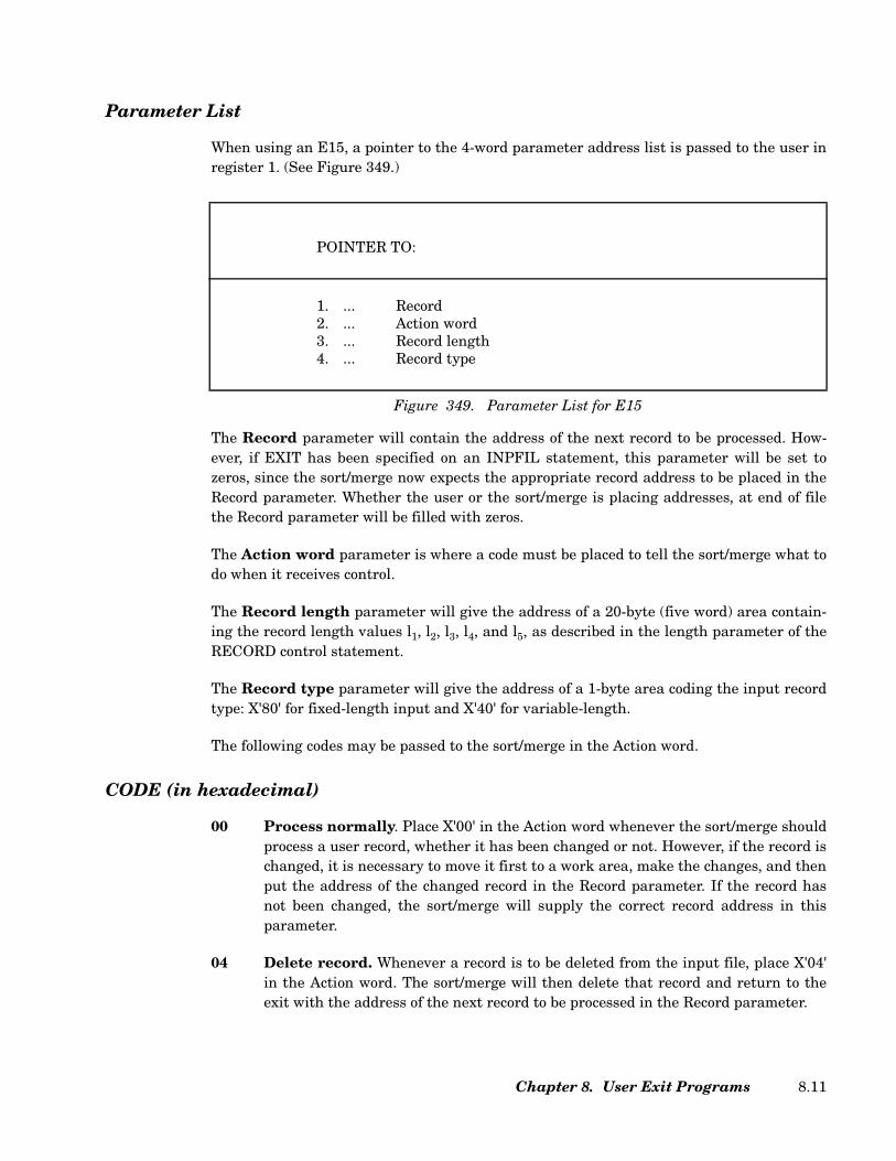
Parameter List
When using an E15, a pointer to the 4-word parameter address list is passed to the user inregister 1. (See Figure 349.)
The Record parameter will contain the address of the next record to be processed. How-ever, if EXIT has been specified on an INPFIL statement, this parameter will be set tozeros, since the sort/merge now expects the appropriate record address to be placed in theRecord parameter. Whether the user or the sort/merge is placing addresses, at end of filethe Record parameter will be filled with zeros.
The Action word parameter is where a code must be placed to tell the sort/merge what todo when it receives control.
The Record length parameter will give the address of a 20-byte (five word) area contain-ing the record length values l1, l2, l3, l4, and l5, as described in the length parameter of theRECORD control statement.
The Record type parameter will give the address of a 1-byte area coding the input recordtype: X'80' for fixed-length input and X'40' for variable-length.
The following codes may be passed to the sort/merge in the Action word.
CODE (in hexadecimal)
00 Process normally. Place X'00' in the Action word whenever the sort/merge shouldprocess a user record, whether it has been changed or not. However, if the record ischanged, it is necessary to move it first to a work area, make the changes, and thenput the address of the changed record in the Record parameter. If the record hasnot been changed, the sort/merge will supply the correct record address in thisparameter.
04 Delete record. Whenever a record is to be deleted from the input file, place X'04'in the Action word. The sort/merge will then delete that record and return to theexit with the address of the next record to be processed in the Record parameter.
POINTER TO:
1. ... Record2. ... Action word3. ... Record length4. ... Record type
Figure 349. Parameter List for E15
Chapter 8. User Exit Programs 8.11
08 No return. Once an E15 exit has been entered, the sort/merge will keep returningto it until it receives an X'08' in the Action word. In other words, it is necessary totell the sort/merge when this exit is no longer required.
0C Insert record When a record is to be inserted by the user, replace the address inthe Record parameter with the main storage address of the record that is to beadded. Then, place X'0C' in the low order byte of the Action word. When the sort/merge receives this code, it will insert the user’s record and return the address ofthe next record to be processed (the one replaced by the user) in the Record param-eter.
If additions are to be made at the end of the input file, check for zeros in the Recordparameter. Any number of records can be added at this point, since the sort/mergewill continue to return to exit E15 until an X'08' is coded to signal no return.
10 End sort/merge. If the sort/merge is to be terminated, place an X'10' in the low-order byte of the Action word. This will cause the sort/merge to go directly to EOJ.A message will then be given indicating how many records were processed in thelast phase before the EOJ.
Note: If EXIT has been specified on an INPFIL statement, only the last three codesmay be used.
A Sample EXIT E15 Program
The E15 program in Figure 350 should be compared with the SYSIPT examples in “Chap-ter 5. Job Control Language and Sample Control Statement Streams” (see Figure 308 andFigure 310). For increased efficiency when using card input for a sort, the SYSIPT parame-ter should be used.
SyncSort for z/VSE 3.7 Programmer’s Guide8.12
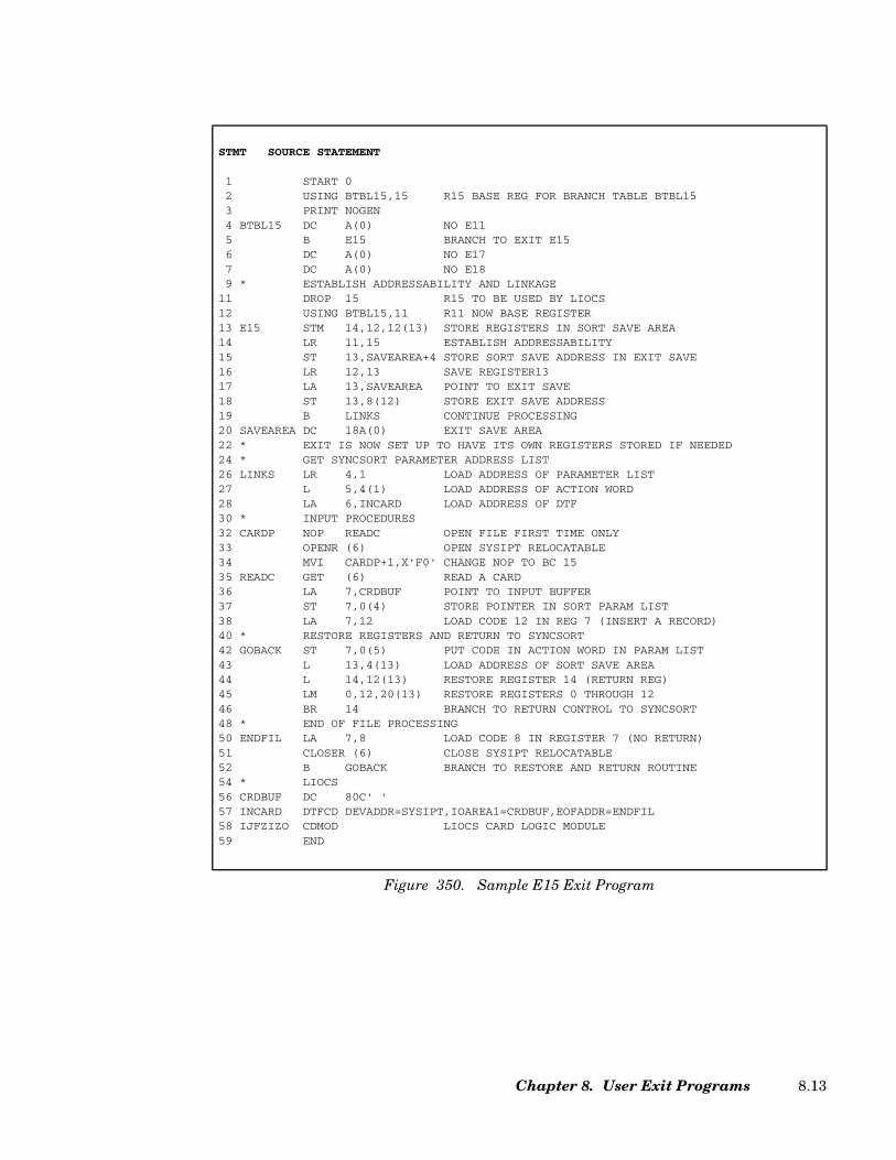
STMT SOURCE STATEMENT
1 START 02 USING BTBL15,15 R15 BASE REG FOR BRANCH TABLE BTBL153 PRINT NOGEN4 BTBL15 DC A(0) NO E115 B E15 BRANCH TO EXIT E156 DC A(0) NO E177 DC A(0) NO E189 * ESTABLISH ADDRESSABILITY AND LINKAGE
11 DROP 15 R15 TO BE USED BY LIOCS12 USING BTBL15,11 R11 NOW BASE REGISTER13 E15 STM 14,12,12(13) STORE REGISTERS IN SORT SAVE AREA14 LR 11,15 ESTABLISH ADDRESSABILITY15 ST 13,SAVEAREA+4 STORE SORT SAVE ADDRESS IN EXIT SAVE16 LR 12,13 SAVE REGISTER1317 LA 13,SAVEAREA POINT TO EXIT SAVE18 ST 13,8(12) STORE EXIT SAVE ADDRESS19 B LINKS CONTINUE PROCESSING20 SAVEAREA DC 18A(0) EXIT SAVE AREA22 * EXIT IS NOW SET UP TO HAVE ITS OWN REGISTERS STORED IF NEEDED24 * GET SYNCSORT PARAMETER ADDRESS LIST26 LINKS LR 4,1 LOAD ADDRESS OF PARAMETER LIST27 L 5,4(1) LOAD ADDRESS OF ACTION WORD28 LA 6,INCARD LOAD ADDRESS OF DTF30 * INPUT PROCEDURES32 CARDP NOP READC OPEN FILE FIRST TIME ONLY33 OPENR (6) OPEN SYSIPT RELOCATABLE34 MVI CARDP+1,X'F0' CHANGE NOP TO BC 1535 READC GET (6) READ A CARD36 LA 7,CRDBUF POINT TO INPUT BUFFER37 ST 7,0(4) STORE POINTER IN SORT PARAM LIST38 LA 7,12 LOAD CODE 12 IN REG 7 (INSERT A RECORD)40 * RESTORE REGISTERS AND RETURN TO SYNCSORT42 GOBACK ST 7,0(5) PUT CODE IN ACTION WORD IN PARAM LIST43 L 13,4(13) LOAD ADDRESS OF SORT SAVE AREA44 L 14,12(13) RESTORE REGISTER 14 (RETURN REG)45 LM 0,12,20(13) RESTORE REGISTERS 0 THROUGH 1246 BR 14 BRANCH TO RETURN CONTROL TO SYNCSORT48 * END OF FILE PROCESSING50 ENDFIL LA 7,8 LOAD CODE 8 IN REGISTER 7 (NO RETURN)51 CLOSER (6) CLOSE SYSIPT RELOCATABLE52 B GOBACK BRANCH TO RESTORE AND RETURN ROUTINE54 * LIOCS56 CRDBUF DC 80C' '57 INCARD DTFCD DEVADDR=SYSIPT,IOAREA1=CRDBUF,EOFADDR=ENDFIL58 IJFZIZO CDMOD LIOCS CARD LOGIC MODULE59 END
Figure 350. Sample E15 Exit Program
Chapter 8. User Exit Programs 8.13

Coding a COBOL E15 Exit Program
An E15 exit program can be coded in COBOL/VSE. A COBOL E15 exit program is indi-cated in the MODS control statement.
A COBOL exit uses GETVIS space to load run-time library routines. Allow at least 500K ofextra GETVIS when executing SyncSort with a COBOL exit. Communication betweenSyncSort and the COBOL exit takes place in the LINKAGE SECTION of the COBOL pro-gram. For example, records are passed to the COBOL routine in the second definition(RECORD-UP) area of the LINKAGE SECTION.
The LINKAGE SECTION
The LINKAGE SECTION examples that follow show the parameters required for passingfixed-length and variable-length records to the sort. The data-names and conditionalnames used in the examples are arbitrary but each definition is required. The completeprograms from which the examples are taken follow the discussion of the exit.
MODS PH1=(MYCOBE15,COBOL,E15)
Figure 351. Sample MODS control statement for a COBOL E15
SyncSort for z/VSE 3.7 Programmer’s Guide8.14

Example 1: Fixed-Length Records
• For the first definition (EXIT-STATUS) specify PIC 9(8) COMPUTATIONAL. (Thisarea defines exit status codes.) When using 88 levels to define the exit status codes,specify values 00, 04, and 08.
• For the second definition (RECORD-UP) define the SORTIN record.
• For the third definition (WORK) define the record that will be passed to SyncSort. (Thisis the “work area.”)
• For the fourth through the eighth definitions define dummy areas.
• For the ninth definition (COMM-LEN) specify PIC 9(4) COMPUTATIONAL. This areadefines the communication area length.
• For the tenth definition (COMMUNICATION-AREA) code an OCCURS clauseDEPENDING ON data-name PIC X.
LINKAGE SECTION.
01 EXIT-STATUS PIC 9 (8) COMPUTATIONAL.
88 FIRST-TIME VALUE 00.
88 MOST-TIME VALUE 04.
88 LAST-TIME VALUE 08.
01 RECORD-UP.
07 FILLER PIC 9(6).
07 R-SEQ2 PIC 9(2).
07 FILLER PIC X(92).
01 WORK PIC X(100).
01 DUMMY1 PIC X.
01 DUMMY2 PIC X.
01 DUMMY3 PIC X.
01 DUMMY4 PIC X.
01 DUMMY5 PIC X.
01 COMM-LEN PIC 9(4) COMPUTATIONAL.
01 COMMUNICATION-AREA.
05 COMM-AREA OCCURS 1 TO 256 TIMES
DEPENDING ON COMM-LEN PIC X.
Figure 352. Sample LINKAGE SECTION for Fixed-Length Records
Chapter 8. User Exit Programs 8.15

Example 2: Variable-Length Records
• For the first definition (EXIT-STATUS) specify PIC 9(8) COMPUTATIONAL. (Thisarea defines exit status codes.)
• For the second definition (RECORD-UP) code an OCCURS clause with theDEPENDING ON data-name option specifying (1) The minimum and maximumnumber of bytes the variable SORTIN records contain (do not include 4 bytes for theRDW) and (2) DEPENDING ON data-name PIC X. Data-name is defined in the sixthdefinition in the LINKAGE SECTION.
• For the third definition (WORK) code an OCCURS clause with the DEPENDING ONdata-name option specifying (1) The minimum and maximum number of bytes forvariable-length records to be passed to SyncSort (do not include 4 bytes for the RDW)and (2) DEPENDING ON data-name PIC X. Data-name is defined as the seventhdefinition in the LINKAGE SECTION.
• For the fourth definition specify a dummy level 01 data-name of any number of bytes.(IN-BUF is the data-name used in this example.) Note that the level 01 data-name,used here as a dummy address, has no effect on the E15 routine for variable-lengthrecords. The address is usually used as a buffer pointer in the COBOL E35 exit routine.By using it in the E15 LINKAGE SECTION, SyncSort is able to use the sameparameter list for both COBOL exits E15 and E35.
LINKAGE SECTION.
01 EXIT-STATUS PIC 9 (8) COMPUTATIONAL.
88 FIRST-TIME VALUE 00.
88 MOST-TIME VALUE 04.
88 LAST-TIME VALUE 08.
01 RECORD-UP.
05 RU OCCURS 1 TO 100 TIMES
DEPENDING ON LEN-RU PIC X.
01 WORK.
05 WK OCCURS 1 TO 100 TIMES
DEPENDING ON LEN-WK PIC X.
01 IN-BUF PIC X(100).
01 DUMMY PIC X(4).
01 LEN-RU PIC 9(8) COMPUTATIONAL.
01 LEN-WK PIC 9(8) COMPUTATIONAL.
01 LEN-IB PIC 9(8) COMPUTATIONAL.
01 COMM-LEN PIC 9(4) COMPUTATIONAL.
01 COMMUNICATION-AREA.
05 COMM-AREA OCCURS 1 TO 256 TIMES
DEPENDING ON COMM-LEN PIC X.
Figure 353. Sample LINKAGE SECTION for Variable-Length Records
SyncSort for z/VSE 3.7 Programmer’s Guide8.16
• For the fifth definition specify a dummy area.
• For the sixth definition (LEN-RU) specify data-name PIC 9(8) COMPUTATIONAL.This is where SyncSort passes the length of the SORTIN record to the COBOL exit.
• For the seventh definition (LEN-WK) specify data-name PIC 9(8) COMPUTATIONAL.This is where the E15 routine passes the length of the work area record to SyncSort.
• For the eighth definition define a dummy area.
• For the ninth definition (COMM-LEN) specify PIC 9(4) COMPUTATIONAL. This areadefines the communication area length.
• For the tenth definition (COMMUNICATION-AREA) code an OCCURS clauseDEPENDING ON data-name PIC X.
The IDENTIFICATION, ENVIRONMENT, and DATA DIVISIONs
As always, the COBOL program must contain the entries required by the compiler for theseprogram divisions. Code the optional entries in these divisions according to the require-ments of the application.
The WORKING-STORAGE SECTION
If the exit routine inserts records into the final merge and replaces records passed fromSyncSort, the insertion record and the replacement record may be defined in this section.These records will be moved to the WORK area described in the LINKAGE SECTION, so besure that the PICTURE clause or the OCCURS clause in the WORK area is correct forthese records.
This section may also define the return codes as 77-level data items. Alternatively, thesecodes can be specified as literals in the MOVE instruction. (MOVE literal to RETURN-CODE.) Note that RETURN-CODE is the name of a predefined storage area in COBOLused to pass return codes to the sort; RETURN-CODE should not be defined in the exit rou-tine.
The PROCEDURE DIVISION
Specify the USING option on the PROCEDURE DIVISION header. Each identifierspecified after USING must be the same as those described in the 01-level of the LINKAGESECTION. Taking for example the identifiers defined in the fixed-length record LINKAGESECTION shown here, they would appear as: PROCEDURE DIVISION USING EXIT-STATUS, RECORD-UP, WORK, DUMMY1, DUMMY2, DUMMY3, DUMMY4, DUMMY5,COMM-LEN, COMMUNICATION-AREA.
Chapter 8. User Exit Programs 8.17

The GOBACK statement is used to return control to SyncSort. Do not use the EXIT state-ment as it will cause unpredictable results. Be sure that SyncSort receives a valid returncode before the GOBACK statement is executed.
EXIT-STATUS Codes (Fixed and Variable-Length Records)
00 First record. SyncSort uses this Code to indicate the first call to the COBOLexit and that the first record from SORTIN is in the RECORD-UP area.
04 Most records. This is used for all calls except the first one when there arerecords in the RECORD-UP area. After Code 00 has been issued, Code 04 ispassed to the exit until there is no record for the sort to pass to theRECORD-UP area.
08 All records passed. This indicates that the last SORTIN record has alreadybeen processed by the exit. Do not attempt to reference the record again. Nomore records will be passed to the exit routine. Note that if the SORTINdata set is empty, 08 will be passed every time including the first time.
RETURN-CODE Codes (Fixed and Variable-Length Records)
0 Accept this record. This instructs SyncSort to accept the (unaltered) recordin the RECORD-UP area.
4 Delete this record. SyncSort will delete the current record in the RECORD-UP area.
8 Do not return to this exit. This instructs SyncSort to close the exit for theremainder of the sort application. This return code might be used at SOR-TIN end-of-file (Exit Status Code 08) to indicate that extra records will notbe added at this point. If SORTIN is present, the current input record andall subsequent records will be processed by SyncSort.
12 Insert a record. This instructs SyncSort to add the record in the WORK areato the input data set just ahead of the current record in the RECORD-UParea. When SyncSort returns control to the E15, the same record will be inthe RECORD-UP area. The exit routine can then add another record fromthe WORK area or process the current record in RECORD-UP.
16 Terminate SyncSort. SyncSort will end its program and return to the call-ing program or the Supervisor. SyncSort will issue a completion code of 16to indicate that the sort was unsuccessful.
20 Replace current record. SyncSort will replace the current record in theRECORD-UP area with the record in the WORK area. Be sure that therecord in the WORK area is valid before passing it to SyncSort.
SyncSort for z/VSE 3.7 Programmer’s Guide8.18

To Change a Record
In order to change the record in the RECORD-UP area, first move it to the WORK area. Allchanges are made to the WORK area copy, which replaces the record in RECORD-UP when20 is moved to RETURN-CODE.
Sample COBOL E15, Fixed-Length Records
IDENTIFICATION DIVISION.PROGRAM-ID. E15FL13C.
ENVIRONMENT DIVISION.
CONFIGURATION SECTION.
SOURCE-COMPUTER. IBM-370.OBJECT-COMPUTER. IBM-370.
INPUT-OUTPUT SECTION.FILE-CONTROL.I-O-CONTROL.DATA DIVISION.FILE SECTION.
WORKING-STORAGE SECTION.01 EVEN-FLAG PIC 9(2) VALUE ZERO.
01 USER-RETURN-CODE PIC 9(8) COMPUTATIONAL.88 ACCEPT-REC VALUE 0.88 DELETE-REC VALUE 4.88 END-EXIT VALUE 8.88 INSERT-REC VALUE 12.88 END-SORT VALUE 16.88 REPL-REC VALUE 20.
01 CHANGE-REC.05 C-REC PIC X(6) VALUE 'CHANGE'.05 C-INCR PIC 9(4) VALUE ZERO.05 C-BLANK PIC X(90) VALUE ZERO.
01 INSRT-REC.05 I-REC PIC X(6) VALUE 'INSERT'.05 I-INCR PIC 9(4) VALUE ZERO.05 I-BLANK PIC X(90) VALUE SPACES.
01 TOTAL.05 BLANKS PIC X(10) VALUE ' E15'.05 TITL PIC X(25) VALUE 'TOTAL RECORDS OUT'.05 COUNTER PIC 9(8) VALUE 0.
Figure 354. (Page 1 of 2) Sample COBOL E15, Fixed-Length Records
Chapter 8. User Exit Programs 8.19
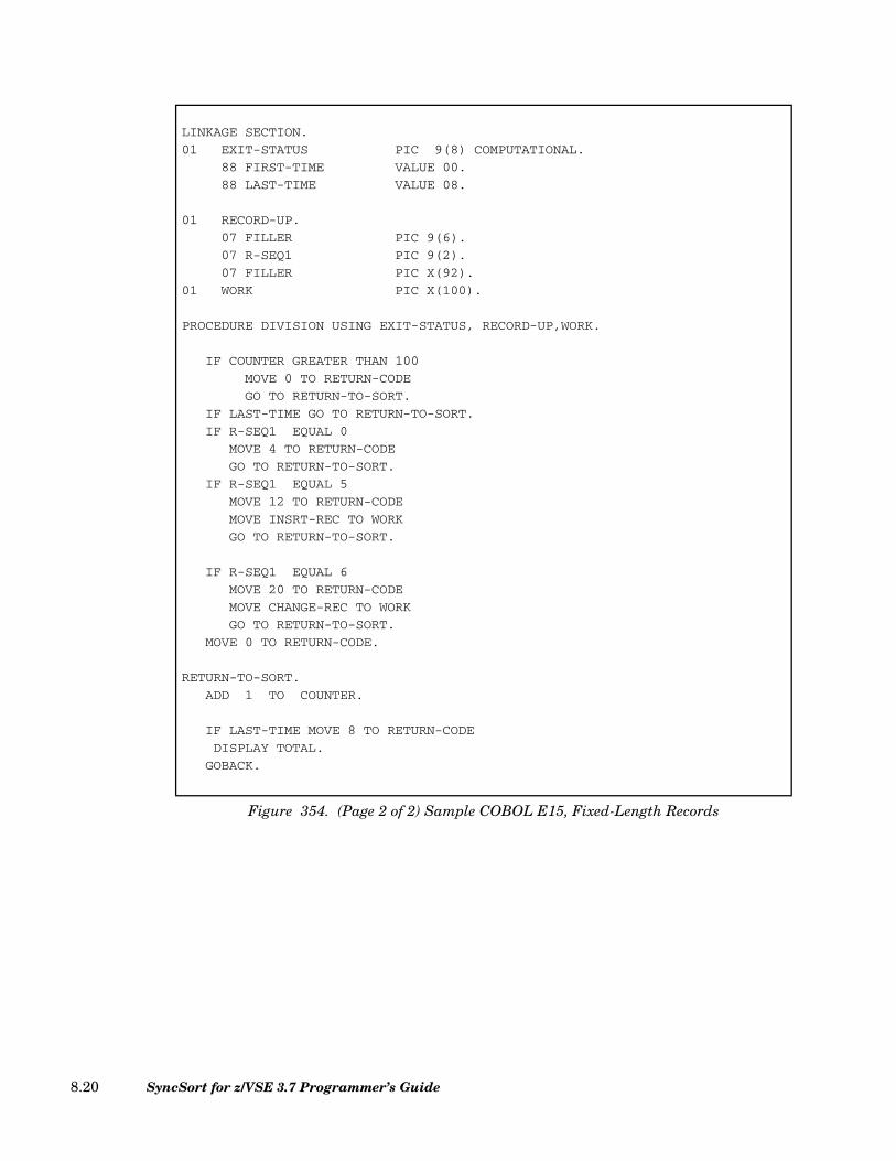
LINKAGE SECTION.
01 EXIT-STATUS PIC 9(8) COMPUTATIONAL.
88 FIRST-TIME VALUE 00.
88 LAST-TIME VALUE 08.
01 RECORD-UP.
07 FILLER PIC 9(6).
07 R-SEQ1 PIC 9(2).
07 FILLER PIC X(92).
01 WORK PIC X(100).
PROCEDURE DIVISION USING EXIT-STATUS, RECORD-UP,WORK.
IF COUNTER GREATER THAN 100
MOVE 0 TO RETURN-CODE
GO TO RETURN-TO-SORT.
IF LAST-TIME GO TO RETURN-TO-SORT.
IF R-SEQ1 EQUAL 0
MOVE 4 TO RETURN-CODE
GO TO RETURN-TO-SORT.
IF R-SEQ1 EQUAL 5
MOVE 12 TO RETURN-CODE
MOVE INSRT-REC TO WORK
GO TO RETURN-TO-SORT.
IF R-SEQ1 EQUAL 6
MOVE 20 TO RETURN-CODE
MOVE CHANGE-REC TO WORK
GO TO RETURN-TO-SORT.
MOVE 0 TO RETURN-CODE.
RETURN-TO-SORT.
ADD 1 TO COUNTER.
IF LAST-TIME MOVE 8 TO RETURN-CODE
DISPLAY TOTAL.
GOBACK.
Figure 354. (Page 2 of 2) Sample COBOL E15, Fixed-Length Records
SyncSort for z/VSE 3.7 Programmer’s Guide8.20
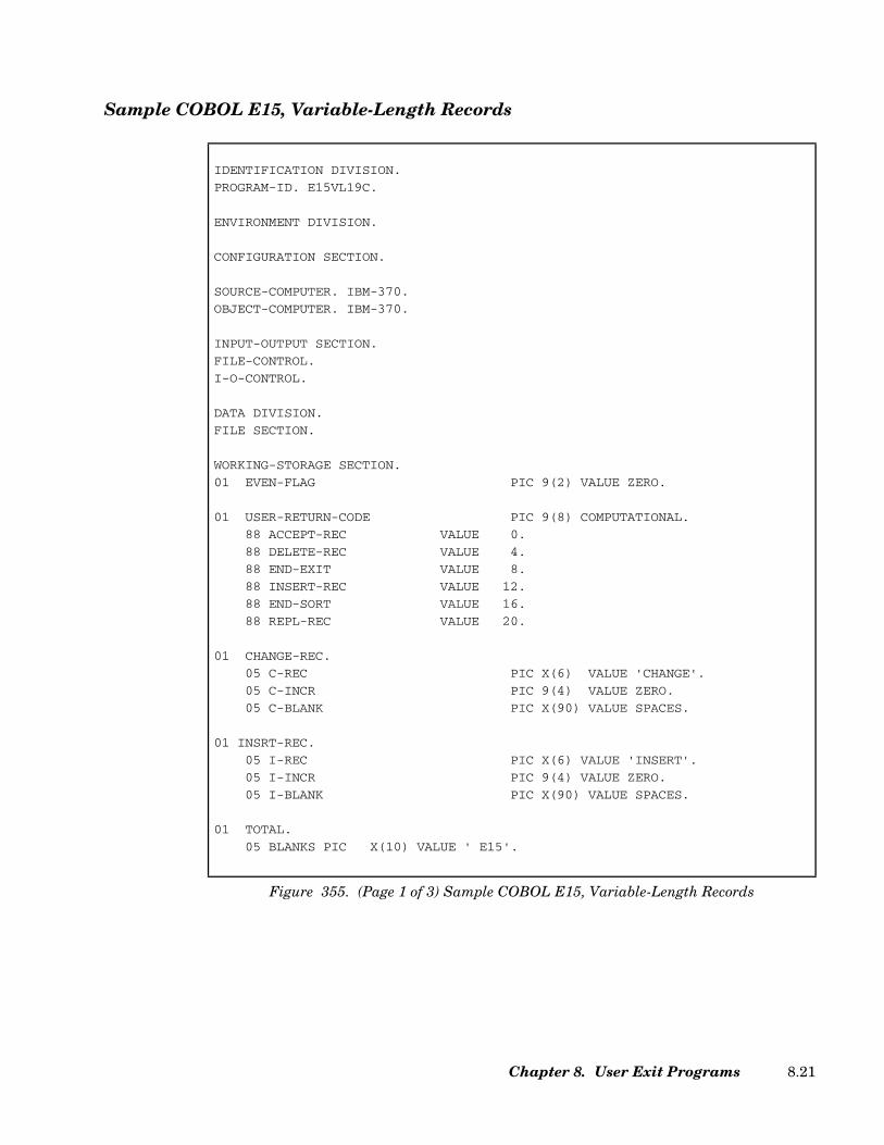
Sample COBOL E15, Variable-Length Records
IDENTIFICATION DIVISION.
PROGRAM-ID. E15VL19C.
ENVIRONMENT DIVISION.
CONFIGURATION SECTION.
SOURCE-COMPUTER. IBM-370.
OBJECT-COMPUTER. IBM-370.
INPUT-OUTPUT SECTION.
FILE-CONTROL.
I-O-CONTROL.
DATA DIVISION.
FILE SECTION.
WORKING-STORAGE SECTION.
01 EVEN-FLAG PIC 9(2) VALUE ZERO.
01 USER-RETURN-CODE PIC 9(8) COMPUTATIONAL.
88 ACCEPT-REC VALUE 0.
88 DELETE-REC VALUE 4.
88 END-EXIT VALUE 8.
88 INSERT-REC VALUE 12.
88 END-SORT VALUE 16.
88 REPL-REC VALUE 20.
01 CHANGE-REC.
05 C-REC PIC X(6) VALUE 'CHANGE'.
05 C-INCR PIC 9(4) VALUE ZERO.
05 C-BLANK PIC X(90) VALUE SPACES.
01 INSRT-REC.
05 I-REC PIC X(6) VALUE 'INSERT'.
05 I-INCR PIC 9(4) VALUE ZERO.
05 I-BLANK PIC X(90) VALUE SPACES.
01 TOTAL.
05 BLANKS PIC X(10) VALUE ' E15'.
Figure 355. (Page 1 of 3) Sample COBOL E15, Variable-Length Records
Chapter 8. User Exit Programs 8.21
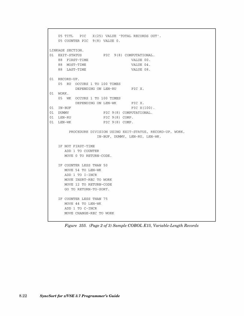
05 TITL PIC X(25) VALUE 'TOTAL RECORDS OUT'.
05 COUNTER PIC 9(8) VALUE 0.
LINKAGE SECTION.
01 EXIT-STATUS PIC 9(8) COMPUTATIONAL.
88 FIRST-TIME VALUE 00.
88 MOST-TIME VALUE 04.
88 LAST-TIME VALUE 08.
01 RECORD-UP.
05 RU OCCURS 1 TO 100 TIMES
DEPENDING ON LEN-RU PIC X.
01 WORK.
05 WK OCCURS 1 TO 100 TIMES
DEPENDING ON LEN-WK PIC X.
01 IN-BUF PIC X(100).
01 DUMMY PIC 9(8) COMPUTATIONAL.
01 LEN-RU PIC 9(8) COMP.
01 LEN-WK PIC 9(8) COMP.
PROCEDURE DIVISION USING EXIT-STATUS, RECORD-UP, WORK,
IN-BUF, DUMMY, LEN-RU, LEN-WK.
IF NOT FIRST-TIME
ADD 1 TO COUNTER
MOVE 0 TO RETURN-CODE.
IF COUNTER LESS THAN 50
MOVE 54 TO LEN-WK
ADD 1 TO I-INCR
MOVE INSRT-REC TO WORK
MOVE 12 TO RETURN-CODE
GO TO RETURN-TO-SORT.
IF COUNTER LESS THAN 75
MOVE 44 TO LEN-WK
ADD 1 TO C-INCR
MOVE CHANGE-REC TO WORK
Figure 355. (Page 2 of 3) Sample COBOL E15, Variable-Length Records
SyncSort for z/VSE 3.7 Programmer’s Guide8.22
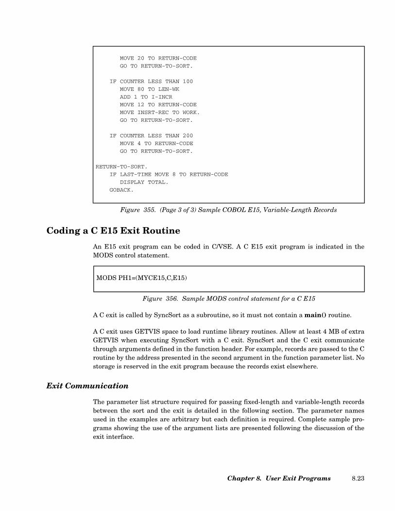
Coding a C E15 Exit Routine
An E15 exit program can be coded in C/VSE. A C E15 exit program is indicated in theMODS control statement.
A C exit is called by SyncSort as a subroutine, so it must not contain a main() routine.
A C exit uses GETVIS space to load runtime library routines. Allow at least 4 MB of extraGETVIS when executing SyncSort with a C exit. SyncSort and the C exit communicatethrough arguments defined in the function header. For example, records are passed to the Croutine by the address presented in the second argument in the function parameter list. Nostorage is reserved in the exit program because the records exist elsewhere.
Exit Communication
The parameter list structure required for passing fixed-length and variable-length recordsbetween the sort and the exit is detailed in the following section. The parameter namesused in the examples are arbitrary but each definition is required. Complete sample pro-grams showing the use of the argument lists are presented following the discussion of theexit interface.
MOVE 20 TO RETURN-CODE
GO TO RETURN-TO-SORT.
IF COUNTER LESS THAN 100
MOVE 80 TO LEN-WK
ADD 1 TO I-INCR
MOVE 12 TO RETURN-CODE
MOVE INSRT-REC TO WORK.
GO TO RETURN-TO-SORT.
IF COUNTER LESS THAN 200
MOVE 4 TO RETURN-CODE
GO TO RETURN-TO-SORT.
RETURN-TO-SORT.
IF LAST-TIME MOVE 8 TO RETURN-CODE
DISPLAY TOTAL.
GOBACK.
Figure 355. (Page 3 of 3) Sample COBOL E15, Variable-Length Records
MODS PH1=(MYCE15,C,E15)
Figure 356. Sample MODS control statement for a C E15
Chapter 8. User Exit Programs 8.23

Fixed-Length Records - Function Definition
The following describes the parameters used in the preceding definition.
exit_status This parameter points to a variable containing one of the follow-ing exit status codes:
00 First record. SyncSort uses this code to indicate the firstcall to the C exit and that the first record from SORTINis in the record_up area. If the SORTIN is empty or doesnot exist, a 08 status will be passed the first time.
04 Most records. This is used for all calls except the firstone when there are records in the record_up area. AfterCode 00 has been issued, Code 04 is passed to the exituntil there is no record for the sort to pass to therecord_up area.
08 All records passed. This indicates that the last SORTINrecord has already been processed by the exit. Do notattempt to reference the record again. No more recordswill be passed to the exit routine. Note that if the SOR-TIN data set is empty or does not exist, 08 will bepassed every time including the first time.
record_up The record_up parameter contains a pointer to the record beingpassed to the E15 from the SORTIN. The struct_ru data typerepresents a structure that describes the fields within the SOR-TIN record.
work The work parameter contains a pointer to a work area that is tobe used to hold an inserted or replaced record returned from theE15. The struct_ins_rep data type represents a structure thatdescribes the fields within the inserted or replaced record.
int E15exit ( int *exit_status,
struct_ru *record_up,
struct_ins_rep *work,
int *dummy1, int *dummy2, int *dummy3,
int *dummy4, int *dummy5,
int *comm_len,
struct_ca *communication_area)
Figure 357. Fixed-Length Records - Function Definition
SyncSort for z/VSE 3.7 Programmer’s Guide8.24

dummy1 - dummy5 These parameters define unused place holders. They are usedwith variable-length E15 and E35 communication. Their defini-tion here allows a common parameter list for fixed-length andvariable-length C E15 and E35 exits.
comm_len This parameter points to a variable that defines the communi-cation area length (always 256 bytes).
communication_area The communication_area parameter contains a pointer to thecommunication area. The struct_ca data type represents a user-defined structure that describes the fields in the communicationarea. This area can be used to pass information between exits.
Variable-Length Records - Function Definition
The following describes the parameters used in the preceding definition.
exit_status This parameter points to a variable containing exit statuscodes. See the exit_status definition for a fixed-length C E15exit for the code definitions.
record_up The record_up parameter contains a “universal” pointer to therecord being passed to the E15 from the SORTIN. The void*pointer can be cast to point an appropriate structure to describethe record passed to the exit. This allows different record struc-tures, as is common with variable-length records, to share a sin-gle pointer definition.
work The work parameter contains a “universal” pointer to a workarea that is to be used to hold an inserted or replaced recordreturned from the E15. The void* pointer can be cast to point anappropriate structure to describe the work record.
int E15exit ( int *exit_status,
void *record_up,
void *work,
int *dummy1, int *dummy2,
int *len_ru,
int *len_wk,
int *dummy3,
int *comm_len,
struct_ca *communication_area)
Figure 358. Variable-Length Records - Function Definition
Chapter 8. User Exit Programs 8.25

dummy1 - dummy3 These parameters define unused place holders. They are usedwith C E35 communication. Their definition here allows a com-mon parameter list for C E15 and E35 exits.
len_ru This parameter points to a variable that defines the length ofthe SORTIN record passed to the E15. This is the length of therecord referred to in the record_up parameter.
len_wk This parameter points to a variable that defines the length ofthe record to be inserted or used as a replacement for therecord_up record. This is the length of the record referred to inthe work parameter. This field must be set by the exit when aninsert or replace operation is performed.
comm_len This parameter points to a variable that defines the communi-cation area length (always 256 bytes).
communication_area The communication_area parameter contains a pointer to thecommunication area. The struct_ca data type represents a user-defined structure that describes the fields in the communicationarea. This area can be used to pass information between exits.
RETURN-CODE Codes (Fixed and Variable-Length Records)
The RETURN statement is used to return control to SyncSort. It must indicate one of thefollowing return values to indicate the action to be taken by SyncSort.
0 Accept this record. This instructs SyncSort to accept the (unaltered) recordin the record_up area.
4 Delete this record. SyncSort will delete the current record in the RECORD-UP area.
8 Do not return to this exit. This instructs SyncSort to close the exit for theremainder of the sort application. This return code might be used at SOR-TIN end-of-file (exit_status code 08) to indicate that extra records will notbe added at this point. If SORTIN is present, the current input record andall subsequent records will be processed by SyncSort.
12 Insert a record. This instructs SyncSort to add the record in the WORK areato the input data set just ahead of the current record in the RECORD-UParea. When SyncSort returns control to the E15, the same record will be inthe RECORD-UP area. The exit routine can then add another record fromthe WORK area or process the current record in RECORD-UP.
SyncSort for z/VSE 3.7 Programmer’s Guide8.26
16 Terminate SyncSort. SyncSort will end its program and return to the call-ing program or the Supervisor. SyncSort will issue a completion code of 16to indicate that the sort was unsuccessful.
20 Replace current record. SyncSort will replace the current record in therecord_up area with the record in the work area. Be sure that the record inthe work area is valid before passing it to SyncSort. When replacing a vari-able-length record, insure that its length is indicated in the len_wk param-eter.
How to Change a Record
To change the record in the record_up area, first move it to the work area. All changes aremade to the work area copy, which replaces the record in record_up when the return valuefrom the exit is 20.
Chapter 8. User Exit Programs 8.27

Sample C E15, Fixed-Length Records
#define FIRST_TIME 0
#define MOST_TIME 4
#define LAST_TIME 8
#define ACCEPT_REC 0
#define DELETE_REC 4
#define END_EXIT 8
#define INSERT_REC 12
#define END_SORT 16
#define REPL_REC 20
typedef _Packed struct record {
char name[6];
char code[4];
int serial_no;
} t_ru;
#include <stdio.h>
#include <stdlib.h>
#include <string.h>
int SMPE15FB(int *exit_status,t_ru *record_up,t_ru *work,int *dummy1,
int *dummy2,int *dummy3,int *dummy4,int *dummy5,int *comm_len,
void *communication_area)
{
static counter=0;
int icode,return_code;
char *text1="CHANGE";
char *text2="INSERT";
if (counter > 10) {return_code=ACCEPT_REC;
goto return_to_sort;}
if (*exit_status == LAST_TIME) {return_code=END_EXIT;
goto return_to_sort;}
Figure 359. (Page 1 of 2) Sample C E15, Fixed-Length Records
SyncSort for z/VSE 3.7 Programmer’s Guide8.28
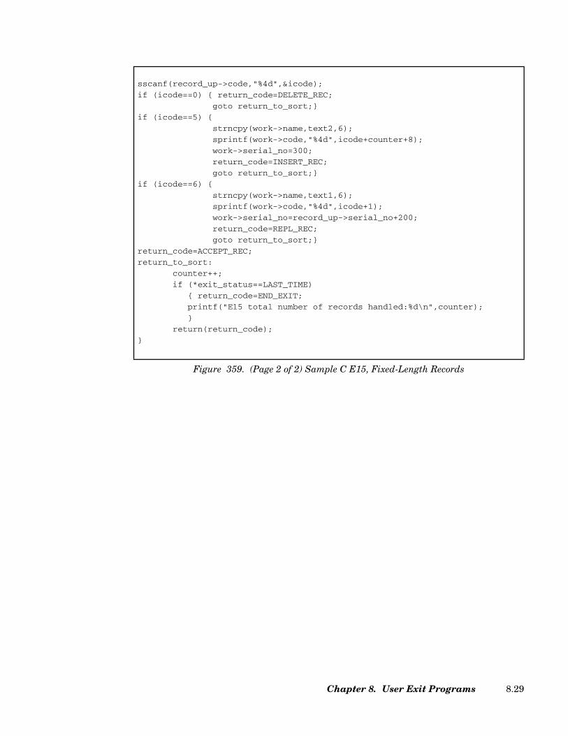
sscanf(record_up->code,"%4d",&icode);
if (icode==0) { return_code=DELETE_REC;
goto return_to_sort;}
if (icode==5) {
strncpy(work->name,text2,6);
sprintf(work->code,"%4d",icode+counter+8);
work->serial_no=300;
return_code=INSERT_REC;
goto return_to_sort;}
if (icode==6) {
strncpy(work->name,text1,6);
sprintf(work->code,"%4d",icode+1);
work->serial_no=record_up->serial_no+200;
return_code=REPL_REC;
goto return_to_sort;}
return_code=ACCEPT_REC;
return_to_sort:
counter++;
if (*exit_status==LAST_TIME)
{ return_code=END_EXIT;
printf("E15 total number of records handled:%d\n",counter);
}
return(return_code);
}
Figure 359. (Page 2 of 2) Sample C E15, Fixed-Length Records
Chapter 8. User Exit Programs 8.29
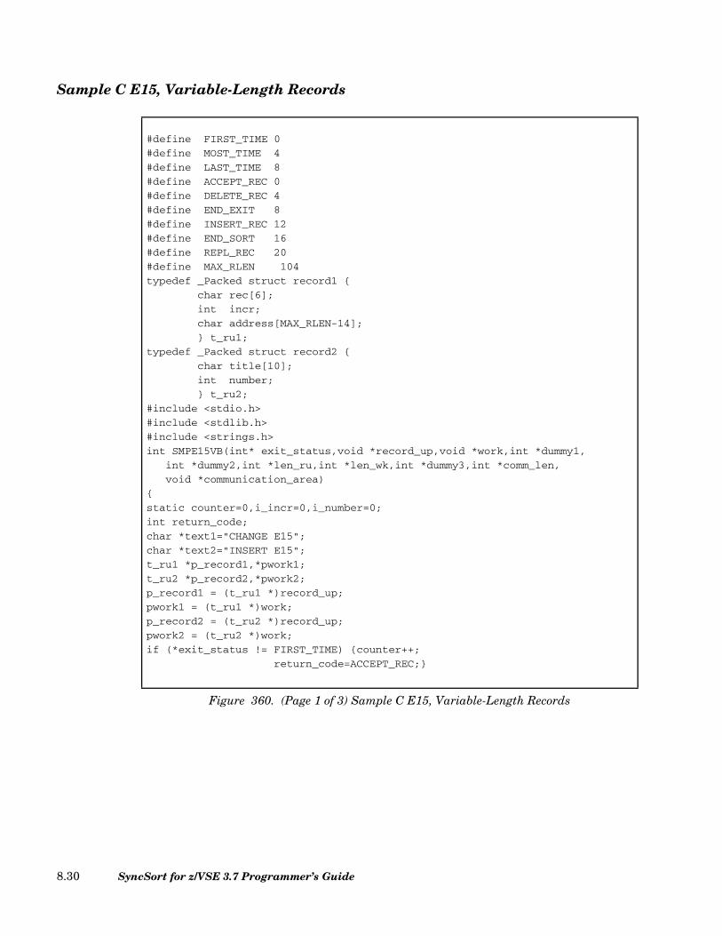
Sample C E15, Variable-Length Records
#define FIRST_TIME 0
#define MOST_TIME 4
#define LAST_TIME 8
#define ACCEPT_REC 0
#define DELETE_REC 4
#define END_EXIT 8
#define INSERT_REC 12
#define END_SORT 16
#define REPL_REC 20
#define MAX_RLEN 104
typedef _Packed struct record1 {
char rec[6];
int incr;
char address[MAX_RLEN-14];
} t_ru1;
typedef _Packed struct record2 {
char title[10];
int number;
} t_ru2;
#include <stdio.h>
#include <stdlib.h>
#include <strings.h>
int SMPE15VB(int* exit_status,void *record_up,void *work,int *dummy1,
int *dummy2,int *len_ru,int *len_wk,int *dummy3,int *comm_len,
void *communication_area)
{
static counter=0,i_incr=0,i_number=0;
int return_code;
char *text1="CHANGE E15";
char *text2="INSERT E15";
t_ru1 *p_record1,*pwork1;
t_ru2 *p_record2,*pwork2;
p_record1 = (t_ru1 *)record_up;
pwork1 = (t_ru1 *)work;
p_record2 = (t_ru2 *)record_up;
pwork2 = (t_ru2 *)work;
if (*exit_status != FIRST_TIME) {counter++;
return_code=ACCEPT_REC;}
Figure 360. (Page 1 of 3) Sample C E15, Variable-Length Records
SyncSort for z/VSE 3.7 Programmer’s Guide8.30
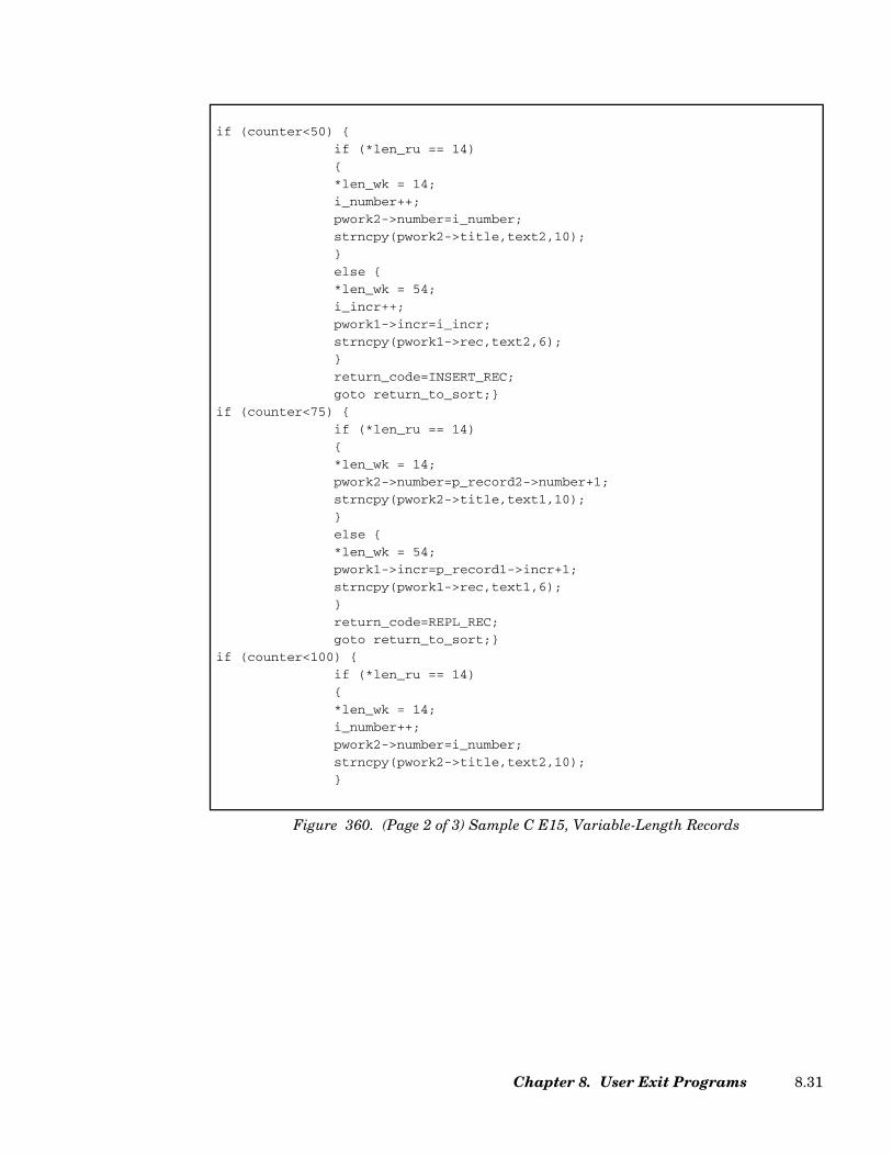
if (counter<50) {
if (*len_ru == 14)
{
*len_wk = 14;
i_number++;
pwork2->number=i_number;
strncpy(pwork2->title,text2,10);
}
else {
*len_wk = 54;
i_incr++;
pwork1->incr=i_incr;
strncpy(pwork1->rec,text2,6);
}
return_code=INSERT_REC;
goto return_to_sort;}
if (counter<75) {
if (*len_ru == 14)
{
*len_wk = 14;
pwork2->number=p_record2->number+1;
strncpy(pwork2->title,text1,10);
}
else {
*len_wk = 54;
pwork1->incr=p_record1->incr+1;
strncpy(pwork1->rec,text1,6);
}
return_code=REPL_REC;
goto return_to_sort;}
if (counter<100) {
if (*len_ru == 14)
{
*len_wk = 14;
i_number++;
pwork2->number=i_number;
strncpy(pwork2->title,text2,10);
}
Figure 360. (Page 2 of 3) Sample C E15, Variable-Length Records
Chapter 8. User Exit Programs 8.31

E25 Programs
Exit E25 programs can be used to sum or delete fixed-length records during Phase 2 of thesort. Exit E25 will be entered just before each record in a string of records is moved to theoutput buffer, except in the case of the first record of the string, which will already havebeen moved. Because you are not allowed to delete the record already in the output buffer,you are cautioned that you may miss deleting certain records if they turn up at the begin-ning of a string. You may also miss examining entire groups of records, if the sort does notneed to process the entire input file in Phase 2. And, in the event that the input file can beprocessed without going through Phase 2 at all, your E25 program will not run.
Parameter List
The three-word parameter list of addresses (see Figure 361) is passed to the user in register1.
else {
*len_wk = 80;
i_incr++;
pwork1->incr=i_incr;
strncpy(pwork1->rec,text2,6);
}
return_code=INSERT_REC;
goto return_to_sort;}
if (counter<200) {
return_code=DELETE_REC;
goto return_to_sort;}
return_to_sort:
if (*exit_status==LAST_TIME)
{ return_code=END_EXIT;
printf("E15 total number of records handled:%d\n",counter);
}
return(return_code);
}
Figure 360. (Page 3 of 3) Sample C E15, Variable-Length Records
POINTER TO:
1. ... Record2. ... Previous record3. ... Action word
Figure 361. Parameter List for E25
SyncSort for z/VSE 3.7 Programmer’s Guide8.32
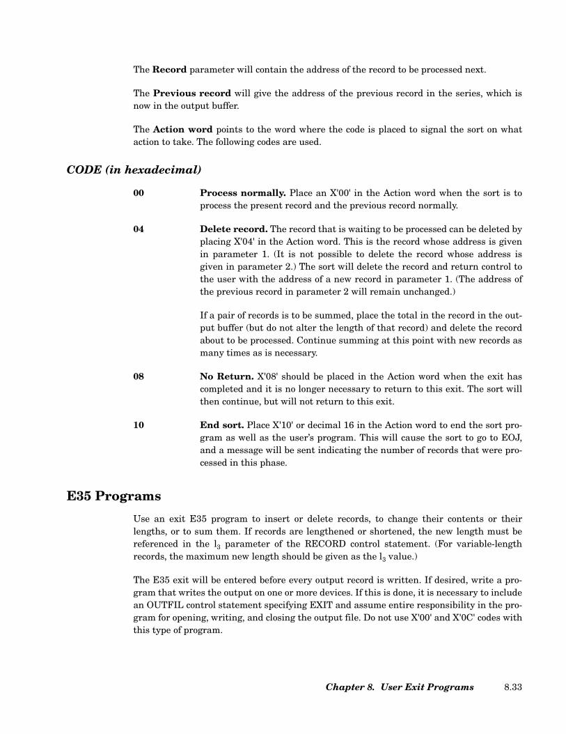
The Record parameter will contain the address of the record to be processed next.
The Previous record will give the address of the previous record in the series, which isnow in the output buffer.
The Action word points to the word where the code is placed to signal the sort on whataction to take. The following codes are used.
CODE (in hexadecimal)
00 Process normally. Place an X'00' in the Action word when the sort is toprocess the present record and the previous record normally.
04 Delete record. The record that is waiting to be processed can be deleted byplacing X'04' in the Action word. This is the record whose address is givenin parameter 1. (It is not possible to delete the record whose address isgiven in parameter 2.) The sort will delete the record and return control tothe user with the address of a new record in parameter 1. (The address ofthe previous record in parameter 2 will remain unchanged.)
If a pair of records is to be summed, place the total in the record in the out-put buffer (but do not alter the length of that record) and delete the recordabout to be processed. Continue summing at this point with new records asmany times as is necessary.
08 No Return. X'08' should be placed in the Action word when the exit hascompleted and it is no longer necessary to return to this exit. The sort willthen continue, but will not return to this exit.
10 End sort. Place X'10' or decimal 16 in the Action word to end the sort pro-gram as well as the user’s program. This will cause the sort to go to EOJ,and a message will be sent indicating the number of records that were pro-cessed in this phase.
E35 Programs
Use an exit E35 program to insert or delete records, to change their contents or theirlengths, or to sum them. If records are lengthened or shortened, the new length must bereferenced in the l3 parameter of the RECORD control statement. (For variable-lengthrecords, the maximum new length should be given as the l3 value.)
The E35 exit will be entered before every output record is written. If desired, write a pro-gram that writes the output on one or more devices. If this is done, it is necessary to includean OUTFIL control statement specifying EXIT and assume entire responsibility in the pro-gram for opening, writing, and closing the output file. Do not use X'00' and X'0C' codes withthis type of program.
Chapter 8. User Exit Programs 8.33
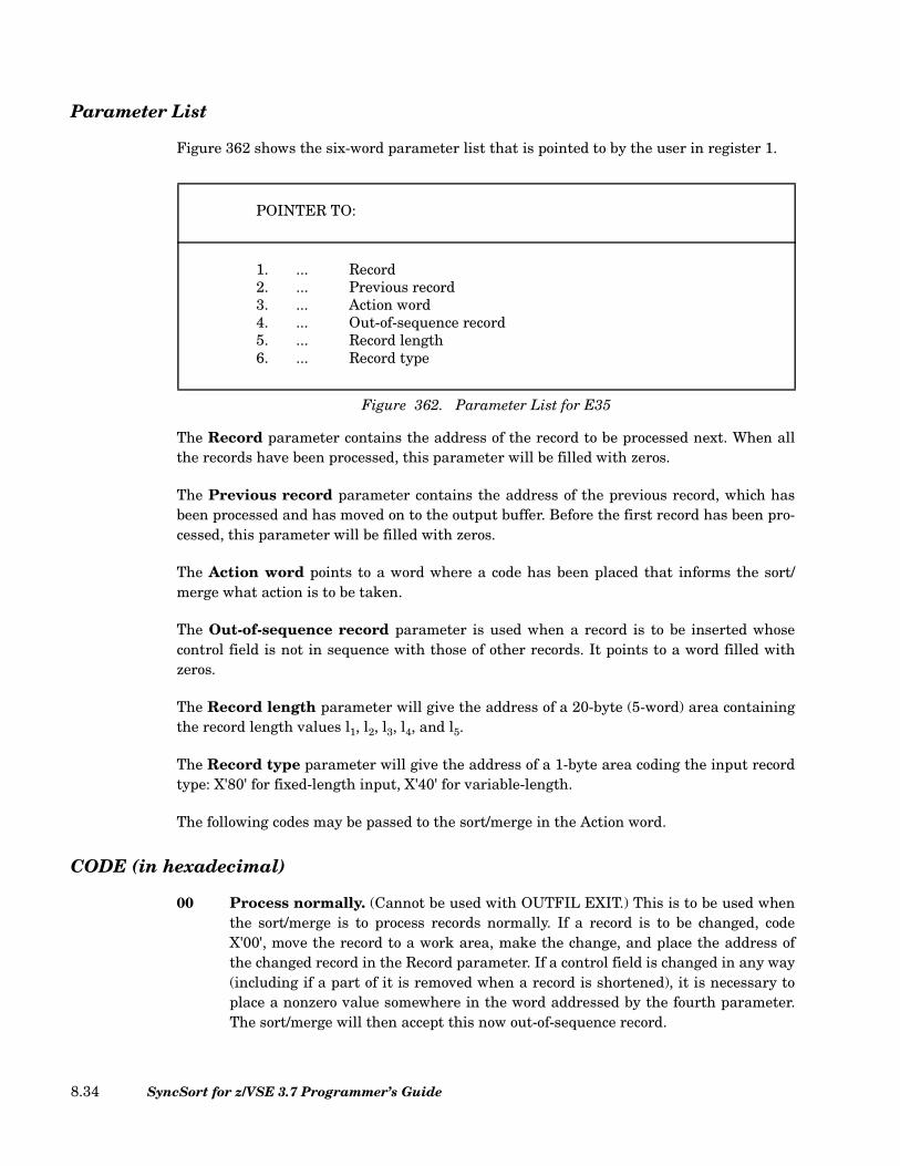
Parameter List
Figure 362 shows the six-word parameter list that is pointed to by the user in register 1.
The Record parameter contains the address of the record to be processed next. When allthe records have been processed, this parameter will be filled with zeros.
The Previous record parameter contains the address of the previous record, which hasbeen processed and has moved on to the output buffer. Before the first record has been pro-cessed, this parameter will be filled with zeros.
The Action word points to a word where a code has been placed that informs the sort/merge what action is to be taken.
The Out-of-sequence record parameter is used when a record is to be inserted whosecontrol field is not in sequence with those of other records. It points to a word filled withzeros.
The Record length parameter will give the address of a 20-byte (5-word) area containingthe record length values l1, l2, l3, l4, and l5.
The Record type parameter will give the address of a 1-byte area coding the input recordtype: X'80' for fixed-length input, X'40' for variable-length.
The following codes may be passed to the sort/merge in the Action word.
CODE (in hexadecimal)
00 Process normally. (Cannot be used with OUTFIL EXIT.) This is to be used whenthe sort/merge is to process records normally. If a record is to be changed, codeX'00', move the record to a work area, make the change, and place the address ofthe changed record in the Record parameter. If a control field is changed in any way(including if a part of it is removed when a record is shortened), it is necessary toplace a nonzero value somewhere in the word addressed by the fourth parameter.The sort/merge will then accept this now out-of-sequence record.
POINTER TO:
1. ... Record2. ... Previous record3. ... Action word4. ... Out-of-sequence record5. ... Record length6. ... Record type
Figure 362. Parameter List for E35
SyncSort for z/VSE 3.7 Programmer’s Guide8.34

04 Delete record. If the sort/merge is to delete a record whose address is in parame-ter 1, place X'04' in the Action word.
08 No return When the program is completed and there is no longer a need to returnto this exit, place X'08' in the Action word. The sort/merge will then continue butwill not return to this exit.
0C Insert record. (Cannot be used with OUTFIL EXIT.) When a record is to beinserted in the output file, put the address of this record in parameter 1 in place ofthe address of the record to be processed next, and store an X'0C' or decimal 12 inthe Action word. The sort/merge will insert the record, and when control isreturned to the user, the address of the inserted record will be in parameter 2, andthe address of the record that was to have been processed next will again appear inparameter 1. Records can continue to be inserted at this point or normal processingcan be resumed.
If the end of the output file has been reached (in this case, the first parameter willcontain zeros), additional records can be inserted because the sort/merge will keepreturning to this exit until a code X'08' in the Action word has been reached.
Since the records at this final output stage are all in order, be sure to place a non-zero value in the out-of-sequence record parameter if a record is added that is not insequence. This fourth parameter is a fullword of zeros, and nonzero values may beplaced anywhere in that word.
10 End sort/merge. Place an X'10'or decimal 16 in the Action word when the sort/merge program is to be terminated. This will cause the sort/merge to go to EOJ, anda message will be sent informing the user how many records were processed duringthis last phase.
Coding a COBOL E35 Exit Program
An E35 exit program can be coded in COBOL/VSE. A COBOL E35 exit program is indi-cated in the MODS control statement.
A COBOL exit uses GETVIS space to load run-time library routines. Allow at least 500K ofextra GETVIS when executing SyncSort with a COBOL exit.
Like any other E35 exit routine, the COBOL E35 is called each time a record is brought outof Phase 3. Communication between SyncSort and the COBOL exit takes place in theLINKAGE SECTION of the COBOL program. For example, records are passed to theCOBOL routine in the second definition (RECORD-UP) area of the LINKAGE SECTION.
MODS PH3=(MYCOBE35,COBOL,E35)
Figure 363. Sample MODS control statement for a COBOL E35
Chapter 8. User Exit Programs 8.35

The LINKAGE SECTION
The LINKAGE SECTION examples that follow show the parameters required for passingfixed-length and variable-length records to the sort. The data-names and conditionalnames used in the examples are arbitrary but each definition is required. The completeprograms from which the examples are taken follow the discussion of the exit.
Example 1: Fixed-Length Records
The PICTURE and VALUE clauses for (1) the record passed from SyncSort, (2) the recordWORK area, and (3) the record in the output buffer are application-specific.
• For the first definition (EXIT-STATUS) specify PIC 9(8) COMPUTATIONAL. Whenusing 88 levels to define exit status codes, specify values 00, 04, and 08.
• For the second definition (RECORD-UP) define the record leaving Phase 3.
LINKAGE SECTION.
01 EXIT-STATUS PIC 9(8) COMPUTATIONAL.
88 FIRST-TIME VALUE 00.
88 MOST-TIME VALUE 04.
88 LAST-TIME VALUE 08.
01 RECORD-UP.
05 RU PIC X(100).
01 WORK.
05 WK PIC X(100).
01 IN-BUF.
05 IB PIC X(100).
01 DUMMY1 PIC X(4).
01 DUMMY2 PIC X.
01 DUMMY3 PIC X.
01 DUMMY4 PIC X.
01 COMM-LEN PIC 9(4) COMPUTATIONAL.
01 COMMUNICATION-AREA.
05 COMM-AREA OCCURS 1 TO 256 TIMES
DEPENDING ON COMM-LEN PIC X.
Figure 364. Sample LINKAGE SECTION for Fixed-Length Records
SyncSort for z/VSE 3.7 Programmer’s Guide8.36
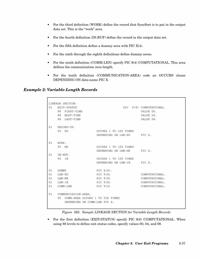
• For the third definition (WORK) define the record that SyncSort is to put in the outputdata set. This is the “work” area.
• For the fourth definition (IN-BUF) define the record in the output data set.
• For the fifth definition define a dummy area with PIC X(4).
• For the sixth through the eighth definitions define dummy areas.
• For the ninth definition (COMM-LEN) specify PIC 9(4) COMPUTATIONAL. This areadefines the communication area length.
• For the tenth definition (COMMUNICATION-AREA) code an OCCURS clauseDEPENDING ON data-name PIC X.
Example 2: Variable-Length Records
• For the first definition (EXIT-STATUS) specify PIC 9(8) COMPUTATIONAL. Whenusing 88 levels to define exit status codes, specify values 00, 04, and 08.
LINKAGE SECTION.
01 EXIT-STATUS PIC 9(8) COMPUTATIONAL.
88 FIRST-TIME VALUE 00.
88 MOST-TIME VALUE 04.
88 LAST-TIME VALUE 08.
01 RECORD-UP.
05 RU OCCURS 1 TO 100 TIMES
DEPENDING ON LEN-RU PIC X.
01 WORK.
05 WK OCCURS 1 TO 100 TIMES
DEPENDING ON LEN-WK PIC X.
01 IN-BUF.
05 IB OCCURS 1 TO 100 TIMES
DEPENDING ON LEN-IB PIC X.
01 DUMMY PIC X(4).
01 LEN-RU PIC 9(8) COMPUTATIONAL.
01 LEN-WK PIC 9(8) COMPUTATIONAL.
01 LEN-IB PIC 9(8) COMPUTATIONAL.
01 COMM-LEN PIC 9(4) COMPUTATIONAL.
01 COMMUNICATION-AREA.
05 COMM-AREA OCCURS 1 TO 256 TIMES
DEPENDING ON COMM-LEN PIC X.
Figure 365. Sample LINKAGE SECTION for Variable-Length Records
Chapter 8. User Exit Programs 8.37
• For the second definition (RECORD-UP) code an OCCURS clause with theDEPENDING ON data-name option specifying (1) the minimum and maximumnumber of bytes of your variable-length records leaving Phase 3 (do not include 4 bytesfor the RDW) and (2) DEPENDING ON data-name PIC X. Data-name is defined in thesixth definition in the LINKAGE SECTION.
• For the third definition (WORK) code an OCCURS clause with the DEPENDING ONdata-name option specifying (1) the minimum and maximum number of bytes forvariable-length records you will pass to SyncSort (do not include 4 bytes for the RDW)and (2) DEPENDING ON data-name PIC X. Data-name is defined as the seventhdefinition in the LINKAGE SECTION. This area is used for the “work” area.
• For the fourth definition (IN-BUF) define records in the output area. Code an OCCURSclause with the DEPENDING ON data-name option specifying (1) the minimum andmaximum number of bytes for variable-length records in the output data set (do notinclude 4-bytes for the RDW) and (2) DEPENDING ON data-name PIC X. Data-nameis defined as the eighth definition in the LINKAGE SECTION.
• For the fifth definition define a dummy area with PIC X(4).
• For the sixth definition (LEN-RU) specify PIC 9(8) COMPUTATIONAL. SyncSort willpass the length of the record leaving Phase 3 in this area.
• For the seventh definition (LEN-WK) specify PIC 9(8) COMPUTATIONAL. The E35routine passes SyncSort the length of the record in the work area in this section.
• For the eighth definition (LEN-IB) specify PIC 9(8) COMPUTATIONAL. SyncSortpasses the length of the record in the output area in this section.
• For the ninth definition (COMM-LEN) specify PIC 9(4) COMPUTATIONAL. This areadefines the communication area length.
• For the tenth definition (COMMUNICATION-AREA) code an OCCURS clauseDEPENDING ON data-name PIC X.
The IDENTIFICATION, ENVIRONMENT, and DATA DIVISIONs
As always, the COBOL program must contain the entries required by the compiler for theseprogram divisions. Code the optional entries in these divisions according to the require-ments of the application.
The WORKING-STORAGE SECTION
If the exit routine inserts records into the final merge and replaces records passed fromSyncSort, the insertion record and the replacement record may be defined in this section.These records will be moved to the WORK area described in the LINKAGE SECTION, so be
SyncSort for z/VSE 3.7 Programmer’s Guide8.38

sure that the PICTURE clause or the OCCURS clause in the WORK area is correct forthese records.
This section may also define the return codes as 77-level data items. Alternatively, thesecodes can be specified as literals in the MOVE instruction. (MOVE literal to RETURN-CODE.) Note that RETURN-CODE is the name of a predefined storage area in COBOLused to pass return codes to the sort; RETURN-CODE should not be defined in the exit rou-tine.
The PROCEDURE DIVISION
Specify the USING option on the PROCEDURE DIVISION header. Each identifierspecified after USING must be the same as those described in the 01-level of the LINKAGESECTION. Taking for example the identifiers defined in the fixed-length record LINKAGESECTION shown here, they would appear as: PROCEDURE DIVISION USING EXIT-STATUS, RECORD-UP, WORK, IN-BUF, DUMMY1, DUMMY2, DUMMY3, DUMMY4,COM-LEN, COMMUNICATION-AREA.
The GOBACK statement is used to return control to SyncSort. Do not use the EXIT state-ment as it will cause unpredictable results. Be sure that SyncSort receives a valid returncode before the GOBACK statement is executed.
EXIT-STATUS Codes (Fixed and Variable-Length Records)
00 First record. SyncSort uses this Code to indicate the first call to the COBOLexit and that the first record to leave Phase 3 is in the RECORD-UP area.
04 Most records. This is used for all calls except the first one when there arerecords in the RECORD-UP area. After Code 00 has been issued, Code 04 ispassed to the exit until there is no record for the sort to pass to theRECORD-UP area.
08 All records passed. This indicates that the last SORTIN record has alreadybeen processed by the exit. Do not attempt to reference the record again. Nomore records will be passed to the exit routine. Note that if the SORTINdata set is empty, 08 will be passed every time including the first time.
RETURN-CODE Codes (Fixed and Variable-Length Records)
0 Accept this record. This instructs SyncSort to accept the (unaltered) recordin the RECORD-UP area.
4 Delete this record. SyncSort will delete the current record in the RECORD-UP area
Chapter 8. User Exit Programs 8.39
8 Disconnect E35. This instructs SyncSort to process any remaining recordswithout showing them to the E35 exit. Register 1 is ignored for processingthis return code.
When this return code is used at end-of-file (signalled by EXIT-STATUSLAST-TIME), it indicates that the E35 is also finished and will not addadditional records. When used before end-of-file, it indicates that SyncSortshould process the “current” record passed to the E35, and any subsequentrecords, as if there were no E35 present. Note that when SyncSort is notcreating any output files and E35 is the only “output”, SyncSort terminatesimmediately, since any subsequent records will never be seen. Also notethat if an XSUM data set was being created, it will only contain recordsgenerated prior to the return code of 8.
12 Insert a record. This instructs SyncSort to add the record in the WORK areato the output data set just ahead of the current record in the RECORD-UParea. When SyncSort returns control to the E35, the same record will be inthe RECORD-UP area. The exit routine can then add another record fromthe WORK area or process the current record in RECORD-UP.
16 Terminate SyncSort. SyncSort will terminate and return to the calling pro-gram or the Supervisor. SyncSort will issue a completion code of 16 to indi-cate that the sort was unsuccessful.
20 Replace current record. SyncSort will replace the current record in theRECORD-UP area with the record in the WORK area. Be sure that therecord in the WORK area is valid before passing it to SyncSort.
To Change a Record
In order to change the record in the RECORD-UP area, first move it to the WORK area.Make the changes there and then pass return code 20 in RETURN-CODE. The alteredrecord in the WORK area will replace the record in RECORD-UP.
SyncSort for z/VSE 3.7 Programmer’s Guide8.40

Sample COBOL E35, Fixed-Length Records
IDENTIFICATION DIVISION.
PROGRAM-ID. E35FL101.
ENVIRONMENT DIVISION.
CONFIGURATION SECTION.
SOURCE-COMPUTER. IBM-370.
OBJECT-COMPUTER. IBM-370.
INPUT-OUTPUT SECTION.
FILE-CONTROL.
I-O-CONTROL.
DATA DIVISION.
FILE SECTION.
WORKING-STORAGE SECTION.
01 EVEN-FLAG PIC 9(2) VALUE ZERO.
01 USER-RETURN-CODE PIC 9(8) COMPUTATIONAL.
88 ACCEPT-REC VALUE 0.
88 DELETE-REC VALUE 4.
88 END-EXIT VALUE 8.
88 INSERT-REC VALUE 12.
88 END-SORT VALUE 16.
88 REPL-REC VALUE 20.
01 CHANGE-REC.
05 C-REC PIC X(6) VALUE 'CHANGE'.
05 C-INCR PIC 9(4) VALUE ZERO.
05 C-BLANK PIC X(90) VALUE SPACES.
01 INSRT-REC.
05 I-REC PIC X(6) VALUE 'INSERT'.
05 I-INCR PIC 9(4) VALUE ZERO.
05 I-BLANK PIC X(90) VALUE SPACES.
01 TOTAL.
05 BLANKS PIC X(10) VALUE 'E35'.
05 TITL PIC X(25)
VALUE 'TOTAL RECORDS HANDLED'.
05 COUNTER PIC 9(8) VALUE 0
Figure 366. (Page 1 of 2) Sample COBOL E35, Fixed-Length Records
Chapter 8. User Exit Programs 8.41

LINKAGE SECTION.01 EXIT-STATUS PIC 9(8) COMPUTATIONAL.
88 FIRST-TIME VALUE 00.88 MOST-TIME VALUE 04.88 LAST-TIME VALUE 08.
01 RECORD-UP.05 RU PIC X(100).
01 WORK.05 WK PIC X(100).
01 IN-BUF.05 IB PIC X(100).
01 DUMMY1 PIC X(4).
PROCEDURE DIVISION USING EXIT-STATUS, RECORD-UP, WORK,IN-BUF, DUMMY.
IF NOT FIRST-TIMEADD 1 TO COUNTERMOVE 0 TO RETURN-CODE.
IF COUNTER LESS THAN 50ADD 1 TO I-INCRMOVE INSRT-REC TO WORKMOVE 12 TO RETURN-CODEGO TO RETURN-TO-SORT.
IF COUNTER LESS THAN 75ADD 1 TO C-INCRMOVE CHANGE-REC TO WORKMOVE 20 TO RETURN-CODEGO TO RETURN-TO-SORT.
IF COUNTER LESS THAN 100ADD 1 TO I-INCRMOVE INSRT-REC TO WORKMOVE 12 TO RETURN-CODEGO TO RETURN-TO-SORT.
IF COUNTER LESS THAN 200MOVE 4 TO RETURN-CODEGO TO RETURN-TO-SORT.
RETURN-TO-SORT.IF LAST-TIME MOVE 8 TO RETURN-CODE
DISPLAY TOTAL.GOBACK.
Figure 366. (Page 2 of 2) Sample COBOL E35, Fixed-Length Records
SyncSort for z/VSE 3.7 Programmer’s Guide8.42
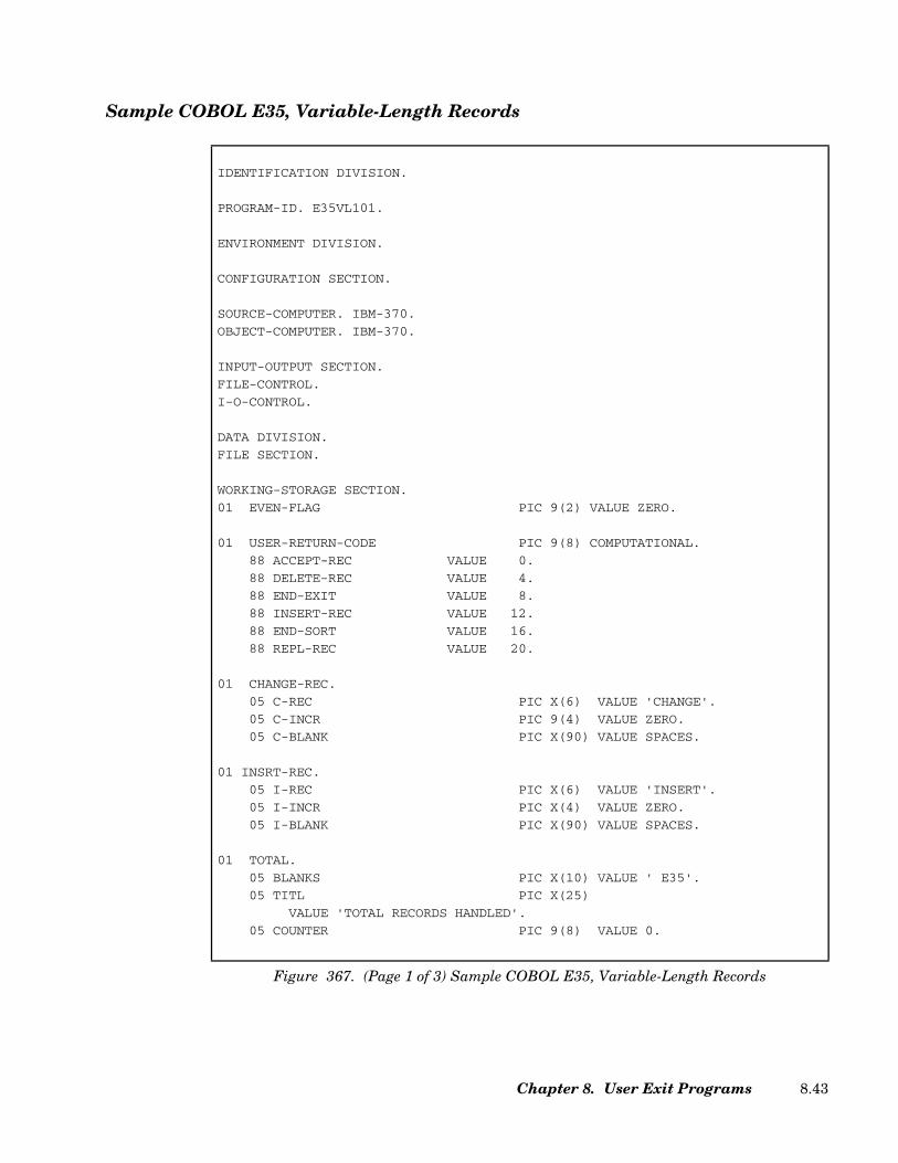
Sample COBOL E35, Variable-Length Records
IDENTIFICATION DIVISION.
PROGRAM-ID. E35VL101.
ENVIRONMENT DIVISION.
CONFIGURATION SECTION.
SOURCE-COMPUTER. IBM-370.
OBJECT-COMPUTER. IBM-370.
INPUT-OUTPUT SECTION.
FILE-CONTROL.
I-O-CONTROL.
DATA DIVISION.
FILE SECTION.
WORKING-STORAGE SECTION.
01 EVEN-FLAG PIC 9(2) VALUE ZERO.
01 USER-RETURN-CODE PIC 9(8) COMPUTATIONAL.
88 ACCEPT-REC VALUE 0.
88 DELETE-REC VALUE 4.
88 END-EXIT VALUE 8.
88 INSERT-REC VALUE 12.
88 END-SORT VALUE 16.
88 REPL-REC VALUE 20.
01 CHANGE-REC.
05 C-REC PIC X(6) VALUE 'CHANGE'.
05 C-INCR PIC 9(4) VALUE ZERO.
05 C-BLANK PIC X(90) VALUE SPACES.
01 INSRT-REC.
05 I-REC PIC X(6) VALUE 'INSERT'.
05 I-INCR PIC X(4) VALUE ZERO.
05 I-BLANK PIC X(90) VALUE SPACES.
01 TOTAL.
05 BLANKS PIC X(10) VALUE ' E35'.
05 TITL PIC X(25)
VALUE 'TOTAL RECORDS HANDLED'.
05 COUNTER PIC 9(8) VALUE 0.
Figure 367. (Page 1 of 3) Sample COBOL E35, Variable-Length Records
Chapter 8. User Exit Programs 8.43
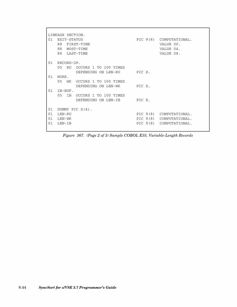
LINKAGE SECTION.01 EXIT-STATUS PIC 9(8) COMPUTATIONAL.
88 FIRST-TIME VALUE 00.88 MOST-TIME VALUE 04.88 LAST-TIME VALUE 08.
01 RECORD-UP.05 RU OCCURS 1 TO 100 TIMES
DEPENDING ON LEN-RU PIC X.01 WORK.
05 WK OCCURS 1 TO 100 TIMESDEPENDING ON LEN-WK PIC X.
01 IN-BUF.05 IB OCCURS 1 TO 100 TIMES
DEPENDING ON LEN-IB PIC X.
01 DUMMY PIC X(4).01 LEN-RU PIC 9(8) COMPUTATIONAL.01 LEN-WK PIC 9(8) COMPUTATIONAL.01 LEN-IB PIC 9(8) COMPUTATIONAL.
Figure 367. (Page 2 of 3) Sample COBOL E35, Variable-Length Records
SyncSort for z/VSE 3.7 Programmer’s Guide8.44
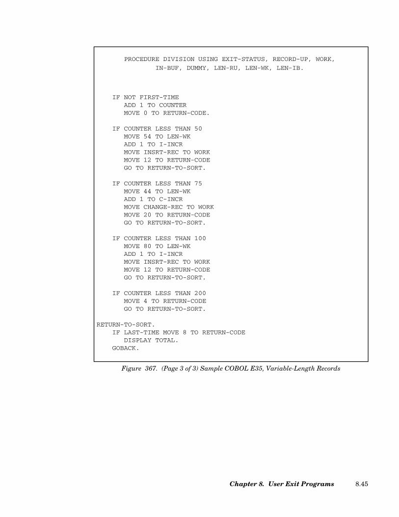
PROCEDURE DIVISION USING EXIT-STATUS, RECORD-UP, WORK,
IN-BUF, DUMMY, LEN-RU, LEN-WK, LEN-IB.
IF NOT FIRST-TIMEADD 1 TO COUNTERMOVE 0 TO RETURN-CODE.
IF COUNTER LESS THAN 50MOVE 54 TO LEN-WKADD 1 TO I-INCRMOVE INSRT-REC TO WORKMOVE 12 TO RETURN-CODEGO TO RETURN-TO-SORT.
IF COUNTER LESS THAN 75MOVE 44 TO LEN-WKADD 1 TO C-INCRMOVE CHANGE-REC TO WORKMOVE 20 TO RETURN-CODEGO TO RETURN-TO-SORT.
IF COUNTER LESS THAN 100MOVE 80 TO LEN-WKADD 1 TO I-INCRMOVE INSRT-REC TO WORKMOVE 12 TO RETURN-CODEGO TO RETURN-TO-SORT.
IF COUNTER LESS THAN 200MOVE 4 TO RETURN-CODEGO TO RETURN-TO-SORT.
RETURN-TO-SORT.IF LAST-TIME MOVE 8 TO RETURN-CODE
DISPLAY TOTAL.GOBACK.
Figure 367. (Page 3 of 3) Sample COBOL E35, Variable-Length Records
Chapter 8. User Exit Programs 8.45
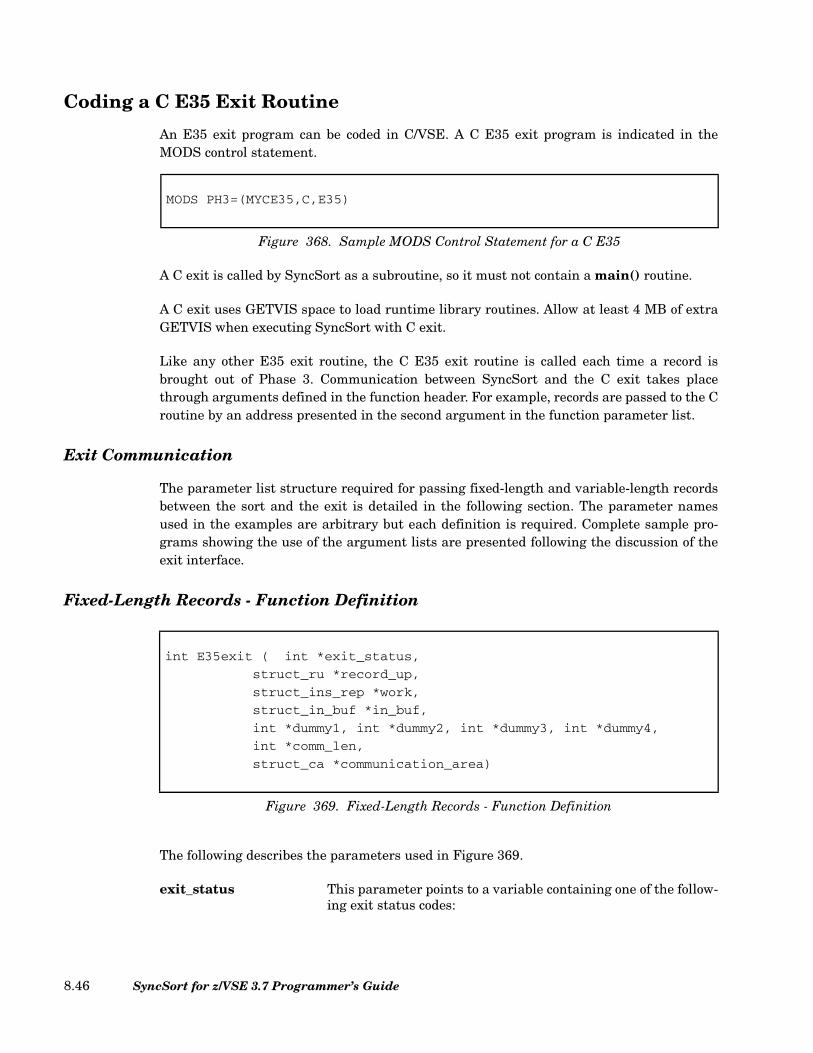
Coding a C E35 Exit Routine
An E35 exit program can be coded in C/VSE. A C E35 exit program is indicated in theMODS control statement.
A C exit is called by SyncSort as a subroutine, so it must not contain a main() routine.
A C exit uses GETVIS space to load runtime library routines. Allow at least 4 MB of extraGETVIS when executing SyncSort with C exit.
Like any other E35 exit routine, the C E35 exit routine is called each time a record isbrought out of Phase 3. Communication between SyncSort and the C exit takes placethrough arguments defined in the function header. For example, records are passed to the Croutine by an address presented in the second argument in the function parameter list.
Exit Communication
The parameter list structure required for passing fixed-length and variable-length recordsbetween the sort and the exit is detailed in the following section. The parameter namesused in the examples are arbitrary but each definition is required. Complete sample pro-grams showing the use of the argument lists are presented following the discussion of theexit interface.
Fixed-Length Records - Function Definition
The following describes the parameters used in Figure 369.
exit_status This parameter points to a variable containing one of the follow-ing exit status codes:
MODS PH3=(MYCE35,C,E35)
Figure 368. Sample MODS Control Statement for a C E35
int E35exit ( int *exit_status,
struct_ru *record_up,
struct_ins_rep *work,
struct_in_buf *in_buf,
int *dummy1, int *dummy2, int *dummy3, int *dummy4,
int *comm_len,
struct_ca *communication_area)
Figure 369. Fixed-Length Records - Function Definition
SyncSort for z/VSE 3.7 Programmer’s Guide8.46
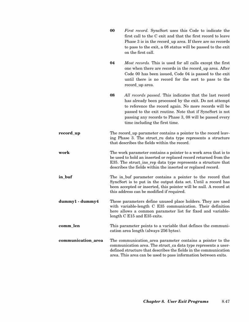
00 First record. SyncSort uses this Code to indicate thefirst call to the C exit and that the first record to leavePhase 3 is in the record_up area. If there are no recordsto pass to the exit, a 08 status will be passed to the exiton the first call.
04 Most records. This is used for all calls except the firstone when there are records in the record_up area. AfterCode 00 has been issued, Code 04 is passed to the exituntil there is no record for the sort to pass to therecord_up area.
08 All records passed. This indicates that the last recordhas already been processed by the exit. Do not attemptto reference the record again. No more records will bepassed to the exit routine. Note that if SyncSort is notpassing any records to Phase 3, 08 will be passed everytime including the first time.
record_up The record_up parameter contains a pointer to the record leav-ing Phase 3. The struct_ru data type represents a structurethat describes the fields within the record.
work The work parameter contains a pointer to a work area that is tobe used to hold an inserted or replaced record returned from theE35. The struct_ins_rep data type represents a structure thatdescribes the fields within the inserted or replaced record.
in_buf The in_buf parameter contains a pointer to the record thatSyncSort is to put in the output data set. Until a record hasbeen accepted or inserted, this pointer will be null. A record atthis address can be modified if required.
dummy1 - dummy4 These parameters define unused place holders. They are usedwith variable-length C E35 communication. Their definitionhere allows a common parameter list for fixed and variable-length C E15 and E35 exits.
comm_len This parameter points to a variable that defines the communi-cation area length (always 256 bytes).
communication_area The communication_area parameter contains a pointer to thecommunication area. The struct_ca data type represents a user-defined structure that describes the fields in the communicationarea. This area can be used to pass information between exits.
Chapter 8. User Exit Programs 8.47

Variable-Length Records - Function Definition
The following describes the parameters used in Figure 370.
exit_status This parameter points to a variable containing exit statuscodes. See the exit_status definition for a fixed-length C E35exit for the code definitions.
record_up The record_up parameter contains a “universal” pointer to therecord leaving Phase 3. The void* pointer can be cast to point anappropriate structure to describe the record passed to the exit.This allows different record structures, as is common with vari-able-length records, to share a universal pointer.
work The work parameter contains a “universal” pointer to a workarea that is to be used to hold an inserted or replaced recordreturned from the E35. The void* pointer can be cast to point anappropriate structure to describe the work record.
in_buf The in_buf parameter contains a “universal” pointer to therecord that SyncSort is to put in the output data set. Until arecord has been accepted or inserted, this pointer will be null.The void* pointer can be cast to point an appropriate structureto describe the work record.
dummy1 This parameter defines an unused place holder.
len_ru This parameter points to a variable that defines the length ofthe record leaving Phase 3. This is the length of the recordreferred to in the record_up parameter.
len_wk This parameter points to a variable that defines the length ofthe record to be inserted or used as a replacement for therecord_up record. This is the length of the record referred to inthe work parameter.
int E35exit ( int *exit_status,
void *record_up,
void *work,
void *in_buf,
int *dummy1,
int *len_ru,
int *len_wk,
int *len_ib,
int *comm_len,
struct_ca *communication_area)
Figure 370. Variable-Length Records - Function Definition
SyncSort for z/VSE 3.7 Programmer’s Guide8.48

len_ib This parameter points to a variable that defines the length ofthe record that SyncSort is to put in the output data set. This isthe length of the record referred to in the in_buf parameter.
comm_len This parameter points to a variable that defines the communi-cation area length.
communication_area The communication_area parameter contains a pointer to thecommunication area. The struct_ca data type represents a user-defined structure that describes the fields in the communicationarea. This information can be used to pass information betweenexits.
RETURN-CODE Codes (Fixed and Variable-Length Records)
0 Accept this record. This instructs SyncSort to accept the (unaltered) recordin the record_up area.
4 Delete this record. SyncSort will delete the current record in the record_uparea.
8 Disconnect E35. This instructs SyncSort to process any remaining recordswithout showing them to the E35 exit. When this return code is used atend-of-file (signalled by exit_status 08), it indicates that the E35 is also fin-ished and will not add additional records. When used before end-of-file, itindicates that SyncSort should process the “current” record passed to theE35, and any subsequent records, as if there were no E35 present. Notethat when SyncSort is not creating any output files and E35 is the only“output,” SyncSort terminates immediately, since any subsequent recordswill never be seen.
12 Insert a record. This instructs SyncSort to add the record in the work areato the output data set just ahead of the current record in the record_uparea. When SyncSort returns control to the E35, the same record will be inthe record_up area. The exit routine can then add another record from thework area or process the current record in record_up.
16 Terminate SyncSort. SyncSort will terminate and return to the calling pro-gram or the Supervisor. SyncSort will issue a completion code of 16 to indi-cate that the sort was unsuccessful.
20 Replace current record. SyncSort will replace the current record in therecord_up area with the record in the work area. Be sure that the record inthe work area is valid before passing it to SyncSort.
Chapter 8. User Exit Programs 8.49

Change a Record
In order to change the record in the record_up area, first move it to the provided work area.Make the changes there and then pass return code 20. The altered record in the work areawill replace the record in record_up.
Sample C E35, Fixed-Length Records
#define FIRST_TIME 0
#define MOST_TIME 4
#define LAST_TIME 8
#define ACCEPT_REC 0
#define DELETE_REC 4
#define END_EXIT 8
#define INSERT_REC 12
#define END_SORT 16
#define REPL_REC 20
#include <decimal.h>
typedef _Packed struct record {
char rec[6];
decimal(7,0) incr;
char address[90];
} t_ru;
int counter,i_incr;
#include <stdio.h>
#include <stdlib.h>
#include <string.h>
int SMPE35FB(int *exit_status,t_ru *record_up,t_ru *work,t_ru *in_buf,
int *dummy1,int *dummy2,int *dummy3,int *dummy4,int *comm_len,
void *communication_area)
{
int return_code;
char *text1="CHANGE";
char *text2="INSERT";
if (*exit_status != FIRST_TIME) {counter++;
return_code=ACCEPT_REC;
}
Figure 371. (Page 1 of 2) Sample C E35, Fixed-Length Records
SyncSort for z/VSE 3.7 Programmer’s Guide8.50

if (counter<50) {
i_incr++;
work->incr=i_incr;
strncpy(work->rec,text2,6);
return_code=INSERT_REC;
goto return_to_sort;}
if (counter<75) {
work->incr=record_up->incr+1d;
strncpy(work->rec,text1,6);
return_code=REPL_REC;
goto return_to_sort;}
if (counter<100) {
i_incr++;
work->incr=i_incr;
strncpy(work->rec,text2,6);
return_code=INSERT_REC;
goto return_to_sort;}
if (counter<200) {
return_code=DELETE_REC;
goto return_to_sort;}
return_to_sort:
if (*exit_status==LAST_TIME)
{ return_code=END_EXIT;
printf("E35 total number of records handled:%d\n",counter);
}
return(return_code);
}
Figure 371. (Page 2 of 2) Sample C E35, Fixed-Length Records
Chapter 8. User Exit Programs 8.51
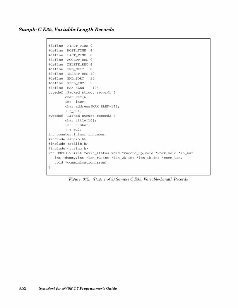
Sample C E35, Variable-Length Records
#define FIRST_TIME 0
#define MOST_TIME 4
#define LAST_TIME 8
#define ACCEPT_REC 0
#define DELETE_REC 4
#define END_EXIT 8
#define INSERT_REC 12
#define END_SORT 16
#define REPL_REC 20
#define MAX_RLEN 104
typedef _Packed struct record1 {
char rec[6];
int incr;
char address[MAX_RLEN-14];
} t_ru1;
typedef _Packed struct record2 {
char title[10];
int number;
} t_ru2;
int counter,i_incr,i_number;
#include <stdio.h>
#include <stdlib.h>
#include <string.h>
int SMPE35VB(int *exit_status,void *record_up,void *work,void *in_buf,
int *dummy,int *len_ru,int *len_wk,int *len_ib,int *comm_len,
void *communication_area)
{
Figure 372. (Page 1 of 3) Sample C E35, Variable-Length Records
SyncSort for z/VSE 3.7 Programmer’s Guide8.52
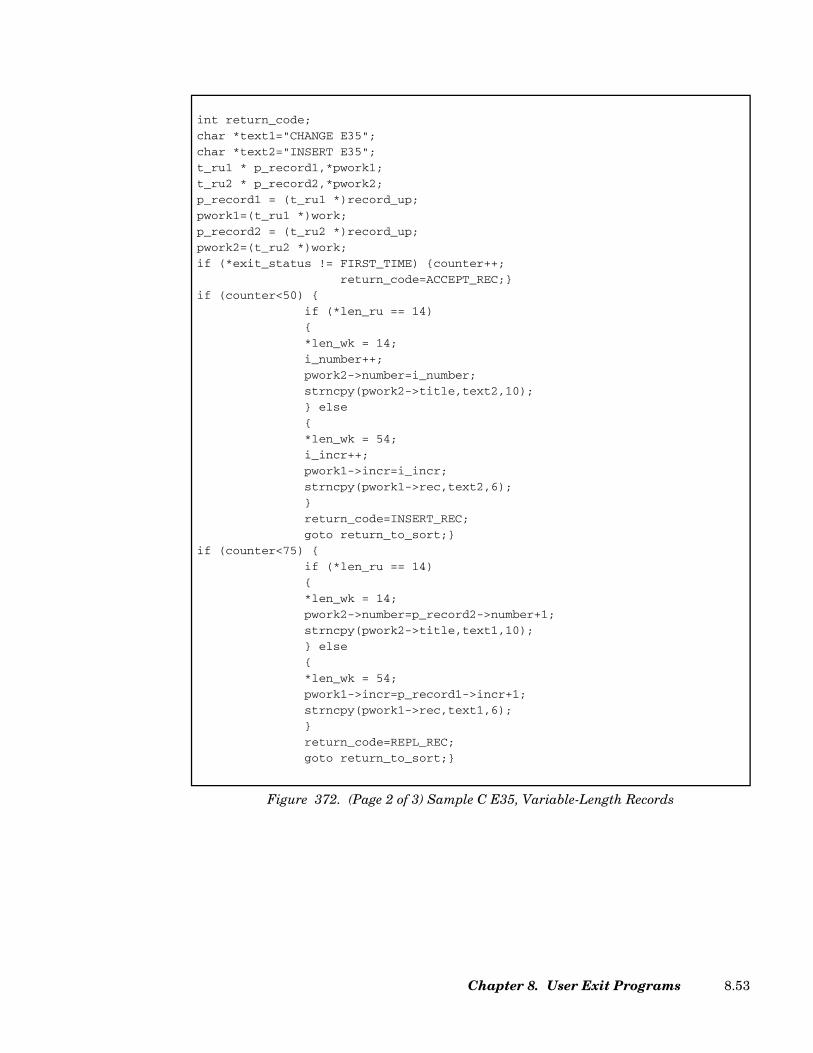
int return_code;
char *text1="CHANGE E35";
char *text2="INSERT E35";
t_ru1 * p_record1,*pwork1;
t_ru2 * p_record2,*pwork2;
p_record1 = (t_ru1 *)record_up;
pwork1=(t_ru1 *)work;
p_record2 = (t_ru2 *)record_up;
pwork2=(t_ru2 *)work;
if (*exit_status != FIRST_TIME) {counter++;
return_code=ACCEPT_REC;}
if (counter<50) {
if (*len_ru == 14)
{
*len_wk = 14;
i_number++;
pwork2->number=i_number;
strncpy(pwork2->title,text2,10);
} else
{
*len_wk = 54;
i_incr++;
pwork1->incr=i_incr;
strncpy(pwork1->rec,text2,6);
}
return_code=INSERT_REC;
goto return_to_sort;}
if (counter<75) {
if (*len_ru == 14)
{
*len_wk = 14;
pwork2->number=p_record2->number+1;
strncpy(pwork2->title,text1,10);
} else
{
*len_wk = 54;
pwork1->incr=p_record1->incr+1;
strncpy(pwork1->rec,text1,6);
}
return_code=REPL_REC;
goto return_to_sort;}
Figure 372. (Page 2 of 3) Sample C E35, Variable-Length Records
Chapter 8. User Exit Programs 8.53

EXIT E32 - Merge Only - Changing and Substituting Records, Reading Input
An E32 exit can only be used while running a merge. It is used to change the contents of arecord or to substitute a record. If an INPFIL control statement specifying EXIT isincluded, E32 is being used to process the input files. A one-word parameter list will bepassed to the user if EXIT is not specified on the INPFIL control statement, and a five-wordparameter list will be passed if it is included.
Changing Records
Exit E32 is entered before each record of the input files is processed. Control, as well asnoncontrol, areas may be changed as long as the total length of the record is not altered andthe change in the control field does not result in an out-of-sequence record. The address ofthe record to be processed will appear in a one-word parameter list pointed to by register 1.
if (counter<100) {
if (*len_ru == 14)
{
*len_wk = 14;
i_number++;
pwork2->number=i_number;
strncpy(pwork2->title,text2,10);
} else
{
*len_wk = 80;
i_incr++;
pwork1->incr=i_incr;
strncpy(pwork1->rec,text2,6);
}
return_code=INSERT_REC;
goto return_to_sort;}
if (counter<200) {
return_code=DELETE_REC;
goto return_to_sort;}
return_to_sort:
if (*exit_status==LAST_TIME)
{ return_code=END_EXIT;
printf("E35 total number of records handled:%d\n",counter);
}
return(return_code);
}
Figure 372. (Page 3 of 3) Sample C E35, Variable-Length Records
SyncSort for z/VSE 3.7 Programmer’s Guide8.54
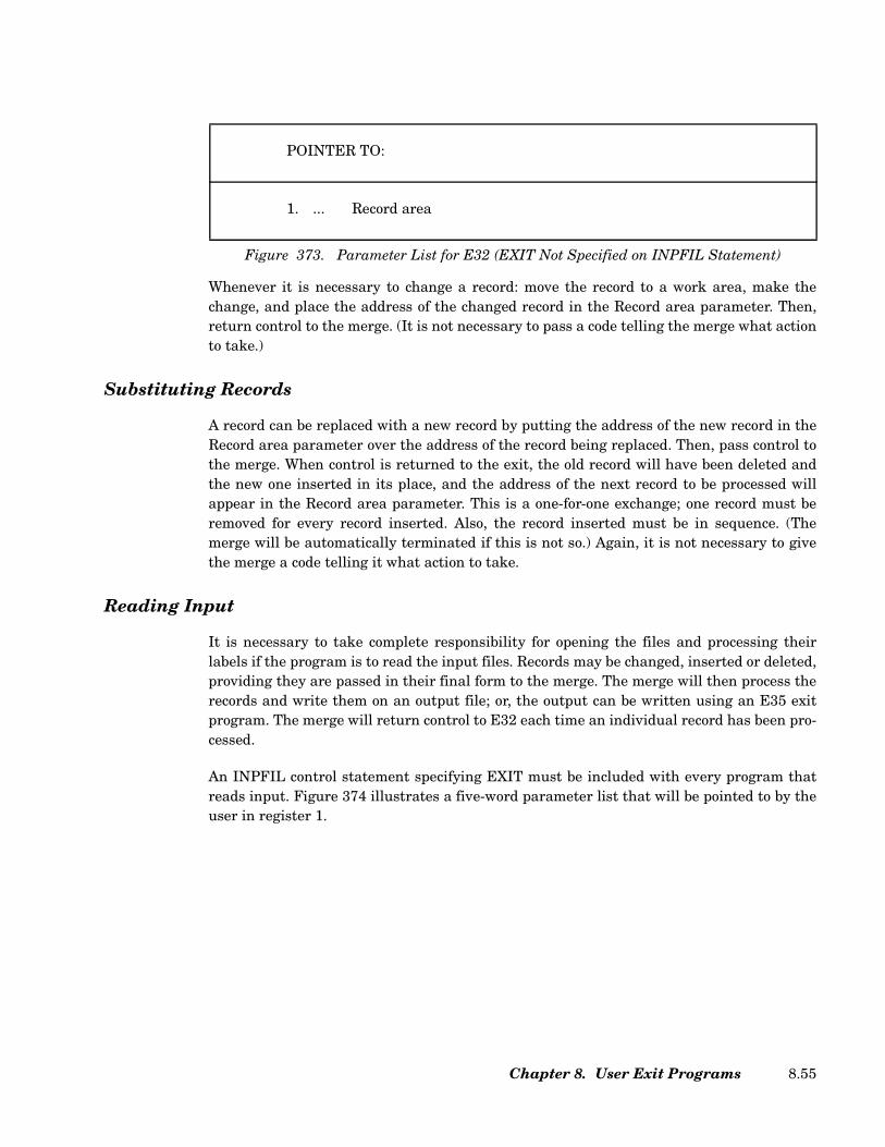
Whenever it is necessary to change a record: move the record to a work area, make thechange, and place the address of the changed record in the Record area parameter. Then,return control to the merge. (It is not necessary to pass a code telling the merge what actionto take.)
Substituting Records
A record can be replaced with a new record by putting the address of the new record in theRecord area parameter over the address of the record being replaced. Then, pass control tothe merge. When control is returned to the exit, the old record will have been deleted andthe new one inserted in its place, and the address of the next record to be processed willappear in the Record area parameter. This is a one-for-one exchange; one record must beremoved for every record inserted. Also, the record inserted must be in sequence. (Themerge will be automatically terminated if this is not so.) Again, it is not necessary to givethe merge a code telling it what action to take.
Reading Input
It is necessary to take complete responsibility for opening the files and processing theirlabels if the program is to read the input files. Records may be changed, inserted or deleted,providing they are passed in their final form to the merge. The merge will then process therecords and write them on an output file; or, the output can be written using an E35 exitprogram. The merge will return control to E32 each time an individual record has been pro-cessed.
An INPFIL control statement specifying EXIT must be included with every program thatreads input. Figure 374 illustrates a five-word parameter list that will be pointed to by theuser in register 1.
POINTER TO:
1. ... Record area
Figure 373. Parameter List for E32 (EXIT Not Specified on INPFIL Statement)
Chapter 8. User Exit Programs 8.55
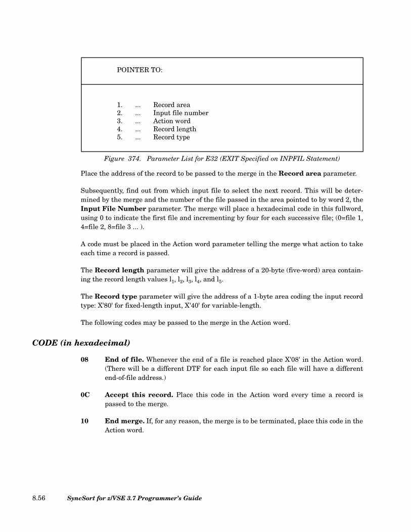
Place the address of the record to be passed to the merge in the Record area parameter.
Subsequently, find out from which input file to select the next record. This will be deter-mined by the merge and the number of the file passed in the area pointed to by word 2, theInput File Number parameter. The merge will place a hexadecimal code in this fullword,using 0 to indicate the first file and incrementing by four for each successive file; (0=file 1,4=file 2, 8=file 3 ... ).
A code must be placed in the Action word parameter telling the merge what action to takeeach time a record is passed.
The Record length parameter will give the address of a 20-byte (five-word) area contain-ing the record length values l1, l2, l3, l4, and l5.
The Record type parameter will give the address of a 1-byte area coding the input recordtype: X'80' for fixed-length input, X'40' for variable-length.
The following codes may be passed to the merge in the Action word.
CODE (in hexadecimal)
08 End of file. Whenever the end of a file is reached place X'08' in the Action word.(There will be a different DTF for each input file so each file will have a differentend-of-file address.)
0C Accept this record. Place this code in the Action word every time a record ispassed to the merge.
10 End merge. If, for any reason, the merge is to be terminated, place this code in theAction word.
POINTER TO:
1. ... Record area2. ... Input file number3. ... Action word4. ... Record length5. ... Record type
Figure 374. Parameter List for E32 (EXIT Specified on INPFIL Statement)
SyncSort for z/VSE 3.7 Programmer’s Guide8.56
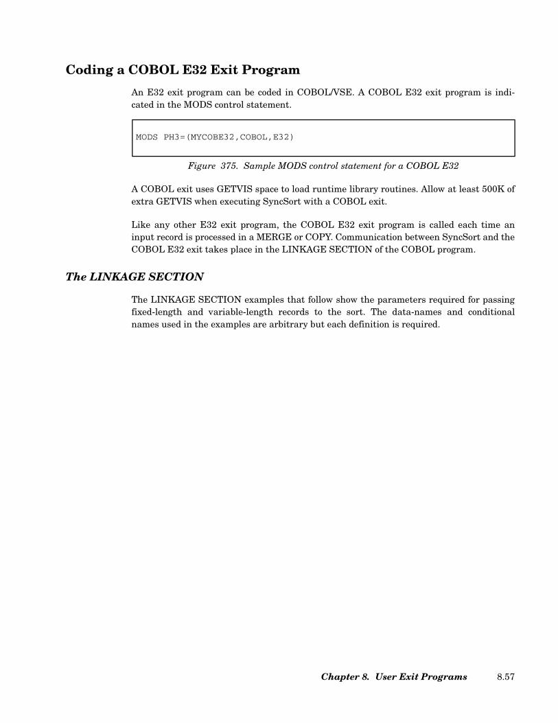
Coding a COBOL E32 Exit Program
An E32 exit program can be coded in COBOL/VSE. A COBOL E32 exit program is indi-cated in the MODS control statement.
A COBOL exit uses GETVIS space to load runtime library routines. Allow at least 500K ofextra GETVIS when executing SyncSort with a COBOL exit.
Like any other E32 exit program, the COBOL E32 exit program is called each time aninput record is processed in a MERGE or COPY. Communication between SyncSort and theCOBOL E32 exit takes place in the LINKAGE SECTION of the COBOL program.
The LINKAGE SECTION
The LINKAGE SECTION examples that follow show the parameters required for passingfixed-length and variable-length records to the sort. The data-names and conditionalnames used in the examples are arbitrary but each definition is required.
MODS PH3=(MYCOBE32,COBOL,E32)
Figure 375. Sample MODS control statement for a COBOL E32
Chapter 8. User Exit Programs 8.57

Example 1: Fixed-Length Records
• For the first definition (EXIT-STATUS) specify PIC 9(8) COMPUTATIONAL. (Thisarea defines exit status codes.) When using 88 levels to define the exit status codes,specify values 00, 04, and 08.
• For the second definition (RECORD-UP) define the SORTIN record.
• For the third definition (WORK) define the record that will be passed to SyncSort. (Thisis the “work area.”)
• For the fourth and sixth through eighth definitions define dummy areas.
• For the fifth definition (FILE-NUMBER) specify PIC 9(8) COMPUTATIONAL.SyncSort places the input file number from which the next record is to be read. (0=file1, 4=file 2, 8=file 3, ...)
• For the ninth definition (COMM-LEN) specify PIC 9(4) COMPUTATIONAL. This areadefines the communication area length.
LINKAGE SECTION.
01 EXIT-STATUS PIC 9(8) COMPUTATIONAL.
88 FIRST-TIME VALUE 00.
88 MOST-TIME VALUE 04.
88 LAST-TIME VALUE 08.
01 RECORD-UP.
07 FILLER PIC 9(6).
07 R-SEQ2 PIC 9(2).
07 FILLER PIC X(92).
01 WORK PIC X(100).
01 DUMMY1 PIC X.
01 FILE-NUMBER PIC 9(8) COMPUTATIONAL.
01 DUMMY2 PIC X.
01 DUMMY3 PIC X.
01 DUMMY4 PIC X.
01 COMM-LEN PIC 9(4) COMPUTATIONAL.
01 COMMUNICATION-AREA.
05 COMM-AREA OCCURS 1 TO 256 TIMES
DEPENDING ON COMM-LEN PIC X.
01 EXIT-ID PIC X(3).
Figure 376. Sample LINKAGE SECTION for Fixed-Length Records
SyncSort for z/VSE 3.7 Programmer’s Guide8.58

• For the tenth definition (COMMUNICATION-AREA) code an OCCURS clauseDEPENDING ON data-name PIC X.
• For the eleventh definition (EXIT-ID) specify PIC X(3). SyncSort places the literals'E32' here.
Example 2: Variable-Length Records
• For the first definition (EXIT-STATUS) specify PIC 9(8) COMPUTATIONAL. (Thisarea defines exit status codes.)
• For the second definition (RECORD-UP) code an OCCURS clause with theDEPENDING ON data-name option specifying (1) The minimum and maximumnumber of bytes the variable SORTIN records contain (do not include 4 bytes for theRDW) and (2) DEPENDING ON data-name PIC X. Data-name is defined in the sixthdefinition in the LINKAGE SECTION.
• For the third definition (WORK) code an OCCURS clause with the DEPENDING ONdata-name option specifying (1) The minimum and maximum number of bytes forvariable-length records to be passed to SyncSort (do not include 4 bytes for the RDW)and (2) DEPENDING ON data-name PIC X. Data-name is defined as the seventhdefinition in the LINKAGE SECTION.
LINKAGE SECTION.01 EXIT-STATUS PIC 9(8) COMPUTATIONAL.
88 FIRST-TIME VALUE 00.88 MOST-TIME VALUE 04.88 LAST-TIME VALUE 08.
01 RECORD-UP.05 RU OCCURS 1 TO 100 TIMES
DEPENDING ON LEN-RU PIC X.01 WORK.
05 WK OCCURS 1 TO 100 TIMESDEPENDING ON LEN-WK PIC X.
01 DUMMY1 PIC X.01 FILE-NUMBER PIC 9(8) COMPUTATIONAL.01 LEN-RU PIC 9(8) COMPUTATIONAL.01 LEN-WK PIC 9(8) COMPUTATIONAL.01 DUMMY2 PIC X.01 COMM-LEN PIC 9(4) COMPUTATIONAL.01 COMMUNICATION-AREA.
05 COMM-AREA OCCURS 1 TO 256 TIMESDEPENDING ON COMM-LEN PIC X.
01 EXIT-ID PIC X(3).
Figure 377. Sample LINKAGE SECTION for Variable-Length Records
Chapter 8. User Exit Programs 8.59

• For the fourth definition specify a dummy area.
• For the fifth definition specify (FILE-NUMBER) specify PIC 9(8) COMPUTATIONAL.SyncSort places the input file number from which the next record is to be read. (0=file1, 4=file 2, 8=file 3, ...)
• For the sixth definition (LEN-RU) specify data-name PIC 9(8) COMPUTATIONAL.This is where SyncSort passes the length of the SORTIN record to the COBOL exit.
• For the seventh definition (LEN-WK) specify data-name PIC 9(8) COMPUTATIONAL.This is where the E32 routine passes the length of the work area record to SyncSort.
• For the eighth definition define a dummy area.
• For the ninth definition (COMM-LEN) specify PIC 9(4) COMPUTATIONAL. This areadefines the communication area length.
• For the tenth definition (COMMUNICATION-AREA) code an OCCURS clauseDEPENDING ON data-name PIC X.
• For the eleventh definition (EXIT-ID) specify PIC X(3). SyncSort places the literals'E32' here.
The IDENTIFICATION, ENVIRONMENT, and DATA DIVISIONs
As always, the COBOL program must contain the entries required by the compiler for theseprogram divisions. Code the optional entries in these divisions according to the require-ments of the application.
The WORKING-STORAGE SECTION
If the exit routine inserts records into the final merge and replaces records passed fromSyncSort, the insertion record and the replacement record may be defined in this section.These records will be moved to the WORK area described in the LINKAGE SECTION, so besure that the PICTURE clause or the OCCURS clause in the WORK area is correct forthese records.
This section may also define the return codes as 77-level data items. Alternatively, thesecodes can be specified as literals in the MOVE instruction. (MOVE literal to RETURN-CODE.) Note that RETURN-CODE is the name of a predefined storage area in COBOLused to pass return codes to the sort; RETURN-CODE should not be defined in the exit rou-tine.
SyncSort for z/VSE 3.7 Programmer’s Guide8.60

The PROCEDURE DIVISION
Specify the USING option on the PROCEDURE DIVISION header. Each identifier speci-fied after USING must be the same as those described in the 01-level of the LINKAGESECTION.
The GOBACK statement is used to return control to SyncSort. Do not use the EXIT state-ment as it will cause unpredictable results. Be sure that SyncSort receives a valid returncode before the GOBACK statement is executed.
EXIT-STATUS Codes (Fixed and Variable-Length Records)
00 First record. SyncSort uses this Code to indicate the first call to the COBOLexit and that the first record from SORTIN is in the RECORD-UP area.
04 Most records. This is used for all calls except the first one when there arerecords in the RECORD-UP area. After Code 00 has been issued, Code 04 ispassed to the exit until there is no record for the sort to pass to theRECORD-UP area.
08 All records passed. This indicates that the last SORTIN record has alreadybeen processed by the exit. Do not attempt to reference the record again. Nomore records will be passed to the exit routine. Note that if the SORTINdata set is empty, 08 will be passed every time including the first time.
RETURN-CODE Codes (Fixed and Variable-Length Records)
0 Accept this record. This instructs SyncSort to accept the (unaltered) recordin the RECORD-UP area.
This return code is valid only when EXIT is not specified on the INPFILcontrol statement.
8 Do not return to this exit. This instructs SyncSort to close the exit for theremainder of the sort application.
12 Accept this record. This instructs SyncSort to accept the record in theWORK area. This return code is valid only when EXIT is specified on theINPFIL control statement.
16 Terminate SyncSort. SyncSort will end its program and return to the call-ing program or the Supervisor. SyncSort will issue a completion code of 16to indicate that the sort was unsuccessful.
20 Replace current record. SyncSort will replace the current record in theRECORD-UP area with the record in the WORK area. Be sure that therecord in the WORK area is valid before passing it to SyncSort.
Chapter 8. User Exit Programs 8.61

This return code is valid only when EXIT is not specified on the INPFILcontrol statement.
Coding a C E32 Exit Program
An E32 exit program can be coded in C/VSE. A C E32 exit program is indicated in theMODS control statement.
A C exit is called by SyncSort as a subroutine, so it must not contain a main() subroutine.
A C exit uses GETVIS space to load runtime library routines. Allow at least 4 MB of extraGETVIS when executing SyncSort with a C exit.
Like any other E32 exit program, the C E32 exit program is called each time an inputrecord is processed in a MERGE or COPY. SyncSort and the C exit communicate througharguments defined in the function header. For example, records are passed to the C routineby an address presented in the second argument in the function parameter list.
Exit Communication
The parameter list structure required for passing fixed-length and variable-length recordsbetween the sort and the exit is detailed in the following section. The parameter namesused in the examples are arbitrary but each definition is required. Complete sample pro-grams showing the use of the argument lists are presented following the discussion of theexit interface.
Fixed-Length Records - Function Definition
MODS PH3=(MYCE32,C,E32)
Figure 378. Sample MODS control statement for a C E32
int E32exit ( int *exit_status,
struct_ru *record_up,
struct_ins_rep *work,
int *dummy1,
int *file_number,
int *dummy2, int *dummy3, int *dummy4,
int *comm_len,
struct_ca *communication_area,
char exit_id [3])
Figure 379. Fixed-Length Records - Function Definition
SyncSort for z/VSE 3.7 Programmer’s Guide8.62
The following describes the parameters used in Figure 379.
exit_status This parameter points to a variable containing one of the follow-ing exit status codes:
00 First record. SyncSort uses this code to indicate the firstcall to the C exit and that the first record from SORTINis in the record_up area. If the SORTIN is empty or doesnot exist, a 08 status will be passed the first time.
04 Most records. This is used for all calls except the firstone when there are records in the record_up area. AfterCode 00 has been issued, Code 04 is passed to the exituntil there is no record for the sort to pass to therecord_up area.
08 All records passed. This indicates that the last SORTINrecord has already been processed by the exit. Do notattempt to reference the record again. No more recordswill be passed to the exit routine. Note that if the SOR-TIN data set is empty or does not exist, 08 will bepassed every time including the first time.
record_up The record_up parameter contains a pointer to the record beingpassed to the E32 from the SORTIN. The struct_ru data typerepresents a structure that describes the fields within the SOR-TIN record.
work The work parameter contains a pointer to a work area that is tobe used to hold an inserted or replaced record returned from theE32. The struct_ins_rep data type represents a structure thatdescribes the fields within the inserted or replaced record.
dummy1 - dummy4 These parameters define unused place holders. They are usedwith variable-length E32 and E35 communication. Their defini-tion here allows a common parameter list for fixed-length andvariable-length C E32 and E35 exits.
file_number This parameter points to an integer number that indicateswhich input file SyncSort is requesting input from. The numberstarts from 0 and increments by 4. (i.e. 0=file 1, 4=file 2, 8=file3, etc.) When E32 encounters end-of-file on the indicated file, itshould return with code 8, and SyncSort will no longer requestinput from that file.
comm_len This parameter points to a variable that defines the communi-cation area length.
Chapter 8. User Exit Programs 8.63
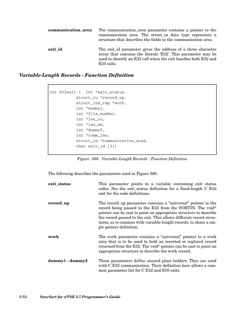
communication_area The communication_area parameter contains a pointer to thecommunication area. The struct_ca data type represents astructure that describes the fields in the communication area.
exit_id The exit_id parameter gives the address of a three characterarray that contains the literals 'E32'. This parameter may beused to identify an E32 call when the exit handles both E32 andE35 calls.
Variable-Length Records - Function Definition
The following describes the parameters used in Figure 380.
exit_status This parameter points to a variable containing exit statuscodes. See the exit_status definition for a fixed-length C E32exit for the code definitions.
record_up The record_up parameter contains a “universal” pointer to therecord being passed to the E32 from the SORTIN. The void*pointer can be cast to point an appropriate structure to describethe record passed to the exit. This allows different record struc-tures, as is common with variable-length records, to share a sin-gle pointer definition.
work The work parameter contains a “universal” pointer to a workarea that is to be used to hold an inserted or replaced recordreturned from the E32. The void* pointer can be cast to point anappropriate structure to describe the work record.
dummy1 - dummy2 These parameters define unused place holders. They are usedwith C E35 communication. Their definition here allows a com-mon parameter list for C E32 and E35 exits.
int E32exit ( int *exit_status,
struct_ru *record_up,
struct_ins_rep *work,
int *dummy1,
int *file_number,
int *len_ru,
int *len_wk,
int *dummy2,
int *comm_len,
struct_ca *communication_area,
char exit_id [3])
Figure 380. Variable-Length Records - Function Definition
SyncSort for z/VSE 3.7 Programmer’s Guide8.64
file_number This parameter points to an integer number that indicateswhich input file SyncSort is requesting input from. The numberstarts from 0 and increments by 4. (i.e. 0=file 1, 4=file 2, 8=file3, etc.) When E32 encounters end-of-file on the indicated file, itshould return with code 8, and SyncSort will no longer requestinput from that file.
len_ru This parameter points to a variable that defines the length ofthe SORTIN record passed to the E15. This is the length of therecord referred to in the record_up parameter.
len_wk This parameter points to a variable that defines the length ofthe record to be inserted or used as a replacement for therecord_up record. This is the length of the record referred to inthe work parameter. This field must be set by the exit when aninsert or replace operation is performed.
comm_len This parameter points to a variable that defines the communi-cation area length.
communication_area The communication_area parameter contains a pointer to thecommunication area. The struct_ca data type represents astructure that describes the fields in the communication area.
exit_id The exit_id parameter gives the address of a three characterarray that contains the literals 'E32'. This parameter may beused to identify an E32 call when the exit handles both E32 andE35 calls.
RETURN-CODE Codes (Fixed and Variable-Length Records)
The RETURN statement is used to return control to SyncSort. It must indicate one of thefollowing return values to indicate the action to be taken by SyncSort.
0 Accept this record. This instructs SyncSort to accept the (unaltered) recordin the record_up area.
This return code is valid only when EXIT is not specified on the INPFILcontrol statement.
8 Do not return to this exit. This instructs SyncSort to close the exit for theremainder of the sort application. This return code might be used at SOR-TIN end-of-file (exit_status code 08) to indicate that extra records will notbe added at this point. If SORTIN is present, the current input record andall subsequent records will be processed by SyncSort.
12 Accept this record. This instructs SyncSort to accept the record in theWORK area. This return code is valid only when EXIT is specified on theINPFIL control statement.
Chapter 8. User Exit Programs 8.65
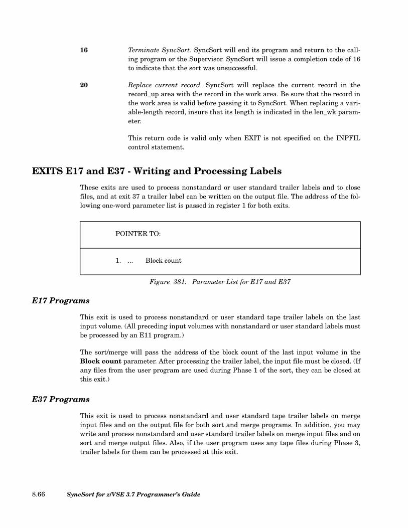
16 Terminate SyncSort. SyncSort will end its program and return to the call-ing program or the Supervisor. SyncSort will issue a completion code of 16to indicate that the sort was unsuccessful.
20 Replace current record. SyncSort will replace the current record in therecord_up area with the record in the work area. Be sure that the record inthe work area is valid before passing it to SyncSort. When replacing a vari-able-length record, insure that its length is indicated in the len_wk param-eter.
This return code is valid only when EXIT is not specified on the INPFILcontrol statement.
EXITS E17 and E37 - Writing and Processing Labels
These exits are used to process nonstandard or user standard trailer labels and to closefiles, and at exit 37 a trailer label can be written on the output file. The address of the fol-lowing one-word parameter list is passed in register 1 for both exits.
E17 Programs
This exit is used to process nonstandard or user standard tape trailer labels on the lastinput volume. (All preceding input volumes with nonstandard or user standard labels mustbe processed by an E11 program.)
The sort/merge will pass the address of the block count of the last input volume in theBlock count parameter. After processing the trailer label, the input file must be closed. (Ifany files from the user program are used during Phase 1 of the sort, they can be closed atthis exit.)
E37 Programs
This exit is used to process nonstandard and user standard tape trailer labels on mergeinput files and on the output file for both sort and merge programs. In addition, you maywrite and process nonstandard and user standard trailer labels on merge input files and onsort and merge output files. Also, if the user program uses any tape files during Phase 3,trailer labels for them can be processed at this exit.
POINTER TO:
1. ... Block count
Figure 381. Parameter List for E17 and E37
SyncSort for z/VSE 3.7 Programmer’s Guide8.66

After you have written and processed trailer labels, the files can be closed.
For a merge program, SyncSort provides a list of 4-byte block counts for the output file andfor each input file. If any of these files are unlabeled or have standard labels, these 4-byteentries will be set to zero. The address of the list will be passed in the Block count parame-ter in register 1.
For a sort program, the address of the block count for the output volume just processed willbe placed in register 1. This will point to a 4-byte entry.
Exits E18, E38, and E39—VSAM Exits
When VSAM files are sorted or merged, exit routines can be entered at E18, E38, or E39 forthe following reasons:
1. To supply passwords.
2. To supply an exit list for VSAM input and output files.
The following sections describe VSAM specific coding instructions for exits E18, E38, andE39.
Passwords for VSAM Files
SyncSort for z/VSE allows password-protected VSAM files to be used for input and output.When a password is needed for a VSAM file, the appropriate user routine is entered at exitE18 (for sort input), E38 (for merge input), and E39 (for sort/merge output) before the filesare opened by SyncSort. In the routine, the user can supply the required password(s). If theVSAM file is password-protected and a sort exit does not provide a password, SyncSort forz/VSE will either request that password to be entered at the operator’s console or ABENDdepending on the ATTEMPTS parameter of the DEFINE CLUSTER for the data set.
When a user activates the E18, E38, and E39 exits, register 1 will contain the address of a12-byte parameter list. Refer to Figure 382 for the format of a parameter list.
Chapter 8. User Exit Programs 8.67

The parameter list contains a 3-byte flag that indicates the purpose for which the exit rou-tine will be used. In this case, 'PWD' stands for password retrieval.
Note: If the user does not want a specific situation, the user routine should return toSyncSort leaving a return code of “0” in the Action Word. This code tells SyncSort to ignorethe entry.
When the VSAM exit routine gets initial control, the pointer to the password list will bezeros. To supply passwords, the user must create a password list and ensure that theparameter list pointer is set to the password list address.
The format of the password list is shown in Figure 383.
As soon as the user routine returns control after the password list is created, the ActionWord will be checked for one of the following hexadecimal codes:
0 Ignore this entry.
4 Accept passwords.
3 BYTES1
BYTE
REGISTER 1 C 'PWD' RES.
PASSWORD LIST
ACTION WORD
4 BYTES
Figure 382. E18, E38, and E39 VSAM Password Parameter List
FIRST ENTRY ADDITIONAL ENTRIES
2 BYTES 8 BYTES 8 BYTES
NO. OF ENTRIES (IN BINARY)
FILENAMEPASS-WORD
Figure 383. E18, E38, and E39 Password List Format
SyncSort for z/VSE 3.7 Programmer’s Guide8.68

8 Do not return to this exit for the exit list.
A user’s routine is entered only once at an exit for passwords. All necessary passwordsmust be supplied at that point.
Exit List for VSAM Files
An exit list for VSAM input and output data sets can be supplied using exits E18, E38, orE39. The exit list must be constructed using the VSAM EXLST macro. All VSAM exit rou-tines pointed to by this macro must return to VSAM by standard VSAM linkage. All con-ventions governing VSAM exit lists must be observed. Consult IBM’s VSE/ESA SystemMacro User’s Guide or VSE/VSAM User’s Guide and Application Programming.
SyncSort comes to the user’s sort/merge exit (containing the VSAM exit list and routines)once for each exit. The parameter list that the sort/merge passes to the exit has the formatshown in Figure 384.
After saving any registers that were used, the 3-byte flag should be checked. In this case,'EXL' stands for exit list. If it is not the proper flag, return to the sort/merge leaving returncode “0” in the Action Word.
The exit list address should be stored in the second word. In addition, a return should bemade to sort/merge with one of the following return codes in the Action Word; it is pointedto by the third word of the parameter list:
0 Ignore this entry.
4 Accept the exit list address.
8 Do not return to this sort/merge exit.
REGISTER 1 3 BYTES1
BYTE
PARAMETER LIST C 'EXL' RES.
ZEROS
ACTION WORD
4 BYTES
Figure 384. Parameter List Passed to the VSAM EXLST Exit
Chapter 8. User Exit Programs 8.69

Exit Coding Instructions
To assist the user in coding exits E18, E38, and E39, the following instructions are pro-vided. Four areas of information will be discussed for each exit. They include the building ofan exit’s parameter, password, and exit lists, and a specific coding procedure.
E18 Parameter List Contains the following data:
• Type indicator (C'PWD', which denotes that passwords arebeing requested, or C'EXL', which denotes that an exit listis being requested).
• Zeros (cleared for address of password list).
• Address of Action Word.
Note: The return code must be placed in the rightmost byte ofthe Action Word. Valid codes are: 0 - no reply, 4 - reply provided,and 8 - do not return.
E18 Password List Begins with a 2-byte entry count. It continues with a 16-byteentry for each password-protected sort input file. Refer to Fig-ure 383 for an E18 password list format.
E18 Exit List Must adhere to rules found in IBM’s VSE/ESA System MacroUser’s Guide or VSE/VSAM User’s Guide and Application Pro-gramming. Those routines to which the list points must usestandard VSAM linkage to return to VSAM.
Note: VSAM EXLST routines, indicated by the EXLST entry toE18/E38/E39, must not use the SAVE area indicated in register13. It is in use by VSAM. The user is responsible for providing aSAVE area.
E18 Routine Procedure E18 is entered twice, as follows:
• The first time, parameter 1 contains C'PWD' (plus apadding byte).
• The second time, parameter 1 contains C'EXL' (plus apadding byte).
If no reply is desired, place a code of “0” in the Action Word. Ifnot, place the address of the password or exit list (whichever isrequested) in parameter 2. Return with a code of "4".
SyncSort for z/VSE 3.7 Programmer’s Guide8.70
E38 Parameter List Contains the following data:
• Type indicator (C'PWD', which denotes passwords are beingrequested, or C'EXL', which denotes the exit list is beingrequested).
• Zeros (cleared for address of password list).
• Address of Action Word.
Note: The return code must be placed in the rightmost byte ofthe Action Word. Valid codes are: 0 - no reply, 4 - reply provided,and 8 - do not return.
E38 Password List Begins with a 2-byte entry count. It continues with a 16-byteentry for each password-protected merge input file. Refer toFigure 383 for an E38 password list format.
E38 Exit List Must adhere to rules found in IBM’s VSE/ESA System MacroUser’s Guide or VSE/VSAM User’s Guide and Application Pro-gramming. Those routines to which the list points must usestandard VSAM linkage to return to VSAM.
Note: VSAM EXLST routines, indicated by the EXLST entry toE18/E38/E39, must not use the SAVE area indicated in register13. It is in use by VSAM. The user is responsible for providing aSAVE area.
For end-of-file processing, the EODAD exit must not be usedbecause the sort will not be able to detect the end-of-file. In itsplace, use a LERAD exit. In addition, test the FDBK code for“4”, which indicates the end-of-file. Do not change the code asthe sort also uses it.
Note: The same exit list must be valid for all SORTIN files.
E38 Routine Procedure E38 is entered twice, as follows:
• The first time, parameter 1 contains C'PWD' (plus apadding byte).
• The second time, parameter 1 contains C'EXL' (plus apadding byte).
If no reply is desired, ensure a code of "0" is placed in the ActionWord. If not, place the address of the password or exit list(whichever is requested) in parameter 2. Return with a code of"4".
Chapter 8. User Exit Programs 8.71

E39 Parameter List Contains the following data:
• Type indicator (C'PWD', which denotes passwords are beingrequested, or C'EXL', which denotes the exit list is beingrequested).
• Zeros (cleared for address of password list).
• Address of Action Word.
Note: The return code must be placed in the rightmost byte ofthe Action Word. Valid codes are: 0 no reply, 4 reply provided,and 8 do not return.
E39 Password List Begins with a 2-byte entry count. It is followed by output filename and associated password pairs. Refer to Figure 383 for anE39 password list format.
E39 Exit List Must adhere to rules found in IBM’s VSE/ESA System MacroUser’s Guide or VSE/VSAM User’s Guide and Application Pro-gramming. Those routines to which the list points must usestandard VSAM linkage to return to VSAM.
Note: VSAM EXLST routines, indicated by the EXLST entry toE18/E38/E39, must not use the SAVE area indicated in register13. It is in use by VSAM. The user is responsible for providing aSAVE area.
E39 Routine Procedure E39 is entered twice, as follows:
• The first time, parameter 1 contains C'PWD' (plus apadding byte).
• The second time, parameter 1 contains C'EXL' (plus apadding byte).
If no reply is desired, place a code of “0” in the Action Word. Ifnot, place the address of the password or exit list (whichever isrequested) in parameter 2. Return with a code of “4”.
SyncSort for z/VSE 3.7 Programmer’s Guide8.72

Coding REXX Exits
The exit programs E15, E32, and E35 can be coded in REXX/VSE. A REXX exit program isindicated in the MODS control statement. A LIBDEF search chain for PROCs must beestablished to include the library where the REXX exit program is catalogued.
REXX Variables Provided by SyncSort
SyncSort provides a number of special REXX variables to facilitate the development ofREXX exits. These variables offer a simple, efficient means of establishing communicationbetween the exit and SyncSort.
SyncSort will automatically load these variables each time it calls a REXX exit. When theexit completes its work, it should use the following sequence of commands to return thevariables to SyncSort:
ADDRESS SYNCREXX 'TAKE'
RETURN
The following table describes the special REXX variables:
MODS PH1=(MYE15,EXEC,E15),PH3=(REXXE35,EXEC,E35)
Figure 385. Sample MODS control statement for REXX exits
VARIABLE FUNCTION
SYRECORD When the exit is entered, SYRECORD contains the current data record. The exit can accept the record, modify it, or add a new record; SYACTION should be set accordingly.
If SYRECORD is null, then SyncSort has no data remaining. When this happens, the exit can either CLOSE or can continue to INSERT new records.
Table 50. (Page 1 of 2) REXX Variables Provided by SyncSort
Chapter 8. User Exit Programs 8.73
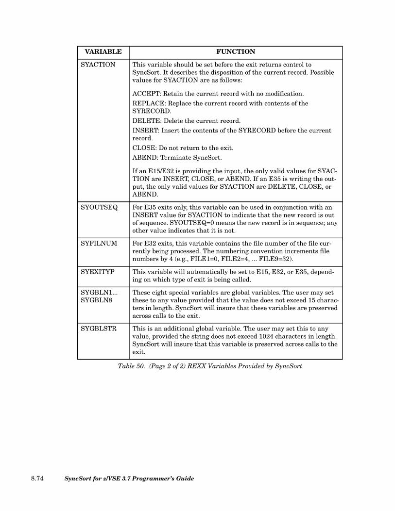
SYACTION This variable should be set before the exit returns control to SyncSort. It describes the disposition of the current record. Possible values for SYACTION are as follows:
ACCEPT: Retain the current record with no modification.REPLACE: Replace the current record with contents of the SYRECORD.DELETE: Delete the current record.INSERT: Insert the contents of the SYRECORD before the current record.CLOSE: Do not return to the exit.ABEND: Terminate SyncSort.
If an E15/E32 is providing the input, the only valid values for SYAC-TION are INSERT, CLOSE, or ABEND. If an E35 is writing the out-put, the only valid values for SYACTION are DELETE, CLOSE, or ABEND.
SYOUTSEQ For E35 exits only, this variable can be used in conjunction with an INSERT value for SYACTION to indicate that the new record is out of sequence. SYOUTSEQ=0 means the new record is in sequence; any other value indicates that it is not.
SYFILNUM For E32 exits, this variable contains the file number of the file cur-rently being processed. The numbering convention increments file numbers by 4 (e.g., FILE1=0, FILE2=4, ... FILE9=32).
SYEXITYP This variable will automatically be set to E15, E32, or E35, depend-ing on which type of exit is being called.
SYGBLN1... SYGBLN8
These eight special variables are global variables. The user may set these to any value provided that the value does not exceed 15 charac-ters in length. SyncSort will insure that these variables are preserved across calls to the exit.
SYGBLSTR This is an additional global variable. The user may set this to any value, provided the string does not exceed 1024 characters in length. SyncSort will insure that this variable is preserved across calls to the exit.
VARIABLE FUNCTION
Table 50. (Page 2 of 2) REXX Variables Provided by SyncSort
SyncSort for z/VSE 3.7 Programmer’s Guide8.74

Sample REXX Exit
The following example illustrates a REXX exit that will count the number of records thatare passed to the exit and convert the first 20 bytes of each record to upper case:
If syrecord='' Then
Do
syaction='CLOSE'
Say 'REXX' syexityp 'counted' sygbln1 'records'
End
Else
Do
sygbln1 = sygbln1 + 1
Parse Var syrecord to_upper 21 no_change
syrecord=Translate(to_upper) || no_change
syaction='REPLACE'
End
Address SYNCREXX 'TAKE'
Return
Figure 386. Sample REXX Exit
Chapter 8. User Exit Programs 8.75

SyncSort for z/VSE 3.7 Programmer’s Guide8.76
Chapter 9. Creating VSAM Alternate Index Files with SyncSort
Introduction
This chapter describes SYNCBIX, SyncSort’s high performance replacement for theBLDINDEX process performed by Access Methods Services (IDCAMS). SYNCBIX inter-faces with SyncSort for z/VSE to allow efficient reading of the base cluster, fast extractingof the record pointer information, primary and alternate keys, and high performance sort-ing of these records.
VSAM alternate index is one of VSAM’s most useful features. It provides an alternatemeans to access records in a base cluster, through different keys. The base cluster, can bean Entry Sequenced Data Set (ESDS) or a Key Sequenced Data Set (KSDS). KSDS andESDS alternate index files can be defined as either a UNIQUE key data set or as aNONUNIQUE key data set:
• UNIQUE indicates that every alternate key is in one and only one data record in thebase cluster.
• NONUNIQUE indicates that an alternate key can be in several records in the basecluster.
The prime key of a KSDS file must be defined as a unique key data set.
Chapter 9. Creating VSAM Alternate Index Files with SyncSort 9.1

Steps to Create an Alternate Index
In order to establish an alternate index to access a base cluster, the following steps are nec-essary, whether you are using BLDINDEX or SYNCBIX. Note that only the fifth item,building the index, differs between BLDINDEX and SYNCBIX.
1. Create the VSAM base file with the IDCAMS DEFINE CLUSTER command.
2. Load the base cluster with data.
3. Define the alternate index file with the IDCAMS DEFINE AIX command.
4. Define a path through the alternate index to the base cluster with a DEFINE PATHcommand for a KSDS base file.
5. Build the alternate index with the BLDINDEX process of IDCAMS or with SYNCBIX.Using SYNCBIX speeds the process because SYNCBIX uses the high-performancesorting of SyncSort for z/VSE. The process is conceptually divided into three steps:reading, sorting, and writing to output:
• The entire base cluster is read and the record pointer information, primary key andalternate key are extracted.
• The extracted data is sorted on the alternate key. This process may be completedentirely in virtual storage or for larger files require the use of disk work files.
• The sorted information is formatted into alternate index data records that areloaded directly into the alternate index cluster.
Sample Alternate Index Definitions: IDCAMS and SYNCBIX
The figures below show JCL and control statements for creating alternative indexes withIDCAMS and SYNCBIX. The pairing highlights the difference between IDCAMS andSyncSort’s SYNCBIX. Note that each pair is identical except for Step 4. Thus, only theactual index building step of IDCAMS (Step 4) requires changes in order to use SYNCBIX.
The following is a generalized Step 4 using SYNCBIX:
SyncSort for z/VSE 3.7 Programmer’s Guide9.2
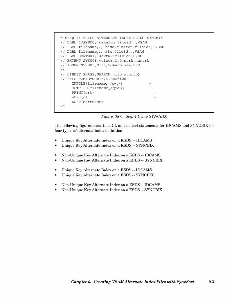
The following figures show the JCL and control statements for IDCAMS and SYNCBIX forfour types of alternate index definition:
• Unique Key Alternate Index on a KSDS -- IDCAMS• Unique Key Alternate Index on a KSDS -- SYNCBIX
• Non-Unique Key Alternate Index on a KSDS -- IDCAMS• Non-Unique Key Alternate Index on a KSDS -- SYNCBIX
• Unique Key Alternate Index on a ESDS -- IDCAMS• Unique Key Alternate Index on a ESDS -- SYNCBIX
• Non-Unique Key Alternate Index on a ESDS -- IDCAMS• Non-Unique Key Alternate Index on a ESDS -- SYNCBIX
* Step 4: BUILD ALTERNATE INDEX USING SYNCBIX// DLBL IJSYSUC,'catalog.fileid',,VSAM// DLBL filenamei.,'base.cluster.fileid',,VSAM// DLBL filenameo.,'aix.fileid',,VSAM// DLBL SORTWK1,'sortwk.fileid',0,SD// EXTENT SYS003,volser,1,0,strk,numtrk// ASSGN SYS003,DISK,VOL=volser,SHR/*// LIBDEF PHASE,SEARCH=(lib.sublib)// EXEC PGM=SYNCBIX,SIZE=512K
INFILE(filenamei</pwi>) -OUTFILE(filenameo</pwo>) -PRINT(prt) -WORK(n) -SORT(sortname)
/*
Figure 387. Step 4 Using SYNCBIX
Chapter 9. Creating VSAM Alternate Index Files with SyncSort 9.3

// JOB AIX1AMS** STEP 1. DEFINE KSDS BASE CLUSTER*// EXEC PGM=IDCAMS,SIZE=AUTODEFINE CLUSTER( NAME(KSDS.BASE.CLUSTER) -
FREESPACE(10 5) -INDEXED -KEYS(4 28) -VOLUMES(VOL001)) -
DATA( NAME(KSDS.BASE.CLUSTER.DATA) -RECORDS(1000) RECORDSIZE(100 100)) -
INDEX( NAME(KSDS.BASE.CLUSTER.INDEX)) -CATALOG(KSDS.USER.CATALOG)
/** STEP 2. LOAD KSDS BASE CLUSTER*// EXEC PGM=LOADKSDS
.
.
./** STEP 3. DEFINE ALTERNATE INDEX AND PATH*// EXEC PGM=IDCAMS,SIZE=AUTODEFINE ALTERNATEINDEX( NAME(KSDS.AIX.CLUSTER) -
FREESPACE(5 5) -KEYS(8 12) -RELATE(KSDS.BASE.CLUSTER) -UNIQUEKEY -UPGRADE -VOLUMES(VOL001)) -
DATA( NAME(KSDS.AIX.CLUSTER.DATA) -RECORDS(1000) RECORDSIZE(50 50)) -
INDEX( NAME(KSDS.AIX.CLUSTER.INDEX)) -CATALOG(KSDS.USER.CATALOG)
DEFINE PATH( NAME(PATH.TO.KSDS.BASE.CLUSTER) -PATHENTRY(KSDS.AIX.CLUSTER)) -CATALOG(KSDS.USER.CATALOG)
/** STEP 4. BUILD ALTERNATE INDEX USING IDCAMS*// EXEC PGM=IDCAMS,SIZE=AUTOBLDINDEX INDATASET(KSDS.BASE.CLUSTER) -
OUTDATASET(KSDS.AIX.CLUSTER) -WORKVOLUMES(VOL001) -CATALOG(KSDS.USER.CATALOG)
/*/&
Figure 388. Unique Key Alternate Index on a KSDS -- IDCAMS
SyncSort for z/VSE 3.7 Programmer’s Guide9.4
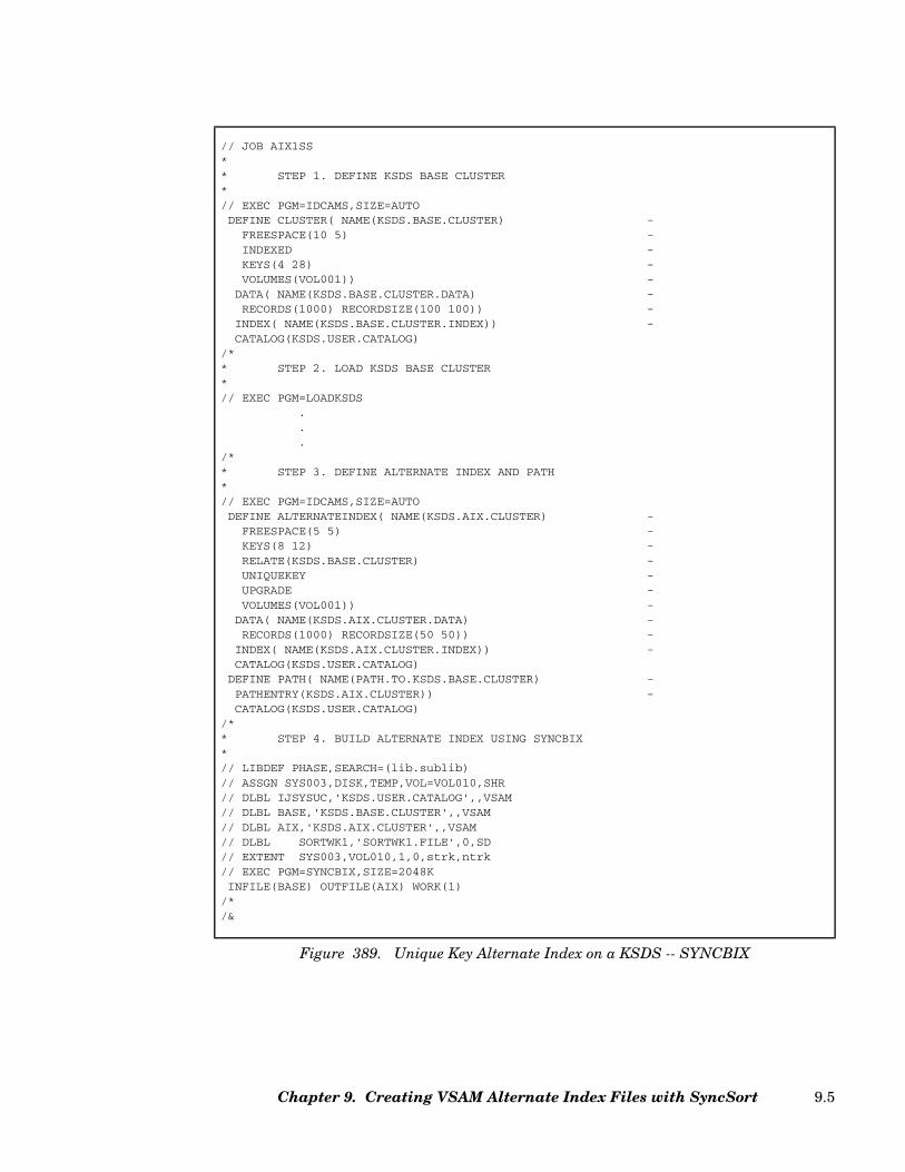
// JOB AIX1SS** STEP 1. DEFINE KSDS BASE CLUSTER*// EXEC PGM=IDCAMS,SIZE=AUTODEFINE CLUSTER( NAME(KSDS.BASE.CLUSTER) -
FREESPACE(10 5) -INDEXED -KEYS(4 28) -VOLUMES(VOL001)) -
DATA( NAME(KSDS.BASE.CLUSTER.DATA) -RECORDS(1000) RECORDSIZE(100 100)) -
INDEX( NAME(KSDS.BASE.CLUSTER.INDEX)) -CATALOG(KSDS.USER.CATALOG)
/** STEP 2. LOAD KSDS BASE CLUSTER*// EXEC PGM=LOADKSDS
.
.
./** STEP 3. DEFINE ALTERNATE INDEX AND PATH*// EXEC PGM=IDCAMS,SIZE=AUTODEFINE ALTERNATEINDEX( NAME(KSDS.AIX.CLUSTER) -
FREESPACE(5 5) -KEYS(8 12) -RELATE(KSDS.BASE.CLUSTER) -UNIQUEKEY -UPGRADE -VOLUMES(VOL001)) -
DATA( NAME(KSDS.AIX.CLUSTER.DATA) -RECORDS(1000) RECORDSIZE(50 50)) -
INDEX( NAME(KSDS.AIX.CLUSTER.INDEX)) -CATALOG(KSDS.USER.CATALOG)
DEFINE PATH( NAME(PATH.TO.KSDS.BASE.CLUSTER) -PATHENTRY(KSDS.AIX.CLUSTER)) -CATALOG(KSDS.USER.CATALOG)
/** STEP 4. BUILD ALTERNATE INDEX USING SYNCBIX*// LIBDEF PHASE,SEARCH=(lib.sublib)// ASSGN SYS003,DISK,TEMP,VOL=VOL010,SHR// DLBL IJSYSUC,'KSDS.USER.CATALOG',,VSAM// DLBL BASE,'KSDS.BASE.CLUSTER',,VSAM// DLBL AIX,'KSDS.AIX.CLUSTER',,VSAM// DLBL SORTWK1,'SORTWK1.FILE',0,SD// EXTENT SYS003,VOL010,1,0,strk,ntrk// EXEC PGM=SYNCBIX,SIZE=2048KINFILE(BASE) OUTFILE(AIX) WORK(1)
/*/&
Figure 389. Unique Key Alternate Index on a KSDS -- SYNCBIX
Chapter 9. Creating VSAM Alternate Index Files with SyncSort 9.5

// JOB AIX2AMS** STEP 1. DEFINE KSDS BASE CLUSTER*// EXEC PGM=IDCAMS,SIZE=AUTODEFINE CLUSTER( NAME(KSDS.BASE.CLUSTER) -
FREESPACE(10 5) -INDEXED -KEYS(8 12) -VOLUMES(VOL001)) -
DATA( NAME(KSDS.BASE.CLUSTER.DATA) -RECORDS(1000) RECORDSIZE(100 100)) -
INDEX( NAME(KSDS.BASE.CLUSTER.INDEX)) -CATALOG(KSDS.USER.CATALOG)
/** STEP 2. LOAD KSDS BASE CLUSTER*// EXEC PGM=LOADKSDS
.
.
./** STEP 3. DEFINE ALTERNATE INDEX AND PATH*// EXEC PGM=IDCAMS,SIZE=AUTODEFINE ALTERNATEINDEX( NAME(KSDS.AIX.CLUSTER) -
FREESPACE(5 5) -KEYS(4 28) -RELATE(KSDS.BASE.CLUSTER) -NONUNIQUEKEY -UPGRADE -VOLUMES(VOL001)) -
DATA( NAME(KSDS.AIX.CLUSTER.DATA) -RECORDS(1000) RECORDSIZE(50 50)) -
INDEX( NAME(KSDS.AIX.CLUSTER.INDEX)) -CATALOG(KSDS.USER.CATALOG)
DEFINE PATH( NAME(PATH.TO.KSDS.BASE.CLUSTER) -PATHENTRY(KSDS.AIX.CLUSTER)) -CATALOG(KSDS.USER.CATALOG)
/** STEP 4. BUILD ALTERNATE INDEX USING IDCAMS*// EXEC PGM=IDCAMS,SIZE=AUTOBLDINDEX INDATASET(KSDS.BASE.CLUSTER) -
OUTDATASET(KSDS.AIX.CLUSTER) -WORKVOLUMES(VOL001) -CATALOG(KSDS.USER.CATALOG)
/*/&
Figure 390. Non-Unique Key Alternate Index on a KSDS -- IDCAMS
SyncSort for z/VSE 3.7 Programmer’s Guide9.6

// JOB AIX2SS** STEP 1. DEFINE KSDS BASE CLUSTER*// EXEC PGM=IDCAMS,SIZE=AUTODEFINE CLUSTER( NAME(KSDS.BASE.CLUSTER) -
FREESPACE(10 5) -INDEXED -KEYS(8 12) -VOLUMES(VOL001)) -
DATA( NAME(KSDS.BASE.CLUSTER.DATA) -RECORDS(1000) RECORDSIZE(100 100)) -
INDEX( NAME(KSDS.BASE.CLUSTER.INDEX)) -CATALOG(KSDS.USER.CATALOG)
/** STEP 2. LOAD KSDS BASE CLUSTER*// EXEC PGM=LOADKSDS
.
.
./** STEP 3. DEFINE ALTERNATE INDEX AND PATH*// EXEC PGM=IDCAMS,SIZE=AUTODEFINE ALTERNATEINDEX( NAME(KSDS.AIX.CLUSTER) -
FREESPACE(5 5) -KEYS(4 28) -RELATE(KSDS.BASE.CLUSTER) -NONUNIQUEKEY -UPGRADE -VOLUMES(VOL001)) -
DATA( NAME(KSDS.AIX.CLUSTER.DATA) -RECORDS(1000) RECORDSIZE(50 50)) -
INDEX( NAME(KSDS.AIX.CLUSTER.INDEX)) -CATALOG(KSDS.USER.CATALOG)
DEFINE PATH( NAME(PATH.TO.KSDS.BASE.CLUSTER) -PATHENTRY(KSDS.AIX.CLUSTER)) -CATALOG(KSDS.USER.CATALOG)
/** STEP 4. BUILD ALTERNATE INDEX USING SYNCBIX*// LIBDEF PHASE,SEARCH=(lib.sublib)// ASSGN SYS003,DISK,TEMP,VOL=VOL010,SHR// DLBL IJSYSUC,'KSDS.USER.CATALOG',,VSAM// DLBL BASE,'KSDS.BASE.CLUSTER',,VSAM// DLBL AIX,'KSDS.AIX.CLUSTER',,VSAM// DLBL SORTWK1,'SORTWK1.FILE',0,SD// EXTENT SYS003,VOL010,1,0,strk,ntrk// EXEC PGM=SYNCBIX,SIZE=2048KINFILE(BASE) OUTFILE(AIX) WORK(1)
/*/&
Figure 391. Non-Unique Key Alternate Index on a KSDS -- SYNCBIX
Chapter 9. Creating VSAM Alternate Index Files with SyncSort 9.7

// JOB AIX3AMS** STEP 1. DEFINE ESDS BASE CLUSTER*// EXEC PGM=IDCAMS,SIZE=AUTODEFINE CLUSTER( NAME(ESDS.BASE.CLUSTER) -
NONINDEXED -VOLUMES(VOL001)) -
DATA( NAME(ESDS.BASE.CLUSTER.DATA) -RECORDS(1000) RECORDSIZE(100 100)) -
CATALOG(ESDS.USER.CATALOG)/** STEP 2. LOAD ESDS BASE CLUSTER*// EXEC PGM=LOADESDS
.
.
./** STEP 3. DEFINE ALTERNATE INDEX AND PATH*// EXEC PGM=IDCAMS,SIZE=AUTODEFINE ALTERNATEINDEX( NAME(ESDS.AIX.CLUSTER) -
FREESPACE(5 5) -KEYS(8 12) -RELATE(ESDS.BASE.CLUSTER) -UNIQUEKEY -UPGRADE -VOLUMES(VOL001)) -
DATA( NAME(ESDS.AIX.CLUSTER.DATA) -RECORDS(1000) RECORDSIZE(50 50)) -
INDEX( NAME(ESDS.AIX.CLUSTER.INDEX)) -CATALOG(ESDS.USER.CATALOG)
DEFINE PATH( NAME(PATH.TO.ESDS.BASE.CLUSTER) -PATHENTRY(ESDS.AIX.CLUSTER)) -CATALOG(ESDS.USER.CATALOG)
/** STEP 4. BUILD ALTERNATE INDEX USING IDCAMS*// EXEC PGM=IDCAMS,SIZE=AUTOBLDINDEX INDATASET(ESDS.BASE.CLUSTER) -
OUTDATASET(ESDS.AIX.CLUSTER) -WORKVOLUMES(VOL001) -CATALOG(ESDS.USER.CATALOG)
/*/&
Figure 392. Unique Key Alternate Index on an ESDS -- IDCAMS
SyncSort for z/VSE 3.7 Programmer’s Guide9.8

// JOB AIX3SS** STEP 1. DEFINE ESDS BASE CLUSTER*// EXEC PGM=IDCAMS,SIZE=AUTODEFINE CLUSTER( NAME(ESDS.BASE.CLUSTER) -
NONINDEXED -VOLUMES(VOL001)) -
DATA( NAME(ESDS.BASE.CLUSTER.DATA) -RECORDS(1000) RECORDSIZE(100 100)) -
CATALOG(ESDS.USER.CATALOG)/** STEP 2. LOAD ESDS BASE CLUSTER*// EXEC PGM=LOADESDS
.
.
./** STEP 3. DEFINE ALTERNATE INDEX AND PATH*// EXEC PGM=IDCAMS,SIZE=AUTODEFINE ALTERNATEINDEX( NAME(ESDS.AIX.CLUSTER) -
FREESPACE(5 5) -KEYS(8 12) -RELATE(ESDS.BASE.CLUSTER) -UNIQUEKEY -UPGRADE -VOLUMES(VOL001)) -
DATA( NAME(ESDS.AIX.CLUSTER.DATA) -RECORDS(1000) RECORDSIZE(50 50)) -
INDEX( NAME(ESDS.AIX.CLUSTER.INDEX)) -CATALOG(ESDS.USER.CATALOG)
DEFINE PATH( NAME(PATH.TO.ESDS.BASE.CLUSTER) -PATHENTRY(ESDS.AIX.CLUSTER)) -CATALOG(ESDS.USER.CATALOG)
/** STEP 4. BUILD ALTERNATE INDEX USING SYNCBIX*// LIBDEF PHASE,SEARCH=(lib.sublib)// ASSGN SYS003,DISK,TEMP,VOL=VOL010,SHR// DLBL IJSYSUC,'ESDS.USER.CATALOG',,VSAM// DLBL BASE,'ESDS.BASE.CLUSTER',,VSAM// DLBL AIX,'ESDS.AIX.CLUSTER',,VSAM// DLBL SORTWK1,'SORTWK1.FILE',0,SD// EXTENT SYS003,VOL010,1,0,strk,ntrk// EXEC PGM=SYNCBIX,SIZE=2048KINFILE(BASE) OUTFILE(AIX) WORK(1)
/*/&
Figure 393. Unique Key Alternate Index on an ESDS -- SYNCBIX
Chapter 9. Creating VSAM Alternate Index Files with SyncSort 9.9

// JOB AIX4AMS** STEP 1. DEFINE ESDS BASE CLUSTER*// EXEC PGM=IDCAMS,SIZE=AUTODEFINE CLUSTER( NAME(ESDS.BASE.CLUSTER) -
NONINDEXED -VOLUMES(VOL001)) -
DATA( NAME(ESDS.BASE.CLUSTER.DATA) -RECORDS(1000) RECORDSIZE(100 100)) -
CATALOG(ESDS.USER.CATALOG)/** STEP 2. LOAD ESDS BASE CLUSTER*// EXEC PGM=LOADESDS
.
.
./** STEP 3. DEFINE ALTERNATE INDEX AND PATH*// EXEC PGM=IDCAMS,SIZE=AUTODEFINE ALTERNATEINDEX( NAME(ESDS.AIX.CLUSTER) -
FREESPACE(5 5) -KEYS(4 28) -RELATE(ESDS.BASE.CLUSTER) -NONUNIQUEKEY -UPGRADE -VOLUMES(VOL001)) -
DATA( NAME(ESDS.AIX.CLUSTER.DATA) -RECORDS(1000) RECORDSIZE(50 50)) -
INDEX( NAME(ESDS.AIX.CLUSTER.INDEX)) -CATALOG(ESDS.USER.CATALOG)
DEFINE PATH( NAME(PATH.TO.ESDS.BASE.CLUSTER) -PATHENTRY(ESDS.AIX.CLUSTER)) -CATALOG(ESDS.USER.CATALOG)
/** STEP 4. BUILD ALTERNATE INDEX USING IDCAMS*// EXEC PGM=IDCAMS,SIZE=AUTOBLDINDEX INDATASET(ESDS.BASE.CLUSTER) -
OUTDATASET(ESDS.AIX.CLUSTER) -WORKVOLUMES(VOL001) -CATALOG(ESDS.USER.CATALOG)
/*/&
Figure 394. Non-Unique Key Alternate Index on an ESDS -- IDCAMS
SyncSort for z/VSE 3.7 Programmer’s Guide9.10
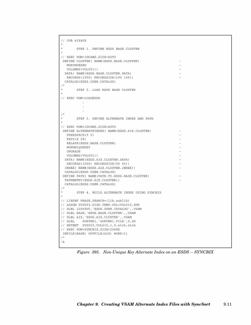
// JOB AIX4SS** STEP 1. DEFINE ESDS BASE CLUSTER*// EXEC PGM=IDCAMS,SIZE=AUTODEFINE CLUSTER( NAME(ESDS.BASE.CLUSTER) -
NONINDEXED -VOLUMES(VOL001)) -
DATA( NAME(ESDS.BASE.CLUSTER.DATA) -RECORDS(1000) RECORDSIZE(100 100)) -
CATALOG(ESDS.USER.CATALOG)/** STEP 2. LOAD ESDS BASE CLUSTER*// EXEC PGM=LOADESDS
.
.
./** STEP 3. DEFINE ALTERNATE INDEX AND PATH*// EXEC PGM=IDCAMS,SIZE=AUTODEFINE ALTERNATEINDEX( NAME(ESDS.AIX.CLUSTER) -
FREESPACE(5 5) -KEYS(4 28) -RELATE(ESDS.BASE.CLUSTER) -NONUNIQUEKEY -UPGRADE -VOLUMES(VOL001)) -
DATA( NAME(ESDS.AIX.CLUSTER.DATA) -RECORDS(1000) RECORDSIZE(50 50)) -
INDEX( NAME(ESDS.AIX.CLUSTER.INDEX)) -CATALOG(ESDS.USER.CATALOG)
DEFINE PATH( NAME(PATH.TO.ESDS.BASE.CLUSTER) -PATHENTRY(ESDS.AIX.CLUSTER)) -CATALOG(ESDS.USER.CATALOG)
/** STEP 4. BUILD ALTERNATE INDEX USING SYNCBIX*// LIBDEF PHASE,SEARCH=(lib.sublib)// ASSGN SYS003,DISK,TEMP,VOL=VOL010,SHR// DLBL IJSYSUC,'ESDS.USER.CATALOG',,VSAM// DLBL BASE,'ESDS.BASE.CLUSTER',,VSAM// DLBL AIX,'ESDS.AIX.CLUSTER',,VSAM// DLBL SORTWK1,'SORTWK1.FILE',0,SD// EXTENT SYS003,VOL010,1,0,strk,ntrk// EXEC PGM=SYNCBIX,SIZE=2048KINFILE(BASE) OUTFILE(AIX) WORK(1)
/*/&
Figure 395. Non-Unique Key Alternate Index on an ESDS -- SYNCBIX
Chapter 9. Creating VSAM Alternate Index Files with SyncSort 9.11
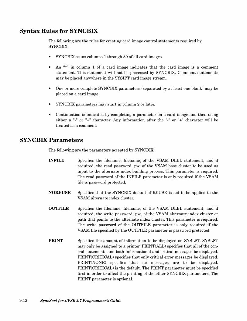
Syntax Rules for SYNCBIX
The following are the rules for creating card image control statements required by SYNCBIX:
• SYNCBIX scans columns 1 through 80 of all card images.
• An “*” in column 1 of a card image indicates that the card image is a commentstatement. This statement will not be processed by SYNCBIX. Comment statementsmay be placed anywhere in the SYSIPT card image stream.
• One or more complete SYNCBIX parameters (separated by at least one blank) may beplaced on a card image.
• SYNCBIX parameters may start in column 2 or later.
• Continuation is indicated by completing a parameter on a card image and then usingeither a "-" or "+" character. Any information after the "-" or "+" character will betreated as a comment.
SYNCBIX Parameters
The following are the parameters accepted by SYNCBIX:
INFILE Specifies the filename, filenamei of the VSAM DLBL statement, and ifrequired, the read password, pwi of the VSAM base cluster to be used asinput to the alternate index building process. This parameter is required.The read password of the INFILE parameter is only required if the VSAMfile is password protected.
NOREUSE Specifies that the SYNCBIX default of REUSE is not to be applied to theVSAM alternate index cluster.
OUTFILE Specifies the filename, filenameo of the VSAM DLBL statement, and ifrequired, the write password, pwo of the VSAM alternate index cluster orpath that points to the alternate index cluster. This parameter is required.The write password of the OUTFILE parameter is only required if theVSAM file specified by the OUTFILE parameter is password protected.
PRINT Specifies the amount of information to be displayed on SYSLST. SYSLSTmay only be assigned to a printer. PRINT(ALL) specifies that all of the con-trol statements and both informational and critical messages be displayed.PRINT(CRITICAL) specifies that only critical error messages be displayed.PRINT(NONE) specifies that no messages are to be displayed.PRINT(CRITICAL) is the default. The PRINT parameter must be specifiedfirst in order to affect the printing of the other SYNCBIX parameters. ThePRINT parameter is optional.
SyncSort for z/VSE 3.7 Programmer’s Guide9.12
SORT Specifies the phase name of SyncSort for z/VSE. The default name is SORT,which is almost always the correct name. This parameter is optional, andshould not be specified without consultation with the system programmerwho installed SyncSort for z/VSE.
WORK Specifies the total number in decimal of disk files to be used for SORTWK.The value of n must be between 1 and 9 and the default value of n is 1. Thisparameter is optional. You must provide n SORTWKx DLBLs in your JCLto be used if the data cannot be processed completely in virtual storage. See“Setting up Disk Work File Statements” on page 5.5 for more details.
SYNCBIX Job Control Statements
The following are the job control statements (JCL) required by SYNCBIX:
IJSYSUC DLBL Specifies the VSAM catalog that contains both theVSAM base cluster and the VSAM alternate indexfile. This statement is not needed if both files arecataloged in the master catalog or if the correct cat-alog is defined as IJSYSUC in standard labels. Thisstatement is also not needed if both of the DLBLsfor the base cluster and the alternate index clusteruse the CAT=parameter on their DLBLs.
filenamei DLBL Specifies the VSAM file that is the base cluster forthe alternate index file. The INFILE parameterspecifies the value of filenamei. This DLBL state-ment may use the CAT=parameter to indicate theVSAM catalog that owns this cluster.
filenameo DLBL Specifies the VSAM file that is the alternate indexcluster that is to created. The OUTFILE parameterspecifies the value of filenameo. This DLBL state-ment may use the CAT=parameter to indicate theVSAM catalog that owns this cluster.
SORTWKx DLBL/EXTENT/ASSGN Specifies the SORTWK disk space to be used bySyncSort for z/VSE if the BLDINDEX process is toolarge to fit completely in virtual storage. Thereshould be one set of SORTWK DLBL/EXTENT/ASSGN statements for each SORTWK specified bythe WORK parameter. For more details onSORTWK JCL, see “Setting up Disk Work FileStatements” on page 5.5. These statements may notbe required if they already exist in the LABEL area.
Chapter 9. Creating VSAM Alternate Index Files with SyncSort 9.13

LIBDEF Defines the VSE library and sublibrary, (lib.sublib),which contains SYNCBIX and SyncSort for z/VSE.This statement may not be required if the SyncSortfor z/VSE library is in the permanent LIBDEFchain.
EXEC Specifies that the program to be executed isSYNCBIX and defines the virtual storage it shoulduse. SYNCBIX will generally execute moreefficiently in larger virtual storage, but reading andwriting the VSAM files efficiently requires asignificant amount of GETVIS storage. UsingSIZE=512K or SIZE=1024K should be reasonable inmost cases. However, when the maximum recordlength of the alternate index file is greater than32K, the “SIZE=” value chosen must include themaximum record length (i.e., SIZE=512K+nnnn orSIZE=1024K+nnnn, where nnnn indicates themaximum record length defined for the alternateindex files).
SYNCBIX Messages
SYNCBIX messages are written to SYSLST with a record length of 121 bytes and SYSLSTmust be ASSGNed to a print device.
SYNCBIX messages have the prefix SBIX. (See “SYNCBIX Messages” on page 12.35 for adescription of SYNCBIX messages.)
SyncSort for z/VSE 3.7 Programmer’s Guide9.14

Chapter 10. SyncSort Reentrant Access Method Operation
Overview
SyncSort Reentrant Access Method (SSRAM) is an interface between an invoking programand SyncSort for z/VSE. SSRAM allows a program to invoke up to sixteen concurrent sortseach of which can manipulate the same data differently.
Syntax Conventions
In this chapter, the following stylistic conventions apply. Lowercase characters in call syn-tax, parameter lists, and error messages indicate variable information or information thatyou must supply. Uppercase characters indicate literal information. Brackets in call syntaxenclose optional parameters.
Linking to SSRAM
SSRAM has a language interface that must be linkedited to the invoking program in orderto use SSRAM. The same language interface is used regardless of the language in whichthe invoking program is written. The language interface interprets the sort call routines.
Following is sample JCL to linkedit the interface to an invoking Assembler program.
Chapter 10. SyncSort Reentrant Access Method Operation 10.1
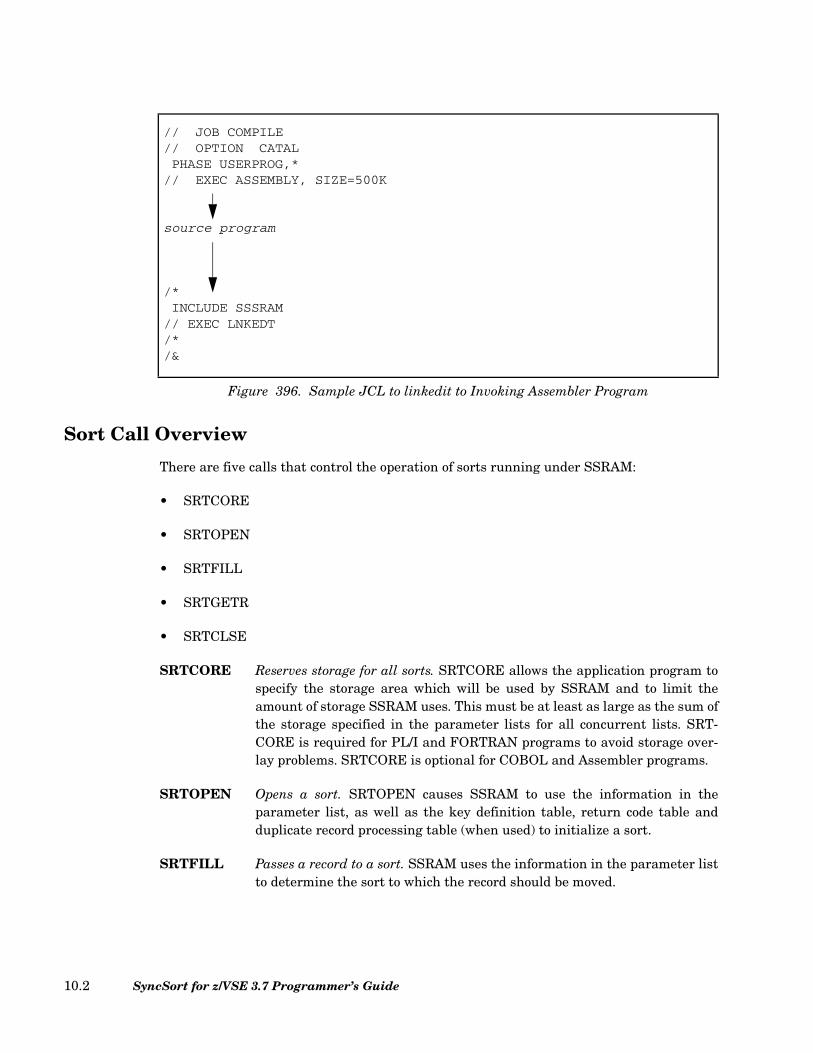
Sort Call Overview
There are five calls that control the operation of sorts running under SSRAM:
• SRTCORE
• SRTOPEN
• SRTFILL
• SRTGETR
• SRTCLSE
SRTCORE Reserves storage for all sorts. SRTCORE allows the application program tospecify the storage area which will be used by SSRAM and to limit theamount of storage SSRAM uses. This must be at least as large as the sum ofthe storage specified in the parameter lists for all concurrent lists. SRT-CORE is required for PL/I and FORTRAN programs to avoid storage over-lay problems. SRTCORE is optional for COBOL and Assembler programs.
SRTOPEN Opens a sort. SRTOPEN causes SSRAM to use the information in theparameter list, as well as the key definition table, return code table andduplicate record processing table (when used) to initialize a sort.
SRTFILL Passes a record to a sort. SSRAM uses the information in the parameter listto determine the sort to which the record should be moved.
// JOB COMPILE// OPTION CATALPHASE USERPROG,*
// EXEC ASSEMBLY, SIZE=500K
source program
/*INCLUDE SSSRAM
// EXEC LNKEDT/*/&
Figure 396. Sample JCL to linkedit to Invoking Assembler Program
SyncSort for z/VSE 3.7 Programmer’s Guide10.2
SRTGETR Retrieves a record from a sort. The first SRTGETR call tells the sort tomerge the sorted strings and moves a sorted record to the work area. Subse-quent SRTGETR calls move a sorted record to the work area of the invokingprogram.
SRTCLSE Ends a sort. The CLOSE call terminates the sort for the specified parame-ter list.
Parameter List Overview
A unique parameter list is required for each sort that is initiated through SSRAM. Theapplication program stores information into this area, which SSRAM uses to run the sort.SSRAM then sets a flag in the parameter list, which can be tested by the application pro-gram. The list must be fullword aligned. The fields of this list are described here; language-specific details are in later sections.
file id This identifies the SSRAM work file name, as specified on theDLBL job control statement. The work file must be on DASD, noton tape.
logical unit number This identifies the LUN for the work file, as specified in theSYSnnn values on the ASSGN and EXTENT job control state-ments. nnn must be between 000 and 221.
storage This sets the amount of storage that SSRAM will use for this sort.At least 64K is required; increased storage improves sort perfor-mance.
record length This specifies the record length (maximum record length for vari-able-length records).
end-of-file flag This is used by SSRAM to return a flag indicating when end-of-filehas been reached.
key definition table This specifies the sort keys and the sorting order.
The Key Definition Table
Each parameter list contains a key definition table. The key definition table defines thefields or sort keys by which records will be sorted. The key definition table also determinesthe order, ascending or descending, in which the sort keys will be sorted.
The key definition table can be 256 characters long. Following is the format for the key def-inition table.
Chapter 10. SyncSort Reentrant Access Method Operation 10.3
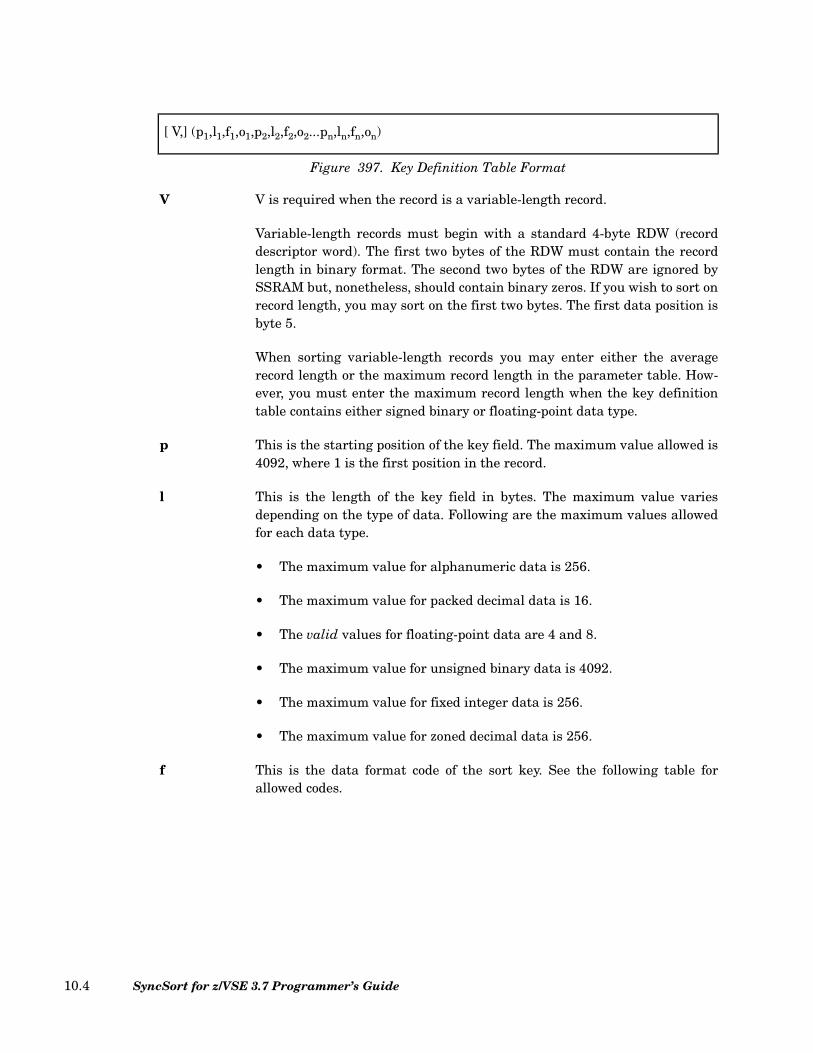
V V is required when the record is a variable-length record.
Variable-length records must begin with a standard 4-byte RDW (recorddescriptor word). The first two bytes of the RDW must contain the recordlength in binary format. The second two bytes of the RDW are ignored bySSRAM but, nonetheless, should contain binary zeros. If you wish to sort onrecord length, you may sort on the first two bytes. The first data position isbyte 5.
When sorting variable-length records you may enter either the averagerecord length or the maximum record length in the parameter table. How-ever, you must enter the maximum record length when the key definitiontable contains either signed binary or floating-point data type.
p This is the starting position of the key field. The maximum value allowed is4092, where 1 is the first position in the record.
l This is the length of the key field in bytes. The maximum value variesdepending on the type of data. Following are the maximum values allowedfor each data type.
• The maximum value for alphanumeric data is 256.
• The maximum value for packed decimal data is 16.
• The valid values for floating-point data are 4 and 8.
• The maximum value for unsigned binary data is 4092.
• The maximum value for fixed integer data is 256.
• The maximum value for zoned decimal data is 256.
f This is the data format code of the sort key. See the following table forallowed codes.
[ V,] (p1,l1,f1,o1,p2,l2,f2,o2...pn,ln,fn,on)
Figure 397. Key Definition Table Format
SyncSort for z/VSE 3.7 Programmer’s Guide10.4

Code Type of Data
AC EBCDIC characters are translated to their ASCII equivalents
ASL Leading separate sign (ASCII + or - )
AST Trailing separate sign (ASCII + or - )
BI or B Unsigned binary
CH or C Alphanumeric EBCDIC characters
CLO Leading overpunch sign
CSF Floating sign
CSL Leading separate sign
CST Trailing separate sign
CTO Zoned decimal, trailing overpunch
FI Signed fixed point
FL Signed floating point
FS Floating sign
LS Leading separate sign
OL Leading overpunch sign
PD or P Signed packed decimal
PD0 Packed decimal, first digit and trailing sign ignored
TS Trailing separate sign
ZD or Z Zoned decimal, trailing overpunch
The following 2-digit formats are treated as 4-digityears by CENTWIN (century window) processing
Y2B Binary 2-digit, 1 byte year
Y2C Character 2-digit year
Y2D Packed decimal 2-digit, 1 byte year
Y2P Packed decimal 2-digit, 2 byte year
Y2S Character or zoned decimal 2-digit, 2-byte year
Y2TY2VY2WY2XY2Y
Full date formats; see Table 37 on page 2.228
Y2Z Character 2-digit year
Table 51. Data Format Codes
Chapter 10. SyncSort Reentrant Access Method Operation 10.5
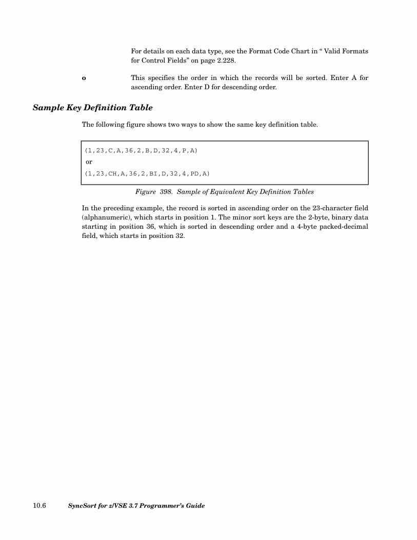
For details on each data type, see the Format Code Chart in “ Valid Formatsfor Control Fields” on page 2.228.
o This specifies the order in which the records will be sorted. Enter A forascending order. Enter D for descending order.
Sample Key Definition Table
The following figure shows two ways to show the same key definition table.
In the preceding example, the record is sorted in ascending order on the 23-character field(alphanumeric), which starts in position 1. The minor sort keys are the 2-byte, binary datastarting in position 36, which is sorted in descending order and a 4-byte packed-decimalfield, which starts in position 32.
(1,23,C,A,36,2,B,D,32,4,P,A)
or
(1,23,CH,A,36,2,BI,D,32,4,PD,A)
Figure 398. Sample of Equivalent Key Definition Tables
SyncSort for z/VSE 3.7 Programmer’s Guide10.6
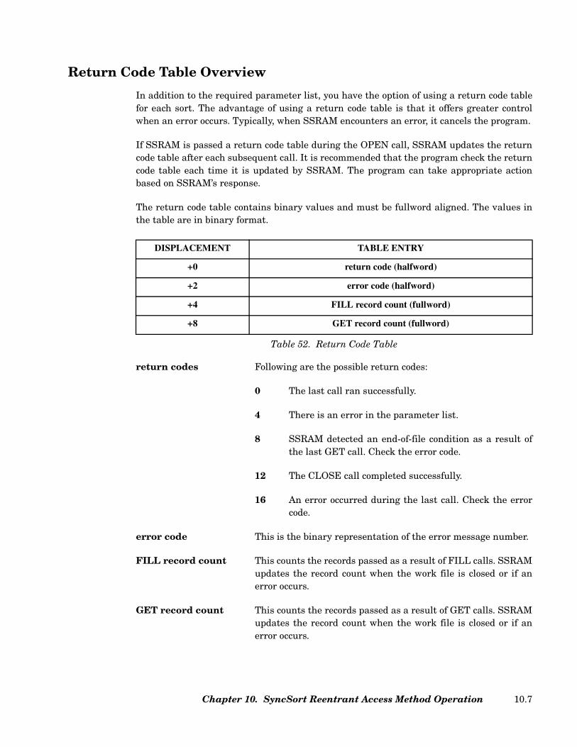
Return Code Table Overview
In addition to the required parameter list, you have the option of using a return code tablefor each sort. The advantage of using a return code table is that it offers greater controlwhen an error occurs. Typically, when SSRAM encounters an error, it cancels the program.
If SSRAM is passed a return code table during the OPEN call, SSRAM updates the returncode table after each subsequent call. It is recommended that the program check the returncode table each time it is updated by SSRAM. The program can take appropriate actionbased on SSRAM’s response.
The return code table contains binary values and must be fullword aligned. The values inthe table are in binary format.
return codes Following are the possible return codes:
0 The last call ran successfully.
4 There is an error in the parameter list.
8 SSRAM detected an end-of-file condition as a result ofthe last GET call. Check the error code.
12 The CLOSE call completed successfully.
16 An error occurred during the last call. Check the errorcode.
error code This is the binary representation of the error message number.
FILL record count This counts the records passed as a result of FILL calls. SSRAMupdates the record count when the work file is closed or if anerror occurs.
GET record count This counts the records passed as a result of GET calls. SSRAMupdates the record count when the work file is closed or if anerror occurs.
DISPLACEMENT TABLE ENTRY
+0 return code (halfword)
+2 error code (halfword)
+4 FILL record count (fullword)
+8 GET record count (fullword)
Table 52. Return Code Table
Chapter 10. SyncSort Reentrant Access Method Operation 10.7

Refer to Figure 400 on page 10.9, Figure 410 on page 10.14, Figure 420 on page 10.18, orFigure 429 on page 10.23 for the format of the return code table for each respective lan-guage.
Duplicate Record Processing Overview
In addition to the required parameter list, you have the option of using a duplicate recordcode for a sort. The advantage of using a duplicate record code is that it offers the option todelete records that have duplicate keys during sort execution. The other fields in the dupli-cate key records can be unequal.
To delete duplicate key records, enter the value 8 in the variable for duplicate record pro-cessing specified in the SRTOPEN parameter list. To retain all records, enter the value 0;this is the default.
If you are deleting duplicate keyed records and the records are variable-length records, besure to enter the maximum record length in the parameter table. If you use the averagerecord length instead of the maximum record length, the sort may terminate and issueerror message WER123A SUM FIELD BEYOND RECORD.
SyncSort for z/VSE 3.7 Programmer’s Guide10.8
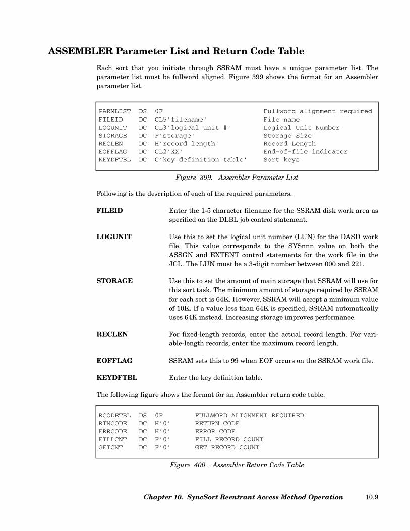
ASSEMBLER Parameter List and Return Code Table
Each sort that you initiate through SSRAM must have a unique parameter list. Theparameter list must be fullword aligned. Figure 399 shows the format for an Assemblerparameter list.
Following is the description of each of the required parameters.
FILEID Enter the 1-5 character filename for the SSRAM disk work area asspecified on the DLBL job control statement.
LOGUNIT Use this to set the logical unit number (LUN) for the DASD workfile. This value corresponds to the SYSnnn value on both theASSGN and EXTENT control statements for the work file in theJCL. The LUN must be a 3-digit number between 000 and 221.
STORAGE Use this to set the amount of main storage that SSRAM will use forthis sort task. The minimum amount of storage required by SSRAMfor each sort is 64K. However, SSRAM will accept a minimum valueof 10K. If a value less than 64K is specified, SSRAM automaticallyuses 64K instead. Increasing storage improves performance.
RECLEN For fixed-length records, enter the actual record length. For vari-able-length records, enter the maximum record length.
EOFFLAG SSRAM sets this to 99 when EOF occurs on the SSRAM work file.
KEYDFTBL Enter the key definition table.
The following figure shows the format for an Assembler return code table.
PARMLIST DS 0F Fullword alignment requiredFILEID DC CL5'filename' File nameLOGUNIT DC CL3'logical unit #' Logical Unit NumberSTORAGE DC F'storage' Storage SizeRECLEN DC H'record length' Record LengthEOFFLAG DC CL2'XX' End-of-file indicatorKEYDFTBL DC C'key definition table' Sort keys
Figure 399. Assembler Parameter List
RCODETBL DS 0F FULLWORD ALIGNMENT REQUIREDRTNCODE DC H'0' RETURN CODEERRCODE DC H'0' ERROR CODEFILLCNT DC F'0' FILL RECORD COUNTGETCNT DC F'0' GET RECORD COUNT
Figure 400. Assembler Return Code Table
Chapter 10. SyncSort Reentrant Access Method Operation 10.9

ASSEMBLER Calls
SRTCORE
The optional SRTCORE call defines a storage length; it may also define a storage area andcentury window. Only one SRTCORE call may be defined in the application program and itmust precede all other SSRAM calls in the program.
starea Enter the variable name of the storage area within the program which willbe used by SSRAM.
stlength Enter the variable name of the storage length, stored as a fullword value. Aminimum of 64K of storage is required for each sort.
When starea is not specified, SSRAM will be loaded at the end of the last program phaseloaded.
When starea is specified within the problem program area, a placeholder value ofX'FFFFFFFF' may be used as the length parameter to specify that storage will be allocatedfrom the starea location to the end of the problem program area.
sys, usr, ops, str, pfx, dsm, and ccw are optional positional parameters which areaccepted but ignored. centwin is an optional positional parameter which specifies the cen-tury window to which 2-digit year data belongs when being processed by the sort. Fordetails on using centwin, see “ CENTWIN Parameter (Optional)” on page 2.101.
If centwin is specified, the preceding 7 parameters must be specified using fullword place-holders. The value X’FFFFFFFF’ may be used for each. A value must also be specified forstarea.
Following are examples of SRTCORE usage:
CALL SRTCORE,([starea,]stlength[,sys,usr,ops,str,pfx,dsm,ccw,centwin])
Figure 401. SRTCORE Format
SyncSort for z/VSE 3.7 Programmer’s Guide10.10

SRTOPEN
The SRTOPEN call starts a SSRAM sort.
parmlist Enter the variable name of the parameter list. The parameter list isrequired.
rcodetbl Enter the variable name of the return code table.
duprecps Enter the variable name of the duplicate record processing field. This is afullword binary value. The duplicate record processing field is optional.
userexit This function is not supported. However, if a variable name is entered,SSRAM will ignore the value and continue processing normally.
Because the variables are positional, if you wish to specify a duplicate record processingtable and a user exit, you must enter a variable name for the return code table even if youare not using return codes. In this case, define a placeholder return code table as follows:
CALL SRTCORE,(AREA,LENGTH)CALL SRTCORE,(AREA,DUMMYLEN) Use space to end of problem program * area (AREA must not be in * GETVIS storage)CALL SRTCORE,(LENGTH) Load at end of last phaseCALL SRTCORE,(AREA,LENGTH,FILL,FILL,FILL,FILL,FILL,FILL,FILL,WINDOW)* Century window specifiedLENGTH DC F'128000' Length of storage area in bytesDUMMYLEN DC F'-1' Special positional value for "stlength"AREA DS XL128000 Storage where SSRAM will be loadedWINDOW DC F’2007’FILL DC F’-1’
Figure 402. Examples of SRTCORE Usage
CALL SRTOPEN,(parmlist[,rcodetbl[,duprecps[,userexit]]])
Figure 403. SRTOPEN Format
rcodetbl DC F'-1'
Figure 404. Placeholder Return Code Table
Chapter 10. SyncSort Reentrant Access Method Operation 10.11

SRTFILL
The SRTFILL call tells SSRAM to pass a record from the specified record area to the sortdefined by the specified parameter list.
parmlist Enter the variable name of the parameter list of the sort to which youwish to pass a record.
record-area Enter the variable name of the area that contains the record to bepassed to the sort.
SRTGETR
The SRTGETR call retrieves a record from the sort defined by the parameter list and putsit in the specified record-area. If SSRAM detects an end-of-file condition, SSRAM sets EOFFLAG to 99. If the program expects a return code, SSRAM will return code 8 at EOF.
parmlist This is the variable name of the parameter list that identifies the sortfrom which the record is being retrieved.
record-area This variable name identifies the name of the record area to which therecord is to be moved.
SRTCLSE
Use the SRTCLSE call to terminate sort processing for an individual sort. If return codeshave been requested, SSRAM supplies the record count and return code 12 if the close wassuccessful.
parmlist This is the variable name of the parameter list of the sort you wish toclose.
CALL SRTFILL,(parmlist,record-area)
Figure 405. SRTFILL Format
CALL SRTGETR,(parmlist,record-area)
Figure 406. SRTGETR Format
CALL SRTCLSE,(parmlist[,rcodetbl])
Figure 407. SRTCLSE Format
SyncSort for z/VSE 3.7 Programmer’s Guide10.12
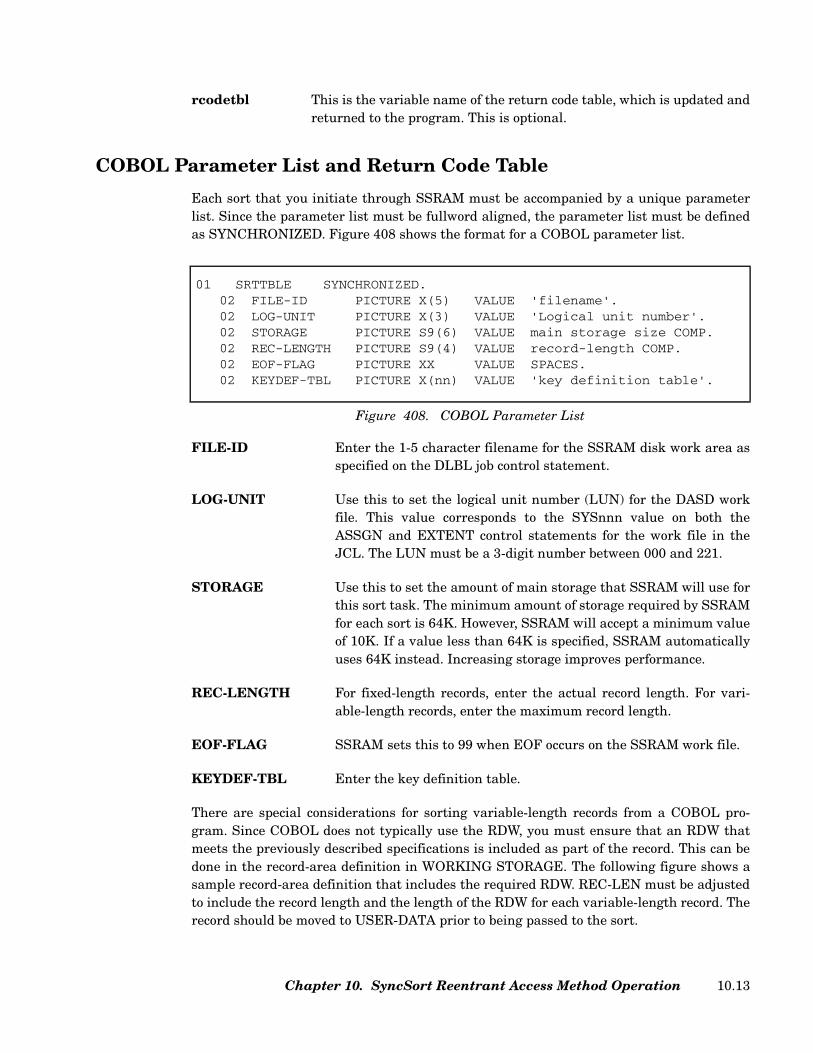
rcodetbl This is the variable name of the return code table, which is updated andreturned to the program. This is optional.
COBOL Parameter List and Return Code Table
Each sort that you initiate through SSRAM must be accompanied by a unique parameterlist. Since the parameter list must be fullword aligned, the parameter list must be definedas SYNCHRONIZED. Figure 408 shows the format for a COBOL parameter list.
FILE-ID Enter the 1-5 character filename for the SSRAM disk work area asspecified on the DLBL job control statement.
LOG-UNIT Use this to set the logical unit number (LUN) for the DASD workfile. This value corresponds to the SYSnnn value on both theASSGN and EXTENT control statements for the work file in theJCL. The LUN must be a 3-digit number between 000 and 221.
STORAGE Use this to set the amount of main storage that SSRAM will use forthis sort task. The minimum amount of storage required by SSRAMfor each sort is 64K. However, SSRAM will accept a minimum valueof 10K. If a value less than 64K is specified, SSRAM automaticallyuses 64K instead. Increasing storage improves performance.
REC-LENGTH For fixed-length records, enter the actual record length. For vari-able-length records, enter the maximum record length.
EOF-FLAG SSRAM sets this to 99 when EOF occurs on the SSRAM work file.
KEYDEF-TBL Enter the key definition table.
There are special considerations for sorting variable-length records from a COBOL pro-gram. Since COBOL does not typically use the RDW, you must ensure that an RDW thatmeets the previously described specifications is included as part of the record. This can bedone in the record-area definition in WORKING STORAGE. The following figure shows asample record-area definition that includes the required RDW. REC-LEN must be adjustedto include the record length and the length of the RDW for each variable-length record. Therecord should be moved to USER-DATA prior to being passed to the sort.
01 SRTTBLE SYNCHRONIZED.02 FILE-ID PICTURE X(5) VALUE 'filename'.02 LOG-UNIT PICTURE X(3) VALUE 'Logical unit number'.02 STORAGE PICTURE S9(6) VALUE main storage size COMP.02 REC-LENGTH PICTURE S9(4) VALUE record-length COMP.02 EOF-FLAG PICTURE XX VALUE SPACES.02 KEYDEF-TBL PICTURE X(nn) VALUE 'key definition table'.
Figure 408. COBOL Parameter List
Chapter 10. SyncSort Reentrant Access Method Operation 10.13
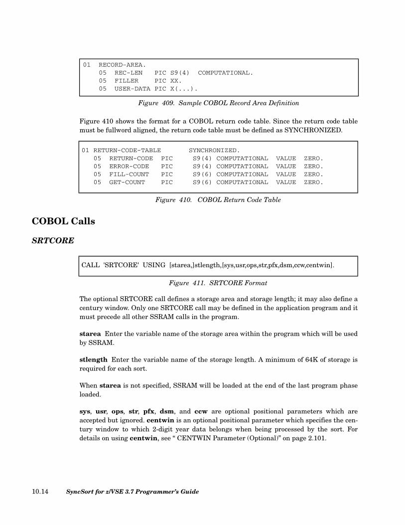
Figure 410 shows the format for a COBOL return code table. Since the return code tablemust be fullword aligned, the return code table must be defined as SYNCHRONIZED.
COBOL Calls
SRTCORE
The optional SRTCORE call defines a storage area and storage length; it may also define acentury window. Only one SRTCORE call may be defined in the application program and itmust precede all other SSRAM calls in the program.
starea Enter the variable name of the storage area within the program which will be usedby SSRAM.
stlength Enter the variable name of the storage length. A minimum of 64K of storage isrequired for each sort.
When starea is not specified, SSRAM will be loaded at the end of the last program phaseloaded.
sys, usr, ops, str, pfx, dsm, and ccw are optional positional parameters which areaccepted but ignored. centwin is an optional positional parameter which specifies the cen-tury window to which 2-digit year data belongs when being processed by the sort. Fordetails on using centwin, see “ CENTWIN Parameter (Optional)” on page 2.101.
01 RECORD-AREA.05 REC-LEN PIC S9(4) COMPUTATIONAL.05 FILLER PIC XX.05 USER-DATA PIC X(...).
Figure 409. Sample COBOL Record Area Definition
01 RETURN-CODE-TABLE SYNCHRONIZED.05 RETURN-CODE PIC S9(4) COMPUTATIONAL VALUE ZERO.05 ERROR-CODE PIC S9(4) COMPUTATIONAL VALUE ZERO.05 FILL-COUNT PIC S9(6) COMPUTATIONAL VALUE ZERO.05 GET-COUNT PIC S9(6) COMPUTATIONAL VALUE ZERO.
Figure 410. COBOL Return Code Table
CALL 'SRTCORE' USING [starea,]stlength,[sys,usr,ops,str,pfx,dsm,ccw,centwin].
Figure 411. SRTCORE Format
SyncSort for z/VSE 3.7 Programmer’s Guide10.14
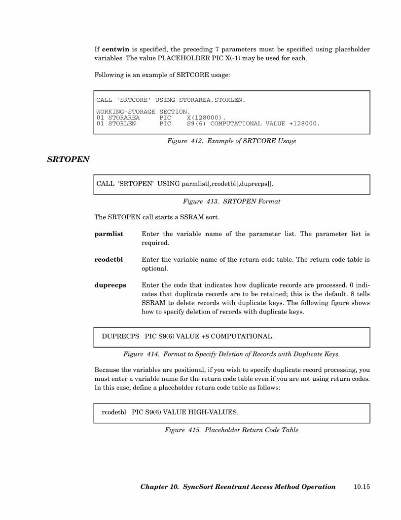
If centwin is specified, the preceding 7 parameters must be specified using placeholdervariables. The value PLACEHOLDER PIC X(-1) may be used for each.
Following is an example of SRTCORE usage:
SRTOPEN
The SRTOPEN call starts a SSRAM sort.
parmlist Enter the variable name of the parameter list. The parameter list isrequired.
rcodetbl Enter the variable name of the return code table. The return code table isoptional.
duprecps Enter the code that indicates how duplicate records are processed. 0 indi-cates that duplicate records are to be retained; this is the default. 8 tellsSSRAM to delete records with duplicate keys. The following figure showshow to specify deletion of records with duplicate keys.
Because the variables are positional, if you wish to specify duplicate record processing, youmust enter a variable name for the return code table even if you are not using return codes.In this case, define a placeholder return code table as follows:
CALL 'SRTCORE' USING STORAREA,STORLEN.
WORKING-STORAGE SECTION.01 STORAREA PIC X(128000).01 STORLEN PIC S9(6) COMPUTATIONAL VALUE +128000.
Figure 412. Example of SRTCORE Usage
CALL 'SRTOPEN' USING parmlist[,rcodetbl[,duprecps]].
Figure 413. SRTOPEN Format
DUPRECPS PIC S9(6) VALUE +8 COMPUTATIONAL.
Figure 414. Format to Specify Deletion of Records with Duplicate Keys.
rcodetbl PIC S9(6) VALUE HIGH-VALUES.
Figure 415. Placeholder Return Code Table
Chapter 10. SyncSort Reentrant Access Method Operation 10.15
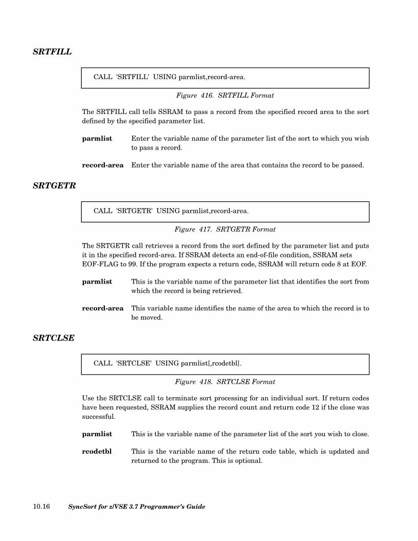
SRTFILL
The SRTFILL call tells SSRAM to pass a record from the specified record area to the sortdefined by the specified parameter list.
parmlist Enter the variable name of the parameter list of the sort to which you wishto pass a record.
record-area Enter the variable name of the area that contains the record to be passed.
SRTGETR
The SRTGETR call retrieves a record from the sort defined by the parameter list and putsit in the specified record-area. If SSRAM detects an end-of-file condition, SSRAM sets EOF-FLAG to 99. If the program expects a return code, SSRAM will return code 8 at EOF.
parmlist This is the variable name of the parameter list that identifies the sort fromwhich the record is being retrieved.
record-area This variable name identifies the name of the area to which the record is tobe moved.
SRTCLSE
Use the SRTCLSE call to terminate sort processing for an individual sort. If return codeshave been requested, SSRAM supplies the record count and return code 12 if the close wassuccessful.
parmlist This is the variable name of the parameter list of the sort you wish to close.
rcodetbl This is the variable name of the return code table, which is updated andreturned to the program. This is optional.
CALL 'SRTFILL' USING parmlist,record-area.
Figure 416. SRTFILL Format
CALL 'SRTGETR' USING parmlist,record-area.
Figure 417. SRTGETR Format
CALL 'SRTCLSE' USING parmlist[,rcodetbl].
Figure 418. SRTCLSE Format
SyncSort for z/VSE 3.7 Programmer’s Guide10.16
Note: With COBOL (D), ENTER LINKAGE and ENTER COBOL must be used with eachcall.
Chapter 10. SyncSort Reentrant Access Method Operation 10.17

FORTRAN Parameter List and Return Code Table
Each sort that you initiate through SSRAM must be accompanied by a unique parameterlist. The parameter list in FORTRAN is defined using the DIMENSION and the DATAstatements. Figure 419 shows the format for a FORTRAN parameter list.
Refer to the IBM VS FORTRAN documentation for a full description of the DIMENSIONand DATA statements syntax. Following is a description of each of the required fields.
parmlist(n) This identifies the variable name of the parmlist defined in the DATAstatement. n is the number of words in the accompanying DATA state-ment; its value depends on the size of the key definition table.
Byte 1-5 Use this to specify the 5-character filename of the SSRAM disk workarea as specified on the DLBL job control statement.
Byte 6-8 Use this to identify the Logical Unit Number of the device that containsthe work file. This value corresponds to the SYSnnn value on both theASSGN and EXTENT control statements for the work file in the JCL.The LUN must be a 3-digit number between 000 and 221.
Byte 9-12 Use this to set the amount of main storage that SSRAM will use for asort task. The minimum amount of storage required by SSRAM for eachsort is 64K. However, SSRAM will accept a minimum value of 10K. If avalue less than 64K is specified, SSRAM automatically uses 64Kinstead. Increasing storage improves performance.
Byte 13-16 Use this to specify the record length. For variable-length records, spec-ify the maximum record length.
Byte 17-n Use this for the key definition table. It must be enclosed within pare-theses. s is the size of the table in bytes.
Figure 420 shows the format for a FORTRAN return code table.
DIMENSION parmlist(n),data-area(nnnnn)DATA parmlist / 5Hbyte1-5,3Hbyte6-8,byte9-12,byte13-16,sH(byte17-n)
Figure 419. FORTRAN Parameter List
DIMENSION rcodetbl (3)
Figure 420. FORTRAN Return Code Table
SyncSort for z/VSE 3.7 Programmer’s Guide10.18
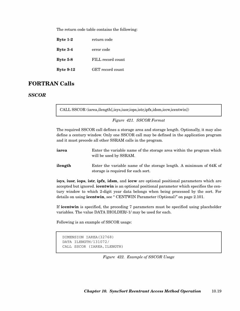
The return code table contains the following:
Byte 1-2 return code
Byte 3-4 error code
Byte 5-8 FILL record count
Byte 9-12 GET record count
FORTRAN Calls
SSCOR
The required SSCOR call defines a storage area and storage length. Optionally, it may alsodefine a century window. Only one SSCOR call may be defined in the application programand it must precede all other SSRAM calls in the program.
iarea Enter the variable name of the storage area within the program whichwill be used by SSRAM.
ilength Enter the variable name of the storage length. A minimum of 64K ofstorage is required for each sort.
isys, iusr, iops, istr, ipfx, idsm, and iccw are optional positional parameters which areaccepted but ignored. icentwin is an optional positional parameter which specifies the cen-tury window to which 2-digit year data belongs when being processed by the sort. Fordetails on using icentwin, see “ CENTWIN Parameter (Optional)” on page 2.101.
If icentwin is specified, the preceding 7 parameters must be specified using placeholdervariables. The value DATA IHOLDER/-1/ may be used for each.
Following is an example of SSCOR usage:
CALL SSCOR (iarea,ilength[,isys,iusr,iops,istr,ipfx,idsm,iccw,icentwin])
Figure 421. SSCOR Format
DIMENSION IAREA(32768)DATA ILENGTH/131072/ CALL SSCOR (IAREA,ILENGTH)
Figure 422. Example of SSCOR Usage
Chapter 10. SyncSort Reentrant Access Method Operation 10.19
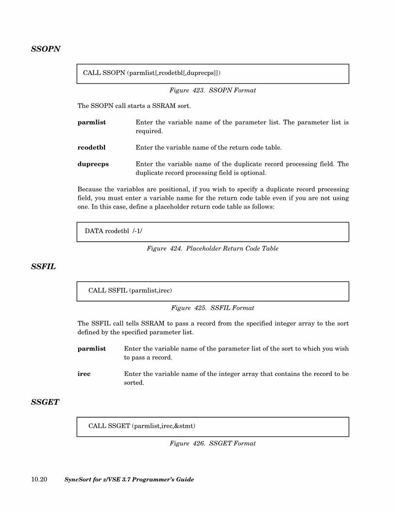
SSOPN
The SSOPN call starts a SSRAM sort.
parmlist Enter the variable name of the parameter list. The parameter list isrequired.
rcodetbl Enter the variable name of the return code table.
duprecps Enter the variable name of the duplicate record processing field. Theduplicate record processing field is optional.
Because the variables are positional, if you wish to specify a duplicate record processingfield, you must enter a variable name for the return code table even if you are not usingone. In this case, define a placeholder return code table as follows:
SSFIL
The SSFIL call tells SSRAM to pass a record from the specified integer array to the sortdefined by the specified parameter list.
parmlist Enter the variable name of the parameter list of the sort to which you wishto pass a record.
irec Enter the variable name of the integer array that contains the record to besorted.
SSGET
CALL SSOPN (parmlist[,rcodetbl[,duprecps]])
Figure 423. SSOPN Format
DATA rcodetbl /-1/
Figure 424. Placeholder Return Code Table
CALL SSFIL (parmlist,irec)
Figure 425. SSFIL Format
CALL SSGET (parmlist,irec,&stmt)
Figure 426. SSGET Format
SyncSort for z/VSE 3.7 Programmer’s Guide10.20

The SSGET call retrieves a record from the sort defined by the parameter list and puts itinto a specified integer array. If SSRAM detects an end-of-file condition, SSRAM passescontrol to the statement specified by &stmt. If the program expects a return code, SSRAMwill return a code of 8 at EOF.
parmlist This is the variable name of the parameter list that identifies the sort fromwhich a record is to be retrieved.
irec This variable name identifies the integer array into which the record is tobe moved.
&stmt This is the statement number of the statement to which SSRAM passescontrol when an end-of-file condition occurs.
SSCLS
Use the SSCLS call to terminate sort processing for an individual sort. If return codes havebeen requested, SSRAM supplies the FILL record count, the GET record count, and returncode 12 if the close was successful.
parmlist This is the variable name of the parameter list of the sort you wish to close.
rcodetbl This is the variable name of the return code table.
CALL SSCLS (parmlist[,rcodetbl])
Figure 427. SSCLS Format
Chapter 10. SyncSort Reentrant Access Method Operation 10.21
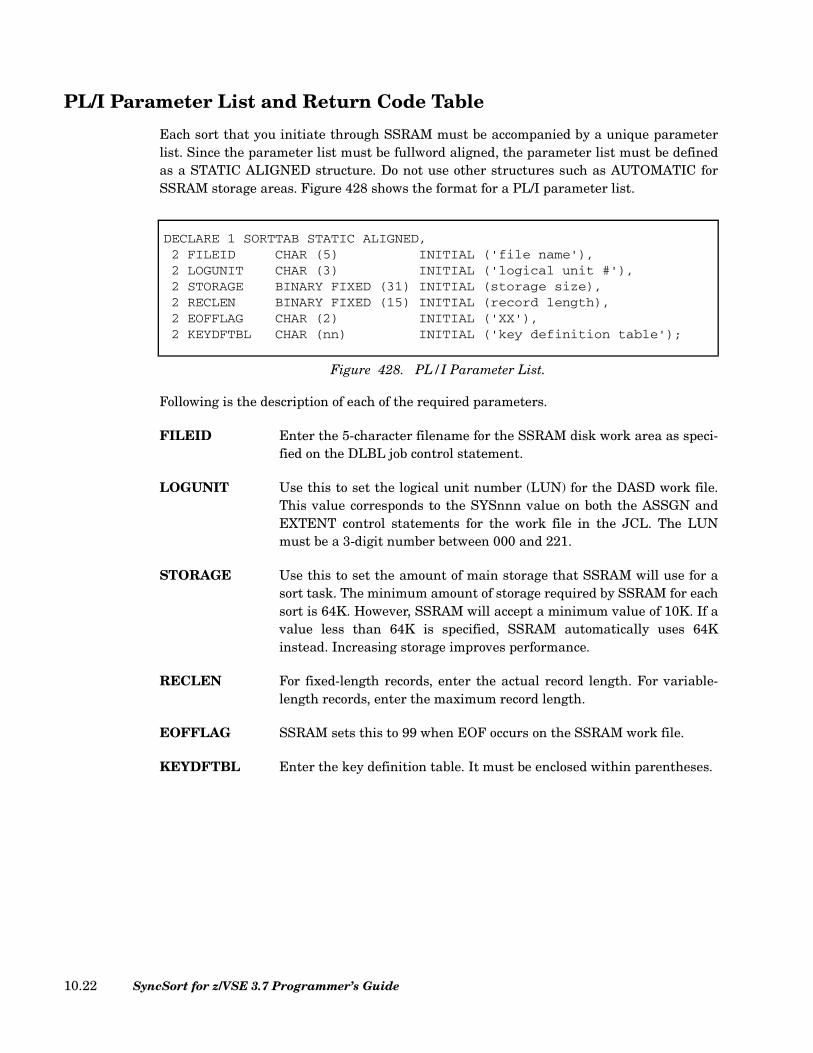
PL/I Parameter List and Return Code Table
Each sort that you initiate through SSRAM must be accompanied by a unique parameterlist. Since the parameter list must be fullword aligned, the parameter list must be definedas a STATIC ALIGNED structure. Do not use other structures such as AUTOMATIC forSSRAM storage areas. Figure 428 shows the format for a PL/I parameter list.
Following is the description of each of the required parameters.
FILEID Enter the 5-character filename for the SSRAM disk work area as speci-fied on the DLBL job control statement.
LOGUNIT Use this to set the logical unit number (LUN) for the DASD work file.This value corresponds to the SYSnnn value on both the ASSGN andEXTENT control statements for the work file in the JCL. The LUNmust be a 3-digit number between 000 and 221.
STORAGE Use this to set the amount of main storage that SSRAM will use for asort task. The minimum amount of storage required by SSRAM for eachsort is 64K. However, SSRAM will accept a minimum value of 10K. If avalue less than 64K is specified, SSRAM automatically uses 64Kinstead. Increasing storage improves performance.
RECLEN For fixed-length records, enter the actual record length. For variable-length records, enter the maximum record length.
EOFFLAG SSRAM sets this to 99 when EOF occurs on the SSRAM work file.
KEYDFTBL Enter the key definition table. It must be enclosed within parentheses.
DECLARE 1 SORTTAB STATIC ALIGNED,2 FILEID CHAR (5) INITIAL ('file name'),2 LOGUNIT CHAR (3) INITIAL ('logical unit #'),2 STORAGE BINARY FIXED (31) INITIAL (storage size),2 RECLEN BINARY FIXED (15) INITIAL (record length),2 EOFFLAG CHAR (2) INITIAL ('XX'),2 KEYDFTBL CHAR (nn) INITIAL ('key definition table');
Figure 428. PL/I Parameter List.
SyncSort for z/VSE 3.7 Programmer’s Guide10.22

Figure 429 shows the format for a PL/I return code table. Since the return code table mustbe fullword aligned, the return code table must be defined as a STATIC ALIGNEDstructure.
PL/I Calls
SRTCORE
The required SRTCORE call defines a storage area and storage length. Optionally, it mayalso define a century window. Only one SRTCORE call may be defined in the applicationprogram and it must precede all other SSRAM calls in the program.
starea Enter the variable name of the storage area within the program whichwill be used by SSRAM.
stlength Enter the variable name of the storage length. A minimum of 64K ofstorage is required for each sort.
sys, usr, ops, str, pfx, dsm, and ccw are optional positional parameters which areaccepted but ignored. centwin is an optional positional parameter which specifies the cen-tury window to which 2-digit year data belongs when being processed by the sort. Fordetails on using centwin, see “ CENTWIN Parameter (Optional)” on page 2.101.
If centwin is specified, the preceding 7 parameters must be specified using placeholdervariables. The value PLACEHOLDER CHAR(-1) may be used for each.
Following is an example of SRTCORE usage:
DECLARE 1 RETURN_CODE_TABLE STATIC ALIGNED,2 RETURN_CODE BINARY FIXED(15) INIT(0),2 ERROR_CODE BINARY FIXED(15) INIT(0),2 FILL_COUNT BINARY FIXED(31) INIT(0),2 GET_COUNT BINARY FIXED(31) INIT(0);
Figure 429. PL/I Return Code Table.
CALL SRTCORE (starea,stlength[,sys,usr,ops,str,pfx,dsm,ccw,centwin]);
Figure 430. SRTCORE Format
DCL1 STOR_AREA STATIC ALIGNED,2 SRAM_AREA CHAR(256000);
DCL STOR_LEN BIN FIXED(31) INIT(256000);
Figure 431. Example of SRTCORE Usage
Chapter 10. SyncSort Reentrant Access Method Operation 10.23

SRTOPEN
The SRTOPEN call starts a SSRAM sort.
parmlist Enter the variable name of the parameter list. The parameter list isrequired.
rcodetbl Enter the variable name of the return code table.
duprecps Enter the variable name of the duplicate record processing field. Theduplicate record processing field is optional.
Because the variables are positional, if you wish to specify a duplicate record processingfield, you must enter a variable name for the return code table even if you are not usingone. In this case, define a placeholder return code table as in the following example:
SRTFILL
The SRTFILL call tells SSRAM to pass a record from the specified record area to the sortdefined by the specified parameter list.
parmlist Enter the variable name of the parameter list of the sort to which you wishto pass a record.
recptr Enter the variable name of an address constant pointer to a one-dimen-sional structure or elementary item that contains the input record to besorted.
CALL SRTOPEN (parmlist[,rcodetbl[,duprecps]]);
Figure 432. SRTOPEN Format
DCL rcodetbl FIXED BIN(31) INIT(-1);
Figure 433. Placeholder Return Code Table
CALL SRTFILL (parmlist,recptr);
Figure 434. SRTFILL Format
SyncSort for z/VSE 3.7 Programmer’s Guide10.24

SRTGETR
The SRTGETR call retrieves a record from the sort defined by the parameter list and putsit in the area specified by the address constant pointer. If SSRAM detects an end-of-file con-dition, SSRAM sets EOFFLAG to 99. If the program expects a return code, SSRAM willreturn a code of 8 at EOF.
parmlist This is the variable name of the parameter list that identifies the sort fromwhich the record is being retrieved.
recptr This variable name identifies the name of the address constant pointer thatspecifies the area to which the record is to be moved.
SRTCLSE
The SRTCLSE call terminates sort processing for an individual sort. If return codes havebeen requested, SSRAM supplies the FILL record count, the GET record count, and thereturn code 12 if the close was successful.
parmlist This is the variable name of the parameter list of the sort you wish to close.
rcodetbl This is the variable name of the return code table, which is updated withthe appropriate return code and record counts. This is optional.
CALL SRTGETR (parmlist,recptr);
Figure 435. SRTGETR Format
CALL SRTCLSE (parmlist[,rcodetbl]);
Figure 436. SRTCLSE Format
Chapter 10. SyncSort Reentrant Access Method Operation 10.25

SyncSort for z/VSE 3.7 Programmer’s Guide10.26

Chapter 11. The SYNCHSTO Utility Program
What is SYNCHSTO?
SYNCHSTO is a separate program that is used to determine information about variable-length record files. The program uses SyncSort to scan a variable-length record file andprovides information about the records in the file, which then can be used to run more effi-cient sorts of that file.
SYNCHSTO will report the:
• minimum and maximum record lengths in the file;
• average record length;
• total number of records in the file;
• total number of bytes in the file;
• measured l5 value (most common record length) for the file;
• recommended l6 value (average work space per record) for the file; and
• recommended l7 value (optimum segment length) for the file.
SYNCHSTO will also produce a histogram that displays the distribution of the lengths ofthe records in the file.
Chapter 11. The SYNCHSTO Utility Program 11.1
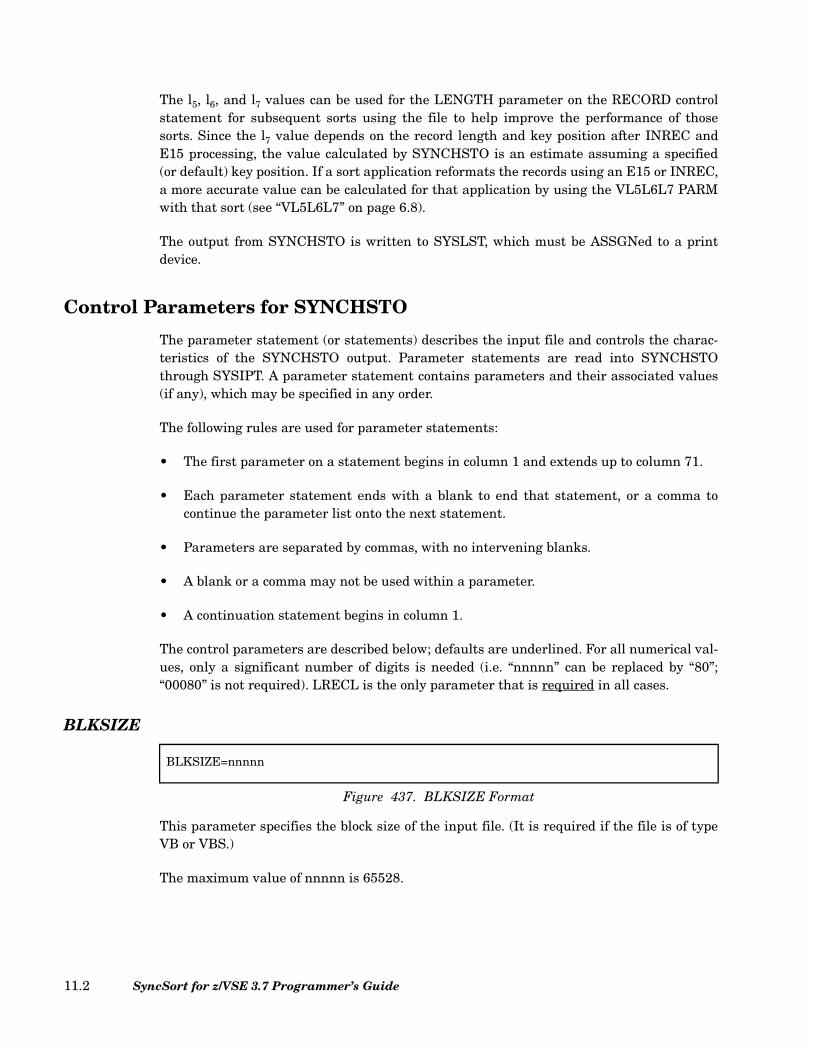
The l5, l6, and l7 values can be used for the LENGTH parameter on the RECORD controlstatement for subsequent sorts using the file to help improve the performance of thosesorts. Since the l7 value depends on the record length and key position after INREC andE15 processing, the value calculated by SYNCHSTO is an estimate assuming a specified(or default) key position. If a sort application reformats the records using an E15 or INREC,a more accurate value can be calculated for that application by using the VL5L6L7 PARMwith that sort (see “VL5L6L7” on page 6.8).
The output from SYNCHSTO is written to SYSLST, which must be ASSGNed to a printdevice.
Control Parameters for SYNCHSTO
The parameter statement (or statements) describes the input file and controls the charac-teristics of the SYNCHSTO output. Parameter statements are read into SYNCHSTOthrough SYSIPT. A parameter statement contains parameters and their associated values(if any), which may be specified in any order.
The following rules are used for parameter statements:
• The first parameter on a statement begins in column 1 and extends up to column 71.
• Each parameter statement ends with a blank to end that statement, or a comma tocontinue the parameter list onto the next statement.
• Parameters are separated by commas, with no intervening blanks.
• A blank or a comma may not be used within a parameter.
• A continuation statement begins in column 1.
The control parameters are described below; defaults are underlined. For all numerical val-ues, only a significant number of digits is needed (i.e. “nnnnn” can be replaced by “80”;“00080” is not required). LRECL is the only parameter that is required in all cases.
BLKSIZE
This parameter specifies the block size of the input file. (It is required if the file is of typeVB or VBS.)
The maximum value of nnnnn is 65528.
BLKSIZE=nnnnn
Figure 437. BLKSIZE Format
SyncSort for z/VSE 3.7 Programmer’s Guide11.2
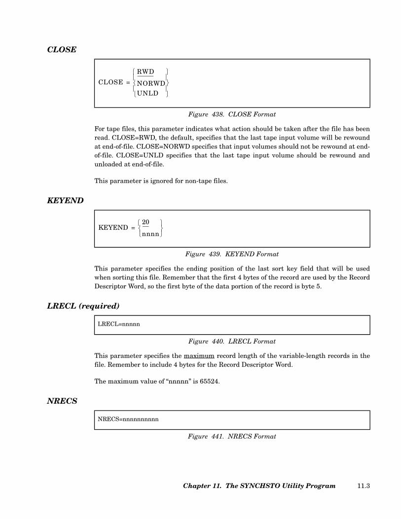
CLOSE
For tape files, this parameter indicates what action should be taken after the file has beenread. CLOSE=RWD, the default, specifies that the last tape input volume will be rewoundat end-of-file. CLOSE=NORWD specifies that input volumes should not be rewound at end-of-file. CLOSE=UNLD specifies that the last tape input volume should be rewound andunloaded at end-of-file.
This parameter is ignored for non-tape files.
KEYEND
This parameter specifies the ending position of the last sort key field that will be usedwhen sorting this file. Remember that the first 4 bytes of the record are used by the RecordDescriptor Word, so the first byte of the data portion of the record is byte 5.
LRECL (required)
This parameter specifies the maximum record length of the variable-length records in thefile. Remember to include 4 bytes for the Record Descriptor Word.
The maximum value of “nnnnn” is 65524.
NRECS
Figure 438. CLOSE Format
CLOSE
RWD
NORWDUNLD
=
Figure 439. KEYEND Format
KEYEND20
nnnn
=
LRECL=nnnnn
Figure 440. LRECL Format
NRECS=nnnnnnnnnn
Figure 441. NRECS Format
Chapter 11. The SYNCHSTO Utility Program 11.3

If specified, this parameter specifies the number of records to be read from the file. If notspecified, the entire file is read. The file characteristics measured and calculated bySYNCHSTO will be based on only the first “nnnnnnnnnn” records of the file. (If the recordlengths are randomly distributed in a very large file, this can provide a useful estimate thatavoids the long processing time required for reading the entire file.)
The maximum value of “nnnnnnnnnn” is 2 gigabytes - 1 (i.e. 2147483647).
OPEN
For tape files, this parameter indicates what action should be taken when the file isopened.
OPEN=RWD, the default, specifies that the first volume of the tape input file is to berewound when the file is opened. OPEN=NORWD specifies that the first volume of the tapeinput file is not to be rewound when the file is opened.
This parameter is ignored for non-tape files.
SORTNAME
This parameter, if specified, indicates the name of SyncSort as installed on your system tobe used by SYNCHSTO.
Specify the “sortname” value as 1 to 8 alphanumeric characters. The first character mustbe alphabetic.
SPAN
This parameter indicates that the input file may contain spanned records.
Figure 442. OPEN Format
OPENRWD
NORWD
=
Figure 443. SORTNAME Format
SORTNAMESORT
sortname
=
SPAN
Figure 444. SPAN Format
SyncSort for z/VSE 3.7 Programmer’s Guide11.4
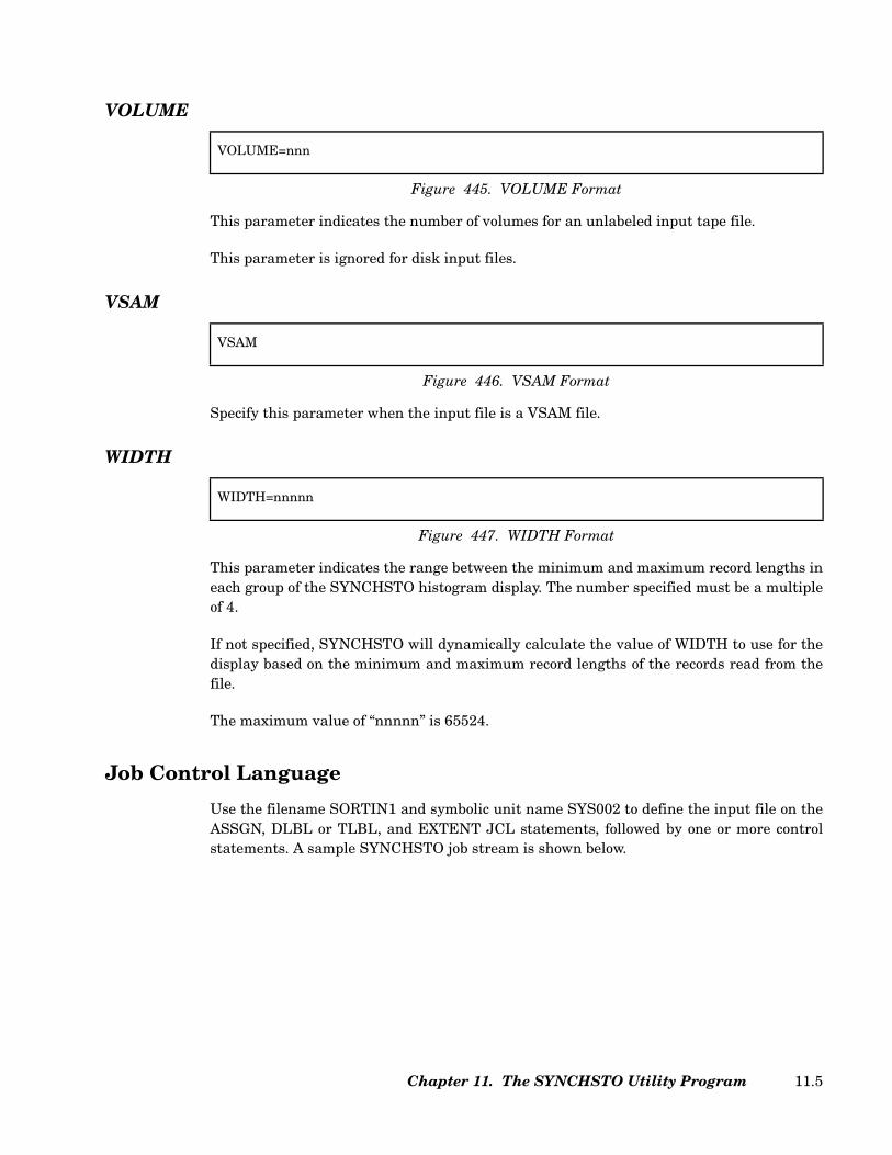
VOLUME
This parameter indicates the number of volumes for an unlabeled input tape file.
This parameter is ignored for disk input files.
VSAM
Specify this parameter when the input file is a VSAM file.
WIDTH
This parameter indicates the range between the minimum and maximum record lengths ineach group of the SYNCHSTO histogram display. The number specified must be a multipleof 4.
If not specified, SYNCHSTO will dynamically calculate the value of WIDTH to use for thedisplay based on the minimum and maximum record lengths of the records read from thefile.
The maximum value of “nnnnn” is 65524.
Job Control Language
Use the filename SORTIN1 and symbolic unit name SYS002 to define the input file on theASSGN, DLBL or TLBL, and EXTENT JCL statements, followed by one or more controlstatements. A sample SYNCHSTO job stream is shown below.
VOLUME=nnn
Figure 445. VOLUME Format
VSAM
Figure 446. VSAM Format
WIDTH=nnnnn
Figure 447. WIDTH Format
Chapter 11. The SYNCHSTO Utility Program 11.5
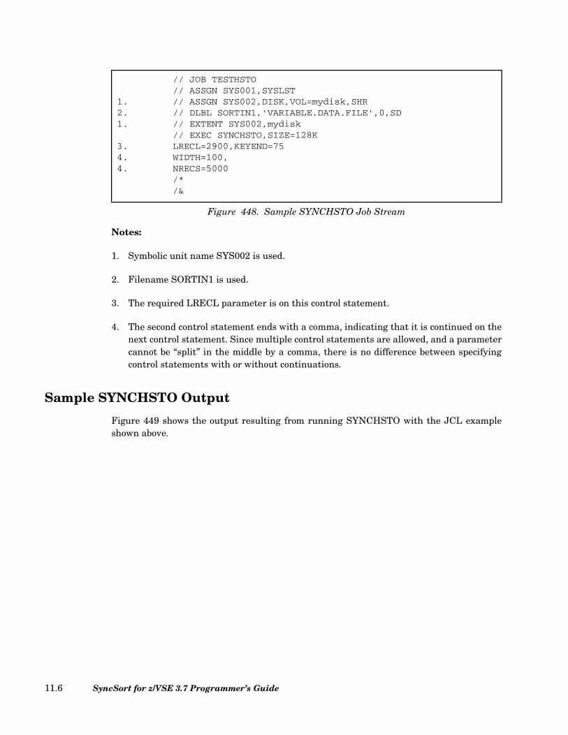
Notes:
1. Symbolic unit name SYS002 is used.
2. Filename SORTIN1 is used.
3. The required LRECL parameter is on this control statement.
4. The second control statement ends with a comma, indicating that it is continued on thenext control statement. Since multiple control statements are allowed, and a parametercannot be “split” in the middle by a comma, there is no difference between specifyingcontrol statements with or without continuations.
Sample SYNCHSTO Output
Figure 449 shows the output resulting from running SYNCHSTO with the JCL exampleshown above.
// JOB TESTHSTO// ASSGN SYS001,SYSLST
1. // ASSGN SYS002,DISK,VOL=mydisk,SHR2. // DLBL SORTIN1,'VARIABLE.DATA.FILE',0,SD1. // EXTENT SYS002,mydisk
// EXEC SYNCHSTO,SIZE=128K3. LRECL=2900,KEYEND=754. WIDTH=100,4. NRECS=5000
/*/&
Figure 448. Sample SYNCHSTO Job Stream
SyncSort for z/VSE 3.7 Programmer’s Guide11.6

1.
* * * * * * * * * * * * * SYNCHSTO PARAMETER STATEMENTS * * * * * * * * * * * * *
LRECL=2900,KEYEND=75
WIDTH=100,
NRECS=5000
2.
SHS001I NUMBER OF RECORDS . . . . . . . 5000
SHS002I TOTAL LENGTH OF ALL RECORDS . . 8169820
SHS003I AVERAGE RECORD LENGTH . . . . . 1633
SHS004I KEY END POSITION . . . . . . . 75
SHS005I HISTOGRAM LINE WIDTH . . . . . 100
SHS006I LONGEST RECORD . . . . . . . . 2900
SHS007I SHORTEST RECORD . . . . . . . . 402
SHS008I MOST COMMON RECORD LENGTH (L5). 1100
SHS009I AVG. SPACE PER RECORD (L6). . . 1651
SHS010I RECOMMENDED SEGMENT SIZE (L7) . 220
3.
RECORD RECORD LENGTH
COUNT MIN MAX
207 ********************************************************************* 400 499
205 ******************************************************************** 500 599
212 ********************************************************************** 600 699
193 **************************************************************** 700 799
214 *********************************************************************** 800 899
179 *********************************************************** 900 999
199 ****************************************************************** 1000 1099
224 ************************************************************************** 1100 1199
210 ********************************************************************** 1200 1299
201 ******************************************************************* 1300 1399
228 **************************************************************************** 1400 1499
200 ****************************************************************** 1500 1599
195 ***************************************************************** 1600 1699
193 **************************************************************** 1700 1799
200 ****************************************************************** 1800 1899
196 ***************************************************************** 1900 1999
192 **************************************************************** 2000 2099
179 *********************************************************** 2100 2199
195 ***************************************************************** 2200 2299
207 ********************************************************************* 2300 2399
194 **************************************************************** 2400 2499
188 ************************************************************** 2500 2599
189 *************************************************************** 2600 2699
188 ************************************************************** 2700 2799
210 ********************************************************************** 2800 2899
2 2900 2903
Fig
ure
449
.S
ampl
e S
YN
CH
ST
O O
utp
ut
1.T
he
para
met
ers
read
by
SY
NC
HS
TO
are
pri
nte
d at
th
e to
p of
th
e re
port
. If
th
ere
are
any
con
trol
sta
tem
ent
erro
rs,
erro
rm
essa
ges
are
prin
ted
her
e.
2.T
he
SY
NC
HS
TO
in
form
atio
nal
mes
sage
s de
scri
be t
he
char
acte
rist
ics
of t
he
reco
rds
that
hav
e be
en r
ead
for
the
file
, an
d th
ere
com
men
ded
valu
es o
f l 6
an
d l 7
th
at h
ave
been
cal
cula
ted.
Th
ese
are
desc
ribe
d in
“S
YN
CH
ST
O M
essa
ges”
on
pag
e 12
.37.
3.T
he
his
togr
am g
ives
a g
raph
ic d
ispl
ay o
f th
e di
stri
buti
on o
f th
e le
ngt
hs
of t
he r
ecor
ds i
n t
he
file
. R
EC
OR
D C
OU
NT
giv
es t
he
nu
mbe
r of
rec
ords
fal
ling
wit
hin
th
e m
inim
um
and
max
imu
m n
um
bers
sh
own
un
der
RE
CO
RD
LE
NG
TH
. Th
e ra
nge
is
the
lin
eW
IDT
H v
alu
e th
at h
as b
een
spe
cifi
ed a
nd
disp
laye
d. T
he
aste
risk
s re
pres
ent
the
nu
mbe
r of
rec
ords
in
eac
h r
ange
of
reco
rdle
ngt
hs.
Chapter 11. The SYNCHSTO Utility Program 11.7

SyncSort for z/VSE 3.7 Programmer’s Guide11.8

Chapter 12. Messages
SyncSort for z/VSE Messages
This chapter identifies SyncSort for z/VSE messages. A section at the end of this chapterdescribes the most common errors and how to correct them.
There are three main types of messages for the sort/merge program:
1. WERnnnA messages generally report a critical error (WER226A, for example, is anexception). The sort/merge has terminated for the indicated reasons.
2. WERnnnI and WERnnnB messages are informational, although some of them can betaken as warnings. In any case, processing continues.
3. WERnnnC messages are automatically printed on the console as well as the printerunless ROUTE=LST has been specified. In that case, they will only appear on theprinter.
Installation-related messages are documented in the SyncSort for z/VSE InstallationGuide.
The messages for SyncSort sort/merge that are not installation-related are given below.
Note: These messages are available in the VSE console EXPLAIN function if your systemsprogrammer installed SyncSort with this option.
WER002A EXCESS CONTROL STATEMENTSEXPLANATION: Over 80 control statements were used.
Chapter 12. Messages 12.1
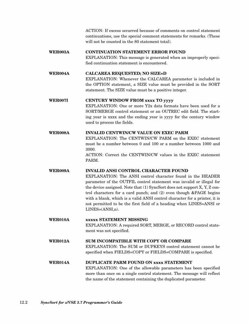
ACTION: If excess occurred because of comments on control statementcontinuations, use the special comment statements for remarks. (Thesewill not be counted in the 80 statement total).
WER003A CONTINUATION STATEMENT ERROR FOUNDEXPLANATION: This message is generated when an improperly speci-fied continuation statement is encountered.
WER004A CALCAREA REQUESTED; NO SIZE=DEXPLANATION: Whenever the CALCAREA parameter is included inthe OPTION statement, a SIZE value must be provided in the SORTstatement. The SIZE value must be a positive integer.
WER007I CENTURY WINDOW FROM xxxx TO yyyyEXPLANATION: One or more Y2x data formats have been used for aSORT/MERGE control statement or an OUTREC edit field. The start-ing year is xxxx and the ending year is yyyy for the century windowused to process the fields.
WER008A INVALID CENTWIN/CW VALUE ON EXEC PARMEXPLANATION: The CENTWIN/CW PARM on the EXEC statementmust be a number between 0 and 100 or a number between 1000 and3000.ACTION: Correct the CENTWIN/CW values in the EXEC statementPARM.
WER009A INVALID ANSI CONTROL CHARACTER FOUNDEXPLANATION: The ANSI control character found in the HEADERparameter of the OUTFIL control statement was invalid or illegal forthe device assigned. Note that (1) SyncSort does not support X, Y, Z con-trol characters for a card punch; and (2) even though &PAGE beginswith a blank, which is a valid ANSI control character for a printer, it isnot permitted to be the first field of a heading when LINES=ANSI orLINES=(ANSI,n).
WER010A xxxxx STATEMENT MISSINGEXPLANATION: A required SORT, MERGE, or RECORD control state-ment was not specified.
WER012A SUM INCOMPATIBLE WITH COPY OR COMPAREEXPLANATION: The SUM or DUPKEYS control statement cannot bespecified when FIELDS=COPY or FIELDS=COMPARE is specified.
WER014A DUPLICATE PARM FOUND ON xxxx STATEMENTEXPLANATION: One of the allowable parameters has been specifiedmore than once on a single control statement. The message will reflectthe name of the statement containing the duplicated parameter.
SyncSort for z/VSE 3.7 Programmer’s Guide12.2
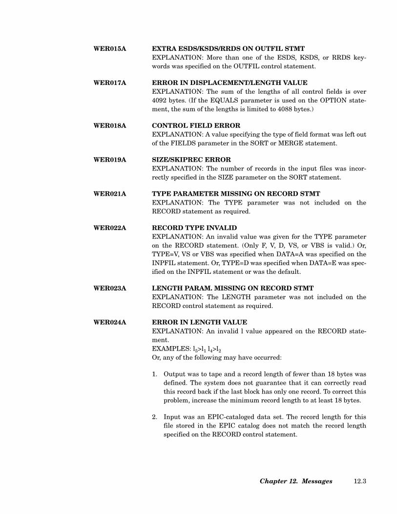
WER015A EXTRA ESDS/KSDS/RRDS ON OUTFIL STMTEXPLANATION: More than one of the ESDS, KSDS, or RRDS key-words was specified on the OUTFIL control statement.
WER017A ERROR IN DISPLACEMENT/LENGTH VALUEEXPLANATION: The sum of the lengths of all control fields is over4092 bytes. (If the EQUALS parameter is used on the OPTION state-ment, the sum of the lengths is limited to 4088 bytes.)
WER018A CONTROL FIELD ERROREXPLANATION: A value specifying the type of field format was left outof the FIELDS parameter in the SORT or MERGE statement.
WER019A SIZE/SKIPREC ERROREXPLANATION: The number of records in the input files was incor-rectly specified in the SIZE parameter on the SORT statement.
WER021A TYPE PARAMETER MISSING ON RECORD STMTEXPLANATION: The TYPE parameter was not included on theRECORD statement as required.
WER022A RECORD TYPE INVALIDEXPLANATION: An invalid value was given for the TYPE parameteron the RECORD statement. (Only F, V, D, VS, or VBS is valid.) Or,TYPE=V, VS or VBS was specified when DATA=A was specified on theINPFIL statement. Or, TYPE=D was specified when DATA=E was spec-ified on the INPFIL statement or was the default.
WER023A LENGTH PARAM. MISSING ON RECORD STMTEXPLANATION: The LENGTH parameter was not included on theRECORD control statement as required.
WER024A ERROR IN LENGTH VALUEEXPLANATION: An invalid l value appeared on the RECORD state-ment.EXAMPLES: l5>l1 l4>l2
Or, any of the following may have occurred:
1. Output was to tape and a record length of fewer than 18 bytes wasdefined. The system does not guarantee that it can correctly readthis record back if the last block has only one record. To correct thisproblem, increase the minimum record length to at least 18 bytes.
2. Input was an EPIC-cataloged data set. The record length for thisfile stored in the EPIC catalog does not match the record lengthspecified on the RECORD control statement.
Chapter 12. Messages 12.3
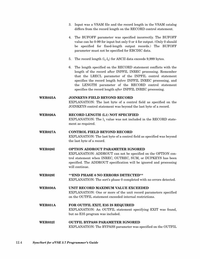
3. Input was a VSAM file and the record length in the VSAM catalogdiffers from the record length on the RECORD control statement.
4. The BUFOFF parameter was specified incorrectly. The BUFOFFvalue can be 0-99 for input but only 0 or 4 for output. (Only 0 shouldbe specified for fixed-length output records.) The BUFOFFparameter must not be specified for EBCDIC data.
5. The record length (l1-l5) for ASCII data exceeds 9,999 bytes.
6. The length specified on the RECORD statement conflicts with thelength of the record after INPFIL INREC processing. Rememberthat the LRECL parameter of the INPFIL control statementspecifies the record length before INPFIL INREC processing, andthe LENGTH parameter of the RECORD control statementspecifies the record length after INPFIL INREC processing.
WER025A JOINKEYS FIELD BEYOND RECORDEXPLANATION: The last byte of a control field as specified on theJOINKEYS control statement was beyond the last byte of a record.
WER026A RECORD LENGTH (L1) NOT SPECIFIEDEXPLANATION: The l1 value was not included in the RECORD state-ment as required.
WER027A CONTROL FIELD BEYOND RECORDEXPLANATION: The last byte of a control field as specified was beyondthe last byte of a record.
WER028I OPTION ADDROUT PARAMETER IGNOREDEXPLANATION: ADDROUT can not be specified on the OPTION con-trol statement when INREC, OUTREC, SUM, or DUPKEYS has beenspecified. The ADDROUT specification will be ignored and processingwill continue.
WER029I **END PHASE 0 NO ERRORS DETECTED**EXPLANATION: The sort’s phase 0 completed with no errors detected.
WER030A UNIT RECORD MAXIMUM VALUE EXCEEDEDEXPLANATION: One or more of the unit record parameters specifiedon the OUTFIL statement exceeded internal restrictions.
WER031A FOR OUTFIL EXIT, E35 IS REQUIREDEXPLANATION: An OUTFIL statement specifying EXIT was found,but no E35 program was included.
WER032I OUTFIL BYPASS PARAMETER IGNOREDEXPLANATION: The BYPASS parameter was specified on the OUTFIL
SyncSort for z/VSE 3.7 Programmer’s Guide12.4

statement. Since this may be specified only on the INPFIL statement,the parameter was ignored and processing continued.
WER033A FILESOUT CONFLICTS WITH OUTFIL FILESEXPLANATION: The number of output files specified in theFILESOUT parameter on the SORT or MERGE control statementdiffers from the number of output files specified in the FILESparameter on the OUTFIL control statement.ACTION: Correct either the FILESOUT parameter or the FILESparameter so that both parameters specify the same number of outputfiles.
WER034A ENDREC < STARTREC ON IN/OUTFIL STMTWER034A ENDREC < STARTREC ON XSUMFIL STMTWER034A ENDREC < STARTREC ON XDUPFIL STMT
EXPLANATION: The values specified for STARTREC and ENDREC onan INPFIL/OUTFIL, XDUPFIL, or XSUMFIL control statement areinconsistent. The ENDREC value must be larger than or equal to theSTARTREC value.
WER036I XSUMFIL IGNORED, XSUM NOT SPECIFIEDWER036I XDUPFIL IGNORED, XDUP NOT SPECIFIED
EXPLANATION: The sort has found and ignored either an XSUMFILcontrol statement because the XSUM parameter is not present, or anXDUPFIL control statement because the XDUP parameter is notpresent. To activate XSUM or XDUP processing (i.e., saving the elimi-nated records in a separate output file), the XSUM or XDUP parametermust be specified.
WER037I NO KEYWORDS FOUND ON xxxxx STATEMENTEXPLANATION: One of the SyncSort control statements, xxxxx, hasbeen specified without any of the allowable keywords. This messagewill reflect the name of the appropriate control statement.
WER039A INSUFFICIENT STORAGEEXPLANATION: The sort started to run, but found insufficient storageduring Phase 0 or Phase 1.ACTION: Check to see that figures are accurate if the SIZE parameterwas used on the JCL EXEC statement and/or STORAGE specified onthe OPTION statement. (SyncSort requires at least 64K of storage torun.) If exit programs have been preloaded, check to see that they wereloaded into the highest possible positions in the partition. Increase stor-age.
WER040A VSAM OR KEYED FILE NOT ON DISKEXPLANATION: All keyed or VSAM files must be on disk.
Chapter 12. Messages 12.5

WER042A UNITS ASSIGN ERR: DVC=XX, LUN=YYEXPLANATION: In attempting to determine the assignment forLUN=YY (where YY is the SYSNBR in hexadecimal), the sort/mergefound a discrepancy. Either (1) DVC=XX was not supported, where XXis the device type in hexadecimal; or (2) LUN=YY was not assigned, UAor IGN (in this case, DVC=FF).
WER043I EXIT IGNORED, THIS PHASE NOT MERGEEXPLANATION: A Phase 2 exit, which can be used only with a sort,was specified for a merge. The exit was never processed, and the sortcontinued.
WER044A ILLEGAL OVERLAPPING OF DECIMAL FIELDSEXPLANATION: Two control fields may not share the rightmost(signed) byte of a packed or zoned decimal field unless they both end atthat byte. (A signed byte can not be embedded in a decimal field.)EXAMPLE: FIELDS=(8,2,PD,A,9,4,PD,A,5,3,CH,D)
WER047A xxxxx STATEMENT HAS SYNTAX ERROREXPLANATION: One of the SyncSort control statements, xxxxx, con-tains a syntax error. The name of the statement containing the syntaxerror will be reflected in the message.
WER048I E32 EXIT IGNORED WITH SORT STATEMENTEXPLANATION: An exit E32 was specified for a sort program. Since anE32 can be used only with a merge, the exit was ignored and the sortcontinued.
WER049A CALCAREA INCOMPATIBLE WITH MERGE/COPYEXPLANATION: CALCAREA cannot be specified for a merge or copyapplication.
WER051A OVERLAPPING SORTWK FILES ON 'nnn'EXPLANATION: Two (or more) of the SORTWK files within the job-stream have overlapping extents. The 'nnn' device address identifiesthe relevant ASSGN statements.
WER054A MIXED CKD AND FBA SORTWKS ARE ILLEGALEXPLANATION: When Fixed Block Architecture (FBA) devices (3310and 3370) are used for SORTWK, they must be the only work devicetype. They can not be mixed with the standard Count Key Data (CKD)devices (3380, 3390, etc.).
WER056A FILEIN CONFLICTS WITH INPFIL STMTWER056A FILES CONFLICTS WITH JOINKEYS STMT
EXPLANATION: The number of input files specified in the FILESparameter on the SORT, MERGE, or JOINKEYS control statement dif-
SyncSort for z/VSE 3.7 Programmer’s Guide12.6

fers from the number of input files specified in the FILES/FNAMESparameter on the INPFIL control statement.ACTION: Correct either the FILES parameter or the number of INPFIL control statements so that both parameters specify the samenumber of input files.
WER058I ALTSEQ STMT IGNORED - NO AQ FIELDEXPLANATION: If an ALTSEQ statement is used, code AQ for the fvalue of at least one control field in the FIELDS parameter of the SORTor MERGE statement. The sort will run as if the ALTSEQ statementhad not been coded.
WER059A RECORD LEN/BLKSIZE INVALID FOR DEVICEEXPLANATION: The l2 value on the RECORD statement exceeded thetrack capacity of the device used for SORTWK, or the BLKSIZE valuespecified on the INPFIL/OUTFIL statement exceeded the track capac-ity of the device used for SORTIN/SORTOUT.
WER063I STORAGE AVAILEXPLANATION: This is the amount of storage, given in decimal bytes,in which the sort/merge is running.
WER065A PROBABLE DECK STRUCTURE ERROREXPLANATION: An invalid operation definer was found.ACTION: Check for misspelling of operation definers such as controlstatements.
WER066I filename CONTROL INTERVAL SIZE=xxxxxEXPLANATION: filename indicates the filename (e.g. SORTOUT,SORTOF2). xxxxx indicates the control interval size SyncSort hasselected for SAM SORTOUT on an FBA device. This value was deter-mined by user DLBL specifications or by internal calculations.
WER067A DUPLICATE xxxxx STATEMENT FOUNDEXPLANATION: One of the allowable SyncSort control statements,xxxxx, was specified more than once. The name of the duplicated state-ment will be reflected in the message.
WER068A INVALID CISIZE SPECIFIEDEXPLANATION: The CISIZE value specified on the DLBL statement isinsufficient for one block or is not a multiple of 512. Or, a disk spacemanagement package has changed the CISIZE via a catalogue entry toa value insufficient to accommodate one block of data.
WER070A INVALID INPUT DEVICE FOR ADDROUTEXPLANATION: SORTIN is an FBA device and CKD ADDROUT for-mat is not applicable.
Chapter 12. Messages 12.7
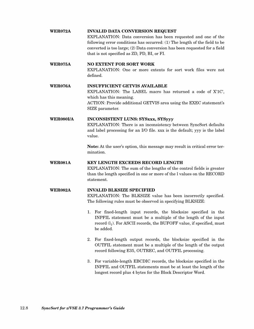
WER072A INVALID DATA CONVERSION REQUESTEXPLANATION: Data conversion has been requested and one of thefollowing error conditions has occurred: (1) The length of the field to beconverted is too large; (2) Data conversion has been requested for a fieldthat is not specified as ZD, PD, BI, or FI.
WER075A NO EXTENT FOR SORT WORKEXPLANATION: One or more extents for sort work files were notdefined.
WER076A INSUFFICIENT GETVIS AVAILABLEEXPLANATION: The LABEL macro has returned a code of X'1C',which has this meaning.ACTION: Provide additional GETVIS area using the EXEC statement’sSIZE parameter.
WER080I/A INCONSISTENT LUNS: SYSxxx, SYSyyyEXPLANATION: There is an inconsistency between SyncSort defaultsand label processing for an I/O file. xxx is the default; yyy is the labelvalue.
Note: At the user’s option, this message may result in critical error ter-mination.
WER081A KEY LENGTH EXCEEDS RECORD LENGTHEXPLANATION: The sum of the lengths of the control fields is greaterthan the length specified in one or more of the l values on the RECORDstatement.
WER082A INVALID BLKSIZE SPECIFIEDEXPLANATION: The BLKSIZE value has been incorrectly specified.The following rules must be observed in specifying BLKSIZE:
1. For fixed-length input records, the blocksize specified in theINPFIL statement must be a multiple of the length of the inputrecord (l1). For ASCII records, the BUFOFF value, if specified, mustbe added.
2. For fixed-length output records, the blocksize specified in theOUTFIL statement must be a multiple of the length of the outputrecord following E35, OUTREC, and OUTFIL processing.
3. For variable-length EBCDIC records, the blocksize specified in theINPFIL and OUTFIL statements must be at least the length of thelongest record plus 4 bytes for the Block Descriptor Word.
SyncSort for z/VSE 3.7 Programmer’s Guide12.8
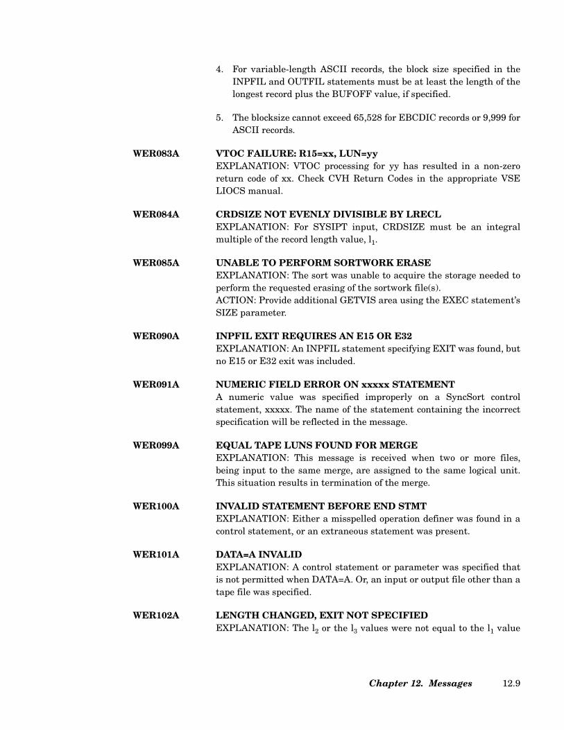
4. For variable-length ASCII records, the block size specified in theINPFIL and OUTFIL statements must be at least the length of thelongest record plus the BUFOFF value, if specified.
5. The blocksize cannot exceed 65,528 for EBCDIC records or 9,999 forASCII records.
WER083A VTOC FAILURE: R15=xx, LUN=yyEXPLANATION: VTOC processing for yy has resulted in a non-zeroreturn code of xx. Check CVH Return Codes in the appropriate VSELIOCS manual.
WER084A CRDSIZE NOT EVENLY DIVISIBLE BY LRECLEXPLANATION: For SYSIPT input, CRDSIZE must be an integralmultiple of the record length value, l1.
WER085A UNABLE TO PERFORM SORTWORK ERASEEXPLANATION: The sort was unable to acquire the storage needed toperform the requested erasing of the sortwork file(s).ACTION: Provide additional GETVIS area using the EXEC statement’sSIZE parameter.
WER090A INPFIL EXIT REQUIRES AN E15 OR E32EXPLANATION: An INPFIL statement specifying EXIT was found, butno E15 or E32 exit was included.
WER091A NUMERIC FIELD ERROR ON xxxxx STATEMENTA numeric value was specified improperly on a SyncSort controlstatement, xxxxx. The name of the statement containing the incorrectspecification will be reflected in the message.
WER099A EQUAL TAPE LUNS FOUND FOR MERGEEXPLANATION: This message is received when two or more files,being input to the same merge, are assigned to the same logical unit.This situation results in termination of the merge.
WER100A INVALID STATEMENT BEFORE END STMTEXPLANATION: Either a misspelled operation definer was found in acontrol statement, or an extraneous statement was present.
WER101A DATA=A INVALIDEXPLANATION: A control statement or parameter was specified thatis not permitted when DATA=A. Or, an input or output file other than atape file was specified.
WER102A LENGTH CHANGED, EXIT NOT SPECIFIEDEXPLANATION: The l2 or the l3 values were not equal to the l1 value
Chapter 12. Messages 12.9

on the RECORD statement, but neither an exit nor an OUTREC state-ment was included.
WER103A HEADER/TRAILER FIELD BEYOND RECORDEXPLANATION: A data field specified in a HEADER or TRAILER isbeyond the length of the record.ACTION: Make sure that the position plus the length of the data fieldspecified in the HEADER or TRAILER does not exceed the length of therecord.
WER105A INVALID FORMAT FOR ASCII DATAEXPLANATION: An invalid value was specified for the code format (f).Only AC, ASL, or AST are valid format values for ASCII data.
WER106A PHASE NAME TOO LONGEXPLANATION: A phase name specified on the MODS statement ismore than the allowed eight characters.
WER108A EXIT ADDRESS IS INVALIDEXPLANATION: An absolute address that is not on a doublewordboundary was specified in the MODS statement (in the loading infor-mation parameter).
WER109A REXX ENVIRONMENT UNAVAILABLEEXPLANATION: The current operating environment does not supportthe execution of a REXX exit. A REXX exit can only be run on an ESAmode machine with REXX/VSE installed.
WER110A FILE NAME TOO LONGEXPLANATION: A file name of over eight characters was specified onthe OPTION statement.
WER112A NO NUMERIC FIELD ON MODS STATEMENTEXPLANATION: A MODS statement with a missing loading addresswas found.
WER113I BLOCK SIZE EXCEEDS CI SIZEEXPLANATION: The BLKSIZE specified on either the INPFIL orOUTFIL control statement is greater than the size of the control inter-val specified for the corresponding input file.
WER114A INVALID INTERMEDIATE STORAGE DEVICEEXPLANATION: This message is due to an error in the JCL specifica-tion of files. User SORTIN files may not be fully specified or there maybe an inconsistency between the values of the WORK and FILESparameters - somehow a discrepancy has arisen between the number offiles and the number of file labels in use.
SyncSort for z/VSE 3.7 Programmer’s Guide12.10

WER115A REQ’D PARM MISSING ON JOINKEYS STMTEXPLANATION: A parameter was not included on the JOINKEYS con-trol statement as required.
WER116A MISSING PARM FOR SORT OR MERGEEXPLANATION: A required parameter is missing from the SORT orMERGE statement.
WER117A PHASE 0 HAS CRITICAL ERROREXPLANATION: The sort/merge has found an error in Phase 0 that istoo serious to allow the program to run.
WER118A MINIMUM XXXX SORT WORK AREA nnnnnnEXPLANATION: Phase 0 has been completed and the CALCAREAparameter (requested explicitly using the OPTION statement or implic-itly using ANALYZE) has terminated the sort with this report of thenumber of tracks (for CKD devices) or blocks (for FBA devices) neces-sary for the SORTWK files. XXXX indicates the device type, andnnnnnn indicates the number of tracks or blocks. If DEVWK is speci-fied, SyncSort will display the number of tracks needed for the workarea of the listed devices. Otherwise, it will display the number oftracks needed for each of the CKD and FBA devices.
WER119A EXCESS ERRORS NOT DISPLAYEDEXPLANATION: A very large number of errors have been generated.Some of the error messages will not be displayed.ACTION: Correct all of the indicated errors.
WER120A OVERLAPPING FIELDS IN HEADER/TRAILEREXPLANATION: A field specified in a header or trailer overlappedanother field.
WER123A SUM FIELD BEYOND RECORDWER123A DUPKEYS FIELD BEYOND RECORD
EXPLANATION: A field specified either on the SUM control statementor the DUPKEYS control statement is beyond the length of the record.
WER124A ILLEGAL OVERLAPPING OF SUM FIELDSWER124A ILLEGAL OVERLAPPING OF DUPKEYS FIELDS
EXPLANATION: A field specified in the SUM or DUPKEYS statementoverlapped with another field in the same statement or a SORT/MERGE control field.
WER127A INREC/OUTREC FIELD BEYOND RECORDREFORMATBUILD/OVERLAYEXPLANATION: A field specified on the INREC, OUTREC,
Chapter 12. Messages 12.11

REFORMAT, BUILD, or OVERLAY control statement or parameterwas either beyond the minimum length of the record or more than 4096bytes long.
WER128A ILLEGAL INREC/OUTREC DATA FIELD REFORMAT BUILD/OVERLAY
EXPLANATION: Any of the following may have occurred:
1. A non-numeric value was given for a numeric field.
2. A zero value was specified.
3. A value was omitted.
4. A space value was greater than 256.
5. An alignment value other than H, F, or D was specified.
6. The last value specified was a p value indicating the variableportion of a record, but fixed-length records were specified.
7. Overlapping output fields were specified.
8. No data portion (past the RDW) was specified for variable-lengthrecords.
WER129A INCLUDE/OMIT FIELD BEYOND RECORDIFTHENEXPLANATION: The length of the field specified on an INCLUDE,OMIT, or IFTHEN control statement or parameter for either inclusionor omission is longer than the length of the user’s records.
WER130A INCLUDE/OMIT INVALID CONDIFTHEN SELF DEF TERM
LENGTHFIELD POSITIONFORMATLOGICAL OPERATORWILDCARD SYNTAX
EXPLANATION: The indicated parameter on the INCLUDE, OMIT, orIFTHEN statement or parameter was incorrectly specified.
WER132A INCLUDE/OMIT FORMATS INCOMPATIBLEIFTHENEXPLANATION: A format code in either a field-to-field comparison orfield-to-constant comparison is illegal.
SyncSort for z/VSE 3.7 Programmer’s Guide12.12
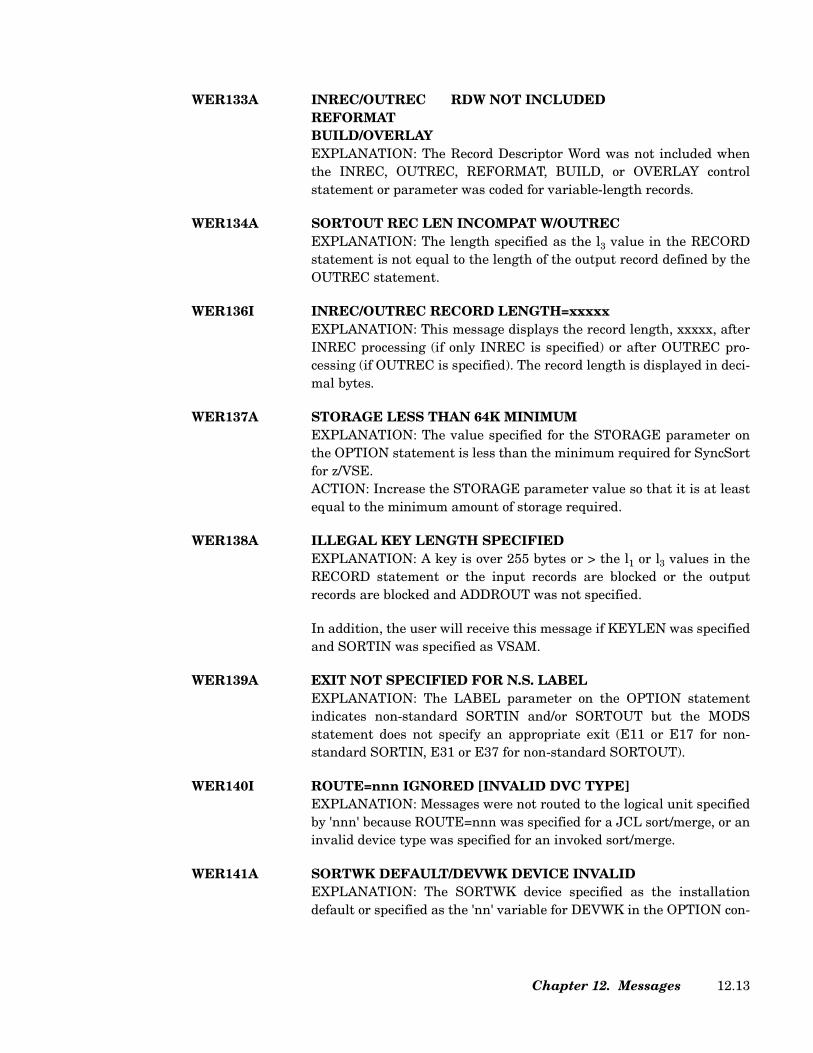
WER133A INREC/OUTREC RDW NOT INCLUDEDREFORMATBUILD/OVERLAYEXPLANATION: The Record Descriptor Word was not included whenthe INREC, OUTREC, REFORMAT, BUILD, or OVERLAY controlstatement or parameter was coded for variable-length records.
WER134A SORTOUT REC LEN INCOMPAT W/OUTRECEXPLANATION: The length specified as the l3 value in the RECORDstatement is not equal to the length of the output record defined by theOUTREC statement.
WER136I INREC/OUTREC RECORD LENGTH=xxxxxEXPLANATION: This message displays the record length, xxxxx, afterINREC processing (if only INREC is specified) or after OUTREC pro-cessing (if OUTREC is specified). The record length is displayed in deci-mal bytes.
WER137A STORAGE LESS THAN 64K MINIMUMEXPLANATION: The value specified for the STORAGE parameter onthe OPTION statement is less than the minimum required for SyncSortfor z/VSE.ACTION: Increase the STORAGE parameter value so that it is at leastequal to the minimum amount of storage required.
WER138A ILLEGAL KEY LENGTH SPECIFIEDEXPLANATION: A key is over 255 bytes or > the l1 or l3 values in theRECORD statement or the input records are blocked or the outputrecords are blocked and ADDROUT was not specified.
In addition, the user will receive this message if KEYLEN was specifiedand SORTIN was specified as VSAM.
WER139A EXIT NOT SPECIFIED FOR N.S. LABELEXPLANATION: The LABEL parameter on the OPTION statementindicates non-standard SORTIN and/or SORTOUT but the MODSstatement does not specify an appropriate exit (E11 or E17 for non-standard SORTIN, E31 or E37 for non-standard SORTOUT).
WER140I ROUTE=nnn IGNORED [INVALID DVC TYPE]EXPLANATION: Messages were not routed to the logical unit specifiedby 'nnn' because ROUTE=nnn was specified for a JCL sort/merge, or aninvalid device type was specified for an invoked sort/merge.
WER141A SORTWK DEFAULT/DEVWK DEVICE INVALIDEXPLANATION: The SORTWK device specified as the installationdefault or specified as the 'nn' variable for DEVWK in the OPTION con-
Chapter 12. Messages 12.13
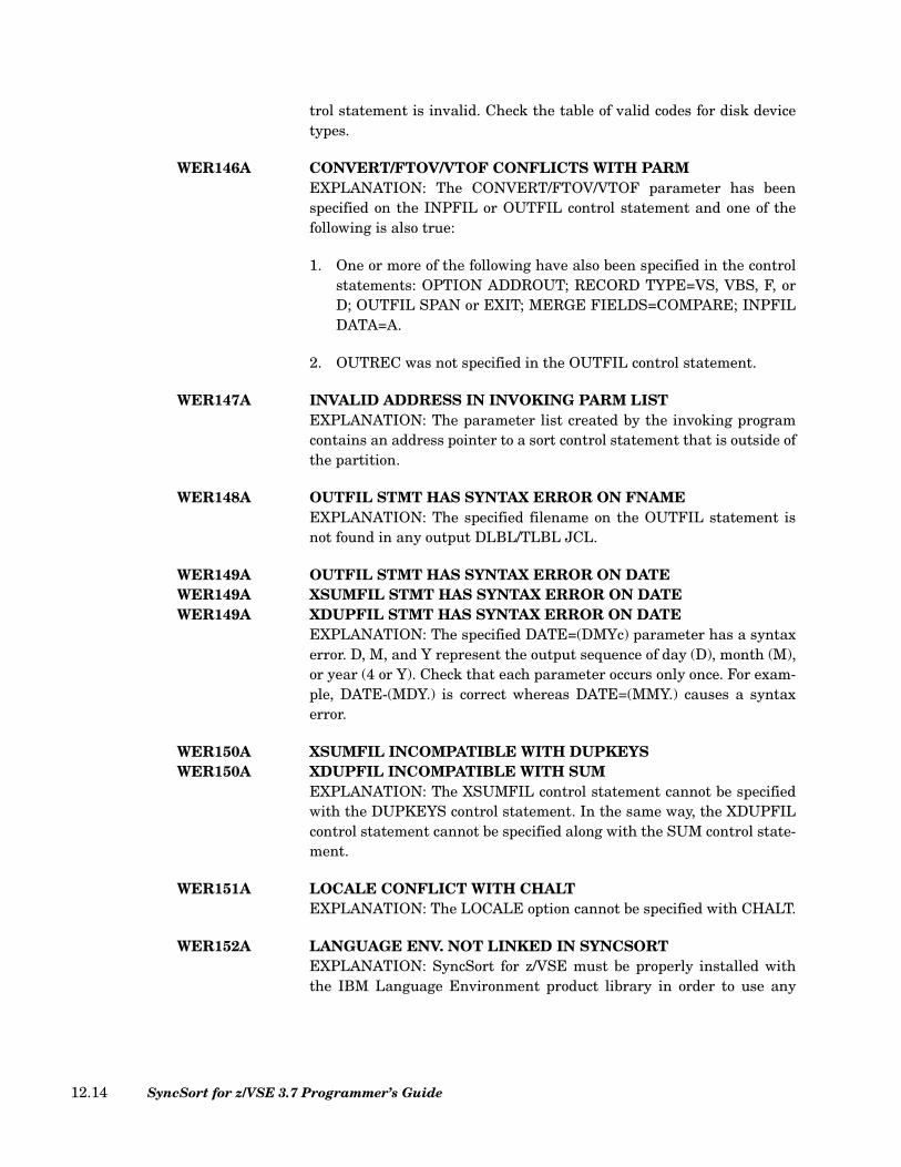
trol statement is invalid. Check the table of valid codes for disk devicetypes.
WER146A CONVERT/FTOV/VTOF CONFLICTS WITH PARMEXPLANATION: The CONVERT/FTOV/VTOF parameter has beenspecified on the INPFIL or OUTFIL control statement and one of thefollowing is also true:
1. One or more of the following have also been specified in the controlstatements: OPTION ADDROUT; RECORD TYPE=VS, VBS, F, orD; OUTFIL SPAN or EXIT; MERGE FIELDS=COMPARE; INPFILDATA=A.
2. OUTREC was not specified in the OUTFIL control statement.
WER147A INVALID ADDRESS IN INVOKING PARM LISTEXPLANATION: The parameter list created by the invoking programcontains an address pointer to a sort control statement that is outside ofthe partition.
WER148A OUTFIL STMT HAS SYNTAX ERROR ON FNAMEEXPLANATION: The specified filename on the OUTFIL statement isnot found in any output DLBL/TLBL JCL.
WER149A OUTFIL STMT HAS SYNTAX ERROR ON DATEWER149A XSUMFIL STMT HAS SYNTAX ERROR ON DATEWER149A XDUPFIL STMT HAS SYNTAX ERROR ON DATE
EXPLANATION: The specified DATE=(DMYc) parameter has a syntaxerror. D, M, and Y represent the output sequence of day (D), month (M),or year (4 or Y). Check that each parameter occurs only once. For exam-ple, DATE-(MDY.) is correct whereas DATE=(MMY.) causes a syntaxerror.
WER150A XSUMFIL INCOMPATIBLE WITH DUPKEYSWER150A XDUPFIL INCOMPATIBLE WITH SUM
EXPLANATION: The XSUMFIL control statement cannot be specifiedwith the DUPKEYS control statement. In the same way, the XDUPFILcontrol statement cannot be specified along with the SUM control state-ment.
WER151A LOCALE CONFLICT WITH CHALTEXPLANATION: The LOCALE option cannot be specified with CHALT.
WER152A LANGUAGE ENV. NOT LINKED IN SYNCSORTEXPLANATION: SyncSort for z/VSE must be properly installed withthe IBM Language Environment product library in order to use any
SyncSort for z/VSE 3.7 Programmer’s Guide12.14
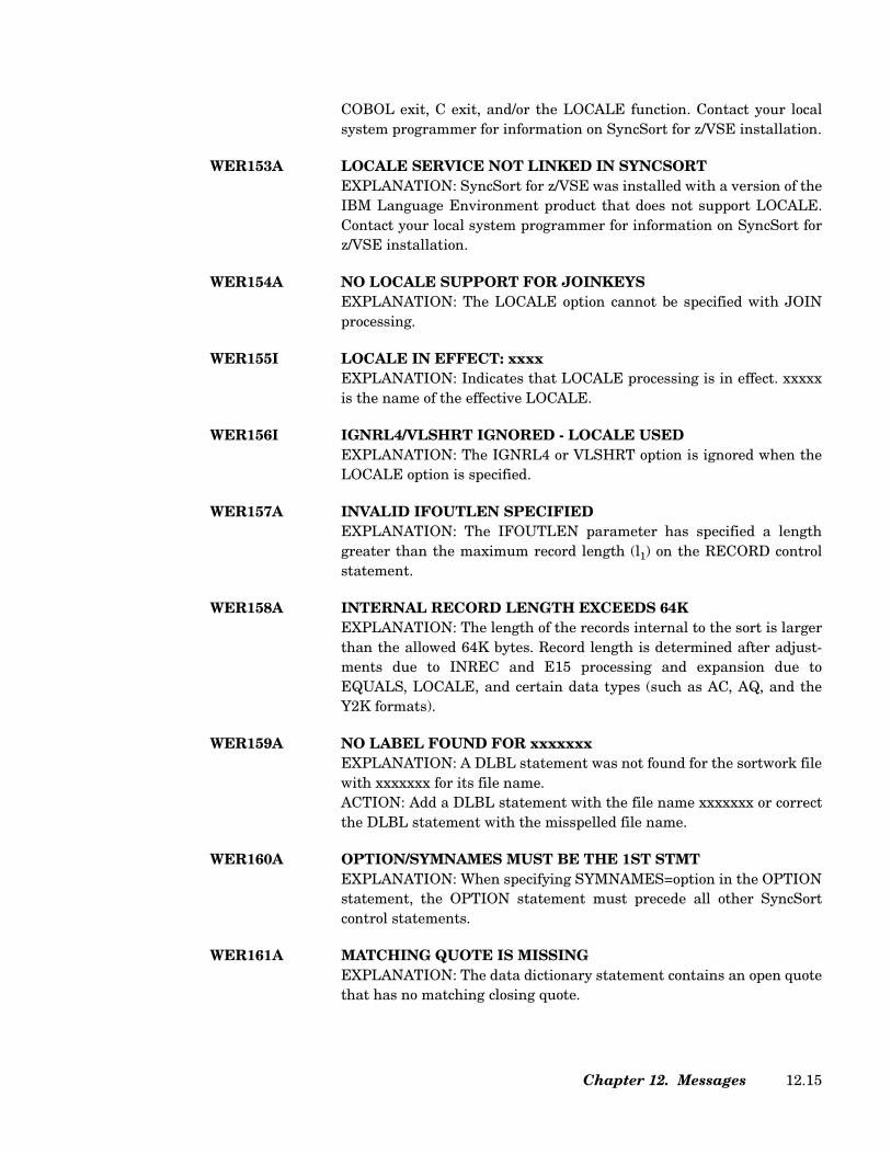
COBOL exit, C exit, and/or the LOCALE function. Contact your localsystem programmer for information on SyncSort for z/VSE installation.
WER153A LOCALE SERVICE NOT LINKED IN SYNCSORTEXPLANATION: SyncSort for z/VSE was installed with a version of theIBM Language Environment product that does not support LOCALE.Contact your local system programmer for information on SyncSort forz/VSE installation.
WER154A NO LOCALE SUPPORT FOR JOINKEYSEXPLANATION: The LOCALE option cannot be specified with JOINprocessing.
WER155I LOCALE IN EFFECT: xxxxEXPLANATION: Indicates that LOCALE processing is in effect. xxxxxis the name of the effective LOCALE.
WER156I IGNRL4/VLSHRT IGNORED - LOCALE USEDEXPLANATION: The IGNRL4 or VLSHRT option is ignored when theLOCALE option is specified.
WER157A INVALID IFOUTLEN SPECIFIEDEXPLANATION: The IFOUTLEN parameter has specified a lengthgreater than the maximum record length (l1) on the RECORD controlstatement.
WER158A INTERNAL RECORD LENGTH EXCEEDS 64KEXPLANATION: The length of the records internal to the sort is largerthan the allowed 64K bytes. Record length is determined after adjust-ments due to INREC and E15 processing and expansion due toEQUALS, LOCALE, and certain data types (such as AC, AQ, and theY2K formats).
WER159A NO LABEL FOUND FOR xxxxxxxEXPLANATION: A DLBL statement was not found for the sortwork filewith xxxxxxx for its file name.ACTION: Add a DLBL statement with the file name xxxxxxx or correctthe DLBL statement with the misspelled file name.
WER160A OPTION/SYMNAMES MUST BE THE 1ST STMTEXPLANATION: When specifying SYMNAMES=option in the OPTIONstatement, the OPTION statement must precede all other SyncSortcontrol statements.
WER161A MATCHING QUOTE IS MISSINGEXPLANATION: The data dictionary statement contains an open quotethat has no matching closing quote.
Chapter 12. Messages 12.15
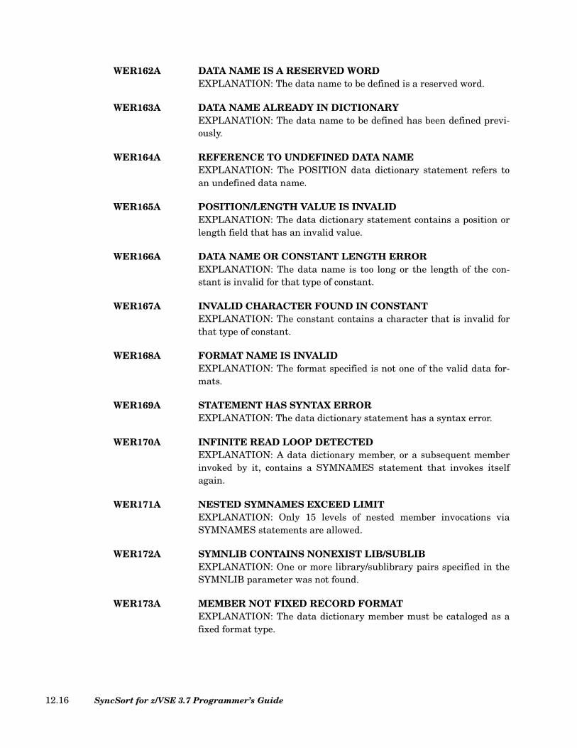
WER162A DATA NAME IS A RESERVED WORDEXPLANATION: The data name to be defined is a reserved word.
WER163A DATA NAME ALREADY IN DICTIONARYEXPLANATION: The data name to be defined has been defined previ-ously.
WER164A REFERENCE TO UNDEFINED DATA NAMEEXPLANATION: The POSITION data dictionary statement refers toan undefined data name.
WER165A POSITION/LENGTH VALUE IS INVALIDEXPLANATION: The data dictionary statement contains a position orlength field that has an invalid value.
WER166A DATA NAME OR CONSTANT LENGTH ERROREXPLANATION: The data name is too long or the length of the con-stant is invalid for that type of constant.
WER167A INVALID CHARACTER FOUND IN CONSTANTEXPLANATION: The constant contains a character that is invalid forthat type of constant.
WER168A FORMAT NAME IS INVALIDEXPLANATION: The format specified is not one of the valid data for-mats.
WER169A STATEMENT HAS SYNTAX ERROREXPLANATION: The data dictionary statement has a syntax error.
WER170A INFINITE READ LOOP DETECTEDEXPLANATION: A data dictionary member, or a subsequent memberinvoked by it, contains a SYMNAMES statement that invokes itselfagain.
WER171A NESTED SYMNAMES EXCEED LIMITEXPLANATION: Only 15 levels of nested member invocations viaSYMNAMES statements are allowed.
WER172A SYMNLIB CONTAINS NONEXIST LIB/SUBLIBEXPLANATION: One or more library/sublibrary pairs specified in theSYMNLIB parameter was not found.
WER173A MEMBER NOT FIXED RECORD FORMATEXPLANATION: The data dictionary member must be cataloged as afixed format type.
SyncSort for z/VSE 3.7 Programmer’s Guide12.16
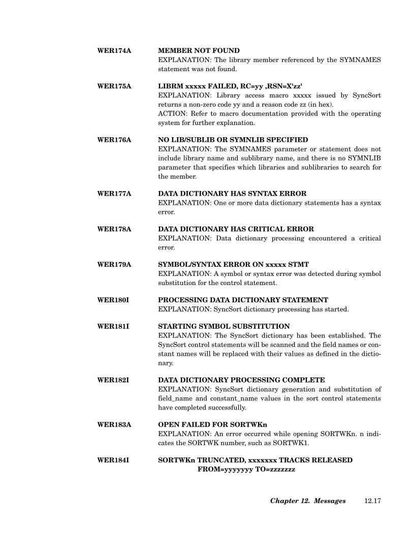
WER174A MEMBER NOT FOUNDEXPLANATION: The library member referenced by the SYMNAMESstatement was not found.
WER175A LIBRM xxxxx FAILED, RC=yy ,RSN=X'zz'EXPLANATION: Library access macro xxxxx issued by SyncSortreturns a non-zero code yy and a reason code zz (in hex). ACTION: Refer to macro documentation provided with the operatingsystem for further explanation.
WER176A NO LIB/SUBLIB OR SYMNLIB SPECIFIEDEXPLANATION: The SYMNAMES parameter or statement does notinclude library name and sublibrary name, and there is no SYMNLIBparameter that specifies which libraries and sublibraries to search forthe member.
WER177A DATA DICTIONARY HAS SYNTAX ERROREXPLANATION: One or more data dictionary statements has a syntaxerror.
WER178A DATA DICTIONARY HAS CRITICAL ERROREXPLANATION: Data dictionary processing encountered a criticalerror.
WER179A SYMBOL/SYNTAX ERROR ON xxxxx STMTEXPLANATION: A symbol or syntax error was detected during symbolsubstitution for the control statement.
WER180I PROCESSING DATA DICTIONARY STATEMENTEXPLANATION: SyncSort dictionary processing has started.
WER181I STARTING SYMBOL SUBSTITUTIONEXPLANATION: The SyncSort dictionary has been established. TheSyncSort control statements will be scanned and the field names or con-stant names will be replaced with their values as defined in the dictio-nary.
WER182I DATA DICTIONARY PROCESSING COMPLETEEXPLANATION: SyncSort dictionary generation and substitution offield_name and constant_name values in the sort control statementshave completed successfully.
WER183A OPEN FAILED FOR SORTWKnEXPLANATION: An error occurred while opening SORTWKn. n indi-cates the SORTWK number, such as SORTWK1.
WER184I SORTWKn TRUNCATED, xxxxxxx TRACKS RELEASEDFROM=yyyyyyy TO=zzzzzzz
Chapter 12. Messages 12.17
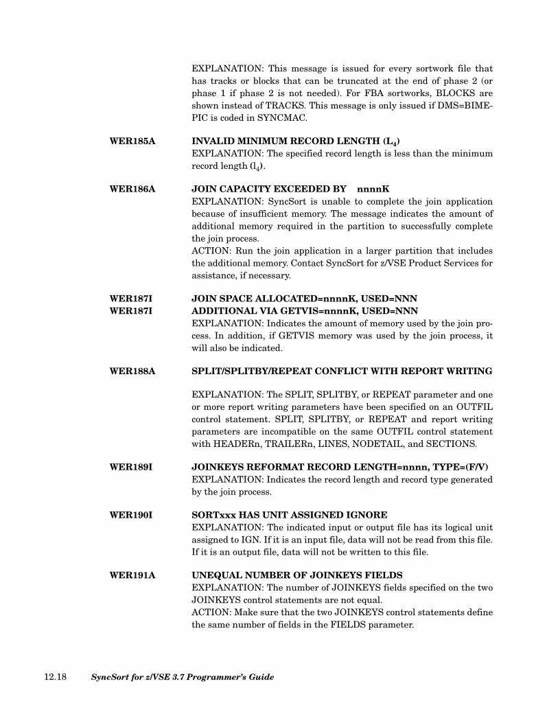
EXPLANATION: This message is issued for every sortwork file thathas tracks or blocks that can be truncated at the end of phase 2 (orphase 1 if phase 2 is not needed). For FBA sortworks, BLOCKS areshown instead of TRACKS. This message is only issued if DMS=BIME-PIC is coded in SYNCMAC.
WER185A INVALID MINIMUM RECORD LENGTH (L4)EXPLANATION: The specified record length is less than the minimumrecord length (l4).
WER186A JOIN CAPACITY EXCEEDED BY nnnnKEXPLANATION: SyncSort is unable to complete the join applicationbecause of insufficient memory. The message indicates the amount ofadditional memory required in the partition to successfully completethe join process.ACTION: Run the join application in a larger partition that includesthe additional memory. Contact SyncSort for z/VSE Product Services forassistance, if necessary.
WER187I JOIN SPACE ALLOCATED=nnnnK, USED=NNNWER187I ADDITIONAL VIA GETVIS=nnnnK, USED=NNN
EXPLANATION: Indicates the amount of memory used by the join pro-cess. In addition, if GETVIS memory was used by the join process, itwill also be indicated.
WER188A SPLIT/SPLITBY/REPEAT CONFLICT WITH REPORT WRITING
EXPLANATION: The SPLIT, SPLITBY, or REPEAT parameter and oneor more report writing parameters have been specified on an OUTFILcontrol statement. SPLIT, SPLITBY, or REPEAT and report writingparameters are incompatible on the same OUTFIL control statementwith HEADERn, TRAILERn, LINES, NODETAIL, and SECTIONS.
WER189I JOINKEYS REFORMAT RECORD LENGTH=nnnn, TYPE=(F/V)EXPLANATION: Indicates the record length and record type generatedby the join process.
WER190I SORTxxx HAS UNIT ASSIGNED IGNOREEXPLANATION: The indicated input or output file has its logical unitassigned to IGN. If it is an input file, data will not be read from this file.If it is an output file, data will not be written to this file.
WER191A UNEQUAL NUMBER OF JOINKEYS FIELDSEXPLANATION: The number of JOINKEYS fields specified on the twoJOINKEYS control statements are not equal. ACTION: Make sure that the two JOINKEYS control statements definethe same number of fields in the FIELDS parameter.
SyncSort for z/VSE 3.7 Programmer’s Guide12.18
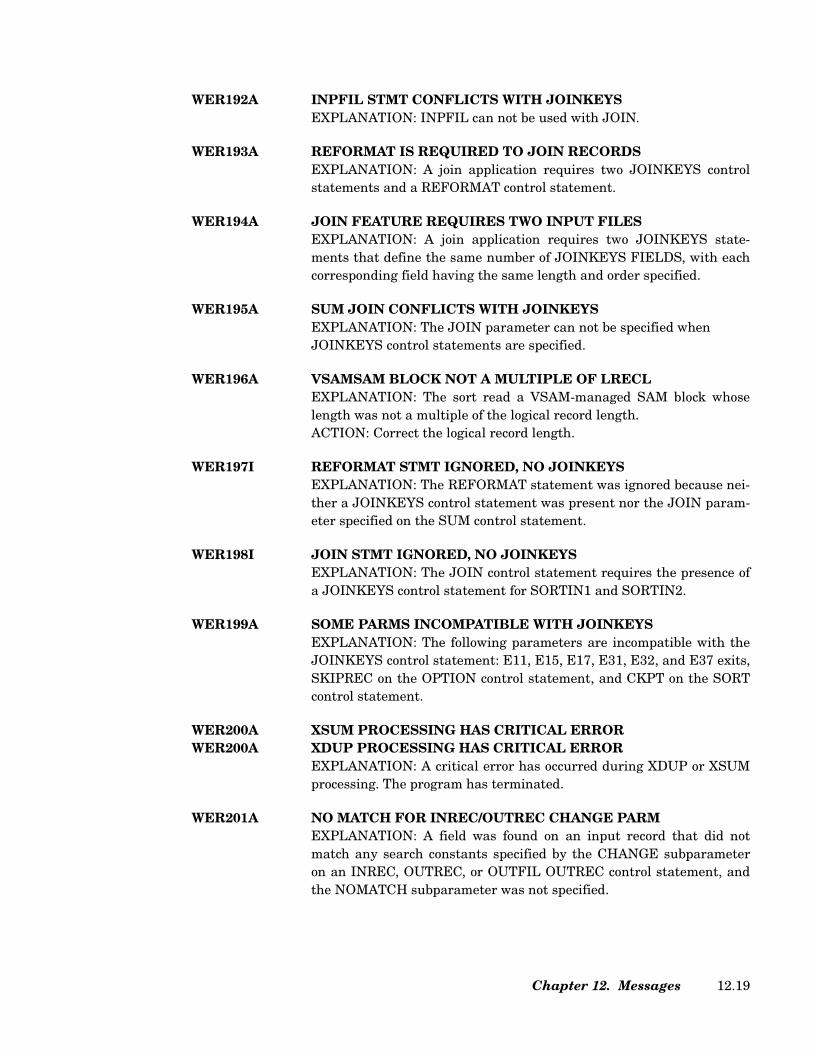
WER192A INPFIL STMT CONFLICTS WITH JOINKEYSEXPLANATION: INPFIL can not be used with JOIN.
WER193A REFORMAT IS REQUIRED TO JOIN RECORDSEXPLANATION: A join application requires two JOINKEYS controlstatements and a REFORMAT control statement.
WER194A JOIN FEATURE REQUIRES TWO INPUT FILESEXPLANATION: A join application requires two JOINKEYS state-ments that define the same number of JOINKEYS FIELDS, with eachcorresponding field having the same length and order specified.
WER195A SUM JOIN CONFLICTS WITH JOINKEYSEXPLANATION: The JOIN parameter can not be specified when JOINKEYS control statements are specified.
WER196A VSAMSAM BLOCK NOT A MULTIPLE OF LRECLEXPLANATION: The sort read a VSAM-managed SAM block whoselength was not a multiple of the logical record length.ACTION: Correct the logical record length.
WER197I REFORMAT STMT IGNORED, NO JOINKEYSEXPLANATION: The REFORMAT statement was ignored because nei-ther a JOINKEYS control statement was present nor the JOIN param-eter specified on the SUM control statement.
WER198I JOIN STMT IGNORED, NO JOINKEYSEXPLANATION: The JOIN control statement requires the presence ofa JOINKEYS control statement for SORTIN1 and SORTIN2.
WER199A SOME PARMS INCOMPATIBLE WITH JOINKEYSEXPLANATION: The following parameters are incompatible with theJOINKEYS control statement: E11, E15, E17, E31, E32, and E37 exits,SKIPREC on the OPTION control statement, and CKPT on the SORTcontrol statement.
WER200A XSUM PROCESSING HAS CRITICAL ERRORWER200A XDUP PROCESSING HAS CRITICAL ERROR
EXPLANATION: A critical error has occurred during XDUP or XSUMprocessing. The program has terminated.
WER201A NO MATCH FOR INREC/OUTREC CHANGE PARMEXPLANATION: A field was found on an input record that did notmatch any search constants specified by the CHANGE subparameteron an INREC, OUTREC, or OUTFIL OUTREC control statement, andthe NOMATCH subparameter was not specified.
Chapter 12. Messages 12.19
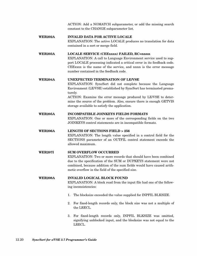
ACTION: Add a NOMATCH subparameter, or add the missing searchconstant to the CHANGE subparameter list.
WER202A INVALID DATA FOR ACTIVE LOCALEEXPLANATION: The active LOCALE produces no translation for datacontained in a sort or merge field.
WER203A LOCALE SERVICE (CEExxxx) FAILED, RC=nnnnEXPLANATION: A call to Language Environment service used to sup-port LOCALE processing indicated a critical error in its feedback code.CEExxxx is the name of the service, and nnnn is the error messagenumber contained in the feedback code.
WER204A UNEXPECTED TERMINATION OF LE/VSEEXPLANATION: SyncSort did not complete because the LanguageEnvironment (LE/VSE) established by SyncSort has terminated prema-turely.ACTION: Examine the error message produced by LE/VSE to deter-mine the source of the problem. Also, ensure there is enough GETVISstorage available to satisfy the application.
WER205A INCOMPATIBLE JOINKEYS FIELDS FORMATSEXPLANATION: One or more of the corresponding fields on the twoJOINKEYS control statements are in incompatible formats.
WER206A LENGTH OF SECTIONS FIELD > 256EXPLANATION: The length value specified in a control field for theSECTIONS parameter of an OUTFIL control statement exceeds theallowed maximum.
WER207I SUM OVERFLOW OCCURREDEXPLANATION: Two or more records that should have been combineddue to the specification of the SUM or DUPKEYS statement were notcombined, because addition of the sum fields would have caused arith-metic overflow in the field of the specified size.
WER208A INVALID LOGICAL BLOCK FOUNDEXPLANATION: A block read from the input file had one of the follow-ing inconsistencies:
1. The blocksize exceeded the value supplied for INPFIL BLKSIZE.
2. For fixed-length records only, the block size was not a multiple ofthe LRECL.
3. For fixed-length records only, INPFIL BLKSIZE was omitted,signifying unblocked input, and the blocksize was not equal to theLRECL.
SyncSort for z/VSE 3.7 Programmer’s Guide12.20
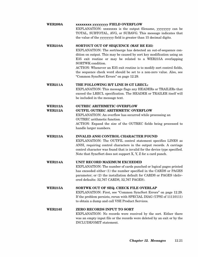
WER209A xxxxxxxx yyyyyyyy FIELD OVERFLOWEXPLANATION: xxxxxxxx is the output filename, yyyyyyyy can beTOTAL, SUBTOTAL, AVG, or SUBAVG. This message indicates thatthe value of the yyyyyyyy field is greater than 15 decimal digits.
WER210A SORTOUT OUT OF SEQUENCE (MAY BE E35)EXPLANATION: The sort/merge has detected an out-of-sequence con-dition on output. This may be caused by sort key modification using anE35 exit routine or may be related to a WER215A overlappingSORTWK condition.ACTION: Whenever an E35 exit routine is to modify sort control fields,the sequence check word should be set to a non-zero value. Also, see“Common SyncSort Errors” on page 12.29.
WER211A THE FOLLOWING H/T LINE IS GT LRECL:EXPLANATION: This message flags any HEADERs or TRAILERs thatexceed the LRECL specification. The HEADER or TRAILER itself willbe included in the message text.
WER212A OUTREC ARITHMETIC OVERFLOWWER212A OUTFIL OUTREC ARITHMETIC OVERFLOW
EXPLANATION: An overflow has occurred while processing an OUTREC arithmetic function.ACTION: Expand the size of the OUTREC fields being processed tohandle larger numbers.
WER213A INVALID ANSI CONTROL CHARACTER FOUNDEXPLANATION: The OUTFIL control statement specifies LINES asANSI, requiring control characters in the output records. A carriagecontrol character was found that is invalid for the device type specified.Note that SyncSort does not support X, Y, Z for a card punch.
WER214A UNIT RECORD MAXIMUM EXCEEDEDEXPLANATION: The number of cards punched or logical pages printedhas exceeded either (1) the number specified in the CARDS or PAGESparameter; or (2) the installation default for CARDS or PAGES (deliv-ered defaults: 32,767 CARDS, 32,767 PAGES).
WER215A SORTWK OUT OF SEQ. CHECK FILE OVERLAPEXPLANATION: First, see “Common SyncSort Errors” on page 12.29.If the problem persists, rerun with SPECIAL DIAG (UPSI of 11110111)to obtain a dump and call VSE Product Services.
WER216I ZERO RECORDS INPUT TO SORTEXPLANATION: No records were received by the sort. Either therewas an empty input file or the records were deleted by an exit or by theINCLUDE/OMIT statement.
Chapter 12. Messages 12.21
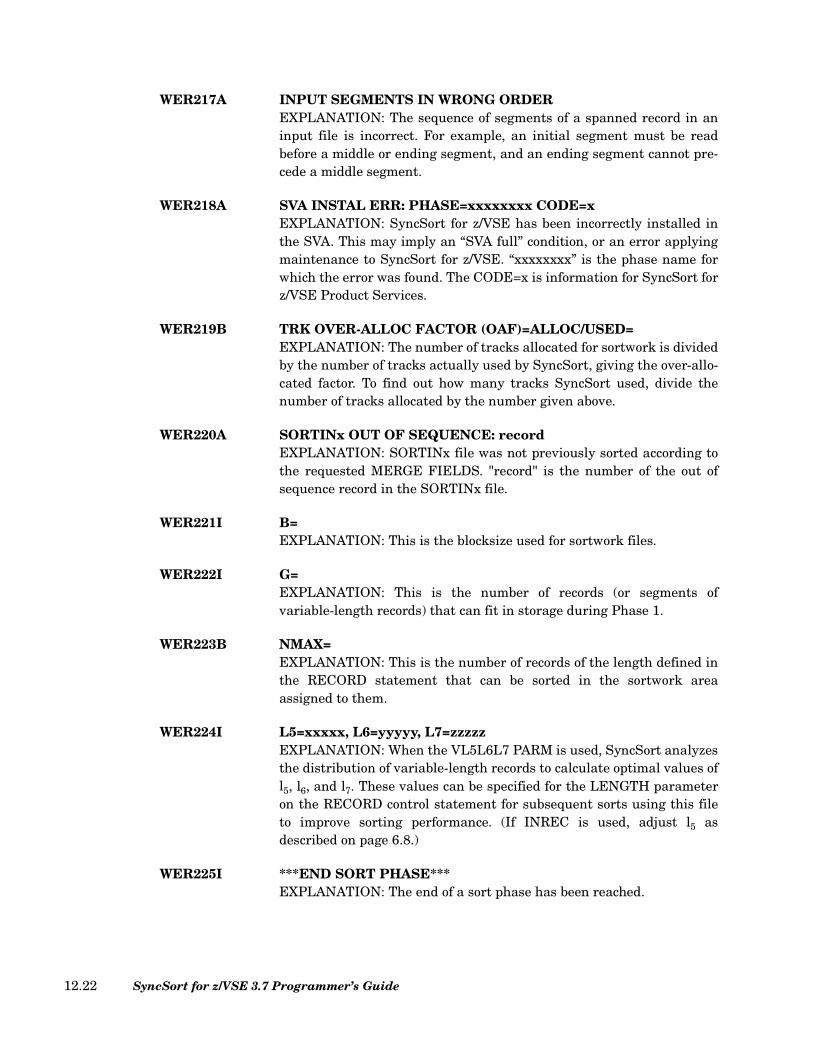
WER217A INPUT SEGMENTS IN WRONG ORDEREXPLANATION: The sequence of segments of a spanned record in aninput file is incorrect. For example, an initial segment must be readbefore a middle or ending segment, and an ending segment cannot pre-cede a middle segment.
WER218A SVA INSTAL ERR: PHASE=xxxxxxxx CODE=xEXPLANATION: SyncSort for z/VSE has been incorrectly installed inthe SVA. This may imply an “SVA full” condition, or an error applyingmaintenance to SyncSort for z/VSE. “xxxxxxxx” is the phase name forwhich the error was found. The CODE=x is information for SyncSort forz/VSE Product Services.
WER219B TRK OVER-ALLOC FACTOR (OAF)=ALLOC/USED=EXPLANATION: The number of tracks allocated for sortwork is dividedby the number of tracks actually used by SyncSort, giving the over-allo-cated factor. To find out how many tracks SyncSort used, divide thenumber of tracks allocated by the number given above.
WER220A SORTINx OUT OF SEQUENCE: recordEXPLANATION: SORTINx file was not previously sorted according tothe requested MERGE FIELDS. "record" is the number of the out ofsequence record in the SORTINx file.
WER221I B=EXPLANATION: This is the blocksize used for sortwork files.
WER222I G=EXPLANATION: This is the number of records (or segments ofvariable-length records) that can fit in storage during Phase 1.
WER223B NMAX=EXPLANATION: This is the number of records of the length defined inthe RECORD statement that can be sorted in the sortwork areaassigned to them.
WER224I L5=xxxxx, L6=yyyyy, L7=zzzzzEXPLANATION: When the VL5L6L7 PARM is used, SyncSort analyzesthe distribution of variable-length records to calculate optimal values ofl5, l6, and l7. These values can be specified for the LENGTH parameteron the RECORD control statement for subsequent sorts using this fileto improve sorting performance. (If INREC is used, adjust l5 asdescribed on page 6.8.)
WER225I ***END SORT PHASE***EXPLANATION: The end of a sort phase has been reached.
SyncSort for z/VSE 3.7 Programmer’s Guide12.22
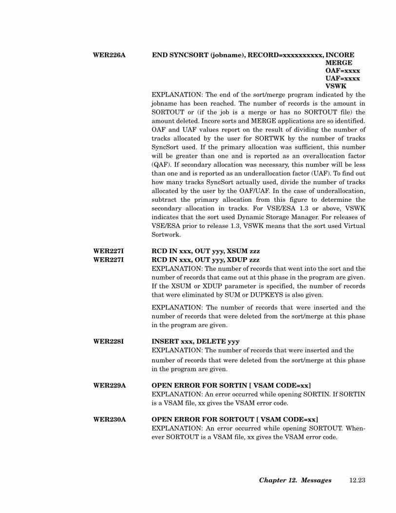
EXPLANATION: The end of the sort/merge program indicated by thejobname has been reached. The number of records is the amount inSORTOUT or (if the job is a merge or has no SORTOUT file) theamount deleted. Incore sorts and MERGE applications are so identified.OAF and UAF values report on the result of dividing the number oftracks allocated by the user for SORTWK by the number of tracksSyncSort used. If the primary allocation was sufficient, this numberwill be greater than one and is reported as an overallocation factor(QAF). If secondary allocation was necessary, this number will be lessthan one and is reported as an underallocation factor (UAF). To find outhow many tracks SyncSort actually used, divide the number of tracksallocated by the user by the OAF/UAF. In the case of underallocation,subtract the primary allocation from this figure to determine thesecondary allocation in tracks. For VSE/ESA 1.3 or above, VSWKindicates that the sort used Dynamic Storage Manager. For releases ofVSE/ESA prior to release 1.3, VSWK means that the sort used VirtualSortwork.
WER227I RCD IN xxx, OUT yyy, XSUM zzzWER227I RCD IN xxx, OUT yyy, XDUP zzz
EXPLANATION: The number of records that went into the sort and thenumber of records that came out at this phase in the program are given.If the XSUM or XDUP parameter is specified, the number of recordsthat were eliminated by SUM or DUPKEYS is also given.
EXPLANATION: The number of records that were inserted and thenumber of records that were deleted from the sort/merge at this phasein the program are given.
WER228I INSERT xxx, DELETE yyyEXPLANATION: The number of records that were inserted and the
number of records that were deleted from the sort/merge at this phasein the program are given.
WER229A OPEN ERROR FOR SORTIN [ VSAM CODE=xx]EXPLANATION: An error occurred while opening SORTIN. If SORTINis a VSAM file, xx gives the VSAM error code.
WER230A OPEN ERROR FOR SORTOUT [ VSAM CODE=xx]EXPLANATION: An error occurred while opening SORTOUT. When-ever SORTOUT is a VSAM file, xx gives the VSAM error code.
WER226A END SYNCSORT (jobname), RECORD=xxxxxxxxxx, INCOREMERGEOAF=xxxxUAF=xxxxVSWK
Chapter 12. Messages 12.23
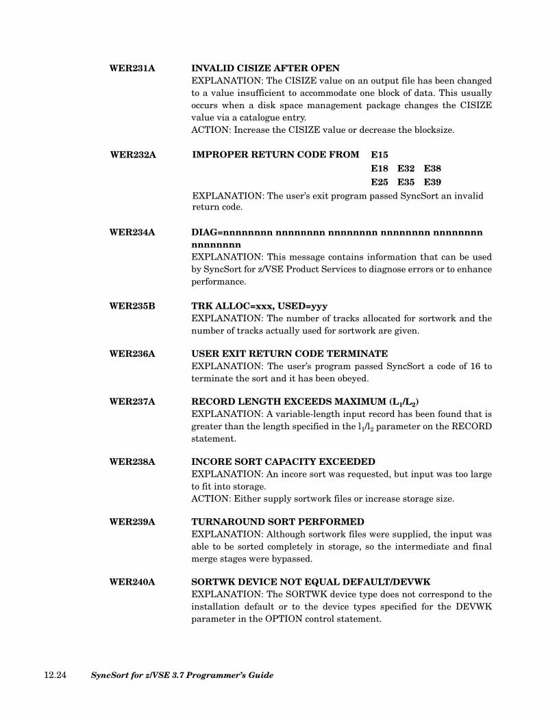
WER231A INVALID CISIZE AFTER OPENEXPLANATION: The CISIZE value on an output file has been changedto a value insufficient to accommodate one block of data. This usuallyoccurs when a disk space management package changes the CISIZEvalue via a catalogue entry.ACTION: Increase the CISIZE value or decrease the blocksize.
WER234A DIAG=nnnnnnnn nnnnnnnn nnnnnnnn nnnnnnnn nnnnnnnnnnnnnnnnEXPLANATION: This message contains information that can be usedby SyncSort for z/VSE Product Services to diagnose errors or to enhanceperformance.
WER235B TRK ALLOC=xxx, USED=yyyEXPLANATION: The number of tracks allocated for sortwork and thenumber of tracks actually used for sortwork are given.
WER236A USER EXIT RETURN CODE TERMINATEEXPLANATION: The user’s program passed SyncSort a code of 16 toterminate the sort and it has been obeyed.
WER237A RECORD LENGTH EXCEEDS MAXIMUM (L1/L2)EXPLANATION: A variable-length input record has been found that isgreater than the length specified in the l1/l2 parameter on the RECORDstatement.
WER238A INCORE SORT CAPACITY EXCEEDEDEXPLANATION: An incore sort was requested, but input was too largeto fit into storage.ACTION: Either supply sortwork files or increase storage size.
WER239A TURNAROUND SORT PERFORMEDEXPLANATION: Although sortwork files were supplied, the input wasable to be sorted completely in storage, so the intermediate and finalmerge stages were bypassed.
WER240A SORTWK DEVICE NOT EQUAL DEFAULT/DEVWKEXPLANATION: The SORTWK device type does not correspond to theinstallation default or to the device types specified for the DEVWKparameter in the OPTION control statement.
WER232A IMPROPER RETURN CODE FROM E15E18 E32 E38E25 E35 E39
EXPLANATION: The user’s exit program passed SyncSort an invalid return code.
SyncSort for z/VSE 3.7 Programmer’s Guide12.24

WER241A RECORD LEN EXCEEDS L3, USER REQ ABORTEXPLANATION: A variable-length record was found that is greaterthan the length specified in the l3 parameter on the RECORD state-ment.
WER242I SEGLENEXPLANATION: The value given above was used by SyncSort to sortthe user’s variable-length records.
WER243A NOT ENOUGH STORAGE IN INT. MERGE PHASE
EXPLANATION: The sort ran out of storage during the phase shown.
WER244A STRING CT OVERFLOW; INCREASE STORAGEEXPLANATION: There was too much data for the sort to process in thestorage available.ACTION: Specify an increased value for the SIZE parameter on theJCL EXEC statement and/or VSCORE/VSCORET parameter on theOPTION statement.
WER245A RECORD LENGTH LESS THAN MINIMUM (L4)EXPLANATION: The sort found a variable-length record that is shorterthan the value the sort is using for l4.
WER246I WRONG LENGTH RECORD. filename
EXPLANATION: The sort found a wrong-length physical or logicalrecord. If BYPASSED is on the message, the record was ignored and thesort continued. If BYPASSED is not on the message, the filename forthe wrong-length record will be given.
WER248A RECORD LENGTH EXCEEDS TRACK CAPACITYEXPLANATION: The record length specified must be no greater thanthe track capacity of the SORTWK disk device.
WER250A ZERO LENGTH RECORD FOUNDEXPLANATION: A variable-length record with a length of zero in itsRecord Descriptor Word was found by the sort/merge.
WER251A RDW INVALID, OVERFLOWS BUFFEREXPLANATION: The sort found a variable-length record with a lengthvalue in its Record Descriptor Word that, when added to the address ofthe end of the previous record in this input buffer, would overflow thebuffer. This message will also be issued when the length of an assem-bled spanned record exceeds the l1 value (input buffer size).ACTION: Check for a bad record in the input files.
FINAL MERGE PH.
BYPASSED
Chapter 12. Messages 12.25
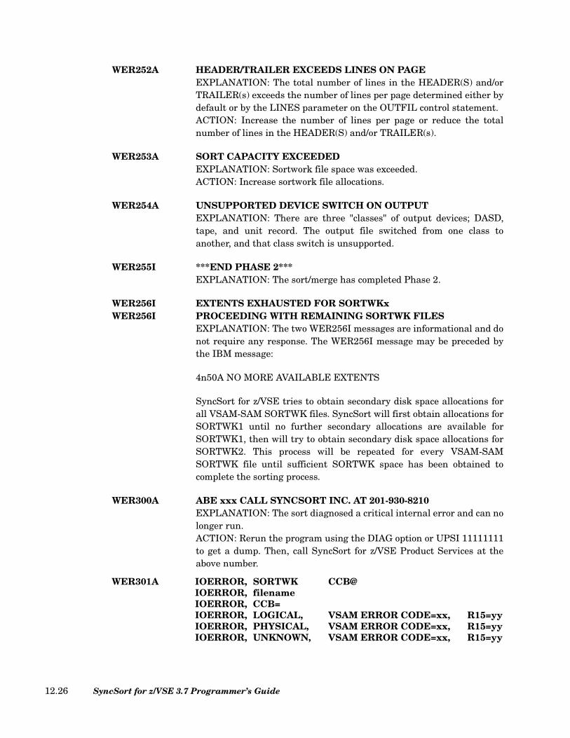
WER252A HEADER/TRAILER EXCEEDS LINES ON PAGEEXPLANATION: The total number of lines in the HEADER(S) and/orTRAILER(s) exceeds the number of lines per page determined either bydefault or by the LINES parameter on the OUTFIL control statement.ACTION: Increase the number of lines per page or reduce the totalnumber of lines in the HEADER(S) and/or TRAILER(s).
WER253A SORT CAPACITY EXCEEDEDEXPLANATION: Sortwork file space was exceeded.ACTION: Increase sortwork file allocations.
WER254A UNSUPPORTED DEVICE SWITCH ON OUTPUTEXPLANATION: There are three "classes" of output devices; DASD,tape, and unit record. The output file switched from one class toanother, and that class switch is unsupported.
WER255I ***END PHASE 2***EXPLANATION: The sort/merge has completed Phase 2.
WER256I EXTENTS EXHAUSTED FOR SORTWKxWER256I PROCEEDING WITH REMAINING SORTWK FILES
EXPLANATION: The two WER256I messages are informational and donot require any response. The WER256I message may be preceded bythe IBM message:
4n50A NO MORE AVAILABLE EXTENTS
SyncSort for z/VSE tries to obtain secondary disk space allocations forall VSAM-SAM SORTWK files. SyncSort will first obtain allocations forSORTWK1 until no further secondary allocations are available forSORTWK1, then will try to obtain secondary disk space allocations forSORTWK2. This process will be repeated for every VSAM-SAMSORTWK file until sufficient SORTWK space has been obtained tocomplete the sorting process.
WER300A ABE xxx CALL SYNCSORT INC. AT 201-930-8210EXPLANATION: The sort diagnosed a critical internal error and can nolonger run.ACTION: Rerun the program using the DIAG option or UPSI 11111111to get a dump. Then, call SyncSort for z/VSE Product Services at theabove number.
WER301A IOERROR,IOERROR,IOERROR,
SORTWKfilenameCCB=
CCB@
IOERROR,IOERROR,IOERROR,
LOGICAL,PHYSICAL,UNKNOWN,
VSAM ERROR CODE=xx,VSAM ERROR CODE=xx,VSAM ERROR CODE=xx,
R15=yyR15=yyR15=yy
SyncSort for z/VSE 3.7 Programmer’s Guide12.26

EXPLANATION: An I/O error has occurred. If byte 5 of the CCB showsa X'40', there is a wrong-length record. If the error occurred while pro-cessing a VSAM file, the message will indicate whether it is known tobe logical or physical. xx is the error code; yy is the value of register 15returned by VSAM.
WER400A CRITICAL ERROR. SORT TERMINATEDEXPLANATION: Due to a critical error, the sort could not run to com-pletion.ACTION: Check for other error messages to determine the nature of theerror.
WER401I STARTING INTERNAL SORT FOR JOINEXPLANATION: SyncSort has started an additional internal sort aspart of JOIN processing.
WER402I END INTERNAL SORT, RECORD=nnnnn, OAFUAFINCORE
EXPLANATION: The additional internal sort started by SyncSort aspart of JOIN processing has successfully completed. nnnnn is the num-ber of records processed by this internal sort.
WER403A ERROR RETURNED FROM INTERNAL SORTEXPLANATION: The additional internal sort started by SyncSort aspart of JOIN processing has encountered a problem. There will be addi-tional messages displayed related to this problem.
WER405A INPFIL LRECL REQUIRES AN INRECEXPLANATION: An INPFIL control statement specifying LRECL wasdifferent than the length specified on the LENGTH parameter on theRECORD control statement, but no INREC control statement wasincluded.
WER406I SORTINx: IN nnnnn, OUT nnnnnLRECL= nnnnn, BLKSIZE=xxxxx, INREC=(inr1,inr2)
CISIZE=xxxxxEXPLANATION: The number of records that went into the INPFILprocessor and the number of records that came out of this processor aregiven. If the input file is VSAM, xxxxx indicates the control intervalsize SyncSort has selected, otherwise the BLKSIZE value is displayedalong with the LRECL value. If INREC is specified, inr1 indicates theuser-specified input record length and inr2 indicates the record lengthselected by SyncSort.
Chapter 12. Messages 12.27
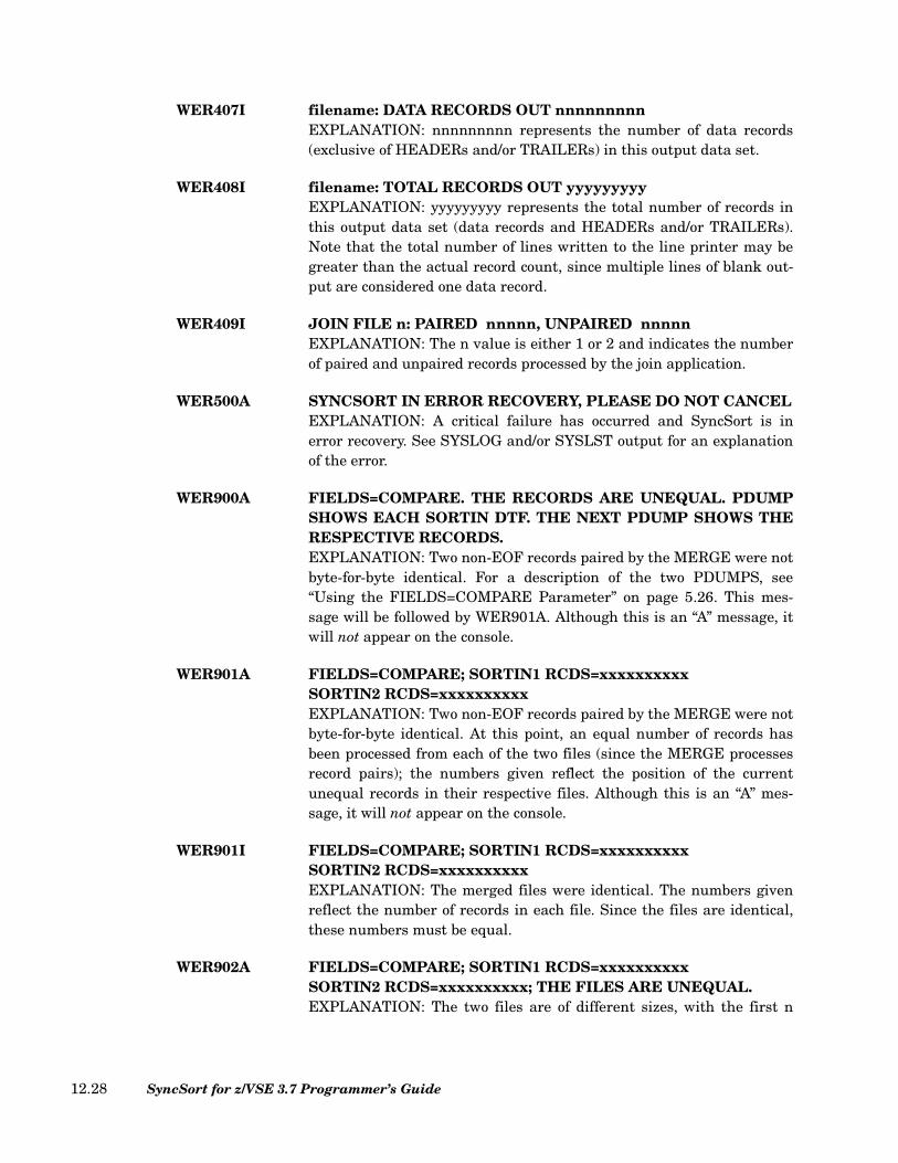
WER407I filename: DATA RECORDS OUT nnnnnnnnnEXPLANATION: nnnnnnnnn represents the number of data records(exclusive of HEADERs and/or TRAILERs) in this output data set.
WER408I filename: TOTAL RECORDS OUT yyyyyyyyyEXPLANATION: yyyyyyyyy represents the total number of records inthis output data set (data records and HEADERs and/or TRAILERs).Note that the total number of lines written to the line printer may begreater than the actual record count, since multiple lines of blank out-put are considered one data record.
WER409I JOIN FILE n: PAIRED nnnnn, UNPAIRED nnnnnEXPLANATION: The n value is either 1 or 2 and indicates the numberof paired and unpaired records processed by the join application.
WER500A SYNCSORT IN ERROR RECOVERY, PLEASE DO NOT CANCELEXPLANATION: A critical failure has occurred and SyncSort is inerror recovery. See SYSLOG and/or SYSLST output for an explanationof the error.
WER900A FIELDS=COMPARE. THE RECORDS ARE UNEQUAL. PDUMPSHOWS EACH SORTIN DTF. THE NEXT PDUMP SHOWS THERESPECTIVE RECORDS.EXPLANATION: Two non-EOF records paired by the MERGE were notbyte-for-byte identical. For a description of the two PDUMPS, see“Using the FIELDS=COMPARE Parameter” on page 5.26. This mes-sage will be followed by WER901A. Although this is an “A” message, itwill not appear on the console.
WER901A FIELDS=COMPARE; SORTIN1 RCDS=xxxxxxxxxxSORTIN2 RCDS=xxxxxxxxxxEXPLANATION: Two non-EOF records paired by the MERGE were notbyte-for-byte identical. At this point, an equal number of records hasbeen processed from each of the two files (since the MERGE processesrecord pairs); the numbers given reflect the position of the currentunequal records in their respective files. Although this is an “A” mes-sage, it will not appear on the console.
WER901I FIELDS=COMPARE; SORTIN1 RCDS=xxxxxxxxxxSORTIN2 RCDS=xxxxxxxxxxEXPLANATION: The merged files were identical. The numbers givenreflect the number of records in each file. Since the files are identical,these numbers must be equal.
WER902A FIELDS=COMPARE; SORTIN1 RCDS=xxxxxxxxxxSORTIN2 RCDS=xxxxxxxxxx; THE FILES ARE UNEQUAL.EXPLANATION: The two files are of different sizes, with the first n
SyncSort for z/VSE 3.7 Programmer’s Guide12.28
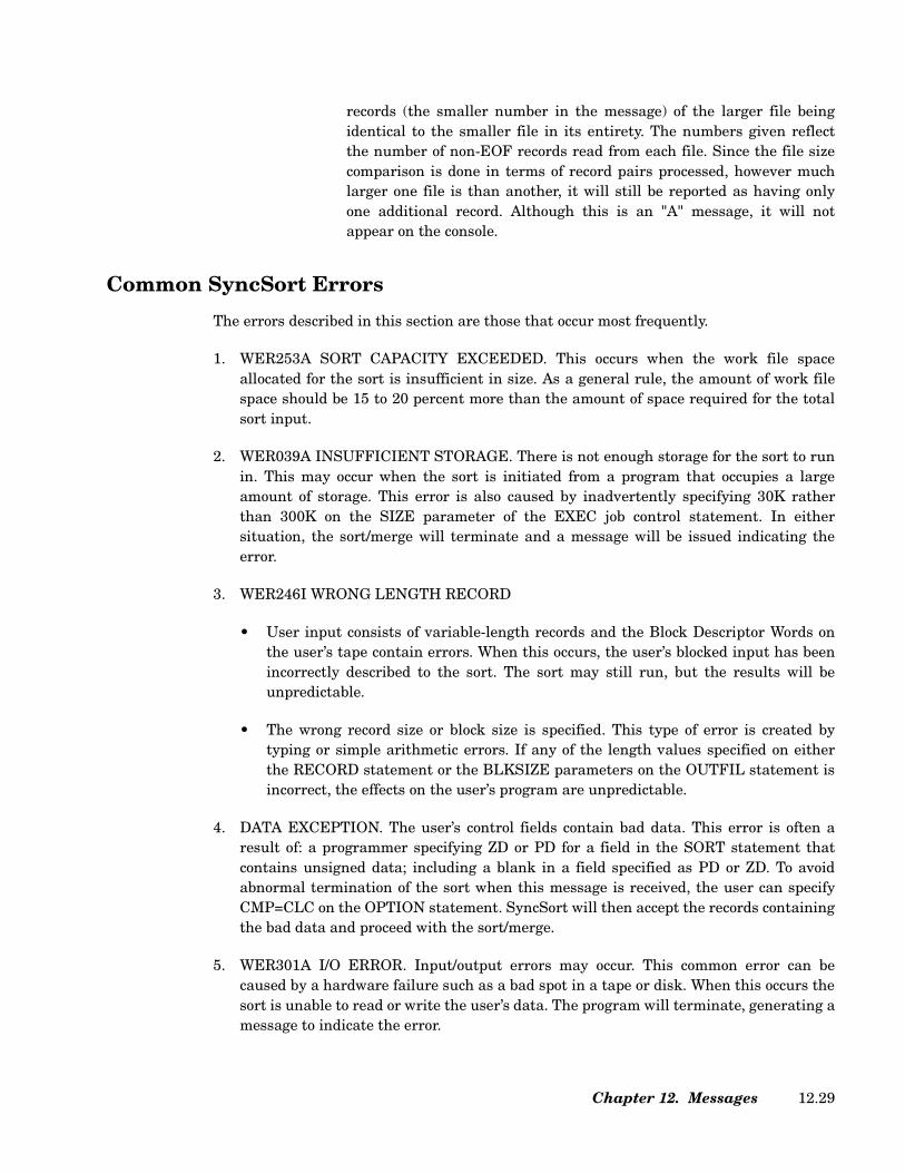
records (the smaller number in the message) of the larger file beingidentical to the smaller file in its entirety. The numbers given reflectthe number of non-EOF records read from each file. Since the file sizecomparison is done in terms of record pairs processed, however muchlarger one file is than another, it will still be reported as having onlyone additional record. Although this is an "A" message, it will notappear on the console.
Common SyncSort Errors
The errors described in this section are those that occur most frequently.
1. WER253A SORT CAPACITY EXCEEDED. This occurs when the work file spaceallocated for the sort is insufficient in size. As a general rule, the amount of work filespace should be 15 to 20 percent more than the amount of space required for the totalsort input.
2. WER039A INSUFFICIENT STORAGE. There is not enough storage for the sort to runin. This may occur when the sort is initiated from a program that occupies a largeamount of storage. This error is also caused by inadvertently specifying 30K ratherthan 300K on the SIZE parameter of the EXEC job control statement. In eithersituation, the sort/merge will terminate and a message will be issued indicating theerror.
3. WER246I WRONG LENGTH RECORD
• User input consists of variable-length records and the Block Descriptor Words onthe user’s tape contain errors. When this occurs, the user’s blocked input has beenincorrectly described to the sort. The sort may still run, but the results will beunpredictable.
• The wrong record size or block size is specified. This type of error is created bytyping or simple arithmetic errors. If any of the length values specified on eitherthe RECORD statement or the BLKSIZE parameters on the OUTFIL statement isincorrect, the effects on the user’s program are unpredictable.
4. DATA EXCEPTION. The user’s control fields contain bad data. This error is often aresult of: a programmer specifying ZD or PD for a field in the SORT statement thatcontains unsigned data; including a blank in a field specified as PD or ZD. To avoidabnormal termination of the sort when this message is received, the user can specifyCMP=CLC on the OPTION statement. SyncSort will then accept the records containingthe bad data and proceed with the sort/merge.
5. WER301A I/O ERROR. Input/output errors may occur. This common error can becaused by a hardware failure such as a bad spot in a tape or disk. When this occurs thesort is unable to read or write the user’s data. The program will terminate, generating amessage to indicate the error.
Chapter 12. Messages 12.29
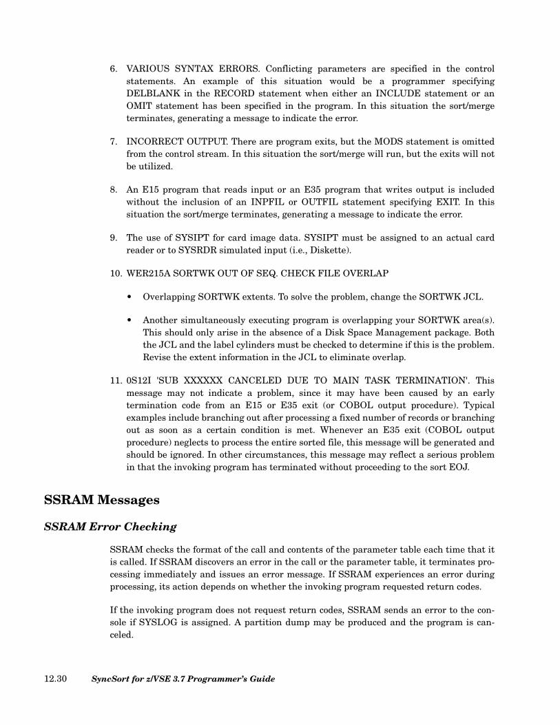
6. VARIOUS SYNTAX ERRORS. Conflicting parameters are specified in the controlstatements. An example of this situation would be a programmer specifyingDELBLANK in the RECORD statement when either an INCLUDE statement or anOMIT statement has been specified in the program. In this situation the sort/mergeterminates, generating a message to indicate the error.
7. INCORRECT OUTPUT. There are program exits, but the MODS statement is omittedfrom the control stream. In this situation the sort/merge will run, but the exits will notbe utilized.
8. An E15 program that reads input or an E35 program that writes output is includedwithout the inclusion of an INPFIL or OUTFIL statement specifying EXIT. In thissituation the sort/merge terminates, generating a message to indicate the error.
9. The use of SYSIPT for card image data. SYSIPT must be assigned to an actual cardreader or to SYSRDR simulated input (i.e., Diskette).
10. WER215A SORTWK OUT OF SEQ. CHECK FILE OVERLAP
• Overlapping SORTWK extents. To solve the problem, change the SORTWK JCL.
• Another simultaneously executing program is overlapping your SORTWK area(s).This should only arise in the absence of a Disk Space Management package. Boththe JCL and the label cylinders must be checked to determine if this is the problem.Revise the extent information in the JCL to eliminate overlap.
11. 0S12I 'SUB XXXXXX CANCELED DUE TO MAIN TASK TERMINATION'. Thismessage may not indicate a problem, since it may have been caused by an earlytermination code from an E15 or E35 exit (or COBOL output procedure). Typicalexamples include branching out after processing a fixed number of records or branchingout as soon as a certain condition is met. Whenever an E35 exit (COBOL outputprocedure) neglects to process the entire sorted file, this message will be generated andshould be ignored. In other circumstances, this message may reflect a serious problemin that the invoking program has terminated without proceeding to the sort EOJ.
SSRAM Messages
SSRAM Error Checking
SSRAM checks the format of the call and contents of the parameter table each time that itis called. If SSRAM discovers an error in the call or the parameter table, it terminates pro-cessing immediately and issues an error message. If SSRAM experiences an error duringprocessing, its action depends on whether the invoking program requested return codes.
If the invoking program does not request return codes, SSRAM sends an error to the con-sole if SYSLOG is assigned. A partition dump may be produced and the program is can-celed.
SyncSort for z/VSE 3.7 Programmer’s Guide12.30

If the invoking program does request return codes, SSRAM passes control back to theinvoking program along with the return code table. The return code table will containeither return code 4 or 16 and the error message. If SSRAM then receives another call fromthe invoking program after experiencing an error on the preceding call, SSRAM cancels theprogram. Therefore, the invoking program should include a check of requested return codesso that it takes the appropriate action.
Any error SSRAM encounters during initialization is non-recoverable regardless ofwhether return codes were requested by the invoking program. The program is canceled.
SSRAM Message Format
All SSRAM messages have the following format:
nnn This is the message number.
xxxxx This is either INIT or the sortwork filename passed in the parameter table.INIT means that the error occurred during initialization. The sortwork filename lets you identify which sort experienced the error.
message This is the message text.
Note: These messages are available in the VSE console EXPLAIN function if your systemsprogrammer installed SyncSort with this option.
WERS001 RE-OPEN FUNCTION NOT SUPPORTED.EXPLANATION: An attempt was made to use either the SRTOPN,CAROP, or SSAROP call to re-use a sortwork file and this function isnot supported.
WERS002 DUPLICATE RECORD DELETE OPTION NOT SUPPORTED.EXPLANATION: An attempt was made to delete a duplicate recordduring sort processing and this function is not supported. ACTION: You can delete only records that have duplicate keys.
WERS005 MULTIPLE SRTCORE CALLS ARE ILLEGALEXPLANATION: More than one SRTCORE function call was used forthe application.
WERSnnn xxxxx message
Figure 450. SSRAM Message Format
Chapter 12. Messages 12.31

WERS006 SRTCORE CALL MUST PRECEDE SRTOPEN CALLEXPLANATION: The application issued a SRTCORE function call afterissuing a SRTOPEN function call.
WERS010 SRTCORE STORAGE ADDRESS IS INVALIDEXPLANATION: The storage address passed in the SRTCORE param-eter list is invalid. The address is invalid for one of the following rea-sons:
• The address is lower than the beginning address of thepartition.
• The address is higher than the ending address of the partition.
• A storage length value was not specified and the address is inthe partition GETVIS area.
WERS011 SRTCORE STORAGE LENGTH IS INVALIDEXPLANATION: The storage length value passed in the SRTCOREparameter list is invalid. The storage length is invalid for one of the fol-lowing reasons:
• If the SRTCORE storage address is in the problem programarea of the partition (not the GETVIS area), then the endingaddress implied by adding the storage length to the storageaddress must also be in the problem program area (not theGETVIS area).
• If the SRTCORE storage address is in the GETVIS area, thenthe ending address implied by adding the storage length valueto the storage address must be less than the ending address ofthe GETVIS area.
WERS101 SUBSID SVC FAILURE. RETURN CODE=xx EXPLANATION: An SVC 105 (X'69') was issued and failed. xx is thereturn code from SUBSID.ACTION: Call SyncSort for z/VSE Product Services.
WERS102 INIT OPERATING SYSTEM NOT SUPPORTED.EXPLANATION: SSRAM supports only standard IBM operating sys-tems.
WERS103 INIT INSUFFICIENT STORAGE.EXPLANATION: Either the main storage value passed in the SSRAMparameter table during a SRTOPEN call was less than 10K or therewas not enough storage in the partition to run SSRAM.ACTION: In the first case increase the main storage value in theSSRAM parameter table to at least 10K. In the second case, SSRAM
SyncSort for z/VSE 3.7 Programmer’s Guide12.32
requires a minimum of 64K in the partition for each sort in addition tothe storage required for the invoking program and the 8K required bySRAM itself.
WERS104 INIT GETVIS NOT INITIALIZED.EXPLANATION: The partition GETVIS area has not been properly ini-tialized by VSE.ACTION: Call SyncSort for z/VSE Product Services.
WERS105 INIT PARAMETER TABLE NOT FULLWORD ALIGNED.EXPLANATION: The SSRAM parameter table is not aligned to a full-word boundary.ACTION: If you are using PL/I, use the ALIGNED keyword in the defi-nition of the parameter table. If you are using COBOL, use the SYN-CHRONIZED keyword in the definition of the parameter table.
WERS106 xxxxx LABEL ERROR DETECTED.EXPLANATION: The DLBL statement in the JCL does not match bytes1 to 5 of the SSRAM parameter.ACTION: Correct the DLBL statement so that it matches bytes 1 to 5 ofthe SSRAM parameter.
WERS107 xxxxx KEY DEFINITION ERROR DETECTED.EXPLANATION: There is a syntax error in the sort key definition.ACTION: Ensure that opening and closing parentheses match, that allthe keys are valid, or that there are no typographical errors. See “TheKey Definition Table” on page 10.3.
WERS108 xxxxx ALREADY OPENED.EXPLANATION: An attempt was made to open the specified file andthat file is open already.ACTION: Check to see if more than one sort is using the same parame-ter table.
WERS109 xxxxx LOGICAL UNIT ASSIGNMENT ERROR.EXPLANATION: There are several possible reasons for this error mes-sage. The SSRAM workfile name in the parameter table is assigned to atape (TLBL) instead of a disk (DLBL). Either the Logical Unit Number(LUN) is a non-numeric value, is greater than 255, is unassigned, or isset to IGNORE.ACTION: Change the TLBL to a DLBL. The LUN cannot be a non-numeric value, cannot be greater than 255, cannot be unassigned andcannot be set to IGNORE. Correct the parameter table and re-run thejob.
WERS110 xxxxx FILL CALL ERROR.EXPLANATION: The FILL call was issued in an improper sequence,
Chapter 12. Messages 12.33

either preceding an SRTOPEN call or following a CLOSE or GET call.ACTION: Correct the program that issues the calls.
WERS111 xxxxx FILL PARAMETER LIST INCOMPLETE.EXPLANATION: The record area is missing from a FILL call.ACTION: Provide the record area.
WERS113 xxxxx GET CALL ERROR.EXPLANATION: The GET call was issued in an improper sequence,either preceding an OPEN or FILL call or following a CLOSE.ACTION: Correct the program that issues the calls.
WERS114 xxxxx GET PARAMETER LIST INCOMPLETE.EXPLANATION: The record area is missing from a GET call.ACTION: Provide the record area.
WERS116 xxxxx CLOSE CALL ERROR.EXPLANATION: The CLOSE call was issued in an improper sequence,preceding an OPEN, FILL, or GET call.ACTION: Correct the program that issues the calls.
WERS191 xxxxx INVALID DUPLICATE RECORD PROCESSING CODE.EXPLANATION: A code other than 0, 4, or 8 was passed to SSRAM.ACTION: 0, 4, or 8 are the only valid duplicate record processing codes.Correct the fullword that contains the duplicate record processing code.
WERS201 xxxxx FREEVIS FAILURE.EXPLANATION: SSRAM received a non-zero return code in responseto a FREEVIS request.ACTION: Call SyncSort for z/VSE Product Services.
WERS202 xxxxx WORK FILE DEVICE NOT SUPPORTED.EXPLANATION: The LUN is assigned to a device other than DASD.ACTION: Correct the JCL and rerun the job.
WERS203 INIT INCORRECT RELEASE OF SYNCSORT/VSE.EXPLANATION: This release of SSRAM is incompatible with therelease of SyncSort for z/VSE that you are trying to use.ACTION: Call SyncSort for z/VSE Product Services.
WERS204 INIT PHASE RELEASE MISMATCH.EXPLANATION: SSRAM has detected that its two phases are from dif-ferent releases.ACTION: Call SyncSort for z/VSE Product Services.
WERS210 xxxxx SORT INITIALIZATION ERROR.EXPLANATION: Prior to the completion of the first FILL call,SyncSort for z/VSE experienced an error.
SyncSort for z/VSE 3.7 Programmer’s Guide12.34
ACTION: See accompanying sort messages. Call SyncSort for z/VSEProduct Services.
WERS211 xxxxx SORT ERROR DURING FILL PHASE.EXPLANATION: While SSRAM was passing records with a FILL call,SyncSort for z/VSE experienced an error.ACTION: See accompanying sort messages. Call SyncSort for z/VSEProduct Services.
WERS212 xxxxx SORT ERROR DURING INTERMEDIATE MERGEPHASE.EXPLANATION: Prior to the completion of the first GET call, SyncSortfor z/VSE experienced an error.ACTION: See accompanying sort messages. Call SyncSort for z/VSEProduct Services.
WERS213 xxxxx SORT ERROR DURING FINAL MERGE PHASE.EXPLANATION: While SSRAM was receiving records with a GET call,SyncSort for z/VSE experienced an error.ACTION: See accompanying sort messages. Call SyncSort for z/VSEProduct Services.
SYNCBIX Messages
SYNCBIX is SyncSort’s high performance replacement for IDCAMS. All SYNCBIX mes-sages have prefix SBIX. Otherwise the message format is the same as WER messages.SYNCBIX messages printed are written to SYSLST with a record length of 121 bytes andSYSLST must be ASSGNed to a print device.
Note: These messages are available in the VSE console EXPLAIN function if your systemsprogrammer installed SyncSort with this option.
SBIX001A INVALID DEBUGGING OPTIONEXPLANATION: The option specified for debugging is not permis-sible.
SBIX002A FILE xxxxxxxx OPEN ERROR. VSAM RC=X'nn' , EC=X'nn'....EXPLANATION: An error was encountered while opening a VSAMfile.ACTION: Check the VSAM Return and Error codes for detailedinformation.
SBIX003A FILE xxxxxxxx : INVALID RECORDSIZE SPECIFIEDEXPLANATION: The value specified in the RECORDSIZE parame-ter of the VSAM cluster definition exceeds the maximum limit of32760 bytes.
Chapter 12. Messages 12.35
SBIX004A FILE xxxxxxxx OPEN ERROR: NOT AIX FILEEXPLANATION: The file specified by the OUTFILE parametermust be defined as an AIX file.
SBIX005A AIX DATASET MUST BE A KSDSEXPLANATION: The file specified by the OUTFILE parameter isnot properly defined as an alternate index.
SBIX006A FILE xxxxxxxx IS NOT A BASE CLUSTEREXPLANATION: The file specified by the OUTFILE parameter isnot defined as a base cluster or a path over a base cluster.
SBIX007A INVALID CONTINUATION STMT: EXPLANATION: A continuation character was specified on the cur-rent control statement with no additional control statements follow-ing. The invalid statement is displayed following this errormessage.
SBIX008A INVALID PARAMETER SPECIFIED: EXPLANATION: A keyword or value is not recognized. It may bemisspelled. The invalid parameter is displayed following this errormessage.
SBIX009A DUPLICATE xxxx PARAMETER FOUNDEXPLANATION: The specified parameter xxxx was specified morethan once.
SBIX010A MISSING INFILE/OUTFILE PARAMETEREXPLANATION: One or more of the required parameters were notspecified.
SBIX011A INVALID SORTWK NUMBER SPECIFIEDEXPLANATION: The allowable WORK values are from 1 through9.
SBIX012I TRUNCATED nnnn EXCESS AIX KEY xxxxEXPLANATION: The alternate index record was too short to con-tain all of the prime key or RBA pointers. The record is created withonly those pointers that would fit. nnnn gives the number of point-ers that could not fit into the record. xxxx represents the AIX keyvalue that had too many primary keys associated with it.ACTION: Increase the maximum length of the RECORDSIZE valuein the IDCAMS DEFINE AIX command.
SBIX013I VSAM FILE xxxxxxxx BUILT WITH ERRORSEXPLANATION: This is an informational message, indicating thatthe file was built with alternate index records without all of the
SyncSort for z/VSE 3.7 Programmer’s Guide12.36
record pointers. This message is displayed along with messageSBIX012I.
SBIX014A VSAM FILE xxxxxxxx PUT ERROR, RC=X'XX' ,EC=X'xx'EXPLANATION: An error occurred while writing a logical recordinto the VSAM AIX file. Check the VSAM Return and Error codesfor detailed information.
SBIX015I VSAM FILE xxxxxxxx SUCCESSFULLY BUILTEXPLANATION: The alternate index file was built successfullywith no errors.
SBIX016A VSAM FILE xxxxxxxx WAS NOT BUILTEXPLANATION: The alternate index file was not built due to someerror.
SBIX020A SYNCBIX TERMINATED. ERROR FROM SORT, RC=X'xxxx'EXPLANATION: SYNCBIX was terminated due to an error thatoccurred during sort operation.
SBIX021A CRITICAL ERROR. INVALID AIX TYPESEXPLANATION: SYNCBIX was terminated due to internal errors.
SBIX022I NONUNIQUE AIX KEY xxxx; PRIME KEY yyyyEXPLANATION: The AIX was defined as unique. More than onerecord with AIX key value xxxx was encountered. The primary keywas yyyy. SYNCBIX continued to build the remainder of the AIX.The keys are displayed in hexadecimal. If the length of a key isgreater than 20 bytes, only the first 20 bytes of the key are dis-played in the message.
SBIX023A INSUFFICIENT STORAGEEXPLANATION: SYNCBIX did not have enough storage to load theSORT phase. SYNCBIX requires at least 100K plus the maximumrecord length of the alternate index file.
SYNCHSTO Messages
There are two main types of messages for the SYNCHSTO program:
1. SHSnnnI messages, messages ending in ‘I’, are informational. They describe controlinformation used by SYNCHSTO and the characteristics of the records that have beenread.
2. SHSnnnA, messages ending in ‘A’, indicate critical error conditions. SYNCHSTOterminates to allow you to correct the error(s) so that a successful program may be run.
Chapter 12. Messages 12.37
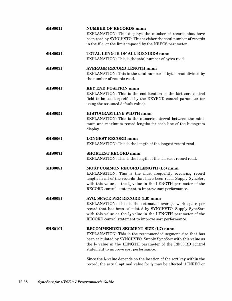
SHS001I NUMBER OF RECORDS nnnn EXPLANATION: This displays the number of records that havebeen read by SYNCHSTO. This is either the total number of recordsin the file, or the limit imposed by the NRECS parameter.
SHS002I TOTAL LENGTH OF ALL RECORDS nnnn EXPLANATION: This is the total number of bytes read.
SHS003I AVERAGE RECORD LENGTH nnnn EXPLANATION: This is the total number of bytes read divided bythe number of records read.
SHS004I KEY END POSITION nnnn EXPLANATION: This is the end location of the last sort controlfield to be used, specified by the KEYEND control parameter (orusing the assumed default value).
SHS005I HISTOGRAM LINE WIDTH nnnn EXPLANATION: This is the numeric interval between the mini-mum and maximum record lengths for each line of the histogramdisplay.
SHS006I LONGEST RECORD nnnn EXPLANATION: This is the length of the longest record read.
SHS007I SHORTEST RECORD nnnnEXPLANATION: This is the length of the shortest record read.
SHS008I MOST COMMON RECORD LENGTH (L5) nnnnEXPLANATION: This is the most frequently occurring recordlength in all of the records that have been read. Supply SyncSortwith this value as the l5 value in the LENGTH parameter of theRECORD control statement to improve sort performance.
SHS009I AVG. SPACE PER RECORD (L6) nnnnEXPLANATION: This is the estimated average work space perrecord that has been calculated by SYNCHSTO. Supply SyncSortwith this value as the l6 value in the LENGTH parameter of theRECORD control statement to improve sort performance.
SHS010I RECOMMENDED SEGMENT SIZE (L7) nnnnEXPLANATION: This is the recommended segment size that hasbeen calculated by SYNCHSTO. Supply SyncSort with this value asthe l7 value in the LENGTH parameter of the RECORD controlstatement to improve sort performance.
Since the l7 value depends on the location of the sort key within therecord, the actual optimal value for l7 may be affected if INREC or
SyncSort for z/VSE 3.7 Programmer’s Guide12.38
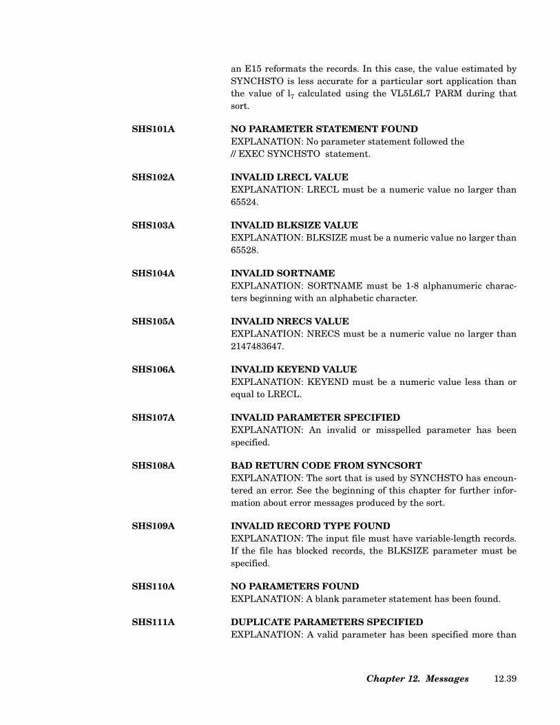
an E15 reformats the records. In this case, the value estimated bySYNCHSTO is less accurate for a particular sort application thanthe value of l7 calculated using the VL5L6L7 PARM during thatsort.
SHS101A NO PARAMETER STATEMENT FOUNDEXPLANATION: No parameter statement followed the // EXEC SYNCHSTO statement.
SHS102A INVALID LRECL VALUE EXPLANATION: LRECL must be a numeric value no larger than65524.
SHS103A INVALID BLKSIZE VALUE EXPLANATION: BLKSIZE must be a numeric value no larger than65528.
SHS104A INVALID SORTNAMEEXPLANATION: SORTNAME must be 1-8 alphanumeric charac-ters beginning with an alphabetic character.
SHS105A INVALID NRECS VALUE EXPLANATION: NRECS must be a numeric value no larger than2147483647.
SHS106A INVALID KEYEND VALUE EXPLANATION: KEYEND must be a numeric value less than orequal to LRECL.
SHS107A INVALID PARAMETER SPECIFIEDEXPLANATION: An invalid or misspelled parameter has beenspecified.
SHS108A BAD RETURN CODE FROM SYNCSORTEXPLANATION: The sort that is used by SYNCHSTO has encoun-tered an error. See the beginning of this chapter for further infor-mation about error messages produced by the sort.
SHS109A INVALID RECORD TYPE FOUNDEXPLANATION: The input file must have variable-length records.If the file has blocked records, the BLKSIZE parameter must bespecified.
SHS110A NO PARAMETERS FOUNDEXPLANATION: A blank parameter statement has been found.
SHS111A DUPLICATE PARAMETERS SPECIFIED EXPLANATION: A valid parameter has been specified more than
Chapter 12. Messages 12.39
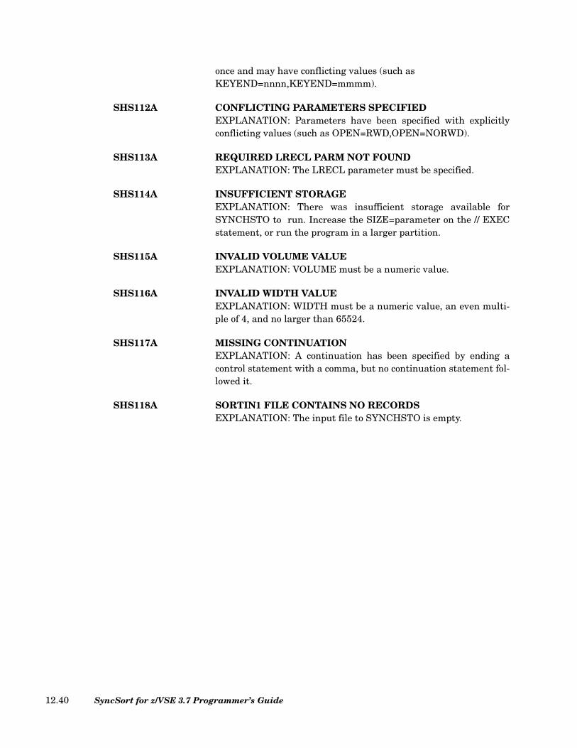
once and may have conflicting values (such as KEYEND=nnnn,KEYEND=mmmm).
SHS112A CONFLICTING PARAMETERS SPECIFIED EXPLANATION: Parameters have been specified with explicitlyconflicting values (such as OPEN=RWD,OPEN=NORWD).
SHS113A REQUIRED LRECL PARM NOT FOUND EXPLANATION: The LRECL parameter must be specified.
SHS114A INSUFFICIENT STORAGE EXPLANATION: There was insufficient storage available forSYNCHSTO to run. Increase the SIZE=parameter on the // EXECstatement, or run the program in a larger partition.
SHS115A INVALID VOLUME VALUE EXPLANATION: VOLUME must be a numeric value.
SHS116A INVALID WIDTH VALUEEXPLANATION: WIDTH must be a numeric value, an even multi-ple of 4, and no larger than 65524.
SHS117A MISSING CONTINUATIONEXPLANATION: A continuation has been specified by ending acontrol statement with a comma, but no continuation statement fol-lowed it.
SHS118A SORTIN1 FILE CONTAINS NO RECORDSEXPLANATION: The input file to SYNCHSTO is empty.
SyncSort for z/VSE 3.7 Programmer’s Guide12.40
Appendix A. Devices and Software Supported by SyncSort
Devices Supported by SyncSort
All current disk and tape devices may be used for SyncSort input and output files as well asany card reader for input and card punch or printer for output; all current disk devices maybe used for workfiles.
Whenever new devices become available, support will be developed for them. Should anyproblems arise with new devices, please let us know.
Proprietary Software Packages Compatible with SyncSort
All proprietary software packages that interface with a sort/merge program are compatiblewith SyncSort. Should any problems arise, please let us know.
Via a default setting (see the SyncSort for z/VSE Installation Guide), SyncSort can takeadvantage of the presence of a variety of disk space management packages to dynamicallyappropriate and release disk space at various stages of the sort/merge. For example, underany package that allocates and frees disk space at OPEN and CLOSE, unused SORTOUTspace and all SORTWK extents will be returned to the system at termination of the sort.Whenever all current SORTWK space is exhausted and more is needed, SyncSort willOPEN additional extents from the preassigned pool that is part of these disk space man-agement packages.
Appendix A. Devices and Software Supported by SyncSort A.1
For information regarding specific compatibility with a disk space management package,please contact SyncSort for z/VSE Product Services. (See SyncSort for z/VSE InstallationGuide for technical support.)
SyncSort for z/VSE 3.7 Programmer’s GuideA.2

Appendix B. Helpful Formulas for SyncSort Programs
Calculating How Much Disk Workfile Space Is Needed for a Job
The rule-of-thumb is 15 to 20 percent more workfile space is needed than the amount ofspace occupied by the total input for the job.
Minimum Storage Needed to Run a Sort or Merge
The minimum storage requirement for SyncSort is 64K. This minimum applies for smallapplications; for more complex applications (such as the use of SortWriter features, multi-ple output files and user exits) it is recommended that at least 128K of storage be used.
Appendix B. Helpful Formulas for SyncSort Programs B.1

SyncSort for z/VSE 3.7 Programmer’s GuideB.2

Appendix C. VSE/VSAM Space Management for SAM Files
Introduction
This appendix outlines the use of VSE/VSAM space management for SAM files (VSAM/DMS/SAM) with SyncSort. It assumes a basic understanding of VSAM file organizationand access techniques, VSAM space allocation, and the IDCAMS utility. In particular, thereader is assumed to have a working knowledge of the material covered in these IBM publi-cations:
• VSE/VSAM Commands
• VSE/VSAM User’s Guide and Application Programming
The discussion that follows is for the user who has VSAM/DMS/SAM installed. This userhas already allocated space for Master and User catalogues, and for VSAM to build andmanage data structures and files. This appendix discusses the use of VSAM/DMS/SAM forSORTOUT, SORTWK, and SORTIN files.
SAM ESDS Files
By definition, SAM ESDS files are SAM files that have been loaded into VSAM/DMS/ SAM;these files are typically changed to control interval format as part of the load. "Work files"are those files whose space is managed by VSAM/DMS/SAM but whose format is importantonly to the program using the file, e.g., SORTWK files. Regardless of the RECORDFOR-
Appendix C. VSE/VSAM Space Management for SAM Files C.1

MAT value specified by the user, SORTWK files will not be loaded in control interval for-mat, since this would lead to inefficiency.
SAM ESDS files can be read and accessed by VSAM as well as SAM access methods, pro-viding RECORDFORMAT is set to F, FB, V, or FB, and not to U (undefined) or NCIF (non-control interval, used only for work files). The VSAM parameter must be specified in theDLBL statement. In the absence of other deciding factors, SyncSort will choose the accessmethod for a particular SAM ESDS file based on the presence or absence of a VSAMparameter in the INPFIL/OUTFIL statement:
1. VSAM in the INPFIL or KSDS/ESDS/RRDS in OUTFIL statement: VSAM access.
2. VSAM parameter omitted from INPFIL/OUTFIL statement: SAM access.
With a RECORDFORMAT value of U, however, only SAM access methods can be used.
VSAM-Managed SORTIN Files
A SAM ESDS input file is a file that already exists and has been defined as part of VSAM/DMS/SAM. Therefore, a cluster already exists and it is necessary only to alert SyncSort toits presence. The JCL for SAM ESDS SORTIN files must include a DLBL statement speci-fying VSAM; EXTENT and ASSGN statements are not necessary.
For VSAM access of a SAM ESDS input file, the format is given below in Figure 451.
For SAM access of a SAM ESDS input file, the format is given below in Figure 452.
When mixing SAM ESDS files with other files as SORTIN, note the following:
// DLBL SORTIN1,'cluster NAME',,VSAM...
INPFIL VSAM
Figure 451. Sample for VSAM Access of a SAM ESDS Input File
// DLBL SORTIN1,'cluster NAME',,VSAM...
INPFIL BLKSIZE=xxx
Figure 452. Sample for VSAM Access of a SAM ESDS Input File
SyncSort for z/VSE 3.7 Programmer’s GuideC.2
• VSAM access is used if the VSAM parameter is specified in the INPFIL controlstatement.
• It is possible to mix a VSAM file and/or a SAM ESDS file.
• SAM ESDS files of different control intervals can be mixed.
• RECORDSIZE (block size) values can be mixed provided each value evenly divides intothe BLKSIZE value specified in the INPFIL statement. In order for the BLKSIZEparameter to be processed, VSAM can not be specified in the INPFIL statement; SAMaccess methods will be used. As always, VSAM must appear in the DLBL statement toindicate a VSAM-managed file.
VSAM-Managed SORTWK Files
The goal is to have SORTWK space managed by VSAM/DMS/SAM, i.e., to have VSAMdynamically allocate the amount of SORTWK space requested for a particular job at OPENand then delete that space at CLOSE. SyncSort opens its SORTWK files as OUTPUT usingDTFPH.
VSAM-managed SORTWK files can be defined explicitly or implicitly (with or without amodel). If specified in the DEFINE CLUSTER command for an explicit define or a defaultmodel, the optional RECORDS-RECORDSIZE pair of parameters will be used to determineallocation size. RECORDS and RECORDSIZE will not be used to determine the character-istics of the SORTWK file; SyncSort will control the use of the space allocated for SORTWKin its own way. All SORTWK files will be treated as NCIF, regardless of theRECORD-FORMAT value specified in the DEFINE CLUSTER command.
Successive sections describe the three methods of defining a VSAM-managed SORTWKfile, detailing each technique’s advantages and drawbacks.
Explicit Define Using DEFINE CLUSTER
In order to explicitly define SORTWK1,..., SORTWK9 as dynamic files, it is necessary tospecify NOALLOCATION and REUSE in their definitions. These parameters instructVSAM not to allocate space for these files until OPEN time. It is more efficient to accesssingle-extent SORTWK files. In order to ensure that VSAM will allocate DASD space forSORTWK as a single extent, the special prefix DOS.WORKFILE.SYS must precede thedata component name. The IDCAMS utility program is executed with the DEFINECLUSTER command specifying NAME(%DOS.WORKFILE.SYSnnn...) for each of the clus-ters.
Note: Under VSAM/DMS/SAM, SyncSort automatically obtains the secondary allocationfor SORTWK1 (WORK=DA is treated as WORK=1); therefore, the prefix is not necessarywhen defining SORTWK1. However, the prefix is always required forSORTWK2,...,SORTWK9.
Appendix C. VSE/VSAM Space Management for SAM Files C.3

The IDCAMS job must be run once for each work file (SORTWK1,..., SORTWKn; n≤9) ineach partition in which SyncSort will execute. The '%' will add a partition identifier(BG,F1,...,Fn) at the end of the cluster name (File-ID). Thus, DOS.WORK-FILE.SYSWK4.BG could be used by a sort running in BG as its File-ID for SORTWK4.
The major disadvantage of this approach is the initial overhead (as many as 9 executions ofIDCAMS per partition). On the other hand, VSAM processing is most efficient when a clus-ter is already explicitly defined at OPEN time, and there is never a need for an EXTENTstatement for SORTWK files that are explicitly defined as SAM ESDS files.
Implicit Define Using a Model
First, define a model that VSAM can use whenever it encounters a managed file (indicatedby the VSAM parameter of the DLBL statement) whose File-ID does not have a match inthe catalog. VSAM will use the model, which includes VOLUME information, to define acluster for all such files. Since VOLUME information is provided by the model, SORTWKfiles will not require EXTENT statements when defined in this way.
Implicit Define Without a Model
In order to define SORTWK files implicitly without a model, both a DLBL and an EXTENTstatement will be necessary.
JCL Requirements for VSAM-Managed SORTWK Files
The required DLBL statement in the job control stream or standard label cylinder is usedto trigger VSAM/DMS/SAM involvement. In the case of an implicit define without a model,the DLBL statement must include allocation information (TRACKS/CYLINDERS/BLOCKS or both RECORDS and RECSIZE). The DLBL statement’s allocation parametersare also used to override allocation values provided by IDCAMS for a default model. SinceSyncSort opens its SORTWK files as OUTPUT, it is important to override the KEEPdefault value with DISP=(,DELETE), as in Figure 453, below.
The DLBL statement above in Figure 453 instructs VSAM to allocate enough space tocontain 400 80-byte records (i.e., 32,000 bytes of data) and to DELETE the file at CLOSE.Provided the cluster was not defined with a specific secondary allocation value, the primaryallocation is automatically supplemented by a secondary allocation of 20% (i.e., enoughspace to contain 6,400 bytes of data) when the primary allocation is exhausted. SinceSyncSort’s structuring of the SORTWK space is not constrained by the RECORDS or the
// DLBL SORTWK1,'%DOS.WORKFILE.SYSWK1',0,VSAM,RECORDS=400,RECSIZE=80,DISP=(,DELETE)
Figure 453. Sample DLBL Statement for a VSAM-Managed SORTWK File
SyncSort for z/VSE 3.7 Programmer’s GuideC.4

RECSIZE values, RECORDS=400,RECSlZE=80 is equivalent to RECORDS=80,RECSIZE=400; or RECORDS=1, RECSIZE=32000.
The DLBL statement below in Figure 454 defines the primary allocation as enough space tocontain 40,000 bytes of data (40 1,000-byte records) and the secondary allocation as 50% ofthat (20 1,000-byte records or 20,000 bytes of data).
Again, DISP’s KEEP default must be changed to DELETE. Assuming SORTWK1 wasexplicitly defined or defined using a default model, allocation could be determined byIDCAMS and allocation values omitted from the DLBL statement.
An EXTENT statement is required only when SORTWK files are implicitly defined withouta model. Figure 455 illustrates how to direct VSAM to the proper volume. It is assumedthat the user has already defined VSAM space on this volume.
An ASSGN statement is never required, although some unassigned logical units must beavailable for VSAM’s use.
Sample JCL/Control Streams
// DLBL SORTWK1,"%DOS.WORKFILE.SYSWK1',0,VSAM,RECORDS=(40,20),RECSIZE=(1000),DISP=(,DELETE)
Figure 454. Sample DLBL Statement for a VSAM-Managed SORTWK File
// EXTENT ,VOL1
Figure 455. Sample EXTENT Statement for a VSAM-Managed SORTWK File
// JOB EXPLICIT DEFINE FOR SORTWK3// EXEC IDCAMS,SIZE=AUTO
DEFINE CLUSTER(NAME(%DOS.WORKFILE.SYS.SORTWK3)-VOLUMES(VSER77)-CYLINDERS(8)-RECORDFORMAT(NCIF)-REUSE-NOALLOCATION-NONINDEXED)
/*/&
Figure 456. Explicitly Defined SAM ESDS SORTWK3 File
Appendix C. VSE/VSAM Space Management for SAM Files C.5

In Figure 456, DEFINE CLUSTER specifies REUSE and NOALLOCATION to makeSORTWK3 a dynamic file (primary allocation at OPEN). A typical cluster NAME forSORTWK3 might be %DOS.WORKFILE.SYS.SORTWK3, where the prefix is required bySyncSort and the entryname, 'SORTWK3', may be selected by the user. IDCAMS must beexecuted once for each partition in which sorting will be done in order to succeed in defin-ing SORTWK3 as a SAM ESDS file. Similar jobstreams would be constructed for all addi-tional SORTWK files to be used. The DLBL statement for SORTWK3 in the SyncSortjobstream must specify VSAM in order to identify the file as a SAM ESDS file, as below inFigure 457.
Note the use of DISP=(,DELETE) to delete the file at CLOSE, as required. Since allocationvalues are not coded on the sample DLBL statement, allocation is determined by theIDCAMS executions, which provide eight cylinders of primary space.
An EXTENT statement is not required.
The model is defined using IDCAMS with the required cluster NAME of DEFAULT.MODEL.ESDS.SAM and the NOALLOCATION parameter (also required). The volumespecified can be overridden by an EXTENT statement for an implicitly defined SAM ESDS.
Although one of the DEFINE CLUSTER’s allocation parameters (TRACKS/BLOCKS/CYLINDERS or both RECORDS and RECORDSIZE) is specified as required, the DLBLstatement can be used to change the allocation size.
Assuming the allocation value is acceptable for SORTWK, SORTWK2 is implicitly definedas SAM ESDS using the DLBL statement in Figure 459.
// DLBL SORTWK3,'%DOS.WORKFILE.SYS.SORTWK3',0,VSAM,DISP=(,DELETE)
Figure 457. DLBL for Explicitly Defined SAM ESDS SORTWK File
// JOB MODEL FOR IMPLICIT SAM ESDS FILES// EXEC IDCAMS,SIZE=AUTODEFINE CLUSTER
(NAME(DEFAULT.MODEL.ESDS.SAM)-VOLUMES(VSER12)-TRACKS(20)-RECORDFORMAT(NCIF)-REUSE-NOALLOCATION-NONINDEXED)
/*/&
Figure 458. Implicitly Defined SAM ESDS SORTWK File Using a Model
SyncSort for z/VSE 3.7 Programmer’s GuideC.6
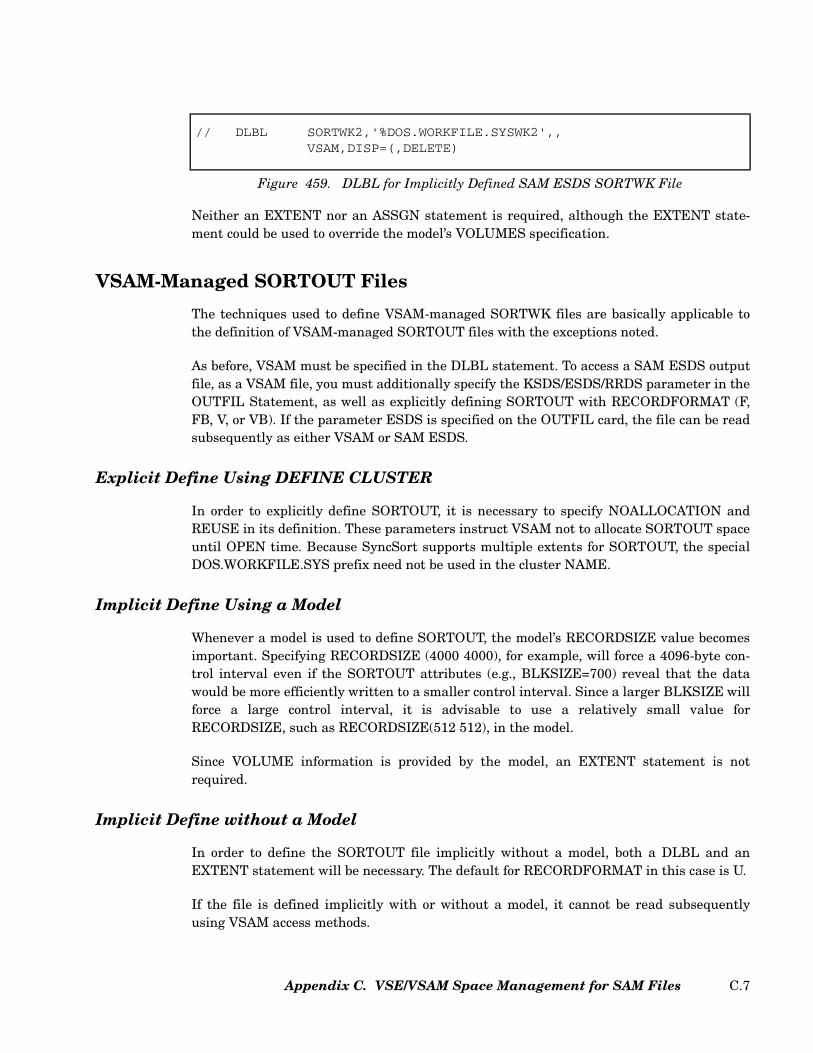
Neither an EXTENT nor an ASSGN statement is required, although the EXTENT state-ment could be used to override the model’s VOLUMES specification.
VSAM-Managed SORTOUT Files
The techniques used to define VSAM-managed SORTWK files are basically applicable tothe definition of VSAM-managed SORTOUT files with the exceptions noted.
As before, VSAM must be specified in the DLBL statement. To access a SAM ESDS outputfile, as a VSAM file, you must additionally specify the KSDS/ESDS/RRDS parameter in theOUTFIL Statement, as well as explicitly defining SORTOUT with RECORDFORMAT (F,FB, V, or VB). If the parameter ESDS is specified on the OUTFIL card, the file can be readsubsequently as either VSAM or SAM ESDS.
Explicit Define Using DEFINE CLUSTER
In order to explicitly define SORTOUT, it is necessary to specify NOALLOCATION andREUSE in its definition. These parameters instruct VSAM not to allocate SORTOUT spaceuntil OPEN time. Because SyncSort supports multiple extents for SORTOUT, the specialDOS.WORKFILE.SYS prefix need not be used in the cluster NAME.
Implicit Define Using a Model
Whenever a model is used to define SORTOUT, the model’s RECORDSIZE value becomesimportant. Specifying RECORDSIZE (4000 4000), for example, will force a 4096-byte con-trol interval even if the SORTOUT attributes (e.g., BLKSIZE=700) reveal that the datawould be more efficiently written to a smaller control interval. Since a larger BLKSIZE willforce a large control interval, it is advisable to use a relatively small value forRECORDSIZE, such as RECORDSIZE(512 512), in the model.
Since VOLUME information is provided by the model, an EXTENT statement is notrequired.
Implicit Define without a Model
In order to define the SORTOUT file implicitly without a model, both a DLBL and anEXTENT statement will be necessary. The default for RECORDFORMAT in this case is U.
If the file is defined implicitly with or without a model, it cannot be read subsequentlyusing VSAM access methods.
// DLBL SORTWK2,'%DOS.WORKFILE.SYSWK2',,VSAM,DISP=(,DELETE)
Figure 459. DLBL for Implicitly Defined SAM ESDS SORTWK File
Appendix C. VSE/VSAM Space Management for SAM Files C.7

JCL Requirements for VSAM-Managed SORTOUT Files
In Figure 460, the DLBL statement in the job control stream or standard label cylinder isused to trigger VSAM/DMS/SAM involvement.
The sample DLBL statement instructs VSAM to allocate enough space to contain 1,000 80-byte records (i.e., enough space to contain 80,000 bytes of data). Provided the cluster wasnot defined with a specific secondary allocation value, this primary allocation is automati-cally supplemented by a secondary allocation of 20% (i.e., enough space to contain 16,000bytes of data) when the primary allocation is exhausted. Note the use ofDISP=(NEW,KEEP) to retain the sorted output after the sort.
An EXTENT statement is required only when SORTOUT is implicitly defined without amodel. Figure 461 illustrates how to direct VSAM to the proper volume. It is assumed thatthe user has already defined VSAM space on this volume.
An ASSGN statement is never required.
Setting Up a JCL/Control Stream for Sorts with VSAM-Managed Files
Figure 462 shows a sort with normal SAM input, output, and work files. The object of thissort is to create a paycheck file from the input payroll data. Later, paychecks will be printedfrom this output disk. The OUTREC feature has been used to select the pay, department,and name fields from the input record for the new, shortened output records.
// DLBL SORTOUT,'SAM.ESDS.SORTOUT',0,VSAM,RECORDS=1000,RECSIZE=80,DISP=(NEW,KEEP)
Figure 460. Sample DLBL Statement for a VSAM-Managed SORTOUT File
// EXTENT ,VOL1
Figure 461. Sample EXTENT Statement for a VSAM-Managed SORTOUT File
SyncSort for z/VSE 3.7 Programmer’s GuideC.8
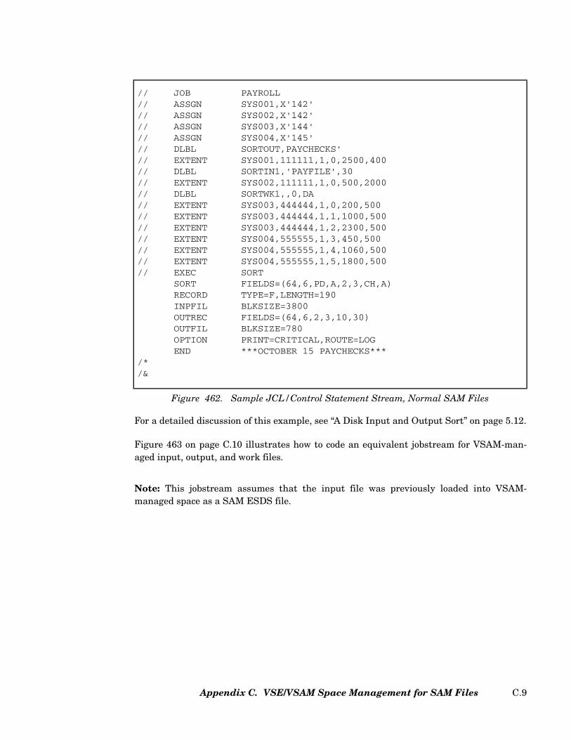
For a detailed discussion of this example, see “A Disk Input and Output Sort” on page 5.12.
Figure 463 on page C.10 illustrates how to code an equivalent jobstream for VSAM-man-aged input, output, and work files.
Note: This jobstream assumes that the input file was previously loaded into VSAM-managed space as a SAM ESDS file.
// JOB PAYROLL// ASSGN SYS001,X'142'// ASSGN SYS002,X'142'// ASSGN SYS003,X'144'// ASSGN SYS004,X'145'// DLBL SORTOUT,PAYCHECKS'// EXTENT SYS001,111111,1,0,2500,400// DLBL SORTIN1,'PAYFILE',30// EXTENT SYS002,111111,1,0,500,2000// DLBL SORTWK1,,0,DA// EXTENT SYS003,444444,1,0,200,500// EXTENT SYS003,444444,1,1,1000,500// EXTENT SYS003,444444,1,2,2300,500// EXTENT SYS004,555555,1,3,450,500// EXTENT SYS004,555555,1,4,1060,500// EXTENT SYS004,555555,1,5,1800,500// EXEC SORT
SORT FIELDS=(64,6,PD,A,2,3,CH,A)RECORD TYPE=F,LENGTH=190INPFIL BLKSIZE=3800OUTREC FIELDS=(64,6,2,3,10,30)OUTFIL BLKSIZE=780OPTION PRINT=CRITICAL,ROUTE=LOGEND ***OCTOBER 15 PAYCHECKS***
/*/&
Figure 462. Sample JCL/Control Statement Stream, Normal SAM Files
Appendix C. VSE/VSAM Space Management for SAM Files C.9
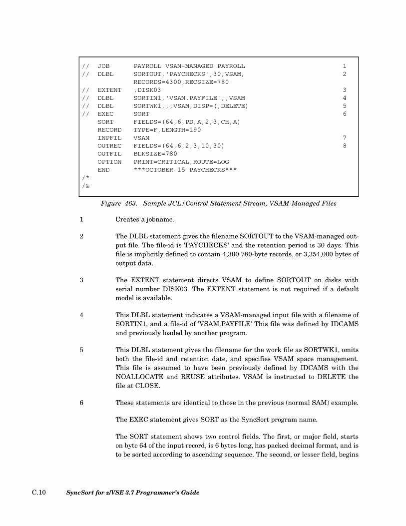
1 Creates a jobname.
2 The DLBL statement gives the filename SORTOUT to the VSAM-managed out-put file. The file-id is 'PAYCHECKS' and the retention period is 30 days. Thisfile is implicitly defined to contain 4,300 780-byte records, or 3,354,000 bytes ofoutput data.
3 The EXTENT statement directs VSAM to define SORTOUT on disks withserial number DISK03. The EXTENT statement is not required if a defaultmodel is available.
4 This DLBL statement indicates a VSAM-managed input file with a filename ofSORTIN1, and a file-id of 'VSAM.PAYFILE' This file was defined by IDCAMSand previously loaded by another program.
5 This DLBL statement gives the filename for the work file as SORTWK1, omitsboth the file-id and retention date, and specifies VSAM space management.This file is assumed to have been previously defined by IDCAMS with theNOALLOCATE and REUSE attributes. VSAM is instructed to DELETE thefile at CLOSE.
6 These statements are identical to those in the previous (normal SAM) example.
The EXEC statement gives SORT as the SyncSort program name.
The SORT statement shows two control fields. The first, or major field, startson byte 64 of the input record, is 6 bytes long, has packed decimal format, and isto be sorted according to ascending sequence. The second, or lesser field, begins
// JOB PAYROLL VSAM-MANAGED PAYROLL 1// DLBL SORTOUT,'PAYCHECKS',30,VSAM, 2
RECORDS=4300,RECSIZE=780// EXTENT ,DISK03 3// DLBL SORTIN1,'VSAM.PAYFILE',,VSAM 4// DLBL SORTWK1,,,VSAM,DISP=(,DELETE) 5// EXEC SORT 6
SORT FIELDS=(64,6,PD,A,2,3,CH,A)RECORD TYPE=F,LENGTH=190INPFIL VSAM 7OUTREC FIELDS=(64,6,2,3,10,30) 8OUTFIL BLKSIZE=780OPTION PRINT=CRITICAL,ROUTE=LOGEND ***OCTOBER 15 PAYCHECKS***
/*/&
Figure 463. Sample JCL/Control Statement Stream, VSAM-Managed Files
SyncSort for z/VSE 3.7 Programmer’s GuideC.10
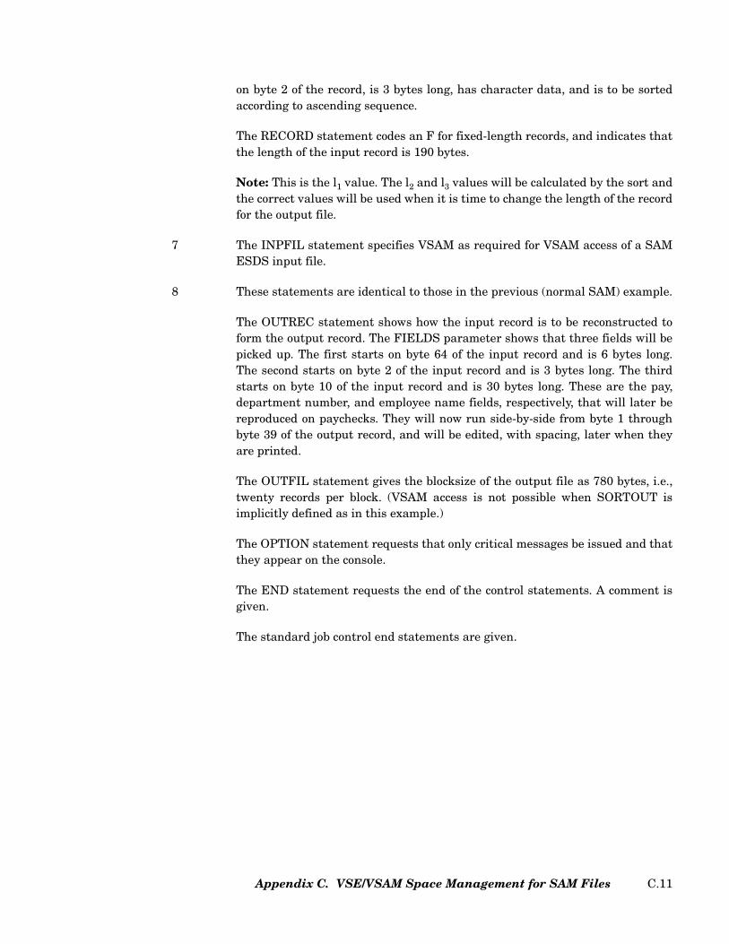
on byte 2 of the record, is 3 bytes long, has character data, and is to be sortedaccording to ascending sequence.
The RECORD statement codes an F for fixed-length records, and indicates thatthe length of the input record is 190 bytes.
Note: This is the l1 value. The l2 and l3 values will be calculated by the sort andthe correct values will be used when it is time to change the length of the recordfor the output file.
7 The INPFIL statement specifies VSAM as required for VSAM access of a SAMESDS input file.
8 These statements are identical to those in the previous (normal SAM) example.
The OUTREC statement shows how the input record is to be reconstructed toform the output record. The FIELDS parameter shows that three fields will bepicked up. The first starts on byte 64 of the input record and is 6 bytes long.The second starts on byte 2 of the input record and is 3 bytes long. The thirdstarts on byte 10 of the input record and is 30 bytes long. These are the pay,department number, and employee name fields, respectively, that will later bereproduced on paychecks. They will now run side-by-side from byte 1 throughbyte 39 of the output record, and will be edited, with spacing, later when theyare printed.
The OUTFIL statement gives the blocksize of the output file as 780 bytes, i.e.,twenty records per block. (VSAM access is not possible when SORTOUT isimplicitly defined as in this example.)
The OPTION statement requests that only critical messages be issued and thatthey appear on the console.
The END statement requests the end of the control statements. A comment isgiven.
The standard job control end statements are given.
Appendix C. VSE/VSAM Space Management for SAM Files C.11

SyncSort for z/VSE 3.7 Programmer’s GuideC.12

Index
Symbols
&DATEx 2.53–2.54&DATEx(c) 2.53–2.54&DATExP 2.53–2.54’YDATEx’ 2.53
A
AC Format 2.43, 2.54, 2.96, 2.199, 2.228Address Files 2.115–2.118Addressing Modes 7.2, 8.5ADDROUT Parameter (OPTION) 2.115–2.118ALLDUPS Parameter (DUPKEYS) 2.33–2.34Alternate Collating Sequence 2.30–2.31Alternative Indexes 9.1–9.14ALTSEQ Control Statement 2.30–2.31
Alternative to 7.5AMODE 24 7.2, 8.5–8.6AMODE 31 7.2, 8.5–8.6ANALYZE Control Statement 2.32AND Operator 2.46–2.47, 4.3ANSI Control Characters 2.155–2.157AQ Format 2.30, 2.43, 2.54, 2.96, 2.199, 2.228ASL Format 2.43, 2.54, 2.96, 2.199, 2.228Assembler Program
Initiating SyncSort 1.1, 7.1–7.6ASSGN Statement 5.1
AST Format 2.43, 2.54, 2.96, 2.199, 2.228AVG Parameter (DUPKEYS) 2.34, 2.169
B
BDW 2.65, 2.143BI Format 2.43, 2.54, 2.96, 2.199, 2.228BIAS Parameter (MERGE) 2.101BIAS Parameter (SORT) 2.232Binary Fields 2.227Binary Zeros, Insertion of 2.176, 4.22–4.23Bit Level Comparison 2.45Bit Level Logic 2.45–2.46, 2.57–2.59Bit Level Processing 2.26BLKSIZE Parameter (INPFIL) 2.65BLKSIZE Parameter (OUTFIL) 2.143–2.144Block Descriptor Word (BDW) 2.65, 2.143Block Size
for Fixed-length Records 2.65, 2.143for Variable-length Records 2.65, 2.143
BUFLIM Parameter (INPFIL) 2.66BUFLIM Parameter (OUTFIL) 2.144BUFOFF Parameter (INPFIL) 2.66, 11.2BUFOFF Parameter (OUTFIL) 2.144BUILD Parameter (INPFIL) 2.66BUILD Parameter (OUTFIL) 2.144BYPASS Parameter (INPFIL) 2.66–2.67
Index I.1

C
C E15 8.21–8.30C E35 8.46C Exits 8.21–8.30, 8.46CALC Parameter (ANALYZE) 2.32CALCAREA Parameter (OPTION) 2.32, 2.118CARDS Parameter (OUTFIL) 2.144CCW Translation 2.135Century Processing 2.96, 2.102, 2.119, 2.228,
2.235Data Formats 2.96, 2.228
Century Window with OUTREC 2.194, 2.213CENTWIN 2.102, 2.194, 2.235
With Merge 2.102with OUTREC 2.194With Sort 2.235
CENTWIN Parameter (MERGE) 2.101CENTWIN Parameter (OPTION) 2.119CENTWIN Parameter (SORT) 2.233CH Format 2.43, 2.54, 2.96, 2.199, 2.228CHALT Parameter (OPTION) 2.119CHANGE 2.188Changing Records (Merge)
See Exit ProgramsChanging Records and Files
See Exit ProgramsCharacters, Insertion of 2.176Checkpoint 2.233, 5.4–5.5Checkpointing
See Exit ProgramsCHKPT Parameter (SORT) 2.233CISIZE Parameter (OUTFIL) 2.145CKD 2.32CKPT Parameter (SORT) 2.233CLO Format 2.43, 2.54, 2.96, 2.199, 2.228CLOSE Parameter (INPFIL) 2.67CLOSE Parameter (OUTFIL) 2.145CMP Parameter (OPTION) 2.121CMPINOM=CLC Parameter (OPTION) 2.121CMPINOM=CPD Parameter (OPTION) 2.121COBOL E15 8.14–8.21
DATA DIVISION 8.17, 8.60ENVIRONMENT DIVISION 8.17, 8.60EXIT-STATUS Codes 8.18, 8.61Fixed-length Records 8.15, 8.19–8.20, 8.58IDENTIFICATION DIVISION 8.17, 8.60LINKAGE SECTION 8.14–8.17, 8.57–8.60PROCEDURE DIVISION 8.17, 8.61
SyncSort for z/VSE 3.7 Programmer’s GuideI.2
RETURN-CODE Codes 8.18, 8.61Variable-length Records 8.16–8.17, 8.21,
8.59–8.60WORKING-STORAGE SECTION 8.17, 8.60
COBOL E35 8.35–8.45DATA DIVISION 8.38ENVIRONMENT DIVISION 8.38EXIT-STATUS Codes 8.39Fixed-length Records 8.36–8.37, 8.41IDENTIFICATION DIVISION 8.38LINKAGE SECTION 8.36–8.38PROCEDURE DIVISION 8.39RETURN CODE Codes 8.39–8.40Variable-length Records 8.37–8.38, 8.43–8.45WORKING STORAGE SECTION 8.38
COBOL Exits 8.14–8.21, 8.35–8.45COBOL Program
Initiating SyncSort 1.1, 7.6–7.10CODE Parameter (ALTSEQ) 2.30Collating Order 2.96, 2.228Collating Sequence 2.91
Alternate Sequence 2.30–2.31EBCDIC Sequence 2.30Full-Date Formats 2.97
Combining Records in a File 2.246–2.248, 4.13–4.16
Commentsin Control Statements 2.27
Compare 2.95, 2.100See also FIELDS=COMPARESee also MERGE Control StatementSample Application 5.26–5.28
Comparing Fields 2.41, 4.2–4.13Bit Level Criteria 2.45–2.46Constants 2.44Decimal Field (PD, ZD) Comparison 2.121Field to Constant Comparison 2.48Field to Field Comparison 2.47
COND Parameter (INCLUDE/OMIT) 2.41Constant_name 3.1–3.28Control Statement Syntax 2.25–2.29Control Statements
ALTSEQ 2.30–2.31ANALYZE 2.32Comments in 2.27Continuation of 2.27–2.28DUPKEYS 2.33–2.37END 2.38

INCLUDE/OMIT 2.39, 4.2–4.7INPFIL 2.64–2.78INREC 2.83–2.86, 2.88, 4.7–4.13JOIN 2.86–2.87JOINKEYS 2.88–2.94Labels in 2.28MERGE 2.95–2.109MODS 2.110–2.112Notational Conventions 2.28OMIT 2.113OPTION 2.2, 2.114–2.140OUTFIL 2.2, 2.141–2.172, 4.60OUTREC 2.2, 2.174–2.218, 4.16–4.18RECORD 2.2, 2.219–2.223REFORMAT 2.224–2.226Rules for Specifying 2.25–2.28SORT 2.2, 2.227–2.246Specifying Field Formats in 2.26Specifying Field Lengths in 2.26Specifying Field Positions in 2.26Specifying Parameters in 2.25–2.26SUM 2.2, 4.13–4.14Summary of Functions 11.1XDUPFIL 2.249XSUMFIL 2.2, 2.249–2.250
CONVERT Parameter (OUTFIL) 2.145Converting and Editing Numeric Data 4.23Converting Data 4.23Converting SMF Formats 2.199Converting Variable-length Records to Fixed-length
Records 2.145Converting Year Data 2.194Copy 1.1, 2.95, 2.100, 2.232
See also FIELDS=COPYSee also MERGE Control StatementDefined 1.1Phases of 1.2Sample Application 5.23–5.26
CopyingSee Copy
Counting Records 4.53–4.57CRDSIZE Parameter (INPFIL) 2.68CSF Format 2.43, 2.54, 2.96, 2.199CSL Format 2.43, 2.54, 2.96, 2.199, 2.228CST Format 2.43, 2.54, 2.96, 2.199, 2.228CTO Format 2.43, 2.54, 2.98, 2.199, 2.230
D
Data Conversion 2.192Data Conversion and Data Editing 4.23–4.31DATA Parameter (INPFIL) 2.68Data Utility 1.2–1.6, 4.1–4.60
Application Examples, Index to 4.2Duplicate Records 4.13–4.16Features of 4.1–4.2Input Record Selection 4.2–4.13Input Records, Selection of Relevant Fields
4.7–4.13Output Files, Multiple 4.57–4.60Output Records
Converting Data 4.27–4.29Converting Data to Hexadecimal Format
4.25–4.27Converting Data to Readable Form
4.23–4.25Editing Data 4.16–4.29Formatting Data Fields 4.29Inserting Binary Zeros 4.22–4.23Inserting Blanks 4.20–4.21Reordering Field Positions 4.18–4.21
Output ReportsCounting Data Records 4.53–4.57Headers and Trailers for 4.36–4.46Sectioning of 4.33–4.36Totaling and Subtotaling Data 4.46–4.52
Date Data FormatsY2B 2.103, 2.119, 2.236Y2C 2.103, 2.119, 2.236Y2D 2.103, 2.119, 2.236Y2P 2.103, 2.119, 2.236Y2S 2.103, 2.119, 2.236Y2T 2.119Y2U 2.119Y2V 2.119Y2W 2.119Y2X 2.119Y2Y 2.119Y2Z 2.103, 2.119, 2.236
DATE Parameter (OPTION) 2.122DELBLANK Parameter (RECORD) 2.222–2.223Device Support A.1DEVIN Parameter (OPTION) 2.122DEVOUT Parameter (OPTION) 2.122DEVWK Parameter (OPTION) 2.123DIAG Parameter (OPTION) 2.32, 2.124Diagnostic Messages 2.124Dictionary 3.1–3.28, 6.2
Index I.3

Constant_name Statement 3.11Field_name Statement 3.13Operator Statement 3.17, 3.21
Dictionary_statement 3.1–3.28Disk Devices
CKD 2.32FBA 2.32Overriding the Default Device 2.123
DISK Parameter (OUTFIL) 2.146Disk Space 2.118
See also SIZE Parameter (SORT)Determining the Amount Needed 2.32, 2.118,
2.234, 5.8, 5.17, B.1Management A.1Specifying the Number of Disk Files for Sort
Work 2.235Disk Work File Statements 5.5–5.8DLBL Statement 5.2DT1 2.199DT2 2.199DT3 2.199DUMP Parameter (OPTION) 2.124DUMP Parameter (OUTFIL) 2.146Dumps 2.124DUPKEYS 2.3, 2.20DUPKEYS Control Statement 2.1, 2.3, 2.18, 2.20,
2.33–2.37Duplicate Records 4.13–4.16, 4.42–4.44
E
E15See COBOL E15
EBCDIC Collating Sequence 2.30Edit Patterns 4.17, 4.47Editing Data 2.192, 4.16Editing Masks 2.202–2.204, 4.17, 4.29, 4.47–4.48,
4.50, 4.52END Control Statement 2.38ENDREC Parameter (INPFIL) 2.69ENDREC Parameter (OUTFIL) 2.146Equal-keyed Records 2.20, 2.102, 2.124,
2.234–2.248See also EQUALS Parameter (MERGE)See also EQUALS Parameter (OPTION)See also NOEQUALS Parameter (MERGE)See also NOEQUALS Parameter (OPTION)
EQUALS Parameter (MERGE) 2.102, 2.234
SyncSort for z/VSE 3.7 Programmer’s GuideI.4
EQUALS Parameter (OPTION) 2.124EQUALS Parameter (SORT) 2.234ERASE Parameter (OPTION) 2.124, 2.130Error handling 2.66ESDS Parameter (OUTFIL) 2.146EXEC PARM 6.1EXEC Statement 5.5EXIT Parameter (INPFIL) 2.70EXIT Parameter (OUTFIL) 2.147Exit Programs 2.110–2.112, 8.1–8.72
See also EXIT Parameter (INPFIL)See also EXIT Parameter (OUTFIL)See also MODS Control StatementChanging Records (Merge) 8.54Changing Records and Files 8.10–8.35Checkpointing 8.6–8.7E11 8.6–8.10E15 2.70, 8.10–8.13E17 8.66E21 8.3E25 8.32–8.33E27 8.3E31 8.6–8.10E32 2.70, 8.54–8.56E35 8.33–8.35E37 8.66–8.67Label Processing 8.6–8.10, 8.66–8.67Label Writing 8.66–8.67Linking 8.3–8.5Loading 8.1–8.3Phases 2.110–2.112Reading Input (Merge) 8.55–8.56Substituting Records (Merge) 8.55Summary of Tasks 8.2VSAM Exits 8.67–8.72
EXTENT Statement 5.3
F
FBA 2.32FI Format 2.43, 2.54, 2.96, 2.199, 2.228Field Format Codes 2.96, 2.228
AC 2.43, 2.54, 2.96, 2.199, 2.228AQ 2.43, 2.54, 2.96, 2.199, 2.228ASL 2.43, 2.54, 2.96, 2.199, 2.228AST 2.43, 2.54, 2.96, 2.199, 2.228BI 2.43, 2.54, 2.96, 2.199, 2.228CH 2.43, 2.54, 2.96, 2.199, 2.228

CLO 2.43, 2.54, 2.96, 2.199, 2.228CSF 2.43, 2.54, 2.96, 2.199CSL 2.43, 2.54, 2.96, 2.199, 2.228CST 2.43, 2.54, 2.96, 2.199, 2.228CTO 2.43, 2.54, 2.98, 2.199, 2.230FI 2.43, 2.54, 2.96, 2.199, 2.228FL 2.96, 2.228FS 2.43, 2.54, 2.96, 2.199LS 2.43, 2.54, 2.199OL 2.43, 2.54, 2.96, 2.199, 2.228OT 2.43, 2.54, 2.199PD 2.43, 2.54, 2.96, 2.199, 2.228PD0 2.43, 2.54, 2.96, 2.199, 2.228SFF 2.43, 2.47, 2.49, 2.97, 2.184, 2.193, 2.229SS 2.43TS 2.43, 2.54, 2.96, 2.199, 2.228UFF 2.43, 2.47, 2.49, 2.97, 2.184, 2.193, 2.229Y2B 2.43, 2.54, 2.199Y2C 2.43, 2.54, 2.96, 2.199, 2.228Y2D 2.43, 2.54, 2.96, 2.199, 2.228Y2P 2.43, 2.54, 2.96, 2.199, 2.228Y2S 2.43, 2.54, 2.96, 2.199Y2T 2.44, 2.98, 2.185, 2.228, 2.231Y2U 2.44, 2.98, 2.185, 2.228, 2.231Y2V 2.44, 2.98, 2.185, 2.228, 2.231Y2W 2.44, 2.98, 2.185, 2.228, 2.231Y2X 2.44, 2.98, 2.185, 2.228, 2.231Y2Y 2.44, 2.98, 2.185, 2.228, 2.231Y2Z 2.43, 2.54, 2.96, 2.199ZD 2.43, 2.54, 2.98, 2.199, 2.230
Field_name 3.1–3.28Field_name Statement 3.8field_name statement 3.8Fields
Binary 2.39, 2.45–2.46, 2.227Bit Level Comparison 2.45Bit Level Processing 2.26Comparing PD and ZD Fields 2.121Comparison of 2.41, 4.2–4.13Constants 2.44, 4.3Format Codes, Full-Date 2.230–2.231Format Codes, List of 2.96, 2.228Insertion of Binary Zeros 4.22–4.23Insertion of Blanks 4.20–4.21Reordering 4.18–4.21Rules for Specifying 2.100, 2.232Selection of 4.7–4.13Specifying Collating Order 2.96, 2.228
Specifying Format 2.26, 2.95, 2.228, 2.246, 4.3, 4.14, 4.17–4.18, 4.46
Specifying Length 2.26, 2.95, 2.162, 2.176, 2.227–2.228, 2.246, 4.3, 4.8, 4.14, 4.17–4.18, 4.34, 4.46
Specifying Position 2.26, 2.162, 2.176, 2.227, 2.246, 4.3, 4.8, 4.14, 4.17–4.18, 4.34, 4.46
Substring Comparison 2.55Use in Control Statements 2.26
FIELDS Parameter (INREC) 2.84FIELDS Parameter (MERGE) 2.95–2.101FIELDS Parameter (OUTREC) 2.175FIELDS Parameter (SORT) 2.227–2.232FIELDS Parameter (SUM) 2.246–2.247FIELDS=COMPARE 2.95, 2.100
Sample Application 5.26–5.28FIELDS=COPY 2.95, 2.100, 2.232
Sample Application 5.23–5.26Figure 5.2File Labels
See LabelsFile Names 2.125, 5.2
See also FILNM Parameter (OPTION)See also WORKNM Parameter (OPTION)Default File Names 2.125, 5.4Multiple File Names 2.125
FILES Parameter (INPFIL) 2.70FILES Parameter (MERGE) 2.102FILES Parameter (OUTFIL) 2.147, 4.57–4.60FILES Parameter (SORT) 2.234FILESOUT Parameter (MERGE) 2.102FILESOUT Parameter (SORT) 2.234FILNM Parameter (OPTION) 2.125–2.126, 5.2FIRSTDUP Parameter (DUPKEYS) 2.35Fixed-length Records 2.26, 2.65–2.66, 2.118,
2.145, 8.15, 8.19, 8.58Specifying Block Size for 2.65
FL Format 2.96, 2.228FNAMES Parameter (INPFIL) 2.70FNAMES Parameter (OUTFIL) 2.147FORMAT 4.14FORMAT Parameter (INCLUDE/OMIT) 4.3FREEOUT Parameter (OUTFIL) 2.148FS Format 2.43, 2.96, 2.199FTHEN 2.205Full-Date Formats 2.97, 2.230
Collating Sequence 2.107
Index I.5
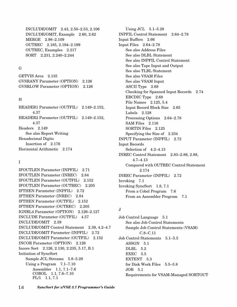
INCLUDE/OMIT 2.43, 2.50–2.53, 2.106INCLUDE/OMIT, Example 2.60, 2.62MERGE 2.98–2.109OUTREC 2.185, 2.194–2.199OUTREC, Examples 2.217SORT 2.231, 2.240–2.244
G
GETVIS Area 2.135GVSRANY Parameter (OPTION) 2.126GVSRLOW Parameter (OPTION) 2.126
H
HEADER1 Parameter (OUTFIL) 2.149–2.152, 4.37
HEADER2 Parameter (OUTFIL) 2.149–2.152, 4.37
Headers 2.149See also Report Writing
Hexadecimal DigitsInsertion of 2.176
Horizontal Arithmetic 2.174
I
IFOUTLEN Parameter (INPFIL) 2.71IFOUTLEN Parameter (INREC) 2.84IFOUTLEN Parameter (OUTFIL) 2.152IFOUTLEN Parameter (OUTREC) 2.205IFTHEN Parameter (INPFIL) 2.72IFTHEN Parameter (INREC) 2.84IFTHEN Parameter (OUTFIL) 2.152IFTHEN Parameter (OUTREC) 2.205IGNRL4 Parameter (OPTION) 2.126–2.127INCLUDE Parameter (OUTFIL) 4.57INCLUDE/OMIT 2.39INCLUDE/OMIT Control Statement 2.39, 4.2–4.7INCLUDE/OMIT Parameter (INPFIL) 2.72INCLUDE/OMIT Parameter (OUTFIL) 2.152INCOR Parameter (OPTION) 2.126Incore Sort 2.126, 2.130, 2.235, 5.17, B.1Initiation of SyncSort
Sample JCL Streams 5.8–5.28Using a Program 7.1–7.10
Assembler 1.1, 7.1–7.6COBOL 1.1, 7.6–7.10PL/1 1.1, 7.1
SyncSort for z/VSE 3.7 Programmer’s GuideI.6
Using JCL 5.1–5.28INPFIL Control Statement 2.64–2.78Input Buffers 2.66Input Files 2.64–2.78
See also Address FilesSee also DLBL StatementSee also INPFIL Control StatementSee also Tape Input and OutputSee also TLBL StatementSee also VSAM FilesSee also VSAM InputASCII Type 2.68Checking for Spanned Input Records 2.74EBCDIC Type 2.68File Names 2.125, 5.4Input Record Block Size 2.65Labels 2.128Processing Options 2.64–2.78SAM Files 2.116SORTIN Files 2.125Specifying the Size of 2.234
INPUT Parameter (INPFIL) 2.72Input Records
Selection of 4.2–4.13INREC Control Statement 2.83–2.86, 2.88,
4.7–4.13Compared with OUTREC Control Statement
2.174INREC Parameter (INPFIL) 2.72Invoking 7.1Invoking SyncSort 1.8, 7.1
From a Cobol Program 7.6From an Assembler Program 7.1
J
Job Control Language 5.1See also Job Control StatementsSample Job Control Statements (VSAM)
C.8–C.11Job Control Statements 5.1–5.5
ASSGN 5.1DLBL 5.2EXEC 5.5EXTENT 5.3for Disk Work Files 5.5–5.8JOB 5.1Requirements for VSAM-Managed SORTOUT
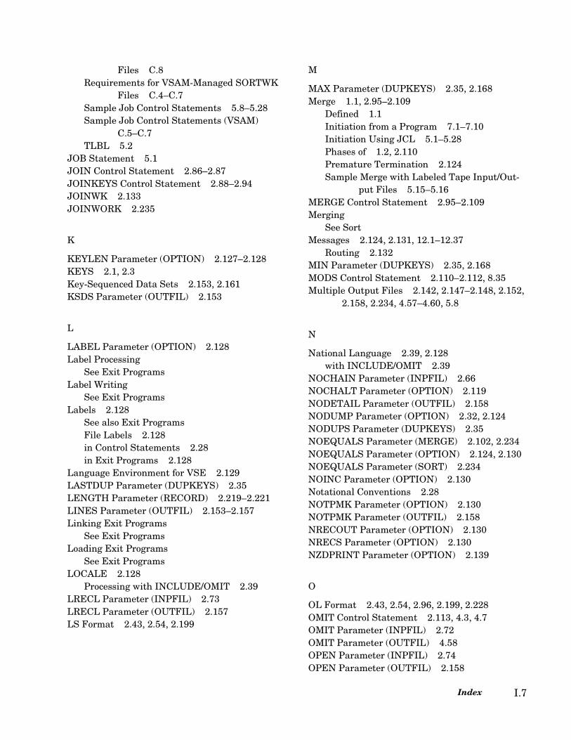
Files C.8Requirements for VSAM-Managed SORTWK
Files C.4–C.7Sample Job Control Statements 5.8–5.28Sample Job Control Statements (VSAM)
C.5–C.7TLBL 5.2
JOB Statement 5.1JOIN Control Statement 2.86–2.87JOINKEYS Control Statement 2.88–2.94JOINWK 2.133JOINWORK 2.235
K
KEYLEN Parameter (OPTION) 2.127–2.128KEYS 2.1, 2.3Key-Sequenced Data Sets 2.153, 2.161KSDS Parameter (OUTFIL) 2.153
L
LABEL Parameter (OPTION) 2.128Label Processing
See Exit ProgramsLabel Writing
See Exit ProgramsLabels 2.128
See also Exit ProgramsFile Labels 2.128in Control Statements 2.28in Exit Programs 2.128
Language Environment for VSE 2.129LASTDUP Parameter (DUPKEYS) 2.35LENGTH Parameter (RECORD) 2.219–2.221LINES Parameter (OUTFIL) 2.153–2.157Linking Exit Programs
See Exit ProgramsLoading Exit Programs
See Exit ProgramsLOCALE 2.128
Processing with INCLUDE/OMIT 2.39LRECL Parameter (INPFIL) 2.73LRECL Parameter (OUTFIL) 2.157LS Format 2.43, 2.54, 2.199
M
MAX Parameter (DUPKEYS) 2.35, 2.168Merge 1.1, 2.95–2.109
Defined 1.1Initiation from a Program 7.1–7.10Initiation Using JCL 5.1–5.28Phases of 1.2, 2.110Premature Termination 2.124Sample Merge with Labeled Tape Input/Out-
put Files 5.15–5.16MERGE Control Statement 2.95–2.109Merging
See SortMessages 2.124, 2.131, 12.1–12.37
Routing 2.132MIN Parameter (DUPKEYS) 2.35, 2.168MODS Control Statement 2.110–2.112, 8.35Multiple Output Files 2.142, 2.147–2.148, 2.152,
2.158, 2.234, 4.57–4.60, 5.8
N
National Language 2.39, 2.128with INCLUDE/OMIT 2.39
NOCHAIN Parameter (INPFIL) 2.66NOCHALT Parameter (OPTION) 2.119NODETAIL Parameter (OUTFIL) 2.158NODUMP Parameter (OPTION) 2.32, 2.124NODUPS Parameter (DUPKEYS) 2.35NOEQUALS Parameter (MERGE) 2.102, 2.234NOEQUALS Parameter (OPTION) 2.124, 2.130NOEQUALS Parameter (SORT) 2.234NOINC Parameter (OPTION) 2.130Notational Conventions 2.28NOTPMK Parameter (OPTION) 2.130NOTPMK Parameter (OUTFIL) 2.158NRECOUT Parameter (OPTION) 2.130NRECS Parameter (OPTION) 2.130NZDPRINT Parameter (OPTION) 2.139
O
OL Format 2.43, 2.54, 2.96, 2.199, 2.228OMIT Control Statement 2.113, 4.3, 4.7OMIT Parameter (INPFIL) 2.72OMIT Parameter (OUTFIL) 4.58OPEN Parameter (INPFIL) 2.74OPEN Parameter (OUTFIL) 2.158
Index I.7
Operator Statement 3.17OPTION Control Statement 2.2, 2.114–2.140OR Operator 2.46–2.47, 4.3OT Format 2.43, 2.54, 2.199OUTFIL Control Statement 2.2, 2.141–4.60Output Buffers 2.144Output Files 2.141–2.172
See also Address FilesSee also ADDROUT Parameter (OPTION)See also DLBL StatementSee also Multiple Output FilesSee also Record LengthSee also Tape Input and OutputSee also TLBL StatementSee also VSAM FilesSee also VSAM OutputDirecting to Card Punch 2.160Directing to Printer 2.160Directing to Tape 2.164Entry-sequenced Data Sets 2.146File Names 2.125, 5.4Key-Sequenced Data Sets 2.153, 2.161Labels 2.128Printing in Hexadecimal Format 2.146Relative Record Data Sets 2.160SORTOF Files 2.125SORTOUT Files 2.125Spanned Records 2.163Storing on Disk 2.146Tape Output Files 2.145
Output Lines, Multiple 2.159, 4.33OUTPUT Parameter (OUTFIL) 2.158Output Record Block Size 2.143–2.144Output Record Length 2.146Output Reports 4.33–4.60
See Report WritingOUTREC Control Statement 2.2, 2.174–2.218,
4.16–4.18Compared with INREC Control Statement
2.174OUTREC Parameter (OUTFIL) 2.158–2.159, 4.58OVERLAY Parameter (INPFIL) 2.74OVERLAY Parameter (INREC) 2.84OVERLAY Parameter (OUTFIL) 2.159OVERLAY Parameter (OUTREC) 2.209OVFLO Parameter (OPTION) 2.131
SyncSort for z/VSE 3.7 Programmer’s GuideI.8
P
PagesLogical 2.144, 2.153–2.157Physical 2.144
PAGES Parameter (OUTFIL) 2.144Parameter 2.152Parameters
BUILD (INPFIL) 2.66Parameters (Control Statements)
ADDROUT (OPTION) 2.115–2.118ALLDUPS (DUPKEYS) 2.34AVG (DUPKEYS) 2.34BIAS (MERGE) 2.101BIAS (SORT) 2.232BLKSIZE (INPFIL) 2.65BLKSIZE (OUTFIL) 2.143–2.144BUFLIM (INPFIL) 2.66BUFLIM (OUTFIL) 2.144BUFOFF (INPFIL) 2.66, 11.2BUFOFF (OUTFIL) 2.144BUILD (INPFIL) 2.66BUILD (INREC) 2.84BUILD (OUTFIL) 2.144BUILD (OUTREC) 2.175BYPASS (INPFIL) 2.66CALC (ANALYZE) 2.32CALCAREA (OPTION) 2.32, 2.118CARDS (OUTFIL) 2.144CENTWIN (MERGE) 2.101CENTWIN (OPTION) 2.119CENTWIN (SORT) 2.233CHALT (OPTION) 2.119CHKPT(SORT) 2.233CISIZE (OUTFIL) 2.145CKPT (SORT) 2.233CLOSE (INPFIL) 2.67CLOSE (OUTFIL) 2.145CMP (OPTION) 2.121CMPINOM=CLC (OPTION) 2.121CMPINOM=CPD (OPTION) 2.121CODE (ALTSEQ) 2.30COND 2.41CONVERT (OUTFIL) 2.145CRDSIZE (INPFIL) 2.68DATA (INPFIL) 2.68DATE (OPTION) 2.122DELBLANK (RECORD) 2.222–2.223DEVIN (OPTION) 2.122

DEVOUT (OPTION) 2.122DEVWK (OPTION) 2.123DIAG (OPTION) 2.32, 2.124DISK (OUTFIL) 2.146DUMP (OPTION) 2.124DUMP (OUTFIL) 2.146ENDREC (INPFIL) 2.69ENDREC (OUTFIL) 2.146EQUALS (MERGE) 2.102, 2.234EQUALS (OPTION) 2.124EQUALS (SORT) 2.234ERASE (OPTION) 2.124, 2.130ESDS (OUTFIL) 2.146EXIT (INPFIL) 2.70EXIT (OUTFIL) 2.147FIELDS (MERGE) 2.95–2.101FIELDS (OUTREC) 2.175FIELDS (SORT) 2.227–2.232FIELDS (SUM) 2.246–2.247FILES (INPFIL) 2.70FILES (MERGE) 2.102FILES (OUTFIL) 2.147, 4.57–4.60FILES (SORT) 2.234FILESOUT (MERGE) 2.102FILESOUT (SORT) 2.234FILNM (OPTION) 2.125–2.126FIRSTDUP (DUPKEYS) 2.35FNAMES (INPFIL) 2.70FNAMES (OUTFIL) 2.147FORMAT (INCLUDE/OMIT) 4.3FREEOUT (OUTFIL) 2.148GVSRANY (OPTION) 2.126GVSRLOW (OPTION) 2.126HEADER1 (OUTFIL) 2.149–2.152, 4.37HEADER2 (OUTFIL) 2.149–2.152, 4.37IFOUTLEN (INPFIL) 2.71IFOUTLEN (INREC) 2.84IFOUTLEN (OUTFIL) 2.152IFOUTLEN (OUTREC) 2.205IFTHEN (INPFIL) 2.72IFTHEN (INREC) 2.84IFTHEN (OUTFIL) 2.152IFTHEN (OUTREC) 2.205IGNRL4 (OPTION) 2.126–2.127INCLUDE (OUTFIL) 4.57INCLUDE/OMIT (INPFIL) 2.72INCLUDE/OMIT (OUTFIL) 2.152INCOR (OPTION) 2.126
INPUT (INPFIL) 2.72INREC (INPFIL) 2.72KEYLEN (OPTION) 2.127–2.128KSDS (OUTFIL) 2.153LABEL (OPTION) 2.128LASTDUP (DUPKEYS) 2.35LENGTH (RECORD) 2.219–2.221LINES (OUTFIL) 2.153–2.157LRECL (INPFIL) 2.73LRECL (OUTFIL) 2.157MAX (DUPKEYS) 2.35MIN (DUPKEYS) 2.35NOCHAIN (INPFIL) 2.66NOCHALT (OPTION) 2.119NODETAIL (OUTFIL) 2.158NODUMP (OPTION) 2.32, 2.124NODUPS (DUPKEYS) 2.35NOEQUALS (MERGE) 2.102, 2.234NOEQUALS (OPTION) 2.124NOEQUALS(SORT) 2.234NOERASE (OPTION) 2.124, 2.130NOIGNRL4 (OPTION) 2.126–2.127NOINC (OPTION) 2.130NOTPMK (OPTION) 2.130NOTPMK (OUTFIL) 2.158NOVLSHRT (OPTION) 2.126–2.127NRECOUT (OPTION) 2.130NRECS (OPTION) 2.130NZDPRRINT (OPTION) 2.139OMIT (INPFIL) 2.72OMIT (OUTFIL) 4.58OPEN (INPFIL) 2.74OPEN (OUTFIL) 2.158ORDER (MERGE) 2.102OUTPUT (OUTFIL) 2.158OUTREC (OUTFIL) 2.158–2.159, 4.58OVERLAY (INPFIL) 2.74OVERLAY (INREC) 2.84OVERLAY (OUTFIL) 2.159OVERLAY (OUTREC) 2.209OVFLO (OPTION) 2.131PAGES (OUTFIL) 2.144PHn (MODS) 2.110–2.112PRESEQ (INPFIL) 2.74PRINT (OPTION) 2.32, 2.131PRINT (OUTFIL) 2.160PUNCH (OUTFIL) 2.160REUSE (OUTFIL) 2.160
Index I.9

ROUTE (OPTION) 2.32, 2.132RPS (OPTION) 2.132RRDS (OUTFIL) 2.160–2.161SAVE (OUTFIL) 2.161SECTIONS (OUTFIL) 2.161–2.163, 4.33–4.34SEQNUM (OUTREC) 2.176–2.177SIZE (SORT) 2.32, 2.234SKIPBYTE (INPFIL) 2.74SKIPREC (INPFIL) 2.74SKIPREC (OPTION) 2.132SORTIN (OPTION) 2.133SORTOUT (OPTION) 2.133SORTWK (OPTION) 2.133SPAN (INPFIL) 2.74SPAN (OUTFIL) 2.163SPANINC (OPTION) 2.134STARTREC (INPFIL) 2.75STARTREC (OUTFIL) 2.163–2.164STOPAFT (INPFIL) 2.75STOPAFT (OPTION) 2.134STORAGE (OPTION) 2.135SUM (DUPKEYS) 2.36SYMNAMES (OPTION) 2.136SYMNLIB (OPTION) 2.136SYMNOUT (OPTION) 2.136SYSIPT (INPFIL) 2.75TAPE (OUTFIL) 2.164TOL (INPFIL) 2.75TOL (OUTFIL) 2.164TP (OPTION) 2.137TRAILER1 (OUTFIL) 2.164–2.170, 4.37, 4.46,
4.53TRAILER2 (OUTFIL) 2.164–2.170, 4.37, 4.46,
4.53TYPE (RECORD) 2.221–2.222VERIFY (OPTION) 2.137VLSHRT (OPTION) 2.126–2.127VOLUME (INPFIL) 2.76VSAM (INPFIL) 2.64, 2.76VSCORE (OPTION) 2.137VSCORET (OPTION) 2.137WORK (SORT) 2.235WORKNM (OPTION) 2.137XSUM (SUM) 2.247XSUMLAB (OPTION) 2.138XSUMNM (OPTION) 2.138–2.139XSUMOUT (OPTION) 2.138–2.139ZDPRRINT (OPTION) 2.139
SyncSort for z/VSE 3.7 Programmer’s GuideI.10
PD Format 2.43, 2.54, 2.96, 2.199, 2.228Comparison with a ZD Field 2.121
PD0 Format 2.43, 2.54, 2.96, 2.105, 2.195, 2.199, 2.228, 2.238
Performance ConsiderationsSee BUFLIM Parameter (INPFIL)See BUFLIM Parameter (OUTFIL)See BYPASS Parameter (INPFIL)See CHKPT Parameter (SORT)See CKPT Parameter (SORT)See DEVIN Parameter (OPTION)See DEVOUT Parameter (OPTION)See DEVWK Parameter (OPTION)See RPS Parameter (OPTION)See SYSIPT Parameter (INPFIL)See WORK Parameter (SORT)
Phases 2.110See also Exit ProgramsDiagnostic Messages 2.124
PHn (MODS) 2.110–2.112PKEYS 2.20PL/1 Program
Initiating SyncSort 1.1, 7.1PRESEQ Parameter (INPFIL) 2.74PRINT Parameter (OPTION) 2.32, 2.131PRINT Parameter (OUTFIL) 2.160Processing Sequence 1.5PSI Format 2.195–2.196PUNCH Parameter (OUTFIL) 2.160PZ Format 2.196
R
RANGE 2.42RDW 2.65, 2.143Reading Input (Merge)
See Exit ProgramsRECORD Control Statement 2.2, 2.219–2.223Record Counts 4.53–4.57Record Descriptor Word (RDW) 2.65, 2.143Record Length 2.117–2.118, 2.145, 2.154, 2.157,
2.219–2.221Record Length and Block Size
Fixed-length ASCII Records 2.65Fixed-length EBCDIC Records 2.65Variable-length ASCII Records 2.65Variable-length EBCDIC Records 2.65
Record Length and Error Handling 2.66

Record SelectionSee also Selecting RecordsUsing Bit Level Logic 2.57–2.59
Record Type 2.221REFORMAT Control Statement 2.224–2.226Reformatting Input Records 2.83–2.86, 2.88,
4.2–4.16Reformatting Output
CHANGE Subparameter 2.188Reformatting Output Records 2.25, 2.158–2.159,
2.174–2.218, 4.16–4.31Column Positioning 4.41–4.42, 4.44Conversion of Numeric Data to Printable
Format 2.205, 4.23Conversion of Numeric Fields to Printable
Format 4.23Conversion of Record Fields to Hexadecimal
Format 2.186, 4.25–4.27Conversion of Variable-length Records to Fixed-
length 2.145Converting and Editing Numeric Data 2.192Data Conversion and Data Editing 4.23–4.31Editing Data 4.16, 4.27–4.29Field Positioning 4.18–4.22Insertion of Binary Zeros 2.176, 4.22–4.23Insertion of Characters 2.176Insertion of Hexadecimal Digits 2.176Insertion of Spaces 2.176, 4.20–4.21Length of Converted Data 2.146OUTFIL Control Statement 2.141OUTREC Control Statement 2.174OUTREC Parameter 2.22, 2.192Record on Multiple Lines 2.159Reordering Field Positions 4.18–4.21Replace 2.234Search and Replace 2.188Specifying an Editing Pattern 2.205, 4.29,
4.48, 4.50, 4.52Use of Editing Masks 2.186, 2.202–2.204, 4.29,
4.48, 4.50, 4.52Reformatting Records
Replace 2.188Relative Record Data Sets 2.160Replace 2.188Report Writing 1.3–1.6, 2.143, 4.33, 4.37–4.60
Date 2.122Headers 2.149–2.152, 4.36–4.46
Types of 2.149Logical Pages 2.153–2.157, 4.38
Sections 2.161–2.163, 4.33–4.36Subtotaling Data 4.46–4.52Title Page 4.38–4.39Totaling Data 4.46–4.52Trailers 2.164–2.170, 4.36–4.57
Types of 2.164Repositioning Record Fields 4.18–4.21Residence Modes 7.2, 8.5REUSE Parameter (OUTFIL) 2.160REXX exits 8.3Rotational Position Sensing 2.132ROUTE Parameter (OPTION) 2.32, 2.132RPS Parameter (OPTION) 2.132RRDS Parameter (OUTFIL) 2.160–2.161RWD 2.26
S
SAM FilesSee VSAM Files
SAVE Parameter (OUTFIL) 2.161Search and Replace 2.188SECTIONS Parameter (OUTFIL) 2.161–2.163,
4.33–4.34Selecting Fields 2.83–2.86, 2.88Selecting Records 2.39, 2.132, 2.134, 2.152, 2.222,
4.2–4.13See also SKIPREC Parameter (OPTION)See also STOPAFT Parameter (OPTION)
SEQNUM 2.83, 2.176–2.177SFF Data Format 2.97, 2.229SIZE Parameter (SORT) 2.32, 2.118, 2.234SKIPBYTE Parameter (INPFIL) 2.74SKIPREC Parameter (INPFIL) 2.74SKIPREC Parameter (OPTION) 2.132SMF Formats 2.199SMF Formats, Converting 2.199Sort
Control Statement 2.227–2.245Defined 1.1Initiation from a Program 7.1–7.10Initiation Using JCL 5.1–5.28Phases of 1.2, 2.110Premature Termination 2.124Sample Sort with Disk Input/Output Files
5.12–5.14Sample Sort with Labeled Tape Input/Output
Files 5.8–5.10Sample Sort with Unlabeled Tape Input/Out-
Index I.11
put Files 5.10–5.12Sample Sort with VSAM Input/Output Files
5.21–5.23Sort with Card Input 5.17–5.19SYNCHSTO 11.1Work Space Requirements 2.32
SORT Control Statement 2.2, 2.95, 2.227–2.246Sort Keys 2.127–2.128SORTGETR 10.3SORTIN End-of-File 8.18SORTIN File 8.15–8.18, 8.58–8.61SORTIN Files 2.125, 5.2
See also VSAM FilesSORTIN Parameter (OPTION) 2.133, 5.3SORTOF Files 2.125, 5.8
See also Multiple Output FilesSORTOUT Files 2.125, 5.2, 5.8
See also Multiple Output FilesSee also VSAM Files
SORTOUT Parameter (OPTION) 2.133, 5.3SORTWK Devices 2.124SORTWK Files 2.125, 5.2
See also VSAM FilesSORTWK Parameter (OPTION) 2.133, 5.3SortWriter 1.2–1.6, 2.143, 2.149
See also Report WritingSpaces
Insertion of 2.176, 4.20–4.21SPAN Parameter (INPFIL) 2.74SPAN Parameter (OUTFIL) 2.163SPANINC Parameter (OPTION) 2.134Spanned Input Records 2.74SRTCLSE 10.3SRTCORE 10.2SRTFILL 10.2SRTOPEN 10.2SS Format 2.43SSRAM 10.1
Assembler Parameter List 10.8COBOL Parameter List 10.13End-of-File Flag 10.3EOFFLAG 10.9File ID 10.3FILEID 10.9FORTRAN Parameter List 10.18Key Definition Table 10.3KEYDFTBL 10.9Logical Unit Number 10.3
SyncSort for z/VSE 3.7 Programmer’s GuideI.12
LOGUNIT 10.9PL/I Parameter List 10.22RECLEN 10.9Record Length 10.3STORAGE 10.9Storage 10.3
STARTREC Parameter (INPFIL) 2.75STARTREC Parameter (OUTFIL) 2.163–2.164STOPAFT Parameter (INPFIL) 2.75STOPAFT Parameter (OPTION) 2.134Storage
Determining the Size of 2.135, 2.137STORAGE Parameter (OPTION) 2.135SUBAVG 2.169SUBMAX 2.169SUBMIN 2.168Substituting Records (Merge)
See Exit ProgramsSubstring Comparison 2.55Subtotaling Data 4.46–4.52SUM Control Statement 2.2, 2.16, 2.18, 2.20,
2.246–2.248, 4.13–4.14SUM Parameter (DUPKEYS) 2.36Summing Data
Printing Summed ZD Data 2.139Summing Records
See Combining Records in a FileSYMNAMES Parameter (OPTION) 2.136SYMNLIB Parameter (OPTION) 2.136SYMNOUT Parameter (OPTION) 2.136SYNCBIX 9.1–9.14
Job Control Statements 9.13Messages 9.14, 12.35Parameters 9.12Syntax Rules 9.12
SYNCHSTO 11.1Control Parameters 11.2Job Control Language 11.5Messages 12.37
SyncSort Application FunctionsSee also MERGE Control StatementSee also SORT Control StatementCompare 2.95Copy 1.1–1.2, 2.227, 2.232Merge 1.1–1.2, 2.95–2.109Sort 1.1–1.2, 2.227–2.245
SyncSort for z/ VSE Data UtilitySummary of Application Functions
Copy 1.1Summary of Features 1.1
SyncSort for z/VSE Data UtilityApplications 4.1–4.60Device Support A.1Initiation from a Program 7.1–7.10Initiation Using JCL 5.1–5.28SortWriter 1.2Summary of Application Functions
Copy ??–1.2Merge 1.1–1.2Sort 1.1–1.2
Summary of Features ??–1.7SYSIPT Parameter (INPFIL) 2.75
T
Tape DevicesIdentification of 2.122–2.123
Tape Input and Output 2.66–2.67, 2.74, 2.76, 2.145, 2.158, 5.2
See also CLOSE Parameter (INPFIL)See also DLBL StatementSee also NOCHAIN Parameter (INPFIL)See also OPEN Parameter (INPFIL)Restrictions on Input 2.68–2.69Sample Merge with Labeled Tape Input/Output
Files 5.15–5.16Sample Sort with Labeled Tape Input/Output
5.10Sample Sort with Labeled Tape Input/Output
Files 5.8Sample Sort with Unlabeled Tape Input/Output
Files 5.10–5.12Tape Devices 2.122–2.123Tape Mark in Unlabeled Output File 2.130,
2.158Treatment of Opened Tape Output Files 2.158
Tape Mark 2.130, 2.158TAPE Parameter (OUTFIL) 2.164TLBL Statement 5.2TM1 2.199TM2 2.199TM3 2.199TM4 2.199TOL Parameter (INPFIL) 2.75TOL Parameter (OUTFIL) 2.164Totaling Data 4.46–4.52TP Parameter (OPTION) 2.137
TRAILER1 Parameter (OUTFIL) 2.164–2.170, 4.37, 4.46, 4.53
TRAILER2 Parameter (OUTFIL) 2.164–2.170, 4.37, 4.46, 4.53
Trailers 2.164–2.170See Report Writing
TS Format 2.43, 2.54, 2.96, 2.199, 2.228TYPE Parameter (RECORD) 2.221–2.222
U
UFF Data Format 2.97, 2.229Unit Names
Default Unit Names 5.4
V
Variable-length Records 2.26, 2.65–2.66, 2.118, 2.145, 2.180, 4.11–4.13, 8.16–8.17, 8.21, 8.37–8.38, 8.43–8.45, 8.59–8.60
and Field Selection 4.11–4.13Specifying Block Size for 2.65
VERIFY Parameter (OPTION) 2.137VOLUME Parameter (INPFIL) 2.76VSAM Alternative Indexes 9.1–9.14VSAM Exits 8.67VSAM Files 2.64, 2.115–2.116, 2.146, 2.160,
2.164, 5.21, 5.23, C.1–C.11JCL Requirements for VSAM-Managed SOR-
TOUT Files C.8JCL Requirements for VSAM-Managed SORT-
WK Files C.4–C.7SAM ESDS Files C.1–C.3Sort with VSAM Input/Output Files
5.21–5.23SORTIN Files C.2–C.3SORTOUT Files C.7SORTWK Files C.3–C.7VSAM Exits 8.67–8.72
VSAM Input 2.64, 2.75, 2.115–2.116, 5.21–5.23VSAM Output 2.146, 2.153, 2.160–2.161,
5.21–5.23VSAM Parameter (INPFIL) 2.76VSAM-managed SAM 2.145VSCORE Parameter (OPTION) 2.137VSCORET Parameter (OPTION) 2.137
Index I.13
W
Work FilesChanging Default Work File Names 2.137File Names 2.125Job Control Statements for Disk Work Files
5.5–5.8Labels 2.128SORTWK Files 2.125Specifying the Number of Disk Files for Sort
Work 2.235WORK Parameter (SORT) 2.235Work Space
See Disk SpaceWORKNM Parameter (OPTION) 2.137, 5.2
X
XDUP Parameter (DUPKEYS) 2.36XDUPFIL Control Statement 2.249XRANGE 2.42XSUM 4.14XSUM Parameter (SUM) 2.247XSUMFIL Control Statement 2.2, 2.249–2.250XSUMLAB Parameter (OPTION) 2.138XSUMNM Parameter (OPTION) 2.138–2.139XSUMOUT Parameter (OPTION) 2.138–2.139
Y
Y constant 2.45Y’DATEx’ 2.54–2.55Y2B Format 2.43, 2.54, 2.119, 2.194, 2.199Y2C Format 2.43, 2.54, 2.96, 2.119, 2.194, 2.199,
2.228Y2D Format 2.43, 2.54, 2.96, 2.119, 2.194, 2.199,
2.228Y2ID Format 2.194Y2IP Format 2.194Y2P Format 2.43, 2.54, 2.96, 2.119, 2.194, 2.199,
2.228Y2S Format 2.43, 2.54, 2.96, 2.119, 2.194, 2.199Y2T Format 2.44, 2.54, 2.98, 2.119, 2.185, 2.199,
2.228, 2.231Y2U Format 2.44, 2.98, 2.185, 2.231Y2V Format 2.44, 2.98, 2.185, 2.231Y2W Format 2.44, 2.98, 2.185, 2.231Y2X Format 2.44, 2.98, 2.185, 2.231Y2Y Format 2.44, 2.98, 2.185, 2.231
SyncSort for z/VSE 3.7 Programmer’s GuideI.14
Y2U Format 2.54, 2.119, 2.199, 2.228Y2V Format 2.54, 2.119, 2.199, 2.228Y2W Format 2.54, 2.119, 2.199, 2.228Y2X Format 2.54, 2.119, 2.199, 2.228Y2Y Format 2.54, 2.119, 2.199, 2.228Y2Z Format 2.43, 2.54, 2.96, 2.98, 2.119, 2.194,
2.199, 2.230
Z
ZD Format 2.43, 2.54, 2.98, 2.199, 2.230Comparison with a PD Field 2.121
ZDPRINT Parameter (OPTION) 2.139Zoned 2.98, 2.230ZSI Format 2.195–2.196


Syncsort Incorporated50 Tice Boulevard
Woodcliff Lake, New Jersey 07677(201) 930-8200
E-mail: [email protected]