Wireless Location Privacy Protection in Vehicular Ad-Hoc Networks
12
Mobile Netw Appl DOI 10.1007/s11036-009-0167-4 Wireless Location Privacy Protection in Vehicular Ad-Hoc Networks Joo-Han Song · Vincent W.S. Wong · Victor C.M. Leung © Springer Science + Business Media, LLC 2009 Abstract Advances in mobile networks and positioning technologies have made location information a valu- able asset in vehicular ad-hoc networks (VANETs). However, the availability of such information must be weighted against the potential for abuse. In this paper, we investigate the problem of alleviating unauthorized tracking of target vehicles by adversaries in VANETs. We propose a vehicle density-based location privacy (DLP) scheme which can provide location privacy by utilizing the neighboring vehicle density as a threshold to change the pseudonyms. We derive the delay distri- bution and the average total delay of a vehicle within a density zone. Given the delay information, an adver- sary may still be available to track the target vehicle by some selection rules. We investigate the effectiveness of DLP based on extensive simulation study. Simulation results show that the probability of successful location tracking of a target vehicle by an adversary is inversely proportional to both the traffic arrival rate and the variance of vehicles’ speed. Our proposed DLP scheme also has a better performance than both Mix-Zone scheme and AMOEBA with random silent period. Keywords vehicular ad-hoc network · location privacy J.-H. Song · V. W. S. Wong (B ) · V. C. M. Leung Department of Electrical and Computer Engineering, The University of British Columbia, Vancouver, British Columbia, Canada e-mail: [email protected] J.-H. Song e-mail: [email protected] V. C. M. Leung e-mail: [email protected] 1 Introduction Due to the technological advancement and widespread deployment, nowadays there are various ways to access the Internet from a mobile device. For example, one can either use the IEEE 802.11 [1] compliant WiFi networks or by subscribing to the third generation (3G) wireless cellular services. Recently, a new type of wireless ad-hoc networks, also known as the vehicular ad hoc network (VANET), has gained increasing atten- tion. VANETs aim to provide communications among vehicles (i.e., vehicle-to-vehicle (V2V)) and between vehicle and fixed roadside equipment (i.e., vehicle-to- roadside (V2R)). Significant progress has been made in Intelligent Transportation Systems (ITS) to create a safe and efficient driving environment. The DSRC (Dedicated Short Range Communications) [2] is a short to medium range wireless technology for V2R and V2V communications. VANET is an important component in ITS, and is expected to play a crucial role in various applications such as collision warning, road sign alarms, driver assistance, and infotainment. In safety enhancing applications, each vehicle needs to periodically broadcast an authenticated safety mes- sage, which includes its verifiable identity, its current location, speed, and acceleration. Although these safety messages can help to prevent accidents, they may also be used by the adversaries for unauthorized location tracking of vehicles. By using an external IEEE 802.11 compliant wireless network, an attacker can eavesdrop on all the broadcast messages and determine the loca- tions visited by the vehicles (or users) over a period of time. The location history information (or mobility traces of the target vehicles) can be associated with places of interest of vehicle users. This information
-
Upload
independent -
Category
Documents
-
view
6 -
download
0
Transcript of Wireless Location Privacy Protection in Vehicular Ad-Hoc Networks

Mobile Netw ApplDOI 10.1007/s11036-009-0167-4
Wireless Location Privacy Protection in VehicularAd-Hoc Networks
Joo-Han Song · Vincent W.S. Wong ·Victor C.M. Leung
© Springer Science + Business Media, LLC 2009
Abstract Advances in mobile networks and positioningtechnologies have made location information a valu-able asset in vehicular ad-hoc networks (VANETs).However, the availability of such information must beweighted against the potential for abuse. In this paper,we investigate the problem of alleviating unauthorizedtracking of target vehicles by adversaries in VANETs.We propose a vehicle density-based location privacy(DLP) scheme which can provide location privacy byutilizing the neighboring vehicle density as a thresholdto change the pseudonyms. We derive the delay distri-bution and the average total delay of a vehicle withina density zone. Given the delay information, an adver-sary may still be available to track the target vehicle bysome selection rules. We investigate the effectiveness ofDLP based on extensive simulation study. Simulationresults show that the probability of successful locationtracking of a target vehicle by an adversary is inverselyproportional to both the traffic arrival rate and thevariance of vehicles’ speed. Our proposed DLP schemealso has a better performance than both Mix-Zonescheme and AMOEBA with random silent period.
Keywords vehicular ad-hoc network · location privacy
J.-H. Song · V. W. S. Wong (B) · V. C. M. LeungDepartment of Electrical and Computer Engineering,The University of British Columbia, Vancouver,British Columbia, Canadae-mail: [email protected]
J.-H. Songe-mail: [email protected]
V. C. M. Leunge-mail: [email protected]
1 Introduction
Due to the technological advancement and widespreaddeployment, nowadays there are various ways to accessthe Internet from a mobile device. For example, onecan either use the IEEE 802.11 [1] compliant WiFinetworks or by subscribing to the third generation(3G) wireless cellular services. Recently, a new type ofwireless ad-hoc networks, also known as the vehicularad hoc network (VANET), has gained increasing atten-tion. VANETs aim to provide communications amongvehicles (i.e., vehicle-to-vehicle (V2V)) and betweenvehicle and fixed roadside equipment (i.e., vehicle-to-roadside (V2R)). Significant progress has been madein Intelligent Transportation Systems (ITS) to createa safe and efficient driving environment. The DSRC(Dedicated Short Range Communications) [2] is a shortto medium range wireless technology for V2R and V2Vcommunications. VANET is an important componentin ITS, and is expected to play a crucial role in variousapplications such as collision warning, road sign alarms,driver assistance, and infotainment.
In safety enhancing applications, each vehicle needsto periodically broadcast an authenticated safety mes-sage, which includes its verifiable identity, its currentlocation, speed, and acceleration. Although these safetymessages can help to prevent accidents, they may alsobe used by the adversaries for unauthorized locationtracking of vehicles. By using an external IEEE 802.11compliant wireless network, an attacker can eavesdropon all the broadcast messages and determine the loca-tions visited by the vehicles (or users) over a periodof time. The location history information (or mobilitytraces of the target vehicles) can be associated withplaces of interest of vehicle users. This information
Mobile Netw Appl
can be exploited for advertisement or surveillance.Moveover, it can be misused for crimes, such as ab-ductions or automobile thefts. Protecting the locationprivacy of vehicles is important because the lack ofprivacy may hinder the wide acceptance of VANETtechnology.
In general, location privacy protection schemes formobile networks can be classified as policy-based [3]and anonymity-based [4]. In policy-based schemes,vehicles specify their location privacy preferences aspolicies and trust that the third party location-basedservice (LBS) providers adhere to these policies. In theanonymity-based approaches, the location tracking ofa target vehicle can be mitigated by using a randomlychosen and changing identifier, called the pseudonym.Pseudonyms are generated in a predefined way suchthat the adversaries cannot link a new pseudonym toprevious ones of the same vehicle. Pseudonyms caneither be a set of public keys, network layer addresses,or link layer addresses [5]. The change of pseudonymdenotes that the vehicle either changes its public keyor addresses on the different layers (i.e., network andlink). This approach regards anonymity as being un-traceable between two successive locations of the tar-get. Since pseudonyms cannot be linked to each other,they can provide a certain degree of privacy. In gen-eral, frequently changing pseudonyms are accepted as asolution to protecting the privacy of VANET [6]. How-ever, in most communication protocols, it can be com-plicated to re-establish the session frequently as bothcommunication parties should be re-authenticated.
Since adversaries can predict the movement of thevehicles based on the position and speed informationfrom all the broadcast messages of a target vehicle, theycan use this prediction to link different pseudonyms ofthe target vehicle with a high probability. In this paper,we propose a vehicle density-based location privacy(DLP) scheme which can provide location privacy byutilizing the neighboring vehicle density as a thresh-old to change the pseudonyms. The level of locationprivacy protection of changing pseudonyms dependson the road traffic condition. The neighboring vehicledensity can be used to assess the road traffic condi-tion. In particular, a high neighboring vehicle densityusually indicates that there is traffic congestion. Eachvehicle can easily obtain the number of neighboringvehicles through the exchange of the periodic link-layer HELLO messages in VANETS. In our proposedscheme, by monitoring the neighboring vehicle den-sity, each vehicle updates its pseudonym only whenthere are at least ki − 1 distinct neighboring vehicles.To the best of our knowledge, it is the first approachthat considers the neighboring vehicle density as the
triggering factor for updating the pseudonym. The goalof our proposed scheme is to minimize the probabilityof successful location tracking of a target vehicle byan adversary. The contributions of this paper are asfollows:
1. We propose the vehicle density-based location pri-vacy (DLP) scheme, which can mitigate the loca-tion tracking of vehicles by changing pseudonymsbased on a threshold in neighboring vehicle countwithin a density zone.
2. We derive the delay distribution and the expectedtotal delay of a vehicle within the density zone.Given the delay information, an adversary may stillbe available to track the target vehicle based onselection rules.
3. Simulation results show that the probability ofsuccessful location tracking by an adversary is in-versely proportional to the intensity of the traffic
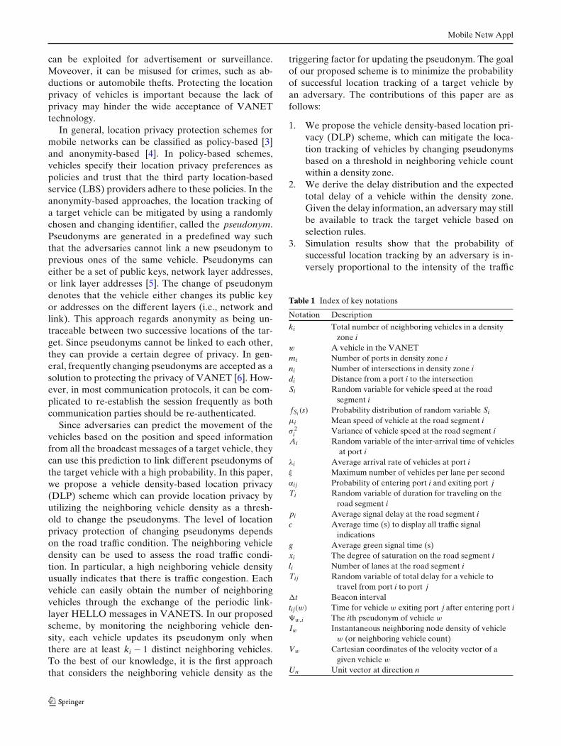
Table 1 Index of key notations
Notation Description
ki Total number of neighboring vehicles in a densityzone i
w A vehicle in the VANETmi Number of ports in density zone ini Number of intersections in density zone idi Distance from a port i to the intersectionSi Random variable for vehicle speed at the road
segment ifSi (s) Probability distribution of random variable Si
μi Mean speed of vehicle at the road segment iσ 2
i Variance of vehicle speed at the road segment iAi Random variable of the inter-arrival time of vehicles
at port iλi Average arrival rate of vehicles at port iξ Maximum number of vehicles per lane per secondαij Probability of entering port i and exiting port jTi Random variable of duration for traveling on the
road segment ipi Average signal delay at the road segment ic Average time (s) to display all traffic signal
indicationsg Average green signal time (s)xi The degree of saturation on the road segment ili Number of lanes at the road segment iTij Random variable of total delay for a vehicle to
travel from port i to port j�t Beacon intervaltij(w) Time for vehicle w exiting port j after entering port i�w,i The ith pseudonym of vehicle w
Iw Instantaneous neighboring node density of vehiclew (or neighboring vehicle count)
Vw Cartesian coordinates of the velocity vector of agiven vehicle w
Un Unit vector at direction n
Mobile Netw Appl
and the variance of the vehicles’ speed. Our pro-posed DLP scheme outperforms both AMOEBA(with random silent period) [7] and Mix-Zone [8]schemes in reducing the probability of successfultracking by an adversary.
This paper is organized as follows. The related workis summarized in Section 2. The system model is de-scribed in Section 3. Our proposed DLP scheme isdescribed in Section 4. Performance evaluations andcomparisons are presented in Section 5. Conclusionsare given in Section 6. A list of the notations that weused in this paper is shown in Table 1.
2 Related work
In this section, we summarize the recent work on lo-cation privacy enhancement schemes. In [7], a protocolcalled AMOEBA is proposed which can mitigate theunauthorized location tracking of vehicles by using theconcept of group navigation for V2R communicationsand by introducing the random silent period betweenupdate of pseudonyms [9] for V2V communications.Since the mobility of vehicles is spatially restrictedand dependent, vehicles in geographical proximity cannavigate as a group. These vehicles have the sameaverage speed and moving direction over a period oftime. Since each group can be represented by a singlevehicle, which is a group leader, the location of othervehicle is protected from disclosing. When other vehi-cles are joining the network, AMOEBA can preventan adversary to link a new pseudonym to the previousone by enforcing a target vehicle to remain silent for arandom period.
In [8], the road network is divided into the observedzones and the unobserved zones from the viewpointof the adversaries. The observed zones are those areaswhere the adversaries can track the locations of the tar-get vehicles. The unobserved zones (also called the mixzones) are some predetermined locations (e.g., roadintersections) where the vehicles vary their directions,speeds, and their pseudonyms. The adversaries wouldhave difficulty in linking the vehicles that emerge fromthe mix zone to those that entered it earlier. Since thelocations of mix zones are predetermined, the adver-saries may still attempt to eavesdrop on transmissionsoriginating from the mix-zone area.
The concept of location k-anonymity [10] is pro-posed for protecting the location information throughspatial and temporal cloaking. In spatial cloaking, avehicle broadcast its coarse-grained spatial range infor-mation when the number of vehicles within its range
is greater than a certain threshold. In other words,the real location of vehicle hides somewhere within athreshold. In temporal cloaking, the beacon messagewill not be broadcast by the vehicle until a certain num-ber of other vehicles have visited the same location. Itrefers to replacing a time point associated with a targetvehicle with a time interval.
In [11], a protocol is proposed to create the CMIX(Cryptographic MIX-zone) at road intersection. Eachvehicle obtains a public/private key pair from certificateauthority (CA) via the roadside equipment, and utilizesthese keys to encrypt all messages while they are withinthe mix zone. By key forwarding mechanism, vehicles,which are approaching to the mix-zone, can obtain thesymmetric key directly from roadside equipment.
Since vehicles use multiple addresses simultaneouslyon the different layers, changing the pseudonym onlyat one layer implies the risk that an adversary can linktwo consecutive pseudonym by the unchanged addressat another protocol layer. In [12], the multi-layer ad-dressing scheme is proposed to support pseudonymityenabling user privacy at the different layers. It is a studyof practicability in pseudonymity deployment and im-plementation. In [13], the effects of pseudonym changeson the performance of network layer are investigatedin VANET environments. Simulation results show thatpseudonym changes can affect routing procedure andresult in packet losses. By introducing a callback mech-anism from the link layer, the network layer can bettercope with the pseudonym changes.
3 System model
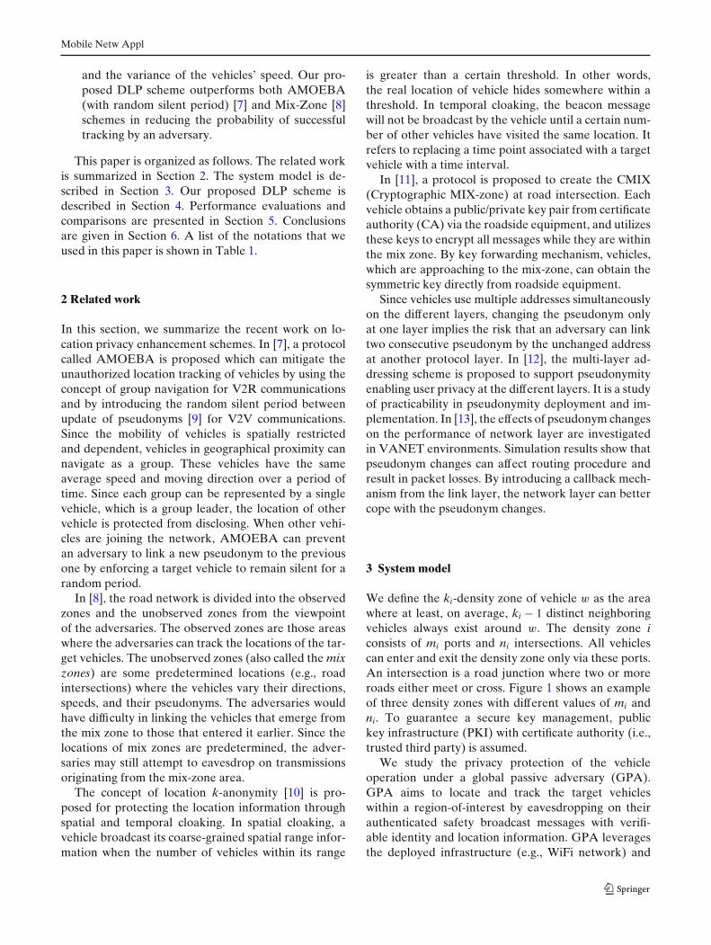
We define the ki-density zone of vehicle w as the areawhere at least, on average, ki − 1 distinct neighboringvehicles always exist around w. The density zone iconsists of mi ports and ni intersections. All vehiclescan enter and exit the density zone only via these ports.An intersection is a road junction where two or moreroads either meet or cross. Figure 1 shows an exampleof three density zones with different values of mi andni. To guarantee a secure key management, publickey infrastructure (PKI) with certificate authority (i.e.,trusted third party) is assumed.
We study the privacy protection of the vehicleoperation under a global passive adversary (GPA).GPA aims to locate and track the target vehicleswithin a region-of-interest by eavesdropping on theirauthenticated safety broadcast messages with verifi-able identity and location information. GPA leveragesthe deployed infrastructure (e.g., WiFi network) and
Mobile Netw Appl
Fig. 1 An example of a VANET with three density zones. Thesolid black lines denote the road. The shaded areas correspond tothe density zones
utilizes the adversarial roadside equipment deployedto track the movement of the target vehicles withinthe region-of-interest. Compared to the GPA, the re-stricted passive attacker (RPA) proposed in [7] is awareof the number of vehicles entering and exiting a densityzone, but not of the traveling time and trajectories ofthe vehicles. In this paper, we only consider the privacyprotection against GPA.
Although the GPA cannot distinguish the targetvehicle from other vehicles within the density zonedue to the change of pseudonym, it can still eavesdropon all the broadcast messages within the density zone.By installing radio receivers at opportune locations,the GPA can observe entering and exiting events ofvehicles where an event is a pair consisting of a portnumber and a time stamp. In addition, a GPA caneither measure (via extensive real measurements [8])or estimate the probability distribution of the delay ofvehicles within the density zone. Given the delay distri-bution, a GPA can attempt to link an entering vehicleand an exiting vehicle with certain success probability.Thus, GPA should have a knowledge of the delaycharacteristics of the intersection and on the trajectoryof the vehicles in the density zone. In the followingsubsections, we describe how the GPA obtain the delaydistributions via estimation.
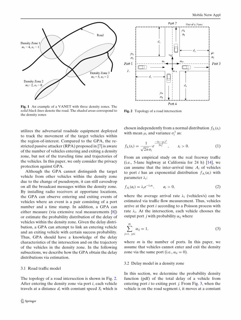
3.1 Road traffic model
The topology of a road intersection is shown in Fig. 2.After entering the density zone via port i, each vehicletravels at a distance di with constant speed Si which is
d1
d2
d3
d4
Fig. 2 Topology of a road intersection
chosen independently from a normal distribution fSi(si)
with mean μi and variance σ 2i as:
fSi(si) = 1√2πσi
e−(si−μi)
2
2σ 2i , si > 0. (1)
From an empirical study on the real freeway traffic(i.e., 5-lane highway at California for 24 h) [14], wecan assume that the inter-arrival time Ai of vehiclesto port i has an exponential distribution fAi(ai) withparameter λi:
fAi(ai) = λie−λiai , ai > 0, (2)
where the average arrival rate λi (vehicles/s) can beestimated via traffic flow measurement. Thus, vehiclesarrive at the port i according to a Poisson process withrate λi. At the intersection, each vehicle chooses theoutput port j with probability αij where
m∑
j=1, j�=i
αij = 1, (3)
where m is the number of ports. In this paper, weassume that vehicles cannot enter and exit the densityzone via the same port (i.e., αii = 0).
3.2 Delay model in a density zone
In this section, we determine the probability densityfunction (pdf) of the total delay of a vehicle fromentering port i to exiting port j. From Fig. 3, when thevehicle is on the road segment i, it moves at a constant
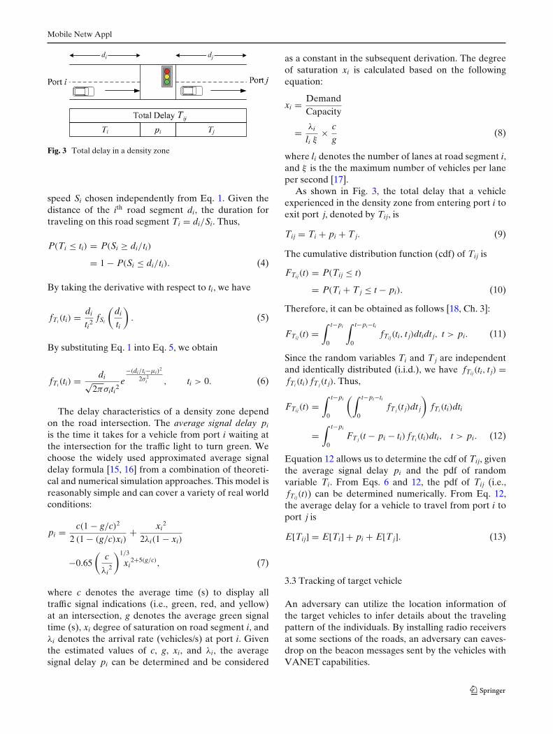
Mobile Netw Appl
di dj
Fig. 3 Total delay in a density zone
speed Si chosen independently from Eq. 1. Given thedistance of the ith road segment di, the duration fortraveling on this road segment Ti = di/Si. Thus,
P(Ti ≤ ti) = P(Si ≥ di/ti)
= 1 − P(Si ≤ di/ti). (4)
By taking the derivative with respect to ti, we have
fTi(ti) = di
ti2fSi
(di
ti
). (5)
By substituting Eq. 1 into Eq. 5, we obtain
fTi(ti) = di√2πσiti2
e−(di/ti−μi)
2
2σ 2i , ti > 0. (6)
The delay characteristics of a density zone dependon the road intersection. The average signal delay pi
is the time it takes for a vehicle from port i waiting atthe intersection for the traffic light to turn green. Wechoose the widely used approximated average signaldelay formula [15, 16] from a combination of theoreti-cal and numerical simulation approaches. This model isreasonably simple and can cover a variety of real worldconditions:
pi = c(1 − g/c)2
2 (1 − (g/c)xi)+ xi
2
2λi(1 − xi)
−0.65
(c
λi2
)1/3
xi2+5(g/c), (7)
where c denotes the average time (s) to display alltraffic signal indications (i.e., green, red, and yellow)at an intersection, g denotes the average green signaltime (s), xi degree of saturation on road segment i, andλi denotes the arrival rate (vehicles/s) at port i. Giventhe estimated values of c, g, xi, and λi, the averagesignal delay pi can be determined and be considered
as a constant in the subsequent derivation. The degreeof saturation xi is calculated based on the followingequation:
xi = DemandCapacity
= λi
li ξ× c
g(8)
where li denotes the number of lanes at road segment i,and ξ is the the maximum number of vehicles per laneper second [17].
As shown in Fig. 3, the total delay that a vehicleexperienced in the density zone from entering port i toexit port j, denoted by Tij, is
Tij = Ti + pi + T j. (9)
The cumulative distribution function (cdf) of Tij is
FTij(t) = P(Tij ≤ t)
= P(Ti + T j ≤ t − pi). (10)
Therefore, it can be obtained as follows [18, Ch. 3]:
FTij(t) =∫ t−pi
0
∫ t−pi−ti
0fTij(ti, t j)dtidt j, t > pi. (11)
Since the random variables Ti and T j are independentand identically distributed (i.i.d.), we have fTij(ti, t j) =fTi(ti) fT j(t j). Thus,
FTij(t) =∫ t−pi
0
(∫ t−pi−ti
0fT j(t j)dt j
)fTi(ti)dti
=∫ t−pi
0FT j(t − pi − ti) fTi(ti)dti, t > pi. (12)
Equation 12 allows us to determine the cdf of Tij, giventhe average signal delay pi and the pdf of randomvariable Ti. From Eqs. 6 and 12, the pdf of Tij (i.e.,fTij(t)) can be determined numerically. From Eq. 12,the average delay for a vehicle to travel from port i toport j is
E[Tij] = E[Ti] + pi + E[T j]. (13)
3.3 Tracking of target vehicle
An adversary can utilize the location information ofthe target vehicles to infer details about the travelingpattern of the individuals. By installing radio receiversat some sections of the roads, an adversary can eaves-drop on the beacon messages sent by the vehicles withVANET capabilities.
Mobile Netw Appl
We assume that the adversary has information of thesystem model of the density zones. It can also observethe entering and exit events corresponding to vehiclesentering and exiting the density zone, respectively. Anentering event consists of the port where the vehicleentered the density zone, and the time when it hap-pened. Similarly, an exit event consists of the port wherethe vehicle left the density zone, and the time when ithappened.
The objective of an adversary is to relate exit eventsto entering events. Specifically, in our model, the adver-sary selects a target vehicle w and tracks its movementuntil it enters the density zone. Within the density zone,the target vehicle may change its pseudonym if it satis-fies the criteria in the DLP scheme (as explained in thenext section). The adversary then needs to determinewhich vehicle coming out from one of the exiting portscorresponds to the target vehicle.
In the following, we denote the port at which thetarget vehicle w entered the density zone by i. Withoutloss of generality, at time 0, the adversary observesthat the target vehicle w entered the density zone viaport i. The adversary observes the exit events at allports j ∈ J for a time Tmax such that the probabilitythat the target vehicle w leaves the density zone beforeTmax approaches to 1. Since each vehicle travels a roadsegment with a constant speed, which is chosen inde-pendently from a normal distribution, about 99.7% ofvehicles are within three standard deviations 3σ awayfrom the mean μ in terms of speed. To be more precise,the area under the bell curve between μ − 3σ and ∞in terms of the normal distribution function is about0.9985. Therefore, in Fig. 3, the value of Tmax can bedefined as
Tmax =(
di
μi − 3σi
)+ pi +
(d j
μ j − 3σ j
). (14)
The adversary records the time tij(wr) for each vehiclewr which exits port j before Tmax. Let {w1, . . . , wR} ∈W be the set of vehicles observed during the timeinterval (0, Tmax). We propose two selection rules foran adversary to choose a vehicle w′ ∈ W to be the targetvehicle w.
Rule 1 The adversary chooses a vehicle which min-imizes the time difference between the average delayE[Tij] to the exit time tij of all candidate vehicles:
(w′, j ′) = arg min
{w1,...,wR}∈W, j∈Jαij
(tij(wr) − E[Tij]
)2 (15)
where the multiplication of αij gives a different weightvalue depending on the direction of vehicle at theintersection.
Rule 2 The adversary chooses a vehicle which canmaximize the cdf of Tij between tij + δ and tij − δ:(w′, j ′) = arg max
{w1,...,wR}∈W, j∈Jαij(Pij(wr) − Qij(wr)), (16)
where Pij(wr) = FTij(tij(wr) + δ), and Qij(wr) =FTij(tij(wr) − δ).
The range value δ is a configurable parameter. Theadversary is successful in tracking the target vehicle ifthe selected vehicle w′ is indeed the target vehicle w.
4 Density-based location privacy (DLP)
In DLP scheme, each vehicle can provide connectiv-ity information by broadcasting local beacon messagesperiodically. A beacon message is a short packet withthe current pseudonym and location information of thevehicle. At every beacon interval �t, the vehicle checkswhether it has sent a broadcast within the last �t (e.g.,the default beacon interval in 802.11-based networks is100 ms [1] and the default HELLO message interval inAODV [19] is 1000 ms). If it has not, it will broadcasta beacon message with time-to-live (TTL) value equalsto 1.
Each vehicle w determines its instantaneous neigh-boring node density Iw, (or neighboring vehicle count)by listening for beacon messages from its set of neigh-bors. If a vehicle w has not received a beacon messagefrom another neighbor for �t, the vehicle w assumesthat the link to its neighbor is lost. Therefore, thevehicle w decreases its neighboring vehicle count by1. On the other hand, whenever vehicle w receivesa beacon message from a new neighbor (i.e., with anew pseudonym), w will increase its neighboring ve-hicle count by 1. Due to the change of pseudonym ofneighboring vehicles, the neighboring vehicle count canbe greater than the real density for �t at maximum.By using neighboring node density, each vehicle w canupdate the average neighboring node density at everybeacon interval �t. DLP uses the arithmetic averageneighboring node density, which is the sum of Iw’s di-vided by the number of observations. DLP can also usean exponential weighted moving average (EWMA),which applies weighting factors. The weighting for aprevious value decreases exponentially, giving muchmore importance to recent observations.
If the deployed network layer protocol does notsupport the exchange of beacon messages, each vehiclecan maintain accurate information about its continuedconnectivity to its neighboring vehicles by using eitherlink layer or other network layer mechanisms. Anyadequate link layer notification, such as those provided
Mobile Netw Appl
by IEEE 802.11, can be used to determine connectivity.For example, the absence of a link layer feedback orfailure to receive a clear-to-send (CTS) after sendinga request-to-send (RTS) may indicate the loss of thelink to its neighboring vehicle. If link layer notificationis not available, passive acknowledgment can be used innetwork layer when the neighboring vehicle is expectedto forward the packet, by listening to the channel for atransmission attempt made by the neighboring vehicle.If transmission is not detected within a predefined time-out value, an Internet control message protocol (ICMP)[20] echo request message can also be sent to the targetneighboring vehicle. If a link to the neighboring vehiclecannot be detected by any of the above methods, thevehicle assumes that the link is lost.
We assume each vehicle w has been preloaded withZ different pseudonyms {ψw,1, ψw,2, . . . , ψw,Z }, whereZ is a large number. Pseudonyms can either be a setof public keys, network layer or link layer addresses.Many protocols need to commit to a sequence of ran-dom values. For this purpose, we use a one-way hashfunction [21] to generate a one-way chain. One-waychains are a widely-used cryptographic primitive [22].Each vehicle chooses a random initial value ψw,Z andgenerates a one-way chain by repeatedly computing aone-way hash function H on this starting value:
ψw,1 = H(ψw,2, PSK)
= H2(ψw,3, PSK)
...
= HS−2(ψw,Z−1, PSK)
= HS−1(ψw,Z , PSK) (17)
where PSK is a pre-shared key with the trusted thirdparty.
Before joining the VANET, each vehicle registerswith the trusted third party. We can verify any elementof the chain through ψw,1. For example, to verify thatelement ψw,k is indeed the element with index k ofthe hash chain, we check that Hk−1(ψv,k, PSK) = ψw,1.Due to the lack of PSK, attackers cannot link anytwo pseudonyms from the same vehicle. Moreover, thispseudonym chain can also be used for non-repudiationpurpose. The third party authority can provide proof ofthe integrity and origin of pseudonyms of each vehiclein case of a dispute.
Depending on the frequency of pseudonym update,the size of chain can be large. For example, when thepseudonym update interval is 1 s, each vehicle needsto store 3600 pseudonyms for an hour driving. It may
cause an issue of storing lots of pseudonyms. Sincehash chain can be used to compute any other elementon demand simply by storing ψw,Z , it is efficient interms of memory usage. The number of hash functionevaluations can vary depending on its implementation.For example, the sender can compute approximately106 MD5 hash function evaluations per second (i.e.,software-based implementation) [23]. Moreover, thespeed of MD5 hash function evaluation can be acceler-ated with the help of simple stand-alone hardware [24].
A change of pseudonym is triggered by vehicles onlywhen the average neighboring vehicle count is morethan or equal to ki − 1. In other words, DLP prevents aprivacy breach by ensuring that each vehicle triggers apseudonym change only when there are at least ki − 1neighboring vehicles on average.
4.1 Extension of DLP with vehicle-heading (VH)
DLP can be extended by including any information thatis used to characterize the situation of either densityzone or other neighboring vehicles, such as the mov-ing direction and relative speed. In order to calculateboth the speed and direction of neighboring vehicles,distance during two consecutive beacon messages ismeasured from the same neighboring vehicle. Sinceevery vehicle broadcasts its own location informationin periodic beacon messages, all vehicles within thetransmission range are able to maintain a status of aneighboring vehicle including its moving direction andrelative speed. In our proposed DLP with Vehicle-Heading (VH) scheme, the moving direction of neigh-boring vehicle is considered in updating neighboringvehicle density.
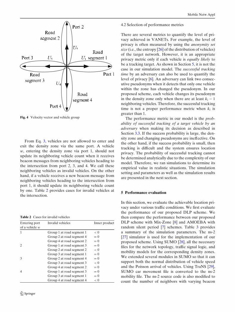
In DLP with VH, vehicles are grouped into fourdifferent groups based on their velocity vectors [25]. Ina Cartesian space, each group is characterized by one ofthe unit vectors, U1 = (1, 0), U2 = (0, 1), U3 = (−1, 0),U4 = (0, −1), as shown in Fig. 4. Vehicles are assumedto be equipped with a global positioning system (GPS)to detect their geographical location. Location detec-tion is performed every �t interval. Let Vw = (vx, vy)
denote the Cartesian coordinates of the velocity vectorof a given vehicle w. Using the velocity vector andunit vectors, the group of vehicle w can be decidedas follows: Vehicle w belongs to group n, if the innerproduct of its velocity vector Vw and the unit vectorUn takes the positive value. Vehicle w with negativeinner product with the unit vector Un is heading to theopposite direction, and vehicle w with zero inner prod-uct with the unit vector Un is moving to the orthogonaldirection to the vehicles in group n.
Mobile Netw Appl
Fig. 4 Velocity vector and vehicle group
From Eq. 3, vehicles are not allowed to enter andexit the density zone via the same port. A vehiclew, entering the density zone via port 1, should notupdate its neighboring vehicle count when it receivesbeacon messages from neighboring vehicles heading tothe intersection from port 2, 3, and 4. We call theseneighboring vehicles as invalid vehicles. On the otherhand, if a vehicle receives a new beacon message fromneighboring vehicles heading to the intersection fromport 1, it should update its neighboring vehicle countby one. Table 2 provides cases for invalid vehicles atthe intersection.
Table 2 Cases for invalid vehicles
Entering port Invalid vehicles Inner productof a vehicle w
1 Group 1 at road segment 1 < 0Group 2 at road segment 4 = 0Group 4 at road segment 2 = 0
2 Group 1 at road segment 3 = 0Group 2 at road segment 2 < 0Group 3 at road segment 1 = 0
3 Group 2 at road segment 4 = 0Group 3 at road segment 3 < 0Group 4 at road segment 2 = 0
4 Group 1 at road segment 3 = 0Group 3 at road segment 1 = 0Group 4 at road segment 4 < 0
4.2 Selection of performance metrics
There are several metrics to quantify the level of pri-vacy achieved in VANETs. For example, the level ofprivacy is often measured by using the anonymity setsize (i.e., the entropy [26] of the distribution of vehicles)of the target network. However, it is an appropriateprivacy metric only if each vehicle is equally likely tobe a tracking target. As shown in Section 5, it is not thecase in our simulation model. The successful trackingtime by an adversary can also be used to quantify thelevel of privacy [6]. An adversary can link two consec-utive pseudonyms when it detects that only one vehiclewithin the zone has changed the pseudonym. In ourproposed scheme, each vehicle changes its pseudonymin the density zone only when there are at least ki − 1neighboring vehicles. Therefore, the successful trackingtime is not a proper performance metric when ki isgreater than 1.
The performance metric in our model is the prob-ability of successful tracking of a target vehicle by anadversary when making its decision as described inSection 3.3. If the success probability is large, the den-sity zone and changing pseudonyms are ineffective. Onthe other hand, if the success probability is small, thentracking is difficult and the system ensures locationprivacy. The probability of successful tracking cannotbe determined analytically due to the complexity of ourmodel. Therefore, we ran simulations to determine itsempirical value in realistic situations. The simulationsetting and parameters as well as the simulation resultsare presented in the next section.
5 Performance evaluation
In this section, we evaluate the achievable location pri-vacy under various traffic conditions. We first evaluatethe performance of our proposed DLP scheme. Wethen compare the performance between our proposedDLP scheme with Mix-Zone [8] and AMOEBA withrandom silent period [7] schemes. Table 3 providesa summary of the simulation parameters. The ns-2[27] simulator is used for the implementation of ourproposed scheme. Using SUMO [28], all the necessaryfiles for the network topology, traffic signal logic, andmobility models for the corresponding density zones.We extended several modules in SUMO so that it cansupport both the normal distribution of vehicle speedand the Poisson arrival of vehicles. Using TraNS [29],SUMO car movement file is converted to the ns-2mobility file. The ns-2 source code is also modified tocount the number of neighbors with varying beacon
Mobile Netw Appl
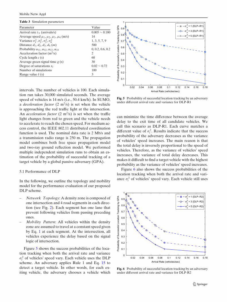
Table 3 Simulation parameters
Parameter Value
Arrival rate λ1 (arrivals/s) 0.005 ∼ 0.180Average speed μ1, μ2, μ3, μ4 (m/s) 14Variance σ 2
1 , σ 22 , σ 2
3 , σ 24 1, 3, 5, 7, 9
Distance d1, d2, d3, d4 (m) 500Probability α11, α12, α13, α14 0, 0.2, 0.6, 0.2Acceleration factor (m2/s) 2Cycle length c (s) 60Average green signal time g (s) 30Degree of saturations xi 0.02 ∼ 0.72Number of simulations 100Range value δ (s) 3
intervals. The number of vehicles is 100. Each simula-tion run takes 30,000 simulated seconds. The averagespeed of vehicles is 14 m/s (i.e., 50.4 km/h). In SUMO,a deceleration factor (2 m2/s) is set when the vehicleis approaching the red traffic light at the intersection.An acceleration factor (2 m2/s) is set when the trafficlight changes from red to green and the vehicle needsto accelerate to reach the chosen speed. For medium ac-cess control, the IEEE 802.11 distributed coordinationfunction is used. The nominal data rate is 2 Mb/s anda transmission radio range is 250 m. The propagationmodel combines both free space propagation modeland two-ray ground reflection model. We performedmultiple independent simulation runs to obtain an es-timation of the probability of successful tracking of atarget vehicle by a global passive adversary (GPA).
5.1 Performance of DLP
In the following, we outline the topology and mobilitymodel for the performance evaluation of our proposedDLP scheme.
– Network Topology: A density zone is composed ofone intersection and 4 road segments in each direc-tion (see Fig. 2). Each segment has one lane thatprevent following vehicles from passing precedingones.
– Mobility Pattern: All vehicles within the densityzone are assumed to travel at a constant speed givenby Eq. 1 at each segment. At the intersection, allvehicles experience the delay based on the signallogic of intersection.
Figure 5 shows the success probabilities of the loca-tion tracking when both the arrival rate and varianceσ 2
i of vehicles’ speed vary. Each vehicle uses the DLPscheme. An adversary applies Rule 1 and Eq. 15 todetect a target vehicle. In other words, for each ex-iting vehicle, the adversary chooses a vehicle which
0.02 0.04 0.06 0.08 0.1 0.12 0.14 0.16 0.180
0.1
0.2
0.3
0.4
0.5
0.6
0.7
0.8
0.9
1
Arrival Rate (vehicles/sec)
Pro
babili
ty o
f S
uccessfu
l Location T
rackin
g b
y G
PA
σn
2 = 1 (DLP– R1)
σn
2 = 3 (DLP– R1)
σn
2 = 5 (DLP– R1)
Fig. 5 Probability of successful location tracking by an adversaryunder different arrival rate and variance for DLP-R1
can minimize the time difference between the averagedelay to the exit time of all candidate vehicles. Wecall this scenario as DLP-R1. Each curve matches adifferent value of σ 2
i . Results indicate that the successprobability of the adversary decreases as the varianceof vehicles’ speed increases. The main reason is thatthe total delay is inversely proportional to the speed ofvehicles. Therefore, as the variance of vehicles’ speedincreases, the variance of total delay decreases. Thismakes it difficult to find a target vehicle with the highestprobability as the variance of vehicles’ speed increases.
Figure 6 also shows the success probabilities of thelocation tracking when both the arrival rate and vari-ance σ 2
i of vehicles’ speed vary. Each vehicle still uses
0.02 0.04 0.06 0.08 0.1 0.12 0.14 0.16 0.180
0.1
0.2
0.3
0.4
0.5
0.6
0.7
0.8
0.9
1
Arrival Rate (vehicles/sec)
Pro
ba
bili
ty o
f S
ucce
ssfu
l L
oca
tio
n T
rackin
g b
y G
PA
σn
2 = 1 (DLP– R2)
σn
2 = 3 (DLP– R2)
σn
2 = 5 (DLP– R2)
Fig. 6 Probability of successful location tracking by an adversaryunder different arrival rate and variance for DLP-R2
Mobile Netw Appl
the DLP scheme. This time, the adversary applies Rule2 and Eq. 16 to detect a target vehicle. For each exit-ing vehicle, the adversary chooses a vehicle which canmaximize the cdf of the total traveling time in a giveninterval. We denote this scenario as DLP-R2. Eachcurve corresponds to the different value of σ 2
i . Resultsin Figs. 5 and 6 show that DLP-R1 scheme outperformsDLP-R2 scheme as the arrival rate increases. It showsthat the accuracy of derived cdf decreases as the arrivalrate increases.
5.2 Performance comparison with other schemes
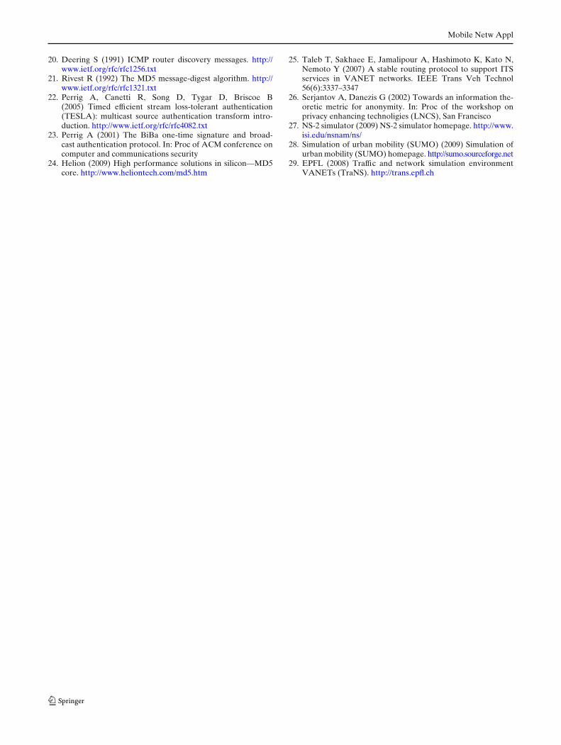
The topology for the performance comparison amongAMOEBA, Mix-Zone, and DLP is shown in Fig. 7.There are three density zones with different values ofAR, which is the arrival rate of vehicles in density zone.Each vehicle is allowed to change its own pseudonymonly one time during the whole travel. For example, ifa vehicle w changes its pseudonym in the density zone#1, it cannot change its pseudonym in the other twodensity zones. In AMOEBA, each vehicle can changeits pseudonym only when there are new neighboringvehicles joining the density zone via the entrance ramp.After a silent period chosen randomly between 0.1to 3 s (recommended values in [7]), each vehicle canupdate its own pseudonym. In Mix-Zone scheme, eachvehicle changes its pseudonym in any density zone withthe same probability of 1/3. In our proposed DLPscheme, each vehicle changes its pseudonym in the den-sity zone only when there are at least ki − 1 neighboringvehicles on average. The value of ki is set to 10 in thesimulation.
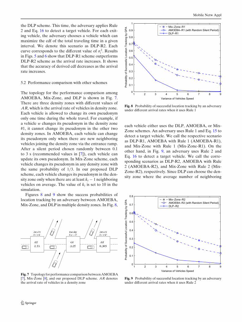
Figures 8 and 9 show the success probabilities oflocation tracking by an adversary between AMOEBA,Mix-Zone, and DLP in multiple density zones. In Fig. 8,
Fig. 7 Topology for performance comparison between AMOEBA[7], Mix-Zone [8], and our proposed DLP scheme. AR denotesthe arrival rate of vehicles in a density zone
1 2 3 4 5 6 7 8 90
0.1
0.2
0.3
0.4
0.5
0.6
0.7
0.8
0.9
1
Variance of Vehicles Speed
Pro
babili
ty o
f S
uccessfu
l Location T
rackin
g b
y G
PA
Mix– Zone– R1
AMOEBA– R1 (with Random Silent Period)
DLP– R1
Fig. 8 Probability of successful location tracking by an adversaryunder different arrival rates when it uses Rule 1
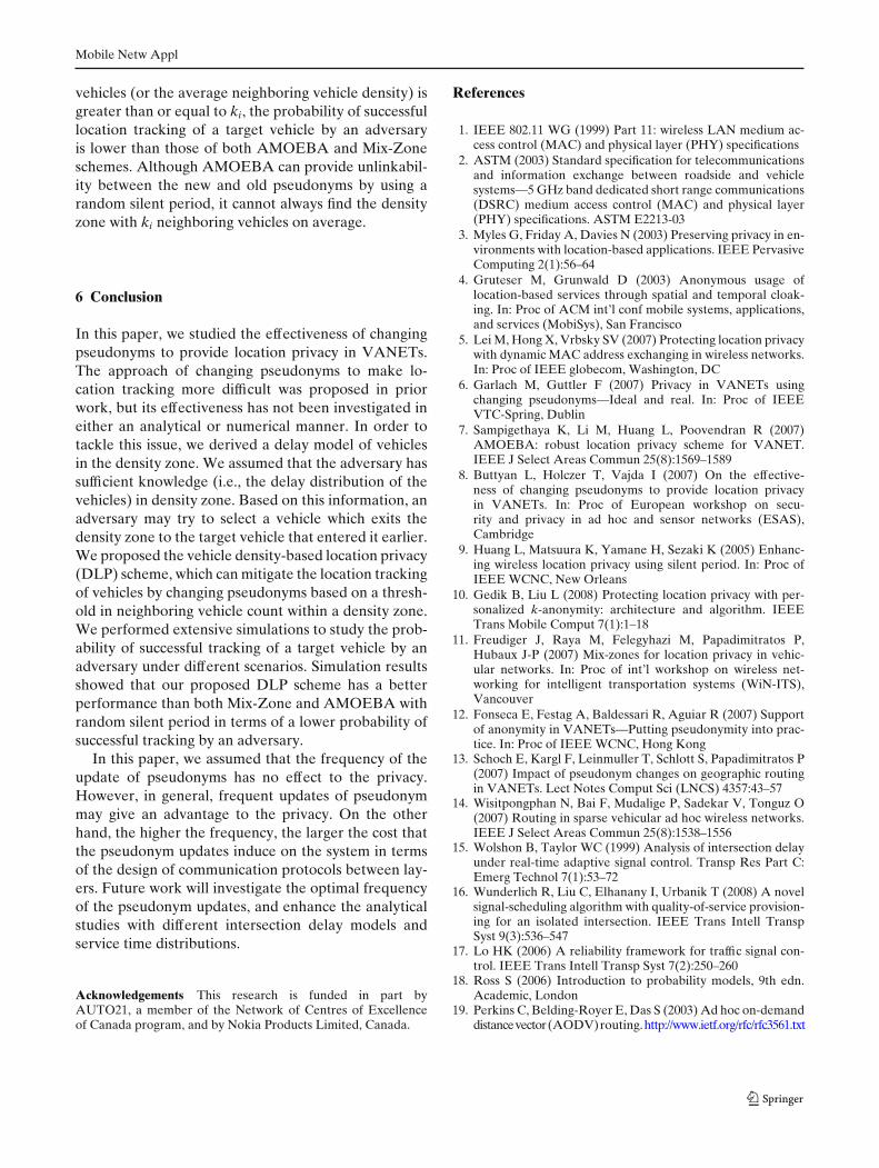
each vehicle either uses the DLP, AMOEBA, or Mix-Zone schemes. An adversary uses Rule 1 and Eq. 15 todetect a target vehicle. We call the respective scenarioas DLP-R1, AMOEBA with Rule 1 (AMOEBA-R1),and Mix-Zone with Rule 1 (Mix-Zone-R1). On theother hand, in Fig. 9, an adversary uses Rule 2 andEq. 16 to detect a target vehicle. We call the corre-sponding scenarios as DLP-R2, AMOEBA with Rule2 (AMOEBA-R2), and Mix-Zone with Rule 2 (Mix-Zone-R2), respectively. Since DLP can choose the den-sity zone where the average number of neighboring
1 2 3 4 5 6 7 8 90
0.1
0.2
0.3
0.4
0.5
0.6
0.7
0.8
Variance of Vehicles Speed
Pro
babili
ty o
f S
uccessfu
l Location T
rackin
g b
y G
PA
Mix– Zone– R2
AMOEBA– R2 (with Random Silent Period)
DLP– R2
Fig. 9 Probability of successful location tracking by an adversaryunder different arrival rates when it uses Rule 2
Mobile Netw Appl
vehicles (or the average neighboring vehicle density) isgreater than or equal to ki, the probability of successfullocation tracking of a target vehicle by an adversaryis lower than those of both AMOEBA and Mix-Zoneschemes. Although AMOEBA can provide unlinkabil-ity between the new and old pseudonyms by using arandom silent period, it cannot always find the densityzone with ki neighboring vehicles on average.
6 Conclusion
In this paper, we studied the effectiveness of changingpseudonyms to provide location privacy in VANETs.The approach of changing pseudonyms to make lo-cation tracking more difficult was proposed in priorwork, but its effectiveness has not been investigated ineither an analytical or numerical manner. In order totackle this issue, we derived a delay model of vehiclesin the density zone. We assumed that the adversary hassufficient knowledge (i.e., the delay distribution of thevehicles) in density zone. Based on this information, anadversary may try to select a vehicle which exits thedensity zone to the target vehicle that entered it earlier.We proposed the vehicle density-based location privacy(DLP) scheme, which can mitigate the location trackingof vehicles by changing pseudonyms based on a thresh-old in neighboring vehicle count within a density zone.We performed extensive simulations to study the prob-ability of successful tracking of a target vehicle by anadversary under different scenarios. Simulation resultsshowed that our proposed DLP scheme has a betterperformance than both Mix-Zone and AMOEBA withrandom silent period in terms of a lower probability ofsuccessful tracking by an adversary.
In this paper, we assumed that the frequency of theupdate of pseudonyms has no effect to the privacy.However, in general, frequent updates of pseudonymmay give an advantage to the privacy. On the otherhand, the higher the frequency, the larger the cost thatthe pseudonym updates induce on the system in termsof the design of communication protocols between lay-ers. Future work will investigate the optimal frequencyof the pseudonym updates, and enhance the analyticalstudies with different intersection delay models andservice time distributions.
Acknowledgements This research is funded in part byAUTO21, a member of the Network of Centres of Excellenceof Canada program, and by Nokia Products Limited, Canada.
References
1. IEEE 802.11 WG (1999) Part 11: wireless LAN medium ac-cess control (MAC) and physical layer (PHY) specifications
2. ASTM (2003) Standard specification for telecommunicationsand information exchange between roadside and vehiclesystems—5 GHz band dedicated short range communications(DSRC) medium access control (MAC) and physical layer(PHY) specifications. ASTM E2213-03
3. Myles G, Friday A, Davies N (2003) Preserving privacy in en-vironments with location-based applications. IEEE PervasiveComputing 2(1):56–64
4. Gruteser M, Grunwald D (2003) Anonymous usage oflocation-based services through spatial and temporal cloak-ing. In: Proc of ACM int’l conf mobile systems, applications,and services (MobiSys), San Francisco
5. Lei M, Hong X, Vrbsky SV (2007) Protecting location privacywith dynamic MAC address exchanging in wireless networks.In: Proc of IEEE globecom, Washington, DC
6. Garlach M, Guttler F (2007) Privacy in VANETs usingchanging pseudonyms—Ideal and real. In: Proc of IEEEVTC-Spring, Dublin
7. Sampigethaya K, Li M, Huang L, Poovendran R (2007)AMOEBA: robust location privacy scheme for VANET.IEEE J Select Areas Commun 25(8):1569–1589
8. Buttyan L, Holczer T, Vajda I (2007) On the effective-ness of changing pseudonyms to provide location privacyin VANETs. In: Proc of European workshop on secu-rity and privacy in ad hoc and sensor networks (ESAS),Cambridge
9. Huang L, Matsuura K, Yamane H, Sezaki K (2005) Enhanc-ing wireless location privacy using silent period. In: Proc ofIEEE WCNC, New Orleans
10. Gedik B, Liu L (2008) Protecting location privacy with per-sonalized k-anonymity: architecture and algorithm. IEEETrans Mobile Comput 7(1):1–18
11. Freudiger J, Raya M, Felegyhazi M, Papadimitratos P,Hubaux J-P (2007) Mix-zones for location privacy in vehic-ular networks. In: Proc of int’l workshop on wireless net-working for intelligent transportation systems (WiN-ITS),Vancouver
12. Fonseca E, Festag A, Baldessari R, Aguiar R (2007) Supportof anonymity in VANETs—Putting pseudonymity into prac-tice. In: Proc of IEEE WCNC, Hong Kong
13. Schoch E, Kargl F, Leinmuller T, Schlott S, Papadimitratos P(2007) Impact of pseudonym changes on geographic routingin VANETs. Lect Notes Comput Sci (LNCS) 4357:43–57
14. Wisitpongphan N, Bai F, Mudalige P, Sadekar V, Tonguz O(2007) Routing in sparse vehicular ad hoc wireless networks.IEEE J Select Areas Commun 25(8):1538–1556
15. Wolshon B, Taylor WC (1999) Analysis of intersection delayunder real-time adaptive signal control. Transp Res Part C:Emerg Technol 7(1):53–72
16. Wunderlich R, Liu C, Elhanany I, Urbanik T (2008) A novelsignal-scheduling algorithm with quality-of-service provision-ing for an isolated intersection. IEEE Trans Intell TranspSyst 9(3):536–547
17. Lo HK (2006) A reliability framework for traffic signal con-trol. IEEE Trans Intell Transp Syst 7(2):250–260
18. Ross S (2006) Introduction to probability models, 9th edn.Academic, London
19. Perkins C, Belding-Royer E, Das S (2003) Ad hoc on-demanddistancevector(AODV)routing.http://www.ietf.org/rfc/rfc3561.txt
Mobile Netw Appl
20. Deering S (1991) ICMP router discovery messages. http://www.ietf.org/rfc/rfc1256.txt
21. Rivest R (1992) The MD5 message-digest algorithm. http://www.ietf.org/rfc/rfc1321.txt
22. Perrig A, Canetti R, Song D, Tygar D, Briscoe B(2005) Timed efficient stream loss-tolerant authentication(TESLA): multicast source authentication transform intro-duction. http://www.ietf.org/rfc/rfc4082.txt
23. Perrig A (2001) The BiBa one-time signature and broad-cast authentication protocol. In: Proc of ACM conference oncomputer and communications security
24. Helion (2009) High performance solutions in silicon—MD5core. http://www.heliontech.com/md5.htm
25. Taleb T, Sakhaee E, Jamalipour A, Hashimoto K, Kato N,Nemoto Y (2007) A stable routing protocol to support ITSservices in VANET networks. IEEE Trans Veh Technol56(6):3337–3347
26. Serjantov A, Danezis G (2002) Towards an information the-oretic metric for anonymity. In: Proc of the workshop onprivacy enhancing technoligies (LNCS), San Francisco
27. NS-2 simulator (2009) NS-2 simulator homepage. http://www.isi.edu/nsnam/ns/
28. Simulation of urban mobility (SUMO) (2009) Simulation ofurban mobility (SUMO) homepage. http://sumo.sourceforge.net
29. EPFL (2008) Traffic and network simulation environmentVANETs (TraNS). http://trans.epfl.ch