WHAT IS MAXIMUM DEMAND
12
-
Upload
independent -
Category
Documents
-
view
0 -
download
0
Transcript of WHAT IS MAXIMUM DEMAND
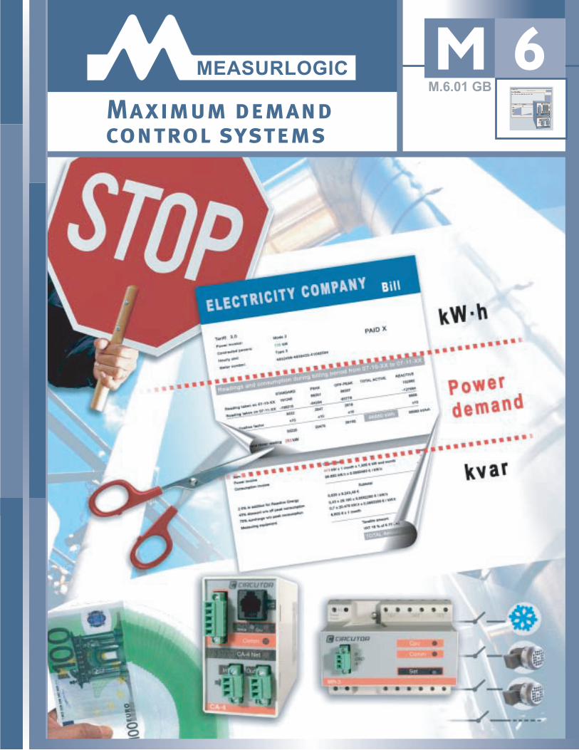
MAXIMUM DEMAND CONTROL SYSTEMS
2
Active energy consumption (kWh)
Reactive energy consumption (kvarh)
Maximum Demand
Traditionally, utility companies have concentrated their energy saving efforts
on two items:
Reduction of Kilowatt Hour consumption
Improving the electrical system’s Power Factor
There is a third item to consider when reducing the amount of the electric
company bill, proper kW Demand management which allows:
The reduction of the contracted power
Adjusting to the new kW limit
Avoiding kW Demand limit penalties
•••
••
•••
Maximum Demand Control
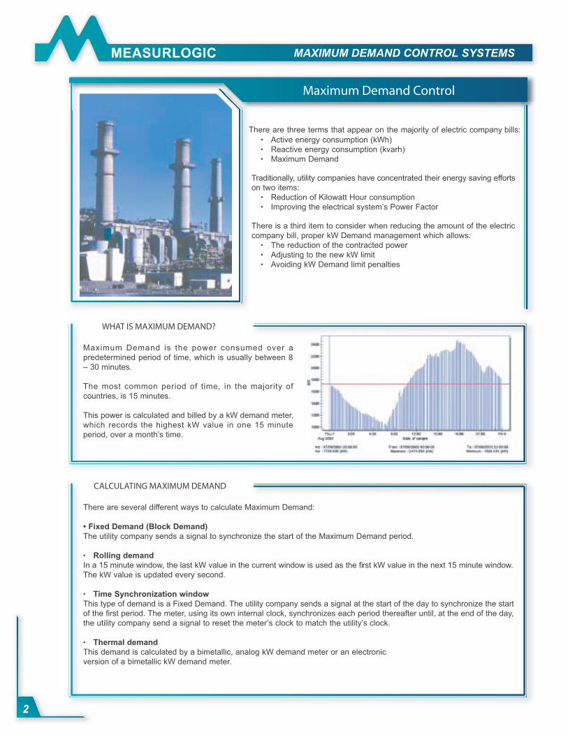
WHAT IS MAXIMUM DEMAND?
Maximum Demand is the power consumed over a
predetermined period of time, which is usually between 8
– 30 minutes.
The most common period of time, in the majority of
countries, is 15 minutes.
This power is calculated and billed by a kW demand meter,
which records the highest kW value in one 15 minute
period, over a month’s time.
CALCULATING MAXIMUM DEMAND
There are several different ways to calculate Maximum Demand:
• Fixed Demand (Block Demand)
The utility company sends a signal to synchronize the start of the Maximum Demand period.
Rolling demand
In a 15 minute window, the last kW value in the current window is used as the fi rst kW value in the next 15 minute window.
The kW value is updated every second.
Time Synchronization window
This type of demand is a Fixed Demand. The utility company sends a signal at the start of the day to synchronize the start
of the fi rst period. The meter, using its own internal clock, synchronizes each period thereafter until, at the end of the day,
the utility company send a signal to reset the meter’s clock to match the utility’s clock.
Thermal demand
This demand is calculated by a bimetallic, analog kW demand meter or an electronic
version of a bimetallic kW demand meter.
•
•
•
There are three terms that appear on the majority of electric company bills:
MAXIMUM DEMAND CONTROL SYSTEMS
3
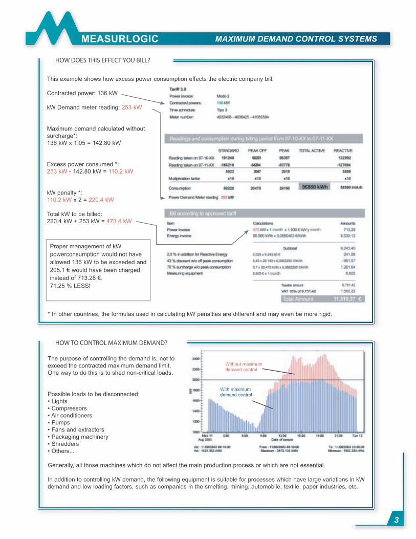
HOW DOES THIS EFFECT YOU BILL?
This example shows how excess power consumption effects the electric company bill:
Contracted power: 136 kW
kW Demand meter reading: 253 kW
Maximum demand calculated without
surcharge*:
136 kW x 1.05 = 142.80 kW
Excess power consumed *:
253 kW - 142.80 kW = 110.2 kW
kW penalty *:
110.2 kW x 2 = 220.4 kW
Total kW to be billed:
220.4 kW + 253 kW = 473.4 kW
Proper management of kW
powerconsumption would not have
allowed 136 kW to be exceeded and
205.1 € would have been charged
instead of 713.28 €.
71.25 % LESS!
HOW TO CONTROL MAXIMUM DEMAND?
The purpose of controlling the demand is, not to
exceed the contracted maximum demand limit.
One way to do this is to shed non-critical loads.
Possible loads to be disconnected:
• Lights
• Compressors
• Air conditioners
• Pumps
• Fans and extractors
• Packaging machinery
• Shredders
• Others...
Generally, all those machines which do not affect the main production process or which are not essential.
In addition to controlling kW demand, the following equipment is suitable for processes which have large variations in kW
demand and low loading factors, such as companies in the smelting, mining, automobile, textile, paper industries, etc.
With maximum
demand control
Without maximum
demand control
* In other countries, the formulas used in calculating kW penalties are different and may even be more rigid.
MAXIMUM DEMAND CONTROL SYSTEMS
4
METHMETHOD OF OPERD OF OPERATIONION
There are two methods used to avoid excess Maximum Demand:
• Preventive
The Preventive method is suitable for those companies who do not want to allow the automatic connection or disconnection
of loads.
This system operates using visual or audible alarms indicating that the kW demand limt is going to be exceeded and that
an operator should manually disconnect certain loads.
• Predictive
The predictive method is most often used.
The unit predicts what is going to happen, based on the load at the end of the current period and optimises the loads
in order to have as many loads connected without exceeding the maximum demand limit, which is preset in the unit.
This method of control is used when calculating demand using the fi xed or synchronised demand methods.
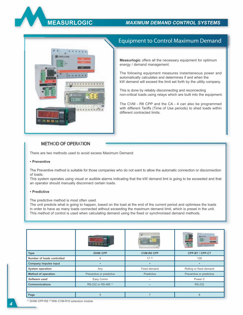
Measurlogic offers all the necessary equipment for optimum
energy / demand management.
The following equipment measures instantaneous power and
automatically calculates and determines if and when the
kW demand will exceed the limit set forth by the utility company.
This is done by reliably disconnecting and reconnecting
non-critical loads using relays which are built into the equipment.
The CVM - R8 CPP and the CA - 4 can also be programmed
with different Tariffs (Time of Use periods) to shed loads within
different contracted limits.
Equipment to Control Maximum Demand
Type DH96 CPP CVM-R8 CPP CPP-BT / CPP-CT
Number of loads controlled 4 17 (2) 128
Company impulse input • • •
System operation Any Fixed demand Rolling or fi xed demand
Method of operation Preventive or predictive Predictive Preventive or predictive
Software used Easy Comm -- Power C
Communications RS-232 or RS-485 (1) -- RS-232
Page 5 7 8
(1) DH96 CPP-RS (2) With CVM-R10 extension module
MAXIMUM DEMAND CONTROL SYSTEMS
5
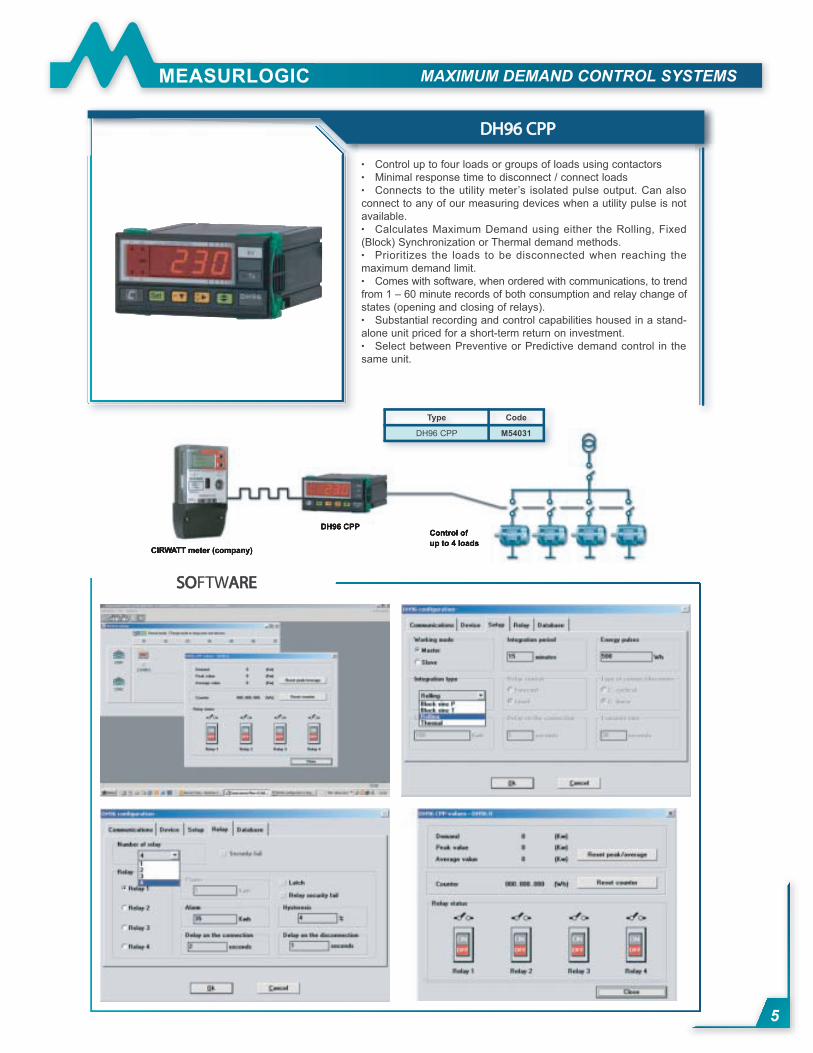
Control up to four loads or groups of loads using contactors
Minimal response time to disconnect / connect loads
Connects to the utility meter’s isolated pulse output. Can also
connect to any of our measuring devices when a utility pulse is not
available.
Calculates Maximum Demand using either the Rolling, Fixed
(Block) Synchronization or Thermal demand methods.
Prioritizes the loads to be disconnected when reaching the
maximum demand limit.
Comes with software, when ordered with communications, to trend
from 1 – 60 minute records of both consumption and relay change of
states (opening and closing of relays).
Substantial recording and control capabilities housed in a stand-
alone unit priced for a short-term return on investment.
Select between Preventive or Predictive demand control in the
same unit.
•••
•
•
•
•
•
DH96 CPPDH96 CPP
SOSOFTWAREARE
Type Code
DH96 CPP M54031
MAXIMUM DEMAND CONTROL SYSTEMS
6
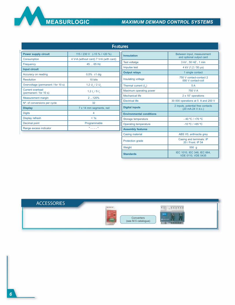
FFeaturestures
Power supply circuit 115 / 230 V (-15 % / +20 %)
Consumption 4 V•A (without card) 7 V•A (with card)
Frequency 45 ... 65 Hz
Input circuit
Accuracy on reading 0,5% ±1 dig
Resolution 10 bits
Overvoltage (permanent / for 10 s) 1,2 Un / 2 U
n
Current overload (permanent / for 10 s)
1,2 In / 5 I
n
Measurement margin 2 ...120%
Nº. of conversions per cycle 32
Display 7 x 14 mm segments, red
Digits 4
Display refresh < 1s
Decimal point Programmable
Range excess indicator " - - - - "
InnsulationBetween input, measurement
and optional output card
Test voltatge 3 kV , 50 HZ , 1 min
Impulse test 4 kV (1,2 / 50 µs)
Output relays 1 single contact
Insulating voltage 750 V contact-contact 2
000 V contact-coil
Thermal current (Ith) 5 A
Maximum operating power 750 V·A
Mechanical life 2 x 10⁷ operations
Electrical life 30 000 operations at 5 A and 250 V
Digital inputs 2 inputs, potential free contacts
(20 mA-24 V d.c.)
Environmental conditions
Storage temperature - 40 ºC / +70 ºC
Operating temperature -10 ºC / +65 ºC
Assembly features
Casing material ABS V0, anthracite grey
Protection grade Casing and terminals: IP
20 / Front: IP 54
Weight 550 g
Standards IEC 1010, IEC 348, IEC 664,
VDE 0110, VDE 0435
5 AACCESSORIES
Converters(see M.5 catalogue)
MAXIMUM DEMAND CONTROL SYSTEMS
7
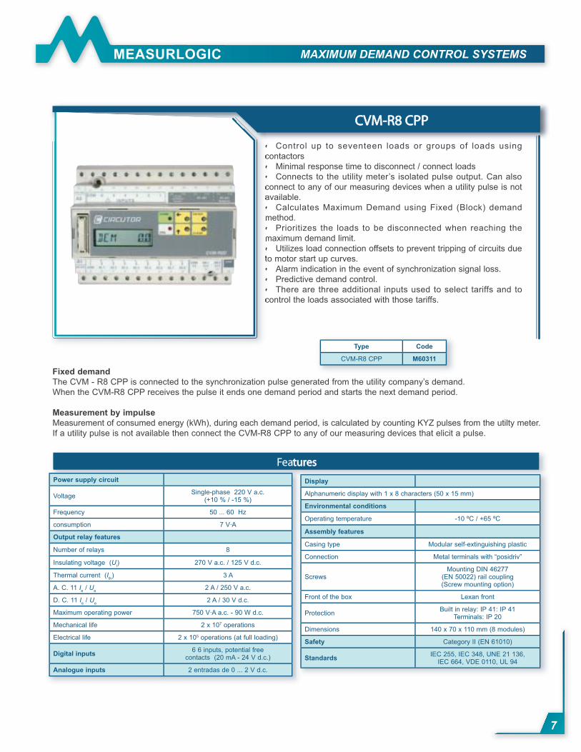
Control up to seventeen loads or groups of loads using
contactors
Minimal response time to disconnect / connect loads
Connects to the utility meter’s isolated pulse output. Can also
connect to any of our measuring devices when a utility pulse is not
available.
Calculates Maximum Demand using Fixed (Block) demand
method.
Prioritizes the loads to be disconnected when reaching the
maximum demand limit.
Utilizes load connection offsets to prevent tripping of circuits due
to motor start up curves.
Alarm indication in the event of synchronization signal loss.
Predictive demand control.
There are three additional inputs used to select tariffs and to
control the loads associated with those tariffs.
•
••
•
•
•
•••
CVM-R8 CPPCVM-R8 CPP
Fixed demand
The CVM - R8 CPP is connected to the synchronization pulse generated from the utility company’s demand.
When the CVM-R8 CPP receives the pulse it ends one demand period and starts the next demand period.
Measurement by impulse
Measurement of consumed energy (kWh), during each demand period, is calculated by counting KYZ pulses from the utilty meter.
If a utility pulse is not available then connect the CVM-R8 CPP to any of our measuring devices that elicit a pulse.
Featurestures
Power supply circuit
VoltageSingle-phase 220 V a.c.
(+10 % / -15 %)
Frequency 50 ... 60 Hz
consumption 7 V·A
Output relay features
Number of relays 8
Insulating voltage (Ui) 270 V a.c. / 125 V d.c.
Thermal current (Ith) 3 A
A. C. 11 Ie / U
e2 A / 250 V a.c.
D. C. 11 Ie / U
e2 A / 30 V d.c.
Maximum operating power 750 V·A a.c. - 90 W d.c.
Mechanical life 2 x 10⁷ operations
Electrical life 2 x 10⁵ operations (at full loading)
Digital inputs 6 6 inputs, potential free
contacts (20 mA - 24 V d.c.)
Analogue inputs 2 entradas de 0 ... 2 V d.c.
Display
Alphanumeric display with 1 x 8 characters (50 x 15 mm)
Environmental conditions
Operating temperature -10 ºC / +65 ºC
Assembly features
Casing type Modular self-extinguishing plastic
Connection Metal terminals with “posidriv”
ScrewsMounting DIN 46277
(EN 50022) rail coupling(Screw mounting option)
Front of the box Lexan front
ProtectionBuilt in relay: IP 41: IP 41
Terminals: IP 20
Dimensions 140 x 70 x 110 mm (8 modules)
Safety Category II (EN 61010)
StandardsIEC 255, IEC 348, UNE 21 136,
IEC 664, VDE 0110, UL 94
Type Code
CVM-R8 CPP M60311
MAXIMUM DEMAND CONTROL SYSTEMS
8
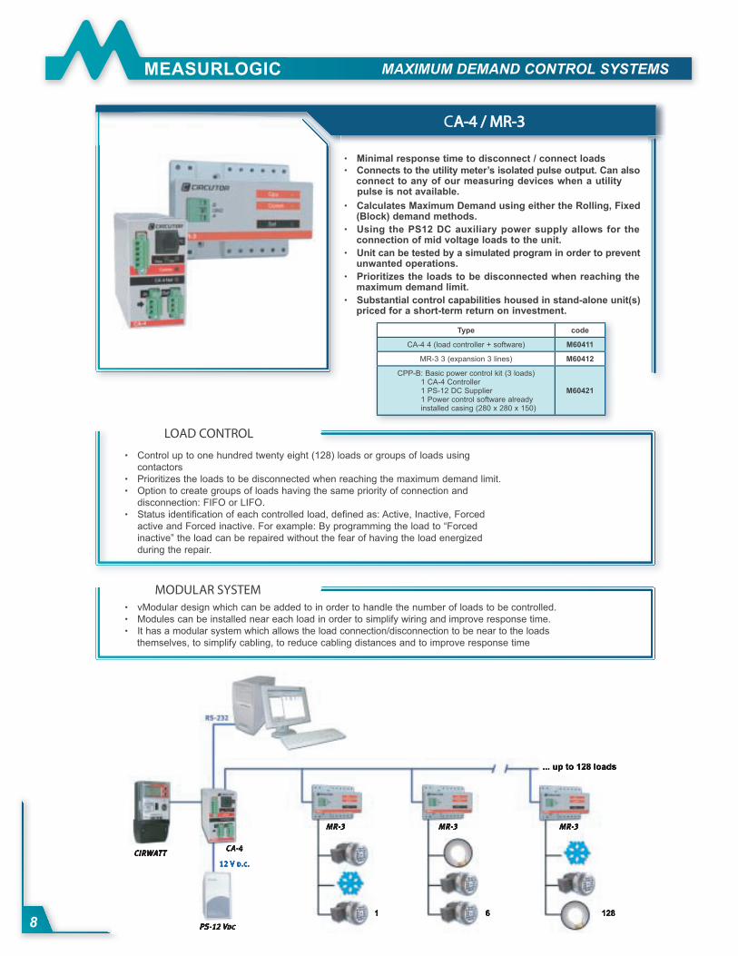
Minimal response time to disconnect / connect loads
Connects to the utility meter’s isolated pulse output. Can also connect to any of our measuring devices when a utility pulse is not available.
Calculates Maximum Demand using either the Rolling, Fixed (Block) demand methods.
Using the PS12 DC auxiliary power supply allows for the connection of mid voltage loads to the unit.
Unit can be tested by a simulated program in order to prevent unwanted operations.
Prioritizes the loads to be disconnected when reaching the maximum demand limit.
Substantial control capabilities housed in stand-alone unit(s) priced for a short-term return on investment.
••
•
•
•
•
•
CA-4 / A-4 / MR-3MR-3
LOAD CONTROL
Control up to one hundred twenty eight (128) loads or groups of loads using
contactors
Prioritizes the loads to be disconnected when reaching the maximum demand limit.
Option to create groups of loads having the same priority of connection and
disconnection: FIFO or LIFO.
Status identifi cation of each controlled load, defi ned as: Active, Inactive, Forced
active and Forced inactive. For example: By programming the load to “Forced
inactive” the load can be repaired without the fear of having the load energized
during the repair.
•
••
•
MODULAR SYSTEM vModular design which can be added to in order to handle the number of loads to be controlled.
Modules can be installed near each load in order to simplify wiring and improve response time.
It has a modular system which allows the load connection/disconnection to be near to the loads
themselves, to simplify cabling, to reduce cabling distances and to improve response time
•••
Type code
CA-4 4 (load controller + software) M60411
MR-3 3 (expansion 3 lines) M60412
CPP-B: Basic power control kit (3 loads)1 CA-4 Controller1 PS-12 DC Supplier1 Power control software already installed casing (280 x 280 x 150)
M60421
MAXIMUM DEMAND CONTROL SYSTEMS
9
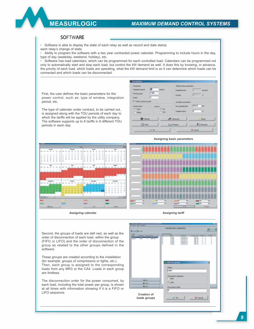
SOSOFTWAREARE
Software is able to display the state of each relay as well as record and date stamp
each relay’s change of state.
Ability to program the software with a two year contracted power calendar. Programming to include hours in the day,
type of day (weekday, weekend, holiday), etc.
Software has load calendars, which can be programmed for each controlled load. Calendars can be programmed not
only to automatically start and stop each load, but control the kW demand as well. It does this by knowing, in advance,
the priority of each load, which loads are operating, what the kW demand limit is so it can determine which loads can be
connected and which loads can be disconnected.
•
•
•
First, the user defi nes the basic parameters for the
power control, such as: type of window, integration
period, etc.
The type of calendar under contract, to be carried out,
is assigned along with the TOU periods of each day to
which the tariffs will be applied by the utility company.
The software supports up to 8 tariffs in 8 different TOU
periods in each day.
Second, the groups of loads are defi ned, as well as the
order of disconnection of each load, within the group
(FIFO or LIFO) and the order of disconnection of the
group as related to the other groups defined in the
software.
These groups are created according to the installation
(for example: groups of compressors or lights, etc.).
Then, each group is assigned to the corresponding
loads from any MR3 or the CA4. Loads in each group
are limitless.
The disconnection order for the power consumed, by
each load, including the total power per group, is shown
at all times with information showing if it is a FIFO or
LIFO sequence.
Assigning tariffAssigning calendar
Assigning basic parameters
Creation of
loads groups
MAXIMUM DEMAND CONTROL SYSTEMS
10
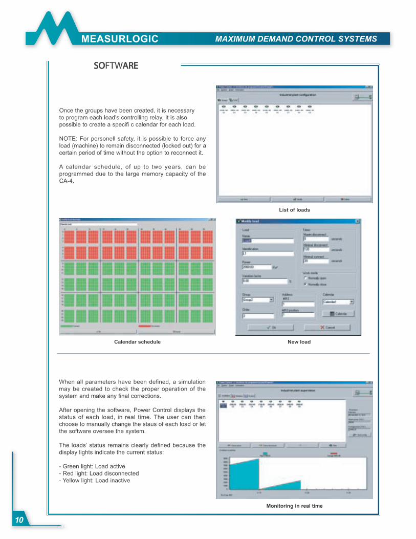
SOSOFTWAREARE
Once the groups have been created, it is necessary
to program each load’s controlling relay. It is also
possible to create a specifi c calendar for each load.
NOTE: For personell safety, it is possible to force any
load (machine) to remain disconnected (locked out) for a
certain period of time without the option to reconnect it.
A calendar schedule, of up to two years, can be
programmed due to the large memory capacity of the
CA-4.
List of loads
New loadCalendar schedule
When all parameters have been defi ned, a simulation
may be created to check the proper operation of the
system and make any fi nal corrections.
After opening the software, Power Control displays the
status of each load, in real time. The user can then
choose to manually change the staus of each load or let
the software oversee the system.
The loads’ status remains clearly defi ned because the
display lights indicate the current status:
- Green light: Load active
- Red light: Load disconnected
- Yellow light: Load inactive
Monitoring in real time
MAXIMUM DEMAND CONTROL SYSTEMS
11
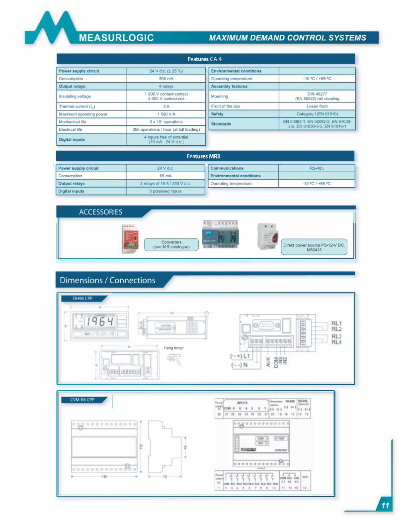
FFeaturestures CA 4
Power supply circuit 24 V d.c. (± 25 %)
Consumption 500 mA
Output relays 4 relays
Insulating voltage1 000 V contact-contact
4 000 V contact-coil
Thermal current (Ith) 3 A
Maximum operating power 1 500 V·A
Mechanical life 3 x 10⁷ operations
Electrical life 350 operations / hour (at full loading)
Digital inputs 4 inputs free of potential
(10 mA - 24 V d.c.)
Environmental conditions
Operating temperature -10 ºC / +65 ºC
Assembly features
MountingDIN 46277
(EN 50022) rail coupling
Front of the box Lexan front
Safety Category I (EN 61010)
StandardsEN 50082-1, EN 50082-2, EN 61000-
3-2, EN 61000-3-3, EN 61010-1
Featurestures MR3MR3
Power supply circuit 24 V d.c.
Consumption 65 mA
Output relays 3 relays of 10 A / 250 V a.c.
Digital inputs 3 polarised inputs
Communications RS-485
Environmental conditions
Operating temperature -10 ºC / +65 ºC
DH96 CPP
CVM-R8 CPP
5 AACCESSORIES
Direct power source PS-12-V DC.M60413
Converters(see M.5 catalogue)
Dimensions / Connections
Fixing fl ange
MAXIMUM DEMAND CONTROL SYSTEMS
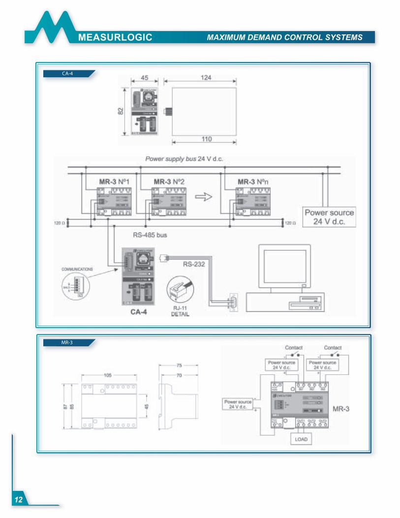
12
MR-3
CA-4