Well Control using Volumetric Method اﻟطرﯾﻘﺔ اﻟﺣﺟﻣﯾﺔ ﺎﺳﺗﺧدام ﺑ...
47
Sudan University of Science and Technology Collage of Petroleum Engineering Petroleum Engineering Department Research Titled: Well Control using Volumetric Method ا لتحكم فيبار ا بستخدام اقة الحجمية الطريProject Submitted to College of Petroleum Engineering in Partial Fulfillment for the Degree of B-Tech in Petroleum Engineering Prepared By: Ashraf Elzeain Shareef Elhassan Mohammed Awad Elgeed Abd Elaleem Mohieldeen Mortada Albakri Yusra Magzoub Ali Supervisored by: Ms. Ayah Abdelhai October, 2017
-
Upload
khangminh22 -
Category
Documents
-
view
0 -
download
0
Transcript of Well Control using Volumetric Method اﻟطرﯾﻘﺔ اﻟﺣﺟﻣﯾﺔ ﺎﺳﺗﺧدام ﺑ...
Sudan University of Science and Technology
Collage of Petroleum Engineering
Petroleum Engineering Department
Research Titled:
Well Control using Volumetric Method
الطريقة الحجمية استخدامب اآلبار في لتحكما
Project Submitted to College of Petroleum Engineering in Partial
Fulfillment for the Degree of B-Tech in Petroleum Engineering
Prepared By:
Ashraf Elzeain Shareef Elhassan
Mohammed Awad Elgeed Abd Elaleem
Mohieldeen Mortada Albakri
Yusra Magzoub Ali
Supervisored by:
Ms. Ayah Abdelhai
October, 2017
i
ةــــــــاآلي
بسم اهلل الرمحن الرحيم : قال تعاىل
وشلمهانسماءماءفسانتأوديحتمدرهافاحتممانسيمستداراتيا} ومما يولدون ػهيه في
اننار اتتغاء حهيح أو متاع ستد مثهه كذنك يضزب انهه انحك وانثاطم فأما فيذهة انشتد
جفاء وأما ما ينفغ انناص فيمكث في انأرض كذنك يضزب انهه انأمثال (71(}
صدقاهللانؼظيم
(71سورجانزػداآليح)
ii
DEDICATION
To each of the following in the presence of God and His Messenger.
To the big heart my dear father …. my mother dear..
To those who have demonstrated to me what is the most beautiful in life, my brothers
and my sisters.
Finally to any gifts from the sky.

iii
ACKNOWLEDGEMENT
First of all gives thanks to Allah
And a special thanks to supervisor
Ms. ayah abdelhai
&
Mr. Mohammed Abdalkhalig
I can’t forget giving thanks to everyone who helped us and gave new hope to
successful.
I'm gratefully acknowledge the financial support of lectures and all staff of Sudan
Universities and Technology .
I wish to acknowledge the efforts of the auto work shop staff for their standing beside
us the experimental work .
iv
ABSTRACT
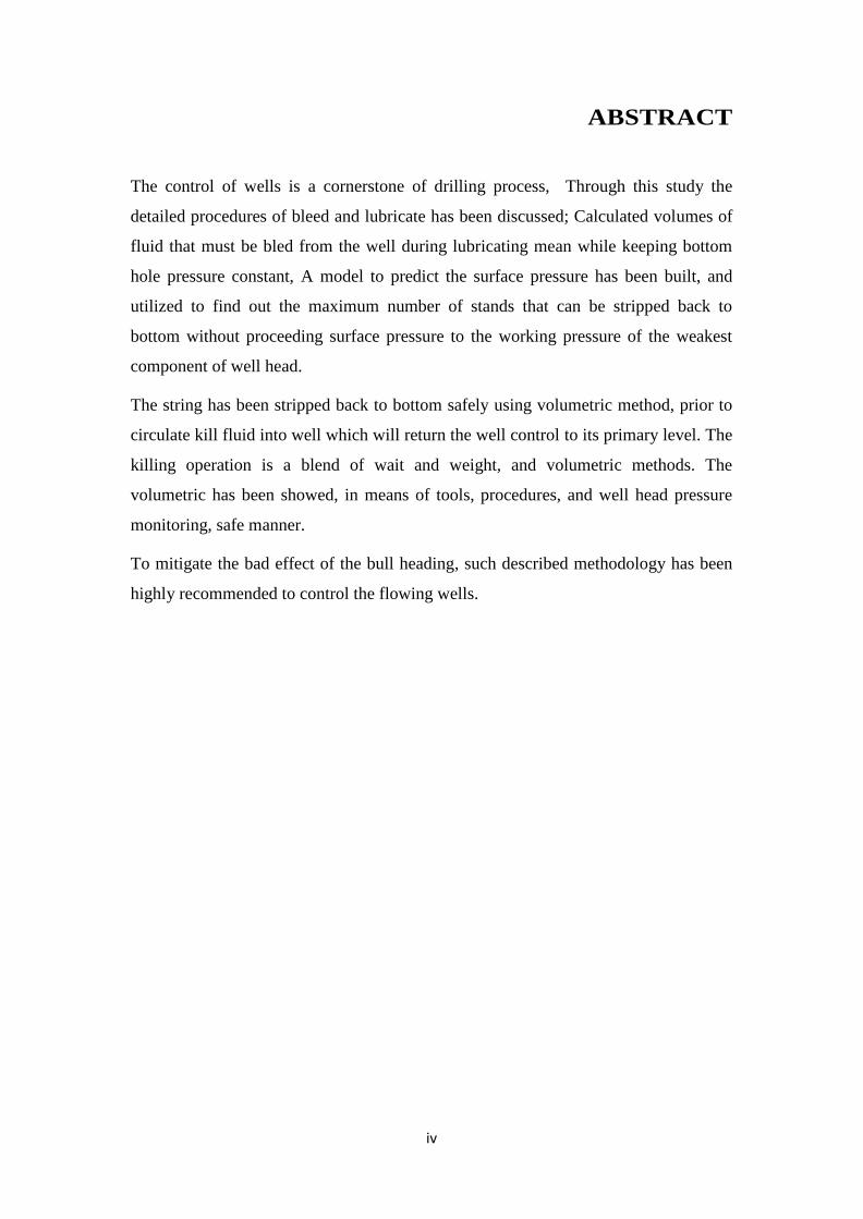
The control of wells is a cornerstone of drilling process, Through this study the
detailed procedures of bleed and lubricate has been discussed; Calculated volumes of
fluid that must be bled from the well during lubricating mean while keeping bottom
hole pressure constant, A model to predict the surface pressure has been built, and
utilized to find out the maximum number of stands that can be stripped back to
bottom without proceeding surface pressure to the working pressure of the weakest
component of well head.
The string has been stripped back to bottom safely using volumetric method, prior to
circulate kill fluid into well which will return the well control to its primary level. The
killing operation is a blend of wait and weight, and volumetric methods. The
volumetric has been showed, in means of tools, procedures, and well head pressure
monitoring, safe manner.
To mitigate the bad effect of the bull heading, such described methodology has been
highly recommended to control the flowing wells.
v
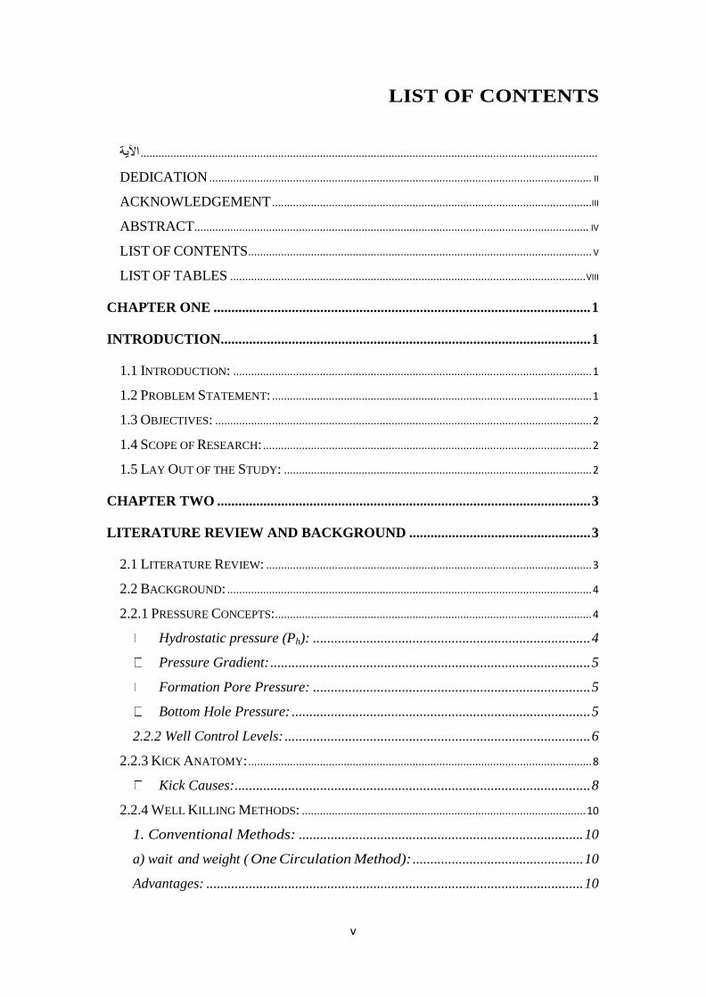
LIST OF CONTENTS
......................................................................................................................................................... اآلية
DEDICATION ................................................................................................................................ II
ACKNOWLEDGEMENT ...........................................................................................................III
ABSTRACT .................................................................................................................................... IV
LIST OF CONTENTS................................................................................................................... V
LIST OF TABLES ....................................................................................................................... VIII
CHAPTER ONE .......................................................................................................... 1
INTRODUCTION........................................................................................................ 1
1.1 INTRODUCTION: ........................................................................................................................ 1
1.2 PROBLEM STATEMENT: ........................................................................................................... 1
1.3 OBJECTIVES: .............................................................................................................................. 2
1.4 SCOPE OF RESEARCH: .............................................................................................................. 2
1.5 LAY OUT OF THE STUDY: ....................................................................................................... 2
CHAPTER TWO ......................................................................................................... 3
LITERATURE REVIEW AND BACKGROUND ................................................... 3
2.1 LITERATURE REVIEW: ............................................................................................................. 3
2.2 BACKGROUND: .......................................................................................................................... 4
2.2.1 PRESSURE CONCEPTS: .......................................................................................................... 4
Hydrostatic pressure (Ph): .............................................................................. 4
Pressure Gradient: .......................................................................................... 5
Formation Pore Pressure: .............................................................................. 5
Bottom Hole Pressure: .................................................................................... 5
2.2.2 Well Control Levels: ...................................................................................... 6
2.2.3 KICK ANATOMY: ................................................................................................................... 8
Kick Causes: .................................................................................................... 8
2.2.4 WELL KILLING METHODS: ............................................................................................... 10
1. Conventional Methods: ................................................................................ 10
a) wait and weight ( One Circulation Method): ................................................ 10
Advantages: .......................................................................................................... 10
vi
Disadvantages: ..................................................................................................... 11
Advantages: .......................................................................................................... 11
Disadvantages: ..................................................................................................... 11
a) Volumetric Method: ...................................................................................... 11
2.2.5 STRIPPING AND SNUBBING: .............................................................................................. 13
a) Stripping: .......................................................................................................... 13
Snubbing tools: ..................................................................................................... 15
2.2.6 CAPACITY FACTORS AND DISPLACEMENT: .................................................................. 18
CHAPTER THREE METHODOLOGY ................................................................ 20
3.1 VOLUMETRIC METHOD: ........................................................................................................ 20
3.2 ENGINEER’S METHOD: .......................................................................................................... 23
2.2 ENGINEER’S METHOD STAGES: .......................................................................................... 23
Phase I (displacing drill string to kill mud) ................................................. 23
PHASE II (PUMPING HEAVY MUD INTO THE ANNULUS UNTIL INFLUX REACHES THE
CHOKE) ............................................................................................................................................. 24
PHASE III (ALL THE INFLUX REMOVED FROM THE ANNULUS) ............................................ 24
PHASE IV: (STAGE BETWEEN ALL THE INFLUX BEING EXPELLED AND HEAVY MUD
REACHING SURFACE) .................................................................................................................... 24
4.1 THE VOLUME OF FLUID TO BE BLED PER STAND: ........................................................... 26
CHAPTER FIVE CONCLUSION AND RECOMMENDATIONS ...................... 37
REFFERENCES ........................................................................................................ 38
vii
LIST OF FIGURES
1 (FIGURE (2.1): PRIMARY CONTROL - PRESSURE DUE TO MUD COLUMN EXCEEDS PORE
PRESSURE (DRILLING ENGINEERING 2001)) .................................................................... 6
2 (FIGURE (2.2): SECONDARY CONTROL -INFLUX CONTROLLED BY CLOSING
BOP'S(DRILLING ENGINEERING2001)) ........................................................................... 7
3 (FIG.(2.3): BASIC SNUBBING STACK (ROBERT D.GARCE, 1994)) .............................. 16
4 (FIGURE (2.4) SNUBBING UNIT.) ................................................................................. 16
5(FIG (2.5) MECHANICAL SNUBBERS) ........................................................................... 17
6 (FIGURE (2.6) HYDRANT SNUBBER) ........................................................................... 17
7 (FIGURE 2.7) ONE WAY VALVE ................................................................................ 18
8 (FIGURE (3.1): SUMMARY OF STANDPIPE AND ANNULUS PRESSURE DURING THE "ONE
CIRCULATION" METHOD (DRILLING ENGINEERING 2001)) ............................................. 25
9(FIG4.1) SURFACE PRESSURE VS VOLUME BLEED PER STANDS ................................. 32
10 (FIG (4.2.) CASING PRESSURE VS. NUMBER OF STANDS..) ...................................... 34
11 (FIG 4.3) PRESSURE VS VOLUME TO BLEED PER STANDS ....................................... 35

viii
LIST OF TABLES
1 (TABLE 4.1 ) VOLUMETRIC KILL SHEET ................................................................. 27
1
Chapter One
Introduction
1.1 Introduction:
The control of the formation pressure , either by ensuring that the borehole
pressure is greater than the formation pressure known as ( primary control ) or by
closing BOP valves at surface known ( Secondary control ) is generally referred to as
keeping the pressure in the well under control .
The purpose of well control is to ensure that fluid (oil, gas and water) does not
flow in an uncontrolled way from the formation being drilled, into the borehole and
eventually to surface. This flow will occur if the pressure in the pore space of the
formation being drilled (formation pressure ) is greater than the hydrostatic pressure
exerted by the column of mud in the wellbore ( bore hole pressure ) . It is essential
that the borehole pressure, due to the column of fluid, exceeds the formation pressure
at all times during drilling.
As the well reach to the artificial lift stage, pumps are installed in the well;
therefore a frequent process of work over interventions is required to maintain the oil
production from the formations. Prior to make any intervention the well must be dead,
unless none of the work over activity can be conducted. At this point many methods
of non-conventional methods to retrieve the primary well control are rise.
1.2 Problem Statement:
Many of Sudanese Oil Company used to handle the issue of well control when
there is no way to circulate the killing fluid, such procedure is suffer from
disadvantages, e.g. a great deal of undesirable fluid enters into formation, this makes a
highly potential for positive skin factor.
This study aims to return the well to its primary control by using volumetric
method, in means of tools, procedures, and well head pressure.
2
1.3 Objectives:
1. Review the procedure of bleed and lubricate.
2. Calculate volumes of fluid that must be bled from the well during lubricating.
3. Design a chart to monitor wellhead pressure (casing pressure).
1.4 Scope of Research:
This study is focusing on retrieving the primary well control to a life well and
there is no way to commence any full circulation because of the string at the highest
portion of the well.
1.5 Lay Out of the Study:
Chapter one
This chapter presents Background of the Research, Statement of the Problem,
Objectives of the project and scope of research.
Chapter Two:
This chapter presents Literature Review and Theoretical Background.
Chapter Three:
In this chapter present the methodology of well control.
Chapter Four:
In this chapter, present the result and discussion for design and analysis for well
control.
Chapter Five:
This chapter presents conclusions and recommendation.
3
Chapter Two
Literature Review and Background
2.1 Literature Review:
Davorin Matanovic et.al (1994) to kill a production well means to
perform some technical and technological processes for establishing the static
hydraulic balance in the well with no additional surface pressures. The standard
procedure of the well killing process as adopted in Croatia, is described.
Further, the procedures of how to locate the spot where there is a leakage on
production equipment and Row to determine the level of fluid in tubing or
annulus is explained. Finally, the aim of this paper is also to point out the
importance in selection of killing fluids considering a possibility of formation
damage.
S.Nishikawa et.al (2001) performed a series of experiments to investigate a
procedure for killing sustained casing pressure (SCP) by the bleed –and lubricate
method of injecting heavy brine in to the annulus. The procedure involves bleeding
fluids from the annulus and lubricating in weighted fluids in order to displace annular
fluid with the heavy brine. Three concepts of annular fluid displacement were
investigated: brine or mud lubricated into a water-filled annulus, brine into bentonite
slurry and immiscible displacement. The experiments showed that annular density
increased after many injections of brine into the water-filled annulus and more
desirable performance using immiscible fluid. However, the experiment demonstrated
an inability to displace drilling mud with brine due to flocculation effect.
A.k wojtanowicz.r.smith(2001) In this study ,aservies of experimenls was
performed to in vestigate aprocedure for killing sustained casing pressure (scp) by the
bleed –and lubricate method of injecting heavy brine in to the annular the procedure
in volves bleeding fluids from the annular and lubricating in weighted fluids in oreder
to displaced annular fluid eith the heavy brine .The concept of this method in the
annulus the objective of the study was to evaluate theperformace of cyclir injection
in view of the efficiency of displacing annulr fluid with injected fluid
4
Yuan Qiji Zheng Zheng et.al(2012) The paper was aimed at finding out
the non-routine well control procedure to deal with the overflow of the well
in special operating conditions. Study the well killing technology in four
situations. The situation included the well is full of natural gas, lower of the
well is liquid column and upper of the well is natural gas, the wellbore blocks
and unable establish cycling for containing liquid column, besides the wellbore
holds fish where the fish is intact and doesn’t block the wellbore, the fish
blocks the wellbore or the fish is breakup and blocks the
wellbore. Discuss the principles, steps, calculation procedure and formulas of
killing well in volumetric control mode
2.2 Background:
The most important concern when plan to drilling or completion a well is how
to management difficulties and danger effect that may be initiated with unexpected
release of formation fluids such as water, oil and gas by applying pressure balance
concept by using either dense fluid to exert enough balance against formation as the
first line of defense or using high efficient equipment’s as the second line of defense
to reestablish the equivalent pressure.
2.2.1 Pressure Concepts:
When dealing with well control issue many pressure should be differentiated
form each other to make a clear realize of the situation.
Hydrostatic pressure (Ph):
Is the pressure exerted by static fluid column (drilling/completion fluid), It varies
with the height of the fluid column (depth of the well) and the weight of the fluid. The
pressure of the fluid in a well depends on the "True Vertical Depth" which may be
less than the "Measured Depth". And can be calculated from the equation (2.1).
(2.1)
Where;
Hydrostatic pressure (Psi)
TVD: True vertical depth (ft)
5
Mw: Mud weight ( ppg)
Pressure Gradient:
The pressure Gradient is the pressure per vertical depth.
(2.2)
Or;
(2.3)
Where:
PG: Pressure Gradient (psi/ft)
Formation Pore Pressure:
Is the pressure exerted by formation fluids (water, oil or gas) contained in the
formation pore and can be divided referring to the formation pressure gradient of fluid
trapped as:
Normal Formation Pressure.
Abnormal Formation Pressure.
Subnormal Formation Pressure.
Bottom Hole Pressure:
Bottom hole pressure is equal to the sum of all pressures in a well. Generally
speaking, bottom hole pressure is the sum of the hydrostatic pressure of the fluid
column above the point of interest, plus any surface pressure which may be exerted on
the top of the fluid column, and the effect of friction pressure must be added or
subtracted depending on the direction of flow. This is expressed mathematically as:
……………………………..(2.4)
Where;
BHP = Bottom hole Pressure (psi)
HP = Hydrostatic Pressure (psi).
SP = Surface Pressure (psi)
FP = Friction Pressure (psi).

6
2.2.2 Well Control Levels:
1. Primary Control: Primary well control is the use of drilling fluid density to provide
sufficient pressure to prevent the influx of formation fluid into the wellbore. It
is of the utmost importance to ensure that primary well control is maintained
at all times. This involves the following: Drilling fluids of adequate density
are used, well is kept full of adequate density fluid at all times and changes in:
density, volumes and flow rate of drilling fluids from the wellbore are
immediately detected and appropriate action taken.
1 (Figure (2.1): Primary Control - Pressure due to mud column exceeds Pore Pressure (Drilling engineering 2001))
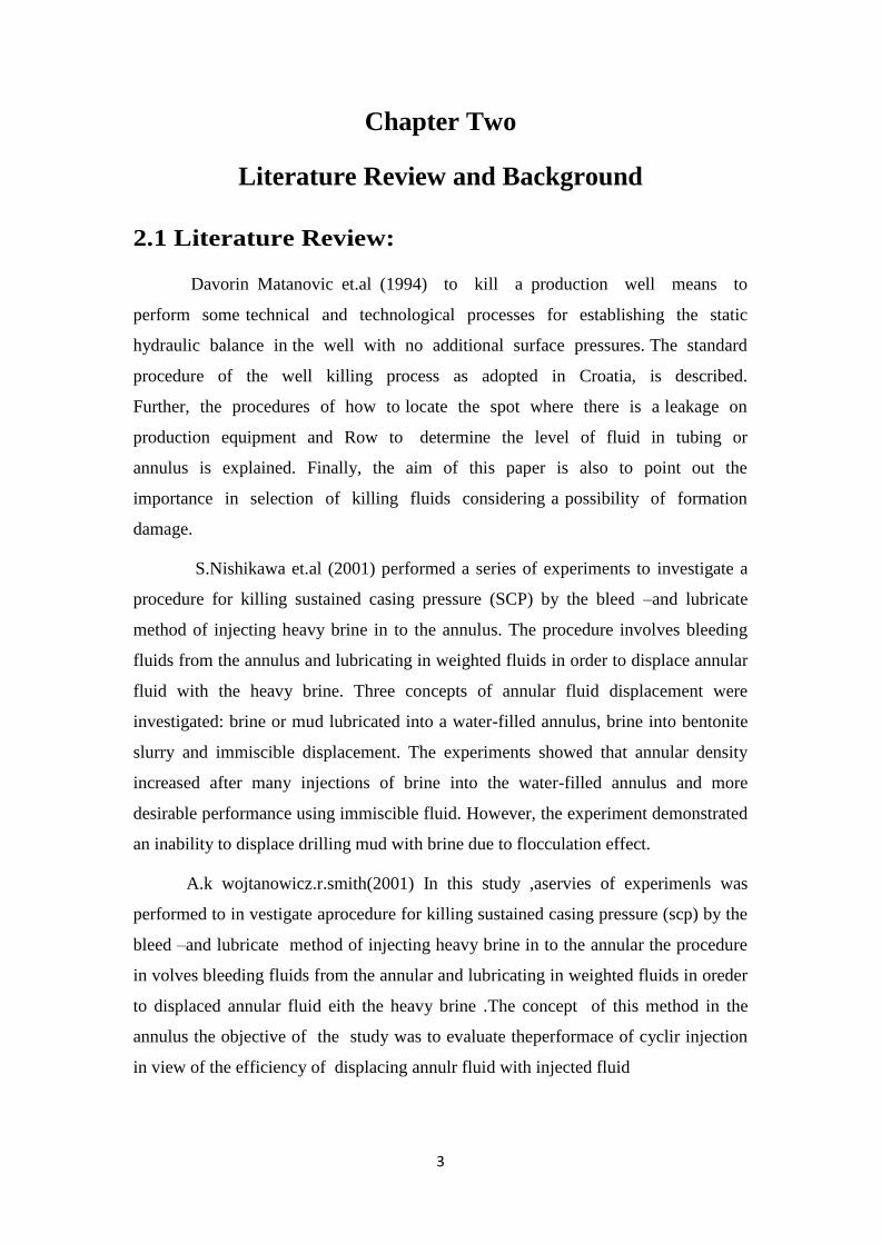
2. Secondary control:
Secondary control is required when primary control has failed (e.g. an
unexpectedly high pressure formation has been entered) and formation fluids are
flowing into the wellbore. The aim of secondary control is to stop the flow of fluids
into the wellbore and eventually allow the influx to be circulated to surface and safely
discharged, while preventing further influx downhole. The first step in this process is
7
to close the annulus space off at surface, with the BOP valves, to prevent further
influx of formation fluids (Figure 2.2). The next step is to circulate heavy mud down
the drillstring and up the annulus, to displace the influx and replace the original mud
(which allowed the influx in the first place). The second step will require flow the
annulus but this is done in a controlled way so that no further influx occurs at the
bottom of the borehole. The heavier mud should prevent a further influx of formation
fluid when drilling ahead. The well will now be back under primary control.
2 (Figure (2.2): Secondary Control -Influx Controlled by Closing BOP's(Drilling Engineering2001))
3. Tertiary well control:
In the event that secondary control cannot be properly maintained due to hole
conditions or equipment failure, certain emergency procedures can be implemented to
prevent the loss of control. These procedures are referred to as "Tertiary Control" and
usually lead to partial or complete abandonment of the well.
Unlike primary and secondary control, there are no established tertiary well control
procedures that will work in most situations.
The procedures to be applied depends on the particular operating conditions
which are encountered, and specific recommendations regarding appropriate tertiary
control procedures cannot be given until the circumstances leading to the loss of
secondary control are established. However, there are two procedures that are widely
used, include: Barite plugs and Cement plugs. (Schlumberger, 1999)
8
2.2.3 Kick Anatomy:
A kick is an influx, or flow, of formation fluids into the well. The successful
detection and handling of kicks is extremely important. Obviously, there are times
when it’s desirable to have a flow of formation fluids, e.g. when the well is put in
production. However, the unplanned kick during completion, workover, or production
operations threatens control of the well. We must be prepared for this unplanned kick
and ensure that we have a method to control and deal with it.
A kick, if not controlled, can result in a blowout. A blowout is the
uncontrolled flow of formation fluids from a well. Blowouts endanger personnel
safety and pose a significant threat to an environment. Thus, the single most important
step in well control and blowout prevention is to shut the well in when the well kicks.
Kick Causes:
Wells kick when the reservoir pressure of an exposed formation exceeds the
wellbore (bottom hole) pressure. During the period of completion, Workover, and
production operations there are many procedures which could produce this downhole
condition. Some of the most common causes of kicks include:
Not keeping the hole full.
Lost circulation.
Swabbing.
Underbalanced pressures.
Gas cut mud.
Mechanical failures.
a) Not Keeping the Hole Full:
Hydrostatic pressure is the only pressure exerted on exposed perforations. If the
hydrostatic pressure in a well drops below the reservoir pressure, the exposed zone
will flow into the wellbore. Statistics reveal that most kicks occur on trips, which
indicates that the wells were either swabbed or improperly filled during the trip.
When tripping out of the hole, a volume (of steel) is being removed from the well. As
the steel is removed, the fluid level (and hydrostatic pressure) in the well drops. If the
hydrostatic pressure drops below the reservoir pressure, the exposed zone will flow.
9
Therefore it is extremely important to fill the hole with fluid while tripping out of the
hole.
Normal pressure zone, Common practice is to pump the theoretical fill up volume
while pulling out of the well.
b) Lost Circulation:
Loss of circulation leads to a drop of both the fluid level and hydrostatic pressure of a
well. If the hydrostatic pressure falls below the reservoir pressure, it is difficult to
detect when losses occur during tripping pipe into or out of the hole, large volume of
kick fluid may inter the hole before the mud level increase is observed at the surface.
c) Swabbing:
Swabbing is caused by the upward movement of pipe in a well and results in a
decrease in bottom hole pressure. In some cases, the bottom hole pressure reduction
can be large enough to cause the well to go underbalanced and allow formation fluids
inters the wellbore and there are various factors conductive to swab pressure are: (pipe
pulling speed, mud properties, filtration cake, annular clearance…etc.)
d) Underbalanced Pressures:
Underbalanced pressure is the condition that occurs when wellbore (bottom hole)
pressure is less than the reservoir pressure of an exposed formation. An
underbalanced condition is most common on wells that are on production, but can
also occur during the course of completion/workover operations. In many fields,
completion/workover programs incorporate drill stem tests and underbalanced.
e) Gas Cut Mud:
As the gas is circulated to the surface, it expands and reduces the hydrostatic pressure
sufficient to allow to kick to enter.
Kick Warning Sign:
1. Drilling break
2. Increase in stroke per minute
3. Pump pressure decrease
4. Gas Cutting
5. Change in cutting shape and size
10
kick indicators:
Primary (positive) indicators:
Upon recognition of a positive indicator, immediate action should be taken to
control the well. The three Positive indicators of a kick are:
Increase in pit volume
Increase in return flow rate or flow with pumps off
Surface pressure with the well shut-in
2.2.4 Well Killing Methods:
Various methods are used to returning the kicked off well to its original
circumstance depending on the current situation and the availability of the
material.
1. Conventional Methods:
a) wait and weight ( One Circulation Method):
The "One circulation Method" ("balanced mud density" or "wait and weight"
method):
The procedure used in this method is to circulate out the influx and circulate
in the heavier mud simultaneously. The influx is circulated out by pumping kill mud
down the drill string displacing the influx up the annulus.
The kill mud is pumped into the drill string at a constant pump rate and the
pressure on the annulus is controlled on the choke so that the bottom hole pressure
does not fall, allowing a further influx to occur.
Advantages:
1. Since heavy mud will usually enter the annulus before the influx reaches
surface the annulus pressure will be kept low; thus there is less risk of
fracturing the formation at the casing shoe.
2. The maximum annulus pressure will only be exerted on the wellhead for a
short time.

11
3. It is easier to maintain a constant BHP by adjusting the choke.
Disadvantages:
1. It requires longest waiting time prior to circulation
2. In a case where a significant amount of the hole is drilled prior to encountering
the kick, the cutting could settle out and plug the annulus.
3. Gas migrations become a problem during waiting period for increasing the
mud weight.
b) Driller’s Method (Two Circulation Method):
In this method the influx is circulated out from the well after that the kill mud is
circulated to control the well.
Advantages:
1. Simple to understand.
2. Minimum calculation.
3. In case of salt water kick ,sand settling around BHA is minimum
Disadvantages:
1. Higher annular pressure.
2. Higher casing shoe pressure in gas kick.
3. Minimum two circulations are required more time on choke operation.
2. Non-Conventional Methods:
These methods are used when the circulation of killing fluid cannot be
conducted, mainly consists on bull heading and volumetric methods. The
causes that make the circulation is prohibited that either the string is far away
from the bottom of the well, this means even if the kill fluid is circulated it
cannot return the situation to its original, i.e. primary well control, or the
string is at bottom but some blockage is exist.
a) Volumetric Method:
The volumetric method is mostly used in work-over and production
operations. In this method the string is usually far away from the bottom.
In order to stop the flowing of the well through the pipe string side; one way
valve has to be installed. After that the string is run back to bottom while closing the

12
BOP, i.e. stripping and snubbing. When the string has been run back to bottom the kill
operation is return to the conventional methods.
The reasons for using this method instead of another kill method are based on
different variables in the well. Some of them are listed below (Oystein
Rossland,2013):
If the drill string is on its way in the well or out of it, if this is the case
an attempt to run it to the bottom with the drill string should be made.
If there are no drill string in the well.
If the drill bit or the drill string has been plugged with some kind of
debris or lost circulation material (LCM), to open the plugged area
explosives can be an alternative.
Hole collapse can be a reason – this prevents circulation
Advantages:
1. Allow gas migrate mean while expansion.
2. Control bottom hole pressure when no drill pipe in hole.
3. Control bottom hole pressure when pump failure.
Disadvantages:
1. Complicated.
2. Great low fracture pressure.
3. Wearer of ram while stripping.
b) Bull Heading Method:
This method can be achieved when the string is blockage or when it’s far away
from the bottom of the well, the concept is very easy; the influx will be forced to
return to the formation by pumping kill fluid to the well and squeezing all well fluid
to the opened formation.
Advantages:
1. Quickly control of blow out.
2. Control of gas expansion.
3. Low cost.
Disadvantages:
1. Positive skin factor
13
2. May break weak formation
3. May require stimulation
2.2.5 Stripping and Snubbing:
One of the most serious well control problems faced by a drilling representative is
being off bottom or out of the hole with a kick in the wellbore. Unfortunately,
statistics indicate that most kicks occur on trips, and, as previously stressed, kicks
taken with the pipe off bottom (or out of the hole) create a serious complication to
conventional well control techniques. When a kick occurs on a trip, or with pipe out
of the hole, there are several options available to deal with the kick. Some of these
options include:
Kill the well-off bottom
Use Volumetric Control if you have a gas kick in the well
Strip the drill pipe back to bottom
Strip using Volumetric Control if you have a gas kick in the well
Snub the drill pipe back in the well
Stripping and snubbing are specialized operations used to trip tubular into or out
of a pressurized wellbore through the blowout preventers. Normally, the objective of
these operations is to return the pipe to bottom where the well can be conventionally
circulated to remove the influx, however, in recent years, many completion/work-over
programs have used snubbing techniques to work on wells without killing them.
a) Stripping:
Can be defined as tripping pipe through the blowout preventers when the drill
string weight is greater than the net upward force created from wellbore pressures.
(2.5)
Where:
T.J.D=Tool joint diameter
String weight=lightest weight string that will stripe without snubbing unit.
(1000lb) is added to compensate for frictional force between pipe and packer element
Stripping using the annular ram preventer:
14
It is common practice but it is limited to surface pressure of 1500psi and
maximum length to be stripped as 1000ft, the following points should be kept in mind
while stripping through annular preventer:
1. Drill pipe rubber should be removed.
2. The pressure regulating valve must being good condition.
3. Using closing pressure also was possible.
4. If drill string does not strip –in on its own weight, Additional down
ward force will be needed to push the string in the well.
Procedures:
1) Adjust the pressure on the annular preventer until it weeps when the pipe is
going in the hole
2) Run the pipe not as term than one foot per second and Maintain the annulus
pressure constant with a choke as the pipe goes in the hole.
3) Every stand of pipe should displace mud.
4) If the pressure starts rising between stand sit means gas migration is taking
place, use the volumetric correction.
Stripping using the ram blowout preventer:
Procedures:
1) Select the two rams to be used and measure the distance from the rotary table
to the top of each one.
2) Reduce the closing pressure on the ram to 500psi, or less.
3) 3 -With the upper ram closed, lower pipe slowly, measuring it until the tool
joint is two feet above the upper ram.
4) Stop lowering, close the lower pipe ram.
5) Bleed off the pressure between the ram sand open the upper ram.
6) Lower the pipe, measuring it until the tool joint is between the two rams.
7) Stop the lowering and close the top ram.
8) Pressurize up towel pressure between the rams with the test pump .Open the
bottom ram.
9) Continue by going back to step (3).
While doing this, maintain the casing pressure constant by bleeding mud from the
choke.
b) Snubbing:
15
Is defined as forcing pipe through the blowout preventers when the drill string
weight is not sufficient to overcome the net upward force created by wellbore
pressures.
Often a combination of stripping and snubbing techniques is used to get the
drill string to the desired depth. To adequately understand stripping and snubbing,
familiarity with the pressures and forces involved in these operations is a must.
Snubbing tools:
The Snubbing Stack:
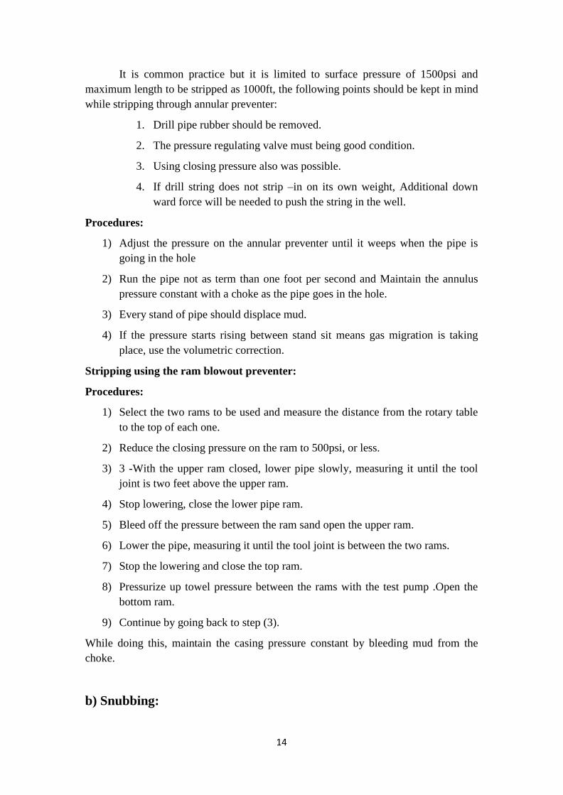
There are many acceptable snubbing stack arrangements. The basic snubbing stack is
illustrated in (FIG. (2.3) as illustrated, from bottom to top, blind safety rams, the pipe
safety rams, the bottom snubbing ram, followed by a spacer spool and the upper
snubbing ram.
Since a ram preventer should not be operated with a pressure differential
across the ram, an equalizing loop is required to equalize the pressure across the
snubbing rams during the snubbing operation. The pipe safety ram are used only when
the snubbing rams become worn and require changing.
When a snubbing ram begins to leak, the upper safety ram is closed and the
pressure above the upper safety ram is released through the bleed-off line. The
snubbing ram is then repaired. The pump in line can be used to equalize the pressure
across the safety ram and the snubbing operation continued.
Since all rams hold pressure from below, an inverted ram must be included
below the stack if the snubbing stack is to be tested to pressures greater than well
pressure. The essential tools required to conduct the snubbing operations is one way
valve and the snubbing unit.(Robert D.Garce, 1994)
16
3 (FIG.(2.3): Basic Snubbing Stack (Robert D.Garce, 1994))
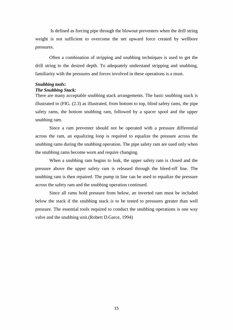
4 (Figure (2.4) snubbing unit.)
Types of snubbing unit:
Mechanical Snubbers
This type of equipment utilizes the rig system to force the pipe in to the hole
17
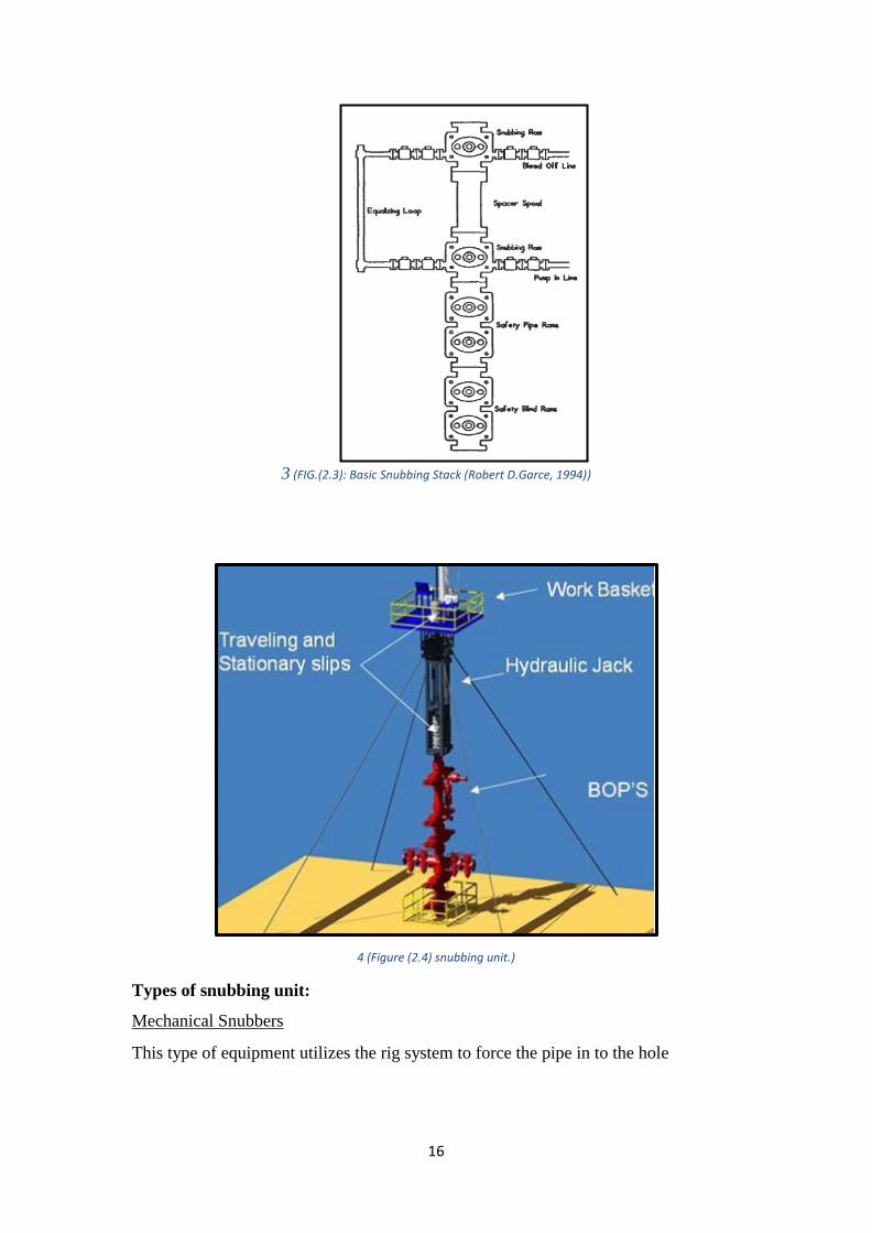
5(Fig (2.5) Mechanical Snubbers)
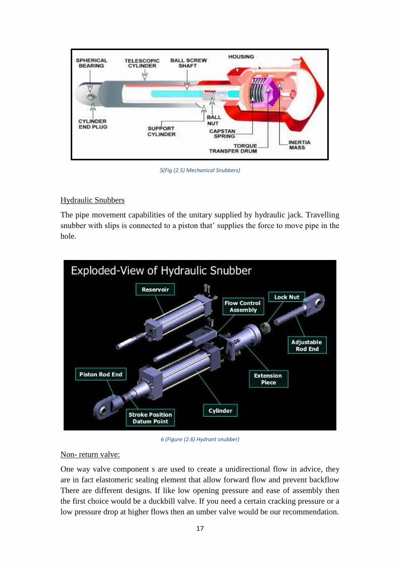
Hydraulic Snubbers
The pipe movement capabilities of the unitary supplied by hydraulic jack. Travelling
snubber with slips is connected to a piston that’ supplies the force to move pipe in the
hole.
6 (Figure (2.6) Hydrant snubber)
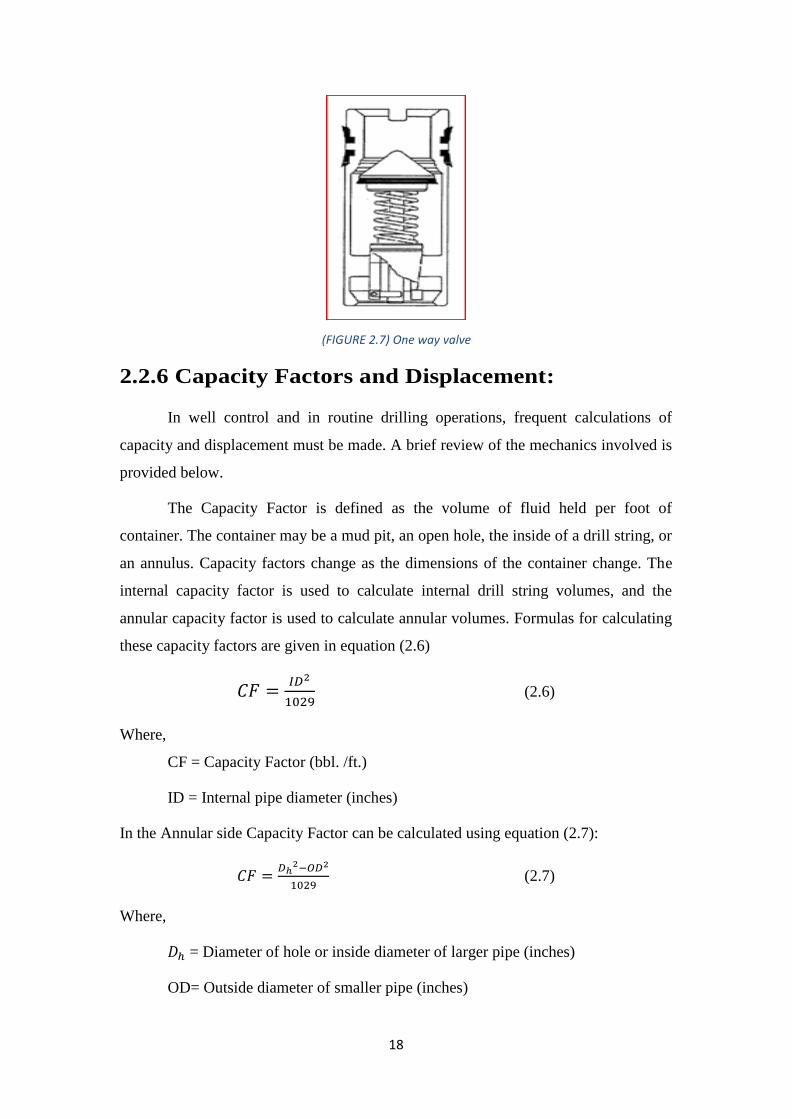
Non- return valve:
One way valve component s are used to create a unidirectional flow in advice, they
are in fact elastomeric sealing element that allow forward flow and prevent backflow
There are different designs. If like low opening pressure and ease of assembly then
the first choice would be a duckbill valve. If you need a certain cracking pressure or a
low pressure drop at higher flows then an umber valve would be our recommendation.
18
7 (FIGURE 2.7) One way valve
2.2.6 Capacity Factors and Displacement:
In well control and in routine drilling operations, frequent calculations of
capacity and displacement must be made. A brief review of the mechanics involved is
provided below.
The Capacity Factor is defined as the volume of fluid held per foot of
container. The container may be a mud pit, an open hole, the inside of a drill string, or
an annulus. Capacity factors change as the dimensions of the container change. The
internal capacity factor is used to calculate internal drill string volumes, and the
annular capacity factor is used to calculate annular volumes. Formulas for calculating
these capacity factors are given in equation (2.6)
(2.6)
Where,
CF = Capacity Factor (bbl. /ft.)
ID = Internal pipe diameter (inches)
In the Annular side Capacity Factor can be calculated using equation (2.7):
(2.7)
Where,
= Diameter of hole or inside diameter of larger pipe (inches)
OD= Outside diameter of smaller pipe (inches)
19
This equation can be used to determine internal and annular capacity factors for
several wellbore configurations.
Capacity is the volume of fluid held within a specific container. Internal (drill string)
and annular capacities are two of the most important parameters that are calculated in
a well control situation.
Capacity is determined by multiplying the height (or length) of the container by its
capacity factor.
Displacement is the volume of fluid displaced by placing a solid, such as drill pipe or
tubing into a fixed volume of liquid such as drilling mud. Total displacement of drill
pipe, casing, tubing, etc. can be determined by multiplying the length of pipe
immersed times the displacement factor (bbl. /ft.).
The volume of mud in the hole is always equal to the capacity of the entire hole,
minus the displacement of the pipe in the hole (assuming the pipe and annulus are
full). The annular capacity between drill string components and the casing or hole can
be calculated by subtracting both the capacity and displacement of the drill string
component from the capacity of the hole.
20
Chapter Three
Methodology
3.1 Volumetric Method:
It is necessary to do some volume calculations that are related to the pressure
increase in advance of using this method. Fracture pressure is the guide line, and the
pressure calculations need to be based on this and one must not exceed it to avoid any
losses (Oystein Rossland,2013).
3.1.2Volumetric Killing Procedure:
In this method the bottom hole pressure is maintained relatively constant and slightly
in excess of the pore pressure whilst the gas is allowed to expand as it migrates up to
the surface.
1) A constant bottom hole pressure is maintained by bleeding off mud, with an
equivalent hydrostatic head, equal to the rise in pressure caused by migrating
gas. For instance if the choke pressure rises by 100psi, a volume of mud
equivalent to the hydrostatic pressure of 100psi is slowly bled off, maintaining
constant casing pressure.
Pressure Increment = (safety factor) / 3………………………………………… (3.1).
Mud Increment = (PI X ACF)/ (MW x 0.052)…………..…………….…………. (3.2)
Where:
PI = Pressure Increment (psi).
ACF = Annulus Capacity Factor (bbl/ft).
MW = Mud Weight (ppg).
ROR = DSICP/(FD × 0.052 × T) ……………….………………….……………(3.3)
Where
ROR = Rate of Rise (ft/min)
DSICP = Change in Shut-in Casing Pressure
FD = Fluid Weight (ppg)
T = Time (min)
2) Bleed off in very small increments to allow the pressure to respond by using a
manual adjustable choke and diverting the mud into the scaled trip tank.
21
3) Repeat this process until the influx has migrated up to the BOP.
4) When the gas is at the BOP stack, lubricate mud into the well. The lubrication
5) procedure will replace the influx with mud, as the gas is bleed off at the choke.
6) Pump mud into the casing until pump pressure reaches the predetermined limit
and
7) stop the pump.
8) Leave the well shut-in for a time to allow gas to migrate through the lubricated
mud.
9) Bleed gas from the well until the surface pressure is reduced by the exact
amount equal to the hydrostatic pressure of the fluid volume lubricated into the
well.
10) Route returns via the mud gas separator and monitor. If a significant quantity of
mud is returned, bleeding should be stopped, and further time allowed for the
gas to migrate through the lubricated mud.
11) It is unlikely that all the gas will rise to surface as a discrete bubble and it will
be mixed through the mud, therefore, will take a considerable length of time to
be completed.
3.1.3The operating steps of killing with volumetric control
mode:
(1) Adjust the wellhead pressure, and the wellhead pressure is the reference value
during the Killing process.
(2) Inject kill fluid Δ V, and record the injected time, the amount of injected kill fluid,
the Injected pressure
(3) Observe and record the change of SIP.
(4) Air discharge after injected kill fluid drops to the bottom. Shut in well after the
wellhead Pressure down to base pressure, record the time of air discharge, the
mutative value of pressure During the air discharge process, the volume of discharged
liquid.
(5) Repeat the above process, until Pa = 0
22
3.1.4Volumetric method calculations:
The basic concept to establish volumetric method calculation is to keep
bottom hole pressure equal to the hydrostatic pressure and back pressure created by
well control elements.
BHP = Hp + Sp ………………………………………..………………..……. (3.4)
Where:
BHP: bottom hole project.
Hp : Hydrostatic pressure
Sp : surface pressure.
P.choke : Pann + Ps + Pw ……………………………………….….…………..(3.5)
Where:
Pann: Initial SICP
Ps: Built in safety margin prior to volumetric well control commencing.
Recommended safety margin according to operating company
policy.
Pw: = Working margin for volumetric well control
Allow the casing pressure to increase to P.choke (psi),when casing pressure is
at P.choke bleed off at choke a volume of mud equal to the working pressure
margin.
Casing pressure must be kept constant at Pchoke during this operation. After
working pressure margin of mud equivalent has been bled off at choke allow the gas
to migrate unexpanded until a further pressure margin of overbalance is attained.
Bleed off (working pressure margin Pw) equivalent mud at choke and repeat
procedure until gas is at choke.
3.1.5.CALCULATIONS FOR MUD VOLUME TO BLEED FOR PW:
Volume to bleed around drill pipe:
Dp = Pw X Dp/OH Csg Cap /mud gradient………….….…………..….….........(3.6)
Volume to bleed around drill collar:
Dc = Pw X Dp/Dcs Cap /mud gradient ……………..……..….………..…..…...(3.7)
ACF = ( ID2- OD2)/1029 ………………………………………....……..….......(3.8)
Where:
23
ACF: annular capacity factor
ID : inside diameter.
OD : outside diameter
after Kick and volumetric
Pit volume = bleed volume + total volume in tank……….…………………....…(3.9)
Pf = SICP +( P hyd mud + P hyd gas)ann ……………………………………….(3.10)
BHP = SICP +Ph ……………………………………………………………..….(3.11)
P hyd mud : hydrostatic pressure of original mud in the annulus
P hyd gas : hydrostatic pressure of influx
3.2 Engineer’s Method:
Many equations are used to accomplish kill operation.
(3.1)
(3.2)
(3.3)
(3.4)
Where;
SIDPP = shut in drill pipe pressure, psi.
= Kill mud weight, ppg.
ICP = initial circulation pressure. Psi
SCR = slow circulation rate,
= current mud, ppg.
FCP = final circulation pressure, psi.
2.2 Engineer’s Method Stages:
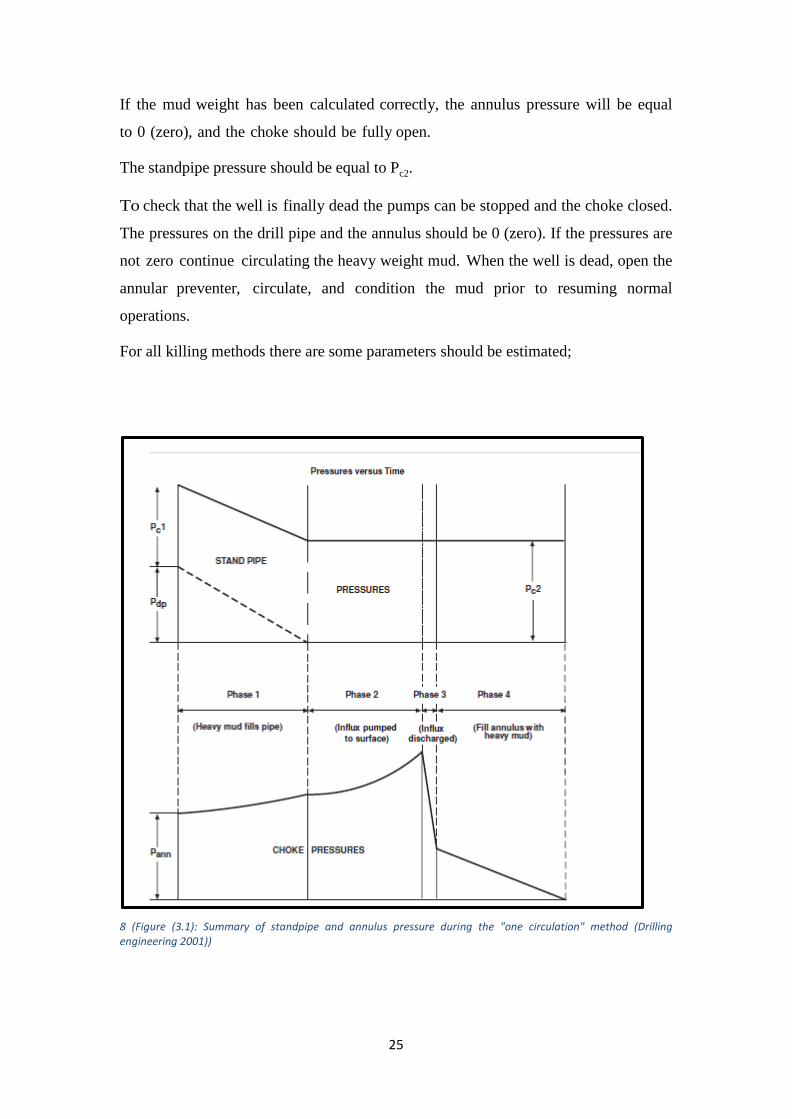
Phase I (displacing drill string to kill mud)
As the kill mud is pumped at a constant rate down the drill string the choke is
opened. The choke should be adjusted to keep the standpipe pressure decreasing
according to the pressure vs. time plot discussed above. In fact the pressure is reduced
24
in steps by maintaining the standpipe pressure constant for a period of time and
opening the choke to allow the pressure to drop in regular increments. Once the heavy
mud completely fills the drill string the standpipe pressure should become equal to
Pc2.
The pressure on the annulus usually increases during phase I due to the
reduction in hydrostatic pressure caused by gas expansion in the annulus.
Phase II (pumping heavy mud into the annulus until
influx reaches the choke)
During this stage of the operation the choke is adjusted to keep the
standpipe pressure constant (i.e. standpipe pressure = Pc2). The annulus pressure
will vary more significantly than in phase I due to two effects:
a) The increased in hydrostatic pressure due to the heavy mud entering the
annulus will tend to reduce Pann.
b) If the influx is gas, the expansion of the gas will tend to increase Pann since
some of the annular column of mud is being replaced by gas, leading to a
decrease in hydrostatic pressure in the annulus.
Phase III (all the influx removed from the annulus)
As the influx is allowed to escape, the hydrostatic pressure in the annulus
will increase due to more heavy mud being pumped through the bit to replace the
influx. Therefore, Pann will reduce significantly.
If the influx is gas this reduction may be very severe and cause vibrations
which may damage the surface equipment (choke lines and choke manifold should
be well secured). As in phase II the standpipe pressure should remain constant
Phase IV: (stage between all the influx being expelled
and heavy mud reaching Surface)
During this phase all the original mud is circulated out of the annulus and is
the annulus is completely full of heavy mud.
25
If the mud weight has been calculated correctly, the annulus pressure will be equal
to 0 (zero), and the choke should be fully open.
The standpipe pressure should be equal to Pc2.
To check that the well is finally dead the pumps can be stopped and the choke closed.
The pressures on the drill pipe and the annulus should be 0 (zero). If the pressures are
not zero continue circulating the heavy weight mud. When the well is dead, open the
annular preventer, circulate, and condition the mud prior to resuming normal
operations.
For all killing methods there are some parameters should be estimated;
8 (Figure (3.1): Summary of standpipe and annulus pressure during the "one circulation" method (Drilling engineering 2001))
26
Chapter Four
Results and Discussion
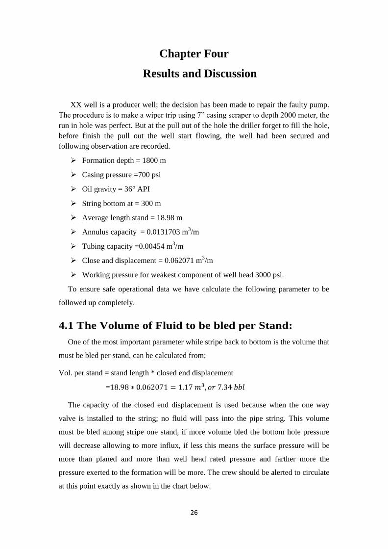
XX well is a producer well; the decision has been made to repair the faulty pump.
The procedure is to make a wiper trip using 7” casing scraper to depth 2000 meter, the
run in hole was perfect. But at the pull out of the hole the driller forget to fill the hole,
before finish the pull out the well start flowing, the well had been secured and
following observation are recorded.
Formation depth = 1800 m
Casing pressure =700 psi
Oil gravity = 36 API
String bottom at = 300 m
Average length stand = 18.98 m
Annulus capacity = 0.0131703 m3/m
Tubing capacity =0.00454 m3/m
Close and displacement = 0.062071 m3/m
Working pressure for weakest component of well head 3000 psi.
To ensure safe operational data we have calculate the following parameter to be
followed up completely.
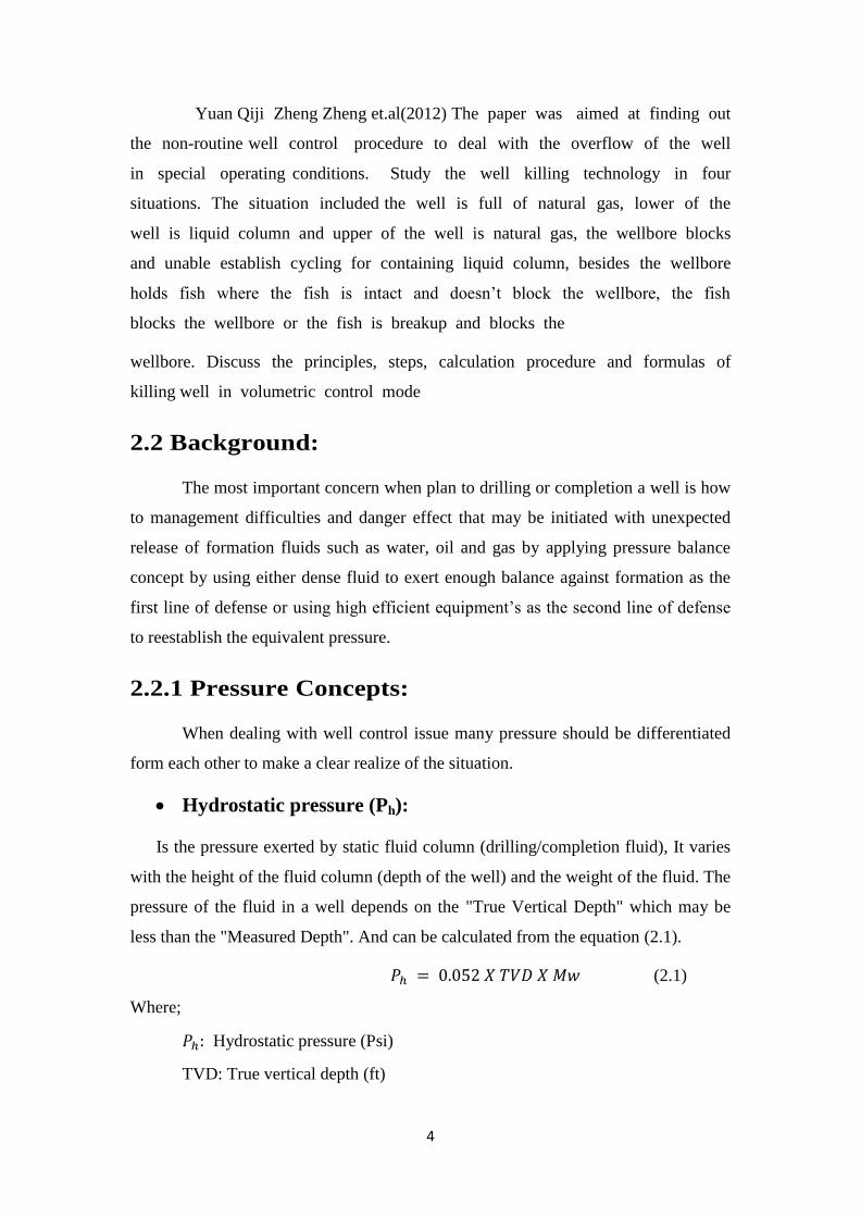
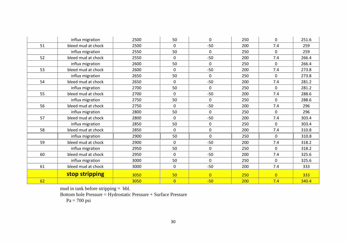
4.1 The Volume of Fluid to be bled per Stand:
One of the most important parameter while stripe back to bottom is the volume that
must be bled per stand, can be calculated from;
Vol. per stand = stand length * closed end displacement
=
The capacity of the closed end displacement is used because when the one way
valve is installed to the string; no fluid will pass into the pipe string. This volume
must be bled among stripe one stand, if more volume bled the bottom hole pressure
will decrease allowing to more influx, if less this means the surface pressure will be
more than planed and more than well head rated pressure and farther more the
pressure exerted to the formation will be more. The crew should be alerted to circulate
at this point exactly as shown in the chart below.
27
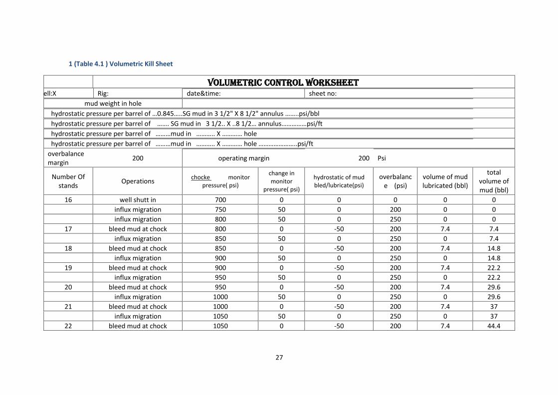
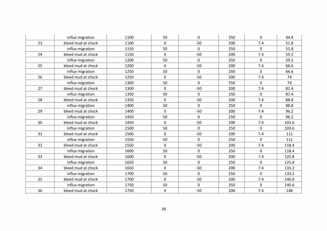
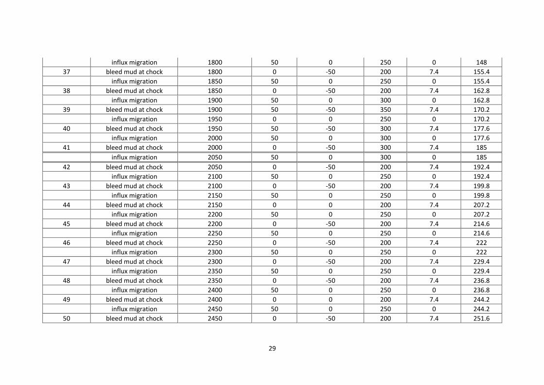
1 (Table 4.1 ) Volumetric Kill Sheet
volumetric control worksheet
well:X Rig: date&time: sheet no:
mud weight in hole
hydrostatic pressure per barrel of …0.845…..SG mud in 3 1/2" X 8 1/2" annulus ……..psi/bbl
hydrostatic pressure per barrel of ……. SG mud in 3 1/2.. X ..8 1/2… annulus……………psi/ft
hydrostatic pressure per barrel of ………mud in ……….. X ………… hole
hydrostatic pressure per barrel of ………mud in ……….. X ………… hole …………………..psi/ft
overbalance margin
200 operating margin 200 Psi
Number Of stands
Operations chocke monitor
pressure( psi)
change in monitor
pressure( psi)
hydrostatic of mud bled/lubricate(psi)
overbalance (psi)
volume of mud lubricated (bbl)
total volume of mud (bbl)
16 well shutt in 700 0 0 0 0 0
influx migration 750 50 0 200 0 0
influx migration 800 50 0 250 0 0
17 bleed mud at chock 800 0 -50 200 7.4 7.4
influx migration 850 50 0 250 0 7.4
18 bleed mud at chock 850 0 -50 200 7.4 14.8
influx migration 900 50 0 250 0 14.8
19 bleed mud at chock 900 0 -50 200 7.4 22.2
influx migration 950 50 0 250 0 22.2
20 bleed mud at chock 950 0 -50 200 7.4 29.6
influx migration 1000 50 0 250 0 29.6
21 bleed mud at chock 1000 0 -50 200 7.4 37
influx migration 1050 50 0 250 0 37
22 bleed mud at chock 1050 0 -50 200 7.4 44.4
28
influx migration 1100 50 0 250 0 44.4
23 bleed mud at chock 1100 0 -50 200 7.4 51.8
influx migration 1150 50 0 250 0 51.8
24 bleed mud at chock 1150 0 -50 200 7.4 59.2
influx migration 1200 50 0 250 0 59.2
25 bleed mud at chock 1200 0 -50 200 7.4 66.6
influx migration 1250 50 0 250 0 66.6
26 bleed mud at chock 1250 0 -50 200 7.4 74
influx migration 1300 50 0 250 0 74
27 bleed mud at chock 1300 0 -50 200 7.4 81.4
influx migration 1350 50 0 250 0 81.4
28 bleed mud at chock 1350 0 -50 200 7.4 88.8
influx migration 1400 50 0 250 0 88.8
29 bleed mud at chock 1400 0 -50 200 7.4 96.2
influx migration 1450 50 0 250 0 96.2
30 bleed mud at chock 1450 0 -50 200 7.4 103.6
influx migration 1500 50 0 250 0 103.6
31 bleed mud at chock 1500 0 -50 200 7.4 111
influx migration 1550 50 0 250 0 111
32 bleed mud at chock 1550 0 -50 200 7.4 118.4
influx migration 1600 50 0 250 0 118.4
33 bleed mud at chock 1600 0 -50 200 7.4 125.8
influx migration 1650 50 0 250 0 125.8
34 bleed mud at chock 1650 0 -50 200 7.4 133.2
influx migration 1700 50 0 250 0 133.2
35 bleed mud at chock 1700 0 -50 200 7.4 140.6
influx migration 1750 50 0 250 0 140.6
36 bleed mud at chock 1750 0 -50 200 7.4 148
29
influx migration 1800 50 0 250 0 148
37 bleed mud at chock 1800 0 -50 200 7.4 155.4
influx migration 1850 50 0 250 0 155.4
38 bleed mud at chock 1850 0 -50 200 7.4 162.8
influx migration 1900 50 0 300 0 162.8
39 bleed mud at chock 1900 50 -50 350 7.4 170.2
influx migration 1950 0 0 250 0 170.2
40 bleed mud at chock 1950 50 -50 300 7.4 177.6
influx migration 2000 50 0 300 0 177.6
41 bleed mud at chock 2000 0 -50 300 7.4 185
influx migration 2050 50 0 300 0 185
42 bleed mud at chock 2050 0 -50 200 7.4 192.4
influx migration 2100 50 0 250 0 192.4
43 bleed mud at chock 2100 0 -50 200 7.4 199.8
influx migration 2150 50 0 250 0 199.8
44 bleed mud at chock 2150 0 0 200 7.4 207.2
influx migration 2200 50 0 250 0 207.2
45 bleed mud at chock 2200 0 -50 200 7.4 214.6
influx migration 2250 50 0 250 0 214.6
46 bleed mud at chock 2250 0 -50 200 7.4 222
influx migration 2300 50 0 250 0 222
47 bleed mud at chock 2300 0 -50 200 7.4 229.4
influx migration 2350 50 0 250 0 229.4
48 bleed mud at chock 2350 0 -50 200 7.4 236.8
influx migration 2400 50 0 250 0 236.8
49 bleed mud at chock 2400 0 0 200 7.4 244.2
influx migration 2450 50 0 250 0 244.2
50 bleed mud at chock 2450 0 -50 200 7.4 251.6
30
influx migration 2500 50 0 250 0 251.6
51 bleed mud at chock 2500 0 -50 200 7.4 259
influx migration 2550 50 0 250 0 259
52 bleed mud at chock 2550 0 -50 200 7.4 266.4
influx migration 2600 50 0 250 0 266.4
53 bleed mud at chock 2600 0 -50 200 7.4 273.8
influx migration 2650 50 0 250 0 273.8
54 bleed mud at chock 2650 0 -50 200 7.4 281.2
influx migration 2700 50 0 250 0 281.2
55 bleed mud at chock 2700 0 -50 200 7.4 288.6
influx migration 2750 50 0 250 0 288.6
56 bleed mud at chock 2750 0 -50 200 7.4 296
influx migration 2800 50 0 250 0 296
57 bleed mud at chock 2800 0 -50 200 7.4 303.4
influx migration 2850 50 0 250 0 303.4
58 bleed mud at chock 2850 0 0 200 7.4 310.8
influx migration 2900 50 0 250 0 310.8
59 bleed mud at chock 2900 0 -50 200 7.4 318.2
influx migration 2950 50 0 250 0 318.2
60 bleed mud at chock 2950 0 -50 200 7.4 325.6
influx migration 3000 50 0 250 0 325.6
61 bleed mud at chock 3000 0 -50 200 7.4 333
stop stripping 3050 50 0 250 0 333
62 3050 0 -50 200 7.4 340.4
mud in tank before stripping = bbl.
Bottom hole Pressure = Hydrostatic Pressure + Surface Pressure
Pa = 700 psi
31
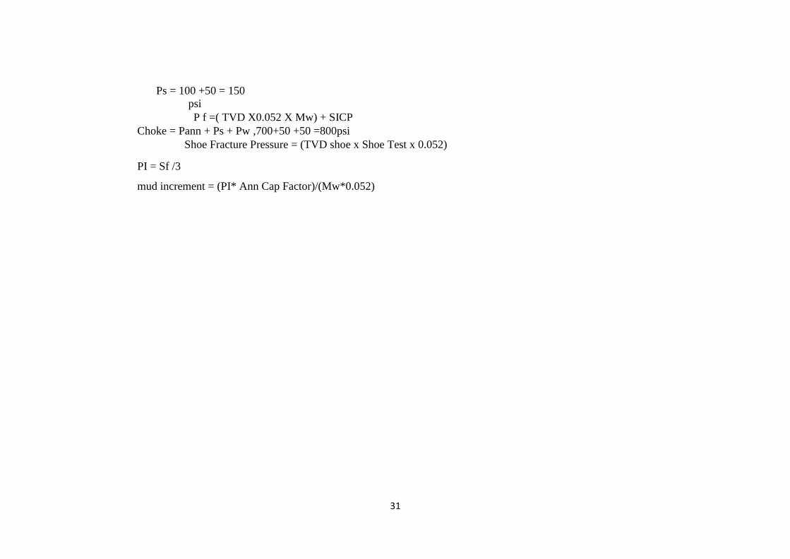
Ps = 100 +50 = 150
psi
P f =( TVD X0.052 X Mw) + SICP
Choke = Pann + Ps + Pw ,700+50 +50 =800psi
Shoe Fracture Pressure = (TVD shoe x Shoe Test x 0.052)
PI = Sf /3
mud increment = (PI* Ann Cap Factor)/(Mw*0.052)
32
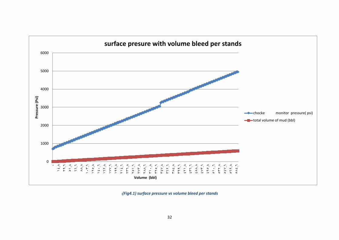
9(Fig4.1) surface pressure vs volume bleed per stands
0
1000
2000
3000
4000
5000
60000
14.8
29.6
51.8
66.6
88.8
103.6
125.8
140.6
162.8
177.6
199.8
214.6
236.8
251.6
273.8
288.6
310.8
325.6
347.8
362.6
384.8
399.6
421.8
436.6
458.8
473.6
495.8
510.6
532.8
547.6
569.8
584.6
Pre
ssu
re (
Psi
)
Volume (bbl)
surface presure with volume bleed per stands
chocke monitor pressure( psi)
total volume of mud (bbl)
33
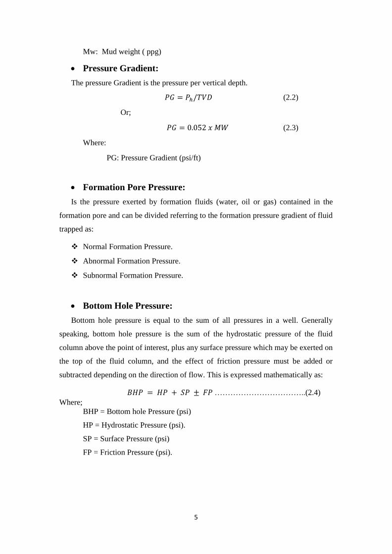
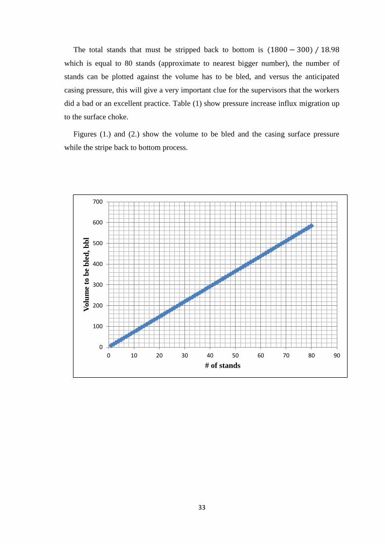
The total stands that must be stripped back to bottom is
which is equal to 80 stands (approximate to nearest bigger number), the number of
stands can be plotted against the volume has to be bled, and versus the anticipated
casing pressure, this will give a very important clue for the supervisors that the workers
did a bad or an excellent practice. Table (1) show pressure increase influx migration up
to the surface choke.
Figures (1.) and (2.) show the volume to be bled and the casing surface pressure
while the stripe back to bottom process.
0
100
200
300
400
500
600
700
0 10 20 30 40 50 60 70 80 90
Volu
me
to b
e b
led
, b
bl
# of stands
34
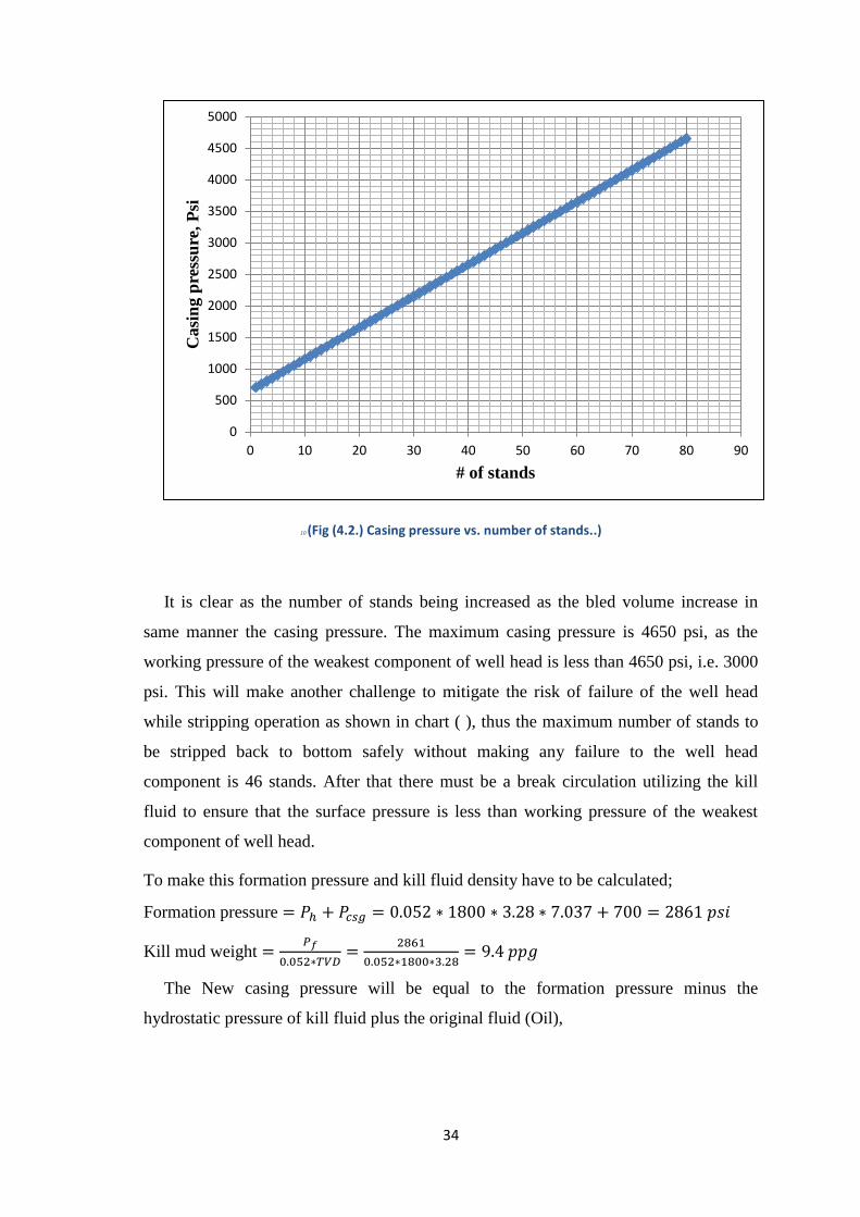
10 (Fig (4.2.) Casing pressure vs. number of stands..)
It is clear as the number of stands being increased as the bled volume increase in
same manner the casing pressure. The maximum casing pressure is 4650 psi, as the
working pressure of the weakest component of well head is less than 4650 psi, i.e. 3000
psi. This will make another challenge to mitigate the risk of failure of the well head
while stripping operation as shown in chart ( ), thus the maximum number of stands to
be stripped back to bottom safely without making any failure to the well head
component is 46 stands. After that there must be a break circulation utilizing the kill
fluid to ensure that the surface pressure is less than working pressure of the weakest
component of well head.
To make this formation pressure and kill fluid density have to be calculated;
Formation pressure
Kill mud weight
The New casing pressure will be equal to the formation pressure minus the
hydrostatic pressure of kill fluid plus the original fluid (Oil),
0
500
1000
1500
2000
2500
3000
3500
4000
4500
5000
0 10 20 30 40 50 60 70 80 90
Casi
ng p
ress
ure
, P
si
# of stands
35
(
)
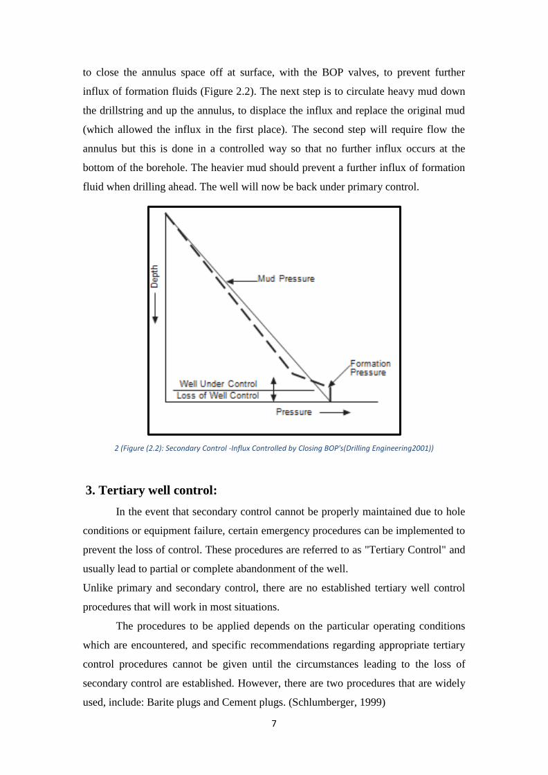
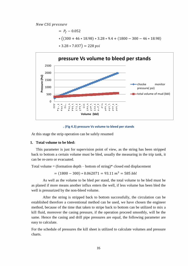
11 (Fig 4.3) pressure Vs volume to bleed per stands
At this stage the strip operation can be safely resumed
1. Total volume to be bled:
This parameter is just for supervision point of view, as the string has been stripped
back to bottom a certain volume must be bled, usually the measuring in the trip tank, it
can be re-zero or evacuated.
Total volume = (formation depth – bottom of string)* closed end displacement
As well as the volume to be bled per stand, the total volume to be bled must be
as planed if more means another influx enters the well, if less volume has been bled the
well is pressurized by the non-bleed volume.
After the string is stripped back to bottom successfully, the circulation can be
established therefore a conventional method can be used, we have chosen the engineer
method, because of the time that taken to stripe back to bottom can be utilized to mix a
kill fluid, moreover the casing pressure, if the operation proceed smoothly, will be the
same. Hence the casing and drill pipe pressures are equal, the following parameter are
easy to calculate.
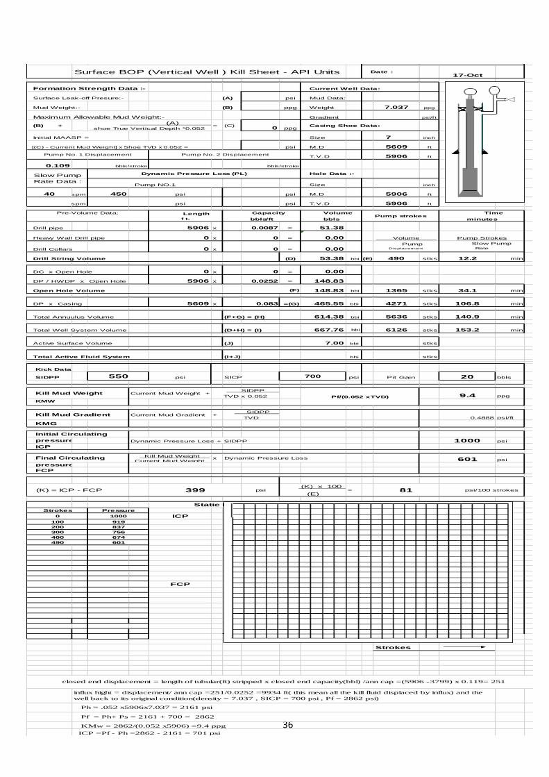
For the schedule of pressures the kill sheet is utilized to calculate volumes and pressure
charts.
0
500
1000
1500
2000
2500
333
340.4
355.2
370
384.8
399.6
414.4
429.2
444
458.8
473.6
488.4
503.2
518
532.8
547.6
562.4
577.2
Pre
ssu
re (
Psi
)
Volume (bbl)
pressure Vs volume to bleed per stands
chocke monitorpressure( psi)
total volume of mud (bbl)
36
International Well Control Forum Name :
KICK EXERCISE
Surface BOP (Vertical Well ) Kill Sheet - API Units Date :17-Oct
Formation Strength Data :- Current Well Data:
Surface Leak-off Presure:- (A) psi Mud Data:
Mud Weight:- (B) ppg Weight 7.037 ppg
Maximum Allowable Mud Weight:- Gradient psi/ft
(B) + (A)
shoe True Vertical Depth *0.052= (C)
0 ppg Casing Shoe Data:
Initial MAASP = Size 7 inch
[(C) - Current Mud Weight] x Shoe TVD x 0.052 = psi M.D 5609 f t
Pump No. 1 Displacement Pump No. 2 Displacement T.V.D 5906 f t
0.109 bbls/stroke bbls/stroke
Slow Pump Dynamic Pressure Loss (PL) Hole Data :-
Rate Data :Pump NO.1 Size inch
40 spm 450 psi psi M.D 5906 f t
spm psi psi T.V.D 5906 f t
Pre-Volume Data: Length
f t.
Capacity
bbls/ft
Volume
bblsPump strokes
Time
minutes
Drill pipe 5906 x 0.0087 = 51.38
Heavy Wall Drill pipe 0 x 0 = 0.00 Volume Pump Strokes
Drill Collars 0 x 0 = 0.00 Pump Displacement
Slow Pump
Rate
Drill String Volume (D) 53.38 bbi (E) 490 stks 12.2 min
DC x Open Hole 0 x 0 = 0.00
DP / HWDP x Open Hole 5906 x 0.0252 = 148.83
Open Hole Volume (F) 148.83 bbi 1365 stks 34.1 min
DP x Casing 5609 x 0.083 =(G) 465.55 bbi 4271 stks 106.8 min
Total Annuulus Volume (F+G) = (H) 614.38 bbi 5636 stks 140.9 min
Total Well System Volume (D+H) = (I) 667.76 bbi 6126 stks 153.2 min
Active Surface Volume (J) 7.00 bbi stks
Total Active Fluid System (I+J) bbi stks
Kick Data
SIDPP 550 psi SICP 700 psi Pit Gain 20 bbls
Kill Mud Weight Current Mud Weight + SIDPP
TVD x 0.052 9.4 ppg
KMW
Kill Mud Gradient Current Mud Gradient + SIDPP
TVD 0.4888 psi/ft
KMG
Initial Circulating
pressure Dynamic Pressure Loss + SIDPP 1000 psi
ICP
Final Circulating Kill Mud Weight
Current Mud Weightx Dynamic Pressure Loss 601 psi
pressure
FCP
(K) = ICP - FCP 399 psi (K) x 100
(E)= 81 psi/100 strokes
Static Drill Pipe Pressure (psi)
Strokes Pressure
0 1000 ICP
100 919
200 837
300 756
400 674
490 601
FCP
Strokes
Pf/(0.052 xTVD)
influx hight = displacement/ ann cap =251/0.0252 =9934 ft( this mean all the kill fluid displaced by influx) and the
well back to its original condition(density = 7.037 , SICP = 700 psi , Pf = 2862 psi)
Ph = .052 x5906x7.037 = 2161 psi
Pf = Ph+ Ps = 2161 + 700 = 2862
KMw = 2862/(0.052 x5906) =9.4 ppg
ICP =Pf - Ph =2862 - 2161 = 701 psi
closed end displacement = length of tubular(ft) stripped x closed end capacity(bbl) /ann cap =(5906 -3799) x 0.119= 251

37
Chapter five
Conclusion and Recommendations
5.1Conclusion
From the data collected, shown the well X has started to flow during pulling
out of the hole.
Using volumetric method to control the well and strip tubing to the bottom.
Surface pressure increases and may cause blow out due to exceeding of the
wellhead rated pressure, this problem solved by stop striping and using
conventional well control (wait and weight).
Surface pressure control by increasing hydrostatic head and back to normal
stripping.
Strip back completely to the bottom and circulate using a kill mud weight until
the well-controlled and operation back to normal.
5.2 Recommendations:
From the previous well X study we find that the most important issues is to
used volumetric control method as the first choice when conventional method
can’t be applied to control formation fluids flow, than to used bull heading
method because bull heading will cause positive skin factor and may require
stimulation which will increase over all well cost and reduce well productivity.
For most of Sudanese oil field to use the volumetric method, its more safe,
cheaper and simple.
It’s recommended because it can accurately monitoring through bleeded
volume in the scaled tank.
Any time after commence stripping operation can change to circulation
method to avoid pressure limitation for the surface equipment and casing burst
pressure.
38
REFFERENCES
1. A.K.Mehra D.D. Jaju, 1994,Drilling Operations Manual,P.S.Bais,Parel ,Bombay, India.
2. H.RABIA , 1985, Oil well Drilling Engineering Graoham & Trotman limited.
3. Adam T.Bourgoy Jr . Keith K.Millheim . Martin E.Chenevert . F.S.Young,Jr,1984,
Applied Drilling Engineering , SPE.
4. J.J.Azar. G.Robello Samuel ,2007,Drilling Engineering,United state of America
5. Chevron Petroleum Technology Company,1994, U.S.A.
6. Kerry Koffler, Mike Oliver, Jeff Carlone, ,Alan Lockstedt,,2001, Smith Tool Dull Grading
Manual, Smith Internationa.
7. Davorin Matanovic et.al ,(1994), Particulars in Killing gas production wells.
8. Yuan Qiji Zheng Zheng et.al(2012) , The Killing method of exceptional
operating conditions well.