Welcome to the HMMWV Quick Reference Guide Third Edition.
627
Welcome to the HMMWV Quick Reference Guide Third Edition. This book contains Digest Articles, PS Magazine Articles and SOUMs that provide solutions to a variety of reported problems on the HMMWV. These articles were published Aug 93 through Dec 96. To use this guide, just determine the functional group code your problem falls within and go to the index found on pages 2-19. The index is grouped by functional group code and is in order by group code. Then just pick your subject and locate the page. The information contained in this reference guide is unclassified. We hope you find this guide useful. Any comments or questions regarding this book can be directed to: Ms. Jody McInerney, AMSTA-IM-HLA, DSN: 786-5481, Commercial: (810) 574-5481 or email: [email protected] In case you did not know the HMMWV Maintenance Team and Supply Team have become one under Integrated Materiel Management Center (IMMC). Below is a list of phone numbers that will get you the HMMWV Team. (DSN is 786-XXXX and Commercial (810) 574-XXXX) Maintenance Related: Ext. 7566 5481 5763 Supply Related: Ext. 7493 7566 8142 Page 1 The information presented here wouldn't be available if it wasn't for you (the user) telling us about your problems. So please continue to submit your SMARTS, Suggestions, QDR/ElRs, and 2028s.
-
Upload
khangminh22 -
Category
Documents
-
view
2 -
download
0
Transcript of Welcome to the HMMWV Quick Reference Guide Third Edition.

Welcome to the HMMWV Quick Reference GuideThird Edition.
This book contains Digest Articles, PS Magazine Articles and SOUMsthat provide solutions to a variety of reported problems on the HMMWV.These articles were published Aug 93 through Dec 96.
To use this guide, just determine the functional group code yourproblem falls within and go to the index found on pages 2-19. The index isgrouped by functional group code and is in order by group code. Then justpick your subject and locate the page.
The information contained in this reference guide is unclassified.
We hope you find this guide useful. Any comments or questionsregarding this book can be directed to:
Ms. Jody McInerney,AMSTA-IM-HLA, DSN: 786-5481,Commercial: (810) 574-5481or email: [email protected]
In case you did not know the HMMWV Maintenance Team and SupplyTeam have become one under Integrated Materiel Management Center(IMMC).Below is a list of phone numbers that will get you the HMMWV Team.
(DSN is 786-XXXX and Commercial (810) 574-XXXX)Maintenance Related: Ext. 7566
54815763
Supply Related: Ext. 7493 75668142
Page 1
The information presented here wouldn't beavailable if it wasn't for you (the user) telling usabout your problems. So please continue tosubmit your SMARTS, Suggestions, QDR/ElRs,and 2028s.

HMMWV QUICKREFERENCE GUIDE
INDEX
FGC TITLE OF ARTICLE TYPE OF ARTICLE PAGE NUMBER
CHAPTER: 00
MISC AOAP INTERVALS EIR 1-2MISC ARMY OIL ANALYSIS PROGRAM (AOAP) EIR 3
SAMPLINGMISC. CLEANING RUSTPROOFED VEHICLES EIR 4-5MISC CONVERSION FROM DIESEL FUEL TO JP8 EIR 5-6MISC ENGINE AND TRANSMISSION OIL COOLER AND EIR 7
RADIATOR CLEANINGMISC GETTING IN AND OUT OF THE REAR OF THE EIR 7
VEHICLEMISC ENROLLMENT OF HMMWVS IN THE ARMY OIL EIR 8-9
ANALYSIS PROGRAM (AOAP)MISC COMMERCIAL HEAVY DUTY OIL UPDATE EIR 10-11MISC FABRICATE ENGINEITRANSMISSION SUPPORT EIR 12-31
SLINGMISC COLOR HIGHLIGHTING OF FLUID LEVEL GAGE EIR 32-33
RODS (DIPSTICKS)MISC FEASIBILITY STUDY FOR IMPROVING EIR 33-34
MIL-A-46153 ANTIFREEZEMISC LOW SULFUR DIESEL AND JP-8 FUELS EIR 34-36MISC LUBRICATING OIL UPDATE EIR 36-38MISC TM UPDATE EIR 39-50MISC WIDELY USED FORMS EIR 51-53MISC JACK'EM UP ... SAFELY PS 54MISC COLD CALLS FOR OEA PS 55MISC GAA NEEDS NO SUBSTITUTES PS 55
Page I02

HMMWV QUICKREFERENCE GUIDE
INDEX
FGC TITLE OF ARTICLE TYPE OF ARTICLE PAGE NUMBER
CHAPTER: 00
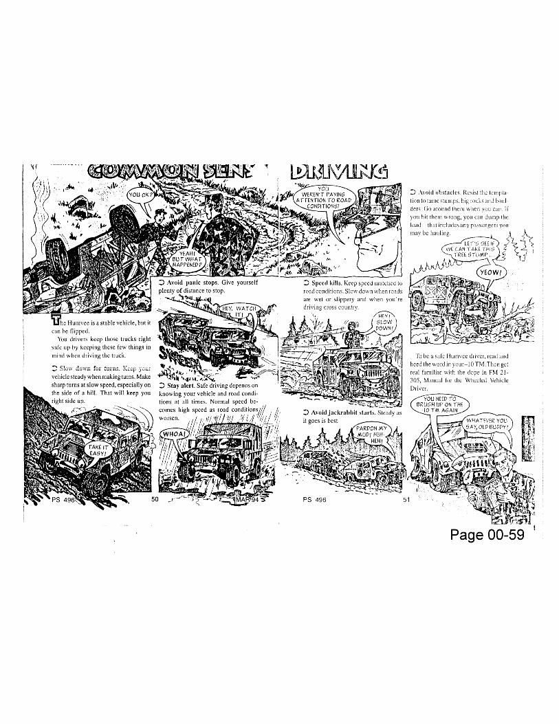
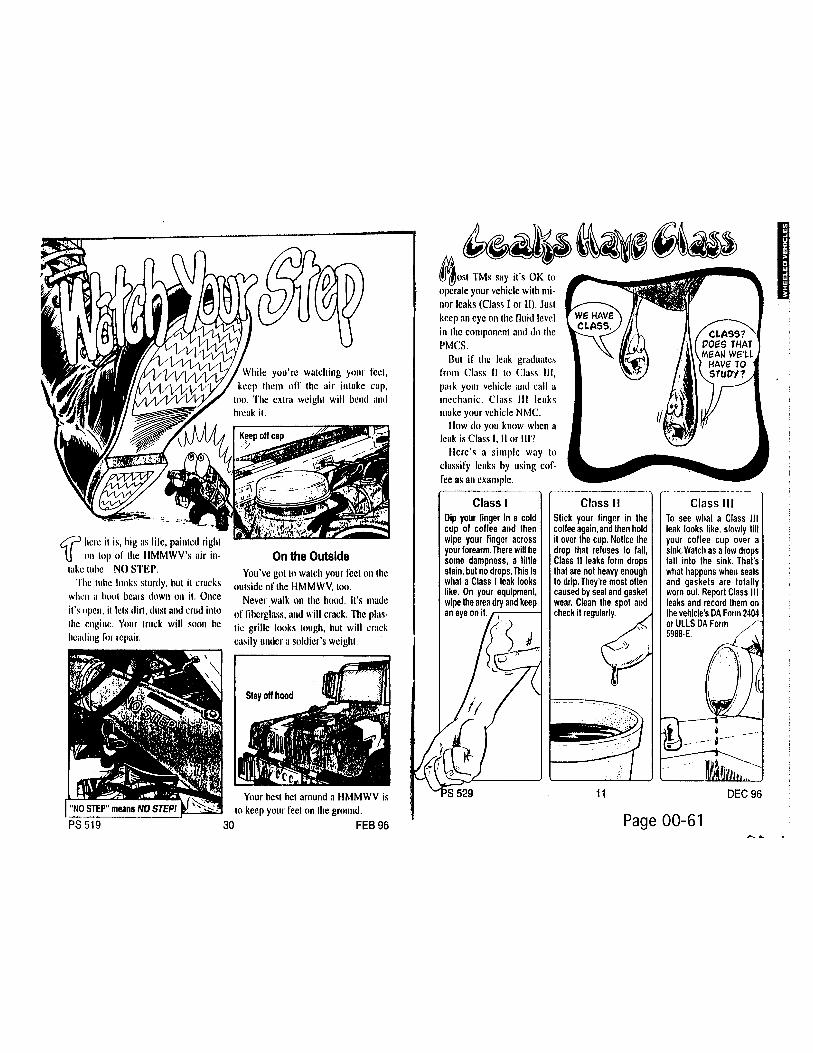
MISC GO SLOW WHEN FORDING PS 55MISC JACK THE SLIPPER? PS 56MISC LUBING-MORE AND LESS PS 56MISC PM LETS YOU DRIVE ON PS 57MISC EXTREME PM FOR EXTREME COLD PS 58MISC COMMON SENSE DRIVING PS 59MISC COPING WITH THE COLD PS 60MISC LEAKS HAVE CLASS PS 61MISC WATCH YOUR STEP PS 61MISC SHIFTING SANDS PS 62
CHAPTER: 01
0100 USE OF CYLINDER SLEEVES ON6.2L ENGINES EIR 1-2
0100 ENGINE BLOCK REPAIR EIR 2-30100 REPLACEMENT ENGINE ASSEMBLIES EIR 3-40100 ENGINE PISTON TO CYLINDER EIR 4-5
SPECIFICATIONS0100 RUBBING AND CHAFING OF ENGINE EIR 14-20
COMPARTMENT HARDWARE0100 REMOVING/INSTALLING ENGINE EIR 21-24
ASSEMBLY FROM/IN SHIPPING ANDSTORAGE CONTAINER
0100 STOP ENGINE RUN-ON-ON-ON-ON PS 25
Page 3

HMMWV QUICKREFERENCE GUIDE
INDEX
FGC TITLE OF ARTICLE TYPE OF ARTICLE PAGE NUMBER
CHAPTER: 01
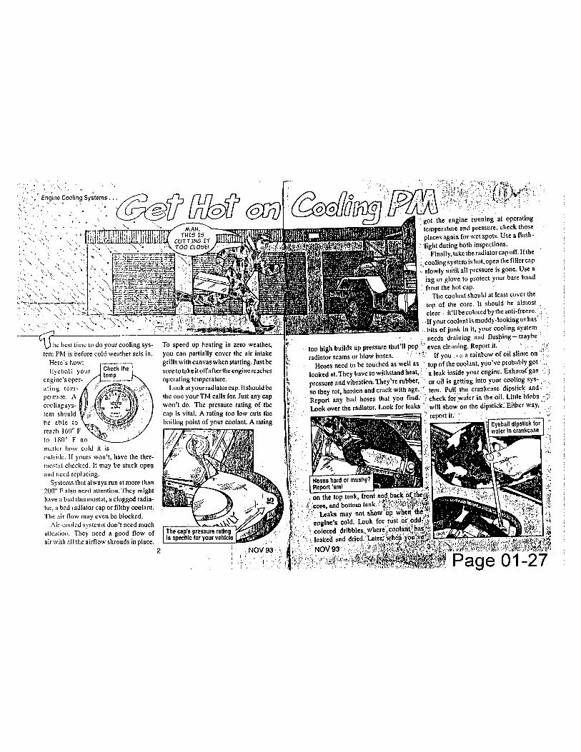
0100 GET HOT ON COOLING PM PS 27 0106 VALVE COVER AND OIL PAN GASKETS EIR 5-60106 6.2 LITER DIESEL ENGINE CONNECTING ROD EIR 6-7
BEARINGS (.010" OVERSIZE),NSN 2815-01-165-4826
0106 DRAIN COCK ADAPTOR EIR 7-80106 FABRICATION AND USE OF CYLINDER HEAD EIR 9-13
LIFTING DEVICE0106 CUCV/HMMWV GASKET PS 250106 OIL PAN NSNS PS 250106 OIL PAN SHROUD NOW "O" PS 250106 KEEP CRANKCASE VENTED PS 260106 USE DRIP PANS PS 28
CHAPTER: 03
0302 FUEL INJECTOR PUMP LINE NUT WRENCH EIR 10302 SUBSTITUTE CLAMP FOR FUEL RETURN LINE EIR 2
AT THE INJECTOR0302 LOOK FOR FUEL ON THE BLOCK PS 230304 M998 SERIES VEHICLES WITH AIR CLEANER EIR 3
PRE-CLEANER NSN 2940-01-302-8028
Page 4
HMMWV QUICKREFERENCE GUIDE
INDEX
FGC TITLE OF ARTICLE TYPE OF ARTICLE PAGE NUMBER
CHAPTER: 03
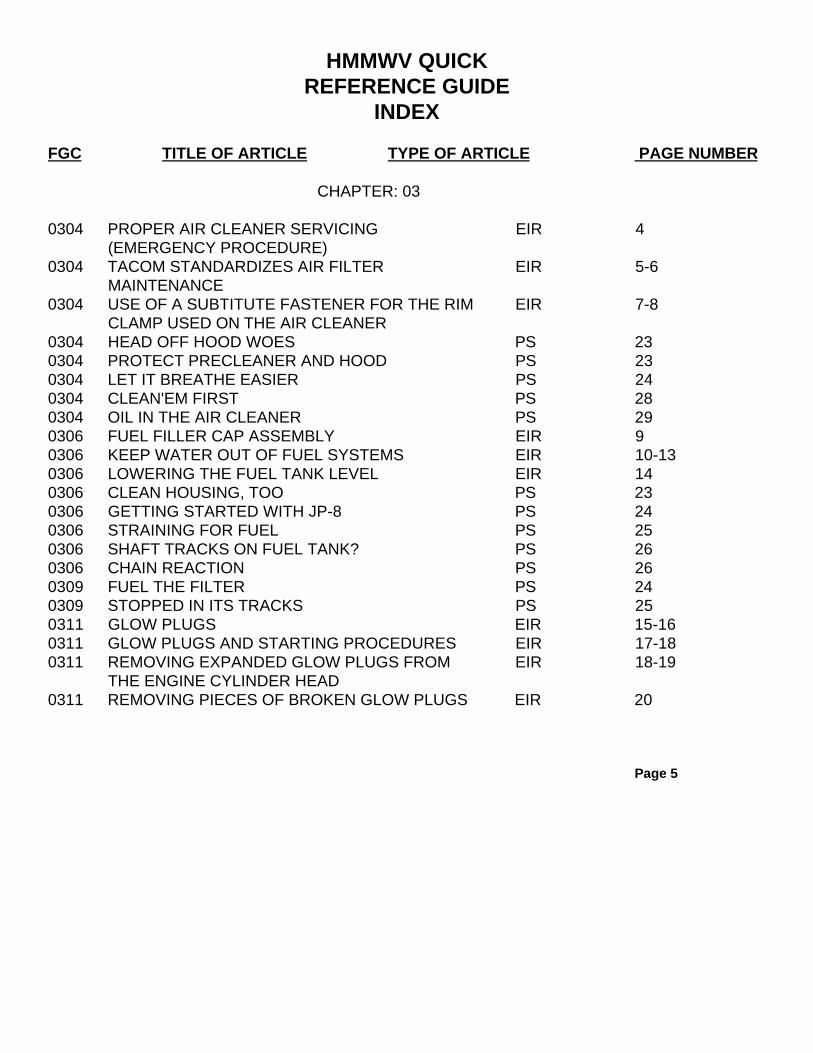
0304 PROPER AIR CLEANER SERVICING EIR 4(EMERGENCY PROCEDURE)
0304 TACOM STANDARDIZES AIR FILTER EIR 5-6MAINTENANCE
0304 USE OF A SUBTITUTE FASTENER FOR THE RIM EIR 7-8CLAMP USED ON THE AIR CLEANER
0304 HEAD OFF HOOD WOES PS 230304 PROTECT PRECLEANER AND HOOD PS 230304 LET IT BREATHE EASIER PS 240304 CLEAN'EM FIRST PS 280304 OIL IN THE AIR CLEANER PS 290306 FUEL FILLER CAP ASSEMBLY EIR 90306 KEEP WATER OUT OF FUEL SYSTEMS EIR 10-130306 LOWERING THE FUEL TANK LEVEL EIR 140306 CLEAN HOUSING, TOO PS 230306 GETTING STARTED WITH JP-8 PS 240306 STRAINING FOR FUEL PS 250306 SHAFT TRACKS ON FUEL TANK? PS 260306 CHAIN REACTION PS 260309 FUEL THE FILTER PS 240309 STOPPED IN ITS TRACKS PS 250311 GLOW PLUGS EIR 15-160311 GLOW PLUGS AND STARTING PROCEDURES EIR 17-180311 REMOVING EXPANDED GLOW PLUGS FROM EIR 18-19
THE ENGINE CYLINDER HEAD0311 REMOVING PIECES OF BROKEN GLOW PLUGS EIR 20
Page 5

HMMWV QUICKREFERENCE GUIDE
INDEXFGC TITLE OF ARTICLE TYPE OF ARTICLE PAGE NUMBER
CHAPTER: 03
0311 REMOVAL OF SWOLLEN GLOW PLUGS EIR 21-220311 CHECK BEFORE YOU CHUCK PS 270311 GLOW PLUG SOCKET PS 270311 VACUUM GLOW PLUG PARTS PS 270311 WATCH YOUR WAIT PS 270311 GLOW PLUG REMOVAL TOOL PS 290311 GLOW PLUG WARNING LABEL PS 29
CHAPTER: 04
0401 EXHAUST MANIFOLD EIR 1-50401 EXHAUST GOES OUTSIDE PS 6
CHAPTER: 05
0501 COOLING SYSTEM SURGE TANK EIR 10501 CAP OFF RADIATOR PS 290501 COOLERS NEED PM PS 300502 RADIATOR RETAINING STRAP EIR 2-30502 CRACKDOWN ON FAN SHROUD CRACKS PS 290502 HMMWV FAN SHROUD REPAIR PS 31
Page 6

HMMWV QUICKREFERENCE GUIDE
INDEX
FGC TITLE OF ARTICLE TYPE OF ARTICLE PAGE NUMBER
CHAPTER: 05
0502 RIVET HOLDS SHROUD BRACKET PS 310503 A/C BELT RUBBING AGAINST COOLANT HOSE EIR 40503 RADIATOR HOSE TO DRIVE BELT EIR 5-6
INTERFERENCE0504 WATER PUMP REPLACEMENT EIR 10-140505 FAN DRIVE QUICK DISCONNECT EIR 6-90505 FAN CLUTCH EIR 15-170505 FAN CLUTCH CYLINDER DUST SEAL EIR 18-200505 FAN DRIVE AND FAN BLADE REPLACEMENT EIR 21-230505 FAN FAILURES EIR 240505 REPLACEMENT OF FAN DRIVE FRICTION EIR 25-28
LINING0505 FAN DRIVE & BLADE OFF AS ONE PS 310505 FAN MODULE DISCONNECT PS 31
CHAPTER: 06
0601 60 AMPERE ALTERNATOR REGULATOR EIR 1-2REPLACEMENT
0601 60/100 AMP ALTERNATOR BRACKET EIR 3-5MODIFICATION
0601 ALTERNATOR INSTALLATION EIR 6
Page 7

HMMWV QUICKREFERENCE GUIDE
INDEX
FGC TITLE OF ARTICLE TYPE OF ARTICLE PAGE NUMBER
CHAPTER: 06
0601 NIEHOFF 1 00 AMP ALTERNATOR EIR 7-32REPLACEMENT PROCEDURES
0601 BREAK THE BROKEN BOLT SYNDROME PS 550601 CARE FOR BOLTS AND BELTS PS 550601 ONE THING LEADS TO ANOTHER PS 570601 HMMWV ALTERNATOR BRACKET MOD PS 620603 HMMV\[V STARTER EIR 330603 STARTER REPLACEMENT OF VEHICLES WITH EIR 35-36
ARCTIC HEATER KIT INSTALLED0603 FINISH THE STARTER JOB PS 560603 GET THE RIGHT STARTER BOLT PS 560607 INSTRUMENT CLUSTER LAMP AND LENS EIR 370607 REPAIR OF MASTER LIGHT SWITCH, NSN EIR 38-39
5930-00-307-88560608 BRAKE WARNING LAMP STAYS ON EIR 39-400608 DON'T TOSS SIGNAL SWITCH JUST YET PS 580609 BRAKE WARNING LAMP REMOVAL AND EIR 41-42
INSTALLATION PROCEDURES0609 RUSTED HEADLIGHT ASSEMBLY RETAINING EIR 43-44
RINGS, PN 8741446, NSN 5365-00-832-56500609 TAILLIGHT LENS, NSN 6220-01-359-2870 EIR 450609 WATER MEANS LIGHTS OUT PS 580609 PENNY SAVED, DOLLAR BURNED PS 620609 COMPOSITE LIGHTES VS. WATER PS 630609 LET THE WATER OUT PS 630612 BATTERY BOX EIR 46
Page 8

HMMWV QUICKREFERENCE GUIDE
INDEX
FGC TITLE OF ARTICLE TYPE OF ARTICLE PAGE NUMBER
CHAPTER: 06
0612 REPAIR OF MILITARY STANDARD BATTERY EIR 470612 SLAVE RECEPTACLE MOUNT EIR 48-490612 ELECTRONIC BATTERY TESTER EIR 49-500612 WATER IN BATTERY TRAY EIR 510612 DRAIN BATTERY TRAY PS 550612 POSITIVE FIRST? NEGATIVE PS 570612 TAKING CHARGE OF PM PS 590612 AS EASY AS ONE-TWO-THREE PS 60-610612 ADD BATTERY DRAINS PS 620612 DROP VOLTAGE IN THE HEAT PS 620613 DIAGNOSING ELECTRICAL SYSTEM FAILURES EIR 52-54
CHAPTER: 07
0705 NEW AUTOMATIC TRANSMISSION FLUID, EIR 1-2DEXRONIII
0705 REPLACEMENT OF 1995 4L80E TRANSMISSION EIR 3-6(NSN 2520-01-399-4691) AND/OR 1995TRANSMISSION CONTROL MODULE (TCM)E-PROM
0705 TRANSMISSION MODULATOR ASSEMBLY EIR 7-110705 TRANSMISSION GEAR SHIFT AND RELEASE EIR 11-12
BUTTON
Page 9

HMMWV QUICKREFERENCE GUIDE
INDEX
FGC TITLE OF ARTICLE TYPE OF ARTICLE PAGE NUMBERCHAPTER: 07
0705 DEXRON III ON THE JOB PS 14 0708 TORQUE CONVERTER BRACE EIR 12-13
CHAPTER: 08
0801 TRANSFER CASE VENT LINE DESIGN EIR 1-11 IMPROVEMENT
0801 TRANSFER CASE LEAKS PS 120801 MAKE NO TRANSFER PS 12
CHAPTER: 09
0900 PROPELLER SHAFT WEAR ONFUEL TANKS EIR 1
CHAPTER: 10
1000 JOLTED HALFSHAFT BOLT PS 1 3
Page 1 0

HMMWV QUICKREFERENCE GUIDE
INDEX
FGC TITLE OF ARTICLE TYPE OF ARTICLE PAGE NUMBER
CHAPTER: 10
1000 USE OF PERMA-QUICK PLIERS TO SECURE EIR 1BOOT ON THE HALFSHAFT
1002 PART NUMBER FOR THE FRONT AXLE EIR 2DIFFERENTIAL
1002 DIFFERENTIAL INSTALLATION EIR 2-31004 USE OF PICKLE FORK FOR HMMWV REPAIRS EIR 3-41004 HMMWV SEALS EIR 41004 TIE ROD CLAMPS EIR 4-51004 LUBRICATION OF UPPER BALL JOINT AND TIE EIR 6
ROD ENDS1004 GPM, TACOM CONTROL NO. 95-02, SOUM 7-12
MAINTENANCE ADVISORY FOR GEARED HUB(NSN 2530-01-203-5746 AND 2530-01-203-5745,HMMWV)
1004 ONE TIME LOCK WASHER PS 131004 REPLACE SPINDLE LOCKWASHER PS 131004 CLAMP GOES BEHIND PS 141004 SEALING GEARED HUBS PS 14
CHAPTER: 1 1
1100 REARHALFSHAFTBOLTHELP PS 1
Page 11

HMMWV QUICKREFERENCE GUIDE
INDEX
FGC TITLE OF ARTICLE TYPE OF ARTICLE PAGE NUMBER
CHAPTER 12
1201 MWO-0-2320-280-35-1 EIR 11201 REAR PARKING BRAKE CABLE AND CLAMP EIR 21201 REAR PARKING BRAKE CABLE/BRACKET EIR 3-41201 PAINT PARKING BRAKE LEVER PS 101201 PARKING BRAKE CABLE PINCH PS 101202 BRAKE ADAPTERS EIR 51202 FRONT BRAKE SHOES EIR 61204 ALTERNATIVE METHOD OF MINIMIZING EIR 7
EXPOSURE TO ASEBESTOS DURING BRAKESERVICE/INSP
1204 FABRICATION OF REAR BRAKE CALIPER TOOL EIR 8-9
CHAPTER: 13
1311 RUNFLAT SPACER INSTALLATION EIR 11311 AIR ON THE SAFE SIDE PS 31311 PM STARTS AT GROUND LEVEL PS 41311 RIM SHOT? PS 51313 POLICY ON NOT MIXING RADIAL AND BIAS PLY EIR 2
TIRES1313 STRAP SNUG CHAINS PS 51313 TIRED TIRES PS 51313 WRAP UP GO WOES PS 6-7
Page 12
HMMWV QUICKREFERENCE GUIDE
INDEX
FGC TITLE OF ARTICLE TYPE OF ARTICLE PAGE NUMBER
CHAPTER: 13
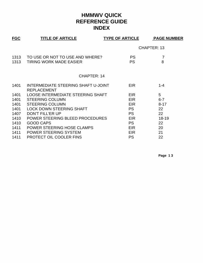
1313 TO USE OR NOT TO USE AND WHERE? PS 71313 TIRING WORK MADE EASIER PS 8
CHAPTER: 14
1401 INTERMEDIATE STEERING SHAFT U-JOINT EIR 1-4REPLACEMENT
1401 LOOSE INTERMEDIATE STEERING SHAFT EIR 51401 STEERING COLUMN EIR 6-71401 STEERING COLUMN EIR 8-171401 LOCK DOWN STEERING SHAFT PS 221407 DON'T FILL'ER UP PS 221410 POWER STEERING BLEED PROCEDURES EIR 18-191410 GOOD CAPS PS 221411 POWER STEERING HOSE CLAMPS EIR 201411 POWER STEERING SYSTEM EIR 211411 PROTECT OIL COOLER FINS PS 22
Page 1 3

HMMWV QUICKREFERENCE GUIDE
INDEX
FGC TITLE OF ARTICLE TYPE OF ARTICLE PAGE NUMBER
CHAPTER: 15
1501 MAINTENANCE LEVEL CHANGE FOR REAR EIR 1-2CROSS MEMBER REPLACEMENT
1503 NO STEP HERE! PS 3
CHAPTER: 18
1801 "C" PILLAR REINFORCEMENT BRACKETS EIR 1-91801 HOOD LIFTING PROCEDURES EIR 10-121801 HOOD LIGHT EIR 131801 RUBBER WELL NUT OR INSERT REPLACEMENT EIR 14-15
FOR A-PILLAR AND B-PILLAR1801 HOLD HMMWV HOODS PS 1781801 GIVE HOOD A HANDLEPS 1821802 BALLISTIC GLASS EIR 161802 PREVENT ICE AND SNOW FROM EIR 17
ACCUMULATING ON WINDSHIELDS1802 JUST SAY NO PS 1781802 KEEP AMMONIA AWAY PS 1821805 DAMAGED FLOOR DRAIN REPLACEMENT EIR 18-31
PROCEDURE1805 FLOOR REPAIR EIR 321805 LEFT FRONT FLOOR PANEL REPAIR EIR 33-651805 PAD INSULATION, NSN 2510-01-209-1881 EIR 66
Page 14

HMMWV QUICKREFERENCE GUIDE
INDEX
FGC TITLE OF ARTICLE TYPE OF ARTICLE PAGE NUMBER
CHAPTER: 18
1806 APPLICATION OF UNAUTHORIZED MSG 67MODIFICATION TO HMMWV MODELS, AMGENERAL SEAT KIT (5743095)
1806 SEATBELT STRUX NUT REPLACEMENT EIR 68-741806 NEW SEATS SOFTEN RIDE PS 1811806 SEAT BELTS DRAW GRIT PS 1811808 PIN ASSEMBLY USED ON THE PINTLE EIR 75
ADAPTER1808 TOW MISSILE STOWAGE CASE DAMAGE EIR 76-781810 TAILGATE CHAIN COVER REPLACEMENT EIR 79-851810 TAILGATE OPERATIONEIR 861812 AMBULANCE REAR STEP HAND KNOB EIR 87-88
SEPARATES FROM STEP1812 ARMORED DOOR CRACKS EIR 89-931812 FABRICATION FOR RETAINER BRACKET, NSN EIR 94-95
2510-01-265-1127 & 5340-01-273-1684 USEDM996/M997 BULKHEAD DOOR
1812 M997 AMBULANCE EXTERIOR BODY REPAIR EIR 96-134PROCEDURES
1812 MODIFICATION TO HMMV\/V'S WITH TURRET EIR 135-140WATER LEAKS
1812 NBC FILTER STRAP ON AMBULANCE EIR 1411812 REAR CARGO DOOR GAS SPRING ASSEMBLIES EIR 142-1461812 TURRET CLEANING EIR 147-1611812 TURRET HANDLE REPLACEMENT EIR 162-165
Page 15

HMMWV QUICKREFERENCE GUIDE
INDEX
FGC TITLE OF ARTICLE TYPE OF ARTICLE PAGE NUMBER
CHAPTER: 18
1812 WEAPON STATION TURRET ADJUSTMENT AND EIR 166-177CLEANING
1812 HMMWV CARRIER TURRETS...YOU'VE GOT TO PS 178ADJUST
1812 STRAPLESS DOOR GOES BALLISTIC PS 1781812 DOOR SPRINGS LOSING GAS PS 1791812 S-HOOK FOR HMMWV STEP PS 1791812 KEEP SEAL IN PLACE PS 1801812 WASH OUT TURRETS PS 1801812 TURRET SEAL TIP PS 181
CHAPTER: 20
2001 6000 LB WINCH ASSEMBLY REPAIR EIR 1-5PROCEDURE
2001 6000 LB WINCH GROUND WIRE EIR 6-82001 9000 LB WINCH KIT EIR 92001 WIRE ROPE NEEDS PM PS 10
Page 16

HMMWV QUICKREFERENCE GUIDE
INDEX
FGC TITLE OF ARTICLE TYPE OF ARTICLE PAGE NUMBER
CHAPTER: 22
2201 CANVAS TOP AND DOOR SEAM LEAK REPAIR EIR 12201 DOOR SEALS EIR 22201 FITTING VINYL COVERS EIR 3-42201 HMMWV SOFT TOP DOOR WINDOW EIR 5-62201 HMMWV SOFT TOP FIT EIR 7-92201 SOFT TOP DOOR HANDLE REPAIR EIR 10-172201 SOFT TOP DOOR HANDLE REPAIR EIR 182201 SOFT TOP DOOR SEALS EIR 19-202201 SOFT TOP REPAIR/REINFORCEMENT EIR 21-23
PROCEDURES2201 SEAL SEEPY SEAMS PS 342201 BUCKLE DOWN BUCKLE UP PS 352201 CLEAN WINDOWS RIGHT PS 372201 QUICK ZIPPER FIX PS 372201 TAPE THE BOWS PS 372201 DOOR HANDLE FIX PS 382201 MUSCLE AND ZIPPERS DON'T MIX PS 382201 SAVE THOSE DOORS PS 382202 HEATER HOSE EIR 242202 HEATER TEMPERATURE CONTROL ASSEMBLY EIR 252202 HMMWV STANDARD MIRROR EIR 262202 HMMV\IV WINDSHIELD WIPERS EIR 272202 REARVIEW MIRROR KITS USED ON THE EIR 28
HMMWV
Page 17

HMMWV QUICKREFERENCE GUIDE
INDEX
FGC TITLE OF ARTICLE TYPE OF ARTICLE PAGE NUMBER
CHAPTER: 22
2202 WINDSHIELD WASHER CLAMP EIR 292202 WINDSHIELD WIPER ARM SPRING EIR 30-32
REPLACEMENT2202 WINDSHIELD WIPER KNOB EIR 332202 HEATER UPDATE PS 342202 MAKE HEATER HOSES PS 342202 BUSHING SAVES WIPER ARM PS 362202 SPRING FOR WIPER REPAIR PS 36
CHAPTER: 26
2604 TIRE COMPRESSION TOOL INSPECTION EIR 1
CHAPTER: 32
3200 2 TON JACK USAGE EIR 13900 HEAVIER JACK FOR M1097S PS 1
Page 18

HMMWV QUICKREFERENCE GUIDE
INDEX
FGC TITLE OF ARTICLE TYPE OF ARTICLE PAGE NUMBER
CHAPTER: 33
3303 MODIFICATION OF ARCTIC HEATER KIT AND EIR 1-12FRONT RADIO RACK INSTALLATION
3303 MODIFICATION OF DIVERTER ASSY AND EIR 22-30INSTALLATION OF AIR VENTILATOR AND LIGHTDIVER
3307 IMPROVED FRONT RADIO RACK MOUNTING EIR 13-21INSTALLATION
3307 COMMERCIAL BRUSHGUARDS EIR 313307 NIEHOFF 1 00 AMP ALTERNATOR ASSEMBLY EIR 32-37
DIAGNOSTIC PROCEDURES3307 SLAVE RECEPTACLE COVER EIR 383307 TROOP SEAT SAFETY STRAP BRACKET EIR 39-423307 100 AMP ALTERNATOR EIR 43-443307 REPAIR PARTS KIT FOR 100 AMP ALTERNATOR EIR 453307 FOR CLEAR VIEW PS 463307 STOP "WEST COAST" QUAKES PS 463307 TWIST OFF CABLE CONNECTOR PS 463307 MIRROR REFLECTIONS PS 473307 WATCH OUT FOR RAWLS PS 47
CHAPTER: 47
4701 SPEEDOMETER CABLE DESIGN IMPROVEMENT EIR 1
Page 19

Chapter 00
MISCELLANEOUSINFO
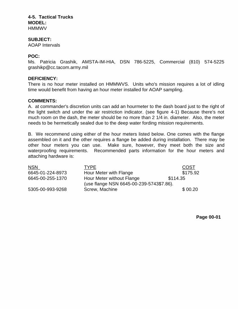
4-5. Tactical Trucks MODEL:HMMWV
SUBJECT:AOAP Intervals
POC:Ms. Patricia Grashik, AMSTA-IM-HIA, DSN 786-5225, Commercial (810) [email protected]
DEFICIENCY:There is no hour meter installed on HMMWVS. Units who's mission requires a lot of idlingtime would benefit from having an hour meter installed for AOAP sampling.
COMMENTS:A. at commander's discretion units can add an hourmeter to the dash board just to the right ofthe light switch and under the air restriction indicator. (see figure 4-1) Because there's notmuch room on the dash, the meter should be no more than 2 1/4 in. diameter. Also, the meterneeds to be hermetically sealed due to the deep water fording mission requirements.
B. We recommend using either of the hour meters listed below. One comes with the flangeassembled on it and the other requires a flange be added during installation. There may beother hour meters you can use. Make sure, however, they meet both the size andwaterproofing requirements. Recommended parts information for the hour meters andattaching hardware is:
NSN TYPE COST6645-01-224-8973 Hour Meter with Flange $175.926645-00-255-1370 Hour Meter without Flange $114.35
(use flange NSN 6645-00-239-5743$7.86).5305-00-993-9268 Screw, Machine $ 00.20
Page 00-01


4-3. Tactical Trucks
MODEL:HMMWV
SUBJECT:Army Oil Analysis Program (AOAP) Sampling
POC:Ms. Patricia Grashik, AMSTA-IM-HLA, DSN 786-7566, Commercial (810) [email protected]
COMMENTS:A. For easier access to the sampling locations, elbow, NSN 4730-00-277-5553, can be attached tothe sampling valves. Secure a piece of hose, NSN 4720-01-159-5796, to the elbow with clamp, NSN5340-00-954-6014. The elbow can remain installed on the sampling valve, but ensure you remove thehose and clamp after you obtain your sample. Dirt and debris could accumulate in the hose, if it is keptattached, contaminating your next sample.
B. This is an alternative method for sampling, if you are not experiencing a clearance problem, contine touse the sampling valves with no modification. If you prefer to use the sampling pump, NSN 4930-01-119-4030, that is also acceptable. The sampling method to use is at your commander's discretion.
PUBLICATIONS AFFECTED:None
LEVEL OF MAINTENANCE:Unit
Page 10-03

8-5. Misc. Vehicles
MODEL:All Tactical Wheeled Vehicles and Trailers
SUBJECT:Cleaning Rustproofed Vehicles
POC:Mr. Gary Mitchell, AMSTA-MTA, DSN 786-7346, Commercial (313) 574-7346
DEFICIENCY:Keeping your equipment’s clean as possible is not only a requirement in accordance with your technicalManuals, but it's also smart. Dirt, grease, oil, and other contamination can cover up serious problems. But,using the wrong methods or equipment to clean tactical vehicles can damage, loosen, or removerustproofing compounds, leaving your equipment more susceptible to corrosion damage.
COMMENTS:A. Do not use steam cleaners on equipment that has been rustproofed. Steam and hot water (over 160degrees F) softens and loosens the rustproofing compound, and pressurized steam or water may remove itcompletely, resulting in a need to re-rustproof your equipment.
B. The use of steam cleaners and high pressure/hot water washers on equipment that is NOT rustproofed isauthorized, but you still need to take certain precautions. Never direct water at electrical connectors,electronic parts, seals, or injection pumps. Doing so could lead to malfunctioning equipment.
PROCEDURE:A. A "combination" type steam/pressure cleaner can be used in the "pressure" mode as long as the watertemperature doesn't exceed 160 degrees F and the pressure doesn't exceed 500 psi (3448 kPa).
B. There are numerous suppliers of powerwash equipment, and TB43-0213 lists some of them. The TB inno way endorses one product or supplier over another. The list is provided for convenience only and is notall inclusive; it's also subject to change without notice. You should select a powerwash unit based on yourparticular requirements.
C. Cleaning with a hot water / high pressure washer and detergent is very effective and does not damagethe rustproofing, or other components, as long as you adhere to the temperature/pressure restrictions. Inaddition, this type of cleaner meets requirements of DOD 5030.49R and AR 700-93 that equipment returningfrom OCONUS be free of agricultural pests and contraband, and Air Force Reg 76-6 for cleaning vehiclesthat will be air transported..
Page 00-04

D. See TB 43-0213 for more detailed rustproofing and cleaninginformation.
8-5. Misc. Vehicles cont. PUBLICATIONS AFFECTED:NoneLEVEL OF MAINTENANCE:All
8-3. Misc . Vehicles MODEL:All TACOM Equipment with DieseLlurbine EnginesSUBJECT:Conversion from Diesel Fuel to JP8
POC:Mrs. Landis Kazsuk, AMSTA-IM-MTA, DSN 786-8288, Commercial(810) 574-8288 [email protected]
DEFICIENCY-A. JP8 has a cleansing effect, it causes microbiological growthand other fuel contaminants to break free from fuel cells and lines.As these contaminants travel through the fuel system, they plugup your fuel filters.
B. JP8 also causes a slight decrease in the engine's rated power,but will have no effect on engine durability. The slight powerdecrease is caused by JP8 having a lower energy content thandiesel fuel. The power decrease will only be apparent when thevehicle is at full load.
COMMENTS:A. JP8 is designated as the 'Single Fuel on the Battlefield" aspart of the DOD Fuel Standardization Policy. This means thateventually you will be converting to JP8 and you may experiencefuel filter plugging.
B. The conversion process will not be complete for several years;it's being phased-in by regions. We're providing this informationfor your use as you are affected.
C. Although you may initially have problems due to theconversion, the program goals are to:
(1) Provide a safer, less volatile fuel.(2) Improve cold weather starting.
Page 00-05

8-3. Misc. Vehicles cont.
(3) Reduce the number of fuels on the battlefield.(4) Increase tactical flexibility and POL logistics supportability.
D. The problems you experience are going to depend on the type of equipment youhave, how often you operate it, climatic conditions, etc. For example, microbiologicalgrowth will be more severe in fuel systems that are rarely exercised and in high humidityareas. So when you convert, initially, your filters will clog more quickly and requirereplacement more often. If on the other hand, you have a piece of equipment that you useon a daily basis and you're in a fairly dry environment, you shouldn't have too bad of aproblem.
PROCEDURES:Replace fuel filters as needed. On the average, your fuel filter plugging problem should goaway after two complete refuels.
PUBLICATIONS AFFECTED:We will update vehicle TMs to reflect JP8 as an authorized fuel.
LEVEL OF MAINTENANCE:All levels
Page 00-06

TB 43-0001-39-8 MARCH 1996
4-5. Tactical Trucks
MODEL:HMMWV M998 Series
SUBJECT:Engine and Transmission Oil Cooler and Radiator Cleaning
POC: Ms. Leona Milas, AMSTA-IM-MTA, DSN 786-7346, Commercial (810) [email protected]
COMMENTS:Using high water pressure when cleaning the engine and transmission oil cooler andradiator, can cause damage. High water pressure should not be directed on the cooler orradiator.
PUBLICATIONS AFFECTED:TM9-2320-280-20
LEVEL OF MAINTENANCE:Unit
MODEL:HMMWV
SUBJECT:Getting In and Out of the Rear of the Vehicle
POC:Ms. Jody McInerney, AMSTA-IM-MTA, DSN 786-7346, Commercial (810) [email protected]
COMMENTS:It's been brought to our attention that soldiers are using the tow pintle as a step to get inand out of the rear of the vehicle. We recommend you not use the tow pintle as a step.The tow pintle is designed to swivel 360 degrees and when stepped on can twist, causingyour foot to slip and injury to personnel. The tailgate should be lowered to ease getting inand out of the rear of the vehicle.
PUBLICATIONS AFFECTED:TM9-2320-280-10
LEVEL OF MAINTENANCE:Crew
Page 00-07

TB 43-0001-3 MARCH 19963-8. Tactical Trucks
MODEL:HMMWV
SUBJECT:Enrollment of HMMWVs in the Army Oil Analysis Program (AOAP)
POC:Ms. Patricia Grashik, AMSTA-IM-MTA, DSN 786-7713, Commercial (810) 574-7713,[email protected]
COMMENTS:A. Effective 1 Oct 95, HMMWV engines and transmissions are enrolled in the Army OilAnalysis Program (AOAP). The sampling interval for the HMMWV engine is every sixmonths. For the transmission, the sampling interval is every 12 months.
B. Use the vehicle serial number with an "E” (engine) suffix for engine serialization andthe transmission serial number located on the transmission data plate for AOAP tracking.If the transmission data plate is missing, use the vehicle serial with a “T” (transmission)suffix.
C. Because HMMWVs weren't part of AOAP, sampling valves aren't installed onvehicles with serial numbers 100,000 and above. Units may install sampling valves, NSN4820-00-845-1096, at their own cost. Valves are installed on the engine and transmissionoil cooler. (see figure 3-4)
D. On some vehicles, the power steering oil cooler line may block access to the enginesampling valve location. If access is blocked, or units don't want to install samplingvalves, Oil sampling pump, NSN 4930-01-119- 4030, and 1/4” nonmetallic tubing, NSN4720-00-964-1433 can be used to obtain samples through the dipstick filler tube.
PUBLICATIONS AFFECTED :TM9-2320-280-20-1
LEVEL OF MAINTENANCE:Unit
Page 00-08


8-4. Tactical Trucks
MODEL:All Tactical Wheeled Vehicle Engines
SUBJECT:Commercial Heavy Duty Oil Update
POC: Ms. Landis Kazsuk, AMSTA-MTA, DSN 786-7416
DEFICIENCY:The purpose of this article is to provide information pertaining to ordering and using Commercial Heavy Duty Oil (CHDO) in tactical wheeled vehicle engines.
COMMENTS:Commercial Heavy Duty Oil is authorized as an alternative to MIL- L-2104 for use in all tactical wheeled vehicle engines only.
NOTECombat (tracked) vehicle applications, all tactical (wheeled vehiclenon-engine applications, and special purpose equipment (i.e.,materiel handling, construction, construction support,trailer/tanker pony auxiliary engine) applications are not authorizedto use the Commercial Heavy Duty Oil. Users should continue touse lubricants identified in the appropriate lubrication orders for allequipment except tactical wheeled vehicle engines.
B. We encourage maintenance managers and supply personnel to order CHDOproducts over MIL-L-2104 whenever possible. CHDO costs less than MIL-L-2104 and is delivered directly from the vendor in CONUS. When you order in pallet sized quantities, you should receive your shipment in less than 15 days. Direct vendor delivery is not available for OCONUS customers. All OCONUS requirements will be filled from depot stocks.
Page 0010

8-4. Tactical Trucks
C. The following is a complete list of authorized available CHDO products:
GRADE UNIT OF ISSUE NSN PALLET LOAD FY93 PRICE15W40 BX (12 1 QT) 9150-01-351-9019 N/A $ 10.57/BX15W40 CO (5 GAL) 9150-01-352-2962 36 CO $ 17.60/CO15W40 DR (55 GAL) 9150-01-351-9018 4 DR $ 165.59/DR3OW BX (12 1 QT) 9150-01-351-9016 80 BX $ 10.53/BX3OW CO (5 GAL) 9150-01-352-8090 36 CO $ 17.55/CO3OW DR (55 GAL) 9150-01-351-9015 4 DR $ 168.82/DR4OW DR (55 GAL) 9150-01-352-8091 4 DR $ 172.86/DR
D. REMINDER: Only use Commercial Heavy Duty Oil in tactical wheeled vehicle engines.
PUBLICATIONS AFFECTED:All tactical wheeled vehicle lubrication orders will be updated to include both CommercialHeavy Duty Oil and MIL-L-2104 oil during their next scheduled change/revision.
LEVEL OF MAINTENANCE:Operator and Unit
Page 00-11

3-27. Tactical Trucks MODEL:HMMWV, M998 Series
SUBJECT:Fabricate Engine/Transmission Support Sling.
POC:Mr. Daniel Dudek, AMSTA-MTA, DSN 786-7416
DEFICIENCY:When the engine or transmission is removed from the vehicle formaintenance, the remaining component, (engine or transmission) is notadequately supported. If a vehicle is moved because of limited shopspace or tactical movement, damage to the remaining component and thevehicle can occur.
COMMENTS:A. Two suggestions submitted through the Army Ideas for ExcellenceProgram (AIEP) were recently adopted resulting in the followinginstruction. Both suggestions recommended support devices for theengine and transmission while one or the other component is removedfrom the vehicle for maintenance. The first device supports thecomponents from underneath by hanging between the frame rails. Thesecond device supports the components from above braced between thedash panel and the vehicle tunnel. Either device used independently willsafely support the engine or transmission during maintenance. Individualpreference and work area will determine which device best suits yourneeds.
B. Direct Support or General Support maintenance personnel canfabricate either of the support devices. Fabrication and installation canbe accomplished using the following material, parts, and procedures.
MATERIALS:Parts and Materials to be Requisitioned for Bottom Support Sling:
Page 00-12

3-27. Tactical Trucks
NSN NOMENCLATURE QTY9540-00-197-9865 Channel, aluminum 6 ft5305-00-269-2804 Bolt 65310-00-655-9544 Nut 109510-00-813-5322 Bar, metal 5 ft5310-01-280-5796 Washer 16
Parts to be Fabricated from Materials Requisitioned for Bottom Support Sling:
NOMENCLATURE QTY
Support hook 2Bottom support sling 1Brace 2
Parts and Materials to be Requisitioned for Overhead Support Sling:
NSN NOMENCLATURE QTY
9520-00-061-6507 Angle, structural 1 ft4010-00-174-4879 Chain, welded link 4 ft5306-00-225-9091 Bolt 69520-00-277-4925 Angle, structural 3 ft9520-00-294-0986 Bar, metal 2 ft5306-00-402-2674 Eyebolt, R.H. 15306-00-411-6457 Eyebolt, L.H. 15310-00-660-3381 Nut 65340-00-995-6335 Turnbuckle 15310-01-358-0596 Washer 12
Parts to be Fabricated from Materials Requisitioned for Overhead Support Sling:
NOMENCLATURE QTY
Engine bracket 2Transmission bracket, L.H. 1
00-13

3-27. Tactical Trucks
NOMENCLATURE QTY
Transmission bracket, R.H. 1A-frame brace 1Center support beam 1Inner floor support 1Outer floor support 1Engine support chain 1Transmission support chain 1
PROCEDURE:Bottom Support Sling:
A. Fabrication.
(1) Using NSN 9510-00-813-5322 metal bar, fabricate two support hooks. (see figure 3-58)(2) Using NSN 9540-00-197-9865 aluminum channel, fabricate two braces. (see figure 3-59)(3) Using NSN 9540-00-197-9865 aluminum channel, fabricate support. (see figure 3-60)
B. Assembly.
(1) Position two braces (1) on support (7) and secure with six NSN 5305-00-269-2804 bolts (3),twelve NSN 5310-01-280-5796 washers (2), and six NSN 5310-00-655-9544 nuts (8).(see figure 3-61)
(2) Install two support hooks (4) on support (7) and secure with four NSN 5310-01-280-5796washers (5) and four NSN 5310-00-655-9544 nuts (6).
C. Bottom Support Sling Installation.
NOTE
Bottom support sling must be installed prior to engine or transmission removal.When performing step 1, ensure support hooks are positioned flat on frame rail toprevent damage to oil and vent lines.When performing step 1, ensure nuts on support books are adjusted evenly tokeep from bending engine or transmission oil pan.
Page 00-14


8-8. Misc. Vehicles
MODEL:All TACOM Managed Vehicles
SUBJECT:Color Highlighting of Fluid Level Gage Rods (Dipsticks)
POC:Mr. Daniel Dudek, AMSTA-MTA, DSN 786-7416, Commercial (810) 574-7416
DEFICIENCY:Dipstick handles painted to match engines sometime make it difficult to locate them. Painting thedipsticks handles yellow makes them easier to locate and lessens the chance of them being missedduring routine PMCS.
COMMENTS:An adopted suggestion has resulted in the following instruction for painting dipstick handlessimilar to what's being done in the commercial automotive industry. Implementation of thefollowing is left to the discretion of the local commander.
PROCEDURES:
Cover dipstick openings while dipstick is being cleaned andpainted to prevent dirt or debris from entering fluid reservoirand causing damage to equipment.
NOTE
The following are generic procedures for painting dipstickhandles. Minor variations may be required to accommodateyour specific situation.
A. Remove dipstick from dipstick tube and cover opening.
B. Using soap and water clean all grease, oil, and dirt from dipstick and handle. Dry the dipstickassembly using compressed air. Ensure dipstick and handle are clean and dry before proceeding to
next step.
C. Using clean rags or adhesive tape, cover the gage portion and any seals used on the gageportion of the dipstick.
Page 00-32
WARNING

8-8 Misc. Vehicles cont.D. Using NSN 8010-00-721-9744, paint the handle end of the dipstick following theinstructions from the paint can label, allowing the paint sufficient time to dry beforereinstalling the dipstick.
E. Repeat the above for each fluid reservoir dipstick for the vehicle.
PUBLICATIONS AFFECTED:TB 43-0209 31 Oct 90
LEVEL OF MAINTENANCE:Crew/Unit
8-2. MiscellaneousSUBJECT:Feasibility study for improving MIL-A-46153 antifreeze
POC:Mr. Gary Mitchell, AMSTA-IM-MTA, DSN 786-6950, Commercial (810) [email protected]
DEFICIENCY:The present MIL-A-46153 antifreeze formulation contains no "aluminum specific” anti-corrosion inhibitors. When the MIL-A-46153 formulation was developed in the 1950's,heavy-duty engines were constructed of cast iron, with brass/copper radiators. Today,heavy-duty engine manufacturers are using aluminum alloys to reduce engine weightand increase overall efficiency. Aluminum alloys can be found in radiators, cylinderheads, water pump housings, manifolds, and engine blocks.
COMMENTS:A. The Fuels & Lubricants Division of TACOM RD&E Center evaluated theperformance of MIL-A-46153 and found it to be satisfactory. However, they felt that itcould be improved to provide better corrosion protection for aluminum components.They initiated a study, which involved developing and testing 14 different antifreezeformulations. Of the 14 experimental formulations, 3 showed a significant improvementover the current MIL-A-46153 formulation. However, because of funding constraintsand loss of technology base resources, this effort could not be completed.
Page 00-33

8-2. Miscellaneous cont.
B. In FY93, the Defense General Supply Center (DGSC) initiated a parallel effort to develop a lesstoxic alternative antifreeze. Current MIL-A-46153 antifreeze uses ethylene glycol (EG) as its basematerial and has a relatively high toxicity. Propylene glycol (PG) was chosen as a less toxic basematerial. Because of PG's similar chemical characteristics compared to EG, the research anddevelopment accomplished during the program to improve MIL-A-46153 will be directly applied to thePG antifreeze effort.
CONCLUSIONS: Even though the effort to improve MIL-A-46153 antifreeze aluminum corrosioninhibitor characteristics has ended, the technology that was developed will be transitioned directly tothe less toxic PG antifreeze development. No target date has been established when a new MIL-Spec "aluminum specific," less toxic antifreeze will be released for tactical and combat vehicle use.We will keep you informed of the progress.
PUBLICATIONS AFFECTED:None
LEVEL OF MAINTENANCE:All
8-4. Misc. Vehicles
MODEL:All tactical vehicles
SUBJECT:Low Sulfur Diesel and JP-8 Fuels
POC:Mr. Steve Weisenhaus, AMSTA-IM-MTA, DSN 786-6950, Commercial (810) [email protected]:The following is provided for field information only:
1. Low Sulfur Diesel Fuel (LSDF) was mandated nationwide in October 1993 for all on-highwayvehicles. This is part of the Clean Air Acts Amendment (CAAA) and is enforced by theEnvironmental Protection Agency (EPA). LSDF contains less than 0.05% sulfur by weight and meetsother environmental requirements (such as reduced aromatic content) for highway use. Soon afterthe mandate, there were reports of fuel-related problems such as leaking 0-rings in fuel systemcomponents and premature wear of rotary-type fuel lubricated fuel injector pumps.
2. Army vehicles are especially vulnerable to this problem for the following reasons:
Page 00-34

a. Severe operational requirements are placed on Army vehicles, such as long periods of non-usefollowed by short periods of intense use and operation in hostile areas, including extremes intemperature, humidity, dust, and terrain.
b. The military stores fuel for long periods, especially in vehicle fuel tanks. This allows a wintergrade fuel purchased in the late fall to be used during the spring and summer, and vice-versa.Winter grade fuels have a lower density and viscosity than regular grade diesel fuel. The wintergrade fuels are also more volatile so that they can be used in extremely low temperatures.Moreover, the long storage can promote fuel deterioration due to auto-oxidation and possiblemicrobiological growth.
C. The Army has a high density of diesel engines with fuel-wetted components that are wearsensitive such as the Stanadyne rotary injection fuel pump. The reduced lubricity of LSDF canlead to increased wear on these components.
8-4. Misc. Vehs. cont.
3. The changes in fuel refining, fuel processing, and distribution required to meet the new CAAArequirements also raise the question of how other fuel properties might be affected. Fuel propertiesinclude cloud point, freeze point, pour point, stability, and cleanliness. All diesel fuel purchased bythe Defense Fuel Supply Center (DFSC) as motor vehicle fuel for military use is purchased underthe Post-Camp-Station (PCS) procurement system. The fuel is purchased against VV-F-800D,however, this specification does not currently include all of the changes in fuel quality resulting fromthe mandate to LSDF. The Army is revising VV-F-800D to include these changes.
4. The Army selected diesel fuel samples from thirty-eight fuel delivery trucks at selected militaryinstallations. Each sample was tested for lubricity and other properties. By analyzing fuel sampleswe can better judge the need for changes to VV-F-800D and the need for interim fixes to any fuel-related problems. Fuel samples will continue to be measured for lubricity. If lubricity continues to bea problem, we will look into using additives to those fuels having low lubricity.
NOTE
If you are having any fuel-related problems, report them to theBelvoir Mobility Tech Center at DSN 654-1819/1817 or Commercial(703) 704-1817.
5. The Army has adopted a strategy to use a single fuel for the battlefield, i.e., one fuel that can beused for both aircraft and ground vehicles/equipment. Under the single fuel concept, the Army hasbeen using JP-8 at selected locations. When the CAAA went into effect, the Army had to limit itsuse of JP-8 to those locations where refiners would "guarantee" supplying a low-sulfur
Page 00-35

JP-8; i.e., less than 0.05 sulfur, as the JP-8 specification allows up to 0.30% sulfur. The Armysubsequently conducted tests on JP-8 because they believed it would produce lower diesel exhaustemissions than expected. The results showed that JP-8 has essentially the same emissions as theLSDF that meets CAAA requirements. Based upon these results DOD has formally requested thatthe EPA grant an exception for using JP-8 on an unrestricted basis. Hopefully, this will open thedoor for Army use of JP-8 as a universal ground fuel.
PUBLICATIONS AFFECTED:All -10 and -20 level publications
LEVEL OF MAINTENANCE:All
8-3. Misc. Vehicles
MODEL:All TACOM-Managed Diesel Engine Powered Ground Vehicles and Equipment
SUBJECT:Lubricating Oil Update
POC:Mr. Steve Weisenhaus, AMSTA-IM-MTA, DSN 786-6950, Commercial (810) [email protected]
COMMENTS:The following is provided for field information only:
A. MILITARY SPECIFICATION (MIL-L-2104) OILS:
1. The military specification governing lubricating oils is MIL-L-2104, Lubricating Oil, InternalCombustion Engine, Combat/Tactical Service. The specification covers viscosity grades 10, 30,40 and multi-viscosity 15W40 weight oils. In Apr 83, MIL-L-2104 was revised. In the revision,50 weight oil was deleted and multi-viscosity 15W40 was added. OE/HDO-15/40 is the militarysymbol for the SAE 15W40 Grade under MIL-L-2104.15W40 is packaged in either a 1 quart, 5gallon, or 55 gallon container, each with a different NSN.
Page 00-36

8-3. Misc. Vehs. cont.
2. These oils (MIL-L-2104) can be used in internal combustion engines, power steering units,hydraulic systems, transmissions, and gearbox units. However, you should check theapplicable vehicle/equipment lubrication order if you are unsure about proper grade or typeof lubrication.
3. With certain exceptions, which are detailed in paragraph 5, 15W40 oils can be used in placeof 10, 30 and 40 weight oils where ambient temperatures are expected to exceed 5 degreesFahrenheit (- 15 degrees Celsius). When used, 15W40 oils must not be mixed with singlegrade lubricating oils. This ensures the lubrication and protective properties will not bediluted. Complete oil change is required when converting to 15W40 oil. Arctic grade oil(OEA) is still required in areas where expected ambient temperature is lower than 5 degreesFahrenheit.
4. Straight weight oils such as 10, 30, and 40 weight oils are still valid for individualapplications and may be used where appropriate. Changing from straight weight oils to15W40 is not required, however, under certain climatic conditions use of 15W40 may reduceor eliminate the need for seasonal oil changes.
5. Multiviscosity 15W40 oil should not be used in the following vehicle components orsituations:
a. Abrams Tank - X1100 Transmissionb. JD 410 Loader Backhoe Transmissionc. Equipment covered by a manufacturer's warranty specifying other lubricating oils.d. Hydraulic systems requiring use of MIL-H-6083 or MIL-H-46170 Hydraulic Fluids.e. The M88 Improved Recovery Vehicle (IRV) transmission.
6. Since straight weight oils should not be mixed with multi-viscosity oils, we recommend thatthose vehicle components with multi-grade oil be identified. The following are suggestedmethods for identifying vehicles using multi-viscosity oils:
a. Use red wire tag, NSN 8135-00-952-0672, and mark the tag with a statement such as"use 15W40 oil only" and secure the tag in the oil dipstick.
b. Use the Equipment Identification Card, record a statement such as "use 15W40 oilonly" between the NSN AOAP sample lines.
c. Use DD Form 1970 Motor Equipment Utilization, and record in the oil block astatement such as "use 15W40 oil only."
Page 00-37

8-3. Misc. Vehs. cont. d. In the remarks block of DD Form 314, Preventive Maintenance Schedule, record a statement such as "Change oil with 15W40."
e. In the remarks block of DA Form 2408-20, oil analysis log, record astatement such as "oil changed with 15W40."
B. COMMERCIAL HEAVY DUTY OIL (CHDO):
1. CHDO is authorized as an alternative to MIL-L-2104 for use in alltactical wheeled vehicle engines only. Combat (tracked) vehicleapplications, all tactical (wheeled) vehicle non-engine applications,and special purpose equipment (such as material handling,construction, construction support, trailer/tanker pony auxiliaryengine) applications are not authorized to use the CHDO. Usersshould continue to use lubricants identified in the appropriatelubrication orders for all equipment, except for the use of CHDO intactical wheeled vehicle engines.
2. We encourage maintenance managers and supply personnel toorder CHDO products over MIL-L-2104 whenever possible. CHDOcosts less than MIL-L-2104 and is delivered directly from thevendor in CONUS. When you order in pallet sized quantities, youshould receive your shipment in less than 15 days. Direct vendordelivery is not available for OCONUS customers. All OCONUSrequirements will be filled from depot stocks.
3. The following is a complete list of authorized available CHDOproducts:
GRADE UNIT OF ISSUE NSN PALLET LOAD15W40 BX (12 1 QT) 9150-01-351-9019 Not Available15W40 CO (5 GAL) 9150-01-352-2962 36 CO15W40 DR (55 GAL) 9150-01-351-9018 4 DR3OW BX (12 1 QT) 9150-01-351-9016 80 BX3OW CO (5 GAL) 9150-01-352-8090 36 CO3OW DR (55 GAL) 9150-01-351-9015 4 DR4OW DR (55 GAL) 9150-01-352-8091 4 DR
PUBLICATIONS AFFECTED:All tactical vehicle lubrication orders will be updated to include both CHDOand MIL-L-2104 oil during their next scheduled change/revision.
LEVEL OF MAINTENANCE :Operator and Unit
Page 00-38

8-2. Tactical Trucks MODEL:HMMWV M998A2 Series
SUBJECT:TM Update
POC:Ms. Patricia Grashik, AMSTA-IM-HLA, DSN 786-5225,Commercial (810) [email protected]
COMMENTS:The M998A2 series vehicles will be fielded soon. To keep pacewith vehicle changes, updated TMs will be issued to the field units.The revised manuals include all approved DA Form 2028-2recommended changes from field units, PS Magazine articles, EIRDigest articles, and vehicle enhancements. Vehicleenhancements resulting in changes to the TMs are: 6.5L engine,4L80E (electronic transmission), muffler and catalytic converter,serpentine drive belt, dual voltage regulator, self-canceling turnsignal*, 9,000 lb winch*, wheel and tire assembly (new runflat),front bumper, and related parts not listed in this TB. We changedthe format of TM9-2320-280-34. Direct Support procedures aregrouped together in the beginning of the TM with General Supporttasks following. Before using revised manuals, review your tableof contents for new location of tasks, and ensure the applicablemodel and/or part number matches your vehicle. The following listis a description of changes, TMs affected, and the referenced EIRDigest or PS Magazine issues where the changes or updates wereinitially published.
*SEE FCG 3307 for HMMWV basic, heavy, and A1 upgrade kits.
Page 00-39

TB 43-0001-39-3 DECEMBER 1996
8-2. Tact. Trucks cont .
FUNCTIONAL DESCRIPTION TM AFFECTED OTHERGROUP CODE OF CHANGE _____________ PUBLICATIONS
Bll First-Aid Kit Relocated 9-2320-280-10,Para. 2-2
AAL Padlock Set Added 9-2320-280-10,Appendix C
AAL Fire Extinguisher Bracket Deleted 9-2320-280-10,Appendix C
0100 Engine Mount Starter Bracket 9-2320-280-34,Para. 3-3
0100/0710 Engine/Transmission Support Sling 9-2320-280-34, TB 43-0001-39-6,Fabrication Paras. 3-22, 3-24, Sep 93
Appendix C
0106 CDR Caution 9-2320-280-20-1,Table 2-1 (PMCS)
0106 Optional Oil Pan Gasket and Washers 9-2320-280-20-2, TB 43-0001-39-7,Para. 3-6; Dec 939-2815-237-34,Para. 2-14
0302 Fuel Injection Bleeding 9-2320-280-34,Para. 4-4
0302 Kick-Down Switch Replacement Moved 9-2320-280-20-2,from Chapter 5 Para. 4-43
0302 Wire Numbers 569B/569D Added 9-2320-280-20-1,Para. 2-22
0303 200-Amp Alternator Note for 9-2320-280-20-2, TB 43-0001-39-6,Radiator Inlet Hose Paras. 3-61, 3-69 Sep 93
Page 00-40

TB 43-0001-39-3 DECEMBER 1996
B-2. Tact. Trucks cont.
FUNCTIONAL DESCRIPTION TM AFFECTED OTHERGROUPCODE OFCHANGE ______________ PUBLICATIONS
0304 Air Filter Cleaning 9-2320-280-20-2,Para. 3-13
0311 Glow Plug Foldout 9-2320-280-20-3,Appendix F
0311 Glow Plug Warnings Changed 9-2320-280-10,Para. 2-10
0401 Exhaust System PMCS Check 9-2320-280-10,Table 2-2 (PMCS)
0501 Surge Tank Replacement 9-2320-280-20-2,Paras. 3-64, 3-73
0505 Fan Clutch Dust Seal 9-2815-237-34, TB 43-0001-39-6,Para. 2-40 Sep 93
0505 Sleeves Repair for 6.2L Block 9-2815-237-34, TB 43-0001-39-8,Para. 2-16 Mar 94
0605 Fan Clutch Compressed Air Note 9-2320-280-20-1,Para. 2-25;9-2320-280-20-2, TB 43-0001-39-2,Para. 3-78 Sep 94
0506 Fan Drive Friction Lining 9-2320-280-20-2, TB 43-0001-39-7,Replacement Par&. 3-79 Dec 93
0601 Drive Belt Flutter 9-2320-280-10,Table 2-2 (PMCS)
0603 Starter Repair Torque 9-2320-280-34,Para. 6-6
Page 00-41

TB 43-0001-39-3 DECEMBER 1996
8-2. Tact. Trucks cont.
FUNCTIONAL DESCRIPTION TM AFFECTED OTHERGROUP CODE OF CHANGE _____________ PUBLICATIONS
0607 Brake Warning Lamp Stays ON 9-2320-280-20-1, TB 43-0001-39-1,Troubleshooting Para. 2-32 May 94
0607 Fuel Gauge Troubleshooting 9-2320-280-20-1,Para. 2-32
0607 Instrument Test 9-2320-280-20-1,Para. 2-32
0608 Directional Signal Switch Cleaning 9-2320-280-20-2, PS Magazine,Para. 4-64 Dec 93
0608 Fabricate Power-On Test Module for 9-2320-280-20-1,Troubleshooting Para. 2-28;
9-2320-280-20-3, TB 43-0001-39-5,Appendix D Jun 93
0608 PCB Wiring Diagram 9-2320-280-20-3,Appendix F
0608 Time Delay Module Troubleshooting 9-2320-280-20-1, PS Magazine,Note Para. 2-25 Jul 93
0608 Add Sealing Compound to 9-2320-280-20-2,Stoplight Switch Para. 4-60
0612 Slave Receptacle Cable Caution 9-2320-280-10,Para. 2-23
0613 Battery Test Troubleshooting 9-2320-280-20-1,Para. 2-30
0613 Drain Holes Drilled in Battery Tray 9-2320-280-20-2, TB 43-0001-39-6,Para. 4-80 Sep 93
Page 00-42

TB 43-0001-39-3 DECEMBER 1996
8-2. Tact. Trucks cont.
FUNCTIONAL DESCRIPTION TM AFFECTED OTHERGROUP CODE OF CHANGE ______________ PUBLICATIONS
0705 Neutral Start Switch Torque 9-2320-280-20-2,Para. 6-6
0705 Transmission Modulator Assembly 9-2320-280-20-2, TB 43-0001-39-2,Moved to Unit Level Paras. 5-14, 5-15 Sep 94
0706 Transmission Service Torque 9-2320-280-20-2,Para. 5-2
0713 Transmission Repair 9-2320-280-34,Para. 17-10
0713 Transmission Road Test Moved 9-2320-280-20-2, TB 43-0001-39-2,to Unit Level Para. 5-21 Sep 94
0801 Transfer Case Yokes Moved 9-2320-280-20-2, TB 43-0001-39-4,to Unit Level Para. 5-26 Mar 93
0801 Transfer Case Caution 9-2320-280-20-1,Table 2-1 (PMCS)
0801 Transfer Case Oil Capacity 9-2320-280-10,Table 1-2;9-2320-280-20-1,Table 1-2
0900 Front Propeller Shaft U-Bolt and 9-2320-280-20-1,Adapter Tool (M1O97, A1 and A2 Models) Table 2-1 (PMCS);
9-2320-280-20-2, TB 43-0001-39-3,Para. 6-2; Dec 949-2320-280-20-3,Appendix E
1002/1102 Differential Axle Free Play 9-2320-280-34, TB 43-0001-39-5,Para. 9-11 Apr 91
Page 00-43
TB 43-0001-39-3 DECEMBER 1996
8-2. Tact. Trucks cont .
FUNCTIONAL DESCRIPTION TM AFFECTED OTHERGROUP CODE OF CHANGE ______________ PUBLICATIONS
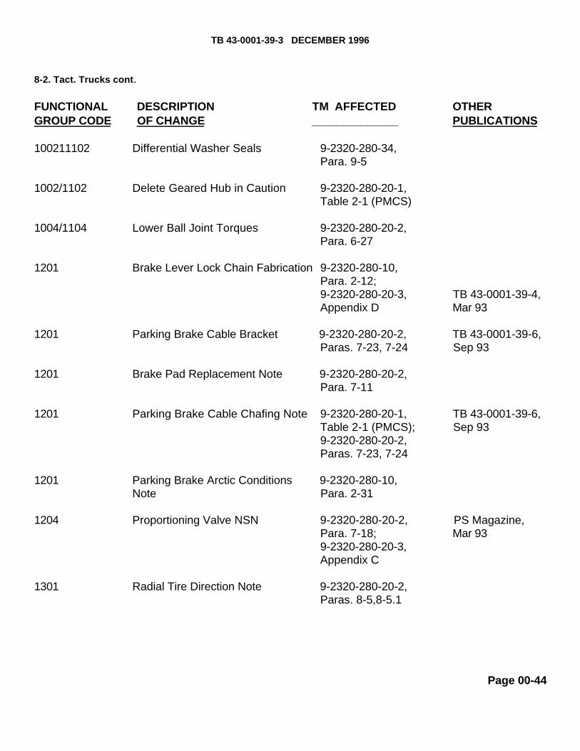
100211102 Differential Washer Seals 9-2320-280-34,Para. 9-5
1002/1102 Delete Geared Hub in Caution 9-2320-280-20-1,Table 2-1 (PMCS)
1004/1104 Lower Ball Joint Torques 9-2320-280-20-2,Para. 6-27
1201 Brake Lever Lock Chain Fabrication 9-2320-280-10,Para. 2-12;9-2320-280-20-3, TB 43-0001-39-4,Appendix D Mar 93
1201 Parking Brake Cable Bracket 9-2320-280-20-2, TB 43-0001-39-6,Paras. 7-23, 7-24 Sep 93
1201 Brake Pad Replacement Note 9-2320-280-20-2,Para. 7-11
1201 Parking Brake Cable Chafing Note 9-2320-280-20-1, TB 43-0001-39-6,Table 2-1 (PMCS); Sep 939-2320-280-20-2,Paras. 7-23, 7-24
1201 Parking Brake Arctic Conditions 9-2320-280-10,Note Para. 2-31
1204 Proportioning Valve NSN 9-2320-280-20-2, PS Magazine,Para. 7-18; Mar 939-2320-280-20-3,Appendix C
1301 Radial Tire Direction Note 9-2320-280-20-2,Paras. 8-5,8-5.1
Page 00-44

TB 43-0001-39-3 DECEMBER 1996
8-2. Tact. Trucks cont .
FUNCTIONAL DESCRIPTION TM AFFECTED OTHERGROUP CODE OF CHANGE _____________ PUBLICATIONS
1311 Wheel and Tire Replacement 9-2320-280-20-3,MAC Chart
1311 Wheel Stud Replacement 9-2320-280-20-2,Para. 8-8
1311 Wheels and Tire Spacer Note 9-2320-280-20-2,Para. 8-5
1311 Tire Flat Spot and Warm Tire 9-2320-280-20-1,Troubleshooting Notes Para. 2-37
1401 Steering Column Rigidity Brackets 9-2320-280-20-2, TB 43-0001-39-1,Para. 8-19 May 94
1401 Steering Shaft U-Joint Repair 9-2320-280-20-2, TB 43-0001-39-8,Para. 8-22 Mar 94
1401 Toe-In Adjustment Notes 9-2320-280-20-2,Para. 8-10
1401 Tie Rod Clamp Rotated 90' in Art 9-2320-280-20-2,Para. 8-10
1801 Bulkhead Door Retainer Fabrication 9-2320-280-20-3, TB 43-0001-39-2,Para.11-155, Sep 94Appendix D
1801 Splash Shield Access Cover 9-2320-280-20-3, TB 43-0001-39-5,Replacement Para. 10-18, Jun 93
Appendix D
1808 Water Can Art Reversed 9-2320-280-20-3, TB 43-0001-39-3,Para. 11-108 Dec 94
Page 00-45

TB 43-0001-39-3 DECEMBER 1996
B-2. Tact. Trucks cont .
FUNCTIONAL DESCRIPTION TM AFFECTED OTHERGROUP CODE OF CHANGE _____________ PUBLICATIONS
1810 Tailgate Chain Cover and 9-2320-280-20-1,Reinforcement Bracket Table 2-1 (PMCS);
9-2320-280-20-3,Para. 10-60
1810 Tailgate Lowering Note 9-2320-280-10,Para. 2-21
1812 Cargo Door Gas Springs 9-2320-280-20-3, TB 43-0001-39-3,Rotation Para. 11-21 Dec 94
1812 Turret Bearing and 9-2320-280-20-3,Armament Seals Paras. 11-51,11-61 TB 43-0001-39-7,
Dec 93
1812 Turret Handle Replacement 9-2320-280-20-3, TB 43-0001-39-7,Para. 11-55, Dec93Appendix D
1812 Weapon Station Turret Adjustment, 9-2320-280-20-3, TB 43-0001-39-7,Cleaning, and Seal Replacement Para. 11-113 Dec 93
2001 Winch Thimble Fabrication 9-2320-280-20-3,Para. 10-110;9-2320-280-34, PS Magazine,Appendix C Jul 93
2201 C-Pillar Reinforcement Bracket 9-2320-280-20-3, TB 43-0001-39-3,Para. 10-105, Dec 93Appendix D
2201 Soft Door Window and Leak Repair 9-2320-280-20-3, TB 43-0001-39-7,Para. 10-104 Dec 93
2201 Soft Top Zippers PMCS Check 9-2320-280-10,Table 2-2 (PMCS)
Page 00-46

TB 43-0001-39-3 DECEMBER 19968-2. Tact. Trucks cont.
FUNCTIONAL DESCRIPTION TM AFFECTED OTHERGROUPCODE OFCHANGE PUBLICATIONS
2202 Direction Note for Windshield 9-2320-280-20-3, TB 43-0001-39-6,Washer Hose Clamp Added Para. 10-76 Sep 93
2202 Ambulance Body Repair 9-2320-280-34, TB 43-0001-39-1,Para. 22-8, May 94Appendix C
2202 Mirror Blind Hole Puller Set Note 9-2320-280-20-3,Appendix B
2202 Spreader Bar Replacement 9-2320-280-20-3,Para. 11-215
2202 Wiper Arm Spring Replacement 9-2320-280-20-3, TB 43-0001-39-5,Para. 10-70 Sep 93
2202 Wiper Pivot Arm Temporary Repair 9-2320-280-20-3, TB 43-0001-39-5,Para. 10-74 Jun 93
2604 Tool Kits Added 9-2320-280-20-3,MAC Chart
3307 Mud Flap Installation 9-2320-280-20-3, TB 43-0001-39-4,Para. 10-63, Mar 93Appendix D
3307 Fan Drive Hose Quick-Disconnect 9-2320-280-20-2, TB 43-0001-39-2,ReplacementPara. 3-68; Dec 949-2320-280-20-3,Appendix D
Page 00-47

TB 43-0001-39-3 DECEMBER 1996
8-2. Tact. Trucks cont.
FUNCTIONAL DESCRIPTION TM AFFECTED OTHERGROUP CODE OF CHANGE PUBLICATIONS
3307 9,000 lb Winch Kit, 9-2320-280-20-3,57K3217, 2590-01-418-2135 Paras. 10-108,(AVY, A11, A13, A14, A15, A20, A24, A25, 10-112A26, A27, B 16, B 17, B18, HVY, H11, H13,H14, H15, H16, H17, H18, H20,H21, H24,H25, H26, H27, H28)
3307 100-Amp Niehoff Alternator Testing 9-2320-280-34, TB 43-0001-39-6,and Repair Para. 16-15 Sep 93
3307 Cargo Barrier and Net Kit, 9-2320-280-20-3,57KO293, 2510-01-K64-6462 Paras. 11-110,(H17, H18, B17, B18) 11-111
3307 60/100-Amp Alternator Bracket Kit, 9-2320-280-20-2,57KO294, 2590-01-423-1975 Para. 4-2;(A11, A13, A14, A20, A24, A25, A26, A27, 9-2320-280-20-3,B16, B17, B18, H11, H13, H14, H16, H17, Paras. 12-23, 12-24;H18, H20, H21, H24, H25, H26, H27, H28) 9-2320-280-34,
Para. 3-26
3307 200-Amp Alternator Bracket Kit, 9-2320-280-20-2,57KO295 (A15, AVY, H15, HVY) Para.4-110;
9-2320-280-34,Paras. 3-22, 3-23
3307 Rearview Mirror Kit (LH Lowered), 9-2320-280-20-3,57K3214, 2540-01-424-7363 Para. 10-82(AVY, A11, A13, A14, A15, A20, A24, A25,A26, A27, B16,B17, B18, HVY, H11, H13,H14, H15,H16,H17, H18, H20, H2l, H24,H25, H26,H27, H28)
Page 00-48

TB 43-0001-39-3 DECEMBER 1996
8-2. Tact. Trucks cont.
FUNCTIONAL DESCRIPTION TM AFFECTED OTHERGROUP CODE OF CHANGE _____________ PUBLICATIONS
3307 Rifle Mounting Kit, 9-2320-280-20-3,57KO234, 2590-01-380-8283 Para. 11-91(H VY, H11, H13, H14, H15, H16, H17,H18, H20, H21,H24,H25, H26, H27, H28)
3307 Steering Column Kit, 9-2320-280-20-2,57K3216, 2530-01-380-9584 Para. 8-19(HVY, H11, H13,H14, H 15, H 16, H 17,H18, H20, H21, H24, H25, H26, H27,H28)
3307 Sun Visor Kit, 9-2320-280-20-3,57K3209, 2540-01-431-9182 Para. 10-77(AVY, A11, A 13, A 14, A15, A20,. A24, A25,A26, A27, B16, B17, B18, HVY, H11, H13,H14, H15, Hl6, H17, H18, H20, H21, H24,H25, H26, H27, H28)
3307 Windshield Retention Kit, 9-2320-280-20-3,67K3206, 2540-01-431-1339 Para. 10-24(HVY, H11, H13, H14, H15, H16, H17,H18, H20, H21, H24, H25, H26, H27, H28)
3307 Tailgate Upper Hinge Replacement Kit, 9-2320-280-20-3,57KO107, 2510-01-364-3120 Para. 10-62(HVY, H11, H13, H14, H17, H18, H20,H21, H24, H25, H26, H27, H28)
3307 Turn Signal Kit, 9-2320-280-24P57K3222, 2540-01-431-1338(AVY, A11, A13, A14, A15, A20, A24, A25,A26, A27, B16, B17, B18, HVY, H11, H13,H14, H15, H16, H17, H18, H20, H21, H24,H25, H26, H27, H28)
Page 00-49

TB 43-0001-39-3 DECEMBER 1996
8-2. Tact. Trucks cont.
FUNCTIONAI, DESCRIPTION TM AFFECTED OTHERGROUP CODE OF CHANGE ______________ PUBLICATIONS
3307 Wheel Spacer Kit, 9-2320-280-24P57K3215(AVY, A11, A13, A14, A15, A20, A24, A25,A26, A27, B16, B17, B18, HVY, H11, H13,H14, H15, H16, H17, H18, H20, H21, H24H25, H26, H27, H28)
3307 Rear Seat Kit, 9-2320-280-24P57K3196, 2510-01-410-7035571K3197, 2510-01-410-7034(AVY, A11, A13, A14, A15, A20, A24, A25,A26, A27, B16, B17, B18, HVY, H11, H13,H14, H15, H16, H17, H18, H20,1121, H24,1125, H26, H27, H28)
4701 Speedometer Cable 9-2320-280-20-2, and Core Replacement Para. 4-15.1
4702 Air Restriction Gauge Note 9-2320-280-10,Table 2-2 (PMCS)
5203 A/C PMCS Checks Movedfrom Unit to Operator's Level 9-2320-280-10,
Table 2-2 (PMCS)
PUBLICATIONS AFFECTED:N/A
LEVEL OF MAINTENANCE:N/A
Page 00-50

8-2. Miscellaneous SUBJECT:Widely used forms
POC:Ms. Jody McInerney, AMSTA-IM-MTA, DSN 786-7346, Commercial(810) [email protected]
COMMENTS:Hey folks, in this edition to the TB, we've included a couple samplesof some widely used forms (SF 368, Quality Deficiency Reports(QDRS) (see page 8-2) and DA Form 1045, Army Ideas ofExcellence Program (AIEP) Proposal) (see page 8-3). These are theforms you use to supply us with the information and ideas we needto improve and better support our vehicles.
Two things to remember when filling out these forms:
1. A properly completed form will help us better understandyour problem and be able to evaluate it quicker.
2. The more information you provide, the better.
Please keep your ideas and comments coming!
Page 00-51


Chapter 01
ENGINE
FunctionalGroup Code
0100-0106

3-9. Tactical Trucks
MODEL:CUCV/HMMWV
SUBJECT:Use of Cylinder Sleeves on 6.2L Engines
POC:Mr. Eric Sutman, AMSTA-MTA, DSN 786-7151, Commercial (313) 574-7151
DEFICIENCY:You must replace the 6.2L engine cylinder block if it has a cylinder that you must oversize more than.030".
COMMENTS:We've adopted a suggestion to use cylinder sleeves to repair the engine. If a cylinder is pitted orworn such that you can't hone it and use a high limit or oversized piston to repair it, you can use acylinder sleeve to repair the engine block. If you don't have the tools necessary to install the sleeve,you can have the sleeve installed at a local engine repair shop. Whether you install the sleeveyourself or have it installed at a local repair shop, the procedures below must be followed. Thesleeve can't be used to repair a cracked block.
MATERIAL/PARTS:Ertel Manufacturing Corp. Cylinder Sleeve P/N SL1152 (92947) or comparable cylinder sleeveSealing Compound, NSN 8030-01-268-5917
PROCEDURE:
1. Identify cylinders that require sleeves. Cylinders that still show damage or wear after being honedto a maximum oversize of .030" will require sleeves.
2. Use a micrometer to measure the outside diameter of the cylinder sleeve.
3. Bore the cylinder to the diameter of the sleeve less .002" to .003", to create an interference fitbetween the sleeve and the cylinder wall.
4. Bore the cylinder to within 0.125'” of the rod relief in the bottom of the cylinder. Make sure thedepth of the bore doesn't exceed the length of the sleeve. Make sure to cut the bottom of the boresquare This will provide a stop for the sleeve..
Page 01-01

NOTE
Store the sleeve in a freezer at a temperature of 28-30degrees Fahrenheit for several hours before installing it inthe engine block.
5. Apply a bead of sealing compound to the top and bottom of the cylinderbore. Press a frozen sleeve into the cylinder until it bottoms out on the ledgeat the bottom of the cylinder bore.
6. Remove any excess sleeve material protruding above the head decksurface. Finish the sleeve flush with the deck of the block, taking care not todamage the deck surface.
7 .Bore the sleeved cylinder to the appropriate piston size.8. Use the procedures in TM 9-2815-237-34, paragraph 2-16.d to finish thecylinder surface.
PUBLICATIONS AFFECTED:TM9-2815-237-34TM9-2320-289-34
LEVEL OF MAINTENANCE:General Support
3-11. Tactical TrucksMODEL:HMMWV
SUBJECT:Engine Block Repair
POC:Mr.Daniel Dudek, AMSTA-IM-MTA, DSN 786-7416, Commercial (810) 574-7416 [email protected]
COMMENTS:
The HMMWV Engine Manual does not list cylinder boring as a method ofrepair for the engine block. The following instruction for cylinder boring will beadded to paragraph 2-16.d, Cylinder Block Repair, in a future change orrevision to TM9-2815-237-34.
Page 01-02

PROCEDURE:NOTE
If cylinder block inspection indicated that the cylinder block wassuitable for continued use except for out-of-round, taper, or minornicks or scratches, it can be conditioned by honing or boring.
(1) Boring:
a. Before using any type boring bar, the top of the cylinder block should be filed off to removeany dirt or burrs. This is very important. If not checked, the boring bar may be tilted which wouldresult in the rebored cylinder wall not being at right angles to the crankshaft.b. Measure piston diameter of the piston to be used at the skirt across the center line of thepiston pin.c. Using a boring bar, bore the cylinder to the same diameter as the piston. Hone the cylinder toget proper piston to bore clearance.d. Repeat steps b and c for remaining cylinders.
PUBLICATIONS AFFECTED:TM9-2815-237-34
LEVEL OF MAINTENANCE:General Support
MODEL:M998 Series Vehicles
SUBJECT:Replacement Engine Assemblies
POC:Ms. Jody McInerney, AMSTA-IM-MTA, DSN 786-7346, Commercial (810) [email protected]
COMMENTS:When you replace your engine assembly with a new one, make sure you remove the extra flatwasher located under the fan drive assembly mounting bolts. This washer is for shipping purposesonly. If not removed, the screw and stud will rub together when the fan clutch is disengaged.
Page 01-03

PUBLICATIONS AFFECTED :None
LEVEL OF MAINTENANCE:Direct Support
MODEL:M998 Series HMMWV
SUBJECT:Engine Piston to Cylinder Specifications
POC:Ms. Patti Grashik, AMSTA-IM-MTA, DSN 786-7713, Commercial (810) [email protected]
COMMENTS:The HMMVVV engine manual does not list piston to cylinder specifications. The followinginformation will be added to TM9-2815-237-34, Section VII, Repair and ReplacementStandards.
PISTON - CYLINDER SPECIFICATION
PISTON PISTON SIZE CYLINDER SIZE
6.2 Diesel Engine:
Standard 3.9749" to 3.9754" 3.9778" to 3.9784" (11862)235003912815-01-246-5268
Standard High Limit 3.9759" to 3.9765" 3.9788” to 3.9794" (11862)235003922815-01-164-0138
Oversize (2)* 4.0044" to 4.0050" 4.0074" to 4.0079" (11862)23500393(3)* 4.0050" to 4.0055" 4.0079" to 4.0085"2815-01-246-5269
Page 01-04

*NOTE: GM oversize pistons come in two sizes under one part number.They can be identified by the number stamped on the face of the piston.
Use standard ring set, part number (11862) 15537018, NSN 2815-01-163-7838, withstandard and standard high limit pistons. Oversize piston (.75 mm) ring set part number is(11862) 15537020, NSN 2815-01-163-9999.
6.5L Diesel Engine (HMWV FOV A2 models):
PISTON PISTON SIZE CYLINDER SIZE
Standard 4.0529" to 4.0534" 4.0571" to 4.0576"(11862)12550059
.50 mm Oversized 4.0739" to 4.0745" 4.0782" to 4.0787"(11862)12550062
Piston ring set part numbers are standard, (11862) 12510752, and .50 mm oversized,(11862) 12510753.
NOTE: NSNs aren't available yet. 6.5L engine doesn't have a standardhigh limit piston.
PUBLICATIONS AFFECTED :TM9-2815-237-34
LEVEL OF MAINTENANCE :General Support
MODEL:All HMMWV's and CUCVs
SUBJECT:Valve Cover and Oil Pan Gaskets
POC:Ms. Jody McInerney, AMSTA-MTA, DSN 786-7346, Commercial (313) 574-7346
DEFICIENCY:At the present time, RTV Silicone is used to form a gasket on the valve covers and oilpan. It would save time if units were able to use a gasket instead of the RTV Silicone.
Page 01-05

COMMENTS:Because of a suggestion, it's possible for units to use gaskets in lieu of RTV Silicone. Below are thepart numbers and NSNs for the gaskets that will appear in the next change to the TM:
A. Valve Cover GasketPart Number: (73165) 91599NSN: 5330-01-372-0636
B. Oil Pan Gasket:Part Number: (73165) OS 30442ANSN: 5330-01-310-6780
PUBLICATIONS AFFECTED:TM9-2320-280-20P and 34PTM9-2320-280-20-2TM9-2320-289-20P and 34PTM9-2815-237-34 and 34P
LEVEL OF MAINTENANCE:Unit, Direct Support and General Support
MODEL:CUCV/HMMWV
SUBJECT:6.2 Liter Diesel Engine Connecting Rod Bearings (.010" Oversize), NSN 2815-01- 165-4826
POC:Mr. John Kandrot, AMSTA-IM-MTA, DSN 786-8288, Commercial (810) [email protected]
DEFICIENCY:After engine crankshaft grinding all the connecting rod bearings need to be replaced with oversizedones. Currently they are only available as individual pairs.
COMMENTS:A. As a result of an approved suggestion, the .010" oversize connecting rod bearings will beprovisioned as a complete set of 8 pairs. This makes ordering easier and reduces packaging costs.
Page 01-06

B. They can be local purchased from ACL Automotive, 2488 Tuckerstone Parkway,Tucker, Georgia 30084; Phone 1-800-241-3498 using CAGEC (01RE5), part number8Bl286P until they can be provisioned and assigned a separate NSN. The field will beadvised of the stock number in a future article.
C. Also, provided are the complete sets of main and camshaft bearings that have beenprovisioned.
(1) Main bearings NSN 3120-01-376-0632 (73160) P/N 5129m.25mm (2) Camshaft bearings NSN 3120-01-152-2611 (OBOB1) P/N SH1366S
PUBLICATIONS AFFECTED :TM9-2320-289-34P TM9-2815-237-34P
LEVEL OF MAINTENANCE:General Support
4-7. Tactical Trucks
MODEL:All Tactical Vehicles
SUBJECT:Drain Cock Adapter
POC:Mr. Darius Greene, AMSTA-MTB, DSN 786-7342, Commercial (810) 574-7342
COMMENTS:Often the equipment's drain cock is in a location that would cause the fluid to be drained,to splash on other parts of the equipment and cause a hazardous waste mess. Units mayuse the procedures below to fabricate an "adapter" which will help in controlling theamount of spillage.
PROCEDURES:
A. Obtain a 3/4" inside diameter rubber hose (4720-00-489-5350) and cut the hose to therequired length. The length should be the distance from the drain cock to the drain pan.
B. Cut a 1/2" wide by 1" deep section from one end of the hose.
C. Drill or cut a hole equivalent to the size of the drain cock "wings", through both sides ofthe hose at
Page 01-07

the base of the section cut out in step B.
D. Insert the 'wings" of the drain cock through the holes made in step C to attach the hose to thedrain cock.
E. When the drain cock is opened, the fluid will flow through the hose and into the drain pan.Remove the hose and close the drain cock when draining is completed.
PUBLICATIONS AFFECTED:None
LEVEL OF MAINTENANCE:Unit
Page 01-08

TB 43-0001-39-2 SEPTEMBER 1996
3-11. Tactical Trucks MODEL:M998 and M998Al Series Vehicles with 6.2 Liter Diesel Engine
SUBJECT:Fabrication and Use of Cylinder Head Lifting Device
POC:Mr. Daniel Dudek, AMSTA-IM-HIA, DSN 786-7493,Commercial (810) 574-7493 [email protected]
DEFICIENCY:Reports from the field indicate that a cylinder head lifting device wouldhelp in removal of in-vehicle 6.2 liter diesel engine cylinder heads.
COMMENTS:Instructions have been developed for the fabrication and use of a cylinderhead lifting device which will aid in removal and installation of 6.2 literdiesel engine cylinder heads. This can be accomplished by using thefollowing instructions and materials.
MATERIALS/PARTS:
NSN NOMENCLATURE QTY9510-00-224-1692 Bar, Metal, 0.625-inch Diameter A/R9510-00-287-9402 Bar, Metal, 1-inch Diameter A/R9510-00-596-1405 Bar, Metal, 0.375-inch Diameter A/R5310-01-186-1254 Washer, Flat 2
PROCEDURES:A. Fabrication of Cylinder Head Lifting Device.
1. Using NSN 9510-00-224-1692 metal bar (1), cut a 14.00-inch longsection. (see figure 3-20) Bend metal bar (1). (see figure 3-21)
2. Using NSN 9510-00-596-1405 metal bar (2), cut a 11.50-inch longsection. (see figure 3-20) Bend metal bar (2). (see figure 3-21)
3. Using NSN 9510-00-287-9402 metal bar (3), cut a 8.00-inch longsection. (see figure 3-20) Drill four 0.437-in. diameter holes throughmetal bar (3). (see figure 3-21)
4. Weld all three metal bars together. (see figure 3-21)
Page 01-09

TB 43-0001-39-2 SEPTEMBER 1996
3-1 1. Tact. Trucks cont. B. Utilization of Cylinder Head Lifting Device.
1. Prepare cylinder head for removal. (Refer to TM9-2320-280-34.)2. Install cylinder head lifting device (1) on center two rocker arm saddles (5) of left
or right cylinder head (4) with two NSN 5310-01-186-1254 washers (3) andexisting screws (2) used to secure rocker arm assembly to cylinder head (4). (seefigure 3-22)
3. Remove cylinder head with the aid of a hoist or other suitable lifting equipment.4. Remove two screws (2), washers (3), and cylinder head lifting device (1) from
rocker arm saddles (5).5. Repeat steps 2, 3, and 4 to remove other cylinder head if required.6. Position cylinder head on engine in the same way as removed with cylinder head
lifting device.7. Installation of cylinder head.(Refer to TM9-2320-280-34.)
PUBLICATIONS AFFECTED:TM9-2320-280-34
LEVEL OF MAINTENANCE:Direct and General Support
Page 01-10


TB 43-0001-39-8 MARCH 1996
3-10. Tactical Trucks
MODEL:All M998 and M998Al Series HMMWV
SUBJECT:Rubbing and chafing of Engine Compartment Hardware
POC:Ms. Leona Milas, AMSTA-IM-MTA, DSN 786-7346, Commercial (810) [email protected]
DEFICIENCY:Reports from the field indicate the two left windshield washer hose clamps cause wear on the hood.The hydro-boost return hose rubs against the alternator which may result in hose leakage. Starterwire 74A rubs against the transmission cooling line and injector pump wire 569B rubs against the airhorn. The rubbing causes insulation to wear off, resulting in metal-to-metal contact which could leadto electrical problems.
COMMENTS:Procedures have been developed to reposition the clamps, wires, and hose to prevent prematurewear and tear. These corrective actions can be accomplished in the field by using the followingparts and ,procedure.
MATERIALS/PARTS :NSN NOMENCLATURE QTY
5975-00-074-2072 Strap, Tiedown 3
PROCEDURES:A. Repositioning Windshield Washer Clamps.
1. Remove nut (7), washer (8), clamp (9), screw (10), and washer (8) securing hose (1) to top of body hood rail (6) on A-pillar (5). (see figure 3-6)
2. Remove nut (3), washer (4), two clamps (2), screw (11), and washer (4) securing two hoses (1) and (12) to top of body hood rail (6) on A-pillar (5).
Page 01-14

3-10. Tact. Trucks cont. 3. Position two clamps (2) and hoses (1) and (12) under body hoodrail (8) on A-pillar (5) and install with washer (3), screw (4), washer(3), and nut (11). (see figure 3-7)4. Position clamp (10) and hose (l) under body hood rail(8)on A-pillar(5) and install with washer (6), screw (7), washer (6), and nut(9).
B. Repositioning Hydro-boost Return Hose. Secure hydro-boost returnhose (1) to control valve return hose (3) with NSN 5975-00-074-2072tiedown strap (2). (see figure 3-8)
C. Repositioning Starter Wire 74A.
NOTE
Position wire 74A In place and ensure wire 74A will not rubagainst transmission cooling line once It has been securedto wire 8 IA.
Secure starter wire 74A (3) to starter wire 81A (2) with NSN 5975-00-074-2072 tiedown strap (1). (see figure 3-9)
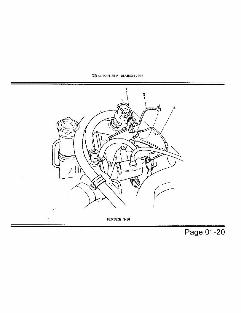
D. Repositioning Injector Pump Wire 569B. Secure injector pump wire569B (3) to injector pump wire 54A (1) with NSN 5975-00-074-2072tiedown strap (2). (see figure 3-10)
PUBLICATIONS AFFECTED:TM9-2320-280-34TM9-2320-280-20PTM9-2320-280-34P
LEVEL OF MAINTENANCE:Unit
Page 01-15


TB 43-0001-39-2? - SEPTEMBER 1996
3-8. Tactical TrucksMODEL:HMMWV
SUBJECT:Removing/installing engine assembly from/in shipping and storage container.
POC:Ms. Patricia Grashik, AMSTA-IM-HLA, DSN 786-7566, Commercial (810) [email protected]
DEFICIENCY :Direct and General Support Units lack technical manual maintenance support for removal andinstallation of engine assembly from/in shipping and storage container.
COMMENTS:Procedures have been developed for removing/installing engine assembly from/in a shipping andstorage container. This task can be accomplished by using the following parts and instructions:
MATERIALS/PARTS :
NOTEOnly damaged parts and lock washers require replacement.Parts are as depicted in figure 3-6.
ITEM NSN NOMENCLATURE OTY7 5310-00-809-4061 Washer 88 5310-00-637-9541* Lockwasher 89 5305-00-781-3926 Screw 4
11 5330-01-264-6537 Gasket 114 5305-00-543-2419 Screw 416 5305-00-732-0511 Screw 2618 5310-00-809-5998 Washer 2619 5310-00-768-0318 Nut 26
*Mandatory replacement item
Page 01-21

TB 43-0001-39-2 SEPTEMBER 1996
3-8. Tact. Trucks cont.PROCEDURES:
A. Removal of Engine Assembly from Shipping and Storage Container.
1. Press air-release button (1) located at center of breather valve (2) before opening enginecontainer (5). (see figure 3-6)
2. Scribe a reference line (17) on upper container (4) and lower container (13).3. Remove twenty-six nuts (19), washers (18), and screws (16) securing upper container (4)
and lower container (13).4. Remove upper container (4) from lower container (13).5. Attach engine lifting sling to engine assembly. (Refer to TM9-2815-237-34.)6. Remove two screws (14), lockwashers (8), and washers (7) securing left engine mount
(12) to engine assembly (6). Discard lockwashers (8).7. Remove two screws (14), lockwashers (8), and washers (7) securing right engine mount
(15) to engine assembly (6). Discard lockwashers (8).8. Remove four screws (9), lockwashers (8), and washers (7) securing rear engine mount
(10) to engine assembly (6). Discard lockwashers (8).9. Remove engine assembly (6) from lower container (13) and mount engine assembly to
repair stand. (Refer to TM9-2815-237-34.)10. Refer to TB9-289 dated 1 October 1990 for shipping and storage container maintenance.
B. Installation of Engine Assembly in Shipping and Storage Container.
1. Attach engine lifting sling to engine assembly. (Refer to TM9-2815-237-34.)2. Remove engine assembly from repair stand, if required. (Refer to TM9-2815-237-34.)3. Position engine assembly (6) in lower container (13). (see figure 3-6)4. Align holes of rear engine mount (10) to engine assembly (6) and secure with four screws
(9), lockwashers (8), and washers (7).5. Align holes of left engine mount (12) to engine assembly (6) and secure with two screws
(14), lockwashers (8), and washers (7).6. Align holes of right engine mount (15) to engine assembly (6) and secure with two screws
(14), lockwashers (8), and washers (7).7. Remove engine lifting sling from engine assembly. (Refer to TM9-2815-237-34.)8. Determine serviceability of gasket (11). If unserviceable, replace with NSN 5330-01-264-
6537 gasket(ll).
Page 01-22

TB 43-0001-39-2 SEPTEMBER 1996
3-8. Tact. Trucks cont .
9. Using scribed line marked in paragraph A, step 2 as reference, position uppercontainer (4) to lower container (13). (see figure 3-6)
10. Secure upper container (4) and lower container (13) with existing twenty-sixscrews (16), washers (18), and nuts (19).
PUBLICATIONS AFFECTED:TM9-2320-280-34TM9-2815-237-34
LEVEL OF MAINTENANCE:Direct and General Support
Page 01-23


Chapter 03
FUEL SYSTEM
FunctionalGroup Code
0302-0311

4-4. Tactical Trucks
MODEL:CUCV/HMMWV Family Of Vehicles
SUBJECT:Fuel injector pump line nut wrench
POC:Mr. Darrel DeLamielleure, AMSTA-IM-HLB, DSN 786-6161, Commercial (810) [email protected]
EDITORS NOTE:This is an updated article that supersedes the one published in TB 43-0001-39-1, dated June 96.The following are the changes that were made:
- new info added to 2nd sentence of Comments
DEFICIENCY:CUCV/HMMWV fuel injector lines may require tightening to prevent leaking. It is difficult to get toinjector lines on CUCV/HMMWV engines without removing a lot of components first.
COMMENTS:As a result of an approved Tool Improvement Program (TIPS) suggestion, an injector pump line nutwrench is approved for CUCV/HMMWV vehicles with local commander approval. This tool is a 5/8inch Hex wrench utilizing standard 3/8 inch drive extensions) in combination with a 3/8 inchUniversal swivel attachment, these items are in the Common Number 1 Tool Set. (This Hex wrenchis slightly different than what is commonly known by mechanics as a "crowsfoot.") Units can orderthis special Stanadyne fuel injection pump tool from Kent-Moore Tools using P/N J28402, CAGE33287. The cost is $17.45.
PUBLICATIONS AFFECTED:None
LEVEL OF MAINTENANCE:Unit
Page 03-01

4-6. Tactical Trucks MODEL:All M998 Series Vehicles
SUBJECT:Substitute Clamp for Fuel Return Line at the Injector
POC:Mr. Daniel Dudek, AMSTA-MTA, DSN 786-7416, Commercial (810)574-7416
DEFICIENCY:Spring clamps used to secure the fuel return lines at the injectormay be out of stock and have long lead times.
CONTENTS:Spring clamp NSN 4730-00-150-6118, used to secure the fuelreturn line at the injectors may have a long lead time when theybecome out of stock. A tie strap NSN 5975-00-903-2284, can besubstituted for the spring clamp during periods of non availability.The vehicle is still considered NMC if a class III leak is evident atthe tie strap. The spring clamp is still the preferred clamp andshould be installed when they become available.
PUBLICATIONS AFFECTED:None
LEVEL OF MAINTENANCE:Unit

4-8. Tactical Trucks
MODEL:M998 Series HMMWV
SUBJECT:M998 series vehicles with air cleaner pre-cleaner (NSN 2940-01-302-8028) installed
POC:Ms. Kathy Catenaro, AMSTA-IM-MTA, DSN 786-7151, Commercial (810) [email protected]
DEFICIENCY:Pre-cleaner (NSN 2940-01-302-8028) is being damaged when the hood is raised andlowered.
COMMENTS:To keep the hood from catching the pre-cleaner you can remove some of the hoodmaterial. Here's how we recommend doing this, but keep in mind that thesedimensions are approximate and you have to shape this alteration to fit properly. First,decide where the hood is hitting the air cleaner and mark it. From that point measure1-1/2 inches up (point A) and 1-1/2 inches down the hood (point B). Then, using a flator half round file, remove 1/4 inch of the hood material between point A and B. (seefigure 4-3)
PUBLICATIONS AFFECTED:NoneLEVEL OF MAINTENANCE:Unit
Page 03-03

3-10. Tactical Trucks
MODEL:HMMWV
SUBJECT:Proper Air Cleaner Servicing (Emergency Procedure)
POC:Mr. Ronald Hanebutt, AMSTA-IM-HLA, DSN 786-5481, Commercial (810) [email protected]
DEFICIENCY:Reports from the field indicate that some HMMWVusers are cleaning the air filter element using theforced air exhaust from the Ml main battle tank.
COMMENTS:1. TACOM does not authorize or recommend the use of the M1's turbine engine exhaust or anyother vehicle exhaust systems as a method for cleaning the HMMWV’s air filter element. Thisprocedure could present serious safety related problems including injury to personnel. Also, theextreme heat of the various exhaust systems could melt and/or destroy the adhesives used in thefilter element.
2. For emergency cleaning, TACOM only authorizes tapping completely around the filter element(1) with your hand to free trapped dirt. (see figure 3-13)
FIGURE 8-13
3. If a filter element requires further cleaning, take it to unit maintenance where they can either usecompressed air or a cleaning solution to free oil and debris from the element.
PUBLICATIONS AFFECTED:TM9-2320-280-10
LEVEL OF MAINTENANCE:Operator
Page 03-04


8-5. Miscellaneous cont.
Consider the other two alternatives:
- There are commercial vendors that provide air filter cleaning services, check your local phonedirectory to see what's available in your area. If you elect to use a service to clean your filters,be aware that there are both dry cleaning and wet washing service vendors.
- There's also an air filter cleaning machine (that uses a dry cleaning method) in the supplysystem. It can clean most of our cylindrical filters, units can order it using NSN 4910-01-381-5426. Operating instructions will be provided with the machine.
Our research with the commercial trucking industry revealed that wet washing is currently thepreferred method of the trucking industry. They say that wet washing removes more contaminantsthan dry cleaning ("dry cleaning" refers to using compressed air, vacuum, vibration, etc., not solvent).Advocates for dry cleaning prefer the dry method; dry cleaning removes contaminants withoutdamaging the filter media.
Here's where you'll really need to weigh your options and check your resources. For example', iswater a scarce commodity in your area? If so, maybe a cleaning service or machine is the way to go.
Know your restrictions
Never clean an inner (safety/secondary) element. Replace it at every third cleaning of theouter/primary element.
The Commercial Utility Cargo Vehicles (CUCVS) are equipped with a light duty air filter element thatwon't stand up to cleaning. Don't even try, just follow the procedures outlined in the CUCV TMs.
There's one other restriction - Ml Abrams Family of Vehicles. Follow the Ml TM cleaning procedures;they're the only ones approved for cleaning Ml V-Pacs.
What to do
No matter which alternative you choose to maintain your air filters, you'll need to follow the followingprocedures.
Carefully remove primary element from the air cleaner housing. Do not remove secondary elementunless you are going to change it. If your system has a secondary element, replace it with a newone every third cleaning of the primary element.
Page 03-06

TB 43-0001-39-6 SEPTEMBER 1995
3-1 1. Tactical Trucks
MODEL:HMMWV
SUBJECT:Use of a substitute fastener (Bolt, Nut and Washer) for the rim clamp used on the HMMWV aircleaner.
POC:Mr. Eddie Bynum, AMSTA-IM-MTA, DSN 786-8288, Commercial (810) [email protected]
DEFICIENCY:The bolt used to fasten the rim clamp may require replacement. We don't provide the boltseparately, so, users must replace the complete rim clamp.
COMMENTS:A. We've received several suggestions that recommend a replacement bolt. However, we madea decision to develop a new design rim clamp that offers Improved maintainability for the HMMWVair cleaner. The new design Is a "no tools needed" over the center clamp. This new clamp allowsfilter accessibility without the use of tools and promotes proper maintenance. The target date for thenew clamp to go In production is Aug 95. We'll provide the National Stock Number (NSN) to the fieldas it becomes available. The NSN will also be added In a future change to the HMMWV technicalmanuals.
B. Until the new clamp is available, you can use a substitute Bolt, Nut and Washer as a fieldexpediency. But, please note, the head height on the existing bolt does allow the operator or crewfilter access with the adjustable wrench provided In the BII. A substitute bolt will require the use of asocket wrench. Use of a substitute fastener is not mandatory, but used at the commandersdiscretion, and should only be used until the first chance to replace the clamp. (see figure 3-18)
MATERIALS/PARTS:Fastener
NOMENCLATURE NSN
Bolt, Hex 5305-00-782-9489Washer, Flat 5310-00-080-6004Nut, Plain, Square 5310-00-010-5606
Page 03-07


4-6. Tactical Trucks
MODEL:M998 Series (HMMWV)
SUBJECT:Fuel Filler Cap Assembly
POC:Ms. Kathy Catenaro, AMSTA-IM-MTA, DSN 786-7151, Commercial (810) [email protected]
DEFICIENCY:Fuel filler caps get lost because the chain that connects the cap to the filler tubebreaks.
CONTENTS:Based on a SMART Initiative the filler cap chain can be replaced.
PROCEDURES:1. Remove the filler cap from the filler spout.2. Pry the link that holds the chain to the cap, and remove the broken chain from the
cap.3. Detach the retaining clip (or spring wire) from the spout and remove the chain.
Save the spring wire or retaining clip to install the new chain.4. Cut an 8" length of chain from bulk NSN 4010-00-958-0633. Hook chain on
retaining clip and attach to filler spout.5. Pry the last link on the opposite end of chain open and attach to plate. Close link.
PUBLICATIONS AFFECTED:TM9-2320-280-20TM9-2320-280-34P
LEVEL OF MAINTENANCE:Unit
Page 03-09

8-9. Misc. Vehicles
MODEL:TACOM Tactical and Combat Equipment
SUBJECT:Keeping Water out of Fuel Systems
POC:Ms. Landis Kazsuk, AMSTA-MTA, DSN 786-8288, Commercial (810) 574-8288
DEFICIENCY:Water in fuel causes problems ranging from microbiological growth, to fuel system corrosion, to fuelline freeze-up during cold weather. These problems all lead to increased maintenance burden, andcan all lead to non-operational equipment.
CONTENTS:A. There are fuel additives designed to combat these deficiencies, but they're intended for use inbulk fuel supplies, so I'm not going to discuss them here. If you, or your Petroleum Officer, need,additional information about these products, please call the POC listed above.
B. The best way to keep your equipment operational is to practice preventive maintenance.Here are some tips you should follow all the time, but especially during cold weather:
(1) Keep your fuel tanks filled to reduce condensation. Condensation forms inside fueltanks when temperatures rise and fall.
(2) Be careful you don't let water and snow fall into your fuel tank while you're refueling.(3) Drain your fuel filters and fuel/water separators daily.
C. In addition to the above, there's aproduct called "Fuel-Dri." Fuel-Dri is a two-piece deviceconsisting of a rigid housing equipped with a tether and a cartridge that contains water absorbinggranules. The NSN for this device is 5430-01-350-1446 and the NSN for replacement cartridges is5430-01-349-8729. We've tested Fuel-Dri; it removes water from fuel and it's authorized for use inthe following TACOM Equipment:
M44A2 2 1/2 Ton Tactical TrucksM39A2 5 Ton Tactical TrucksM809 5 Ton Tactical TrucksM939/A1/A2 5 Ton Tactical Trucks
Page 03-10

M973/Al, M1065, M1066, M1067 Small Unit Support Vehicle (SUSV)M911 Heavy Equipment Transporter
D. Specific information identifying the correct tether length, anchoring point, and any special instructions is in the chart below:
**********FUEL-DRI**********
VEHICLESERIES
TETHERLENGTH
ANCHORPOINT
SPECIAL INSTRUCTIONS
M44A2 M939A2 M809 19 inches Attach the snap swivel on theend of the tether to the secondlink of the chain closest to thefiller neck
Remove the filler neck, attachthe tether to the anchor point anddrop the FUEL-DRI product intothe fuel tank between the fillerneck guides.
M939/Al/ A2 13.5 inch or13.0 inch Attach the snap on the end of thetether to the S-hook that securesthe filler cap chain to the fillerneck
Remove the filler neck, usingcaution to avoid dropping driedsealer material into the fuel tank.Attach the tether to the anchorpoint and drop the FUELDRIproduct into the tank. Install thefiller gasket using a new gasketand thread sealer
VEHICLESERIES
TETHERLENGTH
ANCHORPOINT
SPECIAL INSTRUCTIONS
M939/Al/ A2 (cont) 13.5 inch or13.0 inch strainer. This method can only beused if the S-hook is locatedapproximately in the center of thestrainer.Otherwise, weld a small loop orattach an eyebolt near the centerof the bottom of the filler neckstrainer.
as required. The step over thefuel tank may be removed foreasy access to the filler neck.The newer style fuel tanks withangled fuel necks (P/N12301297 and 12301298)require the 13.0 inch tether.The older style with the verticalfiller neck (P/N 11669353 and11669354) requires a 13.5 inchtether..
Page 03-11

VEHICLESERIES
TETHERLENGTH
ANCHORPOINT
SPECIALINSTRUCTIONS
SUSV 19 inches Bottom of the removablefiller neck strainer
No special instructions
M911 HET 21 inches Underside of fuel tankcap.
The driver's side fueltank doesn't contain fuelsystem components, butthe passenger side tankdoes. FUEL- DRI canonly be used in thedriver's side fuel tank. Itwill remove water fromboth tanks
E. The Fuel-Dri product is not authorized for use in any other tactical or combat equipment.Engineering evaluation has determined that due to fuel tank configuration, permanently installed fillerneck strainers, limited access to lower fuel cells, and the potential for interference with internal fuel levelsensing components, other tactical and combat equipment are not suitable candidates for using Fuel-Dri.
F. The evaluation on special purpose vehicles, (i.e., construction and material handling equipment), isnot yet complete due to the wide range fielded. I will address this type of equipment in a follow-on articleafter all engineering evaluation is complete.
Page 03-12

PROCEDURES:A. If you feel you have a problem with water in your fuel, we recommend you considerusing the Fuel-Dri product. It's simple to use, monitor, and dispose of.
B. To use this product, follow the chart above and place the cartridge in your vehicles'fuel tank.
C. There's no predetermined change interval, the cartridge should be changed whenit's saturated with water. We recommend that you check the cartridge after two or threedays when you initially put it in your fuel tank. After that, depending on weatherconditions, fuel/water separator output, etc. you should change it only as necessary.Air Force testing indicated that the cartridge can be air dried and reused.
D. You should dispose of used Fuel-Dri cartridges in the same manner that youdispose of used fuel filters.
E. If you'd like additional information, please contact the POC above. Additionally, themanufacturer offers a free demonstration video. Call 1-800-368-3835 for a copy.
PUBLICATIONS AFFECTED:None
LEVEL OF MAINTENANCE:All
Page 03-13

4-5. Tactical Trucks
MODEL:HMMWV
SUBJECT:Lowering the fuel tank level
POC:Ms. Jody McInerney, AMSTA-IM-MTA, DSN 786-7346, Commercial (810) [email protected]
DEFICIENCY:The fuel tank levels must be lowered for vehicle transport operations, to compensate fortemperatures at different altitudes.
CONTENTS:The fuel tank drain plug is used to drain the HMMWV fuel tank. However, when the drain plugremoval takes place, some spillage will occur while lowering the fuel level. If the unit wants to avoidspillage, they can use hand pump, NSN 4930-00-028-3598, PN (35301) 40 Hand Pump.
PUBLICATIONS AFFECTED:TM9-2320-280-20-2
LEVEL OF MAINTENANCE:Unit
Page 03-14

TB 43-0001-39-2 SEPTEMBER 1996
MODEL:HMMWV
SUBJECT:Glow Plugs
POC:Ms. Jody McInerney, AMSTA-IM-HLA, DSN 786-5481, Commercial (810) [email protected]
CONTENTS:Here are some tools you may want to try to remove damaged glow plugs. Your fellow peersfabricated these tools and found them helpful. In the future, any tools fabricated or methodsdeveloped for removing damaged glow plugs can be approved at your local commanders discretion.
PROCEDURES:A. Method One: Remove the injector and attach a piece of wire to the glow plug. Tighten the wire bytwisting with pliers (twist pliers available through GSA, NSN 5120-00-305-2306). Hold the wire or tieit to the engine while breaking off the heating element. With the wire attached it is very easy toretrieve the broken/defective heating element.
B. Method Two: Fabricate a removal tool for stubborn glow plugs by using a l0 x l.00 metric nut andan 0-ring (NSN 5330-00-966-8657), see figure 4-2 for instructions. Back the glow plug out of its holeas far as the threads will push it, slip the split nut over the hex end of the plug and down over thethreaded portion of the plug. Once in position place a 14 mm wrench on the nut to hold it fromturning. Using your 3/8 inch deep socket or end wrench continue unscrewing the plug from the head.In some cases, additional spacers will be needed to completely remove the plug. For spacers usewashers that will fit over the hex portion of the glow plug. Place the washers behind the split nut.
C. Method Three: This method involves fabricating a pry or puller toot to help remove swollen glowplugs from the cylinder head and prevent the tip from breaking off. This tool can be made and usedby unit personnel. The procedures to use and fabricate the tool can be found in TB 43-0001-39-8,Mar 96.
D. For methods such as using compressed air to expel the damaged tip through the fue linjectornozzle opening; a piece of coil tie wire to prevent the tip from falling into the cylinder when the glowplug is broken off, or removing the cylinder head to gain access to the cylinder see TM9- 2320-280-34, dated Jan 96, paragraph 3-18, page 3-38.
Page 03-15

3-18. Tactical Trucks
MODEL:HMMWV, M998 Series
SUBJECT:GLOW PLUGS and Starting Procedures
POC:Mr. Daniel Dudek, AMSTA-MTA, DSN 786-7416, Commercial (810) [email protected]
DEFICIENCY:Shortcomings with the starting procedures in TM9-2320-280-10 may cause operators to inadvertentlyfail the glow plugs.
COMMENTS:A. When the rotary switch is turned to the run position you start the glow plug controller's pre-glowcycle. This turns the glow plugs on for up to 9 seconds, depending on temperature. Then the glowplug controller continues to cycle the glow plugs with an after glow cycle.
B. When the wait to start light goes out, you start the engine. If the engine doesn't start, leave theswitch in the "RUN" position and wait 10-15 seconds, then try to start the engine again.
C. If you accidentally turn the switch to "STOP" after an unsuccessful start, wait a minimum of 90seconds before attempting to start again. This allows the glow plugs to cool enough to preventsuperheating the tips.
D. If you turn the switch to 'STOP" and back to "RUN", you start the pre-glow cycle again. If the glowplugs are still hot from the previous pre-glow, the tips will become superheated and burn out.
E. If your vehicle continues to experience starting difficulty, other problems may exist, such as badfuel. Get it checked out by your organizational mechanic.
PROCEDURE:The following notes are being added to paragraph 2-9, Starting the Engine.
Page 03-17

3-18. Tact. Trucks cont.NOTE
Do not leave rotary switch in "RUN" position for extended periods oftime. Glow plugs will continue to cycle and batteries will continue todischarge and lead to a no-start condition. Continued attempts tostart the vehicle with low batteries could lead to failure of the glowplug system.
Starting the vehicle before the WAIT-TO-START lamp goes out canresult in starting problems.
If engine does not start, leave rotary switch in "RUN" position andwait 1 0 to 15 seconds before trying to restart. Failure to do this willresult in damage to the glow plugs or starter.
If you accidentally turn the rotary switch to "ENG STOP" position afteran unsuccessful attempt to start, wait 90 seconds before trying torestart. Failure to do this will result in damage to the glow plugs.
PUBLICATIONS AFFECTED:TM9-2320-280-10
LEVEL OF MAINTENANCE:Operator
3-8. Tactical Trucks
MODEL:CUCV/HMMWV
SUBJECT:Removing Expanded Glow Plugs from the Engine Cylinder Head
POC:Mr. John Kandrot,AMSTA-MTA, DSN 786-8288, Commercial (810) 574-8288 [email protected]
DEFICIENCY:The CUCV/HMMWV glow plugs swell upon failure and are difficult to remove from the cylinder head.
Page 03-18

COMMENTS:The following procedure can be used to help remove the swollen glow plugs fromcylinder heads.
PROCEDURE:1. Unthread glow plug as far as possible.2. Attach a pair of vise grips (NSN 5120-00-277-4244) to the glow plug.
WARNING
Exercise caution to prevent screwdriver from slipping and causinginjury.
3. Place a large screwdriver (NSN 5120-00-278-1276) between the vise grips and theengine block and pry toward the engine.
NOTE
This will apply outward pressure to the glow plug and help remove theswollen tip without breaking it off inside the cylinder head
PUBLICATIONS AFFECTED:None
LEVEL OF MAINTENANCE:Unit
Page 03-19

3-11. Tactical Trucks
MODEL:All CUCV (M1008 Series) and HMMWV (M998 Series) Vehicles
SUBJECT:Removing Pieces of Broken Glow Plugs
POC:Mr. Daniel Cottone, AMSTA-MTA, DSN 786-7151, Commercial (313) 574-7151
DEFICIENCY:Pieces of broken glow plugs are difficult to remove from the engine.
COMMENTS:A. When the glow plugs in the CUCV or HMMWV fail and swell they cannot be removed in thenormal manner. The tip must be separated from the body of the glow plug in order to remove it.Sometimes this causes the glow plug to break into smaller pieces. When this happens the piecesmust be picked out with pliers, blown out with air, or the cylinder head must be removed.
B. As an alternative to using pliers, compressed air, or removing the cylinder head, a shop vacuummay be used to remove the broken pieces. Simply insert one end of a small flexible hose, such asNSN 4720-01-168-0518, in to the vacuum hose and seal the connection with tape. Then remove thefuel injector located next to the broken glow plug. Insert the other end of the small hose into the fuelinjector opening in the engine and turn on the vacuum cleaner. The pieces of glow plug shouldempty into the vacuum cleaner compartment for examination.
C. Some technicians have found this method quick and effective. But if all the pieces do not comeout, one of the other methods including removal of the cylinder head must be used.
PUBLICATIONS AFFECTED:None
LEVEL OF MAINTENANCE:Direct Support
Page 03-20

TB 43-0001-39-8 MARCH 19963-13. Tactical Trucks
MODEL:HMMWV
SUBJECT:Removal of Swollen Glow Plugs
POC:Ms. Jody McInerney, AMSTA-IM-MTA, DSN 786-7346, Commercial (810) [email protected]
DEFICIENCY:When the glow plugs swell up they are difficult to remove from the cylinder head and often break andfall into the cylinder requiring removal of the cylinder head.
COMMENTS:
To help remove swollen glow plugs from the cylinder head and prevent the tip from breaking off, atool can be made and used by unit personnel. This tool is an optional method and can be made asfollows:
1. Using 1/8” flat steel, NSN 9515-00-204-3994, and 3/8” round rod, NSN 9510-00-189-0652,welded together, make a tool as shown in Figure 3-20.
2. Be sure that the open end of the fork (dimension F in figure 3-20) is no more than 11/32”. Thiscan be tested by using an old glow plug as a guide. The forked end must fit behind the hexhead of the glow plug. This may require grinding the thickness down from 1/8” to 1/16” toensure a proper fit.
3. Remove swollen plugs as follows:
Place the fork of the tool behind the hex head of the glow plug with the angle portion against thefuel injector nozzle for leverage. While slowly turning the glow plug out apply slow evenoutward pressure on the glow plug.
NOTE
Too much pressure or turning the glow plug too fast will result In thetip breaking off and still require removal of the cylinder head
Page 03-21
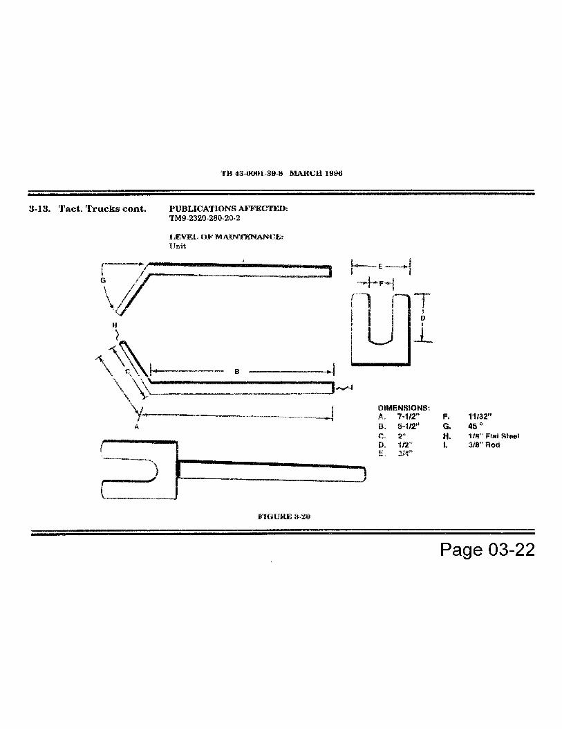


Chapter 04
EXHAUST SYSTEMFunctional Group Code 0401


TB 43-0001-39-1 JUNE 19963-9. Tact. Trucks cont.
WARNING
Vehicles with serial numbers USBL Eff. I through 118767 havemanifold gaskets containing asbestos fibers. When performingmanifold maintenance, place used gaskets In a plastic,leakproof, sealed bag or container and contact the local healthand safety department for further disposal Instructions.Failure to observe above warning may result In anenvironmental hazard.
5. Remove exhaust manifold (4) and gaskets (5) and (10). Discard gaskets. (see figure 3-1 1)
b. InstallationNOTE
Ensure replacement gaskets have a silver, shiny surface, not adull, dark surface, which Is characteristic of a gasket containingasbestos.
1. Install gasket (5) and exhaust manifold (4) on cylinder head (6) with seven washers (13), socket-head screws (12), washer (3), and stud (2). (see figure 3-11)
2. Using hex-head driver, tighten seven socket-head screws (12) and stud (2) to 25- 33 lb-ft (34-45 N•m).
3 . Install alternator support bracket (1) on exhaust manifold (4) and stud (2) with washer (15) and locknut (14). Tighten locknut (14) to 31-39 lb-ft (42-53 N•m).
4. Install gasket (10) and crossover pipe (7) on exhaust manifold (4) with washers (9), three capscrews (11), and locknuts (8). Tighten locknuts (8) to 37 lb-ft (50 N•m).
RIGHT EXHAUST MANIFOLD REPLACEMENT
WARNING
Do not touch hot exhaust system components with bare hands.Severe Injury will result .
Page 04-02

TB 43-0001-39-1 JUNE 19963-9. Tact. Trucks cont.
a. Removal1. Remove three locknuts (10), capscrews (6), and washers (7) from exhaust manifold (3) and crossover pipe (9). Discard locknuts (10). (see figure 3-12)
2. Using hex-head driver, remove eight socket-head screws (5) and washers (4) from exhaust manifold (3) and cylinder head (1).
WARNINGVehicles with serial numbers USBL Eff. 1 through 118767 havemanifold gaskets containing asbestos fibers. When performingmanifold maintenance, place used gaskets In a plastic, leakproof,sealed bag or container and contact the local health and safetydepartment for further disposal Instructions.Failure to observe above warning may result In an environmentalhazard.
3. Remove exhaust manifold (3) and gaskets (2) and (8). Discard gaskets. (see figure 3-12)
b. Installation
NOTEEnsure replacement gaskets have a silver, shiny surface, not a dull,dark surface, which is characteristic of a gasket containingasbestos.
1. Install gasket (2) and exhaust manifold (3) to cylinder head (1) with eight socket-head screws (5) and washers (4). Tighten socket-head screws (5) to 25-33 lb-ft (34-45 N•m). (see figure 3-12)
2. Install exhaust manifold (3) to crossover pipe (9) with gasket (8), washers (7), threecapscrews (6), and locknut (10). Tighten locknuts (10) to 37 lb-ft (50 N•m).
PUBLICATIONS AFFECTED :TM9-2320-280-20 TM9-2320-280-24P
LEVEL OF MAINTENANCE :Unit
Page 04-03


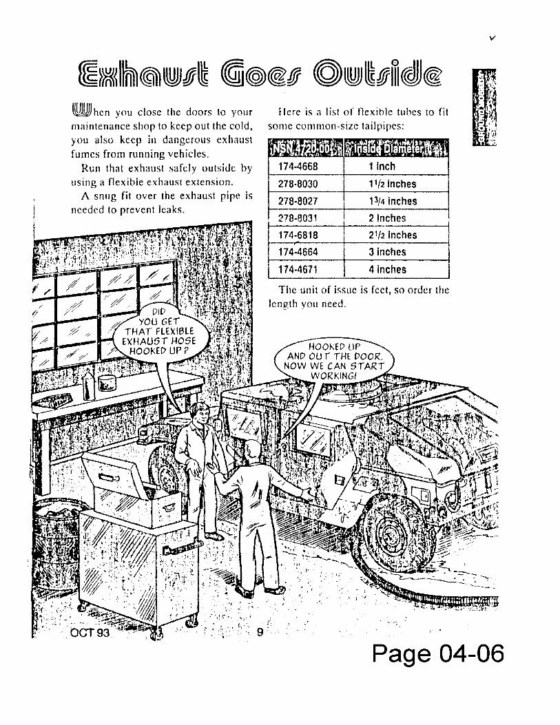

Chapter 05
COOLING SYSTEM
FunctionalGroup Code0501 - 0505

4-8. Tactical Trucks
MODEL:M998 and M998A1 Series Vehicles
SUBJECT:Cooling System Surge Tank
POC:Mr. Keith Barthlow, AMSTA-MTA, DSN 786-8288, Commercial (313) 574-828h
COMMENTS:A. When stocks are exhausted, the cooling system surge tank, NSN 2930-01-232-9695, P/N12340062, will be replaced by the surge tank that was previously used only on the M997 andM997Al. The replacing coolant surge tank, NSN 2930-01-256-5350, P/N 12340061 has a 1/2 quartlarger capacity and can be used on all HMMWV models.
B. When using the larger surge tank P/N 12340061, the radiator to surge tank hose, NSN 4720-01-196-1636, P/N 12339163 can be used by cutting approximately four inches from the surge tank endof the Hose.
PUBLICATIONS AFFECTED:TM9-2320-280-20TM9-2320-280-20PTM9-2320-280-34P
LEVEL OF MAINTENANCE:Unit
Page 05-01

TB 43-0001- MARCH 19963-6. Tactical Trucks
MODEL:M998 and M998AI Series HMMWV
SUBJECT:Radiator Retaining Strap
POC:Ms. Leona Milas, AMSTA-IM-MTA, DSN 786-7346, Commercial (810) [email protected]
DEFICIENCY:Reports from the field indicate the radiator retaining strap NSN 5340-01-251-0724 has atendency to come loose and fall off causing the fan to hit and damage the shroud.
COMMENTS:A procedure has been developed to secure the radiator retaining strap to the fan shroud.A hole is drilled through the radiator retaining strap and fan shroud, and a rivet is installedto secure the radiator retaining strap to the fan shroud. Installation can be accomplishedin the field by using the following part and procedure.
MATERIALS/PARTS:
NSN NOMENCLATURE QTY
5320-00-083-5009 Rivet 1
PROCEDURES:1. Locate, mark, and drill 0. 129-inch diameter hole (#30 drill bit) in radiator
retaining strap (1) and fan shroud (2). (see figure 3-2)2. Secure NSN 5320-00-083-5009 rivet (3) through fan shroud (2) and radiator
retaining strap(1).
PUBLICATIONS AFFECTED:TM9-2320-280-20 TM9-2320-280-20P/34P
LEVEL OF MAINTENANCE:Unit
Page 05-02


TB 43-0001-39-2 SEPTEMBER 19964-7. Tactical Trucks
MODEL:XM1109, Up-Armored HMMWV
SUBJECT:A/C Belt Rubbing Against Coolant Hose
POC:Ms. Jody McInerney, AMSTA-IM-HIA, DSN 786-5481, Commercial (810) 574-5481mcinernjCalcc.tacom.army.mil
COMMENTS:A. We received notice that the XM1109 Uparmored HMMWV A/C belt is rubbing thecoolant hose at the water pump (TM9-2320-280-20P, w/change 2, dated Nov 93, Fig26, Item 8). This creates a hole in the hose, causing coolant loss.
B. To correct the problem, unit maintenance should realign the hose. You canaccomplish this by loosening the hose clamp and slightly twisting the hose to providethe clearance needed. Please note, make sure the engine is completely cooled beforeperforming this task.
PUBLICATIONS AFFECTED:SOMARPITM9-2320-280-14&P
LEVEL OF MAINTENANCE:Unit
Page 05-04

TB 43-0001-39-3 DECEMBER 1994
3-9. Tactical Trucks
MODEL:HMMWV with 200 Amp Alternator
SUBJECT:Radiator Hose to Drive Belt Interference.
POC:Ms. Patricia Grashik, AMSTA-MTA, DSN 786-7427, Commercial (810) [email protected]
:EDITOR'S NOTE
This is a reprint of the same article that was published in TB43-0001-39-6), dated 30,Sep 93.
- hose clamp NSN has been changed.
DEFICIENCY:HMMWVs with the 200 amp alternator are experiencing problems with Interference. There Is verylittle clearance between the radiator hose and the V-belts. This condition Is causing wear and canresult In engine coolant loss.
COMMENTS:A. Recommend the following adjustment procedure be followed if you are experiencing hose to beltInterference. The procedure will provide an additional 3/8" to 1/2" clearance between the alternatordrive belts and the radiator hose:
(1) Loosen the upper radiator hose clamps.(2) Twist the hose counterclockwise by pulling the hose bend elbow upward just until a kink In the
hose starts to form.
(3) Tighten the clamp.
B. Another fix for this problem is to change the hose clamp to a clamp with a metal shield (NSN4730-01-194-2002). This is the same hose clamp used on the CUCV. It will also prevent damage tothe radiator hose.
Page 05-05

TB 43-0001-39- MARCH 1996
3- 1 0. Tactical Trucks
PUBLICATIONS AFFECTED:None
LEVEL OF MAINTENANCE:Unit
MODEL:HMMWV, M998 Series
SUBJECT:Fail Drive Quick-disconnect
POC:Mr. Eric Sutman, AMSTA-MTA, DSN 786-7151, Commercial (810) [email protected]
COMMENTS:Procedures have been developed to install a quick-disconnect between the fan drive and thehydraulic hose for ease of maintenance and decrease maintenance down time during replacement ofpower steering and alternator belts. Installation of the quick-disconnect can be accomplished in thefield using the following parts and materials:
MATERIALS/PARTS:
NSN OR P/N NOMENCLATURE OTY
4720-01-394-3747 Hose, Non-metallic 14730-00-278-3721 Fitting 112342947 Quick-Disconnect 18030-01 054-0740 Sealing Compound 1
PROCEDURE:A. Vehicle Preparation.
1. Disconnect battery ground cable. (Refer to TM9-2320-280-20.)
Page 05-06


TB 43-0001-39-3 DECEMBER 1996
3-7. Tactical Trucks
MODEL:M998, M998Al, and M998A2 Series Vehicles
SUBJECT:Water Pump Replacement
POC:Ms. Jody McInerney, AMSTA-IM-HLA, DSN 786-5481, Commercial (810) [email protected]
DEFICIENCY:A report from the field has requested water pump replacement be moved from direct support level tounit level.
COMMENTS:A procedure to replace the water pump at the unit level has been developed. The procedure can beaccomplished in the field without removing the radiator by using the following instructions andmaterials.
MATERIALS/PARTS :NSN NOMENCLATURE QTY
2930-01-193-7802 Pump, Cooling System (6.2L engines) 15320-01-218-0721 Rivet, Solid 15330-01-149-9808 Gasket, Water Pump 15310-00-637-9541 Lockwasher 18030-01-054-0740 Pipe Sealing Compound A/R8030-00-148-9833 Sealing Compound A/R8030-01-374-3504 Anaerobic Gasket Sealer A/R
PROCEDURES:1. Raise and secure hood. (Refer to TM9-2320-280-10.)2. Remove battery box cover. (Refer to TM9-2320-280-20.)3. Disconnect battery ground cables. (Refer to TM9-2320-280-20.)4. Drain cooling system. (Refer to TM9-2320-280-20.)
Page 05-10

TB 43-0001-39.3 DECEMBER 1996
3-7. Tact. Trucks cont.NOTE
Do not remove radiator and shroud called out in equipment condition forstep 5.
5. Remove fan blade and fan drive assembly. (Refer to TM9-2320-280-20.)6. Disconnect fan drive hose. (Refer to TM9-2320-280-20.)7. Remove alternator drive belt set. (Refer to TM9-2320-280-20.)8. Remove power steering belt. (Refer to TM9-2320-280-20.)9. For A2 models, remove serpentine belt. (Refer to TM9-2320-280-20.)
10. Remove water pump pulley. (Refer to TM9-2320-280-20.)11. For A2 models, remove belt Pensioner, idler pulley, and mount. (Refer to TM9-2320-280-20.)12. Remove power steering pump support brackets. (Refer to TM9-2320-280-20.)13. Remove engine oil filler tube. (Refer to TM9-2320-280-20.)14. Remove heater outlet/inlet hose. (Refer to TM9-2320-280-20.)15. Remove thermostat bypass hose. (Refer to TM9-2320-280-20.)16. Remove water pump inlet hose. (Refer to TM9-2320-280-20.)
NOTEThe following steps will be moved to the unit level manual.
17. Remove cap screw (13), lock washer (12), washer (11), and power steering pump bracket (10)from support bracket (9). Discard lock washer (12). (see figure 3-13)
18. Remove two nuts (14) and support bracket (9) from water pump (6).19. Remove bypass nipple (4) from water crossover (3).20. Remove two studs (1) and (19), studs (8) and (7), four cap screws (17), washers (18), two cap
screws (15), cap screw (16), water pump (6), and adapter plate (5) from timing gear cover (2).21. Remove seven cap screws (21), adapter plate (5), and gasket (20) from water pump (6).
Discard gasket(20).22. Clean remaining gasket material and sealing compound from sealing surfaces on adapter plate
(5), water pump (6), and timing gear cover (2).23. Remove heater hose nipple (23), elbow (22), and bypass hose adapter (24) from water pump
(6).
Page 05-11


TB 43-0001-39-2 SEPTEMBER 1994
3-15. Tactical Trucks
MODEL:M998 Series
SUBJECT:Fan Clutch
POC:Mr. Eric Sutman, AMSTA-MTA, (810) 574-7151
DEFICIENCY:When the HMMWV is parked or stored for long periods, minor corrosion can cause the fan clutch tolock up. This corrosion isn't severe enough to damage the clutch but It can keep it from operatingproperly. To free up the clutch you have to disassemble the engine cooling system and remove theclutch.
COMMENTS:We've adopted a suggestion to apply air pressure to the clutch to disengage it, and then
tap on the clutch with a soft faced hammer to free it up.
MATERIALS:
NSN NOMENCLATURE QUANTITY
4730-00-142-1958 Coupling half, Quick-disconnect 14730-01-242-7738 Connector 14730-00-223-9255 Coupling, Pipe 1
PROCEDURE:A. Disconnect battery ground cable. (Refer to TM 9-2320-280-20).
B. Assemble NSN 4730-00-142-1958 quick disconnect (3), NSN 4730-00-223-9255 pipe coupling (2), and NSN 4730-01-242-7738 connector (1). (see figure 3-9)
C. Loosen clamp (2) and remove hose (1) from fitting (3). (see figure 3-8)
Page 05-15
TB 43-0001-39-2 SEPTEMBER 1994
3-15. Tact. Trucks cont.
D. Install connector (1) to hose (5) and secure with clamp (4). (see figure 3-9)
E. Apply 90 to 120 psi (620 to 827 kPa) air pressure to quick disconnect to disengage the fanclutch.
F. Tap on fan clutch with a soft faced hammer (like NSN 5120-01-065-9037). The clutch should freeup and fan will free wheel.
NOTE
If the fan doesn't free wheel the clutch is still locked. If theseprocedures won't free up the fan clutch, remove it (Refer to TM 9-2320-280-20) and send it to DS for repair.
G. Release air pressure from quick disconnect.
H. Loosen clamp)(4)and remove connector-(1)from hose(5).(see figure 3-9)
I. Connect hose (1) to fitting (3) and secure with existing clamp (2). (see figure 3-8)
J. Connect battery ground cable. (Refer to TM 9-2320-280-20)
K. Bleed power steering system. (Refer to TM 9-2320-280-20)
PUBLICATIONS AFFECTED:TM9-2320- 280-20
LEVEL OF MAINTENANCE:Unit
Page 05-16


TB 43-0001-39-6
3-33. Tactical Trucks
MODEL:HMMWV
SUBJECT:Fan Clutch Cylinder Dust Seal.
POC:Mr. Eric Sutman, AMSTA-MTA, DSN 786-7151
DEFICIENCY:There are no replacement procedures for the fan clutch cylinder dust seal, the housing assemblyrear grease seal, or the housing assembly needle bearings. If the dust seal is damaged, you mustreplace the cylinder. If the rear grease seal or needle bearings are damaged you must replace thefan drive.
COMMENTS:A. Replacement of the grease seal and needle bearings is impractical. If the bearings or seal isdamaged, chances are good that debris has also damaged the housing. Because of this, the greaseseal and needle bearings will remain non-replaceable items. Do not remove them. Clean the areaand inspect the seal and bearings for damage. If either are damaged, replace the fan drive.
B. The dust seal, however, is now available for replacement. We are providing the followingprocedures for replacement of the dust seal. It is important to realize that a damaged dust seal willnot immediately cause the clutch to leak. It only keeps dirt and debris from entering the clutch.Replace the dust seal only if it is cracked or if pieces are missing from it.
C. The dust seal does not yet have an NSN. Until it does, order the seal using a part numberrequisition on DD Form 1348-6.
MATERIALS:
Lock -nut NSN 5310-01-194-0481“O" Ring NSN 5330-01-192-8892Dust Seal P/N (51377) 3018-01339-01
Page 05-18

TB 43-0001-39-6
3-33. Tactical Trucks cont.
PROCEDURE:NOTE
For complete disassembly and repair of the fan clutch refer to TM9-2815-237-34.
A. Disassembly
(1) Remove locknut (1) and tabwasher (2). Discard locknut (1). (see figure 3-80)(2) Remove cylinder (3) from fan clutch (6).
NOTERemove the dust seal only if it is cracked or if pieces are missingfrom it.
(3) Remove dust seat (5) from cylinder (3). Discard dust seat (5). (see figure 3-80)(4) Remove "O” ring (4) from inside cylinder (3). Discard “O" ring (4).
B. Inspection
(1) Inspect cylinder (3) for damage. Replace if damaged.(2) Inspect dust seal (5) for cracks in the seal or pieces missing from it. Replace if the seal iscracked or if pieces are missing from it.
C. Assembly
(1) Install "O" ring (4)in groove inside cylinder (3).
NOTE
Remove the dust seal only if it is cracked or if pieces aremissing from it. Make sure lip of seal is facing out.
(2) Install dust seal (5) in cylinder (3). (see figure 3-80)(3) Install cylinder (3) on fan clutch (6).(4) Secure cylinder (3) to fan clutch (6) with tab washer (2) and locknut (1). Tighten locknut (1)
to 96 lb-in. (10 N•m).
Page 05-19


TB 43-0001-39-8 MARCH 1996
3-9. Tactical Trucks
MODEL:HMMWV
SUBJECT:Fan Drive and Fan Blade Replacement
POC:Ms. Jody McInerney, AMSTA-IM-MTA, DSN 786-7346, Commercial (810) [email protected]
COMMENTS:
A. It's been brought to our attention that the fan drive and fan blade can be removed as anassembly with the radiator and fan shroud in-vehicle. This will save units repair time, improve yourvehicle readiness and help alleviate any work overload at unit maintenance.
B. Below is the new procedure. It eliminates the task to remove radiator and fan shroud beforebeginning the task. Helpful Note: The fan drive hose may be modified to add a quick-disconnect atcommander's discretion. Refer to TB43-0001-39-3, Dec 94. This will make it easier to applycompressed air to disengage fan drive clutch if necessary.
PROCEDURES:Initial Setup:
Special Tools Manual ReferencesHex Head driver, 8mm TM9-2320-280-20P(Appendix B, Item 119)
Materials/Parts Equipment ConditionFour lock washers (Appendix G, Item 108) Hood raised and secured (TM9-2320-280-10)Sealing compound (Appendix C, Item 43)
a. Removal
1. Disconnect fan drive hose (1) from fan drive (2). (see figure 3-5)
Page 05-21

TB 43-0001-39-8 MARCH 1996
3-9. Tact. Trucks cont.NOTE
Mark position of fan blade for Installation.
It may be necessary to apply compressed air toclutch adapter. This disengages fan drive clutchto allow access to socket head screws.
2. Using hex head driver, remove four socket-head screws (3) and fan drive assembly (5)from water pump pulley (4). (see figure 3-5)
3. Remove four nuts (7), lockwashers (8) and fan blade (9) from fan drive (10). Discardlockwashers (8).
b. Inspection
Inspect clutch adapter (6) and fan blade (9) for damaged threads, cracks, bent blades, or breaks.Replace if defective.
c. Installation
1. Align fan blade (9) onto fan drive (10) with four lockwashers (8) and nuts (9). Tightennuts to 26 lb-ft (35 N•m).
2. Apply sealing compound to four socket-head screws (3) and install fan drive assembly(5) to water pump (4). Tighten socket-head screws (3) to 45 lb-ft (61 N•m).
3. Connect fan drive hose (1) to fan drive (2).
FOLLOW-ON TASK:Lower and secure hood (TM9-2320-280-10)Bleed power steering system (para, 8-24)
PUBLICATIONS AFFECTED:TM9-2320-280-20-2
LEVEL OF MAINTENANCE:Unit
Page 05-22


TB 43-0001-39-7 DECEMBER 1995
3-6. Tactical Trucks
MODEL:HMMWV
SUBJECT:Fan Failures
POC:Ms. Patti Grashik, AMSTA-IM-MTA, DSN 786-7713, Commercial (810) [email protected]
DEFICIENCY:Field is reporting fan and fan shroud cracks.
COMMENTS:A. Excessive entry speed during fording operations can cause the fan to crack. Ensure proceduresin TM9-2320-280-10, paragraphs 2-29 and 2-30, are followed to prevent vehicle damage duringfording operation. Vehicle speed should not exceed 5 mph (8 kph) during fording operation.
B. Ensure proper fan shroud clearance is maintained. Fan blade to fan shroud clearance must be atleast 1/4 Inch at any position (TM9-2320-280-20-2, dated Jan 90, with Change 4. paragraph 3-56).
C. Minor fan shroud breaks and cracks can be repaired using fiberglass repair kit NSN 2090-00-372-6064. Use the repair kit only If the repairs can be made while the shroud is installed on thevehicle. The low cost of the fan shroud makes it impractical to remove the shroud for repair. If thefan shroud Is damaged such that it must be removed from the vehicle, the shroud should bereplaced.
D. When making the repair, place the patch on the exterior of the shroud, making sure that It doesnot interfere with the fan to shroud clearance. Instructions for use of the repair kit are included withthe kit. General information concerning fiberglass repair can be found In TO 9-510, Metal BodyRepair and Related Operations.
PUBLICATIONS AFFECTED:None
LEVEL OF MAINTENANCE:Unit
Page 05-24

TB 43-0001-39-7
3-14. Tactical Trucks
MODEL:M998 Series
SUBJECT:Replacement of Fan Drive Friction Lining
POC:Mr. Eric Sutman, AMSTA-MTA, DSN 786-7151, Commercial (313) 574-7151
EDITORS NOTE:This is an updated article that supersedes the one published in TB43-0001-39-5, dated 2 Jul 93. The following are the changes thatwere made:
-new NSN for Lining, friction-two fan drive retaining plate Warnings were deleted-second psi Note was deleted-TM9-2815-237-34 was added to Pubs. Affect.-Direct Support added to Level of Maint.-torque requirement deleted from step H.
DEFICIENCY:Units lack technical maintenance support for replacing friction lining in fan drive while installed onengine.
COMMENTS:Procedures have been developed to replace the fan drive friction lining. This procedure can beaccomplished in the field by using the following parts and materials:
NSN NOMENCLATURE QUANTITY
4730-00-142-1958 Coupling half, quick-disconnect 14730-01-242-7738 Connector 14730-00-223-9255 Coupling, pipe 12930-01-189-8643 Lining, friction 1
Page 05-25

TB 43-0001-39-7
3-14. Tact. Trucks cont.
PROCEDURE:A. Disconnect battery ground cable. (Refer to TM 9-2320-280-20)
B. Assemble NSN 4730-00-142-1958 quick disconnect (3), NSN 4730-00-223-9255 pipe coupling(2), and NSN 4730-01-242-7738 connector (1). (see Figure 3-17)
C. Loosen clamp (2) and remove hose (1) from fitting (3). (see Figure 3-16)
D. Install connector (1) to hose (5) and secure with clamp (4). (see figure 3-17)
NOTE
Apply 90 to 120 psi (620 to 827 kPa) air pressure to quick-disconnect, rotate fan and gain access to the six screws andthree retaining plates on fan drive.
E. Remove six screws (1) and three retaining plates (2) from fan drive (3). (see figure 3-18)
F. Remove friction lining (4) from fan drive (3). (see figure 3-18)
NOTE
Friction lining may be a one or two piece construction,however installation instructions are not affected .
G. Install new NSN 2930-01-189-8643 friction lining (4) in fan drive (3). (see figure 3-18)
H. Install existing three retaining plates (2) to fan drive (3) and secure with six existingscrews(1).(see figure 3-18) Tighten screws (1).
I. Loosen clamp (4) and remove connector (I,) from hose (5). (see Figure 3-17)
J. Connect hose (1) to fitting (3) and secure with existing clamp (2). (see figure 3-16)
K. Connect battery ground cable. (Refer to TM 9-2320-280-20)
I. Bleed power steering system. (Refer to TM 9-2320-280-20)
Page 05-26


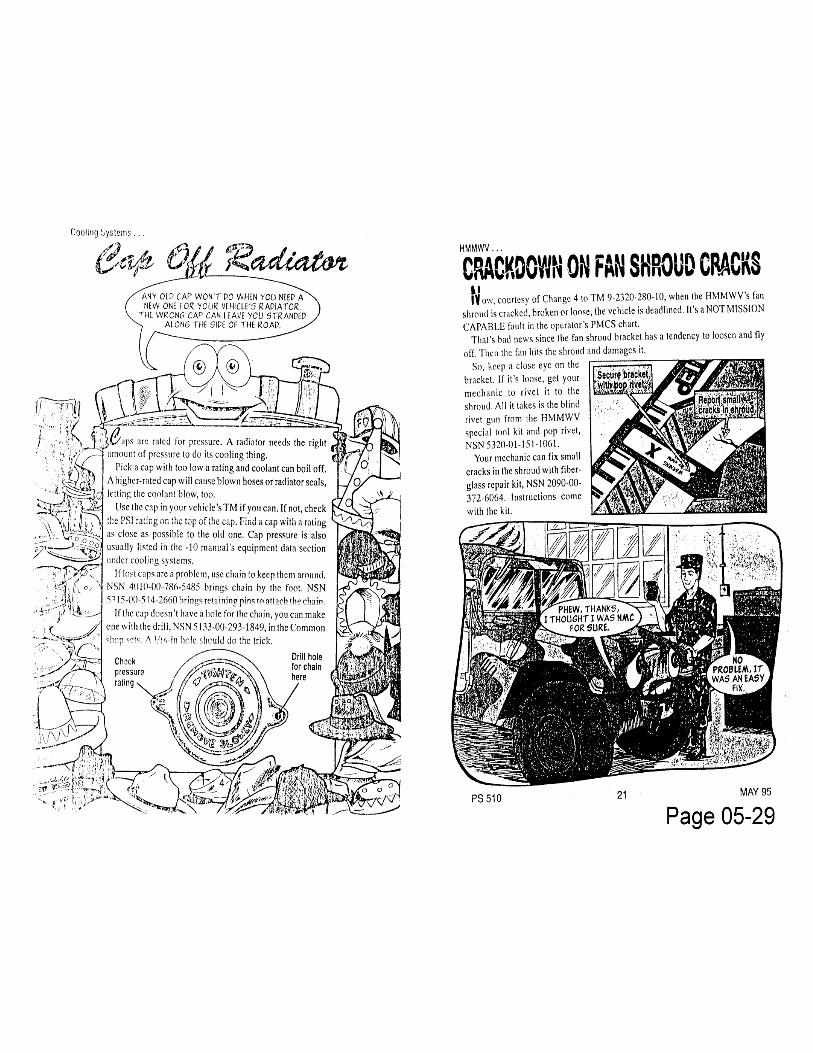


Chapter 06
ELECTRICAL SYSTEM
FunctionalGroup Code
0601-0613

TB 43-0001-3 March 19963-7. Tactical Trucks
MODEL:M998 Series HMMWV
SUBJECT:60 Ampere Alternator Regulator Replacement
POC:Ms. Patricia Grashik, AMSTA-IM-MTA, DSN 786-7713, Commercial (810) [email protected]
COMMENTS:60 ampere alternator charging problems could be caused by a faulty regulator. We arechanging the current alternator trouble shooting procedures (TM9-2320-280-20-1, page 2-190). Unit maintenance will replace the regulator instead of the alternator, if voltage can't beadjusted.
MATERIALS/PARTS:
PART NUMBER NSN NOMENCLATURE(19728)20X-4383* * Screw Self-tapping Regulator,
Cover19728) AMA2004S 2920-01-180-8666 End Head, Intermediate (includes
ring seal)
*NSN presently being assigned. May be requisitioned by Part Number and CAGE.
PROCEDURES:REMOVAL:
NOTERegulator Is part of end cover. Do not disassemble.
1. Battery ground cable disconnected (TM9-2320-280-20-1, paragraph 4-57).2. Hood raised and secured (TM9-2320-280-10).3. Remove six screws (1), end cover (2), and “O" ring (3) from alternator end housing (4).
Discard “O" ring. (see figure 3-3)4. Disconnect four leads (5) from terminals (6) on regulator (7).
Page 06-01


3-9. Tactical Trucks MODEL:M966, M966Al, M998, M998Al, M1025, M1025Al, M1026,M1026Al, M1035, M1035Al, M1037, M1038, M1038AI, M1042,M1043, M1043Al, M1044, M1044Al, M1045, M1045Al, M1046, andM1046Al
SUBJECT:60/100 amp Alternator Bracket Modification
POC:Mr. Ronald Hanebutt, AMSTA-IM-MTA, DSN 786-7151,Commercial (810) 574-7151 [email protected]
DEFICIENCY:The 60/100 amp alternator bracket NSN 5340-01-257-7706 failswhen mounting bolts are over tightened to take out the gap presentbetween the alternator and bracket.
COMMENTS:Procedures have been developed for modifying the 60/100 ampalternator bracket. These corrective actions can be accomplishedin the field by using the following parts and materials:
MATERIALS/PARTS:
NSN/PN CAGE C NOMENCLATURE QTYB1821BHO44F975N (05047) Screw 15310-00-194-0743 Washer 15310-00-010-3329 Washer 15310-00-880-7745 Nut 15305-00-071-1788 Screw 15305-01-032-2311 Screw 15305-00-071-2064 Screw 15310-01-107-3570 Nut 49515-00-969-5124 Plate, Metal A/R9530-01-262-8866 Bar, Metal A/R5310-01-206-7306 Washer 15310-00-774-7293 Washer 35306-01-263-8889 Screw 15310-00-809-4085 Washer 2
Page 06-03

3-9. Tact. Trucks cont .Parts to be fabricated from materials requisitioned:
NOMENCLATURE QTYDrilling Fixture 1Spacer 1
PROCEDURE:A. FABRICATING DRILL FIXTURE AND SPACER.1. Using NSN 9515-00-969-5124 metal plate, fabricate drill fixture. (see
figure 3-18)2. Locate, mark, and drill three 0.438-inch diameter holes in metal plate.3. Install NSN 5305-00-071-1788 screw (2) and NSN 5305-00-071-2064
screw (4) on drill fixture(1) with three NSN 5310-01-107-3570 nuts (3). (see figure 3-19)
4. Using NSN 9530-01-262-8866 metal bar, fabricate spacer. (see figure3-20)
5. Locate, mark, and drill 0.469-inch diameter hole in spacer.
B. ALTERNATOR BRACKET REMOVAL AND DRILLING.
1. Disconnect battery ground cables. (Refer to TM9-2320-280-20.)2. Remove alternator bracket (1). (Refer to TM9-2320-280-20.)3. Remove helical (2) from alternator bracket (1). (see figure 3-21)4. Position fabricated drill fixture (2) in machine table vise (3). (see
figure 3-22)5. Position alternator bracket (1) and fabricated spacer (4) (see figure 3-
23) on drill fixture (2) and secure with screw (4). (see figure 3-22)
NOTEThe following step requires a TIG welding process performed at DSlevel due to the aluminum content of the spacer and bracket.
6. Weld spacer (4) to alternator bracket (2). (see figure 3-23)
NOTEWhen drilling alternator bracket, drill to maximum depth.
7. Drill 0.469-inch diameter hole in alternator bracket (1). (see figure 3-22)
8. Remove alternator bracket (1) from drill fixture (2).9. Remove helical (3) from alternator bracket (1). (see figure 3-21)10. Position alternator bracket (2) on drill fixture (3) and secure with NSN
5305-01-032-2311 screw (1), and NSN 5310-01-107-3570 nut (5).(see figure 3-23)
Page 06-04

3-9. Tact. Trucks cont. 11. Drill 0.469-inch diameter hole in alternator bracket (2).12. Remove screw (1), nut (5), and alternator bracket (2) from drill fixture
(3).
C. BRACKET AND ALTERNATOR INSTALLATION.1. Install alternator bracket(l) on frontof engine (2) with NSN 5306-01-263-
8889 screw (11) and existing screw (6). (see figure 3-24) Tightenscrews to 48 lb-ft (65 Nom).
2. Position power steering pump bracket (7) to alternator bracket (1) andinstall existing screw (9) and NSN 5310-01-206-7306 washer (10).Tighten screw to 48 lb-ft (65 Nom).
NOTEScrews not tightened during steps 3 and 6 will be tightened during finalpreparation.
3. Install two existing screws (3), washers (5), NSN 5310-00-774-7293washer (8), and NSN 5310-00-010-3329 washer (4) to power steeringbracket (7) and alternator bracket (1). (see figure 3-24) Do not tightenscrews.
4. Install power steering belts. (Refer to TM9-2320-280-20.)5. Adjust power steering belts. (Refer to TM9-2320-280-20.)6. Position alternator (7) between alternator bracket (10), rear support
bracket (8), and bracket(6). Install B1821BHO44F975N screw (9), twoNSN 5310-00-809-4085 washers (5), NSN 5310-00-194-0743 washer(11), and NSN 5310-00-880-7745 nut (12). (see figure 3-25) Do nottighten screw.
7. Install alternator adjustment bracket (1) on alternator bracket (10) andalternator (7), and secure with existing two screws (4), washers (2), andNSN 5310-00-774-7293 washers (3). Do not tighten screws.
D. FINAL PREPARATION.1. Install electrical leads on alternator. (Refer to TM9-2320-280-20.)2. Tighten rear support bracket stud and nut, if necessary. (Refer to
TM9-2320-280-20.)3. Install and adjust alternator belts. (Refer to TM9-2320-280-20.)4. Connect battery ground cables. (Refer to TM9-2320-280-20.)
PUBLICATIONS AFFECTED:TM9-2320-280-20TM9-2320-280-20P
Page 06-05

4-3. Tactical TrucksMODEL:M998 Series (HMMWV)
SUBJECT:Alternator Installation
POC:Mr. Keith Barthlow, AMSTA-IM-MTA, DSN 786-8288, Commercial (810)574-8288 [email protected]
DEFICIENCY:Alternator brackets are being damaged when the spacer isn't installedbetween the alternator flange and the rear support bracket when replacingthe alternator.
COMMENTS:A. Units should pay particular attention to the alternator spacer duringrepair or replacement. Inspect to ensure the spacer is placed between thealternator flange and bracket.
B. Use the spacer listed in TM9-2320-280-20P, dated August 1994,Figure 34, Item 4, P/N (19207)12338186-62, NSN 5310-01-337-7034 for 200 AMP and P/N (19207)12338186-20, NSN 5310-01-127-2456, for 60 and 100 AMP. Spacers areavailable through the supply system.
PUBLICATIONS AFFECTED:TM9-2320-280-20TM9-2320-280-20P
LEVEL OF MAINTENANCE:Unit
Page 06-06

TB 43-0001-39-63-26. Tactical Trucks
MODEL:M998 Series Vehicles, 1-1/4 ton 4x4
SUBJECT:Niehoff 100 Amp Alternator Replacement Procedures.
POC:Mr. Eric Sutman, AMSTA-MTA, DSN 786-7151
DEFICIENCY:Units lack technical maintenance manual support for the Niehoff 100 amp alternator system.
COMMENTS:Procurement of replacement parts, installation, removal, andtroubleshooting maintenance procedures have been developed for theNiehoff alternator system. These procedures can be accomplished in thefield by using the following instructions, materials, and replacement partslist.
MATERIALS:
NSN NOMENCLATURE QTY
8030-00-111-2762 Sealing, Compound 16850-01-159-4844 Sealant Compound 18030-01-328-0574 Sealing Compound 1
PROCEDURES:A. Replacement Parts.
For 100 amp alternator system breakdown and part identification, referto parts list and see figures 3-42 and 3-43.
ITEM CAGE P/N OR NSN NOMENCLATURE QTY
1 19207 12342944 Alternator Assembly 12 5301-01-348-8360 Nut, Lock 13 5310-01-348-8384 Washer, Flat 1
Page 06-07

TB 43-0001-39-63-26. Tactical Trucks cont.
ITEM CAGE P/N OR NSN NOMENCLATURE QTY4 3110-00-144-8561 Bushing5 5305-01-032-4165 Screw 46 5310-01-136-4888 Washer, Lock 47 76761 N9493 Cover Plate 18 5310-01-232-6617 Nut 69 76761 N9062 Washer, Flat 8
10 5310-01-362-6171 Nut 211 76761 N7398 Front Housing Assembly 112 5310-01-304-8733 Washer, Flat 413 5310-01-348-8398 Nut, Keps 214 5306-00-226-4824 Bolt 215 5310-00-407-9566 Washer, Lock 216 5310-01-348-8385 Washer, Flat 217 5365-01-136-7662 Retaining Ring 118 76761 N9486 Bearing, Ball (Front) 119 5365-01-136-4880 Retaining Ring (Inside) 120 5305-01-032-6099 Screw 621 5310-01-032-4827 Washer, Lock 822 5310-01-032-4169 Washer, Flat 823 76761 N7402 Rotor Assembly 224 5315-01-348-6880 Woodruff Key 125 76761 N7400 Core / Shaft Assembly 126 76761 N9494 Retaining Ring (Outside) 127 5310-01-165-1312 Nut,Lock 1828 76761 N7399 Shell/Stator/Field Coil Assembly 129 3110-01-348-4867 Bearing, Ball (Rear) 130 76761 N3106 Regulator Assembly 131 5305-00-442-7347 Screw 232 5310-01-350-8549 Washer, Flat 133 5310-01-042-8391 Washer, Flat 134 5310-01-350-4257 Nut, Elastic Stop 135 5975-01-350-1987 Boot, Rubber 336 N9491 Fan, Molded 1
Page 06-08
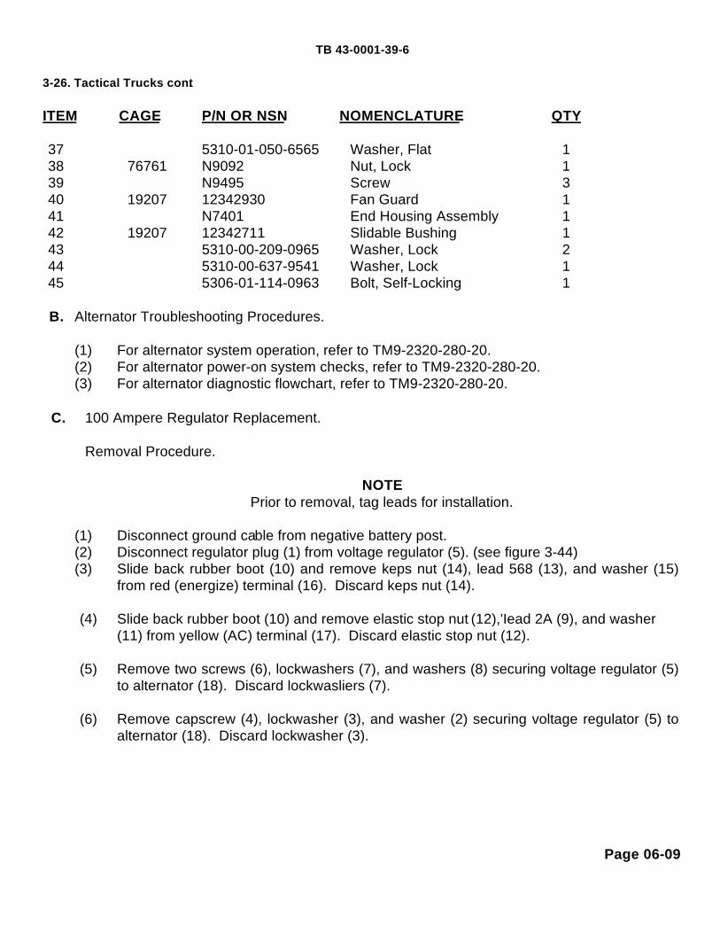
TB 43-0001-39-6
3-26. Tactical Trucks cont.
ITEM CAGE P/N OR NSN NOMENCLATURE QTY
37 5310-01-050-6565 Washer, Flat 138 76761 N9092 Nut, Lock 139 N9495 Screw 340 19207 12342930 Fan Guard 141 N7401 End Housing Assembly 142 19207 12342711 Slidable Bushing 143 5310-00-209-0965 Washer, Lock 244 5310-00-637-9541 Washer, Lock 145 5306-01-114-0963 Bolt, Self-Locking 1
B. Alternator Troubleshooting Procedures.
(1) For alternator system operation, refer to TM9-2320-280-20.(2) For alternator power-on system checks, refer to TM9-2320-280-20.(3) For alternator diagnostic flowchart, refer to TM9-2320-280-20.
C. 100 Ampere Regulator Replacement.
Removal Procedure.
NOTEPrior to removal, tag leads for installation.
(1) Disconnect ground cable from negative battery post.(2) Disconnect regulator plug (1) from voltage regulator (5). (see figure 3-44)(3) Slide back rubber boot (10) and remove keps nut (14), lead 568 (13), and washer (15)
from red (energize) terminal (16). Discard keps nut (14).
(4) Slide back rubber boot (10) and remove elastic stop nut (12),'Iead 2A (9), and washer(11) from yellow (AC) terminal (17). Discard elastic stop nut (12).
(5) Remove two screws (6), lockwashers (7), and washers (8) securing voltage regulator (5)to alternator (18). Discard lockwasliers (7).
(6) Remove capscrew (4), lockwasher (3), and washer (2) securing voltage regulator (5) toalternator (18). Discard lockwasher (3).
Page 06-09

TB 43-0001-39-6
3-26. Tactical Trucks Installation Procedure.cont.
(1) Apply NSN 8030-00-111-2762 sealing compound to threads ofcapscrew (4). (see figure 3-44)
(2) Install voltage regulator (5) on alternator (18) and secure withwasher (2), lockwasher (3), and capscrew (4). Tighten capscrew (4)to 90 lb-in (10 N•m).
(3) Apply NSN 8030-00-111-2762 sealing compound to threads of twoscrews (6).
(4) Install two washers (8), lock washers (7), and screws (6) in voltageregulator (5) and alternator (18). Tighten screws (6) to 30 lb-in (3N•m).
(5) Install washer (15), lead 568 (13), and keps nut (14) on red(energize) terminal (16). Tighten keps nut (14) to 25 lb-in (3 N•n).
(6) Apply 8030-01-328-0574 sealing compound to lead 568 (13) andkeps nut (14) on red (energize) terminal (16). Slide rubber boot(10)on lead 568 (13) over red (energize) terminal (16).
(7) Install washer (11), lead 2A (9) and elastic stop nut (12) on yellow(AC) terminal (17). Tighten elastic stop nut (12) to 20 lb-in (2 N•m).
(8) Apply 8030-01-328-0574 sealing compound to lead 2A (9) andelastic stop nut (12) on yellow (AC) terminal (1 7). Slide rubber boot(10) on lead 2A (9) over yellow (AC) terminal (17).
(9) Connect regulator plug (1) to voltage regulator (5).(10) Connect ground cable to negative battery post.
D. 100 Ampere Alternator Replacement. Removal Procedure.
NOTEPrior to removal, tag leads for installation.
(1) Disconnect ground cable from negative battery post.(2) Remove screw (6), lockwasher (7), washer (8), and lead 3B (9) from
ground point (IO) on alternator (1). (see figure 3-45) Discardlockwasher (7).
(3) Slide back rubber boot (5) and remove keps nut (4), washer (3), andlead 5A (2) from positive terminal (II) on alternator (1). Discard kepsnut (4).
(4) Slide back rubber boot (18) and remove keps nut (I 9), lead 568(15), and washer (20) from red (energize) terminal (21). Discardkeps nut (19).
(5) Slide back rubber boot (16) and remove elastic stop nut (1 7), lead2A (1 3), and washer (14) from yellow (AC) terminal (12). Discardelastic stop nut (17).
Page 06-10

TB 43-0001-39-6Tactical Trucks cont.
(6) Loosen two capscrews (31) and (36) on alternator adjusting bracket (33.).
(7) Loosen two capscrews (38) and (39) securing alternator (1) to mounting bracket (30), powersteering line support bracket (41), and rear support bracket (42). (see figure 3-45)
(8) Remove two drivebelts (34) from alternator pulley (24).
WARNING
Alternator must be supported during removal and Installation. Failure to supportalternator may cause Injury to personnel or damage to equipment.
(9) Remove capscrew (31) and lockwasher (32) securing adjusting bracket (33) to alternator (1).(see figure 3-45) Discard lockwasher (32).
(10) Remove capscrew (36), washer (35), and adjusting bracket (33) from mounting bracket (30).Discard capscrew (36).
(11) Remove two capscrews (38) and (39) and lockwashers (37) and (40) securing alternator (1),power steering lines bracket (41), and rear support bracket (42) to mounting bracket (30).Discard lockwashers (37) and (40).
(12) Remove alternator (1).(13) Remove three capscrews (27) and washers (28) securing fan guard (29) to alternator (1).(14) Remove nut (22) and washer (23) from shaft assembly (25) on alternator (1). Discard nut
(22).(15) Remove pulley (24) and woodruff key (26) from shaft assembly (25) on alternator (1).
Installation Procedure.
(1) Install woodruff key (26) and pulley (24) to shaft assembly (25) on alternator (1). (see figure 3-45 )
(2) Install washer (23) and nut (22) to shaft assembly (25) on alternator (1). Tighten nut (22) to120 lb-ft (163 N m).
(3) Install fan guard (29) on alternator (1) and secure with three washers (28) and capscrews(27). Tighten capscrews (27) to 90-120 lb-in (10-12 N m).
WARNING
Alternator must be supported during removal and Installation. Failure to supportalternator may cause Injury to personnel or damage to equipment.
Page 06-11

TB 43-0001-39-6
3-26. Tactical Trucks cont.(4) Position alternator (1) on mounting bracket (30) and secure with washer- (37) and
capscrew (38). (see figure 3-45) Do not tighten capscrew (38).(5) Position power steering line support bracket (41), rear support bracket (42), and
alternator (1)to mounting bracket (30) and secure with washer (40) and capscrew(39).Do not tighten capscrew (39).
(6) Position alternator adjusting bracket (33), washer (35), and capscrew (36) to mounting bracket (30). Do not tighten capscrew (36).
(7) align alternator (1) with adjusting bracket (33) and install lockwasher (32) and capscrew (31). Do not tighten capscrew (31).
(8) Install two drive belts (34) on pulley (24).(9) Adjust alternator and power steering belts. (Refer to TM9-2320-280-20.)
(10) Install washer (20), lead 568( (15), and keps nut (19) on red (energize) terminal (21).Tighten keps nut (1 9) to 25 lb-in (3 N●m).
(11) Apply NSN 8030-01-328-0574 sealing compound to lead 568 (15) and keps nut (I 9) on red (energize) terminal (21). Slide rubber boot (18) on lead 568 (15) over terminal (21).
(12) Install washer (14), lead 2A (13), and elastic stop nut (17) on yellow (AC) terminal (12).Tighten elastic stop nut (17) to 20 lb-in (2 N●m).
(13) Apply NSN 8030-01-328-0574 sealing compound to lead 2A (13) and elastic stop nut(17) on yellow (AC) terminal (12). Slide rubber boot (16) on lead 2A (13) over yellow (AC) terminal(12).
(14) Install lead 5A (2), washer (3), and keps nut (4) to positive terminal (11) on alternator (1). Tighten nut (4) to 65 lb-in (7 N●m).
(15) Apply NSN 8030-01-328-0574 sealing compound to lead 5A (2) and keps nut (4) to positive terminal (11) on alternator (1). Slide rubber boot (5) on lead 5A (2) over positive terminal(11).
(16) Install lead 3B (9), washer (8), lockwasher (7), and screw (6) to ground point (10) on alternator (1). Tighten screw (6) to 80 lb-in (9 N●m).
(17) Apply NSN 8030-01-328-0574 sealing compound to lead 3B (9) and screw (6) on ground point( 10) and alternator (1).
(18) Connect ground cable to negative battery post.
E. 100 Amperes Alternator Testing and Repair
Alternator Output Testing Procedure
Page 06-12

TB 43-0001-39-6
3-26. Tactical Trucks cont.
(1) Mount pivot arm of 500-amp test stand to high speed side and screw mounting flangeadapter to pivot arm. Connect pulley drive shaft to high speed head. Screw pulley drive shaft tomounting flange adapter.
(2) Mount alternator to starter / alternator mounting bracket on 500-amp test stand. Connect "V"belt from 500-amp test stand pulley to alternator pulley. Adjust belt tension.
NOTEFigures 3-56 and 3-57 illustrate connecting and testing 1 00-amp alternator system withapplicable test stands. Prior to operation of test stand ensure all switches and controls are inthe "initial" position. Refer to:
a) TM9-4910-663-12 for UMC model GASR-500.b) TM9-4910-485-12 for sun model AGT-9/9A.
(3) Connect cable from alternator ground terminal to 500-amp test stand "G-" terminal. Connectcable from alternator "BAT" terminal to 500-amp test stand "G+" terminal. Connect cable fromalternator regulator- "IGN" to 500-amp test stand "F" terminal.
(4) Make a jumper wire with a ring terminal at both ends. Connect jumper wire on 500-amp teststand from "IGN" switch terminal to "F-B" terminal.
(5) Set 500 amp test stand as follows: GSAR-500 SUNa. DC Load Ammeter Switch to X10 500 ampb. DC Field Ammeter- to X1 5 ampc. Field Circuit Switch to Regulator Regulatord. DC Voltmeter select to Rect / Gen Rect / Gen
(6) Perform no-load test. Set test stand battery circuit selector to 24 VDC, IGN switch to ON, andstart varidrive. Observing the DC voltmeter output voltage and tachometer rpm, increase speeduntil tachometer reads 5000 rpm. Record voltmeter reading and refer to table 6-A for diagnosis.
(7) Perform full-load test. Set test stand battery circuit selector to 24 VDC, IGN switch to ON, startvaridrive, and set the 100A load bank switch to ON. Snap the load bank master switch to theON position and adjusting variable load control to 91 ± 1 0 percent amp load. Observing theDC output readings. Refer to table 6-B for diagnosis.
(8) Regulator Bypass Test.
Page 06-13

TB 43-0001-39-63-26. Tactical Trucks cont.
NOTEPerform this test only when instructed from tables 6-A and 6-B
a. Prepare alternator as in full-load test.
NOTEUse jumper wire rated for 15 amps.
b. Disconnect alternator connector from regulator. With alternator spinning, use jumper wireand short pin "A' of connector to ground momentarily. Record results.
c. Ampere should rise within ± 10 percent of rated output with jumper wire connected and fallwith jumper wire disconnected. Refer to table 6-C for diagnosis.
(9) Turn test stand master power switch and load switch to "OFF".(10) Disconnect jumper wires from terminals on test stand and alternator.(11) Remove "V" belt from test stand pulley and alternator pulley. Remove alternator from test
stand..
AMPS VOLTS DIAGNOSISHigh Low Test bench battery is discharged (or defective). Allow to charge (or
replace).High Normal Give time to stabilize while monitoring volts. If volts rise above
normal range (26-30 volts), regulator and / or tube assemblymust be replaced. If amps fall, charging system is OK.
High High Stop test. Regulator and / or tube assembly must be replaced.Refer to static testing.
Low Low Alternator and / or regulator must be repaired or replaced.Perform regulator bypass test. Refer to table 6-C.
Low Normal Regulator OK Perform full-load test. Refer to table 6B.Low High Stop test. Bench malfunction or wiring error
Table 6-A. No-Load Test.
Page 06-14

TB 43-0001-39-63-26. Tactical Trucks cont.
AMPS VOLTS DIAGNOSIS
High Low Test bench battery is discharged (or defective). Allow to charge(or replace).
High Normal Charging system OK.High High Stop test. Regulator and / or tube
assembly must be replaced. Refer to static testing.
Low Low Alternator and / or regulator must be repaired or replaced. Perform regulator bypass test. Refer to table 6-C.
Low Normal Increase load.Low High Stop test. Bench malfunction or wiring
error.
Table 6-B. Full-Load Test.
CONNECT DISCONNECT DIAGNOSIS
Amps Rise Amps Fall Alternator OK. See note. Replace regulator only if low amps/low volts are indicated in table 6-A and/ or table 6-B.
No Charge No Charge Alternator must be repaired. Refer to statictesting.
Table 6-C. Regulator Bypass Test.
Disassembly Procedure.
NOTEComplete alternator disassembly is not required for static testing.
Page 06-15

TB 43-0001-39-63-26. Tactical Trucks cont.
(1) Secure core and shaft assembly (1) in a soft-jawed vise and removelocknut (4), washer (3),and fan (2). (see figure 3-46) Discard locknut (4).
(2) Remove bearing bushing (1) from core and shaft assembly (9). (seefigure 3-47).
(3) Remove four screws (2) and lockwashers (3) securing cover plate (4) tofront housing assembly (5). Discard lockwashers (3).
(4) Scribe alignment marks (8) on front housing assembly (5) to shell stator/ field coil assembly (6) and end housing assembly (7).
(5) Disconnect regulator plug (1) from voltage regulator (5). (see Figure 3-44).
(6) Remove two screws (6), lockwashers (7), and washers (8) securingvoltage regulator (5) to alternator (18). Discard lockwashers (7).
(7) Remove capscrew (4), lockwasher (3), and washer (2) securing voltageregulator (5) to. alternator (18). Discard lockwasher (3).
(8) Remove nine locknuts (7) securing end housing assembly (6) to shell /stator / field coil assembly (1). (see figure 3-48). Discard locknuts (7).
(9) Use a puller to remove end housing assembly (6) from shell / stator /field coil assembly (1).
(10) Remove three screws (5), lockwashers (4), and washers (3) securingrotor assembly (2) to core and shaft assembly (9). Discard lockwashers(4).
(11) Use three 10-32x2-inch machine screws(5)as jacks in threadedholes(l)on end plate of rotor assembly (4). Gradually tighten screws (5)and remove rotor assembly (4) from core and shaft assembly (2). (seefigure 3-49).
(12) Use a press or bearing puller to remove rear bearing (3) from core andshaft assembly (2).
NOTEPrior to removal, tag leads for installation.
(13) Remove eight nuts (1) securing two field leads (2) and six phase leads(5) to diodes in Front housing assembly (7) and disconnect leads (2)and (5). (see figure 3-50)
(14) Remove nine locknuts (1) securing front housing assembly (6) to shellstator / field coil assembly (2). (see figure 3-51) Discard locknuts (1).
(15) Remove front housing assembly (6) from shell / stator / field coilassembly (2) by tapping lightly with a soft-faced mallet.
(16) Remove retaining ring (1) from core and shaft assembly (2) and fronthousing assembly (3). (see figure 3-52)
Page 06-16

TB 43-0001-39-63-26. Tactical Trucks cont.
WARNING
Always support alternator core shaft assembly during removal.Failure to do so may cause Injury to personnel or equipmentdamage.
(17) Use press to remove core and shaft assembly (2) from front bearing (4) andfront housing assembly (3). (see figure 3-52)
(18) Remove front (1) and rear (4) retaining rings from front housing assembly(2). (see figure 3-53)
(19) Use a press to remove front bearing (3) from front housing assembly (2).(20) Remove three screws (6), lockwasher-s (5), and washers (4) securing front
rotor assembly (2) to core and shaft assembly (3). (see figure 3-54) Discardlockwashers (5).
(21) Use three 10-32x2-inch machine screws (1) in threaded holes on end plateof front rotor assembly (2). Gradually tighten screws (1) and remove rotorassembly (2) from core and shaft assembly (3).
Static Testing Procedure.
NOTERefer to disassembly procedure for component removal, if necessary.
(1) Perform Stator Test.
a. Remove six nuts and phase leads from diodes in front housing.(see figure 3-55)
b. Set ohmmeter to X1 scale and zero ohmmeter.c. Connect ohmmeter leads between each successive pair of
stator phase leads "P1” -'“P2”, “P2” - "P3", and ”P1" - "P3".Ohmmeter should read less than 1 ohm. If ohmmeter readsinfinity (∞), the stator is open. Replace alternator.
d. Set ohmmeter to X10 scale and zero ohmmeter.e. Connect ohmmeter leads between each phase lead, "PI ", "P2",
and "P3" and the ground point on outside of front housing.Ohmmeter should read infinity (∞). If ohmmeter reads zero, thestator is grounded. Replace alternator.
f. Repeat step (e) to check phase leads "P4", "P5", and "P6".
Page 06-17

TB 43-0001-39-63-26. Tactical Trucks cont.
(2) Perform Field Coil Test.a. Remove two nuts and field coil leads (F+, F-) from diodes in front housing. (see figure
3-55)b. Set ohmmeter to X1scale and zero ohmmeter.C. Connect ohmmeter leads to the two field coil leads (F+, F-). Ohmmeter should read less
than 3 ohms. If ohmmeter reads more than 3 ohms, the field coil is open. Replacealternator.
d. Set ohmmeter to X10 scale and zero ohmmeter.e. Connect one ohmmeter lead to a field coil lead and the other to the ground point on the
front housing. Ohmmeter should read infinity (∞). If ohmmeter reads less than 100Kohms, the field coil is grounded. Replace alternator.
(3) Perform Positive Diode Test.
a. Set ohmmeter to X100 scale and zero ohmmeter.b. Connect one ohmmeter lead to the "B+" output stud and the other lead to each of the six
diode terminals "S". (see figure 3-55) Ohmmeter should read nearly alike for all six,either less than 600 ohms or infinity (∞). Reverse ohmmeter leads. Ohmmeter shouldread nearly alike for all six, but opposite the first set of readings. If readings are notopposite, the diode rectifier assembly is open. Replace alternator.
(4) Perform Negative Diode Test.
a. Set ohmmeter to X100 scale and zero ohmmeter.b. Connect one ohmmeter lead to the ground point and the other lead to each of the six
diode terminals "S". (see figure 3-55) Ohmmeter should read nearly alike for all six,either less than 600 ohms or infinity (∞). Reverse ohmmeter leads. Ohmmeter shouldread nearly alike for all six, but opposite the first set of readings. If readings are notopposite, the diode rectifier assembly is open. Replace alternator.
Cleaning Procedure.
Clean all alternator components in accordance with TM9-2320-280-34, paragraph 2-9.
Assembly Procedure.
Page 06-18

TB 43-0001-39-63-26. Tactical Trucks cont.
WARNINGAlways support alternator core and shaft assembly during Installation.Failure to do so may cause Injury to personnel or equipment damage.
(1) Install front rotor assembly (2) on core and shaft assembly (3). (see figure 3-54)(2) Apply NSN 8030-00-111-2762 sealing compound to three screws (6).(3) Align slots in front rotor assembly (2) to mount holes on core and shaft assembly (3) and secure
with three screws (6), lockwashers (5), and washers (4). Tighten screws (6) to 45 lb-in (5 N m).(4) Coat outer race of front bearing (3) with a thin coat of NSN 8030-00-111-2762 sealing compound.
(see figure 3-53)(5) Use a press to install front bearing (3) in front housing assembly (2).(6) Install front (1) and rear (4) retaining rings in front housing assembly (2).
WARNINGAlways support alternator core and shaft assembly during Installation.Failure to do so may cause Injury to personnel or equipment damage.
(7)Use a press to install front bearing (4) and front housing assembly (3) on core and shaft assembly(2). (see figure 3-52)
(8) Install retaining ring (1) on core and shaft assembly (2). (9) Insert core and shaft assembly (5) and front housing assembly (6) into shell stator/ field coil assembly (2). (see figure 3-51)
NOTEAlign scribe marks on front housing assembly and shell / stator / field coil assembly.
(10) Feed leads (4) from shell / stator / field coil assembly (2) through front housing assembly (6).(see figure 3-51)
(11) Apply NSN 8030-00-111-2762 sealing compound to studs (3) on shell stator / field coilassembly (2).
(12) Secure front housing assembly (6) to shell / stator/ field coil assembly (2) with nine locknuts(1). Tighten locknuts (1) to 18 lb-in (2 N m).
Page 06-19

TB 43-0001-39-6
3-26. Tactical Trucks cont.
(13) Install six washers (3), phase leads (5), and nuts (8) to diodes (6) onfront housing assembly (7). (see figures 3-50 and 3-55) Tighten nuts (8)to 18 lb-in (2 N•m).
(14) Install two washers (3), field leads (2), and nuts (1) to studs (4) on fronthousing assembly (7). Tighten nuts (1) to 18 lb-in (2 Nom).
(15) Apply a thin coat of NSN 8030-01-159-4844 sealant to leads (2) and (5)on studs (4), diodes (6), and front housing assembly (7).
WARNING
Always support alternator core and shaft assembly duringInstallation. Failure to do so may cause Injury to personnel orequipment damage.
(16) Use a press to install rear bearing (3) on core and shaft assembly (2).(see figure 3-49)
(17) Install rear rotor assembly (4) on core and shaft assembly (2).(18) Apply NSN 8030-,00-111-2762 seating compound to three screws (5).
(see figure 3-48)(19) Align slots in rear rotor assembly (2) to mount holes on core and shaft
assembly (9) and secure with three screws (5), lockwashers (4), andwashers (3). Tighten screws (5) to 45 lb-in (5 N m).
NOTEAlign scribe marks on end housing assembly and shell / stator / field coilassembly.
(20) Install end housing assembly (6) on core and shaft assembly (9) and rearbearing (10). (see Figure 3-48) Tap lightly with a soft-faced mallet.
(21) Apply NSN 8030-00-111-2762 sealing compound to studs (8) on shellstator/ field coil assembly (1).
(22) Secure end housing assembly (6) to shell / stator / field coil assembly (1)with nine locknuts (7). Tighten locknuts (7) to 18 lb-in (2 N m).
(23) Apply NSN 8030-00-111-2762 sealing compound to threads of capscrew(4). (see figure 3-44)
(24) Install voltage regulator (5) on alternator (18) and secure with washer (2),lockwasher (3), and capscrew(4).
(25) Apply NSN 8030-00-111-2762 sealing compound to threads of two screws(6).
(26) Install two washers (8), lockwashers (7), and screws (6) in voltageregulator (5) and alternator (18).
(27) Connect regulator plug (1) to voltage regulator (5).
Page 06-20

TB 43-0001-39-6
3-26. Tactical Trucks cont.
(28) Install fan(2)on core and shaft assembly (l) and securewith washer (3) and locknut (4). (see figure 3-46)
WARNINGAlways support alternator core and shaft assembly duringInstallation. Failure to do so may cause Injury to personnel orequipment damage.
(29) Secure core and shaft assembly (1) on a soft-jawedvise. (see figure 3-46) Tighten locknut (4) to 50 lb-ft (68N●m).
(30) Install coverplate (4) on front housing assembly (5) andsecure with four lockwashers (3) and screws (2). (seefigure 3-47)
(31) Install bearing bushing (1) on core and shaft assembly(9).
PUBLICATIONS AFFECTED:TM9-2320-280-20TM9-2320-280-20PTM9-2320-280-34TM9-2320-280-34P
LEVEL OF MAINTENANCE:Unit and Direct Support
Page 06-21

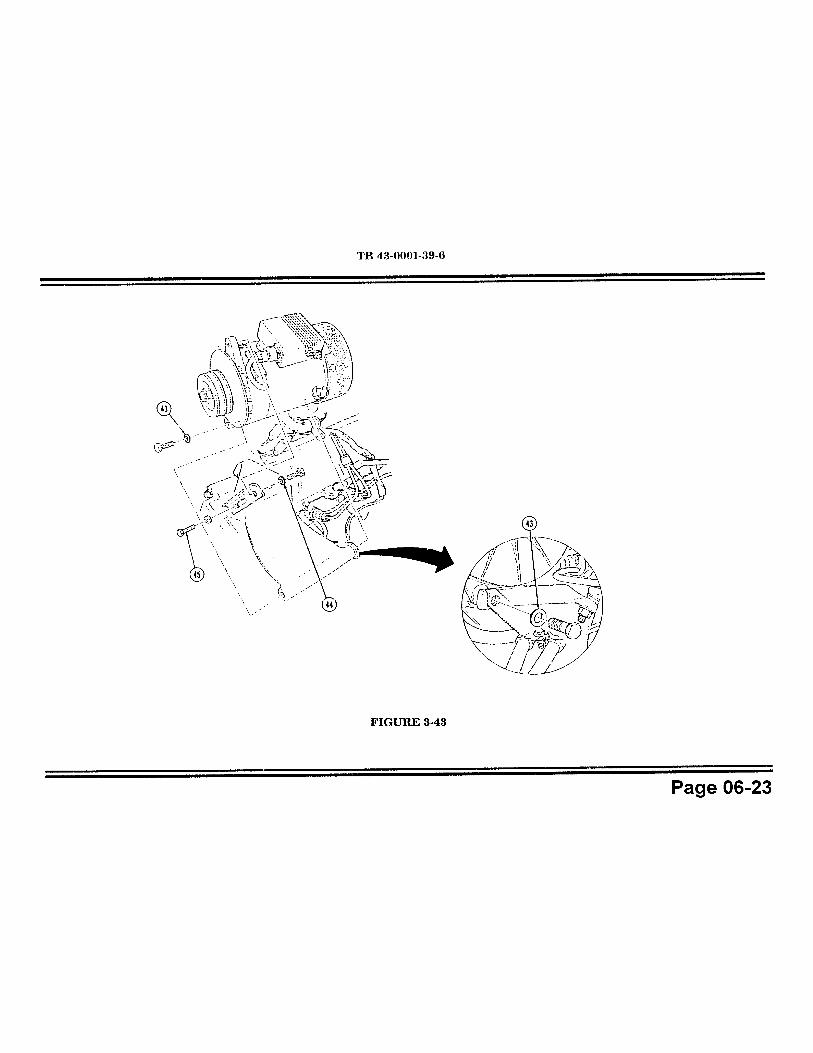


3.8 Tactical Trucks
MODEL:HMMWVs
SUBJECT:HMMWV Starter
POC:Ms. Jody McInerney, AMSTA-IM-MTA, DSN 786-7346, Commercial (810) [email protected]
DEFICIENCY:Due to recent reports of problems with the HMMWV Starter, such as, loose starter bolts (from wrongbolts being used), front support bracket missing, and improper shimming, we are publishing thisarticle. It contains the latest information related to HMMWV starter maintenance.
COMMENTS:A. Order NSN 5305-01-285-4923, CAGE 34623, PN 5598856 to receive the correct bolt. This boltshould be 4-5/8 inches long (no more, no less) and a sealing compound pre-applied. You shouldtorque these bolts to 30-40 lb-ft (41-54 N•m). If you get or have bolts that are the correct length butdon't have loctite pre-applied, apply sealing compound NSN 8030-00-148-9833 before installing.
B. Make sure you have the starter mounting bracket installed. We are replacing the old bracket(NSN 2910-01-168-7873, PN (19207) 12338793) with a new bracket PN (19207) 12446777 (no NSNassigned yet). The new bracket's slot is positioned so that it cradles the stud.
Also, the original design used a locknut and washer to secure the starter to the mounting bracket.This locknut and washer is replaced by a serrated flanged hex locknut (NSN 5310-01-381-1471, PN(24617) 9411507). This locknut should be tightened to 15-19 lb-ft (20-26 N•m).
C. As far as using shims when installing the starter, you no longer have to note the size of shims forinstallation. You only need to install a .08 in (2 mm) shim on your starter. The PN/NSN for this shimis (19207) 12338789-2, NSN 5365-01-210-4903. Using the .08 shim will give you the proper gearmesh tolerance for starter pinion and flywheel gear.
D. If you would like to save time down the road, the next time you replace your starter, you may wantto consider replacing the one-piece torque converter cover with a two-piece torque converter cover(NSN 5340-01-311-1633). It will save you about an hour and half of time the next time you replaceyour starter.
PUBLICATIONS AFFECTED:None
LEVEL OF MAINTENANCE:Unit
Page 06-33

TB 43-0001-39- MARCH 1996
3-11. Tactical Trucks MODEL:M998 Series HMMWV
SUBJECT:STARTER Replacement of Vehicles with ARCTIC HEATER Kit Installed
POC:Ms. Kathy Catenaro, AMSTA-IM-MTA, DSN 786-7151,Commercial (810) [email protected]
DEFICIENCY:Starter removal is a Unit level task, and the Arctic Heater Oil Pan Shroudhas to be removed to get at it.Arctic Heater Oil Pan Shroud removal is presently listed as a DS task.
COMMENTS:Removal of Arctic Heater Oil Pan Shroud is now authorized at Unit level.The TMs will be changed to reflect this authorization. The followingprocedures will be put in TM9-2320-280-20-2.
PROCEDURES:ARCTIC HEATER OIL PAN SHROUD REPLACEMENT
This task covers:a. Removal b. Installation
Materials/Parts ToolsCotter pin (Appendix E, Item 8.1) General mechanic's tool kit:Nine nut and lockwasher assemblies automotive(Appendix E, Item 73.1) (NSN 5180-00-177-7033)
WARNINGDo not touch hot exhaust system components with bare hands.Severe Injury will result.
Page 06-34

TB 43-0001-39-8 MARCH 1996
3-1 1. Tact. Trucks cont. a. Removal
1. Remove cotter pin (8) securing flex tube (7) to oil pan shroud(6) and disconnect flex tube (7). Discard cotter pin (8). (seefigure 3-11)
2. Remove two nut and lockwasher assemblies (5) and washers(4) securing starter cable bracket (3), oil pan shroud (6), andwasher (2) to oil pan (1). Discard nut and lockwasherassemblies (5).
3. Remove seven nut and lockwasher assemblies (9) andwashers (10) securing oil pan shroud (6) to oil pan (1) andremove oil pan shroud from oil pan (1).
b. Installation
1. Install oil pan shroud (6) on oil pan (1) and secure with sevenwashers (10) and nut and lockwasher assemblies (9).
2. Secure washer (2), oil pan shroud (6), and starter cablebracket (3) to oil pan (1) with two washers (4) and nut andlockwasher assemblies (5).
3. Connect flex tube (7) to oil pan shroud (6) and secure withcotter pin (8).
PUBLICATIONS AFFECTED:TM9-2320-280-34TM9-2320-280-20TM9-2320-280-20P
LEVEL OF MAINTENANCE:Unit
Page 06-35

All M998 and M998A1 Series HMMWV
SUBJECT:Instrument Cluster Lamp and Lens
POC:Leona Milas, AMSTA-IM-MTA, DSN 786-7346, Commercial (810) [email protected]
DEFICIENCY:Reports from the field indicate the incandescent lamp for the instrument clusterlight gets hot with prolonged use on high, causing the green lens to melt.
COMMENTS:A Light Emitting Diode (LED), P/N 12460228, and clear lens, P/N 12339203-1,have been developed to replace the current lamp and green lens. The LEDproduces far less heat during operation, and is available in a kit, P/N 57K3238,which includes both the LED and the clear lens. Replacement of the lamp andlens can be accomplished in the field using the parts below and the procedureslocated in TM9-2320-280-20.
MATERIALS/PARTS:Listed below is the replacement kit. Items in the kit may be ordered separatelyand are also listed.
PART NUMBER CAGE CODE NOMENCLATURE QTY57K3238 19207 Kit, Lens and Lamp Replacement A/R12339203-1 19207 Lens (Part of Kit P/N 57K3238) 112460228 19207 LED (Part of Kit P/N 57K3238) 1
PUBLICATIONS AFFECTED:TM9-2320-280-20-2TM9-2320-280-20PTM9-2320-280-34P
LEVEL OF MAINTENANCE:Unit
Page 06-37

8-7. Misc. Vehicles MODEL :All Army Vehicles
SUBJECT :Repair of Master Light Switch, NSN 5930-00-307-8856
POC:Mr. Darius Greene, AMSTA-MTB, DSN 786-7342,Commercial (810) 574-7342
DEFICIENCY:There are no repair procedures for the light switch and thefield discards the switch when it fails.
COMMENTS:Reports from the field indicates that the most common causeof the light switch failing is the build-up of corrosion on theinternal contacts. Units may use the following procedures toremove the corrosion from the contacts and repair theswitch.
PROCEDURES:A. Remove switch from vehicle in accordance with the
appropriate vehicle's TM.
NOTEThe light switch assembly contains small parts. Care shouldbe taken when disassembling the switch assembly.
B. Remove screw securing the back cover to the switch.
C. Remove back cover from switch.
Page 06-38

8-7. Misc. Vehicles cont. D. Remove three screws and control assembly from switch housing.
E. Rotate disks to disengage the locking tabs and remove the lockingclip.
F. Taking care not to lose the electrical contacts, turn the switchassembly over so that the disks are onthe bottom.
G. Rotate and remove each disk, one at a time.
H. Clean all terminals/contacts with emery cloth or steel wool.
I. Reinstall disks and ensure that the locking tabs and clips are inplace.
J. Test switch for operation.(If the switch assembly does not operateproperly, repeat steps E thru J). If still inoperative, discard lightswitch assembly.
K. Remove lever stems from switch housing and insert in disks.
L. Reinstall control assembly and three screws in switch housing.
M. Reinstall cover and screw on switch assembly.
N. Install switch assembly on vehicle in accordance with theprocedures provided in the vehicle's TM.
PUBLICATIONS AFFECTED:None
LEVEL OF MAINTENANCE:Unit
8-3. Tactical Trucks MODEL:HMMWV
SUBJECT:Brake Warning Lamp Stays On
POC:
Page 06-39
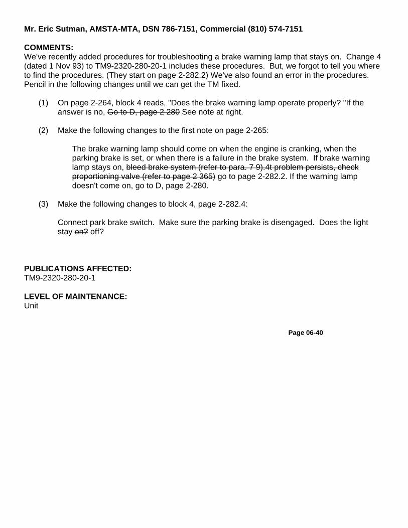
Mr. Eric Sutman, AMSTA-MTA, DSN 786-7151, Commercial (810) 574-7151
COMMENTS:We've recently added procedures for troubleshooting a brake warning lamp that stays on. Change 4(dated 1 Nov 93) to TM9-2320-280-20-1 includes these procedures. But, we forgot to tell you whereto find the procedures. (They start on page 2-282.2) We've also found an error in the procedures.Pencil in the following changes until we can get the TM fixed.
(1) On page 2-264, block 4 reads, "Does the brake warning lamp operate properly? "If theanswer is no, Go to D, page 2 280 See note at right.
(2) Make the following changes to the first note on page 2-265:
The brake warning lamp should come on when the engine is cranking, when theparking brake is set, or when there is a failure in the brake system. If brake warninglamp stays on, bleed brake system (refer to para. 7 9).4t problem persists, checkproportioning valve (refer to page 2 365) go to page 2-282.2. If the warning lampdoesn't come on, go to D, page 2-280.
(3) Make the following changes to block 4, page 2-282.4:
Connect park brake switch. Make sure the parking brake is disengaged. Does the lightstay on? off?
PUBLICATIONS AFFECTED:TM9-2320-280-20-1
LEVEL OF MAINTENANCE:Unit
Page 06-40
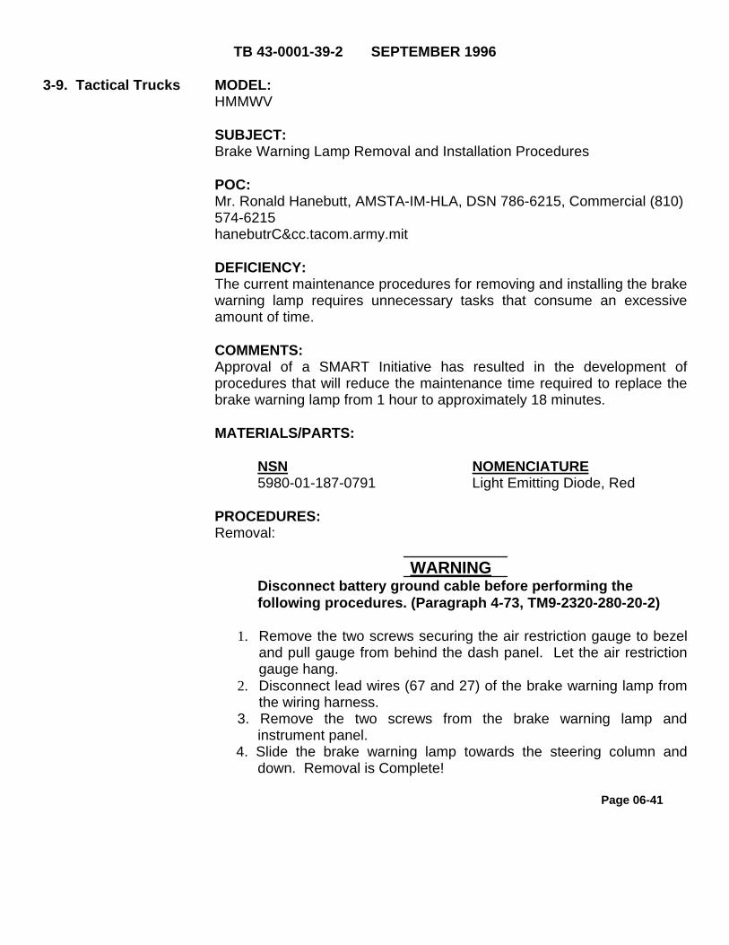
TB 43-0001-39-2 SEPTEMBER 1996
3-9. Tactical Trucks MODEL:HMMWV
SUBJECT:Brake Warning Lamp Removal and Installation Procedures
POC:Mr. Ronald Hanebutt, AMSTA-IM-HLA, DSN 786-6215, Commercial (810)574-6215hanebutrC&cc.tacom.army.mit
DEFICIENCY:The current maintenance procedures for removing and installing the brakewarning lamp requires unnecessary tasks that consume an excessiveamount of time.
COMMENTS:Approval of a SMART Initiative has resulted in the development ofprocedures that will reduce the maintenance time required to replace thebrake warning lamp from 1 hour to approximately 18 minutes.
MATERIALS/PARTS:
NSN NOMENCIATURE5980-01-187-0791 Light Emitting Diode, Red
PROCEDURES:Removal:
WARNINGDisconnect battery ground cable before performing thefollowing procedures. (Paragraph 4-73, TM9-2320-280-20-2)
1. Remove the two screws securing the air restriction gauge to bezeland pull gauge from behind the dash panel. Let the air restrictiongauge hang.
2. Disconnect lead wires (67 and 27) of the brake warning lamp fromthe wiring harness.
3. Remove the two screws from the brake warning lamp andinstrument panel.
4. Slide the brake warning lamp towards the steering column anddown. Removal is Complete!
Page 06-41

TB 43-0001-39-2 SEPTEMBER 1996
3-9. Tact. Trucks cont. Installation:1. Install tape around the new lamp and lead wires
(67 and 27). (see figure 3-7) Placing the tapearound the lead wires enables the installer to keepthe lamp in the proper position during installation.
NOTEWe found that tape works better for this application than twist or zip ties.
FIGURE 3-7
2. Maneuver the new brake warning lamp up alongthe steering column and to the left towards themount location on the dash panel.
3. Install lamp on dash panel with two screws.4. Connect lamp lead wires (67 and 27) to the wiring
harness.5. Install air restriction gauge behind dash panel on
bezel with two screws.6. Connect battery ground cable according toparagraph 4-73 of TM9-2320-280-20-2.
PUBLICATIONS AFFECTED:TM9-2320-280-20-2
LEVEL OF MAINTENANCE:Unit
Page 06- 42

8.2. Tactical Trucks MODEL:HMMWV M998 Series, M939, M809, M39 and 2 1/2 Ton Trucks
SUBJECT:Rusted Headlight Assembly Retaining Rings, PN 8741446, NSN 5365-00-832-5650
POC:Ms. Leona Milas, AMSTA-IM-HIA, DSN 786-5481,Commercial (810) [email protected]
COMMENTS:Water and condensation can accumulate in the bottom of the headlightassembly retaining ring causing a potential rust situation. To alleviatethis problem, a small hole may be drilled in the retaining ring to allowwater to drain out.
PROCEDURES:1. Remove retaining ring according to TM.
2. Clean and remove dirt/rust conditions from surface of retaining ring.
3. Drill a 9/64 inch hole in the bottom of the ring, 3/4 inch from the insideedge of the ring. (see figure 8-1)
4. Paint all unprotected areas.(Refer to TM 43-0139).
5. Replace retaining ring.
Page 06-43


8-2. Vehicles with Brakes cont. PUBLICATIONS AFFECTED:None
LEVEL OF MAINTENANCE:N/A
8-3. Tactical Trucks MODEL:All Tactical Vehicles
SUBJECT:Taillight Lens, NSN 6220-01-359-2870
POC:Lori Neal, AMSTA-FTMA, DSN 786-5703
DEFICIENCY:We approved an Engineering Change Proposal(ECP) TAC 7300 which altered the compositematerial on Taillight Lens, NSN 6220-00-179-4324from plastic to aluminum. The plastic and aluminumlens are not directly interchangeable. A plastic lenswill only fit correctly on a plastic housing and thesame is true of the aluminum lens.
COMMENTS:We have assigned a new NSN for the plasticconfiguration, NSN 6220-01-359-2870, P/N12375841. Deliveries from the contractor areexpected to begin in August 1993.
PROCEDURES:Advise all units to requisition NSN 6220-01-359-2870when replacing the lens on plastic housings. NSN6220-00-179-4324 should still be used whenrequisitioning the replacement lens for the aluminumhousing.
PUBLICATIONS AFFECTED:TM9-2320-262-20PMIL-STD-1179
Page 06-45

3-10. Tactical Trucks MODEL:HMMWV
SUBJECT:Battery Box
POC:Ms. Patricia Grashik, AMSTA-IM-HIA, DSN 786-5225, Commercial(810) 574-5225 [email protected]
COMMENTS:We added a semi-annual inspection of the battery tray bolts andwashers for corrosion. If corrosion is evident, wipe the bolts and/orwashers clean. If the corrosion cannot be removed, or the surface ofthe bolt is pitted, replace the bolt and washer (TM9-2320-280-20-2, Para4-80).
PUBLICATIONS AFFECTED:TM9-2320-280-20-1
LEVEL OF MAINTENANCE:Unit
Page 06-46

8-3. Miscellaneous MODEL:All Military Standard Batteries
SUBJECT:Repair of the Military Standard Battery
POC:Mr. Clarence Woodard, AMSTA-MCB, DSN 786-7362, Commercial(810) 574-7362 [email protected]
DEFICIENCY:TM9-6140-200-14, Page 4-2, Para 4-3 Battery Repair, does not statewhat batteries to use this repair procedure on.
COMMENTS:The 6TL battery NSN 6140-01-210-1964 may not be repaired IAW theseprocedures listed in the TM because of the plastic case and hollowbattery post, at this time there is no repair procedures for the plasticcase or battery post, as soon as they become available they will beissued to the field.
PROCEDURES:The procedures listed in TM9-6140-200-14 is to be used on thefollowing batteries: 6TN (black) NSN 6140-00-053-2554, 2HN NSN6140-00-053-2553 and 4HN NSN 6140-00-059-3528.
PUBLICATIONS AFFECTED:TM9-6140-200-14
LEVEL OF MAINTENANCE:Direct Support
Page 06-47

3-12. Tactical Trucks MODEL:HMMWV
SUBJECT:Slave Receptacle Mount
POC:Mr. Eric Sutman, AMSTA-MTA, DSN 786-7151, Commercial (810) 574-7151
DEFICIENCY:The HMMWV has a fiberglass mount for the slave receptacle. If themount is broken, you can ground the positive terminal of the slavereceptacle against the vehicle when connecting or disconnecting theslave cable. This could result in injury to personnel or damage toequipment.COMMENTS:
A. We received a SMART initiative about this problem. To alleviate theproblem of the mount breaking, the initiator recommended relocatingand mounting the receptacle to the rear of the passenger's seatcompartment. We looked at that idea, and we also considered changingthe material of the mount, and improving the procedures for slavestarting contained in TM9-2320-280-10.
B. We found that moving the receptacle isn't practical, and the materialthe mount is made out of is suitable for the HMMWV application. Thebest solution for reducing mount failures is to use a twisting motion whenyou connect the slave cable to, or remove it from, the receptacle.
C. Forcefully pushing the slave cable on, and pulling it off the receptaclecan cause the mount to break. Using a twisting motion to put the cableon and take it off will help to reduce failures of the mount.
D. To prevent accidentally grounding the receptacle against the vehicle, always make sure the receptacle is in good condition. There are two types of slave receptacles used on the HMMWV. Older models have a rubber boot that insulates the receptacle. Make sure the boot is in placeand serviceable before using the slave receptacle. The rubber boot will help to prevent accidental grounding. Newer HMMWVs have a one piece receptacle/cable assembly. The receptacle's terminals aren't exposed so you won't have a problem with accidental grounding.
Page 06-48

3-12. Tact. Trucks cont. PUBLICATIONS AFFECTED:TM9-2320-280-10
LEVEL OF MAINTENANCE:Operator
8-4. Miscellaneous MODEL:All Military Vehicles
SUBJECT:Electronic Battery Tester
POC:Mr. Clarence Woodard, AMSTA-IM-MCB, DSN 786-7362,Commercial (810) 574-7362 [email protected]
Page 06-49
EDITOR'S NOTE:This is an updated article that supersedes the one published in TB 43-0001-39-6, dated Sep 93. The following are the changes that weremade:
- new temperature compensation range- new charging / starting voltage- new voltmeter range

8-4. Miscellaneous cont. DEFICIENCY:Unit maintenance does not have a good way to test batteries beforethey are turned in except for the hand held electrolyte tester.
COMMENTS:This battery tester will allow the unit maintenance to perform a testbefore they turn in batteries as unserviceable. The NSN is 6625-01-032-4344 and the cost is approximately $300.00 each, so before youorder this item get your commanders approval. The following are thespecifications of the battery tester:
Battery rating range 150 to 1,250 CCATemperature Compensation range Battery below 32 degrees F.
will read lower by 15 to 20percent.
Battery Voltage Automatic 6-12 volt systemsCharging/starting voltage 12 volt systemsVoltmeter range 0- 16 voltsBattery Condition Scale Replace/Good (Red-Green)Protective, custom mold carrying case Standard
PUBLICATIONS AFFECTED:TM9-6140-200-14LEVEL OF MAINTENANCE:Unit, Direct Support, General Support and Depot
Page 06-50

3-24. Tactical Trucks MODEL:HMMWV
SUBJECT:Water in Battery Tray.
POC:Mr. Eric Sutman, AMSTA-MTA, DSN 786-7151
DEFICIENCY:The battery tray drainage relief notch becomes clogged with debrisallowing water to accumulate in the battery tray. If the water freezes itcould damage the battery.
COMMENTS:The PMCS in TM9-2320-280-10 includes a weekly procedure to cleardebris from the battery box drain holes. In most cases, performing thisprocedure will keep water from accumulating in the battery tray.
If you're having problems with water collecting in the battery traybetween PMCS services, it's OK to drill some holes in it. Remove thetray from the vehicle (TM9-2320-280-20). Drill four 1/2 inch holes in thebattery tray. (see figure 3-41) This will help keep water from collectingbetween services. Don't drill extra holes in the battery box floor. Thereare enough drain holes there already. Drilling extra holes in the batterybox floor could weaken the floor.
PUBLICATIONS AFFECTED:TM9-2320-280-20
LEVEL OF MAINTENANCE:Unit
Page 06-51

3-28. Tactical Trucks MODEL:HMMWV
SUBJECT:Diagnosing Electrical System Failures.
POC:Mr. Eric Sutman, AMSTA-MTA, DSN 786-7151
DEFICIENCY:There is no protection against corrosion at the electrical ground pointwhere wires 3C, 57A, and 79A are connected to the vehicle body.Corrosion at this point can cause problems in the HMMWV electricalsystem. Troubleshooting procedures can falsely identify these problemsas failures of the PCB or glow plug controller.
COMMENTS:A. When troubleshooting HMMWV electrical problems, always makesure the system you're working on is properly grounded. Thetroubleshooting procedures may tell you to replace the glow plugcontroller or the PCB when the problem is really a bad ground. Theground point is located on the firewall, behind the instrument cluster.Many of the HMMWV electrical systems, including the glow plugcontroller and the PCB, are grounded through this point. Beforereplacing any parts, clean the ground point to make sure the problem'snot a bad ground. After cleaning and reassembling the ground point,cover both sides with RTV to protect it against corrosion.
B. Excessive failures of the PCB, glow plug controller and glow plugsmight be an indication of a bad ground. After replacing failedcomponents use the following procedures to make sure the system isproperly grounded.
C. If you've experienced a problem like this on your HMMWV and theseprocedures help, we'd like to know about it. Give us a call or let your local TACOM LAR know.
Materials:737 RTV NSN 8030-01-328-0574Anti-seize Compound NSN 8030-00-155-6444Nut and Lockwasher Assembly (2 ea.) NSN 5310-01-252-2999
Page 06-52

3-28. Tactical Truckscont. PROCEDURE:
A. Remove instrument panel (1). (refer to TM9-2320-280-20-2, paragraph4-12) (see figure 3-77)
B. Remove nut and lockwasher assembly (3) securing engine harnessground lead 3C (4) to body (2). Remove nut and lockwasher assembly(5) and capscrew (7) securing harness ground leads 57A (6) and 79A(8) to body (2). Discard nut and lockwasher assemblies (3) and (5).
C. Inspect and clean wires and connection points.
D. Apply antiseize compound to harness leads 57A (6) and 79A (8) andsecure to body (2) with capscrew (7) and nut and lockwasher assembly(5). Apply antiseize compound to engine harness ground lead 3C (4)and secure to body (2) with nut and lockwasher assembly (3).
E. Cover leads 3C (4), 57A (6), and 79A (8) with RTV.
F. Install instrument panel (1).(refer to TM9-2320-280-20-2, paragraph 4-12)
PUBLICATIONS AFFECTED:TM9-2320-280-20-1TM9-2320-280-34
LEVEL OF MAINTENANCE:Unit
06-5 3
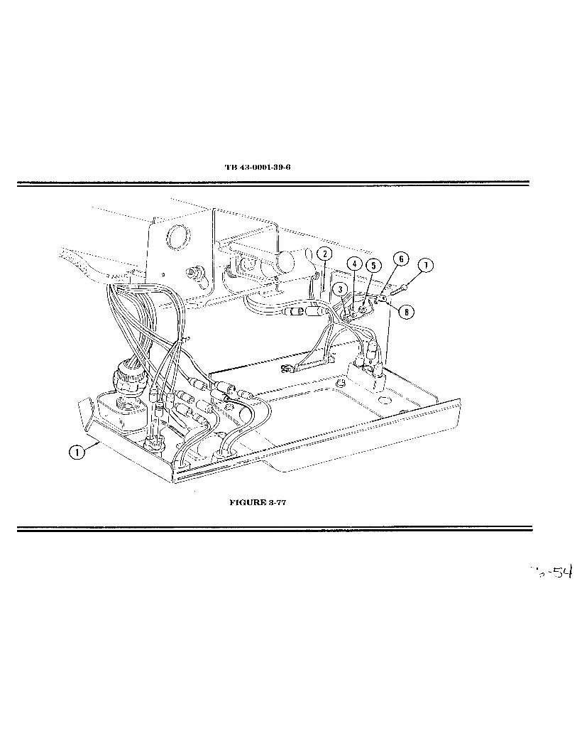


Chapter 07
TRANSMISSION
FunctionalGroup Code
0705-0708

TB 43-0001-39-1 JUNE 1996
8-3. Misc. Vehicles MODEL:Any Vehicle that uses Dexron II
SUBJECT:New Automatic Transmission Fluid, Dexron III
POC:Mrs. Landis Kazsuk, AMSTA-IM-H, DSN 786-8507, Commercial (810)574-8507 [email protected]
DEFICEENCY:Dexron II is being replaced with Dexron III.
COMMENTS:A. Dexron III is the new version of Dexron II. You will derive severalbenefits from using Dexron III in your transmission: higher flash and firepoints, lower foaming, increased thermal stability, greater oxidationstability, improved friction performance, and better corrosion resistance.As a result, equipment performance will improve and service life willlengthen.
B. Use the following National Stock Numbers (NSN) to order Dexron III:
9150-01-353-4799 1 Quart Plastic Bottle9150-01-114-9968 55 Gallon Drum
C. If your system is designed for Dexron III (your Technical Manuals,Lubrication Instructions and Lubrication Orders identify Dexron III as therequired product) you MUST use Dexron III. However, if you arecurrently using Dexron II in your system, adding Dexron III to it will notharm it. You do not have to flush Dexron II out of the system before youadd Dexron III to it.
D. Dexron II is nolonger manufactured and when the existing stock isexhausted, only Dexron III will be available. In an effort to deplete theinventory, Supply may force issue Dexron II. So if you order Dexron III,you may receive Dexron II. To prevent this from happening, use AdviceCode 2B and the NSNs for Dexron III stated above.
Page 07-01

TB 43-0001-39-1 JUNE 1996
8-3. Misc. Vehs. Cont . E. Until the supply is gone, you can still order Dexron II byusing the following NSNS:
9150-00-698-2382 1 Quart Can9150-00-657-4959 5 Gallon Can
PUBLICATIONS AFFECTED:All that contain Dexron II NSNs
LEVEL OF MAINTENANCE:All levels
Page 07-02

TB 43-0001-39-2 SEPTEMBER 19963-12. Tactical Trucks
MODEL:M998A2 Series Vehicles
SUBJECT:Replacement of 1995 4L80E Transmission (NSN 2520-01-399-4691) and/or1995 Transmission Control Module (TCM) E-Prom (NSN 5962-01- 430-0182)
POC:Ms. Patricia Grashik, AMSTA-IM-HLA, DSN 786-7566, Commercial (810) 574-7566 [email protected]
DEFICIENCY:The 1995 4L80E transmission used in M998A2 series vehicles is no longer inproduction and only five will be available when the vehicles are fielded. TM9-2320-280 series maintenance manuals do not contain E-Prom replacementprocedures.
COMMENTS:A. When it is necessary to replace the 1995 4L80E transmission, usetransmission replacement kit (19207) 57K3502, NSN 2520-01-430-5274. Thereplacement kit includes the 1996 4L80E transmission and 1996 calibrated E-Prom.
NOMENCLATURE CAGE/PART NO. NSN1996 Transmission (16764)24205114 2520-01-430-27651996 E-Prom (16764)16229203 5962-01-430-0208
B. It is necessary to replace the E-Prom located inside the TCM due to changesin the transmission shift points. The TCM controls transmission shift points andsequence based on signals from engine and transmission sensors. The E-Promis the "brain" of the TCM and is uniquely calibrated to its matching productionyear transmission to interpret transmission shift points and sensors.
C. GM informed us they will not supply the inner module assembly of the TCMpart number (16764) 16197359, NSN 5930-01-430-4541. The inner moduleassembly consists of a terminal box, circuit cards and E-Proms. Since we cannotget the TCM module complete, we have provisioned the terminal box, with thecircuit cards installed, and E-Proms separately. Also, since E-Prom replacementprocedures are not in the revision to TM9-2320-280 series manuals, wedeveloped the following procedures.
Page 07-03

TB 43-0001-39-2 SEPTEMBER 19963-12. Tact. Trucks cont.
MATERIALS/PARTS:NOMENCLATURE NSN/PART NO, QTY1995 E-Prom 5962-01-430-0182 1or1996 E-Prom 5962-01-430-0208 1RTV Adhesive Sealant 8040-00-938-1535 AR*Screw, Captive, M6 x 1.0-25 MM (5A910) 01620290 4*Screw, Machine M3.5 x 0.6-9 MM (39375)16074380 2Module, Transmission w/circuit cards 5940-01-430-2764 1
*Not available through the supply system yet. Provisioning actions on-going.Anticipate availability through the supply system 2nd Qtr FY97.
PROCEDURES:A. E-Prom Removal:
1. Disconnect negative battery cables. (Refer to TM9-2320-280-20.)2. Remove left rear seat. (Refer to TM9-2320-280-20.)3. Loosen four screws (1) and remove cover (2) and foam insulation (4) from
TCM box (8). (see figure 3-23)4. Remove two screws (5) and access panel (6) from terminal box (9).5. Disconnect E-Prom (10) from circuit board (7). Discard E-Prom.
B. E-Prom Installation Procedures:
NOTEFor proper calibration of E-Prom to transmission, ensure E-Prom isthe same production year as the transmission installed in vehicle.
1. Install E-Prom (10) on circuit board (7). (see figure 3-23)2. Install access panel (6) on terminal box (9) with two existing screws (5).3. Clean sealant from TCM box (8) and cover (2).4. Apply 1/8-in. bead of NSN 8040-00-938-1535 RTV adhesive sealant in
groove (3) on cover (2).5. Install foam insulation (4) and cover (2) on TCM box (8) and tighten four
existing screws (1). Tighten screws (1) to 30 lb-in (3 N•m).
Page 07-04

TB 43-0001-39-2 SEPTEMBER 1996
3-12. Tact. Trucks cont. 6. Install left rear seat. (Refer to TM9-2320-280-20).7. Connect negative battery cables. (Refer to TM9-2320-280-20.)
NOTETo replace the terminal box, disconnect input plug and testplug and remove terminal box from TCM.
PUBLICATIONS AFFECTED:TM9-2320-280-20TM9-2320-280-24P
LEVEL OF MAINTENANCE:Unit
Page 07-05

3-13. Tactical Trucks MODEL:All HMMWVs
SUBJECT:Transmission Modulator Assembly
POC:Ms. Jody McInerney, AMSTA-MTA, (810)574-7346
3-13. Tact. Trucks cont. COMMENTS:Currently, the replacement and adjustment procedures of thetransmission modulator assembly is at Direct Support. However, due toa SMART initiative, we are changing the authority level to replace andadjust the transmission modulator assembly to Unit Level maintenance.Below are the procedures needed to perform this task:
PROCEDURE:MODULATOR ASSEMBLY REPLACEMENT
This task covers:
A. Removal B. Installation
INITIAL SETUPTools Equipment ConditionGeneral mechanic's tool kit: *Hood raised and securedautomotive (NSN 5180-00-177-7033) (TM9-2320-280-10)
*Engine access coverremoved
(TM9-2320-280-20)
Materials/Parts General Safety Instructions"O" ring seal Allow transmission to coolNSN 5330-01-043-5572 before performing this task.
Manual References Maintenance LevelTM9-2320-280-10 UnitTM9-2320-280-20
Page 07-07

TM9-2320-280-20P
A. Removal
Allow transmission to cool before performingthis task. Failure to do this may cause injury.
3-13. Tact. Trucks cont . 1. Pull off cable clip (6) from modulator control rod head (3).
2. Loosen mounting nuts (8) and (4) securing modulatorcable (7) to cable bracket (1) and remove cable (7) andwasher (5) from bracket (1).
3. Underneath vehicle, remove capscrew (11) and modulatorretaining clip (12) from transmission (13).
NOTEHave drainage container ready to catch fluid.
4. Remove modulator (10) and "O" ring seal (14) fromtransmission (13). Discard "O" ring seal (14).
B. Installation
1. Install "O" ring seal (14) on modulator (10) and installmodulator (10) in transmission (13).
2. Install modulator retaining clip (12) on transmission (13)and secure with capscrew (11). Tighten capscrew (11) to18 lb-ft (24 N.m).
NOTEDo not tighten mounting nuts.
3. Position modulator cable (7) through cable bracket (1)and install washer (5) and start mounting nut (4).
CAUTION
Page 07-08
WARNING

Ensure cable is clear of exhaust system or othersources of extreme heat to prevent damage toequipment.
4. Pull modulator control rod (2) to the rear until stop is engaged andhold in position.
5. With modulator cable core (9) in idle position (cable core (9) isextended) adjust modulator mounting nuts (4) and (8) until modulatorcontrol rod head (3) and cable clip (6) aline.
3-13. Tact. Trucks cont. 6. Tighten mounting nuts (4) and (8) and recheck alignment. Readjust ifalignment has changed.
7. Pull modulator cable core (9) outward and connect cable clip (6) tomodulator control rod head(3).
8. Check modulator cable (7) for ease and smoothness of operation andensure cable core (9) returns to the idle position.
FOR ILLUSTRATION - - SEE TM9-2320-280-34, PARAGRAPH 7-4,PAGE 7-5
FOLLOW ON TASKS: Install engine access cover(TM9-2320-280-20).Fill transmission to proper fluid level(TM9-2320-280-10)
Lower and secure hood (TM9-2320-280-10)Road test and check for proper operation(see below)
TRANSMISSION ROAD TEST
This task covers: Road Test
INITIAL SETUP
Tools Equipment ConditionGeneral mechanic's tool kit: Transmission fluid at proper levelautomotive (NSN 5180-00-177-7033) (TM9-2320-280-10)
Adjust manual shift linkage
Page 07-09

(TM9-2320-280-20)Adjust modulator cable
(see above)
Manual References Maintenance LevelTM9-2320-280-10 UnitTM9-2320-280-20
3-13. Tact. Trucks cont. ROAD TEST
1. Position transmission shift lever in "D" (drive) and acceleratevehicle from 0 mph. A 1-2 and 2-3 shift should occur at all throttleopenings. Shift points will vary with throttle openings. Allowvehicle to decrease in speed to 0 mph and 3-2 and 2-1 shiftsshould occur.
2. Position transmission shift lever in "2" (low 2) and accelerate from0 mph. A 1-2 shift should occur at all throttle openings (no 2-3shift can be obtained in this range). The 1-2 shift in "2" (low 2) issomewhat firmer than in "D" (drive). This is normal.
3. Position transmission shift lever in "l" (low 1) and accelerate thevehicle from 0 mph. No upshift should occur in this range.
4. Position transmission shift lever in "D" (drive) and with the vehiclespeed at approximately 35 mph, close throttle and movetransmission shift lever to "2" (low 2). Transmission shoulddownshift to 2nd gear. An increase in engine rpm and an enginebraking effect should be noticed.
5. Position transmission shift lever in "2" (low 2) and with vehiclespeed at approximately 25 mph, close throttle and movetransmission shift lever to "1" (low 1). Transmission shoulddownshift to lst gear. An increase in engine rpm and enginebraking effect should be noticed.
6. Position transmission shift lever in "R" (reverse) and check forreverse operation.
PUBLICATIONS AFFECTED:TM9-2320-280-20TM9-2320-280-20P
Page 07-10

TM9-2320-280-34TM9-2320-280-34P
LEVEL OF MAINTENANCE:Unit
4-4. Tactical Trucks MODEL:HMMWV
SUBJECT:Transmission Gear Shift and Release Button
POC:Ms. Jody McInerney, AMSTA-IM-MTA, DSN 786-7346,Commercial (810) 574-7346 [email protected]
DEFICIENCY:Transmission gear shift and release button sticks when dirt and waterenter the space between the shifter knob and release button.
COMMENTS:Approval of a SMART Initiative has resulted in the development ofprocedures for fabrication of a protective cover for the transmission shiftlever. The protective cover prevents dirt, water, or other contaminantsfrom entering the space between the shift knob and release button.
MATERIALS/PARTS:NSN NOMENCLATURE
6115-01-364-8553 Glove, Patient Exam5975-01-077-2222 Strap, Tie Down
PROCEDURES:
(1) Clean and inspect transmission shift lever in accordance withTM9-2320-280-20-2.
(2) Cut one finger at the palm from a glove.
Ensure Parking Brake is applied. Use care whenstretching glove finger over shifter knob not to engagethe release button. Failure to do this may result in injuryto personnel or damage to equipment.
Page 07-11
WARNING

4-4. Tact. Trucks cont. (3) Stretch and pull glove finger completely over shifter knob,making sure not to engage the release button.(4) Secure the glove finger to the shifter lever with a strap, tiedown.
PUBLICATIONS AFFECTED:TM9-2320-280-20
LEVEL OF MAINTENANCE:Unit
4-4. Tactical Trucks MODEL:CUCV and HMMWV
SUBJECT:Torque Converter Brace
POC:Ms. Patricia Grashik, AMSTA-IM-MTA, DSN 786-7713,Commercial (810) 574-7713 [email protected]
DEFICIENCY:The torque converter brace isn't referenced in the HMMWV and CUCVSpecial Packaging Instructions (SPI). The brace keeps the torqueconverter seated to the transmission during shipping. Without thebrace, the torque converter can become unseated causing possibledamage to the transmission front seal and oil pump.
COMMENTS:A. The HMMWV and CUCV SPIs have been updated to include therequirement for the torque converter brace. In case the original bracefrom the manufacturer is not available, fabrication instructions for thebrace were also added. The SPIs affected are:
VEHICLE SPI PART NUMBER NSNHMMWV AK11612136 (19207)12339146 2520-01-161-2136
Rev HCUCV AK11465482 (11862)8655111 2520-01-146-5482
Rev E
Page 07-12

B. The SPIs are available through the Packaging DataMaster File (PMDF) at:
Director AMCPSCCAttn: AMXLS-TM111 Midway RoaTobyhanna, PA 18466-5097
4-4. Tact. Trucks cont. PUBLICATIONS AFFECTED:None
LEVEL OF MAINTENANCE:Direct and General Support
Page 0713

PS 524 19 JUL 96
Page 07-14
Automatic Transmissions ...
Dexron III on the JobDexron III Is the new fluid for automatic transmissions. It's an Improvement over Dexron II, and replaces it In all applications.Don't use Dexron II In any vehicle that calls for Dexron Ill. It may nothold up and could lead to equipment failure.Dexron III Is available In 1-qt plastic bottles with NSN 91 50-00-698-2382 and 55-gal drums with NSN 9150-01-114-9968.

Chapter 08TRANSFER ANDFINAL DRIVEASSEMBLY
FunctionalGroup Code
0801

TB 43-0001-39-8 MARCH 1996
3-12. Tactical Trucks MODEL:All M998 Series HMMWVs with 12340073 Transfer Case AssemblyInstalled
SUBJECT:Transfer Case Vent Line Design Improvement
POC:Ms. Jody McInerney, AMSTA-IM-MTA, DSN 786-7346,Commercial (810) 574-7346 [email protected]
DEFICIENCY:Reports from the field indicate that the vent line on transfer caseassembly 12340073 can suck fluid into the air cleaner. This can occurwhen outside temperature is 80 F (26.6 C) or higher, speed is 60 mph(96 kph) or faster, and vehicle is driven for long durations.
COMMENTS:Procedures have been developed to replace an existing vent line andadd an additional vent line. This corrective action can be accomplished inthe field by using the following parts and materials:
MATERIALS/PARTS:
NSNIPN CAGEC NOMENCLATURE QTY
1064X6X6X4 79470 Tee 14730-01-211-0896 Elbow 34730-01-058-0900 Elbow 14730-00-278-3721 Nipple, Pipe 14730-01-175-6362 Elbow 15340-00-954-6014 Loop Clamp 14720-01-014-4915 Hose 100.4” Required5340-00-057-3037 Loop Clamp 15975-00-074-2072 Tiedown Strap 35340-00-725-5280 Loop Clamp 15975-00-570-9598 Tiedown Strap 14730-01-070-7680 Elbow 11015-01-255-4144 Sealant A/R5305-01-393-6311 Screw 1
Page 08-01

TB 43-0001 MARCH 1996
3.12. Tact. Trucks cont. PROCEDURES:REMOVAL AND INSTALLATION OF VENT HOSES:
1. Disconnect battery ground cable. (Refer to TM9-2320-280-20).2. Remove rear drive shaft. (Refer to TM9-2320-280-20).
NOTEAll material removed and not reused during installationwill be returned to stock for disposition In accordancewith AR 725-50.
3. Disconnect vent line (1) from elbow (10) on transfer case (2). (seefigure 3-12)
4. Remove elbow (10) from transfer case (2).5. Remove screw (4) and loop clamp (3) from bracket (5).6. Remove screw (9) and loop clamp (7) from transmission governor
cover (6).7. Remove tee (8) from vent line (1) and discard vent line (1).8. Remove tee (3) from two vent lines (2). (see figure 3-13)9. Install two vent lines (2) on NSN 4730-01-058-0900 elbow (1).
10. Install NSN 4730-00-249-9721 pipe nipple (1) and NSN 4730-01-175-6362 elbow (2) on transfer case (3). (see figure 3-14)
11. Cut a piece of NSN 4720-01-014-4915 hose (4) 23.90- incheslong, and connect to elbow (2) on transfer case (3).
12. Install hose (4) on transfer case bracket (7) with NSN 5340-00-954-6014 loop clamp (5) and NSN 5305-01-393-6311 screw (6).Tighten screw (6) to 15 lb-ft (20 N!m).
13. Install hose (4) on transmission governor cover (8) with NSN 5340-00-057-3037 loop clamp (9) and existing screw (10). Tightenscrew (10) to 15 lb-ft (20 Nom).
14. Connect hose (4) to NSN 4730-01-211-0896 elbow (11).15. Cut a piece of NSN 4720-01-014-4915 hose (12) 1 1-inches long,
and connect to elbow (II).16. Connect hose (2) to NSN 4730-01-211-0896 elbow (3). (see figure
3-15)17. Using two NSN 5975-00-074-2072 tiedown straps (1), secure hose
(2) to hose (5).18. Cut a piece of NSN 4720-01-014-4915 hose (4) 39.25-inches long,
and connect to elbow (3)..19. Remove screw (1) from bracket (2) on frame rail (3), reposition
bracket (2), and install on frame rail (3) with existing screw (1) andhole. (see figure 3-16)
20. Remove screw (4) and loop clamp (5) from bracket (2).21. Route existing hose (6) and vent line hose (7) through NSN
5340-00-725-5280 loop clamp (5), and secure to bracket (2) with existing screw (4).
Page 08-02

TB 43-0001-39-8 MARCH 1996
3-12. Tact. Trucks cont. 22.Remove screw (1) from bracket (2) on frame rail (3), repositionbracket (2), and install on frame rail (3) with existing screw (1) andhole. (see figure 3-16)
23.Connect hose (5) to NSN 4730-01-211-0896 elbow (3). (see figure3-17)
24.Using NSN 5975-00-074-2072 tiedown strap (2), secure hose (4) tohose (5).
25.Remove hose (1) from elbow (3) on air cleaner (2). (see figure 3-18)
26. Remove elbow (1) from air cleaner (2). (see figure 3-19)27. Cut 9.75-inches off of vent line (1). (see figure 3-18)28.Cut two pieces of NSN 4720-01-014-4915 hose 10.50 and 15.75-
inches long.29.Connect the 15.75-inch piece of hose (1) to elbow (3). (see figure
3-17)30.Connect hoses (5) and (6) to 1064X6X6X4 tee (4). (see figure 3-19)31.Connect the 10.50-inch piece of hose (3) to tee (4).32. Install NSN 4730-01-070-7680 elbow (1) in air cleaner (2).33.Connect hose (3) to elbow (1) on air cleaner (2).34.Using NSN 5340-01-205-5379 tiedown strap (8), secure hoses (5)
and (6) to surge tank hose (7).35. Install rear drive shaft. (Refer to TM9-2320-280-20).36. Install battery ground cable. (Refer to TM9-2320-280-20).
PUBLICATIONS AFFECTED:TM9-2320-280-20TM9-2320-280-20P
LEVEL OF MAINTENANCE:Unit
Page 08-03


Chapter 09
PROPELLERSHAFTS
FunctionalGroup Code
0900

4-5. Tactical Trucks MODEL:HMMWV, M998 Series
SUBJECT:Propeller Shaft Wear on Fuel Tanks
POC:Ms. Patricia Grashik, AMSTA-IM-MTA, DSN 786-7713,Commercial (810) 574-7713 [email protected]
DEFICIENCY:In rough terrain, there is potential for the fuel tank to expand and drop onthe propeller shaft if the fuel tank straps or body mounts are loose andthe fuel vent line filter is plugged.
COMMENTS:A. If you notice evidence of propeller shaft rub marks on the fuel tank,replace the fuel vent line filter, NSN 2910-01-210-5872. Use theprocedures in TM9-2320-280-20-2 (Jan 90) w/C4, paragraph 3-26, page3-48. Also, check the locknuts securing the fuel tank straps and bodymounts for looseness. Proper torque for the strap locknuts is 23-27 lb-in(3-5 N•m). The body mount locknuts torque should be 90 lb-ft (122N•m).
B. A semiannual PMCS check for fuel tank leaks, damage, mounting,proper torque of the locknuts securing the straps, and security of bodymounts will be added in a future change to TM9-2320-280-20-1,Table 2-1.
PUBLICATIONS AFFECTED:TM9-2320-280-20-1
LEVEL OF MAINTENANCE:Unit
Page 09-01

Chapter 1 0FRONT AXLE
FunctionalGroup Code
1000-1004

4-8. Tactical Trucks MODEL:HMMWV
SUBJECT:Use of Perma-Quick Pliers to secure the boot on the halfshaft with thesmall (33.7 mm) clamp.
POC:Mr. Eddie Bynum, AMSTA-IM-MTA, DSN 786-8288,Commercial (810) 574-8288 [email protected]
DEFICIENCY:Information received from the field indicates that during halfshaft bootinstallation, some mechanics are damaging the small (33.7 mm) clampused to secure the boot to the halfshaft.
COMMENTS:
A. We reviewed and approved a DA Form 2028 to use Perma-QuickPliers, part number (08292) 424, NSN 5120-01-368-4179, as analternative to side cutting pliers. The side cutting pliers should allowmechanics to secure the boot on the halfshaft without damage to thesmall clamp. However, they are configured with two blades and coulddamage the clamp when mechanics crimp the clamp together.
4-8. Tact. Trucks cont. B. Since all users do not encounter this problem, use of Perma-Quickpliers is not mandatory but at the commanders discretion.
PUBLICATIONS AFFECTED:NoneLEVEL OF MAINTENANCE:Unit
Page 10-01

4-6. Tactical Trucks MODEL:HMMWV
SUBJECT:Part Number for the Front Axle Differential
POC:Ms. Patricia Grashik, AMSTA-IM-MTA, DSN 786-7713, Commercial (810)574-7713 [email protected]
DEFICIENCY:The part number listed for the differentials, (19207) 12338415-3, in TM9-2320-280-34P (Aug. 91) doesn't have an NSN assigned and is notavailable through the supply system.
COMMENTS:A. We updated the differential part number to (19207) 12338415-3from (19207) 12338415-2. The updated part number doesn't include theflange as part of the assembly. This way the existing flanges can bereinstalled when replacing the differential. Also, the seals and locknutscome overpacked instead of installed on the assembly.
B. We're working on NSN assignment for part number (19207)12338415-3. Until the overpacked configuration (less flanges) is availablethrough the supply system, continue to use (19207) 12338414-2, NSN2520-01-291-2975. We will publish another article once the NSN isassigned.
PUBLICATIONS AFFECTED:TM9-2320-280-34P
LEVEL OF MAINTENANCE:Direct Support
4-7. Tactical Trucks MODEL:HMMVW
SUBJECT:Differential Installation
POC:Mr. Keith J. Barthlow, AMSTA-IM-MTA, DSN 786-8288,Commercial (810) 574-8288 [email protected]
Page 10-02

DEFICIENCY:Loose differential mounting bolts can cause enlargement of the mountingholes in the aluminum housing. The differentials may be gettingdamaged because of improper use of sealing compound duringinstallation of replacement differentials.
COMMENTS:A. Be sure to follow the instructions in TM9-2320-280-34 (Aug 91),paragraph 9-4, when installing a replacement differential. Step 9 says toapply sealing compound to the differential tapped holes.
B. When you- apply thread sealing compound to assemblies with blindholes (non-through holes), put a liberal amount into the bottom of thehole. As you install the fastener, the thread sealing compound ispneumatically forced onto the threads. To allow adequate coating of thethreads, you should assemble the parts soon after applying the sealingcompound.
4-7. Tact. Trucks cont. PUBLICATIONS AFFECTED:TM9-2320-280-34
LEVEL OF MAINTENANCE:Direct Support
3-12. Tactical Trucks MODEL:All HMMWVs
SUBJECT:Use of Pickle Fork for HMMVN Repairs
POC:Ms. Kathy Miramonti, AMSTA-MTA, DSN 786-7151,Commercial (313) 574-7151
COMMENTS:A. Reports from the field indicate mechanics are damaging serviceablecomponents, such as boots, by using a pickle fork instead of therecommended puller kit, NSN 5120-01-011-7938, during repair of thesuspension and steering systems.
B. In the future, use the puller kit for the following procedures to avoiddamage and save unnecessary replacement of the boots:
Geared Hub Replacement TM9-2320-280-20-2, para 6-10Center Link Replacement TM9-2320-280-20-2, para 8-12Tie Rod Maintenance TM9-2320-280-20-2, para 8-13
Page 10-03

PUBLICATIONS AFFECTED:TM9-2320-280-20-2
LEVEL OF MAINTENANCE:Unit
4-9. Tactical Trucks MODEL:HMMWV
SUBJECT:HMMWV Seals
POC:Ms. Kathy Catenaro, AMSTA-IM-MTA, DSN 786-7151,Commercial (810) 574-7151 [email protected]
DEFICIENCY:Improper cleaning contributes to seal deterioration.
COMMENTS:Everyone knows proper cleaning methods and authorized cleaningsolutions are essential for the HMMWV. But did you know you willdamage the seals on the HMMWV if you don't take the time to use someprecaution in the seal areas when washing the vehicle after operation?For instance, if you clean with excessive water pressure in the gearedhub area you can force dirt under and around the input seal. The dirtwill deteriorate the seal and in turn ruin the costly hub assembly. Don'tuse harsh solvents either, because they too contribute to seal damage.So, to prolong life of both the seal and geared hub, always remember,take a little more time to clean the vehicle and don't direct high pressurewater or harsh solvents in the seal area. Using the same precautionswhen washing other seal areas, can help prevent seals from beingdamaged on those components too.
PUBLICATIONS AFFECTED:TM9-2320-280-10
LEVEL OF MAINTENANCE:Operator
3-10. Tactical Trucks MODEL:HMMWV
SUBJECT:
Page 10-04

SUBJECT:Tie Rod End Clamps
POC:Ms. Kathy Catenaro, AMSTA-IM-MTA, DSN 786-7151, Commercial (810) 574-7151 [email protected]
DEFICIENCY:Some tie rod end clamps are positioned incorrectly on the HMMWV.Mispositioning causes a slot to be worn in the clamp, which could damage thevehicle.
COMMENTS:The illustrations in TM9-2320-280-20, para 8-7, Front Wheel Toe-In Alignment,8-13, Tie Rod Maintenance, and 8-14, Tie Rod End Replacement will change toshow the correct position of the outboard clamp. (see figure 3-3) The TMcurrently shows the clamp in the wrong position and may mislead mechanics toposition the clamp in the wrong direction. Follow the CAUTION statement thatsays "Ensure bolt and nut on adjusting sleeve clamp nearest to the geared hubis facing half-shaft. Bolt and nut on adjusting sleeve clamp nearest to the framemust be facing away (180 ) from the stabilizing bar to prevent damage toequipment".
PUBLICATIONS AFFECTED:TM9-2320-280-20-2
LEVEL OF MAINTENANCE:
Page 10-05
4-11. Tactical Trucks MODEL:HMMWV
SUBJECT:Lubrication of Upper Ball Joints and Tie-Rod Ends
POC:Mr. Ronald D. Hanebutt, AMSTA-IM-HLA, DSN 786-8837,Commercial (810) 574-8837 [email protected]
DEFICIENCY:Reports from the field indicate that excessive lubrication of the upper balljoints and tie-rod ends is rupturing the rubber protective boot.
COMMENTS:A caution is being added to the next change/revision of TM9-2320-280-10,Appendix G to prevent future failures of the protective boots due toexcessive lubrication. It will read as follows:
Do not over lubricate upper ball joints and tie-rod ends.Excessive lubrication will result in the boot rupturing.Observe the boot during lubrication: a seeping conditionindicates adequate lubrication, expansion of the bootindicates over lubrication.
PUBLICATIONS AFFECTED:TM9-2320-280-10
LEVEL OF MAINTENANCE:Operator/Crew
Page 10-06
CAUTION

UNCLASSIFIED01 06 221818Z NOV 94 RR RR UUUU AA ZYUW AMSTA-IM-MBP
NO
CDRTACOM WARREN MI //AMSTA-M//SA PENTAGON WASHINGTON DC //SAAA//CDRAMC ALEXANDRIA VA //AMCCG//CDRINSCOM FT BELVOIR VA //IALOG//
CDRMTMC FALLS CHURCH VA //MTLO//
CDRUSACE WASHINGTON DC //CELD//CDRUSAEIGHT SEOUL KOR //FKJ4//CDRUSAHSC FT SAM HOUSTON TX //HSLO//
CDRUSARSO FT CLAYTON PM //SOCG//SOSF//
CDRUSARC FT MCPHERSON GA //AFRC//
CDRUSASOC FT BRAGG NC //AOLO//CDRFORSCOM FT MCPHERSON GA //FCJ4//CDRMDW WASHINGTON DC //ANLOG//CDRTRADOC FT MONROE VA //ATPL//CDRUSACIDC WASHINGTON DC //CILO//
CDRUSAISC FT HUACHUCA AZ //ASLO/ASOP-AC//
CDRUSARPAC FT SHAFTER HI //APLG//
CINCUSAREUR HEIDELBERG GE //AEAGD//
CNGB WASHINGTON DC //NGB-ARL-M/NGB-AVN-S//
CDRUSAMRDC FT DETRICK MD //SGRD-ZA//AMSTA-CG/CD/CDD/CZ/CT/K/KA/KL/ML/MLP/B/BTF/F/FR/CL-NG/Q/I/U/MB/tIBP(SOUM POC)/M-PS/SAIW-JME/DLA-ORW/CISAM-E-DE/SFAE-TWV-SPH/AMSTA-TR-KT/-TR-QWL/IM-FTM
KEITH J. BARTHLOW/EQUIP SPEC(AUTO)AMSTA-IM-MTA, 48288
‘SIGNED’CHARLES A. MUNSON/COL, GS/DIR-M
UNCLASSIFIED 221818ZNOV94
Page 10-07

UNCLASSIFIED
02 06 221818Z NOV 94 RR RR UUUU AA ZYUW AMSTA-IM-MBP NO
CDRUSASDC WASHINGTON DC //CSSD-ZA//
MV CAPE DECISION //MCMC//
MV CAPE DOUGLAS //MCMC//
MV CAPE HUDSON //MCMC//
MV CAPE HENRY //MCMC//
MV CAPE HORN //MVMC//
MV CAPE WRATH //MCHC//
MV CAPE WASHINGTON //MCMC//
MV 1ST LT JACK LUMMUS //COR//
CDRDISC PHILADELPHIA PA//DISC-O/OCA
DLA CAMERON STATION ALEXANDRIA VA//MM/MMSRS
MV PVT FRANKLIN J PHILLIPS //COR//
INFO DA WASHINGTON DC
//SARD-ZT/SARD-ZCS/SARD-ZP/SARD-ZR/SARD-ZS/SARD-SA/SARD
-SC/SARD-SM/DAAE-ZB/DAAE-LO/DAAR-OT/DACS-SF/DAIG-SD/DAL O-AOC/DALO-SML/DALO-
SMM/DAMO-DR/DAMO-FDV/DAMO-TRF/SGPS-PSP//
NAVSAFECEN NORFOLK VA //CHIEF OF STAFF//
HQ PABAF HICKAM AFB HI //LGTV//
WR-ALC ROBINS AFB GA //LVRDV//
AMSTA-CG/CD/CDD/CZ/CT/K/KA/KL/liL/IILP/B/BTF/F/FR/CL-NG/Q/I/U/MB/MBP(SOUM POC)/M-PS/SAIW-JME/DLA-ORW/CISAM-E-DE/SFAE-TWV-SPH/AMSTA-TR-KT/-TR-QWL/IM-FTM
KEITH J. BARTHLOW/EQUIP SPEC(AUTO)AMSTA-IM-MTA, 48288
CHARLES A. MUNSON/COL. GS/DIR-M
UNCLASSIFIED 221818ZNOV94
Page 10-08

UNCLASSIFIED
03 06 221818Z NOV 94 RR UUUU AA ZYUW AMSTA-IM-MBPNO
AFLC WRIGHT PATTERSON AFB OH //IGFG//
AFSA KIRTLAND AFB NM //SEG//
CDRLOGSA REDSTONE ARSENAL AL //AMXLS-PS//
CDRUSASC FT RUCKER AL //CSSC-S/CSSC-M//
CDR 200TH TAHHC KAISERSLAUTERN //AERLO-MMC//
AIG 12269
AIG 9004
AIG 12285
UNCLAS
SUBJECT: GROUND PRECAUTIONARY MESSAGE (GPM), TACOM CONTROL NO.95-02.
"MAINTENANCE ADVISORY" FOR GEARED HUB (NSN 2530-01-203-5746 AND
2530-01-203-5745), USED ON THE HIGH MOBILITY MULTI-PURPOSE WHEELED
VEHICLE (HMMWV), M998 T61494, M1038 T61562, M966 T05096, M1097
679, M1025 T92242. M1026 T92310, H1037 T07543, M996 T38707, M997
T38844, M1035, M1042, M1043, M1044, M1045. M1046.
AMSTA-CG/CD/CDD/CZ/CT/K/KA/KL/ML/MLP/B/BTF/F/FR/CL-NG/Q/I/U/MB/MBP(SOUM POC)/M-PS/SAIW-JME/DLA-ORW/CISAM-E-DE/SFAE-TWV-SPH/AMSTA-TR-KT/-TR-QWL/IM-FTM
KEITH J. BARTHLOW/EQUIP SPEC(AUTO)
AMSTA-IM-MTA, 48288
CHARLES A. MUNSON/COL. GS/DIR-M
UNCLASSIFIED 221818ZNOV94
"ATTENTION"THIS MESSAGE CONTAINS INFORMATION THAT IS VITAL TO THESAFETY OF ARMY PERSONNEL AND THE OPERATION ORMAINTENANCE OF ARMY EQUIPMENT.

UNCLASSIFIED
04 06 221818Z NOV 94 RR RR UUUU AA ZYUW AMSTA-IM-MBPNO
XXXXXXXXXXXXXXXXXXXXXXXXXXXXXXXXXXXXXXXXXXXXXXXXXXXXXXXXXXXXXXXXX
A. MESSAGE, TACOM, AMSTA-M. 081415Z JUN 92, TACOM SAFETY-OF-USE MESSAGE,
CONTROL NUMBER 92-10, “LIMITED ONE TIME INSPECTION". OF THE SPINDLE NUT
LOCKWASHER (NSN 5310-01-213-4185) ON M998 SERIES HIGH MOBILITY MULTIPURPOSE
WHEELED VEHICLE (HMMWV) AND GEARED HUB ASSEMBLIES IN STOCK (NSN 2530-01-203-5746
AND 2530-01-203-5745).
B. MESSAGE, TACOM, AMSTA-M, 15130OZ JUN 90, TACOM SAFETY-OF-USE MESSAGE.
CONTROL NO. 90-23, ADVISORY TECHNICAL/MAINTENANCE, HIGH MOBILITY MULTIPURPOSE
WHEELED VEHICLE (HMMWV). SPINDLE LOCKNUT, NSN 5310-01-213-4185.
C. MESSAGE, TACOM, AMSTA-MTA, 121345Z JAN 87. SAFETY-OF-USE-MESSAGE, CONTROL
NUMBER 87-1. ONE-TIME INSPECTION. M998 SERIES HIGH MOBILITY MULTIPURPOSE
WHEELED VEHICLE (HMMWV) SPINDLE NUT LOCKWASHER.
1. DISTRIBUTION: THIS IS A "GROUND PRECAUTIONARY MESSAGE." MACOM COMMANDERS WILL
RETRANSMIT THIS MESSAGE TO ALL SUBORDINATE C0MMANDS/ACTIVITIES WITHIN 24 HOURS
OF RECEIPT OF THIS MESSAGE AND ACKNOWLEDGE RECEIPT OF THIS MESSAGE WITHIN FIVE
WORKING DAYS TO: CDRTACOM, WARREN MI //AMSTA-IM-MBP// DSN 786-6096/7393;
COMMERCIAL(810) 574-6096/7393 OR DDN ADDRESS: [email protected]
2. PROBLEM: TACOM CONTINUES TO RECEIVE REPORTS THAT THE SPINDLE
AMSTA-CG/CD/CDD/CZ/CT/K/KA/KL/ML/MLP/B/BTF/F/FR/CL-NG/Q/I/U/MB/MBP
(SOUM POC)/M-PS/SAIW-JME/DLA-ORW/CISAM-E-DE/SFAE-TVIV-SPH/
AMSTA-TR-KT/-TR-QWL/IM-FTM
KEITH J. BARTHLOW/EQUIP SPEC(AUTO)
AMSTA-IM-MTA, 48288
CHARLES A. MUNSON/COL. GS/DIR-M
UNCLASSIFIED 221818ZNOV94
Page 10-10

UNCLASSIFIED
05 06 221818Z NOV 94 RR RR UUUU AA ZYUW AMSTA-IM-MBP
NO
A LOCKNUT WITHIN THE GEARED HUB ASSEMBLY LOOSENS. THE PROBLEM IS
ATTRIBUTED TO THE LOCKWASHER TAB NOT BEING PROPERLY BENT INTO THE LOCKNUT AND
REUSE OF THE LOCKWASHER. WHEN THIS LOCKNUT LOOSENS. THE WHEEL AND TIRE
ASSEMBLY CAN SEPARATE FROM THE VEHICLE CAUSING LOSS OF VEHICLE CONTROL.
3. USER ACTIONS: A. IT IS ESSENTIAL THAT USERS REPLACE THE SPINDLE NUT
LOCKWASHER (NSN 5310-01-213-4185, TM 9-2320-280-20P C2. AUG 91, FIGURES 103 AND
109, ITEM 20, 4 EACH REQUIRED) DURING THE SEMI-ANNUAL SCHEDULED MAINTENANCE (TM
9-2320-280-20-1 C4. JAN 90, PMCS TABLE 2-1. ITEM 16C). THE SPINDLE NUT
LOCKWASHER IS A MANDATORY REPLACEMENT ITEM; DO NOT REUSE THE LOCKWASHER.
B. REVIEW OF DEMAND DATA FOR THE SPINDLE NUT LOCKWASHER REVEALS A
SIGNIFICANTLY LOW DEMAND WHICH IS NOT CONSISTENT WITH THE SCHEDULED SERVICE
REPLACEMENT. THIS SUGGESTS THAT THE LOCKWASHER IS BEING REUSED OR THE SERVICE IS
NOT BEING PERFORMED.
C. ORGANIZATIONAL MAINTENANCE IS REQUIRED TO PERFORM THIS SCHEDULED SEMI-
ANNUAL SERVICE IAW TM 9-2320-280-20-2 C4, JAN 90, PARA 6-13. COMPLIANCE WITH
THIS SCHEDULED SERVICE WILL PREVENT WHEEL SEPARATIONS.
D. UNIT COMMANDERS, CONTACT YOUR LOCAL TACOM LOGISTICS ASSISTANCE
AMSTA-CG/CD/CDD/CZ/CT/K/KA/KL/ML/MLP/B/BTF/F/FR/CL-NG/Q/I/U/MB/MBP
(SOUM POC)/M-PS/SAIW-JME/DLA-ORW/CISAM-E-DE/SFAE-TWV-SPH/
AMSTA-TR-KT/-TR-QWL/IH-FTM
KEITH J. BARTHLOW/EQUIP SPEC(AUTO)
AMSTA-IM-MTA, 48288
CHARLES A. MUNSON/COL, GS/DIR-M
UNCLASSIFIED 221818ZNOV94
Page 10-11

UNCLASSIFIED
06 06 221818Z NOV 94 RR RR UUUU AA ZYUW AMSTA-IM-MBP
NO
REPRESENTATIVE (LAR) OR YOUR STATE SURFACE MAINTENANCE MANAGER UPON RECEIPT OF
THIS MESSAGE FOR ASSISTANCE. IF YOU DO NOT KNOW WHO YOUR TACOM LAR IS, FOR
CONUS CALL DSN 367-6204/6293, FOR GERMANY CALL DSN 370-6128/7436 AND FOR KOREA
CALL DSN 723-7519/3880. LARS ARE AVAILABLE TO HELP YOU.
4. TACOM/PM ACTION:
A. HMMWV'S WITH SERIAL NUMBER 136,895 AND ABOVE USE A NEW,8 SLOT LOCKNUT
DESIGN. THIS DESIGN ALLOWS TWO OF THE LOCKWASHER TABS TO BE BENT INTO THE
LOCKNUT. TACOM WILL ISSUE MODIFICATION KITS TO INSTALL THE NEW LOCKNUT TO ALL
USERS WITH VEHICLES UNDER SERIAL NUMBER 136,895. FURTHER INFORMATION WILL BE
ISSUED ONCE KIT AVAILABILITY IS DETERMINED.
B. THE INFORMATION PROVIDED IN THIS MESSAGE WILL BE PUBLISHED IN
AN EIR DIGEST ARTICLE AND PS MAGAZINE NLT 2ND QTR FY95.
5. SUPPLY STATUS: DUE TO LOW DEMANDS, LOCKWASHERS ARE IN LIMITED
SUPPLY. AS DEMANDS INCREASE. AVAILABILITY WILL IMPROVE.
6. POC'S: WITHIN THE DIRECTORATE FOR MAINTENANCE (NMP) IS MR. KEITH
BARTHLOW, AMSTA-IM-MTA, DSN 786-8288; WITHIN THE PROJECT MANAGER'S
OFFICE IS MR. DOUG PHILLIPS, SFAE-TWV-SPH, DSN 786-6710.
AMSTA-CG/CD/CDD/CZ/CT/K/KA/KL/ML/MLP/B/BTF/F/F R/CL-NG/Q/I/U/MB/MBP
(SOUM POC)/M-PS/SAIW-JME/DLA-ORW/CISAM-E-DE/SFAE-TWV-SPH/
AMSTA-TR-KT/-TR-QWL/Ill-FTM
KEITH J. BARTHLOW/EQUIP SPEC(AUTO)
AMSTA-IM-MTA, 48288
CHARLES A. MUNSON/COL. GS/DIR-M
UNCLASSIFIED 221818Z NOV94
Page 10-12


Chapter 11
REAR AXLE
FunctionalGroup Code
1100


Chapter 12BRAKES
FunctionalGroup Code
1201-1204

3-13. Tactical Trucks MODEL:HMMWV
SUBJECT:MWO9-2320-280-35-1
POC:Mr. Eric Sutman, AMSTA-MTA, DSN 786-7151,Commercial (313) 574-7151
DEFICIENCY:The HMMWV parking brake MWO is vague about the disposition of thebrake calipers replaced by the MWO.
COMMENTS:A. We're publishing this article in response to an approved SMARTinitiative. The SMART originator recommended that the calipers beinspected, repaired, and restocked.
B. The MWO says, "All parts not used during installation will be returnedto stock for disposition in accordance with AR 725-50." This guidance canbe unclear. The intent is to get the most economical use out of the usedparts.
C. We agree with the SMART originator. Units should inspect, repair andrestock the calipers so that they can be used locally. It wouldn't be costeffective to have a depot level repair program. The costs to transport,store, rebuild. and reissue the calipers would make a depot level repairprogram uneconomical. But, the calipers can be economically repairedand reissued locally.
D. If local units can't use the calipers, they should be turned in to theDRMO.
PUBLICATIONS AFFECTED:MWO9-2320-280-35-1
LEVEL OF MAINTENANCE:Direct Support
Page 12-01

TB 43-0001-39-2 SEPTEMBER 1996
4-4. Tactical Trucks MODEL:M998 Series Vehicles
SUBJECT:Rear Parking Brake Cable and Clamp
POC:Ms. Patricia Grashik, AMSTA-IM-HIA, DSN 786-7566,Commercial (810) 574-7566 [email protected]
DEFICIENCY:The rear parking brake cables are being crushed or chafed.
COMMENTS:During your semi-annual PMCS, check the rear parking brake cables andclamps for damage. If any damage to the cable is detected, install thenew design cable clamp bracket, NSN 5340-01-394-2408 (RH) or 5340-01-394-8496 (LH). Replace missing or damaged clamps.
PUBLICATIONS AFFECTED:TM9-2320-280-20-1
LEVEL OF MAINTENCE:Unit
Page 12-02
3-30. Tactical Trucks PUBLICATIONS AFFECTED:cont. TM9-2320-280-34P
TM9-2320-280-20P
LEVEL OF MAINTENANCE:Unit
3-31. Tactical Trucks MODEL:HMMWV M998 Series Vehicles (Serial Number 44825 and above) andM998 Series Vehicles with MWO 9-2320-280-35-1 (Park Brake Retrofit)applied.
SUBJECT:Rear Parking Brake Cable/Bracket.
POC:Ms. Jody McInerney, AMSTA-HLA, DSN 786-5481
DEFICIENCY:The parking brake cables used on the combined service/park brakeassembly are chafing. They are also being crushed by the lower controlarm.
COMMENTS:The deficiency is caused by the park brake cable bracket. A designchange is being made to the bracket. The new bracket will allow use ofthe existing mounting holes and keep the cable from being crushed andchafed.
PROCEDURE:Until the new brackets are available through the supply system,recommend the parking brake cables and clamps be checked duringPMCS for damage and/or chaffing in the area of the control arm. (seefigure 3-79) If detected, perform the following steps.
1. Remove clamp. Discard if damaged.2. Remove any old tape that may exist.
Page 12-03

3-31. Tactical Trucks cont. 3. Wrap approximately a six inch piece of rubberized tape (NSN9320- 01-299-3332) or equivalent in a spiral motion around thecable in the area of the control arm. (see figure 3-79)4. Install clamp.
If during next PMCS, damage or chaffing is detected, repeat procedure.
PUBLICATIONS AFFECTED:None
LEVEL OF MAINTENANCE:Unit
Page 12-04

4-5. Tactical Trucks MODEL:HMMWV
SUBJECT:Brake Adapters
POC:Ms. Patricia Grashik, AMSTA-MTA, DSN 786-7427,Commercial (313) 574-7427
DEFICIENCY:There is not enough clearance to remove the center screws on thedifferential cover. In order to remove the differential cover, the housingcaliper and rotors need to be removed and the left hand disk brakeadapter loosened.
COMMENTS:A. We've redesigned the adapters by cutting away the overlap of materialon the adapters where it's positioned near the differential cover screws.This provides clearance so the center differential cover screws can beremoved. The part number for the new adapters, (22075) 10453002,NSN 2530-01-314-1129, is listed in TM9-2320-280-34P, Figure 115, Item12, and Figure 116, Item 13. The new adapters were installed onproduction vehicles beginning Jan 90, with vehicle serial numbers100,000 and above. Vehicles with serial numbers below 100,000 canhave the adapters installed on an attrition basis by Direct Support.
B. Do not attempt to modify the original brake adapters. Cutting awayany material could cause the brake adapter to fail.
C. The differential cover replacement procedures are in TM9-2320-280-20-2, Page6-40.2, Para 6-18.1.
PUBLICATIONS AFFECTED:TM9-2320-280-20-2TM9-2320-280-34TM9-2320-280-34P
LEVEL OF MAINTENANCE:Unit and Direct Support
Page 12-05

4-10. Tactical Trucks
MODEL:All Heavy and Al Model HMMWV Vehicles (M966A1,M996A1, M997A1, M998A1,MlO25A1, MlO26A1, M1035A1, M1038A1, M1043A1, M1044A1, M1045A1,M1046A1, M1097A1, M1097)
SUBJECT:Front Brake Shoes
POC:Mr. Fred Steele, AMSTA-IM-MTA, DSN 786-7713, Commercial (810) [email protected]
EFICIENCY:The current part number in TM9-2320-280-20P, Fig. 116, Item 12 lists theindividual front shoe for the HVY (M1097) only.
COMMENTS:The current part number 6000026 (NSN 2530-01-359-1457) is the individualshoe for the HMMWV A1 and Heavy applications. In the future, requisitionsshould be for -part number 57K0264 (NSN 2530-01-407-3977) which is the kit of4 each for the above applications. This will be reflected in the new RPSTL TM9-2320-280-24P-1.
PUBLICATIONS AFFECTED:TM9-2320-280-24P-1
LEVEL OF MAINTENANCE:Unit
Page 12-06

8-2. Vehicles with MODEL:Brakes All vehicles with brakes
SUBJECT:Alternative method of minimizing exposure to asbestos during brakeservice/inspection (control number MTB 93-005)
POC:Mr. Milt Parker, AMSTA-MTB, DSN 786-8277
COMMENTS:A. The preferred method of minimizing exposure to asbestos is the HighEfficiency Particulate Air (HEPA) vacuum. See Apr 90 issue of PSMagazine.
B. However, in the event the HEPA is not available or work is performed ina field environment, an additional alternative method can be utilized toreduce exposure to asbestos fibers. Use an ordinary spray bottle filledwith a soap/water solution. Spray affected area and surrounding airspace. Asbestos fibers will saturate out of the air and settle. Work mustbe performed in a timely manner as water will evaporate. Clean all soapfrom brake linings being reused.
C. Waste material must be captured in a suitable container, clearlymarked, and disposed of IAW the installation's hazardous waste policy. Ifthe service situation risks introducing airborne particles into the work area,the technician should use a respirator IAW AR 11-34. Personnel exposedto asbestos must comply with the local Commander's asbestosmanagement program and TB MED 513.
PUBLICATIONS AFFECTED:None
LEVEL OF MAINTENANCE:N/A
Page 12-07

3-12. Tactical Trucks MODEL:All M998, M998A1, and M998A2 Series
SUBJECT:Fabrication of Rear Brake Caliper Tool
POC:Ms. Patricia Grashik, AMSTA-IM-MTA, DSN 786-7713,Commercial (810) 574-7713 [email protected]
DEFICIENCY:Reports from the field indicate that personnel have had difficulty inrotating and resealing rear brake caliper pistons when replacing brakepads.
COMMENTS:Procedures have been developed to fabricate two tools, either of whichcan aid in rotating and resealing the caliper piston. Tool one is a hexwrench that can be made at unit maintenance level. Tool two is an openend wrench that can be made at direct and/or general supportmaintenance levels. Use of these tools is not mandatory, but they can befabricated and used at the commander’s discretion.
MATERIALS/PARTS:NSN NOMENCLATURE QT-Y
9515-00-254-6914 Strip, Metal A/R9515-00-204-3981 Strip, Metal A/R
PROCEDURES:A. FABRICATION OF TOOL ONE, HEX WRENCH
Using NSN 9515-00-254-6914 strip metal, fabricate hex wrench asshown in figure 3-19.
B. FABRICATION OF TOOL TWO, OPEN END WRENCH
1. Using NSN 9515-00-254-6914 metal strip, 0.188 inch thick, fabricatehandle (2) as shown in figure 3-20.
2. Using NSN 9515-00-204-3981 metal strip, 0.125 inch thick, fabricatetwo jaws (1).
3. Weld two jaws (1) to handle (2).
Page 12-08

3-12. Tact. Trucks cont.
C. UTILIZATION OF HEX WRENCH OR OPEN END WRENCH TOROTATE AND RESEAT CALIPER PISTON
Caliper must be supported during removal to preventdamage to brake lines. This can be accomplished by usingNSN 5975-00-985-6630 tiedown strap or similar tiedownstrap.Applying force to piston cap will result in piston cap damage.
With caliper secured, use either hex wrench or open end wrench torotate caliper piston in a clockwise direction, and at the same time,apply force on outer piston hex until caliper piston is seated in caliperbore.
PUBLICATIONS AFFECTED:None
LEVEL OF MAINTENANCE:Unit, Direct and General Support
Page 12-09
CAUTION


Chapter 13
WHEELS AND TRACKS
FunctionalGroup Code
1311-1313

8-4. Tactical Trucks MODEL:HMMWV
SUBJECT:Runflat Spacer Installation
POC:Mr. Ronald Hanebutt, AMSTA-IM-MTA, DSN 786-7151,Commercial (816) r)74-7151 [email protected]
DEFICIENCY:Difficulty installing the runflat spacer in the radial tires of the HMMWV.
COMMENTS:To retain the original shape and flexibility of the radial tire and ensureeasy installation of the runflat spacer, follow these guidelines:
(1) Remove the tires from the manufacturer's packaging upon arrival.(2) Store the tires on their tread, and not on their sidewalls.(3) Store the tires at a warm room temperature.(4) If stored in a cold environment, bring the tires into a heated room
24 hours prior to installation making sure to stand the tires ontheir tread.
PUBLICATIONS AFFECTED:None
LEVEL OF MAINTENANCE:Unit
Page 13-01

SUBJECT: Policy on Not Mixing Radial and Bias Ply Tires
POC: Mr. Ed Klisz, AMSTA-MTA, DSN 786-7379, Commercial (810) 574-7379
DEFICIENCY: The introduction of radial tires on newer vehicles or as alternatives to bias ply tires in thesupply system has resurfaced the question on the Army's policy of "Not mixing radial and bias ply tires onthe same vehicle or piece of equipment”. This only applies to ground vehicles with pneumatic tires. Itdoes not apply to vehicles with solid tires.
COMMENTS:A. As radial tires enter the system on newer versions of standard Army equipment, such as the HMMWV
series and the M969A1 Fuel Tanker, the question arises if radial tires can be used on the older vehicle,and if so can they be mixed on the same vehicle. Likewise, as radial tires are introduced in the supplysystem as an alternative for bias tires, the same questions arise.
B. Individual vehicle TM's should contain information on whether or not radial tires can be used on oldervehicles, and if so, are there other items that must be replaced to accommodate radial tires. A review ofseveral vehicle TM's showed that the data was there, but sometimes it was difficult to find.
C. The Army's policy on 'Not mixing radial and bias ply tires" is found in TM9-2610-200-14 on page 2-4,paragraph 2-7.c. It currently states; 'Tires should be used in sets. Mixing bias, belted bias,and radial plytires must be avoided. ... Radial ply tires should always be used in sets and under no circumstancesshould be mixed with bias tires. The problems encountered when mixing tire sizes and types on a vehicleare loss of steering control, inadequate vehicle handling, and potential mechanical damage. ... '
NOTEThe term “in sets" apparently caused some confusion in the field in that it could be taken to mean'per axle" or 'on an axle". The term 'in sets' is being replaced by 'on the same vehicle" in a changeto the TM).
D. Individual vehicle TM's vary in how they address the issue. At a minimum we plan to have a standardwarning that says; 'Never mix radial ply tires with bias or belted bias tires on the same vehicle. Theproblems encountered when mixing tire sizes and types on a vehicle are loss of steering control,inadequate vehicle handling, and potential mechanical damage." In many cases we would like to expandthe coverage on tires to clearly emphasize the benefits of proper tire care and maintenance.
E. We know that there is commercial literature out there that outlines under what specific circumstancesradial and bias or belted bias tires can be mixed. We have talked to experts in both the tire and vehicleindustry and the consensus is "No one RECOMMENDS mixing radial and bias or belted bias tires on thesame vehicle." We have reviewed the literature and determined that there are so few occasions whenmixing would be permitted on our vehicles, and the guidance is so limited, that the risk of error in applyingthe rules is too great.
F. Our policy is "NEVER MIX RADIAL PLY TIRES AND BIAS OR BELTED BIAS TIRES ON THE SAMEVEHICLE'
PUBLICATIONS AFFECTED: TM 9-2610-200-14 Numerous wheeled vehicle operator or unit maintenanceTM's.
LEVEL OF MAINTENANCE: Operator and Unit Maintenance
Page 13-02
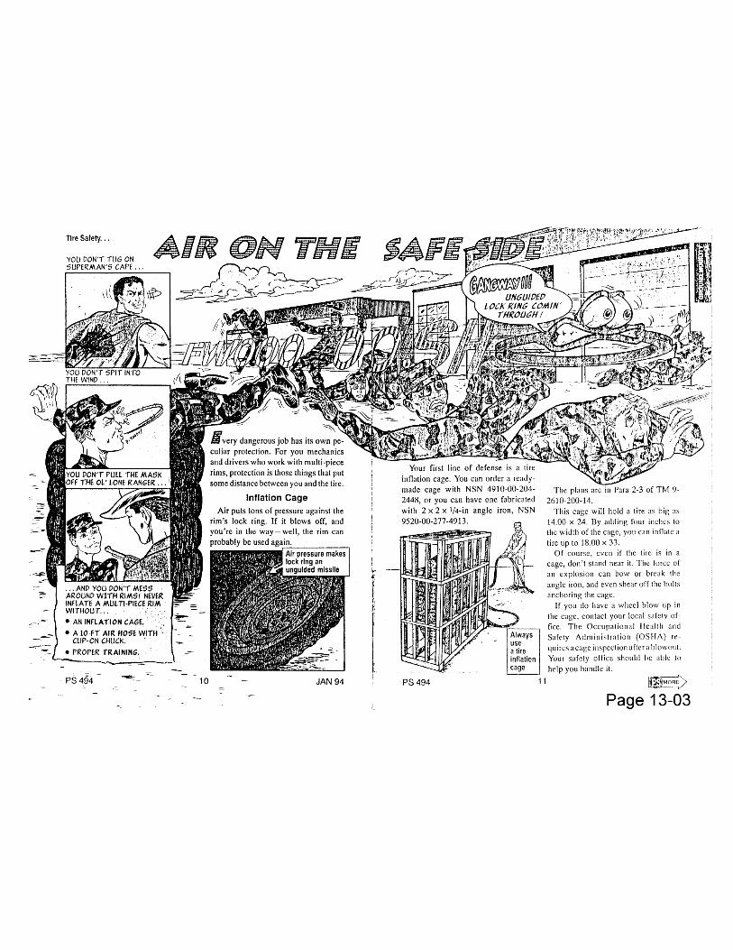


Wheeled Vehicles…
Mechanics, you can make tires, especially HMMWV tires, easier to work with byfollowing these simple tips.
Remove tires from the restrictive manufacturer’s packaging as soon as youcan after they get to the motor pool.
Store the tires on their tread, not on their side.
Keep tires at room temperature, if possible. Tires that sit in cold weathershould come indoors at least 24 hours before they’re mounted. This will makeinstalling a runflat spacer, for example, much easier for your HMMWWVmaintainers.
From PS Magazine
Page 13-08

Chapter 14
STEERING
FunctionalGroup Code
1401-1411

TB 43-0001-39-8
3-12. Tactical Trucks MODEL:M998 Series Vehicles
SUBJECT:Intermediate Steering Shaft U-Joint Replacement
POC:Ms. Jody McInerney, AMSTA-MTA, DSN 786-7346,Commercial (313) 574-7346
COMMENTS:Presently, units must replace the intermediate steering shaft if the U-jointsare worn. From a maintenance standpoint, we feel lack of lubricationcauses increased wear of U-joints and leads to premature replacement ofthe steering shaft. However, from a user standpoint, we are aware that itwould save you money, if you were able to repair the steering shaft.Therefore, we are changing our previous decision and making the U-jointsreplaceable.
MATERIALS/PARTS:Removal and Installation of the U-joints can be accomplished by using thefollowing materials and procedures:
NSN NOMENCLATURE QUANTITY2520-00-352-2168 Center Parts let 15120-01-210-4096 Universal Joint Bearing Kit I
PROCEDURE:Equipment Condition
Intermediate Steering Shaft removed. (Refer to TM9-2320-280-20-2, Para8-17)
A. Removal
CAUTION
Do not drop bearing cups. Needle bearing can be easilylost.
Page 14-01

TB 43-0001-39-8
3-12. Tact. Trucks cont. (1) Remove grease fitting (6) from cross (4). (see figure 3-36)(2) Remove four bearing cups (1) from cross (4).(3) Remove four snap rings (2) from yoke (5).(4) Position intermediate steering shaft (3) in vise with 1-1/8' socket
between vise jaw and bearing cup (1) being removed. Ensureopen end of socket is facing bearing cup (1).
(5) Place 11/16" socket between opposite bearing cup (1) and visejaw.Ensure open end of socket is facing vise jaw.
(6) Press bearing cup (1) out of yoke (5) and remove bearing cup (1)from cross (4).
(7) Reverse position of sockets and press remaining bearing cup (1)out of yoke (5).
(8) Remove cross (4) from yoke (5).B. Assembly
CAUTION
Ensure grease fitting on cross faces yoke. Damage toequipment will result if Improperly installed.
(1) Install cross (4) into yoke (5). (see figure 3-36)(2) Install bearing cup (1) into yoke (5).
CAUTION
Ensure bearing cup Is aligned with yoke before pressing in with vise.Damage to cross and bearing cups will result if forced into yoke.
(3) Place yoke (5) in vise with 11/16” socket between vise jaw andbearing cup (1). (see figure 3-36)
(4) Press bearing cup (1) into yoke (5) far enough to install snap ring(2), and install snap ring (2) into yoke (5).
(5) Install bearing cup (1) into yoke (5).(6) Place yoke (5) in vise with 11/16” socket between bearing cup (1)
and vise jaw.(7) Press bearing cup (1) into yoke (5) far enough to install snap ring
(2), and install snap ring (2) into yoke (5).(8) Install four bearing cups (1) on cross (4).(9) Install grease fitting (6) into cross (4).
Page 14-02

TB 43-0001-39-8
3-12. Tact Trucks cont. Follow-on Task
Install Intermediate Steering Shaft. (Refer to TM9-2320-280-20-2, Para8-17)
PUBLICATIONS AFFECTED:TM9-2320-280-34PTM9-2320-280-20PTM9-2320-280-20-2
LEVEL OF MAINTENANCE:Unit
Page 14-03


TB 43-0001-39-2 SEPTEMBER 1994
3-10. Tactical Trucks MODEL:All HMMWV Models
SUBJECT:Loose Intermediate Steering Shaft
POC:Mr. Daniel Dudek, AMSTA-MTA, DSN 786-7416,Commercial (810) 574-7416
DEFICIENCY:The original article printed In TB 43-0001-39-8, dated 31 Mar 94 calls outan Improper torque. This article Is a reprint with correction.
COMMENTS:Reports from the field indicate that users may not be replacing and/orproperly torquing the locknuts used on the intermediate steering shaft.Failure to replace and properly torque the locknut can cause prematurewear of other components (such as worn splines and U-joints). When youreplace the intermediate steering shaft or steering gear box, you need toremember to discard the old locknut and put a new one on. Also, properlytorque the locknut to 40-50 lb-ft* (54-68 N m). Following thesemaintenance procedures will help to keep your steering components Ingood shape.
*NOTE: TM 9-2320-280-20-2 dated Jan 90 with change 4, paragraph 8-17, page 8-44 changes the torque to 40-50 lb-ft (54-68 N m).
PUBLICATIONS AFFECTED:None
LEVEL OF MAINTENANCE:UNIT
Page 14-05
EDITOR'S NOTE:This is a reprint of the same article that was published In TB 43-0001-39-8, dated 31 Mar 94, chapter 4.
- torque values have been changed

SUBJECT:Steering Column
POC:Ms. Jody McInerney, AMSTA-MTA, DSN 786-7346,Commercial (810) 574-7346 [email protected]
DEFICIENCY:Steering Column, P/N (81263) 1419, NSN 2530-01-185-8154, used onvehicles with serial # I thru 99,999 Is no longer available. If you order thisItem, you will receive P/N (81263) 1493, NSN 2530-01-314-4470.
COMMENTS:A. Steering Column P/N 1493, has a built-in safety feature. New shoulderbolts (P/N 12342440) are needed when installing the P/N 1493 column.Here's a complete list of the parts you'll need:
MANDATORY PARTS:
NSN/Part No. Item Name QTY
(19207)12342440 Shoulder Bolt 25310-00-935-9021 Self-Locking Nut 15310-00-637-9541 Lockwasher 15310-01-315-3403 Self-Locking Nut 15310-00-061-4650 Self-Locking Nut 2
The following parts can be re-used from the old steering column:
NSN/Part No. Item Name QTY
5310-01-257-7719 Washer 25315-01-201-3592 Pin 15310-01-188-0745 Key Washer 1
To Install the new steering column, follow the replacementprocedures for vehicles with serial number 100,000 and above(P/N 1493) In TM9-2320-280-20-2 (paragraph 8-16).
B. The new steering column (P/N 1493) was designed to reduce chestInjuries in the event of an accident. Excessive force on the steeringcolumn can lead to premature failure of the built in safety features. Tohelp prevent this from occurring you can make sure to avoid using forceon the steering wheel and Install new rigidity brackets.
C. We've developed a steering column replacement kit that Includes thesteering column, hardware, and rigidity brackets for vehicle serialnumbers 1-99,999. The NSN Is 2530-01-395-9584. You can order thefollowing parts to Install the rigidity brackets, If the kit Is not available.

3-19. Tact. Trucks cont. NSN Item Name QTY
2530-01-383-5740 Bracket 12530-01-384-7154 Bracket 15310-00-061-4650 Locknut 15310-00-124-9265 Nut 15305-00-225-3843 Screw 15305-00-582-9501 Screw 15310-00-809-4058 Washer 2
For instructions on how to Install the rigidity brackets, please refer toTM 9-2320-280-20-2 (paragraph 8-16).
D. An article similar to this one appeared in TB 43-0001-39-1, dated Jun94, paragraph 3-1O. Please NOTE there is an error In the previousarticle. The NSN (5305-00-709-8542) for the Shoulder Bolt is incorrect.The correct P/N Is (19207) 12342440.
PUBLICATIONS AFFECTED:TM9-2320-280-20
LEVEL OF MAINTENANCE:Unit
Page 14-07

TB 43-0001-39-1 JUNE 19943-10. Tactical Trucks MODEL:
HMMWV M998 Series
SUBJECT:Steering Column
POC:Mr. Daniel Dudek, AMSTA-MTA, DSN 786-7416,Commercial (810) 574-7416
DEFICIENCY:Steering columns wears and cracks at mounting points and becomesloose.
Page 14-08

TB 43-0001-39-1 JUNE 1994
3-10. Tact. Trucks cont. COMMENTS:A. A modification Work Order (MWO) is being developed to inspectsteering columns for movement and the repair of those with excessivemovement or damaged mountings. Since efforts for development andimplementation of an MWO take some time, the following procedures areprovided in advance of the MWO.
B. The following procedures provide methods to inspect steering columns,install rigidity brackets, and to replace the steering column. If you chooseto apply these procedures we would like you to report to us your unit, thevehicle serial number, and the action taken. The Information should bereported on a DA2407, multiple vehicles can be reported on a singleDA2407. The information should be sent to:
Commander,U.S. Tank-Automotive CommandAttn: AMSTA-MTAWarren, Ml 48397-5000
MATERIALS/PARTS:The following parts are required for shoulder bolt replacement:
NSN NOMENCLATURE QTY
5310-01-315-3403 Nut 25305-00-709-8542 Shoulder Bolt 25310-00-809-4085 Washer 2
The following parts are required for adding rigidity brackets to a steeringcolumn:
PART NUMBER/NSN NOMENCLATURE QTY
12342875 Bracket 112342876 Bracket 15310-00-061-4650 Locknut 15310-00-124-9265 Nut 15305-00-225-3843 Screw 15305-00-582-9501 Screw 15310-00-809-4058 Washer 2
Page 14-09

TB 43-0001-39-1 JUNE 1994
3-10. Tact. Trucks cont. The following parts are required for steering column replacement:
PART NUMBER/NSN NOMENCLATURE QTY12342875 Bracket 112342876 Bracket 15310-00-061-4650 Locknut 35310-00-124-9265 Nut 15305-00-225-3843 Screw 15305-00-582-9501 Screw 15310-00-637-9541 Lockwasher 15310-00-809-4058 Washer 25310-00-809-4085 Washer 25305-00-709-8542 Shoulder Bolt 25310-00-935-9021 Nut 15310-01-188-0745 Key Washer 15315-01-201-3592 Pin 12530-01-314-4470 Steering Column 15310-01-315-3403 Nut 1
PROCEDURE:NOTE
Section I is an inspection procedure todetermine if a steering column requiresreplacement or the addition of rigidity brackets.
Section II is a procedure to add rigidity bracketsto a steering column that originally did not haverigidity brackets.
Section III is a procedure to replace a steeringcolumn with a new steering column.
SECTION 1. STEERING COLUMN INSPECTION PROCEDURE
NOTE
When performing step "A", use a ruler (2)positioned on steering column (5) and mark areference line (3) on dash (4) to check verticalmovement. (see figure 3-13)
Page 14-10

TB 43-0001-39-1 JUNE 1994
3-10. Tact. Trucks cont.
A. Using moderate hand force, move steering wheel (1) up and down.Steering column (5) should have 0. 125" or less movement from centerposition to highest and lowest vertical points. (see figure 3-13)
NOTEIf the steering column inspected was model 12338621,without tab inserts, and the movement exceeded 0.125",replace steering column. (Refer to Section 111)
If the steering column inspected was model 12338621,without tab inserts, and the movement exceeded 0.125" orless, discontinue inspection; movement is within acceptablelimits.
B. Record data found from performing step "A".
NOTEThe remainder of this inspection procedure applies to12338621-1 steering columns with tab inserts.
C. Remove two existing shoulder bolts (15), washers (16), and nuts (17)from steering column (7). (see figure 3-15)
D. Check tab Inserts (2) at end of steering column (1) for paint and metalcracking. (see figure 3-14) If cracking is present on or around tabInserts (2), discontinue Inspection procedure and replace steeringcolumn. (Refer to Section III.)
NOTECheck shoulder bolts (3) removed in step "C" for“mushrooming" around shaft area (4) of shoulder bolt (3).(see figure 3-14) If mushrooming is present, perform step"E". If mushrooming is not present, perform step “F”.
E. Discard two shoulder bolts (15), washers (16), and nuts (17). Securesteering column (7) to bracket (4) with two NSN 5305-00-709-8542shoulder bolts (15), NSN 5310-00-809-4085 washers (16), and NSN5310-01-315-3403 nuts (17). Tighten nuts (17) to 10 lb-ft (14 N m).(see figure 3-15)
F. Install two existing shoulder bolts (15), washers (16), and NSN 5310-01-315-3403 nuts (17). Tighten nuts (17) to 10 lb-ft (14 N m).
Page 14-11

TB 43-0001-39-1 JUNE 1994
3-10. Tact. Trucks cont. NOTE
If vertical movement of steering column exceeded0.125" in step 'A", then install rigidity brackets tosteering column. (Refer to Section II.)
SECTION II. INSTALLATION OF RIGIDITY BRACKETS ON STEERINGCOLUMN
A. Remove screw (8), nut (14), and ground lead 57C (13) from steeringcolumn (7). (see figure 3-15)
B. Secure ground lead 57C (2) and 12342875 rigidity bracket (5) to steeringcolumn (3) with NSN 5305-00-582-9501 screw (4) and NSN 5310-00-124-9265 nut (1). Do not tighten nut (1). (see figure 3-16)
C. Secure 12342876 bracket (8) to bracket (5) and steering column (3) withNSN 5305-00-225-3843 screw (9), two NSN 5310-00-809-4058 washers(7), and NSN 5310-00-061-4650 locknut (6). Tighten nut (6) to 10 lb-ft(14 N m).
D. Tighten nut (1) to 5 lb-ft (7 N m).
SECTION III. STEERING COLUMN REPLACEMENT
A. Remove steering column. (Refer to TM9-2320-280-20.)B. Secure NSN 2530-01-314-4470 steering column (7) to bracket (4) with
two NSN 5305-00-709-8542 shoulder bolts (15), NSN 5310-00-809-4085washers (16). and NSN 5310-00-061-46 50 nuts (17). Tighten nuts (17)to I 0 lb-ft (14 N m). (see figure 3-15)
C . Secure steering column (7) to bracket (4) with NSN 5315-01-201-3592pin (5), NSN 5310-01-188-0745 key washer (3), NSN 5310-00-637-9541lockwasher (2), and NSN 5310-00-935-9021 nut (1). Tighten nut (1) to 14lb-ft (19 N m).
D. Secure intermediate shaft (I 2) to steering column (7) with existing screw(I 1), two washers (10), and NSN 5310-01-315-3403 nut (9). Tighten nut(9) to 45 lb-ft (61 N m).
E. Connect lead 25A (18) to steering column connector (6).
NOTEIf steering column being replaced had rigidity brackets
installed, reuse existing brackets and all hardware except fortwo NSN 5310-00-061-4650 nuts that require replacement.Perform step "F".
If steering column being replaced did not have rigidity bracketsinstalled, acquire parts needed and perform step "F".
Page 14 -12

TB 43-0001-39-1 JUNE 1994
3- 1 0. Tact. Trucks cont. F. Secure ground lead 57C (2) and 12342875 rigidity bracket (5) tosteering column (3) with NSN 5305-00-582-9501 screw (4) andNSN 5310-00-124-9265 nut (1). Do not tighten nut (1). (see figure3-16)
G. Secure 12342876 rigidity bracket (8) to bracket (5) and steeringcolumn (3) with NSN 5305-00-225-3843 screw (9), two NSN 5310-00-809-4058 washers (7), and NSN 5310-00-061-4650 locknut (6),Tighten nut (6) to 10 lb-ft (14 N m).
H. Tighten nut (1) to 5 lb-ft (7 N m).I. Install directional signal control. (Refer to TM9-2320-280-20.)J. Install steering wheel. (Refer to TM9-2320-280-20.)
PUBLICATIONS AFFECTED:TM9-2320-280-20
LEVEL OF MAINTENANCE:Unit
Page 14-13


TB 43-0001-39-3 SEPTEMBER 1996
3-9. Tactical Trucks MODEL:HMMWV
SUBJECT:Power Steering Bleed Procedures
POC:Ms. Patricia Grashik, AMSTA-IM-HLA, DSN 786-5225,Commercial (810) 574-5225, [email protected]
DEFICIENCY:The current bleed procedures in TM9-2320-280-20-2, dated Jan 96, ParaB-29, may not expel all air out of the steering system.
COMMENTS:We are aligning our bleeding procedures with those recommended bySaginaw Steering Systems, the steering system vendor.
PROCEDURES:NOTE
Before bleeding the steering system inspect toensure that hoses are not touching vehiclebody or other components and all connectionsare tight.
1. Shut engine off. (TM9-2320-280-10)2. Turn steering wheel full left.3. Raise and secure hood.4. Fill fluid reservoir to "FULL COLD" level. (TM9-2320-280-20)
Leave cap off.5. Raise front wheels off ground. (TM9-2320-280-20)6. Turn steering wheel left and right holding wheels at steering stops
for five seconds at least 40 times.
NOTEPower steering fluid must be free of bubblesand foam. If bubbles or foam are noted, itcould be an indication of a loose connection orleaky 0-ring.
Page 14-18

TB 43-0001-39-3 DECEMBER 1996
3-9. Tact. Trucks cont. 7. Check fluid. If any bubbles are seen, repeat step 5.8. Start engine. With engine idling, add power steering fluid, if
necessary. (TM9-2320-280-10)9· Install reservoir cap.10.With wheels to center, lower front wheels to ground. (TM9-2320-280-
20)11.Keep engine running for two or three minutes. Turn steering wheel left
and right.
NOTE
It pump is noisy, recheck hoses for possiblecontact with vehicle body or engine. If nocontact is found and noise continues, switchengine off and re-pressurize system byfollowing steps 12 and/or 13.
12.Remove reservoir cap. Wait for system to cool. Reinstall reservoircap. Start engine and check pump for noise, if noise is still presentcontinue to step 13. If noise stopped, proceed to step 14.
13.Turn engine off. Remove fluid from reservoir using a suction device.Refill reservoir with clean, cool fluid. Install reservoir cap. Start engineand check pump for noise. If noise is still present, replace powersteering pump. (TM9-2320-280-20)
14.Turn engine off. (TM9-2320-280-10)15.Check power steering level. (TM9-2320-280-10)16.Lower and secure hood. (TM9-2320-280-10)17. Operate vehicle and check for proper steering operation. (TM9-2320-
280-10)
PUBLICATIONS AFFECTED:TM9-2320-280-20
LEVEL OF MAINTENANCE:Unit
Page 14-19

4-4. Tactical Trucks MODEL:HMMWV
SUBJECT:Power Steering Hose Clamps
POC:Mr. Eric Sutman, AMSTA-MTA, DSN 786-7151,Commercial (313) 574-7151
DEFICIENCY:Power steering hoses pull away from their fittings, causing loss of powersteering fluid. This results in loss of power assist during steering andbraking.
COMMENTS:A. We've investigated this problem and found that the power steeringhose clamps used on HMMWVs produced between Jan 90 and Jan 93can become loose. This allows the hose to pull away from the flaredfittings. The vehicle manufacturer is now using a better clamp.
B. On vehicles experiencing this problem, replace the clamps with theclamps called out in TM 9-2320-280-20P, Figure 132. Clamps receivedthrough the supply system will keep the hose from pulling away from thefittings.
PUBLICATIONS AFFECTED:None
LEVEL OF MAINTENANCE:Unit
Page 14-20
4-8. Tactical Trucks MODEL:HMMWV
SUBJECT:Power Steering System
POC:Mr. Keith J. Barthlow, AMSTA-IM-MTA, DSN 786-8288, Commercial (810)574-8288 [email protected]
DEFICIENCY:Users report that power steering hoses come off at the fittings by thesolenoid control valve and fan drive.This can result In a loss of power assist during steering and braking.
COMMENTS:We published an article In TB 43-0001-39-8 (Mar 94) that advised of thisdeficiency. The article said to replace the hose clamps with the clampscalled out In TM9-2320-280-20P. Figure 132. While this Information isstill good and should resolve the problem, we recently completed anevaluation concerning the use of multi-barbed fittings and are planning touse them in future production. If you are still experiencing any problemsor desire to use them, here are the NSN'S:
1. For Figure 131 (Item 3) and Figure 132 (Item 1) In TM9-2320-280-20P, use NSN 4730-00-136-2018 for the multi-barb fitting.
2. For Figure 132 (Item 2), use NSN 4730-00-722-5194.
PUBLICATIONS AFFECTED:TM9-2320-280-20P
LEVEL OF MAINTENANCE:Unit
Page 14-21


Chapter 15
FRAME AND TOWINGATTACHMENTS
FunctionalGroup Code
1501-1503

4-5. Tactical Trucks
MODEL:HMMWV
SUBJECT:Maintenance Level Change for Rear Crossmember Replacement
POC:Mr. Keith Barthlow, AMSTA-IM-MTA, DSN 786-8288,Commercial (810) 574-8288 [email protected]
DEFICIENCY:Currently the rear crossmember Is replaced by Direct Support.
COMMENTS:We are changing the maintenance level for rear crossmember replacement from DirectSupport to Unit. Until the procedures are moved to TM9-2320-280-20, unit maintenance canreplace the rear crossmember using the following procedure:
MATERIALS/PARTS:
NOMENCLATURE PART NUMBER NSNLocknut (96906) MS51943-39 5310-00-488-3889Flatwasher (06032) 2310-0143-001 5310-01-121-1703Capscrew (80204) B1821BH050C125N 5305-00-071-2067Channel, Structural Frame (19207)12338193 9520-01-175-7222
PROCEDURES:A. REMOVAL
Remove four locknuts (3), washers (2), capscrews (5), and washers (2) securing rearcrossmember (1) to rear crossmember mounting brackets (4) and remove rearcrossmember(1). Discard locknuts (3). (see figure 4 - 1)
Page 15-01


Chapter 18
BODY, CAB ANDHOOD
ASSEMBLY
FunctionalGroup Code
1801-1812


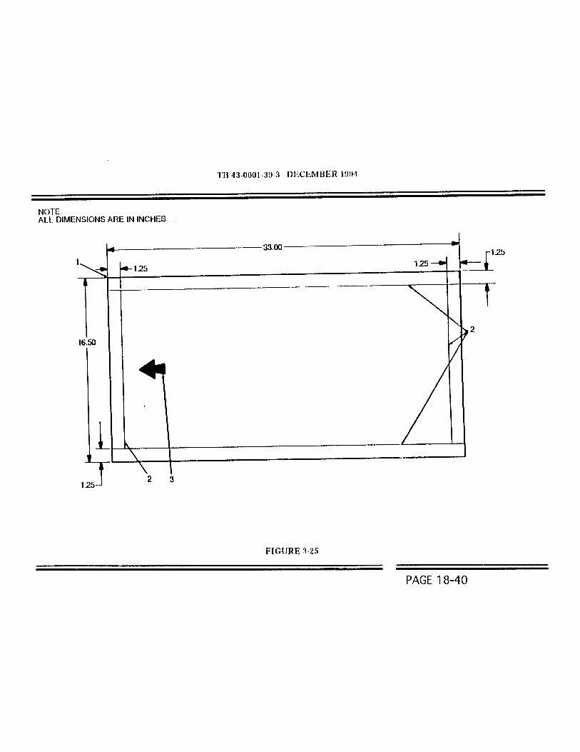


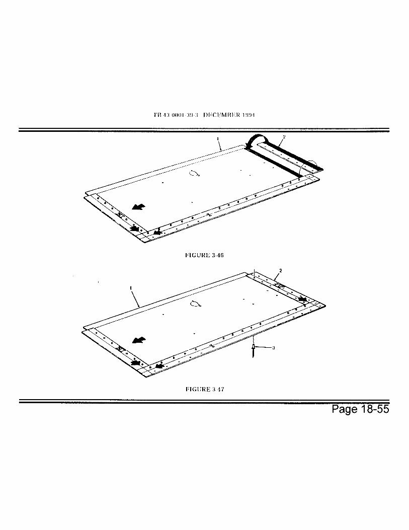


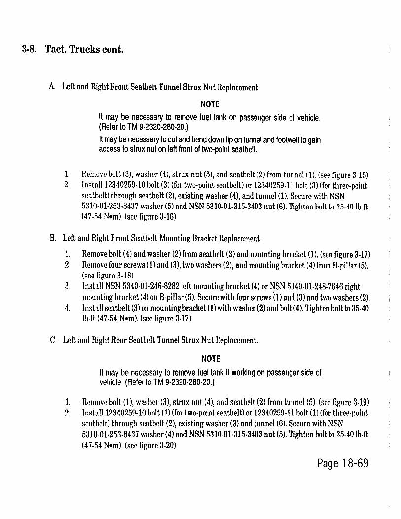


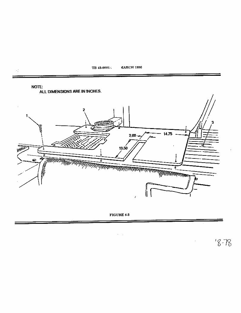


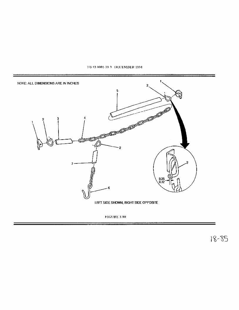


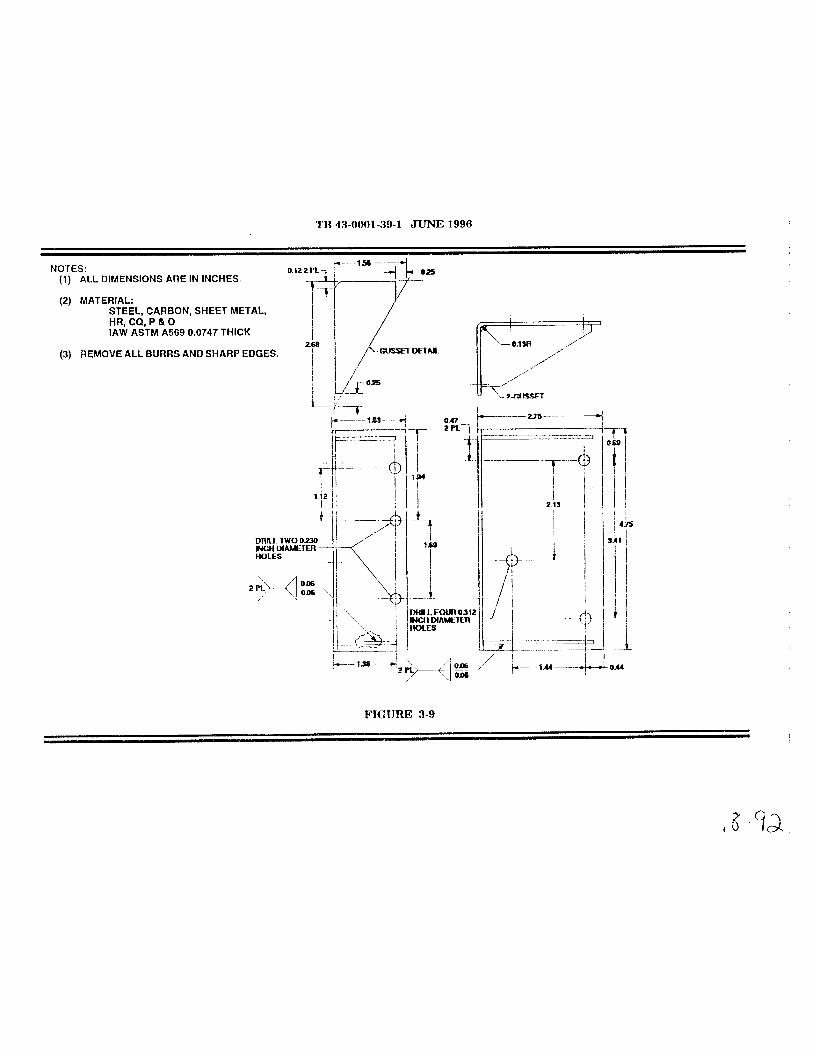


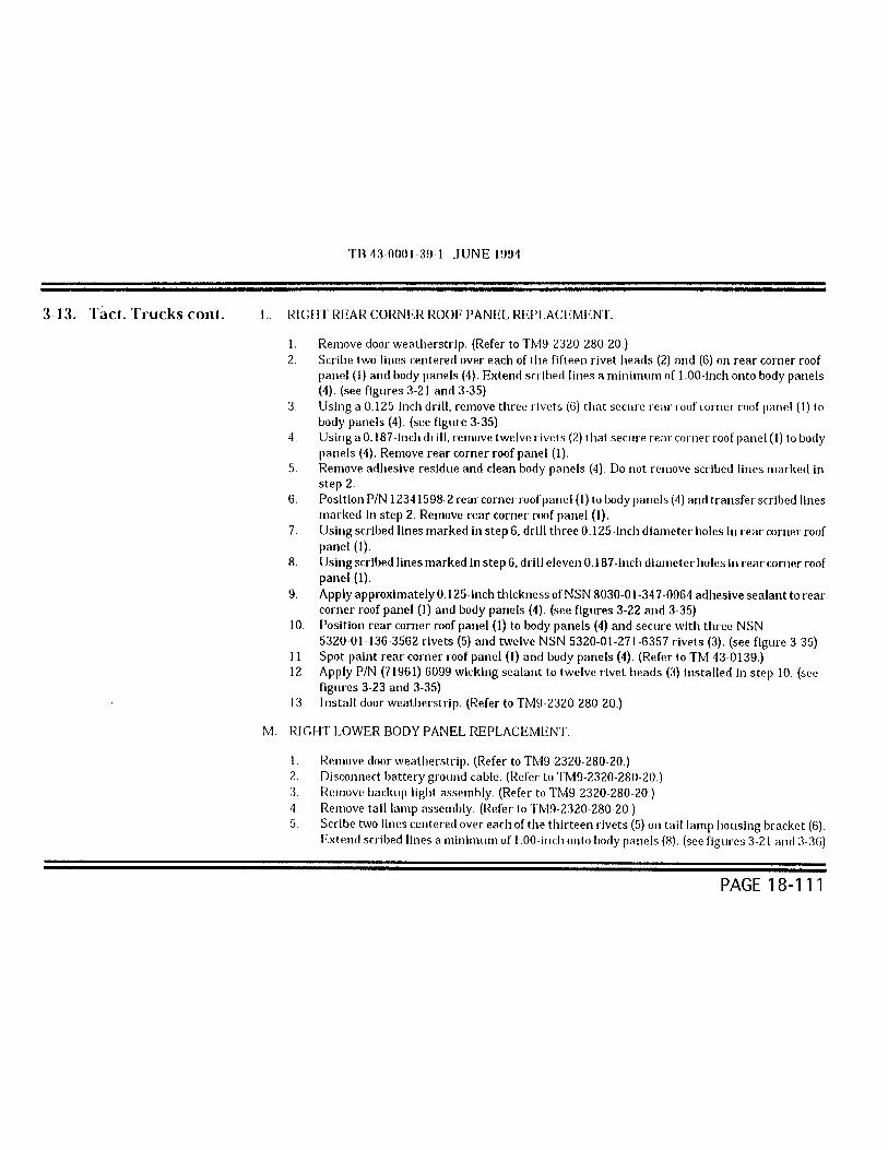


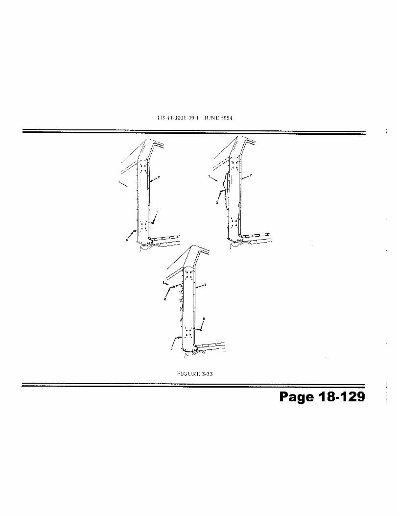


4-6. Tactical Trucks
MODEL:M996 and M997
SUBJECT:NBC Filter Strap on Ambulance
POC:Mr. David J. Rinke, AMSTA-IM-HLA, DSN 786-8373, Commercial (810) [email protected]
COMMENTS:In the past, when your NBC filter strap broke you had to replace the entire bracket. Notanymore - you can use hose clamp, 4720-00-908-6294 as a field fix. If you decide touse this fix, be sure the clamp goes behind the entire bracket and the rivet that holdsthe old strap is removed before tightening the hose clamp around the filter securing thefilter to the bracket.
PUBLICATIONS AFFECTED:TM9-2320-280-20-3
LEVEL OF MAINTENANCE:Unit
Page 18-141

TB 43-0001-39-3 DECEMBER 1994
3-14. Tactical Trucks
MODEL:HMMWV, M966, M966A1, M1025, M1025A1, M1026, M1026A1, M1036, M1043, M1043A1,M1044, M1044A1, M1045, M1045A1, M1046, and M1046A1 Vehicles
SUBJECT:Rear Cargo Door Gas Spring Assemblies
POC:Ms. Jody McInerney, AMSTA-MTA, DSN 786-7346, Commercial (810) 574-7346mcinerj@ cc.tacom.army.mil
DEFICIENCY:Reports from the field indicate that the gas spring assemblies on armament carriers havefailed to keep rear cargo doors open. The gas spring assemblies are made of a short and longgas spring positioned In opposite directions in a telescopic steel cover. The long springoriented In the upward direction Is subject to Insufficient seal lubrication leading to prematurefailure.
COMMENTS:If the gas spring assemblies will not keep the rear cargo door open, the defective gas springshould be replaced. Improved internal lubrication of the gas spring can extend its service life.This can be accomplished by rotating the gas spring assemblies 180 degrees every sixmonths moving left spring to right side, and right spring to left side. This procedure will beadded as a maintenance task and to the Preventive Maintenance Checks and Services(PMCS) during the next manual update. The task can be accomplished in the field using thefollowing procedure.
PROCEDURE:
NOTEPrior to starting any maintenance, ensure forward end of cargo shell door is locked.
1. Remove cargo door strap. (Refer to TM9-2320-280-20)2. Remove cargo door retention cables. (Refer to TM9-2320-280-20)
NOTEA 2 x4 x 79.25 inch long board can be used to support cargo door in the open position.
Page 18-142


Page 18-144


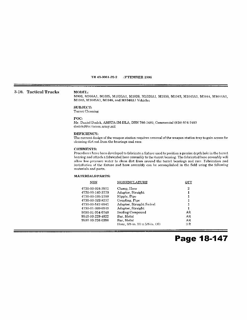


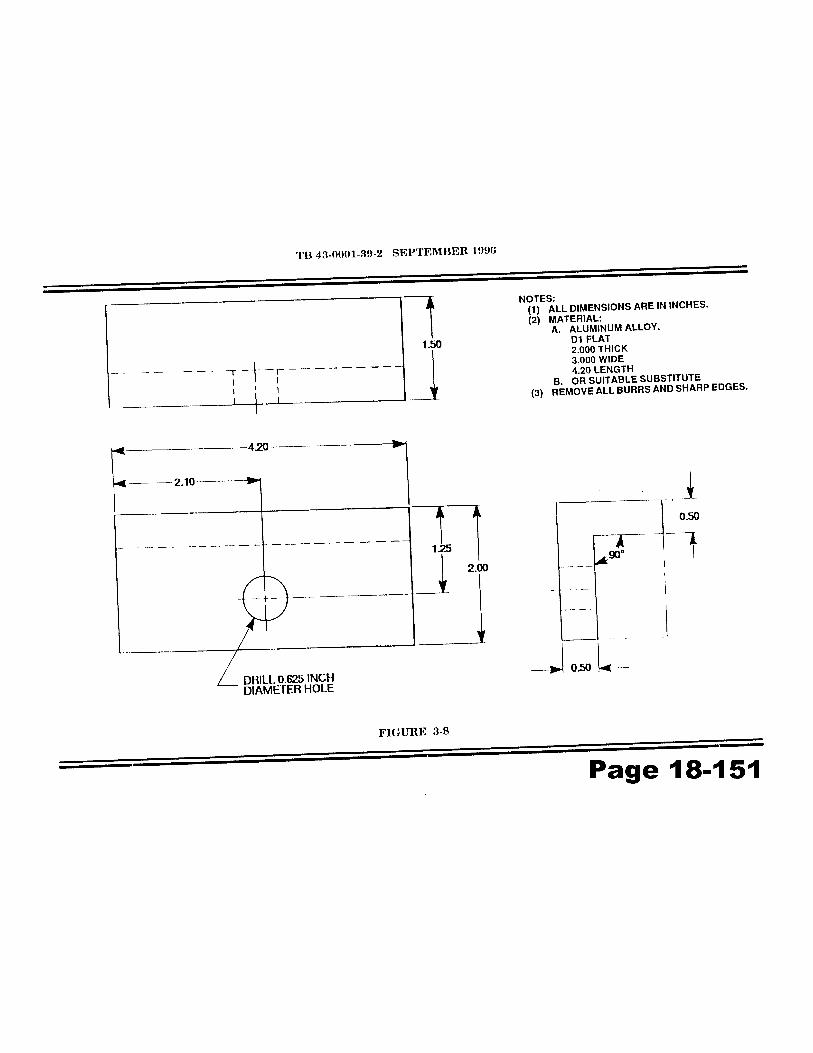


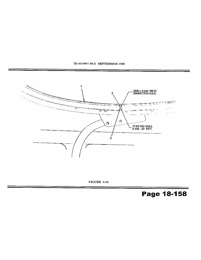


TB 43-0001-39-3 DECEMBER 1994
3-1 1. Tact. Trucks cont.
NOTEEnsure only turret handle is drilled; do not drill through or into weapon
station.
C. Drill six 0.313-inch diameter holes (3) through spot-welds in turret handle (2)marked in step "B” (see figure 3-16, view B)
D. Using a chisel, remove turret handle (2) from weapon station (1).
NOTEUse care when grinding the weapon station to ensure the tworeference lines are not removed.
E. Grind spot-welds flush with weapon station.
F. Using two reference lines (4) marked in step "A" as a guide, position Part Number12446730 turret handle (2) on weapon station (1). (see figure 3-17, view A)
G. Using holes (3) In turret handle (2) as a template, locate, mark, and drill four 0.344-inch diameter holes (5) In weapon station (1).
H. Spot paint weapon station. (Refer to TM 43-0139.)
I. Position turret handle (2) on weapon station (1) and secure with four NSN 5306-00-050-1237 bolts(3), eight NSN 5310-01-119-1024 washers (4), and four NSN 5310-00-241-6658 lock-nuts (5). (see figure3-17, view B)
J. Spot paint bolts and nuts. (Refer to TM 43-0139).
PUBLICATIONS AFFECTED:TM9-2320-280-20TM9-2320-280-20PTM9-2320-280-34P
LEVEL OF MAINTENANCE:Unit
Page 18-163


Chapter 20
WINCH
FunctionalGroup Code
2001
TB 43-0001-39-7 DECEMBER 1995
3-7. Tactical Trucks MODEL:M1026, M1026AI, M1036, M1038, M1038AI, M1042, M1044, M1044AI,M1046, and M1046AI
SUBJECT:6000 lb Winch Assembly Repair Procedure
POC:Ms. Jody McInerney, AMSTA-IM-MTA, DSN 786-7346, Commercial (810)574-7346 [email protected]
DEFICIENCY:Due to vendor changes in part configuration, there is a lack of technicalsupport on the 6,000 lb winch. Three areas will be addressed: wlnch wirerope, stage-three gear carrier assembly, and end housing assemblybushing.
COMMENTS:The following is provided for Interim field Information, notification of minoralterations, publications changes, and advance Information on the 6,000lb winch assembly repair procedures covering winch wire rope assembly15667, stage-three gear carrier assembly 26781, and the end housingassembly 16013.
MATERIALS/PARTS:Using tile following NSN'S, the wire rope can be requisitioned as anassembly, or as separate parts. NSN 4010-01-315-4179 is the completeassembly; the other items are the down parts. Wire rope assemblyInstructions are found In TM9-2320-280-34, Appendix C, Section II.
NSN NOMENCLATURE QTY4010-01-315-4179 Wire Rope Assembly 14030-01-210-0691 Terminal 14030-01-209-7047 Hook 14030-00-237-8741 Clamp 14030-01-256-0471 Thimble 14010-01-231-5075 Wire Rope (MIL - W - 83420D) 100 ft
Page 20-01

3-7. Tact. Trucks cont. PROCEDURES:A. Winch wire rope.
NOTEThe following instructions are for the 6,000 lb winch forseparate part installation only, and should be used inconjunction with TM 9-2320-280-20-3, Para 10-104,Page 10-182.
1. For removal:
a. After step 2, add, "remove terminal (7) from winch cable (2)".(see figure 3-3)
b. Replace step 3 with "loosen clamp (3) securing hook (4) andthimble (5) to winch cable (2) and remove hook (4), thimble (5),and clamp (3) from winch cable (2)".
2. For Installation:
a. Replace step I with "Install clamp (3), hook (4), and thimble (5)on winch cable (2) and secure with clamp (3)". (see figure 3-3)
b. After step 1. add, "Install terminal (7) to winch cable (2)".
B. Winch maintenance and repair.
NOTEThe following instructions are for the 6,000 lb winch withthe new part configurations only, and should be used inconjunction with TM 9-2320-280-34.
1 . Refer to TM9-2320-280-34, Chapter 15, Winch Maintenance,Winch Repair, pages 15-2 through 15-15.
2. Skip step 19 on page 15-6 If splined drive (1) and retainer ring (2)are part of stage-three gear carrier (3). (see figure 3-4)
NOTEReplace steps 10 through 12 on page 15-8 with thefollowing steps 10 and 11.
Page 20-02


3-8. Tactical Trucks MODEL:M1026, M1026AI, M1038, M1038AI, M1042, M1044, M1044AI, M1046,and M1046AI
SUBJECT:6000 lb Winch Ground Wire
POC:Ms.Jody McInerney, AMSTA-IM-MTA, DSN 786-7346,Commercial (810) 574-7346, [email protected]
DEFICIENCY:Reports from the field indicate that corrosion on internal ground strap maycause winch to be inoperative.
COMMENTS:Procedures have been developed to fabricate and install an externalground wire on the winch. The ground wire can be fabricated, using thefollowing materials, parts, and procedures.
MATERIALS/PARTS:NSN NOMENCLATURE QTY
5940-00-705-6708 Terminal 15940-00-705-6711 Terminal 16145-00-152-6499 Wire, electrical 6-inches
PROCEDURES:A. GROUND WIRE FABRICATION.
1. Install NSN 5940-00-705-671 1 terminal (3) to 6-inch piece ofNSN 6145-00-152-6499 wire (2). (see figure 3-7)
2. Install NSN 5940-00-705-6708 terminal (1) to NSN 6145-00-152-6499 wire (2).
B. GROUND WIRE INSTALLATION.
1. Remove existing screw (5), washer (4), and ground cable (1) fromwinch motor (3). (see figure 3--8)
2. Remove existing screw (7) and washer (8) from solenoid cover(2).
Page 20-06


4-5. Tactical Trucks MODEL:M998 and M998Al Series HMMWV (Less M996, M996Al, M997, M997A1,M1035, and M1035Al)
SUBJECT:9,000 lb Winch Kit
POC:Ms. Patricia Grashik, AMSTA-IM-HLA, DSN 786-7566,Commercial (810) 574-7566 [email protected]
COMMENTS:A 9,000 lb winch kit is available for M998 and M998Al series HMMWVs,except for the ambulance variants (M996, M996A1, M997, M997Al, M1035, M 1035A1). The kit part number is (19207) 57K3217, NSN 2590-01-418-2135. This kit can replace the 6,000 lb winch currently installedon HMMWV models.
The kit includes a modified front bumper, winch, bracketry, hardware, andinstallation instructions.
PUBLICATIONS AFFECTED:TM9-2320-280-24P
LEVEL OF MAINTENANCE:Direct Support
Page 20-09


Chapter 22
BODY ANDCHASSISACCESSORYITEMS
FuntionalGroup Code
2201-2202

TB 43-0001-39-7
8-4. Tactical Trucks MODEL:M998, M1035, M1037, M1038, M1042, and M1097
SUBJECT:Canvas Top and Door Seam Leak Repair
POC:Mr. Eric Sutman, AMSTA-MTA, DSN 786-7151,Commercial (313) 574-7151
DEFICIENCY:Reports from the field indicate that some vinyl coated canvas tops anddoors leak along seam areas.
COMMENTS:A. In the past, we've recommended several different sealants for use on
canvas tops. We've found that NSN 8040-01-010-8758 is best suitedfor this purpose. It has good resistance to weathering, vibration,moisture and temperature extremes. From now on, use only NSN8040-01-010-8758 when sealing canvas tops and doors.
B. We've developed a seam leak repair procedure using NSN8040-01-010-8758 sealing compound. The following provides a method for on-vehicle repair of vinyl coated canvas seam areas that leak.
PROCEDURE:A. Locate source of leak on canvas seam.
B. Clean canvas seam area you're going to seal. (Refer to TM9-2320-280-10).
NOTEWhen performing step C, ensure to make contact betweenseam stitching and sealing compound by pressing sealingcompound into stitching of seam.
C. Apply a thin coat of NSN 8040-01-010-8758 sealing compound one-half inch wide over outside canvas Seam area.
D. Allow 20 minutes for sealing compound to cure.
PUBLICATIONS AFFECTED:TM9-2320-280-10TM9-2320-280-20
LEVEL OF MAINTENANCE:Unit
Page 22-01

TB 43-0001-39-3 DECEMBER 1996
4-6. Tactical Trucks MODEL:HMMWV (4 Door Soft Tops)
SUBJECT:Door Seals
POC:Ms. Jody McInerney, AMSTA-IM-HLA, DSN 786-5481,Commercial (810) 574-5481, [email protected]
COMMENTS:if your front door seals are getting caught on your rear door hinge,causing them to rip and tear, we suspect you may have a dimensionproblem. This problem could be caused from a component such as thehinge, door or body not meeting specifications, a short term productionline error, or a damaged component. In any case, thanks to a fellow user,here are some fixes that will eliminate the problem:
1. Since the hinge is inexpensive, you may want to try and install anew one.
2. Elongate the slots on the hinge located in the front door half.3. Elongate the holes in the vehicle half of the rear door.4. Remove the rear hinges, cut the weld at the rolled part of the
hinge, place the bolt into the hinge to keep the same diameter andthen roll the hinge in 1/8 inch, be sure to reweld the hinge at therolled part.
PUBLICATIONS AFFECTED:TM9-2320-280-20
LEVEL OF MAINTENANCE:Unit or Direct Support
Page 22-02

TB 43-0001-39-3 SEPTEMBER 1996
4-9. Tactical Trucks MODEL:M998, M1038, M1097, Al and A2 (four-man soft top installed)
SUBJECT:Fitting Vinyl Covers
POC:Ms. Jody McInerney, AMSTA-IM-HIA, DSN 786-5481,Commercial (810) 574-5481, [email protected]
COMMENTS:The four-man cargo area soft top enclosure on the HMMWVs take a realbeating from changing weather conditions. The covers shrink enoughthat the clips and velcro strips won't hold.
MATERIALS/PARTS:
NSN ITEM QTY9510-00-596-2063 Metal Bar (.049" wall thickness on bow) AR9510-00-596-2066 Metal Bar (.095" wall thickness on bow) AR9510-00-596-2066 Metal Bar(.120" wall thickness on bow) AR5305-00-225-3841 Capscrew 85310-00-761-6882 Nut, self-locking 8
PROCEDURES:A. Remove the support bows and cut one inch off both ends. Then re-drillthe 1/4 inch bolt holes.
B. Shrunken covers should now fit fine. You've cut the problem down tosize. Of course, when you do replace old covers, you'll either need newbows or modify the existing bows as follows:
(1) Cut through bows 6 inches up from bottom of bows. (see figure 4-2)
(2) Insert a 6 1/2-7 inch metal bar (depends on wall thickness of bow)into 6 inch piece of bow (leaving bolt hole at bottom clear).
(3) Drill 1/4 inch hole 1 inch down from top of 6 inch piece of bow.Secure bow and metal bar with capscrew and locknut.
(4) Butt top portion of bow up against 6 inch piece of bow. Drill 1/4inch hole through bow and metal bar 1/2 inch up from cut line.
(5) Remove top portion of bow.(6) Measure I inch from center of hole. Drill another 1/4 inch hole.
Install capscrew and locknut.
Page 22-03


3-11. Tactical Trucks MODEL:M998, M998A1, M1038, M1038A1, M1097, M1097A1, M1035, M1035A1,M1037, M1042
SUBJECT:HMMWV Soft Top Door Window
POC:Ms. Jody McInerney, AMSTA-IM-HIA, DSN 786-5481,Commercial (810) 574-5481 [email protected]
COMMENTS:The plastic windows in the HMMWV get scratched and discolored easilyresulting in unsafe conditions. Here's a method for replacing just theplastic window, instead of having to replace the entire door assembly.
PROCEDURES:1. Make a template using figure 3-14 or cut out a window from an old door
and use it.
2. Remove door handle. (Refer to TM9-2320-280-20-3, Nov 93,Paragraph 10 -13)
3. Cut at border edge of plastic, leaving zipper halves together andattached to door frame.
4. Using template cut out new window from bulk plastic (NSN 9330-00-988-1894).
5. Using a large industrial sewing machine sew in new plastic.
6. Install Door Handle (Refer to TM9-2320-280-20-3, Nov 93, Paragraph10-13).
Page 22-05


3-1 1. Tactical Trucks MODEL:M998, M998A1, M1037, M1038, M1038A1, M1042, M1097, M1097A1
SUBJECT:HMMWV soft top fit
POC:Ms. Jody McInerney, AMSTA-IM-MTA, DSN 786-7346,Commercial (810) 574-7346, [email protected]
DEFICIENCY:Reports from the field indicate the soft top on some vehicles does not fitproperly because the top cannot be positioned on front turn-button.
COMMENTS:Procedures have been developed to relocate the soft top 'A" pillar turn-buttons as an aid to improve soft top fit. This corrective action can beaccomplished in the field by using the following part:
MATERIALS/PARTS:
NSN NOMENCLATURE QTY
5320-01-023-2529 Blind, Rivet 4
PROCEDURES:NOTE
This procedure is for the right turn-button relocation. Theleft turn-button relocation procedure is the same.
1. Move eyelet (2) and top cover (1) to gain access to "A" pillar (7). (seefigure 3-4)
2. Using 0.125-inch diameter drill, remove bottom rivet (6) securing turn-button (4) to “A” pillar (7).
3. Rotate turn-button (4) 180 degrees.
Page 22-07

TB 43-0001-39-5 JUNE 1995
3-1 1. Tact. Trucks cont. 4. Using turnbutton (4) as a template, locate, mark, and drill 0.1285-inchdiameter hole (5) in "A" pillar (7). (see figure 3-4)
5. Install NSN 5320-01-023-2529 rivet (3) In turnbutton (4) and "A" pillar(7).
6. Install NSN 5320-01-023-2529 rivet (3) in existing hole (8) underturnbutton (4) and "A" pillar (7).
7. Spot paint as necessary. (Refer to TM 43-0139.)
8. Secure top cover (1) on "A" pillar (7) with turnbutton (4).
PUBLICATIONS AFFECTED:None
LEVEL OF MAINTENANCE:Unit
Page 22-08


TB 43-0001-39-7 DECEMBER 1995
3-8. Tactical Trucks MODEL:M998, M998A1, M1035, M1035A1,M1035A2, M1037, M1038, M1038A1,M1042, M1097, M1097A1, and M1097A2
SUBJECT:Soft Top Door Handle Repair
POC:Ms. Jody McInerney, AMSTA-IM-MTA, DSN 786-7346,Commercial (810) 574-7346, [email protected]
DEFICIENCY:Reports from the field Indicate that threaded insert in outer handle breaksloose, causing door handle separation.
COMMENTS:A new procedure has been developed to repair the door handle in thefield, which results In a durable, maintence-free handle. The repair canbe accomplished using the following parts and procedures.
MATERIALS/PARTS:
NSN/PN (CAGE C) NOMENCLATURE QTY
5310-01-249-0899 Nut # 10-32 25310-00-014-5850 Washer # IO 15310-00-402-2778 Washer #IO 15305-00-995-3440 Screw #10-32 X 1.75 11032Ll9-30 (07514) Insert #10-32 190276A850 (39428) Screw #10-32 X 5 1
PROCEDURES:1. Remove screw (4), inner (3) and outer (1) door handles, washer (6).
and spring (5) from door (2), if still attached. (see figure 3-6)
2. Check outer door handle (1) for insert (2), and remove insert (2), Ifpresent. (see figure 3-7)
Page 22-10

TB 43-0001-39-7 DECEMBER 1995
3-8. Tact. Trucks cont. 3. Locate and drill 0.250- inch diameter hole through outer door handle(1) using insert hole (2) as a guide. (see figure 3-8)
NOTECountersink hole in door handle deep enough so screwhead will be flush with surface of handle.
4. Using a 0.500-inch diameter drill bit, countersink outer handle (I). (seefigure 3-9)
CAUTIONUse tape or drill stop to ensure the proper depth is notexceeded when counterboring, or inner door handle may bedamaged.
5. Counterbore existing hole (2) of inner handle (1) to 0.238-inch diameterand 0.531-inch depth. (see figure 3- 1 0)
NOTEEnsure smaller diameter washer is installed closest to theinsert.
6. Install two NSN 5310-01-249-0899 nuts (4), NSN 5310-00-014-5850washer (3). NSN 5310-00-402-2778 washer (2), and P/N 1032L 19-30 Insert (1) on NSN 5305-00-995-3440 screw (5). (see figure 3-1 1)Tighten washer (2) and (3), and nuts (4) against insert (1) to lock Inplace.
7. Using screw (4) as a driver, thread insert (2) into Inner handle (1) untilbottom washer (3) seats against handle surface (5). (see figure 3-12)
8. Loosen two nuts (3) and remove screw (4), two nuts (3), and washers(2) from insert (1). (see figure 3-13)
9. Secure Inner door handle (1), existing washer (3), spring (2), andouter handle (4) with P/N 90276A850 screw (5). (see figure 3-14)
10.Measure the length of screw (2) protruding from the insert (1); recordthat measurement. (see figure 3-15)
11.Remove screw (3) from Inner (2) and outer (1) door handles and cutscrew (3) to measurement recorded In step 10. (see figure 3-16)
12.Position washer (6) on outer door handle (1) atid Install spring (4) Inthe inner door handle (2). Place handles on soft-top) door (5) andsecure with shortened screw (3). (see figure 3-17)
13. Check door handle for proper operation.
Page 22-11


TB 43-0001-39-2 SEPTEMBER 19964-10. Tactical Trucks
MODEL:M998, M998A1, M1035, M1035A1, M1035A2, M1037, M1038, M1038A1, M1042, M1097,M1097A1 and M1097A2
SUBJECT:Soft Top Door Handle Repairs
POC:Ms. Jody McInerney, AMSTA-IM-HIA, DSN 786-5481, Commercial (810) 574- [email protected]
COMMENTS:Reports from the field indicate that the threaded insert in the outer door handle breaks loose,causing the door handle to separate. Here are some ideas you may want to try to repair thedoor handles. Your fellow peers developed these methods of repair and found them to work.In the future, any new field fixes for repairing the soft top door handles can be approved atyour local commanders discretion.
PROCEDURES:A. Method One: This method involves drilling a 0.125 inch diameter hole though the insidedoor handle and outside door handle, then installing a spring pin (NSN 5315-01-007-8299)through the inside door handle and outside door handle. This procedure can be found in TM9-2320-280-20-3, dated Jan 96, Page 10-18, Paragraph 10-13.
B. Method Two: This method involves drilling a hole through the outer door handle, threadinga new insert into the inner handle and securing the inner and outer door handle together withscrew PN (39428)90276A850. This procedure can be found in TB43-0001-39-7, datedDec95,Page 3-11, Paragraph 3-8.
C. Method Three: You will need to remove the old insert. Tap the hole in outer door handle(where you removed old insert from) to 5/16 inches. Install new insert (NSN 5340-00-021-3495) into the hole in outer door handle. This insert has two pins at the top. Bend these overand drive into the door handle. This keeps the insert from working loose. Install the washer,door handle spring and inside door handle on outside door handle in door frame with existingscrew.
PUBLICATIONS AFFECTED:TM9-2320-280-20-3
LEVEL OF MAITENANCE:Unit
Page 22-18

4-8. Tactical Trucks
MODEL:M998, M998A1, M1038, M1038A1, M1035, M1037, M1042, M1097, and M1097A1, M1097A2
SUBJECT:Soft Top Door Seals
POC:Ms. Jody McInerney, AMSTA-IM-HLA, DSN 786-5481, Commercial (810) [email protected]
COMMENTS:A. It's been said that the soft top door seals fill up with water at the seam by the doorhandles. Is this happening to you? If yes, here is a quick and simple fix. Put three small drainholes in the bottom of the seal. This will allow the water to drain. (see figure 4-1)
B. To accomplish this task, you can use a punch, small pocket knife, or a pair of scissors.The hole should be anywhere between 1/8 to 1/4 inch in diameter. If you choose to use theknife or scissors, you may want to pinch the seal together to form a crease, then cut a halfmoon out.
C. To prevent water from entering again, you can apply RTV Sealant, NSN 8040-00-833-9563 to the seam by the door handle.
PUBLICATIONS AFFECTED:TM9-2320-280-20
LEVEL OF MAINTENANCE:Unit
Page 22-19


8-4. Tactical Trucks MODEL:Tactical Vehicles
SUBJECT:Soft Top Repair/Reinforcement Procedures
POC:Mr. Eric Sutman, AMSTA-MTA, DSN 786-7151, Commercial (810)574-7151
DEFICIENCY:Soft Top Enclosures rub against the support bows causing holesto develop In the enclosures.
COMMENTS:Application of the following repair/reinforcement procedures canreduce wear and associated damage to the soft top enclosures. Itwill also return enclosures that are damaged to a serviceablecondition at a significantly lower cost than replacing the enclosure.These procedures are offered as a guide and can be modified tomeet Individual needs.
MATERIALS:
ITEM QTY NSNCanvas, Rubber, Green 1 Sq Yd 8305-00-616-0022Grommet 6 ea 5325-00-281-8643Turn Button 6 ea 5325-00-930-7607Clinch Plate 12 ea 5325-00-371-8108
PROCEDURES:Fabrication:
From the Canvas, Rubber, Green, cut the following straps:
Page 22-21

TB 43-0001-39-2 SEPTEMBER 19948-4. Tact. Trucks cont.
A. STRAP A (2 ea.) - Approximately 3" wide x 12" long, fashioned to fit around the cornersof the soft top enclosure. (see figure 8-1)
B. STRAP B (4 ea.) - Approximately 4" wide x 15” long.C. STRAP C (2 ea.) - Approximately 36" long x 6" wide. These will serve as the securing
straps and should be fashioned as illustrated in Figure 8-3.
D. Straps should be sewn to the Inside of the soft top enclosure. Procedures for sewing thestraps onto the enclosure and securing the grommets and turn buttons to the securingstraps can be found In FM I0- 16, General Fabric Repair.
E. The top front corners of the soft top enclosure should be reinforced with strap A.(seefigure 8-2)
F. The enclosure should be reinforced with strap B where the corners of the second andthird bows come Into contact with the enclosure. (see figure 8-2)
G. The securing straps C, should be sewn Into the soft top where the second and third bowsmake contact with the soft top enclosure. (see figure 8-2) When the enclosure IsInstalled on the vehicle, the straps should be fastened around the bows with turn buttons.The securing straps will serve to reinforce the enclosure and reduce the "ballooning"action of the enclosure which will reduce wear- between the enclosure and the bows.
Page 22-22
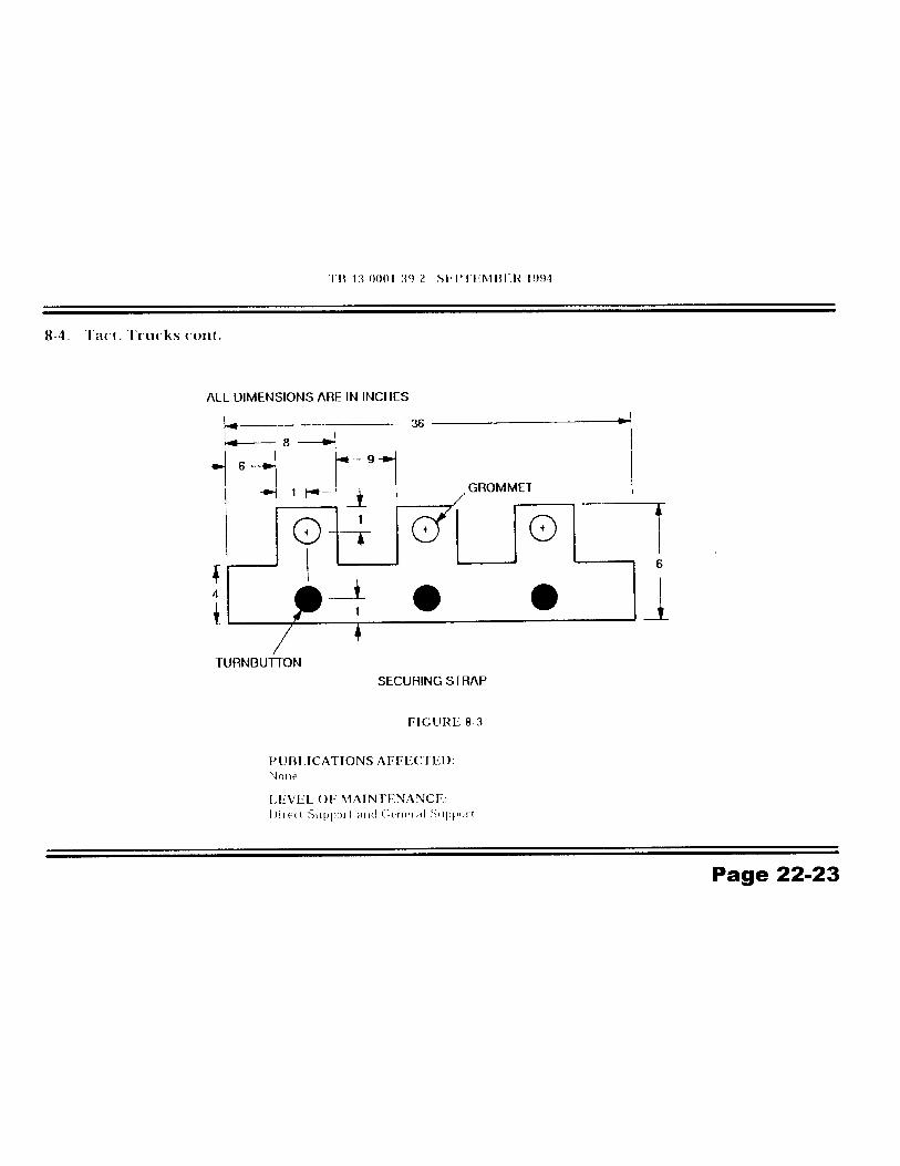

TB 43-0001-39-2 SEPTEMBER 1996
4-12. Tactical Trucks
MODEL: HMMWVSUBJECT:Heater Hose
POC:Ms. Jody McInerney, AMSTA-IM-HIA, DSN 786-5481, Commercial (810) [email protected]
COMMENTS:
A. It's been brought to our attention that the HMMWV heater hoses are easily tornbecause they get kicked and pushed around due to their location. The hoses tear by theclamps.
B. To eliminate the problem, we suggest you duct tape (NSN 7510-00-530-6375) the hosewhere the clamps are attached. This will reinforce the hose and protect it against thecutting action the clamps create when the hoses are being pushed and kicked.
PUBLICATIONS AFFECTED:TM9-2320-280-20
LEVEL OF MAINTENANCE:Unit
Page 22-24

4-7. Tactical Trucks MODEL:M998 Series (HMMWV)
SUBJECT:Heater Temperature Control Assembly
4-7. Tact. Trucks cont. POC:Ms. Kathy Catenaro, AMSTA-IM-MTA, DSN786-7151,Commercial(810)574-7151 [email protected]
DEFICIENCY:Heater cable binding.
COMMENTS:If you're having problems turning the heater control off, you may want tolook at the latest procedure for routing the heater cables. We'reconcerned that all units aren't aware of the change and may still bereplacing heater cables and control valves to solve their problem. Wepublished revised routing procedures in TB 43-0001-39-6, dated Sep 9 1.Now, you can find them in TM9-2320-280-20-3, para 10-86, dtd Nov 93.
PUBLICATIONS AFFECTED:None
LEVEL OF MAINTENANCE:Unit
Page 22-25

TB 43-0001-39-7
8-3. Tactical Trucks MODEL:HMMWV
SUBJECT:HMMWV Standard Mirror
POC:Ms. Patricia Grashik or Mr. Keith Barthlow, AMSTA-MTA,DSN 786-7427/8288, Commercial (313) 574-7427/8288
COMMENTS:Don't overtighten the round nut (NSN 5310-01-256-0416) attaching theMirror bracket to the vehicle. You only need to tighten the nut enough tohold the bracket secure. If your screwdriver breaks while you'retightening the nut, its either too tight or the screwdriver may be defective.If you think your screwdriver is defective, or any tool for that matter,contact the GSA Quality Hotline:
GSA Quality Hotline(703) 305-7368FTS 365-7368DSN 327-1996
General Services AdministrationFederal Supply ServiceWashington, DC 20406
PUBLICATIONS AFFECTED:N/A
LEVEL OF MAINTENANCE:N/A
Page 22-26

4-6. Tactical Trucks MODEL:HMMWV
SUBJECT:HMMWV Windshield Wipers
POC:Ms. Kathy Miramonti, AMSTA-MTA, DSN 786-7151,Commercial (313) 574-7151
DEFICIENCY:Reports from the field indicate users may be experiencing intermittentelectrical failures to the wiper motors due to a poor connection at thecontact assembly. This poor connection is the result of either corrosionof the terminals or a loose fit at the contact assembly because thegrommet has deteriorated.
COMMENTS:If you experience intermittent problems with the wiper motor on yourvehicle, inspect the terminals and the rubber grommet of the contactassembly (see TM9-2320-280-20P/-34P, Figure 269). If the terminals aredirty or corroded, clean or replace as required. If the grommet showssigns of damage or deformity, replace the contact assembly (NSN 5999-01-183-9530).
PUBLICATIONS AFFECTED:TM9-2320-280-20-1
LEVEL OF MAINTENANCE:Unit
Page 22-27

4-5. Tactical Trucks MODEL:HMMWV
SUBJECT:Rearview Mirror Kits used on the HMMWV
POC:Mr. Eddie Bynum, AMSTA-MTA. DSN 786-7346,Commercial (810) 574-7346
DEFICIENCY:Reports from the field indicated that the blind rivets used to hold the westcoast style mirrors on the windshield frame are coming loose or fallingout.
COMMENTS:Tool Kit, Riveter, (D- 100-MIL- 1) NSN 5180-01-218-8234 must be usedto install the blind rivet nuts (MS 27130-S43). The tool kit is issued as aspecial tool (TM9-2320-280-20-3, Appendix "B", Section III). Instructionsfor using the tool can be found in TM9-2320-280-20-3, Para. 10-63c.
PUBLICATIONS AFFECTED:None
LEVEL OF MAINTENANCE:Unit
Page 22-28

TB 43-0001-39-6
3-32. Tactical Trucks MODEL:HMMWV
SUBJECT:Windshield Washer Clamps.
POC:Mr. Eric Sutman, AMSTA-MTA, DSN 786-7151
DEFICIENCY:If the windshield washer hose clamps aren't positioned properly, whenthe hood closes it can flatten the clamps and hose. This keeps thewindshield washer from working.
COMMENTS:To prevent the hood from flattening the clamps and hose, the clampsshould be positioned below the hood rest. TM9-2320-280-20-3,paragraph 10-61 contains procedures for windshield washer hosereplacement. These procedures do not mention the proper positioning ofthe hose clamps. To help ensure proper positioning of the clamps, wewill add the following note to the TM:
NOTE
When mounting the clamps, make sure they are positioned belowthe level of the hood rest so that when the hood is closed It doesnot interfere with the clamps or hose.
PUBLICATIONS AFFECTED:TM9-2320-280-20-3
LEVEL OF MAINTENANCE:Unit
Page 22-29

TB 43-0001-39-1 JUNE 1994
3-1 1. Tactical Trucks MODEL:HMMWV M998 Series
SUBJECT:Windshield Wiper Arm Spring Replacement
POC:Ms. Patricia Grashik, AMSTA-MTA, DSN 786-7427,Commercial (810) 574-7427
DEFICIENCY:The spring inside the HMMWV windshield wiper arm loses Its tension dueto rust.
COMMENTS:We've developed procedures for replacing the spring inside thewindshield wiper arm. These procedures may be followed as analternative to replacement of the windshield wiper arm..
MATERIALS:Spring, helical, NSN 5360-01-282-9316.
PROCEDURES:Visually inspect the windshield wiper arm for damage. If there is damageother than the spring being rusted and loose, replace the entire wiperarm, NSN 2540-01-212-4959. The procedures for windshield wiper armreplacement are in TM9-2320-280-20-3, Nov 93, Para 10-67, Page 10-116. Use the following procedLWeSif only the spring Is damaged.
NOTE
Ensure windshield wiper motor switch Is In off position. Noteposition of wiper arm for Installation.
(1) Lift wiper arm (1) away from windshield. (see figure 3-17)
(2) Lift up latch (2) at base of wiper arm (1) and remove wiper arm (1) from splined shaft (3).
(3) Remove spring (5) from wiper arm (1). Discard spring (5).
Page 22-30

TB 43-0001-39-1 JUNE 1994
3-1 1. Tact. Trucks cont. 4) Install spring NSN 5360-01-282-9316 in second hole ofwiper arm tab (4).
(5) Ensure wiper arm latch (2) Is unlocked.
NOTE
With motor switched off (parked position), mount wiperarm approximately 60° to vertical centerline, so that asweep of approximately 120° will be achieved inoperation.
(6) Install wiper arm (1) on splined shaft (3).
(7) Check windshield wiper for proper operation.
PUBLICATIONS AFFECTED:TM9-2320-280-20-3
LEVEL OF MAINTENANCE:Unit
Page 22-31


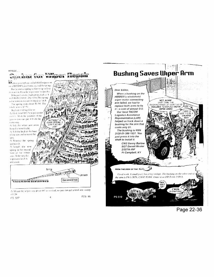
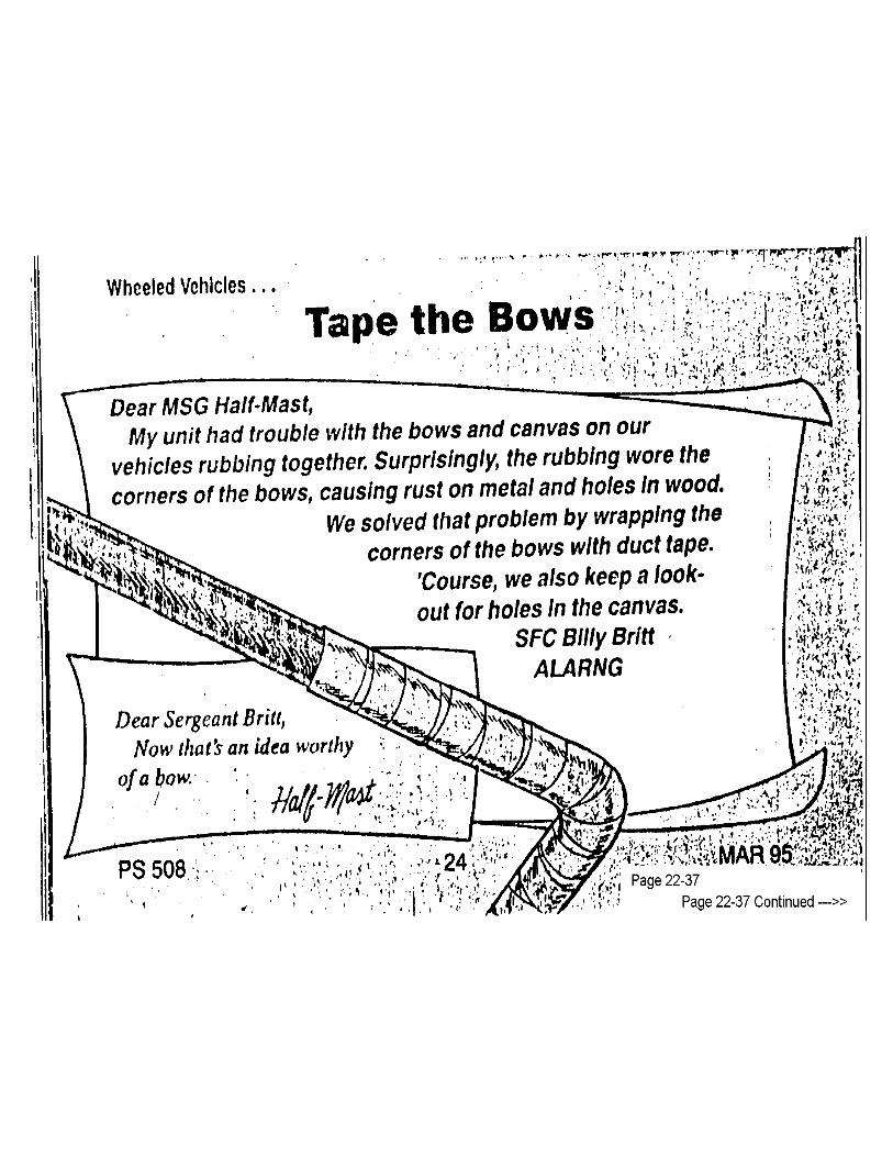

Those plastic windows in your soft-top HMMWV’s doors can’t stand up to abrasivecleaners and still do their job. The wrong stuff will scratch the plastic or turn it cloudy.
Here’s how to keep windows clean and clear:• Wash with soap, water and a clean, soft cloth.• Rinse with clean water.• Apply hand cleaner, NSN 8520-00-782-3509 or NSN 8520-00-782-3509 with a cleansoft cloth or sponge.• Wipe the cleaner off immediately with a dry cloth.
Page 22-37
Page 37 Continued ----->>


Page 22-38
A stuck zipper on a HMMWV’s soft top needs cleaning and lube,not muscle. Muscle just ruins the zipper.Drivers, you’ve got to remove grit and sand caught in the zipperteeth. Do it with an old toothbrush. Then lube the zipper teeth withzipper lube, NSN 9150-00-999-7548. That NSN brings a box of 24sticks.If you’ve already ruined a zipper, here’s a tip to keep your soft topfrom flapping until it’s repaired or replaced:Use hook and pile tape. It won’t be waterproof and it isn’t asstrong as a zipper, but it works.Get a yard of 1-in wide, self-adhesive hook with NSN 8315-01--115-7617. Matching pile is:NSN 8315-01-043-9881. Cut andplace pieces of tape where they’ll do the most good.
Before you trash that HMMWV soft-top door because the window is too scratched ordiscolored to see through, as your DS canvas repair shop if they can replace the plastic.That’s what SSG Clarence Johnson and SPC Alice Pursley of the California ARNG did.They figure they’ve saved their state more than $13,000 in replacement costs in sixmonths.One plastic sheet, NSN 9330-00-988-1894, should fix two soft-top doors for about $16plus labor. New doors cost from $73 to more than $100.


Chapter 26
TOOLS ANDTEST
EQUIPMENT
FunctionalGroup Code
2604

3-11. Tactical Trucks MODEL:HMMWV
SUBJECT:Tire Compression Tool Inspection
POC:Ms. Patricia Grashik, AMSTA-IM-HLA, DSN 786-5225, Commercial (810)574-5225 [email protected]
COMMENTS:A. Before using the runflat compression tool, NSN 5120-01-335-5847, inspect the tool’s pivot points, bearings, and strap for fraying.
CAUTIONOil on belt or handle could result in personnel injury ordamage to equipment. Wipe any oil off belt or handle .
B. Ensure gears and pivot points have a light coat of oil (seasonal grade OE) for ease of operation and protection against rust.
PUBLICATIONS AFFECTED :TM9-2320-280-20-2
LEVEL OF MAINTENANCE:Unit
Page 26-01

Chapter 32
BASIC ISSUEITEMS (BII)
FunctionalGroup Code
3200

3-10. Tactical Trucks
MODEL:HMMWV
SUBJECT:2 Ton Jack Usage
POC:Ms. Jody McInerney, AMSTA-MTA, DSN 786-7346, Commercial (313) 574-7346
DEFICIENCY:We have received reports of the 2 Ton Jack bending when attempting to change a tire on theS-250 Shelter Carrier (M1037).
COMMENTS:A. The two main causes of failure are due to the jack slipping under possible overload, or jackloaded improperly causing a side overload condition. This jack has been tested and it hasbeen demonstrated that it meets all weight requirements. It is designed to support loads in araised and lowered position.
B. The jack is intended to be used for tire replacement only. Don't try to lift more than onewheel at a time. Make sure to follow the procedures located in the Operators Manual, TM9-2320-280-10, Wheel Assembly Replacement, paragraph 3-25 for proper placement of the jackunder the control arm. Lift only as high as needed to replace the tire. Remember the higheryou lift, the greater chance of a side overload/slippage to occur.
PUBLICATIONS AFFECTED:None
LEVEL OF MAINTENANCE:Operator and Unit
Page 32-01
Heavier Jack for M1097sA 31/2 ton jack, NSN 5120-01-375-0070, is authorized for M 1097 HMMWVs. Some trucks(serial number 147072 and below), however, came with a 2-ton jack. If your truck doesn't havethe heavier jack, get one in a one-time free issue deal by sending a memo to:US Army TACOM You can also use e-mail: ATTN: SFAE-TWV-LTV (Ron Mara) [email protected], Ml 48397-5000Include the vehicle serial number and your complete address, DODAAC and POC with phonenumber

Chapter 33
SPECIALPURPOSE KITS
FunctionalGroup Code
3303-3307

TB 43-0001-39-3 DECEMBER 19943-16. Tactical Trucks
MODEL:M998 series vehicles equipped with 5705698 Arctic Heater Kit
SUBJECT:Modification of Arctic Heater Kit and Front Radio Rack Installation
POC:Ms. Jody McInerney, AMSTA-MTA, DSN 786-7346, Commercial (810) 574-7346,[email protected]
DEFICIENCY:Reports from the field Indicate that In arctic conditions from O F to -50 F thearctic heater does not provide an even flow of heat. Also, the current design offront radio rack mount Is causing cracks in the tunnel floor and upper bracket nutfailures.
COMMENTS:A procedure has been developed to modify the arctic heater kit to direct asufficient amount of heat through the vehicle during arctic operations. Also, anew brace and bracket design has been developed which will prevent tunnelfloor cracks and eliminate upper bracket nut failures. The new arctic heater kitcan only be Installed In conjunction with the front radio rack improvement.Improvements and Installation can be accomplished in the field using thefollowing materials, parts, and procedures.
MATERIALS/PARTS:NSN/(CAGEC) P/N NOMENCLATURE QTY(5DO28) RTV 736 Sealant A/R5310-00-013-1245 Nut 45310-01-102-3270 Washer 25310-01-186-8641 Nut 25305-00-543-4372 Screw 25310-00-935-9021 Nut 25975-01-034-5871 Strap, Tie-down 35320-01-134-8671 Rivet 25310-00-044-6212 Washer 25310-00-814-0673 Nut 25310-01-171-8120 Washer 2
Page 33-01

TB 43-0001-39-3 DECEMBER 1994
3-16. Tact. Trucks cont. NSN/(CAGEC) P/N NOMENCLATURE OTY5320-01-023-2529 Rivet 25320-01-143-5075 Rivet 2(19207)12446763 Rack Bracket, Upper Radio 2(19207)12446764 Brace, Radio Rack 1(19207)12446765 Bracket Assembly, Radio Mounting 2(19207)12446766 Bracket, Radio Rack Mounting 2(19207)12447054 Duct, Flexible 1
PROCEDURE:A. VEHICLE PREPARATION.
1. Remove front radio rack. (Refer to TM9-2320-280-20.)2. Remove front floorboard. (Refer to TM9-2320-280-20.)3. Remove front radio rack mounting bracket. (Refer to TM9-2320-
280-20.)4. Remove engine access cover. (Refer to TM9-2320-280-20.)5. Remove instrument cluster. (Refer to TM9-230-280-20.)6. Repair any cracks in tunnel floor. (Refer to TM9-2320-280-34.)7. Remove seven rivets (7) from top retainer (8) and diverter box (9).
(see figure 3-69)8. Remove top retainer (8) and cover (12) from plenum panel (1).9. Remove nine screws (I 1), engine shroud mount (10), and plenum
panel (1) from "A" beam (2).10. Remove four screws (3), washers (5), nuts (6), and two mounting
brackets (4) from "A" beam (2).11. Remove two rivets (2), heater duct Insert (3), and heater duct
bracket (4) from "A" beam (5). (see figure 3-70)12. Remove clamp (1) from heater duct bracket (4) and remove heater
duct insert (3) and heater duct bracket (4) from heater duct (6).13. Remove two clamps (8), three tie-down straps (10), and heater duct
(6) from dimmer switch bracket (7) and dimmer switch wire harness(9).
14. Remove two rivets (2) from tunnel floor (1) and remove radio rackbrace (3). (see figure 3-7 1)
B. INSTALLATION OF RADIO RACK MOUNTING BRACKETS.
1. Locate, mark, and drill two 0.440-inch diameter holes (1) in plenumpanel (2). (see figure 3-72)
Page 33-02

TB 43-0001-39-3 DECEMBER 1994
3-16. Tact. Trucks cont. 2. Locate, mark, and drill four 0.281-inch diameter holes (2) in "A"beam (1). (see figure 3-73)3. Cut two 0.75-inch square holes (5) in floor mat (4) on top of tunnelfloor (7).4. Using two P/N 12446766 radio rack mounting brackets (8) astemplates, locate, mark, and drill two 0.313-inch diameter holes (6) Intop of tunnel floor (7).5. Secure P/N 12446764 radio rack brace (12) and two radio rackmounting brackets (I 1) to tunnel floor (13) with four existing screws(9) and washers (10). (see figure 3-74)6. Locate two holes (I 5) in tunnel floor (I 3) made by rivets removed inpara. A, step 14, and drill two 0. 192-inch diameter holes In radio rackbrace (I 2).7. Install two NSN 5320-01-143-5075 rivets (14) in tunnel floor (13)and radio rack brace (12).8. Position two P/N 12446765 radio mounting bracket assemblies (3)to "A" beam (6) and secure with four existing screws (2), washers (4),and NSN 5310-00-013-1245 nuts (5).
C. INSTALLATION OF FLEXIBLE DUCT.
1. Route P/N 12447054 flexible duct (2) from diverter box (3) along 'A"beam (5), through dash (1), down to and through dimmer switchbracket (7). (see figure 3-75)'2. Install flexible duct (2) In diverter box (3).3. Locate, mark, and drill two 0. 129-inch diameter holes In diverterbox (3) and flexible duct (2).4. Remove flexible duct (2) and apply RTV 736 sealant around thearea of the flexible duct (2) that Is to be Installed in diverter box (3).Then Install flexible duct (2) in diverter box (3).5. Install two NSN 5320-01-134-8671 rivets (4) In diverter box (3) andflexible duct (2).6. Secure flexible duct (2) to steering column mount (10) and dimmerswitch bracket (7) with two clamps (8).7. Secure flexible duct (2) to dimmer switch wire harness (6) withthree NSN 5975-01-034-5871 tiedown straps (9).8. Apply RTV 736 sealant to fill two holes (3) In plenum panel (2). (seefigure 3-72)9. Apply RTV 736 sealant to fill four holes (3) In "A" beam (1) and twoholes (9) In floor mat (4). (see figure 3-73)10. Position plenum panel (1) and engine shroud mount (8) on "A"beam (6) and secure with nine existing screws (7). (see figure 3-74)11. Install two NSN 5320-01-023-2529 rivets (7) and NSN 5310-01-171-8120 washers (8) in diverter box (9). (see figure 3-76)12. Install two P/N 12446763 tipper radio rack brackets (5) on plenumpanel (6) and secure with two NSN 5305-00-543-4372 screws (3) andNSN 5310-00-044-6212 washers (4).
Page 33-03

TB 43-0001-39-3 DECEMBER 1994
3-16. Tact. Trucks cont. 13. Install front floor board. (Refer to TM9-2320-280-20.)14.Install engine access cover. (Refer to TM9-2320-280-20.)15. Install instrument cluster. (Refer to TM9-2320-280-20.)16. Position front radio rack (17) on two radio rack mounting brackets
(I 4) and secure with two existing screws (13), washers (15), andNSN 5310-00-935-9021 nuts (16). (see figure 3-76)
17. Position front radio rack (17) to tipper radio rack brackets (5) andsecure with two NSN 5310-01-102-3270 washers (2) and NSN5310-01-186-8641 nuts (1).
18. Install two "P" clamps (10) on front radio rack (17) and secure withtwo existing screws (11) and NSN 5310-00-814-0673 nuts (12).
19. Spot paint as necessary. (Refer to TM 43-0139.)
PUBLICATIONS AFFECTED:TM9-2320-280-20TM9-2320-280-20PTM9-2320-280-34P
LEVEL OF MAINTENANCE:Direct Support
Page 33-04


TB 43-0001-39-3 DECEMBER 1994
3-15. Tactical Trucks MODEL:All M998 Series Vehicles except those with 5705698 Arctic Heater KitInstalled
SUBJECT:Improved Front Radio Rack Mounting Installation
POC:Ms. Jody McInerney, AMSTA-MTA, DSN 786-7346,Commercial (810) 574-7346, [email protected]
DEFICIENCY:Current design of front radio rack mount is causing tunnel floor cracksand upper bracket nut failures.
COMMENTS:A new radio rack mount has been developed which will prevent tunnelfloor cracks and eliminate upper bracket nut failures. The current radiorack mount can be improved by using the following materials, parts, andprocedures.
MATERIALS/PARTS:
NSN/(CAGEC) P/N NOMENCLATURE QTY
5310-00-013-1245 Nut 45310-01-102-3270 Washer 25310-01-186-8641 Nut 25305-00-543-4372 Screw 25310-00-044-6212 Washer 25310-00-814-0673 Nut 25310-00-935-9021 Nut 25320-01-143-5075 Rivet 26850-01-159-4844 RTV Sealant A/R(19207)12446763 Rack Bracket, Upper Radio 2(19207)12446764 Brace, Radio Rack 1(19207)12446765 Bracket Assembly, Radio Mounting 2(19207)12446766 Bracket, Radio Rack Mounting 2
Page 33-13

TB 43-0001-39 -3 DECEMBER 1994
3-15. Tact. Trucks cont. PROCEDURE:A. VEHICLE PREPARATION.
1. Remove front radio rack. (Refer to TM9-2320-280-20.)2. Remove front floorboard. (Refer to TM9-2320-280-20.)3. Remove front radio rack mounting bracket. (Refer to TM9-2320-
280-20.)4. Remove engine access cover-. (Refer to TM9-2320-280-20.)5. Remove nine screws (8) and plenum panel (1) from "A" beam (2)
and engine shroud mount (7). (see figure 3-63)6. Remove four- nuts (6), washers (5), screws (3), and two mounting
brackets (4) from "A" beam (2).7. Remove two rivets (2) from tunnel floor (1) and remove radio rack
brace (3). (see figure 3-64)8. If damaged, repair tunnel floor around radio rack mounting area.
(Refer to TM9-2320-280-34.)
B. FRONT RADIO RACK INSTALLATION.
1. Locate, mark, and drill two 0.440-inch diameter holes In plenumpanel (1). (see figure 3-65)
2. Locate, mark, and drill four 0.281-inch diameter holes In "A" beam(1). (see figure 3-66)
3. Cut two 0.75-inch square holes in floor mat (5) on top of tunnel floor(6).
4. Using two P/N 12446766 radio rack mounting brackets (3) astemplates, locate, mark, and drill two 0.313-inch diameter holes intop of tunnel floor (6).
5. Apply NSN 6850-01-159-4844 RTV sealant to two holes (2) inplenum panel (1). (see figure 3-65)
6. Apply NSN 6850-01-159-4844 RTV sealant to four holes (2) In “A"beam (1) and two holes (4) in top of tunnel floor (6). (see figure 3-66)
7. Position P/N 12446764 radio rack brace (13) and two radio rackMounting brackets (12) to tunnel floor (14) and secure with fourexisting washers (15) and screws (16). (see figure 3-67)
8. Position two P/N 12446765 radio mounting bracket assemblies (7)to "A" beam (5) and secure with four existing screws (6), washers(8), and NSN 5310-00-013-1245 nuts (9).
9. Position plenum panel (1) oil "A" beam (5) and engine shroudmount (I 1) and secure with nine existing screws (10).
10.Position two P/N 12446763 upper radio rack brackets (2) onplenum panel (1) and secure with two NSN 5305-00-543-4372screws (3) and NSN 5310-00-044-6212 washers (4).
11.Locate two holes (6) in tunnel floor (1) left by rivets (2) removed inpara. A, step 7, and drill two 0. 192-inch diameter holes (4) in radiorack brace (3). (see figure 3-64)
Page 33-14

TB 43-0001-39-3 DECEMBER 1994
3-15. Tact. Trucks cont. 12. Install two NSN 5320-01-143-5075 rivets (5) in tunnel floor (1)and radio rack brace (3). (see figure 3-64)
13. Install front floorboard. (Refer to TM9-2320-280-20.)14. Install engine access cover. (Refer to TM9-2320-280-20.)15. Position front radio rack (1) on tunnel floor (12) and secure to two
radio rack mounting brackets (I 1) with two existing screws (10),washers (I 3), and NSN 5310-00-935-9021 nuts (14). (seefigure 3-68)
16. Position front radio rack (1) to plenum panel (4) and secure toupper radio rack brackets (5) with two NSN 5310-01-102-3270washers (3) and NSN 5310-01-186-8641 nuts (2).
17. Position radio cables (9) on front radio rack (1) and secure withtwo existing clamps (7), screws (6), and NSN 5310-00-814-0673nuts (8).
18. Spot paint as necessary. (Refer to TM 43-0139.)
PUBLICATIONS AFFECTED:TM9-2320-280-20TM9-2320-280-20PTM9-2320-280-34P
LEVEL OF MAINTENANCE:Direct Support
Page 33-15


3-11. Tactical Trucks MODEL:HMMWV, with Troop/Cargo Area, Two-Door Winterization Kit 5705611installed
SUBJECT:Modification of diverter assembly and installation of air ventilator and lightdiverter
POC:Ms. Patricia Grashik or Mr. Keith Barthlow, AMSTA-MTA,DSN 786-7427/8288, Commercial (313) 574-7427/8288
DEFICIENCY:Reports from the field indicate that NSN 2805-01-317-2725 diverterassembly can starve heater of air.
COMMENTS:Procedures have been developed to modify NSN 2805-01-317-2725diverter assembly to eliminate the possibility of the heater being starvedof air. Fabrication of light diverter and installation of NSN 2540-01-164-1886 ventilator to ventilate the cargo area enclosure will eliminateinsufficient air problems. These corrective actions can be accomplishedin the field by using the following parts and materials.
Page 33-22

TB 43-0001-39-83-11. Tact. Trucks cont.
MATERIALS/PARTS:
NSN NOMENCLATURE QUANTITY2540-01-164-1886 Ventilator 15305-01-315-9882 Screw 85320-01-271-6357 Rivet 36850-01-159-4844 Sealant RTV AR9515-00-640-4201 Steel Sheet 1
Part to be fabricated from material requisitioned:
NOMENCLATURE QUANTITYLight Diverter 1
PROCEDURE:A. Fabrication.
Using NSN 9515-00-640-4201 steel sheet, fabricate light diverter. (see figures 3-30and 3-31)
B. Installation Procedures.
(1) Loosen two clamps (2) and remove diverter assembly (3) from adapter (4)and flex duct (1). (see figure 3-32)
(2) Locate, mark, and drill three O.193" diameter holes through diverter assembly (1)and damper (2). (see figure 3-33)
(3) Secure damper (2) to diverter assembly (1) using three NSN 5320-01-271-6357 rivets (3).
(4) Cut handle assembly (4) from diverter assembly (1).
(5) Install diverter assembly (3) on adapter (4) and flex duct (1) with two clamps (2). (see Figure 3-32)
(6) Using NSN 2540-01-164-1886 ventilator (2) as a template, locate, mark, and drill four 0.109" diameter holes 0.750” deep in right rear enclosure (1). (see figure 3-34)
(7) Locate and mark area (5) to be cut out in right rear enclosure (1).
Page 33-23

TB 43-0001-39-83-11. Tact. Trucks cont.
(8) Cut out area (5) in right rear enclosure (1).(9) Apply a bead of NSN 6850-01-159-4844 RTV sealant (4) on
ventilator (2).(10) Secure ventilator (2) to right rear enclosure (1) using four NSN
5305-01-315-9882 screws (3).(11) Using light diverter (2) as a template, locate, mark, and drill four
0.109” diameter holes 0.750” deep in right rear enclosure (1). (see figure 3-35)
(12) Apply beads of RTV sealant (4) on light diverter (2).(13) Secure light diverter (2) on right rear enclosure (1) using four
screws (3).(14) Apply a bead of RTV sealant (5) between ventilator (6) and light
diverter (2).(15) Spot paint as necessary. (Refer to TM43-0139).
PUBLICATIONS AFFECTED:TM9-2320-280-34 TM9-2320-280-34P
LEVEL OF MAINTENANCE:Direct Support
Page 33-24


4-8. Tactical Trucks MODEL:HMMWV
SUBJECT:Commercial Brushguards
POC:Ms. Kathy Catenaro, AMSTA-IM-HLA, DSN 786-5481,Commercial (810) 574-5481, [email protected]
COMMENTS:Before a standardized brushguard was developed for the HMMWV,various commercial brushguards were installed by the field. TACOMdoes not support the repair of those brushguards. So, if you need parts,you'll have to contact the company directly. If you have a Luvernebrushguard, you can contact them @ 1-800-533-0506 to get your repairparts.
PUBLICATIONS AFFECTED:None
LEVEL OF MAINTENANCE:N/A
Page 33-31

TB 43-0001-39-5 JUNE 1995
3-7. Tactical Trucks MODEL:M998 Series Vehicles, 1-1/4 Ton, 4x4
SUBJECT:Niehoff 100 AMP Alternator Assembly Diagnostic Procedures
POC:Ms. Jody McInerney, AMSTA-IM-MTA, DSN 786-7346,Commercial (810) 574-7346, [email protected]
DEFICIENCY:Units lack diagnostic procedures for troubleshooting the Niehoff 100 AMPalternator (NSN 2920-00-000-0183).
COMMENTS:This procedure provides the diagnostics for troubleshooting the Niehoff100 AMP alternator assembly when installed In the vehicle. This can beaccomplished in the field by using the -following Instructions. Thisinformation will be Incorporated Into the next manual change of TM9-2320-280-20.
PROCEDURES:Section I: Alternator Troubleshooting Procedures
For alternator operation, power-on checks, and electrical systemwiring diagrams, refer to TM9-2320-280-20.
Section II: Diagnostic Procedures
A. ON-VEHICLE TESTING.
The alternator is examined most easily on the vehicle, where thecharging and ignition systems of the vehicle can be examined atthe same time.
B. PRELIMINARY CHECKS.
1. Check belt tension. (Refer to TM9-2320-280-20.)2. Check batteries. (Refer to TM9-2320-280-20.)3. Check electrical connections in the charging circuits. (Refer to
TM9-2320-280-20.)4. Check ignition circuit. (Refer to TM9-2320-280-20.)
Page 33-32

TB 43-0001-39-5 JUNE 1995
3-7. Tact. Trucks cont. C. TEST SETUP.1. Turn fuel off. (Refer to TM9-2320-280-20.)2. Turn all lights and accessory switches to the “ON”" position.
(Refer to TM9-2320-280-10.)3. Crank engine for 10-15 seconds to discharge the battery, then
stop cranking.4. Turn all lights and accessory switches to the "OFF" position.
(Refer to TM9-2320-280-10.)5. Turn fuel on. (Refer to TM9-2320-280-20.)
D. TEST PROCEDURE.
NOTE
All page and paragraphs referencedwithin steps F1 through F5 refer to TM9-2320-280-20.
Complete diagnostic flowchart steps Fl through F5, as required.(see the following pages 3-11 through 3-14)
PUBLICATIONS AFFECTED:TM9-2320-280-20TM9-2320-280-34
LEVEL OF MAINTENANCE:Unit and Direct Support
Page 33-33


8-2. Misc. Vehicles
MODEL:All TACOM Vehicles that use NSN: 5340-01-059-0114, Slave Receptacle DustCap
SUBJECT:Slave Receptacle Cover
POC:Ms. Kathy Catenaro, AMSTA-IM-MTA, DSN 786-715 1, Commercial (810) 574-7151, [email protected]
DEFICIENCY:The NATO slave receptacle cover sticks, especially in cold weather. Not onlydoes It stick, but sometimes It seizes. When this happens It is pried off, causingthe cover to break.
COMMENTS:To keep the dust cap from sticking, you can apply either a little dry graphite,NSN 9620-00-204-2643, or a thin layer of waterless hand cleaner, NSN 8520-00-965-2109 on the inside of the cover.
PUBLICATIONS AFFECTED: N/A
LEVEL OF MAINTENANCE: Unit
Page 33-38

TB 43-0001-39-4 MARCH 19951 2. Tactical Trucks
MODEL:HMMWV M998, M998A1, M1038, M1038A1, M1097, and M1097A1
SUBJECT:Troop Seat Safety Strap Bracket
POC:Ms. Patricia Grashik, AMSTA-IM-MTA, DSN 786-7713, Commercial (810) 574-7713,[email protected]
DEFICIENCY:Reports from the field indicate the troop seat safety strap brackets are breaking ,making itimpossible to secure the troop safety strap. This restricts transporting of troops In the vehicledue to safety requirements.
COMMENTS:A procedure has been developed to replace a broken troop seat safety strap bracket with afabricated bracket. Replacement of the bracket can be accomplished in the field using thefollowing parts, material, and procedures:
MATERIALS/PARTS:
NSN NOMENCLATURE QTY9510-00-596-2309 Bar, Metal AR5310-00-933-4310 Nut, Assembled Washer 2
PROCEDURE:1. Remove two bolts (7), bow retainer (5), two washers (4), assembled washer nuts (3), andbackboard (2) from top of two channels (1) oil troop seat back (8). (see figure 3-38)
2. Remove any existing metal or weld of broken safety strap bracket (6) from channel (1) ontroop seat back (8).
3. Using NSN 9510-00-596-2309 metal bar, fabricate troop seat safety strap bracket. (seefigure 3-39)
Page 33-39

TB 43-0001-39-4 MARCH 1995
3-12. Tact. Trucks cont. 4. Weld fabricated safety strap bracket (2) to troop seat channel (1). (seefigure 3-40)
5. Position existing backboard (2) to top of two channels (1) on troopseat back (8) and secure with two existing bolts (7), bow retainer (5),two washers (4), and NSN 5310-00-933-43 10 assembled washernuts (3). (see figure 3-38)
6. Spot-paint troop seat back channel and hardware. (Refer to TM 43- 0139.)
PUBLICATIONS AFFECTED:TM9-2320-280-20
LEVEL OF MAINTENANCE:Unit
Page 33-40

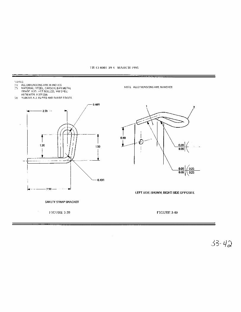

TB 43-0001-39-2 SEPTEMBER 19943-14. Tactical Trucks
MODEL:M998 Series
SUBJECT:100 Amp Alternator
POC:Mr. Eric Sutman, AMSTA-MTA, (810) 574-7151
DEFICIENCY:here's been some confusion about the interchangeability between the Prestoliteand Niehoff models of the 100 amp alternator used on the HMMWV. We'll try toclear up this confusion with this article.
COMMENTS:A. The HMMWV could be equipped with either the Prestolite (PN 12340912) orNiehoff (PN 12342944) 100 amp alternator. The Prestolite alternator is part of kitNSN 2920-01-199-2393. The Niehoff alternator Is part of kit NSN 2920-01-371-4030. The alternator assemblies are interchangeable. The down parts, Includingthe regulators. aren't Interchangeable.
B. If your vehicle has the Prestolite alternator you can replace the alternatorwith the Niehoff model. The mounting brackets are the same but the wiringconnections are a little different. See figure 3-7 for the proper wiring connectionsfor the Niehoff alternator.
C. If your vehicle has the Niehoff alternator you can replace the alternator withthe Prestolite model. Again, the mounting brackets are the same but the wiringconnections are a little different. See TM 9-2320- 280-20-3, paragraph 12-21, forthe proper wiring connections for the Prestolite alternator.
D. Remember, you can’t use a Prestolite regulator on a Niehoff alternator or aNiehoff regulator on a Prestolite alternator. If you need to switch from aPrestolite alternator to a Niehoff, or vice versa, you have to change out theentire alternator assembly.
PUBLICATIONS AFFECTED:TM9-2320-280-20-3
EVEL OF MAINTENANCE:Unit
Page 33-43


TB 43-0001-39-2 SEPTEMBER 19943-12. Tactical Trucks
MODEL:All HMMWVs
SUBJECT:Repair Parts Kit for 100 AMP Alternator
POC:Ms. Jody McInerney, AMSTA-MTA, (810)574-7346
COMMENTS:A. When you order the repair kit for the 100 AMP Alternator (P/N(19207)'5703776), NSN 2920-00-472-1723, you should only receive Item 26,Rectifier and Lead and 28, Rectifier and Lead on figure 324.
B. If you want to get the other parts listed (brush, holder and stud, seals, andpreformed packing) you need to order P/N (19207) 5703776-1, NSN 2920-01-222-2183. The TMs will be updated In the next change.
PUBLICATIONS AFFECTED :TM9-2320-280-34P
LEVEL OF MAINTENANCE:Direct Support
Page 33-45


Chapter 47
GAGES ANDMEASURING
DEVICES
FunctionalGroup Code
4701
3-11. Tactical Trucks MODEL:HMMWV
SUBJECT:Speedometer Cable Design Improvement
POC:Ms. Jody McInerney, AMSTA-IM-HLA, DSN 786-5481, Commercial (810)574-5481 [email protected]
DEFICIENCY:Reports from the field indicate that the speedometer cable routing through the cowl has too small of a radius, causing the cable to kink and become inoperable.
COMMENTS:Procedures have been developed to install a longer speedometer cable, witha larger bend radius. The instructions and parts required can be obtained byordering NSN 2590-01-433-8553, PN (19207) 57K3491.
PUBLICATIONS AFFECTED :TM9-2320-280-20TM9-2320-280-24P
LEVEL OF MAINTENANCE:Unit
Page 47-01