Hydrodynamic modelling of a direct drive wave energy converter
Upload
independentCategory
view
3download
0
Coordinated Offshore Energy Extraction, Floating Wind Turbines and Bridges Wave Energy Extraction - Calculation
http://www.renewableenergypumps.com Page 1 of 23
The following is an analysis of Offshore Energy Extraction Systems, (COEE&FB) with detailed calculation of Wave Energy Extraction for selected float dimensions as needed.
For further details refer to: http://www.renewableenergypumps.com
Available Energy Extraction Systems “There are floats, flaps, ramps, funnels, cylinders, air-bags and liquid pistons. Devices can be at the surface, the sea bed or anywhere between. They can face backwards, forwards, sideways or obliquely and move in heave, surge, sway, pitch and roll. They can use oil, air, water, steam, gearing or electro-magnetics for (electric power) generation. They make a range of different demands on attachments to the sea bed and connections of power cables. They have a range of methods to survive extreme conditions but perhaps not quite enough.
The inventors, myself included, invariably claim at first that they are simple and, after experience with the dreadful friction of reality, invariably discover that this is not totally true when they come to test in the correct wave spectra with a Gaussian distribution of wave amplitudes.”
As so often in physics and engineering, a full understanding of all the energy flows leads to a full understanding of the problem and points to suitable solutions.
Many inventors of wave power devices, going back to Girard pere et fils in 1799.”
By Stephen Salter, School of Engineering and Electronics, University of Edinburgh, EH9 3JL, Scotland. [email protected].
Abstract of the (COEE&FB) system The wave gear drive, (WGD) system is a new method for converting wave energy from the front and lee sides of the wave using a buoyant float following wave undulations, developing a vertical uplift, that acts on a pull reversing pulley located below the wave trough line and a power pulley located at the dry deck of a (floating construction unit) to directly convert the float up and down movement to rotary motion and drive a water pump to lift a small quantity of water to a much higher head, collect it through a closed circuit piping system and feed it to a hydro turbo generator to generate electric power, step it up and transmit it to the shore line.
The (WGD) system uses a (floating construction unit) supported by suitable floats, moored and anchored to the seabed supports and provides a dry closed space to house the water pumps, the hydro-turbo generator and associated equipment.
A hydro turbine with suitable shrouds installed below the wave trough line, extracts the wave lee side energy from the downward flow of water during the lee side of the wave cycle, and extracts energy from the ebb/tide energy.
The roof of the (floating construction unit) provides dry support for a solar system.
Adding fixed floats at the bottom of the (floating construction unit) and arranging the (floating construction units) in a stepped configuration, makes it suitable as a floating wind turbine support, thus having a coordinated wave, tidal, solar and wind energy extraction system.
Further reinforcing the (floating construction units) with additional fixed floats would make the system suitable for a covered floating offshore bridge.
System Information A schematic overview of the (COEE&FB) system is shown by Figure–1., Sheet-5.
Depending on sea and wind states the (COEE&FB) system can provide energy in excess of 40 kw per one meter of sea front; that is a minimum of 34,700 kw-hours per year per one meter of sea front, excluding tidal, solar and wind energy, with a breakeven point at 7 to 10 years.
It is worth comparing the (COEE&FB) system with other existing systems, especially wave energy extraction systems, where the following advantages stand out:
a. The (FCU) system extracts wave energy from the front and lee side of the wave.
b. The total net electric power efficiency fed into the electric utility network is 30% of incoming wave energy.
c. 92% of the wave energy extracted is for waves between 1.5 and 4 meters, and 68% for waves between 1 and 2 meters high, out of a wave height ranging between 0.5 and 8 meters.
Coordinated Offshore Energy Extraction, Floating Wind Turbines and Bridges Wave Energy Extraction - Calculation
http://www.renewableenergypumps.com Page 2 of 23
d. The “Floating Construction Unit” (FCU) is the building block for the (COEE&FB) system. It measures 18.75 meters wave front, 28.5 meters long and 16 meters deep excluding the fixed floats.
e. The (FCU) is of modular construction, completely assembled with all equipment at the shoreline, floated and installed at location ready for operation
f. The system uses materials and equipment available on the market with proven quality and performance.
g. The system contributes to providing support for the solar, tidal and wind energy extraction systems, thus reducing costs.
Using the Program
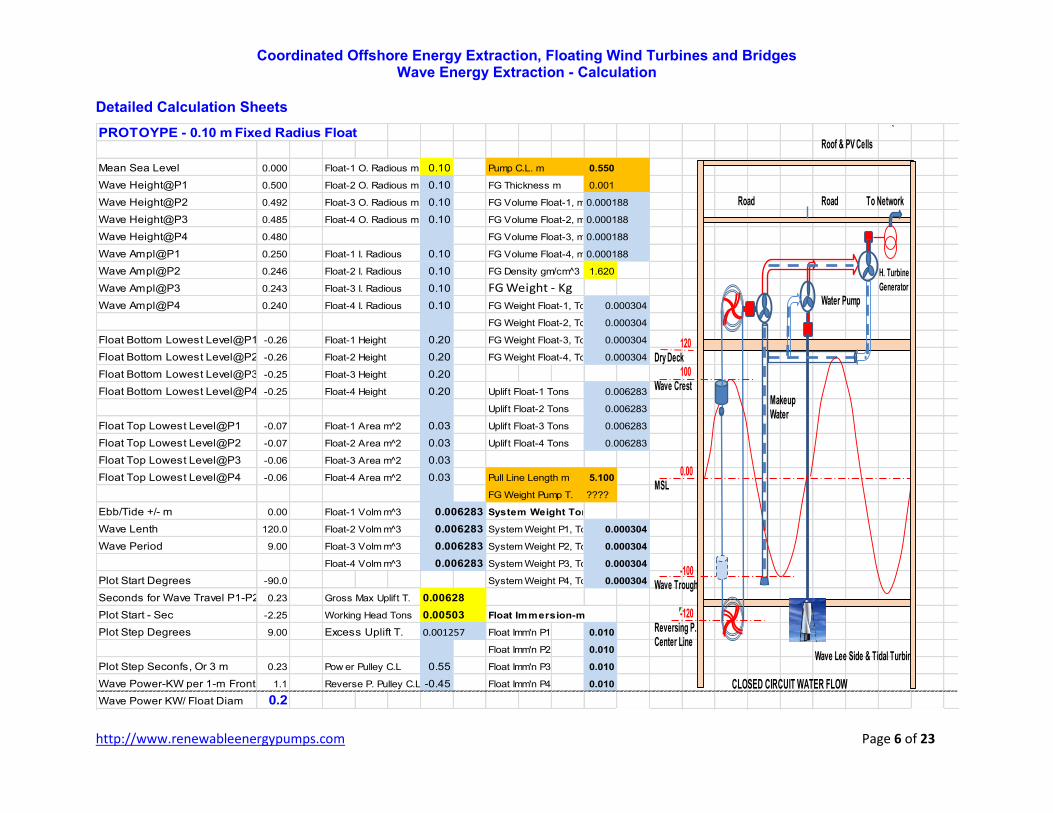
1. Detailed shop drawings and bill of quantities for fabricating, assembling and installing a scaled prototype with a 0.10 m radius and 0.20 m height, Sheets 15 to 22.
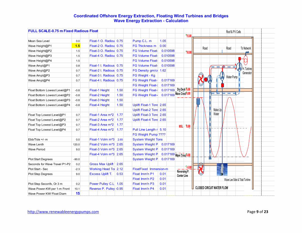
2. Plan view is also provided for a (FCU) with a 0.75 m fixed radius and 1.50 m height. The shop drawings for this fixed type float and for other variable type float can be easily developed, using the system elevation, Sheet 23.
Three (3) sets of detailed calculations are provided as shown below:
1. Prototype with a float radius of 0.10 m and a height of 0.20 m, Sheets 6, 7, 8.
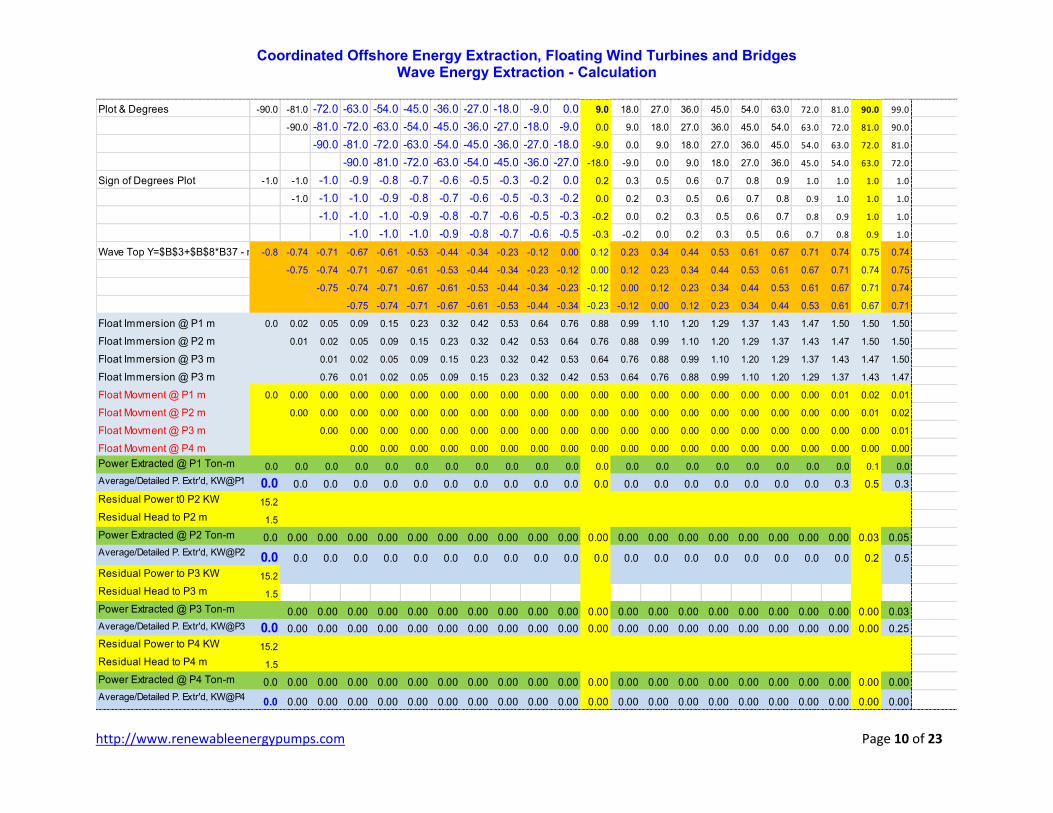
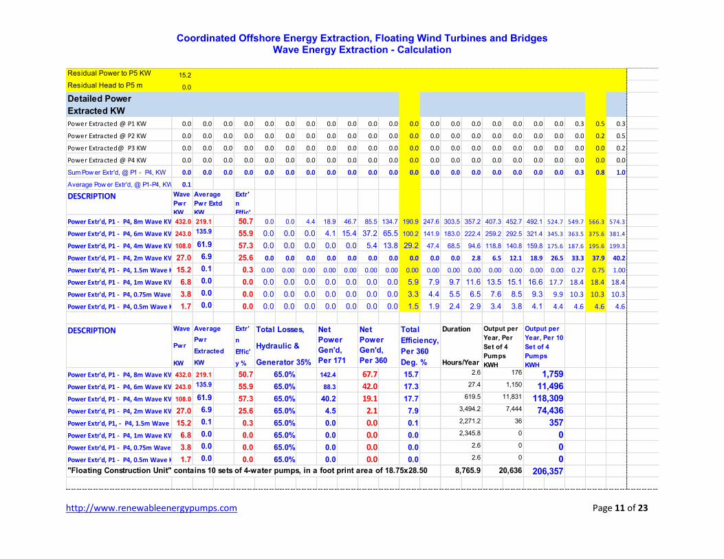
2. Fixed type float with a radius of 0.75 m and a height of 1.50 m, developing an uplift of 2.6501 tons per float; Sheets 9, 10, 11.
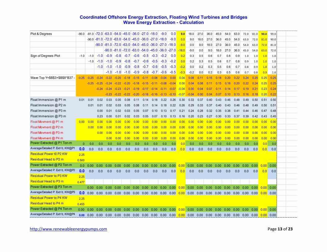
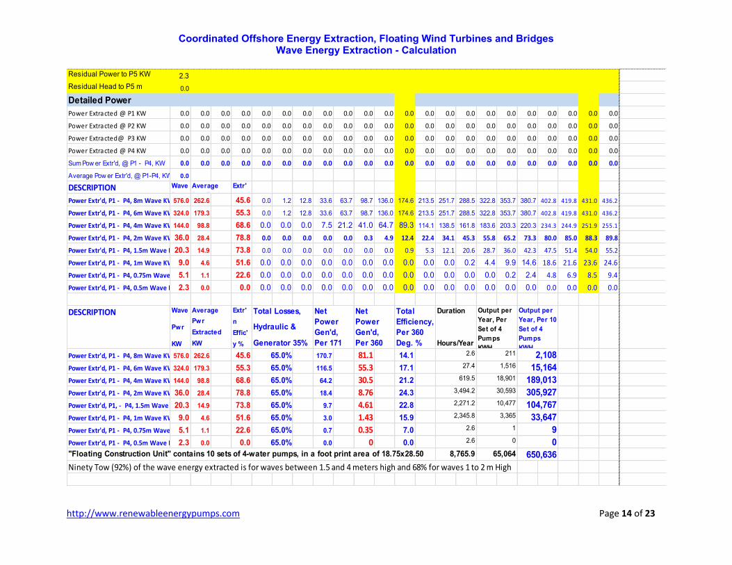
3. Variable type float with a radius of 1.00, 2.10, 1.21, 1.32 and heights of 0.80, 0.70, 0.58,and 0.48 respectively for pumps P1, P2, P3, P4 to keep a constant uplift of 2.6501 tons per float; Sheets 12, 13, 14.
4. The system variables are: float radius, height and material specific gravity, mean sea level, wave height, wave period, and plot steps.
The power output is automatically calculated between -90 and +90 degrees of the wave cycle, in steps of 9 degrees, and extrapolated as an average over a complete wave cycle from -90 to 180 degrees.
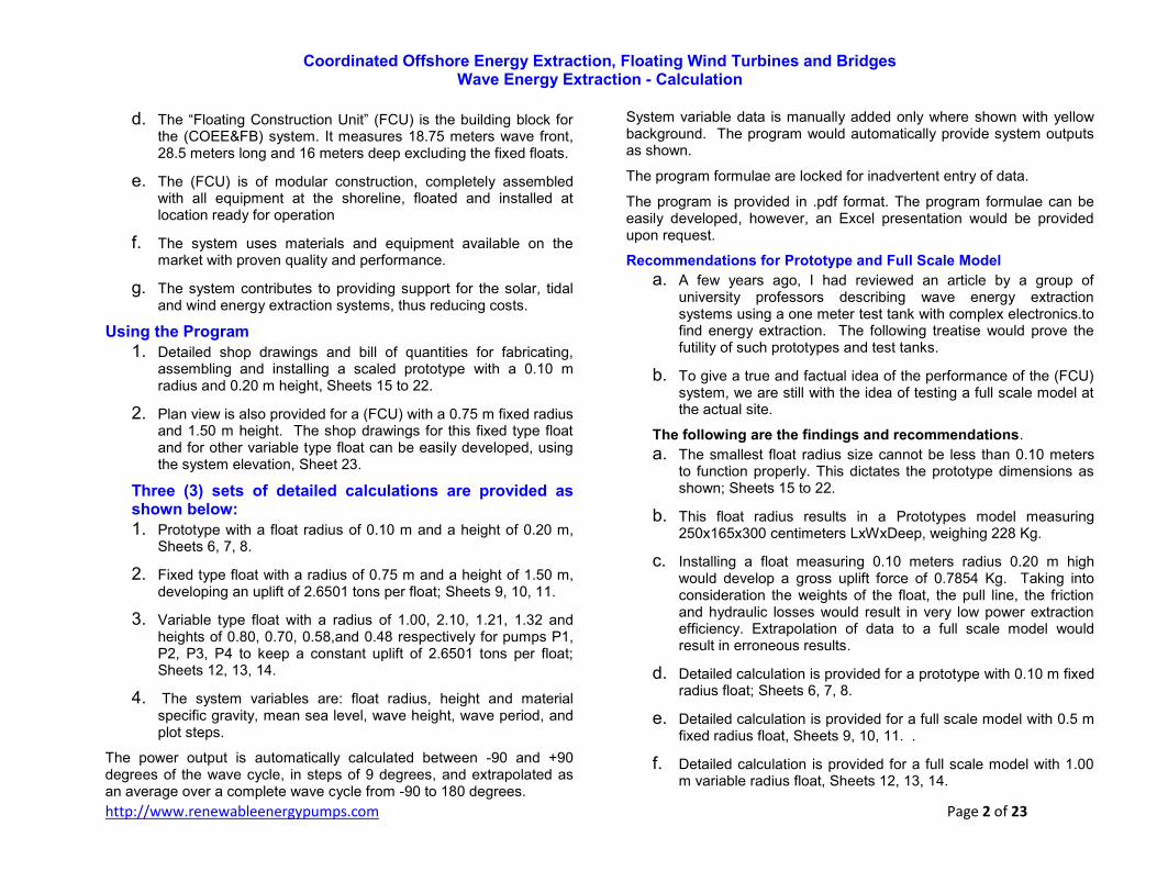
System variable data is manually added only where shown with yellow background. The program would automatically provide system outputs as shown.
The program formulae are locked for inadvertent entry of data.
The program is provided in .pdf format. The program formulae can be easily developed, however, an Excel presentation would be provided upon request.
Recommendations for Prototype and Full Scale Model
a. A few years ago, I had reviewed an article by a group of university professors describing wave energy extraction systems using a one meter test tank with complex electronics.to find energy extraction. The following treatise would prove the futility of such prototypes and test tanks.
b. To give a true and factual idea of the performance of the (FCU) system, we are still with the idea of testing a full scale model at the actual site.
The following are the findings and recommendations.
a. The smallest float radius size cannot be less than 0.10 meters to function properly. This dictates the prototype dimensions as shown; Sheets 15 to 22.
b. This float radius results in a Prototypes model measuring 250x165x300 centimeters LxWxDeep, weighing 228 Kg.
c. Installing a float measuring 0.10 meters radius 0.20 m high would develop a gross uplift force of 0.7854 Kg. Taking into consideration the weights of the float, the pull line, the friction and hydraulic losses would result in very low power extraction efficiency. Extrapolation of data to a full scale model would result in erroneous results.
d. Detailed calculation is provided for a prototype with 0.10 m fixed radius float; Sheets 6, 7, 8.
e. Detailed calculation is provided for a full scale model with 0.5 m fixed radius float, Sheets 9, 10, 11. .
f. Detailed calculation is provided for a full scale model with 1.00 m variable radius float, Sheets 12, 13, 14.

Coordinated Offshore Energy Extraction, Floating Wind Turbines and Bridges Wave Energy Extraction - Calculation
http://www.renewableenergypumps.com Page 3 of 23
g. It is recommended to provide a full scale model with 5-sets, each with 4-pumps and/or VSG generators at the actual site of the project with full data acquisition for; solar, wind, ebb/tide and ambient states for a whole year.
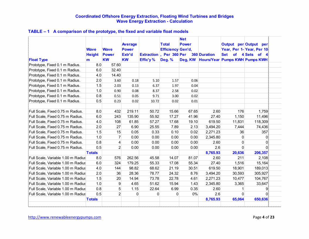
h. A comparison of the prototype, the fixed and variable float models are shown in Table-1, Sheet 4.
Funding and Results Federal, Public Agencies and Utilities had done more than their share in subcontracting consultants to devise an efficient method for Marine Energy Extraction to the extent of pilfering large funds to consultants and developers. No efficient system had been devised yet in spite of these efforts.
There seems to be a normal tendency by renewable energy developers to exclude new ideas, without consideration of better ideas that lead to improving the renewable energy extraction systems. For example proposing wind turbines above 6 MW capacities would exclude small manufacturers.
The intention of this analysis is to get feedback to improve marine energy extraction systems, cooperate with developers and public entities to test and execute the (COEE&FB) system.
(COEE&FB) System Findings and Recommendations The renewable energy wave pumps had been developed and patented as of 2004. Since then continuous improvements had been made culminating in the present system.
The decision to publish and make this information public is to get feedback and come up with a viable system. Lot of universities and developers are spending funds and efforts to analyze wave energy extraction.
It is requested that if anyone feels that he had previously devised a similar system, or this system infringes on any patent, is kindly requested to voice his opinion and ideas.
Coordinated Offshore Energy Extraction, Floating Wind Turbines and Bridges Wave Energy Extraction - Calculation
http://www.renewableenergypumps.com Page 4 of 23
TABLE – 1 A comparison of the prototype, the fixed and variable float models
Float Type
Wave
Height
m
Wave
Power
KW
Average
Power
Extr'd
KW
Extraction
Effic'y %
Total
Efficiency
, Per 360
Deg. %
Net
Power
Gen'd,
Per 360
Deg, KW
Duration
Hours/Year
Output per
Year, Per 1-
Set of 4
Pumps KWH
Output per
Year, Per 10-
Sets of 4
Pumps KWH
Prototype, Fixed 0.1 m Radius. 8.0 57.60
Prototype, Fixed 0.1 m Radius. 6.0 32.40
Prototype, Fixed 0.1 m Radius. 4.0 14.40
Prototype, Fixed 0.1 m Radius. 2.0 3.60 0.18 5.10 1.57 0.06
Prototype, Fixed 0.1 m Radius. 1.5 2.03 0.13 6.37 1.97 0.04
Prototype, Fixed 0.1 m Radius. 1.0 0.90 0.08 8.37 2.58 0.02
Prototype, Fixed 0.1 m Radius. 0.8 0.51 0.05 9.71 3.00 0.02
Prototype, Fixed 0.1 m Radius. 0.5 0.23 0.02 10.72 0.02 0.01
Full Scale, Fixed 0.75 m Radius. 8.0 432 219.11 50.72 15.66 67.65 2.60 176 1,759
Full Scale, Fixed 0.75 m Radius. 6.0 243 135.90 55.92 17.27 41.96 27.40 1,150 11,496
Full Scale, Fixed 0.75 m Radius. 4.0 108 61.85 57.27 17.68 19.10 619.50 11,831 118,309
Full Scale, Fixed 0.75 m Radius. 2.0 27 6.90 25.55 7.89 2.13 3,494.20 7,444 74,436
Full Scale, Fixed 0.75 m Radius. 1.5 15 0.05 0.33 0.10 0.02 2,271.23 36 357
Full Scale, Fixed 0.75 m Radius. 1.0 7 0.00 0.00 0.00 0.00 2,345.80 0 0
Full Scale, Fixed 0.75 m Radius. 0.8 4 0.00 0.00 0.00 0.00 2.60 0 0
Full Scale, Fixed 0.75 m Radius. 0.5 2 0.00 0.00 0.00 0.00 2.6 0 0
Totals 8,765.93 20,636 206,357
Full Scale, Variable 1.00 m Radius. 8.0 576 262.56 45.58 14.07 81.07 2.60 211 2,108
Full Scale, Variable 1.00 m Radius. 6.0 324 179.25 55.33 17.08 55.34 27.40 1,516 15,164
Full Scale, Variable 1.00 m Radius. 4.0 144 98.82 68.62 21.19 30.51 619.50 18,901 189,013
Full Scale, Variable 1.00 m Radius. 2.0 36 28.36 78.77 24.32 8.76 3,494.20 30,593 305,927
Full Scale, Variable 1.00 m Radius. 1.5 20 14.94 73.78 22.78 4.61 2,271.23 10,477 104,767
Full Scale, Variable 1.00 m Radius. 1.0 9 4.65 51.62 15.94 1.43 2,345.80 3,365 33,647
Full Scale, Variable 1.00 m Radius. 0.8 5 1.15 22.64 6.99 0.35 2.60 1 9
Full Scale, Variable 1.00 m Radius. 0.5 2 0 0 0 0% 2.6 0 0
Totals 8,765.93 65,064 650,636

Coordinated Offshore Energy Extraction, Floating Wind Turbines and Bridges Wave Energy Extraction - Calculation
http://www.renewableenergypumps.com Page 5 of 23
SCHEMATIC VIEW OF COEE&FB SYSTEM
Roof & PV Cells15.00
Road Road To Network10.00
H. TurbineGenerator
Water Pump
Dry Deck 6.00Wave Crest 4.00
Make UpWater
MSL 0.00
Wave Trough4.00
- 6.00Reversing P.Center Line
Wave Lee Side & Tidal Turbine
CLOSED CIRCUIT WATER FLOW
Coordinated Offshore Energy Extraction, Floating Wind Turbines and Bridges Wave Energy Extraction - Calculation
http://www.renewableenergypumps.com Page 6 of 23
Detailed Calculation Sheets
PROTOYPE - 0.10 m Fixed Radius Float
Mean Sea Level 0.000 0.10 0.550
Wave Height@P1 0.500 0.10 0.001
Wave Height@P2 0.492 0.10
Wave Height@P3 0.485 0.10
Wave Height@P4 0.480
Wave Ampl@P1 0.250 0.10
Wave Ampl@P2 0.246 0.10 1.620
Wave Ampl@P3 0.243 0.10 FG Weight - Kg
Wave Ampl@P4 0.240 0.10
Float Bottom Lowest Level@P1 -0.26 0.20
Float Bottom Lowest Level@P2 -0.26 0.20
Float Bottom Lowest Level@P3 -0.25 0.20
Float Bottom Lowest Level@P4 -0.25 0.20
Float Top Lowest Level@P1 -0.07 0.03
Float Top Lowest Level@P2 -0.07 0.03
Float Top Lowest Level@P3 -0.06 0.03
Float Top Lowest Level@P4 -0.06 0.03 5.100
????
Ebb/Tide +/- m 0.00
Wave Lenth 120.0
Wave Period 9.00
Plot Start Degrees -90.0
Seconds for Wave Travel P1-P2 0.23
Plot Start - Sec -2.25 Float Immersion-m
Plot Step Degrees 9.00 Excess Uplift T. Float Imm'n P1 0.010
Float Imm'n P2 0.010
Plot Step Seconfs, Or 3 m 0.23 Pow er Pulley C.L 0.55 Float Imm'n P3 0.010
Wave Power-KW per 1-m Front 1.1 Reverse P. Pulley C.L.-0.45 Float Imm'n P4 0.010
Wave Power KW/ Float Diam 0.2
Float-2 Height
Float-1 Volm m^3
Float-1 Area m^2
System Weight Tons
System Weight P1, Tons
Float-4 Area m^2
Uplift Float-3 Tons
Float-2 Volm m^3
0.006283
0.006283
FG Weight Pump T.
Pull Line Length m
Float-2 Area m^2
Float-3 Area m^2
0.001257
Float-4 Volm m^3 System Weight P3, Tons
System Weight P4, Tons
0.006283
0.000304
0.006283
0.006283
0.000188
0.000188
0.000188
FG Volume Float-2, m^3
FG Volume Float-3, m^3
FG Volume Float-4, m^3
0.000304
Float-3 I. Radious
Float-4 I. Radious
Float-1 Height
0.006283
0.006283Uplift Float-4 Tons
0.000304
Uplift Float-1 Tons
0.000304
0.000304
0.000304
0.000188
FG Density gm/cm^3
FG Weight Float-1, Tons
FG Weight Float-2, Tons
FG Weight Float-4, Tons
FG Weight Float-3, Tons
Uplift Float-2 Tons
0.000304
0.000304
Pump C.L. m
Working Head Tons
Gross Max Uplift T. 0.00628
0.00503
Float-2 I. Radious
Float-3 Height
Float-4 Height
Float-1 O. Radious m
Float-2 O. Radious m
Float-3 O. Radious m
Float-4 O. Radious m
Float-1 I. Radious
0.006283
System Weight P2, TonsFloat-3 Volm m^3
FG Volume Float-1, m^3
FG Thickness m
`Roof & PV Cells
Road Road To Network
H. Turbine
Generator
Water Pump
120Dry Deck
100Wave Crest
MakeupWater
0.00MSL
-100Wave Trough
-120Reversing P.Center Line
Wave Lee Side & Tidal Turbine
CLOSED CIRCUIT WATER FLOW

Coordinated Offshore Energy Extraction, Floating Wind Turbines and Bridges Wave Energy Extraction - Calculation
http://www.renewableenergypumps.com Page 7 of 23
PROTOTYPE
Plot & Degrees -90.0 -81.0 -72.0 -63.0 -54.0 -45.0 -36.0 -27.0 -18.0 -9.0 0.0 9.0 18.0 27.0 36.0 45.0 54.0 63.0 72.0 81.0 90.0 99.0
-90.0 -81.0 -72.0 -63.0 -54.0 -45.0 -36.0 -27.0 -18.0 -9.0 0.0 9.0 18.0 27.0 36.0 45.0 54.0 63.0 72.0 81.0 90.0
-90.0 -81.0 -72.0 -63.0 -54.0 -45.0 -36.0 -27.0 -18.0 -9.0 0.0 9.0 18.0 27.0 36.0 45.0 54.0 63.0 72.0 81.0
-90.0 -81.0 -72.0 -63.0 -54.0 -45.0 -36.0 -27.0 -18.0 -9.0 0.0 9.0 18.0 27.0 36.0 45.0 54.0 63.0 72.0
Sign of Degrees Plot -1.0 -1.0 -1.0 -0.9 -0.8 -0.7 -0.6 -0.5 -0.3 -0.2 0.0 0.2 0.3 0.5 0.6 0.7 0.8 0.9 1.0 1.0 1.0 1.0
-1.0 -1.0 -1.0 -0.9 -0.8 -0.7 -0.6 -0.5 -0.3 -0.2 0.0 0.2 0.3 0.5 0.6 0.7 0.8 0.9 1.0 1.0 1.0
-1.0 -1.0 -1.0 -0.9 -0.8 -0.7 -0.6 -0.5 -0.3 -0.2 0.0 0.2 0.3 0.5 0.6 0.7 0.8 0.9 1.0 1.0
-1.0 -1.0 -1.0 -0.9 -0.8 -0.7 -0.6 -0.5 -0.3 -0.2 0.0 0.2 0.3 0.5 0.6 0.7 0.8 0.9 1.0
Wave Top Y=$B$3+$B$8*B37 - m-0.25 -0.25 -0.24 -0.22 -0.20 -0.18 -0.15 -0.11 -0.08 -0.04 0.00 0.04 0.08 0.11 0.15 0.18 0.20 0.22 0.24 0.25 0.25 0.25
-0.25 -0.24 -0.23 -0.22 -0.20 -0.17 -0.14 -0.11 -0.08 -0.04 0.00 0.04 0.08 0.11 0.14 0.17 0.20 0.22 0.23 0.24 0.25
-0.24 -0.24 -0.23 -0.22 -0.20 -0.17 -0.14 -0.11 -0.07 -0.04 0.00 0.04 0.07 0.11 0.14 0.17 0.20 0.22 0.23 0.24
-0.24 -0.24 -0.23 -0.21 -0.19 -0.17 -0.14 -0.11 -0.07 -0.04 0.00 0.04 0.07 0.11 0.14 0.17 0.19 0.21 0.23
Float Immersion @ P1 m 0.01 0.01 0.02 0.04 0.06 0.08 0.11 0.15 0.18 0.20 0.20 0.20 0.20 0.20 0.20 0.20 0.20 0.20 0.20 0.20 0.20 0.20
Float Immersion @ P2 m 0.01 0.01 0.02 0.04 0.06 0.08 0.11 0.14 0.18 0.20 0.20 0.20 0.20 0.20 0.20 0.20 0.20 0.20 0.20 0.20 0.20
Float Immersion @ P3 m 0.01 0.01 0.02 0.04 0.06 0.08 0.11 0.14 0.18 0.20 0.20 0.20 0.20 0.20 0.20 0.20 0.20 0.20 0.20 0.20
Float Immersion @ P3 m 0.20 0.01 0.01 0.02 0.04 0.06 0.08 0.11 0.14 0.18 0.20 0.20 0.20 0.20 0.20 0.20 0.20 0.20 0.20 0.20
Float Movment @ P1 m 0.00 0.00 0.00 0.00 0.00 0.00 0.00 0.00 0.00 0.03 0.07 0.11 0.15 0.18 0.22 0.25 0.27 0.29 0.31 0.32 0.32 0.32
Float Movment @ P2 m 0.00 0.00 0.00 0.00 0.00 0.00 0.00 0.00 0.00 0.03 0.07 0.10 0.14 0.18 0.21 0.24 0.26 0.28 0.30 0.31 0.31
Float Movment @ P3 m 0.00 0.00 0.00 0.00 0.00 0.00 0.00 0.00 0.00 0.02 0.06 0.10 0.14 0.17 0.20 0.23 0.26 0.28 0.29 0.30
Float Movment @ P4 m 0.00 0.00 0.00 0.00 0.00 0.00 0.00 0.00 0.00 0.02 0.06 0.10 0.13 0.17 0.20 0.23 0.25 0.27 0.29
Power Extracted @ P1 Ton-m 0 0.0 0.0 0.0 0.0 0.0 0.0 0.0 0.0 0.0 0.0 0.0 0.0 0.0 0.0 0.0 0.0 0.0 0.0 0.0 0.0 0.0
Average/Detailed P. Extr'd,
[email protected] 0.0 0.0 0.0 0.0 0.0 0.0 0.0 0.0 0.0 0.0 0.0 0.0 0.0 0.0 0.0 0.0 0.0 0.0 0.0 0.0 0.0
Residual Power t0 P2 KW 0.22
Residual Head to P2 m 0.492
Power Extracted @ P2 Ton-m 0.0 0.00 0.00 0.00 0.00 0.00 0.00 0.00 0.00 0.00 0.00 0.00 0.00 0.00 0.00 0.00 0.00 0.00 0.00 0.00 0.00 0.00
Average/Detailed P. Extr'd,
[email protected] 0.0 0.0 0.0 0.0 0.0 0.0 0.0 0.0 0.0 0.0 0.0 0.0 0.0 0.0 0.0 0.0 0.0 0.0 0.0 0.0 0.0
Residual Power to P3 KW 0.21
Residual Head to P3 m 0.485
Power Extracted @ P3 Ton-m 0.00 0.00 0.00 0.00 0.00 0.00 0.00 0.00 0.00 0.00 0.00 0.00 0.00 0.00 0.00 0.00 0.00 0.00 0.00 0.00 0.00
Average/Detailed P. Extr'd,
[email protected] 0.00 0.00 0.00 0.00 0.00 0.00 0.00 0.00 0.00 0.00 0.00 0.00 0.01 0.01 0.01 0.01 0.01 0.02 0.02 0.02 0.02
Residual Power to P4 KW 0.21
Residual Head to P4 m 0.480

Coordinated Offshore Energy Extraction, Floating Wind Turbines and Bridges Wave Energy Extraction - Calculation
http://www.renewableenergypumps.com Page 8 of 23
PROTOTYPE
Power Extracted @ P4 Ton-m 0.00 0.00 0.00 0.00 0.00 0.00 0.00 0.00 0.00 0.00 0.00 0.00 0.00 0.00 0.00 0.00 0.00 0.00 0.00 0.00 0.00 0.00
Average/Detailed P. Extr'd,
[email protected] 0.00 0.00 0.00 0.00 0.00 0.00 0.00 0.00 0.00 0.00 0.00 0.00 0.00 0.01 0.01 0.01 0.01 0.01 0.02 0.02 0.02
Residual Power to P5 KW 0.2
Residual Head to P5 m 0.1
Detailed Power
Power Extracted @ P1 KW 0.0 0.0 0.0 0.0 0.0 0.0 0.0 0.0 0.0 0.0 0.0 0.0 0.0 0.0 0.0 0.0 0.0 0.0 0.0 0.0 0.0 0.0
Power Extracted @ P2 KW 0.0 0.0 0.0 0.0 0.0 0.0 0.0 0.0 0.0 0.0 0.0 0.0 0.0 0.0 0.0 0.0 0.0 0.0 0.0 0.0 0.0 0.0
Power Extracted@ P3 KW 0.0 0.0 0.0 0.0 0.0 0.0 0.0 0.0 0.0 0.0 0.0 0.0 0.0 0.0 0.0 0.0 0.0 0.0 0.0 0.0 0.0 0.0
Power Extracted @ P4 KW 0.0 0.0 0.0 0.0 0.0 0.0 0.0 0.0 0.0 0.0 0.0 0.0 0.0 0.0 0.0 0.0 0.0 0.0 0.0 0.0 0.0 0.0
Sum Pow er Extr'd, @ P1 - P4, KW 0.0 0.0 0.0 0.0 0.0 0.0 0.0 0.0 0.0 0.0 0.0 0.0 0.0 0.0 0.0 0.0 0.1 0.1 0.1 0.1 0.1 0.1
Average Pow er Extr'd, @ P1-P4, KW 0.0
DESCRIPTION Wave
Pwr
Extr'
n Power Extr'd, P1 - P4, 8m Wave KW
Power Extr'd, P1 - P4, 6m Wave KW
Power Extr'd, P1 - P4, 4m Wave KW
Power Extr'd, P1 - P4, 2m Wave KW 3.6 0.183 5.1 0.00 0.01 0.02 0.04 0.07 0.11 0.14 0.18 0.22 0.26 0.29 0.33 0.36 0.38 0.40 0.42 0.43 0.44
Power Extr'd, P1 - P4, 1.5m Wave KW2.0 0.129 6.4 0.00 0.00 0.01 0.02 0.04 0.07 0.10 0.12 0.15 0.18 0.21 0.23 0.25 0.27 0.29 0.30 0.31 0.32
Power Extr'd, P1 - P4, 1m Wave KW 0.9 0.075 8.4 0.00 0.00 0.00 0.01 0.02 0.03 0.05 0.07 0.09 0.10 0.12 0.14 0.15 0.17 0.18 0.19 0.19 0.20
Power Extr'd, P1 - P4, 0.75m Wave KW0.5 0.049 9.7 0.00 0.00 0.00 0.00 0.01 0.01 0.03 0.04 0.05 0.07 0.08 0.09 0.10 0.11 0.12 0.13 0.13 0.14
Power Extr'd, P1 - P4, 0.5m Wave KW0.2 0.024 10.7 0.00 0.00 0.00 0.00 0.00 0.00 0.01 0.01 0.02 0.03 0.04 0.05 0.05 0.06 0.07 0.07 0.07 0.07
DESCRIPTION Wave
Pwr
KW
Extr'
n
Effic'
y %
Power Extr'd, P1 - P4, 8m Wave KW
Power Extr'd, P1 - P4, 6m Wave KW
Power Extr'd, P1 - P4, 4m Wave KW
Power Extr'd, P1 - P4, 2m Wave KW 3.6 0.183 5.1 0.1 0.06 1.6
Power Extr'd, P1, - P4, 1.5m Wave KW2.0 0.129 6.4 0.1 0.04 2.0
Power Extr'd, P1 - P4, 1m Wave KW 0.9 0.075 8.4 0.0 0.02 2.6
Power Extr'd, P1 - P4, 0.75m Wave KW0.5 0.049 9.7 0.0 0.02 3.0
Power Extr'd, P1 - P4, 0.5m Wave KW0.2 0.024 10.7 0.0 0.01 3.365.0% 2.6 0 0
65.0% 2,345.8 55 546
65.0% 2.6 0 0
65.0% 3,494.2 198 1,979
65.0% 2,271.2 91 905
Duration
Hours/Year
Output per
Year, Per
Set of 4
Pumps
KWH
Output per
Year, Per 10
Set of 4
Pumps
KWH
Total Losses,
Hydraulic &
Generator 35%
Average
Pwr
Extracted
KW
Net
Power
Gen'd,
Per 171
Net
Power
Gen'd,
Per 360
Total
Efficiency,
Per 360
Deg. %
Average
Pwr Extd
Coordinated Offshore Energy Extraction, Floating Wind Turbines and Bridges Wave Energy Extraction - Calculation
http://www.renewableenergypumps.com Page 9 of 23
FULL SCALE-0.75 m Fixed Radious Float
Mean Sea Level 0.0 Float-1 O. Radious m0.75 Pump C.L. m 1.05
Wave Height@P1 1.5 Float-2 O. Radious m0.75 FG Thickness m 0.00
Wave Height@P2 1.5 Float-3 O. Radious m0.75 FG Volume Float-1, m 3̂
Wave Height@P3 1.5 Float-4 O. Radious m0.75 FG Volume Float-2, m 3̂
Wave Height@P4 1.5 FG Volume Float-3, m 3̂
Wave Ampl@P1 0.8 Float-1 I. Radious 0.75 FG Volume Float-4, m 3̂
Wave Ampl@P2 0.7 Float-2 I. Radious 0.75 FG Density gm/cm 3̂1.62
Wave Ampl@P3 0.7 Float-3 I. Radious 0.75 FG Weight - Kg
Wave Ampl@P4 0.7 Float-4 I. Radious 0.75 FG Weight Float-1, Tons
FG Weight Float-2, Tons
Float Bottom Lowest Level@P1 -0.8 Float-1 Height 1.50 FG Weight Float-3, Tons
Float Bottom Lowest Level@P2 -0.8 Float-2 Height 1.50 FG Weight Float-4, Tons
Float Bottom Lowest Level@P3 -0.8 Float-3 Height 1.50
Float Bottom Lowest Level@P4 -0.8 Float-4 Height 1.50 Uplift Float-1 Tons 2.65
Uplift Float-2 Tons 2.65
Float Top Lowest Level@P1 0.7 Float-1 Area m 2̂ 1.77 Uplift Float-3 Tons 2.65
Float Top Lowest Level@P2 0.7 Float-2 Area m 2̂ 1.77 Uplift Float-4 Tons 2.65
Float Top Lowest Level@P3 0.7 Float-3 Area m 2̂ 1.77
Float Top Lowest Level@P4 0.7 Float-4 Area m 2̂ 1.77 Pull Line Length m 5.10
FG Weight Pump T.????
Ebb/Tide +/- m 0.0 Float-1 Volm m 3̂ 2.65 System Weight Tons
Wave Lenth 120.0 Float-2 Volm m 3̂ 2.65 System Weight P1, Tons
Wave Period 9.0 Float-3 Volm m 3̂ 2.65 System Weight P2, Tons
Float-4 Volm m 3̂ 2.65 System Weight P3, Tons
Plot Start Degrees -90.0 System Weight P4, Tons
Seconds for Wave Travel P1-P2 0.2 Gross Max Uplift T.2.65
Plot Start - Sec -2.3 Working Head Tons2.12 FloatFixed Immersion-m
Plot Step Degrees 9.0 Excess Uplift T. 0.53 Float Imm'n P1 0.01
Float Imm'n P2 0.01
Plot Step Seconfs, Or 3 m 0.2 Power Pulley C.L 1.05 Float Imm'n P3 0.01
Wave Power-KW per 1-m Front 10.1 Reverse P. Pulley C.L.-0.95 Float Imm'n P4 0.01
Wave Power KW/ Float Diam 15
0.010598
0.010598
0.010598
0.010598
0.017169
0.017169
0.017169
0.017169
0.017169
0.017169
0.017169
0.017169
Roof & PV Cells15.00
Road Road To Network10.00
H. TurbineGenerator
Water Pump
Dry Deck 6.00Wave Crest 4.00
Make UpWater
MSL 0.00
Wave Trough4.00
- 6.00Reversing P.Center Line
Wave Lee Side & Tidal Turbine
CLOSED CIRCUIT WATER FLOW
Coordinated Offshore Energy Extraction, Floating Wind Turbines and Bridges Wave Energy Extraction - Calculation
http://www.renewableenergypumps.com Page 10 of 23
Plot & Degrees -90.0 -81.0 -72.0 -63.0 -54.0 -45.0 -36.0 -27.0 -18.0 -9.0 0.0 9.0 18.0 27.0 36.0 45.0 54.0 63.0 72.0 81.0 90.0 99.0
-90.0 -81.0 -72.0 -63.0 -54.0 -45.0 -36.0 -27.0 -18.0 -9.0 0.0 9.0 18.0 27.0 36.0 45.0 54.0 63.0 72.0 81.0 90.0
-90.0 -81.0 -72.0 -63.0 -54.0 -45.0 -36.0 -27.0 -18.0 -9.0 0.0 9.0 18.0 27.0 36.0 45.0 54.0 63.0 72.0 81.0
-90.0 -81.0 -72.0 -63.0 -54.0 -45.0 -36.0 -27.0 -18.0 -9.0 0.0 9.0 18.0 27.0 36.0 45.0 54.0 63.0 72.0
Sign of Degrees Plot -1.0 -1.0 -1.0 -0.9 -0.8 -0.7 -0.6 -0.5 -0.3 -0.2 0.0 0.2 0.3 0.5 0.6 0.7 0.8 0.9 1.0 1.0 1.0 1.0
-1.0 -1.0 -1.0 -0.9 -0.8 -0.7 -0.6 -0.5 -0.3 -0.2 0.0 0.2 0.3 0.5 0.6 0.7 0.8 0.9 1.0 1.0 1.0
-1.0 -1.0 -1.0 -0.9 -0.8 -0.7 -0.6 -0.5 -0.3 -0.2 0.0 0.2 0.3 0.5 0.6 0.7 0.8 0.9 1.0 1.0
-1.0 -1.0 -1.0 -0.9 -0.8 -0.7 -0.6 -0.5 -0.3 -0.2 0.0 0.2 0.3 0.5 0.6 0.7 0.8 0.9 1.0
Wave Top Y=$B$3+$B$8*B37 - m -0.8 -0.74 -0.71 -0.67 -0.61 -0.53 -0.44 -0.34 -0.23 -0.12 0.00 0.12 0.23 0.34 0.44 0.53 0.61 0.67 0.71 0.74 0.75 0.74
-0.75 -0.74 -0.71 -0.67 -0.61 -0.53 -0.44 -0.34 -0.23 -0.12 0.00 0.12 0.23 0.34 0.44 0.53 0.61 0.67 0.71 0.74 0.75
-0.75 -0.74 -0.71 -0.67 -0.61 -0.53 -0.44 -0.34 -0.23 -0.12 0.00 0.12 0.23 0.34 0.44 0.53 0.61 0.67 0.71 0.74
-0.75 -0.74 -0.71 -0.67 -0.61 -0.53 -0.44 -0.34 -0.23 -0.12 0.00 0.12 0.23 0.34 0.44 0.53 0.61 0.67 0.71
Float Immersion @ P1 m 0.0 0.02 0.05 0.09 0.15 0.23 0.32 0.42 0.53 0.64 0.76 0.88 0.99 1.10 1.20 1.29 1.37 1.43 1.47 1.50 1.50 1.50
Float Immersion @ P2 m 0.01 0.02 0.05 0.09 0.15 0.23 0.32 0.42 0.53 0.64 0.76 0.88 0.99 1.10 1.20 1.29 1.37 1.43 1.47 1.50 1.50
Float Immersion @ P3 m 0.01 0.02 0.05 0.09 0.15 0.23 0.32 0.42 0.53 0.64 0.76 0.88 0.99 1.10 1.20 1.29 1.37 1.43 1.47 1.50
Float Immersion @ P3 m 0.76 0.01 0.02 0.05 0.09 0.15 0.23 0.32 0.42 0.53 0.64 0.76 0.88 0.99 1.10 1.20 1.29 1.37 1.43 1.47
Float Movment @ P1 m 0.0 0.00 0.00 0.00 0.00 0.00 0.00 0.00 0.00 0.00 0.00 0.00 0.00 0.00 0.00 0.00 0.00 0.00 0.00 0.01 0.02 0.01
Float Movment @ P2 m 0.00 0.00 0.00 0.00 0.00 0.00 0.00 0.00 0.00 0.00 0.00 0.00 0.00 0.00 0.00 0.00 0.00 0.00 0.00 0.01 0.02
Float Movment @ P3 m 0.00 0.00 0.00 0.00 0.00 0.00 0.00 0.00 0.00 0.00 0.00 0.00 0.00 0.00 0.00 0.00 0.00 0.00 0.00 0.01
Float Movment @ P4 m 0.00 0.00 0.00 0.00 0.00 0.00 0.00 0.00 0.00 0.00 0.00 0.00 0.00 0.00 0.00 0.00 0.00 0.00 0.00
Power Extracted @ P1 Ton-m 0.0 0.0 0.0 0.0 0.0 0.0 0.0 0.0 0.0 0.0 0.0 0.0 0.0 0.0 0.0 0.0 0.0 0.0 0.0 0.0 0.1 0.0
Average/Detailed P. Extr'd, KW@P1 0.0 0.0 0.0 0.0 0.0 0.0 0.0 0.0 0.0 0.0 0.0 0.0 0.0 0.0 0.0 0.0 0.0 0.0 0.0 0.3 0.5 0.3
Residual Power t0 P2 KW 15.2
Residual Head to P2 m 1.5
Power Extracted @ P2 Ton-m 0.0 0.00 0.00 0.00 0.00 0.00 0.00 0.00 0.00 0.00 0.00 0.00 0.00 0.00 0.00 0.00 0.00 0.00 0.00 0.00 0.03 0.05
Average/Detailed P. Extr'd, KW@P2 0.0 0.0 0.0 0.0 0.0 0.0 0.0 0.0 0.0 0.0 0.0 0.0 0.0 0.0 0.0 0.0 0.0 0.0 0.0 0.0 0.2 0.5
Residual Power to P3 KW 15.2
Residual Head to P3 m 1.5
Power Extracted @ P3 Ton-m 0.00 0.00 0.00 0.00 0.00 0.00 0.00 0.00 0.00 0.00 0.00 0.00 0.00 0.00 0.00 0.00 0.00 0.00 0.00 0.00 0.03
Average/Detailed P. Extr'd, KW@P3 0.0 0.00 0.00 0.00 0.00 0.00 0.00 0.00 0.00 0.00 0.00 0.00 0.00 0.00 0.00 0.00 0.00 0.00 0.00 0.00 0.00 0.25
Residual Power to P4 KW 15.2
Residual Head to P4 m 1.5
Power Extracted @ P4 Ton-m 0.0 0.00 0.00 0.00 0.00 0.00 0.00 0.00 0.00 0.00 0.00 0.00 0.00 0.00 0.00 0.00 0.00 0.00 0.00 0.00 0.00 0.00
Average/Detailed P. Extr'd, [email protected] 0.00 0.00 0.00 0.00 0.00 0.00 0.00 0.00 0.00 0.00 0.00 0.00 0.00 0.00 0.00 0.00 0.00 0.00 0.00 0.00 0.00
Coordinated Offshore Energy Extraction, Floating Wind Turbines and Bridges Wave Energy Extraction - Calculation
http://www.renewableenergypumps.com Page 11 of 23
Residual Power to P5 KW 15.2
Residual Head to P5 m 0.0
Detailed Power
Extracted KW
Power Extracted @ P1 KW 0.0 0.0 0.0 0.0 0.0 0.0 0.0 0.0 0.0 0.0 0.0 0.0 0.0 0.0 0.0 0.0 0.0 0.0 0.0 0.3 0.5 0.3
Power Extracted @ P2 KW 0.0 0.0 0.0 0.0 0.0 0.0 0.0 0.0 0.0 0.0 0.0 0.0 0.0 0.0 0.0 0.0 0.0 0.0 0.0 0.0 0.2 0.5
Power Extracted@ P3 KW 0.0 0.0 0.0 0.0 0.0 0.0 0.0 0.0 0.0 0.0 0.0 0.0 0.0 0.0 0.0 0.0 0.0 0.0 0.0 0.0 0.0 0.2
Power Extracted @ P4 KW 0.0 0.0 0.0 0.0 0.0 0.0 0.0 0.0 0.0 0.0 0.0 0.0 0.0 0.0 0.0 0.0 0.0 0.0 0.0 0.0 0.0 0.0
Sum Pow er Extr'd, @ P1 - P4, KW 0.0 0.0 0.0 0.0 0.0 0.0 0.0 0.0 0.0 0.0 0.0 0.0 0.0 0.0 0.0 0.0 0.0 0.0 0.0 0.3 0.8 1.0
Average Pow er Extr'd, @ P1-P4, KW 0.1
DESCRIPTION Wave
Pwr
KW
Extr'
n
Effic'
Power Extr'd, P1 - P4, 8m Wave KW 432.0 219.1 50.7 0.0 0.0 4.4 18.9 46.7 85.5 134.7 190.9 247.6 303.5 357.2 407.3 452.7 492.1 524.7 549.7 566.3 574.3
Power Extr'd, P1 - P4, 6m Wave KW 243.0 135.9 55.9 0.0 0.0 0.0 4.1 15.4 37.2 65.5 100.2 141.9 183.0 222.4 259.2 292.5 321.4 345.3 363.5 375.6 381.4
Power Extr'd, P1 - P4, 4m Wave KW 108.0 61.9 57.3 0.0 0.0 0.0 0.0 0.0 5.4 13.8 29.2 47.4 68.5 94.6 118.8 140.8 159.8 175.6 187.6 195.6 199.3
Power Extr'd, P1 - P4, 2m Wave KW 27.0 6.9 25.6 0.0 0.0 0.0 0.0 0.0 0.0 0.0 0.0 0.0 0.0 2.8 6.5 12.1 18.9 26.5 33.3 37.9 40.2
Power Extr'd, P1 - P4, 1.5m Wave KW15.2 0.1 0.3 0.00 0.00 0.00 0.00 0.00 0.00 0.00 0.00 0.00 0.00 0.00 0.00 0.00 0.00 0.00 0.27 0.75 1.00
Power Extr'd, P1 - P4, 1m Wave KW 6.8 0.0 0.0 0.0 0.0 0.0 0.0 0.0 0.0 0.0 5.9 7.9 9.7 11.6 13.5 15.1 16.6 17.7 18.4 18.4 18.4
Power Extr'd, P1 - P4, 0.75m Wave KW3.8 0.0 0.0 0.0 0.0 0.0 0.0 0.0 0.0 0.0 3.3 4.4 5.5 6.5 7.6 8.5 9.3 9.9 10.3 10.3 10.3
Power Extr'd, P1 - P4, 0.5m Wave KW1.7 0.0 0.0 0.0 0.0 0.0 0.0 0.0 0.0 0.0 1.5 1.9 2.4 2.9 3.4 3.8 4.1 4.4 4.6 4.6 4.6
DESCRIPTION Wave
Pwr
KW
Extr'
n
Effic'
y %
Power Extr'd, P1 - P4, 8m Wave KW 432.0 219.1 50.7 142.4 67.7 15.7
Power Extr'd, P1 - P4, 6m Wave KW 243.0 135.9 55.9 88.3 42.0 17.3
Power Extr'd, P1 - P4, 4m Wave KW 108.0 61.9 57.3 40.2 19.1 17.7
Power Extr'd, P1 - P4, 2m Wave KW 27.0 6.9 25.6 4.5 2.1 7.9
Power Extr'd, P1, - P4, 1.5m Wave KW15.2 0.1 0.3 0.0 0.0 0.1
Power Extr'd, P1 - P4, 1m Wave KW 6.8 0.0 0.0 0.0 0.0 0.0
Power Extr'd, P1 - P4, 0.75m Wave KW3.8 0.0 0.0 0.0 0.0 0.0
Power Extr'd, P1 - P4, 0.5m Wave KW1.7 0.0 0.0 0.0 0.0 0.0
Average
Pwr Extd
KW
"Floating Construction Unit" contains 10 sets of 4-water pumps, in a foot print area of 18.75x28.50
meters
Total
Efficiency,
Per 360
Deg. %
Net
Power
Gen'd,
Per 360
Deg, KW
Net
Power
Gen'd,
Per 171
Deg, KW
Average
Pwr
Extracted
KW
Total Losses,
Hydraulic &
Generator 35%
65.0%
65.0%
65.0%
65.0%
65.0%
65.0%
65.0%
65.0%
0
Duration
Hours/Year
2.6
27.4
619.5
3,494.2
2,271.2
2,345.8
2.6
2.6
Output per
Year, Per
Set of 4
Pumps
KWH 176
1,150
11,831
20,6368,765.9
Output per
Year, Per 10
Set of 4
Pumps
KWH
1,759
11,496
118,309
74,436
357
0
0
0
206,357
7,444
36
0
0

Coordinated Offshore Energy Extraction, Floating Wind Turbines and Bridges Wave Energy Extraction - Calculation
http://www.renewableenergypumps.com Page 12 of 23
FULL SCALE-1.00 m Variable Radius Float
Mean Sea Level 0.000 Float-1 O. Radious m1.00 Pump C.L. m 0.55
Wave Height@P1 0.500 Float-2 O. Radious m1.10 FG Thickness m 0.00
Wave Height@P2 0.500 Float-3 O. Radious m1.21 FG Volume Float-1, m 3̂
Wave Height@P3 0.477 Float-4 O. Radious m1.33 FG Volume Float-2, m 3̂
Wave Height@P4 0.455 FG Volume Float-3, m 3̂
Wave Ampl@P1 0.250 Float-1 I. Radious 1.00 FG Volume Float-4, m 3̂
Wave Ampl@P2 0.250 Float-2 I. Radious 1.10 FG Density gm/cm 3̂1.62
Wave Ampl@P3 0.238 Float-3 I. Radious 1.21 FG Weight - Kg
Wave Ampl@P4 0.227 Float-4 I. Radious 1.33 FG Weight Float-1, Tons
FG Weight Float-2, Tons
Float Botm Lowest Level@P1 -0.26 Float-1 Height 0.84 FG Weight Float-3, Tons
Float Botm Lowest Level@P2 -0.26 Float-2 Height 0.70 FG Weight Float-4, Tons
Float Botm Lowest Level@P3 -0.24 Float-3 Height 0.58
Float Botm Lowest Level@P4 -0.23 Float-4 Height 0.48 Uplift Float-1 Tons 2.65
Uplift Float-2 Tons 2.65
Float Top Lowest Level@P1 0.58 Float-1 Area m 2̂ 3.14 Uplift Float-3 Tons 2.65
Float Top Lowest Level@P2 0.44 Float-2 Area m 2̂ 3.80 Uplift Float-4 Tons 2.65
Float Top Lowest Level@P3 0.33 Float-3 Area m 2̂ 4.60
Float Top Lowest Level@P4 0.24 Float-4 Area m 2̂ 5.57 Pull Line Length m 5.10
FG Weight Pump T.????
Ebb/Tide +/- m 0.00 Float-1 Volm m 3̂ 2.65 System Weight Tons
Wave Lenth 120.0 Float-2 Volm m 3̂ 2.65 System Weight P1, Tons
Wave Period 9.00 Float-3 Volm m 3̂ 2.65 System Weight P2, Tons
Float-4 Volm m 3̂ 2.65 System Weight P3, Tons
Plot Start Degrees -90.0 System Weight P4, Tons
Seconds for Wave Travel P1-P2 0.23 Gross Max Uplift T.2.65
Plot Start - Sec -2.25 Working Head Tons2.12 Float Immersion-m
Plot Step Degrees 9.00 Excess Uplift T. 0.53 Float Imm'n P1 0.01
Float Imm'n P2 0.01
Plot Step Seconfs, Or 3 m 0.23 Power Pulley C.L 0.55 Float Imm'n P3 0.00
Wave Power-KW per 1-m Front 1.1 Reverse P. Pulley C.L.-0.45 Float Imm'n P4 0.00
Wave Power KW/ Float Diam 2.3
0.011583
0.018764
0.018764
0.024483
0.020121
0.021998
0.024483
0.012420
0.013579
0.015113
0.020121
0.021998
Roof & PV Cells15.00
Road Road To Network10.00
H. TurbineGenerator
Water Pump
Dry Deck 6.00Wave Crest 4.00
Make UpWater
MSL 0.00
Wave Trough4.00
- 6.00Reversing P.Center Line
Wave Lee Side & Tidal Turbine
CLOSED CIRCUIT WATER FLOW
Coordinated Offshore Energy Extraction, Floating Wind Turbines and Bridges Wave Energy Extraction - Calculation
http://www.renewableenergypumps.com Page 13 of 23
Plot & Degrees -90.0 -81.0 -72.0 -63.0 -54.0 -45.0 -36.0 -27.0 -18.0 -9.0 0.0 9.0 18.0 27.0 36.0 45.0 54.0 63.0 72.0 81.0 90.0 99.0
-90.0 -81.0 -72.0 -63.0 -54.0 -45.0 -36.0 -27.0 -18.0 -9.0 0.0 9.0 18.0 27.0 36.0 45.0 54.0 63.0 72.0 81.0 90.0
-90.0 -81.0 -72.0 -63.0 -54.0 -45.0 -36.0 -27.0 -18.0 -9.0 0.0 9.0 18.0 27.0 36.0 45.0 54.0 63.0 72.0 81.0
-90.0 -81.0 -72.0 -63.0 -54.0 -45.0 -36.0 -27.0 -18.0 -9.0 0.0 9.0 18.0 27.0 36.0 45.0 54.0 63.0 72.0
Sign of Degrees Plot -1.0 -1.0 -1.0 -0.9 -0.8 -0.7 -0.6 -0.5 -0.3 -0.2 0.0 0.2 0.3 0.5 0.6 0.7 0.8 0.9 1.0 1.0 1.0 1.0
-1.0 -1.0 -1.0 -0.9 -0.8 -0.7 -0.6 -0.5 -0.3 -0.2 0.0 0.2 0.3 0.5 0.6 0.7 0.8 0.9 1.0 1.0 1.0
-1.0 -1.0 -1.0 -0.9 -0.8 -0.7 -0.6 -0.5 -0.3 -0.2 0.0 0.2 0.3 0.5 0.6 0.7 0.8 0.9 1.0 1.0
-1.0 -1.0 -1.0 -0.9 -0.8 -0.7 -0.6 -0.5 -0.3 -0.2 0.0 0.2 0.3 0.5 0.6 0.7 0.8 0.9 1.0
Wave Top Y=$B$3+$B$8*B37 - m-0.25 -0.25 -0.24 -0.22 -0.20 -0.18 -0.15 -0.11 -0.08 -0.04 0.00 0.04 0.08 0.11 0.15 0.18 0.20 0.22 0.24 0.25 0.25 0.25
-0.25 -0.25 -0.24 -0.22 -0.20 -0.18 -0.15 -0.11 -0.08 -0.04 0.00 0.04 0.08 0.11 0.15 0.18 0.20 0.22 0.24 0.25 0.25
-0.24 -0.24 -0.23 -0.21 -0.19 -0.17 -0.14 -0.11 -0.07 -0.04 0.00 0.04 0.07 0.11 0.14 0.17 0.19 0.21 0.23 0.24
-0.23 -0.22 -0.22 -0.20 -0.18 -0.16 -0.13 -0.10 -0.07 -0.04 0.00 0.04 0.07 0.10 0.13 0.16 0.18 0.20 0.22
Float Immersion @ P1 m 0.01 0.01 0.02 0.03 0.05 0.08 0.11 0.14 0.18 0.22 0.26 0.30 0.33 0.37 0.40 0.43 0.46 0.48 0.49 0.50 0.51 0.50
Float Immersion @ P2 m 0.01 0.01 0.02 0.03 0.05 0.08 0.11 0.14 0.18 0.22 0.26 0.29 0.33 0.37 0.40 0.43 0.46 0.48 0.49 0.50 0.51
Float Immersion @ P3 m 0.00 0.01 0.02 0.03 0.05 0.07 0.10 0.13 0.17 0.21 0.24 0.28 0.32 0.35 0.38 0.41 0.44 0.46 0.47 0.48
Float Immersion @ P3 m 0.23 0.00 0.01 0.02 0.03 0.05 0.07 0.10 0.13 0.16 0.20 0.23 0.27 0.30 0.33 0.37 0.39 0.42 0.43 0.45
Float Movment @ P1 m 0.00 0.00 0.00 0.00 0.00 0.00 0.00 0.00 0.00 0.00 0.00 0.00 0.00 0.00 0.00 0.00 0.00 0.00 0.00 0.00 0.00 0.00
Float Movment @ P2 m 0.00 0.00 0.00 0.00 0.00 0.00 0.00 0.00 0.00 0.00 0.00 0.00 0.00 0.00 0.00 0.00 0.00 0.00 0.00 0.00 0.00
Float Movment @ P3 m 0.00 0.00 0.00 0.00 0.00 0.00 0.00 0.00 0.00 0.00 0.00 0.00 0.00 0.00 0.00 0.00 0.00 0.00 0.00 0.00
Float Movment @ P4 m 0.00 0.00 0.00 0.00 0.00 0.00 0.00 0.00 0.00 0.00 0.00 0.00 0.00 0.00 0.00 0.00 0.00 0.00 0.00
Power Extracted @ P1 Ton-m 0 0.0 0.0 0.0 0.0 0.0 0.0 0.0 0.0 0.0 0.0 0.0 0.0 0.0 0.0 0.0 0.0 0.0 0.0 0.0 0.0 0.0
Average/Detailed P. Extr'd, KW@P1 0.0 0.0 0.0 0.0 0.0 0.0 0.0 0.0 0.0 0.0 0.0 0.0 0.0 0.0 0.0 0.0 0.0 0.0 0.0 0.0 0.0 0.0
Residual Power t0 P2 KW 2.25
Residual Head to P2 m 0.500
Power Extracted @ P2 Ton-m 0.0 0.00 0.00 0.00 0.00 0.00 0.00 0.00 0.00 0.00 0.00 0.00 0.00 0.00 0.00 0.00 0.00 0.00 0.00 0.00 0.00 0.00
Average/Detailed P. Extr'd, KW@P2 0.0 0.0 0.0 0.0 0.0 0.0 0.0 0.0 0.0 0.0 0.0 0.0 0.0 0.0 0.0 0.0 0.0 0.0 0.0 0.0 0.0 0.0
Residual Power to P3 KW 2.25
Residual Head to P3 m 0.477
Power Extracted @ P3 Ton-m 0.00 0.00 0.00 0.00 0.00 0.00 0.00 0.00 0.00 0.00 0.00 0.00 0.00 0.00 0.00 0.00 0.00 0.00 0.00 0.00 0.00
Average/Detailed P. Extr'd, KW@P3 0.0 0.00 0.00 0.00 0.00 0.00 0.00 0.00 0.00 0.00 0.00 0.00 0.00 0.00 0.00 0.00 0.00 0.00 0.00 0.00 0.00 0.00
Residual Power to P4 KW 2.25
Residual Head to P4 m 0.455
Power Extracted @ P4 Ton-m 0.00 0.00 0.00 0.00 0.00 0.00 0.00 0.00 0.00 0.00 0.00 0.00 0.00 0.00 0.00 0.00 0.00 0.00 0.00 0.00 0.00 0.00
Average/Detailed P. Extr'd, KW@P4 0.00 0.00 0.00 0.00 0.00 0.00 0.00 0.00 0.00 0.00 0.00 0.00 0.00 0.00 0.00 0.00 0.00 0.00 0.00 0.00 0.00 0.00
Coordinated Offshore Energy Extraction, Floating Wind Turbines and Bridges Wave Energy Extraction - Calculation
http://www.renewableenergypumps.com Page 14 of 23
Residual Power to P5 KW 2.3
Residual Head to P5 m 0.0
Detailed Power
Power Extracted @ P1 KW 0.0 0.0 0.0 0.0 0.0 0.0 0.0 0.0 0.0 0.0 0.0 0.0 0.0 0.0 0.0 0.0 0.0 0.0 0.0 0.0 0.0 0.0
Power Extracted @ P2 KW 0.0 0.0 0.0 0.0 0.0 0.0 0.0 0.0 0.0 0.0 0.0 0.0 0.0 0.0 0.0 0.0 0.0 0.0 0.0 0.0 0.0 0.0
Power Extracted@ P3 KW 0.0 0.0 0.0 0.0 0.0 0.0 0.0 0.0 0.0 0.0 0.0 0.0 0.0 0.0 0.0 0.0 0.0 0.0 0.0 0.0 0.0 0.0
Power Extracted @ P4 KW 0.0 0.0 0.0 0.0 0.0 0.0 0.0 0.0 0.0 0.0 0.0 0.0 0.0 0.0 0.0 0.0 0.0 0.0 0.0 0.0 0.0 0.0
Sum Pow er Extr'd, @ P1 - P4, KW 0.0 0.0 0.0 0.0 0.0 0.0 0.0 0.0 0.0 0.0 0.0 0.0 0.0 0.0 0.0 0.0 0.0 0.0 0.0 0.0 0.0 0.0
Average Pow er Extr'd, @ P1-P4, KW 0.0
DESCRIPTION Wave
Pwr
Extr'
n Power Extr'd, P1 - P4, 8m Wave KW576.0 262.6 45.6 0.0 1.2 12.8 33.6 63.7 98.7 136.0 174.6 213.5 251.7 288.5 322.8 353.7 380.7 402.8 419.8 431.0 436.2
Power Extr'd, P1 - P4, 6m Wave KW324.0 179.3 55.3 0.0 1.2 12.8 33.6 63.7 98.7 136.0 174.6 213.5 251.7 288.5 322.8 353.7 380.7 402.8 419.8 431.0 436.2
Power Extr'd, P1 - P4, 4m Wave KW144.0 98.8 68.6 0.0 0.0 0.0 7.5 21.2 41.0 64.7 89.3 114.1 138.5 161.8 183.6 203.3 220.3 234.3 244.9 251.9 255.1
Power Extr'd, P1 - P4, 2m Wave KW36.0 28.4 78.8 0.0 0.0 0.0 0.0 0.0 0.3 4.9 12.4 22.4 34.1 45.3 55.8 65.2 73.3 80.0 85.0 88.3 89.8
Power Extr'd, P1 - P4, 1.5m Wave KW20.3 14.9 73.8 0.0 0.0 0.0 0.0 0.0 0.0 0.0 0.9 5.3 12.1 20.6 28.7 36.0 42.3 47.5 51.4 54.0 55.2
Power Extr'd, P1 - P4, 1m Wave KW 9.0 4.6 51.6 0.0 0.0 0.0 0.0 0.0 0.0 0.0 0.0 0.0 0.0 0.2 4.4 9.9 14.6 18.6 21.6 23.6 24.6
Power Extr'd, P1 - P4, 0.75m Wave KW5.1 1.1 22.6 0.0 0.0 0.0 0.0 0.0 0.0 0.0 0.0 0.0 0.0 0.0 0.0 0.2 2.4 4.8 6.9 8.5 9.4
Power Extr'd, P1 - P4, 0.5m Wave KW2.3 0.0 0.0 0.0 0.0 0.0 0.0 0.0 0.0 0.0 0.0 0.0 0.0 0.0 0.0 0.0 0.0 0.0 0.0 0.0 0.0
DESCRIPTION Wave
Pwr
KW
Extr'
n
Effic'
y %
Power Extr'd, P1 - P4, 8m Wave KW576.0 262.6 45.6 170.7 81.1 14.1
Power Extr'd, P1 - P4, 6m Wave KW324.0 179.3 55.3 116.5 55.3 17.1
Power Extr'd, P1 - P4, 4m Wave KW144.0 98.8 68.6 64.2 30.5 21.2
Power Extr'd, P1 - P4, 2m Wave KW36.0 28.4 78.8 18.4 8.76 24.3
Power Extr'd, P1, - P4, 1.5m Wave KW20.3 14.9 73.8 9.7 4.61 22.8
Power Extr'd, P1 - P4, 1m Wave KW 9.0 4.6 51.6 3.0 1.43 15.9
Power Extr'd, P1 - P4, 0.75m Wave KW5.1 1.1 22.6 0.7 0.35 7.0
Power Extr'd, P1 - P4, 0.5m Wave KW2.3 0.0 0.0 0.0 0 0.0
Ninety Tow (92%) of the wave energy extracted is for waves between 1.5 and 4 meters high and 68% for waves 1 to 2 m High
Average
Pwr Extd
Average
Pwr
Extracted
KW
Total Losses,
Hydraulic &
Generator 35%
Net
Power
Gen'd,
Per 171
Net
Power
Gen'd,
Per 360
Total
Efficiency,
Per 360
Deg. %
Duration
Hours/Year
Output per
Year, Per
Set of 4
Pumps
KWH
Output per
Year, Per 10
Set of 4
Pumps
KWH
65.0% 2.6 211 2,108
65.0% 27.4 1,516 15,164
65.0% 619.5 18,901 189,013
65.0% 3,494.2 30,593 305,927
65.0% 2,271.2 10,477 104,767
65.0% 2,345.8 3,365 33,647
65.0% 2.6 1 9
65.0% 2.6 0 0
"Floating Construction Unit" contains 10 sets of 4-water pumps, in a foot print area of 18.75x28.50
meters
8,765.9 65,064 650,636

Coordinated Offshore Energy Extraction, Floating Wind Turbines and Bridges Wave Energy Extraction - Calculation
http://www.renewableenergypumps.com Page 15 of 23
PLAN VIEW @ Deck Level +125 cm
3 Floats at 45 cm spacing
4 4
6
6
5 5 5
5 5
5 5 5
5 5
4 Water Pump 6 -- 5x5x0.5 Angle 5 VSG Generator
Power Pulley Axis
2. Power Pulley 6 6
6 Power Pulley Support, E/W Side View1. Buoyant Float, below
0Power Pulley Support Scale:
11
262.5
27
1114
3030
2121
12
11 1130 45
14
12
3030
3030
45
165 cm
37.5
45 45
15 30 45 60 75 cm
Coordinated Offshore Energy Extraction, Floating Wind Turbines and Bridges Wave Energy Extraction - Calculation
http://www.renewableenergypumps.com Page 16 of 23
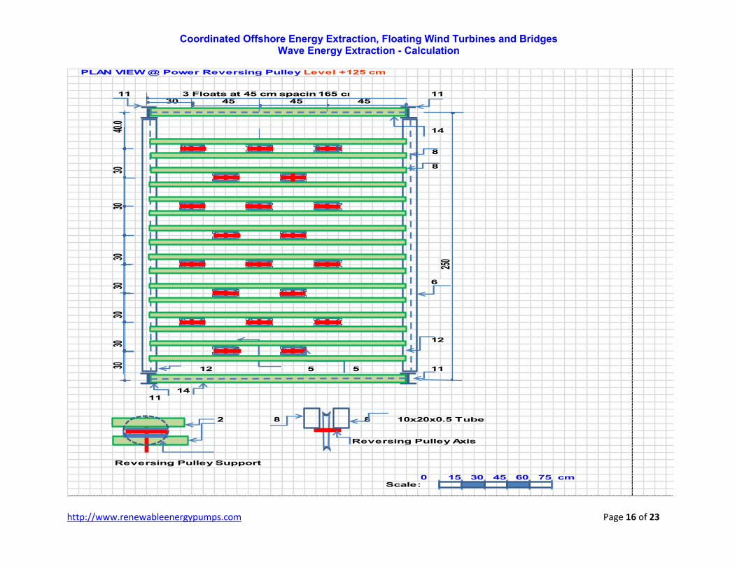
PLAN VIEW @ Power Reversing Pulley Level +125 cm
3 Floats at 45 cm spacing
8
8
5 5
2 8 8 10x20x0.5 Tube
Reversing Pulley Axis
Reversing Pulley Support
0Scale:
60
165 cm 111130 45
12
40.0
30 12
1411
30
11
15
3030
3030
30
45 45
30
250
45
14
75 cm
6

Coordinated Offshore Energy Extraction, Floating Wind Turbines and Bridges Wave Energy Extraction - Calculation
http://www.renewableenergypumps.com Page 17 of 23
FRONT VIEW
1 140
125 Deck
115
100
9
0.00MSL
8-100
-110
3
-130
0Scale:
7
11
15 30 45
1616
60 75 cm
14

Coordinated Offshore Energy Extraction, Floating Wind Turbines and Bridges Wave Energy Extraction - Calculation
http://www.renewableenergypumps.com Page 18 of 23
SIDE VIEW
4, 5 2 4,5 2
170
140
Wave Crest
`
9
1
MSL
8 87
Wave Trough
cmScale:
0 15
11
12
30 45 60 75
##
11
0.00
-100
11
Coordinated Offshore Energy Extraction, Floating Wind Turbines and Bridges Wave Energy Extraction - Calculation
http://www.renewableenergypumps.com Page 19 of 23
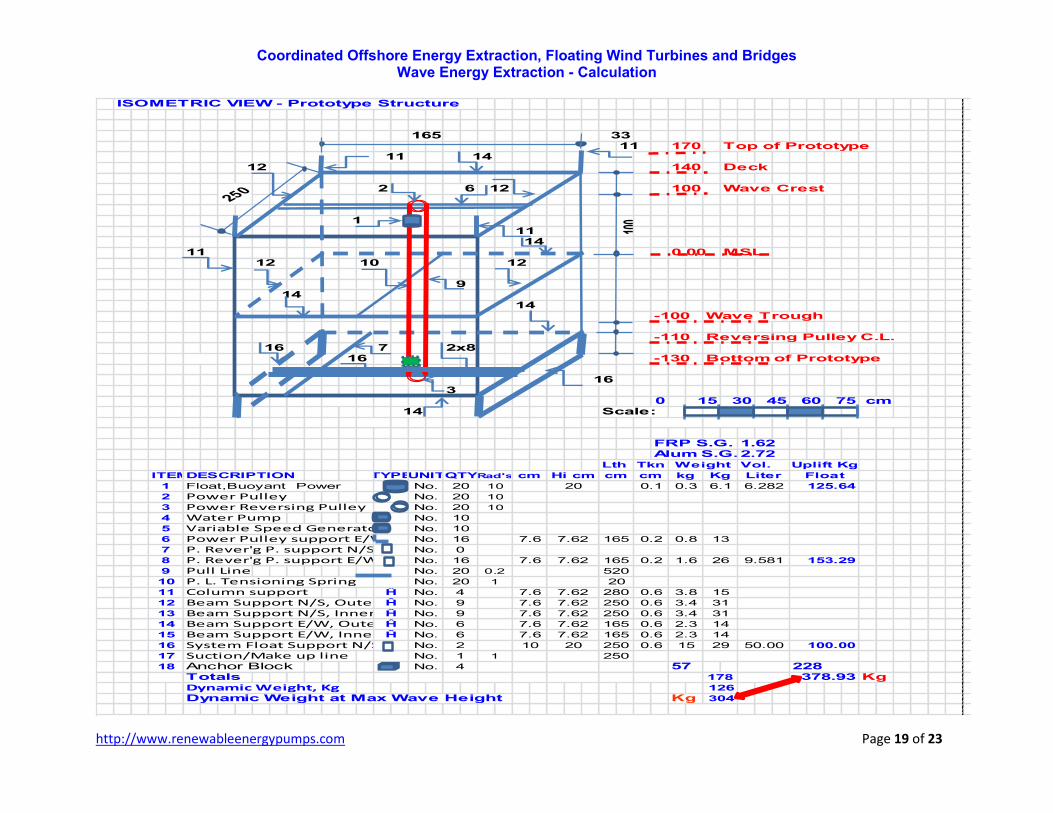
ISOMETRIC VIEW - Prototype Structure
170 Top of Prototype
140 Deck
100 Wave Crest
0.00 MSL
-100 Wave Trough
-110 Reversing Pulley C.L.7
-130 Bottom of Prototype
0Scale:
FRP S.G.Alum S.G.
DESCRIPTION
Float,Buoyant Power
Power PulleyPower Reversing PulleyWater PumpVariable Speed GeneratorPower Pulley support E/WP. Rever'g P. support N/SP. Rever'g P. support E/WPull LineP. L. Tensioning SpringColumn supportBeam Support N/S, OuterBeam Support N/S, InnerBeam Support E/W, OuterBeam Support E/W, InnerSystem Float Support N/SSuction/Make up lineAnchor BlockTotals KgDynamic Weight, KgDynamic Weight at Max Wave Height Kg
30 45 60 75 cm
228378.93
304
178
No. 2 10 20
No. 4
Ĥ No. 6 7.6 7.62
2.3 14
165
Ĥ No. 9 7.6
Ĥ No. 9 7.6 7.62 250 0.6 3.4
0.6
31
Ĥ No. 4 7.6 7.62 280 0.6 3.8 15
No. 20
9.581 153.290.2
20
10
No. 16 7.6 7.62 165 0.2 0.8
125.64
10
KgRad's cmTYPE Liter Float
20 10
20No.
Vol.
20 10
No. 20 6.1 6.282
250
100
11
3
14
14
cm kg
1
UNITQTY
2x8
16
Hi cm
15
1211
1133165
14
2
3
ITEM
1
5
12
16
2
10
914
16
1211
12
14
6
14
7.62
7.6 7.62
15
16
17
18
Ĥ No. 6
No. 1 1
50.00
57
126
100.00
250
250
20
0.2
165
520
7.6
165
250
0.6
3.4 31
0
1.6 26
4
11
16
1
7.62
No. 10
No.
No.
12
13
6
7
8
9
10
No.
No.
No.
0.1
13
cm
0.3
0.6 2.3 14
0.6 15 29
Lth Tkn Weight
1.622.72
Uplift Kg

Coordinated Offshore Energy Extraction, Floating Wind Turbines and Bridges Wave Energy Extraction - Calculation
http://www.renewableenergypumps.com Page 20 of 23
ISOMETRIC VIEW
25,26
25,26
Wave Direction22 31
20
2020
20
#25,26
28, 29, 30
20
24
22 31
23
25,26
23
22
25,264 4
20
17
Prototype Flow Diagram and Data Monitoring
DESCRIPTION Length cm Total cm
Pipe, 1/4 Ebb/Tide Hydro-TurbinePipe, 1/2 Pipe, 3/4 Pump Discharge, Check Valve
Pressure Gauge, Kg/cm 2̂Flow Meter, Liters/SecHydro Turbo GeneratorAmmeter, AmpsVoltmeter, Volts Digital
Frequency Meter, HZ Digital
Power Line, 3-1/2 x 4 mm 2̂Control Cables, 12/cWave Height Monitor,0-10 m
20
10
2
1
8
2
1
1
125
80
20
2,000
2,000
160
100
10
20
20
440
100
10
No.
No.
No.
No.
No.
No.
2
2
10
2
1
1
1
5
17
21 21
31 PVC
3029
3332 PVC
28 Digital
25 Digital
24 Bronze
23PVC
PVC
222120 PVC
Digital
27Digital
Digital
26 5
1
ITEM UNIT
No.
No.
No.
No.
No.
No.
No.
No.
RatingTYPE QTY
1,000
Coordinated Offshore Energy Extraction, Floating Wind Turbines and Bridges Wave Energy Extraction - Calculation
http://www.renewableenergypumps.com Page 21 of 23
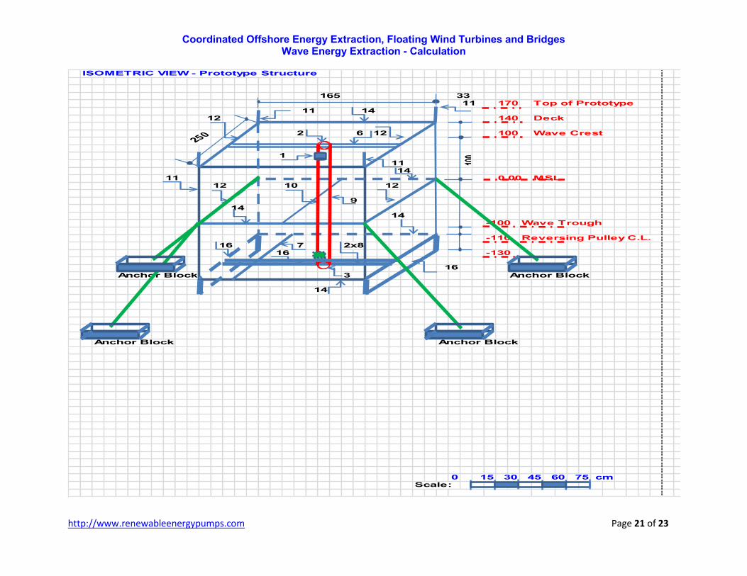
ISOMETRIC VIEW - Prototype Structure
170 Top of Prototype
140 Deck
100 Wave Crest
0.00 MSL
-100 Wave Trough
-110 Reversing Pulley C.L.7
-130
Anchor Block Anchor Block
Anchor Block Anchor Block
0Scale:
15 30 45 60 75 cm
16
3
14
1
100
1114
10 12
9
14
2x816
165 3311
11 14
2 6 12
14
16
1112
12
250
Coordinated Offshore Energy Extraction, Floating Wind Turbines and Bridges Wave Energy Extraction - Calculation
http://www.renewableenergypumps.com Page 22 of 23
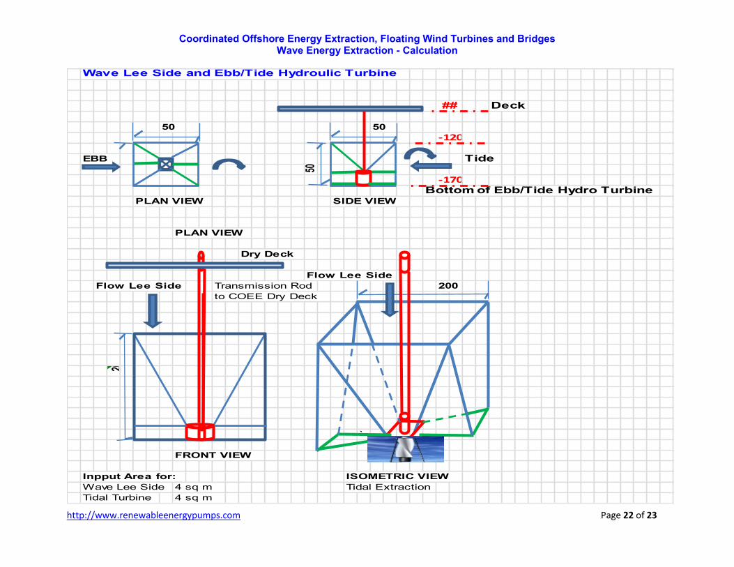
Wave Lee Side and Ebb/Tide Hydroulic Turbine
Deck
50 50
EBB Tide
Bottom of Ebb/Tide Hydro TurbinePLAN VIEW SIDE VIEW
PLAN VIEW
Dry Deck
Flow Lee Side
Flow Lee Side Transmission Rod 200
to COEE Dry Deck
200
`
FRONT VIEW
Inpput Area for: ISOMETRIC VIEW
Wave Lee Side 4 sq m Tidal Extraction
Tidal Turbine 4 sq m
50
##
-120
-170
Coordinated Offshore Energy Extraction, Floating Wind Turbines and Bridges Wave Energy Extraction - Calculation
http://www.renewableenergypumps.com Page 23 of 23
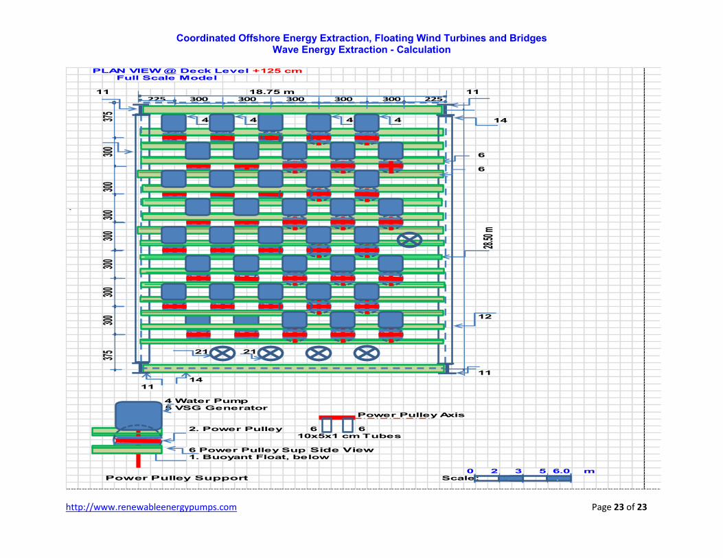
PLAN VIEW @ Deck Level +125 cmFull Scale Model
4 4 4 4
`
4 Water Pump5 VSG Generator
Power Pulley Axis
2. Power Pulley 6 610x5x1 cm Tubes
6 Power Pulley Support, E/WSide View1. Buoyant Float, below
0 mPower Pulley Support Scale:
225 300 300 300 300 300 225
6
6
2 53 6.0
18.75 m
11
1114
21
375
21
11 11
14
12
300
28.50
m
300
375
300
300
300
300
300
` `
Copyright © 2022 FDOKUMEN