Water Treatment Laboratory Workshop - TN.gov
293
Water Treatment Laboratory Workshop Week 1 Course # 2112 Updated September 2021
-
Upload
khangminh22 -
Category
Documents
-
view
0 -
download
0
Transcript of Water Treatment Laboratory Workshop - TN.gov

Water Treatment Laboratory Workshop
Week 1
Course # 2112
Updated September 2021


Water Treatment Laboratory Week 1
Course # 2122 September 20-24, 2021
Monday 8:30 Basic Lab Skills/Safety/Lab Equipment 11:00 Lunch 12:15 QA/QC Tuesday 8:30 pH 9:30 Specific Gravity 11:00 Lunch 12:00 Potassium Permanganate Residual 1:00 Chlorine, Free Residual & Total Wednesday 8:30 Bacteriological Test 11:00 Lunch 12:00 Tour - to be announced Thursday 8:30 Turbidity 10:30 Jar Testing 11:30 Lunch 12:30 Corrosion Control Friday 8:30 Lead & Copper 9:00 Review/Questions 11:00 Lunch 12:00 Class Exam and Evaluations
Instructor: Amanda Carter
Phone: 615-898-6507 Fax: 615-898-8064 E-mail: [email protected]
Fleming Training Center 2022 Blanton Dr. Murfreesboro, TN 37129


Water Treatment Laboratory Week 1
Course# 2112
Section 1 Basic Laboratory Safety 3
Section 2 QA/QC Program 27
Section 3 pH 39
Section 4 Specific Gravity 65
Section 5 Potassium Permanganate Residual 73
Section 6 Chlorine Residual and Demand 77
Section 7 Bacteriological Testing 143
Section 8 Orthophosphates and Corrosion Control 213
Section 9 Lead and Copper Sampling 243
Section 10 Turbidity 253
Section 11 Jar Tests 277
1

2

Section 1
Laboratory Safety
3

Lab Policies
1. No horse play.
2. No shorts or open-toed shoes.
3. No smoking, eating, dipping or drinking in the lab.
4. Put broken glass in broken glass container, NOT IN THE TRASH.
5. Do not pipet by mouth.
6. Each day after class:
All used glassware will be washed in hot soapy water, rinsed in
tap water, then distilled water.
All counter tops will be wiped clean with disinfectant.
Balance room must be clean.
7. Used pipets are placed in containers containing detergent immediately
after use, tip up.
8. Acid spills must be cleaned up immediately.
9. Pipet bulbs must be cleaned immediately after overpipeting.
10. Wear safety glasses when performing any experiment.
11. Wear aprons in the lab at all times.
12. Wear gloves when performing any experiment or washing glassware.
13. Wash your hands before leaving the laboratory.
14. Know where the eye wash stations are located and how to use them.
15. Know where the emergency shower is and how to use it.
16. Know where each fire extinguisher is located and how to use them.
17. Read carefully the Safety Data Sheets for all chemicals used in the
laboratory.
Section 1 TDEC - Fleming Training Center
Basic Lab Skills4

Reference Tables for Physical Setting/CHEMISTRY 98 Reference Tables for Physical Setting/CHEMISTRY
(223)
Fr87-18-32-18-8-1
+1 226.025
Ra88-18-32-18-8-2
+2 227.028
Ac89-18-32-18-9-2
+3 (261)
Rf104
138.906
La572-8-18-18-9-2
+3 178.49
Hf72**18-32-10-2
+4
91.224
Zr402-8-18-10-2
+4
47.88
Ti222-8-10-2
+2+3+4
50.9415
V232-8-11-2
+2+3+4+5
51.996
Cr242-8-13-1
+2+3+6
95.94
Mo422-8-18-13-1
+3+6
183.85
W74-18-32-12-2
+6
54.9380
Mn252-8-13-2
+2+3+4+7
55.847
Fe262-8-14-2
+2+3
58.9332
Co272-8-15-2
+2+3
58.69
Ni282-8-16-2
+2+3
63.546
Cu292-8-18-1
+1+2
107.868
Ag472-8-18-18-1
+1
65.39
Zn302-8-18-2
+2 69.72
Ga312-8-18-3
+3
26.98154
Al132-8-3
+3
10.81
B52-3
+3 12.0111
C62-4
–4+2+4
15.9994
O82-6
–2 18.998403
F92-7
–1 20.179
Ne102-8
0
4.00260
He22
0
28.0855
Si142-8-4
–4+2+4
72.59
Ge322-8-18-4
–4+2+4
74.9216
As332-8-18-5
–3+3+5
78.96
Se342-8-18-6
–2+4+6
127.60
Te522-8-18-18-6
–2+4+6
126.905
l532-8-18-18-7
–1+1+5+7
131.29
Xe542-8-18-18-8
0+2+4+6
(209)
Po84-18-32-18-6
+2+4
(210)
At85-18-32-18-7
79.904
Br352-8-18-7
–1+1+5
83.80
Kr362-8-18-8
0+2
(222)
Rn86-18-32-18-8
0
174.967
Lu71
+3173.04
Yb70
+2+3
168.934
Tm69
+3167.26
Er68
+3164.930
Ho67
+3162.50
Dy66
+3158.925
Tb65
+3157.25
Gd64
+3151.96
Eu63
+2+3
150.36
Sm62
+2+3
(145)
Pm61
+3144.24
Nd60
+3140.908
Pr59
+3140.12
Ce58
+3+4
232.038
Th90
+4 231.036
Pa91
+4+5
238.029
U92
+3+4+5+6
237.048
Np93
+3+4+5+6
(244)
Pu94
+3+4+5+6
(243)
Am95
+3+4+5+6
(247)
Cm96
+3 (247)
Bk97
+3+4
(251)
Cf98
+3 (252)
Es99
(257)
Fm100
(258)
Md101
(259)
No102
(260)
Lr103
30.97376
P152-8-5
–3+3+5
32.06
S162-8-6
–2+4+6
39.948
Ar182-8-8
035.453
Cl172-8-7
–1+1+3+5+7
118.71
Sn502-8-18-18-4
+2+4
14.0067
N72-5
–3–2–1+1+2+3+4+5
112.41
Cd482-8-18-18-2
+2 114.82
In492-8-18-18-3
+3
200.59
Hg80-18-32-18-2
+1+2
204.383
Tl81-18-32-18-3
+1+3
207.2
Pb82-18-32-18-4
+2+4
208.980
Bi83-18-32-18-5
+3+5
121.75
Sb512-8-18-18-5
–3+3+5
106.42
Pd462-8-18-18
+2+4
195.08
Pt78-18-32-17-1
+2+4
196.967
Au79-18-32-18-1
+1+3
101.07
Ru442-8-18-15-1
+3
190.2
Os76-18-32-14-2
+3+4
192.22
Ir77-18-32-15-2
+3+4
102.906
Rh452-8-18-16-1
+3(98)
Tc432-8-18-14-1
+4+6+7
186.207
Re75-18-32-13-2
+4+6+7
92.9064
Nb412-8-18-12-1
+3+5
180.948
Ta73-18-32-11-2
+5
(262)
Db105
(263)
Sg106
(264)
Bh107
(265)
Hs108
(268)
Mt109
(269)
Uun(272)
Uuu111
(277)
Uub112
(285)
Uuq114
88.9059
Y392-8-18-9-2
+3
44.9559
Sc212-8-9-2
+3
137.33
Ba562-8-18-18-8-2
+2
87.62
Sr382-8-18-8-2
+2
40.08
Ca202-8-8-2
+2
24.305
Mg122-8-2
+2
9.01218
Be42-2
+2
132.905
Cs552-8-18-18-8-1
+1
85.4678
Rb372-8-18-8-1
+1
39.0983
K192-8-8-1
+1
22.98977
Na112-8-1
+1
6.941
Li32-1
+1
1.00794
H11
+1–1
*The systematic names and symbols for elements of atomic numbers above 109 will be used until the approval of trivial names by IUPAC.**Denotes the presence of (2-8-)
for elements 72 and above
Per
iod
1
2
1
1
2Group
1716151413 18
18
Group
109876543 11 12Group3
4
5
6
7
Periodic Table of the Elements
C12.011 –4
+2+4
62-4
Atomic Mass
Symbol
Atomic Number
Electron Configuration
Selected Oxidation States
Relative atomic masses are basedon 12C = 12.000
Note: Mass numbers in parenthesesare mass numbers of the moststable or common isotope.
KEY
TDEC - Fleming Training Center Section 1
Basic Lab Skills 5

Common Valences
1+ 2+ 3+ Ammonium, NH4
+ Cuprous, Cu+ Hydrogen, H+
Hydronium, H3O+
Potassium, K+ Silver, Ag+ Sodium, Na+
Barium, Ba2+ Calcium, Ca2+ Cupric, Cu2+ Ferrous, Fe2+ Lead, Pb2+
Magnesium, Mg2+ Mercuric, Hg2+ Nickel, Ni2+ Zinc, Zn2+
Aluminum, Al3+ Chromic, Cr3+ Ferric, Fe3+
1‐ 2‐ 3‐ Bicarbonate, HCO3
‐ Bromide, Br‐ Chlorate, ClO3
‐ Chloride, Cl‐
Hydroxide, OH‐ Hypochlorite, OCl‐
Iodide, I‐ Nitrate, NO3
‐ Nitrite, NO2
‐ Bisulfate, HSO4
‐ Permanganate, MnO4
‐
Carbonate, CO3‐
Chromate, CrO4‐
Peroxide, O2‐
Sulfate, SO4‐
Sulfide, S‐ Sulfite, SO3
‐
Phosphate, PO43‐
Section 1 TDEC - Fleming Training Center
Basic Lab Skills6

How many grams of Na2CO3 would it take to make a 1 Molar and a 1 Normal solution? Step 1: Determine the molecular weight of Na2CO3. Na = 22.99 amu X 2 = 45.98 amu C = 12.01 amu X 1 = 12.01 amu Na2CO3 → Na+ + Na+ + CO3
2- O = 16 amu X 3 = 48.00 amu Molecular weight = 105.99 amu
Molarity
Step 2: Calculate the number of moles
# moles = total weight molecular weight
# moles = 105.99 g 105.99 g/mole
# moles = 1 or
grams required = (#moles required)(grams/mole) grams required = (1 mole)(105.99 grams/mole)
grams required = 105.99 g
Step 3: Calculate the Molarity of the solution.
Molarity = # of moles
volume of solvent
Molarity = 1 mole 1 liter of water
Molarity = 1M Every 105.99 grams of Na2CO3 in 1 L of water gives a 1M solution.
Normality
Step 2a: Calculate the equivalent weight.
equivalent weight = molecular weight # of positive charges
equivalent weights = 105.99 2
equivalent weights = 53 grams
Step 2b: Calculate the number of equivalent weights.
# equivalent weights = total weight equivalent weight
# equivalent weights = 105.99 g 53 g/equivalent
# equivalent weights = 2 or
grams required = (# equivalent weights)(grams/equivalent weight) grams required = (2 equivalent weights)(53 g/equivalent)
grams required = 106 g
Step 3: Calculate Normality
Normality = # of equivalents volume of solvent
Normality = 2 equivalents 1 liter of water
Normality = 2N Every 105.99 g of Na2CO3 in 1 L of water gives a 2N solution. To make a
1N solution, cut the grams in half.
TDEC - Fleming Training Center Section 1
Basic Lab Skills 7

1
Lab Safety
Water Treatment Lab
TDEC - Fleming Training Center 2
Before Lab Work, Get to Know:
• Hazards of materials and their prescribed safety procedures
• Learn the lay-out of the building • location of emergency exits• emergency exit routes• emergency telephones• emergency ventilation system• fire-fighting equipment and how it works• emergency shower• first aid equipment
TDEC - Fleming Training Center
3
Communication
• Emergency 911 number sticker on telephone set
• Emergency notification procedures, contacts, and phone numbers are posted
• Emergency procedures and Updated Fire Escape Route posted
TDEC - Fleming Training Center 4
General Preparedness
• Emergency ventilation switch (in laboratory) unobstructed and function properly
• Exit signs readily visible/ illuminated
• Hazardous materials not stored along exit route and exit route free from obstruction
• Two well-separated exits, doors swing outward for chemistry laboratories or other high hazardous laboratories
TDEC - Fleming Training Center
5
Chemical Spill
• Chemical spill kit, cleanup procedures available and training provided if considered necessary by departmental plan
• Safety showers and eyewashes (inspected weekly) easily accessible/unobstructed
TDEC - Fleming Training Center 6
First Aid
• First aid box easily accessible and adequately stocked
• First-aider name posted on first aid box
• First aid box contain a copy of first aid instructions
• Medication items not stored in first aid box
TDEC - Fleming Training Center
Section 1 TDEC - Fleming Training Center
Basic Lab Skills8

7
First Aid
• When a major injury occurs:• Call the emergency contact number, e.g. 911.
• Keep the victim warm, lying down, and quiet until medical assistance arrives.
• It is better NOT to move the injured person unless he or she is immediately threatened by further injury.
TDEC - Fleming Training Center 8
First Aid
• While waiting for the response personnel to arrive: • Treat acid and alkali burns with running water
for 20-30 minutes• Use emergency eyewash/shower if necessary.
• Do not attempt to neutralize.
• Take care not to contaminate yourself.
• Irrigate burned (heat or cryogenic) areas with cold water.
TDEC - Fleming Training Center
9
First Aid
• While waiting for the response
personnel to arrive: • Remove contact lenses, if present
• Use eyewash for 15 minutes to cleanse eye after chemical splash.
• Treat major bleeding with direct compression of the wound using a clean cloth.
• Expose anyone who has inhaled toxic materials to fresh air.
TDEC - Fleming Training Center 10
Safety Data Sheets
• SDS
• Keep on file for all chemicals purchased• According to the Americans with Disabilities Act
of 1990, SDS’s should be kept for a minimum of 30 years
• Includes all information shown on a chemical label and more
TDEC - Fleming Training Center
Safety Data Sheet
• OSHA moving from HCS (Hazard Communication Standard) to GHS (Globally Harmonized System)
• Revised criteria for chemical hazard classification, labeling & new format for Safety Data Sheets (SDS)
• Final rule effective May 25, 2012 but compliance dates are phased in:
• Complete training on new label formats: 12/1/13
• Comply with label and SDS requirements: 6/1/15
• Update Hazcom programs: 6/1/16
TDEC - Fleming Training Center 11
Minimum Info for SDS
• Product identification
• Hazard Identification
• Composition/info on ingredients
• First-aid measures
• Fire-fighting measures
• Accidental release measures
• Handling and storage
• Exposure controls
• Physical/chemical properties
• Stability & reactivity
• Toxicological information
• Ecological information*
• Disposal considerations*
• Transport information*
• Regulatory information*
• Other information (including date of SDS or last revision)
TDEC - Fleming Training Center
12* Non mandatory
TDEC - Fleming Training Center Section 1
Basic Lab Skills 9

OSHA Pictograms
TDEC - Fleming Training Center 13
Flammables Oxidizers Explosives Acute toxicity Corrosives
Gases under pressure
Carcinogens Environmental toxicity
Irritant
GHS Degree of Hazard
• 1 extreme
• 2 serious
• 3 moderate
• 4 minimal
TDEC - Fleming Training Center 14
15
NFPA
• National Fire Protection Association• Chemical hazard label
• Color coded• Numerical system
• Health• Flammability• Reactivity
• Special precautions
• Labels are required on all chemicals in the lab
TDEC - Fleming Training Center 16
Degrees of Hazard
• Each of the colored areas has a number in it regarding the degree of hazard• 4 extreme
• 3 serious
• 2 moderate
• 1 slight
• 0 minimal
TDEC - Fleming Training Center
17
Chemical Label
TDEC - Fleming Training Center 18
Special
• W• Water reactive
• Ox• Oxidizing agent
TDEC - Fleming Training Center
Section 1 TDEC - Fleming Training Center
Basic Lab Skills10

19
Chemical Safety - Storage
• Current chemical inventory available
• No expired chemicals.• Disposed of out-dated
chemicals
• Chemical containers properly labeled, in good condition and closed properly
• Only compatible chemicals are stored together
• Everything not stored in alphabetical order
TDEC - Fleming Training Center 20
Chemical Safety - Storage
• Secondary containment for stored chemicals as necessary.• Polyethylene trays for
separate storage of acids and bases
• Chemicals stored at safe levels, in cabinets or on stable shelving (but not on high levels)
TDEC - Fleming Training Center
21
Chemical Safety -Flammables
• Stored in flammable cabinet and/or explosion-proof or flammable storage refrigerator
• Stored away from sources of heat and ignition
• Not stored along path of egress or in aisle space
TDEC - Fleming Training Center 22TDEC - Fleming Training Center
23
Lab Hygiene
• Food and drink are not to be stored or prepared in laboratories or chemical storerooms
• Use appropriate personal protective equipment and wash your hands regularly when working with chemical reagents, especially before meals or snacks.
• Smoking in laboratories is prohibited.
TDEC - Fleming Training Center 24
Lab Hygiene
• Loose sleeves are a hazard and should not be worn in the lab.
• If you have long hair, ensure that it is properly tied back.
• Wearing of contact lenses in the lab is strongly discouraged.• If it is unavoidable, advise your supervisor and
co-workers so that this information is known in the event of a chemical splash in the eyes.
TDEC - Fleming Training Center
TDEC - Fleming Training Center Section 1
Basic Lab Skills 11

25
Personal Practices
• No inappropriate clothing and shoes (shorts, sandals, slippers, etc.)
• Gloves removed before handling telephone, door handle or leaving laboratory
• No pipeting by mouth
TDEC - Fleming Training Center 26
Personal Practices
• Lab coats and safety glasses/ goggles worn by all where necessary
• Proper gloves are used as needed
• Other personal protective equipment used properly as needed
TDEC - Fleming Training Center
27
Safety Glasses
• Unbreakable lenses of plastic or tempered glass
• For light-to-moderate work
• Can be prescription glasses
• Do not interfere with contact lenses
TDEC - Fleming Training Center 28
Goggles
• Work with significant risk of splash of chemicals or projectiles
• Can be worn over prescription glasses
TDEC - Fleming Training Center
29
Face Shield
• Work with significant risk of splash on face or possible explosion
• Face shield protects face adequately but not eyes• Should be worn with
safety glasses and/or goggles to protect eyes
TDEC - Fleming Training Center 30
Pregnancy
• Women who are pregnant should discuss their work assignments with their supervisors to seek alternate work assignments if the potential for exposure to teratogens exist• Teratogens are reproductive toxins that may
cause damage to the fetus
• THM Plus method by Hach for determining Trihalomethanes deals with chloroform, a teratogen
TDEC - Fleming Training Center
Section 1 TDEC - Fleming Training Center
Basic Lab Skills12

31
Fume Hood
• All work generating toxic/hazardous vapor, fume, or aerosol performed in hood
• Front sash at appropriate level when hood is in use/ not in use
• Storage within the hood minimized and containers kept sealed
TDEC - Fleming Training Center 32
Fume Hood
• Verify that the fume cupboard is working properly.
• Locate work at least 6 inches inside the hood.
• Do not block the face of the hood, e.g. with shielding or large equipment.
• Do not block the space between tapered metal front lip and the work surface.
• Do not block rear exhaust slot. Place bulky items to rear and sides.
• Secure papers and other light weight materials to prevent their entrainment in the exhaust.
TDEC - Fleming Training Center
Autoclave
• Because an autoclave uses saturated steam under high pressure to achieve sterilizing temperatures, proper use is important to ensure operator safety.
33TDEC - Fleming Training Center
Autoclave
• Racks of test tubes, stacks of culture media and trays of used needles awaiting sterilization prior to disposal were splattered across the room by the tremendous concussion.
• Metal shrapnel penetrated the walls.
• A few minutes sooner or later and those projectiles could have easily struck a lab worker.
• Luckily, the room was unoccupied at the critical moment.
34TDEC - Fleming Training Center
Autoclave
• Prevent injuries when using the autoclave by observing the following rules: • Wear heat resistant gloves, eye protection, closed toed
shoes and a lab coat, especially when unloading the autoclave.
• Prevent steam burns and shattered glassware by making sure that the pressure in the autoclave chamber is near zero before opening the door at the end of a cycle. Slowly crack open the autoclave door and allow the steam to escape gradually.
35TDEC - Fleming Training Center
Autoclave
• Prevent injuries when using the autoclave by observing the following rules: • Allow items to cool for 10 minutes before
removing them from the autoclave.
• Never put sealed containers in an autoclave. They can explode. Large bottles with narrow necks may also explode if filled too full of liquid.
• Never put solvents, volatile or corrosive chemicals (such as phenol, chloroform, bleach, etc.), or radioactive materials in an autoclave.
36TDEC - Fleming Training Center
TDEC - Fleming Training Center Section 1
Basic Lab Skills 13

37
Lab Work Area
• The work bench is to be kept clean at all times, and free from chemicals and apparatus which are not required.
• Before starting an experiment, make sure you are familiar with all the procedures and the potential hazards of the starting materials and products. • Determine the appropriate safeguards and remedies. • Know the procedures for emergency shut off as well as
the person and phone numbers to contact in case of emergency.
• If anything unexpected occurs during your experiment, or if you are in any doubt, consult your supervisor immediately. TDEC - Fleming Training Center 38
Handling Glassware
• Examine all glassware before use.• Discard any broken glass apparatus in the appropriate
sharps container.
• Never store damaged glassware in cupboards.• Damaged glassware should either be sent for repair
properly or disposed in a separate labeled container for sharps disposal.
• Use gloves when sweeping up broken glass, do not use bare hands.• Pick up fine glass particles with wet paper toweling.
TDEC - Fleming Training Center
39
Handling Glassware
• Cut ends of glass rods and tubing should always be fire-polished before use.
• Use a cloth for protection when inserting glass tubing, rods or thermometers into bungs or tubing• Use a lubricant or water where necessary.
TDEC - Fleming Training Center 40
Chemical Spills
• Small spills (generally less than 100 mL) can usually be cleaned up safely by the employees involved.
• The hazardous properties of the material must be considered when deciding whether it is a “small” spill or not, and therefore whether unassisted clean-up should be attempted.
• Employees must be trained in advance to handle cleanup of even small spills
TDEC - Fleming Training Center
Section 1 TDEC - Fleming Training Center
Basic Lab Skills14

1
Laboratory Equipment
Identification, Handling and Cleaning
TDEC - Fleming Training Center 2
Objectives
Identify equipment commonly used in water treatment and wastewater laboratory Discuss accuracy and use of glasswareDiscuss how to maintain analytical equipment
TDEC - Fleming Training Center
3
Beakers
Used for: Mixing Measuring
approximate volumes ~10% accuracy
TDEC - Fleming Training Center 4
Graduated Cylinders
Accurate to ~1%Measures liquid volumes more accurately than beakers, but still not the most accurateMeasure quicker
TDEC - Fleming Training Center
5
Volumetric Flasks
Most accurate way to measure volumeDisadvantage: Only can measure
one volume Not used for storing
or heating solutions
TDEC - Fleming Training Center 6
What Are Pipets?
Pipets are glass or plastic tubes, usually open at both ends,which are used to transfer specific amounts of liquid from one container to another
They are usually used for volumes between 1 and 100 milliliters
TDEC - Fleming Training Center
TDEC - Fleming Training Center Section 1
Basic Lab Skills 15

7
Types of Pipets
VolumetricMeasuring Mohr Serological
TDEC - Fleming Training Center 8
Volumetric Pipets
Used to deliver a single specific volume of liquid, usually between 1 and 100 mL
Shaped like rolling pins with a large belly, one blunt end, the neck, and one tapering end, the tip
TDEC - Fleming Training Center
9
Volumetric Pipets
Used for accurate measurements, since it is designed to deliver only one volume and is calibrated at that volumeShould be used when accuracy and reproducibility are crucial, because these can achieve accuracy to four significant figures
TDEC - Fleming Training Center 10
Specifications on a Volumetric Pipet
When emptying a volumetric pipet, the liquid is allowed to drain out It is NOT forced out
After it is emptied, the small amount of liquid which remains in the tip should not be blown out
Volumetric pipets are NOT blow-out pipets
TDEC - Fleming Training Center
11
Measuring Pipets
They are straight glass or plastic tubes with one tapering endCalibrated into small divisions so that various amounts of liquid can be measured with the same pipetUsually used to measure any amount between 0.1mL and 25.0mLThey are not as accurate due to the fact that any imperfection in their internal diameter will have a greater effect on the volume delivered
TDEC - Fleming Training Center 12
Mohr and Serological Pipets
Measuring pipets are divided into:
Mohr PipetsGraduations on these always end before the
tip
Serological PipetsGraduation marks continue to the tip
TDEC - Fleming Training Center
Section 1 TDEC - Fleming Training Center
Basic Lab Skills16

13
Examine pipets A and B. Which is the serological and which is the
Mohr?
Mohr
Serological
TDEC - Fleming Training Center 14
Specifications on a Measuring Pipet
Maximum volume of liquid that can be transferredSize of the divisions on the pipetTemperature at which calibrations were madeIf the pipet is a “to deliver”(TD) or “to contain”(TC) pipet.
TDEC - Fleming Training Center
15
5 mL in 1/10 mL TD 20oC
Specifications on a pipet as shown above indicate that the pipet is calibrated in 1/10 mL divisions and will deliver up to 5.0 mL within published tolerance levels at 20°C
TDEC - Fleming Training Center 16
1 mL in 1/100 mLTD 20oC
These specifications indicate that the pipet is calibrated in 1/100 mL divisions and it will deliver up to 1.00 mL within published tolerance levels at 20°C
TDEC - Fleming Training Center
17
Handling and Disposing of Pipets
Chipped and cracked pipets should be replaced as they are unsafe and may affect the accuracy of measurements
NEVER mouth pipet
Hold the pipet by the upper third of the tube and keep the tip from touching anything
TDEC - Fleming Training Center 18
Handling and Disposing of Pipets
Dispose dirty pipets by placing in soapy water solution in a tray or pipet washer Place disposable pipets in a cardboard holderDo not leave pipets on counters or sinks
TDEC - Fleming Training Center
TDEC - Fleming Training Center Section 1
Basic Lab Skills 17

19
Handling Sterile Pipets
When using sterile pipets, be sure to use proper sanitary techniques If you have a sterile package of disposable pipets, tear only a small corner of the package open and push one pipet out of this opening, then immediately close the package to prevent contamination TDEC - Fleming Training Center 20
Handling Sterile Pipets
If you are using sterile pipets in a pipet canister, place the canister on its side, slide off the cover, pull out one pipet and replace the cover immediately
TDEC - Fleming Training Center
21
Transferring a Precise Volume of Liquid
A pipet bulb is used to draw liquid up into the pipet
There are many types of pipet bulbs
TDEC - Fleming Training Center 22
Transferring a Precise Volume of Liquid
You should observe the meniscus at eye-level
Touch the tip of the pipet to the inside of the container when the meniscus is at the desired level
TDEC - Fleming Training Center
23
Transferring a Precise Volume of Liquid
Squeeze bulb and touch it to the mouth of the pipetPlace other end of the pipet in liquid to be transferred and slowly release pressure on bulbDraw liquid up past desired level, quickly replacing bulb with index finger
TDEC - Fleming Training Center 24
Transferring a Precise Volume of Liquid
Let liquid drain until bottom of meniscus lines up with desired level on pipetTouch tip of pipet to inside of beaker to remove any adhering dropsTransfer liquid to second beaker and touch tip to inside of beaker and let liquid drain out of pipet
TDEC - Fleming Training Center
Section 1 TDEC - Fleming Training Center
Basic Lab Skills18

25
Other Pipet Bulbs
Other pipet bulbs that are often used include the Vadosa pipet filler, seen on the left, and the pipet Pumper, on the right
TDEC - Fleming Training Center 26
Other Pipet Types
Transfer of uncalibrated volumes up to 2.5 mL can be accomplished using glass “transfer” or “Pasteur” pipets shown below. These may be sterilized before use.Roughly calibrated volumes of 1 and 2 mL can be transferred with the one piece plastic transfer pipets which may be purchased as sterile or non-sterile units.
TDEC - Fleming Training Center
27
Burettes and Titrations
Burettes Used for titrations Treat like a Mohr
pipet, do not let liquid completely drain out
Also, make sure to remove air bubble in tip before titrating
TDEC - Fleming Training Center 28
Flasks
Distilling Flask Florence (Flat Bottom) Flask
TDEC - Fleming Training Center
29
Flasks
Erlenmeyer Flasks Filter Flask
TDEC - Fleming Training Center 30
Filter Apparatus
Vacuum Pump
TDEC - Fleming Training Center
TDEC - Fleming Training Center Section 1
Basic Lab Skills 19

31
Bottles
Dilution Bottle Sample Bottles
TDEC - Fleming Training Center 32
Bottles
Reagent Bottle Weighing Bottles
TDEC - Fleming Training Center
33
Funnels
Separatory Buchner
General
TDEC - Fleming Training Center 34
Petri Dish Culturing container
Desiccators Dust and moisture
free
TDEC - Fleming Training Center
35
Evaporating Dish Crucible
TDEC - Fleming Training Center 36
Centrifuge
Used to separate materials of different density
TDEC - Fleming Training Center
Section 1 TDEC - Fleming Training Center
Basic Lab Skills20

37
Autoclave
Pressure cooker used to sterilize glassware, bottles, membrane filter equip, culture media and contaminated material to be discarded.
Standard temperature is set at121°C and 15 PSI
TDEC - Fleming Training Center 38
RefrigeratorsSample storage should maintain between 1-5 CNever store samples and chemicals together
Walk-in cooler
Explosion proof
TDEC - Fleming Training Center
39
Incubators
Artificially heated container used for growing bacteria culturesDry-Heat types hold temperatures to 0.5°CFor E. coli and Total coliform = 35 0.5°CWater Bath for fecals = 44.5 0.2°C
TDEC - Fleming Training Center 40
Incubators
For BOD incubation at 20 1 °C
Do not store chemical solutions and samples in same refrigerator
TDEC - Fleming Training Center
41
UV Sterilizer
Use in Bac’T Lab to sterilize test equipment
TDEC - Fleming Training Center 42
Drying Oven
Used more often in wastewater labs
For some solids testing set oven at 103-105CTDEC - Fleming Training Center
TDEC - Fleming Training Center Section 1
Basic Lab Skills 21

43
Muffle Furnace
High temp oven used to ignite or burn solids.
Usually operate at temps of 550°C.
More often used in Wastewater lab work.
TDEC - Fleming Training Center 44
Fume Hood
Can prevent serious accidents
Use whenever heat is used in a test procedure
Fumes vented out of lab
Use when harmful smoke, gas, vapors, splashes or fumes are possible
TDEC - Fleming Training Center
45
Water Still
Produces distilled water for lab tests and rinsing washed glasswareRemoves dissolved minerals, organic and inorganic nonvolatile compoundsDoes not sterilize
TDEC - Fleming Training Center 46
Heating and Stirring SamplesCombo Heat/Stir Plate Can be used to stir
or heat and stir samples
Safer than heating with an open flame
Gas Burner Uses natural
gas
TDEC - Fleming Training Center
47
Balances
Top Loading Weighs to the
nearest 0.01 g
Analytical Precise to 0.0001 g
TDEC - Fleming Training Center 48
pH Meter
Use buffer solutions to calibrate
Store electrodes properly
Calibrate daily
Maintain records on daily calibrations
TDEC - Fleming Training Center
Section 1 TDEC - Fleming Training Center
Basic Lab Skills22

49
Spectrophotometer
HACH DR 6000 Factory pre-set
programs for lab chemical analysis
Very versatile
TDEC - Fleming Training Center 50
Colorimeters
Determine the concentration of many chemicals
Most commonly used is chlorine type colorimeter
Portable and battery powered
TDEC - Fleming Training Center
51
Amperometric Titrator
Chlorine analysis
Accurate and unaffected by sample color or turbidity
Takes greater skill to use than DPD method with colorimetric devices
TDEC - Fleming Training Center 52
Turbidimeter
Desk top and continuous on-line monitoring
Position away from direct sunlight and have extra light bulb on hand
Ensure sample bottles maintained; no scratches; acid clean if necessary
TDEC - Fleming Training Center
53
Chemical Storage
Do not store volatile chemicals together
Have separate storage cabinets for acids and bases/caustics
TDEC - Fleming Training Center 54
Flammable Cabinet
Flammable chemicals should be kept in a flammable cabinet.
TDEC - Fleming Training Center
TDEC - Fleming Training Center Section 1
Basic Lab Skills 23

55
Safety EquipmentPPE (Personal Protective Equipment):
Goggles
Gloves
Aprons
Wear safetyclothing.
TDEC - Fleming Training Center 56
Eye Wash and Shower
TDEC - Fleming Training Center
57
Cleaning Glassware
Just because it looks clean does not mean residues are not left behindResults need to be accurate to use data for process control and/or reporting to the StateDetergents, such as Alconox, may be sufficient Should be phosphate-free
TDEC - Fleming Training Center 58
Residues of minerals and other substances can build up on glassware, causing erroneous test results
TDEC - Fleming Training Center
Cleaning Glassware
59
Steps for Washing
Clean glassware using laboratory detergent (phosphate-free)Rinse with tap waterRinse at least three times with distilled waterLet air dry
TDEC - Fleming Training Center 60
Steps for Acid-Washing
Clean glassware using laboratory detergent (phosphate-free)Rinse with tap waterRinse with 1:1 hydrochloric acid or nitric acid 1:1 means equal parts distilled water and acid
Rinse well with distilled waterLet air dry
Note: always use gloves and goggles when handling acids
TDEC - Fleming Training Center
Section 1 TDEC - Fleming Training Center
Basic Lab Skills24

Cleaning Glassware
We often overlook the importance of clean glassware in the lab. We think if it looks clean, it must be clean. But there may be residues on the glassware that can affect our results. Since we use those results for both running the plant and reporting water quality to the state, it is important that those results be as accurate as possible. For many purposes in the water treatment lab, washing in a detergent such as Alconox is sufficient. However, some analyses and some glassware require special cleaning procedures to ensure removal of all residues. Residues of minerals and other substances can build up on glassware, causing erroneous test results. Always follow the recommendations for cleaning glassware and sample containers, and always use the suggested type of sample container. The following is a partial list of special cleaning procedures for laboratory glassware used for chemical analyses: Sample containers: When collecting samples for metals analyses, special cleaning of the containers is necessary to prevent residues from affecting results. Clean the sample bottles by thoroughly washing with laboratory soap (preferably phosphate-free), followed by an acid wash and multiple rinses with distilled or deionized water. Do not use glass sample bottles for metals analysis. Sample cells and cuvets: Wash thoroughly using laboratory soap (preferably phosphate-free), followed by an acid wash and multiple rinses with distilled or deionized water. Allow to air dry or wipe with a Kim-wipe, don’t use paper towels. Flasks, beakers, etc used for metals analysis: Wash thoroughly using laboratory soap (preferably phosphate-free), followed by an acid wash and multiple rinses with distilled or deionized water. Pipets: Soak overnight in a solution of Alconox. Rinse thoroughly using a pipet washer.
Procedure for Acid Washing Glassware If acid washing is required, follow these steps:
- Clean the glassware using laboratory detergent (phosphate-free) - Rinse with tap water - Rinse with 1:1 hydrochloric acid solution or 1:1 nitric acid solution - Rinse well with distilled water - Air dry Note: always use gloves and safety goggles when handling acids
TDEC - Fleming Training Center Section 1
Basic Lab Skills 25

26

Section 2
QA/QC Program
27

1
Terms• A QA/QC program consists of procedures that
ensure the precision and accuracy of tests performed on a daily basis.
• Precision – repeatability; being able to get the same results time after time• Shooting at a target and hitting the same spot
repeatedly• Accuracy – closeness of test results to the correct
(known) value• Shooting at a target and hitting bull’s eye
2
Precision and Accuracy
• Accuracy• Correctness• Checked by using a
different method• Poor accuracy results from
procedural or equipment flaws
• Precision• Reproducibility• Check by repeating
measurements• Poor precision results from
poor technique
3
Three Phases of QA/QC• Keeping records• Documenting that equipment is regularly
calibrated and temperatures are correct• Quality Assurance
• Perform tests to demonstrate precision and accuracy• Quality Control
4
Record Keeping• Maintain a complete and accurate list of exact
locations of all sampling sites• Maintain a complete and accurate list of all test
procedures used• Record method numbers on bench sheets
• Write in pen• Initial your entries• Use a notebook that has numbered pages
5
Laboratory Conditions• Lab equipment should be in good working
condition• Calibrated• Checked against standards
• Lab quality distilled water and fresh, pure reagents must be on hand
• Lab temperature should be 68°F
6
Section 2 TDEC - Fleming Training Center
QA/QC Program28

Laboratory Conditions• Glassware
• Keep it clean• pH meter
• Calibrated daily w/ fresh buffers• Spectrophotometer• Incubator
• Keep records of temperatures• Balances
• Checked at least annually for accuracy• Use ASTM Class 1 weights to check calibration
7
Laboratory Conditions• Whenever repairs or maintenance are
done on lab equipment, record those activities in a logbook
8
Reagents• Use only fresh ACS (American Chemical Society)
Reagent Grade chemicals• Check for expiration dates• Mark chemicals with date arrived in lab, date
opened and expiration date• When solutions are mixed using dry reagents,
record this in a reagent log• If standardization is required, include this
information in the reagent log as well
9
Distilled or Deionized Water• The quality of distilled or deionized water
can greatly influence the quality of the test
• There should be no traces of chlorine, ammonia and total suspended solids
• TDS should be less than 1 mg/L• Distilled is better than deionized• Ultrapure is better than distilled
10
Quality Control Tests• Duplicates• Blanks• Lab Standards• Unknown Lab Standards• Spikes
11
Duplicates• Simplest form of QC test• Run two tests on one sample
• This shows how precise the analyst’s procedure is• Sample results should yield very close results (goal
is to have no difference)• General recommendation is to run a
duplicate sample for every 10 samples
12
TDEC - Fleming Training Center Section 2
QA/QC Program 29

Duplicates• Common sources of error:
• Sample size (should be the same size)• Insufficient mixing• Dirty glassware• Calculation errors• Titration (misreading the burette)• Weighing• Calibration• Reagent water• Reagents
13
Duplicates• Range
• Difference between the test results
• RPD (Relative Percent Difference)• Calculate the average of the two results• Divide the range by the average
Range Sample 1 Sample 2
Average Sum of measurements
# of measurements
RPD Range
Average14
Duplicates• You tested a sample for chlorine residual.
The sample read 2.1 mg/L and the duplicate sample read 2.2 mg/L. What is the range and RPD?
Range 2.2 mg L 2.1⁄ mg L 0.1 mg L⁄⁄
Average 2.1 2.2
22.15 mg L⁄
RPD 0.1 mg L⁄ 2.15 mg L⁄
100 4.7%
15
Blanks• Blanks can show test interferences• Blanks should be treated as a sample
• Take through all procedures• Add all reagents or incubate along with other
samples• Target value for blanks is zero
16
Blanks• Positive blanks shows problem
• Bad reagents• Bad technique• Unclean glassware• Bad distilled water
• Coliform Tests• A blank should never be positive• If the pre-sample blank has colony growth, the
equipment was not properly sterilized• If the post sample blank has colony growth, the
equipment was not cleaned well enough between samples
17
• Determines accuracy• If the test value agrees with the true value, the
test has been performed accurately• Mix onsite or purchased from a supplier
• Purchased standards should be the preference, because this can reduce the possibility of having mixing errors; they also come with a certificate of analysis
• Perform along with dups., one every 10 samples
18
Laboratory Standards
Section 2 TDEC - Fleming Training Center
QA/QC Program30

Unknown Laboratory Samples• EPA quality control unknowns• Commercially available• Gives confidence to analyst • Can show deficiencies in the testing
procedure
19
Spikes• Determines accuracy• A known amount of standard is added to a
sample• The results should equal the sample value
plus the added known amount• Goal is to have 100% recovery of spike
and sample• If your sample result was 100 mg/L and
you added 50 mg/L into the spiked sample, you should yield 150 mg/L
20
Spikes – Hach ExampleOrtho-Phosphate
1. After reading test results, leave the sample cell (unspiked sample) in the instrument. Verify the chemical form.
2. Touch Options. Touch Standard Additions. A summary of the standard additions procedure will appear.
3. Touch OK to accept the default values for standard concentration, sample volume, and spike volumes. Touch Edit to change these values. After values are accepted, the unspikedsample reading will appear in the top row. See Standard Additions in the instrument manual for more information.
21
Spikes – Hach ExampleOrtho-Phosphate
4. Open a Phosphate 10-mL Ampule Standard, 50-mg/L PO4
3–.5. Prepare a 0.1-mL sample spike by adding 0.1 mL
of standard to the unspiked sample. Touch the timer icon. After the timer beeps, read the result.
6. Prepare a 0.2-mL sample spike by adding 0.1 mL of standard to the 0.1-mL sample spike. Touch the timer icon. After the timer beeps, read the result.
22
Spikes – Hach ExampleOrtho-Phosphate
7. Prepare a 0.3-mL sample spike by adding 0.1 mL of standard to the 0.2-mL sample spike. Touch the timer icon. After the timer beeps, read the result. Each addition should reflect approximately 100% recovery.
8. After completing the sequence, touch Graph to view the best-fit line through the standard additions data points, accounting for matrix interferences. Touch View: Fit, then select Ideal Line and touch OK to view the relationship between the sample spikes and the “Ideal Line” of 100% recovery.
23
Split Samples• Some labs split samples with other labs to
check the accuracy of the testing procedure
• If you are concerned that your contracted lab is getting wrong values, send in a known standard as a sample• This does double you cost, but you can see
how close they are to the known value• Don’t tell the contracted lab that the second
sample is a known
24
TDEC - Fleming Training Center Section 2
QA/QC Program 31

40CFR136
Method Update Rule
For Backwash Lagoons that have Discharge Permits
Fleming Training Center
25TDEC - Fleming Training Center
You Have Heard it All Before
26
More Rules
More Testing
More Paperwork
More Cost
But everything we do is regulated.
TDEC - Fleming Training Center
2017 Update of 136
TDEC - Fleming Training Center 27
Standard Methods approved by date not Edition
Section 136.7 Quality Assurance and Quality Control.
Appendix B to Part 136 –Definition and Procedure for the Determination of the Method Detection Limit –Revision 2
“Standard Methods” Changes
Approved methods are not listed by the Edition of Standard Methods, but by the year the method was approved…
TDEC - Fleming Training Center 28
Where’s Waldo?
TDEC - Fleming Training Center 29
THERE’S Waldo!
TDEC - Fleming Training Center 30
Section 2 TDEC - Fleming Training Center
QA/QC Program32

31TDEC - Fleming Training Center
Parameter Methodology EPA StandardMethods
ASTM USGS/AOAC/Other
Chlorine‐TotalResidual, mg/L
Amperometric Direct …… 4500‐Cl D‐2011 D1253‐08
Amperometric Direct (Low Level)
…… 4500‐Cl E‐2011
Iodometric Direct …… 4500‐Cl B‐2011
Back Titration Ether End‐Point15 …… 4500‐Cl C‐2000
DPD‐FAS …… 4500‐Cl F‐2000
Spectrophotometric, DPD
…… 4500‐Cl G‐2000
Electrode …… ………… …… See Footnote 16
40 CFR 136 as of 8/28/17 Table 1B
32TDEC - Fleming Training Center
Parameter Methodology EPA StandardMethods
ASTM USGS/AOAC/Other
Hydrogen Ion (pH), pH units
ElectronicMeasurement
…………… 4500‐‐‐H+
B‐2011
D1293‐99 (A or B)
973.41, 3 I‐1586‐85.2
Automated Electrode 150.2 (Dec. 1982)1
………………. ………… See Footnote, 21 I‐2587‐852
40 CFR 136 as of 8/28/17 Table 1B
33TDEC - Fleming Training Center
Parameter Methodology EPA StandardMethods
ASTM USGS/AOAC/Other
Residue –Non‐filterable (TSS), mg/L
Gravimetric, 103‐105 post washing of residue
………… 2540 D‐2011 D5907‐03
I‐3765‐85.2
Residue –Settleable, mg/L
Volumetric, (Imhoff cone) or gravimetric
………… 2540 F‐2011
Temperature, C
Thermometric ………… 2550 B‐2010 ……… See Footnote.32
40 CFR 136 as of 8/28/17 Table 1B
34TDEC - Fleming Training Center
Parameter Methodology EPA StandardMethods
ASTM USGS/AOAC/Other
Aluminum –Total, mg/L
Digestion, followed by any of the following
• AA direct aspiration …………3111 D‐2011 or 3111 E‐2011
……… I3051‐85
• AA furnace ………… 3113 B‐2010
• STGFAA200.9 Rev 2.2
(1994)
• ICP/AES200.5 Rev 4.2 (2003), 200.7 Rev 4.4 (1994)
3120 B‐2011D1976‐07
I‐4471‐97
• ICP/MS200.8 Rev 5.4
(1994)3125 B‐2011
D5673‐05
993.14, I‐4471‐97
• Direct CurrentPlasma (DCP)
………… …………D4190‐08
• Colorimetric (Eriochrome cyanine R)
…………3500‐Al B‐
2011
40 CFR 136 as of 8/28/17 Table 1B
35TDEC - Fleming Training Center
Parameter Methodology EPA StandardMethods
ASTM USGS/AOAC/Other
Iron – Total, mg/L
Digestion, followed by any of the following
• AA direct aspiration …………3111 B‐2011 or 3111 C‐2011
D1068‐05
974.27, I‐3381‐85
• AA furnace ………… 3113 B‐2011D1068‐
05
• STGFAA200.9 Rev 2.2
(1994)
• ICP/AES200.5 Rev 4.2 (2003), 200.7 Rev 4.4 (1994)
3120 B‐2011D1976‐07
I‐4471‐97
• ICP/MS200.8 Rev 5.4
(1994)3125 B‐2011
D5673‐05
993.14
• Direct CurrentPlasma (DCP)
………… …………D4190‐08
• Colorimetric (Phenanthroline)
………… 3500‐Fe‐2011D1068‐
05
40 CFR 136 as of 8/28/17 Table 1B
A. …follow equivalent EPA procedures
B. Refer to QA/QC in consensus organization compendium. (Follow Standard Methods) didn’t we have that on the previous slide?
C. Follow the 12 Steps where applicable.
36
Three QA Options
TDEC - Fleming Training Center
TDEC - Fleming Training Center Section 2
QA/QC Program 33

1. DOC – demonstration of capability
2. MDL – method detection level
3. LRB/MB – method blank
4. LFB – laboratory fortified blank (standard)
5. LFM/LFMD – laboratory fortified matrix/duplicate (spike)
6. Internal standards, surrogate standards or tracer – only applies to organic analysis and radiochemistry
7. Calibration‐ initial and continuing
8. Control charts or other trend analysis
9. Corrective action – root cause analysis
10. QC acceptance criteria
11. Definition of a batch (preparation and analytical)
12. Minimum frequency for conducting all QC elements
13. Unwritten 13th Step – SOP – Standard Operating Procedures need to be written and followed for all lab sampling and analyses
Not all of these items apply to all tests, there are many exceptions!
37
12 Quality Control Elements
TDEC - Fleming Training Center
Can you defend what you do?
TDEC - Fleming Training Center 38
How do you interpret your Permit language or the Rule?
Can you defend that interpretation, will a judge or jury support you?
What do Regulators say and what is written?
Is it clear?
Don’t be afraid to ask Why?
Don’t be afraid to ask for directives in writing.
Applicable Tests for Drinking Water
TDEC - Fleming Training Center 39
Total Residual Chlorine
pH
TSS
Settleable Solids
Aluminum
What You Are Already Doing
40
Most Labs are doing lots of QA/QC stuff
Write down what you do….SOP
Summarize QC Data
Table Form
Average, Max, Min.
Control Charts
TDEC - Fleming Training Center
DOC
Standard Methods 1020.B.1
As a minimum, include a reagent blank and at least 4 LFBs at a concentration between 10 times the MDL and the midpoint of a calibration curve.
Standard Methods 2020B.1.a, 4020B.1.a. & 5020.B.1.a
Run a laboratory‐fortified blank (LFB) at least four times and compare to the limits listed in the method
LFB initial recovery limits = Mean ± (5.84xStandard Deviation)
TDEC - Fleming Training Center 41
Demonstration of Capability
What tests does this apply to?
Chlorine, pH, TSS
Analyst needs to make up this standard, cannot be bought premade
Example: for chlorine, the analyst needs to make up 0.5 mg/L, not purchase pre‐made 0.5 mg/L
Analyst can make 1 L of 0.5 mg/L by diluting down from 100 mg/L or 1000 mg/L and then pour up 4‐100 mL aliquots
TDEC - Fleming Training Center 42
Demonstration of Capability
Section 2 TDEC - Fleming Training Center
QA/QC Program34

How often?
Once for each analyst.
Recommended yearly for backup analyst who does not perform tests frequently
Each analyst should have a file kept on their training within and for the lab.
Something to keep along with these records is a signed form (documentation) that analyst has read and understands all appropriate SOPs and Methods.
TDEC - Fleming Training Center 43
Demonstration of Capability
New definition of the MDL: "The method detection limit (MDL) is defined as the minimum measured concentration of a substance that can be reported with 99% confidence that the measured concentration is distinguishable from method blank results."
44
Method Detection Level (MDL)
It is a calculation that statistically gives the lowest concentration that a lab/facility can “see”, that is detect as an analyte
Not practical for many analyses
As detector sensitivity improves, the background contamination of the lab, consumable supplies, and equipment can be more important in determining the detection limit than the sensitivity of the instrument
2014 Update – this is your reporting limit45
What is an MDL study? Method Detection Level
TDEC - Fleming Training Center 46
• Estimation of the detection limit for variety of physical and chemical methods
• How often?
• Annually – but at least every 13 months
• Ongoing data collection and MDL validation is now required quarterly
The implied requirement that the calculated MDL must be no less than one‐tenth the spike value in Revision 1.11 of the MDL procedure has been eliminated in Revision 2, so laboratories will not have to redo the MDL procedure if the calculated MDL is lower than expected.
Latest update effective September 27, 2017
Required to calculate the MDL using spiked samples and blank samples for multiple instruments (MDL samples are a reference matrix, such as reagent water, spiked with a known and consistent quantity of the analyte.)
Required to check MDL values once a quarter instead of just once per year
Recalculation of the MDL is required annually (at leastonce every thirteen months)
Method Detection Level
Standard Methods 1020.B.4
As a starting point for selecting the concentration to use when determining the MDL, us an estimate of five times the estimated true detection level
Prepare and analyze at least seven portions of this solution over a 3‐day period to ensure the MDL determination is more representative of routine measurements as performed in the laboratory
Ideally use pooled data from several analysts rather than data from one analyst
48
Method Detection Level
TDEC - Fleming Training Center Section 2
QA/QC Program 35

• Determine Initial MDL:
– Process a minimum of 7 spiked samples and 7 method blank samples
– Must be prepared in at least 3 batches on 3 separate dates and analyzed on 3 separate dates (Preparation and analysis may be on the same day)
– If multiple instruments will be assigned the same MDL, sample analyses must be distributed across all of the instruments
• Minimum two spiked and two blank samples per instrument, analyzed on different dates
– Compute MDLs – value based on spiked samples
– Compute MDLb – value based on method blank samples
– Initial MDL is the greater of MDLs or MDLb
Method Detection Level How MDL Studies are Performed
Ongoing Data Collection:
Procedure uses method blanks, as well as spiked samples to calculate MDL
MDLs: value calculated from the spiked samples
Min 2 spiked samples on each instrument
Min 8/year (2/quarter)
MDLb: value calculated from the method blanks
No additional sample required, use your routine method blanks
Annual Verification:
At least once every 13 months, re‐calculate MDLs and MDLb
Ideally, use all method blank results from last 24 months for MDLb calculation
The verified MDL = the higher of the two numbers
Existing MDL may be left unchanged if specific criteria are met
51
How MDL Studies are Performed
Samples used to calculate MDL should be performed throughout the year, not on a single date
Samples analyzed every quarter, but calculation performed only once a year
Lab has the option to pool data from multiple instruments to calculate one MDL that represents multiple instruments
52
MDL Calculations
What tests does this apply to?
Chlorine
How often?
Annually
TDEC - Fleming Training Center 53
Method Detection Level Method Detection Level (MDL)
Where do I find the MDL Calculator?
1. Go to Fleming Training Center’s website https://www.tn.gov/environment/program‐areas/wr‐water‐
resources/fleming‐training‐center.html
2. On left side, click on “Course Books and Reference Material”
3. In the drop‐down menu, click on “Waste Water Information”
4. Click on “Method Update Rule – Method Detection Level Math 2018”
Section 2 TDEC - Fleming Training Center
QA/QC Program36

Method Detection Level (MDL)
Some things to remember about the calculator…
Record values in multiple places so you don’t lose them
You need to “save as” for each parameter
Save a copy of the calculator before you change the I3 cell date (every 13 months)
You need an electronic or a hardcopy on file
Play it safe – have both
Date Analyst Number True Value Value Read % Recovery (50‐150%)
1/28/2013 SEP 1 0.05 0.09 180.001/28/2013 SEP 2 0.05 0.07 140.001/28/2013 SEP 3 0.05 0.07 140.001/30/2013 SEP 4 0.05 0.08 160.001/30/2013 SEP 5 0.05 0.08 160.002/1/2013 SEP 6 0.05 0.07 140.002/1/2013 SEP 7 0.05 0.08 160.00
Standard Deviation 0.007559289
Relative Standard Deviation (RSD) 9.7990789 (Needs to be ≤ 20%)
MDL 0.0237362
TDEC - Fleming Training Center 56
Good MDL Values for Cl2
LRB Also known as Method Blank Standard Methods 1020.B.5
A reagent blank (method blank) consists of reagent water and all reagents that normally are in contact with a sample during the entire analytical procedure (distillation, incubation, etc.)
What tests does this apply to? Chlorine, TSS
How often? Depends on method QA/QC
TDEC - Fleming Training Center 57
Laboratory Reagent Blank
LFB
Standard Methods 1020.B.6 A laboratory‐fortified blank is a reagent water sample to
which a known concentration of the analyte of interest has been added
Sample batch = 5% basis = 1 every 20 samples (or day of for monthly reporting purposes)
Use an added concentration of at least 10 times the MDL, or less than or equal to the midpoint of the calibration curve
TDEC - Fleming Training Center 58
Laboratory Fortified Blank
Standard Methods 2020.B.2.e – TSS
Using stock solutions, prepare fortified concentrations so they are within the calibration curve
Standard Methods 4020.B.2.e – Chlorine
Calculate percent recovery, plot control charts and determine control limits
What tests does this apply to?
Chlorine, TSS
TDEC - Fleming Training Center 59
Laboratory Fortified Blank
How often? For samples that need to be analyzed on a 5% basis or once
for every 20 samples follow these criteria: If a permit stated that 3 analyses per week, we would
allow for a LFB to be analyzed at least once per month. Pick a date and be consistent, the 1st of every month or the 1st
Thursday of every month. Mark your calendar!!
If a permit stated 5 analyses per week, we would suggest twice a month. Pick a date and be consistent, the 1st and 15th of every month
or the 1st and 3rd Thursday of every month. Mark your calendar!!
TDEC - Fleming Training Center 60
Laboratory Fortified Blank
TDEC - Fleming Training Center Section 2
QA/QC Program 37

Dup
Not a part of the 12 Steps of QA, an addition from the State of TN
Standard Methods 1020.B.8 As a minimum, include one duplicate sample with each
sample set or on a 5% basis
Standard Methods 1020.B.12 Calculate the RPD (relative percent difference)
Equal to or less than 20% RPD
TDEC - Fleming Training Center 61
Duplicate
Standard Methods 4020.B.2.f
Randomly select routine samples to be analyzed twice
Process duplicate sample independently through the entire sample preparation and analysis
Include at least one duplicate for each matrix type daily or with each batch of 20
TDEC - Fleming Training Center 62
Duplicate – Cl2 and pH
What tests does this apply to? Chlorine, pH, TSS and Settleable Solids
How often? For samples that need to be analyzed on a 5% basis or once for every
20 samples follow these criteria: (10% would be once every 10 samples for TSS) If a permit stated that 3 analyses per week, we would allow for a dup to
be analyzed at least once per month. Pick a date and be consistent, the 1st of every month or the 1st Thursday
of every month. Mark your calendar!!
If a permit stated 5 analyses per week, we would suggest twice a month. Pick a date and be consistent, the 1st and 15th of every month or the 1st
and 3rd Thursday of every month. Mark your calendar!!
TDEC - Fleming Training Center 63
Duplicate
ICV
Standard Methods 1020.B.11.b
Perform initial calibration using at least three concentrations of standards for linear curves
Calibrate pH meter or verify scale, thermometer and colorimeter/spectrophotometer
TDEC - Fleming Training Center 64
Initial Calibration Verification & Continuing Calibration Verification
CCV Standard Methods 1020.B.11.c
Analysts periodically use a calibration standard to confirm that the instrument performance has not changed significantly since initial calibration.
Verify calibration by analyzing one standard at a concentration near or at the mid‐point of the calibration range.
Verify the calibration (especially if preset by manufacturer) at beginning of day, after every 10 readings and at the end of the batch
Daily (or day of for monthly reporting purposes)
TDEC - Fleming Training Center 65
Initial Calibration Verification & Continuing Calibration Verification
Standard Methods 1020 B.15
QC data that are outside the acceptance limits or exhibit a trend are evidence of unacceptable error in the analytical process.
Take corrective action promptly to determine and eliminate the source of error.
Do not report data until the cause of the problem is identified and either corrected or qualified (see Table 1020:II)
TDEC - Fleming Training Center 66
Corrective Action
Section 2 TDEC - Fleming Training Center
QA/QC Program38

The corrective action plan needs to be in your SOP for each method on what to do if your QC tests fail or are out of range
If you have a “boo boo”, write down how you fixed it
Any issues should be recorded and a sentence on how it can be prevented, if possible, in the future
Common problems and their corrections should be covered in your Standard Operating Procedures (SOP) If you see things frequently, you can give them qualifiers that
are noted in your SOP
TDEC - Fleming Training Center 67
Corrective Action
Have in SOP for each method the acceptance ranges for standards, duplicates, etc. and make sure they match the method requirements.
If not mentioned in method, these are the accepted criteria for QC: Blank < reporting limit
LFB ± 15%
ICV/CCV ± 10%
RPD ± 20%
TDEC - Fleming Training Center 68
QC Acceptance
Each “Batch” could be daily (day of testing), every 10 samples or every 20 samples.
Check method
If you sample only once a month, need to run QC each time.
TDEC - Fleming Training Center 69
Batch Size
Usually lumped in with the definition of a “batch” and should be in the SOP of some kind
TDEC - Fleming Training Center 70
QC Frequency
Here’s that “13th Step”, your SOP
All procedures must be documented in some type of SOP
It can be very simple but must provide the information necessary for someone who is not familiar with the test to perform it
Step by step instructions on how and where to collect the samples and then how to run the test.
It must include the QC Acceptance Criteria, the definition of a “Batch” and the minimum frequency of QC checks
TDEC - Fleming Training Center 71
Standard Operating Procedure
Common documents in an SOP:
Copy of method from manufacturer on how to calibrate instrument, run samples, etc.
QA/QC information from TDEC
Step‐by‐step instruction for you plant on the 12 Steps that apply to that test.
Where you grab your samples
TDEC - Fleming Training Center 72
Standard Operating Procedure
TDEC - Fleming Training Center Section 2
QA/QC Program 39

TDEC – Fleming Training Center – S. Pratt (revised March 22, 2013)
12 Steps of Lab Quality Assurance
DOC – Demonstration of Capability Each analyst should have a file kept from where they have calibrated and analyzed 4 standards to demonstrate they can accurately run this test DMRQA’s could qualify for these Documentation (signed form) that analyst has read and understands all appropriate SOPs and Methods Recommend backup analyst do this once a year
MDL – Method Detection Limit Annually run at least 7 samples at low levels
LRB – Laboratory Reagent Blank Analyze distilled/deionized water as a sample
LFB – Laboratory Fortified Blank Analyze a known standard
LFM/LFMD – Laboratory Fortified Matrix/Laboratory Fortified Matrix Duplicate Analyze a sample with a known amount of standard added (spike)
Parameter Method DOC MDL LRB LFB LFM / LFMD Dup ICAL / CCV Control
Charts Corrective Action
QC Acceptance
Batch Size
*QC Frequency
Ammonia SM4500‐NH3 D ‐ 1997 X X X X X X, Calibrate meter daily X X X 20 1/2 weeks BOD5 / CBOD5
SM5210 B ‐ 2001 X X X X X, Calibrate meter daily X X X 20 1/2 weeks
Chlorine, TR SM4500‐Cl G ‐ 2000 X X X X X X, verify meter daily wSecondary Gel Standards X X X 20 1/2 weeks
pH SM4500‐H+ B ‐ 2000 X X X, Calibrate meter daily X X 20 1/2 weeks
Oxygen, dissolved
SM4500‐O G ‐ 2001 X X X, Calibrate meter daily & verify with air‐saturated water X X 20 1/8 hours
Hach Method 10360 Luminescence Oct. 2011 X X X, Calibrate meter daily
& verify with air‐saturated water X X 20 1/8 hours
Phosphorus, total
SM4500‐P B and E ‐ 1999 X X X X X X, verify meter X X X 20 1/2 weeks
TSS SM2540 D ‐ 1997 X X X X X, verify scale daily X X 10 1/2 weeks
Sett. Solids SM2540 F ‐ 1997 X X 20 1/month
Temperature SM2550 B ‐ 2000 X, verify against
NIST thermometer X Annually
Section 2 TDEC - Fleming Training Center
QA/QC Program40

TDEC – Fleming Training Center – S. Pratt (revised March 22, 2013)
Dup – Duplicate Analyze a sample twice
ICAL/CCV – Initial Calibration/Continuing Calibration Verification Calibrate meter (DO, pH, ISE) or verify scale, thermometer and colorimeter/spectrophotometer Verify the calibration (especially if preset by manufacturer) at beginning of day and/or after every 10 readings, whichever comes first.
Corrective Action o Have corrective action plan in SOP for each method on what to do if QC tests fail or are out of range. o For example, if standards fail, re‐calibrate and run test again.
QC Acceptance Have in SOP for each method the acceptance ranges for standards, duplicates, spikes, etc. and make sure they match the method requirements.
Batch Size Each batch could be daily, every 10 samples or every 20 samples. Check method.
*QC Frequency (depends on permit) For samples that need to be analyzed on a 5% basis or once for every 20 samples, follow these criteria:
o If a permit stated that 3 analyses per week, we would allow for a duplicate to be analyzed at least once per month. Pick a date and be consistent, the 1st of every month or the 1st Thursday of every month. Mark your calendar!!
o If a permit stated 5 analyses per week, we would suggest twice a month. Pick a date and be consistent, the 1st and 15th of every month or the 1st and 3rd Thursday of every month. Mark your calendar!!
o Please note that influent and effluent samples count as two separate samples. For example, if you are supposed to run 3 BODs a week, that should be counted as running 6 samples for that week.
For samples that need to be analyzed on a 10% basis or once for 10 samples, follow these criteria: o If a permit stated that 3 analyses per week, we would allow for a duplicate to be analyzed at least once per month.
Pick a date and be consistent, the 1st of every month or the 1st Thursday of every month. Mark your calendar!! o If a permit stated 5 analyses per week, we would suggest twice a month.
Pick a date and be consistent, the 1st and 15th of every month or the 1st and 3rd Thursday of every month. Mark your calendar!! o Please note that influent and effluent samples count as two separate samples. For example, if you are supposed to run 5 TSSs a week, that
should be counted as running 10 samples for that week and you should run your QC once a week. Standard Operating Procedure
Here’s that “13th Step”, your SOP All procedures must be documented in some type of SOP It can be very simple but must provide the information necessary for someone who is not familiar with the test to perform it
o Step by step instructions on how and where to collect the samples and then how to run the test. It must include the QC Acceptance Criteria, the definition of a “Batch” and the minimum frequency of QC checks
TDEC - Fleming Training Center Section 2
QA/QC Program 41

Units 00:00 02:00 04:00 06:00 08:00 10:00 12:00 14:00 16:00 18:00 20:00 22:00Raw CelciusFinished CelciusRaw NTUJar NTUSettled NTUFinished NTUTop of Filter mg/LLowest Plant Eff. mg/LRaw mg/LJar mg/LSettled mg/LFinished mg/LRawJarPre-SedFlash MixSettledClearwellFinishedRaw mg/LFinished mg/LRaw mg/LFinished mg/LRaw mg/LFinished mg/LRaw mg/LFinished mg/L
Phosphate Finished mg/LTDS Finished mg/LColor Finished CUUV-254 RawOdor Finished TON
Raw mg/LFlash Mix mg/LSettled mg/LFinished mg/L
Langelier's Finished
Temperature
TurbidityChlorine, Residual
Alkalinity
Daily Laboratory RecordMonth and Day ____________________
Operators on DutyAnalysis
Fluoride
Carbon Dioxide
pH
Hardness
Iron
Manganese
Section 2 TDEC - Fleming Training Center
QA/QC Program42

Section 3
pH
43

pH
TDEC - Fleming Training Center 1
pH
• One of the most important and frequently used tests in water chemistry
• A measure of the intensity of the acidic or alkaline character of a solution
• Logarithmic scale of ionic activity 0 to 14 s.u. (standard units)
• pH values cannot be averaged
TDEC - Fleming Training Center 2
pH Theory
• pH is defined as the negative log of the molar hydrogen ion concentration in aqueous solution
• pH runs from a scale of 0-14• H2O H+ + OH-
• H+ = 10-7 mol/L
• OH- = 10-7 mol/L
1014 mol/L
TDEC - Fleming Training Center 3
pH Measurement
• pH is typically measured with a meter and probe
• This is an electrochemical method of analysis
4
pH Theory
• Acid• increases the hydrogen ion (H+) concentration in a solution
• Base• increases the hydroxide ion (OH-) concentration in a solution
TDEC - Fleming Training Center 5
H+ ion concentrationOH- ion concentration
OH- ion concentrationH+ ion concentration
pH Scale
• pH is a negative logarithmic function
• Each decrease in pH unit = 10X increase in acidity• Solution at pH 4 is 10X more acidic than solution at pH
5
• Solution at pH 4 is 100X more acidic than pH 6 solution
• pH 7: H+ = 10-7 and OH- = 10-7
• pH 4: H+ = 10-4 and OH- = 10-10
TDEC - Fleming Training Center 6
7 140654
10X
100X
Section 3 TDEC - Fleming Training Center
pH44

How Does a pH Probe Work?
• Probe measures hydrogen ion concentration• Two electrodes in probe:
a) ion sensing pH half cell
• glass bulb that is sensitive to H+
b) reference half-cell
• Glass tube filled with salt solution to complete the circuit
TDEC - Fleming Training Center 7
METER
Ion SensingHalf-Cell
ReferenceHalf-Cell
Ag/AgClWire
Internal FillingSolution
ReferenceElectrolyte
Salt BridgeJunction
TDEC - Fleming Training Center 8
TDEC - Fleming Training Center 9
Sensing Half-Cell
TDEC - Fleming Training Center 10
H+
H+
H+
H+H+
H+H+
H+
Hydrogen ion concentration fixed
at pH 7
pH 7 Solution
H+ conc the same both inside and outside glass bulb
*No potential develops
H+=10-7
H+
H+
H+
H+
H+
H+H+
H+
H+=10-7
Sensing Half-Cell
TDEC - Fleming Training Center 11
pH 7 Solution
H+ conc the same both inside and outside glass bulb
*No potential develops
0.0mV
Sensing Half-Cell
TDEC - Fleming Training Center 12
Hydrogen ion concentration fixed
at pH 7
pH 4 Solution
H+ conc 1000x greater outside glass bulb
*Potential develops
10-4 H+
10-4 H+
10-4 H+
10-4 H+
10-4 H+
10-4 H+10-4 H+
H+=10-7
H+
H+
H+
H+
H+
H+H+
H+
TDEC - Fleming Training Center Section 3
pH 45

Sensing Half-Cell
TDEC - Fleming Training Center 13
180mV
pH 4 Solution
H+ conc 1000x greater outside glass bulb
*Potential develops
Sensing Half-Cell
TDEC - Fleming Training Center 14
Hydrogen ion concentration fixed
at pH 7
pH 10 Solution
H+ conc 1000x greater inside glass bulb
*Potential develops
H+=10-7
H+
H+
H+
H+
H+
H+H+
H+
10-10 H+
10-10 H+
10-10 H+
10-10 H+
10-10 H+
10-10 H+10-10 H+
Sensing Half-Cell
TDEC - Fleming Training Center 15
-180mV
pH 10 Solution
H+ conc. 1000x greater inside glass bulb
*Potential develops
Calibration
TDEC - Fleming Training Center 16
mV
pH
0
+180
-180
4 7 10
Calibration
• The optimal slope for pH is
-583 mV/decade
• -58 mV/decade is a generalized number• Each probe will have a different acceptable slope associated
with it
• When a new probe is purchased, make a note of the acceptable slope range on the bench sheet
TDEC - Fleming Training Center 17
Calibration
• A calibration curve allows the meter to convert a measured millivolt potential into a pH reading.
TDEC - Fleming Training Center 18
pH
mV
Section 3 TDEC - Fleming Training Center
pH46

Calibration
• -180 mV difference measured between pH 4 and pH 7
• pH 4 to pH 7 (3 pH units) is 1000x concentration change
• Decade = 10-fold concentration change = 1 pH unit
• -180/3 = -60 -58 mV/decade
TDEC - Fleming Training Center 19
pH Sampling
• Holding time = 15 minutes
• Preservation = none
• Sample container = glass or plastic
• Grab sample
• Continuous monitoring possible
TDEC - Fleming Training Center 20
pH Meter Calibration • Follow manufacturers instructions • Use fresh buffers (4, 7, & 10 s.u.)• Stir buffers and samples at the same speed without a
vortex • Constant stirring is not necessary during calibration
• It is recommended not to stir the 10• Carbon dioxide mixes with water and creates carbonic acid
• This lowers the pH and makes the 10 the most unstable
• If mixing buffer from powder, it is a good idea to stir the standard
• Rinse and blot dry electrodes between samples and buffers
• Accurate and reproducible to within 0.1 s.u.
TDEC - Fleming Training Center 21
pH Meter Calibration (cont.)
• Start with pH = 7.0 buffer (usually)• Always calibrate with at least 2 buffers, 3 recommended • If you only use 2 buffers, bracket the expected pH range
• Second and third buffer should be 3 s.u. different than original and brackets expected sample pH (4 or 10)
• After calibration, immerse in a known concentration -reading should be within 0.1 s.u.
• If response is accurate - read and record previous buffers as samples (pH and temperature )
TDEC - Fleming Training Center 22
Continuous pH Monitoring EPA Method 150.2• Immersion type electrodes easily removed from mounting:
• Should be calibrated with two buffers that bracket expected pH and are at least 3 pH units apart
• Adjustments made until readings are within ±0.1 s.u. of buffer value
• Calibration must be made at least daily
TDEC - Fleming Training Center 23
Continuous pH Monitoring EPA Method 150.2• Immersion type electrodes not easily removed from
mounting :• Indirect procedure - System must agree within 0.1 s.u. of a
calibrated lab meter on an effluent sample
• Indirect calibration once per day
• Recalibration - System should be calibrated against two fresh buffers at least every 30 days and more often if needed
TDEC - Fleming Training Center 24
TDEC - Fleming Training Center Section 3
pH 47

COMMON DEFICIENCIES
• The pH meter was calibrated using one buffer or expired buffers
• The continuous pH meter was not calibrated on a regular basis
• Buffers were left open and being reused for a week
TDEC - Fleming Training Center 25
• New probe
• Calibration
• Measurement/Storage
• Troubleshooting
• Cleaning
Maintenance
TDEC - Fleming Training Center 26
• Calibrate pH meters daily using two or three buffer solutions • 2 required (3 recommended)
Calibrate
TDEC - Fleming Training Center 28
4.0 7.0 10.0
yellowpink blue
Measurement• Place probe into sample, press read button, if necessary,
and wait for readings to stabilize• Ensure there are no bubbles on the probe tip
• Ensure there are not encrustations on the probe
• Often caused by the KCl storage solution
• Rinse and blot dry between measurements• Do not wipe
• Storage between measurements• pH electrode storage solution (best)
• 3M KCl – same as what is in the probe to prevent loss of electrolyte
• Sample or solution of similar ionic strength to sample
• pH 7 buffer
• Most similar to storage solution
TDEC - Fleming Training Center 29
Troubleshooting• mV reading in pH 7 buffer
• Should read 0 30 mV in pH 7 buffer
• Response time• May require cleaning if slow in buffered solution
• Slope• Optimal slope is -58 3 mV/decade (will vary from probe to probe)
• If can calibrate on 4 & 7 buffer but not 7 & 10• 10 buffer has probably gone bad
• If millivolts jump around when put in solution• Out of reference solution
• Could be clogged or could be empty
• Storing problematic probe in pH 4 may fix problem
TDEC - Fleming Training Center 31
Cleaning
• Slow response may indicate need for cleaning• 1. Swish/soak probe in soapy water; rinse probe; read 7
buffer
• 2. Soak probe in HCl; rinse probe; read 7 buffer
• 3. Alternate soaking in dilute hydrochloric acid and dilute sodium hydroxide• Using less than 6 N HCl, make 1:10 dilution of HCl: H2O
• Rinse with deionized water
• Condition in pH 7 buffer before use
• Read probe manual for cleaning method recommended by manufacturer
TDEC - Fleming Training Center 32
Section 3 TDEC - Fleming Training Center
pH48

40CFR136Method Update Rule
For Backwash Lagoons that have Discharge Permits
May 10, 2013
Fleming Training Center
33TDEC - Fleming Training Center 34TDEC - Fleming Training Center
Parameter Methodology EPA StandardMethods
ASTM USGS/AOAC/Other
Hydrogen Ion (pH), pH units
ElectronicMeasurement
…………… 4500‐‐‐H+
B‐2000
D1293‐99 (A or B)
973.41, 3 I‐1586‐85.2
Automated Electrode 150.2 (Dec. 1982)1
………………. ………… See Footnote, 21 I‐2587‐852
40 CFR 136 05‐21‐2012 Table 1B
1. DOC – demonstration of capability
2. MDL – method detection level
3. LRB/MB – method blank
4. LFB – laboratory fortified blank (standard)
5. LFM/LFMD – laboratory fortified matrix/duplicate (spike)
6. Internal standards, surrogate standards or tracer – only applies to organic analysis and radiochemistry
7. Calibration‐ initial and continuing
8. Control charts or other trend analysis
9. Corrective action – root cause analysis
10. QC acceptance criteria
11. Definition of a batch (preparation and analytical)
12. Minimum frequency for conducting all QC elements
13. Unwritten 13th Step – SOP – Standard Operating Procedures need to be written and followed for all lab sampling and analyses
Not all of these items apply to all tests, there are many exceptions!35
12 Quality Control Elements
TDEC - Fleming Training Center
pH SM4500‐H+ B – 2000 Electrometric Method
TDEC - Fleming Training Center 36
DOC
Dup
ICAL/CCV
Corrective Action
QC Acceptance
Batch Size
QC Frequency
Read to 1/10th units only, 0.0 s.u.
Demonstration of Capability (DOC) Run buffer at least four times and compare to the limits listed
in the method
Real people language: each operator running this test need to calibrate and analyze 4 buffers at a pH of 7
Documentation (signed form) that analyst has read and understands all appropriate SOPs and Methods.
Recommend backup analyst do this once a year.
37
pH SM4500‐H+ B – 2000 Electrometric Measurement
TDEC - Fleming Training Center
pH SM4500‐H+ B – 2000 Electrometric Measurement
TDEC - Fleming Training Center 38
Initial Calibration Calibrate per manufactures
instructions with fresh buffers daily
Calibration Verification Read 7 buffer after analyzing
samples daily (or day of for monthly reporting purposes)
Duplicates of the sample Run on a 5% basis, one for
every 20 samples Within ± 0.2 s.u.
TDEC - Fleming Training Center Section 3
pH 49

0 1 2 3 4 5 6 7 8 9 10 11 12 13 140 1 2 3 4 5 6 7 8 9 10 11 12 13 14
pH
Section 3 TDEC - Fleming Training Center
pH50

pH for Water
The pH stands for pouvoir hydrogène, which is French for power of hydrogen. The pH of a water sample indicates the intensity of its acidity or basicity. Its scale runs from 0 to 14, with 7 being neutral. The pH is a measure of the hydrogen ion concentration. Each decrease in pH unit equals a 10x increase in acid. For example, solution at pH of 4 is 10x more acidic than a solution at a pH of 5 and a solution at pH of 4 is 100x more acidic than a solution at a pH of 6.
pH is very important in water treatment. The coagulation process is most effective when water is in the proper pH range. The pH is used in determining if the water will be corrosive or scale forming. The effectiveness of the chlorination process is also affected by the pH of the water. Finished water must be in the pH range of 6.5 – 8.5.
The pH meter works by the use of a glass electrode and a silver – silver chloride (Ag – AgCl) electrode. A voltage is generated between them and is converted to a pH reading by the meter. Temperature affects the voltage generated. To get an accurate pH reading, you would need a temperature probe as well. Some meters have a combination electrode that serves the purpose for both probes and adjusts the pH if needed according to the temperature.
At least two buffers must be used to calibrate the pH meter. A pH 7 buffer must be used, in addition to either a pH 4 or pH 10 buffer, depending on the pH range expected for your samples. Some pH meters may be calibrated using three or more buffers. Follow the manufacturer’s instructions. The meter should be calibrated daily and each calibration should use fresh buffer solutions. Procedure for calibrating pH meter:
Press calibrate. The time and date of the last calibration will be displayed. ENTER NO. BUFFERS is displayed. Press 2 or 3, depending on how many
buffers will be used. When the prompt appears, place the electrode in the 7.00 buffer and wait until the
meter reading stabilizes. When the prompt READY CAL AS 7.00 appears, press yes. Repeat the two previous steps for each buffer, rinsing electrode with distilled
water between buffers. When calibration is completed, the meter will display the slope and proceed to the
MEASURE mode. It is ready to measure the first sample. Re-read the buffers used to calibrate to check your calibration.
Procedure for measuring pH of samples: Remove electrode from storage solution and rinse with distilled water. Place electrode in sample and wait for reading to stabilize. If meter goes into “sleep” mode, press any key.
TDEC - Fleming Training Center Section 3
pH 51

Slope %95% - 105% 4 7 10
0.00
0.00
0.00
0.00
0.00
0.00
0.00
0.00
0.00
0.00
0.00
0.00
0.00
0.00
0.00
0.00
0.00
0.00
0.00
0.00
0.00
0.00
Slope = I mV pH buffer 7 – mV pH buffer 4 I X 100/177 OR Slope = [the absolute value of mV (pH buffer 7 – mV pH buffer 4)] X 100/177
Fleming Training Center
mV of Buffers Used
pH Calibration Record
Temp of Buffers
Date Time Tech Remarks
Month___________ pH Meter _______________
Section 3 TDEC - Fleming Training Center
pH52

TDEC – Fleming Training Center S. Pratt, March 2013
pH, SM 4500-H+ B, 22nd edition (2000) – Electrometric Method Initial Demonstration of Capability (DOC)
4020 B.1.a. - each analyst must run a known standard concentration at least four times and compare limits listed in the method.
Real people language – each operator running this test needs calibrate and analyze 4 buffers at a pH of 7
o Keep a folder for each analyst, keep a copy here o Documentation (signed form) that analyst has read and understands all
appropriate SOPs and Methods. o Recommend backup analyst do this once a year. o Only good for that type of instrument you are using at that plant. If you have a
backup instrument made by a different manufacturer or you work at another plant with a different make/model, you would need another DOC. DOCs demonstrate you are proficient with that one instrument.
Method Detection Limit (MDL)
NONE Initial Calibration Verification (ICV)
1020 B.11.b. – Perform initial calibration using at least three concentrations of standards for linear curves.
Real people language – calibrate daily with fresh buffers by following manufacturer’s instructions.
Method Blank
NONE Laboratory Fortified Blank (LFB)
NONE Duplicate
1020 B.12.f. – Calculate RPD (relative percent difference) 4020 B.2.f. – Randomly select routine samples to be analyzed twice.
o Process duplicate sample independently through the entire sample preparation and analysis.
o Include at least one duplicate for each matrix type daily or with each batch of 20 or fewer samples.
Real people language – on a 5% basis (1 for every 20 samples) analyze 2 samples for pH, after reading one, pour out sample and start with a fresh sample
o Example, grab sample in bucket and dip pH probe in twice to get a duplicate reading
o Target value is to get close to the first value and have a small RPD (within ± 0.2 s.u.)
TDEC - Fleming Training Center Section 3
pH 53

TDEC – Fleming Training Center S. Pratt, March 2013
Laboratory Fortified Matrix (LFM)/Laboratory Fortified Matrix Duplicate (LFMD) NONE
Continuing Calibration Verification (CCV)
1020 B.11.c. – Analysts periodically use a calibration standard to confirm that the instrument performance has not changed significantly since initial calibration.
o Verify calibration by analyzing one standard at a concentration near or at the mid-point of the calibration range.
4020.B.2.b. – Verify calibration by periodically analyzing a calibration standard and calibration blank during a run – typically after each batch of 10 samples and at the end of the run.
o For the calibration verification to be valid, check standards must be within +/- 0.2 pH units of its true value, and calibration blank results must not be greater than one-half the reporting level
Real people language – read 7 Buffer after analyzing samples daily. Control Charts
NONE Corrective Action - 1020 B.5., B.8,. & B.15. QC Acceptance Criteria
Duplicates within ± 0.2 s.u. Batch Size
For samples that need to be analyzed on a 5% basis or once for every 20 samples follow these criteria:
o If a permit stated that 3 analyses per week, we would allow for a duplicate to be analyzed at least once per month. Pick a date and be consistent, the 1st of every month or the 1st Thursday of
every month. Mark your calendar!! o If a permit stated 5 analyses per week, we would suggest twice a month.
Pick a date and be consistent, the 1st and 15th of every month or the 1st and 3rd Thursday of every month. Mark your calendar!!
Calculations
NONE
Section 3 TDEC - Fleming Training Center
pH54

4500-H� pH VALUE*
4500-H� A. Introduction
1. Principles
Measurement of pH is one of the most important and fre-quently used tests in water chemistry. Practically every phase ofwater supply and wastewater treatment (e.g., acid–base neutral-ization, water softening, precipitation, coagulation, disinfection,and corrosion control) is pH-dependent. pH is used in alkalinityand carbon dioxide measurements and many other acid–baseequilibria. At a given temperature the intensity of the acidic orbasic character of a solution is indicated by pH or hydrogen ionactivity. Alkalinity and acidity are the acid- and base-neutraliz-ing capacities of a water and usually are expressed as milligramsCaCO3 per liter. Buffer capacity is the amount of strong acid orbase, usually expressed in moles per liter, needed to change thepH value of a 1-L sample by 1 unit. pH as defined by Sorenson1
is �log [H�]; it is the “intensity” factor of acidity. Pure water isvery slightly ionized and at equilibrium the ion product is
(1)[H�][OH�] � Kw
� 1.01 � 10�14 at 25°C
and
[H�] � [OH�]� 1.005 � 10�7
where:
[H�] � activity of hydrogen ions, moles/L,[OH�] � activity of hydroxyl ions, moles/L, and
Kw � ion product of water.
Because of ionic interactions in all but very dilute solutions, itis necessary to use the “activity” of an ion and not its molarconcentration. Use of the term pH assumes that the activity of thehydrogen ion, aH
�, is being considered. The approximate equiv-
alence to molarity, [H�] can be presumed only in very dilutesolutions (ionic strength �0.1).
A logarithmic scale is convenient for expressing a wide rangeof ionic activities. Equation 1 in logarithmic form and correctedto reflect activity is:
(�log10 aH�) � (�log10 aOH�) � 14 (2)
or
pH � pOH � pKw
where:
pH† � log10 aH� andpOH � log10 aOH
�.
Equation 2 states that as pH increases pOH decreasescorrespondingly and vice versa because pKw is constant for agiven temperature. At 25°C, pH 7.0 is neutral, the activities ofthe hydrogen and hydroxyl ions are equal, and each corre-sponds to an approximate activity of 10�7 moles/L. Theneutral point is temperature-dependent and is pH 7.5 at 0°Cand pH 6.5 at 60°C.
The pH value of a highly dilute solution is approximately thesame as the negative common logarithm of the hydrogen ionconcentration. Natural waters usually have pH values in therange of 4 to 9, and most are slightly basic because of thepresence of bicarbonates and carbonates of the alkali and alka-line earth metals.
2. Reference
1. SORENSON, S. 1909. Über die Messung und die Bedeutung der Was-serstoff ionen Konzentration bei Enzymatischen Prozessen. Biochem.Z. 21:131.
4500-H� B. Electrometric Method
1. General Discussion
a. Principle: The basic principle of electrometric pH measure-ment is determination of the activity of the hydrogen ions bypotentiometric measurement using a standard hydrogen elec-trode and a reference electrode. The hydrogen electrode consistsof a platinum electrode across which hydrogen gas is bubbled at
a pressure of 101 kPa. Because of difficulty in its use and thepotential for poisoning the hydrogen electrode, the glass elec-trode commonly is used. The electromotive force (emf) producedin the glass electrode system varies linearly with pH. This linearrelationship is described by plotting the measured emf againstthe pH of different buffers. Sample pH is determined by extrap-olation.
* Approved by Standard Methods Committee, 2000. Editorial revisions, 2011,2017. † p designates �log10 of a number.
https://doi.org/10.2105/SMWW.2882.082 1
TDEC - Fleming Training Center Section 3
pH 55
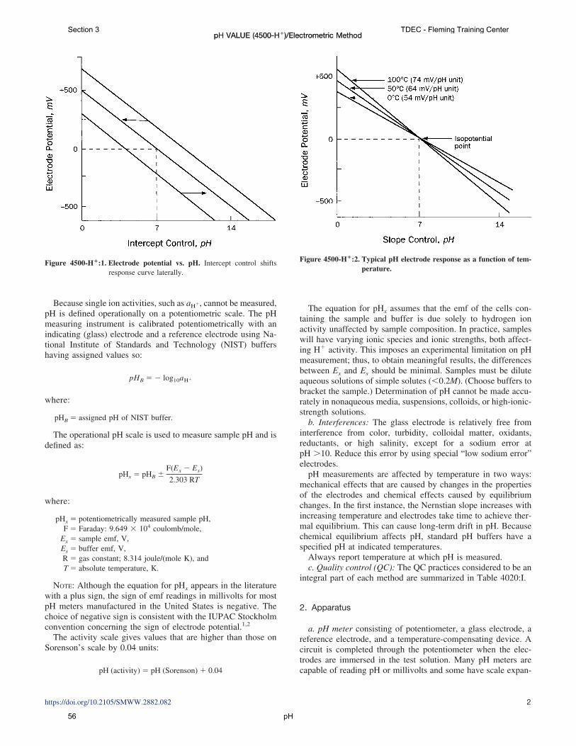
Because single ion activities, such as aH�, cannot be measured,pH is defined operationally on a potentiometric scale. The pHmeasuring instrument is calibrated potentiometrically with anindicating (glass) electrode and a reference electrode using Na-tional Institute of Standards and Technology (NIST) buffershaving assigned values so:
pHB � � log10aH�
where:
pHB � assigned pH of NIST buffer.
The operational pH scale is used to measure sample pH and isdefined as:
pHx � pHB �F(Ex � Es)
2.303 RT
where:
pHx � potentiometrically measured sample pH,F � Faraday: 9.649 � 104 coulomb/mole,
Ex � sample emf, V,Es � buffer emf, V,R � gas constant; 8.314 joule/(mole K), andT � absolute temperature, K.
NOTE: Although the equation for pHx appears in the literaturewith a plus sign, the sign of emf readings in millivolts for mostpH meters manufactured in the United States is negative. Thechoice of negative sign is consistent with the IUPAC Stockholmconvention concerning the sign of electrode potential.1,2
The activity scale gives values that are higher than those onSorenson’s scale by 0.04 units:
pH (activity) � pH (Sorenson) � 0.04
The equation for pHx assumes that the emf of the cells con-taining the sample and buffer is due solely to hydrogen ionactivity unaffected by sample composition. In practice, sampleswill have varying ionic species and ionic strengths, both affect-ing H� activity. This imposes an experimental limitation on pHmeasurement; thus, to obtain meaningful results, the differencesbetween Ex and Es should be minimal. Samples must be diluteaqueous solutions of simple solutes (�0.2M). (Choose buffers tobracket the sample.) Determination of pH cannot be made accu-rately in nonaqueous media, suspensions, colloids, or high-ionic-strength solutions.
b. Interferences: The glass electrode is relatively free frominterference from color, turbidity, colloidal matter, oxidants,reductants, or high salinity, except for a sodium error atpH �10. Reduce this error by using special “low sodium error”electrodes.
pH measurements are affected by temperature in two ways:mechanical effects that are caused by changes in the propertiesof the electrodes and chemical effects caused by equilibriumchanges. In the first instance, the Nernstian slope increases withincreasing temperature and electrodes take time to achieve ther-mal equilibrium. This can cause long-term drift in pH. Becausechemical equilibrium affects pH, standard pH buffers have aspecified pH at indicated temperatures.
Always report temperature at which pH is measured.c. Quality control (QC): The QC practices considered to be an
integral part of each method are summarized in Table 4020:I.
2. Apparatus
a. pH meter consisting of potentiometer, a glass electrode, areference electrode, and a temperature-compensating device. Acircuit is completed through the potentiometer when the elec-trodes are immersed in the test solution. Many pH meters arecapable of reading pH or millivolts and some have scale expan-
Figure 4500-H�:1. Electrode potential vs. pH. Intercept control shiftsresponse curve laterally.
Figure 4500-H�:2. Typical pH electrode response as a function of tem-perature.
pH VALUE (4500-H�)/Electrometric Method
https://doi.org/10.2105/SMWW.2882.082 2
pH VALUE (4500-H�)/Electrometric MethodSection 3 TDEC - Fleming Training Center
pH56

sion that permits reading to 0.001 pH unit, but most instrumentsare not that precise.
For routine work, use a pH meter accurate and reproducible to0.1 pH unit with a range of 0 to 14 and equipped with atemperature-compensation adjustment.
Although manufacturers provide operating instructions, theuse of different descriptive terms may be confusing. For mostinstruments, there are two controls: intercept (set buffer, asym-metry, standardize) and slope (temperature, offset); their func-tions are shown diagramatically in Figures 4500-H�:1 and 2.The intercept control shifts the response curve laterally to passthrough the isopotential point with no change in slope. Thispermits bringing the instrument on scale (0 mV) with a pH 7buffer that has no change in potential with temperature.
The slope control rotates the emf/pH slope about the isopo-tential point (0 mV/pH 7). To adjust slope for temperaturewithout disturbing the intercept, select a buffer that brackets thesample with pH 7 buffer and adjust slope control to pH of thisbuffer. The instrument will indicate correct millivolt change perunit pH at the test temperature.
b. Reference electrode consisting of a half cell that provides aconstant electrode potential. Commonly used are calomel andsilver: silver-chloride electrodes. Either is available with severaltypes of liquid junctions.
The liquid junction of the reference electrode is critical be-cause at this point the electrode forms a salt bridge with thesample or buffer and a liquid junction potential is generated thatin turn affects the potential produced by the reference electrode.Reference electrode junctions may be annular ceramic, quartz, orasbestos fiber, or the sleeve type. The quartz type is most widelyused. The asbestos fiber type is not recommended for stronglybasic solutions. Follow the manufacturer’s recommendation onuse and care of the reference electrode.
Refill nonsealed electrodes with the correct electrolyte toproper level and make sure junction is properly wetted.
c. Glass electrode: The sensor electrode is a bulb of specialglass containing a fixed concentration of HCl or a bufferedchloride solution in contact with an internal reference electrode.
Upon immersion of a new electrode in a solution, the outer bulbsurface becomes hydrated and exchanges sodium ions for hy-drogen ions to build up a surface layer of hydrogen ions. This,together with the repulsion of anions by fixed, negativelycharged silicate sites, produces at the glass–solution interface apotential that is a function of hydrogen ion activity in solution.
Several types of glass electrodes are available. Combinationelectrodes incorporate the glass and reference electrodes into asingle probe. Use a “low sodium error” electrode that can operateat high temperatures for measuring pH � 10 because standardglass electrodes yield erroneously low values. For measuringpH �1 standard glass electrodes yield erroneously high values;use liquid membrane electrodes instead.
d. Beakers: Preferably use polyethylene or TFE* beakers.e. Stirrer: Use either a magnetic, TFE-coated stirring bar or a
mechanical stirrer with inert plastic-coated impeller.f. Flow chamber: Use for continuous flow measurements or
for poorly buffered solutions.
3. Reagents
a. General preparation: Calibrate the electrode system againststandard buffer solutions of known pH. Because buffer solutionsmay deteriorate as a result of mold growth or contamination,prepare fresh as needed for accurate work by weighing theamounts of chemicals specified in Table 4500-H�:I, dissolvingin distilled water at 25°C, and diluting to 1000 mL. This isparticularly important for borate and carbonate buffers.
Boil and cool distilled water having a conductivity of less than2 �mhos/cm. To 50 mL, add 1 drop of saturated KCl solutionsuitable for reference electrode use. If the pH of this test solutionis between 6.0 and 7.0, use it to prepare all standard solutions.
Dry KH2PO4 at 110 to 130°C for 2 h before weighing but donot heat unstable hydrated potassium tetroxalate above 60°C nordry the other specified buffer salts.
* Teflon, or equivalent
TABLE 4500-H�:I. PREPARATION OF PH STANDARD SOLUTIONS3
Standard Solution (molality)pH at25°C
Weight of Chemicals Needed/1000 mLPure Water at 25°C
Primary standards:Potassium hydrogen tartrate (saturated at 25°C) 3.557 � 7 g KHC4H4O6*0.05 potassium dihydrogen citrate 3.776 11.41 g KH2C6H5O7
0.05 potassium hydrogen phthalate 4.004 10.12 g KHC8H4O4
0.025 potassium dihydrogen phosphate � 0.025disodium hydrogen phosphate
6.863 3.387 g KH2PO4� 3.533 g Na2HPO4†
0.008 695 potassium dihydrogen phosphate �0.030 43 disodium hydrogen phosphate
7.415 1.179 g KH2PO4 � 4.303 g Na2HPO4†
0.01 sodium borate decahydrate (borax) 9.183 3.80 g Na2B4O7 � 10H2O†0.025 sodium bicarbonate � 0.025 sodium
carbonate10.014 2.092 g NaHCO3 � 2.640 g Na2CO3
Secondary standards:0.05 potassium tetroxalate dihydrate 1.679 12.61 g KH3C4O8 � 2H2OCalcium hydroxide (saturated at 25°C) 12.454 � 2 g Ca(OH)2*
* Approximate solubility.† Prepare with freshly boiled and cooled distilled water (carbon-dioxide-free).
pH VALUE (4500-H�)/Electrometric Method
https://doi.org/10.2105/SMWW.2882.082 3
pH VALUE (4500-H�)/Electrometric MethodTDEC - Fleming Training Center Section 3
pH 57

Although ACS-grade chemicals generally are satisfactory forpreparing buffer solutions, use certified materials available fromthe National Institute of Standards and Technology when thegreatest accuracy is required. For routine analysis, use commer-cially available buffer tablets, powders, or solutions of testedquality. In preparing buffer solutions from solid salts, ensurecomplete solution.
As a rule, select and prepare buffer solutions classed as pri-mary standards in Table 4500-H�:I; reserve secondary standardsfor extreme situations encountered in wastewater measurements.Consult Table 4500-H�:II for accepted pH of standard buffersolutions at temperatures other than 25°C. In routine use, storebuffer solutions and samples in polyethylene bottles. Replacebuffer solutions every 6 months.
b. Saturated potassium hydrogen tartrate solution: Shake vig-orously an excess (5 to 10 g) of finely crystalline KHC4H4O6
with 100 to 300 mL distilled water at 25°C in a glass-stopperedbottle. Separate clear solution from undissolved material bydecantation or filtration. Preserve for 2 months or more byadding one thymol crystal (8 mm diam) per 200 mL solution.
c. Saturated calcium hydroxide solution: Calcine a well-washed, low-alkali grade CaCO3 in a platinum dish by ignitingfor 1 h at 1000°C. Cool, hydrate by slowly adding distilled waterwith stirring, and heat to boiling. Cool, filter, and collect solidCa(OH)2 on a fritted glass filter of medium porosity. Dry at110°C, cool, and pulverize to uniformly fine granules. Vigor-ously shake an excess of fine granules with distilled water in astoppered polyethylene bottle. Let temperature come to 25°Cafter mixing. Filter supernatant under suction through a sinteredglass filter of medium porosity and use filtrate as the buffersolution. Discard buffer solution when atmospheric CO2 causesturbidity to appear.
d. Auxiliary solutions: 0.1N NaOH, 0.1N HCl, 5N HCl (dilutefive volumes 6N HCl with one volume distilled water), and acidpotassium fluoride solution (dissolve 2 g KF in 2 mL concH2SO4 and dilute to 100 mL with distilled water).
4. Procedure
a. Instrument calibration: In each case, follow manufacturer’sinstructions for pH meter and for storage and preparation ofelectrodes for use. Recommended solutions for short-term stor-age of electrodes vary with type of electrode and manufacturer,but generally have a conductivity greater than 4000 �mhos/cm.A pH 4 buffer is best for the single glass electrode and saturatedKCl is preferred for a calomel and Ag/AgCl reference electrode.Saturated KCl is the preferred solution for a combination elec-trode. Keep electrodes wet by returning them to storage solutionwhenever pH meter is not in use.
Before use, remove electrodes from storage solution, rinse,blot dry with a soft tissue, place in initial buffer solution, and setthe isopotential point (4500-H�.B.2a). Select a second bufferwithin 2 pH units of sample pH and bring sample and buffer tosame temperature, which may be the room temperature; a fixedtemperature, such as 25°C; or the temperature of a fresh sample.Remove electrodes from first buffer, rinse thoroughly with dis-tilled water, blot dry, and immerse in second buffer. Recordtemperature of measurement and adjust temperature dial onmeter so meter indicates pH value of buffer at test temperature(this is a slope adjustment).
Use the pH value listed in the tables for the buffer used at thetest temperature. Remove electrodes from second buffer, rinsethoroughly with distilled water and dry electrodes as indicatedabove. Immerse in a third buffer below pH 10, approximately
TABLE 4500-H�:II. STANDARD PH VALUES3
Temperature°C
Primary Standards Secondary Standards
Tartrate(Saturated)
Citrate(0.05M)
Phthalate(0.05M)
Phosphate(1:1)
Phosphate(1:3.5)
Borax(0.01M)
Bicarbonate-Carbonate(0.025M)
Tetroxalate(0.05M)
CalciumHydroxide(Saturated)
05
10
4.0033.9983.996
6.9826.9496.921
7.5347.5017.472
9.4609.3929.331
10.32110.24810.181
1.6661.6681.670
152025 3.557 3.776
3.9963.9994.004
6.8986.8786.863
7.4497.4307.415
9.2769.2279.183
10.12010.06410.014
1.6721.6751.679 12.454
303537
3.5523.549
4.0114.0204.024
6.8516.8426.839
7.4037.3947.392
9.1439.1079.093
9.9689.928
1.6831.688
404550
3.5473.5473.549
4.0304.0424.055
6.8366.8326.831
7.3887.3857.384
9.0749.0449.017
9.8919.8599.831
1.6941.7001.707
556070
3.5543.5603.580
4.0704.0854.12
1.7151.7231.743
809095
3.6093.6503.674
4.164.194.21
1.7661.7921.806
pH VALUE (4500-H�)/Electrometric Method
https://doi.org/10.2105/SMWW.2882.082 4
pH VALUE (4500-H�)/Electrometric MethodSection 3 TDEC - Fleming Training Center
pH58

3 pH units different from the second; the reading should bewithin 0.1 unit for the pH of the third buffer. If the meterresponse shows a difference greater than 0.1 pH unit fromexpected value, look for trouble with the electrodes or potenti-ometer (4500-H�.B.5a and b).
The purpose of standardization is to adjust the response of theglass electrode to the instrument. When only occasional pHmeasurements are made, standardize instrument before eachmeasurement. When frequent measurements are made and theinstrument is stable, standardize less frequently. If sample pHvalues vary widely, standardize for each sample with a bufferhaving a pH within 1 to 2 pH units of the sample.
b. Sample analysis: Establish equilibrium between electrodesand sample by stirring sample to ensure homogeneity; stir gentlyto minimize carbon dioxide entrainment. For buffered samples orthose of high ionic strength, condition electrodes after cleaningby dipping them into sample for 1 min. Blot dry, immerse in afresh portion of the same sample, and read pH.
With dilute, poorly buffered solutions, equilibrate electrodesby immersing in three or four successive portions of sample.Take a fresh sample to measure pH.
5. Troubleshooting
a. Potentiometer: To locate trouble source, disconnect elec-trodes and, using a short-circuit strap, connect reference elec-trode terminal to glass electrode terminal. Observe change in pHwhen instrument calibration knob is adjusted. If potentiometer isoperating properly, it will respond rapidly and evenly to changesin calibration over a wide scale range. A faulty potentiometerwill fail to respond, will react erratically, or will show a driftupon adjustment. Switch to the millivolt scale on which themeter should read zero. If inexperienced, do not attempt poten-tiometer repair other than maintenance as described in instru-ment manual.
b. Electrodes: If potentiometer is functioning properly, lookfor the instrument fault in the electrode pair. Substitute oneelectrode at a time and cross-check with two buffers that areabout 4 pH units apart. A deviation greater than 0.1 pH unitindicates a faulty electrode. Glass electrodes fail because ofscratches, deterioration, or accumulation of debris on the glasssurface. Rejuvenate electrode by alternately immersing it threetimes each in 0.1N HCl and 0.1N NaOH. If this fails, immerse tipin KF solution for 30 s. After rejuvenation, soak in pH 7.0 bufferovernight. Rinse and store in pH 7.0 buffer. Rinse again withdistilled water before use. Protein coatings can be removed bysoaking glass electrodes in a 10% pepsin solution adjusted topH 1 to 2.
To check reference electrode, oppose the emf of a question-able reference electrode against another one of the same type thatis known to be good. Using an adapter, plug good referenceelectrode into glass electrode jack of potentiometer; then plugquestioned electrode into reference electrode jack. Set meter toread millivolts and take readings with both electrodes immersedin the same electrolyte (KCl) solution and then in the samebuffer solution. The millivolt readings should be 0 � 5 mV forboth solutions. If different electrodes are used (i.e., silver:silver-chloride against calomel or vice versa) the reading will be 44 �5 mV for a good reference electrode.
Reference electrode troubles generally are traceable to aclogged junction. Interruption of the continuous trickle of elec-trolyte through the junction causes increase in response time anddrift in reading. Clear a clogged junction by applying suction tothe tip or by boiling tip in distilled water until the electrolyteflows freely when suction is applied to tip or pressure is appliedto the fill hole. Replaceable junctions are available commer-cially.
6. Precision and Bias
By careful use of a laboratory pH meter with good electrodes,a precision of �0.02 pH unit and an accuracy of �0.05 pH unitcan be achieved. However, �0.1 pH unit represents the limit ofaccuracy under normal conditions, especially for measurementof water and poorly buffered solutions. For this reason, report pHvalues to the nearest 0.1 pH unit. A synthetic sample of a Clarkand Lubs buffer solution of pH 7.3 was analyzed electrometri-cally by 30 laboratories with a standard deviation of �0.13 pHunit.
7. References
1. BATES, R.G. 1978. Concept and determination of pH. In I.M. Kolthoff& P.J. Elving, eds. Treatise on Analytical Chemistry. Part 1, Vol. 1,p. 821. Wiley-Interscience, New York, N.Y.
2. LICHT, T.S. & A.J. DE BETHUNE. 1957. Recent developments concern-ing the signs of electrode potentials. J. Chem. Educ. 34:433.
3. DURST, R.A. 1975. Standard Reference Materials: Standardization ofpH Measurements; NBS Spec. Pub. 260-53. National Bur. Standards,Washington, D.C.
8. Bibliography
CLARK, W.M. 1928. The Determination of Hydrogen Ions, 3rd ed.Williams & Wilkins Co., Baltimore, Md.
DOLE, M. 1941. The Glass Electrode. John Wiley & Sons, New York,N.Y.
BATES, R.G. & S.F. ACREE. 1945. pH of aqueous mixtures of potassiumdihydrogen phosphate and disodium hydrogen phosphate at 0 to60°C. J. Res. Nat. Bur. Standards 34:373.
LANGELIER, W.F. 1946. Effect of temperature on the pH of natural water.J. Amer. Water Works Assoc. 38:179.
BRITTON, H.T.S. 1956. Hydrogen Ions, 4th ed. D. Van Nostrand Co.,Princeton, N.J.
FELDMAN, I. 1956. Use and abuse of pH measurements. Anal. Chem.28:1859.
KOLTHOFF, I.M. & H.A. LAITINEN. 1958. pH and Electrotitrations. JohnWiley & Sons, New York, N.Y.
KOLTHOFF, I.M. & P.J. ELVING. 1959. Treatise on Analytical Chemistry.Part I, Vol. 1, Chapter 10. Wiley-Interscience, New York, N.Y.
BATES, R.G. 1962. Revised standard values for pH measurements from0 to 95°C. J. Res. Nat. Bur. Standards 66A:179.
AMERICAN WATER WORKS ASSOCIATION. 1964. Simplified Procedures forWater Examination; Manual M12. New York, N.Y.
WINSTEAD, M. 1967. Reagent Grade Water: How, When and Why?American Soc. Medical Technologists, The Steck Company, Aus-tin, Tex.
STAPLES, B.R. & R.G. BATES. 1969. Two new standards for the pH scale.J. Res. Nat. Bur. Standards 73A:37.
BATES, R.G. 1973. Determination of pH, Theory and Practice, 2nd ed.John Wiley & Sons, New York, N.Y.
pH VALUE (4500-H�)/Electrometric Method
https://doi.org/10.2105/SMWW.2882.082 5
pH VALUE (4500-H�)/Electrometric MethodTDEC - Fleming Training Center Section 3
pH 59

pH DOC316.53.01245
USEPA Electrode Method Method 8156pH electrode
Scope and application: For drinking water1, wastewater2 and process water.1 Based on Standard Method 4500-H+B, ASTM Method D1293-95 and USEPA Method 150.12 Based on Standard Method 4500-H+B, ASTM Method D1293-84(90)/(A or B) and USEPA Method 150.1
Test preparation
Instrument specific informationThis procedure is applicable to the meters and probes that are shown in Table 1.Procedures for other meters and probes can be different.
Table 1 Instrument-specific information
Meter Probe
HQ11d portable single input, pH/ORPHQ30d portable single input, multi-parameterHQ40d portable dual input, multi-parameterHQ411d benchtop single input, pH/mVHQ430d benchtop single input, multi-parameterHQ440d benchtop dual input, multi-parameter
IntelliCAL PHC101, PHC201, PHC281 or PHC301 pH
sensION™+ MM156 portable pH/EC/DO sensION+ 5049 multi-parameter
sensION™+ pH1 portable pHsensION™+ MM110 portable pH/ORPsensION™+ MM150 portable pH/ORP/EC
sensION+ 5050T, 5051T or 5052T combination pHsensION+ 5045, 5048 or 5059 multi-parameter
sensION™+ pH3 lab pHsensION™+ pH31 GLP lab pHsensION™+ MM340 lab dual input, pH/mV/ISEsensION™+ MM374 lab dual input, pH/mV/EC/ISEsensION™+ MM378 lab dual input, pH/ISE/EC/DO
sensION+ 5010T, 5011T, 5014T or 5021T combination pH
Before startingRefer to the meter documentation for meter settings and operation. Refer to probe documentation for probe preparation,maintenance and storage information.
Prepare the probe before initial use. Refer to probe documentation.
When an IntelliCAL™ probe is connected to an HQd meter, the meter automatically identifies the measurement parameterand is prepared for use.
Condition the electrode for the best response time. To condition the electrode, soak the electrode for several minutes in asolution that has almost the same pH and ionic strength as the sample.
Calibrate the probe before initial use. Refer to Calibration procedure on page 3.
For rugged electrodes, it may be necessary to remove the shroud before measurement and calibration.
Air bubbles under the sensor tip can cause slow response or measurement errors. To remove the bubbles, carefully shakethe probe.
To save data automatically, set the measurement mode to Press to Read or Interval. When the measurement mode isContinuous, select Store to save data manually.
Rinse the electrode between measurements to prevent contamination.
1
Section 3 TDEC - Fleming Training Center
pH60

Keep the electrode in a pH storage solution when not in use. Refer to the probe documentation.
Review the Safety Data Sheets (MSDS/SDS) for the chemicals that are used. Use the recommended personal protectiveequipment.
Dispose of reacted solutions according to local, state and federal regulations. Refer to the Safety Data Sheets for disposalinformation for unused reagents. Refer to the environmental, health and safety staff for your facility and/or local regulatoryagencies for further disposal information.
This procedure is specified for the HQd meters. The sensION+ meters can be used, but the menus and navigation will bedifferent.
Items to collect
Description Quantity
Beaker or sample containers 3
Wash bottle with deionized water 1
pH buffers (4.0, 7.0, 10.0) 3
Refer to Consumables and replacement items on page 5 for order information.
Sample collection• Analyze the samples immediately. The samples cannot be preserved for later
analysis.• Collect samples in clean glass or plastic bottles.
Test procedure
1. Rinse the probe withdeionized water. Dry theprobe with a lint-free cloth.
2. Laboratory test: Put theprobe in a beaker thatcontains the solution. Do notlet the probe touch the stirbar, bottom or sides of thecontainer. Remove the airbubbles from under theprobe tip. Stir the sample ata slow to moderate rate.Field test: Put the probe inthe sample. Move the probeup and down to removebubbles from the electrode.Make sure to put thetemperature sensor fully inthe sample.
3. Push Read. A progressbar is shown. When themeasurement is stable, thelock icon is shown.
4. Rinse the probe withdeionized water. Dry theprobe with a lint-free cloth.
2 pH, USEPA electrode method
TDEC - Fleming Training Center Section 3
pH 61

Calibration procedure
1. Prepare two or threefresh buffer solutions inseparate beakers. If twobuffers are used, use a 7.0and a 4.0 or a 7.0 and a10.0 pH buffer solution.
2. Add a stir bar and put thebeaker on a magneticstirrer. Stir at a moderaterate.
3. Rinse the probe withdeionized water. Dry theprobe with a lint-free cloth.
4. Put the probe in thesolution. Do not let theprobe touch the stir bar,bottom or sides of thecontainer. Remove the airbubbles from under theprobe tip.
5. Push Calibrate. Thestandard solution value isshown.
6. Push Read. A progressbar is shown. When themeasurement is stable, thelock icon is shown.
7. Measure the remainingbuffer solutions.
8. Push Done. A calibrationsummary is shown when theminimum number ofcalibration standards aremeasured.
9. Push Store to accept thecalibration.
Low ionic strength or high-purity water measurements
N O T I C E
Do not keep the probe in LIS samples for a long period of time because this can decrease theprobe life. Put the probe in electrode storage solution or 3 M KCl when LIS measurements arecomplete.
Low ionic strength (LIS) solutions have very low buffering capacity and absorb carbondioxide from the air. When a sample absorbs carbon dioxide from the atmosphere,carbonic acid forms. Carbonic acid decreases the sample pH, which causes inaccurate
pH, USEPA electrode method 3
Section 3 TDEC - Fleming Training Center
pH62

readings. One solution to this problem is to measure the sample in a low volume, airtightsample chamber such as a low ionic strength chamber.Use refillable or platinum series electrodes for measurement of pH in LIS or high puritywaters.Before an LIS sample is measured, condition the probe as follows:
1. Soak the probe in a solution equivalent to the sample in ionic strength and pH for10 to 15 minutes.
2. Rinse the probe with deionized water.3. Dry the probe with a soft paper towel.
Between measurements, keep the probe in the sample or a neutral LIS solution (e.g., tapwater) for a maximum of 2 hours.
InterferencesThe sodium error is low but increases at pH values that are higher than pH 11. The aciderror is negligible. Refer to the electrode or the meter documentation.
Accuracy check
Slope testThe electrode operation is satisfactory when the calibration slope is within the specifiedrange (typically –58 mV (±3) at 25 °C).
Calibration accuracyMeasure the pH of a fresh buffer solution. A calibration is satisfactory when the measuredpH value agrees with the known pH value of the buffer solution.
Clean the probeClean the probe when:
• Drifting/inaccurate readings occur as a result of contamination on the sensingelement or incorrect storage conditions.
• Slow response time occurs as a result of contamination on the sensing element.• The slope is out of range as a result of contamination on the sensing element.
For general contamination, complete the steps that follow.
1. Rinse the probe with deionized water. Blot dry with a lint-free cloth. 2. Soak the glass bulb for 12 to 16 hours in Hach Electrode Cleaning Solution.3. Rinse or soak the probe for 1 minute in deionized water.4. Soak the probe in pH 4 buffer for up to 20 minutes, then rinse with deionized water.5. Blot dry with a lint-free cloth.6. If harsh contaminants are attached to the probe, polish the probe tip with a soft cloth
or cotton swab to remove the contaminants.7. Soak for up to 20 minutes in pH 4 buffer, then rinse with deionized water.
Method performanceThe accuracy of the measurements is dependent on many factors that are related withthe overall system, which includes the meter, the probe and calibration solutions. Refer tothe meter or probe documentation for more information.
Summary of methodA combination pH electrode develops a potential at the glass/liquid interface. At aconstant temperature, this potential varies linearly with the pH of the solution.The pH is the hydrogen ion activity in a solution and is defined as –log10a(H+), wherea(H+) is the activity of the hydrogen ion. The sample pH can change when carbon dioxideis absorbed from the atmosphere. In water that has a high conductivity, the buffercapacity is typically high and the pH does not change much.
4 pH, USEPA electrode method
TDEC - Fleming Training Center Section 3
pH 63

Consumables and replacement itemsHQd meters and probes
Description Unit Item no.
HQ11d portable single input, pH/ORP meter each HQ11D53000000
HQ30d portable single input, multi-parameter meter each HQ30D53000000
HQ40d portable dual input, multi-parameter meter each HQ40D53000000
HQ411d benchtop single input, pH/mV meter each HQ411D
HQ430d benchtop single input, multi-parameter meter each HQ430D
HQ440d benchtop dual input, multi-parameter meter each HQ440D
IntelliCAL™ pH gel probe, standard with 1 m cable each PHC10101
IntelliCAL™ pH gel probe, standard with 3 m cable each PHC10103
IntelliCAL™ pH gel probe, rugged with 5 m cable each PHC10105
IntelliCAL™ pH gel probe, rugged with 10 m cable each PHC10110
IntelliCAL™ pH gel probe, rugged with 15 m cable each PHC10115
IntelliCAL™ pH gel probe, rugged with 30 m cable each PHC10130
IntelliCAL™ pH gel probe, standard with 1 m cable each PHC20101
IntelliCAL™ pH gel probe, standard with 3 m cable each PHC20103
IntelliCAL™ pH gel probe, ultra with 1 m cable each PHC28101
IntelliCAL™ pH gel probe, ultra with 3 m cable each PHC28103
IntelliCAL™ pH liquid probe, standard with 1 m cable each PHC30101
IntelliCAL™ pH liquid probe, standard with 3 m cable each PHC30103
sensION+ meters and probes
Description Unit Item no.
sensION™+ pH1 portable pH meter each LPV2500.97.0002
sensION™+ MM110 portable pH/ORP meter each LPV2600.97.0002
sensION™+ MM150 portable pH/ORP/EC meter each LPV4000.97.0002
sensION™+ MM156 portable pH/EC/DO meter each LPV4030.97.0002
sensION™+ pH3 lab pH meter each LPV2010T.97.002
sensION™+ pH31 GLP lab pH meter each LPV2110T.97.002
sensION™+ MM340 lab dual input, pH/mV/ISE meter each LPV2200.97.0002
sensION™+ MM374 lab dual input, pH/mV/EC/ISE meter each LPV4110.97.0002
sensION™+ MM378 lab dual input, pH/ISE/EC/DO meter each LPV4130.97.0002
sensION™+ 5010T combination pH probe each LZW5010T.97.002
sensION™+ 5011T combination pH probe each LZW5011T.97.002
sensION™+ 5014T combination pH probe each LZW5014T.97.002
sensION™+ 5021T combination pH probe each LZW5021T.97.002
sensION™+ 5050T combination pH probe each LZW5050T.97.002
sensION™+ 5051T combination pH probe each LZW5051T.97.002
sensION™+ 5052T combination pH probe each LZW5052T.97.002
pH, USEPA electrode method 5
Section 3 TDEC - Fleming Training Center
pH64

sensION+ meters and probes (continued)
Description Unit Item no.
sensION™+ 5045 multi-parameter probe each LZW5045.97.0002
sensION™+ 5048 multi-parameter probe each LZW5048.97.0002
sensION™+ 5049 multi-parameter probe each LZW5049.97.0002
sensION™+ 5059 multi-parameter probe each LZW5059.97.0002
Recommended standards
Description Unit Item no.
pH color-coded buffer solution kit (NIST), 500 mL, includes: 1 2947600
pH 4.01 ± 0.02 pH buffer (NIST) 500 mL 2283449
pH 7.00 ± 0.02 pH buffer (NIST) 500 mL 2283549
pH 10.01 ± 0.02 pH buffer (NIST) 500 mL 2283649
Powder pillows:
pH 4.01 ± 0.02 pH buffer powder pillow (NIST) 50/pkg 2226966
pH 7.00 ± 0.02 pH buffer powder pillow (NIST) 50/pkg 2227066
pH 10.01 ± 0.02 pH buffer powder pillow (NIST) 50/pkg 2227166
Radiometer Analytical (IUPAC Series certified pH standards):
pH 1.679 ± 0.010 at 25 °C (77 °F) 500 mL S11M001
pH 4.005 ± 0.010 at 25 °C (77 °F) 500 mL S11M002
pH 7.000 ± 0.010 at 25 °C (77 °F) 500 mL S11M004
pH 10.012 ± 0.010 at 25 °C (77 °F) 500 mL S11M007
pH buffer 1.09, technical 500 mL S11M009
pH buffer 4.65, technical 500 mL S11M010
pH buffer 9.23, technical 500 mL S11M011
Accessories
Description Unit Item no.
Beaker, polypropylene, 50-mL, low form each 108041
Beaker, polypropylene, 100-mL each 108042
Bottle, wash, 500-mL each 62011
Stir bar, magnetic, 2.2 x 0.5 cm (7/8 x 3/16 in.) each 4531500
Stirrer, electromagnetic, 120 VAC, with electrode stand each 4530001
Stirrer, electromagnetic, 230 VAC, with electrode stand each 4530002
Sample bottle with screw-top cap, polypropylene, 500-mL each 2758101
Water, deionized 4 L 27256
HACH COMPANYWORLD HEADQUARTERSTelephone: (970) 669-3050FAX: (970) 669-2932
FOR TECHNICAL ASSISTANCE, PRICE INFORMATION AND ORDERING:Call 800-227-4224
Contact the HACH office or distributor serving you.www.hach.com [email protected]
In the U.S.A. –
Outside the U.S.A. –
On the Worldwide Web – ; E-mail –
toll-free
© Hach Company/Hach Lange GmbH, 2007–2015. All rights reserved. 03/2015, Edition 8
TDEC - Fleming Training Center Section 3
pH 65

Date Time Location Temp. of Date of Last Measured Technician Solution Calibration pH
pH Sample Record
Fleming Training Center
Month___________ pH Meter _______________
Section 3 TDEC - Fleming Training Center
pH66

Section 4 Specific Gravity
67

Density and Specific Gravity
•1
Density
O Weight per unit volumeO solids and gases expressed in lb/ft3
O liquids measured in lb/gal or lb/ft3
O Density of water varies slightly with temperature and pressure
O Density of gases changes significantly with changes in temperature and pressure
•2•TDEC - Fleming Training Center
Density of Water
The density of water is62.4 lbs/ft3
or8.34 lbs/gal •3
1 ft
1 ft
1 ft
1 gal
62.4 lbs
8.34 lbs
•TDEC - Fleming Training Center
Specific Gravity
O Compares density of a substance to a standard density
O Does not have unitsO For solids and liquids
O compare to standard density of waterO 62.4 lb/ft3
O 8.34 lb/gal
•4•TDEC - Fleming Training Center
Example #1
O The density of SAE motor oil is 56 lb/ft3. Find the specific gravity.
𝑠𝑝𝑒𝑐𝑖𝑓𝑖𝑐 𝑔𝑟𝑎𝑣𝑖𝑡𝑦 𝑑𝑒𝑛𝑠𝑖𝑡𝑦 𝑜𝑓 𝑠𝑢𝑏𝑠𝑡𝑎𝑛𝑐𝑒𝑑𝑒𝑛𝑠𝑖𝑡𝑦 𝑜𝑓 𝑤𝑎𝑡𝑒𝑟
𝑠𝑝𝑒𝑐𝑖𝑓𝑖𝑐 𝑔𝑟𝑎𝑣𝑖𝑡𝑦 56 𝑙𝑏 𝑓𝑡
62.4 𝑙𝑏 𝑓𝑡𝑠𝑝𝑒𝑐𝑖𝑓𝑖𝑐 𝑔𝑟𝑎𝑣𝑖𝑡𝑦 0.90
•TDEC - Fleming Training Center •5
Example #2
O A sample of liquid alum has a density of 11.2 lb/gal. What is the specific gravity?
𝑠𝑝𝑒𝑐𝑖𝑓𝑖𝑐 𝑔𝑟𝑎𝑣𝑖𝑡𝑦 𝑑𝑒𝑛𝑠𝑖𝑡𝑦 𝑜𝑓 𝑠𝑢𝑏𝑠𝑡𝑎𝑛𝑐𝑒𝑑𝑒𝑛𝑠𝑖𝑡𝑦 𝑜𝑓 𝑤𝑎𝑡𝑒𝑟
𝑠𝑝𝑒𝑐𝑖𝑓𝑖𝑐 𝑔𝑟𝑎𝑣𝑖𝑡𝑦 11.2 𝑙𝑏 𝑔𝑎𝑙
8.34 𝑙𝑏 𝑔𝑎𝑙𝑠𝑝𝑒𝑐𝑖𝑓𝑖𝑐 𝑔𝑟𝑎𝑣𝑖𝑡𝑦 1.34
•TDEC - Fleming Training Center •6
Section 4 TDEC - Fleming Training Center
Specific Gravity68

Specific Gravity of Gases
Compare to standard density of air:0.075 lb/ft3
•7•TDEC - Fleming Training Center
Example #3
O The density chlorine gas is 0.187 lb/ft3. Find the specific gravity.
𝑠𝑝𝑒𝑐𝑖𝑓𝑖𝑐 𝑔𝑟𝑎𝑣𝑖𝑡𝑦 𝑑𝑒𝑛𝑠𝑖𝑡𝑦 𝑜𝑓 𝑠𝑢𝑏𝑠𝑡𝑎𝑛𝑐𝑒
𝑑𝑒𝑛𝑠𝑖𝑡𝑦 𝑜𝑓 𝑎𝑖𝑟
𝑠𝑝𝑒𝑐𝑖𝑓𝑖𝑐 𝑔𝑟𝑎𝑣𝑖𝑡𝑦 0.187 𝑙𝑏 𝑓𝑡
0.075 𝑙𝑏 𝑓𝑡𝑠𝑝𝑒𝑐𝑖𝑓𝑖𝑐 𝑔𝑟𝑎𝑣𝑖𝑡𝑦 2.49
•TDEC - Fleming Training Center •8
Measuring Specific Gravity
•9
Chemical Verification
O Place 100 mL graduated cylinder on a scale
•10
130.90 g
•TDEC - Fleming Training Center
Chemical Verification
O Tare the scale so it reads zero with the cylinder on it.
•11
0.00 g
•TDEC - Fleming Training Center
Chemical Verification
O Weigh 100 mL of your sample or chemical.
•12
99.09 g
•TDEC - Fleming Training Center
TDEC - Fleming Training Center Section 4
Specific Gravity 69

Chemical Verification
O Find the specific gravity of a substance in which 100 mL weighs 99.09 grams.
𝑠𝑝𝑒𝑐𝑖𝑓𝑖𝑐 𝑔𝑟𝑎𝑣𝑖𝑡𝑦 𝑤𝑒𝑖𝑔ℎ𝑡 𝑜𝑓 100 𝑚𝐿 𝑜𝑓 𝑠𝑜𝑙′𝑛,𝑔𝑟𝑎𝑚𝑠
100 𝑔𝑟𝑎𝑚𝑠
𝑠𝑝𝑒𝑐𝑖𝑓𝑖𝑐 𝑔𝑟𝑎𝑣𝑖𝑡𝑦99.09 𝑔100 𝑔
𝑠𝑝𝑒𝑐𝑖𝑓𝑖𝑐 𝑔𝑟𝑎𝑣𝑖𝑡𝑦 0.99
•TDEC - Fleming Training Center •13
Hydrometer
O A hydrometer is an instrument whose function is based on Archimedes principle.
O This principle states that a body (the hydrometer) immersed in a fluid is buoyed up by a force equal to the weight of the displaced fluid.
O The hydrometer measures the weight of the liquid displaced by the volume of the hydrometer.
•TDEC - Fleming Training Center
Hydrometer
O The greater the density, the tighter or closer the molecules are packed inside the substance.
O Therefore, the greater the density / specific gravity of a liquid the higher a hydrometer will be buoyed by it.
•TDEC - Fleming Training Center •15
HydrometerO Fill your hydrometer jar about ¾ with the liquid you
wish to testO Insert the hydrometer slowly. Do not drop it in! O Now give it a spin with your thumb and index finger,
this will dislodge any bubbles that may have formedO Once the hydrometer comes to a rest, observe the
plane of the liquid surfaceO Your eye must be horizontal to this plane
O The point at which this line cuts the hydrometer scale is your reading
•16
•17
Section 4 TDEC - Fleming Training Center
Specific Gravity70

DENSITY & SPECIFIC GRAVITY Density: Weight per unit volume. 2 ways to express density: Specific gravity: Density of any substance compared to a “standard density.” Standard density of water: lb/gal lb/ft3 1. Find the specific gravity for rock granite if the density is 162 lbs/ft3. 2. Find the specific gravity for SAE 30 motor oil if the density is 56 lbs/ft3. 3. Find the specific gravity of dry alum if the density is 65 lbs/ft3. 4. Find the specific gravity for liquid alum that weighs 11.07 lbs/gal. 5. Find the specific gravity for fluorosilicic acid that weighs 10.5 lbs/gal.
TDEC - Fleming Training Center Section 4
Specific Gravity 71

6. Find the specific gravity for ferric sulfate that weighs 12.34 lbs/gal. 7. Find the density (lbs/ft3) of a certain oil that has a S.G. of 0.92. 8. Find the density (lbs/gal) of ferric chloride that has a S.G. of 1.140. 9. Find the density (lbs/gal) of caustic soda that has a S.G. of 1.530. 10. Find the density (lbs/ft3) of potassium permanganate that has a S.G. of 1.522. 11. A tank holds 1,240 gallons of a certain liquid. The specific gravity is 0.93. How
many pounds of liquid are in the tank? 12. Pump rate desired: 25 gpm Liquid weight: 74.9 lbs/ft3 How many pounds of liquid can be pumped per day?
Section 4 TDEC - Fleming Training Center
Specific Gravity72

13. A certain pump delivers 23 gallons per minute. A. How many lbs of water does the pump deliver in 1 minute? B. How many lbs/min will the pump deliver if the liquid weighs 71.9 lbs/ft3? 14. A certain pump delivers 14 gallons per minute. A. How many lbs of water does the pump deliver in 24 hours? B. How many lbs/day will the pump deliver if the liquid weighs 8.1 lbs/gal? 15. Compare the density of chlorine gas with the density of air. Chlorine gas weighs
0.187 lbs/ft3. (Standard density of air = 0.075 lb/ft3) ANSWERS: 1. 2.6 2. 0.9 3. 1.04 4. 1.33 5. 1.26 6. 1.48 7. 57.4 lbs/ft3 8. 9.5 lbs/gal 9. 12.76 lbs/gal 10. 95 lbs/ft3
11. 9,617.7 lbs 12. 360,481 lbs/day 13. a. 191.8 lbs/min b. 221 lbs/min 14. a. 168,134 lbs/day b. 163,296 lbs/day 15. 2.49
TDEC - Fleming Training Center Section 4
Specific Gravity 73

Sample Sample
Size
Sample
Weight
Specific Gravity
(using balance)
Specific Gravity
Specific Gravity
(using hydrometer)
Specific Gravity = weight of 100 mL of solu on, g
100 g
Section 4 TDEC - Fleming Training Center
Specific Gravity74

Section 5 Potassium Permanganate Residual
75

California State University: Sacramento
Oxidative Processes Oxidation – destructive technique used to control tastes and odors by chemical application
Objectionable compounds broken down into less objectionable by‐products
Common chemical oxidants
Chlorine
Potassium permanganate/sodium permanganate
Ozone
Chlorine dioxide
Potassium Permanganate (KMnO4) Used to oxidize natural organic matter (NOM), iron, manganese, and sulfide compounds
Produces intense purple color initially
Changes from purple to yellow/brown during reactions with compounds being oxidized
Manganese dioxide (MnO2) – insoluble precipitate
If any permanganate remains in solution, pink water will pass through filters and go to customer
Potassium Permanganate (KMnO4) To minimize finished pink water
Measure time required for pink to disappear in jar test
Visually observe plant process to determine when pink disappears
Each operator must use the same visual cues
Feeding at intake allows for higher feed rates and more contact time
Permanganate overdose
Feed powdered activated carbon (PAC)
Increase pH to increase manganese precipitation rate (extreme measure)
Dosing of Permanganate Determining dosage should be determined in the lab with a jar test
Run the jar test for an amount of time and RPMs appropriate for your plant
Jar test should mimic the plant process
Add enough permanganate to maintain a residual
Sample jar test water every 30 minutes until contact time is reached
Subtract ending residual from initial dosage to determine demand
Dose – residual = demand
Dosing of Permanganate 1 mg/L of KMnO4 required to oxidize 0.92 mg/L of soluble iron
1 mg/L of KMnO4 required to oxidize 1.92 mg/L of soluble manganese
If demand is found to be higher than the current residual in the flash mix, increase dosage and run a new demand test
If demand is going down, decrease feed rate to prevent an overdosage and run a new demand test Overdosing can lead to membrane filter fouling, manganese dioxide in the clearwell and distribution system, as well as pink water in customers’ homes
Section 5 Fleming Training Center
Potassium Permanganate Residual76

Testing for Permanganate Demand Permanganate residual is determined in the same manner as chlorine residual
Colorimetric
Follow method for reagent used
i.e. free chlorine DPD or total chlorine DPD
Amperometric titration
If permanganate concentration is less than 1 mg/L, multiply reading by the concentration
Example: if using KMnO4 stock that is 0.891 g/L, multiply residual by 0.891 to get actual mg/L residual
Fleming Training Center Section 5
Potassium Permanganate Residual 77

Permanganate Residual Potassium permanganate (KMnO4) is used in water treatment for the oxidation of iron, manganese, and substances causing taste and odor. It has also been used to control zebra mussels. Potassium permanganate is a dark purple crystalline solid that produces a solution ranging from faint pink (dilute) to deep purple (concentrated). As permanganate oxidizes compounds in the water, it changes from purple to brown. The final product is manganese dioxide (MnO2), an insoluble precipitate that can be removed by sedimentation or filtration. All of the KMnO4 must be converted to MnO2 prior to filtration. Otherwise the pink color may pass through the filters and into the clearwell. On the other hand, if too little permanganate is added, dissolved iron and manganese may pass through the treatment process and into the clearwell. Once chlorine is added, these minerals may then precipitate out, creating color problems in the distribution system. Measuring permanganate residual at different stages of the treatment process may be helpful in ensuring that the proper dose is being added. The jar test may also be used in determining the best dosage.
Solutions of potassium permanganate for use in the lab may be stored for a long time if they are made with oxidant-demand-free water and kept in an amber bottle out of sunlight. Sampling and Storage Samples collected from source waters with an oxidant demand should be analyzed immediately. Procedure for measuring free chlorine using DPD Colorimetric Method Procedure
Follow the instructions for measuring chlorine residual. Multiply the reading in mg/L by the conversion factor of 0.891 to convert the chlorine reading to permanganate.
Page 273 in Hach Water Analysis Handbook for chlorine residual method
Reagents DPD Powder Pillows for Free Chlorine
Apparatus Spectrophotometer Hach Pocket Cl2 Colorimeter
Procedure for measuring free chlorine using Amperometric Titration Method Follow manufacturer’s instructions
Section 5 Fleming Training Center
Potassium Permanganate Residual78

Section 6
Chlorine, Free and Total Residual
79

Chlorine ResidualWater Treatment Lab
1TDEC - Fleming Training Center
Chlorination
o Chlorination is the process of adding chlorine to water for the destruction or
inactivation of pathogenic (disease-causing) organisms
2TDEC - Fleming Training Center
Chemistry of Chlorination
Cl2 + H2O HOCl + HClhypochlorous acid hydrochloric acid
o Hypochlorous acid o Most effective disinfectanto Prevalent at pH less than 7
Dissociates at higher pH:HOCl H+ + OCl−
hypochlorite iono Hypochlorite ion is only 1% as effective as hypochlorous
acid.3TDEC - Fleming Training Center
Chemistry of Hypochlorination
NaOCl + H2O HOCl + NaOHhypochlorous acid
o Sodium hypochlorite will slightly raise the pH because of the sodium hydroxide (NaOH)
4TDEC - Fleming Training Center
Chemistry of Chlorination
o Chlorine reacts with reducing agents in the water o organic mattero iron and manganeseo nitrites
o No free residual will be formed until all reducing agents are destroyed
o Chlorine also reacts with ammonia and organics to form combined residuals
o These are not as effective as free residual 5TDEC - Fleming Training Center
Residual Formation
o The breakpoint is the point at which the chlorine dosage has met the demand
o Any additional chlorine will result in a free residual
6TDEC - Fleming Training Center
Section 6 TDEC - Fleming Training Center
Chlorine Residual80

Breakpoint
Chloramine formation
Chloramine decomposition
Free Chlorine, HOCland OCl are present
7TDEC - Fleming Training Center
Breakpoint
8TDEC - Fleming Training Center
Chlorine Demand
o Chlorine Demando The difference between the chlorine added to
the water and the amount of residual chlorine remaining after a given time
o Dose = Demand + Residual
9TDEC - Fleming Training Center
Chlorine Demand
o Chlorine demand can be measured by using separate samples (same source, divided up into separate samples) each dosed with a series of increasing doses of chlorine
o After appropriate contact time, measure free chlorine residual
o Demand is determined by the difference between the original dose and the final free residual concentration
10TDEC - Fleming Training Center
Disinfection Control Tests
o Chlorine Residualo Presence of residualo Free or combinedo Concentrationo By amperometric titration (most accurate, not affected by
color or turbidity) or colorimetric (DPD) methodo Bacteriological Test
o Indicates fecal contaminationo Coliforms are more resistant to chlorine than other fecal
bacteria, if coliforms are not present, other fecals will not be present either
11TDEC - Fleming Training Center
Amperometric Titration
o Accurate and unaffected by sample color or turbidity
o Takes greater skill to use than DPD method with colorimetric devices
12TDEC - Fleming Training Center
TDEC - Fleming Training Center Section 6
Chlorine Residual 81
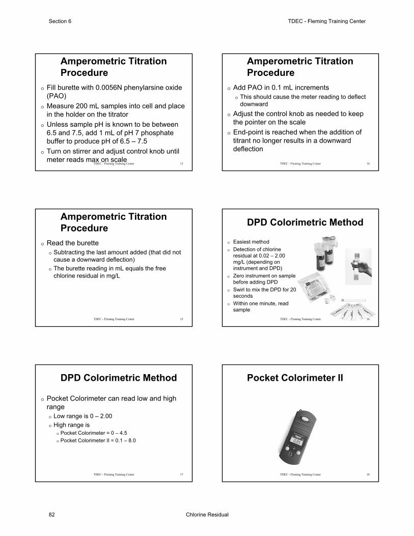
Amperometric Titration Procedure
o Fill burette with 0.0056N phenylarsine oxide (PAO)
o Measure 200 mL samples into cell and place in the holder on the titrator
o Unless sample pH is known to be between 6.5 and 7.5, add 1 mL of pH 7 phosphate buffer to produce pH of 6.5 – 7.5
o Turn on stirrer and adjust control knob until meter reads max on scale
13TDEC - Fleming Training Center
Amperometric Titration Procedure
o Add PAO in 0.1 mL incrementso This should cause the meter reading to deflect
downwardo Adjust the control knob as needed to keep
the pointer on the scaleo End-point is reached when the addition of
titrant no longer results in a downward deflection
14TDEC - Fleming Training Center
Amperometric Titration Procedure
o Read the buretteo Subtracting the last amount added (that did not
cause a downward deflection)o The burette reading in mL equals the free
chlorine residual in mg/L
15TDEC - Fleming Training Center
DPD Colorimetric Method
o Easiest methodo Detection of chlorine
residual at 0.02 – 2.00 mg/L (depending on instrument and DPD)
o Zero instrument on sample before adding DPD
o Swirl to mix the DPD for 20 seconds
o Within one minute, read sample
16TDEC - Fleming Training Center
DPD Colorimetric Method
o Pocket Colorimeter can read low and high rangeo Low range is 0 – 2.00o High range is
o Pocket Colorimeter = 0 – 4.5 o Pocket Colorimeter II = 0.1 – 8.0
17TDEC - Fleming Training Center
Pocket Colorimeter II
18TDEC - Fleming Training Center
Section 6 TDEC - Fleming Training Center
Chlorine Residual82

0.02 – 2.00 mg/L Cl2
19TDEC - Fleming Training Center
0.02 – 2.00 mg/L Cl2
20TDEC - Fleming Training Center
0.02 – 2.00 mg/L Cl2
21TDEC - Fleming Training Center
0.02 – 2.00 mg/L Cl2
22TDEC - Fleming Training Center
0.1 – 8.0 mg/L Cl2
o Press the MENU key. o The display will show “SEL”. o A flashing arrow indicates the current range.o Press the READ/ENTER key to toggle
between ranges.o Press MENU again to accept and exit back
to the measurement screen.
23TDEC - Fleming Training Center
0.1 – 8.0 mg/L Cl2
24TDEC - Fleming Training Center
TDEC - Fleming Training Center Section 6
Chlorine Residual 83

0.1 – 8.0 mg/L Cl2
25TDEC - Fleming Training Center
0.1 – 8.0 mg/L Cl2
26TDEC - Fleming Training Center
10 – 200 mg/L Cl2
27TDEC - Fleming Training Center
DPD Accuracy Check
o Pre-made Gelex Standardso Similar to turbidity secondary standardso Make sure to check expiration dates
28TDEC - Fleming Training Center
DPD Accuracy Check
o Potassium permanganate solutionso Weigh out 0.891g of reagent grade KMnO4
o Transfer to 1000 mL volumetric flask, fill with distilled water and mix
o Transfer 10 mL of this solution to 100 mL flask, fill with distilled water and mix
29TDEC - Fleming Training Center
40CFR136Method Update Rule
For Backwash Lagoons that have Discharge PermitsMay 10, 2013
Updated December 2018Fleming Training Center
30TDEC - Fleming Training Center
Section 6 TDEC - Fleming Training Center
Chlorine Residual84

31TDEC - Fleming Training Center
Parameter Methodology EPA StandardMethods
ASTM USGS/AOAC/Other
Chlorine-TotalResidual, mg/L
Amperometric Direct …… 4500-Cl D-2000 D1253-08
Amperometric Direct (Low Level)
…… 4500-Cl E-2000
Iodometric Direct …… 4500-Cl B-2000
Back Titration Ether End-Point15 …… 4500-Cl C-2000
DPD-FAS …… 4500-Cl F-2000
Spectrophotometric, DPD
…… 4500-Cl G-2000
Electrode …… ………… …… See Footnote 16
40 CFR 136 05-21-2012 Table 1B
1. DOC – demonstration of capability2. MDL – method detection level3. LRB/MB – method blank4. LFB – laboratory fortified blank (standard)5. LFM/LFMD – laboratory fortified matrix/duplicate (spike)6. Internal standards, surrogate standards or tracer – only applies to organic analysis and
radiochemistry7. Calibration- initial and continuing8. Control charts or other trend analysis9. Corrective action – root cause analysis10. QC acceptance criteria11. Definition of a batch (preparation and analytical)12. Minimum frequency for conducting all QC elements13. Unwritten 13th Step – SOP – Standard Operating Procedures need to be written and
followed for all lab sampling and analysesNot all of these items apply to all tests, there are many exceptions!32
12 Quality Control Elements
TDEC - Fleming Training Center
Total Residual Chlorine SM4500-Cl G - 2000, DPD
TDEC - Fleming Training Center 33
∗ DOC∗ MDL∗ LRB∗ LFB∗ Dup∗ ICAL/CCV
∗ Control Charts∗ Corrective Action∗ QC Acceptance∗ Batch Size∗ QC Frequency
∗ Demonstration of Capability (DOC)∗ Run a laboratory-fortified blank (LFB) at least four times and
compare to the limits listed in the method∗ No limits listed for chlorine
∗ Real people language: each operator running this test need to analyze 4 samples of a Chlorine Standard or Potassium Permanganate (KMnO4) at a concentration around 0.5 mg/L.
∗ Documentation (signed form) that analyst has read and understands all appropriate SOPs and Methods.
∗ Recommend backup analyst do this once a year.
TDEC - Fleming Training Center 34
Total Residual Chlorine SM4500-Cl G - 2000, DPD
∗ Method Detection Limit∗ HACH- Estimated Detection Level=0.02mg/L∗ Initial MDL From SM 1030 C.
∗ Make a 0.10 mg/L standard∗ Analyze 7 portions over ≥ 3 days∗ Calculate standard deviation (s)∗ s* 3.14= MDL
∗ Ongoing MDL data∗ Run two (2) spiked samples at least every quarter∗ Record results of method results for each discharge testing
35
Total Residual Chlorine SM4500-Cl G - 2000, DPD
TDEC - Fleming Training Center
∗ Laboratory Reagent Blank∗ Real people language: analyze distilled water as a sample by adding DPD powder
pillow and waiting the 3-6 minutes before reading∗ Target value is less than MDL∗ Run Daily (or day of for monthly reporting purposes)
∗ Laboratory Fortified Blank ∗ Real people language: analyze a chlorine standard or potassium permanganate
(KMnO4) at a concentration around 0.5 mg/L∗ Run on a 5% basis, one for every 20 samples (or day of for monthly reporting
purposes)∗ Duplicates of the sample
∗ Run on a 5% basis, one for every 20 samples (or day of for monthly reporting purposes)
∗ Calculate %RPD, ≤ 20%
36
Total Residual Chlorine SM4500-Cl G - 2000, DPD
TDEC - Fleming Training Center
TDEC - Fleming Training Center Section 6
Chlorine Residual 85

Total Residual Chlorine SM4500-Cl G - 2000, DPD
TDEC - Fleming Training Center 37
∗ Initial Calibration∗ Prepare a set of chlorine
standard or potassium permanganate (KMnO4) in accordance with the Guidance for Secondary Standards Use in Calibration monthly.∗ Once per month at
minimum, before the use of new DPD reagents, or the use of new gel standards
∗ Stock Standard Solution∗ 0.891 grams of reagent grade KMnO4 in 1000 mL vol.
flask made to mark with deionized water. ∗ Deionized water must never be stored in plastic
containers or exposed to airborne contamination. ∗ Store the stock solution in amber bottle in a cool area. ∗ The typical shelf life of the stock solution is six
(6) months. ∗ If solids appear in the solution, do not use.
TDEC - Fleming Training Center 38
Total Residual Chlorine SM4500-Cl G - 2000, DPD
∗ Intermediate (Working) Standard Solution∗ 10 mL of STOCK made in 1000 mL vol. flask made to
mark with deionized water. ∗ The flask should be labeled with the name, KMnO4, date
of preparation, initials of who made it.∗ This information should also be entered into a logbook.
∗ **The intermediate stock solution should be stable for approximately 5 days if kept cool and away from light.**
TDEC - Fleming Training Center 39
Total Residual Chlorine SM4500-Cl G - 2000, DPD
∗ Potassium Permanganate Standard Solution∗ Care should be taken that the pipette and glassware are
clean and thoroughly rinsed with deionized water to avoid contamination.
∗ Store only in glass container (preferably amber glass) never in plastic containers.
∗ The working solution should be remade if solids appear in the bottom of the container.
TDEC - Fleming Training Center 40
Total Residual Chlorine SM4500-Cl G - 2000, DPD
∗ Calibration Standard Solutions∗ Four to five calibration standard solutions should be made
according to the table below to create a calibration curve once per month at a minimum.
∗ The linear regression of the curve should correlate to 0.995 or better.
∗ This curve is then used to check or calibrate the instrument. ∗ Gel standards are run against the curve and must agree to
within + 10%.∗ **The working solution should be stable for approximately
2 hours and will fade rapidly (within 15 minutes) if chlorine demand-free water is not used.**
TDEC - Fleming Training Center 41
Total Residual Chlorine SM4500-Cl G - 2000, DPD
∗ Calibration Standard Solutions∗ A target value (e.g. permit value for a facility) should be
known and three gel standards, 0.00 mg/L, blank, and two other standards (a low and a high standard) that bracket the target value should be chosen.
∗ Gel standards are run against the curve and must agree to within + 10%.
TDEC - Fleming Training Center 42
Total Residual Chlorine SM4500-Cl G - 2000, DPD
Section 6 TDEC - Fleming Training Center
Chlorine Residual86

mL Working Standard Diluted w/Deionized water Chlorine Equivalent mg/L
20 mL (vol. Pipette) to 100 mL (vol. flask) 2.0 mg/L
10 mL (vol. Pipette) to 100 mL (vol. flask) 1.0 mg/L
5 mL (vol. Pipette) to 100 mL (vol. flask) 0.5 mg/L
1 mL (vol. Pipette) to 100 mL (vol. flask) 0.1 mg/L
1 mL (vol. Pipette) to 200 mL (vol. flask) 0.05 mg/L
1 mL (vol. Pipette) to 500 mL (vol. flask) 0.02 mg/L
100 mL of deionized water 0.00 mg/L
TDEC - Fleming Training Center 43
Total Residual Chlorine SM4500-Cl G - 2000, DPD
Don’t forget to use DPD on Potassium Permanganate standards
Total Residual Chlorine SM4500-Cl G - 2000, DPD
TDEC - Fleming Training Center 44
∗ Calibration Verification daily (or day of for monthly reporting purposes)
∗ Verify meter with secondary gel standards using a minimum of one blank and two gel standards that bracket the expected sample concentration
∗ OR verify meter after running samples with a standard of chlorine or potassium permanganate
TDEC - Fleming Training Center Section 6
Chlorine Residual 87
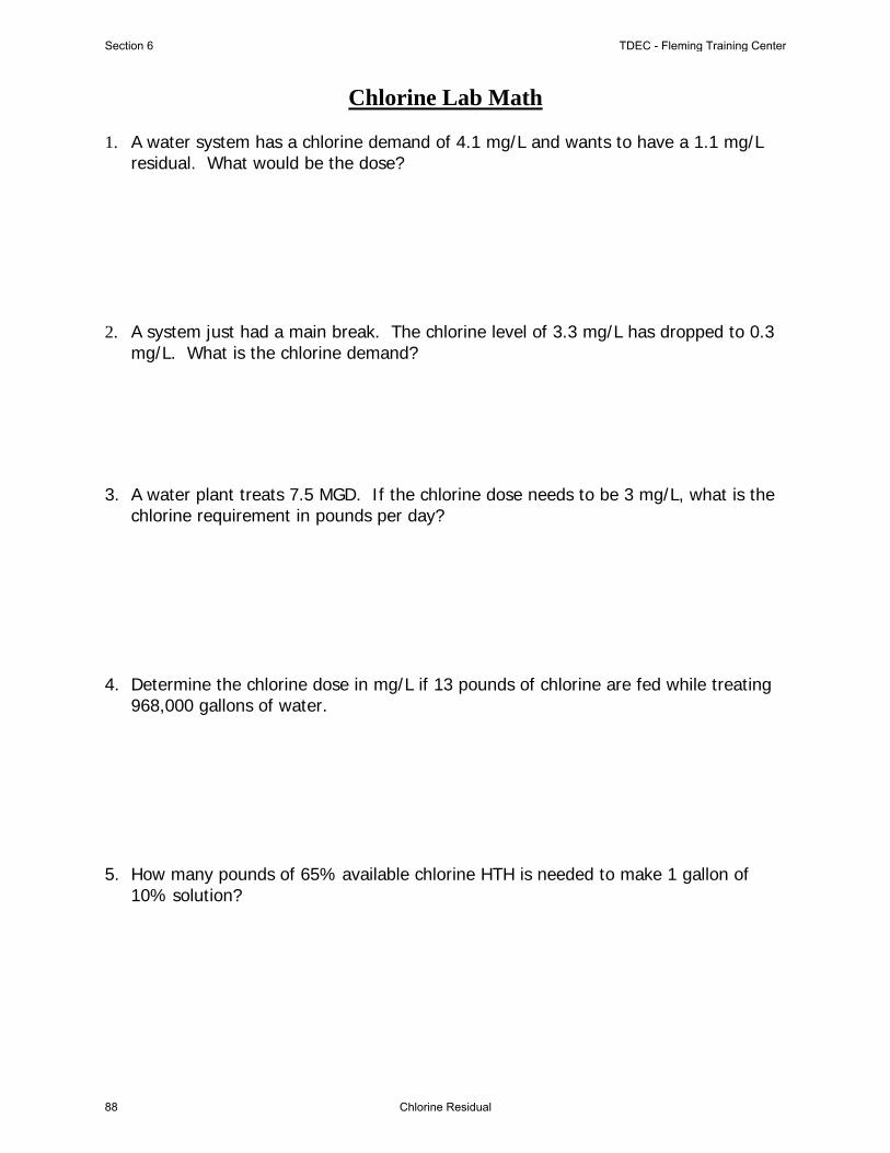
Chlorine Lab Math 1. A water system has a chlorine demand of 4.1 mg/L and wants to have a 1.1 mg/L
residual. What would be the dose? 2. A system just had a main break. The chlorine level of 3.3 mg/L has dropped to 0.3
mg/L. What is the chlorine demand? 3. A water plant treats 7.5 MGD. If the chlorine dose needs to be 3 mg/L, what is the
chlorine requirement in pounds per day? 4. Determine the chlorine dose in mg/L if 13 pounds of chlorine are fed while treating
968,000 gallons of water. 5. How many pounds of 65% available chlorine HTH is needed to make 1 gallon of
10% solution?
Section 6 TDEC - Fleming Training Center
Chlorine Residual88

6. How many gallons of bleach (15% available chlorine) will it take to make a 4% solution when added to enough water to make 50 gallons of hypochlorite?
Answers: 1. 5.2 mg/L 2. 3.0 mg/L 3. 188 lbs/day 4. 1.62 mg/L 5. 1.28 lbs 6. 13 gallons
TDEC - Fleming Training Center Section 6
Chlorine Residual 89

1
The Use of Secondary Standards for Spectrophotometer/Colorimeter
Calibration 0 Secondary standards (gel standards) are specifically
designed to verify the instrument’s calibration and to check the instrument’s performance.
0 They are not intended to be used to create calibration curves or to calibrate the instrument.
0 Because the DPD reagent cannot be mixed with the gel standards, the quality and the reaction time of the reagent cannot be assessed.
0 For these reasons gel standards cannot take the place of primary standards.
The Use of Secondary Standards for Spectrophotometer/Colorimeter
Calibration 0 The analyst is responsible for the following:
0 Preparing the calibration curve for each instrument once per month at a minimum with chlorine standards or potassium permanganate (see instructions below for KMnO4), before the use of new DPD reagents, or the use of new gel standards
0 Recording reagent lot #’s for reagents and standards
0 Recording calibration concentrations
0 Verifying the calibration curve using a minimum of one blank and two gel standards that bracket the expected sample concentration
0 Recording all verification data
Potassium permanganate (KMnO4) stock standard solution
0 0.891 grams of reagent grade KMnO4 in 1000 mL vol. flask made to mark with deionized water.
0 Deionized water must never be stored in plastic containers or exposed to airborne contamination. Store the stock solution in an amber bottle in a cool area.
0 The typical shelf life of the stock solution is six (6) months. If solids appear in the solution, do not use
0 ***Avoid leaving the cap off for extended periods of time and avoid contamination.***
Intermediate (working) standard solution (10 mg/L)
0 10 mL of STOCK made in 1000 mL vol. flask made to mark with
deionized water. 0 The flask should be labeled with the name, KMnO4, date of
preparation, and initials of who made it. 0 This information should also be entered into a logbook 0 **The intermediate stock solution should be stable for
approximately 5 days if kept cool and away from light.* 0 Care should be taken that the pipette and glassware are clean
and thoroughly rinsed with deionized water to avoid contamination.
0 Store only in a glass container (preferably amber glass) never in plastic containers. The working solution should be remade if solids appear in the bottom of the container
Calibration Standard Solutions
0 If using KMnO4, four to five calibration standard solutions should be made according to the table on the next slide with the addition of DPD to create a calibration curve once per month at a minimum.
0 The correlation coefficient of the curve should correlate to 0.995 or better.
0 This curve is then used to check instrument calibration.
0 Gel standards are run against the curve and must agree to within + 10%
0 **The working solution should be stable for approximately 2 hours and will fade rapidly (within 15 minutes) if chlorine demand-free water is not used.**
Section 6 TDEC - Fleming Training Center
Chlorine Residual90

2
ICV/CCV –Chlorine
mL Working Standard Diluted w/Deionized water
Chlorine Equivalent mg/L
20 mL (vol. Pipette) to 100 mL (vol. flask) 2.0 mg/L 10 mL (vol. Pipette) to 100 mL (vol. flask) 1.0 mg/L 5 mL (vol. Pipette) to 100 mL (vol. flask) 0.5 mg/L 1 mL (vol. Pipette) to 100 mL (vol. flask) 0.1 mg/L ½ mL (vol. Pipette) to 100 mL (vol. flask) 0.05 mg/L 1 mL (vol. Pipette) to 500 mL (vol. flask) 0.02 mg/L
100 mL of deionized water 0.00 mg/L Don’t forget to use DPD on Potassium Permanganate standards
Calibration Standard Solutions
Dilutions for Today’s Example – Pick 4
mL Working Standard Diluted w/Deionized water
Chlorine Equivalent mg/L
20 mL (vol. Pipette) to 100 mL (vol. flask) 2.0 mg/L 10 mL (vol. Pipette) to 100 mL (vol. flask) 1.0 mg/L 5 mL (vol. Pipette) to 100 mL (vol. flask) 0.5 mg/L 1 mL (vol. Pipette) to 100 mL (vol. flask) 0.1 mg/L ½ mL (vol. Pipette) to 100 mL (vol. flask) 0.05 mg/L 1 mL (vol. Pipette) to 500 mL (vol. flask) 0.02 mg/L
Don’t forget to use DPD on Potassium Permanganate standards
Subject true value (x) value read (y)
1 0.02 0.02
2 0.05 0.03
3 0.10 0.05
4 0.50 0.42
5 1.00 0.91
R2 = 0.997567397 Not a good recovery, tried a second dilution Although, still
greater than 0.995
Calibration Standard Solutions Subject true value (x) value read (y)
1 0.02 0.02
2 0.05 0.03
3 0.10 0.09
4 0.50 0.42
5 1.00 0.91
R2 = 0.99833 Better recovery with second
dilution Better than previous
calibration curve
TDEC - Fleming Training Center Section 6
Chlorine Residual 91

3
Method Detection Limit (MDL)
0 1020 B. 4 – As a starting point for selecting the concentration to use when determining the MDL, use an estimate of five times the estimated true detection level (5 x 0.010 mg/L = 0.050 mg/L). 0 Ideally, prepare and analyze at least seven (7) portions of this
solution over a 3-day period to ensure that the MDL determination is more representative of routine measurements as performed in the laboratory.
0 The replicate measurements should be in the range of one to five times the estimated MDL, and recoveries of the known addition should be between 50 and 150%, with %RSD (relative standard deviation) values ≤ 20%.
0 4020 B.1.b. – Verify MDL at least annually. 0 Ideally use pooled data from several analysts rather than data from
one analyst.
Method Detection Limit (MDL)
0 Real people language – have several operators, who run this test, analyze chlorine or Potassium Permanganate (KMnO4) standards at a concentration of 0.05 mg/L over several days with a total of at least 7 samples
0 Joe analyzes 3 samples on Monday
0 Bob analyzes 3 samples on Tuesday
0 Mary analyzes 3 samples on Wednesday
0 Run this once a year
Method Detection Limit (MDL) Dilutions for Today’s Example for MDL
mL Working Standard Diluted w/Deionized water
Chlorine Equivalent mg/L
½ mL (vol. Pipette) to 100 mL (vol. flask) 0.05 mg/L
Don’t forget to use DPD on Potassium Permanganate standards
Method Detection Limit (MDLs)
Date Analyst Number True Value Value Read % Recovery (50-150%)
4/12/2018 BGL 1 0.05 0.05 93.33
4/12/2018 BGL 2 0.05 0.05 96.67
4/13/2018 BGL 3 0.05 0.05 66.67
4/13/2018 BGL 4 0.05 0.05 66.67
4/14/2018 BGL 5 0.05 0.05 100.00
4/14/2018 BGL 6 0.05 0.05 83.33
4/14/2018 BGL 7 0.05 0.05 90.00
Enter a date in cell I3 below. MDLs will be re-evaluated based on the
most recent 24 months' data.
Enter Analyte Name
04/16/2018
Total Chlorine
Spike Standard Dev 0.01272
Spike Average 0.05571
Data Points <24 mo. 7
Students t value 3.14267
Required # of Dates PASS
Required # of Replicates PASS
Spike Level Evaluation PASS
Spiked MDL 0.0400
Blank MDL 0.0300
Minimum Level 0.1200
Method Detection Limit 0.0400
Method Detection Limit (MDLb)
Date Analyst Number Method Blank
4/12/2018 BGL 1 0.01
4/12/2018 BGL 2 0.01
4/13/2018 BGL 3 0.02 Blank Standard Deviation 0.01049
4/13/2018 BGL 4 0.03 Blank Average 0.01500
4/14/2018 BGL 5 0.02 Data Points <24 mo. 7
4/14/2018 BGL 6 0 Students t value 3.14267
4/15/2018 BGL 7 nd Total Chlorine
Required # of Dates PASS
Required # of Blanks PASS
Blank MDL 0.0300
Analyte Name
Section 6 TDEC - Fleming Training Center
Chlorine Residual92
4500-Cl CHLORINE (RESIDUAL)*
4500-Cl A. Introduction
1. Effects of Chlorination
The chlorination of water supplies and polluted waters servesprimarily to destroy or deactivate disease-producing microorgan-isms. A secondary benefit, particularly in treating drinking water,is the overall improvement in water quality resulting from thereaction of chlorine with ammonia, iron, manganese, sulfide, andsome organic substances.
Chlorination may produce adverse effects. Taste and odor char-acteristics of phenols and other organic compounds present in awater supply may be intensified. Potentially carcinogenic chloroor-ganic compounds, such as chloroform, may be formed. Combinedchlorine formed on chlorination of ammonia- or amine-bearingwaters adversely affects some aquatic life. To fulfill the primarypurpose of chlorination and to minimize any adverse effects, it isessential that proper testing procedures be used with a foreknow-ledge of the limitations of the analytical determination.
2. Chlorine Forms and Reactions
Chlorine applied to water in its molecular or hypochloriteform initially undergoes hydrolysis to form free chlorine con-sisting of aqueous molecular chlorine, hypochlorous acid, andhypochlorite ion. The relative proportion of these free chlorineforms is pH- and temperature-dependent. At the pH of mostwaters, hypochlorous acid and hypochlorite ion will predomi-nate.
Free chlorine reacts readily with ammonia and certain nitrog-enous compounds to form combined chlorine. With ammonia,chlorine reacts to form the chloramines: monochloramine,dichloramine, and nitrogen trichloride. The presence and con-centrations of these combined forms depend chiefly on pH,temperature, initial chlorine-to-nitrogen ratio, absolute chlorinedemand, and reaction time. Both free and combined chlorinemay be present simultaneously. Combined chlorine in watersupplies may be formed in the treatment of raw waters contain-ing ammonia or by the addition of ammonia or ammonium salts.Chlorinated wastewater effluents, as well as certain chlorinatedindustrial effluents, normally contain only combined chlorine.Historically, the principal analytical problem has been to distin-guish between free and combined forms of chlorine.
3. Selection of Method
In two separate but related studies, samples were prepared anddistributed to participating laboratories to evaluate chlorinemethods. Because of poor accuracy and precision and a highoverall (average) total error in these studies, all orthotolidineprocedures except one were dropped in the 14th Edition of thiswork. The useful stabilized neutral orthotolidine method was
deleted from the 15th Edition because of the toxic nature oforthotolidine. The leuco crystal violet (LCV) procedure wasdropped from the 17th Edition because of its relative difficultyand the lack of comparative advantages.
a. Natural and treated waters: The iodometric methods(4500-Cl.B and C) are suitable for measuring total chlorineconcentrations greater than 1 mg/L, but the amperometric end-point of 4500-Cl.C and D gives greater sensitivity. All acidiciodometric methods suffer from interferences, generally in pro-portion to the quantity of potassium iodide (KI) and H� added.
The amperometric titration method (4500-Cl.D) is a standardof comparison for the determination of free or combined chlo-rine. It is affected little by common oxidizing agents, tempera-ture variations, turbidity, and color. The method is not as simpleas the colorimetric methods and requires greater operator skill toobtain the best reliability. Loss of chlorine can occur because ofrapid stirring in some commercial equipment. Clean and condi-tioned electrodes are necessary for sharp endpoints.
A low-level amperometric titration procedure (4500-Cl.E) hasbeen added to determine total chlorine at levels below 0.2 mg/L.This method is recommended only when quantification of suchlow residuals is necessary. The interferences are similar to thosefound with the standard amperometric procedure (4500-Cl.D).The DPD methods (4500-Cl.F and G) are operationally simplerfor determining free chlorine than the amperometric titration.Procedures are given for estimating the separate mono- anddichloramine and combined fractions. High concentrations ofmonochloramine interfere with the free chlorine determinationunless the reaction is stopped with arsenite or thioacetamide. Inaddition, the DPD methods are subject to interference by oxi-dized forms of manganese unless compensated for by a blank.
The amperometric and DPD methods are unaffected by di-chloramine concentrations in the range of 0 to 9 mg Cl as Cl2/Lin the determination of free chlorine. Nitrogen trichloride, ifpresent, may react partially as free chlorine in the amperometric,DPD, and FACTS methods. The extent of this interference in theDPD methods does not appear to be significant.
The free chlorine test, syringaldazine (FACTS, 4500-Cl.H)was developed specifically for free chlorine. It is unaffected bysignificant concentrations of monochloramine, dichloramine, ni-trate, nitrite, and oxidized forms of manganese.1
Sample color and turbidity may interfere in all colorimetricprocedures.
Organic contaminants may produce a false free chlorine read-ing in most colorimetric methods (see ¶ b below). Many strongoxidizing agents interfere in the measurement of free chlorine inall methods. Such interferences include bromine, chlorine diox-ide, iodine, permanganate, hydrogen peroxide, and ozone.However, the reduced forms of these compounds—bromide,chloride, iodide, manganous ion, and oxygen, in the absence ofother oxidants, do not interfere. Reducing agents, such as ferrouscompounds, hydrogen sulfide, and oxidizable organic matter,generally do not interfere.* Approved by Standard Methods Committee, 2000. Editoral revisions, 2011.
https://doi.org/10.2105/SMWW.2882.078 1
TDEC - Fleming Training Center Section 6
Chlorine Residual 93

b. Wastewaters: The determination of total chlorine in samplescontaining organic matter presents special problems. Because of thepresence of ammonia, amines, and organic compounds, particularlyorganic nitrogen, residual chlorine exists in a combined state. Aconsiderable residual may exist in this form, but at the same timethere may be appreciable unsatisfied chlorine demand. Addition ofreagents in the determination may change these relationships soresidual chlorine is lost during the analysis. Only the DPD methodfor total chlorine is performed under neutral pH conditions. Inwastewater, the differentiation between free chlorine and combinedchlorine ordinarily is not made because wastewater chlorinationseldom is carried far enough to produce free chlorine.
The determination of residual chlorine in industrial wastes issimilar to that in domestic wastewater when the waste containsorganic matter, but may be similar to the determination in waterwhen the waste is low in organic matter.
None of these methods is applicable to estuarine or marinewaters because the bromide is converted to bromine and brom-amines, which are detected as free or total chlorine. A procedurefor estimating this interference is available for the DPD method.
Although the methods given below are useful for the determina-tion of residual chlorine in wastewaters and treated effluents, selectthe method in accordance with sample composition. Some indus-trial wastes, or mixtures of wastes with domestic wastewater, mayrequire special precautions and modifications to obtain satisfactoryresults.
Determine free chlorine in wastewater by any of the methodsprovided that known interfering substances are absent or appro-priate correction techniques are used. The amperometric methodis the method of choice because it is not subject to interferencefrom color, turbidity, iron, manganese, or nitrite nitrogen. TheDPD method is subject to interference from high concentrationsof monochloramine, which is avoided by adding thioacetamideimmediately after reagent addition. Oxidized forms of manga-nese at all levels encountered in water will interfere in allmethods except in the free chlorine measurement of amperomet-ric titrations and FACTS, but a blank correction for manganesecan be made in 4500-Cl.F and G.
The FACTS method is unaffected by concentrations of mono-chloramine, dichloramine, nitrite, iron, manganese, and otherinterfering compounds normally found in domestic wastewaters.
For total chlorine in samples containing significant amounts oforganic matter, use either the DPD methods (4500-Cl.F and G),amperometric, or iodometric back titration method (4500-Cl.C)to prevent contact between the full concentration of liberatediodine and the sample. With 4500-Cl.C, do not use the starch-iodide endpoint if the concentration is less than 1 mg/L. In theabsence of interference, the amperometric and starch-iodide end-points give concordant results. The amperometric endpoint isinherently more sensitive and is free of interference from colorand turbidity, which can cause difficulty with the starch-iodideendpoint. On the other hand, certain metals, surface-activeagents, and complex anions in some industrial wastes interfere inthe amperometric titration and indicate the need for anothermethod for such wastewaters. Silver in the form of soluble silvercyanide complex, in concentrations of 1.0 mg Ag/L, poisons thecell at pH 4.0 but not at 7.0. The silver ion, in the absence of thecyanide complex, gives extensive response in the current at pH4.0 and gradually poisons the cell at all pH levels. Cuprous
copper in the soluble copper cyanide ion, in concentrations of5 mg Cu/L or less, poisons the cell at pH 4.0 and 7.0. Althoughiron and nitrite may interfere with this method, minimize theinterference by buffering to pH 4.0 before adding KI. Oxidizedforms of manganese interfere in all methods for total chlorineincluding amperometric titration. An unusually high content oforganic matter may cause uncertainty in the endpoint.
Regardless of endpoint detection, either phenylarsine oxide orthiosulfate may be used as the standard reducing reagent at pH 4.The former is more stable and is preferred.
The DPD titrimetric and colorimetric methods (4500-Cl.F andG, respectively) are applicable to determining total chlorine inpolluted waters. In addition, both DPD procedures and the am-perometric titration method allow for estimating monochlora-mine and dichloramine fractions. Because all methods for totalchlorine depend on the stoichiometric production of iodine,waters containing iodine-reducing substances may not be ana-lyzed accurately by these methods, especially where iodine re-mains in the solution for a significant time. This problem occursin 4500-Cl.B and D. The back titration procedure (4500-Cl.C)and 4500-Cl.F and G cause immediate reaction of the iodinegenerated so it has little chance to react with other iodine-reducing substances.
In all colorimetric procedures, compensate for color and tur-bidity by using color and turbidity blanks.
A method (4500-Cl.I) for total residual chlorine using a po-tentiometric iodide electrode is proposed. This method is suitablefor analysis of chlorine residuals in natural and treated waters andwastewater effluents. No differentiation of free and combined chlo-rine is possible. This procedure is an adaptation of other iodometrictechniques and is subject to the same inferences.
4. Sampling and Storage
Chlorine in aqueous solution is not stable, and the chlorinecontent of samples or solutions, particularly weak solutions, willdecrease rapidly. Exposure to sunlight or other strong light oragitation will accelerate the reduction of chlorine. Therefore,start chlorine determinations immediately after sampling, avoid-ing excessive light and agitation. Do not store samples to beanalyzed for chlorine.
5. Reference
1. COOPER, W.J., N.M. ROSCHER & R.A. SLIFER. 1982. Determining freeavailable chlorine by DPD-colorimetric, DPD-steadifac (colorimet-ric) and FACTS procedures. J. Amer. Water Works Assoc. 74:362.
6. Bibliography
MARKS, H.C., D.B. WILLIAMS & G.U. GLASGOW. 1951. Determination ofresidual chlorine compounds. J. Amer. Water Works Assoc. 43:201.
NICOLSON, N.J. 1965. An evaluation of the methods for determiningresidual chlorine in water, Part 1. Free chlorine. Analyst 90:187.
WHITTLE, G.P. & A. LAPTEFF, JR. 1973. New analytical techniques for thestudy of water disinfection. In Chemistry of Water Supply, Treat-ment, and Distribution, p. 63. Ann Arbor Science Publishers, AnnArbor, Mich.
GUTER, W.J., W.J. COOPER & C.A. SORBER. 1974. Evaluation of existingfield test kits for determining free chlorine residuals in aqueoussolutions. J. Amer. Water Works Assoc. 66:38.
CHLORINE (RESIDUAL) (4500-Cl)/Introduction
https://doi.org/10.2105/SMWW.2882.078 2
CHLORINE (RESIDUAL) (4500-Cl)/IntroductionSection 6 TDEC - Fleming Training Center
Chlorine Residual94

4500-Cl B. Iodometric Method I
1. General Discussion
a. Principle: Chlorine will liberate free iodine from potassiumiodide (KI) solutions at pH 8 or less. The liberated iodine istitrated with a standard solution of sodium thiosulfate (Na2S2O3)with starch as the indicator. Titrate at pH 3 to 4 because thereaction is not stoichiometric at neutral pH due to partial oxida-tion of thiosulfate to sulfate.
b. Interference: Oxidized forms of manganese and otheroxidizing agents interfere. Reducing agents, such as organicsulfides, also interfere. Although the neutral titration mini-mizes the interfering effect of ferric and nitrite ions, the acidtitration is preferred because some forms of combined chlo-rine do not react at pH 7. Use only acetic acid for the acidtitration; sulfuric acid (H2SO4) will increase interferences;never use hydrochloric acid (HCl). See 4500-Cl.A.3 for dis-cussion of other interferences.
c. Minimum detectable concentration: The minimum detect-able concentration approximates 40 �g Cl as Cl2/L if0.01N Na2S2O3 is used with a 1000-mL sample. Concentrationsbelow 1 mg/L cannot be determined accurately by the starch-iodide endpoint used in this method. Lower concentrations canbe measured with the amperometric endpoint in 4500-Cl.C andD.
d. Quality control (QC): The QC practices considered to be anintegral part of each method are summarized in Table 4020:I.
2. Reagents
a. Acetic acid, conc (glacial).b. Potassium iodide (KI), crystals.c. Standard sodium thiosulfate, 0.1N: Dissolve 25 g
Na2S2O3 � 5H2O in 1 L freshly boiled distilled water and stan-dardize against potassium bi-iodate or potassium dichromateafter at least 2 weeks storage. This initial storage is necessary toallow oxidation of any bisulfite ion present. Use boiled distilledwater and add a few milliliters chloroform (CHCl3) to minimizebacterial decomposition.
Standardize 0.1N Na2S2O3 by one of the following:1) Iodate method—Dissolve 3.249 g anhydrous potassium
bi-iodate, KH(IO3)2, primary standard quality, or 3.567 gKIO3 dried at 103 � 2°C for 1 h, in distilled water and diluteto 1000 mL to yield a 0.1000N solution. Store in a glass-stoppered bottle.
To 80 mL distilled water, add, with constant stirring, 1 mLconc H2SO4, 10.00 mL 0.1000N KH(IO3)2, and 1 g KI. Titrateimmediately with 0.1N Na2S2O3 titrant until the yellow colorof the liberated iodine almost is discharged. Add 1 mL starchindicator solution and continue titrating until the blue colordisappears.
2) Dichromate method—Dissolve 4.904 g anhydrous potas-sium dichromate, K2Cr2O7, of primary standard quality, indistilled water and dilute to 1000 mL to yield a 0.1000Nsolution. Store in a glass-stoppered bottle.
Proceed as in the iodate method, with the following excep-tions: Substitute 10.00 mL 0.1000N K2Cr2O7 for iodate and let
reaction mixture stand 6 min in the dark before titrating with0.1N Na2S2O3 titrant.
Normality Na2S2O3 �1
mL Na2S2O3 consumed
d. Standard sodium thiosulfate titrant, 0.01N or 0.025N: Improvethe stability of 0.01N or 0.025N Na2S2O3 by diluting an aged 0.1Nsolution, made as directed above, with freshly boiled distilled water.Add 4 g sodium borate and 10 mg mercuric iodide/L solution. Foraccurate work, standardize this solution daily in accordance with thedirections given above, using 0.01N or 0.025N iodate or K2Cr2O7.Use sufficient volumes of these standard solutions so their finaldilution is not greater than 1 � 4. To speed up operations wheremany samples must be titrated use an automatic buret of a type inwhich rubber does not come in contact with the solution. Standardtitrants, 0.0100N and 0.0250N, are equivalent, respectively, to354.5 �g and 886.3 �g Cl as Cl2/1.00 mL.
e. Starch indicator solution: To 5 g starch (potato, arrowroot,or soluble), add a little cold water and grind in a mortar to a thinpaste. Pour into 1 L of boiling distilled water, stir, and let settleovernight. Use clear supernate. Preserve with 1.25 g salicylicacid, 4 g zinc chloride, or a combination of 4 g sodium propi-onate and 2 g sodium azide/L starch solution. Some commercialstarch substitutes are satisfactory.
f. Standard iodine, 0.1N: See 4500-Cl.C.3g.g. Dilute standard iodine, 0.0282N: See 4500-Cl.C.3h.
3. Procedure
a. Volume of sample: Select a sample volume that will requireno more than 20 mL 0.01N Na2S2O3 and no less than 0.2 mL forthe starch-iodide endpoint. For a chlorine range of 1 to 10 mg/L,use a 500-mL sample; above 10 mg/L, use proportionately lesssample. Use smaller samples and volumes of titrant with theamperometric endpoint.
b. Preparation for titration: Place 5 mL acetic acid, or enoughto reduce the pH to between 3.0 and 4.0, in a flask or whiteporcelain casserole. Add about 1 g KI estimated on a spatula.Pour sample in and mix with a stirring rod.
c. Titration: Titrate away from direct sunlight. Add 0.025N or0.01N Na2S2O3 from a buret until the yellow color of theliberated iodine almost is discharged. Add 1 mL starch solutionand titrate until blue color is discharged.
If the titration is made with 0.025N Na2S2O3 instead of 0.01N,then, with a 1-L sample, 1 drop is equivalent to about 50 �g/L.It is not possible to discern the endpoint with greater accuracy.
d. Blank titration: Correct result of sample titration by deter-mining blank contributed by oxidizing or reducing reagent im-purities. The blank also compensates for the concentration ofiodine bound to starch at the endpoint.
Take a volume of distilled water corresponding to the sampleused for titration in 4500-Cl.B.3a–c, add 5 mL acetic acid, 1 gKI, and 1 mL starch solution. Perform blank titration as in ¶s 1)or 2) below, whichever applies.
1) If a blue color develops, titrate with 0.01N or0.025N Na2S2O3 to disappearance of blue color and recordresult. B (see 4500-Cl.B.4) is negative.
CHLORINE (RESIDUAL) (4500-Cl)/Iodometric Method I
https://doi.org/10.2105/SMWW.2882.078 3
CHLORINE (RESIDUAL) (4500-Cl)/Iodometric Method ITDEC - Fleming Training Center Section 6
Chlorine Residual 95

2) If no blue color occurs, titrate with 0.0282N iodine solutionuntil a blue color appears. Back-titrate with 0.01N or0.025N Na2S2O3 and record the difference. B is positive.
Before calculating the chlorine concentration, subtract theblank titration of ¶ 1) above from the sample titration; or, ifnecessary, add the net equivalent value of the blank titration of¶ 2) above.
4. Calculation
For standardizing chlorine solution for temporary standards:
mg Cl as Cl2/mL �(A � B) � N � 35.45
mL sample
For determining total available residual chlorine in a watersample:
mg Cl as Cl2/L �(A � B) � N � 35 450
mL sample
where:
A � mL titration for sample,B � mL titration for blank (positive or negative), andN � normality of Na2S2O3.
5. Precision and Bias
Published studies1,2 give the results of nine methods used toanalyze synthetic water samples without interferences; variations
of some of the methods appear in this edition. More current dataare not now available.
6. References
1. LISHKA, R.J., E.F. MCFARREN & J.H. PARKER. 1969. Water Chlorine(Residual) No. 1: Report Number 35: Report of a Study Conductedby Analytical Reference Service. U.S. Public Health Service, Con-sumer Protection and Environmental Health Service, EnvironmentalControl Administration, Cincinnati, Ohio.
2. LISHKA, R.J. & R.F. MCFARREN. 1971. Water Chlorine (Residual) No.2: Report Number 40: Report of a Study Conducted by AnalyticalReference Service. Water Hygiene Division, Office of Water Pro-grams, U.S. Environmental Protection Agency, Cincinnati, Ohio.
7. Bibliography
LEA, C. 1933. Chemical control of sewage chlorination. The use andvalue of orthotolidine test. J. Soc. Chem. Ind. (London) 52:245T.
AMERICAN WATER WORKS ASSOCIATION. 1943. Committee report: Controlof chlorination. J. Amer. Water Works Assoc. 35:1315.
MARKS, H.C., R. JOINER & F.B. STRANDSKOV. 1948. Amperometric titra-tion of residual chlorine in sewage. Water Sewage Works 95:175.
STRANDSKOV, F.B. , H.C. MARKS & D.H. HORCHIER. 1949. Application ofa new residual chlorine method to effluent chlorination. SewageWorks J. 21:23.
NUSBAUM, I. & L.A. MEYERSON. 1951. Determination of chlorinedemands and chlorine residuals in sewage. Sewage Ind. Wastes23:968.
MARKS, H.C. & N.S. CHAMBERLIN. 1953. Determination of residualchlorine in metal finishing wastes. Anal. Chem. 24:1885.
4500-Cl C. Iodometric Method II
1. General Discussion
a. Principle: In this method, used for wastewater analysis, theendpoint signal is reversed because the unreacted standard re-ducing agent (phenylarsine oxide or thiosulfate) remaining in thesample is titrated with standard iodine or standard iodate, ratherthan the iodine released being titrated directly. This indirectprocedure is necessary regardless of the method of endpointdetection, to avoid contact between the full concentration ofliberated iodine and the wastewater.
When iodate is used as a back titrant, use only phosphoricacid. Do not use acetate buffer.
b. Interference: Oxidized forms of manganese and other oxidiz-ing agents give positive interferences. Reducing agents, such asorganic sulfides, do not interfere as much as in 4500-Cl.B. Mini-mize iron and nitrite interference by buffering to pH 4.0 beforeadding potassium iodide (KI). An unusually high content of organicmatter may cause some uncertainty in the endpoint. Whenevermanganese, iron, and other interferences definitely are absent, re-duce this uncertainty and improve precision by acidifying to pH 1.0.Control interference from more than 0.2 mg nitrite/L with phos-phoric acid-sulfamic acid reagent. A larger fraction of organicchloramines will react at lower pH along with interfering sub-stances. See 4500-Cl.A.3 for a discussion of other interferences.
c. Quality control (QC): The QC practices considered to be anintegral part of each method are summarized in Table 4020:I.
2. Apparatus
For a description of the amperometric endpoint detectionapparatus and a discussion of its use, see 4500-Cl.D.2a.
3. Reagents
a. Standard phenylarsine oxide solution, 0.005 64N: Dissolveapproximately 0.8 g phenylarsine oxide powder in 150 mL0.3N NaOH solution. After settling, decant 110 mL into 800 mLdistilled water and mix thoroughly. Bring to pH 6 to 7 with6N HCl and dilute to 950 mL with distilled water. CAUTION:Severe poison, cancer suspect agent.
Standardization—Accurately measure 5 to 10 mL freshly stan-dardized 0.0282N iodine solution into a flask and add 1 mL KIsolution. Titrate with phenylarsine oxide solution, using theamperometric endpoint (4500-Cl.D) or starch solution (see4500-Cl.B.2e) as an indicator. Adjust to 0.005 64N and recheckagainst the standard iodine solution; 1.00 mL � 200 �g availablechlorine. (CAUTION: Toxic—take care to avoid ingestion.)
CHLORINE (RESIDUAL) (4500-Cl)/Iodometric Method II
https://doi.org/10.2105/SMWW.2882.078 4
CHLORINE (RESIDUAL) (4500-Cl)/Iodometric Method IISection 6 TDEC - Fleming Training Center
Chlorine Residual96

b. Standard sodium thiosulfate solution, 0.1N: See4500-Cl.B.2c.
c. Standard sodium thiosulfate solution, 0.005 64N: Prepareby diluting 0.1N Na2S2O3. For maximum stability of the dilutesolution, prepare by diluting an aged 0.1N solution with freshlyboiled distilled water (to minimize bacterial action) and add 4 gNa4B4O7/L. To inhibit mold formation optionally add either10 mg HgI2 or 2 drops toluene per liter of solution. Standardizedaily as directed in 4500-Cl.B.2c using 0.005 64N K2Cr2O7 oriodate solution. Use sufficient volume of sample so the finaldilution does not exceed 1 � 2. Use an automatic buret of a typein which rubber does not come in contact with the solution.1.00 mL � 200 �g available chlorine.
d. Potassium iodide (KI), crystals.e. Acetate buffer solution, pH 4.0: Dissolve 146 g anhydrous
NaC2H3O2, or 243 g NaC2H3O2 � 3H2O, in 400 mL distilledwater, add 480 g conc acetic acid, and dilute to 1 L withchlorine-demand-free water.
f. Standard arsenite solution, 0.1N: Accurately weigh a stop-pered weighing bottle containing approximately 4.95 g arsenictrioxide, As2O3. Transfer without loss to a 1-L volumetric flaskand again weigh bottle. Do not attempt to brush out adheringoxide. Moisten As2O3 with water and add 15 g NaOH and100 mL distilled water. Swirl flask contents gently to dissolve.Dilute to 250 mL with distilled water and saturate with CO2, thusconverting all NaOH to NaHCO3. Dilute to mark, stopper, andmix thoroughly. This solution will preserve its titer almost in-definitely. (CAUTION: Severe poison. Cancer suspect agent.)
Normality �g As2O3
49.455
g. Standard iodine solution, 0.1N: Dissolve 40 g KI in 25 mLchlorine-demand-free water, add 13 g resublimed iodine, and stir untildissolved. Transfer to a 1-L volumetric flask and dilute to mark.
Standardization—Accurately measure 40 to 50 mL 0.1N ar-senite solution into a flask and titrate with 0.1N iodine solution,using starch solution as indicator. To obtain accurate results,ensure that the solution is saturated with CO2 at end of titrationby passing current of CO2 through solution for a few minutes justbefore endpoint is reached, or add a few drops of HCl to liberatesufficient CO2 to saturate solution. Alternatively, standardizeagainst Na2S2O3; see 4500-Cl.B.2c1).
Optionally, prepare 0.1000N iodine solution directly as a standardsolution by weighing 12.69 g primary standard resublimed iodine.Because I2 may be volatilized and lose from both solid and solution,transfer the solid immediately to KI as specified above. Never letsolution stand in open containers for extended periods.
h. Standard iodine titrant, 0.0282N: Dissolve 25 g KI in a littledistilled water in a 1-L volumetric flask, add correct amount of0.1N iodine solution exactly standardized to yield a 0.0282Nsolution, and dilute to 1 L with chlorine-demand-free water. Foraccurate work, standardize daily according to directions in ¶ gabove, using 5 to 10 mL of arsenite or Na2S2O3 solution. Storein amber bottles or in the dark; protect solution from directsunlight at all times and keep from all contact with rubber.
i. Starch indicator: See 4500-Cl.B.2e.
j. Standard iodate titrant, 0.005 64N: Dissolve 201.2 mg pri-mary standard grade KIO3, dried for 1 h at 103°C, or 183.3 mgprimary standard anhydrous potassium bi-iodate in distilled wa-ter and dilute to 1 L.
k. Phosphoric acid solution (H3PO4), 1 � 9.l. Phosphoric acid-sulfamic acid solution: Dissolve 20 g
NH2SO3H in 1 L 1 � 9 phosphoric acid.m. Chlorine-demand-free water: Prepare chlorine-demand-free
water from good-quality distilled or deionized water by addingsufficient chlorine to give 5 mg/L free chlorine. After standing 2 dthis solution should contain at least 2 mg/L free chlorine; if not,discard and obtain better-quality water. Remove remaining freechlorine by placing container in sunlight or irradiating with anultraviolet lamp. After several hours take sample, add KI, andmeasure total chlorine with a colorimetric method using a nesslertube to increase sensitivity. Do not use before last trace of free andcombined chlorine has been removed.
Distilled water commonly contains ammonia and also maycontain reducing agents. Collect good-quality distilled or deion-ized water in a sealed container from which water can be drawnby gravity. To the air inlet of the container add an H2SO4 trapconsisting of a large test tube half filled with 1 � 1 H2SO4
connected in series with a similar but empty test tube. Fit bothtest tubes with stoppers and inlet tubes terminating near thebottom of the tubes and outlet tubes terminating near the top ofthe tubes. Connect outlet tube of trap containing H2SO4 to thedistilled water container, connect inlet tube to outlet of emptytest tube. The empty test tube will prevent discharge to theatmosphere of H2SO4 due to temperature-induced pressurechanges. Stored in such a container, chlorine-demand-free wateris stable for several weeks unless bacterial growth occurs.
4. Procedure
a. Preparation for titration:1) Volume of sample—For chlorine concentration of 10 mg/L
or less, titrate 200 mL. For greater chlorine concentrations, useproportionately less sample and dilute to 200 mL with chlorine-demand-free water. Use a sample of such size that not more than10 mL phenylarsine oxide solution is required.
2) Preparation for titration—Measure 5 mL 0.005 64N phe-nylarsine oxide or thiosulfate for chlorine concentrations from 2to 5 mg/L, and 10 mL for concentrations of 5 to 10 mg/L, intoa flask or casserole for titration with standard iodine or iodate.Start stirring. For titration by amperometry or standard iodine,also add excess KI (approximately 1 g) and 4 mL acetate buffersolution or enough to reduce the pH to between 3.5 and 4.2.
b. Titration: Use one of the following:1) Amperometric titration—Add 0.0282N iodine titrant in
small increments from a 1-mL buret or pipet. Observe meterneedle response as iodine is added: the pointer remains practi-cally stationary until the endpoint is approached, whereuponeach iodine increment causes a temporary deflection of themicroammeter, with the pointer dropping back to its originalposition. Stop titration at endpoint when a small increment ofiodine titrant gives a definite pointer deflection upscale and thepointer does not return promptly to its original position. Recordvolume of iodine titrant used to reach endpoint.
CHLORINE (RESIDUAL) (4500-Cl)/Iodometric Method II
https://doi.org/10.2105/SMWW.2882.078 5
CHLORINE (RESIDUAL) (4500-Cl)/Iodometric Method IITDEC - Fleming Training Center Section 6
Chlorine Residual 97

2) Colorimetric (iodine) titration—Add 1 mL starch solutionand titrate with 0.0282N iodine to the first appearance of bluecolor that persists after complete mixing.
3) Colorimetric (iodate) titration—To suitable flask or casse-role add 200 mL chlorine-demand-free water and add, withagitation, the required volume of reductant, an excess of KI(approximately 0.5 g), 2 mL 10% H3PO4 solution, and 1 mLstarch solution in the order given, and titrate immediately* with0.005 64N iodate solution to the first appearance of a blue colorthat persists after complete mixing. Designate volume of iodatesolution used as A. Repeat procedure, substituting 200 mL sam-ple for the 200 mL chlorine-demand-free water. If sample iscolored or turbid, titrate to the first change in color, using forcomparison another portion of sample with H3PO4 added. Des-ignate this volume of iodate solution as B.
5. Calculation
a. Titration with standard iodine:
mg Cl as Cl2/L �(A � 5B) � 200
C
where:
A � mL 0.005 64N reductant,B � mL 0.0282 N I2, andC � mL sample.
b. Titration with standard iodate:
mg Cl as Cl2/L �(A � B) � 200
C
where:
A � mL Na2S2O3,B � mL iodate required to titrate Na2S2O3, andC � mL sample.
6. Bibliography
See 4500-Cl.B.7.
4500-Cl D. Amperometric Titration Method
1. General Discussion
Amperometric titration requires a higher degree of skill andcare than the colorimetric methods. Chlorine residuals over2 mg/L are measured best by means of smaller samples or bydilution with water that has neither residual chlorine nor achlorine demand. The method can be used to determine totalchlorine and can differentiate between free and combinedchlorine. A further differentiation into monochloramine anddichloramine fractions is possible by control of KI concen-tration and pH.
a. Principle: The amperometric method is a special adaptationof the polarographic principle. Free chlorine is titrated at a pHbetween 6.5 and 7.5, a range in which the combined chlorinereacts slowly. The combined chlorine, in turn, is titrated in thepresence of the proper amount of KI in the pH range 3.5 to 4.5.When free chlorine is determined, the pH must not be greaterthan 7.5 because the reaction becomes sluggish at higher pHvalues, nor less than 6.5 because at lower pH values somecombined chlorine may react even in the absence of iodide.When combined chlorine is determined, the pH must not be lessthan 3.5 because of increased interferences at lower pH values,nor greater than 4.5 because the iodide reaction is not quantita-tive at higher pH values. The tendency of monochloramine toreact more readily with iodide than does dichloramine providesa means for further differentiation. The addition of a smallamount of KI in the neutral pH range enables estimation ofmonochloramine content. Lowering the pH into the acid rangeand increasing the KI concentration allows the separation deter-mination of dichloramine.
Organic chloramines can be measured as free chlorine, mono-chloramine, or dichloramine, depending on the activity of chlo-rine in the organic compound.
Phenylarsine oxide is stable even in dilute solution and eachmole reacts with two equivalents of halogen. A special ampero-metric cell is used to detect the endpoint of the residual chlorine-phenylarsine oxide titration. The cell consists of a nonpolarizablereference electrode that is immersed in a salt solution and areadily polarizable noble-metal electrode that is in contactwith both the salt solution and the sample being titrated. Insome applications, endpoint selectivity is improved by adding�200 mV to the platinum electrode versus silver, silver chloride.Another approach to endpoint detection uses dual platinum elec-trodes, a mercury cell with voltage divider to impress a potentialacross the electrodes, and a microammeter. If there is no chlorineresidual in the sample, the microammeter reading will be com-paratively low because of cell polarization. The greater theresidual, the greater the microammeter reading. The meter actsmerely as a null-point indicator—that is, the actual meter readingis not important, but rather the relative readings as the titrationproceeds. The gradual addition of phenylarsine oxide causes thecell to become more and more polarized because of the decreasein chlorine. The endpoint is recognized when no further decrease inmeter reading can be obtained by adding more phenylarsine oxide.
b. Interference: Accurate determinations of free chlorine can-not be made in the presence of nitrogen trichloride, NCl3, orchlorine dioxide, which titrate partly as free chlorine. Whenpresent, NCl3 can titrate partly as free chlorine and partly asdichloramine, contributing a positive error in both fractions at arate of approximately 0.1%/min. Some organic chloramines alsocan be titrated in each step. Monochloramine can intrude into the
* Titration may be delayed up to 10 min without appreciable error if H3PO4 is notadded until immediately before titration.
CHLORINE (RESIDUAL) (4500-Cl)/Amperometric Titration Method
https://doi.org/10.2105/SMWW.2882.078 6
CHLORINE (RESIDUAL) (4500-Cl)/Amperometric Titration MethodSection 6 TDEC - Fleming Training Center
Chlorine Residual98

free chlorine fraction and dichloramine can interfere in themonochloramine fraction, especially at high temperatures andprolonged titration times. Free halogens other than chlorine alsowill titrate as free chlorine. Combined chlorine reacts with iodideions to produce iodine. When titration for free chlorine followsa combined chlorine titration, which requires addition of KI,erroneous results may occur unless the measuring cell is rinsedthoroughly with distilled water between titrations.
Interference from copper has been noted in samples takenfrom copper pipe or after heavy copper sulfate treatment ofreservoirs, with metallic copper plating out on the electrode.Silver ions also poison the electrode. Interference occurs in somehighly colored waters and in waters containing surface-activeagents. Very low temperatures slow response of measuring celland longer time is required for the titration, but precision is notaffected. A reduction in reaction rate is caused by pH valuesabove 7.5; overcome this by buffering all samples to pH 7.0 orless. On the other hand, some substances, such as manganese,nitrite, and iron, do not interfere. The violent stirring of somecommercial titrators can lower chlorine values by volatilization.When dilution is used for samples containing high chlorinecontent, take care that the dilution water is free of chlorine andammonia and possesses no chlorine demand.
See 4500-Cl.A.3 for a discussion of other interferences.c. Quality control (QC): The QC practices considered to be an
integral part of each method are summarized in Table 4020:I.
2. Apparatus
a. Endpoint detection apparatus, consisting of a cell unitconnected to a microammeter, with necessary electrical acces-sories. The cell unit includes a noble-metal electrode of sufficientsurface area, a salt bridge to provide an electrical connectionwithout diffusion of electrolyte, and a reference electrode ofsilver–silver chloride in a saturated sodium chloride solutionconnected into the circuit by means of the salt bridge. Numerouscommercial systems are available.
Keep platinum electrode free of deposits and foreign matter.Vigorous chemical cleaning generally is unnecessary. Occa-sional mechanical cleaning with a suitable abrasive usually issufficient. Keep salt bridge in good operating condition; do notallow it to become plugged nor permit appreciable flow ofelectrolyte through it. Keep solution surrounding reference elec-trode free of contamination and maintain it at constant compo-sition by ensuring an adequate supply of undissolved salt at alltimes. A cell with two metal electrodes polarized by a small DCpotential also may be used. (See 4500-Cl.D.7.)
b. Agitator, designed to give adequate agitation at the noble-metal electrode surface to ensure proper sensitivity. Thoroughlyclean agitator and exposed electrode system to remove allchlorine- consuming contaminants by immersing them in watercontaining 1 to 2 mg/L free chlorine for a few minutes. Add KIto the same water and let agitator and electrodes remain im-mersed for 5 min. After thorough rinsing with chlorine-demand-free water or the sample to be tested, sensitized electrodes andagitator are ready for use. Remove iodide reagent completelyfrom cell.
c. Buret: Commercial titrators usually are equipped with suit-able burets (1 mL). Manual burets are available.*
d. Glassware, exposed to water containing at least 10 mg/Lchlorine for 3 h or more before use and rinsed with chlorine-demand-free water.
3. Reagents
a. Standard phenylarsine oxide titrant: See 4500-Cl.C.3a.b. Phosphate buffer solution, pH 7: Dissolve 25.4 g anhydrous
KH2PO4 and 34.1 g anhydrous Na2HPO4 in 800 mL distilledwater. Add 2 mL sodium hypochlorite solution containing 1%chlorine and mix thoroughly. Protect from sunlight for 2 d.Determine that free chlorine still remains in the solution. Thenexpose to sunlight until no chlorine remains. If necessary, carryout the final dechlorination with an ultraviolet lamp. Determinethat no total chlorine remains by adding KI and measuring withone of the colorimetric tests. Dilute to 1 L with distilled waterand filter if any precipitate is present.
c. Potassium iodide solution: Dissolve 50 g KI and dilute to1 L with freshly boiled and cooled distilled water. Store in thedark in a brown glass-stoppered bottle, preferably in the refrig-erator. Discard when solution becomes yellow.
d. Acetate buffer solution, pH 4: See 4500-Cl.C.3e.
4. Procedure
a. Sample volume: Select a sample volume requiring no morethan 2 mL phenylarsine oxide titrant. Thus, for chlorine concen-trations of 2 mg/L or less, take a 200-mL sample; for chlorinelevels in excess of 2 mg/L, use 100 mL or proportionately less.
b. Free chlorine: Unless sample pH is known to be between6.5 and 7.5, add 1 mL pH 7 phosphate buffer solution to producea pH of 6.5 to 7.5. Titrate with standard phenylarsine oxidetitrant, observing current changes on microammeter. Add titrantin progressively smaller increments until all needle movementceases. Make successive buret readings when needle actionbecomes sluggish, signaling approach of endpoint. Subtract lastvery small increment that causes no needle response because ofovertitration. Alternatively, use a system involving continuouscurrent measurements and determine endpoint mathematically.
Continue titrating for combined chlorine as described in ¶ cbelow or for the separate monochloramine and dichloraminefractions as detailed in ¶s e and ƒ.
c. Combined chlorine: To sample remaining from free-chlorine titration add 1.00 mL KI solution and 1 mL acetatebuffer solution, in that order. Titrate with phenylarsine oxidetitrant to the endpoint, as above. Do not refill buret but simplycontinue titration after recording figure for free chlorine. Againsubtract last increment to give amount of titrant actually used inreaction with chlorine. (If titration was continued without refill-ing buret, this figure represents total chlorine. Subtracting freechlorine from total gives combined chlorine.) Wash apparatusand sample cell thoroughly to remove iodide ion to avoid inac-curacies when the titrator is used subsequently for a free chlorinedetermination.
* Kimax 17110-F, 5 mL, Kimble Products, Box 1035, Toledo, OH, or equivalent.
CHLORINE (RESIDUAL) (4500-Cl)/Amperometric Titration Method
https://doi.org/10.2105/SMWW.2882.078 7
CHLORINE (RESIDUAL) (4500-Cl)/Amperometric Titration MethodTDEC - Fleming Training Center Section 6
Chlorine Residual 99

d. Separate samples: If desired, determine total chlorine and freechlorine on separate samples. If sample pH is between 3.5 and 9.5and total chlorine alone is required, treat sample immediately with1 mL KI solution followed by 1 mL acetate buffer solution, andtitrate with phenylarsine oxide titrant as described in ¶ c above.
e. Monochloramine: After titrating for free chlorine, add 0.2 mL KIsolution to same sample and, without refilling buret, continuetitration with phenylarsine oxide titrant to endpoint. Subtract lastincrement to obtain net volume of titrant consumed by mono-chloramine.
f. Dichloramine: Add 1 mL acetate buffer solution and 1 mLKI solution to same sample and titrate final dichloramine fractionas described above.
5. Calculation
Convert individual titrations for free chlorine, combined chlo-rine, total chlorine, monochloramine, and dichloramine by thefollowing equation:
mg Cl as Cl2/L �A � 200
mL sample
where:
A � mL phenylarsine oxide titration.
6. Precision and Bias
See 4500-Cl.B.5.
7. Bibliography
FOULK, C.W. & A.T. BAWDEN. 1926. A new type of endpoint in elec-trometric titration and its application to iodimetry. J. Amer. Chem.Soc. 48:2045.
MARKS, H.C. & J.R. GLASS. 1942. A new method of determining residualchlorine. J. Amer. Water Works Assoc. 34:1227.
HALLER, J.F. & S.S. LISTEK. 1948. Determination of chloride dioxideand other active chlorine compounds in water. Anal. Chem.20:639.
MAHAN, W.A. 1949. Simplified amperometric titration apparatus for deter-mining residual chlorine in water. Water Sewage Works 96:171.
KOLTHOFF, I.M. & J.J. LINGANE. 1952. Polarography, 2nd ed. IntersciencePublishers, New York, N.Y.
MORROW, J.J. 1966. Residual chlorine determination with dual polariz-able electrodes. J. Amer. Water Works Assoc. 58:363.
4500-Cl E. Low-Level Amperometric Titration Method
1. General Discussion
Detection and quantification of chlorine residuals below0.2 mg/L require special modifications to the amperometrictitration procedure. With these modifications chlorine concentra-tions at the 10-�g/L level can be measured. It is not possible todifferentiate between free and combined chlorine forms. Oxidiz-ing agents that interfere with the amperometric titration method(4500-Cl.D) will interfere.
a. Principle: This method modifies 4500-Cl.D by using a moredilute titrant and a graphical procedure to determine the endpoint.
b. Interference: See 4500-Cl.D.1b.c. Quality control (QC): The QC practices considered to be an
integral part of each method are summarized in Table 4020:I.
2. Apparatus
See 4500-Cl.D.2.
3. Reagents
a. Potassium bi-iodate, 0.002 256N: Dissolve 0.7332 g anhy-drous potassium bi-iodate, KH(IO3)2, in 500 mL chlorine-freedistilled water and dilute to 1000 mL. Dilute 10.00 mL to 100.0 mLwith chlorine-free distilled water. Use only freshly preparedsolution for the standardization of phenylarsine oxide.
b. Potassium iodide (KI), crystals.c. Low-strength phenylarsine oxide titrant, 0.000 564N: Di-
lute 10.00 mL of 0.005 64N phenylarsine oxide (see4500-Cl.C.3a) to 100.0 mL with chlorine-demand-free water(see 4500-Cl.C.3m).
Standardization—Dilute 5.00 mL 0.002 256N potassium bi-iodate to 200 mL with chlorine-free water. Add approximately1.5 g KI and stir to dissolve. Add 1 mL acetate buffer and letstand in the dark for 6 min. Titrate using the amperometrictitrator and determine the equivalence point as indicated below.
Normality � 0.002256 � 5/A
where:
A � mL phenylarsine oxide titrant required to reach theequivalence point of standard bi-iodate.
d. Acetate buffer solution, pH 4: See 4500-Cl.C.3e.
4. Procedure
Select a sample volume requiring no more than 2 mL phen-ylarsine oxide titrant. A 200-mL sample will be adequate forsamples containing less than 0.2 mg total chlorine/L.
Before beginning titration, rinse buret with titrant severaltimes. Rinse sample container with distilled water and then with
CHLORINE (RESIDUAL) (4500-Cl)/Low-Level Amperometric Titration Method
https://doi.org/10.2105/SMWW.2882.078 8
CHLORINE (RESIDUAL) (4500-Cl)/Low-Level Amperometric Titration MethodSection 6 TDEC - Fleming Training Center
Chlorine Residual100

sample. Add 200 mL sample to sample container and approxi-mately 1.5 g KI. Dissolve, using a stirrer or mixer. Add 1 mLacetate buffer and place container in endpoint detection appara-tus. When the current signal stabilizes, record the reading. Ini-tially adjust meter to a near full-scale deflection. Titrate byadding small, known, volumes of titrant. After each addition,record cumulative volume added and current reading when thesignal stabilizes. If meter reading falls to near or below 10% offull-scale deflection, record low reading, readjust meter to nearfull-scale deflection, and record difference between low amountand readjusted high deflection. Add this value to all deflectionreadings for subsequent titrant additions. Continue adding titrantuntil no further meter deflection occurs. If fewer than three titrantadditions were made before meter deflection ceased, discardsample and repeat analysis using smaller titrant increments.
Determine equivalence point by plotting total meter deflectionagainst titrant volume added. Draw straight line through the firstseveral points in the plot and a second, horizontal straight line
corresponding to the final total deflection in the meter. Readequivalence point as the volume of titrant added at the intersec-tion of these two lines.
5. Calculation
mg Cl as Cl2/L �A � 200 � N
B � 0.00564
where:
A � mL titrant at equivalence point,N � phenylarsine oxide normality, andB � sample volume, mL.
6. Bibliography
BROOKS, A.S. & G.L. SEEGERT. 1979. Low-level chlorine analysis byamperometric titration. J. Water Pollut. Control Fed. 51:2636.
4500-Cl F. DPD Ferrous Titrimetric Method
1. General Discussion
a. Principle: N,N-diethyl-p-phenylenediamine (DPD) is usedas an indicator in the titrimetric procedure with ferrous ammo-nium sulfate (FAS). Where complete differentiation of chlorinespecies is not required, the procedure may be simplified to giveonly free and combined chlorine or total chlorine.
In the absence of iodide ion, free chlorine reacts instantly withDPD indicator to produce a red color. Subsequent addition of asmall amount of iodide ion acts catalytically to cause monochlor-amine to produce color. Addition of iodide ion to excess evokesa rapid response from dichloramine. In the presence of iodideion, part of the nitrogen trichloride (NCl3) is included withdichloramine and part with free chlorine. A supplementary pro-cedure based on adding iodide ion before DPD permits estimat-ing proportion of NCl3 appearing with free chlorine.
Chlorine dioxide (ClO2) appears, to the extent of one-fifth ofits total chlorine content, with free chlorine. A full response fromClO2, corresponding to its total chlorine content, may be ob-tained if the sample first is acidified in the presence of iodide ionand subsequently is brought back to an approximately neutral pHby adding bicarbonate ion. Bromine, bromamine, and iodinereact with DPD indicator and appear with free chlorine.
Addition of glycine before determination of free chlorineconverts free chlorine to unreactive forms, with only bromineand iodine residuals remaining. Subtractions of these residualsfrom the residual measured without glycine permits differentia-tion of free chlorine from bromine and iodine.
b. pH control: For accurate results careful pH control isessential. At the proper pH of 6.2 to 6.5, the red colors producedmay be titrated to sharp colorless endpoints. Titrate as soon asthe red color is formed in each step. Too low a pH in the firststep tends to make the monochloramine show in the free-chlorine step and the dichloramine in the monochloramine step.Too high a pH causes dissolved oxygen to give a color.
c. Temperature control: In all methods for differentiating freechlorine from chloramines, higher temperatures increase the
tendency for chloramines to react and lead to increased apparentfree-chlorine results. Higher temperatures also increase colorfading. Complete measurements rapidly, especially at highertemperature.
d. Interference: The most significant interfering substancelikely to be encountered in water is oxidized manganese. Tocorrect for this, place 5 mL buffer solution and 0.5 mL sodiumarsenite solution in the titration flask. Add 100 mL sample andmix. Add 5 mL DPD indicator solution, mix, and titrate withstandard FAS titrant until red color is discharged. Subtract read-ing from Reading A obtained by the normal procedure as de-scribed in 4500-Cl.F.3a1) of this method or from the totalchlorine reading obtained in the simplified procedure given in4500-Cl.F.3a4). If the combined reagent in powder form (seebelow) is used, first add KI and arsenite to the sample and mix,then add combined buffer-indicator reagent.
As an alternative to sodium arsenite use a 0.25% solution ofthioacetamide, adding 0.5 mL to 100 mL sample.
Interference by copper up to approximately 10 mg Cu/L isovercome by the EDTA incorporated in the reagents. EDTA en-hances stability of DPD indicator solution by retarding deteriorationdue to oxidation, and in the test itself, provides suppression ofdissolved oxygen errors by preventing trace metal catalysis.
Chromate in excess of 2 mg/L interferes with endpoint deter-mination. Add barium chloride to mask this interference byprecipitation.
High concentrations of combined chlorine can break throughinto the free chlorine fraction. If free chlorine will be measuredin the presence of more than 0.5 mg/L combined chlorine, usethe thioacetamide modification. If this modification is not used,a color-development time in excess of 1 min leads to progres-sively greater interference from monochloramine. Adding thio-acetamide (0.5 mL 0.25% solution to 100 mL) immediately aftermixing DPD reagent with sample completely stops further reac-tion with combined chlorine in the free chlorine measurement.Continue immediately with FAS titration to obtain free chlorine.
CHLORINE (RESIDUAL) (4500-Cl)/DPD Ferrous Titrimetric Method
https://doi.org/10.2105/SMWW.2882.078 9
CHLORINE (RESIDUAL) (4500-Cl)/DPD Ferrous Titrimetric MethodTDEC - Fleming Training Center Section 6
Chlorine Residual 101

Obtain total chlorine from the normal procedure (i.e., withoutthioacetamide).
Because high concentrations of iodide are used to measurecombined chlorine and only traces of iodide greatly increasechloramine interference in free chlorine measurements, take careto avoid iodide contamination by rinsing between samples orusing separate glassware.
See 4500-Cl.A.3 for a discussion of other interferences.e. Minimum detectable concentration: Approximately 18 �g
Cl as Cl2/L. This detection limit is achievable under ideal con-ditions; normal working detection limits typically are higher.
f. Quality control (QC): The QC practices considered to be anintegral part of each method are summarized in Table 4020:I.
2. Reagents
a. Phosphate buffer solution: Dissolve 24 g anhydrousNa2HPO4 and 46 g anhydrous KH2PO4 in distilled water. Com-bine with 100 mL distilled water in which 800 mg disodiumethylenediamine tetraacetate dihydrate (EDTA) have been dis-solved. Dilute to 1 L with distilled water and optionally addeither 20 mg HgCl2 or 2 drops toluene to prevent mold growth.Interference from trace amounts of iodide in the reagents can benegated by optional addition of 20 mg HgCl2 to the solution.(CAUTION: HgCl2 is toxic—take care to avoid ingestion.)
b. N,N-Diethyl-p-phenylenediamine (DPD) indicator solution:Dissolve 1 g DPD oxalate,* or 1.5 g DPD sulfate pentahydrate,† or1.1 g anhydrous DPD sulfate in chlorine-free distilled water con-taining 8 mL 1 � 3 H2SO4 and 200 mg disodium EDTA. Make upto 1 L, store in a brown glass-stoppered bottle in the dark, anddiscard when discolored. Periodically check solution blank forabsorbance and discard when absorbance at 515 nm exceeds0.002/cm. (The buffer and indicator sulfate are available com-mercially as a combined reagent in stable powder form.) CAU-
TION: The oxalate is toxic—take care to avoid ingestion.c. Standard ferrous ammonium sulfate (FAS) titrant: Dissolve
1.106 g Fe(NH4)2(SO4)2 � 6H2O in distilled water containing1 mL 1 � 3 H2SO4 and make up to 1 L with freshly boiled andcooled distilled water. This standard may be used for 1 month,and the titer checked by potassium dichromate. For this purposeadd 10 mL 1 � 5 H2SO4, 5 mL conc H3PO4, and 2 mL 0.1%barium diphenylamine sulfonate indicator to a 100-mL sample ofFAS and titrate with potassium dichromate to a violet endpointthat persists for 30 s. FAS titrant equivalent to 100 �g Cl asCl2/1.00 mL requires 20.00 mL dichromate for titration.
d. Potassium iodide (KI), crystals.e. Potassium iodide solution: Dissolve 500 mg KI and dilute
to 100 mL, using freshly boiled and cooled distilled water. Storein a brown glass-stoppered bottle, preferably in a refrigerator.Discard when solution becomes yellow.
f. Potassium dichromate solution, 0.691 g to 1000 mL.g. Barium diphenylaminesulfonate, 0.1%: Dissolve 0.1 g
(C6H5NHC6H4-4-SO3)2Ba in 100 mL distilled water.h. Sodium arsenite solution: Dissolve 5.0 g NaAsO2 in dis-
tilled water and dilute to 1 L. (CAUTION: Toxic—take care toavoid ingestion.)
i. Thioacetamide solution: Dissolve 250 mg CH3CSNH2 in100 mL distilled water. (CAUTION: Cancer suspect agent. Takecare to avoid skin contact or ingestion.)
j. Chlorine-demand-free water: See 4500-Cl.C.3m.k. Glycine solution: Dissolve 20 g glycine (aminoacetic acid)
in sufficient chlorine-demand-free water to bring to 100 mL totalvolume. Store under refrigerated conditions and discard if cloud-iness develops.
l. Barium chloride crystals (BaCl2 � 2H2O).
3. Procedure
The quantities given below are suitable for concentrations oftotal chlorine up to 5 mg/L. If total chlorine exceeds 5 mg/L, usea smaller sample and dilute to a total volume of 100 mL. Mixusual volumes of buffer reagent and DPD indicator solution, orusual amount of DPD powder, with distilled water before addingsufficient sample to bring total volume to 100 mL. (If sample isadded before buffer, test does not work.)
If chromate is present (�2 mg/L) add and mix 0.2 gBaCl2 � 2H2O/100 mL sample before adding other reagents. If,in addition, sulfate is �500 mg/L, use 0.4 g BaCl2 � 2H2O/100 mL sample.
a. Free chlorine or chloramine: Place 5 mL each of bufferreagent and DPD indicator solution in titration flask and mix (oruse about 500 mg DPD powder). Add 100 mL sample, or dilutedsample, and mix.
1) Free chlorine—Titrate rapidly with standard FAS titrantuntil red color is discharged (Reading A).
2) Monochloramine—Add one very small crystal of KI (about0.5 mg) or 0.1 mL (2 drops) KI solution and mix. Continuetitrating until red color is discharged again (Reading B).
3) Dichloramine—Add several crystals KI (about 1 g) and mixto dissolve. Let stand for 2 min and continue titrating until redcolor is discharged (Reading C). For dichloramine concentra-tions greater than 1 mg/L, let stand 2 min more if color driftbackindicates slightly incomplete reaction. When dichloramine con-centrations are not expected to be high, use half the specifiedamount of KI.
4) Simplified procedure for free and combined chlorine ortotal chlorine—Omit ¶ a2) above to obtain monochloramine anddichloramine together as combined chlorine. To obtain totalchlorine in one reading, add full amount of KI at the start, withthe specified amounts of buffer reagent and DPD indicator, andtitrate after 2 min standing.
b. Nitrogen trichloride: Place one very small crystal of KI(about 0.5 mg) or 0.1 mL KI solution in a titration flask. Add100 mL sample and mix. Add contents to a second flask con-taining 5 mL each of buffer reagent and DPD indicator solution(or add about 500 mg DPD powder direct to the first flask).Titrate rapidly with standard FAS titrant until red color is dis-charged (Reading N).
c. Free chlorine in presence of bromine or iodine: Determinefree chlorine as in ¶ a1) above. To a second 100-mL sample, add1 mL glycine solution before adding DPD and buffer. Titrateaccording to ¶ a1) above. Subtract the second reading from thefirst to obtain Reading A.
* Eastman Chemical No. 7102, or equivalent.† Available from Gallard-Schlesinger Chemical Mfg. Corp., 584 Mineloa Ave-nue, Carle Place, NY 11514, or equivalent.
CHLORINE (RESIDUAL) (4500-Cl)/DPD Ferrous Titrimetric Method
https://doi.org/10.2105/SMWW.2882.078 10
CHLORINE (RESIDUAL) (4500-Cl)/DPD Ferrous Titrimetric MethodSection 6 TDEC - Fleming Training Center
Chlorine Residual102
4. Calculation
For a 100-mL sample, 1.00 mL standard FAS titrant �1.00 mg Cl as Cl2/L.
Reading NCl3 Absent NCl3 Present
A Free Cl Free ClB � A NH2Cl NH2ClC � B NHCl2 NHCl2 � 1⁄2NCl3
N — Free Cl � 1⁄2NCl32(N � A) — NCl3
C � N — NHCl2
In the event that monochloramine is present with NCl3, it willbe included in N, in which case obtain NCl3 from 2(N�B).
Chlorine dioxide, if present, is included in A to the extent ofone-fifth of its total chlorine content.
In the simplified procedure for free and combined chlorine,only A (free Cl) and C (total Cl) are required. Obtain combinedchlorine from C�A.
The result obtained in the simplified total chlorine procedurecorresponds to C.
5. Precision and Bias
See 4500-Cl.B.5.
6. Bibliography
PALIN, A.T. 1957. The determination of free and combined chlorine inwater by the use of diethyl-p-phenylene diamine. J. Amer. WaterWorks Assoc. 49:873.
PALIN, A.T. 1960. Colorimetric determination of chlorine dioxide inwater. Water Sewage Works 107:457.
PALIN, A.T. 1961. The determination of free residual bromine in water.Water Sewage Works 108:461.
NICOLSON, N.J. 1963, 1965, 1966. Determination of chlorine in water,Parts 1, 2, and 3. Water Res. Assoc. Tech. Pap. Nos. 29, 47, and53.
PALIN, A.T. 1967. Methods for determination, in water, of free andcombined available chlorine, chlorine dioxide and chlorite, bro-mine, iodine, and ozone using diethyl-p-phenylenediamine (DPD).J. Inst. Water Eng. 21:537.
PALIN, A.T. 1968. Determination of nitrogen trichloride in water.J. Amer. Water Works Assoc. 60:847.
PALIN, A.T. 1975. Current DPD methods for residual halogen com-pounds and ozone in water. J. Amer. Water Works Assoc.67:32.
GREAT BRITAIN STANDING COMMITTEE OF ANALYSTS. 1980. ChemicalDisinfecting Agents in Water and Effluents, and ChlorineDemand. In Methods for the Examination of Water and Associ-ated Materials. Her Majesty’s Stationary Office, London,England.
4500-Cl G. DPD Colorimetric Method
1. General Discussion
a. Principle: This is a colorimetric version of the DPD methodand is based on the same principles. Instead of titration withstandard ferrous ammonium sulfate (FAS) solution as in thetitrimetric method, a colorimetric procedure is used.
b. Interference: See 4500-Cl.A.3 and F.1d. Compensate forcolor and turbidity by using sample to zero photometer. Mini-mize chromate interference by using the thioacetamide blankcorrection.
c. Minimum detectable concentration: Approximately 10 �gCl as Cl2/L. This detection limit is achievable under ideal con-ditions; normal working detection limits typically are higher.
d. Quality control (QC): The QC practices considered to be anintegral part of each method are summarized in Table 4020:I.
2. Apparatus
a. Photometric equipment: One of the following is required:1) Spectrophotometer, for use at a wavelength of 515 nm and
providing a light path of 1 cm or longer.2) Filter photometer, equipped with a filter having maximum
transmission in the wavelength range of 490 to 530 nm andproviding a light path of 1 cm or longer.
b. Glassware: Use separate glassware, including separatespectrophotometer cells, for free and combined (dichloramine)
measurements, to avoid iodide contamination in free chlorinemeasurement.
3. Reagents
See 4500-Cl.F.2a, b, c, d, e, h, i, and j.
4. Procedure
a. Calibration of photometric equipment: Calibrate instrumentwith chlorine or potassium permanganate solutions.
1) Chlorine solutions—Prepare chlorine standards in the rangeof 0.05 to 4 mg/L from about 100 mg/L chlorine water standard-ized as follows: Place 2 mL acetic acid and 10 to 25 mLchlorine-demand-free water in a flask. Add about 1 g KI. Mea-sure into the flask a suitable volume of chlorine solution. Inchoosing a convenient volume, note that 1 mL 0.025N Na2S2O3
titrant (see 4500-Cl.B.2d) is equivalent to about 0.9 mg chlorine.Titrate with standardized 0.025N Na2S2O3 titrant until the yellowiodine color almost disappears. Add 1 to 2 mL starch indicatorsolution and continue titrating to disappearance of blue color.
Determine the blank by adding identical quantities of acid, KI,and starch indicator to a volume of chlorine-demand-free watercorresponding to the sample used for titration. Perform blanktitration A or B, whichever applies, according to 4500-Cl.B.3d.
CHLORINE (RESIDUAL) (4500-Cl)/DPD Colorimetric Method
https://doi.org/10.2105/SMWW.2882.078 11
CHLORINE (RESIDUAL) (4500-Cl)/DPD Colorimetric MethodTDEC - Fleming Training Center Section 6
Chlorine Residual 103
mg Cl as Cl2/mL �(A � B) � N � 35.45
mL sample
where:
A � mL titrant for sample,B � mL titrant for blank (to be added or subtracted according to
required blank titration. See 4500-Cl.B.3d), andN � normality of Na2S2O3.
Use chlorine-demand-free water and glassware to prepare thesestandards. Develop color by first placing 5 mL phosphate buffersolution and 5 mL DPD indicator reagent in flask and then adding100 mL chlorine standard with thorough mixing as described in ¶sb and c below. Fill photometer or colorimeter cell from flask andread color at 515 nm. Return cell contents to flask and titrate withstandard FAS titrant as a check on chlorine concentration.
2) Potassium permanganate solutions—Prepare a stock solu-tion containing 891 mg KMnO4/1000 mL. Dilute 10.00 mLstock solution to 100 mL with distilled water in a volumetricflask. When 1 mL of this solution is diluted to 100 mL withdistilled water, a chlorine equivalent of 1.00 mg/L will beproduced in the DPD reaction. Prepare a series of KMnO4
standards covering the chlorine equivalent range of 0.05 to4 mg/L. Develop color by first placing 5 mL phosphate bufferand 5 mL DPD indicator reagent in flask and adding 100 mLstandard with thorough mixing as described in ¶s b and c below.Fill photometer or colorimeter cell from flask and read color at515 nm. Return cell contents to flask and titrate with FAS titrantas a check on any absorption of permanganate by distilled water.
Obtain all readings by comparison to color standards or thestandard curve before use in calculation.
b. Volume of sample: Use a sample volume appropriate to thephotometer or colorimeter. The following procedure is based onusing 10-mL volumes; adjust reagent quantities proportionatelyfor other sample volumes. Dilute sample with chlorine-demand-free water when total chlorine exceeds 4 mg/L.
c. Free chlorine: Place 0.5 mL each of buffer reagent andDPD indicator reagent in a test tube or photometer cell. Add10 mL sample and mix. Read color immediately (Reading A).
d. Monochloramine: Continue by adding one very small crys-tal of KI (about 0.1 mg) and mix. If dichloramine concentration
is expected to be high, instead of small crystal add 0.1 mL(2 drops) freshly prepared KI solution (0.1 g/100 mL). Readcolor immediately (Reading B).
e. Dichloramine: Continue by adding several crystals of KI(about 0.1 g) and mix to dissolve. Let stand about 2 min and readcolor (Reading C).
f. Nitrogen trichloride: Place a very small crystal of KI (about0.1 mg) in a clean test tube or photometer cell. Add 10 mLsample and mix. To a second tube or cell add 0.5 mL each ofbuffer and indicator reagents; mix. Add contents to first tube orcell and mix. Read color immediately (Reading N).
g. Chromate correction using thioacetamide: Add 0.5 mL thio-acetamide solution (F.2i) to 100 mL sample. After mixing, addbuffer and DPD reagent. Read color immediately. Add severalcrystals of KI (about 0.1 g) and mix to dissolve. Let stand about 2min and read color. Subtract the first reading from Reading A andthe second reading from Reading C and use in calculations.
h. Simplified procedure for total chlorine: Omit Step d aboveto obtain monochloramine and dichloramine together as com-bined chlorine. To obtain total chlorine in one reading, add thefull amount of KI at the start, with the specified amounts ofbuffer reagent and DPD indicator. Read color after 2 min.
5. Calculation
Reading NCl3 Absent NCl3 Present
A Free Cl Free ClB � A NH2Cl NH2ClC � B NHCl2 NHCl2 � 1⁄2NCl3
N — Free Cl � 1⁄2NCl32(N � A) — NCl3
C � N — NHCl2
In the event that monochloramine is present with NCl3, it willbe included in Reading N, in which case obtain NCl3 from2(N�B).
6. Bibliography
See 4500-Cl.F.6.
4500-Cl H. Syringaldazine (FACTS) Method
1. General Discussion
a. Principle: The free (available) chlorine test, syringaldazine(FACTS) measures free chlorine over the range of 0.1 to 10 mg/L.A saturated solution of syringaldazine (3,5-dimethoxy-4-hydroxy-benzaldazine) in 2-propanol is used. Syringaldazine is oxidized byfree chlorine on a 1:1 molar basis to produce a colored product withan absorption maximum of 530 nm. The color product is onlyslightly soluble in water; therefore, at chlorine concentrationsgreater than 1 mg/L, the final reaction mixture must contain 2-pro-panol to prevent product precipitation and color fading.
The optimum color and solubility (minimum fading) areobtained in a solution having a pH between 6.5 and 6.8. At apH �6, color development is slow and reproducibility is poor.At a pH �7, the color develops rapidly but fades quickly. Abuffer is required to maintain the reaction mixture pH atapproximately 6.7. Take care with waters of high acidity oralkalinity to assure that the added buffer maintains the properpH.
Temperature has a minimal effect on the color reaction. Themaximum error observed at temperature extremes of 5 and 35°Cis �10%.
CHLORINE (RESIDUAL) (4500-Cl)/Syringaldazine (FACTS) Method
https://doi.org/10.2105/SMWW.2882.078 12
CHLORINE (RESIDUAL) (4500-Cl)/Syringaldazine (FACTS) MethodSection 6 TDEC - Fleming Training Center
Chlorine Residual104

b. Interferences: Interferences common to other methodsfor determining free chlorine do not affect the FACTS pro-cedure. Monochloramine concentrations up to 18 mg/L, di-chloramine concentrations up to 10 mg/L, and manganeseconcentrations (oxidized forms) up to 1 mg/L do not interfere.Trichloramine at levels above 0.6 mg/L produces an apparentfree chlorine reaction. Very high concentrations of monochlo-ramine (�35 mg/L) and oxidized manganese (�2.6 mg/L)produce a color with syringaldazine slowly. Ferric iron canreact with syringaldazine; however, concentrations up to 10 mg/Ldo not interfere. Nitrite (�250 mg/L), nitrate (�100 mg/L),sulfate (�1000 mg/L), and chloride (�1000 mg/L) do not inter-fere. Waters with high hardness (�500 mg/L) will produce acloudy solution that can be compensated for by using a blank.Oxygen does not interfere.
Other strong oxidizing agents, such as iodine, bromine, andozone, will produce a color.
c. Minimum detectable concentration: The FACTS procedureis sensitive to free chlorine concentrations of 0.1 mg/L or less.
d. Quality control (QC): The QC practices considered to be anintegral part of each method are summarized in Table 4020:I.
2. Apparatus
Colorimetric equipment: One of the following is required:a. Filter photometer, providing a light path of 1 cm for
chlorine concentrations �1 mg/L or a light path from 1 to 10 mmfor chlorine concentrations above 1 mg/L; also equipped with afilter having a band pass of 500 to 560 nm.
b. Spectrophotometer, for use at 530 nm, providing the lightpaths noted above.
3. Reagents
a. Chlorine-demand-free water: See 4500-Cl.C.3m. Use toprepare reagent solutions and sample dilutions.
b. Syringaldazine indicator: Dissolve 115 mg 3,5-dimethoxy-4-hydroxybenzaldazine* in 1 L 2-propanol.
c. 2-Propanol: To aid in dissolution use ultrasonic agitation orgentle heating and stirring. Redistill reagent-grade 2-propanol toremove chlorine demand. Use a 30.5-cm Vigreux column andtake the middle 75% fraction. Alternatively, chlorinate good-quality 2-propanol to maintain a free residual overnight; thenexpose to UV light or sunlight to dechlorinate. CAUTION: 2-Propanol is extremely flammable.
d. Buffer: Dissolve 17.01 g KH2PO4 in 250 mL water; pHshould be 4.4. Dissolve 17.75 g Na2HPO4 in 250 mL water; thepH should be 9.9. Mix equal volumes of these solutions to obtainFACTS buffer, pH 6.6. Verify pH with pH meter. For waterscontaining considerable hardness or high alkalinity other pH 6.6buffers can be used, for example, 23.21 g maleic acid and16.5 mL 50% NaOH per liter of water.
e. Hypochlorite solution: Dilute household hypochlorite solu-tion, which contains about 30 000 to 50 000 mg Cl equivalent/L,to a strength between 100 and 1000 mg/L. Standardize as di-rected in 4500-Cl.G.4a1).
4. Procedure
a. Calibration of photometer: Prepare a calibration curve bymaking dilutions of a standardized hypochlorite solution(4500-Cl.H.3e). Develop and measure colors as described in¶ b below. Check calibration regularly, especially as reagentages.
b. Free chlorine analysis: Add 3 mL sample and 0.1 mL bufferto a 5-mL-capacity test tube. Add 1 mL syringaldazine indicator,cap tube, and invert twice to mix. Transfer to a photometer tube orspectrophotometer cell and measure absorbance. Compare absor-bance value obtained with calibration curve and report correspond-ing value as milligrams free chlorine per liter.
5. Bibliography
BAUER, R. & C. RUPE. 1971. Use of syringaldazine in a photometricmethod for estimating “free” chlorine in water. Anal. Chem. 43:421.
COOPER, W.J., C.A. SORBER & E.P. MEIER. 1975. A rapid, free, availablechlorine test with syringaldazine (FACTS). J. Amer. Water WorksAssoc. 67:34.
COOPER, W.J., P.H. GIBBS, E.M. OTT & P. PATEL. 1983. Equivalencytesting of procedures for measuring free available chlorine: ampero-metric titration, DPD, and FACTS. J. Amer. Water Works Assoc.75:625.
4500-Cl I. Iodometric Electrode Technique
1. General Discussion
a. Principle: This method involves the direct potentiomet-ric measurement of iodine released on the addition of potas-sium iodide to an acidified sample. A platinum–iodide elec-trode pair is used in combination with an expanded-scale pHmeter.
b. Interference: All oxidizing agents that interfere with otheriodometric procedures interfere. These include oxidized manga-nese and iodate, bromine, and cupric ions. Silver and mercuricions above 10 and 20 mg/L interfere.
c. Quality control (QC): The QC practices considered to be anintegral part of each method are summarized in Table 4020:I.
2. Apparatus
a. Electrodes: Use either a combination electrode consisting of aplatinum electrode and an iodide ion-selective electrode or twoindividual electrodes. Both systems are available commercially.
b. pH/millivolt meter: Use an expanded-scale pH/millivolt meterwith 0.1 mV readability or a direct-reading selective ion meter.
* Aldrich No. 17, 753-9, Aldrich Chemical Company, Inc., 1001 West St. PaulAve., Milwaukee, WI 53233, or equivalent.
CHLORINE (RESIDUAL) (4500-Cl)/Iodometric Electrode Technique
https://doi.org/10.2105/SMWW.2882.078 13
CHLORINE (RESIDUAL) (4500-Cl)/Iodometric Electrode TechniqueTDEC - Fleming Training Center Section 6
Chlorine Residual 105

3. Reagents
a. pH 4 buffer solution: See 4500-Cl.C.3e.b. Chlorine-demand-free water: See 4500-Cl.C.3m.c. Potassium iodide solution: Dissolve 42 g KI and 0.2 g
Na2CO3 in 500 mL chlorine-demand-free, distilled water. Storein a dark bottle.
d. Standard potassium iodate 0.002 81N: Dissolve 0.1002 gKIO3 in chlorine-demand-free, distilled water and dilute to1000 mL. Each 1.0 mL, when diluted to 100 mL, produces asolution equivalent to 1 mg/L as Cl2.
4. Procedure
a. Standardization: Pipet into three 100-mL stoppered volu-metric flasks 0.20, 1.00, and 5.00 mL standard iodate solution.Add to each flask, and a fourth flask to be used as a reagentblank, 1 mL each of acetate buffer solution and KI solution.Stopper, swirl to mix, and let stand 2 min before dilution. Diluteeach standard to 100 mL with chlorine-demand-free distilledwater. Stopper, invert flask several times to mix, and pour intoseparate 150-mL beakers. Stir gently without turbulence, us-ing a magnetic stirrer, and immerse electrode(s) in the 0.2-mg/L(0.2-mL) standard. Wait for the potential to stabilize and recordpotential in mV. Rinse electrodes with chlorine-demand-freewater and repeat for each standard and for the reagent blank.Prepare a calibration curve by plotting, on semilogarithmic pa-per, potential (linear axis) against concentration. Determine ap-parent chlorine concentration in the reagent blank from thisgraph (Reading B).
b. Analysis: Select a volume of sample containing no morethan 0.5 mg chlorine. Pipet 1 mL acetate buffer solution and1 mL KI into a 100-mL glass-stoppered volumetric flask. Stop-
per, swirl and let stand for at least 2 min. Adjust sample pH to4 to 5, if necessary (mid-range pH paper is adequate for pHmeasurement), by adding acetic acid. Add pH-adjusted sample tovolumetric flask and dilute to mark. Stopper and mix by inver-sion several times. Let stand for 2 min. Pour into a 150-mLbeaker, immerse the electrode(s), wait for the potential to stabi-lize, and record. If the mV reading is greater than that recordedfor the 5-mg/L standard, repeat analysis with a smaller volume ofsample.
5. Calculation
Determine chlorine concentration (mg/L) corresponding to therecorded mV reading from the standard curve. This is Reading A.Determine total residual chlorine from the following:
Total residual chlorine � A � 100/V
where V � sample volume, mL. If total residual chlorine isbelow 0.2 mg/L, subtract apparent chlorine in reagent blank(Reading B) to obtain the true total residual chlorine value.
6. Bibliography
JENKINS, R.L. & R.B. BAIRD. 1979. Determination of total chlorineresidual in treated wastewaters by electrode. Anal. Letters 12:125.
DIMMOCK, N.A. & D. MIDGLEY. 1981. Determination of Total ResidualChlorine in Cooling Water with the Orion 97-70 Ion SelectiveElectrode; Central Electricity Generating Board (U.K.) Report RD/L/2159N81.
SYNNOTT, J.C. & A.M. SMITH. 1985. Total Residual Chlorine by Ion-Selective Electrode—from Bench Top to Continuous Monitor. Pa-per presented at 5th International Conf. on Chemistry for Protectionof the Environment, Leuven, Belgium.
CHLORINE (RESIDUAL) (4500-Cl)/Iodometric Electrode Technique
https://doi.org/10.2105/SMWW.2882.078 14
CHLORINE (RESIDUAL) (4500-Cl)/Iodometric Electrode TechniqueSection 6 TDEC - Fleming Training Center
Chlorine Residual106

Chlorine, Free DOC316.53.01023
USEPA DPD Method1 Method 80210.02 to 2.00 mg/L Cl2 Powder Pillows or AccuVac® Ampuls
Scope and application: For testing free chlorine (hypochlorous acid and hypochlorite ion) in water, treatedwaters, estuary and seawater. USEPA accepted for reporting for drinking water analyses.2 This product has notbeen evaluated to test for chlorine and chloramines in medical applications in the United States.
1 Adapted from Standard Methods for the Examination of Water and Wastewater.2 Procedure is equivalent to USEPA and Standard Method 4500-Cl G for drinking water.
Test preparation
Instrument-specific informationTable 1 shows sample cell and orientation requirements for reagent addition tests, suchas powder pillow or bulk reagent tests. Table 2 shows sample cell and adapterrequirements for AccuVac Ampul tests. The tables also show all of the instruments thathave the program for this test.To use the table, select an instrument, then read across to find the applicable informationfor this test.
Table 1 Instrument-specific information for reagent addition
Instrument Sample cell orientation Sample cell
DR 6000 DR 3800 DR 2800 DR 2700 DR 1900
The fill line is to the right. 2495402
DR 5000 DR 3900
The fill line is toward the user.
DR 900 The orientation mark is toward the user. 2401906
Table 2 Instrument-specific information for AccuVac Ampuls
Instrument Adapter Sample cell
DR 6000 DR 5000 DR 900
— 2427606
DR 3900 LZV846 (A)
DR 1900 9609900 or 9609800 (C)
DR 3800 DR 2800 DR 2700
LZV584 (C) 2122800
1
TDEC - Fleming Training Center Section 6
Chlorine Residual 107

Before startingSamples must be analyzed immediately after collection and cannot be preserved for later analysis.
Install the instrument cap on the DR 900 cell holder before ZERO or READ is pushed.
Do not use the same sample cells for free and total chlorine. If trace iodide from the total chlorine reagent is carried over intothe free chlorine determination, monochloramine will interfere. It is best to use separate, dedicated sample cells for free andtotal chlorine measurements.
If the test result is over-range, or if the sample temporarily turns yellow after the reagent addition, dilute the sample with aknown volume of high quality, chlorine demand-free water and do the test again. Some loss of chlorine may occur due to thedilution. Multiply the result by the dilution factor. Additional methods are available to measure chlorine without dilution.
For the best results, measure the reagent blank value for each new lot of reagent. Replace the sample with deionized waterin the test procedure to determine the reagent blank value. Subtract the reagent blank value from the sample resultsautomatically with the reagent blank adjust option.
An AccuVac Ampule for Blanks can be used to zero the instrument in the AccuVac test procedure.
Review the Safety Data Sheets (MSDS/SDS) for the chemicals that are used. Use the recommended personal protectiveequipment.
Dispose of reacted solutions according to local, state and federal regulations. Refer to the Safety Data Sheets for disposalinformation for unused reagents. Refer to the environmental, health and safety staff for your facility and/or local regulatoryagencies for further disposal information.
The SwifTest Dispenser for Free Chlorine can be used in place of the powder pillow in the test procedure.
Items to collectPowder pillows
Description Quantity
DPD Free Chlorine Reagent Powder Pillows, 10-mL 1
Sample cells. (For information about sample cells, adapters or light shields, refer to Instrument-specific information on page 1.) 2
Refer to Consumables and replacement items on page 6 for order information.
AccuVac Ampuls
Description Quantity
DPD Free Chlorine Reagent AccuVac Ampuls 1
Beaker, 50-mL 1
Sample cells (For information about sample cells, adapters or light shields, refer to Instrument-specific information on page 1.) 1
Stopper for 18-mm tubes and AccuVac Ampuls 1
Refer to Consumables and replacement items on page 6 for order information.
Sample collection• Analyze the samples immediately. The samples cannot be preserved for later
analysis.• Chlorine is a strong oxidizing agent and is unstable in natural waters. Chlorine reacts
quickly with various inorganic compounds and more slowly with organic compounds.Many factors, including reactant concentrations, sunlight, pH, temperature andsalinity influence the decomposition of chlorine in water.
• Collect samples in clean glass bottles. Do not use plastic containers because thesecan have a large chlorine demand.
2 Chlorine, Free, DPD Method (2.00 mg/L)
Section 6 TDEC - Fleming Training Center
Chlorine Residual108

• Pretreat glass sample containers to remove chlorine demand. Soak the containers ina weak bleach solution (1 mL commercial bleach to 1 liter of deionized water) for atleast 1 hour. Rinse fully with deionized or distilled water. If sample containers arerinsed fully with deionized or distilled water after use, only occasional pretreatment isnecessary.
• Make sure to get a representative sample. If the sample is taken from a spigot orfaucet, let the water flow for at least 5 minutes. Let the container overflow with thesample several times and then put the cap on the sample container so that there isno headspace (air) above the sample.
Powder pillow procedure
Start
1. Start program 80Chlorine F&T PP. Forinformation about samplecells, adapters or lightshields, refer to Instrument-specific informationon page 1.Note: Although the programname can be differentbetween instruments, theprogram number does notchange.
2. Prepare the blank: Fillthe sample cell with 10 mLof sample.
3. Clean the preparedsample cell.
4. Insert the blank into thecell holder.
Zero
5. Push ZERO. The displayshows 0.00 mg/L.
6. Prepare the sample: Filla second sample cell with10 mL of sample.
7. Add the contents of onepowder pillow to the samplecell.
8. Swirl the sample cell for20 seconds to mix.A pink color will develop ifchlorine is present. Proceedto the next stepimmediately.
Chlorine, Free, DPD Method (2.00 mg/L) 3
TDEC - Fleming Training Center Section 6
Chlorine Residual 109

9. Clean the preparedsample cell.
10. Within 60 seconds ofthe reagent addition, insertthe prepared sample intothe cell holder.
Read
11. Push READ. Resultsshow in mg/L Cl2.
AccuVac Ampul procedure
Start
1. Start program 85Chlorine F&T AV. Forinformation about samplecells, adapters or lightshields, refer to Instrument-specific informationon page 1.Note: Although the programname can be differentbetween instruments, theprogram number does notchange.
2. Prepare the blank: Fillthe sample cell with 10 mLof sample.
3. Clean the blank samplecell.
4. Insert the blank into thecell holder.
Zero
5. Push ZERO. The displayshows 0.00 mg/L.
6. Prepare the sample:Collect at least 40 mL ofsample in a 50-mL beaker.Fill the AccuVac Ampul withsample. Keep the tipimmersed while theAccuVac Ampul fillscompletely.
7. Quickly invert theAccuVac Ampul severaltimes to mix.
8. Clean the AccuVacAmpul.
4 Chlorine, Free, DPD Method (2.00 mg/L)
Section 6 TDEC - Fleming Training Center
Chlorine Residual110

9. Within 60 seconds of thereagent addition, insert theprepared sample AccuVacAmpul into the cell holder.
Read
10. Push READ. Resultsshow in mg/L Cl2.
InterferencesInterfering substance Interference level
Acidity More than 150 mg/L CaCO3. The full color may not develop or the color may fade instantly.Adjust to pH 6–7 with 1 N Sodium Hydroxide. Measure the amount to add on a separatesample aliquot, then add the same amount to the sample that is tested. Correct the test resultfor the dilution from the volume addition.
Alkalinity More than 250 mg/L CaCO3. The full color may not develop or the color may fade instantly.Adjust to pH 6–7 with 1 N Sulfuric Acid. Measure the amount to add on a separate samplealiquot, then add the same amount to the sample that is tested. Correct the test result for thedilution from the volume addition.
Bromine, Br2 Positive interference at all levels
Chlorine Dioxide, ClO2 Positive interference at all levels
Inorganic chloramines Positive interference at all levels
Chloramines, organic May interfere
Hardness No effect at less than 1000 mg/L as CaCO3
Manganese, Oxidized(Mn4+, Mn7+) or Chromium,Oxidized (Cr6+)
Pre-treat the sample as follows:
1. Adjust the sample pH to 6–7.2. Add 3 drops of Potassium Iodide (30-g/L) to 10 mL of sample.3. Mix and wait 1 minute.4. Add 3 drops of Sodium Arsenite (5-g/L) and mix.5. Use the test procedure to measure the concentration of the treated sample.6. Subtract this result from the result without the treatment to obtain the correct chlorine
concentration.
Monochloramine Causes a gradual drift to higher readings. When read within 1 minute after reagent addition,3 mg/L monochloramine causes less than a 0.1 mg/L increase in the reading.
Ozone Positive interference at all levels
Peroxides May interfere
Highly buffered samples orextreme sample pH
Can prevent the correct pH adjustment of the sample by the reagents. Sample pre-treatmentmay be necessary. Adjust to pH 6–7 with acid (Sulfuric Acid, 1.000 N) or base (SodiumHydroxide, 1.00 N).
Accuracy check
Standard additions method (sample spike)Use the standard additions method (for applicable instruments) to validate the testprocedure, reagents and instrument and to find if there is an interference in the sample.
Chlorine, Free, DPD Method (2.00 mg/L) 5
TDEC - Fleming Training Center Section 6
Chlorine Residual 111

Items to collect:
• Chlorine Standard Solution, 2-mL PourRite® Ampule, 25–30 mg/L (use mg/L on label)• Breaker, PourRite Ampules• Pipet, TenSette®, 0.1–1.0 mL and tips
1. Use the test procedure to measure the concentration of the sample, then keep the(unspiked) sample in the instrument.
2. Go to the Standard Additions option in the instrument menu.3. Select the values for standard concentration, sample volume and spike volumes.4. Open the standard solution.5. Prepare three spiked samples: use the TenSette pipet to add 0.1 mL, 0.2 mL and
0.3 mL of the standard solution, respectively, to three 10-mL portions of fresh sample.Mix well.Note: For AccuVac® Ampuls, add 0.4 mL, 0.8 mL and 1.2 mL of the standard solution to three50-mL portions of fresh sample.
6. Use the test procedure to measure the concentration of each of the spiked samples.Start with the smallest sample spike. Measure each of the spiked samples in theinstrument.
7. Select Graph to compare the expected results to the actual results.Note: If the actual results are significantly different from the expected results, make sure thatthe sample volumes and sample spikes are measured accurately. The sample volumes andsample spikes that are used should agree with the selections in the standard additions menu. Ifthe results are not within acceptable limits, the sample may contain an interference.
Method performanceThe method performance data that follows was derived from laboratory tests that weremeasured on a spectrophotometer during ideal test conditions. Users can get differentresults under different test conditions.
Program Standard Precision (95% Confidence Interval) SensitivityConcentration change per 0.010 Abs change
80 1.25 mg/L Cl2 1.23–1.27 mg/L Cl2 0.02 mg/L Cl2
85 1.25 mg/L Cl2 1.21–1.29 mg/L Cl2 0.02 mg/L Cl2
Summary of methodChlorine in the sample as hypochlorous acid or hypochlorite ion (free chlorine or freeavailable chlorine) immediately reacts with DPD (N,N-diethyl-p-phenylenediamine)indicator to form a pink color, the intensity of which is proportional to the chlorineconcentration. The measurement wavelength is 530 nm for spectrophotometers or520 nm for colorimeters.
Consumables and replacement itemsRequired reagents
Description Quantity/Test Unit Item no.
DPD Free Chlorine Reagent Powder Pillow, 10-mL 1 100/pkg 2105569
OR
DPD Free Chlorine Reagent AccuVac® Ampul 1 25/pkg 2502025
6 Chlorine, Free, DPD Method (2.00 mg/L)
Section 6 TDEC - Fleming Training Center
Chlorine Residual112

Required apparatus
Description Quantity/Test Unit Item no.
AccuVac Snapper 1 each 2405200
Beaker, 50-mL 1 each 50041H
Stoppers for 18-mm tubes and AccuVac Ampuls 2 6/pkg 173106
Recommended standards
Description Unit Item no.
Chlorine Standard Solution, 2-mL PourRite® Ampules, 25–30 mg/L 20/pkg 2630020
Optional reagents and apparatus
Description Unit Item no.
AccuVac® Ampul vials for sample blanks 25/pkg 2677925
Ampule Breaker, 2-mL PourRite® Ampules each 2484600
Ampule Breaker, 10-mL Voluette® Ampules each 2196800
Water, Chlorine-demand Free 500 mL 2641549
Mixing cylinder, graduated, 25-mL each 2088640
Mixing cylinder, graduated, 50-mL each 189641
Chlorine Standard Solution, 2-mL PourRite® Ampules, 50–75 mg/L 20/pkg 1426820
Chlorine Standard Solution, 10-mL Voluette® Ampule, 50–75 mg/L 16/pkg 1426810
DPD Free Chlorine Reagent Powder Pillows, 10-mL 1000/pkg 2105528
DPD Free Chlorine Reagent Powder Pillows, 10-mL 300/pkg 2105503
DPD Free Chlorine Reagent, 10-mL, SwifTest™ Dispenser refill vial 250 tests 2105560
Paper, pH, 0–14 pH range 100/pkg 2601300
Pipet, TenSette®, 0.1–1.0 mL each 1970001
Pipet tips for TenSette® Pipet, 0.1–1.0 mL 50/pkg 2185696
Pipet tips for TenSette® Pipet, 0.1–1.0 mL 1000/pkg 2185628
Potassium Iodide, 30-g/L 100 mL 34332
Sodium Arsenite, 5-g/L 100 mL 104732
Sodium Hydroxide Standard Solution, 1.0 N 100 mL MDB 104532
SpecCheck™ Secondary Standard Kit, Chlorine DPD, 0–2.0 mg/L Set each 2635300
Sulfuric Acid Standard Solution, 1 N 100 mL MDB 127032
Chlorine, Free, DPD Method (2.00 mg/L) 7
TDEC - Fleming Training Center Section 6
Chlorine Residual 113

HACH COMPANYWORLD HEADQUARTERSTelephone: (970) 669-3050FAX: (970) 669-2932
FOR TECHNICAL ASSISTANCE, PRICE INFORMATION AND ORDERING:Call 800-227-4224
Contact the HACH office or distributor serving you.www.hach.com [email protected]
In the U.S.A. –
Outside the U.S.A. –
On the Worldwide Web – ; E-mail –
toll-free
© Hach Company/Hach Lange GmbH, 1989–2014. All rights reserved. 01/2014, Edition 9
Section 6 TDEC - Fleming Training Center
Chlorine Residual114

Chlorine, Free DOC316.53.01303
USEPA DPD Method2 Method 102451
0.05 to 4.00 mg/L Cl2 (MR) Powder Pillows
Scope and application: For free chlorine (hypochlorous acid and hypochlorite ion) measurements in water,treated waters, estuary and seawater. This product has not been evaluated to test for chlorine and chloramines inmedical applications in the United States.
1 USEPA accepted for reporting wastewater and drinking water analyses.2 Procedure is equivalent to USEPA method 330.5 for wastewater and Standard Method 4500-Cl G for drinking water.
Test preparation
Instrument-specific informationTable 1 shows all of the instruments that have the program for this test. The table alsoshows sample cell and adapter requirements for this test.To use the table, select an instrument, then read across to find the applicable informationfor this test.
Table 1 Instrument-specific information
Instrument Adapter Sample cell
DR6000 — 2427606
DR5000 A23618
DR3900 LZV846 (A)
DR3800 DR2800 DR2700
LZV584 (C)
DR1900 9609900 or 9609800 (C)
DR900 — 2401906
Before startingAnalyze the samples immediately. The samples cannot be preserved for later analysis.
Install the instrument cap on the DR900 cell holder before ZERO or READ is pushed.
Do not use the same sample cells for free and total chlorine. If trace iodide from the total chlorine reagent is carried over intothe free chlorine determination, monochloramine will interfere. It is best to use separate, dedicated sample cells for free andtotal chlorine measurements.
If the test result is over-range, or if the sample temporarily turns yellow after the reagent addition, dilute the sample with aknown volume of high quality, chlorine demand-free water and do the test again. Some loss of chlorine may occur due to thedilution. Multiply the result by the dilution factor. Additional methods are available to measure chlorine without dilution.
For the best results, measure the reagent blank value for each new lot of reagent. Replace the sample with deionized waterin the test procedure to determine the reagent blank value. Subtract the reagent blank value from the sample resultsautomatically with the reagent blank adjust option.
Cold waters can cause condensation on the sample cells during color development. Examine the sample cells forcondensation before measurements.
1
TDEC - Fleming Training Center Section 6
Chlorine Residual 115
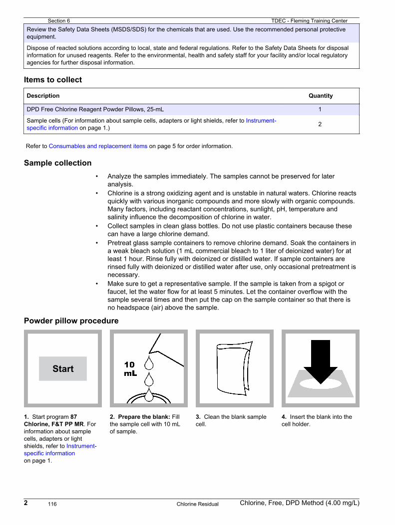
Review the Safety Data Sheets (MSDS/SDS) for the chemicals that are used. Use the recommended personal protectiveequipment.
Dispose of reacted solutions according to local, state and federal regulations. Refer to the Safety Data Sheets for disposalinformation for unused reagents. Refer to the environmental, health and safety staff for your facility and/or local regulatoryagencies for further disposal information.
Items to collect
Description Quantity
DPD Free Chlorine Reagent Powder Pillows, 25-mL 1
Sample cells (For information about sample cells, adapters or light shields, refer to Instrument-specific information on page 1.) 2
Refer to Consumables and replacement items on page 5 for order information.
Sample collection• Analyze the samples immediately. The samples cannot be preserved for later
analysis.• Chlorine is a strong oxidizing agent and is unstable in natural waters. Chlorine reacts
quickly with various inorganic compounds and more slowly with organic compounds.Many factors, including reactant concentrations, sunlight, pH, temperature andsalinity influence the decomposition of chlorine in water.
• Collect samples in clean glass bottles. Do not use plastic containers because thesecan have a large chlorine demand.
• Pretreat glass sample containers to remove chlorine demand. Soak the containers ina weak bleach solution (1 mL commercial bleach to 1 liter of deionized water) for atleast 1 hour. Rinse fully with deionized or distilled water. If sample containers arerinsed fully with deionized or distilled water after use, only occasional pretreatment isnecessary.
• Make sure to get a representative sample. If the sample is taken from a spigot orfaucet, let the water flow for at least 5 minutes. Let the container overflow with thesample several times and then put the cap on the sample container so that there isno headspace (air) above the sample.
Powder pillow procedure
Start
1. Start program 87Chlorine, F&T PP MR. Forinformation about samplecells, adapters or lightshields, refer to Instrument-specific informationon page 1.
2. Prepare the blank: Fillthe sample cell with 10 mLof sample.
3. Clean the blank samplecell.
4. Insert the blank into thecell holder.
2 Chlorine, Free, DPD Method (4.00 mg/L)
Section 6 TDEC - Fleming Training Center
Chlorine Residual116

Zero
5. Push ZERO. The displayshows 0.00 mg/L Cl2.
6. Prepare the sample: Filla second sample cell with10 mL of sample.
7. Add the contents of oneDPD Free Chlorine PowderPillow for 25‑mL sample tothe prepared sample cell.
8. Put the stopper on theprepared sample cell. Invertthe sample cell severaltimes to mix. A pink colorshows if chlorine is present.Go to the next stepimmediately.
9. Clean the preparedsample cell.
10. Within one minute ofthe reagent addition, insertthe prepared sample intothe cell holder.
Read
11. Push READ. Resultsshow in mg/L Cl2.
InterferencesInterfering substance Interference level
Acidity More than 150 mg/L CaCO3. The full color may not develop or the color may fade instantly. Adjustto pH 6–7 with 1 N Sodium Hydroxide. Measure the amount to add on a separate sample aliquot,then add the same amount to the sample that is tested. Correct the test result for the dilution fromthe volume addition.
Alkalinity More than 250 mg/L CaCO3. The full color may not develop or the color may fade instantly. Adjustto pH 6–7 with 1 N Sulfuric Acid. Measure the amount to add on a separate sample aliquot, thenadd the same amount to the sample that is tested. Correct the test result for the dilution from thevolume addition.
Bromine, Br2 Positive interference at all levels
Chlorine Dioxide, ClO2 Positive interference at all levels
Inorganic chloramines Positive interference at all levels
Chloramines, organic May interfere in the result for total chlorine analysis
Hardness No effect at less than 1000 mg/L as CaCO3
Chlorine, Free, DPD Method (4.00 mg/L) 3
TDEC - Fleming Training Center Section 6
Chlorine Residual 117

Interfering substance Interference level
Manganese, Oxidized(Mn4+, Mn7+) orChromium, Oxidized(Cr6+)
Pre-treat the sample as follows:
1. Adjust the sample pH to 6–7.2. Add 3 drops of Potassium Iodide (30-g/L) to 10 mL of sample.3. Mix and wait 1 minute.4. Add 3 drops of Sodium Arsenite (5-g/L) and mix.5. Use the test procedure to measure the concentration of the treated sample.6. Subtract this result from the result without the treatment to obtain the correct chlorine
concentration.
Ozone Positive interference at all levels
Peroxides May interfere
Highly buffered samplesor extreme sample pH
Can prevent the correct pH adjustment (of the sample) by the reagents. Sample pretreatment maybe necessary. Adjust to pH 6–7 with acid (Sulfuric Acid, 1.000 N) or base (Sodium Hydroxide,1.00 N).
Monochloramine interference
For conventional free chlorine disinfection (beyond the breakpoint), typicalmonochloramine concentrations are very low. If monochloramine is present in thesample, its interference in the free chlorine test depends on the sample temperature,relative amount of monochloramine to free chlorine and the time required to do theanalysis. Typical interference levels of monochloramine as mg/L Cl2 in the free chlorinetest are shown in Table 2 (1 minute test time). Measure the monochloramine levels withmethod 10200 for Chloramine (Mono) and Free Ammonia.
Table 2 Monochloramine interference at different sample temperatures
NH2Cl (as Cl2) 5 °C (41 °F) 10 °C (50 °F) 20 °C (68 °F) 30 °C (83 °F)
1.2 mg/L 0.15 0.19 0.30 0.29
2.2 mg/L 0.35 0.38 0.55 0.61
3.2 mg/L 0.38 0.56 0.69 0.73
Accuracy check
Standard additions method (sample spike)Use the standard additions method (for applicable instruments) to validate the testprocedure, reagents and instrument and to find if there is an interference in the sample.Items to collect:
• Chlorine Standard Solution, 2-mL PourRite® Ampule, 25–30 (or 50–75) mg/L• Ampule breaker• Pipet, TenSette®, 0.1–1.0 mL and tips
1. Use the test procedure to measure the concentration of the sample, then keep the(unspiked) sample in the instrument.
2. Go to the Standard Additions option in the instrument menu.3. Select the values for standard concentration, sample volume and spike volumes.4. Open the standard solution.5. Prepare three spiked samples: use the TenSette pipet to add 0.1 mL, 0.2 mL and
0.3 mL of the standard solution, respectively, to three 10-mL portions of fresh sample.Mix well.
6. Use the test procedure to measure the concentration of each of the spiked samples.Start with the smallest sample spike. Measure each of the spiked samples in theinstrument.
4 Chlorine, Free, DPD Method (4.00 mg/L)
Section 6 TDEC - Fleming Training Center
Chlorine Residual118

7. Select Graph to compare the expected results to the actual results.Note: If the actual results are significantly different from the expected results, make sure thatthe sample volumes and sample spikes are measured accurately. The sample volumes andsample spikes that are used should agree with the selections in the standard additions menu. Ifthe results are not within acceptable limits, the sample may contain an interference.
Verification of on-line analyzersThis procedure can be used to meet the requirements of USEPA Method 334.0 -Determination of Residual Chlorine in Drinking Water Using an On-line Chlorine Analyzer.The procedure and requirements for compliance with EPA Method 334.0 can bedownloaded directly from http://www.hach.com/method334.
Method performanceThe method performance data that follows was derived from laboratory tests that weremeasured on a spectrophotometer during ideal test conditions. Users can get differentresults under different test conditions.
Program Standard Precision (95% confidence interval) SensitivityConcentration change per 0.010 Abs change
87 2.68 mg/L Cl2 2.63–2.73 mg/L Cl2 0.03 mg/L Cl2
Summary of methodChlorine in the sample as hypochlorous acid or hypochlorite ion (free chlorine or freeavailable chlorine) immediately reacts with DPD (N,N-diethyl-p-phenylenediamine)indicator to form a pink color, the intensity of which is proportional to the chlorineconcentration. The measurement wavelength is 530 nm for spectrophotometers or520 nm for colorimeters.
Consumables and replacement itemsRequired reagents
Description Quantity/test Unit Item no.
DPD Free Chlorine Reagent Powder Pillow, 25 mL 1 100/pkg 1407099
Sample cell, 10-mL round, 25 mm x 60 mm 1 6/pkg 2427606
Recommended standards
Description Unit Item no.
Chlorine Standard Solution, 2-mL PourRite® Ampules, 25–30 mg/L 20/pkg 2630020
Ampule Breaker, 10-mL Voluette® Ampules each 2196800
PourRite® Ampule Breaker, 2-mL each 2484600
Chlorine Standard Solution, 2-mL PourRite® Ampules, 50–75 mg/L 20/pkg 1426820
Chlorine Standard Solution, 10-mL Voluette® Ampule, 50–75 mg/L 16/pkg 1426810
Optional reagents and apparatus
Description Unit Item no.
Sodium Hydroxide Standard Solution, 1.0 N 100 mL MDB 104532
Sulfuric Acid Standard Solution, 1 N 100 mL MDB 127032
Potassium Iodide, 30-g/L 100 mL 34332
Sodium Arsenite, 5-g/L 100 mL 104732
Pipet, TenSette®, 0.1–1.0 mL each 1970001
Chlorine, Free, DPD Method (4.00 mg/L) 5
TDEC - Fleming Training Center Section 6
Chlorine Residual 119

Optional reagents and apparatus (continued)
Description Unit Item no.
Pipet tips for TenSette® Pipet, 0.1–1.0 mL 50/pkg 2185696
Pipet tips for TenSette® Pipet, 0.1–1.0 mL 1000/pkg 2185628
Paper, pH, 0–14 pH range 100/pkg 2601300
DPD Free Chlorine Reagent Powder Pillows, 25 mL 1000/pkg 1407028
SpecCheck™ Secondary Standard Kit, Chlorine DPD, MR each 2980500
Water, organic-free 500 mL 2641549
Freechlor F Reagent Solution 50 mL SCDB 2964926
Monochlor F Reagent Powder Pillows 100/pkg 2802299
HACH COMPANYWORLD HEADQUARTERSTelephone: (970) 669-3050FAX: (970) 669-2932
FOR TECHNICAL ASSISTANCE, PRICE INFORMATION AND ORDERING:Call 800-227-4224
Contact the HACH office or distributor serving you.www.hach.com [email protected]
In the U.S.A. –
Outside the U.S.A. –
On the Worldwide Web – ; E-mail –
toll-free
© Hach Company/Hach Lange GmbH, 1989–2014, 2019. All rights reserved. 05/2019, Edition 11
Section 6 TDEC - Fleming Training Center
Chlorine Residual120

Chlorine, Total DOC316.53.01027
USEPA DPD Method1 Method 81670.02 to 2.00 mg/L Cl2 Powder Pillows or AccuVac® Ampuls
Scope and application: For testing residual chlorine and chloramines in water, wastewater, estuary water andseawater; USEPA-accepted for reporting for drinking and wastewater analyses.2 This product has not beenevaluated to test for chlorine and chloramines in medical applications in the United States.
1 Adapted from Standard Methods for the Examination of Water and Wastewater.2 Procedure is equivalent to USEPA and Standard Method 4500-Cl G for drinking water and wastewater analysis.
Test preparation
Instrument-specific informationTable 1 shows sample cell and orientation requirements for reagent addition tests, suchas powder pillow or bulk reagent tests. Table 2 shows sample cell and adapterrequirements for AccuVac Ampul tests. The tables also show all of the instruments thathave the program for this test.To use the table, select an instrument, then read across to find the applicable informationfor this test.
Table 1 Instrument-specific information for reagent addition
Instrument Sample cell orientation Sample cell
DR 6000 DR 3800 DR 2800 DR 2700 DR 1900
The fill line is to the right. 2495402
DR 5000 DR 3900
The fill line is toward the user.
DR 900 The orientation mark is toward the user. 2401906
Table 2 Instrument-specific information for AccuVac Ampuls
Instrument Adapter Sample cell
DR 6000 DR 5000 DR 900
— 2427606
DR 3900 LZV846 (A)
DR 1900 9609900 or 9609800 (C)
DR 3800 DR 2800 DR 2700
LZV584 (C) 2122800
1
TDEC - Fleming Training Center Section 6
Chlorine Residual 121

Before startingAnalyze the samples immediately. The samples cannot be preserved for later analysis.
Install the instrument cap on the DR 900 cell holder before ZERO or READ is pushed.
If the test result is over-range, or if the sample temporarily turns yellow after the reagent addition, dilute the sample with aknown volume of high quality, chlorine demand-free water and do the test again. Some loss of chlorine may occur due to thedilution. Multiply the result by the dilution factor. Additional methods are available to measure chlorine without dilution.
For chloramination disinfection control, use one of the available Chloramine (Mono) methods.
For the best results, measure the reagent blank value for each new lot of reagent. Replace the sample with deionized waterin the test procedure to determine the reagent blank value. Subtract the reagent blank value from the sample resultsautomatically with the reagent blank adjust option.
Review the Safety Data Sheets (MSDS/SDS) for the chemicals that are used. Use the recommended personal protectiveequipment.
Dispose of reacted solutions according to local, state and federal regulations. Refer to the Safety Data Sheets for disposalinformation for unused reagents. Refer to the environmental, health and safety staff for your facility and/or local regulatoryagencies for further disposal information.
The SwifTest Dispenser for Total Chlorine can be used in place of the powder pillow in the test procedure. One dispensationis equal to one powder pillow for 10-mL samples.
An AccuVac Ampul for Blanks can be used to zero the instrument in the AccuVac test procedure.
Items to collectPowder pillows
Description Quantity
DPD Total Chlorine Reagent Powder Pillow, 10-mL 1
Sample cells. (For information about sample cells, adapters or light shields, refer to Instrument-specific information on page 1.) 2
Refer to Consumables and replacement items on page 6 for order information.
AccuVac Ampuls
Description Quantity
DPD Total Chlorine Reagent AccuVac® Ampul 1
Beaker, 50-mL 1
Sample cells (For information about sample cells, adapters or light shields, refer to Instrument-specific information on page 1.) 1
Stopper for 18-mm tubes and AccuVac Ampuls 1
Refer to Consumables and replacement items on page 6 for order information.
Sample collection• Analyze the samples immediately. The samples cannot be preserved for later
analysis.• Chlorine is a strong oxidizing agent and is unstable in natural waters. Chlorine reacts
quickly with various inorganic compounds and more slowly with organic compounds.Many factors, including reactant concentrations, sunlight, pH, temperature andsalinity influence the decomposition of chlorine in water.
• Collect samples in clean glass bottles. Do not use plastic containers because thesecan have a large chlorine demand.
2 Chlorine, Total, DPD Method (2.00 mg/L)
Section 6 TDEC - Fleming Training Center
Chlorine Residual122

• Pretreat glass sample containers to remove chlorine demand. Soak the containers ina weak bleach solution (1 mL commercial bleach to 1 liter of deionized water) for atleast 1 hour. Rinse fully with deionized or distilled water. If sample containers arerinsed fully with deionized or distilled water after use, only occasional pretreatment isnecessary.
• Make sure to get a representative sample. If the sample is taken from a spigot orfaucet, let the water flow for at least 5 minutes. Let the container overflow with thesample several times and then put the cap on the sample container so that there isno headspace (air) above the sample.
Powder pillow procedure
Start
1. Start program 80Chlorine F&T PP. Forinformation about samplecells, adapters or lightshields, refer to Instrument-specific informationon page 1.
2. Fill a sample cell with10 mL of sample.
3. Prepare the sample:Add the contents of onepowder pillow to the samplecell.
4. Swirl the sample cell for20 seconds to mix.A pink color shows ifchlorine is present in thesample.
5. Start the instrumenttimer. A 3‑minute reactiontime starts.Prepare the sample blankand set the instrument tozero during the reactiontime.
6. Prepare the blank: Fill asecond sample cell with10 mL of sample.
7. Clean the blank samplecell.
8. Insert the blank into thecell holder.
Chlorine, Total, DPD Method (2.00 mg/L) 3
TDEC - Fleming Training Center Section 6
Chlorine Residual 123

Zero
9. Push ZERO. The displayshows 0.00 mg/L Cl2.
10. Clean the preparedsample cell.
11. Within 3 minutes afterthe timer expires, insert theprepared sample into thecell holder.
Read
12. Push READ. Resultsshow in mg/L Cl2.
AccuVac Ampul procedure
Start
1. Start program 85Chlorine F&T AV. Forinformation about samplecells, adapters or lightshields, refer to Instrument-specific informationon page 1.
2. Prepare the blank: Fillthe sample cell with 10 mLof sample.
3. Prepare the sample:Collect at least 40 mL ofsample in a 50‑mL beaker.Fill the AccuVac Ampul withsample. Keep the tipimmersed while theAccuVac Ampul fillscompletely.
4. Quickly invert theAccuVac Ampul severaltimes to mix.
5. Start the instrumenttimer. A 3‑minute reactiontime starts.Prepare the sample blankand set the instrument tozero during the reactiontime.
6. Clean the blank samplecell.
7. Insert the blank into thecell holder.
Zero
8. Push ZERO. The displayshows 0.00 mg/L Cl2.
4 Chlorine, Total, DPD Method (2.00 mg/L)
Section 6 TDEC - Fleming Training Center
Chlorine Residual124

9. Clean the AccuVacAmpul.
10. Within 3 minutes afterthe timer expires, insert theprepared sample AccuVacAmpul into the cell holder.
Read
11. Push READ. Resultsshow in mg/L Cl2.
InterferencesInterfering substance Interference level
Acidity More than 150 mg/L CaCO3. The full color may not develop or the color may fade instantly. Adjustto pH 6–7 with 1 N Sodium Hydroxide. Measure the amount to add on a separate sample aliquot,then add the same amount to the sample that is tested. Correct the test result for the dilution fromthe volume addition.
Alkalinity More than 250 mg/L CaCO3. The full color may not develop or the color may fade instantly. Adjustto pH 6–7 with 1 N Sulfuric Acid. Measure the amount to add on a separate sample aliquot, thenadd the same amount to the sample that is tested. Correct the test result for the dilution from thevolume addition.
Bromine, Br2 Positive interference at all levels
Chlorine Dioxide, ClO2 Positive interference at all levels
Inorganic chloramines Positive interference at all levels
Chloramines, organic May interfere in the result for total chlorine analysis
Hardness No effect at less than 1000 mg/L as CaCO3
Manganese, Oxidized(Mn4+, Mn7+) orChromium, Oxidized(Cr6+)
Pre-treat the sample as follows:
1. Adjust the sample pH to 6–7.2. Add 3 drops of Potassium Iodide (30-g/L) to 10 mL of sample.3. Mix and wait 1 minute.4. Add 3 drops of Sodium Arsenite (5-g/L) and mix.5. Use the test procedure to measure the concentration of the treated sample.6. Subtract this result from the result without the treatment to obtain the correct chlorine
concentration.
Ozone Positive interference at all levels
Peroxides May interfere
Highly buffered samplesor extreme sample pH
Can prevent the correct pH adjustment (of the sample) by the reagents. Sample pretreatment maybe necessary. Adjust to pH 6–7 with acid (Sulfuric Acid, 1.000 N) or base (Sodium Hydroxide,1.00 N).
Accuracy check
Standard additions method (sample spike)Use the standard additions method (for applicable instruments) to validate the testprocedure, reagents and instrument and to find if there is an interference in the sample.
Chlorine, Total, DPD Method (2.00 mg/L) 5
TDEC - Fleming Training Center Section 6
Chlorine Residual 125

Items to collect:
• Chlorine Standard Solution, 2-mL PourRite® Ampule, 25–30 mg/L (use mg/L on label)• Breaker, PourRite Ampules• Pipet, TenSette®, 0.1–1.0 mL and tips
1. Use the test procedure to measure the concentration of the sample, then keep the(unspiked) sample in the instrument.
2. Go to the Standard Additions option in the instrument menu.3. Select the values for standard concentration, sample volume and spike volumes.4. Open the standard solution.5. Prepare three spiked samples: use the TenSette pipet to add 0.1 mL, 0.2 mL and
0.3 mL of the standard solution, respectively, to three 10-mL portions of fresh sample.Mix well.Note: For AccuVac® Ampuls, add 0.4 mL, 0.8 mL and 1.2 mL of the standard solution to three50-mL portions of fresh sample.
6. Use the test procedure to measure the concentration of each of the spiked samples.Start with the smallest sample spike. Measure each of the spiked samples in theinstrument.
7. Select Graph to compare the expected results to the actual results.Note: If the actual results are significantly different from the expected results, make sure thatthe sample volumes and sample spikes are measured accurately. The sample volumes andsample spikes that are used should agree with the selections in the standard additions menu. Ifthe results are not within acceptable limits, the sample may contain an interference.
Method performanceThe method performance data that follows was derived from laboratory tests that weremeasured on a spectrophotometer during ideal test conditions. Users can get differentresults under different test conditions.
Program Standard Precision (95% Confidence Interval) SensitivityConcentration change per 0.010 Abs change
80 1.25 mg/L Cl2 1.23–1.27 mg/L Cl2 0.02 mg/L Cl2
85 1.25 mg/L Cl2 1.21–1.29 mg/L Cl2 0.02 mg/L Cl2
Summary of methodChlorine can be present in water as free chlorine and as combined chlorine. Both formscan exist in the same water and be determined together as total chlorine. Free chlorine ispresent as hypochlorous acid and/or hypochlorite ion. Combined chlorine exists asmonochloramine, dichloramine, nitrogen trichloride and other chloro derivatives. Thecombined chlorine oxidizes iodide in the reagent to iodine. The iodine and free chlorinereact with DPD (N,N-diethyl-p-phenylenediamine) to form a pink color which isproportional to the total chlorine concentration.To find the concentration of combined chlorine, run a free chlorine test and a totalchlorine test. Subtract the results of the free chlorine test from the total chlorine test toobtain the combined chlorine concentration. The measurement wavelength is 530 nm forspectrophotometers or 520 nm for colorimeters.
Consumables and replacement itemsRequired reagents
Description Quantity/Test Unit Item no.
DPD Total Chlorine Reagent Powder Pillow, 10 mL 1 100/pkg 2105669
OR
DPD Total Chlorine Reagent AccuVac® Ampul 1 25/pkg 2503025
6 Chlorine, Total, DPD Method (2.00 mg/L)
Section 6 TDEC - Fleming Training Center
Chlorine Residual126

Required apparatus
Description Quantity/Test Unit Item no.
AccuVac Snapper 1 each 2405200
Beaker, 50 mL 1 each 50041H
Stoppers for 18-mm tubes and AccuVac Ampuls 2 6/pkg 173106
Recommended standards
Description Unit Item no.
Chlorine Standard Solution, 10-mL Voluette® Ampule, 50–75 mg/L 16/pkg 1426810
Chlorine Standard Solution, 2-mL PourRite® Ampules, 50–75 mg/L 20/pkg 1426820
Chlorine Standard Solution, 2-mL PourRite® Ampules, 25–30 mg/L 20/pkg 2630020
Optional reagents and apparatus
Description Unit Item no.
AccuVac® Ampul vials for sample blanks 25/pkg 2677925
Ampule Breaker, 2-mL PourRite® Ampules each 2484600
Ampule Breaker, 10-mL Voluette® Ampules each 2196800
Water, Chlorine-demand Free 500 mL 2641549
Mixing cylinder, graduated, 25-mL each 2088640
Mixing cylinder, graduated, 50 mL each 189641
DPD Total Chlorine Reagent Powder Pillows, 10 mL 1000/pkg 2105628
DPD Total Chlorine Reagent Powder Pillows, 10 mL 300/pkg 2105603
DPD Total Chlorine Reagent, 10-mL, SwifTest™ Dispenser refill vial 250 tests 2105660
Paper, pH, 0–14 pH range 100/pkg 2601300
Pipet, TenSette®, 0.1–1.0 mL each 1970001
Pipet tips for TenSette® Pipet, 0.1–1.0 mL 50/pkg 2185696
Pipet tips for TenSette® Pipet, 0.1–1.0 mL 1000/pkg 2185628
Potassium Iodide, 30-g/L 100 mL 34332
Sodium Arsenite, 5-g/L 100 mL 104732
Sodium Hydroxide Standard Solution, 1.0 N 100 mL MDB 104532
SpecCheck™ Secondary Standard Kit, Chlorine DPD, 0–2.0 mg/L Set each 2635300
Sulfuric Acid Standard Solution, 1 N 100 mL MDB 127032
Water, deionized 4 L 27256
Chlorine, Total, DPD Method (2.00 mg/L) 7
TDEC - Fleming Training Center Section 6
Chlorine Residual 127

HACH COMPANYWORLD HEADQUARTERSTelephone: (970) 669-3050FAX: (970) 669-2932
FOR TECHNICAL ASSISTANCE, PRICE INFORMATION AND ORDERING:Call 800-227-4224
Contact the HACH office or distributor serving you.www.hach.com [email protected]
In the U.S.A. –
Outside the U.S.A. –
On the Worldwide Web – ; E-mail –
toll-free
© Hach Company/Hach Lange GmbH, 1989–2014, 2018. All rights reserved. 09/2018, Edition 10
Section 6 TDEC - Fleming Training Center
Chlorine Residual128

Chlorine, Free and Total TNTplus DOC316.53.01248
DPD Method1 Method 10231 (Free Chlorine) and Method 10232 (Total Chlorine)0.05 to 2.00 mg/L Cl2 TNTplus™ 866/867
Scope and application: For drinking water, wastewater and pool water. This product has not been evaluated totest for chlorine and chloramines in medical applications in the United States.
1 Adapted from Standard Methods for the Examination of Water and Wastewater.
Test preparation
Instrument-specific informationTable 1 shows all of the instruments that have the program for this test. The table alsoshows the adapter and light shield requirements for the applicable instruments that canuse TNTplus vials.To use the table, select an instrument, then read across to find the applicable informationfor this test.
Table 1 Instrument-specific information for TNTplus vials
Instrument Adapters Light shield
DR 6000, DR 5000 — —
DR 3900 — LZV849
DR 3800, DR 2800 — LZV646
DR 1900 9609900 or 9609800 (A) —
Before startingDR 3900, DR 3800, DR 2800: Install the light shield in Cell Compartment #2 before this test is started.
Review the safety information and the expiration date on the package.
Analyze the samples immediately. The samples cannot be preserved for later analysis.
The recommended sample pH is 3–10.
The recommended temperature for samples and reagents is 15–25 °C (59–77 °F).
The recommended temperature for reagent storage is 2–8 °C (35–46 °F).
To sequentially measure free and total chlorine, complete the free chlorine procedure, then start the total chlorine procedureat step 2.
DR 1900: Go to All Programs>LCK or TNTplus Methods>Options to select the TNTplus number for the test. Otherinstruments automatically select the method from the barcode on the vial.
Review the Safety Data Sheets (MSDS/SDS) for the chemicals that are used. Use the recommended personal protectiveequipment.
Dispose of reacted solutions according to local, state and federal regulations. Refer to the Safety Data Sheets for disposalinformation for unused reagents. Refer to the environmental, health and safety staff for your facility and/or local regulatoryagencies for further disposal information.
Items to collect
Description Quantity
Chlorine Free (TNT866) or Total (TNT867) Reagent Set 1
Beaker, 50 mL 1
1
TDEC - Fleming Training Center Section 6
Chlorine Residual 129

Refer to Consumables and replacement items on page 4 for order information.
Sample collection• Analyze the samples immediately. The samples cannot be preserved for later
analysis.• Chlorine is a strong oxidizing agent and is unstable in natural waters. Chlorine reacts
quickly with various inorganic compounds and more slowly with organic compounds.Many factors, including reactant concentrations, sunlight, pH, temperature andsalinity influence the decomposition of chlorine in water.
• Collect samples in clean glass bottles. Do not use plastic containers because thesecan have a large chlorine demand.
• Pretreat glass sample containers to remove chlorine demand. Soak the containers ina weak bleach solution (1 mL commercial bleach to 1 liter of deionized water) for atleast 1 hour. Rinse fully with deionized or distilled water. If sample containers arerinsed fully with deionized or distilled water after use, only occasional pretreatment isnecessary.
• Make sure to get a representative sample. If the sample is taken from a spigot orfaucet, let the water flow for at least 5 minutes. Let the container overflow with thesample several times and then put the cap on the sample container so that there isno headspace (air) above the sample.
Test procedure—free chlorine
Start
1. DR 1900 only: Selectprogram 866. Refer to Before starting on page 1.
2. Insert the Zero vial intothe cell holder. DR 1900only: Push ZERO. Theinstrument zero is set.
3. Complete this procedurewithin 1 minute: Fill thesample vial with sample tothe throat of the vial.
4. Tighten the cap on thevial and invert the vial 2–3times. Carefully rotate thevial to remove air bubbles.Do not shake.
5. Clean the vial. 6. Insert the vial into the cellholder. DR 1900 only: PushREAD.Results show in mg/L Cl2.
2 Chlorine, Free and Total, DPD TNTplus Method (2.00 mg/L)
Section 6 TDEC - Fleming Training Center
Chlorine Residual130

Test procedure—total chlorine
Start
1. DR 1900 only: Selectprogram 867. Refer to Before starting on page 1.
2. Insert the Zero vial intothe cell holder. DR 1900only: Push ZERO. Theinstrument zero is set.
3. Fill the sample vial withsample to the throat of thevial.
4. Immediately add 1 dropof potassium iodide SolutionA.
5. Tighten the cap on thevial and invert the vial 2–3times. Carefully rotate thevial to remove air bubbles.Do not shake.
6. Start the reaction time of3 minutes.
7. When the timer expires,clean the vial.
8. Insert the vial into the cellholder. DR 1900 only: PushREAD.Results show in mg/L Cl2.
InterferencesInterferingsubstance
Interference level
Color Can cause high results. To make a correction for the interference, measure a sample blank.
Oxidizing agents All oxidizing agents (e.g., ozone, iodine, chlorine dioxide, manganese dioxide and chromate) react withthe indicator and are included in the results. If a large number of oxidizing agents shows, some or all ofthe indicator changes to a colorless form. The test result will be negative or within the range of the test.
pH The sample pH should be between pH 3 and pH 10.
Turbidity Can cause high results. To make a correction for the interference, measure a sample blank.
Sample blanksIf the sample has color or turbidity, measure a sample blank to correct the test result forthe interference.Items to collect:
• TNTplus 919 sample blank vial
1. Do the test procedure.2. Put the sample in the sample blank vial. Fill to the neck of the sample blank vial.3. Wipe the sample blank vial clean, then put it into the cell holder. If applicable, the
instrument reads the barcode of the sample blank vial and subtracts the value fromthe initial test result.
Chlorine, Free and Total, DPD TNTplus Method (2.00 mg/L) 3
TDEC - Fleming Training Center Section 6
Chlorine Residual 131

Accuracy check
Standard solution methodUse the standard solution method to validate the test procedure, the reagents and theinstrument.Items to collect:
• 50–75 mg/L Chlorine Standard Solution (use mg/L on label)• 100-mL volumetric flask, Class A• Ampule breaker• Pipet, adjustable volume, 1.0–5.0 mL and pipet tip• Deionized water
1. Prepare a 1.3-mg/L (approximate) chlorine standard solution as follows:
a. Use a pipet to add 2.0 mL of the chlorine standard solution into the volumetricflask. First add approximately 50 mL of deionized water to the flask. Multiply theconcentration that is shown on the chlorine standard solution label by 0.02 to findthe concentration of the prepared standard solution.
b. Dilute to the mark with deionized water. Mix well. Prepare this solution daily.2. Use the test procedure to measure the concentration of the prepared standard
solution.3. Compare the expected result to the actual result.
Note: The factory calibration can be adjusted slightly with the standard adjust option so that theinstrument shows the expected value of the standard solution. The adjusted calibration is thenused for all test results. This adjustment can increase the test accuracy when there are smallvariations in the reagents or instruments.
Summary of MethodChlorine can show in water as free chlorine and as combined chlorine. Both forms canexist in the same water and can be determined together as total chlorine. Free chlorineshows as hypochlorous acid and/or hypochlorite ion. Combined chlorine exists asmonochloramine, dichloramine, nitrogen trichloride and other chloro derivatives. Thecombined chlorine oxidizes iodide in the reagent to iodine. The iodine and free chlorinereact with DPD (N,N-diethyl-p-phenylenediamine) to form a pink color that is proportionalto the chlorine concentration. The measurement wavelength is 515 nm.
Consumables and replacement itemsRequired reagents
Description Quantity/Test Unit Item no.
Free Chlorine TNT 866 Reagent Set 1 24/pkg TNT866
Free and Total Chlorine TNT 867 Reagent Set 1 24/pkg TNT867
Required apparatus
Description Quantity/test Unit Item no.
Beaker, 50 mL 1 each 50041H
Light shield, DR 3800, DR 2800, DR 2700 1 each LZV646
Light shield, DR 3900 1 each LZV849
4 Chlorine, Free and Total, DPD TNTplus Method (2.00 mg/L)
Section 6 TDEC - Fleming Training Center
Chlorine Residual132

Recommended standards
Description Unit Item no.
Chlorine Standard Solution, 2-mL PourRite® Ampules, 50–75 mg/L 20/pkg 1426820
Chlorine Standard Solution, 10-mL Voluette® Ampule, 50–75 mg/L 16/pkg 1426810
Chlorine Standard Solution, 2-mL PourRite® Ampule, 25-30 mg/L 20/pkg 2630020
Optional reagents and apparatus
Description Unit Item no.
Ampule Breaker, 2-mL PourRite® Ampules each 2484600
Ampule Breaker, 10-mL Voluette® Ampules each 2196800
Flask, volumetric, Class A, 100 mL, glass each 1457442
Pipet, adjustable volume, 1.0–5.0 mL each BBP065
Pipet tips, for 1.0–5.0 mL pipet 75/pkg BBP068
Sample blank vials for TNTplus™ methods 5/pkg TNT919
Sampling bottle with cap, low density polyethylene, 500-mL 12/pkg 2087079
Water, deionized 4 L 27256
Chlorine, Free and Total, DPD TNTplus Method (2.00 mg/L) 5
TDEC - Fleming Training Center Section 6
Chlorine Residual 133

HACH COMPANYWORLD HEADQUARTERSTelephone: (970) 669-3050FAX: (970) 669-2932
FOR TECHNICAL ASSISTANCE, PRICE INFORMATION AND ORDERING:Call 800-227-4224
Contact the HACH office or distributor serving you.www.hach.com [email protected]
In the U.S.A. –
Outside the U.S.A. –
On the Worldwide Web – ; E-mail –
toll-free
© Hach Company/Hach Lange GmbH, 2007, 2010, 2011, 2014, 2017. All rights reserved. 01/2017, Edition 9
Section 6 TDEC - Fleming Training Center
Chlorine Residual134

Chlorine, free, BT, 8334
Chlorine, Free DOC316.53.01155
USEPA1 Amperometric Buret Titration Method2
1 USEPA accepted; 40 CFR Part 141, Section 141.74.2 Adapted from Standard Methods for the Examination of Water and Wastewater (4500 Cl-D).
Method 8334
0.5 mg/L and above Buret Titration
Scope and Application: For water and wastewater.
Test preparation
Before starting the test:
Chlorine can be lost from the sample during sample collection. Review the precautions in Sample collection, preservation and storage before the test is started.
Use only a 50-mm stir bar. The wrong size can cause the loss of chlorine, unstable readings and loss of method sensitivity, especially when measuring low level chlorine concentrations.
For added convenience when stirring, use the TitraStir® apparatus.
When a new probe is placed in service or when the probe has not been used recently, prepare it according to the Probe Stabilization instructions in the Amperometric Titrator Instruction Manual.
Collect the following items:
Description Quantity
Phenylarsine Oxide Solution, 0.00564 N 1 bottle
Phosphate Buffer Solution, pH 7 1 mL
Amperometric Buret Titrator System 1
Beaker, 250-mL 1
Graduated cylinder, 250-mL 1
See Consumables and replacement items for reorder information.
TDEC - Fleming Training Center Section 6
Chlorine, Free
Page 1 of 4
Chlorine Residual 135

Chlorine, Free
Section 6 TDEC - Fleming Training Center
Buret titration
1. Fill the 5-mL automatic buret to the zero mark with 0.00564 N Phenylarsine Oxide (PAO) Solution.
2. Put a 50-mm stir bar into a 250-mL beaker. Use a graduated cylinder to measure 200 mL of sample. Add the sample to the beaker.
3. If the pH is less than 6 or greater than 7.5, add 1.0 mL of pH 7 Phosphate Buffer Solution to make the prepared sample.
4. Place the beaker of prepared sample on the TitraStir titration stand and turn on the stirring motor. Put the tip of the probe fully into the prepared sample. The platinum wires must be submerged.If a stir plate other than the TitraStir® is used, set the speed for moderate mixing. Do not adjust the speed after this point.
5. Turn the BIAS control knob to adjust the value on the display to approximately 1.00.The BIAS adjustment controls the slope of the titration curve. The actual value is not important. Only the relative value as the titration continues is important. A precise adjustment is not necessary.
6. Dispense the titrant into the beaker in small increments while monitoring the values on the Amperometric Titrator. The values will decrease.
7. Continue dispensing slowly. Near the end point of the titration, write down the value on the display and the corresponding total volume of titrant that was added. Read the volume to the nearest 0.01 mL. Add a small amount of titrant and wait several seconds for a stable value. Write down the value.
8. Continue the titration by recording at least three points on the downward sloping curve and at least three points after the end point has been reached. The value on the display will not change significantly after the end point.
Chlorine, Free
Page 2 of 4
Chlorine Residual136
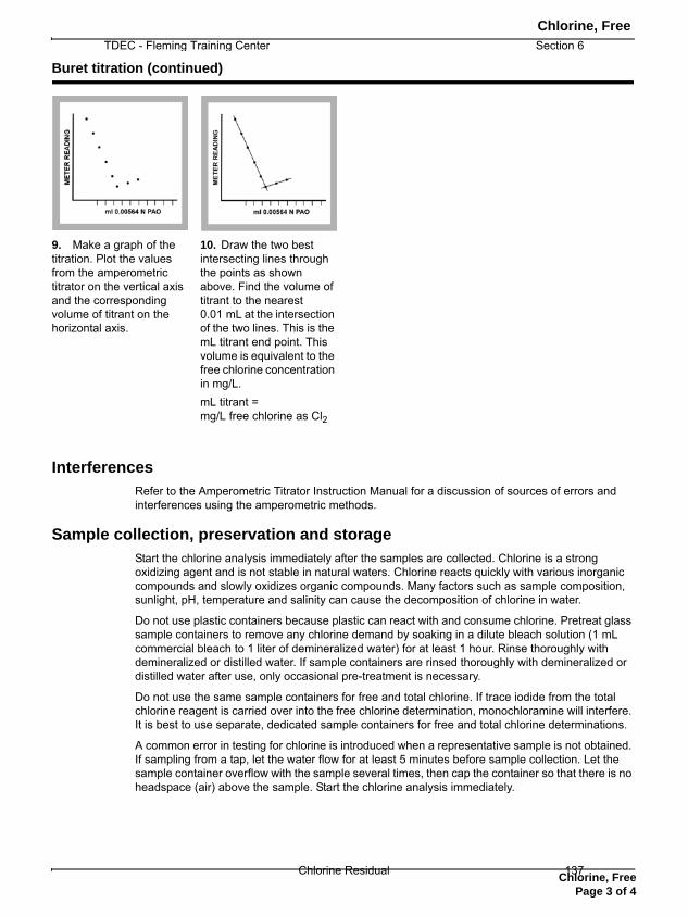
Chlorine, Free
TDEC - Fleming Training Center Section 6
Interferences
Refer to the Amperometric Titrator Instruction Manual for a discussion of sources of errors and interferences using the amperometric methods.
Sample collection, preservation and storage
Start the chlorine analysis immediately after the samples are collected. Chlorine is a strong oxidizing agent and is not stable in natural waters. Chlorine reacts quickly with various inorganic compounds and slowly oxidizes organic compounds. Many factors such as sample composition, sunlight, pH, temperature and salinity can cause the decomposition of chlorine in water.
Do not use plastic containers because plastic can react with and consume chlorine. Pretreat glass sample containers to remove any chlorine demand by soaking in a dilute bleach solution (1 mL commercial bleach to 1 liter of demineralized water) for at least 1 hour. Rinse thoroughly with demineralized or distilled water. If sample containers are rinsed thoroughly with demineralized or distilled water after use, only occasional pre-treatment is necessary.
Do not use the same sample containers for free and total chlorine. If trace iodide from the total chlorine reagent is carried over into the free chlorine determination, monochloramine will interfere. It is best to use separate, dedicated sample containers for free and total chlorine determinations.
A common error in testing for chlorine is introduced when a representative sample is not obtained. If sampling from a tap, let the water flow for at least 5 minutes before sample collection. Let the sample container overflow with the sample several times, then cap the container so that there is no headspace (air) above the sample. Start the chlorine analysis immediately.
9. Make a graph of the titration. Plot the values from the amperometric titrator on the vertical axis and the corresponding volume of titrant on the horizontal axis.
10. Draw the two best intersecting lines through the points as shown above. Find the volume of titrant to the nearest 0.01 mL at the intersection of the two lines. This is the mL titrant end point. This volume is equivalent to the free chlorine concentration in mg/L.mL titrant = mg/L free chlorine as Cl2
Buret titration (continued)
Chlorine, Free
Page 3 of 4
Chlorine Residual 137

Chlorine, Free
Section 6 TDEC - Fleming Training Center
Summary of method
Free chlorine is measured by a titration at pH 7 with PAO solution to the amperometric end point. The amperometric titration method has greater sensitivity and accuracy when compared to colorimetric methods. Refer to the Amperometric Titrator Instruction Manual for more information.
Consumables and replacement items
Required reagents
Description Quantity/Test Unit Catalog number
Phenylarsine Oxide Solution, 0.00564 N varies 1 L 199953Phosphate Buffer Solution, pH 7 1 mL 100 mL MDB 2155332
Required apparatus
Description Unit Catalog number
Amperometric Buret Titrator System, 115 VAC each 1930010Beaker, 250-mL each 50046HGraduated Cylinder, 250-mL each 50846Stir bar, 50 mm each 2095355
TitraStir® apparatus, 115 VAC each 1940000
TitraStir apparatus, 230 VAC each 1940010pH Paper, 0–14 pH range 100/pkg) 2601300
Optional reagents and apparatus
Description Unit Catalog number
Chlorine Standard Solution, 10-mL Voluette® Ampules, 50–75 mg/L 16/pkg 1426810
Chlorine Standard Solution, 2-mL PourRite® Ampule, 50–75 mg/L 20/pkg 1426820
Chlorine Standard Solution, 2-mL PourRite Ampule, 25–30 mg/L 20/pkg 2630020Voluette Ampule breaker 10-mL each 2196800PourRite Ampule breaker 2-mL each 2484600Water, deionized 500 mL 27249
HACH COMPANYWORLD HEADQUARTERSTelephone: (970) 669-3050FAX: (970) 669-2932
FOR TECHNICAL ASSISTANCE, PRICE INFORMATION AND ORDERING:Call 800-227-4224
Contact the HACH office or distributor serving you.www.hach.com [email protected]
In the U.S.A. –Outside the U.S.A. –On the Worldwide Web – ; E-mail –
toll-free
© Hach Company, 2007, 2010, 2012. All rights reserved. Printed in the U.S.A. Edition 7Chlorine Residual138

TDEC – Fleming Training Center S. Pratt, March 2013
Total Residual Chlorine, SM 4500-Cl G, 22nd edition (2000) – DPD Colorimetric Method
Minimum Detectable Concentration – 4500-Cl G.1.c. – approximately 10 g/L (0.010 mg/L) Initial Demonstration of Capability (DOC)
4020 B.1.a. - each analyst must run a known standard concentration at least four times and compare limits listed in the method.
Real people language – each operator running this test needs to analyze 4 samples of a chlorine standard or potassium permanganate (KMnO4) at a concentration of 0.5 mg/L
o Keep a folder for each analyst, keep a copy here o Documentation (signed form) that analyst has read and understands all
appropriate SOPs and Methods. o Recommend backup analyst do this once a year. o Only good for that type of instrument you are using at that plant. If you have a
backup instrument made by a different manufacturer or you work at another plant with a different make/model, you would need another DOC. DOCs demonstrate you are proficient with that one instrument.
Method Detection Limit (MDL)
1020 B. 4 – As a starting point for selecting the concentration to use when determining the MDL, use an estimate of five times the estimated true detection level (5 x 0.010 mg/L = 0.050 mg/L).
o Ideally, prepare and analyze at least seven (7) portions of this solution over a 3-day period to ensure that the MDL determination is more representative of routine measurements as performed in the laboratory.
o The replicate measurements should be in the range of one to five times the estimated MDL, and recoveries of the known addition should be between 50 and 150%, with %RSD (relative standard deviation) values ≤ 20%.
4020 B.1.b. – Verify MDL at least annually. o Ideally use pooled data from several analysts rather than data from one analyst.
Real people language – have several operators, who run this test, analyze chlorine standards or Potassium Permanganate (KMnO4) at a concentration of 0.05 mg/L over several days with a total of at least 7 samples
o Joe analyzes 3 samples on Monday o Bob analyzes 3 samples on Tuesday o Mary analyzes 3 samples on Wednesday
Run this once a year Initial Calibration Verification (ICV)
1020 B.11.b. – Perform initial calibration using at least three concentrations of standards for linear curves.
4020.B.2.a. – Calibrate initially with at least one blank and three calibration standards. o The appropriate linear correlation coefficient for standard concentration-to-instrument
response should be greater than or equal to 0.995.
o The back-calculated and true concentrations should agree within 10%.
TDEC - Fleming Training Center Section 6
Chlorine Residual 139

TDEC – Fleming Training Center S. Pratt, March 2013
Real people language – prepare a set of chlorine standards or potassium permanganate (KMnO4) in accordance with Guidance for Secondary Stds use in Calibration 10-19-2012 monthly.
Method Blank
1020 B.5.– A reagent blank (method blank) consists of reagent water and all reagents that normally are in contact with a sample during the entire analytical procedure.
4020 B.2.d. – Include at least one method blank daily or with each batch of 20 or fewer samples, whichever is more frequent.
o If any method blanks measurements are at or above the reporting level, take immediate corrective action.
Real people language – analyze distilled water as a sample by adding a DPD powder pillow and waiting the 3-6 minutes before reading
o Target value is less than detection level o Do this every day you analyze total residual chlorine
Laboratory Fortified Blank (LFB)
1020 B.6.– A laboratory-fortified blank is a reagent water sample to which a known concentration of the analyte of interest has been added.
o Sample batch = 5% basis = 1 every 20 samples o Use an added concentration of at least 10 times the MDL, less than or equal to the
midpoint of the calibration curve. 4020 B.2.e. – Calculate percent recovery, plot control charts and determine control limits
Real people language – analyze chlorine standard or potassium permanganate sample at a concentration of 0.5 mg/L
o Run on a 5% basis, see batch size for more information Duplicate
1020 B.12.f. – Calculate RPD (relative percent difference) 4020 B.2.f. – Randomly select routine samples to be analyzed twice.
o Process duplicate sample independently through the entire sample preparation and analysis.
o Include at least one duplicate for each matrix type daily or with each batch of 20 or fewer samples.
Real people language – on a 5% basis (1 for every 20 samples) analyze 2 samples for chlorine, after reading one, pour out sample and start with a fresh sample
o First sample is result, second sample is duplicate o Target value is to get close to the first value and have a small RPD
Continuing Calibration Verification (CCV)
1020 B.11.c. – Analysts periodically use a calibration standard to confirm that the instrument performance has not changed significantly since initial calibration.
o Verify calibration by analyzing one standard at a concentration near or at the mid-point of the calibration range.
4020.B.2.b. – Verify calibration by periodically analyzing a calibration standard and calibration blank during a run – typically after each batch of 10 samples and at the end of the run.
Section 6 TDEC - Fleming Training Center
Chlorine Residual140

TDEC – Fleming Training Center S. Pratt, March 2013
o For the calibration verification to be valid, check standards must not exceed 10% of its true value, and calibration blank results must not be greater than one-half the reporting level
Real people language o Read Secondary Standards in accordance with Guidance for Secondary Stds use
in Calibration 10-19-2012 daily. o OR run a chlorine or potassium permanganate standard daily.
Control Charts – 1020 B.13. Corrective Action - 1020 B.5., B.8,. & B.15. QC Acceptance Criteria
Blanks < reporting limits LFB ± 15% ICV/CCV ± 10% RPD± 20%
Batch Size
For samples that need to be analyzed on a 5% basis or once for every 20 samples follow these criteria:
o If a permit stated that 3 analyses per week, we would allow for a duplicate to be analyzed at least once per month. Pick a date and be consistent, the 1st of every month or the 1st Thursday of
every month. Mark your calendar!! o If a permit stated 5 analyses per week, we would suggest twice a month.
Pick a date and be consistent, the 1st and 15th of every month or the 1st and 3rd Thursday of every month. Mark your calendar!!
o If sampling only once a month, need to run QC once a month. Calculations
% Recovery for LFB o = LFB concentration X 100%
Expected concentration RPD – relative percent differences for duplicates and LFM/LFMD
o = Difference between sample and duplicate X 100% Average of the sample and duplicate
TDEC - Fleming Training Center Section 6
Chlorine Residual 141

Chlorine Lab
Bench Sheet
Sample Name Reading (mg/L) Spike (r2= ??)
Sample 1 (low range)
Sample 2 (medium range)
Sample 3 (total Cl2)
TNT – Free Cl2
TNT ‐ Total Cl2
Section 6 TDEC - Fleming Training Center
Chlorine Residual142

Chlorine QA/QC Bench sheet
mL Working Standard Diluted with Deionized Water
Chlorine Equivalent
ActualReading
20 mL (vol. pipet) to 100 mL (vol. flask) 2.0 mg/L
10 mL (vol. pipet) to 100 mL (vol. flask) 1.0 mg/L
5 mL (vol. pipet) to 100 mL (vol. flask) 0.5 mg/L
1 mL (vol. pipet) to 100 mL (vol. flask) 0.1 mg/L
0.5 mL (vol. pipet) to 100 mL (vol. flask) 0.05 mg/L
1 mL (vol. pipet) to 500 mL (vol. flask) 0.02 mg/L
TDEC - Fleming Training Center Section 6
Chlorine Residual 143

144

Section 7
Bacteriological Testing
145

*
1
*
*Importance of proper sampling and analysis*Selecting sampling points*Collection, preservation, and storage of samples*Preparation of samples for testing*Methods for bacteriological analysis
2
*
*Representative sample - contains basically the same constituents as the body of water from which it was taken
*Test results are worthless unless they indicate actual water quality
3
*
*Revised Total Coliform Rule (2016) requires written sampling plan to be approved by the State.
*Points should be representative of system:*Dead ends *Pressure zones*Storage facilities
4
*
*Only approved containers should be used
*125 mL volume
*Pre-sterilized bottles recommended
*Other bottles sterilized at 121ºC for 15 minutes
*Should contain sodium thiosulfate
*To remove chlorine
5
Sterile bottle, never been opened
Sodium Thiosulfate (white crystals)
*
*Check sample bottle for flaws before use
*Red strip indicating bottle has not been opened
*No cracks or signs of contamination
*Leave adequate space at top for mixing
*Collect 100 mL +/- 2 mL
*Use aseptic technique to avoid contamination
*Aseptic - free from contamination caused by harmful bacteria, viruses, or other microorganisms
6
Section 7 TDEC - Fleming Training Center
Bacteriological Testing146

*
*Collect samples from approved faucets only
7
*
*Avoid sampling from hydrants, taps from water softeners and leaking faucets*Very good chance for contamination
*Avoid water fountains
*Collect sample from a non-swivel faucet
8
*
*Mixing faucets should not be used because water passing through the “hot” waterside may not be representative of the water in the distribution system
*Water in the hot water tank is more likely to grow bacteria because the warm water may promote growth
9
*
*Threaded taps should be avoided
*Never use a tap with an internal thread
*Bacteria can grow in the grooves of the threads
*Never take samples from taps that are clearly contaminated with scum or build up around faucet
10
*
*Avoid faucets close to the ground or sink bottom
*Close to the ground can be contaminated with dirt
*Close to the sink bottom may not allow room for bottle to be put under flow without touching the inside of the bottle
11
*
*Good sample sites:
*Water tank
*Dead end with sampling tap
*Fire halls
*Public buildings
12
TDEC - Fleming Training Center Section 7
Bacteriological Testing 147

*
*If a faucet has a strainer, aerator or any other attachment, remove before sampling
*Let the water run for several minutes (3-5 min) to insure fresh water from the main
13
*
*Take Free Chlorine Residual using DPD method and record*Required whenever a bacteriological sample is collected
*Disinfect faucet with either a dilute bleach spray (~200 mg/L), rubbing alcohol (~25%) or flame it with a propane or butane torch
14
**Reopen the faucet and let the water run in a stream about the size of a pencil to prevent splashing during sampling*Remember the bottles are sterile*DO NOT rinse the bottle*If you feel you have contaminated the bottle, dispose & start with a new one*Use fresh bottles, old bottles left out in the sun may not eliminate chlorine as well
15
*
*Hold the bottle in one hand near the bottom and with the other hand remove the top
*Care should be taken in removing the lid so as not to touch the inside of the bottle or lid
16
*
*Hold the bottle under the faucet, allowing only a small, steady stream to flow from the faucet*When filling the bottle, hold the bottle so as to avoid water contacting the hand and running into the bottle*Collect 100 mL ± 2%*Meniscus needs to touch the 100 mL mark
*Immediately remove bottle from underneath the faucet and replace the lid
17
*
*Document the required information from the sample site*Time and date collected*Location or address*Free chlorine residual*Collector’s name*Sample type*Routine DS sample
*Check sample
*Raw or finished water sample
*Repeat or confirmation sample
*Other special purpose sample18
Section 7 TDEC - Fleming Training Center
Bacteriological Testing148

*
*Replace all attachments after sampling is completed
*All samples must be tested within 30 hours of collection
https://youtu.be/yyyk_M7ah3c
19
*
*Repeat samples shall be collected within 24 hours of positive results*For systems that collect > 40 samples/month
*One repeat sample at original site of total coliform-positive sample
*At least one at a tap within 5 service connections upstream
*At least one at a tap within 5 service connections downstream
20
*
*Always present in contaminated water
*Always absent when contamination is absent
*If no indicator organism is present, then there should be no E. coli present
*Survives longer in water than other pathogens
*Is easily identified
Total Coliform Group
21
*
*Indicator organism – provide good index of degree of bacteriologic safety of water
*Two types
*Fecal coliform – occur in the intestines of warm-blooded animals and fecal matter
*Total coliform – consists of fecal and non-fecal coliform i.e. Citrobacter, Enterbacter, Escherichia, and Klebsiella
*Includes all the aerobic and facultative anaerobic gram-negative, nonspore-forming, rod-shaped bacteria that ferment lactose
22
*
*Total coliform are “presumptive” indicator of pollution
*Their presence or numbers may not necessarily relate to either the occurrence or degree of fecal pollution
*When testing for TC and EC, test must be specific and sensitive
*Incubate Total Coliform and E. coli samples
24 +/- 2 hrs @ 35 +/-0.5°C
23
*
*Approved testing procedures
*Multiple tube fermentation method (MPN procedure)
*Presumptive test
*Confirmed test
*Completed test
*Membrane filter (MF) method
*Enzyme Substrate Tests
*aka Presence/Absence (P/A) method
24
TDEC - Fleming Training Center Section 7
Bacteriological Testing 149

*
*Place portions of a water sample in lauryl tryptosebroth (LTB)
*lauryl tryptose broth - standard bacteriological media containing lactose (milk) sugar and tryptose broth.
*After incubating for 24-48 hours at 35°C, examine test tubes for presence of acid and gas
25
*
26
*
27
*
*The presumptive test, is a screening test to sample water for the presence of coliform organisms
*If the presumptive test is negative, no further testing is performed, and the water source is considered microbiologically safe
*If, however, any tube in the series shows acid and gas, the water is considered unsafe and the confirmed test is performed on the tube displaying a positive reaction
*The method of presumptive test varies for treated and untreated water
29https://microbeonline.com/probable-number-mpn-test-principle-procedure-results/
*
*All tubes that showed color change and gas production at 24 or 48 hours must be tested for fecal coliform
*Sample from each positive tube is transferred to new test tubes with LTB and Brilliant Green Bile (BGB)
*Incubate for an additional 48 hours
*Look for gas production in sample
31
*
*Filter a known volume of sample (up to 100 mL) through a sterile filter
*When the sample is filtered, bacteria (larger than 0.45 µm) are retained on the filter surface
*Filter is placed on Petri dish and pad saturated with a liquid or agar based medium
32
Section 7 TDEC - Fleming Training Center
Bacteriological Testing150

*
*Prep Petri dish for filter (using aseptic technique)
*Use wax pencil to label each petri dish
*Team name/number
*Sample (pre blank, sample 1, river, post blank, etc.)
*Add appropriate liquid medium to sample
*Total coliform – m-Endo
*E. coli – m-coliblue
*Decant excess medium
*Replace lid on petri dish
33
*
*Set up vacuum pump, hose, vacuum funnel
*Obtain sterile filter apparatus (2 pieces), sterile filters, alcohol burner, tweezers, sample(s), beaker with alcohol
*Sterilize forceps by dipping in alcohol and passing quickly through flame to burn off alcohol
*Using aseptic technique, place filter on filter apparatus (grid side up)
*Replace funnel top
34
*
*Pour appropriate sample volume into funnel
*If using small sample dilution, add dilution water to sample prior to starting vacuum
*Apply vacuum
*Rinse filter with three 20 to 30 mL portions of sterile dilution water
*Resterilize forceps, remove filter from funnel
*Center membrane filter on pad containing m-Endo media with a rolling motion to ensure water seal
*If portions of membrane do not have m-endo stain, there is an air bubble that must be removed
35
*
*Invert dish and incubate
*24 hours at 35 +/- 0.5°C
*Using low power microscope, count colonies formed
*Total Coliform – red with green-gold metallic sheen
*When using m-Endo
*E. coli – Blue
*When using m-coliblue
*Report number of colonies as CFUs (colony forming units)
36
*
*Total coliforms will produce a red colony
*Enterobacter species
*E. cloacae
*E. aerogenes
*Klebsiella species
*K. pneumoniae
*Citrobacter species
*C. freundii
37
*
*Escherichia coli will produce a blue colony
*E. coli O157:H7 will not produce a blue colony, but will grow as a red colony
*Known negative reaction (no growth) after 24-25 hours
*Pseudomonas aeruginosa
*Variable reaction may be positive for total coliform when incubated longer than 25 hours
*Proteus vulgaris
*Aeromonas hydrophila
38
TDEC - Fleming Training Center Section 7
Bacteriological Testing 151

*
Bacteria Medium Temperature Time Results
Total Coliform m-Endo 35 +/- 0.5°C 22-24 hours
Red colony with green-
gold metallic sheen
Fecal Coliform(heat tolerant
bacteria)m-FC 44.5 +/- 0.2°C 22-24 hours Blue colony
E. coli m-coliblue 35 +/- 0.5°C 22-24 hours Blue colony
39
*
*Use a media that contains specific indicator nutrients for TC and EC
*As nutrients are metabolized, yellow color and fluorescence are released confirming the presence of TC and EC
*Non-coliform bacteria are suppressed to prevent interference
*Two common enzyme substrate tests
*Colilert
*Colisure
40
*
*One large portion in a single bottle is used to obtain qualitative information on the presence or absence of coliforms
*Media placed in sample during incubation time is a mixture of lactose and lauryl tryptose broths with bromcresol purple
*Coliforms are present if gas or acid (yellow colored) is produced
41
*
*Colilert (P/A)
*Colilert Quanti-Tray
*Colilert-18 (P/A)
*Colilert-18 Quanti-Tray
*E*Colite
42
*Colisure
*Readycult Coliforms 100 (P/A) and Fluorocult LMX Broth
*Colitag
Incubate Total Coliform and E. coli samples 24 +/- 2 hrs @ 35 +/-0.5°C
*
*Samples containing excessive amounts of free chlorine can cause this reaction
*A 700 mg/l level of chlorine will produce this transient blue color when Colilert is added
*Sometimes gas production can be seen immediately after the Colilert is added along with the blue reaction
*The sample should be considered invalid and it is recommended to resample and retest
*The source and/or amount of chlorine in the sample should also be investigated for 700 mg/l is not a typical chlorine level in a water sample
43
*
*This can be done if someone has poured bleach into a well or even “dosed” a bac’t bottle with as little as 1.3 mL of fresh bleach.
*To catch lower doses of chlorine for outside samples, send two bottles, one with sodium thiosulfate for your bac’t analysis and one without to check for chlorine*There should not be any chlorine present in a well sample
44
Section 7 TDEC - Fleming Training Center
Bacteriological Testing152

Glossary of Microbiological Terms Aseptic – free from germs, fermentation, or putrefaction; sterile. Aseptic technique – procedure in which no microbiological contamination occurs. Autoclave – device used for sterilizing laboratory equipment by using pressurized steam. Coliform bacteria – a group of bacteria including all the aerobic and facultative anaerobic gram-negative, non-spore forming, rod shaped bacteria that ferment lactose with gas and acid production within 48 hours at 35C. The presence of coliform bacteria in drinking water indicates fecal contamination. Colilert Method – a presence/absence test for total coliforms that will also confirm the presence or absence of E. coli within 24 hours. Composite sample – series of samples taken at different times and mixed together to determine average concentration of a substance in the water. Desiccator – heavy glass container that allows substances to be cooled in a dry environment. It is used to store substances that readily absorb moisture from the air. It contains a chemical in the bottom that absorbs moisture and keeps the relative humidity near zero. Dilution water – reagent grade water that is buffered with potassium dihydrogen phosphate and magnesium chloride and sterilized in an autoclave. It is used for rinsing the funnel used in the membrane filter method, and for diluting samples. Escherichia coli (E. coli) – a bacteria of the fecal coliform group. Its presence may be tested for in lieu of fecal coliforms following a total coliform positive sample in the distribution system. This organism is used for quality control of m-Endo broth for bacteriological testing. Fecal coliform – a bacteria of the coliform group that indicates fecal contamination. The presence of fecal coliforms in a water sample is a violation of the Total Coliform Rule. Grab sample – a sample of water collected at a specific time and place that represents water quality at that time and place. Graduated cylinder – glass or plastic container used for making measurements of volume. They are less accurate than pipets and volumetric flasks, but are more accurate than beakers and Erlenmeyer flasks. Heterotrophic Plate Count (HPC) – laboratory procedure used for estimating the total bacterial count in a water sample. Also called standard plate count. Incubator – heated container that maintains a constant temperature for the proper development of microbiological cultures.
TDEC - Fleming Training Center Section 7
Bacteriological Testing 153

Indicator organism – an organism that is always present in contaminated water, is not present in uncontaminated water, survives longer in water than other pathogens, and is easily identified. The indicator organism for bacteriological quality of drinking water is the total coliform group. Klebsiella – a member of the coliform group, used for quality control of media for bacteriological testing. m-Endo broth – nutritive media used in the membrane filter method for total coliform analysis. Maximum Contaminant Level (MCL) – the maximum permissible level of a contaminant in drinking water as specified by the Safe Drinking Water Act. Membrane Filter Method – test for coliform bacteria that uses a 0.45 filter to trap coliform bacteria from a 100 mL sample, then incubates the bacteria in a petri dish with nutritive broth at 35C for 24 hours. The presence of total coliforms is indicated by dark colonies with a green-gold metallic sheen. MPN – Most Probable Number of coliform bacteria in a 100 mL sample. Used in the Multiple Tube Fermentation Method and other methods Pathogen – an organism capable of causing disease in a host. Petri dish – a round, shallow glass or plastic dish with a loose-fitting lid used for bacterial cultures. Pipet – glass tube used for accurately measuring small volumes. Includes volumetric, Mohr, and serological. Potable water – water that does not contain objectionable pollution, contamination, minerals, or infective agents, and is considered satisfactory for drinking Representative sample – sample that contains basically the same constituents as the body of water from which it was taken. Sodium thiosulfate – chemical in a bacteriological sample bottle that neutralizes the chlorine residual in a water sample. Sterilization – destruction or inactivation of all microorganisms. Total Coliform Rule – a regulation that became effective December 31, 1990. It changed the MCL for total coliforms from a quantitative density to presence/absence. Volumetric flask – glassware used for mixing accurate solutions. Each flask is calibrated for a single volume. Waterborne disease – an illness that is caused a pathogenic organism carried by water.
Section 7 TDEC - Fleming Training Center
Bacteriological Testing154

Total Coliform Action Flow Chart
Original Total Coliform Positive
2 Routine Samples/Month
1 Routine Samples/Month
Routine Sampling
NEXT MONTH: regular
monitoring schedule or at least 5
Routine Sampling
NEXT MONTH: 5
4 Repeat Samples
3 Repeat Samples
Repeat Sample Coliform Results
Stop
Original Sample FECAL
NEGATIVE
Original Sample FECAL
NEGATIVE
Total Coliform Absent
Total Coliform Present (only)
>1 positive sample for PWSs taking < 40 samples/month >5% positive samples for PWSs taking 40 samples/month
Acute MCL violation
Fecal or E. coli
Present
No Yes
If State Requires Another Set of
Samples
Start Notification
Process
Total Coliform MCL Violation
Contact Lab for 3 or 4 More
Repeat Samples
TDEC - Fleming Training Center Section 7
Bacteriological Testing 155

9050 PREPARATION OF CULTURE MEDIA*
9050 A. General Procedures
1. Storage of Culture Media
Store dehydrated media (powders) in tightly closed bottles inthe dark at less than 30°C in an atmosphere of low humidity, e.g.,desiccator. Do not use them if they are discolored or caked, or ifthe character of a free-flowing powder is lost. Use stocks ofdehydrated media before their expiration date or use within ayear of purchase if dehydrated media contain selective agents,such as sodium azide, bile salts, antibiotics, sulfur-containingamino acids, etc., so as to maintain optimum selectivity. Reviewmanufacturer’s instructions, product Material Safety Data Sheets(MSDS), and analytical methods before preparing media. Usecommercially prepared media wherever available. Avoid prepar-ing media from essential ingredients unless necessary. See alsoSection 9020B.5j.
Prepare culture media in batches that will be used in less than2 weeks unless otherwise specified by the method. However, ifthe media are contained in screw-capped tubes they may bestored for up to 3 months. See Table 9020:V for specific details.Store media out of direct sunlight and avoid excessive evapora-tion. Place prepared petri dishes in airtight containers or plasticbags, close with twist-ties, and store under refrigerated condi-tions. Invert petri dishes to prevent moisture condensation onagar.
If refrigerated, liquid media in fermentation tubes may dis-solve sufficient air to produce, upon incubation at 35°C, a bubbleof air in the tube. Bring all media (especially fermentation orcarbohydrate broth) to room temperature before use and discardtubes containing air bubble.
Fermentation tubes may be stored at approximately 25°C; butbecause evaporation may proceed rapidly under these condi-tions—resulting in marked changes in concentration of the in-gredients—do not store at this temperature for more than 2weeks. Discard tubes with growth due to contamination or anevaporation loss of more than 1 mL. A 1-mL or greater loss fromthe initial 10 mL can affect most-probable-number calculations.Selective agents also may break down after prolonged incubationor storage.
2. pH Adjustment
Determine and record pH of medium after sterilization. Therequired final pH is given in the directions for preparing eachmedium. If a specific pH is not prescribed, adjustment is unnec-essary. The decrease in pH during sterilization will vary slightlywith the individual sterilizer in use, and the initial pH required toobtain the correct final reaction will have to be determined. Thedecrease in pH usually will be 0.1 to 0.2 but occasionally may be
as great as 0.3 in double-strength media. When buffers arepresent in the media the decrease in pH value will be negligible.
For determination of final pH, cool medium to 44 to 46°C,aseptically remove a small quantity, and determine pH aftersetting the meter for the higher temperature if not done automat-ically. Alternatively, cool a sample of the medium completely toroom temperature before determining final pH. If pH adjustmentis necessary, use sterile stir bar and pipet a sufficient quantity offilter-sterilized 0.1N NaOH or 0.1N HCl into the bulk medium toreach the proper pH.
The pH of reconstituted dehydrated media seldom will requireadjustment if made according to directions. Errors in weighingdehydrated medium, overheating reconstituted medium, or aproblem with the medium itself may produce an unacceptablefinal pH. If pH values of prepared media are consistently outsidethe allowed pH range, determine cause. Adjustment of pH beforesterilization may be necessary.
3. Sterilization
After rehydrating a medium, dispense promptly to culturevessels and sterilize within 2 h. Do not store nonsterile media.
Sterilize media in an autoclave at 121°C. The required expo-sure time will vary with form and type of material, medium,presence of carbohydrates, and volume. For example, sterilizecarbohydrate broths at 121°C for only 12 to 15 min. after thetemperature has reached 121°C. When the pressure reaches zero,remove medium from autoclave and cool quickly to avoid de-composition of sugars by prolonged exposure to heat. To permituniform heating and rapid cooling, pack materials loosely and insmall containers. The maximum elapsed time for exposure ofcarbohydrate broths to any heat (from time of closing loadedautoclave to unloading) is 45 min. Preferably use a double-walled autoclave to permit preheating before loading to reducetotal heating time to within the 45-min or less limit. Adjustautoclave times as volumes/loads increase. Presterilized mediamay be available commercially.
4. Quality Control
See Section 9020B.5j.
5. Bibliography
BUNKER, G.C. & H. SCHUBER. 1922. The reaction of culture media.J. Amer. Water Works Assoc. 9:63.
BALOWS, A., W.J. HAUSLER, JR., K.L. HERRMANN, H.D. ISENBERG & H.J.SHADOMY, eds. 1991. Manual of Clinical Microbiology, 5th ed.American Soc. Microbiology, Washington, D.C.
RICHARDSON, G.H., ed. 2004. Standard Methods for the Examination ofDairy Products, 17th ed. American Public Health Assoc., Washing-ton, D.C.
* Approved by Standard Methods Committee, 2006.Joint Task Group: Margo E. Hunt (chair), Ellen B. Braun-Howland, Terry C.Covert, Gil Dichter, Nancy H. Hall, Robin K. Oshiro.
1
Section 7 TDEC - Fleming Training Center
Bacteriological Testing156

9050 B. Water
1. Specifications
To prepare culture media and reagents, use only distilled ordemineralized reagent-grade water that has been tested andfound free from traces of dissolved metals and bactericidal orinhibitory compounds. Toxicity in distilled water may be derivedfrom fluoridated water high in silica. Other sources of toxicityare silver, lead, and various unidentified organic complexes.Where condensate return is used as feed for a still, toxic aminesor other boiler compounds may be present in distilled water.Residual chlorine or chloramines also may be found in distilledwater prepared from chlorinated water supplies. If chlorine com-pounds are found in distilled water, neutralize them by adding anequivalent amount of sodium thiosulfate or sodium sulfite.
Distilled water also should be free of contaminating nutrients.Such contamination may be derived from flashover of organicsduring distillation, continued use of exhausted carbon filter beds,deionizing columns in need of recharging, solder flux residues in
new piping, dust and chemical fumes, and storage of water inunclean bottles.
Store distilled water out of direct sunlight to prevent growth ofalgae. Aged distilled water may contain toxic volatile organiccompounds absorbed from the atmosphere if stored for pro-longed periods in unsealed containers. Good housekeeping prac-tices that minimize the presence of airborne particulates usuallywill eliminate nutrient contamination.
See Section 9020B and Table 9020:II.
2. Bibliography
STRAKA, R.P. & J.L. STOKES. 1957. Rapid destruction of bacteria incommonly used diluents and its elimination. Appl. Microbiol. 5:21.
GELDREICH, E.E. & H.F. CLARK. 1965. Distilled water suitability formicrobiological applications. J. Milk Food Technol. 28:351.
MACLEOD, R.A., S.C. KUO & R. GELINAS. 1967. Metabolic injury tobacteria. II. Metabolic injury induced by distilled water or Cu�� inthe plating diluent. J. Bacteriol. 93:961.
9050 C. Media Specifications
The need for uniformity dictates the use of dehydrated media.Never prepare media from basic ingredients when suitable com-mercially prepared dehydrated media are available. Follow man-ufacturer’s directions for rehydration and sterilization. Commer-cially prepared media in liquid form (sterile ampule or other)also may be used if known to give equivalent results. See Section9020B.5j for quality-control specifications.
The terms used for protein source in most media, for example,peptone, tryptone, tryptose, were coined by the developers of themedia and may reflect commercial products rather than clearlydefined entities. It is not intended to preclude the use of alter-native materials provided that they produce equivalent results.
NOTE: The term percent solution as used in these directions isto be understood to mean “grams of solute per 100 mL solution.”
1. Dilution Water
Various dilution water solutions can be prepared. The follow-ing represent two of the most commonly used solutions in thebasic water microbiology laboratory.
a. Buffered water:1) Stock phosphate buffer solution—Dissolve 34.0 g potas-
sium dihydrogen phosphate (KH2PO4) in 500 mL reagent-gradewater, adjust to pH 7.2 � 0.5 with 1N sodium hydroxide(NaOH), and dilute to 1 L with reagent-grade water. Sterilize byfiltration or autoclave. Store stock solution under refrigeratedconditions and discard if turbidity develops.
2) Magnesium chloride stock solution—Add magnesium chlo-ride (38 g/L MgCl2 or 81.1 g MgCl2 � 6H2O) to 1 L reagent-
grade water. Sterilize and store stock solution under refrigeratedconditions, discarding if solution becomes turbid.
3) Working solution—Add 1.25 mL stock phosphate buffersolution and 5.0 mL magnesium chloride stock solution to 1 Lreagent-grade water. Dispense in amounts that will provide 99 �2.0 mL or 9 � 0.2 mL after autoclaving for 15 min. Final pHshould be 7.2 � 0.1. Note that pH values will change with time.Store under refrigerated conditions after opening and discard ifturbidity develops. Use within 6 months.
b. Peptone water, 0.1%: Prepare by adding 1 g peptone to 1 Lreagent water. Final pH should be 7.0 � 0.2 after sterilization.
Dispense in amounts to provide 99 � 2.0 mL or 9 � 0.2 mLafter autoclaving for 15 min. Store as above.
Do not suspend a sample in any dilution water for more than30 min at room temperature because injury, death, or multipli-cation may occur.
2. Culture Media
Specifications for individual media are included in subsequentsections. Details are provided where use of a medium is firstdescribed.
3. Bibliography
U.S. ENVIRONMENTAL PROTECTION AGENCY. 1978. Microbiological Meth-ods for Monitoring the Environment, Water and Wastes. EPA-600/8-78-017, U.S. Environmental Protection Agency, Cincinnati,Ohio.
PREPARATION OF CULTURE MEDIA (9050)/Media Specifications
2
PREPARATION OF CULTURE MEDIA (9050)/Media SpecificationsTDEC - Fleming Training Center Section 7
Bacteriological Testing 157

9221 MULTIPLE-TUBE FERMENTATION TECHNIQUE FOR MEMBERS OF THECOLIFORM GROUP*
9221 A. Introduction
The coliform group consists of several genera of bacteriabelonging to the family Enterobacteriaceae. The historical defi-nition of this group has been based on the method used fordetection, lactose fermentation, rather than on the tenets ofsystematic bacteriology. Accordingly, when the fermentationtechnique is used, this group is defined as all facultative anaer-obic, gram-negative, non-spore-forming, rod-shaped bacteriathat ferment lactose with gas and acid formation within 48 h at35°C.
The standard test for the coliform group may be carried out bythe multiple-tube fermentation technique or presence–absenceprocedure (through the presumptive-confirmed phases or com-pleted test) described herein, the membrane filter (MF) technique(Section 9222) or the enzymatic substrate coliform test (Section9223). Each technique is applicable within the limitations spec-ified and with due consideration of the purpose of the examina-tion. Production of valid results requires strict adherence toquality control procedures. Quality control guidelines are out-lined in Section 9020.
When multiple tubes are used in the fermentation technique,coliform density can be estimated by using a most probablenumber (MPN) table. This number, based on certain probabilityformulas, is an estimate of the mean density of coliforms in thesample. Results of coliform testing, together with other informa-tion obtained from engineering or sanitary surveys, provide thebest assessment of water treatment effectiveness and the sanitaryquality of source water.
The precision of the fermentation test in estimating coliformdensity depends on the number of tubes used. The most satis-factory information will be obtained when the largest sampleinoculum examined shows acid and/or gas in some or all of thetubes and the smallest sample inoculum shows no acid and/orgas in any or a majority of the tubes. Bacterial density can beestimated by the formula given or from the table using thenumber of positive tubes in the multiple dilutions (9221C.2). Thenumber of sample portions selected will be governed by thedesired precision of the result. The MPN tables are based on theassumption of a Poisson distribution (random dispersion). How-ever, if the sample is not adequately shaken before the portionsare removed or if bacterial cells clump, the MPN value will bean underestimate of actual bacterial density.
1. Water of Drinking Water Quality
When analyzing drinking water to determine if the qualitymeets U.S. Environmental Protection Agency (EPA) standards,
use the fermentation technique with 10 replicate tubes eachcontaining 10 mL, 5 replicate tubes each containing 20 mL, or asingle bottle containing a 100-mL sample portion. When exam-ining drinking water via the fermentation technique, process alltubes or bottles demonstrating growth, with or without a positiveacid or gas reaction, to the confirmed phase (9221B.3). Drinkingwater samples that are positive for total coliforms also must betested for thermotolerant (fecal) coliforms (9221E) or Esche-richia coli (9221F).
For routine examinations of public water supplies, the objec-tive of the total coliform test is to determine the efficiency oftreatment plant operations and the integrity of the distributionsystem. It is also used as a screen for the presence of fecalcontamination. Some coliform occurrences in a distribution sys-tem may be attributed to growth or survival of coliforms inbacterial biofilms in the mains, rather than treatment failure atthe plant or well source, or outside contamination of the distri-bution system. Because it is difficult to distinguish betweencoliforms entering the distribution system and coliforms alreadypresent in the pipe biofilm and sediments, assume that all coli-forms originate from a source outside the distribution system.
2. Water of Other than Drinking Water Quality
When examining nonpotable waters, inoculate a series oftubes with appropriate decimal dilutions of the water (multiplesof 10 mL), based on the probable coliform density. Use thepresumptive–confirmed phases of the multiple-tube procedure.Use the more labor-intensive completed test (9221B.4) as aquality control measure on at least 10% of coliform-positivenonpotable water samples on a seasonal basis. The objective ofthe examination of nonpotable water, generally, is to estimate thebacterial density, determine a source of pollution, enforce waterquality standards, or trace the survival of microorganisms. Themultiple-tube fermentation technique may be used to obtainstatistically valid MPN estimates of coliform density. Examine asufficient number of water samples to yield representative resultsfor the sampling station. Generally, the geometric mean ormedian value of the results of a number of samples will yield avalue in which the effect of sample-to-sample variation is min-imized.
3. Other Samples
The multiple-tube fermentation technique is applicable to theanalysis of salt or brackish waters as well as muds, sediments,and sludges. Collect samples as directed in Sections 9060A andB, using sample containers specified in Section 9030B.19. Fol-low the precautions given above on portion sizes and numbers oftubes per dilution.
* Approved by Standard Methods Committee, 2006.Joint Task Group: Ellen B. Braun-Howland (chair), Paul S. Berger, Robert J.Blodgett, Clifford H. Johnson, Shundar Lin, Mark C. Meckes, Eugene W. Rice.
1
Section 7 TDEC - Fleming Training Center
Bacteriological Testing158

To prepare solid or semisolid samples, weigh the sample and adddiluent to make a 10–1 dilution. For example, place 30 g sample insterile blender jar, add 270 mL sterile phosphate buffered or 0.1%
peptone dilution water, and blend for 1 to 2 min at high speed(8000 rpm). Prepare the appropriate decimal dilutions of the ho-mogenized slurry as quickly as possible to minimize settling.
9221 B. Standard Total Coliform Fermentation Technique
1. Samples
Collect samples as directed in Sections 9060A and B, usingsample containers specified in Section 9030B.19.
2. Presumptive Phase
Use lauryl tryptose broth in the presumptive portion of themultiple-tube test. If the medium has been refrigerated aftersterilization, incubate overnight at room temperature (20°C)before use. Discard tubes showing growth and/or bubbles.
a. Reagents and culture medium: If possible, use a commer-cially available medium.
Lauryl tryptose broth:
Tryptose ................................................................................... 20.0 gLactose ....................................................................................... 5.0 gDipotassium hydrogen phosphate, K2HPO4............................. 2.75 gPotassium dihydrogen phosphate, KH2PO4.............................. 2.75 gSodium chloride, NaCl.............................................................. 5.0 gSodium lauryl sulfate ................................................................ 0.1 gReagent-grade water.................................................................. 1 L
Add dehydrated ingredients to water, mix thoroughly, and heatto dissolve. Before sterilization, dispense—in fermentation tubeswith an inverted vial (Durham tube)—sufficient medium tocover the inverted vial at least one-half to two-thirds aftersterilization. Alternatively, omit the inverted vial and add0.01 g/L bromcresol purple to lauryl tryptose broth to determineacid production, an indicator of a positive result in this part of thecoliform test. Close tubes with metal or heat-resistant plasticcaps.
Make lauryl tryptose broth of such strength that adding100-mL, 20-mL, or 10-mL portions of sample to the mediumwill not reduce ingredient concentrations below those of thestandard medium. Prepare in accordance with Table 9221:I.Autoclave medium at 121oC for 12 to 15 min. Ensure that
inverted vials, if used, are free of air bubbles. Medium pH shouldbe 6.8 � 0.2 after sterilization.
b. Procedure:1) Arrange fermentation tubes in rows of five or ten tubes each
in a test tube rack. The number of rows and the sample volumesselected depend on the quality and character of the water to beexamined. For potable water, use five 20-mL portions, ten10-mL portions, or a single bottle of 100-mL portion; for non-potable water, use five tubes per dilution (of 10, 1, 0.1 mL, etc.).
When making dilutions and measuring diluted sample vol-umes, follow the precautions given in Section 9215B.2. UseFigure 9215:1 as a guide to preparing dilutions. Shake sampleand dilutions vigorously about 25 times. Inoculate each tube ina set of five with replicate sample volumes in increasing decimaldilutions, if decimal quantities of the sample are used. Mix testportions in the medium by gentle agitation.
2) Incubate inoculated tubes or bottles at 35 � 0.5°C. After 24� 2 h swirl each tube or bottle gently and examine it for growth,gas, and/or acidic reaction (shades of yellow color) and, if no gasor acidic reaction is evident, re-incubate and re-examine at theend of 48 � 3 h. Record presence or absence of growth, gas,and/or acid production. If the inner vial is omitted, growth withacidity (yellow color) signifies a positive presumptive reaction.
c. Interpretation: Production of an acidic reaction and/or gasin the tubes or bottles within 48 � 3 h constitutes a positivepresumptive reaction. Submit tubes or bottles with a positivepresumptive reaction to the confirmed phase (9221B.3).
The absence of acidic reaction and/or gas formation at the endof 48 � 3 h of incubation constitutes a negative test. Submitdrinking water samples demonstrating growth without a positivegas or acid reaction to the confirmed phase (9221B.3). Anarbitrary 48-h limit for observation doubtless excludes occa-sional members of the coliform group that grow very slowly (seeSection 9212).
3. Confirmed Phase
a. Culture medium: Use brilliant green lactose bile brothfermentation tubes for the confirmed phase. If possible, use acommercially available medium.
Brilliant green lactose bile broth:
Peptone ................................................................................ 10.0 gLactose ................................................................................. 10.0 gOxgall .................................................................................. 20.0 gBrilliant green........................................................................ 0.0133 gReagent-grade water.............................................................. 1 L
Add dehydrated ingredients to water, mix thoroughly, and heatto dissolve. Before sterilization, dispense—in fermentation tubeswith an inverted vial—sufficient medium to cover the invertedvial at least one-half to two-thirds after sterilization. Close tubes
TABLE 9221:I. PREPARATION OF LAURYL TRYPTOSE BROTH
InoculummL
Amount ofMedium in
TubemL
Volume ofMedium �Inoculum
mL
Dehydrated LaurylTryptose Broth
Requiredg/L
1 10 or more 11 or more 35.610 10 20 71.210 20 30 53.420 10 30 106.8
100 50 150 106.8100 35 135 137.1100 20 120 213.6
MULTIPLE TUBE FERMENTATION TECHNIQUE (9221)/Standard Total Coliform Fermentation Technique
2
MULTIPLE TUBE FERMENTATION TECHNIQUE (9221)/Standard Total Coliform Fermentation TechniqueTDEC - Fleming Training Center Section 7
Bacteriological Testing 159

with metal or heat-resistant plastic caps. Autoclave medium at121oC for 12 to 15 min. Ensure that inverted vials are free of airbubbles. Medium pH should be 7.2 � 0.2 after sterilization.
b. Procedure: Submit all presumptive tubes or bottles showinggrowth, any amount of gas, or acidic reaction within 24 � 2 h ofincubation to the confirmed phase. If additional presumptivetubes or bottles show active fermentation or acidic reaction at theend of a 48 � 3 h incubation period, submit these to theconfirmed phase. Simultaneous inoculation into brilliant greenlactose bile broth for total coliforms and EC broth for thermo-tolerant (fecal) coliforms (see 9221E) or EC-MUG broth forEscherichia coli (see 9221F) may be used. To confirm presump-tive coliform colonies growing on a solid medium using fermen-tation media, see Section 9222B.4f.
Gently shake or rotate presumptive tubes or bottles showinggas or acidic growth to resuspend the organisms. With a sterileloop 3.0 to 3.5 mm in diameter, transfer one or more loopfuls ofculture to a fermentation tube containing brilliant green lactosebile broth. Alternatively, insert a sterile wooden applicator atleast 2.5 cm into the culture, promptly remove, and plungeapplicator to bottom of fermentation tube containing brilliantgreen lactose bile broth. Remove and discard applicator. Repeatfor all other positive presumptive tubes.
Incubate the inoculated brilliant green lactose bile broth tubesat 35 � 0.5°C. Formation of gas in any amount in the invertedvial of the brilliant green lactose bile broth fermentation tube atany time within 48 � 3 h constitutes a positive confirmed phase.
To estimate the coliform density, calculate the MPN value fromthe number of positive brilliant green lactose bile tubes (asdescribed in 9221C).
c. Alternative procedure: Use this alternative only for pollutedwater or wastewater known to produce positive results consis-tently.
If all presumptive tubes are positive in two or more consecu-tive dilutions within 24 h, submit to the confirmed phase only thetubes of the highest dilution (smallest sample inoculum) inwhich all tubes are positive and any positive tubes in still higherdilutions. Submit to the confirmed phase all tubes in which gasor acidic growth is produced in 24 to 48 h.
4. Completed Phase
To verify the presence of coliform bacteria and to providequality control data for nonpotable water sample analysis, usethe completed test on 10% (or a set percentage) of positiveconfirmed tubes (see Figure 9221:1). Use the completed test onat least one positive sample per quarter. If no positive sampleoccurs within a quarter, a QC check must be performed using aknown positive sample. Simultaneous inoculation into brilliantgreen lactose bile broth for total coliforms and EC broth forthermotolerant (fecal) coliforms (9221E) or EC MUG broth forEscherichia coli (9221F) may be used. Positive results fromincubation in EC and/or EC-MUG broths at elevated temperature(44.5 � 0.2oC) can be considered as a completed test. Parallel
Figure 9221:1. Schematic outline of presumptive, confirmed, and completed phases for total coliform detection.
MULTIPLE TUBE FERMENTATION TECHNIQUE (9221)/Standard Total Coliform Fermentation Technique
3
MULTIPLE TUBE FERMENTATION TECHNIQUE (9221)/Standard Total Coliform Fermentation TechniqueSection 7 TDEC - Fleming Training Center
Bacteriological Testing160

positive brilliant green lactose bile broth cultures with negativeEC or EC-MUG broth cultures indicate the presence of nonfecalcoliforms. Parallel positive EC or EC-MUG tubes and negativebrilliant green lactose bile broth cultures are recorded as positivefor fecal coliforms or E. coli, respectively. Alternatively, thecompleted test for positive total coliforms may be performed asfollows.
a. Culture media and reagents: If possible, use a dehydrated,commercially available medium.
1) LES Endo agar: See Section 9222B.2a. Use 100- � 15-mmpetri plates.
2) MacConkey agar:
Peptone .................................................................................. 17 gProteose peptone...................................................................... 3 gLactose ................................................................................... 10 gBile salts .................................................................................. 1.5 gSodium chloride, NaCl............................................................ 5 gAgar ....................................................................................... 13.5 gNeutral red ............................................................................... 0.03 gCrystal violet ........................................................................... 0.001 gReagent-grade water ............................................................... 1 L
Add ingredients to water, mix thoroughly, and heat to boilingto dissolve. Sterilize by autoclaving for 15 min at 121°C. Temperagar after sterilization and pour into petri plates (100 � 15 mm).Medium pH should be 7.1 � 0.2 after sterilization.
3) Nutrient agar:
Peptone ........................................................................................ 5.0 gBeef extract.................................................................................. 3.0 gAgar ........................................................................................... 15.0 gReagent-grade water.................................................................... 1 L
Add ingredients to water, mix thoroughly, and heat to dis-solve. Before sterilization, dispense in screw-capped tubes. Au-toclave at 121°C for 15 min. Medium pH should be 6.8 � 0.2after sterilization. After sterilization, immediately place tubes inan inclined position so the agar will solidify with a slopedsurface. Tighten screw caps after cooling and store in a pro-tected, cool storage area.
4) Gram-stain reagents: Reagents are commercially availableas prepared solutions.
a) Ammonium oxalate-crystal violet (Hucker’s): Dissolve 2 gcrystal violet (90% dye content) in 20 mL 95% ethyl alcohol.Dissolve 0.8 g (NH4)2C2O4 � H2O in 80 mL reagent-grade water.Mix the two solutions and age for 24 h before use. Filter throughpaper into a staining bottle.
b) Lugol’s solution, Gram’s modification: Grind 1 g iodinecrystals and 2 g KI in a mortar. Add reagent-grade water a fewmilliliters at a time, and grind thoroughly after each additionuntil solution is complete. Rinse solution into an amber glassbottle with the remaining water, using a total of 300 mL.
c) Counterstain: Dissolve 2.5 g safranin dye in 100 mL 95%ethyl alcohol. Add 10 mL to 100 mL reagent-grade water.CAUTION: Flammable.
d) Acetone alcohol: Mix equal volumes of ethyl alcohol (95%)with acetone. CAUTION: Flammable.
b. Procedure:1) Using aseptic technique, streak one LES Endo agar (Section
9222B.2a.) or MacConkey agar plate from each tube of brilliantgreen lactose bile broth showing gas, as soon as possible after theobservation of gas. Streak plates in a manner to ensure the
presence of some discrete colonies separated by at least 0.5 cm.To obtain a high proportion of successful isolations if coliformorganisms are present, the following approach may be used:(a) Use a sterile 3-mm-diam loop or an inoculating needleslightly curved at the tip; (b) tap and incline the fermentationtube to avoid picking up any membrane or scum on the needle;(c) insert the end of the loop or needle into the liquid in the tubeto a depth of approximately 0.5 cm; and (d) streak a plate forisolation with the curved section of the needle in contact with theagar to avoid a scratched or torn surface. Flame the loop betweenthe second and third quadrants to improve colony isolation.
Incubate plates, inverted, at 35 � 0.5°C for 24 � 2 h.2) The colonies developing on LES Endo agar are defined as
typical (pink to dark red with a green metallic surface sheen) oratypical (pink, red, white, or colorless colonies without sheen)after 24 h incubation. Typical lactose-fermenting colonies de-veloping on MacConkey agar are red and may be surrounded byan opaque zone of precipitated bile. From each plate pick one ormore typical, well-isolated coliform colonies or, if no typicalcolonies are present, pick two or more colonies considered mostlikely to be organisms of the coliform group. Transfer growthfrom each isolate to a single-strength lauryl tryptose broth fer-mentation tube and onto a nutrient agar slant.
If needed, use a colony magnifying device to provide optimummagnification when colonies are picked from the LES Endo orMacConkey agar plates. When transferring colonies, choosewell-isolated ones and barely touch the surface of the colonywith a flame-sterilized, air-cooled transfer needle to minimizethe danger of transferring a mixed culture.
Incubate secondary broth tubes (lauryl tryptose broth withinverted fermentation vials ) at 35 � 0.5°C for 24 � 2 h; if gasis not produced within 24 � 2 h, reincubate and examine againat 48 � 3 h. Microscopically examine Gram-stained preparationsfrom those 24-h nutrient agar slant cultures corresponding to thesecondary tubes that show gas.
3) Gram-stain technique—The Gram stain may be omittedfrom the completed test for potable water samples only becausethe occurrences of gram-positive bacteria and spore-formingorganisms surviving this selective screening procedure are in-frequent in drinking water.
Various modifications of the Gram stain technique exist. Usethe following modification by Hucker for staining smears of purecultures; include a gram-positive and a gram-negative culture ascontrols.
Prepare separate light emulsions of the test bacterial growthand positive and negative control cultures on the same slide,using drops of distilled water on the slide. Air-dry, fix by passingslide through a flame, and stain for 1 min with ammoniumoxalate-crystal violet solution. Rinse slide in tap water, and drainoff excess; apply Lugol’s solution for 1 min.
Rinse stained slide in tap water. Decolorize for approximately15 to 30 s with acetone alcohol by holding slide between thefingers and letting acetone alcohol flow across the stained smearuntil the solvent flows colorlessly from the slide. Do not over-decolorize. Counterstain with safranin for 15 s, rinse with tapwater, blot dry with absorbent paper or air dry, and examinemicroscopically. Gram-positive organisms are blue; gram-negative organisms are red. Results are acceptable only whencontrols have given proper reactions.
MULTIPLE TUBE FERMENTATION TECHNIQUE (9221)/Standard Total Coliform Fermentation Technique
4
MULTIPLE TUBE FERMENTATION TECHNIQUE (9221)/Standard Total Coliform Fermentation TechniqueTDEC - Fleming Training Center Section 7
Bacteriological Testing 161

c. Interpretation: Formation of gas in the secondary tube oflauryl tryptose broth within 48 � 3 h and demonstration ofgram-negative, nonspore-forming, rod-shaped bacteria from theagar culture constitute a positive result for the completed test,demonstrating the presence of a member of the coliform group.
5. Bibliography
MEYER, E.M. 1918. An aerobic spore-forming bacillus giving gas inlactose broth isolated in routine water examination. J. Bacteriol.3:9.
HUCKER, G.J. & H.J. CONN. 1923. Methods of Gram Staining. N.Y. StateAgr. Exp. Sta. Tech. Bull. No. 93.
NORTON, J.F. & J.J. WEIGHT. 1924. Aerobic spore-forming lactose fer-menting organisms and their significance in water analysis. Amer. J.Pub. Health 14:1019.
HUCKER, G.J. & H.J. CONN. 1927. Further Studies on the Methods ofGram Staining. N.Y. State Agr. Exp. Sta. Tech. Bull. No. 128.
PORTER, R., C.S. MCCLESKEY & M. LEVINE. 1937. The facultative spo-rulating bacteria producing gas from lactose. J. Bacteriol. 33:163.
COWLES, P.B. 1939. A modified fermentation tube. J. Bacteriol. 38:677.
SHERMAN, V.B.D. 1967. A Guide to the Identification of the Genera ofBacteria. Williams & Wilkins, Baltimore, Md.
GELDREICH, E.E. 1975. Handbook for Evaluating Water BacteriologicalLaboratories, 2nd ed. EPA-670/9-75-006, U.S. Environmental Pro-tection Agency, Cincinnati, Ohio.
EVANS, T.M., C.E. WAARVICK, R.J. SEIDLER & M.W. LECHEVALLIER.1981. Failure of the most-probable number technique to detectcoliforms in drinking water and raw water supplies. Appl. Environ.Microbiol. 41:130.
SEIDLER, R.J., T.M. EVANS, J.R. KAUFMAN, C.E. WAARVICK & M.W.LECHEVALLIER. 1981. Limitations of standard coliform enumerationtechniques. J. Amer. Water Works Assoc. 73:538.
GERHARDS, P., ed. 1981. Manual of Methods for General Bacteriology.American Soc. Microbiology, Washington, D.C.
KRIEG, N.R. & J.G. HOLT, eds. 1984. Bergey’s Manual of SystematicBacteriology, Vol 1. Williams & Wilkins, Baltimore, Md.
GREENBERG, A.E. & D.A. HUNT, eds. 1985. Laboratory Procedures forthe Examination of Seawater and Shellfish, 5th ed. American PublicHealth Assoc., Washington, D.C.
U.S. ENVIRONMENTAL PROTECTION AGENCY. 1989. National primary drink-ing water regulations: analytical techniques; coliform bacteria; finalrule. Federal Register 54(135):29998 (July 17, 1989).
9221 C. Estimation of Bacterial Density
1. Precision of the Multiple-Tube Fermentation Test
Unless many sample portions are examined, the precision of theMultiple-Tube Fermentation Test is rather low. Consequently, usecaution when interpreting the sanitary significance of any singlecoliform result. When several samples from a given sampling pointare estimated separately and the results combined in their geometricmean, the precision is greatly improved. Although most probablenumber (MPN) tables and calculations are described for use in thecoliform test, they also can be used to determine the MPN of anyother organisms, provided that suitable test media are available.
2. Table Reading and Recording of Most Probable Number(MPN)
Record coliform concentration as MPN/100 mL. MPN valuesfor a variety of positive and negative tube combinations aregiven in Tables 9221:II, III, and IV. The sample volumes indi-
cated in Tables 9221:II and III are chosen especially for exam-ining drinking waters. Table 9221:IV illustrates MPN values forcombinations of positive and negative results when five 10-mL,five 1.0-mL, and five 0.1-mL sample portion volumes of non-potable water are tested. If the sample portion volumes used arethose found in the tables, report the value corresponding to thenumber of positive and negative results in the series as MPN/100 mL. When the series of decimal dilutions is different fromthat in Table 9221:IV, select the MPN value from Table 9221:IVfor the combination of positive results and calculate according tothe following formula:
MPN/100 mL � (Table MPN/100 mL) � 10/V
TABLE 9221:II. MPN INDEX AND 95% CONFIDENCE LIMITS FOR ALL
COMBINATIONS OF POSITIVE AND NEGATIVE RESULTS WHEN FIVE 20-MLPORTIONS ARE USED
No. of Tubes GivingPositive Reaction Out
of 5 (20 mL Each)MPN Index/
100 mL
95% ConfidenceLimits (Exact)
Lower Upper
0 �1.1 — 3.51 1.1 0.051 5.42 2.6 0.40 8.43 4.6 1.0 134 8.0 2.1 235 �8.0 3.4 —
TABLE 9221:III. MPN INDEX AND 95% CONFIDENCE LIMITS FOR ALL
COMBINATIONS OF POSITIVE AND NEGATIVE RESULTS WHEN TEN 10-MLPORTIONS ARE USED
No. of Tubes GivingPositive Reaction Out of
10 (10 mL Each)MPN Index/
100 mL
95% ConfidenceLimits (Exact)
Lower Upper
0 �1.1 — 3.41 1.1 0.051 5.92 2.2 0.37 8.23 3.6 0.91 9.74 5.1 1.6 135 6.9 2.5 156 9.2 3.3 197 12 4.8 248 16 5.8 349 23 8.1 5310 �23 13 —
MULTIPLE-TUBE FERMENTATION TECHNIQUE (9221)/Estimation of Bacterial Density
5
MULTIPLE-TUBE FERMENTATION TECHNIQUE (9221)/Estimation of Bacterial DensitySection 7 TDEC - Fleming Training Center
Bacteriological Testing162

where:
V � volume of sample portion at the lowest selected dilution.
When more than three dilutions are used in a decimal series1
of dilutions, use the following guidelines to select the three mostappropriate dilutions and refer to Table 9221:IV. Several illus-
trative examples (A through G) of combinations of positives areshown in Table 9221:V. First, remove the highest dilution(smallest sample volume) if it has all negative tubes and at leastone remaining dilution has a negative tube. Next, remove thelowest dilution (largest sample volume) if it has all positive tubesand at least one remaining dilution has a positive tube. Accord-
TABLE 9221:IV. MPN INDEX AND 95% CONFIDENCE LIMITS FOR VARIOUS COMBINATIONS OF POSITIVE RESULTS WHEN FIVE TUBES ARE USED PER
DILUTION (10 ML, 1.0 ML, 0.1 ML)*
Combination ofPositives MPN Index/100 mL
ConfidenceLimits
Combination ofPositives MPN Index/100 mL
Confidence Limits
Low High Low High
0-0-0 �1.8 — 6.8 4-0-3 25 9.8 700-0-1 1.8 0.090 6.8 4-1-0 17 6.0 400-1-0 1.8 0.090 6.9 4-1-1 21 6.8 420-1-1 3.6 0.70 10 4-1-2 26 9.8 700-2-0 3.7 0.70 10 4-1-3 31 10 700-2-1 5.5 1.8 15 4-2-0 22 6.8 500-3-0 5.6 1.8 15 4-2-1 26 9.8 701-0-0 2.0 0.10 10 4-2-2 32 10 701-0-1 4.0 0.70 10 4-2-3 38 14 1001-0-2 6.0 1.8 15 4-3-0 27 9.9 701-1-0 4.0 0.71 12 4-3-1 33 10 701-1-1 6.1 1.8 15 4-3-2 39 14 1001-1-2 8.1 3.4 22 4-4-0 34 14 1001-2-0 6.1 1.8 15 4-4-1 40 14 1001-2-1 8.2 3.4 22 4-4-2 47 15 1201-3-0 8.3 3.4 22 4-5-0 41 14 1001-3-1 10 3.5 22 4-5-1 48 15 1201-4-0 10 3.5 22 5-0-0 23 6.8 702-0-0 4.5 0.79 15 5-0-1 31 10 702-0-1 6.8 1.8 15 5-0-2 43 14 1002-0-2 9.1 3.4 22 5-0-3 58 22 1502-1-0 6.8 1.8 17 5-1-0 33 10 1002-1-1 9.2 3.4 22 5-1-1 46 14 1202-1-2 12 4.1 26 5-1-2 63 22 1502-2-0 9.3 3.4 22 5-1-3 84 34 2202-2-1 12 4.1 26 5-2-0 49 15 1502-2-2 14 5.9 36 5-2-1 70 22 1702-3-0 12 4.1 26 5-2-2 94 34 2302-3-1 14 5.9 36 5-2-3 120 36 2502-4-0 15 5.9 36 5-2-4 150 58 4003-0-0 7.8 2.1 22 5-3-0 79 22 2203-0-1 11 3.5 23 5-3-1 110 34 2503-0-2 13 5.6 35 5-3-2 140 52 4003-1-0 11 3.5 26 5-3-3 170 70 4003-1-1 14 5.6 36 5-3-4 210 70 4003-1-2 17 6.0 36 5-4-0 130 36 4003-2-0 14 5.7 36 5-4-1 170 58 4003-2-1 17 6.8 40 5-4-2 220 70 4403-2-2 20 6.8 40 5-4-3 280 100 7103-3-0 17 6.8 40 5-4-4 350 100 7103-3-1 21 6.8 40 5-4-5 430 150 11003-3-2 24 9.8 70 5-5-0 240 70 7103-4-0 21 6.8 40 5-5-1 350 100 11003-4-1 24 9.8 70 5-5-2 540 150 17003-5-0 25 9.8 70 5-5-3 920 220 26004-0-0 13 4.1 35 5-5-4 1600 400 46004-0-1 17 5.9 36 5-5-5 �1600 700 —4-0-2 21 6.8 40
* Results to two significant figures.
MULTIPLE-TUBE FERMENTATION TECHNIQUE (9221)/Estimation of Bacterial Density
6
MULTIPLE-TUBE FERMENTATION TECHNIQUE (9221)/Estimation of Bacterial DensityTDEC - Fleming Training Center Section 7
Bacteriological Testing 163

ing to these guidelines, the three dilutions in Example A areselected by removal of the highest (0.001-mL) and the lowest(10-mL) dilutions.
If the lowest dilution does not have all positive tubes, andseveral of the highest dilutions have all negative tubes, thenremove the highest negative dilutions (Example B).
More than three dilutions may remain after removal of thelowest dilution with all positive tubes and high dilutions with allnegative tubes. In this case, if the highest dilution with allpositive tubes is within two dilutions of the highest dilution withany positive tubes, then use the highest dilution with any positivetubes and the two immediately lower dilutions. In Example C,the highest dilution with all positive tubes is 0.1 mL, which iswithin two dilutions of 0.001 mL, which has one positive tube.In Example D, the highest dilution with all positive tubes is0.01 mL, which is within two decimal dilutions of 0.001 mL, toyield a combination of 4-5-1.
If, after removal of the lowest dilution with all positive tubes,no dilution with all positive reactions remains, then select thelowest two dilutions and assign the sum of any remaining dilu-tions to the third dilution. In Example E, the highest dilution withall positive tubes contains 10 mL; this dilution was removed inthe second step. Four dilutions, none of which have all positivetubes, remain. Under these circumstances, select the two lowestremaining dilutions corresponding to 1 and 0.1 mL sample. Forthe third dilution, add the number of positive tubes in all higherdilutions (0.01 and 0.001 mL sample), to yield a final combina-tion of 4-4-1.
If no dilution has all positive tubes (Example F), select thelowest two dilutions, corresponding to 10 and 1 mL sample. Forthe third dilution, add the number of positive tubes in theremaining dilutions (0.1, 0.01, and 0.001 mL sample), to yield afinal combination of 4-3-2. If the third dilution is assigned morethan five positive tubes, then the selected combination will not bein Table 9221:IV.
If the three dilutions selected are not found in Table 9221:IV,then something in the serial dilution was unusual. In this case,the usual methods for calculating the MPN, presented here, maynot apply. If a new sample cannot be collected and an MPNvalue is still desired, use the highest dilution with at least onepositive tube and the two dilutions immediately lower as thethree selected dilutions. In Example G, the first selection, 4-3-6(the outcome from the highest three dilutions), is not in Table9221:IV because 6 is greater than 5. The second selection,
according to the above guidelines, would be 3-2-1. If this secondset of selected dilutions is not in Table 9221:IV, then use thefollowing formula to calculate the MPN:
�230.3
zslog10�1 �
xszs
�j�s
K
njzj�where:
j � a dilution,s � the highest dilution with at least one positive tube,xs � the number of positive tubes in the sth dilution,nj � the number of tubes in the jth dilution,zj � the amount of the original sample inoculated into each tube in
the jth dilution,zs � the amount of the original sample inoculated into each tube of
the sth dilution, andK � the number of dilutions.
For example, in the series x-x-3-0-0, where the third dilutionlevel (zs) equals 0.1 mL, xszs � 0.3, and � njzj � 0.555. Thus, thecalculated MPN � 780/100 mL.
This formula also applies to serial dilutions having all positivetubes in a single dilution, and can serve as an approximation foroutcomes like 5-5-5-0-0-0, where five tubes are used per dilu-tion, by using just the last four dilutions.
Table 9221:IV shows all but the improbable positive tubecombinations for a three-dilution series. In testing 10 samples,there is a 99% chance of finding all the results among these 95outcomes. If untabulated combinations occur with a frequencygreater than 1%, it indicates that the technique is faulty or thatthe statistical assumptions underlying the MPN estimate are notbeing fulfilled (e.g., growth inhibition at low dilutions).
The MPN for combinations not appearing in the table, or forother combinations of tubes or dilutions, may be estimated asfollows: First, select the lowest dilution that does not have allpositive results. Second, select the highest dilution with at leastone positive result. Finally, select all the dilutions between them.For example, from (10/10, 10/10, 4/10, 1/10, 0/10) use only (–,–, 4/10, 1/10, –), corresponding to 4/10 @ 0.1 mL sample/tubeand 1/10 @ 0.01 mL sample/tube. Likewise, from (10/10, 10/10,10/10, 0/10, 0/10), select only (–, –, 10/10, 0/10, –), correspond-ing to 10/10 @ 0.1 mL sample/tube and 0/10 @ 0.01 mL
TABLE 9221:V. EXAMPLES FOR CHOICE OF THREE COMBINATIONS OF POSITIVES FROM FIVE DILUTIONS
Example
VolumemL
Combination ofPositives
MPN IndexNo./100 mL10 1 0.1 0.01 0.001
A 5 5 1 0 0 x-5-1-0-x 330B 4 5 1 0 0 4-5-1-x-x 48C 5 2 5 2 1 x-x-5-2-1 7000D 4 5 4 5 1 x-x-4-5-1 4800E 5 4 4 0 1 x-4-4-1-x 400F 4 3 0 1 1 4-3-2-x-x 39G 4 3 3 2 1 x-x-3-2-1 1700
MULTIPLE-TUBE FERMENTATION TECHNIQUE (9221)/Estimation of Bacterial Density
7
MULTIPLE-TUBE FERMENTATION TECHNIQUE (9221)/Estimation of Bacterial DensitySection 7 TDEC - Fleming Training Center
Bacteriological Testing164

sample/tube. Use only the selected dilutions in the followingformula of Thomas:1
MPN/100 mL (approx.) � 100 � P/(N � T)1/2
where:
P � number of positive results,N � volume of sample in all the negative portions combined, mL, andT � total volume of sample in the selected dilutions, mL.
That is, N � (nj–xj)zj, P � xj, and T � njzj, where thesummations are over the dilutions selected, and xj � the numberof positive tubes in the jth dilution.
In the first example above,
MPN/100 mL (approx.) � 100 � 5/(0.69 � 1.1)1/2
� 500/0.87 � 570/100 mL
In the second example above,
MPN/100 mL (approx.) � 100 � 10/ (0.1 � 1.1)1/2
� 1000/0.332 � 3000/100 mL
The two examples compare well with the true MPNs, 590/100 mL and 2400/100 mL, respectively. The second example isa special case for which an exact solution can be calculateddirectly for the two selected dilutions.
When it is desired to summarize the results from severalsamples with a single MPN value, use the geometric mean or themedian. The geometric mean is calculated by averaging thelogarithmic values; for example, the geometric mean of A, B, andC is 10L where:
L � (log10 A � log10 B � log10 C)/3
Mean values are reported as the antilog of L.
3. Reference
1. THOMAS, H.A., JR. 1942. Bacterial densities from fermentation tubetests. J. Amer. Water Works Assoc. 34:572.
4. Bibliography
MCCRADY, M.H. 1915. The numerical interpretation of fermentationtube results. J. Infect. Dis. 12:183.
MCCRADY, M.H. 1918. Tables for rapid interpretation of fermentation-tube results. Pub. Health J. 9:201.
HOSKINS, J.K. 1933. The most probable numbers of B. coli in wateranalysis. J. Amer. Water Works Assoc. 25:867.
HOSKINS, J.K. 1934. Most Probable Numbers for evaluation of coli-aerogenes tests by fermentation tube method. Pub. Health Rep.49:393.
HALVORSON, H.O. & N.R. ZIEGLER. 1933–35. Application of statistics toproblems in bacteriology. J. Bacteriol. 25:101; 26:331, 559;29:609.
EISENHART, C. & P.W. WILSON. 1943. Statistical methods and control inbacteriology. Bacteriol. Rev. 7:57.
COCHRAN, W.G. 1950. Estimation of bacterial densities by means of the“Most Probable Number.” Biometrics 6:105.
WOODWARD, R.L. 1957. How probable is the Most Probable Number?J. Amer. Water Works Assoc. 49:1060.
DEMAN, J.C. 1983. MPN tables, corrected. Eur. J. Appl. Biotechnol.17:301.
GARTHRIGHT, W.E. 1998. Appendix 2. Most probable number from serialdilutions. FDA Bacteriological Analytical Manual, 8th ed., Rev. A.AOAC International, Gaithersburg, Md.
BLODGETT, R.J. & W.E. GARTHRIGHT. 1998. Several MPN models forserial dilutions with suppressed growth at low dilutions. FoodMicrobiol. 15:91.
BLODGETT, R.J. 2002. Measuring improbability of outcomes from a serialdilution test. Commun. Statist. Theory Meth. 31:2209.
GARTHRIGHT, W.E. & R.J. BLODGETT. 2003. FDA’s Preferred MPNmethods for standard, large, or unusual tests, with a spreadsheet.Food Microbiol. 20:439.
BLODGETT, R.J. 2006. Appendix 2. Most probable number fromserial dilutions. FDA Bacteriological Analytical Manual. (http://www.fda.gov/Food/ScienceResearch/LaboratoryMethods/BacteriologicalAnalyticalManualBAM/ucm109656.htm. Ac-cessed November 2011.
9221 D. Presence–Absence (P–A) Coliform Test
The presence–absence (P–A) test for the coliform group is asimple modification of the multiple-tube procedure. Simplifica-tion—by use of one large test portion (100 mL) in a singleculture bottle to obtain qualitative information on the presence orabsence of coliforms—is justified on the theory that no coliformsshould be present in 100 mL of a drinking water sample. Anotheradvantage includes the possibility of examining a larger numberof samples per unit of time. Comparative studies with the mem-brane filter procedure indicate that the P–A test may maximizecoliform detection in samples containing many organisms thatcould overgrow coliform colonies and cause problems in detec-tion.
The P–A test is intended for use on routine samples collectedfrom distribution systems or water treatment plants.
1. Samples
Collect samples as directed in Sections 9060A and B, usingsample containers specified in Section 9030B.19.
2. Presumptive Phase
a. Culture medium:P–A broth: This medium is commercially available in dehy-
drated and in sterile concentrated form.
MULTIPLE-TUBE FERMENTATION TECHNIQUE (9221)/Presence–Absence Coliform Test
8
MULTIPLE-TUBE FERMENTATION TECHNIQUE (9221)/Presence–Absence Coliform TestTDEC - Fleming Training Center Section 7
Bacteriological Testing 165

Beef extract............................................................................ 3.0 gPeptone .................................................................................. 5.0 gLactose ................................................................................... 7.46 gTryptose ................................................................................. 9.83 gDipotassium hydrogen phosphate, K2HPO4......................... 1.35 gPotassium dihydrogen phosphate, KH2PO4.......................... 1.35 gSodium chloride, NaCl.......................................................... 2.46 gSodium lauryl sulfate ............................................................ 0.05 gBromcresol purple ................................................................. 0.0085 gReagent-grade water.............................................................. 1 L
Make this formulation triple strength (3�) when examining100-mL samples. Dissolve the P–A broth medium in waterwithout heating, using a stirring device. Dispense 50 mL pre-pared medium into screw-capped 250-mL milk dilution bottlesor equivalent containers. A fermentation tube insert is not nec-essary. Autoclave for 12 min at 121°C, with the total time in theautoclave limited to 30 min or less. Medium pH should be 6.8 �0.2 after sterilization. When the P–A medium is sterilized viafiltration, a 6� strength medium may be used. Aseptically dis-pense 20 mL of the 6� medium into a sterile 250-mL dilutionbottle or equivalent container.
b. Procedure: Shake sample vigorously for 5 s (approximately25 times) and inoculate 100 mL into a P–A culture bottle. Mixthoroughly by inverting bottle once or twice to achieve evendistribution of the medium throughout the sample. Incubate at35 � 0.5°C and inspect after 24 � 2 and 48 � 3 h for acidreactions.
c. Interpretation: A distinct yellow color forms in the mediumwhen acidic conditions exist following lactose fermentation. Ifgas also is being produced, gently shaking the bottle will resultin a foaming reaction. Any amount of gas and/or acid constitutesa positive presumptive test requiring confirmation. Simultaneousinoculation of EC broth or EC MUG and then brilliant greenlactose bile broth is permitted.
3. Confirmed Phase
The confirmed phase is outlined in Figure 9221:1.
a. Culture medium: Use brilliant green lactose bile (BGLB)fermentation tubes (see 9221B.3a).
b. Procedure: Use a sterile wire loop or wooden applicator totransfer all cultures that show acid reaction or acid and gasreaction to BGLB broth for incubation at 35 � 0.5°C (see9221B.3).
c. Interpretation: Gas production in BGLB broth culturewithin 48 � 3 h confirms the presence of coliform bacteria.Report result as P–A test positive or negative for total coliformsin 100 mL of sample. Drinking water samples that are positivefor total coliforms also must be tested for thermotolerant (fecal)coliforms (9221E) or E. coli (9221F).
4. Completed Phase
The completed phase, required for nonpotable water sampleanalysis, is outlined in 9221B.4 and Figure 9221:1.
5. Bibliography
WEISS, J.E. & C.A. HUNTER. 1939. Simplified bacteriological examina-tion of water. J. Amer. Water Works Assoc. 31:707.
CLARK, J.A. 1969. The detection of various bacteria indicative of waterpollution by a presence–absence (P–A) procedure. Can. J. Micro-biol. 15:771.
CLARK, J.A. & L.T. VLASSOFF. 1973. Relationships among pollutionindicator bacteria isolated from raw water and distribution systemsby the presence–absence (P–A) test. Health Lab. Sci. 10:163.
CLARK, J.A. 1980. The influence of increasing numbers of nonindicatororganisms upon the detection of indicator organisms by the mem-brane filter and presence–absence tests. Can. J. Microbiol. 26:827.
CLARK, J.A., C.A. BURGER & L.E. SABATINOS. 1982. Characterization ofindicator bacteria in municipal raw water, drinking water, and newmain water samples. Can. J. Microbiol. 28:1002.
JACOBS, N.J., W.L. ZEIGLER, F.C. REED, T.A. STUKEL & E.W. RICE. 1986.Comparison of membrane filter, multiple-fermentation-tube, andpresence–absence techniques for detecting total coliforms in smallcommunity water systems. Appl. Environ. Microbiol. 51:1007.
RICE, E.W., E.E. GELDREICH & E.J. READ. 1989. The presence–absencecoliform test for monitoring drinking water quality. Pub. HealthRep. 104:54.
9221 E. Fecal Coliform Procedure
Thermotolerant coliforms (those that ferment lactose to pro-duce gas at 44.5°C) were traditionally called fecal coliforms, butthey also have been documented in organically rich waters ortropical climates in the absence of recent fecal contamination.So, testing for E. coli—a specific indicator of fecal contamina-tion—is recommended.
Nevertheless, current regulations may require that thermotol-erant (formerly fecal) coliforms be identified and enumerated. Inthe multiple-tube fermentation technique, this group of organ-isms is identified by their ability to ferment lactose to producegas at 44.5°C.
A test for thermotolerant coliforms can be performed usingone of the multiple-tube procedures described here or the mem-brane filter methods described in Sections 9222D and E.
1. Thermotolerant Coliform Test (EC Medium)
The thermotolerant coliform test using EC medium is appli-cable to investigations of drinking water, stream pollution, rawwater sources, wastewater treatment systems, bathing waters,seawaters, and general water-quality monitoring. Do not use ECmedium for the direct isolation of thermotolerant coliforms fromwater. Prior enrichment in a presumptive medium is required foroptimum recovery of thermotolerant coliforms. For testing ofpresumptive coliform colonies growing on solid media, refer toSection 9222G.2.
a. EC medium: Preferably use a dehydrated, commerciallyavailable medium.
Tryptose or trypticase .................................................................20.0 g
MULTIPLE-TUBE FERMENTATION TECHNIQUE (9221)/Fecal Coliform Procedure
9
MULTIPLE-TUBE FERMENTATION TECHNIQUE (9221)/Fecal Coliform ProcedureSection 7 TDEC - Fleming Training Center
Bacteriological Testing166

Lactose ......................................................................................... 5.0 gBile salts mixture or bile salts No. 3 ......................................... 1.5 gDipotassium hydrogen phosphate, K2HPO4............................... 4.0 gPotassium dihydrogen phosphate, KH2PO4................................ 1.5 gSodium chloride, NaCl................................................................ 5.0 gReagent-grade water.................................................................... 1 L
Add dehydrated ingredients to water, mix thoroughly, andheat to dissolve. Before sterilization, dispense sufficient me-dium, in fermentation tubes with an inverted vial, to cover theinverted vial at least one-half to two-thirds after sterilization.Close tubes with metal or heat-resistant plastic caps. Auto-clave medium at 121oC for 12 to 15 min. Ensure that invertedvials are free of air bubbles. Medium pH should be 6.9 � 0.2after sterilization.
b. Procedure:1) Gently shake or rotate fermentation tubes or bottles show-
ing gas, growth, or acidity. Using a sterile 3- or 3.5-mm-diamloop or sterile wooden applicator stick, transfer growth fromeach presumptive or confirmed fermentation tube or bottle to ECbroth (see Section 9221B.3).
2) Place all EC tubes in a water bath within 30 min afterinoculation. Incubate inoculated EC broth tubes in a water bathat 44.5 � 0.2°C for 24 � 2 h. Maintain a sufficient water depthin the water bath incubator to immerse tubes to the upper levelof the medium.
c. Interpretation: Gas production and growth in an EC brothculture within 24 � 2 h or less is considered a positive thermo-tolerant coliform reaction. Failure to produce gas (with little orno growth) constitutes a negative reaction. If multiple tubes areused, calculate the MPN of thermotolerant coliforms from thenumber of positive EC broth tubes (as described in 9221C).When using only one tube for subculturing from a single pre-sumptive bottle, report as presence or absence of thermotolerantcoliforms. If heavy growth occurs with no gas production, sub-ject the culture to a thermotolerant coliform or E. coli test usinga different medium.
2. Thermotolerant Coliform Direct Test (A-1 Medium)
a. A-1 medium: This medium may be used for the directisolation of thermotolerant coliforms from source water, treatedwastewater and seawater, but not drinking water. Unlike ECmedium, A-1 medium does not require prior enrichment in apresumptive medium for optimum recovery of thermotolerant(fecal) coliforms. Preferably use a dehydrated, commerciallyavailable medium.
Lactose ..................................................................................... 5.0 gTryptone................................................................................. 20.0 g
Sodium chloride, NaCl............................................................ 5.0 gSalicin ...................................................................................... 0.5 gPolyethylene glycol p-isooctylphenyl ether*.......................... 1.0 mLReagent-grade water ................................................................ 1 L
Heat to dissolve solid ingredients, add polyethylene glycolp-isooctylphenyl ether, and adjust to pH 6.9 � 0.1. For 10-mLsamples, prepare double-strength medium so the final concen-tration of ingredients after sample addition is correct. Beforesterilization dispense, in fermentation tubes with an invertedvial, sufficient medium to cover the inverted vial at least one-halfto two-thirds after sterilization. Close with metal or heat-resistantplastic caps. Sterilize by autoclaving at 121°C for 10 min. Ensurethat inverted vials are free of air bubbles. Store in the dark atroom temperature for not longer than 7 d. Ignore formation ofprecipitate during storage.
b. Procedure: Inoculate tubes of A-1 broth as directed in9221B.2b ). Incubate for 3 h at 35 � 0.5°C. Transfer tubes to awater bath at 44.5 � 0.2°C and incubate for another 21 � 2 h.
c. Interpretation: Gas production in any A-1 broth culturewithin 24 h or less is a positive reaction indicating the presenceof thermotolerant coliforms. Calculate the MPN of thermotoler-ant coliforms from the number of positive A-1 broth tubes (asdescribed in 9221C).
3. Bibliography
PERRY, C.A. & A.A. HAJNA. 1933. A modified Eijkman medium.J. Bacteriol. 26:419.
PERRY, C.A. & A.A. HAJNA. 1944. Further evaluation of EC medium forthe isolation of coliform bacteria and Escherichia coli. Amer. J.Pub. Health 34:735.
GELDREICH, E.E., H.F. CLARK, P.W. KABLER, C.B. HUFF & R.H. BORDNER.1958. The coliform group. II. Reactions in EC medium at 45°C.Appl. Microbiol. 6:347.
GELDREICH, E.E., R.H. BORDNER, C.B. HUFF, H.F. CLARK & P.W. KABLER.1962. Type distribution of coliform bacteria in the feces of warm-blooded animals. J. Water Pollut. Control Fed. 34:295.
GELDREICH, E.E. 1966. Sanitary significance of fecal coliforms in theenvironment. FWPCA Publ. WP-20-3 (Nov.). U.S. Dep. Interior,Washington, D.C.
ANDREWS, W.H. & M.W. PRESNELL. 1972. Rapid recovery of Escherichiacoli from estuarine water. Appl. Microbiol. 23:521.
OLSON, B.H. 1978. Enhanced accuracy of coliform testing in seawater bya modification of the most-probable-number method. Appl. Micro-biol. 36:438.
STANDRIDGE, J.H. & J.J. DELFINO. 1981. A-1 Medium: Alternative tech-nique for fecal coliform organism enumeration in chlorinatedwastewaters. Appl. Environ. Microbiol. 42:918.
9221 F. Escherichia coli Procedure Using Fluorogenic Substrate
Escherichia coli is a member of the indigenous fecal floraof warm-blooded animals. The presence of E. coli in water isconsidered a specific indicator of fecal contamination and thepossible presence of enteric pathogens. Tests for E. coli are appli-
cable to the analysis of drinking water, surface water, groundwater,and wastewater. Testing for E. coli can be performed using themultiple-tube procedure described here, by the membrane filtermethod described in Section 9222G, or by chromogenic enzyme
* Triton X-100, Rohm and Haas Co., or equivalent.
MULTIPLE-TUBE FERMENTATION TECHNIQUE (9221)/Escherichia coli Procedure Using Fluorogenic Substrate
10
MULTIPLE-TUBE FERMENTATION TECHNIQUE (9221)/Escherichia coli Procedure Using Fluorogenic SubstrateTDEC - Fleming Training Center Section 7
Bacteriological Testing 167

substrate tests described in Section 9223. Other E. coli proceduresare presented in 9221G.
For the E. coli test using EC-MUG medium, E. coli is definedas the species of coliform bacteria possessing the enzyme�-glucuronidase and capable of cleaving the fluorogenic sub-strate 4-methylumbelliferyl-�-D-glucuronide (MUG) with thecorresponding release of the fluorogen within 24 � 2 h or lesswhen grown in EC-MUG medium at 44.5°C.
1. Escherichia coli Test (EC-MUG Medium)
Use EC-MUG medium to test for E. coli in a total coliform-positive culture. The procedure also can be used to confirmpresumptive total coliform colonies growing on solid media,described in Section 9222B.4f.
a. EC-MUG medium:
Tryptose or trypticase.......................................................... 20.0 gLactose ................................................................................... 5.0 gBile salts mixture or bile salts No. 3 ................................... 1.5 gDipotassium hydrogen phosphate, K2HPO4......................... 4.0 gPotassium dihydrogen phosphate, KH2PO4...........................1.5 gSodium chloride, NaCl.......................................................... 5.0 g4-Methylumbelliferyl-�-D-glucuronide (MUG).................... 0.05 gReagent-grade water.............................................................. 1 L
Add dehydrated ingredients to water, mix thoroughly, and heatto dissolve. Before sterilization, dispense in tubes that do notfluoresce under long-wavelength (366 nm) ultraviolet (UV) light.An inverted tube is not necessary. Close tubes with metal orheat-resistant plastic caps. Medium pH should be 6.9 � 0.2 aftersterilization for 15 min at 121°C.
b. Procedure:1) Gently shake or rotate fermentation tubes or bottles show-
ing growth, gas, or acidity. Using a sterile 3- or 3.5-mm-diam
metal loop or sterile wooden applicator stick, transfer growthfrom the fermentation tube or bottle to EC-MUG broth.
2) Place all EC-MUG tubes in water bath within 30 min afterinoculation. Incubate inoculated EC-MUG tubes for 24 � 2 h ina water bath maintained at 44.5 � 0.2°C. Maintain a sufficientwater depth in the water-bath incubator to immerse tubes to theupper level of medium.
c. Interpretation: Examine all tubes exhibiting growth forfluorescence using a 6W, 365 to 366 nm long-wavelength UVlamp. The presence of bright blue fluorescence is considered apositive result for E. coli. Growth in the absence of bright bluefluorescence is considered a negative result. To aid in the inter-pretation of results and to avoid confusion of weak autofluores-cence of the medium or glass tubes as a positive response,include in the assay a positive control consisting of a knownE. coli (MUG-positive) culture, a negative control consisting ofa thermotolerant Klebsiella pneumoniae (MUG-negative) cul-ture, and an uninoculated medium control. If multiple tubes areused, calculate the MPN for E. coli from the number of positiveEC-MUG broth tubes as described in Section 9221C. Whenusing only one tube, or subculturing from a single presumptivebottle or colony, report as presence or absence of E. coli.
2. Bibliography
FENG, P.C.S. & P.A. HARTMAN. 1982. Fluorogenic assays for immediateconfirmation of Escherichia coli. Appl. Environ. Microbiol.43:1320.
HARTMAN, P.A. 1989. The MUG (glucuronidase) test for E. coli in foodand water. In A. Balows et al., eds., Rapid Methods and Automationin Microbiology and Immunology. Proc. 5th Intl. Symp. on RapidMethods and Automation in Microbiology & Immunology, Flor-ence, Italy, Nov. 4–6, 1987.
SHADIX, L.C. & E.W. RICE. 1991. Evaluation of �-glucuronidase assayfor the detection of Escherichia coli from environmental waters.Can. J. Microbiol. 37:908.
9221 G. Other Escherichia coli Procedures (PROPOSED)
For the E. coli test using the GAD reagent, E. coli is definedas the species of coliform bacteria possessing the enzyme glu-tamate decarboxylase (GAD), and capable of producing an al-kaline reaction within 4 h in a reagent containing glutamic acidand a lytic agent. The procedure is used to test for E. coli afterprior enrichment in a medium used for the identification ofcoliform bacteria. The procedure is particularly useful for deter-mining the presence of MUG-negative strains of E. coli, some ofwhich are pathogenic (see also Section 9260F).
1. Escherichia coli Test (GAD Procedure)
Use the GAD procedure to test for E. coli in a total coliform-positive culture
a. GAD reagent:
L-Glutamic acid ................................................................. 1.0 gSodium chloride, NaCl.................................................... 90.0 gBromcresol green .............................................................. 0.05 g
Polyethylene glycol octylphenyl ether* ........................... 3.0 mLReagent-grade water ......................................................... 1 L
Add ingredients to water and mix thoroughly until all ingre-dients are dissolved. pH should be 3.4 � 0.2. The reagent isstable for 2 months when stored at 5°C. It can be filter-sterilized(0.2-�m filter) and treated as a sterile solution.
b. Procedure:1) Gently shake or rotate presumptive tubes or bottles showing
growth, gas, or acidity. Using a graduated pipet, transfer 5 mL brothfrom the fermentation tube or bottle to 15-mL centrifuge tube.
2) Concentrate the bacterial cells from the broth by centrifu-gation at 2500 to 3000 � g for 10 min. Discard supernatant andresuspend cells in 5 mL phosphate buffer. Reconcentrate cells bycentrifugation (2500 to 3000 � g, 10 min). Discard supernatant
* Triton X-100, Union Carbide Co., or equivalent.
MULTIPLE-TUBE FERMENTATION TECHNIQUE (9221)/Other Escherichia coli Procedures
11
MULTIPLE-TUBE FERMENTATION TECHNIQUE (9221)/Other Escherichia coli ProceduresSection 7 TDEC - Fleming Training Center
Bacteriological Testing168

and add 1.0 mL GAD reagent. Vigorously swirl tube to resus-pend cells in GAD reagent.
3) Incubate tubes at 35°C and observe after 1 h. Tubes may beincubated for a maximum of 4 h.
c. Interpretation: Examine all tubes for a distinct color changefrom yellow to blue. The presence of a blue color is considereda positive result for E. coli. To assist in interpretation of results,incorporate in the assay a positive control consisting of a knownE. coli (GAD-positive) culture, a negative control consisting ofa known total coliform organism [e.g., Enterobacter cloacae(GAD-negative)] and an uninoculated GAD reagent control. Ifmultiple tubes are used, calculate the MPN for E. coli from thenumber of positive GAD tubes as described in Section 9221C.When using only one tube or a single presumptive bottle, reportas presence or absence of E. coli.
2. Escherichia coli Test (Indole Production)
For the purposes of this test, E. coli is defined as the speciesof coliform bacteria that can produce indole within 24 � 2 hwhen grown in tryptone water at 44.5 � 0.2°C. However, itshould be noted that Klebsiella oxytoca is indole positive. Usetryptone water and Kovacs’ reagent to test for E. coli in a totalcoliform-positive culture.
a. Reagents:1) Tryptone water:
Tryptone .........................................................................................20 gSodium chloride, NaCl ....................................................................5 gReagent-grade water........................................................................1 L
Add ingredients to water and mix thoroughly until dissolved.Adjust pH to 7.5. Dispense 5-mL portions into tubes, cap, andsterilize for 10 min at 115°C.
2) Kovacs’ reagent:
p-Dimethylaminobenzaldehyde .................................................. 5 gAmyl alcohol (analytical grade)............................................... 75 mLHydrochloric acid, conc............................................................ 25 mL
Dissolve aldehyde in alcohol. Cautiously add acid to alde-hyde-alcohol mixture and swirl to mix. Store in the dark at 4°C.
CAUTION: Reagent is corrosive and flammable. This reagentshould be pale yellow to light brown in color. Use of low-qualityamyl alcohol may produce a dark-colored reagent; do not usesuch a reagent.
b. Procedure: Gently shake or rotate presumptive tubes orbottles showing growth, gas, or acidity. Using a sterile 3- or3.5-mm-diam metal loop or sterile wooden applicator stick,transfer growth from presumptive fermentation tube or bottle toa tube containing 5 mL tryptone water. Incubate inoculatedtryptone water tubes in a water bath or incubator maintained at44.5°C for 24 � 2 h. After incubation, add 0.2 to 0.3 mLKovacs’ reagent to each tube of tryptone water.
c. Interpretation: Examine all tubes for the appearance of adeep red color in the upper layer. The presence of a red color isconsidered a positive result for E. coli. To assist in interpretationof results, incorporate into the assay a positive control consistingof a known E. coli (indole-positive) culture, a negative controlconsisting of a known total coliform organism [e.g., Enterobac-ter cloacae (indole-negative)] and an uninoculated reagent con-trol. If multiple tubes are used, calculate the MPN for E. colifrom the number of indole-positive tubes as described in Section9221C. When using only one tube or a single presumptive bottle,report as presence or absence of E. coli.
3. Bibliography
FIEDLER, J. & J. REISKE. 1990. Glutaminsauredecarboxylase-schnelltestzur identifikation von Escherichia coli. Z. Ges. Hyg. Grenzgeb.36:620.
RICE, E.W., C.H. JOHNSON, M.E. DUNNIGAN & D.J. REASONER. 1993.Rapid glutamate decarboxylase assay for detection of Escherichiacoli. Appl. Environ. Microbiol. 59:4347. Errata. 1995. Appl. Envi-ron. Microbiol. 61:847.
STANDING COMMITTEE OF ANALYSTS. 1994. Report on Public Health andMedical Subjects No. 71, Methods for the Examination of Watersand Associated Materials, The Microbiology of Water, Part1—Drinking Water. HMSO Books, London, U.K.
RICE, E.W., C.H. JOHNSON & D.J. REASONER. 1996. Detection of Esche-richia coli O157:H7 in water from coliform enrichment cultures.Lett. Appl. Microbiol. 23:179.
MULTIPLE-TUBE FERMENTATION TECHNIQUE (9221)/Other Escherichia coli Procedures
12
MULTIPLE-TUBE FERMENTATION TECHNIQUE (9221)/Other Escherichia coli ProceduresTDEC - Fleming Training Center Section 7
Bacteriological Testing 169

9222 MEMBRANE FILTER TECHNIQUE FOR MEMBERS OF THE COLIFORM GROUP*
9222 A. Introduction
The membrane filter (MF) technique is reproducible, can beused to test relatively large sample volumes, and usually yieldsnumerical results more rapidly than the multiple-tube fermenta-tion procedure. The MF technique is useful in monitoring drink-ing water and a variety of natural waters. However, the MFtechnique has limitations, particularly when testing waters withhigh turbidity or large numbers of noncoliform (background)bacteria. If heterotrophic bacteria interference is exhibited, forexample, sample results may need to be invalidated and newsamples collected. When the MF technique has not been usedpreviously, it is desirable to conduct parallel tests with themethod the laboratory is using currently to demonstrate applica-bility and comparability. There have been many coliform per-formance studies reported in the literature, and the rates of falsepositive and negative results can differ among various media.Users should carefully select the medium and procedure that bestfits their needs.
1. Definition
As related to the MF technique, the coliform group is definedas facultative anaerobic, gram-negative, non-spore-forming, rod-shaped bacteria that develop colonies with distinctive character-istics on specific media. Occasionally on m-Endo media, typicalsheen colonies may be produced by noncoliform organisms, andatypical colonies (pink, dark red, or nucleated colonies withoutsheen) may be coliform bacteria; thus, verification of all typicaland atypical colonies is recommended. Details of these charac-teristics are given below for the standard total coliform MFprocedure (9222B) and for two procedures for simultaneousdetection of total coliforms and E. coli (9222H and I).
a. Endo-type agar medium: Coliform bacteria are defined asbacteria that develop red colonies with a metallic (golden-green)sheen within 24 h at 35°C on an Endo-type medium containinglactose. Some members of the total coliform group also producedark red, mucoid, or nucleated colonies without a metallic sheen.When verified, these are classified as atypical coliform colonies.When purified cultures of coliform bacteria are tested, theyproduce negative cytochrome oxidase and positive �-galactosi-dase test reactions.† Generally, pink (non-mucoid), blue, white,or colorless colonies lacking sheen on Endo media are consid-ered noncoliforms by this technique.
b. Dual-chromogen agar medium (mColiBlue24): Coliformbacteria (other than E. coli) are defined as those that produce redcolonies within 24 h at 35°C on a medium containing lactose anda nonselective dye [2,3,5-triphenoltetrazolium chloride (TTC)].E. coli are distinguished from other coliform bacteria by blue topurple colonies from the action of �-glucuronidase enzyme on
5-bromo-4-chloro-3-indolyl-�-D-glucuronide (BCIG), also pres-ent in the medium.
c. Fluorogen/chromogen MI medium: Coliform bacteria aredefined as bacteria that produce fluorescent colonies upon expo-sure to longwave ultraviolet (UV) light within 24 h at 35°C onMI medium containing the fluorogen 4-methylumbelliferyl-�-D-galactopyranoside (MUGal). This differential membrane filtermedium simultaneously detects and enumerates both total coli-forms (TC) and Escherichia coli (E. coli) in water samples in24 h based on their specific enzyme activities. Two enzymesubstrates—the fluorogen MUGal and a chromogen indoxyl-�-D-glucuronide (IBDG)—are included in the medium to detect theenzymes �-galactosidase and �-glucuronidase produced by TCand E. coli, respectively.
2. Applications
The MF technique may be used for testing drinking, surface,ground, swimming pool, and marine waters. Do not use the MFtechnique to test wastewater receiving only primary treatmentunless the sample is diluted, because the high turbidity level mayquickly clog the membrane filter before sufficient sample iscollected. Chlorinated effluents should have low counts andturbidity. Also, do not use the MF technique to test wastewatercontaining high levels of toxic metals or toxic organic com-pounds (e.g., phenols) because such substances may be concen-trated by the filter and inhibit coliform growth. For waters otherthan wastewater, high turbidity levels may clog the filter andhigh levels of heterotrophic bacteria may interfere with thegrowth of coliforms on the filter, possibly requiring the use ofmore than one filter for a sample. This is not a problem with MImedium. To detect stressed total coliforms in treated drinkingwater and chlorinated secondary or tertiary wastewater effluents,use a method designed for stressed organism recovery (seeSection 9212B.1). A modified MF technique for thermotolerantcoliforms, some of which are of fecal origin, in chlorinatedwastewater (Section 9212) may be used if parallel testing over a3-month period with the multiple-tube fermentation techniqueshows comparability for each site-specific type of sample. Thestandard volume to be filtered for drinking water samples is 100� 2.5 mL. This may be distributed among multiple membranes,if necessary. However, for special monitoring purposes (e.g.,troubleshooting water quality problems or identifying coliformbreakthrough in low concentrations from treatment barriers), itmay be desirable to test 1-L samples. If particulates preventfiltering a 1-L sample through a single filter, divide sample intofour 250-mL portions for analysis. Total the coliform counts oneach membrane to report the number of coliforms per liter.Smaller sample volumes will be necessary for source or recre-ational waters and wastewater effluents that have much highercoliform densities.
Statistical comparisons of results obtained by the multiple-tube method and the MF technique show that MF is more
* Approved by Standard Methods Committee, 2006.Joint Task Group: Nancy Hall (chair), Paul Berger, John K. Brokaw, Terry C.Covert, Sharon H. Kluender, Mark W. LeChevallier.† ONPG is a substrate for the �-galactosidase test.
1
Section 7 TDEC - Fleming Training Center
Bacteriological Testing170

precise (compare Tables 9221:III and IV with Table 9222:III).Data from each test yield approximately the same waterquality information, although numerical results are not iden-tical.
3. Bibliography
CLARK, H.F., E.E. GELDREICH, H.L. JETER & P.W. KABLER. 1951. Themembrane filter in sanitary bacteriology. Pub. Health Rep. 66:951.
KABLER, P.W. 1954. Water examinations by membrane filter and MPNprocedures. Amer. J. Pub. Health 44:379.
THOMAS, H.A. & R.L. WOODWARD. 1956. Use of molecular filter mem-branes for water potability control. J. Amer. Water Works Assoc.48:1391.
MCCARTHY, J.A., J.E. DELANEY & R.J. GRASSO. 1961. Measuring coli-forms in water. Water Sewage Works 108:238.
LIN, S. 1973. Evaluation of coliform test for chlorinated secondaryeffluents. J. Water Pollut. Control Fed. 45:498.
MANDEL, J. & L.F. NANNI. 1978. Measurement evaluation. In S.L.Inhorn, ed. Quality Assurance Practices for Health Laboratories,p. 209. American Public Health Assoc., Washington, D.C.
BRENNER, K.P., C.C. RANKIN, Y.R. ROYBAL, G.N. STELMA, JR., P.V.SCARPINO & A.P. DUFOUR. 1993. New medium for the simultaneousdetection of total coliforms and Escherichia coli in water. Appl.Environ. Microbiol. 59:3534.
BRENNER, K.P., C.C. RANKIN, M. SIVAGANESAN & P.V. SCARPINO. 1996.Comparison of the recoveries of Escherichia coli and total coli-forms from drinking water by the MI agar method and the U.S.Environmental Protection Agency-approved membrane filtermethod. Appl. Environ. Microbiol. 62:203.
GRANT, M.A. 1997. A new membrane filtration medium for simultane-ous detection and enumeration of Escherichia coli and total coli-forms. Appl. Environ. Microbiol. 63:3526.
FRANCY, D.S. & R.A. DARNER. 2000. Comparison of methods for deter-mining Escherichia coli concentrations in recreational waters. Wa-ter Res. 34:2770.
U.S. ENVIRONMENTAL PROTECTION AGENCY. 2002. Method 1604: TotalColiforms and Escherichia coli in Water by Membrane FiltrationUsing a Simultaneous Detection Technique (MI Medium), EPA821-R-02-024. Off. Water, U.S. Environmental Protection Agency,Washington, D.C.
OLSTADT, J., J.J. SHAUER, J. STANDRIDGE & S. KLUENDER. 2007. A com-parison of ten USEPA approved total coliform/E. coli tests.J. Water and Health 05:267.
9222 B. Standard Total Coliform Membrane Filter Procedure
1. Laboratory Apparatus
For MF analyses, use glassware and other apparatus composedof material free from agents that may affect bacterial growth.
a. Sample bottles: See Section 9030B.19.b. Dilution bottles: See Section 9030B.13.c. Pipets and graduated cylinders: See Section 9030B.9. Be-
fore sterilization, loosely cover opening of graduated cylinderswith metal foil or a suitable heavy wrapping-paper substitute.Immediately after sterilization, secure cover to prevent contam-ination.
d. Containers for culture medium: Use clean borosilicate glassflasks. Any size or shape of flask may be used, but erlenmeyerflasks with metal caps, metal foil covers, or screw caps providefor adequate mixing of the medium contained and are convenientfor storage.
e. Culture dishes: Use sterile borosilicate glass or disposable,presterilized plastic petri dishes, 15- � 60-mm, 9- � 50-mm, orother appropriate size. Wrap convenient numbers of clean, glassculture dishes in metal foil if sterilized by dry heat, or suitableheavy wrapping paper when autoclaved. Incubate loose-liddedglass and disposable plastic culture dishes in tightly closedcontainers to prevent moisture evaporation with resultant dryingof medium and to maintain a humid environment for optimumcolony development.
Presterilized disposable plastic dishes with tight-fitting lidsthat meet the specifications above are available commerciallyand used widely. Reseal opened packages of disposable dishsupplies for storage.
f. Filtration units: The filter-holding assembly (constructed ofglass, autoclavable plastic, porcelain, stainless steel, or dispos-able plastic) consists of a seamless funnel fastened to a base by
a locking device or by magnetic force. The design should permitthe membrane filter to be held securely on the receptacle’sporous plate without mechanical damage and allow all fluid topass through the membrane during filtration. Discard plasticfunnels with deep scratches on inner surface or glass funnelswith chipped surfaces. Replace damaged screens on stainlesssteel units.
Wrap the assembly (as a whole or separate parts) in heavywrapping paper or aluminum foil, or place in commerciallyavailable autoclave bags, sterilize via autoclaving, and store untiluse. Alternatively, expose all surfaces of the previously cleanedand sterilized assembly to UV radiation (2 min exposure) for theinitial sanitization before use in the test procedure, or beforereusing units in successive filtration series. Field units may besanitized by dipping in or spraying with alcohol and then ignitingor immersing in boiling water for 2 min. Reagent water shouldbe used to avoid hard-water deposits. After submerging unit inboiling water, cool to room temperature before reuse. Do notignite plastic parts. Sterile, disposable field units also may beused.
For filtration, mount receptacle of filter-holding assembly on a1-L filtering flask with a side tube or other suitable device(manifold to hold three to six filter assemblies) such that apressure differential (34 to 51 kPa) can be exerted on the filtermembrane. Connect flask to a vacuum line, an electric vacuumpump, a filter pump operating on water pressure, a hand aspira-tor, or other means of securing a pressure differential (138 to207 kPa). Connect a flask of approximately the same capacitybetween filtering flask and vacuum source to trap carry-over water.
g. Membrane filters: Use membrane filters with a rated porediameter to provide complete retention of coliform bacteria(usually 0.45 �m) (for additional specifications, see Section
MEMBRANE FILTER TECHNIQUE (9222)/Total Coliforms
2
MEMBRANE FILTER TECHNIQUE (9222)/Total ColiformsTDEC - Fleming Training Center Section 7
Bacteriological Testing 171
9020). Only use filter membranes that have been found, throughadequate quality control (QC) testing and certification by themanufacturer, to exhibit the following: full retention of theorganisms to be cultivated, stability in use, freedom from chem-ical extractables that may inhibit bacterial growth and develop-ment, a satisfactory filtration speed (within 5 min), no significantinfluence on medium pH (beyond �0.2 units), and no increase innumber of confluent colonies or spreaders compared to controlmembrane filters. Use membranes grid-marked so bacterialgrowth is neither inhibited nor stimulated along the grid lineswhen membranes with entrapped bacteria are incubated on asuitable medium. Preferably use fresh stocks of membrane filtersand, if necessary, store them in an environment without temper-ature and humidity extremes. Obtain no more than a year’ssupply at any one time.
Preferably use presterilized membrane filters for which themanufacturer has certified that the sterilization technique hasneither induced toxicity nor altered the membrane’s chemical orphysical properties. If membranes are sterilized in the laboratory,autoclave for 10 min at 121°C. At the end of the sterilizationperiod, let the steam escape rapidly to minimize accumulation ofwater of condensation on filters.
h. Absorbent pads: Disks of filter paper or other material thatthe manufacturer has certified, by lot, to be of high quality andfree of sulfites or other substances that could inhibit bacterialgrowth. Use pads approximately 48 mm in diameter and ofsufficient thickness to absorb 1.8 to 2.2 mL of medium. Somepads may require 3.0 mL of medium. Presterilized absorbentpads or pads subsequently sterilized in the laboratory shouldrelease less than 1 mg total acidity (calculated as CaCO3) whentitrated to the phenolphthalein endpoint, pH 8.3, using 0.02 NNaOH and produce pH levels of 7.0 � 0.2. Sterilize padssimultaneously with membrane filters available in resealablekraft envelopes, or separately in other suitable containers. Drypads so they are free of visible moisture before use. See steril-ization procedure described for membrane filters above.
i. Forceps: Use smooth blunt forceps, without corrugations onthe inner sides of the tips. Sterilize before use by dipping in 95%ethyl or absolute methyl alcohol and flaming.
j. Incubators: Use incubators to provide a temperature of 35 �0.5°C and to maintain a humid environment (60% relative hu-midity).
k. Microscope and light source: To determine colony countson membrane filters, use a magnification of 10 to 15� and a coolwhite fluorescent light source adjusted to give maximum sheendiscernment. Optimally, use a binocular wide-field dissectingmicroscope. Do not use a microscope illuminator with opticalsystem for light concentration from an incandescent light sourcefor discerning coliform colonies on Endo-type media.
2. Materials and Culture Media
The need for uniformity dictates the use of commercial dehy-drated media. Never prepare media from basic ingredients whensuitable dehydrated media are available. Follow manufacturer’sdirections for rehydration. Store opened supplies of dehydratedmedia in a desiccator (if necessary). Commercially preparedmedia in liquid form (sterile ampule or other) may be used ifknown to give equivalent results. See Section 9020 for media QCspecifications.
Test each new medium lot against a previously acceptable lotfor satisfactory performance (as described in Section 9020B.5j).With each new lot of Endo-type medium, verify a minimum 10%of coliform colonies (obtained from natural samples or sampleswith known additions) to establish the comparative recovery ofthe medium lot.
Before use, test each batch of laboratory-prepared MF mediumfor performance with positive and negative culture controls.Check for coliform contamination at the beginning and end ofeach filtration series by filtering 20 to 30 mL of dilution or rinsewater through the filter. If controls indicate contamination, rejectall data from affected samples and request new samples.
a. LES Endo agar:*
Yeast extract ............................................................................. 1.2 gCasitone or trypticase .............................................................. 3.7 gThiopeptone or thiotone ........................................................... 3.7 gTryptose .................................................................................... 7.5 gLactose ...................................................................................... 9.4 gDipotassium hydrogen phosphate, K2HPO4 ............................ 3.3 gPotassium dihydrogen phosphate, KH2PO4 ............................ 1.0 gSodium chloride, NaCl ............................................................ 3.7 gSodium desoxycholate ............................................................. 0.1 gSodium lauryl sulfate ............................................................... 0.05 gSodium sulfite, Na2SO3 ........................................................... 1.6 gBasic fuchsin ............................................................................ 0.8 gAgar ........................................................................................ 15.0 gReagent-grade water ................................................................ 1 L
CAUTION: Basic fuchsin is a suspected carcinogen and mu-tagen. Avoid skin contact, ingestion, and exposure to mucousmembrane. Follow manufacturer’s and Material Safety DataSheet (MSDS) instructions.
Rehydrate product in 1 L water containing 20 mL 95% etha-nol. Do not use denatured ethanol, which reduces backgroundgrowth and coliform colony size. Bring to a near boil to dissolveagar, then promptly remove from heat and cool to between 45and 50°C. Do not sterilize by autoclaving. Final pH 7.2 � 0.2.Dispense in 5- to 7-mL quantities into lower section of 60-mmglass petri dishes or 4- to 6-mL quantities into lower section of50-mm plastic petri dishes and allow to solidify. If dishes of anyother size are used, adjust quantity to give an equivalent depth of4 to 5 mm. Do not expose poured plates to direct sunlight;refrigerate in the dark, preferably in sealed plastic bags or othercontainers to reduce moisture loss. Discard unused medium after2 weeks [or sooner if there is evidence of moisture loss, mediumcontamination, medium deterioration (darkening of the me-dium), or surface sheen formation].
b. m-Endo medium:†
Tryptose or polypeptone ...................................................... 10.0 gThiopeptone or thiotone ......................................................... 5.0 gCasitone or trypticase ............................................................ 5.0 gYeast extract ........................................................................... 1.5 gLactose .................................................................................. 12.5 gSodium chloride, NaCl .......................................................... 5.0 g
* Dehydrated Difco m-Endo Agar LES (No. 273610), or equivalent† Dehydrated Difco m-Endo Broth MF (No. 274920), dehydrated BBL m-EndoBroth (No. 21119), or equivalent may be used if absorbent pads are used.
MEMBRANE FILTER TECHNIQUE (9222)/Total Coliforms
3
MEMBRANE FILTER TECHNIQUE (9222)/Total ColiformsSection 7 TDEC - Fleming Training Center
Bacteriological Testing172

Dipotassium hydrogen phosphate, K2HPO4 .......................... 4.375 gPotassium dihydrogen phosphate, KH2PO4 .......................... 1.375 gSodium lauryl sulfate ............................................................. 0.05 gSodium desoxycholate ........................................................... 0.10 gSodium sulfite, Na2SO3 ......................................................... 2.10 gBasic fuchsin .......................................................................... 1.05 gAgar (optional) ..................................................................... 15.0 gReagent-grade water ............................................................... 1 L
CAUTION: Basic fuchsin is a suspected carcinogen and mu-tagen. Avoid skin contact, ingestion, or exposure to mucousmembranes. Follow manufacturer’s and MSDS instructions.
1) Agar preparation—Rehydrate product in 1 L water contain-ing 20 mL 95% ethanol. Heat to near boiling to dissolve agar,promptly remove from heat, and cool to between 45 and 50°C.Dispense 5- to 7-mL quantities into 60-mm sterile glass or 4- to6-mL quantities into 50-mm plastic petri dishes. If dishes of anyother size are used, adjust quantity to give an equivalent depth.Do not sterilize by autoclaving. Final pH should be 7.2 � 0.2. Aprecipitate is normal in Endo-type media.
Refrigerate finished medium in the dark, and discard unusedagar after 2 weeks.
2) Broth preparation—Prepare as above, omitting agar. Dis-pense liquid medium (at least 2.0 mL per plate) onto sterileabsorbent pads (see absorbent pad specifications, 9222B.1h) andcarefully remove excess medium by decanting the plate. Thebroth may have a precipitate but this does not interfere withmedium performance if pads are certified free of sulfite or othertoxic agents at a concentration that could inhibit bacterialgrowth. Refrigerated broth in screw-capped bottles or flasks maybe stored for up to 4 d.
c. Buffered dilution rinse water: See Section 9050C.1.
3. Samples
Collect samples as directed in Sections 9060A and B.
4. Procedures
a. Selection of sample size: Size of sample will be governed byexpected bacterial density and, if applicable, by regulatory re-quirements.‡ In drinking water analyses, sample size will belimited only by the degree of turbidity or by the noncoliformgrowth on the medium (Table 9222:I).
An ideal sample volume will yield 20 to 80 total coliformcolonies and not more than 200 colonies of all types (typical,atypical, and noncoliform background colonies) on a membrane-filter surface (Table 9222:II). Analyze drinking waters by filter-ing 100 to 1000 mL, or by filtering replicate smaller samplevolumes (e.g., duplicate 50-mL portions or four replicates of25-mL portions). Analyze other waters by filtering three differ-ent volumes (diluted or undiluted), depending on the expectedbacterial density. (See Section 9215B.2 for preparation of dilu-tions.) When less than 10 mL of sample (diluted or undiluted) isto be filtered, add approximately 10 mL sterile buffered dilutionwater to the funnel and then add sample followed by another 25
to 50 mL dilution water before filtration or pipet the samplevolume into sterile dilution water and then filter the entirecontents of the dilution bottle. This increase in water volume aidsin uniform dispersion of the bacterial suspension over the entireeffective filtering surface.
b. Sterile filtration units: Use sterile filtration units at thebeginning of each filtration series as a minimum precaution toavoid accidental contamination. A filtration series is interruptedwhen an interval of 30 min or longer elapses between samplefiltrations. After such interruption, treat any further sample fil-tration as a new filtration series and sterilize all membrane filterholders in use. (See 9222B.1f for sterilization procedures andSection 9020B.4l and m for UV cleaning and safety guidelines.)
c. Filtration of sample: Using sterile forceps, place a sterilemembrane filter (grid side up) over porous plate of the base.Carefully place matched funnel unit over base and lock it inplace. Filter sample under partial vacuum. With filter still inplace, rinse the interior surface of the funnel by filtering three 20-to 30-mL portions of sterile buffered dilution water. Alterna-tively, rinse funnel by a flow of sterile buffered dilution waterfrom a squeeze bottle (or other appropriate device). This issatisfactory only if the squeeze bottle and its contents do notbecome contaminated during use. Do not reuse partially filleddilution water bottles. Rinsing between samples prevents carry-over contamination. Upon completion of final rinse and filtrationprocess, disengage vacuum, unlock and remove funnel, imme-diately remove membrane filter with a sterile forceps, and placefilter on selected medium with a rolling motion to avoid entrap-ment of air. Incorrect filter placement is at once obvious, becausepatches of unstained membrane indicate entrapment of air.Where such patches occur, carefully reseat filter on agar surface.
‡ U.S. EPA Total Coliform Rule (June 29, 1989, Fed. Reg. 54:27547) prescribes100-mL for sample size.
TABLE 9222:II. NUMBERS OF COLONIES IN THE IDEAL RANGE FOR
QUANTITATIVE DETERMINATIONS
Colony Counting Range
Test Minimum Maximum
Total coliform 20 80Fecal coliform 20 60Fecal streptococci 20 100Enterococci 20 60E. coli 20 60
TABLE 9222:I. SUGGESTED SAMPLE VOLUMES FOR MEMBRANE FILTER
TOTAL COLIFORM TEST
Volume (X) To Be FilteredmL
Water Source 100 50 10 1 0.1 0.01 0.001 0.0001
Drinking water XSwimming pools XWells, springs X X XLakes, reservoirs X X XWater supply intake X X XBathing beaches X X XRiver water X X X XChlorinated sewage X X XRaw sewage X X X X
MEMBRANE FILTER TECHNIQUE (9222)/Total Coliforms
4
MEMBRANE FILTER TECHNIQUE (9222)/Total ColiformsTDEC - Fleming Training Center Section 7
Bacteriological Testing 173
bg44011
Highlight
bg44011
Highlight
bg44011
Highlight

Place only one membrane filter per plate. Invert dish, and incu-bate for 22 to 24 h at 35 � 0.5°C.
If liquid Endo medium is used, aseptically place a sterile padin the culture dish and saturate it with at least 2.0 to 3.0 mL ofmedium (depending on the pad manufacturer), and carefullyremove excess medium by decanting the plate. Place preparedfilter directly on the pad, invert dish, and incubate Endo plate for22 to 24 h at 35 � 0.5°C. If loose-lidded plates are used, placeplates in a humid chamber (or humidified incubator).
Differentiation of some colonies may be lost if cultures areincubated beyond 24 h.
Insert a sterile rinse water sample (100 mL) after filtration ofa series of 10 samples to check for possible cross-contaminationor contaminated rinse water. Incubate the rinse water controlmembrane culture under the same conditions as the sample.
For nonpotable water samples, preferably rinse and then san-itize the filter unit after each sample (as described above) be-cause of the high number of coliform bacteria present in thesesamples
d. Alternative enrichment technique: Use this technique withm-Endo media only. Place a sterile absorbent pad in the lid of asterile culture dish, and pipet at least 2.0 mL lauryl tryptose broth(prepared as directed in Section 9221B.2a) to saturate pad.Carefully remove any excess liquid from absorbent pad bydecanting plate. Aseptically place filter—through which the sam-ple has been passed—on the pad. Incubate filter, without invert-ing dish, for 1.5 to 2 h at 35 � 0.5°C in an atmosphere of at least60% relative humidity.
Remove enrichment culture from incubator, lift filter fromenrichment pad, and roll it onto the m-Endo agar surface, whichhas been allowed to equilibrate to room temperature. Incorrectfilter placement is at once obvious because patches of unstainedmembrane indicate entrapment of air. Where such patches occur,carefully reseat filter on agar surface. If liquid medium is used,prepare final culture by removing enrichment culture from incu-bator and separating the dish halves. Place a fresh sterile pad indish bottom, saturate with at least 2.0 mL of m-Endo medium,and carefully remove excess liquid from absorbent pad by de-canting plate. Transfer filter, with same precautions as above, tonew pad. Discard used enrichment pad.
With either the agar or the liquid medium, invert dish andincubate for 20 to 22 h at 35 � 0.5°C. Proceed to ¶ e below.
e. Counting: To determine colony counts on m-Endo mem-brane filters, use a low-power (10 to 15� magnification) binoc-ular wide-field dissecting microscope or other optical device,with a cool white fluorescent light source directed to provideoptimal viewing of sheen. The angle of light on the colonyaffects the detection of sheen for coliform colonies growing onm-Endo plates. Rocking and turning the petri plate reflects lightat different angles and aids in detecting sheen on the colony. Thetypical coliform colony on m-Endo media has a pink to dark-redcolor with a metallic surface sheen. Count both typical andatypical coliform colonies. The sheen area may vary in size froma small pinhead to complete coverage of the colony surface.Atypical coliform colonies can be dark red, mucoid, or nucleatedwithout sheen. Generally pink, blue, white, or colorless colonieslacking sheen are considered noncoliforms. The total count ofcolonies (coliform and noncoliform) on Endo-type medium hasno consistent relationship to the total number of bacteria presentin the original sample. A high count of noncoliform colonies
may interfere with the maximum development of coliforms.After 22 h incubation, refrigerating cultures with high densitiesof noncoliform colonies for 0.5 to 1 h before counting may deterspread of noncoliform growth while aiding sheen discernment.Samples of disinfected water or wastewater effluent may includestressed organisms that grow relatively slowly and producemaximum sheen in 22 to 24 h. Organisms from undisinfectedsources may produce sheen at 16 to 18 h.
f. Coliform verification: Occasionally on m-Endo media, typ-ical sheen colonies may be produced by noncoliform organisms,and atypical colonies (pink, dark red, or nucleated colonieswithout sheen) may be coliforms. Preferably, verify all typicaland atypical colony types, but at a minimum, verify at least fivetypical and five atypical colonies per membrane. For drinkingwater, verify all colonies on Endo media by swabbing the entiremembrane or picking at least five typical colonies and fiveatypical colonies from a given membrane filter culture. (SeeSection 9020B.9.) Based on need and sample type, laboratoriesmay incorporate more stringent QC measures (e.g., verify at leastone colony from each typical or atypical colony type from agiven membrane filter culture, or verify 10% of positive sam-ples). Adjust counts based on verification results. Verificationtests are listed below.
1) Lactose fermentation—Transfer growth from each colony,or swab the entire membrane with a sterile cotton swab (forpresence–absence results in drinking water samples) and place inlauryl tryptose broth; incubate the lauryl tryptose broth at 35 �0.5°C for up to 48 h. Gas formed in lauryl tryptose broth andconfirmed in brilliant green lactose broth (see Section 9221B.3afor medium preparation) within 48 h verifies the colony as acoliform. Simultaneous inoculation of both media for gas pro-duction is acceptable. Inclusion of EC broth inoculation for 44.5� 0.2°C incubation will provide information on the presence ofthermotolerant coliforms. Use of EC-MUG with incubation at44.5 �0.2°C for 24 h will provide information on presence ofE. coli. (See 9222G for MF partition procedures.)
2) Alternative coliform verifications—Apply this alternativecoliform verification procedure to isolated colonies on the Endomembrane filter media. If a mixed culture is suspected or ifcolony separation is less than 2 mm, streak the growth to m-Endomedium or MacConkey agar to ensure culture purity or submitthe mixed growth to the fermentation tube method.
a) Rapid test—A rapid verification of colonies uses test reac-tions for cytochrome oxidase (CO) and �-galactosidase. Coli-form reactions are CO negative and �-galactosidase positivewithin 4 h incubation of tube culture or micro (spot) test proce-dure.
b) Commercial multi-test systems—Verify coliform colony byselecting a well-isolated colony, streaking for isolation, andinoculating a pure colony into a multi-test identification systemfor Enterobacteriaceae that includes lactose fermentation and/or�-galactosidase and CO test reactions.
5. Calculation of Coliform Density
Quantitative information only provides a gross estimation ofthe actual coliform population at collection time due to non-uniform distribution within the matrix. Select the membrane(s)with acceptable number of colonies (Table 9222:II) and not more
MEMBRANE FILTER TECHNIQUE (9222)/Total Coliforms
5
MEMBRANE FILTER TECHNIQUE (9222)/Total ColiformsSection 7 TDEC - Fleming Training Center
Bacteriological Testing174
bg44011
Highlight
bg44011
Highlight
bg44011
Highlight

than 200 colony-forming units (CFU) of all types per membrane,by the following equation:
(Total) coliforms, No./100 mL �
coliform colonies counted � 100
mL sample filtered� No. CFU/100 mL
For drinking water samples, if no total coliform colonies areobserved, then report the total coliform colonies counted as“�1 CFU/100 mL.”
For nonpotable water samples, if 10.0-, 0.1-, and 0.01-mLportions are examined and all counts are 0, then calculate thenumber of coliforms per 100 mL that would have been reported
1/10 � 100 � �10 CFU/100 mL
For verified coliform counts, adjust the initial count based onthe positive verification percentage and report as follows:
Verified (total) coliforms, No./100 mL �
number of verified colonies
total number of coliform colonies subjected to verification� 100
If no colonies are found in a drinking water sample, report“total coliforms absent per 100 mL sample.”
a. Water of drinking water quality: While the EPA TotalColiform Rule for drinking water samples requires only a recordof total coliform presence or absence in 100-mL samples, quan-titative information may sometimes be useful in providing anindication of the magnitude of a contaminating event.
With water of good quality, the occurrence of coliforms gen-erally will be minimal. Therefore, count all coliform colonies(disregarding the lower limit of 20 cited above) and use theformula given above to obtain coliform density.
If confluent growth occurs, covering either the entire filtrationarea of the membrane or a portion thereof, and colonies are notdiscrete, report results as “confluent growth with (or without)coliforms.” If the total number of bacterial colonies—coliformsplus noncoliforms—exceeds 200 per membrane or if the colo-nies are not distinct enough for accurate counting, then reportresults as “too numerous to count” (TNTC) or “confluent,”respectively. For drinking water samples using Endo-type media,the presence of coliforms in such cultures may be confirmed (seeSection 9224). As an alternative, brush entire filter surface witha sterile loop, applicator stick, or cotton swab and inoculate thisgrowth into a tube of brilliant green lactose bile broth. If gas isproduced from the brilliant green bile broth tube within 48 h at35 � 0.5°C, coliforms are present. For compliance with the EPATotal Coliform Rule, report confluent growth or TNTC with atleast one detectable coliform colony (verification only requiredwith Endo media) as a total coliform positive sample. Reportconfluent growth or TNTC without detectable coliforms as in-valid. For invalid samples, request a new sample from the samelocation within 24 h and select more appropriate volumes to befiltered per membrane (observing the requirement that the stan-dard drinking water portion is 100 mL) or choose another coli-form method that is less subject to heterotrophic bacterial inter-ferences. Thus, to reduce interference from overcrowding, in-
stead of filtering 100 mL per membrane, filter 50-mL portionsthrough two separate membranes, 25-mL portions through fourseparate membranes, etc. For the Total Coliform Rule, report thesample as total coliform positive if any membrane contains averified total coliform colony. If a density determination isdesired, total the coliform counts observed on all membranes andreport as number per 100 mL.
b. Water of other than drinking water quality: As with potablewater samples, if no filter has a coliform count falling in the idealrange, total the coliform counts on all filters and report asnumber per 100 mL. For example, if duplicate 50-mL portionswere examined and the two membranes had five and threecoliform colonies, respectively, then report the total coliformcount as 8 CFU per 100 mL:
��5 � 3� � 100
�50 � 50�� 8 CFU/100 mL
Similarly, if 50-, 25-, and 10-mL portions were examined andthe counts were 15, 6, and �1 coliform colonies, respectively,then calculate on the basis of the most nearly acceptable valueand report the total coliform count with a qualifying remark as“estimated 30 CFU/100 mL”:
��15� � 100
�50�� estimated 30 CFU/100 mL
On the other hand, if 10-, 1.0-, and 0.1-mL portions wereexamined with counts of 40, 9, and �1 coliform colonies,respectively, then select the 10-mL portion only for calculatingthe coliform density because this filter had a coliform countfalling in the acceptable range (see Table 9222:II), and reportresult as 400 CFU/100 mL:
�40 � 100�
10� 400 CFU/100 mL
In this last example, if the membrane with 40 coliform colo-nies also had a total bacterial colony count greater than 200, thenreport the coliform count as �400 CFU/100 mL.
If 10.0-, 1.0-, and 0.1-mL portions were examined with countsof TNTC, 150, and 92 coliform colonies, respectively, thencalculate on the basis of the most nearly acceptable value andreport, with a qualifying remark, as estimated 92 000 CFU/100 mL:
�92 � 100�
0.1� estimated 92 000 CFU/100 mL
If 1.0-, 0.3-, 0.1-, and 0.03-mL portions were examined withcounts of TNTC, TNTC, 78, and 21 coliform colonies, respec-tively, then sum the total coliform counts on the two filters anddivide by the sum of their volume to obtain the final reportedvalue of 76 000 CFU/100 mL:
��78 � 21� � 100
�0.1 � 0.03�� 76 000 CFU/100 mL
MEMBRANE FILTER TECHNIQUE (9222)/Total Coliforms
6
MEMBRANE FILTER TECHNIQUE (9222)/Total ColiformsTDEC - Fleming Training Center Section 7
Bacteriological Testing 175

If 1.0-, 0.3-, and 0.01-mL portions were examined with countson all portions of TNTC coliform colonies, then calculate usingthe maximum number of colonies acceptable for quantitativedetermination for that indicator with the smallest filtration vol-ume and report result as 800 000 CFU/100 mL (for totalcoliform):
�80 � 100�
0.01� � 800 000 CFU/100 mL
c. Statistical reliability of membrane filter results: AlthoughMF results are considered more precise than most probablenumber (MPN) results, membrane counts may underestimate thenumber of viable coliform bacteria. Table 9222:III illustratessome 95% confidence limits. These values are based on theassumption that bacteria are distributed randomly and follow aPoisson distribution. For results with counts (c) greater than 20organisms, calculate the approximate 95% confidence limitsusing the following normal distribution equations:
Upper limit � c � 2�c
Lower limit� c � 2�c
6. Bibliography
FIFIELD, C.W. & C.P. SCHAUFUS. 1958. Improved membrane filter me-dium for the detection of coliform organisms. J. Amer. Water WorksAssoc. 50:193.
MCCARTHY, J.A. & J.E. DELANEY. 1958. Membrane filter media studies.Water Sewage Works 105:292.
RHINES, C.E. & W.P. CHEEVERS. 1965. Decontamination of membranefilter holders by ultraviolet light. J. Amer. Water Works Assoc.57:500.
GELDREICH, E.E., H.L. JETER & J.A. WINTER. 1967. Technical consider-ations in applying the membrane filter procedure. Health Lab. Sci.4:113.
WATLING, H.R. & R.J. WATLING. 1975. Note on the trace metal contentof membrane filters. Water SA 1:28.
GELDREICH, E.E. 1976. Performance variability of membrane filter pro-cedure. Pub. Health Lab. 34:100.
LIN, S.D. 1976. Evaluation of Millipore HA and HC membrane filters forthe enumeration of indicator bacteria. Appl. Environ. Microbiol.32:300.
STANDRIDGE, J.H. 1976. Comparison of surface pore morphology of twobrands of membrane filters. Appl. Environ. Microbiol. 31:316.
U.S. ENVIRONMENTAL PROTECTION AGENCY. 1978. Microbiological Meth-ods for Monitoring the Environment: Water and Wastes, EPA600/8-78-017. Off. Research and Development, U.S. Environmen-tal Protection Agency, Cincinnati, Ohio.
GRABOW, W.O.K. & M. DU PREEZ. 1979. Comparison of m-Endo LES,MacConkey and Teepol media for membrane filtration counting oftotal coliform bacteria in water. Appl. Environ. Microbiol. 38:351.
DUTKA, B.D., ed. 1981. Membrane Filtration Applications, Techniquesand Problems. Marcel Dekker, Inc., New York, N.Y.
EVANS, T.M., R.J. SEIDLER & M.W. LECHEVALLIER. 1981. Impact ofverification media and resuscitation on accuracy of the membranefilter total coliform enumeration technique. Appl. Environ. Micro-biol. 41:1144.
FRANZBLAU, S.G., B.J. HINNEBUSCH, T.M. KELLEY & N.A. SINCLAIR. 1984.Effect of noncoliforms on coliform detection in potable groundwa-ter: improved recovery with an anaerobic membrane filter tech-nique. Appl. Environ. Microbiol. 48:142.
MCFETERS, G.A., J.S. KIPPIN & M.W. LECHEVALLIER. 1986. Injuredcoliforms in drinking water. Appl. Environ. Microbiol. 51:1.
BRENNER, K.P., C.C. RANKIN, Y.R. ROYBAL, G.N. STELMA, JR., P.V.SCARPINO & A.P. DUFOUR. 1993. New medium for the simultaneousdetection of total coliforms and Escherichia coli in water. Appl.Environ. Microbiol. 59:3534.
BRENNER, K.P., C.C. RANKIN, M. SIVAGANESAN & P.V. SCARPINO. 1996.Comparison of the recoveries of Escherichia coli and total coli-forms from drinking water by the MI agar method and the U.S.Environmental Protection Agency-approved membrane filtermethod. Appl. Environ Microbiol. 62:203.
U.S. ENVIRONMENTAL PROTECTION AGENCY. 2002. Method 1604: Totalcoliforms and Escherichia coli in water by membrane filtrationusing a simultaneous detection technique (MI medium), EPA 821-R-02-024. Off. Water, U.S. Environmental Protection Agency,Washington, D.C.
TABLE 9222:III. CONFIDENCE LIMITS FOR MEMBRANE FILTER COLIFORM
RESULTS USING 100-ML SAMPLE
Number of ColiformColonies Counted
95% Confidence Limits
Lower Upper
0 0.0 3.71 0.1 5.62 0.2 7.23 0.6 8.84 1.0 10.25 1.6 11.76 2.2 13.17 2.8 14.48 3.4 15.89 4.0 17.1
10 4.7 18.411 5.4 19.712 6.2 21.013 6.9 22.314 7.7 23.515 8.4 24.816 9.2 26.017 9.9 27.218 10.7 28.419 11.5 29.620 12.2 30.8
MEMBRANE FILTER TECHNIQUE (9222)/Total Coliforms
7
MEMBRANE FILTER TECHNIQUE (9222)/Total ColiformsSection 7 TDEC - Fleming Training Center
Bacteriological Testing176

9222 C. Delayed-Incubation Total Coliform Procedure
Modification of the standard MF technique permits membraneshipment or transport after filtration to a distant laboratory fortransfer to another substrate, incubation, and completion of thetest. This delayed-incubation test may be used where it is im-practical to apply conventional procedures. It also may be used:(a) where it is not possible to maintain the desired sampletemperature during transport; (b) when the elapsed time betweensample collection and analysis would exceed the approved timelimit; or (c) where the sampling location is remote from labora-tory services. (See Section 9060B, Preservation and Storage.)
Independent studies using both fresh- and salt-water sampleshave shown consistent results between the delayed incubationand standard direct test. Determine the applicability of the de-layed-incubation test for a specific water source by comparingwith results of conventional MF methods.
To conduct the delayed-incubation test, filter sample in thefield immediately after collection, place filter on transport me-dium, and ship to laboratory. Complete coliform determinationin the laboratory by transferring the membrane to standardm-Endo or LES Endo medium, incubating at 35 � 0.5°C for 20to 22 h, and counting the typical and atypical coliform coloniesthat develop. For drinking water samples collected for compli-ance with the EPA Total Coliform Rule, report the presence orabsence of verified coliforms in 100-mL samples. Verify colo-nies as outlined previously in 9222B.4f.
Transport media are designed to keep coliform organismsviable and generally do not permit visible growth during transittime. Bacteriostatic agents in holding/preservative media sup-press growth of microorganisms en route but allow normalcoliform growth after transfer to a fresh medium.
The delayed-incubation test follows the methods outlined forthe total coliform MF procedure, except as indicated below. Twoalternative methods are given: one using the m-Endo preserva-tive medium and the other the m-ST holding medium.
1. Apparatus
a. Culture dishes: Use disposable, sterile, plastic petri dishes(9 � 50 mm) with tight-fitting lids. Such containers are light-weight and less likely to break in transit. In an emergency orwhen plastic dishes are unavailable, use sterile glass petri disheswrapped in plastic film or similar material. (See 9222B.1e forspecifications.)
b. Field filtration units: See 9222B.1f for specifications. Dis-infect by adding methyl alcohol to the filtering chamber, ignitingthe alcohol, and covering unit to produce formaldehyde. Ultra-violet light disinfection also may be used in the field if anappropriate power source is available (115 V, 60 Hz). Glass ormetal filtration units may be sterilized by immersing in boilingwater for 2 min. Use reagent water to avoid hard-water deposits.Use a hand aspirator to obtain necessary vacuum.
2. Materials and Transport Media
a. m-Endo methods:1) m-Endo preservative medium: Prepare m-Endo medium as
described in 9222B.2b. After cooling to below 45°C, aseptically
add 3.84 g sodium benzoate (USP grade)/L or 3.2 mL 12%sodium benzoate solution to 100 mL medium. Mix ingredientsand dispense in 5- to 7-mL quantities to 9- � 50-mm petri plates.Refrigerate poured plates. Discard unused medium after 96 h.
2) Sodium benzoate solution: Dissolve 12 g NaC7H5O2 insufficient reagent water to make 100 mL. Sterilize by autoclav-ing or by filtering through a 0.22-�m pore size membrane filter.Discard after 6 months.
3) Cycloheximide:* Optionally, add cycloheximide to m-Endopreservative medium. It may be used for samples that previouslyhave shown overgrowth by fungi, including yeasts. Prepare byaseptically adding 50 mg cycloheximide/100 mL to m-Endopreservative medium. Store cycloheximide solution in refriger-ator, and discard after 6 months. CAUTION: Cycloheximide is apowerful skin irritant. Follow manufacturer’s MaterialSafety Data Sheet (MSDS) instructions for proper handlingand storage of this chemical.
b. m-ST method:m-ST holding medium:
Sodium phosphate, monobasic, NaH2PO4 � H2O .................. 0.1 gDipotassium hydrogen phosphate, K2HPO4 ......................... 3.0 gSulfanilamide ......................................................................... 1.5 gEthanol (95%) ...................................................................... 10 mLTris (hydroxymethyl) aminomethane .................................... 3.0 gReagent-grade water .............................................................. 1 L
Dissolve ingredients by rehydrating in water. Sterilize byautoclaving at 121°C for 15 min. Final pH should be 8.6 � 0.2.Dispense at least 2.0 to 3.0 mL (depending on pad manufacturer)to tight-lidded plastic culture dishes containing an absorbent pad,and carefully remove excess liquid from pad by decanting theplate. Store plates in the refrigerator for use within 96 h.
3. Procedure
a. Sample preservation and shipment: Place absorbent pad inbottom of sterile petri dish and saturate with selected coliformholding medium (see 9222C.2). Remove membrane filter fromfiltration unit with sterile forceps and roll it, grid side up, ontosurface of medium-saturated pad. Protect membrane from mois-ture loss by tightly closing plastic petri dish. Seal loose-fittingdishes with an appropriate sealing tape to prevent membranedehydration during transit. Place culture dish containing mem-brane in an appropriate shipping container and send to laboratoryfor test completion. The sample can be held without visiblegrowth for a maximum of 72 h at ambient temperature on theholding/preservative medium. Visible growth occasionally be-gins on transport medium when high temperatures are encoun-tered during transit.
b. Transfer and incubation: At the laboratory, transfer filterfrom holding medium on which it was shipped to a second sterilepetri dish containing m-Endo or LES Endo medium and incubateat 35 � 0.5°C for 20 to 22 h.
* Actidione®, manufactured by the Upjohn Company, Kalamazoo, MI, or equiv-alent.
MEMBRANE FILTER TECHNIQUE (9222)/Ttal Coliforms
8
MEMBRANE FILTER TECHNIQUE (9222)/Ttal ColiformsTDEC - Fleming Training Center Section 7
Bacteriological Testing 177

4. Estimation of Coliform Density
Proceed as in 9222B.5 above. Record times of collection,filtration, and laboratory examination, and calculate the elapsedtime. Report elapsed time with coliform results.
5. Bibliography
GELDREICH, E.E., P.W. KABLER, H.L. JETER & H.F. CLARK. 1955. Adelayed incubation membrane filter test for coliform bacteria inwater. Amer. J. Pub. Health 45:1462.
PANEZAI, A.K., T.J. MACKLIN & H.G. COLES. 1965. Coli-aerogenes andEscherichia coli counts on water samples by means of transportedmembranes. Proc. Soc. Water Treat. Exam. 14:179.
BREZENSKI, F.T. & J.A. WINTER. 1969. Use of the delayed incubationmembrane filter test for determining coliform bacteria in sea water.Water Res. 3:583.
CHEN, M. & P.J. HICKEY. 1986. Elimination of overgrowth in delayed-incubation membrane filter test for total coliforms by M-ST holdingmedium. Appl. Environ. Microbiol. 52:778.
9222 D. Thermotolerant (Fecal) Coliform Membrane Filter Procedure
Thermotolerant coliform (also known as fecal coliform) bac-terial densities may be determined either by the multiple-tubeprocedure or by the MF technique. (See Section 9225 for dif-ferentiation of Escherichia coli, the predominant thermotolerantcoliform.) The thermotolerant coliform MF procedure uses anenriched lactose medium and incubation temperature of 44.5 �0.2°C for selectivity. Because incubation temperature is critical,submerge waterproofed (plastic bag enclosures) MF cultures in awater bath for incubation at the elevated temperature or use anappropriate solid heat sink incubator or other incubator that isdocumented to hold the 44.5°C temperature within 0.2°Cthroughout the chamber over a 24-h period. Areas of applicationfor the fecal coliform method in general are stated in the intro-duction to the multiple-tube fecal coliform procedures (Section9221E).
There are limitations to the interpretation of a thermotolerantcoliform result from thermal waters (e.g., the tropics), drinkingwater biofilms, and pulp and paper mill effluent samples wherethermotolerant Klebsiella have predominated and not been in-dicative of a sewerage source. As with all coliform results, asanitary survey should be conducted to identify the most plau-sible source and public health risk interpretation (see 9222F,Klebsiella Membrane Filter Procedure).
According to the World Health Organization, Klebsiella spp.do not represent a source of gastrointestinal illness via ingestionof drinking water in the general population. Klebsiella spp.detected in drinking water are generally biofilm organisms andare unlikely to represent a health risk.
1. Materials and Culture Medium
a. mFC medium: The need for uniformity dictates the use ofdehydrated media. Never prepare media from basic ingredientswhen suitable dehydrated media are available. Follow manufac-turer’s directions for rehydration. Commercially prepared mediain liquid form (sterile ampule or other) also may be used ifknown to give equivalent results. See Section 9020 for QCspecifications.
mFC medium:
Tryptose or biosate .................................................................. 10.0 gProteose peptone No. 3 or polypeptone .................................... 5.0 gYeast extract .............................................................................. 3.0 gSodium chloride, NaCl .............................................................. 5.0 g
Lactose ..................................................................................... 12.5 gBile salts No. 3 or bile salts mixture ........................................ 1.5 gAniline blue ............................................................................... 0.1 gAgar (optional) ........................................................................ 15.0 gReagent-grade water ................................................................... 1 L
Rehydrate product in 1 L water containing 10 mL 1% rosolicacid in 0.2 N NaOH.* Heat to near boiling, promptly removefrom heat, and cool to below 50°C. Do not sterilize by autoclav-ing. If agar is used, dispense 4- to 6-mL quantities to 9- �50-mm petri plates (approximately 4 to 5 mm deep) and letsolidify. Final pH should be 7.4 � 0.2. Refrigerate finishedmedium (preferably in sealed plastic bags or other containers toreduce moisture loss) and discard unused broth after 96 h orunused agar after 2 weeks.
Test each medium lot against a previously acceptable lot forsatisfactory performance (as described in Section 9020B.5j) bymaking dilutions of a culture of E. coli (Section 9020) andfiltering appropriate volumes to give 20 to 60 colonies per filter.With each new lot of medium, verify 10 or more coloniesobtained from several natural samples to establish the absence offalse positives. For most samples, mFC medium may be usedwithout the 1% rosolic acid addition, provided there is no inter-ference with background growth. Such interference may beexpected in stormwater samples collected during the first runoff(initial flushing) after a long dry period.
Before use, test each batch of laboratory-prepared MF mediumfor performance with positive and negative culture controls.Check for coliform contamination at the beginning and end ofeach filtration series by filtering 20 to 30 mL of dilution or rinsewater through filter. If controls indicate contamination, reject alldata from affected samples and request new samples.
b. Culture dishes: Tight-fitting plastic dishes are preferredbecause the membrane filter culture plates are submerged in awater bath during incubation. Place fecal coliform culture platesin plastic bags or seal individual dishes with waterproof (freezer)tape to prevent leakage during submersion. A dry recirculatingincubator that can maintain this �0.2 tolerance can also be used.(Specifications for plastic culture dishes are given in 9222B.1e.)
* Rosolic acid reagent will decompose if sterilized by autoclaving. Refrigeratestock solution in the dark and discard after 2 weeks, or sooner, if its color changesfrom dark red to muddy brown.
MEMBRANE FILTER TECHNIQUE (9222)/Thermotolerant (Fecal) Coliforms
9
MEMBRANE FILTER TECHNIQUE (9222)/Thermotolerant (Fecal) ColiformsSection 7 TDEC - Fleming Training Center
Bacteriological Testing178

c. Incubator: The specificity of the fecal coliform test isrelated directly to the incubation temperature. Static air incuba-tion may be a problem in some types of incubators because ofpotential heat layering within the chamber, slower heat transferfrom air to the medium, and the slow recovery of temperatureeach time the incubator is opened during daily operations. Tomeet the need for greater temperature control, use a water bath,a heat-sink incubator, or a properly designed and constructedincubator shown to give equivalent results. A temperature toler-ance of 44.5 � 0.2°C can be obtained with most types ofcirculating water baths that are also equipped with a gable top forthe reduction of water and heat loss.
2. Procedure
a. Selection of sample size: Select volume of water sample tobe examined in accordance with the information in Table9222:IV. Use sample volumes that will yield counts between 20and 60 fecal coliform colonies per membrane.
When the bacterial density of the sample is unknown, filterseveral volumes or dilutions to achieve a countable density.Estimate the volume and/or dilution expected to yield a count-able membrane, and select two additional quantities representingone-tenth and ten times (or one-third and three times) thisvolume, respectively.
b. Filtration of sample: Follow the same procedure and pre-cautions as prescribed under 9222B.4c.
c. Preparation of culture dish: Using aseptic technique, placea sterile absorbent pad in each culture dish and pipet at least2.0 mL mFC medium (prepared as directed above) to saturatepad. Carefully remove any excess liquid from culture dish bydecanting the plate. After filtration, aseptically place samplefilter on medium-impregnated pad (as described in 9222B).
As a substrate substitution for the nutrient-saturated absorbentpad, add 1.5% agar to mFC broth (as described in 9222B).
d. Incubation: Place prepared dishes in waterproof plastic bagsand seal, invert, and submerge petri dishes in water bath; incu-bate for 24 � 2 h at 44.5 � 0.2°C. Anchor dishes below watersurface to maintain critical temperature requirements. Place allprepared cultures in the water bath within 30 min after filtration.
Alternatively, use an appropriate, accurate solid heat sink orequivalent incubator.
e. Counting: Colonies produced by fecal coliform bacteria onmFC medium are various shades of blue. Nonfecal coliformcolonies are gray to cream-colored. Normally, few nonfecalcoliform colonies will be observed on mFC medium because ofselective action of the elevated temperature and addition ofrosolic acid salt reagent. Count colonies with a low-power (10 to15 magnifications) binocular wide-field dissecting microscope orother optical device.
f. Verification: Verify at a frequency established by the labo-ratory. Verify typical blue colonies and any atypical grey togreen colonies as described in Section 9020 for fecal coliformanalysis. Simultaneous inoculation at both temperatures is ac-ceptable.
3. Calculation of Fecal Coliform Density
a. General: Compute the density from the sample quantitiesthat produced MF counts within the desired range of 20 to 60fecal coliform colonies. This colony density range is more re-strictive than the 20 to 80 total coliform range because of largercolony size on mFC medium. Calculate fecal coliform density asdirected in 9222B.5. Record fecal coliform densities as CFU perl00 mL.
b. Sediment and biosolids samples: For total solids (dry weightbasis), see Section 2540G.
Calculate fecal coliforms per gram dry weight for biosolidsanalysis as follows:
Fecal coliform, CFU /g dry weight �
colonies counted
(dilution chosen) � (% dry solids)
where dilution and % dry solids are expressed in decimal form.Example 1: There were 22 colonies observed on the 1:10 000
dilution plate of a biosolids with 4% dry solids.
22
�0.0001� �0.04�� 5.5 � 106 CFU / g dry weight
If no filter has a coliform count falling in the ideal range (20to 60), total the coliform counts on all countable filters, andreport as fecal coliforms per gram dry weight:
Example 2: There were 18 colonies observed on the 1:10 000dilution plate and 2 colonies observed on the 1:100 000 dilutionplate of a biosolids sample with 4% dry solids.
�18 � 2�
�0.0001 � 0.00001� �0.04�� 4.5 � 106
To compute a geometric mean of samples, convert coliformdensities of each sample to log10 values. Determine the geomet-ric mean for the given number of samples† by averaging the
† Usually seven if collecting for the EPA Pathogen Reduction Rule, 40 CFR Part503.
TABLE 9222:IV. SUGGESTED SAMPLE VOLUMES FOR MEMBRANE FILTER
THERMOTOLERANT COLIFORM OR E. COLI TEST
Volume (X) To Be FilteredmL
Water Source 100 50 10 1 0.1 0.01 0.001 0.0001
Drinking water XLakes, reservoirs X XWells, springs X XWater supply intake X X XNatural bathing waters X X XSewage treatment plant X X XFarm ponds, rivers X X XStormwater runoff X X XRaw municipal sewage X X XFeedlot runoff X X XSewage sludge X X X
MEMBRANE FILTER TECHNIQUE (9222)/Thermotolerant (Fecal) Coliforms
10
MEMBRANE FILTER TECHNIQUE (9222)/Thermotolerant (Fecal) ColiformsTDEC - Fleming Training Center Section 7
Bacteriological Testing 179

log10 values of the coliform densities and taking the antilog ofthat value.
4. Bibliography
GELDREICH, E.E., H.F. CLARK, C.B. HUFF & L.C. BEST. 1965. Fecal-coliform-organism medium for the membrane filter technique.J. Amer. Water Works Assoc. 57:208.
ROSE, R.E., E.E. GELDREICH & W. LITSKY. 1975. Improved membranefilter method for fecal coliform analysis. Appl. Microbiol. 29:532.
LIN, S.D. 1976. Membrane filter method for recovery of fecal coliformsin chlorinated sewage effluents. Appl. Environ. Microbiol. 32:547.
PRESSWOOD, W.G. & D.K. STRONG. 1978. Modification of MFC mediumby eliminating rosolic acid. Appl. Environ. Microbiol. 36:90.
GREEN, B.L., W. LITSKY & K.J. SLADEK. 1980. Evaluation of membranefilter methods for enumeration of faecal coliforms from marinewaters. Mar. Environ. Res. 67:267.
SARTORY, D.P. 1980. Membrane filtration faecal coliform determinationswith unmodified and modified MFC medium. Water SA 6:113.
GRABOW, W.O.K., C.A. HILNER & P. COUBROUGH. 1981. Evaluation ofstandard and modified MFC, MacConkey, and Teepol media formembrane filter counting of fecal coliform in water. Appl. Environ.Microbiol. 42:192.
RYCHERT, R.C. & G.R. STEPHENSON. 1981. Atypical Escherichia coli instreams. Appl. Environ. Microbiol. 41:1276.
PAGEL, J.E., A.A. QURESHI, D.M. YOUNG & L.T. VLASSOFF. 1982. Com-parison of four membrane filter methods for fecal coliform enumer-ation. Appl. Environ. Microbiol. 43:787.
U.S. ENVIRONMENTAL PROTECTION AGENCY. 1992. Environmental Regu-lations and Technology. Control of Pathogens and Vector Attrac-tion in Sewage Sludge, EPA-626/R-92-013. U.S. EnvironmentalProtection Agency, Washington, D.C.
U.S. ENVIRONMENTAL PROTECTION AGENCY. 1993. Standards for the Useor Disposal of Sewage Sludge: Final Rule. 40 CFR Part 503; Fed.Reg. 58:9248, Feb. 19, 1993.
9222 E. Delayed-Incubation Thermotolerant (Fecal) Coliform Procedure
This delayed-incubation procedure is similar to the delayed-incubation total coliform procedure (9222C). Use the delayed-incubation test only when the standard immediate thermotolerantcoliform test cannot be performed (i.e., where the appropriatefield incubator is unavailable, or where, under certain circum-stances, a specialized laboratory service is advisable to examine,confirm, or speciate the suspect colonies).
Results obtained by this delayed method have been consistentwith results from the standard fecal coliform MF test undervarious laboratory and field use conditions. However, determinetest applicability for a specific water source by comparison withthe standard MF test, especially for saline waters, chlorinatedwastewaters, and waters containing toxic substances.
To conduct the delayed-incubation test, filter sample in thefield immediately after collection, place filter on m-ST holdingmedium (see 9222C.2b), and ship to the laboratory. Completethermotolerant coliform test by transferring filter to mFC me-dium, incubating at 44.5°C for 24 � 2 h, and counting thermo-tolerant coliform colonies.
The m-ST medium keeps thermotolerant coliform organismsviable but prevents visible growth during transit. Membranefilters can be held for up to 3 d on m-ST holding medium withlittle effect on the thermotolerant coliform counts.
1. Apparatus
a. Culture dishes: See 9222C.1a for specifications.b. Field filtration units: See 9222C.1b.
2. Materials and Transport Medium
a. m-ST medium: Prepare as described in 9222C.2b.b. mFC medium: Prepare as described in 9222D.1a.
3. Procedure
a. Membrane filter transport: Using aseptic technique, placean absorbent pad in a tight-lid plastic petri dish and saturate with
m-ST holding medium. After filtering sample, remove the mem-brane filter from filtration unit and place it on medium-saturatedpad. Use only tight-lid dishes to prevent moisture loss; however,avoid having excess liquid in the dish. Place culture dish con-taining the filter in an appropriate shipping container and send tolaboratory. Membranes can be held on the transport medium atambient temperature for a maximum of 72 h with little effect onfecal coliform counts.
b. Transfer: At the laboratory, remove membrane from hold-ing medium and place it in another dish containing mFC me-dium.
c. Incubation: After transfering filter to mFC medium, placetight-lid dishes in waterproof plastic bags, invert, and submergein a water bath at 44.5 � 0.2°C for 24 � 2 h, or use a solid heatsink or equivalent incubator.
d. Counting: Colonies produced by fecal coliform bacteria arevarious shades of blue. Nonfecal coliform colonies are gray tocream-colored. Count colonies with a binocular wide-field dis-secting microscope at 10 to 15� magnification.
e. Verification: Verify colonies at a frequency established bythe laboratory. Verify typical blue colonies and any atypical(grey to green) colonies as described in Section 9020 for fecalcoliform analysis.
4. Estimation of Fecal Coliform Density
Count as directed in 9222D.2e above and compute fecal co-liform density as described in 9222D.3. Record time of collec-tion, filtration, and laboratory examination, and calculate andreport elapsed time.
5. Bibliography
CHEN, M. & P.J. HICKEY. 1983. Modification of delayed-incubationprocedure for detection of fecal coliforms in water. Appl. Environ.Microbiol. 46:889.
MEMBRANE FILTER TECHNIQUE (9222)/Thermotolerant (Fecal) Coliforms
11
MEMBRANE FILTER TECHNIQUE (9222)/Thermotolerant (Fecal) ColiformsSection 7 TDEC - Fleming Training Center
Bacteriological Testing180
9222 F. Klebsiella Membrane Filter Procedure
Klebsiella bacteria belong to the family Enterobacteriaceaeand are included in the total coliform group. The outermost layerof Klebsiella bacteria consists of a large polysaccharide capsule(a characteristic that distinguishes this genus from most otherbacteria in this family); this capsule provides some measure ofprotection from disinfectants. Klebsiella bacteria are commonlyassociated with coliform regrowth in large water supply distri-bution systems.
Klebsiella bacteria may be opportunistic pathogens that cangive rise to bacteremia, pneumonia, urinary tract, and severalother types of human infection where spread is associated withfrequent handling of hospital patients—especially those withimpaired immune systems, patients with burns or excessivewounds, etc. Klebsiella spp. are also excreted in the feces ofmany healthy humans and animals, and they are readily detectedin sewage-polluted waters. Approximately 60 to 80% of allKlebsiella from feces and from clinical specimens are positive inthe fecal coliform test and are Klebsiella pneumoniae.
Klebsiella bacteria also are widely distributed in nature, oc-curring in soil, water, grain, vegetation, etc. Wood pulp, papermills, textile finishing plants, and sugar-cane processing opera-tions contain large numbers of Klebsiella sp. in their effluents(104 to 106), and Klebsiella sp. are often the predominant coli-form in such effluents.
Rapid quantitation may be achieved in the MF procedure bymodifying mFC agar base through substitution of inositol forlactose and adding carbenicillin or by using mKleb agar. Thesemethods reduce the necessity for biochemical testing of purestrains. Preliminary verification of differentiated colonies is rec-ommended.
1. Apparatus
a. Culture dishes: See 9222B.1e for specifications.b. Filtration units: See 9222B.1f.
2. Materials and Culture Medium
a. Modified mFC agar (mFCIC agar): This medium may notbe available in dehydrated form and may require preparationfrom the basic ingredients:
Tryptose or biosate .................................................................. 10.0 gProteose peptone No. 3 or polypeptone .................................... 5.0 gYeast extract .............................................................................. 3.0 gSodium chloride, NaCl .............................................................. 5.0 gInositol ..................................................................................... 10.0 gBile salts No. 3 or bile salts mixture ........................................ 1.5 gAniline blue ............................................................................... 0.1 gAgar .......................................................................................... 15.0 gReagent-grade water .................................................................. 1 L
Heat medium to boiling, and add 10 mL 1% rosolic aciddissolved in 0.2 N NaOH. Cool to below 45°C, and add 50 mgcarbenicillin.* Dispense aseptically in 4- to 6-mL quantities into
9- � 50-mm plastic petri dishes (approximate depth of 4 to5 mm). Refrigerate until needed. Discard unused agar mediumafter 2 weeks. Do not sterilize by autoclaving. Final pH shouldbe 7.4 � 0.2.
b. mKleb agar:
Phenol red agar ........................................................................ 31.0 gAdonitol ..................................................................................... 5.0 gAniline blue ............................................................................... 0.1 gSodium lauryl sulfate ................................................................ 0.1 gReagent-grade water .................................................................. 1 L
Sterilize by autoclaving for 15 min at 121°C. After autoclav-ing, cool to 50°C in a water bath; add 20 mL 95% ethyl alcohol(not denatured) and 0.05 g filter-sterilized carbenicillin/L. Shakethoroughly and dispense aseptically into 9- � 50-mm plasticculture plates. The final pH should be 7.4 � 0.2. Refrigeratedmedium can be held for 20 d at 4 to 8°C.
3. Procedure
a. See 9222B.4 for selection of sample size and filtrationprocedure. Select sample volumes that will yield counts between20 and 60 Klebsiella colonies per membrane. Place membranefilter on agar surface; incubate for 24 � 2 h at 35 � 0.5°C.Klebsiella colonies on mFCIC agar are blue or bluish-gray. Mostatypical colonies are brown or brownish. Occasional false-positive occurrences are caused by Enterobacter species. Kleb-siella colonies on mKleb agar are deep blue to blue gray,whereas other colonies most often are pink or occasionally paleyellow. Count colonies with a low-power (10 to 15� magnifi-cation) binocular wide-field dissecting microscope or other op-tical device.
b. Verification: Verify Klebsiella colonies from the first set ofsamples from ambient waters and effluents, and when Klebsiellais suspect in water supply distribution systems. Verify a mini-mum of five typical colonies by transferring growth from acolony or pure culture to a commercial multi-test system forgram-negative speciation. Key tests for Klebsiella are citrate(positive), motility (negative), lysine decarboxylase (positive),ornithine decarboxylase (negative), and urease (positive). AKlebsiella strain that is indole-positive, liquefies pectin, anddemonstrates a negative fecal coliform response is most likely ofnonfecal origin.
4. Bibliography
DUNCAN, D.W. & W.E. RAZELL. 1972. Klebsiella biotypes among coli-forms isolated from forest environments and farm produce. Appl.Microbiol. 24:933.
STRAMER, S.L. 1976. Presumptive identification of Klebsiella pneu-moniae on M-FC medium. Can. J. Microbiol. 22:1774.
BAGLEY, S.T. & R.J. SEIDLER. 1977. Significance of fecal coliform-positive Klebsiella. Appl. Environ. Microbiol. 33:1141.
KNITTEL, M.D., R.J. SEIDLER, C. EBY & L.M. CABE. 1977. Colonizationof the botanical environment by Klebsiella isolates of pathogenicorigin. Appl. Environ. Microbiol. 34:557.* Available from Geopen, Roerig-Pfizer, Inc., New York, NY.
MEMBRANE FILTER TECHNIQUE (9222)/Klebsiella Membrane Filter Procedure
12
MEMBRANE FILTER TECHNIQUE (9222)/Klebsiella Membrane Filter ProcedureTDEC - Fleming Training Center Section 7
Bacteriological Testing 181

EDMONSON, A.S., E.M. COOK, A.P.D. WILCOCK & R. SHINEBAUM. 1980. Acomparison of the properties of Klebsiella isolated from differentsources. J. Med. Microbiol. (U.K.) 13:541.
SMITH, R.B. 1981. A Critical Evaluation of Media for the SelectiveIdentification and Enumeration of Klebsiella. M.S. thesis, Dept.Civil & Environmental Engineering, Univ. Cincinnati, Ohio.
NIEMELA, S.I. & P. VAATANEN. 1982. Survival in lake water of Klebsiella
pneumoniae discharged by a paper mill. Appl. Environ. Microbiol.44:264.
GELDREICH, E.E. & E.W. RICE. 1987. Occurrence, significance, anddetection of Klebsiella in water systems. J. Amer. Water WorksAssoc. 79:74.
DUNCAN, I.B.R. 1988. Waterborne Klebsiella and human disease. Tox-icity Assess. 3:581.
9222 G. MF Partition Procedures
1. Escherichia coli Partition Methods
a. Applications: Escherichia coli is a member of the thermo-tolerant coliform group of bacteria; its presence is indicative offecal contamination. Rapid quantitation and verification forE. coli may be achieved for a total-coliform- or fecal-coliform-positive MF sample by using media containing 4-methylumbel-liferyl-�-D-glucuronide (MUG). In this method, E. coli is definedas any coliform that produces the enzyme �-glucuronidase andhydrolyzes the MUG substrate to produce a blue fluorescence.
When examining drinking water samples, use one of thepartition methods to determine the presence of E. coli from atotal-coliform-positive MF sample on Endo-type media. Whenexamining wastewater and other nonpotable water samples, useone of the partition methods to determine the presence of E. colifrom thermotolerant (fecal)-coliform-positive MF samples onmFC media.
b. Apparatus:1) Culture dishes: See 9222B.1e.2) Filtration units: See 9222B.1f.3) Forceps: See 9222B.1i.4) Incubator: See 9222B.1j.5) Ultraviolet lamp, long wave (366 nm), 6 W.6) Microscope and light source: See 9222B.1k.c. Materials and culture medium:1) Nutrient agar with MUG (NA-MUG):
Peptone ....................................................................................... 5.0 gBeef extract ................................................................................ 3.0 gAgar .......................................................................................... 15.0 g4-methylumbelliferyl-�-D-glucuronide ...................................... 0.1 gReagent-grade water .................................................................. 1 L
Add dehydrated ingredients to reagent-grade water, mix thor-oughly, and heat to dissolve. Sterilize by autoclaving for 15 minat 121°C. Dispense 4- to 6-mL quantities aseptically into 50-mmplastic culture plates (approximate depth of 4 to 5 mm) and allowto solidify. Final pH should be 6.8 � 0.2. Refrigerated preparedmedium may be held for 2 weeks.
2) EC broth with MUG (EC-MUG):
Tryptose or trypticase ............................................................ 20.0 gLactose ..................................................................................... 5.0 gBile salts mixture or bile salts No. 3 ...................................... 1.5 gDipotassium hydrogen phosphate, K2HPO4 ........................... 4.0 gPotassium dihydrogen phosphate, KH2PO4 ............................ 1.5 g
Sodium chloride, NaCl ............................................................ 5.0 g4-methylumbelliferyl-�-D-glucuronide .................................... 0.05 gReagent-grade water ................................................................ 1 L
Add dehydrated ingredients to reagent-grade water, mix thor-oughly, and heat to dissolve. pH should be 6.9 � 0.2 aftersterilization. Before sterilization, dispense into culture tubes, andcap with metal or heat-resistant plastic caps.
d. Procedure:1) Selection of sample size and filtration procedure—See
9222B.4.2) Total coliform verification—For drinking water samples
using Endo-type medium, total coliform verification procedurescan be performed before or after the partition method. Swabsurface growth on the m-Endo filter or, if quantification isdesired, transfer small portions of each target colony on m-Endofilter to the appropriate total coliform verification medium usinga sterile needle. Alternatively, after transferring filter to NA-MUG media, incubating, and reading the results on this media,either transfer individual colonies, swab surface growth on filter,or place whole filter into appropriate total coliform verificationmedium. (See 9222B.4 for total coliform verification proce-dures.)
3) Partition method for E. coli determination—If NA-MUGmedium is used, aseptically transfer membrane filter with at leastone coliform-positive colony to NA-MUG plate. If quantificationis desired, mark each sheen colony with a fine-tipped marker onreverse side of plate or puncture a hole in membrane filteradjacent to the colony with a sterile needle after transfer ofmembrane to NA-MUG medium. Incubate NA-MUG at 35 �0.5°C for 4 h. If EC-MUG medium is used, use aseptic techniqueto transfer total coliform-positive colonies on the membranefilter to a tube containing EC-MUG medium by one of thefollowing methods: (a) remove membrane containing total coli-form colonies from the substrate with sterile forceps and care-fully curl and insert membrane into tube of EC-MUG medium,(b) swab entire membrane filter surface with a sterile cottonswab and transfer the inoculum to EC-MUG medium (do notleave cotton swab in EC-MUG medium), or (c) if quantificationis desired, inoculate individual total coliform-positive coloniesinto separate EC-MUG tubes. Incubate EC-MUG media at 44.5� 0.2°C for 24 � 2 h.
Observe individual colonies or tubes using a long-wavelength(366-nm) UV light source, preferably containing a 6-W bulb.The presence of a bright blue fluorescence in the tube, on the
MEMBRANE FILTER TECHNIQUE (9222)/MF Partition Procedures
13
MEMBRANE FILTER TECHNIQUE (9222)/MF Partition ProceduresSection 7 TDEC - Fleming Training Center
Bacteriological Testing182

periphery (outer edge) of a colony, or observed from the back ofthe plate is a positive response for E. coli. Record presence orabsence of fluorescence, or if quantification is desired, count andrecord the number of target colonies. For nonpotable watersamples, this partition method can be used to determine E. colifrom the fecal coliform MF procedure using mFC medium forinitial isolation before transfer to NA-MUG or EC-MUG me-dium. The procedure is the same as the above, with the exceptionof the total coliform verification process.
For the EC-MUG method, a positive control consisting of aknown E. coli (MUG-positive) culture, a negative control con-sisting of a thermotolerant Klebsiella pneumoniae (MUG-nega-tive) culture, and an uninoculated medium control may be nec-essary to interpret sample results and to avoid confusion of weakautofluorescence of the medium as a positive response. (SeeSection 9221F.)
2. Thermotolerant (Fecal) Coliform Partition Method
a. Applications: In a drinking water sample, thermotolerantcoliform determination can be performed from a total-coliform-positive MF filter within 24 h. This technique may be applicableto other waters if warranted.
b. Materials and culture medium: EC broth. See Section9221E.1a.
c. Procedure:1) Selection of sample size and filtration procedure—See
9222B.4.2) Total coliform verification—Verify total coliforms before
using the fecal coliform partition method. Swab surface growthon the total-coliform-positive filter or, if quantification is de-sired, transfer small portions of each target colony on the filter tothe appropriate total coliform verification medium using a sterileneedle. See 9222B.4f for total coliform verification procedures.
3) Partition method for fecal coliform determination—Usingaseptic technique, transfer total-coliform-positive colonies fromthe membrane filter to a tube containing EC medium by one
of the following methods: (a) remove membrane containingthe total coliform colonies from the substrate with sterileforceps and carefully curl and insert membrane into tube ofEC medium, (b) swab the entire membrane filter surface witha sterile cotton swab and transfer the inoculum to EC medium(do not leave the cotton swab in the medium), or (c) ifquantification is desired, inoculate individual total coliform-positive colonies into separate EC tubes. Incubate inoculatedEC broth in a water bath at 44.5 � 0.2°C for 24 � 2 h. Placeall EC tubes in water bath within 30 min after inoculation.Maintain a sufficient water depth in water bath incubator toimmerse tubes to upper level of the medium. Gas productionin an EC broth culture in 24 h or less is considered a positiveresponse for fecal coliform bacteria.
3. Bibliography
MATES, A. & M. SHAFFER. 1989. Membrane filtration differentiation ofE. coli from coliforms in the examination of water. J. Appl. Bac-teriol. 67:343.
U.S. ENVIRONMENTAL PROTECTION AGENCY. 1989. Drinking Water; Na-tional Primary Drinking Water Regulations; Total Coliforms (In-cluding Fecal Coliforms and E. coli); Final Rule. 40 CFR Parts 141and 142. Fed. Reg. 54:27544, June 29, 1989.
U.S. ENVIRONMENTAL PROTECTION AGENCY. 1991. National PrimaryDrinking Water Regulations; Analytical Techniques; Coliform Bac-teria. 40 CFR Part 141, Fed. Reg. 56:636, Jan. 8, 1991.
MATES, A. & M. SHAFFER. 1992. Quantitative determination of Esche-richia coli from coliforms and fecal coliforms in sea water. Micro-bios 71:27.
SARTORY, D. & L. HOWARD. 1992. A medium detecting beta-glucuroni-dase for the simultaneous membrane filtration enumeration of Esch-erichia coli and coliforms from drinking water. Lett. Appl. Micro-biol. 15:273.
SHADIX, L.C., M.E. DUNNIGAN & E.W. RICE. 1993. Detection of Esche-richia coli by the nutrient agar plus 4-methylumbelliferyl-�-D-glucuronide (MUG) membrane filter method. Can. J. Microbiol.39:1066.
9222 H. Simultaneous Detection of Total Coliform and E. coli by Dual–ChromogenMembrane Filter Procedure (PROPOSED)
1. Laboratory Apparatus
For MF analyses, use glassware and other apparatus composedof material free from agents that may affect bacterial growth.
a. Sample bottles: See Section 9030B.19.b. Dilution bottles: See Section 9030B.13.c. Pipets, sample containers, and graduated cylinders: See
9222B.1c.d. Culture dishes: See 9222B.1e.e. Filtration units: See 9222B.1f.f. Membrane filters: See 9222B.1g.g. Absorbent pads: See 9222B.1h.h. Forceps: See 9222B.1i.i. Incubators: See 9222B.1j.
2. Culture Medium
Purchase this medium* from a commercial vendor; it cannotbe prepared from basic ingredients. See Section 9020 for mediaQC specifications.
Before use, test each lot with positive and negative culture con-trols. Check for coliform contamination at the beginning and end ofeach filtration series by filtering 20 to 30 mL of dilution or rinsewater through the filter. If controls indicate contamination, reject alldata from affected samples and request new samples.
* m-ColiBlue24® broth, Hach Company, Loveland, CO; Millipore Corporation,Billerica, MA.
MEMBRANE FILTER TECHNIQUE (9222)/Dual Chromogen Membrane Filter Procedure
14
MEMBRANE FILTER TECHNIQUE (9222)/Dual Chromogen Membrane Filter ProcedureTDEC - Fleming Training Center Section 7
Bacteriological Testing 183
bg44011
Highlight

L-Methionine .......................................................................... 0.1 gMethylene blue ...................................................................... 0.016 gCasitone .................................................................................. 8.0 gYeast extract .......................................................................... 0.5 gLactose ................................................................................... 0.6 gSodium chloride, NaCl .......................................................... 3.0 gDipotassium hydrogen phosphate, K2HPO4 ......................... 1.75 gPotassium dihydrogen phosphate, KH2PO4 .......................... 1.25 gTriphenyl tetrazolium chloride .............................................. 0.07 gSodium pyruvate .................................................................... 1.0 gErythromycin ......................................................................... 3.0 gOctyphenol ethoxylate† ......................................................... 0.5 gMagnesium sulfate, MgSO4 .................................................. 0.3 g5-bromo-4-chloro-3-indolyl-�-D–glucuronicacid (proprietary)Sodium azide ......................................................................... 0.02 gCyclohexylammonium salt .................................................... 0.2 gReagent-grade water .............................................................. 1 L
CAUTION: Sodium azide is highly toxic and mutagenic.Follow manufacturer’s MSDS instructions for proper stor-age and handling of this medium.
Mix broth gently by inverting ampules two or three timesbefore dispensing. Pour liquid medium (approximately 2.0 mLper plate) evenly onto sterile absorbent pads and place lid onpetri dish. Final pH should be 7.0 � 0.2.
3. Procedure
a. Selection of sample size: See 9222B.4a.b. Sterile filtration units: See 9222B.4b.c. Filtration of sample: See 9222B.4c.d. Counting: To count colonies on membrane filters, use a
low-powered (10 to 15�) binocular wide-field dissecting micro-scope or other optical device with a cool white fluorescent lightsource directed to provide optimal viewing. Count all red andblue to purple colonies under normal/ambient light and record asthe total coliform result. Count only blue to purple colonies andrecord as E. coli result. Clear or white colonies are considerednoncoliform colonies. A high noncoliform count may interferewith the development of coliform colonies.
e. Coliform verification: For drinking water, total coliform andcolony verification is not required for this medium. For watersother than drinking water, verify at a frequency established bythe laboratory (see Section 9020B.9). Based on need and sampletype, laboratories may incorporate more stringent QC measures(e.g., verify at least one colony from each typical or atypicalcolony type from a given membrane filter culture, verify 10% ofthe positive samples) (see Section 9020B.9). Adjust counts basedon verification results. Verification tests are listed in 9222B.4f.
4. Calculation of Coliform Density
See 9222B.5. Calculate the final values using the formula:
E.coli/100 mL �number of blue-purple colonies
volume of sample filtered (mL)� 100
Total coliforms/100 mL �
number of red and blue to purple colonies
volume of sample filtered (mL)� 100
5. Bibliography
GRANT, M.A. 1997. A new membrane filtration medium for simultane-ous detection and enumeration of Escherichia coli and total coli-forms. Appl. Environ. Microbiol. 63:3526.
PASS , T. 1998. Comparability Study Using the Protocol for AlternateTest Procedures for Microbiology in Compliance With DrinkingWater Regulations—m-ColiBlue 24, Membrane Filter Methodfor Isolation of Total Coliforms and E. coli in Finished Water.Morehead State Univ. Water Testing Laboratory, Morehead,Ky.
U.S. ENVIRONMENTAL PROTECTION AGENCY. 1999. National Primary andSecondary Drinking Water Regulations: Analytical Methods forChemical and Microbiological Contaminants and Revisions to Li-brary Certification Requirement, Final Rule. 40 CFR Parts 141 and143. Fed. Reg. 64 (230).
FRANCY, D.S. & R.A. DARNER. 2000. Comparison of methods for deter-mining Escherichia coli concentrations in recreational waters. Wa-ter Res. 34:2770.
OLSTADT, J., J.J. SCHAUER, J. STANDRIDGE & S. KLUENDER. 2007. Acomparison of ten USEPA approved total coliform/E. coli tests.J. Water and Health 05:267.
9222 I. Simultaneous Detection of Total Coliform and E. coli by Fluorogen/ChromogenMembrane Filter Procedure (PROPOSED)
1. Laboratory Apparatus
For MF analyses, use glassware and other apparatus composedof material free from agents that may affect bacterial growth.
a. Sample bottles: See Section 9030B.19.b. Dilution bottles: See Section 9030B.13.
c. Pipets, sample containers, and graduated cylinders: See9222B.1c.
d. Culture dishes: See 9222B.1e.e. Filtration units: See 9222B.1f.f. Membrane filters: See 9222B.1g.g. Absorbent pads: See 9222B.1h.
† Triton X-114.
MEMBRANE FILTER TECHNIQUE (9222)/Fluorogen/Chromogen Membrane Filter Procedure
15
MEMBRANE FILTER TECHNIQUE (9222)/Fluorogen/Chromogen Membrane Filter ProcedureSection 7 TDEC - Fleming Training Center
Bacteriological Testing184
bg44011
Highlight
bg44011
Highlight

h. Forceps: See 9222B.1i.i. Incubators: See 9222B.1j.
2. Culture Media
The need for uniformity dictates the use of commercial dehy-drated media. Never prepare media from basic ingredients whensuitable dehydrated media are available. Follow manufacturer’sdirections for rehydration. Store opened supplies of dehydratedmedia in a desiccator (if necessary). Commercially preparedmedia in liquid form (sterile ampule or other) may be used ifknown to give equivalent results. See Section 9020 for media QCspecifications.
Test each new medium lot against a previously acceptable lotfor satisfactory performance (as described in Section 9020B).
a. Cefsulodin solution, 1 mg/1 mL: Add 0.02 g of cefsulodinto 20 mL reagent-grade distilled water, sterilize using a 0.22-�msyringe filter, and store in a sterile tube at 4°C until needed.Prepare fresh solution each time MI medium is made. Do notsave the unused portion.
b. MI agar:*
Proteose peptone No. 3 ........................................................... 5.0 gYeast extract ...............................................................................3.0 g�-D-Lactose.................................................................................1.0 g4-Methylumbelliferyl-�-D-galactopyranoside (MUGal)
(final concentration 100 �g/mL)...........................................0.1 gIndoxyl-�-D-glucuronide (IBDG)
(final concentration 320 �g/mL)...........................................0.32 gNaCl............................................................................................7.5 gK2HPO4 ......................................................................................3.3 gKH2PO4 ......................................................................................1.0 gSodium lauryl sulfate .................................................................0.2 gSodium desoxycholate................................................................0.1 gAgar ..........................................................................................15.0 gReagent-grade distilled water.....................................................1 L
Autoclave medium for 15 min at 121°C, and add 5 mL offreshly-prepared cefsulodin (¶ a above) solution (5 �g/mL finalconcentration) per liter of tempered agar medium. Final pHshould be 6.95 � 0.2. Pipet medium into 9- � 50-mm petridishes (5 mL/plate). Store plates at 4°C for up to 2 weeks.
c. MI broth:† Use same ingredients as MI agar, but omit agar.Prepare and sterilize, and add cefsulodin by the methods de-scribed for MI agar. Alternatively, the broth can be filter-steril-ized. Final pH should be 7.05 � 0.2. Place absorbent pads in 9-� 50-mm petri dishes and saturate with 2.0 to 3.0 mL MI brothcontaining 5 �g/mL final concentration of cefsulodin. Storeplates in the refrigerator and discard after 96 h. Pour off excessbroth before using the plates.
3. Procedure
a. Selection of sample size: See 9222B.4a.b. Sterile filtration units: See 9222B.4b.c. Filtration of sample: See 9222B.4c, with the following
exception: incubate MI broth plates grid-side up at 35 � 0.5°Cfor 22 to 24 h.
d. Counting: To count colonies on membrane filters, use alow-powered (10 to 15�) binocular wide-field dissecting micro-scope or other optical device with a cool white fluorescent lightsource directed to provide optimal viewing. Count all blue col-onies on each MI plate under normal/ambient light and record asE. coli results. Positive results that occur in less than 24 h arevalid, but results cannot be recorded as negative until the 24-hincubation period is complete. Expose each MI plate to long-wave UV light (366 nm), and count all fluorescent colonies[blue/green fluorescent E. coli, blue/white fluorescent TC otherthan E. coli, and blue/green with fluorescent edges (also E. coli)]to obtain the TC count. Record the data. Add any blue, nonfluo-rescent colonies (if any) found on the same plate to the TC count.
Calculate the final values using the formula:
E.coli/100 mL �number of blue colonies
volume of sample filtered (mL)� 100
TC/100 mL �
number of fluorescent colonies� number of blue, non-fluorescent colonies (if any)
volume of sample filtered (mL)� 100
e. Coliform verification: For drinking water, total coliformcolony verification is not required for this medium on coliformcolonies from MI media. For waters other than drinking water,verify at a frequency established by the laboratory (see Section9020B.9). Based on need and sample type, laboratories mayincorporate more stringent QC measures (e.g., verify at least onecolony from each typical or atypical colony type from a givenmembrane filter culture, verify 10% of positive samples) (seeSection 9020B.9). Adjust counts based on verification results.Verification tests are listed in 9222B.4f.
4. Calculation of Coliform Density
See 9222B.5.
5. Bibliography
BRENNER, K.P., C.C. RANKIN, Y.R. ROYBAL, G.N. STELMA, JR., P.V.SCARPINO & A.P. DUFOUR. 1993. New medium for the simultaneousdetection of total coliforms and Escherichia coli in water. Appl.Environ. Microbiol. 59:3534.
BRENNER, K.P., C.C. RANKIN, M. SIVAGANESAN & P.V. SCARPINO. 1996.Comparison of the recoveries of Escherichia coli and total coli-forms from drinking water by the MI agar method and the U.S.Environmental Protection Agency-approved membrane filtermethod. Appl. Environ Microbiol. 62:203.
FRANCY, D.S. & R.A. DARNER. 2000. Comparison of methods for deter-mining Escherichia coli concentrations in recreational water. WaterRes. 34:2770.
U.S. ENVIRONMENTAL PROTECTION AGENCY. 2002. Method 1604: TotalColiforms and Escherichia coli in Water by Membrane FiltrationUsing a Simultaneous Detection Technique (MI Medium), EPA821-R-02-024. Off. Water, U.S. Environmental Protection Agency,Washington, D.C.
OLSTADT, J., J.J. SCHAUER, J. STANDRIDGE & S. KLUENDER. 2007. Acomparison of the USEPA approved total coliform/E. coli tests.J. Water and Health 05:267.
* BBL™ MI prepared plates (No. 214986), or equivalent.† Dehydrated DifcoTM MI Broth (No. 214882), or equivalent.
MEMBRANE FILTER TECHNIQUE (9222)/Fluorogen/Chromogen Membrane Filter Procedure
16
MEMBRANE FILTER TECHNIQUE (9222)/Fluorogen/Chromogen Membrane Filter ProcedureTDEC - Fleming Training Center Section 7
Bacteriological Testing 185

9223 ENZYME SUBSTRATE COLIFORM TEST*
9223 A. Introduction
The enzyme substrate test utilizes hydrolyzable substrates forthe simultaneous detection of total coliform bacteria and Esch-erichia coli enzymes. When the enzyme technique is used, thetotal coliform group is defined as all bacteria possessing theenzyme �-D-galactosidase, which cleaves the chromogenic sub-strate, resulting in release of the chromogen. Escherichia coli aredefined as bacteria giving a positive total coliform response andpossessing the enzyme �-glucuronidase, which cleaves a fluo-rogenic substrate, resulting in the release of the fluorogen. Thetest can be used in a multiple-tube, multi-well, or a presence-absence (single 100-mL sample) format.
1. Principle
a. Total coliform bacteria: Chromogenic substrates, such asortho-nitrophenyl-�-D-galactopyranoside (ONPG) or chlorophe-nol red-�-D-galactopyranoside (CPRG), are used to detect theenzyme �-D-galactosidase, which is produced by total coliformbacteria. The �-D-galactosidase enzyme hydrolyzes the substrateand produces a color change, which indicates a positive test fortotal coliforms at 18 and 24 h (ONPG) or 24 h (CPRG) withoutadditional procedures. Noncoliform bacteria, such as Aeromo-nas, Flavobacterium, and Pseudomonas species, may producesmall amounts of the enzyme �-D-galactosidase, but are sup-pressed and generally will not produce a positive response withinthe incubation time unless more than 104 colony-forming units(CFU)/mL (106 CFU/100 mL) are present.
b. Escherichia coli: A fluorogenic substrate, such as 4-methyl-umbelliferyl-�-D-glucuronide (MUG), is used to detect the enzyme�-glucuronidase, which is produced by E. coli. The �-glucuronidaseenzyme hydrolyzes the substrate and produces a fluorescent productwhen viewed under long-wavelength (365-nm) ultraviolet (UV)light. The presence of fluorescence indicates a positive test forE. coli. Some strains of Shigella and Salmonella spp. also mayproduce a positive fluorescence response. Because Shigella andSalmonella spp. are overt human pathogens, this is not considered adetriment for testing the sanitary quality of water.
2. Applications
The enzyme substrate coliform test is recommended for theanalysis of drinking and source water samples. Formulations alsoare available for the analysis of marine waters. Initially, labora-tories planning to use this procedure should conduct parallelquantitative testing (including seasonal variations) with one ofthe standard coliform tests to assess the effectiveness of the testfor the specific water type being analyzed and to determine thecomparability of the two techniques. This is particularly impor-tant when testing source waters.
Water samples containing humic or other material may becolored. If there is background color, compare inoculated tubesto a control tube containing only water sample. In certain waters,high calcium salt content can cause precipitation but this shouldnot affect the reaction.
Do not use the enzyme substrate test to verify presumptive coliformcultures or membrane filter colonies, because the substrate may beoverloaded by the heavy inoculum of weak �-D-galactosidase-producing noncoliforms, causing false-positive results.
9223 B. Enzyme Substrate Test
1. Substrate Media
Formulations are available commercially* in premeasuredpackets for presence-absence or quantification† and disposabletubes for the multiple-tube procedure.* The need for good qual-ity assurance and uniformity requires the use of a commercialsubstrate medium. Avoid prolonged exposure of the substrate todirect sunlight. Store media according to directions and usebefore expiration date. Discard colored media.
2. Procedure
a. Multiple-tube procedure: Select the appropriate number oftubes per sample with predispensed media for the multiple-tube testand label. Follow manufacturer’s instructions for preparing serialdilutions for various formulations. Aseptically add 10 mL sample toeach tube, cap tightly, and mix vigorously to dissolve. The mixtureremains colorless with ONPG-based tests and turns yellow with theCPRG format. Some particles may remain undissolved throughoutthe test; this will not affect test performance. Incubate at 35 � 0.5°Cfor period specified by substrate manufacturer.
The procedure also can be performed by adding appropriateamounts of the substrate media to the sample, mixing thor-oughly, and dispensing into five 20-mL or ten 10-mL steriletubes. Incubate as stated for multiple-tube procedure.
* Approved by Standard Methods Committee, 2004.Joint Task Group: Carol J. Palmer (chair), Terry C. Covert, Robert E. Grant,Nancy H. Hall, Eugene W. Rice, Bruce M. Roll, Helena M. Solo-Gabriele.
* Colilert® and Colilert 18® and Colisure™ for multi-tube, P/A, and tray formatsavailable from IDEXX Laboratories, Inc., Westbrook, ME.† Quanti-Tray® or Quanti-Tray®/2000, available from IDEXX Laboratories, Inc.,Westbrook, ME.
1
Section 7 TDEC - Fleming Training Center
Bacteriological Testing186

b. Multi-well procedure: The multi-well procedure is per-formed with sterilized disposable packets. Add enzyme substrateto a 100-mL sample in a container, shake vigorously, and pourinto tray. The tray sealer dispenses the sample into the wells andseals the package. Incubate at 35 � 0.5°C for period specified bysubstrate manufacturer. The MPN value is obtained from thetable provided by the manufacturer.
c. Presence-absence procedure (P/A): Aseptically add pre-weighed enzyme medium to 100-mL sample in a sterile, trans-parent, nonfluorescent borosilicate glass or equivalent bottle orcontainer. Optionally, add the enzyme substrate to a 100-mLsample in a sterile nonfluorescent container that is purchasedcommercially. Aseptically cap and mix thoroughly to dissolve.Incubate as specified in manufacturer’s instructions.
3. Interpretation
a. Total coliform bacteria: After the minimum proper incuba-tion period, examine tubes or containers for the appropriate colorchange (Table 9223:I). ONPG is hydrolyzed by the bacterialenzyme to yield a yellow color. CPRG is hydrolyzed by thebacterial enzyme to yield a red or magenta color. If the colorresponse is not uniform throughout the sample, mix by inversionbefore reading. Read manufacturer’s instructions for interpreta-tion guidelines. Some manufacturers suggest comparing sampleagainst a color comparator available through the manufacturer.Samples are negative for total coliforms if no color is observedin ONPG tests or if the tube is yellow when CPRG is used. If achromogenic response is questionable after 18 or 24 h forONPG, incubate up to an additional 4 h. If response is negativeafter 24 h for CPRG, incubate up to an additional 24 h. If thechromogen intensifies, the sample is total-coliform positive; if itdoes not, the sample is negative.
b. Escherichia coli: Examine positive total coliform tubes orcontainers for fluorescence using a long-wavelength (365-nm)ultraviolet lamp (6-W bulb). Compare each tube against thereference comparator available from a commercial source of thesubstrate. The presence of fluorescence is a positive test for E.coli. If fluorescence is questionable, incubate for an additional4 h for ONPG tests and up to an additional 24 h for CPRG tests;intensified fluorescence is a positive test result.
4. Reporting
If performing an MPN procedure, calculate the MPN value fortotal coliforms and E. coli from the number of positive tubes asdescribed in Section 9221C. If using the presence-absence pro-cedure, report results as total coliform and E. coli present orabsent in 100-mL sample.
5. Quality Control
Test each lot of media purchased for performance by inocu-lation with three control bacteria: Escherichia coli, a total coli-form other than E. coli (e.g., Enterobacter cloacae), and anoncoliform. Also add a sterile water control. If the sterile watercontrol exhibits faint fluorescence or faint positive coliformresult, discard and use a new batch of substrate. Avoid using aheavy inoculum. If Pseudomonas is used as the representativenoncoliform, select a nonfluorescent species. Incubate these con-trols at 35 � 0.5°C as indicated above. Read and record results.Other quality-control guidelines are included in Section 9020.
6. Bibliography
EDBERG, S.C., M.J. ALLEN, D.B. SMITH & THE NATIONAL COLLABORATIVE
STUDY. 1988. National field evaluation of a defined substratemethod for the simultaneous enumeration of total coliforms andEscherichia coli from drinking water: Comparison with the stan-dard multiple tube fermentation method. Appl. Environ. Microbiol.54:1595.
EDBERG, S.C. & M.M. EDBERG. 1988. A defined substrate technology forthe enumeration of microbial indicators of environmental pollution.Yale J. Biol. Med. 61:389.
COVERT, T.C., L.C. SHADIX, E.W. RICE, J.R. HAINES & R.W. FREYBERG.1989. Evaluation of the Autoanalysis Colilert test for detection andenumeration of total coliforms. Appl. Environ. Microbiol. 55:2443.
EDBERG, S.C. & D.B. SMITH. 1989. Absence of association between totalheterotrophic and total coliform bacteria from a public water sup-ply. Appl. Environ. Microbiol. 55:380.
EDBERG, S.C., M.J. ALLEN, D.B. SMITH & THE NATIONAL COLLABORATIVE
STUDY. 1989. National field evaluation of a defined substratemethod for the simultaneous detection of total coliforms and Esch-erichia coli from drinking water: Comparison with presence-ab-sence techniques. Appl. Environ. Microbiol. 55:1003.
EDBERG, S.C., M.J. ALLEN, D.B. SMITH & N.J. KRIZ. 1990. Enumerationof total coliforms and Escherichia coli from source water by thedefined substrate technology. Appl. Environ. Microbiol. 56:366.
RICE, E.W., M.J. ALLEN & S.C. EDBERG. 1990. Efficacy of �-glucuron-idase assay for identification of Escherichia coli by the defined-substrate technology. Appl. Environ. Microbiol. 56:1203.
RICE, E.W., M.J. ALLEN, D.J. BRENNER & S.S. EDBERG. 1991. Assay for�-glucuronidase in species of the genus Escherichia and its applicationfor drinking water analysis. Appl. Environ. Microbiol. 57:592.
SHADIX, L.C. & E.W. RICE. 1991. Evaluation of �-glucuronidase assayfor the detection of Escherichia coli from environmental waters.Can. J. Microbiol. 37:908.
EDBERG, S.C., M.J. ALLEN & D.B. SMITH. 1991. Defined substrate tech-nology method for rapid and simultaneous enumeration of totalcoliforms and Escherichia coli from water: Collaborative study. J.Assoc. Offic. Anal. Chem. 74:526.
EDBERG, S.C., F. LUDWIG & D.B. SMITH. 1991. The Colilert® System forTotal Coliforms and Escherichia coli. American Water WorksAssociation Research Foundation, Denver, Colo.
COVERT, T.C., E.W. RICE, S.A. JOHNSON, D. BERMAN, C.H. JOHNSON &P.M. MASON. 1992. Comparing defined-substrate coliform tests forthe detection of Escherichia coli in water. J. Amer. Water WorksAssoc. 84(5):98.
MCCARTY, S.C., J.H. STANDRIDGE & M.C. STASIAK. 1992. Evaluating acommercially available defined-substrate test for recovery of chlorine-treated Escherichia coli. J. Amer. Water Works Assoc. 84(5):91.
PALMER, C.J., Y. TSAI, A.L. LANG & L.R. SANGERMANO. 1993. Evaluationof Colilert-marine water for detection of total coliforms and Esch-erichia coli in the marine environment. Appl. Environ. Microbiol.59:786.
TABLE 9223:I. COLOR CHANGES FOR VARIOUS MEDIA
SubstrateTotal Coliform
PositiveE. coli
Positive Negative Result
ONPG-MUG Yellow Bluefluorescence
Colorless/nofluorescence
CPRG-MUG Red ormagenta
Bluefluorescence
Yellow/nofluorescence
ENZYME SUBSTRATE COLIFORM TEST (9223)/Enzyme Substrate Test
2
ENZYME SUBSTRATE COLIFORM TEST (9223)/Enzyme Substrate TestTDEC - Fleming Training Center Section 7
Bacteriological Testing 187

CLARK, J.A. & A.H. SHAARAWI. 1993. Evaluation of commercialpresence-absence test kits for detection of total coliforms, Esch-erichia coli, and other indicator bacteria. Appl. Environ. Micro-biol. 59:380.
U.S. ENVIRONMENTAL PROTECTION AGENCY. 1994. National Primary andSecondary Drinking Water Regulation: Analytical methods for reg-
ulated drinking water contaminants; Final Rule. 40 CFR Parts 141& 143; Federal Register 59:62456.
MCFETERS, G.A., S.C. BROADWAY, B.H. PYLE, M. PICKETT & Y. EGOZY.1995. Comparative performance of Colisure™ and accepted meth-ods in the detection of chlorine-injured total coliforms and E. coli.Water Sci. Technol. 31:259.
ENZYME SUBSTRATE COLIFORM TEST (9223)/Enzyme Substrate Test
3
ENZYME SUBSTRATE COLIFORM TEST (9223)/Enzyme Substrate TestSection 7 TDEC - Fleming Training Center
Bacteriological Testing188

Coliforms, Total and E. coli DOC316.53.01213
m-ColiBlue24 Broth PourRite Ampules1 Method 10029Membrane Filtration
Scope and application: For potable water, nonpotable water, recreation water and wastewater.1 USEPA approved.
Test preparation
Before startingLet the media in PourRite ampules increase to room temperature before the ampule is opened.
Set the temperature of the incubator to 35 ± 0.5 °C (95 ± 0.9 °F). Let the incubator temperature become stable, then add thesamples.
Wash hands thoroughly with soap and water.
Use a germicidal cloth, bactericidal spray, weak bleach solution or weak iodine solution to clean the work area.
Make sure that all of the materials that come in contact with samples are sterile.
During filtration, remove the vacuum as soon as the funnel is empty so that the membrane filter does not become dry.
As an alternative to the filter assembly with flask, use a sterile, disposable filter unit.
Items to collect
Description Quantity
Broth ampule, m-ColiBlue24 1
Sterile buffered dilution water 1
Membrane filter, 0.45 micron 1
Petri dish with absorbent pad, 47-mm 1
Filtration apparatus with aspirator or pump 1
Forceps, sterilized 1
Incubator 1
Microscope, low-power 1
Pipet(s) for dilution or for sample volumes less than 100 mL, if necessary 1
Refer to Consumables and replacement items on page 6 for order information.
1
TDEC - Fleming Training Center Section 7
Bacteriological Testing 189
Sample collection• Use a sterile glass or plastic container such as a Whirl-Pak bag that contains
sterilized sodium thiosulfate. The sodium thiosulfate is not necessary if the sampledoes not contain a residual disinfectant.
• Open the sample containers immediately before collection and close immediatelyafter collection. Do not put the lid or cap down. Do not touch the lip or inner surfacesof the container. Do not rinse the containers before use.
• To collect a potable water sample from a faucet, spigot, hydrant or pump, let thewater flow at a moderate rate for 2–3 minutes. Remove the screens or aerators. Donot use faucets or spigots that have a bad seal or that show a leak betweencomponents.
• To collect a non-potable sample from a river, lake or reservoir, hold the containerbelow the water surface, then remove the cap. As an alternative, remove the cap andpush the container, mouth down, below the water surface to prevent the collection ofsurface scum. Put the mouth of the container into the current. Fully fill the containerbelow the water surface.
• Collect a minimum of 100 mL of sample. Keep a minimum of 2.5 cm (1 inch) of airspace in the container.
• Write the sample information on the container and start the analysis as soon aspossible.
• If immediate analysis is not possible, keep the sample at or below 10 °C (50 °F) for amaximum of 8 hours. Do not let the sample freeze.
Sample volumesUse a sample volume that is applicable to the sample type. For samples with a low levelof bacteria such as finished, potable water, use 100 mL of sample. Use less sample fornon-potable water or water that contains more bacteria.When the approximate bacteria level is unknown, analyze three different samplevolumes. Use the results from the sample volume that shows approximately 20 to200 colonies for each membrane filter.When the sample volume is less than 20 mL (diluted or undiluted), add 10 mL of sterilebuffered dilution water to the filter funnel before the vacuum is applied. The additionaldilution water helps to apply the bacteria equally across the membrane filter.
Sample dilutionDilute samples that contain a high level of bacteria so that approximately 20 to200 bacteria colonies grow on the membrane filter. Use the steps that follow to makeserial dilutions of the sample.
1. Wash hands thoroughly with soap and water.2. Invert the sample container for 30 seconds (approximately 25 times).3. Open a bottle of sterile buffered dilution water.4. Use a sterile pipet to add 11 mL of sample into the dilution water bottle.5. Put the cap on the dilution water bottle and invert for 30 seconds (25 times). This is a
10x dilution (sample is diluted by a factor of 10).6. Add 11 mL of the 10-fold dilution to another dilution bottle (100x dilution). Mix well.7. Add 11 mL of the 100-fold dilution to the third bottle (1000x dilution). Mix well.8. If necessary, continue to dilute the sample.
2 Coliforms, Total and E. coli, m-ColiBlue24
Section 7 TDEC - Fleming Training Center
Bacteriological Testing190

Membrane filtration test procedure
1. Invert one m-ColiBlue24broth ampule 2 to 3 times.Open the ampule. Lift the lidof a petri dish and carefullypour the contents equally onthe absorbent pad.
2. Set up the membranefiltration apparatus. Use asterile forceps to put amembrane filter in theassembly. Make sure thatthe grid side is up.
3. Invert the sample or thediluted sample for30 seconds (25 times) tomake sure that the sampleis mixed well.
4. Pour or use a pipet toadd the sample into thefunnel. If the volume is lessthan 20 mL, add 10 mL ofsterile buffered dilutionwater to the funnel.
5. Apply the vacuum untilthe funnel is empty. Stop thevacuum.
6. Rinse the funnel with 20to 30‑mL of sterile buffereddilution water. Apply thevacuum. Rinse the funneltwo more times.
7. Stop the vacuum whenthe funnel is empty. Removethe funnel from the filterassembly. Use sterileforceps to lift the membranefilter.
8. Put the membrane filteron the absorbent pad. Letthe membrane filter bendand fall equally across theabsorbent pad to make surethat air bubbles are notcaught below the filter.
9. Put the lid on the petridish and invert the petridish.
10. Incubate the invertedpetri dish at 35 ± 0.5 °C(95 ± 0.9 °F) for 24 hours.
11. Remove the petri dishfrom the incubator. Use a 10to 15x microscope to countthe number of bacteriacolonies on the membranefilter. Refer to Interpret andreport the coliform resultson page 5.
Optional testing of red coloniesThe m-ColiBlue24 Broth is made so that coliforms other than E. coli form red colonies.The percentage of red colonies that are false positives (non-coliforms) is equivalent to the
Coliforms, Total and E. coli, m-ColiBlue24 3
TDEC - Fleming Training Center Section 7
Bacteriological Testing 191

percentage of sheen colonies grown on m-Endo Broth that are false positives (non-coliforms). So, a confirmation procedure is not necessary.Some varieties of the non-coliform bacteria Pseudomonas, Vibrio, and Aeromonas spp.can form on m-ColiBlue24 Broth and form red colonies. Use the oxidase method toquickly identify between these bacteria and total coliforms. Pseudomonas, Vibrio, andAeromonas spp. are oxidase-positive. Total coliforms and Escherichia coli are oxidase-negative. If the sample has high levels of interfering bacteria, do an oxidase method toidentify which of the red colonies are total coliforms.Two oxidase methods follow. Count the red and blue colonies on the m-ColiBlue24 Brothmembrane filter before the oxidase method is started.
Oxidase method 1Use this method to easily and quickly analyze membrane filters that have numerouscolonies. Use this method after 24 hours of incubation on m-ColiBlue24 Broth.Research1 shows that the oxidase method cannot be done on media where acidificationof the media occurs during bacterial growth. The m-ColiBlue24 Broth is made so thatacidification of the medium does not occur. As a result, the method can analyze manycolonies at the same time for their oxidase reaction.
1. Remove the lid from the petri dish.2. Invert the lid.3. Put the lid on the bench top.4. Use a dropper to put 0.5 mL of Difco SpotTest Oxidase Reagent in the center of the
inverted lid.5. Use sterile forceps to move the membrane filter from the pad in the petri dish to the
inverted lid.After 10 to 15 seconds, the filter absorbs the Difco SpotTest Oxidase Reagent. Theoxidase-positive colonies change from red to purple. This purple color shows in thecolony or adjacent to the colony. Oxidase-negative colonies stay red.
6. After the initial 10 to 15 second reaction time, count the red colonies that are purple in30 seconds or less. Use a 10 to 15x microscope to count the number of bacteriacolonies on the membrane filter.For easy colony counting, put a spare lid on the petri dish lid. Use a felt-tip pen to puta mark on each purple colony. After 30 seconds, count the marks.Note: The red oxidase-negative colonies start to change to a purple color after 30 secondsafter the initial 10 to 15 second reaction time.
Bacteria are not killed with this method, so colonies can be selected for streaking and formore testing.Colonies that are blue after the initial 24-hour incubation are almost always E. coli. So,confirmation with the oxidase method is not necessary.
Oxidase method 2This method is the official oxidase test in Standard Methods for the Examination of Waterand Wastewater, 18th edition, 1992.
1. Select red colonies from an m-ColiBlue24 Broth membrane filter and streak on TrypticSoy Agar.
2. Incubate the Tryptic Soy Agar plates at 35 °C (95 °F) for 18 to 24 hours or until theisolated colonies form.
1 A.H. Havelaar et al. 1980. False-negative oxidase reaction as a result of medium acidification. Antonie vanLeeuwenhoek. 46, 301-312. L.K. Hunt et al. 1981. Role of pH in oxidase variability of Aeromonas hydrophila.Journal of Clinical Microbiology. 13: 1054-1059.
4 Coliforms, Total and E. coli, m-ColiBlue24
Section 7 TDEC - Fleming Training Center
Bacteriological Testing192

3. Soak a piece of filter paper with Difco SpotTest Oxidase Reagent. This reagent has astabilized solution of N,N,N’,N’-tetramethyl-p-phenylenediamine dihydrochloride.Note: As an alternative, use a dropper to add oxidase reagent directly on colonies on TrypticSoy Agar. Oxidase-positive colonies change from pink to purple.
4. Use a sterile nichrome inoculating needle to move cellular material from an isolatedTryptic Soy Agar colony to the moist filter paper.Note: Do not use iron or other reactive needles for inoculation, because they cause false-positive results. Wooden applicator sticks work well.
Oxidase-negative colonies will not react with the reagent, but oxidase-positivecolonies cause the reagent to change to dark purple within 10 seconds.
5. Count the oxidase-negative colonies as total coliform bacteria.
Interpret and report the coliform resultsReport the coliform density as the number of colonies in 100 mL of sample. For totalcoliforms, use a sample volume that gives 20–80 coliform colonies on the membranefilter. For fecal coliforms, use a sample volume that gives 20–60 fecal coliform colonieson the membrane filter.If there are more than 200 colonies, dilute the sample and use the diluted sample in thetest procedure. Use the sample volume before dilution in the coliform densitydetermination.
1. Use the microscope to look at the colonies on the membrane filter. Count the numberof isolated coliform colonies.
2. Determine the coliform density as follows:
Membrane filter(s) Coliform density determination
One membranefilter
Coliform colonies in 100 mL = Coliform colonies counted ÷ mL sample× 100Example: 50 coliform colonies were counted. The sample volume was20 mL. The coliform density is 50 ÷ 20 mL × 100 = 250 coliforms in100 mL of sample.
Multiple filters,dilutions orduplicates foreach sample
Average coliform colonies in 100 mL = Sum of coliform colonies in allsamples ÷ sum of mL sample × 100Example: Two 50-mL samples gave 5 colonies on one filter and9 colonies on another filter. The coliform density is (5 + 9) ÷ (50 + 50) ×100 = 14 coliforms in 100 mL of sample.
3. If colonies are not isolated or if there are more than 200 colonies of all types:
a. Report the results as “Confluent growth with or without coliforms” when thebacteria grows together across some or all of the membrane filter.
b. Do the test procedure again with half the sample volume. If the total number ofcolonies (coliforms plus non-coliforms) is more than 200 for each membrane orthe colonies are not isolated, report the results as “Too numerous to count”(TNTC).
c. Do the test procedure again with a dilution that gives approximately 50 coliformcolonies and not more than 200 colonies of all types.
Controls for coliform bacteria testsPositive and negative controls validate that the test gives a positive result when coliformbacteria are in the sample and a negative result when coliform bacteria are not in thesample. Pseudomonas aeruginosa is recommended as a negative control andEscherichia coli is recommended as a positive control.
Coliforms, Total and E. coli, m-ColiBlue24 5
TDEC - Fleming Training Center Section 7
Bacteriological Testing 193

Bacteria disposalMake sure to kill the cultured bacteria before disposal. Refer to Figure 1 and theinformation that follows.
• Microwave—Add 1–2 mL of hypochlorite (bleach) solution to each test container. If acontainer has a lid, do not close it too tightly. Put the container in the microwave at70–80 °C (158–176 °F) for 50 seconds. Wait 10 to 15 minutes. Pour the liquid downthe drain.
• Autoclave—Put the used test containers in a contaminated items bag or biohazardbag to prevent leaks. Do not seal the bag. Put the bag in the autoclave at 121 °C(250 °F) for 30 minutes at 1.0 bar (15 psi) of pressure. When the bag is cool, seal itand put it into a garbage bag. Make sure to tie the garbage bag tightly.
Figure 1 Bacteria disposal
Summary of methodThe m-ColiBlue24 Broth can be used to analyze drinking water, bottled water, beverages,surface water, well water, groundwater, waste water, recreational waters and processwater for ultrapure, chemical processing and pharmaceutical applications.Count all of the red and blue colonies as total coliforms. Count all of the blue colonies asE. coli. Blue colonies can be blue to purple.Note: Sometimes only the center of a colony shows color. Count a colony with any red color as red.Count a colony with any blue as a blue colony. Red colonies can be different in color intensity.
The membrane filtration procedure is used for samples that are low in turbidity and havelow bacteria counts. The sample is poured through a membrane filter. The bacteria in thesample stays on the membrane filter. The membrane filter is moved to a petri dish thatcontains a nutritional broth or agar. During incubation, the bacteria grow and formcolonies on the membrane filter. After incubation, the filter is examined with a microscopefor bacteria colonies.
Consumables and replacement itemsRequired reagents
Description Quantity/test Unit Item no.
m-ColiBlue24® broth ampules, glass 1 20/pkg 2608420
m-ColiBlue24® broth ampules, plastic 1 50/pkg 2608450
6 Coliforms, Total and E. coli, m-ColiBlue24
Section 7 TDEC - Fleming Training Center
Bacteriological Testing194

Consumables and replacement items (continued)Description Quantity/test Unit Item no.
m-ColiBlue24®, prepared agar plates 1 15/pkg 2805215
Dilution water, buffered, 99 mL, sterile2 1 25/pkg 1430598
Required apparatus
Description Unit Item no.
Ampule breaker, PourRite™ each 2484600
Membrane filter holder, magnetic, 300-mL funnel each 1352900
Filter pump, aspirator each 213100
Flask, filtering, glass, 1000 mL each 54653
Forceps, stainless steel each 2141100
Membrane filter, 0.45 micron, 47 mm diameter, sterile 200/pkg 1353001
Membrane filter, 0.45 micron, 47 mm diameter, sterile EO (ethylene oxide) 150/pkg 2936100
Microscope, compound each 2947050
Petri dish with absorbent pad, for 47-mm membrane filters, sterile 100/pkg 1471799
Petri dish with absorbent pad, for 47-mm membrane filters, sterile EO (ethylene oxide) 150/pkg 25248000
Stopper, rubber, size 8, for filtration assembly 6/pkg 211908
Pipet, TenSette®, 1.0–10.0 mL each 1970010
Pipet tips, TenSette, 1.0–10.0 mL, sterile, individually wrapped 50/pkg 2558996
Tubing, rubber, 7.9 mm (5/16-in.) inside diameter 3.66 m (12 ft) 56019
Incubators
Description Unit Item no.
Laboratory incubator, culture, 110 VAC each 2619200
Laboratory incubator, culture, 230 VAC each 2619202
Portable incubator with 12 VDC power socket each 2569900
AC power supply for portable incubator, 110–240 VAC each 2968100
Battery pack, rechargeable, for portable incubator 12 VDC each 2580300
Portable incubator rack, general purpose/petri dish each 2580502
Sample collection
Description Unit Item no.
Sampling bags, Whirl-Pak® with dechlorinating reagent, 177 mL 100/pkg 2075333
Sampling bags, Whirl-Pak without dechlorinating reagent, 207 mL 100/pkg 2233199
Sampling bottles, sterilized, with dechlorinating agent, 100-mL sample 100/pkg 8888006
Sampling bottles, sterilized, without dechlorinating reagent, 100-mL sample 12/pkg 2495012
Sampling bottles, sterilized, without dechlorinating reagent, 100-mL sample 50/pkg 2495050
Sample transport kit, includes 100 sample bags with dechlorinating agent, refrigerantpack, rack and 9-L cooler each 2568700
2 Buffered dilution water is prepared with magnesium chloride and potassium dihydrogen phosphate.
Coliforms, Total and E. coli, m-ColiBlue24 7
TDEC - Fleming Training Center Section 7
Bacteriological Testing 195

Optional reagents and apparatus
Description Unit Item no.
m-ColiBlue24® Broth, glass bottle 100 mL 2608442
Disposable filter funnels with membrane filters, sterile 150/pkg 2586300
Pipet, serological, 10–11 mL, sterile, disposable 25/pkg 209798
Pipet, serological, 2 mL, sterile, glass 35/pkg 2093136
Pipet filler, safety bulb each 1465100
Support base for disposable filter funnels each 2586201
Vacuum pump, hand-operated each 1428300
HACH COMPANYWORLD HEADQUARTERSTelephone: (970) 669-3050FAX: (970) 669-2932
FOR TECHNICAL ASSISTANCE, PRICE INFORMATION AND ORDERING:Call 800-227-4224
Contact the HACH office or distributor serving you.www.hach.com [email protected]
In the U.S.A. –
Outside the U.S.A. –
On the Worldwide Web – ; E-mail –
toll-free
© Hach Company/Hach Lange GmbH, 2007–2018. All rights reserved. 10/2018, Edition 11
Section 7 TDEC - Fleming Training Center
Bacteriological Testing196

Coliforms, Total, Fecal and E. coli DOC316.53.01224
m-Endo Broth Ampule1 Method 8074Membrane Filtration
Scope and application: For potable water, nonpotable water, recreation water and wastewater.1 Adapted from Standard Methods for the Examination of Water and Wastewater, 9222 B and 9221 B.
Test preparation
Before startingLet the media in PourRite ampules increase to room temperature before the ampule is opened.
Set the temperature of the incubator to 35 ± 0.5 °C (95 ± 0.9 °F). Let the incubator temperature become stable, then add thesamples.
Potable water must have no coliform bacteria. Do not dilute potable water samples.
Wash hands thoroughly with soap and water.
Use a germicidal cloth, bactericidal spray, weak bleach solution or weak iodine solution to clean the work area.
Make sure that all of the materials that come in contact with samples are sterile.
During filtration, remove the vacuum as soon as the funnel is empty so that the membrane filter does not become dry.
As an alternative to the filter assembly with flask, use a sterile, disposable filter unit.
As an alternative to the m-Endo broth, use m-Endo agar plates.
Items to collect
Description Quantity
Broth ampule, m-Endo 1
Sterile buffered dilution water 1
Membrane filter, 0.45 micron 1
Petri dish with absorbent pad, 47-mm 1
Filtration apparatus with aspirator or pump 1
Forceps, sterilized 1
Incubator 1
Microscope, low-power 1
Pipet(s) for dilution or for sample volumes less than 100 mL, if necessary 1
Refer to Consumables and replacement items on page 11 for order information.
1
TDEC - Fleming Training Center Section 7
Bacteriological Testing 197

Sample collection• Use a sterile glass or plastic container such as a Whirl-Pak bag that contains
sterilized sodium thiosulfate. The sodium thiosulfate is not necessary if the sampledoes not contain a residual disinfectant.
• Open the sample containers immediately before collection and close immediatelyafter collection. Do not put the lid or cap down. Do not touch the lip or inner surfacesof the container. Do not rinse the containers before use.
• To collect a potable water sample from a faucet, spigot, hydrant or pump, let thewater flow at a moderate rate for 2–3 minutes. Remove the screens or aerators. Donot use faucets or spigots that have a bad seal or that show a leak betweencomponents.
• To collect a non-potable sample from a river, lake or reservoir, hold the containerbelow the water surface, then remove the cap. As an alternative, remove the cap andpush the container, mouth down, below the water surface to prevent the collection ofsurface scum. Put the mouth of the container into the current. Fully fill the containerbelow the water surface.
• Collect a minimum of 100 mL of sample. Keep a minimum of 2.5 cm (1 inch) of airspace in the container.
• Write the sample information on the container and start the analysis as soon aspossible.
• If immediate analysis is not possible, keep the sample at or below 10 °C (50 °F) for amaximum of 8 hours. Do not let the sample freeze.
Sample volumesUse a sample volume that is applicable to the sample type. For samples with a low levelof bacteria such as finished, potable water, use 100 mL of sample. Use less sample fornon-potable water or water that contains more bacteria.When the approximate bacteria level is unknown, analyze three different samplevolumes. Use the results from the sample volume that shows approximately 20 to200 colonies for each membrane filter.When the sample volume is less than 20 mL (diluted or undiluted), add 10 mL of sterilebuffered dilution water to the filter funnel before the vacuum is applied. The additionaldilution water helps to apply the bacteria equally across the membrane filter.
Sample dilutionDilute samples that contain a high level of bacteria so that approximately 20 to200 bacteria colonies grow on the membrane filter. Use the steps that follow to makeserial dilutions of the sample.
1. Wash hands thoroughly with soap and water.2. Invert the sample container for 30 seconds (approximately 25 times).3. Open a bottle of sterile buffered dilution water.4. Use a sterile pipet to add 11 mL of sample into the dilution water bottle.5. Put the cap on the dilution water bottle and invert for 30 seconds (25 times). This is a
10x dilution (sample is diluted by a factor of 10).6. Add 11 mL of the 10-fold dilution to another dilution bottle (100x dilution). Mix well.7. Add 11 mL of the 100-fold dilution to the third bottle (1000x dilution). Mix well.8. If necessary, continue to dilute the sample.
2 Coliforms, Total, Fecal and E. coli, m-Endo
Section 7 TDEC - Fleming Training Center
Bacteriological Testing198

Presumptive test for total coliforms
1. Invert one m-Endo brothampule 2 to 3 times. Openthe ampule. Lift the lid of apetri dish and carefully pourthe contents equally on theabsorbent pad.
2. Set up the membranefiltration apparatus. Use asterile forceps to put amembrane filter in theassembly. Make sure thatthe grid side is up.
3. Invert the sample or thediluted sample for30 seconds (25 times) tomake sure that the sampleis mixed well.
4. Pour or use a pipet toadd the sample into thefunnel. If the volume is lessthan 20 mL, add 10 mL ofsterile buffered dilutionwater to the funnel.
5. Apply the vacuum untilthe funnel is empty. Stop thevacuum.
6. Rinse the funnel with 20to 30‑mL of sterile buffereddilution water. Apply thevacuum. Rinse the funneltwo more times.
7. Stop the vacuum whenthe funnel is empty. Removethe funnel from the filterassembly. Use sterileforceps to lift the membranefilter.
8. Put the membrane filteron the absorbent pad. Letthe membrane filter bendand fall equally across theabsorbent pad to make surethat air bubbles are notcaught below the filter.
9. Put the lid on the petridish and invert the petridish.
10. Incubate the invertedpetri dish at 35 (± 0.5) °C(95 (± 0.9) °F) for22–24 hours.
11. Remove the petri dishfrom the incubator. Use a 10to 15x microscope to countthe number of bacteriacolonies on the membranefilter. Refer to Interpret andreport the coliform resultson page 9.
About confirmation of total coliformsFor potable water samples, do the confirmation procedure on typical colonies to makesure that they are coliforms. Confirm sheen colonies to a maximum of five. Move growth
Coliforms, Total, Fecal and E. coli, m-Endo 3
TDEC - Fleming Training Center Section 7
Bacteriological Testing 199

from each colony to inoculate parallel tubes of Lauryl Tryptose (LT) single-strength (SS)broth and Brilliant Green Bile (BGB) broth. Growth and gas production in the two tubesmakes sure that the organisms are coliforms. Most Probable Number (MPN) coliformtubes are recommended for this procedure.Use the swabbing technique for fecal coliforms or E. coli as follows:
• To determine only if total coliforms are in or not in the sample• To inoculate EC or EC/MUG media
Inoculate in the sequence that follows:
1. EC or EC/MUG media2. Lauryl Tryptose (LT) single-strength broth3. Brilliant Green Bile (BGB) broth
Confirmation test of total coliforms (LT and BGB)
1. Touch a sterilizedinoculating needle or asterile disposable needle tothe coliform (sheen) colonygrowth. Put the needle in aLauryl Tryptose broth tube.
2. Touch the sterilizedinoculating needle again tothe same coliform (sheen)colony growth. Put theneedle in a Brilliant GreenBile (BGB) broth tube.
3. Invert the tubes toremove air from the innervials. Gently swirl, ifnecessary.
4. Examine the tubes tomake sure that the inner vial(if Durham tubes are used)is full of liquid with no airbubbles.
4 Coliforms, Total, Fecal and E. coli, m-Endo
Section 7 TDEC - Fleming Training Center
Bacteriological Testing200

5. Incubate the inoculatedconfirmation media at 35 ±0.5 °C (95 ± 0.9 °F) for 1hour.Bubbles that form in theinner vials during the firsthour are not from bacteria.
6. After 1 hour, invert thetubes to remove air from theinner vials. Make sure thatthere are no bubbles andkeep the tubes in a verticalposition. Loosen the capsonly a little, then put thetubes in the incubator.
7. Incubate the inoculatedconfirmation media at 35 ±0.5 °C (95 ± 0.9 °F) for 24(±2) hours.Note: It is necessary tokeep the tubes in a verticalposition for the remainder ofthe test.
8. After 24 (±2) hours,remove the samples fromthe incubator. Tap eachtube gently and examine theinner vials for gas.If the broth is cloudy and theinner vials contain gasbubbles, coliform bacteriaare likely in the sample. Anygas that shows is anindication of coliformbacteria.If no gas can be seen, putthe tubes in the incubator for24 (±2) hours (48 (±3) hourstotal) and examine the tubesagain.
9. After 48 (±3) hours,gently tap each tube andexamine the inner vials forgas. If the inner vial containsgas bubbles, the test ispositive for total coliformbacteria.If none of the tubes containgas, then the test isnegative for total coliformbacteria.
10. Confirm positive results.If growth and gas occur inthe Lauryl Tryptose brothtube but not in the BrilliantGreen Bile (BGB) brothtube, inoculate anotherBrilliant Green Bile (BGB)broth tube from the gas-positive Lauryl Tryptosebroth tube.
11. Do steps 3–9 again onthe Brilliant Green Bile(BGB) broth tube. If growthand gas occur within 48 (±3)hours, the colony isconfirmed as coliform.
Coliforms, Total, Fecal and E. coli, m-Endo 5
TDEC - Fleming Training Center Section 7
Bacteriological Testing 201

Confirmation test for fecal coliforms (EC Medium)
1. Use a sterile cotton swabor inoculating loop to touchall of the surface of themembrane filter that ispositive for total coliforms.
2. Swirl the cotton swab orinoculating loop in an ECMedium Broth tube to movethe colonies collected fromthe filter to the tube.
3. Do steps 1–2 again foreach test to be verified. Useone broth tube for each test.Use the same cottom swab.
4. Invert the tubes toremove air from the innervials. Gently swirl, ifnecessary.
5. Examine the tubes tomake sure that the inner vial(if Durham tubes are used)is full of liquid with no airbubbles.
6. Incubate the inoculatedconfirmation media at 44.5 ±0.2 °C (112.1 ± 0.5 °F) for 1hour.Bubbles that form in theinner vials during the firsthour are not from bacteria.
7. After 1 hour, invert thetubes to remove air from theinner vials. Make sure thatthere are no bubbles andkeep the tubes in a verticalposition. Loosen the capsonly a little, then put thetubes in the incubator.
8. Incubate the inoculatedconfirmation media at 44.5 ±0.2 °C (112 ± 5 °F) for 24(±2) hours.
9. After 24 (±2) hours,remove the samples fromthe incubator. Gently tapeach tube and examine theinner vials for gas. If theinner vial contains gasbubbles, the test is positivefor fecal coliform bacteria.If none of the tubes containgas, then the test isnegative for fecal coliformbacteria.
6 Coliforms, Total, Fecal and E. coli, m-Endo
Section 7 TDEC - Fleming Training Center
Bacteriological Testing202

Confirmation of E. coli (EC or EC/MUG)
C A U T I O N
Ultraviolet (UV) light exposure hazard. Exposure to UV light can cause eye and skindamage. Protect eyes and skin from direct exposure to UV light.
When the nutritional media contains MUG, use a long-wave (e.g., 365 nm) UV lamp toconfirm the presence of E. coli. The sample will fluoresce if E. coli is in the sample. Noadditional confirmation procedure is necessary.Note: The sample container can fluoresce slightly. To help with fluorescence detection, use an E.coli Fluorescence Standard. Compare the fluorescence from the sample and the standard.
1. Use a sterile cotton swabor inoculating loop to touchall of the surface of themembrane filter that ispositive for total coliforms.
2. Swirl the cotton swab orinoculating loop in anEC/MUG Broth tube tomove the colonies collectedfrom the filter to the tube.
3. Do steps 1–2 again foreach test to be verified. Useone broth tube for each test.Use the same cottom swab.
4. Invert the tubes toremove air from the innervials. Gently swirl, ifnecessary.
5. Examine the tubes tomake sure that the inner vial(if Durham tubes are used)is full of liquid with no airbubbles.
6. Incubate the inoculatedconfirmation media at 44.5 ±0.2 °C (112.1 ± 0.5 °F) for 1hour.Bubbles that form in theinner vials during the firsthour are not from bacteria.
7. After 1 hour, invert thetubes to remove air from theinner vials. Make sure thatthere are no bubbles andkeep the tubes in a verticalposition. Loosen the capsonly a little, then put thetubes in the incubator.
8. Incubate the inoculatedconfirmation media at 44.5 ±0.2 °C (112 ± 5 °F) for 24(±2) hours.
Coliforms, Total, Fecal and E. coli, m-Endo 7
TDEC - Fleming Training Center Section 7
Bacteriological Testing 203

9. Put on UV safety goggles 10. Apply UV light to theincubated sample thatcontains MUG broth with along-wave UV lamp.Examine the tubes in a darkarea. Look at the tube 90°from the UV light. Comparethe fluorescence of thesample tubes to a tube thatcontains a known E. colipositive confirmation.If the sample fluoresces, E.coli bacteria are in thesample.If the sample does notfluoresce, the test isnegative for E. coli.
Confirmation of E. coli (Nutrient Agar/MUG)
C A U T I O N
Ultraviolet (UV) light exposure hazard. Exposure to UV light can cause eye and skindamage. Protect eyes and skin from direct exposure to UV light.
When the nutritional media contains MUG, use a long-wave (e.g., 365 nm) UV lamp toconfirm the presence of E. coli. The sample will fluoresce if E. coli is in the sample. Noadditional confirmation procedure is necessary.Note: The sample container can fluoresce slightly. To help with fluorescence detection, use an E.coli Fluorescence Standard. Compare the fluorescence from the sample and the standard.
1. Use sterile forceps to putthe membrane filter that ispositive for total coliforms onthe prepared NA/MUG agarplate. Let the membranefilter bend and fall equallyacross the agar to makesure that air bubbles are notcaught below the filter.
2. Put the lid on the petridish and invert the petridish.
3. Incubate the inoculatedconfirmation media at 35 (±0.5) °C (95 (± 0.9) °F) for4 hours.
4. Put on UV safety goggles
8 Coliforms, Total, Fecal and E. coli, m-Endo
Section 7 TDEC - Fleming Training Center
Bacteriological Testing204

5. Apply UV light to theincubated sample thatcontains MUG broth with along-wave UV lamp.Examine the tubes in a darkarea. Look at the tube 90°from the UV light. Comparethe fluorescence of thesample tubes to a tube thatcontains a known E. colipositive confirmation.If the sample fluoresces, E.coli bacteria are in thesample.If the sample does notfluoresce, the test isnegative for E. coli.
Interpret and report the coliform resultsReport the coliform density as the number of colonies in 100 mL of sample. For totalcoliforms, use a sample volume that gives 20–80 coliform colonies on the membranefilter. For fecal coliforms, use a sample volume that gives 20–60 fecal coliform colonieson the membrane filter.If there are more than 200 colonies, dilute the sample and use the diluted sample in thetest procedure. Use the sample volume before dilution in the coliform densitydetermination.
1. Use the microscope to look at the colonies on the membrane filter. Count the numberof isolated coliform colonies.
2. Determine the coliform density as follows:
Membrane filter(s) Coliform density determination
One membranefilter
Coliform colonies in 100 mL = Coliform colonies counted ÷ mL sample× 100Example: 50 coliform colonies were counted. The sample volume was20 mL. The coliform density is 50 ÷ 20 mL × 100 = 250 coliforms in100 mL of sample.
Multiple filters,dilutions orduplicates foreach sample
Average coliform colonies in 100 mL = Sum of coliform colonies in allsamples ÷ sum of mL sample × 100Example: Two 50-mL samples gave 5 colonies on one filter and9 colonies on another filter. The coliform density is (5 + 9) ÷ (50 + 50) ×100 = 14 coliforms in 100 mL of sample.
3. If colonies are not isolated or if there are more than 200 colonies of all types:
a. Report the results as “Confluent growth with or without coliforms” when thebacteria grows together across some or all of the membrane filter.
b. Do the test procedure again with half the sample volume. If the total number ofcolonies (coliforms plus non-coliforms) is more than 200 for each membrane or
Coliforms, Total, Fecal and E. coli, m-Endo 9
TDEC - Fleming Training Center Section 7
Bacteriological Testing 205

the colonies are not isolated, report the results as “Too numerous to count”(TNTC).
c. Do the test procedure again with a dilution that gives approximately 50 coliformcolonies and not more than 200 colonies of all types.
Controls for coliform bacteria testsPositive and negative controls validate that the test gives a positive result when coliformbacteria are in the sample and a negative result when coliform bacteria are not in thesample. Pseudomonas aeruginosa is recommended as a negative control andEscherichia coli is recommended as a positive control.
Bacteria disposalMake sure to kill the cultured bacteria before disposal. Refer to Bacteria disposalon page 10 to sterilize with a microwave or an autoclave.Use one of the methods that follow to kill the cultured bacteria before disposal:
• Hypochlorite (bleach) solution can also be used. Add 1–2 mL of hypochlorite (bleach)solution to each test container. If a container has a lid, do not close it too tightly. Putthe container in the microwave at 70–80 °C (158–176 °F) for 50 seconds. Wait 10 to15 minutes. Pour the liquid down the drain.
• Kill the cultured bacteria with autoclave pressure. Put the used test containers in acontaminated items bag or biohazard bag to prevent leaks. Do not seal the bag. Putthe bag in the autoclave at 121 °C (250 °F) for 30 minutes at 15 lb of pressure. Whenthe bag is cool, seal it and put it into a garbage bag. Make sure to tie the garbage bagtightly.
Figure 1 Bacteria disposal
Summary of methodColiforms ferment lactose in the medium and form an acid-aldehyde complex. Thecomplex mixes with Schiff’s Reagent (also in the medium) to form an iridescent greencoating above the colonies. When magnified 10x to 15x, coliforms show as dark redcolonies with a greenish-gold sheen.The membrane filtration procedure is used for samples that are low in turbidity and havelow bacteria counts. The sample is poured through a membrane filter. The bacteria in thesample stays on the membrane filter. The membrane filter is moved to a petri dish thatcontains a nutritional broth or agar. During incubation, the bacteria grow and form
10 Coliforms, Total, Fecal and E. coli, m-Endo
Section 7 TDEC - Fleming Training Center
Bacteriological Testing206

colonies on the membrane filter. After incubation, the filter is examined with a microscopefor bacteria colonies.
Consumables and replacement items
Presumptive for total coliforms (BGB and LT)
Required reagents
Description Quantity/test Unit Item no.
m-Endo broth ampules, plastic 1 50/pkg 2373550
m-Endo broth PourRite™ ampules, glass (for total coliformpresumptive) 1 20/pkg 2373520
m-Endo, prepared agar plates 1 15/pkg 2811615
Dilution water, buffered, 99 mL, sterile1 1 25/pkg 1430598
Required apparatus
Description Unit Item no.
Ampule breaker, PourRite™ each 2484600
Membrane filter holder, magnetic, 300-mL funnel each 1352900
Filter pump, aspirator each 213100
Flask, filtering, glass, 1000 mL each 54653
Forceps, stainless steel each 2141100
Membrane filter, 0.45 micron, 47 mm diameter, sterile 200/pkg 1353001
Membrane filter, 0.45 micron, 47 mm diameter, sterile EO (ethylene oxide) 150/pkg 2936100
Microscope, compound each 2947050
Petri dish with absorbent pad, for 47-mm membrane filters, sterile 100/pkg 1471799
Petri dish with absorbent pad, for 47-mm membrane filters, sterile EO (ethylene oxide) 150/pkg 25248000
Stopper, rubber, size 8, for filtration assembly 6/pkg 211908
Pipet, TenSette®, 1.0–10.0 mL each 1970010
Pipet tips, TenSette, 1.0–10.0 mL, sterile, individually wrapped 50/pkg 2558996
Tubing, rubber, 7.9 mm (5/16-in.) inside diameter 3.66 m (12 ft) 56019
Incubators
Description Unit Item no.
Laboratory incubator, culture, 110 VAC each 2619200
Laboratory incubator, culture, 230 VAC each 2619202
Portable incubator with 12 VDC power socket each 2569900
AC power supply for portable incubator, 110–240 VAC each 2968100
Battery pack, rechargeable, for portable incubator 12 VDC each 2580300
Portable incubator rack, general purpose/petri dish each 2580502
1 Buffered dilution water is prepared with magnesium chloride and potassium dihydrogen phosphate.
Coliforms, Total, Fecal and E. coli, m-Endo 11
TDEC - Fleming Training Center Section 7
Bacteriological Testing 207

Sample collection
Description Unit Item no.
Sampling bags, Whirl-Pak® with dechlorinating reagent, 177 mL 100/pkg 2075333
Sampling bags, Whirl-Pak without dechlorinating reagent, 207 mL 100/pkg 2233199
Sampling bottles, sterilized, with dechlorinating agent, 100-mL sample 100/pkg 8888006
Sampling bottles, sterilized, without dechlorinating reagent, 100-mL sample 12/pkg 2495012
Sampling bottles, sterilized, without dechlorinating reagent, 100-mL sample 50/pkg 2495050
Sample transport kit, includes 100 sample bags with dechlorinating agent, refrigerantpack, rack and 9-L cooler each 2568700
Optional reagents and apparatus
Description Unit Item no.
m-Endo broth, glass bottle 100 mL 2373542
Disposable filter funnels with membrane filters, sterile 150/pkg 2586300
Pipet, serological, 10–11 mL, sterile, disposable 25/pkg 209798
Pipet, serological, 2 mL, sterile, glass 35/pkg 2093136
Pipet filler, safety bulb each 1465100
Support base for disposable filter funnels each 2586201
Vacuum pump, hand-operated each 1428300
Confirmation of total coliforms (BGB and LT)Note: Many of the confirmation products are given in the presumptive products tables.
Required reagents
Description Quantity/test Unit Item no.
Brilliant Green Bile (BGB) Broth tubes (for total coliform confirmation) 1 15/pkg 32215
Lauryl Tryptose Broth tubes, single-strength (for total coliformconfirmation) 1 15/pkg 2162315
Required apparatusNote: Many of the required apparatus are in the required apparatus table for confirmation of fecalcoliforms (EC medium broth).
Description Quantity/test Unit Item no.
Inoculating loop, plastic disposable 1 25/pkg 2749125
Inoculating loop, nichrome wire 1 each 2112100
Confirmation of fecal coliforms (EC medium broth)Note: Many of the confirmation products are given in the presumptive products tables.
Required reagents
Description Quantity/test Unit Item no.
EC Medium Broth tubes (for fecal coliform confirmation) 1 15/pkg 1410415
12 Coliforms, Total, Fecal and E. coli, m-Endo
Section 7 TDEC - Fleming Training Center
Bacteriological Testing208

Confirmation of E. coli with EC/MUGNote: Many of the confirmation products are given in the presumptive products tables.
Required reagents
Description Quantity/test Unit Item no.
EC Medium with MUG Broth Tubes (for E. coli confirmation) 1 15/pkg 2471515
Required apparatus
Description Unit Item no.
UV lamp, long-wave portable each 2415200
Replacement bulb for portable UV lamp each 2584600
UV lamp, long-wave 115 VAC each 2184300
UV lamp, long-wave 230 VAC each 2184302
Optional apparatus
Description Unit Item no.
E. coli fluorescence standard each 2361100
Incubator, Water Bath, 120 VAC, 50/60 Hz each 2616300
Incubator, Water Bath, 240 VAC, 50/60 Hz each 2616302
Confirmation of E. coli with nutrient agarNote: Many of the confirmation products are given in the presumptive products tables and in theproducts tables for the confirmation of E. coli with EC/MUG.
Required reagents
Description Quantity/test Unit Item no.
Nutrient agar with MUG prepared plates 1 15/pkg 2812115
Nutrient agar with MUG tubes, two tests for each tube (for E. coliconfirmation) 1 6/pkg 2437306
Coliforms, Total, Fecal and E. coli, m-Endo 13
TDEC - Fleming Training Center Section 7
Bacteriological Testing 209

HACH COMPANYWORLD HEADQUARTERSTelephone: (970) 669-3050FAX: (970) 669-2932
FOR TECHNICAL ASSISTANCE, PRICE INFORMATION AND ORDERING:Call 800-227-4224
Contact the HACH office or distributor serving you.www.hach.com [email protected]
In the U.S.A. –
Outside the U.S.A. –
On the Worldwide Web – ; E-mail –
toll-free
© Hach Company/Hach Lange GmbH, 2007–2017. All rights reserved. 04/2017, Edition 10
Section 7 TDEC - Fleming Training Center
Bacteriological Testing210

Membrane Filtration Bacteriological Test
Supply List (to collect)
Vacuum pump
Filter flask
Vacuum hose
Funnel (2 pieces)
o wrapped in brown paper.
o DO NOT OPEN!
Tweezers
Spirit lamp
50 mL beaker
Alcohol
5 sample bottles
5 petri dishes
5 filters
7 dilution waters (milk bottles)
1 sterile water (milk bottle)
5 broths
1 control bacteria
TDEC - Fleming Training Center Section 7
Bacteriological Testing 211

Introduction Colilert* simultaneously detects total coliforms and E. coli in water. It is based on IDEXX’s proprietary Defined Substrate Technology*. When total coliforms metabolize Colilert’s DST* nutrient-indicator, ONPG, the sample turns yellow. When E. coli metabolize Colilert’s DST* nutrient-indicator, MUG, the sample also fluoresces. Colilert can simultaneously detect these bacteria at 1 cfu/100 mL within 24 hours even with as many as 2 million heterotrophic bacteria per 100 mL present.
StorageStore at 2–30°C away from light.
Presence/Absence (P/A) Procedure1. Add contents of one pack to a 100 mL sample in a sterile, transparent, nonfluorescing vessel.2. Cap vessel and shake.3. Incubate at 35±0.5°C for 24 hours.4. Read results according to Result Interpretation table below.
Quanti-Tray* Enumeration Procedure1. Add contents of one pack to a 100 mL water sample in a sterile vessel.2. Cap vessel and shake until dissolved.3. Pour sample/reagent mixture into a Quanti-Tray* or Quanti-Tray*/2000 and seal in an IDEXX Quanti-Tray* Sealer.4. Place the sealed tray in a 35±0.5°C incubator for 24 hours.5. Read results according to the Result Interpretation table below. Count the number of positive wells and refer to the MPN table provided with the trays to obtain a Most Probable Number.
Result Interpretation
• Look for fluorescence with a 6-watt, 365-nm UV light within 5 inches of the sample in a dark environment. Face light away from your eyes and towards the sample.• Colilert results are to be read after 24 hours of incubation. • However, if the results are ambiguous to the analyst based on the initial reading, incubate up to an additional four hours (but not to exceed 28 hours total) to allow the color and/or fluorescence to intensify.• Positives for both total coliforms and E. coli observed before 24 hours and negatives observed after 28 hours are also valid.• In addition, laboratories may incubate samples for additional time (up to 28 hours total) for their convenience.
Procedural Notes• This insert may not reflect your local regulations. For compliance testing, be sure to follow appropriate regulatory procedures. For example, samples run in other countries are incubated at 36±2°C for 24–28 hours.• Colilert can be run in any multiple tube format. Standard Methods for the Examination of Water and Wastewater2 MPN tables should be used to find Most Probable Numbers (MPNs).• If a water sample has some background color, compare inoculated Colilert sample to a control blank of the same water sample.• If sample dilutions are made, multiply the MPN value by the dilution factor to obtain the proper quantitative result.• Use only sterile, nonbuffered, oxidant-free water for dilutions.• Colilert is a primary water test. Colilert performance characteristics do not apply to samples altered by any pre-enrichment or concentration.• In samples with excessive chlorine, a blue flash may be seen when adding Colilert. If this is seen, consider sample invalid and discontinue testing.• Aseptic technique should always be followed when using Colilert. Dispose of in accordance with Good Laboratory Practices.
Quality Control Procedures1. One of the following quality control procedures is recommended for each lot of Colilert: A. IDEXX-QC Coliform and E.coli 3: Escherichia coli, Klebsiella variicola‡, and Pseudomonas aeruginosa B. Quanti-Cult*4: Escherichia coli, Klebsiella pneumoniae and Pseudomonas aeruginosa. C. Fill three sterile vessels with 100 mL of sterile nonbuffered oxidant-free water and inoculate with a sterile loop of ATCC5
strains, Escherichia coli ATCC 25922/WDCM 00013 or ATCC 11775/WDCM 00090, Klebsiella variicola‡ ATCC 31488/ WDCM 00206 and Pseudomonas aeruginosa ATCC 10145/WDCM 00024 or ATCC 27853.
2. Follow the P/A Procedure or Quanti-Tray Enumeration Procedure above.3. Results should match the Result Interpretation table above.NOTE: IDEXX internal quality control testing is performed in accordance with ISO 11133:2014. Quality Control Certificates are available at idexx.com/water.
Colilert* Test Kit
1. IDEXX P/A Comparator, catalog #WP104; Quanti-Tray Comparator #WQTC, or Quanti-Tray/2000 Comparator #WQT2KC2. Eaton, AD, Clesceri, LS, Greenberg, AE, Rice, EN. Standard Methods for the Examination of Water and Wastewater. American Public Health Association, 2005. Washington, DC.3. IDEXX-QC Coliform and E. coli—IDEXX Catalog #UN3373-WQC-TCEC4. Quanti-Cult cultures—IDEXX catalog # WKIT-10015. American Type Culture Collection 1-800-638-6597 atcc.org‡. Klebsiella pneumoniae (ATCC 31488/WDCM 00206) has been renamed to Klebsiella variicola.
*Colilert, Defined Substrate Technology, DST and Quanti-Tray are trademarks or registered trademarks of IDEXX Laboratories, Inc. or its affiliates in the United States and/or other countries. Quanti-Cult is a trademark or registered trademark of Remel Inc.
Patent information: idexx.com/patents.
© 2019 IDEXX Laboratories, Inc. All rights reserved.
Appearance Result
Less yellow than the comparator1 Negative for total coliforms and E. coli
Yellow equal to or greater than the comparator Positive for total coliforms
Yellow and fluorescence equal to or greater than the comparator Positive for E. coli
Section 7 TDEC - Fleming Training Center
Bacteriological Testing212

Updated 9‐2021
Even Number Teams Odd Number Teams
Tryp c Soy Broth
Posi ve Control (Pseudomonas)
Tryp c Soy Broth
Nega ve Control (no addi on)
Membrane Filtra on (m‐Endo)
Pre‐blank (buffered water)
River Sample
Sample 1
Posi ve TC Control
Klebsiella + Sterile Water
Post‐blank (buffered water)
Membrane Filtra on (m‐Coliblue)
Pre‐blank (buffered water)
River Sample
Sample 1
Posi ve EC Control
E. coli + Sterile Water
Post‐blank (buffered water)
Colilert (E. coli)
Sample 1
Posi ve EC Control
E. coli + Sterile Water
Colilert (Klebsiella)
River Water
Nega ve Control
Pseudomonas + Sterile
Water
Colilert Quan ‐tray
River Water
Nega ve TC & EC Control
Pseudomonas + Sterile
Water
Colilert Quan ‐tray
Sample 1
Posi ve TC Control
Klebsiella + Sterile Water
Bacteriological Tes ng
_______
_______
_______
_______
_______
_______
_______
_______
_______
_______
_______
_______
_______
_______
_______
_______
_______
_______
_______
_______
“Pall” should be on bench when adding broth and filter to petri dish.
Invert dish to incubate.
Incubate at 35.5 +/‐ 0.5oC for 24 hours.
TDEC - Fleming Training Center Section 7
Bacteriological Testing 213

214

Section 8
Corrosion Control
215

1
Phosphorous Testing
TDEC - Fleming Training Center
Phosphorus• Occurs in natural waters and wastewaters almost
solely as phosphates• Classified as
– Orthophosphates or– Condensed phosphates
• Pyrophosphates• Metaphosphates• Polyphosphates
• Occurs in solution, in particles, or in aquatic organisms
TDEC - Fleming Training Center 2
Phosphate Sources• Some condensed phosphates added during water
treatment• Condensed phosphates may be added during
laundering or other cleaning as phosphates are in many cleaners
• Orthophosphates applied as fertilizers and carried into surface waters a runoff
• Organic phosphorus formed by biological processes– Bodily wastes and food residues
TDEC - Fleming Training Center 3
Types of Phosphates• Total phosphorus
– May divided into three chemical types• Reactive phosphorus
– Phosphates that respond to colorimetric tests without preliminary hydrolysis or oxidative digestion
– aka orthophosphate– Occurs in dissolved and suspended forms
TDEC - Fleming Training Center 5
Types of Phosphates• Acid-hydrolyzable phosphate
– The fraction of phosphorus in which acid hydrolysis converts dissolved and particulate condensed phosphates to dissolved orthophosphates
• Organic phosphorus– The fraction of phosphates that are converted to
orthophosphate only by oxidation
TDEC - Fleming Training Center 6 7
Environmental Impact• Phosphate will stimulate the growth of aquatic
plants• High levels of phosphates entering waterways can
stimulate algae and water plants to grow wildly which chokes up the waterways and uses up large amounts of dissolved oxygen
TDEC - Fleming Training Center
Section 8 TDEC - Fleming Training Center
Corrosion Control216

8
Environmental Impact• Eutrophication or over-fertilization of receiving
water from wastewater effluents• Digestive problems can occur from extremely high
levels of phosphate
TDEC - Fleming Training Center 9
Water Stabilization• The process for controlling corrosion and scale
deposits on pipelines and plumbing fixtures• Corrosion and scale deposits in the distribution
system can be very costly for utility
TDEC - Fleming Training Center
10
Water Stabilization• Problems range from excessive customer
complaints to increased pumping costs, to replacement of mains due to leaks and breaks
• Corrosion control is also important in protecting consumers from the dangers of excess lead and copper
TDEC - Fleming Training Center 11
Polyphosphates• Polyphoshates work as sequestering agents - tie up
iron and manganese to prevent color and taste complaints– They also tie up calcium carbonate to prevent
excess scale– Calcium (from alkalinity) is required as a catalyst– If low alkalinity, need a blend of polyphosphate
and orthophosphate
TDEC - Fleming Training Center
12TDEC - Fleming Training Center 13
Orthophosphates• Orthophosphate coats pipe, polyphosphate
sequesters• Orthophosphates work well for lead and copper
protection
TDEC - Fleming Training Center
TDEC - Fleming Training Center Section 8
Corrosion Control 217

14
Methods for Determining Phosphates
• Orthophosphate is the amount of inorganic phosphorus in a sample and is measured by direct colorimetric procedures
• Total phosphorus is the amount of all phosphorus present in the sample regardless of form and is measured by the persulfate digestion procedure followed by the colormetric analysis
TDEC - Fleming Training Center 15
Shortcut for Total Phosphorous• If you feed a blend of ortho and poly phosphates
and you know the % ortho:– Divide ortho mg/L by % to get approximate total
concentration– Example: 0.32 mg/L ortho and the blend is 30%
ortho• 0.32 ÷ 0.30 ≈ 1.07 mg/L total phosphate
TDEC - Fleming Training Center
Section 8 TDEC - Fleming Training Center
Corrosion Control218

Phosphorus, Reactive(Orthophosphate) and Total
DOC316.53.01124
Ascorbic Acid Method Method 10209/102100.15 to 4.50 mg/L PO4
3– or 0.05 to 1.50 mg/L PO43–-P (LR) TNTplus® 843
Scope and application: For wastewater, drinking water, boiler water, surface water and process water.
Test preparation
Instrument-specific informationTable 1 shows all of the instruments that have the program for this test. The table alsoshows the adapter and light shield requirements for the applicable instruments that canuse TNTplus vials.To use the table, select an instrument, then read across to find the applicable informationfor this test.
Table 1 Instrument-specific information for TNTplus vials
Instrument Adapters Light shield
DR 6000, DR 5000 — —
DR 3900 — LZV849
DR 3800, DR 2800 — LZV646
DR 1900 9609900 or 9609800 (A) —
Before startingDR 3900, DR 3800, DR 2800: Install the light shield in Cell Compartment #2 before this test is started.
Review the safety information and the expiration date on the package.
The recommended sample pH is 2–10.
The recommended temperature for samples and reagents is 15–25 °C (59–77 °F).
The recommended temperature for reagent storage is 15–25 °C (59–77 °F).
The reagents that are used in this test contain molybdenum and are corrosive. Collect the reacted samples for properdisposal.
Use the DRB reactor with 13-mm wells for the digestion. If the reactor has 16-mm wells, insert adapter sleeves into the wells.
DR 1900: Go to All Programs>LCK or TNTplus Methods>Options to select the TNTplus number for the test. Otherinstruments automatically select the method from the barcode on the vial.
Review the Safety Data Sheets (MSDS/SDS) for the chemicals that are used. Use the recommended personal protectiveequipment.
Dispose of reacted solutions according to local, state and federal regulations. Refer to the Safety Data Sheets for disposalinformation for unused reagents. Refer to the environmental, health and safety staff for your facility and/or local regulatoryagencies for further disposal information.
Items to collect
Description Quantity
Phosphorus, Reactive and Total LR TNTplus Reagent Set 1
DRB200 reactor with 13-mm wells 1
1
TDEC - Fleming Training Center Section 8
Corrosion Control 219

Items to collect (continued)Description Quantity
Pipet, adjustable volume, 1.0–5.0 mL 1
Pipet, adjustable volume, 0.2–1.0 mL 1
Pipet tips 1
Test tube rack 1
Refer to Consumables and replacement items on page 7 for order information.
Sample collection and storage• Collect samples in clean glass or plastic bottles that have been cleaned with 6 N (1:1)
hydrochloric acid and rinsed with deionized water. • Analyze the samples as soon as possible for best results.• Do not use a detergent that contains phosphate to clean the sample bottles. The
phosphate in the detergent will contaminate the sample.• To preserve samples for later analysis, adjust the sample pH to 2 or less with
concentrated sulfuric acid (approximately 2 mL per liter). Do not acidify samples to beanalyzed only for reactive phosphorus. No acid addition is necessary if the sample istested immediately.
• Keep the preserved samples at or below 6 °C (43 °F) for a maximum of 28 days(reactive phosphorus only: 48 hours).
• Let the sample temperature increase to room temperature before analysis.• Before analysis, adjust the pH to 7 with 5 N sodium hydroxide solution.• Correct the test result for the dilution caused by the volume additions.
Test procedure—total phosphorus
1. Set the DRB200 reactorpower to on. Set thetemperature to 100 °C.
2. Carefully remove the lidfrom the DosiCap™ Zip cap.Remove the cap from thetest vial.
3. Use a pipet to add 2.0mL of sample to the testvial.
4. Turn the DosiCap Zipover so that the reagent sidegoes on the test vial.Tighten the cap on the vial.
2 Phosphorus, Reactive and Total, Ascorbic Acid TNTplus Method (4.50 mg/L)
Section 8 TDEC - Fleming Training Center
Corrosion Control220

5. Shake the vial 2–3 timesto dissolve the reagent inthe cap.Look through the open endof the DosiCap to make surethat the reagent hasdissolved.
6. Insert the vial in thepreheated DRB200 reactor.Close the lid.
7. Keep the vial in thereactor for 1 hour.
8. When the timer expires,carefully remove the vialfrom the reactor. Set the vialin a test tube rack. Let thetemperature of the vialdecrease to roomtemperature.
9. Shake the vial 2–3 times. 10. Use a pipet to add 0.2mL of Solution B to the testvial. Immediately tighten thecap on the Solution Bcontainer.
11. Put a grey DosiCap Con the vial.
12. Tighten the cap on thevial and invert the vial 2–3times.
13. Start the reaction timeof 10 minutes.
14. When the timer expires,invert the vial 2–3 times.
15. Clean the vial.
Start
16. DR 1900 only: Selectprogram 843. Refer to Before starting on page 1.
Phosphorus, Reactive and Total, Ascorbic Acid TNTplus Method (4.50 mg/L) 3
TDEC - Fleming Training Center Section 8
Corrosion Control 221

17. Insert the vial into thecell holder. DR 1900 only:Push READ.Results show in mg/LPO4
3–.
Test procedure—reactive phosphorus
1. Use a pipet to add 2.0mL of sample to the testvial.
2. Use a pipet to add 0.2mL of Solution B to the testvial. Immediately tighten thecap on the Solution Bcontainer.
3. Put a grey DosiCap C onthe vial.
4. Tighten the cap on thevial and invert the vial 2–3times.
5. Start the reaction time of10 minutes.
6. When the timer expires,invert the vial 2–3 times.
7. Clean the vial.
Start
8. DR 1900 only: Selectprogram 843. Refer to Before starting on page 1.
4 Phosphorus, Reactive and Total, Ascorbic Acid TNTplus Method (4.50 mg/L)
Section 8 TDEC - Fleming Training Center
Corrosion Control222

9. Insert the vial into the cellholder. DR 1900 only: PushREAD.Results show in mg/LPO4
3–.
Reagent blank correctionFor the best results, measure the reagent blank value for each new lot of reagent.Replace the sample with deionized water in the test procedure to determine the reagentblank value. Subtract the reagent blank value from the sample results automatically withthe reagent blank adjust option. Measure the reagent blank value when a new lot ofreagent is used.
1. Use deionized water as the sample in the test procedure to measure the reagentblank value.
2. Set the reagent blank function to on. The measured reagent blank value is shown.3. Accept the blank value. The reagent blank value is then subtracted from all results
until the reagent blank function is set to off or a different method is selected.Note: As an alternative, record or enter the reagent blank value at a different time. Push thehighlighted reagent blank box and use the keypad to enter the value.
Sample blanksSamples with color or turbidity can cause high results. Samples without color or turbiditydo not require sample blanks. The digestion in the total phosphate test procedure usuallyremoves all color and turbidity. A sample blank is not required. To adjust for color orturbidity in the reactive phosphate test procedure, use the steps that follow to find thesample blank.
1. Do the test procedure, but do not add the DosiCap C.2. Put the cap on the vial, but do not remove the foil. Use the side of the cap that does
not have the reagent.3. Subtract the value from the final procedure step from the initial sample value to get
the corrected sample concentration.Note: Alternatively, samples that contain only turbidity can be filtered through a membranefilter, then analyzed.
InterferencesTable 2 shows that the ions were individually examined to the given concentrations anddo not cause interference. No cumulative effects or influences of other ions were found.Verify the measurement results with sample dilutions or standard additions.
Table 2 Interfering substances
Interfering substance Interference level
SO42– 5000 mg/L
Cl– 2000 mg/L
K+, Na+ 1000 mg/L
Phosphorus, Reactive and Total, Ascorbic Acid TNTplus Method (4.50 mg/L) 5
TDEC - Fleming Training Center Section 8
Corrosion Control 223

Table 2 Interfering substances (continued)
Interfering substance Interference level
NO3– 500 mg/L
Ca2+ 250 mg/L
Mg2+ 100 mg/L
CO32–, Fe2+, Fe3+, Zn2+, Cu2+, Ni2+, I–, NO2
–, Cd2+, NH4+. Mn2+, Al3+, SiO2 50 mg/L
Sn4+, Hg2+ 5 mg/L
Ag+, Pb2+ 2.5 mg/L
Cr3+ 1 mg/L
Cr6+ 0.5 mg/L
Accuracy check
Standard solution methodUse the standard solution method to validate the test procedure, the reagents and theinstrument.Items to collect:
• Phosphate Standard Solution, 3-mg/L PO43– or Wastewater Effluent Standard
Solution, Mixed Parameter (contains 2-mg/L PO43–)
1. Use the test procedure to measure the concentration of the standard solution.2. Compare the expected result to the actual result.
Note: The factory calibration can be adjusted slightly with the standard adjust option so that theinstrument shows the expected value of the standard solution. The adjusted calibration is thenused for all test results. This adjustment can increase the test accuracy when there are smallvariations in the reagents or instruments.
Method performanceThe method performance data that follows was derived from laboratory tests that weremeasured on a spectrophotometer during ideal test conditions. Users can get differentresults under different test conditions.
Program Standard Precision (95% confidence interval) SensitivityConcentration change per 0.010 Abs change
barcode 3.50 mg/L PO43– 3.39–3.61 mg/L PO4
3– —
Summary of MethodPhosphates in organic and condensed inorganic forms (meta-, pyro- or otherpolyphosphates) are first converted to reactive orthophosphate in the total phosphorusprocedure. Treatment of the sample with acid and heat provides the conditions forhydrolysis of the condensed inorganic forms. Organic phosphates are also converted toorthophosphates in the total phosphorus procedure by heating with acid and persulfate.The reactive phosphorus procedure measures only the reactive (ortho) phosphorus thatare in the sample. The reactive or orthophosphate ions react with molybdate andantimony ions in an acidic solution to form an antimonyl phosphomolybdate complex,which is reduced by ascorbic acid to phosphomolybdenum blue. The measurementwavelength is 880 nm (DR 1900: 714 nm).
6 Phosphorus, Reactive and Total, Ascorbic Acid TNTplus Method (4.50 mg/L)
Section 8 TDEC - Fleming Training Center
Corrosion Control224

Consumables and replacement itemsRequired reagents
Description Quantity/Test Unit Item no.
Phosphorus, Reactive and Total LR TNTplus Reagent Set 1 25/pkg TNT843
Required apparatus
Description Quantity/test Unit Item no.
DRB 200 Reactor, 115 VAC option, 9 x 13 mm + 2 x 20 mm, 1 block 1 each DRB200-01
DRB 200 Reactor, 230 VAC option, 9 x 13 mm + 2 x 20 mm, 1 block 1 each DRB200-05
Pipet, adjustable volume, 1.0–5.0 mL 1 each BBP065
Pipet tips, for 1.0–5.0 mL pipet 1 75/pkg BBP068
Pipet, adjustable volume, 0.2–1.0 mL 1 each BBP078
Pipet tips, for 0.2–1.0 mL pipet 2 100/pkg BBP079
Test tube rack 1 each 1864100
Light shield, DR 3800, DR 2800, DR 2700 1 each LZV646
Light shield, DR 3900 1 each LZV849
Recommended standards
Description Unit Item no.
Phosphate Standard Solution, 3-mg/L as PO43– 946 mL 2059716
Wastewater Effluent Standard Solution, Mixed Parameter, for NH3-N, NO3-N, PO43–,
COD, SO42–, TOC 500 mL 2833249
Optional reagents and apparatus
Description Unit Item no.
Filter membrane, 0.45-micron, 25-mm 100/pkg 2514101
Flask, volumetric, Class A, 1000 mL glass each 1457453
Hydrochloric Acid Solution, 6.0 N (1:1) 500 mL 88449
Reactor adapter sleeves, 16 mm to 13 mm diameter, for TNTplus vials 5/pkg 2895805
Sampling bottle with cap, low density polyethylene, 500-mL 12/pkg 2087079
Sodium Hydroxide Standard Solution, 5.0 N 100 mL MDB 245032
Sulfuric Acid, concentrated, ACS 500 mL 97949
Phosphorus, Reactive and Total, Ascorbic Acid TNTplus Method (4.50 mg/L) 7
TDEC - Fleming Training Center Section 8
Corrosion Control 225

HACH COMPANYWORLD HEADQUARTERSTelephone: (970) 669-3050FAX: (970) 669-2932
FOR TECHNICAL ASSISTANCE, PRICE INFORMATION AND ORDERING:Call 800-227-4224
Contact the HACH office or distributor serving you.www.hach.com [email protected]
In the U.S.A. –
Outside the U.S.A. –
On the Worldwide Web – ; E-mail –
toll-free
© Hach Company/Hach Lange GmbH, 2007, 2010, 2012, 2014, 2016. All rights reserved. 12/2016, Edition 11
Section 8 TDEC - Fleming Training Center
Corrosion Control226

Phosphorus, Total DOC316.53.01121
USEPA1 PhosVer® 3 with Acid Persulfate Digestion Method Method 81900.06 to 3.50 mg/L PO4
3– (0.02 to 1.10 mg/L P) Test ‘N Tube™ Vials
Scope and application: For water, wastewater and seawater.1 USEPA accepted for reporting wastewater analyses (Standard Methods 4500-P E).
Test preparation
Instrument-specific informationTable 1 shows all of the instruments that have the program for this test. The table alsoshows adapter and light shield requirements for the instruments that use them.To use the table, select an instrument, then read across to find the applicable informationfor this test.
Table 1 Instrument-specific information for test tubes
Instrument Adapters Light shield
DR 6000, DR 5000 — —
DR 3900 — LZV849
DR 3800, DR 2800, DR 2700 — LZV646
DR 1900 9609900 (D1) —
DR 900 4846400 Cover supplied with the instrument
Before startingInstall the instrument cap on the DR 900 cell holder before ZERO or READ is pushed.
DR 3900, DR 3800, DR 2800 and DR 2700: Install the light shield in Cell Compartment #2 before this test is started.
For the best results, measure the reagent blank value for each new lot of reagent. Replace the sample with deionized waterin the test procedure to determine the reagent blank value. Subtract the reagent blank value from the sample resultsautomatically with the reagent blank adjust option.
The test range for total phosphate is limited to 0.06 to 3.5 mg/L PO43–. Test results that are more than 3.5 mg/L can be used
to estimate dilution ratios, but should NOT be used for reporting purposes. If the test result is more than 3.5 mg/L, dilute thesample and repeat the digestion and the colorimetric test.
Clean all glassware with 6.0 N (1:1) hydrochloric acid, then fully rinse with deionized water to remove contaminants.
The reagent that is used in this test is corrosive. Use protection for eyes and skin and be prepared to flush any spills withrunning water.
Review the Safety Data Sheets (MSDS/SDS) for the chemicals that are used. Use the recommended personal protectiveequipment.
Dispose of reacted solutions according to local, state and federal regulations. Refer to the Safety Data Sheets for disposalinformation for unused reagents. Refer to the environmental, health and safety staff for your facility and/or local regulatoryagencies for further disposal information.
1 The D adapter is not available with all instrument versions.
1
TDEC - Fleming Training Center Section 8
Corrosion Control 227

Items to collect
Description Quantity
Total Phosphorus Test 'N Tube Reagent Set 1
DRB200 Reactor 1
Funnel, micro 1
Light shield or adapter (For information about sample cells, adapters or light shields, refer to Instrument-specific information on page 1.) 1
Pipet, TenSette®, 1.0- to 10.0-mL, with pipet tips 1
Test tube rack 1
Water, deionized varies
Refer to Consumables and replacement items on page 5 for order information.
Sample collection and storage• Collect samples in clean glass or plastic bottles that have been cleaned with
1:1 hydrochloric acid and rinsed with deionized water.• Analyze the samples as soon as possible for best results.• Do not use a detergent that contains phosphate to clean the sample bottles. The
phosphate in the detergent will contaminate the sample.• To preserve samples for later analysis, adjust the sample pH to less than 2 with
concentrated sulfuric acid (about 2 mL per liter). No acid addition is necessary if thesample is tested immediately.
• Keep the preserved samples at or below 6 °C (43 °F) for a maximum of 28 days.• Let the sample temperature increase to room temperature before analysis.• Before analysis, adjust the pH to 7 with 5.0 N sodium hydroxide standard solution.• Correct the test result for the dilution caused by the volume additions.
Acid persulfate digestion for Test 'N Tubes
1. Start the DRB200Reactor. Preheat to 150 °C.Refer to the DRB200manual.
Start
2. Start program 536 PTotal/AH PV TNT. Forinformation about samplecells, adapters or lightshields, refer to Instrument-specific informationon page 1.
3. Add 5.0 mL of sample tothe Total Phosphorus TestVial.
4. Add the contents of onePotassium PersulfatePowder Pillow forPhosphonate to the vial.
2 Phosphorus, Total, PhosVer 3 TNT Method (3.50 mg/L)
Section 8 TDEC - Fleming Training Center
Corrosion Control228

5. Put the cap on the vial.Shake to dissolve thepowder.
6. Insert the vial into thereactor. Close the reactor.
7. Start the instrumenttimer. A 30‑minute reactiontime starts.
8. When the timer expires,carefully remove the vialfrom the reactor. Set the vialin a test tube rack. Let thevial cool to roomtemperature.
9. Add 2 mL of 1.54 NSodium Hydroxide StandardSolution to the vial.
10. Put the cap on the vial.Invert to mix.
11. Clean the vial. 12. Insert the vial into the16‑mm cell holder.
Zero
13. Push ZERO. Thedisplay shows 0.00 mg/LPO4
3–.
14. Add the contents of onePhosVer 3 Powder Pillow tothe vial.
15. Put the cap on the vial.Shake to mix for20–30 seconds. The powderwill not dissolve completely.
16. Start the instrumenttimer. A 2‑minute reactiontime starts.Measure the sample within8 minutes after the timerexpires.
Phosphorus, Total, PhosVer 3 TNT Method (3.50 mg/L) 3
TDEC - Fleming Training Center Section 8
Corrosion Control 229

17. Clean the vial. 18. Insert the vial into the16‑mm cell holder.
Read
19. Push READ. Resultsshow in mg/L PO4
3–.
InterferencesInterfering substance Interference level
Aluminum More than 200 mg/L
Arsenate Interferes at any level
Chromium More than 100 mg/L
Copper More than 10 mg/L
Sulfide More than 90 mg/L
Iron More than 100 mg/L
Nickel More than 300 mg/L
Highly buffered samples orextreme sample pH
Can prevent the correct pH adjustment (of the sample) by the reagents. Samplepretreatment may be necessary.
Silica More than 50 mg/L
Silicate More than 10 mg/L
Turbidity or color Samples with a high amount of turbidity can give inconsistent results. The acid in thereagents can dissolve some of the suspended particles and variable desorption oforthophosphate from the particles can occur.
Zinc More than 80 mg/L
Accuracy check
Standard additions method (sample spike)Use the standard additions method (for applicable instruments) to validate the testprocedure, reagents and instrument and to find if there is an interference in the sample.Items to collect:
• Phosphate 10-mL Ampule Standard, 50-mg/L as PO43–
• Ampule breaker• Pipet, TenSette®, 0.1–1.0 mL and tips• Mixing cylinders, 25-mL (3)
1. Use the test procedure to measure the concentration of the sample, then keep the(unspiked) sample in the instrument.
2. Go to the Standard Additions option in the instrument menu.3. Select the values for standard concentration, sample volume and spike volumes.4. Open the standard solution.5. Prepare three spiked samples: use the TenSette pipet to add 0.1 mL, 0.2 mL and
0.3 mL of the standard solution, respectively, to three 25-mL portions of fresh sample.Mix well.
4 Phosphorus, Total, PhosVer 3 TNT Method (3.50 mg/L)
Section 8 TDEC - Fleming Training Center
Corrosion Control230

6. Use the test procedure to measure the concentration of each of the spiked samples.Start with the smallest sample spike. Measure each of the spiked samples in theinstrument.
7. Select Graph to compare the expected results to the actual results.Note: If the actual results are significantly different from the expected results, make sure thatthe sample volumes and sample spikes are measured accurately. The sample volumes andsample spikes that are used should agree with the selections in the standard additions menu. Ifthe results are not within acceptable limits, the sample may contain an interference.
Standard solution methodUse the standard solution method to validate the test procedure, the reagents and theinstrument.Items to collect:
• 3.0-mg/L phosphate standard solution
1. Use the test procedure to measure the concentration of the standard solution.2. Compare the expected result to the actual result.
Note: The factory calibration can be adjusted slightly with the standard adjust option so that theinstrument shows the expected value of the standard solution. The adjusted calibration is thenused for all test results. This adjustment can increase the test accuracy when there are smallvariations in the reagents or instruments.
Method performanceThe method performance data that follows was derived from laboratory tests that weremeasured on a spectrophotometer during ideal test conditions. Users can get differentresults under different test conditions.
Program Standard Precision (95% confidence interval) SensitivityConcentration change per 0.010 Abs change
536 3.00 mg/L PO43– 2.93–3.07 mg/L PO4
3– 0.06 mg/L PO43–
Summary of methodPhosphates present in organic and condensed inorganic forms (meta-, pyro- or otherpolyphosphates) must be converted to reactive orthophosphate before analysis.Pretreatment of the sample with acid and heat provides the conditions for hydrolysis ofthe condensed inorganic forms. Organic phosphates are converted to orthophosphatesby heating with acid and persulfate. Orthophosphate reacts with molybdate in an acidmedium to produce a mixed phosphate/molybdate complex. Ascorbic acid then reducesthe complex, giving an intense molybdenum blue color. The measurement wavelength is880 nm (DR 1900: 710 nm) for spectrophotometers or 610 nm for colorimeters.
Pollution prevention and waste managementReacted samples contain molybdenum and must be disposed of as a hazardous waste.Dispose of reacted solutions according to local, state and federal regulations.
Consumables and replacement itemsRequired reagents
Description Quantity/test Unit Item no.
Water, deionized varies 100 mL 27242
Total Phosphorus Test ’N Tube™ Reagent Set 1 50 tests 2742645
Includes:
PhosVer® 3 Phosphate Reagent Powder Pillow, 10 mL 1 50/pkg 2106046
Potassium Persulfate Powder Pillow 1 pillow 50/pkg 2084766
Phosphorus, Total, PhosVer 3 TNT Method (3.50 mg/L) 5
TDEC - Fleming Training Center Section 8
Corrosion Control 231

Consumables and replacement items (continued)Description Quantity/test Unit Item no.
Sodium Hydroxide, 1.54 N varies 100 mL 2743042
Total and Acid Hydrolyzable Test Vials (not sold separately) 1 50/pkg —
Required apparatus
Description Quantity/test Unit Item no.
DRB 200 Reactor, 110 VAC option, 15 x 16-mm wells 1 each LTV082.53.40001
DRB 200 Reactor, 220 VAC option, 15 x 16-mm wells 1 each LTV082.52.40001
Funnel, micro, poly 1 each 2584335
Light shield, DR 3900 1 each LZV849
Light shield, DR 3800, DR 2800, DR 2700 1 each LZV646
Pipet, TenSette®, 1.0–10.0 mL 1 each 1970010
Pipet tips, for TenSette® Pipet, 1.0–10.0 mL 2 250/pkg 2199725
Test tube rack 1 each 1864100
Recommended standards and apparatus
Description Unit Item no.
Drinking Water Standard, Mixed Parameter, Inorganic for F-, NO3–N, PO43–, SO4
2– 500 mL 2833049
Phosphate Standard Solution, 50-mg/L, 10-mL Voluette® Ampules 16/pkg 17110
Phosphate Standard Solution, 1 mg/L as PO43– 500 mL 256949
Phosphate Standard Solution, 3-mg/L as PO43– 946 mL 2059716
Wastewater Effluent Standard Solution, Mixed Parameter, for NH3-N, NO3-N, PO43–,
COD, SO42–, TOC 500 mL 2833249
Ampule Breaker, 10-mL Voluette® Ampules each 2196800
Optional reagents and apparatus
Description Unit Item no.
Mixing cylinder, graduated, 25 mL each 189640
Pipet, volumetric, Class A, 2 mL each 1451536
Hydrochloric Acid Solution, 6.0 N (1:1) 500 mL 88449
Sodium Hydroxide Standard Solution, 5.0 N 1 L 245053
Sulfuric Acid, concentrated, ACS 500 mL 97949
Pipet, TenSette®, 0.1–1.0 mL each 1970001
Pipet tips for TenSette® Pipet, 0.1–1.0 mL 50/pkg 2185696
Pipet tips for TenSette® Pipet, 0.1–1.0 mL 1000/pkg 2185628
Bottle, sampling, with cap, low density polyethylene, 250 mL 12/pkg 2087076
Paper, pH, 0–14 pH range 100/pkg 2601300
Water, deionized 4 L 27256
Thermometer, non-mercury, –10 to +225 °C each 2635700
Finger cots 2/pkg 1464702
6 Phosphorus, Total, PhosVer 3 TNT Method (3.50 mg/L)
Section 8 TDEC - Fleming Training Center
Corrosion Control232

Optional standards
Description Unit Item no.
Phosphate Standard Solution, 10-mg/L as PO43– 946 mL 1420416
Phosphate Standard Solution, 15-mg/L as PO43– 100 mL 1424342
Phosphate Standard Solution, 100-mg/L as PO4 100 mL 1436832
Phosphate Standard Solution, 10-mL ampule, 500 mg/L as PO4 16/pkg 1424210
Phosphate Standard Solution, 500-mg/L as PO4 100 mL 1424232
Phosphorus, Total, PhosVer 3 TNT Method (3.50 mg/L) 7
TDEC - Fleming Training Center Section 8
Corrosion Control 233

HACH COMPANYWORLD HEADQUARTERSTelephone: (970) 669-3050FAX: (970) 669-2932
FOR TECHNICAL ASSISTANCE, PRICE INFORMATION AND ORDERING:Call 800-227-4224
Contact the HACH office or distributor serving you.www.hach.com [email protected]
In the U.S.A. –
Outside the U.S.A. –
On the Worldwide Web – ; E-mail –
toll-free
© Hach Company/Hach Lange GmbH, 1989–2014, 2017. All rights reserved. 06/2017, Edition 10
Section 8 TDEC - Fleming Training Center
Corrosion Control234
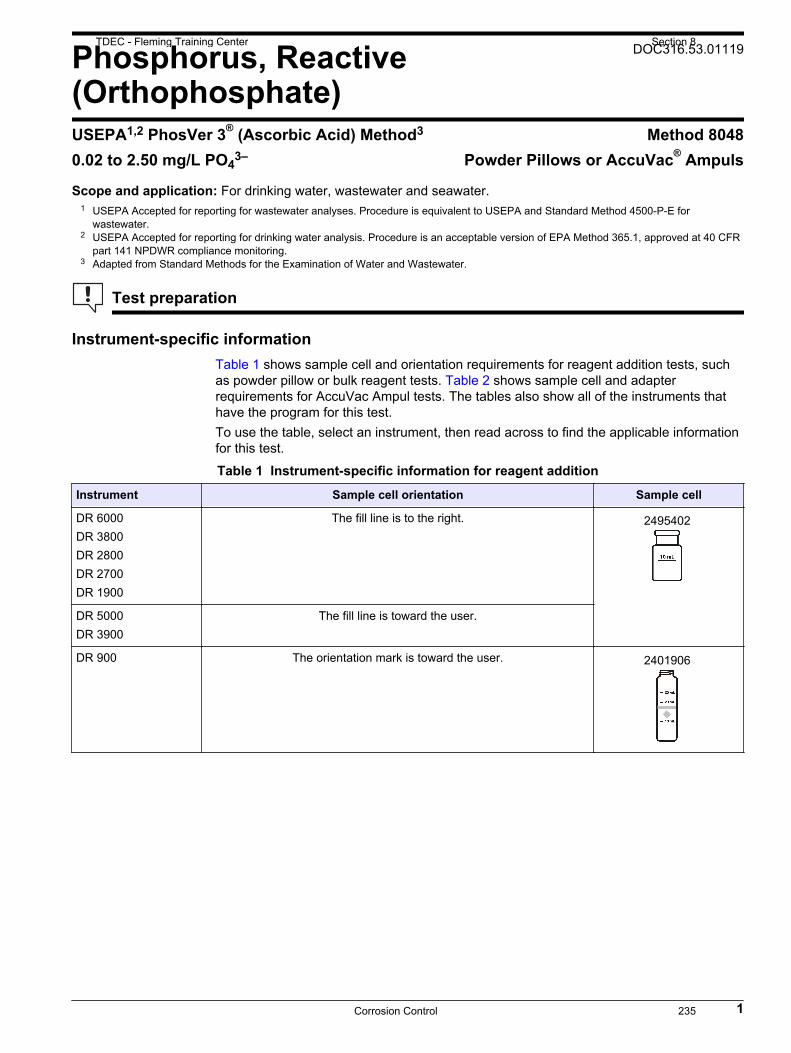
Phosphorus, Reactive(Orthophosphate)
DOC316.53.01119
USEPA1,2 PhosVer 3® (Ascorbic Acid) Method3 Method 80480.02 to 2.50 mg/L PO4
3– Powder Pillows or AccuVac® Ampuls
Scope and application: For drinking water, wastewater and seawater.1 USEPA Accepted for reporting for wastewater analyses. Procedure is equivalent to USEPA and Standard Method 4500-P-E for
wastewater.2 USEPA Accepted for reporting for drinking water analysis. Procedure is an acceptable version of EPA Method 365.1, approved at 40 CFR
part 141 NPDWR compliance monitoring.3 Adapted from Standard Methods for the Examination of Water and Wastewater.
Test preparation
Instrument-specific informationTable 1 shows sample cell and orientation requirements for reagent addition tests, suchas powder pillow or bulk reagent tests. Table 2 shows sample cell and adapterrequirements for AccuVac Ampul tests. The tables also show all of the instruments thathave the program for this test.To use the table, select an instrument, then read across to find the applicable informationfor this test.
Table 1 Instrument-specific information for reagent addition
Instrument Sample cell orientation Sample cell
DR 6000 DR 3800 DR 2800 DR 2700 DR 1900
The fill line is to the right. 2495402
DR 5000 DR 3900
The fill line is toward the user.
DR 900 The orientation mark is toward the user. 2401906
1
TDEC - Fleming Training Center Section 8
Corrosion Control 235

Table 2 Instrument-specific information for AccuVac Ampuls
Instrument Adapter Sample cell
DR 6000 DR 5000 DR 900
— 2427606
DR 3900 LZV846 (A)
DR 1900 9609900 or 9609800 (C)
DR 3800 DR 2800 DR 2700
LZV584 (C) 2122800
Before startingInstall the instrument cap on the DR 900 cell holder before ZERO or READ is pushed.
For the best results, measure the reagent blank value for each new lot of reagent. Replace the sample with deionized waterin the test procedure to determine the reagent blank value. Subtract the reagent blank value from the sample resultsautomatically with the reagent blank adjust option.
Review the Safety Data Sheets (MSDS/SDS) for the chemicals that are used. Use the recommended personal protectiveequipment.
Dispose of reacted solutions according to local, state and federal regulations. Refer to the Safety Data Sheets for disposalinformation for unused reagents. Refer to the environmental, health and safety staff for your facility and/or local regulatoryagencies for further disposal information.
Items to collectPowder pillows
Description Quantity
PhosVer® 3 Phosphate Reagent powder pillow, 10-mL 1
Sample cells. (For information about sample cells, adapters or light shields, refer to Instrument-specific information on page 1.) 2
Refer to Consumables and replacement items on page 6 for order information.
AccuVac Ampuls
Description Quantity
PhosVer® 3 Phosphate Reagent AccuVac® Ampul 1
Beaker, 50-mL 1
Sample cells (For information about sample cells, adapters or light shields, refer to Instrument-specific information on page 1.) 1
Stopper for 18-mm tubes and AccuVac Ampuls 1
Refer to Consumables and replacement items on page 6 for order information.
Sample collection and storage• Collect samples in clean glass or plastic bottles that have been cleaned with 6 N (1:1)
hydrochloric acid and rinsed with deionized water.
2 Phosphorus, Reactive, PhosVer 3 Method (2.50 mg/L)
Section 8 TDEC - Fleming Training Center
Corrosion Control236

• Do not use a detergent that contains phosphate to clean the sample bottles. Thephosphate in the detergent will contaminate the sample.
• Analyze the samples as soon as possible for best results.• If immediate analysis is not possible, immediately filter and keep the samples at or
below 6 °C (43 °F) for a maximum of 48 hours.• Let the sample temperature increase to room temperature before analysis.
Powder pillow procedure
Start
1. Start program 490 PReact. PP. For informationabout sample cells,adapters or light shields,refer to Instrument-specificinformation on page 1.
2. Prepare the sample: Filla sample cell with 10 mL ofsample.
3. Add the contents of onePhosVer 3 PhosphateReagent Powder Pillow tothe cell. A blue colordevelops if phosphorus is inthe sample.
4. Immediately close thesample cell. Shakevigorously for20–30 seconds.
5. Start the instrumenttimer. A 2‑minute reactiontime starts.If the sample was digestedusing the Acid Persulfatedigestion, a 10‑minutereaction period isnecessary.
6. Prepare the blank: Fill asecond sample cell with10 mL of sample.
7. When the timer expires,clean the blank sample cell.
8. Insert the blank into thecell holder.
Zero
9. Push ZERO. The displayshows 0.00 mg/L PO4
3–.10. Clean the preparedsample cell.
11. Insert the preparedsample into the cell holder.
Read
12. Push READ. Resultsshow in mg/L PO4
3–.
Phosphorus, Reactive, PhosVer 3 Method (2.50 mg/L) 3
TDEC - Fleming Training Center Section 8
Corrosion Control 237

AccuVac Ampul procedure
Start
1. Start program 492 PReact. PV AV. Forinformation about samplecells, adapters or lightshields, refer to Instrument-specific informationon page 1.
2. Prepare the blank: Fillthe sample cell with 10 mLof sample.
3. Prepare the sample:Collect at least 40 mL ofsample in a 50‑mL beaker.Fill the AccuVac Ampul withsample. Keep the tipimmersed while theAccuVac Ampul fillscompletely.
4. Close the AccuVacAmpul. Shake forapproximately 30 seconds.Accuracy is not affected byundissolved powder.
5. Start the instrumenttimer. A 2‑minute reactiontime starts.If the sample was digestedusing the Acid Persulfatedigestion, a 10‑minutereaction period isnecessary.
6. When the timer expires,clean the blank sample cell.
7. Insert the blank into thecell holder.
Zero
8. Push ZERO. The displayshows 0.00 mg/L PO4
3–.
9. Clean the AccuVacAmpul.
10. Insert the preparedsample AccuVac Ampul intothe cell holder.
Read
11. Push READ. Resultsshow in mg/L PO4
3–.
4 Phosphorus, Reactive, PhosVer 3 Method (2.50 mg/L)
Section 8 TDEC - Fleming Training Center
Corrosion Control238

InterferencesInterfering substance Interference level
Aluminum More than 200 mg/L
Arsenate Interferes at any level
Chromium More than 100 mg/L
Copper More than 10 mg/L
Hydrogen Sulfide Interferes at any level
Iron More than 100 mg/L
Nickel More than 300 mg/L
Highly buffered samples orextreme sample pH
Can prevent the correct pH adjustment (of the sample) by the reagents. Samplepretreatment may be necessary. A pH range of 2–10 is recommended.
Silica More than 50 mg/L
Silicate More than 10 mg/L
Turbidity or color Samples with a high amount of turbidity can give inconsistent results. The acid in thereagents can dissolve some of the suspended particles and variable desorption oforthophosphate from the particles can occur.
Zinc More than 80 mg/L
Accuracy check
Standard additions method (sample spike)Use the standard additions method (for applicable instruments) to validate the testprocedure, reagents and instrument and to find if there is an interference in the sample.Items to collect:
• Phosphate standard solution, 50 mg/L PO43– ampule
• Ampule breaker• Pipet, TenSette®, 0.1–1.0 mL and tips• Mixing cylinders, 25-mL (3)
1. Use the test procedure to measure the concentration of the sample, then keep the(unspiked) sample in the instrument.
2. Go to the Standard Additions option in the instrument menu.3. Select the values for standard concentration, sample volume and spike volumes.4. Open the standard solution.5. Prepare three spiked samples: use the TenSette pipet to add 0.1 mL, 0.2 mL and
0.3 mL of the standard solution, respectively, to three 10-mL portions of fresh sample.Mix well.Note: For AccuVac® Ampuls, add 0.2 mL, 0.4 mL and 0.6 mL of the standard solution to three50-mL portions of fresh sample.
6. Use the test procedure to measure the concentration of each of the spiked samples.Start with the smallest sample spike. Measure each of the spiked samples in theinstrument.
7. Select Graph to compare the expected results to the actual results.Note: If the actual results are significantly different from the expected results, make sure thatthe sample volumes and sample spikes are measured accurately. The sample volumes andsample spikes that are used should agree with the selections in the standard additions menu. Ifthe results are not within acceptable limits, the sample may contain an interference.
Standard solution methodUse the standard solution method to validate the test procedure, the reagents and theinstrument.
Phosphorus, Reactive, PhosVer 3 Method (2.50 mg/L) 5
TDEC - Fleming Training Center Section 8
Corrosion Control 239

Items to collect:
• 50 mg/L phosphate standard solution• 100-mL volumetric flask, Class A• 4-mL volumetric pipet, Class A and pipet filler safety bulb• Deionized water
1. Prepare a 2.00-mg/L phosphate standard solution as follows:
a. Use a pipet to add 4.00 mL of a 50-mg/L phosphate standard solution into thevolumetric flask. (Alternately, use one of the available mixed parameterstandards. These standards contain 2.0 mg/L phosphate.)
b. Dilute to the mark with deionized water. Mix well. Prepare this solution daily.2. Use the test procedure to measure the concentration of the prepared standard
solution.3. Compare the expected result to the actual result.
Note: The factory calibration can be adjusted slightly with the standard adjust option so that theinstrument shows the expected value of the standard solution. The adjusted calibration is thenused for all test results. This adjustment can increase the test accuracy when there are smallvariations in the reagents or instruments.
Method performanceThe method performance data that follows was derived from laboratory tests that weremeasured on a spectrophotometer during ideal test conditions. Users can get differentresults under different test conditions.
Program Standard Precision (95% Confidence Interval) SensitivityConcentration change per 0.010 Abs change
490 2.00 mg/L PO43– 1.98–2.02 mg/L PO4
3– 0.02 mg/L PO43–
492 2.00 mg/L PO43– 1.98–2.02 mg/L PO4
3– 0.02 mg/L PO43–
Summary of methodOrthophosphate reacts with molybdate in an acid medium to produce a mixedphosphate/molybdate complex. Ascorbic acid then reduces the complex, which gives anintense molybdenum blue color. The measurement wavelength is 880 nm forspectrophotometers (DR 1900: 710 nm) or 610 nm for colorimeters.
Consumables and replacement itemsRequired reagents
Description Quantity/Test Unit Item no.
PhosVer® 3 Phosphate Reagent Powder Pillow1, 10 mL 1 100/pkg 2106069
OR
PhosVer® 3 Phosphate Reagent AccuVac® Ampul 1 25/pkg 2508025
Required apparatus
Description Quantity/Test Unit Item no.
Beaker, 50 mL 1 each 50041H
Stoppers for 18-mm tubes and AccuVac Ampuls 2 6/pkg 173106
1 PhosVer is a registered trademark of Hach Company.
6 Phosphorus, Reactive, PhosVer 3 Method (2.50 mg/L)
Section 8 TDEC - Fleming Training Center
Corrosion Control240

Recommended standards
Description Unit Item no.
Phosphate Standard Solution, 10-mL Voluette® Ampule, 50 mg/L as PO4 16/pkg 17110
Phosphate Standard Solution, 50 mg/L as PO43– 500 mL 17149
Phosphate Standard Solution, 1 mg/L as PO43– 500 mL 256949
Drinking Water Standard, Mixed Parameter, Inorganic for F-, NO3–N, PO43–, SO4
2– 500 mL 2833049
Wastewater Effluent Standard Solution, Mixed Parameter, for NH3-N, NO3-N, PO43–,
COD, SO42–, TOC 500 mL 2833249
Water, deionized 4 L 27256
Optional reagents and apparatus
Description Unit Item no.
AccuVac® Drainer each 4103600
AccuVac® Ampul Snapper each 2405200
AccuVac® Ampul vials for sample blanks 25/pkg 2677925
Ampule Breaker, 10-mL Voluette® Ampules each 2196800
Bottle, sampling, with cap, low density polyethylene, 250 mL 12/pkg 2087076
Mixing cylinder, graduated, 50 mL each 189641
Flask, volumetric, Class A, 100 mL, glass each 1457442
Hydrochloric Acid Solution, 6.0 N (1:1) 500 mL 88449
Paper, pH, 0–14 pH range 100/pkg 2601300
Phosphate Treatment Powder Pillows 100/pkg 1450199
Phosphate Standard Solution, 10 mg/L as PO4 946 mL 1420416
Phosphate Standard Solution, 15-mg/L as PO43– 100 mL 1424342
Phosphate Standard Solution, 100-mg/L as PO4 100 mL 1436832
Phosphate Standard Solution, 10-mL ampule, 500 mg/L as PO4 16/pkg 1424210
Phosphate Standard Solution, 500-mg/L as PO4 100 mL 1424232
Pipet, TenSette®, 0.1–1.0 mL each 1970001
Pipet, TenSette®, 1.0–10.0 mL each 1970010
Pipet tips for TenSette® Pipet, 0.1–1.0 mL 50/pkg 2185696
Pipet tips for TenSette® Pipet, 0.1–1.0 mL 1000/pkg 2185628
Pipet tips for TenSette® Pipet, 1.0–10.0 mL 50/pkg 2199796
Pipet tips for TenSette® Pipet, 1.0–10.0 mL 250/pkg 2199725
Pipet, volumetric, Class A, 4.00 mL each 1451504
Phosphorus, Reactive, PhosVer 3 Method (2.50 mg/L) 7
TDEC - Fleming Training Center Section 8
Corrosion Control 241

HACH COMPANYWORLD HEADQUARTERSTelephone: (970) 669-3050FAX: (970) 669-2932
FOR TECHNICAL ASSISTANCE, PRICE INFORMATION AND ORDERING:Call 800-227-4224
Contact the HACH office or distributor serving you.www.hach.com [email protected]
In the U.S.A. –
Outside the U.S.A. –
On the Worldwide Web – ; E-mail –
toll-free
© Hach Company/Hach Lange GmbH, 1989–2017. All rights reserved. 01/2017, Edition 10
Section 8 TDEC - Fleming Training Center
Corrosion Control242

Phosphorus Lab
Bench Sheet
Total Phosphorus Test Results (mg/L PO4
3‐)
Tap Water Standard
TNT843
Test ‘N Tube Vials
Spike (r2)
Reac ve (Ortho) Phosphorus Test Results (mg/L PO4
3‐)
Tap Water Standard
TNT843
Powder Pillow
Spike (r2)
TDEC - Fleming Training Center Section 8
Corrosion Control 243

244

Section 9
Lead and Copper Sampling
245

Lead&CopperWater Treatment Lab
1
TD
EC
-F
lem
ing
Tra
inin
g C
ente
r
TD
EC
-F
lem
ing
Tra
inin
g C
ente
r
2
Lead• Primary cause of contamination in drinking water
• Caused by corrosion of leaded materials in the water distribution system
• Lead ‐ based solder used to join copper pipe• Brass ‐ and chrome‐plated brass faucets• Lead service lines that connect houses to water mains
TD
EC
-F
lem
ing
Tra
inin
g C
ente
r
3
HealthEffectsofLeadContamination• Children
• Altered physical/mental development• Interference with growth• Deficits in IQ, attention span and hearing• Interference with heme (blood) synthesis
• Women• Increased blood pressure• Shorter gestation period
• Men• Increased blood pressure
TD
EC
-F
lem
ing
Tra
inin
g C
ente
r
4
HealthEffectsofCopperContamination• Complications of Wilson’s Disease
• Wilson’s Disease is a hereditary liver condition that restricts the body’s ability to metabolize copper
• Stomach and intestinal distress• Liver or kidney damage
TD
EC
-F
lem
ing
Tra
inin
g C
ente
r
5
TreatmentTechniques• Corrosion control – Lead & Copper• Source water treatment – Lead & Copper• Lead service line replacement – Lead • Public education – Lead
TD
EC
-F
lem
ing
Tra
inin
g C
ente
r
6
Section 9 TDEC - Fleming Training Center
Lead and Copper Sampling246

ActionLevels• Lead = 0.015 mg/L• Copper = 1.3 mg/L
• A system is often required to begin initiating treatment techniques when lead and/or copper levels in more than 10%
of samples exceed these levels
TD
EC
-F
lem
ing
Tra
inin
g C
ente
r
7
WaterQualityParameters
• pH• Alkalinity• Calcium• Conductivity• Water temperature• Orthophosphate or silica
• If an inhibitor containing these compounds is used
TD
EC
-F
lem
ing
Tra
inin
g C
ente
r
8
SampleSiteSelection• All public water systems are required to sample at the customer’s tap
• Specified targeting criteria have been selected to indicate probability of lead or copper contamination and to create a tiered system
TD
EC
-F
lem
ing
Tra
inin
g C
ente
r
9
Howmanysamplingsites?• The number of sampling sites are determined by the size of the population served by the system
TD
EC
-F
lem
ing
Tra
inin
g C
ente
r
10
Tier1
• Consists of single family structures with:• Copper pipes with lead solder installed after 1982• Interior lead piping• Lead service lines
• May include multiple family residences if these comprise of more than 20% of the service connections to the public water supply
TD
EC
-F
lem
ing
Tra
inin
g C
ente
r
11
Tier2• Consist of buildings, including multiple family residences, with:
• Copper pipes with lead solder installed after 1982• Interior lead piping• Lead service lines
TD
EC
-F
lem
ing
Tra
inin
g C
ente
r
12
TDEC - Fleming Training Center Section 9
Lead and Copper Sampling 247

Tier3• Consist of single family structures with:
• Copper pipes with lead solder installed before 1983
TD
EC
-F
lem
ing
Tra
inin
g C
ente
r
13
TapWaterSamples• First draw
• Tap water that has remained motionless in the plumbing system for at least 6 hours
• Collected without flushing the tap• One liter• Collected from a cold water kitchen tap or from a bathroom sink
TD
EC
-F
lem
ing
Tra
inin
g C
ente
r
14
TapWaterSamples• Samples should be preserved with nitric acid (HNO3) to a pH<2• Plastic or glass container• Holding time is 6 months
TD
EC
-F
lem
ing
Tra
inin
g C
ente
r
15
Reporting
• Results of all tap samples for lead and copper• Location of each site• Criteria used for site selection
• Certification that lead and copper samples were collected properly
• Certification that residents who collected lead and copper samples were informed of correct sampling procedures
TD
EC
-F
lem
ing
Tra
inin
g C
ente
r
16
Reporting
• Lead and copper 90th percentile concentrations• Designation of any new sampling sites
• Explanation of why sites have changed
• Result of all tap sampling for pH and other water quality parameters
• Results of all water quality samples collected at entry point(s) to the distribution system
TD
EC
-F
lem
ing
Tra
inin
g C
ente
r
17
90th PercentileConcentrations
• 0400‐45‐1.33(1)(c)(i) – The results of all lead or copper samples taken during a monitoring period shall be placed in ascending order from the sample with the lowest concentration to the sample with the highest concentration.
• Each sampling result shall be assigned a number, ascending by single integers beginning with the number 1 for the sample with the lowest contaminant level.
TD
EC
-F
lem
ing
Tra
inin
g C
ente
r
18
Section 9 TDEC - Fleming Training Center
Lead and Copper Sampling248

90th PercentileConcentrations
• 0400‐45‐1.33(1)(c)(i) cont. – The number assigned to the sample with the highest contaminant level shall be equal to the total number of samples taken.
• 0400‐45‐1.33(1)(c)(ii) – The number of samples taken during the monitoring period shall be multiplied by 0.9.
TD
EC
-F
lem
ing
Tra
inin
g C
ente
r
19
90th PercentileConcentrations
• 0400‐45‐1.33(1)(c)(iii) – The contaminant concentration in the numbered sample yielded by the calculation in (c)3(ii) is the 90th percentile contaminant level.
• 0400‐45‐1.33(1)(c)(iv) – For water systems serving fewer than 100 people that collect 5 samples per monitoring period, the 90th percentile is computed by taking the average of the highest and second highest concentrations.
TD
EC
-F
lem
ing
Tra
inin
g C
ente
r
20
90th PercentileConcentrations• Copper Samples
1. 0.032. 0.113. 0.234. 0.275. 0.286. 0.597. 0.638. 0.989. 1.31
90th Percentile is less than the action level
0400-45-1.33(1)(c)(ii) (0.9)(9) = 8.1
TD
EC
-F
lem
ing
Tra
inin
g C
ente
r
21
RecordKeeping• Systems must retain on its premises original records of:
• All sampling data and analyses• Reports• Surveys• Letters• Evaluations• Schedules• State determinations
• These records must be kept for 12 years
TD
EC
-F
lem
ing
Tra
inin
g C
ente
r
22
TDEC - Fleming Training Center Section 9
Lead and Copper Sampling 249

Lead and Copper
Review Questions
1. Name the primary cause of lead contamination in drinking water.
2. List two negative health effects of lead contamination.
3. List two negative health effects of copper contamination.
4. What are the treatment technique requirements specified in the Lead and Copper
Rule?
5. What is the action level for lead and for copper?
Section 9 TDEC - Fleming Training Center
Lead and Copper Sampling250

6. For community water systems, Tier 1 sampling sites consist of single family
structures with:
a ____________________________________________________________
b ____________________________________________________________
c ____________________________________________________________
7. All tap water samples must be ____________ in volume and must have stood
motionless in the plumbing system of the sampling site for at least ______ hours.
8. True or False. The number of sampling sites is determined by the size of the
population served by the system.
9. The Lead and Copper Rule specifies that systems must monitor the following
water quality parameters:
a ____________________________________________________________
b ____________________________________________________________
c ____________________________________________________________
d ____________________________________________________________
e ____________________________________________________________
f ____________________________________________________________
g ____________________________________________________________
10. How many years must the system keep records required by the Lead and Copper
Rule?
11. How do you preserve a sample for Lead and Copper and what is the holding
time?
TDEC - Fleming Training Center Section 9
Lead and Copper Sampling 251

Answers 1. Corrosion of lead-containing materials in distribution and plumbing systems. 2. Negative health effects of lead contamination include:
a Increased blood pressure b Shorter gestational period for pregnant women c Brain, red blood cell and kidney damage d Deficits in IQ, attention span and hearing in children e Interference with growth in children f Interference with heme (blood) synthesis in children g Slowed mental and physical development in children
3. Negative health effects of copper contamination include: a Stomach and intestinal
distress b Complications of Wilson’s
disease
c Liver and kidney damage d Anemia
4. The treatment technique requirements specified in the Lead and Copper Rule are: a For lead: corrosion control treatment, source water treatment, lead service
line replacement, public education b For copper: corrosion control treatment and source water treatment
5. The action level for lead is exceeded if more than 10% of samples have lead concentrations greater than 0.015 mg/L (15 ppb). The action level for copper is exceeded if more than 10% of samples have copper concentrations greater than 1.3 mg/L.
6. For CWSs, Tier 1 sampling sites consist of single family structures with: a Copper pipes with lead solder installed after 1982 b Interior lead piping c Lead service lines
7. All tap water samples must be 1L in volume and must have stood motionless in the plumbing system of the sampling site for at 6 hours.
8. True 9. The Lead and Copper Rule specifies that systems must monitor the following
water quality parameters: a pH b Alkalinity c Orthophosphate d Silica
e Conductivity f Calcium g Water temperature
10. at least 12 years 11. Preserve with HNO3 (nitric acid) to a pH<2 in a plastic or glass container with a
holding time of 6 months.
Section 9 TDEC - Fleming Training Center
Lead and Copper Sampling252

TDEC - Fleming Training Center Section 9
Lead and Copper Sampling 253

The New Lead and Copper Rule
On December 22, 2020, U.S. Environmental Protection
Agency (EPA) finalized the first major update to the Lead
and Copper Rule (LCR) in nearly 30 years. EPA’s new
rule strengthens every aspect of the LCR to better protect
children and communities from the risks of lead exposure.
The new LCR will better protect children at elementary
schools and child care facilities, get the lead out of our
nation’s drinking water, and empower communities
through information.
Better Protecting Children at Elementary
Schools and Child Care Facilities Children spend a large amount of time in elementary
schools and child care facilities and lead in the internal
plumbing of these facilities can pose a risk to children’s
health. For the first time, the new Lead and Copper Rule
requires that community water systems test for lead in
drinking water in elementary schools and child care
facilities that they serve. The old rule had no federal
requirement for community water systems to test for lead
in drinking water in these buildings. This common sense
and critical improvement ensures that children—who are at
increased risk from lead exposure—are protected where
they spend a significant amount of time learning and playing. The water system is also required
to provide timely results along with information about the actions the elementary school or child
care facility can take to reduce lead in drinking water.
Getting the Lead Out EPA’s new rule uses science-based testing protocols to find more sources of lead in drinking
water. The new rule also triggers actions to address lead earlier in more communities and reduces
lead by more effectively managing corrosion control treatment, closing loopholes, and replacing
more lead service lines in their entirety.
Better Science, Better Testing
The old rule enabled sampling techniques that could underestimate lead in drinking water. Based
on better science, the new LCR requires water systems to follow new, improved tap sampling
procedures that will better locate elevated levels of lead in drinking water. One key improvement
in testing protocols is the new “fifth liter” sampling requirement, which captures lead that can
enter drinking water from a lead service line (LSL)—a lead pipe that connects tap-water service
between a water main and house or building. Under the new rule, a sampler must draw four liters
of water before collecting a test sample so that the water is more likely to come from the lead
service line and not the internal plumbing of a building. To get the most accurate test results, the
rule also requires wide-mouth bottles for collecting samples and prohibits sampling instructions
that recommend flushing and cleaning or removing the screen (called an aerator) that covers the
In older homes and buildings, lead
can leach from service lines, solder,
and fixtures into tap water and
become a significant source of lead
exposure. In children, lead exposure
can cause irreversible and life-long
health effects, including decreasing
IQ, focus, and academic
achievement. EPA’s new Lead and
Copper Rule strengthens regulatory
requirements to better protect
children and communities from lead
in drinking water.
Section 9 TDEC - Fleming Training Center
Lead and Copper Sampling254

faucet before collecting samples. Additionally, to target homes with the highest potential for
elevated lead levels, systems must collect samples at homes with lead service lines. If there are
no LSLs, systems must collect samples from other leaded plumbing. When an individual sample
at a home exceeds 15 ppb, systems must conduct follow-up sampling as part of a find-and-fix
process to identify sources of lead and actions to reduce lead in the drinking water.
Triggering Actions to Reduce Lead Exposure Earlier and in More Communities
The new LCR jumpstarts corrosion control and actions to replace lead service lines—the primary
sources of lead in drinking water—in more communities across the country. Because lead can
corrode (or leach) from leaded plumbing as water flows through it, systems that take steps to
control that corrosion or remove lead service lines can reduce the amount of lead that makes it
into the drinking water supply. The rule establishes a new threshold of 10 ppb, that when
exceeded, requires more and rapid implementation of corrosion control treatment to reduce lead
in drinking water. The old rule allowed up to 48 months—four years—to pass in our small towns
after a system exceeded the 15 ppb action level before corrosion control was in place. The new
rule’s trigger level requires systems that already have corrosion control to re-optimize their
treatment. It also requires systems that do not have corrosion control to conduct a corrosion
control study to identify the best treatment approach. If that system exceeds the action level in
the future, the system must install the treatment it identified in its study right away. The 10 ppb
trigger level also requires systems to start lead service line replacement programs.
Closing Loopholes and Replacing More Lead Service Lines in Their Entirety
The new LCR will drive more instances where lead service lines are replaced in their entirety.
The old rule created so many loopholes that since 1991—over nearly 30 years—only 1 percent
of utilities actually replaced lead pipes as a result of an action level exceedance. Under the new
rule, water systems will be required to fully replace at least 3 percent of lead service lines each
year when 10 percent of sampling results are above 15 ppb. The new rule’s real 3 percent
replacement rate will do more to remove lead service lines than the old rule’s unmet 7 percent
rate by propelling early action, closing loopholes, and strengthening replacement requirements.
Under the new rule, systems:
• Must have a plan in place and must start replacing lines as soon as sample results are
above the trigger or action level.
• Cannot avoid replacing lead service lines through testing.
• Are required to replace the water system-owned portion of a lead service line when a
customer chooses to replace their customer-owned portion of the line.
Additionally, partial lead service line replacements, which can lead to short term spikes in lead
concentrations, will not meet the new requirements. Under the old rule, partial service line
replacements were allowed and were common.
Empowering Communities In order for individuals, communities, water systems, and local governments to effectively take
action to reduce lead in drinking water, they need to know where lead service lines are and what
resources are available to help address lead in drinking water. The new Lead and Copper Rule
builds the information infrastructure needed to empower these decisions.
Public Inventory of Lead Service Lines
TDEC - Fleming Training Center Section 9
Lead and Copper Sampling 255

Under the new rule, water systems are required to identify and make public the locations of lead
service lines, following the example of many cities across the country who have proactively
taken this step. By providing thorough and transparent information on where lead service lines
exist, communities can make informed decisions to reduce lead exposure. Additionally, residents
with a known or potential lead service line will be notified and receive information about steps
that they can take to reduce their exposure to lead in drinking water.
Timely Testing Notifications and Lead Reduction Options for Homeowners
If a sample taken from a home has a result over 15 ppb of lead, the water system must notify
occupants of the home within three days, so that steps to reduce lead exposure can be taken
immediately. Notification of tap sample results under 15 ppb will occur within 30 days. If there
is a systemwide action level exceedance, water systems will notify all customers within 24 hours
and provide educational materials within 60 days. Water systems will also notify homeowners
and building owners about opportunities to replace lead service lines, including information
about financial assistance programs, if available, to help pay for replacing the customer-owned
side of the line.
Information on Funding Resources to Support Lead Service Line Replacement
To help communities as they make decisions about funding, EPA has compiled information
about federal funding, case studies, and other additional resources to assist states, local and tribal
governments, and water utilities. These options include EPA’s Drinking Water State Revolving
Loan Fund, the Water Infrastructure Improvements for the Nation Act (WIIN) Grant, Water
Infrastructure Finance and Innovation Act (WIFIA) financing program, as well as the Housing
and Urban Development’s (HUD) Community Development Block Grants. For a list of funding
opportunities and for additional information on how to apply for and meet the funding
requirements please visit: www.epa.gov/safewater/pipereplacement.
For more information on the new Lead and Copper Rule visit:
https://www.epa.gov/ground-water-and-drinking-water/final-revisions-lead-and-copper-rule
Section 9 TDEC - Fleming Training Center
Lead and Copper Sampling256

Copper DOC316.53.01255
Bathocuproine Method1 Method 102380.1 to 8.0 mg/L Cu TNTplus™ 860
Scope and application: For water, wastewater and process water. Digestion can be necessary to determine totalcopper.
1 Adapted from Standard Methods for the Examination of Water and Wastewater.
Test preparation
Instrument-specific informationTable 1 shows all of the instruments that have the program for this test. The table alsoshows the adapter and light shield requirements for the applicable instruments that canuse TNTplus vials.To use the table, select an instrument, then read across to find the applicable informationfor this test.
Table 1 Instrument-specific information for TNTplus vials
Instrument Adapters Light shield
DR 6000, DR 5000 — —
DR 3900 — LZV849
DR 3800, DR 2800 — LZV646
DR 1900 9609900 or 9609800 (A) —
Before startingDR 3900, DR 3800, DR 2800: Install the light shield in Cell Compartment #2 before this test is started.
Review the safety information and the expiration date on the package.
The recommended sample pH is 2.5–11.
The recommended temperature for samples and reagents is 15–25 °C (59–77 °F).
The recommended temperature for reagent storage is 15–25 °C (59–77 °F).
To make sure that all forms of the metal are measured, digest the sample with heat and acid. Use the Metals Prep SetTNTplus 890 to digest the sample.
DR 1900: Go to All Programs>LCK or TNTplus Methods>Options to select the TNTplus number for the test. Otherinstruments automatically select the method from the barcode on the vial.
Review the Safety Data Sheets (MSDS/SDS) for the chemicals that are used. Use the recommended personal protectiveequipment.
Dispose of reacted solutions according to local, state and federal regulations. Refer to the Safety Data Sheets for disposalinformation for unused reagents. Refer to the environmental, health and safety staff for your facility and/or local regulatoryagencies for further disposal information.
Items to collect
Description Quantity
Copper TNTplus reagent set 1
Pipet, adjustable volume, 1.0–5.0 mL 1
Pipet tips, for 1.0–5.0 mL pipet 1
1
TDEC - Fleming Training Center Section 9
Lead and Copper Sampling 257
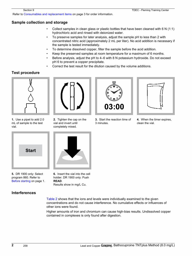
Refer to Consumables and replacement items on page 3 for order information.
Sample collection and storage• Collect samples in clean glass or plastic bottles that have been cleaned with 6 N (1:1)
hydrochloric acid and rinsed with deionized water. • To preserve samples for later analysis, adjust the sample pH to less than 2 with
concentrated nitric acid (approximately 2 mL per liter). No acid addition is necessary ifthe sample is tested immediately.
• To determine dissolved copper, filter the sample before the acid addition.• Keep the preserved samples at room temperature for a maximum of 6 months.• Before analysis, adjust the pH to 4–6 with 8 N potassium hydroxide. Do not exceed
pH 6 to prevent a copper precipitate.• Correct the test result for the dilution caused by the volume additions.
Test procedure
1. Use a pipet to add 2.0mL of sample to the testvial.
2. Tighten the cap on thevial and invert untilcompletely mixed.
3. Start the reaction time of3 minutes.
4. When the timer expires,clean the vial.
Start
5. DR 1900 only: Selectprogram 860. Refer to Before starting on page 1.
6. Insert the vial into the cellholder. DR 1900 only: PushREAD.Results show in mg/L Cu.
InterferencesTable 2 shows that the ions and levels were individually examined to the givenconcentrations and do not cause interference. No cumulative effects or influences ofother ions were found.Higher amounts of iron and chromium can cause high-bias results. Undissolved coppercontained in complexes is only found after digestion.
2 Copper, Bathocuproine TNTplus Method (8.0 mg/L)
Section 9 TDEC - Fleming Training Center
Lead and Copper Sampling258
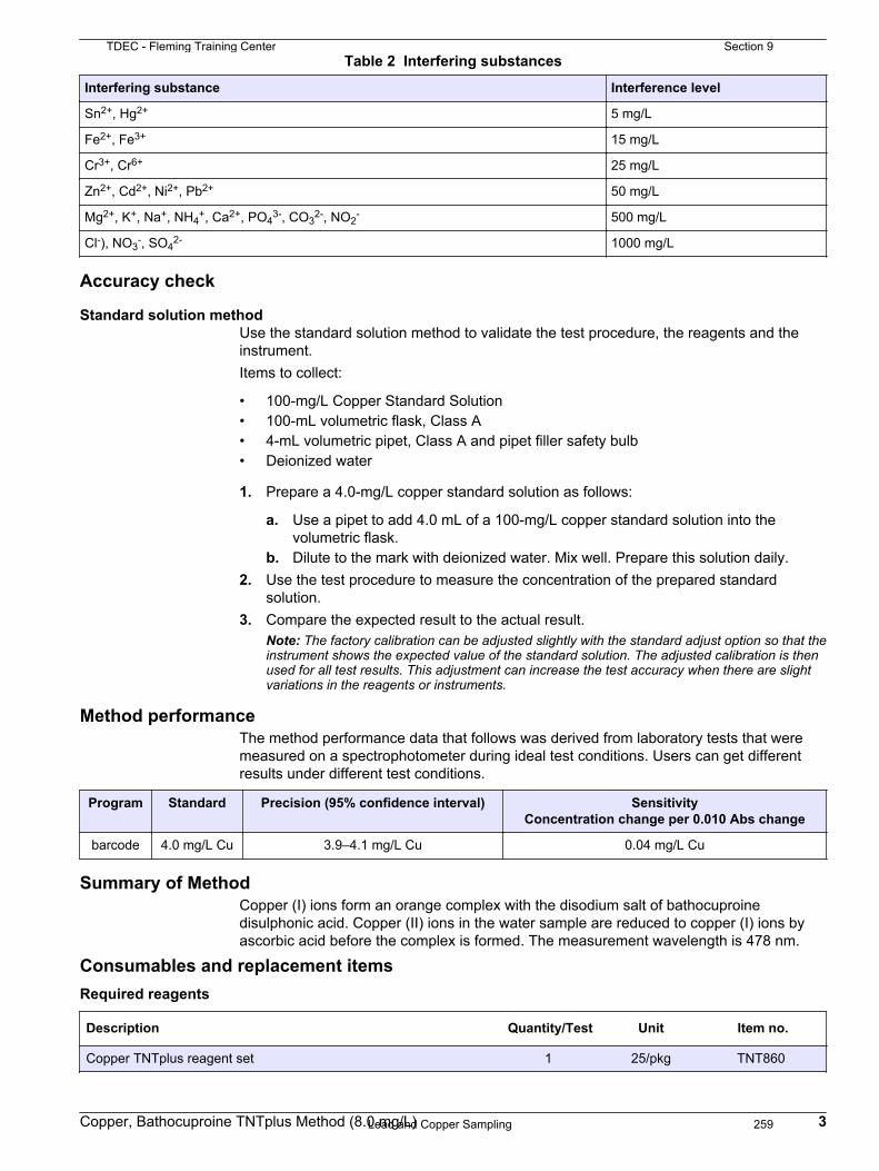
Table 2 Interfering substances
Interfering substance Interference level
Sn2+, Hg2+ 5 mg/L
Fe2+, Fe3+ 15 mg/L
Cr3+, Cr6+ 25 mg/L
Zn2+, Cd2+, Ni2+, Pb2+ 50 mg/L
Mg2+, K+, Na+, NH4+, Ca2+, PO4
3-, CO32-, NO2
- 500 mg/L
Cl-), NO3-, SO4
2- 1000 mg/L
Accuracy check
Standard solution methodUse the standard solution method to validate the test procedure, the reagents and theinstrument.Items to collect:
• 100-mg/L Copper Standard Solution• 100-mL volumetric flask, Class A• 4-mL volumetric pipet, Class A and pipet filler safety bulb• Deionized water
1. Prepare a 4.0-mg/L copper standard solution as follows:
a. Use a pipet to add 4.0 mL of a 100-mg/L copper standard solution into thevolumetric flask.
b. Dilute to the mark with deionized water. Mix well. Prepare this solution daily.2. Use the test procedure to measure the concentration of the prepared standard
solution.3. Compare the expected result to the actual result.
Note: The factory calibration can be adjusted slightly with the standard adjust option so that theinstrument shows the expected value of the standard solution. The adjusted calibration is thenused for all test results. This adjustment can increase the test accuracy when there are slightvariations in the reagents or instruments.
Method performanceThe method performance data that follows was derived from laboratory tests that weremeasured on a spectrophotometer during ideal test conditions. Users can get differentresults under different test conditions.
Program Standard Precision (95% confidence interval) SensitivityConcentration change per 0.010 Abs change
barcode 4.0 mg/L Cu 3.9–4.1 mg/L Cu 0.04 mg/L Cu
Summary of MethodCopper (I) ions form an orange complex with the disodium salt of bathocuproinedisulphonic acid. Copper (II) ions in the water sample are reduced to copper (I) ions byascorbic acid before the complex is formed. The measurement wavelength is 478 nm.
Consumables and replacement itemsRequired reagents
Description Quantity/Test Unit Item no.
Copper TNTplus reagent set 1 25/pkg TNT860
Copper, Bathocuproine TNTplus Method (8.0 mg/L) 3
TDEC - Fleming Training Center Section 9
Lead and Copper Sampling 259

Required apparatus
Description Quantity/test Unit Item no.
Pipet, adjustable volume, 1.0–5.0 mL 1 each BBP065
Pipet tips, for 1.0–5.0 mL pipet 1 75/pkg BBP068
Light shield, DR 3800, DR 2800, DR 2700 1 each LZV646
Light shield, DR 3900 1 each LZV849
Recommended standards
Description Unit Item no.
Copper Standard Solution, 100-mg/L as Cu 100 mL 12842
Optional reagents and apparatus
Description Unit Item no.
DRB 200 Reactor, 115 VAC option, 9 x 13 mm + 2 x 20 mm, 1 block each DRB20001
Flask, volumetric, Class A, 100-mL glass each 1457442
Metals Prep Set TNTplus 50/pkg TNT890
Nitric Acid, concentrated 500 mL 15249
Potassium Hydroxide Solution, 8 N 100 mL MDB 28232H
Sampling bottle with cap, low density polyethylene, 500-mL 12/pkg 2087079
Water, deionized 4 L 27256
HACH COMPANYWORLD HEADQUARTERSTelephone: (970) 669-3050FAX: (970) 669-2932
FOR TECHNICAL ASSISTANCE, PRICE INFORMATION AND ORDERING:Call 800-227-4224
Contact the HACH office or distributor serving you.www.hach.com [email protected]
In the U.S.A. –
Outside the U.S.A. –
On the Worldwide Web – ; E-mail –
toll-free
© Hach Company/Hach Lange GmbH, 2008, 2014. All rights reserved. 02/2014, Edition 2
Section 9 TDEC - Fleming Training Center
Lead and Copper Sampling260

Lead DOC316.53.01056
PAR Method Method 102160.1 to 2.0 mg/L Pb TNTplus™ 850
Scope and application: For wastewater and process control.
Test preparation
Instrument-specific informationTable 1 shows all of the instruments that have the program for this test. The table alsoshows the adapter and light shield requirements for the applicable instruments that canuse TNTplus vials.To use the table, select an instrument, then read across to find the applicable informationfor this test.
Table 1 Instrument-specific information for TNTplus vials
Instrument Adapters Light shield
DR 6000, DR 5000 — —
DR 3900 — LZV849
DR 3800, DR 2800 — LZV646
DR 1900 9609900 or 9609800 (A) —
Before startingDR 3900, DR 3800, DR 2800: Install the light shield in Cell Compartment #2 before this test is started.
Review the safety information and the expiration date on the package.
The recommended sample pH is 3–9.
The recommended temperature for samples and reagents is 15–25 °C (59–77 °F).
The recommended temperature for reagent storage is 2–8 °C (35–46 °F).
Samples that do not contain complexing agents and have a pH between 3 and 6 can be analyzed directly. Samples thathave a pH between 6 and 9 must be digested with the Metals Prep Set TNTplus 890 to bring undissolved lead hydroxide orcomplex lead compounds into solution.
DR 1900: Go to All Programs>LCK or TNTplus Methods>Options to select the TNTplus number for the test. Otherinstruments automatically select the method from the barcode on the vial.
Review the Safety Data Sheets (MSDS/SDS) for the chemicals that are used. Use the recommended personal protectiveequipment.
Dispose of reacted solutions according to local, state and federal regulations. Refer to the Safety Data Sheets for disposalinformation for unused reagents. Refer to the environmental, health and safety staff for your facility and/or local regulatoryagencies for further disposal information.
Items to collect
Description Quantity
Lead TNTplus Reagent Set 1
Pipet, adjustable volume, 0.2–1.0 mL 1
Pipet, adjustable volume, 1.0–5.0 mL 1
Pipet tips 1
1
TDEC - Fleming Training Center Section 9
Lead and Copper Sampling 261

Items to collect (continued)Description Quantity
Pipet, volumetric, Class A, 10.0 mL 1
Pipet filler, safety bulb 1
Refer to Consumables and replacement items on page 4 for order information.
Sample collection and storage• Collect samples in clean glass or plastic bottles that have been cleaned with 6 N (1:1)
hydrochloric acid and rinsed with deionized water. • To preserve samples for later analysis, adjust the sample pH to less than 2 with
concentrated nitric acid (approximately 2 mL per liter). No acid addition is necessary ifthe sample is tested immediately.
• Keep the preserved samples at room temperature for a maximum of 6 months.• Before analysis, adjust the pH to 3–6 with 5 N sodium hydroxide solution.• Correct the test result for the dilution caused by the volume additions.
Test procedure
1. Use a pipet to add 10 mLof sample to a 20‑mmreaction tube.
2. Add one level spoonful ofReagent A to the reactiontube.
3. Tighten the cap on thereaction tube and invert thevial 2–3 times.
4. Start the reaction time of2 minutes.
5. Use a pipet to add 1.5mL of Solution B to the testvial.
6. Use a pipet to add 4.0mL of the treated samplefrom the 20‑mm reactiontube to the vial.
7. Tighten the cap on thevial and invert the vial 2–3times.
8. Start the reaction time of2 minutes.
2 Lead, PAR TNTplus Method (2.0 mg/L)
Section 9 TDEC - Fleming Training Center
Lead and Copper Sampling262

9. When the timer expires,clean the vial.
Start
10. DR 1900 only: Selectprogram 850. Refer to Before starting on page 1.
11. Insert the vial into thecell holder. DR 1900 only:Push READ1. Theinstrument zero is set.
12. Use a pipet to add 0.3mL of Solution C to the testvial.
13. Tighten the cap on thevial and invert the vial 2–3times.
14. Start the reaction timeof 1 minute.
15. When the timer expires,clean the vial.
16. Insert the vial into thecell holder. DR 1900 only:Push READ2.Results show in mg/L Pb.
Reagent blank correctionFor the best results, measure the reagent blank value for each new lot of reagent.Replace the sample with deionized water in the test procedure to determine the reagentblank value. Subtract the reagent blank value from the sample results automatically withthe reagent blank adjust option. Measure the reagent blank value when a new lot ofreagent is used.
1. Use deionized water as the sample in the test procedure to measure the reagentblank value.
2. Set the reagent blank function to on. The measured reagent blank value is shown.3. Accept the blank value. The reagent blank value is then subtracted from all results
until the reagent blank function is set to off or a different method is selected.Note: As an alternative, record or enter the reagent blank value at a different time. Push thehighlighted reagent blank box and use the keypad to enter the value.
InterferencesTable 2 shows that the ions listed have been individually examined to the givenconcentrations and do not cause interference. No cumulative effects or influences ofother ions were found.Verify the measurement results with sample dilutions or standard additions.
Table 2 Interfering substances
Interfering substance Interference level
K+, Na+, Ca2+, Mg2+, NO3–, Cl-, PO4
3-, CO32-, SO4
2- 500 mg/L
F-, NH4+, Sr2+ 50 mg/L
Ag+, Cd2+, Cr6+, Zn2+, Cu2+, Co2+, Ni2+ 25 mg/L
Lead, PAR TNTplus Method (2.0 mg/L) 3
TDEC - Fleming Training Center Section 9
Lead and Copper Sampling 263

Table 2 Interfering substances (continued)
Interfering substance Interference level
Cr3+, Al3+, Fe2+, Fe3+ 10 mg/L
Mn2+, Hg2+ 5 mg/L
Sn2+ 0.5 mg/L
Accuracy check
Standard solution methodUse the standard solution method to validate the test procedure, the reagents and theinstrument.Items to collect:
• 100-mg/L Lead Standard Solution• 100-mL volumetric flask, Class A• 1.0-mL volumetric pipet, Class A and pipet filler safety bulb• Deionized water
1. Prepare a 1.0-mg/L lead standard solution as follows:
a. Use a pipet to add 1.0 mL of a 100-mg/L lead standard solution into thevolumetric flask.
b. Dilute to the mark with deionized water. Mix well. Prepare this solution daily.2. Use the test procedure to measure the concentration of the prepared standard
solution.3. Compare the expected result to the actual result.
Note: The factory calibration can be adjusted slightly with the standard adjust option so that theinstrument shows the expected value of the standard solution. The adjusted calibration is thenused for all test results. This adjustment can increase the test accuracy when there are smallvariations in the reagents or instruments.
Summary of MethodLead (II) ions react at pH 9 with 4-(2-pyridylazo)-resorcinol (PAR) to form a red complex.The measurement wavelength is 520 nm.
Consumables and replacement itemsRequired reagents
Description Quantity/Test Unit Item no.
Lead TNTplus Reagent Set 1 25/pkg TNT850
Required apparatus
Description Quantity/test Unit Item no.
Pipet, adjustable volume, 1.0–5.0 mL 1 each BBP065
Pipet tips, for 1.0–5.0 mL pipet 1 75/pkg BBP068
Light shield, DR 3800, DR 2800, DR 2700 1 each LZV646
Light shield, DR 3900 1 each LZV849
Recommended standards
Description Unit Item no.
Lead Standard Solution, 100-mg/L Pb 100 mL 1261742
4 Lead, PAR TNTplus Method (2.0 mg/L)
Section 9 TDEC - Fleming Training Center
Lead and Copper Sampling264

Optional reagents and apparatus
Description Unit Item no.
DRB 200 Reactor, 115 VAC option, 9 x 13 mm + 2 x 20 mm, 1 block each DRB20001
DRB 200 Reactor, 230 VAC option, 9 x 13 mm + 2 x 20 mm, 1 block each DRB20005
Metals Prep Set TNTplus 50/pkg TNT890
Nitric Acid, concentrated 500 mL 15249
Sampling bottle with cap, low density polyethylene, 500-mL 12/pkg 2087079
Sodium Hydroxide Standard Solution, 5.0 N 100 mL MDB 245032
Water, deionized 4 L 27256
Lead, PAR TNTplus Method (2.0 mg/L) 5
TDEC - Fleming Training Center Section 9
Lead and Copper Sampling 265

HACH COMPANYWORLD HEADQUARTERSTelephone: (970) 669-3050FAX: (970) 669-2932
FOR TECHNICAL ASSISTANCE, PRICE INFORMATION AND ORDERING:Call 800-227-4224
Contact the HACH office or distributor serving you.www.hach.com [email protected]
In the U.S.A. –
Outside the U.S.A. –
On the Worldwide Web – ; E-mail –
toll-free
© Hach Company/Hach Lange GmbH, 2007, 2010, 2012, 2014, 2017. All rights reserved. 01/2017, Edition 9
Section 9 TDEC - Fleming Training Center
Lead and Copper Sampling266

Section 10
Turbidity
267

TurbidityAWWA WSO: Water Quality
Chapter 5
CSUS: Water Treatment Plant Operation, Vol 1
Chapter 9
Turbidity
• Expression of the physical cloudiness of water
• Caused by the presence of suspended matter such as silt, finely divided organic and inorganic matter, and microscopic organisms such as algae
• Measured using nephelometric method
• Passes light through a sample and the amount of light deflected, usually at a 90° angle, is measured
Turbidity
• Measured in turbidity units (TUs) of various kinds
• Formazin Turbidity Unit (FTU)
• Used when formazin is the standard
• Nephelometric Turbidity Units (NTU)
• Most common and interchangeable with FTU
• SDWA requires turbidity to be measured every 4 hours or continuously
• Most critical tool in efficient plant operation
Turbidity
• Turbidity vs Suspended solids
• Turbidity expresses how much light is scattered by sample (NTU)
• Suspended solids measurements express weight of suspended materials in sample (mg/L)
• Interferences• Color • Scratched Sample Cells
• High Turbidity • Condensation
• Gas Bubbles • Poor Calibration
• Stray Light
Significance
• > 5 NTU noticeable to customers
• Increased turbidity decreases disinfection efficiency
• Can shelter pathogens allowing viable microorganisms to reach customers
• Can create disinfection by-products (DBPs)
• Monitor turbidity for finished water quality compliance with state and federal standards
• In-plant analysis can be used to evaluate treatment operations
Significance
• Changes in raw water turbidity usually require a change in coagulant dose
• Measurements taken after settling and before filtration reflect performance of coagulation, flocculation, and sedimentation processes
• Increase in turbidity here indicates the coagulant application should be changed and/or operational changes made
• Turbidity should be < 10 ntu to minimize load on filter
Section 10 TDEC - Fleming Training Center
Turbidity268

Rules of Public Water Systems
• 0400-45-01-.08(2)(a) Turbidity measurements must be performed on representative samples of the system’s filtered water every four hours
• 0400-45-01-.08(4)(b) Surface water systems and ground water systems under the direct influence of surface water - Turbidity measurements must be reported within 10 days after the end of each month the system serves water to the public.
• 0400-45-01-.17(40) Benchtop and continuous turbidimeters used to determine compliance with limits set forth in this rule chapter must be calibrated at least every three months with primary standards and documented. Documentation shall be maintained for a period not less than five years.
Rules of Public Water Systems
• 0400-45-01-.17(41)(a) Verification of benchtop turbidimeters must be performed daily and documented. Verifications must include a sample in the expected working range of the instrument or as close to the working range as possible. Documentation must include assigned reference material value after calibration, recorded daily reading for all reference standards, instrument identification, and date.
Rules of Public Water Systems
• 0400-45-01-.31(4)(c)
1. For systems using conventional filtration or direct filtration, the turbidity level of representative samples of a system’s filtered water must be less than or equal to 0.3 NTU in at least 95 percent of the measurements taken each month…
2. The turbidity level of representative samples of a system’s filtered water must at no time exceed 1 NTU…
Turbidity
• Procedure
• Follow manufacturer’s instructions to calibrate turbidimeter
• If already calibrated, verify calibration
• Measurements
• Clean sample tube inside and out
• Measure sample as soon as possible
• Shaking sample will not re-create lost turbidity
• Agitate sample enough to assure particle suspension, but not so much to introduce bubbles
• Do not dilute samples unless absolutely necessary
Measuring Turbidity
• Jackson Candle
• Could not measure low turbidities accurately
• Candle wick burned at a certain length
• Photometers
• Measured “transmitted light”
• Could not measure low turbidities
• Nephelometers
• Detector is 90° from light source
11
Nephelometer
Scattered Light
Photometer
Transmitted Light
Scattered light measuredfor turbidity at a 90° angle
Light source from tungsten lamp passing through three preciselyaligned lenses, the light is focused in a narrow, collimated beam
Turbidimeters
TDEC - Fleming Training Center Section 10
Turbidity 269

HACH 2100-N Laboratory Turbidimeter Benchtop (obselete)
Instruments
Portable Turbidimeter
Measuring Notes
• Always cap the sample cell to prevent spillage into instrument
• Close the sample compartment lid during measurement
• Do not leave sample cell in the cell compartment for extended periods of time
• Leave the instrument on 24 hours a day if instrument is used regularly
Measuring Notes
• Always use clean, scratch free sample cells and caps
• Always use silicone oil
• Do NOT use silicone oil for new TU series
• Measuring samples immediately to prevent changes in sample characteristics
• Remove air bubbles in sample cells
• Discard sample cells with scratches
Measuring Turbidity Sources of Error
• Contaminated cells
• Wash cells with detergent and HCL acid
• Use ultrasonic bath
• Rinse with filtered DI water very regularly (5-15 times)
• Scratched cells
• Silicone oil has some refractive properties as sample cell
• Do not use silicone oil with new TU5 series turbs
Measuring Turbidity Sources of Error
• Gas bubbles
• Sample cell probably dirty
• Stray light
• Keep sample compartment and optics clean
• Improper calibration
TU5 Series
• https://youtu.be/ZAGkXgDaHYk?list=PLL5AjVHeGuHm4_cih1-H_CojnAmJve92W
Section 10 TDEC - Fleming Training Center
Turbidity270

Turbidity Standards
• Formazin• Purchased as 4000 NTU
• Diluted immediately prior to use as dilution is unstable
• EPA approved
• Can be made by operators when following Standard Methods
• StablCal• Purchased at required NTU value
• Liquid matrix to make dilution is not water so allows longer stability
• Stable for 1 year
• EPA approved
19
Turbidity Standards
• Gelex Secondary Standards
• Approximate turbidity range
• No shelf life or expiration date
• Should read within 10% of assigned value after turbidimeter calibration
• Primary standards are used for calibration (every 90 days)
• Formazin
• StablCal
• Secondary Standards are used for verification (daily)
• Gelex
• Gel standards should never be used for calibration
Calibration
• Calibrate regularly with primary standards at values recommended by manufacturer
• Hach recommends standards no less than 20 NTU
• Small amounts of error (0.23) in a 20 NTU standard prepared by operator will not affect accuracy
• However, 0.23 error in a 0.5 NTU will greatly affect accuracy of low level measurements
TDEC - Fleming Training Center Section 10
Turbidity 271

2130 TURBIDITY*
2130 A. Introduction
1. Sources and Significance
Clarity of water is important in producing products destinedfor human consumption and in many manufacturing operations.Beverage producers, food processors, and potable water treat-ment plants drawing from a surface water source commonly relyon fluid-particle separation processes such as sedimentation andfiltration to increase clarity and ensure an acceptable product.The clarity of a natural body of water is an important determi-nant of its condition and productivity.
Turbidity in water is caused by suspended and colloidalmatter such as clay, silt, finely divided organic and inorganicmatter, and plankton and other microscopic organisms. Tur-bidity is an expression of the optical property that causes lightto be scattered and absorbed rather than transmitted with nochange in direction or flux level through the sample. Corre-lation of turbidity with the weight or particle number concen-tration of suspended matter is difficult because the size, shape,and refractive index of the particles affect the light-scatteringproperties of the suspension. When present in significantconcentrations, particles consisting of light-absorbing mate-rials such as activated carbon cause a negative interference. Inlow concentrations these particles tend to have a positiveinfluence because they contribute to turbidity. The presence ofdissolved, color-causing substances that absorb light maycause a negative interference. Some commercial instrumentsmay have the capability of either correcting for a slight colorinterference or optically blanking out the color effect.
2. Selection of Method
Historically, the standard method for determination of turbidityhas been based on the Jackson candle turbidimeter; however, thelowest turbidity value that can be measured directly on this deviceis 25 Jackson Turbidity Units (JTU). Because turbidities of watertreated by conventional fluid-particle separation processes usuallyfall within the range of 0 to 1 unit, indirect secondary methods weredeveloped to estimate turbidity. Electronic nephelometers are thepreferred instruments for turbidity measurement.
Most commercial turbidimeters designed for measuring lowturbidities give comparatively good indications of the intensity
of light scattered in one particular direction, predominantly atright angles to the incident light. Turbidimeters with scattered-light detectors located at 90° to the incident beam are callednephelometers. Nephelometers are relatively unaffected by smalldifferences in design parameters and therefore are specified asthe standard instrument for measurement of low turbidities.Instruments of different make and model may vary in response.† However, interinstrument variation may be effectively negli-gible if good measurement techniques are used and the charac-teristics of the particles in the measured suspensions are similar.Poor measurement technique can have a greater effect on mea-surement error than small differences in instrument design. Tur-bidimeters of nonstandard design, such as forward-scatteringdevices, may be more sensitive than nephelometers to the pres-ence of larger particles. While it may not be appropriate tocompare their output with that of instruments of standard design,they still may be useful for process monitoring.
An additional cause of discrepancies in turbidity analysis isthe use of suspensions of different types of particulate matter forinstrument calibration. Like water samples, prepared suspen-sions have different optical properties depending on the particlesize distributions, shapes, and refractive indices. A standardreference suspension having reproducible light-scattering prop-erties is specified for nephelometer calibration.
Its precision, sensitivity, and applicability over a wideturbidity range make the nephelometric method preferable tovisual methods. Report nephelometric measurement results asnephelometric turbidity units (NTU).
3. Storage of Sample
Determine turbidity as soon as possible after the sample istaken. Gently agitate all samples before examination to ensure arepresentative measurement. Sample preservation is not practi-cal; begin analysis promptly. Refrigerate or cool to 4°C, tominimize microbiological decomposition of solids, if storage isrequired. For best results, measure turbidity immediately withoutaltering the original sample conditions such as temperature orpH.
* Approved by Standard Methods Committee, 2001. Editorial revisions, 2011.Joint Task Group: 20th Edition—Raymond D. Letterman (chair), John A. Ar-rington, Alvin Lieberman, Kemon J. Papacosta, Theodore S. Tanaka, Brannon H.Wilder.
† Nephelometers that instrument manufacturers claim meet the design specifica-tions of this method may not give the same reading for a given suspension, evenwhen each instrument has been calibrated using the manufacturer’s manual. Thisdifferential performance is especially important when measurements are made forregulatory purposes. Consult regulatory authorities when selecting a nephelometerto be used for making measurements that will be reported for regulatory purposes.
https://doi.org/10.2105/SMWW.2882.018 1
Section 10 TDEC - Fleming Training Center
Turbidity272

2130 B. Nephelometric Method
1. General Discussion
a. Principle: This method is based on a comparison of theintensity of light scattered by the sample under defined con-ditions with the intensity of light scattered by a standardreference suspension under the same conditions. The higherthe intensity of scattered light, the higher the turbidity.Formazin polymer is used as the primary standard referencesuspension. The turbidity of a specified concentration offormazin suspension is defined as 4000 NTU.
b. Interference: Turbidity can be determined for any watersample that is free of debris and rapidly settling coarse sediment.Dirty glassware and the presence of air bubbles give false results.“True color” (i.e., water color due to dissolved substances thatabsorb light) causes measured turbidities to be low. This effectusually is not significant in treated water.
c. Quality control (QC): The QC practices considered to be anintegral part of each method are summarized in Tables 2020:Iand II.
2. Apparatus
a. Laboratory or process nephelometer consisting of a lightsource for illuminating the sample and one or more photoelectricdetectors with a readout device to indicate intensity of light scat-tered at 90° to the path of incident light. Use an instrument designedto minimize stray light reaching the detector in the absence ofturbidity and to be free from significant drift after a short warmupperiod. The sensitivity of the instrument should permit detectingturbidity differences of 0.02 NTU or less in the lowest range inwaters having a turbidity of less than 1 NTU. Several ranges may benecessary to obtain both adequate coverage and sufficient sensitivityfor low turbidities. Differences in instrument design will causedifferences in measured values for turbidity even though the samesuspension is used for calibration. To minimize such differences,observe the following design criteria:
1) Light source—Tungsten-filament lamp operated at a colortemperature between 2200 and 3000K.
2) Distance traversed by incident light and scattered lightwithin the sample tube—Total not to exceed 10 cm.
3) Angle of light acceptance by detector—Centered at 90° tothe incident light path and not to exceed �30° from 90°.The detector and filter system, if used, shall have a spectralpeak response between 400 and 600 nm.
b. Sample cells: Use sample cells or tubes of clear, colorlessglass or plastic. Keep cells scrupulously clean, both inside andout, and discard if scratched or etched. Never handle them wherethe instrument’s light beam will strike them. Use tubes withsufficient extra length, or with a protective case, so that they maybe handled properly. Fill cells with samples and standards thathave been agitated thoroughly and allow sufficient time forbubbles to escape.
Clean sample cells by thorough washing with laboratory soapinside and out followed by multiple rinses with distilled ordeionized water; let cells air-dry. Handle sample cells only bythe top to avoid dirt and fingerprints within the light path.
Cells may be coated on the outside with a thin layer of silicone oilto mask minor imperfections and scratches that may contribute tostray light. Use silicone oil with the same refractive index as glass.Avoid excess oil because it may attract dirt and contaminate thesample compartment of the instrument. Using a soft, lint-free cloth,spread the oil uniformly and wipe off excess. The cell should appearto be nearly dry with little or no visible oil.
Because small differences between sample cells significantlyimpact measurement, use either matched pairs of cells or thesame cell for both standardization and sample measurement.
3. Reagents
a. Dilution water: High-purity water will cause some lightscattering, which is detected by nephelometers as turbidity. Toobtain low-turbidity water for dilutions, nominal value0.02 NTU, pass laboratory reagent-grade water through a filterwith pore size sufficiently small to remove essentially all parti-cles larger than 0.1 �m;* the usual membrane filter used forbacteriological examinations is not satisfactory. Rinse collectingflask at least twice with filtered water and discard the next 200mL.
Some commercial bottled demineralized waters have a lowturbidity. These may be used when filtration is impractical or agood grade of water is not available to filter in the laboratory.Check turbidity of bottled water to make sure it is lower than thelevel that can be achieved in the laboratory.
b. Stock primary standard formazin suspension:1) Solution I—Dissolve 1.000 g hydrazine sulfate,
(NH2)2�H2SO4, in distilled water and dilute to 100 mL in avolumetric flask. CAUTION: Hydrazine sulfate is a carcinogen;avoid inhalation, ingestion, and skin contact. Formazin sus-pensions can contain residual hydrazine sulfate.
2) Solution II—Dissolve 10.00 g hexamethylenetetramine,(CH2)6N4, in distilled water and dilute to 100 mL in a volumetricflask.
3) In a flask, mix 5.0 mL Solution I and 5.0 mL Solution II.Let stand for 24 h at 25 � 3°C. This results in a 4000-NTUsuspension. Transfer stock suspension to an amber glass or otherUV-light-blocking bottle for storage. Make dilutions from thisstock suspension. The stock suspension is stable for up to 1 yearwhen properly stored.
c. Dilute turbidity suspensions: Dilute 4000 NTU primarystandard suspension with high-quality dilution water. Prepareimmediately before use and discard after use.
d. Secondary standards: Secondary standards are standardsthat the manufacturer (or an independent testing organization)has certified will give instrument calibration results equivalent(within certain limits) to the results obtained when the instru-ment is calibrated with the primary standard (i.e., user-preparedformazin). Various secondary standards are available including:commercial stock suspensions of 4000 NTU formazin, commer-cial suspensions of microspheres of styrene-divinylbenzene co-
* Nuclepore Corp., 7035 Commerce Circle, Pleasanton, CA, or equivalent.
TURBIDITY (2130)/Nephelometric Method
https://doi.org/10.2105/SMWW.2882.018 2
TURBIDITY (2130)/Nephelometric MethodTDEC - Fleming Training Center Section 10
Turbidity 273

polymer,† and items supplied by instrument manufacturers, suchas sealed sample cells filled with latex suspension or with metaloxide particles in a polymer gel. The U.S. Environmental Pro-tection Agency1 designates user-prepared formazin, commercialstock formazin suspensions, and commercial styrene-divinylben-zene suspensions as “primary standards,” and reserves the term“secondary standard” for the sealed standards mentioned above.
Secondary standards made with suspensions of microspheresof styrene-divinylbenzene copolymer typically are as stable asconcentrated formazin and are much more stable than dilutedformazin. These suspensions can be instrument-specific; there-fore, use only suspensions formulated for the type of nephelom-eter being used. Secondary standards provided by the instrumentmanufacturer (sometimes called “permanent” standards) may benecessary to standardize some instruments before each readingand in other instruments only as a calibration check to determinewhen calibration with the primary standard is necessary.
All secondary standards, even so-called “permanent” standards,change with time. Replace them when their age exceeds the shelflife. Deterioration can be detected by measuring the turbidity of thestandard after calibrating the instrument with a fresh formazin ormicrosphere suspension. If there is any doubt about the integrity orturbidity value of any secondary standard, check instrument cali-bration first with another secondary standard and then, if necessary,with user-prepared formazin. Most secondary standards have beencarefully prepared by their manufacturer and should, if properlyused, give good agreement with formazin. Prepare formazin pri-mary standard only as a last resort. Proper application of secondarystandards is specific for each make and model of nephelometer. Notall secondary standards have to be discarded when comparison witha primary standard shows that their turbidity value has changed. Insome cases, the secondary standard should be simply relabeled withthe new turbidity value. Always follow the manufacturer’s direc-tions.
4. Procedure
a. General measurement techniques: Proper measurement tech-niques are important in minimizing the effects of instrument vari-ables as well as stray light and air bubbles. Regardless of theinstrument used, the measurement will be more accurate, precise,and repeatable if close attention is paid to proper measurementtechniques.
Measure turbidity immediately to prevent temperaturechanges and particle flocculation and sedimentation from chang-ing sample characteristics. If flocculation is apparent, break upaggregates by agitation. Avoid dilution whenever possible. Par-ticles suspended in the original sample may dissolve or other-wise change characteristics when the temperature changes orwhen the sample is diluted.
Remove air or other entrained gases in the sample beforemeasurement. Preferably degas even if no bubbles are visible.Degas by applying a partial vacuum, adding a nonfoaming-typesurfactant, using an ultrasonic bath, or applying heat. In somecases, two or more of these techniques may be combined formore effective bubble removal. For example, it may be neces-
sary to combine addition of a surfactant with use of an ultrasonicbath for some severe conditions. Any of these techniques, ifmisapplied, can alter sample turbidity; use with care. If degas-sing cannot be applied, bubble formation will be minimized ifthe samples are maintained at the temperature and pressure of thewater before sampling.
Do not remove air bubbles by letting sample stand for a period oftime because during standing, turbidity-causing particulates maysettle and sample temperature may change. Both of these conditionsalter sample turbidity, resulting in a nonrepresentative measure-ment.
Condensation may occur on the outside surface of a samplecell when a cold sample is being measured in a warm, humidenvironment. This interferes with turbidity measurement. Re-move all moisture from the outside of the sample cell beforeplacing the cell in the instrument. If fogging recurs, let samplewarm slightly by letting it stand at room temperature or bypartially immersing it in a warm water bath for a short time.Make sure samples are again well mixed.
b. Nephelometer calibration: Follow the manufacturer’s op-erating instructions. Run at least one standard in each instrumentrange to be used. Make certain the nephelometer gives stablereadings in all sensitivity ranges used. Follow techniques out-lined in Sections 2130B.2b and 4a for care and handling ofsample cells, degassing, and dealing with condensation.
c. Measurement of turbidity: Gently agitate sample. Waituntil air bubbles disappear and pour sample into cell. Whenpossible, pour well-mixed sample into cell and immerse it inan ultrasonic bath for 1 to 2 s or apply vacuum degassing,causing complete bubble release. Read turbidity directly frominstrument display.
d. Calibration of continuous turbidity monitors: Calibrate con-tinuous turbidity monitors for low turbidities by determining tur-bidity of the water flowing out of them, using a laboratory-modelnephelometer, or calibrate the instruments according to manufac-turer’s instructions with formazin primary standard or appropriatesecondary standard.
5. Interpretation of Results
Report turbidity readings as follows:
Turbidity RangeNTU
Report to theNearest
NTU
0–1.01–10
10–4040–100
100–400400–1000
�1000
0.050.115
1050
100
When comparing water treatment efficiencies, do not esti-mate turbidity more closely than specified above. Uncertain-ties and discrepancies in turbidity measurements make itunlikely that results can be duplicated to greater precisionthan specified.
† AMCO-AEPA-1 Standard, Advanced Polymer Systems, 3696 Haven Ave.,Redwood City, CA, or equivalent.
TURBIDITY (2130)/Nephelometric Method
https://doi.org/10.2105/SMWW.2882.018 3
TURBIDITY (2130)/Nephelometric MethodSection 10 TDEC - Fleming Training Center
Turbidity274

6. Reference
1. U.S. ENVIRONMENTAL PROTECTION AGENCY. 1993. Methods forDetermination of Inorganic Substances in Environmental Samples;EPA-600/R/93/100—Draft. Environmental Monitoring SystemsLab., Cincinnati, Ohio.
7. Bibliography
HACH, C.C., R.D. VANOUS & J.M. HEER. 1985. Understanding TurbidityMeasurement. Hach Co., Technical Information Ser., Booklet 11,Loveland, Colo.
KATZ, E.L. 1986. The stability of turbidity in raw water and its relationshipto chlorine demand. J. Amer. Water Works Assoc. 78:72.
MCCOY, W.F. & B.H. OLSON. 1986. Relationship among turbidity,particle counts and bacteriological quality within water distributionlines. Water Res. 20:1023.
BUCKLIN, K.E., G.A. MCFETERS & A. AMIRTHARAJAH. 1991. Penetrationof coliform through municipal drinking water filters. Water Res.25:1013.
HERNANDEZ, E., R.A. BAKER & P.C. CRANDALL. 1991. Model for evalu-ating turbidity in cloudy beverages. J. Food Sci. 56:747.
HART, V.S., C.E. JOHNSON & R.D. LETTERMAN. 1992. An analysis oflow-level turbidity measurements. J. Amer. Water Works Assoc.,84(12):40.
LECHEVALLIER, M.W. & W.D. NORTON. 1992. Examining relationshipbetween particle counts and Giardia, Cryptosporidium, and turbid-ity. J. Amer. Water Works Assoc. 84(12):54.
TURBIDITY (2130)/Nephelometric Method
https://doi.org/10.2105/SMWW.2882.018 4
TURBIDITY (2130)/Nephelometric MethodTDEC - Fleming Training Center Section 10
Turbidity 275

Frequently Asked Questions Regarding Turbidity from Hach
What is the difference between the turbidity units NTU, FNU, FTU, and FAU? What is a JTU? Problem Solution: NTU stands for Nephelometric Turbidity Unit and signifies that the instrument is measuring scattered light from the sample at a 90-degree angle from the incident light. FNU standards for Formazin Nephelometric Units and also signifies that the instrument is measuring scattered light from the sample at a 90-degree angle from the incident light. NTU is most often used when referencing the USEPA Method 180.1 or Standard Methods For the Examination of Water and Wastewater. FNU is most often used when referencing the ISO 7027 (European) turbidity method. When formazin was initially adopted as the primary reference standard for turbidity, units of FTU or Formazin Turbidity Units were used. These units, however, do not specify how the instrument measures the sample. FAU or Formazin Attenuation Units signify that the instrument is measuring the decrease in transmitted light through the sample at an angle of 180 degrees to the incident light. This type of measurement is often made in a spectrophotometer or colorimeter and is not considered a valid turbidity measurement by most regulatory agencies. The turbidity units NTU, FNU, FTU, AND FAU are all based on calibrations using the same formazin primary standards. Therefore when a formazin standard is measured, the value for each of these units will be the same, however the value on samples may differ significantly. A JTU or Jackson Turbidity Unit is a historical unit used when measurements were made visually using a Jackson Candle Turbidimeter. Water was poured into a tube until a flame underneath the tube could no longer be distinguished.
Section 10 TDEC - Fleming Training Center
Turbidity276

Why do I need to calibrate my turbidimeter? Aren't turbidimeters calibrated at the factory? Problem Solution: The light source used in turbidimeters has a specified temperature (required by USEPA regulations) at which it is required to operate. Because these lamps operate at a relatively high temperature, the output of the lamps can change over time, which can affect the amount of light that reaches the detector and thus the turbidity reading. Hach lamps are specially designed for increased stability and are stable upon factory calibration. However, USEPA regulations mandate calibration upon receipt and set up of the instrument at the test site, as well as calibration on a quarterly basis. Can I use Gelex standards to calibrate my turbidimeter? Problem Solution: Gelex standards should never be used to calibrate a turbidimeter. They are designed to check the calibration after the turbidimeter has been calibrated with a primary standard such as StablCal. After calibrating the turbidimeter with StablCal or formazin standards, place each Gelex vial in the sample compartment, and write the NTU value of each Gelex standard on each vial. Place the Gelex vials in the turbidimeter on a regular basis and compare the NTU value with the value written on the vial. When the measured turbidity is greater than 5 percent different from the recorded value, the turbidimeter should be calibrated again using a primary standard. Note: you may need to calibrate your turbidimeter more often than indicated by the reading from the Gelex vials in order to meet regulatory compliance How do I use Gelex secondary standards? Problem Solution: Gelex standards are secondary standards in solid or gel form that require no dilution or mixing. They provide a quick and convenient way to check if the calibration of laboratory and portable turbidimeters has changed on a daily basis. To use, place the Gelex standard in the sample cell compartment in a defined orientation right after the turbidimeter has been calibrated with a primary
TDEC - Fleming Training Center Section 10
Turbidity 277

standard, and record the displayed value. Then periodically (daily or weekly, for instance) place the standard back in the instrument in the same orientation to verify that the calibration has not changed significantly. When the value of the Gelex standard differs by more than 5% from the value right after the turbidimeter was last calibrated, the turbidimeter should be calibrated again with a primary formazin or StablCal standard. Both formazin and StablCal are accepted primary standards for turbidimeter calibration. Gelex standards should never be used to calibrate a turbidimeter, only to check the calibration after the turbidimeter has been calibrated with a primary standard. My laboratory turbidimeter reads higher than my on-line turbidimeter on the same sample. Which instrument is correct? Problem Solution: When measuring very clean water with very low turbidity (below about 0.2 NTU), it becomes more and more difficult to obtain an accurate reading with a laboratory turbidimeter. This is primarily due to contamination of the sample cells and stray light in the instrument, which can be caused by imperfections on the surface of the sample cells as well as dust on the optical lenses and other internal components. Sample cells must be cleaned meticulously with 1:1 hydrochloric acid and rinsed thoroughly with distilled or deionized water and then sample water. Sonicating the cells in a sonicating bath is also helpful for dislodging particles attached to the cell walls. Once clean, sample cells should be stored with the caps on and rinsed with deionized water immediately after sample measurement. When contamination is removed from the sample cells and silicone oil is properly applied to minimize the effects of scratches on the outer cell walls, the turbidity levels will drop and approach the readings obtained from the process turbidimeter. Because process turbidimeters do not use sample cells and the detector is placed directly in the sample stream, turbidity due to contamination and stray light are minimized.
Section 10 TDEC - Fleming Training Center
Turbidity278

Our new turbidimeter reads higher than the one we’ve used for decades (for example 2100A turbidimeter). We prefer the readings from the older instrument. What can we do? Problem Solution: Different turbidimeters may have different light sources, photodetectors, and optical systems that can result in differences in sensitivity and linearity between instruments. In addition, the way that the zero point is set and how calibrations are done has changed over the years to improve accuracy, especially at low concentrations. Many older turbidimeters did not incorporate the ratio mode for color interference and therefore give lower than actual results for samples having color. Some of the older turbidimeters also had zero knobs to zero out the reading from deionized water. Modern instruments do not zero on deionized water because even the cleanest water will have some turbidity. Zero knobs create a false negative condition where the instrument displays a lower than actual result. Newer instruments use the dark current (90-degree detector current with the lamp off) reading, made when the instrument is first turned on, to set the zero point. A dilution water (or <0.1 NTU StablCal) reading is taken and used to adjust the concentration of calibration standards for greatest accuracy. Modern turbidimeters incorporate the latest advances in electronics, optical components, and design, and will have the lowest stray light interference and give the most accurate results. My 2100N or 2100AN Laboratory Turbidimeter does not display 0.000 when no sample is in the instrument. Does it need repair? Problem Solution: The empty cell reading (no sample cell in instrument, lid closed) in a turbidimeter displays stray light in the instrument and is normal. Stray light comes from light that reflects off internal surfaces in the instrument and reaches the detector. Stray light increases over time as dust collects on the optical lenses and other surfaces. When the stray light reading gets above 0.03 NTU, clean the EPA filter (Catalog No. 3031200) with glass cleaner and a lint-free cloth. If the reading is still high, the instrument should be thoroughly cleaned by the Hach Service Department.
TDEC - Fleming Training Center Section 10
Turbidity 279

47000-44
E
le the sample cell by the top. Typical application is to leave the
sing the oiling cloth provided, ction 2.3.2 Applying
y, press ENTER.)
idimeter. Prepare all Formazin one year, diluted solutions reparation) in Section 3 of the
nstrument Manual).
ctable results may points are those
s other than those
ibration. The three-detector PA reporting, recalibrate at least
ed.
TDEC - Fleming Training Center
2100N LABORATORY TURBIDIMETER QUICK REFERENCE GUID
NEPHELOMETRIC MEASUREMENT PROCEDURE1. Collect a representative sample in a clean container. Fill the sample cell to the line (approximately 30 mL). Take care to handCap the sample cell. (Note: Instrument warm-up stabilization time with Ratio on is 30 minutes and with Ratio off is 60 minutes.instrument on 24 hours a day.)
2. Hold the sample cell by the cap, and wipe to remove water spots and finger prints.
3. Apply a thin bead of silicone oil from the top to the bottom of the cell—just enough to coat the cell with a thin layer of oil. Uspread the oil uniformly. Then, wipe off the excess. The cell should appear nearly dry with little or no visible oil. (Note: See SeSilicone Oil in the instrument manual.)
4. Place the sample cell in the instrument cell compartment, and close the cell cover. (Note: For immediate update of the displa
5. If necessary, insert the EPA filter. Select manual or automatic ranging by pressing the RANGE key.
6. Select the appropriate SIGNAL AVERAGING setting (on or off) by pressing the SIGNAL AVG key.
7. Select the appropriate RATIO setting (on or off) by pressing the RATIO key. (Note: Values >40 NTU require Ratio on.)
8. Select the appropriate measurement unit (NTU, EBC or NEPH) by pressing the UNITS/EXIT key.
9. Read and record the results.
CALIBRATIONPreparing Recommended Formazin Dilutions
Hach Company recommends use of 20-, 200-, 1000- and 4000-NTU Formazin standards for calibration of the Model 2100N Turbdilutions immediately before calibration, and discard the dilutions after use. While 4000-NTU stock solutions are stable for up to deteriorate more rapidly. Prepare dilutions of 20, 200 and 1000 NTUs according to the directions in Table 2 (Formazin Standard PInstrument Manual. The dilution water also is used to make an initial blank measurement (refer to Section 3.2 Calibration in the I
NOTEThe calibration is based on a first order linear equation consisting of up to three independent variables. Unpredioccur if standards other than the recommended calibration points are used. The factory-suggested calibrationdetermined by Hach Company chemists and engineers to provide the best calibration accuracy. Use of standardspecified may result in less accurate calibrations.
Calibrating with Formazin Standards
The electronic and optical design of the 2100N Turbidimeter provides long-term stability and minimizes the need for frequent calratioing optical system compensates for electronic and optical system variations between calibrations. When data is used for USEevery 90 days, or as stipulated by the regulating authority. Refer to Section 3.2 Calibration in the Instrument Manual.
1. Fill a clean sample cell to the line (≅ 30 mL) with dilution water. Wipe the cell clean and apply a thin film of silicone oil.
2. Place the sample cell into the cell holder, and close the cell cover.
3. Press the CAL key. The S0 annunciator lights. The NTU value of the dilution water used in the previous calibration is display
Section 10
Turbidity280

red and used to compensate for the
S1 annunciator lights. Remove the
in film of silicone oil on its surface.
rements to the next standard, the
of silicone oil to the surface. and then makes a measurement. emove the sample cell
of silicone oil to the surface. d then makes a measurement. The
he sample cell from the instrument.
lm of silicone oil to the surface. makes a measurement. The display f the dilution water is displayed.
turns the instrument to the
t. If the instrument is connectedg mode without altering the current
. If the reading in the range of use is x Secondary Turbidity Standards in
on the instrument sample
al with a water soluble marker.
zin.
Section 10
281
4. Press the ENTER key. The instrument display counts down from 60 to 0, and then makes a measurement. This result is stoturbidity of the dilution water.
5. The instrument automatically increments to the next standard, displays the expected NTU value (e.g., 20.00 NTU), and thesample cell from the cell holder.
6. Fill a clean sample cell to the line with well-mixed, 20-NTU Formazin standard. Wipe the sample cell clean, and apply a thPlace it into the cell holder, and close the cell cover.
7. Press the ENTER key. The display counts down from 60 to 0, and makes a measurement. The instrument automatically incdisplay shows 200.0 NTU, and the S2 annunciator lights. Remove the sample cell from the instrument.
8. Fill a clean sample cell to the line with well-mixed, 200-NTU Formazin standard. Wipe the cell clean and apply a thin filmPlace it into the cell holder, and close the cell cover. Press the ENTER key. The instrument display counts down from 60 to 0,The instrument automatically increments to the next standard, the display shows 1000 NTU, and the S3 annunciator lights. Rfrom the instrument.
9. Fill a clean sample cell to the line with well-mixed, 1000-NTU Formazin standard. Wipe the cell clean and apply a thin filmPlace it in the cell holder and close the cell cover. Press the ENTER key. The instrument display counts down from 60 to 0, andisplay automatically increments to the next standard, the display shows 4000 NTU, and the S4 annunciator lights. Remove t
10. Fill a clean sample cell to the line with well-mixed, 4000-NTU Formazin standard. Wipe the cell clean and apply a thin fiPlace it in the cell holder and close the cell cover. Press the ENTER key. The instrument counts down from 60 to 0, and then automatically increments back to the dilution water standard. The S0 annunciator lights, and the previously measured value o
11. Press the CAL key. The instrument makes calculations based on the new calibration data, stores the new calibration and remeasurement mode.
Reviewing the Calibration SequencePress the CAL key and then use the UP ARROW key to scroll through the standards to review calibration data currently in effecto a printer, pressing the PRINT key prints all of the calibration data in effect. Press the UNITS/EXIT key to return to the operatincalibration data.
Using Gelex® Secondary Turbidity StandardsPeriodically, as experience or regulating authorities indicate, verify the instrument calibration using Gelex Secondary Standardsnot within 5% of the standard’s assigned value, recalibrate using Formazin primary standards (refer to Section 3.2.5 Using Gelethe Instrument Manual).
1. Calibrate the instrument with Formazin (refer to Section 3.2 Calibration in the Instrument Manual).
2. Verify that the instrument is set for the NTU mode, Ratio on and Automatic Ranging.
3. Thoroughly clean the outside of the Gelex vials, and apply a thin coating of silicone oil.
4. Place the lowest NTU Gelex Standard in the sample compartment with the triangle on the vial aligned with the index markcompartment. Close the sample cell cover.5. Press the ENTER key. Record the value displayed. Remove the standard from the instrument, and mark this value on the vi
6. Repeat steps 3 through 5 for the other Gelex standards.NOTE
Reassign new values to the Gelex standards each time the instrument is calibrated with Forma
TDEC - Fleming Training Center
Turbidity

ng the ENTER key. The meter me the message appears) is discarded;
e Action
quality dilution water, or filter the re use.
s and repeat calibration.
p is on. Dilution may be
n with I/O. Call Hach Service.
perly connected. Check that e).
n with I/O. Call Hach Service.
n with I/O. Call Hach Service.
TDEC - Fleming Training Center
ERROR CODESError codes may result from instrument malfunction or operator error. Errxx error codes are cleared from the display by pressicontinues operating in the error condition; a calibration in progress can be continued. Any calibration being calculated (at the tithe old calibration is retained. Table 1 lists the error codes displayed for specific conditions.
Table 1. Error Codes
Code Probable Cause Correctiv
Err01 Dilution water calculated to be >0.5 NTUStart calibration over with higher water with a membrane filter befo
Err02Two calibration standards have the same value, or their difference is less than 60.0 NTU. Standard 1 is too low (<10 NTU)
Recheck preparation of standard
Err03 Low light errorReinsert sample. Check that lamnecessary.
Err04 Memory malfunction Switch instrument off and back o
Err05 A/D over-range Contact Hach Service.
Err06 A/D under-range Contact Hach Service.
Err07 Light leak Contact Hach Service.
Err08 Bad lamp circuit Contact Hach Service.
Err09 Printer timeout error Check that external printer is proexternal printer is selected (on-lin
Err10 System voltage out of range Switch instrument off and back o
Err11 System loop test error Switch instrument off and back o
Section 10
Turbidity282

ach service technicians use the
he display to read the diagnostic code e instrument service manual, or
iagnostic codes.
Off
e
11/96 2ed
Section 10
283
Diagnostic FunctionsThe diagnostic mode accesses system function information that is useful primarily when the instrument function is in doubt. Hinformation for precise troubleshooting, speeding repairs, and avoiding unnecessary service returns.
Access diagnostic information by pressing and holding the RIGHT ARROW key for 3 seconds. Use the ARROW keys to edit tnumber of interest. Press the ENTER key to display the diagnostic value. More information may be obtained by purchasing thcontacting the service center nearest you.
Diagnostic Codes
Refer to Table 6 Diagnostic Codes in Section 8 Troubleshooting of the instrument manual for a list of d
Code Display Description
00 bP on/bP of Keyboard Beeper On/
01 FS Pr/SL Pr Fast/Slow Print Devic
21 Pr ln Printer Test
22 * Display Test
23 * Keyboard Test
24 * Memory Test
HACH COMPANYWORLD HEADQUARTERSP.O. BOX 389Loveland, Colorado 80539Telephone: (970) 669-3050FAX: (970) 669-2932
TDEC - Fleming Training Center
Turbidity
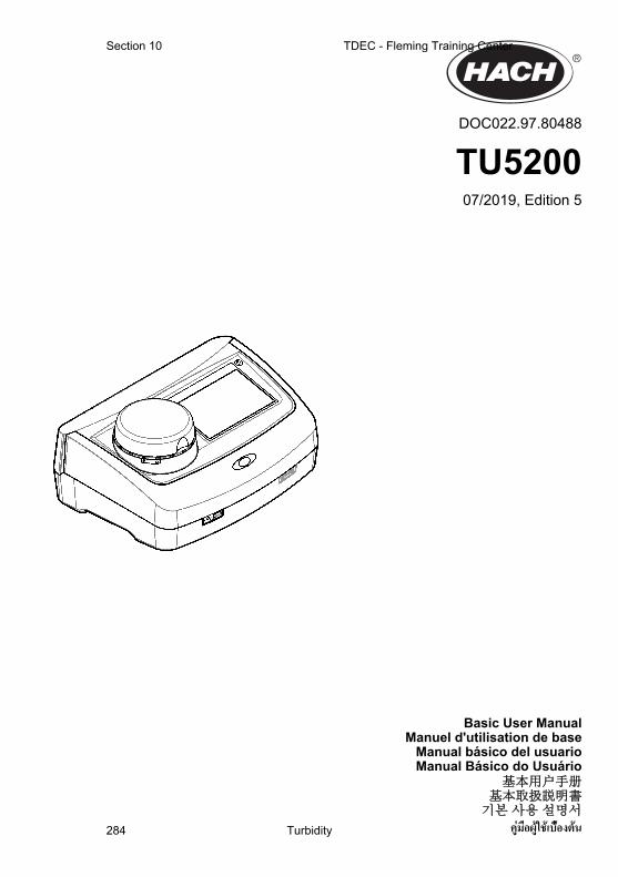
DOC022.97.80488
TU520007/2019, Edition 5
Basic User ManualManuel d'utilisation de base
Manual básico del usuarioManual Básico do Usuário
基本用户手册基本取扱説明書기본 사용 설명서
คู่มือผู้ใช้เบื้องต้น
Section 10 TDEC - Fleming Training Center
Turbidity284

8.1.4 Configure the measurement settingsSelect the reading mode, measurement units, data log settings, resolution and more.
1. At the main reading screen, push Options>Reading Setup.2. Select an option.
Option Description
Reading Sets the reading mode to single, continuous or minimum mode. Default: Single. Single—The measurement stops when the reading is stable. Continuous—The measurementcontinues until the user pushes Done. Minimum Mode—Set to on when a process andlaboratory measurement are compared and the process measurement is a lower NTUrange. Removes the effect of non-representative particles in the grab sample. Signal Avg—The turbidity reading that shows on the display is an average of the values measuredduring the time interval selected. Options: For single measurement mode, 5 to 15 seconds.For continuous measurement mode, 5 to 90 seconds.
Unit Selects the measurement units that show on the display and that are recorded to the datalog. Options: NTU, FNU, TE/F, FTU, EBC, mNTU or mFNU. Default: NTU ).
Data LogSetup
Sets the data log settings. Auto Store—Measurement data is automatically recorded in thereading log. Default: On. When not selected, push Options>Store to record the currentmeasurement to the reading log as necessary. Send Data Format—Sets the output formatof measurement data that is sent to external devices (CSV or XML). Default: XML. PrintFormat—Sets the output format of measurement data that is sent to a printer (Quick Printor Detailed Print (GLP)). Comments—Lets users add comments to log entries. Auto Send—Measurement data is automatically sent to all of the devices (e.g., printer, USB flashdrive and FTP server) that are connected to the instrument after each measurement.
Resolution Selects the number of decimal places that show on the display. Options: 0.001 (default) or0.0001.
Bubble Reject Sets the bubble reject to on (default) or off. When set to on, high turbidity readings causedby bubbles in the sample are not shown or saved to the data log.
Close lid tostart reading
Enables or disables the instrument to start a measurement automatically when the lid isclosed. Default: On. A measurement is only done when there is a sample vial in theinstrument.
8.1.5 Set the acceptance rangeBefore process and laboratory measurements are compared on the instrument, set the acceptancerange for the compare results. The acceptance range is the maximum difference permitted betweenthe process and laboratory measurements.
1. Push LINK2SC.2. Push Options>Compare Setup.3. Push Acceptance Range>Unit.4. Select an option.
Option Description
% Sets the acceptance range to a percentage (1 to 99%).
NTU Sets the acceptance range to NTU units (0.015 to 100.00 NTU).
5. Push Value, then enter the acceptance range.
8.2 Measurement8.2.1 Sample collection
• Collect samples in clean glass or plastic bottles with tight-fitting caps.• Rinse the container a minimum of three times with the sample.
English 15
TDEC - Fleming Training Center Section 10
Turbidity 285

• When collecting a sample from a water tap in a distribution system or treatment plant, turn thewater on for at least five minutes, then collect the sample. Do not adjust the flow because this canadd particles.
• When collecting a sample from a body of water (e.g., a stream or storage tank), collect at least oneliter (1 quart) and fully mix before taking an aliquot for measurement. If the quality of the samplesource is not constant, collect samples at many locations at different depths as necessary. Then,mix the samples together to prepare one sample for measurement.
• Fill the container. Let the container overflow with the sample and then immediately put the cap onthe sample container so that there is no headspace (air) above the sample.
• Write the sample information on the container.• Start analysis as soon as possible to prevent temperature changes, bacteria growth and settling.
8.2.2 Prevent vial contamination
N O T I C E Do not to touch or scratch the glass of the sample vial. Contamination or scratches on the glass can causemeasurement errors.
The glass must stay clean and have no scratches. Use a no-lint cloth to remove dirt, fingerprints orparticles from the glass. Replace the sample vial when the glass has scratches.Refer to Figure 4 to identify where not to touch the sample vial. Always keep the sample vials in thevial stand to prevent contamination on the bottom of the vial.
Figure 4 Sample vial overview
1 Measurement surface—Do not touch.
8.2.3 Prepare a sample vial
C A U T I O N Chemical exposure hazard. Dispose of chemicals and wastes in accordance with local, regional andnational regulations.
N O T I C E Always put a cap on the sample vial to prevent spills in the vial compartment.
Refer to the illustrated steps that follow to prepare a sample vial for measurement. Measure thesample immediately.Note: If there is contamination in the sample vial after it is rinsed with the sample, clean the sample vial. Refer to Clean a sample vial on page 21.
16 English
Section 10 TDEC - Fleming Training Center
Turbidity286

8.2.4 Put the vial in the instrument
C A U T I O N Personal injury hazard. Never remove covers from the instrument. This is a laser-based instrument andthe user risks injury if exposed to the laser.
C A U T I O N Personal injury hazard. Do not look into the vial compartment when the instrument is connected topower.
N O T I C E Keep the lid closed to keep contamination out of the vial compartment.
English 17
TDEC - Fleming Training Center Section 10
Turbidity 287

1. Log in to the instrument as follows:
• Put an operator RFID tag in front of the RFID module or• Push Login. Select the applicable operator ID, then push Select.
2. Select the sample ID as follows:
• Put the sample RFID sticker on the sample bottle in front of the RFID module or• Push Sample ID. Select the applicable sample ID, then push Select.
Note: To add sample IDs to the instrument, refer to Add sample IDs on page 14.
3. Clean the sample vial with a no-lint cloth to remove contamination.4. Dry the external surfaces of the vial with a no-lint cloth. Make sure to dry the bottom of the vial.5. Put the sample vial in the vial compartment. Refer to the illustrated steps that follow.
8.2.5 Measure the sample
1. Push Read if a measurement does not start automatically when the lid is closed.2. When the measurement is complete, push Options>Store to record the measurement to the
reading log as necessary.Note: If the Auto Save setting is set to on, "Data Stored" shows on the display and the measurement isautomatically recorded to the reading log.
3. To show the recorded measurements, push Options>Reading Log. Refer to Show the recordeddata on page 18 for more options.
4. To send the measurement data to external devices that are connected to the instrument, pushOptions>Send Data. Refer to Show the recorded data on page 18 for more options.Note: If the Auto Send settings is set to on, the measurement data is automatically sent to the externaldevice(s) that is connected to the instrument.
8.2.6 Compare process and laboratory measurementsRefer to the expanded user manual on www.hach.com to compare process and laboratorymeasurements.
8.3 Show the recorded dataAll the recorded data is kept in the data log. The data log is divided into four logs:
• Reading log—Shows the recorded measurements.• Calibration log—Shows the calibration history.• Verification log—Shows the verification history.• Compare log—Shows the recorded comparisons of process and laboratory measurements.
18 English
Section 10 TDEC - Fleming Training Center
Turbidity288

Section 9 CalibrationW A R N I N G
Chemical exposure hazard. Obey laboratory safety procedures and wear all of the personal protectiveequipment appropriate to the chemicals that are handled. Refer to the current safety data sheets(MSDS/SDS) for safety protocols.
When the instrument is used for US EPA regulatory reporting, calibrations must be done according toUS EPA guidance documents and methodologies. Contact local regulating authorities for additionalcompliance regulations.The instrument is factory calibrated and the laser light source is stable. The manufacturerrecommends that a calibration verification be done periodically to make sure that the systemoperates as intended. The manufacturer recommends calibration after repairs or comprehensivemaintenance work.Refer to the expanded user manual on the manufacturer's website to calibrate the instrument and doa calibration verification.
Section 10 MaintenanceC A U T I O N
Multiple hazards. Only qualified personnel must conduct the tasks described in this section of thedocument.
C A U T I O N
Chemical exposure hazard. Obey laboratory safety procedures and wear all of the personal protectiveequipment appropriate to the chemicals that are handled. Refer to the current safety data sheets(MSDS/SDS) for safety protocols.
C A U T I O N Personal injury hazard. Never remove covers from the instrument. This is a laser-based instrument andthe user risks injury if exposed to the laser.
N O T I C E Do not disassemble the instrument for maintenance. If the internal components must be cleaned or repaired,contact the manufacturer.
10.1 Clean spillsC A U T I O N
Chemical exposure hazard. Dispose of chemicals and wastes in accordance with local, regional andnational regulations.
1. Obey all facility safety protocols for spill control.2. Discard the waste according to applicable regulations.
20 English
TDEC - Fleming Training Center Section 10
Turbidity 289